Bioaerosol deposition in single and two-bed hospital rooms: A numerical and experimental study
12
Bioaerosol deposition in single and two-bed hospital rooms: A numerical and experimental study M.-F. King * , C.J. Noakes, P.A. Sleigh, M.A. Camargo-Valero Pathogen Control Engineering Institute, School of Civil Engineering, University of Leeds, Leeds LS2 9JT, UK article info Article history: Received 6 June 2012 Received in revised form 8 September 2012 Accepted 16 September 2012 Keywords: Hospital acquired infection Particle deposition CFD Turbulence models Experiment Bioaerosol abstract Aerial dispersion of pathogenic microorganisms and subsequent contamination of surfaces is well rec- ognised as a potential transmission route for hospital acquired infection. Simulation approaches such as computational fluid dynamics (CFD) are increasingly used to model particle behaviour in indoor air and the results interpreted to infer infection risk. However there is little validation of such methods in the open literature. This paper considers the ability of CFD simulations to accurately predict spatial distri- butions of bioaerosol deposition in indoor environments and explores the influence that different room layouts have on deposition patterns. Spatial deposition of aerosolised Staphylococcus aureus was measured in an aerobiology test room arranged in three different layouts: an empty room, a single-bed and a two-bed hospital room. Comparison with CFD simulations using Lagrangian particle tracking demonstrates that a realistic prediction of spatial deposition is feasible, and that a Reynolds Stress (RSM) turbulence model yields significantly better results than the ke 3 RNG turbulence model used in most indoor air simulations. Results for all layouts demonstrate that small particle bioaerosols are deposited throughout a room with no clear correlation between relative surface concentration and distance from the source. However, a physical partition separating patients is shown to be effective at reducing cross- contamination of neighbouring patient zones. Ó 2012 Elsevier Ltd. All rights reserved. 1. Introduction The risk of acquiring nosocomial infections is omnipresent in health-care facilities worldwide. Globally it is estimated that 1.4 million people are suffering from such an affliction at any one time [1]. In the USA for example, the National Nosocomial Infections Surveillance (NNIS) calculated that approximately 1.7 million patients were infected by Healthcare Associated Infections (HCAIs) and 99,000 attributable deaths were reported in 2002 [2]. The European counterpart (Hospital in Europe Link for Infection Control through Surveillance e HELICS) considers the figure of affected patients to be around 5 million in Europe [1]. Differences in benchmarking of surveillance data often make comparisons diffi- cult on an international level however the significance of the problem is undisputed. While the transmission routes for some diseases are well documented, the precise mode of transmission is uncertain for many infections, particularly for those pathogens that cause HCAIs. Although it is highly likely that the majority of transmission occurs via a contact route [1], there is evidence suggesting that at least 20% of HCAIs potentially could have arisen from an environmental reservoir [3]. Deposition of pathogen laden bioaerosols has been highlighted as a potential mechanism for such environmental contamination. Several recent studies have demonstrated a strong correlation between hospital airborne microflora and contaminated surfaces [4,5]. Complementary studies have shown that the application of air cleaning technologies can reduce surface contamination [6]; while others have highlighted that environmental contamination, through the deposition on surfaces, cannot be underestimated in the contribution to fomite-based transmission [7e9]. That said, the fate of aerial pathogens in indoor environments is still poorly under- stood and constitutes an area of much controversy and challenging research. Conventional infection theory regards bioaerosol particles with a diameter below 5 mm (e.g., droplet nuclei) as remaining airborne and being controlled by ventilation, while particles with larger diameters (e.g., larger droplets from a sneeze, skin squama, etc) are cited as depositing out of the air within a 2 m radius of the source [10,11]. However the reality is not quite so clear cut. Smaller particles, while remaining airborne for longer, may still deposit out onto surfaces creating a possible contact transmission risk. While very large particles (>100 mm) will clearly deposit quickly, mid- range (5e100 mm) particles will be influenced by the air, initially * Corresponding author. Tel.: þ44 113 343 3292; fax: þ44 113 343 2265. E-mail address: [email protected] (M.-F. King). Contents lists available at SciVerse ScienceDirect Building and Environment journal homepage: www.elsevier.com/locate/buildenv 0360-1323/$ e see front matter Ó 2012 Elsevier Ltd. All rights reserved. http://dx.doi.org/10.1016/j.buildenv.2012.09.011 Building and Environment 59 (2013) 436e447
Transcript of Bioaerosol deposition in single and two-bed hospital rooms: A numerical and experimental study
at SciVerse ScienceDirect
Building and Environment 59 (2013) 436e447
Contents lists available
Building and Environment
journal homepage: www.elsevier .com/locate/bui ldenv
Bioaerosol deposition in single and two-bed hospital rooms: A numerical andexperimental study
M.-F. King*, C.J. Noakes, P.A. Sleigh, M.A. Camargo-ValeroPathogen Control Engineering Institute, School of Civil Engineering, University of Leeds, Leeds LS2 9JT, UK
a r t i c l e i n f o
Article history:Received 6 June 2012Received in revised form8 September 2012Accepted 16 September 2012
Keywords:Hospital acquired infectionParticle depositionCFDTurbulence modelsExperimentBioaerosol
* Corresponding author. Tel.: þ44 113 343 3292; faE-mail address: [email protected] (M.-F. King)
0360-1323/$ e see front matter � 2012 Elsevier Ltd.http://dx.doi.org/10.1016/j.buildenv.2012.09.011
a b s t r a c t
Aerial dispersion of pathogenic microorganisms and subsequent contamination of surfaces is well rec-ognised as a potential transmission route for hospital acquired infection. Simulation approaches such ascomputational fluid dynamics (CFD) are increasingly used to model particle behaviour in indoor air andthe results interpreted to infer infection risk. However there is little validation of such methods in theopen literature. This paper considers the ability of CFD simulations to accurately predict spatial distri-butions of bioaerosol deposition in indoor environments and explores the influence that different roomlayouts have on deposition patterns. Spatial deposition of aerosolised Staphylococcus aureus wasmeasured in an aerobiology test room arranged in three different layouts: an empty room, a single-bedand a two-bed hospital room. Comparison with CFD simulations using Lagrangian particle trackingdemonstrates that a realistic prediction of spatial deposition is feasible, and that a Reynolds Stress (RSM)turbulence model yields significantly better results than the ke 3RNG turbulence model used in mostindoor air simulations. Results for all layouts demonstrate that small particle bioaerosols are depositedthroughout a room with no clear correlation between relative surface concentration and distance fromthe source. However, a physical partition separating patients is shown to be effective at reducing cross-contamination of neighbouring patient zones.
� 2012 Elsevier Ltd. All rights reserved.
1. Introduction
The risk of acquiring nosocomial infections is omnipresent inhealth-care facilities worldwide. Globally it is estimated that 1.4million people are suffering from such an affliction at any one time[1]. In the USA for example, the National Nosocomial InfectionsSurveillance (NNIS) calculated that approximately 1.7 millionpatients were infected by Healthcare Associated Infections (HCAIs)and 99,000 attributable deaths were reported in 2002 [2]. TheEuropean counterpart (Hospital in Europe Link for Infection Controlthrough Surveillance e HELICS) considers the figure of affectedpatients to be around 5 million in Europe [1]. Differences inbenchmarking of surveillance data often make comparisons diffi-cult on an international level however the significance of theproblem is undisputed. While the transmission routes for somediseases are well documented, the precise mode of transmission isuncertain for many infections, particularly for those pathogens thatcause HCAIs. Although it is highly likely that the majority oftransmission occurs via a contact route [1], there is evidence
x: þ44 113 343 2265..
All rights reserved.
suggesting that at least 20% of HCAIs potentially could have arisenfrom an environmental reservoir [3].
Deposition of pathogen laden bioaerosols has been highlightedas a potential mechanism for such environmental contamination.Several recent studies have demonstrated a strong correlationbetween hospital airborne microflora and contaminated surfaces[4,5]. Complementary studies have shown that the application of aircleaning technologies can reduce surface contamination [6]; whileothers havehighlighted that environmental contamination, throughthe deposition on surfaces, cannot be underestimated in thecontribution to fomite-based transmission [7e9]. That said, the fateof aerial pathogens in indoor environments is still poorly under-stood and constitutes an area of much controversy and challengingresearch. Conventional infection theory regards bioaerosol particleswith a diameter below 5 mm (e.g., droplet nuclei) as remainingairborne and being controlled by ventilation, while particles withlarger diameters (e.g., larger droplets from a sneeze, skin squama,etc) are cited as depositing out of the air within a 2 m radius of thesource [10,11]. However the reality is not quite so clear cut. Smallerparticles, while remaining airborne for longer, may still deposit outonto surfaces creating a possible contact transmission risk. Whilevery large particles (>100 mm) will clearly deposit quickly, mid-range (5e100 mm) particles will be influenced by the air, initially
M.-F. King et al. / Building and Environment 59 (2013) 436e447 437
through evaporation and then subsequently by ventilation flowpatterns [12,13]. As a result, the final destination of an airbornepathogen may be many metres away from its original source.
Understanding the role that ventilation airflow and ward designplay in the dispersion and deposition of infectious bioaerosols istantamount to assessing pathogenexposure risk.With the difficultiesin aerosolising microorganisms in most experimental settings, manystudies have turned to inert particle tracers [14,15] or computationalfluid dynamics (CFD) models to infer bioaerosol behaviour in air anddeposition onto surfaces [16]. As highlighted by Hathway et al. [17]direct comparison between CFD models and bioaerosol experi-ments is sparse. Wong et al. [18] undertook a small scale experi-mental/numerical comparison using bioaerosol deposition withina climatically controlled enclosure. They showed good comparisonusing the RNG ke 3turbulence model and their results are encour-aging at high grid densities, despite the many reservations heldregardingeddyviscosity turbulencemodelling.Hathwayet al.’s study[17] is the only direct comparison between measured airborneconcentrations and CFD simulations in a controlled room scale envi-ronment. While they also analysed and modelled deposition on thefloor of an empty test room, only total depositionwas considered andhence spatial variation is still uncharacterised. Lai and Chen [19,20]predicted deposition of particles sizes ranging from 0.01 to 10 mmwith strong evidence supporting the claim that larger particles dropclose to the source and do not remain suspended.
Deposition of bioaerosols also has implications for ward layout.Recommended bed spacing inmulti-bed environments is often citedas being based on droplet transmission risk [21], and studies haverecognised the relevance for pathogens such as Staphylococcus aureusaswell as respiratory diseases [22]. Tracer gas and simulation studieshave shown that ventilation design [13,23] and the presence ofpartitions between beds [23] influences airborne cross-infection riskbetween two patients. Several studies advocate the benefits of singlepatient rooms in reducing infection risk [24e26], although it is diffi-cult to ascertain whether benefits can be directly attributed to roomdesign or resulting change in nursing and hygiene practice. In realitymany hospitals are constrained by their existing building stock andhave a shortage of single rooms. There is currently little knowledge asto the importance of bioaerosol deposition in environmentalcontamination, so quantifying deposition in both single and multi-bed rooms is important for informing nursing practice and design.
This study uses a combined experimental and CFD modellingapproach to evaluate the spatial distribution of bioaerosol deposi-tion in a ventilated room. The primary objective of the study is todemonstrate, under a full-scale test environment, that CFD simula-tions are able to predict realistic deposition patterns for smalldiameter bioaerosol particles. The secondary objective of the studyis to establish the influence of room layout on the spatial depositionof bioaerosols and the implications for infection control in a hospitalcontext. The work builds on that of Hathway et al. [17] to carry outa direct comparison between the deposition pattern of a non-fastidious microorganism (S. aureus) nebulised into an aerobiologytest room and the predicted deposition from CFD models incorpo-rating Lagrangian particle tracking methodologies and two alter-native turbulencemodels. The study then considers idealised singleand two-bed hospital room scenarios to explore how the location ofthe source and room and ventilation layout influences the relativedeposition on key surfaces in a patient environment.
2. Experimental methodology
2.1. Experimental set-up
Experiments were conducted in the environmentally controlled,negatively pressurized, aerobiology chamber at the University of
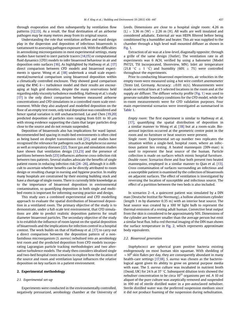
Leeds. Dimensions are close to a hospital single room: 4.26 m(L) � 3.36 m (W) � 2.26 m (H). All walls are well insulated andconsidered adiabatic. External air was HEPA filtered before beingconditioned by a humidifier and heater. This air was supplied to thechamber through a high level wall mounted diffuser as shown inFig. 1.
Extraction of air was at a low-level, diagonally opposite; througha grille of the same design (Outlet). The ventilation rate in allexperiments was 6 ACH, verified by using a balometer (ModelPH721, TSI Incorporated, Shoreview, MN). Inlet air temperature(21.8 �C � 1 �C) and humidity (60% � 7%) were controlledthroughout the experiments.
Prior to conducting bioaerosol experiments, air velocities in theempty roomwere measured using a hot wire comfort anemometer(Testo Ltd, Germany. Accuracy: �0.01 m/s). Measurements weremade on vertical lines at 5 selected locations in the room and at thesupply air diffuser. The diffuser velocity profile (Fig. 1) was used togenerate suitable boundary conditions for the CFDmodel, while thein-room measurements were for CFD validation purposes. Fourmain experimental scenarios were investigated as summarised inTable 1.
Empty room: The first experiment is similar to Hathway et al.[17], quantifying the spatial distribution of deposition ina similar manner to Wong et al. [18] but at a room-scale. Bio-aerosol injection occurred at the geometric centre point in theroom and no furniture or heat sources were present.Single room: Experimental set-up number two replicates thesituation within a single-bed, hospital room, where an infec-tious patient lies resting. A heated mannequin (DIN-man) isused to represent the heat source of the human. Particlecollection is made on surfaces which mimic hospital furniture.Double room: Scenarios three and four both present two heatedmannequins, employed in a similar manner to Qian et al. [13].Cross contamination of surfaces surrounding an infectious anda susceptible patient is examined by the collection of bioaerosolson adjacent surfaces. The effect of ventilation is investigated byreversing the location of susceptible and infectious source. Theeffect of a partition between the two beds is also included.
In scenarios 2e4, a quiescent patient was simulated by a DINman (Deutsche Institut für Normung), a hollow aluminium cylinder(length 1 m by diameter 0.35 m) with an interior heat source. Theheat source was created by a 100 W light bulb to represent thethermal emission of a resting adult human. Convective heat outputfrom the skin is considered to be approximately 50%. Dimensions ofthe cylinder are however smaller than the average person but emita similar heat flux. Infra-red thermal imaging of the DINman showsthe surface temperature in Fig. 2, which represents approximatebody equivalents.
2.2. Bioaerosol generation
Staphylococci are spherical gram positive bacteria existingendogenously on most human skin squamae. With shedding ofw106 skin flakes per day, they are consequently abundant in manyhealth-care settings [17,18]. S. aureus was chosen as the bacterio-logical agent given its ability to grow on general purpose mediawith ease. The S. aureus culture was incubated in nutrient broth(Oxoid, UK) for 24 h at 37 �C. Subsequent dilution tests showed thenebuliser concentration to be circa 1011 organisms per ml. A 10 mlaliquot of the pure culture was aseptically removed and suspendedin 100 ml of sterile distilled water in a pre-autoclaved nebuliser.Sterile distilled water was the preferred suspension medium sinceit did not produce foaming of the suspension during nebulisation.
Fig. 1. Chamber geometry including centreline air speeds at the inlet. (a) Chamber geometry including source location for scenario 1 (Table 1) and contour plot showing measuredvelocities at inlet diffuser: (range: 0e0.7 m/s). (b) Horizontal centreline plot of velocity magnitudes measured at the inlet diffuser.
M.-F. King et al. / Building and Environment 59 (2013) 436e447438
Aerosols were injected into the room via a six jet CollisonNebuliser (CN 25, BGI Inc, USA) attached to the inlet port of thechamber. The nebuliser utilises a separate pump, pressure regulatorand metre operating at a flow rate of 8 L min�1 to deliver HEPAfiltered air. Manufacturer’s data from BGI indicate the size distri-bution of particles ejected during the process to have a mean massdiameter of 2.5 mm and a standard deviation of 1.8 mm. Eventualsize distribution may vary through evaporation and the experi-mental set-up. While bioaerosol samples were not taken here,previous studies such as Hathway [4] have shown this experi-mental approach typically results in a bioaerosol concentration inthe room of the order of 103e104 cfu/m3, with over 90% of thebioaerosols collected on plates 5 and 6 of an Anderson sampler,corresponding to particle diameters of the order 1e2 mm (Anderson1958). Method of injection varied based on the requirements foreach experimental scenario. In the case of the empty chamber
Table 1Experimental scenarios. *Heated cylinders (DIN man) used as mannequins toproduce a thermal plume representative of a human.
Case N� 1 2 3a 3b 4a 4b
Scenario Empty room Single room Doubleroom nopartition
Doubleroom withpartition
Details No furnitureor mannequin
Hospitalsingleroom & 1heatedmannequin
Hospitaldoubleroom & 2heatedmannequins
Hospitaldouble room,2 heatedmannequins& partitionbetween beds.
Aerosolrelease
Room centre Patienthead
Patient 1 Patient 2 Patient 1 Patient 2
(scenario 1), bioaerosols were released from the centre of the roomisotropically. In subsequent cases, (scenarios 2e4) a plastic tube of2.5 cm Ø was clamped at the head of the infectious DIN-man anddroplets were released into the thermal plume.
2.3. Sampling methodologies
All biological samples were taken on Tryptone soya agar (Oxoid,UK) as the controlled chamber conditions meant that no otherspecies were present. Deposition was measured using settle plateslocated on the floor or on surfaces in the room. Given the inherentvariability of biological particle collection, it was found that
Fig. 2. Typical DIN man thermal output (�C).
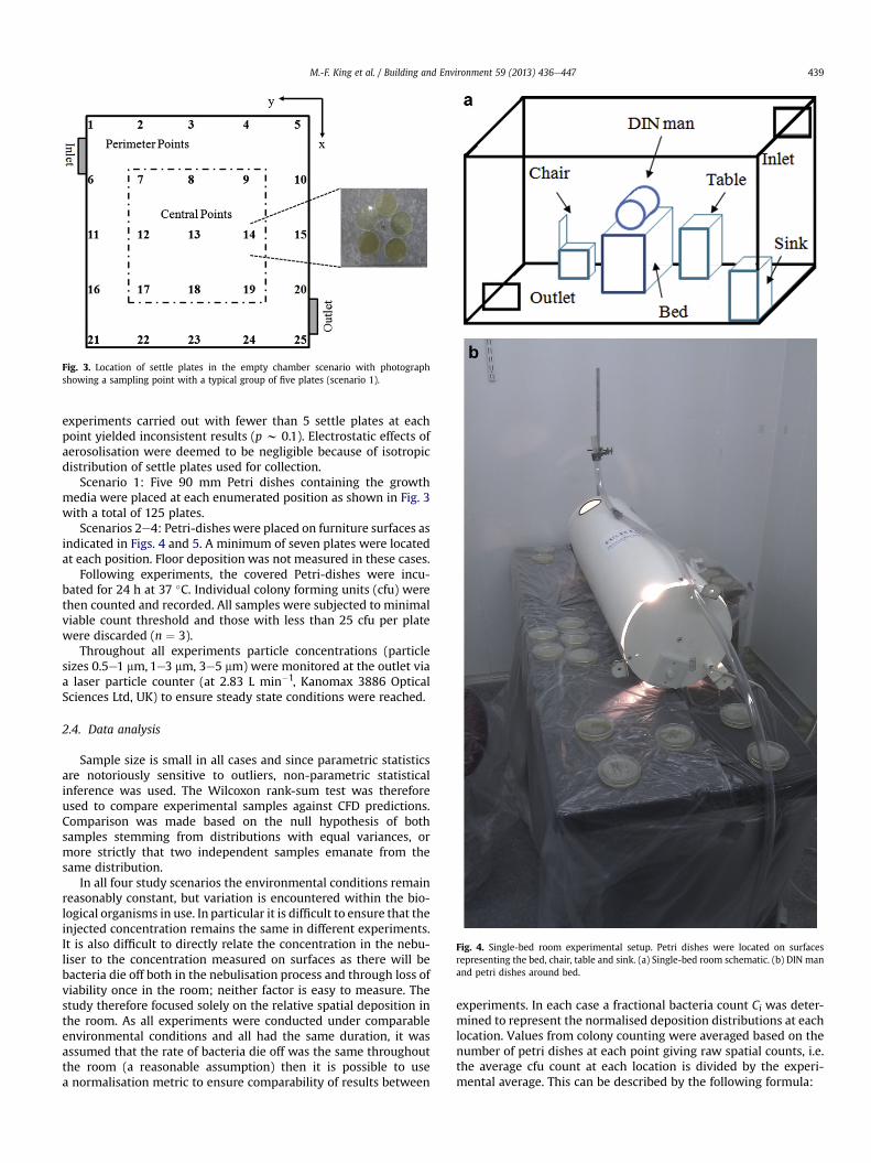
Fig. 3. Location of settle plates in the empty chamber scenario with photographshowing a sampling point with a typical group of five plates (scenario 1).
Fig. 4. Single-bed room experimental setup. Petri dishes were located on surfacesrepresenting the bed, chair, table and sink. (a) Single-bed room schematic. (b) DIN manand petri dishes around bed.
M.-F. King et al. / Building and Environment 59 (2013) 436e447 439
experiments carried out with fewer than 5 settle plates at eachpoint yielded inconsistent results (p w 0.1). Electrostatic effects ofaerosolisation were deemed to be negligible because of isotropicdistribution of settle plates used for collection.
Scenario 1: Five 90 mm Petri dishes containing the growthmedia were placed at each enumerated position as shown in Fig. 3with a total of 125 plates.
Scenarios 2e4: Petri-dishes were placed on furniture surfaces asindicated in Figs. 4 and 5. A minimum of seven plates were locatedat each position. Floor deposition was not measured in these cases.
Following experiments, the covered Petri-dishes were incu-bated for 24 h at 37 �C. Individual colony forming units (cfu) werethen counted and recorded. All samples were subjected to minimalviable count threshold and those with less than 25 cfu per platewere discarded (n ¼ 3).
Throughout all experiments particle concentrations (particlesizes 0.5e1 mm, 1e3 mm, 3e5 mm) were monitored at the outlet viaa laser particle counter (at 2.83 L min�1, Kanomax 3886 OpticalSciences Ltd, UK) to ensure steady state conditions were reached.
2.4. Data analysis
Sample size is small in all cases and since parametric statisticsare notoriously sensitive to outliers, non-parametric statisticalinference was used. The Wilcoxon rank-sum test was thereforeused to compare experimental samples against CFD predictions.Comparison was made based on the null hypothesis of bothsamples stemming from distributions with equal variances, ormore strictly that two independent samples emanate from thesame distribution.
In all four study scenarios the environmental conditions remainreasonably constant, but variation is encountered within the bio-logical organisms in use. In particular it is difficult to ensure that theinjected concentration remains the same in different experiments.It is also difficult to directly relate the concentration in the nebu-liser to the concentration measured on surfaces as there will bebacteria die off both in the nebulisation process and through loss ofviability once in the room; neither factor is easy to measure. Thestudy therefore focused solely on the relative spatial deposition inthe room. As all experiments were conducted under comparableenvironmental conditions and all had the same duration, it wasassumed that the rate of bacteria die off was the same throughoutthe room (a reasonable assumption) then it is possible to usea normalisation metric to ensure comparability of results between
experiments. In each case a fractional bacteria count Ci was deter-mined to represent the normalised deposition distributions at eachlocation. Values from colony counting were averaged based on thenumber of petri dishes at each point giving raw spatial counts, i.e.the average cfu count at each location is divided by the experi-mental average. This can be described by the following formula:
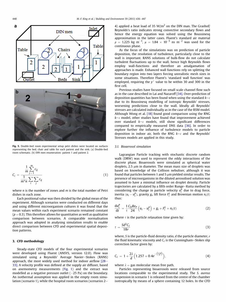
Fig. 5. Double-bed room experimental setup petri dishes were located on surfacesrepresenting the bed, chair and table for each patient and the sink. (a) Double-bedroom schematic. (b) DIN men enumeration: patient 1 and patient 2.
M.-F. King et al. / Building and Environment 59 (2013) 436e447440
Ci ¼
1m
Xm
j¼1
cij
1m*n
Xi
Xj
cij
(1)
where n is the number of zones and m is the total number of Petridishes in each zone.
Each positional valuewas then divided by the global mean of theexperiment. Although scenarios were conducted on different daysand using different microorganism cultures it was found that themean values within each experiment scenario remained constant(p¼ 0.3). This therefore allows for quantitative as well as qualitativecomparison between scenarios. A comparable normalisationapproach was adopted in analysing simulation results to enabledirect comparison between CFD and experimental spatial deposi-tion patterns.
3. CFD methodology
Steady-state CFD models of the four experimental scenarioswere developed using Fluent (ANSYS, version 12.0). Flow wassimulated using a Reynolds’ Average NaviereStokes (RANS)approach, the most widely used method for indoor airflow [28e33]. A velocity profile was defined at the supply air diffuser, basedon anemometry measurements (Fig. 1) and the extract wasmodelled as a negative pressure outlet (�25 Pa) on the boundary.An isothermal assumption was applied in the empty room simu-lation (scenario 1), while the hospital room scenarios (scenarios 2e
4) applied a heat load of 35 W/m2 on the DIN man. The Grashof/Reynolds’s ratio indicates strong convective secondary flows andhence the energy equation was solved using the Boussinesqapproximation in the latter cases. Fluent’s standard air materialr ¼ 1.225 kg m�3, m ¼ 1.84 � 10�5 ns m�2 was used for thecontinuous phase.
As the focus of the simulations was on prediction of particledeposition, the resolution of turbulence, particularly close to thewall is important. RANS solutions of bulk-flow do not calculateturbulent fluctuations up to the wall, hence high Reynolds flowsemploy wall-functions and therefore an amalgamation ofapproaches is made. Enhanced wall functions rely on splitting theboundary region into two layers forcing unrealistic mesh sizes insome situations. Therefore Fluent’s ‘standard wall function’ wasemployed, requiring the yþ value to be within 30 and 300 in thefirst cell.
Previous studies have focused on small scale channel flow suchas in the case described in Lai and Nazaroff [34]. Over-prediction ofdeposition quantities has been found when using the standard ke 3
due to its Boussinesq modelling of isotropic Reynolds’ stresses,worsening predictions close to the wall. Ideally all Reynolds’stresses are calculated individually as in the case of the RSMmodel.Although Wong et al. [18] found good comparison using the RNGke 3model, other studies have found that improvement achievedover standard ke 3 models, still show significant differencescompared to empirically measured DNS data [36]. In order toexplore further the influence of turbulence models to particledeposition in indoor air, both the RNG ke 3 and the Reynolds’Stresses models are applied in this study.
3.1. Bioaerosol simulation
Lagrangian Particle tracking with stochastic discrete randomwalk (DRW) was used to represent the eddy interactions of thediscrete phase. Bioaerosols were simulated as spherical waterdroplets, 2.5 mm in diameter. The mean mass size of droplets wasbased on knowledge of the Collison nebuliser, although it wasfound that particles between 1 and 5 mmyielded similar results. Thepresence of microorganisms in the diluted aerosolised solutionwasassumed to have a minimal influence on droplet density. Particletrajectories are calculated by a fifth order RungeeKutta method byconsidering the change in particle velocity upi due to drag force,inertia ðui � upi Þ, gravity gi, lift force FLi and Brownian motion niðtÞthus:
dupidt
¼ 1sCDReP24
�ui � upi
�þ gi þ FLi þ niðtÞ (2)
where s is the particle relaxation time given by:
s ¼ Sd2Cc18n
(3)
where, S is the particle-fluid density ratio, d the particle diameter, nthe fluid kinematic viscosity and Cc is the CunninghameStokes slipcorrection factor given by:
Cc ¼ 1þ 2ld
�1:257þ 0:4e
��1:1d2l
��; (4)
where l ¼ gas molecular mean free path.Particles representing bioaerosols were released from source
locations comparable to the experimental study. The S. aureussuspension in scenario 1 is released from the centre of the chamberisotropically by means of a sphere containing 12 holes. In the CFD
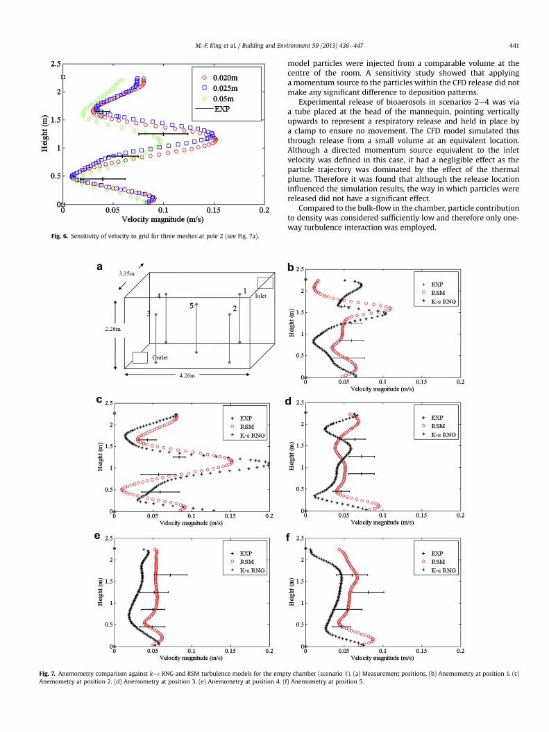
Fig. 6. Sensitivity of velocity to grid for three meshes at pole 2 (see Fig. 7a).
Fig. 7. Anemometry comparison against ke 3RNG and RSM turbulence models for the empAnemometry at position 2. (d) Anemometry at position 3. (e) Anemometry at position 4. (f
M.-F. King et al. / Building and Environment 59 (2013) 436e447 441
model particles were injected from a comparable volume at thecentre of the room. A sensitivity study showed that applyinga momentum source to the particles within the CFD release did notmake any significant difference to deposition patterns.
Experimental release of bioaerosols in scenarios 2e4 was viaa tube placed at the head of the mannequin, pointing verticallyupwards to represent a respiratory release and held in place bya clamp to ensure no movement. The CFD model simulated thisthrough release from a small volume at an equivalent location.Although a directed momentum source equivalent to the inletvelocity was defined in this case, it had a negligible effect as theparticle trajectory was dominated by the effect of the thermalplume. Therefore it was found that although the release locationinfluenced the simulation results, the way in which particles werereleased did not have a significant effect.
Compared to the bulk-flow in the chamber, particle contributionto density was considered sufficiently low and therefore only one-way turbulence interaction was employed.
ty chamber (scenario 1). (a) Measurement positions. (b) Anemometry at position 1. (c)) Anemometry at position 5.
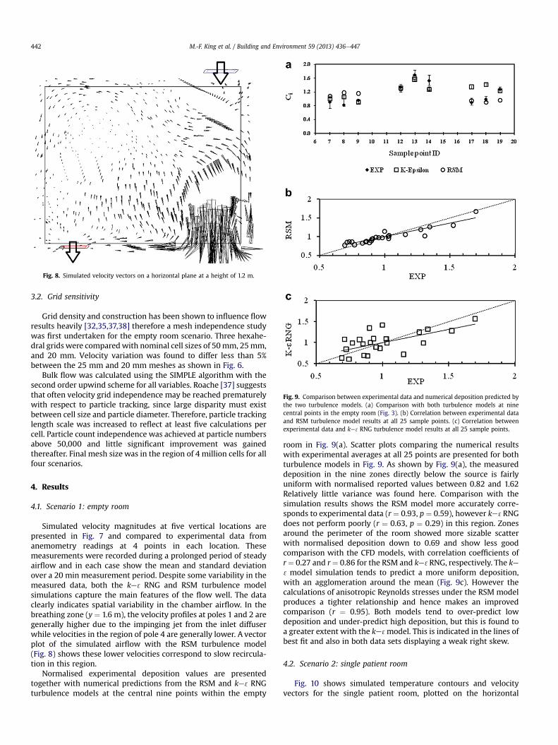
Fig. 8. Simulated velocity vectors on a horizontal plane at a height of 1.2 m.
Fig. 9. Comparison between experimental data and numerical deposition predicted bythe two turbulence models. (a) Comparison with both turbulence models at ninecentral points in the empty room (Fig. 3). (b) Correlation between experimental dataand RSM turbulence model results at all 25 sample points. (c) Correlation betweenexperimental data and ke 3RNG turbulence model results at all 25 sample points.
M.-F. King et al. / Building and Environment 59 (2013) 436e447442
3.2. Grid sensitivity
Grid density and construction has been shown to influence flowresults heavily [32,35,37,38] therefore a mesh independence studywas first undertaken for the empty room scenario. Three hexahe-dral grids were comparedwith nominal cell sizes of 50mm, 25mm,and 20 mm. Velocity variation was found to differ less than 5%between the 25 mm and 20 mm meshes as shown in Fig. 6.
Bulk flow was calculated using the SIMPLE algorithm with thesecond order upwind scheme for all variables. Roache [37] suggeststhat often velocity grid independence may be reached prematurelywith respect to particle tracking, since large disparity must existbetween cell size and particle diameter. Therefore, particle trackinglength scale was increased to reflect at least five calculations percell. Particle count independence was achieved at particle numbersabove 50,000 and little significant improvement was gainedthereafter. Final mesh size was in the region of 4 million cells for allfour scenarios.
4. Results
4.1. Scenario 1: empty room
Simulated velocity magnitudes at five vertical locations arepresented in Fig. 7 and compared to experimental data fromanemometry readings at 4 points in each location. Thesemeasurements were recorded during a prolonged period of steadyairflow and in each case show the mean and standard deviationover a 20 min measurement period. Despite some variability in themeasured data, both the ke 3 RNG and RSM turbulence modelsimulations capture the main features of the flow well. The dataclearly indicates spatial variability in the chamber airflow. In thebreathing zone (y ¼ 1.6 m), the velocity profiles at poles 1 and 2 aregenerally higher due to the impinging jet from the inlet diffuserwhile velocities in the region of pole 4 are generally lower. A vectorplot of the simulated airflow with the RSM turbulence model(Fig. 8) shows these lower velocities correspond to slow recircula-tion in this region.
Normalised experimental deposition values are presentedtogether with numerical predictions from the RSM and ke 3RNGturbulence models at the central nine points within the empty
room in Fig. 9(a). Scatter plots comparing the numerical resultswith experimental averages at all 25 points are presented for bothturbulence models in Fig. 9. As shown by Fig. 9(a), the measureddeposition in the nine zones directly below the source is fairlyuniform with normalised reported values between 0.82 and 1.62Relatively little variance was found here. Comparison with thesimulation results shows the RSM model more accurately corre-sponds to experimental data (r ¼ 0.93, p ¼ 0.59), however ke 3RNGdoes not perform poorly (r ¼ 0.63, p ¼ 0.29) in this region. Zonesaround the perimeter of the room showed more sizable scatterwith normalised deposition down to 0.69 and show less goodcomparison with the CFD models, with correlation coefficients ofr¼ 0.27 and r¼ 0.86 for the RSM and ke 3RNG, respectively. The ke3model simulation tends to predict a more uniform deposition,with an agglomeration around the mean (Fig. 9c). However thecalculations of anisotropic Reynolds stresses under the RSM modelproduces a tighter relationship and hence makes an improvedcomparison (r ¼ 0.95). Both models tend to over-predict lowdeposition and under-predict high deposition, but this is found toa greater extent with the ke 3model. This is indicated in the lines ofbest fit and also in both data sets displaying a weak right skew.
4.2. Scenario 2: single patient room
Fig. 10 shows simulated temperature contours and velocityvectors for the single patient room, plotted on the horizontal
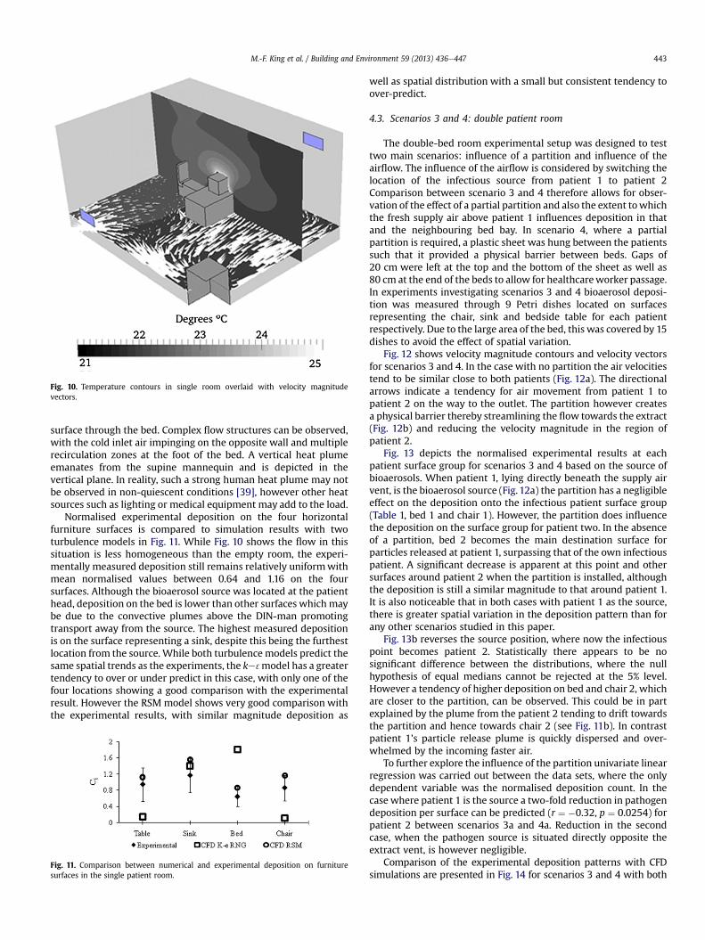
Fig. 10. Temperature contours in single room overlaid with velocity magnitudevectors.
M.-F. King et al. / Building and Environment 59 (2013) 436e447 443
surface through the bed. Complex flow structures can be observed,with the cold inlet air impinging on the opposite wall and multiplerecirculation zones at the foot of the bed. A vertical heat plumeemanates from the supine mannequin and is depicted in thevertical plane. In reality, such a strong human heat plume may notbe observed in non-quiescent conditions [39], however other heatsources such as lighting or medical equipment may add to the load.
Normalised experimental deposition on the four horizontalfurniture surfaces is compared to simulation results with twoturbulence models in Fig. 11. While Fig. 10 shows the flow in thissituation is less homogeneous than the empty room, the experi-mentally measured deposition still remains relatively uniformwithmean normalised values between 0.64 and 1.16 on the foursurfaces. Although the bioaerosol source was located at the patienthead, deposition on the bed is lower than other surfaces whichmaybe due to the convective plumes above the DIN-man promotingtransport away from the source. The highest measured depositionis on the surface representing a sink, despite this being the furthestlocation from the source. While both turbulence models predict thesame spatial trends as the experiments, the ke 3model has a greatertendency to over or under predict in this case, with only one of thefour locations showing a good comparison with the experimentalresult. However the RSM model shows very good comparison withthe experimental results, with similar magnitude deposition as
Fig. 11. Comparison between numerical and experimental deposition on furnituresurfaces in the single patient room.
well as spatial distribution with a small but consistent tendency toover-predict.
4.3. Scenarios 3 and 4: double patient room
The double-bed room experimental setup was designed to testtwo main scenarios: influence of a partition and influence of theairflow. The influence of the airflow is considered by switching thelocation of the infectious source from patient 1 to patient 2Comparison between scenario 3 and 4 therefore allows for obser-vation of the effect of a partial partition and also the extent towhichthe fresh supply air above patient 1 influences deposition in thatand the neighbouring bed bay. In scenario 4, where a partialpartition is required, a plastic sheet was hung between the patientssuch that it provided a physical barrier between beds. Gaps of20 cm were left at the top and the bottom of the sheet as well as80 cm at the end of the beds to allow for healthcareworker passage.In experiments investigating scenarios 3 and 4 bioaerosol deposi-tion was measured through 9 Petri dishes located on surfacesrepresenting the chair, sink and bedside table for each patientrespectively. Due to the large area of the bed, this was covered by 15dishes to avoid the effect of spatial variation.
Fig. 12 shows velocity magnitude contours and velocity vectorsfor scenarios 3 and 4. In the case with no partition the air velocitiestend to be similar close to both patients (Fig. 12a). The directionalarrows indicate a tendency for air movement from patient 1 topatient 2 on the way to the outlet. The partition however createsa physical barrier thereby streamlining the flow towards the extract(Fig. 12b) and reducing the velocity magnitude in the region ofpatient 2.
Fig. 13 depicts the normalised experimental results at eachpatient surface group for scenarios 3 and 4 based on the source ofbioaerosols. When patient 1, lying directly beneath the supply airvent, is the bioaerosol source (Fig. 12a) the partition has a negligibleeffect on the deposition onto the infectious patient surface group(Table 1, bed 1 and chair 1). However, the partition does influencethe deposition on the surface group for patient two. In the absenceof a partition, bed 2 becomes the main destination surface forparticles released at patient 1, surpassing that of the own infectiouspatient. A significant decrease is apparent at this point and othersurfaces around patient 2 when the partition is installed, althoughthe deposition is still a similar magnitude to that around patient 1.It is also noticeable that in both cases with patient 1 as the source,there is greater spatial variation in the deposition pattern than forany other scenarios studied in this paper.
Fig. 13b reverses the source position, where now the infectiouspoint becomes patient 2. Statistically there appears to be nosignificant difference between the distributions, where the nullhypothesis of equal medians cannot be rejected at the 5% level.However a tendency of higher deposition on bed and chair 2, whichare closer to the partition, can be observed. This could be in partexplained by the plume from the patient 2 tending to drift towardsthe partition and hence towards chair 2 (see Fig. 11b). In contrastpatient 1’s particle release plume is quickly dispersed and over-whelmed by the incoming faster air.
To further explore the influence of the partition univariate linearregression was carried out between the data sets, where the onlydependent variable was the normalised deposition count. In thecase where patient 1 is the source a two-fold reduction in pathogendeposition per surface can be predicted (r ¼ �0.32, p ¼ 0.0254) forpatient 2 between scenarios 3a and 4a. Reduction in the secondcase, when the pathogen source is situated directly opposite theextract vent, is however negligible.
Comparison of the experimental deposition patterns with CFDsimulations are presented in Fig. 14 for scenarios 3 and 4 with both
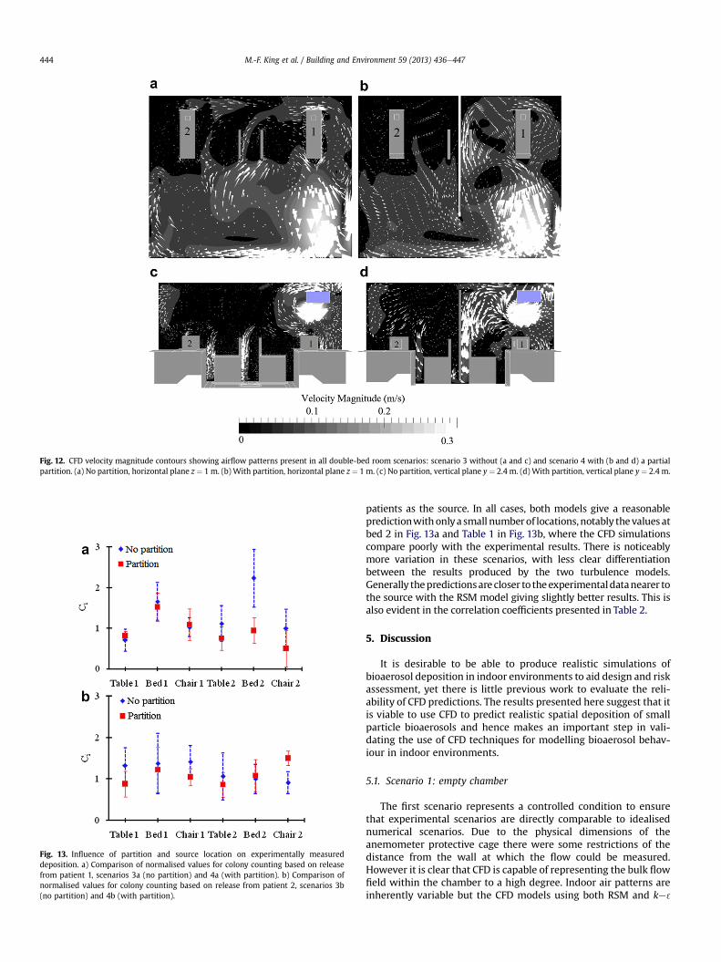
Fig. 12. CFD velocity magnitude contours showing airflow patterns present in all double-bed room scenarios: scenario 3 without (a and c) and scenario 4 with (b and d) a partialpartition. (a) No partition, horizontal plane z ¼ 1 m. (b) With partition, horizontal plane z ¼ 1 m. (c) No partition, vertical plane y ¼ 2.4 m. (d) With partition, vertical plane y ¼ 2.4 m.
Fig. 13. Influence of partition and source location on experimentally measureddeposition. a) Comparison of normalised values for colony counting based on releasefrom patient 1, scenarios 3a (no partition) and 4a (with partition). b) Comparison ofnormalised values for colony counting based on release from patient 2, scenarios 3b(no partition) and 4b (with partition).
M.-F. King et al. / Building and Environment 59 (2013) 436e447444
patients as the source. In all cases, both models give a reasonablepredictionwithonlya small numberof locations,notably thevalues atbed 2 in Fig. 13a and Table 1 in Fig. 13b, where the CFD simulationscompare poorly with the experimental results. There is noticeablymore variation in these scenarios, with less clear differentiationbetween the results produced by the two turbulence models.Generally thepredictionsarecloser to theexperimentaldatanearer tothe source with the RSM model giving slightly better results. This isalso evident in the correlation coefficients presented in Table 2.
5. Discussion
It is desirable to be able to produce realistic simulations ofbioaerosol deposition in indoor environments to aid design and riskassessment, yet there is little previous work to evaluate the reli-ability of CFD predictions. The results presented here suggest that itis viable to use CFD to predict realistic spatial deposition of smallparticle bioaerosols and hence makes an important step in vali-dating the use of CFD techniques for modelling bioaerosol behav-iour in indoor environments.
5.1. Scenario 1: empty chamber
The first scenario represents a controlled condition to ensurethat experimental scenarios are directly comparable to idealisednumerical scenarios. Due to the physical dimensions of theanemometer protective cage there were some restrictions of thedistance from the wall at which the flow could be measured.However it is clear that CFD is capable of representing the bulk flowfield within the chamber to a high degree. Indoor air patterns areinherently variable but the CFD models using both RSM and ke 3
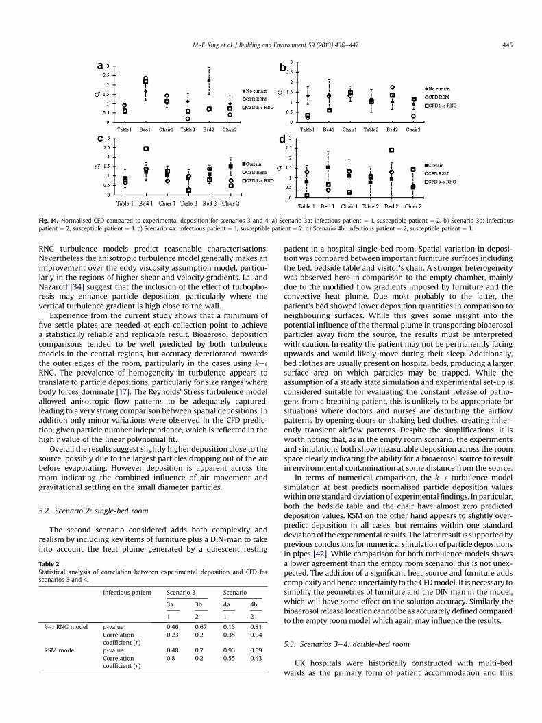
Fig. 14. Normalised CFD compared to experimental deposition for scenarios 3 and 4. a) Scenario 3a: infectious patient ¼ 1, susceptible patient ¼ 2. b) Scenario 3b: infectiouspatient ¼ 2, susceptible patient ¼ 1. c) Scenario 4a: infectious patient ¼ 1, susceptible patient ¼ 2. d) Scenario 4b: infectious patient ¼ 2, susceptible patient ¼ 1.
M.-F. King et al. / Building and Environment 59 (2013) 436e447 445
RNG turbulence models predict reasonable characterisations.Nevertheless the anisotropic turbulence model generally makes animprovement over the eddy viscosity assumption model, particu-larly in the regions of higher shear and velocity gradients. Lai andNazaroff [34] suggest that the inclusion of the effect of turbopho-resis may enhance particle deposition, particularly where thevertical turbulence gradient is high close to the wall.
Experience from the current study shows that a minimum offive settle plates are needed at each collection point to achievea statistically reliable and replicable result. Bioaerosol depositioncomparisons tended to be well predicted by both turbulencemodels in the central regions, but accuracy deteriorated towardsthe outer edges of the room, particularly in the cases using ke 3
RNG. The prevalence of homogeneity in turbulence appears totranslate to particle depositions, particularly for size ranges wherebody forces dominate [17]. The Reynolds’ Stress turbulence modelallowed anisotropic flow patterns to be adequately captured,leading to a very strong comparison between spatial depositions. Inaddition only minor variations were observed in the CFD predic-tion, given particle number independence, which is reflected in thehigh r value of the linear polynomial fit.
Overall the results suggest slightly higher deposition close to thesource, possibly due to the largest particles dropping out of the airbefore evaporating. However deposition is apparent across theroom indicating the combined influence of air movement andgravitational settling on the small diameter particles.
5.2. Scenario 2: single-bed room
The second scenario considered adds both complexity andrealism by including key items of furniture plus a DIN-man to takeinto account the heat plume generated by a quiescent resting
Table 2Statistical analysis of correlation between experimental deposition and CFD forscenarios 3 and 4.
Infectious patient Scenario 3 Scenario
3a 3b 4a 4b
1 2 1 2
ke 3RNG model p-value 0.46 0.67 0.13 0.81Correlationcoefficient (r)
0.23 0.2 0.35 0.94
RSM model p-value 0.48 0.7 0.93 0.59Correlationcoefficient (r)
0.8 0.2 0.55 0.43
patient in a hospital single-bed room. Spatial variation in deposi-tionwas compared between important furniture surfaces includingthe bed, bedside table and visitor’s chair. A stronger heterogeneitywas observed here in comparison to the empty chamber, mainlydue to the modified flow gradients imposed by furniture and theconvective heat plume. Due most probably to the latter, thepatient’s bed showed lower deposition quantities in comparison toneighbouring surfaces. While this gives some insight into thepotential influence of the thermal plume in transporting bioaerosolparticles away from the source, the results must be interpretedwith caution. In reality the patient may not be permanently facingupwards and would likely move during their sleep. Additionally,bed clothes are usually present on hospital beds, producing a largersurface area on which particles may be trapped. While theassumption of a steady state simulation and experimental set-up isconsidered suitable for evaluating the constant release of patho-gens from a breathing patient, this is unlikely to be appropriate forsituations where doctors and nurses are disturbing the airflowpatterns by opening doors or shaking bed clothes, creating inher-ently transient airflow patterns. Despite the simplifications, it isworth noting that, as in the empty room scenario, the experimentsand simulations both showmeasurable deposition across the roomspace clearly indicating the ability for a bioaerosol source to resultin environmental contamination at some distance from the source.
In terms of numerical comparison, the ke 3 turbulence modelsimulation at best predicts normalised particle deposition valueswithin one standard deviation of experimental findings. In particular,both the bedside table and the chair have almost zero predicteddeposition values. RSM on the other hand appears to slightly over-predict deposition in all cases, but remains within one standarddeviationof the experimental results. The latter result is supportedbyprevious conclusions for numerical simulation of particle depositionsin pipes [42]. While comparison for both turbulence models showsa lower agreement than the empty room scenario, this is not unex-pected. The addition of a significant heat source and furniture addscomplexity and hence uncertainty to the CFDmodel. It is necessary tosimplify the geometries of furniture and the DIN man in the model,which will have some effect on the solution accuracy. Similarly thebioaerosol release location cannot be as accurately defined comparedto the empty roommodel which again may influence the results.
5.3. Scenarios 3e4: double-bed room
UK hospitals were historically constructed with multi-bedwards as the primary form of patient accommodation and this
M.-F. King et al. / Building and Environment 59 (2013) 436e447446
remains the case in the majority of hospitals. The results from thefinal stage of this study give some insight into the potential forcross-transmission of infection between patients due to depositionof pathogenic aerosol particles on key surfaces. As with the twoprevious scenarios, both experiments and simulations demon-strated that a bioaerosol release in both an open (scenario 3) andpartitioned (scenario 4) room can result in measurable surfacecontamination across the whole of the room space. Of particularinterest was the effect of both the location of the infectious sourcewith respect to the inlet diffuser and the level of protection thata partition provides in terms of surface deposition in the neigh-bouring cubicle. When the source patient is located directly underthe inlet vent (cubicle 1) the partition proved effective at limitingthe deposition in the neighbouring cubicle (Fig. 12a). However thepartition’s influence appears to be quite sensitive to reversing thesource location (Fig. 12b). In the latter case particle depositionproved more homogeneous and hence the partition playeda secondary role to the effect of ventilation inlet position. As notedduring the CFD and anemometry measurements, cubicle 2 providesareas of very slow moving air and consequently probable recircu-lation pockets. Therefore these allow particles to be dispersedtowards cubicle 1 as well as being extracted. As a corollary, posi-tioning the susceptible patient upwind of the infectious source (inour case in cubicle 1) also results in a significant reduction in risk.The effectiveness of the partition is also likely related to itsparticular deployment in the form of a curtain with gaps above andbelow. However during a common diurnal hospital scene mostcurtains are usually only half drawn or fully retracted. In addition tothis, and mainly to aid in cleaning, they often hang approximately20 cm from the ground and a similar distance from the ceiling.Consequently this space exposes a gap for potential passage ofpathogens, increasing cross transfer susceptibility. Previousnumerical simulations have shown that full height partitions mayreduce airborne transmission risk [26] and that those curtainingthe length of patient beds are more effective than partiallyextended ones at preventing infection [40,41]. Physical barriersclearly point to effective intervention measures however furtherevaluation is needed to explore the most appropriate design andthe limitations of such an approach.
CFD comparison concurred with the findings from the twoprevious scenarios. The further increase in complexity in the two-bed case again led to more variation in the CFD solutions. Aspreviously shown, the RSM model generally led to better predicteddeposition than the ke 3 RNG model, although both modelsproduced realistic deposition patterns. Simulations suggested thatparticles released from patient 2 were drawn towards the inlet jet,probably due to the regions of low pressure created by the fastermoving air. This effect dominated the simulations where a partialpartition was absent and to a lesser effect when one was present.
5.4. Implications of results
Across all scenarios it is noted that both experiments andsimulations predict measurable deposition across the room space.While spatial variation depends on layout, the results suggest thereis clear potential for small diameter (w2.5 mm) particles to playa role in transmission of infection through indirect contact routes.This is an important consideration; such particles are routinelyregarded as airborne and hence controlled through ventilationrather than cleaning. Moreover, these small particles are usuallyonly considered of concern where the pathogen is classed aspossibly capable of direct airborne transmission, for exampletuberculosis, measles or influenza. The deposition of culturablebioaerosols in this study adds support to the hypothesis thatairborne dispersion may play a role in non-respiratory infections
such as MRSA and Clostridium difficile [23,27], with surfacecontamination and subsequent contact by susceptible peopleresulting in transmission.
The study conducted here demonstrates the potential for CFDsimulations to accurately predict the relative spatial distribution ofbioaerosol deposition, but it has not been possible to confirmwhether simulations can predict the actual level of contaminationbased on a particular amount released into the space. The reasonfor this lies in the limitations of the experimental methods. Torelate the deposition to the bioaerosol concentration in the airrequires taking air samples. While this is straightforward [17], it iswell documented that sampler efficiencies are far from 100%, withsome estimated to sample well below 50% of the viable concen-tration in the air [43]. The settle plate approach used to measuredeposition is unlikely to experiencemicrobial losses due to physicaldamage from impaction that is present in an air sampler, but maystill underestimate total counts as it is based on colony formationafter incubation. As the surface deposition and air samples must bemeasured using different techniques, neither of which has a wellcharacterised sampling efficiency, it is not feasible to quantitativelyrelate the results from the two approaches. It is for this reason thatbiological air sampling was not conducted in this study.
The CFD solutions may benefit in future from the use of a low-Reynolds’ turbulence model instead of the logarithmic law utilisedwith both turbulence models tested. Given the exclusion of theeffect of turbophoresis, the DRW model provides extra impetus todeposition velocities. In some cases this may be unphysically large,which probably accounts for some of the over-deposition observed.However computational costs would still be unreasonable due tothe level of grid resolution required.
The Reynolds’ Stress model used in this study requires greatercare during pre-processing and initially defining the geometry andmesh than the empirically based ke 3model. It was found that smallfascia such as a patient’s mouth proved a source of instability whenutilising the second order spatial discretisation scheme and hencethese should be replaced by appropriate energy and momentumsources. Implications for convergence and computational resourcesare also considerable however substantially lower than thoserequired for a transient LES simulation. Ultimately a physicallyrealistic solution can nevertheless be obtained.
6. Conclusions
This study provides a direct room-scale comparison betweenCFD simulations and experimental bioaerosol deposition underidealised but realistic single and two-bed room scenarios. Theresults have demonstrated the following:
� A good comparison is possible between the spatial depositionpatterns predicted through CFD simulation and thosemeasured through experimentation. Comparison is improvedby using an RSM turbulencemodel which correctly resolves theanisotropic nature of the flow compared to the ke 3turbulencemodel that is applied in the majority of indoor air studies. It isrecommended that when CFD is applied as a design tool,careful consideration should be given to which turbulencemodel is used particularly where particle deposition isconsidered.
� Common hospital ventilation guidelines consider that bio-aerosols of diameters less than 5 mm are typically thought to beextracted by the ventilation regime before being deposited onsurfaces. However this study shows that bioaerosol particlesbelow 5 mm diameter do deposit on surfaces. The bioaerosolsstudied have shown to be deposited across all horizontalsurfaces in a room, with surface concentration not clearly
M.-F. King et al. / Building and Environment 59 (2013) 436e447 447
related to distance from the bioaerosol source. This suggeststhat small pathogen carrying particles may play a role in theenvironmental contamination of hospital rooms and hence therisk of indirect contact transmission. Hospital studies haveshown that bedside tables are both high contact nodes forhealthcare workers [44] and are also proven to exhibit contacttransmission probabilities of at least 1 in 5 [45]. Depositiononto such surfaces may therefore be important in some situa-tions and may have implications for nursing practices orfrequency of cleaning procedures.
� The spatial deposition of particles is influenced by the location ofthe ventilation supply inlet relative to the source. Locatinga susceptible patient closer to the supply air and introducinga partition between beds are both likely to reduce the risk ofenvironmental contamination due to bioaerosol release froma neighbouring patient. This finding concurs with tracer gas andsimulationbased studies evaluatingairborne infection risk [13,26]
Acknowledgements
This work was carried out as part of a PhD studentship sup-ported by the UK Engineering and Physical Sciences ResearchCouncil (EPSRC) and Arup. The authors would like to thank DrLouise Fletcher and Sheena Bennett for their assistance with theexperimental work along with Dr Carl Gilkeson and Dr Amir Khanfor CFD expertise and logistics.
References
[1] World Health Organization. WHO guidelines on hand hygiene in health care.Technical report; 2009.
[2] Klevens RM, Edwards JR, Richards CL. Estimating health-care associatedinfections and deaths in U.S. hospitals. Public Health Rep 2002;122.
[3] Harbarth S, Sax H, Gastmeier P. The preventable proportion of nosocomialinfections: an overview of published reports. J Hosp Infect 2003;54:258e66.
[4] Hathway EA. CFD modelling of pathogen transport due to human activity. PhDthesis: Civil Engineering, University of Leeds; 2008.
[5] Roberts K, Hathway EA, Fletcher LA, Beggs CB, Elliot MW, Sleigh PA. Bioaerosolproduction on a respiratory ward. Indoor Built Environ 2006;15:35e40.
[6] Boswell TC, Fox PC. Reduction in MRSA environmental contamination witha portable HEPA-filtration unit. J Hosp Infect 2006;63(1):47e54.
[7] Dancer SJ. Mopping up hospital infection. J Hosp Infect 1999;43:85e100.[8] Otter JA, Yezli S, French GL. The role played by contaminated surfaces in the
transmission of nosocomial pathogens. Infect Control Hosp Epidemiol 2011;32(7):687e99.
[9] Rusin P, Maxwell S, Gerba C. Comparative surface-to-hand and fingertip-to-mouth transfer efficiency of gram-positive bacteria, gram-negative bacteriaand phage. J Appl Microbiol 2002;93:585e92.
[10] Ayliffe GAJ, Fraise AP, Geddes AM, Mitchell K. Control of hospital infection:a practical handbook. 4th ed. London: Arnold; 2000.
[11] Rutala WA, Katz EB, Sherertz RJ, Sarrubi Jr FA. Environmental study ofa methicillin-resistant Staphylococcus aureus epidemic in a burn unit. J ClinMicrobiol 1983;18(3):683.
[12] Xie X. Evaporation and movement of respiratory droplets in indoor envi-ronments. PhD thesis: The University of Hong Kong; 2008.
[13] Qian H, Li Y, Nielsen PV, Hyldgaard CE, Wong TW, Chwang ATY. Dispersion ofexhaled droplet nuclei in a two-bed hospital ward with three differentventilation systems. Indoor Air 2006;16(2):111e28.
[14] Tian ZF, Tu JY, Yeoh GH, Yuen RKK. On the numerical study of contaminantparticle concentration in indoor airflow. Building Environ 2006;41:1504e14.
[15] Zoon WAC, Loomans MGLC, Hensen JLM. Testing the effectiveness of oper-ating room ventilation with regard to removal of airborne bacteria. BuildingEnviron 2011;46(12):2050e77.
[16] Tian L, Ahmadi G. Particle deposition in turbulent duct flows e comparisons ofdifferent model predictions. J Aerosol Sci 2007;38:377e97.
[17] Hathway EA, Noakes CJ, Sleigh PA, Fletcher LA. CFD simulation of airbornepathogen transport due to human activities. Building Environ 2011;46(12):2500e11.
[18] Wong LT, Chan WY, Mui KW, Lai ACK. An experimental and numerical studyon deposition of bioaerosols in a scaled chamber. Aerosol Sci Technol 2010;44(2):117e28.
[19] Lai ACK, Chen F. Modelling particle deposition and distribution in a chamberwith a two-equation Reynolds-averaged NaviereStokes model. J Aerosol Sci2006;37:1770e80.
[20] Chen Q, Jiang Z, Moser A. Control of airborne particle concentration anddraught risk in an operating room. Indoor Air 1992;2(3):154e67.
[21] Kibbler CC, Quick A, O’Neill AM. The effect of increased bed numbers on MRSAtransmission in acute medical wards. J Hosp Infect 1998;39:213e9.
[22] Sheretz RJ, Reagan DR, Hampton KD, Robertson KL, Streed SA, Hoen HM, et al.A cloud adult: the Staphylococcus aureus virus-interaction revisited. AnnIntern Med 1996;124(6):539e47.
[23] Noakes CJ, Sleigh PA, Escombe AR, Beggs CB. Use of CFD analysis in modifyinga TB ward in Lima, Peru. Indoor Built Environ 2005;15(1):41e7.
[24] Chaudhury H, Mahmood A, Valente M. Advantages and disadvantages ofsingle-versus multiple-occupancy rooms in acute care environments:a review and analysis of the literature. Environ Behav 2005;37:760.
[25] Dettenkofer MS, Seegers S, Antes G, Motschall E, Schumacher M. Does thearchitecture of hospital facilities influence nosocomial infection rates? Asystematic review. Infect Control Hosp Epidemiol 2004;25(1):21e5.
[26] Ulrich RS, Zimring C, Zhu X, DuBose J, Seo H-B, Choi Y-S, et al. A review of theresearch literature on evidence-based healthcare design. The Center forHealth Design; 2008.
[27] Roberts K, Smith C, Snelling A, Kerr K, Banfield K, Sleigh PA, et al. Aerialdissemination of Clostridium difficile spores. BMC Infect Dis 2008;8:1e7.
[28] Chow TT, Yang XY. Performance of ventilation system in non-standardoperating room. Building Environ 2003;38(12):1401e11.
[29] Zhang Z, Chen Q. Comparison of the Eulerian and Lagrangian methods forpredicting particle transport in enclosed spaces. Atmos Environ 2007;41:5236e48.
[30] Bjørn E, Nielsen PV. Dispersal of exhaled air and personal exposure indisplacement ventilated rooms. Indoor Air 2002;12(3):147e64.
[31] Noakes CJ, Sleigh PA. Mathematical models for assessing the role of airflow onthe risk of airborne infection in hospital wards. J R Soc Interf 2009;6:S791e800.
[32] Nielsen PV, Allard F, Awbi HB, Davidson L, Schälin A. CFD in ventilation designa new REHVA guide book. Aalborg University; 2009.
[33] Qian H, Li YG, Nielsen PV, Huang XH. Spatial distribution of infection risk ofSARS transmission in a hospital ward. Building Environ 2009;44:1651e8.
[34] Lai ACK, Nazaroff WW. Modelling indoor particle deposition from turbulentflow onto smooth surfaces. J Aerosol Sci 2000;31(4):463e76.
[35] Li Y, Huang X, Yu ITS, Wong TW, Qian H. Role of air distribution in SARStransmission during the largest nosocomial outbreak in Hong Kong. Indoor Air2005;15(2):83e95.
[36] Kim J, Moin P, Moser RD. Turbulent statistics in fully developed channel flow,at low Reynolds number. J Fluids Mech 1987;177:133e66.
[37] Roache PJ. Quantification of uncertainty in computational fluid dynamics.Annu Rev Fluid Mech 1999;29(123):60.
[38] Srebric J, Vukovic V, He G, Yang X. CFD boundary conditions for contaminantdispersion, heat transfer and airflow simulations around human occupants inindoor environments. Building Environ 2008;43(3):294e303.
[39] Tang JW, Noakes CJ, Nielsen PV, Eames I, Nicolle A, Li Y, et al. Observingand quantifying airflows in the infection control of aerosol and airborne-transmitted diseases: an overview of approaches. J Hosp Infect 2011;7:213e22.
[40] Okell CC, Elliot SD. Cross-infection with haemolytic streptococci in oto-rhinological wards. The Lancet 1936;228(5902):836e42.
[41] Ching WH, Leung MKH, Leung DYC, Li Y. Reducing risk of airborne transmittedinfection in hospitals by use of hospital curtains. Indoor Built Environ 2008;17(3):252e9.
[42] Lach W. Performance of the surface air system air samplers. J Hosp Infect1985;6:102e7.
[43] Dehbi A. A CFD model for particle dispersion in turbulent boundary layerflows. Nucl Eng Des 2008;238(3):707e15.
[44] Huslage K, Rutala WA, Sickbert-Bennett E, Weber DJ. A quantitative approachto defining “high-touch” surfaces in hospitals. Infect Control Hosp Epidemiol2010;31(8):850e3.
[45] Hayden MK, Blom DW, Lyle EA, Moore CA, Weinstein DA. Risk of hand orglove contamination after contact with patients colonized with vancomycin-resistant enterococcus or the colonized patients’ environment. Infect ControlHosp Epidemiol 2008;29(2):149e54.