Bio-based polyurethane reinforced with cellulose nanofibers: A comprehensive investigation on the...
45
Accepted Manuscript Title: Bio-based polyurethane reinforced with cellulose nanofibers: A comprehensive investigation on the effect of interface Author: Karima Benhamou Hamid Kaddami Albert Magnin Alain Dufresne Azizan Ahmad PII: S0144-8617(15)00029-6 DOI: http://dx.doi.org/doi:10.1016/j.carbpol.2014.12.081 Reference: CARP 9600 To appear in: Received date: 5-9-2014 Revised date: 28-12-2014 Accepted date: 30-12-2014 Please cite this article as: Benhamou, K., Kaddami, H., Magnin, A., Dufresne, A., and Ahmad, A.,Bio-based polyurethane reinforced with cellulose nanofibers: A comprehensive investigation on the effect of interface, Carbohydrate Polymers (2015), http://dx.doi.org/10.1016/j.carbpol.2014.12.081 This is a PDF file of an unedited manuscript that has been accepted for publication. As a service to our customers we are providing this early version of the manuscript. The manuscript will undergo copyediting, typesetting, and review of the resulting proof before it is published in its final form. Please note that during the production process errors may be discovered which could affect the content, and all legal disclaimers that apply to the journal pertain.
-
Upload
univ-grenoble-alpes -
Category
Documents
-
view
1 -
download
0
Transcript of Bio-based polyurethane reinforced with cellulose nanofibers: A comprehensive investigation on the...

Accepted Manuscript
Title: Bio-based polyurethane reinforced with cellulosenanofibers: A comprehensive investigation on the effect ofinterface
Author: Karima Benhamou Hamid Kaddami Albert MagninAlain Dufresne Azizan Ahmad
PII: S0144-8617(15)00029-6DOI: http://dx.doi.org/doi:10.1016/j.carbpol.2014.12.081Reference: CARP 9600
To appear in:
Received date: 5-9-2014Revised date: 28-12-2014Accepted date: 30-12-2014
Please cite this article as: Benhamou, K., Kaddami, H., Magnin, A., Dufresne,A., and Ahmad, A.,Bio-based polyurethane reinforced with cellulose nanofibers: Acomprehensive investigation on the effect of interface, Carbohydrate Polymers (2015),http://dx.doi.org/10.1016/j.carbpol.2014.12.081
This is a PDF file of an unedited manuscript that has been accepted for publication.As a service to our customers we are providing this early version of the manuscript.The manuscript will undergo copyediting, typesetting, and review of the resulting proofbefore it is published in its final form. Please note that during the production processerrors may be discovered which could affect the content, and all legal disclaimers thatapply to the journal pertain.

Page 1 of 44
Accep
ted
Man
uscr
ipt
Highlights1
2
CNC and CNF reinforced bio-based polyurethane nanocomposites were prepared3 Fully biodegradable high-performance nanocomposites were obtained4 Detailed investigation of thermal and mechanical properties was reported5 Solubility parameters were calculated6 Difference in properties between CNC and CNF is quantified through solubility parameters7
8

Page 2 of 44
Accep
ted
Man
uscr
ipt
Bio-based polyurethane reinforced with cellulose nanofibers: A comprehensive investigation on the effect of interface8
Karima Benhamou,a,b,c Hamid Kaddami*,aAlbert Magnin,d Alain Dufresne*,b,c and Azizan Ahmade9
a Faculty of Sciences and Technologies, Laboratory of Organometallic and Macromolecular Chemistry-Composite Materials, Cadi Ayyad 10
University, Avenue Abdelkrim Elkhattabi, B.P. 549, Marrakech 40000, Morocco11
b Univ. Grenoble Alpes, LGP2, F-38000 Grenoble, France12
c CNRS, LGP2, F-38000 Grenoble, France13
d Laboratoire Rhéologie et Procédés, Grenoble-INP, UJF Grenoble 1, UMR CNRS 5520, BP 53, 38041 Grenoble Cedex 9, France14
Page 3 of 44
Accep
ted
Man
uscr
ipt
e School of Chemical Sciences and Food Technology, Faculty of Science and Technology, Universiti Kebangsaan Malaysia, 43600, Bangi, 15
Selangor Darul Ehsan, Malaysia.16
* Corresponding authors: [email protected]; [email protected]
18
Keywords: PCL-based polyurethane, nanocomposites, cellulose nanofibers, interface, solubility parameters19
20
21
Page 4 of 44
Accep
ted
Man
uscr
ipt
21
Abstract22
Novel bio-based polyurethane (PU) nanocomposites composed of cellulose nanofiller extracted from the rachis of date palm tree and 23
polycaprolactone (PCL) diol based PU were prepared by casting/evaporation. Two types of nanofiber were used: cellulose nanofibrils (CNF), 24
and cellulose nanocrystals (CNC). The mechanical and thermal properties of the nanocomposite films were studied by DMA, DSC, and tensile 25
tests and the morphology was investigated by SEM. Bionanocomposites presented good mechanical properties in comparison to neat PU. While 26
comparing both nanofillers, the improvement in mechanical and thermal properties was more pronounced for the nanocomposites based on CNF 27
which could be explained, not only by the higher aspect ratio of CNF, but also by their better dispersion in the PU matrix. Calculation of the 28
solubility parameters of the nanofiller surface polymers and of the PU segments portend a better interfacial adhesion for CNF based 29
nanocomposites compared to CNC. 30
31
Page 5 of 44
Accep
ted
Man
uscr
ipt
31
1. Introduction32
The development of biodegradable films that combine innovative properties and sustainability is one of the most important challenges of the 33
packaging industry today. Biodegradable packaging prepared from renewable materials could contribute to managing the carbon cycle in a 34
sustainable manner (Narayan, 2006).35
Polysaccharides isolated from natural materials are more environmentally friendly than synthetic polymers not only because of their 36
biodegradability, but also because of the amount of energy and environmental impact required for the production of synthetic polymers (Shen & 37
Patel, 2010). Cellulose molecules are always biosynthesized in the form of nanosized fibrils; up to 100 glucan chains aggregate together to form 38
cellulose nano-sized microfibrils or nanofibers (McCann, Wells, & Roberts, 1990; McCann, Wells, & Roberts, 1992; Clowes & Juniper, 1968; 39
Stamboulis, Baillie & Peijs, 2001). The mechanical performance of cellulose nanofibers in terms of tensile strength and Young’s modulus is 40
higher than for glass fiber. Therefore, cellulose nanofibers can be considered to be an important structural element of natural cellulose in a 41
number of applications such as plastic reinforcement, gel forming and thickening agents (Eichhorn et al., 2001, Dinand, Chanzy, Vignon,42
Maureaux & Vincent, 1999; Dinand, Chanzy & Vignon, 1999). Furthermore, cellulose nanofiber has more than 200 times higher surface area 43
than isolated softwood cellulose fiber (Krieger, 1990) and possesses higher water holding capacity, higher crystallinity, higher tensile strength, 44
and a finer web-like network. In combination with a suitable polymer matrix, the cellulose nanofiber network shows considerable potential as an 45
effective reinforcement for high quality bio-based composites. 46

Page 6 of 44
Accep
ted
Man
uscr
ipt
Fully biodegradable polymers have been commercially available since 1990, such as polyvinyl alcohol (PVA), polylactic acid (PLA), 47
polycaprolactone (PCL), and polyhydroxybutyrate (PHB). In view of better environmental characteristics at the end of service life, 48
bionanocomposites, in which the reinforcing material has nanometer dimensions, is emerging to create value-added materials with superior 49
performance and extensive applications. Due to their lightweight and high strength; nanofibers can be used as high strength components in 50
aerospace and automotive sector.51
Polyurethane (PU) is generally synthesized by polyaddition polymerization between polyisocyanates and polyols. Its molecular structure and 52
properties vary over a broad range of stiffness or flexibility, hardness, and density (Hepburn, 1996). There are many applications for PU such as 53
flexible or rigid foams, chemical resistant coatings, rigid and flexible plastics, specialty adhesives and sealants, and elastomers (Prisacariu, 2011). 54
Two types of PU can be distinguished, depending on the polyol used: polyester PU and polyether PU.55
Typical synthetic polymers have caused serious environmental problems because they are not easy to degrade in the natural environment. PU56
based materials also present this drawback and, moreover, they are highly resistant to microbial attack. Generally, the ester-type PU is more 57
easily degraded than ether type of PU: the degradation is considered to be initiated by hydrolysis of the ester bond by some hydrolytic enzyme(s), 58
such as esterase (Zia, Bhatti & Bhatti, 2007). This explains why the development of biodegradable PUs has recently generated increasing 59
interest. One of the possible ways to address the problem is to insert a fragment of a known easily biodegradable polymer in the PU backbone. 60
PCL, for instance, a biodegradable aliphatic polyester, has been used as a diol to synthesize biodegradable PUs for different applications (Gorna 61
& Gogolewski, 2002; Zhu, Hu & Yeung, 2009). PCL is synthesized via the ring-opening polymerization (ROP) of ε-caprolactone (CL) (which is 62
Page 7 of 44
Accep
ted
Man
uscr
ipt
a petrochemical based monomer) using a diol as initiator/chain-transfer agent in the presence of a catalyst. Another issue of great concern in 63
polymer synthesis is to conceive novel materials from renewable resources.64
Recently, numerous reports have focused on the addition of nanosized polysaccharide particles, especially nanocrystals, to improve physical and 65
mechanical properties of PU matrices. An interesting review on this family of nanocomposites has been published (Li & Ragauskas, 2011). 66
Among these nanocomposites few studies were dedicated to PCL or biodegradable polyester based PU-nanocomposites. Cao et al. (Cao, Dong & 67
Li, 2007) have found that the incorporation of cellulose nanocrystals, extracted from flax (fCNC), promote microphase separation between soft 68
and hard segments in PCLdiol/ dimethylol propionic acid / isophorone diisocyanate based water borne Polyurethane (WPU), which can influence 69
the value of the glass transition temperature (Tg) in two opposite ways. Firstly, the solid surface of fCNC can induce a restricted mobility of 70
WPU chains by forming hydrogen bonds in the interfacial area. It may result in a shift of Tg toward higher temperatures. Secondly, in an 71
opposite way, the incorporation of fCNCs might interrupt the original interactions between soft and hard segments and improve the microphase 72
separation in WPU. This effect can lead to a decrease of the Tg of soft segments indirectly. However, the interactions between two types of 73
polymers are far less than the chemical linkages between the soft and hard segments, that can be proved by a decrease of both Tg and associated 74
specific heat increment (∆Cp) for WPU/fCNC nanocomposites compared to WPU. However, the Young’s modulus and the tensile strength 75
increased with the CNC content in WPU-CNC nanocomposites. The authors explained the improvement of the mechanical properties by the 76
occurrence of three-dimensional networks owing to the hydrogen-bonding interactions between CNC particles and to the interactions between77
CNC and WPU matrix. Chen et al. (Chen et al., 2008) have conducted a comprehensive study on nanocomposites based on starch nanocrystals 78

Page 8 of 44
Accep
ted
Man
uscr
ipt
(StNs) and WPU matrix based on poly(1,4-butylene glycol adipate), dimethylol propionic acid and toluene diisocyanate. In this work the pure 79
WPU was synthesized in a typical three-stage process : (i) synthesis of the prepolymer PU, (ii) emulsification to disperse PU in water and (iii) the 80
chain-extending of PU prepolymer. To prepare the StN-WPU nanocomposites, the StNs were incorporated in the midst of emulsification and 81
chain-extending stage. This resulted in simultaneous reinforcing and toughening thanks to the better interactions between StNs and WPU. 82
Saralegi et al. (Saralegi et al., 2013) have studied the structure/properties relationships of CNC-PU nanocomposites by varying both the CNC 83
content and the soft/hard segment ratio in polyurethane matrix based on castor oil derived difunctional polyester (poly(butylene sebacate) diol), 84
1,6-hexamethylene diisocyanate and 1,3-propanediol. In this PU both soft and hard segments were crystalline. Even if an improvement of the 85
mechanical properties was obtained by incorporating CNC, they found that the observed improvement was not as high as that observed for 86
nanocomposites with amorphous and homogeneous matrix. Due to the high crystalline nature of both soft and hard segments, they also served as 87
reinforcing agents, and therefore the effect of the addition of CNC on the final properties was less pronounced. Rueda et al. (Rueda et al., 2013)88
analyzed the reinforcement of CNC on PU based on PCL-b-polytetradydrofuran-b-PCL copolymers as macrodiol, 1,6-hexamethylene 89
diisocyanate and 1,4-butanediol as chain extender. The authors observed that the incorporation of low CNC contents in PU nanocomposites leads 90
to a tough material without loss in ductility, whereas an increase in CNC content enhanced the soft and hard segment crystallization, which 91
provoked an increase in the material stiffness and thermal stability. It is worth noting that CNC network formation can be directly affected by the 92
PU microstructure and also, by the interactions between nanoreinforcement and soft and hard segments of the matrix, mainly due to the high 93
number of hydroxyl groups at CNC surface, which induced nucleation of the crystallization from CNC. 94
Page 9 of 44
Accep
ted
Man
uscr
ipt
Cao et al. (Cao, Habibi & Lucia, 2009) studied the morphology, thermal and mechanical properties of CNC/WPU nanocomposites based on PCL 95
diol, isophorone diisocyanate and dimethylol propionic acid. The process of preparation of these nanocomposites designed by the authors as a 96
one-pot polymerization was orchestrated to allow chemical reaction between PU and CNC and then favor the formation of a co-continuous 97
nanocomposite morphology. Such morphology fosters the crystallization of PCL chains, expedited by the CNC surface, which contributes to the 98
significant improvement of the thermal and mechanical properties obtained for the nanocomposite materials.99
Few studies in literature were systematically dedicated to comparing the reinforcement effect of CNC and cellulose nanofibrils (CNF). The 100
existing works showed that CNF shows higher reinforcement for polymeric matrix and related it principally to the higher aspect ratio and 101
flexibility of CNF compared to CNC (Bendahou, Kaddami & Dufresne, 2010; Siqueira, Bras & Dufresne, 2009; Ben mabrouk, Kaddami, Boufi, 102
Erchiqui & Dufresne, 2012). On the other hand, to the best of our knowledge, no study in the literature was dedicated to the relationship between 103
the polymer solubility parameter (SP) and cellulose nanoparticle dispersion. So the aim of the present study was to evaluate the thermal and 104
mechanical properties of nanocomposite films obtained from PU based on PCL, designed here as soft segment and isophorone diisocyante 105
(IPDI)-butanediol 1.4 (BDO 1.4), designed here as hard segment and cellulosic nanoparticles extracted from the rachis of date palm tree, 106
focusing on the differences induced by the nature of the nanoparticle (CNC versus CNF). Solubility parameter calculation was used to 107
understand and compare the differences in morphology and properties of these two families of nanocomposites. 108
2. Experimental109
2.1. Materials110

Page 10 of 44
Accep
ted
Man
uscr
ipt
Cellulose nanocrystals (CNCs) and cellulose nanofibrils (CNFs) were extracted from the rachis of the date palm tree. Colloidal suspensions of 111
CNC and CNF in water were prepared as largely described elsewhere (Marchessault, Morehead & Walter, 1959; Turbak, Snyder & Sandberg, 112
1983; Herrick, Casebier, Hamilton & Sandberg, 1983). Sulfuric acid (95%), methanol, isophorone diisocyanate (IPDI), 1,4-butanediol (BDO), 113
tetrahydrofuran (THF), Tin (II) ethylhexanoate (Sn(Oct)2) were all obtained from Sigma-Aldrich. Poly(ε-caprolactone) (PCL) with a molecular 114
weight of 4000g/mol was obtained from PERSTORP (CAPA®2402). All chemicals were used without further purification.115
Cellulose nanofibrils were prepared by a two-step process: mechanical refining of natural fiber pulp followed by several passes through a high 116
intensity homogenizer (Turbak, Snyder & Sandberg, 1983; Herrick, Casebier, Hamilton & Sandberg, 1983). The ensuing material was a dense 117
network of highly fibrillated cellulose consisting of nanofibers ranging from 10 to 29 nm in width. Furthermore, the CNCs were generated from 118
acid hydrolysis of pulp fibers. The hydrolysis process dissolves the amorphous regions of the fiber leaving intact the crystalline fraction (Edgar & 119
Gray, 2003). The CNC suspension was washed and further homogenized by ultrasonic treatment.120
2.2. Synthesis of polyurethane (PU)121
PU based on IPDI, PCL and the chain extender was synthesized using two-step polymerization. The NCO/OH ratio of 2 was chosen in order to 122
avoid chemical cross linking due to isocyanate secondary reactions (Corniglion, 1991). In the first step, the reaction between IPDI and PCL was 123
conducted at 80°C under dry nitrogen atmosphere. In the second step, the chain extender (BDO) and 0.01 wt% stannous octoate (catalyst) were 124
added to the mixture and the reaction was conducted at 45°C for 3h. During this second step, THF was added to reduce the high viscosity of the 125
reaction medium. 126

Page 11 of 44
Accep
ted
Man
uscr
ipt
2.3. Preparation of nanocomposite films127
The nanocomposite films consist of PU reinforced by various percentages of cellulose nanoparticles (CNC or CNF) extracted from the rachis of 128
the date palm tree. The aqueous suspension of cellulose nanoparticles was solvent-exchanged to acetone and then to dry ethanol by several 129
successive centrifugation and redispersion operations. The polyurethane and the cellulose nanoparticle suspension (CNC/CNF) were mixed to 130
obtain dry films of about 6g with a nanoparticle content varying from 0 to 10 wt%. The mixtures were stirred for one day by magnetic stirring 131
and then sonicated by means of high power ultrasound disperser during 20 min; degassed, then poured into a Teflon mold and placed at room 132
temperature during one week to allow slow elimination of the solvent. 133
2.4. Characterization134
2.4.1. Dynamic mechanical analysis (DMA)135
DMA of the prepared nanocomposites was carried out in tensile mode (METRAVIB, ACOEM). The measurements were carried out at a constant 136
frequency of 1 Hz, a strain amplitude of 0.05%, a temperature range from -100°C to 300°C, a heating rate of 5°C min-1 and gap distance of 10 137
mm. The samples were prepared by cutting strips from the films with a width of 5 mm. 138
2.4.2. Differential scanning calorimetry (DSC)139
DSC was performed using a DSC Q100 differential scanning calorimeter from TA Instruments (New Castle, Delaware). Around 8-10 mg of 140
sample was placed in a DSC cell in glove box. Each sample was heated from -100 to 150°C at a heating rate of 10 °C min-1, kept at this 141
temperature for 2 min and then cooled down at a cooling rate of 10°C min-1.142
Page 12 of 44
Accep
ted
Man
uscr
ipt
2.4.3. Tensile tests143
The mechanical behavior at large deformations for the nanocomposites was analyzed with a RSA3 instrument (TA Instruments, USA) with a 144
load cell of 100 N. Experiments were performed with a cross-head speed of 10 mm min-1 at 25°C. Sample dimensions were 10×5× 0.25 mm3, 145
and results were the average of five measurements.146
2.4.4. Swelling properties147
Specimens in the form of squared films with dimensions around 10×10 mm2 were first dried and weighed using a four-digit balance and then 148
immersed in distilled water. The samples were removed at specific intervals and weighed. The water uptake (WU) was calculated as follows:149
(1)150
Where Mt and Mo are the weights of the sample after exposure to water for a time t and before exposure to water, respectively.151
2.4.5. Atomic force microscopy (AFM)152
A Nanoscope III (Veeco Co. Ltd., USA) was used to perform AFM observations. An aqueous suspension (0.01 wt %) was sonicated for 30 min 153
to allow better dispersion of CNC/CNF. The samples for AFM characterization were prepared by depositing drops of the sonicated CNC/CNF 154
dispersion onto the mica substrates and thereafter air drying the sample at ambient conditions. Silicon cantilevers were used for the in air tapping 155
mode to record all AFM micrographs. The tapping was performed in the frequency range of 264−339 kHz and with a radius of curvature between 156
10 and 15 nm. The CNC/CNF dimensions, including length (L) and width (W), were measured by using Nanoscope software. An average of 157

Page 13 of 44
Accep
ted
Man
uscr
ipt
more than 100 measurements performed on individual nanoparticles statistically chosen and analyzed was calculated and used to determine 158
length and width distribution (mainly focusing on the images with the scale of 3.3 μm × 3.3 μm).159
2.4.6. Scanning electron microscopy (SEM)160
SEM (S-570, Hitachi, Japan) at 20 kV was used to observe the fractured surfaces of the composite films pre-chilled in liquid nitrogen. Samples 161
were sputter-coated with gold prior to SEM observation.162
2.4.7. Fourier-Transform Infrared Spectroscopy (FTIR)163
FTIR spectra were recorded at room temperature on a FTIR Perkin-Elmer Spectrum One spectrometer (Perkin Elmer Inc.) to characterize 164
cellulose pulp, CNC and CNF. All the samples were characterized by FTIR using a spectral width ranging from 4000 to 400 cm−1, with a 4 cm−1165
resolution and an accumulation of 32 scans.166
3. Results and discussion167
Atomic force microscopy (AFM) is a technique to obtain images and other information from a wide variety of samples, at extremely high 168
resolution at nanometer scale. The morphology of CNC obtained by acid hydrolysis and CNF extracted from the rachis of the date palm tree are 169
shown in Figure 1 using AFM microscopy. The AFM images are presented in topography, amplitude and phase modes. The topography images, 170
which are common to AFM characterization, were obtained owing to the calibration sensor in Z axis and are presented as a map of differently 171
colored pixels with color bar relating the color to a height. Even if in this type of image the appearance of the shape is generally very different 172
from what would have in optical (or electron) microscopy, it enables to estimate both lateral and height sizes.173
Page 14 of 44
Accep
ted
Man
uscr
ipt
The amplitude image, which is equivalent to a map of the slope of the sample, often displays the shape of the sample more easily. It should be 174
kept in mind that the z-scale in deflection or amplitude is completely meaningless in terms of sample structure. It is considered as the error 175
signals in AFM. The phase images are a map of how the phase of cantilever oscillation is affected by its interaction with the surface. In general, 176
the physical meaning of this signal is complicated, but in addition to topographic information, relative softness/hardness of the sample or its 177
chemical nature can affect the phase images. In general, in mixed samples, it is easy to get a contrast in the phase, but interpretation is more 178
complicated.179
CNC with an average diameter of 5.8 ± 1.5 nm and length about 235 ± 21 nm were obtained. Additionally, the average lateral size of CNF is of 180
the order of 29 ± 9 nm. These values are in agreement with CNC/CNF obtained from similar sources in literature (Siqueira, Bras & Dufresne, 181
2009). 182
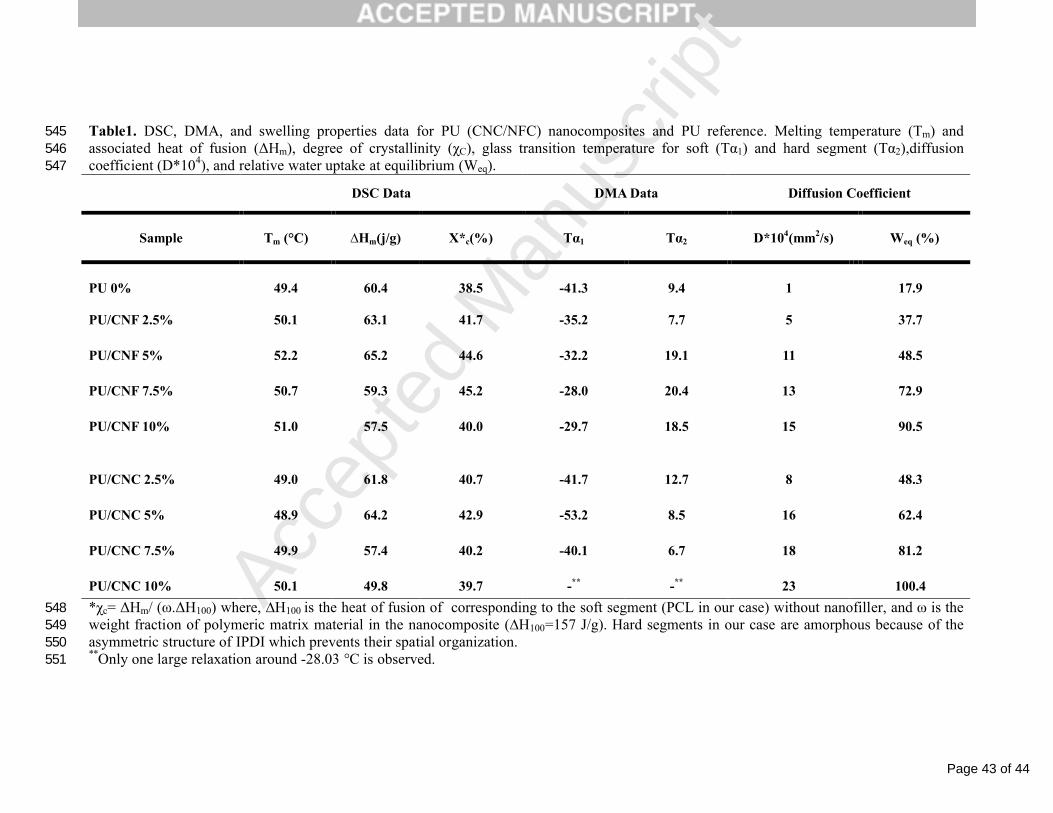
To investigate the interactions between the nanofiller and the host polymer (PCL based PU), DSC analysis was performed for unfilled and filled 183
samples. The melting temperature (Tm), associated melting heat (ΔHm), and degree of crystallinity (χc) were calculated for the unfilled PU film 184
and nanocomposite materials reinforced with both cellulosic nanofillers, and are listed in Table 1. 185
For all nanocomposites, the degree of crystallinity (χc) was slightly higher compared to the neat PU matrix. This resulted from a nucleation effect 186
induced by the presence of the cellulosic nanofiller as noticed by others (Corniglio, 1991; Gray, 2008; Han et al., 2012; Pandey, Lee & Ahn, 187
2010). On the other hand CNF reinforced nanocomposites show slightly higher degree of crystallinity (χc) compared to CNC based films.188
However, it’s worth noting that the degree of crystallinity decreased at higher nanofiller contents (beyond 5 wt% for CNC based nanocomposites 189

Page 15 of 44
Accep
ted
Man
uscr
ipt
and beyond 7.5 wt% for CNF based ones). This result can be explained by the hindrance to growth of PCL crystallites in the presence of highly 190
developed cellulosic network (Gray, 2008; Han et al., 2012; Pandey et al., 2010; Bendahou et al., 2008). 191
Similarly, a slight increase in the degree of crystallinity of PVA nanocomposites upon addition of a small amount of CNF (1-5 wt%) was 192
reported (Lu, Wang & Drzal, 2008). In contrast, some studies report higher increase in crystallinity upon loading with cellulose nanoparticles. 193
Sorbitol plasticized starch for instance exhibited higher crystallinity with increasing loading of tunicin nanocrystals (Mathew & Dufresne, 2002).194
A significantly higher degree of crystallinity for PLA-CNF nanocomposites compared to the neat PLA has been reported (Suryanegara, 195
Nakagaito & Yano, 2009). This increase was ascribed to the fact that CNF favored the crystallinity of PLA. In both studies, the higher degree of 196
crystallinity for nanocomposites was attributed to an anchoring effect of the cellulose filler, possibly acting as a nucleation agent. In our case, and 197
in comparison to CNC, it seems that the CNF-induced crystallization of PCL segments is favored, which may stem from well dispersed 198
nanoreinforcement that maximize matrix–cellulose interactions through physical bonding, taking advantage of the abundant hydroxyl groups 199
(OH) on the surface of CNF, and/or from the higher thermodynamic compatibility between CNF polymeric surface and PU, as will be discussed 200
later.201
Microscopic observation of the cryo-fractured surface of the studied films was carried out using SEM. Figure 2 shows SEM images for the neat 202
PU film (Fig. 2a) and nanocomposite films containing 1, 5 and 10 wt% CNF/CNC (Fig. 2b-g). For 1 wt% filler content, the PU/CNF and 203
PU/CNC nanocomposite films (Fig. 2b and 2e, respectively) showed a fluctuant fractured surface similar to the neat PU (Fig. 2a). This was 204
attributed to the fact that at lower loading levels the nanofiber (CNF or CNC) is uniformly dispersed in the PU matrix and had almost no 205

Page 16 of 44
Accep
ted
Man
uscr
ipt
detectable effect on the structure of the fractured surface in comparison to the PU matrix. However, with an increase in the CNF/CNC loading 206
level, the nanofiber become detectable and appears as white dots in the SEM image. Similar SEM pictures have been reported in the literature 207
and were attributed to nanofiber aggregation (Favier, Cavaille, Chanzy & Dufresne, 1995). The surface morphology of nanocomposite film based 208
on CNF was dominated by coherent structure of the fibrils (Fig. 2g) which may reflect better interactions existing between these nanofillers and 209
the hosting polymer. Such an event and uniform distribution of the filler in the matrix could play an important role in improving the mechanical 210
and physical properties of the resulting nanocomposite films as will be discussed later. In contrast, the nanocomposite film containing 10 wt% 211
CNC (Fig. 2g) showed voids and large CNC aggregates reflecting their poor dispersion in the matrix that should probably result from, 212
comparatively, weaker interactions between CNC and the hosting polymer. 213
The mechanical properties for PU/CNC and PU/CNF nanocomposites derived from engineering stress-strain curves are presented in Figure 3. As 214
expected, the Young’s modulus and strength values increased, and strain at break decreased by increasing the cellulose nanofiller content in both 215
bionanocomposite series. However, the increase in the tensile properties observed for the nanocomposites based on CNF was sharper comparing 216
with the increase observed for the nanocomposites based on CNC, due certainly to the formation of a more interconnected cellulosic network 217
when increasing the nanoparticle content. The formation of such a network in the case of CNF is facilitated by their flexibility resulting from 218
their high aspect ratio and the presence of amorphous domains along the nanofiber (Bendahou et al., 2010, Siqueira et al., 2009). On the other 219
hand, and even less important in this study the contribution of the crystalline domains from the matrix in improving the mechanical properties 220
should be considered.221

Page 17 of 44
Accep
ted
Man
uscr
ipt
Nevertheless, another important parameter which explains the better mechanical properties of the CNF based nanocomposites, is the stronger 222
interaction between the CNF and the PU hosting polymer as portended by the SEM analyses. These interactions would restrict the motion of the 223
polymeric chains of the hosting polymer, leading to higher Young modulus and strength.224
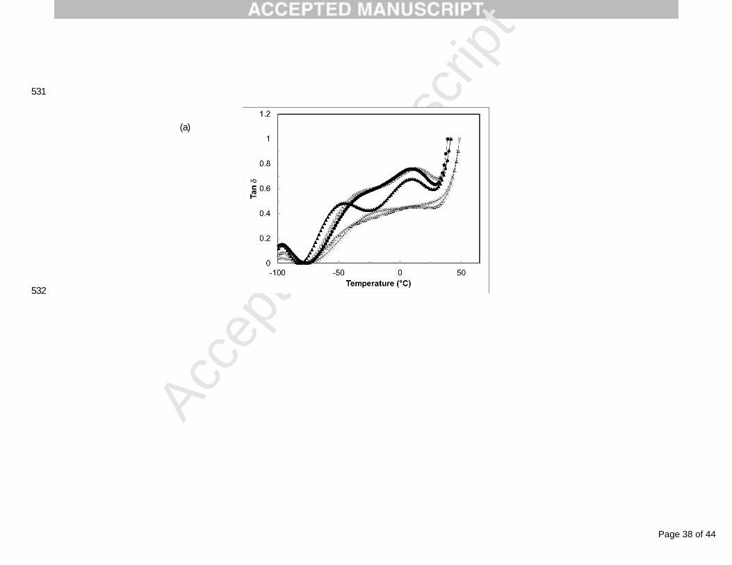
DMA is a powerful technique that reflects the mobility of the soft-segment through α-relaxation at the molecular-level. The evolution of the loss 225
factor (tan ) is depicted in Figure 4. It can be clearly seen that neat PU shows two adjacent mechanical relaxations. The first one has a maximum 226
around -40°C that we attributed to the PCL-rich amorphous phase and the second has a maximum around +10°C that we attributed to the IPDI-227
BDO-IPDI sequence-rich phase. The latter is rich in urethane and hydrogen bonds which could explain its higher temperature position. The trend 228
is that the introduction of cellulose nanofibers leads to a significant reduction of the amplitude of these two relaxations. It is obviously ascribed to 229
the reduction of the matrix material content but interfacial phenomena are also expected to strengthen this magnitude reduction. The temperature 230
position of these relaxation processes gives an indication of the mobility of the matrix polymer chains. However, and because of the 231
superposition of the two mechanical relaxations, it’s difficult to determine precisely the temperature at their maxima. Nevertheless, these 232
temperatures have been evaluated and their values are reported in Table 1. One can clearly see that these relaxations tend to shift toward higher 233
temperatures for nanocomposites reinforced with CNF, whereas this trend is not so clear for CNC based nanocomposites. This temperature shift 234
is associated with a reduction in molecular mobility and it is more pronounced for higher nanofiller contents. According to Huang et al. (Huang, 235
Zou, Chang, Yu & Dufresne, 2011), the restriction of the mobility of the hosting polymer chains is proportional to the effective surface of the 236

Page 18 of 44
Accep
ted
Man
uscr
ipt
nanofiller. This is another indication of a better dispersion of CNF (in comparison to CNC) in the PU polymer, resulting from stronger interaction 237
between CNF and PU chains.238
In sorption kinetics experiments, the mass of sorbed water is measured as a function of time. The change in weight of nanocomposite samples 239
during exposure to water is plotted against time in Figure 5. It can be observed that all samples absorb water during the experiment, even unfilled 240
PU. For all samples, the water uptake increases continuously during the whole experiment duration and reaches equilibrium after a specific time. 241
Moreover, it is worthy to note that the matrix material is rather hydrophilic, considering its sorbed water amount at equilibrium (18-20%). On the 242
other hand, and as expected, the sorbed water at equilibrium increases as the cellulosic nanoparticle content increases (see Table 1). This is 243
explained by the increasing amount of highly hydrophilic material in the nanocomposite film and possible infiltration of water molecules in the 244
interfacial filler/matrix zone. The higher the cellulose nanoparticle content is, the higher the interfacial area is and then the possible interfacial 245
water infiltration increases. However, a significant difference in the amount of water sorbed at equilibrium was observed while comparing the 246
two series of nanocomposites. It’s clear that CNC based nanocomposites absorb higher amount of water at equilibrium than CNF based ones (see 247
Table 1). This result seems surprising considering the higher crystallinity of CNC compared to CNF. This difference could be explained by the 248
degree of hydrophobicity which stem from their chemical composition as will be discussed later. However, the specific morphology of CNF and 249
the possibility to form a denser network within the polymeric matrix should be also considered.250
The mass of water sorbed at time t, (Mt - Mo), can be expressed as (Comyn, 1985): 251
(2)252
Page 19 of 44
Accep
ted
Man
uscr
ipt
Where, M∞ is the mass sorbed at equilibrium, 2L the thickness of the polymer film, and D the diffusion coefficient. At short times, Equation 2 253
can be written as:254
(3)255
At (Mt - Mo)/M`≤ 0.5, the error in using Equation 3 instead of Equation 2 to determine the diffusion coefficient is on the order of 0.1% (Comyn, 256
1985). The plot of (Mt - Mo)/M` as a function of (t/L2)1/2 has been performed for all compositions and for (Mt - Mo)/M`≤ 0.5.257
It was observed that the behavior was Fickian (plots are not reported in this paper). The diffusion coefficients calculated from the slope of these 258
plots are reported in Table 1. It can be clearly seen that the diffusion coefficient increases with the nanofiber content for both nanocomposite 259
series. However, while comparing the two types of nanocomposites, the diffusion coefficient is found to be higher for CNC based 260
nanocomposites for a given composition. Again, this difference could be explained from the structure and composition of both nanoparticles, and 261
in particular by the presence of residual lignin, and extractive substances at the surface of CNF that reduces, comparatively, the hydrophilic 262
character of the filler.263
4. Discussion based on solubility parameters264
One can easily understand that the dispersion of cellulose nanoparticles may depend on the solubility parameter of the polymer matrix. The 265
regular solution theory, or solubility parameter theory, developed by Hildebrand and Scott (Hildebrand & Scott, 1950; Hildebrand & Scott, 266
1962), has been used in many areas of technology (Barton, 1991) to explain certain aspects of solution and solubility behavior. The key 267
parameters in this theory are the solubility parameters, which are defined as the square root of the cohesive energy densities of the solute and 268
Page 20 of 44
Accep
ted
Man
uscr
ipt
solvent, respectively (Reynolds, 1963). A basic tenet of the above theory is that the maximum solubility for a given solute-solvent system is 269
attained when the solubility parameters of the solute and solubility are identical. Therefore knowledge of the individual solubility parameters for 270
the solute and solvent is required in order to make predictions from this theory. Solubility parameters for non-volatile materials, such as 271
polymers, are usually difficult to determine by a direct experimental measurement. They have been inferred on one hand from solubility 272
measurements of these macromolecules in a variety of solvents with a known solubility parameter (Crowley, Teague & Lowe, 1966), and on the 273
other hand from group contribution schemes based on molecular structure correlations (Rheineck & Lin, 1968; Fedors, 1974). The development 274
of inverse gas chromatography as a technique for the measurement of polymer solubility parameters has also provided an alternative method for 275
the measurement of this data (Dipaola-Baranyi & Guillet, 1978; Lipson & Guillet, 1981).276
In this study, we have used a thermodynamics way to predict and/or explain the miscibility in multiple phase system (Olabisi, Robeson & Shaw, 277
1979; Krause, 1978), including the solubility parameter, the lattice theory, and the equation of state. This concept could be used to understand the 278
thermodynamic affinity between the studied cellulose nanofiller and the host PU. In fact, the nanofiller consist of rigid domains that establish 279
physical interactions with the polymer chains of the PU by mean of their surface chains and entities. Thus, to predict the strength of the 280
interactions between these nanoparticles and the hosting polymer chains, i.e. good dispersion of the nanofibers within the PU, one should 281
compare the solubility parameters of the surface polymer chains of these nanofibers to the solubility parameters of the sequences existing in PU 282
polymer chains. The solubility parameters were calculated on the basis of the method proposed by Fedors (Fedors, 1974) and using Equation (4).283
Page 21 of 44
Accep
ted
Man
uscr
ipt
(4)284
Where δ, ΔE, and V are the solubility parameter, molar vaporization energy and molar volume, respectively. The solubility parameters are given 285
in MPa1/2. The values of the molar vaporization energy and molar volume used for the calculation of the solubility parameters were taken from 286
references (Fedors, 1974; Baron, 1991). The calculated solubility parameters are reported in Table 2. For simplicity, room temperature was used 287
as the standard condition.288
The FTIR spectra presented in Figure 6 permit to detect the changes in chemical composition between CNF, obtained by mechanical shearing of 289
the raw fiber using a microfluidizer processor, and CNC resulting from the acid hydrolysis of the raw fiber. The FTIR spectrum for raw cellulose 290
fiber is reported as reference. Thus this technique can give information about the chemical structure of the polymer chains at the surface of these 291
nanofibers. 292
The absorbance peaks in the 3400-3300 cm-1 and 1634-1640 cm-1 regions are attributed to the stretching vibrations of the OH groups of cellulose 293
and the elongation of adsorbed water molecules, respectively Baron, 1991; Blackwell, Vasko & Koenig, 1970; Edwards, Farwell & Williams, 294
1994; Edwards, Farwell & Webster, 1997). The peaks around 2900-2800 cm-1 correspond to C–H stretching (Nelson & O’Connor, 1964; Sain & 295
Panthapulakkal, 2006). The prominent peak at 1731 cm-1 in the spectrum obtained for the raw fiber and CNF was assigned to the C=O stretching 296
of the acetyl group and uranic ester groups of hemicellulose or to the ester linkage of the carboxylic group in the ferulic and p-coumaric acids of 297
lignin and/or hemicellulose (Le Troedec et al., 2008; Ahmad, Mosadeghzad, Daik & Ramli, 2008). The peak at 1245 cm-1 corresponds to the C–298
O stretching of the aryl group in lignin. These last two peaks were absent from the spectra for CNC. Taken together, these findings indicate that 299
Page 22 of 44
Accep
ted
Man
uscr
ipt
almost all of the hemicellulose and lignin were removed by the acid hydrolysis treatment (Zuluaga et al., 2009). The peaks observed in the range 300
of 1420-1430 cm-1 and 1330-1380 cm-1 in all spectra were attributed to the symmetric bending of CH2 and the bending vibrations of the C–H and 301
C–O groups of in the polysaccharides, respectively (Jonoobi, Harun, shakeri, Misra & Oksman, 2009). 302
From this comparison it’s reasonable to assume that the CNF surface is covered by hemicellulose and lignin polymers and that the one of CNC is 303
free from these entities and contains only cellulose chains. 304
To calculate the solubility parameters for hemicelluloses and lignin we used their chemical structure according to structure presented in reference305
(Lignin and its properties, 2001) (see the structures in Table 2). In Table 2 are given the solubility parameters of various entities forming the PU306
chains and those of the chains at the surface of the studied nanofibers. The solubility parameter for polymers present at the surface of CNF, i.e. 307
xylan and lignin, are 31.95 MPa1/2 and 21.65 MPa1/2, respectively. However, It’s important to remind that the process of sulfuric acid-hydrolysis 308
of cellulose fibers for the preparation of CNCs induces an esterification reaction between acid and cellulose molecules, which induces the 309
covalent coupling of sulfate groups on the surface of prepared CNCs (Rånby, Banderet & Sillén, 1949; Rånby & Ribi, 1950; Habibi, 2014; Lin & 310
Dufresne, 2014). Negatively charged sulfate groups play an important role in both surface chemistry and physical properties of CNCs. Thus the 311
solubility parameter undergoes a small change from 36 MPa1/2 for cellulose to 34.63 MPa1/2 for sulfonated cellulose. The entities composing the 312
PU polymer have solubility parameters ranging from 21.86 MPa1/2 to 24.57 MPa1/2. These latter are of the same order of magnitude than the 313
solubility parameter of lignin. Thus, while comparing the solubility parameters of the entities forming the PU polymer and those of the surface 314

Page 23 of 44
Accep
ted
Man
uscr
ipt
chains of the cellulose nanofibers, one can easily conclude that the PU polymers have higher thermodynamic compatibility with CNF than with 315
CNC, resulting in stronger interactions, adhesion and miscibility between CNF and PU. 316
This difference in miscibility for both cellulose nanofibers towards PU, in addition to the difference in their aspect ratio, can explain the 317
difference previously reported in the microstructures, and mechanical properties of the resulting nanocomposites. In addition, assuming that the 318
filler/matrix compatibility is lower for CNC-based nanocomposites, one can imagine that water infiltration could be easier at the filler/matrix 319
interface. For CNF-based nanocomposites, despite higher amorphous cellulose content, the higher hydrophobic character of the filler favors the 320
compatibility with PU and restricts therefore the interfacial diffusion pathway for water.321
5. Conclusion322
This manuscript reports the preparation and characterization of nanocomposites made of cellulose nanoparticles extracted from the rachis of date 323
palm (Phoenix dactylifera). We characterized the thermal and mechanical behavior of these materials. The results showed significant differences 324
between the two series of nanocomposites, viz. CNC and CNF reinforced materials. DSC and DMA measurements, as well as tensile tests 325
confirmed that PU/CNF films possessed higher crystallinity, and tensile strength than PU/CNC films, owing to the interaction between molecules 326
at the surface of CNF and PU. An attempt to explain the difference of miscibility between the nanofibers and the host polymer in both327
nanocomposites, which is based on the calculation of solubility parameters, was proposed. This enabled one to better clarify the differences 328
observed for the structure, mechanical and physical properties. 329
Acknowledgments330
Page 24 of 44
Accep
ted
Man
uscr
ipt
The authors thank for their financial supports the Hassan II Academy of Science and Technology, and The CNRST-Morocco/CNRS-France 331
(Volubilis Project). The authors are also thankful to Prof. Yves Grohens, Dr. Abdelkader Bendahou and the team of LITMAB laboratory of 332
University of South Brittany for the DMA analyses.333
References334
Ahmad, I., Mosadeghzad, Z., Daik, R., & Ramli, A. (2008). The effect of alkali treatment and filler size on the properties of sawdust/UPR 335
composites based on recycled PET wastes. Journal of Applied Polymer Science, 109, 3651-3658.336
Barton, A. F. M. (1991). Handbook of solubility parameters and other cohesion parameters (2nd ed.). Boca Raton: CRC Press. 337
Ben Mabrouk, A., Kaddami, H., Boufi, S., Erchiqui, F., & Dufresne, A. (2012). Cellulosic nanoparticles from alfa fibers (Stipa tenacissima): 338
Extraction procedures and reinforcement potential in polymer nanocomposites. Cellulose, 19, 843-853.339
Bendahou, A., Kaddami, H. , Sautereau, H., Raihane, M., Erchiqui, F., & Dufresne, A. (2008). Comparative study on short palm tree fibers -340
thermoplastic matrices composites. Macromolecular Materials and Engineering, 293, 140-148.341
Bendahou, A., Kaddami, H., & Dufresne, A. (2010). Investigation on the effect of cellulosic nanoparticles morphology on the properties of 342
natural rubber based nanocomposites. European Polymer Journal, 46, 609−620. 343
Blackwell, J., Vasko, P. D., & Koenig, J. L. (1970). Infrared and Raman spectra of the cellulose from the cell wall of Valonia ventricosa. Journal 344
of Applied Physics, 41, 4375-4379.345
Page 25 of 44
Accep
ted
Man
uscr
ipt
Cao, X., Dong, H., & Li, C. (2007). New nanocomposite materials reinforced with flax cellulose nanocrystals in waterborne polyurethane. 346
Biomacromolecules, 8, 899–904.347
Cao, X., Habibi, Y. & Lucia, L. A. (2009). One-pot polymerization, surface grafting, and processing of waterborne polyurethane-cellulose 348
nanocrystal nanocomposites. Journal of Materials Science, 19, 7137-7145.349
Chen, G. J., Wei, M., Chen, J. H., Huang, J., Dufresne, A., & Chang, P. R. (2008). Simultaneous reinforcing and toughening: New 350
nanocomposites of waterborne polyurethane filled with low loading level of starch nanocrystals. Polymer, 49, 1860-1870.351
Clowes, F. A. L., & Juniper, B. E. (1968). Plant cells. Blackwell Scientific publication: Oxford Edinburgh.352
Comyn, J. (1985). Introduction to polymer permeability and the mathematics diffusion. In J. Comyn (Ed.), Polymer permeability (pp. 1-10), 353
London: Chapman et Hall. 354
Corniglion, I. (1991). Synthesis and properties of polyurethane coatings for polyester film. PhD Thesis, INSA-LYON (France).355
Crowley, J. D., Teague, G. S. Jr., Lowe, J. W. Jr. (1966). A three dimensional approach to solubility. Jounal of Paint Technology, 38, 269-280.356
Dinand, E., Chanzy, H., Vignon, M.R., Maureaux, A., & Vincent, I. (1999). Microfibrillated cellulose and method for 357
preparing a microfibrillated cellulose. US Patent 5964983.358
Dinand, E., Chanzy, H., & Vignon, M. R. (1999). Suspensions of cellulose microfibrils from sugar beet pulp. Food Hydrocolloids, 13, 275-283.359
Dipaola-Baranyi, G., & Guillet, J. E. (1978). Estimation of polymer solubility parameters by gas chromatography. Macromolecules, 11, 228-235.360
Edgar, C. D. & Gray, D. G. (2003). Smooth model cellulose I surfaces from nanocrystal suspensions. Cellulose, 10, 299-306.361

Page 26 of 44
Accep
ted
Man
uscr
ipt
Edwards, H. G. M., Farwell, D. W., & Williams, A. C. (1994). FT-Raman spectrum of cotton: A polymeric biomolecular analysis. 362
Spectrochimica Acta Part A, 50, 807-811.363
Edwards, H. G. M., Farwell, D. W., & Webster, D. (1997). FT-Raman microscopy of untreated natural plant fibres. Spectrochimica Acta Part A, 364
53, 2383-2392.365
Eichhorn, S. J., Baillie, C. A., Zafeiropoulos, N., Mwaikambo, L. Y., Ansell, M. P., Dufresne, A., Entwistle, K. M., Herrera-Franco, P. J., 366
Escamilla, G. C., Groom, L., Hughes, M., Hill, C., Rials, T. G., & Wild, P. M. (2001). Review: Current international research into cellulosic 367
fibres and composites. Journal of Materials Science, 36, 2107-2131.368
Favier, V., Cavaille, J. Y., Chanzy, H., & Dufresne, A. (1995). Cellulose whiskers in polymeric matrix forming nanocomposites. Abstracts of 369
Papers of the American Chemical Society, 209, 29-MACR.370
Fedors, R. F. (1974). A method for estimating both the solubility parameters and molar volumes of liquids. Polymer Engineering and Sciences, 371
14, 147-154.372
Gorna, K., & Gogolewski, S. (2002). In vitro degradation of novel medical biodegradable aliphatic polyurethanes based on epsilon-caprolactone 373
and pluronics (R) with various hydrophilicities. Polymer Degradation and. Stability, 75, 113-122.374
Gray, D. G. (2008). Transcrystallization of polypropylene at cellulose nanocrystal surfaces. Cellulose, 15, 297-301.375
Habibi, Y. (2014). Key advances in the chemical modification of nanocelluloses. Chemical Society reviews, 43, 1519-1542.376
Page 27 of 44
Accep
ted
Man
uscr
ipt
Han, J. P., Zhu, Y., Hu, J. L., Luo, H. S., Yeung, L. Y., Li, W. G., Meng, Q. H., Ye, G. D., Zhang, S., & Fan, Y. (2012). Morphology, reversible 377
phase crystallization, and thermal sensitive shape memory effect of cellulose whisker/SMPU nano-composites. Journal of Applied Polymer 378
Science, 123, 749-762.379
Hepburn, C. (1996). Polyurethane elastomers: The ultimate in multiphase polymeric materials. Key Engineering Materials, 118, 3-18.380
Herrick, F. W., Casebier, R. L., Hamilton J. K., & Sandberg, K. R. (1983). Microfibrillated cellulose: Morphology and accessibility. Journal of 381
Applied Polymer Science, 37, 797-813.382
Hildebrand, J. H. & Scott, R. L. (1950). The solubility of nanoelectrolytes. New York: Reinhold Pub. Corp.383
Hildebrand, J. H. & Scott, R. L. (1962). Regular solutions. Prentice Hall, Englewood Cliffs, NJ.384
Huang, J., Zou, J. W., Chang, P. R., Yu, J. H., Dufresne, A. (2011). New waterborne polyurethane-based nanocomposites reinforced with low 385
loading levels of chitin whisker. eXPRESS Polymer Letters, 5, 362-373.386
Jonoobi, M., Harun, J., Shakeri, A., Misra, M., & Oksman, K. (2009). Chemical composition, crystallinity, and thermal degradation of bleached 387
and unbleached kenaf bast (Hibiscus cannabinus) pulp and nanofibers. BioResources, 4, 626-639.388
Krause, S. (1978). Polymer-polymer compatibility. In D.R. Paul, & S. Newman (Eds.), Polymer Blends, Vol. 1 (pp. 15-114), New York: 389
Academic Press.390
Krieger, J. (1990). New coating increases efficiency of lamps. Chemical & Engineering News, 68, 35-35.391

Page 28 of 44
Accep
ted
Man
uscr
ipt
Le Troedec, M., Sedan, D., Peyratout, C., Bonnet, J. P., Smith, A., Guinebretiere, R., loaguen, V., & Krausz, P. (2008). Influence of various 392
chemical treatments on the composition and structure of hemp fibers. Composites Part A, 39, 514-522.393
Li, Y., & Ragauskas, A. J. (2011). Cellulose nano whiskers as a reinforcing filler in polyurethanes . In B. Reddy (Ed.), Advances in diverse 394
industrial applications of nanocomposites (pp. 17-36). ISBN 978-953-307-202-9, Rijeka: InTech.395
Lignin and its properties: Glossary of lignin nomenclature. Dialogue/Newsletters Volume 9, Number 1. Lignin Institute, July 2001.396
Lin, N., & Dufresne, A. (2014). Surface chemistry, morphological analysis and properties of cellulose nanocrystals with gradient sulfation 397
degrees. Nanoscale, 6, 5384-5393.398
Lipson, J. E. G., & Guillet, J. E. (1981). Studies of polar and nonpolar probes in the determination of infinite-dilution solubility parameters. 399
Journal of Polymer Science:Polymer Physics, 19, 1199-1209.400
45. LIPSON, J. E. G.; GUILLET, J. E.,.401402
Lu, J., Wang, T., & Drzal, L. T. (2008). Preparation and properties of microfibrillated cellulose polyvinyl alcohol composite materials. 403
Composites Part A., 39, 738-746.404
Marchessault, R. H., Morehead, F. F., & Walter, N. M. (1959). Liquid crystal systems from fibrillar polysaccharides. Nature, 184, 632-633.405
Mathew, A. P., & Dufresne, A. (2002). Morphological investigation of nanocomposites from sorbitol plasticized starch and tunicin whiskers. 406
Biomacromolecules, 3, 609-617.407
Page 29 of 44
Accep
ted
Man
uscr
ipt
McCann, M. C., Wells, B., & Roberts, K. (1990). Direct visualisation of cross-links in the primary plant-cell wall. Journal of Cell Science, 96, 408
323-334.409
McCann, M. C., Wells, B., & Roberts, K. (1992). Complexity in the spatial localization and length distribution of plant cell-wall matrix 410
polysaccharides. Journal of Microscopy, 166, 123-136.411
Narayan, R. (2006). Biobased and biodegradable materials, rationale, drivers, & technology exemplars. In K. C. Khemani, & C. Scholz (Eds.), 412
Degradable polymers and materials. Principles and practice (pp. 282-306). ACS Symposium Series vol. 939.413
Nelson, M. L., & O’Connor, R. T. (1964). Relation of certain infrared bands to cellulose crystallinity and crystal latticed type. Part I: Spectra of 414
lattice types I, II, III and of amorphous cellulose. Journal of Applied Polymer Science, 8, 1311-1324.415
Olabisi, O., Robeson, L. M., & Shaw, M. T. (1979). Polymer-polymer miscibility. New York: Academic Press.416
Pandey, J. K., Lee, C. S., & Ahn, S. H. (2010). Preparation and properties of bio-nanoreinforced composites from biodegradable polymer matrix 417
and cellulose whiskers. Journal of Applied Polymer Science, 115, 2493-2501.418
Prisacariu, C. (2011). Polyurethane elastomers from morphology to mechanical aspects. Wien/New York: Springer.419
Rånby, B. G., Banderet, A., Sillén, L. G. (1949). Aqueous colloidal solutions of cellulose micelles. Acta Chemica Scandinavica, 3, 649-650.420
Rånby, B. G., & Ribi, E. (1950). Über den feinbau der zellulose. Experimentia, 6, 12-14.421
Rheineck, A. E., & Lin, K. E. (1968). Solubility parameter calculations based on group contributions. Journal of Paint Technology, 40, 611-613.422
Reynolds, W. W. (1963). Physical chemistry of petroleum solvents. New York: Reinhold Pub. Corp.423
Page 30 of 44
Accep
ted
Man
uscr
ipt
Rueda, L., Saralegui, A., d’Arlas, B. F., Zhou, Q., Berglund, L. A., Corcuera, M. A., Mondragon, I., & Eceiza, A. (2013). Cellulose424
nanocrystals/polyurethane nanocomposites. Study from the viewpoint of microphase separated structure. Carbohydrate Polymers, 92, 751-757.425
Sain, M., & Panthapulakkal, S. (2006). Bioprocess preparation of wheat straw fibers and their characterization. Industrial Crops and Products, 426
23, 1-8.427
Saralegi, A., Ruedla, L., Martin, L., Arbelaiz, A., Eceiza, A., & Corcuera, M. A. (2013). From elastomeric to rigid polyurethane/cellulose 428
nanocrystal bionanocomposites. Composites Science and Technology, 88, 39-47.429
Shen, L., & Patel, M. K. (2010). Life cycle assessment of polysaccharide materials: A review. Journal of Polymers and the Environment, 16,430
154-167.431
Siqueira, G., Bras, J., & Dufresne, A. (2009). Cellulose whiskers versus microfibrils: Influence of the nature of the nanoparticle and its surface 432
functionalization on the thermal and mechanical properties of nanocomposites. Biomacromolecules, 10, 425-432.433
Stamboulis, A., Baillie, C. A., & Peijs, T. (2001). Effects of environmental conditions on mechanical and physical properties of flax fibers. 434
Composites Part A, 32, 1105-1115.435
Suryanegara, L., Nakagaito, A. N., & Yano, H. (2009). The effect of crystallization of PLA on the thermal and mechanical properties of 436
microfibrillated cellulose-reinforced PLA composites. Composites Science and Technology, 69, 1187-1192.437
Turbak, A. F., Snyder, F. W., & Sandberg, K. R. (1983). Microfibrillated cellulose, a new cellulose product: Properties, uses, and commercial 438
potential. Journal of Applied Polymer Science, 37, 815-827.439

Page 31 of 44
Accep
ted
Man
uscr
ipt
Zhu, Y., Hu, J., & Yeung, K. (2009). Effect of soft segment crystallization and hard segment physical crosslink on shape memory function in 440
antibacterial segmented polyurethane ionomers. Acta Biomateriala, 5, 3346-3357.441
Zia, K. M., Bhatti, H. N., & Bhatti, I. A. (2007). Methods for polyurethane and polyurethane composites, recycling and recovery: A review. 442
Reactive and Functional Polymers, 67, 675-692.443
Zuluaga, R., Putaux, J. L., Cruz, J., Vélez, J., Mondragon, I., & Ganán, P. (2009). Cellulose microfibrils from banana rachis: Effect of alkaline 444
treatments on structural and morphological features. Carbohydrate Polymers, 76, 51-59.445
446

Page 32 of 44
Accep
ted
Man
uscr
ipt
446
Figure captions447
Figure 1. AFM observation of CNC and CNF extracted from the rachis of the date palm tree. 448
Figure 2. SEMs of the fractured surfaces of PU-based films reinforced with cellulose nanoparticles extracted from the rachis of date palm tree. 449
(a) Neat PU, (b) PU/CNF 1 wt%, (c) PU/CNF 5 wt%, (d) PU/CNF 10 wt%, (e) PU/CNC 1 wt%, (f) PU/CNC 5wt%, (g) PU/CNC 10 wt%.450
Figure 3. Mechanical properties for PU based nanocomposites reinforced with (a) CNC and (b) CNF extracted from date palm tree: (●) tensile 451
modulus, (○) strength, and (×) strain at break.452
Figure 4. Evolution of the loss factor (tan ) vs temperature at 1 Hz for PU-based nanocomposite films reinforced with (a) CNC and (b) CNF. 453
The cellulose nanoparticle content is (●) 0, (○) 2.5, (▲) 5, (Δ) 7.5, and (×) 10 wt%.454
Figure 5. Water uptake during exposure to water versus time for nanocomposites filled with (a) CNC and (b) CNF. The cellulose nanoparticle 455
content is (●) 0, (○) 2.5, (▲) 5, (Δ) 7.5, and (×) 10 wt%.456
Figure 6. FTIR spectra of (a) raw cellulose fibers, (b) CNF, and (c) CNC.457
458
459
460

Page 33 of 44
Accep
ted
Man
uscr
ipt
460
461
462
464
466
468
470
472
474
476
478
480
482
484
486
488
490
492
3.3X3.3µm
Phase images
3.3X3.3µm
Amplitude images
3.3X3.3µm
Height images
CNC CNF

Page 34 of 44
Accep
ted
Man
uscr
ipt
493
494
495
496
Figure 1.497
498
499

Page 35 of 44
Accep
ted
Man
uscr
ipt
499
501
503
505
507
509
511
513
515Figure 2.517
519
521
523
525
b c de
a

Page 36 of 44
Accep
ted
Man
uscr
ipt
526
527
(a)

Page 37 of 44
Accep
ted
Man
uscr
ipt
528
529
Figure 3.530531
(b)
Page 38 of 44
Accep
ted
Man
uscr
ipt
531
532
(a)

Page 39 of 44
Accep
ted
Man
uscr
ipt
533
534
Figure 4. 535
536
(b)

Page 40 of 44
Accep
ted
Man
uscr
ipt
536
537
(a)

Page 41 of 44
Accep
ted
Man
uscr
ipt
538
539
Figure 5.540
541
(b)

Page 42 of 44
Accep
ted
Man
uscr
ipt
541
4000,0 3600 3200 2800 2400 2000 1800 1600 1400 1200 1000 800 600 450,0cm-1
%T
a
b
c
3300
-340
0 cm
-1
2800
-290
0 cm
-1
1731
cm-1
1630
-164
0 cm
-1
1420
-143
0 cm
-113
40-1
380
cm-1
1245
cm
-1
542
Figure 6.543
544
545
Page 43 of 44
Accep
ted
Man
uscr
ipt
Table1. DSC, DMA, and swelling properties data for PU (CNC/NFC) nanocomposites and PU reference. Melting temperature (Tm) and 545associated heat of fusion (ΔHm), degree of crystallinity (χC), glass transition temperature for soft (Tα1) and hard segment (Tα2),diffusion 546coefficient (D*104), and relative water uptake at equilibrium (Weq).547
DSC Data DMA Data Diffusion Coefficient
Sample Tm (°C) ∆Hm(j/g) Χ*c(%) Tα1 Tα2 D*104(mm2/s) Weq (%)
PU 0% 49.4 60.4 38.5 -41.3 9.4 1 17.9
PU/CNF 2.5% 50.1 63.1 41.7 -35.2 7.7 5 37.7
PU/CNF 5% 52.2 65.2 44.6 -32.2 19.1 11 48.5
PU/CNF 7.5% 50.7 59.3 45.2 -28.0 20.4 13 72.9
PU/CNF 10% 51.0 57.5 40.0 -29.7 18.5 15 90.5
PU/CNC 2.5% 49.0 61.8 40.7 -41.7 12.7 8 48.3
PU/CNC 5% 48.9 64.2 42.9 -53.2 8.5 16 62.4
PU/CNC 7.5% 49.9 57.4 40.2 -40.1 6.7 18 81.2
PU/CNC 10% 50.1 49.8 39.7 -** -** 23 100.4
*χc= ΔHm/ (ω.ΔH100) where, ∆H100 is the heat of fusion of corresponding to the soft segment (PCL in our case) without nanofiller, and ω is the 548weight fraction of polymeric matrix material in the nanocomposite (∆H100=157 J/g). Hard segments in our case are amorphous because of the 549asymmetric structure of IPDI which prevents their spatial organization.550**Only one large relaxation around -28.03 °C is observed.551

Page 44 of 44
Accep
ted
Man
uscr
ipt
44
Table 2. solubility parameters of polymers and cellulose nanoparticles adapted from Fedors 552et al.42553
Sample Structure Solubility parameter ( MPa1/2)
Cellulose36.00
Xylan 28.90
Lignin 21.65
CNC 34.63
PCL4000 O CH2 C
O
5 n21.86
IPDINCO
OCN
21.56
BDO 1.4 HO
OH 26.51
IPDI-BDO-IPDI
C NH R' NH CO O R'' O CO NH R' NH C
O
O
O
O 22.21
BDO-IPDI-BDO
O R'' O CO NH R' NH CO O R'' O 21.40
PCL-IPDI-PCL OH R O CO NH R'' NH CO O R OH 24.57
554
R: Polydiol PCL4000, R’: Diisocyante IPDI, R’’: Chain extender BDO1.4555
556
557
558