
BIDDING DOCUMENT - the e-Tendering System for ...
457
PUBLIC WORKS DEPARTMENT (BUILDING WING) BIDDING DOCUMENT Name of work: - “CONSTRUCTION WORK OF THE PROPOSED NEW ASSAM LEGISLATIVE ASSEMBLY BUILDING AT DISPUR WITH BUDGETARY COST ESTIMATE & REVISED DESIGN PROPOSAL (INTERIOR WORKS FOR ASSEMBLY MAIN BUILDING)” OFFICE OF THE CHIEF ENGINEER, P.W.D., BUILDING ASSAM, CHANDMARI, GUWAHATI.
-
Upload
khangminh22 -
Category
Documents
-
view
0 -
download
0
Transcript of BIDDING DOCUMENT - the e-Tendering System for ...
PUBLIC WORKS DEPARTMENT(BUILDING WING)
BIDDING DOCUMENT
Name of work: - “CONSTRUCTION WORK OF THE PROPOSED NEW ASSAM LEGISLATIVE
ASSEMBLY BUILDING AT DISPUR WITH BUDGETARY COST ESTIMATE
& REVISED DESIGN PROPOSAL (INTERIOR WORKS FOR ASSEMBLY
MAIN BUILDING)”
OFFICE OF THE CHIEF ENGINEER, P.W.D., BUILDINGASSAM, CHANDMARI, GUWAHATI.

2
GOVERNMENT OF ASSAMOFFICE OF THE CHIEF ENGINEER: P.W.D.: BUILDING: ASSAM: GUWAHATI-3
NATIONAL COMPETITIVE BIDDING
(CIVIL WORKS)
NAME OF THE WORK : “Construction work of the proposed New Assam
Legislative Assembly Building at Dispur with Budgetary
cost estimate & revised Design proposal (Interior works
for Assembly Main Building)”
NODAL AUTHORITY : The Chief Engineer, PWD (B), Govt. of Assam.
PERIOD OF DOWNLOAD OF BIDDING DOCUMENT.
: Date22-12-2015 at 13.31 hrs to 11-01-2016 at 14.00 hrs
DATE AND TIME OF PRE-BID CONFERENCE
: Date: 04-01-2016 time 14:00 hrs
LAST DATE AND TIME FOR RECEIPT OF BIDS
: Date: 11-01-2016 time 14:00 hrs
DATE AND TIME OF OPENING OF TECHNICAL BIDS.
: Date 13-01-2016 time 11:01 hrs to 22-01-2016 time 17:00 hrs
DATE AND TIME OFOPENING OF FINANCIAL BIDS
: Date 22-01-2016 time 11:01 hrs to 25-01-2016 time 17.00hrs
PLACE OF OPENING BIDS : Office of the Chief Engineer, P.W.D., (Bldg.) Assam, Chandmari, Guwahati – 3.
OFFICER INVITING BIDS : Chief Engineer, P.W.D., (Bldg.) Assam,Chandmari, Guwahati – 3.

3
INVITATION FOR BID
( IFB )

4
GOVERNMENT OF ASSAMOFFICE OF THE CHIEF ENGINEER: : P.W.D.: : BUILDING:
ASSAM : : CHANDMARI : : GUWAHATI-3
No. CS/T/BD/8/2013/94 Dated Guwahati the 14th December ,2015
PRESS NOTICE
The Chief Engineer, P.W.D (Building), Assam on behalf of the Governor of Assam invites bids for “Construction work of the proposed New Assam Legislative Assembly Building at Dispur with Budgetary cost estimate & revised Design proposal (Interior works for Assembly Main Building)” amounting to Rs. 40,00,00,000.00 (approx) from Reputed firms experienced in execution of Interior works in Individual/Joint Venture(JV). Details of the bids may be seen at website- assam.etenders.in and also in the office of the undersigned from 21-12-2015 to 22-12-2015 during office hours.
Press Notice published vide this office letter No: CS/T/BD/8/2013/46 dated 17th March, 2015 is hereby canceled.
Chief Engineer, P.W.D. (Bldg.)Assam, Chandmari, Guwahati-3.
Memo No: CS/T/BD/8/2013/94-A Dated Guwahati the 14th December, 2015 Copy to:
1. The Principal Secretary, Assam Legislative Assembly for favour of information. This has a reference to the letter No.LAN.4/2008/6717 dtd.26-11-2015.
2. The Commissioner & Special Secretary to the Govt. of Assam, PW (Bldg. & NH) Deptt. Dispur, Guwahati-6 for favour of information. This has a reference to the letter No.B.126/2012/118 dtd.09-12-2015 from Under Secretary to the Govt. of Assam, PW (Bldg. &NH) (Bldg. Branch) Deptt., Dispur, Guwahati – 6.
3. The Addl. Chief Engineer, PWD (Bldg) P.C.C. Project Complex Assam, Chandmari, Guwahati-3 for information.
4. The Addl. Chief Engineer P.W.D. (Electrical) O/o the Chief Engineer, PWD (Bldg.), Chandmari, Guwahati-3 for information.
5. The Director of Information and Public Relation, Govt. of Assam, Dispur, Guwahati-6 for information. He is requested to publish the notice in two consecutive issues of at least widely circulated English daily The Telegraph (Kolkata Edition), The Assam Tribune and Assamese Daily News papers on or before 20-12-2015. Enclosed: 6 (six) spare copies.
6. The Director Printing & Stationary, Bamunimaidam, Guwahati-21, for information with 2(two) spare copies with a request to publish the notice in Assam Gazette on or before 20-12-2015.
7. The Superintending Engineer, P.W.D. Guwahati Building Circle-I, Fancy Bazar, Guwahati-1 for information and wide circulation. Enclosed: 4(Four) spare copies.
8. The Sr Architect (B/N) O/o the Chief Engineer, PWD (Bldg.), Chandmari, Guwahati-3 for information.
9. The Executive Engineer, PCC Division, Dispur, Guwahati-6, for information and wide circulation. Enclosed: 4(Four) spare copies
10. Consultant M/S Dulal Mukherjee & Associates for information and necessary action.
11. M/S NexTenders India Pvt. Ltd. camp Guwahati for information with a request to publish the notice in their web site. The time schedule has been fixed as discussed with the officials of NexTenders stationed at the CE PWD’s office premises at Guwahati.
12. Notice Board
Chief Engineer, P.W.D. (Bldg.) Assam ,Chandmari, Guwahati-3.
5
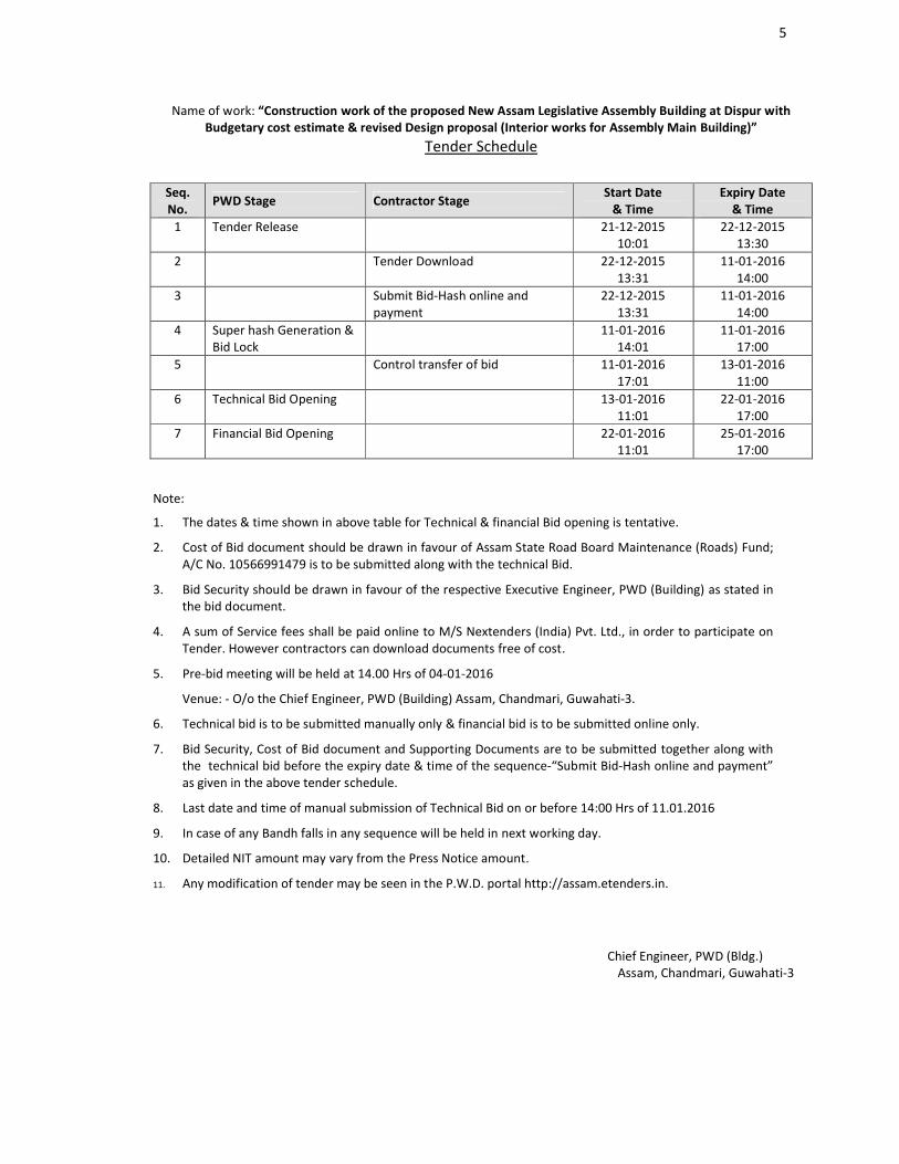
Name of work: “Construction work of the proposed New Assam Legislative Assembly Building at Dispur with Budgetary cost estimate & revised Design proposal (Interior works for Assembly Main Building)”
Tender Schedule
Seq. No.
PWD Stage Contractor StageStart Date
& TimeExpiry Date
& Time1 Tender Release 21-12-2015
10:0122-12-2015
13:302 Tender Download 22-12-2015
13:3111-01-2016
14:003 Submit Bid-Hash online and
payment22-12-2015
13:3111-01-2016
14:004 Super hash Generation &
Bid Lock11-01-2016
14:0111-01-2016
17:005 Control transfer of bid 11-01-2016
17:0113-01-2016
11:006 Technical Bid Opening 13-01-2016
11:0122-01-2016
17:007 Financial Bid Opening 22-01-2016
11:0125-01-2016
17:00
Note:
1. The dates & time shown in above table for Technical & financial Bid opening is tentative.
2. Cost of Bid document should be drawn in favour of Assam State Road Board Maintenance (Roads) Fund; A/C No. 10566991479 is to be submitted along with the technical Bid.
3. Bid Security should be drawn in favour of the respective Executive Engineer, PWD (Building) as stated in the bid document.
4. A sum of Service fees shall be paid online to M/S Nextenders (India) Pvt. Ltd., in order to participate on Tender. However contractors can download documents free of cost.
5. Pre-bid meeting will be held at 14.00 Hrs of 04-01-2016
Venue: - O/o the Chief Engineer, PWD (Building) Assam, Chandmari, Guwahati-3.
6. Technical bid is to be submitted manually only & financial bid is to be submitted online only.
7. Bid Security, Cost of Bid document and Supporting Documents are to be submitted together along with the technical bid before the expiry date & time of the sequence-“Submit Bid-Hash online and payment” as given in the above tender schedule.
8. Last date and time of manual submission of Technical Bid on or before 14:00 Hrs of 11.01.2016
9. In case of any Bandh falls in any sequence will be held in next working day.
10. Detailed NIT amount may vary from the Press Notice amount.
11. Any modification of tender may be seen in the P.W.D. portal http://assam.etenders.in.
Chief Engineer, PWD (Bldg.)Assam, Chandmari, Guwahati-3
6
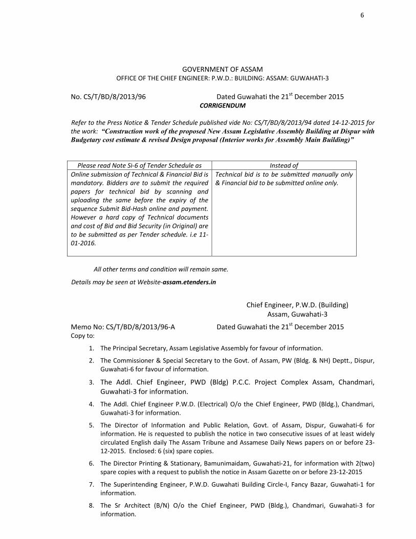
GOVERNMENT OF ASSAMOFFICE OF THE CHIEF ENGINEER: P.W.D.: BUILDING: ASSAM: GUWAHATI-3
No. CS/T/BD/8/2013/96BN/22/06/22 Dated Guwahati the 21st December 2015CORRIGENDUM
Refer to the Press Notice & Tender Schedule published vide No: CS/T/BD/8/2013/94 dated 14-12-2015 for the work: “Construction work of the proposed New Assam Legislative Assembly Building at Dispur with Budgetary cost estimate & revised Design proposal (Interior works for Assembly Main Building)”
Please read Note Sl-6 of Tender Schedule as Instead ofOnline submission of Technical & Financial Bid is mandatory. Bidders are to submit the required papers for technical bid by scanning and uploading the same before the expiry of the sequence Submit Bid-Hash online and payment. However a hard copy of Technical documents and cost of Bid and Bid Security (in Original) are to be submitted as per Tender schedule. i.e 11-01-2016.
Technical bid is to be submitted manually only & Financial bid to be submitted online only.
All other terms and condition will remain same.
Details may be seen at Website-assam.etenders.in
Chief Engineer, P.W.D. (Building)Assam, Guwahati-3
Memo No: CS/T/BD/8/2013/96-A Dated Guwahati the 21st December 2015 Copy to:
1. The Principal Secretary, Assam Legislative Assembly for favour of information.
2. The Commissioner & Special Secretary to the Govt. of Assam, PW (Bldg. & NH) Deptt., Dispur, Guwahati-6 for favour of information.
3. The Addl. Chief Engineer, PWD (Bldg) P.C.C. Project Complex Assam, Chandmari, Guwahati-3 for information.
4. The Addl. Chief Engineer P.W.D. (Electrical) O/o the Chief Engineer, PWD (Bldg.), Chandmari, Guwahati-3 for information.
5. The Director of Information and Public Relation, Govt. of Assam, Dispur, Guwahati-6 for information. He is requested to publish the notice in two consecutive issues of at least widely circulated English daily The Assam Tribune and Assamese Daily News papers on or before 23-12-2015. Enclosed: 6 (six) spare copies.
6. The Director Printing & Stationary, Bamunimaidam, Guwahati-21, for information with 2(two) spare copies with a request to publish the notice in Assam Gazette on or before 23-12-2015
7. The Superintending Engineer, P.W.D. Guwahati Building Circle-I, Fancy Bazar, Guwahati-1 for information.
8. The Sr Architect (B/N) O/o the Chief Engineer, PWD (Bldg.), Chandmari, Guwahati-3 for information.

7
9. The Executive Engineer, PCC Division, Dispur, Guwahati-6, for information.
10. Consultant M/S Dulal Mukherjee & Associates for information.
11. M/S Nex Tenders India Pvt. Ltd. camp Guwahati for information with a request to publish the corrigendum in their web site.
Chief Engineer, P.W.D. (Bldg.) Assam ,Chandmari, Guwahati-3
8
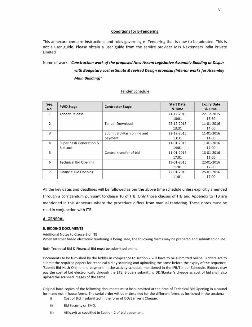
Conditions for E-Tendering
This annexure contains instructions and rules governing e -Tendering that is now to be adopted. This is not a user guide. Please obtain a user guide from the service provider M/s Nextenders India Private Limited
Name of work: “Construction work of the proposed New Assam Legislative Assembly Building at Dispur
with Budgetary cost estimate & revised Design proposal (Interior works for Assembly
Main Building)”
Tender Schedule
Seq. No.
PWD Stage Contractor StageStart Date
& TimeExpiry Date
& Time1 Tender Release 21-12-2015
10:0122-12-2015
13:302 Tender Download 22-12-2015
13:3111-01-2016
14:003 Submit Bid-Hash online and
payment22-12-2015
13:3111-01-2016
14:004 Super hash Generation &
Bid Lock11-01-2016
14:0111-01-2016
17:005 Control transfer of bid 11-01-2016
17:0113-01-2016
11:006 Technical Bid Opening 13-01-2016
11:0122-01-2016
17:007 Financial Bid Opening 22-01-2016
11:0125-01-2016
17:00
All the key dates and deadlines will be followed as per the above time schedule unless explicitly amended
through a corrigendum pursuant to clause 10 of ITB. Only those clauses of ITB and Appendix to ITB are
mentioned in this Annexure where the procedure differs from manual tendering. These notes must be
read in conjunction with ITB.
A. GENERAL
B. BIDDING DOCUMENTSAdditional Notes to Clause 8 of ITBWhen Internet based electronic tendering is being used, the following forms may be prepared and submitted online.
Both Technical Bid & Financial Bid must be submitted online.
Documents to be furnished by the bidder in compliance to section 2 will have to be submitted online .Bidders are to submit the required papers for technical bid by scanning and uploading the same before the expiry of the sequence-‘Submit Bid-Hash Online and payment’ in the activity schedule mentioned in the IFB/Tender Schedule. Bidders may pay the cost of bid electronically through the ETS. Bidders submitting DD/Banker’s cheque as cost of bid shall also upload the scanned images of the same.
Original hard-copies of the following documents must be submitted at the time of Technical Bid Opening in a bound form and not in loose forms. The serial order will be maintained for the different forms as furnished in the section.:
i) Cost of Bid if submitted in the form of DD/Banker’s Cheque.
ii) Bid Security or EMD.
iii) Affidavit as specified in Section-2 of bid document.
9
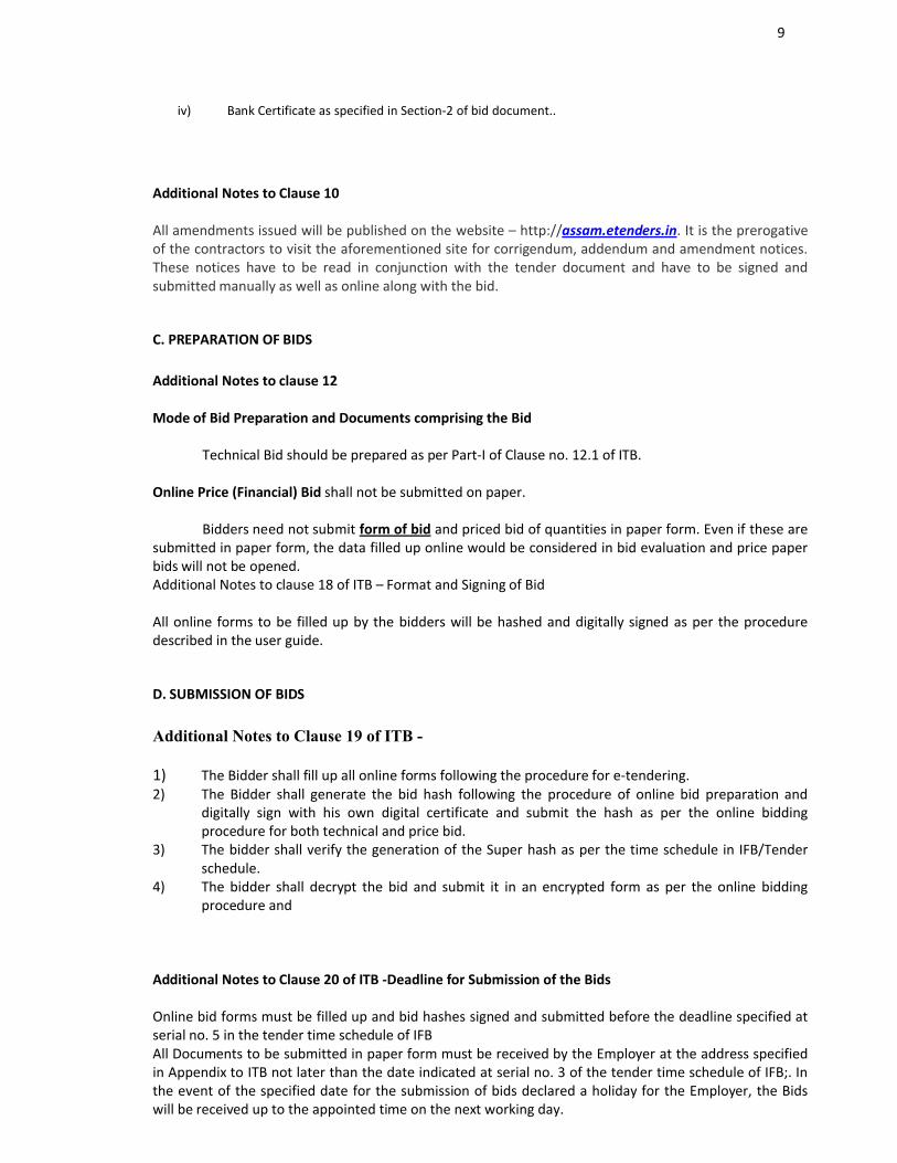
iv) Bank Certificate as specified in Section-2 of bid document..
Additional Notes to Clause 10
All amendments issued will be published on the website – http://assam.etenders.in. It is the prerogative of the contractors to visit the aforementioned site for corrigendum, addendum and amendment notices. These notices have to be read in conjunction with the tender document and have to be signed and submitted manually as well as online along with the bid.
C. PREPARATION OF BIDS
Additional Notes to clause 12
Mode of Bid Preparation and Documents comprising the Bid
Technical Bid should be prepared as per Part-I of Clause no. 12.1 of ITB.
Online Price (Financial) Bid shall not be submitted on paper.
Bidders need not submit form of bid and priced bid of quantities in paper form. Even if these are submitted in paper form, the data filled up online would be considered in bid evaluation and price paper bids will not be opened. Additional Notes to clause 18 of ITB – Format and Signing of Bid
All online forms to be filled up by the bidders will be hashed and digitally signed as per the procedure described in the user guide.
D. SUBMISSION OF BIDS
Additional Notes to Clause 19 of ITB -
1) The Bidder shall fill up all online forms following the procedure for e-tendering. 2) The Bidder shall generate the bid hash following the procedure of online bid preparation and
digitally sign with his own digital certificate and submit the hash as per the online bidding procedure for both technical and price bid.
3) The bidder shall verify the generation of the Super hash as per the time schedule in IFB/Tender schedule.
4) The bidder shall decrypt the bid and submit it in an encrypted form as per the online bidding procedure and
Additional Notes to Clause 20 of ITB -Deadline for Submission of the Bids
Online bid forms must be filled up and bid hashes signed and submitted before the deadline specified at serial no. 5 in the tender time schedule of IFBAll Documents to be submitted in paper form must be received by the Employer at the address specified in Appendix to ITB not later than the date indicated at serial no. 3 of the tender time schedule of IFB;. In the event of the specified date for the submission of bids declared a holiday for the Employer, the Bids will be received up to the appointed time on the next working day.
10
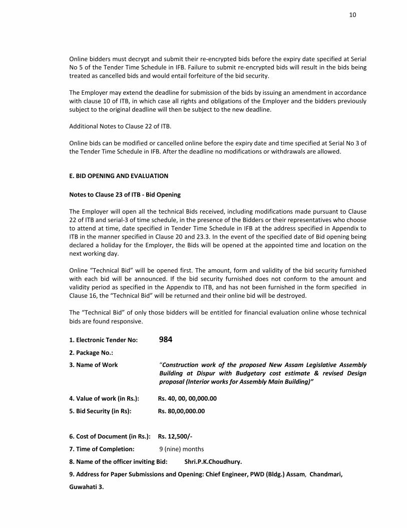
Online bidders must decrypt and submit their re-encrypted bids before the expiry date specified at Serial No 5 of the Tender Time Schedule in IFB. Failure to submit re-encrypted bids will result in the bids being treated as cancelled bids and would entail forfeiture of the bid security.
The Employer may extend the deadline for submission of the bids by issuing an amendment in accordance with clause 10 of ITB, in which case all rights and obligations of the Employer and the bidders previously subject to the original deadline will then be subject to the new deadline.
Additional Notes to Clause 22 of ITB.
Online bids can be modified or cancelled online before the expiry date and time specified at Serial No 3 of the Tender Time Schedule in IFB. After the deadline no modifications or withdrawals are allowed.
E. BID OPENING AND EVALUATION
Notes to Clause 23 of ITB - Bid Opening
The Employer will open all the technical Bids received, including modifications made pursuant to Clause 22 of ITB and serial-3 of time schedule, in the presence of the Bidders or their representatives who choose to attend at time, date specified in Tender Time Schedule in IFB at the address specified in Appendix to ITB in the manner specified in Clause 20 and 23.3. In the event of the specified date of Bid opening being declared a holiday for the Employer, the Bids will be opened at the appointed time and location on the next working day.
Online “Technical Bid” will be opened first. The amount, form and validity of the bid security furnished with each bid will be announced. If the bid security furnished does not conform to the amount and validity period as specified in the Appendix to ITB, and has not been furnished in the form specified in Clause 16, the “Technical Bid” will be returned and their online bid will be destroyed.
The “Technical Bid” of only those bidders will be entitled for financial evaluation online whose technical bids are found responsive.
1. Electronic Tender No: 9842. Package No.:
3. Name of Work “Construction work of the proposed New Assam Legislative Assembly Building at Dispur with Budgetary cost estimate & revised Design proposal (Interior works for Assembly Main Building)”
4. Value of work (in Rs.): Rs. 40, 00, 00,000.00)
5. Bid Security (in Rs): Rs. 80,00,000.00
6. Cost of Document (in Rs.): Rs. 12,500/-
7. Time of Completion: 9 (nine) months
8. Name of the officer inviting Bid: Shri.P.K.Choudhury.
9. Address for Paper Submissions and Opening: Chief Engineer, PWD (Bldg.) Assam, Chandmari,
Guwahati 3.

11
INDEX
SECTION ITEM PAGE NO.
1) INSTRUCTION TO BIDDER
2) QUALIFICATION INFORMATION
3) CONDITIONS OF CONTGRACT (GCC & SCC)
4) CONTRACT DATA
5) TECHNICAL SPECIFICATION
6) SECURITIES AND OTHER FORMS
7) FORM OF BID
8) BILL OF QUANTITIES
9) DRAWINGS
10) DOCUMENTS TO BE FURNISHED BY THE BIDDER

12
SECTION : 1
INSTRUCTION TO BIDDERS( ITB )
13
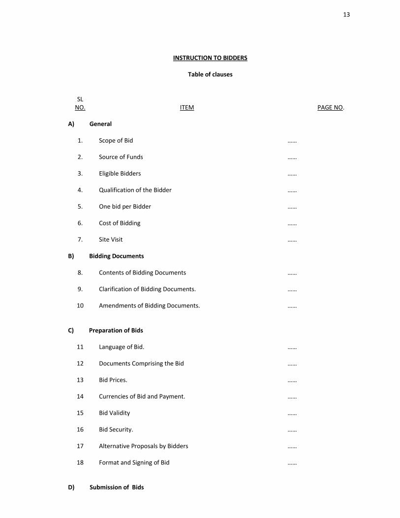
INSTRUCTION TO BIDDERS
Table of clauses
SLNO. ITEM PAGE NO.
A) General
1. Scope of Bid ……
2. Source of Funds ……
3. Eligible Bidders ……
4. Qualification of the Bidder ……
5. One bid per Bidder ……
6. Cost of Bidding ……
7. Site Visit ……
B) Bidding Documents
8. Contents of Bidding Documents ……
9. Clarification of Bidding Documents. ……
10 Amendments of Bidding Documents. ……
C) Preparation of Bids
11 Language of Bid. ……
12 Documents Comprising the Bid ……
13 Bid Prices. ……
14 Currencies of Bid and Payment. ……
15 Bid Validity ……
16 Bid Security. ……
17 Alternative Proposals by Bidders ……
18 Format and Signing of Bid ……
D) Submission of Bids
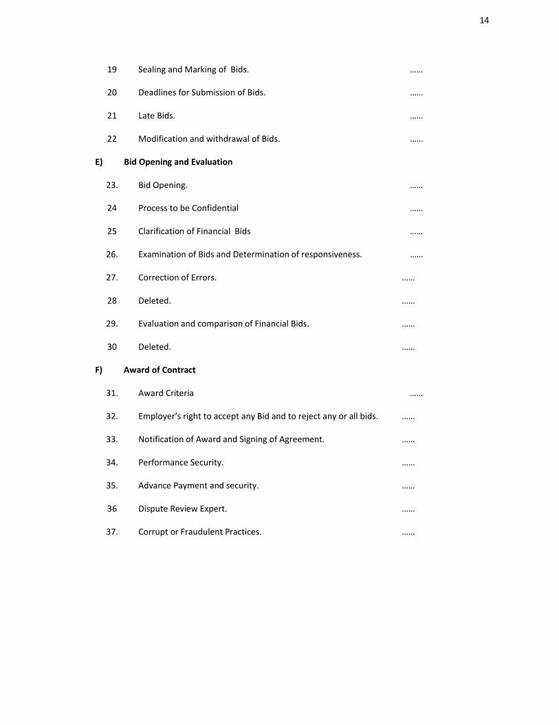
14
19 Sealing and Marking of Bids. ……
20 Deadlines for Submission of Bids. ……
21 Late Bids. ……
22 Modification and withdrawal of Bids. ……
E) Bid Opening and Evaluation
23. Bid Opening. ……
24 Process to be Confidential ……
25 Clarification of Financial Bids ……
26. Examination of Bids and Determination of responsiveness. ……
27. Correction of Errors. ……
28 Deleted. ……
29. Evaluation and comparison of Financial Bids. ……
30 Deleted. ……
F) Award of Contract
31. Award Criteria ……
32. Employer’s right to accept any Bid and to reject any or all bids. ……
33. Notification of Award and Signing of Agreement. ……
34. Performance Security. ……
35. Advance Payment and security. ……
36 Dispute Review Expert. ……
37. Corrupt or Fraudulent Practices. ……
15
GENERAL
1.0 Scope of Bid
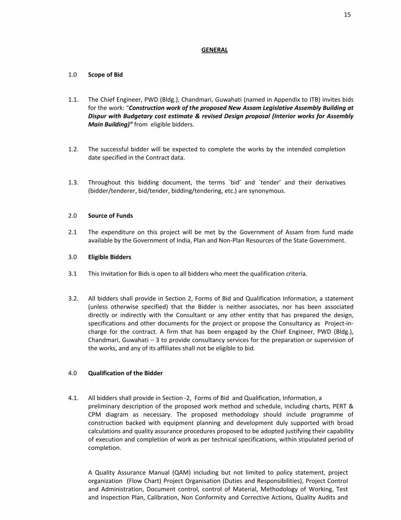
1.1. The Chief Engineer, PWD (Bldg.), Chandmari, Guwahati (named in Appendix to ITB) invites bidsfor the work: “Construction work of the proposed New Assam Legislative Assembly Building at Dispur with Budgetary cost estimate & revised Design proposal (Interior works for Assembly Main Building)” from eligible bidders.
1.2. The successful bidder will be expected to complete the works by the intended completion date specified in the Contract data.
1.3. Throughout this bidding document, the terms `bid’ and `tender’ and their derivatives (bidder/tenderer, bid/tender, bidding/tendering, etc.) are synonymous.
2.0 Source of Funds
2.1 The expenditure on this project will be met by the Government of Assam from fund made available by the Government of India, Plan and Non-Plan Resources of the State Government.
3.0 Eligible Bidders
3.1 This Invitation for Bids is open to all bidders who meet the qualification criteria.
3.2. All bidders shall provide in Section 2, Forms of Bid and Qualification Information, a statement (unless otherwise specified) that the Bidder is neither associates, nor has been associated directly or indirectly with the Consultant or any other entity that has prepared the design, specifications and other documents for the project or propose the Consultancy as Project-in-charge for the contract. A firm that has been engaged by the Chief Engineer, PWD (Bldg.), Chandmari, Guwahati – 3 to provide consultancy services for the preparation or supervision of the works, and any of its affiliates shall not be eligible to bid.
4.0 Qualification of the Bidder
4.1. All bidders shall provide in Section -2, Forms of Bid and Qualification, Information, a preliminary description of the proposed work method and schedule, including charts, PERT & CPM diagram as necessary. The proposed methodology should include programme of construction backed with equipment planning and development duly supported with broad calculations and quality assurance procedures proposed to be adopted justifying their capability of execution and completion of work as per technical specifications, within stipulated period of completion.
A Quality Assurance Manual (QAM) including but not limited to policy statement, project organization (Flow Chart) Project Organisation (Duties and Responsibilities), Project Control and Administration, Document control, control of Material, Methodology of Working, Test and Inspection Plan, Calibration, Non Conformity and Corrective Actions, Quality Audits and
16
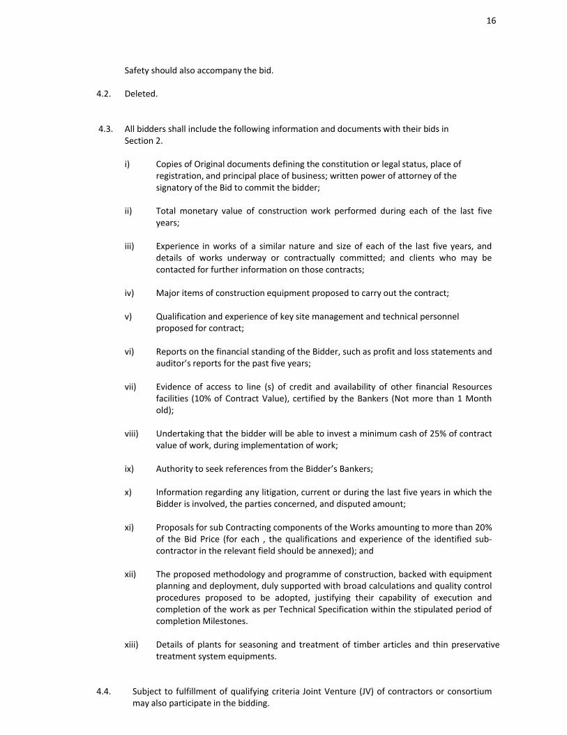
Safety should also accompany the bid.
4.2. Deleted.
4.3. All bidders shall include the following information and documents with their bids in Section 2.
i) Copies of Original documents defining the constitution or legal status, place of registration, and principal place of business; written power of attorney of the signatory of the Bid to commit the bidder;
ii) Total monetary value of construction work performed during each of the last five years;
iii) Experience in works of a similar nature and size of each of the last five years, and details of works underway or contractually committed; and clients who may be contacted for further information on those contracts;
iv) Major items of construction equipment proposed to carry out the contract;
v) Qualification and experience of key site management and technical personnel proposed for contract;
vi) Reports on the financial standing of the Bidder, such as profit and loss statements and auditor’s reports for the past five years;
vii) Evidence of access to line (s) of credit and availability of other financial Resources facilities (10% of Contract Value), certified by the Bankers (Not more than 1 Month old);
viii) Undertaking that the bidder will be able to invest a minimum cash of 25% of contract value of work, during implementation of work;
ix) Authority to seek references from the Bidder’s Bankers;
x) Information regarding any litigation, current or during the last five years in which the Bidder is involved, the parties concerned, and disputed amount;
xi) Proposals for sub Contracting components of the Works amounting to more than 20% of the Bid Price (for each , the qualifications and experience of the identified sub-contractor in the relevant field should be annexed); and
xii) The proposed methodology and programme of construction, backed with equipment planning and deployment, duly supported with broad calculations and quality control procedures proposed to be adopted, justifying their capability of execution and completion of the work as per Technical Specification within the stipulated period of completion Milestones.
xiii) Details of plants for seasoning and treatment of timber articles and thin preservative treatment system equipments.
4.4. Subject to fulfillment of qualifying criteria Joint Venture (JV) of contractors or consortium may also participate in the bidding.
17
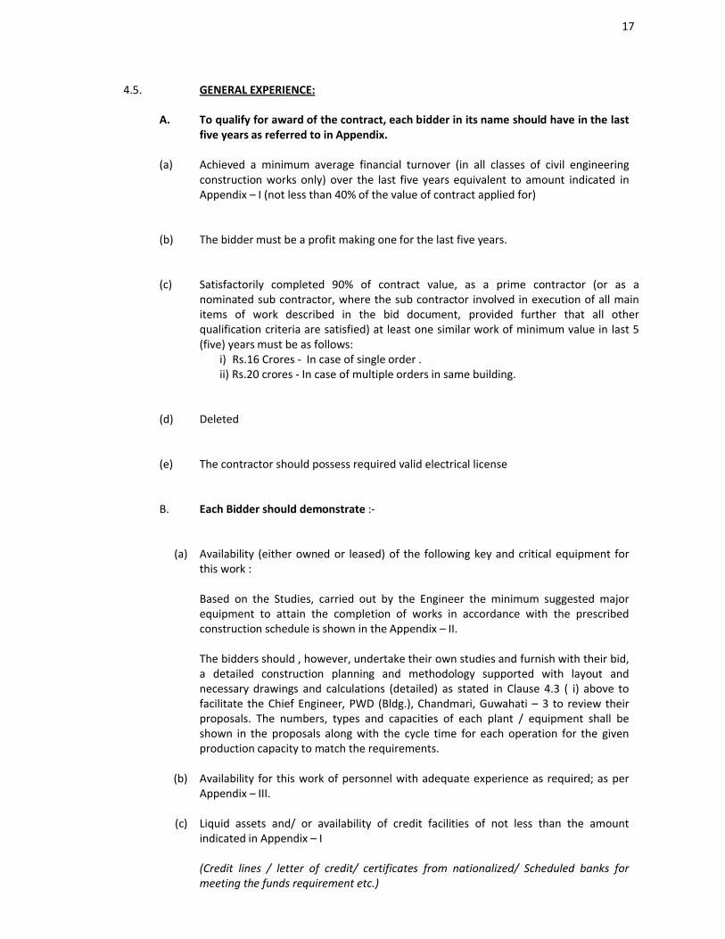
4.5.
A.
GENERAL EXPERIENCE:
To qualify for award of the contract, each bidder in its name should have in the last five years as referred to in Appendix.
(a) Achieved a minimum average financial turnover (in all classes of civil engineering construction works only) over the last five years equivalent to amount indicated in Appendix – I (not less than 40% of the value of contract applied for)
(b) The bidder must be a profit making one for the last five years.
(c) Satisfactorily completed 90% of contract value, as a prime contractor (or as a nominated sub contractor, where the sub contractor involved in execution of all main items of work described in the bid document, provided further that all other qualification criteria are satisfied) at least one similar work of minimum value in last 5 (five) years must be as follows:
i) Rs.16 Crores - In case of single order .ii) Rs.20 crores - In case of multiple orders in same building.
(d) Deleted
(e) The contractor should possess required valid electrical license
B. Each Bidder should demonstrate :-
(a) Availability (either owned or leased) of the following key and critical equipment for this work :
Based on the Studies, carried out by the Engineer the minimum suggested major equipment to attain the completion of works in accordance with the prescribed construction schedule is shown in the Appendix – II.
The bidders should , however, undertake their own studies and furnish with their bid, a detailed construction planning and methodology supported with layout and necessary drawings and calculations (detailed) as stated in Clause 4.3 ( i) above to facilitate the Chief Engineer, PWD (Bldg.), Chandmari, Guwahati – 3 to review their proposals. The numbers, types and capacities of each plant / equipment shall be shown in the proposals along with the cycle time for each operation for the given production capacity to match the requirements.
(b) Availability for this work of personnel with adequate experience as required; as per Appendix – III.
(c) Liquid assets and/ or availability of credit facilities of not less than the amount indicated in Appendix – I
(Credit lines / letter of credit/ certificates from nationalized/ Scheduled banks for meeting the funds requirement etc.)
18
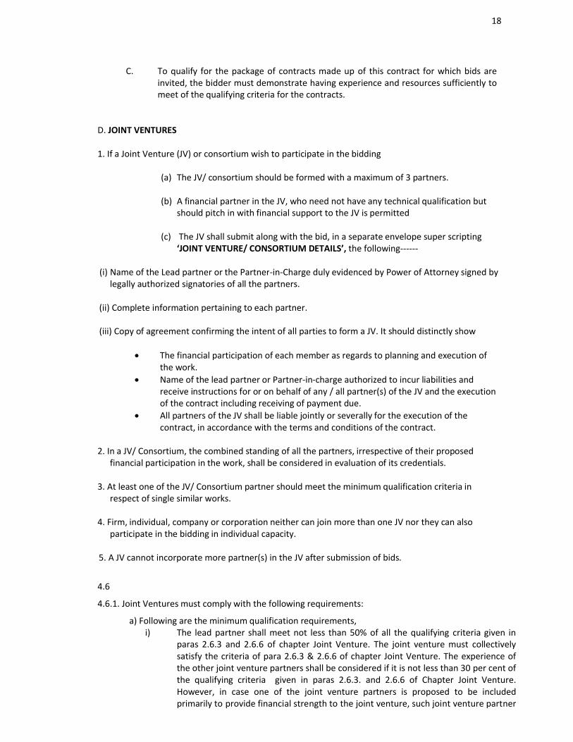
C. To qualify for the package of contracts made up of this contract for which bids are invited, the bidder must demonstrate having experience and resources sufficiently to meet of the qualifying criteria for the contracts.
D. JOINT VENTURES
1. If a Joint Venture (JV) or consortium wish to participate in the bidding
(a) The JV/ consortium should be formed with a maximum of 3 partners.
(b) A financial partner in the JV, who need not have any technical qualification but should pitch in with financial support to the JV is permitted
(c) The JV shall submit along with the bid, in a separate envelope super scripting ‘JOINT VENTURE/ CONSORTIUM DETAILS’, the following------
(i) Name of the Lead partner or the Partner-in-Charge duly evidenced by Power of Attorney signed by legally authorized signatories of all the partners.
(ii) Complete information pertaining to each partner.
(iii) Copy of agreement confirming the intent of all parties to form a JV. It should distinctly show
The financial participation of each member as regards to planning and execution of the work.
Name of the lead partner or Partner-in-charge authorized to incur liabilities and receive instructions for or on behalf of any / all partner(s) of the JV and the execution of the contract including receiving of payment due.
All partners of the JV shall be liable jointly or severally for the execution of the contract, in accordance with the terms and conditions of the contract.
2. In a JV/ Consortium, the combined standing of all the partners, irrespective of their proposed financial participation in the work, shall be considered in evaluation of its credentials.
3. At least one of the JV/ Consortium partner should meet the minimum qualification criteria in respect of single similar works.
4. Firm, individual, company or corporation neither can join more than one JV nor they can also participate in the bidding in individual capacity.
5. A JV cannot incorporate more partner(s) in the JV after submission of bids.
4.6
4.6.1. Joint Ventures must comply with the following requirements:
a) Following are the minimum qualification requirements,i) The lead partner shall meet not less than 50% of all the qualifying criteria given in
paras 2.6.3 and 2.6.6 of chapter Joint Venture. The joint venture must collectively satisfy the criteria of para 2.6.3 & 2.6.6 of chapter Joint Venture. The experience of the other joint venture partners shall be considered if it is not less than 30 per cent of the qualifying criteria given in paras 2.6.3. and 2.6.6 of Chapter Joint Venture. However, in case one of the joint venture partners is proposed to be included primarily to provide financial strength to the joint venture, such joint venture partner
19
shall have to commit to provide liquidity support to the project to the extent of 20 percent of the value of the contract.
ii) The joint ventures must satisfy collectively the criteria of paras 2.6.4 & 2.6.5 of chapter Joint Venture for which purpose the relevant figures for each of the partners shall be added together to arrive at the joint venture’s total capacity. Individual members must each satisfy requirements of para 2.6.7 & 2.6.8 chapter Joint Venture.
b) Bid shall be signed so as to legally bind all partners, jointly and severally, and shall be submitted with a copy of the joint venture agreement providing the ‘joint and several’ liability with respect to the contract.
4.6.2 Qualification of a joint venture does not necessarily qualify any of its partners individually or as a partner in any other joint venture. In case of dissolution of a joint venture, each one of the constituent firms may qualify if they meet all the qualification requirements, subject to the written approval of the Employer.
4.7. Sub Contractor’s experience and resources shall not be taken into account in determining the bidder’s compliance with the qualifying criteria except to the extent stated in 4.5(A), above.
4.8. Bidders who meet the minimum qualification criteria will be qualified only if their available bid capacity is more than the total bid value. The available bid capacity will be calculated as under :
Assessed Available bid Capacity = (A X N X 2 – B)
Where,
A = Maximum value of Interior works executed in any one year during the last five years (updated to the price level of the year indicated in Appendix – I) taking into account the completed as well as works in progress.
N = Number of years prescribed for completion of the works for which bids are invited.
B = Value (updated to the price level of the year indicated in Appendix – I) of existing commitments and on-going works to be completed during the next 9 months. (Period of completion of the works for which bid is invited).
Note : The Statements showing the value of existing commitments and on-going works as well as the stipulated period of completion remaining for each of the works listed should be countersigned by the Engineer-in-charge, not below the rank of an Executive Engineer or equivalent.
4.9. Even though the bidders meet the above qualifying criteria, they are subject to be disqualified if they have :
Made misleading or false representations in the forms, statements and attachments submitted in proof of the qualification requirements;
20
and/or.
Record of poor performance such as abandoning the works, not properly completing the contract, inordinate delays in completion, litigation history, or financial failures etc. and /or
Participated in the previous bidding for the same work and had quoted unreasonably high bid prices and could not furnish rational justification to the Chief Engineer, PWD (BLDG.), Chandmari, Guwahati – 3.
5.0. One Bid per Bidder
5.1. Each bidder shall submit only one bid for one package. A bidder who submits or participates in more than one Bid (other than as a sub-contractor or in cases of alternatives that have been permitted or requested) will cause all the proposals with the Bidder’s participation to be disqualified.
6.0. Cost of Bidding
6.1. The bidder shall bear all costs associated with the preparation and submission of this Bid, and the Chief Engineer, PWD (Bldg.), Chandmari, Guwahati – 3 will in no case be responsible and liable for those costs.
7.0. Site Visit
7.1. The Bidder, at the Bidder’s own responsibility and risk is encouraged to visit and examine Site of Works and its surroundings and obtain all information that may be necessary for preparing the Bid and entering into a contract for construction of the works. The cost of visiting the Site shall be at the Bidder’s own expense.
21
B. BIDDING DOCUMENTS
8.0. Content of Bidding Documents
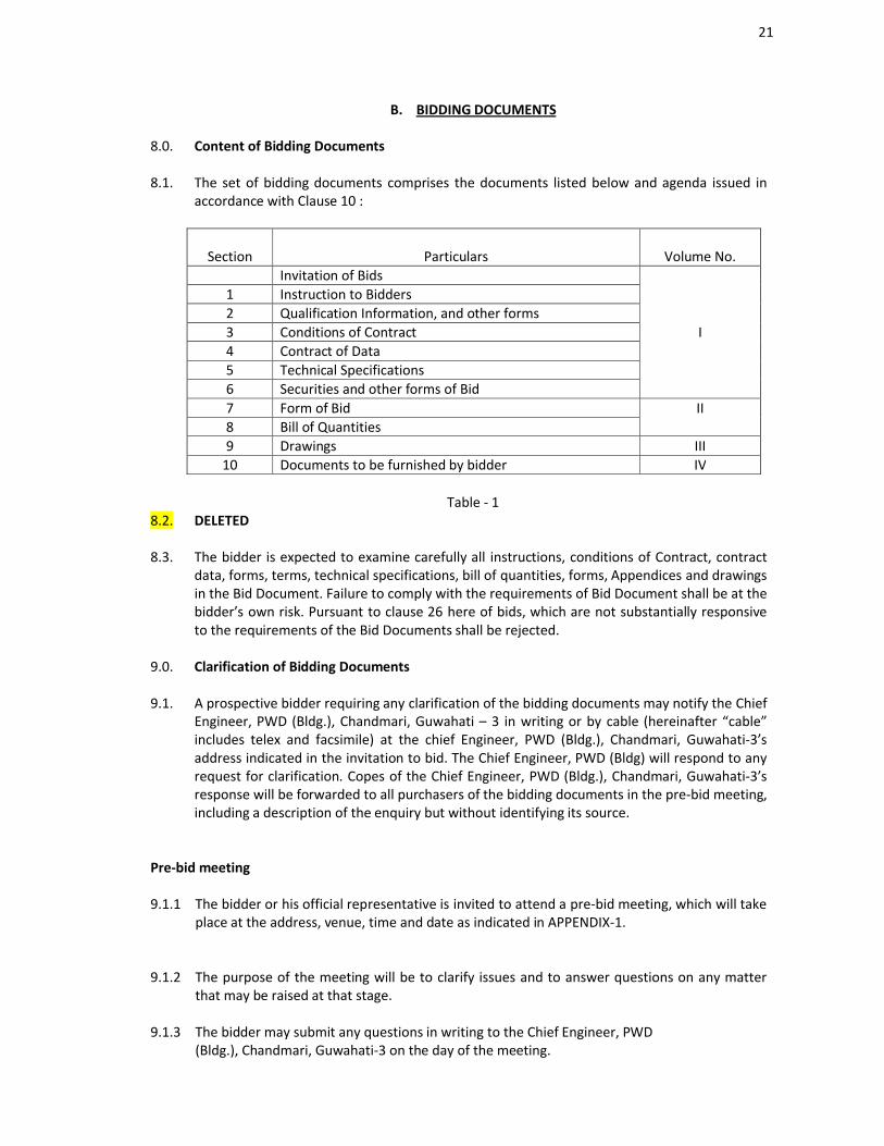
8.1. The set of bidding documents comprises the documents listed below and agenda issued in accordance with Clause 10 :
Section Particulars Volume No.Invitation of Bids
1 Instruction to Bidders2 Qualification Information, and other forms3 Conditions of Contract I4 Contract of Data5 Technical Specifications6 Securities and other forms of Bid7 Form of Bid II8 Bill of Quantities9 Drawings III
10 Documents to be furnished by bidder IV
Table - 18.2. DELETED
8.3. The bidder is expected to examine carefully all instructions, conditions of Contract, contract data, forms, terms, technical specifications, bill of quantities, forms, Appendices and drawings in the Bid Document. Failure to comply with the requirements of Bid Document shall be at the bidder’s own risk. Pursuant to clause 26 here of bids, which are not substantially responsive to the requirements of the Bid Documents shall be rejected.
9.0. Clarification of Bidding Documents
9.1. A prospective bidder requiring any clarification of the bidding documents may notify the Chief Engineer, PWD (Bldg.), Chandmari, Guwahati – 3 in writing or by cable (hereinafter “cable” includes telex and facsimile) at the chief Engineer, PWD (Bldg.), Chandmari, Guwahati-3’s address indicated in the invitation to bid. The Chief Engineer, PWD (Bldg) will respond to any request for clarification. Copes of the Chief Engineer, PWD (Bldg.), Chandmari, Guwahati-3’s response will be forwarded to all purchasers of the bidding documents in the pre-bid meeting,including a description of the enquiry but without identifying its source.
Pre-bid meeting
9.1.1 The bidder or his official representative is invited to attend a pre-bid meeting, which will take place at the address, venue, time and date as indicated in APPENDIX-1.
9.1.2 The purpose of the meeting will be to clarify issues and to answer questions on any matter that may be raised at that stage.
9.1.3 The bidder may submit any questions in writing to the Chief Engineer, PWD (Bldg.), Chandmari, Guwahati-3 on the day of the meeting.
22
9.1.4 Minutes of the meeting, including the text of the questions (without identifying the source of enquiry) and the responses given will be transmitted without delay. Any modification of the bidding documents listed in Sub Clause 8.1, which may become necessary as a result of the pre-bid meeting shall be made by the Chief Engineer, PWD (Bldg.), Chandrmari, Guwahati-3 exclusively through the issue of an Addendum pursuant to Clause 10 and not through the minutes of the pre-bid meeting.
9.1.5 Non-attendance at the pre-bid meeting will not be a cause for disqualification of a bidder.
10.0 Amendment of Bidding Documents
10.1. Before the deadline for submission of bids, the Chief Engineer, PWD (Bldg.), Chandmari, Guwahati-3 may modify the bidding documents by issuing addenda/ amendments.
10.2 Any addendum thus issued shall be a part of the bidding documents and shall be communicated in writing or by cable to all the purchasers of the bidding documents. Prospective bidders shall acknowledge receipt of each addendum in wiring or by cable to the Chief Engineer, PWD (Bldg.), Chandmari, Guwahati-3. The Chief Engineer, PWD (Bldg.) Chandmari, Guwahati-3 will assume no responsibility for postal delays.
10.3. All corrections / amendments may be seen in the website- assam.etenders.in
10.4. To give prospective bidders reasonable time in which to take an addendum into account in preparing their bids, the Chief Engineer, PWD (Bldg.), Chandmari, Guwahati – 3 may, at his discretion, extend as necessary the deadline for submission of bid, in accordance with Sub-Clause 20.2. below
23
C. PREPARATION OF BIDS
11. Language of the Bid
All documents relating to the bid shall be in the English Language.
12. Documents Comprising Bid
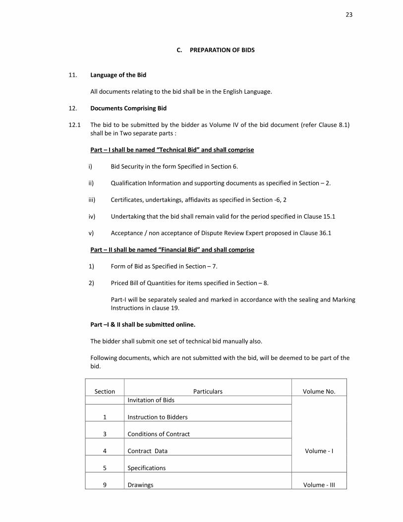
12.1 The bid to be submitted by the bidder as Volume IV of the bid document (refer Clause 8.1)shall be in Two separate parts :
Part – I shall be named “Technical Bid” and shall comprise
i) Bid Security in the form Specified in Section 6.
ii) Qualification Information and supporting documents as specified in Section – 2.
iii) Certificates, undertakings, affidavits as specified in Section -6, 2
iv) Undertaking that the bid shall remain valid for the period specified in Clause 15.1
v) Acceptance / non acceptance of Dispute Review Expert proposed in Clause 36.1
Part – II shall be named “Financial Bid” and shall comprise
1) Form of Bid as Specified in Section – 7.
2) Priced Bill of Quantities for items specified in Section – 8.
Part-I will be separately sealed and marked in accordance with the sealing and Marking Instructions in clause 19.
Part –I & II shall be submitted online.
The bidder shall submit one set of technical bid manually also.
Following documents, which are not submitted with the bid, will be deemed to be part of the bid.
Section Particulars Volume No.Invitation of Bids
1 Instruction to Bidders
3 Conditions of Contract
4 Contract Data Volume - I
5 Specifications
9 Drawings Volume - III
24
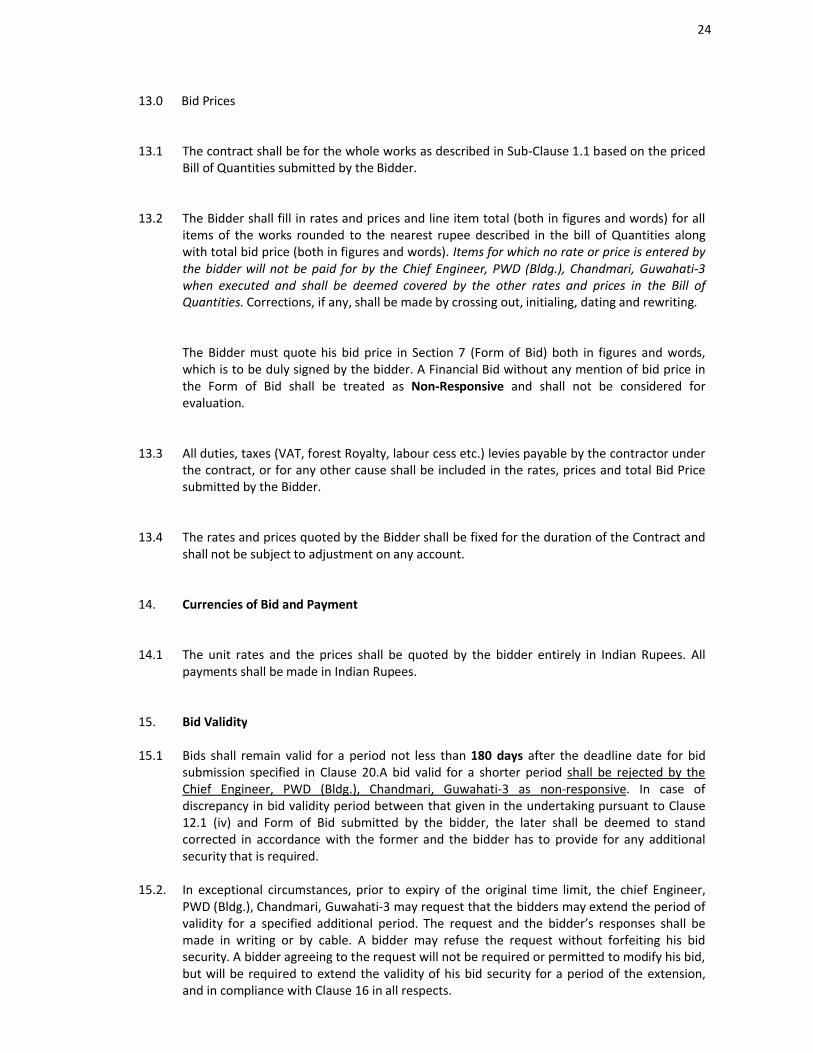
13.0 Bid Prices
13.1 The contract shall be for the whole works as described in Sub-Clause 1.1 based on the priced Bill of Quantities submitted by the Bidder.
13.2 The Bidder shall fill in rates and prices and line item total (both in figures and words) for all items of the works rounded to the nearest rupee described in the bill of Quantities along with total bid price (both in figures and words). Items for which no rate or price is entered by the bidder will not be paid for by the Chief Engineer, PWD (Bldg.), Chandmari, Guwahati-3 when executed and shall be deemed covered by the other rates and prices in the Bill of Quantities. Corrections, if any, shall be made by crossing out, initialing, dating and rewriting.
The Bidder must quote his bid price in Section 7 (Form of Bid) both in figures and words, which is to be duly signed by the bidder. A Financial Bid without any mention of bid price in the Form of Bid shall be treated as Non-Responsive and shall not be considered for evaluation.
13.3 All duties, taxes (VAT, forest Royalty, labour cess etc.) levies payable by the contractor under the contract, or for any other cause shall be included in the rates, prices and total Bid Price submitted by the Bidder.
13.4 The rates and prices quoted by the Bidder shall be fixed for the duration of the Contract and shall not be subject to adjustment on any account.
14. Currencies of Bid and Payment
14.1 The unit rates and the prices shall be quoted by the bidder entirely in Indian Rupees. All payments shall be made in Indian Rupees.
15. Bid Validity
15.1 Bids shall remain valid for a period not less than 180 days after the deadline date for bid submission specified in Clause 20.A bid valid for a shorter period shall be rejected by the Chief Engineer, PWD (Bldg.), Chandmari, Guwahati-3 as non-responsive. In case of discrepancy in bid validity period between that given in the undertaking pursuant to Clause 12.1 (iv) and Form of Bid submitted by the bidder, the later shall be deemed to stand corrected in accordance with the former and the bidder has to provide for any additional security that is required.
15.2. In exceptional circumstances, prior to expiry of the original time limit, the chief Engineer, PWD (Bldg.), Chandmari, Guwahati-3 may request that the bidders may extend the period of validity for a specified additional period. The request and the bidder’s responses shall be made in writing or by cable. A bidder may refuse the request without forfeiting his bid security. A bidder agreeing to the request will not be required or permitted to modify his bid, but will be required to extend the validity of his bid security for a period of the extension, and in compliance with Clause 16 in all respects.
25
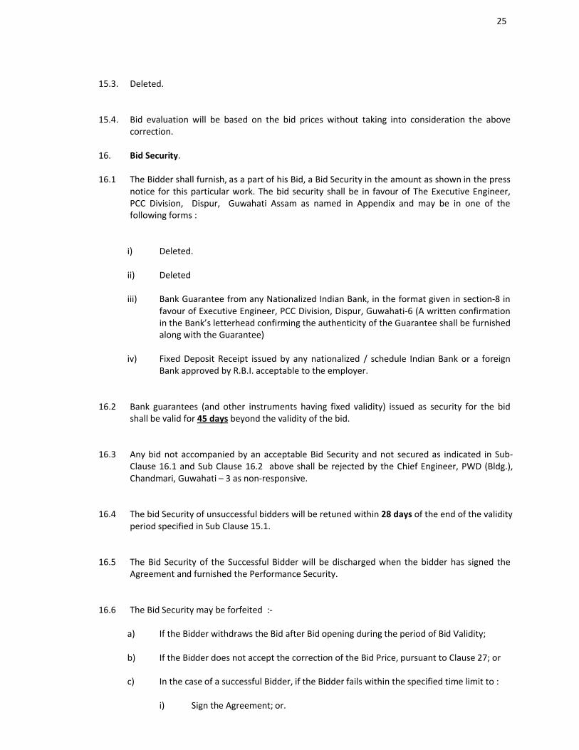
15.3. Deleted.
15.4. Bid evaluation will be based on the bid prices without taking into consideration the above correction.
16. Bid Security.
16.1 The Bidder shall furnish, as a part of his Bid, a Bid Security in the amount as shown in the press notice for this particular work. The bid security shall be in favour of The Executive Engineer, PCC Division, Dispur, Guwahati Assam as named in Appendix and may be in one of the following forms :
i) Deleted.
ii) Deleted
iii) Bank Guarantee from any Nationalized Indian Bank, in the format given in section-8 in favour of Executive Engineer, PCC Division, Dispur, Guwahati-6 (A written confirmation in the Bank’s letterhead confirming the authenticity of the Guarantee shall be furnished along with the Guarantee)
iv) Fixed Deposit Receipt issued by any nationalized / schedule Indian Bank or a foreign Bank approved by R.B.I. acceptable to the employer.
16.2 Bank guarantees (and other instruments having fixed validity) issued as security for the bid shall be valid for 45 days beyond the validity of the bid.
16.3 Any bid not accompanied by an acceptable Bid Security and not secured as indicated in Sub-Clause 16.1 and Sub Clause 16.2 above shall be rejected by the Chief Engineer, PWD (Bldg.), Chandmari, Guwahati – 3 as non-responsive.
16.4 The bid Security of unsuccessful bidders will be retuned within 28 days of the end of the validity period specified in Sub Clause 15.1.
16.5 The Bid Security of the Successful Bidder will be discharged when the bidder has signed the Agreement and furnished the Performance Security.
16.6 The Bid Security may be forfeited :-
a) If the Bidder withdraws the Bid after Bid opening during the period of Bid Validity;
b) If the Bidder does not accept the correction of the Bid Price, pursuant to Clause 27; or
c) In the case of a successful Bidder, if the Bidder fails within the specified time limit to :
i) Sign the Agreement; or.
26
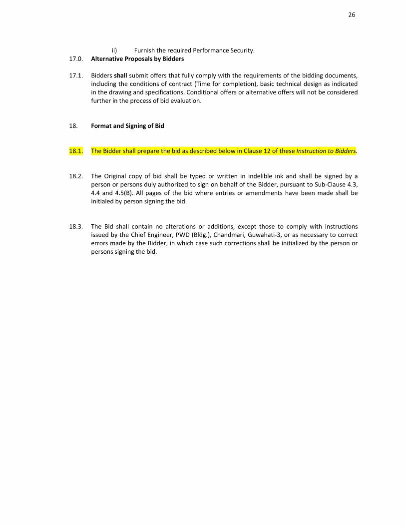
ii) Furnish the required Performance Security.17.0. Alternative Proposals by Bidders
17.1. Bidders shall submit offers that fully comply with the requirements of the bidding documents, including the conditions of contract (Time for completion), basic technical design as indicated in the drawing and specifications. Conditional offers or alternative offers will not be considered further in the process of bid evaluation.
18. Format and Signing of Bid
18.1. The Bidder shall prepare the bid as described below in Clause 12 of these Instruction to Bidders.
18.2. The Original copy of bid shall be typed or written in indelible ink and shall be signed by a person or persons duly authorized to sign on behalf of the Bidder, pursuant to Sub-Clause 4.3, 4.4 and 4.5(B). All pages of the bid where entries or amendments have been made shall be initialed by person signing the bid.
18.3. The Bid shall contain no alterations or additions, except those to comply with instructions issued by the Chief Engineer, PWD (Bldg.), Chandmari, Guwahati-3, or as necessary to correct errors made by the Bidder, in which case such corrections shall be initialized by the person or persons signing the bid.
27
D. SUBMISSION OF BIDS
19.0. Sealing and Marking of Bids
19.1. The Bidder shall seal the Technical Bid in an envelopes and submit the same as per schedule.
. Bid to be opened on 13-01-2015 at 11:01 Hrs. Clause No.19.1 is not applicable except the following:
##The contents of Technical and Financial Bids will be as specified in clause 12.1
19.2. The inner and outer and separate enveloped containing Technical shall
(a) Be addressed to the Chief Engineer, PWD (Bldg.), Chandmari, Guwahati-3
(b)Bear the identification as indicated in Appendix-I
Clause No.19.2 is not applicable
19.3. In addition to the identification required in Sub-Clause 19.1 and 19.2, each of the enveloped shall indicate the name and address of the bidder to enable the bid to be returned unopened incase it is declared late, pursuant to Clause 21, or the Evaluation Committee declares the Bid as non-responsive pursuant to Clause 23. Clause No.19.3 is not applicable
19.4. If the outer envelope is not sealed and marked as above, the Chief Engineer, PWD (Bldg.), Chandmari, Guwahati - 3 will assume no responsibility for the misplacement or premature opening of the bid. Clause No.19.4 is not applicable
20. Deadline for Submission of Bids
20.1. Complete Bids (including Technical and Financial Bids) must be received by the Chief Engineer, PWD (Bldg.), Chandmari, Guwahati-3 at the address specified above not later than the date indicated in Appendix-I. In the event of the specified date for the submission of bids declared as holiday on the date of receipt of the bids as specified the bids will be received and opened on the next working day at the same time and venue.
20.2 The Chief Engineer, PWD (Bldg.), Chandmari, Guwahati-3 may extend the deadline for submission of bids by issuing an amendment in accordance with Clause 10, in which case all rights and obligations of the chief Engineer, PWD (Bldg.), Chandmari, Guwahati-3 and the Bidders previously subject to original deadline will then be subject to the new deadline.
28
21. Late Bids
21.1. Any Bid received late by the Chief Engineer, PWD (Bldg.), Chandmari, Guwahati -3 after the deadline prescribed in Clause 20 will be returned unopened to the bidder.
22. Modifications and Withdrawal of Bids
22.1 Bidders may modify or withdraw their bids by giving notice in writing before the deadline prescribed in Clause 20 or pursuant to Clause 23. (Not Applicable)
22.2 Each Bidder’s modification or withdrawal notice shall be prepared, sealed, marked, and delivered in accordance to Clause 18 & 19, with the outer and inner envelopes additionally marked “MODIFICATION” or “WITHDRAWAL” as appropriate. (Not Applicable)
22.3 No bid may be modified after the Deadline for submission of bids except in pursuance of Clause - 23.
22.4 Withdrawal or modification of a Bid between the deadline for submission of bids and the expiration of the original period of bid validity specified in Clause 15.1 above or as extended to Clause 15.2 may result in the forfeiture of Bid Security pursuant to Clause 16.6.
29
E.BID OPENING AND EVALUATION
23. Bid Opening
23.1 The Chief Engineer, PWD (Bldg.), Chandmari, Guwahati - 3 will open all the Bids received, in the presence of the Bidders or their representatives who choose to attend at time, date and the place specified in Appendix-I in the manner specified in Clause 20 and 23.3. In the event of specified date of Bid opening being declared a holiday on the date of receipt of the bids as specified the bids will be received and opened on the next working day at the same time and venue.
23.2 Envelope marked “WITHDRAWAL” shall be opened and read out first. Bids for which an acceptance notice of withdrawal has been submitted pursuant to Clause 22 shall not be opened. (Not Applicable)
23.3 The amount, form and validity of the Bid security furnished with each bid will be announced. If the bid security furnished does not conform to the amount and validity period as specified in the Invitation for Bid, and has not been furnished in the form specified in Clause 16, the bid shall be returned to the bidder.
23.4
i) Subject to confirmation of the bid security by the issuing Bank, the bid accompanied with valid bid security will be taken up for evaluation with respect to the Qualification information and other information furnished in Part I if the bid pursuant to Clause 12.1.
ii) After receipt to confirmation of the bid security, the bidder will be asked in writing (usually) within 10 days of opening of the Technical Bid) to clarify or modify his technical bid, if necessary, with respect to any rectifiable defects.
iii) The bidders will respond in not more than 7 days of issue of the clarification letter, which will also indicate the date, time and venue of opening of the financial bid (usually on 21st
day of opening of the technical bid).
iv) Immediately (usually within 3 or 4 days), on receipt of these clarifications the Evaluation Committee will finalize the list of responsive bidders, whose financial bids are eligible for consideration.
23.5 If, as a consequence of the modification carried out by the bidder. In response to sub-clause 23.4, the bidders desire to modify their financial bid; they will submit the modification in separate sealed envelope so as to reach the Employer’s address (refer sub-clause 19.2) before the opening of the Technical Bid/financial bid as intimated in the clarification letter (refer sub-clause 23.4). The envelope shall have clear marking “MODIFICATION TO BID – Not to be opened except with the approval of theEvaluation Committee”.
23.6 At the time of opening of “Bid”, the name of the bidders will be announced. The Bidders Names, the Bid prices, the total amount of each bid, any discounts, Bid modifications and withdrawals, and such others details as the Chief Engineer, PWD (Bldg.), Chandmari, Guwahati-3 may consider appropriate, will be announced by the Chief Engineer, PWD (Bldg.), Chandmari,
30
Guwahati-3 at the opening. Any bid price or discounts, which is not read out recorded will not be taken into account in Bid Evaluation. The Bidders responsiveness to the Bids will be examined as per Clause 26.2. Only the responsive bidders’ Bids will be evaluated.
23.7. Deleted.
23.8. The Chief Engineer, PWD (Bldg.), Chandmari, Guwahati-3 shall prepare minutes of the Bid opening, including the information disclosed to those present in accordance with Sub-Clause 23.6.
24. Process to be Confidential
24.1. Information relating to the examination, clarification, evaluation and comparison of Bids and recommendations for the award of a contract shall not be disclosed to Bidders or any other person officially concerned with such process until the award to the successful Bidder has been announced. Any effort by a Bidder to influence the Chief Engineer, PWD (Bldg.), Chandmari, Guwahati-3’s processing of Bids or award decision may result in the rejection of his Bid.
25. Clarification of Financial Bids
25.1 To assist in the examination, evaluation and comparison of Bids, the chief Engineer, PWD (Bldg.), Chandmari, Guwahati-3 may, at his discretion, ask any Bidder for clarification of his bid, including breakdowns of unit rates. The request for clarification and the response shall be in writing or by cable, but no change in the price or substance of the Bid shall be sought, offered, or permitted except as required to confirm the correction of arithmetic errors discovered by the Chief Engineer, PWD (Bldg.), Chandmari, Guwahati-3 in the evaluation of the Bids in accordance with Clause 27.
25.2 Subject to sub-clause 25.1, no Bidders shall contact the Chief Engineer, PWD (Bldg.), Chandmari, Guwahati-3 on any matter relating to his bid from the time of the bid opening to the time the contract is awarded. If the Bidders wish to bring additional information to the notice of the Chief Engineer, PWD (Bldg.), Chandmari, Guwahati-3, it should do so in writing.
25.3 Any effort by the Bidders to influence the chief Engineer, PWD (Bldg.), Chandmari, Guwahati-3 in the Chief Engineer , PWD (Bldg.), Chandmari, Guwahati-3’s bid evaluation, bid comparisons or contract award decisions may result in the rejection of the Bidders’ bid.
26. Examination of Bids and Determination of Responsiveness
26.1 Deleted.
26.2 A substantially responsive “Bid” in one, which conforms to all the terms, conditions, and specifications of bidding documents, without material deviation or reservation. A material deviation or reservation is one (a) which affects in any substantial way the scope, quality, or performance of the works; (b) which limits in any substantial way, inconsistent with the Bidding documents, the Chief Engineer, PWD (Bldg.), Chandmari, Guwahati-3’s right or the Bidder’s obligations under the contract; or (c) whose rectification would affect unfairly the competitive position of other Bidders presenting substantially responsive Bids.
26.3 If a “Bid” is not substantially responsive, it will be rejected by the Chief Engineer, PWD (Bldg.), Chandmari, Guwahati-3 and may not subsequently be made responsive by correction or
31
withdrawals of the non-conforming deviation or reservation.27. Correction of Errors
27.1 “Bids” determined to be substantially responsive will be checked by the Chief Engineer, PWD (Bldg.), Chandmari, Guwahati-3 for any arithmetic errors. Errors will be corrected by the Chief Engineer, PWD (Bldg.), Chandmari, Guwahati-3 as follows :
a) Where there is a discrepancy between the rates in figures and in words, the rate in words will govern; and
b) Where there is a discrepancy between the unit rate and the line item total resulting from multiplying the unit rate by the quantity, the unit rate as quoted will govern.
27.2. The amount stated in the “Bid” will be corrected by the Chief Engineer, PWD (Bldg.), Chandmari, Guwahati-3 in accordance with the above procedure and the bid amount adjusted with the concurrence of the Bidder in the following manner :
a) If the Bid price increases as a result of this correction, the amount as stated in the bid will be the `bid price’ and the increase will be treated as rebate;
b) If the Bid price decreases as a result of this correction, the decreased amount will be the “bid price”. Such adjusted bid price shall be considered as binding upon the Bidder. If the Bidder does not accept the corrected amount the Bid will be rejected, and the Bid security may be forfeited in accordance with Sub-Clause 16.6(b).
28. Deleted.
29. Evaluation and Comparison of Bids
29.1. The chief Engineer, PWD (Bldg.), Chandmari, Guwahati-3 will evaluate and compare only the Bids determine to be substantially responsive in accordance with Sub-Clause 26.2.
29.2. In evaluating the Bids the Chief Engineer, PWD (Bldg.), Chandmari, Guwahati-3 will determine for each Bid the evaluated Bid Price by adjusting the Bid Price as follows :
a) Making any correction for errors pursuant to Clause 27; or
b) Making an appropriate adjustments for any other acceptable variations, deviations; and
c) Making appropriate adjustments to reflect discounts or other price modifications offered in accordance with Sub-Clause 23.6.
29.3. The Chief Engineer, PWD (Bldg.), Chandmari, Guwahati-3 reserves the right to accept or reject any variation or deviation. Variations and deviations and other factors, which are in excess of the requirements of the Bidding documents or otherwise results in unsolicited benefits for the Chief Engineer, PWD (Bldg.),Chandmari, Guwahati-3 shall not be taken into account in Bid evaluation.
29.4. The estimated effect of the price adjustment during the period of implementation of the contract will not be taken into account in Bid evaluation.
29.5. If the Bid of the successful Bidder is seriously unbalanced in relation to the Department’s estimate of the cost of work to be performed under the contract, the Chief Engineer, PWD
32
(Bldg.), Chandmari, Guwahati – 3 may require the Bidder to produce detailed price analysis for any or all item of the Bill of Quantities, to demonstrate the internal consistency of those prices with the construction methods and schedule proposed. After evaluation of the amount of the performance security set forth in Clause 34 be increased at the expense of the successful Bidder to a level sufficient to protect the Chief Engineer, PWD (Bldg.), Chandmari, Guwahati-3 against financial loss in the event of default of the successful Bidder under the Contract.
29.6. If a bid contains several items in the Bill of Quantities, which are unrealistically priced low, and which cannot be substantiated satisfactorily by the bidder, may be rejected as non-responsive.
30. Deleted.
33
F. AWARD OF CONTRACT
31. Award Criteria
31.1. Subject to Clause 32, the chief Engineer, PWD (Bldg.), Chandmari, Guwahati-3 will award the Contract to the Bidder whose Bids has been determined.
i) To be substantially responsive to the Bidding documents and who has offered the lowest evaluated Bid pursuant to Clause 29 provided further that the bidder has the capability and resources to carry out the contract effectively.
ii) To be within the available Bid capacity adjusted to account for his quoted bid price.
iii) The work shall be awarded at the lowest responsive bid price.
In no case, the contract shall be awarded to any bidder whose available bid capacity is less than the evaluated bid price, even if the said bid is the lowest evaluated bid. The contract will in such case be awarded to the next lowest bidder at his evaluated bid.
31.2 Deleted.
32. Chief Engineer, PWD (Bldg.), Chandmari, Guwahati-3’s right to accept any Bid and to reject any or all Bids.
32.1 Notwithstanding Clause 31, the Chief Engineer, PWD (Bldg.), Chandmari, Guwahati-3 reserves the right to accept or reject any Bid and to cancel the Bidding process and reject all bids, at any time prior to the awards of Contract, without thereby incurring any liability to the affected Bidder or Bidders or any obligations to inform the affected Bidder or Bidders of the grounds for the chief Engineer, PWD (Bldg.), Chandmari, Guwahati-3’s actions.
33. Notification of Award and Signing of Agreement.
33.1 The Bidders whose Bid has been accepted will be notified for the award by the Chief Engineer, PWD (Bldg.), Chandmari, Guwahati - 3 prior to expiration of the Bid validity period by cable, telex or facsimile confirmed by registered letter. This letter (hereinafter and in the Condition of Contract called the “Letter of Acceptance”) will state the sum that the Chief Engineer, PWD (Bldg.), Chandmari, Guwahati-3 will pay the Contractor in consideration of the execution, completion and maintenance of the Works by the Contractor as prescribed by the contract (hereinafter and in the Contract called the “Contract Price”).
33.2 The notification of award will constitute the formation of the Contract, subject only to the furnishing of a performance security in accordance with the provisions of Clause 34.
33.3 The agreement will incorporate all agreements between the Chief Engineer, PWD (Bldg.), Chandmari, Guwahati-3 and the Successful Bidder. Within 21days of receipt of the “Letter of Acceptance”, the successful Bidder will deposit the requisite Performance Security and attend before the Chief Engineer, P.W.D. (Building) to sign the Agreement and deliver it to the Chief Engineer, PWD (Bldg.), Chandmari, Guwahati-3.
33.4 Upon the furnishing of the Performance security by the successful Bidder, the Chief Engineer, PWD (Bldg.), Chandmari, Guwahati-3 will promptly notify the other Bidders that their Bids have been unsuccessful.
34. Performance Security
34
34.1 Within 21 days of receipt of the Letter of Acceptance, the successful Bidder shall deliver to the Chief Engineer, PWD (Bldg.), Chandmari, Guwahati - 3, a Performance Security in any of the form given below for an amount equivalent to 5% of the Contract price plus additional security for unbalanced Bids in accordance with Clause 29.5 of ITB Clause - 52 of Conditions of Contract.
A bank guarantee in the form given in section 6 :
If the performance security is provided by the successful Bidder in the form of a Bank Guarantee, it shall be issued at the Bidder’s option, by a Nationalized Indian Bank, prepared in non-judicial stamp paper of specified value.
34.2 Failure of the successful Bidder to comply with the requirements of Sub-Clause 34.1. shall constitute sufficient grounds for cancellation of the award and forfeiture of the Bid security.
35. Advance Payment and Security
35.1. The Executive Engineer of the concerned Division will provide an advance Payment as stipulated in the conditions of Contract, subject to maximum amount, as stated in the Contract Data. However such advance will be subject to fund made available.
36. Dispute Review Experts.
36.1. The Chief Engineer, PWD (Bldg.), Chandmari, Guwahati-3 proposes that ( name of proposed Dispute Review Expert in Appendix - I) be appointed as Disputes Review Expert under the Contract, at a daily fee plus reimbursable expenses. If the Bidders disagree with this proposal, the Bidders should so state in the Bids.
37. Corrupt or Fraudulent Practices.
37.1. The Chief Engineer, PWD (Bldg.), Chandmari, Guwahati - 3 will reject a proposal for award if it determine that the Bidder recommended for award has engaged in corrupt or fraudulent in competing for the contract in question and will declare the firm ineligible, either indefinitely or for a stated period of time to be awarded a contract with CPWD / APWD and any other agencies, if it at any time determines that the firm has engaged in corrupt or fraudulent practices in competing for the contractor, or in execution.
37.2 Furthermore, Bidders shall be aware of the provision stated in Sub-Clause 25.3 and Sub-Clause- 59.2 of the Condition of Contract.
35
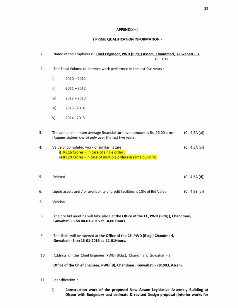
APPENDIX – I
( PRIME QUALIFICATION INFORMATION )
1. Name of the Employer is: Chief Engineer, PWD (Bldg.) Assam, Chandmari, Guwahati – 3. (Cl. 1.1)
2. The Total Volume of Interior work performed in the last five years :
i) 2010 – 2011
ii) 2011 – 2012
iii) 2012 – 2013
iv) 2013– 2014
v) 2014– 2015
3. The annual minimum average financial turn over amount is Rs. 16.00 crore(Rupees sixteen crore) only over the last five years.
(Cl. 4.5A (a))
4. Value of completed work of similar nature i) Rs.16 Crores - In case of single order .ii) Rs.20 Crores - In case of multiple orders in same building.
(Cl. 4.5A (c))
5. Deleted (Cl. 4.5A (d))
6. Liquid assets and / or availability of credit facilities is 10% of Bid Value (Cl. 4.5B (c))
7. Deleted
8. The pre bid meeting will take place at the Office of the CE, PWD (Bldg.), Chandmari, Guwahati - 3 on 04-01-2016 at 14-00 Hours.
9. The Bids will be opened at the Office of the CE, PWD (Bldg.) Chandmari, Guwahati - 3 on 13-01-2016 at 11-01Hours.
10. Address of the Chief Engineer, PWD (Bldg.), Chandmari, Guwahati - 3
Office of the Chief Engineer, PWD (B), Chandmari, Guwahati - 781003, Assam.
11. Identification :
i) Construction work of the proposed New Assam Legislative Assembly Building at Dispur with Budgetary cost estimate & revised Design proposal (Interior works for
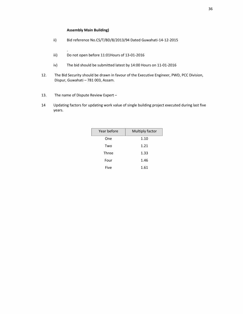
36
Assembly Main Building)
ii) Bid reference No.CS/T/BD/8/2013/94 Dated Guwahati-14-12-2015
.iii) Do not open before 11:01Hours of 13-01-2016
iv) The bid should be submitted latest by 14:00 Hours on 11-01-2016
12. The Bid Security should be drawn in favour of the Executive Engineer, PWD, PCC Division, Dispur, Guwahati – 781 003, Assam.
13. The name of Dispute Review Expert –
14 Updating factors for updating work value of single building project executed during last five years.
Year before Multiply factor
One 1.10
Two 1.21
Three 1.33
Four 1.46
Five 1.61
37
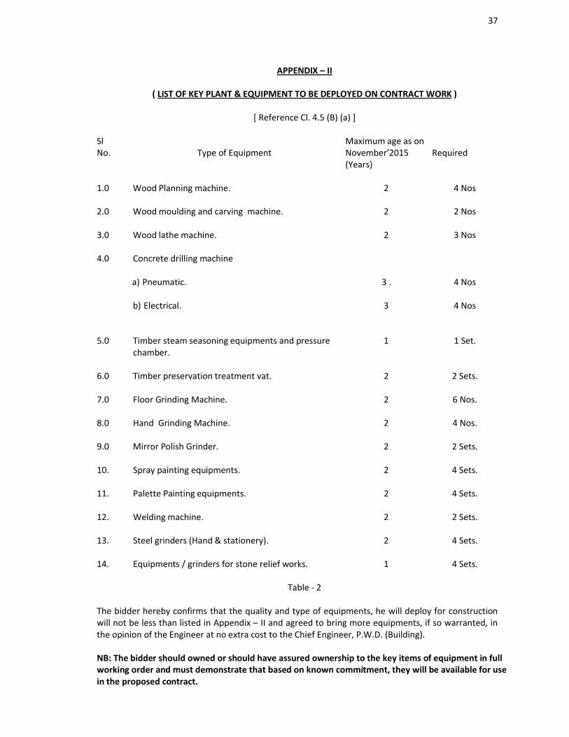
APPENDIX – II
( LIST OF KEY PLANT & EQUIPMENT TO BE DEPLOYED ON CONTRACT WORK )
[ Reference Cl. 4.5 (B) (a) ]
SlNo. Type of Equipment
Maximum age as on November’2015(Years)
Required
1.0 Wood Planning machine. 2 4 Nos
2.0 Wood moulding and carving machine. 2 2 Nos
3.0 Wood lathe machine. 2 3 Nos
4.0 Concrete drilling machine
a) Pneumatic. 3 . 4 Nos
b) Electrical. 3 4 Nos
5.0 Timber steam seasoning equipments and pressure chamber.
1 1 Set.
6.0 Timber preservation treatment vat. 2 2 Sets.
7.0 Floor Grinding Machine. 2 6 Nos.
8.0 Hand Grinding Machine. 2 4 Nos.
9.0 Mirror Polish Grinder. 2 2 Sets.
10. Spray painting equipments. 2 4 Sets.
11. Palette Painting equipments. 2 4 Sets.
12. Welding machine. 2 2 Sets.
13. Steel grinders (Hand & stationery). 2 4 Sets.
14. Equipments / grinders for stone relief works. 1 4 Sets.
Table - 2
The bidder hereby confirms that the quality and type of equipments, he will deploy for construction will not be less than listed in Appendix – II and agreed to bring more equipments, if so warranted, in the opinion of the Engineer at no extra cost to the Chief Engineer, P.W.D. (Building).
NB: The bidder should owned or should have assured ownership to the key items of equipment in full working order and must demonstrate that based on known commitment, they will be available for use in the proposed contract.
38
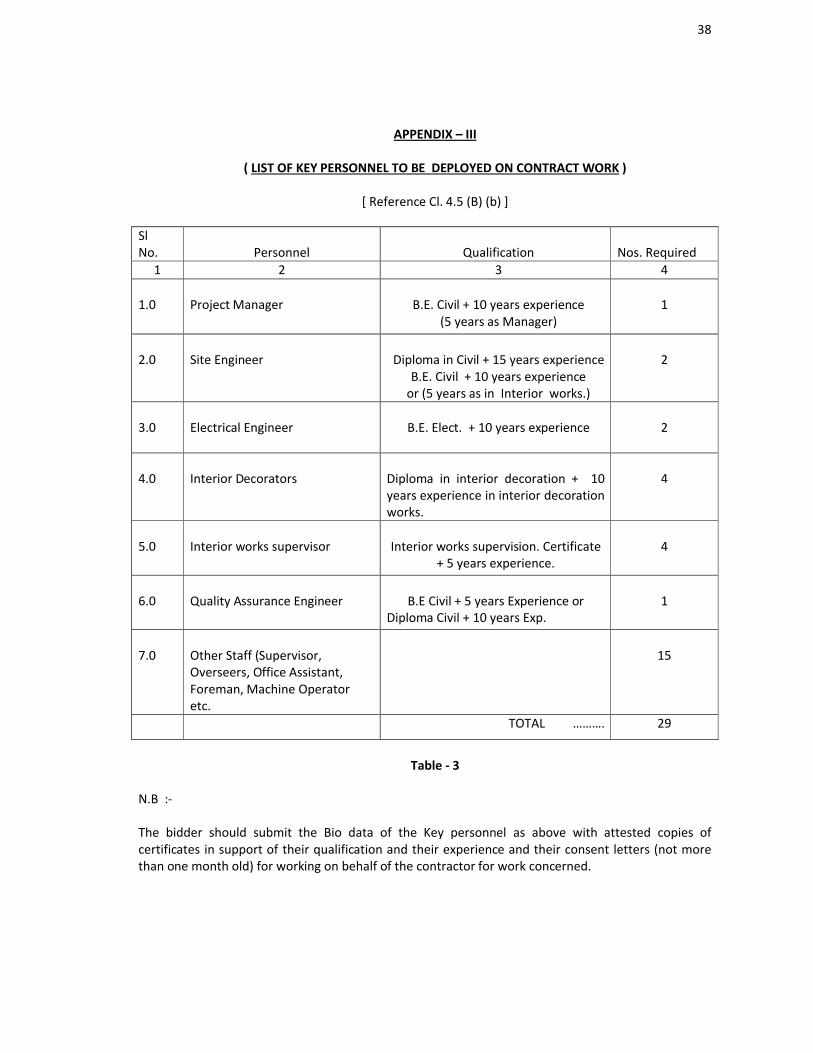
APPENDIX – III
( LIST OF KEY PERSONNEL TO BE DEPLOYED ON CONTRACT WORK )
[ Reference Cl. 4.5 (B) (b) ]
SlNo. Personnel Qualification Nos. Required
1 2 3 4
1.0 Project Manager B.E. Civil + 10 years experience(5 years as Manager)
1
2.0 Site Engineer Diploma in Civil + 15 years experienceB.E. Civil + 10 years experience
or (5 years as in Interior works.)
2
3.0 Electrical Engineer B.E. Elect. + 10 years experience 2
4.0 Interior Decorators Diploma in interior decoration + 10 years experience in interior decoration works.
4
5.0 Interior works supervisor Interior works supervision. Certificate + 5 years experience.
4
6.0 Quality Assurance Engineer B.E Civil + 5 years Experience orDiploma Civil + 10 years Exp.
1
7.0 Other Staff (Supervisor, Overseers, Office Assistant, Foreman, Machine Operator etc.
15
TOTAL ………. 29
Table - 3
N.B :-
The bidder should submit the Bio data of the Key personnel as above with attested copies of certificates in support of their qualification and their experience and their consent letters (not more than one month old) for working on behalf of the contractor for work concerned.

39
SECTION 2
QUALIFICATION INFORMATION
40
QUALIFICATION INFORMATION
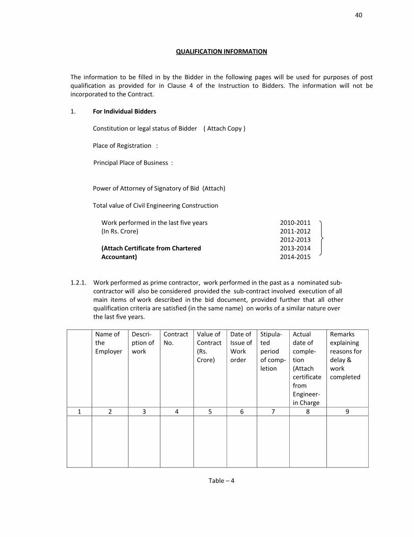
The information to be filled in by the Bidder in the following pages will be used for purposes of post qualification as provided for in Clause 4 of the Instruction to Bidders. The information will not be incorporated to the Contract.
1. For Individual Bidders
Constitution or legal status of Bidder ( Attach Copy )
Place of Registration : Principal Place of Business :
Power of Attorney of Signatory of Bid (Attach)
Total value of Civil Engineering Construction
Work performed in the last five years(In Rs. Crore)
(Attach Certificate from CharteredAccountant)
2010-20112011-20122012-2013 2013-20142014-2015
1.2.1. Work performed as prime contractor, work performed in the past as a nominated sub-contractor will also be considered provided the sub-contract involved execution of allmain items of work described in the bid document, provided further that all otherqualification criteria are satisfied (in the same name) on works of a similar nature overthe last five years.
Name of theEmployer
Descri-ption ofwork
ContractNo.
Value ofContract(Rs. Crore)
Date ofIssue ofWork order
Stipula-ted period of comp-letion
Actualdate ofcomple-tion (AttachcertificatefromEngineer-in Charge
Remarksexplainingreasons for delay & work completed
1 2 3 4 5 6 7 8 9
Table – 4
41
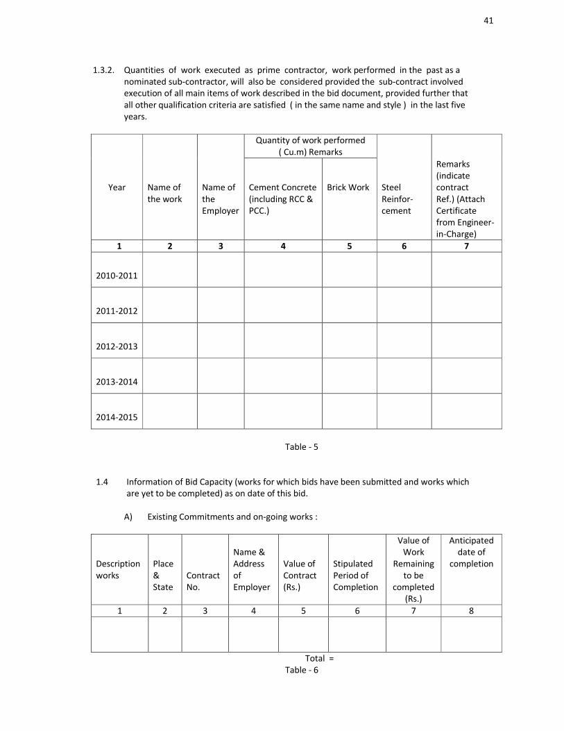
1.3.2. Quantities of work executed as prime contractor, work performed in the past as anominated sub-contractor, will also be considered provided the sub-contract involvedexecution of all main items of work described in the bid document, provided further thatall other qualification criteria are satisfied ( in the same name and style ) in the last five years.
Quantity of work performed( Cu.m) Remarks
Year Name of the work
Name of the Employer
Cement Concrete (including RCC & PCC.)
Brick Work Steel Reinfor-cement
Remarks (indicate contract Ref.) (Attach Certificate from Engineer-in-Charge)
1 2 3 4 5 6 7
2010-2011
2011-2012
2012-2013
2013-2014
2014-2015
Table - 5
1.4 Information of Bid Capacity (works for which bids have been submitted and works whichare yet to be completed) as on date of this bid.
A) Existing Commitments and on-going works :
Descriptionworks
Place&State
ContractNo.
Name &Address of Employer
Value ofContract(Rs.)
StipulatedPeriod ofCompletion
Value ofWork
Remaining to be
completed (Rs.)
Anticipated date of
completion
1 2 3 4 5 6 7 8
Total = Table - 6
42
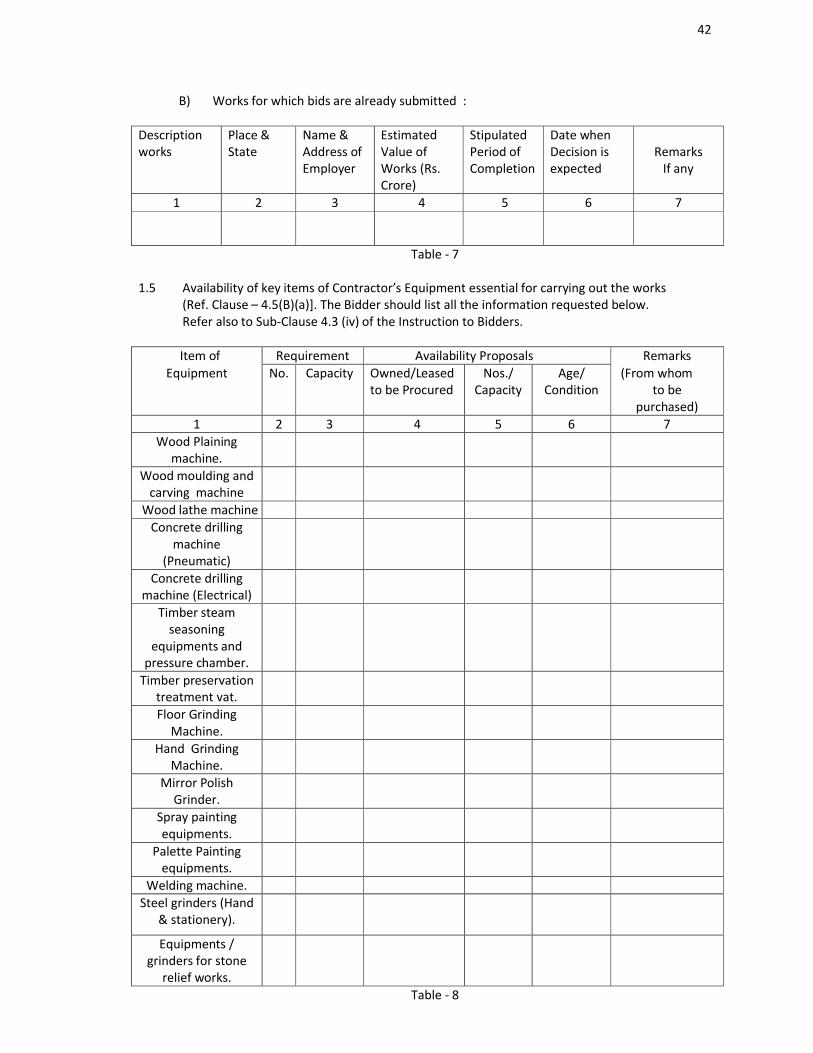
B) Works for which bids are already submitted :
Descriptionworks
Place &State
Name &Address of Employer
EstimatedValue ofWorks (Rs.Crore)
StipulatedPeriod ofCompletion
Date whenDecision isexpected
RemarksIf any
1 2 3 4 5 6 7
Table - 7
1.5 Availability of key items of Contractor’s Equipment essential for carrying out the works (Ref. Clause – 4.5(B)(a)]. The Bidder should list all the information requested below. Refer also to Sub-Clause 4.3 (iv) of the Instruction to Bidders.
Item of Requirement Availability Proposals RemarksEquipment No. Capacity Owned/Leased
to be ProcuredNos./
CapacityAge/
Condition(From whom
to be purchased)
1 2 3 4 5 6 7 Wood Plaining
machine.Wood moulding and
carving machineWood lathe machine
Concrete drilling machine
(Pneumatic)Concrete drilling
machine (Electrical)Timber steam
seasoning equipments and
pressure chamber.Timber preservation
treatment vat. Floor Grinding
Machine.Hand Grinding
Machine.Mirror Polish
Grinder.Spray painting equipments.
Palette Painting equipments.
Welding machine. Steel grinders (Hand
& stationery).
Equipments / grinders for stone
relief works.Table - 8
43
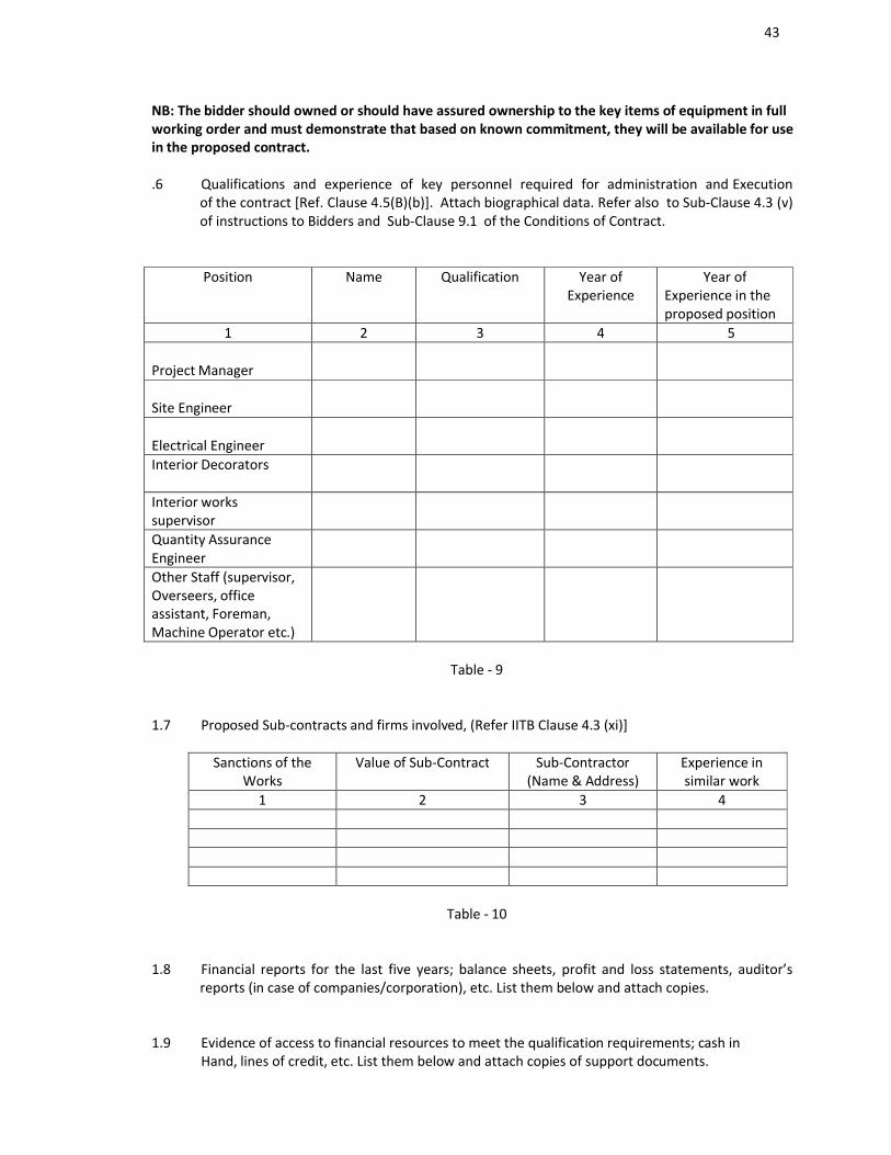
NB: The bidder should owned or should have assured ownership to the key items of equipment in full working order and must demonstrate that based on known commitment, they will be available for use in the proposed contract.
.6 Qualifications and experience of key personnel required for administration and Execution of the contract [Ref. Clause 4.5(B)(b)]. Attach biographical data. Refer also to Sub-Clause 4.3 (v) of instructions to Bidders and Sub-Clause 9.1 of the Conditions of Contract.
Position Name Qualification Year ofExperience
Year ofExperience in the proposed position
1 2 3 4 5
Project Manager
Site Engineer
Electrical Engineer Interior Decorators
Interior workssupervisorQuantity Assurance EngineerOther Staff (supervisor, Overseers, office assistant, Foreman, Machine Operator etc.)
Table - 9
1.7 Proposed Sub-contracts and firms involved, (Refer IITB Clause 4.3 (xi)]
Sanctions of the Works
Value of Sub-Contract Sub-Contractor(Name & Address)
Experience in similar work
1 2 3 4
Table - 10
1.8 Financial reports for the last five years; balance sheets, profit and loss statements, auditor’s reports (in case of companies/corporation), etc. List them below and attach copies.
1.9 Evidence of access to financial resources to meet the qualification requirements; cash inHand, lines of credit, etc. List them below and attach copies of support documents.
44
1.10. Name, address and telephone, telex and fax numbers of the bidder’s bankers who may provide references if contacted by the Chief Engineer, PWD (Bldg.), Chandmari, Guwahati – 3.
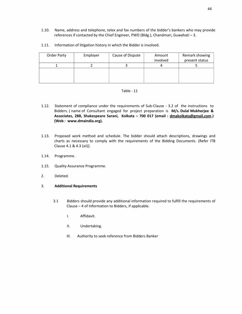
1.11. Information of litigation history in which the Bidder is involved.
Order Party Employer Cause of Dispute Amountinvolved
Remark showing present status
1 2 3 4 5
Table - 11
1.12. Statement of compliance under the requirements of Sub-Clause - 3.2 of the instructions to Bidders. ( name of Consultant engaged for project preparation is M/s. Dulal Mukherjee & Associates, 28B, Shakespeare Sarani, Kolkata – 700 017 (email : [email protected].) (Web : www.dmaindia.org).
1.13. Proposed work method and schedule. The bidder should attach descriptions, drawings and charts as necessary to comply with the requirements of the Bidding Documents. (Refer ITB Clause 4.1 & 4.3 (xii)].
1.14. Programme.
1.15. Quality Assurance Programme.
2. Deleted.
3. Additional Requirements
3.1 Bidders should provide any additional information required to fulfill the requirements of Clause – 4 of Information to Bidders, if applicable.
I. Affidavit.
II. Undertaking.
III. Authority to seek reference from Bidders Banker

45
SECTION 3
CONDITIONS OF CONTRACT
46
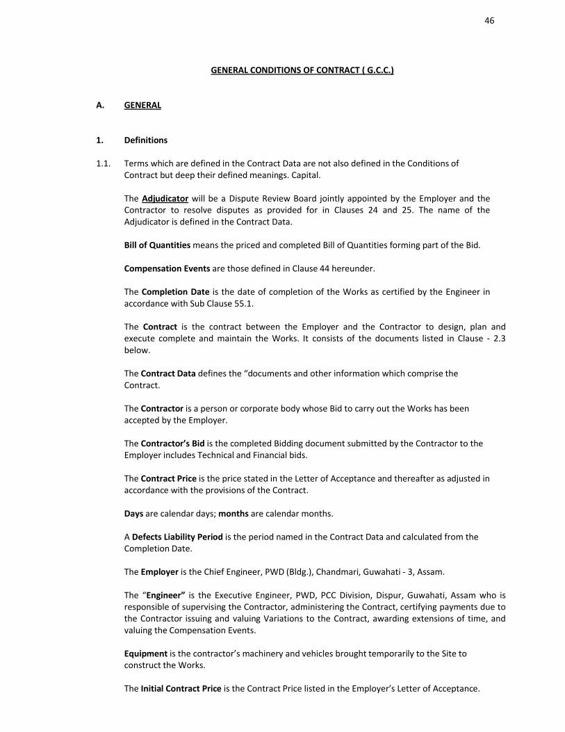
GENERAL CONDITIONS OF CONTRACT ( G.C.C.)
A. GENERAL
1. Definitions
1.1. Terms which are defined in the Contract Data are not also defined in the Conditions of Contract but deep their defined meanings. Capital.
The Adjudicator will be a Dispute Review Board jointly appointed by the Employer and the Contractor to resolve disputes as provided for in Clauses 24 and 25. The name of the Adjudicator is defined in the Contract Data.
Bill of Quantities means the priced and completed Bill of Quantities forming part of the Bid.
Compensation Events are those defined in Clause 44 hereunder.
The Completion Date is the date of completion of the Works as certified by the Engineer in accordance with Sub Clause 55.1.
The Contract is the contract between the Employer and the Contractor to design, plan and execute complete and maintain the Works. It consists of the documents listed in Clause - 2.3 below.
The Contract Data defines the “documents and other information which comprise the Contract.
The Contractor is a person or corporate body whose Bid to carry out the Works has been accepted by the Employer.
The Contractor’s Bid is the completed Bidding document submitted by the Contractor to the Employer includes Technical and Financial bids.
The Contract Price is the price stated in the Letter of Acceptance and thereafter as adjusted in accordance with the provisions of the Contract.
Days are calendar days; months are calendar months.
A Defects Liability Period is the period named in the Contract Data and calculated from the Completion Date.
The Employer is the Chief Engineer, PWD (Bldg.), Chandmari, Guwahati - 3, Assam.
The “Engineer” is the Executive Engineer, PWD, PCC Division, Dispur, Guwahati, Assam who is responsible of supervising the Contractor, administering the Contract, certifying payments due to the Contractor issuing and valuing Variations to the Contract, awarding extensions of time, and valuing the Compensation Events.
Equipment is the contractor’s machinery and vehicles brought temporarily to the Site to construct the Works.
The Initial Contract Price is the Contract Price listed in the Employer’s Letter of Acceptance.
47
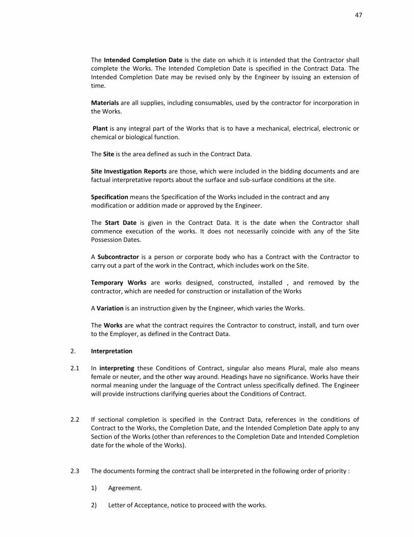
The Intended Completion Date is the date on which it is intended that the Contractor shall complete the Works. The Intended Completion Date is specified in the Contract Data. The Intended Completion Date may be revised only by the Engineer by issuing an extension of time.
Materials are all supplies, including consumables, used by the contractor for incorporation in the Works.
Plant is any integral part of the Works that is to have a mechanical, electrical, electronic or chemical or biological function.
The Site is the area defined as such in the Contract Data.
Site Investigation Reports are those, which were included in the bidding documents and are factual interpretative reports about the surface and sub-surface conditions at the site.
Specification means the Specification of the Works included in the contract and any modification or addition made or approved by the Engineer.
The Start Date is given in the Contract Data. It is the date when the Contractor shall commence execution of the works. It does not necessarily coincide with any of the Site Possession Dates.
A Subcontractor is a person or corporate body who has a Contract with the Contractor to carry out a part of the work in the Contract, which includes work on the Site.
Temporary Works are works designed, constructed, installed , and removed by the contractor, which are needed for construction or installation of the Works
A Variation is an instruction given by the Engineer, which varies the Works.
The Works are what the contract requires the Contractor to construct, install, and turn over to the Employer, as defined in the Contract Data.
2. Interpretation
2.1 In interpreting these Conditions of Contract, singular also means Plural, male also means female or neuter, and the other way around. Headings have no significance. Works have their normal meaning under the language of the Contract unless specifically defined. The Engineer will provide instructions clarifying queries about the Conditions of Contract.
2.2 If sectional completion is specified in the Contract Data, references in the conditions of Contract to the Works, the Completion Date, and the Intended Completion Date apply to any Section of the Works (other than references to the Completion Date and Intended Completion date for the whole of the Works).
2.3 The documents forming the contract shall be interpreted in the following order of priority :
1) Agreement.
2) Letter of Acceptance, notice to proceed with the works.
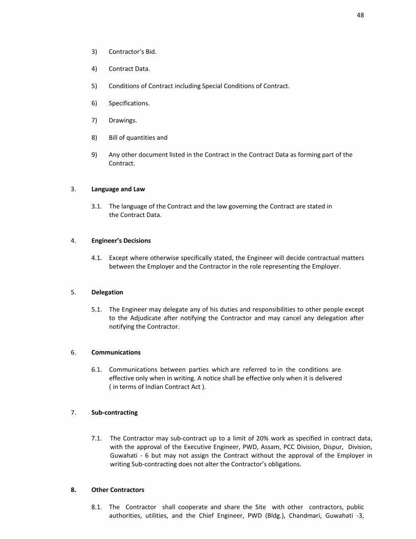
48
3) Contractor’s Bid.
4) Contract Data.
5) Conditions of Contract including Special Conditions of Contract.
6) Specifications.
7) Drawings.
8) Bill of quantities and
9) Any other document listed in the Contract in the Contract Data as forming part of the Contract.
3. Language and Law
3.1. The language of the Contract and the law governing the Contract are stated in the Contract Data.
4. Engineer’s Decisions
4.1. Except where otherwise specifically stated, the Engineer will decide contractual matters between the Employer and the Contractor in the role representing the Employer.
5. Delegation
5.1. The Engineer may delegate any of his duties and responsibilities to other people except to the Adjudicate after notifying the Contractor and may cancel any delegation after notifying the Contractor.
6. Communications
6.1. Communications between parties which are referred to in the conditions are effective only when in writing. A notice shall be effective only when it is delivered ( in terms of Indian Contract Act ).
7. Sub-contracting
7.1. The Contractor may sub-contract up to a limit of 20% work as specified in contract data, with the approval of the Executive Engineer, PWD, Assam, PCC Division, Dispur, Division, Guwahati - 6 but may not assign the Contract without the approval of the Employer in writing Sub-contracting does not alter the Contractor’s obligations.
8. Other Contractors
8.1. The Contractor shall cooperate and share the Site with other contractors, public authorities, utilities, and the Chief Engineer, PWD (Bldg.), Chandmari, Guwahati -3,
49
Assam, between the dates given in the Schedule of other Contracts. The Contractor shall as referred to in the Contract Data, also provide facilities and services for them as described in the Schedule. The Chief Engineer, PWD (Bldg.), Chandmari, Guwahati - 3, Assam may modify the schedule of other contractors and shall notify the contractor of any such modification.
9. Personnel
9.1. The Contractor shall employ the key personnel named in the Schedule of Key Personnel as referred to in the contract Data to carry out the functions stated in the Schedule or other personnel approved by the Engineer. The Engineer will approve any proposed replacement of key personnel only if their qualifications, abilities, and relevant experience are substantially equal to or better than those of the personnel listed in the Schedule.
9.2. If the Engineer asks the Contractor to remove a person who is a member of the Contractor’s staff or his work force stating the reasons the Contractor shall ensure that the person leaves the Site within seven days and has no further connection with the work in the Contract.
10. Employer’s and Contractor’s Risks
10.1. The Chief Engineer, PWD (Bldg.), Chandmari, Guwahati - 3, Assam carries the risks which this Contract states are contractor’s risks, and the contractor carries the risks, which this Contract states are contractor’s risks.
11. Employer’s Risks
11.1. The Chief Engineer, PWD (Bldg.), Chandmari, Guwahati - 3, Assam is responsible for the excepted risks which are (a) in so far as they directly affect the execution of the works in India, the risks of war, hostilities, invasion, act of foreign enemies, rebellion, revolution, insurrection or military or usurped power, civil war, riot commotion or disorder (unless restricted to the Contractor’s employees), and contamination from any nuclear fuel or nuclear waste or radioactive toxic explosive, or (b) a cause due solely to the design of the Works, other than the Contractor’s design.
12. Contractor’s Risks
12.1. All risks of loss of or damage to physical property and of personal injury and death which arise during and in consequence of the performance of the Contract other than the excepted risks are the responsibility of the Contractor.
13. Insurance
13.1. The Contractor shall provide, in the joint names of the Chief Engineer, PWD (Bldg.) , Chandmari, Guwahati-3, Assam and the Contractor, insurance cover from the Start Date to the end of the Defects Liability Period, in the amounts and deductibles stated in the Contract Data for the following events which are due to the contractor’s risks :
a) Loss of or damage to the Works, Plant and Materials;
b) Loss of or damage to Equipment;
50
c) Loss of or damage of property (except the Works, plant, Materials and Equipment) in connection with the contract; and
d) Personal injury or death.
13.2 Policies and certificates for Insurance shall be delivered by the Contractor to the Engineer for the Engineer’s approval before the Start Date. All such Insurance shall provide for compensation to be payable in the types and proportions of currencies required to rectify the loss or damage incurred.
13.3 If the Contractor does not provide any of the policies and certificates required, the Chief Engineer, PWD (Bldg.), Chandmari, Guwahati-3, Assam may effect the insurance which the Contractor should have provided and recover the premiums the Chief Engineer, PWD (Bldg.), Chandmari, Guwahati-3, Assam has paid from payments otherwise due to the contractor or, if no payment is due, the payment of the Premiums shall be a debt due.
13.4 Alterations to the terms of insurance shall not be made without the approval of the Engineer.
13.5 Both parties shall comply with any conditions of the Insurance policies.
14. Currency for payment
14.1. The currency of the contract is Indian Rupees.
15. Queries about the Contract Data
15.1 The Engineer will clarify queries on the Contract Data.
16. Contractor to Construct the Works
16.1 The Contractor shall construct and install the Works in accordance with the Specification and Drawings.
17. The Works to be completed by the Intended Completion Date
17.1 The contractor may commence execution of the Works on the Start Date and shall carry out the Works in accordance with the programmed submitted by the contractor, asupdated with the approval of the Engineer, and complete them by the Intended Completion Date.
18. Approval by the Engineer
18.1 The Contractor shall submit Specifications and Drawing showing the proposed Temporary Works to the Engineer, who is to approve them if they comply with the Specifications and Drawings.
51
18.2 The Contractor shall be responsible of design of Temporary Works.
18.3 The Engineer’s approval shall not alter the Contractor’s responsibility for design of the Temporary Works.
18.4 The Contractor shall obtain approval of third parties to the design of the Temporary Works where required.
18.5 All Drawings prepared by the Contractor for the execution of the temporary or permanent Works, are subject to prior approval by the Engineer before their use.
19. Safety
19.1 The Contractor shall be responsible of the safety of all activities on the Site.
20. Discoveries
20.1 Anything of his topical or other interest or of significant value unexpectedly discovered on the site is the property of the Chief Engineer, PWD (Bldg.), Chandmari, Guwahati - 3, Assam. The Contractor is to notify the Engineer of suchdiscoveries and carry out the Engineer’s instructions for dealing with them.
21. Possession of the Site
21.1 The Chief Engineer, PWD ( Bldg. ), Chandmari, Guwahati - 3, Assam / The Executive Engineer, PCC, Division, Dispur Guwahati - 6 shall give possession of the entire site at a time or part by part in a phased manner to the Contractor as stated in contract data.
22. Access to the Site
22.1 The Contractor shall allow the Engineer and any person authorized by the Engineer access to the Site, to any place where work in connection with the Contract is being carried out or is intended to be carried out and to any place where materials or plant are being manufactured / fabricated / assembled for the works.
23. Instructions
23.1 The Contractor shall carry out all instructions of the Engineer pertaining to works, which comply with the applicable laws where the Site is located.
23.2 The Contractor shall permit the Chief Engineer, PWD (Bldg.), Chandmari, Guwahati - 3, Assam to inspect the Contractor’s accounts and records relating to the performance of the Contractor and to have them audited by auditors appointed by the Chief Engineer, PWD (Bldg.), Chandmari, Guwahati - 3, Assam, if so required by the Employer
24. Disputes
24.1 If the Contractor believes that a decision taken by the Engineer was either outside the authority given to the Engineer by the Contract or that the decision was wrongly taken,
52
the decision shall be referred to the dispute Review Board within 14 days of the notification of the Engineer’s decision. If the decision is not referred to the Dispute Review Board within 14 days of the notification of the Engineer’s decision, the matter will be time barred.
25. Procedure for Disputes
25.1 The Dispute Review Board shall be constituted with three members, one from Employer, One from Contractor and the other to be nominated jointly by the above two members to give a decision in writing within 28 days of receipt of a notification of a dispute.
25.2 The Dispute Review Board shall be paid daily at the rate specified in the Contract Data together with reimbursable expenses of types specified in the Contract Data and the cost shall be divided equally between the Chief Engineer, PWD (Bldg.),Chandmari, Guwahati - 3, Assam and the Contractor, whatever decision is reached by the Dispute Review Board. Either party may give notice to the other to refer a decision of the Dispute Review Board to an Arbitrator within 28 days of the Dispute Review Board’s written decision. If neither party refers the dispute to arbitration within the next 28 days, the Dispute Review Board’s decision will be final and binding.
25.3 The arbitration shall be conducted in accordance with the arbitration procedure stated in the Special Conditions of Contract (SCC)
26. The Replacement of Dispute Review Board
26.1 Should any member of the Dispute Review Board resign or die, or should the Chief Engineer, PWD ( Bldg. ), Chandmari, Guwahati - 3, Assam and the Contractor agree that the Dispute Review Board is not fulfilling their functions inaccordance with the provisions of the Contract, a new Dispute Review Board will be jointly appointed by the Chief Engineer, PWD ( Bldg. ), Chandmari, Guwahati - 3, Assam and the contractor. In case of disagreement between the Employer and the Contractor, within 30 days, the Dispute Review Board shall be designated by the Appointing Authority designated in the Contract Data at the request of either party, within 14 days of receipt of such request.
B. TIME CONTROL
27. Programme
27.1. Within the time stated in the Contract Data the contractor shall submit to the engineer for approval a Programme showing the general methods, arrangements, order, timing for all the activities in the Works along with monthly cash flow forecast.
27.2. An update of the Programme shall be a programme showing the actual progress achieved on each activity and the effect of the progress achieved on the timing of the remaining work including any changes to the sequence of the activities.
53
27.3. The Contractor shall submit to the Engineer, for approval, an updated Programme at intervals no longer than the period stated in the Contract Data. If the Contractor does not submit an updated Programme within this period, the Engineer may withhold the amount stated in the Contract Data from the next payment certificate and continue to withhold this amount until the next payment after the date on which the overdue programme has been submitted.
27.4. The Engineer’s approval of the programme shall not alter the Contractor’s obligations. The Contractor may revise the Programme and submit it to the Engineer again at any time. A revised Programme is to show the effect of Variations and Compensation Events.
28. Extension of the Intended Completion Date
28.1. The Engineer shall extend the Intended Completion Date if a Compensation Event occurs or a Variation is issued which makes it impossible for Completion to be achieved by the Intended Completion Date without the Contractor taking steps to accelerate the remaining work and which would cause the Contractor to incur additional cost.
28.2. The Engineer shall decide whether and by how much to extend the Intended Completion Date within 35 days of the Contractor asking the Engineer for decision upon the effect of a Compensation Event or Variation and submitting full supporting information. If the Contractor has failed to give early warning of a delay or has failed to cooperate in dealing with a delay, the delay by this failure shall not be considered in assessing the new Intended Completion Date.
28.3. The Engineer shall within 14 days of receiving full justification from the contractor for extension of Intended Completion Date refer to the Employer his decision. The Employer shall in not more than 21 days communicate to the Engineer the acceptance or otherwise of the Engineer’s decision.
29. Deleted
30. Delays Ordered by the Engineer
30.1 The Engineer may instruct the Contractor to delay the start or progress of any activity within the works.
31. Management meetings
31.1 Either the Engineer or the Contractor may require the other to attend a management meeting. The business of a management meeting shall be to review the plans for remaining work and to deal with matters raised in accordance with the early warning procedure.
31.2 The Engineer shall record the business of management meetings and is to provide
54
copies of his record to those attending the meeting and to the Chief Engineer, PWD (Bldg.), Chandmari, Guwahati-3, Assam. The responsibility of the parties of actions to be taken is to be decided by the Engineer either at the management meeting or after the management meeting and stated in writing to all who attended the meeting.
32. Early Warning
32.1 The Contractor is to warn the Engineer at the earliest opportunity of specific likely future events or circumstances that may adversely affect the quality of the work increase the Contract Price or delay the execution of works. The Engineer may require the Contractor to provide an estimate of the expected effect of the future event or circumstance on the Contract Price and completion Date. The estimate is to be provided by the Contractor as soon as reasonably possible.
32.2 The Contractor shall cooperate with the Engineer in making and considering proposals for how the effect of such an event or circumstance can be avoided or reduced by anyone involved in the work and in carrying out any resulting instruction of the Engineer.
55
C. QUALITY CONTROL
33. Identifying Defects
33.1 The Engineer shall check the Contractor’s work and notify the Contractor of any defects that are found. Such checking shall not affect the contractor’s responsibilities. The Engineer may instruct the Contractor to search for a Defect and to uncover and test any work that the Engineer considers may have a defect.
34. Tests
34.1 If the Engineer instructs the Contractor to carry out a test not specified in the Specification to check whether any work has a effect and the test shows that it does, the Contractor shall pay for the test and any samples.
35. Correction of Defects
35.1 The Engineer shall give notice to the Contractor of any Defects before the end of theDefects Liability Period, which begins at completion and is defined in the Contract Data. The Defects Liability Period shall be extended for as long as Defects remain to be corrected.
35.1 Every time notice of a Defect is given, the Contractor shall correct the notified Defect within the length of time specified by the Engineer’s notice.
36. Uncorrected Defects
36.1 If the Contractor has not corrected a Defect within the time specified in the Engineer’s notice, the Engineer will assess the cost of having the Defect corrected, and the Contractor will pay this amount.
56
D. COST CONTROL
37. Bill of Quantities
37.1 The Bill of Quantities shall contain items for the construction and installation, work to be done by the Contractor.
37.2 The Bill of Quantities is used to calculate the Contract Price. The Contractor is paid for the quantity of the work done at the rate in the Bill of Quantities for each item.
38. Changes in the Quantities
38.1 If the final quantity of the work done differs from the quantity in the Bill of Quantities for the particular item by more than 25 percent provided the change is attributed to the Department i.e., either the B.O.Q. is prepared by the department or variation is due to change / modification ordered by the Department and the same exceeds 1% of initial Contract Price, the Engineer shall adjust the rate to allow for the change, duly considering,
a) Justification for rate adjustment as furnished by the contractor,
b) Economies resulting from increase in quantities by way of reduced plant, equipment, and overhead costs.
c) Entitlement of contractor to compensation events where such events are caused by any additional work.
38.2 The Engineer shall not adjust rates from changes in quantities if thereby the Initial Contract Price is exceeded by more than 15 per cent, except with the prior approval of the Chief Engineer, PWD (Bldg.), Chandmari, Guwahati-3, Assam.
38.3 If requested by the Engineer, the Contractor shall provide the Engineer with a detailed cost break down of any rate in the Bill of Quantities.
39. Variations
39.1 All Variations shall be included in updated Programmes produced by the Contractor.
39.2 The Engineer shall find out and evaluate all the probable variations in the early period of the contract and submit the same to the Chief Engineer, PWD (Bldg.), Chandmari, Guwahati - 3, Assam.
40. Payments for Variations
40.1 The contractor shall provide the Engineer with a quotation (with break down of unit rates) for carrying out the Variation when requested to do so by the Engineer. The Engineer shall assess the quotation, which shall be given within seven days of the request or within any longer period stated by the Engineer and before the Variation
57
is ordered. The Engineer shall send the rate so assessed to the Chief Engineer, P.W.D. (Bldg.), Assam for approval.
40.2 If the work in the Variation corresponds with an item description in the Bill of Quantities and if, in the opinion of Engineer, the quantity of work above the limit stated in Sub Clause 38.1 or the; timing of its execution do not cause the cost per unit of quantity to change, the rate in the Bill of quantities shall be used to calculate the value of the Variation. If the Cost per unit of quantity changes, or if the nature or timing of the work in the Variation does not correspond with items in the Bill of Quantities, the quotation by the contractor shall be in the form of new rates for the relevant items of work..
40.3 If the Contractor’s quotation is unreasonable, the Engineer may order the Variation and make a change to the Contract Price, which shall be based on Engineer’s own forecaster of the effects of the Variation on the contractor’s costs.
40.4 If the Engineer decides that the urgency of varying the work would prevent a quotation being given and considered without delaying the work, the Engineer shall allow the contractor to proceed with the work using materials having I.S. marks/ approved brand as specified in the A.P.W.D.S.O.R. obtained from approved dealers of the company. The Engineer shall collect the quotation for himself and assess the cost/ rate of the item considering all aspects and submit the same to the Chief Engineer, PWD (Bldg.), Chandmari,Guwahati-3, Assam for approval.
40.5 The contractor shall not be entitled to additional payment for costs, which could have been avoided by giving early warning. No claim of any kind will be entertained for delays in payments.
41. Cash Flow Forecasts
41.1 When the Programme is updated, the contractor is to provide the Engineer with an updated cash flow forecast.
42. Payment Certificates
42.1 The Contractor shall submit to the Engineer monthly statements of the estimated value of the work completed less the cumulative amount certified previously.
42.2 The Engineer shall check the Contractor’s monthly statement within 14 days and certify the amount to be paid to the contractor after taking into account any credit or debit for the month in question in respect of materials for the works in the relevant amounts and under conditions set forth in sub-clause 51(3) of the Contract Data (Secured advance). The payment will be made according to the availability of fund.
42.3 The value of work executed shall be determined by the Engineer.
42.4 The value of work executed shall comprise the value of the quantities of the items in
58
the Bill of Quantities completed.
42.5 The value of work executed shall include the valuation of variations and Compensation Events.
42.6 The Engineer may exclude any item certified in a previous certificate or reduce the proportion of any item previously certified in any certificate in the light of later information.
43. Payments
43.1 Payments shall be adjusted for deductions for advance payments, retention, other recoveries in terms of the contract and taxes at source, as applicable under the law. The Employer shall pay the Contractor the amounts certified by the Engineer within a reasonable time subject to the availability of fund. The Engineer/ Employer shall not delay the payment unreasonably (i.e., without valid reasons), if fund is available.
43.2 If an amount certified is increased in a later certificate as a result of an award by the Dispute Review Board, the contractor shall be paid interest upon the delayed payment as set out in this clause. Interest shall be calculated from the date upon which the increased amount would have been certified in the absence of dispute. The interest rate will be the Bank’s minimum lending rate prevailing at that time.
43.3 Items of the Works for which no rate or price has been entered in will not be paid for by the Employer and shall be deemed covered by other rates and prices in the contract.
43.4 Payments shall be made subject to availability of fund. The non-payment of bills due to non-availability of fund will not be a ground for compensation or any other claim whatsoever.
44. Compensation Events
44.1 The following are Compensation Events unless they are caused by the contractor.
a) The employer does not give access to a part of the Site by the site possession date stated in the contract Data.
b) The Employer modifies the schedule of other contractors in a way, which affects the work of the contractor under the contract.
c) Engineer orders a delay or does not issue drawings, specifications or instructions required for execution of works on time.
d) The Deleted.
e) The Engineer unreasonably does not approve of a subcontract to be let, within 15 days.
f) Deleted.
g) The Engineer gives an instruction for dealing with an unforeseen condition, caused by the Employer, or additional work required for safety or other reasons.
59
h) Other contractors, public authorities, utilities or the Employer does not work within the dates and other constraints stated in the contract, and they cause delay or extra cost to the contractor.
i) Deleted.
j) The effect on the contractor or any of the Employer’s risks.
k) The Engineer unreasonably delays issuing a Certificate of Completion.
l) Other Compensation Events listed in the Contract Data or mentioned in the Contract.
44.2 If compensation Event would cause additional cost or would prevent the work being completed before the Intended Completion Time, the Date, the Contract price shall be increased and / or the Intended Completion Date is extended. The Engineer shall decide whether and by how much the Contract Price shall be extended.
44.3 As soon as information demonstrating the effect of each Compensation Event upon the contractor, it is to be assessed by the Engineer and the contract price shall be adjusted accordingly. If the Contractor’s forecast is deemed unreasonable the Engineer shall adjust the contract price based on Engineer’s own forecast. The Engineer will assume that the contractor will react competently and promptly to the event.
44.4 The Contractor shall not be entitled to compensation to the extend that the Employer’s interests are adversely affected by the Contractor not having given early warning or not having cooperated with the Engineer.
45. Tax
45.1 The rates quoted by the contractor shall be deemed to be inclusive of the VAT, sales, labour cess and any other taxes that the Contractor will have to pay for the performance of this contract. The Employer will perform such duties in regard to the deduction of such taxes at source as per applicable law.
46. Currencies
46.1 All payments shall be made in Indian rupees.
47. Price Adjustment
No price adjustment will be allowed during the contract period.
48. Retention
48.1 The Employer shall retain from each payment due to the contractor the proportion stated in the Contract Data until Completion of the whole of the Works.
48.2 On completion of whole of the Works half the total amount retained is repaid to the Contractor and half when the Defects Liability Period has passed and the Engineer has certified that all Defects notified by the Engineer to the Contractor before the
60
end of this period have been corrected.
48.3 On completion of the whole works, the contractor may substitute retention money with an “on demand” Bank guarantee.
49. Liquidated Damages
49.1 The Contractor shall pay liquidated damages to the Employer at the rate per day stated in the contract data for each day that the completion date is later than the intended completion date (for the whole of the works for the milestone as stated in the contract data). The total amount of liquidated damages shall not exceed the amount defined in the contract Data. The Employer may deduct liquidated damages from payments due to the Contractor. Payment of liquidated damages does not affect the Contractor’s liabilities.
49.2 If the Intended Completion Date is extended after liquidated damages have been paid, the Engineer shall correct any overpayment of liquidated damages by the contractor by adjusting the next payment certificate. The contractor shall be paid interest on the over payment calculated from the date of payment to the date of repayment at the rates specified in Sub Clause - 43.1.
If the contractor fails to comply with the time for completion as stipulated in the bid, then the contractor shall pay to the employer the relevant sum stated in the contract data as liquidated damages for such default and not as penalty for everyday or part of day which elapse between relevant time for completion and the date stated in the taking over certificate of the whole of the works on the relevant sections, subject topthe limit stated in the contract data.
49.3 The employer may without prejudice to any other method of recovery deduct the amount of such damages from any monies due or to decode due to the contractor. The payment or deduction of such damages shall not relieve the contractor from his obligation to complete the works on form any other of his obligations and liabilities under the contract.
49.4. If, before the Time for Completion of the whole of the Works or, if applicable, any Section, a Taking – Over Certificate has been issued for any part of the works or of a section, the liquidated damages for delay in completion of the remainder of the Works or of that Section shall, for any period of delay after the date stated in such Taking-Over Certificate, and in the absence of alternative provisions in the Contract, be reduced in the proportion which the value of the part so certified bears to the value of the whole of the Works or section, a applicable. The provisions of this Sub-Clause shall only apply to the rate of liquidated damages and shall not affect the limit thereof.
50. Deleted
51. Advance Payment
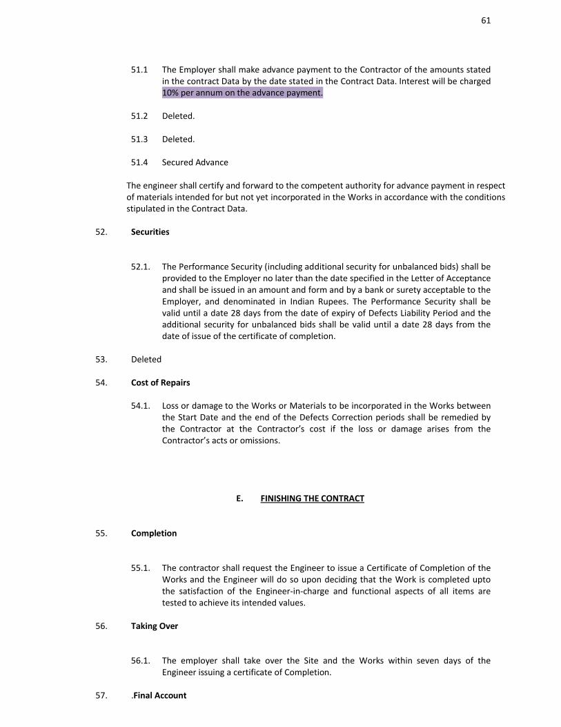
61
51.1 The Employer shall make advance payment to the Contractor of the amounts stated in the contract Data by the date stated in the Contract Data. Interest will be charged 10% per annum on the advance payment.
51.2 Deleted.
51.3 Deleted.
51.4 Secured Advance
The engineer shall certify and forward to the competent authority for advance payment in respect of materials intended for but not yet incorporated in the Works in accordance with the conditions stipulated in the Contract Data.
52. Securities
52.1. The Performance Security (including additional security for unbalanced bids) shall be provided to the Employer no later than the date specified in the Letter of Acceptance and shall be issued in an amount and form and by a bank or surety acceptable to the Employer, and denominated in Indian Rupees. The Performance Security shall be valid until a date 28 days from the date of expiry of Defects Liability Period and the additional security for unbalanced bids shall be valid until a date 28 days from the date of issue of the certificate of completion.
53. Deleted
54. Cost of Repairs
54.1. Loss or damage to the Works or Materials to be incorporated in the Works between the Start Date and the end of the Defects Correction periods shall be remedied by the Contractor at the Contractor’s cost if the loss or damage arises from the Contractor’s acts or omissions.
E. FINISHING THE CONTRACT
55. Completion
55.1. The contractor shall request the Engineer to issue a Certificate of Completion of the Works and the Engineer will do so upon deciding that the Work is completed upto the satisfaction of the Engineer-in-charge and functional aspects of all items are tested to achieve its intended values.
56. Taking Over
56.1. The employer shall take over the Site and the Works within seven days of the Engineer issuing a certificate of Completion.
57. .Final Account
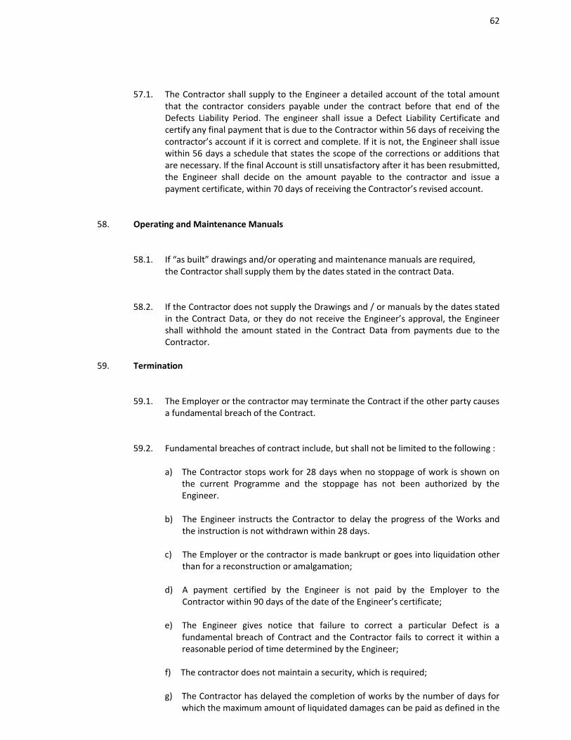
62
57.1. The Contractor shall supply to the Engineer a detailed account of the total amount that the contractor considers payable under the contract before that end of the Defects Liability Period. The engineer shall issue a Defect Liability Certificate and certify any final payment that is due to the Contractor within 56 days of receiving the contractor’s account if it is correct and complete. If it is not, the Engineer shall issue within 56 days a schedule that states the scope of the corrections or additions that are necessary. If the final Account is still unsatisfactory after it has been resubmitted, the Engineer shall decide on the amount payable to the contractor and issue a payment certificate, within 70 days of receiving the Contractor’s revised account.
58. Operating and Maintenance Manuals
58.1. If “as built” drawings and/or operating and maintenance manuals are required, the Contractor shall supply them by the dates stated in the contract Data.
58.2. If the Contractor does not supply the Drawings and / or manuals by the dates stated in the Contract Data, or they do not receive the Engineer’s approval, the Engineer shall withhold the amount stated in the Contract Data from payments due to the Contractor.
59. Termination
59.1. The Employer or the contractor may terminate the Contract if the other party causes a fundamental breach of the Contract.
59.2. Fundamental breaches of contract include, but shall not be limited to the following :
a) The Contractor stops work for 28 days when no stoppage of work is shown on the current Programme and the stoppage has not been authorized by the Engineer.
b) The Engineer instructs the Contractor to delay the progress of the Works and the instruction is not withdrawn within 28 days.
c) The Employer or the contractor is made bankrupt or goes into liquidation other than for a reconstruction or amalgamation;
d) A payment certified by the Engineer is not paid by the Employer to the Contractor within 90 days of the date of the Engineer’s certificate;
e) The Engineer gives notice that failure to correct a particular Defect is a fundamental breach of Contract and the Contractor fails to correct it within a reasonable period of time determined by the Engineer;
f) The contractor does not maintain a security, which is required;
g) The Contractor has delayed the completion of works by the number of days for which the maximum amount of liquidated damages can be paid as defined in the
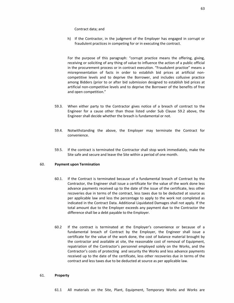
63
Contract data; and
h) If the Contractor, in the judgment of the Employer has engaged in corrupt or fraudulent practices in competing for or in executing the contract.
For the purpose of this paragraph: “corrupt practice means the offering, giving, receiving or soliciting of any thing of value to influence the action of a public official in the procurement process or in contract execution. “Fraudulent practice” means a misrepresentation of facts in order to establish bid prices at artificial non-competitive levels and to deprive the Borrower, and includes collusive practice among Bidders (prior to or after bid submission designed to establish bid prices at artificial non-competitive levels and to deprive the Borrower of the benefits of free and open competition.”
59.3. When either party to the Contractor gives notice of a breach of contract to the Engineer for a cause other than those listed under Sub Clause 59.2 above, the Engineer shall decide whether the breach is fundamental or not.
59.4. Notwithstanding the above, the Employer may terminate the Contract for convenience.
59.5. If the contract is terminated the Contractor shall stop work immediately, make the Site safe and secure and leave the Site within a period of one month.
60. Payment upon Termination
60.1. If the Contract is terminated because of a fundamental breach of Contract by the Contractor, the Engineer shall issue a certificate for the value of the work done less advance payments received up to the date of the issue of the certificate, less other recoveries due in terms of the contract, less taxes due to be deducted at source as per applicable law and less the percentage to apply to the work not completed as indicated in the Contract Data. Additional Liquidated Damages shall not apply. If the total amount due to the Employer exceeds any payment due to the Contractor the difference shall be a debt payable to the Employer.
60.2 If the contract is terminated at the Employer’s convenience or because of a fundamental breach of Contract by the Employer, the Engineer shall issue a certificate for the value of the work done, the cost of balance material brought by the contractor and available at site, the reasonable cost of removal of Equipment, repatriation of the Contractor’s personnel employed solely on the Works, and the Contractor’s costs of protecting and security the Works and less advance payments received up to the date of the certificate, less other recoveries due in terms of the contract and less taxes due to be deducted at source as per applicable law.
61. Property
61.1 All materials on the Site, Plant, Equipment, Temporary Works and Works are
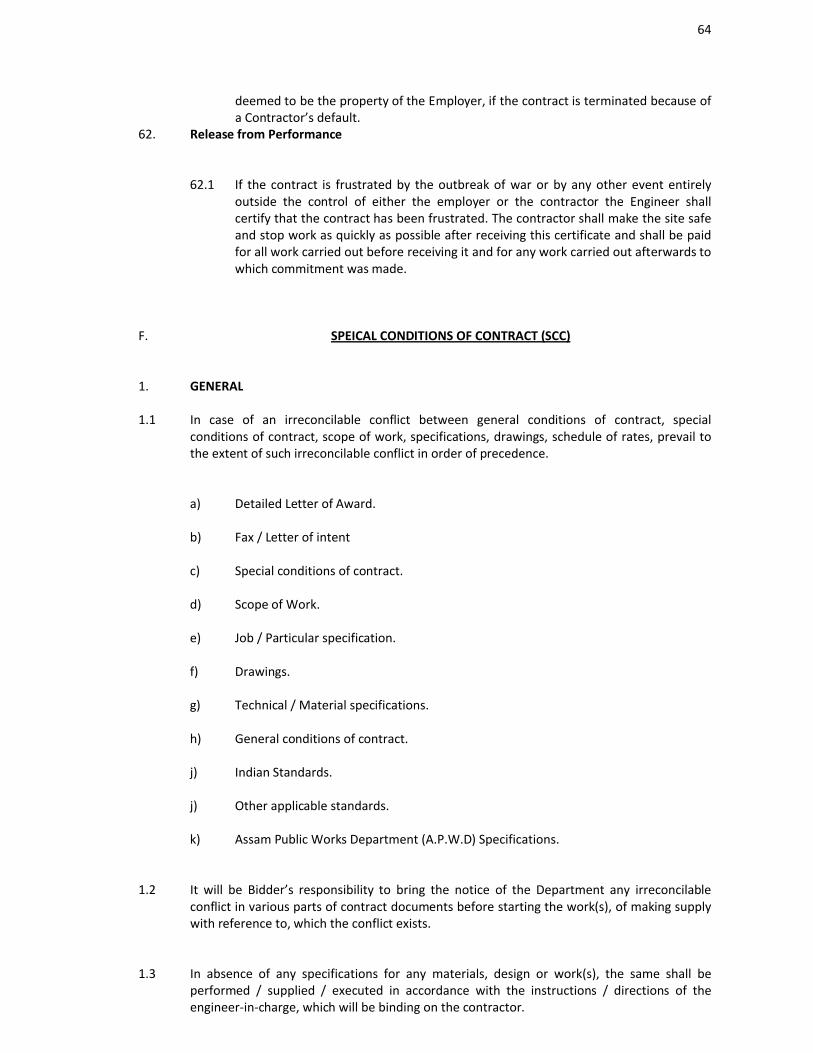
64
deemed to be the property of the Employer, if the contract is terminated because of a Contractor’s default.
62. Release from Performance
62.1 If the contract is frustrated by the outbreak of war or by any other event entirely outside the control of either the employer or the contractor the Engineer shall certify that the contract has been frustrated. The contractor shall make the site safe and stop work as quickly as possible after receiving this certificate and shall be paid for all work carried out before receiving it and for any work carried out afterwards to which commitment was made.
F. SPEICAL CONDITIONS OF CONTRACT (SCC)
1. GENERAL
1.1 In case of an irreconcilable conflict between general conditions of contract, special conditions of contract, scope of work, specifications, drawings, schedule of rates, prevail to the extent of such irreconcilable conflict in order of precedence.
a) Detailed Letter of Award.
b) Fax / Letter of intent
c) Special conditions of contract.
d) Scope of Work.
e) Job / Particular specification.
f) Drawings.
g) Technical / Material specifications.
h) General conditions of contract.
j) Indian Standards.
j) Other applicable standards.
k) Assam Public Works Department (A.P.W.D) Specifications.
1.2 It will be Bidder’s responsibility to bring the notice of the Department any irreconcilable conflict in various parts of contract documents before starting the work(s), of making supply with reference to, which the conflict exists.
1.3 In absence of any specifications for any materials, design or work(s), the same shall be performed / supplied / executed in accordance with the instructions / directions of the engineer-in-charge, which will be binding on the contractor.
65
2. SITE INFORMATION
2.1. The Project site is situated at Dispur, Guwahati, Assam.
2.2 The intending bidder shall be deemed to have visited the site and familiarized themselves with site conditions before submitting their bids at their own cost and responsibility.
3 SCOPE OF WORK
3.1 The scope of work shall include inter-alias, the carrying out of any / all works, and providing any and all facilities, as required, for completing all the works as per terms and conditions of contract documents.
3.2 No materials shall be supplied by the Department. Bidder will have to procure all materials, Labour, T&P and any other arrangements for proper execution of the work and to be of the best quality and workmanship in all respect as per relevant I.S. code of practices and A.P.W.D. general specification.
The lack of road communication during flood seasons will not be considered as a ground for extension of time of completion of the work and escalation of rates.
4. CEMENT
4.1 The Contractor will have to submit their design mix for different grades of concrete, keeping in view the requirements stipulated in specific gravity of materials brought to site as analyzed in the laboratories. The design shall be based upon absolute volume method and theoretical consumption of cement shall be worked on this basis. For other than concrete items, the coefficient for consumption of cement shall be adopted as per APWD practice and relevant IS Codes. Cement required for the work shall be procured by the Contractor only from manufacturer or their authorized dealer directly to ensure quality to their product.Cement of brand conforming to BIS specification only be used subject to the approval of Engineer-in-charge.Super plasticizer shall have to be used in all concreting works e.g. Choksey, Sika wherever required.
4.2. The Contractor shall maintain a goods store for storing cement. The flooring of the storage house, the clearance of cement bags from the sidewalls etc shall be a instructed by the Engineer-In-Charge or his authorized representatives..
4.3. The cement store shall be open for supervision and verification by the Engineer-in-charge or his authorized representatives at any time when he feels the need to do so along with the Contractor’s representatives
5. REINFORCEMENT BARS
5.1. Reinforcement bars to be used should be in conformity with relevant IS code of Practice.

66
Steel reinforcement required for the work shall be procured from manufacture or their authorized dealer directly to ensure proper quality of steel. Super ductile T.M.T. Re-bars manufactured by SAIL / TATA can only be used.
The Engineer-in-Charge shall conduct necessary tests as per codes of practice on all construction materials and maintain the test reports and submit the same to the Chief Engineer, PWD (Bldg.), Chandmari, Guwahati – 3.
6. TIME SCHEDULE
6.1. Time is the essence of the Contract. The work shall be executed strictly as per the Time-Schedule attached separately in the Bid document.
7. PROJECT SCHEDULING AND MONITORING
7.1 The following Schedules / documents / reports shall be prepared and submitted by the contractor for review / approval at various stages of the Contract.
8. ALONG WITH BID
a) Time Schedule.
The Bidder is required to submit a Project Time Schedule as stated in Clause along with the Bid. The Schedule shall cover all aspects like Planning, Designing, Execution, Sub-Ordering and Delivery, Sub-Contracting and within the completion time indicated in the bid Document. The Department interface activities shall be clearly identified with their latest required dates. Department reserves the right to disqualify the Bid if the above Schedule submitted by the Bidder is not in line with the over all Project requirements.
b) Scheduling and Monitoring System
The Bidder should describe their system of Project Scheduling and Monitoring the extent of Computerization Level of Detailing, Track Methodology etc. with the name of Computer Packages and sample outputs.
9. AFTER THE AWARD OF CONTRACT
a) Overall Project Schedule
The Contractor shall submit within 2 (Two) weeks of Letter of Intent, a sufficiently detailed overall Project schedule (in Prima Vera/ MS Project) indicating the inter relationship / inter dependence between various events and tasks.
The project schedule will be reviewed and approved by the Department and the comments if any shall be incorporated in the network before issuing the same for implementation. The Project Schedule thus finalized shall form part of the Contract Document and the same shall not be revised without prior permission from the Department during the entire period of the contract.
b) The contractor shall also submit one quality assurance plan and work programme -showing completion of the work in Prima Vera/MS Project with events and tasks.
67
c) Progress Measurement Methodology
The contractor is required to submit within two weeks of award of work, the methodology of progress measurement of planning, designing, execution., sub-ordering and delivery, sub-contracting, and commissioning of works and the basis of computation of overall services / physical progress informed. Department reserves the right to modify the methodology in part or in full.
d) The Bidder should prepare detailed functional schedule in line with network forfunctional monitoring and control and submit scheduled progress curves for each function viz., Planning, Designing, Execution, Ordering, Delivery and Commissioning.
10. PROJECT REVIEW MEETINGS
The Bidder shall present the programme and status at various review meetings as required.
A) Monthly Review Meeting :
Level of Participation :
i) Senior Officer PWD (Bldg.) Department.
ii) The concerned Executive Engineer.
iii) A member (MLA or Minister) to be deputed by Speaker of the Assam Legislative Assembly.
iv) The contractor or his authorized representatives.
v) A representative from the Consultant’s organization.
Agenda :.
a) Progress status / statistics.
b) Completion outlook.
c) Major Hold Ups / Slippages.
d) Assistance Required.
e) Critical Issues.
f) Depts. Query/Approval.
g) Progress Updating.
Venue : Office of the Chief Engineer, PWD(Bldg.), Chandmari, Guwahati-3
68
10.1 PROGRESS REPORTS
This report shall be submitted on a monthly basis within ten calendar days from cut-off date as agreed upon, covering overall scenario of the work. The report shall include but not be limited, to the following :
a) Brief Introduction of the Work.
b) Activities Executed/ Achievements during the Month.
c) Schedule v/s actual cumulative percentage progress and progress curves for sub-contracting and overall and quantum wise status of purchase orders against schedule.
d) Area of Concern/ Problem/ Hold Ups, Impact and action plans.
e) Resources deployment status.
f) Annexure giving summary for materials requirements and deliveries, sub-contracting and construction.
11. PRICE SCHEDULE WITH PRICE BID
11.1 The rates of price bid shall be read in conjunction of special conditions of contract, General Conditions of contract, Scope of work, scope of supply, Technical specifications, drawings and any other document forming a part of this contract.
11.2. All expenses towards mobilization at site and demobilization including bringing in equipment, work force, materials, dismantling the equipment, clearing the site, etc. shall be deemed to be included in the rates quoted and no separate payment on account of such expenses shall be entertained.
12. MOBILISATION ADVANCE LOAN
12.1 The contractor is entitled for an interest free advance loan for the cost of mobilization in respect of works in lump sum amount equivalent to 5% of Tender value payable in one installment. Payment of loan will be due under separate certification by the Engineer in charge after.
a) Execution of form of agreement by the parties thereto.
b) Providing by the Contractor 5% of Performance Security in accordance with bid clause.
c) Providing by the contractor a non-revocable bank guarantee by a nationalized bank acceptable to the department in an amount equal to the mobilization advance loan. Such bank guarantee to remain effective until the advance loan has been completely repaid by the contractor out of current earning under the contract and certified by the Engineer-in-charge. A form of Bank Guarantee acceptable to the Dept. is indicated in Annexure-X for payment of mobilization advance loan as per this clause.
69
d) The mobilization advance loan shall be used by the contractor exclusively for mobilization expenditure in connection with the works, should the contractor misappropriate any portion of the advance loan, it shall become due and payable to the Chief Engineer, PWD (Building) Assam, Chandmari, Guwahati-3, Assam immediately and no further loan will be made to the contractor thereafter.
e) Repayment of Mobilization advance loan shall commence immediately after commencement of the work and shall be entered as a deduction in the first bill andsubsequent interim payment certificate in equal installment until the total amount of advance loan has been repaid by the contractor. The entire amount shall be recovered before 75% of work completed, payment of mobilization advance by itself shall not be considered as first interim payment to contractor. Percentage of progress referred to shall be reckoned with reference to the gross value of work done as shown in bill.
13. PRICE ADJUSTMENT
The rates and price quoted by the contractor shall be fixed for the duration of the contract and shall not be subjected to adjustment on any account.
14. MEASUREMENT OF WORK
In addition to the provisions of Clause of the General Condition of Contract and associated provision thereof the following provisions shall applicable.
14.1 Payment will be made on the basis of joint measurements, taken by contractor and certified by the Engineer-In-Charge. Measurement shall be based on drawings approved for construction to the extent that the work conforms to the drawings and details are adequate.
14.2 Wherever work is executed based on instruction of Engineer-In-Charge or details are not adequate in the drawings, physical measurement shall be taken by the contractor in the presence of authorized representatives of Engineer-In-Charge.
14.3 Measurement of weight shall be in Metric Tonnes/ Quintal, correct to the nearest kilogram, linear measurements shall be in meters, correct to the nearest centimeter.
14.4 Measurements shall be taken over finished surface in all cases.
15. TERMS OF PAYMENT
All interim payments to the contractor will be made by Engineer-In-Charge on the basis of price bid rates of as the case may be. The Department reserves the rights to alter the percentage breakup for price bid items rate submitted by the contractor were found reasonably and necessary, which shall be binding on contractor.
16. INCOME TAXIncome tax at the prevailing rate as applicable from time to time shall be deducted from the contractor’s bills as per Income Tax Act, and quoted rates shall be deemed to include the same.
70
17. TAXES, DUTIES AND OTHER LEVIESWithout prejudice to stipulations in general conditions of contract, the bidder should quote prices inclusive of all taxes, duties, sales tax, VAT including A.G.S.T on works contract and all other levies.
18. LABOURIf the contractor is covered under the contractor labour (regulation and abolition) act he shall obtain a license from licensing authority (i.e. office of the labour commissioner, Govt. of Assam) by payment of necessary prescribed fees and deposit, if any, before starting the work under the contract. Such fee / deposit shall be borne by the contractor.
The contractor shall, if required by the engineer, deliver to the engineer a return in detail, in such form and at such intervals as the engineer may prescribe , showing the staff and the numbers of the several classes of labour from time to time employed by the contractor on the site and such other information as the engineer may require.
The contractor shall unless otherwise provided in the contract, make his own arrangements of the engagement of all staff and labour, local or other, and for their payment, housing , feeding and transport.
19. COMPLIANCE WITH LABOUR REGULATIONS
During continuance of the contract, the contractor and his sub-contractors shall abide at all times by all existing labour enactments an rules made hereunder, regulations, notifications and bye laws of the State or Central Government or local authority and any other labour law (including rules), regulations, bye laws that may be passed or notification that may be issued under any labour law in future either by the state or the central government or the local authority. Salient features of some of the major labour laws that are applicable to construction authority. Salient features of some of the major labour laws that are applicable to construction industry are given below. The contractor shall keep the Employerindemnified in case any action is taken
against the Employer by the competent authority on account of contravention of any of the provisions of any act or rules made there under, regulations or notifications including amendments. If the Employer is caused to pay or reimburse such amount as may be necessary to cause or observe, or for non-observance of the provisions stipulated in the notifications / bye laws / Acts/ Rules / regulations including amendments, if any, on the part of the contractor, the engineer/employer shall have the right to deduct any money due to the Contractor including his amount of performance security. The employer / engineer shall also have right to recover from the contractor any sum required or estimated to be required for making good the loss or damage suffered by the Employer.
The employees of the contractor and the sub-contractor in no case shall be treated as the employees of the Employer at any point of time.
71
SALIENT FEATURES OF SOME MAJOR LABOUR LAWS APPLICABLE TO ESTABLISHMENTS ENGAGED IN BUILDING AND OTHER CONSTRUCTION WORK
a) Workmen compensation Act 1973 : The Act provides for compensation in case of injury by accident arising out of and during the course of employment.
b) Payment Gratuity Act 1972 : Gratuity payable to an employee under the Act on satisfaction of certain conditions on separation if an employee has completed 5 years service or more on death, the rate of 15 days wages for every completed year of service. The Act is applicable to all establishments employing 10 or more employee.
c) Employees P.F. and Miscellaneous Provision Act 1952 : The Act provides for monthly contributions by the employer plus worker @ 10% or 8.33%. The benefits payable under the Act are :
i) Pension or family pension on retirement or death, as the case may be.
ii) Deposit linked insurance on the death in harness of the worker.
iii) Payment of P.F. accumulation on retirement / death, etc.
d) Maternity Benefit Act 1951 : The Act provides for leave and some other benefits to women employees in case of confinement or miscarriage etc.
e) Contract Labour Regulation and Abolition Act 1970 : The Act provides for certain welfare measures to be provided by the Contractor to contract labour and in case the Contractor fails to provide , the same are required to be provided, by the principal Employer by law. The Principal Employer is required to take certificate of registration and the Contractor is required to take license from the designated Officer. The act is applicable to the establishments or contractor of Principal Employer, if they employ 20 or more contact labour.
f) Minimum wages Act 1948 : The employer is supposed to pay not less than the minimum wages fixed by appropriate Government as per provision of the act, if the employment is a scheduled employment. Construction of Buildings, roads, and runways are scheduled employments.
g) Payment of wages Act 1936 : It lays down as to by what date the wages are to be paid, when it will be paid and what deductions can be made from the wages of the workers
h) Equal Remuneration Act 1979 : The Act provides for payment of equal wages for work nature to Male and Female employees in the matters of transfers, training and promotions etc.
i) Payment of Bonus Act 1956 : The Act is applicable to all establishments employing 20 or more employees. The Act provides for payments of annual bonus subject to a minimum of 8.33% of wages and maximum of 20% of wages to employees drawing Rs. 3,500/- or less. The bonus to be paid to employees getting Rs.2500/- per month or above up to Rs.3500/- per month shall be worked out by taking wages as Rs. 2,500/- per month only. The Act does not apply to certain establishments. Some of the State Governments have reduced the employment size from 20 to 10 for the
72
purpose of applicability of this Act.
j) Industrial Disputes Act : The Act lays down the machinery and procedure for resolution of industrial disputes, in what situations a strike or lock-out becomes illegal and what are the requirements for laying off or retrenching the employees or closing down the establishment.
k) Industrial Employment (Standing Orders) Act 1946 : It is applicable to all establishments employing 100 or more workmen (employment size reduced by some of the states and central government to 50). The Act provides for laying down rules governing the conditions of employment by the Employer on matters provided in the Act and get the same certified by the designated Authority.
l) Trade Union Act1926 :- The Act lays down the procedure for registration of trade unions of workmen and employers. The trade unions registered under the Act have been given certain immunities from civil and Criminal liabilities.
m) Child Labour ( prohibition & Regulation ) Act 1986 : The Act prohibits employment of children below 14 years of age in certain occupations and processes and provides for regulation of employment in all other occupations and processes. Employment of Child Labour is prohibited in Building and Construction Industry.
n) Inter-State Migrant workmen’s ( Regulation of Employment & Conditions of Service ) Act 1979 : The Act is applicable to an establishment, which employs 5, or
more inter state migrant workmen through an intermediary (who has recruited workmen in one state of employment in the establishment situated in another state. The Inter State migrant workmen, in an establishment to which this Act becomes applicable, are required to be provided certain facilities such as housing, medical aid, traveling expenses from home up to the establishment and back etc.
o) The Building and Other Construction workers ( Regulation of Employment and Conditions of Service ) Ct1996 and the Cess Act of 1996 :- All the Establishments who carry on any building or other construction work employs 10 or more workers are covered under this Act. All such establishments are required to pay cess at the rate not exceeding 2% of the cost of construction as may be modified by the Government . The employer of the establishment is required to provide safety measures at the Building or construction works and other welfare measures, such as Canteens, First Aid facilities, Ambulance, Housing accommodations for workers near the work place etc. The Employer to whom the Act applies has to obtain a registration certificate from the Registering Officer appointed by the Government.
p) Factories Act 1948 : The Act lays down the procedure for approval of plans before setting up a factory, health and safety provisions, welfare provisions, working hours, annual earned leave and rendering information regarding accidents or dangerous occurrences to designated authorities. It is able to premises employing 10 persons or more with aid of power or 20 or more persons without aid of power engaged in manufacturing process.
20. ARBITRATION ( GCC Clause 25.3 )
73
This procedure for arbitration will be as follows :
a) In case of Dispute or difference arising between the Employer and the contractor relating to any matter arising out of or connected with this agreement, such disputes or difference shall be settled in accordance with the Arbitration and Conciliation Act, 1996. The Arbitral Tribunal consisting of 3 arbitrators, one each appointed by the Employer and the Contractor. The third arbitrator shall be chosen by the two Arbitrators so appointed by the parties to act as Presiding Arbitrator. In case of failure of the two arbitrators appointed by the parties to reach upon a consensus within a period of 30 days from the appointment of the arbitrator appointed subsequently, the Presiding Arbitrator shall be appointed by the Indian Council of Arbitration/President of the Institution of Engineers India)/ The International Centre for Alternative Dispute Resolution (India ).
b) Deleted
c) Deleted
d) Arbitration proceedings shall be held in Guwahati, and the language of theArbitration proceedings and that of all documents and communications between the parties shall be in English.
e) The decision of majority of arbitrators shall be final and binding upon both parties. The cost and expenses of Arbitration proceedings will be paid as determined by the arbitral tribunal. However, the expenses incurred by each party in connection with the preparation, presentation etc. of its proceedings as also the fees expenses paid to the arbitrator appointed by such party or on its behalf shall be borne by its party itself.
f) Performance under the contract shall continue during the arbitration proceedings and payments due to the contractor by the owners shall not be withheld, unless they are subject matter of the arbitration proceedings.
21. JURISDICTION
21.1 In the event of court cases, Jurisdiction for Settlement of any disputes concerning this agreement shall be at the courts situated in Guwahati.
22. STATUTORY APPROVALS
The approval from any authority required as per statutory rules and regulations of Central / State Government shall be the Contractor’s Responsibility unless otherwise specified in the bid document.
74
The application of behalf of the Department for submission to relevant authorities along with copies of required certificates complete in all respects shall be prepared and submitted by the contractor well ahead of time so that the actual construction / commissioning of the works is not delayed for want of the approval /inspection by concerned authorities. The inspection of the works by the authorities shall be arranged by the contractor and necessary co-ordination of liaison work in this respect shall be the responsibility of the contractor. However, statutory fees paid , if any, for all inspections and approvals by such authorities shall be reimbursed at the actual y the department, to the contractor on production of the documentary evidence. In any fee is to be paid to A.S.E.B or Development Authority for any permission, then the payment will be made by firm and the same will be reimbursed by the department.
Any Changes/ addition required to be made to meet the requirements of the statutory authorities shall be carried by the contractor free of charge. The inspection and acceptance of the work by statutory authorities shall however, not absolve the contractor from any of his responsibilities under this contract.
23. STANDARDS
Materials shall be supplied in brand new conditions and work shall be carried out in conformity with specifications herein and Indian Standard Codes.
The work shall also conform to the regulations laid down by the local authorities.
Approval of statutory authorities for layout and other requirements must be obtained by the contractor before commencement of work.
24. WATER AND POWERArrangement of water and electric power required by the contractor for the works shall be made by him at own cost. Department will however recommend to the State Electricity board for giving the connection and power to the contractor. However the Department will bear no responsibility in this respect.
25. LAND FOR RESIDENTIAL ACCOMODATIONContractor makes his own arrangement for the engagement of labour at site so far as the contract otherwise provide in respect of housing , feeding and payment thereof.
26. RECRUITMENT OF PERSONNEL
The contractor shall not recruit any personnel of any category from those who are already employed by other agencies working within the state.
27. UTILISATION OF LOCAL RESOURCES
The contractor shall maximize the employment of local labour, skilled and /or unskilled, to the extent available. In case of any part or parts of the work is / are sub-contracted, the contractor shall ascertain availability of and endeavor to employ the local sub-contractors. The contractor shall, however, be responsible for maintaining quality of works and adherence to time schedule as per the requirements specified in the agreement.
75
28. COORDINATION WITH OTHER AGENCIESThe work shall be carried out in such a manner that the work of other agencies working out at the site is not hampered due to any action of the contractor. The contractor will be responsible for ensuring proper co-ordination with other agencies. In the event of any dispute between the contractor and any other agency employed at or about then job site arising out of or related the performance of work, the decision of Engineer-In Charge shall be final and binding on the contractor.
29. URGENCY OF WORK
The work being of very urgent nature it shall be carried out with all efforts by the contractor to complete it in all respects within the stipulated time of completion. The progress of the work as shown in work programme shall be continued, by the contractor even if any dispute arises between the contractor and the department on any matter connected with the work and contractor approaches legal authority for settlement of the dispute, on being not satisfied with the decision of the Deptt. on the matter of dispute. The continuation of progress of the work should not be hampered in any case by both parties and order given by legal authority on matter of dispute shall be binding on the parties.
30. REPORT OF ACCIDENTS
The Contractor shall forthwith report of the occurrence of any accident at or about the site or in connection with the execution of the work, report in details such an accident to the Engineer-In-Charge and competent authority wherever such a report is required by law.
31. ROLE OF ARCHITECT / CONSULTANT REPRESENTATIVE :
31.1 Duties & Powers :
The duties of the Architect's/consultant’s Representative are to watch and supervise the works periodically and to test and examine any materials to be used or workmanship employed in connection with the works. He shall have no authority to relieve the Contractor of any of his duties of obligations under the contract or except as expressly provided hereunder or elsewhere in the contract, to order any work involving delay or any extra payment by the Employer nor to make any variation of or in the works. The representative of the consultant shall examine the various works at site during execution, so that the vision of the consultant is reflected.
31.2 Delegation of architect’s/ consultant’s Power :
The Architect/consultants may from time to time in writing delegate to the Architect'/consultant’s Representative any of the powers and authorities vested in the Architect. Any written instruction of approval given by the Architect'/consultant’s Representative to the Contractor within the terms of such delegation [but not otherwise] shall bind the Contractor and the Employer as though it had been given by the Architect/consultant. Provided always as follows :-
a) Failure of the Architect'/consultant’s Representative to disapprove any work or

76
materials shall not prejudice the power of the Architect/consultant thereafter to disapprove such work or materials and to order the pulling down removal or breaking up thereof at no additional cost to the Employer may be added.
b) If the Contractor shall be dissatisfied by reason of any decision of the Architect'/consultant’s Representative he shall be entitled to refer the matter to the Architect/consultant who shall thereupon confirm, reverse or vary such decision.

77
SPECIAL CONDITIONSFOR AUDIO VISUAL SYSTEM, IBMS, ACCESS CONTROL SYSTEM,
IPTV AND TELEPHONE NETWORKING SYSTEM, FIRE ALARM SYSTEM,SECURITY AND SURVEILLANCE SYSTEM
AND ACCESS CONTROL SYSTEM ETC.

78
SPECIAL CONDITIONS FOR AUDIO VISUAL SYSTEM, IBMS, ACCESS CONTROL SYSTEM, IPTV AND TELEPHONE NETWORKING SYSTEM, FIRE ALARM SYSTEM, SECURITY AND SURVEILLANCE SYSTEM AND
ACCESS CONTROL SYSTEM ETC.
1.GENERAL
These special conditions are intended to amplify the General Conditions of Contract, and shall be read in conjunction with the same. For any discrepancies between the General Conditions and Special Conditions, the more stringent shall apply.
The tender consists of the following sections:
a.Building Automation Management System
b.Fire Alarm System.
c.Public Address system
d.Security and Surveillance System
CCTV System Access Control System Intrusion Alarm System
e.IPT/Net working System.
f. Audio Video System.
This tender shall act as a guide to the type of system desired for the project. The specifications described in this tender are as per the ‘Basis of Design’ and are the minimum required from the tenderer. The features offered over and above those mentioned in the tender shall be given due credit.
In the event of any discrepancy between the input/output summary and the schedule of quantities, the input/output summary shall have precedence.
The basic architecture of the system shall be as described here in the tender and the detail engineering based on this shall be carried out by the Integrated Building Management System Contractor after the award of work. The tenderer shall work out the number of controllers required and mark their tentative position on the drawings along with their model numbers, at the time of submission of tender. The tenderer shall also mark any system integration unit, gateway or interface unit required for their proposed system architecture. The final number of controllers and their relative position shall be decided in consultation with the Architect / Consultant / Engineer-in-charge, representative and their decision in this regard shall be final and binding.
Standard literature, not complying to the format and requirement of this tender, submitted by the contractor, shall not be considered or evaluated.
79
2.SCOPE OF WORK
The general character and the scope of work to be carried out under this contract is illustrated in input/output summary, Specifications and Schedule of Quantities. The Contractor shall execute the said work as per the terms & condition set out in the tender documents and in conformity with the specifications laid down. The contractor shall furnish all labour, materials and equipment, transportation and incidentals necessary for supply, installation, testing and commissioning of the complete Integrated Building Management and other allied system as described in the tender document. This also includes any material, equipment, appliances and incidental work not specifically mentioned herein or noted on the Drawings/Documents as being furnished (or installed), but which are necessary and customary to complete the installation.
Contractor should employ an expert and specialized agency who has sound experience in this field and have successfully completed similar type of projects. Before employing the expert agency contractor should submit the credentials of the proposed subcontractor to the Engineer-in-charge and obtain this approval.
Subcontractors’ workmen, technicians should also be certified trained personnel from equipment manufacturers.
In general, the work to be performed under this contract shall comprise/include the following :
2.1Building Automation System
a. The contractor shall supply, install, test, commission and maintain the Building Automation System (BAS) including provision of all necessary hardware, software and relevant spares. Tenant Billing software along with BTU meters for Multitenant Buildings shall also be included in the scope.
b. The IBMS Contractor shall provide all interface components for automation system including, sensors, transducers etc. to interface with other mechanical & electrical equipment unlessspecified otherwise in this contract. Normally, the dry contacts shall be made available, but in the event of these not being available, the BAS contractor may be required to provide the necessary paraphernalia. The terminations in the other services panels shall be in scope of respective services contractors.
c. It shall be the responsibility of BAS contractor to perform all checks on wiring, sensor and actuator mounting for trouble-free operation of the equipment.
d. It shall be responsibility of BAS contractor to in close coordination with services contractor so that desired results are obtained along with complete monitoring of various systems.
e. Cables for the integration of the system shall run in separate ……..(MS/GI) conduits to be provided and installed by the contractor.
f. Proper operation and maintenance of the system shall be responsibility of the contractor and shall include debugging and calibration of each component in the entire system. Maintenance Software package also should be included in the scope. IBMS contractor should
80
obtain all technical details of each equipment which are being controlled/ monitored and programme the maintenance software as per the manufacturer’s recommendations.
g. No claim for extra items shall be entertained for installation / commissioning of the system. All works in connection with completion of the system shall be in scope of this tender. The tenderer shall take into its scope, price for all works and approvals in connection with installation of the BAS System from government as well as statutory bodies.
Besides the above, general scope of work shall also include the following :
a. Supply of all shop drawings produced using latest editing of Computer Aided Design (CAD) and drafting package.
b.Supply and installation of all necessary BAS control and monitoring outstations.
c. Supply and installation of all BAS field controls cabling including local area networks.
d. Supply and installation of field interface cabling between all equipment and the BAS System.
e. Identification of all field cabling from the motor control panels at both ends of each core, and in junction boxes using the same numbering as used for associated outgoing enclosure terminal.
f. Supply and installation of controls for temperature, humidity and pressure detectors, thermostats, flow switches and differential pressure switches, etc. associated with the BAS.
g. Ensure all control devices are positioned such that maximum stability of control for each system can be achieved.
h. Supply and fitting of necessary clips, hangers and supports for all averaging element detectors and for serpentine them across the ducts.
i. G.I trunking/ G.I Trays with GI supports wherever more than 3 Nos. conduits/cables are to be terminated at any point. More than 3 Nos. Armoured cables should not be saddled directly in to wall /ceiling and cable tray/trunking should be used for the same.
j. Supply and installation of valves and valve actuators associated with the BAS.
k. Supply a 2-dimensional schematic and information page graphic for all systems controlled by or monitored on the BAS. Allowance shall be made for any necessary site modifications in graphics to incorporate any revised locations, presentation of dynamic information and Architect / Consultants / Engineer-in-charge’s comments.
l. Supply and fit an engraved “traffolite” label for all controls items, equipment and plant associated with the control system, incorporating the appropriate controller and regulator identification reference number as detailed on the Motor Control Panel Equipment Schedules. All labels shall be fixed with bright finish instrument head screws or plastic flat header push-in rivets of the same colour as the label. Where no flat surfaces are available on valves, labels shall be hung from brass chains.
m. Fine tune all temperature, humidity and pressure control loops with a suitable building load. If necessary, an artificial building load shall be generated by the Engineer.
81
n. Provide documentary evidence to the Architect/ Engineer-in-charge prior to offering the system for testing & commissioning.
2.2Fire Detection & Alarm System
a. The contractor shall supply, install, test, commission and maintain the Fire Alarm System (FAS) including provision of all necessary hardware, software and relevant spares.
b. The FAS contractor shall provide all interface components to interface with other mechanical & electrical equipment unless otherwise specified in this contract. The dry contacts shall be made available.
c. It shall be the responsibility of FAS contractor to perform all checks on wiring for trouble-free operation of the System.
d. Proper operation and maintenance of the system shall be responsibility of the contractor and shall include debugging and proper calibration of each component in the entire system.
e. No claim for extra items shall be entertained for installation / commissioning of the system. All works in connection with completion of the system shall be in scope of this tender. The tenderer shall take into its scope, price for all works and approvals in connection with installation of the FAS System.
f.All necessary Audio interface cards shall be supplied along with the FAS panel for emergency voice evacuation message incase of fire through P A speakers.
g.External box with minimum 2 Hour fire rated to be supplied along with PA.Speaker for wall / ceiling mounting application.
Besides the above, general scope of work shall also include the following :
a. Supply of all drawings produced using latest editing of Computer Aided Design (CAD) and drafting package.
b.Supply and installation of all necessary FAS control and monitoring outstations.
c. Supply and installation of all FAS field controls cabling including local area networks.
d. Supply and installation of field interface cabling between all equipment and the FAS System.
e. Supply and fitting of necessary clips, hangers and supports for all detectors.
f. Supply a 2-dimensional schematic and information page graphic for all systems controlled by or monitored on the FAS. Allowance shall be made for any necessary site modifications to graphics to incorporate any revised locations, presentation of dynamic information and Architect / Consultants / Owner’s site representatives comments.
82
3.QUALITY ASSURANCE PLAN
The system shall be installed by competent technicians & workers, approved by the manufacturer/supplier of the control equipment. The successful contractor shall furnish a list of workers/ technicians approved by the manufacturer/ supplier of the system prior to commencement of work.
The complete IBMS installation shall be in strict accordance with the national and local electrical codes.
Contractor shall ensure that software used, shall carry a certificate from the supplier and shall be original software procured for this particular project. This is to ensure that the Owner is provided with regular updated revisions. All third party software shall also be the original version.
All system components shall be designed and manufactured to the following fault tolerances:
a. All components shall withstand and give satisfactory operation without damage at 110% and 90% of rated voltage and at ± 3 Hertz variation in line frequency.
b. All inputs and outputs shall have static and short circuit protection.
c. Communication lines shall be protected against static, transient and induced magnetic interference.
d. Bus connected devices shall be A.C. coupled or equivalent, and single device failure shall not disrupt bus communication in any way.
4.PROJECT EXECUTION AND MANAGEMENT :
One senior planning and erection personnel from the organization with whom the contractor has technical collaboration shall be assigned to the project. He shall have a minimum of 5 years experience in this type of installation and shall be required to be present on site as and when desired by the Architect / Consultant / Engineer-in-charge during the initial stage of the project and full time during the final stage. The final stage of the project shall be identified by the Architect / Consultant / Engineer-in-charge.
The Contractor shall also assign to the project a Senior Manager who shall be assisted by a minimum of one erection engineer & one supervisor. The project execution shall be carried out using modern techniques. All senior site managers shall be provided with mobile communication means.
The contractor shall also ensure that all the design work and shop drawings for the project are made in co-ordination and complete knowledge of their principal organization. All the shop drawings for the project and design calculations etc. shall be certified by senior planning and erection personnel assigned for the project from the principal organization, before being presented to the Architect/Consultant/ Engineer-in-charge for their approval. If any change are made in drawings the certified revision shall be again submitted.
83
5.BYE-LAWS AND REGULATIONS :
The installation shall be in conformity with the Bye-laws, Regulations and Standards of the local authorities concerned, in so far as these become applicable to the installation. Any
Modifications if suggested by local security agencies like Police or intelligence authorities must be incorporated in the system.
Following codes shall be referred while finalizing the scheme :
A.National Fire Protection Association (NFPA) - USA :
1.No. 70-90 or 70-93National Electric Code (NEC)2.No. 72-1993National Fire Alarm Code
3.No. 101-91Life Safety Code
B.Underwriters laboratories Inc. (UL) - USA :
1.UL 50 Cabinets and Boxes
2.UL 268 Smoke Detectors for Fire Protective Signaling Systems
3.UL 864 Control Units for Fire Protective Signaling Systems
4.UL 268ASmoke Detectors for Duct Applications
5.UL 521 Thermal Detectors for Fire Protective Signaling Systems
6.UL 228 Door Closers-Holders for Fire Protective Signaling Systems
7.UL 464 Audible Signaling Appliances
8.UL 38 Manually Activated Signaling Boxes
9.UL 346 Water flow Indicators for Fire Protective Signaling Systems
10.UL 1481 Power Supplies for Fire Protective Signaling Systems
11.UL 1076 Proprietary Burglar Alarm Units and Systems
12.UL 1971 Visual Notification Appliances
Equivalent European standards shall be acceptable in lieu of UL standards.
C.ANSI A17.1 Safety Code for Elevators and Escalators
D.National Building Code
6.APPROVALS & CLEARANCES
84
The contractor shall obtain all permits / licenses and pay for any all fees required for the inspection, approval and commissioning of their installation.
7.DRAWINGS
The IBMS Drawings are to be prepared by the expert agency and to be enclosed with tender and give arrangement of various systems and the extent of work covered in the system. These Drawings indicate the arrangement of equipments, highlight various services and broadly suggest the routes to be followed. Under no circumstances shall dimensions be scaled from these Drawings.
The contractor shall follow the proposal drawings in preparation of his shop drawings, and for subsequent installation work after the approval of the Architect / Consultant / Owner’s Siterepresentative . He shall check the drawings of other services to verify spaces in which his work will be installed. The shop drawings prepared by IBMS Contractor shall clearly show equipment size, configuration, capacity & location.
Maximum headroom and space conditions shall be maintained at all points. Where headroom appears inadequate, the contractor shall notify the Architect / Consultant / Owner’s Engineer-in-charge and take approval before proceeding with the installation.
The contractor shall examine all architectural, structural, HVAC, plumbing, electrical and other services drawings before starting the work, and shall report to the Architect / Consultant / Engineer-in-charge any discrepancy and obtain clarification. Any changes found essential to co-ordinate installation of this work with other services and trades, shall be made with prior approval of the Architect / Consultant / Engineer-in-charge and without additional cost to the Owner. The data given in the drawings and specifications is for contractor’s guidance only.
8.ACCESSIBILITY
The contractor shall confirm adequacy of the size of the openings and clearances for proper installation of his equipment. The contractor shall locate all equipments which must be serviced, operated or maintained, in fully accessible positions. The exact location and size of all access panels, required for each concealed control equipment, valve or other devices, shall be finalized and got approved from Engineer well in advance of the site installation.
9.SHOP DRAWINGS
a. All the shop drawings shall be prepared on computer and on a system compatible with the kind of system being followed by the Architect . Within four weeks after the award of the contract, the Contractor shall furnish, for the approval of the Architect / Consultant / Engineer-in-charge two sets of detailed shop drawings of all controllers and sensors layouts for Plant room, AHU rooms, fan rooms, cooling towers, ventilation fans; ducting drawings showing exact location of sensors; piping drawings showing exact location of supports, valves, fittings, etc; electrical panels drawings with inside/outside views, power and control wiring schematics, cable trays, supports and terminations. Fire alarm & security system if indicated in BOQ shall also be shown & coordinated with various other services in the shop drawings.

85
These shop drawings shall contain all information required to complete the Project as per specifications and as required by the Architect / Consultant / Engineer-in-charge. These drawings shall contain details of construction, size, arrangement, operating clearances, performance characteristics and capacity of all items of equipment, also the details of all related items of work by other contractors. Each shop drawing shall contain tabulation of all measurable items of equipment/ materials/ works and progressive cumulative totals from other related drawings to arrive at a variation-in-quantity statement at the completion of all shop drawings. Each item of equipment /material proposed shall be a standard catalogue product of an established manufacturer strictly from the approved list of the manufacturers listed in the tender.
When the Architect/Consultant/ Engineer-in-charge makes any amendments in the above drawings, the contractor shall supply two fresh sets of drawings with the amendments duly incorporated, alongwith the drawings on which corrections were indicated. After final approval is obtained from the Architect / Consultant / Engineer-in-charge the contractor shall submit further twelve sets of shop drawings to the
Architect /Consultant / Engineer-in-charge for the exclusive use by the Architect / Consultant / Engineer-in-charge and other contracting agencies. No material or equipment may be delivered or installed at the job site until the contractor has in his possession, approved shop drawings for the particular material/ equipment installation.
b. Shop drawing submittals to include sufficient data to indicate complete compliance with Contract Documents. Submissions in form of drawings, brochures, bulletins, catalog data, and/or narrative descriptions. As a minimum requirement submit:
1. Symbol and abbreviation lists.
2. System block diagram showing quantity and location of Operator’s Work Station (OWS), printer and all Work Station Equipment, DDCPs, Field Equipment Panels, physical communication cable routing between system components, sources for all power to each device (other than final control devices) and coordinated location of all major system components.
3. Network riser and communication map indicating all network resident devises (OWS, DDCP controllers, intelligent sensors & actuators, routers, repeaters, gateways, connectivity to packaged systems, etc.
4. A network map clearly depicting the actual routing of all network wiring and location of all network resident devices.
5. Control diagrams for all systems controlled, including panel layouts and internal wiring details. Controls shall be shown on system flow diagrams, with sources of power for each device. Arrange all sub systems on the same set or series of drawings. Include associated wiring diagrams, bills of material, and DDC panel wiring and mounting details in the same section. It is the intent of this requirement that it is not necessary to page through the submittal to locate associated sub systems.
6. Interfaces (software and hardware) with equipment provided in other sections of specifications. Show connection details based upon the approved submittals of the equipment being interfaced with. Comment such as “information to be completed with As Built Documentation” will not be acceptable.
86
7. Narrative description of operation for each system, enumerating and describing the function of each component. Include alarm and emergency sequences, and equipment interlocks.
8. Description of manual override capabilities.
9. Complete input output point schedule. Identify point function, type and location.
10. Spare capacity provisions.
11. Detailed bill of materials.
12. Valve and Damper Schedule: Provide identification numbers, location, system, dimensions and performance data. Damper schedule shall be based upon approved sheet metal shop drawings. Schedule shall show damper leakage rates. Valve sizing shall be based on approved equipment cut sheets and approved piping shop drawings.
13. Device mounting details. Include as a minimum :
i. Sensing elements in ducts or casings.ii.Sensing elements in piping.iii. Variable volume inlet vane damper operator.
14. Ladder wiring diagrams.
15. Data maps for network integrated components, indicating parameters and data being shared amongst systems.
16. Other information as requested herein.
17. Complete full size drawings, 11 in. x 17 in. minimum. Each system shall be submitted separately. Do not submit “typical” system as one drawing unless the systems depicted are identical with the exception of DDCP point addresses. In such cases, provide a schedule on the drawing with rows and columns for each device in each system detailing part numbers, point addresses, etc.
18. Programming
i.Point identification code.
ii.System advisory messages, printouts, logging formats.
iii.Drawings of system graphics showing monitored points.
iv.Software flow charts for application and DDCP programs.
v. Person machine interface program, include commands, alarm annunciation, logs and programming capabilities.
vi. Listing of all alarm messages (with their text) to be programmed for each alarm specified. Messages shall require system operator’s or owner’s representative’s approval.
vii. Description of system operation under failure conditions, including restart sequences and hierarchy for all systems.
19. Samples
87
i. Thermostats, temperature sensors, Humidistat and humidity sensors.ii. All devices mounted on finished surfaces.
20. Quality Control Submittals
i. U.L., FM, CSA listing compliance certificates.ii. Final calibration, commissioning and testing reports.
c. Shop drawings shall be submitted for approval sufficiently in advance of planned delivery and installation of any materials to allow Architect / Consultant / Engineer-in-charge ample time for scrutiny. No claims for extension of time shall be entertained because of any delay in the work due to his failure to produce shop drawings at the right time, in accordance with the approved program.
d. Manufactures drawings, catalogues, pamphlets and other documents submitted for approval shall be in two sets. Each item in each set shall be properly labeled, indicating the specific services for which material or equipment is to be used, giving reference to the governing section and clause number and clearly identifying in ink the items and the operating characteristics. Data of general nature shall not be accepted.
e. Approval of shop drawings shall not be considered as a guarantee of measurements or of building dimensions. Where drawings are approved, said approval does not mean that the drawings supersede the contract requirements, nor does it in any way relieve the contractor of the responsibility or requirement to furnish material and perform work as required by the contract.
f. Where the contractor proposes to use an item of equipment, other than that specified or detailed on the drawings, which requires any re-design of any part of the mechanical, electrical or architectural layouts; all such re-design, and all new drawings and detailing required thereof, shall be prepared by the contractor at his own expense and gotten approved by the Architect / Consultant / Engineer-in-charge
g. Where the work of the contractor has to be installed in close proximity to, or will interfere with work of other trades, he shall assist in working out space conditions to make a satisfactory adjustment. If so directed by the Architect / Consultant / Engineer-in-charge, the contractor shall prepare composite working drawings and sections at a suitable scale not less than 1:50, clearly showing how his work is to be installed in relation to the work of other trades. If the contractor installs his work before coordinating with other trades, or so as to cause any interference with work of other trades, he shall make all the necessary changes without extra cost to the Owner.
h. Within four weeks of approval of all the relevant shop drawings, the contractor shall submit four copies of a comprehensive variation in quantity statement, and itemized price list of recommended (by manufacturers) imported and local spare parts and tools covering all equipment and materials in this contract. The Architect / Consultant/ Engineer-in-charge shall make recommendation to Owner for acceptance of anticipated variation in contract amounts and also advise Owner to initiate action for procurement of spare parts and tools at the completion of project.
10.ELECTRICAL INSTALLATION :
The electrical work related to Integrated Building Management System works in various panels, shall be carried out in full knowledge of, and with the complete co-ordination of the respective
88
services contractor. Such electrical work shall be in total conformity with the control wiring drawings prepared by the respective contractor and approved by the Architect / Consultant / Engineer-in-charge. All equipment other than those in the scope of this
tender shall be connected and tested in the presence of an authorized representative of the respective contractor, whose equipment is being tested. The Architect / Consultant / Owner’s site representative decision shall be binding on all parties in case of any dispute.
11.MATERIAL AND EQUIPMENT
All materials and equipment shall conform to the relevant Standards and shall be of the approved make listed in Appendix II. Deviation , if any will be highlighted by the tenderer at the time of submission of tenders.
12.MANUFACTURERS INSTRUCTIONS :
Specific instructions, from manufacturers of the materials and equipment used in this project, and not specifically mentioned in these documents, shall be followed in all cases.
13.INSTALLATION
1. The electrical work related to automation system, in various panels, shall be carried out by the IBMS Contractor, in full knowledge of, and with the complete co-ordination of the respective services contractor. Such electrical work shall be in total conformity with the control wiring drawings prepared by the respective services contractor and approved by the Architect / Consultant /Engineer-in-charge . All equipment other than those in the scope of this tender, shall be connected and tested in the presence of an authorized representative of the respective contractor. The decision by Architect / Consultant / Owner’s site representative shall be binding on all parties, in case of dispute.
2. All wiring and conduiting shall be properly supported. Cable routing must be approved by Architect / Consultant / Engineer-in-charge before being installed. All field wiring shall run parallel to or at right angles to the walls. Wiring running within enclosures shall be neatly clamped and anchored.
3. Loading of all the computer programs and data files including control programs, initial parameters, settings, English descriptors etc shall be the responsibility of the IBMS Contractor.
14.TESTING :
The installed system shall be tested as per relevant codes as applicable. The results for these shall be submitted in quadruplicate for scrutiny.
The contractor shall pay for and arrange, without any extra cost to the Owner, all necessary testing equipment, instruments, materials, accessories, and the requisite labour. Any defects in materials and / or in workmanship detected in the course of testing shall be rectified by the
89
contractor, entirely at his own cost, to the satisfaction of the Architect / Consultant / Engineer-in-charge.
14.1Building Automation System
For every analog input point tested, the system shall be capable of simulating any value of input, independent of the actual field condition. This shall be accomplished either through software or a discrete field mounted potentiometer for each analog input.
For every digital input point tested, the system shall be capable of simulating either an open or closed status, independent of the actual field condition. This shall be accomplished either through software or a discrete field mounted input switch for each digital input.
Handover acceptance procedures shall include but not be restricted to the following :
Display and printout of all points Verification for control for all output points Concurrent point history of all points Display of all graphic screens including historical and Real time graphs for all analog points
14.2Fire Detection & Alarm System
Each circuit in the fire alarm system shall be tested in accordance with the requirements of NFPA 72 Guide for Testing Procedures for Local, Auxiliary, Remote Station, and Proprietary Protective Signaling Systems.
Each smoke detector shall be tested in accordance with the requirements of NFPA 72.
The Integrated Building Management System (IBMS) shall be commissioned only after the contractor has certified in writing that the electrical installation work for automation services has been thoroughly checked, tested and found to be totally satisfactory and in full conformity with the approved shop drawings, specifications and manufacturers instructions. It is to be clearly understood that the final responsibility for the sufficiency, adequacy and conformity to the contract requirements, of the electrical installation work relating to IBMS interaction, lies solely with the BAS contractor in so far as the functioning of the IBMS system is concerned.
15.ACCEPTANCE TESTING
As part of Acceptance Testing, following shall be submitted as minimum by the contractor:
a. Submit a detailed acceptance test procedure designed to demonstrate compliance with contract requirements at least 4 weeks before the start of testing. This procedure to be approved prior to the start of the testing.
b. During acceptance testing provide services of a fully qualified building automation technician who is knowledgeable of the project.
c. Using the commissioning test data the Owner / Engineer-in-charge shall select, at random, functions to be demonstrated. These functions shall be demonstrated by the
90
Contractor in accordance with the acceptance test procedure. At least 15 percent of the systems functions as selected by the Owner, or engineer shall be demonstrated. At least 95% of the functions demonstrated must perform as specified and documented on commissioning data sheets or the system must be retested.
d. Furnish instruments required for testing. Submit catalog data on all instruments for approval prior to performance of tests.Instrument AccuracyTemperature: ¼°F or 1/2% of full scale, whichever is lessPressure: ½% PSI or 1/2% of full scale, whichever is lessHumidity: 2% RHElectrical: ¼° of full scale
e. After the above acceptance tests are complete and the system is demonstrated to be functioning as specified, a thirty-day endurance test period shall begin. If the system functions as specified throughout the endurance test period requiring only routine maintenance and adjustment, the system shall be accepted. If during the endurance test period the system fails to perform as specified and cannot be corrected within eight hours, the Owner may request that the endurance tests be repeated after problems have been corrected.
16.COMMISSIONING
The contractor shall indicate to the Architect / Consultants / Engineer-in-charge his readiness for commissioning of the system and shall commission the system only upon obtaining written approval for the same.
Upon completion, devices subject to manual operation shall be operated in presence of Architect / Consultant / Engineer-in-charge to demonstrate satisfactory operation.
17. CALIBRATION AND COMMISSIONING
As part of Calibration & Commissioning exercise, contractor shall be required to carry out the following:
a. Perform a three-phase commissioning procedure consisting of field I/O calibration and commissioning, system commissioning and integrated system program commissioning.
Document all commissioning information on commissioning data sheets that shall be submitted prior to acceptance testing. Notify the Owner in writing of the testing schedule so that operating personnel may observe calibration and commissioning.
b. Field I/O Calibration and Commissioning
c. Prior to system program commissioning, verify that each control panel has been installed according to the shop drawings and test, calibrate, and bring on-line each control device. Commissioning to include but not be limited to:
i. Sensor accuracy at 10, 50 and 90% of range.ii. Sensor range.iii. Verify analog limit and binary alarm reporting.iv. Point value reporting.

91
v. Binary alarm and switch settings.vi. Actuator spring ranges.vii. Failsafe position on loss of control signal or electric supply.
e. Record calibration and test data on commissioning data sheets and submit. Data sheets shall include the device designation, the date of commissioning and the name of person who performed commissioning.
f. Fan Speed Control With Out Air Flow Sensors
g. The BMCS Contractor shall work closely with the Balancing Contractor to setup fan tracking per the following procedure.
i. With return fan at minimum speed, set supply fan to produce volume equal to system differential. Record SF output signal.
ii. Increase supply fan output signal 20% and raise return fan speed until differential is once again obtained. Record return fan output signal.
iii. Continue this procedure until the supply fan is at full speed. Set all values in a look-up table so fans will track accordingly.
iv. Vary the speed of the supply fan and verify fans are tracking with the proper differential.
h. System Program Commissioning
After control devices have been commissioned, each DDCP program shall be put on-line and commissioned. The contractor shall confirm that the DDCP program logic follows the approved software flow chart and sequence of operation. Each control loop shall be adjusted to provide stable control and control within the specified accuracies. System program test results and loop adjustments shall be recorded on commissioning data sheets and submitted.
i. Integrated System Commissioning
After all DDCP programs have been commissioned, the contractor shall verify the overall system performs as specified. Tests shall include but not be limited to:
i. Data communication, both normal and failure modesii. Fully loaded system response timeiii. Impact of component failures on system operationiv. Time/date changesv. End of month/end of year operationvi. Global application programsvii. System backup and reloadingviii. System status displaysix. Diagnosticsx. Power fail/restartxi. Battery backupxii. Non-DDC Subsystemsxiii. Subsystems not controlled by DDC shall also be tested and commissioned
92
18.COMPLETION CERTIFICATES
On completion of the installation, a certificate shall be furnished by the contractor, counter signed by the licensed supervisor, under whose direct supervision the installation was carried out. This certificate shall be in the prescribed form as required by the local authority.
The contractor shall be responsible for getting the entire installation duly approved by the authorities concerned as required, and shall bear all expenses in connection with the same. However, any receipted fees paid shall be reimbursed by the Owner on production of proof of payment.
19.COMPLETION DRAWINGS
On completion of the work in all respects, the contractor shall supply two sets of CDs and four portfolios (300x450mm) each, containing complete set of “As Built Drawings” on approved scale. These drawings shall clearly indicate system architecture with complete equipment layout, location of wiring and sequencing of automatic controls. Each portfolio shall also contain consolidated control diagrams and technical literature of the entire system.
20.OPERATING INSTRUCTIONS & MAINTENANCE MANUAL :
The Contractor shall submit a draft copy of comprehensive operating instructions & maintenance schedule for all systems and equipment included in this contract. Upon approval of the draft, the contractor shall submit four (4) complete bound sets of printed operating instructions and maintenance manuals.
The contractor shall also submit a preventive maintenance schedule for the hardware components supplied and flowchart of each DDC program showing interrelationship between inputs, PID functions, other functions, outputs etc.
21.OWNER’S MANUALS
The Operation & Maintenance Manuals shall contain the following
A. General
1. Submit 2 draft copies of owner's manuals for review. After review by authorized representative, the contractor shall incorporate review comments and submit 6 final copies.
2. Update manuals with modifications made to system during guarantee period. Provide replacement pages or supplements in quantity stated above.
3. Assemble owner's manuals into multi-volume sets as necessary and required by the Owner.
93
4. Protect each volume with a heavy-duty vinyl plastic binder. Volumes to have plastic printed dividers between major sections and have oversized binders to accommodate up to ½ inch thick set of additional information.
5. Each binder to be silk-screened with project name and volume title on front cover and binder.
6. On the first page of each manual identify with project name, manual title, owner's name, engineer's name, contractor's name, address and service phone number, and person who prepared manual.
B. Operating manual to serve as training and reference manual for all aspects of day-to-dayoperation of the system. As a minimum include the following:
1. Control flow diagrams.
2. Sequence of operation for automatic and manual operating modes. The sequences shall cross-reference the system point names.
3. Description of manual override operation of control points.
4. System manufacturer's complete operating manuals.
C. Provide maintenance manual to serve as training and reference manual for all aspects of day-to-day maintenance and major system repairs. As a minimum include the following:
1. Complete as-built installation drawings for each system.
2. Overall system electrical power supply scheme indicating source of electrical power for each system component. Indicate which components are on emergency power and indicate all battery backup provisions.
3. Overall system shielding and grounding scheme indicating all major components and ground paths.
4. Photographs and drawings showing installation details and locations of equipment.
5. Charts showing normal operating conditions at significant points such as electrical test points.
6. Routine preventive maintenance procedures, corrective diagnostic troubleshooting procedures, and calibration procedures.
7. Parts lists with manufacturer's catalog numbers and ordering information.
8. Lists of ordinary and special tools, operating materials supplies and test equipment recommended for operation and servicing.
9. Manufacturer's operating set up, maintenance and catalog literature for each piece of equipment.
10. Maintenance and repair instructions.
11. Recommended spare parts.
12. Field test reports.
94
D. Provide Programming Manual to serve as training and reference manual for all aspects of system programming. As a minimum include the following:
1. Complete programming manuals, and reference guides.
2. Details of any special software packages and compilers supplied with system.
3. Information required for independent programming of system.
4. Documentation on application and DDCP programs: Flow charts, equations, and parameters.
5. Point schedule; include all points, real and virtual.
6. Software troubleshooting procedures.
22.TRAINING
A. Two training sessions shall be provided by the contractor to the Owners personnel free of cost, which shall be suitable to the type of system installed. The first training session shall be imparted in IBMS contractors local office in India. All the travelling and living expenses shall be borne by the Owner.
These sessions shall include, but not be limited to:
a)Written training material
b)Hands-on Lab exercise
c)Quiz Test
The following duration of training schedules shall be offered :
Operators - 80 HoursSupervisors - 70 HoursManagers - 60 HoursSuper User - 50 Hours
Second training session shall be conducted at site partly during system installation and partly after system completion/testing /commissioning.
B. The Contractor shall furnish the services of competent instructors who will give instruction in the adjustment, operation and maintenance, including pertinent safety requirements, of the equipment and system specified. The training shall be oriented toward the system installed rather than being a general training course. Each instructor shall be thoroughly familiar with all aspects of the subject matter they are to teach. All equipment and material required for classroom training shall be provided by the Contractor.
. The training program shall be accomplished in two phases for the time interval specified for each phase :
1. The first phase shall be given prior to the acceptance test period at a time mutually agreeable between the Contractor and the Owner, and shall be at least five (5) days (8 hours/day) in length. Operating personnel to be trained in the functional operations of the BMCS installed and the procedures that the operators will employ for system operation. The training shall include but not be limited to:
95
a. General BMCS Configurationb. Operation of Computer and Peripheralsc. Command Line Mnemonicsd. Report Generatione. Operator Control Functionsf. Graphics Generationg. General equipment layouth. Troubleshooting proceduresi. Preventive Maintenance proceduresj. Sensor maintenance and calibrationk. Proper use of service kit.
2. The second phase shall be conducted after system acceptance testing for a period of three (3) days. The training shall include but not be limited to:
a. DDCP Programmingb. Data Base Generationc. Supervisory Level Operator Commandsd. Topics requested by Owner.
23.MAINTENANCE DURING DEFECTS LIABILITY PERIOD :
It shall be responsibility of the contractor to carry out the Maintenance of the complete system during the Defect Liability Period(Maintenance Visits) at no extra cost. The contractor shall receive calls for any and all problems experienced in the operation of the system under this contract, attend to these within 24 hours of receiving the complaints and shall take steps to immediately correct any deficiency that may exist.
All components, system software, parts and assemblies supplied by the IBMS Contractor shall be guaranteed against defects in materials and workmanship for two years from the date of handing over to the Owner.
Labor, repair or replacement of system components shall be the responsibility of contractor at no extra cost to the Owner.
All equipment that require repairing shall be immediately serviced and repaired. All replacement parts and labour shall be supplied promptly & free-of-charge to the Owner.
24.UPTIME GUARANTEE
The contractor shall guarantee for the installed system an uptime of 99%. In case of shortfall in any month during the defects liability period, the Defects Liability Period shall get extended by a month for every month having shortfall. In case of shortfall beyond the defects liability period, the contract for Operation and Maintenance shall get extended by a month for every month having the shortfall and no reimbursement shall be made for the extended period.
96
The tenderer shall submit along with the tender, a detailed operation assistance proposal for the Architect / Consultant / Owner’s site representative’s review. This shall include the type of service planned to be offered during Defects Liability Period and beyond. The operation assistance proposal shall give the details of the proposed monthly reports to the Management.
The tenderer shall include a list of other projects where such an Operation Assistance has been provided.
25.OPERATION AND MAINTENANCE
Contractor may be required to carry out the operation of the installation for a period of ONE YEAR from the date of commissioning and handing over the entire system, i.e. during the defects liability period. Further, he may also be required to carry out operation and all inclusive maintenance of the entire system for a period of four years beyond the defects liability period.
25.1 Operation contract
i.16 hours a day, year round during working office hours for full load.
ii. All stand-by equipment to be operated as per mutually agreed program..
iii.Proper entry and upkeep of relevant log books.
iv.Maintain complaints register. Submit weekly report.
v.Proper housekeeping of all areas under the contract.
vi.Prepare daily consumption report and summary of operation.
25.2 All Inclusive Maintenance Contract
aScope
The AMC shall cover all the items installed by the Contractor including consumable like gas, Proximity Cards, etc.
b.Routine Preventive Maintenance Schedule to be submitted
i. Schedule to cover manufacturer’s recommendation and/or common engineering practice (for all plant and machinery under contract).
ii. Monthly status report.
c.Uptime during maintenance contract
i.98% uptime of all systems under contract.
ii. Up time shall be assessed every month and in case of shortfall during any month the contract shall be extended by a month.
iii. There shall be no reimbursement for the extended period.
iv. Break-downs shall be attended to within ten hours of reporting.
97
d.Manpower
i. Adequate number of persons to the satisfaction of the Owner’s site representative shall be provided including relievers.
ii. Statutory requirements of EPF, ESIC and other applicable labour legislations to be complied with; and monthly certification to that effect to be submitted.
iii. Duty allocation and Roaster control shall be contractor’s responsibility.
iv. No overtime shall be payable by Owner for any reason whatsoever.
e.Shut Downs
i. Routine shut downs shall be permitted in consultation with Owner.
ii. Contractor shall be at liberty to carry out routine maintenance as and when required but with prior permission of the Owner.
f. Payment Terms
i. Quarterly payment or as per the main contractors payment schedule as per G.C.C. based on measurement and pro-rata basis.
26.PARTIAL ORDERING :
The Owner through the Architect / Consultant / Engineer-in-charge reserve the right to order equipment and materials or parts thereof from one or more tenderers.
27.POWER REQUIREMENT :
The contractor shall identify and submit with their tender, their requirement of power at each of their major power consuming equipment.
28.COMPLIANCE LIST AND TECHNICAL DATA :
The contractor shall submit paragraph-by-paragraph listing of strict word-for-word compliance or non-compliance of specifications. In case of any item of conditional compliance or non-compliance , the tenderer shall spell out the substitute to the feature.
At the time of tender, all tenderers shall include a detailed compliance statement, listing each clause of the specifications and highlighting :
a.Exceed specification requirements (explanation required)b.Meet specification requirementsc.Meet intent of specification (explanation required)d.Deviation from specification
98
Each tenderer must also submit alongwith his tender the technical data for all items listed in schedule of quantities. Failure to furnish technical data with tenders may result in summary rejection of the tender.
The contractor shall also submit the following documents and details at the time of submission of the tender. These shall be from the system which contractor is offering for this project.
i. Available services for full system maintenance, software updates and modifications, hardware spare parts, adds and changes, system changes and training classes.
ii. Technical data for all hardware components as asked for in the tender as per Appendix -III.
iii. Manufacturers, Test Certificate for each device/ sensor / equipment, clearly highlighting the conforming standards.
29.EXCLUSIONS
1) Services contractor shall provide potential free contacts for digital points, wherever required, to ensure compatibility with the BAS system. The responsibility for providing the above rest entirely with the respective services contractor.
2) All theequipment’s whose start/stop is being governed by the IBMS shall be provided with STOP/MANUAL/AUTO two pole selector switch in the panel by the respective services contractor. Necessary modifications required in the panel for this shall be carried out by the respective services contractor.
3) The electrical terminations in the other services panels shall be done by respective services contractors.
4) Provision of power supply wherever required to power the BAS equipment shall be provided by the electrical contractor within 2 meters distance of the BAS equipment.
5) Breaking and making good of openings for cable crossings shall be in scope of Civil Contractor.
6) a) For sensors, transmitters which are installed on pipes, the respective services contractor shall provide a nipple/socket and an isolation valve duly installed.
b) For control valves, the services contractor shall provide counter flanges wherever counter flanges not come as a part of the valves/couplings(150 lbs rating) welded/threaded on the pipes drilled and machined as per standards. Control valves / Butterfly valves shall be installed by HVAC Contractor. BAS contractor will provide power supply and necessary control signal and associated wiring for controlling the valves.
All switching relays and transducers shall be mounted in a separate cabinet and shall be designed, supplied, installed & commissioned by the BAS contractor. Cabling between the relay/transducers panel and the local panel shall be supplied and laid by the BAS contractor. Termination on the relay panel shall be carried out by the IBMS Contractor. Terminations on the local panel shall be done by the respective services contractor.
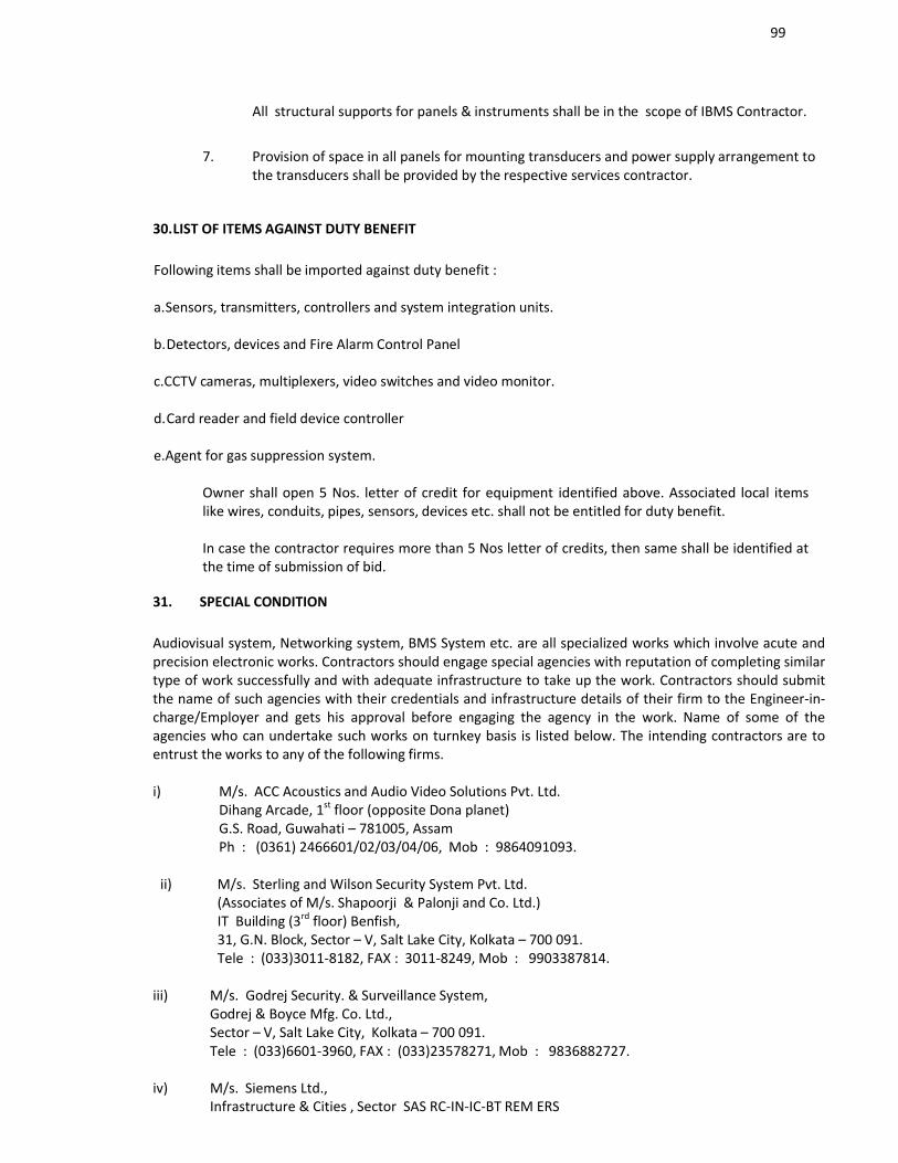
99
All structural supports for panels & instruments shall be in the scope of IBMS Contractor.
7. Provision of space in all panels for mounting transducers and power supply arrangement to the transducers shall be provided by the respective services contractor.
30.LIST OF ITEMS AGAINST DUTY BENEFIT
Following items shall be imported against duty benefit :
a.Sensors, transmitters, controllers and system integration units.
b.Detectors, devices and Fire Alarm Control Panel
c.CCTV cameras, multiplexers, video switches and video monitor.
d.Card reader and field device controller
e.Agent for gas suppression system.
Owner shall open 5 Nos. letter of credit for equipment identified above. Associated local items like wires, conduits, pipes, sensors, devices etc. shall not be entitled for duty benefit.
In case the contractor requires more than 5 Nos letter of credits, then same shall be identified at the time of submission of bid.
31. SPECIAL CONDITION
Audiovisual system, Networking system, BMS System etc. are all specialized works which involve acute and precision electronic works. Contractors should engage special agencies with reputation of completing similar type of work successfully and with adequate infrastructure to take up the work. Contractors should submit the name of such agencies with their credentials and infrastructure details of their firm to the Engineer-in-charge/Employer and gets his approval before engaging the agency in the work. Name of some of the agencies who can undertake such works on turnkey basis is listed below. The intending contractors are to entrust the works to any of the following firms.
i) M/s. ACC Acoustics and Audio Video Solutions Pvt. Ltd.Dihang Arcade, 1st floor (opposite Dona planet)G.S. Road, Guwahati – 781005, AssamPh : (0361) 2466601/02/03/04/06, Mob : 9864091093.
ii) M/s. Sterling and Wilson Security System Pvt. Ltd.(Associates of M/s. Shapoorji & Palonji and Co. Ltd.)IT Building (3rd floor) Benfish,31, G.N. Block, Sector – V, Salt Lake City, Kolkata – 700 091.Tele : (033)3011-8182, FAX : 3011-8249, Mob : 9903387814.
iii) M/s. Godrej Security. & Surveillance System,Godrej & Boyce Mfg. Co. Ltd.,Sector – V, Salt Lake City, Kolkata – 700 091.Tele : (033)6601-3960, FAX : (033)23578271, Mob : 9836882727.
iv) M/s. Siemens Ltd.,Infrastructure & Cities , Sector SAS RC-IN-IC-BT REM ERS
100
43, Shantipally. Rashbehari Bypass connector, Kolkata – 700 042Tele : (033)3093-9526, FAX : (033)2444-9667, Mob : 94322-54665
v) M/s. Voltas Limited,Gillander House,8, N. S. Road, Kolkata – 700 001Tele : (033) 6626 6200.
vi) M/s. Blue Star Limited, 7, Hare Street, Kolkata – 700 001Tele : (033) 2213 4000.
APPENDIX – I
LIST OF DRAWINGS
Sl.No. Drawing No. T i t l e
To be submitted by specialized sub contractor alongwith tender under main contractor.
All vendors are encouraged to visit the office of Architect / Consultants for any clarification / details.
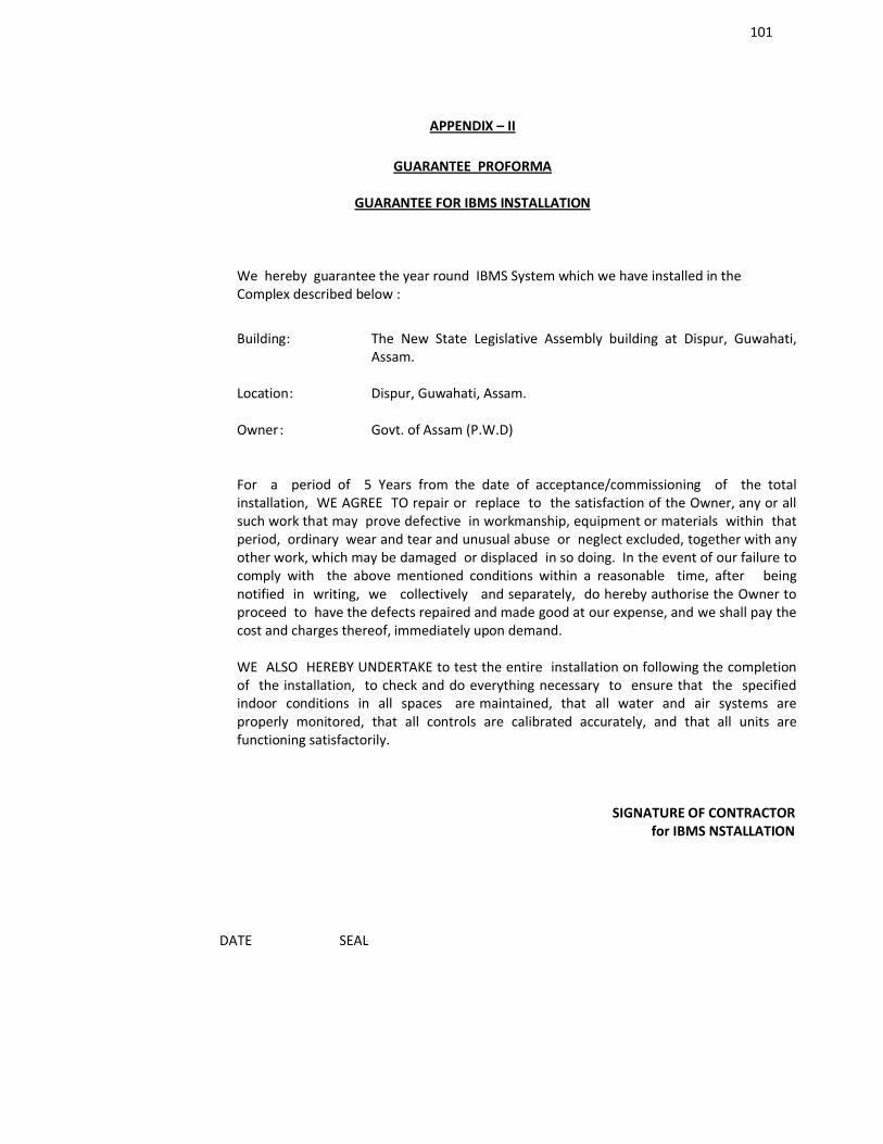
101
APPENDIX – II
GUARANTEE PROFORMA
GUARANTEE FOR IBMS INSTALLATION
We hereby guarantee the year round IBMS System which we have installed in the Complex described below :
Building: The New State Legislative Assembly building at Dispur, Guwahati, Assam.
Location: Dispur, Guwahati, Assam.
Owner: Govt. of Assam (P.W.D)
For a period of 5 Years from the date of acceptance/commissioning of the total installation, WE AGREE TO repair or replace to the satisfaction of the Owner, any or all such work that may prove defective in workmanship, equipment or materials within that period, ordinary wear and tear and unusual abuse or neglect excluded, together with any other work, which may be damaged or displaced in so doing. In the event of our failure to comply with the above mentioned conditions within a reasonable time, after being notified in writing, we collectively and separately, do hereby authorise the Owner to proceed to have the defects repaired and made good at our expense, and we shall pay the cost and charges thereof, immediately upon demand.
WE ALSO HEREBY UNDERTAKE to test the entire installation on following the completion of the installation, to check and do everything necessary to ensure that the specified indoor conditions in all spaces are maintained, that all water and air systems are properly monitored, that all controls are calibrated accurately, and that all units are functioning satisfactorily.
SIGNATURE OF CONTRACTORfor IBMS NSTALLATION
DATE SEAL
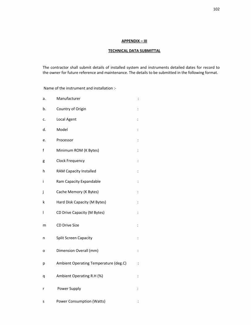
102
APPENDIX – III
TECHNICAL DATA SUBMITTAL
The contractor shall submit details of installed system and instruments detailed dates for record to the owner for future reference and maintenance. The details to be submitted in the following format.
Name of the instrument and installation :-
a. Manufacturer :
b. Country of Origin :
c. Local Agent :
d. Model :
e. Processor : f Minimum ROM (K Bytes) : g Clock Frequency :
h RAM Capacity Installed :
i Ram Capacity Expandable :
j Cache Memory (K Bytes) :
k Hard Disk Capacity (M Bytes) :
l CD Drive Capacity (M Bytes) :
m CD Drive Size :
n Split Screen Capacity :
o Dimension Overall (mm) :
p Ambient Operating Temperature (deg.C) :
q Ambient Operating R.H (%) :
r Power Supply :
s Power Consumption (Watts) :

103
t UL Listing :
GENERAL NOTES ON BOQ:
MISCELLANEOUS
Notes:
Items 292 & 293 of BOQ are very specialized item and the work is to be got done from any of the following specialised agencies with due approval from Engineer-in-Charge/Architect
1. M/s. Constro Art Engineering Company. Sl. No. 50/4,5 Narhe - Ambegaon Road, Narhe, Pune – 411041 Tel. : 91 20 24426797 / 4446 [email protected]
2. M/S Construction Catalyser Pvt. Ltd483/37, Mitramandal ColonyOpposite House of Jagtap, ParavatiPune-411009 Tel-912024426797/4446 [email protected]
3. Saksi Engineering ProjectsHarthala Railway Station Road, Vidyanagar, Harthala (Sonakpur)Moradabad-244001 (U.P.)09897622006/[email protected]
FURNITURE AND ARTEFACTSNotes:
All the furniture are very much descriptive as per the picture given and the finishing should be factory made of International standard.
LIGHTING AUTOMATION CONTROL SYSTEMNotes :Supply of items Like Enclosures, with ELCB and MCB protection for Dimmers for site basis are in Client's scope.
AUDIO VIDEO SYSTEMNotes :Audio video system including design and project management, programming as required, design and as built drawings (reproducible), operation and maintenance manuals - including equipment manuals, training - operation and maintenance, warranty - 24 months extended manufacturer's warranty at same terms and conditions.
Telephone & networking System
PART - I : ACTIVE COMPONENTS
Notes :

104
i)
Bidder shall provide OEM authorisation certificate in original certifying the bidder to participate in the tender.The name of the project should be clearly mentioned in the certificate
ii) Bidder shall provide schedule of all items and shall give in the format indicating the make & listing of the components.
iii)
Quantities shall be checked at site and approval shall be taken from the Engineer In charge before procuring the materials.
iv) Quantity of materials shall be supplied after approval of shop drawings and as per instructions of Engineer-in-charge only.
PART II: PASSIVE COMPONENTS
Notes :
1Bidder shall provide OEM authorisation certificate in original certifying the bidder to participate in the tender. The name of the project should be clearly mentioned in the certificate.
2 Bidder shall provide schedule of all items and shall give in the format indicating the make & listing of the components.
3Quantities shall be checked at site and approval shall be taken from the Engineer In charge before procuring the materials.
4 Quantity of materials shall be supplied after approval of shop drawings and as per instructions of Engineer-in-charge only.
IP TELEPHONE SYSTEM
i) Bidder shall provide OEM authorization certificate in original certifying the bidder to participate in the tender. The name of the project should be clearly mentioned in the certificate.
ii) Bidder shall provide schedule of all items and shall give in the format indicating the make & listing of the components.
iii) Quantities shall be checked at site and approval shall be taken from the Engineer In charge before
procuring the materials.
iv) Quantity of materials shall be supplied after approval of shop drawings and as per instructions of Engineer-in-charge only.
BUILDING MANAGEMENT SYSTEM
Notes:
i All data historical log shall be saved to hard disk before the expiry of 50 days.
105
ii All controllers shall be UL listed.
iii Catalogues for all controllers shall be submitted with bid.
iv Contractor shall provide schedule of all items in a format indicating the make & listing of the component (UL) & Indian/Imported.
v Quantities shall be checked at site and approval shall be taken from the Engineer Incharge before procuring the materials.
vi The Quantity of cable/wire/conduits are tentative. The contactor has to provide the DDC controllers as per manufacturer selected from list of approved makes and the qty. of cables/wires/conduits etc. will depend on the selection of controllers.
vii Procurement shall be done after the approval of shop drawing and material data sheets.
viii Other details shall be as per the technical specification.
CHILLER/ PUMPS/ COOLING /TOWER SYSTEM :
i) All data historical log shall be maintained for minimum 50 days.
AHU/TFA/VENT./EXHAUST FANS :
NOTE:
i) All data historical log shall be maintained for minimum 50 days.
PLUMBING/FIRE FIGHTING/STP/WTP/RO/ELECTRICAL :
NOTE:
The Bidder must submit OEM authorisation certificate along with submission of the Bid document. The name of the project should be clearly mentioned in the certificate.
All data historical log shall be maintained for minimum 50 days.
106
H. Joint Ventures.
Para’s for joint Ventures
Bidders willing to participate in a Joint Venture (JV) must submit their JV agreement in sealed envelop along with the Technical Bid at ……………………….. (Address) and clearly marked ………………….. (Name of project)
Joint Ventures
2.6.1 Joint venture partners would be limited to three (including the lead partner but excluding the financial partner).
2.6.2A) One of the partners, who is responsible for performing a key function in contract management or
is executing a major component of the proposed contract, shall be nominated as being in charge
during the bidding periods and, in the event of a successful bid, during contract execution. The
partner in charge shall be authorized to incur liabilities and receive instructions for and on behalf
of the partner(s) of the joint venture; this authorization shall be evidenced by submitting a power
of attorney signed by legally authorized signatories of all the partners.
B) All the partners of the joint venture shall be, jointly and severally liable, during the bidding process
and for the execution of the contract in accordance with the contract terms, and a statement to
this effect shall be included in the authorization mentioned under sub clause 2.6.2(A) above. The
bid shall be signed so as to legally bind all the partners, jointly and severally.
Bid security and the performance guarantee as required will be furnished by the Lead partner and
joint venture partner(s), out of their account in proportion to their participation in joint venture.
Qualifying criteria for joint ventures
2.6.3 General Experience:
The Applications shall meet the minimum qualification criteria as defined in Clause No.4.5 of
Section-1(Instructions to bidders) except 4.5A(c), the lead partner must fulfill criteria of similar
nature of single work as indicated in 4.5A(c) however a successfully or 90% completed similar
nature of single work by the same JV partners will be considered as qualifying criteria.
2.6.4 Personnel Capabilities.
The applicant must have available key personnel for this work as defined in Clause No.4.5 of Section-1(Instructions to bidders)
2.6.5 Availability of key and critical equipments as defined in Clause No.4.5 of Section-1(Instructions to bidders)
2.6.6 Financial position.
107
The applicant should demonstrate that he access to or has available liquid assets ( working capital each in hand and bank guarantees) and / or credit facilities of not less than 10% of the contract / contracts applied for, construction cash – flow may be taken as 10% of the estimated value of contract / contracts. (See Clause No 4.3(vii) and 4.5 of Section-1(Instructions to bidders)
2.6.7 The audited balance sheet for the last five years should be submitted, which must demonstrate the soundness of the applicant’s financial position showing long – term profitability including an estimated financial projection for the next two years. Where necessary, the employer will make inquires with the applicant’s bankers. (See Clause No.4.3 (vi) of Section-1(Instructions to bidders)
2.6.8 Litigation History.The applicant should provide accurate information on any litigation or arbitration resulting from contracts completed or under execution by him over the last five years. A consistent history of awards against the applicant or any partner of a joint venture may result in failure of the applicant.
2.6.9 Bid capacity : Applicant should fulfilled the clause No.4.8 of Section-1 (Instructions to bidders).
Note : In case of a joint venture, the available bid capacity will be applied for each partner to the extent of his proposed participation in the execution of the works and combined.
2.6.10 Disqualification: This should be as per clause No.4.9 of Section-1(Instructions to bidders).
2.7 Joint Ventures must comply with the following requirements:
Refer to Clause No.4.6 of Section-1 of ITB.
2.7.2 Refer to Clause No. 4.6.2 of Section-1 of ITB..2.8 Deleted.
2.9 Conflict of interest
2.9.1 The Applicant (including all members of a joint venture) must not be associated, nor have been
associated in the past, with the consultant (M/S Dulal Mukherjee & Associates, Kolkata ) or any
other entity that has prepared the design, specifications and bidding documents for the project,
or what was proposed as Engineer for the contract, over the last five years
Any such association may result in the disqualification of the Applicant.
2.10 General:
2.10.1 A firm or a member of a joint venture may participate in only one bid for the contract. If a firm
submits more than one bid singly or in joint venture all bids including that party will be rejected.
This rule will not apply in respect of bids which include specialist subcontractors who are used by
more than one bidder.
2.10.2 Bidders will be required to provide bid security in the form of a bankers cheque/bank guaranties
or / other security acceptable to employer about 1% of the estimated cost and the successful
108
bidder will be required to provide performance security. Example of acceptable forms will be
supplied with the bidding documents.
2.10.3 The employer reserves the right to :
a) amend the scope and value of any contract (s) to bid.
b) Reject or accept any application, and
c) The employer shall neither be liable for any such actions nor be under any obligation to inform
the applicant of the grounds for them.
ADDITIONAL SPECIAL CONDITIONS FOR JV
A copy of the Joint Venture (JV) entered into by the partners shall be submitted with the application.
Alternatively, a letter of intent to execute a JVA in the event of a successful bid shall be signed by all
partners and submitted with the Application together with a copy of the proposed Agreement. Pursuant
to sub-clause 2.6.2(A) & 2.6.2(B) above, the JV shall include among other things, the Joint Venture’s
objectives, the proposed management structure, the contribution of each partner to the Joint Venture
operation, the commitment of the partners to joint and several liability for due performance,
recourse/sanctions within the Joint Venture in the event of default or withdrawal of any partner and
arrangements for providing the required indemnities.
In case of withdrawal of any partner from the Joint Venture the following shall be applicable:
i) Stepping into the shoes of the existing partners of Joint Venture with all the liabilities of the
existing partners from the beginning of the contract.
ii) With prior approval of Assam PWD.
iii) Not withstanding demarcation or allotment of work between two JV
partners JV shall liable for non-performance of the whole contract
irrespective of their demarcation or share of work.
iv) In case of successful bid being accepted by Assam PWD, the payments under the contract will
only be made to the JV and not to the individual partners.
2) Joint venture agreement shall contain a clause to the effect that there shall be a separate JV Bank
Account (distinct from the bank accounts of the individual partners) to which the individual partners shall
contribute their share capital and/or working capital.
Joint Venture agreement shall contain a clause to the effect that the financial obligations of the JV shall be
discharged through the said JV Bank account only and also all the payments received or paid by the
Govt.of Assam or by the JV shall be through that account alone.
4) Joint Venture is applicable to the project costing Rs.15.00 Crore or above
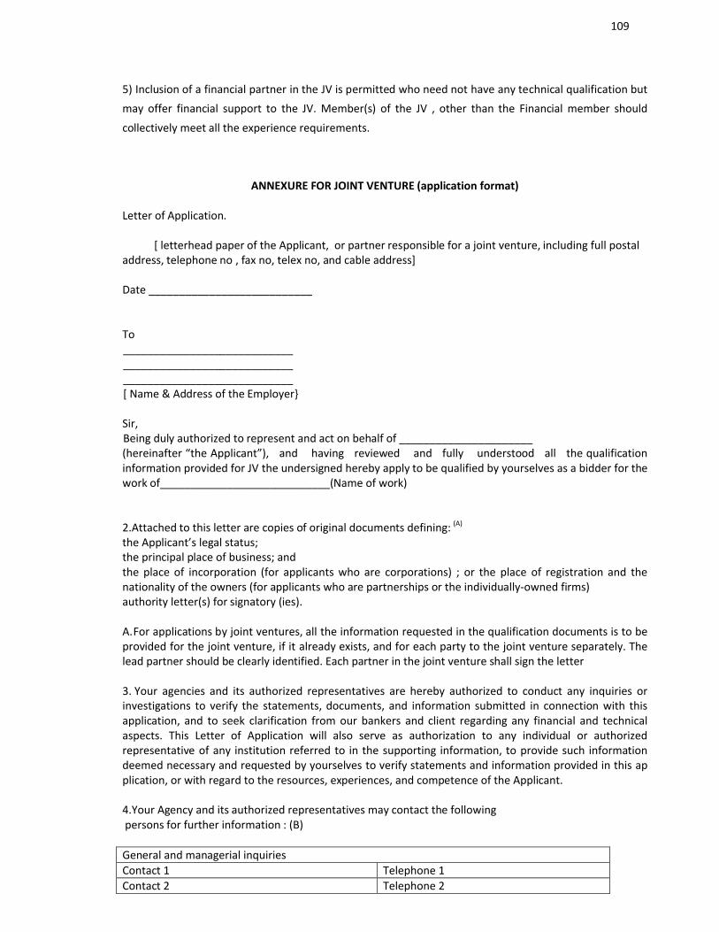
109
5) Inclusion of a financial partner in the JV is permitted who need not have any technical qualification but
may offer financial support to the JV. Member(s) of the JV , other than the Financial member should
collectively meet all the experience requirements.
ANNEXURE FOR JOINT VENTURE (application format)
Letter of Application.
[ letterhead paper of the Applicant, or partner responsible for a joint venture, including full postal address, telephone no , fax no, telex no, and cable address]
Date ___________________________
To____________________________________________________________________________________[ Name & Address of the Employer
Sir, Being duly authorized to represent and act on behalf of ______________________(hereinafter “the Applicant”), and having reviewed and fully understood all the qualification information provided for JV the undersigned hereby apply to be qualified by yourselves as a bidder for the work of____________________________(Name of work)
2.Attached to this letter are copies of original documents defining: (A)
the Applicant’s legal status;the principal place of business; and the place of incorporation (for applicants who are corporations) ; or the place of registration and the nationality of the owners (for applicants who are partnerships or the individually-owned firms)authority letter(s) for signatory (ies).
A.For applications by joint ventures, all the information requested in the qualification documents is to be provided for the joint venture, if it already exists, and for each party to the joint venture separately. The lead partner should be clearly identified. Each partner in the joint venture shall sign the letter
3. Your agencies and its authorized representatives are hereby authorized to conduct any inquiries or investigations to verify the statements, documents, and information submitted in connection with this application, and to seek clarification from our bankers and client regarding any financial and technical aspects. This Letter of Application will also serve as authorization to any individual or authorized representative of any institution referred to in the supporting information, to provide such information deemed necessary and requested by yourselves to verify statements and information provided in this application, or with regard to the resources, experiences, and competence of the Applicant.
4.Your Agency and its authorized representatives may contact the followingpersons for further information : (B)
General and managerial inquiriesContact 1 Telephone 1Contact 2 Telephone 2
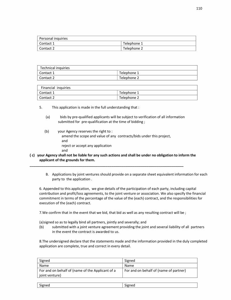
110
Personal inquiriesContact 1 Telephone 1Contact 2 Telephone 2
Technical inquiriesContact 1 Telephone 1Contact 2 Telephone 2
Financial inquiriesContact 1 Telephone 1Contact 2 Telephone 2
5. This application is made in the full understanding that :
(a) bids by pre-qualified applicants will be subject to verification of all information submitted for pre-qualification at the time of bidding ;
(b) your Agency reserves the right to :amend the scope and value of any contracts/bids under this project, andreject or accept any applicationand
( c) your Agency shall not be liable for any such actions and shall be under no obligation to inform the applicant of the grounds for them.
_______________________________________________________________________________
B. Applications by joint ventures should provide on a separate sheet equivalent information for each party to the application .
6. Appended to this application, we give details of the participation of each party, including capital contribution and profit/loss agreements, to the joint venture or association. We also specify the financial commitment in terms of the percentage of the value of the (each) contract, and the responsibilities for execution of the (each) contract.
7.We confirm that in the event that we bid, that bid as well as any resulting contract will be ;
(a)signed so as to legally bind all partners, jointly and severally; and(b) submitted with a joint venture agreement providing the joint and several liability of all partners
in the event the contract is awarded to us.
8.The undersigned declare that the statements made and the information provided in the duly completed application are complete, true and correct in every detail.
Signed SignedName NameFor and on behalf of name of the Applicant of a joint venture
For and on behalf of name of partner
Signed Signed
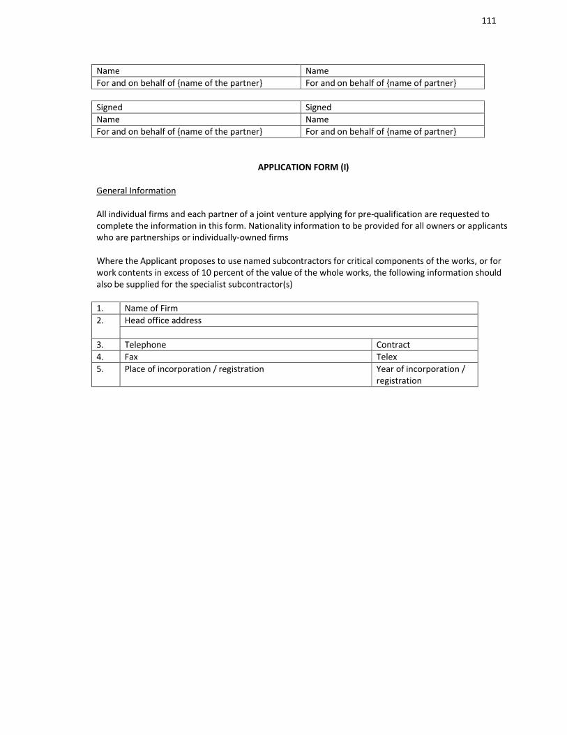
111
Name NameFor and on behalf of name of the partner For and on behalf of name of partner
Signed SignedName NameFor and on behalf of name of the partner For and on behalf of name of partner
APPLICATION FORM (I)
General Information
All individual firms and each partner of a joint venture applying for pre-qualification are requested to complete the information in this form. Nationality information to be provided for all owners or applicants who are partnerships or individually-owned firms
Where the Applicant proposes to use named subcontractors for critical components of the works, or for work contents in excess of 10 percent of the value of the whole works, the following information should also be supplied for the specialist subcontractor(s)
1. Name of Firm2. Head office address
3. Telephone Contract4. Fax Telex5. Place of incorporation / registration Year of incorporation /
registration
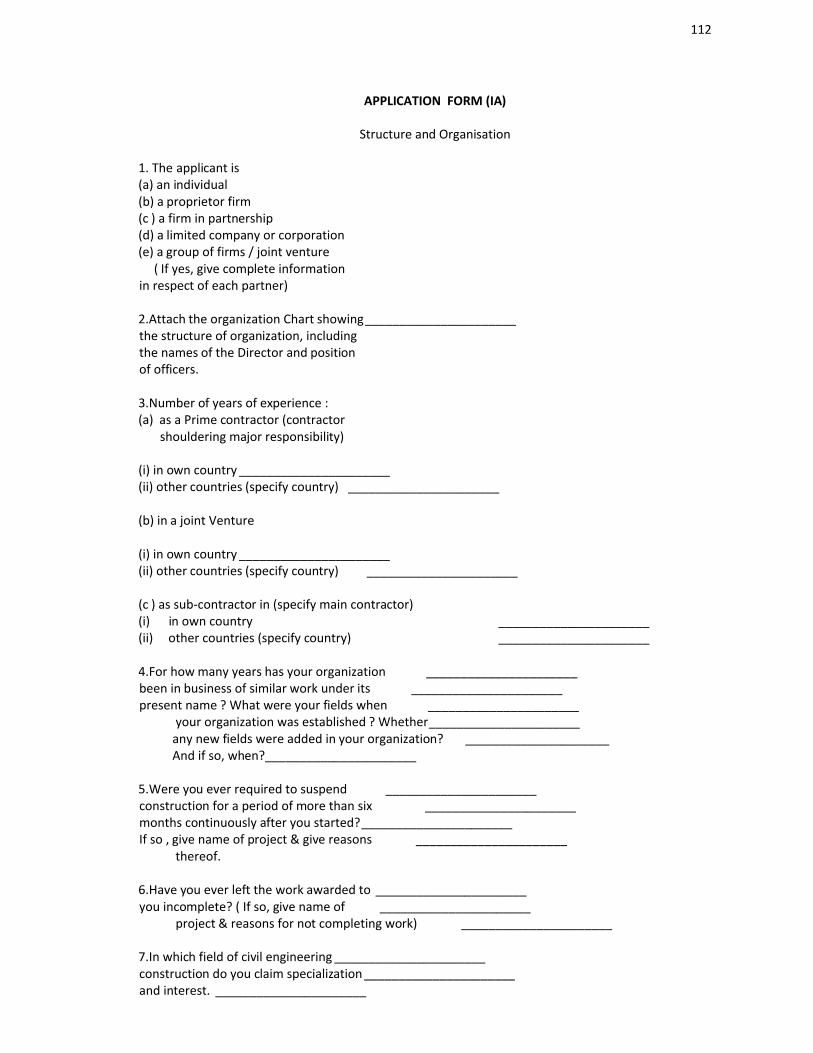
112
APPLICATION FORM (IA)
Structure and Organisation
1. The applicant is (a) an individual(b) a proprietor firm(c ) a firm in partnership(d) a limited company or corporation(e) a group of firms / joint venture ( If yes, give complete informationin respect of each partner)
2.Attach the organization Chart showing______________________the structure of organization, includingthe names of the Director and positionof officers.
3.Number of years of experience :(a) as a Prime contractor (contractor shouldering major responsibility)
(i) in own country ______________________(ii) other countries (specify country) ______________________
(b) in a joint Venture
(i) in own country ______________________(ii) other countries (specify country) ______________________
(c ) as sub-contractor in (specify main contractor)(i) in own country ______________________(ii) other countries (specify country) ______________________
4.For how many years has your organization ______________________been in business of similar work under its ______________________present name ? What were your fields when ______________________ your organization was established ? Whether______________________ any new fields were added in your organization? _____________________ And if so, when?______________________
5.Were you ever required to suspend ______________________construction for a period of more than six ______________________months continuously after you started?______________________If so , give name of project & give reasons ______________________ thereof.
6.Have you ever left the work awarded to ______________________you incomplete? ( If so, give name of ______________________ project & reasons for not completing work) ______________________
7.In which field of civil engineering ______________________construction do you claim specialization ______________________and interest. ______________________

113
8.Give details of your experience in ______________________Sanitary & Water Supply Works ______________________In Building
9.Give details of your experience in ______________________Electrical Works in Building Works ______________________
10. Give details of your experience in ______________________Audio Visual System ______________________IBMS ________________________Access control System ________________________IPTV ________________________Telephone networking system ________________________Fire Alarm System ________________________Security & surveillance System ________________________
C.These are sample illustration to be modified as appropriate.
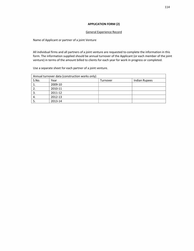
114
APPLICATION FORM (2)
General Experience Record
Name of Applicant or partner of a joint Venture
All individual firms and all partners of a joint venture are requested to complete the information in this form. The information supplied should be annual turnover of the Applicant (or each member of the joint venture) in terms of the amount billed to clients for each year for work in progress or completed.
Use a separate sheet for each partner of a joint venture.
Annual turnover data (construction works only)S.No. Year Turnover Indian Rupees1. 2009-102. 2010-113. 2011-124. 2012-135. 2013-14
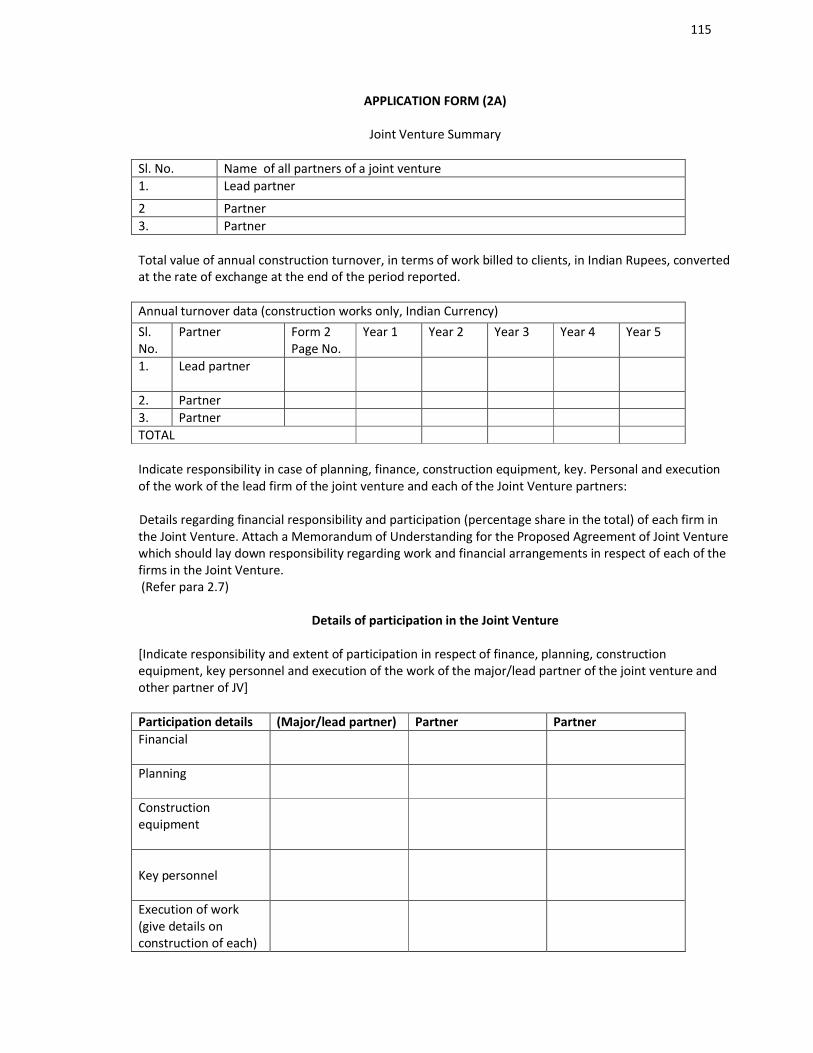
115
APPLICATION FORM (2A)
Joint Venture Summary
Sl. No. Name of all partners of a joint venture1. Lead partner
2 Partner3. Partner
Total value of annual construction turnover, in terms of work billed to clients, in Indian Rupees, converted at the rate of exchange at the end of the period reported.
Annual turnover data (construction works only, Indian Currency)Sl. No.
Partner Form 2Page No.
Year 1 Year 2 Year 3 Year 4 Year 5
1. Lead partner
2. Partner3. PartnerTOTAL
Indicate responsibility in case of planning, finance, construction equipment, key. Personal and execution of the work of the lead firm of the joint venture and each of the Joint Venture partners:
Details regarding financial responsibility and participation (percentage share in the total) of each firm in the Joint Venture. Attach a Memorandum of Understanding for the Proposed Agreement of Joint Venture which should lay down responsibility regarding work and financial arrangements in respect of each of the firms in the Joint Venture.(Refer para 2.7)
Details of participation in the Joint Venture
[Indicate responsibility and extent of participation in respect of finance, planning, construction equipment, key personnel and execution of the work of the major/lead partner of the joint venture and other partner of JV]
Participation details (Major/lead partner) Partner PartnerFinancial
Planning
Construction equipment
Key personnel
Execution of work (give details on construction of each)
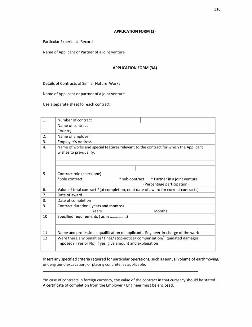
116
APPLICATION FORM (3)
Particular Experience Record
Name of Applicant or Partner of a joint venture
APPLICATION FORM (3A)
Details of Contracts of Similar Nature Works
Name of Applicant or partner of a joint venture
Use a separate sheet for each contract.
1. Number of contractName of contractCountry
2. Name of Employer3. Employer’s Address4. Name of works and special features relevant to the contract for which the Applicant
wishes to pre-qualify.
5 Contract role (check one)*Sole contract * sub-contract * Partner in a joint venture (Percentage participation)
6. Value of total contract *(at completion, or at date of award for current contracts)7. Date of award8. Date of completion9. Contract duration ( years and months)
Years Months10 Specified requirements ( as in ……………..)
11 Name and professional qualification of applicant’s Engineer-in-charge of the work12 Were there any penalties/ fines/ stop-notice/ compensation/ liquidated damages
imposed? (Yes or No) If yes, give amount and explanation
Insert any specified criteria required for particular operations, such as annual volume of earthmoving, underground excavation, or placing concrete, as applicable._________________________________________________________________________
*In case of contracts in foreign currency, the value of the contract in that currency should be stated.A certificate of completion from the Employer / Engineer must be enclosed.
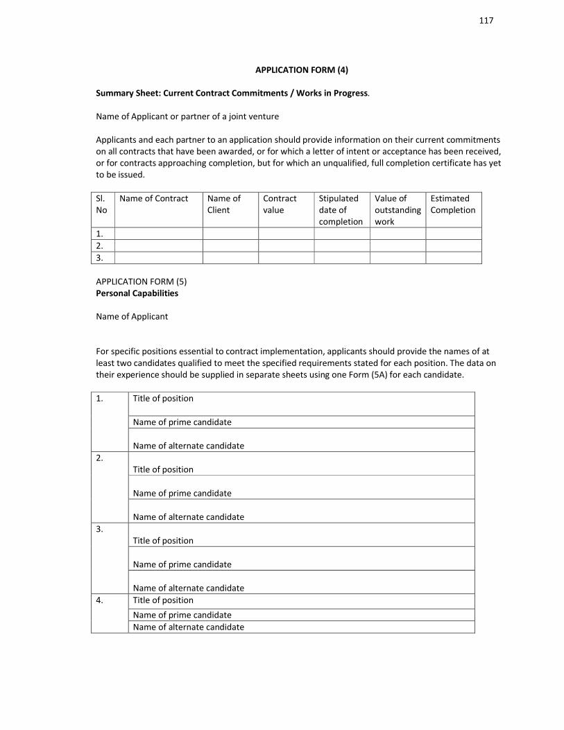
117
APPLICATION FORM (4)
Summary Sheet: Current Contract Commitments / Works in Progress.
Name of Applicant or partner of a joint venture
Applicants and each partner to an application should provide information on their current commitments on all contracts that have been awarded, or for which a letter of intent or acceptance has been received, or for contracts approaching completion, but for which an unqualified, full completion certificate has yet to be issued.
Sl.No
Name of Contract Name of Client
Contract value
Stipulated date of completion
Value of outstanding work
Estimated Completion
1.2.3.
APPLICATION FORM (5)Personal Capabilities
Name of Applicant
For specific positions essential to contract implementation, applicants should provide the names of at least two candidates qualified to meet the specified requirements stated for each position. The data on their experience should be supplied in separate sheets using one Form (5A) for each candidate.
1. Title of position
Name of prime candidate
Name of alternate candidate2.
Title of position
Name of prime candidate
Name of alternate candidate3.
Title of position
Name of prime candidate
Name of alternate candidate4. Title of position
Name of prime candidateName of alternate candidate

118
APPLICATION FORM (5A)
Candidate Summary
Name of Applicant
Position Candidate* Prime * Alternate
Candidate information
1.Name of the Candidate 2. Date of birth
3. Professional Qualification
Present Employment
4. Name of the EmployerAddress of the Employer
Telephone Contact (Manager/ personal Officer)
Fax TelexJob title of Candidate Years with present Employer
Summarize professional experience over the last 20 years, in reverse chronological order.Indicate particular technical and managerial experience relevant to the Project.
From To Company/Project/Position/relevant technical & managerial experience
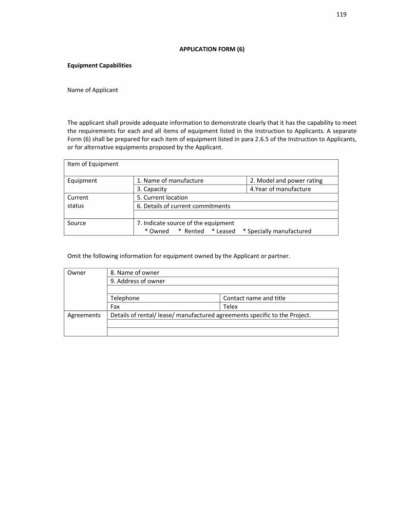
119
APPLICATION FORM (6)
Equipment Capabilities
Name of Applicant
The applicant shall provide adequate information to demonstrate clearly that it has the capability to meet the requirements for each and all items of equipment listed in the Instruction to Applicants. A separate Form (6) shall be prepared for each item of equipment listed in para 2.6.5 of the Instruction to Applicants, or for alternative equipments proposed by the Applicant.
Item of Equipment
Equipment 1. Name of manufacture 2. Model and power rating3. Capacity 4.Year of manufacture
Current status
5. Current location6. Details of current commitments
Source 7. Indicate source of the equipment * Owned * Rented * Leased * Specially manufactured
Omit the following information for equipment owned by the Applicant or partner.
Owner 8. Name of owner9. Address of owner
Telephone Contact name and titleFax Telex
Agreements Details of rental/ lease/ manufactured agreements specific to the Project.
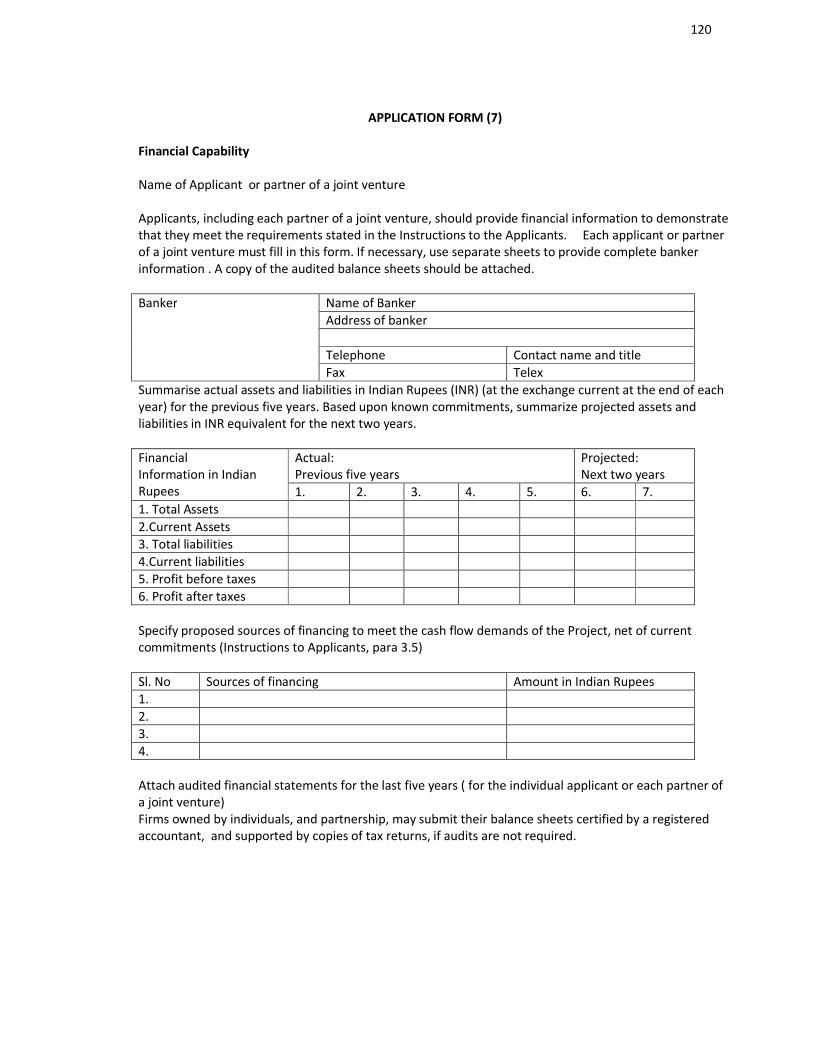
120
APPLICATION FORM (7)
Financial Capability
Name of Applicant or partner of a joint venture
Applicants, including each partner of a joint venture, should provide financial information to demonstrate that they meet the requirements stated in the Instructions to the Applicants. Each applicant or partner of a joint venture must fill in this form. If necessary, use separate sheets to provide complete banker information . A copy of the audited balance sheets should be attached.
Banker Name of BankerAddress of banker
Telephone Contact name and titleFax Telex
Summarise actual assets and liabilities in Indian Rupees (INR) (at the exchange current at the end of each year) for the previous five years. Based upon known commitments, summarize projected assets and liabilities in INR equivalent for the next two years.
FinancialInformation in Indian Rupees
Actual:Previous five years
Projected:Next two years
1. 2. 3. 4. 5. 6. 7.1. Total Assets2.Current Assets3. Total liabilities4.Current liabilities5. Profit before taxes6. Profit after taxes
Specify proposed sources of financing to meet the cash flow demands of the Project, net of current commitments (Instructions to Applicants, para 3.5)
Sl. No Sources of financing Amount in Indian Rupees1.2.3.4.
Attach audited financial statements for the last five years ( for the individual applicant or each partner of a joint venture)Firms owned by individuals, and partnership, may submit their balance sheets certified by a registered accountant, and supported by copies of tax returns, if audits are not required.
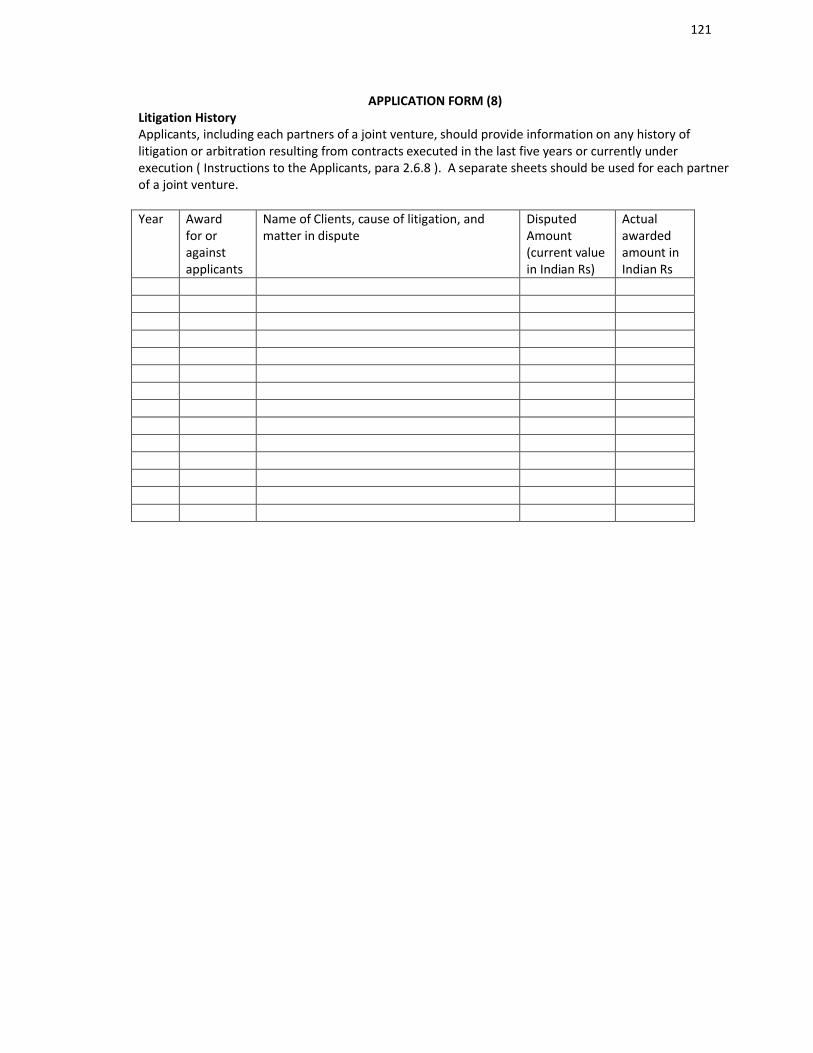
121
APPLICATION FORM (8)Litigation HistoryApplicants, including each partners of a joint venture, should provide information on any history of litigation or arbitration resulting from contracts executed in the last five years or currently under execution ( Instructions to the Applicants, para 2.6.8 ). A separate sheets should be used for each partner of a joint venture.
Year Awardfor oragainstapplicants
Name of Clients, cause of litigation, and matter in dispute
Disputed Amount(current valuein Indian Rs)
Actual awarded amount inIndian Rs
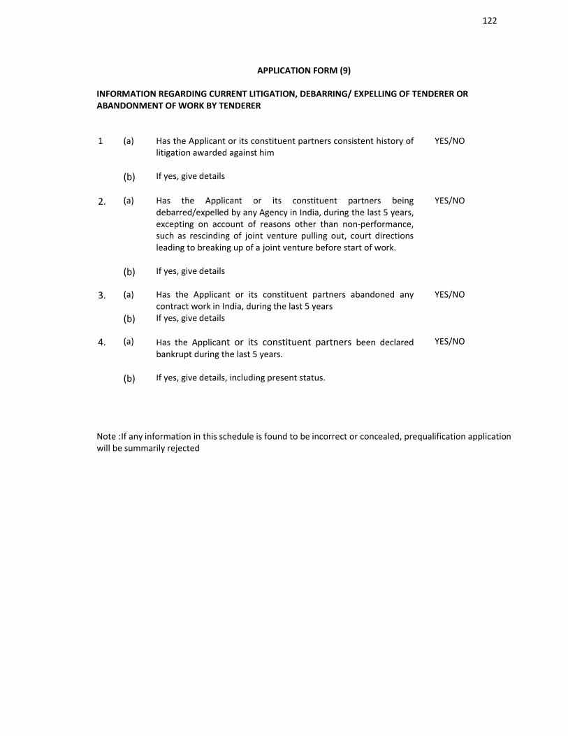
122
APPLICATION FORM (9)
INFORMATION REGARDING CURRENT LITIGATION, DEBARRING/ EXPELLING OF TENDERER OR ABANDONMENT OF WORK BY TENDERER
1 (a) Has the Applicant or its constituent partners consistent history of litigation awarded against him
YES/NO
(b) If yes, give details
2. (a) Has the Applicant or its constituent partners being debarred/expelled by any Agency in India, during the last 5 years, excepting on account of reasons other than non-performance, such as rescinding of joint venture pulling out, court directions leading to breaking up of a joint venture before start of work.
YES/NO
(b) If yes, give details
3. (a) Has the Applicant or its constituent partners abandoned any contract work in India, during the last 5 years
YES/NO
(b) If yes, give details
4. (a) Has the Applicant or its constituent partners been declared bankrupt during the last 5 years.
YES/NO
(b) If yes, give details, including present status.
Note :If any information in this schedule is found to be incorrect or concealed, prequalification application will be summarily rejected
123
APPLICATION FORM (10)
AFFIDAVIT(To be given separately by each partner of Joint venture)
1.I, the undersigned do hereby certify that all the statements made in the required attachments are true and correct.
2.The undersigned also hereby certifies that neither out firm M/s ______________________nor any of its constituent partners have abandoned any work on Building works in India nor any contract awarded to us for such works have been rescinded during last five years prior to the date of this bid.
The undersigned hereby authorize(s) and request(s) any bank, person, firm or corporation to furnish pertinent information deemed necessary and requested by the Department to verify this statement or regarding my (our) competence and general reputation.The undersigned understand and agrees that further qualifying information may be requested, and agrees to furnish any such information at the request of the Department/ Project implementing agency.
____________________________________(Signed by an Authorised Officer of the Firm)
________________ Title of Officer
______________________ Name of Firm
DATE

124
SECTION - 4
CONTRACT DATA
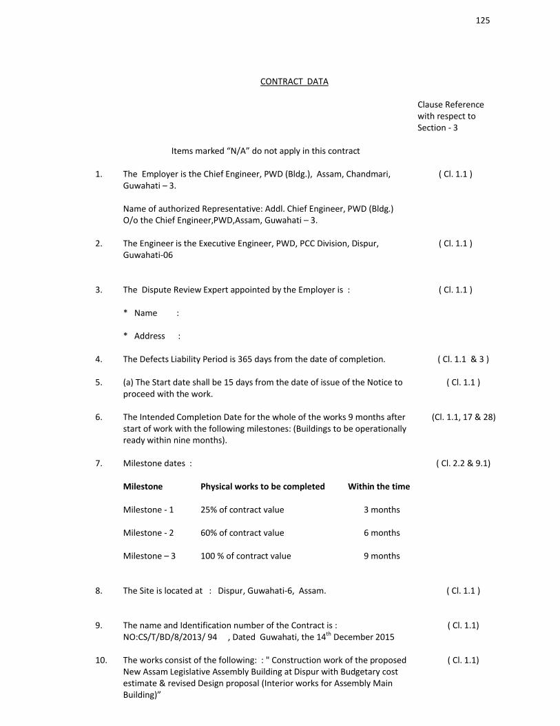
125
CONTRACT DATA
Clause Referencewith respect to Section - 3
Items marked “N/A” do not apply in this contract
1. The Employer is the Chief Engineer, PWD (Bldg.), Assam, Chandmari,Guwahati – 3.
Name of authorized Representative: Addl. Chief Engineer, PWD (Bldg.) O/o the Chief Engineer,PWD,Assam, Guwahati – 3.
( Cl. 1.1 )
2. The Engineer is the Executive Engineer, PWD, PCC Division, Dispur, Guwahati-06
( Cl. 1.1 )
3. The Dispute Review Expert appointed by the Employer is :
* Name :
* Address :
( Cl. 1.1 )
4. The Defects Liability Period is 365 days from the date of completion. ( Cl. 1.1 & 3 )
5. (a) The Start date shall be 15 days from the date of issue of the Notice toproceed with the work.
( Cl. 1.1 )
6. The Intended Completion Date for the whole of the works 9 months after start of work with the following milestones: (Buildings to be operationally ready within nine months).
(Cl. 1.1, 17 & 28)
7. Milestone dates : ( Cl. 2.2 & 9.1)
Milestone Physical works to be completed Within the time
Milestone - 1 25% of contract value 3 months
Milestone - 2 60% of contract value 6 months
Milestone – 3 100 % of contract value 9 months
8. The Site is located at : Dispur, Guwahati-6, Assam. ( Cl. 1.1 )
9. The name and Identification number of the Contract is :NO:CS/T/BD/8/2013/ 94 , Dated Guwahati, the 14th December 2015
( Cl. 1.1)
10. The works consist of the following: : " Construction work of the proposed New Assam Legislative Assembly Building at Dispur with Budgetary cost estimate & revised Design proposal (Interior works for Assembly Main Building)”
( Cl. 1.1)
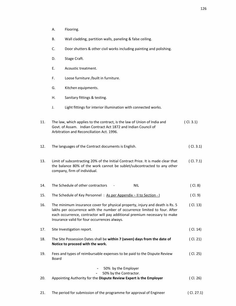
126
A. Flooring.
B. Wall cladding, partition walls, paneling & false ceiling.
C. Door shutters & other civil works including painting and polishing.
D. Stage Craft.
E. Acoustic treatment.
F. Loose furniture /built in furniture.
G. Kitchen equipments.
H. Sanitary fittings & testing.
J. Light fittings for interior illumination with connected works.
11. The law, which applies to the contract, is the law of Union of India and Govt. of Assam. Indian Contract Act 1872 and Indian Council of Arbitration and Reconciliation Act. 1996.
( Cl. 3.1)
12. The languages of the Contract documents is English. ( Cl. 3.1)
13. Limit of subcontracting 20% of the Initial Contract Price. It is made clear that the balance 80% of the work cannot be sublet/subcontracted to any other company, firm of individual.
( Cl. 7.1)
14. The Schedule of other contractors - NIL ( Cl. 8)
15. The Schedule of Key Personnel : As per Appendix – II to Section - I ( Cl. 9)
16. The minimum insurance cover for physical property, injury and death is Rs. 5 lakhs per occurrence with the number of occurrence limited to four. After each occurrence, contractor will pay additional premium necessary to make Insurance valid for four occurrences always.
( Cl. 13)
17. Site Investigation report. ( Cl. 14)
18. The Site Possession Dates shall be within 7 (seven) days from the date of Notice to proceed with the work.
( Cl. 21)
19. Fees and types of reimbursable expenses to be paid to the Dispute Review Board
- 50% by the Employer- 50% by the Contractor.
( Cl. 25)
20. Appointing Authority for the Dispute Review Expert is the Employer ( Cl. 26)
21. The period for submission of the programme for approval of Engineer ( Cl. 27.1)
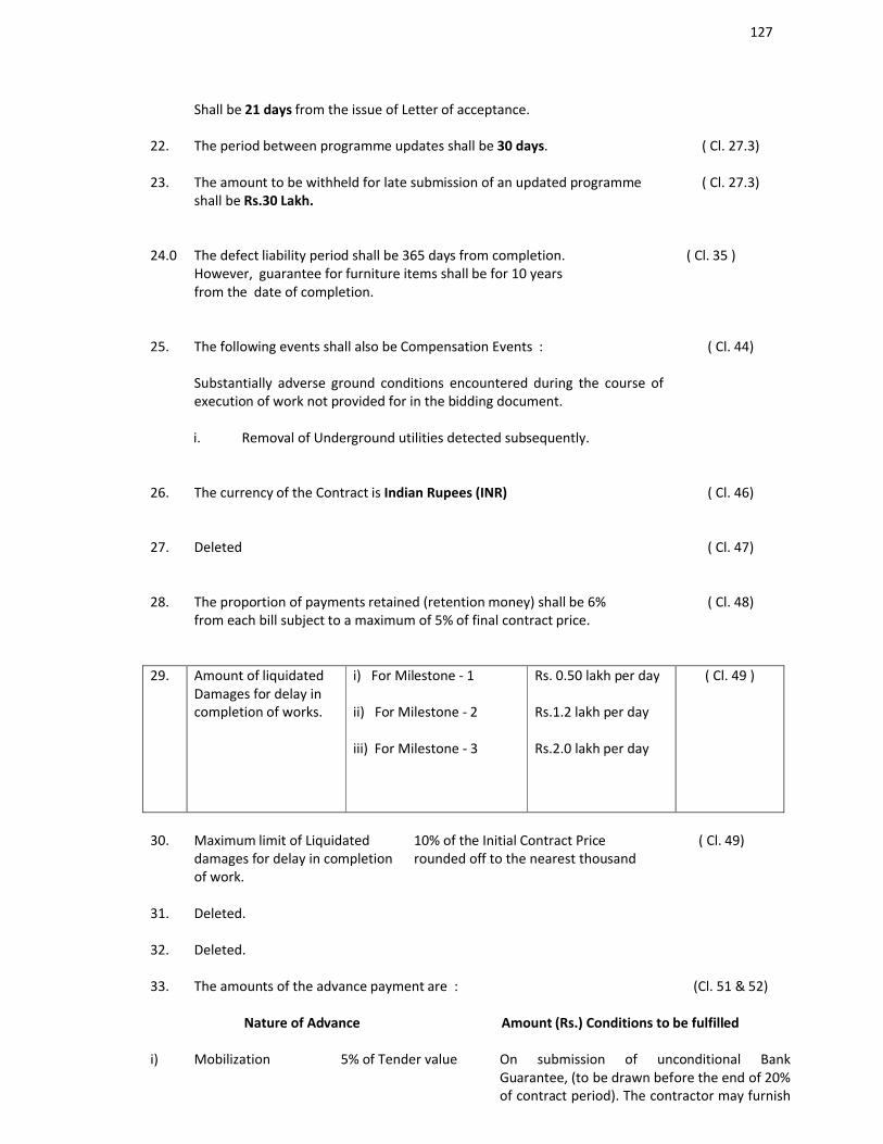
127
Shall be 21 days from the issue of Letter of acceptance.
22. The period between programme updates shall be 30 days. ( Cl. 27.3)
23. The amount to be withheld for late submission of an updated programme shall be Rs.30 Lakh.
( Cl. 27.3)
24.0 The defect liability period shall be 365 days from completion.However, guarantee for furniture items shall be for 10 years from the date of completion.
( Cl. 35 )
25. The following events shall also be Compensation Events :
Substantially adverse ground conditions encountered during the course of execution of work not provided for in the bidding document.
( Cl. 44)
i. Removal of Underground utilities detected subsequently.
26. The currency of the Contract is Indian Rupees (INR) ( Cl. 46)
27. Deleted ( Cl. 47)
28. The proportion of payments retained (retention money) shall be 6%from each bill subject to a maximum of 5% of final contract price.
( Cl. 48)
29. Amount of liquidatedDamages for delay incompletion of works.
i) For Milestone - 1
ii) For Milestone - 2
iii) For Milestone - 3
Rs. 0.50 lakh per day
Rs.1.2 lakh per day
Rs.2.0 lakh per day
( Cl. 49 )
30. Maximum limit of Liquidated damages for delay in completion of work.
10% of the Initial Contract Price rounded off to the nearest thousand
( Cl. 49)
31. Deleted.
32. Deleted.
33. The amounts of the advance payment are : (Cl. 51 & 52)
Nature of Advance Amount (Rs.) Conditions to be fulfilled
i) Mobilization 5% of Tender value On submission of unconditional Bank Guarantee, (to be drawn before the end of 20% of contract period). The contractor may furnish
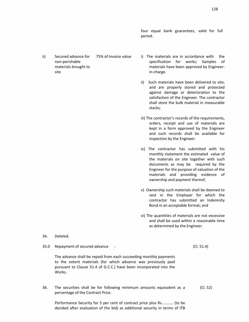
128
four equal bank guarantees, valid for full period.
ii) Secured advance for non-perishable materials brought to site
75% of Invoice value i) The materials are in accordance with the specification for works; Samples of materials have been approved by Engineer-in-charge.
ii) Such materials have been delivered to site, and are properly stored and protected against damage or deterioration to the satisfaction of the Engineer. The contractor shall store the bulk material in measurable stacks;
iii) The contractor’s records of the requirements, orders, receipt and use of materials are kept in a form approved by the Engineer and such records shall be available for inspection by the Engineer.
iv) The contractor has submitted with his
monthly statement the estimated value of the materials on site together with such documents as may be required by the Engineer for the purpose of valuation of the materials and providing evidence of ownership and payment thereof;
v) Ownership such materials shall be deemed to vest in the Employer for which the contractor has submitted an Indemnity Bond in an acceptable format; and
vi) The quantities of materials are not excessive and shall be used within a reasonable time as determined by the Engineer.
34. Deleted.
35.0 Repayment of secured advance :
The advance shall be repaid from each succeeding monthly payments to the extent materials (for which advance was previously paid pursuant to Clause 51.4 of G.C.C.) have been incorporated into the Works.
(Cl. 51.4)
36. The securities shall be for following minimum amounts equivalent as a percentage of the Contract Price.
Performance Security for 5 per cent of contract price plus Rs………… (to be decided after evaluation of the bid) as additional security in terms of ITB
(Cl. 52)
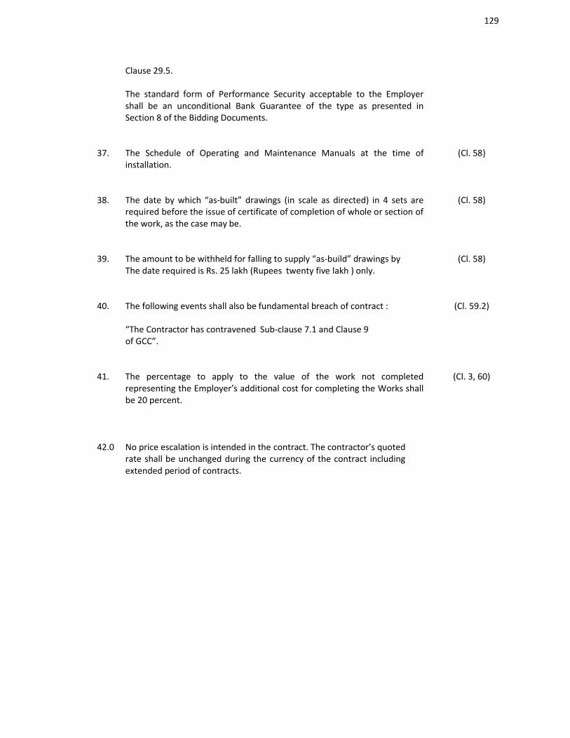
129
Clause 29.5.
The standard form of Performance Security acceptable to the Employer shall be an unconditional Bank Guarantee of the type as presented in Section 8 of the Bidding Documents.
37. The Schedule of Operating and Maintenance Manuals at the time of installation.
(Cl. 58)
38. The date by which “as-built” drawings (in scale as directed) in 4 sets arerequired before the issue of certificate of completion of whole or section of the work, as the case may be.
(Cl. 58)
39. The amount to be withheld for falling to supply “as-build” drawings byThe date required is Rs. 25 lakh (Rupees twenty five lakh ) only.
(Cl. 58)
40. The following events shall also be fundamental breach of contract :
“The Contractor has contravened Sub-clause 7.1 and Clause 9of GCC”.
(Cl. 59.2)
41. The percentage to apply to the value of the work not completed representing the Employer’s additional cost for completing the Works shall be 20 percent.
(Cl. 3, 60)
42.0 No price escalation is intended in the contract. The contractor’s quoted rate shall be unchanged during the currency of the contract including extended period of contracts.
130
SECTION: 5
TECHNICAL SPECIFICATION

131
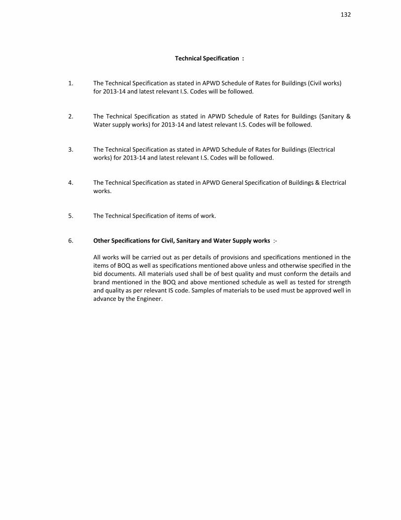
132
Technical Specification :
1. The Technical Specification as stated in APWD Schedule of Rates for Buildings (Civil works) for 2013-14 and latest relevant I.S. Codes will be followed.
2. The Technical Specification as stated in APWD Schedule of Rates for Buildings (Sanitary & Water supply works) for 2013-14 and latest relevant I.S. Codes will be followed.
3. The Technical Specification as stated in APWD Schedule of Rates for Buildings (Electrical works) for 2013-14 and latest relevant I.S. Codes will be followed.
4. The Technical Specification as stated in APWD General Specification of Buildings & Electricalworks.
5. The Technical Specification of items of work.
6. Other Specifications for Civil, Sanitary and Water Supply works :-
All works will be carried out as per details of provisions and specifications mentioned in the items of BOQ as well as specifications mentioned above unless and otherwise specified in the bid documents. All materials used shall be of best quality and must conform the details and brand mentioned in the BOQ and above mentioned schedule as well as tested for strength and quality as per relevant IS code. Samples of materials to be used must be approved well in advance by the Engineer.

133
TECHNICAL SPECIFICATION FOR INTERIOR WORKS FOR
ASSAM LEGISLATIVE ASSEMBLY
PREAMBLES
1.0 The work shall be carried out strictly in accordance with the particular specifications and drawings. The drawing and specification shall be taken complimentary and also supplementary to each other and shall from part of this contract. Any work or material shown on drawing and not specifically included in specification or vice versa shall be executed and deemed to have been included in the scope of work for rate or items. If any item required for requirement for its functional utility and not specifically included in either BOQ or in drawings, the same is supposed to be included in the rates of items of BOQ.
2.0 Wherever no specification is included in the specifications but item shown on drawing, the same are to be specified by the approved manufacturer of the product and manufacturer’s specification should be followed.
3.0 The tenderer shall inspect the site and ascertain all the conditions impediments and facilities available there and shall cater for all contingencies expenses to complete the work in all respects.
4.0 The items in the BOQs shall briefly cover the specifications and in drawings. The technical specifications given hereinafter will be supplementary to the description given in BOQ.
5.0 The specification of earth work, PCC, brickwork and R.C.C. etc. shuttering, reinforcements and steel work wherever required should be as specified on the Assam PWD Specifications. No separate specification for these items have been specified in this tender. In case of valuation of the items APWD schedule 2013 shall be followed.
6.0 The built in furniture and loose furniture articles where specification are not exhaustively given either in the description of BOQ, these shall be carried out as per approved manufacturers’ specifications. The quality of steel, timber, plywood and block boards are to be as per specification in the latest ISS Specifications. Timber used shall be well seasoned and within the specified quality and density. No immature or unseasoned timber should be used in the work. Contractor will have to produce sample of the species of timber for approval from Engineer-in-charge.
7.0 All fittings, fixtures and accessories for furniture, doors windows and panellings shall be of approved make from Hafele, Hettich, Hilti or DORMA. List of vendors are also included in the vendors list.
8.0 Contractor have to produce the samples of all items of work and get the approval of Engineer-in-charge or Architect before actual work on ground start. Standard of acceptance should be obtained and the samples shall be maintained till completion of work.
9.0 Wherever manufactured loose furniture is shown on drawing with manufacturer’s trade marking, the said articles are to be got approved from Engineer-in-charge before ordering the bulk quantity. However, it will not absolve contractor’s responsibility for any defective material supplied by the manufacturer. Manufacturer’s guarantee also to be handed over to the Engineer-in-charge before completion of the work. For all furniture items guarantee of minimum 10 years
134
should be given by contractor. TECHNICAL SPECIFICATION FOR INTERIOR WORKS
1. MATERIALS :
All materials used in the work shall be of respective kind and quality as specified in the schedule of quantities, obtained from approved source/manufacturer and shall be subjected to prior approval of the Engineer-in-Charge/Interior Designer. Samples of materials shall be got approved before placement of order and approved samples shall be deposited with the Engineer-in-Charge/Interior Designer’s office. Specification of all building materials, dismantling, redoing etc. will be as specified in APWD Schedule.
2. WORKMANSHIP :
All works shall be of best workmanship and shall be carried out in proper manner and in accordance with sound engineering practice to the satisfaction of the Engineer-in-Charge/ Interior Designer. No work shall be considered complete until the Engineer-in-Charge / Interior Designer’s certificate in writing that it has been completed.
Levels of finish and quality of workmanship should be of international standards. Contractor should deploy the Craftsman who can produce that type of finish in the interior works. Neat and superior finish is the essence of the contract.
3. APPLICATION OF WHITE CEMENT BASED WALL CARE PUTTY :
Surface at wall / ceiling where specified shall be treated with white cement base wall care putty of minimum thickness 1.5 mm. The particular brand of the special plaster and its composition must be previously approved by the Engineer-in-Charge/Interior Designer. The basic materials for the putty shall be white cement. The entire surface must be very smooth and unevenness must be removed.Before application of wall care putty, the surface to be treated shall be thoroughly cleaned, brushed and scrapped properly and then all holes, cracks, and patches shall be made good with approved materials.
4. APPLICATION OF PLASTER OF PARIS
Surface of walls / ceilings where specified shall be treated with Plaster of Paris of minimum thickness 1.5mm. The particular brand of this special plaster and its composition must be previously approved by the E.I.C. The basic materials for the plaster shall be either Calcium Sulphate or Gypsum. The entire surface must be very smooth and unevenness must be removed. Special trained and skilled artisans with previous experience of this work will have to be employed for the purpose of achieving high grade finish.
Before application of Plaster of Paris the surface to be treated shall be thoroughly cleaned, brushed and patching must be scraped properly, and then all holes, cracks, and patches shall be made good with approved materials..
5. ARTIFICIAL STONE/PATENT STONE FLOORING / PCC FLOORING
It shall consists of an underbed and a topping; laid on matured concrete base.
a) Thickness :
135
I) Underbed : Unless otherwise specified the underbed thickness shall be of 22 mm to 32 mm.
ii) Topping : The top finish thickness shall be of 3 mm
b) MiX :
i) Underbed : 1 part by Volume of cement : 2 parts by Vol. of course sand : 4 parts by volume of stone chips.
ii) Topping : The top finish thickness shall be of 3 mm.
c) Laying :
The toppings including the underbed shall be laid in alternated bays or in chequred board pattern. No panel shall be cast in contact with another already laid till the contraction of the letter has already taken place. The maximum area of each panel shall be 3 sq.m of which no side shall be more than 2 M long. A cement grout shall be applied and workedinto the surface to receive the finish, the underbed then laid, compacted and levelled to proper grade with a screed or float. The topping shall be applied evenly on the underbed while it is not fully set but firm enough and rolled and pressed to get full bond. The topping shall trowelled to a dense finish to the satisfaction of the Engineer. All trowel marks shall be mopped out with a soft cloth to give a clean smooth surface.
d) Curing :
After the surface is sufficiently set, the finished floor shall be kept moist for a minimum period of 7 (seven) days. If desired the finish shall be polished as directed.
6.0
6.1
GRANITE STONE IN FACIA, DADO FLOOR
Materials :
Shall be of selected quality, hard, sound, dense and homogeneous texture, free from cracks, decay, weathering of flaws. Stone slabs shall be of uniform colours and as approved by the Architect/Employer. They shall be machine cut and machine polished / honed finish / leather finished where specified and shall conform to the required sizes. Thickness shall be as specified in the respective items. Source of all granite stone shall be from South India.
6.2. Workmanship :
Stone or stone slab shall be of size as shown on drawings or as directed by Consultants. Exposed faces, full beds and joints shall be dressed/finished as directed. Joints shall be cut square to the face and shall be at right angles to each other or as directed. The facing shall be fixed truly in plumb and in perfect place straight or curved as shown on drawing, the bed being fully flushed with mortar. The joints shall be exactly vertical and horizontal. The joints shall be exactly vertical and machine polished/fine tooled/clear punched and chisel dressed work. The stones shall break joins for about half height of the coarse. Courses shall be shown on the drawing or as directed. Gap between the facing stone and the wall shall be filled with 1:4 cement mortar. Small pieces of stone to be fixed with approved epoxy based adhesive at the back of each stone pieces and kept at least 48 hours for curing prior fixing. Gun metal, wrought iron/copper pins and hold fasts shall be used as and wherever directed. Lead
136
caulking shall be used for fixing holdfasts. The surface shall be protected from sun and rain and cured for ten days. Face shall be finished as specified or directed after pointing the joints with approved joint filler.
7.0 PRE-POLISHED KOTA STONE FLOORING/WALL CLADDING
It shall be hard, sound, dense and homogenous in texture with crystalline and coarse grains. It shall be free from stains, cracks, decay and weathering, flaws, defects or damages.
7.1.
7.1.1
Materials :
Kota Stone slabs - The slabs shall be of selected quality of approved sizes, as shown on drawings, hard, sound, dense and homogenous in texture, free from cracks, decay, weathering and flaws. They should be of the colour indicated in the drawings or as instructed by the Architect/Employer. The slabs shall have the top (exposed) face polished before being brought to site.
The slabs shall conform to the size required. Before starting the work, the contractor shall get the samples of slabs approved by the Engineer-in-Charge.
7.2 Workmanship :
7.2.1. Dressing of Slabs - Each slab shall be cut to the required size and shape and fine chisel dressed at all the edges to the full depth. The sides thus dressed shall have a full contact if a straight edge is laid along. The sides shall be table rubbed with coarse sand or machine rubbed before paving. All angles and edges of the slabs shall be in true square and free from chippings giving a plane surface.
7.2.2. Thickness - Thickness shall be 25 to 37.5 mm or as specified in the item. Tolerance allowed shall be as under :-The thickness should be as specified with a tolerance of +/- 2 mm.
7.2.3. Preparation of Surface - The surface shall be clean and wetted thoroughly before commencing the fixing work.
7.2.4 Kota stone fixing arrangement on walls :-
At the back of all the stone slab small piece of stone chips to be fixed with epoxy based adhesive and kept for 48 hrs. for curing. The entire back surface of the stone slab to be covered with non-skid adhesive prior pressing it over the (20mm thick minimum) green mortar (1 cement: 4 coarse sand) Gunmetals / copper pins and hold fasts shall be used for fixing of stone on wall. Pins will be fixed by lead caulking. The stone slabs thus fixed are to be properly supported till it fixed with the bed mortar rigidly. Proper tools should be used while fixing the slab. Care should be taken that no cavity is formed behind the stone slab with the wall. The joints should be filled up with approved joint filler.
7.2.5. Laying for flooring -
Sub-grade shall be cleared, wetted and mopped, bedding for kota stone shall be of 1:4 cement sand mortar of minimum thickness at any place not be less than 10mm. The slab shall be washed clean before laying. It shall be laid on top, pressed, tapped gently to bring it in level with the other slabs. It shall then be lifted and laid aside. Top surface of the mortar shall then be corrected by adding fresh mortar at hollows or depressions. The mortar is then allowed to
137
harden a bit. Over this surface is bid a cement slurry of honey like consistency at 4.4 kg of cement per square metre. The edges of the slabs already paved shall be buttered with gray or white cement with or without pigment to match the shade of the kota slabs as given in the description of item. The slab shall then be gently placed in position and taped with wooden mallet till it is properly bedded, in level with and close to the adjoining slab. The joint shall be as fine as possible and surplus cement on the surface of the slab shall be removed. The slabs fixed in the floor adjoining the walls shall enter not less than 10 mm under the plaster, skirting or dado. The junction between the wall and floor shall be finished neatly. The finished surface shall be true to lines, levels and slopes as specified in the drawing and or instructed by Architect/Employer.
7.2.6 Curing - The floor shall be cured for a minimum period of seven days/or as per direction of E.I.C.
7.2.7. Rates to Include - Apart from other factors mentioned elsewhere in this contract, the rates for item of kota stone flooring/cladding shall include for the following :-
i) All labour, materials and equipment, consumables, including preparing/ treating the surface of the base or structural member to the required line and level or slope, cutting to the required configuration cleaning the sub-base, laying mortar bed and cement grout and fixing kota stone slab as specified above, and making up the joints.
ii) Any cutting and waste if required.
iii) Curing (wherever necessary).
iv) Cleaning the surface from all stains etc.
v) Forming coves at junctions of well and rounding or nosing at the edges, including butting or making holes in slabs for providing opening in floor wherever required and finishing of the same with the adjoining surface.
vi) Work at all positions/ heights/depths line and level and with all lead and lift.
7.2.8. Mode of Measurement :
The measurement shall be in square metres for the actual kota stone flooring/wall cladding provided.
8.0
8.1.
CERAMIC TILE FLOOR
Materials :
Ceramic tiles should conform to I.S. 770, B.S. 6431, E.N. 777 of the latest editions. Sizes may be 600x600 mm / 450 x 450 mm / 300 x 300 mm. The thickness of the tiles shall vary from 7.3 mm to 9.5 mm. The colours and brand shall be approved by E.I.C.
8.2. Workmanship :
138
8.2.1 Sub-floor preparation - The floor should be structurally sound and rigid and cleared off waxy / oily films and curing compounds. Surface must be free from rising dampness and hydrostatic pressure. If required, the floor should be levelled with screed concrete as per directions of the E.I.C.
8.2.2. Floor layout - The room should be squared off, measured and chalk lines are snapped. Once in place, lay loose tiles across the slope in both directions to balance the room so that the cut lines are of the same size on each wall.
8.2.3. Fixing - Tile fixing adhesive shall be applied on the entire back surface of the tiles and pressed rigidly on the levelelled subbase firmly and pitted with wooden mallet etc. The joints should be filled with approved tile joint filler.
9.0
9.1.
CERAMIC TILES IN DADO/SKIRTING
Materials :-
Ceramic tiles - Sizes may 200 x 200mm / 200 x 300mm / 300x450mm, the thickness of tiles shall vary from 5mm to 9.5mm. The colours and brand or design shall be approved by the Architect/E.I.C.
9.2. Mortar Backing :-
All joints in the face work shall be racked out to a depth equal to not less than the width of the joints or as directed by the Architect/E.I.C. Concrete surfaces shall be properly backed to the lines and levels. All dirt, oil, dust or any other loose materials that might interfere with satisfactory bond shall be removed. The surface shall be cleaned and scrubbed with fresh water and kept wet for 6 hours prior to applying backing mortar. The dado/skirting work shall not be commenced unless the preparatory work is approved by the Architect/E.I.C. The proportion of mortar for backing shall be 1:4 cement mortar (1 cement : 4 coarse sand). The thickness of mortar backing shall not be less than 15mm.
9.3. Workmanship :-
a) Fixing of Tiles :-
Tile fixing adhesive shall be applied on the entire back surface of the tiles and pressed rigidly on the levelling sub-base firmly and pitted with wooden mallet etc. The joints should be filled with approved tile joint filler.
b) After the tiles have been fixed the surplus mortar that may have been come out of the joints shall be cleared off before it sets. After the complete curing, the dado or skirting work shall be washed thoroughly clean.
9.4. Rates to include :-
Apart from other factors mentioned elsewhere in this contract, the rates for the items of dado or skirting shall include the following :-
139
i) Preparing/tracing the surface of the base or structural member to the required line, level or slope to the specified configuration with all bye works.
ii) Backing mortar.
iii) Providing and fixing tiles including all specials, like round edges, angles, copings etc. in neat cement float over backing mortar including cutting of tiles and wastage of tiles etc.
iv) Jointing of the tiles with approved tile joint filler.
v) Curing.
vi) Cleaning the wall, dado, skirting surface and flooring from all stairs and removal of all debris.
vii) All labours, material, use of tools and equipments and consumables for carrying out the items as specified above including all bye-works for achieving the required surface finish.
viii) Work at all positions, heights depths, line, and level, with all lead and lift.
Mode of Measurement :-
Measurement shall be in Sq.m. as provided.
10.0 MARBLES & GRANITES :
Marbles to be used shall be hard, dense and durable and of selective quality. These shall be obtained from the approved supplier. The shades of marble to be used shall be approved by the Interior Designer / Engineer-in-Charge before laying the same. These shall be free from any cracks or other defects developed during sawing
Pre-polished granite shall be of approved shades and colour and of selective quality. These shall be hard, dense and shall be obtained from the approved supplier. These shall be free from any sorts of cracks.
11.0
11.1.
11.1.1
MARBLE FLOORING / GRANITE STONE FLOORING
Materials :
Marble Slab -
The marble shall be approved shade/texture and sources as mentioned in the schedule of quantities and their size and the thickness shall be as shown on the drawings and as approved by the Architect/Employer. They shall be of selected quality, hard, dense, uniform and homogeneous in texture and free from flaws, cracks or other structural defects. It shall have even and crystalline grains. The surface shall be machine polish to an even and perfectly plain surface and edges machine cut true and square. The rear face shall be rough enough to provide a key for the mortar. No slab shall be thinner than the specified thickness at its thinnest part. A few approved samples of finished slabs to be used shall be deposited by the contractor in the office of the Architect/Employer. Unless otherwise mentioned the thickness of the marble shall be of not less than 18 mm.
Granite slabs shall not be less than 18 mm thick and will conform to all physical characteristics as stated in above para. Thickness of flamed granites shall not be less than 25mm or as
140
specified in the item. 11.1.2. Concrete Base & Mortar Bedding
The base of cement concrete shall be laid and compacted to a true plain surface and to the required slopes and below the level of the finished floors to the extent of the thickness of the slabs and mortar bedding. Cement mortar for bedding may be mixed manually or by a mechanical mixer as directed. The amount of water added shall be the minimum necessary to give just sufficient plasticity for laying and satisfactory bedding. Care shall be taken in preparing the mortar to ensure that there are no hard lumps that would interfere with the even bedding of the stones. Before spreading the mortar sub-floor or base shall be prepared/ treated exactly to the lines, levels and slopes, cleaned of all dirt, scum, or loose materials and then well wetted without forming any pool of water on the surface. In case of R.C.C floors, the top shall be left a little dry. All point of level for the finished paving surface shall be marked out. The mortar shall then be evenly and smoothly spread over the base by the use of screed battens only over so much area as will be covered with slabs within half an hour. The thickness of the mortar bedding shall not be less than 20 mm.
For laying granite flooring above procedure should be followed.
11.1.3 Workmanship (For marble stones slabs and granite stone slab)
11.1.4 Laying Marble slabs / granite stone slab - Before laying , the marble shall be thoroughly wetted with clean water. Neat cement grout of honey like consistency shall be spread on the mortar bed over as much area as could be covered with the slabs within half an hour. The specified type of marble slabs shall be laid to pattern as directed on the neat cement float and shall be evenly and firmly laid to pattern as directed to the required level and slope in the mortar bed Each slab shall be gently tapped with a wooden mallet, till it is firmly and properly bedded. There shall be no hollows left. If there is a hollow sound gently tapping on the slabs, such slabs shall be removed and rested properly.
The edges of the slabs shall be buttered with slurry of gray/white cement mixed with pigment matching the colour of stone slab and joint shall be hair fine in width and straight line grouted with neat coloured cement slurry to match the colour of the marble. The Joints shall be struck smooth but there shall be no smearing over the mortar of the slabs. The edges of the adjoining slabs shall be in one plan. All surplus cement slurry Shall be removed and the surface wiped out clean with wet soft cloth.
The flooring shall be kept undistrubed for at least 7 days, and wet of fourteen days. Marble flooring shall be finished as specified by the Architect/Consultant.
The same procedure shall be followed while laying granite stone slabs.
11.1.5 Rates to include :
Apart from other factors mentioned elsewhere in this contract, the rates for item of marble flooring shall include for the following :
i) Preparing/treating the sub-floor or base.
ii) All labour, materials and equipments and consumables, sub-base, laying mortar bed and cement grout and fixing marble slabs, as specified above and making up the joints including grinding and finishing to the satisfaction of Architect/Employer, polishing and all bye works.
141
iii) Any cutting and wastages, if required, to make it in required size/shape and configuration as specified in the drawing.
iv) Curing and removal of muck.
v) Cleaning the floor from all stains etc.
vi) Forming coves at junctions of wall, rounding or nosing at the edge and making holes or opening wherever required and finishing with the adjoining surface and machine polishing wherever required.
vii) At all positions, heights, depths, line and level, with all lead and lift.
11.1.6 Mode of Measurement :
The measurement shall be in sq. metres for the actual marble / granite stone flooring provided.
12.0
12.1.
ARTIFICIAL STONE FLOORING WITH HARDENER
Flooring with Non-metallic floor hardner
It shall consist of an underbed and a topping laid on an already laid and matured concrete base.
a) Thickness : Unless otherwise specified, the underbed thickness shall be of 40mm and topping shall be of 12 MM.
b) Mix :
i) Underbed : 1 part by vol. of cement +2 parts by vol. of course sand + 4 parts by vol. of 10mm graded stone chips.
c) Materials :
The material should be ready to use, high abrasion and wear resistant. Bonds monolithically to the base concrete. It must be resistant to oils and grease and should not shrink or crack. The materials should conforms to IS-1237 and ASTM-E97. The material should be single component and have compressive strength of 70N/Sq.mm. after 28 days curing.
d) Application :
The material should be evenly spread on the freshly laid concrete surface when it has set initially but still green enough to react with the floor hardener. Wooden floats or power trowel with disc may be used to make the surface uniformly finished smooth. the procedure of application and finishing as laid down by the manufacturers may be followed. The rate of application shall be 5 kg. of Hardener per sq. metre of area.
e) Curing :
The floor with non-metallic hardener finish should be cured for 28 days before putting it on to traffic.
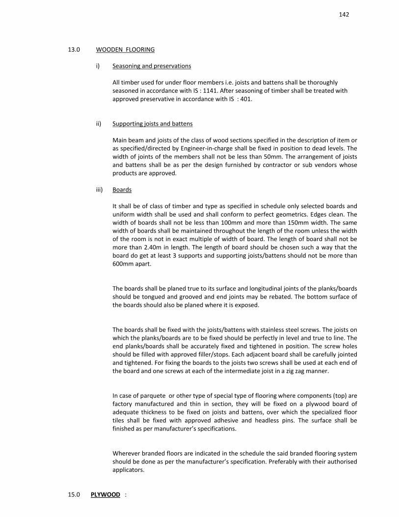
142
13.0 WOODEN FLOORING
i) Seasoning and preservations
All timber used for under floor members i.e. joists and battens shall be thoroughly seasoned in accordance with IS : 1141. After seasoning of timber shall be treated with approved preservative in accordance with IS : 401.
ii) Supporting joists and battens
Main beam and joists of the class of wood sections specified in the description of item or as specified/directed by Engineer-in-charge shall be fixed in position to dead levels. The width of joints of the members shall not be less than 50mm. The arrangement of joists and battens shall be as per the design furnished by contractor or sub vendors whose products are approved.
iii) Boards
It shall be of class of timber and type as specified in schedule only selected boards and uniform width shall be used and shall conform to perfect geometrics. Edges clean. The width of boards shall not be less than 100mm and more than 150mm width. The same width of boards shall be maintained throughout the length of the room unless the width of the room is not in exact multiple of width of board. The length of board shall not be more than 2.40m in length. The length of board should be chosen such a way that the board do get at least 3 supports and supporting joists/battens should not be more than 600mm apart.
The boards shall be planed true to its surface and longitudinal joints of the planks/boards should be tongued and grooved and end joints may be rebated. The bottom surface of the boards should also be planed where it is exposed.
The boards shall be fixed with the joists/battens with stainless steel screws. The joists on which the planks/boards are to be fixed should be perfectly in level and true to line. The end planks/boards shall be accurately fixed and tightened in position. The screw holes should be filled with approved filler/stops. Each adjacent board shall be carefully jointed and tightened. For fixing the boards to the joists two screws shall be used at each end of the board and one screws at each of the intermediate joist in a zig zag manner.
In case of parquete or other type of special type of flooring where components (top) are factory manufactured and thin in section, they will be fixed on a plywood board of adequate thickness to be fixed on joists and battens, over which the specialized floor tiles shall be fixed with approved adhesive and headless pins. The surface shall be finished as per manufacturer’s specifications.
Wherever branded floors are indicated in the schedule the said branded flooring system should be done as per the manufacturer’s specification. Preferably with their authorised applicators.
15.0 PLYWOOD :
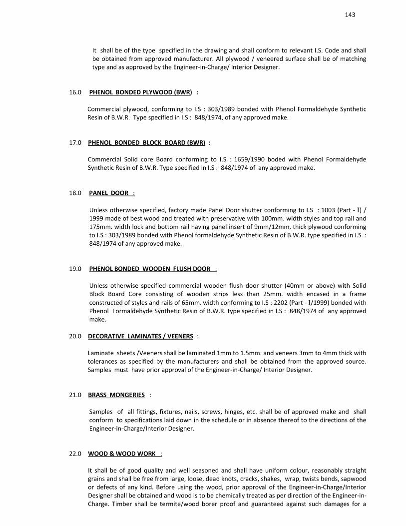
143
It shall be of the type specified in the drawing and shall conform to relevant I.S. Code and shall be obtained from approved manufacturer. All plywood / veneered surface shall be of matching type and as approved by the Engineer-in-Charge/ Interior Designer.
16.0 PHENOL BONDED PLYWOOD (BWR) :
Commercial plywood, conforming to I.S : 303/1989 bonded with Phenol Formaldehyde Synthetic Resin of B.W.R. Type specified in I.S : 848/1974, of any approved make.
17.0 PHENOL BONDED BLOCK BOARD (BWR) :
Commercial Solid core Board conforming to I.S : 1659/1990 boded with Phenol Formaldehyde Synthetic Resin of B.W.R. Type specified in I.S : 848/1974 of any approved make.
18.0 PANEL DOOR :
Unless otherwise specified, factory made Panel Door shutter conforming to I.S : 1003 (Part - ) / 1999 made of best wood and treated with preservative with 100mm. width styles and top rail and 175mm. width lock and bottom rail having panel insert of 9mm/12mm. thick plywood conforming to I.S : 303/1989 bonded with Phenol formaldehyde Synthetic Resin of B.W.R. type specified in I.S : 848/1974 of any approved make.
19.0 PHENOL BONDED WOODEN FLUSH DOOR :
Unless otherwise specified commercial wooden flush door shutter (40mm or above) with Solid Block Board Core consisting of wooden strips less than 25mm. width encased in a frame constructed of styles and rails of 65mm. width conforming to I.S : 2202 (Part - /1999) bonded with Phenol Formaldehyde Synthetic Resin of B.W.R. type specified in I.S : 848/1974 of any approved make.
20.0 DECORATIVE LAMINATES / VEENERS :
Laminate sheets /Veeners shall be laminated 1mm to 1.5mm. and veneers 3mm to 4mm thick with tolerances as specified by the manufacturers and shall be obtained from the approved source. Samples must have prior approval of the Engineer-in-Charge/ Interior Designer.
21.0 BRASS MONGERIES :
Samples of all fittings, fixtures, nails, screws, hinges, etc. shall be of approved make and shall conform to specifications laid down in the schedule or in absence thereof to the directions of the Engineer-in-Charge/Interior Designer.
22.0 WOOD & WOOD WORK :
It shall be of good quality and well seasoned and shall have uniform colour, reasonably straight grains and shall be free from large, loose, dead knots, cracks, shakes, wrap, twists bends, sapwood or defects of any kind. Before using the wood, prior approval of the Engineer-in-Charge/Interior Designer shall be obtained and wood is to be chemically treated as per direction of the Engineer-in-Charge. Timber shall be termite/wood borer proof and guaranteed against such damages for a
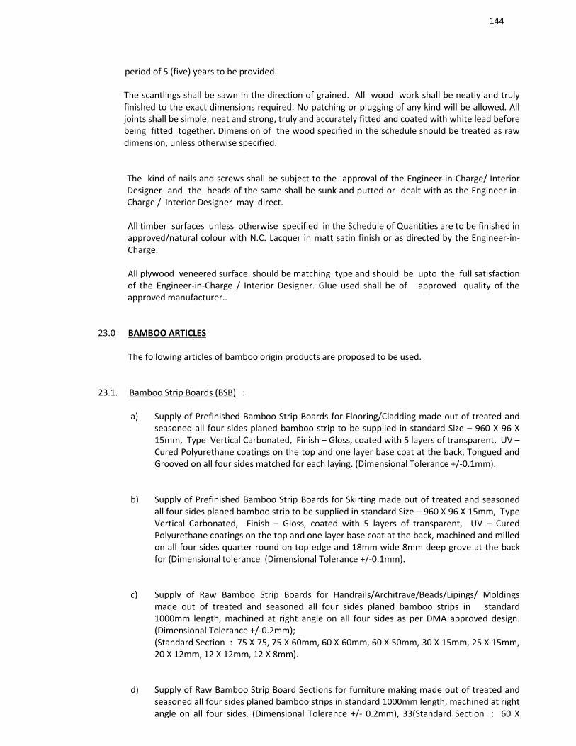
144
period of 5 (five) years to be provided.
The scantlings shall be sawn in the direction of grained. All wood work shall be neatly and truly finished to the exact dimensions required. No patching or plugging of any kind will be allowed. All joints shall be simple, neat and strong, truly and accurately fitted and coated with white lead before being fitted together. Dimension of the wood specified in the schedule should be treated as raw dimension, unless otherwise specified.
The kind of nails and screws shall be subject to the approval of the Engineer-in-Charge/ Interior Designer and the heads of the same shall be sunk and putted or dealt with as the Engineer-in-Charge / Interior Designer may direct.
All timber surfaces unless otherwise specified in the Schedule of Quantities are to be finished in approved/natural colour with N.C. Lacquer in matt satin finish or as directed by the Engineer-in-Charge.
All plywood veneered surface should be matching type and should be upto the full satisfaction of the Engineer-in-Charge / Interior Designer. Glue used shall be of approved quality of the approved manufacturer..
23.0 BAMBOO ARTICLES
The following articles of bamboo origin products are proposed to be used.
23.1. Bamboo Strip Boards (BSB) :
a) Supply of Prefinished Bamboo Strip Boards for Flooring/Cladding made out of treated and seasoned all four sides planed bamboo strip to be supplied in standard Size – 960 X 96 X 15mm, Type Vertical Carbonated, Finish – Gloss, coated with 5 layers of transparent, UV –Cured Polyurethane coatings on the top and one layer base coat at the back, Tongued and Grooved on all four sides matched for each laying. (Dimensional Tolerance +/-0.1mm).
b) Supply of Prefinished Bamboo Strip Boards for Skirting made out of treated and seasoned all four sides planed bamboo strip to be supplied in standard Size – 960 X 96 X 15mm, Type Vertical Carbonated, Finish – Gloss, coated with 5 layers of transparent, UV – Cured Polyurethane coatings on the top and one layer base coat at the back, machined and milled on all four sides quarter round on top edge and 18mm wide 8mm deep grove at the back for (Dimensional tolerance (Dimensional Tolerance +/-0.1mm).
c) Supply of Raw Bamboo Strip Boards for Handrails/Architrave/Beads/Lipings/ Moldings made out of treated and seasoned all four sides planed bamboo strips in standard 1000mm length, machined at right angle on all four sides as per DMA approved design. (Dimensional Tolerance +/-0.2mm);(Standard Section : 75 X 75, 75 X 60mm, 60 X 60mm, 60 X 50mm, 30 X 15mm, 25 X 15mm, 20 X 12mm, 12 X 12mm, 12 X 8mm).
d) Supply of Raw Bamboo Strip Board Sections for furniture making made out of treated and seasoned all four sides planed bamboo strips in standard 1000mm length, machined at right angle on all four sides. (Dimensional Tolerance +/- 0.2mm), 33(Standard Section : 60 X
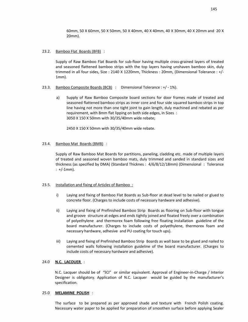
145
60mm, 50 X 60mm, 50 X 50mm, 50 X 40mm, 40 X 40mm, 40 X 30mm, 40 X 20mm and 20 X 20mm).
23.2. Bamboo Flat Boards (BFB) :
Supply of Raw Bamboo Flat Boards for sub-floor having multiple cross-grained layers of treated and seasoned flattened bamboo strips with the top layers having unshaven bamboo skin, duly trimmed in all four sides, Size : 2140 X 1220mm, Thickness : 20mm, (Dimensional Tolerance : +/-1mm).
23.3. Bamboo Composite Boards (BCB) : Dimensional Tolerance : +/ - 1%).
a) Supply of Raw Bamboo Composite board sections for door frames made of treated and seasoned flattened bamboo strips as inner core and four side squared bamboo strips in top line having not more than one tight joint to gain length, duly machined and rebated as per requirement, with 8mm flat lipping on both side edges, in Sizes :3050 X 150 X 50mm with 30/35/40mm wide rebate;
2450 X 150 X 50mm with 30/35/40mm wide rebate.
23.4. Bamboo Mat Boards (BMB) :
Supply of Raw Bamboo Mat Boards for partitions, paneling, cladding etc. made of multiple layers of treated and seasoned woven bamboo mats, duly trimmed and sanded in standard sizes and thickness (as specified by DMA) (Standard Thicknes : 4/6/8/12/18mm) (Dimensional : Tolerance : +/-1mm).
23.5. Installation and fixing of Articles of Bamboo :
i) Laying and fixing of Bamboo Flat Boards as Sub-floor at dead level to be nailed or glued to concrete floor. (Charges to include costs of necessary hardware and adhesive).
ii) Laying and fixing of Prefinished Bamboo Strip Boards as flooring on Sub-floor with tongue and groove structure at edges and ends tightly joined and floated freely over a combination of polyethylene and thermorex foam following free floating installation guideline of the board manufacturer. (Charges to include costs of polyethylene, thermorex foam and necessary hardware, adhesive and PU coating for touch ups).
iii) Laying and fixing of Prefinished Bamboo Strip Boards as wall base to be glued and nailed to cemented walls following installation guideline of the board manufacturer. (Charges to include costs of necessary hardware and adhesive).
24.0 N.C. LACOUER :
N.C. Lacquer should be of “CI” or similar equivalent. Approval of Engineer-in-Charge / Interior Designer is obligatory. Application of N.C. Lacquer would be guided by the manufacturer’s specification.
25.0 MELAMINE POLISH :
The surface to be prepared as per approved shade and texture with French Polish coating. Necessary water paper to be applied for preparation of smoothen surface before applying Sealer
146
coat. After drying of first coat of Melamine polish water paper to be applied before second and third coat of final polishing. The work has to be carried out to the satisfaction of the Engineer-in-Charge / Interior Designer.
26.0 PREPARATORY WORKS FOR PAINTING ETC. :
Painting, polishing, plaster of Paris work etc. shall not be taken up unless the surfaces to be so treated are made ready with all related preliminary works and the approval of the Engineer-in-Charge / Interior Designer is obtained.
27.0 GYPBOARD CEILING :
Gypbaord ceiling shall be obtained either from the manufacturer or of their authorized dealers.(M/s. Gyproc of St. Gobain, M/s. Lloyd Insulation or of M/s. India Gypsum Ltd. etc.
The entire installation work is to be carried out in conformity with manufacturer’s specification and as per detail drawing of the Interior Designer.
28.0 CEILING LININGS :
28.1.1. M/F suspended ceiling regular (single layer) (GS-MFSC-4.1).
28.1.2. M/F suspended ceiling which includes G.I. perimeter channels of size 0.55mm thick having one flange of 20mm and another flange of 30mm and a web of 27mm alongwith perimeter of ceiling, screw fixed to brick wall/partition with the help of nylon sleeves and screws, at 610mm centers. Then suspending G.I. having hologram intermediate channels of size 45mm, 0.9mm thick with two flanges of 15mm each from the soffit at 1220mm centers with ceiling angle of width 25mm x 10mm x 0.55mm thick fixed to soffit with G.I. cleat and steel expansion fasteners. Ceiling section of 0.55mm thickness having knurled wed of 51.5nn and two flange of 26mm each with lips of 10.5mm are then fixed to the intermediate channel with the help of connecting clip and in direction perpendicular to the intermediate channel at 457mm centers, 12.5mm tapered edge Gypboard (confirming to IS: 2095-1982 & 2542-1981) is then screw fixed to ceiling section with 25mm drywall screws at 230mm centers. Screw fixing is done mechanically either with screwdriver or drilling machine with suitable attachment.
28.1.3. Finally the boards are then jointed and finished so as to have flush look which includes filling and finishing the tapered and square edges of the boards with jointing compound, joint paper tape and two coats of drywall top coat suitable for Gypboard (as per recommended practices of India Gypsum or equivalent).
Note : For light fittings, grill diffusers & cutouts etc. have to be made with frame of perimeter channels of size 20mm x 27mm x 30mm x 0.55mm thick, supported suitably.
28.1.4. Metal stud partition (Single layer) (GS-MSP-975-1.2)
28.1.5. 97mm thick Metal stud partition which includes one layer of tapered edge 12.5mm thick Gypboard (conforming to IS :2095-1982 & 2542-1981) Screw fixed with 25mm drywall screw at 300mm centers to either side of 70mm studs (0.55mm thick having one flange of 34mm and
147
another flange of 36mm made of G.I. Steel having hologram) placed at 610mm center to center in 72mm floor and ceiling channel (0.55mm thick having two equal flanges of 32mm made of G.I. steel) with joints staggered to avoid through joints. Finally square and tapered edges of the boards are to be jointed and finished so as to have a flush book which includes filling and finishing with jointing compound, joint paper tape and two coats of drywall top coat suitable for Gypboard (as per recommended practices of India Gypsum or equivalent).
28.1.6. Specification of Luxalon Unperforated Linear Aluminium False Ceiling System – 84C/300C
a) Specification of Luxalon® UnPerforated Linear Aluminium False Ceiling System – 84C./300C
Luxalon 84C Unperforated Linear aluminum panel false ceiling system as manufactured by Hunter Douglas India Pvt. Ltd. or any other similar equivalent (shade as per Luxalon® Colour chart). The system shall consist of Panel 84mm wide X 12.5mm deep X 0.5mm thick with square edges andRecess Flange of 24mm in standard length of 1 meter – 6 meters. The Panels shall be coil coated on a continuous paint line, double baked & roll formed from stove enameled corrosion resistant aluminum alloy AA5050 (Al.Mg.) for higher strength & good roll forming characteristics. Panels shall be clipped to an enameled & roll formed Aluminum panel carrier of 32mm wide X 39mm deep X 0.90mm thick in standard length of 5 meters. The panel carrier shall be double baked & roll formed from enameled corrosion resistant aluminum alloy AA5050/5052 (Al.Mg.) in Black colour with cut outs to hold the panels in modules of 100mm & provide a 16mm closed gap between 2 panels.
The carriers shall be fixed at a distance of 1.3 meters c/c. The carriers shall be suspended from the roof by 4mm diameter G.I. suspension rod with special height adjustment clips made from spring steel. The rod hangers shall be fixed at a distance of 1.2 meters c/c. The G.I. rod hangers shall be fixed to the roof by ‘J’ hooks & nylon inserts.
Wherever required, two panels will be coupled horizontally with panel splice & similarly for carriers, carrier splice shall be used. At the perimeter, where the panels & wall meets ‘L’ Edge profile Powder coated shall be used.
b) Specification of Luxalon® UnPerforated Linear Aluminium False Ceiling System – 300C.
Luxalon 300C Unperforated Linear aluminum panel false ceiling system as manufactured by Hunter Douglas India Pvt. Ltd. or any other similar equivalent (shade as per Luxalon® Colour chart). The system shall consist of Panel 300mm wide X 29mm deep X 0.7mm thick. The panels to feature 5mm bevel edge to form a visually closed ‘V’ grove joint between 2 panels.
The panels shall be in standard length of 1 meter – 6 meters. The Panels shall be coil coated on a continuous paint line, double baked & roll formed from stove enameled corrosion resistant aluminum alloy AA3005 for higher strength & good roll forming characteristics. Panels shall be clipped to an enameled & roll formed Aluminum panel carrier of 41.5mm wide X 62mm deep X 0.95mm thick in standard length of 5 meters. The panel carrier shall be double baked & roll formed from enameled corrosion resistant aluminum alloy AA5052 (Al.Mg.) in Black colour with cut outs to hold the panels in modules of 300mm. The Carrier shall be provided with special Lock In Clips to lock the panels if desired. The first carriers shall be fixed at a distance of 300mm from the wall & thereafter at 1.3 meters c/c. The carriers shall be suspended from the roof by 4mm diameter G.I. suspension rod with special height adjustment clips made from spring steel. The rod hangers shall be fixed at a distance of 1.2 meters c/c. The G.I. rod hangers shall be fixed to the roof by ‘J’ hooks & nylon inserts. Wherever required, two panels will be coupled horizontally with pressure clips & similarly for
148
carriers, carrier splice shall be used. At the perimeter, where the panels & wall meets ‘L’ Edge profile Powder coated shall be used.
c) Paint Finish: The panels shall be chromatised for maximum bond between metal & paint & enameled twice under high temperature, visible side with full primer & finish coat & inner side with primer coat & skin coat in a continuous paint line.
28.1.7. G.I. FRAME WORK (600 X 600) CLADDED WITH 12MM PLY (BWR) BOARD FOR FALSE CEILING WORK
28.1.8. G.I. frame work (600 x 600) shall be consist of G.I. perimeter channels of size 0.55mm thick having one flange of 20mm and another flange of 30mm and a web of 27mm alongwith perimeter of ceiling, screw fixed to brick wall/partition with the help of nylon sleeves and screws at 600mm centers. Then suspending G.I. having hologram intermediate channels of size 45mm, 0.9mm thick with two flanges of 15mm each from the soffit at 1200mm centers with ceiling angle of width 25mm x 10mm x 0.5mm thick fixed to soffit with G.I. cleat and steel expansion fasteners. The ceiling section 0.5mm thick having knurled web of 51.5mm and two flanges of 26mm each with lips of 10.5mm are then fixed to the intermediate channels with the help of connecting clip and in the direction perpendicular to the intermediate channels at 457mm centers. 12mm BWR ply board as per IS : 740/1996 is then screw fixed to ceiling section with 25mm dry wall screws at 230mm centers. Screw fixing is done mechanically either with screwdriver or drilling machine with suitable attachment.
28.1.9. Plywood : Plywood shall be 12mm thick marine ply (WBP) as per IS 710/1996.
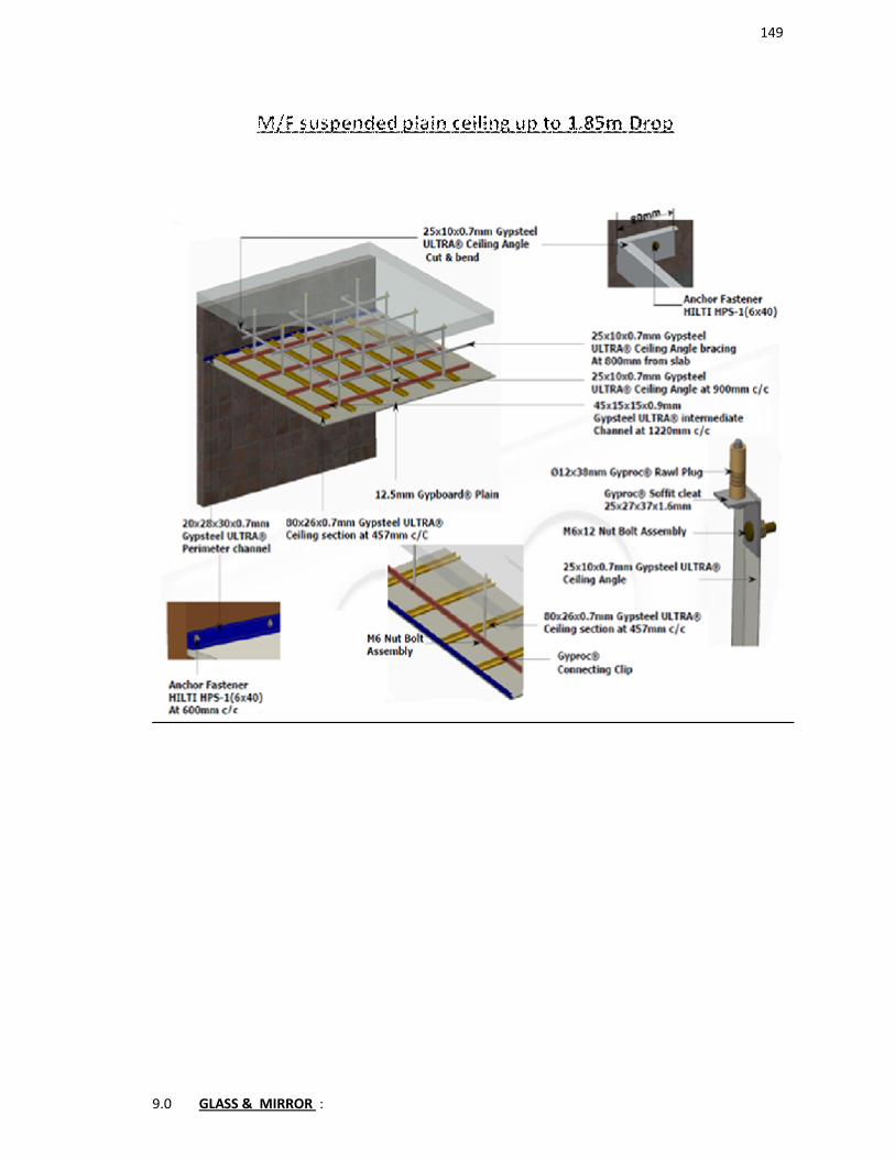
149
9.0 GLASS & MIRROR :
150
Glasses and mirrors shall be free from waves, scratches and any other defects and shall be of superior quality available in the market. Before using, samples to be got approved from the Engineer-in-Charge / Interior Designer.
30.0 HARDWARE :
All hardware materials should be of approved variety. Before using samples to be got approved from the Engineer-in-Charge / Interior Designer.
31.0 AUTOMATIC SLIDING DOORS :
Specification Text for Sliding Door Operator
Product :
DORMA ES200 Sliding Operator system or its equivalent system
Automatic sliding door operator
Automatic sliding door operator, modular design, including internal cover.
1/2 - panel sliding door
Operator Dimensions (H x T): 100 x 180 mm.
Microprocessor control, self-learning, reverses when obstruction is encountered.
Clear Passage Width :
2-panel = 900 – 2,000 mm (for 4,150mm Operator length)
2-panel = 900 – 3,000 mm (for 6,250mm Operator length)
Clear Passage Height :
LH = 2,100 mm – 3,000 mm
Door weight :
Bi-Parting Door Panel, max. 2 x 160 kg.
Single-Parting Door Panel, max. 1 x 200 kg
Function programs :
Program modes :
Off, Automatic, Permanent open, Partial opening, Exit only, Self-regulating partial open, Exit only partial opening, Night-bank facility. Compliant with future European standards and specifications as per EN 12650.
151
Microprocessor-controlled control unit. Self-learning, with adjustable parameters for opening and closing speed, hold-open time and opening and closing force. With pulse expansion for cheque card or code card reader or key switch. Class of protection IP 20.
Produced according to the guidelines for power-operated windows, doors and gates BGR 232, the UVV and the VDE regulations. TÜV design tested, tested according to the low voltage guidelines, production according to ISO 9001:2000 certification. Fulfils the DIN V18650 (EN 12650).
DORMA ES200 Operators are of very sturdy design with Self balancing Panel suspension system and with Anti-Jump fitting.
Operator System Section: 100 mm (Ht) X 180 mm (Depth).
With clip-on Cover Profile for easy installation and Service.
With separate Track Profile with Rubber lining with ‘Noise Reduction’ and Smooth-ride quality.
Program Function: Off, Automatic, Permanent open, Exit only, Partial open.
Night-bank switch (Optional) – Additional External Operation Switch incase Operator has been Locked.
Adjustable Hold Open Time: Hold Open is easily adjustable at module as per client’s requirement. Hold Open Range: 0.5 Sec – 30 Sec.
Adjustable Parameters Via parameter display and selection key at electronic module.
Adjustable closing Speed: 10 -50 Cm/S.
Adjustable Opening Speed: 10 – 70 Cm/S
Hold Open time: 0.5 – 60 Sec
Night Bank Opening time: 0.5 – 30 Sec
Auto Error Display, with Error Code Display for error correction.
Read-out error store with error codes
Additional Equipment Integration:
Connection for External 24V DC supply: Operator can be integrated and also supply operating voltage of 24V DC for one external device e.g. Smoke Detector, alarm system.
Carrier-head assembly designed for:
a.Frameless Glass Sliding Panels.
b.Aluminum / Wooden Framed Panels.
152
Emergency off – Connection for Emergency Off Button, On activation Operator will Open Fully and Stop all functions, enabling passenger to pass through in case of Panic.
Fail Safe / Fail Secure: Choice between emergency opening(Fail Safe) and emergency closing (Fail Secure) in the event of a power cut (with battery pack).
Connections for Air-Lock Control.
Safety devices :
Inbuilt Obstruction detection feature with automatic reversing cycle on obstruction, dynamic and static force limitation, emergency control unit (emergency stop).
Safety Photo Cells: 1 / 2 Pair of Photo Cells are provided for safety of passenger standing in line of motion of Moving Panel and for through-passage monitoring.
Operator can be also be integrated with following Systems.
Access Control System with Proximity Card system / Codic Card Reader.
Keypad System.
Biometric sensor system.
Push Buttons.
Connection :
230 V, 50/60 Hz, Stabilized-UPS Supply.
Activators :
(√) Radar system: 02 Nos, with 24 GHz, Mandatory as Int’Nat Standards.
(√) Light barriers: comprising receiver and transmi er -01 Pair
Locking :
(√ ) Electro-mechanical locking, Bi-stable.
Color light alloy parts :
(√) silver, Anodised E6/C0 - standard
32.0 PAINTING :
a) Ready mixed synthetic enamel paints and primer shall be of approved quality, colour and shall be obtained from approved ,manufacturer’s. These shall be in sealed containers. Surface to be painted shall be thoroughly cleaned sand papered and/or rubbed with emery cloth. In case of rusted steel surface, it shall be ensured all corroded rust is
153
removed. In case of timber, the knots and nail hole shall be filled with knotting and stopping materials. The prepared surface shall be allowed to dry and sand papered smooth. The paint shall be applied with brushes of type and size suitable for the job and subsequent coat shall be applied on the previous coat and care shall be taken so that dust or other foreign materials do not settle.
b) Textured paints shall be of approved quality, colour and shall be obtained from approved manufacturers. These shall be applied with foam roller or brush as per discretion of Interior Designer/Engineer-in-Charge. These shall be applied one or more coats as per the item described in B.O.Q.
32.1. MATERIAL :
The paint and primers in general shall be of approved quality, colour and shade.
32.2. SCAFFOLDING :
This shall be strong and stout, rigidly tied, catering to the safety needs and shall be double or single scaffolding as required and directed. If ladders are used, pieces of gunny bags or cloths bags shall be tied on their tops to avoid damage of scratches to the plastered surfaces. Proper stage scaffolding shall be erected when painting the ceiling.
32.3. PREPARATION OF THE SURFACE :
a) New Surface :
The surface to be painted shall be cleaned and all cracks, holes and surface defects shall be repaired with plaster of paris for spot fillings, and with filler prepared with whiting, water and a little quantity paint for filling and levelling the wider areas.
b) Old Surface :
i) The surfaces, which had been previously painted with emulsion paint, shall be lightly rubbed down and washed with clean water.
ii) The surface, which had been painted with oil bound distemper or oilpaint, shall be cleaned, washed and sand papered.
iii) The surface, finished with lime colour wash, powdered distemper, etc.shall be completely scrapped off to the bare surfaces.
iv) In case, after scrapping the surface, any cracks, holes or other surface defects are noted, the same shall be repaired, before applying priming coat, with plaster of paris for spot filling and with filler prepared with whiting, water and a little quantity of paint for filling and levelling the wider areas.
154
32.4. PRIMING COAT :
The priming coat of the approved shade shall be applied over the completely dry surface in the manner as recommended by the paint manufacturers. The emulsion paint in the priming coat may be thinned down with 20% water or as recommended by the paint manufacturer. Tarpentine or any other solvent shall not be used for thinning the paint.
32.5. APPLICATION OF PAINT :
The recommendation of approved paint manufacturer, whose product is used, shall be followed regarding the preparation of the surface and the application of the priming and finishing coats. The Contractor shall arrange for technical assistance and supervision from the paint manufacturer during the execution of the painting work. After the priming coat has been applied and perfectly dried, all holes, scratches, if any, shall be repaired as mentioned in preparation of surface and then the second coat of paint of shade of approved shade and manufacture shall be evenly applied and allowed to dry.
The third coat shall be carefully applied to achieve smooth and even surface after the previous coats have dried. Minimum 3 coats shall be applied inclusive of primer coat. All paint are to be applied with good quality brushes and finished with spongy roller so that no impressions of hair line remains on the surface. This is to be approved by Architects/Employer. If a proper and even surface is not obtained to the satisfaction of the Architect/Employer in coats, the Contractor shall carry out additional coats of painting for the approval of Architects/ Employer at Contractor's expenses. Care shall be taken so that dust or other foreign materials do not settle or disfigure the various coats.
32.6. RATES TO INCLUDE :
Apart from other factors mentioned elsewhere in the contract the rates for the item of paint shall include for the following :-
i) All labour, materials, consumables and equipment necessary to carry out the work.
ii) Supplying the approved emulsion paint for priming and finishing coats.
iii)
iv)
Preparing the surface for receiving the primer and finishing coats.
Providing scaffolding/ladder/platform/staging including its erections and dismantling.
v)
vi)
vii)
viii)
Application of one primer coat and minimum two coats of finishing. If a proper and even surface is not obtained to the satisfaction of Architects/ Employer, coats of painting to be done for the approval of Architects/ Employer at Contractor's expense.
Protection of painted surface when they have dried and being handed over.
Expenses, if any, for supervision and technical assistance supplied by the approved paint manufacturers.
Cleaning the floor of droppings and splashes.
155
32.7. MODE OF MEASUREMENT :
The measurement shall be in square metre. The mode of measurement shall be applicable similar to that for white washing.
33.0 SYNTHETIC ENAMEL PAINT :
33.1. Material :
Synthetic enamel paints and primers, in general, shall be of approved quality, colour and of approved manufacturer. These materials shall be in sealed tins and shall be opened in the presence of the Architects/Employer.
33.2. Preparation of Surface :
33.2.1. Iron and Steel Works :
Surface to be painted shall be thoroughly cleaned, sand papered and/or rubbed with emery cloth, if necessary, to remove grease, mortar or any other foreign materials. In case of rusted surface, it shall be first cleaned with wire brush till the corroded rust is removed. The prepared surface shall be shiny and free from brush marks, patches, blisters and other irregularities. The surface thus finished shall be got approved for painting.
33.2.2 Wood Work :
All surface to be painted shall be thoroughly cleaned, sand papered and free from all foreign materials. In case of surfaces having knots and nail holes, this shall be filled knotting and stopping materials. The materials shall consist of pure shellac dissolved in methylated spirit. Stopping materials shall consist of putty. The surface thus treated shall be allowed to dry and then sand paper smooth (for veneered surface, a surface film or french chalk shall be provided to give a smooth surface prior to application of primer).
33. 2.3. Application :
After preparing the surface, a primer coat shall be applied. The primer coat shall be ready mixed of approved make and manufacturer. After the primer coat is applied and perfectly dried, all holes, cracks etc. still remaining shall be filled in with putty and the surface sand papered smooth. Then a second coat of paint of approved shade and manufacturer shall be evenly applied and allowed to dry.
The third coat shall be carefully applied to achieve smooth and even surface after the previous coat has dried up. Minimum 3 coats of paint shall be applied inclusive of a primer coat. If a proper and even surface is not obtained to the satisfaction of the Architects/Employer in 3 coats, Contractor shall carry out additional coats of painting for the approval at Contractor's own expenses. Care shall be taken to see that dust or other foreign materials do not settle or otherwise disfigure the various coats.
33.4. Rates to Include :
Apart from other factors mentioned elsewhere in this contract, the rate for the item of painting shall include for the following :-
156
i) All labour, materials, consumables, equipment etc. necessary to carry out the work.
ii) Supplying the approved paint for priming and finishing coats.
iii) Preparing the surface including knotting and stopping for receiving the priming and finishing coats.
iv) Providing strong and stout, catering to safety needs (wherever required),single or double scaffolding including its erection and dismantling.
v) Application of a minimum of one primer coat and two coats of finishing, to the required finish line and level, at all heights, with all lead and lift and adopting all safety measures. If a proper and even surface is not obtained to the satisfaction of the Architects/Employer in 3 coats, Contractor shall carry out additional coats of painting to the approval of Architects/Employer at Contractor's own expenses.
vi) Protection to painted surface till dried and handed over.
vii) Cleaning walls, floor, etc. of dropping and splashes.
32.5. Mode of Measurement :
Painting to wood work, steel etc. shall be measured separately, as per I.S. 1200 (Part - XV) 1968.
33. WOOD & STEEL PRIMER :
a) Wood primer
Wood primer of approved brand and manufacturer is to be applied on the wooden surface which would be free from moisture and loose particles.
b) Steel primer
For steel surface red oxide zinc chromate primer of approved brand and manufacture and as per direction of the Engineer-in-charge is to be applied on the surface. The surface should be made free of grease, rust, moisture and loose particles.
34.0 SPECIAL TYPE OF PAINTING :
34.1 Polyurethene wood finish painting for Interior works. The finished painted surface produce wood texture finish.
The process would involve minimum 3 coat application, if proper finish not achieved more coats would be necessary. All the stages of application shall be with spray painting with a pressure of 2.2 to 2.8 kg./Cum. inclusive of the primer application. The process should preferably be done by the authorized applicator of the approved manufacturer of the paint.
After application of primer on the prepared surface, the surface will be sand paper with Emery paper 320 or 400 and wipe clean. Then apply the 2nd coat after 8 to 10 hours with 15 to 30% dilution with viscosity limit of 15 to 20. After 2nd coat surface to be Emery papered (300 to 400 grade) and wiped clean. Then apply the 3rd coat after waiting 8 to 10 hrs. If staining is required, approved strainer of the same manufacturer should be used.
157
Safety precautions as specified by manufacturer should be followed.
34.2 Polyurethene painting with Palette finish for Interiors & Exteriors
PU palette finish paint should be from an approved manufacturer. In order to achieve the best finish it is advisable to get the work done by the authorized applicator oh the manufacturer. Otherwise a skilled painter may apply the said paint with manufacturer’s supervision.
For optimum performance the paint should be applied at a temperature of 200 C to 400 CAnd humidity not above 70%.
The PU palette finish paint should be applied on solid wooden base duly treated with Emery paper 320 and applying the primer with spray at 2.20 to 2.80 kg./Cum pressure. In case to be applied on previously painted surface, the existing painting must be scraped clean. The dilution of paint shall be 25 to 35% and viscosity level between 17 to 21. 4-5 hours gap should be given for subsequent coating. The final coating should be finished with shine paper till it achieve the desired sheen in the surface.
Safety precaution as directed in the manufacturer’s specification should be followed.
35.0
35.1.
ALUMINIUM PARTITION :
All aluminium partition or others shall be procured from the reputed manufacturers, subject to the approval of Architect/Employer. Aluminium sections for fabricating frame work of doors, windows, etc. shall be of extruded sections conforming to I.S.: 1948 & 1949 of latest edition or as manufactured by Indian Aluminium Co. Ltd. or approved equivalent. The alloy used shall conform to I.S. Designation H.E.9 - WP of I.S. 733.
Extruded section shall have a minimum 3mm thickness. All sections shall be approved by Architect/Employer before fabrication is taken up. Door frames, mullions, transoms etc. shall be anodised to 20 Micron thickness in a bath of sulphuric acid to provide a uniform coating. A protective transparent coating shall be applied to the sections before shipment from the factory. All works for doors, windows and frames etc. shall be fitted and shop assembled to a first class job, and ready for erection. Shop joints shall be made to hair lines and then welded or braced. Work on the above, other than these described shall be carefully fitted and assembled with neat in concealed location and on edges of doors. Field connections of all work may be made with concealed screws or other approved type of fasteners. All fasteners connecting aluminium members should be of stainless steel. Glazing beads shall be of snap fit type without visible screw and shall be of sizes to accommodate upto 5.5mm or 6mm thick glazing and or as specified.
35.2. HANDLING & STORAGE OF FABRICATING MATERIALS :
All aluminum doors, windows, jallies, etc. shall be packed and created properly, before despatch, to ensure that there will be no damage to the fabricated materials. Loading into 'Wagons'/'Trucks' shall be done with all care to ensure safe arrival of materials at site in undamaged condition. All the fabricated materials at site shall be stored under cover in such a way to prevent damage or distortion. Special care shall be taken to prevent staining of aluminum products by mortar, etc. after erection at site.
158
36.0
36.1.
STRUCTURAL GLAZING / CURTAIN WALL AND GLASS PARTITION WALLS
Scope
This specification only broadly describes the proposed requirements for structural glazing/ curtain walls and glass partitions.
36.2. Applicable Codes and Specifications
The following Indian Standards and Codes are made part of this Specification. all the Standards and Codes of Practice referred to herein are references to the latest editions including any and all official amendments and revisions.
IS 419
IS 1081
IS 2553
IS 2835
IS 3548
IS 5437
Specification for putty for use on window frames.
Code of Practice for fixing and glazing of metal, (steel and aluminium) doors, windows and ventilators.
Specification for safety glass.
Specification for flat transparent sheet glass.
Code of Practice for glazing in building.
Specification for wire and figured glass.
36.3. Materials
36.3.1 Glass
All glasses unless otherwise stated shall be atleast 6mm thick best quality flat, transparent and clear free form cracks, blisters, specks, flaws, waves, blemishes, bubbles, stones, scratches and other defects that can interfere with the vision and service of the glass with square corners and straight edges and shall not show any distortion of light when tested in accordance with the relevant Standard and shall confirm to relevant IS/BIS/ASTM standards and be of approved make quality size shade etc. and shall not have defects greater than those given in the table of IS 2835 and tests shall be conducted in accordance with IS 2835-Appendices A, B and C.
a) Tint. Sheet/Reflective Glass
Tint. Sheet/Reflective Glass shall be flat transparent/reflective and clear when judged by the unaided eye and when tested shall not show any distortion of light greater than in accordance with the relevant Standard.
b) Plate Glass
Plate glass shall be flat glass formed by a rolling process, ground and polished on both sides with plane and parallel surfaces.
c) Rough cast wired and figured Glass
159
Wired and figured glass shall be in sheet form 6.4mm thick +/- 0.4mm thick form and shall not contain and stones or cracks. Wire mesh shall be steel wire 0.46mm to 0.56mm in diameter, the pattern of mesh being square or diamond with wires welded or hexagonal with wires twisted. Wire mesh shall be completely embedded minimum 1mm from either of glass surfaces and shall not contain more than 3 broken wires per square metre. Wired and wired figured glass shall satisfy fireproof tests as prescribed by IS 5437 - Appendix A.
d) Toughened or Laminated Safety Glass
Transparent, translucent or coloured, toughened or laminated safety glass shall conform to IS : 2553 and be made of sheet glass of selected best quality in accordance with IS 2835.
Toughened or laminated glass shall be subject to uniformity, fragmentation, humidity, fracture and adhesion tests as prescribed in IS 2553-Appendixes A,B,C and D respectively.
e) Frosted or obscured Glass
Frosted or obscured glass shall be best quality sheet glass ground to achieves frosting and obscuring effect. Grinding shall be done uniformly and glass cleaned thoroughly to avoid stain formations on surfaces. Obscuring with sand blasting method shall be preferred.
Sand blasting should be factory made and level of obscurity should be got approved from the sample. Abrasive sand blasting can be done to from pattern or murals in the surfaces. The pattern and murals will be as shown on drawings.
f) Approved Imported Glass for single and double Glazing.
All imported glasses for single and double glazing unless otherwise stated shall be atleast 6mm thick best quality flat, transparent and clear free from form cracks, blisters, specks, flaws, waves, blemishes, bubbles, stones, scratches, and other defects that can interfere with the vision and service of the glass with square corners and straight edges and shall confirm to relevant IS/BIS/ASTM standards and be of approved make quality size shade etc.
g) Stained glass
The stained glass wherever specified and shown on drawing shall be factory manufactured by adding oxides to the glass. The pattern and usage of stained glass shall be as shown on drawing. Designs should be got approved before fixing the stained glass in the skeleton shutters.
36.3.2 Structural Glazing :
a) Single Glazing
All glasses for single glazing shall be imported in the specified thickness and shall be float quality tempered clear transparent, tinted or approved solar reflective glass of approved make such as Glaverbel Belgium or Glaverbas, Singapore or Saint Gobain, France with the
160
following characteristics :
Coated face
Daylight reflection
.....
.....
2
27%
Daylight transmission
Solar energy reflection
Solar energy absorption
Solar energy transmission
Solar factor
Shading Co-efficient
U Values (ISO) W/sqm. Deg C
.....
.....
.....
.....
.....
.....
.....
45%
21%
27%
53%
0.6
0.69
5.8
b) Double Glazing
Double glazing units shall comprise in outer faces imported 6mm thick flat quality tempered, reflective of approved colour shade (such as Glaverbel, Belgium or Glaverbas, Singapore or Saint Gobain, France) with Indian Manufactured 6mm thick clear float glass of approved colour shade in inner surfaces (such as Modifloat or Asahi or approved other equal) and fixed on at least 12mm wide aluminium perforated spacer members. Aluminium spacer members shall be filled with best quality silica gel and complete units hermetically sealed with Silicon Sealant of approved make as manufactured by GE silicones/wackier Silicones/ Dow coring or approved equal as shall be directed by Architect. All the norms laid down by silicone manufacturer will be adhered to the full satisfaction of Architect.
c) Frame Work
i) Material :
Approved aluminium extruded sections made of aluminium alloy conforming to I.S. : 63400 artificially aged or precipitation heat treated/ hermally sheathed with minimum ultimate tensile strength of 21 KG/Cum. hard coated anodised of 20-25 micron shall only be used as shall be directed and to the entire satisfaction of the Architect.
ii) Putty :
Approved putty shall consist of a homogenous paste, free from dust, grit and other visible impurities and conforming to I.S. 419.
iii) Gasket :
161
All structural gaskets shall be of high resistance of organic, prolong compressive material with ability to recover from compression or deformation and shall have the property to allow joint movement.
iv) Fire & Smoke Resistance :
The system should include approved fire & smoke seals at all required places as per approved design.
v) Thermal and acoustic insulation :
The structural glazing system should conform to the relevant standards for thermal and acoustic performance
vi) Air & Water tightness
The structural glazing system shall be designed to prevent Air and water penetration as per relevant IS/BIS/ASTM standards.
vii) Load :
The structural glazing system shall be capable of accommodating dead load, wind load, seismic force, thermal movement and any other forces without reducing its performance or causing permanent damages.
However maximum permissible deflection should not exceed 1/200 and no permanent deformation for 1.5 times the design load shall be permitted.
viii) Static/Structural performance :
The system shall be strong enough to withstand a positive and negative pressure for any particular designated section.
36.3.3 Curtain Wall :
a) Sections for the curtain wall : For the main structure Indal Section No. 9303 weighing 1.879 kg./m.
For the top cover section No. 7557 weighing 0.317 kg./m.
For pressure plate section No. 7559, weighing 0.515 kg./m.
b) Suitable E.P.D.M. Gaskets are to be used on both sides of the glass.
162
36.4. Workmanship :
General :
The contractor upon approval by Architect to his initial scheme with detailed specifications covering all factors for the entire works of structural glazing/curtain wall shall before taking up any portion of the work shall submit to the Architect all shop drawings for initial approval as also shop drawings from time to time or as may be directed for execution of all relevant portions of the works only after specific approvals thereto. The contractor shall however remain solely responsible for designing procurement manufacture fixing and installation or otherwise for the entire works and for its due performance and to the entire satisfaction of theEmployer.
The entire works of structural glazing/curtain wall shall conform to relevant building codes/safety regulations. The contractor shall take special care for Load, Static/ Structural performance, Air and Water tightness, Fire & Smoke Resistance, Thermal and acoustic insulation etc.
Structural glazing system with glazed panels would be factory made to the unit size as per design.
Fixing of the structure shall be all round by approved suitable fasteners and supporting brackets of Aluminium/Stainless Steel fixed with stainless steel bolt and nuts.
Glazing work shall be executed strictly in accordance with IS 3548 for glazing to timber frames and IS 1081 for metal frames where applicable. Glass for glazing shall have a clearance of not less than 2.5mm between the edges and the surrounding wood or metal frames.
Aluminium frame work shall be either colour anodized / power coatd / MRF Vapouring as shall be decided by the Architect whose approval therefore shall also be taken before commencement of the work.
Sufficient compound shall be applied to rebates such that when glass is pressed into the rebate a bed of compound not less than 1.5mm thick remains between glass and rebate. Beads shall then be bedded with compound against glass and rebate.
Beads shall be as detailed in the relevant Standard and/or as approved by the Architect/Engineer-in-Charge/ E.I.C. and shall be secured with panel pins or screwed as approved, care being taken to ensure that no voids are left between glass and beads.
36.5 Glass Thickness and Tolerances shall be as specified and as indicated in the relevant codes of BIS/ASTM standards.
36.6. RATES TO INCLUDE
Apart from other factors mentioned elsewhere herein, the rates of items of structural glazing/curtain wall in the schedule of quantities shall include besides for all stages and scope of work and all things incidental thereto besides for all labour, material, consumables, supply, fabrication, fixing/installing, use of plant machinery, tools tackles etc. including for the wastages etc. all lead and lift work at all levels, all bye works for the completed finished work and no
163
extra whatsoever on this account will be entertained.
36.7. Payments for single and or double glazing system shall be made for actual finished approved area measured in sq. metre. from one side only.
37.0. WALL PANELLING :
Wherever wall paneling is specified and shown on drawings, the same will be done in two stages. The primary stage and top finishing stage. The primary surface will be the base for the decorative finishes as specified in the schedule of works.
Primary surface shall be prepared with plywood or gypsum board fixed on timber battening work fixed to wall surface with timber or nylon plugs driven on wall. Battens will be 40m to 50mm wide and 25mm thick or as shown on drawing. Battens are placed generally 500mm to 600mm c/c both ways or as shown on drawing. Plywood, commercial finish will be fixed on the battens with nails to form the base primary surface. The battens should be treated with wood preservatives before fixing. The edges of the primary surface to be finished with wooden beads as shown on drawing. Wherever gypsum board are forming the primary surface the 12.50mm thick gypboards will be fixed on the wall battens with screws and finished the gypsum board surface with paper tape and gypsum powder.
37.1 GLASS PANELLING ON WALL
Glass sheets 6mm thick plain or obscured glass or stained glass sheet will be fixed on the primary surface with SS studs or patch fittings as directed and as shown on drawing by interior designers. The variety of glass sheet must be toughened glass sheets for glass paneling works and must have machine finished edges.
37.2 WALL PANELLING WITH SELECTIVE VENEERS
The selective veneers (either teakwood, rosewood or burl, etc.) not less than 3mm to 4mm thick should be fixed on a 6mm thick BWR commercial plywood with phenol formaldehyde adhesive. The 6mm thick plywood with veneer facings shall then be fixed to the primary surface of wall paneling with SS studs or otherwise as shown on drawing. The edges of the veneered toping over the plywood should be finished with teak wood beads at the edges and melamine finish the surface upto the satisfaction of the Engineer-in-charge.
37.3 WALL PANELLING WITH WOODEN OR BAMBOO SLATS
Wherever wall paneling with wooden slats or bamboo composite laminate slats are shown on drawing the said paneling work should be done with wooden slats of selective timber species size ranging from 50mm to 75mm wide and 12mm thick shall be fixed on the 12mm thick BWR commercial plywood base with phenol formal dehyde adhesive pressed hard to have good grip. The edges should be finished with teakwood beads 25mm to 40mm wide as shown on drawing. The bamboo composite slats also shall be pasted in similar manner and edges finished. The plywood board then be fixed over the primary surface with either with stainless steel studs or to be screwed with stainless steel screws. Louvered paneling shall be done in
164
similar manner. Edges finished with wooden moulding.
37.4 WALL PANELLING WITH CARPETS
Wall paneling with the carpets shall be done with the carpet directly fixed on the primary surface plywood with nails (preferably stainless steel) and edge moulding done wherever catered for in the item. It should be ensured that the carpet is flattened and fixed tight and wriggle nowhere formed. The carpet preferably be ironed and planed before fixing.
37.5 CLOTH OR FABRIC PANELLING ON WALL
Approved cloth either silken or cotton or decorative fabric cloth shall be fixed on a 6mm thick BWR plywood boards with stainless steel nails or screws with identical cloth washers tightly spread on the plywood wriggle free as per the direction of Engineer-in-charge or interior designer. It is advisable to iron the cloth or fabric before fixing and a thin layer of foam is backed below the cloth / fabric for proper surface appearance. The edges of the board should be finished with appropriate moulding either PVC or wooden as per the description in the schedule.
37.6 WALL PANELLING WITH CANE OR BAMBOO WORKS
Cane paneling on wall shall be done with finely wooven cane work with 2mm to 3mm wide cane strips, woven in a pattern as shown by the interior designer. The woven cane mat then be fixed on a 6mm thick BWR commercial plywood board and edges finished with wooden moulding as per direction of interior designer. The completed board then be erected and fixed on the primary surface. The surface shall be coated with 2 to 3 coats of melamine polish upto the satisfaction of Engineer-in-charge.
Wherever decorative art work is done with half round matured canes the same shall be done on a 6mm thick or 12mm thick BWR plywood boards. The half round matured and dried canes should be used for the said work. The half round cane sticks shall be laid over the plywood board and fixed with nails as per the design pre=approved by the interior designer. For this type of work, it shall be ensured that the size of half round cane sticks are reasonably of the uniform size. The art work after completion, the board is to be finished with teak wood moulding and finished. The completed board should then be fixed on the primary surface either with SS studs or can be directly screwed. The surface to be treated with 2 to 3 coats of melamine polish.
Wherever cane work is to be placed on ceiling panels, the same system should be followed and the completed board be fixed directly on the ceiling frame work. All as shown on drawing and as directed by the Engineer-in-charge / Interior designer.
38.0. TIMBER : (for Built in and Loose Furniture)
i) Unless otherwise specified, all timber for frames and shutters for doors, windows,ventilators, cupboards, etc. shall be first class, sound, well matured teak woodand shall be free from knots, shakes, fissures, flaws, sub-cracks and other defects. The planned surface shall be smooth and free from blemishes anddiscolourations. Wherever in B.O.Q. Sal wood is specified, it shall be Siliguri Sal.
165
ii) All timber for carpentry and joinery in touch with masonry or concrete shall be creosoted before fixing.
iii) All full fabricated timber in general shall be air seasoned (except teak wood) on site of work for a period of not less than two months to allow for any shrinkage that may take place. The preparation of timber for joinery is to commence simultaneously with the beginning of the project work and should generally proceed continuously until all the wood work is prepared and fixed/stacked on or near the site as the case may be.
iv) Each member of all frames, transoms, mullions, etc. of doors and windowsshall be made out of single piece of timber only.
v) Unless otherwise specified all joints shall be through toned having thickness not less than 1.25 cm. and close fitted truly and fully without filling into the mortice of the adjoining member of the frame to the full width of the latter and pinned with corrosion resisting metal pins or wooden dowels not less than 8mm and 10mm respectively, as approved by the Architect/Employer. The surfaces in contact with tendon and mortises shall be treated with an approved adhesive before joining together.
Door and window frames shall be held and ensured square and flat at the time of delivery and while fitting and fixing in position, shrinkage if any in any direction shall not impair the appearance and strength of the finished work.
39.0 WORKMANSHIP & CONSTRUCTORS :
i) The workmanship shall be first class and to the approval of the Architect/ Employer. Scantlings and boarding shall be accurately sawn and shall be of required finished width and thickness. All carpenter's work shall be wrought except where otherwise described.
The workmanship and joinery shall be accurately set out in strict conformity according to the drawings and shall be framed together and securely fixed in approved manner and with properly made joints. All work is to be properly tennoned, shouldered, wedged, pinned, braced, etc. and properly glued with approved quality glue to the satisfaction of the Architect/ Employer.
ii) Screws :
Unless otherwise specified all screws to be used in wood work and joinery shall be of stainless steel and of approved quality and manufacturer. The size (diameter and length) should conform to those specified in hardware schedule.
iii) Tolerance :
1.5 mm (1/6") tolerance will be allowed for each wrought face of sizes specified except where described as finished in which case they shall hold to the full dimensions.
166
iv) Protection :
All edges of timber frames etc. shall be protected from being damaged during construction by providing rough timber casing securely fixed and other adequate protective measures.
v) If it is decided by the Employer to provide anti-termite treatment, the buildings Contractor shall co-ordinate his work suitably as directed by the Architect/ Employer.
vi) Where door frames are fixed flush with plaster to wall teak wood cover mould 20 mm x 12 mm ,35 mm x 15 mm specified as per drawings shall be provided all round where the plaster is flush with the frame painted or finished as in doors. (This will be paid as a separate item as described in schedule of quantities).
40.0 LOOSE FURNITURE
40.1 TABLE - GENERAL
TOP
All four sides with Burma Teak wood finished mouldings out of 75 X 38 sections with 18mm thick BWR plywood surface with secondary species. Timber frame with teak veneer surface duly polished and melamine finish. Top measuring approx. 6’-0” X 3’-0” or as shown on drawing, wherever glass top has been specified in item 12mm thick plain toughened glass shall be placed over veneered table top fixed with side clips or studs at shown on drawings.
40.2 DRAWER & CUPBOARD UNITS
Catered for in BOQ
Carcass made out of 18mm BWR plywood with veneer finish all sides with a drawer and cupboard unit and a fixed panel to be fixed with a decorative M.S. frame out of hollow sections (25mm) with two flanges with circular plate in one side only of the table with bottom support on both faces of the cup-board. The unit is provided with necessary grooves, provide best quality Burma Teak wood moulds, lipping, etc. M.S. frame should be provided as foot rest and fixed to the right side bottom of the cup-board. All drawers to be fixed on best quality slides. All drawers with 12mm plywood construction finished with polish to desired shade. Set Lock to be provided for the drawer and lockers.
40.3 SIDE UNIT
Basic structure with 12mm thick BWR plywood with best quality lipping, moulding with one drawer and cup-board unit and one of semi open type drawer with teak wood front. All exterior surface to be finished in polish and melamined on decorative veneer surface. Note : For necessary embellishment to add value to the table and side units. Set lock to be provided for all the side units.
40.4 WORK STATIONS
167
Work station may be of 4 units compact or double unit compact comprising of the following elements :-
i) Partitions.
ii) Work Top.
iii) Drawer Units.
iv) Key Board Tray.
v) Hard Disc Carrier.
vi) Locker Unit.
40.5 PARTITIONS
Frame work with seasoned teakwood frame work with 6mm thick BWR plywood skin on both side upto approx. 1,350mm height partition upto 2 ft. high with either decorative veneer / or laminate on both sides. Above 2 ft. one 150mm thick timber band to receive all plugs and switches. Provide for running electrical and low line conduits. Above 3ft. high partition is provided with partly frosted / clear glass and partly pin up board panel on both sides fixed with Burma Teak wood beads /Mouldings etc. duly polished and melamine finish top and side runs provided with Burma Teak Wood beads/Mouldings with grooves etc. out of 80 X 25 sections. Partition on smaller sides should also be considered. All partition etc. will have 100mm wooden skirting both sides.
40.6 WORK TOP
Made of 18m of BWR plywood with decorative veneer with polish and melamine finish of appropriate finished thickness, necessary Burma Teak wood lipping / mouldings etc. as per layout plan (L shaped) provide for side run on left or right hand side.
40.7 DRAWER UNIT & KEYBOARD TRAY
Made of 18m of BWR plywood with decorative veneer finish exterior surface with necessary mouldings, lipping, drawers made of 12mm thick plywood structure and 6mm plywood bottom duly polished with lipping as necessary. Each unit to have one drawers and cup-boards with shutters locking arrangements. With all best quality drawer slides etc. Key board tray front with Burma Teak wood timber as per sketch and the Tray is polished on 6mm veneer finish surface.
40.8 METAL HARD DISC holder with approximately of standard size and finishes matching with the workstation finish. Wooden foot rest shall be provided with 1st class hard wood and finishes with French polish and PVC coating.
40.9 LOCKER UNIT
Locker unit shall have 2 tired cupboard shelves shall be made with 12mm thick BWR plywood supported with 2 wooden beads fixed on cupboard wall. Shelves and inside of locker finished with polish and PU finish complete. The locker door made of 18mm thick BWR plywood with
168
commercial finish, exposed surface shall be provided with approved veneer finish edges provided with hardwood lipping complete Locks should be of Hafele or Hettic as approved by Architect.
Guaranteed period of the work station shall be 10 years. Contractor shall submit the written guarantee to the Engineer-in-charge.
41. SOFA SETS - STANDARD & BRANDED
Sofa sets wherever indicated in the drawings to be provided as per the model and make from reputed classic furniture manufacturers. The basic specifications of those articles shall be as per approved manufacturer’s specifications. The leather and fabric upholstery should be specified while placing order. The skeleton timber frame work should be with seasoned hardwood. The base support may be on swiveled wheeled or with compressed nylon shoes, hard enough to withstand the wear and tear. While selecting the model of furniture these points may be examined. Manufacturer’s guarantee for each article to be obtained from supplier and contractor to hand over the same to the Engineer-in-charge. Guarantee period should be minimum 10 years.
42.0 SOFA SETS - NON STANDARD / CUSTOMISED
Basic structure of the sofa frame shall be with seasoned hardwood. The wooden structure should be stout enough to withstand the vagaries of use of sofas.
The springs shall be copper coated steel to be fixed as per standard carpentry practice. Padding for back and sides shall be with medium density foam and bottom seat shall be with high density foam, cotton and coir packing and cushioning should be done as per direction of Engineer-in-charge or as per design.
Workmanship for upholstery should be of high precision and quality, finish, samples of workmanship to be got approved. Upholstery shall be either with leather or fabric as approved by the Engineer-in-charge. Where leather or synthetic leather (leatherite) upholstery is specified the quality and cost of the leather and shall be not less than Rs. 500.00 per Sqft. for normal leather, for synthetic leather or leatherite it should be Rs. 200.00 per Sq.ft. and fabric shall be minimum Rs. 1,000.00 per R.M. Samples of cloth and leather should be got approved from the Engineer-in-charge before starting the upholstery works.
The whole unit of sofa can either be mounted on swiveled roller wheels or on compressed nylon studs as directed by the Engineer-in-charge or as per BOQ.
It is imperative that the contractor shall get the drawings/sketch of the sofas to be got approved from Engineer-in-charge or Architect. Guarantee of the article should be given by the contractor. The guarantee period shall be minimum 10 years.
43.0 SPECIFICATION FOR CENTRE TABLES AND SIDE TABLES
Centre tables and side tables may be of the following types as specified in the BOQs.
i) Centre table with glass table top and stainless steel support frame work (single or two tired).
169
ii) Wooden Centre tables and side tables with glass or laminated top.
iii) Wooden Centre table or side tables with BWR plywood base, top and side with veneered finish.
43.1 Centre tables with glass top and stainless steel tubular support structure. Tubular support structure may be either 20mm dia. or 25mm dia. With seamless finished bright polished. The joints in the tubes should be soldered/welded/polished to match the tubuler finishes. The lugs to hold the glass top or bottom tires also welded to main frame.
Holders will be screwed with stainless steel screws. Design of the table with drawings/ sketches should be got approved from Engineer-in-charge/Architect. Side units shall also be of matching specification.
43.2 Wooden centre tables shall be made with 1st class teakwood (Burma teak or C.P. teak) with high precision finish. Table top shall be either of glass or with laminated top. Wherever glass top is specified, the glass thickness shall be 10mm thick toughened glass. The supporting plywood (BWR grade with commercial finish shall be with P.U finish. All timber surfaces shall be French polished and with a P.U. coating. Side units shall also match the specification of centre table. The centre table may be mounted on swiveled wheels specifically ordered. Otherwise all the supporting legs should be fitted with highly compressed nylon shoes.
43.3 Centre tables with complete plywood structure with BWR grade high quality plywood. The top and sides of the units may be with classical selected veneers. Edge mouldings will be provided with 1st class teak wood beads. The joints should be neatly finished with proper filling and sandpapering joints shall be dovetailed joints with approved glue. Screwing should be done with stainless steel screws. The screw position should be properly sealed with putty. The entire unit is to be treated with 1st class French polish with P.U. finish. The whole system shall be mounted on wheeled system (swiveled wheel) to facilitate shifting position as required. Otherwise highly compressed nylon studs may be fixed at bottom for support.
44.0 SEATING SYSTEM
Executive Chairs (Revolving type) wheeled and reclining with high back and head rest .
Officers chair (revolving) low height cushioned and headrest wheeled.
Conference Chairs – revolving low height or mid height cushioned backrest.
Chairs for Ministerial staff
Chairs for visitors
Assembly hall chairs and desks
Auditorium Chairs (tip up type) – fabric cushioned
VIPs’ Chairs and Sofa sets.
44.1 EXECUTIVE CHAIRS
Chairs for Ministers, Dy. Speakers and high officials.
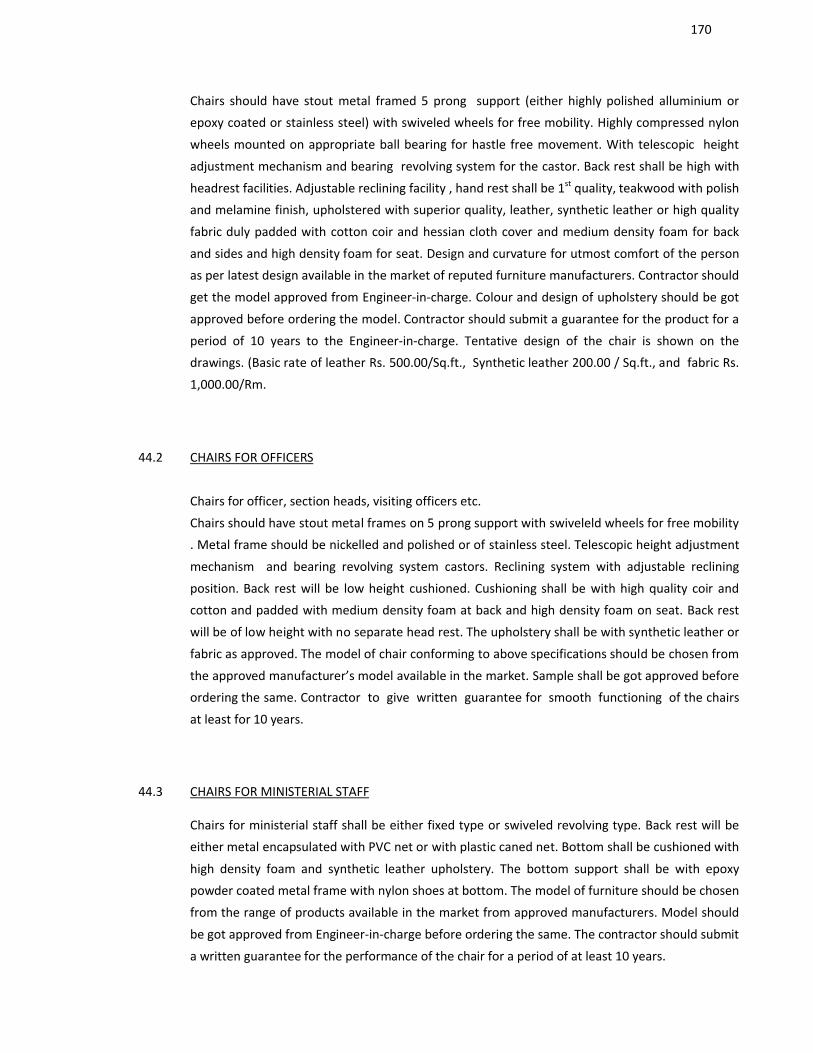
170
Chairs should have stout metal framed 5 prong support (either highly polished alluminium or
epoxy coated or stainless steel) with swiveled wheels for free mobility. Highly compressed nylon
wheels mounted on appropriate ball bearing for hastle free movement. With telescopic height
adjustment mechanism and bearing revolving system for the castor. Back rest shall be high with
headrest facilities. Adjustable reclining facility , hand rest shall be 1st quality, teakwood with polish
and melamine finish, upholstered with superior quality, leather, synthetic leather or high quality
fabric duly padded with cotton coir and hessian cloth cover and medium density foam for back
and sides and high density foam for seat. Design and curvature for utmost comfort of the person
as per latest design available in the market of reputed furniture manufacturers. Contractor should
get the model approved from Engineer-in-charge. Colour and design of upholstery should be got
approved before ordering the model. Contractor should submit a guarantee for the product for a
period of 10 years to the Engineer-in-charge. Tentative design of the chair is shown on the
drawings. (Basic rate of leather Rs. 500.00/Sq.ft., Synthetic leather 200.00 / Sq.ft., and fabric Rs.
1,000.00/Rm.
44.2 CHAIRS FOR OFFICERS
Chairs for officer, section heads, visiting officers etc.
Chairs should have stout metal frames on 5 prong support with swiveleld wheels for free mobility
. Metal frame should be nickelled and polished or of stainless steel. Telescopic height adjustment
mechanism and bearing revolving system castors. Reclining system with adjustable reclining
position. Back rest will be low height cushioned. Cushioning shall be with high quality coir and
cotton and padded with medium density foam at back and high density foam on seat. Back rest
will be of low height with no separate head rest. The upholstery shall be with synthetic leather or
fabric as approved. The model of chair conforming to above specifications should be chosen from
the approved manufacturer’s model available in the market. Sample shall be got approved before
ordering the same. Contractor to give written guarantee for smooth functioning of the chairs
at least for 10 years.
44.3 CHAIRS FOR MINISTERIAL STAFF
Chairs for ministerial staff shall be either fixed type or swiveled revolving type. Back rest will be
either metal encapsulated with PVC net or with plastic caned net. Bottom shall be cushioned with
high density foam and synthetic leather upholstery. The bottom support shall be with epoxy
powder coated metal frame with nylon shoes at bottom. The model of furniture should be chosen
from the range of products available in the market from approved manufacturers. Model should
be got approved from Engineer-in-charge before ordering the same. The contractor should submit
a written guarantee for the performance of the chair for a period of at least 10 years.
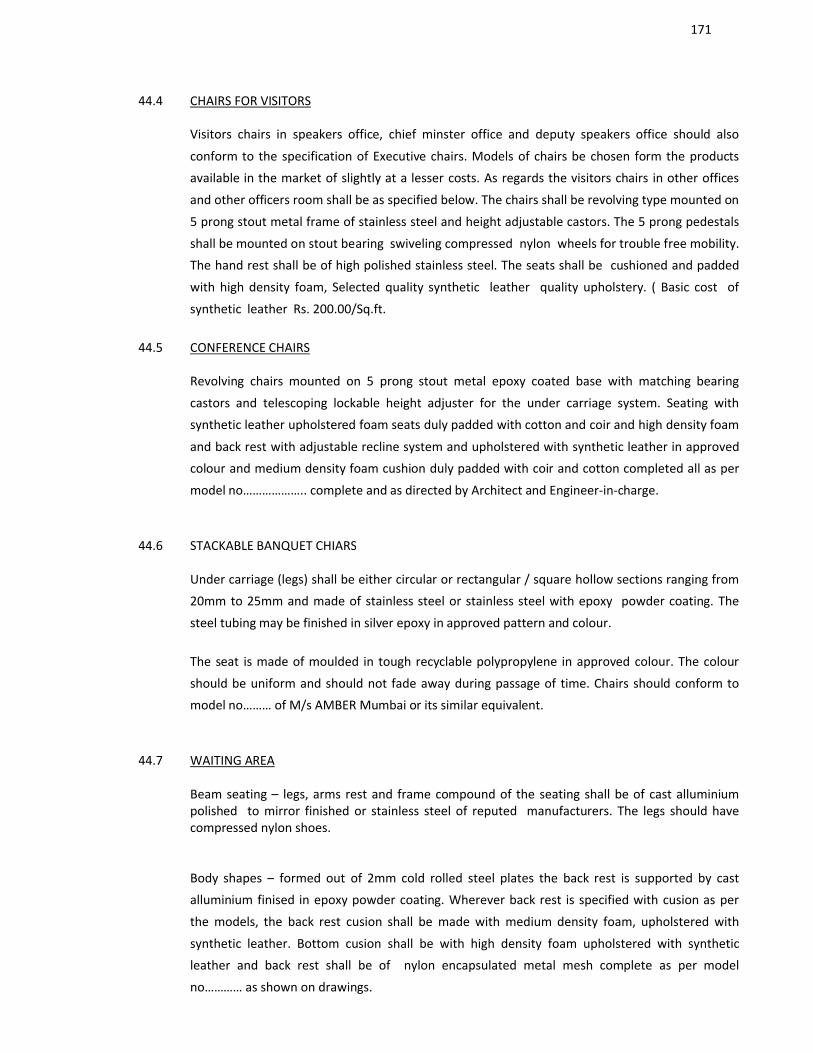
171
44.4 CHAIRS FOR VISITORS
Visitors chairs in speakers office, chief minster office and deputy speakers office should also
conform to the specification of Executive chairs. Models of chairs be chosen form the products
available in the market of slightly at a lesser costs. As regards the visitors chairs in other offices
and other officers room shall be as specified below. The chairs shall be revolving type mounted on
5 prong stout metal frame of stainless steel and height adjustable castors. The 5 prong pedestals
shall be mounted on stout bearing swiveling compressed nylon wheels for trouble free mobility.
The hand rest shall be of high polished stainless steel. The seats shall be cushioned and padded
with high density foam, Selected quality synthetic leather quality upholstery. ( Basic cost of
synthetic leather Rs. 200.00/Sq.ft.
44.5 CONFERENCE CHAIRS
Revolving chairs mounted on 5 prong stout metal epoxy coated base with matching bearing
castors and telescoping lockable height adjuster for the under carriage system. Seating with
synthetic leather upholstered foam seats duly padded with cotton and coir and high density foam
and back rest with adjustable recline system and upholstered with synthetic leather in approved
colour and medium density foam cushion duly padded with coir and cotton completed all as per
model no……………….. complete and as directed by Architect and Engineer-in-charge.
44.6 STACKABLE BANQUET CHIARS
Under carriage (legs) shall be either circular or rectangular / square hollow sections ranging from
20mm to 25mm and made of stainless steel or stainless steel with epoxy powder coating. The
steel tubing may be finished in silver epoxy in approved pattern and colour.
The seat is made of moulded in tough recyclable polypropylene in approved colour. The colour
should be uniform and should not fade away during passage of time. Chairs should conform to
model no……… of M/s AMBER Mumbai or its similar equivalent.
44.7 WAITING AREA
Beam seating – legs, arms rest and frame compound of the seating shall be of cast alluminium polished to mirror finished or stainless steel of reputed manufacturers. The legs should have compressed nylon shoes.
Body shapes – formed out of 2mm cold rolled steel plates the back rest is supported by cast
alluminium finised in epoxy powder coating. Wherever back rest is specified with cusion as per
the models, the back rest cusion shall be made with medium density foam, upholstered with
synthetic leather. Bottom cusion shall be with high density foam upholstered with synthetic
leather and back rest shall be of nylon encapsulated metal mesh complete as per model
no………… as shown on drawings.
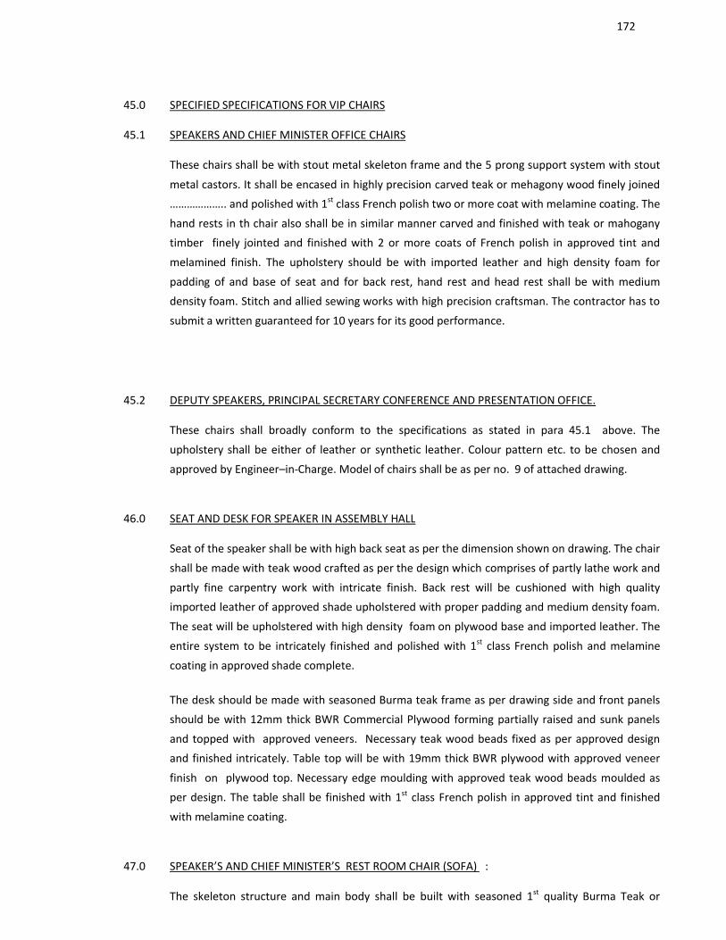
172
45.0 SPECIFIED SPECIFICATIONS FOR VIP CHAIRS
45.1 SPEAKERS AND CHIEF MINISTER OFFICE CHAIRS
These chairs shall be with stout metal skeleton frame and the 5 prong support system with stout
metal castors. It shall be encased in highly precision carved teak or mehagony wood finely joined
……………….. and polished with 1st class French polish two or more coat with melamine coating. The
hand rests in th chair also shall be in similar manner carved and finished with teak or mahogany
timber finely jointed and finished with 2 or more coats of French polish in approved tint and
melamined finish. The upholstery should be with imported leather and high density foam for
padding of and base of seat and for back rest, hand rest and head rest shall be with medium
density foam. Stitch and allied sewing works with high precision craftsman. The contractor has to
submit a written guaranteed for 10 years for its good performance.
45.2 DEPUTY SPEAKERS, PRINCIPAL SECRETARY CONFERENCE AND PRESENTATION OFFICE.
These chairs shall broadly conform to the specifications as stated in para 45.1 above. The
upholstery shall be either of leather or synthetic leather. Colour pattern etc. to be chosen and
approved by Engineer–in-Charge. Model of chairs shall be as per no. 9 of attached drawing.
46.0 SEAT AND DESK FOR SPEAKER IN ASSEMBLY HALL
Seat of the speaker shall be with high back seat as per the dimension shown on drawing. The chair
shall be made with teak wood crafted as per the design which comprises of partly lathe work and
partly fine carpentry work with intricate finish. Back rest will be cushioned with high quality
imported leather of approved shade upholstered with proper padding and medium density foam.
The seat will be upholstered with high density foam on plywood base and imported leather. The
entire system to be intricately finished and polished with 1st class French polish and melamine
coating in approved shade complete.
The desk should be made with seasoned Burma teak frame as per drawing side and front panels
should be with 12mm thick BWR Commercial Plywood forming partially raised and sunk panels
and topped with approved veneers. Necessary teak wood beads fixed as per approved design
and finished intricately. Table top will be with 19mm thick BWR plywood with approved veneer
finish on plywood top. Necessary edge moulding with approved teak wood beads moulded as
per design. The table shall be finished with 1st class French polish in approved tint and finished
with melamine coating.
47.0 SPEAKER’S AND CHIEF MINISTER’S REST ROOM CHAIR (SOFA) :
The skeleton structure and main body shall be built with seasoned 1st quality Burma Teak or
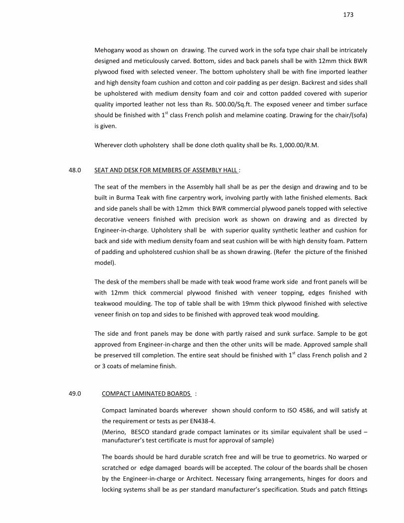
173
Mehogany wood as shown on drawing. The curved work in the sofa type chair shall be intricately
designed and meticulously carved. Bottom, sides and back panels shall be with 12mm thick BWR
plywood fixed with selected veneer. The bottom upholstery shall be with fine imported leather
and high density foam cushion and cotton and coir padding as per design. Backrest and sides shall
be upholstered with medium density foam and coir and cotton padded covered with superior
quality imported leather not less than Rs. 500.00/Sq.ft. The exposed veneer and timber surface
should be finished with 1st class French polish and melamine coating. Drawing for the chair/(sofa)
is given.
Wherever cloth upholstery shall be done cloth quality shall be Rs. 1,000.00/R.M.
48.0 SEAT AND DESK FOR MEMBERS OF ASSEMBLY HALL :
The seat of the members in the Assembly hall shall be as per the design and drawing and to be
built in Burma Teak with fine carpentry work, involving partly with lathe finished elements. Back
and side panels shall be with 12mm thick BWR commercial plywood panels topped with selective
decorative veneers finished with precision work as shown on drawing and as directed by
Engineer-in-charge. Upholstery shall be with superior quality synthetic leather and cushion for
back and side with medium density foam and seat cushion will be with high density foam. Pattern
of padding and upholstered cushion shall be as shown drawing. (Refer the picture of the finished
model).
The desk of the members shall be made with teak wood frame work side and front panels will be
with 12mm thick commercial plywood finished with veneer topping, edges finished with
teakwood moulding. The top of table shall be with 19mm thick plywood finished with selective
veneer finish on top and sides to be finished with approved teak wood moulding.
The side and front panels may be done with partly raised and sunk surface. Sample to be got
approved from Engineer-in-charge and then the other units will be made. Approved sample shall
be preserved till completion. The entire seat should be finished with 1st class French polish and 2
or 3 coats of melamine finish.
49.0 COMPACT LAMINATED BOARDS :
Compact laminated boards wherever shown should conform to ISO 4586, and will satisfy at
the requirement or tests as per EN438-4.
(Merino, BESCO standard grade compact laminates or its similar equivalent shall be used –manufacturer’s test certificate is must for approval of sample)
The boards should be hard durable scratch free and will be true to geometrics. No warped or
scratched or edge damaged boards will be accepted. The colour of the boards shall be chosen
by the Engineer-in-charge or Architect. Necessary fixing arrangements, hinges for doors and
locking systems shall be as per standard manufacturer’s specification. Studs and patch fittings
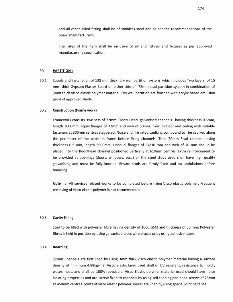
174
and all other allied fitting shall be of stainless steel and as per the recommendations of the
board manufacturer’s.
The rates of the item shall be inclusive of all and fittings and fixtures as per approved
manufacturer’s specification.
50. PARTITION :
50.1 Supply and installation of 138 mm thick dry wall partition system which includes Two layers of 15
mm thick Gypsum Plaster Board on either side of 72mm stud partition system in combination of
3mm thick Visco elastic polymer material .Dry wall partition are finished with acrylic based emulsion
paint of approved shade.
50.2 Construction (Frame work)
Framework consists two sets of 72mm Floor/ Head galvanised channels having thickness 0.5mm,
length 3600mm, equal flanges of 32mm and web of 50mm fixed to floor and ceiling with suitable
fasteners at 300mm centres staggered. Noise and fire rated caulking compound to be caulked along
the perimeter of the partition frame before fixing channels. Then 70mm Stud channel having
thickness 0.5 mm, length 3600mm, unequal flanges of 34/36 mm and web of 70 mm should be
placed into the floor/head channel positioned vertically at 610mm centres. Extra reinforcement to
be provided at openings (doors, windows, etc.,) all the steel studs used shall have high quality
galvanising and must be fully knurled. Ensure studs are firmly fixed and no undulations before
boarding
Note : All services related works to be completed before fixing Visco elastic polymer. Frequent
removing of visco elastic polymer is not recommended
50.3 Cavity Filling
Stud to be filled with polyester fibre having density of 1000 GSM and thickness of 50 mm. Polyester
fibres is held in position by using galvanised cross wire braces or by using adhesive tapes.
50.4 Boarding
72mm Channels are first lined by using 3mm thick visco elastic polymer material having a surface
density of minimum 4.88kg/m2. Visco elastic layer used shall of UV resistant, resistance to mold ,
water, heat, and shall be 100% recyclable. Visco Elastic polymer material used should have noise
isolating properties and are screw fixed to channels by using self tapping pan head screws of 25mm
at 450mm centres. Joints of visco elastic polymer sheets are lined by using special jointing tapes.
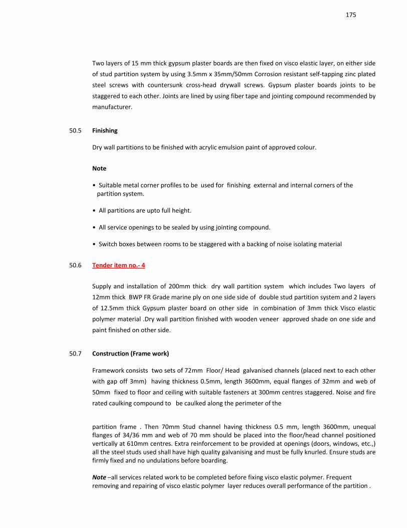
175
Two layers of 15 mm thick gypsum plaster boards are then fixed on visco elastic layer, on either side
of stud partition system by using 3.5mm x 35mm/50mm Corrosion resistant self-tapping zinc plated
steel screws with countersunk cross-head drywall screws. Gypsum plaster boards joints to be
staggered to each other. Joints are lined by using fiber tape and jointing compound recommended by
manufacturer.
50.5 Finishing
Dry wall partitions to be finished with acrylic emulsion paint of approved colour.
Note
• Suitable metal corner profiles to be used for finishing external and internal corners of the partition system.
• All partitions are upto full height.
• All service openings to be sealed by using jointing compound.
• Switch boxes between rooms to be staggered with a backing of noise isolating material
50.6 Tender item no.- 4
Supply and installation of 200mm thick dry wall partition system which includes Two layers of
12mm thick BWP FR Grade marine ply on one side side of double stud partition system and 2 layers
of 12.5mm thick Gypsum plaster board on other side in combination of 3mm thick Visco elastic
polymer material .Dry wall partition finished with wooden veneer approved shade on one side and
paint finished on other side.
50.7 Construction (Frame work)
Framework consists two sets of 72mm Floor/ Head galvanised channels (placed next to each other
with gap off 3mm) having thickness 0.5mm, length 3600mm, equal flanges of 32mm and web of
50mm fixed to floor and ceiling with suitable fasteners at 300mm centres staggered. Noise and fire
rated caulking compound to be caulked along the perimeter of the
partition frame . Then 70mm Stud channel having thickness 0.5 mm, length 3600mm, unequal flanges of 34/36 mm and web of 70 mm should be placed into the floor/head channel positioned vertically at 610mm centres. Extra reinforcement to be provided at openings (doors, windows, etc.,) all the steel studs used shall have high quality galvanising and must be fully knurled. Ensure studs are firmly fixed and no undulations before boarding.
Note –all services related work to be completed before fixing visco elastic polymer. Frequent removing and repairing of visco elastic polymer layer reduces overall performance of the partition .
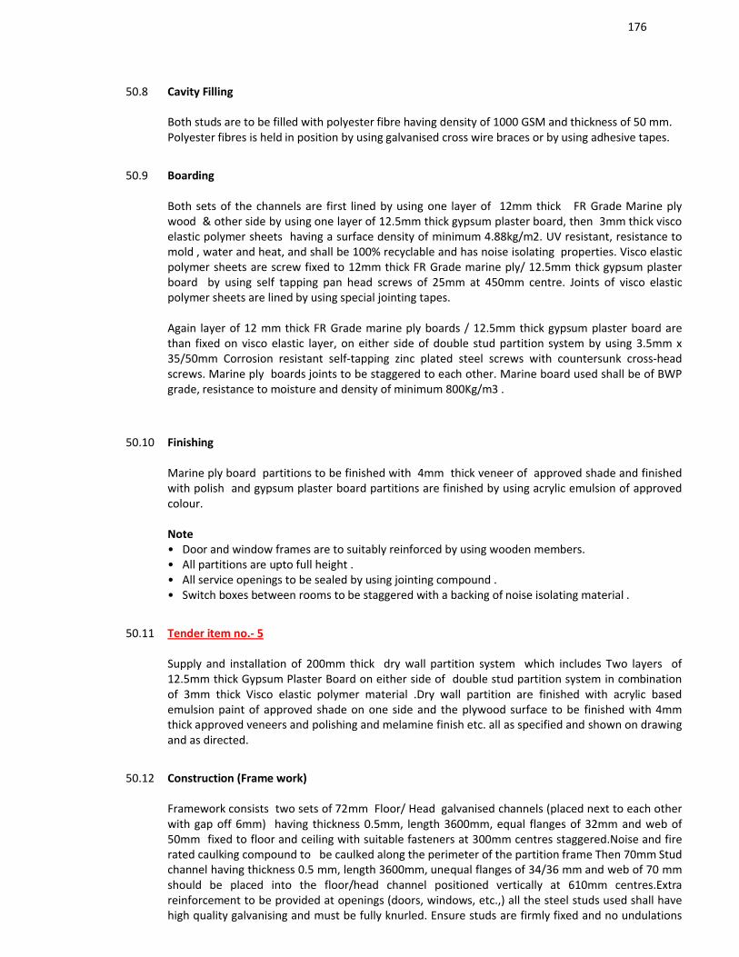
176
50.8 Cavity Filling
Both studs are to be filled with polyester fibre having density of 1000 GSM and thickness of 50 mm. Polyester fibres is held in position by using galvanised cross wire braces or by using adhesive tapes.
50.9 Boarding
Both sets of the channels are first lined by using one layer of 12mm thick FR Grade Marine ply wood & other side by using one layer of 12.5mm thick gypsum plaster board, then 3mm thick visco elastic polymer sheets having a surface density of minimum 4.88kg/m2. UV resistant, resistance to mold , water and heat, and shall be 100% recyclable and has noise isolating properties. Visco elastic polymer sheets are screw fixed to 12mm thick FR Grade marine ply/ 12.5mm thick gypsum plaster board by using self tapping pan head screws of 25mm at 450mm centre. Joints of visco elastic polymer sheets are lined by using special jointing tapes.
Again layer of 12 mm thick FR Grade marine ply boards / 12.5mm thick gypsum plaster board are than fixed on visco elastic layer, on either side of double stud partition system by using 3.5mm x 35/50mm Corrosion resistant self-tapping zinc plated steel screws with countersunk cross-head screws. Marine ply boards joints to be staggered to each other. Marine board used shall be of BWP grade, resistance to moisture and density of minimum 800Kg/m3 .
50.10 Finishing
Marine ply board partitions to be finished with 4mm thick veneer of approved shade and finished with polish and gypsum plaster board partitions are finished by using acrylic emulsion of approved colour.
Note • Door and window frames are to suitably reinforced by using wooden members. • All partitions are upto full height .• All service openings to be sealed by using jointing compound .• Switch boxes between rooms to be staggered with a backing of noise isolating material .
50.11 Tender item no.- 5
Supply and installation of 200mm thick dry wall partition system which includes Two layers of 12.5mm thick Gypsum Plaster Board on either side of double stud partition system in combination of 3mm thick Visco elastic polymer material .Dry wall partition are finished with acrylic based emulsion paint of approved shade on one side and the plywood surface to be finished with 4mm thick approved veneers and polishing and melamine finish etc. all as specified and shown on drawing and as directed.
50.12 Construction (Frame work)
Framework consists two sets of 72mm Floor/ Head galvanised channels (placed next to each other with gap off 6mm) having thickness 0.5mm, length 3600mm, equal flanges of 32mm and web of 50mm fixed to floor and ceiling with suitable fasteners at 300mm centres staggered.Noise and fire rated caulking compound to be caulked along the perimeter of the partition frame Then 70mm Stud channel having thickness 0.5 mm, length 3600mm, unequal flanges of 34/36 mm and web of 70 mm should be placed into the floor/head channel positioned vertically at 610mm centres.Extra reinforcement to be provided at openings (doors, windows, etc.,) all the steel studs used shall have high quality galvanising and must be fully knurled. Ensure studs are firmly fixed and no undulations

177
before boarding.
Note – All services related work to be completed before fixing visco elastic polymer. Frequent removing and repairing of visco elastic polymer layer reduces overall performance of the partition .
50.13 Cavity Filling
Both studs are to be filled with polyester fibre having density of 1000 GSM and thickness of 50 mm. Polyester fibres is held in position by using galvanised cross wire braces or by using adhesive tapes.
50.14 Boarding
Both sets of the channels are first lined by using 3mm thick visco elastic polymer material having a surface density of minimum 4.88kg/m2. Visco elastic layer used shall of UV resistant, resistance to mold , water and heat, and shall be 100% recyclable. Visco Elastic polymer material used should have noise isolating properties. Visco elastic polymer sheets are screw fixed to channels by using self tapping pan head screws of 25mm at 450mm centres. Joints of visco elastic polymer sheets are lined by using special jointing tapes.Two layers of 12.5 mm thick gypsum plaster boards are than fixed on visco elastic layer, on either side of double stud partition system by using 3.5mm x 35/50mm Corrosion resistant self-tapping zinc plated steel screws with countersunk cross-head drywall screws. Gypsum plaster boards joints to be staggered to each other. Joints are lined by using fiber tape and jointing compound recommended by manufacturer.
50.15 Finishing
Dry wall partitions to be finished with acrylic emulsion paint of approved colour.
Note • Suitable metal corner profiles to be used for finishing external and internal corners of the partition system .• Door and window frames are to suitably reinforced by using wooden members.• All partitions are upto full height .• All service openings to be sealed by using jointing compound .• Switch boxes between rooms to be staggered with a backing of noise isolating material.
50.16 Tender item no.- 6
Supply and installation of 200mm thick dry wall partition system which includes Two layers of 12mm thick BWP FR Grade marine ply on either side of double stud partition system in combination of 3mm thick Visco elastic polymer material .Dry wall partition finished with 4mm thick wooden veneer approved shade and finishing both sides surfaces with French polish and melamine finish complete as specified and as directed by Architect and Engineer-in-charge.
50.17 Construction (Frame work) Framework consists two sets of 72mm Floor/ Head galvanised channels (placed next to each other with gap off 3mm) having thickness 0.5mm, length 3600mm, equal flanges of 32mm and web of 50mm fixed to floor and ceiling with suitable fasteners at 300mm centres staggered. Noise and fire rated caulking compound to be caulked along the perimeter of the partition frame . Then 70mm Stud channel having thickness 0.5 mm, length 3600mm, unequal flanges of 34/36 mm and web of 70
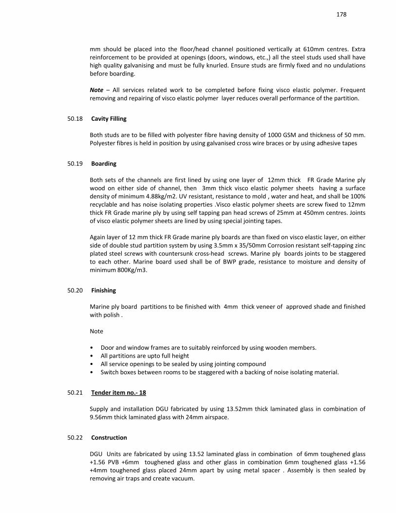
178
mm should be placed into the floor/head channel positioned vertically at 610mm centres. Extra reinforcement to be provided at openings (doors, windows, etc.,) all the steel studs used shall have high quality galvanising and must be fully knurled. Ensure studs are firmly fixed and no undulations before boarding.
Note – All services related work to be completed before fixing visco elastic polymer. Frequent removing and repairing of visco elastic polymer layer reduces overall performance of the partition.
50.18 Cavity Filling
Both studs are to be filled with polyester fibre having density of 1000 GSM and thickness of 50 mm. Polyester fibres is held in position by using galvanised cross wire braces or by using adhesive tapes
50.19 Boarding
Both sets of the channels are first lined by using one layer of 12mm thick FR Grade Marine ply wood on either side of channel, then 3mm thick visco elastic polymer sheets having a surface density of minimum 4.88kg/m2. UV resistant, resistance to mold , water and heat, and shall be 100% recyclable and has noise isolating properties .Visco elastic polymer sheets are screw fixed to 12mm thick FR Grade marine ply by using self tapping pan head screws of 25mm at 450mm centres. Jointsof visco elastic polymer sheets are lined by using special jointing tapes.
Again layer of 12 mm thick FR Grade marine ply boards are than fixed on visco elastic layer, on either side of double stud partition system by using 3.5mm x 35/50mm Corrosion resistant self-tapping zinc plated steel screws with countersunk cross-head screws. Marine ply boards joints to be staggered to each other. Marine board used shall be of BWP grade, resistance to moisture and density of minimum 800Kg/m3.
50.20 Finishing
Marine ply board partitions to be finished with 4mm thick veneer of approved shade and finished with polish .
Note • Door and window frames are to suitably reinforced by using wooden members. • All partitions are upto full height • All service openings to be sealed by using jointing compound • Switch boxes between rooms to be staggered with a backing of noise isolating material.
50.21 Tender item no.- 18
Supply and installation DGU fabricated by using 13.52mm thick laminated glass in combination of 9.56mm thick laminated glass with 24mm airspace.
50.22 Construction
DGU Units are fabricated by using 13.52 laminated glass in combination of 6mm toughened glass +1.56 PVB +6mm toughened glass and other glass in combination 6mm toughened glass +1.56 +4mm toughened glass placed 24mm apart by using metal spacer . Assembly is then sealed by removing air traps and create vacuum.
179
50.23 Framework
47mm thick DGU units are then placed in solid timber frame work fabricated by using 150x 150mm thick wooden frame. Perimeter of wooden frames to be embaded with neoprene sheets of 3mm to achieve desired air tightness of the assembly.
50.24 Framework
47mm thick DGU units are then placed in solid timber frame work fabricated by using 150x 150mm thick wooden frame. Perimeter of wooden frames to be embedded with neoprene sheets of 3mm to achieve desired air tightness of the assembly.
50.25 Finishing
All joints between wooden frame & masonry are to be lined with noise and fire rated caulking compound.
51.0 Panelling :
51.1 Tender item no.- 13
Supply and Installation of GFR grade micro perforated (3 x 3mm square) gypsum plaster board of size 1200x 2400x 12.5mm thick back lined with acoustical fleece. Gypsum boards used shall have tapered edge along the length having base density of minimum 800Kgs/m3, and lined with paintable glass fabrics.
51.2 Construction Frame work
Frame work consists of Galvanised Cross channel(CC25) having thickness 0.5mm, length 3600mm, knurled web 80mm, depth of 25mm and equal flanges 10.5mm is fastened to the drywall at 450mm centre perpendicular to Micro perforated gypsum plaster board .
51.3 Cavity Filling
Ceiling frame work shall be backlined by using polyester fiber rolls of size 600mm width having a density of 1000 GSM and 25mm thick.
51.4 Boarding
1200x 2400x 12.5 mm glass fiber reinforced gypsum plaster board, having long edges tapered is than screw fixed to frame work by using 25mm dry wall screws every 300mm centres. Ensure board is in plumb level and fix glass woven fabrics to the gypsum ceiling. Joints of the plaster boards to be finished with fiber tape and jointing compound as per manufacturers recommendation. Screw heads to be covered with compound and sand the surface.
Note : (use of glass fabrics) • Use products with same serial number of glass fabrics on adjacent surfaces.
180
• Allow 10-12hrs to dry it is advised to paint immediately after adhering.
• Follow marking backside before gluing wall paneling.
Gypsum, Brand : Danogips, Model Micro Perforated, Glass Fabric : Brand Systex.
52.5 Tender item no.- 14
Supply and installation of non combustible magnesite bonded wood wool board on 50mm thick glavansied channels and finished with proprietary traditional fabric at site.Wood wool boards are fixed directly on masonry brick wall lined by using visco elastic polymer material of 6mm thick .
Fixing of Visco elastic polymer layer along the perimeter of assembly hall Supply and installation of 3 mm thick visco elastic polymer sheets having a surface density of minimum 4.88kg/m2. UV resistant, resistance to mold , water and heat, and shall be 100% recyclable and has noise isolating properties. Visco elastic polymer sheets are screw fixed to wall by using adhesive recommended by manufacturer ,Joints of visco elastic polymer sheets are lined by using special jointing tapes.
52.6 Construction of Frame work
Frame work consists of 25mm thick GI wall channels with fully knurled surface of 0.55mm thick 80mm width, having two equal flanges of 26mm is anchored to wooden studs of 25mm thick x 100 wide. Wooden studs of 25mm thick is first grouted to wall at 600mm centres, 25mm thick channels are than fixed to wooden studs to achieve overall airgap of 50mm from the wall.To achieve sturdiness of the system channels are to be fixed perpendicular to wood wool boards.
52.7 Cavity Filling
Resultant air gap between wall and channel to be lined by using polyester fiber rolls of size 600mm width having a density of 1000 GSM and 50mm thick, held in position by using adhesive or G.I binding wires.
52.8 Boarding
Non combustible magnesite bonded square edge wood wool board having density of minimum 450 Kg/m3 of size 1200x 600x 25mm thick manufactured by using superfine fibres having width of 1mm and meeting fire requirements as per EN 13501-1 A2,S1 d0 is than fixed on to metal channels by using rust protected metal fasteners of size 4.5mm Ø x 50mm length . Each panel should receive minimum 6nos fasteners. Wood wool boards to be butt jointed and ensure boards are in plumb level to adhere proprietary fabric above wood wool board.
Note • Screw head to be countersunk • Adhesive used shall be of spray grade to adhere proprietary Fabric • Cost of fabric not taken. Considered seperately.
Brand : Magnasite Bonded Woodwool board : Heradesign Super Fine A2 , Visco elastic polymer : coustiblok
53.0 False ceiling :
181
53.1 Tender item no.- 7
Supply and Installation of GFR grade micro perforated (3 x 3mm square) gypsum plaster board of size 1200x 2400x 12.5mm thick back lined with acoustical fleece. Gypsum boards used shall have tapered edge along the length having base density of minimum 800Kgs/m3, and lined with paintable glass fabrics.
53.2 Construction Frame work
Frame work consists of Galvanised Wall channel 25mm width having thickness 0.5mm, length 3600mm, unequal flanges of 20 & 30mm and web of 25mm should be fixed along the perimeters of the wall (Brick/Block/partition ) with nylon sleeves and suitable fasteners at every 300mm centers. Then suspend Main channels (MC45) having thickness 0.9mm, length 3600mm, equal flanges of 15mm and web 45mm from the soffit at every 900mm centers with Suspender angle25mm having thickness 0.45mm, unequal flanges of 25 & 10mm. GI Cross channel(CC25) having thickness 0.5mm, length 3600mm, knurled web 80mm, depth of 25mm and equal flanges 10.5mm is fastened to the Main channel in the direction perpendicular to the Main Channel at every 450mm centers. All metal to metal screws must be self drilling wafer thin head 4.2mmx 13mm length.
53.3 Cavity Filling
Ceiling frame work shall be backlined by using polyester fiber rolls of size 600mm width having a density of 1000 GSM and 50mm thick.
53.4 Boarding
1200x 2400x 12.5 mm glass fiber reinforced gypsum plaster board, having long edges tapered is than screw fixed to frame work by using 25mm dry wall screws every 300mm centers. Ensure board is in plumb level and fix glass woven fabrics to the gypsum ceiling. Joints of the plaster boards to be finished with fiber tape and jointing compound as per manufacturers recommendation. Screw heads to be covered with compound and sand the surface.
Note • Use products with same serial number on adjacent surfaces.
• Allow 10-12hrs to dry it is advised to paint immediately after adhering.
• Follow marking backside before gluing.
54. Door Shutter :
Tender item no. – 20
Acoustical Door Seals (Single shutter with door closures)
Perimeter seals
182
Supply and installation of medium duty acoustic door seals manufactured by using silver anodised aluminium with grey silicone rubber gasket Tested in accordance with BS EN ISO 10140-2: 2010 fixed to wooden doors on predrilled holes . Assembly shall also consist of PVC cover strips to conceal fixings .Door set pack should consists of 3nos seals (1no for door top &other for 2 sides ) Door seal assembly shall have valid test certificate and shall have STC of minimum 33-35 .
Drop down seals
Supply and installation of medium duty automatic concealed door bottom seal manufactured by using silver anodised aluminium with grey silicone rubber gasket Tested in accordance with AS 1428/1 having polypropylene fins incorporated within the gasket housing to provide additional sealing properties.
Tested for reliability, completing over 1,000,000 open and close cycles. fixed to bottom wooden doors by using hardware's supplied with seals Door seal assembly shall have valid test certificate and shall have STC of minimum 33-35 . seal is mortised into a 15mm x 35mm groove in the door bottom and supported by end plates,(refer seal manufacturer guidelines for groove cutting).
55. Tender item no.- 21
Acoustical Door Seals (Double shutter with door closers)
Perimeter seals
Supply and installation of medium duty acoustic door seals manufactured by using silver anodised aluminium ( powder coated to match colour of door) with Co-extruded elastomeric with flexible curved fins Tested in accordance with BS EN ISO 10140-2: 2010 fixed to wooden doors on predrilled holes . Door seal assembly shall have valid test certificate and shall have STC of minimum 33-35 .
Drop down seals
Supply and installation of medium duty automatic concealed door bottom seal manufactured by using silver anodised aluminium with grey silicone rubber gasket Tested in accordance with AS 1428/1 having polypropylene fins incorporated within the gasket housing to provide additional sealing properties.
Tested for reliability, completing over 1,000,000 open and close cycles. fixed to bottom wooden doors by using hardware's supplied with seals Door seal assembly shall have valid test certificate and shall have STC of minimum 33-35 . seal is mortised into a 15mm x 35mm groove in the door bottom and supported by end plates, (refer seal manufacturer guidelines for groove cutting).
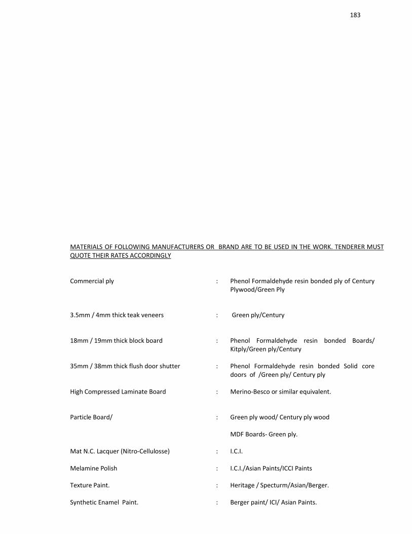
183
MATERIALS OF FOLLOWING MANUFACTURERS OR BRAND ARE TO BE USED IN THE WORK. TENDERER MUST QUOTE THEIR RATES ACCORDINGLY
Commercial ply : Phenol Formaldehyde resin bonded ply of Century Plywood/Green Ply
3.5mm / 4mm thick teak veneers : Green ply/Century
18mm / 19mm thick block board : Phenol Formaldehyde resin bonded Boards/ Kitply/Green ply/Century
35mm / 38mm thick flush door shutter : Phenol Formaldehyde resin bonded Solid core doors of /Green ply/ Century ply
High Compressed Laminate Board : Merino-Besco or similar equivalent.
Particle Board/ : Green ply wood/ Century ply wood
MDF Boards- Green ply.
Mat N.C. Lacquer (Nitro-Cellulosse) : I.C.I.
Melamine Polish : I.C.I./Asian Paints/ICCI Paints
Texture Paint. : Heritage / Specturm/Asian/Berger.
Synthetic Enamel Paint. : Berger paint/ ICI/ Asian Paints.

184
Plaster of paris : Materials are to be of approved quality (Druk or similar equivalent).
Putty : Birla / JK/ Berger.
Patch /Spider fittings : Dormer/Geze Hafele/ Hettick Frosted film : Garware or equivalent.
Adhesive (for timber work). : Pidilite / Bal Endura.
Glazed Tiles /Ceramic /Vitrified tiles. : Kajaria / Somany / Johnson./NIITCO
Locks with Security latch : Godrej / Dorma / Hardwyn / Hafele/Geze.
Door Closer : Rolex / Dorma /Hardwyn/ Hafele/Geze/Godrej
Door fittings : Hafele / Hettic./Geze /Godrej.
Brass hinges / handles : Best quality as approved by Interior Designer, Hafele / Hettic or similar equivalent/Godrej..
Stainless steel fasteners : Hillti / Hettic.
Glass / Mirror : Modifloat/Saint Gobain, Wherever required etching/ Bevelling should be done with machine finish and edge polished.
Stained glass : Saint Gobain,, Pilkingson.
Floor spring : Garnish / Rolex / Dorma/Hafele./Geze.
Marble (Indian & Italian) : Best quality to be approved by the Engineer-in-charge / Interior Designer.
Granite (Indian & Imported) : Krishna Transnational Marbles Pvt. Ltd. (Bangalore / Kolkata), IES make
Radha Rani Marbles or Marudhar Marbles Kolkata.
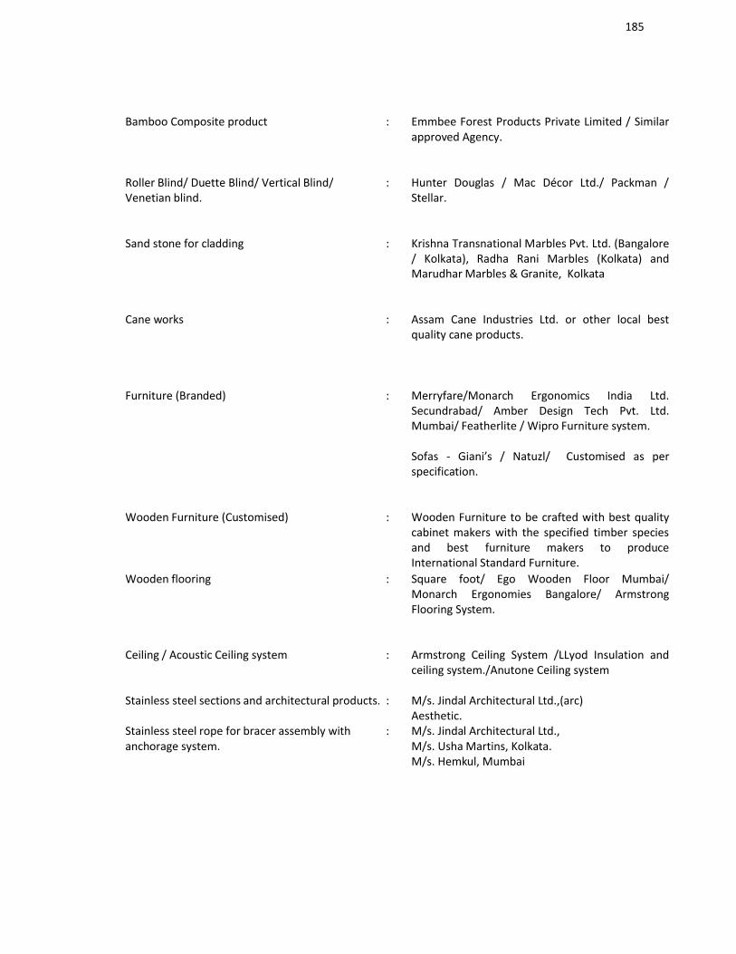
185
Bamboo Composite product : Emmbee Forest Products Private Limited / Similar approved Agency.
Roller Blind/ Duette Blind/ Vertical Blind/Venetian blind.
: Hunter Douglas / Mac Décor Ltd./ Packman / Stellar.
Sand stone for cladding : Krishna Transnational Marbles Pvt. Ltd. (Bangalore / Kolkata), Radha Rani Marbles (Kolkata) and Marudhar Marbles & Granite, Kolkata
Cane works : Assam Cane Industries Ltd. or other local best quality cane products.
Furniture (Branded) : Merryfare/Monarch Ergonomics India Ltd. Secundrabad/ Amber Design Tech Pvt. Ltd. Mumbai/ Featherlite / Wipro Furniture system.
Sofas - Giani’s / Natuzl/ Customised as per specification.
Wooden Furniture (Customised) : Wooden Furniture to be crafted with best quality cabinet makers with the specified timber species and best furniture makers to produce International Standard Furniture.
Wooden flooring : Square foot/ Ego Wooden Floor Mumbai/ Monarch Ergonomies Bangalore/ Armstrong Flooring System.
Ceiling / Acoustic Ceiling system : Armstrong Ceiling System /LLyod Insulation and ceiling system./Anutone Ceiling system
Stainless steel sections and architectural products. : M/s. Jindal Architectural Ltd.,(arc)Aesthetic.
Stainless steel rope for bracer assembly with anchorage system.
: M/s. Jindal Architectural Ltd.,M/s. Usha Martins, Kolkata.M/s. Hemkul, Mumbai
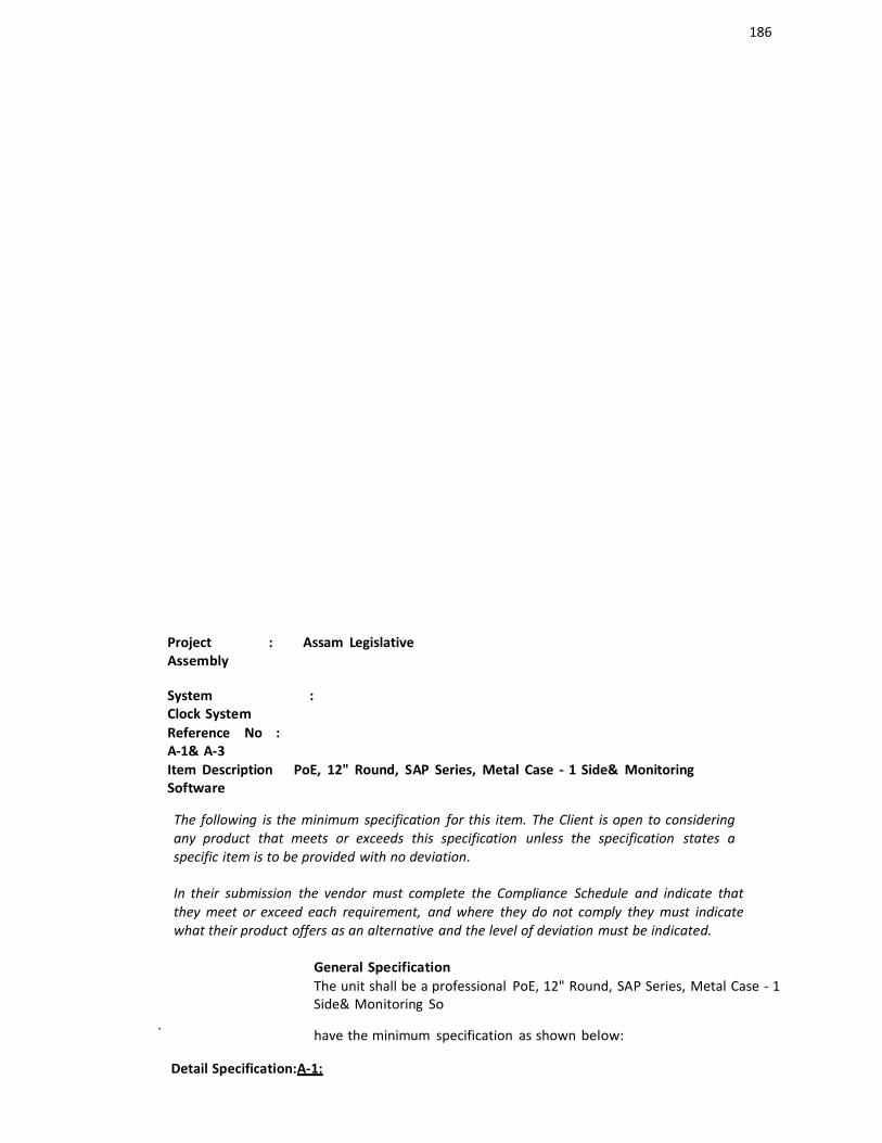
186
Project : Assam LegislativeAssembly
System : Clock SystemReference No : A-1& A-3Item Description PoE, 12" Round, SAP Series, Metal Case - 1 Side& MonitoringSoftware
The following is the minimum specification for this item. The Client is open to consideringany product that meets or exceeds this specification unless the specification states aspecific item is to be provided with no deviation.
In their submission the vendor must complete the Compliance Schedule and indicate thatthey meet or exceed each requirement, and where they do not comply they must indicatewhat their product offers as an alternative and the level of deviation must be indicated.
General SpecificationThe unit shall be a professional PoE, 12" Round, SAP Series, Metal Case - 1Side& Monitoring So
.have the minimum specification as shown below:
Detail Specification:A-1:
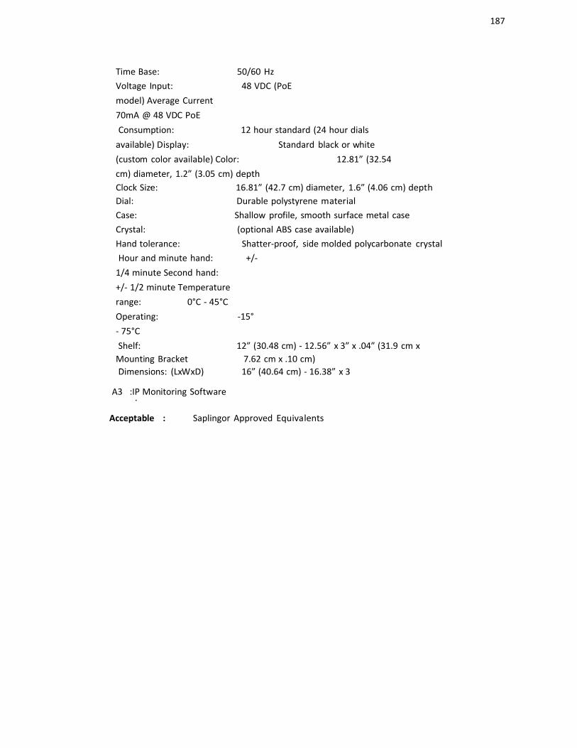
187
Time Base: 50/60 HzVoltage Input: 48 VDC (PoEmodel) Average Current 70mA @ 48 VDC PoEConsumption: 12 hour standard (24 hour dials
available) Display: Standard black or white(custom color available) Color: 12.81” (32.54cm) diameter, 1.2” (3.05 cm) depthClock Siz.e: 16.81” (42.7 cm) diameter, 1.6” (4.06 cm) depthDial: Durable polystyrene materialCase: Shallow profile, smooth surface metal caseCrystal: (optional ABS case available)Hand tolerance: Shatter-proof, side molded polycarbonate crystalHour and minute hand: +/-
1/4 minute Second hand: +/- 1/2 minute Temperaturerange: 0°C - 45°C Operating: -15°- 75°CShelf: 12” (30.48 cm) - 12.56” x 3” x .04” (31.9 cm x
Mounting Bracket 7.62 cm x .10 cm).Dimensions: (LxWxD) 16” (40.64 cm) - 16.38” x 3
A3 :IP Monitoring Software.
Acceptable : Saplingor Approved Equivalents
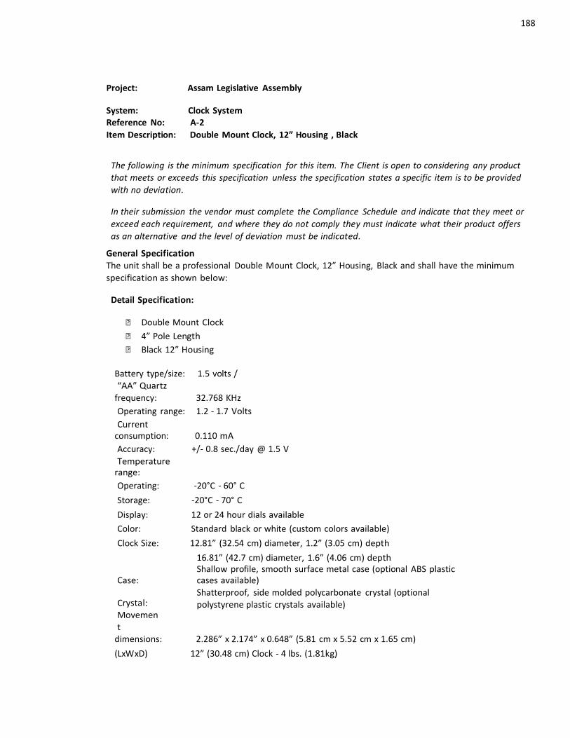
188
Project: Assam Legislative Assembly
System: Clock SystemReference No: A-2Item Description: Double Mount Clock, 12” Housing , Black
The following is the minimum specification for this item. The Client is open to considering any productthat meets or exceeds this specification unless the specification states a specific item is to be providedwith no deviation.
In their submission the vendor must complete the Compliance Schedule and indicate that they meet orexceed each requirement, and where they do not comply they must indicate what their product offersas an alternative and the level of deviation must be indicated.
General SpecificationThe unit shall be a professional Double Mount Clock, 12” Housing, Black and shall have the minimumspecification as shown below:
Detail Specification:
Double Mount Clock 4” Pole Length Black 12” Housing
Battery type/size: 1.5 volts /“AA” Quartz
frequency: 32.768 KHz Operating range: 1.2 - 1.7 Volts Current
consumption: 0.110 mAAccuracy: +/- 0.8 sec./day @ 1.5 V Temperature
range:Operating: -20°C - 60° C Storage: -20°C - 70° CDisplay: 12 or 24 hour dials availableColor: Standard black or white (custom colors available) Clock Size: 12.81” (32.54 cm) diameter, 1.2” (3.05 cm) depth
16.81” (42.7 cm) diameter, 1.6” (4.06 cm) depthShallow profile, smooth surface metal case (optional ABS plastic
Case:
Crystal: Movement
cases available)Shatterproof, side molded polycarbonate crystal (optionalpolystyrene plastic crystals available)
dimensions: 2.286” x 2.174” x 0.648” (5.81 cm x 5.52 cm x 1.65 cm) (LxWxD) 12” (30.48 cm) Clock - 4 lbs. (1.81kg)

189
Shipping weight: 16” (40.64 cm) Clock - 6 lbs. (2.72kg)
Acceptable: Sapling or Approved Equivalents
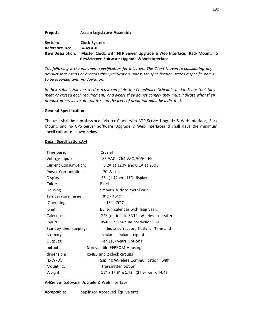
190
Project: Assam Legislative Assembly
System: Clock SystemReference No: A-4&A-6Item Description: Master Clock, with NTP Server Upgrade & Web Interface, Rack Mount, no
GPS&Server Software Upgrade & Web interface
The following is the minimum specification for this item. The Client is open to considering any product that meets or exceeds this specification unless the specification states a specific item is to be provided with no deviation.
In their submission the vendor must complete the Compliance Schedule and indicate that they meet or exceed each requirement, and where they do not comply they must indicate what their product offers as an alternative and the level of deviation must be indicated.
General Specification
The unit shall be a professional Master Clock, with NTP Server Upgrade & Web Interface, Rack Mount, and no GPS Server Software Upgrade & Web interfaceand shall have the minimum specification as shown below :
Detail Specification:A-4
Time base: CrystalVoltage input: 85 VAC - 264 VAC, 50/60 Hz Current Consumption: 0.2A at 120V and 0.1A at 230V Power Consumption: 20 WattsDisplay: .56” (1.42 cm) LED displayColor: BlackHousing Smooth surface metal caseTemperature range 0°C - 45°C Operating: -15° - 70°CShelf: Built-in calendar with leap years
Calendar: GPS (optional), SNTP, Wireless repeater, Inputs: RS485, 58 minute correction, 59Standby time keeping: minute correction, National Time andMemory: Rauland, Dukane digitalOutputs: Ten (10) years Optionaloutputs: Non-volatile EEPROM Housingdimensions RS485 and 2 clock circuits(LxWxD): Sapling Wireless Communication (withMounting: transmitter option)Weight: 11” x 17.5” x 1.75” (27.94 cm x 44.45
A-6Server Software Upgrade & Web interface
Acceptable: Saplingor Approved Equivalents
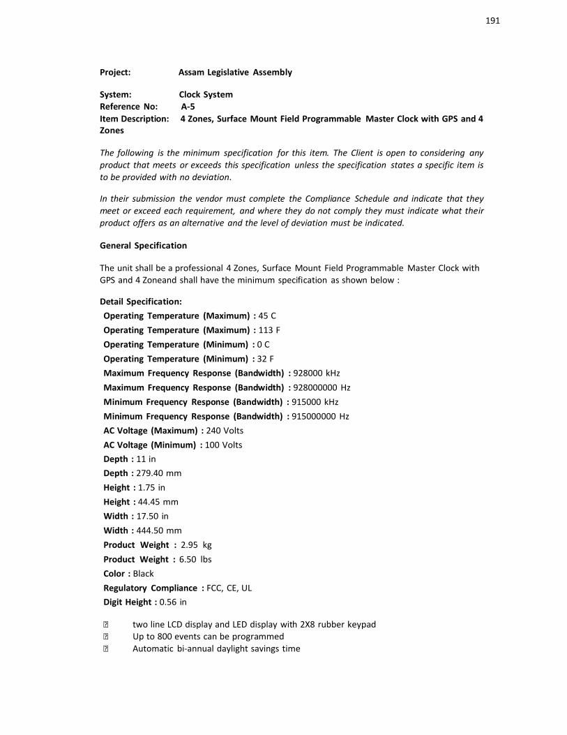
191
Project: Assam Legislative Assembly
System: Clock SystemReference No: A-5Item Description: 4 Zones, Surface Mount Field Programmable Master Clock with GPS and 4Zones
The following is the minimum specification for this item. The Client is open to considering any product that meets or exceeds this specification unless the specification states a specific item is to be provided with no deviation.
In their submission the vendor must complete the Compliance Schedule and indicate that they meet or exceed each requirement, and where they do not comply they must indicate what their product offers as an alternative and the level of deviation must be indicated.
General Specification
The unit shall be a professional 4 Zones, Surface Mount Field Programmable Master Clock withGPS and 4 Zoneand shall have the minimum specification as shown below :
Detail Specification:Operating Temperature (Maximum) : 45 C Operating Temperature (Maximum) : 113 F Operating Temperature (Minimum) : 0 C Operating Temperature (Minimum) : 32 FMaximum Frequency Response (Bandwidth) : 928000 kHz Maximum Frequency Response (Bandwidth) : 928000000 Hz Minimum Frequency Response (Bandwidth) : 915000 kHz Minimum Frequency Response (Bandwidth) : 915000000 Hz AC Voltage (Maximum) : 240 VoltsAC Voltage (Minimum) : 100 VoltsDepth : 11 inDepth : 279.40 mm Height : 1.75 in Height : 44.45 mm Width : 17.50 in Width : 444.50 mmProduct Weight : 2.95 kg Product Weight : 6.50 lbs Color : BlackRegulatory Compliance : FCC, CE, ULDigit Height : 0.56 in
two line LCD display and LED display with 2X8 rubber keypad Up to 800 events can be programmed Automatic bi-annual daylight savings time

192
Two pre-programmed relays for correction of synchronous systems Optional GPS and/or transmitter option for increase system flexibility Optional web interface for complete control of the master clock from any computer via
LAN connection or through a crossover cable Available in rack mount or wall mount
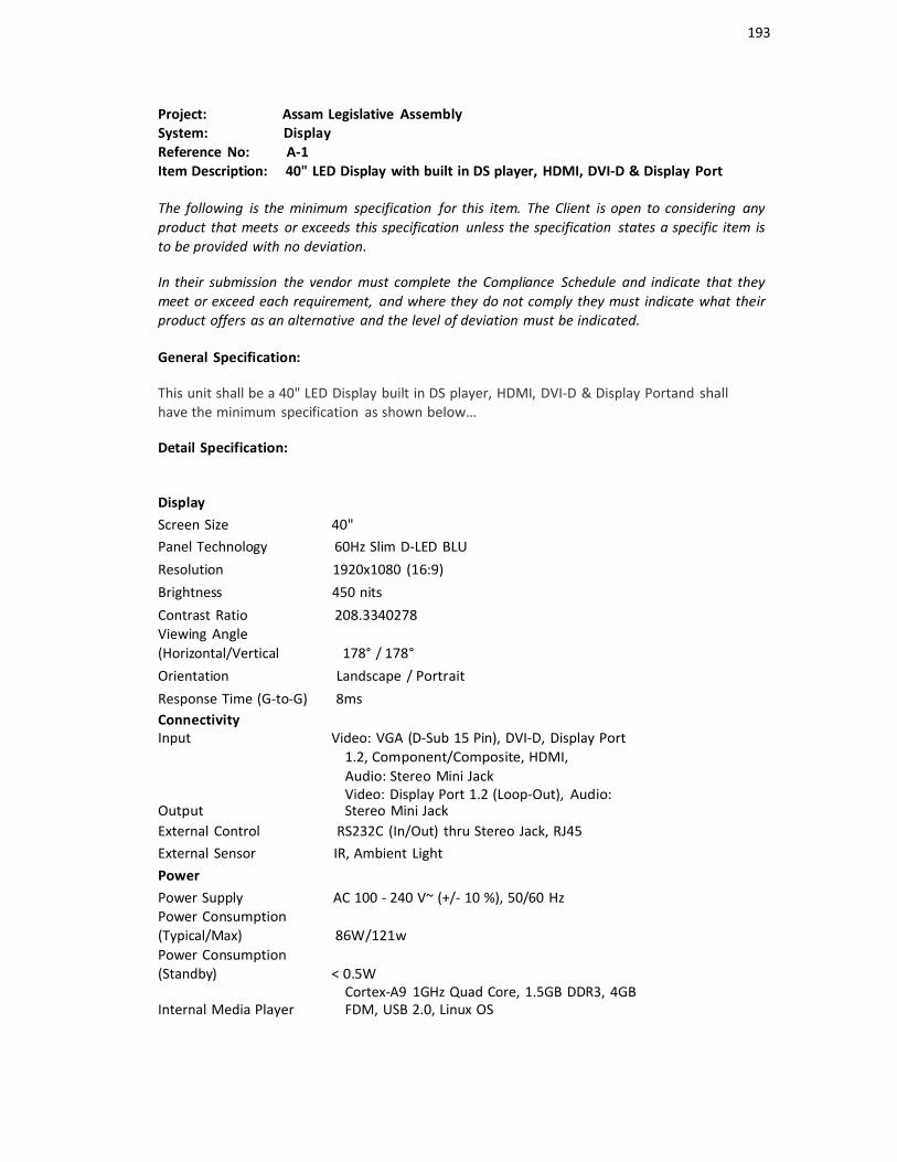
193
Project: Assam Legislative AssemblySystem: DisplayReference No: A-1Item Description: 40" LED Display with built in DS player, HDMI, DVI-D & Display Port
The following is the minimum specification for this item. The Client is open to considering any product that meets or exceeds this specification unless the specification states a specific item is to be provided with no deviation.
In their submission the vendor must complete the Compliance Schedule and indicate that they meet or exceed each requirement, and where they do not comply they must indicate what their product offers as an alternative and the level of deviation must be indicated.
General Specification:
This unit shall be a 40" LED Display built in DS player, HDMI, DVI-D & Display Portand shall have the minimum specification as shown below…
Detail Specification:
DisplayScreen Size 40"Panel Technology 60Hz Slim D-LED BLU Resolution 1920x1080 (16:9) Brightness 450 nitsContrast Ratio 208.3340278Viewing Angle(Horizontal/Vertical 178° / 178° Orientation Landscape / Portrait Response Time (G-to-G) 8msConnectivityInput Video: VGA (D-Sub 15 Pin), DVI-D, Display Port
1.2, Component/Composite, HDMI,Audio: Stereo Mini JackVideo: Display Port 1.2 (Loop-Out), Audio:
Output Stereo Mini JackExternal Control RS232C (In/Out) thru Stereo Jack, RJ45External Sensor IR, Ambient LightPowerPower Supply AC 100 - 240 V~ (+/- 10 %), 50/60 HzPower Consumption(Typical/Max) 86W/121wPower Consumption(Standby) < 0.5W
Cortex-A9 1GHz Quad Core, 1.5GB DDR3, 4GBInternal Media Player FDM, USB 2.0, Linux OS
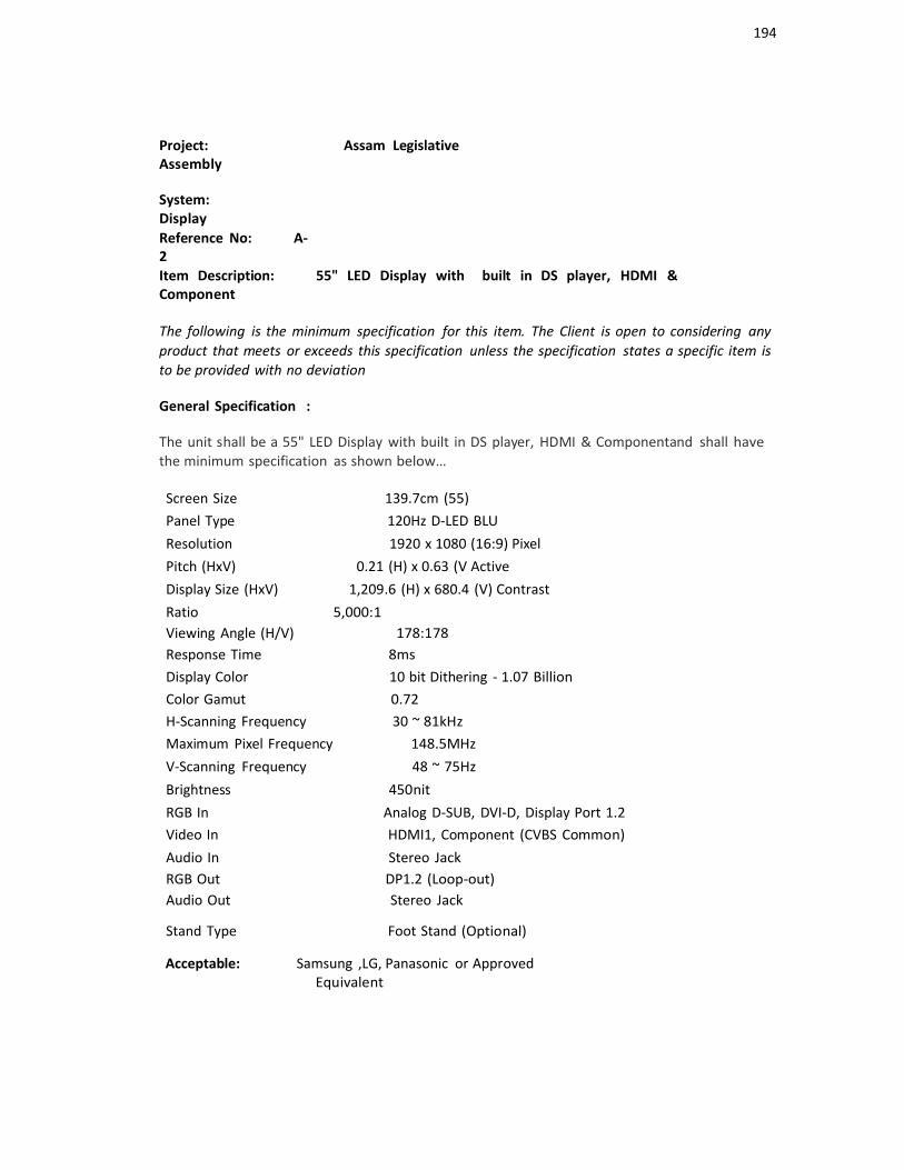
194
Project: Assam LegislativeAssembly
System: DisplayReference No: A-2Item Description: 55" LED Display with built in DS player, HDMI &Component
The following is the minimum specification for this item. The Client is open to considering any product that meets or exceeds this specification unless the specification states a specific item is to be provided with no deviation
General Specification :
The unit shall be a 55" LED Display with built in DS player, HDMI & Componentand shall have the minimum specification as shown below…
Screen Size 139.7cm (55)Panel Type 120Hz D-LED BLU Resolution 1920 x 1080 (16:9) PixelPitch (HxV) 0.21 (H) x 0.63 (V ActiveDisplay Size (HxV) 1,209.6 (H) x 680.4 (V) ContrastRatio 5,000:1Viewing Angle (H/V) 178:178Response Time 8msDisplay Color 10 bit Dithering - 1.07 BillionColor Gamut 0.72H-Scanning Frequency 30 ~ 81kHzMaximum Pixel Frequency 148.5MHz V-Scanning Frequency 48 ~ 75Hz Brightness 450nitRGB In Analog D-SUB, DVI-D, Display Port 1.2Video In HDMI1, Component (CVBS Common) Audio In Stereo JackRGB Out DP1.2 (Loop-out)Audio Out Stereo Jack
Stand Type Foot Stand (Optional)
Acceptable: Samsung ,LG, Panasonic or ApprovedEquivalent

195
Project: Assam Legislative AssemblySystem: DisplayReference No : A-3ItemDescription:
46" Interactive Display with 2 HDMI, USB Interface along with PedestalStand
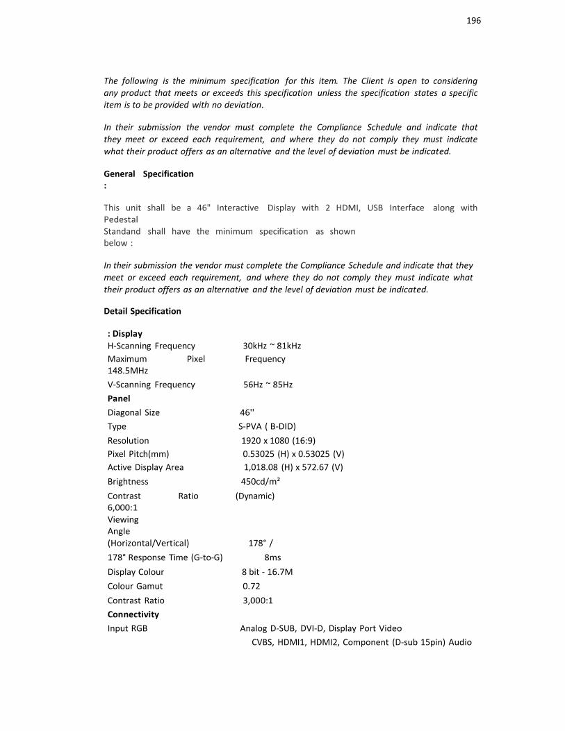
196
The following is the minimum specification for this item. The Client is open to consideringany product that meets or exceeds this specification unless the specification states a specificitem is to be provided with no deviation.
In their submission the vendor must complete the Compliance Schedule and indicate thatthey meet or exceed each requirement, and where they do not comply they must indicatewhat their product offers as an alternative and the level of deviation must be indicated.
General Specification:
This unit shall be a 46" Interactive Display with 2 HDMI, USB Interface along withPedestalStandand shall have the minimum specification as shownbelow :
In their submission the vendor must complete the Compliance Schedule and indicate that they meet or exceed each requirement, and where they do not comply they must indicate whattheir product offers as an alternative and the level of deviation must be indicated.
Detail Specification
: DisplayH-Scanning Frequency 30kHz ~ 81kHzMaximum Pixel Frequency 148.5MHzV-Scanning Frequency 56Hz ~ 85HzPanelDiagonal Size 46''Type S-PVA ( B-DID) Resolution 1920 x 1080 (16:9)Pixel Pitch(mm) 0.53025 (H) x 0.53025 (V)Active Display Area 1,018.08 (H) x 572.67 (V) Brightness 450cd/m²Contrast Ratio (Dynamic) 6,000:1ViewingAngle(Horizontal/Vertical) 178° /178° Response Time (G-to-G) 8msDisplay Colour 8 bit - 16.7M Colour Gamut 0.72Contrast Ratio 3,000:1ConnectivityInput RGB Analog D-SUB, DVI-D, Display Port Video
CVBS, HDMI1, HDMI2, Component (D-sub 15pin) Audio

197
RCA (L / R) , Stereo mini JackOutput Audio Stereo mini Jack
PowerOut
5V (for SBB)External Control RJ45, RS232C (in / out) , USB B type (touch screen)
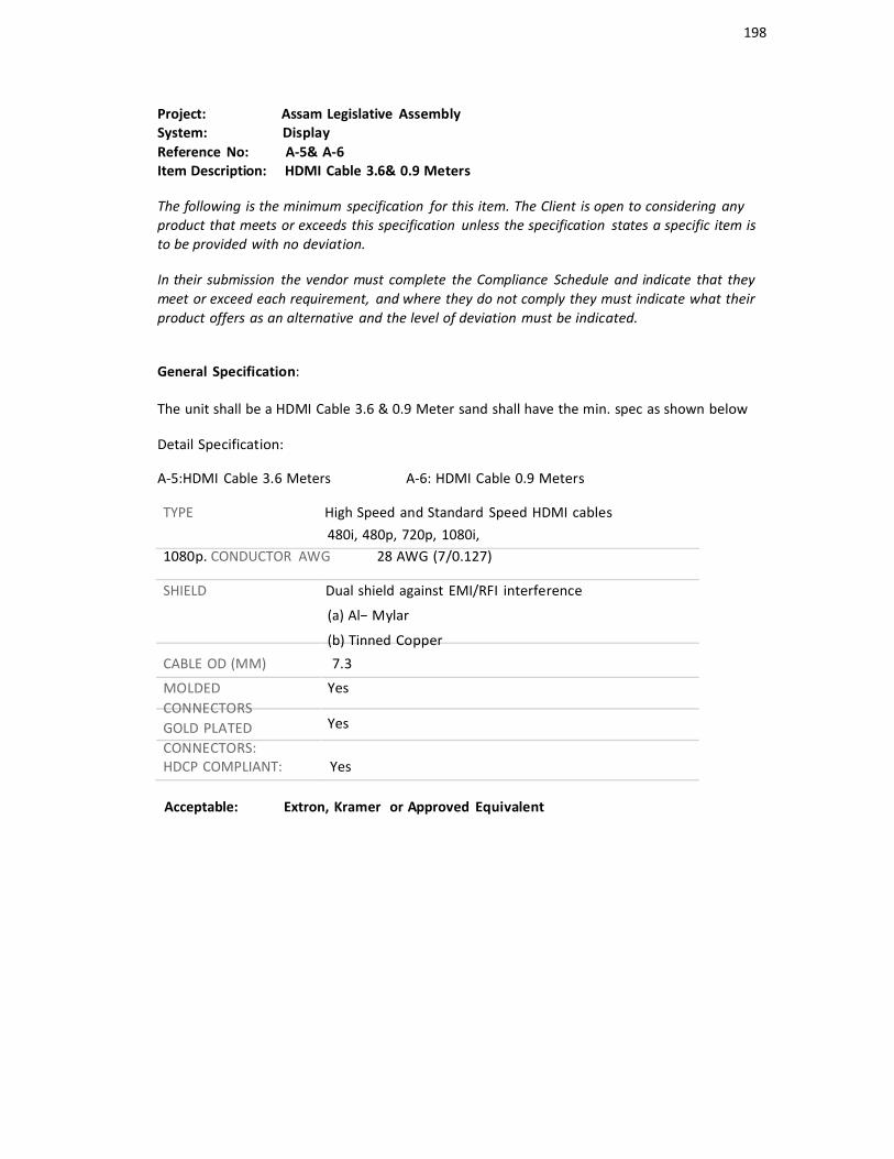
198
Project: Assam Legislative AssemblySystem: DisplayReference No: A-5& A-6Item Description: HDMI Cable 3.6& 0.9 Meters
The following is the minimum specification for this item. The Client is open to considering any product that meets or exceeds this specification unless the specification states a specific item is to be provided with no deviation.
In their submission the vendor must complete the Compliance Schedule and indicate that they meet or exceed each requirement, and where they do not comply they must indicate what their product offers as an alternative and the level of deviation must be indicated.
General Specification:
The unit shall be a HDMI Cable 3.6 & 0.9 Meter sand shall have the min. spec as shown below
Detail Specification:
A-5:HDMI Cable 3.6 Meters A-6: HDMI Cable 0.9 Meters
TYPE High Speed and Standard Speed HDMI cables480i, 480p, 720p, 1080i,
1080p. CONDUCTOR AWG 28 AWG (7/0.127)
SHIELD Dual shield against EMI/RFI interference
(a) Al− Mylar
(b) Tinned Copper
CABLE OD (MM) 7.3
MOLDED CONNECTORS GOLD PLATED CONNECTORS:
Yes
Yes
HDCP COMPLIANT: Yes
Acceptable: Extron, Kramer or Approved Equivalent

199
Project: Assam Legislative Assembly
System: Installation EquipmentReference No: C-1Item Description: Wall / ceiling mount bracket for the display
The following is the minimum specification for this item. The Client is open to considering any product that meets or exceeds this specification unless the specification states a specific item is to be provided with no deviation.
In their submission the vendor must complete the Compliance Schedule and indicate that they meet or exceed each requirement, and where they do not comply they must indicate what their product offers as an alternative and the level of deviation must be indicated.
Detail Specifications :
The Wall/Ceiling Bracket for Display shall be made from mild steel or Stainless steel, can be custom made based on submitted drawings and shall be of a laser etched, matte black powder coat finish. Please note, all fixings shall be invisible from the front and all cable management shall be incorporated in the design of the unit.
All Bracket designs are to be approved by the AV consultant before fabrication, sample of finish and detailed
Drawings are to be provided.
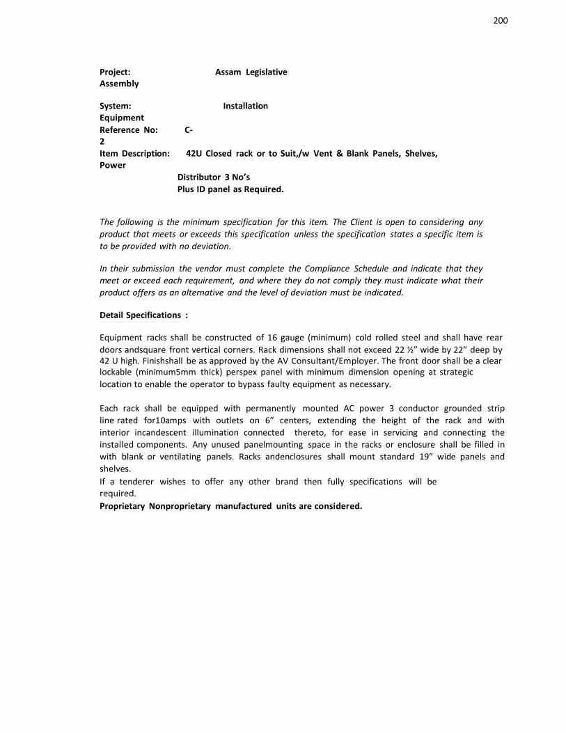
200
Project: Assam LegislativeAssembly
System: InstallationEquipmentReference No: C-2Item Description: 42U Closed rack or to Suit,/w Vent & Blank Panels, Shelves,Power
Distributor 3 No’sPlus ID panel as Required.
The following is the minimum specification for this item. The Client is open to considering any product that meets or exceeds this specification unless the specification states a specific item is to be provided with no deviation.
In their submission the vendor must complete the Compliance Schedule and indicate that they meet or exceed each requirement, and where they do not comply they must indicate what their product offers as an alternative and the level of deviation must be indicated.
Detail Specifications :
Equipment racks shall be constructed of 16 gauge (minimum) cold rolled steel and shall have rear doors andsquare front vertical corners. Rack dimensions shall not exceed 22 ½” wide by 22” deep by42 U high. Finishshall be as approved by the AV Consultant/Employer. The front door shall be a clearlockable (minimum5mm thick) perspex panel with minimum dimension opening at strategiclocation to enable the operator to bypass faulty equipment as necessary.
Each rack shall be equipped with permanently mounted AC power 3 conductor grounded stripline rated for10amps with outlets on 6” centers, extending the height of the rack and with interior incandescent illumination connected thereto, for ease in servicing and connecting theinstalled components. Any unused panelmounting space in the racks or enclosure shall be filled inwith blank or ventilating panels. Racks andenclosures shall mount standard 19” wide panels andshelves.If a tenderer wishes to offer any other brand then fully specifications will berequired.Proprietary Nonproprietary manufactured units are considered.

201
Project: Assam Legislative Assembly
System: IPTV & Digital Signage Management SystemReference No: B-1Item Description: Chassis with 9 slots for the Encoders & Processor Modules
The following is the minimum specification for this item. The Client is open to considering any product that meets or exceeds this specification unless the specification states a specific item is to be provided with no deviation.
In their submission the vendor must complete the Compliance Schedule and indicate that they meet or exceed each requirement, and where they do not comply they must indicate what their product offers as an alternative and the level of deviation must be indicated.
General Specification
The unit shall be a professional Chassis with 9 slots for the Encoders & Processor Modulesand shall have the minimum specification as shown below:
Detail specification
Power Input 100 – 240 VAC maximum 2.2 – 1A47 - 63 Hz200 watts via IEC Mains connector
Enclosure PowerDissipation 130 watts (typical)
200 watts (maximum)External LNB power drain(from 774 DVB-S2modules) 3A total
450mA per 774 DVB-S2 module
Any combination of up to 9 Processor Modules can be fitted in a single rack
Acceptable: Media Star, AMX or Approved Equivalents
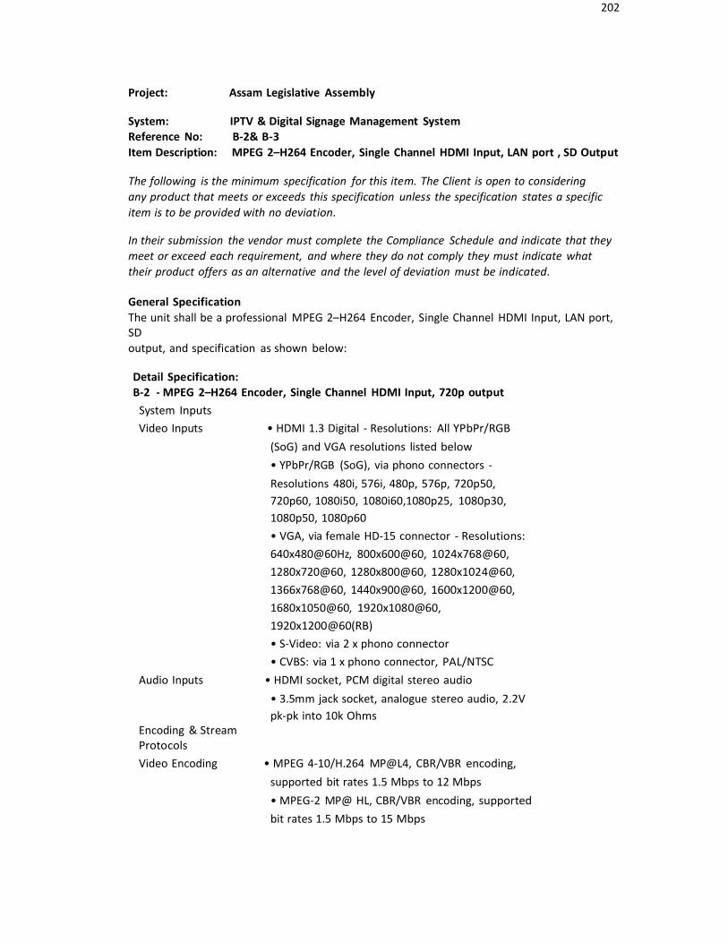
202
Project: Assam Legislative Assembly
System: IPTV & Digital Signage Management SystemReference No: B-2& B-3Item Description: MPEG 2–H264 Encoder, Single Channel HDMI Input, LAN port , SD Output
The following is the minimum specification for this item. The Client is open to consideringany product that meets or exceeds this specification unless the specification states a specificitem is to be provided with no deviation.
In their submission the vendor must complete the Compliance Schedule and indicate that theymeet or exceed each requirement, and where they do not comply they must indicate whattheir product offers as an alternative and the level of deviation must be indicated.
General SpecificationThe unit shall be a professional MPEG 2–H264 Encoder, Single Channel HDMI Input, LAN port,SDoutput, and specification as shown below:
Detail Specification:B-2 - MPEG 2–H264 Encoder, Single Channel HDMI Input, 720p output
System InputsVideo Inputs • HDMI 1.3 Digital - Resolutions: All YPbPr/RGB
(SoG) and VGA resolutions listed below• YPbPr/RGB (SoG), via phono connectors -Resolutions 480i, 576i, 480p, 576p, 720p50,720p60, 1080i50, 1080i60,1080p25, 1080p30,1080p50, 1080p60• VGA, via female HD-15 connector - Resolutions:640x480@60Hz, 800x600@60, 1024x768@60,1280x720@60, 1280x800@60, 1280x1024@60,1366x768@60, 1440x900@60, 1600x1200@60,1680x1050@60, 1920x1080@60,1920x1200@60(RB)• S-Video: via 2 x phono connector• CVBS: via 1 x phono connector, PAL/NTSC
Audio Inputs • HDMI socket, PCM digital stereo audio• 3.5mm jack socket, analogue stereo audio, 2.2Vpk-pk into 10k Ohms
Encoding & StreamProtocolsVideo Encoding • MPEG 4-10/H.264 MP@L4, CBR/VBR encoding,
supported bit rates 1.5 Mbps to 12 Mbps• MPEG-2 MP@ HL, CBR/VBR encoding, supported bit rates 1.5 Mbps to 15 Mbps

203
Detail Specification:
Audio Encoding • MPEG-1 Layer 2- 32, 44.1, 48 KHz sampling, 64 -448 Kbps Stereo• AAC LC encoding - 16, 32, 44.1, 48, 88.2, 96 KHz sampling, 40 - 576 Kbps Stereo
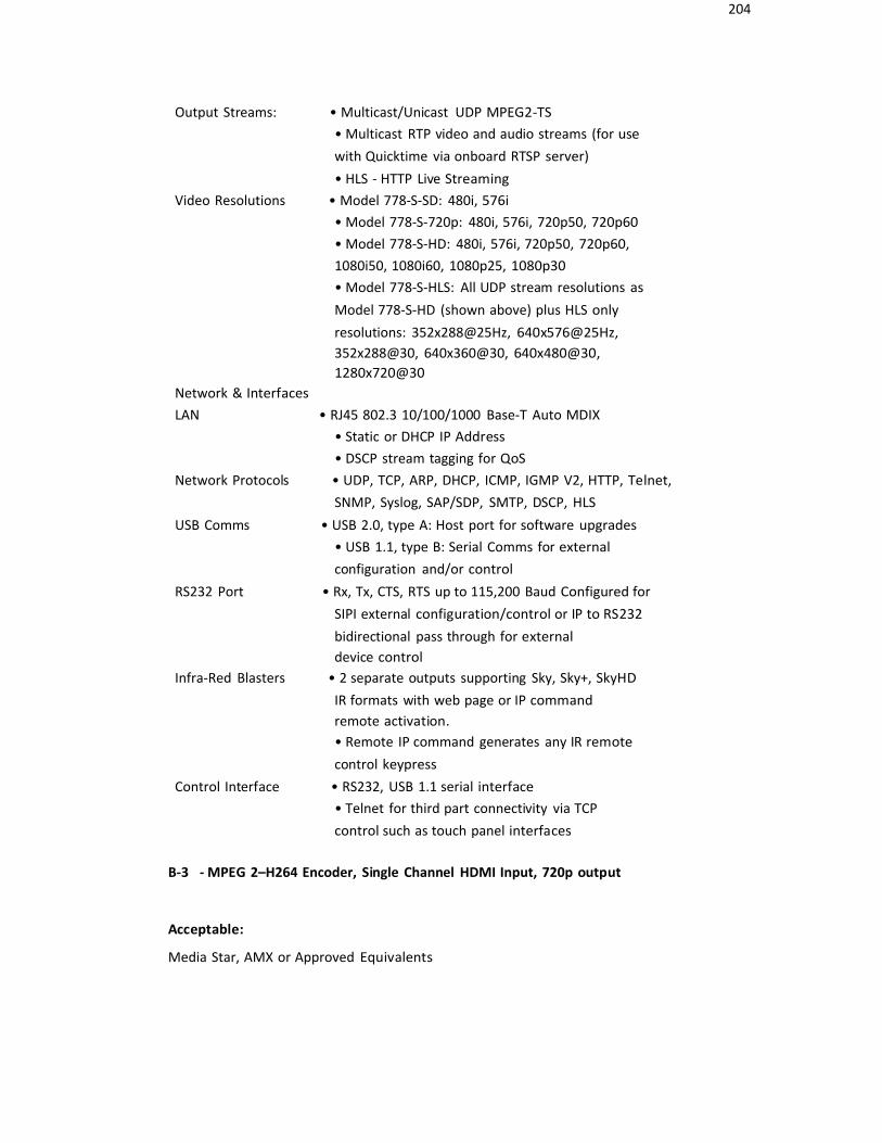
204
Output Streams: • Multicast/Unicast UDP MPEG2-TS• Multicast RTP video and audio streams (for use with Quicktime via onboard RTSP server)• HLS - HTTP Live Streaming
Video Resolutions • Model 778-S-SD: 480i, 576i• Model 778-S-720p: 480i, 576i, 720p50, 720p60• Model 778-S-HD: 480i, 576i, 720p50, 720p60,1080i50, 1080i60, 1080p25, 1080p30• Model 778-S-HLS: All UDP stream resolutions as Model 778-S-HD (shown above) plus HLS only resolutions: 352x288@25Hz, 640x576@25Hz,352x288@30, 640x360@30, 640x480@30,1280x720@30
Network & InterfacesLAN • RJ45 802.3 10/100/1000 Base-T Auto MDIX
• Static or DHCP IP Address• DSCP stream tagging for QoS
Network Protocols • UDP, TCP, ARP, DHCP, ICMP, IGMP V2, HTTP, Telnet, SNMP, Syslog, SAP/SDP, SMTP, DSCP, HLS
USB Comms • USB 2.0, type A: Host port for software upgrades• USB 1.1, type B: Serial Comms for external configuration and/or control
RS232 Port • Rx, Tx, CTS, RTS up to 115,200 Baud Configured forSIPI external configuration/control or IP to RS232bidirectional pass through for externaldevice control
Infra-Red Blasters • 2 separate outputs supporting Sky, Sky+, SkyHD IR formats with web page or IP commandremote activation.• Remote IP command generates any IR remote control keypress
Control Interface • RS232, USB 1.1 serial interface• Telnet for third part connectivity via TCPcontrol such as touch panel interfaces
B-3 - MPEG 2–H264 Encoder, Single Channel HDMI Input, 720p output
Acceptable:
Media Star, AMX or Approved Equivalents
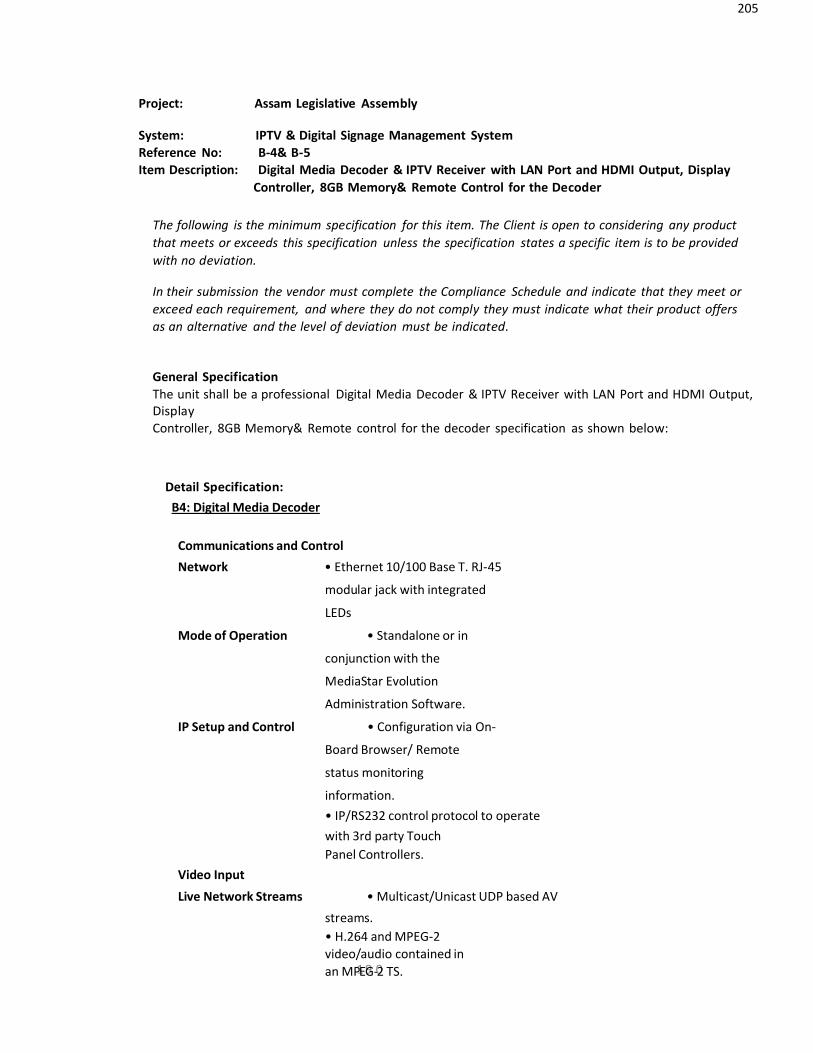
205
Project: Assam Legislative Assembly
System: IPTV & Digital Signage Management SystemReference No: B-4& B-5Item Description: Digital Media Decoder & IPTV Receiver with LAN Port and HDMI Output, Display
Controller, 8GB Memory& Remote Control for the Decoder
The following is the minimum specification for this item. The Client is open to considering any productthat meets or exceeds this specification unless the specification states a specific item is to be providedwith no deviation.
In their submission the vendor must complete the Compliance Schedule and indicate that they meet orexceed each requirement, and where they do not comply they must indicate what their product offersas an alternative and the level of deviation must be indicated.
General SpecificationThe unit shall be a professional Digital Media Decoder & IPTV Receiver with LAN Port and HDMI Output,DisplayController, 8GB Memory& Remote control for the decoder specification as shown below:
Detail Specification:B4: Digital Media Decoder
Communications and Control
Network • Ethernet 10/100 Base T. RJ-45
modular jack with integrated
LEDs
Mode of Operation • Standalone or in
conjunction with the
MediaStar Evolution
Administration Software.
IP Setup and Control • Configuration via On-
Board Browser/ Remote
status monitoring
information.• IP/RS232 control protocol to operatewith 3rd party TouchPanel Controllers.
Video Input
Live Network Streams • Multicast/Unicast UDP based AV
streams.• H.264 and MPEG-2video/audio contained inan MP1E9G-02 TS.

206
(480i, 480p, 576i, 576p, 720p, 1080i,1080p60 formats).

207
Project: Assam Legislative Assembly
System: IPTV & Digital Signage Management SystemReference No: B-6Item Description: Wired IR Sensor for above Decoder for digital signage system
The following is the minimum specification for this item. The Client is open to considering any productthat meets or exceeds this specification unless the specification states a specific item is to be providedwith no deviation.
In their submission the vendor must complete the Compliance Schedule and indicate that they meet orexceed each requirement, and where they do not comply they must indicate what their product offersas an alternative and the level of deviation must be indicated.
General Specification:
This unit shall be a Wired IR Sensor for above Decoder for digital signage systemnand shall have theminimum specification as shown below…
Detail Specification:
IR Sensor Module fitted with 3.5mm Jack for connection to MediastarPro Micro Set topUnit to allow the small IR sensor to be located in aconvenient location and the larger receiver unit housed discreetlybehind a screen.
Acceptable: Media star , AMX or Approved Equivalent
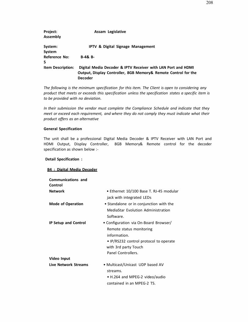
208
Project: Assam LegislativeAssembly
System: IPTV & Digital Signage ManagementSystemReference No: B-4& B-5Item Description: Digital Media Decoder & IPTV Receiver with LAN Port and HDMI
Output, Display Controller, 8GB Memory& Remote Control for theDecoder
The following is the minimum specification for this item. The Client is open to considering any product that meets or exceeds this specification unless the specification states a specific item is to be provided with no deviation.
In their submission the vendor must complete the Compliance Schedule and indicate that they meet or exceed each requirement, and where they do not comply they must indicate what their product offers as an alternative
General Specification
The unit shall be a professional Digital Media Decoder & IPTV Receiver with LAN Port and HDMI Output, Display Controller, 8GB Memory& Remote control for the decoderspecification as shown below :-
Detail Specification :
B4 : Digital Media Decoder
Communications andControlNetwork • Ethernet 10/100 Base T. RJ-45 modular
jack with integrated LEDsMode of Operation • Standalone or in conjunction with the
MediaStar Evolution Administration Software.
IP Setup and Control • Configuration via On-Board Browser/ Remote status monitoringinformation.• IP/RS232 control protocol to operatewith 3rd party TouchPanel Controllers.
Video InputLive Network Streams • Multicast/Unicast UDP based AV
streams.• H.264 and MPEG-2 video/audio contained in an MPEG-2 TS.

209
(480i, 480p, 576i, 576p, 720p, 1080i,1080p60 formats).• Locally Stored Files (on-board memory of 4GB to 128 GB by option)
Detail Specification:
Digital Terrestrial and Satellite TV • DVB-T2 and DVB-S2 compliant
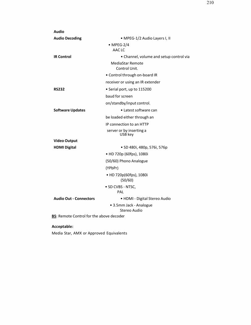
210
Audio
Audio Decoding • MPEG-1/2 Audio Layers I, II
• MPEG-2/4AAC LC
IR Control • Channel, volume and setup control via
MediaStar RemoteControl Unit.
• Control through on-board IR
receiver or using an IR extender
RS232 • Serial port, up to 115200
baud for screen
on/standby/input control.
Software Updates • Latest software can
be loaded either through an
IP connection to an HTTPserver or by inserting a
USB keyVideo Output
HDMI Digital • SD 480i, 480p, 576i, 576p
• HD 720p (60fps), 1080i
(50/60) Phono Analogue
(YPbPr)
• HD 720p(60fps), 1080i(50/60)
• SD CVBS - NTSC,PAL
Audio Out - Connectors • HDMI - Digital Stereo Audio
• 3.5mm Jack - AnalogueStereo Audio
B5: Remote Control for the above decoder
Acceptable:
Media Star, AMX or Approved Equivalents
211
Project: Assam Legislative Assembly
System: IPTV & Digital Signage Management SystemReference No: B-6Item Description: Wired IR Sensor for above Decoder for digital signage system
The following is the minimum specification for this item. The Client is open to considering any productthat meets or exceeds this specification unless the specification states a specific item is to be providedwith no deviation.
In their submission the vendor must complete the Compliance Schedule and indicate that they meet orexceed each requirement, and where they do not comply they must indicate what their product offersas an alternative and the level of deviation must be indicated.
General Specification:
This unit shall be a Wired IR Sensor for above Decoder for digital signage systemnand shall have theminimum specification as shown below…
Detail Specification:
IR Sensor Module fitted with 3.5mm Jack for connection to MediastarPro Micro Set topUnit to allow the small IR sensor to be located in aconvenient location and the larger receiver unit housed discreetlybehind a screen.
Acceptable: Media star , AMX or Approved Equivalent
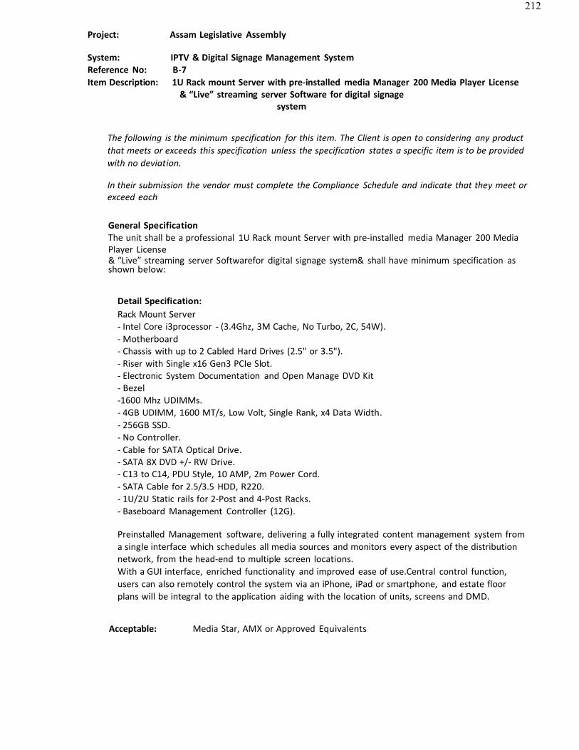
212
Project: Assam Legislative Assembly
System: IPTV & Digital Signage Management SystemReference No: B-7Item Description: 1U Rack mount Server with pre-installed media Manager 200 Media Player License
& “Live” streaming server Software for digital signagesystem
The following is the minimum specification for this item. The Client is open to considering any productthat meets or exceeds this specification unless the specification states a specific item is to be providedwith no deviation.
In their submission the vendor must complete the Compliance Schedule and indicate that they meet orexceed each
General SpecificationThe unit shall be a professional 1U Rack mount Server with pre-installed media Manager 200 MediaPlayer License& “Live” streaming server Softwarefor digital signage system& shall have minimum specification asshown below:
Detail Specification:Rack Mount Server- Intel Core i3processor - (3.4Ghz, 3M Cache, No Turbo, 2C, 54W).- Motherboard- Chassis with up to 2 Cabled Hard Drives (2.5" or 3.5").- Riser with Single x16 Gen3 PCIe Slot.- Electronic System Documentation and Open Manage DVD Kit- Bezel-1600 Mhz UDIMMs.- 4GB UDIMM, 1600 MT/s, Low Volt, Single Rank, x4 Data Width.- 256GB SSD.- No Controller.- Cable for SATA Optical Drive.- SATA 8X DVD +/- RW Drive.- C13 to C14, PDU Style, 10 AMP, 2m Power Cord.- SATA Cable for 2.5/3.5 HDD, R220.- 1U/2U Static rails for 2-Post and 4-Post Racks.- Baseboard Management Controller (12G).
Preinstalled Management software, delivering a fully integrated content management system froma single interface which schedules all media sources and monitors every aspect of the distributionnetwork, from the head-end to multiple screen locations.With a GUI interface, enriched functionality and improved ease of use.Central control function,users can also remotely control the system via an iPhone, iPad or smartphone, and estate floorplans will be integral to the application aiding with the location of units, screens and DMD.
Acceptable: Media Star, AMX or Approved Equivalents
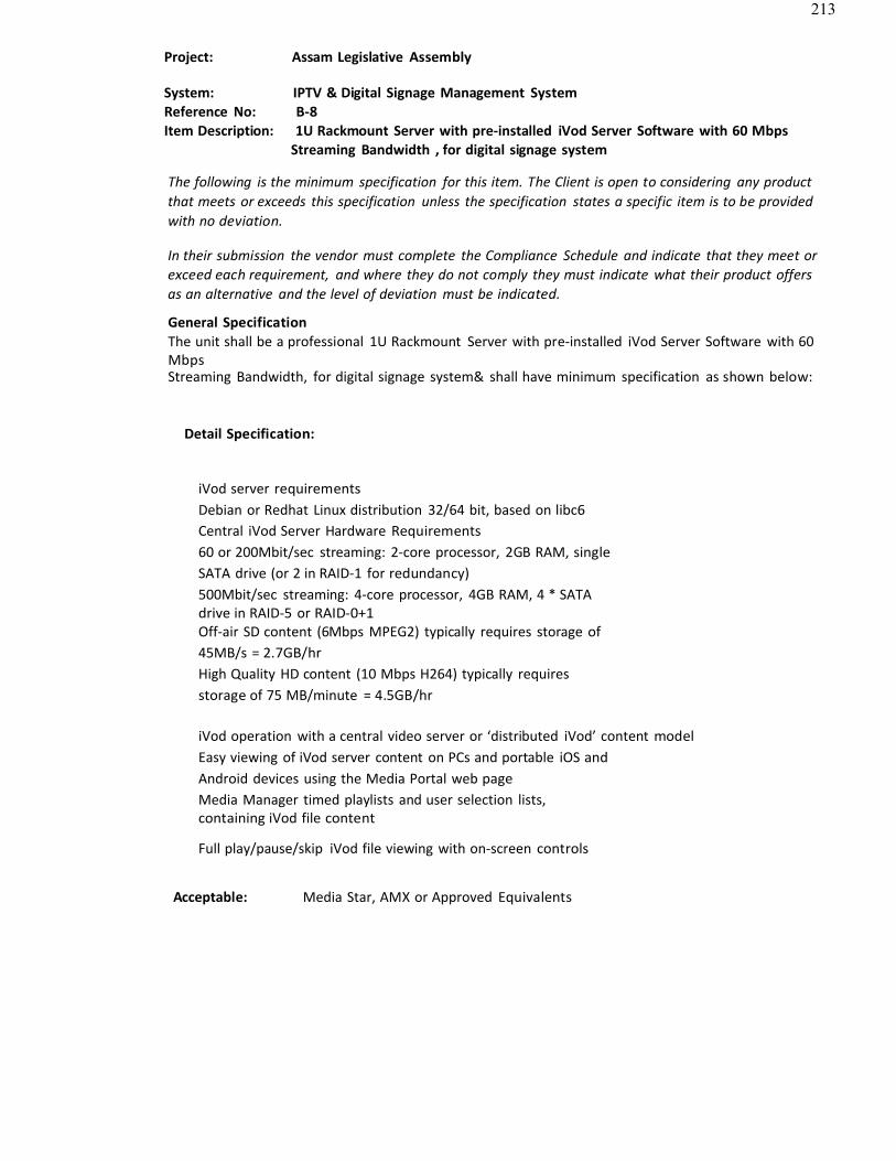
213
Project: Assam Legislative Assembly
System: IPTV & Digital Signage Management SystemReference No: B-8Item Description: 1U Rackmount Server with pre-installed iVod Server Software with 60 Mbps
Streaming Bandwidth , for digital signage system
The following is the minimum specification for this item. The Client is open to considering any productthat meets or exceeds this specification unless the specification states a specific item is to be providedwith no deviation.
In their submission the vendor must complete the Compliance Schedule and indicate that they meet orexceed each requirement, and where they do not comply they must indicate what their product offersas an alternative and the level of deviation must be indicated.
General SpecificationThe unit shall be a professional 1U Rackmount Server with pre-installed iVod Server Software with 60MbpsStreaming Bandwidth, for digital signage system& shall have minimum specification as shown below:
Detail Specification:
iVod server requirementsDebian or Redhat Linux distribution 32/64 bit, based on libc6Central iVod Server Hardware Requirements60 or 200Mbit/sec streaming: 2-core processor, 2GB RAM, singleSATA drive (or 2 in RAID-1 for redundancy)500Mbit/sec streaming: 4-core processor, 4GB RAM, 4 * SATAdrive in RAID-5 or RAID-0+1Off-air SD content (6Mbps MPEG2) typically requires storage of45MB/s = 2.7GB/hrHigh Quality HD content (10 Mbps H264) typically requiresstorage of 75 MB/minute = 4.5GB/hr
iVod operation with a central video server or ‘distributed iVod’ content modelEasy viewing of iVod server content on PCs and portable iOS andAndroid devices using the Media Portal web pageMedia Manager timed playlists and user selection lists,containing iVod file content
Full play/pause/skip iVod file viewing with on-screen controls
Acceptable: Media Star, AMX or Approved Equivalents
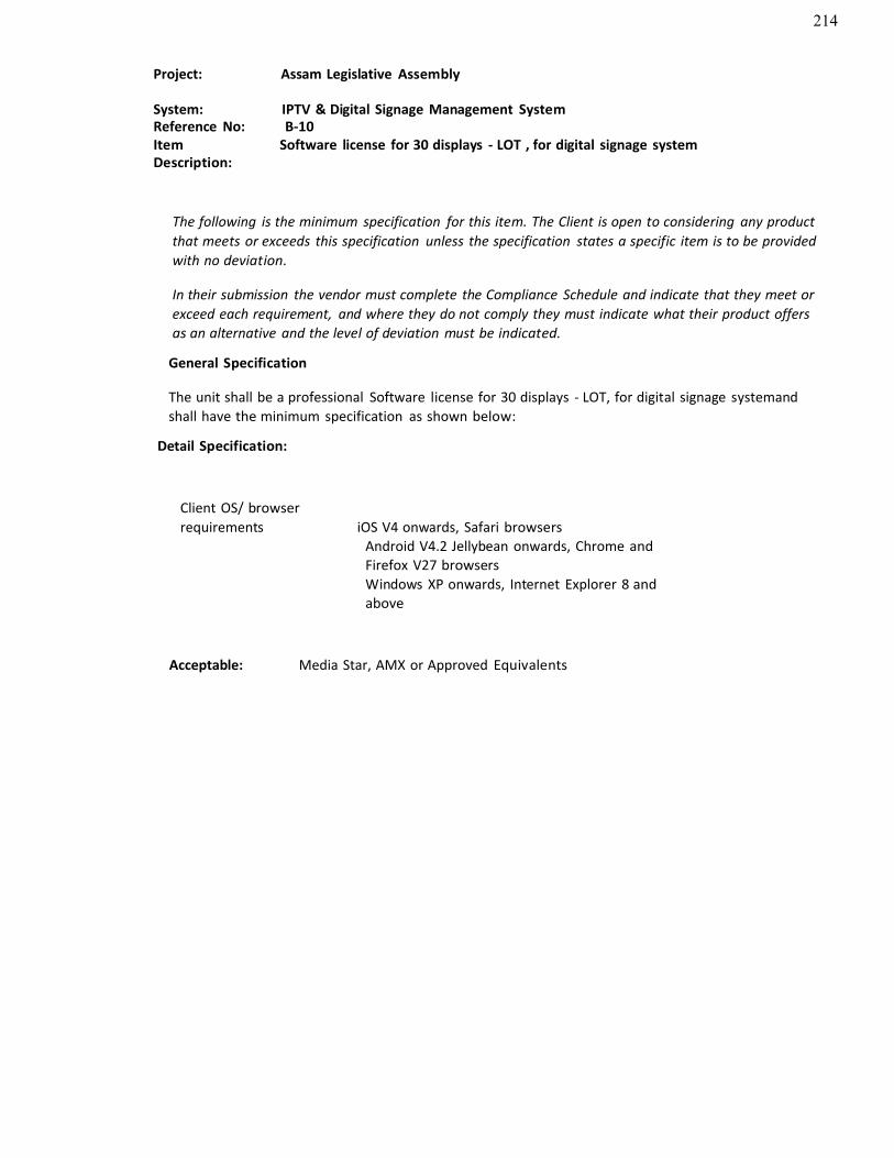
214
Project: Assam Legislative Assembly
System: IPTV & Digital Signage Management SystemReference No: B-10ItemDescription:
Software license for 30 displays - LOT , for digital signage system
The following is the minimum specification for this item. The Client is open to considering any productthat meets or exceeds this specification unless the specification states a specific item is to be providedwith no deviation.
In their submission the vendor must complete the Compliance Schedule and indicate that they meet or exceed each requirement, and where they do not comply they must indicate what their product offersas an alternative and the level of deviation must be indicated.
General Specification
The unit shall be a professional Software license for 30 displays - LOT, for digital signage systemandshall have the minimum specification as shown below:
Detail Specification:
Client OS/ browserrequirements iOS V4 onwards, Safari browsers
Android V4.2 Jellybean onwards, Chrome andFirefox V27 browsersWindows XP onwards, Internet Explorer 8 and above
Acceptable: Media Star, AMX or Approved Equivalents

215
Project: Assam Legislative Assembly
System: IPTV & Digital Signage Management SystemReference No: B-10Item Description: Software license for 30 displays - LOT , for digital signage system
The following is the minimum specification for this item. The Client is open to considering any productthat meets or exceeds this specification unless the specification states a specific item is to be providedwith no deviation.
In their submission the vendor must complete the Compliance Schedule and indicate that they meet orexceed each requirement, and where they do not comply they must indicate what their product offersas an alternative and the level of deviation must be indicated.
General Specification
The unit shall be a professional Software license for 30 displays - LOT, for digital signage system andshall have the minimum specification as shown below :
Detail Specification:
Software license for 30 displays-LOT, for digital signage System
Acceptable: Samsung ,Sony or Approved Equivalent
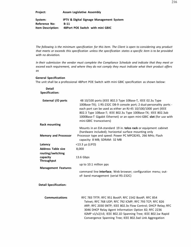
216
Project: Assam Legislative Assembly
System: IPTV & Digital Signage Management SystemReference No: B-11Item Description: 48Port POE Switch with mini GBIC
The following is the minimum specification for this item. The Client is open to considering any product that meets or exceeds this specification unless the specification states a specific item is to be provided with no deviation.
In their submission the vendor must complete the Compliance Schedule and indicate that they meet or exceed each requirement, and where they do not comply they must indicate what their product offersas
General SpecificationThe unit shall be a professional 48Port POE Switch with mini GBIC specification as shown below:
DetailSpecification:
External I/O ports 48 10/100 ports (IEEE 802.3 Type 10Base-T, IEEE 02.3u Type100Base-TX); 1 RS-232C DB-9 console port; 2 dual-personality ports -each port can be used as either an RJ-45 10/100/1000 port (IEEE802.3 Type 10Base-T; IEEE 802.3u Type 100Base-TX; IEEE 802.3ab1000Base-T Gigabit Ethernet) or an open mini-GBIC slot (for use with mini-GBIC transceivers)
Rack mountingMounts in an EIA-standard 19 in. telco rack or equipment cabinet(hardware included); horizontal surface mounting only
Memory and Processor Processor type and speed: Power PC MPC8245, 266 MHz; Flash capacity: 8 MB; SDRAM: 32 MB
Latency <13.3 µs (LIFO) Address Table size 8,000 routing/switchingcapacity 13.6 GbpsThroughput
Management Featuresup to 10.1 million pps
command line interface; Web browser; configuration menu; out-of- band management (serial RS-232C)
Detail Specification:
Communications RFC 783 TFTP; RFC 951 BootP; RFC 1542 BootP; RFC 854Telnet; RFC 768 UDP; RFC 792 ICMP; RFC 793 TCP; RFC 826ARP; RFC 2030 SNTP; IEEE 802.3x Flow Control; DHCP Relay; RFC3046 DHCP Relay Agent Information Option 82; RFC 2236IGMP v1/v2/v3; IEEE 802.1D Spanning Tree; IEEE 802.1w Rapid Convergence Spanning Tree; IEEE 802.3ad Link Aggregation

217
Control Protocol; IEEE 802.1AB Link Layer Discovery Protocol; ANSI/TIA-1057 LLDP Media Endpoint Discovery (MED); RFC1492 TACACS+; SSHv1/SSHv2 Secure Shell
Power consumption 100W
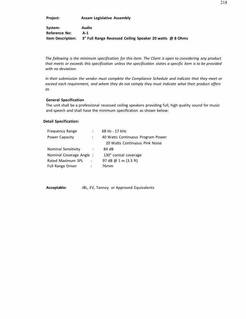
218
Project: Assam Legislative Assembly
System: AudioReference No: A-1Item Description: 3" Full Range Recessed Ceiling Speaker 20 watts @ 8 Ohms
The following is the minimum specification for this item. The Client is open to considering any product that meets or exceeds this specification unless the specification states a specific item is to be provided with no deviation.
In their submission the vendor must complete the Compliance Schedule and indicate that they meet or exceed each requirement, and where they do not comply they must indicate what their product offersas
General SpecificationThe unit shall be a professional recessed ceiling speakers providing full, high quality sound for music and speech and shall have the minimum specification as shown below:
Detail Specification:
Frequency Range : 68 Hz - 17 kHzPower Capacity : 40 Watts Continuous Program Power
20 Watts Continuous Pink NoiseNominal Sensitivity : 84 dBNominal Coverage Angle : 130° conical coverageRated Maximum SPL : 97 dB @ 1 m (3.3 ft) Full Range Driver : 76mm
Acceptable: JBL, EV, Tannoy or Approved Equivalents
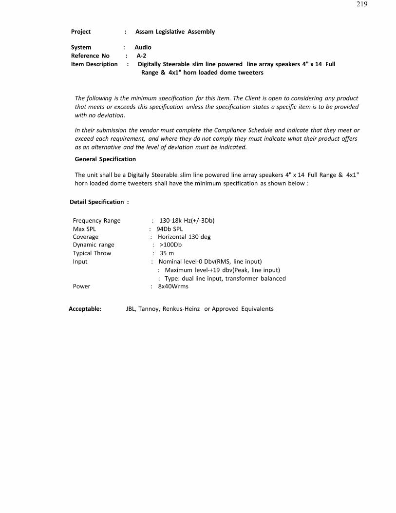
219
Project : Assam Legislative Assembly
System : AudioReference No : A-2Item Description : Digitally Steerable slim line powered line array speakers 4" x 14 Full
Range & 4x1" horn loaded dome tweeters
The following is the minimum specification for this item. The Client is open to considering any product that meets or exceeds this specification unless the specification states a specific item is to be provided with no deviation.
In their submission the vendor must complete the Compliance Schedule and indicate that they meet or exceed each requirement, and where they do not comply they must indicate what their product offersas an alternative and the level of deviation must be indicated.
General Specification
The unit shall be a Digitally Steerable slim line powered line array speakers 4" x 14 Full Range & 4x1" horn loaded dome tweeters shall have the minimum specification as shown below :
Detail Specification :
Frequency Range : 130-18k Hz(+/-3Db) Max SPL : 94Db SPLCoverage : Horizontal 130 degDynamic range : >100DbTypical Throw : 35 mInput : Nominal level-0 Dbv(RMS, line input)
: Maximum level-+19 dbv(Peak, line input): Type: dual line input, transformer balanced
Power : 8x40Wrms
Acceptable: JBL, Tannoy, Renkus-Heinz or Approved Equivalents
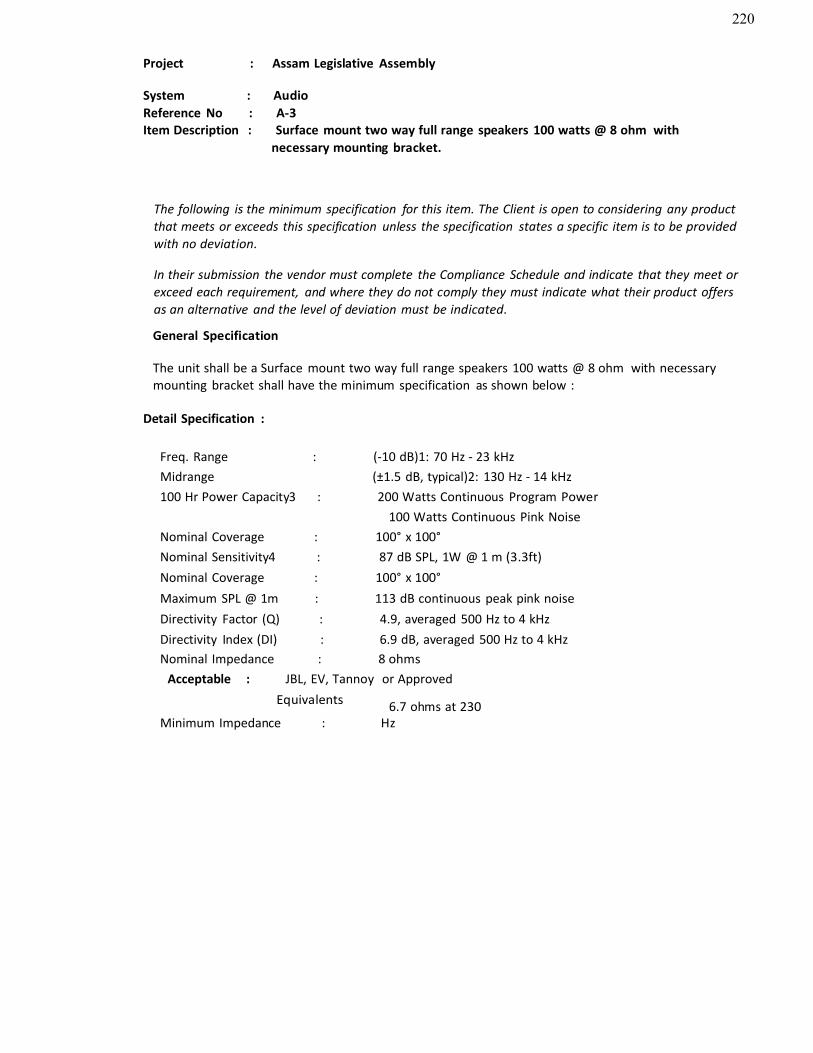
220
Project : Assam Legislative Assembly
System : AudioReference No : A-3Item Description : Surface mount two way full range speakers 100 watts @ 8 ohm with
necessary mounting bracket.
The following is the minimum specification for this item. The Client is open to considering any product that meets or exceeds this specification unless the specification states a specific item is to be provided with no deviation.
In their submission the vendor must complete the Compliance Schedule and indicate that they meet or exceed each requirement, and where they do not comply they must indicate what their product offersas an alternative and the level of deviation must be indicated.
General Specification
The unit shall be a Surface mount two way full range speakers 100 watts @ 8 ohm with necessary mounting bracket shall have the minimum specification as shown below :
Detail Specification :
Freq. Range : (-10 dB)1: 70 Hz - 23 kHzMidrange (±1.5 dB, typical)2: 130 Hz - 14 kHz100 Hr Power Capacity3 : 200 Watts Continuous Program Power
100 Watts Continuous Pink NoiseNominal Coverage : 100° x 100°Nominal Sensitivity4 : 87 dB SPL, 1W @ 1 m (3.3ft) Nominal Coverage : 100° x 100°Maximum SPL @ 1m : 113 dB continuous peak pink noise Directivity Factor (Q) : 4.9, averaged 500 Hz to 4 kHz Directivity Index (DI) : 6.9 dB, averaged 500 Hz to 4 kHzNominal Impedance : 8 ohms
Acceptable : JBL, EV, Tannoy or ApprovedEquivalents 6.7 ohms at 230
Minimum Impedance : Hz
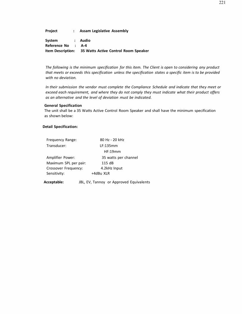
221
Project : Assam Legislative Assembly
System : AudioReference No : A-4Item Description: 35 Watts Active Control Room Speaker
The following is the minimum specification for this item. The Client is open to considering any productthat meets or exceeds this specification unless the specification states a specific item is to be providedwith no deviation.
In their submission the vendor must complete the Compliance Schedule and indicate that they meet orexceed each requirement, and where they do not comply they must indicate what their product offersas an alternative and the level of deviation must be indicated.
General SpecificationThe unit shall be a 35 Watts Active Control Room Speaker and shall have the minimum specificationas shown below:
Detail Specification:
Frequency Range: 80 Hz - 20 kHzTransducer: LF:135mm
HF:19mmAmplifier Power: 35 watts per channelMaximum SPL per pair: 115 dB Crossover Frequency: 4.2kHz InputSensitivity: +4dBu XLR
Acceptable: JBL, EV, Tannoy or Approved Equivalents
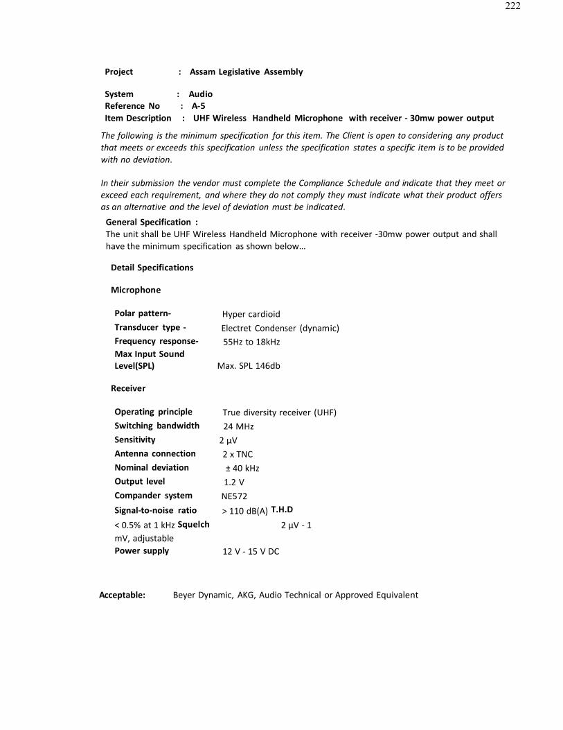
222
Project : Assam Legislative Assembly
System : AudioReference No : A-5Item Description : UHF Wireless Handheld Microphone with receiver - 30mw power output
The following is the minimum specification for this item. The Client is open to considering any product that meets or exceeds this specification unless the specification states a specific item is to be provided with no deviation.
In their submission the vendor must complete the Compliance Schedule and indicate that they meet or exceed each requirement, and where they do not comply they must indicate what their product offersas an alternative and the level of deviation must be indicated.
General Specification :The unit shall be UHF Wireless Handheld Microphone with receiver -30mw power output and shallhave the minimum specification as shown below…
Detail Specifications
Microphone
Polar pattern- Hyper cardioidTransducer type - Electret Condenser (dynamic)Frequency response- 55Hz to 18kHzMax Input SoundLevel(SPL) Max. SPL 146db
Receiver
Operating principle True diversity receiver (UHF)Switching bandwidth 24 MHz Sensitivity 2 μV Antenna connection 2 x TNC Nominal deviation ± 40 kHz Output level 1.2 V Compander system NE572Signal-to-noise ratio > 110 dB(A) T.H.D
< 0.5% at 1 kHz Squelch 2 μV - 1mV, adjustablePower supply 12 V - 15 V DC
Acceptable: Beyer Dynamic, AKG, Audio Technical or Approved Equivalent
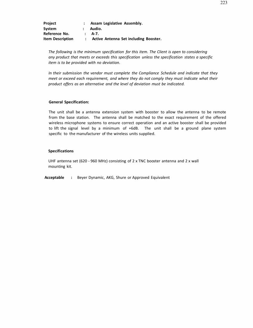
223
Project : Assam Legislative Assembly. System : Audio.Reference No. : A-7.Item Description : Active Antenna Set including Booster.
The following is the minimum specification for this item. The Client is open to consideringany product that meets or exceeds this specification unless the specification states a specific item is to be provided with no deviation.
In their submission the vendor must complete the Compliance Schedule and indicate that they meet or exceed each requirement, and where they do not comply they must indicate what their product offers as an alternative and the level of deviation must be indicated.
General Specification:
The unit shall be a antenna extension system with booster to allow the antenna to be remotefrom the base station. The antenna shall be matched to the exact requirement of the offeredwireless microphone systems to ensure correct operation and an active booster shall be providedto lift the signal level by a minimum of +6dB. The unit shall be a ground plane system specific to the manufacturer of the wireless units supplied.
Specifications
UHF antenna set (620 - 960 MHz) consisting of 2 x TNC booster antenna and 2 x wall mounting kit.
Acceptable : Beyer Dynamic, AKG, Shure or Approved Equivalent
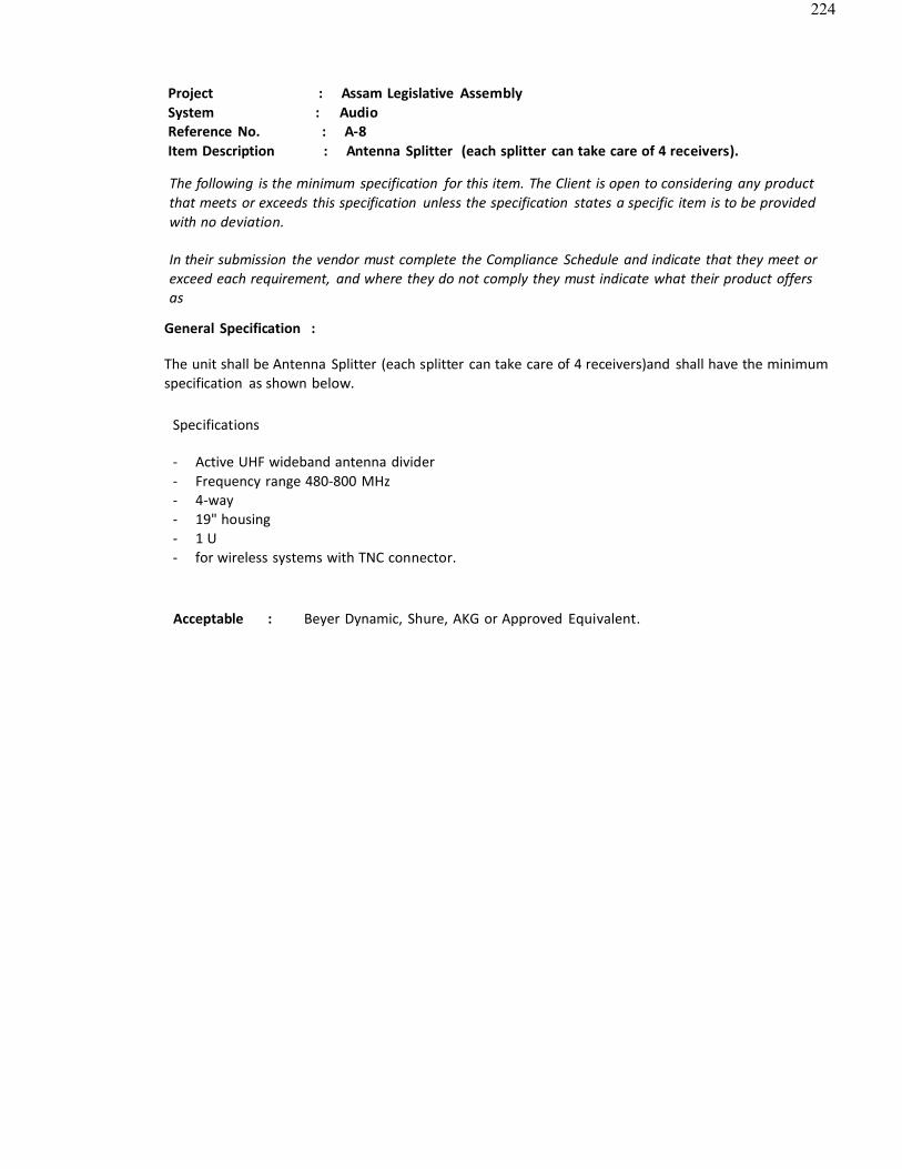
224
Project : Assam Legislative AssemblySystem : AudioReference No. : A-8Item Description : Antenna Splitter (each splitter can take care of 4 receivers).
The following is the minimum specification for this item. The Client is open to considering any product that meets or exceeds this specification unless the specification states a specific item is to be provided with no deviation.
In their submission the vendor must complete the Compliance Schedule and indicate that they meet or exceed each requirement, and where they do not comply they must indicate what their product offersas
General Specification :
The unit shall be Antenna Splitter (each splitter can take care of 4 receivers)and shall have the minimum specification as shown below.
Specifications
- Active UHF wideband antenna divider- Frequency range 480-800 MHz- 4-way- 19" housing- 1 U- for wireless systems with TNC connector.
Acceptable : Beyer Dynamic, Shure, AKG or Approved Equivalent.
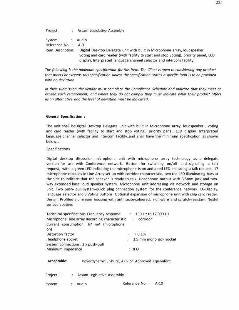
225
Project : Assam Legislative Assembly
System : AudioReference No : A-9Item Description: Digital Desktop Delegate unit with built in Microphone array, loudspeaker,
voting and card reader (with facility to start and stop voting), priority panel, LCDdisplay, Interpreted language channel selector and intercom facility.
The following is the minimum specification for this item. The Client is open to considering any product that meets or exceeds this specification unless the specification states a specific item is to be provided with no deviation.
In their submission the vendor must complete the Compliance Schedule and indicate that they meet or exceed each requirement, and where they do not comply they must indicate what their product offersas an alternative and the level of deviation must be indicated.
General Specification :
The unit shall beDigital Desktop Delegate unit with built in Microphone array, loudspeaker , votingand card reader (with facility to start and stop voting), priority panel, LCD display, Interpreted language channel selector and intercom facility..and shall have the minimum specification as shownbelow…
Specifications
Digital desktop discussion microphone unit with microphone array technology as a delegateversion for use with Conference network. Button for switching on/off and signalling a talkrequest, with a green LED indicating the microphone is on and a red LED indicating a talk request. 17 microphone capsules in Line-Array set-up with corridor characteristic, two red LED illuminating bars atthe side to indicate that the speaker is ready to talk. Headphone output with 3.5mm jack and two-way extended base loud speaker system. Microphone unit addressing via network and storage onunit. Two push- pull system-quick plug connection system for the conference network. LC-Display,language selector and 5 Voting Buttons. Optional expansion of microphone unit with chip card reader.Design: Profiled aluminium housing with anthracite-coloured, non-glare and scratch-resistant Nextelsurface coating.
Technical specifications Frequency response : 130 Hz to 17,000 HzMicrophone: line array Recording characteristic : corridorCurrent consumption: 67 mA (microphoneon)Distortion factor : < 0.1%Headphone socket : 3.5 mm mono jack socketSystem connections: 2 x push-pullMinimum impedance : 8 O
Acceptable: Beyerdynamic , Shure, AKG or Approved Equivalent
Project : Assam Legislative Assembly
System : Audio Reference No : A-10

226
209Item Description: Digital Desktop Chairman unit with built in Microphone array, loudspeaker ,
voting and card reader (with facility to start and stop voting), priority panel, LCDdisplay,
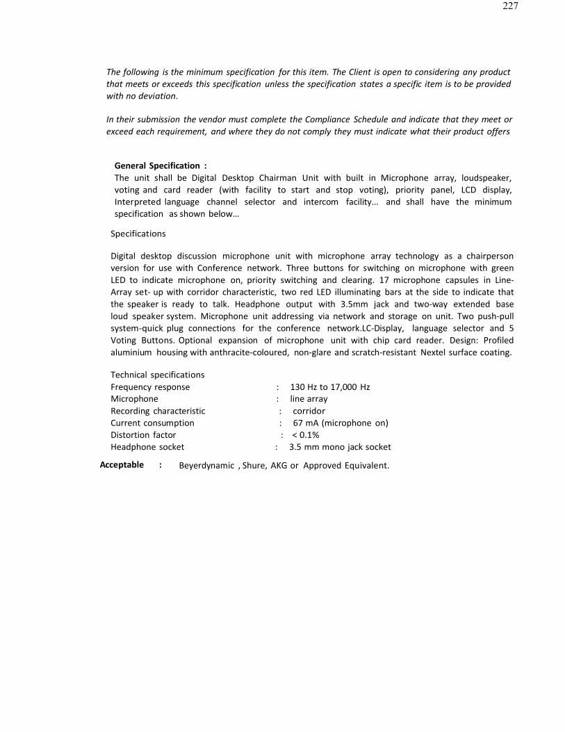
227
The following is the minimum specification for this item. The Client is open to considering any product that meets or exceeds this specification unless the specification states a specific item is to be provided with no deviation.
In their submission the vendor must complete the Compliance Schedule and indicate that they meet or exceed each requirement, and where they do not comply they must indicate what their product offers
General Specification :The unit shall be Digital Desktop Chairman Unit with built in Microphone array, loudspeaker,voting and card reader (with facility to start and stop voting), priority panel, LCD display, Interpreted language channel selector and intercom facility... and shall have the minimum specification as shown below…
Specifications
Digital desktop discussion microphone unit with microphone array technology as a chairperson version for use with Conference network. Three buttons for switching on microphone with greenLED to indicate microphone on, priority switching and clearing. 17 microphone capsules in Line-Array set- up with corridor characteristic, two red LED illuminating bars at the side to indicate thatthe speaker is ready to talk. Headphone output with 3.5mm jack and two-way extended base loud speaker system. Microphone unit addressing via network and storage on unit. Two push-pullsystem-quick plug connections for the conference network.LC-Display, language selector and 5Voting Buttons. Optional expansion of microphone unit with chip card reader. Design: Profiled aluminium housing with anthracite-coloured, non-glare and scratch-resistant Nextel surface coating.
Technical specificationsFrequency response : 130 Hz to 17,000 HzMicrophone : line arrayRecording characteristic : corridorCurrent consumption : 67 mA (microphone on) Distortion factor : < 0.1%Headphone socket : 3.5 mm mono jack socket
Acceptable : Beyerdynamic , Shure, AKG or Approved Equivalent.
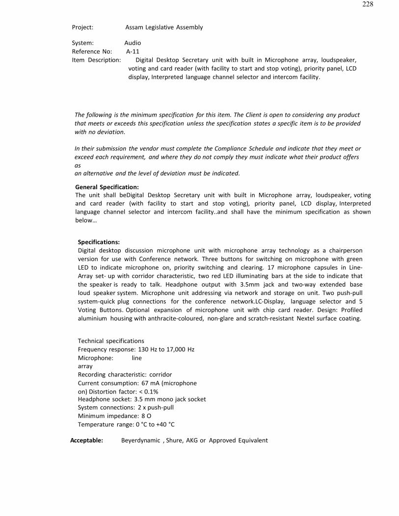
228
Project: Assam Legislative Assembly
System: AudioReference No: A-11Item Description: Digital Desktop Secretary unit with built in Microphone array, loudspeaker,
voting and card reader (with facility to start and stop voting), priority panel, LCDdisplay, Interpreted language channel selector and intercom facility.
The following is the minimum specification for this item. The Client is open to considering any product that meets or exceeds this specification unless the specification states a specific item is to be provided with no deviation.
In their submission the vendor must complete the Compliance Schedule and indicate that they meet or exceed each requirement, and where they do not comply they must indicate what their product offersasan alternative and the level of deviation must be indicated.
General Specification:The unit shall beDigital Desktop Secretary unit with built in Microphone array, loudspeaker, voting and card reader (with facility to start and stop voting), priority panel, LCD display, Interpretedlanguage channel selector and intercom facility..and shall have the minimum specification as shownbelow…
Specifications:Digital desktop discussion microphone unit with microphone array technology as a chairperson version for use with Conference network. Three buttons for switching on microphone with greenLED to indicate microphone on, priority switching and clearing. 17 microphone capsules in Line-Array set- up with corridor characteristic, two red LED illuminating bars at the side to indicate thatthe speaker is ready to talk. Headphone output with 3.5mm jack and two-way extended base loud speaker system. Microphone unit addressing via network and storage on unit. Two push-pullsystem-quick plug connections for the conference network.LC-Display, language selector and 5Voting Buttons. Optional expansion of microphone unit with chip card reader. Design: Profiled aluminium housing with anthracite-coloured, non-glare and scratch-resistant Nextel surface coating.
Technical specificationsFrequency response: 130 Hz to 17,000 HzMicrophone: linearrayRecording characteristic: corridorCurrent consumption: 67 mA (microphoneon) Distortion factor: < 0.1%Headphone socket: 3.5 mm mono jack socketSystem connections: 2 x push-pull Minimum impedance: 8 O Temperature range: 0 °C to +40 °C
Acceptable: Beyerdynamic , Shure, AKG or Approved Equivalent
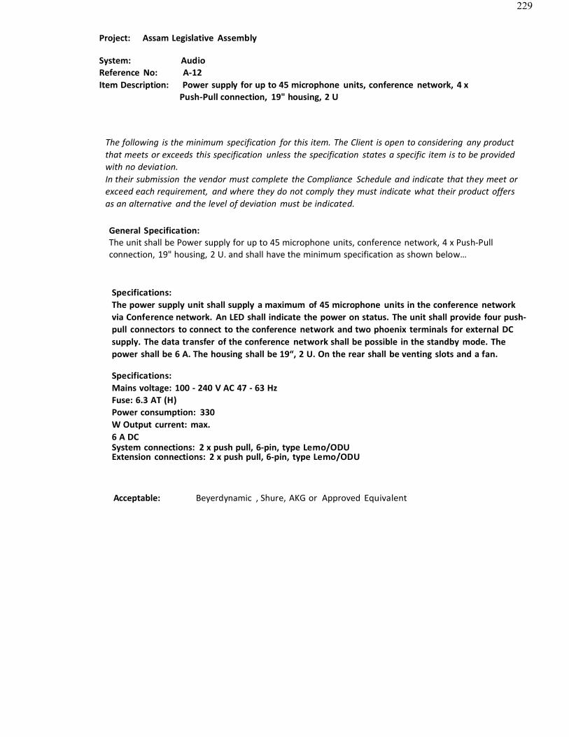
229
Project: Assam Legislative Assembly
System: AudioReference No: A-12Item Description: Power supply for up to 45 microphone units, conference network, 4 x
Push-Pull connection, 19" housing, 2 U
The following is the minimum specification for this item. The Client is open to considering any productthat meets or exceeds this specification unless the specification states a specific item is to be providedwith no deviation.In their submission the vendor must complete the Compliance Schedule and indicate that they meet orexceed each requirement, and where they do not comply they must indicate what their product offersas an alternative and the level of deviation must be indicated.
General Specification:The unit shall be Power supply for up to 45 microphone units, conference network, 4 x Push-Pull connection, 19" housing, 2 U. and shall have the minimum specification as shown below…
Specifications:The power supply unit shall supply a maximum of 45 microphone units in the conference networkvia Conference network. An LED shall indicate the power on status. The unit shall provide four push-pull connectors to connect to the conference network and two phoenix terminals for external DCsupply. The data transfer of the conference network shall be possible in the standby mode. Thepower shall be 6 A. The housing shall be 19“, 2 U. On the rear shall be venting slots and a fan.
Specifications:Mains voltage: 100 - 240 V AC 47 - 63 HzFuse: 6.3 AT (H)Power consumption: 330W Output current: max.6 A DCSystem connections: 2 x push pull, 6-pin, type Lemo/ODUExtension connections: 2 x push pull, 6-pin, type Lemo/ODU
Acceptable: Beyerdynamic , Shure, AKG or Approved Equivalent
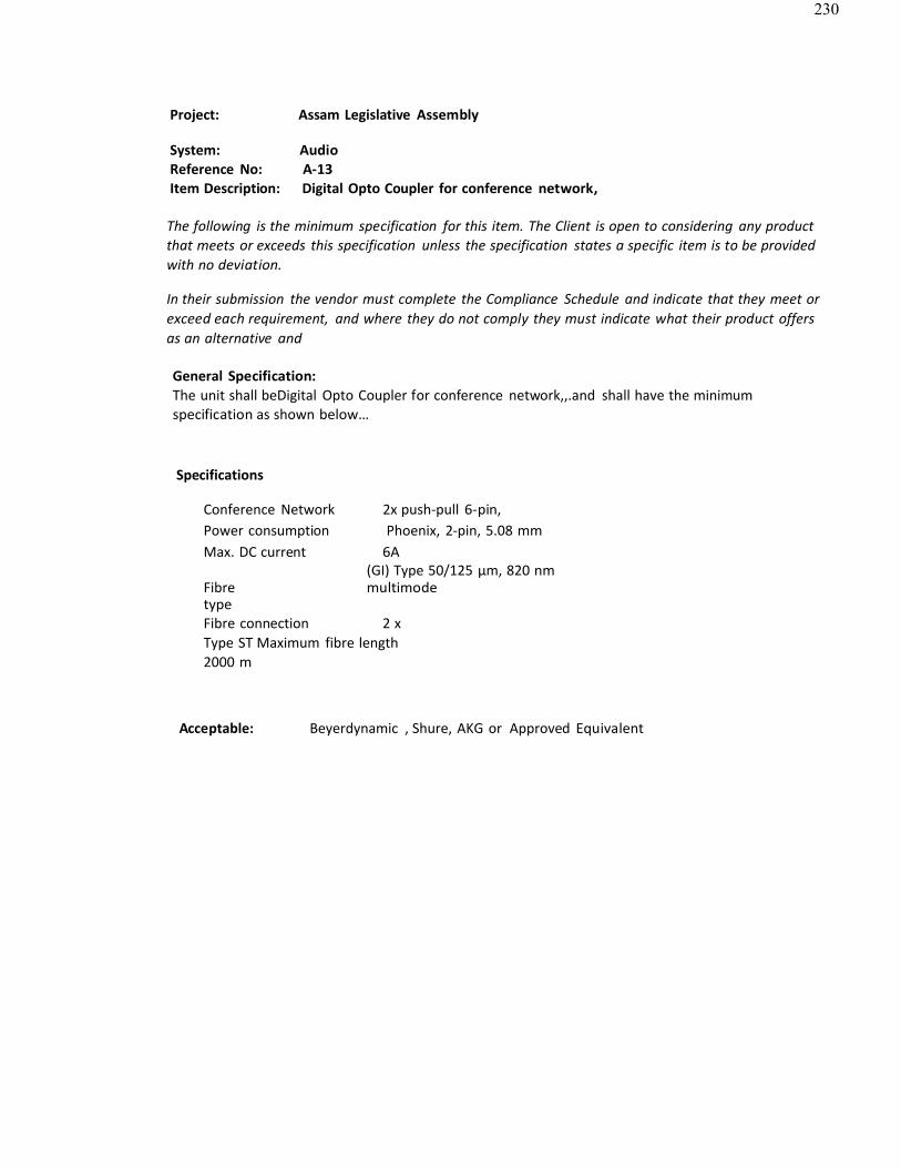
230
Project: Assam Legislative Assembly
System: AudioReference No: A-13Item Description: Digital Opto Coupler for conference network,
The following is the minimum specification for this item. The Client is open to considering any productthat meets or exceeds this specification unless the specification states a specific item is to be providedwith no deviation.
In their submission the vendor must complete the Compliance Schedule and indicate that they meet orexceed each requirement, and where they do not comply they must indicate what their product offersas an alternative and
General Specification:The unit shall beDigital Opto Coupler for conference network,,.and shall have the minimumspecification as shown below…
Specifications
Conference Network 2x push-pull 6-pin,Power consumption Phoenix, 2-pin, 5.08 mmMax. DC current 6A
(GI) Type 50/125 μm, 820 nmFibretype
multimode
Fibre connection 2 xType ST Maximum fibre length 2000 m
Acceptable: Beyerdynamic , Shure, AKG or Approved Equivalent
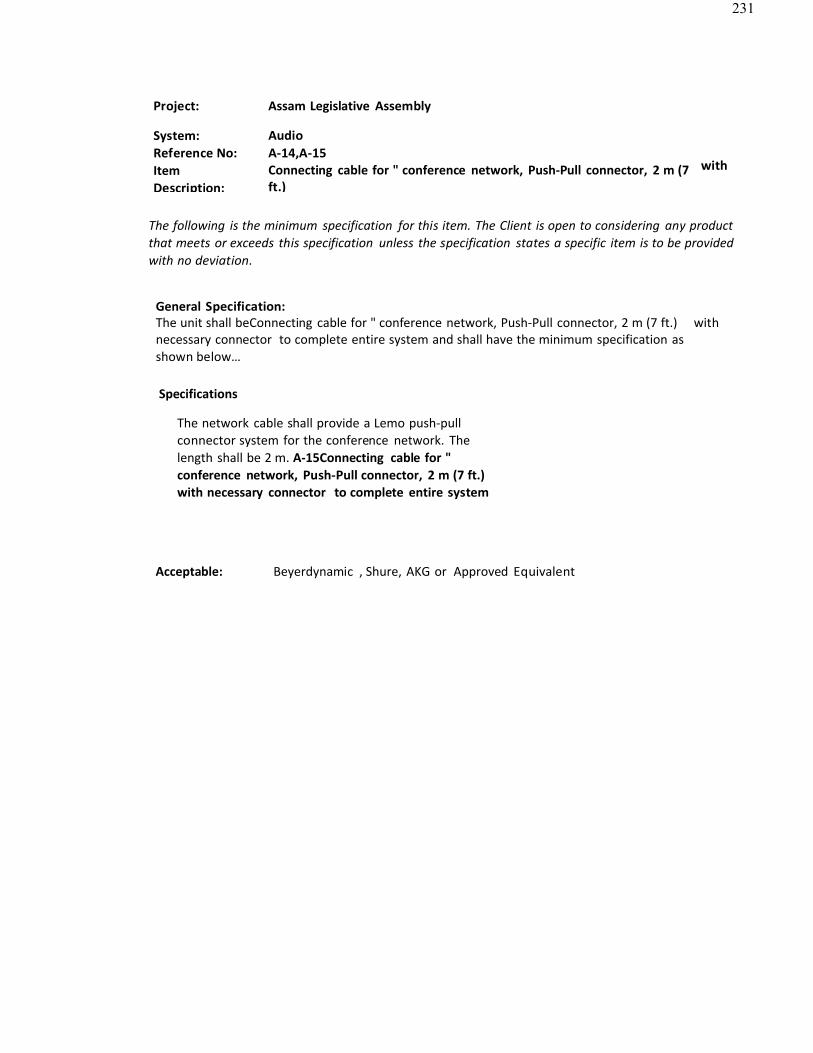
231
Project: Assam Legislative Assembly
System: Reference No: ItemDescription:
AudioA-14,A-15Connecting cable for " conference network, Push-Pull connector, 2 m (7ft.)
with
The following is the minimum specification for this item. The Client is open to considering any productthat meets or exceeds this specification unless the specification states a specific item is to be providedwith no deviation.
General Specification:The unit shall beConnecting cable for " conference network, Push-Pull connector, 2 m (7 ft.) withnecessary connector to complete entire system and shall have the minimum specification asshown below…
Specifications
The network cable shall provide a Lemo push-pullconnector system for the conference network. Thelength shall be 2 m. A-15Connecting cable for "conference network, Push-Pull connector, 2 m (7 ft.) with necessary connector to complete entire system
Acceptable: Beyerdynamic , Shure, AKG or Approved Equivalent
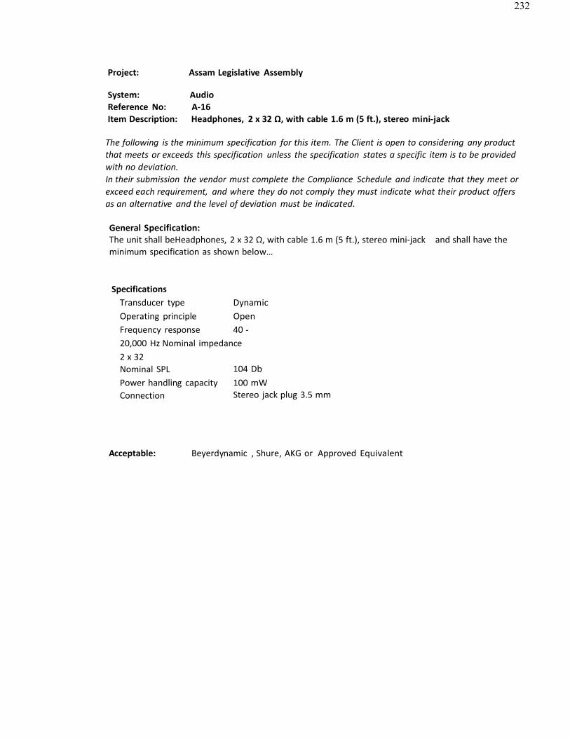
232
Project: Assam Legislative Assembly
System: AudioReference No: A-16Item Description: Headphones, 2 x 32 Ω, with cable 1.6 m (5 ft.), stereo mini-jack
The following is the minimum specification for this item. The Client is open to considering any productthat meets or exceeds this specification unless the specification states a specific item is to be providedwith no deviation.In their submission the vendor must complete the Compliance Schedule and indicate that they meet orexceed each requirement, and where they do not comply they must indicate what their product offersas an alternative and the level of deviation must be indicated.
General Specification:The unit shall beHeadphones, 2 x 32 Ω, with cable 1.6 m (5 ft.), stereo mini-jack and shall have the minimum specification as shown below…
SpecificationsTransducer type Dynamic Operating principle Open Frequency response 40 -20,000 Hz Nominal impedance 2 x 32Nominal SPL 104 DbPower handling capacity 100 mWConnection Stereo jack plug 3.5 mm
Acceptable: Beyerdynamic , Shure, AKG or Approved Equivalent
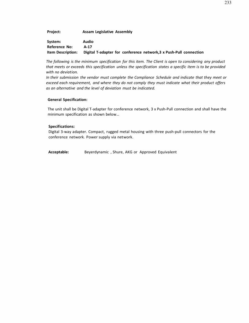
233
Project: Assam Legislative Assembly
System: AudioReference No: A-17Item Description: Digital T-adapter for conference network,3 x Push-Pull connection
The following is the minimum specification for this item. The Client is open to considering any productthat meets or exceeds this specification unless the specification states a specific item is to be providedwith no deviation.In their submission the vendor must complete the Compliance Schedule and indicate that they meet orexceed each requirement, and where they do not comply they must indicate what their product offersas an alternative and the level of deviation must be indicated.
General Specification:
The unit shall be Digital T-adapter for conference network, 3 x Push-Pull connection and shall have the minimum specification as shown below…
Specifications:Digital 3-way adapter. Compact, rugged metal housing with three push-pull connectors for theconference network. Power supply via network.
Acceptable: Beyerdynamic , Shure, AKG or Approved Equivalent

234
Project: Assam Legislative Assembly
System: AudioReference No: A-18Item Description: Configuration and controller software for Digital Conference Network
The following is the minimum specification for this item. The Client is open to considering any productthat meets or exceeds this specification unless the specification states a specific item is to be providedwith no deviation.In their submission the vendor must complete the Compliance Schedule and indicate that they meet orexceed each requirement, and where they do not comply they must indicate what their product offersas an alternative and the level of deviation must be indicated.
General Specification:The unit shall beConfiguration and controller software for Digital Conference Networkand shall have the minimum specification as shown below…
Specifications
Control- and configuration Software for digital Conference network SystemComplete Software package, ICNS modules activated by license key in Central Unit
Acceptable: Beyerdynamic , Shure, AKG or Approved Equivalent
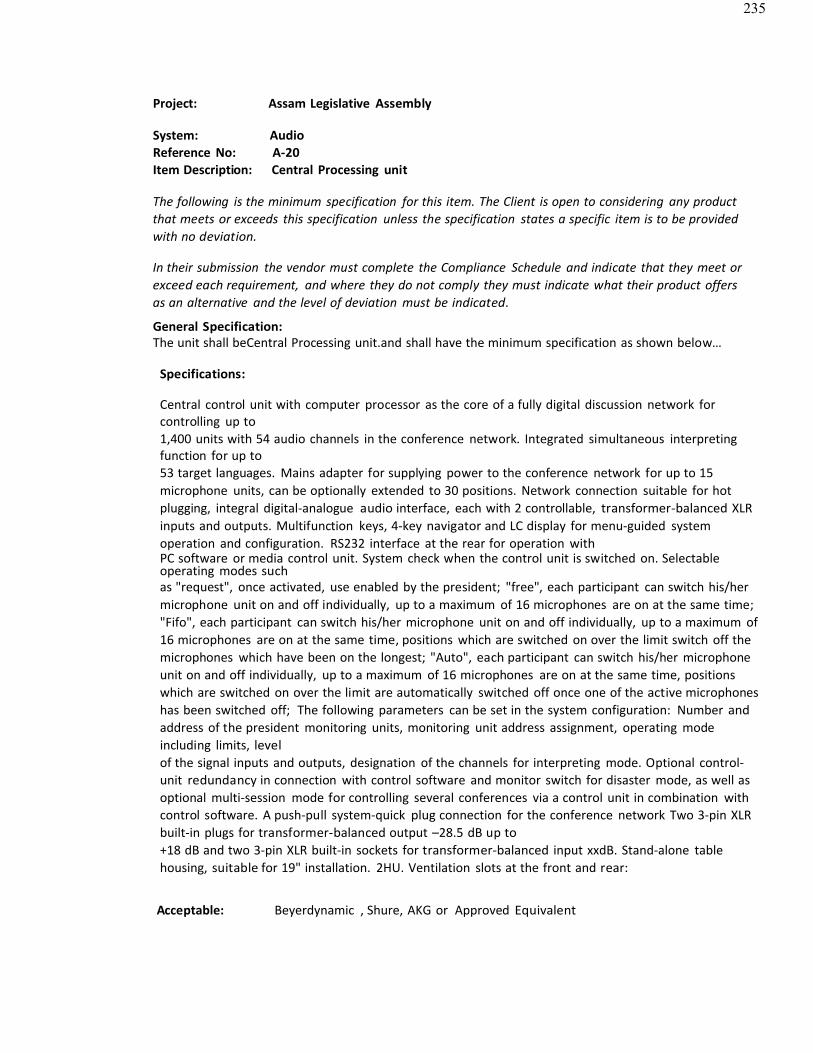
235
Project: Assam Legislative Assembly
System: AudioReference No: A-20Item Description: Central Processing unit
The following is the minimum specification for this item. The Client is open to considering any productthat meets or exceeds this specification unless the specification states a specific item is to be providedwith no deviation.
In their submission the vendor must complete the Compliance Schedule and indicate that they meet orexceed each requirement, and where they do not comply they must indicate what their product offersas an alternative and the level of deviation must be indicated.
General Specification:The unit shall beCentral Processing unit.and shall have the minimum specification as shown below…
Specifications:
Central control unit with computer processor as the core of a fully digital discussion network forcontrolling up to1,400 units with 54 audio channels in the conference network. Integrated simultaneous interpretingfunction for up to53 target languages. Mains adapter for supplying power to the conference network for up to 15microphone units, can be optionally extended to 30 positions. Network connection suitable for hotplugging, integral digital-analogue audio interface, each with 2 controllable, transformer-balanced XLRinputs and outputs. Multifunction keys, 4-key navigator and LC display for menu-guided systemoperation and configuration. RS232 interface at the rear for operation withPC software or media control unit. System check when the control unit is switched on. Selectableoperating modes suchas "request", once activated, use enabled by the president; "free", each participant can switch his/hermicrophone unit on and off individually, up to a maximum of 16 microphones are on at the same time;"Fifo", each participant can switch his/her microphone unit on and off individually, up to a maximum of16 microphones are on at the same time, positions which are switched on over the limit switch off themicrophones which have been on the longest; "Auto", each participant can switch his/her microphoneunit on and off individually, up to a maximum of 16 microphones are on at the same time, positionswhich are switched on over the limit are automatically switched off once one of the active microphoneshas been switched off; The following parameters can be set in the system configuration: Number and address of the president monitoring units, monitoring unit address assignment, operating modeincluding limits, levelof the signal inputs and outputs, designation of the channels for interpreting mode. Optional control-unit redundancy in connection with control software and monitor switch for disaster mode, as well asoptional multi-session mode for controlling several conferences via a control unit in combination withcontrol software. A push-pull system-quick plug connection for the conference network Two 3-pin XLRbuilt-in plugs for transformer-balanced output –28.5 dB up to+18 dB and two 3-pin XLR built-in sockets for transformer-balanced input xxdB. Stand-alone tablehousing, suitable for 19" installation. 2HU. Ventilation slots at the front and rear:
Acceptable: Beyerdynamic , Shure, AKG or Approved Equivalent
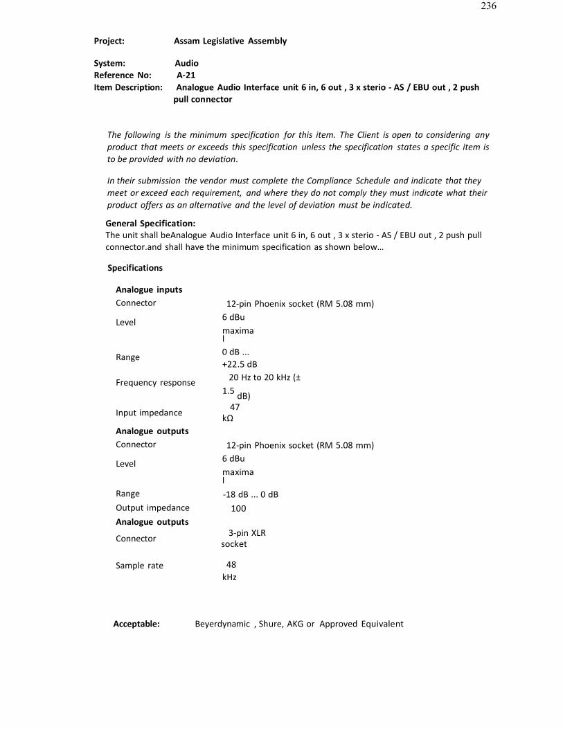
236
Project: Assam Legislative Assembly
System: AudioReference No: A-21Item Description: Analogue Audio Interface unit 6 in, 6 out , 3 x sterio - AS / EBU out , 2 push
pull connector
The following is the minimum specification for this item. The Client is open to considering anyproduct that meets or exceeds this specification unless the specification states a specific item isto be provided with no deviation.
In their submission the vendor must complete the Compliance Schedule and indicate that theymeet or exceed each requirement, and where they do not comply they must indicate what theirproduct offers as an alternative and the level of deviation must be indicated.
General Specification:The unit shall beAnalogue Audio Interface unit 6 in, 6 out , 3 x sterio - AS / EBU out , 2 push pull connector.and shall have the minimum specification as shown below…
Specifications
Analogue inputsConnector 12-pin Phoenix socket (RM 5.08 mm)
Level 6 dBu maximal
Range 0 dB ...+22.5 dB
Frequency response 20 Hz to 20 kHz (±1.5 dB)
Input impedance 47kΩ
Analogue outputsConnector 12-pin Phoenix socket (RM 5.08 mm)
Level 6 dBu maximal
Range -18 dB ... 0 dBOutput impedance 100Analogue outputs
Connector 3-pin XLRsocket
Sample rate 48 kHz
Acceptable: Beyerdynamic , Shure, AKG or Approved Equivalent

237
Project: Assam Legislative Assembly
System: AudioReference No: A-22Item Description: Interpreter desk with LCD display, Pluggable extended stem
microphone, Interpreter head phone, Intercom etc.
The following is the minimum specification for this item. The Client is open to consideringany product that meets or exceeds this specification unless the specification states a specificitem is to be provided with no deviation.
In their submission the vendor must complete the Compliance Schedule and indicate that theymeet or exceed each requirement, and where they do not comply they must indicate what theirproduct offers as an alternative and the level of deviation must be indicated.
General Specification:The unit shall be Interpreter desk with LCD display, Pluggable extended stem microphone, Interpreter head phone, Intercom etc. and shall have the minimum specification as shown below…
Specifications:Digital interpreter microphone unit for 1 interpreter as a single desk, up to 53 target languages foroperation in the conference network. Two separate LC displays for relay channels and microphoneoutput channels, connection for the headphone/microphone set or headphones and microphoneseparate, menu-controlled channel pre-selection field and listening monitor field for up to three relaychannels and two microphone output channels, can be programmed for direct access. Two-band soundcontrol for headphones and controllable monitor speakers. Service call button, president call buttonand cough button. Integration at any position in the conference network with integrated power supplyvia bus. Complies with the requirements of the AIIC (Association International des Interprets deConference – International Association of Interpreters) and the corresponding standards (ISO 4043, ISO2603, DIN 56924). Twopush-pull system-quick plug connections for the conference network.
Acceptable: Beyerdynamic , Shure, AKG or Approved Equivalent

238
Project: Assam Legislative Assembly
System: AudioReference No: A-23Item Description: Control Unit for Portable Conference Units
The following is the minimum specification for this item. The Client is open to considering any productthat meets or exceeds this specification unless the specification states a specific item is to be providedwith no deviation.
In their submission the vendor must complete the Compliance Schedule and indicate that they meet orexceed each requirement, and where they do not comply they must indicate what their product offersas an alternative and the level of deviation must be indicated.
General Specification:The unit shall be Control Unit for Portable Conference Units and shall have the minimum specification as shown below…
SpecificationsThe control unit shall be the core of a discussion system with media control system. It shall beequipped with an integrated power supply unit and processor to control a maximum of 64microphone units. The control unit shall have 2 multifunction buttons and an LC-Display with 2lines/16 digits for menu-driven system operation and configuration. The RS 232 interface port on the front shall be used for a system configuration via PC. After switching on the control unit a system check shall be performed. The master reset shall be accessible for manufacturer’s default settings. The serial RS 232 interface shall connect to an operator’s PC orexternal console. The control unit shall have two inputs for sound signals 250 mV (balanced) and1.55 V (unbalanced). The following three operation modes shall be available: Request-to-Talk (the chairman shall release the microphone of the participant who wants to talk), Autonomy(each participant shall switch on and off his microphone unit), Override (each switched onmicrophone unit shall switch off the previously activated microphone unit). ”Next” function control (first in - first out) in the Request-to-Talk mode. In each operation mode the talk time andwarning time for the illuminated ring shall be pre-set to indicate that the talk time has elapsed.The following parameters shall be adjusted within the system configuration: number and addressof the chairman microphone units, function of the priority button, number of the openmicrophones, number and address of the loudspeakers to be muted in the microphone units, input level of the signals and volume and sound control of the master signal. For the microphone lines 2 connections shall be available. The control unit shall have a recording output(RCA, 250 mV) and a 3-pin XLR socket for transformer balanced line level output (+6 dBm). The recording output shall be independent from the output volume adjustment. The desktop housing shall be 2 rack units high, for 19" rack mounting. The control unit shall have ventilationlouvres on top and bottom.
Acceptable: Beyerdynamic , Shure, AKG or Approved Equivalent
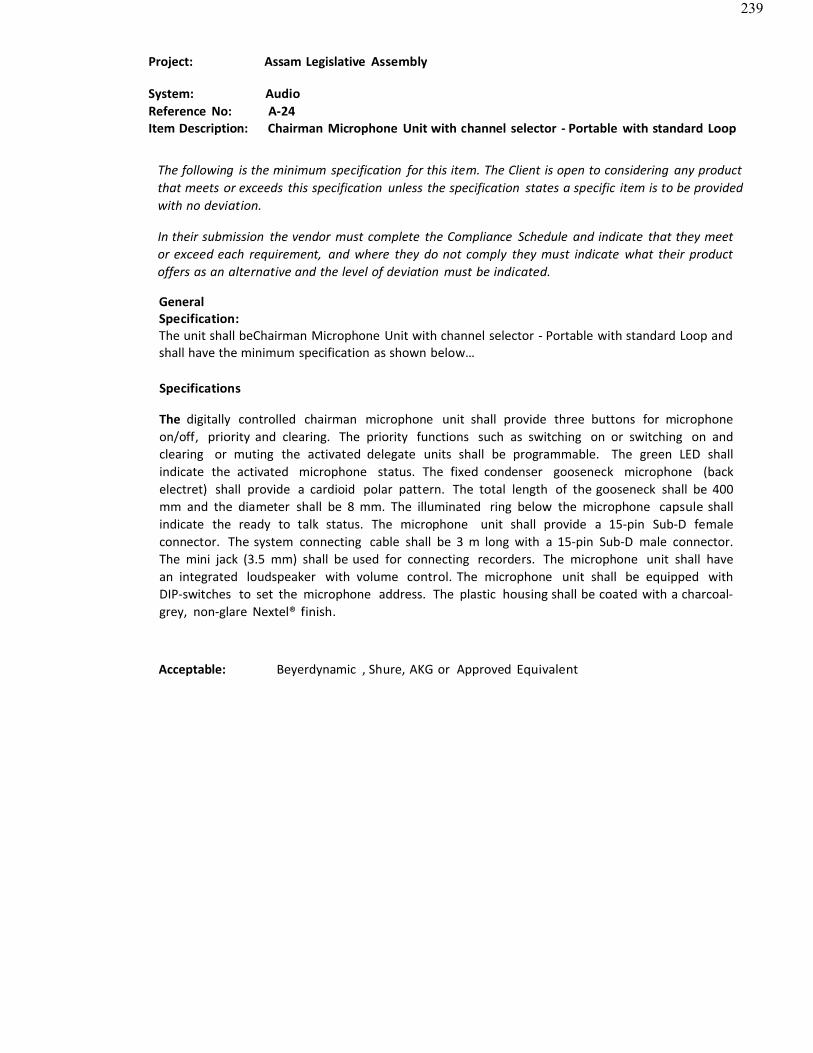
239
Project: Assam Legislative Assembly
System: AudioReference No: A-24Item Description: Chairman Microphone Unit with channel selector - Portable with standard Loop
The following is the minimum specification for this item. The Client is open to considering any productthat meets or exceeds this specification unless the specification states a specific item is to be providedwith no deviation.
In their submission the vendor must complete the Compliance Schedule and indicate that they meetor exceed each requirement, and where they do not comply they must indicate what their productoffers as an alternative and the level of deviation must be indicated.
GeneralSpecification:The unit shall beChairman Microphone Unit with channel selector - Portable with standard Loop and shall have the minimum specification as shown below…
Specifications
The digitally controlled chairman microphone unit shall provide three buttons for microphone on/off, priority and clearing. The priority functions such as switching on or switching on andclearing or muting the activated delegate units shall be programmable. The green LED shallindicate the activated microphone status. The fixed condenser gooseneck microphone (backelectret) shall provide a cardioid polar pattern. The total length of the gooseneck shall be 400mm and the diameter shall be 8 mm. The illuminated ring below the microphone capsule shallindicate the ready to talk status. The microphone unit shall provide a 15-pin Sub-D femaleconnector. The system connecting cable shall be 3 m long with a 15-pin Sub-D male connector. The mini jack (3.5 mm) shall be used for connecting recorders. The microphone unit shall havean integrated loudspeaker with volume control. The microphone unit shall be equipped withDIP-switches to set the microphone address. The plastic housing shall be coated with a charcoal-grey, non-glare Nextel® finish.
Acceptable: Beyerdynamic , Shure, AKG or Approved Equivalent
240
Project: Assam LegislativeAssembly
System: AudioReference No: A-25Item Description: Delegate Microphone Unit -Portable
The following is the minimum specification for this item. The Client is open to considering anyproduct that meets or exceeds this specification unless the specification states a specific item isto be provided with no deviation.
In their submission the vendor must complete the Compliance Schedule and indicate that theymeet or exceed each requirement, and where they do not comply they must indicate what theirproduct offers as an alternative and the level of deviation must be indicated.
GeneralSpecification:The unit shall beDelegate Microphone Unit – Portableand shall have the minimum specification as shown below…
SpecificationsThe digitally controlled delegate microphone unit shall provide one button for switchingon/off or request-to-talk. The dual-colour LED shall indicate the microphone on (green) orrequest- to-talk (red) status. The fixed condenser gooseneck microphone (back electret) shall provide a cardioid polar pattern. The total length of the gooseneck shall be 400 mm andthe diameter shall be 8 mm. The illuminated ring below the microphone capsule shallindicate the ready to talk status. The microphone unit shall provide a 15-pin Sub-D femaleconnection. The system connecting cable shall be 3 m long with a 15-pin Sub-D maleconnector. The microphone unit shall provide a mini jack for connecting recorders. The microphone unit shall have an integrated loudspeaker with volume control. The microphoneunit shall be equipped with DIP- switches to adjust the microphone address. The plastic housing shall be coated with a charcoal-grey, non-glare and scratch-resistant Nextel® finish.
Acceptable: Beyerdynamic , Shure, AKG or Approved Equivalent
241
Project : Assam Legislative Assembly
System : AudioReference No : A-26Item Description : Connecting cable length 20 mtr length
The following is the minimum specification for this item. The Client is open to considering anyproduct that meets or exceeds this specification unless the specification states a specific item isto be provided with no deviation.
In their submission the vendor must complete the Compliance Schedule and indicate that they meet or exceed each requirement, and where they do not comply they must indicate what theirproduct offers as an alternative and the level of deviation must be indicated.
GeneralSpecification :
The unit shall be Connecting cable length 20 mtr length and shall have the minimum specification as shown below…
SpecificationsConnecting cable length 20 mtr length
Acceptable: Beyerdynamic , Shure, AKG or Approved Equivalent
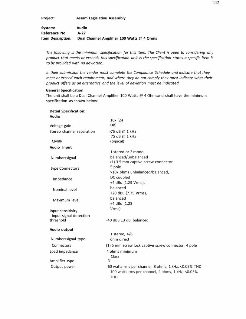
242
Project: Assam Legislative Assembly
System: AudioReference No: A-27Item Description: Dual Channel Amplifier 100 Watts @ 4 Ohms
The following is the minimum specification for this item. The Client is open to considering anyproduct that meets or exceeds this specification unless the specification states a specific item is to be provided with no deviation.
In their submission the vendor must complete the Compliance Schedule and indicate that theymeet or exceed each requirement, and where they do not comply they must indicate what theirproduct offers as an alternative and the level of deviation must be indicated.
General SpecificationThe unit shall be a Dual Channel Amplifier 100 Watts @ 4 Ohmsand shall have the minimumspecification as shown below:
Detail Specification: Audio
Voltage gain16x (24DB)
Stereo channel separation >75 dB @ 1 kHz75 dB @ 1 kHz
CMRRAudio Input
Number/signal
type Connectors
Impedance
Nominal level
Maximum level
Input sensitivityInput signal detection
(typical)
1 stereo or 2 mono, balanced/unbalanced(1) 3.5 mm captive screw connector,5 pole>10k ohms unbalanced/balanced, DC coupled+4 dBu (1.23 Vrms), balanced+20 dBu (7.75 Vrms), balanced+4 dBu (1.23Vrms)
threshold -40 dBu ±3 dB, balanced
Audio output
Number/signal type1 stereo, 4/8 ohm direct
Connectors (1) 5 mm screw lock captive screw connector, 4 poleLoad impedance 4 ohms minimum
ClassAmplifier type DOutput power 60 watts rms per channel, 8 ohms, 1 kHz, <0.05% THD
100 watts rms per channel, 4 ohms, 1 kHz, <0.05% THD
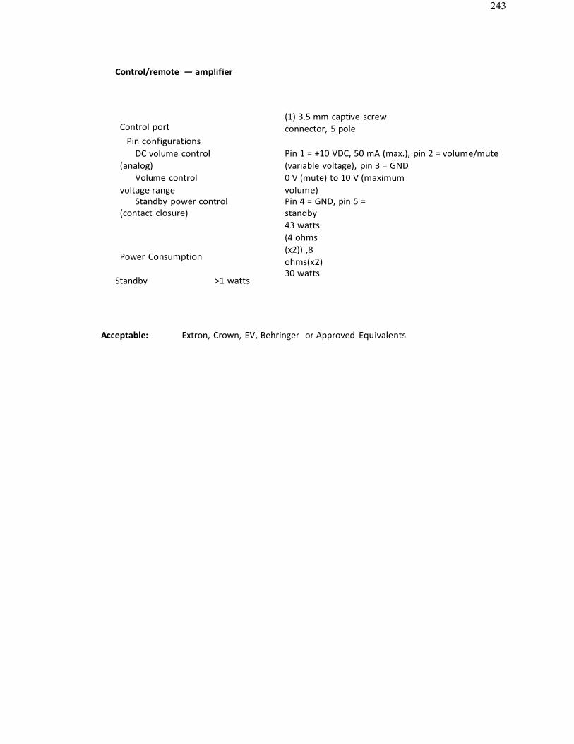
243
Control/remote — amplifier
Control portPin configurations
DC volume control(analog)
Volume controlvoltage range
Standby power control(contact closure)
Power Consumption
Standby >1 watts
(1) 3.5 mm captive screw connector, 5 pole
Pin 1 = +10 VDC, 50 mA (max.), pin 2 = volume/mute(variable voltage), pin 3 = GND0 V (mute) to 10 V (maximum volume)Pin 4 = GND, pin 5 =standby43 watts (4 ohms (x2)) ,8 ohms(x2)30 watts
Acceptable: Extron, Crown, EV, Behringer or Approved Equivalents
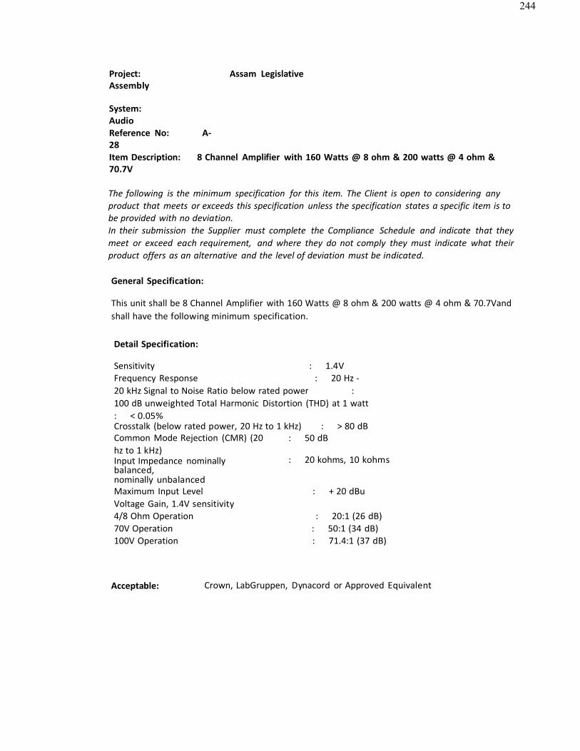
244
Project: Assam LegislativeAssembly
System: AudioReference No: A-28Item Description: 8 Channel Amplifier with 160 Watts @ 8 ohm & 200 watts @ 4 ohm &70.7V
The following is the minimum specification for this item. The Client is open to considering anyproduct that meets or exceeds this specification unless the specification states a specific item is tobe provided with no deviation.In their submission the Supplier must complete the Compliance Schedule and indicate that theymeet or exceed each requirement, and where they do not comply they must indicate what theirproduct offers as an alternative and the level of deviation must be indicated.
General Specification:
This unit shall be 8 Channel Amplifier with 160 Watts @ 8 ohm & 200 watts @ 4 ohm & 70.7Vandshall have the following minimum specification.
Detail Specification:
Sensitivity : 1.4VFrequency Response : 20 Hz -20 kHz Signal to Noise Ratio below rated power : 100 dB unweighted Total Harmonic Distortion (THD) at 1 watt : < 0.05%Crosstalk (below rated power, 20 Hz to 1 kHz) : > 80 dBCommon Mode Rejection (CMR) (20hz to 1 kHz)Input Impedance nominallybalanced,nominally unbalanced
: 50 dB
: 20 kohms, 10 kohms
Maximum Input Level : + 20 dBuVoltage Gain, 1.4V sensitivity4/8 Ohm Operation : 20:1 (26 dB)70V Operation : 50:1 (34 dB)100V Operation : 71.4:1 (37 dB)
Acceptable: Crown, LabGruppen, Dynacord or Approved Equivalent
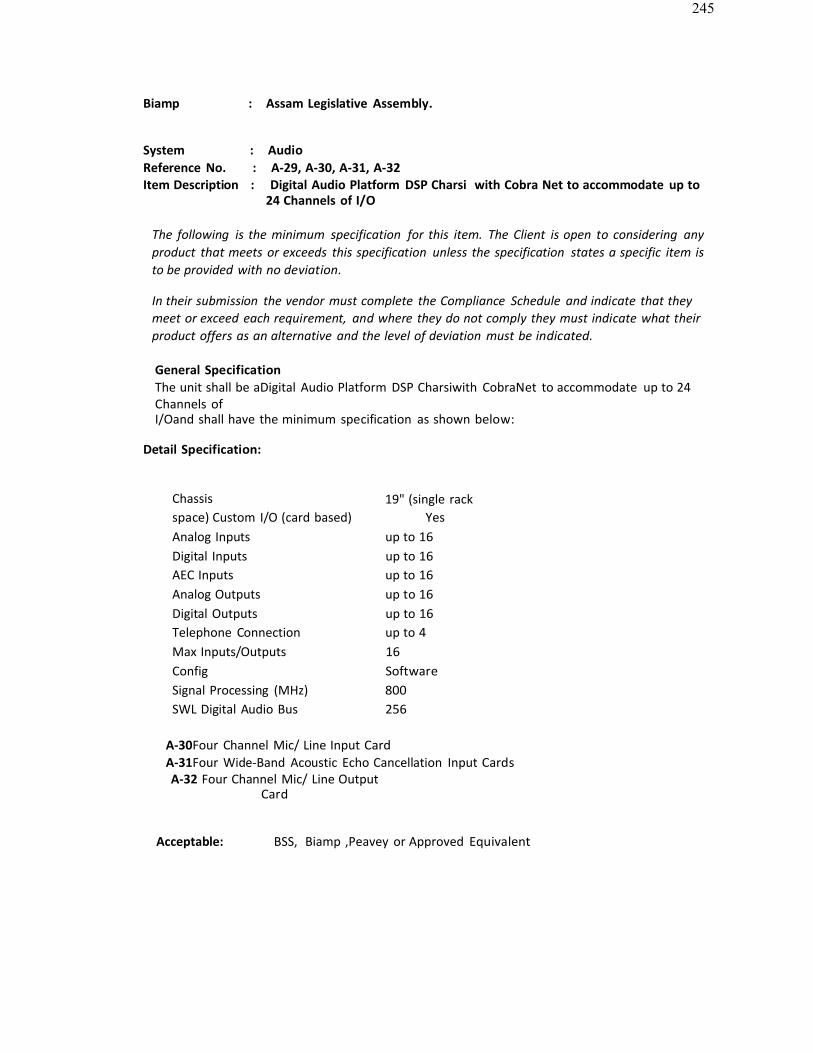
245
Biamp : Assam Legislative Assembly.
System : AudioReference No. : A-29, A-30, A-31, A-32Item Description : Digital Audio Platform DSP Charsi with Cobra Net to accommodate up to
24 Channels of I/O
The following is the minimum specification for this item. The Client is open to considering anyproduct that meets or exceeds this specification unless the specification states a specific item isto be provided with no deviation.
In their submission the vendor must complete the Compliance Schedule and indicate that theymeet or exceed each requirement, and where they do not comply they must indicate what theirproduct offers as an alternative and the level of deviation must be indicated.
General SpecificationThe unit shall be aDigital Audio Platform DSP Charsiwith CobraNet to accommodate up to 24Channels ofI/Oand shall have the minimum specification as shown below:
Detail Specification:
Chassis 19" (single rackspace) Custom I/O (card based) YesAnalog Inputs up to 16Digital Inputs up to 16AEC Inputs up to 16Analog Outputs up to 16Digital Outputs up to 16Telephone Connection up to 4Max Inputs/Outputs 16Config SoftwareSignal Processing (MHz) 800SWL Digital Audio Bus 256
A-30Four Channel Mic/ Line Input CardA-31Four Wide-Band Acoustic Echo Cancellation Input CardsA-32 Four Channel Mic/ Line Output
Card
Acceptable: BSS, Biamp ,Peavey or Approved Equivalent
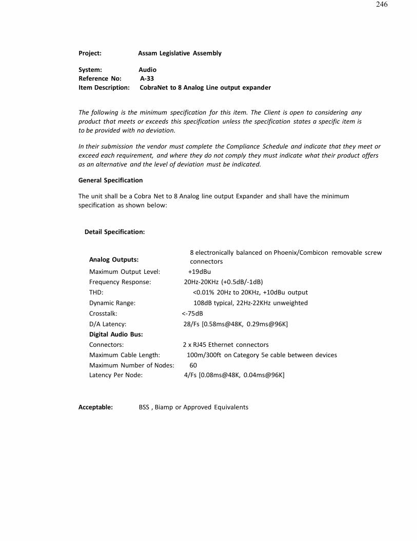
246
Project: Assam Legislative Assembly
System: AudioReference No: A-33Item Description: CobraNet to 8 Analog Line output expander
The following is the minimum specification for this item. The Client is open to considering anyproduct that meets or exceeds this specification unless the specification states a specific item is to be provided with no deviation.
In their submission the vendor must complete the Compliance Schedule and indicate that they meet orexceed each requirement, and where they do not comply they must indicate what their product offersas an alternative and the level of deviation must be indicated.
General Specification
The unit shall be a Cobra Net to 8 Analog line output Expander and shall have the minimumspecification as shown below:
Detail Specification:
Analog Outputs:8 electronically balanced on Phoenix/Combicon removable screw connectors
Maximum Output Level: +19dBuFrequency Response: 20Hz-20KHz (+0.5dB/-1dB)THD: <0.01% 20Hz to 20KHz, +10dBu output Dynamic Range: 108dB typical, 22Hz-22KHz unweighted Crosstalk: <-75dBD/A Latency: 28/Fs [0.58ms@48K, 0.29ms@96K]Digital Audio Bus:Connectors: 2 x RJ45 Ethernet connectorsMaximum Cable Length: 100m/300ft on Category 5e cable between devicesMaximum Number of Nodes: 60Latency Per Node: 4/Fs [0.08ms@48K, 0.04ms@96K]
Acceptable: BSS , Biamp or Approved Equivalents
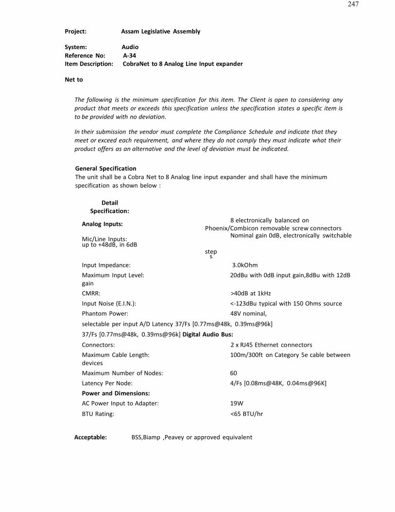
247
Project: Assam Legislative Assembly
System: AudioReference No: A-34Item Description: CobraNet to 8 Analog Line Input expander
Net to
The following is the minimum specification for this item. The Client is open to considering anyproduct that meets or exceeds this specification unless the specification states a specific item is to be provided with no deviation.
In their submission the vendor must complete the Compliance Schedule and indicate that theymeet or exceed each requirement, and where they do not comply they must indicate what theirproduct offers as an alternative and the level of deviation must be indicated.
General SpecificationThe unit shall be a Cobra Net to 8 Analog line input expander and shall have the minimumspecification as shown below :
DetailSpecification:
Analog Inputs: 8 electronically balanced onPhoenix/Combicon removable screw connectors
Mic/Line Inputs: Nominal gain 0dB, electronically switchableup to +48dB, in 6dB
steps
Input Impedance: 3.0kOhmMaximum Input Level: 20dBu with 0dB input gain,8dBu with 12dBgainCMRR: >40dB at 1kHzInput Noise (E.I.N.): <-123dBu typical with 150 Ohms sourcePhantom Power: 48V nominal,
selectable per input A/D Latency 37/Fs [0.77ms@48k, 0.39ms@96k]
37/Fs [0.77ms@48k, 0.39ms@96k] Digital Audio Bus:
Connectors: 2 x RJ45 Ethernet connectorsMaximum Cable Length: 100m/300ft on Category 5e cable betweendevicesMaximum Number of Nodes: 60Latency Per Node: 4/Fs [0.08ms@48K, 0.04ms@96K]Power and Dimensions:AC Power Input to Adapter: 19W
BTU Rating: <65 BTU/hr
Acceptable: BSS,Biamp ,Peavey or approved equivalent
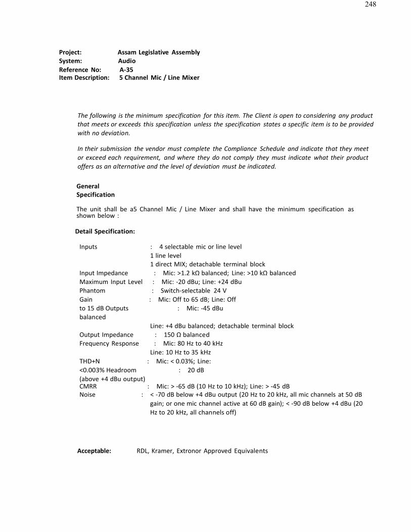
248
Project: Assam Legislative AssemblySystem: AudioReference No: A-35Item Description: 5 Channel Mic / Line Mixer
The following is the minimum specification for this item. The Client is open to considering any productthat meets or exceeds this specification unless the specification states a specific item is to be providedwith no deviation.
In their submission the vendor must complete the Compliance Schedule and indicate that they meetor exceed each requirement, and where they do not comply they must indicate what their productoffers as an alternative and the level of deviation must be indicated.
GeneralSpecification
The unit shall be a5 Channel Mic / Line Mixer and shall have the minimum specification asshown below :
Detail Specification:
Inputs : 4 selectable mic or line level1 line level1 direct MIX; detachable terminal block
Input Impedance : Mic: >1.2 kΩ balanced; Line: >10 kΩ balancedMaximum Input Level : Mic: -20 dBu; Line: +24 dBuPhantom : Switch-selectable 24 VGain : Mic: Off to 65 dB; Line: Offto 15 dB Outputs : Mic: -45 dBubalanced
Line: +4 dBu balanced; detachable terminal blockOutput Impedance : 150 Ω balancedFrequency Response : Mic: 80 Hz to 40 kHz
Line: 10 Hz to 35 kHz THD+N : Mic: < 0.03%; Line:<0.003% Headroom : 20 dB(above +4 dBu output)CMRR : Mic: > -65 dB (10 Hz to 10 kHz); Line: > -45 dBNoise : < -70 dB below +4 dBu output (20 Hz to 20 kHz, all mic channels at 50 dB
gain; or one mic channel active at 60 dB gain); < -90 dB below +4 dBu (20Hz to 20 kHz, all channels off)
Acceptable: RDL, Kramer, Extronor Approved Equivalents
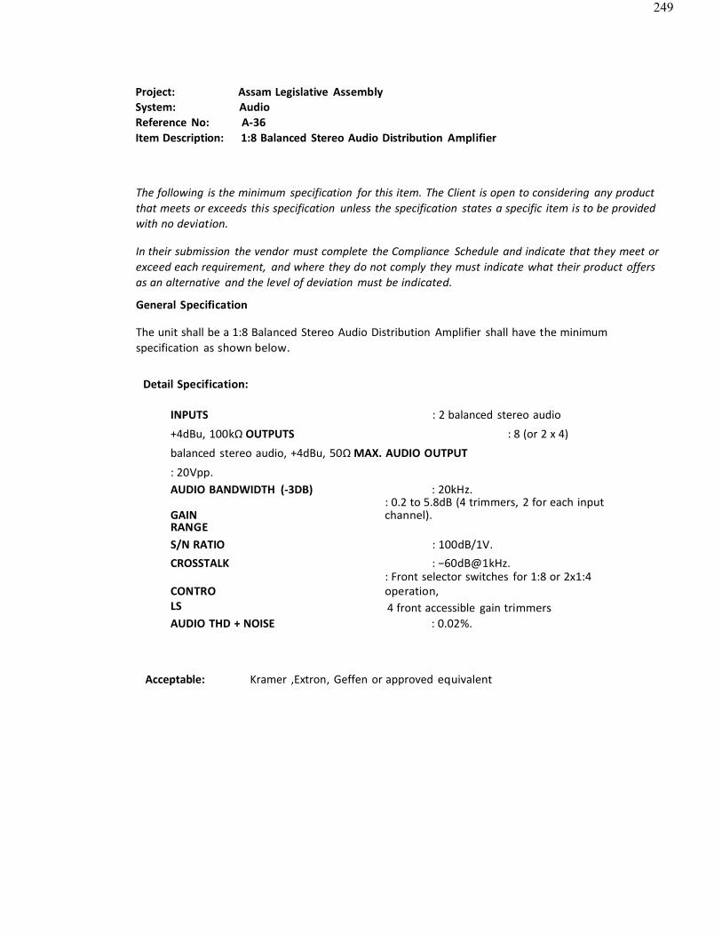
249
Project: Assam Legislative AssemblySystem: AudioReference No: A-36Item Description: 1:8 Balanced Stereo Audio Distribution Amplifier
The following is the minimum specification for this item. The Client is open to considering any productthat meets or exceeds this specification unless the specification states a specific item is to be providedwith no deviation.
In their submission the vendor must complete the Compliance Schedule and indicate that they meet orexceed each requirement, and where they do not comply they must indicate what their product offersas an alternative and the level of deviation must be indicated.
General Specification
The unit shall be a 1:8 Balanced Stereo Audio Distribution Amplifier shall have the minimumspecification as shown below.
Detail Specification:
INPUTS : 2 balanced stereo audio
+4dBu, 100kΩ OUTPUTS : 8 (or 2 x 4)
balanced stereo audio, +4dBu, 50Ω MAX. AUDIO OUTPUT
: 20Vpp.AUDIO BANDWIDTH (-3DB) : 20kHz.
: 0.2 to 5.8dB (4 trimmers, 2 for each inputGAINRANGE
channel).
S/N RATIO : 100dB/1V.CROSSTALK : −60dB@1kHz.
: Front selector switches for 1:8 or 2x1:4CONTROLS
operation,4 front accessible gain trimmers
AUDIO THD + NOISE : 0.02%.
Acceptable: Kramer ,Extron, Geffen or approved equivalent
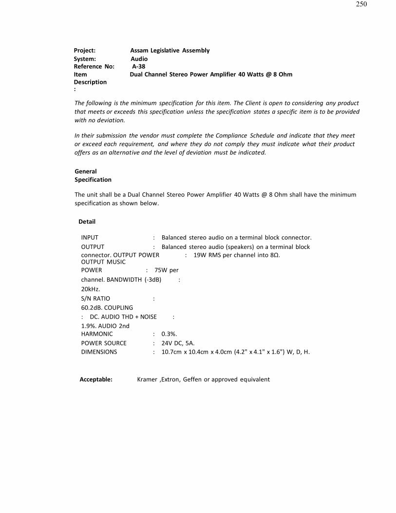
250
Project: Assam Legislative AssemblySystem: AudioReference No: A-38ItemDescription:
Dual Channel Stereo Power Amplifier 40 Watts @ 8 Ohm
The following is the minimum specification for this item. The Client is open to considering any productthat meets or exceeds this specification unless the specification states a specific item is to be providedwith no deviation.
In their submission the vendor must complete the Compliance Schedule and indicate that they meetor exceed each requirement, and where they do not comply they must indicate what their productoffers as an alternative and the level of deviation must be indicated.
GeneralSpecification
The unit shall be a Dual Channel Stereo Power Amplifier 40 Watts @ 8 Ohm shall have the minimumspecification as shown below.
Detail
INPUT : Balanced stereo audio on a terminal block connector.OUTPUT : Balanced stereo audio (speakers) on a terminal blockconnector. OUTPUT POWER : 19W RMS per channel into 8Ω.OUTPUT MUSICPOWER : 75W perchannel. BANDWIDTH (-3dB) : 20kHz.S/N RATIO : 60.2dB. COUPLING : DC. AUDIO THD + NOISE : 1.9%. AUDIO 2ndHARMONIC : 0.3%.POWER SOURCE : 24V DC, 5A.DIMENSIONS : 10.7cm x 10.4cm x 4.0cm (4.2" x 4.1" x 1.6") W, D, H.
Acceptable: Kramer ,Extron, Geffen or approved equivalent
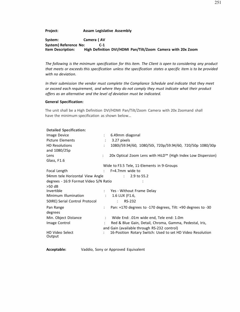
251
Project: Assam Legislative Assembly
System: Camera ( AVSystem) Reference No: C-1Item Description: High Definition DVI/HDMI Pan/Tilt/Zoom Camera with 20x Zoom
The following is the minimum specification for this item. The Client is open to considering any productthat meets or exceeds this specification unless the specification states a specific item is to be providedwith no deviation.
In their submission the vendor must complete the Compliance Schedule and indicate that they meetor exceed each requirement, and where they do not comply they must indicate what their productoffers as an alternative and the level of deviation must be indicated.
General Specification:
The unit shall be a High Definition DVI/HDMI Pan/Tilt/Zoom Camera with 20x Zoomand shallhave the minimum specification as shown below…
Detailed Specification:Image Device : 6.49mm diagonalPicture Elements : 3.27 pixelsHD Resolutions : 1080i/59.94/60, 1080/50i, 720p/59.94/60, 720/50p 1080/30pand 1080/25pLens : 20x Optical Zoom Lens with HiLD™ (High Index Low Dispersion)Glass, F1.6
Wide to F3.5 Tele, 11-Elements in 9-GroupsFocal Length : F=4.7mm wide to94mm tele Horizontal View Angle : 2.9 to 55.2degrees - 16:9 Format Video S/N Ratio : >50 dBInvertible : Yes - Without Frame DelayMinimum Illumination : 1.6 LUX (F1.6,50IRE) Serial Control Protocol : RS-232Pan Range : Pan: +170 degrees to -170 degrees, Tilt: +90 degrees to -30degreesMin. Object Distance : Wide End: .01m wide end, Tele end: 1.0mImage Control : Red & Blue Gain, Detail, Chroma, Gamma, Pedestal, Iris,
and Gain (available through RS-232 control)HD Video Select : 16-Position Rotary Switch: Used to set HD Video ResolutionOutput
Acceptable: Vaddio, Sony or Approved Equivalent
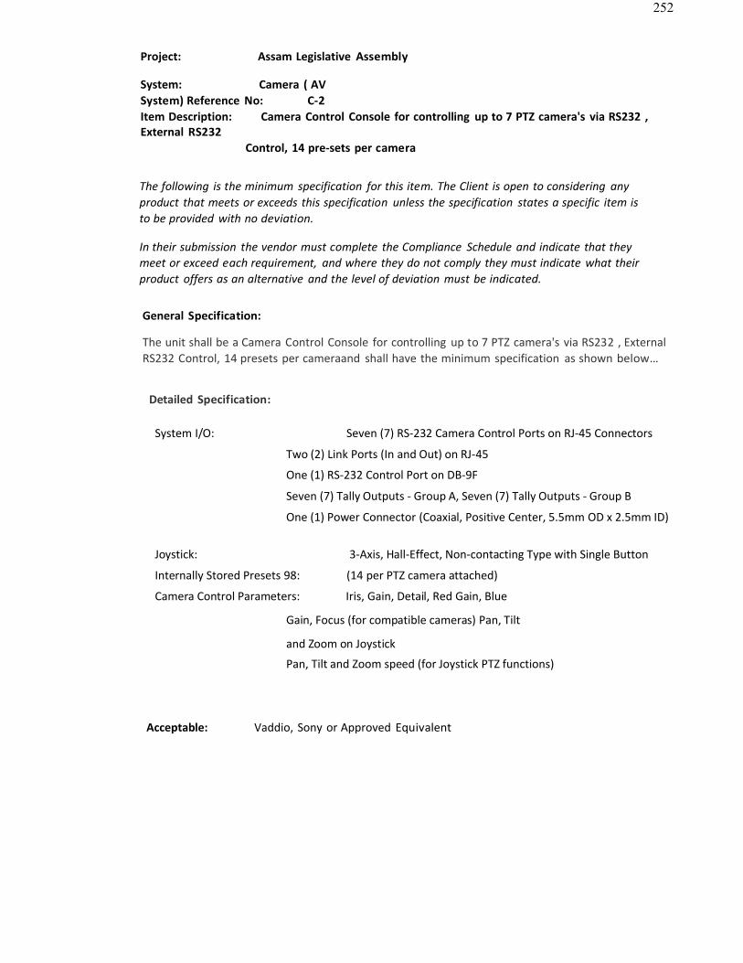
252
Project: Assam Legislative Assembly
System: Camera ( AVSystem) Reference No: C-2Item Description: Camera Control Console for controlling up to 7 PTZ camera's via RS232 ,External RS232
Control, 14 pre-sets per camera
The following is the minimum specification for this item. The Client is open to considering anyproduct that meets or exceeds this specification unless the specification states a specific item isto be provided with no deviation.
In their submission the vendor must complete the Compliance Schedule and indicate that theymeet or exceed each requirement, and where they do not comply they must indicate what theirproduct offers as an alternative and the level of deviation must be indicated.
General Specification:
The unit shall be a Camera Control Console for controlling up to 7 PTZ camera's via RS232 , ExternalRS232 Control, 14 presets per cameraand shall have the minimum specification as shown below…
Detailed Specification:
System I/O: Seven (7) RS-232 Camera Control Ports on RJ-45 Connectors
Two (2) Link Ports (In and Out) on RJ-45
One (1) RS-232 Control Port on DB-9F
Seven (7) Tally Outputs - Group A, Seven (7) Tally Outputs - Group B
One (1) Power Connector (Coaxial, Positive Center, 5.5mm OD x 2.5mm ID)
Joystick: 3-Axis, Hall-Effect, Non-contacting Type with Single Button
Internally Stored Presets 98: (14 per PTZ camera attached)
Camera Control Parameters: Iris, Gain, Detail, Red Gain, Blue
Gain, Focus (for compatible cameras) Pan, Tilt
and Zoom on Joystick
Pan, Tilt and Zoom speed (for Joystick PTZ functions)
Acceptable: Vaddio, Sony or Approved Equivalent
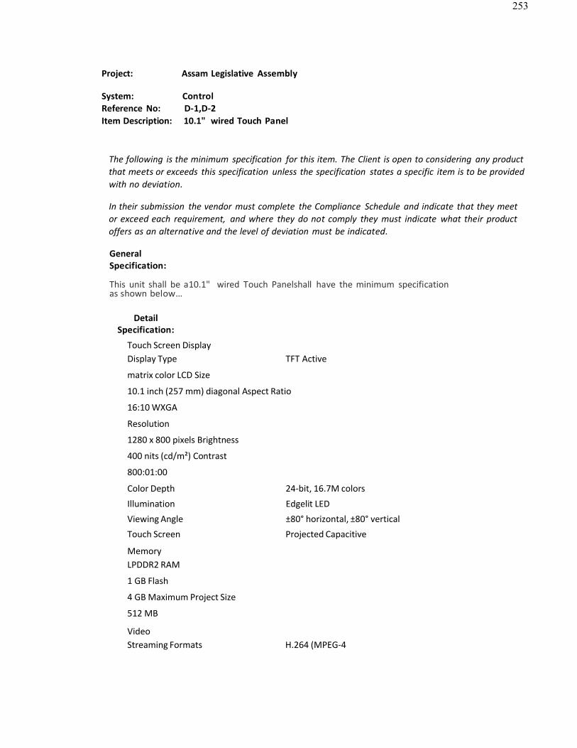
253
Project: Assam Legislative Assembly
System: ControlReference No: D-1,D-2Item Description: 10.1" wired Touch Panel
The following is the minimum specification for this item. The Client is open to considering any productthat meets or exceeds this specification unless the specification states a specific item is to be providedwith no deviation.
In their submission the vendor must complete the Compliance Schedule and indicate that they meetor exceed each requirement, and where they do not comply they must indicate what their productoffers as an alternative and the level of deviation must be indicated.
GeneralSpecification:
This unit shall be a10.1" wired Touch Panelshall have the minimum specificationas shown below…
DetailSpecification:
Touch Screen DisplayDisplay Type TFT Active
matrix color LCD Size
10.1 inch (257 mm) diagonal Aspect Ratio
16:10 WXGA
Resolution
1280 x 800 pixels Brightness
400 nits (cd/m²) Contrast
800:01:00
Color Depth 24-bit, 16.7M colors
Illumination Edgelit LED
Viewing Angle ±80° horizontal, ±80° vertical
Touch Screen Projected Capacitive
MemoryLPDDR2 RAM
1 GB Flash
4 GB Maximum Project Size
512 MB
VideoStreaming Formats H.264 (MPEG-4

254
[1]
part 10 AVC), MJPEG Audio
Features Built-in microphone and speakers, Rava™ SIP Intercom,multi-language voice
recognitionAudio Feedback Formats MP3Connectors
LANPoE
(1) 8-wire RJ45 with 2 LED indicators;10Base-T/100Base-TX Ethernet port, Power overEthernet compliant;Green and yellow LEDs indicate Ethernet port status
D-2 TABLE TOP KIT FOR ABOVE TOUCH PANEL
Acceptable: Crestron, AMX or Approved Equivalent

255
Project: Assam Legislative Assembly
System: ControlReference No: D-3Item Description: POE injector for the touch panel
The following is the minimum specification for this item. The Client is open to considering anyproduct that meets or exceeds this specification unless the specification states a specific item is tobe provided with no deviation.
In their submission the vendor must complete the Compliance Schedule and indicate that they meet orexceed each requirement, and where they do not comply they must indicate what their product offers asan alternative and the level of deviation must be indicated.
General Specification:
The device shall be a POE injector for the touch panel. The device shall have the minimum specification asshown below:
Detail Specification:
Connectors
LAN : (1) 8-wire RJ45, female;10BaseT/100BaseTX Ethernet port; Connects toEthernet LAN
LAN PoE : (1) 8-wire RJ45, female; 10BaseT/100BaseTX Ethernet pass-thru portand IEEE 802.3af Class 0
PoE Power Sourcing Equipment output
Main Power Input : (1) IEC 320 C14 socket; Mates with removable power cord, included
LED IndicatorsPOWER : (1) Tri-colour LED; Amber indicates power is available but no device isconnected;
Green indicates a PoE device is connected and drawing power; Red(flashing) indicates a non- PoE device is connected
Power Requirements : 100-250 Volts AC, 50/60 Hz
Acceptable: Crestron, AMX ,CUE or Approved Equivalent
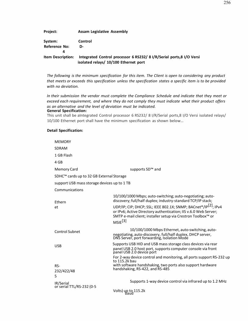
256
Project: Assam Legislative Assembly
System: ControlReference No: D-
4Item Description: Integrated Control processor 6 RS232/ 8 I/R/Serial ports,8 I/O Versi
isolated relays/ 10/100 Ethernet port
The following is the minimum specification for this item. The Client is open to considering any productthat meets or exceeds this specification unless the specification states a specific item is to be providedwith no deviation.
In their submission the vendor must complete the Compliance Schedule and indicate that they meet orexceed each requirement, and where they do not comply they must indicate what their product offersas an alternative and the level of deviation must be indicated.General Specification:This unit shall be aIntegrated Control processor 6 RS232/ 8 I/R/Serial ports,8 I/O Versi isolated relays/10/100 Ethernet port shall have the minimum specification as shown below…
Detail Specification:
MEMORY
SDRAM
1 GB Flash
4 GB
Memory Card supports SD™ and
SDHC™ cards up to 32 GB External Storage
support USB mass storage devices up to 1 TB
Communications
Ethernet
10/100/1000 Mbps; auto-switching; auto-negotiating; auto-discovery; full/half duplex; industry-standard TCP/IP stack;UDP/IP; CIP; DHCP; SSL; IEEE 802.1X; SNMP; BACnet®/IP[2]; IPv4or IPv6; Active Directory authentication; IIS v.6.0 Web Server; SMTP e-mail client; installer setup via Crestron Toolbox™ orMSIE[3]
Control Subnet 10/100/1000 Mbps Ethernet, auto-switching, auto-negotiating, auto-discovery, full/half duplex, DHCP server,DNS Server, port forwarding, Isolation Mode
USB Supports USB HID and USB mass storage class devices via rearpanel USB 2.0 host port, supports computer console via frontpanel USB 2.0 device portFor 2-way device control and monitoring, all ports support RS-232 upto 115.2k bau
RS-232/422/485
with software handshaking, two ports also support hardwarehandshaking, RS-422, and RS-485
IR/Serial Supports 1-way device control via infrared up to 1.2 MHzor serial TTL/RS-232 (0-5
Volts) up to 115.2kbaud

257
Detail Specification:
100-240V~2.4A50/60HZ
(1) IEC 60320 C14 main power inlet;Mates with removable power cord, included
G (1) 6-32 screw, chassis ground lug(1) USB Type B
female;COMPUTER(front)
LCD Display
USB 2.0 computer console port (6 ft
cable included); For setup only
Display Type TFT active
matrix color LCD Size
2.8 inch (72 mm) diagonal Resolution
320 x 240 pixels
Functions Displays configuration menus, control port activity, andother system information
Power RequirementsMain Power 2.4 A2m3p8s @ 100-240 Volts AC, 50/60 Hz
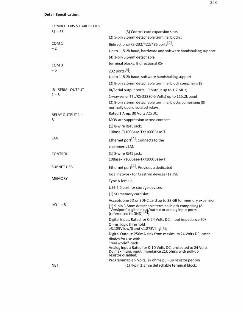
258
Detail Specification:
CONNECTORS & CARD SLOTSS1 – S3 (3) Control card expansion slots
(2) 5-pin 3.5mm detachable terminal blocks;COM 1– 2
COM 3– 6
Bidirectional RS-232/422/485 ports[4];
Up to 115.2k baud; hardware and software handshaking support
(4) 3-pin 3.5mm detachableterminal blocks; Bidirectional RS-
232 ports[4];Up to 115.2k baud; software handshaking support
IR - SERIAL OUTPUT1 – 8
RELAY OUTPUT 1 –8
LAN
CONTROL
SUBNET USB
MEMORY
I/O 1 – 8
(2) 8-pin 3.5mm detachable terminal block comprising (8)
IR/Serial output ports; IR output up to 1.2 MHz;
1-way serial TTL/RS-232 (0-5 Volts) up to 115.2k baud(2) 8-pin 3.5mm detachable terminal blocks comprising (8)normally open, isolated relays;Rated 1 Amp, 30 Volts AC/DC;
MOV arc suppression across contacts
(1) 8-wire RJ45 jack;10Base-T/100Base-TX/1000Base-T
Ethernet port[4]; Connects to the
customer's LAN
(1) 8-wire RJ45 jack;10Base-T/100Base-TX/1000Base-T
Ethernet port[4]; Provides a dedicated
local network for Crestron devices (1) USB
Type A female;
USB 2.0 port for storage devices
(1) SD memory card slot;
Accepts one SD or SDHC card up to 32 GB for memory expansion(1) 9-pin 3.5mm detachable terminal block comprising (8)"Versiport" digital input/output or analog input ports(referenced to GND) [4];Digital Input: Rated for 0-24 Volts DC, input impedance 20kOhms, logic threshold>3.125V low/0 and <1.875V high/1;Digital Output: 250mA sink from maximum 24 Volts DC, catchdiodes for use with"real world" loads;Analog Input: Rated for 0-10 Volts DC, protected to 24 VoltsDC maximum, input impedance 21k ohms with pull-upresistor disabled;Programmable 5 Volts, 2k ohms pull-up resistor per pin
NET (1) 4-pin 3.5mm detachable terminal block;

259
Acceptable: Crestron, AMX or Approved Equivalent
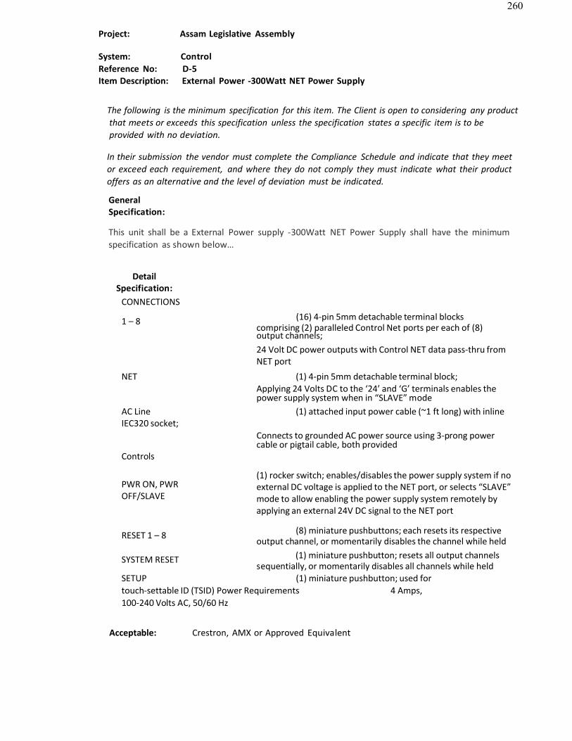
260
Project: Assam Legislative Assembly
System: ControlReference No: D-5Item Description: External Power -300Watt NET Power Supply
The following is the minimum specification for this item. The Client is open to considering any productthat meets or exceeds this specification unless the specification states a specific item is to beprovided with no deviation.
In their submission the vendor must complete the Compliance Schedule and indicate that they meetor exceed each requirement, and where they do not comply they must indicate what their productoffers as an alternative and the level of deviation must be indicated.
GeneralSpecification:
This unit shall be a External Power supply -300Watt NET Power Supply shall have the minimumspecification as shown below…
DetailSpecification:
CONNECTIONS
1 – 8 (16) 4-pin 5mm detachable terminal blockscomprising (2) paralleled Control Net ports per each of (8)output channels;24 Volt DC power outputs with Control NET data pass-thru fromNET port
NET (1) 4-pin 5mm detachable terminal block;Applying 24 Volts DC to the ‘24’ and ‘G’ terminals enables thepower supply system when in “SLAVE” mode
AC Line (1) attached input power cable (~1 ft long) with inlineIEC320 socket;
Connects to grounded AC power source using 3-prong powercable or pigtail cable, both provided
Controls
PWR ON, PWROFF/SLAVE
(1) rocker switch; enables/disables the power supply system if noexternal DC voltage is applied to the NET port, or selects “SLAVE”mode to allow enabling the power supply system remotely byapplying an external 24V DC signal to the NET port
RESET 1 – 8 (8) miniature pushbuttons; each resets its respectiveoutput channel, or momentarily disables the channel while held
SYSTEM RESET (1) miniature pushbutton; resets all output channelssequentially, or momentarily disables all channels while held
SETUP (1) miniature pushbutton; used fortouch-settable ID (TSID) Power Requirements 4 Amps, 100-240 Volts AC, 50/60 Hz
Acceptable: Crestron, AMX or Approved Equivalent
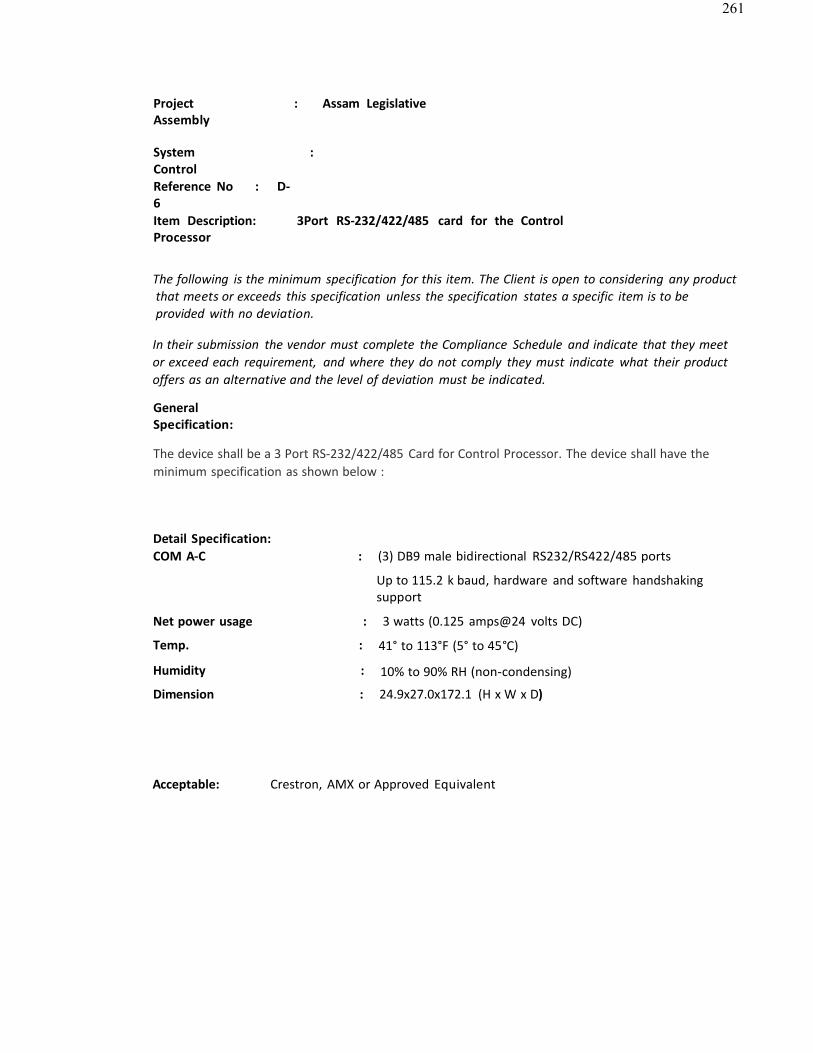
261
Project : Assam LegislativeAssembly
System : ControlReference No : D-6Item Description: 3Port RS-232/422/485 card for the ControlProcessor
The following is the minimum specification for this item. The Client is open to considering any productthat meets or exceeds this specification unless the specification states a specific item is to beprovided with no deviation.
In their submission the vendor must complete the Compliance Schedule and indicate that they meetor exceed each requirement, and where they do not comply they must indicate what their productoffers as an alternative and the level of deviation must be indicated.
GeneralSpecification:
The device shall be a 3 Port RS-232/422/485 Card for Control Processor. The device shall have the minimum specification as shown below :
Detail Specification:COM A-C : (3) DB9 male bidirectional RS232/RS422/485 ports
Up to 115.2 k baud, hardware and software handshakingsupport
Net power usage : 3 watts (0.125 amps@24 volts DC)
Temp. : 41° to 113°F (5° to 45°C)
Humidity : 10% to 90% RH (non-condensing)
Dimension : 24.9x27.0x172.1 (H x W x D)
Acceptable: Crestron, AMX or Approved Equivalent
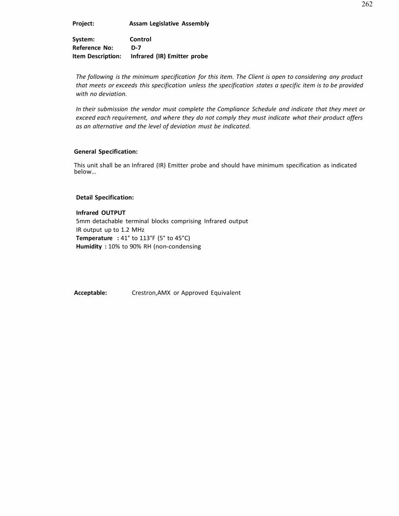
262
Project: Assam Legislative Assembly
System: ControlReference No: D-7Item Description: Infrared (IR) Emitter probe
The following is the minimum specification for this item. The Client is open to considering any productthat meets or exceeds this specification unless the specification states a specific item is to be providedwith no deviation.
In their submission the vendor must complete the Compliance Schedule and indicate that they meet orexceed each requirement, and where they do not comply they must indicate what their product offersas an alternative and the level of deviation must be indicated.
General Specification:
This unit shall be an Infrared (IR) Emitter probe and should have minimum specification as indicatedbelow…
Detail Specification:
Infrared OUTPUT5mm detachable terminal blocks comprising Infrared outputIR output up to 1.2 MHzTemperature : 41° to 113°F (5° to 45°C)Humidity : 10% to 90% RH (non-condensing
Acceptable: Crestron,AMX or Approved Equivalent
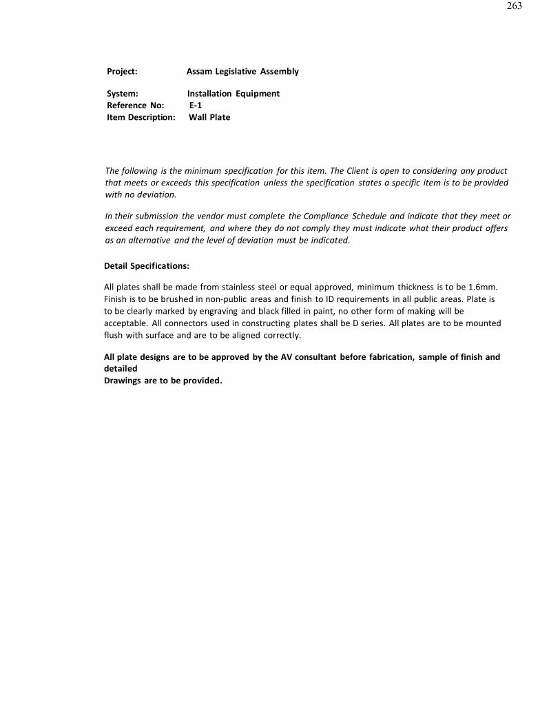
263
Project: Assam Legislative Assembly
System: Installation EquipmentReference No: E-1Item Description: Wall Plate
The following is the minimum specification for this item. The Client is open to considering any productthat meets or exceeds this specification unless the specification states a specific item is to be providedwith no deviation.
In their submission the vendor must complete the Compliance Schedule and indicate that they meet orexceed each requirement, and where they do not comply they must indicate what their product offersas an alternative and the level of deviation must be indicated.
Detail Specifications:
All plates shall be made from stainless steel or equal approved, minimum thickness is to be 1.6mm.Finish is to be brushed in non-public areas and finish to ID requirements in all public areas. Plate isto be clearly marked by engraving and black filled in paint, no other form of making will beacceptable. All connectors used in constructing plates shall be D series. All plates are to be mountedflush with surface and are to be aligned correctly.
All plate designs are to be approved by the AV consultant before fabrication, sample of finish anddetailedDrawings are to be provided.
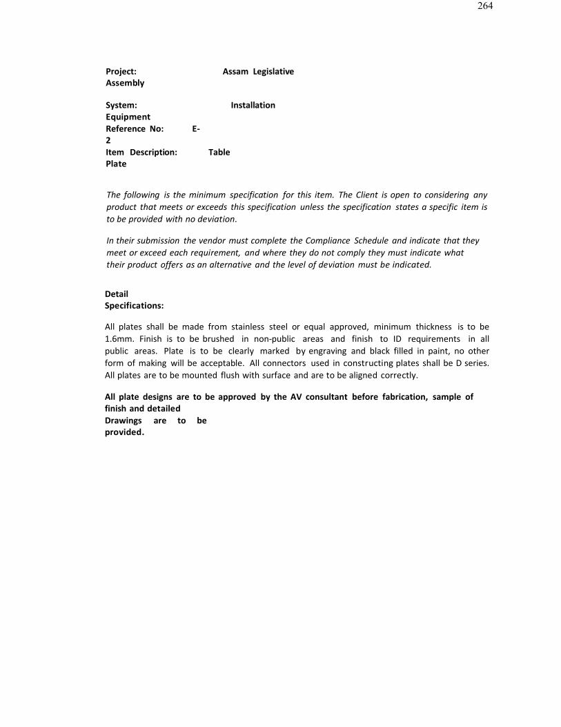
264
Project: Assam LegislativeAssembly
System: InstallationEquipmentReference No: E-2Item Description: TablePlate
The following is the minimum specification for this item. The Client is open to considering anyproduct that meets or exceeds this specification unless the specification states a specific item isto be provided with no deviation.
In their submission the vendor must complete the Compliance Schedule and indicate that theymeet or exceed each requirement, and where they do not comply they must indicate whattheir product offers as an alternative and the level of deviation must be indicated.
DetailSpecifications:
All plates shall be made from stainless steel or equal approved, minimum thickness is to be1.6mm. Finish is to be brushed in non-public areas and finish to ID requirements in all public areas. Plate is to be clearly marked by engraving and black filled in paint, no otherform of making will be acceptable. All connectors used in constructing plates shall be D series.All plates are to be mounted flush with surface and are to be aligned correctly.
All plate designs are to be approved by the AV consultant before fabrication, sample offinish and detailedDrawings are to beprovided.
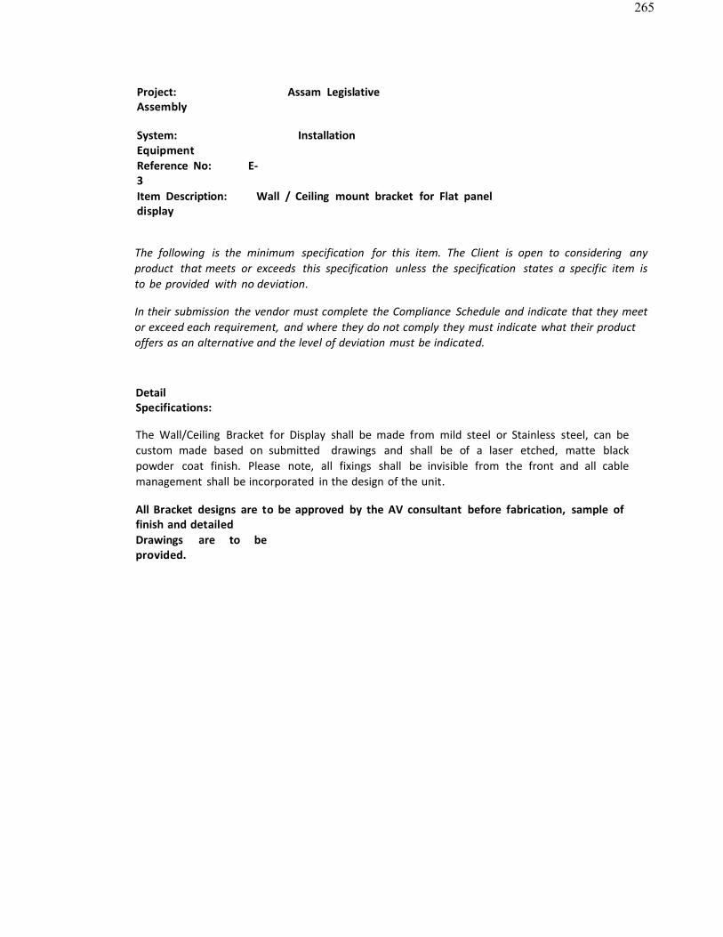
265
Project: Assam LegislativeAssembly
System: InstallationEquipmentReference No: E-3Item Description: Wall / Ceiling mount bracket for Flat paneldisplay
The following is the minimum specification for this item. The Client is open to considering anyproduct that meets or exceeds this specification unless the specification states a specific item isto be provided with no deviation.
In their submission the vendor must complete the Compliance Schedule and indicate that they meetor exceed each requirement, and where they do not comply they must indicate what their productoffers as an alternative and the level of deviation must be indicated.
DetailSpecifications:
The Wall/Ceiling Bracket for Display shall be made from mild steel or Stainless steel, can be custom made based on submitted drawings and shall be of a laser etched, matte blackpowder coat finish. Please note, all fixings shall be invisible from the front and all cablemanagement shall be incorporated in the design of the unit.
All Bracket designs are to be approved by the AV consultant before fabrication, sample offinish and detailedDrawings are to beprovided.
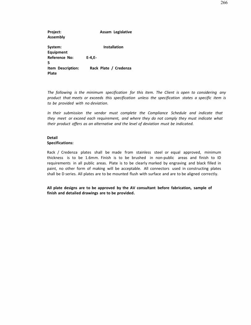
266
Project: Assam LegislativeAssembly
System: InstallationEquipmentReference No: E-4,E-5Item Description: Rack Plate / CredenzaPlate
The following is the minimum specification for this item. The Client is open to considering anyproduct that meets or exceeds this specification unless the specification states a specific item isto be provided with no deviation.
In their submission the vendor must complete the Compliance Schedule and indicate that they meet or exceed each requirement, and where they do not comply they must indicate whattheir product offers as an alternative and the level of deviation must be indicated.
DetailSpecifications:
Rack / Credenza plates shall be made from stainless steel or equal approved, minimum thickness is to be 1.6mm. Finish is to be brushed in non-public areas and finish to IDrequirements in all public areas. Plate is to be clearly marked by engraving and black filled inpaint, no other form of making will be acceptable. All connectors used in constructing platesshall be D series. All plates are to be mounted flush with surface and are to be aligned correctly.
All plate designs are to be approved by the AV consultant before fabrication, sample offinish and detailed drawings are to be provided.
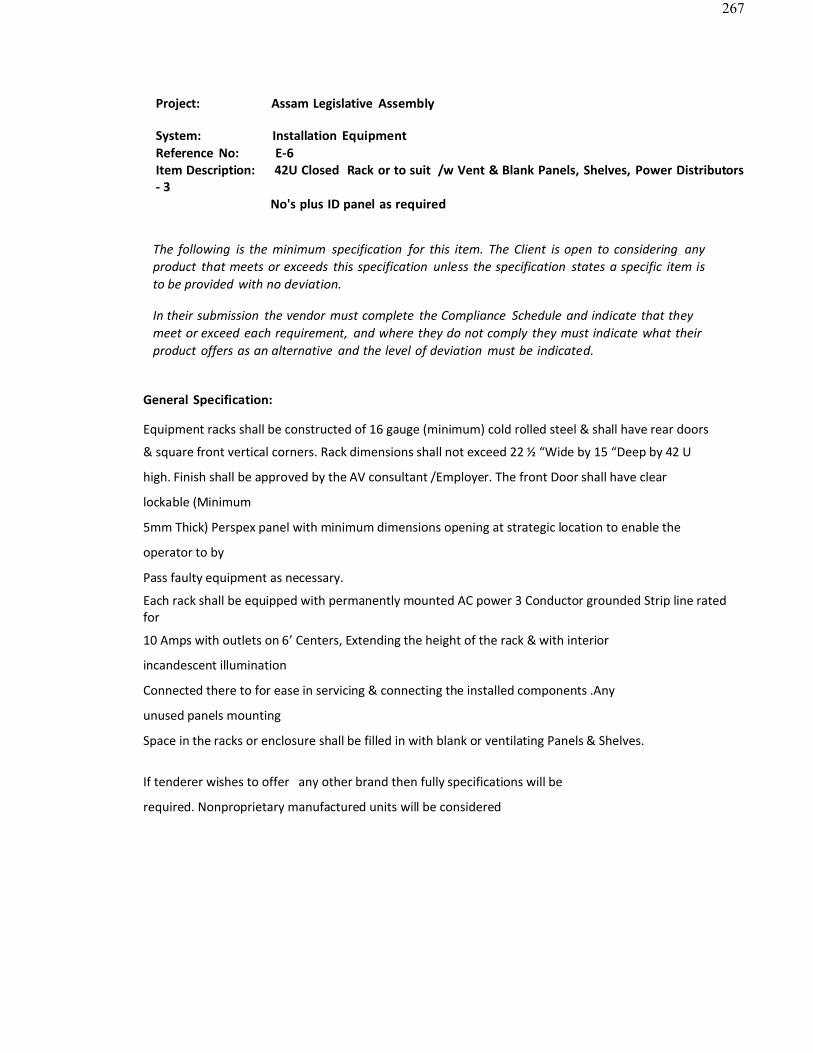
267
Project: Assam Legislative Assembly
System: Installation EquipmentReference No: E-6Item Description: 42U Closed Rack or to suit /w Vent & Blank Panels, Shelves, Power Distributors- 3
No's plus ID panel as required
The following is the minimum specification for this item. The Client is open to considering anyproduct that meets or exceeds this specification unless the specification states a specific item is to be provided with no deviation.
In their submission the vendor must complete the Compliance Schedule and indicate that theymeet or exceed each requirement, and where they do not comply they must indicate what theirproduct offers as an alternative and the level of deviation must be indicated.
General Specification:
Equipment racks shall be constructed of 16 gauge (minimum) cold rolled steel & shall have rear doors
& square front vertical corners. Rack dimensions shall not exceed 22 ½ “Wide by 15 “Deep by 42 U
high. Finish shall be approved by the AV consultant /Employer. The front Door shall have clear
lockable (Minimum
5mm Thick) Perspex panel with minimum dimensions opening at strategic location to enable the
operator to by
Pass faulty equipment as necessary.
Each rack shall be equipped with permanently mounted AC power 3 Conductor grounded Strip line rated for
10 Amps with outlets on 6’ Centers, Extending the height of the rack & with interior
incandescent illumination
Connected there to for ease in servicing & connecting the installed components .Any
unused panels mounting
Space in the racks or enclosure shall be filled in with blank or ventilating Panels & Shelves.
If tenderer wishes to offer any other brand then fully specifications will be
required. Nonproprietary manufactured units will be considered
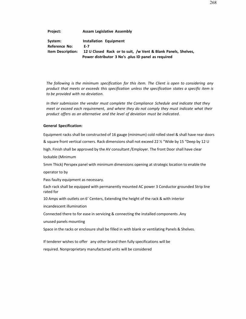
268
Project: Assam Legislative Assembly
System: Installation EquipmentReference No: E-7Item Description: 12 U Closed Rack or to suit, /w Vent & Blank Panels, Shelves,
Power distributor 3 No's .plus ID panel as required
The following is the minimum specification for this item. The Client is open to considering anyproduct that meets or exceeds this specification unless the specification states a specific item is to be provided with no deviation.
In their submission the vendor must complete the Compliance Schedule and indicate that theymeet or exceed each requirement, and where they do not comply they must indicate what theirproduct offers as an alternative and the level of deviation must be indicated.
General Specification:
Equipment racks shall be constructed of 16 gauge (minimum) cold rolled steel & shall have rear doors
& square front vertical corners. Rack dimensions shall not exceed 22 ½ “Wide by 15 “Deep by 12 U
high. Finish shall be approved by the AV consultant /Employer. The front Door shall have clear
lockable (Minimum
5mm Thick) Perspex panel with minimum dimensions opening at strategic location to enable the
operator to by
Pass faulty equipment as necessary.
Each rack shall be equipped with permanently mounted AC power 3 Conductor grounded Strip line rated for
10 Amps with outlets on 6’ Centers, Extending the height of the rack & with interior
incandescent illumination
Connected there to for ease in servicing & connecting the installed components .Any
unused panels mounting
Space in the racks or enclosure shall be filled in with blank or ventilating Panels & Shelves.
If tenderer wishes to offer any other brand then fully specifications will be
required. Nonproprietary manufactured units will be considered
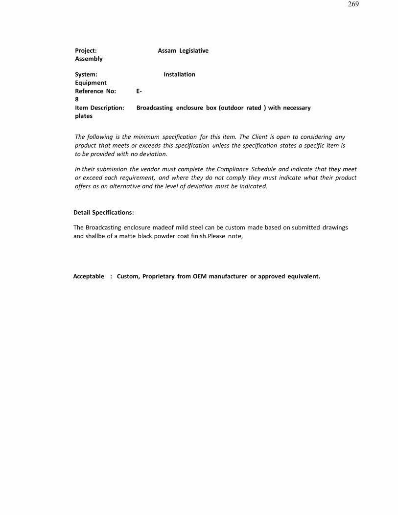
269
Project: Assam LegislativeAssembly
System: InstallationEquipmentReference No: E-8Item Description: Broadcasting enclosure box (outdoor rated ) with necessaryplates
The following is the minimum specification for this item. The Client is open to considering anyproduct that meets or exceeds this specification unless the specification states a specific item is to be provided with no deviation.
In their submission the vendor must complete the Compliance Schedule and indicate that they meetor exceed each requirement, and where they do not comply they must indicate what their productoffers as an alternative and the level of deviation must be indicated.
Detail Specifications:
The Broadcasting enclosure madeof mild steel can be custom made based on submitted drawings and shallbe of a matte black powder coat finish.Please note,
Acceptable : Custom, Proprietary from OEM manufacturer or approved equivalent.
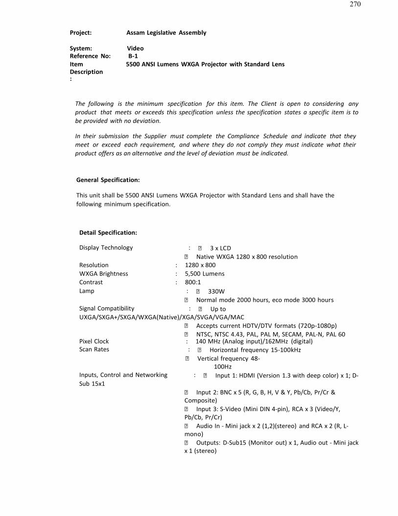
270
Project: Assam Legislative Assembly
System: VideoReference No: B-1ItemDescription:
5500 ANSI Lumens WXGA Projector with Standard Lens
The following is the minimum specification for this item. The Client is open to considering anyproduct that meets or exceeds this specification unless the specification states a specific item is tobe provided with no deviation.
In their submission the Supplier must complete the Compliance Schedule and indicate that theymeet or exceed each requirement, and where they do not comply they must indicate what theirproduct offers as an alternative and the level of deviation must be indicated.
General Specification:
This unit shall be 5500 ANSI Lumens WXGA Projector with Standard Lens and shall have thefollowing minimum specification.
Detail Specification:
Display Technology : 3 x LCD Native WXGA 1280 x 800 resolution
Resolution : 1280 x 800WXGA Brightness : 5,500 Lumens Contrast : 800:1Lamp : 330W
Normal mode 2000 hours, eco mode 3000 hoursSignal Compatibility : Up toUXGA/SXGA+/SXGA/WXGA(Native)/XGA/SVGA/VGA/MAC
Accepts current HDTV/DTV formats (720p-1080p) NTSC, NTSC 4.43, PAL, PAL M, SECAM, PAL-N, PAL 60
Pixel Clock : 140 MHz (Analog input)/162MHz (digital)Scan Rates : Horizontal frequency 15-100kHz
Vertical frequency 48-100Hz
Inputs, Control and Networking : Input 1: HDMI (Version 1.3 with deep color) x 1; D-Sub 15x1
Input 2: BNC x 5 (R, G, B, H, V & Y, Pb/Cb, Pr/Cr &Composite) Input 3: S-Video (Mini DIN 4-pin), RCA x 3 (Video/Y,Pb/Cb, Pr/Cr) Audio In - Mini jack x 2 (1,2)(stereo) and RCA x 2 (R, L-mono) Outputs: D-Sub15 (Monitor out) x 1, Audio out - Mini jackx 1 (stereo)

271
RJ45 LANx 1
Control port - Dsub-9 x 1
Acceptable: Christie, Panasonic, Projection Design or Approved Equivalent
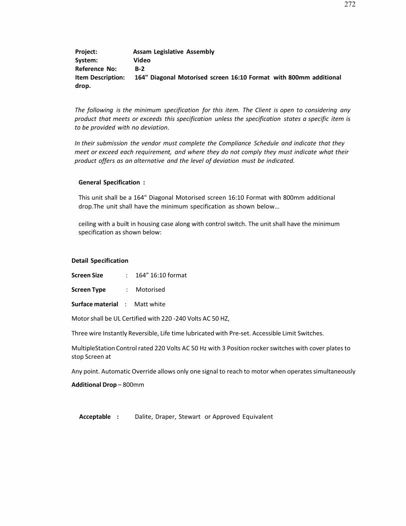
272
Project: Assam Legislative AssemblySystem: VideoReference No: B-2Item Description: 164" Diagonal Motorised screen 16:10 Format with 800mm additionaldrop.
The following is the minimum specification for this item. The Client is open to considering anyproduct that meets or exceeds this specification unless the specification states a specific item isto be provided with no deviation.
In their submission the vendor must complete the Compliance Schedule and indicate that theymeet or exceed each requirement, and where they do not comply they must indicate what theirproduct offers as an alternative and the level of deviation must be indicated.
General Specification :
This unit shall be a 164" Diagonal Motorised screen 16:10 Format with 800mm additionaldrop.The unit shall have the minimum specification as shown below…
ceiling with a built in housing case along with control switch. The unit shall have the minimum specification as shown below:
Detail Specification
Screen Size : 164” 16:10 format
Screen Type : Motorised
Surface material : Matt white
Motor shall be UL Certified with 220 -240 Volts AC 50 HZ,
Three wire Instantly Reversible, Life time lubricated with Pre-set. Accessible Limit Switches.
MultipleStation Control rated 220 Volts AC 50 Hz with 3 Position rocker switches with cover plates tostop Screen at
Any point. Automatic Override allows only one signal to reach to motor when operates simultaneously
Additional Drop – 800mm
Acceptable : Dalite, Draper, Stewart or Approved Equivalent
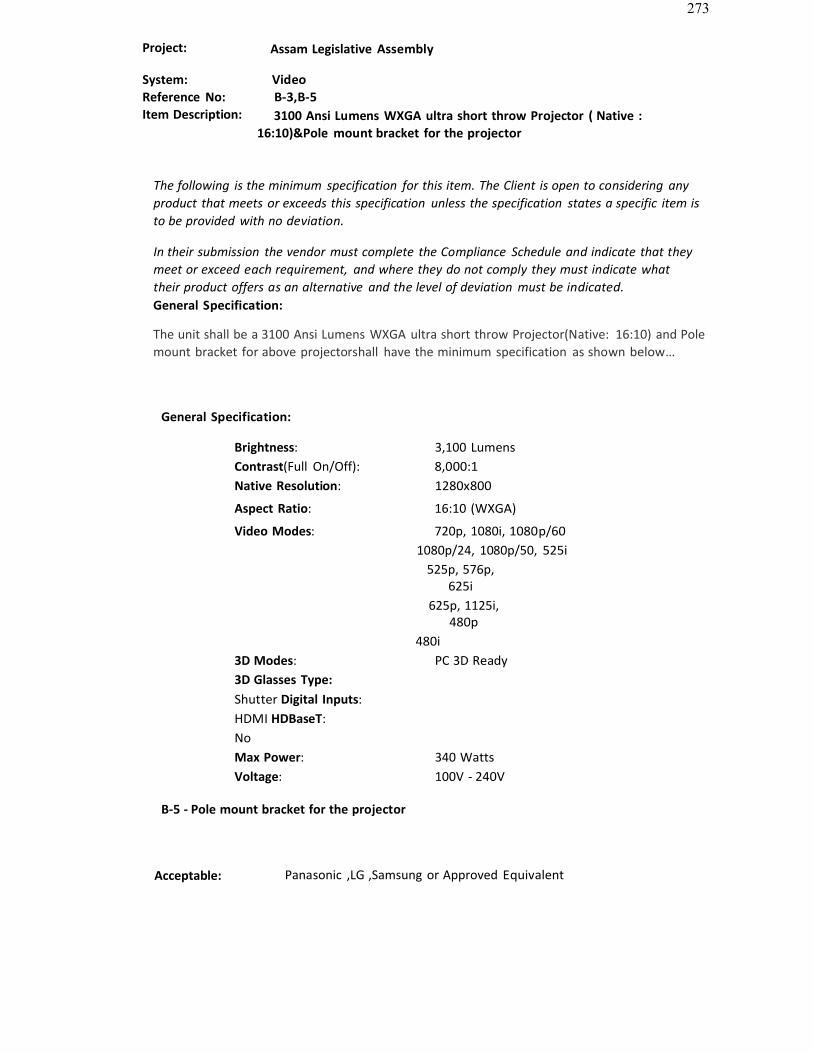
273
Project: Assam Legislative Assembly
System: VideoReference No: B-3,B-5Item Description: 3100 Ansi Lumens WXGA ultra short throw Projector ( Native :
16:10)&Pole mount bracket for the projector
The following is the minimum specification for this item. The Client is open to considering anyproduct that meets or exceeds this specification unless the specification states a specific item isto be provided with no deviation.
In their submission the vendor must complete the Compliance Schedule and indicate that theymeet or exceed each requirement, and where they do not comply they must indicate whattheir product offers as an alternative and the level of deviation must be indicated.General Specification:
The unit shall be a 3100 Ansi Lumens WXGA ultra short throw Projector(Native: 16:10) and Polemount bracket for above projectorshall have the minimum specification as shown below…
General Specification:
Brightness: 3,100 LumensContrast(Full On/Off): 8,000:1Native Resolution: 1280x800
Aspect Ratio: 16:10 (WXGA)
Video Modes: 720p, 1080i, 1080p/601080p/24, 1080p/50, 525i
525p, 576p,625i
625p, 1125i,480p
480i3D Modes: PC 3D Ready3D Glasses Type: Shutter Digital Inputs: HDMI HDBaseT: NoMax Power: 340 WattsVoltage: 100V - 240V
B-5 - Pole mount bracket for the projector
Acceptable: Panasonic ,LG ,Samsung or Approved Equivalent
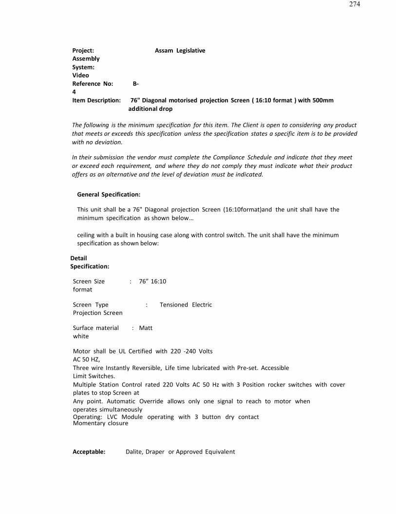
274
Project: Assam LegislativeAssemblySystem: VideoReference No: B-4Item Description: 76" Diagonal motorised projection Screen ( 16:10 format ) with 500mm
additional drop
The following is the minimum specification for this item. The Client is open to considering any productthat meets or exceeds this specification unless the specification states a specific item is to be providedwith no deviation.
In their submission the vendor must complete the Compliance Schedule and indicate that they meetor exceed each requirement, and where they do not comply they must indicate what their productoffers as an alternative and the level of deviation must be indicated.
General Specification:
This unit shall be a 76" Diagonal projection Screen (16:10format)and the unit shall have theminimum specification as shown below…
ceiling with a built in housing case along with control switch. The unit shall have the minimumspecification as shown below:
DetailSpecification:
Screen Size : 76” 16:10format
Screen Type : Tensioned ElectricProjection Screen
Surface material : Mattwhite
Motor shall be UL Certified with 220 -240 VoltsAC 50 HZ,Three wire Instantly Reversible, Life time lubricated with Pre-set. AccessibleLimit Switches.Multiple Station Control rated 220 Volts AC 50 Hz with 3 Position rocker switches with coverplates to stop Screen atAny point. Automatic Override allows only one signal to reach to motor whenoperates simultaneouslyOperating: LVC Module operating with 3 button dry contactMomentary closure
Acceptable: Dalite, Draper or Approved Equivalent
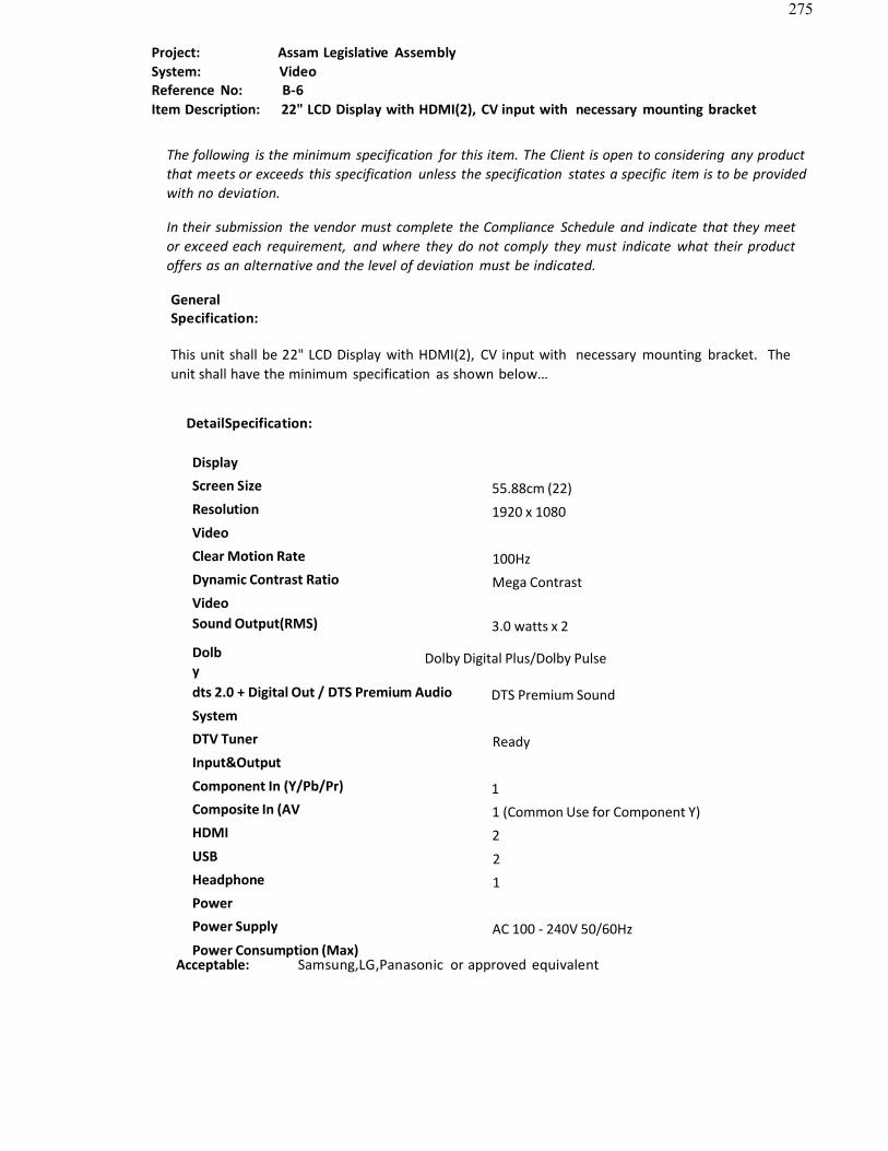
275
Project: Assam Legislative AssemblySystem: VideoReference No: B-6Item Description: 22" LCD Display with HDMI(2), CV input with necessary mounting bracket
The following is the minimum specification for this item. The Client is open to considering any productthat meets or exceeds this specification unless the specification states a specific item is to be providedwith no deviation.
In their submission the vendor must complete the Compliance Schedule and indicate that they meetor exceed each requirement, and where they do not comply they must indicate what their productoffers as an alternative and the level of deviation must be indicated.
GeneralSpecification:
This unit shall be 22" LCD Display with HDMI(2), CV input with necessary mounting bracket. Theunit shall have the minimum specification as shown below…
DetailSpecification:
Display
Screen Size 55.88cm (22)Resolution 1920 x 1080Video
Clear Motion Rate 100HzDynamic Contrast Ratio Mega ContrastVideoSound Output(RMS) 3.0 watts x 2
Dolby
Dolby Digital Plus/Dolby Pulse
dts 2.0 + Digital Out / DTS Premium Audio DTS Premium SoundSystem
DTV Tuner ReadyInput&Output
Component In (Y/Pb/Pr) 1Composite In (AV 1 (Common Use for Component Y)HDMI 2USB 2Headphone 1Power
Power Supply AC 100 - 240V 50/60HzPower Consumption (Max)
Acceptable: Samsung,LG,Panasonic or approved equivalent
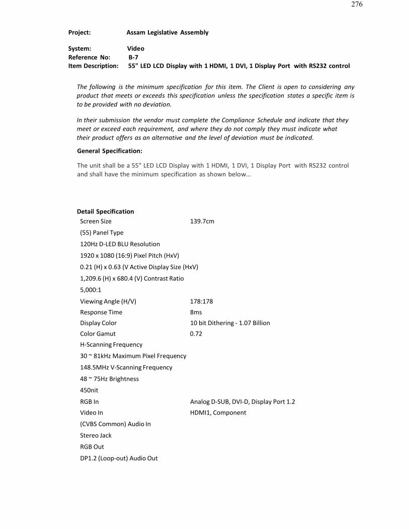
276
Project: Assam Legislative Assembly
System: VideoReference No: B-7Item Description: 55" LED LCD Display with 1 HDMI, 1 DVI, 1 Display Port with RS232 control
The following is the minimum specification for this item. The Client is open to considering anyproduct that meets or exceeds this specification unless the specification states a specific item is to be provided with no deviation.
In their submission the vendor must complete the Compliance Schedule and indicate that theymeet or exceed each requirement, and where they do not comply they must indicate whattheir product offers as an alternative and the level of deviation must be indicated.
General Specification:
The unit shall be a 55" LED LCD Display with 1 HDMI, 1 DVI, 1 Display Port with RS232 controland shall have the minimum specification as shown below…
Detail SpecificationScreen Size 139.7cm
(55) Panel Type
120Hz D-LED BLU Resolution
1920 x 1080 (16:9) Pixel Pitch (HxV)
0.21 (H) x 0.63 (V Active Display Size (HxV)
1,209.6 (H) x 680.4 (V) Contrast Ratio
5,000:1
Viewing Angle (H/V) 178:178
Response Time 8ms
Display Color 10 bit Dithering - 1.07 Billion
Color Gamut 0.72
H-Scanning Frequency
30 ~ 81kHz Maximum Pixel Frequency
148.5MHz V-Scanning Frequency
48 ~ 75Hz Brightness
450nit
RGB In Analog D-SUB, DVI-D, Display Port 1.2
Video In HDMI1, Component
(CVBS Common) Audio In
Stereo Jack
RGB Out
DP1.2 (Loop-out) Audio Out

277
Stereo JackStand Type Foot Stand (Optional)
Acceptable : Samsung ,LG,Panasonic or Approved Equivalent
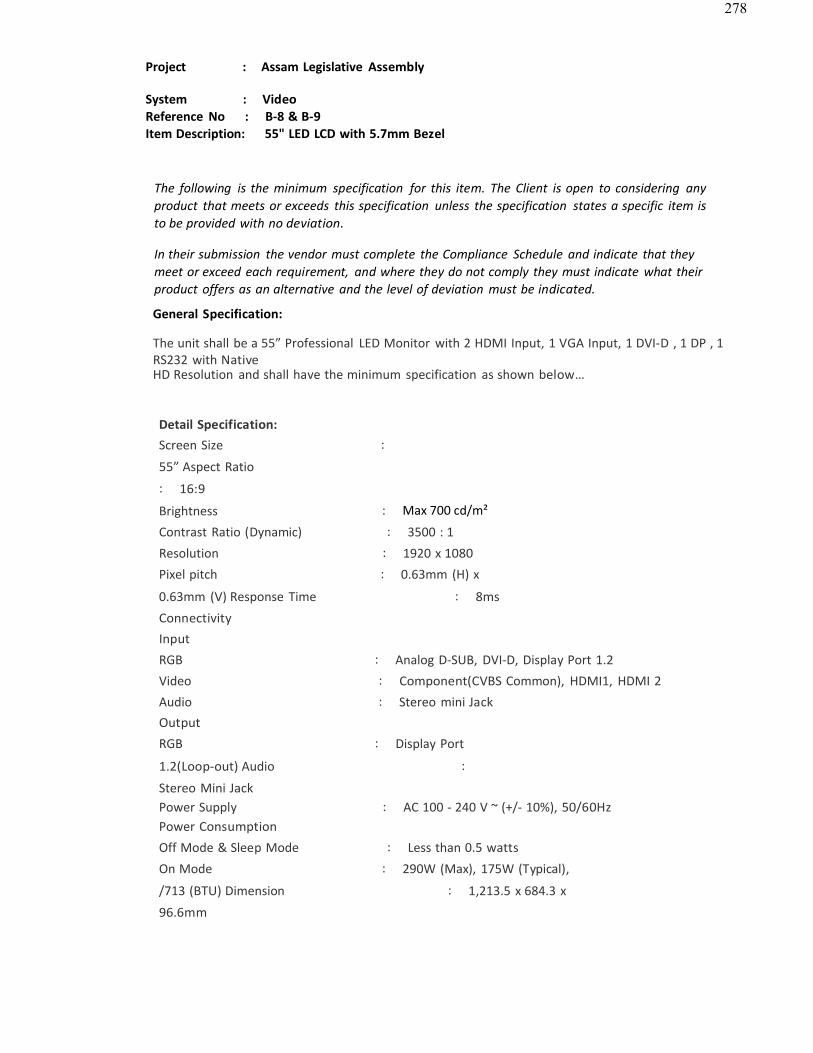
278
Project : Assam Legislative Assembly
System : VideoReference No : B-8 & B-9Item Description: 55" LED LCD with 5.7mm Bezel
The following is the minimum specification for this item. The Client is open to considering anyproduct that meets or exceeds this specification unless the specification states a specific item isto be provided with no deviation.
In their submission the vendor must complete the Compliance Schedule and indicate that theymeet or exceed each requirement, and where they do not comply they must indicate what theirproduct offers as an alternative and the level of deviation must be indicated.
General Specification:
The unit shall be a 55” Professional LED Monitor with 2 HDMI Input, 1 VGA Input, 1 DVI-D , 1 DP , 1RS232 with NativeHD Resolution and shall have the minimum specification as shown below…
Detail Specification:Screen Size :
55” Aspect Ratio
: 16:9
Brightness : Max 700 cd/m²
Contrast Ratio (Dynamic) : 3500 : 1
Resolution : 1920 x 1080Pixel pitch : 0.63mm (H) x
0.63mm (V) Response Time : 8ms
ConnectivityInputRGB : Analog D-SUB, DVI-D, Display Port 1.2Video : Component(CVBS Common), HDMI1, HDMI 2Audio : Stereo mini JackOutputRGB : Display Port
1.2(Loop-out) Audio :
Stereo Mini JackPower Supply : AC 100 - 240 V ~ (+/- 10%), 50/60HzPower ConsumptionOff Mode & Sleep Mode : Less than 0.5 watts
On Mode : 290W (Max), 175W (Typical),
/713 (BTU) Dimension : 1,213.5 x 684.3 x
96.6mm

279
Viewing Angle(Horizontal/Vertical) : 178˚/178˚
B-9 -Specialised video wall bracket for the above display
Acceptable: Samsung ,LG,Panasonic or Approved Equivalent
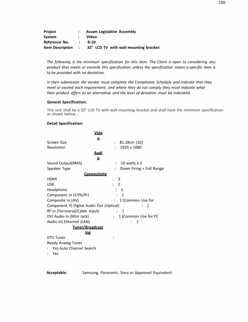
280
Project : Assam Legislative AssemblySystem : VideoReference No. : B-10Item Description : 32" LCD TV with wall mounting bracket
The following is the minimum specification for this item. The Client is open to considering anyproduct that meets or exceeds this specification unless the specification states a specific item isto be provided with no deviation.
In their submission the vendor must complete the Compliance Schedule and indicate that theymeet or exceed each requirement, and where they do not comply they must indicate whattheir product offers as an alternative and the level of deviation must be indicated.
General Specification:
This unit shall be a 32” LCD TV with wall mounting bracket and shall have the minimum specificationas shown below…
Detail Specification:
Video
Screen Size : 81.28cm (32)Resolution : 1920 x 1080
Audio
Sound Output(RMS) : 10 watts x 2Speaker Type : Down Firing + Full Range
ConnectivityHDMI : 3USB : 2Headphone : 1Component In (Y/Pb/Pr) : 1Composite In (AV) : 1 (Common Use forComponent Y) Digital Audio Out (Optical) : 1RF In (Terrestrial/Cable Input) : 1DVI Audio In (Mini Jack) : 1 (Common Use for PCAudio in) Ethernet (LAN) : 1
Tuner/Broadcasting
DTV Tuner : Ready Analog Tuner : Yes Auto Channel Search : Yes
Acceptable: Samsung, Panasonic, Sony or Approved Equivalent

281
Project: Assam Legislative Assembly
System: VideoReference No: B-11Item Description: HDMI Twisted Pair Transmitter & Receiver to handle true HD resolution
with deep colour up to 100 Mtr ( HDMI TX RX )The following is the minimum specification for this item. The Client is open to considering anyproduct that meets or exceeds this specification unless the specification states a specific item isto be provided with no deviation.
In their submission the vendor must complete the Compliance Schedule and indicate that theymeet or exceed each requirement, and where they do not comply they must indicate what theirproduct offers as an alternative and the level of deviation must be indicated.
General Specification:
The unit shall be a HDMI Twisted Pair Transmitter & Receiver to handle true HD resolution withdeep colour up to100 Mtr ( HDMI TX RX )and shall have the minimum specification as shown below…
Detail Specification:TransmitterINPUTS: 1 HDMI connector.
OUTPUTS: 1 HDBaseT twisted pair RJ−45 connector.
PORTS: 1 IR on a 3.5mm mini jack, 1 RS−232 on a 9−pinD−sub connector.
BANDWIDTH: 10.2Gbps (3.4Gbps
per graphic channel). RS-232 BAUD RATE:
115200
COMPLIANCE WITH HDMI STANDARD: Supports HDMI and HDCP.
POWER CONSUMPTION: 12V
DC,275mA. OPERATING TEMPERATURE:
0° to 40°C (32° to 104°F). STORAGE TEMPERATURE:
−40° to +70°C (−40° to 158°F).
HUMIDITY: 10% to 90%, RHL non−condensing.Detail Specification:Receiver
INPUTS: 1 HDMI connector.
OUTPUTS: 1 HDBaseT twisted pair RJ−45 connector.
PORTS: 1 IR on a 3.5mm mini jack, 1 RS−232 on a 9−pin D−subconnector.
MAX. DATA RATE: 10.2Gbps (3.4Gbps per
graphic channel). RS-232 BAUD RATE:
115200

282
COMPLIANCE WITH HDMISTANDARD: Supports HDMI and HDCP.
POWER CONSUMPTION: 12V DC,
295mA. OPERATING TEMPERATURE: 0° to
40°C (32° to 104°F). STORAGE TEMPERATURE:
−40° to +70°C (−40° to 158°F)
HUMIDITY: 10% to 90%, RHL non−condensing.
Acceptable: Kramer,Extron or Approved Equivalent
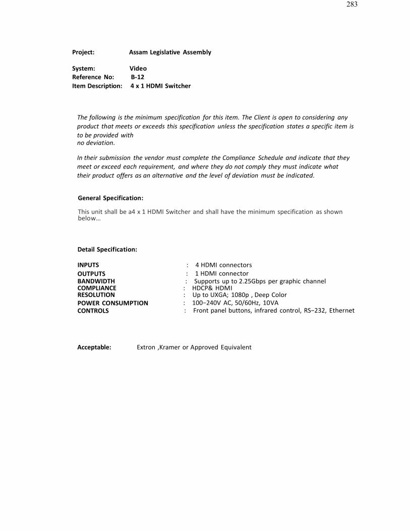
283
Project: Assam Legislative Assembly
System: VideoReference No: B-12Item Description: 4 x 1 HDMI Switcher
The following is the minimum specification for this item. The Client is open to considering anyproduct that meets or exceeds this specification unless the specification states a specific item isto be provided withno deviation.
In their submission the vendor must complete the Compliance Schedule and indicate that theymeet or exceed each requirement, and where they do not comply they must indicate whattheir product offers as an alternative and the level of deviation must be indicated.
General Specification:
This unit shall be a4 x 1 HDMI Switcher and shall have the minimum specification as shownbelow…
Detail Specification:
INPUTS : 4 HDMI connectorsOUTPUTS : 1 HDMI connectorBANDWIDTH : Supports up to 2.25Gbps per graphic channelCOMPLIANCE : HDCP& HDMIRESOLUTION : Up to UXGA; 1080p , Deep ColorPOWER CONSUMPTION : 100−240V AC, 50/60Hz, 10VACONTROLS : Front panel buttons, infrared control, RS−232, Ethernet
Acceptable: Extron ,Kramer or Approved Equivalent
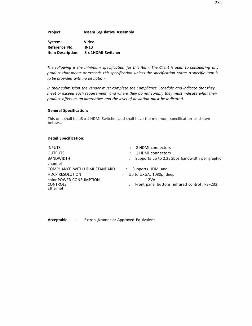
284
Project: Assam Legislative Assembly
System: VideoReference No: B-13Item Description: 8 x 1HDMI Switcher
The following is the minimum specification for this item. The Client is open to considering anyproduct that meets or exceeds this specification unless the specification states a specific item is to be provided with no deviation.
In their submission the vendor must complete the Compliance Schedule and indicate that theymeet or exceed each requirement, and where they do not comply they must indicate what theirproduct offers as an alternative and the level of deviation must be indicated.
General Specification:
This unit shall be a8 x 1 HDMI Switcher and shall have the minimum specification as shownbelow…
Detail Specification:
INPUTS : 8 HDMI connectorsOUTPUTS : 1 HDMI connectorsBANDWIDTH : Supports up to 2.25Gbps bandwidth per graphicchannelCOMPLIANCE WITH HDMI STANDARD : Supports HDMI andHDCP RESOLUTION : Up to UXGA; 1080p, deepcolor POWER CONSUMPTION : 12VACONTROLS : Front panel buttons, infrared control , RS−232,Ethernet
Acceptable : Extron ,Kramer or Approved Equivalent
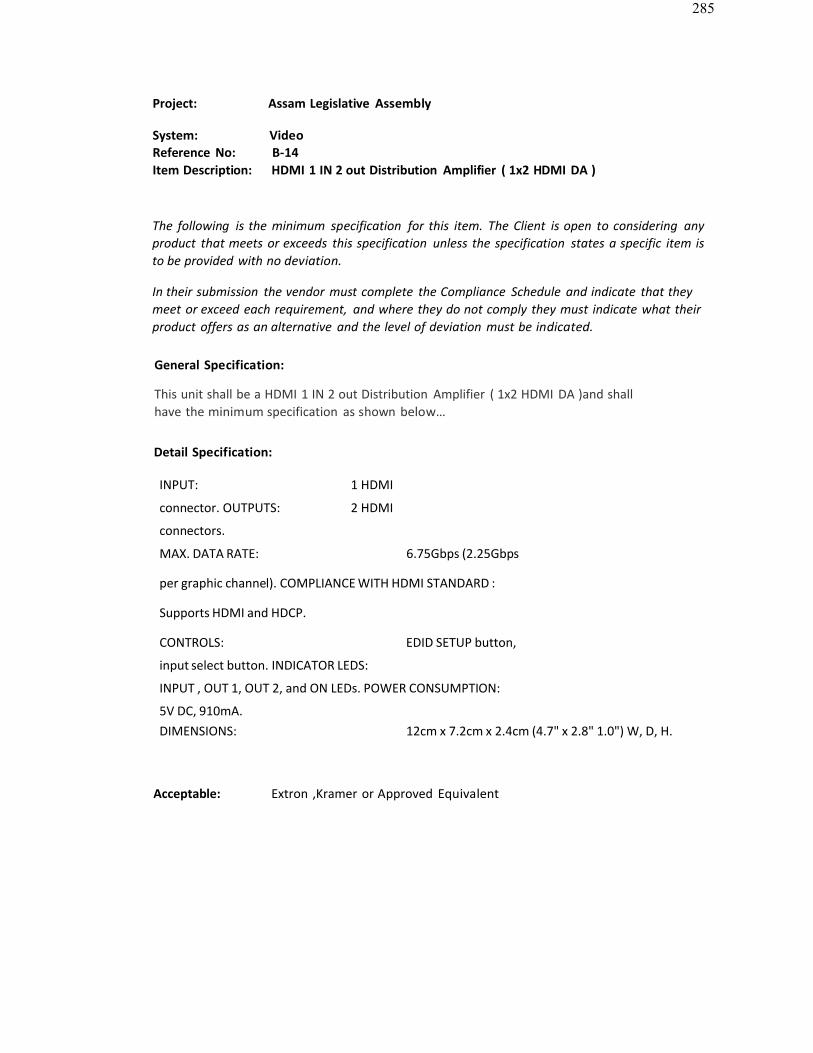
285
Project: Assam Legislative Assembly
System: VideoReference No: B-14Item Description: HDMI 1 IN 2 out Distribution Amplifier ( 1x2 HDMI DA )
The following is the minimum specification for this item. The Client is open to considering anyproduct that meets or exceeds this specification unless the specification states a specific item isto be provided with no deviation.
In their submission the vendor must complete the Compliance Schedule and indicate that theymeet or exceed each requirement, and where they do not comply they must indicate what theirproduct offers as an alternative and the level of deviation must be indicated.
General Specification:
This unit shall be a HDMI 1 IN 2 out Distribution Amplifier ( 1x2 HDMI DA )and shallhave the minimum specification as shown below…
Detail Specification:
INPUT: 1 HDMI
connector. OUTPUTS: 2 HDMI
connectors.
MAX. DATA RATE: 6.75Gbps (2.25Gbps
per graphic channel). COMPLIANCE WITH HDMI STANDARD :
Supports HDMI and HDCP.
CONTROLS: EDID SETUP button,
input select button. INDICATOR LEDS:
INPUT , OUT 1, OUT 2, and ON LEDs. POWER CONSUMPTION:
5V DC, 910mA.DIMENSIONS: 12cm x 7.2cm x 2.4cm (4.7" x 2.8" 1.0") W, D, H.
Acceptable: Extron ,Kramer or Approved Equivalent
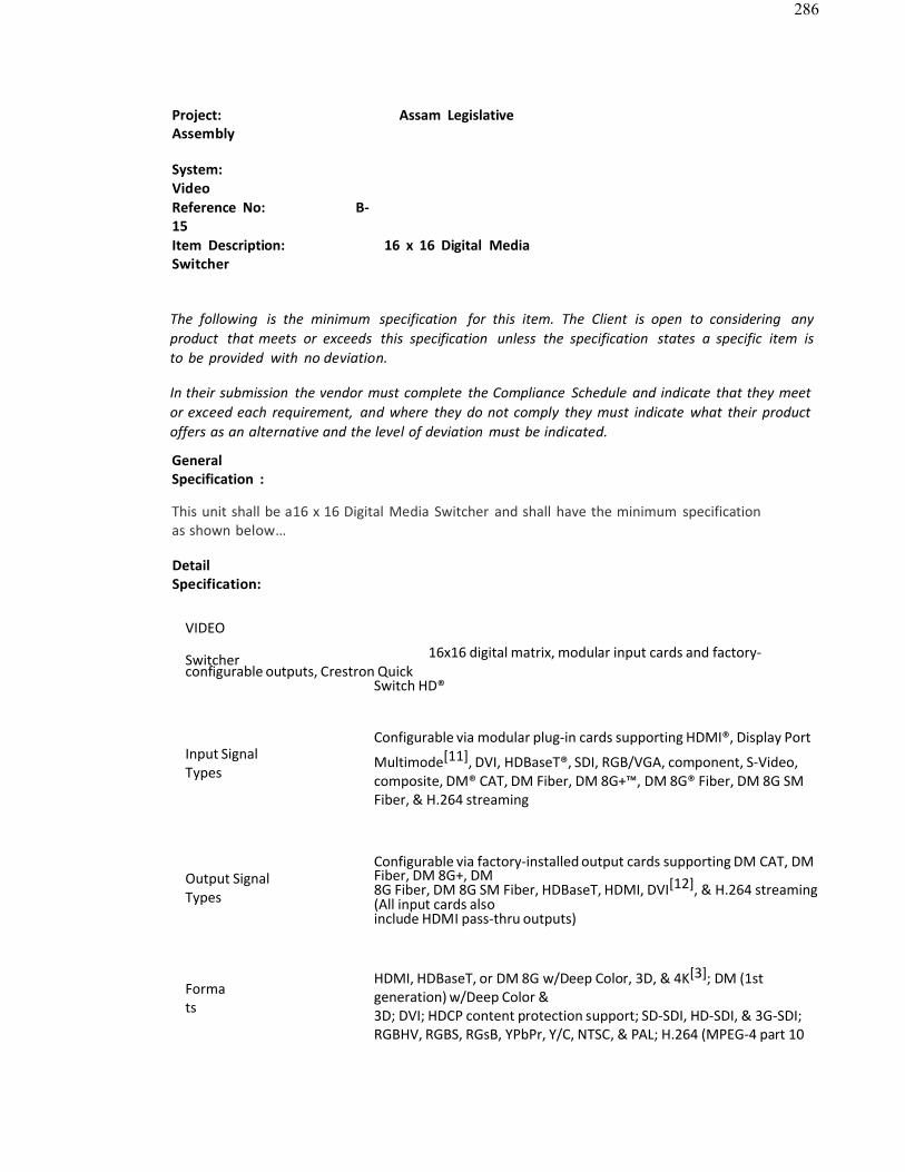
286
Project: Assam LegislativeAssembly
System: VideoReference No: B-15Item Description: 16 x 16 Digital MediaSwitcher
The following is the minimum specification for this item. The Client is open to considering anyproduct that meets or exceeds this specification unless the specification states a specific item isto be provided with no deviation.
In their submission the vendor must complete the Compliance Schedule and indicate that they meetor exceed each requirement, and where they do not comply they must indicate what their productoffers as an alternative and the level of deviation must be indicated.
GeneralSpecification :
This unit shall be a16 x 16 Digital Media Switcher and shall have the minimum specificationas shown below…
DetailSpecification:
VIDEO
Switcher 16x16 digital matrix, modular input cards and factory-configurable outputs, Crestron Quick
Switch HD®
Input SignalTypes
Configurable via modular plug-in cards supporting HDMI®, Display Port
Multimode[11], DVI, HDBaseT®, SDI, RGB/VGA, component, S-Video,composite, DM® CAT, DM Fiber, DM 8G+™, DM 8G® Fiber, DM 8G SMFiber, & H.264 streaming
Output SignalTypes
Configurable via factory-installed output cards supporting DM CAT, DMFiber, DM 8G+, DM8G Fiber, DM 8G SM Fiber, HDBaseT, HDMI, DVI[12], & H.264 streaming(All input cards alsoinclude HDMI pass-thru outputs)
Formats
HDMI, HDBaseT, or DM 8G w/Deep Color, 3D, & 4K[3]; DM (1stgeneration) w/Deep Color &3D; DVI; HDCP content protection support; SD-SDI, HD-SDI, & 3G-SDI;RGBHV, RGBS, RGsB, YPbPr, Y/C, NTSC, & PAL; H.264 (MPEG-4 part 10

287
AVC)
Input Resolutions Refer to the specifications
for each input card Output Resolutions Refer to
the specifications for each output card Backplane Data Rate
12.5 Gbps
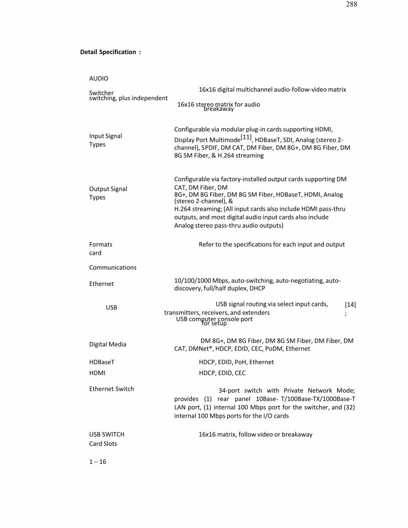
288
Detail Specification :
AUDIO
Switcher 16x16 digital multichannel audio-follow-video matrixswitching, plus independent
16x16 stereo matrix for audiobreakaway
Input SignalTypes
Configurable via modular plug-in cards supporting HDMI,Display Port Multimode[11], HDBaseT, SDI, Analog (stereo 2-channel), SPDIF, DM CAT, DM Fiber, DM 8G+, DM 8G Fiber, DM8G SM Fiber, & H.264 streaming
Output SignalTypes
Configurable via factory-installed output cards supporting DMCAT, DM Fiber, DM8G+, DM 8G Fiber, DM 8G SM Fiber, HDBaseT, HDMI, Analog(stereo 2-channel), &H.264 streaming; (All input cards also include HDMI pass-thruoutputs, and most digital audio input cards also includeAnalog stereo pass-thru audio outputs)
Formats Refer to the specifications for each input and outputcard
Communications
Ethernet 10/100/1000 Mbps, auto-switching, auto-negotiating, auto-discovery, full/half duplex, DHCP
USB USB signal routing via select input cards,transmitters, receivers, and extenders
USB computer console portfor setup
[14];
Digital Media DM 8G+, DM 8G Fiber, DM 8G SM Fiber, DM Fiber, DMCAT, DMNet®, HDCP, EDID, CEC, PoDM, Ethernet
HDBaseT HDCP, EDID, PoH, Ethernet
HDMI HDCP, EDID, CEC
Ethernet Switch 34-port switch with Private Network Mode; provides (1) rear panel 10Base- T/100Base-TX/1000Base-T LAN port, (1) internal 100 Mbps port for the switcher, and (32)internal 100 Mbps ports for the I/O cards
USB SWITCH 16x16 matrix, follow video or breakawayCard Slots
1 – 16

289
DM OUTPUTS (SLOT1 – 2)
(16) DM switcher input card slots;
Each slot accepts (1) DMC-series
input card; Input cards are field-
installable
(2) DM switcher output card slots;
Each slot accepts (1) DMCO-series
output card; Output cards require
factory installation
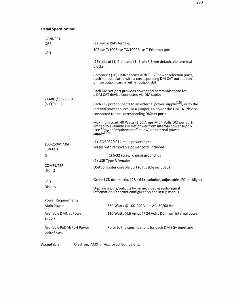
290
Detail Specification:
CONNECTORS
LAN
(1) 8-wire RJ45 female;
10Base-T/100Base-TX/1000Base-T Ethernet port
(16) sets of (1) 4-pin and (1) 3-pin 3.5mm detachable terminalblocks;
Comprises (16) DMNet ports with “EIG” power selection ports,each set associated with a corresponding DM CAT output porton the output card in either output slot;
24ABG / EIG 1 – 8(SLOT 1 – 2)
Each DMNet port provides power and communications fora DM CAT device connected via DM cable;
Each EIG port connects to an external power supply[15], or to theinternal power source via a jumper, to power the DM CAT deviceconnected to the corresponding DMNet port;
Maximum Load: 40 Watts (1.66 Amps @ 24 Volts DC) per port,limited to available DMNet power from internal power supply(see "Power Requirements" below) or external power supply[15]
100-250V~7.0A50/60Hz
(1) IEC 60320 C14 main power inlet;Mates with removable power cord, included
G (1) 6-32 screw, chassis ground lug(1) USB Type B female;
COMPUTER(front)
USB computer console port (6 ft cable included)
LCDDisplay
Green LCD dot matrix, 128 x 64 resolution, adjustable LED backlight;
Displays inputs/outputs by name, video & audio signalinformation, Ethernet configuration and setup menus
Power RequirementsMain Power 550 Watts @ 100-240 Volts AC, 50/60 Hz
Available DMNet Power 110 Watts (4.6 Amps @ 24 Volts DC) from internal powersupply
Available PoDM/PoH Power Refer to the specifications for each DM 8G+ input andoutput card
Acceptable: Crestron, AMX or Approved Equivalent.
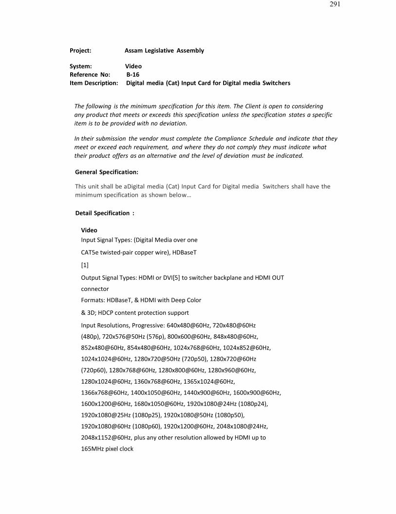
291
Project: Assam Legislative Assembly
System: VideoReference No: B-16Item Description: Digital media (Cat) Input Card for Digital media Switchers
The following is the minimum specification for this item. The Client is open to consideringany product that meets or exceeds this specification unless the specification states a specificitem is to be provided with no deviation.
In their submission the vendor must complete the Compliance Schedule and indicate that theymeet or exceed each requirement, and where they do not comply they must indicate whattheir product offers as an alternative and the level of deviation must be indicated.
General Specification:
This unit shall be aDigital media (Cat) Input Card for Digital media Switchers shall have theminimum specification as shown below…
Detail Specification :
VideoInput Signal Types: (Digital Media over one
CAT5e twisted-pair copper wire), HDBaseT
[1]
Output Signal Types: HDMI or DVI[5] to switcher backplane and HDMI OUT
connector
Formats: HDBaseT, & HDMI with Deep Color
& 3D; HDCP content protection support
Input Resolutions, Progressive: 640x480@60Hz, 720x480@60Hz
(480p), 720x576@50Hz (576p), 800x600@60Hz, 848x480@60Hz,
852x480@60Hz, 854x480@60Hz, 1024x768@60Hz, 1024x852@60Hz,
1024x1024@60Hz, 1280x720@50Hz (720p50), 1280x720@60Hz
(720p60), 1280x768@60Hz, 1280x800@60Hz, 1280x960@60Hz,
1280x1024@60Hz, 1360x768@60Hz, 1365x1024@60Hz,
1366x768@60Hz, 1400x1050@60Hz, 1440x900@60Hz, 1600x900@60Hz,
1600x1200@60Hz, 1680x1050@60Hz, 1920x1080@24Hz (1080p24),
1920x1080@25Hz (1080p25), 1920x1080@50Hz (1080p50),
1920x1080@60Hz (1080p60), 1920x1200@60Hz, 2048x1080@24Hz,
2048x1152@60Hz, plus any other resolution allowed by HDMI up to
165MHz pixel clock

292
Input Resolutions, Interlaced: 720x480@30Hz
(480i), 720x576@25Hz (576i),
1920x1080@25Hz (1080i25), 1920x1080@30Hz
(1080i30), plus any other resolution allowed by
HDMI up to 165MHz pixel clock Output
Resolutions: Matched to input
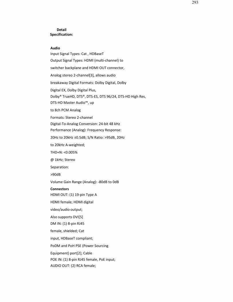
293
DetailSpecification:
AudioInput Signal Types: Cat , HDBaseT
Output Signal Types: HDMI (multi-channel) to
switcher backplane and HDMI OUT connector,
Analog stereo 2-channel[3], allows audio
breakaway Digital Formats: Dolby Digital, Dolby
Digital EX, Dolby Digital Plus,
Dolby® TrueHD, DTS®, DTS-ES, DTS 96/24, DTS-HD High Res,
DTS-HD Master Audio™, up
to 8ch PCM Analog
Formats: Stereo 2-channel
Digital-To-Analog Conversion: 24-bit 48 kHz
Performance (Analog): Frequency Response:
20Hz to 20kHz ±0.5dB; S/N Ratio: >95dB, 20Hz
to 20kHz A-weighted;
THD+N: <0.005%
@ 1kHz; Stereo
Separation:
>90dB
Volume Gain Range (Analog): -80dB to 0dB
ConnectorsHDMI OUT: (1) 19-pin Type A
HDMI female; HDMI digital
video/audio output;
Also supports DVI[5]
DM IN: (1) 8-pin RJ45
female, shielded; Cat
input, HDBaseT compliant;
PoDM and PoH PSE (Power Sourcing
Equipment) port[2]; Cable
POE IN: (1) 8-pin RJ45 female, PoE input;
AUDIO OUT: (2) RCA female;

294
Unbalanced stereo line-level
audio output[3]; Output
Impedance: 100 Ohms
nominal;
Maximum Output Level: 2 Vrms
Acceptable: Crestron, AMX or Approved Equivalent
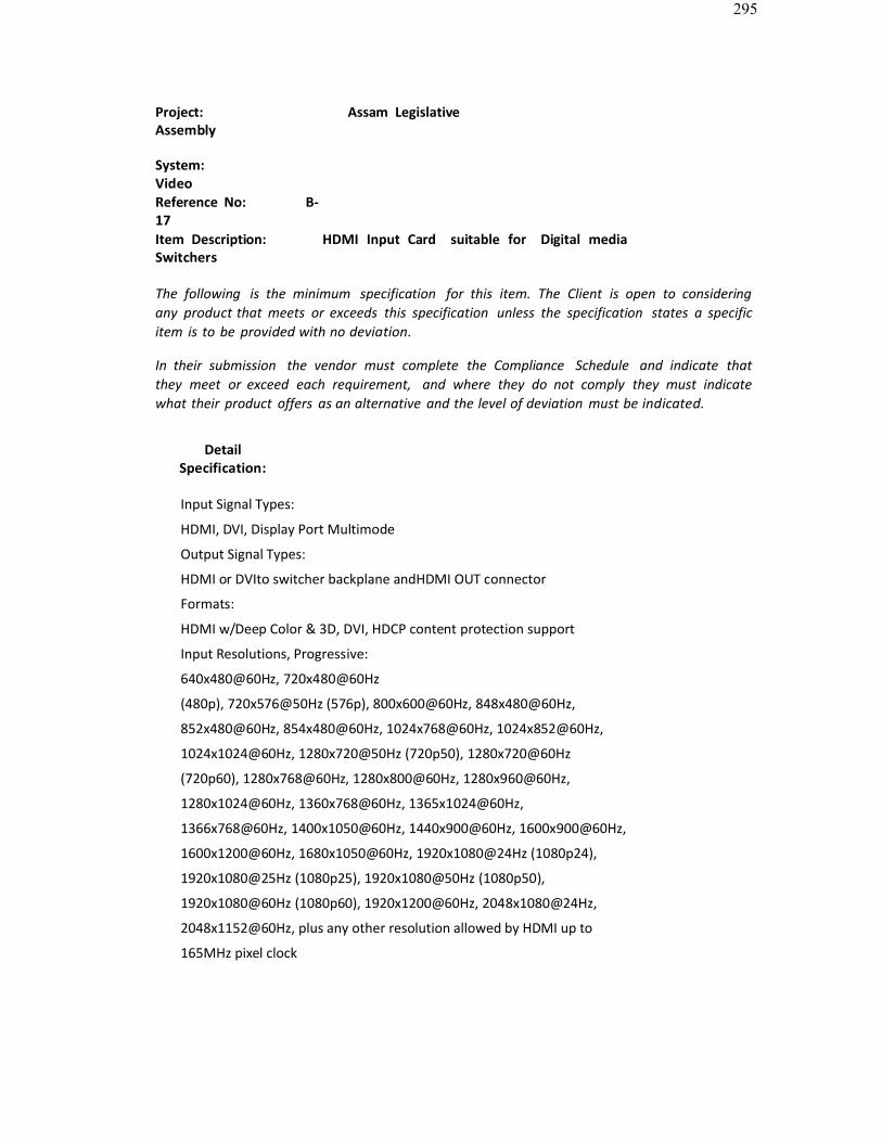
295
Project: Assam LegislativeAssembly
System: VideoReference No: B-17Item Description: HDMI Input Card suitable for Digital mediaSwitchers
The following is the minimum specification for this item. The Client is open to considering any product that meets or exceeds this specification unless the specification states a specificitem is to be provided with no deviation.
In their submission the vendor must complete the Compliance Schedule and indicate thatthey meet or exceed each requirement, and where they do not comply they must indicatewhat their product offers as an alternative and the level of deviation must be indicated.
DetailSpecification:
Input Signal Types:
HDMI, DVI, Display Port Multimode
Output Signal Types:
HDMI or DVIto switcher backplane andHDMI OUT connector
Formats:
HDMI w/Deep Color & 3D, DVI, HDCP content protection support
Input Resolutions, Progressive:
640x480@60Hz, 720x480@60Hz
(480p), 720x576@50Hz (576p), 800x600@60Hz, 848x480@60Hz,
852x480@60Hz, 854x480@60Hz, 1024x768@60Hz, 1024x852@60Hz,
1024x1024@60Hz, 1280x720@50Hz (720p50), 1280x720@60Hz
(720p60), 1280x768@60Hz, 1280x800@60Hz, 1280x960@60Hz,
1280x1024@60Hz, 1360x768@60Hz, 1365x1024@60Hz,
1366x768@60Hz, 1400x1050@60Hz, 1440x900@60Hz, 1600x900@60Hz,
1600x1200@60Hz, 1680x1050@60Hz, 1920x1080@24Hz (1080p24),
1920x1080@25Hz (1080p25), 1920x1080@50Hz (1080p50),
1920x1080@60Hz (1080p60), 1920x1200@60Hz, 2048x1080@24Hz,
2048x1152@60Hz, plus any other resolution allowed by HDMI up to
165MHz pixel clock

296
DetailSpecification:Input Resolutions, Interlaced:
720x480@30Hz (480i), 720x576@25Hz
(576i), 1920x1080@25Hz (1080i25),
1920x1080@30Hz (1080i30), plus any other
resolution allowed by HDMI up to 165MHz pixel
clock Output Resolutions:
Matched to inputs
AudioInput Signal Types:
HDMI or Display Port
Multimode supporting
HD
lossless multi-channel up to 7.1
Output Signal Types:
HDMI (multi-channel) to switcher backplane and
HDMI OUT connector, Analog stereo 2-channel
, allows audio breakaway
Formats:
Dolby
Digital
, Dolby Digital EX, Dolby
Digital Plus, Dolby
True HD, DTS
, DTS-ES, DTS 96/24, DTS-
HD High Res, DTS-HD
Master Audio
, Up to 8ch PCM
Digital-To-Analog Conversion:
24-bit 48 kHz
Performance (Analog):
Frequency Response: 20Hz to
20kHz ±0.5dB; S/N Ratio:
>95dB, 20Hz to 20kHz A-
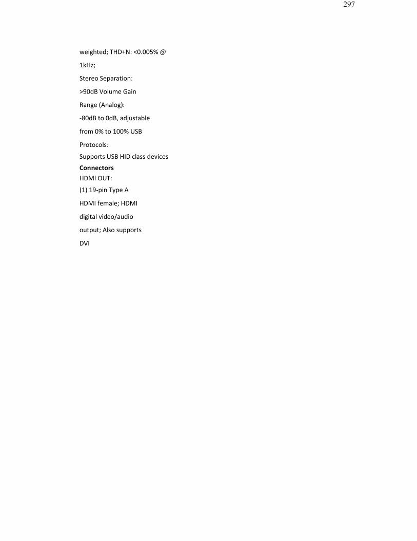
297
weighted; THD+N: <0.005% @
1kHz;
Stereo Separation:
>90dB Volume Gain
Range (Analog):
-80dB to 0dB, adjustable
from 0% to 100% USB
Protocols:
Supports USB HID class devices
ConnectorsHDMI OUT:
(1) 19-pin Type A
HDMI female; HDMI
digital video/audio
output; Also supports
DVI
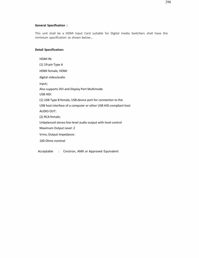
298
General Specification :
This unit shall be a HDMI Input Card suitable for Digital media Switchers shall have the minimum specification as shown below…
Detail Specification:
HDMI IN:
(1) 19-pin Type A
HDMI female; HDMI
digital video/audio
input;
Also supports DVI and Display Port Multimode
USB HID:
(1) USB Type B female, USB device port for connection to the
USB host interface of a computer or other USB HID-compliant host
AUDIO OUT:
(2) RCA female;
Unbalanced stereo line-level audio output with level control
Maximum Output Level: 2
Vrms; Output Impedance:
100 Ohms nominal
Acceptable : Crestron, AMX or Approved Equivalent
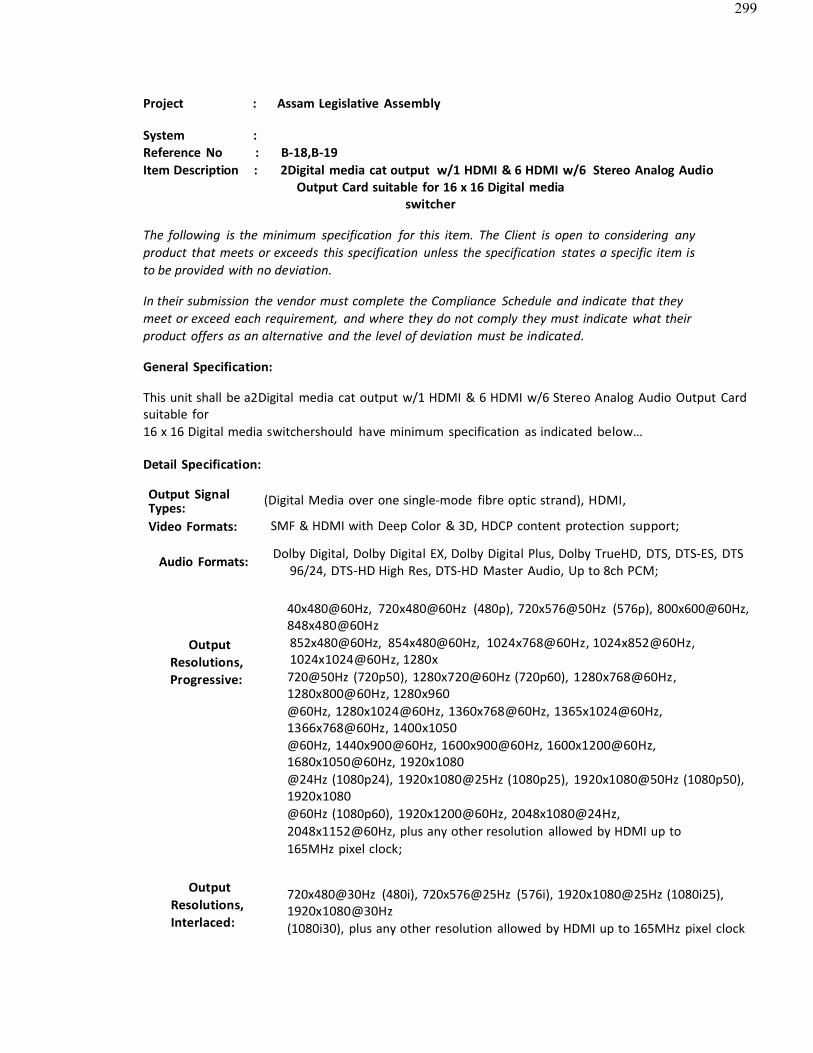
299
Project : Assam Legislative Assembly
System :Reference No : B-18,B-19Item Description : 2Digital media cat output w/1 HDMI & 6 HDMI w/6 Stereo Analog Audio
Output Card suitable for 16 x 16 Digital mediaswitcher
The following is the minimum specification for this item. The Client is open to considering anyproduct that meets or exceeds this specification unless the specification states a specific item is to be provided with no deviation.
In their submission the vendor must complete the Compliance Schedule and indicate that theymeet or exceed each requirement, and where they do not comply they must indicate what theirproduct offers as an alternative and the level of deviation must be indicated.
General Specification:
This unit shall be a2Digital media cat output w/1 HDMI & 6 HDMI w/6 Stereo Analog Audio Output Cardsuitable for16 x 16 Digital media switchershould have minimum specification as indicated below…
Detail Specification:
Output SignalTypes: (Digital Media over one single-mode fibre optic strand), HDMI,
Video Formats: SMF & HDMI with Deep Color & 3D, HDCP content protection support;
Audio Formats: Dolby Digital, Dolby Digital EX, Dolby Digital Plus, Dolby TrueHD, DTS, DTS-ES, DTS96/24, DTS-HD High Res, DTS-HD Master Audio, Up to 8ch PCM;
Output Resolutions, Progressive:
40x480@60Hz, 720x480@60Hz (480p), 720x576@50Hz (576p), 800x600@60Hz,848x480@60Hz852x480@60Hz, 854x480@60Hz, 1024x768@60Hz, 1024x852@60Hz, 1024x1024@60Hz, 1280x720@50Hz (720p50), 1280x720@60Hz (720p60), 1280x768@60Hz, 1280x800@60Hz, 1280x960@60Hz, 1280x1024@60Hz, 1360x768@60Hz, 1365x1024@60Hz,1366x768@60Hz, 1400x1050@60Hz, 1440x900@60Hz, 1600x900@60Hz, 1600x1200@60Hz,1680x1050@60Hz, 1920x1080@24Hz (1080p24), 1920x1080@25Hz (1080p25), 1920x1080@50Hz (1080p50),1920x1080@60Hz (1080p60), 1920x1200@60Hz, 2048x1080@24Hz,2048x1152@60Hz, plus any other resolution allowed by HDMI up to165MHz pixel clock;
Output Resolutions, Interlaced:
720x480@30Hz (480i), 720x576@25Hz (576i), 1920x1080@25Hz (1080i25),1920x1080@30Hz(1080i30), plus any other resolution allowed by HDMI up to 165MHz pixel clock

300
Output Signal Types: DM CAT (Digital Media over shielded twisted-pair copper wire),HDMI®, DVI[2];
Video Formats: DM CAT & HDMI with Deep Color & 3D, HDCP contentprotection support;
Dolby Digital, Dolby Digital EX, Dolby Digital Plus, Dolby TrueHD, DTS, DTS-ES,DTS 96/24,Audio
Formats: DTS-HD High Res, DTS-HD Master Audio, Up to 8ch PCM;

301
OutputResolutions, Progressive:
OutputResolutions, Interlaced:
640x480@60Hz, 720x480@60Hz (480p), 720x576@50Hz (576p),800x600@60Hz, 848x480@60Hz, 852x480@60Hz, 854x480@60Hz,1024x768@60Hz, 1024x852@60Hz, 1024x1024@60Hz, 1280x720@50Hz(720p50), 1280x720@60Hz (720p60), 1280x768@60Hz, 1280x800@60Hz,1280x960@60Hz, 1280x1024@60Hz, 1360x768@60Hz, 1365x1024@60Hz,1366x768@60Hz, 1400x1050@60Hz, 1440x900@60Hz, 1600x900@60Hz,1600x1200@60Hz, 1680x1050@60Hz, 1920x1080@24Hz (1080p24),1920x1080@25Hz (1080p25), 1920x1080@50Hz (1080p50),1920x1080@60Hz (1080p60), 1920x1200@60Hz, 2048x1080@24Hz,2048x1152@60Hz, plus any other resolution allowed by HDMI up to165MHz pixel clock;
720x480@30Hz (480i), 720x576@25Hz (576i), 1920x1080@25Hz (1080i25),1920x1080@30Hz (1080i30), plus any other resolution allowed by HDMI up to165MHz pixelclock
B-19 - 2 Digital media SM Fiber w/1 HDMI & 6 Digital media catoutput with 4HDMI outputcard
Acceptable : Crestron, Extron, AMX or Approved Equivalent
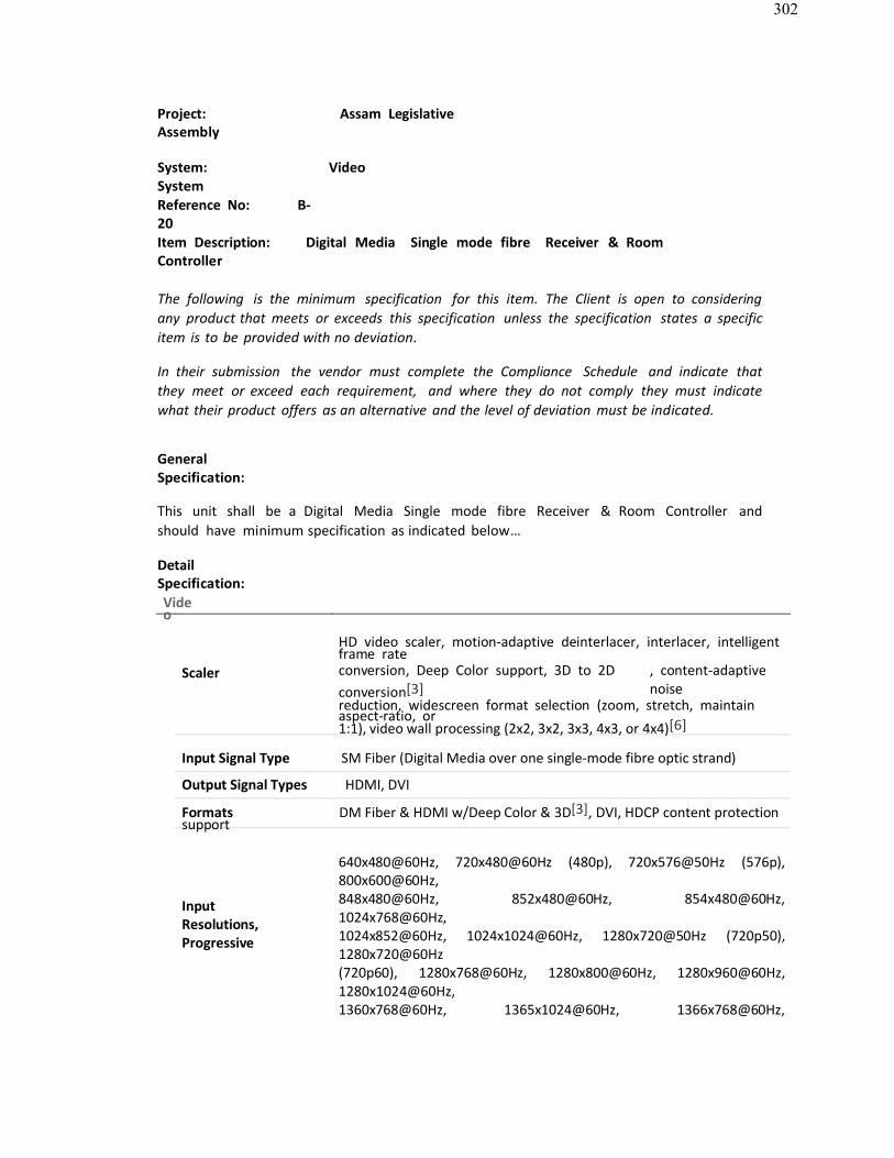
302
Project: Assam LegislativeAssembly
System: VideoSystemReference No: B-20Item Description: Digital Media Single mode fibre Receiver & RoomController
The following is the minimum specification for this item. The Client is open to considering any product that meets or exceeds this specification unless the specification states a specificitem is to be provided with no deviation.
In their submission the vendor must complete the Compliance Schedule and indicate thatthey meet or exceed each requirement, and where they do not comply they must indicatewhat their product offers as an alternative and the level of deviation must be indicated.
GeneralSpecification:
This unit shall be a Digital Media Single mode fibre Receiver & Room Controller and should have minimum specification as indicated below…
DetailSpecification:Video
HD video scaler, motion-adaptive deinterlacer, interlacer, intelligent frame rate
Scaler conversion, Deep Color support, 3D to 2Dconversion[3]
, content-adaptive noise
reduction, widescreen format selection (zoom, stretch, maintainaspect-ratio, or1:1), video wall processing (2x2, 3x2, 3x3, 4x3, or 4x4)[6]
Input Signal Type SM Fiber (Digital Media over one single-mode fibre optic strand)
Output Signal Types HDMI, DVI
Formats DM Fiber & HDMI w/Deep Color & 3D[3], DVI, HDCP content protectionsupport
InputResolutions, Progressive
640x480@60Hz, 720x480@60Hz (480p), 720x576@50Hz (576p),800x600@60Hz,848x480@60Hz, 852x480@60Hz, 854x480@60Hz, 1024x768@60Hz,1024x852@60Hz, 1024x1024@60Hz, 1280x720@50Hz (720p50),1280x720@60Hz(720p60), 1280x768@60Hz, 1280x800@60Hz, 1280x960@60Hz,1280x1024@60Hz,1360x768@60Hz, 1365x1024@60Hz, 1366x768@60Hz,
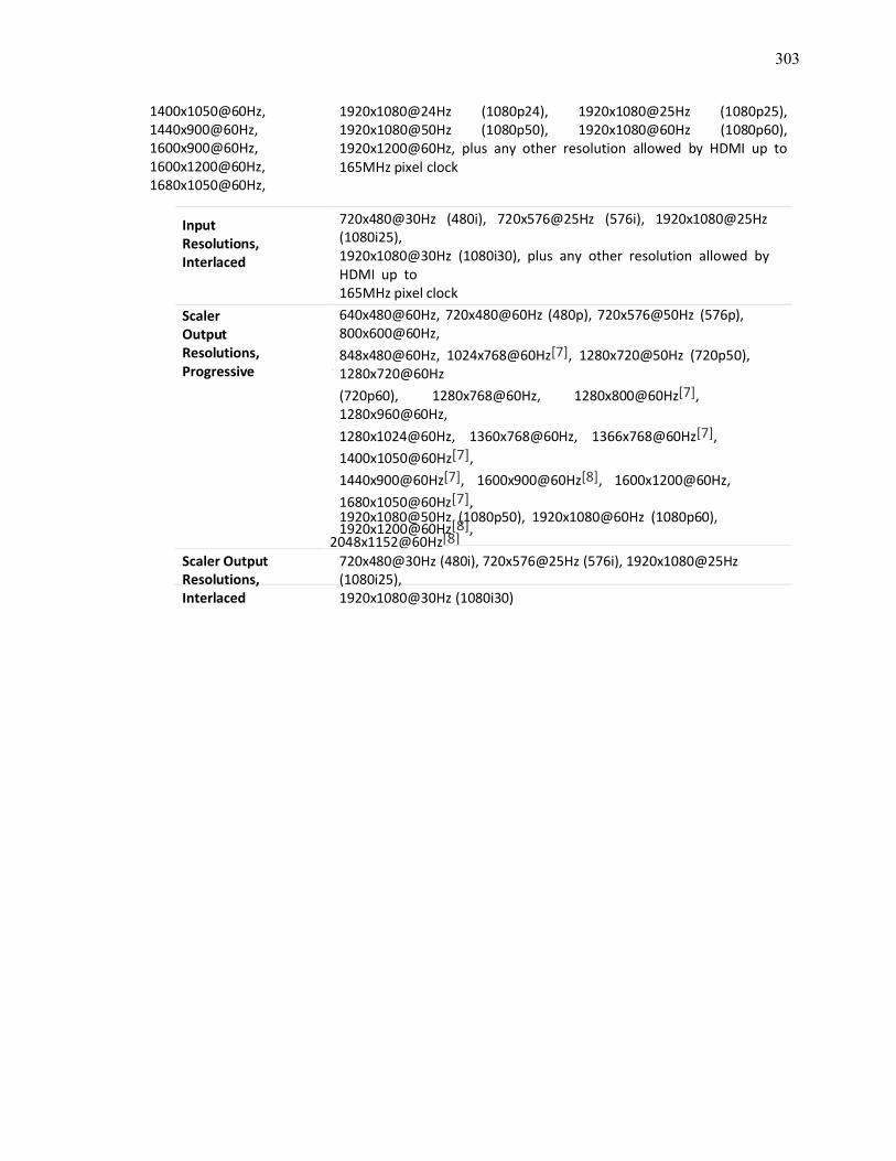
303
1400x1050@60Hz,1440x900@60Hz, 1600x900@60Hz, 1600x1200@60Hz, 1680x1050@60Hz,
1920x1080@24Hz (1080p24), 1920x1080@25Hz (1080p25), 1920x1080@50Hz (1080p50), 1920x1080@60Hz (1080p60),1920x1200@60Hz, plus any other resolution allowed by HDMI up to165MHz pixel clock
InputResolutions, Interlaced
Scaler Output Resolutions, Progressive
720x480@30Hz (480i), 720x576@25Hz (576i), 1920x1080@25Hz (1080i25),1920x1080@30Hz (1080i30), plus any other resolution allowed byHDMI up to165MHz pixel clock640x480@60Hz, 720x480@60Hz (480p), 720x576@50Hz (576p),800x600@60Hz,848x480@60Hz, 1024x768@60Hz[7], 1280x720@50Hz (720p50),1280x720@60Hz(720p60), 1280x768@60Hz, 1280x800@60Hz[7], 1280x960@60Hz,1280x1024@60Hz, 1360x768@60Hz, 1366x768@60Hz[7], 1400x1050@60Hz[7],1440x900@60Hz[7], 1600x900@60Hz[8], 1600x1200@60Hz, 1680x1050@60Hz[7],1920x1080@50Hz (1080p50), 1920x1080@60Hz (1080p60),1920x1200@60Hz[8],
2048x1152@60Hz[8] Scaler OutputResolutions,Interlaced
720x480@30Hz (480i), 720x576@25Hz (576i), 1920x1080@25Hz(1080i25),1920x1080@30Hz (1080i30)
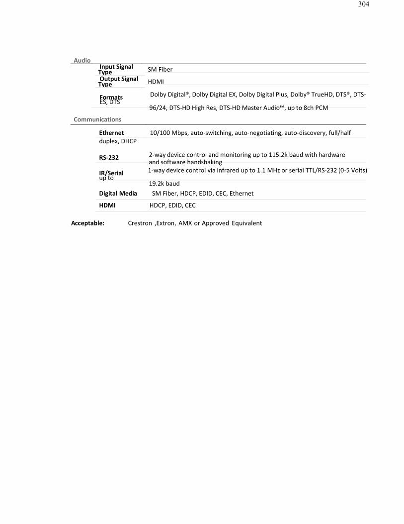
304
AudioInput SignalType SM FiberOutput SignalType HDMI
Formats Dolby Digital®, Dolby Digital EX, Dolby Digital Plus, Dolby® TrueHD, DTS®, DTS-ES, DTS
96/24, DTS-HD High Res, DTS-HD Master Audio™, up to 8ch PCM
Communications
Ethernet 10/100 Mbps, auto-switching, auto-negotiating, auto-discovery, full/halfduplex, DHCP
RS-232 2-way device control and monitoring up to 115.2k baud with hardwareand software handshaking
IR/Serial 1-way device control via infrared up to 1.1 MHz or serial TTL/RS-232 (0-5 Volts)up to
19.2k baudDigital Media SM Fiber, HDCP, EDID, CEC, Ethernet
HDMI HDCP, EDID, CEC
Acceptable: Crestron ,Extron, AMX or Approved Equivalent
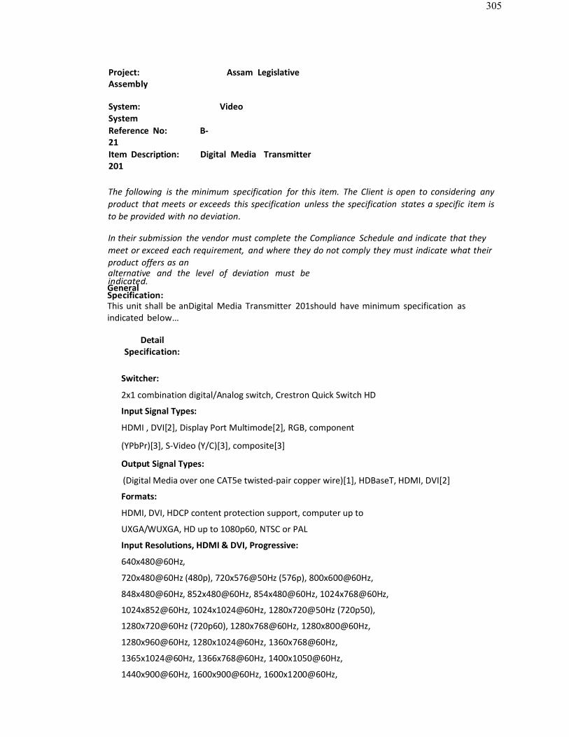
305
Project: Assam LegislativeAssembly
System: VideoSystemReference No: B-21Item Description: Digital Media Transmitter201
The following is the minimum specification for this item. The Client is open to considering anyproduct that meets or exceeds this specification unless the specification states a specific item isto be provided with no deviation.
In their submission the vendor must complete the Compliance Schedule and indicate that theymeet or exceed each requirement, and where they do not comply they must indicate what theirproduct offers as analternative and the level of deviation must beindicated.GeneralSpecification:This unit shall be anDigital Media Transmitter 201should have minimum specification asindicated below…
DetailSpecification:
Switcher:
2x1 combination digital/Analog switch, Crestron Quick Switch HD
Input Signal Types:
HDMI , DVI[2], Display Port Multimode[2], RGB, component
(YPbPr)[3], S-Video (Y/C)[3], composite[3]
Output Signal Types:
(Digital Media over one CAT5e twisted-pair copper wire)[1], HDBaseT, HDMI, DVI[2]
Formats:
HDMI, DVI, HDCP content protection support, computer up to
UXGA/WUXGA, HD up to 1080p60, NTSC or PAL
Input Resolutions, HDMI & DVI, Progressive:
640x480@60Hz,
720x480@60Hz (480p), 720x576@50Hz (576p), 800x600@60Hz,
848x480@60Hz, 852x480@60Hz, 854x480@60Hz, 1024x768@60Hz,
1024x852@60Hz, 1024x1024@60Hz, 1280x720@50Hz (720p50),
1280x720@60Hz (720p60), 1280x768@60Hz, 1280x800@60Hz,
1280x960@60Hz, 1280x1024@60Hz, 1360x768@60Hz,
1365x1024@60Hz, 1366x768@60Hz, 1400x1050@60Hz,
1440x900@60Hz, 1600x900@60Hz, 1600x1200@60Hz,

306
1680x1050@60Hz, 1920x1080@24Hz (1080p24), 1920x1080@25Hz
(1080p25), 1920x1080@50Hz (1080p50), 1920x1080@60Hz (1080p60),
1920x1200@60Hz, 2048x1080@24Hz,
2048x1152@60Hz, plus any other resolution
allowed by HDMI up to 165MHz pixel clock
Input Resolutions, HDMI & DVI, Interlaced:
720x480@30Hz (480i),
720x576@25Hz (576i), 1920x1080@25Hz (1080i25),
1920x1080@30Hz (1080i30), plus any other resolution
allowed by HDMI up to 165MHz pixel clock
Input Resolutions, RGB:
640x480@60Hz, 720x480@60Hz(480p), 720x576@50Hz (576p), 800x600@60Hz, 848x480@60Hz,
1024x768@60Hz, 1280x720@50Hz (720p50), 1280x7202@7640Hz (720p60),1280x768@60Hz, 1280x800@60Hz, 1280x960@60Hz, 1280x1024@60Hz,1360x768@60Hz, 1366x768@60Hz, 1400x1050@60Hz, 1440x900@60Hz,

307
Connectors
LAN: (1) 8-wire RJ45 female, shielded;
10BaseT/100BaseTX Ethernet port
DM OUT: (1) 8-pin RJ45 female,
shielded; DM output, HDBaseT
compliant;
PoDM and PoH PD (Powered Device) port[4];
Connects to the cat input of a Digital Media switcher,
receiver/room controller, HDMI OUT: (1) 19-pin Type A HDMI
female;
HDMI digital video/audio
output; Also supports
DVI[2]
PWR 24VDC 0.75A: (1) 2.1 x 5.5 mm DC power connector;
24 Volt DC power input;
Ground: (1) 6-32 screw, chassis ground lug
USB HID: (1) USB Type B female;
USB 2.0 device port for connection to the USB host
interface of a computer or other USB HID-compliant hostHDMI IN: (1) 19-pin Type A HDMI female;HDMI digital video/audio input;
Also supports DVI and Display Port
Multimode[2] RGB IN: (1) DB15HD
female;RGB (VGA), component, S-Video, or composite video input[3];Formats: RGBHV, RGBS, RGsB, YPbPr, Y/C,
NTSC, PAL; Input Levels: 0.5 to 1.5 Vp-p
with built-in DC restoration; Input
Impedance: 75 Ohms;
Sync Input Type: AutoDetect RGBHV, RGBS,
RGsB, YPbPr; Sync Input Level: 3 to 5 Vp-p;Sync Input Impedance: 1k OhmsAUDIO IN: (1) 3.5mm TRS miniphone jack; Unbalanced stereoline-level audio input;
Acceptable : Crestron ,Extron, AMX or Approved Equivalent.
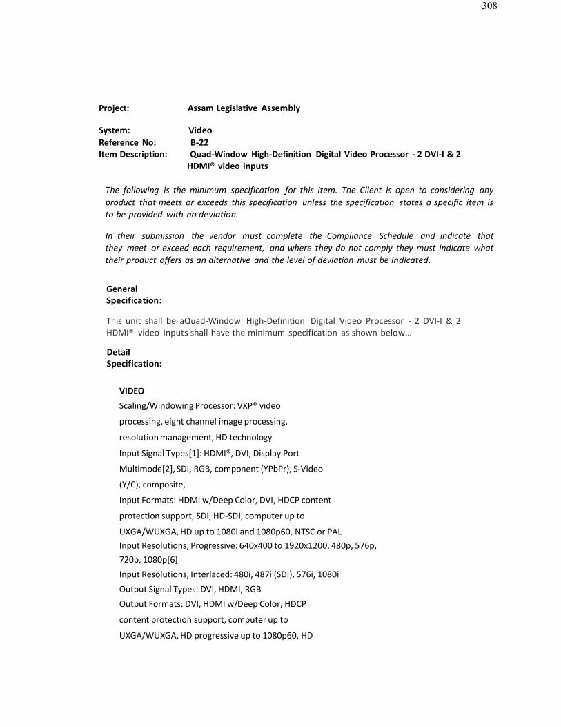
308
Project: Assam Legislative Assembly
System: VideoReference No: B-22Item Description: Quad-Window High-Definition Digital Video Processor - 2 DVI-I & 2
HDMI® video inputs
The following is the minimum specification for this item. The Client is open to considering anyproduct that meets or exceeds this specification unless the specification states a specific item isto be provided with no deviation.
In their submission the vendor must complete the Compliance Schedule and indicate thatthey meet or exceed each requirement, and where they do not comply they must indicate whattheir product offers as an alternative and the level of deviation must be indicated.
GeneralSpecification:
This unit shall be aQuad-Window High-Definition Digital Video Processor - 2 DVI-I & 2HDMI® video inputs shall have the minimum specification as shown below…
DetailSpecification:
VIDEO
Scaling/Windowing Processor: VXP® video
processing, eight channel image processing,
resolution management, HD technology
Input Signal Types[1]: HDMI®, DVI, Display Port
Multimode[2], SDI, RGB, component (YPbPr), S-Video
(Y/C), composite,
Input Formats: HDMI w/Deep Color, DVI, HDCP content
protection support, SDI, HD-SDI, computer up to
UXGA/WUXGA, HD up to 1080i and 1080p60, NTSC or PALInput Resolutions, Progressive: 640x400 to 1920x1200, 480p, 576p,720p, 1080p[6]
Input Resolutions, Interlaced: 480i, 487i (SDI), 576i, 1080i
Output Signal Types: DVI, HDMI, RGB
Output Formats: DVI, HDMI w/Deep Color, HDCP
content protection support, computer up to
UXGA/WUXGA, HD progressive up to 1080p60, HD

309
interlaced @ 1080i onlyOutput Resolutions, Progressive: 640x400 to 1920x1200, 480p, 576p,720p, 1080p[6]
Output Resolution, Interlaced: 1080i via DVI or HDMI only
Color Depth: 24-bit, 16.7M
colours Analog Gain: 0dB (75
ohms terminated) Analog
Bandwidth: 400MHz

310
DetailSpecification:
MEMORY
DDR RAM: 256
MB Flash: 64
MB
Memory Card: Accepts up to 4 GB (1 GB
CompactFlash® card included) Maximum Project Size:
200 MB
Communications
Ethernet: 10/100 Mbps, auto-switching, auto-
negotiating, auto-discovery, full/half duplex, DHCP, for
control and console
Control Net slave port for control and console
USB: Rear panel host ports for mouse/touch screen
input, front panel client port for consoleRS-232: Bidirectional, up to 115.2k baud, hardware and softwarehandshaking, for console and mouse/touch screen input
ConnectorsINPUT – HDMI IN: Up to (4) 19-pin Type A
HDMI female[1]; HDMI digital video/audio
inputs[7];
Signal Types: HDMI, DVI, or Display Port Multimode[2];
Input Resolution, Progressive: 640x400 to 1920x1200, 480p, 576p,
720p, 1080p[6];
Input Resolution, Interlaced: 480i, 576i, 1080i
INPUT – HDMI OUT: Up to (4) 19-pin Type A HDMI female;
HDMI digital video/audio outputs (pass-thru from
corresponding HDMI IN)[2]; Signal Types: HDMI, DVI[2]
INPUT – DVI/RGB/YPBPR: Up to (4) DVI-I female (or
DB15HD female via adapter included)[1];
DVI, RGB, or component video inputs;
Signal Types: DVI, HDMI, Display Port Multimode,
RGB (VGA), or component[2];INPUT – VIDEO: UP TO (8) SETS OF (3) BNC FEMALE, EACH SET COMPRISING (1)auto-detecting multi-format Analog
video input[1]; Signal Types:

311
Component, S-Video, or composite;
Formats: YPbPr, Y/C, NTSC or PAL;
Input Resolution: 480i, 576i, 480p, 576p,
720p, 1080i; Horizontal Frequency: 15 to
67.5 kHz;
Vertical Frequency: 25 to 60 Hz;
INPUT LEVELS: 0.5 TO 1.5 VP-P WITH BUILT-IN DC
RESTORATION; Input Impedance: 75 Ohms
nominal

312
Detail Specification:
INPUT – SDI/HD-SDI: UP TO (4) BNC FEMALE, SDI
VIDEO INPUTS[1]; Signal Types: SDI (SMPTE 125M),
HD-SDI (SMPTE 274M, 295M, 296M); Formats: SDI and
HD-SDI interlaced 487i, 576i, 1080i25, 1080i30;HD-SDI progressive 720p24, 720p25, 720p30, 720p50, 720p60, 1080p24,1080p25, 1080p30
INPUT – QM: Up to (4) 8-wire RJ45 female
Input Resolution, Progressive: 640x400 to 1920x1200, 480p, 576p,
720p, 1080p[6];
Input resolution, interlaced: 480i,
576i, 1080i; Horizontal Frequency:
15 to 91 kHz;Vertical Frequency: 25 to 85 Hz;Delay Skew Compensation: 0
to 22 ns; Maximum Cable
Length: 450 ft
OUTPUT – DVI/RGBHV: (1) DVI-I female (or DB15HD
female via adapter included);
DVI or RGB video output[10];
Signal Types: DVI, HDMI, or RGB (VGA)[2];Digital Formats: DVI, HDMI w/Deep Color, HDCP content
protection support, EDID;
Analog Formats: RGBHV;
Output Resolution, Progressive: 640x400 to 1920x1200, 480p, 576p,
720p, 1080p[6];
Output Resolution, Interlaced: 1080i
(digital only); Horizontal Frequency: 30
to 91 kHz;Vertical Frequency: 50 to 85 Hz;Analog Sync Output Type:
RGBHV; Analog Sync Output
Level: TTL, 5Vp-p FORMAT:
RGBHV;
Output Resolution: Same as RGBHV OUTPUT;
RS-232: (1) DB9 female, bidirectional
RS-232 port; Computer console and

313
mouse/touch screen input;Up to 115.2k baud; hardware and software handshaking supportLAN: (1) 8-wire RJ45 female;
10Base-T/100Base-TX Ethernet port for console and control
USB A – B: (2) USB Type A female host ports for mouse or touch
Acceptable : Crestron, AMX or ApprovedEquivalent.
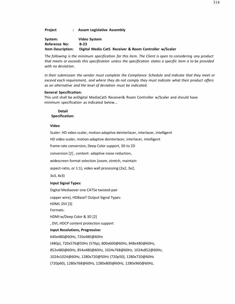
314
Project : Assam Legislative Assembly
System: Video SystemReference No: B-23Item Description: Digital Media Cat5 Receiver & Room Controller w/Scaler
The following is the minimum specification for this item. The Client is open to considering any productthat meets or exceeds this specification unless the specification states a specific item is to be providedwith no deviation.
In their submission the vendor must complete the Compliance Schedule and indicate that they meet orexceed each requirement, and where they do not comply they must indicate what their product offersas an alternative and the level of deviation must be indicated.
General Specification:This unit shall be anDigital MediaCat5 Receiver& Room Controller w/Scaler and should haveminimum specification as indicated below…
DetailSpecification:
Video
Scaler: HD video scaler, motion-adaptive deinterlacer, interlacer, intelligent
HD video scaler, motion-adaptive deinterlacer, interlacer, intelligent
frame rate conversion, Deep Color support, 3D to 2D
conversion [2] , content- adaptive noise reduction,
widescreen format selection (zoom, stretch, maintain
aspect-ratio, or 1:1), video wall processing (2x2, 3x2,
3x3, 4x3)
Input Signal Types:
Digital Mediaover one CAT5e twisted-pair
copper wire), HDBaseT Output Signal Types:
HDMI, DVI [3]
Formats:
HDMI w/Deep Color & 3D [2]
, DVI, HDCP content protection support
Input Resolutions, Progressive:
640x480@60Hz, 720x480@60Hz
(480p), 720x576@50Hz (576p), 800x600@60Hz, 848x480@60Hz,
852x480@60Hz, 854x480@60Hz, 1024x768@60Hz, 1024x852@60Hz,
1024x1024@60Hz, 1280x720@50Hz (720p50), 1280x720@60Hz
(720p60), 1280x768@60Hz, 1280x800@60Hz, 1280x960@60Hz,

315
1280x1024@60Hz, 1360x768@60Hz, 1365x1024@60Hz,
1366x768@60Hz, 1400x1050@60Hz, 1440x900@60Hz, 1600x900@60Hz,
1600x1200@60Hz, 1680x1050@60Hz, 1920x1080@24Hz (1080p24),
1920x1080@25Hz (1080p25), 1920x1080@50Hz (1080p50),
1920x1080@60Hz (1080p60), 1920x1200@60Hz, plus any other

316
Input Resolutions, Interlaced:
720x480@30Hz (480i), 720x576@25Hz
(576i), 1920x1080@25Hz (1080i25),
1920x1080@30Hz (1080i30), plus any other
resolution allowed by HDMI up to 165MHz pixel
clock
Scaler Output Resolutions, Progressive:
640x480@60Hz,
Scaler Output Resolutions, Interlaced:
720x480@30Hz (480i),
720x576@25Hz (576i), 1920x1080@25Hz (1080i25), 1920x1080@30Hz
(1080i30)
Audio
Input Signal Types: CAT
, HDBaseT Output
Signal Type: HDMI
Formats: Dolby Digital, Dolby Digital EX,
Dolby Digital Plus, Dolby® TrueHD, DTS®,
DTS-ES, DTS 96/24, DTS-HD High Res,
DTS-HD Master Audio™, Up to 8ch PCM
Communications
Digital Media: CAT, HDCP management, EDID
format management, CEC, HDBaseT compliant
Ethernet: 10/100 Mbps, auto-switching, auto-
negotiating, auto-discovery, full/half duplex, DHCP
Connectors – Bottom
HDMI OUT:
(1) 19-pin Type A
HDMI female; HDMI
digital video/audio
output; Also supports
DVI[3]
USB HID:
(1) USB Type A female;

317
USB 2.0 host port for connection of a
mouse/keyboard or other USB HID- compliant
device
COM:
(1) 5-pin 3.5mm detachable
terminal block; Bidirectional
RS-232 port;
Up to 115.2k baud, hardware and software handshaking support
IR 1 – 2:
(1) 4-pin 3.5mm detachable terminal
block comprising (2) IR/ Serial ports;
IR output up to 1.1 MHz;1-way serial TTL/RS-232 (0-5 Volts) up to 19200 baud
Acceptable: Crestron ,Extron, AMX or Approved Equivalent

318
Project: Assam Legislative AssemblySystem: VideoReference No: B-24Item Description: 4−Channel 3G HD−SDI over Single multi Fiber Optic Transmitter & Receiver
to carry signal up to 1000 mtr
The following is the minimum specification for this item. The Client is open to considering any productthat meets or exceeds this specification unless the specification states a specific item is to be providedwith no deviation.
In their submission the vendor must complete the Compliance Schedule and indicate that they meet orexceed each requirement, and where they do not comply they must indicate what their product offersas an alternative and the level of deviation must be indicated.
General Specification:
The unit shall be a 4−Channel 3G HD−SDI over Single mulƟ Fiber OpƟc TransmiƩ er & Receiver to carrysignal up to 1000 mtr and shall have the min. spec as shown below
Detail Specification:
INPUTS: 4 SD/HD/3G HD−SDI and dual−link, 75Ω on BNCconnectors (673T); 1
multi−mode OM3 fibre on SC connectors (673R).
OUTPUTS: 1 multi−mode OM3 fibre on SC connectors(673T); 4 SD/HD/3G HD−SDI
and dual−link, 75Ω on BNC connectors (673R).
BANDWIDTH: Up to 3Gbps for each SDI input.FIBER OPTIC EXTENSION: Up to 1000m (>3200ft) for 3G HD−SDI.
Acceptable: Extron, Kramer or Approved Equivalent
INPUT CABLE EQUALIZATION : 140m for HD−SDI, 120m for 3G HD−SDI.
FIBER-OPTIC CONNECTION: SC connectors for
multimode (OM3) fibre cable. INDICATOR LEDS:
VIDEO, SOURCE, FIBER and ON LEDs.POWER CONSUMPTION: 5V DC, 520mA (673T); 5V DC, 780mA (673R).
INSERTION LOSS FROM TRANSMITTER TO RECEIVER: Must not exceed 10dB.
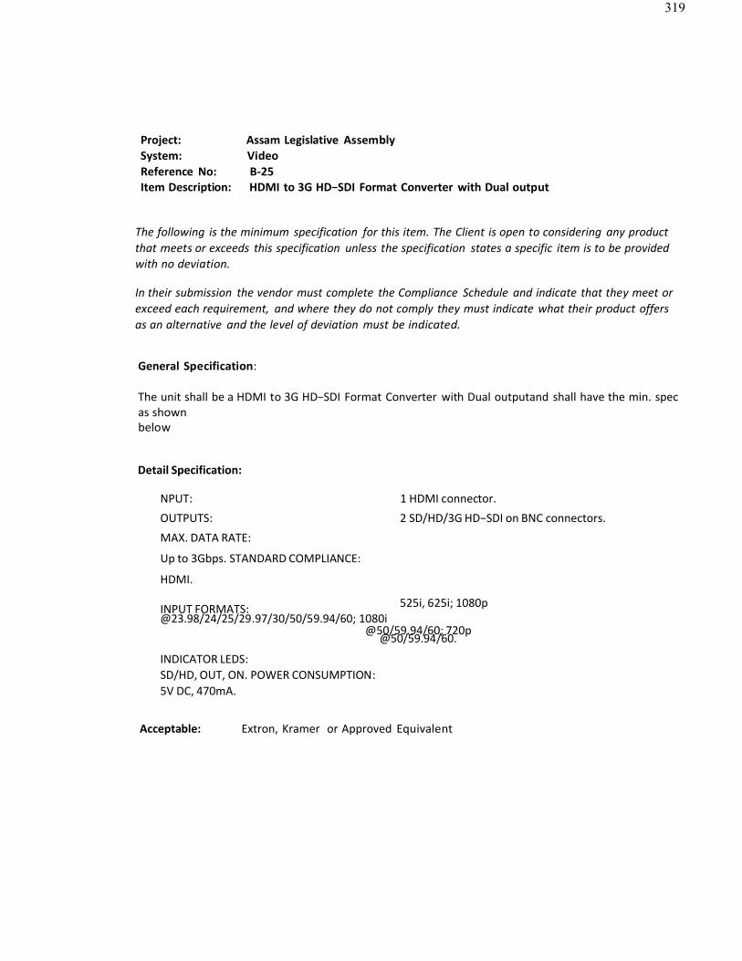
319
Project: Assam Legislative AssemblySystem: VideoReference No: B-25Item Description: HDMI to 3G HD−SDI Format Converter with Dual output
The following is the minimum specification for this item. The Client is open to considering any productthat meets or exceeds this specification unless the specification states a specific item is to be providedwith no deviation.
In their submission the vendor must complete the Compliance Schedule and indicate that they meet orexceed each requirement, and where they do not comply they must indicate what their product offersas an alternative and the level of deviation must be indicated.
General Specification:
The unit shall be a HDMI to 3G HD−SDI Format Converter with Dual outputand shall have the min. specas shownbelow
Detail Specification:
NPUT: 1 HDMI connector.
OUTPUTS: 2 SD/HD/3G HD−SDI on BNC connectors.
MAX. DATA RATE:
Up to 3Gbps. STANDARD COMPLIANCE:
HDMI.
INPUT FORMATS: 525i, 625i; [email protected]/24/25/29.97/30/50/59.94/60; 1080i
@50/59.94/60; 720p@50/59.94/60.
INDICATOR LEDS: SD/HD, OUT, ON. POWER CONSUMPTION: 5V DC, 470mA.
Acceptable: Extron, Kramer or Approved Equivalent

320
Project: Assam Legislative AssemblySystem: VideoReference No: B-26Item Description: 1:10 3G HD-SDI Distribution Amplifier
The following is the minimum specification for this item. The Client is open to considering any productthat meets or exceeds this specification unless the specification states a specific item is to be providedwith no deviation.
In their submission the vendor must complete the Compliance Schedule and indicate that they meet orexceed each requirement, and where they do not comply they must indicate what their product offersas an alternative and the level of deviation must be indicated.
General Specification:
The unit shall be a 1:10 3G HD-SDI Distribution Amplifier and shall have the min. spec as shown below
Detail Specification:
INPUTS: 1 SMPTE−259M/292M/424M serial video, 75Ω on a BNC connector.
OUTPUTS: 10 equalized and re clocked SMPTE−259M/292M/424M outputs, 75Ω on BNCconnectors;
1 looped GENLOCK 75Ω/Hi−Z on a BNC connector.
MAX. OUTPUT LEVEL:
800mVpp/75Ω. MAXIMUM DATA
RATE: Up to 2.97Gbps.
COUPLING: AC.
POWER CONSUMPTION: 100/240V AC, 50/60Hz,
5VA. DIMENSIONS: 19" x 7" x 1U W, D, H,
rack mountable. WEIGHT: 1.5kg
(3.3lbs) approx.INCLUDED ACCESSORIES: Power cord, rack "ears"
Acceptable: Extron, Kramer or Approved Equivalent
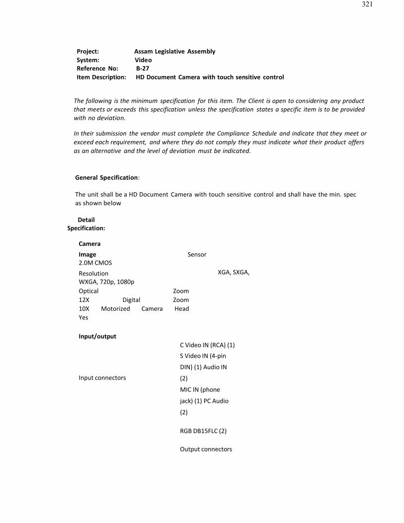
321
Project: Assam Legislative AssemblySystem: VideoReference No: B-27Item Description: HD Document Camera with touch sensitive control
The following is the minimum specification for this item. The Client is open to considering any productthat meets or exceeds this specification unless the specification states a specific item is to be providedwith no deviation.
In their submission the vendor must complete the Compliance Schedule and indicate that they meet orexceed each requirement, and where they do not comply they must indicate what their product offersas an alternative and the level of deviation must be indicated.
General Specification:
The unit shall be a HD Document Camera with touch sensitive control and shall have the min. specas shown below
DetailSpecification:
Camera
Image Sensor 2.0M CMOS
Resolution XGA, SXGA,WXGA, 720p, 1080pOptical Zoom 12X Digital Zoom 10X Motorized Camera Head Yes
Input/output
Input connectors
C Video IN (RCA) (1)
S Video IN (4-pin
DIN) (1) Audio IN
(2)
MIC IN (phone
jack) (1) PC Audio
(2)
RGB DB15FLC (2)
Output connectors

322
HDMI (1)
RGB DB15FLC (2)
C Video OUT (RCA) (1)
S Video OUT (4-pin DIN) (1)
Audio OUT (Mini Jack) (1)

323
Imaging Features
Image Storage 16
Negative Yes
Black/white and color selection Yes
Freeze
Yes Split
Yes Title
Yes Mirror
Yes
Image Rotate
0°90°180°270° Camera Rotation
Vertically 330° On Board LCD Monitor
3.5"
PC ConnectivityDriver
Plug-n-Play Frame Rate
Up to 20 fps Computer Connectivity
USB
OS Support PC, MAC
Lighting
Lights Arm light: 4W LED lamps
Light Box Yes
Control
RS232 Control
Yes Remote Control
Yes Form Factor
Full SizeShooting Area 440 x 330mm
Acceptable: Aver, Qomo or Approved Equivalent

324
Project: Assam Legislative AssemblySystem: VideoReference No: B-28Item Description: Video Production Switcher with Production software with 6 HD-SDI & 2
HDMI Input & 2 HDMI Output
The following is the minimum specification for this item. The Client is open to considering any productthat meets or exceeds this specification unless the specification states a specific item is to be providedwith no deviation.
In their submission the vendor must complete the Compliance Schedule and indicate that they meet orexceed each requirement, and where they do not comply they must indicate what their product offersas an alternative and the level of deviation must be indicated.
General Specification:
The unit shall be a Video Production Switcher with Production software with 6 HD-SDI & 2 HDMI Input& 2 HDMI Output and shall have the min. spec as shown below
Detail Specification:
Supports 8 or 12 HD or SD Inputs in a variety of
configurations: HD Mode
1) 6 HD-SDI
2) 2 HDMI
2 HDMI outputs for multi view monitoring
Audio I/O
Input: 4 analogue balanced XLR
Output: 2 analogue balanced XLR. Supports embedded audio SDI output from 4-CH XLR Audio input
Two DSK, supports Key and Fill
AcCcute, pMtiaxbalned: Wipe withEbxotrdeeenr,s Kramer or Approved Equivalent
Clock on screenCountdown counter on multiscreenTwo PIP displays with user-defined bordersTally, GPI interface and RJ45 for firmware upgrade
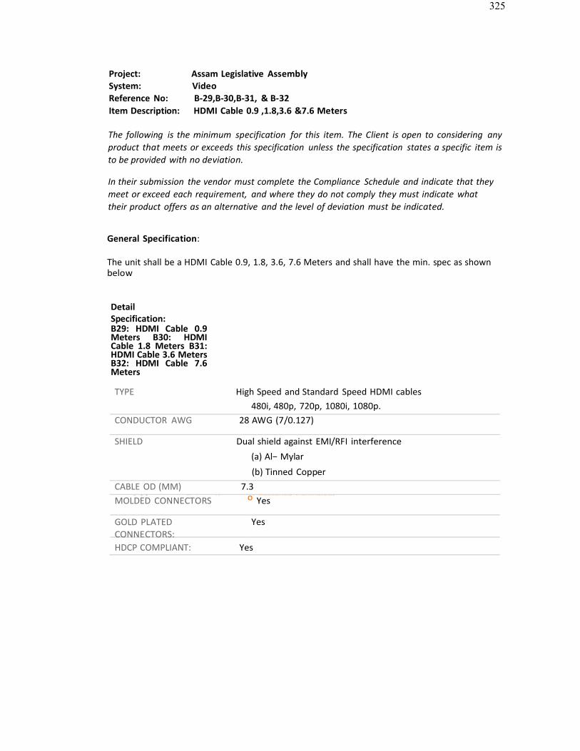
325
cceptable: Extron, Kramer r Approved Equivalent
Project: Assam Legislative AssemblySystem: VideoReference No: B-29,B-30,B-31, & B-32Item Description: HDMI Cable 0.9 ,1.8,3.6 &7.6 Meters
The following is the minimum specification for this item. The Client is open to considering anyproduct that meets or exceeds this specification unless the specification states a specific item isto be provided with no deviation.
In their submission the vendor must complete the Compliance Schedule and indicate that theymeet or exceed each requirement, and where they do not comply they must indicate whattheir product offers as an alternative and the level of deviation must be indicated.
General Specification:
The unit shall be a HDMI Cable 0.9, 1.8, 3.6, 7.6 Meters and shall have the min. spec as shownbelow
DetailSpecification:B29: HDMI Cable 0.9Meters B30: HDMICable 1.8 Meters B31:HDMI Cable 3.6 Meters B32: HDMI Cable 7.6Meters
TYPE High Speed and Standard Speed HDMI cables480i, 480p, 720p, 1080i, 1080p.
CONDUCTOR AWG 28 AWG (7/0.127)
SHIELD Dual shield against EMI/RFI interference
(a) Al− Mylar
(b) Tinned CopperCABLE OD (MM) 7.3MOLDED CONNECTORS o Yes
GOLD PLATED CONNECTORS:
Yes
HDCP COMPLIANT: Yes
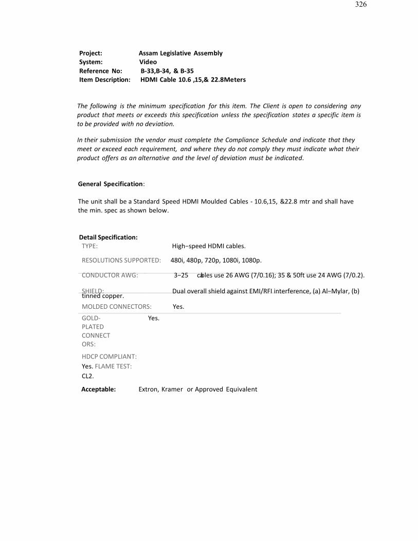
326
Project: Assam Legislative AssemblySystem: VideoReference No: B-33,B-34, & B-35Item Description: HDMI Cable 10.6 ,15,& 22.8Meters
The following is the minimum specification for this item. The Client is open to considering anyproduct that meets or exceeds this specification unless the specification states a specific item isto be provided with no deviation.
In their submission the vendor must complete the Compliance Schedule and indicate that theymeet or exceed each requirement, and where they do not comply they must indicate what theirproduct offers as an alternative and the level of deviation must be indicated.
General Specification:
The unit shall be a Standard Speed HDMI Moulded Cables - 10.6,15, &22.8 mtr and shall havethe min. spec as shown below.
Detail Specification:TYPE: High−speed HDMI cables.
RESOLUTIONS SUPPORTED: 480i, 480p, 720p, 1080i, 1080p.
CONDUCTOR AWG: 3−25 cables use 26 AWG (7/0.16); 35 & 50ft use 24 AWG (7/0.2).
SHIELD: Dual overall shield against EMI/RFI interference, (a) Al−Mylar, (b)tinned copper.MOLDED CONNECTORS: Yes.
GOLD-PLATED CONNECTORS:
Yes.
HDCP COMPLIANT: Yes. FLAME TEST: CL2.
Acceptable: Extron, Kramer or Approved Equivalent
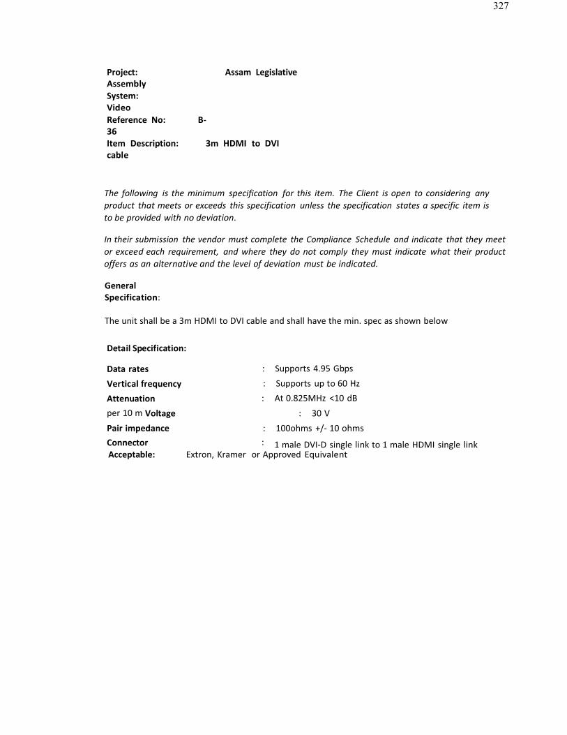
327
Project: Assam LegislativeAssemblySystem: VideoReference No: B-36Item Description: 3m HDMI to DVIcable
The following is the minimum specification for this item. The Client is open to considering anyproduct that meets or exceeds this specification unless the specification states a specific item isto be provided with no deviation.
In their submission the vendor must complete the Compliance Schedule and indicate that they meetor exceed each requirement, and where they do not comply they must indicate what their productoffers as an alternative and the level of deviation must be indicated.
GeneralSpecification:
The unit shall be a 3m HDMI to DVI cable and shall have the min. spec as shown below
Detail Specification:
Data rates : Supports 4.95 Gbps
Vertical frequency : Supports up to 60 Hz
Attenuation : At 0.825MHz <10 dB
per 10 m Voltage : 30 V
Pair impedance : 100ohms +/- 10 ohmsConnector : 1 male DVI-D single link to 1 male HDMI single linkAcceptable: Extron, Kramer or Approved Equivalent
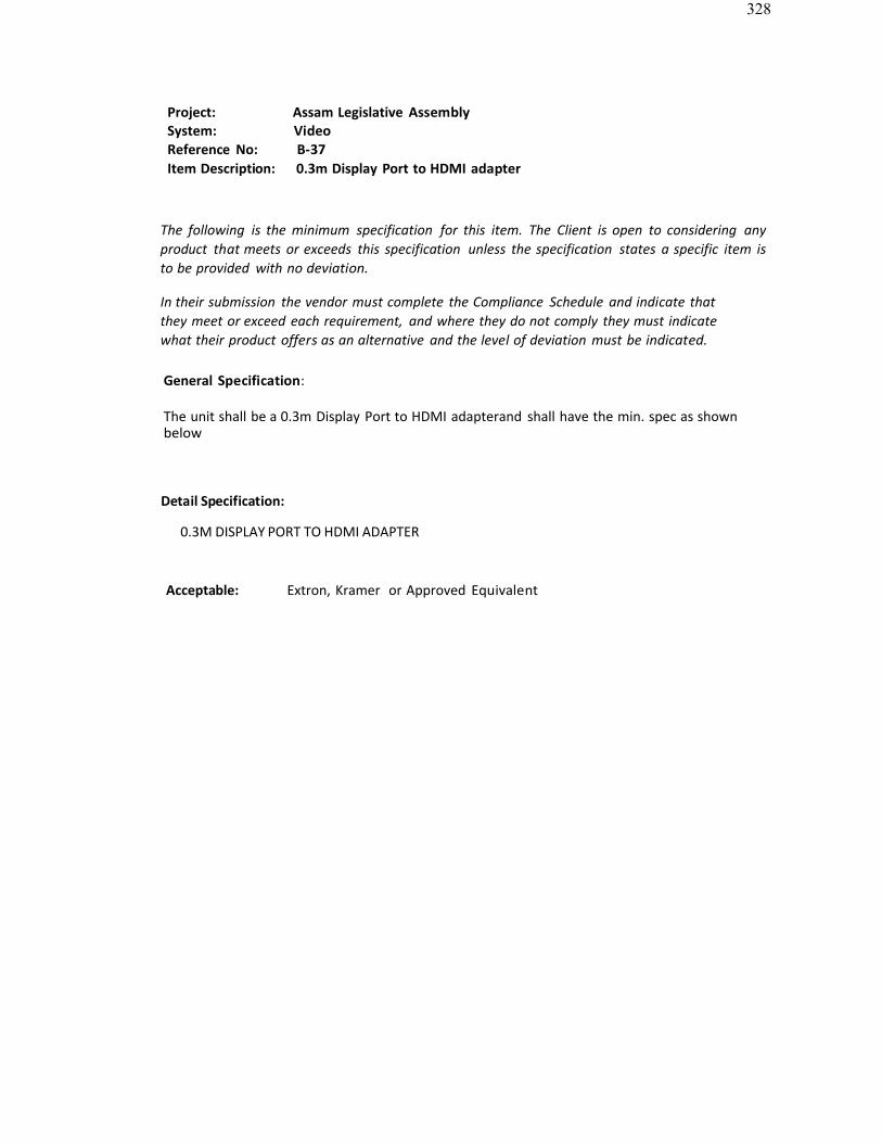
328
Project: Assam Legislative AssemblySystem: VideoReference No: B-37Item Description: 0.3m Display Port to HDMI adapter
The following is the minimum specification for this item. The Client is open to considering anyproduct that meets or exceeds this specification unless the specification states a specific item isto be provided with no deviation.
In their submission the vendor must complete the Compliance Schedule and indicate thatthey meet or exceed each requirement, and where they do not comply they must indicatewhat their product offers as an alternative and the level of deviation must be indicated.
General Specification:
The unit shall be a 0.3m Display Port to HDMI adapterand shall have the min. spec as shownbelow
Detail Specification:
0.3M DISPLAY PORT TO HDMI ADAPTER
Acceptable: Extron, Kramer or Approved Equivalent
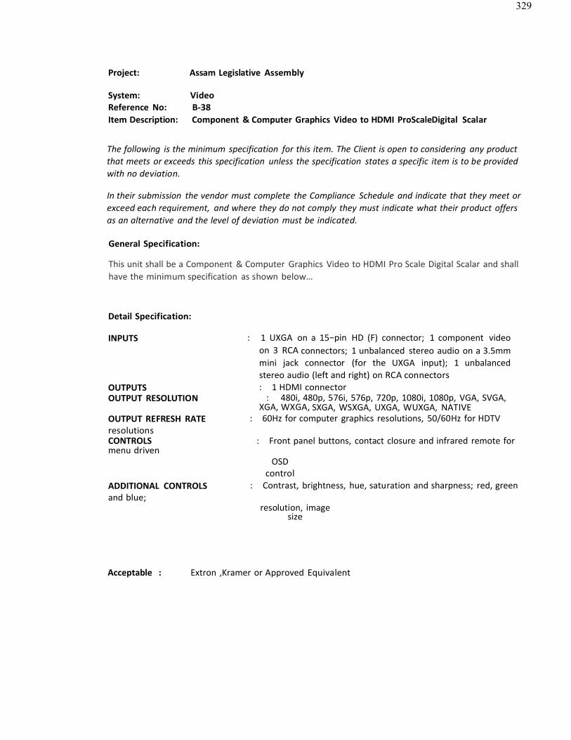
329
Project: Assam Legislative Assembly
System: VideoReference No: B-38Item Description: Component & Computer Graphics Video to HDMI ProScaleDigital Scalar
The following is the minimum specification for this item. The Client is open to considering any productthat meets or exceeds this specification unless the specification states a specific item is to be providedwith no deviation.
In their submission the vendor must complete the Compliance Schedule and indicate that they meet orexceed each requirement, and where they do not comply they must indicate what their product offersas an alternative and the level of deviation must be indicated.
General Specification:
This unit shall be a Component & Computer Graphics Video to HDMI Pro Scale Digital Scalar and shallhave the minimum specification as shown below…
Detail Specification:
INPUTS : 1 UXGA on a 15−pin HD (F) connector; 1 component videoon 3 RCA connectors; 1 unbalanced stereo audio on a 3.5mmmini jack connector (for the UXGA input); 1 unbalancedstereo audio (left and right) on RCA connectors
OUTPUTS : 1 HDMI connectorOUTPUT RESOLUTION : 480i, 480p, 576i, 576p, 720p, 1080i, 1080p, VGA, SVGA,
XGA, WXGA, SXGA, WSXGA, UXGA, WUXGA, NATIVEOUTPUT REFRESH RATE : 60Hz for computer graphics resolutions, 50/60Hz for HDTVresolutionsCONTROLS : Front panel buttons, contact closure and infrared remote formenu driven
OSDcontrol
ADDITIONAL CONTROLS : Contrast, brightness, hue, saturation and sharpness; red, greenand blue;
resolution, imagesize
Acceptable : Extron ,Kramer or Approved Equivalent
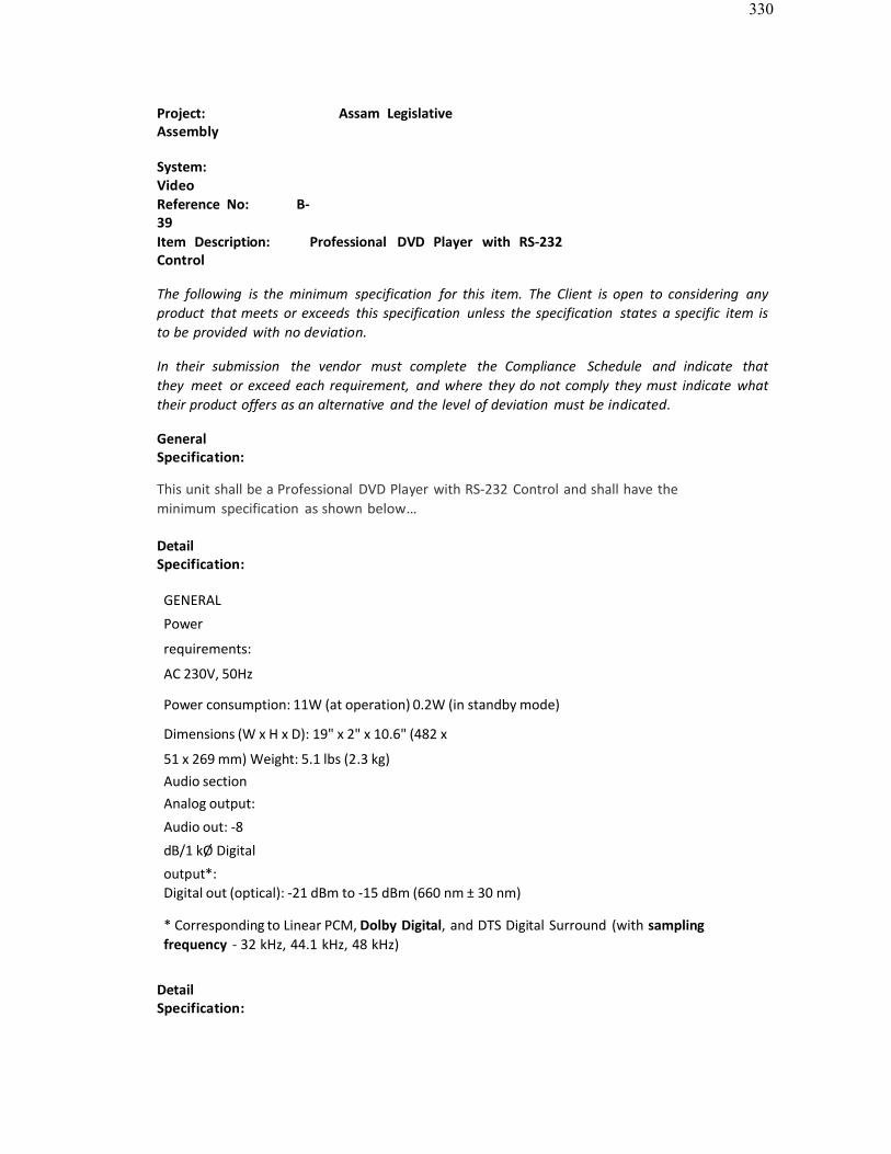
330
Project: Assam LegislativeAssembly
System: VideoReference No: B-39Item Description: Professional DVD Player with RS-232Control
The following is the minimum specification for this item. The Client is open to considering anyproduct that meets or exceeds this specification unless the specification states a specific item isto be provided with no deviation.
In their submission the vendor must complete the Compliance Schedule and indicate thatthey meet or exceed each requirement, and where they do not comply they must indicate whattheir product offers as an alternative and the level of deviation must be indicated.
GeneralSpecification:
This unit shall be a Professional DVD Player with RS-232 Control and shall have theminimum specification as shown below…
DetailSpecification:
GENERAL
Power
requirements:
AC 230V, 50Hz
Power consumption: 11W (at operation) 0.2W (in standby mode)
Dimensions (W x H x D): 19" x 2" x 10.6" (482 x
51 x 269 mm) Weight: 5.1 lbs (2.3 kg)Audio sectionAnalog output:
Audio out: -8
dB/1 kØ Digital
output*:Digital out (optical): -21 dBm to -15 dBm (660 nm ± 30 nm)
* Corresponding to Linear PCM, Dolby Digital, and DTS Digital Surround (with samplingfrequency - 32 kHz, 44.1 kHz, 48 kHz)
DetailSpecification:

331
VIDEO SECTION
Video system:
NTSC
Horizontal Resolution: 500 lines
Signal-to-Noise Ratio:64 dB Video outputlevel Composite: 1.0V(p-p)/75Ø
S-video-Y: 1.0 V(p-p)/75Ø
S-video-C: 0.286 V(p-p)/75Ø

332
Component-Y: 1.0 V(p-p)/75Ø
Component-Pb/Pr: 0.7
V(p-p)/75Ø HDMIHDMI Output (Ver. 1.1): HDMIRS-232C
Serial command: 9-Pin D-SUB
Acceptable : Extron ,Kramer or Approved Equivalent
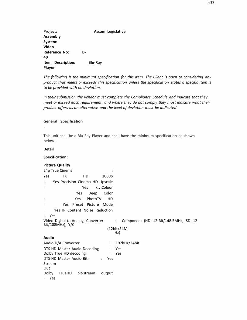
333
Project: Assam LegislativeAssemblySystem: VideoReference No: B-40Item Description: Blu-RayPlayer
The following is the minimum specification for this item. The Client is open to considering anyproduct that meets or exceeds this specification unless the specification states a specific item is to be provided with no deviation.
In their submission the vendor must complete the Compliance Schedule and indicate that theymeet or exceed each requirement, and where they do not comply they must indicate what theirproduct offers as an alternative and the level of deviation must be indicated.
General Specification :
This unit shall be a Blu-Ray Player and shall have the minimum specification as shownbelow…
Detail
Specification:
Picture Quality24p True Cinema : Yes Full HD 1080p : Yes Precision Cinema HD Upscale : Yes x.v.Colour : Yes Deep Color : Yes PhotoTV HD : Yes Preset Picture Mode : Yes IP Content Noise Reduction : YesVideo Digital-to-Analog Converter : Component (HD: 12-Bit/148.5MHz, SD: 12-Bit/108MHz), Y/C
(12bit/54MHz)
AudioAudio D/A Converter : 192kHz/24bitDTS-HD Master Audio Decoding : YesDolby True HD decoding : YesDTS-HD Master Audio Bit-StreamOut
: Yes
Dolby TrueHD bit-stream output : Yes
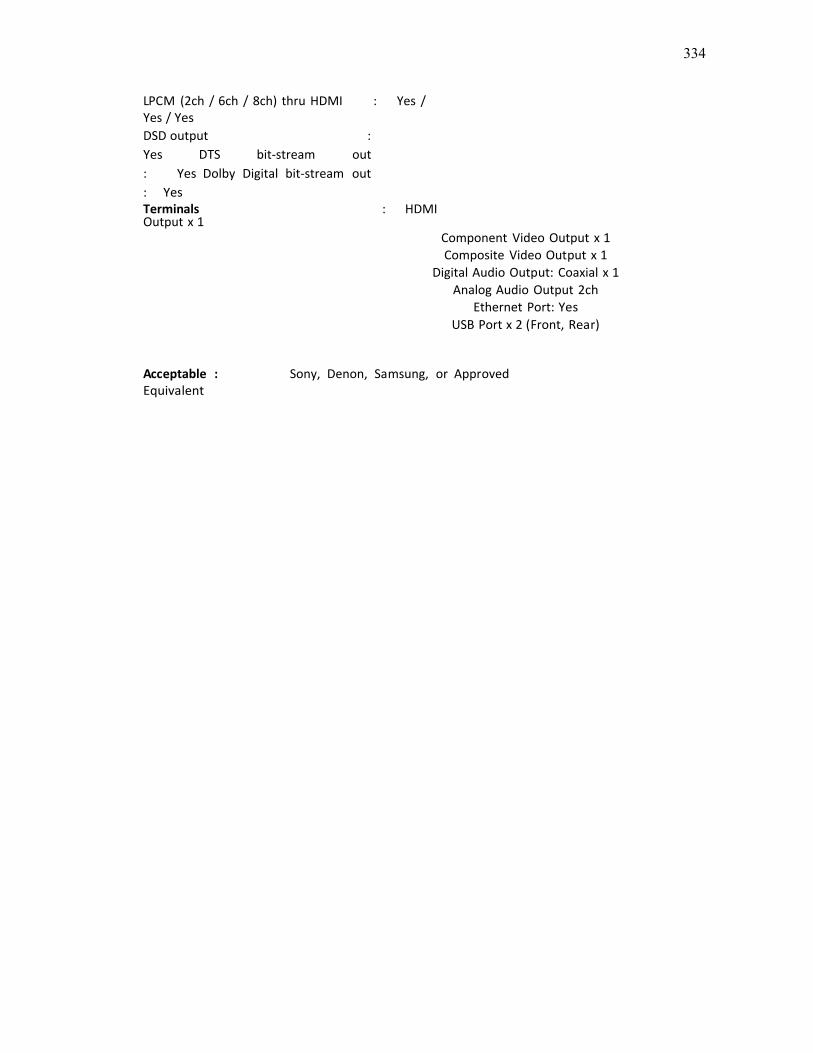
334
LPCM (2ch / 6ch / 8ch) thru HDMI : Yes /Yes / YesDSD output : Yes DTS bit-stream out : Yes Dolby Digital bit-stream out : YesTerminals : HDMIOutput x 1
Component Video Output x 1Composite Video Output x 1
Digital Audio Output: Coaxial x 1Analog Audio Output 2ch
Ethernet Port: YesUSB Port x 2 (Front, Rear)
Acceptable : Sony, Denon, Samsung, or ApprovedEquivalent
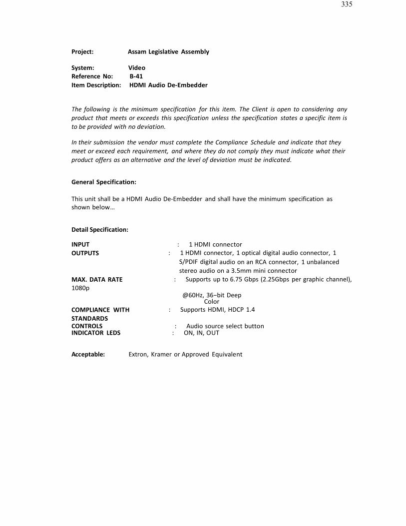
335
Project: Assam Legislative Assembly
System: VideoReference No: B-41Item Description: HDMI Audio De-Embedder
The following is the minimum specification for this item. The Client is open to considering anyproduct that meets or exceeds this specification unless the specification states a specific item is to be provided with no deviation.
In their submission the vendor must complete the Compliance Schedule and indicate that theymeet or exceed each requirement, and where they do not comply they must indicate what theirproduct offers as an alternative and the level of deviation must be indicated.
General Specification:
This unit shall be a HDMI Audio De-Embedder and shall have the minimum specification asshown below…
Detail Specification:
INPUT : 1 HDMI connectorOUTPUTS : 1 HDMI connector, 1 optical digital audio connector, 1
S/PDIF digital audio on an RCA connector, 1 unbalancedstereo audio on a 3.5mm mini connector
MAX. DATA RATE : Supports up to 6.75 Gbps (2.25Gbps per graphic channel),1080p
@60Hz, 36−bit DeepColor
COMPLIANCE WITH STANDARDS
: Supports HDMI, HDCP 1.4
CONTROLS : Audio source select buttonINDICATOR LEDS : ON, IN, OUT
Acceptable: Extron, Kramer or Approved Equivalent
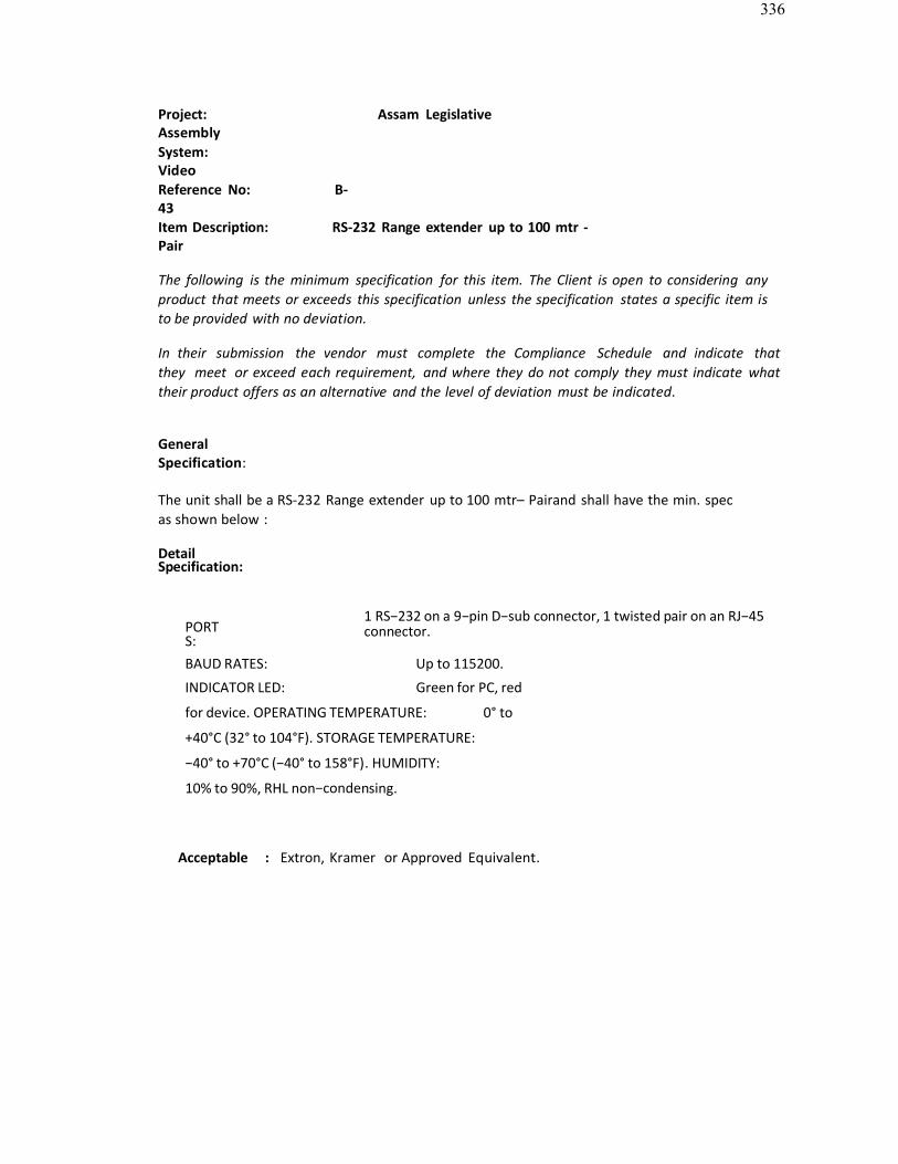
336
Project: Assam LegislativeAssemblySystem: VideoReference No: B-43Item Description: RS-232 Range extender up to 100 mtr -Pair
The following is the minimum specification for this item. The Client is open to considering anyproduct that meets or exceeds this specification unless the specification states a specific item is to be provided with no deviation.
In their submission the vendor must complete the Compliance Schedule and indicate thatthey meet or exceed each requirement, and where they do not comply they must indicate whattheir product offers as an alternative and the level of deviation must be indicated.
GeneralSpecification:
The unit shall be a RS-232 Range extender up to 100 mtr– Pairand shall have the min. specas shown below :
DetailSpecification:
PORTS:
1 RS−232 on a 9−pin D−sub connector, 1 twisted pair on an RJ−45connector.
BAUD RATES: Up to 115200.
INDICATOR LED: Green for PC, red
for device. OPERATING TEMPERATURE: 0° to
+40°C (32° to 104°F). STORAGE TEMPERATURE:
−40° to +70°C (−40° to 158°F). HUMIDITY:
10% to 90%, RHL non−condensing.
Acceptable : Extron, Kramer or Approved Equivalent.
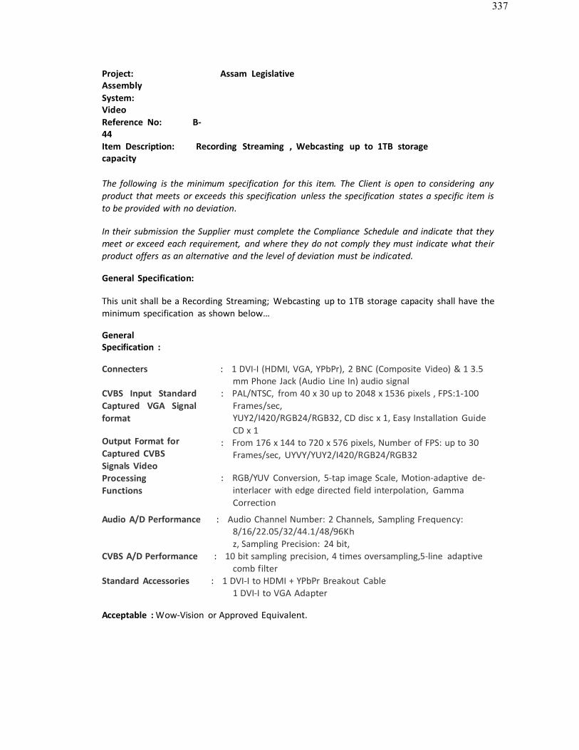
337
Project: Assam LegislativeAssemblySystem: VideoReference No: B-44Item Description: Recording Streaming , Webcasting up to 1TB storagecapacity
The following is the minimum specification for this item. The Client is open to considering any product that meets or exceeds this specification unless the specification states a specific item is to be provided with no deviation.
In their submission the Supplier must complete the Compliance Schedule and indicate that they meet or exceed each requirement, and where they do not comply they must indicate what their product offers as an alternative and the level of deviation must be indicated.
General Specification:
This unit shall be a Recording Streaming; Webcasting up to 1TB storage capacity shall have the minimum specification as shown below…
GeneralSpecification :
Connecters : 1 DVI-I (HDMI, VGA, YPbPr), 2 BNC (Composite Video) & 1 3.5 mm Phone Jack (Audio Line In) audio signal
CVBS Input Standard Captured VGA Signal format
Output Format forCaptured CVBSSignals VideoProcessing Functions
: PAL/NTSC, from 40 x 30 up to 2048 x 1536 pixels , FPS:1-100Frames/sec,YUY2/I420/RGB24/RGB32, CD disc x 1, Easy Installation GuideCD x 1
: From 176 x 144 to 720 x 576 pixels, Number of FPS: up to 30Frames/sec, UYVY/YUY2/I420/RGB24/RGB32
: RGB/YUV Conversion, 5-tap image Scale, Motion-adaptive de-interlacer with edge directed field interpolation, GammaCorrection
Audio A/D Performance : Audio Channel Number: 2 Channels, Sampling Frequency:8/16/22.05/32/44.1/48/96Khz, Sampling Precision: 24 bit,
CVBS A/D Performance : 10 bit sampling precision, 4 times oversampling,5-line adaptive comb filter
Standard Accessories : 1 DVI-I to HDMI + YPbPr Breakout Cable1 DVI-I to VGA Adapter
Acceptable : Wow-Vision or Approved Equivalent.
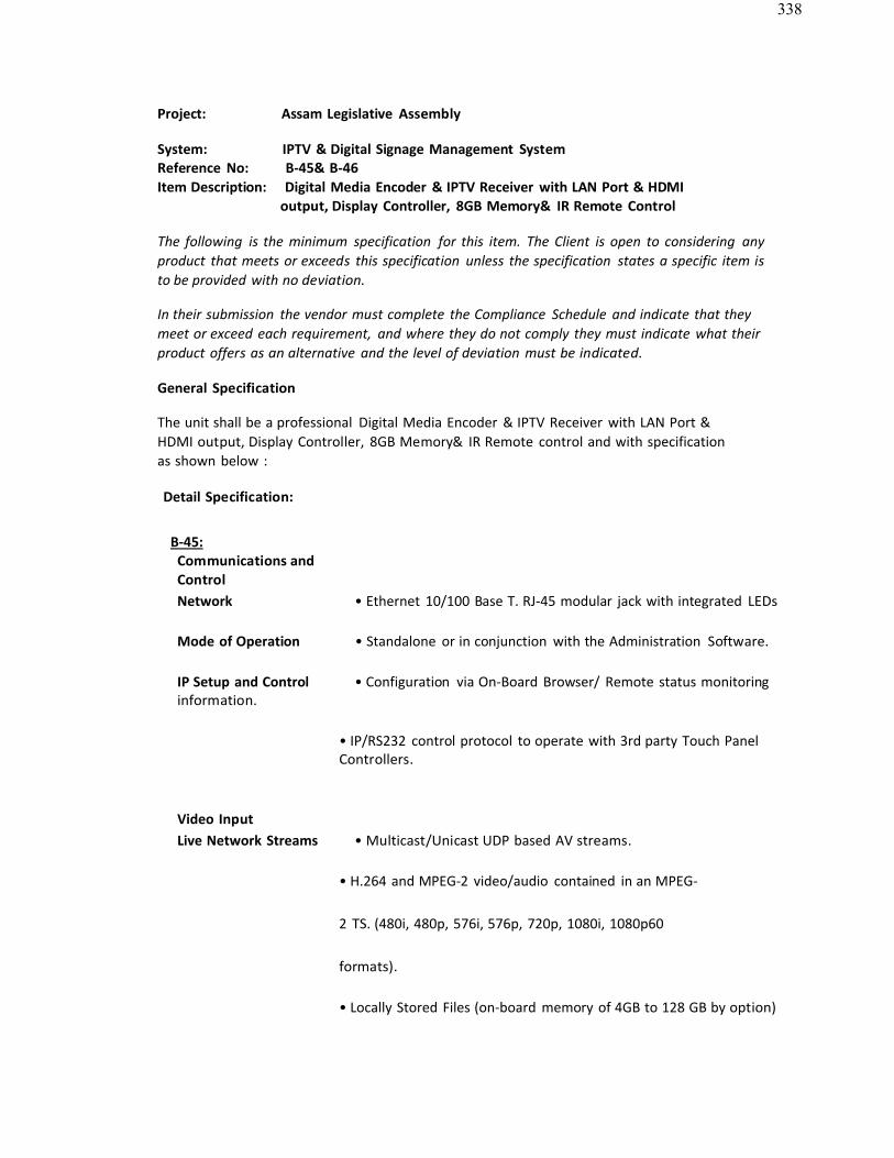
338
Project: Assam Legislative Assembly
System: IPTV & Digital Signage Management SystemReference No: B-45& B-46Item Description: Digital Media Encoder & IPTV Receiver with LAN Port & HDMI
output, Display Controller, 8GB Memory& IR Remote Control
The following is the minimum specification for this item. The Client is open to considering anyproduct that meets or exceeds this specification unless the specification states a specific item is to be provided with no deviation.
In their submission the vendor must complete the Compliance Schedule and indicate that theymeet or exceed each requirement, and where they do not comply they must indicate what theirproduct offers as an alternative and the level of deviation must be indicated.
General Specification
The unit shall be a professional Digital Media Encoder & IPTV Receiver with LAN Port &HDMI output, Display Controller, 8GB Memory& IR Remote control and with specificationas shown below :
Detail Specification:
B-45:Communications andControlNetwork • Ethernet 10/100 Base T. RJ-45 modular jack with integrated LEDs
Mode of Operation • Standalone or in conjunction with the Administration Software.
IP Setup and Control • Configuration via On-Board Browser/ Remote status monitoringinformation.
• IP/RS232 control protocol to operate with 3rd party Touch PanelControllers.
Video InputLive Network Streams • Multicast/Unicast UDP based AV streams.
• H.264 and MPEG-2 video/audio contained in an MPEG-
2 TS. (480i, 480p, 576i, 576p, 720p, 1080i, 1080p60
formats).
• Locally Stored Files (on-board memory of 4GB to 128 GB by option)
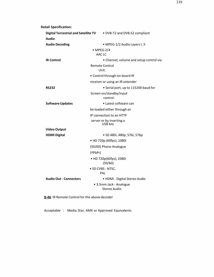
339
Detail Specification:
Digital Terrestrial and Satellite TV • DVB-T2 and DVB-S2 compliant
Audio
Audio Decoding • MPEG-1/2 Audio Layers I, II
• MPEG-2/4AAC LC
IR Control • Channel, volume and setup control via
Remote ControlUnit.
• Control through on-board IR
receiver or using an IR extender
RS232 • Serial port, up to 115200 baud for
Screen on/standby/inputcontrol.
Software Updates • Latest software can
be loaded either through an
IP connection to an HTTPserver or by inserting a
USB keyVideo Output
HDMI Digital • SD 480i, 480p, 576i, 576p
• HD 720p (60fps), 1080i
(50/60) Phono Analogue
(YPbPr)
• HD 720p(60fps), 1080i(50/60)
• SD CVBS - NTSC,PAL
Audio Out - Connectors • HDMI - Digital Stereo Audio
• 3.5mm Jack - AnalogueStereo Audio
B-46: IR Remote Control for the above decoder
Acceptable : Media Star, AMX or Approved Equivalents
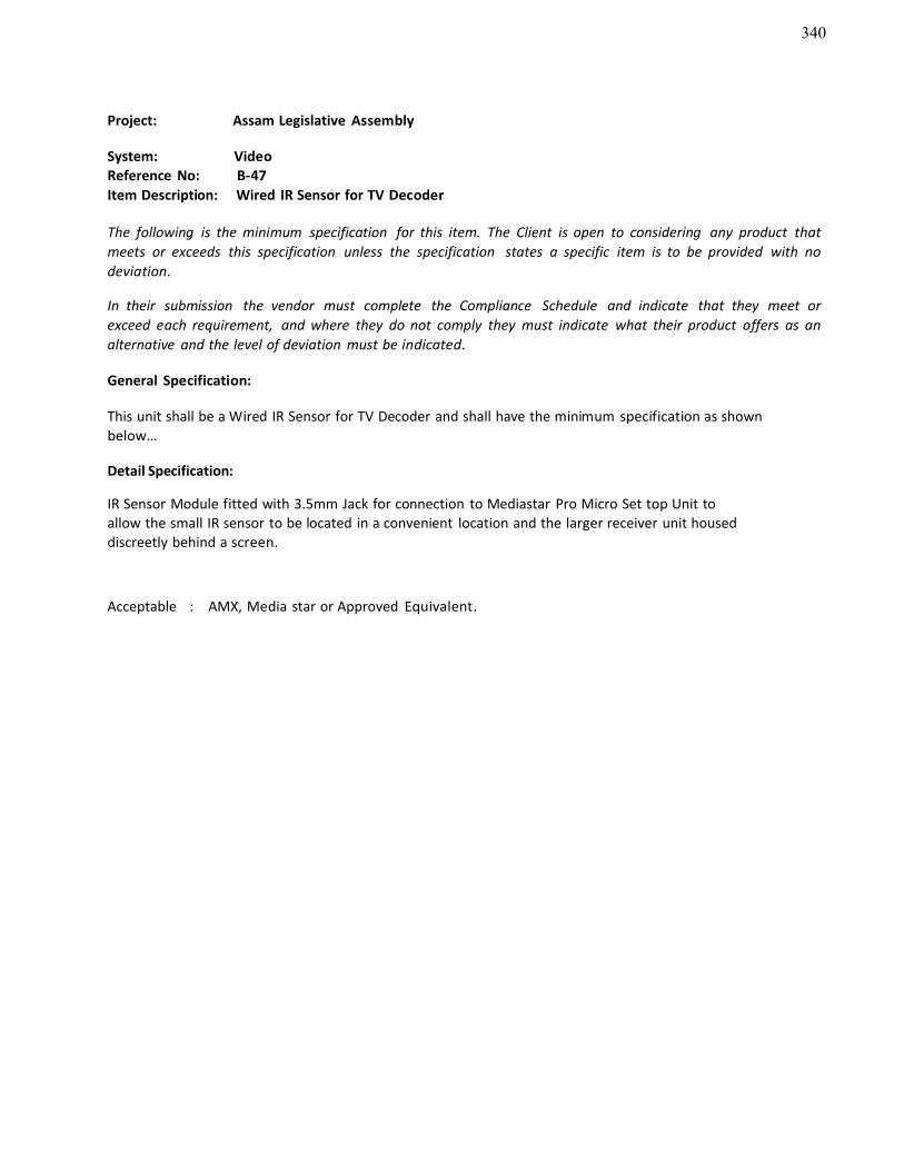
340
Project: Assam Legislative Assembly
System: VideoReference No: B-47Item Description: Wired IR Sensor for TV Decoder
The following is the minimum specification for this item. The Client is open to considering any product that meets or exceeds this specification unless the specification states a specific item is to be provided with no deviation.
In their submission the vendor must complete the Compliance Schedule and indicate that they meet or exceed each requirement, and where they do not comply they must indicate what their product offers as an alternative and the level of deviation must be indicated.
General Specification:
This unit shall be a Wired IR Sensor for TV Decoder and shall have the minimum specification as shownbelow…
Detail Specification:
IR Sensor Module fitted with 3.5mm Jack for connection to Mediastar Pro Micro Set top Unit toallow the small IR sensor to be located in a convenient location and the larger receiver unit houseddiscreetly behind a screen.
Acceptable : AMX, Media star or Approved Equivalent.
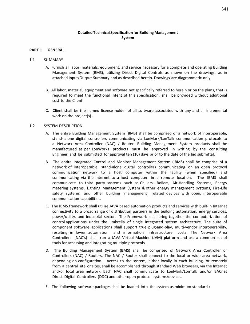
341
Detailed Technical Specification for Building ManagementSystem
PART 1 GENERAL
1.1 SUMMARY
A. Furnish all labor, materials, equipment, and service necessary for a complete and operating Building Management System (BMS), utilizing Direct Digital Controls as shown on the drawings, as inattached Input/Output Summary and as described herein. Drawings are diagrammatic only.
B. All labor, material, equipment and software not specifically referred to herein or on the plans, that is required to meet the functional intent of this specification, shall be provided without additionalcost to the Client.
C. Client shall be the named license holder of all software associated with any and all incrementalwork on the project(s).
1.2 SYSTEM DESCRIPTION
A. The entire Building Management System (BMS) shall be comprised of a network of interoperable,stand- alone digital controllers communicating via LonMark/LonTalk communication protocols toa Network Area Controller (NAC) / Router. Building Management System products shall bemanufactured as per LonWorks products must be approved in writing by the consulting Engineer and be submitted for approval ten (10) days prior to the date of the bid submittal.
B. The entire Integrated Control and Monitor Management System (IBMS) shall be comprise of anetwork of interoperable, stand-alone digital controllers communicating on an open protocol communication network to a host computer within the facility (when specified) andcommunicating via the Internet to a host computer in a remote location. The IBMS shallcommunicate to third party systems such as Chillers, Boilers, Air-Handling Systems, Energymetering systems, Lighting Management System & other energy management systems, Fire-Life safety systems and other building management related devices with open, interoperablecommunication capabilities.
C. The IBMS framework shall utilize JAVA based automation products and services with built-in Internet connectivity to a broad range of distribution partners in the building automation, energy services, power/utility, and industrial sectors. The Framework shall bring together the computerization of control applications under the umbrella of single integrated system architecture. The suite of component software applications shall support true plug-and-play, multi-vendor interoperability,resulting in lower automation and information infrastructure costs. The Network AreaControllers (NAC’s) shall run a JAVA Virtual Machine (JVM) platform and use a common set of tools for accessing and integrating multiple protocols.
D. The Building Management System (BMS) shall be comprised of Network Area Controller orControllers (NAC) / Routers. The NAC / Router shall connect to the local or wide area network,depending on configuration. Access to the system, either locally in each building, or remotelyfrom a central site or sites, shall be accomplished through standard Web browsers, via the Internetand/or local area network. Each NAC shall communicate to LonMark/LonTalk and/or BACnetDirect Digital Controllers (DDC) and other open protocol systems/devices.
E. The following software packages shall be loaded into the system as minimum standard :-
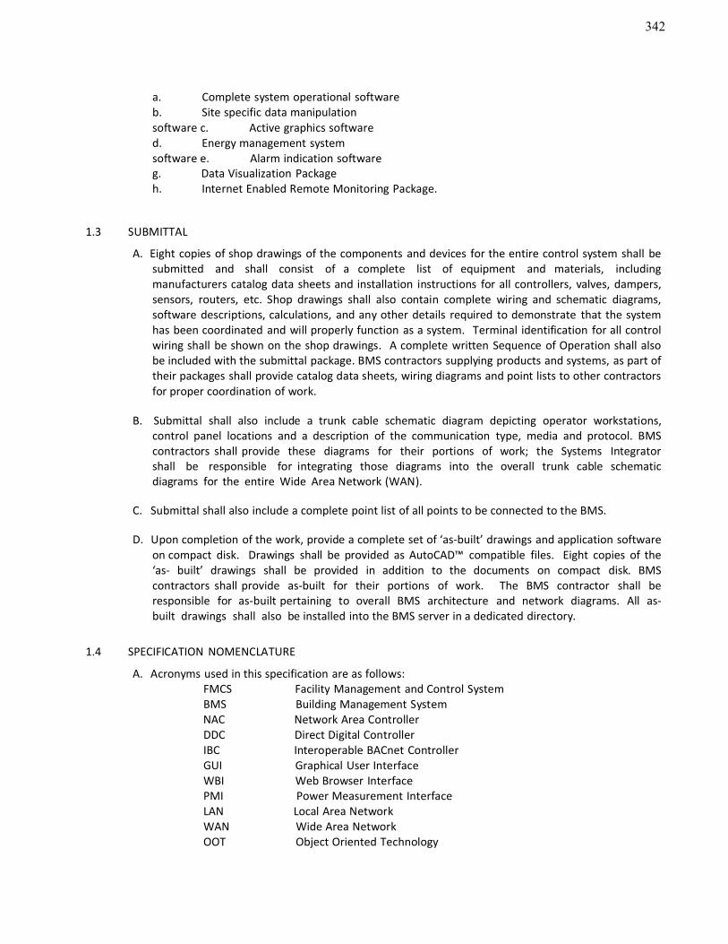
342
a. Complete system operational softwareb. Site specific data manipulationsoftware c. Active graphics softwared. Energy management systemsoftware e. Alarm indication softwareg. Data Visualization Packageh. Internet Enabled Remote Monitoring Package.
1.3 SUBMITTAL
A. Eight copies of shop drawings of the components and devices for the entire control system shall be submitted and shall consist of a complete list of equipment and materials, including manufacturers catalog data sheets and installation instructions for all controllers, valves, dampers,sensors, routers, etc. Shop drawings shall also contain complete wiring and schematic diagrams,software descriptions, calculations, and any other details required to demonstrate that the systemhas been coordinated and will properly function as a system. Terminal identification for all controlwiring shall be shown on the shop drawings. A complete written Sequence of Operation shall alsobe included with the submittal package. BMS contractors supplying products and systems, as part of their packages shall provide catalog data sheets, wiring diagrams and point lists to other contractorsfor proper coordination of work.
B. Submittal shall also include a trunk cable schematic diagram depicting operator workstations,control panel locations and a description of the communication type, media and protocol. BMScontractors shall provide these diagrams for their portions of work; the Systems Integrator shall be responsible for integrating those diagrams into the overall trunk cable schematic diagrams for the entire Wide Area Network (WAN).
C. Submittal shall also include a complete point list of all points to be connected to the BMS.
D. Upon completion of the work, provide a complete set of ‘as-built’ drawings and application softwareon compact disk. Drawings shall be provided as AutoCAD™ compatible files. Eight copies of the‘as- built’ drawings shall be provided in addition to the documents on compact disk. BMScontractors shall provide as-built for their portions of work. The BMS contractor shall be responsible for as-built pertaining to overall BMS architecture and network diagrams. All as-built drawings shall also be installed into the BMS server in a dedicated directory.
1.4 SPECIFICATION NOMENCLATURE
A. Acronyms used in this specification are as follows:FMCS Facility Management and Control SystemBMS Building Management SystemNAC Network Area ControllerDDC Direct Digital ControllerIBC Interoperable BACnet ControllerGUI Graphical User InterfaceWBI Web Browser InterfacePMI Power Measurement InterfaceLAN Local Area NetworkWAN Wide Area NetworkOOT Object Oriented Technology
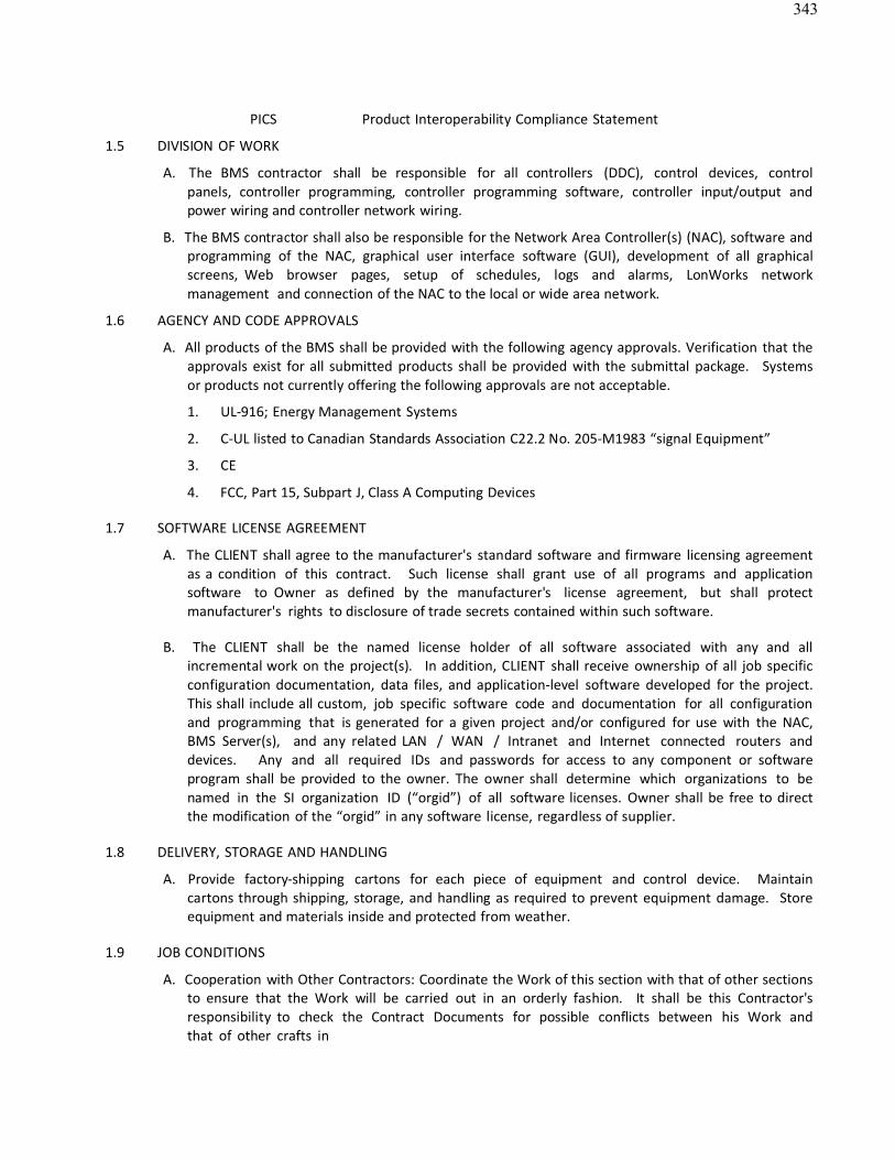
343
PICS Product Interoperability Compliance Statement
1.5 DIVISION OF WORK
A. The BMS contractor shall be responsible for all controllers (DDC), control devices, control panels, controller programming, controller programming software, controller input/output and power wiring and controller network wiring.
B. The BMS contractor shall also be responsible for the Network Area Controller(s) (NAC), software and programming of the NAC, graphical user interface software (GUI), development of all graphicalscreens, Web browser pages, setup of schedules, logs and alarms, LonWorks network management and connection of the NAC to the local or wide area network.
1.6 AGENCY AND CODE APPROVALS
A. All products of the BMS shall be provided with the following agency approvals. Verification that the approvals exist for all submitted products shall be provided with the submittal package. Systemsor products not currently offering the following approvals are not acceptable.
1. UL-916; Energy Management Systems
2. C-UL listed to Canadian Standards Association C22.2 No. 205-M1983 “signal Equipment”
3. CE
4. FCC, Part 15, Subpart J, Class A Computing Devices
1.7 SOFTWARE LICENSE AGREEMENT
A. The CLIENT shall agree to the manufacturer's standard software and firmware licensing agreementas a condition of this contract. Such license shall grant use of all programs and application software to Owner as defined by the manufacturer's license agreement, but shall protectmanufacturer's rights to disclosure of trade secrets contained within such software.
B. The CLIENT shall be the named license holder of all software associated with any and allincremental work on the project(s). In addition, CLIENT shall receive ownership of all job specificconfiguration documentation, data files, and application-level software developed for the project. This shall include all custom, job specific software code and documentation for all configurationand programming that is generated for a given project and/or configured for use with the NAC,BMS Server(s), and any related LAN / WAN / Intranet and Internet connected routers anddevices. Any and all required IDs and passwords for access to any component or softwareprogram shall be provided to the owner. The owner shall determine which organizations to benamed in the SI organization ID (“orgid”) of all software licenses. Owner shall be free to directthe modification of the “orgid” in any software license, regardless of supplier.
1.8 DELIVERY, STORAGE AND HANDLING
A. Provide factory-shipping cartons for each piece of equipment and control device. Maintain cartons through shipping, storage, and handling as required to prevent equipment damage. Storeequipment and materials inside and protected from weather.
1.9 JOB CONDITIONS
A. Cooperation with Other Contractors: Coordinate the Work of this section with that of other sectionsto ensure that the Work will be carried out in an orderly fashion. It shall be this Contractor'sresponsibility to check the Contract Documents for possible conflicts between his Work andthat of other crafts in
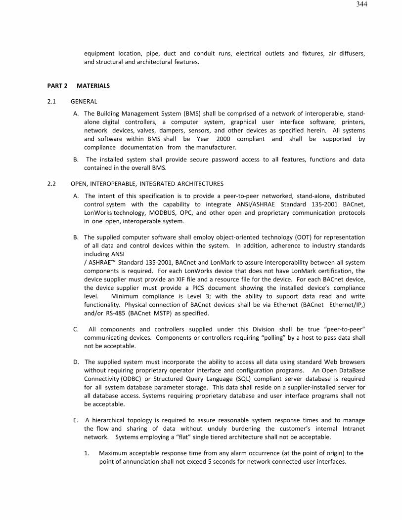
344
equipment location, pipe, duct and conduit runs, electrical outlets and fixtures, air diffusers, and structural and architectural features.
PART 2 MATERIALS
2.1 GENERAL
A. The Building Management System (BMS) shall be comprised of a network of interoperable, stand-alone digital controllers, a computer system, graphical user interface software, printers, network devices, valves, dampers, sensors, and other devices as specified herein. All systemsand software within BMS shall be Year 2000 compliant and shall be supported by compliance documentation from the manufacturer.
B. The installed system shall provide secure password access to all features, functions and datacontained in the overall BMS.
2.2 OPEN, INTEROPERABLE, INTEGRATED ARCHITECTURES
A. The intent of this specification is to provide a peer-to-peer networked, stand-alone, distributedcontrol system with the capability to integrate ANSI/ASHRAE Standard 135-2001 BACnet, LonWorks technology, MODBUS, OPC, and other open and proprietary communication protocolsin one open, interoperable system.
B. The supplied computer software shall employ object-oriented technology (OOT) for representationof all data and control devices within the system. In addition, adherence to industry standardsincluding ANSI/ ASHRAE™ Standard 135-2001, BACnet and LonMark to assure interoperability between all system components is required. For each LonWorks device that does not have LonMark certification, thedevice supplier must provide an XIF file and a resource file for the device. For each BACnet device,the device supplier must provide a PICS document showing the installed device’s compliance level. Minimum compliance is Level 3; with the ability to support data read and writefunctionality. Physical connection of BACnet devices shall be via Ethernet (BACnet Ethernet/IP,) and/or RS-485 (BACnet MSTP) as specified.
C. All components and controllers supplied under this Division shall be true “peer-to-peer”communicating devices. Components or controllers requiring “polling” by a host to pass data shallnot be acceptable.
D. The supplied system must incorporate the ability to access all data using standard Web browserswithout requiring proprietary operator interface and configuration programs. An Open DataBaseConnectivity (ODBC) or Structured Query Language (SQL) compliant server database is required for all system database parameter storage. This data shall reside on a supplier-installed server forall database access. Systems requiring proprietary database and user interface programs shall notbe acceptable.
E. A hierarchical topology is required to assure reasonable system response times and to managethe flow and sharing of data without unduly burdening the customer’s internal Intranet network. Systems employing a “flat” single tiered architecture shall not be acceptable.
1. Maximum acceptable response time from any alarm occurrence (at the point of origin) to thepoint of annunciation shall not exceed 5 seconds for network connected user interfaces.
345
2. Maximum acceptable response time from any alarm occurrence (at the point of origin) to thepoint of annunciation shall not exceed 60 seconds for remote or dial-up connected userinterfaces.
2.3 NETWORKS
A. The Local Area Network (LAN) shall be a 100 Megabits/sec Ethernet network supporting BACnet,Java, XML, HTTP, and SOAP for maximum flexibility for integration of building data with enterprise information systems and providing support for multiple Network Area Controllers (NACs), user workstations and, if specified, a local server.
B. Local area network minimum physical and media access requirements:
1. Ethernet; IEEE standard 802.3
2. Cable; 100 Base-T, UTP-8 wire, category 5
3. Minimum throughput; 100 Mbps.
2.4 NETWORK ACCESS A.
Remote Access.
1. For Local Area Network installations, provide access to the LAN from a remote location, via the Internet. The CLIENT shall provide a connection to the Internet to enable this access viahigh speed cable modem, asynchronous digital subscriber line (ADSL) modem, ISDN line, T1Line or via the customer’s Intranet to a corporate server providing access to an InternetService Provider (ISP). Customer agrees to pay monthly access charges for connection and ISP.
2.5 NETWORK AREA CONTROLLER (NAC) / ROUTER
A. The BMS contractor shall supply one or more Network Area Controllers (NAC) / Router as part of this contract. Number of area controllers required is dependent on the type and quantity of devicesprovided in IO Summary.
B. The Network Area Controller (NAC) / Router shall provide the interface between the LAN or WANand the field control devices, and provide global supervisory control functions over the control devices connected to the NAC / Router. It shall be capable of executing application controlprograms to provide:
1. Calendar functions
2. Scheduling
3. Trending
4. Alarm monitoring and routing
5. Time synchronization
6. Integration of LonWorks controller data and BACnet controller data
7. Network Management functions for all LonWorks based devices
C. The Network Area Controller must provide the following hardware features as a minimum:
1. One Ethernet Port – 10/100 Mbps

346
2. One RS-232 port
3. One LonWorks Interface Port – 78KB FTT-10A
4. One RS-485 ports
347
5. Battery Backup
6. Flash memory for long term data backup (If battery backup or flash memory is not supplied, the controller must contain a hard disk with at least 1 gigabyte storage capacity)
7. The NAC / Router must be capable of operation over a temperature range of 32 to 122°F
8. The NAC / Router must be capable of withstanding storage temperatures of between 0 and 158°F
9. The NAC / Router must be capable of operation over a humidity range of 5 to 95% RH, non-condensing
D. The NAC / Router shall provide multiple user access to the system and support for ODBC or SQL. A databaseresident on the NAC / Router shall be an ODBC-compliant database or must provide an ODBC data accessmechanism to read and write data stored within it.
E. The NAC / Router shall support standard Web browser access via the Intranet/Internet. It shall support a minimum of 32 simultaneous users.
F. Event Alarm Notification and actions
1. The NAC / Router shall provide alarm recognition, storage; routing, management, and analysis to supplement distributed capabilities of equipment or application specific controllers.
2. The NAC / Router shall be able to route any alarm condition to any defined user location whether connected to a local network or remote via dial-up telephone connection, or wide-area network.
3. Alarm generation shall be selectable for annunciation type and acknowledgement requirements including but limited to:
a. To alarm
b. Return to normal c.
To fault
4. Provide for the creation of a minimum of eight of alarm classes for the purpose of routing types andor classes of alarms, i.e.: Electricals, HVAC, Fire, etc.
5. Provide timed (schedule) routing of alarms by class, object, group, or node.
6. Provide alarm generation from binary object “runtime” and /or event counts for equipment maintenance. The user shall be able to reset runtime or event count values with appropriate password control.
G. Control equipment and network failures shall be treated as alarms and annunciated. H.
Alarms shall be annunciated in any of the following manners as defined by the user:
1. Screen message text
2. Email of the complete alarm message to multiple recipients. Provide the ability to route and email alarms based on:
a. Day of week b.
Time of day c. Recipient
3. Pagers via paging services that initiate a page on receipt of email message
4. Graphic with flashing alarm object(s)5. Printed message, routed directly to a dedicated alarm printer
348
I. The following shall be recorded by the NAC / Router for each alarm (at a minimum):
1. Time and date
2. Location (building, floor, zone, office number, etc.)
3. Equipment (air handler #, accessway, etc.)
4. Acknowledge time, date, and user who issued acknowledgement.
5. Number of occurrences since last acknowledgement.
J. Alarm actions may be initiated by user defined programmable objects created for that purpose.
K. Defined users shall be given proper access to acknowledge any alarm, or specific types orclasses of alarms defined by the user.
L. A log of all alarms shall be maintained by the NAC / Router and/or a server (if configured in thesystem)
and shall be available for review by the user.
M. Provide a “query” feature to allow review of specific alarms by user defined parameters.
N. A separate log for system alerts (controller failures, network failures, etc.) shall be provided and available for review by the user.
O. An Error Log to record invalid property changes or commands shall be provided and available forreview by the user.
2.6 Data Collection andStorage
A. The NAC / Router shall have the ability to collect data for any property of any object and store thisdata for future use.
B. The data collection shall be performed by log objects, resident in the NAC / Router that shall have,at a minimum, the following configurable properties:
1. Designating the log as interval or deviation.
2. For interval logs, the object shall be configured for time of day, day of week and thesample collection interval.
3. For deviation logs, the object shall be configured for the deviation of a variable to a fixedvalue.
This value, when reached, will initiate logging of theobject.
4. For all logs, provide the ability to set the maximum number of data stores for the log andto set whether the log will stop collecting when full, or rollover the data on a first-in, first-outbasis.
5. Each log shall have the ability to have its data cleared on a time-based event or by a user-defined event or action.
C. All log data shall be stored in a relational database in the NAC / Router and the data shall beaccessed from a server (if the system is so configured) or a standard Web browser.
D. All log data, when accessed from a server, shall be capable of being manipulated using standardSQL
statements.
349
E. All log data shall be available to the user in the following data formats:
1. HTML
2. XML
3. Plain Text
4. Comma or tab separated values
F. Systems that do not provide log data in HTML and XML formats at a minimum shall not be
acceptable. G. The NAC / Router shall have the ability to archive its log data either locally (to itself),
or remotely to aserver or other NAC / Router on the network. Provide the ability to configure the followingarchiving properties, at a minimum:
1. Archive on time of day
2. Archive on user-defined number of data stores in the log (buffer size)
3. Archive when log has reached it’s user-defined capacity of data stores
4. Provide ability to clear logs once archived
2.7 AUDIT LOG
A. Provide and maintain an Audit Log that tracks all activities performed on the NAC / Router. Providethe ability to specify a buffer size for the log and the ability to archive log based on time or when thelog has reached its user-defined buffer size. Provide the ability to archive the log locally (to theNAC / Router), to another NAC / Router on the network, or to a server. For each log entry, providethe following data:
1. Time and date
2. User ID
3. Change or activity: i.e., Change setpoint, add or delete objects, commands, etc.
2.8 DATABASE BACKUP AND STORAGE
A. The NAC / Router shall have the ability to automatically backup its database. The databaseshall be backed up based on a user-defined time interval.
B. Copies of the current database and, at the most recently saved database shall be stored in theNAC / Router. The age of the most recently saved database is dependent on the user-defineddatabase save interval.
C. The NAC / Router database shall be stored, at a minimum, in XML format to allow for user viewingand editing, if desired. Other formats are acceptable as well, as long as XML format is supported.
2.9 DIRECT DIGITAL CONTROLLERS (DDC)
A. Direct Digital Controllers shall be 16 bit microprocessor based Interoperable LonWorks Controllers.
B. The Network Area Controller (NAC) / Router will provide all scheduling, alarming, trending, and network management for the LonMark / LonWorks based devices.
C. The DDCs shall communicate with the NAC / Router at a baud rate of not less than 78.8K baud.The DDC shall provide LED indication of communication and controller performance to thetechnician, without cover removal.

350
D. All DDCs shall be fully application programmable. Controllers offering application selection only (non programmable), require a 10% spare point capacity to be provided for all applications. Allcontrol sequences within or programmed into the DDC shall be stored in non-volatile memory,which is not dependent upon the presence of a battery, to be retained.
E. The BMS contractor supplying the DDC’s shall provide documentation for each device, with the following information at a minimum:
1. Network Variable Inputs (nvi’s); name and type
2. Network Variable Outputs (nvo’s); name and type
3. Network configuration parameters (nci, nco); name and type
F. It is the responsibility of the BMS contractor to ensure that the proper Network Variable Inputs andOutputs (nvi and nvo) are provided in each DDC, as required by the point charts.
G. The supplier of any programmable DDC shall provide one copy of the manufacturer’s programming tool, withdocumentation, to the CLIENT.
H. The controller shall be capable of either integrating with other LonMark™ devices or stand-alone operation.
I. The controller shall have two microprocessors. The Host processor contains on-chip FLASH program memory, FLASH information memory, and RAM to run the main HVAC application. The second processor for LonWorks™ network communications.
a. FLASH Memory Capacity: 60 Kilobytes with 8 Kilobytes for application program. b.
FLASH Memory settings retained for ten years.
c. RAM: 2 Kilobytes
J. The controller shall have an FTT transformer-coupled communications port interface for common mode-noise rejection and DC isolation.
K. The controller shall have an internal time clock with the ability to automatically revert from a master time clock on failure.
a. Operating Range: 24 hour, 365 day, multi-year calendar including day of week and configuration for automatic day-light savings time adjustment to occur on configured start and stop dates.
b. Accuracy: ±1 minute per month at 77° F (25° C).
c. Power Failure Backup: 24 hours at 32° to 122° F (0° to 50° C).
O The controller shall have Significant Event Notification, Periodic Update capability, and Failure Detect whennetwork inputs fail to be detected within their configurable time frame.
P Rated voltage: 20-30 VAC, 50/60 Hz
Q The controller shall have an internal DC power supply to power external sensors. a.
Power Output: 20 VDC ±10% at 75 mA.
R The controller shall have a visual indication (LED) of the status of the device:
a. Controller operating normally.
b. Controller in process of download.
351
c. Controller in manual mode under control of software tool. d.
Controller lost its configuration.
e. No power to controller, low voltage, or controller damage. f.
Processor and/or controller is not operating.
S The minimum controller Environmental ratings:
a. Operating Temperature Ambient Rating: -40° to 150° F (-40° to 65.5° C).
b. Storage Temperature Ambient Rating: -40° to 150° F (-40° to 65.5°
C). c. Relative Humidity: 5% to 95% non-condensing.
T The controller shall have the additional approval requirements, listings, and approvals:
a. UL/cUL (E87741) listed under UL916 (Standard for Open Energy ManagementEquipment)
with plenum rating.
b. CSA (LR95329-3) Listed
c. Meets FCC Part 15, Subpart B, Class B (radiated emissions)
requirements. d. Meets Canadian standard C108.8 (radiated emissions).
e. Conforms requirements European Consortium standard EN 61000-6-1; 2001 (EU Immunity)
f. Conforms requirements European Consortium standard EN 61000-6-3; 2001 (EU
Emission) U The controller shall have three analog outputs (AO).
a. Analog outputs (AO) shall be capable of being configured as digital outputs (DO).
b. Input and Output wiring terminal strips shall be removable from the controller without disconnecting wiring.
c. Input and Output wiring terminals shall be designated with color coded labels.
V The controller shall provide for “user defined” Network Variables (NV) for customized configurations.
2.10 GRAPHICAL USER INTERFACE SOFTWARE A.
Operating System:
1. The GUI shall run on Microsoft Windows XP Professional.
B. The GUI shall employ browser-like functionality for ease of navigation. It shall include a treeview (similar to Windows Explorer) for quick viewing of, and access to, the hierarchical structure of the database. In addition, menu-pull downs, and toolbars shall employ buttons,commands and navigation to permit the operator to perform tasks with a minimum knowledge ofthe HVAC Control System and basic computing skills. These shall include, but are not limited to,forward/backward buttons, home button, and a context sensitive locator line (similar to a URLline), that displays the location and the selected object identification.
C. Real-Time Displays. The GUI, shall at a minimum, support the following graphical features and functions:
352
1. Graphic screens shall be developed using any drawing package capable of generating a GIF,BMP, or JPG file format. Use of proprietary graphic file formats shall not be acceptable. Inaddition to, or in lieu of a graphic background, the GUI shall support the use of scannedpictures.
2. Graphic screens shall have the capability to contain objects for text, real-time values,animation, color spectrum objects, logs, graphs, HTML or XML document links, scheduleobjects, hyperlinks to other URL’s, and links to other graphic screens.
3. Graphics shall support layering and each graphic object shall be configurable for assignment toa layer. A minimum of six layers shall be supported.
4. Modifying common application objects, such as schedules, calendars, and set points shall be accomplished in a graphical manner.
a. Schedule times will be adjusted using a graphical slider, without requiring any keyboard entry from the operator.
b. Holidays shall be set by using a graphical calendar without requiring any keyboard entry fromthe operator.
5. Commands to start and stop binary objects shall be done by right-clicking the selected object and selecting the appropriate command from the pop-up menu. No entry of text shall be required.
6. Adjustments to analog objects, such as set points, shall be done by right-clicking the selected object and using a graphical slider to adjust the value. No entry of text shall be required.
D. System Configuration. At a minimum, the GUI shall permit the operator to perform the following tasks, with proper password access:
a. Create, delete or modify control strategies. b.
Add/delete objects to the system.
c. Tune control loops through the adjustment of control loop parameters. d.
Enable or disable control strategies.
e. Generate hard copy records or control strategies on a printer. f.
Select points to be alarmable and define the alarm state.
g. Select points to be trended over a period of time and initiate the recording of values automatically.
E. On-Line Help. Provide a context sensitive, on-line help system to assist the operator in operation and editing of the system. On-line help shall be available for all applications and shall provide the relevant data for that particular screen. Additional help information shall be available through the use of hypertext. All system documentation and help files shall be in HTML format.
F. Security. Each operator shall be required to log on to that system with a user name and password in order to view, edit, add, or delete data. System security shall be selectable for each operator. The system administrator shall have the ability to set passwords and security levels for all other operators. Each operator password shall be able to restrict the operators’ access for viewing and/or changing each system application, full screen editor, and object. Each operator shall automatically be logged off of the system ifno keyboard or mouse activity is detected. This auto log-off time shall be set per operator password. Allsystem security data shall be stored in an encrypted format.
G. System Diagnostics. The system shall automatically monitor the operation of all workstations, printers,
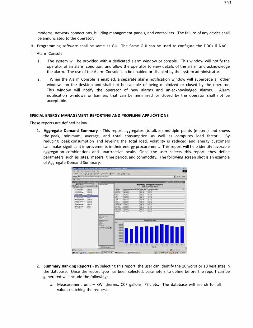
353
modems, network connections, building management panels, and controllers. The failure of any device shallbe annunciated to the operator.
H. Programming software shall be same as GUI. The Same GUI can be used to configure the DDCs & NAC.
I. Alarm Console
1. The system will be provided with a dedicated alarm window or console. This window will notify theoperator of an alarm condition, and allow the operator to view details of the alarm and acknowledgethe alarm. The use of the Alarm Console can be enabled or disabled by the system administrator.
2. When the Alarm Console is enabled, a separate alarm notification window will supercede all other windows on the desktop and shall not be capable of being minimized or closed by the operator. This window will notify the operator of new alarms and un-acknowledged alarms. Alarmnotification windows or banners that can be minimized or closed by the operator shall not be acceptable.
SPECIAL ENERGY MANAGEMENT REPORTING AND PROFILING APPLICATIONS
These reports are defined below.
1. Aggregate Demand Summary - This report aggregates (totalizes) multiple points (meters) and showsthe peak, minimum, average, and total consumption as well as computes load factor. By reducing peak consumption and leveling the total load, volatility is reduced and energy customers can make significant improvements in their energy procurement. This report will help identify favorableaggregation combinations and unattractive peaks. Once the user selects this report, they defineparameters such as sites, meters, time period, and commodity. The following screen shot is an exampleof Aggregate Demand Summary.
2. Summary Ranking Reports - By selecting this report, the user can identify the 10 worst or 10 best sites inthe database. Once the report type has been selected, parameters to define before the report can begenerated will include the following:
a. Measurement unit – KW, therms, CCF gallons, PSI, etc. The database will search for allvalues matching the request.
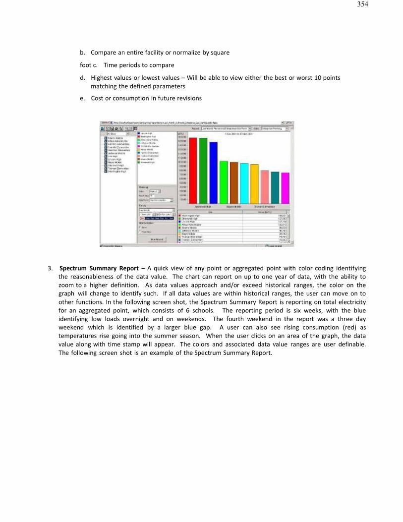
354
b. Compare an entire facility or normalize by square
foot c. Time periods to compare
d. Highest values or lowest values – Will be able to view either the best or worst 10 pointsmatching the defined parameters
e. Cost or consumption in future revisions
3. Spectrum Summary Report – A quick view of any point or aggregated point with color coding identifying the reasonableness of the data value. The chart can report on up to one year of data, with the ability tozoom to a higher definition. As data values approach and/or exceed historical ranges, the color on thegraph will change to identify such. If all data values are within historical ranges, the user can move on toother functions. In the following screen shot, the Spectrum Summary Report is reporting on total electricityfor an aggregated point, which consists of 6 schools. The reporting period is six weeks, with the blueidentifying low loads overnight and on weekends. The fourth weekend in the report was a three dayweekend which is identified by a larger blue gap. A user can also see rising consumption (red) as temperatures rise going into the summer season. When the user clicks on an area of the graph, the datavalue along with time stamp will appear. The colors and associated data value ranges are user definable. The following screen shot is an example of the Spectrum Summary Report.
355
4. Equipment Operation Reports - Users will have the ability to analyze digital points and identify runtimes.
Comparisons between sites or points can be made and run times can be graphed. For example,comparing lighting or HVAC run hours in a group of stores or comparing HVAC run hours in June forStore 1 versus Store 2. Data will be displayed in time and percentage.
5. Relative Contribution Report – This pie chart report will give users the ability to identify howindividual points contribute to a total from a point group. The user would select a group of points,calculate the aggregate consumption of the group, and report on the individual contribution of each. Data will be displayed both graphically in a pie chart as well as in tabular format. Users could identifythat HVAC is 48% of the building load; lighting is 42%, or Building 1 accounts for 14% of the totalenterprise load and Building 2 contributes19%. This report will allow users to identify inefficiencies and help performbudgeting.
356
6. Average Profile – The report will allow the user to average the load for a single load across time periodsand give the average load, and/or aggregate multiple meters (loads) and view the average aggregatedload. This report will be very beneficial when negotiating with energy service providers because itincludes the load profile and consumption totals. With the ability to filter by time periods,measurement units, points or point groups, weekdays, and weekends, load profiles with associated datawill allow the user to procure exactly the amount of energy required. This reduces risk for the energyprovider and therefore reduces cost for the end- user.
The user will be able to manipulate between 1-minute intervals and hourly intervals. In addition, users will beable to choose between auto scale and manual scale. For example, if the minimum value is 100KW and themaximum is 500 kW, the user can have the chart automatically scale between those values or they can selectany range to scale the400kW range. When printing charts, this may be useful. This will be useful for sophisticated users who need ahigher resolution of data. The following screen shot is an example of the Average Profile Report.
7. Point Trending – This report will allow the user to choose a single or multiple points and trend thevalues over a specified time period. Either analog or digital points can be trended and multiplevariables can be selected to be report. For a visual representation of several point values, the user willview all points on the left Y-axis. If the user would like to perform a statistical analysis identifyingcorrelation coefficient and standard deviation between variables, they will have the ability to select asingle point for each Y-axis. If a point group has been created, it would be presented as a single point value. The same auto scale/manual scale feature discussed in Average Profile Report is available in PointTrending. The following screen shot is an example of the Point Trending Report.
357
8. Exception Report – This report will identify all data values for the specified period that does not fall in a user-defined range. Although the range will be user definable, the benchmark or baseline to becompared against will be historical data. Users can get to this report by selecting it among the library ofreport templates, or can automatically be taken here from the Average Profile Report or Point TrendingReport by clicking on an “Exception” button once a profile is being viewed.
2.11 WEB BROWSER CLIENTS
A. The system shall be capable of supporting an unlimited number of clients using a standard Webbrowser such as Internet Explorer™ or Netscape Navigator™. Systems requiring additional software(to enable a standard Web browser) to be resident on the client machine, or manufacture-specificbrowsers shall not be acceptable.
B. The Web browser software shall run on any operating system and system configuration that issupported by the Web browser. Systems that require specific machine requirements in terms ofprocessor speed, memory, etc., in order to allow the Web browser to function with the FMCS, shallnot be acceptable.
358
C. The Web browser shall provide the same view of the system, in terms of graphics, schedules,calendars, logs, etc., and provide the same interface methodology as is provided by the GraphicalUser Interface. Systems that require different views or that require different means of interactingwith objects such as schedules, or logs, shall not be permitted.
D. The Web browser client shall support at a minimum, the following functions:
1. User log-on identification and password shall be required. If an unauthorized user attemptsaccess, a blank web page shall be displayed. Security using Java authentication andencryption techniques to prevent unauthorized access shall be implemented.
2. Graphical screens developed for the GUI shall be the same screens used for the Webbrowser client. Any animated graphical objects supported by the GUI shall be supportedby the Web browser interface.
3. HTML programming shall not be required to display system graphics or data on a Webpage.
HTML editing of the Web page shall be allowed if the user desires a specific look orformat.
4. Storage of the graphical screens shall be in the Network Area Controller (NAC), withoutrequiring any graphics to be stored on the client machine. Systems that require graphicsstorage on each client are not acceptable.
5. Real-time values displayed on a Web page shall update automatically without requiring amanual
“refresh” of the Web page.
6. Users shall have administrator-defined access privileges. Depending on the access privileges assigned, the user shall be able to perform the following:
a. Modify common application objects, such as schedules, calendars, and set points in a graphical manner.
1. Schedule times will be adjusted using a graphical slider, without requiring any keyboard entry from the operator.
2. Holidays shall be set by using a graphical calendar, without requiring anykeyboard entry from the operator.
b. Commands to start and stop binary objects shall be done by right-clicking the selectedobject and selecting the appropriate command from the pop-up menu. No entry of textshall be required.
c. View logs and charts
d. View and acknowledge alarms
e. Setup and execute SQL queries on log and archive information
7. The system shall provide the capability to specify a user’s (as determined by the log-onuser identification) home page. Provide the ability to limit a specific user to just theirdefined home page. From the home page, links to other views, or pages in the systemshall be possible, if allowed by the system administrator.
8. Graphic screens on the Web Browser client shall support hypertext links to other locations onthe Internet or on Intranet sites, by specifying the Uniform Resource Locator (URL) for thedesired link.
359
2.12 SERVER FUNCTIONS AND HARDWARE
A. A central server shall be provided. The server shall support all Network Area Controllers (NAC) / Router connected to the customer’s network whether local or remote.
B. Local connections shall be via an Ethernet LAN. Remote connections can be via ISDN, ADSL, T1or dial-up connection.
C. It shall be possible to provide access to all Network Area Controllers via a single connection tothe server. In this configuration, each Network Area Controller can be accessed from a remoteGraphical User Interface (GUI) or from a standard Web browser (WBI) by connecting to the server.
D. The server shall provide the following functions, at a minimum:
1. Global Data Access: The server shall provide complete access to distributed data definedanywhere in the system.
2. Distributed Control: The server shall provide the ability to execute global control strategiesbased on control and data objects in any NAC / Router in the network, local or remote.
3. The server shall include a master clock service for its subsystems and provide timesynchronization for all Network Area Controllers (NAC) / Routers.
4. The server shall accept time synchronization messages from trusted precision Atomic Clock
Internet sites and update its master clock based on this data.
5. The server shall provide scheduling for all Network Area Controllers and their underlyingfield control devices.
6. The server shall provide demand limiting that operates across all Network Area Controllers. The server must be capable of multiple demand programs for sites with multiple meters andor multiple sources of energy. Each demand program shall be capable of supportingseparate demand shed lists for effective demand control.
7. The server shall implement the BACnet Command Prioritization scheme (16 levels) for safeand effective contention resolution of all commands issued to Network Area Controllers /Routers. Systems not employing this prioritization shall not be accepted.
8. Each Network Area Controller / Router supported by the server shall have the ability toarchive its log data, alarm data and database to the server, automatically. Archiving optionsshall be user- defined including archive time and archive frequency.
9. The server shall provide central alarm management for all Network Area Controllers /Routers supported by the server. Alarm management shall include:
1. Routing of alarms to display, printer, email and pagers
2. View and acknowledge alarms
3. Query alarm logs based on user-defined parameters
10. The server shall provide central management of log data for all Network Area Controllers /Routers supported by the server. Log data shall include process logs, runtime and eventcounter logs, audit logs and error logs. Log data management shall include:
1. Viewing and printing log data
2. Exporting log data to other software applications
3. Query log data based on user-defined parameters

360
E. Server Hardware Requirements: The server hardware platform shall have the followingrequirements:
1. The computer shall be an Intel Pentium M based computer (minimum processing speed of 2.4GHz with 1 GB RAM and a 100-gigabyte minimum hard drive). It shall include a DVD-ROM/CD-RW Combination Drive, 2-parallel ports, 2-asynchronous serial ports and 2-USB ports. Aminimum17” flat panel color monitor, 1280 x 1024 optimal preset resolution, 25 ms response time shallalsobe included.
2. The server operating system shall be Microsoft Windows XP Professional. Include Microsoft
Internet Explorer 6.0 or later.
3. Connection to the BMS network shall be via an Ethernet network interface card, 100 Mbps.
4. A system printer shall be provided. Printer shall be laser type with a minimum 600 x 600-dpi resolution and rated for 60-PPM print speed minimum.
5. For dedicated alarm printing, provide a dot matrix printer, either 80 or 132 column width. The printer shall have a parallel port interface.
2.13 SYSTEM PROGRAMMING
A. The Graphical User Interface software (GUI) shall provide the ability to perform systemprogramming and graphic display engineering as part of a complete software package. Access tothe programming functions and features of the GUI shall be through password access as assigned by the system administrator.
B. A library of control, application, and graphic objects shall be provided to enable the creationof all applications and user interface screens. Applications are to be created by selecting thedesired control objects from the library, dragging or pasting them on the screen, and linking themtogether using a built in graphical connection tool. Completed applications may be stored in the library for future use.Graphical User Interface screens shall be created in the same fashion. Data for the userdisplays is obtained by graphically linking the user display objects to the application objects toprovide “real-time” data updates. Any real-time data value or object property may be connectedto display its current value on a user display. Systems requiring separate software tools or processes to create applications and user interface displays shall not be acceptable.
C. Programming Methods
1. Provide the capability to copy objects from the supplied libraries, or from a user-definedlibrary to the user’s application. Objects shall be linked by a graphical linking scheme bydragging a link from one object to another. Object links will support one-to-one, many-to-one, or one-to-many relationships. Linked objects shall maintain their connections to otherobjects regardless of where they are positioned on the page and shall show link identificationfor links to objects on other pages for easy identification. Links will vary in colordepending on the type of link; i.e., internal, external, hardware, etc.
2. Configuration of each object will be done through the object’s property sheet using fill-in theblank fields, list boxes, and selection buttons. Use of custom programming, scriptinglanguage, or a manufacturer-specific procedural language for configuration will not beaccepted.
361
3. The software shall provide the ability to view the logic in a monitor mode. When on-line,the monitor mode shall provide the ability to view the logic in real time for easy diagnosis ofthe logic execution. When off-line (debug), the monitor mode shall allow the user to set valuesto inputs and monitor the logic for diagnosing execution before it is applied to the system.
4. All programming shall be done in real-time. Systems requiring the uploading, editing, and downloading of database objects shall not be allowed.
5. The system shall support object duplication within a customer’s database. An application,once configured, can be copied and pasted for easy re-use and duplication. All links, otherthan to the hardware, shall be maintained during duplication.
2.14 LonWorks NETWORK MANAGEMENT
A. The Graphical User Interface software (GUI) shall provide a complete set of integrated LonWorks network management tools for working with LonWorks networks. These tools shallmanage a database for all LonWorks devices by type and revision, and shall provide a softwaremechanism for identifying each device on the network. These tools shall also be capable ofdefining network data connections between LonWorks devices, known as “binding”. Systemsrequiring the use of third party LonWorks network management tools shall not be accepted.
B. Network management shall include the following services: device identification, device installation, device configuration, device diagnostics, device maintenance and network variablebinding.
C. The network configuration tool shall also provide diagnostics to identify devices on the network, toreset devices, and to view health and status counters within devices.
D. These tools shall provide the ability to “learn” an existing LonWorks network, regardless ofwhat network management tool(s) were used to install the existing network, so that existing LonWorks devices and newly added devices are part of a single network management database.
E. The network management database shall be resident in the Network Area Controller (NAC) /Router, ensuring that anyone with proper authorization has access to the network managementdatabase at all times. Systems employing network management databases that are not resident, at all times, within the control system, shall not be accepted.
2.15 OBJECT LIBRARIES
A. A standard library of objects shall be included for development and setup of application logic, user interface displays, system services, and communication networks.
B. The objects in this library shall be capable of being copied and pasted into the user’s database and shall beorganized according to their function. In addition, the user shall have the capability to group objects createdin their application and store the new instances of these objects in a user-defined library.
C. In addition to the standard libraries specified here, the supplier of the system shall maintain an on-line accessible (over the Internet) library, available to all registered users to provide new or updated objects and applications as they are developed.
D. All control objects shall conform to the control objects specified in the BACnet specification. E.
The library shall include applications or objects for the following functions, at a minimum:
1. Scheduling Object. The schedule must conform to the schedule object as defined in the BACnet specification, providing 7-day plus holiday & temporary scheduling features and a minimum of 10 on/off events per day. Data entry to be by graphical sliders to speed creation and selection of on- off
362
events.
2. Calendar Object. . The calendar must conform to the calendar object as defined in the BACnet specification, providing 12-month calendar features to allow for holiday or special event data entry. Data entry to be by graphical “point-and-click” selection. This object must be “linkable” to any or allscheduling objects for effective event control.
3. Duty Cycling Object. Provide a universal duty cycle object to allow repetitive on/off time control ofequipment as an energy conserving measure. Any number of these objects may be created to control equipment at varying intervals
4. Temperature Override Object. Provide a temperature override object that is capable of overriding equipment turned off by other energy saving programs (scheduling, duty cycling etc.) to maintain occupant comfort or for equipment freeze protection.
5. Start-Stop Time Optimization Object. Provide a start-stop time optimization object to provide the capability of starting equipment just early enough to bring space conditions to desired conditions by the scheduled occupancy time. Also, allow equipment to be stopped before the scheduled un-occupancy time just far enough ahead to take advantage of the building’s “flywheel” effect for energy savings. Provide automatic tuning of all start / stop time object properties based on the previous day’s performance.
6. Demand Limiting Object. Provide a comprehensive demand-limiting object that is capable of controlling demand for any selected energy utility (electric, oil, and gas). The object shall provide thecapability of monitoring a demand value and predicting (by use of a sliding window prediction algorithm) the demand at the end of the user defined interval period (1-60 minutes). This object shall also accommodate a utility meter time sync pulse for fixed interval demand control. Upon a prediction that will exceed the user defined demand limit (supply a minimum of 6 per day), the demandlimiting object shall issue shed commands to either turn off user specified loads or modify equipmentset points to effect the desired energy reduction. If the list of sheddable equipment is not enoughto reduce the demand to below the set point, a message shall be displayed on the users screen (as analarm) instructing the user to take manual actions to maintain the desired demand. The shed listsare specified by the user and shall be selectable to be shed in either a fixed or rotating order tocontrol which equipment is shed the most often. Upon suitable reductions in demand, the demand-limiting object shall restore the equipment that was shed in the reverse order in which it was shed. Each sheddable object shall have a minimum and maximum shed time property to effect bothequipment protection and occupant comfort.
F. The library shall include control objects for the following functions. All control objects shall conform to theobjects as specified in the BACnet specification.
1. Analog Input Object - Minimum requirement is to comply with the BACnet standard for data sharing. Allow high, low and failure limits to be assigned for alarming. Also, provide a time delay filterproperty to prevent nuisance alarms caused by temporary excursions above or below the user definedalarm limits.
2. Analog Output Object - Minimum requirement is to comply with the BACnet standard for data sharing.
3. Binary Input Object - Minimum requirement is to comply with the BACnet standard for data sharing. The user must be able to specify either input condition for alarming. This object must also include the capability to record equipment run-time by counting the amount of time the hardware input is in an “on” condition. The user must be able to specify either input condition as the“on” condition.
363
4. Binary Output Object - Minimum requirement is to comply with the BACnet standard for data sharing. Properties to enable minimum on and off times for equipment protection as well as interstart delay must be provided. The BACnet Command Prioritization priority scheme shall be incorporated to allow multiple control applications to execute commands on this object with the highest priority command being invoked. Provide sixteen levels of priority as a minimum. Systems notemploying the BACnet method of contention resolution shall not be acceptable.
5. PID Control Loop Object - Minimum requirement is to comply with the BACnet standard for data sharing. Each individual property must be adjustable as well as to be disabled to allow proportional control only, or proportional with integral control, as well as proportional, integral and derivative control.
6. Comparison Object - Allow a minimum of two analog objects to be compared to select either the highest, lowest, or equality between the two linked inputs. Also, allow limits to be applied to the output value for alarm generation.
7. Math Object - Allow a minimum of four analog objects to be tested for the minimum or maximum, orthe sum, difference, or average of linked objects. Also, allow limits to be applied to the output valuefor alarm generation.
8. Custom Programming Objects - Provide a blank object template for the creation of new custom objects to meet specific user application requirements. This object must provide a simple BASIC- likeprogramming language that is used to define object behavior. Provide a library of functions includingmath and logic functions, string manipulation, and e-mail as a minimum. Also, provide a comprehensiveon-line debug tool to allow complete testing of the new object. Allow new objects to be stored in thelibrary for re-use.
9. Interlock Object - Provide an interlock object that provides a means of coordination of objects within a piece of equipment such as an Air Handler or other similar types of equipment. An example is to link the return fan to the supply fan such that when the supply fan is started, the return fan object is also started automatically without the user having to issue separate commands or to link each object to a schedule object. In addition, the control loops, damper objects, and alarm monitoring (such as return air, supply air, and mixed air temperature objects) will be inhibited from alarming during a user-defined period after startup to allow for stabilization. When theair handler is stopped, the interlocked return fan is also stopped, the outside air damper is closed, and other related objects within the air handler unit are inhibited from alarming thereby eliminating nuisance alarms during the off period.
10. Temperature Override Object - Provide an object whose purpose is to provide the capability of overriding a binary output to an “On” state in the event a user specified high or low limit value is exceeded. This object is to be linked to the desired binary output object as well as to an analog object for temperature monitoring, to cause the override to be enabled. This object will execute a Start command at the Temperature Override level of start/stop command priority unless changed by the user.
11. Composite Object - Provide a container object that allows a collection of objects representing an application to be encapsulated to protect the application from tampering, or to more easily represent large applications. This object must have the ability to allow the user to select the appropriate parameters of the “contained” application that are represented on the graphical shell of this container.
G. The object library shall include objects to support the integration of devices connected to the Network Area Controller (NAC) / Router. At a minimum, provide the following as part of the standard library
364
included with the programming software:
1. LonMark/LonWorks devices. These devices shall include, but not be limited to, devices for control ofHVAC, lighting, access, and metering. Provide LonMark manufacturer-specific objects to facilitatesimple integration of these devices. All network variables defined in the LonMark profile shall besupported. Information (type and function) regarding network variables not defined in the LonMarkprofile shall be provided by the device manufacturer.
2. For devices not conforming to the LonMark standard, provide a dynamic object that can be assigned to the device based on network variable information provided by the device manufacturer. Device manufacturer shall provide an XIF file, resource file and documentation for the device to facilitate device integration.
3. For BACnet devices, provide the following objects at a minimum:
a. Analog In
b. Analog Out
c. Analog Value
d. Binary
e. Binary Inf. Binary Out
g. Binary Value
h. Multi-State In
i. Multi-State Out
j. Multi-State Value
k. Schedule Export
l. Calendar Export
m. Trend Export
n. Device
4. For each BACnet object, provide the ability to assign the object a BACnet device and object instance number.
5. For BACnet devices, provide the following support at a minimum
a. Segmentationb. Segmented Request
c. Segmented Response d. Application Services e. Read Propertyf. Read Property multiple g. Write Propertyh. Write Property Multiplei. Confirmed Event Notification
365
j. Unconfirmed Event Notification k. Acknowledge Alarml. Get Alarm Summary
m. Who-has
n. I-have
o. Who-is
p. I-am
q. Subscribe COV
r. Confirmed COV notification
s. Unconfirmed COV notification
t. Media Types
u. Ethernet
v. BACnet IP Annex J
w. MSTP
x. BACnet Broadcast Management Device (BBMD) function
y. Routing
2.16 DDE DEVICE INTEGRATION
A. The Network Area Controller / Router shall support the integration of device data via Dynamic Data Exchange (DDE), over the Ethernet Network. The Network Area Controller shall act as a DDE clientto another software application that functions as a DDE server.
B. Provide the required objects in the library, included with the Graphical User Interfaceprogramming software, to support the integration of these devices into the BMS. Objects providedshall include at a minimum:
1. DDE Generic AI Object
2. DDE Generic AO Object
3. DDE Generic BO Object4. DDE Generic BI Object
2.17 MODBUS SYSTEM INTEGRATION
A. The Network Area Controller / Router shall support the integration of device data from ModbusRTU, Ascii, or TCP control system devices. The connection to the Modbus system shall be via anRS-232, RS485, or Ethernet IP as required by the device.
B. Provide the required objects in the library, included with the Graphical User Interfaceprogramming software, to support the integration of the Modbus system data into the BMS. Objects provided shall include at a minimum:
1. Read/Write Modbus AI Registers
2. Read/Write Modbus AO Registers
3. Read/Write Modbus BI Registers
4. Read/Write Modbus BO Registers
366
C. All scheduling, alarming, logging and global supervisory control functions, of the Modbus system devices, shall be performed by the Network Area Controller.
D. The BMS supplier shall provide a Modbus system communications driver. The equipment system vendor that provided the equipment utilizing Modbus shall provide documentation of the system’s Modbus interface and shall provide factory support at no charge during systemcommissioning
2.18 OPC SYSTEM INTEGRATION
A. The Network Area Controller / Router shall act as an OPC client and shall support theintegration of device data from OPC servers. The connection to the OPC server shall be Ethernet IPas required by the device. The OPC client shall support third party OPC servers compatible withthe Data Access 1.0 and2.0 specifications.
B. Provide the required objects in the library, included with the Graphical User Interfaceprogramming software, to support the integration of the OPC system data into the BMS. Objects provided shall include at a minimum:
1. Read/Write OPC AI Object
2. Read/Write OPC AO Object
3. Read/Write OPC BI Object
4. Read/Write OPC BO Object
5. Read/Write OPC Date/Time Input Object
6. Read/Write OPC Date/Time Output Object
7. Read/Write OPC String Input Object
8. Read/Write OPC String Output Object
C. All scheduling, alarming, logging and global supervisory control functions, of the OPC systemdevices, shall be performed by the Network Area Controller / Router.
D. The BMS supplier shall provide an OPC client communications driver. The equipment systemvendor that provided the equipment utilizing OPC shall provide documentation of the system’sOPC server interface and shall provide factory support at no charge during system commissioning.
2.19 GRAPHICAL USER INTERFACE COMPUTER HARDWARE (DESKTOP)
A. The browser workstation shall be an Intel Pentium based computer (minimum processing speedof 2.4
Ghz with 1.0 GB RAM and a 100-gigabyte minimum hard drive). It shall include a DVD-ROM/CD-RW Combination Drive, 2-parallel ports, 2-asynchronous serial ports and 2-USB ports. A minimum17”flat panel color monitor, 1280 x 1024 optimal preset resolution, 25 ms response time, shall alsobe included.
B. Connection to the BMS network shall be via an Ethernet network interface card, 10 Mbps.
C. A system printer shall be provided. Printer shall be laser type with a minimum 600 x 600-dpiresolution and rated for 8 PPM print speed minimum.
367
OTHER CONTROL SYSTEM HARDWARE FIELD
DEVICES
7.1 ELECTRIC AND ELECTRONIC CONTROLS RELATED EQUIPMENT
General Requirements
All controls shall be capable of operating in ambient conditions varying between 0-55 deg. C and90% R.H. non-condensing.
All Control devices shall have a 20 mm conduit knockout. Alternatively, they shall be suppliedwith adaptors for 20 mm conduit.
Ancillary Items
When items of equipment are installed in the situations listed below, the BAS contractor shall include the following ancillary items :
(i) WeatherProtection
All devices required to be weatherproofed are detailed in the Schedule of Quantities. IP ratings for the equipment is mentioned in the respective section.
(ii) Pipe work Immersion
Corrosion resisting pockets of a length suitable for the complete active length of the device,screwed½” (13 mm) or ¾” (20 mm) NPT suitable for the temperature, pressure and medium.
(iii) DuctMounting(MetalorBuildersWork)
Mounting flanges, clamping bushes, couplings, locknuts, gaskets, brackets, sealing glands and any special fittings necessitated by the device.
Additional features
(i) Concealed Adjustment : All two position switching devices shall have concealedadjustment unless detailed otherwise in the Schedule of Quantities.
(ii) Operating Voltage : All two position switching devices shall operate on 230 v a.c and all accessible live parts shall be shrouded. An earth terminal shall be provided.
7.2 TEMPERATURE SENSOR
Temperature sensors for space, pipes and ducts, shall be of the Resistance Temperature detector (RTD)type or thermistor. These shall be two wire type and shall conform to the following specifications :
1) Immersion sensors shall be high accuracy type with a high resistance versus temperature change.
368
The accuracy shall be atleast ± 0.33 degrees F and sensitivity of atleast 2 ohm/F.
2) Immersion sensors shall be provided with separate stainless steel thermo well. Theseshall be manufactured from bar stock with hydrostatic pressure rating of atleast 10 kgf/cm2.
3) The connection to the pipe shall be screwed ¾ inch NPT (M). An aluminum sleeve shall be provided to ensure proper heat transfer from the well to the sensor. Terminations to beprovided on the head. Flying leads shall not be acceptable.
4) The sensor housing shall plug into the base so that the same can be easily removed withoutdisturbing the wiring connections.
5) Duct temperature sensors shall be with rigid stem and of averaging type. These shall be suitable for duct installation.
6) Outdoor air temperature sensor shall be provided with a sunshield.
7) The sensors shall not be mounted near any heat source such as windows, electrical
appliances etc. The temperature sensors may be of any of the following types :
1) PT 100, PT 1000, PT 30002) NI 100, NI 10003) Balco 500.4) Thermistor
7.3 HUMIDITY SENSOR
Space and duct humidity sensors shall be of capacitance type with an effective sensing range of 10% to90% RH. Accuracy shall be + 3% or better. Duct mounted humidity sensors shall be provided with asampling chamber. Wall mounted sensors shall be provided with a housing. The sensor housing shallplug into the base so that the same can be easily removed without disturbing the wiring connections. The sensors shall not be mounted near any heat source such as windows, electrical appliances etc.
7.4 FLOW METER
Water flow meters shall be either Ultrasonic type or electromagnetic type. For electromagnetic flowmeter, teflon lining with 316 SS electrodes must be provided. The housing shall have IP 55protection. Vendors shall have to get their design/ selection approved by the Consultant, prior to thesupply.
The exact ranges to be set shall be determined by the contractor at the time of commissioning. It should be possible to ‘zero’ the flowmeter without any external instruments, with the overall accuracy of atleast ± 1% full scale.
7.5 PRESSURE TRANSMITTER FOR WATER
Pressure transmitters shall be piezo-electric type or diaphragm type. (Bourdon Tube type shall not be acceptable). Output shall be 4-20mA or 0-10V DC and the range as specified in the data sheetdepending on the line pressure. Power supply shall be either 24 V AC, 24 V DC or 230 V AC.
369
Connection shall be as per manufacturer’s standards. The pressure detector shall be capable ofwithstanding a hydraulic test pressure of twice the working pressure. The set point shall fall within 40%-70% of the sensing range and detector shall have sensitivity such that change of 1.5% from the stabilized condition shall cause modulation of the corrective element. The sensor must be pressure
compensated for a medium temperature of -10 o C to60o C with ambient ranging between 0 o C to 55o C.
7.6 DIFFERENTIAL PRESSURE SWITCH FOR PIPE WORK
These shall be used to measure pressure differential across suction and discharge of pumps. The rangeshall be as specified in the data sheet. Switch shall be ON with increase in differential. Housing forthese shall be weather proof with IP 55 protection. The pressure switch shall be capable ofwithstanding a hydraulic test pressure of 1.5 times the working pressure. The set point shall fall in 40-70% of the scale range and shall have differentials adjustable over 10%-30% of the scale range. Theswitches shall be provided with site adjustable scale and with 2 NO/NC contacts.
7.7 DIFFERENTIAL PRESSURE SWITCH FOR AIR SYSTEMS
These shall be diaphragm operated. Switches shall be supplied with air connections permitting theiruse as static or differential pressure switches.
The switch shall be of differential pressure type complete with connecting tube and metal bends for connections to the duct. The housing shall be IP 54 rated. The pressure switches shall be available inminimum of 3 ranges suitable for applications like Air flow proving, dirty filter, etc. The set point shallbe concealed type. The contact shall be SPDT type with 230 VAC, 1 A rating.
The switch shall be supplied suitable for wall mounting on ducts in any plane. It should be mounted insuch a way that the condensation flow out of the sensing tips. Proper adaptor shall be provided for thecables.
The set point shall fall within 40%-70% of the scale range and l has differentials adjustable over 10%-30% of the scale range.
The switches shall be provided with site adjustable scale and with 2 NO/NCcontacts.
7.8 AIR FLOW SWITCHES
Air flow switches shall be selected for the correct air velocity, duct size and mounting attitude. If any special atmospheric conditions are detailed in the Schedule of Quantity the parts of the switchesshall be suitably coated or made to withstand such conditions. These shall be suitable formounting in any plane. Output shall be 2 NO/NC potential free. Site adjustable scale shall also beprovided.
7.9 AIR PRESSURE SENSOR
The pressure sensor shall be differential type. The construction shall be spring loaded diaphragm type.The movement of the membrane in relation to the pressure should be converted by an inductiveelectromagnet coupling which would give an output suitable for the controller. The pressure sensorshall be in a housing having IP 54 ratings in accordance with IEC 529. Suitable mounting arrangement
370
shall be available on the sensor. The sensor shall come complete with the PVC tubes & probes.
7.10 WATER FLOW SWITCH
These shall be paddle type and suitable for the type of liquid flowing in the line. Output shall be2NO/2NCpotentialfree.
7.11 TRANSDUCERS FOR ELECTRICAL SERVICES
Electrical transducers shall be integrated electronic type and rack mounted on the field. These shallwork on230 V supply with the output being standard type i.e. 4-20 mA, 0- 10 Voltsetc.
Power factor, Voltage, Current, Frequency and Kilowatt transducers shall have standard outputsignal for measurement for the specified variable.
Kilowatt-Hour metering (if any) shall be poly-phase; three- element with current transformer (CT)operated type. The metering shall feature high accuracy with no more than +/- 1% error over theexpected load range. The coils shall be totally encapsulated against high impulse levels.
7.12 LEVEL SWITCH
The level switches shall have to meet the followingrequirement :
Type : Float Type/Capacitance type/Conductivity typeMounting : To suit application.Connection : Flanged ANSI 150 lbs RF Carbon steelFloat material : 316 SS Stem Material : 316 SSOutput : 2 NO, 2 NC potential freeSwitch Enclosure : IP 55
7.13 DIGITAL THERMOSTATS
Thermostats for FCU’s should be Digital on/off OR Modulating Type for Actuating 2 way or 3 way Valves(On- off/Modulating)
Thermostats should display Room Temp and Setpoint simultaneously which is easy to read from atleast 6-8 feet distance.
Thermostats should have Fan Speed Control Switch (Low-Med-High-Auto). Auto Mode should be able tosave energy by automatically reducing the Fan Speed when Room Temp Achieves Set Point.
LCD Display should be available in Blue or Green Backlit for ease in viewing the Room Temperature and
Setpoint. Thermostats should work on 230V PS for on-off models and 24V for Modulating Thermostats
371
The User Settings should be retained in Thermostat Memory in case of PowerFailure
The Switching Relays should be separately wired and should be mounted inside the Junction Box, so that theThermostat front is sleek in mounting.Thermostat Thickness should be 17mm orless
Thermostats should have Energy Savings Feature with dual setpoint which can be interlocked with Occupancy Sensor or Hotel Key Card input. This should be indicated in the LCD Display in the mode it is being operated. This Programming should be possible by Hotel maintenance Staff.
Thermostats should be similar or equivalent to Honeywell Halo Series Digital Thermostats ModelT6861(on/off) orT6865(modulating) version.
7.15 Pressure Independent Dynamic Balancing Valve (ranges from25mm to150mm)
The Valve should have self Dynamic Flow Control Valves that are pressure independent, two way,Modulating to accept digital/analog input BMS/Controller signals and should provide position feedback signalto the control system. The Feedback signal should have the feedback feature of the Valve/Actuator itself withoutany need of any additional accessory/instrument/device.
• PICV should be capable of maintaining the max flow rate atleast +/-4% Accuracy• The PICV Should be capable of maintaining Linear Temperature Control, Pressure Independence and
Electric Modulation in one Valve body.• The Flow rates should be field settable electronically upto 60% of the valve Max set Flow rate• The Differential Pressure Ranges for which the valve can maintain the flow rates should be mentionedin the
Product literature
• Valve Actuator housing shall be rated to IP54• Actuator shall be driven by a 24Vac power supply and shall accept universal Input signals like 0/2-10Vdcor 4-
20mA signal• Actuator shall be capable of providing feedback Signal of 0/2-10Vdc to the Control System/BMS• PICV should have an option for adjusting the Flow Characteristics as per AHU in every PICV to ensure
Linear Temp Control.• PICV should have an option for changing the Max Flow Rates in future and no additional Instrument
should be required. Flow Values can be changed by entering in LCD Display only and not by any DIPSwitches or Setting Dial to improve accuracy.
• PICV shall provide full valve Authority• PICV Valve body shall be rated at least PN16• Max Close off Pressure shall be mentioned in the Product Datasheet.• Min Working Differential Pressure shall be 30Kpa• Valve shall be Internal BSP Threaded from DN25 to DN50 and Flanged end Connection for DN65 to DN150• Min Stroke Length of the Valve shall be 20mm

372
• Media Temperature : 0-130 deg C• Valve shall be of Brass/Bronze Construction upto DN50 and Cast Iron upto DN150• Shut off Leakage shall be 0.1 Kvs
7.16 Motorized Butterfly Valve
Valve BodyType of Valve : Butterfly ValveBody Material : Cast Iron or Ductile Iron Body Disc Material : Nickel plated Ductile Iron Stem : SS416Liner Material : EPDM Nominal Static Body Rating : PN16Tightness : Bubble TightMedium Temperature : -10 dec C to 120 deg CPipe Connection : ISO7005-2
ActuatorType : ElectricMotor Supply : 230 Vac, 50hz/60Hz Travel Angle : 90 deg +/- 5 deg Enclosure : IP67 WaterproofIndicator : Continuous Position IndicatorSpace Heater : 15W 220V Anti CondensationStall Protection : Built-in thermal protection Cut off at 125 ± 5 Reset at 95 ± 5Manual Override : By Handwheel, nonclutch designTorque Limit Switches : 2 nosExternal Coating : Dry Aluminium Alloy in Painted BlackMake : Honeywell
7.17 On/Off type FCU valves
Two way on/off type FCU valve
The two way FCU valve should be design in such a way that it can withstand a static pressure of 20 bar and aburst pressure of 100 bar.
The ports are designated in such a way that flow through the two way valve can be in either
direction. The valve shall be designed to handle the fluid temperature from1degreeC to
95degreeC
It can withstand the differential pressure upto 4 Bar.
The valve is of bronze body with stainless steel stem and Noryl cover.
The FCU valve shall have a minimum stroke length of 10mm so that it has the sufficient distance to travel. The

373
hydronic FCU valves shall been designed to meet the European standard EN 60730-2-8.
The actuator shall require the power supply of 220 Volts AC so that no transformer is required.
The actuator is easily removable from the valve so that in case the actuator fails at site it can be easily replacedwithout affecting the integrity of the water system.
The actuator shall have the provision to operate manually.
The actuator shall meet the low voltage directive 73/23/EEC. The actuator shall be selected in such a waythat the maximum power consumed by the actuator is 6 Watt.
The valve should be similar or equivalent to Honeywell VC6013 version.
7.18 Snap Acting Digital Thermostats
Thermostats for FCU’s should be Digital on/off for Actuating 2 way or 3 way Valves (On-off/Modulating)
Thermostats should display Room Temp and Set point simultaneously which is easy to read from at least 6-8feet distance.
Thermostats should have Fan Speed Control Switch (Low-Med-High-Auto). Auto Mode should be able tosave energy by automatically reducing the Fan Speed when Room Temp Achieves Set Point.
LCD Display should be available in Blue or Green Backlit for ease in viewing the Room Temperature and Set
point. Thermostats should work on power supply of 230V for on-off models.
The User Settings should be retained in Thermostat Memory in case of Power Failure
The Switching Relays should be separately wired and should be mounted inside the Junction Box, so that theThermostat front is sleek in mounting. Thermostat Thickness should be 17mm or less
Thermostats should have Energy Savings Feature with dual set point which can be interlocked with Occupancy Sensor or Hotel Key Card input. This should be indicated in the LCD Display in the mode it is being operated. This Programming should be possible by Hotel maintenance Staff.
Thermostats should be similar or equivalent to Honeywell Halo Series Digital Thermostats Model T6861(on/off) version.
PART 3 EXECUTION
3.1 INSTALLATION
A. All work described in this section shall be performed by system integrators or contractors that havea successful history in the design and installation of integrated control systems.
B. Install system and materials in accordance with manufacturer’s instructions, and as detailed
374
on the project drawing set.
C. Drawings of the BMS network are diagrammatic only and any apparatus not shown, butrequired to make the system operative to the complete satisfaction of the Architect shall befurnished and installed without additional cost.
D. Line and low voltage electrical connections to control equipment shown specified or shown onthe control diagrams shall be furnished and installed by this contractor in accordance with these specifications.
E. Equipment furnished by the HVAC Contractor that is normally wired before installation shall be furnished completely wired. Control wiring normally performed in the field will befurnished and installed by this contractor.
3.2 WIRING
A. All electrical control wiring and power wiring to the control panels, NAC, computers andnetwork components shall be the responsibility of the this contractor.
B. The electrical contractor shall furnish all power wiring to electrical starters and motors.
C. All wiring shall be in accordance with the Project Electrical Specifications, the National ElectricalCode and any applicable local codes. All BMS wiring shall be installed in the conduit types specifiedin the Electrical Specifications unless otherwise allowed by the National Electrical Code orapplicable local codes. Where BMS plenum rated cable wiring is allowed it shall be run parallel toor at right angles to the structure, properly supported and installed in a neat and workmanlikemanner.
3.3 WARRANTY
A. Equipment, materials and workmanship incorporated into the work shall be warranted for a periodof one year from the time of system acceptance.
B. Within this period, upon notice by the CLIENT, any defects in the work provided under this sectiondue to faulty materials, methods of installation or workmanship shall be promptly (within 48hours after receipt of notice) repaired or replaced by this contractor at no expense to the CLIENT.
3.4 WARRANTY ACCESS
A. The CLIENT shall grant to this contractor, reasonable access to the BMS during the warranty period.
B. The CLIENT shall allow the contractor to access the BMS from a remote location for the purpose of diagnostics and troubleshooting, via the Internet, during the warranty period.
3.5 SOFTWARE LICENSE
A. CLIENT shall be the named license holder of all software associated with any and all incrementalwork on the project(s). The owner, or his appointed agent, shall determine which organizationsto be named in the “orgid” of all software licenses.
B. CLIENT, or his appointed agent, shall be free to direct the modification of the “orgid” in anysoftware license, regardless of supplier.
C. The owner, or his appointed agent, shall receive ownership of all job specific software configuration documentation, data files, and application-level software developed for the project. This shallinclude all custom, job specific software code and documentation for all configuration andprogramming that is generated for a given project and /or configured for use within basedcontrollers and/or servers and any related LAN / WAN / Intranet and Internet connected routersand devices. Any and all required Ids and passwords for access to any component or softwareprogram shall be provided to the owner.
375
3.6 ACCEPTANCE TESTINGA. Upon completion of the installation, this contractor shall load all system software and start-
up the system. This contractor shall perform all necessary calibration, testing and de-bugging andperform all required operational checks to insure that the system is functioning in full accordancewith these specifications.
B. This contractor shall perform tests to verify proper performance of components, routines, andpoints.
Repeat tests until proper performance results. This testing shall include a point-by-point log tovalidate100% of the input and output points of the DDC system operation.
C. Upon completion of the performance tests described above, repeat these tests, point by point asdescribed in the validation log above in presence of CLIENT's Representative, as required. Properlyschedule these tests so testing is complete at a time directed by the CLIENT's Representative. Donot delay tests so as to prevent delay of occupancy permits or building occupancy.
D. System Acceptance: Satisfactory completion is when BMS contractor have performedsuccessfully all the required testing to show performance compliance with the requirements ofthe Contract Documents to the satisfaction of CLIENT Representative. System acceptance shall becontingent upon completion and review of all corrected deficiencies.
3.7 OPERATOR INSTRUCTION, TRAINING
A. During system commissioning and at such time acceptable performance of the BMS hardware and software has been established this contractor shall provide on-site operator instruction to theowner's operating personnel. Operator instruction shall be done during normal working hoursand shall be performed by a competent representative familiar with the system hardware,software and accessories.
B. This contractor shall provide 40 hours of instruction to the CLIENT's designated personnel onthe operation of the BMS and describe its intended use with respect to the programmed functionsspecified. Operator orientation of the systems shall include, but not be limited to; the overalloperation program, equipment functions (both individually and as part of the total integratedsystem), commands, systems generation, advisories, and appropriate operator intervention required in responding to the System's operation.
C. The training shall be in three sessions as follows:
1. Initial Training: One day session (8 hours) after system is started up and at least one weekbefore first acceptance test. Manual shall have been submitted at least two weeks prior totraining so that the owners' personnel can start to familiarize themselves with the system before classroom instruction begins.
2. First Follow-Up Training: Two days (16 hours total) approximately two weeks after initialtraining, and before Formal Acceptance. These sessions will deal with more advanced topicsand answer questions.
3. Warranty Follow Up: Two days (16 hours total) in no less than 4 hour increments, to bescheduled at the request of the owner during the one year warranty period. These sessionsshall cover topics as requested by the owner such as; how to add additional points, create andgather data for trends, graphic screen generation or modification of control routines.
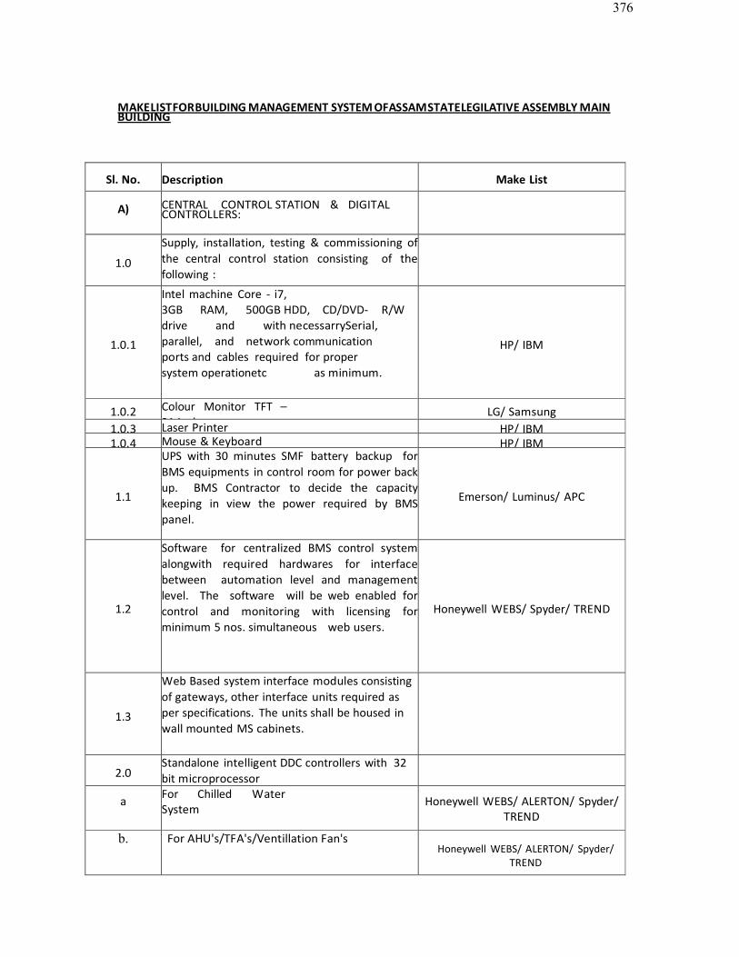
376
MAKELISTFORBUILDING MANAGEMENT SYSTEM OFASSAMSTATELEGILATIVE ASSEMBLY MAINBUILDING
Sl. No. Description Make List
A) CENTRAL CONTROL STATION & DIGITAL CONTROLLERS:
1.0
Supply, installation, testing & commissioning of the central control station consisting of the following :
1.0.1
Intel machine Core - i7,3GB RAM, 500GB HDD, CD/DVD- R/W drive and with necessarrySerial, parallel, and network communication ports and cables required for proper system operationetc as minimum.
HP/ IBM
1.0.2 Colour Monitor TFT –21 inch.
LG/ Samsung1.0.3 Laser Printer HP/ IBM1.0.4 Mouse & Keyboard HP/ IBM
1.1
UPS with 30 minutes SMF battery backup for BMS equipments in control room for power back up. BMS Contractor to decide the capacitykeeping in view the power required by BMSpanel.
Emerson/ Luminus/ APC
1.2
Software for centralized BMS control system alongwith required hardwares for interface between automation level and management level. The software will be web enabled for control and monitoring with licensing for minimum 5 nos. simultaneous web users.
Honeywell WEBS/ Spyder/ TREND
1.3
Web Based system interface modules consistingof gateways, other interface units required asper specifications. The units shall be housed inwall mounted MS cabinets.
2.0Standalone intelligent DDC controllers with 32 bit microprocessor
a For Chilled WaterSystem
Honeywell WEBS/ ALERTON/ Spyder/TREND
b. For AHU's/TFA's/Ventillation Fan'sHoneywell WEBS/ ALERTON/ Spyder/
TREND
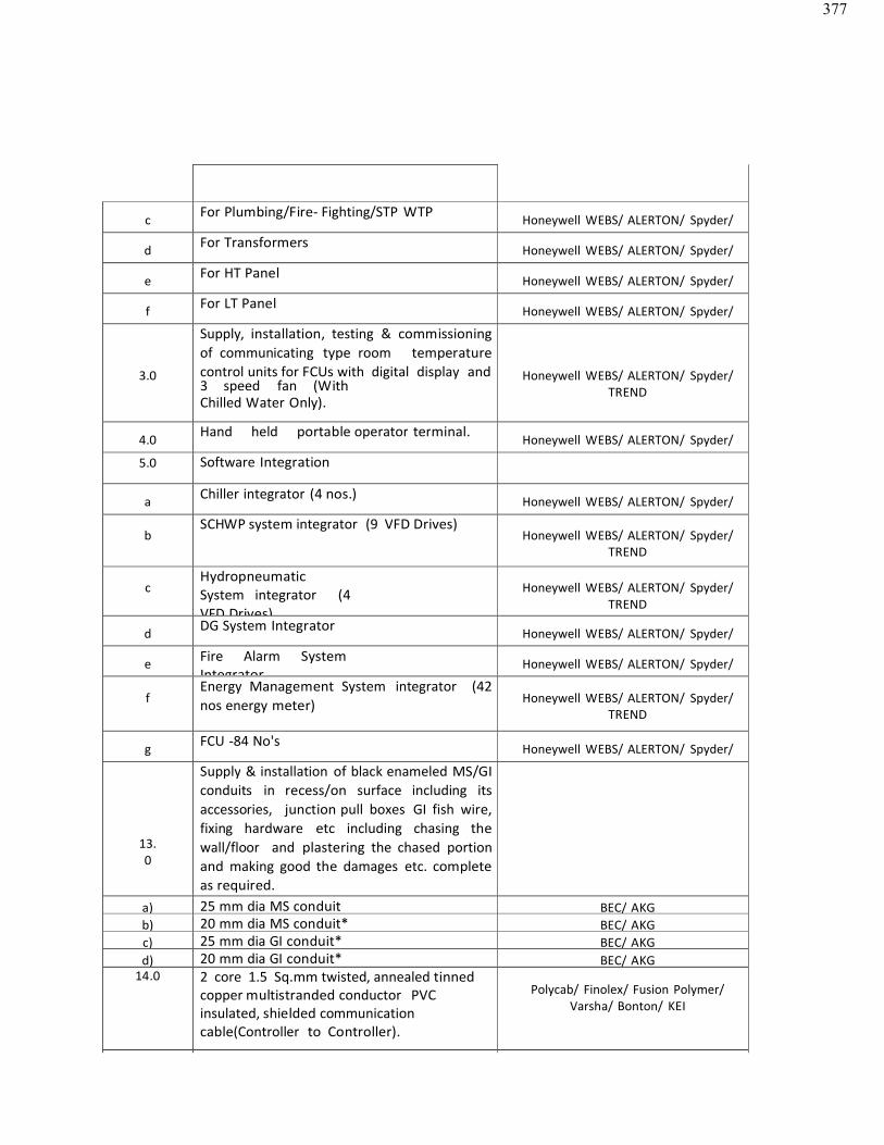
377
c For Plumbing/Fire- Fighting/STP WTP Honeywell WEBS/ ALERTON/ Spyder/TREND
d For Transformers Honeywell WEBS/ ALERTON/ Spyder/TREND
e For HT Panel Honeywell WEBS/ ALERTON/ Spyder/TREND
f For LT Panel Honeywell WEBS/ ALERTON/ Spyder/TREND
3.0
Supply, installation, testing & commissioning of communicating type room temperature control units for FCUs with digital display and3 speed fan (WithChilled Water Only).
Honeywell WEBS/ ALERTON/ Spyder/TREND
4.0 Hand held portable operator terminal. Honeywell WEBS/ ALERTON/ Spyder/TREND5.0 Software Integration
a Chiller integrator (4 nos.) Honeywell WEBS/ ALERTON/ Spyder/TREND
bSCHWP system integrator (9 VFD Drives)
Honeywell WEBS/ ALERTON/ Spyder/TREND
cHydropneumaticSystem integrator (4VFD Drives)
Honeywell WEBS/ ALERTON/ Spyder/TREND
d DG System Integrator Honeywell WEBS/ ALERTON/ Spyder/TREND
e Fire Alarm SystemIntegrator
Honeywell WEBS/ ALERTON/ Spyder/TREND
fEnergy Management System integrator (42 nos energy meter) Honeywell WEBS/ ALERTON/ Spyder/
TREND
g FCU -84 No's Honeywell WEBS/ ALERTON/ Spyder/TREND
13.0
Supply & installation of black enameled MS/GI conduits in recess/on surface including its accessories, junction pull boxes GI fish wire, fixing hardware etc including chasing the wall/floor and plastering the chased portionand making good the damages etc. complete as required.
a) 25 mm dia MS conduit BEC/ AKGb) 20 mm dia MS conduit* BEC/ AKGc) 25 mm dia GI conduit* BEC/ AKGd) 20 mm dia GI conduit* BEC/ AKG
14.0 2 core 1.5 Sq.mm twisted, annealed tinned copper multistranded conductor PVC insulated, shielded communication cable(Controller to Controller).
Polycab/ Finolex/ Fusion Polymer/Varsha/ Bonton/ KEI
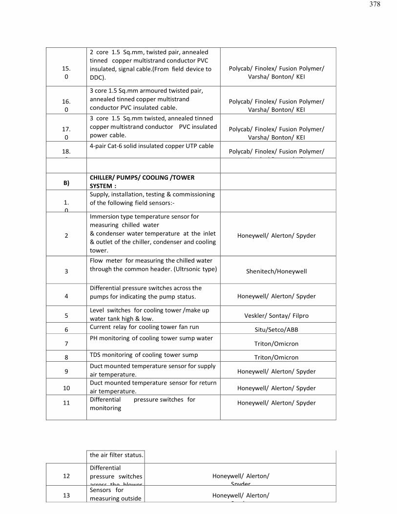
378
15.0
2 core 1.5 Sq.mm, twisted pair, annealed tinned copper multistrand conductor PVC insulated, signal cable.(From field device toDDC).
Polycab/ Finolex/ Fusion Polymer/Varsha/ Bonton/ KEI
16.0
3 core 1.5 Sq.mm armoured twisted pair, annealed tinned copper multistrand conductor PVC insulated cable.
Polycab/ Finolex/ Fusion Polymer/Varsha/ Bonton/ KEI
17.0
3 core 1.5 Sq.mm twisted, annealed tinned copper multistrand conductor PVC insulatedpower cable.
Polycab/ Finolex/ Fusion Polymer/Varsha/ Bonton/ KEI
18.0
4-pair Cat-6 solid insulated copper UTP cablePolycab/ Finolex/ Fusion Polymer/
Varsha/ Bonton/ KEI
B)CHILLER/ PUMPS/ COOLING /TOWER SYSTEM :
1.0
Supply, installation, testing & commissioning of the following field sensors:-
2
Immersion type temperature sensor for measuring chilled water& condenser water temperature at the inlet& outlet of the chiller, condenser and cooling tower.
Honeywell/ Alerton/ Spyder
3
Flow meter for measuring the chilled water through the common header. (Ultrsonic type) Shenitech/Honeywell
4Differential pressure switches across the pumps for indicating the pump status. Honeywell/ Alerton/ Spyder
5Level switches for cooling tower /make up water tank high & low. Veskler/ Sontay/ Filpro
6 Current relay for cooling tower fan runstatus.
Situ/Setco/ABB
7PH monitoring of cooling tower sump water
Triton/Omicron
8 TDS monitoring of cooling tower sump Triton/Omicron
9Duct mounted temperature sensor for supplyair temperature. Honeywell/ Alerton/ Spyder
10Duct mounted temperature sensor for returnair temperature. Honeywell/ Alerton/ Spyder
11 Differential pressure switches for monitoring
Honeywell/ Alerton/ Spyder
the air filter status.
12Differential pressure switchesacross the blower
Honeywell/ Alerton/Spyder
13Sensors for measuring outside Honeywell/ Alerton/
Spyder
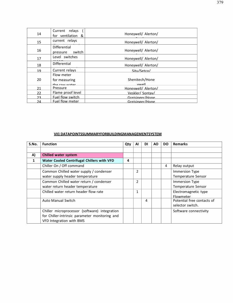
379
14Current relays ( for ventilation & Honeywell/ Alerton/
Spyder15 current relays
(for air washer)Honeywell/ Alerton/
16Differential pressure switch Honeywell/ Alerton/
Spyder17 Level switches
(DPDTHoneywell/ Alerton/
18 Differential pressure switch
Honeywell/ Alerton/Spyder19 Current relays Situ/Setco/
20Flow meterfor measuringthe raw water
Shenitech/Honeywell
21 Pressure Honeywell/ Alerton/22 Flame proof level Veskler/ Sontay/23 Fuel flow switch Greisinger/Hone24 Fuel flow meter Greisinger/Hone
VII) DATAPOINTSSUMMARYFORBUILDINGMANAGEMENTSYSTEM
S.No. Function Qty AI DI AO DO Remarks
A) Chilled water system1 Water Cooled Centrifugal Chillers with VFD 4
Chiller On / Off command 4 Relay outputCommon Chilled water supply / condenser water supply header temperature
2 Immersion TypeTemperature Sensor
Common Chilled water return / condenser water return header temperature
2 Immersion TypeTemperature Sensor
Chilled water return header flow rate 1 Electromagnetic typeFlowmeter
Auto Manual Switch 4 Potential free contacts ofselector switch.
Chiller microprocessor (software) integration for Chiller-intrinsic parameter monitoring and VFD Integration with BMS
Software connectivity
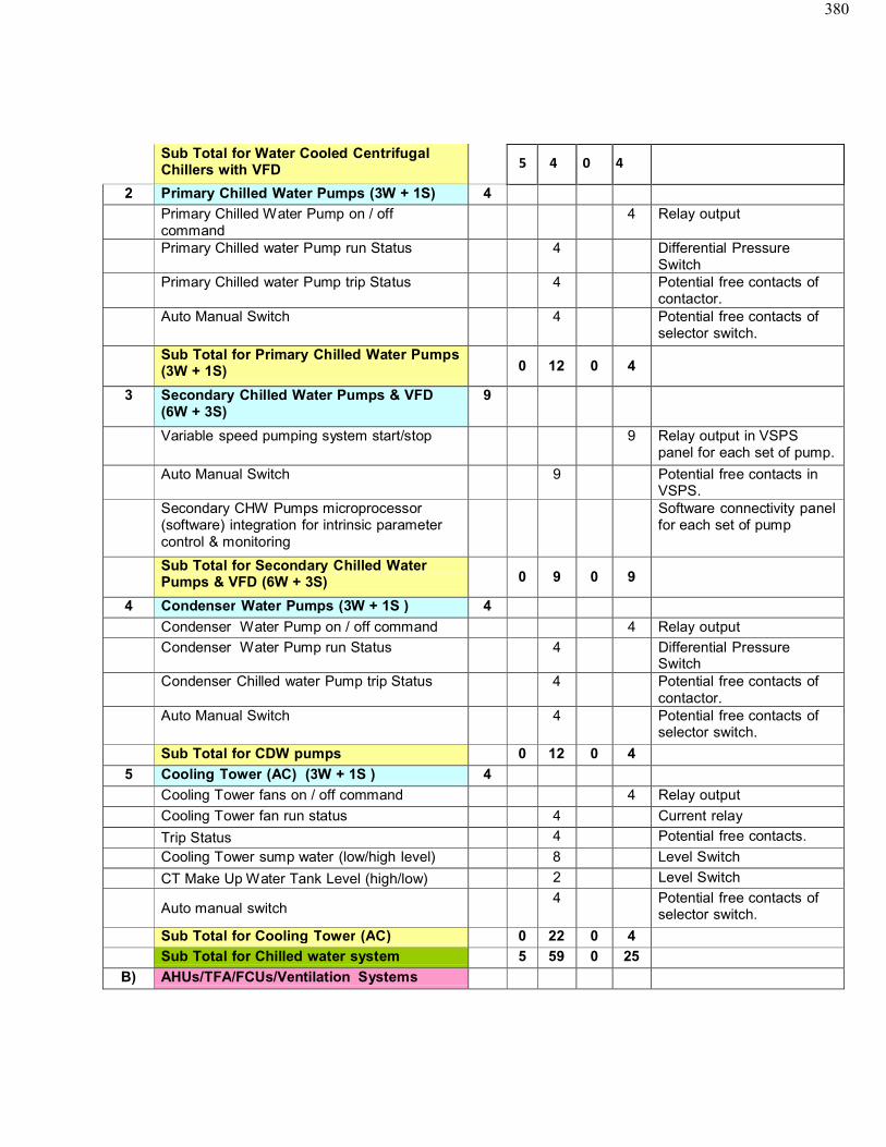
380
Sub Total for Water Cooled CentrifugalChillers with VFD
2 Primary Chilled Water Pumps (3W + 1S) 4
Primary Chilled Water Pump on / off command
4 Relay output
Primary Chilled water Pump run Status 4 Differential PressureSwitch
Primary Chilled water Pump trip Status 4 Potential free contacts ofcontactor.
Auto Manual Switch 4 Potential free contacts of selector switch.
Sub Total for Primary Chilled Water Pumps(3W + 1S) 0 12 0 4
3 Secondary Chilled Water Pumps & VFD(6W + 3S)
9
Variable speed pumping system start/stop 9 Relay output in VSPSpanel for each set of pump.
Auto Manual Switch 9 Potential free contacts inVSPS.
Secondary CHW Pumps microprocessor(software) integration for intrinsic parameter control & monitoring
Software connectivity panelfor each set of pump
Sub Total for Secondary Chilled WaterPumps & VFD (6W + 3S) 0 9 0 9
4 Condenser Water Pumps (3W + 1S ) 4
Condenser Water Pump on / off command 4 Relay output
Condenser Water Pump run Status 4 Differential PressureSwitch
Condenser Chilled water Pump trip Status 4 Potential free contacts ofcontactor.
Auto Manual Switch 4 Potential free contacts of selector switch.
Sub Total for CDW pumps 0 12 0 4
5 Cooling Tower (AC) (3W + 1S ) 4
Cooling Tower fans on / off command 4 Relay output
Cooling Tower fan run status 4 Current relay
Trip Status 4 Potential free contacts.
Cooling Tower sump water (low/high level) 8 Level Switch
CT Make Up Water Tank Level (high/low) 2 Level Switch
Auto manual switch4 Potential free contacts of
selector switch.
Sub Total for Cooling Tower (AC) 0 22 0 4
Sub Total for Chilled water system 5 59 0 25
B) AHUs/TFA/FCUs/Ventilation Systems
5 4 0 4
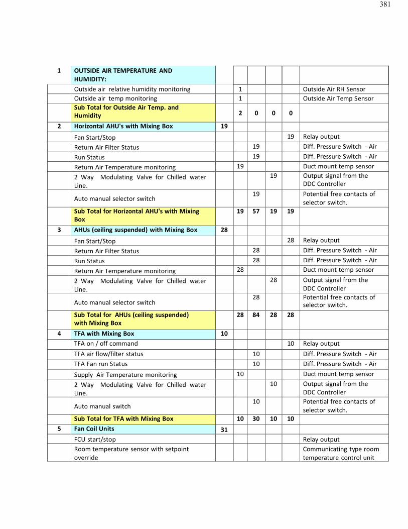
381
1 OUTSIDE AIR TEMPERATURE AND HUMIDITY:Outside air relative humidity monitoring 1 Outside Air RH SensorOutside air temp monitoring 1 Outside Air Temp SensorSub Total for Outside Air Temp. andHumidity 2 0 0 0
2 Horizontal AHU's with Mixing Box 19
Fan Start/Stop 19 Relay output
Return Air Filter Status 19 Diff. Pressure Switch - Air
Run Status 19 Diff. Pressure Switch - Air
Return Air Temperature monitoring 19 Duct mount temp sensor
2 Way Modulating Valve for Chilled waterLine.
19 Output signal from theDDC Controller
Auto manual selector switch19 Potential free contacts of
selector switch.Sub Total for Horizontal AHU's with MixingBox
19 57 19 19
3 AHUs (ceiling suspended) with Mixing Box 28
Fan Start/Stop 28 Relay output
Return Air Filter Status 28 Diff. Pressure Switch - Air
Run Status 28 Diff. Pressure Switch - Air
Return Air Temperature monitoring 28 Duct mount temp sensor
2 Way Modulating Valve for Chilled waterLine.
28 Output signal from theDDC Controller
Auto manual selector switch28 Potential free contacts of
selector switch.Sub Total for AHUs (ceiling suspended)with Mixing Box
28 84 28 28
4 TFA with Mixing Box 10TFA on / off command 10 Relay outputTFA air flow/filter status 10 Diff. Pressure Switch - AirTFA Fan run Status 10 Diff. Pressure Switch - Air
Supply Air Temperature monitoring 10 Duct mount temp sensor
2 Way Modulating Valve for Chilled waterLine.
10 Output signal from theDDC Controller
Auto manual switch10 Potential free contacts of
selector switch.Sub Total for TFA with Mixing Box 10 30 10 10
5 Fan Coil Units 31FCU start/stop Relay outputRoom temperature sensor with setpoint override
Communicating type room temperature control unit
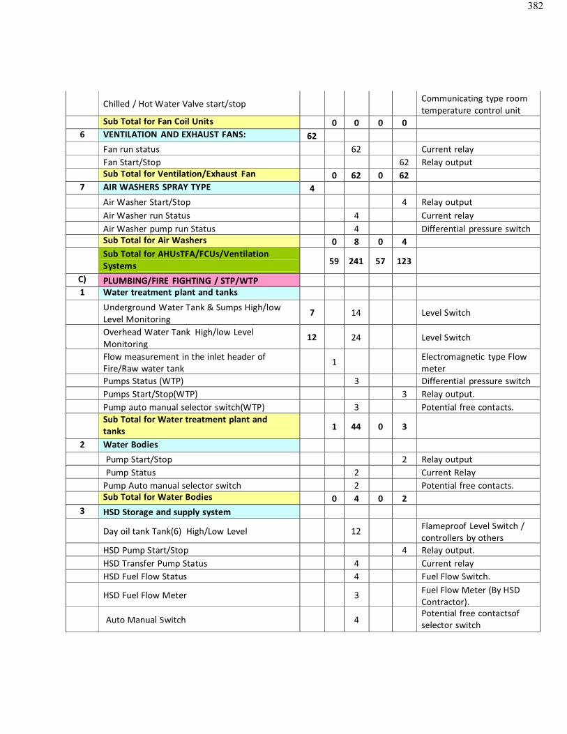
382
Chilled / Hot Water Valve start/stop Communicating type room temperature control unit
Sub Total for Fan Coil Units 0 0 0 06 VENTILATION AND EXHAUST FANS: 62
Fan run status 62 Current relayFan Start/Stop 62 Relay outputSub Total for Ventilation/Exhaust Fan 0 62 0 62
7 AIR WASHERS SPRAY TYPE 4Air Washer Start/Stop 4 Relay outputAir Washer run Status 4 Current relayAir Washer pump run Status 4 Differential pressure switchSub Total for Air Washers 0 8 0 4Sub Total for AHUsTFA/FCUs/VentilationSystems 59 241 57 123
C) PLUMBING/FIRE FIGHTING / STP/WTP1 Water treatment plant and tanks
Underground Water Tank & Sumps High/lowLevel Monitoring
7 14 Level Switch
Overhead Water Tank High/low LevelMonitoring
12 24 Level Switch
Flow measurement in the inlet header ofFire/Raw water tank
1 Electromagnetic type Flow meter
Pumps Status (WTP) 3 Differential pressure switchPumps Start/Stop(WTP) 3 Relay output.Pump auto manual selector switch(WTP) 3 Potential free contacts.Sub Total for Water treatment plant and tanks 1 44 0 3
2 Water Bodies
Pump Start/Stop 2 Relay outputPump Status 2 Current Relay
Pump Auto manual selector switch 2 Potential free contacts.Sub Total for Water Bodies 0 4 0 2
3 HSD Storage and supply system
Day oil tank Tank(6) High/Low Level 12 Flameproof Level Switch /controllers by others
HSD Pump Start/Stop 4 Relay output.HSD Transfer Pump Status 4 Current relayHSD Fuel Flow Status 4 Fuel Flow Switch.
HSD Fuel Flow Meter 3 Fuel Flow Meter (By HSD Contractor).
Auto Manual Switch 4Potential free contactsof selector switch
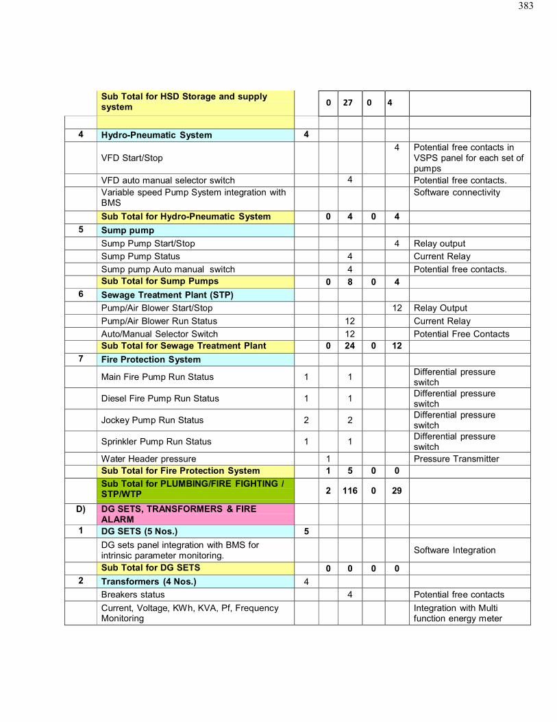
383
Sub Total for HSD Storage and supply system
4 Hydro-Pneumatic System 4
VFD Start/Stop4 Potential free contacts in
VSPS panel for each set of pumps
VFD auto manual selector switch 4 Potential free contacts.Variable speed Pump System integration withBMS
Software connectivity
Sub Total for Hydro-Pneumatic System 0 4 0 4
5 Sump pump
Sump Pump Start/Stop 4 Relay output
Sump Pump Status 4 Current Relay
Sump pump Auto manual switch 4 Potential free contacts.Sub Total for Sump Pumps 0 8 0 4
6 Sewage Treatment Plant (STP)
Pump/Air Blower Start/Stop 12 Relay Output
Pump/Air Blower Run Status 12 Current Relay
Auto/Manual Selector Switch 12 Potential Free ContactsSub Total for Sewage Treatment Plant 0 24 0 12
7 Fire Protection System
Main Fire Pump Run Status 1 1 Differential pressure switch
Diesel Fire Pump Run Status 1 1 Differential pressure switch
Jockey Pump Run Status 2 2Differential pressure switch
Sprinkler Pump Run Status 1 1Differential pressureswitch
Water Header pressure 1 Pressure TransmitterSub Total for Fire Protection System 1 5 0 0
Sub Total for PLUMBING/FIRE FIGHTING /STP/WTP 2 116 0 29
D) DG SETS, TRANSFORMERS & FIREALARM
1 DG SETS (5 Nos.) 5
DG sets panel integration with BMS for intrinsic parameter monitoring.
Software Integration
Sub Total for DG SETS 0 0 0 02 Transformers (4 Nos.) 4
Breakers status 4 Potential free contacts
Current, Voltage, KWh, KVA, Pf, FrequencyMonitoring
Integration with Multi function energy meter
0 27 0 4
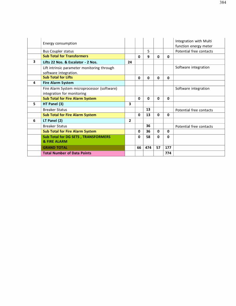
384
Energy consumption Integration with Multi function energy meter
Bus Coupler status 5 Potential free contactsSub Total for Transformers 0 9 0 0
3 Lifts 22 Nos. & Escalator - 2 Nos. 24Lift intrinsic parameter monitoring through software integration.
Software integration
Sub Total for Lifts 0 0 0 04 Fire Alarm System
Fire Alarm System microprocessor (software)integration for monitoring
Software integration
Sub Total for Fire Alarm System 0 0 0 05 HT Panel (3) 3
Breaker Status 13 Potential free contactsSub Total for Fire Alarm System 0 13 0 0
6 LT Panel (2) 2Breaker Status 36 Potential free contactsSub Total for Fire Alarm System 0 36 0 0Sub Total for DG SETS , TRANSFORMERS& FIRE ALARM
0 58 0 0
GRAND TOTAL 66 474 57 177Total Number of Data Points 774
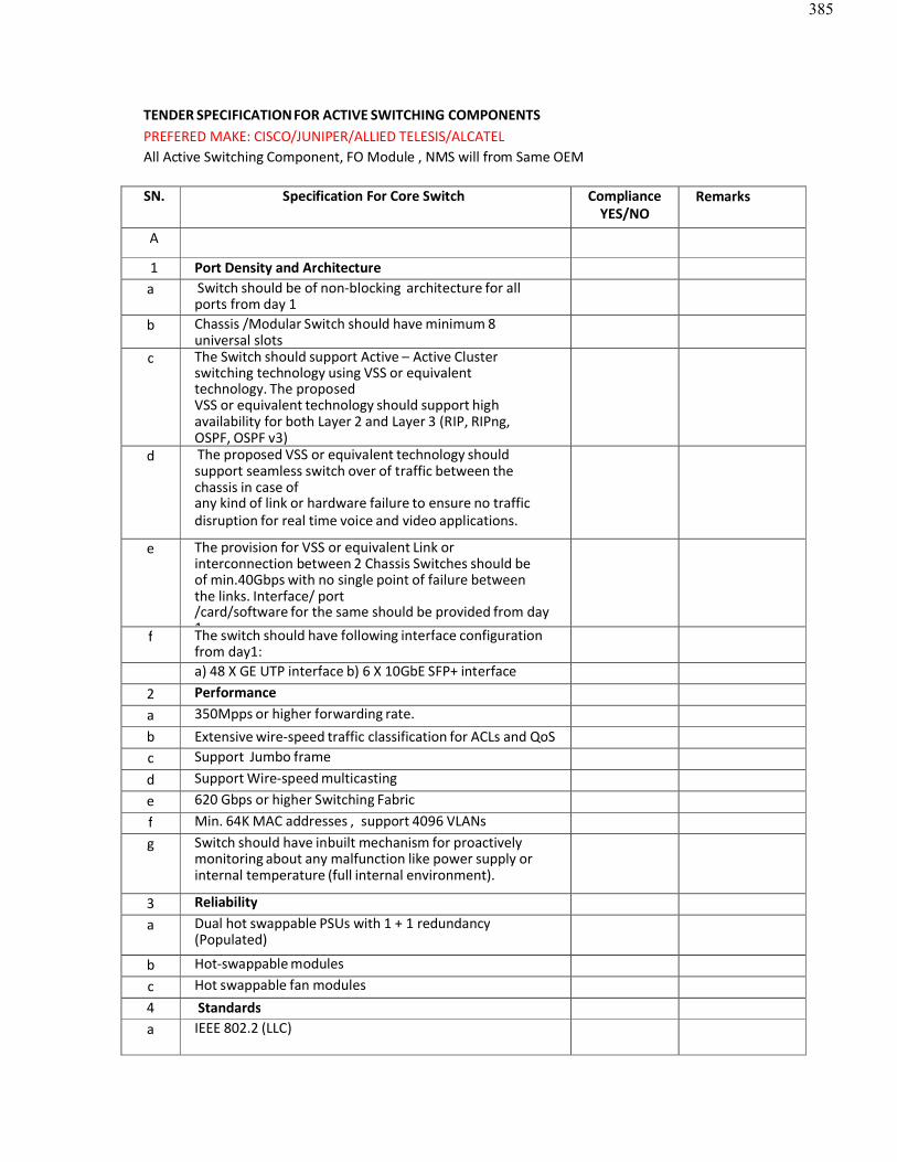
385
TENDER SPECIFICATIONFOR ACTIVE SWITCHING COMPONENTSPREFERED MAKE: CISCO/JUNIPER/ALLIED TELESIS/ALCATELAll Active Switching Component, FO Module , NMS will from Same OEM
SN. Specification For Core Switch ComplianceYES/NO
Remarks
A
1 Port Density and Architecturea Switch should be of non-blocking architecture for all
ports from day 1b Chassis /Modular Switch should have minimum 8
universal slotsc The Switch should support Active – Active Cluster
switching technology using VSS or equivalenttechnology. The proposedVSS or equivalent technology should support highavailability for both Layer 2 and Layer 3 (RIP, RIPng,OSPF, OSPF v3)Including for IP Multicasting (PIM v4,PIM v6) for CCTV videod The proposed VSS or equivalent technology shouldsupport seamless switch over of traffic between thechassis in case ofany kind of link or hardware failure to ensure no trafficdisruption for real time voice and video applications.
e The provision for VSS or equivalent Link orinterconnection between 2 Chassis Switches should beof min.40Gbps with no single point of failure betweenthe links. Interface/ port/card/software for the same should be provided from day1.f The switch should have following interface configurationfrom day1:a) 48 X GE UTP interface b) 6 X 10GbE SFP+ interface
2 Performancea 350Mpps or higher forwarding rate.b Extensive wire-speed traffic classification for ACLs and QoSc Support Jumbo framed Support Wire-speed multicastinge 620 Gbps or higher Switching Fabricf Min. 64K MAC addresses , support 4096 VLANsg Switch should have inbuilt mechanism for proactively
monitoring about any malfunction like power supply orinternal temperature (full internal environment).
3 Reliabilitya Dual hot swappable PSUs with 1 + 1 redundancy
(Populated)
b Hot-swappable modulesc Hot swappable fan modules4 Standardsa IEEE 802.2 (LLC)
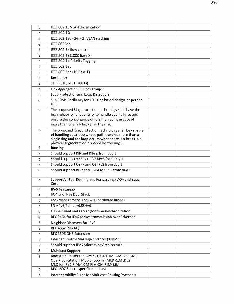
386
b IEEE 802.1v VLAN classificationc IEEE 802.1Qd IEEE 802.1ad (Q-in-Q),VLAN stackinge IEEE 8023aef IEEE 802.3x flow controlg IEEE 802.3z (1000 Base X)h IEEE 802.1p Priority Taggingi IEEE 802.3abj IEEE 802.3an (10 Base T)5 Resiliencya STP, RSTP, MSTP (801s)b Link Aggregation (803ad) groupsc Loop Protection and Loop Detectiond Sub 50Ms Resiliency for 10G ring based design as per the
IEEE802.17/RPR / ERPS or equivalent technologye The proposed Ring protection technology shall have the high reliability functionality to handle dual failures andensure the convergence of less than 50ms in case ofmore than one link broken in the ring.
f The proposed Ring protection technology shall be capableof handling data loop whose path traverse more than a single ring and the loop occurs when there is a break in aphysical segment that is shared by two rings.
6 Routinga Should support RIP and RIPng from day 1b Should support VRRP and VRRPv3 from Day 1c Should support OSPF and OSPFv3 from day 1d Should support BGP and BGP4 for IPv6 from day 1
e Support Virtual Routing and Forwarding (VRF) and EqualCostMulti-Path (ECMP) routing from day 17 IPv6 Features:-
a IPv4 and IPv6 Dual Stackb IPv6 Management ,IPv6 ACL (hardware based)c SNMPv6,Telnet v6,SSHv6d NTPv6 Client and server (for time synchronization)e RFC 2464 for IPv6 packet transmission over Ethernet
networkf Neighbor Discovery for IPv6g RFC 4862 (SLAAC)h RFC 3596 DNS Extensioni Internet Control Message protocol (ICMPv6)k Should support IPv6 Addressing Architecture8 Multicast Supporta Bootstrap Router for IGMP v1,IGMP v2, IGMPv3,IGMP
Query Solicitation ,MLD Snooping (MLDv1,MLDv2),MLD for IPv6,PIMv4-SM,PIM-DM,PIM-SSM
b RFC 4607 Source specific multicastc Interoperability Rules for Multicast Routing Protocols
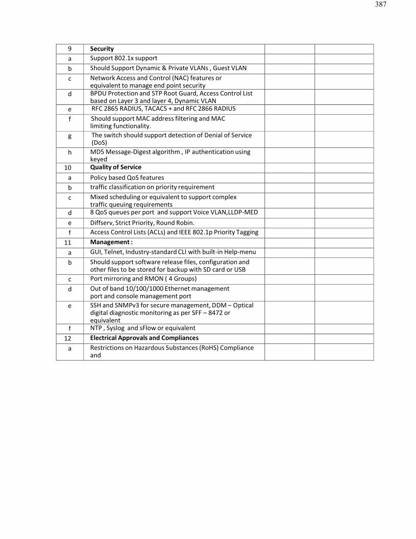
387
9 Securitya Support 802.1x supportb Should Support Dynamic & Private VLANs , Guest VLANc Network Access and Control (NAC) features or
equivalent to manage end point securityd BPDU Protection and STP Root Guard, Access Control List
based on Layer 3 and layer 4, Dynamic VLANe RFC 2865 RADIUS, TACACS + and RFC 2866 RADIUS
accountingf Should support MAC address filtering and MAClimiting functionality.
g The switch should support detection of Denial of Service(DoS)attack.h MD5 Message-Digest algorithm , IP authentication usingkeyedMD510 Quality of Service
a Policy based QoS featuresb traffic classification on priority requirementc Mixed scheduling or equivalent to support complex
traffic queuing requirementsd 8 QoS queues per port and support Voice VLAN,LLDP-MEDe Diffserv, Strict Priority, Round Robin.f Access Control Lists (ACLs) and IEEE 802.1p Priority Tagging
11 Management :a GUI, Telnet, Industry-standard CLI with built-in Help-menub Should support software release files, configuration and
other files to be stored for backup with SD card or USBdrives.c Port mirroring and RMON ( 4 Groups)
d Out of band 10/100/1000 Ethernet managementport and console management port
e SSH and SNMPv3 for secure management, DDM – Opticaldigital diagnostic monitoring as per SFF – 8472 orequivalentstandardsf NTP , Syslog and sFlow or equivalent
12 Electrical Approvals and Compliancesa Restrictions on Hazardous Substances (RoHS) Compliance
andEnergy Efficient Ethernet compliant (EEE) compliance
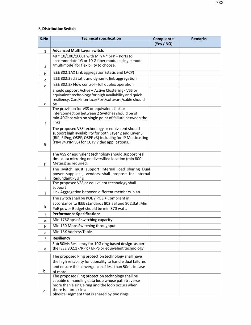
388
B.Distribution Switch
S.No Technical specification Compliance(Yes / NO)
Remarks
1 Advanced Multi Layer switch.
a
48 * 10/100/1000T with Min 4 * SFP + Ports to accommodate 1G or 10 G fiber module (single mode/multimode) for flexibility to choose.
b IEEE 802.1AX Link aggregation (static and LACP)
c IEEE 802.3ad Static and dynamic link aggregation
d IEEE 802.3x Flow control - full duplex operation
e
Should support Active – Active Clustering - VSS or equivalent technology for high availability and quick resiliency. Card/Interface/Port/software/cable shouldbeprovided from day one.
f
The provision for VSS or equivalent Link or interconnection between 2 Switches should be of min.40Gbps with no single point of failure between thelinks
g
The proposed VSS technology or equivalent should support high availability for both Layer 2 and Layer 3 (RIP, RIPng, OSPF, OSPF v3) Including for IP Multicasting(PIM v4,PIM v6) for CCTV video applications.
h
The VSS or equivalent technology should support real time data mirroring on diversified location (min 800Meters) as required.
i
The switch must support Internal load sharing Dual power supplies , vendors shall propose for Internal Redundant PSU ' s
j
The proposed VSS or equivalent technology shallsupportLink Aggregation between different members in anActive
k
The switch shall be POE / POE + Compliant inaccordance to IEEE standards 802.3af and 802.3at .MinPoE power Budget should be min 370 watt.
2 Performance Specifications
a Min 176Gbps of switching capacity
b Min 130 Mpps Switching throughput
c Min 16K Address Table
3 Resiliency
aSub 50Ms Resiliency for 10G ring based design as perthe IEEE 802.17/RPR / ERPS or equivalent technology
b
The proposed Ring protection technology shall havethe high reliability functionality to handle dual failuresand ensure the convergence of less than 50ms in caseof more
c
The proposed Ring protection technology shall becapable of handling data loop whose path traversemore than a single ring and the loop occurs whenthere is a break in aphysical segment that is shared by two rings.
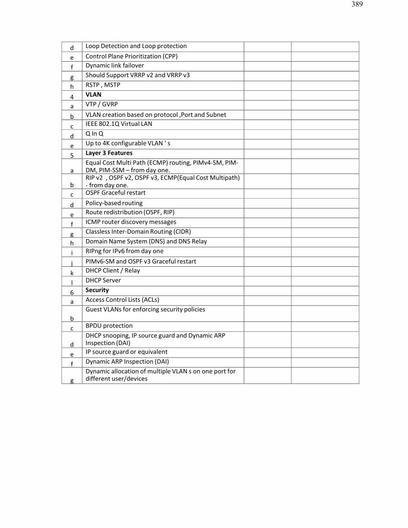
389
d Loop Detection and Loop protection
e Control Plane Prioritization (CPP)
f Dynamic link failover
g Should Support VRRP v2 and VRRP v3
h RSTP , MSTP
4 VLAN
a VTP / GVRP
b VLAN creation based on protocol ,Port and Subnetbasedc IEEE 802.1Q Virtual LAN
d Q In Q
e Up to 4K configurable VLAN ' s
5 Layer 3 Features
aEqual Cost Multi Path (ECMP) routing, PIMv4-SM, PIM-DM, PIM-SSM – from day one.
bRIP v2 , OSPF v2, OSPF v3, ECMP(Equal Cost Multipath)- from day one.
c OSPF Graceful restart
d Policy-based routing
e Route redistribution (OSPF, RIP)
f ICMP router discovery messages
g Classless Inter-Domain Routing (CIDR)
h Domain Name System (DNS) and DNS Relay
i RIPng for IPv6 from day one
j PIMv6-SM and OSPF v3 Graceful restart
k DHCP Client / Relay
l DHCP Server
6 Security
a Access Control Lists (ACLs)
bGuest VLANs for enforcing security policies
c BPDU protection
dDHCP snooping, IP source guard and Dynamic ARP Inspection (DAI)
e IP source guard or equivalent
f Dynamic ARP Inspection (DAI)
gDynamic allocation of multiple VLAN s on one port for different user/devices
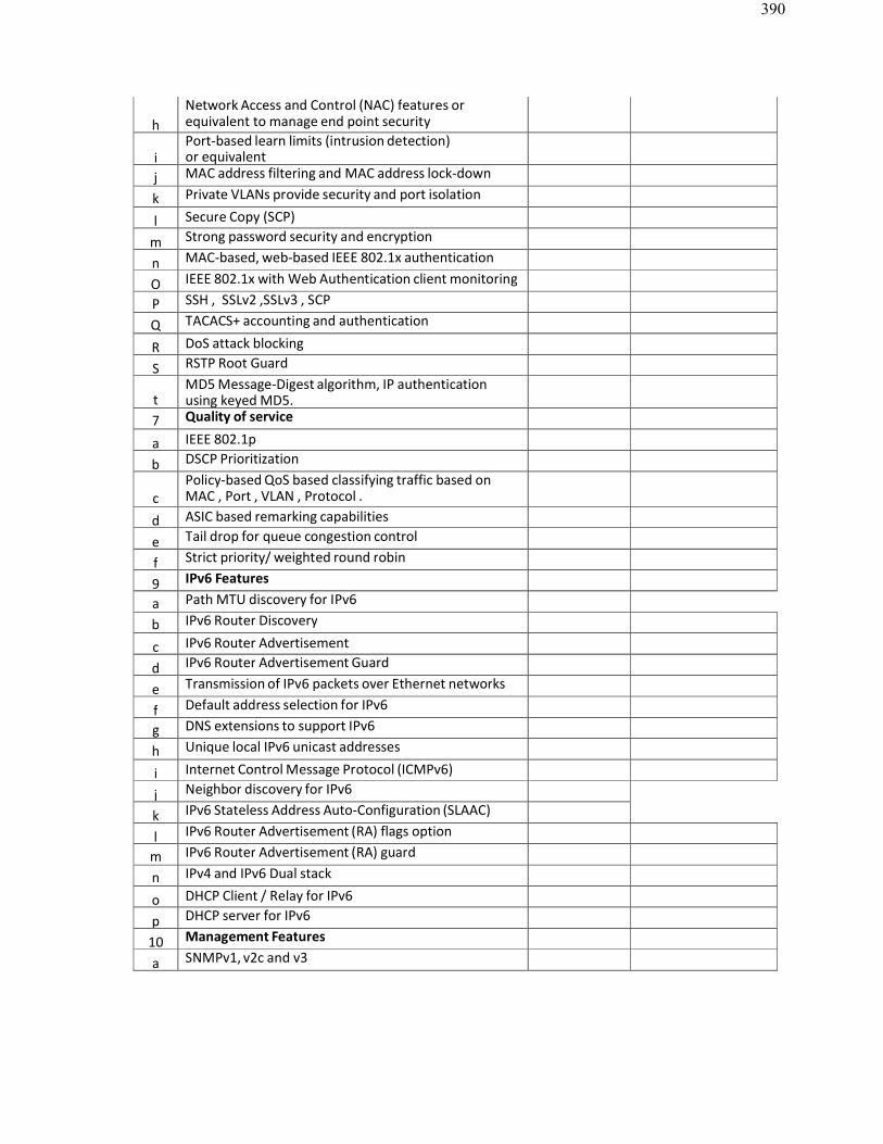
390
hNetwork Access and Control (NAC) features orequivalent to manage end point security
iPort-based learn limits (intrusion detection)or equivalent
j MAC address filtering and MAC address lock-down
k Private VLANs provide security and port isolation
l Secure Copy (SCP)
m Strong password security and encryption
n MAC-based, web-based IEEE 802.1x authentication
O IEEE 802.1x with Web Authentication client monitoring
P SSH , SSLv2 ,SSLv3 , SCP
Q TACACS+ accounting and authentication
R DoS attack blocking
S RSTP Root Guard
tMD5 Message-Digest algorithm, IP authenticationusing keyed MD5.
7 Quality of service
a IEEE 802.1p
b DSCP Prioritization
cPolicy-based QoS based classifying traffic based onMAC , Port , VLAN , Protocol .
d ASIC based remarking capabilities
e Tail drop for queue congestion control
f Strict priority/ weighted round robin
9 IPv6 Features
a Path MTU discovery for IPv6
b IPv6 Router Discovery
c IPv6 Router Advertisement
d IPv6 Router Advertisement Guard
e Transmission of IPv6 packets over Ethernet networks
f Default address selection for IPv6
g DNS extensions to support IPv6
h Unique local IPv6 unicast addresses
i Internet Control Message Protocol (ICMPv6)
j Neighbor discovery for IPv6
k IPv6 Stateless Address Auto-Configuration (SLAAC)
l IPv6 Router Advertisement (RA) flags option
m IPv6 Router Advertisement (RA) guard
n IPv4 and IPv6 Dual stack
o DHCP Client / Relay for IPv6
p DHCP server for IPv6
10 Management Features
a SNMPv1, v2c and v3
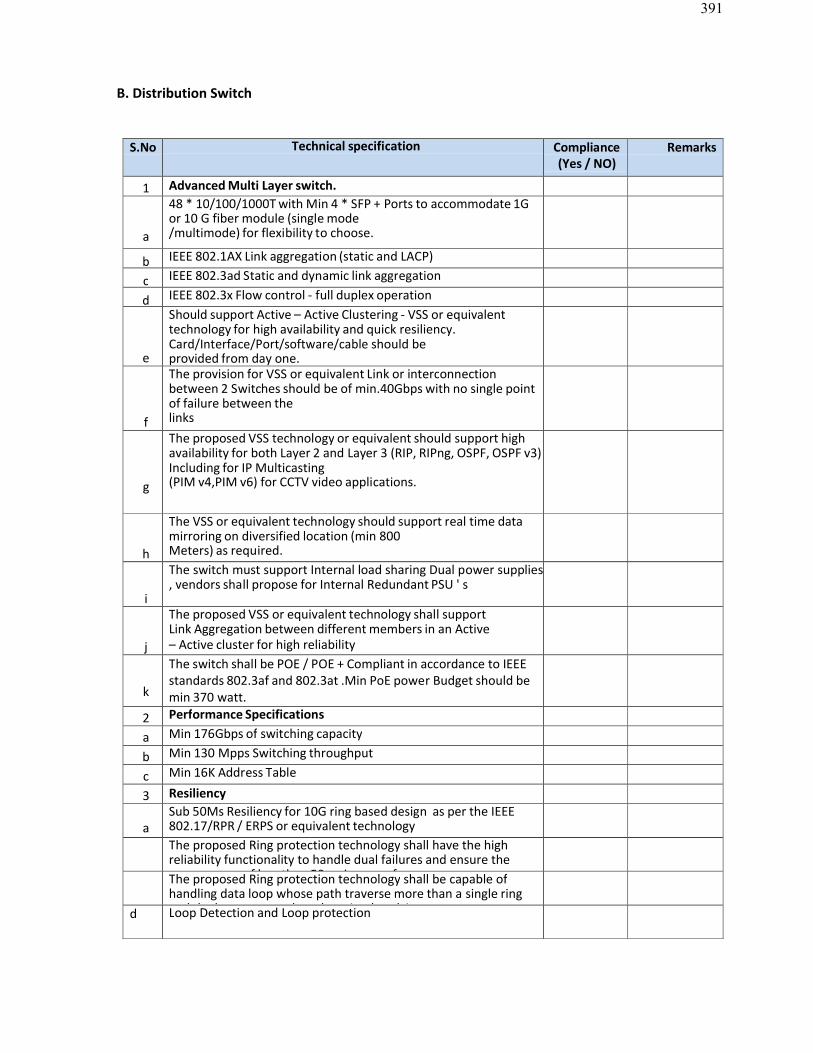
391
B. Distribution Switch
S.No Technical specification Compliance(Yes / NO)
Remarks
1 Advanced Multi Layer switch.
a
48 * 10/100/1000T with Min 4 * SFP + Ports to accommodate 1Gor 10 G fiber module (single mode/multimode) for flexibility to choose.
b IEEE 802.1AX Link aggregation (static and LACP)
c IEEE 802.3ad Static and dynamic link aggregation
d IEEE 802.3x Flow control - full duplex operation
e
Should support Active – Active Clustering - VSS or equivalenttechnology for high availability and quick resiliency.Card/Interface/Port/software/cable should beprovided from day one.
f
The provision for VSS or equivalent Link or interconnectionbetween 2 Switches should be of min.40Gbps with no single pointof failure between thelinks
g
The proposed VSS technology or equivalent should support highavailability for both Layer 2 and Layer 3 (RIP, RIPng, OSPF, OSPF v3)Including for IP Multicasting(PIM v4,PIM v6) for CCTV video applications.
h
The VSS or equivalent technology should support real time datamirroring on diversified location (min 800Meters) as required.
i
The switch must support Internal load sharing Dual power supplies, vendors shall propose for Internal Redundant PSU ' s
j
The proposed VSS or equivalent technology shall supportLink Aggregation between different members in an Active– Active cluster for high reliability
k
The switch shall be POE / POE + Compliant in accordance to IEEEstandards 802.3af and 802.3at .Min PoE power Budget should bemin 370 watt.
2 Performance Specifications
a Min 176Gbps of switching capacity
b Min 130 Mpps Switching throughput
c Min 16K Address Table
3 Resiliency
aSub 50Ms Resiliency for 10G ring based design as per the IEEE802.17/RPR / ERPS or equivalent technologyThe proposed Ring protection technology shall have the highreliability functionality to handle dual failures and ensure theconvergence of less than 50ms in case of moreThe proposed Ring protection technology shall be capable ofhandling data loop whose path traverse more than a single ringand the loop occurs when there is a break in ad Loop Detection and Loop protection
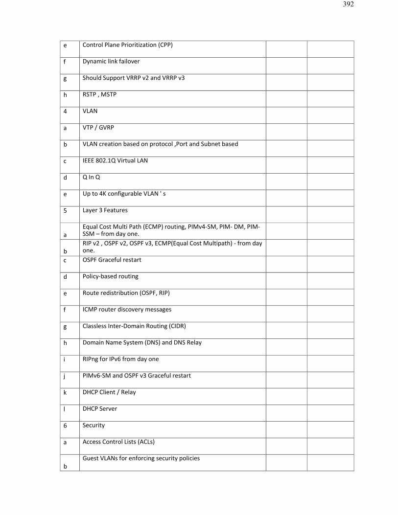
392
e Control Plane Prioritization (CPP)
f Dynamic link failover
g Should Support VRRP v2 and VRRP v3
h RSTP , MSTP
4 VLAN
a VTP / GVRP
b VLAN creation based on protocol ,Port and Subnet based
c IEEE 802.1Q Virtual LAN
d Q In Q
e Up to 4K configurable VLAN ' s
5 Layer 3 Features
aEqual Cost Multi Path (ECMP) routing, PIMv4-SM, PIM- DM, PIM-SSM – from day one.
bRIP v2 , OSPF v2, OSPF v3, ECMP(Equal Cost Multipath) - from dayone.
c OSPF Graceful restart
d Policy-based routing
e Route redistribution (OSPF, RIP)
f ICMP router discovery messages
g Classless Inter-Domain Routing (CIDR)
h Domain Name System (DNS) and DNS Relay
i RIPng for IPv6 from day one
j PIMv6-SM and OSPF v3 Graceful restart
k DHCP Client / Relay
l DHCP Server
6 Security
a Access Control Lists (ACLs)
bGuest VLANs for enforcing security policies
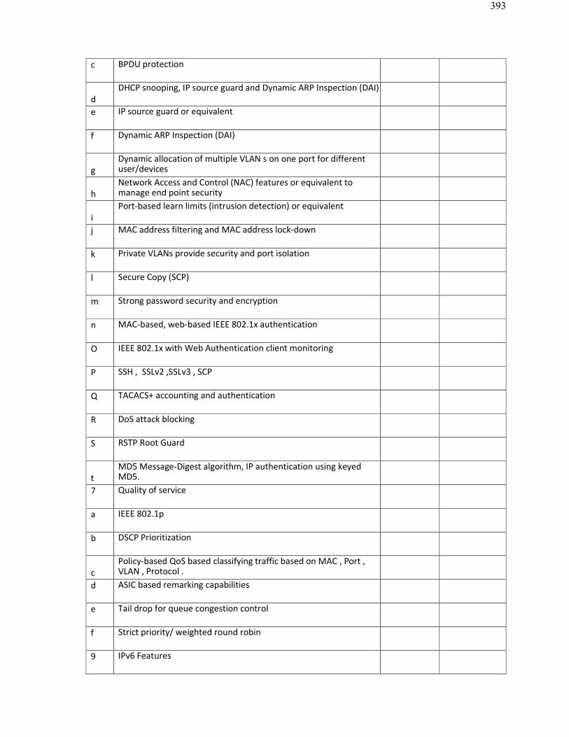
393
c BPDU protection
dDHCP snooping, IP source guard and Dynamic ARP Inspection (DAI)
e IP source guard or equivalent
f Dynamic ARP Inspection (DAI)
gDynamic allocation of multiple VLAN s on one port for differentuser/devices
hNetwork Access and Control (NAC) features or equivalent tomanage end point security
iPort-based learn limits (intrusion detection) or equivalent
j MAC address filtering and MAC address lock-down
k Private VLANs provide security and port isolation
l Secure Copy (SCP)
m Strong password security and encryption
n MAC-based, web-based IEEE 802.1x authentication
O IEEE 802.1x with Web Authentication client monitoring
P SSH , SSLv2 ,SSLv3 , SCP
Q TACACS+ accounting and authentication
R DoS attack blocking
S RSTP Root Guard
tMD5 Message-Digest algorithm, IP authentication using keyedMD5.
7 Quality of service
a IEEE 802.1p
b DSCP Prioritization
cPolicy-based QoS based classifying traffic based on MAC , Port ,VLAN , Protocol .
d ASIC based remarking capabilities
e Tail drop for queue congestion control
f Strict priority/ weighted round robin
9 IPv6 Features
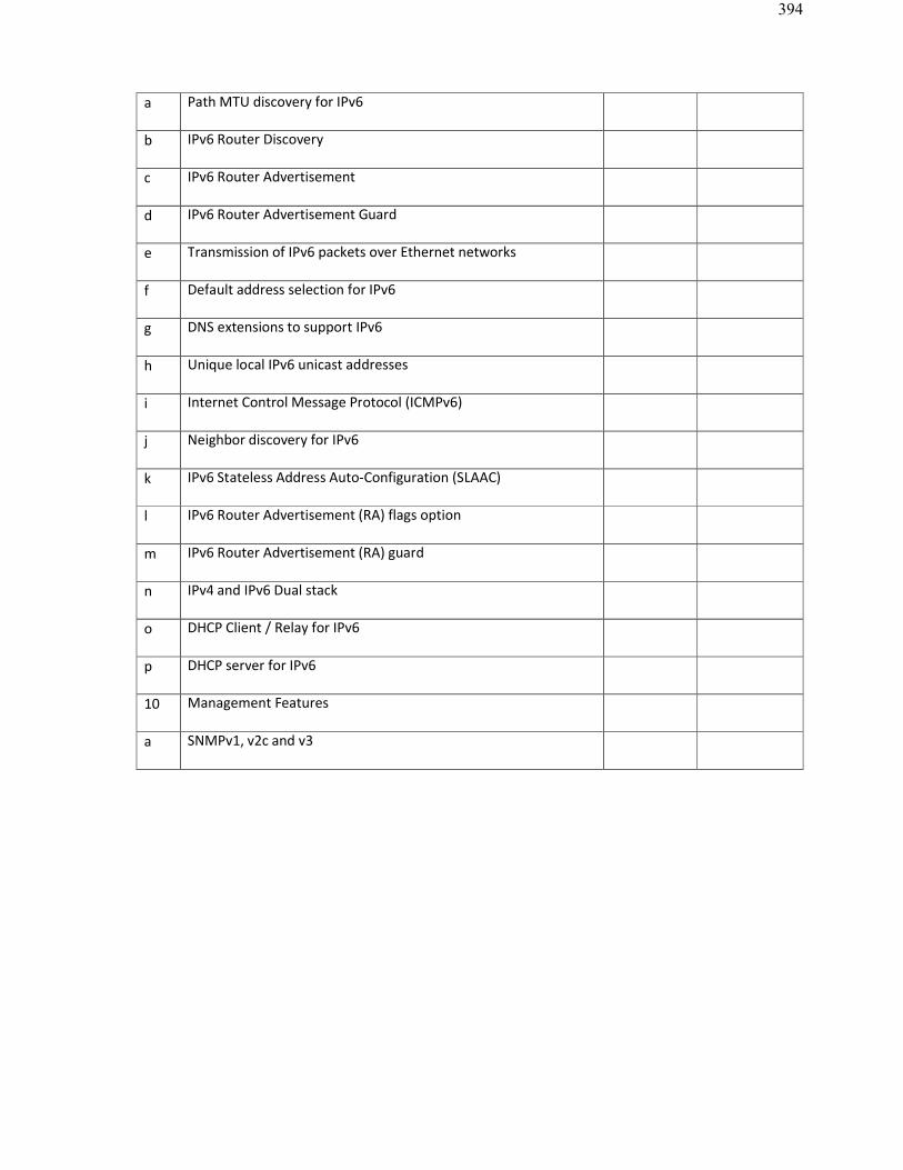
394
a Path MTU discovery for IPv6
b IPv6 Router Discovery
c IPv6 Router Advertisement
d IPv6 Router Advertisement Guard
e Transmission of IPv6 packets over Ethernet networks
f Default address selection for IPv6
g DNS extensions to support IPv6
h Unique local IPv6 unicast addresses
i Internet Control Message Protocol (ICMPv6)
j Neighbor discovery for IPv6
k IPv6 Stateless Address Auto-Configuration (SLAAC)
l IPv6 Router Advertisement (RA) flags option
m IPv6 Router Advertisement (RA) guard
n IPv4 and IPv6 Dual stack
o DHCP Client / Relay for IPv6
p DHCP server for IPv6
10 Management Features
a SNMPv1, v2c and v3
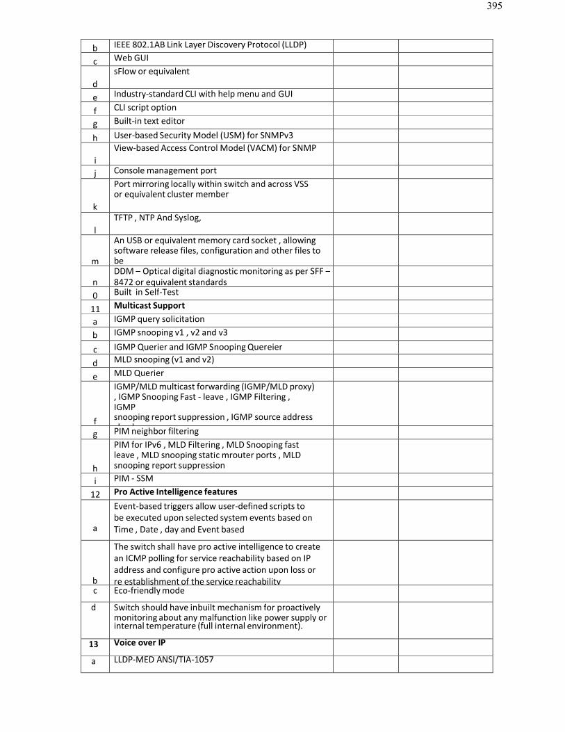
395
b IEEE 802.1AB Link Layer Discovery Protocol (LLDP)
c Web GUI
dsFlow or equivalent
e Industry-standard CLI with help menu and GUI
f CLI script option
g Built-in text editor
h User-based Security Model (USM) for SNMPv3
iView-based Access Control Model (VACM) for SNMP
j Console management port
k
Port mirroring locally within switch and across VSSor equivalent cluster member
lTFTP , NTP And Syslog,
m
An USB or equivalent memory card socket , allowing software release files, configuration and other files tobestored for backup and distribution to other switches
nDDM – Optical digital diagnostic monitoring as per SFF –8472 or equivalent standards
0 Built in Self-Test
11 Multicast Support
a IGMP query solicitation
b IGMP snooping v1 , v2 and v3
c IGMP Querier and IGMP Snooping Quereier
d MLD snooping (v1 and v2)
e MLD Querier
f
IGMP/MLD multicast forwarding (IGMP/MLD proxy), IGMP Snooping Fast - leave , IGMP Filtering ,IGMPsnooping report suppression , IGMP source addresscheck
g PIM neighbor filtering
h
PIM for IPv6 , MLD Filtering , MLD Snooping fastleave , MLD snooping static mrouter ports , MLDsnooping report suppression
i PIM - SSM
12 Pro Active Intelligence features
a
Event-based triggers allow user-defined scripts tobe executed upon selected system events based onTime , Date , day and Event based
b
The switch shall have pro active intelligence to createan ICMP polling for service reachability based on IPaddress and configure pro active action upon loss orre establishment of the service reachability
c Eco-friendly mode
d Switch should have inbuilt mechanism for proactively monitoring about any malfunction like power supply or internal temperature (full internal environment).
13 Voice over IP
a LLDP-MED ANSI/TIA-1057

396
b Voice VLAN
14 Compliances
a ROHS compliant is must
b IEEE 802.3az Energy Efficient Ethernet (EEE)
c UL, cUL, TUV
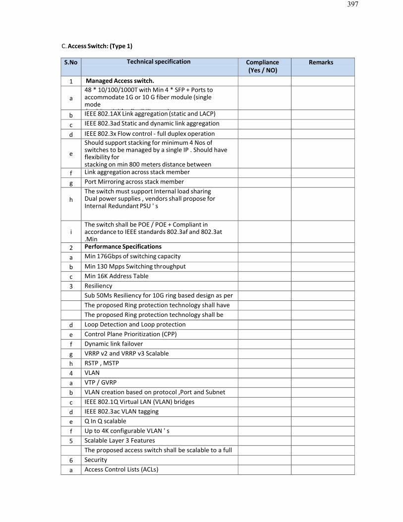
397
C. Access Switch: (Type 1)
S.No Technical specification Compliance(Yes / NO)
Remarks
1 Managed Access switch.
a48 * 10/100/1000T with Min 4 * SFP + Ports to accommodate 1G or 10 G fiber module (singlemode/multimode) for flexibility to choose.b IEEE 802.1AX Link aggregation (static and LACP)
c IEEE 802.3ad Static and dynamic link aggregation
d IEEE 802.3x Flow control - full duplex operation
e
Should support stacking for minimum 4 Nos ofswitches to be managed by a single IP . Should haveflexibility forstacking on min 800 meters distance betweenmembers of individual stack switches as required.f Link aggregation across stack member
g Port Mirroring across stack member
hThe switch must support Internal load sharingDual power supplies , vendors shall propose forInternal Redundant PSU ' s
iThe switch shall be POE / POE + Compliant in accordance to IEEE standards 802.3af and 802.3at.MinPoE power Budget should be min 370 watt.2 Performance Specifications
a Min 176Gbps of switching capacity
b Min 130 Mpps Switching throughputc Min 16K Address Table3 Resiliency
Sub 50Ms Resiliency for 10G ring based design as per the IEEE 802.17/RPR / ERPS or equivalent technologyThe proposed Ring protection technology shall have the high reliability functionality to handle dual failures The proposed Ring protection technology shall be capable of handling data loop whose path traverse d Loop Detection and Loop protection
e Control Plane Prioritization (CPP)f Dynamic link failoverg VRRP v2 and VRRP v3 Scalableh RSTP , MSTP4 VLANa VTP / GVRPb VLAN creation based on protocol ,Port and Subnet
basedc IEEE 802.1Q Virtual LAN (VLAN) bridgesd IEEE 802.3ac VLAN tagginge Q In Q scalablef Up to 4K configurable VLAN ' s5 Scalable Layer 3 Features
The proposed access switch shall be scalable to a full layer 3 switch supporting routing protocols RIP, OSPF, 6 Security
a Access Control Lists (ACLs)
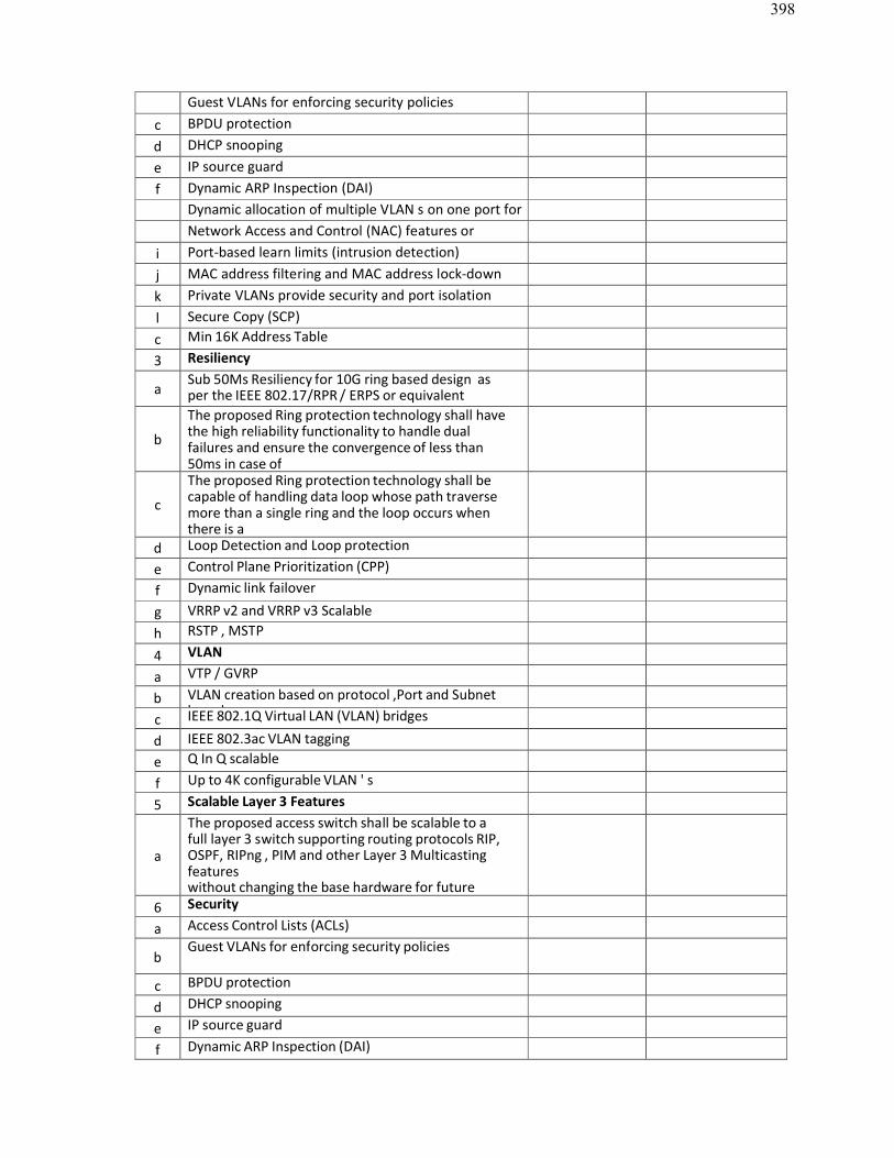
398
Guest VLANs for enforcing security policiesc BPDU protectiond DHCP snoopinge IP source guardf Dynamic ARP Inspection (DAI)
Dynamic allocation of multiple VLAN s on one port for different user/devicesNetwork Access and Control (NAC) features or equivalent to manage end point securityi Port-based learn limits (intrusion detection)
j MAC address filtering and MAC address lock-downk Private VLANs provide security and port isolationl Secure Copy (SCP)c Min 16K Address Table
3 Resiliency
aSub 50Ms Resiliency for 10G ring based design asper the IEEE 802.17/RPR / ERPS or equivalenttechnology
b
The proposed Ring protection technology shall havethe high reliability functionality to handle dualfailures and ensure the convergence of less than50ms in case ofmore than one link broken in the ring.
c
The proposed Ring protection technology shall be capable of handling data loop whose path traversemore than a single ring and the loop occurs whenthere is abreak in a physical segment that is shared by two ringsd Loop Detection and Loop protection
e Control Plane Prioritization (CPP)
f Dynamic link failover
g VRRP v2 and VRRP v3 Scalableh RSTP , MSTP
4 VLAN
a VTP / GVRP
b VLAN creation based on protocol ,Port and Subnetbasedc IEEE 802.1Q Virtual LAN (VLAN) bridges
d IEEE 802.3ac VLAN tagginge Q In Q scalable
f Up to 4K configurable VLAN ' s
5 Scalable Layer 3 Features
a
The proposed access switch shall be scalable to afull layer 3 switch supporting routing protocols RIP,OSPF, RIPng , PIM and other Layer 3 Multicastingfeatureswithout changing the base hardware for futurescalability / further expansion of the network.6 Security
a Access Control Lists (ACLs)
bGuest VLANs for enforcing security policies
c BPDU protection
d DHCP snooping
e IP source guard
f Dynamic ARP Inspection (DAI)
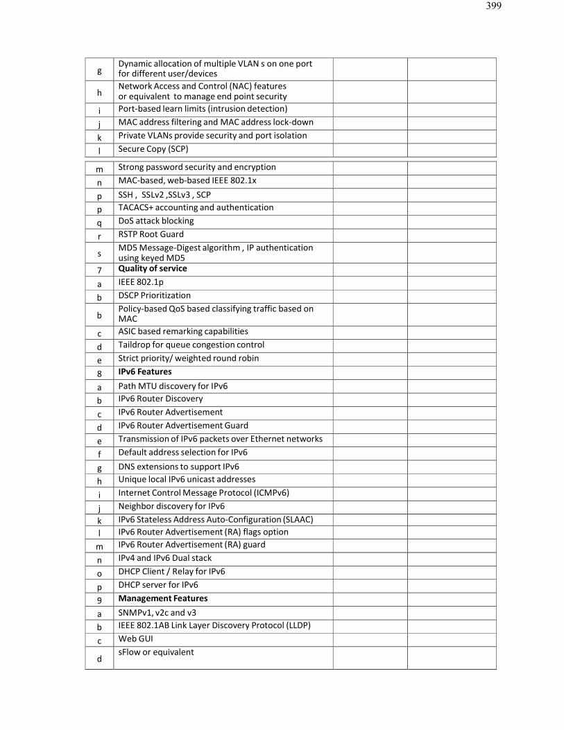
399
gDynamic allocation of multiple VLAN s on one portfor different user/devices
hNetwork Access and Control (NAC) featuresor equivalent to manage end point security
i Port-based learn limits (intrusion detection)
j MAC address filtering and MAC address lock-down
k Private VLANs provide security and port isolation
l Secure Copy (SCP)
m Strong password security and encryption
n MAC-based, web-based IEEE 802.1x
p SSH , SSLv2 ,SSLv3 , SCPp TACACS+ accounting and authentication
q DoS attack blocking
r RSTP Root Guard
sMD5 Message-Digest algorithm , IP authenticationusing keyed MD5
7 Quality of service
a IEEE 802.1p
b DSCP Prioritization
bPolicy-based QoS based classifying traffic based onMAC, Port , VLAN , Protocol .c ASIC based remarking capabilities
d Taildrop for queue congestion control
e Strict priority/ weighted round robin
8 IPv6 Features
a Path MTU discovery for IPv6b IPv6 Router Discovery
c IPv6 Router Advertisement
d IPv6 Router Advertisement Guard
e Transmission of IPv6 packets over Ethernet networks
f Default address selection for IPv6
g DNS extensions to support IPv6
h Unique local IPv6 unicast addresses
i Internet Control Message Protocol (ICMPv6)
j Neighbor discovery for IPv6
k IPv6 Stateless Address Auto-Configuration (SLAAC)l IPv6 Router Advertisement (RA) flags option
m IPv6 Router Advertisement (RA) guard
n IPv4 and IPv6 Dual stack
o DHCP Client / Relay for IPv6
p DHCP server for IPv6
9 Management Features
a SNMPv1, v2c and v3b IEEE 802.1AB Link Layer Discovery Protocol (LLDP)
c Web GUI
dsFlow or equivalent
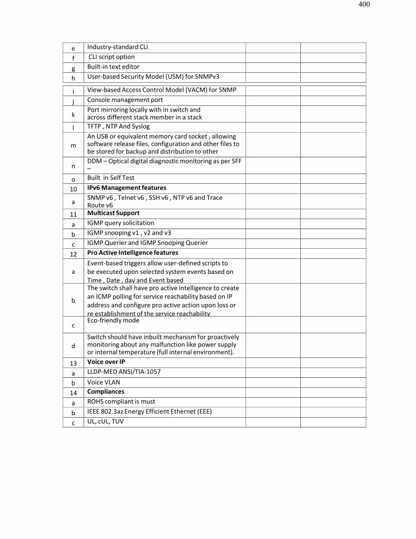
400
e Industry-standard CLI
f CLI script option
g Built-in text editor
h User-based Security Model (USM) for SNMPv3
i View-based Access Control Model (VACM) for SNMP
j Console management port
kPort mirroring locally with in switch andacross different stack member in a stack
l TFTP , NTP And Syslog
mAn USB or equivalent memory card socket , allowing software release files, configuration and other files tobe stored for backup and distribution to otherswitches
nDDM – Optical digital diagnostic monitoring as per SFF–8472 or equivalent standardso Built in Self Test
10 IPv6 Management features
a SNMP v6 , Telnet v6 , SSH v6 , NTP v6 and TraceRoute v6
11 Multicast Support
a IGMP query solicitation
b IGMP snooping v1 , v2 and v3
c IGMP Querier and IGMP Snooping Querier
12 Pro Active Intelligence features
aEvent-based triggers allow user-defined scripts tobe executed upon selected system events based onTime , Date , day and Event based
b
The switch shall have pro active intelligence to createan ICMP polling for service reachability based on IPaddress and configure pro active action upon loss orre establishment of the service reachability
cEco-friendly mode
dSwitch should have inbuilt mechanism for proactively monitoring about any malfunction like power supplyor internal temperature (full internal environment).
13 Voice over IP
a LLDP-MED ANSI/TIA-1057
b Voice VLAN14 Compliances
a ROHS compliant is must
b IEEE 802.3az Energy Efficient Ethernet (EEE)
c UL, cUL, TUV
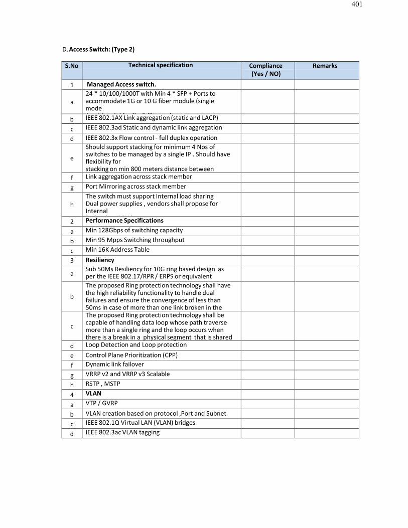
401
D.Access Switch: (Type 2)
S.No Technical specification Compliance(Yes / NO)
Remarks
1 Managed Access switch.
a24 * 10/100/1000T with Min 4 * SFP + Ports to accommodate 1G or 10 G fiber module (singlemode/multimode) for flexibility to choose .b IEEE 802.1AX Link aggregation (static and LACP)
c IEEE 802.3ad Static and dynamic link aggregation
d IEEE 802.3x Flow control - full duplex operation
e
Should support stacking for minimum 4 Nos ofswitches to be managed by a single IP . Should haveflexibility forstacking on min 800 meters distance betweenmembers of individual stack switches as required.f Link aggregation across stack member
g Port Mirroring across stack member
hThe switch must support Internal load sharingDual power supplies , vendors shall propose forInternalRedundant PSU ' s2 Performance Specifications
a Min 128Gbps of switching capacity
b Min 95 Mpps Switching throughput
c Min 16K Address Table
3 Resiliency
aSub 50Ms Resiliency for 10G ring based design asper the IEEE 802.17/RPR / ERPS or equivalenttechnology
b
The proposed Ring protection technology shall havethe high reliability functionality to handle dualfailures and ensure the convergence of less than50ms in case of more than one link broken in thering.
c
The proposed Ring protection technology shall be capable of handling data loop whose path traversemore than a single ring and the loop occurs whenthere is a break in a physical segment that is sharedby two ringsd Loop Detection and Loop protection
e Control Plane Prioritization (CPP)f Dynamic link failover
g VRRP v2 and VRRP v3 Scalable
h RSTP , MSTP
4 VLAN
a VTP / GVRP
b VLAN creation based on protocol ,Port and Subnetbasedc IEEE 802.1Q Virtual LAN (VLAN) bridges
d IEEE 802.3ac VLAN tagging
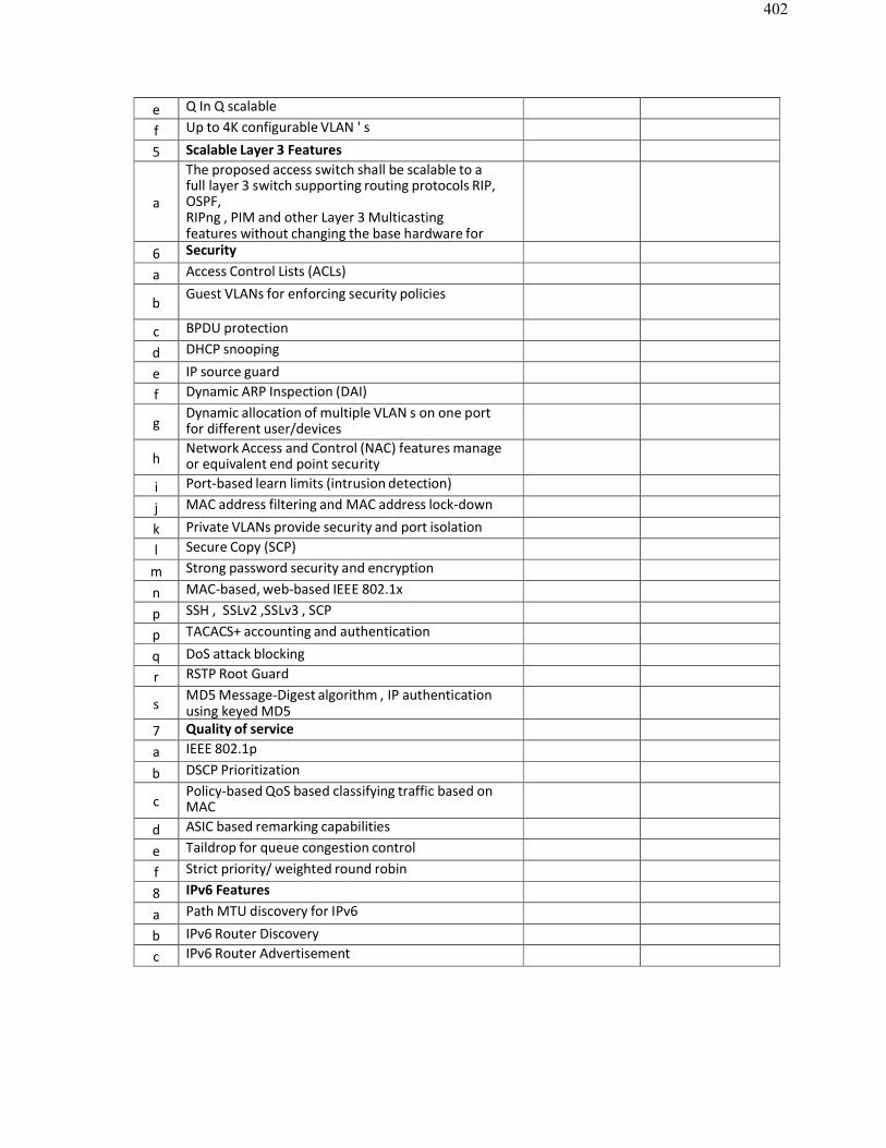
402
e Q In Q scalable
f Up to 4K configurable VLAN ' s
5 Scalable Layer 3 Features
a
The proposed access switch shall be scalable to afull layer 3 switch supporting routing protocols RIP,OSPF,RIPng , PIM and other Layer 3 Multicastingfeatures without changing the base hardware forfuture6 Security
a Access Control Lists (ACLs)
bGuest VLANs for enforcing security policies
c BPDU protection
d DHCP snooping
e IP source guardf Dynamic ARP Inspection (DAI)
gDynamic allocation of multiple VLAN s on one portfor different user/devices
hNetwork Access and Control (NAC) features manageor equivalent end point security
i Port-based learn limits (intrusion detection)
j MAC address filtering and MAC address lock-down
k Private VLANs provide security and port isolationl Secure Copy (SCP)
m Strong password security and encryption
n MAC-based, web-based IEEE 802.1x
p SSH , SSLv2 ,SSLv3 , SCP
p TACACS+ accounting and authentication
q DoS attack blocking
r RSTP Root Guard
sMD5 Message-Digest algorithm , IP authenticationusing keyed MD5
7 Quality of servicea IEEE 802.1p
b DSCP Prioritization
cPolicy-based QoS based classifying traffic based onMAC, Port , VLAN , Protocol .d ASIC based remarking capabilities
e Taildrop for queue congestion control
f Strict priority/ weighted round robin
8 IPv6 Features
a Path MTU discovery for IPv6
b IPv6 Router Discoveryc IPv6 Router Advertisement
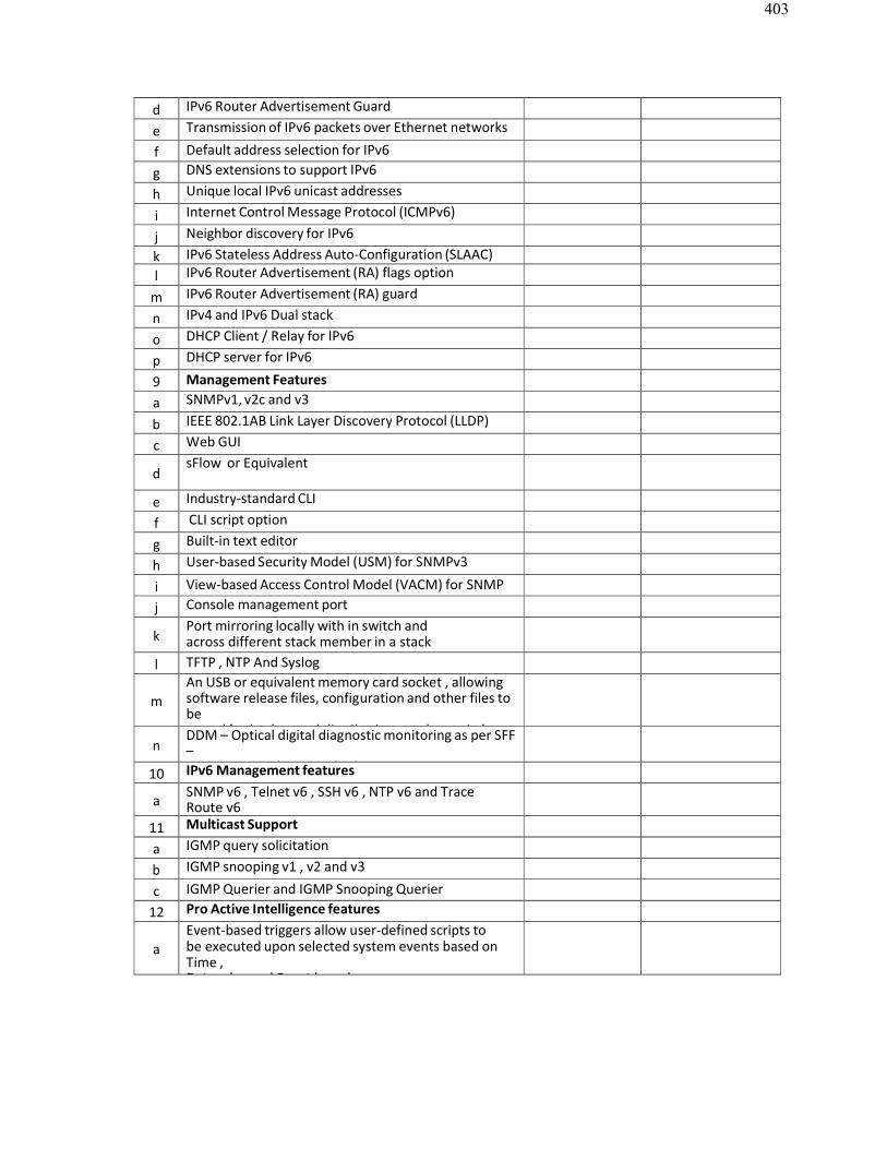
403
d IPv6 Router Advertisement Guard
e Transmission of IPv6 packets over Ethernet networks
f Default address selection for IPv6
g DNS extensions to support IPv6
h Unique local IPv6 unicast addresses
i Internet Control Message Protocol (ICMPv6)
j Neighbor discovery for IPv6
k IPv6 Stateless Address Auto-Configuration (SLAAC)l IPv6 Router Advertisement (RA) flags option
m IPv6 Router Advertisement (RA) guard
n IPv4 and IPv6 Dual stack
o DHCP Client / Relay for IPv6
p DHCP server for IPv6
9 Management Features
a SNMPv1, v2c and v3
b IEEE 802.1AB Link Layer Discovery Protocol (LLDP)
c Web GUI
dsFlow or Equivalent
e Industry-standard CLI
f CLI script option
g Built-in text editor
h User-based Security Model (USM) for SNMPv3
i View-based Access Control Model (VACM) for SNMPj Console management port
kPort mirroring locally with in switch andacross different stack member in a stack
l TFTP , NTP And Syslog
mAn USB or equivalent memory card socket , allowing software release files, configuration and other files tobestored for backup and distribution to other switches
nDDM – Optical digital diagnostic monitoring as per SFF–8472 or equivalent standards10 IPv6 Management features
a SNMP v6 , Telnet v6 , SSH v6 , NTP v6 and TraceRoute v6
11 Multicast Support
a IGMP query solicitation
b IGMP snooping v1 , v2 and v3
c IGMP Querier and IGMP Snooping Querier
12 Pro Active Intelligence features
aEvent-based triggers allow user-defined scripts tobe executed upon selected system events based onTime ,Date , day and Event based
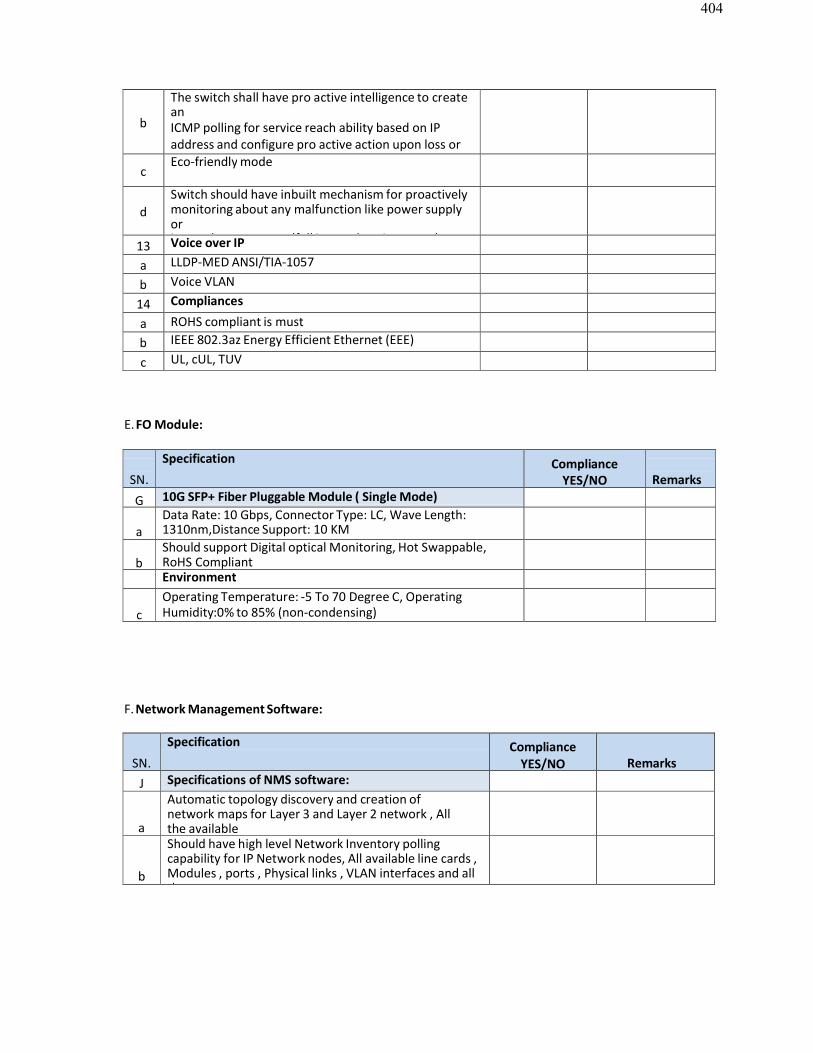
404
b
The switch shall have pro active intelligence to createanICMP polling for service reach ability based on IP address and configure pro active action upon loss orre establishment of the service reach ability
cEco-friendly mode
dSwitch should have inbuilt mechanism for proactively monitoring about any malfunction like power supplyorinternal temperature (full internal environment).13 Voice over IP
a LLDP-MED ANSI/TIA-1057
b Voice VLAN
14 Compliances
a ROHS compliant is mustb IEEE 802.3az Energy Efficient Ethernet (EEE)
c UL, cUL, TUV
E.FO Module:
SN.
Specification ComplianceYES/NO Remarks
G 10G SFP+ Fiber Pluggable Module ( Single Mode)
aData Rate: 10 Gbps, Connector Type: LC, Wave Length:1310nm,Distance Support: 10 KM
bShould support Digital optical Monitoring, Hot Swappable,RoHS CompliantEnvironment
cOperating Temperature: -5 To 70 Degree C, OperatingHumidity:0% to 85% (non-condensing)
F.Network Management Software:
SN.
Specification ComplianceYES/NO Remarks
J Specifications of NMS software:
a
Automatic topology discovery and creation ofnetwork maps for Layer 3 and Layer 2 network , Allthe availableVLANS
b
Should have high level Network Inventory pollingcapability for IP Network nodes, All available line cards ,Modules , ports , Physical links , VLAN interfaces and allthe
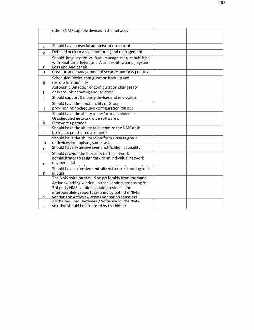
405
other SNMP capable devices in the network
c Should have powerful administration control
d Detailed performance monitoring and management
e
Should have extensive fault manage men capabilitieswith Real time Event and Alarm notifications , SystemLogs and Audit trials
f Creation and management of security and QOS policies
gScheduled Device configuration back-up andrestore functionality
hAutomatic Detection of configuration changes foreasy trouble shooting and Isolation
i Should support 3rd party devices and end points
jShould have the functionality of Groupprovisioning / Scheduled configuration roll outmanagement
k
Should have the ability to perform scheduled orUnscheduled network wide software orFirmware upgrades
lShould have the ability to customize the NMS dashboards as per the requirements
mShould have the ability to perform / create groupof devices for applying same task
n Should have extensive Event notification capability
o
Should provide the flexibility to the networkadministrator to assign task to an Individual networkengineer andassign ownership / track the status of the issue resolution
pShould have extensive centralized trouble shooting toolsin built
q
The NMS solution should be preferably from the sameActive switching vendor , in case vendors proposing for3rd party NMS solution should provide all the interoperability reports certified by both the NMSvendor and Active switching vendor on seamless
rAll the required Hardware / Software for the NMSsolution should be proposed by the bidder
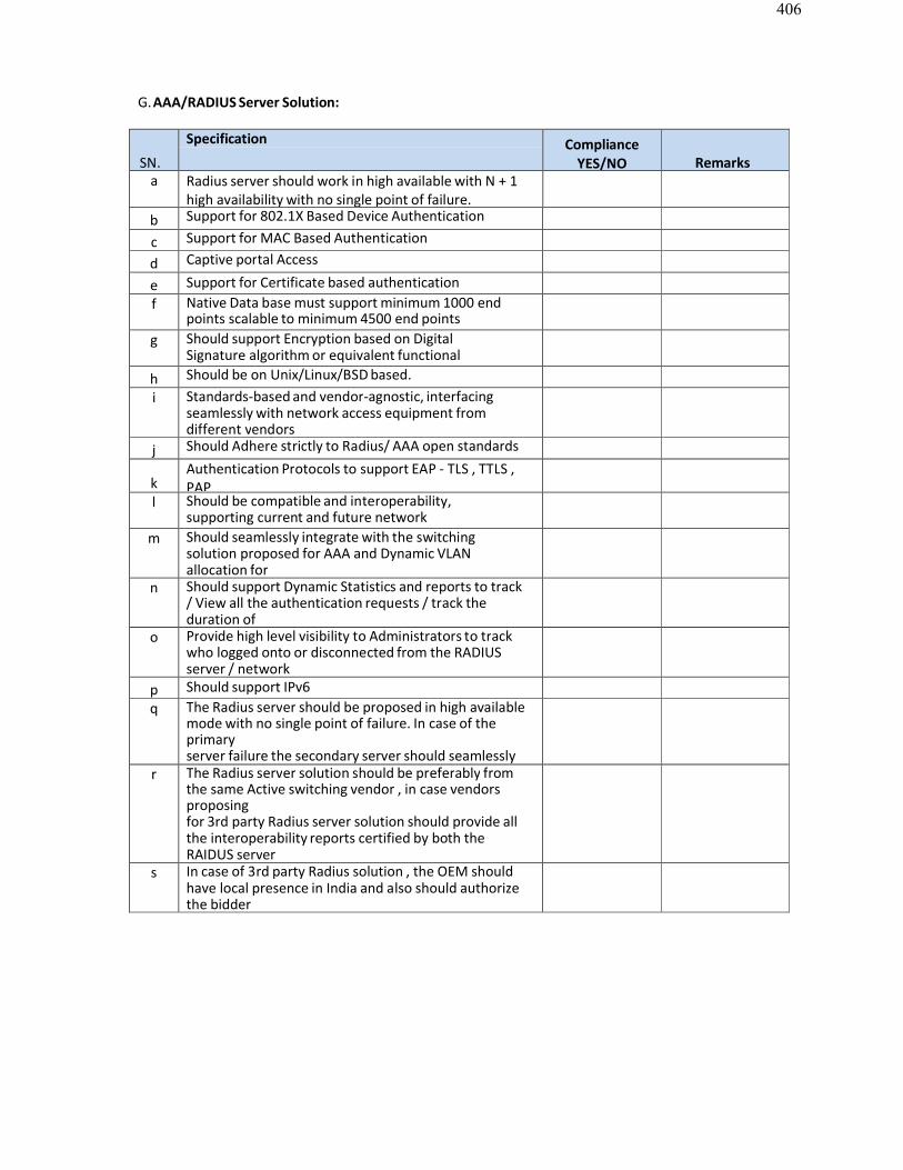
406
G.AAA/RADIUS Server Solution:
SN.
Specification ComplianceYES/NO Remarks
a Radius server should work in high available with N + 1high availability with no single point of failure.
b Support for 802.1X Based Device Authentication
c Support for MAC Based Authentication
d Captive portal Access
e Support for Certificate based authenticationf Native Data base must support minimum 1000 end
points scalable to minimum 4500 end pointsg Should support Encryption based on Digital
Signature algorithm or equivalent functionalencryption protocolsh Should be on Unix/Linux/BSD based.
i Standards-based and vendor-agnostic, interfacing seamlessly with network access equipment fromdifferent vendors
j Should Adhere strictly to Radius/ AAA open standards
kAuthentication Protocols to support EAP - TLS , TTLS ,PAP
l Should be compatible and interoperability,supporting current and future networkconfigurationsm Should seamlessly integrate with the switchingsolution proposed for AAA and Dynamic VLANallocation forroaming user profilesn Should support Dynamic Statistics and reports to track/ View all the authentication requests / track theduration ofuser connection with Radius accountingo Provide high level visibility to Administrators to trackwho logged onto or disconnected from the RADIUSserver / network
p Should support IPv6q The Radius server should be proposed in high available
mode with no single point of failure. In case of theprimaryserver failure the secondary server should seamlesslytake over with zero network disruptionr The Radius server solution should be preferably fromthe same Active switching vendor , in case vendorsproposingfor 3rd party Radius server solution should provide allthe interoperability reports certified by both theRAIDUS servervendor and Active switching vendor on seamlesss In case of 3rd party Radius solution , the OEM shouldhave local presence in India and also should authorizethe bidderparticipating
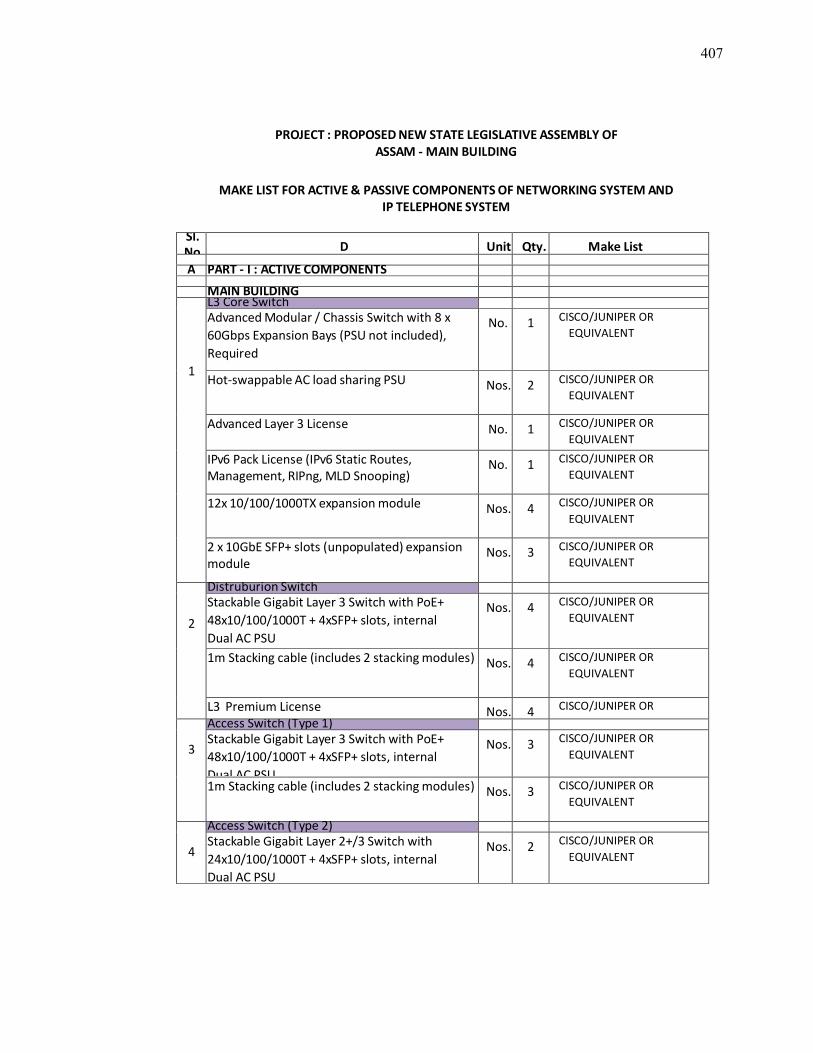
407
PROJECT : PROPOSED NEW STATE LEGISLATIVE ASSEMBLY OFASSAM - MAIN BUILDING
MAKE LIST FOR ACTIVE & PASSIVE COMPONENTS OF NETWORKING SYSTEM ANDIP TELEPHONE SYSTEM
Sl.No. D Unit Qty. Make List
A PART - I : ACTIVE COMPONENTS
MAIN BUILDING
1
L3 Core SwitchAdvanced Modular / Chassis Switch with 8 x60Gbps Expansion Bays (PSU not included),Required
No. 1 CISCO/JUNIPER OR EQUIVALENT
Hot-swappable AC load sharing PSU Nos. 2 CISCO/JUNIPER OR EQUIVALENT
Advanced Layer 3 License No. 1 CISCO/JUNIPER OR EQUIVALENT
IPv6 Pack License (IPv6 Static Routes,Management, RIPng, MLD Snooping)
No. 1 CISCO/JUNIPER OR EQUIVALENT
12x 10/100/1000TX expansion module Nos. 4 CISCO/JUNIPER OR EQUIVALENT
2 x 10GbE SFP+ slots (unpopulated) expansionmodule
Nos. 3 CISCO/JUNIPER OR EQUIVALENT
2
Distruburion SwitchStackable Gigabit Layer 3 Switch with PoE+48x10/100/1000T + 4xSFP+ slots, internalDual AC PSU
Nos. 4 CISCO/JUNIPER OR EQUIVALENT
1m Stacking cable (includes 2 stacking modules) Nos. 4 CISCO/JUNIPER OR EQUIVALENT
L3 Premium License Nos. 4 CISCO/JUNIPER OR EQUIVALENT
3
Access Switch (Type 1)Stackable Gigabit Layer 3 Switch with PoE+48x10/100/1000T + 4xSFP+ slots, internalDual AC PSU
Nos. 3 CISCO/JUNIPER OR EQUIVALENT
1m Stacking cable (includes 2 stacking modules) Nos. 3 CISCO/JUNIPER OR EQUIVALENT
4
Access Switch (Type 2)Stackable Gigabit Layer 2+/3 Switch with24x10/100/1000T + 4xSFP+ slots, internalDual AC PSU
Nos. 2 CISCO/JUNIPER OR EQUIVALENT
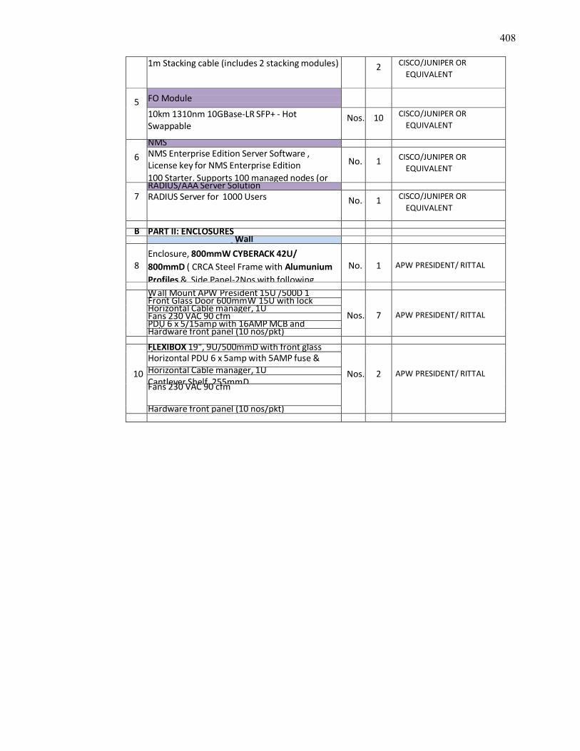
408
1m Stacking cable (includes 2 stacking modules) 2 CISCO/JUNIPER OR EQUIVALENT
5 FO Module
10km 1310nm 10GBase-LR SFP+ - HotSwappable
Nos. 10 CISCO/JUNIPER OR EQUIVALENT
6NMSNMS Enterprise Edition Server Software ,License key for NMS Enterprise Edition100 Starter. Supports 100 managed nodes (or
No. 1 CISCO/JUNIPER OR EQUIVALENT
7RADIUS/AAA Server SolutionRADIUS Server for 1000 Users No. 1 CISCO/JUNIPER OR
EQUIVALENT
B PART II: ENCLOSURESWall
Mount
8Enclosure, 800mmW CYBERACK 42U/800mmD ( CRCA Steel Frame with AlumuniumProfiles & Side Panel-2Nos with following
No. 1 APW PRESIDENT/ RITTAL
Wall Mount APW President 15U /500D 1Section
Nos. 7 APW PRESIDENT/ RITTAL
Front Glass Door 600mmW 15U with lockHorizontal Cable manager, 1UFans 230 VAC 90 cfmPDU 6 x 5/15amp with 16AMP MCB andindicatorHardware front panel (10 nos/pkt)
10
FLEXIBOX 19", 9U/500mmD with front glassdoor
Nos. 2 APW PRESIDENT/ RITTAL
Horizontal PDU 6 x 5amp with 5AMP fuse &indicator and 1.5meter feed cable andHorizontal Cable manager, 1UCantlever Shelf, 255mmDFans 230 VAC 90 cfm
Hardware front panel (10 nos/pkt)
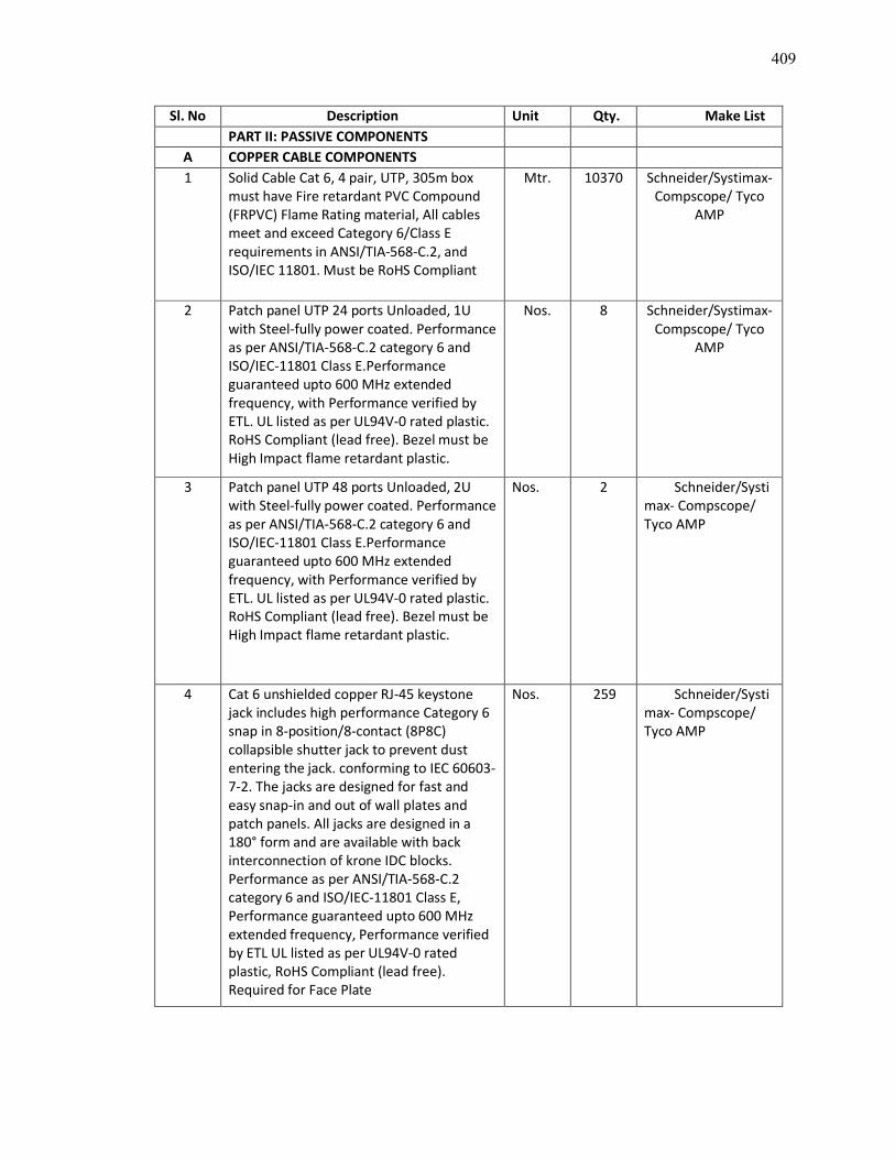
409
Sl. No Description Unit Qty. Make ListPART II: PASSIVE COMPONENTS
A COPPER CABLE COMPONENTS1 Solid Cable Cat 6, 4 pair, UTP, 305m box
must have Fire retardant PVC Compound (FRPVC) Flame Rating material, All cables meet and exceed Category 6/Class E requirements in ANSI/TIA-568-C.2, and ISO/IEC 11801. Must be RoHS Compliant
Mtr. 10370 Schneider/Systimax-Compscope/ Tyco
AMP
2 Patch panel UTP 24 ports Unloaded, 1U with Steel-fully power coated. Performance as per ANSI/TIA-568-C.2 category 6 and ISO/IEC-11801 Class E.Performance guaranteed upto 600 MHz extended frequency, with Performance verified by ETL. UL listed as per UL94V-0 rated plastic. RoHS Compliant (lead free). Bezel must be High Impact flame retardant plastic.
Nos. 8 Schneider/Systimax-Compscope/ Tyco
AMP
3 Patch panel UTP 48 ports Unloaded, 2U with Steel-fully power coated. Performance as per ANSI/TIA-568-C.2 category 6 and ISO/IEC-11801 Class E.Performance guaranteed upto 600 MHz extended frequency, with Performance verified by ETL. UL listed as per UL94V-0 rated plastic. RoHS Compliant (lead free). Bezel must be High Impact flame retardant plastic.
Nos. 2 Schneider/Systimax- Compscope/ Tyco AMP
4 Cat 6 unshielded copper RJ-45 keystone jack includes high performance Category 6 snap in 8-position/8-contact (8P8C) collapsible shutter jack to prevent dust entering the jack. conforming to IEC 60603-7-2. The jacks are designed for fast and easy snap-in and out of wall plates and patch panels. All jacks are designed in a 180° form and are available with back interconnection of krone IDC blocks. Performance as per ANSI/TIA-568-C.2 category 6 and ISO/IEC-11801 Class E, Performance guaranteed upto 600 MHz extended frequency, Performance verified by ETL UL listed as per UL94V-0 rated plastic, RoHS Compliant (lead free). Required for Face Plate
Nos. 259 Schneider/Systimax- Compscope/ Tyco AMP
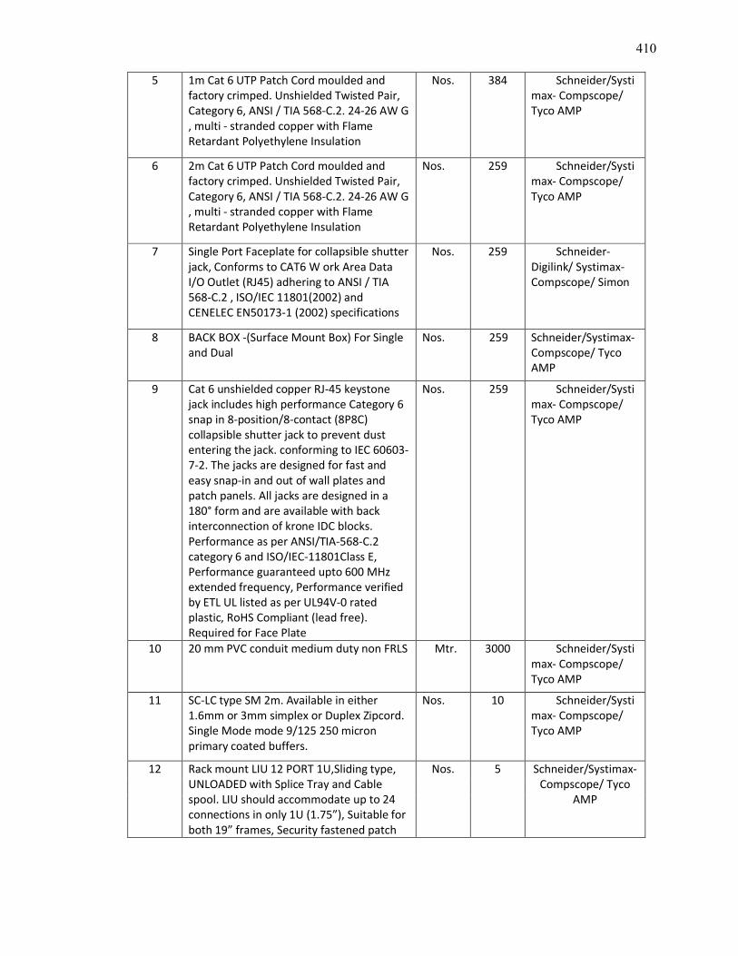
410
5 1m Cat 6 UTP Patch Cord moulded and factory crimped. Unshielded Twisted Pair, Category 6, ANSI / TIA 568-C.2. 24-26 AW G , multi - stranded copper with Flame Retardant Polyethylene Insulation
Nos. 384 Schneider/Systimax- Compscope/ Tyco AMP
6 2m Cat 6 UTP Patch Cord moulded and factory crimped. Unshielded Twisted Pair, Category 6, ANSI / TIA 568-C.2. 24-26 AW G , multi - stranded copper with Flame Retardant Polyethylene Insulation
Nos. 259 Schneider/Systimax- Compscope/ Tyco AMP
7 Single Port Faceplate for collapsible shutter jack, Conforms to CAT6 W ork Area Data I/O Outlet (RJ45) adhering to ANSI / TIA 568-C.2 , ISO/IEC 11801(2002) and CENELEC EN50173-1 (2002) specifications
Nos. 259 Schneider-Digilink/ Systimax-Compscope/ Simon
8 BACK BOX -(Surface Mount Box) For Single and Dual
Nos. 259 Schneider/Systimax-Compscope/ Tyco AMP
9 Cat 6 unshielded copper RJ-45 keystone jack includes high performance Category 6 snap in 8-position/8-contact (8P8C) collapsible shutter jack to prevent dust entering the jack. conforming to IEC 60603-7-2. The jacks are designed for fast and easy snap-in and out of wall plates and patch panels. All jacks are designed in a 180° form and are available with back interconnection of krone IDC blocks. Performance as per ANSI/TIA-568-C.2 category 6 and ISO/IEC-11801Class E, Performance guaranteed upto 600 MHz extended frequency, Performance verified by ETL UL listed as per UL94V-0 rated plastic, RoHS Compliant (lead free). Required for Face Plate
Nos. 259 Schneider/Systimax- Compscope/ Tyco AMP
10 20 mm PVC conduit medium duty non FRLS Mtr. 3000 Schneider/Systimax- Compscope/ Tyco AMP
11 SC-LC type SM 2m. Available in either 1.6mm or 3mm simplex or Duplex Zipcord. Single Mode mode 9/125 250 micron primary coated buffers.
Nos. 10 Schneider/Systimax- Compscope/ Tyco AMP
12 Rack mount LIU 12 PORT 1U,Sliding type, UNLOADED with Splice Tray and Cable spool. LIU should accommodate up to 24 connections in only 1U (1.75”), Suitable for both 19” frames, Security fastened patch
Nos. 5 Schneider/Systimax-Compscope/ Tyco
AMP
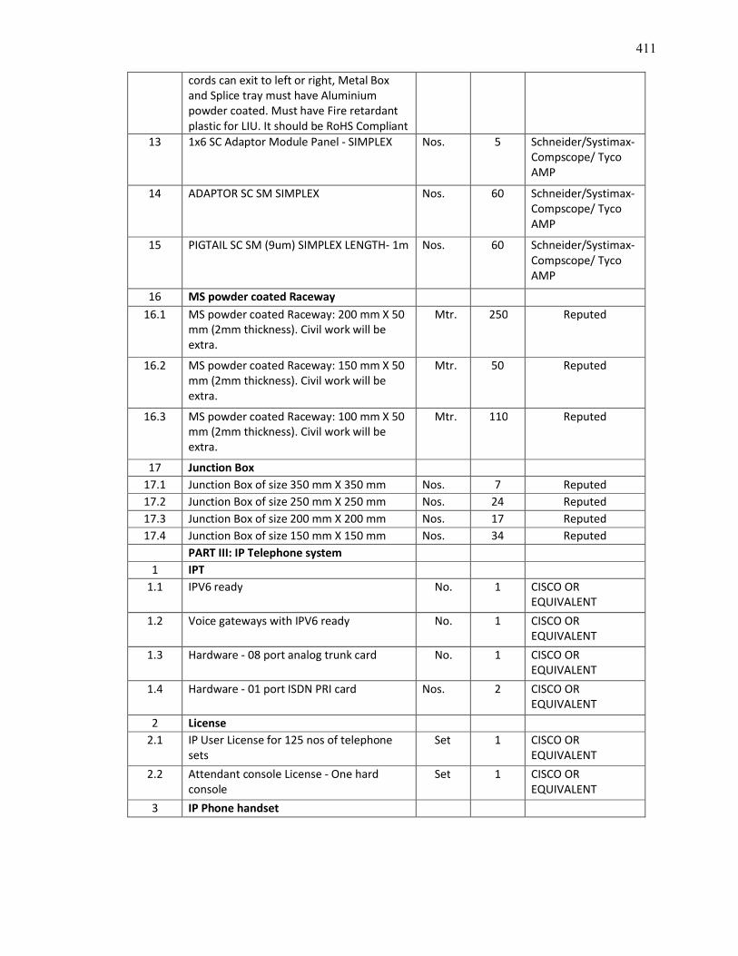
411
cords can exit to left or right, Metal Box and Splice tray must have Aluminium powder coated. Must have Fire retardant plastic for LIU. It should be RoHS Compliant
13 1x6 SC Adaptor Module Panel - SIMPLEX Nos. 5 Schneider/Systimax-Compscope/ Tyco AMP
14 ADAPTOR SC SM SIMPLEX Nos. 60 Schneider/Systimax-Compscope/ Tyco AMP
15 PIGTAIL SC SM (9um) SIMPLEX LENGTH- 1m Nos. 60 Schneider/Systimax-Compscope/ Tyco AMP
16 MS powder coated Raceway16.1 MS powder coated Raceway: 200 mm X 50
mm (2mm thickness). Civil work will be extra.
Mtr. 250 Reputed
16.2 MS powder coated Raceway: 150 mm X 50 mm (2mm thickness). Civil work will be extra.
Mtr. 50 Reputed
16.3 MS powder coated Raceway: 100 mm X 50 mm (2mm thickness). Civil work will be extra.
Mtr. 110 Reputed
17 Junction Box17.1 Junction Box of size 350 mm X 350 mm Nos. 7 Reputed17.2 Junction Box of size 250 mm X 250 mm Nos. 24 Reputed17.3 Junction Box of size 200 mm X 200 mm Nos. 17 Reputed17.4 Junction Box of size 150 mm X 150 mm Nos. 34 Reputed
PART III: IP Telephone system1 IPT
1.1 IPV6 ready No. 1 CISCO OR EQUIVALENT
1.2 Voice gateways with IPV6 ready No. 1 CISCO OR EQUIVALENT
1.3 Hardware - 08 port analog trunk card No. 1 CISCO OR EQUIVALENT
1.4 Hardware - 01 port ISDN PRI card Nos. 2 CISCO OR EQUIVALENT
2 License2.1 IP User License for 125 nos of telephone
setsSet 1 CISCO OR
EQUIVALENT2.2 Attendant console License - One hard
consoleSet 1 CISCO OR
EQUIVALENT3 IP Phone handset
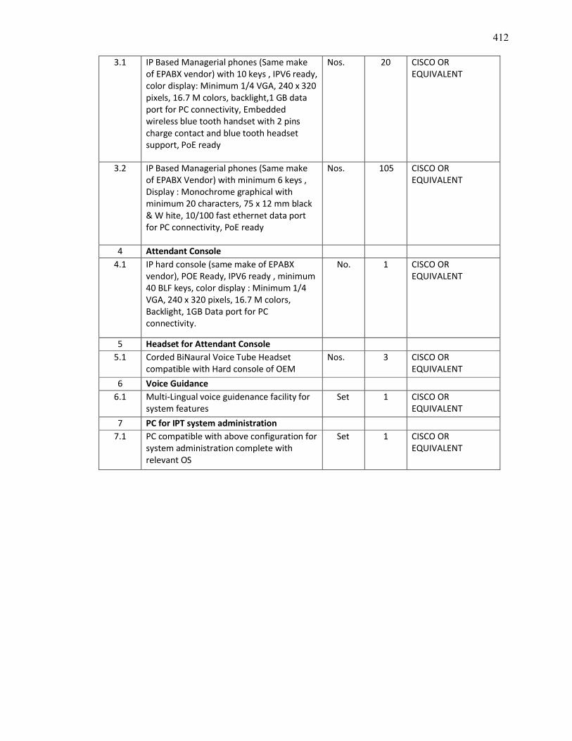
412
3.1 IP Based Managerial phones (Same make of EPABX vendor) with 10 keys , IPV6 ready, color display: Minimum 1/4 VGA, 240 x 320 pixels, 16.7 M colors, backlight,1 GB data port for PC connectivity, Embedded wireless blue tooth handset with 2 pins charge contact and blue tooth headset support, PoE ready
Nos. 20 CISCO OR EQUIVALENT
3.2 IP Based Managerial phones (Same make of EPABX Vendor) with minimum 6 keys , Display : Monochrome graphical with minimum 20 characters, 75 x 12 mm black & W hite, 10/100 fast ethernet data port for PC connectivity, PoE ready
Nos. 105 CISCO OR EQUIVALENT
4 Attendant Console4.1 IP hard console (same make of EPABX
vendor), POE Ready, IPV6 ready , minimum 40 BLF keys, color display : Minimum 1/4 VGA, 240 x 320 pixels, 16.7 M colors, Backlight, 1GB Data port for PC connectivity.
No. 1 CISCO OR EQUIVALENT
5 Headset for Attendant Console5.1 Corded BiNaural Voice Tube Headset
compatible with Hard console of OEMNos. 3 CISCO OR
EQUIVALENT6 Voice Guidance
6.1 Multi-Lingual voice guidenance facility for system features
Set 1 CISCO OR EQUIVALENT
7 PC for IPT system administration7.1 PC compatible with above configuration for
system administration complete with relevant OS
Set 1 CISCO OR EQUIVALENT

413
TECHNICAL SPECIFICATION
FOR
INTERNAL SANITARY INSTALLATION WORKS
AT
DISPUR, GUWAHATI, ASSAM
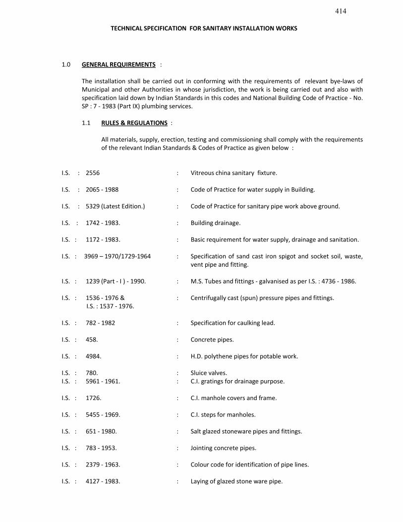
414
TECHNICAL SPECIFICATION FOR SANITARY INSTALLATION WORKS
1.0 GENERAL REQUIREMENTS :
The installation shall be carried out in conforming with the requirements of relevant bye-laws of Municipal and other Authorities in whose jurisdiction, the work is being carried out and also with specification laid down by Indian Standards in this codes and National Building Code of Practice - No. SP : 7 - 1983 (Part IX) plumbing services.
1.1 RULES & REGULATIONS :
All materials, supply, erection, testing and commissioning shall comply with the requirements of the relevant Indian Standards & Codes of Practice as given below :
I.S. : 2556 : Vitreous china sanitary fixture.
I.S. : 2065 - 1988 : Code of Practice for water supply in Building.
I.S. : 5329 (Latest Edition.) : Code of Practice for sanitary pipe work above ground.
I.S. : 1742 - 1983. : Building drainage.
I.S. : 1172 - 1983. : Basic requirement for water supply, drainage and sanitation.
I.S. : 3969 – 1970/1729-1964 : Specification of sand cast iron spigot and socket soil, waste, vent pipe and fitting.
I.S. : 1239 (Part - I ) - 1990. : M.S. Tubes and fittings - galvanised as per I.S. : 4736 - 1986.
I.S. : 1536 - 1976 & I.S. : 1537 - 1976.
: Centrifugally cast (spun) pressure pipes and fittings.
I.S. : 782 - 1982 : Specification for caulking lead.
I.S. : 458. : Concrete pipes.
I.S. : 4984. : H.D. polythene pipes for potable work.
I.S. : 780. : Sluice valves.I.S. : 5961 - 1961. : C.I. gratings for drainage purpose.
I.S. : 1726. : C.I. manhole covers and frame.
I.S. : 5455 - 1969. : C.I. steps for manholes.
I.S. : 651 - 1980. : Salt glazed stoneware pipes and fittings.
I.S. : 783 - 1953. : Jointing concrete pipes.
I.S. : 2379 - 1963. : Colour code for identification of pipe lines.
I.S. : 4127 - 1983. : Laying of glazed stone ware pipe.
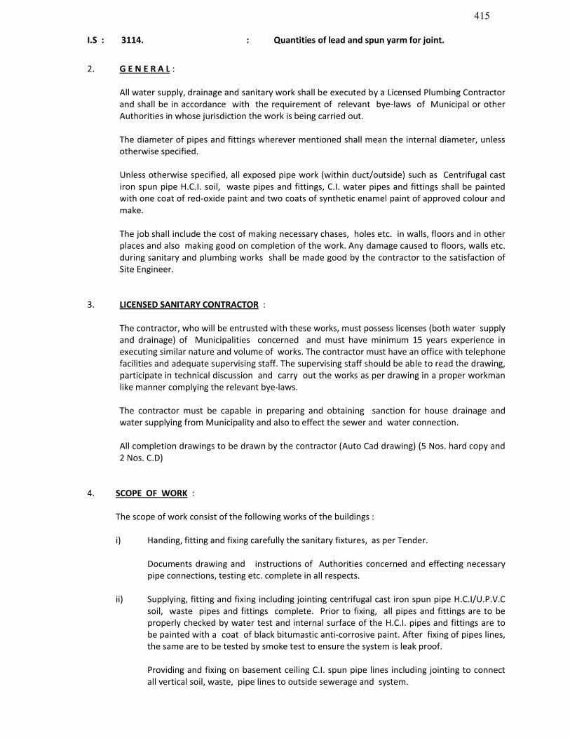
415
I.S : 3114. : Quantities of lead and spun yarm for joint.
2. G E N E R A L :
All water supply, drainage and sanitary work shall be executed by a Licensed Plumbing Contractor and shall be in accordance with the requirement of relevant bye-laws of Municipal or other Authorities in whose jurisdiction the work is being carried out.
The diameter of pipes and fittings wherever mentioned shall mean the internal diameter, unless otherwise specified.
Unless otherwise specified, all exposed pipe work (within duct/outside) such as Centrifugal cast iron spun pipe H.C.I. soil, waste pipes and fittings, C.I. water pipes and fittings shall be painted with one coat of red-oxide paint and two coats of synthetic enamel paint of approved colour and make.
The job shall include the cost of making necessary chases, holes etc. in walls, floors and in other places and also making good on completion of the work. Any damage caused to floors, walls etc. during sanitary and plumbing works shall be made good by the contractor to the satisfaction of Site Engineer.
3. LICENSED SANITARY CONTRACTOR :
The contractor, who will be entrusted with these works, must possess licenses (both water supply and drainage) of Municipalities concerned and must have minimum 15 years experience in executing similar nature and volume of works. The contractor must have an office with telephone facilities and adequate supervising staff. The supervising staff should be able to read the drawing, participate in technical discussion and carry out the works as per drawing in a proper workman like manner complying the relevant bye-laws.
The contractor must be capable in preparing and obtaining sanction for house drainage and water supplying from Municipality and also to effect the sewer and water connection.
All completion drawings to be drawn by the contractor (Auto Cad drawing) (5 Nos. hard copy and 2 Nos. C.D)
4. SCOPE OF WORK :
The scope of work consist of the following works of the buildings :
i) Handing, fitting and fixing carefully the sanitary fixtures, as per Tender.
Documents drawing and instructions of Authorities concerned and effecting necessary pipe connections, testing etc. complete in all respects.
ii) Supplying, fitting and fixing including jointing centrifugal cast iron spun pipe H.C.I/U.P.V.C soil, waste pipes and fittings complete. Prior to fixing, all pipes and fittings are to be properly checked by water test and internal surface of the H.C.I. pipes and fittings are to be painted with a coat of black bitumastic anti-corrosive paint. After fixing of pipes lines, the same are to be tested by smoke test to ensure the system is leak proof.
Providing and fixing on basement ceiling C.I. spun pipe lines including jointing to connect all vertical soil, waste, pipe lines to outside sewerage and system.
416
iii) Supplying and fitting and fixing jointing G.I./C.P.V.C. water pipe lines, valves, cocks, pumps, etc. complete for the purpose. On completion the pipe lines are to be tested by Hydraulic Pressure Machine to ensure that the system is absolute leak proof.
iv) Supplying, laying, jointing and fixing underground sewer lines, yard gullies, construction of inspection pits, etc. complete including testing and effecting sewer connection with manhole on nearby main sewer line.
v) Providing all tools and equipments including testing machines required for testing and supporting & fixing devices so as to install the sanitary fittings, pipe lines etc. securely in position.
5. METHOD OF MEASUREMENT :
The following method of measurement will be followed unless otherwise settled :
a) Sanitary fixtures, Water Heater etc. :
These shall be measured as per actual number of units fixed.
b) Soil Waste & Anti-siphon Pipes & Fittings :
The measurement of pipes shall be taken along the centre line the pipe lines inclusive of fittings and joints. The number of fittings and special will not be measured separately as . No extra payment is admissible for testing of pipe lines.
c) Water Supply Pipes & Fittings :
The measurement shall be taken along the centre line of pipe lines inclusive of Specials. Number of fittings will not be measured separately. No extra payment is admissible for testing of pipe line. Number of valves, cocks, pumps etc. are to be measured separately.
d) Under ground Sewer Lines :
For sewer lines, measurement shall be recorded for the finished length of the pipe line including joints i.e. overall length of sewer line excluding the internal length of manholes.
For yard gully connections, measurement shall be recorded between the joint of Y.G. and inside face of manhole.
Number of manhole, pit and yard gullies etc. are to be measured separately.
No extra payment is admissible for testing of sewer lines.
417
6. INDIAN STANDARD SPECIFICATIONS :
All work under this contract shall be carried out in accordance with the technical specification and the latest issue of the Indian Standard Specification applicable to the particular class of work. If Indian Standards are not formulated for any particular materials of work, the relevant British Standard Specification shall apply. Relevant issues of I.S. Specifications applicable to the particular work have been described along with the specification for the respective works. In case of any confusion or dispute regarding the meaning and interpretation of any specification for therespective works the decision of the Project Manager/Architects shall be final and binding on the contractor.
7. EXCAVATION OF TRENCHES (FOR U.G. WATER , SEWER & LINES) :
Excavation shall generally form part of the item under the schedule and shall not be paid separately unless otherwise specified in the schedule of quantities. It includes excavation in all kinds of soil including shoring and bailing out water wherever necessary and refilling the excavated trenches in 15 cms. layers properly rammed and watered and neatly dressed at the top. If the excavation is done to dimensions
The power shall be mixed with water in the storage tank. If a proprietary greater than those shown on the drawings or as directed by the Project Manager/Architect, the excess depth shall be made good at the own cost of the Contractor. The excavation work should be done in a manner that does not in any way endanger the stability of the adjacent buildings or other structure or services. Where any road pavements or crossings are cut, these shall be restored to their original conditions at no extra cost to the Owner. Moreover, after completion of the work, the Contractor shall have to dress the site including disposal of the surplus earth at his own cost as directed by the Project Manager/Architect.
The bed width of the trenches shall be the exact width as shown in the drawings or as specified.
In firm soil, the sides of trenches shall be widened by allowing steps of 45 Cm. (1’ - 6”) on either side after every 1.82 M. depth from the bottom so as to give side stops of (1/4” to 1”) 6mm. to 25mm. Where the soil is soft, loose or slushy, the width of steps shall be suitably increased as directed by the Project Manager/Architect. It shall be the responsibility of the Contractor to take complete instructions in writing from Project Manager/Architect regarding the stepping, sloping or shoring to be done for excavation in trenches deeper that 1.82 M.
The bed of the trenches shall be made level and firm by watering and ramming. Any soft or defective spots that are found shall be filled \with concrete in the proportion as specified or as may be directed by the Project Manager/Architect.
8.0 INSTALLATION OF SANITARY FIXTURES AND FITTINGS :
8.1 General Requirement
The fixtures and fittings shall be provided with all such accessories as are required to complete the item in satisfactory working conditions, whether specifically mentioned or not in the schedule of quantities, specifications and drawings.
The sanitary fixtures and fittings shall be installed at the correct assigned position as shown on the
418
drawings and as directed by the Architect, and shall fully meet with the aesthetic and symmetrical requirements as demanded by the Architect.
All fixtures and accessories shall be fixed in accordance with a set pattern matching the tile or interior finish as per Architect requirements. Wherever necessary, the fittings shall be centered to dimensions and pattern as called for. Fixtures shall be installed by skilled workman with appropriate tools according to the best trade practice. Manufacturer’s instructions shall be followed for the installation of fixtures. Fixtures in all toilets shall be standard height mounting as called for on the drawings. Fixtures shall be mounted rigid, plumb, and true to alignment.
8.2 Mock up and Trial Assembly
The installation of the sanitary fixtures and fittings shall be as per the shop drawings approved by the Architect/Consultant.
The contractor shall have to assemble at least one set of each type of sanitary fixtures and fittings in order to determine precisely the required supply and disposal connections. Relevant instructions from manufacturers shall be followed as applicable. This trial assembly shall be developed to determine the location of puncture holes, holding devices etc. which will be required for final installation of all sanitary fixtures and fittings. The above assembly shall be subject to final approval by the Architect.
The fixtures in the trial assembly can be re-used for final installation without any additional payments for fixing or dismantling of the fixtures.
8.3 Supporting and Fixing Devices
The contractor shall provide all the necessary supporting and fixing devices to install the sanitary fixtures and fittings securely in position. The fixing devices shall be rigidly anchored into the building structure. The devices shall be rust resistant and shall be so fixed that they do not present an unsightly appearance in the final assembly. Where the location demands, the Architect may instruct the contractor to provide chromium plated or other similarly finished fixing devices. In such circumstances the contractor shall arrange to supply the fixing devices and shall be installed complete with appropriate vibration isolating pads, washers and gaskets.
8.4. Final Installation :-
The contractor shall install all sanitary fixtures and fittings in their final position in accordance with approved trial assemblies and as shown on drawings. The installation shall be complete with all supply and waste connections. The connection between building and piping system and the sanitary fixtures shall be through proper unions and flanges to facilitate removal/replacement of sanitary fixtures without disturbing the build in piping system. All unions and flanges shall match in appearance with other exposed fittings.
Fixtures shall be mounted rigid, plumb and to alignment. The outlets of water closet pans and similar appliances shall be examined to ensure that outlet ends are butting on the receiving pipes before making the joints. It shall be ensured that the receiving pipes are clear of obstruction. When fixtures are being mounted, attention shall be paid to the possibility of movement and settlement by other causes. Overflows shall be made to ensure that necessary anchoring devices have been provided for supporting water closets, wash basins, sinks and other appliances.
9. PROTECTION AGAINST DAMAGES :
419
The contractor shall take every precaution to protect all sanitary fixtures against damage, misuse, cracking, staining, breakage and pilferage by providing proper wrapping and locking arrangement till the completion of the installation. At the time of handing over, the contractor shall clean, disinfect and polish all the fixtures and fittings . Any fixtures and fittings found damaged, cracked chipped stained or scratched shall be removed and new fixtures and fittings free from defects shall be installed at his own accosts to complete the work.
10. SOIL,WASTE AND VENT (ANTI-SYPHONAGE) PIPES & FITTINGS :
a) H.C.I. Pipes & Fittings :
The heavy cast iron pipes and fittings should be of I.S. marked pipes and fittings conforming to I.S. : 1729 or 3989/1970 brand of heavy quality. The pipes shall be free from cracks and other flaws. The interior of pipes and fittings shall be clean and smooth and painted inside and outside with approved brand anti-corrosive paint.
b) Cast iron centrifugal cast iron spun pipe fitting as per I.S : 153681537
U.P.V.C Pipes & Fittings :
The heavy quality pipes and fittings should conforming to type ‘B’ quality of I.S : 13591 – 92. These pipes must have minimum thickness of 3.2 mm. These pipes shall be free from any floors and smooth and restriction free.
c) Fixing :
The pipes and fittings shall be fixed to walls by using proper clamps. The pipes shall be fixed perfectly vertical or in a line as directed. All soil pipes shall be carried up above the roof andshall have cowl on top.
Where pipes are laid along walls, the pipes are to be fixed 25mm away from the wall surface. Necessary nails and clamps etc. are to be used for this purpose.
The access door fittings shall be of proper design so as not to form any cavities in which filth may accumulate. Doors shall be provided with brass bolts for C.I. fittings, doors for U.P.V.C fittings shall be screwed type.
Connections between main pipe and the branch pipes shall be made by using branches andbends invariably with access doors for cleaning.
d) Jointing :
i) C.I. Pipes :
The annular space between the sockets and spigot will be first well packed in with spun yarn leaving 35mm from the lip of the socket for lead. The joint may be leaded by using proper leading rings or if they are not available by wrapping a ring of lamp rope covered with clay round the pipe at the end of the socket, leaving a hole through which molten lead shall be poured in (for pipes with sockets facing upwards) 15mm high by making small clay bound to the socket edge may be used.
The depth of lead joint or C.I. pipes shall be 40 mm for the pipes upto 100 dia.
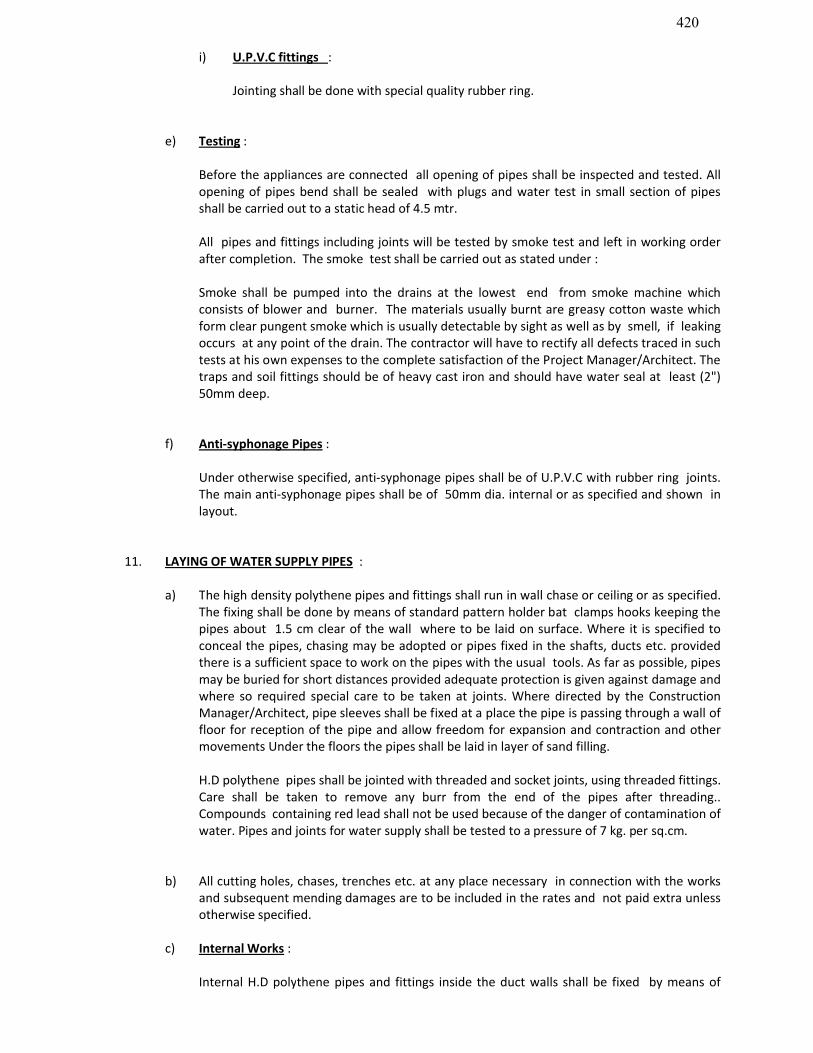
420
i) U.P.V.C fittings :
Jointing shall be done with special quality rubber ring.
e) Testing :
Before the appliances are connected all opening of pipes shall be inspected and tested. All opening of pipes bend shall be sealed with plugs and water test in small section of pipes shall be carried out to a static head of 4.5 mtr.
All pipes and fittings including joints will be tested by smoke test and left in working order after completion. The smoke test shall be carried out as stated under :
Smoke shall be pumped into the drains at the lowest end from smoke machine which consists of blower and burner. The materials usually burnt are greasy cotton waste which form clear pungent smoke which is usually detectable by sight as well as by smell, if leaking occurs at any point of the drain. The contractor will have to rectify all defects traced in such tests at his own expenses to the complete satisfaction of the Project Manager/Architect. The traps and soil fittings should be of heavy cast iron and should have water seal at least (2") 50mm deep.
f) Anti-syphonage Pipes :
Under otherwise specified, anti-syphonage pipes shall be of U.P.V.C with rubber ring joints. The main anti-syphonage pipes shall be of 50mm dia. internal or as specified and shown in layout.
11. LAYING OF WATER SUPPLY PIPES :
a) The high density polythene pipes and fittings shall run in wall chase or ceiling or as specified. The fixing shall be done by means of standard pattern holder bat clamps hooks keeping the pipes about 1.5 cm clear of the wall where to be laid on surface. Where it is specified to conceal the pipes, chasing may be adopted or pipes fixed in the shafts, ducts etc. provided there is a sufficient space to work on the pipes with the usual tools. As far as possible, pipes may be buried for short distances provided adequate protection is given against damage and where so required special care to be taken at joints. Where directed by the Construction Manager/Architect, pipe sleeves shall be fixed at a place the pipe is passing through a wall of floor for reception of the pipe and allow freedom for expansion and contraction and other movements Under the floors the pipes shall be laid in layer of sand filling.
H.D polythene pipes shall be jointed with threaded and socket joints, using threaded fittings. Care shall be taken to remove any burr from the end of the pipes after threading.. Compounds containing red lead shall not be used because of the danger of contamination of water. Pipes and joints for water supply shall be tested to a pressure of 7 kg. per sq.cm.
b) All cutting holes, chases, trenches etc. at any place necessary in connection with the works and subsequent mending damages are to be included in the rates and not paid extra unless otherwise specified.
c) Internal Works :
Internal H.D polythene pipes and fittings inside the duct walls shall be fixed by means of

421
standard pattern clamps keeping the pipe 20mm clear of the wall every where or concealed as directed. If pipes and fittings of inside wall is to be fixed concealed, it is to be by chasing floors and walls as directed. Where it is imperative to fix the pipe in front of a house or in any conspicuous position, where it looks ungainly, chasing may be adopted. The clamps shall be fixed closely as per I.S Code. Concealed pipes are to be secured to walls by hooks. The valves should be fitted with a union/long screw. In long length run of a pipe, at least in every (10') 3.05 metres apart there should be a UNION Joint.
All pipes and fittings shall be fixed truly vertical and horizontal or as directed by the Project Manager/Architect.
For pipes carrying hot water G.I. pipes and fittings are to be used.
d) Disinfecting of piping system and storage tank
Before commissioning the water supply system, the contractor shall arrange to disinfect the entire system as described in the succeeding paragraph.
The water storage tanks and pipes shall first be filled and water and thoroughly flushed out. The storage tanks shall then be filled with water again and disinfecting chemical containing chlorine added gradually while tanks are being filled to ensure thorough mixing. sufficient chemical shall be used to give water a dose of 50 parts of chlorine to one million parts of water. If ordinary bleaching powder is used. The proportions will be 150 gm. Of powder to 1000 liters of water. The power shall be mixed with water in the storage tank. If a proprietarybrand of chemical is used, the proportions shall be specified by makers. When the storage tanks is full, the supply shall be stopped and all the taps on the
distributing pipes are opened successively working progressively away from the storage tank. Each tap shall be closed when the water discharged begins to smell of chlorine. The storage tank shall then be filled up with water from supply pipe and added with more disinfecting chemical in the recommended proportions. The storage tank and pipe shall then remain charged at least for three hours. Finally the tank and pipes shall be thoroughly flushed out before any water is used for domestic purpose.
e) Testing :
All pipes and fittings should be tested by hydraulic pressure machine to a pressure of 7 Kg. per sq.cm. to ensure that pipes have proper threads and that proper materials (such as white lead and hamp) have been used in jointing. All leaky joints must be made leak proof by tightening or re-doing at contractor's expenses.
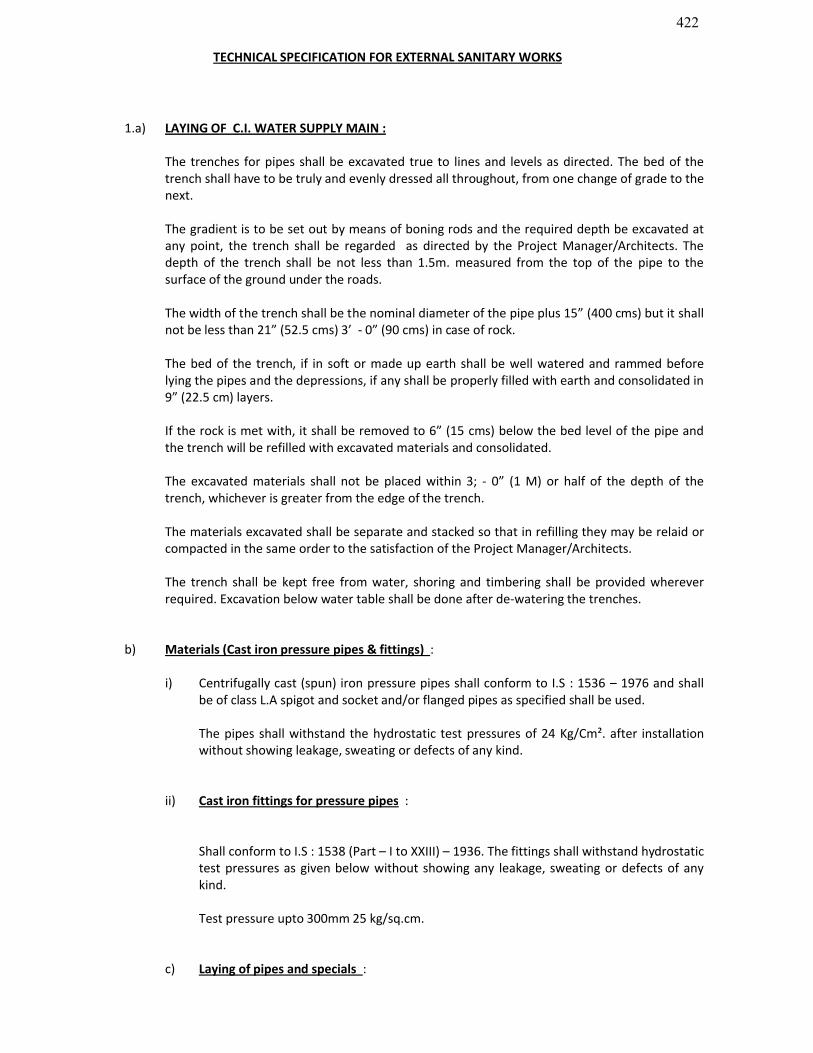
422
TECHNICAL SPECIFICATION FOR EXTERNAL SANITARY WORKS
1.a) LAYING OF C.I. WATER SUPPLY MAIN :
The trenches for pipes shall be excavated true to lines and levels as directed. The bed of the trench shall have to be truly and evenly dressed all throughout, from one change of grade to the next.
The gradient is to be set out by means of boning rods and the required depth be excavated at any point, the trench shall be regarded as directed by the Project Manager/Architects. The depth of the trench shall be not less than 1.5m. measured from the top of the pipe to the surface of the ground under the roads.
The width of the trench shall be the nominal diameter of the pipe plus 15” (400 cms) but it shall not be less than 21” (52.5 cms) 3’ - 0” (90 cms) in case of rock.
The bed of the trench, if in soft or made up earth shall be well watered and rammed before lying the pipes and the depressions, if any shall be properly filled with earth and consolidated in 9” (22.5 cm) layers.
If the rock is met with, it shall be removed to 6” (15 cms) below the bed level of the pipe and the trench will be refilled with excavated materials and consolidated.
The excavated materials shall not be placed within 3; - 0” (1 M) or half of the depth of the trench, whichever is greater from the edge of the trench.
The materials excavated shall be separate and stacked so that in refilling they may be relaid or compacted in the same order to the satisfaction of the Project Manager/Architects.
The trench shall be kept free from water, shoring and timbering shall be provided wherever required. Excavation below water table shall be done after de-watering the trenches.
b) Materials (Cast iron pressure pipes & fittings) :
i) Centrifugally cast (spun) iron pressure pipes shall conform to I.S : 1536 – 1976 and shall be of class L.A spigot and socket and/or flanged pipes as specified shall be used.
The pipes shall withstand the hydrostatic test pressures of 24 Kg/Cm². after installation without showing leakage, sweating or defects of any kind.
ii) Cast iron fittings for pressure pipes :
Shall conform to I.S : 1538 (Part – I to XXIII) – 1936. The fittings shall withstand hydrostatic test pressures as given below without showing any leakage, sweating or defects of any kind.
Test pressure upto 300mm 25 kg/sq.cm.
c) Laying of pipes and specials :
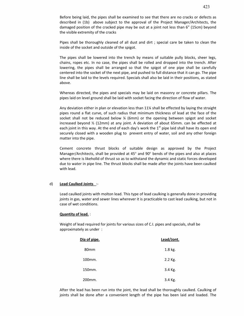
423
Before being laid, the pipes shall be examined to see that there are no cracks or defects as described in (1b) above subject to the approval of the Project Manager/Architects, the damaged position of the cracked pipe may be out at a joint not less than 6” (15cm) beyond the visible extremity of the cracks
Pipes shall be thoroughly cleaned of all dust and dirt ; special care be taken to clean the inside of the socket and outside of the spigot.
The pipes shall be lowered into the trench by means of suitable pully blocks, sheer legs, chains, ropes etc. In no case, the pipes shall be rolled and dropped into the trench. After lowering, the pipes shall be arranged so that the spigot of one pipe shall be carefully centered into the socket of the next pipe, and pushed to full distance that it can go. The pipe line shall be laid to the levels required. Specials shall also be laid in their positions, as stated above.
Whereas directed, the pipes and specials may be laid on masonry or concrete pillars. The pipes laid on level ground shall be laid with socket facing the direction of flow of water.
Any deviation either in plan or elevation less than 11¼ shall be effected by laying the straight pipes round a flat curve, of such radius that minimum thickness of lead at the face of the socket shall not be reduced below ¼ (6mm) or the opening between spigot and socket increased beyond ½ (12mm) at any joint. A deviation of about 65mm. can be effected at each joint in this way. At the end of each day’s work the 1st pipe laid shall have its open end securely closed with a wooden plug to prevent entry of water, soil and any other foreign matter into the pipe.
Cement concrete thrust blocks of suitable design as approved by the Project Manager/Architects, shall be provided at 45 and 90 bends of the pipes and also at places where there is likeholld of thrust so as to withstand the dynamic and static forces developed due to water in pipe line. The thrust blocks shall be made after the joints have been caulked with lead.
d) Lead Caulked Joints :-
Lead caulked joints with molton lead. This type of lead caulking is generally done in providing joints in gas, water and sewer lines wherever it is practicable to cast lead caulking, but not in case of wet conditions.
Quantity of lead. :
Weight of lead required for joints for various sizes of C.I. pipes and specials, shall be approximately as under :
Dia of pipe. Lead/Jont.
80mm 1.8 kg.
100mm. 2.2 Kg.
150mm. 3.4 Kg.
200mm. 3.4 Kg.
After the lead has been run into the joint, the lead shall be thoroughly caulked. Caulking of joints shall be done after a convenient length of the pipe has been laid and loaded. The
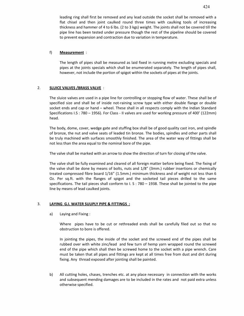
424
leading ring shall first be removed and any lead outside the socket shall be removed with a flat chisel and then joint caulked round three times with caulking tools of increasing thickness and hammer of 4 to 6 lbs. (2 to 3 kgs) weight. The joints shall not be covered till the pipe line has been tested under pressure though the rest of the pipeline should be covered to prevent expansion and contraction due to variation in temperature.
f) Measurement :
The length of pipes shall be measured as laid fixed in running metre excluding specials and pipes at the joints specials which shall be enumerated separately. The length of pipes shall, however, not include the portion of spigot within the sockets of pipes at the joints.
2. SLUICE VALVES /BRASS VALVE :
The sluice valves are used in a pipe line for controlling or stopping flow of water. These shall be of specified size and shall be of inside not-raining screw type with either double flange or double socket ends and cap or hand – wheel. These shall in all respects comply with the Indian Standard Specifications I.S : 780 – 1956). For Class - II valves are used for working pressure of 400’ (122mm) head.
The body, dome, cover, wedge gate and stuffing box shall be of good quality cast iron, and spindle of bronze, the nut and valve seats of leaded tin bronze. The bodies, spindles and other parts shall be truly machined with surfaces smoothly finished. The area of the water way of fittings shall be not less than the area equal to the nominal bore of the pipe.
The valve shall be marked with an arrow to show the direction of turn for closing of the valve.
The valve shall be fully examined and cleared of all foreign matter before being fixed. The fixing of the valve shall be done by means of bolts, nuts and 1/8” (3mm.) rubber insertions or chemically treated compressed fibre board 1/16” (1.5mm.) minimum thickness and of weight not less than 6 Oz. Per sq.ft. with the flanges of spigot and the socketed tail pieces drilled to the same specifications. The tail pieces shall conform to I. S : 780 – 1938. These shall be jointed to the pipe line by means of lead caulked joints.
3. LAYING G.I. WATER SUUPLY PIPE & FITTINGS :
a) Laying and Fixing :
Where pipes have to be cut or rethreaded ends shall be carefully filed out so that no obstruction to bore is offered.
In jointing the pipes, the inside of the socket and the screwed end of the pipes shall be rubbed over with white zinc/lead and few turn of hemp yarn wrapped round the screwed end of the pipe which shall then be screwed home to the socket with a pipe wrench. Care must be taken that all pipes and fittings are kept at all times free from dust and dirt during fixing. Any thread exposed after jointing shall be painted.
b) All cutting holes, chases, trenches etc. at any place necessary in connection with the works and subsequent mending damages are to be included in the rates and not paid extra unless otherwise specified.
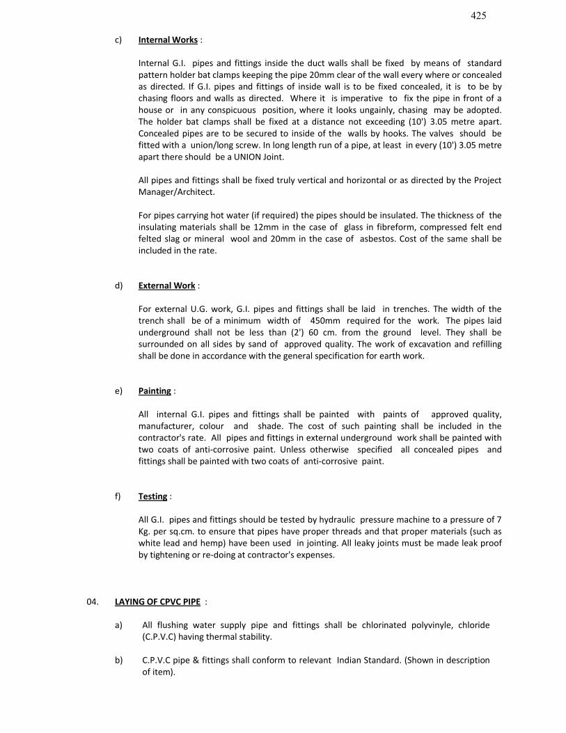
425
c) Internal Works :
Internal G.I. pipes and fittings inside the duct walls shall be fixed by means of standard pattern holder bat clamps keeping the pipe 20mm clear of the wall every where or concealed as directed. If G.I. pipes and fittings of inside wall is to be fixed concealed, it is to be by chasing floors and walls as directed. Where it is imperative to fix the pipe in front of a house or in any conspicuous position, where it looks ungainly, chasing may be adopted. The holder bat clamps shall be fixed at a distance not exceeding (10') 3.05 metre apart. Concealed pipes are to be secured to inside of the walls by hooks. The valves should be fitted with a union/long screw. In long length run of a pipe, at least in every (10') 3.05 metre apart there should be a UNION Joint.
All pipes and fittings shall be fixed truly vertical and horizontal or as directed by the Project Manager/Architect.
For pipes carrying hot water (if required) the pipes should be insulated. The thickness of the insulating materials shall be 12mm in the case of glass in fibreform, compressed felt end felted slag or mineral wool and 20mm in the case of asbestos. Cost of the same shall be included in the rate.
d) External Work :
For external U.G. work, G.I. pipes and fittings shall be laid in trenches. The width of the trench shall be of a minimum width of 450mm required for the work. The pipes laid underground shall not be less than (2') 60 cm. from the ground level. They shall be surrounded on all sides by sand of approved quality. The work of excavation and refilling shall be done in accordance with the general specification for earth work.
e) Painting :
All internal G.I. pipes and fittings shall be painted with paints of approved quality, manufacturer, colour and shade. The cost of such painting shall be included in the contractor's rate. All pipes and fittings in external underground work shall be painted with two coats of anti-corrosive paint. Unless otherwise specified all concealed pipes and fittings shall be painted with two coats of anti-corrosive paint.
f) Testing :
All G.I. pipes and fittings should be tested by hydraulic pressure machine to a pressure of 7 Kg. per sq.cm. to ensure that pipes have proper threads and that proper materials (such as white lead and hemp) have been used in jointing. All leaky joints must be made leak proof by tightening or re-doing at contractor's expenses.
04. LAYING OF CPVC PIPE :
a) All flushing water supply pipe and fittings shall be chlorinated polyvinyle, chloride (C.P.V.C) having thermal stability.
b) C.P.V.C pipe & fittings shall conform to relevant Indian Standard. (Shown in description of item).
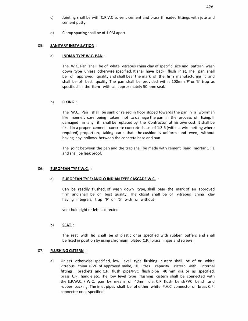
426
c) Jointing shall be with C.P.V.C solvent cement and brass threaded fittings with jute and cement putty.
d) Clamp spacing shall be of 1.0M apart.
05. SANITARY INSTALLATION :
a) INDIAN TYPE W.C. PAN :
The W.C. Pan shall be of white vitreous china clay of specific size and pattern wash down type unless otherwise specified. It shall have back flush inlet. The pan shall be of approved quality and shall bear the mark of the firm manufacturing it and shall be of best quality. The pan shall be provided with a 100mm ‘P’ or ‘S’ trap as specified in the item with an approximately 50mnm seal.
b) FIXING :
The W.C. Pan shall be sunk or raised in floor sloped towards the pan in a workman like manner, care being taken not to damage the pan in the process of fixing. If damaged in any, it shall be replaced by the Contractor at his own cost. It shall be fixed in a proper cement concrete concrete base of 1:3:6 (with a wire netting where required) proportion, taking care that the cushion is uniform and even, without having any hollows between the concrete base and pan.
The joint between the pan and the trap shall be made with cement sand mortar 1 : 1 and shall be leak proof.
06. EUROPEAN TYPE W.C. :
a) EUROPEAN TYPE/ANGLO INDIAN TYPE CASCADE W.C. :
Can be readily flushed, of wash down type, shall bear the mark of an approved firm and shall be of best quality. The closet shall be of vitreous china clay having integrals, trap ‘P’ or ‘S’ with or without
vent hole right or left as directed.
b) SEAT :
The seat with lid shall be of plastic or as specified with rubber buffers and shall be fixed in position by using chromium plated(C.P.) brass hinges and screws.
07. FLUSHING CISTERN :
a) Unless otherwise specified, low level type flushing cistern shall be of or white vitreous china /PVC of approved make, 10 litres capacity cistern with internal fittings, brackets and C.P. flush pipe/PVC flush pipe 40 mm dia. or as specified, brass C.P. handle etc. The low level type flushing cistern shall be connected with the E.P.W.C. / W.C. pan by means of 40mm dia. C.P. flush bend/PVC bend and rubber packing. The inlet pipes shall be of either white P.V.C. connector or brass C.P. connector or as specified.
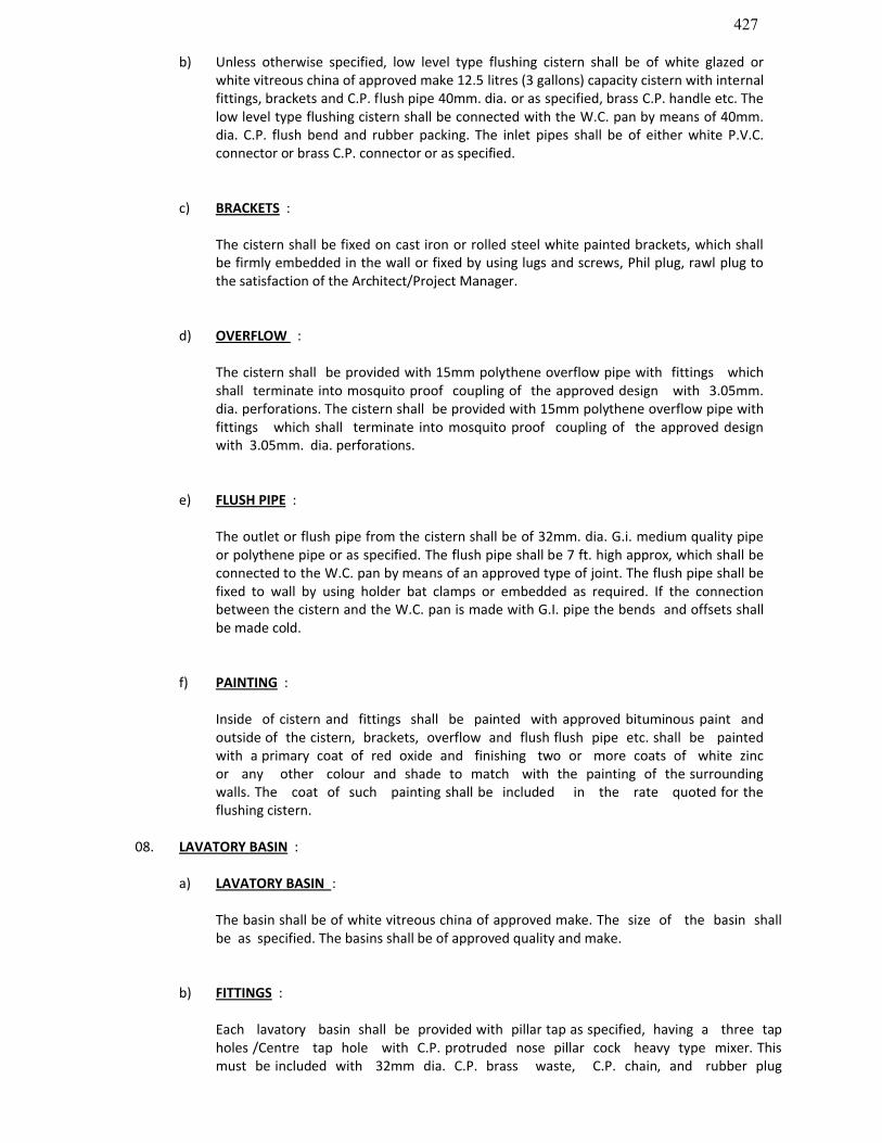
427
b) Unless otherwise specified, low level type flushing cistern shall be of white glazed or white vitreous china of approved make 12.5 litres (3 gallons) capacity cistern with internal fittings, brackets and C.P. flush pipe 40mm. dia. or as specified, brass C.P. handle etc. The low level type flushing cistern shall be connected with the W.C. pan by means of 40mm. dia. C.P. flush bend and rubber packing. The inlet pipes shall be of either white P.V.C. connector or brass C.P. connector or as specified.
c) BRACKETS :
The cistern shall be fixed on cast iron or rolled steel white painted brackets, which shall be firmly embedded in the wall or fixed by using lugs and screws, Phil plug, rawl plug to the satisfaction of the Architect/Project Manager.
d) OVERFLOW :
The cistern shall be provided with 15mm polythene overflow pipe with fittings which shall terminate into mosquito proof coupling of the approved design with 3.05mm. dia. perforations. The cistern shall be provided with 15mm polythene overflow pipe with fittings which shall terminate into mosquito proof coupling of the approved design with 3.05mm. dia. perforations.
e) FLUSH PIPE :
The outlet or flush pipe from the cistern shall be of 32mm. dia. G.i. medium quality pipe or polythene pipe or as specified. The flush pipe shall be 7 ft. high approx, which shall be connected to the W.C. pan by means of an approved type of joint. The flush pipe shall be fixed to wall by using holder bat clamps or embedded as required. If the connection between the cistern and the W.C. pan is made with G.I. pipe the bends and offsets shall be made cold.
f) PAINTING :
Inside of cistern and fittings shall be painted with approved bituminous paint and outside of the cistern, brackets, overflow and flush flush pipe etc. shall be painted with a primary coat of red oxide and finishing two or more coats of white zinc or any other colour and shade to match with the painting of the surrounding walls. The coat of such painting shall be included in the rate quoted for the flushing cistern.
08. LAVATORY BASIN :
a) LAVATORY BASIN :
The basin shall be of white vitreous china of approved make. The size of the basin shall be as specified. The basins shall be of approved quality and make.
b) FITTINGS :
Each lavatory basin shall be provided with pillar tap as specified, having a three tap holes /Centre tap hole with C.P. protruded nose pillar cock heavy type mixer. This must be included with 32mm dia. C.P. brass waste, C.P. chain, and rubber plug
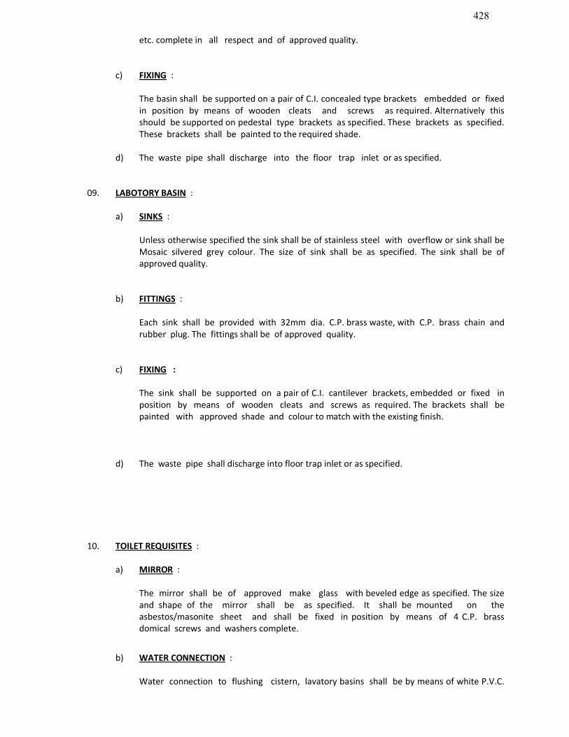
428
etc. complete in all respect and of approved quality.
c) FIXING :
The basin shall be supported on a pair of C.I. concealed type brackets embedded or fixed in position by means of wooden cleats and screws as required. Alternatively this should be supported on pedestal type brackets as specified. These brackets as specified. These brackets shall be painted to the required shade.
d) The waste pipe shall discharge into the floor trap inlet or as specified.
09. LABOTORY BASIN :
a) SINKS :
Unless otherwise specified the sink shall be of stainless steel with overflow or sink shall be Mosaic silvered grey colour. The size of sink shall be as specified. The sink shall be of approved quality.
b) FITTINGS :
Each sink shall be provided with 32mm dia. C.P. brass waste, with C.P. brass chain and rubber plug. The fittings shall be of approved quality.
c) FIXING :
The sink shall be supported on a pair of C.I. cantilever brackets, embedded or fixed in position by means of wooden cleats and screws as required. The brackets shall be painted with approved shade and colour to match with the existing finish.
d) The waste pipe shall discharge into floor trap inlet or as specified.
10. TOILET REQUISITES :
a) MIRROR :
The mirror shall be of approved make glass with beveled edge as specified. The size and shape of the mirror shall be as specified. It shall be mounted on the asbestos/masonite sheet and shall be fixed in position by means of 4 C.P. brass domical screws and washers complete.
b) WATER CONNECTION :
Water connection to flushing cistern, lavatory basins shall be by means of white P.V.C.
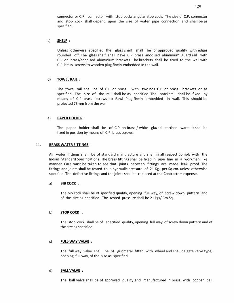
429
connector or C.P. connector with stop cock/ angular stop cock. The size of C.P. connector and stop cock shall depend upon the size of water pipe connection and shall be as specified.
c) SHELF :
Unless otherwise specified the glass shelf shall be of approved quality with edges rounded off. The glass shelf shall have C.P. brass anodised aluminium guard rail with C.P. on brass/anodised aluminium brackets. The brackets shall be fixed to the wall with C.P. brass screws to wooden plug firmly embedded in the wall.
d) TOWEL RAIL :
The towel rail shall be of C.P. on brass with two nos. C.P. on brass brackets or as specified. The size of the rail shall be as specified. The brackets shall be fixed by means of C.P. brass screws to Rawl Plug firmly embedded in wall. This should be projected 75mm from the wall.
e) PAPER HOLDER :
The paper holder shall be of C.P. on brass / white glazed earthen ware. It shall be fixed in position by means of C.P. brass screws.
11. BRASS WATER FITTINGS :
All water fittings shall be of standard manufacture and shall in all respect comply with the Indian Standard Specifications. The brass fittings shall be fixed in pipe line in a workman like manner. Care must be taken to see that joints between fittings are made leak proof. The fittings and joints shall be tested to a hydraulic pressure of 21 Kg. per Sq.cm. unless otherwise specified. The defective fittings and the joints shall be replaced at the Contractors expense.
a) BIB COCK :
The bib cock shall be of specified quality, opening full way, of screw down pattern and of the size as specified. The tested pressure shall be 21 kgs/ Cm.Sq.
b) STOP COCK :
The stop cock shall be of specified quality, opening full way, of screw down pattern and of the size as specified.
c) FULL-WAY VALVE :
The full way valve shall be of gunmetal, fitted with wheel and shall be gate valve type, opening full way, of the size as specified.
d) BALL VALVE :
The ball valve shall be of approved quality and manufactured in brass with copper ball

430
float/polythene float and shall operate freely and efficiently in water.
e) SHOWER ROSE :
The shower rose shall be of specified quality with flat bottom of specified diameter with uniform perforation. The inlet size shall be (3/4” or 1/2”) 20 MM. or 15 MM. as specified.
A stop cock of the requisite size shall be provided to control the inlet water supply to the shower rose.
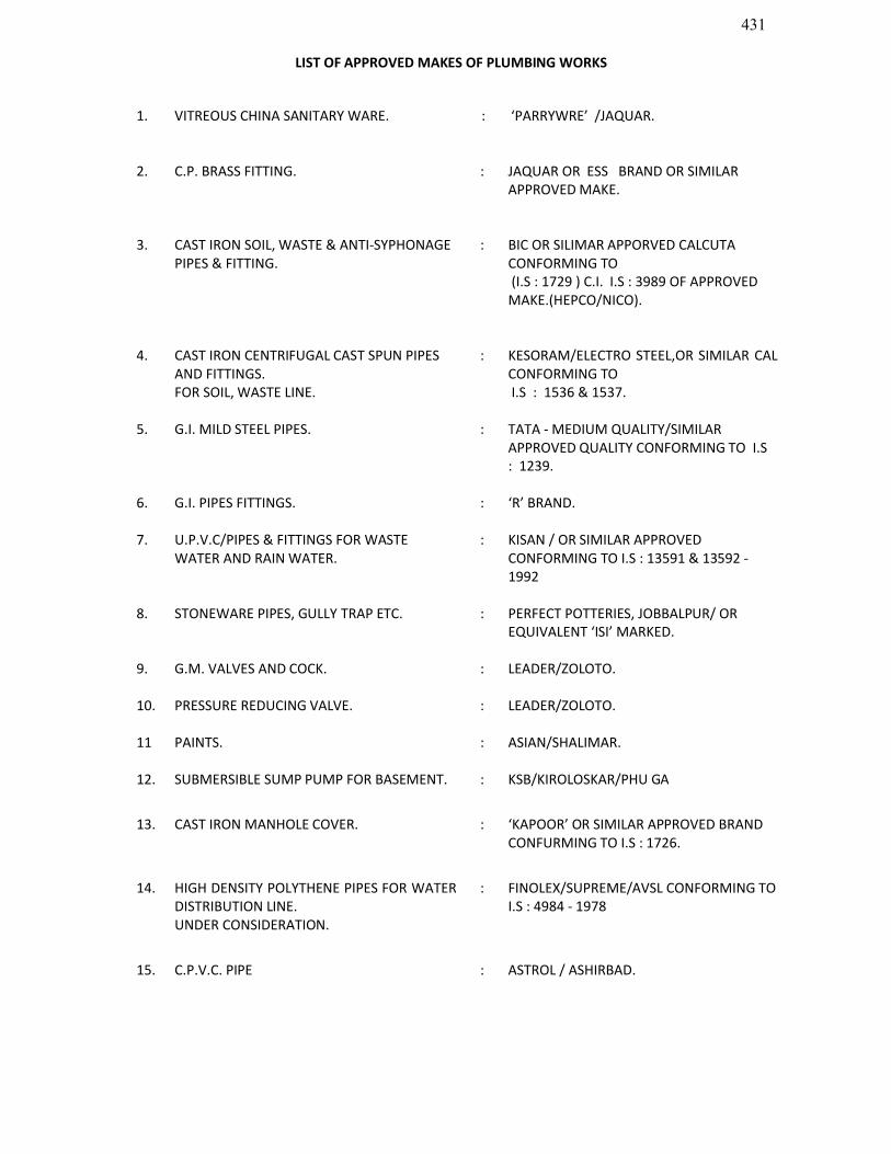
431
LIST OF APPROVED MAKES OF PLUMBING WORKS
1. VITREOUS CHINA SANITARY WARE. : ‘PARRYWRE’ /JAQUAR.
2. C.P. BRASS FITTING. : JAQUAR OR ESS BRAND OR SIMILAR APPROVED MAKE.
3. CAST IRON SOIL, WASTE & ANTI-SYPHONAGE PIPES & FITTING.
: BIC OR SILIMAR APPORVED CALCUTA CONFORMING TO(I.S : 1729 ) C.I. I.S : 3989 OF APPROVED MAKE.(HEPCO/NICO).
4. CAST IRON CENTRIFUGAL CAST SPUN PIPES AND FITTINGS.FOR SOIL, WASTE LINE.
: KESORAM/ELECTRO STEEL,OR SIMILAR CAL CONFORMING TOI.S : 1536 & 1537.
5. G.I. MILD STEEL PIPES. : TATA - MEDIUM QUALITY/SIMILAR APPROVED QUALITY CONFORMING TO I.S : 1239.
6. G.I. PIPES FITTINGS. : ‘R’ BRAND.
7. U.P.V.C/PIPES & FITTINGS FOR WASTE WATER AND RAIN WATER.
: KISAN / OR SIMILAR APPROVED CONFORMING TO I.S : 13591 & 13592 -1992
8. STONEWARE PIPES, GULLY TRAP ETC. : PERFECT POTTERIES, JOBBALPUR/ OR EQUIVALENT ‘ISI’ MARKED.
9. G.M. VALVES AND COCK. : LEADER/ZOLOTO.
10. PRESSURE REDUCING VALVE. : LEADER/ZOLOTO.
11 PAINTS. : ASIAN/SHALIMAR.
12. SUBMERSIBLE SUMP PUMP FOR BASEMENT. : KSB/KIROLOSKAR/PHU GA
13. CAST IRON MANHOLE COVER. : ‘KAPOOR’ OR SIMILAR APPROVED BRAND CONFURMING TO I.S : 1726.
14. HIGH DENSITY POLYTHENE PIPES FOR WATER DISTRIBUTION LINE.UNDER CONSIDERATION.
: FINOLEX/SUPREME/AVSL CONFORMING TO I.S : 4984 - 1978
15. C.P.V.C. PIPE : ASTROL / ASHIRBAD.

432
SECTION : 6
SECURITIES AND OTHER FORMS
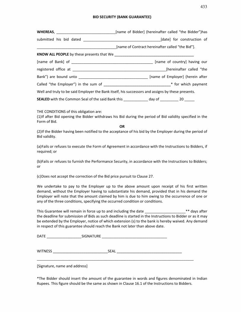
433
BID SECURITY (BANK GUARANTEE)
WHEREAS, _____________________________[name of Bidder] (hereinafter called “the Bidder”)has
submitted his bid dated ______________________________________[date] for construction of
_______________________________________[name of Contract hereinafter called “the Bid”].
KNOW ALL PEOPLE by these presents that We _______________________________________
[name of Bank] of ________________________________________ [name of country] having our
registered office at ______________________________________________[hereinafter called “the
Bank”) are bound unto __________________________________ [name of Employer] (herein after
Called “the Employer”) in the sum of _________________________________* for which payment
Well and truly to be said Employer the Bank itself, his successors and assigns by these presents.
SEALED with the Common Seal of the said Bank this ____________ day of _________ 20 _____
THE CONDITIONS of this obligation are:(1)If after Bid opening the Bidder withdraws his Bid during the period of Bid validity specified in the Form of Bid.
OR(2)If the Bidder having been notified to the acceptance of his bid by the Employer during the period of Bid validity.
(a)Fails or refuses to execute the Form of Agreement in accordance with the Instructions to Bidders, if required; or
(b)Fails or refuses to furnish the Performance Security, in accordance with the Instructions to Bidders; or
(c)Does not accept the correction of the Bid price pursuit to Clause 27.
We undertake to pay to the Employer up to the above amount upon receipt of his first written demand, without the Employer having to substantiate his demand, provided that in his demand the Employer will note that the amount claimed by him is due to him owing to the occurrence of one or any of the three conditions, specifying the occurred condition or conditions.
This Guarantee will remain in force up to and including the date ____________________** days after the deadline for submission of Bids as such deadline is started in the Instructions to Bidder or as it may be extended by the Employer, notice of which extension (s) to the bank is hereby waived. Any demand in respect of this guarantee should reach the Bank not later than above date.
DATE _________________SIGNATURE ________________________________
WITNESS ___________________________SEAL ________________________________
_____________________________________________________________________________
[Signature, name and address]
*The Bidder should insert the amount of the guarantee in words and figures denominated in Indian Rupees. This figure should be the same as shown in Clause 16.1 of the Instructions to Bidders.

434
**45 days after the end of the validity period of the Bid. Date should be inserted by the employer before the Bidding documents are issued.

435
PERFORMANCE BANK GUARANTEE
To
EXECUTIVE ENGINEER, PWD (BLDG.), ASSAM PCC DIVISION, DISPUR, GUWAHATI-6
WHEREAS _________________________________________ [ name and address of Contractor] (hereinafter called “the Contractor”) has undertaken, in pursuance of Contract No. ____________ dated _____________ to execute ______________________________ [name of Contract and brief description of works] (hereinafter called “the Contract”).
AND WHEREAS it has been stipulated by you in the said Contract that the Contractor shall furnish you with a Bank Guarantee by a recognized bank for the sum specified therein as security for compliance with his obligation in accordance with the Contract;
AND WHEREAS we have agreed to give the Contractor such a Bank Guarantee:
NOW THEREFORE we hereby affirm that we are the Guarantor and responsible to you on behalf of the Contractor, up to a total of ______________________________________ [amount of guarantee]* _____________________________ (in words), such sum being payable in the types and proportions of currencies in which the Contract price is payable, and we undertake to pay you, upon your first written demand and without cavil or argument, any sum or sums within the limits of _________________________ amount of guarantee] as aforesaid without your needing to prove or to show grounds or reasons for your demand for the sum specified therein.
We hereby waive the necessary of your demanding the said debt from the contractor before presenting us with the demand.
We further agree that no change or addition to or other modification of the terms of the Contract or of the works to be performed there under or of any of the Contract documents which may be made between your hand and the Contractor shall in any way release us from any liability under this guarantee, and we hereby waive notice of any such change, addition or modification.
This guarantee shall be valid until 28 days from the date of expiry of the Defect Liability Period.
Signature and Seal of the guarantor ___________________
Name of Bank ___________________________________
Address ________________________________________
Date _________________
________________________________________________________________________________*An amount shall be inserted by the Guarantor, representing the percentage of Contract Price specified in the Contract including additional security for unbalanced Bids, if any and denominated in Indian Rupees.
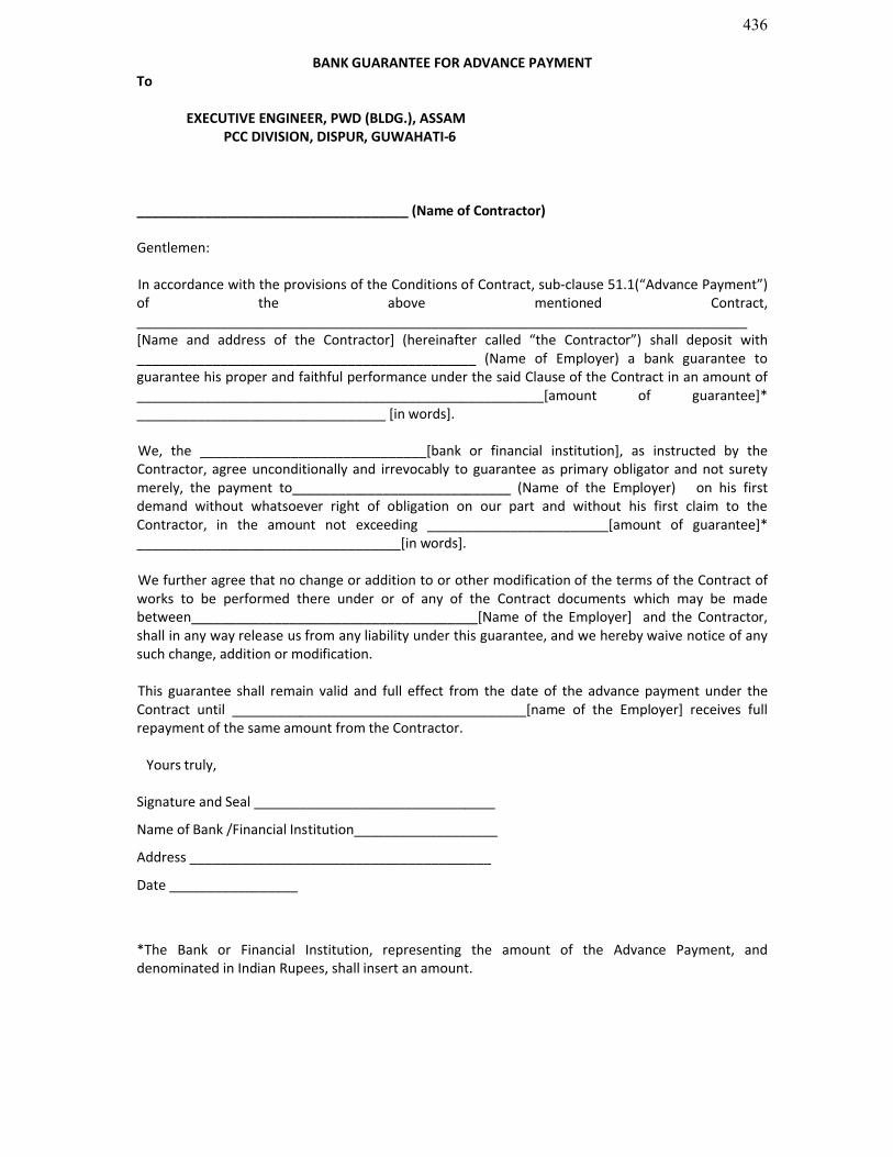
436
BANK GUARANTEE FOR ADVANCE PAYMENTTo
EXECUTIVE ENGINEER, PWD (BLDG.), ASSAM PCC DIVISION, DISPUR, GUWAHATI-6
____________________________________ (Name of Contractor)
Gentlemen:
In accordance with the provisions of the Conditions of Contract, sub-clause 51.1(“Advance Payment”) of the above mentioned Contract, _________________________________________________________________________________ [Name and address of the Contractor] (hereinafter called “the Contractor”) shall deposit with _____________________________________________ (Name of Employer) a bank guarantee to guarantee his proper and faithful performance under the said Clause of the Contract in an amount of ______________________________________________________[amount of guarantee]* _________________________________ [in words].
We, the ______________________________[bank or financial institution], as instructed by the Contractor, agree unconditionally and irrevocably to guarantee as primary obligator and not surety merely, the payment to_____________________________ (Name of the Employer) on his first demand without whatsoever right of obligation on our part and without his first claim to the Contractor, in the amount not exceeding ________________________[amount of guarantee]* ___________________________________[in words].
We further agree that no change or addition to or other modification of the terms of the Contract of works to be performed there under or of any of the Contract documents which may be made between______________________________________[Name of the Employer] and the Contractor, shall in any way release us from any liability under this guarantee, and we hereby waive notice of any such change, addition or modification.
This guarantee shall remain valid and full effect from the date of the advance payment under the Contract until _______________________________________[name of the Employer] receives full repayment of the same amount from the Contractor.
Yours truly,
Signature and Seal ________________________________
Name of Bank /Financial Institution___________________
Address ________________________________________
Date _________________
*The Bank or Financial Institution, representing the amount of the Advance Payment, and denominated in Indian Rupees, shall insert an amount.
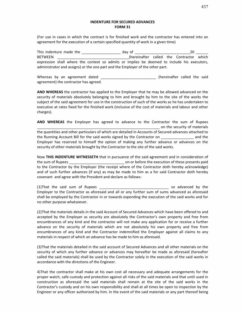
437
INDENTURE FOR SECURED ADVANCESFORM 31
(For use in cases in which the contract is for finished work and the contractor has entered into an agreement for the execution of a certain specified quantity of work in a given time)
This indenture made the ___________________ day of ___________________________20 ______ BETWEEN ___________________________________(hereinafter called the Contractor which expression shall where the context so admits or implies be deemed to include his executors, administrator and assigns) or the one part and the Employer of the other part.
Whereas by an agreement dated ___________________________ (hereinafter called the said agreement) the contractor has agreed.
AND WHEREAS the contractor has applied to the Employer that he may be allowed advanced on the security of materials absolutely belonging to him and brought by him to the site of the works the subject of the said agreement for use in the construction of such of the works as he has undertaken to executive at rates fixed for the finished work (inclusive of the cost of materials and labour and other charges).
AND WHEREAS the Employer has agreed to advance to the Contractor the sum of Rupees ____________________________________________________________ on the security of materials the quantities and other particulars of which are detailed in Accounts of Secured advances attached to the Running Account Bill for the said works signed by the Contractor on ________________ and the Employer has reserved to himself the option of making any further advance or advances on the security of other materials brought by the Contractor to the site of the said works.
Now THIS INDENTURE WITNESSETH that in pursuance of the said agreement and in consideration of the sum of Rupees ___________________________ on or before the execution of these presents paid to the Contractor by the Employer (the receipt where of the Contractor doth hereby acknowledge) and of such further advances (if any) as may be made to him as a for said Contractor doth hereby covenant and agree with the President and declare as follows:
(1)That the said sum of Rupees __________________________________ so advanced by the Employer to the Contractor as aforesaid and all or any further sum of sums advanced as aforesaid shall be employed by the Contractor in or towards expending the execution of the said works and for no other purpose whatsoever.
(2)That the materials details in the said Account of Secured Advances which have been offered to and accepted by the Employer as security are absolutely the Contractor’s own property and free from encumbrances of any kind and the contractor will not make any application for or receive a further advance on the security of materials which are not absolutely his own property and free from encumbrances of any kind and the Contractor indemnified the Employer against all claims to any materials in respect of which an advance has be made to him as aforesaid.
(3)That the materials detailed in the said account of Secured Advances and all other materials on the security of which any further advance or advances may hereafter be made as aforesaid (hereafter called the said materials) shall be used by the Contractor solely in the execution of the said works in accordance with the directions of the Engineer.
4)That the contractor shall make at his own cost all necessary and adequate arrangements for the proper watch, safe custody and protection against all risks of the said materials and that until used in construction as aforesaid the said materials shall remain at the site of the said works in the Contractor’s custody and on his own responsibility and shall at all times be open to inspection by the Engineer or any officer authorized by him. In the event of the said materials or any part thereof being

438
stolen, destroyed or damaged or becoming deteriorated in a greater degree than is due to reasonable use and wear thereof the Contractor will forthwith replace the same with other materials of like quality or repair and make good the same required by the Engineer.
(5)That the said materials shall not be any account be removed from the site of the said works except with the written permission of the Engineer or an officer authorized by him on that behalf.
(6)That the advances shall be repayable in full when or before the Contractor receives payment from the Employer of the price payable to him for the said works under the terms and provisions of the said agreement. Provided that if any intermediate payments are made to the Contractor on account of work done than on the occasion of each such payment the Employer will be at liberty to make a recovery from the Contractor’s Bill for such payment by deducting there from the value of the said materials than actually used in the construction and in respect of which recovery has not been made previously, the value for this purpose being determined in respect of each description of materials at the rates at which the amounts of the advances made under these presents were calculated.
(7)That if the Contractor shall at any time make any default in the performance or observance in any respect of any of the terms and provisions of the said agreement or of these presents the total amount of the advance or advances that may still be owing of the Employer shall immediately on the happening of such default be repayable by the Contractor to be the Employer together with interest thereon at twelve percent per annum from the date or respective dates of such advance or advances to the date of repayment and with all costs, charge, damages and expenses incurred by the Employer in or for the recovery thereof or the enforcement of this security or otherwise by reason of the default of the Contractor and the Contractor hereby covenants and agrees with the Employer to reply and pay the same respectively to him accordingly.
(8)That the contractor hereby charges all the said materials with the repayment to the Employer of the said sum of Rupees ____________________________________ and any further sum of sums advanced as aforesaid and all costs, charges, damages and expenses payable under these presents PROVIDED ALWAYS and it is hereby agreed and declared that not withstanding anything in the said agreement and without prejudice to the power contained therein and whenever the covenant for payment and repayment herein before contained shall become enforceable and the money owing shall not be paid in accordance there with the Employer may at any time thereafter adopt all or any of the following courses as he may deem best:
(a)Seize and utilize the said materials or any part thereof in the completion of the said works on behalf of the contractor in accordance with the provisions in that behalf contained in the said agreement debiting the contractor with the actual cost of effecting such completion and the amount due to the contractor with the value of work done as if he has carried it out in accordance with the said agreement and at the rates thereby provided. If the balance is against the contractor, he is to pay same to the Employer on demand.
(b)Remove and sell by public auction the seized materials or any part thereof and out of the moneys arising from the sale retain all the sums aforesaid repayable or payable to the Employer under these presents and pay over the surplus (if any) to the Contractor.
(c)Deduct all or any part of the moneys owing out of the security deposit or any sum due to the Contractor under the said agreement.
(9)That except in the event of such default on the part of the contractor as aforesaid interest on the said advance shall not be payable.
(10)That in the event of any conflict between the provisions of these presents and the said agreement the provisions of these presents shall prevail and in the event of any dispute or difference arising over the construction or effect of these presents the settlement of which has not been here-in-before

439
expressly provided for the same shall be referred to the Employer whose decision shall be final and the provision of the Indian Arbitration Act for the time being in force shall apply to any such reference.

440
GOVERNMENT OF ASSAMOFFICE OF THE CHIEF ENGINEER : PWD, BUILDING, ASSAM, GUWAHATI
No Dated Guwahati the 2015
LETTER OF ACCEPTANCE
To
_________________________________(Name and address of the Contractor)
__________________________________
__________________________________
Sub:
Dear Sirs,
This is to notify you that your offer dated ___________________________for execution of the ________________________ (name of the contract and identification number, as given in theInstructions to Bidders) for the Contract Price of Rupees __________________ (_____________________________________) (amount in words and figures), as a corrected and modified in accordance with the Instructions to Bidders is hereby accepted by the department of P.W.D.
We accept / do not accept that _______________________ be appointed as the Adjudicator.You are hereby requested to furnish performance Security, in the form detailed in Para 34.1 of ITB for an amount equivalent to Rs._________________ within 21 days of the receipt of this letter of acceptance valid upto 28 days from the date of expiry of Defects Liability Period i.e. upto ___________ and sign the contract, failing which action as stated in Para 34.2 of ITB will be taken.
Yours faithfully,
Chief Engineer, PWD (Bldg.), Assam, Chandmari, Guwahati - 3

441
Issue of Notice to proceed with the works
________________________(date)
To
_________________________________(Name and address of the Contractor)
__________________________________
__________________________________
Dear Sirs,
Pursuant to your furnishing the requisite as stipulated in ITB Clause 34.1 and signing of the construction of ________________________________________________________________________________________________________ at a bid of Rs.____________________
You are hereby instructed to proceed with the execution of the said works in accordance with the contract documents.
Yours faithfully,
( Signature, name and title of signatoryAuthorized to sign on behalf of Employer )

442
Agreement Form
Agreement No………………………………………………………………………………………….
This agreement made this…………………….... day of…………………………….between Chief Engineer, PWD (Bldg.),Assam,Chandmari, Guwahati-3 (hereinafter called “the Employer”) and ………………………………………………………………… ( name and address of contractor ) hereinafter called “the contractor” of the other part.
Whereas the Employer is desirous that the Contractor execute…………………………………..…………………………………………………………………….. (names and identification number of Contract) (hereinafter called “the works”) and the Employer has accepted the Bid by the Contractor for the execution and completion of such works and the remedying of any defects therein, at a cost of Rs………………………………………
NOW THIS AGREEMENT WITHNESSETH as follows :
In this Agreement, words and expression shall have the same meanings as are respectively assigned to them in the conditions hereinafter referred to any they shall be deemed to form and be read and construed as part of this Agreement.
In consideration of the payments to be made by the Employer to the contractor as hereinafter mentioned, the Contractor hereby covenants with the Employer to execute and complete the works and remedy any defects therein in conformity in all aspects with the provision of the contract.
The Employer hereby covenants to pay the contractor in consideration of the execution and completion of the Works and the remedying the defects wherein Contract Price or such other sum as may become payable under the provisions of the contract at the times and in the manner prescribed by the Contract.
The following documents shall be deemed to form and be ready and construed as part of this Agreement viz.
i.Letter of Acceptance;ii. Notice to proceed with the works;iii. Contractor’s Bidiv. Condition of Contract : General and Specialv. Contract Datavi. Additional conditionvii. Drawingsviii. Bill of Quantities andix. Any other documents listed in the contract data as forming part of the contract.

443
Time of completion: 9 (nine) Months
In witnessed whereof the parties there to have caused this Agreement to be executed the day and year first before written.
The common seal of ……………………………………………………….............................. was hereunto affixed in the presence of :
Signed, Sealed and delivered by the said …………….……………………… …………. ………
… ………………………………………………..…………………………………………………….in the presence of :
Binding Signature of Employer ………………………………………………….
Binding Signature of Contractor…………………………………………………….

444
UNDERTAKING
I, the undersigned do hereby undertake that our firm M/s………………………………………..
………………… …………. agree to abide by this bid for a period …………….…………………
……………………………………………… days for the date fixed for receiving the same and it shall be binding on
us and may be accepted at any time before the expiration of that period.
_________________________________________
( Signed by an Authorised Officer of the firm )
Title of Officer
Name of Firm
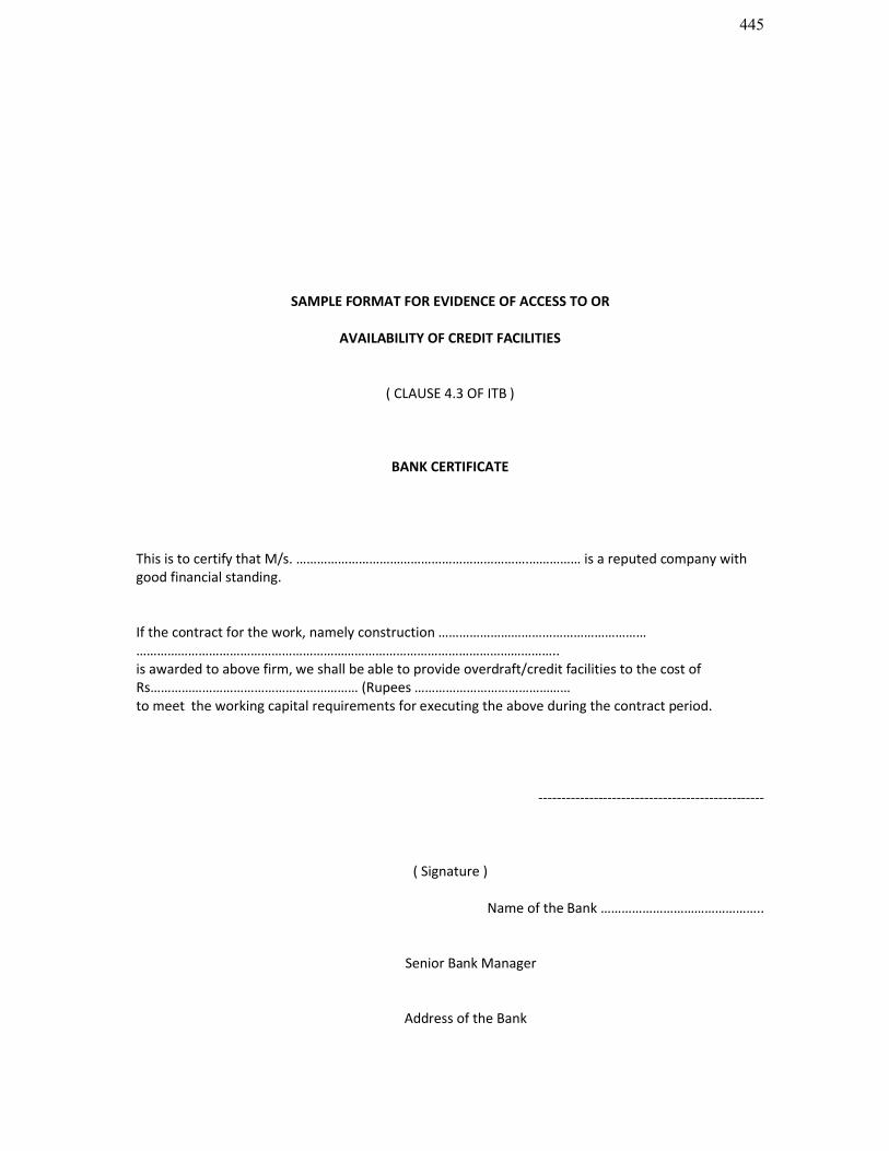
445
SAMPLE FORMAT FOR EVIDENCE OF ACCESS TO OR
AVAILABILITY OF CREDIT FACILITIES
( CLAUSE 4.3 OF ITB )
BANK CERTIFICATE
This is to certify that M/s. ………………………………………………………….…………… is a reputed company with good financial standing.
If the contract for the work, namely construction ………………………………………………………………………………………………………………………………………………………………..is awarded to above firm, we shall be able to provide overdraft/credit facilities to the cost of Rs…………………………………………………… (Rupees ………………………………………to meet the working capital requirements for executing the above during the contract period.
-------------------------------------------------
( Signature )
Name of the Bank ………………………………………..
Senior Bank Manager
Address of the Bank
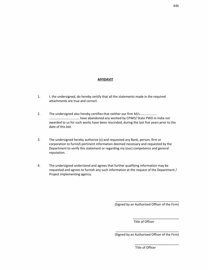
446
AFFIDAVIT
1. I, the undersigned, do hereby certify that all the statements made in the required attachments are true and correct.
2. The undersigned also hereby certifies that neither our firm M/s………………… ………………………………. have abandoned any worked by CPWD/ State PWD in India nor awarded to us for such works have been rescinded, during the last five years prior to the date of this bid.
3. The undersigned hereby authorize (s) and requested any Bank, person, firm or corporation to furnish pertinent information deemed necessary and requested by the Department to verify this statement or regarding my (our) competence and general reputation.
4. The undersigned understand and agrees that further qualifying information may be requested and agrees to furnish any such information at the request of the Department / Project implementing agency.
____________________________________(Signed by an Authorised Officer of the Firm)
__________________________ Title of Officer
____________________________________(Signed by an Authorised Officer of the Firm)
_________________________ Title of Officer
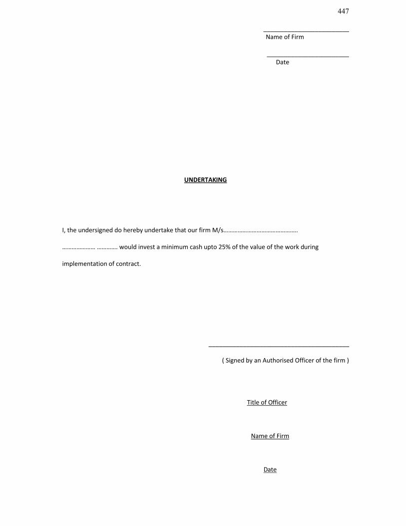
447
_________________________ Name of Firm
________________________ Date
UNDERTAKING
I, the undersigned do hereby undertake that our firm M/s………………………………………..
………………… …………. would invest a minimum cash upto 25% of the value of the work during
implementation of contract.
_________________________________________
( Signed by an Authorised Officer of the firm )
Title of Officer
Name of Firm
Date
448
AUTHORITY
Chief Engineer PWD (Bldg) Assam, Chandmari, Guwahati-3 is hereby authorized to seek reference from my Banker, as and when required.
Name & Address of BankerWith Contact No./ Fax No.
Date: Signature of Bidder
Place: Name (Capital Block letters):
Address:

449
UNDERTAKING FOR BID VALIDITY
Bid for the work:
An undertaking is hereby given that the bid submitted by me/us shall remain valid for a period not less than 180 days after the deadline date for submission specified in clause 20.
Date:
Place: Signature of Bidder
Name (Capital Block letters):
Address:

450
SECTION 7

451
FORM OF BID
FORM OF BID
Description of the Works
ToThe Chief Engineer, PWD (Building), Assam, Chandmari,Guwahati – 3.
We offer to Execute the Works describe above and remedy any defects therein in conformity with the conditions of Contract, specifications, drawings, Bill of Quantities and Addenda for the sums(s) of Rs…………………………….(Rupees ………………………………………………….)
We undertake, if our Bid is accepted, to commence the Works as soon as is reasonably possible after the receipt of the Engineer’s notice to commence, and to complete the whole of the works comprised in the contract within the time stated in the document.
We agree to abide by the Bid for the period of 180 days from the date fixed for receiving the same, and it shall remain binding upon us and may be accepted at any time before the expiration of that period.
Unless and until a formal agreement is prepared and executed this Bid, together with your written
452
acceptance thereof, shall constitute a binding contract between us.
We understand that you are not bound to accept the lowest or any bid you may receive.
We accept the appointment of _________________________________________________as the Dispute Review Expert.
(OR)
We do not accept the appointment of ____________________________________________________________________ Review Expert and propose instead that Shri____________________________________appointed as Dispute Review Expert, whose BIO-DATA is attached.
Dated this ______________ day of _____________________/2010.
Signature ______________________________in the capacity of ___________________dulyAuthorized to sign bids for and on behalf of ____________________________(in block capitals or typed)______________________________________________________
Address ______________________________________________
Witness______________________________________________
Address______________________________________________
_____________________________________Occupation.
SECTION : 8

453
BILL OF QUANTITIES
SECTION : 9
DRAWINGS

454
The drawings may be seen/ collected from the office of the Executive Engineer, PWD (Building), PCC Division, Dispur, Guwahati-6 Assam in due course.

455

456
SECTION : 10
DOCUMENTS TO BE FURNISHED BY THE BIDDER
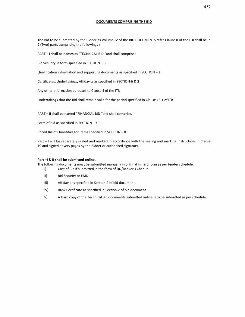
457
DOCUMENTS COMPRISING THE BID
The Bid to be submitted by the Bidder as Volume-IV of the BID DOCUMENTS refer Clause 8 of the ITB shall be in 2 (Two) parts comprising the followings :
PART – I shall be names as “TECHNICAL BID “and shall comprise:
Bid Security in form specified in SECTION – 6
Qualification information and supporting documents as specified in SECTION – 2
Certificates, Undertakings, Affidavits as specified in SECTION-6 & 2
Any other information pursuant to Clause 4 of the ITB
Undertakings that the Bid shall remain valid for the period specified in Clause 15.1 of ITB
PART – II shall be named “FINANCIAL BID “and shall comprise.
Form of Bid as specified in SECTION – 7
Priced Bill of Quantities for Items specified in SECTION – 8.
Part – I will be separately sealed and marked in accordance with the sealing and marking Instructions in Clause 19 and signed at very pages by the Bidder or authorized signatory.
Part –I & II shall be submitted online. The following documents must be submitted manually in original in hard form as per tender schedule.
i) Cost of Bid if submitted in the form of DD/Banker’s Cheque.
ii) Bid Security or EMD.
iii) Affidavit as specified in Section-2 of bid document.
iv) Bank Certificate as specified in Section-2 of bid document
v) A Hard copy of the Technical Bid documents submitted online is to be submitted as per schedule.