BIDDING DOCUMENT (NIT NO. TER- 21/R-APDRP/2016) FOR
299
DAKSHIN HARYANA BIJLI VITRAN NIGAM Office of the Chief Engineer/R-APDRP, Vidyut Sadan, Vidyut Nagar, Hisar-125005 Tel: 01662-223194 Fax: 01662-223181 BIDDING DOCUMENT (NIT NO. TER- 21/R-APDRP/2016) FOR Design, supply, installation and integration of Non-IT infrastructure items (on turnkey basis/ single bidder’s responsibility) for SCADA Center in IMT Faridabad including civil interior work, exterior work, precision air conditioning system, electrical system (including panels), comfort air conditioning system, building management system, Novec 1230 based gas suppression system for server room, PAC rooms, UPS room & battery room, VESDA system, fire alarm system, Access control system, CCTV system, 125 kva diesel generating unit and accessories, public address system, water leak detection system, rodent repellent system, passive network cabling system and miscellaneous items along with 4 years O&M and 3 years AMC etc. under the jurisdiction of DHBVN in the Haryana State on turnkey basis. VOLUME-I CONDITIONS OF CONTRACT Chief Engineer /R-APDRP, DHBVN, Vidyut Sadan, Vidyut Nagar, HISAR – 125005. Phone 01662-223194 Fax No.: 01662-223181 Superintending Engineer/R-APDRP, DHBVN, Vidyut Sadan, Vidyut Nagar, HISAR – 125005.
-
Upload
khangminh22 -
Category
Documents
-
view
4 -
download
0
Transcript of BIDDING DOCUMENT (NIT NO. TER- 21/R-APDRP/2016) FOR

DAKSHIN HARYANA BIJLI VITRAN NIGAM Office of the Chief Engineer/R-APDRP,
Vidyut Sadan, Vidyut Nagar, Hisar-125005
Tel: 01662-223194 Fax: 01662-223181
BIDDING DOCUMENT (NIT NO. TER- 21/R-APDRP/2016)
FOR Design, supply, installation and integration of Non-IT infrastructure items (on turnkey basis/ single bidder’s responsibility) for SCADA Center in IMT Faridabad including civil interior work, exterior work, precision air conditioning system, electrical system (including panels), comfort air conditioning system, building management system, Novec 1230 based gas suppression system for server room, PAC rooms, UPS room & battery room, VESDA system, fire alarm system, Access control system, CCTV system, 125 kva diesel generating unit and accessories, public address system, water leak detection system, rodent repellent system, passive network cabling system and miscellaneous items along with 4 years O&M and 3 years AMC etc. under the jurisdiction of DHBVN in the Haryana State on turnkey basis.
VOLUME-I
CONDITIONS OF CONTRACT
Chief Engineer /R-APDRP, DHBVN, Vidyut Sadan, Vidyut Nagar, HISAR – 125005. Phone 01662-223194 Fax No.: 01662-223181
Superintending Engineer/R-APDRP, DHBVN, Vidyut Sadan, Vidyut Nagar, HISAR – 125005.

PROJECT PROFILE

PROJECT BACKGROUND Ministry of Power, Govt. of India, has launched the Restructured Accelerated Power Development and Reforms Programme (R-APDRP) in the XIth Five Year Plan. Under the RAPDRP programme, urban areas / towns / cities having population of more than 4,00,000 (as per census 2001 figures) & annual input energy of more than 350 MUs, shall be eligible for ‘SCADA / DMS’ Implementation. The eligible town under the scheme in Haryana is Faridabad under DHBVN, Haryana. The SCADA control centers would be used for monitoring power lines and optimizing the power distribution, remote data acquisition, supervisory control , monitoring and at the same time working on methods to minimize power losses eventually leading to better customer management, increased revenue and higher customer satisfaction across state of Haryana. Projects under the scheme shall be taken up in Two Parts. Part-A shall include the projects for establishment of baseline data and IT applications for energy accounting/auditing & IT based consumer service centers. Part-B shall include regular distribution strengthening projects. The activities to be covered under each part are as follows:- Part – A: Preparation of Base-line Data System for the project area covering Consumer Indexing, GIS Mapping, Automatic Metering (AMR) on Distribution Transformers and Feeders, and Automatic Data Logging for all Distribution Transformers & Feeders and SCADA / DMS system for big cities only. It would include Asset Mapping of the entire distribution network at and below the 11kV transformers and include the Distribution Transformers and Feeders, Low Tension lines, poles and other distribution network equipment. It will also include adoption of IT applications for meter reading, billing & collection; energy accounting & auditing; MIS; redressal of consumer grievances and establishment of IT enabled consumer service centers etc. Part – B: Renovation, modernization and strengthening of 11 kV level Substations, Transformers/Transformer Centers, Re-conduct ring of lines at 11kV level and below, Load Bifurcation, Feeder segregation, Load Balancing, Aerial Bunched Conduct ring in thickly populated areas, HVDS, installation of capacitor banks and mobile service centers etc. In exceptional cases, where sub-transmission system is weak, strengthening at 33 kV or 66 kV levels may also be considered

PROJECT SCOPE The SCADA control center is proposed to have following area breakup which need to be covered under this project scope. The details of work location can be found in Annexure Section. SCADA Control Center – Area Breakup (Approximate) Sr. No. Room / Area Size (SFT)
1 Server Room – For Housing Server, Network Racks
Detail mentioned in Layout plan.
2 AHU / Precision Area – For PAC 3 Video Wall Area – Video Wall Screen 4 Control Room – Operators Monitoring the
power 5 UPS Room – For Electrical and UPS 6 PDS Room - 7 Cabin 8 DTS - 9 Entrance Lobby / Waiting Area
10 Pantry 11 Outside Open Area – For DG Installation

Project Scope in Brief The SCADA Control centers are desired to have following features:- NON-IT (As applicable in SCADA Control Center Premises)
1. Civil work a. False Ceiling b. Raised or False Floor c. Fire Rated Door, Standard Doors d. Painting, Finishing, as required (Incl. Fire Proof &Water Proof Treatment) e. Furniture (including Workstation in Control Room) f. Dismantling & reconstruction
2. Electrical Power System
a. Power Cabling, Point Wiring b. Main LT Panel, UPS O/P Panel, Cable Raceways c. Lighting System d. Building Lightening Arrestor e. Data Cabling (Server Room, Workstations in all areas)
3. Power Back-up System a. DG Sets with DG change over panel
4. Air-Conditioning (HVAC) a. PAC (Precision Air Conditioning System for Server Room) b. CAC (Hi-Wall Air Conditioning System for other area)
5. I-BMS (Integrated Building Management System) including Surveillance System using CCTV
a. Access Control System b. Fire Alarm System c. Gas Based Fire Suppression System d. Public Address System e. Water Leak Detection System f. Rodent Repellant System g. Smoke Detection System (VESDA) for Server Room h. Integrated BMS System for UPS, DG, PAC, Energy etc.
6. Video Wall Units (To be prov ided by DHBVN) 7. Primary UPS System (to be provided by DHBVN) 8. Others as specified by department / users

OBJECTIVES OF THE PROJECT
Following summarizes the broad project objectives of DHBVN SCADA Control Center:-
Host, Manage and secure the digital data as created by DHBVN
Provide uninterrupted data services
Provide long-term scalable storage infrastructure
Manage high volume of incoming and outgoing content
Streamline net-centric operations
Provide authorized and secure access
Design and Site Preparation of the SCADA Control centers (in terms of the civil,
electrical and mechanical work and all other necessary components as specified
above)
Supply, installation and setting up of the necessary Physical Infrastructure (State
of the Art Precision Air-Conditioning System fro server room and Hi-wall Split air-
conditioner for other area, Fire Detection and Control System, Diesel Generator
Units, Lighting system, Power and Network Cabling etc.)
Supply, installation and setting up of the multi-layer Physical Security
infrastructure like bio-metric/Smart card etc. based access-control system,
CCTV/ surveillance systems. Establish effective and efficient Infrastructure
monitoring & management practices to ensure reliability, availability, quality of
services and security of the Information systems

INDICATIVE FLOOR LAYOUT

SCOPE OF WORK DHBVN, proposes to select an agency which will built and support the SCADA Control
center at IMT, Faridabad, Haryana for a period of 4 years (1 Year Warranty and 3 Years
Additional Comprehensive AMC). DHBVN reserves the right to extend the period of
support to another 2 years and making it a total of 5 years from the date of installation.
Hence vendors are requested to quote for (i) Supply, installation, testing, commissioning
of entire material alongwith comprehensive warranty support period for 1st year, (ii)
comprehensive support prices for 2nd, 3rd and 4th year need to be quoted separately
and as individual line items. Commercial valuation would be done after including the
overall 4 years (1+3 Years) support prices.
DHBVN reserves the rights to increase or decrease the support period. It may further
decide not to release support contract for CAMC with award of contract, and may
release the support order after completion of warranty period of 1 year.
Successful bidder’s overall responsibility shall be to design, procure, install, and provide
post implementation support to SCADA Control Center. The expected minimum scope
of work is detailed under this section. The bidder shall add additional components as
they feel are required to meet the requirements given in SLA after the approval of CE
PD&C, DHBVN, Hisar.
The bidder has to provide complete solution to DHBVN and fill the gaps which are not
covered in the RFP.
BRIEF SCOPE OF WORK
Sr. No.
Scope of Work – Description
1 Supply, Install, Configure, Test & Commission all the equipment and products with necessary and adequate accessories as specified later in the document
2 One year On-Site Comprehensive Warranty Maintenance and three year CAMC (2nd, 3rd & 4th Year) of various equipments and components supplied, with support level commitment agreed by OEM including adequate number of support people at site during the entire support duration
3 Undertake all server room cabling necessary as per international IT standards 4 While basic design/layout of the SCADA Control Center is given, the Bidder is
advised to make a site survey on its own cost to gather information required for preparing the working drawings/layout plans. Successful bidder is advised to submit (after award of contract) all the working drawings/layout plans along with complete design, specifications and quantity of each item used in the design viz. electrical fixtures, distribution boards, wires, cabling, switches, sockets, MCBs etc of following items:

a. Basic Layout plan of SCADA Control Center b. False ceiling Layout c. Electrical layout (Incl. UPS, DG integration) d. Lighting Layout e. Civil addition and alteration details f. Electrical SLD; Incl Power Cabling, raceways, Power Incomer, Outgoing, ATS, LT Panel, DB (Lighting, Power, Comfort AC etc) g. Access Control system Layout h. CCTV Layout i. Rodent Repellent Layout j. Fire Extinguisher Layout k. Water Leak Detection System layout l. Emergency Evacuation Plan m. Fire Control System Layout (Fire Alarm, Fire Suppressions, VESDA etc.) n. Public Address System Layout o. HVAC Layout (Incl. CFD Diagram, Air-flow Distribution, Position of IDU, ODU) p. DG Set (DG System Orientation, Fuel Tank, Sync Panel, Foundation) q. Data Cabling (Raceway, cable in/out)
5 Bidder has to lay cable from primary source (as provided by DHBVN) to LT Panel. Laying of cable from LT Panel and from DG Set, creation of Earth Pits, fixing of various switches required for proper functioning of DG Sets will be under Bidders scope of work. Bidder can consider DG Sets location to be at backside on ground floor.
6 Provide training to IT Division, Technical and support team as required by DHBVN for the installation, configuration, commissioning, monitoring, and troubleshooting of various equipments / products & other aspects of the SCADA Control Center over a period of 2-3 days for a session size of 05 DHBVN nominated staff
7 After successful completion of 1 year warranty (Incl DLP) all the components covered under warranty will be given under Comprehensive AMC for a period of four years i.e. 2nd, 3rd and 4th year. In case of the item/spare part being not available due to any reason, the bidder shall provide an equivalent or latest item/spare part in lieu of the original item/spare part subject to the approval of the DHBVN. All the quoted material should have a minimum life cycle of 4 years and the same need to be confirmed by the respective OEM on their letterheads. All such OEM communication to be submitted in technical bid by the bidder.

Design, Supply, Installation and Commissioning Phase
Site Preparation The successful bidder shall carry out the site preparation as per the finalized layouts. The selected bidder shall be responsible for obtaining necessary clearances which shall enable them to undertake civil, electrical, and mechanical works at the site. DHBVN shall support and facilitate the successful bidder in obtaining such clearances. The bidders are free to inspect the site prior to submitting their proposals. In case of nonconformance due to the unavoidable building constraints the DHBVN and the Bidder shall agree mutually on alternate arrangements Supply, Installation and Commissioning of Non-IT Components The selected bidder shall procure and supply all Non IT components. The selected bidder would be required to undertake all the necessary civil, electrical, and mechanical works including false ceiling/flooring, partitioning, installation of electrical component, cable laying etc and other infrastructure or services to create the Non- IT/ Physical infrastructure. Based on generic solution design, minimum capacities and specifications for the components have been worked out. The Bidder is at liberty to suggest better solutions to meet the overall SLA requirements. Acceptance Testing and Commissioning DHBVN shall review the detailed acceptance test plan and would also conduct audit of the process, plan and results of the Acceptance Test carried out by the implementation agency. The DHBVN would issue certification of completion for which DHBVN shall verify fulfillment of all the functional requirements as per the contract signed between the Bidder and DHBVN. The Bidder shall be required to demonstrate all the services / features / functionalities as mentioned in the agreement. Testing and Commissioning shall be carried out before the commencement of Operations. DHBVN reserves the right to invite a 3rd party agency for the audit and acceptance testing. Final Acceptance Testing After successful testing by the DHBVN team, a Final Acceptance Test Certificate (FAT) shall be issued to the Bidder. The date on which FAT certificate is issued shall be deemed to be the date of successful commissioning of the SCADA Control Center. Some of the Prerequisite for Carrying out FAT activity:-
All documentation related to DIRF and relevant acceptance test document (including Non IT Components etc.) should be completed & submitted before the final acceptance test.
The training requirements as mentioned should be completed before the final acceptance test.
Submission of Software manuals / brochures / Data Sheets / CD / DVD / media for all the supplied equipments (Wherever applicable)
Completion and verification of all functional requirements, performance verification as agreed between DHBVN and bidder.

Summary of Roles & Responsibilities The responsibilities of DHBVN and prospective vendor (post award of contract) are
highlighted below:-
Table:3 Summary of roles and responsibilities of stakeholders
Sr. No.
Activity Prime Responsibility
Secondary Responsibility
Implementation Phase
1 Provision of Space DHBVN
2 Site Strengthening (as required) DHBVN
3 Provisioning of Raw Power DHBVN
4 Placement of Purchase Order to
Selected bidder
DHBVN
5 Contract Sign-Off DHBVN Select Bidder
6 Site Preparation Select Bidder DHBVN
7 Obtain regulatory and other
clearances
Select Bidder DHBVN
8 Procurement and Installation of
Infrastructure for
SCADA Control Center
Select Bidder DHBVN
9 Training to DHBVN Team Select Bidder DHBVN
10 Acceptance Testing as per
agreed plans
Select Bidder DHBVN
11 Support provision as per agreed
SLA
Select Bidder/ OEM

ESTIMATED TIMELINES The table below provides the time schedule for implementation of the SCADA Control Center, ‘T’ as referred to in the table, will be treated as the date of signing the agreement between DHBVN and successful bidder; Table : 4 Tentative Time Schedule for Implementation (for individual location) Week Activity T+0 Contract Sign-Off / Site handover (Whichever is later) T+2 Site Survey, Feasibility Study, Preparation & submission of final layouts,
drawings T + 4 Approval of Drawings, Temp Power Provisioning for project execution by DHBVN T+10 Setup, Installation, Site Preparation, Build-up
Foundation of DG Sets Minor Civil Works as required Earthing Pits Laying of Electrical, Data Cable Trays Power cabling from DG Set to Electrical and sub-distribution panel Power cabling from UPS to distribution panel Electrical Wiring, Lighting, Fixture as required Laying of cables for CCTV, Access control, Fire Alarms, Smoke
detectors etc. Installation of PAC, UPS, CAC, DG-Set, BMS Integrators, Fire Alarm,
CCTV, Fire Suppression System, Fire Extinguisher, WLD, PA System,
Rodent Repellant, VESDA, DVR etc.
Analog EPABX with phone instruments T+14 Testing, Commissioning of HVAC, DG Set, Entire BMS System T+15 Training, Documentation, FAT T+16 FAT Issues Closure, Project Sign-off, Site Handover to Operations team
Note: ‘T+n’ represents the calendar date of week, on which mentioned activity is supposed to get over

DAKSHIN HARYANA BIJLI VITRAN NIGAM NIT No: TER-21/R-APDRP/2016
E-tenders are invited in two parts (Part I Technical Bid & Part II Price Bid), from the bidders as per following details:-
Description of work Estimated Cost
Design, supply, installation and integration of Non-IT infrastructure items (on turnkey basis/ single bidder’s responsibility) for SCADA Center in IMT Faridabad including civil interior work, exterior work, precision air conditioning system, electrical system (including panels), comfort air conditioning system, building management system, Novec 1230 based gas suppression system for server room, PAC rooms, UPS room & battery room, VESDA system, fire alarm system, Access control system, CCTV system, 125 kva diesel generating unit and accessories, public address system, water leak detection system, rodent repellent system, passive network cabling system and miscellaneous items along with 4 years O&M and 3 years AMC as per detailed scope mentioned in the NIT.
Rs. 2.30 Cr.
Start date of e-tender Last date of Submission of Bids
Opening date of Part-I of Bids
15.03.2016 05.04.2016 (17:00 Hrs) 06.04.2016 (15:00 Hrs)
1. The Tender Documents fee (Rs. 4000 /- Non-refundabale) and E-Service fees (Rs.
1000 /- Non-refundabale) will be paid online.
2. Part-I of the e-tenders against the above Tender Enquiry will be opened in the office
of the Chief Engineer/R-APDRP, Vidyut Sadan, Vidyut Nagar, DHBVN, Hisar, as per
schedule above.
3. The earnest money shall be depostited online in cash by the Tenderer through Debit
Card or RTGS/ NEFT or Net banking. It is expected of the prospective bidder to
deposit EMD online by atleast one day before deadline of submission of bids due to
web portal provisioning. Any non-acceptance of EMD by web-based system on last
day of submission of bids due to web-portal constrainst shall be the bidders
responsibility.
4. The purchaser reserves the right to reject one or all of the tenders received, without
assigning any reason.
5. The online procedures / requirement of webportal shall prevail over the details
mentioned in the bid documents, if there exist any contradiction.

6. The tender documents having detailed terms and conditions can be downloaded
from the website https://www.haryanaeprocurement.gov.in from 15.03.2016
onwards. The e-tenders shall be received through website only. All interested firms /
contractors are requested to get themselves registered as vendors with the said
website for submitting their bids. For any assistance, please contact, Mr. Lalit Saini
(09034357793) or the help desk on Toll free no. 1800-180-2097 or through e-mail:
[email protected] of M/s Nex Tenders (India) Pvt. Ltd., Panchkula. The
bidders who are participating in one or more bids shall deposit one advance set of
hard copy of the bid duly stamped & signed. The price bid is to be submitted on-line
only. The Price bid in hand / paper form shall not to be accepted / entertained.
Corrigendum shall also be published online on the website.
Chief Engineer/R-APDRP, DHBVN, Hisar.

Page 2 of 23
Table of Contents SECTION- 2 - INSTRUCTIONS TO BIDDERS (ITB) ............................................................................. 3
A. GENERAL ................................................................................................................................. 3 1.0 SCOPE OF BID ................................................................................................................................3 2.0 SOURCE OF FUNDS ......................................................................................................................4 3.0 ELIGIBLE BIDDERS ........................................................................................................................4 4.0 QUALIFICATION OF THE BIDDER .................................................................................................4 5.0 COST OF BIDDING .........................................................................................................................6 6.0 SITE VISIT .......................................................................................................................................6
B. BIDDING DOCUMENTS ........................................................................................................... 6 7.0 CONTENT OF BIDDING DOCUMENTS ..........................................................................................6 8.0 CLARIFICATION OF BIDDING DOCUMENTS ................................................................................7 9.0 AMENDEMENT OF BIDDING DOCUMENTS..................................................................................8 10.0 SUBMISSION / DOWNLOADED OF DOCUMENTS .......................................................................8
C. PREPARATION OF BIDS ......................................................................................................... 8 11.0 LANGUAGE OF THE BID ................................................................................................................8 12.0 DOCUMENTS COMPRISING THE BID ...........................................................................................8 13.0 BID PRICES .....................................................................................................................................9 14.0 DUTIES AND TAXES (BOTH CENTRAL AND STATE) ...................................................................9 15.0 INSURANCE ..................................................................................................................................10 16.0 CURRENCIES OF BID AND PAYMENT ........................................................................................10 17.0 TIME SCHEDULE ..........................................................................................................................10 18.0 BID VALIDITY ................................................................................................................................11 19.0 BID SECURITY (BID GUARANTEE/ EARNEST MONEY) .............................................................11
D. SUBMISSION OF BIDS .......................................................................................................... 12 20.0 FORMAT AND SIGNING OF BID...................................................................................................12 21.0 DEADLINE FOR SUBMISSION OF THE BIDS - deleted............................................................13
E. BID OPENING AND EVALUATION ........................................................................................ 13 22.0 BID OPENING ................................................................................................................................13 23.0 PROCESS TO BE CONFIDENTIAL ...............................................................................................13 24.0 CLARIFICATION OF BIDS .............................................................................................................13 25.0 EXAMINATION OF BIDS AND DETERMINATION OF RESPONSIVENESS ................................13 26.0 DEFINITIONS AND MEANINGS ....................................................................................................14 27.0 EVALUATION AND COMPARISON OF BIDS ...............................................................................14
F. AWARD OF CONTRACT ........................................................................................................ 16 28.0 AWARD CRITERIA ........................................................................................................................16 29.0 OWNER’S RIGHT TO ACCEPT ANY BID AND TO REJECT ANY OR ALL BIDS .........................16 30.0 NOTIFICATION OF AWARD AND SIGNING OF AGREEMENT ...................................................16 31.0 PERFORMANCE SECURITY (CONTRACT PERFORMANCE GUARANTEE).............................16 32.0 CORRUPT OR FRADULENT PRACTICES ..........................................................................................18

Page 3 of 23
SECTION- 2 - INSTRUCTIONS TO BIDDERS (ITB) A. GENERAL 1.0 SCOPE OF BID
1 The DHBVN (referred to as Owner in these documents) invites two part (Part-1: Pre-Qualification and Technical without price bid & Part-2: Price Bid) bids for "Design, Supply, Install and Integration of Infrastructure items (On Single Bidder’s responsibility) in the SCADA Centre at IMT Faridabad, Haryana” according to technical specifications. The bidders will have to submit bids for all the works.
2 The successful bidder will be expected to complete the works by the intended completion date specified.
3 The scope of the proposal shall be on the basis of a single Bidder‟s responsibility i.e. completely covering all the equipment / services specified under the accompanying Technical Specification and other related sections.
4 Successful Bidder shall Design, Procure, Supply, Install and Integrate the non-IT infrastructure items as required for key building blocks of the SCADA Centre.
5 Study the civil infrastructure available at site and build the other non IT infrastructure essentially required for the complete operation of the SCADA Centre including civil works required for securing/ fixing these items.
6 Provide on-site services in respect of the items covered under this contract for day-to-day operations at the SCADA Centre, allied application services at the SCADA Centre as scope of Facility Management Services (FMS).
7 Bids containing deviations from provisions relating to the following clauses will be considered as non-responsive:
Price Basis and Payments (Clause 13 of this section) Bid Guarantee Contract Performance Guarantee (Clause 34 of the section) Liquidated Damages
8 The Bidder shall include in his proposal, the quality assurance programme containing the overall
quality management and procedures, which he proposes to follow in the performance of the works during various phases, as detailed in relevant clause of the General Technical Conditions.
9 At the time of award of Contract, the detailed quality assurance programme to be followed for the execution of the contract will be mutually discussed and agreed to and such agreed programme shall form a part of the contract.
10 The specific reference in these specifications and documents to any product by brand name, make or catalogue number shall be construed as establishing standards of quality and performance and not as limiting competition. However, Bidders may offer other similar product. The Bidder shall furnish adequate technical information about such alternative products to enable the Owner to determine its acceptability. The Owner shall be the sole judge on the acceptability or otherwise of such alternative material/equipment.
11 The Bidder shall note that standards for workmanship, products and reference to brand name or catalogue numbers designated by the Owner in its technical Specification are intended to be descriptive only and not restrictive. The Bidder may substitute alternative standards, brand name and/or catalogue numbers in its Bid if asked for equivalent standards/model/make and provided that it demonstrates to the Owners‟ satisfaction that the substitutions are substantially equivalent or superior to those designed in the Technical Specification.
12 The Bidder shall bring of all tools & tackles etc., required for the purpose of installation, handling, testing and commissioning including performance & guarantee tests of the equipment. It should be considered for the price bid.

Page 4 of 23
SPARE PARTS
Since, the successful bidder has to maintain the system as a whole for both hardware and software for initial one year after issue of the Taking Over certificate and thereafter, he has to maintain the system on an Maintenance Contract basis, the bidders should not include separate cost for spare parts while quoting for the item wise price.
2.0 SOURCE OF FUNDS
This project is being created as infrastructure to support R-APDRP, the funding shall be done through DHBVN’s own resources.
3.0 ELIGIBLE BIDDERS
Bidder should not be under a declaration of ineligibility for corrupt and fraudulent practices in accordance with clause 32.
Bids for blacklisted and debarred firms shall not be considered.
The Bidders, who have been blacklisting, debarred or with whom the business has been suspended by any Govt. agency /PSU and Power Utilities, are not eligible.
4.0 QUALIFICATION OF THE BIDDER 1. The bidder must possess the requisite experience, strength and capabilities in providing the
services necessary to meet the requirements, as described in the bid document. The bidder must also possess the technical know-how and the financial capability that would be required to successfully provide the sub-system of SCADA/Data Centre with requisite IT intervention and support services sought by DHBVN. The bids must be complete in all respect and should cover the entire scope of work as stipulated in the bid document. The invitation to bid is open to all bidders who qualify the eligibility criteria as given below:-
(Please note that Bidders should submit all documents confirming the qualification as per the Eligibility Criteria mentioned in this section as part of Technical Bid. The bid is liable to be rejected without the relevant document.) Financial Capability (As per last Audited Annual Accounts)
2. The Bid can be submitted by an individual organization.
3. The bidder should be a company registered under the Companies Act, 1956. The company
should be in existence for more than 5 (five) years in India. (Proof Required: Certificate of Incorporation)
4. Bidder should be an established Information Technology Company / IT System Integrator during the last 5 years (Proof Required- Memorandum and Articles of Associations). They should have been in the business of SCADA / Data Center Project execution for at least last 3 years as on date of submission of bid. (Proof Required: Self certification with Work Orders confirming year and area of activity, Completion Certificate)
5. The bidder must be providing onsite operation maintenance & onsite support for at least one SCADA/Data centre (DC built/Non-IT) for at least 12 months. (Proof required: Work Order/ Contract)
6. The bidder must have:-
a) Successfully executed at least two SCADA/Data Centre Non IT project for a Government/ PSU/ CPSU/ (proof to be attached) in India, in last three (3) years. (Proof required: Work Order/ Contract and Completion Certificate)
b) Out of two projects cited above the total project cost of at least one SCADA/Data Center Non IT work should not be less than Rs. 3 Crore excluding the prices of Servers / Computers / Hardware / Software / Applications / FMS and AMC.

Page 5 of 23
c) Out of the two projects cited above one project should have been built primarily consisting of the - raised flooring & false ceiling, precision AC, fire-fighting & suppression, access control & Closed Circuit television (CCTV), and BMS
Note: Bidder’s in house SCADA / Data Centre shall not be considered for meeting the above criteria. (Proof Required: The bidder must produce a copy of Work order with all details required to ascertain the eligibility for a particular clause. The bidder should provide details of client with information like Name, Designation, Postal Address, Contact Phone, Fax Numbers & email.)
7. The Bidder should quote for the entire project. Partial bids i.e. for a single system will not be
entertained.
8. The Bidder should have average annual turnover of at least Rs. 100.00 Crore during the last three financial years. (Proof Required: Annual Audited Financial Statements for FY12-13, FY13-14 & FY14-15)
9. The bidder should have a positive net worth, in each of the last three financial years. (Proof Required: The bidder shall submit Balance Sheet along with Certification from the CA)
10. The Bidder should be having ISO 9000/9001 certification which should be valid at the time of Bid Submission. (Proof Required: Copy of valid certification from authorized certification body)
11. The bidder should have minimum 5 numbers of CDCP (Certified SCADA Centre Professional) and 3 CDCS (Certified SCADA Centre Specialist) on its roles.
12. The bidder must have on its roll at least 5 technically qualified professionals in systems
integration product installation / commissioning and related services
13. The Bidder shall not be under a Declaration of In-eligibility or should not have been blacklisted with any of the Government/ Public sector unit (Proof Required: Self Declaration from Authorized Signatory of the Bidder).
The bidder should submit valid letter from the major OEMs (whose products are being quoted) confirming the following: Authorization for bidder Confirm that the products/ technologies/ components/ services quoted are not end of life
(Proof required: Authorization and Undertaking letter from OEM) 14. The bidder shall commit that the key personnel to be employed for the project have been
sufficiently involved in the similar implementations (Document Required: Self Certification from Authorized Signatory)
15. Power of Attorney/ Authorization Letter is to be submitted in-favour of the person, who is signing
and submitting the RFP on requisite amount Stamp Paper from Bidder
16. The DHBVN reserves the right to request for any additional information and also reserves the right to reject or accept the bid of any/ all bidder(s), if in the opinion of DHBVN the qualification SCADA is incomplete or the bidder(s) is found not qualified to satisfactorily execute the requirements of the project and no communication shall be entertained in this regard in future what so ever.
17. The bidders should satisfy themselves before purchasing online tender that they meet all above
qualifying criteria. The bidder shall furnish the necessary documents (original/Attested) copies of documents attached with the Tender) in support for fulfilment of pre-qualifying criteria and other tender requirements after opening of tender bids if asked for.
18. The bidders not fulfilling the criteria of submission of the technical bid documents as specified in tender will be disqualified.

Page 6 of 23
19. The on-line purchase of tender documents does not necessarily qualify the bidders for acceptance of their bid.
20. For participation in the tenders, online vendor registration is mandatory, On-line vendor registration is already opened on our website namely www.dhbvn.org.in. Interested bidders are requested to log on to this website and go through detailed procedure of registration and a checklist of required documents carefully after clicking on link “Digital Signature Icon” available in download columns.
21. BIDs (Two bid) duly filed in as per the procedure stipulated in the Bid documents and duly signed with digital signature will be received online on ____________. It is advisable to submit the duly signed BIDs sufficiently in advance of due date & time so as avoid last minute trafficking at server. BID (i.e. Part-I) will be opened on ________________ on the same day, if possible. In case the above opening date happens to be a Public Holiday, the immediate next working day will hold good in lieu of the date mentioned.
22. BIDs shall be submitted only online and not in person. BIDs sent by post / currier will not be accepted. The BIDs will not be accepted after due date & time of submission. Further DHBVN does not accept any responsibility for inability to use and/or for any delay in service provide by the site.
23. The right to reject any or all BIDs without assigning any reason whatsoever is reserved by the DHBVN.
5.0 COST OF BIDDING
The bidder shall bear all costs associated with the preparation and submission of his Bid, and the Owner will in no case be responsible and liable for such costs.
6.0 SITE VISIT 1. The Bidder, at the Bidder’s own responsibility and risk, is encouraged to visit/ examine the
Site of Works and local conditions and obtain all information that may be necessary for
preparing the Bid and entering into a contract for construction of the Works. The costs of
visiting the Site shall be at the Bidder’s own expense. The Owner shall not entertain any
request for clarification from Bidder’s regarding local conditions.
2. It must be understood and agreed that such factors have properly been investigated and
considered while submitting the proposals. No claim for financial adjustment to the contract
awarded under these specifications and documents will be entertained by the Owner. Neither
and change in the time schedule of the contract nor any financial adjustments, arising
therefore shall be permitted by the Owner, which are based on the lack of such clear
information or its effect on the cost of the works to the Bidder.
B. BIDDING DOCUMENTS 7.0 CONTENT OF BIDDING DOCUMENTS The set of bidding documents comprises of the following:
Section Contents
Volume-IA
1. Invitation to Bid (INV)
2. Instructions to Bidders (ITB)

Page 7 of 23
3. General Conditions of Contract (GCC)
4.
Installation & commissioning Conditions of Contract (ICC)
5. Special Conditions of Contract (SCC)
6. General Technical Conditions (GTC)
7. List of activities and Quantity (LoA & Qty)
8. Forms of Bid
9. Technical Specifications
Volume I B
1. Schedules
2. Proposal
Bidders shall examine the list of contents issued with the Documents and shall satisfy themselves that documents as issued are complete with no pages missing and conform to the contents. In case of any discrepancy between the schedule and the documents as received, the Bidder shall immediately inform the concerned authorities and obtain clarifications wherever necessary. 8.0 CLARIFICATION OF BIDDING DOCUMENTS 1. If the prospective Bidder finds discrepancies or omissions in the specifications and documents or
is in doubt as to the true meaning of any part, he shall at once make a request, in writing, for an
interpretation /clarification, to the Owner. The Owner then will issue interpretation/clarification as
he may think fit in writing. After receipt of such interpretation and clarification, the Bidder may
submit his Bid but within the time and date as specified in the Invitation for Bids. All such
interpretations and clarifications shall form a part of the Bidding Documents and shall accompany
the Bidder’s proposal. A prospective Bidder requiring any clarification on Bidding Documents may
notify the Owner in writing. The Owner will respond in writing to any request for such clarification
of the Bidding Documents, which it receives not later than seven (7) days prior to the deadline for
submission of bids prescribed by the Owner. Written copies of the Owner’s response (including
an explanation of the query but without identifying its source uploaded on the website of DHBVN
website www.dhbvn.org.in.
2. Verbal clarification and information given by the Owner or his employee(s) or his representative (s) shall not in any way be binding on the Owner.
3. Bidders may ask for queries from owner in the following format, the same will be responded to the prospective bidders. The queries received not in the given format will be rejected
S No. Document Section Page No. Clause Clarification Sought
1 2
3
4

Page 8 of 23
9.0 AMENDEMENT OF BIDDING DOCUMENTS 1. Before the deadline for submission of bids, the Owner may modify the bidding documents by
issuing addenda.
2. Any addendum thus issued shall be part of the bidding documents and shall be uploaded on website only. Prospective bidders shall check.
3. To give prospective bidder reasonable time in which to take an addendum into account in preparing their bids, the Owner shall extend as necessary the deadline for submission of bids.
10.0 SUBMISSION / DOWNLOADED OF DOCUMENTS Cost of Tender Form = Rs. 4000/- Estimated cost of work: = Rs. 2.30 Cr. Earnest Money = Rs. 4,60,000/- Completion period of work = 4 months
Description Tender Fee
(Rs.) (Non –refundable)
EMD (Rs.)
e-service Fees (Rs.)
(Non –refundable)
Start Date and Last
date of Downloading
of Tender Documents , Bid
Preparation &
Bid Submis
sion 1 SCADA Centre,
IMTSector-68, Faridabad, Haryana.
4000/- 460000/- 1000/- As per NIT
C. PREPARATION OF BIDS 11.0 LANGUAGE OF THE BID All documents relating to the bid shall be in the English language. 12.0 DOCUMENTS COMPRISING THE BID 1. The Bidder shall complete the Bid Form inclusive of Price Schedule, Technical SCADA Sheets
etc. furnished in the Bidding Documents, indicating; for the goods to be supplied and services to be rendered, a brief description of goods and services; quantity and prices in appropriate part of the bids.
2. The Bid Guarantee (The Bid Security) shall be furnished Clause 19.0 of this section.
3. The bids shall be submitted in two parts:
(a) Pre-Qualification and Technical without price bid and, (b) Price bid.

Page 9 of 23
All the technical details/ forms, performance certificates, Acceptance of commercial conditions, EMD etc. and technical bid without price bid and all the price schedules / requirements etc. shall form part of price bid.
13.0 BID PRICES 1. The Bidder shall quote in the appropriate schedule of the Bid Form, lump-sum price for the entire
Scope of Work (covered under the Bidding Documents) and also the unit rates of the goods & services it proposes to supply under the contract. The Bidder shall also furnish the price break-down in the appropriate schedules of bid form to indicate the following:
FOR price of the equipment
Sale Tax, and any other levies legally payable on the transactions between the Owner and
the Bidder
Total Price of all goods and services inclusive of all applicable taxes and levies
The Prices shall remain FIRM during the term of the contract however taxes and duties will be at actuals.
Price quoted for each item in the Bid form and schedule of prices shall be reasonable for each item in the judgment of the Employer. Under no circumstance, will a manifestly unbalanced Bid be considered. DHBVN reserves the right to enforce the estimated rates for any item if the rates quoted are found unfair (if the prices are found to be 20% higher than the estimated price) for that item.
Installation, integration and commissioning charges. 1. Any other charges as per the requirement of Special Conditions of Contract / Technical
Specifications
2. The bidder should quote the prices exactly in the format specified in the respective price schedule, otherwise his bid is likely to be rejected.
3. Price Adjustment 4. All the prices are to be quoted on “FIRM PRICE BASIS”. 14.0 DUTIES AND TAXES (BOTH CENTRAL AND STATE) 1. The Contractor shall be entirely responsible for payment of all taxes, duties, and license fees etc.
incurred until delivery of the Contract supplies to the Employer.
2. The Contractor shall be solely responsible for the taxes that may be levied on the contractor’s persons or on earning of any of his employee and shall hold the Employer indemnified and harmless against any claims that may be made against the Employer. The Employer does not take any responsibility whatsoever regarding taxes under income Tax Act, for the Contractor or his employees. If it is obligatory under the provisions under the Indian Tax Act, deduction of Income Tax at source shall be made by the Employer.
3. The Employer shall be responsible in respect of the taxes, duties and other levies in respect of the transaction between the contractor and the Employer. As such, all customs duties, excise duties, CST, HST and other taxes, duties and levies payable by the contractor in respect of transaction between the contractor and the Employer shall be indicated separately in the price schedule and shall be payable by the Employer against the submission of the requisite sales tax certificate/excise duty certificate by the contractor. Further, all the customs duties, Excise duties, Sales Taxes and other taxes and duties payable by the contractor in respect of transaction

Page 10 of 23
between the contractor and their vendors/ sub-suppliers while procuring any components, sub-assemblies, raw materials and equipment shall be included in the bid price and no claim on this behalf will be entertained by the Employer. The sales to DHBVNL shall be made on sale-in-transit basis wherever possible and the tax liability of DHBVNL in this case shall be limited to the amount of taxes and duties in respect of the transaction between the Employer and the bidder and shall be payable against submission of sales tax/ excise duty certificate. Taxation:-
a. The Contractor shall be entirely responsible for payment of all taxes, duties, and
license fees etc. incurred until delivery of the contract supplies to the employer.
b. The Contractor shall be solely responsible for the taxes that may be levied on the contractor’s persons or on earning of any of his employee and shall hold the Employer indemnified and harmless against any claims that may be made against the Employer. The Employer does not take any responsibility whatsoever regarding taxes under income Tax Act, for the contractor or his employees. If it is obligatory under the provisions under the Indian Tax Act, deduction of Income Tax at source shall be made by the Employer.
c. All custom- duties and levies, duties sales tax payable on equipment, components,
sub assemblies, raw material and any other items used for their consumption or dispatches directly to the Employer from their sub supplier (i.e. sale-in-transit at concessional rate) shall be included in Bid price and any such taxes duties, levies additionally payable will be to Contractor’s account and no separate claim on this behalf will be entertained by the Employer. Employer shall however issue requisite sales Tax declaration form i.e. Form ‘C’/concessional VAT Form (as applicable) and road permit to the Bidder.
d. In case of supply of self manufactured items, Sales Tax (but not surcharge in lieu of
sales Tax), local taxes and other levies solely in respect of transaction between the Employer and Contractor. Under the Contract, if any, shall not be included in the Bid price, but those shall be included separately wherever applicable. These amounts will be payable (along subsequent variation if any) by the Employer on the supplies made by the Contractor but limited to the Tax liability on the transaction between Employer and the Contractor. Employer shall however issue requisite Sales Tax declaration forms.
15.0 INSURANCE The Bidder shall insure the Works/ Materials (in transit and at the site) in accordance with the requirements of Conditions of Contract. The Bidder shall provide details of the policies that he intends to take out as part of his Bid submission. The bid price shall include all costs in pursuance of fulfilling insurance liabilities under the contract. 16.0 CURRENCIES OF BID AND PAYMENT The unit rate and the prices shall be quoted by the bidder entirely in Indian Rupees. 17.0 TIME SCHEDULE 1. The basic consideration and the essence of the contract shall be strict adherence to the time
schedule for performing the specified works.

Page 11 of 23
2. The Owner’s requirements of completion schedule for the works are mentioned in the accompanying Special Conditions of Contract.
3. The completion schedule as stated in the Special Conditions of contract shall be one of the major factors in consideration of the Bids.
4. The Owner reserves the right to request for a change in the work schedule during post-bid discussion with successful bidder.
5. The successful bidder will be required to prepare detailed Project Plan and finalize the same with the Owner, as per the requirement of clause 11.2 of GCC.
18.0 BID VALIDITY 1. Bids shall remain valid for a period not less than six calendar months after the deadline date of
bid submission specified in NIT /corrigendum, if any. A bid valid for a shorter period (less than six months) shall be rejected by the Owner as non-responsive.
2. In exceptional circumstances, prior to expiry of the original time limit, the Owner may request that the bidders may extend the period of validity for a specified additional period. The request and the bidder’s responses shall be made in writing. A bidder may refuse the request without forfeiting his bid security. A bidder agreeing to the request will not be required or permitted to modify his bid, but will be required to extend the validity of his bid security for a period of the extension, and in compliance with Clause 19 in all respects.
19.0 BID SECURITY (BID GUARANTEE/ EARNEST MONEY) 1. The bidder shall furnish EMD as specified in the NIT. 2- The EMD shall be Rs. 4,60,000/- through RTGS / NEFT. 3 Any bid not secured in accordance with para 19.1 and 19.2 above will be rejected by DHBVN as
non-responsive. 4- EMD of Unsuccessful Bidders will be refunded within 2 weeks after the award of the contract. 5 EMD furnished by the Successful bidders will be refunded within 7 days from the receipt of
Performance Guarantee as per contract by the Nigam. 6- The EMD may be forfeited:-
a) If the bidder withdraws / modifies its bid during the period of bid validity
specified by the bidder in the tender or b) If the bidder does not accept the corrections to arithmetical errors identified
during preliminary evaluation of his bid ;or c) If as per the qualifying requirements the bidder has to submit a Deed of Joint
Under taking and he fails to submit the same, duly attested by Notary Public of the place(s) of the respective executants (s) or registered with the Indian Embassy/High commission in that country, within ten days from the date of intimation of bid discussion; or
d) In case of a successful bidder, if the Bidder fails to sign the contract; or e) In case of a successful bidder, if the Bidder fails to furnish the performance
guarantee. 7 The EMD shall be submitted on line through RTGS or NEFT.
Any bid not accompanied by the required in accordance with provisions of this clause will be rejected and shall not be opened.
8- No interest shall be payable by DHBVN on the above EMD.

Page 12 of 23
D. SUBMISSION OF BIDS 20.0 FORMAT AND SIGNING OF BID 1. The Bidder shall prepare one original and one copy of the documents (Part-1: Pre-Qualification
and Technical without price bid & Part-2: Price Bid) comprising the bid as described in Clause 12 of these Instructions to Bidders, bound with the volume containing the Forms of Bid.
2. The Bid shall contain no alterations or additions, except those to comply with instructions, issued by the Owner, or as necessary to correct errors made by the bidder, in which case such corrections shall be initialed by the person or persons signing the bid.
3. The Bid must contain the name, residence and place of business of the person or persons making the Bid and must be signed and sealed by the Bidder with his usual signature. The names of all persons signing should also be typed or printed below the signature.
4. Bids by Corporation/ Company must be signed with the legal name of the Corporation/ Company by the President, Managing Director or by the Secretary or other person or persons authorized to Bid on behalf of such Corporation/ Company in the matter.
5. A Bid by a person who affixes to his signature the word “President”, “Managing Director”,
“Secretary”, “Agent”, or other designation without disclosing his principal will be rejected.
6. Satisfactory evidence of authority/ Power of Attorney of the person signing on behalf of the Bidder shall be furnished with the Bid.
7. The Bidder’s name stated on the proposal shall be exact legal name of the firm.
8. Bids not conforming to the above requirements of signing may be disqualified. BID COMPLIANCE The Bidders have to furnish a compliance statement along with the Bid. This statement shall
indicate the degree of compliance to all clauses and deviations, if any for technically or commercially and justifications, sub-clauses of both Technical Specifications and General Terms and conditions (fully compliant, partially compliant or no compliant). No alteration will be made to the Form of Bid or specifications and schedules except for missing or additional items essentially required for performance of the contract clearly indicating the change/ addition in appropriate deviation schedule.
The Bids must clearly indicate the name of the manufacturer, the type or model of equipment
proposed to be furnished and installed. All bidders will have to provide a self-certification and certification from the proposed OEM that the make and models quoted for all items comply with the technical specifications mentioned in the RFP and BoQ. All bidders will have to provide Data sheets for all makes and models being quoted and provide cross referencing of the same to prove that the products comply with the specifications.
The above information shall be provided by the Bidder in the form of separate sheets,
drawings, catalogues, etc. in the Technical bid. Any bid not containing sufficient descriptive material to describe accurately the equipment and
software proposed and the functionality, kind of analysis and MIS report of software, may be treated as incomplete and hence rejected. Such descriptive materials and drawings submitted by the Bidder will be retained by the Owner. Any major departure from these drawings and technical details submitted will not be permitted during the execution of the Contract without specific written permission of the Owner.
Oral statements made by the Bidder at any time regarding quality, quantity or arrangement for
any other matter will not be considered.

Page 13 of 23
Standard catalogue pages and other documents of the Bidder may be used in the Bid to provide additional information and Data as deemed necessary by the Bidder.
In case of the proposal information contradicts specification requirements; the specification
requirements will govern, unless otherwise brought out clearly in the technical and commercial deviation schedule.
21.0 DEADLINE FOR SUBMISSION OF THE BIDS - deleted E. BID OPENING AND EVALUATION 22.0 BID OPENING 1. The Owner will open the technical part of the Bids received complete. 2. The qualified bidders shall be intimated through email. The date and time of opening of their Price
Bids shall be intimated separately. 3. Part-2: Price Bids of those bidders, who qualify as per Clause 4, shall be opened in the presence
of the bidders who like to be present or their authorized representatives on the date & time to be intimated later on.
23.0 PROCESS TO BE CONFIDENTIAL 1. All recipients of the Bid documents shall treat the details of the documents as private and
confidential. Recipients of these documents shall be deemed to have agreed to these conditions.
2. Information relating to the examination, clarification, evaluation, and comparison of Bids and recommendations for the award of a contract shall not be disclosed to Bidders or any other persons not officially concerned with such process until the award to the successful Bidder has been announced.
24.0 CLARIFICATION OF BIDS 1. To assist in the examination, evaluation, and comparison of Bids, the Owner may, at his
discretion, ask any Bidder for clarification of his Bid, including breakdowns of unit rates. The request for clarification and the responses thereof shall be in writing, but no change in the price or substance of the Bid shall be sought, offered, or permitted except as required to confirm the correction of arithmetic errors discovered by the Owner in the evaluation of the Bids in accordance with Clause 27.
2. No clarification regarding price bid shall be sought, except as specified in clause 24.1 above, which shall result in either loading of the price bid or prevent loading of commercial bids due to errors/ omissions encountered vis-à-vis the bid provisions or change in commercial ranking of the bidder.
3. Subject to Sub-Clause 24.1, no Bidder shall contact the Owner on any matter relating to its bid
from the time of the bid opening to the time the contract is awarded. If the bidder wishes to bring additional information to the notice of the Owner, he should do so in writing.
4. Any effort by the Bidder to influence the Owner in the Owner’s bid evaluation, bid comparison or contract award decisions may result in the rejection of the Bidder’s bid.
25.0 EXAMINATION OF BIDS AND DETERMINATION OF RESPONSIVENESS 1. The Owner will examine the technical & commercial Bids to determine whether they are complete,
whether any computational errors have been made, whether required sureties have been

Page 14 of 23
furnished, whether the documents have been properly signed and whether the Bids are generally in order.
2. Arithmetical errors will be rectified on the following basis:- If there is a discrepancy between the unit price and the total price that is obtained by multiplying the unit price and quantity, all arithmetical errors will be rectified on the basis of the unit price or total price (in figures and in words) whichever is more beneficial to the purchaser. If the Bidder does not accept the correction of the errors as above, his bid will be rejected and the amount of Bid guarantee forfeited.
3. The Bidder should ensure that the prices furnished in various Prices Schedules are consistent with each other. In case of any inconsistency in the price furnished, the purchaser shall be entitled to consider the lowest prices for the purpose of evaluation and award of contract.
4. Prior to the detailed evaluation and opening of commercial bids, the Owner will determine the substantial responsiveness of each Bid to the Bidding documents. For purpose of these Clauses, a substantially responsive Bid is one that conforms to all the terms and conditions of the Bidding documents without material deviations. A material deviation is one which affects in any way the prices, quality, quantity or delivery period of the equipment or which limits in any way the responsibilities or liabilities of the Bidder of any right of the Owner as required in these specifications and documents. The Owner’s determination of a Bid’s responsiveness shall be based on the contents of the Bid itself without recourse to extrinsic evidence.
5. A Bid determined as not substantially responsive will be rejected by the Owner and may not
subsequently be made responsive by the Bidder by correction of the non-conformity. 6. The Owner may waive any minor non-conformity or irregularity in a Bid, which does not constitute
a material deviation, provided such waiver, does not prejudice or affect the relative ranking of any Bidder.
26.0 DEFINITIONS AND MEANINGS For the purpose of the evaluation and comparison of bids, the following meanings and definition will apply: Bid Price shall mean the base price quoted by each bidder in his proposal for the complete
scope of works. 27.0 EVALUATION AND COMPARISON OF BIDS The owner will evaluate and compare only the bids determined to be substantially responsive in
accordance with Clause 25 of this section.
The evaluation term will thoroughly review the proposals submitted by various bidders.
The Broad evaluation will be based as following:-
Technical proposal: 70% weight
Price proposal: 30% weight.
Maintain the bid evaluation process strictly confidential.
Reject any attempts or pressures to distort the outcome of the evaluation, including fraud and
Corruption.
Strictly apply only and all the evaluation and qualification criteria specified in the bid document.
1. Initially the Bidder’s responses shall be reviewed for compliance with the Commercial terms and
conditions. The Suppliers who fail to comply with any of the commercial terms and conditions
mentioned may be termed as non-responsive and will not be evaluated further. For those bidders who

Page 15 of 23
have qualified the commercial terms and conditions and pre-qualification criteria evaluation of Price-
Bids would happen. The Suppliers who qualify the minimum qualification criteria only will be
considered for the price-bid evaluation. The price bids will remain sealed until the prequalification.
Stage-1: Preliminary Evaluation In stage-1, the following shall be confirmed: Deviations, Submission of Bank Guarantee, Acceptance of terms and conditions, Acceptance to scope of work and compliance to mandatory technical requirements. In case the bid doesn’t meet all the mandatory requirements, the bid shall be termed as non-responsive and will not be evaluated further. Stage-2 The distribution of marks in general evaluation shall be as follows: S.No Particulars Point System Points A. Organizational Strength 1 Number of Data Center
Commissioned in last five years till bid submission date.
>2 No =20 Points 2Nos =10 Points
20
2 Total O&M experience of Data Center till bid submission date.
Above one DC for year =10 One DC for one year =5
10
3 An order value for Data Centre of more than 3 Cr commissioned in last five years excluding the cost of Computers, Hardware, Network, Application software Bidder’s in house data centres shall not be considered as on the date of bid.
above1 DC – 10 Points 1 DC – 5 Points
10
4 Bidder on its role having rofessionals that should have certification as Data centre professional as CDCP, CDCS & PMP’s involved in active projects of similar nature. Bidder to submit declaration and certificate letter to this affect. Each professional to have minimum of three years relevant experience. CVs are to be submitted as proof with a certificate from the bidder HR department
For each CV there will be two marks 20
5 Approach and Methodology of proposed solution
a) Scope compliance (4 marks) b) Solution scalability (4 marks) c) Energy efficient design (4 marks) d) Timelines Adherence (4 marks). e) Resource Availability (4 marks). f) Project Implementation and Management Methodology proposed (4 marks). g) Compliance with standards / makes (8 marks). h) Layouts and drawing of DC, Electrical system, Cooling system etc. (8 marks.)
40
For qualifying, Bidder must score minimum of 60 marks in technical evaluation and should comply with all tender requirements. Price proposals of only those bidders who qualify technically shall be opened. Price proposals of the bidders who do not qualify technically shall be returned in due course. Technical proposal score shall be calculated as below: Technical proposal score = Score obtained x 0.70 weightage

Page 16 of 23
Price-Bid Evaluation The Price-Bid evaluation is done only for those bids which are responsive and which have a Final Technical score which is more than or equal to the minimum score for technical proposal mentioned in sub-section A above. The price bids shall be compared on FOR destination prices with two decimal points only i.e. without any taxes/ duties). The price proposal score shall be calculated with following formula: Price proposal score = (LP/FP)*30, where LP: Lowest Price offer without taxes/ duties; FP: Firm’s Price without taxes/ duties Total Score Total score shall be calculated as below: Total Score = Technical Proposal Score + Price Proposal Score The bid with the highest overall score will be awarded the project. In case of tie of total score, the bidder with highest technical marks shall be awarded the project. F. AWARD OF CONTRACT 28.0 AWARD CRITERIA The Owner will award the Contract to the lowest Bidder to execute the project as per the detailed scope of work provided further that the Bidder is determined to be qualified to perform the Contract satisfactorily. However, in case of tie of total cost, the Owner shall be the sole judge in this regard. 29.0 OWNER’S RIGHT TO ACCEPT ANY BID AND TO REJECT ANY OR ALL BIDS 1. Notwithstanding Clause 28, the Owner reserves the right to accept or reject any Bid, and to
cancel the Bidding process and reject all Bids, at any time prior to the award of Contract, without thereby incurring any liability to the affected Bidder or Bidders or any obligation to inform the affected Bidder or Bidders of the grounds for the Owner’s action.
2. DHBVN does not pledge itself to accept the lowest or any tender and reserves itself the right of accepting the whole or any part of the tender or portion quoted.
3. LOW RATES: To curb the tendency to quote low rates and execute the works unsatisfactorily, the quoted rates shall be compared with the estimated cost and shall be dealt with as follows: a. If the quoted rates for a work is below 25% of the estimated rates, such bid can be rejected. b. If the quoted rate is between 10% and 25% below the estimated rate, the supplier will remit
performance guarantee equal to the 10% of the estimated cost rather than at 10% of the award amount.
30.0 NOTIFICATION OF AWARD AND SIGNING OF AGREEMENT
1. Prior to the expiry of the period of bid validity and extended validity period, if any, the Owner will notify the successful Bidder in writing by registered letter or telex or FAX, to be confirmed in writing by registered letter, that his Bid has been accepted.
2. The Notification of Award/ Letter of Award will constitute the formation of the Contract.
3. Upon the successful Bidder’s furnishing of Contract Performance Guarantee pursuant to Clause 31.0, the Owner will promptly notify each unsuccessful bidder and will discharge its bid guarantee, pursuant to Bid Guarantee Clause in this section.
31.0 PERFORMANCE SECURITY (CONTRACT PERFORMANCE GUARANTEE) The supplier will deposit performance guarantee equal to 10% of the total value of Contract price for the performance of the contract in the shape of Bank Guarantee from any scheduled Bank notified by the RBI, for the equivalent amount. This shall guarantee the faithful performance of the contract in

Page 17 of 23
accordance with the terms and conditions specified in these documents and specifications. The Bank Guarantee for part period shall not be entertained. This security deposit shall remain with the purchaser and shall be released after the expiry 90 days of the warranty period. Security deposit shall be retained by the purchaser for the period valid for 90 days after the expiry of warranty period as per clause of 'WARRANTY'. The Contract Agreement is to be signed and the performance Bank Guarantee (PBG) is to be submitted within 15 days from the date of issue of LOA, failing which:- The issue of work order / contract will be withheld by the concerned authority till the receipt of
performance Bank Guarantee or DD in lieu of performance security. Penalty @ 0.35% per week or part thereof of the value of BG would be charged from the due
date of submission till the BG or DD in lieu of BG is submitted. In case the performance bank guarantee or DD in lieu of performance security is not submitted
within 15 days from the date of issue of LOA or the date if any stipulated by the purchasing authority, the employer reserves the right to cancel the LOA and initiate the action for allotment to L-2 firm.
4. It is expressly agreed by the supplier parties that shall not be entitled to claim non-depreciate in
the value of the security deposit against the purchaser. The security deposit/ performance warranty shall be forfeited in the event:-
If, the supplier fails or neglects to observe or perform any of his obligations under this contract,
it shall be lawful for the purchaser to forfeit either in whole or in part, in his absolute discretion, the security deposit furnished by the supplier. If the P.O. has been issued but the supplier refuses to comply with it, the earnest money deposited by him shall be without prejudice forfeited in full, irrespective of whether the purchaser sustains any loss on account of his default or not. This forfeiture shall be without prejudice to the rights of the purchaser to claim any other damages as admissible under the law as well as to take such appropriate action against the supplier as blacklisting, debarring suspension of business etc.
Where the supplier has been partially commenced but the supplier stops making the supplies after partially executing the purchase order, the security deposit shall be retained and adjusted against any loss that may be caused to the purchaser through risk purchase from alternative source and or any other damage recoverable from the supplier under the terms of the contract.
In the event of breach of contract in any manner, the security deposit shall be forfeited and adjusted against the claim of the purchaser on the supplier for any damage or for any loss sustained by the purchaser on account of such breach.
The forfeiture of security deposit shall be without prejudice to the right of the purchaser to recover any further amount of any liquidated and/or other damages, undue payment or overpayment made to the supplier under this Contract or any other contract.
5. The performance guarantee shall cover additionally the following guarantees to the owner:- The successful Bidder guarantees the successful and satisfactory operation of the equipment
and software under the contract, as per the specifications and documents. The successful Bidder guarantees that the equipment provided and installed by him shall be
free from all defects in design, material and workmanship and shall upon written notice from the Owner fully remedy free of expenses to the owner such defects as developed under the normal use of the said equipment within the period of guarantee specified in the relevant clause of the General Terms and conditions / Special Conditions of Contract.
The successful bidder further guarantees that the software supplied should be free from any bugs, if any kind of bugs developed during the testing and also during normal use within the performance guarantee period, the contractor has to make sure that the bugs are cleared and no additional cost will be borne by the owner.
6. The Contract Performance Guarantee is intended to secure the performance of the entire
contract. However, it is not to be construed as limiting the damages under clause entitled “Performance Guarantee” in Technical Specifications and damages stipulated in other clauses in the Bidding Documents.
7. The Contract performance Guarantee will be returned to the Contractor without any interest at the end of guarantee period, unless otherwise specified in the special conditions of contract.

Page 18 of 23
32.0 CORRUPT OR FRADULENT PRACTICES 1. Owner expects that Bidders/ Suppliers/ Contractors observe the highest standard of ethics during
the procurement and execution of such contracts. In pursuance of this policy, the Owner defines, for the purposes of this provision, the terms set forth below as follows:
“Corrupt practice” means the offering, giving, receiving or soliciting of anything of value to
influence the action of a public official in the procurement process or in contract execution, and “Fraudulent practice” means a misrepresentation of facts in order to influence a procurement
process or the execution of a contract to the determent of the Owner, and includes collusive practice among Bidders (prior to or after bid submission) designed to establish bid prices at artificial non-competitive levels and to deprive the Owner of the benefits of free and open competition. Owner will reject a proposal for award if it determines that the Firm recommended for award has engaged in corrupt or fraudulent practices in competing for the contract in question; Will declare a firm ineligible, either indefinitely or for a stated period of time, if Owner any time determines that the firm recommended for award has engaged in corrupt or fraudulent practices in competing for, or in executing the Contract.
As the purchase order becomes a valid contract between the purchaser and supplier on the date of its issue, no further changes in the terms and conditions thereof are permissible and any request received in this regard from the supplier will be summarily rejected, making it clear to supply the goods strictly in accordance with the terms and conditions of the contract unless expressed explicitly elsewhere in the GCC or SCC part of the Bid Documents. It should be noted that such a liability can be enforced on the supplier only if the purchase order does not contain any term or condition contrary to what had been quoted in the supplier's tender. Once this is ensured, any attempt by the supplier to back out of his commitment shall taken as serious and his earnest money deposited be forfeited forthwith, without prejudice to any further legal remedies open to the purchase under the relevant laws. The act conduct/omission/commission neglect/defect of the supplier shall for basis for black listing of supplier towards other damages or permission under law/contract.

Page 19 of 23
DAKSHIN HARYANA BIJLI VITRAN NIGAM
NIT No. TER-21/R-APDRP/2016 Date: - 15.03.2016 E-tenders are invited in two parts (Part I Technical Bid & Part-II Price Bid),
from eligible bidders, by the Chief Engineer/R-APDRP, Dakshin Haryana Bijli Vitran Nigam Ltd., Hisar
as per following details .
S. N.
Description of Work Estimated Cost (Rs.)
Earnest Money (Rs.)
Tender Cost (Rs.)
E-Service Fee in Rs.
1 SCADA Centre,Sector-68, IMT Faridabad
Rs. 2.30 Cr. (Inclusive of running & mtc. of SCADA centre for four years)
Rs. 4,60,000/- 4000/- 1000/-
Key Dates
Sr. No. Department Stage Tenderer’s Stage Start date and
time Expiry date
and time
1. -
Downloading of Tender
Documents & Bid Preparation
15.03.16 05.04.16 at
17:00 Hours
2 Technical Opening (Part-I) -
06.04.16 at 15:00 Hours
---
3
Short listing of Technical bids &
Opening of Financial Bid.
(Part-II)
- Will be intimated to the firms on their E-mail
NOTE:- (The Technical Part – I & Financial bid shall be opened in the office of CE/R-APDRP, DHBVN, Hisar.
Instructions to bidder on Electronic Tendering System
These conditions will over-rule the conditions stated in the tender documents,
wherever relevant and applicable.
1. Registration of bidders on eProcurement Portal:-
All the bidders intending to participate in the tenders processed online are required to get registered on the centralized e - Procurement Portal i.e. https://haryanaeprocurement.gov.in. Please visit the website for more details.
2. Obtaining a Digital Certificate:
2.1 The Bids submitted online should be encrypted and signed electronically with a Digital Certificate to establish the identity of the bidder bidding online.

Page 20 of 23
These Digital Certificates are issued by an Approved Certifying Authority, by the Controller of Certifying Authorities, Government of India.
2.2 A Digital Certificate is issued upon receipt of mandatory identity (i.e. Applicant’s PAN Card) and Address proofs and verification form duly attested by the Bank Manager / Post Master / Gazetted Officer. Only upon the receipt of the required documents, a digital certificate can be issued. For more details please visit the website – https://haryanaeprocurement.gov.in.
2.3 The bidders may obtain Class-II or III digital signature certificate from any Certifying Authority or Sub-certifying Authority authorized by the Controller of Certifying Authorities or may obtain information and application format and documents required for the issue of digital certificate from:
M/s Nextenders (India) Pvt. Ltd. O/o. DS&D Haryana, SCO – 09, IInd Floor, Sector – 16, Panchkula – 134108 E - mail: [email protected] Help Desk: 1800-180-2097 (Toll Free Number)
2.4 Bid for a particular tender must be submitted online using the digital certificate (Encryption & Signing), which is used to encrypt the data and sign the hash during the stage of Tender Download and bid preparation. In case, during the process of a particular tender, the user loses his digital certificate (due to virus attack, hardware problem, operating system or any other problem) he will not be able to submit the bid online. Hence, the users are advised to keep a backup of the certificate and also keep the copies at safe place under proper security (for its use in case of emergencies).
2.5 In case of online tendering, if the digital certificate issued to the authorized user of a firm is used for signing and submitting a bid, it will be considered equivalent to a no-objection certificate/power of attorney /lawful authorization to that User. The firm has to authorize a specific individual through an authorization certificate signed by all partners to use the digital certificate as per Indian Information Technology Act 2000. Unless the certificates are revoked, it will be assumed to represent adequate authority of the user to bid on behalf of the firm in the department tenders as per Information Technology Act 2000. The digital signature of this authorized user will be binding on the firm.
2.6 In case of any change in the authorization, it shall be the responsibility of management / partners of the firm to inform the certifying authority about the change and to obtain the digital signatures of the new person / user on behalf of the firm / company. The procedure for application of a digital certificate however will remain the same for the new user.

Page 21 of 23
2.7 The same procedure holds true for the authorized users in a private/Public limited company. In this case, the authorization certificate will have to be signed by the directors of the company.
3 Opening of an Electronic Payment Account: For purchasing the tender documents online, bidders are required to pay the tender
documents fees online using the electronic payments gateway service. For online payments guidelines, please refer to the Home page of the e-tendering Portal https://haryanaeprocurement.gov.in.
4 Pre-requisites for online bidding: In order to bid online on the portal https://haryanaeprocurement.gov.in , the user
machine must be updated with the latest Java. The link for downloading latest java applet is available on the Home page of the e-tendering Portal.
5 Online Viewing of Detailed Notice Inviting Tenders: The bidders can view the detailed N.I.T and the time schedule (Key Dates) for all the
tenders floated through the single portal eProcurement system on the Home Page at https://haryanaeprocurement.gov.in
6 Download of Tender Documents: The tender documents can be downloaded free of cost from the eProcurement portal
https://haryanaeprocurement.gov.in 7 Key Dates: The bidders are strictly advised to follow dates and times as indicated in the online
Notice Inviting Tenders. The date and time shall be binding on all bidders. All online activities are time tracked and the system enforces time locks that ensure that no activity or transaction can take place outside the start and end dates and the time of the stage as defined in the online Notice Inviting Tenders.
8 Bid Preparation (Technical & Financial) Online/offline Payment of Tender Document Fee, eService fee, EMD fees and Submission of Bid Seal (Hash) of online Bids: 8.1 The Bidders can download the tender documents from the Portal:
https://haryanaeprocurement.gov.in.
The Bidders shall have to pay for the Tender documents, EMD Fees & eService Fee of Rs.1000/- online by using the service of secure electronic payment gateway. The secure electronic payments gateway is an online interface between contractors and online payment authorization networks.
The Payment for Tender Document Fee and eService Fee can be made by
eligible bidders/ contractors online directly through Debit Cards & Internet Banking Accounts. The Payment for EMD can be made online directly through RTGS / NEFT and the bidder would remit the funds at least T + 1 day (Transaction + One working day) in advance to the last day and make the payment via RTGS / NEFT to the beneficiary account number as mentioned in the challan.
8.2 Submission of bids will be preceded by submission of the digitally signed& sealed bid (Hash) as stated in the time schedule (Key Dates) of the Tender.
NOTE:-

Page 22 of 23
(A) Bidders participating in online tenders shall check the validity of his/her Digital Signature Certificate before participating in the online Tenders at the portal https://haryanaeprocurement.gov.in.
(B) Forhelp manual please refer to the ‘Home Page’ of the eProcurement website at https://haryanaeprocurement.gov.in, and click on the available link ‘How to online’ to download the file.
(C) If bidder fails to complete the Online Bid Preparation & Submission stage on the stipulated date and time, his/hers bid will be considered as bid not submitted, and hence not appear during tender opening stage.
Guideline for Online Payments in e-tendering
Post registration, bidder shall proceed for bidding by using both his digital certificates (one each for encryption and signing). Bidder shall proceed to select the tender he is interested in. On the respective Department’s page in the e-tendering portal, the Bidder would have following options to make payment for tender document & EMD: a. Debit Card b. Net Banking c. RTGS/NEFT Operative Procedures for Bidder Payments
A) Debit Card
The procedure for paying through Debit Card will be as follows. (i) Bidder selects Debit Card option in e-Procurement portal.
(ii) The e-Procurement portal displays the amount and the card charges to be paid
by bidder. The portal also displays the total amount to be paid by the bidder.
(iii) Bidder clicks on “Continue” button
(iv) The e-Procurement portal takes the bidder to Debit Card payment gateway screen.
(v) Bidder enters card credentials and confirms payment
(vi) The gateway verifies the credentials and confirms with “successful” or “failure”
message, which is confirmed back to e-Procurement portal.
(vii) The page is automatically routed back to e-Procurement portal
(viii) The status of the payment is displayed as “successful” in e-Procurement portal.
The e-Procurement portal also generates a receipt for all successful transactions. The
bidder can take a print out of the same,
(ix) The e-Procurement portal allows Bidder to process another payment attempt in
case payments are not successful for previous attempt.
B) Netbanking
The procedure for paying through Netbanking will be as follows. (i) Bidder selects Netbanking option in e-Procurement portal.

Page 23 of 23
(ii) The e-Procurement portal displays the amount to be paid by bidder.
(iii) Bidder clicks on “Continue” button
(iv) The e-Procurement portal takes the bidder to Netbanking payment gateway
screen displaying list of Banks
(v) Bidder chooses his / her Bank
(vi) The Netbanking gateway redirects Bidder to the Netbanking page of the
selected Bank
(vii) Bidder enters his account credentials and confirms payment
(viii) The Bank verifies the credentials and confirms with “successful” or “failure”
message to the Netbanking gateway which is confirmed back to e-Procurement
portal.
(ix) The page is automatically routed back to e-Procurement portal
(x) The status of the payment is displayed as “successful” in e-Procurement portal.
The e-Procurement portal also generates a receipt for all successful
transactions. The bidder can take a print out of the same.
(xi) The e-Procurement portal allows Bidder to process another payment attempt in
case payments are not successful for previous attempt.
C) RTGS/ NEFT
The bidder shall have the option to make the EMD payment via RTGS/ NEFT. Using this module, bidder would be able to pay from their existing Bank account through RTGS/NEFT. This would offer a wide reach for more than 90,000 bank branches and would enable the bidder to make the payment from almost any bank branch across India. i. Bidder shall log into the client e-procurement portal using user id and password as per existing process and selects the RTGS/NEFT payment option. ii. Upon doing so, the e-procurement portal shall generate a pre-filled challan. The challan will have all the details that is required by the bidder to make RTGS-NEFT payment. iii. Each challan shall therefore include the following details that will be pre-populated:
Beneficiary account no: (unique alphanumeric code for e-tendering)
Beneficiary IFSC Code:
Amount:
Beneficiary bank branch:
Beneficiary name:
iv. The Bidder shall be required to take a print of this challan and make the RTGS/NEFT on the basis of the details printed on the challan.
v. The bidder would remit the funds at least T+1 day (Transaction + One day) in advance to
the last day and make the payment via RTGS / NEFT to the beneficiary account number as mentioned in the challan.

Page 24 of 23
vi. Post making the payment, the bidder would login to the e-Tendering portal and go to the
payment page. On clicking the RTGS / NEFT mode of payment, there would be a link for real time validation. On clicking the same, system would do auto validation of the payment made.
List of Net banking banks 1. Allahabad Bank 2. Axis Bank 3. Bank of Bahrain and Kuwait 4. Bank of Baroda 5. Bank of India 6. Bank of Maharashtra 7. Canara Bank 8. City Union Bank 9. Central Bank of India 10. Catholic Syrian Bank 11. Corporation Bank 12. Deutsche Bank 13. Development Credit Bank 14. Dhanlaxmi Bank 15. Federal Bank 16. HDFC Bank 17. ICICI Bank 18. IDBI Bank 19. Indian Bank 20. Indian Overseas Bank 21. Indusind Bank 22. ING Vysya Bank 23. J and K Bank 24. Karnataka Bank 25. Kotak Mahindra Bank 26. Karur Vysys Bank 27. Punjab National Bank 28. Oriental Bank of Commerce 29. South Indian Bank 30. Standard Chartered Bank 31. State Bank Of Bikaner and Jaipur 32. State Bank of Hyderabad 33. State Bank of India 34. State Bank of Mysore 35. State Bank of Travencore 36. State Bank Of Patiala 37. Tamilnad Mercantile Bank 38. Union Bank of India 39. United Bank of India 40. Vijaya Bank 41. Yes Bank

Page 2 of 24
Table of Contents SECTION – 3 - GENERAL CONDITIONS OF CONTRACT .................................................................. 4
A. INTRODUCTION ....................................................................................................................... 4 1.0 DEFINITION OF TERMS .................................................................................................................4 2.0 APPLICATION..................................................................................................................................5 3.0 STANDARDS ...................................................................................................................................5 4.0 LANGUAGE AND MEASURES .......................................................................................................5 5.0 CONTRACT DOCUMENTS .............................................................................................................6 6.0 CONSTRUCTION OF THE CONTRACT .........................................................................................6 7.0 JURISDICTION OF CONTRACT .....................................................................................................7 8.0 MANNER OF EXECUTION OF CONTRACT ...................................................................................7 9.0 ENFORCEMENT OF TERMS ..........................................................................................................7 10.0 COMPLETION OF CONTRACT.......................................................................................................7
B. GUARANTEE & LIABILITIES .................................................................................................... 8 11.0 TIME – THE ESSENCE OF CONTRACT.........................................................................................8 12.0 EFFECTIVENESS OF CONTRACT .................................................................................................8 13.0 LIQUIDATED DAMAGES FOR BOTH THE CONTRACTS ..............................................................8 14.0 WARRANTY.....................................................................................................................................9 15.0 REPLACEMENT OF DEFECTIVE HARDWARE AND MATERIALS .............................................12 16.0 TAXES, PERMITS & LICENSES....................................................................................................12 17.0 PATENT RIGHTS AND ROYALTIES .............................................................................................12 18.0 DEFENSE OF SUITS .....................................................................................................................13 19.0 LIMITATION OF LIABILITIES .........................................................................................................13 20.0 OWNER’S DECISION ....................................................................................................................14 21.0 POWER TO VARY OR OMIT WORK ............................................................................................14 22.0 CHANGE OF QUANTITY ...............................................................................................................15 23.0 PACKING, FORWARDING AND SHIPMENT ................................................................................15 24.0 COOPERATION WITH OTHER CONTRACTORS AND CONSULTING ENGINEERS .................16 25.0 NO WAIVER OF RIGHTS ..............................................................................................................16 26.0 CERTIFICATE NOT TO AFFECT RIGHT OF OWNER AND LIABILITY OF CONTRACTOR ........16 27.0 TRAINING OF OWNER’S PERSONNEL .......................................................................................16 28.0 PROGRESS REPORTS AND PHOTOGRAPHS ...........................................................................16 29.0 TAKING OVER ...............................................................................................................................16
C. CONTRACT SECURITY AND PAYMENTS ........................................................................... 17 30.0 CONTRACT PERFORMANCE GUARANTEE ...............................................................................17 31.0 CONTRACT PRICE ADJUSTMENT ..............................................................................................17 32.0 PAYMENT ......................................................................................................................................17 33.0 DEDUCTION FROM CONTRACT PRICE .....................................................................................18
D. SPARES .................................................................................................................................. 19 34.0 SPARES.........................................................................................................................................19
E. RISK DISTRIBUTION .............................................................................................................. 19 35.0 TRANSFER OF THE TITLE ...........................................................................................................19 36.0 INSURANCE ..................................................................................................................................19 37.0 LIABILITY FOR ACCIDENTS AND DAMAGES .............................................................................20 38.0 DELAYS BY OWNER OR HIS AUTHORISED AGENTS ...............................................................20

Page 3 of 24
39.0 DEMURRAGE, WHARFAGE, ETC. ...............................................................................................20 F. FORCE MAJEURE ................................................................................................................. 20
40.0 FORCE MAJEURE ........................................................................................................................20 41.0 SUSPENSION OF WORK .............................................................................................................21 42.0 CONTRACTOR’S DEFAULT .........................................................................................................21 43.0 TERMINATION OF CONTRACT ON OWNER’S INITIATIVE ........................................................21 44.0 GRAFTS AND COMMISSIONS, ETC. ...........................................................................................22 45.0 INDEMNITIES ................................................................................................................................22
G. RESOLUTION OF DISPUTES ................................................................................................ 22 46.0 SETTLEMENT OF DISPUTES .......................................................................................................22 47.0 ARBITRATION ...............................................................................................................................23
H. RECONCILIATION OF ACCOUNTS ...................................................................................... 24

Page 4 of 24
SECTION – 3 - GENERAL CONDITIONS OF CONTRACT A. INTRODUCTION
1.0 DEFINITION OF TERMS 1. “The Contract” means the agreement entered into between Owner and Contractors as per the
contract agreement signed by the parties, including all attachments and appendices thereto and all documents incorporated by reference therein.
2. “Owner” or “Employer” or “Purchaser” shall mean DHBVN and shall include their legal representatives, successors and assigns.
3. “Contractor” or “Manufacturer” shall mean the Bidder whose bid will be accepted by the Owner for award of the Works and shall include such successful Bidder’s legal representatives, successors and permitted assignees.
4. “Sub-Contractor” shall mean the person named in the Contract for any part of the works or any person to whom any part of the contract has been sublet by the contractor with the consent in writing of the Engineer and will include the legal representatives, successors and permitted assigns of such person.
5. “Engineer” shall mean the officer appointed in writing by the Owner to act as Engineer from time to time for the purpose of the Contract.
6. “Consulting Engineer” / “Consultant” shall mean Advisor-cum-Consultant such as National Productivity Council or any firm or person duly appointed as such from time to time by the Owner.
7. The terms “Equipment”, “Hardware”, “Stores” and “Materials” shall mean and include equipment, hardware, stores and materials to be provided by the contractor under the contract.
8. “Works” or “Services” shall mean and include the furnishing of equipment, labour and services, as per the specifications and complete installation, testing and putting into satisfactory operation including all transportation, handling, unloading and storage at the Site as defined in the contract.
9. “Specifications” shall mean the specifications and Bidding Documents forming a part of the contract and such other schedules and drawings as may be mutually agreed upon.
10. “Site” shall mean and include designated offices of DHBVN Limited or the land and other places on, into or through which the works/ services and the related facilities are to be erected or installed and commissioned, any adjacent land, paths, street or reservoir which may be allocated or used by the Owner or contractor in the performance of the contract.
11. The term “Contract Price” shall mean the lump-sum price quoted by the contractor in his bid with additions and/ or deletions as may be agreed and incorporated in the latter of award, for the entire scope of the works.
12. The term “Hardware Portion” of the Contract price shall mean the ex-works value of the hardware/ equipment, fright & insurance and taxes.
13. The term “Services & Software Portion” of the contract price shall mean customization of software, other third party software and the value of field activities of the works including installation, testing and putting into satisfactory operation including successful completion of performance and guarantee tests to be performed at site by the contractor.
14. “Manufacturer’s Works” or “Contractor Works‟ shall mean the place of work used by the manufacturer, the contractor, their collaborators/ associate or sub-contractors for the performance of the contract.
15. “Inspector” shall mean the Owner or any person nominated by the Owner from time to time, to inspect the equipment; stores or works under the contract and/or the duly authorized representative of the Owner.
16. “Notification of Award of Contract/ letter of Award/ Telex of Award” shall mean the official notice issued by the owner notifying the contractor that his bid has been accepted.
17. “Date of Contract” shall mean the date on which the contract agreement is executed 18. “Month” shall mean the calendar month. “Day or Days”, unless herein otherwise expressly
defined, shall mean calendar day or days of 24 hours each. 19. “Writing” shall include any manuscript, type written or printed statement, under or over signature
and/or seal as the case may be. 20. When the words “Approved”. “Subject to Approval”, “Satisfactory”, “Equal to”, “Proper”,
“Requested”, “As Directed”, “Where Directed”, “When Directed”, “Determined by”, “Accepted”, “Permitted”, or words and phrases of like importance are used, the approval, judgment, direction etc. is understood to be a function of the Owner/ Engineer.

Page 5 of 24
21. “Test on Completion” shall mean such tests as prescribed in the contract to be performed by the contractor before the work is taken over by the owner.
22. “Start Up” shall mean the time period required to bring all the hardware/ equipment covered under the contract from an inactive condition, when other prior activities are essentially complete, to the state ready for trial operation. The startup period shall include preliminary inspection and checkout of hardware and supporting sub-system, initial operation of the complete hardware covered under the contract to obtain necessary pre-trial operation SCADA, perform calibration and Corrective action, shut down, inspection and adjustment prior to the trial operation period.
23. “Initial Operation” shall mean the first integral operation of the complete equipment covered under the contract with the sub-system and supporting equipment in service or available for service.
24. “Trial Operation”, “Reliability Test”, “Trial Run”, “Completion Test” shall mean the extended period of time after the startup period. During this trial operation period, the total system as specified in the bid shall be operated. The length of Trial Operation shall be as determined by the Engineer, unless otherwise specified elsewhere in the contract.
25. “Performance and Guarantee Test” shall mean all operational checks and tests required to determine and demonstrate capacity, efficiency and operating characteristics as specified in the contract documents.
26. The term “Final Acceptance/ Taking Over” shall mean the Owner’s writing acceptance of the works performed under the contract, after successful commissioning/ completion of performance and guarantee tests, as specified in the accompanying technical specification or otherwise agreed in the contract.
27. “Commercial Operation” shall mean the conditions of operation in which the complete system covered under the contract is officially declared by the Owner to be available for continuous operation. Such declaration by the Owner, however, shall not relieve or prejudice the contractor of any of his obligations under the contract.
28. “Guarantee Period/Maintenance Period” shall mean the period during which the contractor shall remain liable for repair or replacement of any defective part of or correct any defect in the works performed under the contract.
29. “Latent Defects” shall mean such defects caused by faulty design, material or work man ship which cannot be detected during inspection, testing etc., based on the technology available for carrying out such tests.
30. “Engineer-in-charge” i.e. Chief Engineer/ R-APDRP is the person under whose supervision the projects shall be executed. He will identify the Engineer/ Executive Engineer who will be directly responsible for the execution of Works, measurement and verification of bills for payments. Activities such as GTP/ Drg. approval, inspections of material, foot survey variation approval etc, shall be the responsibility of the office issuing the work order. In the present NIT, SE/Construction, DHBVN, Hisar for the works except Civil works and SE/Civil, DHBVN, Hisar for all Civil works shall be the Nodal officers.
31. Words imparting the singular only shall also include the plural and vice-versa where the contest so requires. Words imparting “Person” shall include firms, companies, corporation and association or bodies of individuals, whether incorporated or not.
2.0 APPLICATION
These General Conditions shall apply to the extent that they are not superseded by provisions in other parts of the contract.
3.0 STANDARDS
The equipment, Software and services supplied under this contract shall conform to the standards mentioned in the Technical Specifications and when no applicable standard is mentioned; to the authoritative standard and such standards shall be the latest issued by the concerned institution.
4.0 LANGUAGE AND MEASURES All documents pertaining to the contact including specification, schedules, notices, correspondence, operating and maintenance instruction, drawings or any other writing shall be written in English language. The Metric System of measurement shall be used exclusively in the contract.

Page 6 of 24
5.0 CONTRACT DOCUMENTS The term “Contract Documents” shall mean and include the following, which shall be deemed to form an integral part of the contract: Invitation of bid including letter forwarding the bidding documents, instructions to bidders, general
terms and conditions of contract, installation & commissioning conditions of contract and all other documents included under and the special conditions of contract and various other sections.
Specifications of the equipment and other related goods to be furnished and installed under the contract as brought out in the accompanying technical specification.
Contractor’s bid proposal and the documents attached there-to including the letter of clarifications thereto between the contractor and the owner prior to the award of contract except to the extent repugnancy.
All the materials, literature, SCADA and information of any sort given by the contractor along with his bid subject to the legal right of the dispute resolution available to the parties.
Letter of award and any agreed variations of the conditions of the documents and special terms and conditions of contract if any.
In the event of any conflict between the above-mentioned documents, the matter shall be referred to the Engineer whose decision shall be considered as final and binding upon the parties. USE THE CONTRACT DOCUMENTS AND INFORMATION 1. The contractor shall not, without the owner’s prior written consent, disclose the contract, or any
provision thereof, or any specification, plan, drawing, pattern, sample or information furnished by or on behalf of the owner in connection therewith, to any person other than a person employed by the contractor in the performance of the contract. Disclosure to any such employed person shall be made in confidence and shall extend only as far as may be necessary for purposes of such performance.
2. The contractor shall not, without the owner’s prior written consent, make use of any document or information enumerated in various contract documents except for purpose of performing the contract.
3. The contractor shall not communicate or use in advertising, publicity, sales releases or in any other medium, photographs or other reproduction of the works under this contract, or descriptions of the site, dimensions, quantity, quality, or other information, concerning the works unless prior written permission has been obtained from the owner.
4. Any document, other than the contract itself, enumerated in various contract documents shall remain the property of the owner and shall be returned (in all copies) to the owner on completion of the contractor’s performance under the contract, if so required by the owner.
6.0 CONSTRUCTION OF THE CONTRACT
1. Notwithstanding anything stated elsewhere in the Bidding Documents, the contract to be entered
into will be treated as (a) Equipment/ hardware/ goods to be supplied, software/ services to be performed under the contract and b) Maintenance Contract (MC) for three years. The M.C. contract shall be extended by another two years on successful performance with mutual consent of both.
Award shall be placed on the successful bidder for the entire portion of the contract as below: Equipment/ hardware/ goods to be supplied under the contract for SCADA Centre infrastructure at
Hisar and Services to be performed under the contract For Ex-work Supply of all hardware/ equipment and inland freight, insurance for delivery at
site, unloading, storage, handling at site. For installation, testing and commissioning including performance testing in respect of all the
hardware, system integration with software and any other services specified in the bid documents.
For providing all software & other services like modification of software, if any, installation, testing and commissioning including performance testing in respect of all the hardware, system integration & software and any other services specified in the bid documents.
Maintenance Contract (MC) for three years
MC for all hardware/ equipment components

Page 7 of 24
MC including updation relating to up-gradation of software implemented at the SCADA center All the parts will be a part of a single contract, which shall be executed at the time of award of
project. However, the MC part of the contract will only be effective after the owner has issued the “Taking Over” certificate to the contractor and the contractor successfully completed the warrantee period of one year.
All parts of the contract will contain interlinking cross fall breach clause specifying that breach of one part of the contract will constitute breach of the other part of the contract.
2. In case, the owner handovers his hardware like PCs, server etc. to the contractor for execution,
the contractor shall, at the time of taking delivery of the hardware/ dispatch documents, be required to execute an indemnity bond in favor of the owner in the form acceptable to DHBVN for keeping the hardware in safe custody and to utilize the same exclusively for the purpose of the said contract.
3. The contract shall in all respects be construed and governed according to Indian Laws. 4. It is clearly understood that the total consideration for the contract(s) has been broken up into
various components only for the convenience of payment of advance under the contract(s) and for the measurement of deviations or modifications under the contract(s).
7.0 JURISDICTION OF CONTRACT
The laws applicable to the contract shall be the laws in force in India. The courts of Hisar shall have exclusive jurisdiction in all matters arising under this contract.
8.0 MANNER OF EXECUTION OF CONTRACT 1. The owner, after the issue of the letter of award to the contractor, will send one copy of the final
agreement to the contractor for his scrutiny and approval.
2. The agreement, unless otherwise agreed to, shall be signed within 15 days of the issuance of the letter of award, at the office of the owner at Hisar on a date and time to be mutually agreed. The contactor shall provide for signing of the contract, performance guarantee in three copies, appropriate power of attorney and other requisite materials. In case the contract is to be singed beyond the stipulated time, the bid guarantee submitted with the proposal will have to be extended accordingly.
3. The agreement will be signed in three originals and the contractor shall be provided with one signed original and the rest will be retained by the owner.
4. The contractor shall provide free of cost to the owner all the relevant specification of hardware, drawings, and descriptive materials submitted with the bid, in at least three (3) copies to form a part of the contract immediately after issue of letter of award.
9.0 ENFORCEMENT OF TERMS
The failure of either party to enforce at any time any of the provisions of this contract or any rights in respect thereto or to exercise any option therein provided, shall in no way be construed to be a waiver of such provisions, rights or options or in any way to affect the validity of the contract. The exercise by either party of any of its rights herein shall not preclude or prejudice either party from exercising the same or any other right it may have under the contract.
10.0 COMPLETION OF CONTRACT Unless otherwise terminated under the provisions of any other relevant clause, this contract shall be deemed to have been completed on the expiry of the total AMC period.

Page 8 of 24
B. GUARANTEE & LIABILITIES
11.0 TIME – THE ESSENCE OF CONTRACT 1. The time and the date of completion of the contract as stipulated in the contract by the owner
without or with modifications, if any, and so incorporated in the letter of award, shall be deemed to be the essence of the contract. The contractor shall so organize his resources and perform his work as to complete it not later than the date agreed to.
2. The contractor shall submit a detailed Project Plan within the time frame agreed consisting of adequate number of activities covering various key phases of the work such as design, procurement, manufacturing, shipment and field erection activities within fifteen (15) days of the date of Notice of Award of Contract. This Project Plan shall also indicate the interface facilities to be provided by the owner and the dates by which such facilities are needed. The contractor shall discuss the Project Plan so submitted with the owner and the agreed Project Plan shall form part of the contract documents. As provided in the clause of terms of payment in this section, finalization of the Project Plan will be pre conditions to release of any initial advance to the contractor. During the performance of the contract, if progress is not maintained as per the schedule, suitable reasonable changes shall be made in the contractor’s operations may be agreed to ensure proper progress without any cost implication to the owner. The interface facilities to be provided by the owner in accordance with the agreed Network shall also be reviewed while reviewing the progress of the contractor.
3. Based on the agreed Project Plan fortnightly reports shall be submitted by the contractor as directed by the Engineer.
4. Subsequent to the finalization of the Network, the contractor shall make available to the Engineer a detailed manufacturing/ work programme in line with the agreed contract Network. Such manufacturing/ work programme shall be reviewed, updated and submitted to the Engineer once in every fortnight thereafter.
5. The above Bar Charts/ Manufacturing programme shall be compatible with the owner’s computer environment and furnished to the owner on such media as may be desired by the owner.
12.0 EFFECTIVENESS OF CONTRACT
The contract shall be considered as having come into force from the date of the notification of award, unless otherwise provided in the notification of award.
13.0 LIQUIDATED DAMAGES FOR BOTH THE CONTRACTS 1. If the contractor fails to successfully complete the implementation and handover the total system
for commercial use within the time fixed under the contract, the contractor shall pay to the owner as liquidated damages and not as penalty a sum specified for each specified period of delays as specified hereunder:
Bidders shall have to adhere to the delivery schedules mentioned in the RFP. For any delay in the same for reasons solely attributable to Bidder, Liquidated Damages shall be applicable 10% of the value of undelivered goods & services.
Date of receipt of material in the consignee stores shall be deemed as the date of delivery for the
levy of liquidated damage.
Delivery time is the essence of the purchase order. The supplier shall complete the supplies within the stipulated delivery period and in case the material is not supplied within scheduled Completion period or beyond 4 months after the completion period is over, with LD charges, the purchaser shall be well within its right to cancel the purchase order and effect purchase at the risk and cost of the firm. In case the delivery schedule provides lot wise delivery of material, lot wise penalty shall be imposed.

Page 9 of 24
2. Equipment and other materials will be deemed to have been delivered only when all its components, parts are also delivered. If certain components are not delivered in time, the hardware and materials will be considered as delayed until such time the missing parts are also delivered.
3. Software will deem to have implemented only when all the equipment/ hardware and functionality/ modules of software as specified in the bid is integrated and demonstrated in the trial run. If equipment/ hardware and all the functionality/ modules of software are not integrated in time, the software implementation will be considered as delayed until, such missing functionality/ modules are also integrated.
14.0 WARRANTY
Hardware 1. The contractor shall warrant that the equipment/ hardware items will be new, unused and in
accordance with the contract documents and free from defects in material and workmanship for a period of twelve (12) calendar months commencing from the date of installation of that material or 30 days from delivery, whichever is earlier. The replacement shall be effected by the supplier within a reasonable time, but not, in any case, exceeding 30 days. The supplier shall also arrange to remove the defective supply within a reasonable period but not exceeding 30 days from the date of issue of the notice in respect thereof. Upon the supplier failing to do so, the damages/defects may be got rectified by the purchaser and the cost adjusted from the firm's pending dues and/or security deposit against this or any other contract in force and the balance left be got deposited/made good by the supplier. The purchaser may withhold the amount equal to cost of defective material.
2. During the warrantee period, the contractor will maintain the total system and its components under his supervision. The contractor’s liability shall be the repair/ replacement of any defective parts in the equipment/ hardware of his own manufacture or those of his sub-contractors under normal use and arising solely from faulty design, materials and/or workmanship provided always that such defective parts are repairable at the site or replace the component at his own cost without interrupting in the commercial use of the total system as a whole. In case the contractor feels the component is repairable, but it will take more time, which will interrupt the smooth functioning of the system, he can replace the equipment/ hardware with a spare one till the original component is rectified. The cost incurred in case of such event will be borne by the contractor.
3. No repairs or replacement shall normally be carried out by the owner, when the total system equipment/ hardware and software are under the supervision of the contractor’s supervisory Engineer.
4. During the three year of annual maintenance contract, which will start just after the completion of the initial warrantee period of one year, the contractor will be responsible for the maintenance of the total system as a whole with all the equipment/ hardware components. In case of any defect or problem in equipment/ hardware components, the contractor will rectify or replace the components as the need be. In case the contractor feels the component is repairable, but it will take more time, which will interrupt the smooth functioning of the system, he can replace the hardware with a spare one till the original component is rectified. The cost incurred in case of such event will be borne by the contractor.
5. The repaired or new parts will be furnished and installed free of cost by the contractor during the MC period. If any repair is carried out on his behalf at the site, the contractor shall bear the cost of such repairs.
6. During the warranty, MC period, the above clauses will not be applicable to consumables like printer cartridges, ribbons, UPS batteries after the expiry of its warranty/ life etc.

Page 10 of 24
Software 1. The contractor shall guarantee that the software with all the functionalities/ modules specified in
the bid, developed/ customized for DHBVN. It shall take reasonable endeavours to ensure that the developed software is free from any kind of bugs. All identified bugs shall be cleared during the testing period.
Service Level of Agreement SLA given below is indicative; however detailed SLA will be signed after award of contract and signing of agreement. SLA Objectives: Supplier is required to provide minimum 99% overall uptime on monthly basis for all the components/services of the SCADA Center. Bidder shall provide warranty /on-site maintenance and operation support services during the period of contract as per SLA for a period of four (4) years (One Year Warranty and three Years comprehensive MC). Comprehensive MC and one year warranty period include replacement/ repair of all faulty component of DC without any cost implication to DHBVN. DHBVN would review performance of Bidder at the end of each year and may or may not renew the contract based on the same. Bidder would be required to provide these services for an additional period of 2 to 3 years after expiry of first four years, if extended by the DHBVN subjected to mutually agreed fees for SLA and any particular / need full addendum with the existing terms and conditions applicable in the Agreement for SLA. Supplier shall provide services as per SLA matrix, which defines maximum response as well as rectification times for all kinds of infrastructure/ equipment covered under this RFP. SLA Duration: Timings: 24x7 Period: Four years (from the date of successful commissioning and Acceptance of equipment) SLA Matrix: The Bidder shall provide Facility Management Services as per SLA matrix given below: Core Facilities Target SLA
(Quarterly) Measurement Remarks
Utility power availability from the Transformer / Sub-Stations
99.98% Responsibility of DHBVN.
Raw Power Availability from LT Panel end and DG Power
99.98% Availability of the power will be measured at Socket level in the Server Room that will be providing power to the racks.
Responsibility of Bidder
Cooling Availability through PAC
99.98% PAC availability would mean maintaining temperature and humidity within Server Room at Rack level. Temperature – 20 degree +/- 2 at all time. Relative Humidity – 50 +/- 5 at all time.
Responsibility of Bidder
Fire Detection and Suppression System
98.50% Will be measured through reports of BMS
Responsibility of Bidder
Comfort AC 98.50% Will be measured from service logs. Responsibility of Bidder
LAN for Non-IT components
98.50% Will be measured from service logs. Responsibility of Bidder
CCTV Surveillance 97.50% Will be measured through reports of BMS
Responsibility of Bidder
PA System 95.00% Will be measured through reports of BMS
Responsibility of Bidder
Rodent Repellent 95.00% Will be measured through reports of Responsibility of

Page 11 of 24
BMS Bidder WLD 95.00% Will be measured through reports of
BMS Responsibility of Bidder
SLA Manpower Requirements: Bidder shall deploy suitably qualified and SCADA Center operation experienced sufficient manpower in shifts to meet out the SLA. Minimum personnel‟s required to be deployed are as under. Supervisor / Technical Support Staff Minimum Six - Two in each shift: Bidder shall appoint as many team members, over and above the manpower specified, as deemed fit by them, to meet out the time Schedule and SLA requirements. DHBVN would not be liable to pay any additional cost for this. In each shift two people must be present at site and one of them must act as a site supervisor and other can be a technician who can monitor electrical and AC faults. From the total six people one of them must have knowledge about BMS who should attend the faults in his shift and not shift hours. All the six persons must be skilled manpower. SLA downtime Guidance: Tie up with OEM/ Manufacture: The Bidder should have back-to-back arrangements with OEM/ Manufacturer for warranty support for a period of one year and AMC period of Three Years It is the responsibility of the Bidder to provide certification of OEM/ Manufacture for complete support for the period of four years in case of product upgrades or discontinue of product and has sufficient provision for spares. S No Availability (On monthly basis) Non-performance deduction in each case
1 Target or above No deduction 2 Less than Target% & upto 95% of Target value 5% of the annual maintenance contract
value for the quarter excluding taxes 3 Less than 95% of Target value & up to 90% of
the Target Value 10% of the annual maintenance contract value for the quarter excluding taxes
4 Less than 90% of Target Value (Target Value – Availability in %) of the annual maintenance contract value for the quarter excluding taxes
Where Target is the target SLA as per above table in SLA Matrix

Page 12 of 24
15.0 REPLACEMENT OF DEFECTIVE HARDWARE AND MATERIALS
1. If the material is found sub-standard or defective or not conforming to the prescribed specification in any manner, at consignee's end shall not be accepted and intimation to this effect shall be given by the consignee to the supplier and purchaser. The purchaser shall promptly take up the matter with the supplier and call up him to rectify or replace the defective/sub-standard material forthwith and in any case within a period of 30days from the date of intimation, failing which, the purchaser shall reserve the right to get the defect rectified at the supplier's cost or to withheld the amount equal to cost of defective material. The supplier shall also be notified that all expenses involved in the replacement by way of handling, transportation, storage, etc. shall be to his account.
2. Before lifting the material for repair/replacement the supplier shall furnish Bank Guarantee (If the cost of the material exceeds the value of the PBG), valid for 6 months, equivalent to 100% of the total cost of the material to be lifted for repair/ replacement. Failure to submit Bank Guarantee or to lift the material or to repair the equipment within the stipulated period , the purchaser shall be entitled to deduct/ recover the full cost of defective material from the outstanding payments/ B.Gs. of the supplier. The payment so deducted/recovered shall be released after receipt of repaired/replaced material. The purchaser shall also be at entitled to suspend further dealing with the supplier till the receipt of repaired/replaced material/equipment.
CONSIGNEES RIGHT OF REJECTION
1. Notwithstanding any approval which the purchaser may have given in respect of the material, it
shall be lawful for the consignee to reject the material or any part thereof on behalf of the purchaser within a reasonable time after actual delivery thereof to him at the place or destination specified in PO if the material or any part or portion thereof is not in all respects in conformity with the terms and conditions of the contract whether on account of any loss, deterioration or damage before despatch or delivery or during transit or otherwise howsoever.
2. The provision contained in clause governing the removal of material rejected by the purchaser or
his authorised agent shall, mutatis mutandis, apply to material rejected by the consignee as herein provided.
REMOVAL OF REJECTED MATERIAL: If any material is rejected by the Purchaser or his authorized agent after tests and inspection or by the consignee, the material so rejected shall be removed from the premises of rejection by the supplier at his own cost. Such rejected material shall under all circumstances lie at the risk of the Supplier from the moment of such rejection; and if such material is not removed by the Supplier within a period of 30 days, the Purchaser or his authorized Agent or consignee may dispose of such material in any way at the Supplier's risk and cost and retain such portion of the proceeds as may be necessary to cover any expense incurred in connection with such disposal and shall also be entitled to recover handling and storage charges for the period during which the rejected material is not removed.
16.0 TAXES, PERMITS & LICENSES The prices are inclusive of all local taxes and duties and the same, to the extent permitted by law. The contractor shall be liable and pay all non-Indian taxes, duties, levies lawfully assessed against the owner or the contractor in pursuance of the contract. In addition, the contractor shall be responsible for payment of all Indian duties, levies and taxes lawfully assessed against the contractor for his personal income & property only. This clause shall be read in conjunction with relevant clause of Section Instructions to Bidders.
17.0 PATENT RIGHTS AND ROYALTIES 1. Royalties and fees for patents covering equipment/ hardware, software or processes used in the
works shall be deemed to have been included in the contract price. The contractor shall satisfy all demands that may be made at any time for such royalties or fees and he alone shall be liable for any damages or claims for patent infringements and shall keep the owner indemnified in that regard. The contractor shall, at his own cost and expense, defend all suits or proceedings that

Page 13 of 24
may be instituted for alleged infringement of any patents involved in the products that are contractor branded, and, in case of an award of damages, the contractor shall pay for such award. In the event of any suit or other proceedings instituted against the owner, the contractor shall be granted full rights to defend and/or settle such claims at the cost and expensed of the contractor who shall also satisfy/comply with any decree, order or award made against the owner.
2. But, it shall be understood that no such thing has been used by the owner for any purpose or any
manner other than that for which they have been furnished and installed by the contractor and specified under these specifications nor has the equipment being modified or used in conjunction with other non-contractor products. In the event any software, hardware, or any part thereof furnished by the contractor, is in such suit or proceedings held to constitute infringement, and its use is enjoined, the contractor shall at his option and at his own expense, either procure for the owner, the right to continue the use of said software, hardware or part thereof, replace it with non-infringing software or hardware or modify it, so it becomes non-infringing.
18.0 DEFENSE OF SUITS
If any action in court is brought against the owner or engineer or an officer or agent of the owner, for damage or injury caused by the alleged omission or negligence on the part of the contractor, his agents, representatives or his sub-contractors, or in connection with any claim based on lawful demands of sub-contractors, workmen, suppliers or employees, the contractor shall in all such cases defend the owner, and the engineer and/or his representative against such claims/suits and pay decreed amounts arising of such action.
19.0 LIMITATION OF LIABILITIES 1. Neither Party shall be liable in connection with this Agreement and/or a Statement of Work,
whether under contract, tort or otherwise, for (a) any indirect, consequential, incidental, punitive, exemplary or special Losses; or (b) loss of SCADA/programs, loss of profits or revenue, loss of anticipated savings and loss of goodwill, even if the loss or damages was reasonably foreseeable or a Party has been advised of the possibility of such damages.
2. Subject to clause 3, each Party's and its Affiliates' aggregate and collective liability arising out of or in connection with this Agreement and any Statement of Work (whether in contract, tort, negligence, under an indemnity or by statute or otherwise) entered into subject to its terms, will, to the extent permissible by law, be limited to the amount of Loss directly resulting from the relevant cause of action and will also not exceed the Annual Charges (excluding reimbursement of expenses, pass-through expenses, taxes and amount attributable to purchase of hardware and software on behalf of Customer) paid or payable by the Customer to Supplier under the relevant Statement of Work to which the cause of action relates. For the purpose of this clause, “Annual Charges” mean the annual average Charges paid to the Supplier in respect of Services delivered under the relevant Statement of Work. For the avoidance of doubt any claim made under an SOW, where the tenure of the SOW is less than 12 months, Annual Charges shall mean the value of such SOW.
3. The limitations of liability set out in clause 2, shall not apply to: wilful misconduct or fraud (including fraudulent); death or personal injury resulting from the negligence of a Party; breach of Confidentiality obligations and Intellectual Property Rights; liability of a Party for Excess Amount (if any) any Losses suffered by a Party pursuant to any Employment Regulations; and Customer’s payment obligations under this Agreement. 4. Each Party agrees that it will not allow its Affiliates to bring a claim directly against the other Party
under, or related to, this Agreement and that all rights and obligations will be enforced directly by between the Customer and SUPPLIER. If either Party breaches this clause 4.4 because an Affiliate of a Party brings a claim against the other Party, and such Affiliate is awarded damages (“Excess Amount”) in judgment from a court of competent jurisdiction, then the breaching Party will reimburse the other Party the Excess Amount actually paid to such Affiliate resulting from such claim. For the avoidance of doubt, it is clarified that Customer may seek to recover damages

Page 14 of 24
suffered by its Affiliates named as beneficiaries in a Statement of Work as if such damages were suffered by the Customer.
5. Any third party hardware and/or software are provided on an ‘as is” basis and Parties
acknowledge that SUPPLIER shall have no liability in respect to any such hardware and/or software provided pursuant to this Agreement.
6. Both Parties shall in any event use all reasonable endeavours to avoid or mitigate any Losses
which may arise under or in connection with this Agreement, regardless of its form.
20.0 OWNER’S DECISION 1. In respect of all matters which are left to the decision of the owner including the granting or with-
holding of the certificates, the owner shall, if required to do so by the contractor, give in writing a decision thereon.
2. If, in the opinion of the contractor, a decision made by the owner is not in accordance with the
meaning and intent of the contract, the contractor may file with the owner, within thirty (30) days after receipt of the decision, a written objection to the decision. Failure to file an objection within the allotted time will be considered as an acceptance of the owner’s decision and the decision shall become final and binding.
3. The Owner’s decision and the filing of the written objection thereto shall be a condition precedent
to the right to request arbitration. It is the intent of the agreement that there shall be no delay in the execution of the works and the decision of the engineer as rendered shall be promptly observed.
21.0 POWER TO VARY OR OMIT WORK
1. No alteration, amendments, omissions, suspensions or variations of the works (hereinafter
referred to as “variation”) under the contract as detailed in the contract document, shall be made by the contractor except as directed in writing by the Engineer, but the Engineer shall have full powers subject to the provisions hereinafter contained, from time to time during the execution of the contract, by notice in writing to instruct the contractor to make such variation without prejudice to the contract. The contractor carries out such variation and be bound by the same conditions as far as applicable as though the said variations occurred in the contact documents. If any suggested variations would, in the opinion of the contractor, if carried out, prevent him from fulfilling any of his obligations or guarantees under the contract, he shall notify the engineer thereof in writing and the engineer shall decide forthwith whether or not, the same shall be carried out and if the engineer confirm his instructions, the contractor’s obligations and guarantees shall be modified to such an extent as may be mutually agreed. Any agreed difference in cost occasioned by any such variation shall be added to or deducted from the contract price as the case may be.
2. In the event of engineer requiring any variation, a reasonable and proper notice shall be given to
the contractor to enable him to work his arrangement accordingly, and in cases where goods or materials are already prepared or any design, drawings or pattern made or work done requires to be altered, a reasonable and agreed sum in respect thereof shall be paid to the contractor.
3. In any case in which the contractor has received instructions from the engineer as to the
requirement of carrying out the alterations or additional or substituted work which either then or later on, will in the opinion of the contractor, involve a claim for additional payment, the contractor shall immediately and in no case later than thirty (30) days, after receipt of the instructions aforesaid and before carrying out the instructions, advice the engineer to that effect. But the engineer shall not become liable for the payment of any charges in respect of any such variations, unless the instructions for the performance of the same shall be confirmed in writing by the engineer.
4. If any variation in the works results in reduction of contract price, the parties shall agree, in
writing, so to the extent of any change in the price, before the contractor proceeds with the change.

Page 15 of 24
5. In all the above cases, in the event of a disagreement as to the reasonableness of the said sum, the decision of the Engineer shall prevail, except in cases where an objection is filed as per clause 21.
6. Notwithstanding anything stated above in this clause, the Engineer shall have the full power to
instruct the contractor, in writing, during the execution of the contract to vary the quantities of the items or groups of items in accordance with the provisions of clause entitled change of Quantity in Section GCC. The contractor shall carry out such variations and be bound by the same conditions as though the said variations occurred in the contract documents. However, the contract price shall be adjusted at the rates and the prices provided for the original quantities in the contract.
22.0 CHANGE OF QUANTITY
1. During the execution of the contract, the Owner reserves the right to increase or decrease the
quantities of items under the Contract but without any change in unit price or other terms and conditions. Such variations unless otherwise specified in the accompanying Special Conditions of Contract and / or Technical Specification, shall not be subjected to any limitation for the individual items but the total variations in all such items under the Contract shall be limited to a percentage of the Contract price as specified in the Special conditions of Contract.
2. The Contract price shall accordingly be adjusted based on the unit rates available in the Contract
for the change in quantities as above. The base unit rates, as identified in the Contract shall however remain constant during the currency of the Contract, except as provided for in clause 33.0 below. In case, the unit rates are not available for the change in quantity, the same shall be subjected to mutual agreement.
23.0 PACKING, FORWARDING AND SHIPMENT
1. The Contractor, wherever applicable, shall after proper painting, pack and crate all hardware
components in such a manner as to protect them from deterioration and damage during rail and road transportation to the site and storage at the site till the time of installation. The contractor shall be held responsible for all damages due to improper package.
2. The Contractor shall notify the Owner of the date of each shipment from his works, and the
expected date of arrival at the site for the information of the Owner. 3. The Contractor shall also give all shipping information concerning the weight, size and content of
each packing including any other information the Owner may require. 4. The following documents shall be sent by registered post to the Owner within three days from the
date of shipment, to enable the Owner to make progressive payments to the Contractor: Application for payment in the Standard format of the Owner (3 copies) Invoice (6 copies) Packing list (6 copies) Pre-dispatch clearance certificate, if any (3 copies) Test Certificate, wherever applicable (3 copies) Insurance Certificate (3 copies) 5. The Contractor shall prepare detailed packing list of all packages and containers, bundles and
loose materials forming each and every consignment dispatch to site. 6. The Contractor shall further be responsible for making all necessary arrangements for loading,
unloading and other handling, right from his works up to the Site and also till the equipment/ hardware is installed, tested and commissioned. The contarctor shall make his own arrangements for proper storage and safe custody of all equipment till installation, integration and commissioning.

Page 16 of 24
24.0 COOPERATION WITH OTHER CONTRACTORS AND CONSULTING ENGINEERS
The Contractor shall agree to cooperate with the Owner’s other Contractors and Consulting Engineers and freely exchange with them such technical information, as is necessary to obtain the most efficient and economical design and to avoid unnecessary duplication of efforts. The Engineer shall be provided with three copies of all correspondence addressed by the Contractor to the other Contractors and consulting Engineers of the Owner in respect of such exchange of technical information.
25.0 NO WAIVER OF RIGHTS 1. Neither the inspection by the Owner or the Engineer or any of their officials, employees, or agents
nor any order by the Owner or the Engineer for payment of money or any payment for or acceptance of, the whole or any part of the Works by the Owner or the Engineer, nor any extension of time, nor any possession taken by the Engineer shall operate as a waiver of any provision of the Contract, or of any power herein reserved to the Owner or any right to damages herein provided nor shall any waiver of any breach in the Contract be held to be a waiver of any other or subsequent breach.
26.0 CERTIFICATE NOT TO AFFECT RIGHT OF OWNER AND LIABILITY OF
CONTRACTOR 1. No interim payment certificate of the Engineer, nor any sum paid on account by the Owner, nor
any extension of time for execution of the works granted by the Engineer shall affect or prejudice the rights of the Owner against the Contractor or relieve the Contractor of his obligation for the due performance of the Contractor, or be interpreted as approval of the Works done or of the equipment furnished and no certificate shall create liability for the Owner to pay for alternations, amendments, variations or additional works not ordered, in writing, by the Engineer or discharge the liability of the contractor for the payment of damages whether due, ascertained or certified or not or any sum against the payment of which he is bound to indemnify the Owner, nor shall any such certificate nor the acceptance by him of any sum paid on account or otherwise affect or prejudice the rights of Owner against the Contractor.
27.0 TRAINING OF OWNER’S PERSONNEL
1. The Contractor shall undertake to train owner’s personnel (minimum 5) on equipment/ hardware
and software preferably at Faridabad. All travelling and living expenses for the engineering personnel to be trained during the total period of training will be borne by the Owner. These owner’s personnel, while undergoing training, shall be responsible to the Contractor for discipline.
28.0 PROGRESS REPORTS AND PHOTOGRAPHS During the various stages of the Work in the pursuance of the Contract. The Contractor shall at his own cost submit periodic progress reports as may be reasonably required by the Engineer with such materials as, charts, net-works, photographs, test certificates, etc. Such progress reports shall be in the form and size as may be required by the Engineer and shall be submitted at least three (3) copies.
29.0 TAKING OVER 1. Upon successful installation of equipment/ hardware and software with all its functionality/
modules as specified in the bid including testing at SCADA Center, the Engineer shall issue to the Certificate in 30 days as a proof of the acceptance only and only if, all the tests and validation with actual SCADA is successfully completed and ready for use.
2. The taking over certificate will be issued by the engineer/ person as designated by the owner in
writing to the contractor.

Page 17 of 24
3. The warrantee period for all equipment and services covered under the contract will only start
from the date of issuance of the taking over certificate. 4. Such certificate shall not relieve the contractor any of his obligations which otherwise survives, by
the terms and conditions of the contract after issue of such certificate. C. CONTRACT SECURITY AND PAYMENTS
30.0 CONTRACT PERFORMANCE GUARANTEE The Contractor shall furnish contract performance guarantee(s) for the proper fulfillment of the Contract in the prescribed form within Fifteen (15) days of “Notice of Award of Contract”. The performance guarantee (s) shall be as per terms prescribed in section Instructions to Bidders and/or special conditions of Contract.
31.0 CONTRACT PRICE ADJUSTMENT 1. All the price components of the contract shall remain firm and no adjustment of price, whatsoever,
shall be applicable during the currency of contract.
32.0 PAYMENT 1. The payment to the Contractor for the performance of the Works under the Contract will be made
by the Owner through FA&CAO/PD&C, DHBVN, Hisar as per the guidelines and conditions specified in relevant clauses of this document. All payment made during the contract shall be on account payments only. The final payment will be made on completion of all Works and on fulfilment by the Contractor of all his liabilities under the contract.
2. Currency of Payment
All payments under the Contract shall be in Indian Rupees only. 3. Due Dates for Payments
The amount shall be payable after fulfilment of all the conditions laid down in the Special Conditions of Contract and receipt of the Contractor’s invoice along with all necessary supporting documents for such payment. All invoices will be raised to the nodal officer for the payment. The price component of the initial advance amount will become due for payment on thirtieth (30th) day of receipt of the Contractor’s invoice. Owner will make progressive payment as and when the payment is due as per the terms of payment set forth in the accompanying Special Conditions of Contract.
4. Payment Schedule
The Contractor shall prepare and submit to the Engineer for approval, a break-up of the Contract Price. This Contract Price break-up shall be interlinked with the agreed detailed Project Plan of the Contract setting forth his starting and completion dates for the various key phases of Works prepared as per conditions in Clause 12.0 of this Section GCC and limiting to the terms of payment as specified in GCC and clause 6 of SCC. Any payment under the Contract shall be made only after the Contractor’s price break-up is approved by the owner and the contractor adhere to the time specified for execution of works. The aggregate sum of the Contractor’s price break-up shall be equal to the lump sum contract Price. A Price Break-up over valuing those items of supply, which will be shipped first, will not be accepted.
Application for Payment 1. The Contractor shall submit application for the payment in the prescribed Proforma of the Owner
and should be submitted to Nodal officer. Proforma for application for payment is enclosed in forms of bid (Section-8).

Page 18 of 24
2. Each such application shall state the amount claimed and shall set forth in detail, in the order of
the Payment Schedule, particulars of the Works including the Works executed at Site and of the equipment shipped/ brought on to the site pursuant to the Contract up to the date mentioned in the application and for the period covered since the last preceding certificate, if any.
3. Every interim payment certificate shall certify the contract value of the Works executed up to the
date mentioned in the application for the payment certificate, provided that no sum shall be included in any interim payment certificate in respect of the works that, according to the decision of the Engineer, does not comply with the contract, or has been performed, at the date of certificate prematurely.
Mode of Payment The payment of the advance, supply payment, taxes and duties (whenever admissible) in land transportation (including port handling), insurance and the erection portion of the Works shall be made direct to the contractor by the Owner. TERMS OF PAYMENT 1. The detailed payment break-up is given in the relevant clause in SCC. The 10% of the equipment/
hardware and other services costs shall be paid as initial advance on fulfilment of the following by the Contractor:-
For Ex-works price component of equipment/ Hardware supplied and for Software & Service
Component Acknowledgement of Letter of Award, signing of contract agreement and on establishing his
office at site, preparatory activities for mobilization of his resources. Submission of an unconditional Bank Guarantee from a scheduled Bank as notified by RBI,
which shall be initially kept valid till 90 days after the schedule date for successful completion of commissioning. The Proforma of Bank Guarantee for advance is enclosed in forms of bid (Section-8).
Submission of an unconditional bank Guarantee towards Contract Performance Guarantee in accordance with relevant clause in Section Instruction to Bidders.
Submission of a detailed Project Plan based on the work schedule stipulated in the Letter of Award for entire contract work as specified in the bid and its approval by the Owner.
Maintenance Contract (MC): No advance will be given, however the contractor has to submit an
unconditional bank Guarantee towards Contract Performance Guarantee valid upto ninety (90) days as per clause 34 of ITB after the end of the MC period. The bank guarantee shall be submitted 30 days prior to the start of part-3 of the contract.
2. All further payments under the contract shall be made as stipulated in the Special Conditions of
Contract after signing the Contract Agreement. The payments linked with the dispatch of materials shall only be made after production of all dispatch documents as specified in the relevant contract conditions which will inter-alia include the Material Inspection Clearance Certificate (MICC) issued by the Owner’s Corporate QA&I representatives.
33.0 DEDUCTION FROM CONTRACT PRICE All costs, damages or expenses that the Owner may have paid, for which under the Contract, the contractor is liable, will be claimed by the Owner. All such claims shall be billed by the Owner to the Contractor regularly as and when they fall due. Such bills shall be supported by appropriate and certified vouchers or explanations, to enable the contractor to properly identify such claims. Such claims shall be paid by the Contractor within thirty (30) days of the receipt of the corresponding bills and if not paid by the Contractor within the said period, the Owner may then deduct the amount, from any monies due or becoming due by him to the contractor under the Contract or may be recovered by sections of Law or otherwise.

Page 19 of 24
D. SPARES
34.0 SPARES 1. All the spares supplied during the contract will strictly conform to the specification and documents
and will be identical to the corresponding main equipment/ components supplied under the Contract and shall be fully interchangeable.
2. The contractor has to keep sufficient quantity of spares for proper operation and maintenance of hardware including networking equipment in order to maintain the system uptime and response & resolution time as mentioned in Service Level Agreement (SLA) in GCC. The quantity and type of spares stock to be maintained shall be as mutually agreed.
E. RISK DISTRIBUTION
35.0 TRANSFER OF THE TITLE 1. Transfer of the title in respect of equipment/ hardware components, software and materials
supplied by the contractor to DHBVN pursuant to the terms of the contract shall pass on to DHBVN with negotiation of dispatch documents.
2. This Transfer of Title shall not be constructed to mean the acceptance and the consequent
“Taking Over” of equipment/ hardware, software and total system. The contractor shall continue to be responsible for the quality and performance of such equipment/ hardware and materials and for their compliance with the specifications until “Taking Over” and the fulfillment of guarantee provisions of this Contract.
3. This Transfer of Title shall not relieve the Contractor from the responsibility for all risks of loss or
damage to the equipment/ hardware components, software and materials as specified under the clause entitled “Insurance” of this Section.
4. PATENT RIGHTS: The supplier shall indemnify the Purchaser against all third-party claims of
infringement of patent, trademark or industrial design rights arising from use of the Goods or any part thereof in India. In the event of any claim asserted by a third party of infringement of copyright, patent, trademark or industrial design rights arising from the use of the Goods or any part thereof in the Purchaser's country, the supplier shall act expeditiously to extinguish such claim. If the supplier fails to comply and the Purchaser is required to pay compensation to a third party resulting from such infringement, the supplier shall be responsible for the compensation including all expenses, and other incidental charges. The Purchaser will give notice to the supplier of such claim expeditiously.
36.0 INSURANCE
1. It shall be the responsibility of the supplier to deliver the goods in sound condition FOR
destination and for that purpose the Supplier shall insure the material against all risks at his own cost during transit for full delivered value of the material up to destination. All works in connection with making and settling of claims, if any, with Railway /Road Transport Authorities and or Insurance Company shall be carried out by the supplier for which no extra payment shall be made by the purchaser. However, necessary assistance required in connection with making and settling of such claims, if any, shall be provided by the consignees.
2. All damages and or shortages during transit as covered by the insurance shall be made good
immediately on receipt of such intimation from the consignees notwithstanding the pendency of such claim. However, in case of apparent damages and/or shortages, the consignees shall obtain the loss/damage certificate from the Railway/ Road Transport authority and send the same to the supplier within a period of fortnight from the date of receipt of material. A certificate shall be submitted by the Supplier with each bill to the effect that the material has been duly insured.

Page 20 of 24
3. The consignees shall report losses and damages to the supplier within fortnight of arrival of the equipment/material at the site. It will, however, be supplier's responsibility to prefer timely claims on the insurance underwriters and to arrange replacement thereof to the consignees.
4. The suppliers shall be wholly responsible for the loss, shortages, and damages etc. during transit.
Such shortages and damages etc. will have to be replaced / repaired by Supplier free of cost within 30 days without waiting for settlement of the Supplier' claims with the Railways/ Road Transport/Road Transport Authorities/ Insurance Company.
5. The clause 22 entitled “Insurance” under the Section ICC, covers the additional insurance
requirements for the portion of the works to be performed at the Site.
37.0 LIABILITY FOR ACCIDENTS AND DAMAGES Under the Contract, the Contractor shall be responsible for loss or damage to the plant until the successful completion of commissioning as defined elsewhere in the Bidding Documents.
38.0 DELAYS BY OWNER OR HIS AUTHORISED AGENTS In case the Contractor’s performance is delayed due to any act of omission on the part of the owner or his authorized agents, then the Contractor shall be given due extension of time for the completion of the Works, to the extent that such omission on the part of the Owner has caused delay in the Contractor’s performance of the Contract. Regarding reasonableness or otherwise of the extension of time, the decision of the Engineer shall be final.
39.0 DEMURRAGE, WHARFAGE, ETC. All demurrage, wharfage and other expenses incurred due to delayed clearance of the material or any other reason shall be to the account of the Contractor. F. FORCE MAJEURE
40.0 FORCE MAJEURE 1. Force majeure is herein defined as any cause which is beyond the control of the contractor or the
Owner as the case may be, which they could not foresee or with a reasonable amount of diligence could not have foreseen and which substantially affects the performance of the Contract, such as:
Natural phenomena, including but not limit to floods, droughts, earthquakes and epidemics; Acts of any Government, domestic or foreign, including but not limited to war, declared or
undeclared, priorities, quarantines, embargoes. Provided either party shall within fifteen (15) days from the occurrence of such a cause notify the
other in writing of such causes. 2. The Contractor or the Owner shall not be liable for delays in performing his obligations resulting
from any force-majeure cause as referred to and/or defined above. 3. The date of completion will, subject to hereinafter provided, be extended by a reasonable time
even though such cause may occur after contractor’s performance of obligation has been delayed to other causes.

Page 21 of 24
41.0 SUSPENSION OF WORK The Owner reserves the right to suspend and reinstate execution of the whole or any part of the Works without invalidating the provisions of the Contract. Orders for suspension or reinstatement of the Works will be issued by the Engineer to the Contractor in writing. The time for completion of the works will be extended for a period equal duration of the suspension.
42.0 CONTRACTOR’S DEFAULT 1. If the Contractor shall neglect to execute the Works with due diligence and expertise or shall
refuse or neglect to comply with any reasonable order given to him, in the Contract by the Engineer in connection with the works or shall contravene the provisions of the Contract, the owner may give notice in writing to the contractor to make good the failure, neglect or contravention complained of. Should the contractor fail to comply with the notice within thirty (30) days from the date of serving the notice, then and in such case the Owner shall be at liberty to employ other workmen and forthwith execute such part of the works as the Contractor, may have neglected to do or if the owner shall think fit, without prejudice to any other right he may have under the Contract to take the work wholly or in part out of the contractor’s hands and re-contract with any other person or persons to complete the works or any part thereof and in that event the Owner shall have free use of all Contractor’s equipment that may have been at the time on the site in connection with the works without being responsible to the Contractor for fair wear and tear thereof and to the exclusion of any right of the contractor over the same, and the Owner shall be entitled to retain and apply any balance which may otherwise be due on the Contract by him to the contractor, or such part thereof as may be necessary, to the payment of the cost of executing the said part of the work or of completing the Works as the case may be.
2. In addition, such action by the Owner as aforesaid shall not relieve the Contractor of his liability to
pay liquidated damages for delay in completion of works as defined in clause 13.0 of this Section. Such action by the Owner as aforesaid, the termination of the Contract under this clause shall neither entitle the contractor to reduce the value of the contract Performance Guarantee nor the time thereof. The contract Performance Guarantee shall be valid for the full value and for the full period of the contract including guarantee period.
43.0 TERMINATION OF CONTRACT ON OWNER’S INITIATIVE
1. The Owner reserves the right to terminate the Contract either in part or in full due to reasons other
than those mentioned under clause entitled “Contractor’s Default.” The Owner shall in such an event give fifteen (15) days’ notice in writing to the Contractor of his decision to do so.
2. The Contractor upon receipt of such notice shall discontinue the work on the date and to the
extent specified in the notice, make all reasonable efforts to obtain cancellation of all orders and contracts to the extent they are related to the work terminated and terms satisfactory to the Owner, stop all further sub-contracting or purchasing activity related to the work terminated, and assist the Owner in maintenance, protection, and disposition of the Works acquired under the Contract by the Owner.
3. In the event of such a termination, the Contractor shall be paid compensation, equitable and
reasonable, dictated by the circumstances prevalent at the time of termination. 4. If the Contractor is an individual or a proprietary concern and the individual or the proprietor dies
and if the contractor is a partnership concern and one of the partners dies then unless the Owner is satisfied that the legal representatives of the individual contractor or of the proprietor of propriety concern and in the case of partnership, the surviving partners, are capable of carrying out and completing the Contract, the Owner shall be entitled to cancel the Contract as to its uncompleted part without being in any way liable to payment of any compensation to the estate of deceased Contractor and/or to surviving partners of the contractor’s firm on account of the cancellation of the contract. The decision of the owner that the legal representatives of the deceased contractor or surviving partners of the contractor’s firm cannot carry out and complete the contract shall be final and binding on the parties. In the event of such cancellation, the Owner shall not hold the estate of the deceased Contractor and/or the surviving partner of the Contractor’s firm liable to damages for not completing the Contract.

Page 22 of 24
44.0 GRAFTS AND COMMISSIONS, ETC. Any graft, commission, gift or advantage given, promised or offered by or on behalf of the Contractor or his partner, agent, officers, director, employee or servant or any one on his or their behalf in relation to the obtaining or to the execution of this or any other Contract with the Owner, shall in addition to any criminal liability which it may incur, subject the contractor to the cancellation of this and all other contracts and also to payment of any loss or damage to the Owner resulting from any cancellation. The Owner shall then be entitled to deduct the amount so payable from any monies otherwise due to Contractor under the Contract. 45.0 INDEMNITIES 1. Each Party hereby undertake to defend, indemnify and keep indemnified (and where a Party is so
indemnifying it shall be the “Indemnifying Party”) the other Party (a Party being indemnified shall be the “Indemnified Party”) against any unaffiliated third party claim and any resultant damages finally awarded by court of competent jurisdiction alleging that the Software and Materials or any part thereof provided by the Indemnifying Party constitutes an infringement or alleged infringement of any patent or copyright of a third party, provided that the Indemnified Party shall:
2. give written notice of any such claims to the Indemnifying Party within five Business Days of
knowledge of such claim; 3. provide the Indemnifying Party with reasonable assistance in defending the claim; 4. make no admission without Indemnifying Party’s prior written consent; and 5. give the Indemnifying Party sole control of the litigation. 6. Provided that if an allegation of infringement of third party IPRs is made as provided for in this
clause 14, the Indemnifying Party shall: 7. procure the right to continue using the affected Software or Materials; 8. replace, remove or modify any part of any affected Software or Materials with a non-infringing
Software or Materials so as to avoid the alleged infringement; or 9. if none of the above are reasonably possible, accept the return of the infringing Software or
Materials and refund the amounts paid for such Software or Deliverables after deduction of pro rata amounts for use until such date
10. The indemnity in clause 14 shall not apply to the extent that the claim arises as a result of: 11. a Party acting on the express instruction of the Indemnified Party to do or cause to be done the
specific acts that resulted in the infringement or alleged infringement; 12. the Services Specification that were provided by the Party seeking indemnity; 13. modification of the allegedly infringing materials by a party other than a Indemnifying Party. G. RESOLUTION OF DISPUTES
46.0 SETTLEMENT OF DISPUTES 1. Any dispute(s) or difference(s) arising out of or in connection with the Contract shall, to the extent
possible, be settled amicably between the parties. 2. If any dispute or difference of any kind whatsoever shall arise between the Owner and the
Contractor, arising out of the contract for the performance of the works whether during the progress of the Works or after its completion or whether before or after the termination, abandonment or breach of the Contract, it shall, in the first place, be referred to and settled by the

Page 23 of 24
owner, who, within a period of thirty (30) days after being requested by either party to do so, shall give written notice of his decision to the Owner and the Contractor.
3. Save as hereinafter provided, such decision in respect of every matters so referred shall be final
and binding upon the parties until the completion of the Works and shall forthwith be given effect to by the contractor who shall proceed with the works with all due diligence, whether he or the Owner requires arbitration as hereinafter provided or not.
4. If after the Owner has given written notice of his decision to the parties, no claim to arbitration has
been communicated to him by either party within thirty (30) days from the receipt of such notice, the said decision shall become final and binding on the parties.
5. In the event of the Owner failing to notify his decision as aforesaid within thirty (30) days after
being requested as aforesaid, or in the event of either the Owner or the Contractor being dissatisfied with any such decision, or within (30) days, after the expiry of the first mentioned period of thirty (30 days, as the case may be, either party may require that the matters in dispute be referred to arbitration as hereinafter provided.
47.0 ARBITRATION
1. The Conciliation/Arbitration of disputes shall not be commenced unless an attempt has first been
made by the parties to settle such disputes through mutual consultation in line with clause No. 46.0 above. Further, the Supplier shall not approach any Court of Law for settlement of such disputes or differences unless an attempt has first been made by the parties to settle such disputes or differences through Mutual Settlement & Conciliation/ Arbitration.
2. If the Bidder is not satisfied with the settlement by the DHBVN on any matter in question, disputes
or differences, the Bidder may refer to the Managing Director of DHBVN in writing to settle such disputes or differences through Conciliation or Arbitration provided that the demand for Conciliation or Arbitration shall specify the matters, which are in question or subject of the disputes or differences as also the amount of claim, item wise. Only such dispute(s) or difference(s) in respect of which the demand has been made, together with counter claims of the DHBVN shall be referred to Conciliator or Arbitrator as the case may be and other matters shall not be included in the reference.
3. All the matters, questions, disputes, differences and/or claims arising out of and/or concerning
and/or in connection and/or relating to this Contract whether or not obligations of either or both parties under this Contract be subsisting at the time of such dispute and whether or not this Contract has been terminated or purported to be terminated or completed, shall be referred to the Sole Arbitrator to be nominated by Managing Director, DHBVN. The Award of the Arbitrator shall be final and binding on the parties to this Contract.
4. The Conciliation and/or Arbitration proceedings shall be governed by the provisions of the Indian
Arbitration and Conciliation Act 1996 or any statutory modification or re-enactment thereof and the rules made there under and for the time being in force shall apply to the conciliation and arbitration proceedings under this clause.
5. The language of proceedings, documents or communications shall be in English and the award
shall be made in English in writing. The settlement agreement shall be final and binding on the parties.
6. The Arbitration proceedings, in case of foreign Contractor shall be regulated and governed by the
rules of Arbitration and Conciliation of International Chamber of Commerce, Paris. The venue shall be New Delhi. The arbitration proceedings in case of Indian Contractor shall be regulated and governed by Indian Arbitration and Conciliation Act, 1996, or such modification thereof. The venue shall be Hisar.
7. The fees and other charges of the Conciliator/ Arbitrator shall be shared equally between the
DHBVN and the Bidder.

Page 24 of 24
H. RECONCILIATION OF ACCOUNTS The Contractor shall prepare and submit every six months, a statement covering payments claimed and the payments received vis-à-vis the works executed, for reconciliation of accounts with the Owner. The Contractor shall also prepare and submit a detailed account of Owner issued Materials received and utilized by him for reconciliation purpose in a format to be discussed and finalized with the Owner before the award of the Contract.

Page 1 of 9
Table of Contents 1. SECTION : 4 - INSTALLATION & COMMISSIONING CONDITIONS OF CONTRACT (ICC) ..... 2
1.0 GENERAL ................................................................................................................................. 2 2.0 REGULATION OF LOCAL AUTHORITIES AND STATUTES .................................................. 2 3.0 OWNER’S/EMPLOYER’S LIEN ON EQUIPMENT ................................................................... 2 4.0 INSPECTION, TESTING AND INSPECTION CERTIFICATES ................................................ 2 5.0 ACCESS TO SITE AND WORKS ON SITE .............................................................................. 4 6.0 CONTRACTORS SITE OFFICE ESTABLISHMENT ................................................................ 4 7.0 CO-OPERATIONS WITH OTHER CONTRACTORS ............................................................... 4 8.0 DISCIPLINE OF WORKMEN .................................................................................................... 4 9.0 CONTRACTOR’S FIELD OPERATION .................................................................................... 5 10.0 PROGRESS REPORT AND PHOTOGRAPHS ........................................................................ 5 11.0 PROTECTION OF WORK ........................................................................................................ 5 12.0 EMPLOYEMENT OF LABOUR ................................................................................................. 5 13.0 FACILITIES TO BE PROVIDED BY THE CONTRACTOR ....................................................... 6 14.0 SECURITY ................................................................................................................................ 6 15.0 CONTRACTOR’S AREA LIMITS .............................................................................................. 6 16.0 CONTRACTOR’S CO-OPERATION WITH THE OWNER ....................................................... 6 17.0 MATERIALS HANDLING AND STORAGE ............................................................................... 7 18.0 INSTALLATION & COMMISSIONING MANAGEMENT ........................................................... 7 19.0 FIELD OFFICE RECORDS ....................................................................................................... 7 20.0 CONTRACTORS’S MATERIALS BROUGHT ON TO SITE ..................................................... 8 21.0 INSURANCE ............................................................................................................................. 8 22.0 UNFAVOURABLE WORKING CONDITIONS .......................................................................... 9 23.0 WORK & SAFETY REGULATIONS .......................................................................................... 9 24.0 CODE REQUIREMENTS .......................................................................................................... 9

Page 2 of 9
1. SECTION : 4 - INSTALLATION & COMMISSIONING CONDITIONS OF CONTRACT (ICC)
1.0 GENERAL 1. The following shall supplement the conditions already contained in the other parts of these
specifications and document and shall govern the portion of the work of this Contract to be performed at Site.
2. The Contractor upon signing of the Contract shall, in addition to a Project Coordinator/ Manager, nominate another responsible officer as his representative at Site suitably designated for the purpose of overall responsibility and co-ordination of the works to be performed at Site. Such person shall function from the Site Office of the Contractor during the pendency of Contract.
2.0 REGULATION OF LOCAL AUTHORITIES AND STATUTES 1. The Contractor shall comply with all the rules and regulations of local authorities during the
performance of his field activities. He shall also comply with the Minimum Wages Act, 1948 and the Payment of Wages Act (both of the government of India/ and the State Govt.) and the rules made there under in respect of any employee or workman employed or engaged by him or his Sub-Contractor.
2. All registration and statutory inspection fees, if any, in respect of his work pursuant to this Contract shall be to the account of the Contractor. However, any registration, statutory inspection fees lawfully payable under any statutory laws and its amendments from time to time during Installation in respect of the equipment ultimately to be owned by the Owner/Employer, shall be to the account of the Owner/Employer. Should any such inspection or registration need to be re-arranged due to the fault of the Contractor or his Sub-Contractor, the additional fees which inspection and/or registration shall be borne by the Contractor.
3.0 OWNER’S/EMPLOYER’S LIEN ON EQUIPMENT The Owner shall have lien on all equipment including those of the Contractor brought to the Site for the purpose of Installation, testing and commissioning of the equipment/ hardware, networking components to be supplied and installed under the Contract. The Owner shall continue to hold the lien on all such equipment throughout the period of Contract. No material brought to the site shall be removed from the Site by the Contractor and/or his Sub-Contractors without the prior written approval of the Engineer. 4.0 INSPECTION, TESTING AND INSPECTION CERTIFICATES 1. The provisions of the clause entitled Inspection, Testing and Inspection Certificates under Technical
Specification, section GTC shall also be applicable to the Installation portion of the Works. The Engineer shall have the right to re-inspect any equipment/ hardware though previously inspected and approved by him at the Contractor’s works, before and after the same are installed at Site. If by the above inspection, the Engineer rejects any equipment/ hardware or goods, the Contractor shall make good for such rejections either by replacement or modification/repairs as may be necessary to the satisfaction of the Engineer.
Such replacements will also include the replacement or re-execution of such of those works of other Contractors and or agencies, which might have got damaged or affected by the replacements or re-work done to the Contractor’s work.

Page 3 of 9
2. The material shall be inspected and tested by the purchaser or his authorised nominee before despatch unless dispensed with, in writing by the purchaser. The Supplier shall give to the purchaser at least 20 days advance notice for such inspection and test.
3. Purchaser intends to procure only High Quality material. For this purpose sample from lot of the
material supplied may be sent to NABL/ Govt. approved test house at the cost of purchaser. Any lot shall be finally accepted only after the samples are passed by the NABL /Govt. approved test house. In case sample fails, the entire lot shall be rejected which shall to be lifted back by the firm at its own cost. If the samples drawn from two or more lots are rejected by the NABL Laboratory the entire balance quantity shall be deemed to have been cancelled and the purchaser will affect the purchases for the balance quantity at the risk and cost of the supplier. For these reasons, the firm can also be blacklisted for future supplies.
FACILITIES FOR TESTS & INSPECTION: 4. The Supplier shall, at his own expense, afford to the Purchaser or his authorised nominee, all
reasonable facilities as may be necessary and expedite for indulging such tests inspection. The Purchaser or his authorized nominee shall have full and free access at any time, during the execution of the contract to the supplier's work for the purpose aforesaid, and he may require the Supplier to make arrangement for inspection of the material or any part thereof at his premises or at any other place specified by the Purchaser.
5. The Supplier shall provide, without any extra charges, all materials, tools labour and assistance of every kind which the Purchaser or his authorized nominee may require for any test/ inspection. The purchaser or the authorized nominee shall in his best judgment, be entitled to remove for tests and inspection any of the material to any premises other than his (Supplier's) premises. In the event of rejection of material or any part thereof by the purchaser or his authorized agent which is removed to the Laboratory or other place of test, the Supplier, on demand, shall pay to the Purchaser all costs incurred in such removal.
METHOD OF TESTING: 6. The Purchaser or his authorised nominee shall have the right to put all the material or part thereof to
such tests as he may think fit and proper. The supplier shall not be entitled to object on any ground whatsoever to the method of testing by the purchaser or his authorised nominee confirming to relevant standards.
7. The Supplier shall mark or permit the purchaser or his authorised agent to mark all the approved material with a recognised Purchaser's mark. The material which cannot be so marked, shall, if so, required by the Purchaser or his authorized agent, be packed in suitable packages or cases which shall be sealed and appropriately marked with such mark.
POST RECEIPT INSPECTION: 8. The material on receipt in the stores of the purchaser is may be inspected to ascertain for its
conformity to the prescribed specification by a representative of the purchaser in the presence of representative of the supplier after one week registered notice to the supplier. In case the supplier fails to depute a representative in the specified period, the purchaser will be free to get the material checked in the absence of supplier representative. In such an eventuality the supplier shall be precluded to lodge any protect at any stage. The report so submitted by the nominee of the purchaser shall be final and binding.

Page 4 of 9
FALSE INSPECTION CALL: 9. On receipt of the advance notice from the supplier offering the material for inspection the purchaser
will get the material inspected and issue dispatch authorization within 20 days. In case the Inspecting Officer notice at the supplier's premises that the material was not ready for inspection and that the notice given by the supplier was in fructuous, the expenditure incurred by the purchaser arranging for such inspection will be debited to the suppliers account. Besides this a letter of warning shall be issued and it shall be considered towards their performance for all intents and purposes. The supplier shall be responsible to pay penalty of 20,000/- for each occasion at which the fake inspection call has been made or the material is rejected during testing/ inspection by the authorised agency/representative of the purchaser. This penalty would be in addition to the expenses incurred by the purchaser in deputing the Inspecting Officer, carrying out such inspection.
5.0 ACCESS TO SITE AND WORKS ON SITE 1. Suitable access to the Site shall be afforded to the Contractor by the Owner/ Employer in reasonable
time.
2. In the execution of the works, no person other than the Contractor or his duly appointed representative, Sub-Contractor and workmen, shall be allowed to do work on the Site, except by the special permission, in writing of the Engineer or his representative.
6.0 CONTRACTORS SITE OFFICE ESTABLISHMENT The Contractor shall establish a Site Office at the Site and keep posted an authorized representative for the purpose of the Contract. Any written order or instruction of the Engineer or his duly authorized representative shall be communicated to the said authorized resident representative of the Contractor and the same shall be deemed to have been communicated to the Contractor at his legal address. 7.0 CO-OPERATIONS WITH OTHER CONTRACTORS 1. The Contractor shall co-operate with all other Contractors or tradesmen of the Owner, who may be
performing other works on behalf of the owner and the workmen who may be employed by the Owner and doing work in the vicinity of the Works under the Contract. The Contractor shall also so arrange to perform his work as to minimize, to the maximum extent possible, interference with the work of other contractors and their workmen. Any injury or damage that may be sustained by the employees of the other Contractors and the Owner, due to the Contractor’s work shall promptly be made good at the contractor’s own expenses. The Engineer shall determine the resolution of any difference or conflict that may arise between the contractor and other Contractors or between the Contractor and the workmen of the Owner in regard to their work. If the work of the Contractor is delayed because of any acts of omission of another contractor, the Contractor shall have no claim against the Owner on that account other than an extension of time for completing his works.
2. The Engineer shall be notified promptly by the Contractor of any defects in the other Contractor’s works that could affect the Contractor’s works. The Engineer shall determine the corrective measures, if any required to rectify this situation after inspection of the works and such decisions by the Engineer shall be binding on the Contractor.
8.0 DISCIPLINE OF WORKMEN The contractor shall adhere to the disciplinary procedure set by the Engineer in respect of his employees and workmen at Site. The Engineer shall be at liberty to object to the presence of any representative or employee of the Contractor at the Site, if in the opinion of the Engineer such employee has misconducted

Page 5 of 9
himself or is incompetent or negligent or otherwise undesirable and then the Contractor shall remove such a person objected to and provide in his place a competent replacement. 9.0 CONTRACTOR’S FIELD OPERATION 1. The Contractor shall keep the Engineer informed in advance regarding his field activity plans and
schedules for carrying out each part of the works, Any review of such plan or schedule or method of work by the Engineer shall not relieve the Contractor of any of his responsibilities towards the field activities. Such reviews shall also not be considered as an assumption of any risk or liability by the engineer or the Owner or any of his representatives and no claim of the Contractor will be entertained because of the failure or inefficiency of any such plan or schedule or method of work reviewed. The Contractor shall be solely responsible for the safety, adequacy and efficiency of Goods and equipment and his Installation methods.
2. The Contractor shall have the complete responsibility for the conditions of the Work Site including the safety of all persons employed by him or his Sub-Contractor and all the properties under his custody during the performance of the work. This requirement shall apply continuously till the completion of the contract and shall not be limited to normal working hours. The construction review by the Engineer is not intended to include review of Contractor’s safety measures in, on or near the work Site, and their adequacy or otherwise.
10.0 PROGRESS REPORT AND PHOTOGRAPHS 1. The Contractor shall furnish time to time the progress report of the works. The periodicity of this
report will be mutually agreed between the owner and the contractor, during the contract agreement time. If necessary, the owner may ask the contractor for furnishing sufficient nos. of photographs of the works under implemented.
11.0 PROTECTION OF WORK The Contractor shall have total responsibility for protecting his works till it is finally taken over by the Engineer. No claim will be entertained by the Owner or by the Engineer for any damage or loss to the Contractor’s works and the Contractor shall be responsible for complete restoration of the damaged works to original conditions to comply with the specification and drawings, should any such damage to the contractor’s works occur because of any other party not being under his supervision or control. The contractor shall make his claim directly with the party concerned. If disagreement or conflict or dispute develops between the contractor and the other party or parties concerned regarding the responsibility for damage to the contractor’s works, the same shall be resolved as per the provisions of the Clause 7.0 above entitled “Cooperation with other contractors”. The contractor shall not cause any delay in the repair of such damaged works because of any delay in the resolution of such dispute. The contractor shall proceed to repair the work immediately and no cause thereof will be assigned pending resolution of such disputes. 12.0 EMPLOYEMENT OF LABOUR 1. The Contractor will be expected to employ on the work only his regular skilled employees with
experience of his particular work. No female labour shall be employed after darkness. No person below the age of eighteen years shall be employed.
2. All traveling expenses including provisions of all necessary transport to and from Site, lodging allowances and other payments to the Contractor’s employees shall be the sole responsibility of the Contractor.

Page 6 of 9
3. The Hours of work on the Site shall be decided by the Owner and the Contractor shall adhere to it.
Working hours will normally be eight (8) hours per day Monday to__________.
4. The contractor’s employees shall wear identification badges while on work at Site.
5. In case the Owner becomes liable to pay any wages or dues to the labour or any Government agency under any of the provisions of the Minimum Wages Act, Workmen Compensation Act, Contract Labour Regulation Abolition Act or any other law due to act of omission of the Contractor, the Owner may make such payments and shall recover the same from the Contractor’s bills
13.0 FACILITIES TO BE PROVIDED BY THE CONTRACTOR Tools The Contractor shall provide all the installation equipment, tools required for pre-assembly, Installation, testing and commissioning of the equipment covered under the Contract. First - aid The Contractor shall provide necessary first-aid facilities for all his employees, representative and workmen working at the Site. Cleanliness The Contractor shall be responsible for keeping the entire area allotted to him clean and free from rubbish, debris etc, during the period of Contract. The Contractor shall employ enough number of special personnel to thoroughly clean his work-area at least once in a day. All such rubbish and scrap material shall be stacked or disposed in a place to be identified by the Engineer. Materials and stores shall be so arranged to permit easy cleaning of the area. In areas where equipment might drip oil and cause damage to the floor surface, a suitable protective cover of a flame resistant, oil proof sheet shall be provided to protect the floor from such damage. 14.0 SECURITY The contractor shall have total responsibility for all hardware and materials in his custody, loose, semi-assembled and/or installed by him at Site. All materials of the contractor shall enter and leave the project site only with the written permission of the Engineer in the prescribed manner. 15.0 CONTRACTOR’S AREA LIMITS The Engineer will mark-out the boundary limits of access roads, parking spaces, storage and construction areas for the contractor and the contractor shall not trespass the areas not so marked out for him. The contractor shall be responsible to ensure that none of his personnel move out of the areas marked out for his operations. In case of such a need for the contractor’s personnel to work out of the areas marked out for him, the same shall be done only with the written permission of the Engineer. 16.0 CONTRACTOR’S CO-OPERATION WITH THE OWNER In case where the performance of the Installation work by the Contractor affects the operation of the system facilities of the owner, such Installation work of the contractor shall be scheduled to be performed only in the manner stipulated by the Engineer and the same shall be acceptable at all times to the contractor. The Engineer may impose such restrictions on the facilities provided to the contractor such as

Page 7 of 9
electricity, water etc. as he may think fit in the interest of the owner and the contractor shall strictly adhere to such restrictions and co-operate with the Engineer. 17.0 MATERIALS HANDLING AND STORAGE 1. All the hardware component/material furnished under the contract and arriving at Site shall be
promptly received, unloaded, transported and stored in the storage spaces by the Contractor subject to Clause 25.7, General Conditions of the Contract. Then it should be promptly delivered at the owner’s store and entered in the store register.
2. Contractor shall be responsible for examining all the shipment and notify the Engineer immediately of any damage, shortage, discrepancy etc. for the purpose of Engineer’s information only. The Contractor shall submit to the Engineer every week a report detailing all the receipts during the week. However, the contractor shall be solely responsible for any shortages or damage in transit, handling and Installation of the hardware at Site. Any demurrage, wharfage and other such charges claimed by the transporters railways etc. shall be to the account of the contractor.
3. The contractor shall maintain an accurate and exhaustive record detailing out the list of all hardware received by him and subsequently deposited in the owner’s store and further issued for the purpose of Installation.
4. The consumable and other supplies likely to deteriorate due to storage must be thoroughly protected and stored in a suitable manner to prevent damage or deterioration in quality by storage.
18.0 INSTALLATION & COMMISSIONING MANAGEMENT 1. The field activities of the contractors working at site, will be coordinated by the Engineer and the
Engineer’s decision shall be final in resolving any disputes or conflicts between the contractor and other contractors and tradesmen of the Owner regarding scheduling and co-ordination of work. Such decision by the Engineer shall not be a cause for extra compensation or extension of time for the Contractor.
2. The Engineer shall hold weekly meetings of all the Contractors working at Site, at a time and place to be designated by the Engineer. The Contractor shall attend such meetings and take notes of discussions during the meeting and the decision of the Engineer and shall strictly adhere to those decisions in performing his works. In addition to the above weekly meeting, the Engineer may call for other meeting either with individual contractors or with selected number of contractors and in such a case the contractor if called, will also attend such meetings.
3. Time is the essence of the contact and the contractor shall be responsible for performance of his works in accordance with the specified schedule. If at any time, the contractor is falling behind the schedule, he shall take necessary action to make good for such delays be increasing his work force or by working overtime or otherwise accelerate the progress of the work to comply with the schedule and shall communicate such actions in writing to the Engineer, satisfying that his action will compensate for the delay. The contractor shall not be allowed any extra compensation for such action.
4. The Engineer shall, however, not be responsible for provision of additional labour and/or materials or supply or any other services to the contractor except for the coordination work between various contractors as set out earlier.
19.0 FIELD OFFICE RECORDS The Contractor shall maintain at his Site office up-to-date copies of all drawings, specifications and other contract documents and any other supplementary data complete with all the latest revisions thereto. The

Page 8 of 9
contractor shall also maintain in addition the continuous record of all changes to the above Contract Documents, drawings, specification’s, supplementary data, etc. effected at the field and on completion of his total assignment under the contract shall incorporate all such changes on the drawings and other engineering data to indicate as installed conditions of the equipment furnished and installed under the contract. Such drawings and engineering data shall be submitted to the Engineer in required number of copies. 20.0 CONTRACTORS’S MATERIALS BROUGHT ON TO SITE 1. The Contractor shall bring to Site all materials including installation tools and tackles for the purpose
of the work under intimation to the Engineer. All such goods shall, from the time of their being brought vest in the Owner, but may be used for the purpose of the Works only and shall not on any account be removed or taken away by the Contractor without the written permission of the Engineer. The Contractor shall nevertheless be solely liable and responsible for any loss or destruction there of and damage thereto.
2. The Owners shall have a lien on such goods for any sum or sums, which may at any time be due or owing to him by the Contractor, under in respect of or by reasons of the Contract. After giving a fifteen (15) days notice in writing of his intention to do so, the Owner shall be at liberty to sell and dispose off any such goods, in such manner as he shall think fit including public auction or private treaty and to apply the proceeds in or towards the satisfaction of such sum or sum due as a foresaid.
3. After the completion of the Works, the Contractor shall remove from the Site under the direction of the Engineer the materials such as construction equipment, Installation tools etc. with the written permission of the Engineer. If the Contractor fails to remove such materials, within fifteen (15) days of issue of a notice by the Engineer to do so then the Engineer shall have the liberty to dispose of such materials as detailed under clause 23.2 above and credit the proceeds thereto to the account of the Contractor.
21.0 INSURANCE In addition to the conditions covered under the Clause entitled “Insurance” in General Conditions of Contract, the following provisions will also apply to the portion of works to be done beyond the Contractor’s own or his sub-contractor’s manufacturing Works. WORKMEN’S COMPENSATION INSURANCE This insurance shall protect the Contractor against all claims applicable under the Workmen’s Compensation Act, 1948 (Government of India). This policy shall also cover the Contractor against claims for injury, disability, disease or death of his or his sub-Contractor’s employee, which for any reasons are not covered under the Workmen’s Compensation Act, 1948. The liabilities shall not be less than: Workmen’s Compensation: As per statutory provisions. Employee’s liability: As per statutory provisions. Comprehensive General Liability Insurance 1. The insurance shall protect the contractor against all claims arising from injuries, disabilities, disease
or death of members of public or damage to property of others, due to any act or omission on the part of the Contractor, his agents his employees, his representatives and Sub-contractors or from riots, strikes and civil commotion. This insurance shall also cover all the liabilities of the Contractor arising out of the Clause entitled Defense of Suits under General Terms and Conditions of Contract of this volume-I.
2. The hazards to be covered will pertain to all the works and areas where the Contractor, his Sub-contractors, his agents and his employees have to perform work pursuant to the contract.

Page 9 of 9
3. The above are only illustrative list of insurance covers normally required and it will be the
responsibility of the Contractors to maintain all necessary insurance coverage to the extent both in time and amount to take care of all his liabilities either direct or indirect, in pursuance of the Contract.
22.0 UNFAVOURABLE WORKING CONDITIONS The Contractor shall confine all his field operations to those works, which can be performed without subjecting the equipment and materials to adverse effects during inclement weather conditions, like monsoon, storms, etc. and during other unfavourable construction conditions. No field activities shall be performed by the Contractor under conditions which might adversely affect the quality and efficiency thereof, unless special precautions or measures are taken by the Contractor in a proper and satisfactory manner in the performance of such works and with the concurrence of the Engineer. Such unfavourable constructions conditions will in no way relieve the Contractor of his responsibility to perform the Works as per the Schedule. 23.0 WORK & SAFETY REGULATIONS 1. The Contractor shall ensure proper safety of all the workmen, materials goods and equipment
belonging to him or to Employer/Owner or to others, working at the Site. The Contractor shall also be responsible for provision of all safety notices and safety equipment required both by the relevant legislations and the Engineer as he may deem necessary.
2. The Contractor shall follow and comply with all State Safety Rules, relevant provisions of applicable laws pertaining to the safety of workmen, employees, plant, goods and equipment as may be prescribed from time to time without any demur, protest or contest or reservation. In case of any discrepancy between statutory requirement and State Safety Rules referred above, the later shall be binding on the Contractor unless the statutory provisions are more stringent.
24.0 CODE REQUIREMENTS The Installation requirements and procedures to be followed during the installation of the hardware items shall be in accordance with the relevant Codes and accepted good IT practice, the Engineer’s Drawings and other applicable Indian recognized codes and laws and regulations of the Government of India.

Page 1 of 5
Table of Contents SECTION: 5 - SPECIAL CONDITIONS OF CONTRACT (SCC) ........................................................... 2
1.0 GENERAL INFORMATION ....................................................................................................... 2 2.0 QUALIFYING REQUIREMENTS .............................................................................................. 2 3.0 BASIS OF BID EVALUATION AND BIDDING SCHEDULE ..................................................... 2 4.0 WORK SCHEDULE .................................................................................................................. 2 5.0 PRICES ..................................................................................................................................... 3 6.0 TERMS OF PAYMENT ............................................................................................................. 3 7.0 DAMAGES FOR DELAY IN COMPLETION ............................................................................. 4 8.0 BID GUARANTEE ..................................................................................................................... 4 9.0 QUANTITY VARIATION ............................................................................................................ 5 10.0 RIGHT OF ACCEPTANCE ....................................................................................................... 5

Page 2 of 5
SECTION: 5 - SPECIAL CONDITIONS OF CONTRACT (SCC)
1.0 GENERAL INFORMATION 1. The following Special Conditions of Contract shall supplement the Instructions to Bidders and
General Conditions of Contract. Wherever there is a conflict in the two, the provision herein shall prevail over those in the Instructions to Bidders and General Condition of Contract.
2. The requirement, conditions, etc. stated in different volumes shall apply to and shall be considered as part of this Volume, as if bound together. In case of any discrepancy between the provisions of this volume and other volumes, the provision of this volume shall prevail.
3. Unless brought out clearly, the Bidder shall be deemed to conform strictly to the provisions of the bidding documents. All deviations to the specifications shall be clearly brought out in respective schedules of deviations. Any discrepancy between specification and bid if not clearly brought out in the schedule, will not be considered as a valid deviation.
2.0 QUALIFYING REQUIREMENTS
The qualifying requirements for the packages will be as per Clause 4.0 of ITB.
3.0 BASIS OF BID EVALUATION AND BIDDING SCHEDULE 1. The quantities of various items for the package are indicated in the respective sections of Bid
Proposal Sheets (BPS) of the bidding documents, which are only provisional. For evaluation purpose, total prices for ex-works, transportation & insurance charges, installation, software, training, MC etc. will be considered on the basis of provisional quantities specified under the respective Schedules of BPS. However, the Contractor shall be paid for actual quantity of items erected based on the unit rates quoted by the bidder & incorporated in the Contract. For this purpose unit rates for each item as required in the Bid Proposal Sheets are also to be quoted.
Conditional rebates, if any, offered by any Bidder shall not be considered in bid evaluation. 2. Bidder has to quote for the complete scope of work for the package. Bids for part of the package will
be treated as incomplete and shall be rejected.
4.0 WORK SCHEDULE 3. The requirement of completion of testing & commissioning of the project shall be as below: S.No Project Completion Schedule
1. Design, Supply, Install and Integration of Infrastructure items (On turnkey basis/ Single Bidder’s responsibility) in the SCADA centre at IMT Faridabad (Haryana)”
4 months from the date of LoA

Page 3 of 5
5.0 PRICES 1. The Bidder shall indicate on the appropriate Price Schedules attached to these documents, the unit
prices and total bid prices of the goods and services, it proposes to provide under the contract.
2. Price indicated on the Price Schedules shall be entered separately in the following manner: The ex-works price of the goods, Charges for freight & insurance and local cost incidental to delivery of the goods to their final
destination Applicable Taxes including service tax, TDS & Duties such as excise duty, sales tax, octroi and entry
tax and other taxes which will be payable on the goods, if this contract is awarded Implementation of integrated solution with all components. 1. The Bidder’s separation of price components in accordance with Para 5.2 above will be solely for the
purpose of facilitating the comparison of bids by the owner and will not in any way limit the Owner’s right to contract on any of the terms offered.
2. Clause 13.3.1 & 13.3.2of Section-II, ITB – All prices and price component quoted on “FIRM Price Basis” and no price adjustment whatsoever shall be applicable on any of the price component during the currency of the contract.
6.0 TERMS OF PAYMENT
The payment to the Contractor for the performance of the contract will be made by the Owner as per Clause 32 of Section GCC, of the bidding documents and as per conditions specified herein. For Ex-works price component of equipment/ Hardware supplied and Software & Service Price
Component, the payments will be made as under:- a) An initial advance of 10% (ten Percent) of the contract price excluding Maintenance Contract
price shall be paid subject to conditions of clause 32 in GCC.
b) An interim payment of 30% (thirty percent) of the contract price excluding Maintenance Contract Price shall be paid on receipt of all equipment/ hardware as per the scope of the contract subject to following:-
i. Copy of the Certificate of Transit Insurance. ii. Pre-dispatch clearance certificate issued by the owner, prior to dispatch of the major
equipment such as LT Panel, Precision ACs and DG Set. iii. Contractor’s Detailed Invoice. iv. Factory routine/ standard Test Certificates. v. Physical Verification Certificate by the site Engineer.
c) An interim payment of 30% (thirty percent) of the contract price excluding Maintenance Contract
Price shall be paid on issuance of certificate of satisfactory installation of all equipment/ hardware as per the scope of the contract.
d) The balance 30% (thirty percent) of the contract price excluding Maintenance Contract price shall be paid on completion of the entire integration, testing, validation and issuance of taking over certificate.
e) Invoice for payments against milestones mentioned at b), c) & d) above shall be submitted once in each month commencing from the date of receipt of first consignment of equipment/ hardware /materials to Engineer-in-incharge/ Nodal Officer.

Page 4 of 5
Maintenance Contract :- 100% payment (Quarterly basis) towards Maintenance Contract (MC) will be made after the end of each quarter (the quarterly amount will be worked out by dividing the total MC amount by number of quarters) on submission of the following: a) Unconditional bank guarantee as per clause no. 31.0 of ITB and clause 30 of GCC. b) Submission of certificate for satisfactory performance of services during the quarter of MC period
as issued by the engineer/ person as designated by the owner in writing to the contractor. c) Submission of certificate of "No delay in attending" or in case of any delay "Deduction Certificate"
to be enclosed as issued by the engineer/person as designated by the owner in writing to the contractor. Deduction certificate will be issued in accordance with relevant clause of specification for MC.
1. Taxes & Duties: Taxes and duties, applicable as per Indian Tax Laws, in respect of transactions
between Owner and the Contract and octroi / entry tax on bought-out finished items as incorporated in the Contract will be paid as per actual after each shipment against documentary evidence, Payments towards taxes and duties shall be released by the Owner directly to the Contractor against invoices to be submitted by the Contractor as specified in the Contract.
2. VAT-CST: Clause 14.3, ITB: Since the material under this package is not being purchased directly for use in Generation/ Distribution, the Purchaser will not issue Form- “C”.
3. Freight & Insurance Charges: Full Freight & Insurance charges shall be paid to the Contractor pro-rata, as per the unit rate indicated in the Letter of Award, after receipt of equipment/ hardware / materials at site and production of the invoices by the Contractor.
4. Mode of Payment: All payments under the contract shall be released directly to the Contractor.
5. INSURANCE: In addition to conditions specified in Clause 36.0 of GCC, following shall also apply.
6. The supplier shall maintain all the material under insurance till its installation, commissioning, integration and final takeover by the owner.
7.0 DAMAGES FOR DELAY IN COMPLETION
Bidders shall have to adhere to the delivery schedules mentioned in the RFP. For any delay in the same for reasons solely attributable to Bidder, Damages shall be applicable @ 0.5% per week, upto a maximum limit of 10% of the value of delayed delivered goods & services.
8.0 BID GUARANTEE 1. A Bid Guarantee shall accompany the bid in the original and two copies of the original for the amount
as per the package as set forth in Clause 19.0, of Section-ITB.
2. Any bid not accompanied by a Bid Guarantee as set forth in Clause 19.0, Section-ITB will be rejected by the Owner as non-responsive.
3. CONTRACT PERFORMANCE GUARANTEE (CPG): The successful Bidder shall furnish to the Owner a Contract Performance Guarantee against the contract as per the terms prescribed in Clause 31.0, Section-ITB & Clause 30 of Section-GCC. The CPG shall however remain valid 90 days beyond the end of warranty + MC period.

Page 5 of 5
9.0 QUANTITY VARIATION 1. Whenever the quantities of items/ works are not indicated, the contractor is required to estimate the
quantity required for the entire execution and completion of works and incorporate their price in respective Bid Proposal Sheets (BPS). Contractors shall estimate the total requirement of the works and indicate it in the relevant Bid Proposal Sheets. Any material/works not specifically mentioned in the description in BPS, as may be required shall be deemed to be included in it.
2. The owner further reserves the right to increase or decrease the quantities of goods to the extent of 25% (twenty five percent) of the contract price, by way of suitable amendments in the contract, without any change of unit rate / price and / or other terms & conditions of the contract.
3. Change Control Note:
a. The change order will be initiated only in case (i) the owner directs in writing the
contractor to include any addition to the scope of work covered under this Contract or delete any part of the scope of the work under the Contract, (ii) contractor requests to delete any part of the work which will not adversely affect the operational capabilities of the facilities and if the deletions proposed are agreed to by the owner and for which cost and time benefits shall be passed on to the owner, (iii) the owner directs in writing the contractor to incorporate changes or additions to the Design Criteria requirements already covered in the Contract.
b. Any change order as stated in Clause above comprising an alteration which involves change in the cost of the works (which sort of alteration is hereinafter called a “Variation”) shall be the Subject of an amendment to the Contract by way of an increase or decrease in the Contract Price and adjustment of the implementation schedule if any.
10.0 RIGHT OF ACCEPTANCE
Clause No. 29.2 of Section-II, ITB is not applicable for the current bid in view of clause No. 28 of Section-II, ITB. Further, the contractor has to quote for all the items mentioned in the bid.
11.0 If any item specific to Bidder solution in accordance to DHBVN’s scope of work is not mentioned
in Bid form, the Bidder may add the same and provide the cost under the line item “Additional Items / Material” in the Bid Forms.
12.0 The specifications of the components / equipments mentioned in this RFP documents are generic
in nature, vendor neutral and technology independent. Whenever any material or article is specified or described by the name of any particular brand, manufacturer or trade mark, the specific item shall be understood as establishing type, function and quality desired.
13.0 All other petty materials not appearing in the bill of materials but required to complete the scope
of work on turnkey basis shall have to be arranged by the successful bidder without any extra payment by DHBVN.
14.0 Charges quoted for Onsite support & Annual Maintenance in Price Bid format for a year cannot
be less than 7% of the total CAPEX value excluding taxes otherwise the bid shall be summarily rejected and will not be evaluated further.

Page 1 of 6
Table of Contents SECTION: 6 - GENERAL TECHNICAL CONDITIONS (GTC) ............................................................ 2
1.0 GENERAL INFORMATION ....................................................................................................... 2 2.0 GENERAL TECHNICAL CONDITIONS .................................................................................... 2 3.0 TECHNICAL DESCRIPTION .................................................................................................... 5 4.0 TESTS AND STANDARDS ....................................................................................................... 5 5.0 GUARANTEED TECHNICAL PARTICULARS ......................................................................... 6

Page 2 of 6
SECTION: 6 - GENERAL TECHNICAL CONDITIONS (GTC)
1.0 GENERAL INFORMATION The material/ equipment covered in this specification shall be used for creating infrastructure for SCADA Centre at IMT Faridabad. The SCADA Centre is being established to accommodate equipment coming up under Restructured Accelerated Power Development Reform Program (R-APDRP) launched under the aegis of Ministry of Power, Government of India.
2.0 GENERAL TECHNICAL CONDITIONS The following provisions shall supplement all the detailed technical specifications and requirements brought out in the accompanying Technical Specifications. The Bidder’s proposal shall be based on the use of equipment and materials complying fully with the requirements, specified herein. The Bidder shall furnish clause-by-clause commentary (with detailed technical data as required) on the Technical Specifications demonstrating the goods substantial responsiveness to the specifications or deviation and exceptions to the provisions of the Technical Specification unless and until advised contrary to this in the bidding document. Performance Guarantee 1. The performance requirements of the items are detailed separately in this specification. These
guarantees shall supplement the general performance guarantee provisions covered under General Terms and Conditions of Contract in clause entitled ‘Guarantee’.
2. Liquidated damages for not meeting specified performance shall be assessed and recovered from the Contractor.
Engineering Data 1. shall be performed in strict conformity, unless otherwise expressly requested by the owner in writing.
The furnishing of specification data by the Contractor shall be in accordance with the appropriate Schedule appended to this document. The review of these data by the Owner will cover only general conformance of the data to the specifications. This review and / or approval by the Owner shall not be considered by the Contractor, as limiting any of his responsibilities and liabilities for mistakes and deviations from the requirement, specified under these Specifications and documents.
2. All designed data submitted by the Contractor after final process including review and approval by the Owner shall form part of the Contract Document and the entire works performed under these Specifications
Hardware Supply Schedule The Contractor shall submit to the Owner the testing and delivery schedules of various items within Fifteen (15) days from the date of the Letter of Award in accordance with the delivery requirements stipulated. Schedules shall also include the materials and items purchased from outside Contractors, if any. Reference Standards 1. The codes and/or Standard referred to in Specifications shall govern, in all cases wherever such
references are made. In case of a conflict between such codes and/or Standards and the specifications, latter shall govern. Such codes and/or Standards, referred to shall mean the latest revisions, amendments/changes adopted and published by the relevant agencies.

Page 3 of 6
2. Other internationally acceptable Standards which ensure equivalent or better performance than those
specified shall also be accepted. Design Improvements 1. The Owner or the Contractor may propose changes in the Specification of the equipment or quality
thereof and if the parties agree upon any such changes the Specification shall be modified accordingly.
2. If any such agreed upon change is such that it affects the price and schedule of completion, the parties shall agree in writing as to the extent of any change in the price and/or schedule of completion before the Contractor proceeds with the change. Following such agreement, the provision thereof, shall be deemed to have been amended accordingly.
Quality Assurance 1. To ensure that the equipment under the scope of this Contract whether manufactured within the
Contractor’s Works or at his Sub-Contractor’s premises is in accordance with the specifications, the Contractor shall adopt suitable Quality Assurance Programme to control such activities at all points necessary.
Such programme shall be outlined by the Contractor and shall be finally accepted by the Owner after discussions before the award of Contract. A Quality Assurance Programme of the Contractor shall generally cover but not limited to the following: His organization structure for the management and implementation of the proposed Quality
Assurance Programme. Documentation control system. Qualification data for key personnel. The procedure for purchases of materials. Parts/components and selection of sub-Contractor’s
services including vendor analysis, source inspection, incoming raw material inspection, verification of material purchases etc.
System for shop manufacturing including process controls. Control of non-conforming items and system for corrective action. Control of calibration and testing of measuring and testing equipments. Inspection and test procedure for manufacturing. System for indication and appraisal of inspection status. System for quality audits. System for authorizing release of manufactured product to the Purchasers. System for maintenance of records. System for handling storage and delivery and A Quality Plan detailing out the specific quality control procedure adopted for controlling the quality
characteristic of the product. The Quality Plan shall be mutually discussed and approved by the Owner after incorporating necessary corrections by the Contractor as may be required. 2. Quality Assurance Documents: The Contractor shall be required to submit all the Quality Assurance
Documents as stipulated in the Quality Plan at the time of Owner’s inspection of equipment/ material. 3. The owner or his duly authorized representatives reserves the right to carry out Quality Audit and
Quality surveillance of the systems and procedures of the Contractor’s/his vendor’s Quality Management and Control Activities.

Page 4 of 6
Owner’s Supervision 1. To eliminate delays and avoid disputes and litigation it is agreed between the parties to the Contract
that all matters and questions shall be resolved in accordance with the provisions of this documents.
2. The manufacturing of the product shall be carried out in accordance with the specifications. The scope of the duties of the Owner, pursuant to the contract, will include but not be limited to the following :
a) Interpretation of all the terms and conditions of these Documents and Specifications. b) Review and interpretation of all the Contractor’s drawings, engineering data etc. c) Witness or authorize his representative to witness tests at the manufacturer’s works or at site, or at
any place where work is performed under the Contract. d) Inspect, accept or reject any equipment, material and work under the Contract, in accordance with
the Specifications. e) Issue certificate of acceptance and / or progressive payment and final payment certificate. f) Review and suggest modification and improvement in completion schedules from time to time; and
Supervise the Quality Assurance Programme implementation at all stages of the Works. Inspection, Testing & Inspection Certificate 1. The Owner, his duly authorized representative and/or outside inspection agency acting on behalf of the
Owner shall have at the reasonable times access to the Contractor’s premises or Works and shall have the power at all reasonable times to inspect and examine the materials and workmanship of the product during its manufacture and if part of the product is being manufactured or assembled at other premises or works, the Contractor shall obtain from the Owner and/or his duly authorized representative permission to inspect as if the equipment/ materials were manufactured or assembled on the Contractor’s own premises or works.
2. The Contractor shall give the Owner/Inspector fifteen (15) days written notice of any hardware being
ready for testing. Such tests shall be to the Contractor’s account except for the expenses of the Inspector. The Owner/Inspector, unless witnessing of the tests is virtually waived, will attend such tests within fifteen (15) days of the date of which the equipment is notified as being ready for test/inspection or on a mutually agreed date, failing which the Contractor may proceed with the test which shall be deemed to have been made in the Inspector’s presence and he shall forthwith forward to the Inspector duly certified copies of tests in triplicate.
3. The Owner / Inspector shall, within fifteen (15) days from the date of inspection as defined herein give notice in writing to the Contractor, of any objection to any drawings and all or any equipment and workmanship which in his opinion is not in accordance with the Contract. The Contractor shall give due consideration to such objections and shall make the modifications that may be necessary to meet the said objections.
4. When the factory tests have been completed at the Contractor’s or Sub-Contractor’s works, the Purchaser Inspector shall issue a certificate to this effect within fifteen (15) days after completion of tests but if the tests are not witnessed by the Owner/Inspector, the certificate shall be issued within fifteen (15) days of receipt of the Contractor’s Test certificate by the Owner/Inspector. The completion of these tests or the issue of the certificate shall not bind the Owner to accept the equipment should it, on further tests after erection, be found not to comply with the Contract.
5. In all cases where the Contract provides for tests whether at the premises or works of, the Contractor,
the Contractor except where otherwise specified shall provide free of charge such item as labour, materials, electricity, fuel, water, stores, apparatus and instruments as may be reasonably demanded by the Owner/inspector or his authorized representative to carry out effectively such tests of the equipment in accordance with the Contract and shall give facilities to the Owner/Inspector or to his authorized representative to accomplish testing. 2.9.6 The inspection by Owner and issue of

Page 5 of 6
Inspection Certificate thereon shall in no way limit the liabilities and responsibilities of the Contractor in respect of the agreed Quality Assurance Programme forming a part of the Contract.
3.0 TECHNICAL DESCRIPTION 1. The technical description of various hardware & software has been specified in the respective
volumes of technical specifications. 4.0 TESTS AND STANDARDS Tests The following type of tests shall be carried out for both hardware and software. For the purpose of this clause:- Hardware 1. Factory Acceptance Tests shall mean those tests, which are to be carried out on samples taken from
each lot offered for pre-dispatch inspection, for the purposes of acceptance of that lot.
2. Routine Tests shall mean those tests, which are to be carried out on the material to check requirements, which are likely to vary during production.
3. Tests During Manufacturing shall mean those tests, which are to be carried out during the process of manufacture and end inspection by the Contractor to ensure the desired quality of the end product to be supplied by him
4. The norms and procedure of sampling for these tests will be as per the Quality Assurance Programme to be mutually agreed to by the Contractor and the Owner.
Testing Expenses No testing expenses will be borne by DHBVN. Additional Tests 1. The Owner reserves the right of having at his own expenses any other test(s) of reasonable nature
carried out at contractor’s premises, at site, or in any other place in addition to the specified type, acceptance and routine tests to satisfy himself that the materials/equipment comply with the Specifications.
2. The Owner also reserves the right to conduct all the tests mentioned in this specification at his own expense on the samples drawn from the site at Contractor’s premises or at any other test center. In case of evidence of non compliance, it shall be binding on the part of contractor to prove the compliance of the items to the technical specifications by repeat tests, or correction of deficiencies, or replacement of defective item all without any extra cost to the Owner.

Page 6 of 6
5.0 GUARANTEED TECHNICAL PARTICULARS 1. The Guaranteed Technical Particulars of the various items shall be furnished by the Bidders in the
prescribed schedules of the Specifications. The Bidder shall also furnish any other schedule information as in their opinion is needed to give full description and details to judge the item(s) offered by them.
2. The data furnished in Guaranteed Technical Particulars should be the minimum or maximum value (as per the requirement of the specification) required. A Bidder may guarantee a value more stringent than the specification requirement. However, for testing purpose or from performance point of view, the material shall be considered performed successfully if it achieves the minimum / maximum value required as per the technical specification. No preference whatsoever shall be given to the bidder offering better/ more stringent values than those required as per specification.

SECTION – 7 Design, Supply, Install and Integration of Infrastructure items (On turnkey basis/
Single Bidder’s responsibility) in the SCADA Centre at IMT Faridabad”
LIST OF ACTIVITIES, AND QUANTITIES CONTENTS
Sr. No. Description 1 ACTIVITIES INVOLVED FOR SUCCESSFUL BIDDERS
2 BILL OF MATERIAL FOR CIVIL INTERIOR FIT-OUTS, Schedule-1
3 BILL OF MATERIAL FOR CIVIL EXTERIOR, Schedule-2
4 BILL OF MATERIAL FOR PRECESION AIR CONDITIONING SYSTEM, Schedule-3
5 BILL OF MATERIAL FOR ELECTRICAL SYSTEM, Schedule-4
6 BILL OF MATERIAL FOR COMFORT AIR CONDITIONING SYSTEM, Schedule-5
7 BILL OF MATERIAL FOR BMS, Schedule-6 8 BILL OF MATERIAL FOR NOVEC 1250, Schedule-7 9 BILL OF MATERIAL FOR VESDA, Schedule-8
10 BILL OF MATERIAL FOR FIRE ALARM SYSTEM, Schedule-9
11 BILL OF MATERIAL FOR ACCESS CONTROL, Schedule-10 12 BILL OF MATERIAL FOR CCTV, Schedule-11
13 BILL OF MATERIAL FOR PUBLIC ADDRESS SYSTEM, Schedule-12
14 BILL OF MATERIAL FOR WATER LEAK DETECTION SYSTEM, Schedule- 13
15 BILL OF MATERIAL FOR RODENT REPPELLENT SYSTEM, Schedule-14
16 BILL OF MATERIAL FOR 125 kVA DG Set, Schedule-15
17 BILL OF MATERIAL FOR PASSIVE NETWORK CABLING SYSTEM, Schedule-16
18 BILL OF MATERIAL FOR O&M for four Years, Schedule-17
19 BILL OF MATERIAL FOR AMC for three Years after warranty period, Schedule-18
20 BILL OF MATERIAL FOR Miscellaneous Items, Schedule-19

1.0 ACTIVITY INVOLVED FOR SUCCESSFUL BIDDERS 1.1 Establishment of site office
1.2 The contractor shall make an implementing team for the project and submit the CVs of the
team members. The contractor shall also submit the ID card of their employees who will be
engaged for execution of the project.
1.3 Successful bidder shall submit to DHBVN for approval the necessary design, technical
literature, specifications, drawings, Layouts, samples, manufacturing schedule, execution
program etc.
1.4 Successful bidder shall arrange for visit of DHBVN engineers, if required, for inspection at the
manufacturing site and to certify the testing. Testing of hardware (100%) at supplier site and
enclosing the test certificates for all the hardware.
1.5 Identifying exact place where hardware has to be installed / commissioned by having
discussions with designated representative of the owner.
1.6 Supply and delivery, installation and commissioning of the Hardware at the identified site and
handing over all the relevant Literatures, CD and other accessories to the authorized
representative of DHBVN.
1.7 Loading of all the PCs with Licensed software of DHBVN and other network related off the
shelf customized/ customized application software facilitation of loading of other vendor
software purchased by the owner i/c their integration with main software.
1.8 Interconnecting local PCs through LAN after getting approval from the Engineer for the
proposed plan.
1.9 Cabling will include laying, conducting and termination at various points wherever applicable.
Proper documentation of the network at each site as per accepted standards has to be
prepared and provided by the contractor to DHBVN.
1.10 Setting up of all non-IT infrastructure items as detailed out in Technical Specifications.
1.11 Team deputed by successful bidder shall visit site for Detailed System Study, analysis and
design of proposed system including preparation of all forms, reports, module validations and
checks including the formats.
1.12 Feasible / applicable best practices shall be proposed by contractor for perusal and upon
approval from DHBVN, the same to be incorporated in the solution..
1.13 Design and customization of the software application for implementation.
1.14 Testing of all individual modules and sub modules, separately and as a whole system, with all
the possible permutations and combinations of data, by simulation of real time situations, for
proper operation and output. The bidder shall arrange for the entry of data for the master
database / Uploading of Master data & information, required if any.
1.15 Supply and installation of the database software and client IT software. Supplier shall indicate
the prices for any such software and licenses separately in the commercial bid.
1.16 Conducting Tests on completion of the whole system (Hardware, software and networking) in

the presence of Engineer/his nominee.
1.17 Identifying Training schedule, venue for Training by having discussion with owner. Successful
bidder has to bear all the expenses of Training except the Travel expenses of DHBVN
nominated Trainees.
1.18 The supplier shall train different operating personnel on the developed application. The training
shall be designed by considering the requirement at various levels of hierarchy of the
organization. Arrangements for the training (Venue arrangements, audio visuals, Working lunch,
Snacks) are to be made by successful bidder.
1.19 Successful bidder has to Conduct Training programme for the Group of people for the Use of
Hardware / Software / Network/Application at main data centre.
1.20 Successful bidder has to provide sufficient copies of reading material free of cost to the
participants from DHBVN.
1.21 Successful bidder should hand over each of the installed and commissioned system to DHBVN
representative and shall obtain Taking over certificate from DHBVN representative
1.22 The sample of installation and commissioned reports of hardware, satisfactory customization
report, taking over report and the training conducted report are given in Annexure-5 of this
section.
1.23 Successful Bidder shall submit the Goods installed & commissioned report and Training
conducted report along with Taking over certificate & Bills for payment / part payment as
applicable
1.24 Successful bidder shall ensure compliance with all the standards, procedures and activities
listed in relevant technical specifications.
1.25 Documentation of the System
The supplier shall prepare and provide the following documents in both hard and soft copies (in
CDs) (Two set of hard copies)
a. User Manuals: User manuals shall explain detail all the menus, icons etc of the different
modules and sub-modules with step by step directions for all operations including data
communication, back-up, recovery etc..
b. Systems Manuals: System manuals shall explain the various flow-charts (relationships
between various tasks, sequential processing of data, programme flowchart showing logical
steps).
c. Source Code: Well-documented source code of the developed and customized software only
will be provided to DHBVN. Other third-party software like RDBMS, CRM, Network
Management Module, antivirus etc. are exempted from the source code submission. The
source code shall contain sufficient in built user and programmer support reference like
comments, description of variable names, module names etc and information pertinent to
programme Customization and maintenance.

NIT NO. TER-21/R-APDRP/2016
Total BOQ Sheet

Sl.No Items Description
Qty (The quantity
mentioned is
tentative for
bidding purpose and may vary as
per actual at site)
Unit
Unit rate of supply inclusive
of all statutory taxes and
lavies i.e. CST / VAT (as the case may be), duties, levies, freight
and insurance
etc.
Amount of supply inclusive
of all statutory taxes and
lavies i.e. CST / VAT (as the case may be), duties, levies, freight
and insurance
etc.
Unit rate of Installation inclusive
of all statutory taxes and lavies (as the case may be).
Amount of Installation inclusive
of all statutory taxes and lavies (as the case may be).
Grand Total
1 CIVIL WORKS for Interior Out Fits i DEMOLITION: Dismantling and
removing all existing infrastructure in the proposed layout. All debris to be removed and carted away from site without damaging the surrounding components.
1.00 Lump sum
ii SCREEDING: Providing and laying of
plain cement concrete 1:3:6 flooring with 20 mm aggregate including placing, compaction, curing, etc. complete. The average thickness to be 50mm so as to obtain uniform level. Finished with machine trowel
42.00 sqm

iii BUNDING UNDER FALSE FLOORING: 100MM HT, 75mmtk brick wall to be constructed around the periferry on the true slab (floor) 75mm away from the externall wall of the data center with plastering and finishing the surfact to a smooth finish
20.00 Rmt.
iv RCC LIntels with M 25 grade
concrete with minimum cement content of 325 kg/cum of 43 gradeConstruction of RCC Lintels of 4" thk. with nominal reinforcement, plastering, curing complete. Rate to be inclusive of shuttering, cost of steel, fabrication of steel etc.
4.00 No
v WALL CONSTRUCTION: Providing
and constructing Brick wall of 230 mm additional walls till 4500mm ht in superstructure using in cement mortar 1:4, using 2 nos. with 1:6 CM 12mm thk plastered and finished to match the existing wall. The junction of existing & new wall or brick wall and RCC surface to be plastered after placing wiremesh 6" wide on either side. . Rate to be inclusive of filling of voids created by chasing of walls for water supply and electrical works with appropriate material as directed, etc. complete. Rates also to include plastering & finishing the surface to a smooth finish to take on paint. Height of the wall is 4.50 mt
0.00 sqmt.

vi WINDOW BOXING: Existing window to be boxedoff on the inside with 2 layers of 12mm tk, gypboard to provide 2hr fire rating. The boxing to be supported on metal frame work on the window sill. The finished surface to be flush with the inner wall surface. to be painted with vapour barrier paint.
35.00 sqft
2 Flooring
i Raised Floor :Providing & fixing steel
cementitious raised access floor of FFH upto 600mm finished with antistatic high pressure laminate in size 600 x 600 mm x 35 mm with point load 450 kg and uniform Dis. load (UDL) 1200 kg per sq. mt. as per specifications
60 SQ. MT
ii VITRIFIED TILE FLOORING:
Providing and laying of pre-polished first class vitrified tile flooring of 600mm X 600mm size, laid to pattern & design, with paper thin joint, set in 20 mm thick cement mortar 1:4, suitably roughened cement slurry and pointing of joints with laticrete to match the colour of tiles, curing, oxalic acid washing etc., complete. (works at all levels). The contractor shall provide and lay the tiles as per the designs approved by Employer/Consultant/Architect . (Tile Basic rate 75 rs/ sqft)
0 SQ. MT

iii VINYL FLOORING: Providing and laying of 2mm thick vinyl flooring of approved quality and colour, in areas as indicated in the detailed drawing.
105 sqmt.
iv Vitrified Skirting : Fabricating and
fixing 100 mm high 8 mm thick ply finished with approved laminate, skirting fixed flush with wall/partitions with 6 mm groove as per details drawing and Architects instructions.
10 sq. mt
v Ramp & Steps: Constructed with MS
framework with ms sheet cladding on top of sufficient gauge. MS sheet to be clad with 19mm ply on top , finished with laminate and provided with appropriate grips.
0 SQ. MT
3 Ceiling i Providing and fixing metal false ceiling
modular tiles of size 595 x 595 mm as per specification. The rates shall be inclusive of cutouts for lighting, AC grills, Fire detectors, nozzles etc.
60 SQ. MT
ii MODULAR GRID CEILING: Providing
and fixing of Armstrong Mineral Fibre board 16mm thick and 600mm x 600mm Dune RH 99 tile with Microlook edge in true horizontal level suspended on locking Armstrong Grid system made of Hot Dip Galvanized steel section powder coated as per manufacturers specification including making opening for electrical & air
50 SQ. MT

conditioning fitting complete as directed. The tiles are to be installed on Armstrong 15 mm grid system having fire rating of 60 minutes as per BS 476 / 23 of 1987 with following properties : Noise Reduction Co-efficient (NRC) of 0.50, Sound Attenuation of 32 db, Light Reflectance of 83%, Thermal Conductivity K-0.052 - 0.057 W/moK Weight of 4.0 kg/m2 and Humidity Resistance of RH - 99.
iii GYPSUM BOARD CEILING: Providing and fixing in position gypsum board false ceiling with approved G.I Frame work and hangers including openings for lights and air conditioning grilles to be framed with teak wood members at no extra cost etc as per specification and description etc complete.
a Plain horizontal surface 100.00 sq mt. b Plain for vertical surface upto 230mm
high 0.00 rmt 4 Doors i 2 Hours fire rated Doors

GENERAL SPECIFICATION:Provision is to be made in the shutter/frame for access control cable/electric mortise lock.Door frames and leaves made of Galvanised steel 304 grade.Door leaves constructed from 1.25mm thk. Galvanised steel sheet press formed to provide a 46mm thk. Fully flush, double skin door shell with lock seam joints at stile edges. Internal reinforcements are provided at top, bottom & stile edges for fire rating. The internal construction of the door is a specially designed Honey comb structure with reinforcements at top, bottom & stile surrounds. The internal construction of the door varies with the degree of fire rating as tested. For doors having overall height in the excess of 2300mm the shutters shall essentially have double latching. Door frames produced from 1.6mm thick galvanised steel sheet press formed to double rebate profile of size 143 x 57 mm (+/- 0.3mm) with a maximum bendingradius of 1.4mm. The door frames may be built into the brick or block walls using corrugated "TEE" anchors not welded to the frame ( first fix).

Frames may be fixed on plastered openings with the help not welded to the frame ( first fix). Frames may be fixed on plastered openings with the help of metallic expansion shield with counter sunk screw ( second fix).Door frames are supplied to knock down form with butt joints for bolt assembly at site. Fire Rated vision glass with 6mm thk. Clear glass can be provided for a maximum of 2 hrs fire rating. The vision glass can be provided in 380mm dia or square/rectangular in various dimensions such as 200mm x 300mm, 300mm x 300mm etc. The door frames and door shutters are primed with Zinc-phosphate stoving primer. Various finishes in synthetic stoving enamel, acrylic stoving paint or polyurethane can be provided on request.
The Fire Doors are to be fully
insulated and have been tested as per IS: 3809-1979, ISO: 834- 1975, IS: 3614 (PART-II)- 1992 and BS 476 (PART- 20 & 22)- 1987 under live fire conditions from Central Building Research Institute (CBRI), Roorkee, National Test House Calcutta for Stability, Integrity and Insulation for 2 Hrs. The wired glass is to comply with both BS 476: PART 22 and BS 6206 relating to fire resistant and impact

performance.
Finalised vendor to submit the Test certificates for the above.
Cost to include all necessary ironmongery which is as follows:
Hinges provided are to be Stainless steel double ball bearing butt hinges of size 100mm x 76mm x 3mm thick conforming to BS 7352 standard for ‘Strength and durability performance of metal hinges for side hanging applications and dimensional requirements for template drilled hinges’ and are classified in class 8 ie, with 20000 annual operations.
The screws for hinges are SS 304
grade Philips head CSK screws of size M6x 15mm. Latching shall be Mortise lock with independent escutcheon. D pull handles of SS shall be provided.Door closures heavy duty rated shall be provided as required.
DOUBLE LEAF WITH VISION PANEL
(0.2x0.3) 2.00 nos SINGLE LEAF WITH VISION PANEL
(0.2x0.3) 1.00 nos

ii SINGLE LEAF FRAMED DOORS: Doors to have 75mmx50mm frame with 40mm tk ply shutter finished in laminte fixed on hinges as approved. 8mm tk glass vision panel of size 230mmx1200mm fixed to the shutter as indicated in the drawing with concealed beading.(concealed door closure to be provided)
doors of size 990x2400mm 0.00 nos iii DOUBLE LEAF FRAMED DOOR:
Doors to have 75mmx50mm frame of wood finished in duco paint with 40mm tk ply shutter finished in laminte fixed on hinges as approved. 8mm tk glass vision panel of size 230mmx1200mm fixed to the frame as indicated in the drawing with concealed beading. (concealed door closure to be provided)
doors of size 1500x2400mm 0.00 nos

iv Providing & fixing Single leaf aluminium door of size 1000 X 2400 mm. in color powder coated/ anodized aluminium hollow section ( Coating of 15 microns) JINDAL/ Hindalco make. 4526 ( 63.5.00 width , 38.1, 1.95 height, 3 thickness (gauge), 2050 weight kg/m) with glazing clips 4420 ( 0.90 thickness (gauge), 0.124 weight kg/m). Rubber gasket shall be fixed and leveled properly with section, before fixing glazing clips from one side. 8mm toughened glass shall be placed on section with good quality and leveled rubber felt. Glazing clip of the other side shall be fixed with rubber gasket leveled properly with section. Door frame of anodized/ powder coated aluminium hollow section JINDAL/ Hindalco make. 2408 ( 101.60 width, 44.75 height, 3.18 thickness (gauge), 2.404 weight kg/m). Aluminium hollow section shall be fixed in level with wall , ceiling and floor with flat head anodized screws , which shall be flushed with the section. Door to be mounted on Dorma doorset floor spring BTS - 75B, Dorma Dead lock 532, dorma stainless steel handle 300mm X 22mm - 9157.
0.00 nos
5
Partitions

i 75MM THK FULL HEIGHT GYPSUM PARTITION -25MM X 50MM al framework, at every 600mmx 600mm spacing, vertically/ horizontally, extended to the nearest structural members (continuing up to slab level), partition to have 75mm high laminate skirting screwed onto the partition. Solid partition on both sides covered with8mm ply & 12mm Gypsum. The partition to have glasswool sandwiched inbetween. framework to be continued up to the slab level and clad with gyp on . Necessary cutouts for services to be provided as per the markings and to be sealed properly . prices inclusive of laminate skirting. (Additional reinforcement/backing to be provided to partitions that need to support plasma TV etc.)
150 SQ fT
ii ALUMUNIUM GRILL PARTITION:-
Providing & fixing Powder coated Aluminium Grill Partition (SAG003 with 15 microns anodisation) of approved color & shade with 2 Hrs Fire Rated SS Frame between Server & PAC Room
0 Sq.M.

iii Aluminium Partition ( Full ht. For other rooms ) : Providing and erecting Colour anodized aluminium partitions of approved make ( Aluminium section with anodic coating of minimum 15 micron ) and shade partly glazed and partly paneled with sturdy hollow sections for frame with a grid generally of 900x900 mm for bottom panel, 900x1500 mm for middle glazed panel and for top panel of smaller sizes depending on location and length of partitions and consisting of the following : a) Colour Anodized aluminium sections of size 63.5x38.1x1.95 mm for horizontal members at bottom and top and vertical members at the corners of the partition.( wt.of section per RM shall be 1.094Kg/M, JINDAL CAT.4605 ) b) do- for Intermediate and horizontal members ( Pl ensure No vertical members are provided other than corners of the partition in the middle Glass panel area ) c) 12mm thick phenol bonded pre laminated particle board ( interior grade ) on both sides, of approved make ( Make Novapan or equivalent & approved ) and shade ( same on both sides ) for top panel above and for bottom panel.
0 SQ MT

d) 10 mm thk . clear float glass of approved make ( Make : Modi guard / saint gobain or equivalent and approved ) for middle panel and EPDM gasket . standard anodized aluminium glazing clip measuring 19.00x17.30x0.90 mm, jindal cat 4420 beading fixed around both for pre laminated panels and glass with rubber gasket etc, complete ( Wt of AL .clip per RM shall be 0.124 Kg ) ( The partitions are to be firmly fixed both to floor and ceiling and also to the side walls with leak proof joints with necessary fixtures, fastenings, etc, as directed )
6 Furniture
i Staging area table of size 600mm x
2400mmwith 2 nos drawer storage unit. Height of the table to be 750mm site fabricated.
1 NOS
ii BMS area table of size 600mm x
2400mmwith 2 nos drawer storage unit. Height of the table to be 1200mm.
1 NOS
iii Modular Storage cabinet (wall
mounted) of 450mm depth made from prelaminated board with matching coloue edge binding, hinges and post form top
4 SQ.MTR

iv Modular workstation 2 tile system. similar to Godrej stallion/enova range or of Wipro's comet range. The sorkstation must have provisions for installaing data and power sockets, pin up boards, cable management system, storage drawer for each seat.
0 seat
v Modular workstation running counter
type with drawer 10 seat
vi Conference room table for min 12 persons similar to Godrej / Geeken 'TALK' range. The table must have wire management facility within the core structure
1 NOS
vii Manger's desk with drawer similar to
Godrej's Finesse range 1 NOS
viii Modular Storage cabinet (Floor standing) of 450mm depth and height of 2400mm approx. made from prelaminated board with matching coloue edge binding, hinges and post form top
6 SQ.MTR
ix providing shoe rack of appropriate
size to hold min 8 pair of shoes. Bidder to include 8 pair of good quality Hawaian slippers in this item
2 NOS
x Medium back swivel chair with
approved fabric, colour and shade and with Arm Rest. Geeken make.
20 NOS
xi Providing & fixing in position pin board made up of 12 mm thick soft board covered with treated fabric
2 SQ. MT

7 Wall Treatments
i WALL PUNNY: All wall to be punnied
using gypplaster of India Gypsum / equivalent make for an average thickness of 15-20mm made of universal plaster . The punning shall be finished uniform and wave free on both sides.The cost to include providing grooves at junctions wherever required as per the instructions of the Architect. Price shall be inclusive of any chipping & replastering if required. (columns included)
800 SQ. MT
ii Providing and applying Fire retardent
paint of approved make and shade. Rate to include sand papering to clean the surface, applying primer and lambi putty to full surface 3 times thereafter painting in 3 coats of fire retardent paint.
200 SQ. MT
iii To prepare & finish 2 coat of acrylic
emulsion paint for RCC SLAB paint of approved quality. This also inludes spray painting the ducts, & other services above on the ceiling.
50 sqmt.

iv WALL PAINT: To prepare & finish 3 coats of acrylic emulsion paint of approved quality & shade by sand papering the surface, applying one coat of primer, prepare the surface with two coats of full putty, sand papering again, repeating a coat of primer, applying one coat of plastic emulsion paint, touching up with putty & applying two final roller coats of plastic emulsion paint, to internal wall/roof slab masonry concrete surfaces incl. preparing the surface by cleaning scrapping, smooth filling crevices, scaffolding etc.
870 sqmt
v CEILING PAINT: To prepare & finish
3 coats of acrylic emulsion paint of approved quality & shade by sand papering the surface, applying one coat of primer, prepare the surface with two coats of full putty, sand papering again, repeating a coat of primer, applying one coat of plastic emulsion paint, touching up with putty & applying two final roller coats of plastic emulsion paint, to gypsum ceiling incl. preparing the surface by cleaning scrapping, smooth filling crevices, scaffolding etc.
0 sqmt
vi Providing and applying Epoxy Paint
for floor area of approved make and shade over a coat of primer and finishing with two coats of epoxy
40 SQ. MT

paints. The overall thickness not less than 320 microns.
8 Insulation i Nitrile rubber insulation of 19mm
thickness on floor 115 SQ. MT ii Nitrile rubber insulation of 9 mm
thickness on roof 100 SQ. MT 9 Miscellaneous i Providing & fixing of 1.5 mm thick
stainless steel 316 grade signage plate with engraving design of different symbol & letter
12 No
ii Sealing floor, ceiling and wall ducts
with industrial grade fire rated sealant 1 JOB iii Cutting of floor tiles, walls ( for cinduits
and wires) and other petty jobs 1 JOB iv Trap Doors as required 3.00 No v Regular Housekeeping 1.00 Job vi White Board (1600 x 900) 1.00 No vii Shoe Rack 1.00 No 10 Providing & fixing structural glazing in
aluminium section powder coated outer frame made of 4"x1.5" size aluminium section. Internal frame of 2"x2" box section complete with heat resistent 5-6mm thick toughened glass reflective.
100.00 sqmt

11 Water Dispenser 1.00 No. 12 DG foundation 1.00 No. 13 Any other item required to
complete the scope as per site conditions (Civil work Interior work)
14 Civil Exterior Works i Construction of PCC Road 4.0 meter wide at
SCADA Center Building as per Annexure-A. Meter 45
ii Cost of P&F of 80 mm thick interlocking tiles
at SCADA Center as per Annexure-B LS LS
iii Cost of outdoor Cable Trenches at SCADA
Center as per Annexure-C Meter 65
15 Precision air conditioning (PAC) UNITS i Precision air conditioning (PAC) unit of 8.5 TR
nominal capacity designed at 35 deg ambient Temp with Electronic expansion valve, EC motor, sequential controller, R407 C refregerant, communication card for BMS integration. Cost of all above to be included in the item. Installtion amount to include loading, unloading, placement, installaiton and commissioning charges
set
2
16 Base frame for indoor and outdoor units PAC base frame made out of solid iron angles
sufficient to hold the load and adjustable height.
set 2
17 Refregerant Piping Refregerant copper piping with insulation for
a running distance of 25 mtrs from indoor to out door units. Bidder to quote per machine and NOT per circuit
set
2

18 Humidifier line Humidifier pipe as per manufacturer
recommendation mtr 60
19 Drain line Drain line as per manufacturer
recomentation mtr 60
20 Cable Interconnetion of cables between indOor and
out door laid in raceways/cable trays mtr 150
21 Supplying and fixing floor mounted MS
painted heavy duty with liner grills of 15 deg angle sufficent to release min of 700 to 800 cfm with volume control dampers
NOS
6
22 Any other item required to complete the
scope as per site conditions (Precision air conditioning (PAC) UNITS)
as reqd as reqd
23 Electrical PANELS a Main LT panel as per the SLD and
specification nos 1
b Utility Panel as per the SLD & specification nos 2 c PAC panel as per the SLD and specification nos 2 d APFC panel as per SLD and specification nos 1 e Manual changeover switch 63 Amps for PAC
input nos 2
f Manual changeover switch 63 Amps for CSU
Units nos 2
24 DISTRIBUTION BOARDS
a LDB (8 Way TPN) with 40A ( 10KA) incomer and 24 nos 10A SP MCB
nos 2
b PDB (8 Way TPN) with 63A ( 10KA) incomer and 2 nos 32A TPN and 16 nos 10A SP MCB
nos 2
c UPSDB (8 Way TPN) with 63A ( 10KA) incomer and 24 nos 10A SP MCB
1

25 LIGHTING
a Supply and Fixing of prewired 2 x 36 W PL LED lamps Recessed mounted direct/indirect aestetic luminiare with all its accessories including making connections (Philips make)
nos 50
b
Supply and Fixing of prewired 2 x 36 W LED with all its accessories , electronics choke including making connections etc.(Philips make)
nos 6
c 1 x 18 watts LED Low depth down lighter with high efficiency anodised aluminium reflector (Philips make)
nos 12
26 CABLE TRAYS
Supply, erection, testing & commissioning of prefabricated perforated type GI cable trays including Tees / Bends / Crossing / Reducers / Couping to be generally laid in false floor /cable trench, on as per site requirement.
a 450 (W) x 50 (H) x 2mm (T) mtr 150 b 300 (W) x 50 (H) x 2mm (T) mtr 150 c 150 (W) x 50 (H) x 2mm (T) mtr 100
27 RACEWAYS
Providing and laying 2.0 MM thick GI factory fabricated raceways in partition of the following sizes including providing removable 3 mm thick GI cover knock out holes and fixing accessories complete as required including floor supports, bends, access boxes and tap off boxes as per specification and cross over as per site requirement.
a 300 mm wide x 100 mm deep raceway mtr 50 b 150 mm wide x 100 mm deep raceway mtr 50 c 300 mm wide x 50 mm deep raceway mtr 40 d 150 mm wide x 50 mm deep raceway mtr 40
28 EARTHING AND ACCESSORIES

28.1
Providing and making earth pits including the cost of 600 mm x 600 mm x 3 mm thick copper plate electrodes, 50 mm dia pipe, CI funnel with wiremesh, GI watering pipe, charcoal, salt, all earth work, masonry enclosure with CI frame & cover plate having locking arrangement complete as per IS 3043:1987
nos 5
28.2
Providing and making earth pits including the cost of 600 mm x 600 mm x 6 mm thick GI plate electrodes, 50 mm dia pipe, CI funnel with wiremesh, GI watering pipe, charcoal, salt, all earth work, masonry enclosure with CI frame & cover plate having locking arrangement complete as per IS 3043:1987
nos
3
a 50x6mm GI strip mtr 200 b 25x6mm GI strip mtr 200 c 25x3mm Cu strip mtr 150
28.3
Supplying and installation of the following earthing bus made out of 75x6mmx300mm long Tinned copper Strips with 10mm hole intermitently as per drawing fixed with two nos insulation pad.including the cost of as required for the complete job.
nos 4
28.4 Supplying and Laying of 1x120 sqmm cu fles cable(As per IS:694) for rarthing including termination of the same
mtr 0
29 CABLES
Supply, laying, testing & commissioning of following sizes of Al/Cu conductor 1.1 kV grade, armoured, PVC insulated FRLS LT Cables including necessary cleats, clamps etc.on existing cable trays.
29.1 Aluminium Armoured cables
a 3.5 C x 120 sqmm AL. Ar. Cable Mtr 300 b 3.5 C x 80 sqmm AL. Ar. Cable Mtr 250
29.2 Cu Flexible FRLS cables

a 1C X 25 sq mm Cu Flexible FRLS cable Mtr 300 b 4c X 25 Sqmm cu armoured cable Mtr 200 c 4c X 16 Sqmm cu armoured cable Mtr 200 d 1C X 10 sqmm Cu Flexible FRLS cable Mtr 200 e 3C X 6 sqmm Cu Flexible FRLS cable Mtr 100 f 5c X 16 Snmm Cu flexible Mtr 0 g 5c X 6 Snmm Cu flexible Mtr 100
30 TERMINATION 30.1 Aluminium Armoured cables
a 3.5 C x 120 sqmm AL. Ar. Cable nos 12 b 3.5 C x 80 sqmm AL. Ar. Cable nos 16
30.2 Cu Flexible FRLS cables a 1C X 25 sq mm Cu Flexible FRLS cable nos 24 b 4c X 25 Sqmm cu armoured nos 12 c 4c X 16 Sqmm cu armoured cable nos 16 d 1C X 10 sqmm Cu Flexible FRLS cable nos 8 e 3C X 6 sqmm Cu Flexible FRLS cable nos 32 f 5c X 16 Snmm Cu flexible nos 0 g 5c X 6 Snmm Cu flexible nos 12
31 CONNECTORS
31.1
Providing & fixing of 1-phase 3 pin, 32A twist lockable type surface mounted industrial socket NEMA/IEC 309 TYPE IP 44 outlets WITH MCB(suitable to accept 3C-6 Sq. mm FRLS copper flexible cable) including making connection etc.
Nos 14
31.2
Providing & fixing of 1-phase 3 pin, 63A twist lockable type surface mounted industrial socket NEMA/IEC 309 TYPE IP 44 outlets WITH MCB(suitable to accept 3C-10 Sq. mm FRLS copper flexible cable) including making connection etc.
Nos 10

31.3
Providing & fixing of 3-phase 5 pin, 32A twist lockable type surface mounted industrial socket NEMA/IEC 309 TYPE IP 44outlets WITH MCB(suitable to accept 4C-6 Sq. mm FRLS copper flexible cable) including making connection etc.
Nos 10
31.4
Providing & fixing of 3-phase 5 pin, 63A twist lockable type surface mounted industrial socket NEMA/IEC 309 TYPE IP 44outlets WITH MCB(suitable to accept 4C-6 Sq. mm FRLS copper flexible cable) including making connection etc.
Nos 0
32 POINT WIRING
32.1
Wiring for 6 pin 6A/ 16A plug point with 4 Sq. mm PVC insulated multistranded copper conductor wire in recessed / surface conduit including providing 6 pin 6/ 16A socket outlet & 16A modular type switches, earthing the 3rd pin etc. including making connection.(Wire from distribution board to sockets to be included in the scope of this item)
nos 20
32.2
Providing & fixing of socket outlet box concealed in wall and complete with 3 nos. 5Pin , 5A socket outlet and 1 No. 6/16A switch including wiring with 4 Sq.mm FRLS copper wire and making connection etc(Wire from distribution board to sockets to be included in the scope of this item)
nos 12
32.3
Wiring for light point with 2.5 Sq. mm FRLS PVC insulated multistranded copper conductor wire in recessed / surface conduit, one point looped from another point for more than one point, including 5A modular type switches as required.
a One Point controlled nos 20 b Two Point controlled nos 10 c Three Point controlled nos 10
33 MISCELLANEOUS ITEMS

a Supply & installation of shock treatment charts.
nos 3
b Supply & installation of Danger Board. (IS mark)
nos 3
c Supply & installation of Rubber mat of 1.1KV grade. (IS Mark)
sq mtr 40
d Supply and fixing of 25mm dia MS conduit along with all accessories.
mtr 200
e Supply and fixing of 40mm dia MS conduit along with all accessories.
mtr 100
f Supply & laying of pipes in ground including fixing of collars/ fixing of ready made bends/ sockets, excavation and refilling of earth.
- Hume pipe 200 mm dia. mtr 0 - Hume pipe 100 mm dia. mtr 0
g 18" dia exhaust fan with housing and with gravity controlled dampers for panel room, battery room etc
nos 0
34 LIGHTNING ARRESTOR
a
Supply of ESE Stormaster type Lightning Protection complete withthe Lightning Air Terminal Configured as a spheroid which is comprised of separate electrically isolated 4 panels surrounding an Earthed Central Finial. The insulation material used to electrically islolate the panels shall be comprised of a base polymer which provides high Ozone & UV resistance with a dielectric strenght tested as per NFC 17 102 & IEC 60 1:1989. The ESE terminal shall be tested & certified by CPRI. The terminal shall offer a protection radius of 32 Mtrs with level 1 (high) protection & preferably to be mounted on roof top & centre of the building with the mast height of 5 mtrs.
Set 1
b Supply of Lightning Strike Recorder- ( 6 Digit Display) of non resettable type in an IP 67 enclosure
Nos 1

c Supply of Transient Earth Clamp for resisting the bounce back of the impulse current. Lot 1
d Supply of G.I. Mast 5 mtr with base plate, Adapter to fix the Stormaster ESE terminal with Stray wires
Lot 1
e Supply of Down conductor
f 1c x 70 Sq. mm. copper Cable with 25 mm PVC covering & Accessories
Meter 100
g Installation Charge for the Installation & Commissioning of Air terminal, Mast, Down Conductor, Earthing etc.
Lot 1
35 Any other mandatory item to make the work complete for Electrical PANELS works
36 1.5TR split aircondition unit
with min 4 star rating. nos
3
37 Voltage stabilier suitable for above Acs nos 3 38 Refrigerant and drain piping for the Acs set 3 39 Power cabling along between indoor and
outdoor unit set 3
40 Power socket with MCB as required for
indoor and outdoor application set 8
41 MS angle stand for indoor/outdoor unit for
Acs set 3
42 Air Cooled Ceiling suspended Ductable Split
units comprising of Scroll Compressor, DX Evaporator coil, thermostatic expansion device with external equilizer, air- cooled condensers, centrifugal blower, Motor, Micro- processor based control panel. All items shall be encased in sheet metal cabinet of following capacities:
a Capacity- 11.5 TR each nos 2

43
Installation, Testing and Commissioning of Ductable Split units with first charge of refrigerant gas & oil, Vibration Isolation pads, lifting-shifting & positioning of indoor & outdoor units of following capacities:-
GSS rectangular ducting (Class VIII Galvanising standard)
a 24 Gauge sqr mtr 20 b 22 Gauge sqr mtr 20
44 Duct Insulation with 6 mm thick closed cell nitrile rubber material
sqr mtr 50
45
Duct Accoustic lining with 25 mm thick fibreglass covered with RP Tissue paper & perforated Al sheet
sqr mtr 25
46
Extruded Aluminium Powder coated supply/ return air linear grilles diffusers without volume control dampers
sqr mtr 8
47
Extruded Aluminium Powder coated supply/ return air diffusers without volume control dampers
sqr mtr 8
48 Supply air linear volume control dampers for duct coller
sqr mtr 4
49 Hard PVC drain pipe of 25 mm dia with fittings duly insulated
sqr mtr 40
50 Canvass connection nos 5
51
Hard drawn copper refrigerant piping each circuit duly insulated with nitrile rubber insulation (Ductable Split units)
rmt 100
52
Interconnecting electrical cabling between indoor & outdoor units with GI earthing (Ductable Split units)
rmt 100
53 MS Stands for mounting the outdoor units (Ductable Split units)
nos 2

54 Sequential Controller nos 2 55 MS Stands for mounting the outdoor units nos 2
56 Any other mandatory item to make the work complete for aircondition unit works
57 BUILDING MANAGEMENT SYSTEMS WORK STATION
57.1
CPU: Dual Core 64-bit processors, (AMD Athlon 64 X2, Intel Core 2 Duo, Intel Xeon, and AMD Phenom), Memory: Minimum: 2 GB of RAM, Recommended: 6 GB of RAM, Hard Disk: Minimum: 4.0 GB free hard disk space on system drive, Recommended: 10 GB free hard disk space, Drive: 8X speed CD-ROM/DVD-ROM, Video Card: Display Resolution Minimum: 1024x768, 32 bit color as per specification document.
SET 1
57.2 Supply and Installation of HP Inkjet Printer A4
Color SET 1
58 SOFTWARE
58.1
Supply, Installation Programming, Testing and Commissioning of WEB BASED 64 bit GUI Software for Building automation, Electrical Systems, Fire Alarm Systems, Air conditioning, Water supply, CCTV, Access Control System and all system specified in the document.
LOT 1
59 Supervisory Controller
59.1
System Interface Controller (should be capable of connecting to TCP/IP network) and must provide hardware features as must provide the following hardware features as a minimum: a) One Ethernet Port -10 / 100 Mbps b) One RS-485 portc) One LONWORKS Interface Port - 78KB TP/FT-10d) Battery Backupe) Flash memory for long term data backup (If battery backup or flash memory is not supplied, the controller must contain a hard disk with at least 1 gigabyte storage capacity)f) capable of Calendar functions.Scheduling, Trending.Alarm monitoring and routing.Time synchronization, Integration of LONWORKS controller data, Integration of BACnet MS/TP and BACnet IP controllers.
Lot 1
60 DDC Controller

60.1
DDC Controllers- Stand alone Intelligent UL Listed Controllers 32 Bit ,BACNET /peer to Peer communication and with Real time clock as per the specifications and must provide the following hardware features as a minimum: a) Shall have a minimum of 1 MB of Non-volatile Flash memory for control applications and 2 MB non-volatile flash memory for storage b) 16 bit input & 10 bit output A/D resolution.
a Room T&RH Monitoring Lot 1
61 NETWORK Controller or SOFT Integrators to integrate Modbus RTU,BACnet, over Rs 485/IP, Open protocl over Rs 485/IP
a PAC - Soft integration Lot 1 b UPS - Soft integration Lot 1 c Fire Panel- soft Integration Lot 1 d DG - Soft Integration Lot 1 e Access Control Panel-Soft Integration Lot 1 f CCTV System-Soft Integration Lot 1 g LT Panels-Soft Integration Lot 1
62 Instrumentation within 2 % accuracy., with all relevant mountingand fittings, junction boxes etc. for proper installation.
a Inside Air Temp + Rh Sensors Nos 4 b Outside Air Temp. + Rh Sensors Nos RO 63 Cabling & Conduits
a 2 Core 1.0 SQ. MM, ATC conductor multistranded, screened FRLS cable. [For ON / OFF Command & various status / Power Supply for Field Devices]
RM 1000
b 2 Core 1.5 Sq.mm twisted pair shielded FRLS
cable for bus connection.[For communication] RM 400
c PVC FRLS Conduit - 25 mm RM 900 d 75mm PVC racway mtr 150
64 Any other mandatory item to make the work complete for BMS works

65 NOVEC 1230 BASED GAS SUPRESSION SYSTEM FOR SERVER ROOM+ PAC ROOMS , UPS ROOM & BATTERY ROOM
65.1 SITC of Tank & Valve assembly 280 lbs, Empty UL Approved No 1
65.2 SITC of Novec 1230 Fire Protection Fluid, OEM Factory Fill in lbs. LBS 360.00
65.3 SITC of Tank Bracket Assembly ( Fits 280 lbs Tanks) No 1
65.4 SITC of Liquid level Indicator ( For 280 lbs Tanks) No 2
65.5 SITC of Single Tank Suivel Adaptor for 280 lbs Tank No 1
65.6 SITC of Electric Actuator Assembly No 3 65.7 SITC of Local Manual Actuator No 3
65.8 SITC of Nozzle, Brass, Drilled ( 1.5 in) - 360 degree No 4
65.9 SITC of Warning Plate ( for use Outside Room) Set 1
65.1 SITC of Warning Plate ( for use Inside Room) Set 1
65.11
SITC of SCh 40 Seamless ASTM 106 gr B, piping with fittings ,rigid supports with angles,2 coats of Zinc primer & 3 coats of red Paint. ( for 3 rooms with 2 voids for 2 & 3 Voids for One room eack, refer area chart on design sheet, Tanks to be placed inside the Risk Area)
Lot 1
65.12 SITC of Cylinder Low Pressure Switch No 2
66 Any other mandatory item to make the work complete for works of NOVEC 1230 BASED GAS SUPRESSION SYSTEM
67 VESDA System
67.1 Supply & Installation of 4 Zone High Sensivity Smoke Detection Panel for server room with Nos. 1

battery back-up 67.2 Supply & Installation of 2 Zone High Sensivity
Smoke Detection Panel for server room with battery back-up
No 1
67.3 Supply & Installation of Power Supply unit for
above panel Nos 2
67.4 Supply & Installation of Capillary tubes with sampling points Nos. 15
67.5 Supply & Installation of Nozzles Lot 1 67.6 Supply & Installation of Electronic Hooter Nos. 3 67.7 Supply & Installation of vesda Pipe.Sugessted
is 25 mm PV heavy duty pipe ( bidder to refer layout for calculation of pipe, cable and sensors)
Lot 3
67.8 Any other mandatory item to make the work complete for works of VESDA System
68 INTELLIGENT FIRE ALARM SYSTEM
68.1
Supply & Installation Testing, commissioning of, Standalone Analog Addressable Main Fire Alarm with Minimum 2 loops , Power supply & battery backup complete as per following features:
Nos 1
i 1 Loop - min 99 detectors + 99 devices
ii Shall integrate Control, Monitor, Relay modules, Duct Detectors, Beam Detectors, Flame detectors.
iii Battery of 48 hrs backup in normal condition + 1 hr backup with 25% Loop under fire condition.
68.2 Addressable type MUILTISENSOR with 9 settable algorithms, base & MS powder coated Junction box
Nos 20
68.3 Addressable type OPTICAL smoke detector with sensitivity range of 0.5% to 2.35% per foot with base & MS Powder coated Junction Box
Nos 20
68.4 BACnet/Modbus interface Card nos 1 68.5 Addressable Manual Call Point Break Glass Type nos 4

68.6 Conventional Sounders 85 DB minimum at 10 feet . nos 3
68.7 Monitor Modules in suitable ABS Plastic glossy Box. nos 1
68.8 Control/Relay Modules in suitable ABS Plastic glossy Box. nos 6
68.9 Fault Isolator Module,in suitable ABS Plastic glossy Box. nos 5
68.1 FRLS 2x1.5 Sqmm twisted pair ,ATC , Shielded Armoured FRLS copper multistrand cable ( RED) Mtr 250
68.11 Auto Dialer nos 1 68.12 Response Indicator nos 45
68.13 Supply & fixing of Fire exit signages as per instruction No 15
68.14 Any other mandatory item to make the work complete for works of INTELLIGENT FIRE ALARM SYSTEM
69 ACCESS CONTROL SYSTEM
69.1 SITC of Proximity Card Readers 3" Read Distance Nos 12
69.2
SITC of Proximity Card Readers 3" cm Read Distance with PIN PAD
Nos 0
69.3 SITC of Electro Magnetic Locks - Single Leaf Nos 12 69.4 SITC of Electro Magnetic Locks - Double Leaf Nos 5
69.5 SITC of Finger Scan Biometric readers (with Proximity Card Support) Nos 2
69.6 SITC of Exit Switch No
4
69.7 SITC of Seven Door Controller, with Power Supply & TCP/IP, UL/CE approved
Nos 3
69.8
SITC of Data base Management, Access Control Management software
Nos 1

69.9 Emergency door release switch Nos 15 69.1 SITC of Panic Bar No 1
69.11 SITC of Proximity cards, duly printed Nos 50
69.12 4/8 core shielded copper cable in existing PVC Conduits Mtr 200
69.13 PVC FRLS conduit Mtr 200
69.14
Any other mandatory item to make the work complete for works of ACCESS CONTROL SYSTEM
70 CCTV System
70.1 SITC of 1/3" CCD, Auto iris, 480 TV lines min. resolution, Digital IP based POE Colour Camera, with power supply unit.support including lens per requested during installation
Nos.
12
70.2 SITC of 1/3" CCD, Auto iris, 29x optical zoom.
resolution, Digital IP based POE Colour Camera, support including lens and with outdoor housing .PTZ outdoor application
Nos
2
70.3 Suppy and installation of PC with Intel i7
processor, 2.0 or higher/4 GB DDR3 RAM/1TB SATA HDD/DVD combo drive/ Intel mother board with graphics card/ 1 GB NIC/ 21" LCD monitor
Nos
1
70.4 Supply and Surface laying of Cat 6 cable mtr 300 70.5 Network L3 switch 16 port Nos 2 70.6 Sofware for the CCTV system Nos 1 70.7 Video Storage server with hard disk capacity
of 15 days storage No 1
70.8 Any other mandatory item to make the
work complete for works of CCTV System
71.1 DIESEL GENERATOR SET and Accessories

a Supply, Transportation, unloading on foundation , Installation, Testing & Commissioning of 125KVA / 100KW ( at 0.8 PF ) Radiator type, Water cooled Diesel Generator set, 3 Phase 415 Volts, 1500 RPM continuously rated along with the fuel tank of capacity 990 Litre. The set shall have one hour overload capacity of 10% in every 12 Hours of duration of operation. The rate shall include anti-vibration pads, common mounting base frame fabricated out of MS channel / Beams & associated accessories as detailed in specifications. The alternator shall be provided with Cable and Box suitable for 3X3.5 C 120 mm2 Aluminium Armoured Cable.
nos
1
b Supply, Transportation , Erection, Testing,
Commissioning of weather-proof acoustic container for ABOVE DG set of Item No.1. The dB level shall not exceed 75dB at 1 meter distance. The temperature inside the acoustic enclosure shall not exceed 45° C under full load. No derating shall result in view of acoustic enclosure temperature of 45° C. The acoustic enclosure shall have necessary ventilation system, if required, to maintain the acoustic enclosure inside temperature. The rate to include adequate light points controlled by MCB for the acoustic Container
nos
1
c Supply, Transportation , Installation, Testing,
Commissioning of Engine starting battery set, Lead Acid Maintenance free 24 Volts system, complete with inter-connecting flexible copper leads protected with anticorrosive element, charging of the batteries, battery stand etc
nos
1

d Exhaust piping of suitable size MS 'B' class pipe with rain water cap & painting with 2 coats of Heat resistance paint. all necessary flanges, bends, hardware and accessories.
nos
1
e Thermal insulation of above pipe with 50mm
thick mineral wool 22SWG Al. cladding set 1
71.2 MS Structural support for exhaust pipe, cable
trays, battery stand etc. painted with 2coat of red oxide and 2 coats of enamel paint.The height of the pipe has to be as per CPCB norms.
set
1
a Supply, Transportation , Installation, Testing,
Commissioning of Residential Silencer. set 1
b Supply, Transportation , Erection &
Commissioning of fuel tank fabricated out of 14G MS sheet steel duly painted after anti-rust treatment and painted with 2 Coats of synthetic enamel paint of approved shade. The rate shall include necessary arrangement for supporting the tank. The capacity of the tank shall 990 liters with lockable Top cover & fuel indicator gauge with metallic cover & electronic fuel gauge. The Rate Shall include PCC 1:2:4 of height 150mm from ground level.This tank is to be installed as a buffer tank with the DG set.
nos 1
c Supply & installation of fuel piping with MS
Seamless 20mm, Class C, with brass valves & fittings wherever required from fuel tank to the DG Set.
set
1
d First fill of diesel,oil & coolant set 1
71.3 Indicative cost of operations and mandatory spares. (add line items below)

71.4 Indicative cost of consumables for 5 years. (add line items below)
71.5 Any other mandatory item to make the work complete for works of DIESEL GENERATOR SET and Accessories.
72 PUBLIC ADDRESS SYSTEM
72.1 6 Zone Call Station Set 1 72.2 480 W Amplifier with mounting arrangement Set 1 72.3 Ceiling Mount Speaker - 6 W Nos. 12 72.4 DVD/CD player Nos. 1 72.5 Supply and installation of copper cable of size
required as per manufacturer recommendation
Mtrs. 150
72.6 Supply & laying of 25mm PVC FRLS conduit Mtrs. 150
72.7
Any other mandatory item to make the work complete for works of PUBLIC ADDRESS SYSTEM.
73 WATER LEAK DETECTION SYSTEM
73.1 Supply & Installation of 4 Zone Water Leak detection Panel
NOS 1
73.2 Supply & Installation of Water leak detection cable ( 15 Mtrs)
nos 6
73.3 Supply & Installation of Sounder set 1 73.4 Supply and installation of power cable MTR 100 73.5 25mm PVC FRLS Conduit MTR 100
73.6 Any other mandatory item to make the work complete for works of WATER LEAK DETECTION SYSTEM.
74
RODENT REPPELLENT SYSTEM
74.1
Supply,Installation,Testing & Commissioning of :Master Console capable of connecting to 12 Satellites complete with all accessories as per specifications
NOS
1

74.2 Supply,Installation,Testing & Commissioning of :Satellite Units complete as per the specification
NOS 15
74.3 Supply,Installation,Testing & Commissioning of :Connecting Cables
MTR 300
74.4 Supply,Installation,Testing & Commissioning of Bracket Stand for Master controller
MTR 3
74.5 Supply & laying of 25mm PVC FRLS conduit MTR 200
74.6 Any other mandatory item to make the work complete for works of RODENT REPPELLENT SYSTEM.
75 PASSIVE NETWORK CABLING SYSTEM
75.1 CAT6 A UTP Cable (Grey)
(each box of 305 mtrs) box 15
75.2 24-port unloaded Modular Jack Panel (for UTP
Jacks only), 1U nos 4
75.3 Rear Cable support bar for jack panel nos 5 75.4 Cat-6 I/O Red nos 60 75.5 CAT6 Patch Cord Blue, 7 Feet nos 120 75.6 CAT6 Patch Cord Blue, 10 Feet nos 100 75.7 Dual face place with shutter ( with gangbox) nos 30 75.8 24U closed network rack with all accessories
including power supply nos 1
75.9 Crone box for 40 voice point user set 1 75.1 Digital EPABX system for 8 incoming and 64
outgoing extensions set 1
75.11 Digital telephone instruments nos 30 75.12 100 pair connection cable from MDF to
EPABX mtr 20
75.13 Cabling for Data and Voice for all the nodes lot 1 75.14 40 mm PVC FRLS conduit with accessories mtr 300 75.15 250 mm MS raceway mtr 100

75.16 Any other mandatory item to make the work complete for works of PASSIVE NETWORK CABLING SYSTEM.
76
MATERIAL FOR Miscellaneous Items
76.1 LCD projector of Min 2000 Lumens alongwith accessories. ( basic cost Rs. 45000) Nos. 1
76.2 Motorised screen 2 Mtr width with mat finish. ( Basic Price RS. 18000) Nos. 1
76.3 46" LED screen with HDMI capabilities Nos. 0 76.4 Coffee vending machine Nos. 0
76.5 Vaccum cleaner ( industrial grade) ( Basic Price RS. 20000) Nos. 1
76.6 Wall clock Nos. 76.7 Colour Laser Printer A4 size Nos. 1 76.8 A4 size scanner Nos. 1
76.9 Fire safe cabinet 300 Ltr capacity, Godrej or equivalent Nos. 1

O&M Sheet

S.No. OPERATIONA AND MAINTAINANCE SUPPORT - Description Description Amount
(in Rs.) Service Tax
(in Rs.) Any Other Charges
Total Amount (in Rs.)
1 Providing the required skilled manpower in the category
of operators, Supervisor, helpers, electricians etc (as per the specification) to run the entire installationon 24 hrs on a day basis for all the days in a year including
Sunday, holidays, national public holidays, strike period, etc. The entire installation (Physical
Infrastructure of the Data Cetre) including all the services are to be comprehensively maintained &
operated as standard adopted manufacturers practices, maintaining all records, log books fault repair, etc and
reporting the same on daily basis to the designated official of DHBVN. The Contractor personal shall take
utmost care while operating the installation and insure all personals and equipments for any accident,
damages, fire etc. The contractor Personals shall arrange for the inspection and approvals from all the
statutory authorities on annual basis including all costs etc. The entire operation shall be further subject to
standard terms and conditions of the SLA.
Cost for 1st Year- Onsite Support Cost
2 Cost for 2nd Year- Onsite Support Cost
3 Cost for 3rd Year- Onsite Support Cost
4 Cost for 4th Year- Onsite Support Cost
5
Additional Item , if any

AMC Sheet

S.No. ANNUAL MAINTENANCE FOR Physical Infrastructure of the Data Centre
Amount (in Rs.) YEAR -1
Amount (in Rs.) YEAR -2
Amount (in Rs.) YEAR -3
TOTAL Amount (in Rs.)
Service Tax
(in Rs.)
Total Amount (in Rs.)
1 2 3 4 5 6=3+4+5 7 9=6+7+8 1 Civil & Interior work 2 Precision Air Conditioning 3 Electrical Installation 4 Comfort Air Conditioning 5 Building Management System 6 NOVEC 1230 Gas based system 7 VESDA system 8 Fire Alam System 9 Access Control System
10 CCTV System 11 Public Address System 12 Water Leakage and Detection System 13 Rodent Repellant System 14 Diesel Generator set with acessories 15 Passive networking ( data and Voice) 16 Miscellaneous

AMC Sheet

Sl.No Items Description
Qty (The quantity
mentioned is
tentative for
bidding
purpose and may vary as per
actual at
site)
Unit
Tax Component levied on the item for self Manufactured items (ED)
Tax Component levied on the item for self Manufactured items (Cess)
Tax Component levied on the item for self Manufactured items (Any other)
Tax Component levied on the item for purchase outside the Haryana (CST)
Tax Component levied on the item for purchase outside the Haryana (Cess)
Tax Component levied on the item for purchase outside the Haryana (Any other)
Tax Component levied on the item for Purchase within the Haryana (VAT)
Tax Component levied on the item for Purchase within the Haryana (Cess)
Tax Component levied on the item for Purchase within the Haryana (Any other)
1 CIVIL WORKS for Interior Out Fits
i DEMOLITION: Dismantling and removing all existing infrastructure in the proposed layout. All debris to be removed and carted away from site without damaging the surrounding
1.00 Lum

components.
ii SCREEDING: Providing and laying of plain cement concrete 1:3:6 flooring with 20 mm aggregate including placing, compaction, curing, etc. complete. The average thickness to be 50mm so as to obtain uniform level. Finished with machine trowel
42.00 sqm
iii BUNDING UNDER
FALSE FLOORING: 100MM HT, 75mmtk brick wall to be constructed around the periferry on the true slab (floor) 75mm away from the externall wall of the data center with plastering and finishing the surfact to a smooth finish
20.00 Rmt.
iv RCC LIntels with M 25
grade concrete with minimum cement content of 325 kg/cum of 43 gradeConstruction of RCC Lintels of 4" thk. with nominal
4.00 No

reinforcement, plastering, curing complete. Rate to be inclusive of shuttering, cost of steel, fabrication of steel etc.
v WALL CONSTRUCTION: Providing and constructing Brick wall of 230 mm additional walls till 4500mm ht in superstructure using in cement mortar 1:4, using 2 nos. with 1:6 CM 12mm thk plastered and finished to match the existing wall. The junction of existing & new wall or brick wall and RCC surface to be plastered after placing wiremesh 6" wide on either side. . Rate to be inclusive of filling of voids created by chasing of walls for water supply and electrical works with appropriate material as directed, etc. complete. Rates also to include plastering & finishing the surface to a smooth finish to take on paint.
0.00 sqmt.

Height of the wall is 4.50 mt
vi WINDOW BOXING: Existing window to be boxedoff on the inside with 2 layers of 12mm tk, gypboard to provide 2hr fire rating. The boxing to be supported on metal frame work on the window sill. The finished surface to be flush with the inner wall surface. to be painted with vapour barrier paint.
35.00 sqft
2 Flooring
i Raised Floor :Providing
& fixing steel cementitious raised access floor of FFH upto 600mm finished with antistatic high pressure laminate in size 600 x 600 mm x 35 mm with point load 450 kg and
60 SQ. MT

uniform Dis. load (UDL) 1200 kg per sq. mt. as per specifications
ii VITRIFIED TILE FLOORING: Providing and laying of pre-polished first class vitrified tile flooring of 600mm X 600mm size, laid to pattern & design, with paper thin joint, set in 20 mm thick cement mortar 1:4, suitably roughened cement slurry and pointing of joints with laticrete to match the colour of tiles, curing, oxalic acid washing etc., complete. (works at all levels). The contractor shall provide and lay the tiles as per the designs approved by Employer/Consultant/Architect . (Tile Basic rate 75 rs/ sqft)
0 SQ. MT
iii VINYL FLOORING:
Providing and laying of 2mm thick vinyl flooring of approved quality and colour, in areas as indicated in the detailed drawing.
105 sqmt.

iv Vitrified Skirting : Fabricating and fixing 100 mm high 8 mm thick ply finished with approved laminate, skirting fixed flush with wall/partitions with 6 mm groove as per details drawing and Architects instructions.
10 sq. mt
v Ramp & Steps:
Constructed with MS framework with ms sheet cladding on top of sufficient gauge. MS sheet to be clad with 19mm ply on top , finished with laminate and provided with appropriate grips.
0 SQ. MT
3 Ceiling i Providing and fixing
metal false ceiling modular tiles of size 595 x 595 mm as per specification. The rates shall be inclusive of cutouts for lighting, AC grills, Fire detectors, nozzles etc.
60 SQ. MT

ii MODULAR GRID CEILING: Providing and fixing of Armstrong Mineral Fibre board 16mm thick and 600mm x 600mm Dune RH 99 tile with Microlook edge in true horizontal level suspended on locking Armstrong Grid system made of Hot Dip Galvanized steel section powder coated as per manufacturers specification including making opening for electrical & air conditioning fitting complete as directed. The tiles are to be installed on Armstrong 15 mm grid system having fire rating of 60 minutes as per BS 476 / 23 of 1987 with following properties : Noise Reduction Co-efficient (NRC) of 0.50, Sound Attenuation of 32 db, Light Reflectance of 83%, Thermal Conductivity K-0.052 - 0.057 W/moK Weight of
50 SQ. MT

4.0 kg/m2 and Humidity Resistance of RH - 99.
iii GYPSUM BOARD CEILING: Providing and fixing in position gypsum board false ceiling with approved G.I Frame work and hangers including openings for lights and air conditioning grilles to be framed with teak wood members at no extra cost etc as per specification and description etc complete.
a Plain horizontal surface 100.0
0 sq mt.
b Plain for vertical surface upto 230mm high 0.00 rmt
4 Doors i 2 Hours fire rated
Doors

GENERAL SPECIFICATION:Provision is to be made in the shutter/frame for access control cable/electric mortise lock.Door frames and leaves made of Galvanised steel 304 grade.Door leaves constructed from 1.25mm thk. Galvanised steel sheet press formed to provide a 46mm thk. Fully flush, double skin door shell with lock seam joints at stile edges. Internal reinforcements are provided at top, bottom & stile edges for fire rating. The internal construction of the door is a specially designed Honey comb structure with reinforcements at top, bottom & stile surrounds. The internal construction of the door varies with the degree of fire rating as tested. For doors having overall height in the excess of 2300mm the shutters shall essentially have

double latching. Door frames produced from 1.6mm thick galvanised steel sheet press formed to double rebate profile of size 143 x 57 mm (+/- 0.3mm) with a maximum bendingradius of 1.4mm. The door frames may be built into the brick or block walls using corrugated "TEE" anchors not welded to the frame ( first fix).
Frames may be fixed on plastered openings with the help not welded to the frame ( first fix). Frames may be fixed on plastered openings with the help of metallic expansion shield with counter sunk screw ( second fix).Door frames are supplied to knock down form with butt joints for bolt assembly at site. Fire Rated vision glass with 6mm thk. Clear glass can be provided for a maximum of 2 hrs fire rating. The vision glass can be provided in

380mm dia or square/rectangular in various dimensions such as 200mm x 300mm, 300mm x 300mm etc. The door frames and door shutters are primed with Zinc-phosphate stoving primer. Various finishes in synthetic stoving enamel, acrylic stoving paint or polyurethane can be provided on request.
The Fire Doors are to be fully insulated and have been tested as per IS: 3809-1979, ISO: 834- 1975, IS: 3614 (PART-II)- 1992 and BS 476 (PART- 20 & 22)- 1987 under live fire conditions from Central Building Research Institute (CBRI), Roorkee, National Test House Calcutta for Stability, Integrity and Insulation for 2 Hrs. The wired glass is to comply with both BS 476: PART 22 and BS 6206 relating to fire resistant and impact

performance.
Finalised vendor to submit the Test certificates for the above.
Cost to include all necessary ironmongery which is as follows:
Hinges provided are to be Stainless steel double ball bearing butt hinges of size 100mm x 76mm x 3mm thick conforming to BS 7352 standard for ‘Strength and durability performance of metal hinges for side hanging applications and dimensional requirements for template drilled hinges’ and are classified in class 8 ie, with 20000 annual operations.

The screws for hinges are SS 304 grade Philips head CSK screws of size M6x 15mm. Latching shall be Mortise lock with independent escutcheon. D pull handles of SS shall be provided.Door closures heavy duty rated shall be provided as required.
DOUBLE LEAF WITH
VISION PANEL (0.2x0.3) 2.00 nos SINGLE LEAF WITH
VISION PANEL (0.2x0.3) 1.00 nos ii SINGLE LEAF FRAMED
DOORS: Doors to have 75mmx50mm frame with 40mm tk ply shutter finished in laminte fixed on hinges as approved. 8mm tk glass vision panel of size 230mmx1200mm fixed to the shutter as indicated in the drawing with concealed beading.(concealed door closure to be provided)
doors of size
990x2400mm 0.00 nos

iii DOUBLE LEAF FRAMED DOOR: Doors to have 75mmx50mm frame of wood finished in duco paint with 40mm tk ply shutter finished in laminte fixed on hinges as approved. 8mm tk glass vision panel of size 230mmx1200mm fixed to the frame as indicated in the drawing with concealed beading. (concealed door closure to be provided)
doors of size
1500x2400mm 0.00 nos iv Providing & fixing Single
leaf aluminium door of size 1000 X 2400 mm. in color powder coated/ anodized aluminium hollow section ( Coating of 15 microns) JINDAL/ Hindalco make. 4526 ( 63.5.00 width , 38.1, 1.95 height, 3 thickness (gauge), 2050 weight kg/m) with glazing clips 4420 ( 0.90 thickness (gauge), 0.124 weight kg/m). Rubber gasket shall be fixed and leveled
0.00 nos

properly with section, before fixing glazing clips from one side. 8mm toughened glass shall be placed on section with good quality and leveled rubber felt. Glazing clip of the other side shall be fixed with rubber gasket leveled properly with section. Door frame of anodized/ powder coated aluminium hollow section JINDAL/ Hindalco make. 2408 ( 101.60 width, 44.75 height, 3.18 thickness (gauge), 2.404 weight kg/m). Aluminium hollow section shall be fixed in level with wall , ceiling and floor with flat head anodized screws , which shall be flushed with the section. Door to be mounted on Dorma doorset floor spring BTS - 75B, Dorma Dead lock 532, dorma stainless steel handle 300mm X 22mm - 9157.
5 Partitions

i 75MM THK FULL HEIGHT GYPSUM PARTITION -25MM X 50MM al framework, at every 600mmx 600mm spacing, vertically/ horizontally, extended to the nearest structural members (continuing up to slab level), partition to have 75mm high laminate skirting screwed onto the partition. Solid partition on both sides covered with8mm ply & 12mm Gypsum. The partition to have glasswool sandwiched inbetween. framework to be continued up to the slab level and clad with gyp on . Necessary cutouts for services to be provided as per the markings and to be sealed properly . prices inclusive of laminate skirting. (Additional reinforcement/backing to be provided to partitions that need to support plasma TV etc.)
150 SQ fT

ii ALUMUNIUM GRILL PARTITION:- Providing & fixing Powder coated Aluminium Grill Partition (SAG003 with 15 microns anodisation) of approved color & shade with 2 Hrs Fire Rated SS Frame between Server & PAC Room
0 Sq.M.

iii Aluminium Partition ( Full ht. For other rooms ) : Providing and erecting Colour anodized aluminium partitions of approved make ( Aluminium section with anodic coating of minimum 15 micron ) and shade partly glazed and partly paneled with sturdy hollow sections for frame with a grid generally of 900x900 mm for bottom panel, 900x1500 mm for middle glazed panel and for top panel of smaller sizes depending on location and length of partitions and consisting of the following : a) Colour Anodized aluminium sections of size 63.5x38.1x1.95 mm for horizontal members at bottom and top and vertical members at the corners of the partition.( wt.of section per RM shall be 1.094Kg/M, JINDAL CAT.4605 ) b) do- for Intermediate
0 SQ MT

and horizontal members ( Pl ensure No vertical members are provided other than corners of the partition in the middle Glass panel area ) c) 12mm thick phenol bonded pre laminated particle board ( interior grade ) on both sides, of approved make ( Make Novapan or equivalent & approved ) and shade ( same on both sides ) for top panel above and for bottom panel. d) 10 mm thk . clear float glass of approved make ( Make : Modi guard / saint gobain or equivalent and approved ) for middle panel and EPDM gasket . standard anodized aluminium glazing clip measuring 19.00x17.30x0.90 mm, jindal cat 4420 beading fixed around both for pre laminated panels and glass with rubber gasket etc, complete ( Wt of AL .clip per RM shall be

0.124 Kg ) ( The partitions are to be firmly fixed both to floor and ceiling and also to the side walls with leak proof joints with necessary fixtures, fastenings, etc, as directed )
6 Furniture
i Staging area table of size
600mm x 2400mmwith 2 nos drawer storage unit. Height of the table to be 750mm site fabricated.
1 NOS

ii BMS area table of size 600mm x 2400mmwith 2 nos drawer storage unit. Height of the table to be 1200mm.
1 NOS
iii Modular Storage cabinet
(wall mounted) of 450mm depth made from prelaminated board with matching coloue edge binding, hinges and post form top
4 SQ.MTR
iv Modular workstation 2
tile system. similar to Godrej stallion/enova range or of Wipro's comet range. The sorkstation must have provisions for installaing data and power sockets, pin up boards, cable management system, storage drawer for each seat.
0 seat
v Modular workstation
running counter type with drawer
10 seat
vi Conference room table for min 12 persons similar to Godrej / Geeken 'TALK' range. The table must have wire management facility
1 NOS

within the core structure
vii Manger's desk with drawer similar to Godrej's Finesse range
1 NOS
viii Modular Storage cabinet
(Floor standing) of 450mm depth and height of 2400mm approx. made from prelaminated board with matching coloue edge binding, hinges and post form top
6 SQ.MTR
ix providing shoe rack of
appropriate size to hold min 8 pair of shoes. Bidder to include 8 pair of good quality Hawaian slippers in this item
2 NOS
x Medium back swivel
chair with approved fabric, colour and shade and with Arm Rest. Geeken make.
20 NOS
xi Providing & fixing in
position pin board made up of 12 mm thick soft board covered with treated fabric
2 SQ. MT
7
Wall Treatments

i WALL PUNNY: All wall to be punnied using gypplaster of India Gypsum / equivalent make for an average thickness of 15-20mm made of universal plaster . The punning shall be finished uniform and wave free on both sides.The cost to include providing grooves at junctions wherever required as per the instructions of the Architect. Price shall be inclusive of any chipping & replastering if required. (columns included)
800 SQ. MT
ii Providing and applying
Fire retardent paint of approved make and shade. Rate to include sand papering to clean the surface, applying primer and lambi putty to full surface 3 times thereafter painting in 3 coats of fire retardent paint.
200 SQ. MT
iii To prepare & finish 2
coat of acrylic emulsion paint for RCC SLAB
50 sqmt.

paint of approved quality. This also inludes spray painting the ducts, & other services above on the ceiling.
iv WALL PAINT: To prepare & finish 3 coats of acrylic emulsion paint of approved quality & shade by sand papering the surface, applying one coat of primer, prepare the surface with two coats of full putty, sand papering again, repeating a coat of primer, applying one coat of plastic emulsion paint, touching up with putty & applying two final roller coats of plastic emulsion paint, to internal wall/roof slab masonry concrete surfaces incl. preparing the surface by cleaning scrapping, smooth filling crevices, scaffolding etc.
870 sqmt

v CEILING PAINT: To prepare & finish 3 coats of acrylic emulsion paint of approved quality & shade by sand papering the surface, applying one coat of primer, prepare the surface with two coats of full putty, sand papering again, repeating a coat of primer, applying one coat of plastic emulsion paint, touching up with putty & applying two final roller coats of plastic emulsion paint, to gypsum ceiling incl. preparing the surface by cleaning scrapping, smooth filling crevices, scaffolding etc.
sqmt
vi Providing and applying
Epoxy Paint for floor area of approved make and shade over a coat of primer and finishing with two coats of epoxy paints. The overall thickness not less than 320 microns.
40 SQ. MT
8 Insulation i Nitrile rubber insulation 115 SQ.

of 19mm thickness on floor
MT
ii Nitrile rubber insulation of 9 mm thickness on roof
100 SQ. MT
9 Miscellaneous i Providing & fixing of 1.5
mm thick stainless steel 316 grade signage plate with engraving design of different symbol & letter
12 No
ii Sealing floor, ceiling and
wall ducts with industrial grade fire rated sealant
1 JOB
iii Cutting of floor tiles, walls ( for cinduits and wires) and other petty jobs
1 JOB
iv Trap Doors as required 3.00 No v Regular Housekeeping 1.00 Job vi White Board (1600 x
900) 1.00 No vii Shoe Rack 1.00 No 10 Providing & fixing
structural glazing in aluminium section powder coated outer frame made of 4"x1.5" size aluminium section. Internal frame of 2"x2" box section complete
100.00
sqmt

with heat resistent 5-6mm thick toughened glass reflective.
11 Water Dispenser 1.00 No. 12 DG foundation 1.00 No. 13 Any other item required
to complete the scope as per site conditions (Civil work Interior work)
14 Civil Exterior Works
i Construction of PCC Road 4.0 meter wide at SCADA Center Building as per Annexure-A.
Meter 45
ii Cost of P&F of 80 mm thick
interlocking tiles at SCADA Center as per Annexure-B
LS LS
iii Cost of outdoor Cable
Trenches at SCADA Center as per Annexure-C
Meter 65
15 Precision air conditioning
(PAC) UNITS
i Precision air conditioning
(PAC) unit of 8.5 TR nominal capacity designed at 35 deg ambient Temp with Electronic expansion valve, EC motor, sequential controller, R407 C refregerant, communication card for BMS integration. Cost of all above to be included in
set
2

the item. Installtion amount to include loading, unloading, placement, installaiton and commissioning charges
16 Base frame for indoor and outdoor units
PAC base frame made out of solid iron angles sufficient to hold the load and adjustable height.
set
2
17 Refregerant Piping Refregerant copper piping
with insulation for a running distance of 25 mtrs from indoor to out door units. Bidder to quote per machine and NOT per circuit
set
2
18 Humidifier line Humidifier pipe as per
manufacturer recommendation
mtr 60
19 Drain line Drain line as per
manufacturer recomentation mtr 60
20 Cable Interconnetion of cables
between indOor and out door laid in raceways/cable trays
mtr 150
21 Supplying and fixing floor
mounted MS painted heavy duty with liner grills of 15 deg angle sufficent to release min of 700 to 800 cfm with
NOS
6

volume control dampers
22 Any other item required to complete the scope as per site conditions (Precision air conditioning (PAC) UNITS)
as reqd as
reqd
23 Electrical PANELS a Main LT panel as per the SLD
and specification nos 1
b Utility Panel as per the SLD &
specification nos 2
c PAC panel as per the SLD and
specification nos 2
d APFC panel as per SLD and
specification nos 1
e Manual changeover switch
63 Amps for PAC input nos 2
f Manual changeover switch
63 Amps for CSU Units nos 2
24 DISTRIBUTION BOARDS
a LDB (8 Way TPN) with 40A ( 10KA) incomer and 24 nos 10A SP MCB
nos 2
b PDB (8 Way TPN) with 63A ( 10KA) incomer and 2 nos 32A TPN and 16 nos 10A SP MCB
nos 2
c UPSDB (8 Way TPN) with 63A ( 10KA) incomer and 24 nos 10A SP MCB
1
25 LIGHTING
a
Supply and Fixing of prewired 2 x 36 W PL LED lamps Recessed mounted direct/indirect aestetic luminiare with all its
nos
50

accessories including making connections (Philips make)
b
Supply and Fixing of prewired 2 x 36 W LED with all its accessories , electronics choke including making connections etc.(Philips make)
nos
6
c
1 x 18 watts LED Low depth down lighter with high efficiency anodised aluminium reflector (Philips make)
nos 12
26 CABLE TRAYS
Supply, erection, testing & commissioning of prefabricated perforated type GI cable trays including Tees / Bends / Crossing / Reducers / Couping to be generally laid in false floor /cable trench, on as per site requirement.
a 450 (W) x 50 (H) x 2mm (T) mtr 150 b 300 (W) x 50 (H) x 2mm (T) mtr 150 c 150 (W) x 50 (H) x 2mm (T) mtr 100
27 RACEWAYS
Providing and laying 2.0 MM thick GI factory fabricated raceways in partition of the following sizes including providing removable 3 mm thick GI cover knock out holes and fixing accessories complete as required including floor supports, bends, access boxes and tap off boxes as per specification and cross over as per site requirement.
a 300 mm wide x 100 mm deep mtr 50

raceway
b 150 mm wide x 100 mm deep raceway
mtr 50
c 300 mm wide x 50 mm deep raceway
mtr 40
d 150 mm wide x 50 mm deep raceway
mtr 40
28 EARTHING AND ACCESSORIES
28.1
Providing and making earth pits including the cost of 600 mm x 600 mm x 3 mm thick copper plate electrodes, 50 mm dia pipe, CI funnel with wiremesh, GI watering pipe, charcoal, salt, all earth work, masonry enclosure with CI frame & cover plate having locking arrangement complete as per IS 3043:1987
nos 5
28.2
Providing and making earth pits including the cost of 600 mm x 600 mm x 6 mm thick GI plate electrodes, 50 mm dia pipe, CI funnel with wiremesh, GI watering pipe, charcoal, salt, all earth work, masonry enclosure with CI frame & cover plate having locking arrangement complete as per IS 3043:1987
nos
3
a 50x6mm GI strip mtr 200 b 25x6mm GI strip mtr 200 c 25x3mm Cu strip mtr 150
28.3
Supplying and installation of the following earthing bus made out of 75x6mmx300mm long Tinned copper Strips with 10mm hole intermitently as
nos 4

per drawing fixed with two nos insulation pad.including the cost of as required for the complete job.
28.4
Supplying and Laying of 1x120 sqmm cu fles cable(As per IS:694) for rarthing including termination of the same
mtr
0
29 CABLES
Supply, laying, testing & commissioning of following sizes of Al/Cu conductor 1.1 kV grade, armoured, PVC insulated FRLS LT Cables including necessary cleats, clamps etc.on existing cable trays.
29.1
Aluminium Armoured cables
a 3.5 C x 120 sqmm AL. Ar. Cable
Mtr 300
b 3.5 C x 80 sqmm AL. Ar. Cable Mtr 250 29.2
Cu Flexible FRLS cables
a 1C X 25 sq mm Cu Flexible FRLS cable
Mtr 300
b 4c X 25 Sqmm cu armoured cable
Mtr 200
c 4c X 16 Sqmm cu armoured cable
Mtr 200
d 1C X 10 sqmm Cu Flexible FRLS cable
Mtr 200
e 3C X 6 sqmm Cu Flexible FRLS cable
Mtr 100
f 5c X 16 Snmm Cu flexible Mtr 0

g 5c X 6 Snmm Cu flexible Mtr 100 30 TERMINATION 30.1
Aluminium Armoured cables
a 3.5 C x 120 sqmm AL. Ar. Cable
nos 12
b 3.5 C x 80 sqmm AL. Ar. Cable nos 16 30.2
Cu Flexible FRLS cables
a 1C X 25 sq mm Cu Flexible FRLS cable
nos 24
b 4c X 25 Sqmm cu armoured nos 12
c 4c X 16 Sqmm cu armoured cable
nos 16
d 1C X 10 sqmm Cu Flexible FRLS cable
nos 8
e 3C X 6 sqmm Cu Flexible FRLS cable
nos 32
f 5c X 16 Snmm Cu flexible nos 0 g 5c X 6 Snmm Cu flexible nos 12
31 CONNECTORS
31.1
Providing & fixing of 1-phase 3 pin, 32A twist lockable type surface mounted industrial socket NEMA/IEC 309 TYPE IP 44 outlets WITH MCB(suitable to accept 3C-6 Sq. mm FRLS copper flexible cable) including making connection etc.
Nos 14
31.2
Providing & fixing of 1-phase 3 pin, 63A twist lockable type surface mounted industrial socket NEMA/IEC 309 TYPE IP 44 outlets WITH
Nos 10

MCB(suitable to accept 3C-10 Sq. mm FRLS copper flexible cable) including making connection etc.
31.3
Providing & fixing of 3-phase 5 pin, 32A twist lockable type surface mounted industrial socket NEMA/IEC 309 TYPE IP 44outlets WITH MCB(suitable to accept 4C-6 Sq. mm FRLS copper flexible cable) including making connection etc.
Nos 10
31.4
Providing & fixing of 3-phase 5 pin, 63A twist lockable type surface mounted industrial socket NEMA/IEC 309 TYPE IP 44outlets WITH MCB(suitable to accept 4C-6 Sq. mm FRLS copper flexible cable) including making connection etc.
Nos 0
32 POINT WIRING
32.1
Wiring for 6 pin 6A/ 16A plug point with 4 Sq. mm PVC insulated multistranded copper conductor wire in recessed / surface conduit including providing 6 pin 6/ 16A socket outlet & 16A modular type switches, earthing the 3rd pin etc. including making connection.(Wire from distribution board to sockets to be included in the scope of this item)
nos 20

32.2
Providing & fixing of socket outlet box concealed in wall and complete with 3 nos. 5Pin , 5A socket outlet and 1 No. 6/16A switch including wiring with 4 Sq.mm FRLS copper wire and making connection etc(Wire from distribution board to sockets to be included in the scope of this item)
nos 12
32.3
Wiring for light point with 2.5 Sq. mm FRLS PVC insulated multistranded copper conductor wire in recessed / surface conduit, one point looped from another point for more than one point, including 5A modular type switches as required.
a One Point controlled nos 20 b Two Point controlled nos 10 c Three Point controlled nos 10
33 MISCELLANEOUS ITEMS
a Supply & installation of shock treatment charts.
nos 3
b Supply & installation of Danger Board. (IS mark)
nos 3
c Supply & installation of Rubber mat of 1.1KV grade. (IS Mark)
sq mtr 40
d Supply and fixing of 25mm dia MS conduit along with all accessories.
mtr 200
e Supply and fixing of 40mm dia MS conduit along with all accessories.
mtr 100

f
Supply & laying of pipes in ground including fixing of collars/ fixing of ready made bends/ sockets, excavation and refilling of earth.
- Hume pipe 200 mm dia. mtr 0 - Hume pipe 100 mm dia. mtr 0
g
18" dia exhaust fan with housing and with gravity controlled dampers for panel room, battery room etc
nos 0
34 LIGHTNING ARRESTOR
a
Supply of ESE Stormaster type Lightning Protection complete withthe Lightning Air Terminal Configured as a spheroid which is comprised of separate electrically isolated 4 panels surrounding an Earthed Central Finial. The insulation material used to electrically islolate the panels shall be comprised of a base polymer which provides high Ozone & UV resistance with a dielectric strenght tested as per NFC 17 102 & IEC 60 1:1989. The ESE terminal shall be tested & certified by CPRI. The terminal shall offer a protection radius of 32 Mtrs with level 1 (high) protection & preferably to be mounted on roof top & centre of the building with the mast height of 5 mtrs.
Set 1
b Supply of Lightning Strike Recorder- ( 6 Digit Display) of non resettable type in an IP 67
Nos 1

enclosure
c Supply of Transient Earth Clamp for resisting the bounce back of the impulse current.
Lot 1
d
Supply of G.I. Mast 5 mtr with base plate, Adapter to fix the Stormaster ESE terminal with Stray wires
Lot 1
e Supply of Down conductor
f 1c x 70 Sq. mm. copper Cable with 25 mm PVC covering & Accessories
Meter 100
g Installation Charge for the Installation & Commissioning of Air terminal, Mast, Down Conductor, Earthing etc.
Lot 1
35 Any other mandatory item to make the work complete for Electrical PANELS works
36 1.5TR split
aircondition unit with min 4 star rating.
nos
3
37 Voltage stabilier suitable for
above Acs nos 3
38 Refrigerant and drain piping
for the Acs set 3
39 Power cabling along between
indoor and outdoor unit set 3
40 Power socket with MCB as
required for indoor and outdoor application
set 8
41 MS angle stand for
indoor/outdoor unit for Acs set 3

42 Air Cooled Ceiling suspended Ductable Split units comprising of Scroll Compressor, DX Evaporator coil, thermostatic expansion device with external equilizer, air- cooled condensers, centrifugal blower, Motor, Micro- processor based control panel. All items shall be encased in sheet metal cabinet of following capacities:
a Capacity- 11.5 TR each nos 2
43
Installation, Testing and Commissioning of Ductable Split units with first charge of refrigerant gas & oil, Vibration Isolation pads, lifting-shifting & positioning of indoor & outdoor units of following capacities:-
GSS rectangular ducting (Class VIII Galvanising standard)
a 24 Gauge sqr
mtr 20
b 22 Gauge sqr
mtr 20
44
Duct Insulation with 6 mm thick closed cell nitrile rubber material
sqr mtr 50
45
Duct Accoustic lining with 25 mm thick fibreglass covered with RP Tissue paper &
sqr mtr 25

perforated Al sheet
46
Extruded Aluminium Powder coated supply/ return air linear grilles diffusers without volume control dampers
sqr mtr 8
47
Extruded Aluminium Powder coated supply/ return air diffusers without volume control dampers
sqr mtr 8
48
Supply air linear volume control dampers for duct coller
sqr mtr 4
49 Hard PVC drain pipe of 25 mm dia with fittings duly insulated
sqr mtr 40
50 Canvass connection nos 5
51
Hard drawn copper refrigerant piping each circuit duly insulated with nitrile rubber insulation (Ductable Split units)
rmt
100
52
Interconnecting electrical cabling between indoor & outdoor units with GI earthing (Ductable Split units)
rmt
100
53
MS Stands for mounting the outdoor units (Ductable Split units)
nos 2
54 Sequential Controller nos 2
55 MS Stands for mounting the outdoor units
nos 2
56 Any other mandatory item to make the work complete for aircondition unit works
57 BUILDING MANAGEMENT

SYSTEMS WORK STATION
57.1
CPU: Dual Core 64-bit processors, (AMD Athlon 64 X2, Intel Core 2 Duo, Intel Xeon, and AMD Phenom), Memory: Minimum: 2 GB of RAM, Recommended: 6 GB of RAM, Hard Disk: Minimum: 4.0 GB free hard disk space on system drive, Recommended: 10 GB free hard disk space, Drive: 8X speed CD-ROM/DVD-ROM, Video Card: Display Resolution Minimum: 1024x768, 32 bit color as per specification document.
SET 1
57.2
Supply and Installation of HP Inkjet Printer A4 Color SET 1
58 SOFTWARE
58.1
Supply, Installation Programming, Testing and Commissioning of WEB BASED 64 bit GUI Software for Building automation, Electrical Systems, Fire Alarm Systems, Air conditioning, Water supply, CCTV, Access Control System and all system specified in the document.
LOT 1
59 Supervisory Controller
59.1
System Interface Controller (should be capable of connecting to TCP/IP network) and must provide hardware features as must provide the following hardware features as a minimum: a) One Ethernet Port -10 / 100 Mbps b) One RS-485 port c) One LONWORKS Interface Port - 78KB TP/FT-10 d) Battery Backup e) Flash memory for long term data backup (If battery backup or
Lot 1

flash memory is not supplied, the controller must contain a hard disk with at least 1 gigabyte storage capacity) f) capable of Calendar functions.Scheduling, Trending.Alarm monitoring and routing.Time synchronization, Integration of LONWORKS controller data, Integration of BACnet MS/TP and BACnet IP controllers.
60 DDC Controller
60.1
DDC Controllers- Stand alone Intelligent UL Listed Controllers 32 Bit ,BACNET /peer to Peer communication and with Real time clock as per the specifications and must provide the following hardware features as a minimum: a) Shall have a minimum of 1 MB of Non-volatile Flash memory for control applications and 2 MB non-volatile flash memory for storage b) 16 bit input & 10 bit output A/D resolution.
a Room T&RH Monitoring Lot 1
61 NETWORK Controller or SOFT Integrators to integrate Modbus RTU,BACnet, over Rs 485/IP, Open protocl over Rs 485/IP
a PAC - Soft integration Lot 1 b UPS - Soft integration Lot 1 c Fire Panel- soft Integration Lot 1 d DG - Soft Integration Lot 1 e Access Control Panel-Soft
Integration Lot 1
f CCTV System-Soft Integration Lot 1

g LT Panels-Soft Integration Lot 1
62
Instrumentation within 2 % accuracy., with all relevant mountingand fittings, junction boxes etc. for proper installation.
a Inside Air Temp + Rh Sensors Nos 4 b Outside Air Temp. + Rh Sensors Nos RO 63 Cabling & Conduits
a
2 Core 1.0 SQ. MM, ATC conductor multistranded, screened FRLS cable. [For ON / OFF Command & various status / Power Supply for Field Devices]
RM 1000
b 2 Core 1.5 Sq.mm twisted pair shielded FRLS cable for bus connection.[For communication]
RM 400
c PVC FRLS Conduit - 25 mm RM 900 d 75mm PVC racway mtr 150
64 Any other mandatory item to make the work complete for BMS works
65 NOVEC 1230 BASED GAS
SUPRESSION SYSTEM FOR SERVER ROOM+ PAC ROOMS , UPS ROOM & BATTERY ROOM
65.1
SITC of Tank & Valve assembly 280 lbs, Empty UL Approved
No 1
65.2
SITC of Novec 1230 Fire Protection Fluid, OEM Factory Fill in lbs.
LBS 360.00
65.3
SITC of Tank Bracket Assembly ( Fits 280 lbs Tanks)
No 1
65.4
SITC of Liquid level Indicator ( For 280 lbs No 2

Tanks) 65.5
SITC of Single Tank Suivel Adaptor for 280 lbs Tank No 1
65.6
SITC of Electric Actuator Assembly No 3
65.7
SITC of Local Manual Actuator No 3
65.8
SITC of Nozzle, Brass, Drilled ( 1.5 in) - 360 degree
No 4
65.9
SITC of Warning Plate ( for use Outside Room) Set 1
65.1
SITC of Warning Plate ( for use Inside Room) Set 1
65.11
SITC of SCh 40 Seamless ASTM 106 gr B, piping with fittings ,rigid supports with angles,2 coats of Zinc primer & 3 coats of red Paint. ( for 3 rooms with 2 voids for 2 & 3 Voids for One room eack, refer area chart on design sheet, Tanks to be placed inside the Risk Area)
Lot 1
65.12
SITC of Cylinder Low Pressure Switch No 2
66 Any other mandatory item
to make the work complete for works of NOVEC 1230 BASED GAS SUPRESSION SYSTEM
67 VESDA System 67.1
Supply & Installation of 4 Zone High Sensivity Smoke Nos. 1

Detection Panel for server room with battery back-up
67.2
Supply & Installation of 2 Zone High Sensivity Smoke Detection Panel for server room with battery back-up
No 1
67.3
Supply & Installation of Power Supply unit for above panel Nos 2
67.4
Supply & Installation of Capillary tubes with sampling points
Nos. 15
67.5
Supply & Installation of Nozzles Lot 1
67.6
Supply & Installation of Electronic Hooter Nos. 3
67.7
Supply & Installation of vesda Pipe.Sugessted is 25 mm PV heavy duty pipe ( bidder to refer layout for calculation of pipe, cable and sensors)
Lot 3
67.8
Any other mandatory item to make the work complete for works of VESDA System
68 INTELLIGENT FIRE ALARM SYSTEM
68.1
Supply & Installation Testing, commissioning of, Standalone Analog Addressable Main Fire Alarm with Minimum 2 loops , Power supply & battery backup complete as per following features:
Nos 1
i 1 Loop - min 99 detectors + 99 devices
ii Shall integrate Control, Monitor,

Relay modules, Duct Detectors, Beam Detectors, Flame detectors.
iii
Battery of 48 hrs backup in normal condition + 1 hr backup with 25% Loop under fire condition.
68.2
Addressable type MUILTISENSOR with 9 settable algorithms, base & MS powder coated Junction box
Nos 20
68.3
Addressable type OPTICAL smoke detector with sensitivity range of 0.5% to 2.35% per foot with base & MS Powder coated Junction Box
Nos 20
68.4 BACnet/Modbus interface Card nos 1
68.5
Addressable Manual Call Point Break Glass Type nos 4
68.6
Conventional Sounders 85 DB minimum at 10 feet . nos 3
68.7
Monitor Modules in suitable ABS Plastic glossy Box. nos 1
68.8
Control/Relay Modules in suitable ABS Plastic glossy Box. nos 6
68.9
Fault Isolator Module,in suitable ABS Plastic glossy Box. nos 5
68.1
FRLS 2x1.5 Sqmm twisted pair ,ATC , Shielded Armoured FRLS copper multistrand cable ( RED)
Mtr 250
68.11 Auto Dialer nos 1
68.12 Response Indicator nos 45
68.13
Supply & fixing of Fire exit signages as per instruction No 15

68.14
Any other mandatory item to make the work complete for works of INTELLIGENT FIRE ALARM SYSTEM
69 ACCESS CONTROL SYSTEM
69.1
SITC of Proximity Card Readers 3" Read Distance Nos 12
69.2
SITC of Proximity Card Readers 3" cm Read Distance with PIN PAD
Nos 0
69.3
SITC of Electro Magnetic Locks - Single Leaf Nos 12
69.4
SITC of Electro Magnetic Locks - Double Leaf Nos 5
69.5
SITC of Finger Scan Biometric readers (with Proximity Card Support)
Nos 2
69.6
SITC of Exit Switch No 4
69.7
SITC of Seven Door Controller, with Power Supply & TCP/IP, UL/CE approved
Nos
3
69.8
SITC of Data base Management, Access Control Management software
Nos 1
69.9
Emergency door release switch Nos 15
69.1 SITC of Panic Bar No 1
69.11
SITC of Proximity cards, duly printed Nos 50
69. 4/8 core shielded copper Mtr 200

12 cable in existing PVC Conduits 69.13 PVC FRLS conduit Mtr 200
69.14
Any other mandatory item to make the work complete for works of ACCESS CONTROL SYSTEM
70 CCTV System 70.1
SITC of 1/3" CCD, Auto iris, 480 TV lines min. resolution, Digital IP based POE Colour Camera, with power supply unit.support including lens per requested during installation
Nos.
12
70.2
SITC of 1/3" CCD, Auto iris, 29x optical zoom. resolution, Digital IP based POE Colour Camera, support including lens and with outdoor housing .PTZ outdoor application
Nos
2
70.3
Suppy and installation of PC with Intel i7 processor, 2.0 or higher/4 GB DDR3 RAM/1TB SATA HDD/DVD combo drive/ Intel mother board with graphics card/ 1 GB NIC/ 21" LCD monitor
Nos
1
70.4
Supply and Surface laying of Cat 6 cable
mtr 300
70.5
Network L3 switch 16 port Nos 2
70. Sofware for the CCTV system Nos 1

6 70.7
Video Storage server with hard disk capacity of 15 days storage
No 1
70.8
Any other mandatory item to make the work complete for works of CCTV System
71.
1 DIESEL GENERATOR SET and Accessories
a Supply, Transportation, unloading on foundation , Installation, Testing & Commissioning of125KVA / 100KW ( at 0.8 PF ) Radiator type, Water cooled Diesel Generator set, 3Phase 415 Volts, 1500 RPM continuously rated along with the fuel tank of capacity 990Litre. The set shall have one hour overload capacity of 10% in every 12 Hours of durationof operation. The rate shall include anti-vibration pads, common mounting base framefabricated out of MS channel / Beams & associated accessories as detailed inspecifications. The alternator shall be provided with Cable and Box suitable for 3X3.5 C 120 mm2 Aluminium Armoured Cable.
nos
1
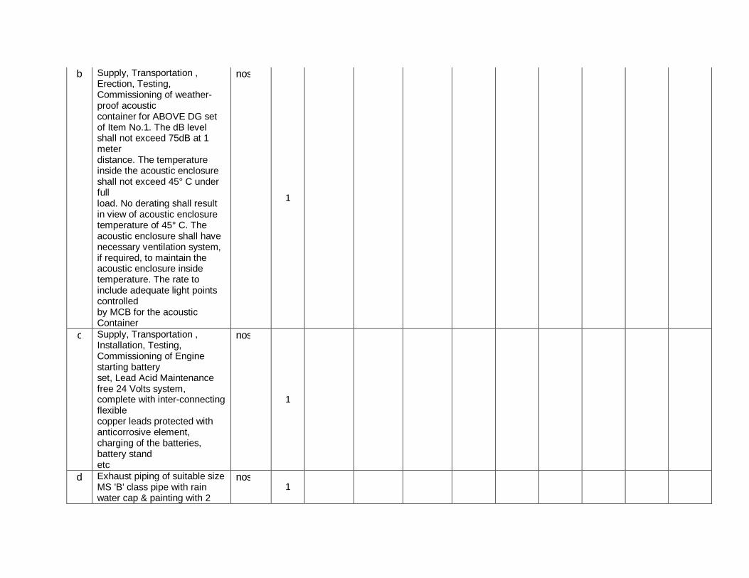
b Supply, Transportation , Erection, Testing, Commissioning of weather-proof acoustic container for ABOVE DG set of Item No.1. The dB level shall not exceed 75dB at 1 meter distance. The temperature inside the acoustic enclosure shall not exceed 45° C under full load. No derating shall result in view of acoustic enclosure temperature of 45° C. The acoustic enclosure shall have necessary ventilation system, if required, to maintain the acoustic enclosure inside temperature. The rate to include adequate light points controlled by MCB for the acoustic Container
nos
1
c Supply, Transportation ,
Installation, Testing, Commissioning of Engine starting battery set, Lead Acid Maintenance free 24 Volts system, complete with inter-connecting flexible copper leads protected with anticorrosive element, charging of the batteries, battery stand etc
nos
1
d Exhaust piping of suitable size
MS 'B' class pipe with rain water cap & painting with 2
nos 1

coats of Heat resistance paint. all necessary flanges, bends, hardware and accessories.
e Thermal insulation of above pipe with 50mm thick mineral wool 22SWG Al. cladding
set 1
71.2
MS Structural support for exhaust pipe, cable trays, battery stand etc. painted with 2coat of red oxide and 2 coats of enamel paint.The height of the pipe has to be as per CPCB norms.
set
1
a Supply, Transportation ,
Installation, Testing, Commissioning of Residential Silencer.
set 1
b Supply, Transportation ,
Erection & Commissioning of fuel tank fabricated out of 14G MS sheet steel duly painted after anti-rust treatment and painted with 2 Coats of synthetic enamel paint of approved shade. The rate shall include necessary arrangement for supporting the tank. The capacity of the tank shall 990 liters with lockable Top cover & fuel indicator gauge with metallic cover & electronic fuel gauge. The Rate Shall include PCC 1:2:4 of height 150mm from ground level.This tank is to be installed as a buffer tank with the DG set.
nos 1

c Supply & installation of fuel piping with MS Seamless 20mm, Class C, with brass valves & fittings wherever required from fuel tank to the DG Set.
set
1
d First fill of diesel,oil & coolant set 1
71.3
Indicative cost of operations and mandatory spares. (add line items below)
71.4
Indicative cost of consumables for 5 years. (add line items below)
71.5
Any other mandatory item to make the work complete for works of DIESEL GENERATOR SET and Accessories.
72 PUBLIC ADDRESS SYSTEM 72.1
6 Zone Call Station Set 1 16,475
72.2
480 W Amplifier with mounting arrangement
Set 1 21,485
72.3
Ceiling Mount Speaker - 6 W Nos. 12 600
72.4
DVD/CD player Nos. 1 6500
72.5
Supply and installation of copper cable of size required as per manufacturer recommendation
Mtrs. 150
39 72.6
Supply & laying of 25mm PVC FRLS conduit
Mtrs. 150 22
72.7
Any other mandatory item to make the work complete for works of PUBLIC ADDRESS SYSTEM.

73 WATER LEAK DETECTION SYSTEM
73.1
Supply & Installation of 4 Zone Water Leak detection Panel
NOS 1
73.2
Supply & Installation of Water leak detection cable ( 15 Mtrs)
nos 6
73.3
Supply & Installation of Sounder
set 1
73.4
Supply and installation of power cable
MTR 100
73.5
25mm PVC FRLS Conduit MTR 100
73.6
Any other mandatory item to make the work complete for works of WATER LEAK DETECTION SYSTEM.
74 RODENT REPPELLENT
SYSTEM
74.1
Supply,Installation,Testing & Commissioning of :Master Console capable of connecting to 12 Satellites complete with all accessories as per specifications
NOS
1
74.2
Supply,Installation,Testing & Commissioning of :Satellite Units complete as per the specification
NOS
15
74.3
Supply,Installation,Testing & Commissioning of :Connecting Cables
MTR 300
74. Supply,Installation,Testing & MTR 3

4 Commissioning of Bracket Stand for Master controller
74.5
Supply & laying of 25mm PVC FRLS conduit
MTR 200
74.6
Any other mandatory item to make the work complete for works of RODENT REPPELLENT SYSTEM.
75 PASSIVE NETWORK CABLING SYSTEM
75.1
CAT6 A UTP Cable (Grey) (each box of 305 mtrs) box 15
75.2
24-port unloaded Modular Jack Panel (for UTP Jacks only), 1U nos 4
75.3
Rear Cable support bar for jack panel nos 5
75.4 Cat-6 I/O Red nos 60
75.5 CAT6 Patch Cord Blue, 7 Feet nos 120
75.6 CAT6 Patch Cord Blue, 10 Feet nos 100
75.7
Dual face place with shutter ( with gangbox) nos 30
75.8
24U closed network rack with all accessories including power supply nos 1
75.9
Crone box for 40 voice point user set 1
75.1
Digital EPABX system for 8 incoming and 64 outgoing extensions set
1
75.11 Digital telephone instruments nos 30

75.12
100 pair connection cable from MDF to EPABX mtr 20
75.13
Cabling for Data and Voice for all the nodes lot 1
75.14
40 mm PVC FRLS conduit with accessories mtr 300
75.15 250 mm MS raceway mtr 100
75.16
Any other mandatory item to make the work complete for works of PASSIVE NETWORK CABLING SYSTEM.
76
MATERIAL FOR Miscellaneous Items
76.1
LCD projector of Min 2000 Lumens alongwith accessories. ( basic cost Rs. 45000) Nos. 1
76.2
Motorised screen 2 Mtr width with mat finish. ( Basic Price RS. 18000) Nos. 1
76.3
46" LED screen with HDMI capabilities Nos. 0
76.4 Coffee vending machine Nos. 0
76.5
Vaccum cleaner ( industrial grade) ( Basic Price RS. 20000) Nos. 1
76.6 Wall clock Nos.
76.7 Colour Laser Printer A4 size Nos. 1
76.8 A4 size scanner Nos. 1

76.9
Fire safe cabinet 300 Ltr capacity, Godrej or equivalent Nos. 1

Annexure-A
Detailed estimate of PCC Road 4.0 Mtr. Wide 100 mtr. Length
1 Surface dressing of ground, including clearing jungle including uprooting of rank vegetation and clearing gradd and removal of the rubbish upto distance of 50m (Ref 6.25 to 6.27)
1x100x4 400 sqmt.
2 Preparation of sub grade, i/c trenching, rough dressing of soil final dressing of earth to given level and camber, watering rolling with road roller and compaction the bed (ref 24.1)
i/c 1.2 mtr wide on both side 1x100.0x6.400 640 sqmt.
3 Cement concrete 1:5:10 with stone ballast 20mm nominal size {10.35 + (10.33 - 10.31)}
1x100.0x4.00x0.125 50.00 cum
4 Supply og 1st class brick for edging of road (M.R.)
Along road 1x2x328x8/3 1750 nos. 5 Laying brick on end edging of (M.R.) 1x2x100.0 200 mtr.
6 C.c 1:1⅟2:3 with stone aggregate 20mm size I pavement, road, etc (10.132 + 10.42 - 10.41)
1x100.0x4.00x0.125 50
7 Providing & fixing pre remolded bituminous joints filler for expansion joints i/c coat of sealing compound and primer coat (24.35 a)
a 12 mm wide @5 mtr. Each
1x20x4 80 mtr. Per 12.5 cm depth
8 Extra for finishing the concrete surface with trimix, vibratory vaccum dry process complete in all respect (N.S iem)
1x100x4 400 sqmt.

Annexure-B
Detailed estimate for p/f of 80mm thick interlocking tile at SCADA center building HSIIDC 33/11 KV Sub-Station, IMT, Faridabad
1 Surface dressing of ground, including clearing jungle including uprooting of rank vegetation and clearing gradd and removal of the rubbish upto distance of 50m (Ref 6.25 to 6.27)
15x20 300 sft. Or 27.88 sqmt.
2 C.conc 1:4:8 with stone aggregate 20mm nominal size (10.38) 1x20'.0x15'.0x0.25 75 cft. Or 2.12 cum
3 Providing & laying 80mm thick interlocking paver block of all shapes (10.159)
1x20'.0x15'.0 300 sft. Or 27.80 sqmt.

Annexure-C
Constructing outdoor cable trench at switching station 3'-6" Wide Sr. no. Description
1 Earthwork in excavation in foundation (Ref 6.6) 1x10.00'x7.00'x4.58' = 320.60 cft. or 9.07 cum
2 C.conc 1:5:10 with brick ballast 40mm gauge in F&P (Ref 10.34)
1x10.00'x7.00'x0.33' = 23.10 cft. or 0.65 cum
3 First class brick work laid in cement sand mortar 1:5 in F&P (Ref 11.3) 2x10.00'x1.50'x0.75' = 22.5 cft. 2x10.00'x1.13'x3.50' = 79.10 cft. Total 101.60 cft. or 2.87 cum
4 Steel work fixed independently without connecting plates i/c cutting, hoisting and fixing in position in tees, angles & channels (Ref 18.1c)
M.S. angle iron 50x50x6 for bottom rack 3x4.00' = 12 rft. for staggred rackson walls 2x3x3x1.50' = 27 rft. Total 49 rft. or 11.88 mtr @ 4.5 kg/mtr.
5 Wrought iron & mild steel ladders framed grills grating, etc. (Ref 18.12)
i) MS angle iron 50x50x6mm for top angle of trench 2x10'.00 = 20.00 rft. for cover of trench 6x[1.67'+1.67'+3.75'+3.75']= 65.04 rft. Total 85.04 rft. or 25.92 mtr @ 4.5 kg/mtr = 117 kg
ii) M.S bar 10mm ɸ:- In covers 6[11.01 + 11.69]= 136.20 rft. In hold fast of top angles 6x2x3x1.00' = 36.00 rft. Total 172.20 rft. or 52.48 mtr. @ 0.62 kg/ mtr. = 33 kg Gronut = 117 + 33 = 150 kg
6 Making holes in M.S angle iron 50x50x6 of 10mm ɸ (NDI) for fixing the cleats
In racks 3x30 = 90 nos.

7 Making the holes in brick work & fixing the M.S. angle racks in portion complete in all respects i/c finishing ( NSI)
18 nos.
8 Conglomerate floor 50mm thick cement conc 1:2:4 (Ref 14.10)
1x3.50'x10.00'= 35 sft. or 3.25 sqm
9 Centering & shuttering for faces of wall partition (Ref 9.5) for top position of C.c of brick wall
2x2x10.00'x0.50'= 20 sft. or 1.80 sqm.
10 C.conc 1:11/2:3 stone aggregate 20mm nominal size in F&P (Ref 10.42)
2x10.00'x1.13'x0.50'= 11.30 cft. or 0.32 cum
11 C.conc 1:2:4 with stone aggregate 20mm nominal size for RCC work in shelves (Ref 10.81) for top RCC covers 6x3.75'x1.67'x0.17' = 6.39 cft. or 0.18 cum
12 12mm thick C.P. 1:5 (Ref 15.6) Inside & outside the brick walls 10x2x8.50' = 170 sft or 15.80 sqm

Page 1 of 9
Table of Contents
1. BID REFERENCE NO.: SCHEDULE – 20 ...................................................................................... 2
2. BID REFERENCE NO.: SCHEDULE – 21 ...................................................................................... 3
3. BID REFERENCE NO.: SCHEDULE –22 ....................................................................................... 4
4. BID REFERENCE NO.: SCHEDULE –23 ....................................................................................... 5
5. BID REFERENCE NO.: SCHEDULE- 24 ........................................................................................ 6
6. BID REFERENCE NO.: SCHEDULE- 25 ........................................................................................ 7
7. BID REFERENCE NO.: SCHEDULE- 26 ........................................................................................ 8

Page 2 of 9
1. BID REFERENCE NO.: SCHEDULE – 20
Page-1 of 1
Design, Procurement, Supply, Installation and Integration of Infrastructure items (On Single Bidder’s responsibility basis) in the SCADA Center at IMT Faridabad in DHBVN. (Firm Price Declaration Schedule) Bidder's Name & Address: To The Chief Engineer/ R-APDRP, DHBVN, Vidyut Sadan, Vidyut Nagar, Hisar. We declare that our price components are on FIRM BASIS for the entire scope of work for the Non IT Package. Date : (Signature) ................................... Place : (Printed Name) ........................... (Designation) .............................. (Common Seal) ...........................

Page 3 of 9
2. BID REFERENCE NO.: SCHEDULE – 21
Page-1 of 1 Design, Procurement, Supply, Installation and Integration of Infrastructure items (On Single Bidder’s responsibility basis) in the SCADA Center at IMT Faridabad in DHBVN. (Commercial Deviation Declaration Schedule) Bidder's Name & Address To The Chief Engineer/ R-APDRP, DHBVN, Vidyut Sadan, Vidyut Nagar, Hisar Dear Sir, Sub.: Commercial Deviations The following are the Commercial Deviations and variations from and exceptions to the specifications and documents for the subject package. These deviations and variations are exhaustive. Except these deviations, the entire work shall be performed as per your specifications and documents.
Volume Clause Reference / Page no. As Specified in the specification
Commercial Deviation and Variations Specification
Date : (Signature) ........................................... Place : (Printed Name) .................................... (Designation) ..................................... (Common Seal) ................................... Note:-
1. Continuation sheets of like size and format may be used as per Bidder's requirements and annexed to this schedule.
2. The deviations and variations, if any, shall be brought out separately for each of the equipment and are to be submitted in five copies.

Page 4 of 9
3. BID REFERENCE NO.: SCHEDULE –22
Page-1 of 1 Design, Procurement, Supply, Installation and Integration of Infrastructure items (On Single Bidder’s responsibility basis) in the SCADA center at IMT Faridabad in DHBVN. (Technical Deviation Declaration Schedule) Bidder's Name & Address: To The Chief Engineer/ R-APDRP, DHBVN, Vidyut Sadan, Vidyut Nagar, Hisar. Dear Sir, Sub : Technical Deviations The following are the Technical Deviations and Variations from and Exceptions to the specifications and documents for the subject package. These deviations and variations are exhaustive. Except these deviations, the entire work shall be performed as per your specifications and documents.
Volume Clause Reference / Page no. As Specified in the specification
Commercial Deviation and Variations Specification
Date : (Signature) .............................. Place : (Printed Name) .............................. (Designation) ................................. (Common Seal) ............................. Note :-
1. Continuation sheets of like size and format may be used as per Bidder's requirements and annexed to this schedule.
2. The deviations and variations, if any, shall be brought out separately for each of the equipment and are to be submitted in five copies.

Page 5 of 9
4. BID REFERENCE NO.: SCHEDULE –23
Page-1 of 1 Design, Procurement, Supply, Installation and Integration of Infrastructure items (On Single Bidder’s responsibility basis) in the SCADA center at IMT Faridabad in DHBVN. (Additional Information Included With This Proposal) Bidder's Name & Address: To The Chief Engineer/ R-APDRP, DHBVN, Vidyut Sadan, Vidyut Nagar, Hisar. Dear Sir, We have enclosed with our proposal the following additional information for the package:
S.no Reference / Page no.
Date: Place:

Page 6 of 9
5. BID REFERENCE NO.: SCHEDULE- 24 Page-1 of 1
Design, Procurement, Supply, Installation and Integration of Infrastructure items (On Single Bidder’s responsibility basis) in the SCADA Center at IMT Faridabad in DHBVN (GUARANTEE DECLARATION) Bidder's Name & Address: To The Chief Engineer/R-APDRP, DHBVN, Hisar Sub: Guarantee Declaration Dear Sirs, We declare that the rating and performance figures of the various equipment/ hardware/ material furnished by us for this package are guaranteed. At the time of delivery, if any specification mentioned in the bid is not available in the market, we will supply the equipment/ hardware/ material having latest configuration meeting the requirement. We further declare that in the event of any deficiencies in meeting the guarantees in respect of the characteristics as established after conducting the test, you may at your discretion, reject or accept the equipment/ hardware/ material after assessing the liquidated damages as specified in relevant clause of Bid Document. Date : (Signature) ................................................... Place : (Printed Name) ............................................ (Designation) ............................................... (Common Seal) ............................................

Page 7 of 9
6. BID REFERENCE NO.: SCHEDULE- 25 Page-1 of 1
Design, Procurement, Supply, Installation and Integration of Infrastructure items (On Single Bidder’s responsibility basis) in the SCADA Center at IMT Faridabad in DHBVN (Work Completion Schedule) Bidder's Name & Address: To The Chief Engineer/R-APDRP, DHBVN, Hisar We hereby declare that the following Work Completion Schedule shall be followed by us for the subject package. —————————————————————————————————————————————— Sl. No. Description of Work Period in Months Date : (Signature) ..................................... Place : (Printed Name) .............................. (Designation) ................................. (Common Seal) .............

Page 8 of 9
7. BID REFERENCE NO.: SCHEDULE- 26 Page-1 of 2
Design, Procurement, Supply, Installation and Integration of Infrastructure items (On Single Bidder’s responsibility basis) in the SCADA Center at IMT Faridabad in DHBVN
PROFORMA OF LETTER OF UNDERTAKINGS (To be submitted by the Bidder along with his Bid)
(To be executed on non-Judicial Stamp Paper of requisite Value) Ref: ………………………. Date …………………………... To The Chief Engineer/ R-APDRP, DHBVN, Vidyut Sadan, Vidyut Nagar, Hisar-125005. Dear Sirs, 1. I*/We* have read and examined the following Bid Documents relating to the
………………………….. (Full scope of work).
a) Notice Inviting Tender. b) Invitation for Bid, Instructions to Bidders, Conditions of Contract along with
Contract Data & Annexures. c) Technical Specifications. d) Drawings attached with Bidding Documents.
2. I*/We* hereby submit our Bid and undertake to keep our Bid value for six
calendar months from the deadline date of bid submission. I*/We* hereby further undertake that during said period I/We shall not vary / alter or revoke my / our Bid.
This undertaking is in consideration of DHBVN agreeing to open my Bid and consider and evaluate the same for the purpose of award of work in terms of provisions of clause entitled “ Award of Contract” section instruction to Bidders in the Bid Document. Should this Bid be accepted, I*/We* also agree to abide by and fulfill all the terms, conditions of provision of the above mentioned bid documents. Signature along with Seal of Company ……………………………………….. (Duly authorized to sign the tender on behalf of the Contractor).
Name : ……………………………………. Designation ……………………………….

Page 9 of 9
Name of Company ………………………. ( In Block Letters) WITNESS : Signature …………………………….Date & Postal Address : Date………………………………… ……………………………………………. Name &Address …………………… ……………………………………………. …………………………………… Telephonic Address ……………………… …………………………………… ……………………………………………. …………………………………… ……………………………………………. Telephone No. …………………………… Telex No. ………………………………… * Strike out whichever is not applicable.

SECTION: 8 FFOORRMMSS OOFF BBIIDD
CCOONNTTEENNTTSS
Annexure Description Annexure-1 Proforma of Bank Guarantee for Bid
Guarantee/Security
Annexure-2 Proforma of Bank Guarantee for Contract
Performance
Annexure-3 Proforma of Extension of Bank Guarantee
Annexure-4 Proforma of Letter of Undertakings
Annexure-5 Proforma of Application for Payment
Annexure-6 Proforma of Bank Guarantee for Advance
Payment
Annexure-7 Proforma of Agreement
Annexure-8 Proforma for Power of Attorney for
Consortium
Annexure-9
Annexure-10
Proforma for Consortium Agreement
Labour Regulations

Annexure-1 Page 1 of 2 PROFORMA OF BANK GUARANTEE FOR BID GUARANTEE/SECURITY (To be stamped in accordance with Stamp Act) The non-Judicial stamp paper should be in the name of issuing bank Ref....................... Bank Guarantee No............... Date........................................ To The Chief Engineer/ R-APDRP, DHBVN, Vidyut Sadan, Vidyut Nagar, Hisar. Dear Sirs, In accordance with Invitation to bid under your Bid No...................... M/s...................... having its Registered/Head Office at.......................(hereinafter called the `Bidder‟ ) wish to participate in the said Bid or...........................and you, as a special favour have agreed to accept an irrevocable and unconditional Bank Guarantee for an amount of.....................valid upto.....................on behalf of Bidder in lieu of the Bid deposit required to be made by the bidder, as a Condition precedent for participation in the Said Bid. We, the.....................Bank at........................having our Head Office at.................. (local address) guarantee and undertake to pay immediately on demand by Himachal Pradesh Sate Electricity Board, the Amount of...................................................... ..................................................................(in words & figures) without any reservation, protest, demur and recourse. Any such demand made by said `Owner‟ shall be conclusive and binding on us irrespective of any dispute or difference raised by the Bidder.

Annexure-1 Page 2 of 2 This Guarantee shall be irrevocable and shall remain valid upto and including............ @.................... If any further extension of this guarantee is required, the same shall be extended to such required period (not exceeding one year) on receiving instruction from M/s..........................................on whose behalf this guarantee is issued. In witness whereof the Bank, through its authorized office, has set its hand and stamp on this...............day of.....................20.....................at........................ WITNESS ............................................ ........................................ (Signature) (Signature) ............................................ ........................................ (Name) (Name) ............................................ ........................................ (Official Address) (Official Address) @ This date shall be thirty (30) days after the last date for which the bid is valid.

Annexure-2 Page 1 of 3 PROFORMA OF BANK GUARANTEE FOR CONTRACT PERFORMANCE (To be stamped in accordance with Stamp Act) Ref....................... Bank Guarantee No............... Date........................................ To The Chief Engineer/ R-APDRP, DHBVN, Vidyut Sadan, Vidyut Nagar, Hisar. Dear Sirs,
In consideration of DHBVN, (herein after referred to as the “Owner” which expression shall
unless repugnant to the contest or meaning thereof include its successors, administrators and
assigns) having awarded to M/s.............................with registered/Head office
at................(hereinafter referred to as “Contractor” which expression shall unless repugnant to
the context or meaning thereof include its successors, administrators, executors and assigns), a
Contract by issued of Owner‟ s Letter of Award No...............dated.................and the same
having been acknowledged by the Contractor, resulting in a Contract bearing
No.................dated Contractor having agreed to provide a Contract Performance Guarantee for
the faithful performance of the entire Contract equivalent to.............. being (%) (percent*) of the
said value of the Contract to the Owner.
We................................................................................................................................. (Name &
Address) having its Head Office at........................(hereinafter referred to as the “Bank”, which
expression shall, unless repugnant to the context or meaning thereof, include its successors,
administrators, executors and assigns) do hereby guarantee and undertake to pay the Owner,
on demand any all monies payable by the Contractor to be extent of.......................as aforesaid
at any time up to......……….** (day/month/year) without any

Annexure-2 Page 2 of 3 demur, reservation, contest, recourse or protest and/or without any reference to this Contractor.
Any such demand made by the Owner on the bank shall be conclusive and binding
notwithstanding any difference between the Owner the Contractor or any dispute pending before
any Court, Tribunal, Arbitrator or any other authority. The Bank undertakes not to revoke this
guarantee during its currency without previous consent of the Owner and further agrees that the
guarantee herein contained shall continue to be enforceable till the Owner discharges this
guarantee.
The Owner shall have the fullest liberty without affecting in any way the liability of the Bank
under the guarantee, from time to time to extend the time for performance or the Contract by the
Contractor. The Owner shall have the fullest liberty, without affecting this guarantee, to postpone
from time to time the exercise of any powers vested in them or of any right which they might
have against the Contractor, and to exercise the same at any time in any manner, and either to
enforce or to for bear to enforce any covenants, contained or implied, in the Contract between
the Owner and the Contractor or any other course or remedy or security available to the Owner.
The Bank shall not be released to its obligations under these presents by any exercise by the
Owner of its liberty with reference to the matters aforesaid or any of them or by reason of any
other act of omission or commission on the part of the Owner or any other indulgences shown
by the Owner or by any other matter or thing whatsoever which under law would, but for this
provision have the effect of relieving the Bank.
The bank also agrees that the Owner at its option shall be entitled to enforce this guarantee
against the Bank as a principal debtor, in the first instance without proceeding against the
Contractor and not withstanding any security or other guarantee the Owner may have in relation
to the Contractor‟ s liabilities).
Notwithstanding anything contained herein above our liability under this guarantee is restricted
to....................and it shall remain in force upto and including..................

Annexure-2 Page 3 of 3 and shall be extended from time to time for such period (not exceeding one year), as may be desired M/s.....................on whose behalf this guarantee has been given. Dated this.......................day of.................20...............at.............. WITNESS .............................................. ..................................... (Signature) (Signature) .............................................. ..................................... (Name) (Name) ............................................. .................................... (Official Address) (Official Address) Attorney as per Power Of Attorney No............................................ Date............................................................ Notes: * This sum shall be ten per cent (10%) of the Contract Price of respective part. ** The date will be ninety (90) days after the end of Warranty Period as specified in the Contract.

Annexure-3 Page 1 of 1 PROFORMA OF EXTENSION OF BANK GUARANTEE Ref....................... Date........................................ To The Chief Engineer/ R-APDRP, DHBVN, Vidyut Sadan, Vidyut Nagar, Hisar. Dear Sirs, Sub: Extension of Bank Guarantee No...............................for Rs........................ favoring yourselves, expiring on..............................on account of M/s...................................in respect of Contract No........................dated............... (hereinafter called original Bank Guarantee). At the request of M/s......................., We....................Bank, branch office at....................and having its Head Office at....................do hereby extend our liability under the above mentioned Bank Guarantee No.................... dated...... for a further period of....................(Years/Months) from...............to expire on............ Expect as provided above, all other terms and conditions of the original bank guarantee No....................dated....................shall remain unaltered and binding. Please treat this as an integral part of the original bank guarantee to which it would be attached. Yours Faithfully, For.................................................... Manager/Agent/Accountant.............. Power of Attorney No....................... Dated............................................... SEAL OF BANK NOTE: The non-judicial stamp paper of appropriate value shall be purchased in the name of the bank who has issued the Bank Guarantee.

Annexure-4 Page 1 of 2 PROFORMA OF LETTER OF UNDERTAKINGS (To be submitted by the Bidder along with his Bid) (To be executed on non-Judicial stamp paper of requisite value) Ref....................... Date........................................ To The Chief Engineer/ R-APDRP, DHBVN, Vidyut Sadan, Vidyut Nagar, Hisar. Dear Sir, 1. I/We* have read and examined the following Bidding Documents relating to the ................(full
scope of work).
a) Notice Inviting Tender
b) Condition of Contract containing section, “Invitation to Bid” (INV), “Instruction to Bidder (ITB)”,
“General Terms and Conditions of Contract (GCC)”, “General Technical Conditions” and
“Installation & Commissioning Conditions of Contract (ICC)”.
c) Special Condition of Contract along with Annexure to......................
d) Drawing No(s).............................................
e) Technical Specifications.
2. I/We* hereby submit our Bid and undertake to keep our Bid Valid for a period of six (6)
calendar months from the date of Bid opening i.e., upto.......................I/We* hereby further
undertake that during said period I/We* shall not vary alter or revoke my/our Bid.
This undertaking is in consideration of DHBVN, agreeing to open my Bid and consider and
evaluate the same for the purpose of award of Work in terms of provisions of clause entitled
“Award of Contract” Section INV Conditions of Contract in the Bidding Documents.

Annexure-4 Page 2 of 2 Should this Bid be accepted, I/We* also agree to abide by and fulfill all the terms and conditions
of provisions of the above mentioned Bidding Documents.
Signature along with Seal of Co............................
(Duly authorized to sign the Tender on behalf of the Contractors)
Name..................................................................
Designation.........................................................
Name of Co........................................................
(in BLOCK Letters)
WITNESS
Signature..................................
Date......................................... Name & Address....................... ................................................ Telegraphic Address.................. ................................................ ................................................ Telephone No........................... Fax No................................... E-mail……………………………… *Strike out whichever is not applicable

Annexure-5 Page 1 of 2 PROFORMA OF APPLICATION FOR PAYMENT Project....................... Equipment package : Date : Name of Contractor: Contract No. Contract Value : Contract Name : Unit Reference : Application : Serial Number: To .........................................................(*) Dakshin Haryana Bijli Vitran Nigam Dear Sir, APPLICATION FOR PAYMENT 1. Pursuant to the above referred Contract, dated...............the undersigned hereby applies for payment of the sum of................................(Specify amount and currency in which claim is made). 2. The above amount is on account of : (check whichever applicable) Initial advance (Schedule**)
Interim payment as advance (Schedule**)
Progressive payment against dispatch of equipment (Schedule**)
Progressive payment against receipt of equipment at site (Schedule**)
Progressive payment against Erection (Schedule**)
Ocean freight & marine insurance (Schedule**)
Inland transportation (Schedule**)
Inland insurance
Extra work not specified in contract
(Ref. Contract change order No.....................................)
Other (specify)
Final payment (Schedule**)
as detailed in the attached schedule(s) which form an integral part of this application.

Annexure-5 Page 2 of 2 3. The payment claimed is as per item(s) No(s)............................of the payment schedule annexed to the above Contract. 4. The application consists of this page, a summary of claim statement (Schedule**) and the following signed schedule. 1. ......................................................................................... 2. ......................................................................................... 3. ......................................................................................... The following documents are also enclosed: 3 ......................................................................................... 4 ......................................................................................... 5 ......................................................................................... (Signature of Contractor/ Authorised Signatory * Application for payment will be made to “Engineer” is to be designated for this purpose Prepare separate application for claims in different currencies. ** Proforma for the Schedules will be mutually discussed and agreed to during the finalization of the Contract Agreement.

Annexure-6 Page 1 of 2 PROFORMA OF BANK GUARANTEE FOR ADVANCE PAYMENT (To be stamped in accordance with Stamp Act) Ref....................... Bank Guarantee No............... Date........................................ To The Chief Engineer/ R-APDRP, DHBVN, Vidyut Sadan, Vidyut Nagar, Hisar. Dear Sirs, In consideration of DHBVN, (hereinafter referred to as the “Owner”, which expression shall
unless repugnant to the context or meaning thereof include its successors, administrators and
assigns) having awarded to M/s...............(hereinafter referred to as the `Contractor‟ , which
expression shall, unless repugnant to the context or meaning thereof, include its successors,
administrators, executors and assigns), a Contract by issue of Owner‟ s Letter of Award
No..................dated................and the same having been acknowledged by the Contractors,
resulting in a Contract bearing No...............dated.................. valued
(at................................................(in words and figures).
For..................................Contract (space of work)........................ (hereinafter called the
`Contract‟ ) and the Owner having agreed to make an advance payment to the Contractor for
performance of the above Contract amounting....................... (in words and figures) as an
advance against Bank Guarantee to be furnished by the contractor.
We................................(Name of the Bank) having its Head Office at..................... (hereinafter
referred to as the `Bank‟ , which expression shall, unless repugnant to the context or meaning
thereof, include its successors, administrators, executors and assigns) do hereby guarantee and
undertake to pay the Owner, immediately on demand any or, all monies payable by the
Contractor to the extent of..................as aforesaid at any time upto..........(a....) without any
demur, reservation, contest, recourse or protest and/or without any reference to the Contractor.
Any such demand made by the Owner on the bank shall be conclusive and binding
notwithstanding any difference between the Owner and the Contractor or any dispute pending
before any Court, Tribunal, Arbitrator or any other authority. We agree that the guarantee
herein contained shall be irrevocable and shall continue to be enforceable till the Owner
discharge this guarantee herein contained shall be irrevocable and shall continue to be
enforceable till the Owner discharge this guarantee.

Annexure- 6 Page 2 of 2 The Owner shall have the fullest liberty without affecting in any way the liability of the Bank
under this guarantee, from time to time to vary the advance or to extend the time for
performance of the Contract by the Contractor. The Owner shall have the fullest liberty without
affecting this guarantee, to postpone from time to time the exercise of any powers vested in
them or of any right which they might have against the Contractor, and to exercise the same at
any time in any manner, and either to enforce any covenants, contained or implied, in the
Contract between the Owner and the contractor or any other course or remedy or security
available to Owner. The bank shall not be released of its obligations under these presents by
any exercise by the Owner of its liberty with reference to the matters aforesaid or any of them or
by reason of any other act or forbearance or other acts of omission or commission on the part of
the Owner or any other indulgence shown by the Owner or by any other matter or thing
whatsoever which under law would be for this provision have the effect of relieving the Bank.
The Bank also agrees that the Owner at its option shall be entitled to enforce this guarantee
against the Bank as a principal debtor, in the first instance without proceeding against the
Contractor and notwithstanding any security or other guarantee that the Owner may have in
relation to the Contractor‟ s liabilities.
Not withstanding anything contained hereinabove our liability under this guarantee is limited
to................and it shall remain in force upto and including.........(@......) and shall be extended
from time to time for such period (not exceeding one year) as may be desired by M/s...........
Dated this..................day of......................200.........at.........................................
WITNESS .............................................. ............................................ (Signature) (Signature) .............................................. ............................................ (Name) (Name) ............................................. Designation.......................... (Official Address) (with Bank Stamp) Attorney as per Power of Attorney No....................... Dated.................................... Strike whichever is not applicable @ The date will be ninety (90) days after the date of completion of the Contract. Note: The non-judicial stamp papers of appropriate value shall be purchased in the name of bank who issued the Bank Guarantee.

Annexure-7 Page 1 of 5 “AGREEMENT” (To be executed on non-Judicial stamp paper) This Agreement made this ....... day of ....... two thousand ....... between DHBVN, having its head office at Vidyut Sadan Vidyut Nagar, Hisar (hereinafter referred to as `Owner‟ or `DHBVN‟ , which expression shall include its administrators, successors and assign on one part and (hereinafter referred to as the `Suppliers/ Contractors/ firm` M/S ____________________________ (which expression shall include its administrators, successors, executors and permitted assigns) on the other part. WHEREAS DHBVN desirous of establishing a Data Center under R-APDRP (Part-„A‟ ) and has invited Bids for Design, Supply, Install and Integration of Infrastructure items (On turnkey basis/ Single Bidder’s responsibility) in the SCADA Centre at IMT FAridabad (Haryana) as per its Bid Specification AND WHEREAS M/S __________________________________ had participated in the above referred Bidding vide their proposal No. ___ dated: __/__/2011 and DHBVN has awarded the Contract on terms and conditions referred to therein, which have been acknowledged by the firm resulting into a “Contract”. NOW THEREFORE THIS DEED WITNESSETH AS UNDER:- 1.0 Article 1.1 Award of Contract: HPSEBL awarded the Contract to M/S _________________________ for the work of Design, Supply, Install and Integration of Infrastructure items (On turnkey basis/ Single Bidder’s responsibility) in the SCADA Centre at IMT Faridabad as per its Bid Specification No __________________ and on the terms and conditions contained in its Letter of Award No. ______________________, Dated: __/__/2016 and the documents referred to therein. The award has taken effect from aforesaid letter of award. The terms and expressions used in this Agreement shall have the same meaning as are assigned to them in the `Contract Documents‟ referred to in the succeeding Article. The scope of Contract, consideration, terms of payment, price adjustment, taxes wherever applicable, insurance, liquidated damages, performance guarantees and all other terms and conditions are contained in DHBVN’s letter of award No. __________. Dated: __/__/2016 read in conjunction with other aforesaid contract documents. The Contract shall be duly performed by the Contractor strictly in accordance with the contract documents and stipulations made herein.

Annexure-7 Page 2 of 5 2.0 Documentation 2.1 The Contract shall be performed strictly as per the terms and conditions stipulated herein and in the following documents attached herewith (hereinafter referred to as “Contract Documents”). i) Vol-1A (Section-1 to 9) and Vol-1B (Section-1 & 2) of the Bidding Document ii) Proposal Sheets, Data Sheets, Drawings, Work Schedules submitted by “M/S ____________________________________________________” iii) DHBVN‟ s Letter of Intent (LoI) No. __________________________, Dated: __/__/2016 duly acknowledged by “M/S _________________________ vide their acceptance letter No. _____, dated: __/__/2016. iv) DHBVN‟ s Letter of Award No._______________________________, Dated: __/__/2016 duly acknowledged by “M/S _____________________” vide their acceptance letter No. ____, dated: __/__/2016. v) PERT Chart submitted by the firm. 2.2 All the aforesaid Contract Documents shall form an integral part of this Agreement, in so far as the same or any part conform to the Bidding Documents and what has been specifically agreed to by the Owner in its Letter of Award. Any matter inconsistent therewith, contrary or repugnant thereto or any deviations taken by the Contractor in its `Proposal‟ but not agreed to specially by the Owner in its Letter of Award shall be deemed to have been withdrawn by the Contractor. For the sake of brevity, this agreement along with its aforesaid Contract Documents shall be referred to as the `Agreement‟ . 3.0 Conditions & Covenants 3.1 The scope of Contract, Consideration, Terms of Payment, Price Adjustment, Taxes wherever applicable, Insurance, Liquidated Damage, Performance Guarantees and all other terms and conditions are contained in DHBVN ‟ s Letter of Award No. ____________________________________________, Dated: __/__/2016 read in conjunction with other aforesaid Contract Documents. The Contract shall be duly performed by the Contract Documents, but which are needed for successful, efficient, safe and reliable operation of the equipment unless otherwise specifically excluded in the specifications under `exclusions‟ or `Letter of Award‟ . 3.2 The scope of work shall also include supply and installation of all such items which are not specifically mentioned in the Contract Documents, but which are needed for successful, efficient, safe and reliable operation of the equipment unless otherwise specifically excluded in the specifications under `exclusions‟ , or `Letter of Award‟ .

Annexure-7 Page 3 of 5 3.3 Time Schedule 3.3.1 Time is the essence of the Contract and schedules shall be strictly adhered to. “M/S ____________________________________________” shall perform the work in accordance with the agreed schedules. 3.4 Quality Plans 3.4.1 The Contractor is responsible for the proper execution of the Quality Plans. The work beyond the customer‟ s hold points will progress only with the Owners consent. The Owner will also undertake quality surveillance and quality audit of the Contractor‟ s/Sub-contractor‟ s works, systems and procedures and quality control activities. The Contractor further agrees that any change in the Quality Plan will be made only with the Owner‟ s approval. The Contractor shall also perform all quality control activities, inspection and tests agreed with the Owner to demonstrate full compliance with the contract requirements. 3.4.2 It is expressly agreed to by the Contractor that the quality tests and inspection by the Owner shall not in any way relieve the Contractor of its responsibilities for quality standards, and performance guarantee and their other obligations under the Agreement. 3.4.3 “M/S DHBVN”, agrees to submit Quality Assurance Documents for the package to HPSEBL for review and record after Completion and within three weeks of dispatch of material. The package will include the following: i) Factory test results inspection reports for testing required by this Contract or applicable codes and standards; ii) Two copies of inspection reports duly signed by Quality Assurance personnel of both DHBVN and “M/S ___________________________________” for the agreed customer hold points; iii) Report of the rectification works where and if applicable. 3.5 It is expressly agreed to by the Contractor that notwithstanding the fact that the Contract has been broken into (a) Equipment/ hardware/ goods to be supplied under the contract, (b) software/ services to be performed under the contract and Maintenance Contract (MC) for three years, the contract shall be treated as one composite Contract on single source responsibility basis and the Contractor is bound to perform the total Contract in its entirety and non-performance of any part or portion of the Contract shall be deemed to be a breach of the entire Contract.

Annexure-7 Page 4 of 5 3.6 The Contractor guarantees that the hardware supplied under the contract shall meet the ratings and performance parameters as stipulated in the technical specifications and in the event of any deficiencies found in the requisite performance figures, the Owner may at its option reject the hardware or alternatively accept it on the terms and conditions and subject to levy of the liquidated damages in terms of contract documents. The amount of liquidated damages so leviable shall be in accordance with the contract documents. 3.7 The Contract guarantee that the software developed will meet all the requirement of Owner as stipulated in the technical specification. It is further agreed by the contractor that it will provide training on hardware & software to DHBVN employees and maintain both hardware and software as per the requirement mentioned in the bid. 3.8 It is further agreed by the Contractor that the contract performance guarantee shall in no way be constructed to limit or restrict the owner‟ s right to recover the damages/compensation due to short-fall in the hardware performance figures. The amount of damages/compensation shall be recoverable either by way of deduction from the contract price, contract performance guarantee and or otherwise. 3.9 The contract performance guarantee furnished by the Contractor is irrevocable and unconditional and the Owner shall have the powers to invoke it notwithstanding any dispute or difference between the owner and the contractor pending before any court tribunal, arbitrator or any other authority. 3.10 This Agreement constitutes full and complete understanding between the parties and shall be governed by the terms and conditions agreed herein above. Only a written instrument signed by the authorized representatives of both the parties with mutual consent shall effect any modification to this agreement. 4.0 SETTLEMENT OF DISPUTES 4.1 It is specifically agreed between the parties that all the differences or disputes arising out of the Agreement shall be decided by process of settlement and Arbitration as specified in clause 48 & 49 of the General conditions of the agreement and the courts situated at Hisar alone shall have exclusive jurisdiction to adjudicate in all matters arising under this contract. 4.2 Notice of Default Notice of default given by either party to the other party under Agreement shall be in writing and shall be deemed to have been duly and properly served upon the parties hereto if delivered against acknowledgement or by telex or by registered mail with acknowledgements due addressed to the signatories at the addresses mentioned at Hisar.

Annexure-7 Page 5 of 5 WITNESS WHEREOF, the parties through their duly authorized representatives have executed these presents (execution where of has been approved by the competent authorities of both the parties) on the day, month and year first above mentioned at Shimla. WITNESS: 1. .......................................... (Owner‟ s signature) (Printed Name) 2. ......................................... (Designation) (Company‟ s Stamp) 3. ......................................... (Contractor‟ s Signature) (Company‟ s Name) 4. ......................................... (Designation) (Company‟ s Stamp)

Annexure -8 Page 1 of 2 FORM OF POWER OF ATTORNEY FOR CONSORTIUM (On Non-judicial Stamp Paper of Appropriate value to be Purchased in the Name of the Partner) KNOW ALL MEN BY THESE PRESENTS THAT WE, the Partners whose details are given
hereunder.............................................................. have formed a consortium under the laws
of....................................................................................... and having our Registered
Office(s)/Head Office(s) at................................................. (hereinafter called the „Consortium'
which expression shall unless repugnant to the context or meaning thereof, include its
successors, administrators and assigns) acting through
M/s............................................................................................ being the Partner in-charge do
hereby constitute, nominate and appoint M/s................................................... a Company
incorporated under the laws of.......................................and having its Registered/Head Office
at..........................................as our duly constituted lawful Attorney (hereinafter called "Attorney"
or " Authorised Representative" or "Partner In-charge") to exercise all or any of the powers for
and on behalf of the Consortium in regard* to --------------------------(Name of the Package)
(Specification No. : -------------------) of DHBVN, having its head office at Vidyut Nagar, Vidyut
Sadan, Hisar (hereinafter called the "Owner") and the bids for which have been invited by the
Owner, to undertake the following acts :
i) To submit proposal and participate in the aforesaid Bid Specification of the Owner on behalf of
the „Consortium' .
ii) To negotiate with the Owner the terms and conditions for award of the Contract pursuant to
the aforesaid Bid and to sign the Contract with the Owner for and on behalf of the „Consortium'.
iii) To do any other act or submit any document related to the above.
iv) To receive, accept and execute the Contract for and on behalf of the "Consortium".
It is clearly understood that the Partner-In-charge (Lead Partner) shall ensure performance of
the Contract(s) and if one or more Partner fail to perform their respective portion of the
Contract(s), the same shall be deemed to be a default by all the Partners.
It is expressly understood that this Power of Attorney shall remain valid binding and irrevocable
till completion of the Defect Liability Period in terms of the Contract.
The Consortium hereby agrees and undertakes to ratify and confirm all the whatsoever the said
Attorney/ Authorized Representative/Partner-In-charge quotes in the bid, negotiates and signs
the Contract with the Owner and/or proposes to act on behalf of the Consortium by virtue of this
Power of Attorney and the same shall bind the Consortium as if done by itself.

Annexure 8 Page 2 of 2 IN WITNESS THEREOF the Partners Constituting the Consortium as aforesaid have executed these presents on this ..............................day of ........................ under the Common Seal(s) of their Companies. for and on behalf of the Partners of Consortium .................................... .................................... .................................... The Common Seal of the above Partners of the consortium : The Common Seal has been affixed there unto in the presence of : WITNESS 1. Signature........................................ Name ........................................... Designation .................................... Occupation .................................... 2. Signature ....................................... Name ............................................ Designation ..................................... Occupation ......................................

Annexure 9 Page 1 of 3 FORM OF CONSORTIUM AGREEMENT (On non-judicial stamp paper of appropriate value to be Purchased in the name of lead partner) Proforma of consortium agreement between ____________________________________________________and_________ For bid specification no. _____________________________ of DHBVN. THIS consortium agreement executed on this ________________day of_____________Two thousand and ________between M/s______________________________________a company incorporated under the laws of_______________________and having its registered office at ____________________________________________(hereinafter called the "Lead Partner" which expression shall include its successors, executors and permitted assigns), M/s. _______________________________________a company incorporated under the laws of ________________________________________ and having its registered office at ______________________________________(hereinafter called the "Partner" which expression shall include its successors, executors and permitted assigns) and M/s ___________________ a company incorporated under the laws of ____________________________________________________________and having its registered office at _______________________ (hereinafter called the "Partner" which expression shall include its successors, executors and permitted assigns) for the purpose of making a bid and entering into a contract* (in case of award) for Construction of -----------------------------------------------------(Name of the Package) against the Specification No.: ---------------------------- of DHBVN,having its head office at Vidyut Sadan Vidyut Nagar, Hisar(hereinafter called the "Owner). WHEREAS the Owner invited bids as per the above mentioned Specification for the IT Package (Specification No.: ------------------------). AND WHEREAS the bid has been submitted to the Owner vide proposal No........................ dated............ by Lead Partner based on the consortium agreement between all the Partners under these presents and the bid in accordance with the requirements of the package has been signed by all the partners. NOW THIS INDENTURE WITNESSETH AS UNDER: In consideration of the above premises and agreements all the Partners to this Consortium do hereby now agree as follows: 1. In consideration of the award of the Contract by the Owner to the Consortium partners, we, the Partners to the Consortium agreement do hereby agree that M/s _________shall act as Lead Partner and further declare and confirm that we shall jointly and severally be bound unto the Owner for the successful performance of the Contract and shall be fully responsible for the design, manufacture, supply, and successful performance of the equipment in accordance with the Contract.

Annexure 9 Page 2 of 3 2. In case of any breach of the said Contract by the Lead Partner or other Partner(s) of the
Consortium agreement, the Partner(s) do hereby agree to be fully responsible for the successful
performance of the Contract and to carry out all the obligations and responsibilities under the
Contract in accordance with the requirements of the Contract.
3. Further, if the Owner suffers any loss or damage on account of any breach in the Contract or
any shortfall in the performance of the equipment in meeting the performance guaranteed as per
the specification in terms of the Contract, the Partner(s) of these presents undertake to promptly
make good such loss or damages caused to the Owner, on its demand without any demur. It
shall not be necessary or obligatory for the Owner to proceed against Lead Partner to these
presents before proceeding against or dealing with the other Partner(s).
4. The financial liability of the Partners of this Consortium agreement to the Owner, with respect
to any of the claims arising out of the performance of non-performance of the obligations set
forth in the said Consortium agreement, read in conjunction with the relevant conditions of the
Contract shall, however, not be limited in any way so as to restrict or limit the liabilities of any of
the Partners of the Consortium agreement.
5. It is expressly understood and agreed between the Partners to this Consortium agreement
that the responsibilities and obligations of each of the Partners shall be as delineated in
Appendix-I (*To be incorporated suitably by the Partners) to this agreement. It is further agreed
by the Partners that the above sharing of responsibilities and obligations shall not in any way be
a limitation of joint and several responsibilities of the Partners under this Contract.
6. This Consortium agreement shall be construed and interpreted in accordance with the laws of
India and the courts of Delhi shall have the exclusive jurisdiction in all matters arising there
under.
7. In case of an award of a Contract, We the Partners to the Consortium agreement do hereby
agree that we shall be jointly and severally responsible for furnishing a contract performance
security from a bank in favour of the Owner in the forms acceptable to purchaser for value of
10% of the Contract Price in the currency/currencies of the Contract.
8. It is further agreed that the Consortium agreement shall be irrevocable and shall form an
integral part of the Contract, and shall continue to be enforceable till the Owner discharges the
same. It shall be effective from the date first mentioned above for all purposes and intents.

Annexure 9 Page 3 of 3
IN WITNESS WHEREOF, the Partners to the Consortium agreement have through their
authorised representatives executed these presents and affixed Common Seals of their
companies, on the day, month and year first mentioned above.
1. Common Seal of............................. For Lead Partner
has been affixed in my/our presence
pursuant to the Board of Director's (Signature of authorised
resolution dated.............................. representative)
Name......................................
Signature.......................................... Designation.............................
Name................................................ Common Seal of the company
Signature......................................
Designition ..............................................
2. Common Seal of.............................. For other Partners
has been affixed in my/our presence
pursuant to the Board of Director's (Signature of authorised
resolution dated................................ representative)
Name......................................
Signature.......................................... Designation.............................
Name............................................... Common Seal of the company
Signature.............................................
Designation......................................
WITNESSES
1. ........................................................ 2. .................................. (Signature)
2. (Signature)
Name .......................................... Name ............................
..............................................................(Official address)
(Official address)

Annexure-10 Contractor’s Labour Regulation
1. Short Title These regulations may be called Haryana Public Works Department Contractor’s Labour Regulations.
2. Definition In these regulations, unless otherwise expressed or indicated the following words and expressions shall have the meaning hereby assigned to them respectively that is to say :
(1) Labour means workers employed by a Public Works Department contractors directly or indirectly through a sub-contractor or other persons of by an agent on his behalf.
(2) Fair wages means, whether for item or place work, notified at the time of inviting tenders for the work and where such wages have not been so notified the wages prescribed by the Public Works, Department for the district in which the work is done.
(3) “Wages” shall have the same meaning as defined in the payment of Wages Act 1936 and includes time and place rate wages.
3. Display of notice regarded wages etc. The contractor shall before he commences his work on contract display and correctly maintain & continue to display and correctly in a clean and legible condition in conspicuous places on the work notice in English and in the Local Language spoken by the majority of the Workers giving the fair wages notified or prescribed by the Haryana Public Works Department and the hours of work for which such wages are earned.
4. Payment of Wages (i) Wages due to every worker be paid to him directly. (ii) All wages shall be paid in current coin or currency or in both.
5. Fixation of Wages Periods
(i) The contractor shall fix the wage periods in respect of which the wages shall be payable. (ii) No wage period shall exceed one month. (iii) Wages of every workman employed on the contract shall be paid before the expiry of ten
days after the last day of the wage period in respect of which the wages are payable. (iv) When the employment of any worker is terminated by or on behalf of the Contractor, the
wages, earned by him shall be paid before the expiry of succeeding the one on which his employment is terminated.
(v) All payment of wages shall be made on a working day.
6. Wages Book and Wages Slip etc.
(i) The contractor shall maintain a wage book of each worker in such form as may be convenient but the same shall include the following particulars
(a) Rate of daily or monthly wages.
(b) Name of work on which employed.

(c) Total numbers of days worked during each wage period.
(d) Total amount payable for the work during each wage period.
(e) All deductions made from the wages with an indication in each case of the ground for which the deduction is made.
(f) Wages actually paid for each wage period. (ii) The contractor shall also maintain a wage slip for each worker employed on the work. (iii) The authority competent to accept the contract may grant an exemption from the
maintenance of Wages book and Wage Slips to a contractor who in his opinion may not directly or indirectly employ more than 100 persons in the work.
7. Fines and deductions which may be made from wages (1) The wages of a worker shall be paid to him without any deduction of any kind except the
following :
(a) Fines. (b) Deductions for absence from duty i.e. from the place or places where by the terms of
his employment he is required to work. The amount of deduction shall be in proportionate to the person for which he was absent.
(c) Deductions for damage to or loss of goods expressly entrusted to the employed person for custody or for loss of money for which he is required to account where such damage or loss is directly attributable to his neglect or default.
(d) Any other deductions which the PWD may from time to time allow.
2.) No fine shall be imposed on a worker and no deduction for damage or loss be made from his wages until the worker has been given an opportunity of showing cause against such fines or deductions.
3.). The total amount of fine which may be imposed in any one wage period on a worker shall not exceed an amount equal to 50 paisa in a rupee of the wage payable to him in respect of that wage period.
4.) No fine imposed on any worker shall be recoverable from him by installments or after the expiry of 60 days from the date on which it was imposed.
8. Register of Fine etc. 1. The contactor shall maintain a register of fine and of all deductions for damage or loss
such Register shall maintain the reason for which fine was imposed or deduction for damage or loss was made.
2. The contractor shall maintain, a list in English and local Indian Language clearly defining acts and commissions for which penalty of fine can be imposed. He shall display such list and maintain it in a clean and legible condition in conspicuous places on the work.

9. Preservation of Books
The wage book, the wage slips and the Register of lines, deductions required be maintained under these regulations shall be preserved for 12 months after the date of last entry made in them.
10. Power of Labour Welfare Officer to make Investigation of Enquiry
The Labour Welfare Officer or any person authorized by the Government on their behalf shall have power to make enquiries with a view to ascertaining and enforcing due and proper observance of the wage clause and provisions of their regulations. He shall investigate into any complaint regarding the default made by the Contractor or sub-Contractor in regard to such provisions.
11. Report of Labour Welfare Officer
The Labour Welfare Officer or any other person authorized aforesaid shall submit a report of the result of his investigations enquiry to the Executive Engineer concerned indicating the extent, if any, to which the default has been committed and the amount of fine recoverable in respect of the acts or commission and omission of the labourer with a note that necessary deduction from contractor’s will be made and the wages and other dues be paid to the labourers concerned.
12. Appeal against the decision of Labour Welfare Officers
Any person aggrieved by the decision and recommendation of the Labour Welfare Officer or other person so authorized may appeal against decision to the Labour Commissioner but subject to such appeal the decision of the officer shall be final and binding upon the Contractor.
12A- No party shall be allowed to be represented by a lawyer during any investigation, enquiry appeal or any other proceedings under these regulations.
13. Inspection of Register
The contractor shall allow inspection of the Wage Book. Wage Slips to any of his workers or to his agent at a convenient time and place after due notice is received, or to the Labour Welfare Officer or any other person authorized by the Haryana Government in his behalf.
14. Submission of Returns
The contractor shall submit periodical as may be specified from time to time.
15. Amendment
The Haryana Government may, from time to time and to amend these regulations, the decision of the Labour Commissioner, Haryana Government or any other person authorized by the Haryana Government in that behalf shall be final.

III- FAIR WAGES CLAUSES
FAIR WAGE CLAUSES
(a) The Contractor shall pay not less than the fair wage to labourers engaged by him on the work. EXAMINATION :- Fair Wage’ means wage whether for t ime of piece work notif ied f rom t ime to t ime for the area and where such wages have not been so notif ied the wages specif ied by the Public Works (B&R) Deptt. Haryana for the district in which the work is done.
(b) The Contractor shall not withstanding the provisions of any agreement to the contrary, caused to be paid fair wages to labour, indirectly engaged on the work including any labour engaged by his sub-contractors in connection with the said work, as if the labourers had been directly employed by him.
(c) In respect of labour directly or indirectly employed on the works for the performances of the contractor’s part on this agreement the contractor shall comply with or cause to be complied with the Haryana PWD Contractor’s Labour’s Regulations made by the Government from time to time in regard to payment of wages wage period deductions from wages recovery of wages not paid and deductions unauthorized made maintenance of wage register wage book, wage slip, publication of wages and other terms of employment inspection and submission of periodical returns and all other matters of a lime nature.
(d) The Executive Engineer or Sub Divisional Engineer concerned shall have the rights to deduct, from the moneys due to the Contractor, any sum required or estimated to be required for making good the loss suffered by a worker or workers by reason of non-fulfillment of the conditions of the contract for benefit of the workers, non payment of wages or deductions made from his or their wages, which are not justified by terms of the contract for non observance of the regulations referred to in clause (c) above.
(e) Vis-à-vis the Haryana Government, the Contractor shall be primarily liable for all payments to be made under and the observance of the regulations aforesaid without prejudice to his right to claim indemnity from his sub Contractors.
(f) The regulations shall be deemed to be a part of this contract and any branch there shall be deemed to be branch of this contract.

RULES FOR PROTECTION OF HEALTH & SANITARY ARRANGEMENTS
Rules for the Protection of Health and Sanitary Arrangements for Workers Employed by the Haryana Public Works Department or its Contractors
The Contractor shall at his own expense provide or arrange for the provision of foot wear for any labour doing cement mixing work (the Contractor has undertaken to execute under this contract) to the satisfaction of the Engineer – in – charge and on his failure to do so Government shall be entitled to provide the same and recover the cost thereof from Contractor.
The Contractor shall submit by the 4th and 19th of every month to the Executive Engineer a true statement showing in respect of the second half of the proceeding month and the first half of the current month respectively (i) the number of labourers employed by him on the work (ii) their working hours (iii) the wages paid to them (iv) the accident that occurred during the said forthright showing the circumstances under which they happened and the extent of damage and injury caused by them and (v) the number of female workers who have been allowed Maternity benefit according to clause 19-F and the amount paid to them failing which the Contractor shall be liable to pay to Government a sum not exceeding Rs. 50/- for each default or materially incorrect statement. The decision of the Executive Engineer shall be final in deducting from any bill due to the contractor the amount levied as fine.
Maternity benefit for female workers employed by the Contractor, leave and pay during leave shall be regulated as follow: -
1. LEAVE (i) in case of delivery/maternity leave not exceeding 8 weeks (4 weeks up to and including the day of delivery and 4 weeks following that day) (ii) in case of miscarriage : up to 3 weeks from the date of miscarriage.
2. PAY (i) In case of delivery, leave pay during maternity leave will be at the rate of the woman’s average daily earning calculated on the total wages earned on the day when full time work was done during a period of 3 months immediately preceding the date of which she gives notice that she excepts to be confined or at the rate of Rs. 12/- per day which ever is greater.
(ii) In case of miscarriage, Leave pay at the rate of average daily earning calculated on the total wages earned on the days when full time work was done during a period of 3 months immediately proceeding the date of such miscarriage.
(iii) Conditions for the grant of Maternity leave :- No Maternity leave benefit shall be admissible to a woman unless she produces a certificate of confinement and excepted delivery within 4 weeks proceeding the date on she proceeds on leave.
3. FIRST AID (a) At every work place, there shall be maintained in readily accessible place first aid appliances including an adequate supply of sterilized dressing and cotton wools. The appliances shall be kept in good order and in large workplaces it shall be placed

under the charge of a responsible person who shall be readily available during the working hours.
(b) All large work places where hospital facilities are not available within easy distance of the work, first aid post shall be established and be run by a trained compo under.
(c) Where large work places are remote from regular hospital an indoor ward shall be provided with one bed for every 250 employees.
(d) Where large work places are situated in cities, towns in their suburbs and no beds are considered necessary owing to the proximity of city or town hospitals a suitable transport shall be provided to facilitate removal of urgent cases to these hospitals.
At other work place, the conveyance facilities such as car shall be kept readily available to take injured or persons suddenly taken seriously ill, to the nearest hospital.
SCALES OF ACCOMMODATION IN LATRINES URINALS These shall be provided within the precinct of every work places, Latrines and Urinals in an accessible place and the accommodation separately for each of them shall not be less than the following scales : -
No. of Shades (a) Where the number of persons does not exceed 50 2 (b) Where the number of persons exceeding 50 but 3 does not exceeds 100 (c) For every additional 100 3 per 100
In particulars cases the Executive Engineer shall have the powers to very the scale where necessary.
Latrines and Urinals for women If women are employed, separate latrines and urinals screamed from these for men and marked in vernacular in conspicuous letters ‘FOR WOMEN ONLY’ shall be provided on the scale laid in rules, Similarly those for men shall be marked ‘FOR MEN ONLY’ A poster showing the figures of a man and women shall also be exhibited at the entrance of latrine for each sex. There shall be adequate supply of water close to latrines.
LATRINES AND URINAL Except in work places provided with flush latrines concerned with a water borne sewerages systems all latrines shall be provided with receptacies order earth system which shall be in working order and kept in strictly sanitary conditions. The receptacles shall be tarried inside and outside at least once a year.

The inside walls shall be constructed of masonry or some suitable heat resisting non absorbent material and shall be cement washed inside and outside at least once a year. The dates of cement shall be noted in register maintained for this purpose and kept available for inspection.
DISPOSAL OF EXCRETA Unless otherwise aggranged for by the local sanitary authority arrangements for proper disposal and a sanitary of excreta by incineration at the work place shall be made by means of a suitable incineration approved by the Asstt. Director of Public Health or Municipal Medical Officer of Health, as the case may be, in whose jurisdiction the work place is situated. Alternately excreta may be disposed of by putting a layer of night soil at the bottom of pucca tank prepared for the purpose and covering it with 9 inches layers of earth for a fortnight when it will turn into a manure.
CRECHE: At every work place these shall be provided free of cost two suitable sheds one main and the other for the use of labour. The height of the shelter shall not be less than eleven feet from the floor level to the lowest part of the roof.
PROVISION OR SHELTER DURING REST:
At every work place at which 50 or more women workers are ordinary employed, these two huts for use of children under the age of six years belonging to such women. One hut shall be used for infants “Games and to play” and the other as their bed room. The hut shall not be constructed on a lower standard then the following :-
(i) Thatched roofs. (ii) Mud floors and walls. (iii) Plants spread over mud floor and covered with mating.
The huts shall be provided with suitable and sufficient opening for light and ventilations. There shall be adequate provision of sweepers to keep the place clean. There shall be two day attendant. Sanitary, utensils shall be provided to the satisfaction of Health Office of the area concerned. The use of the hut shall be restricted to children, their attendant and mothers of the children.
CANTEEN: A cooked food canteen on a moderate scale shall be provided for the benefit of workers where over it is considered expedient.
GENERAL RULES AS TO SCAFFOLDS :
(i) Suitable scaffolds shall be provided for all workmen for all works that cannot be safely done from a ladder or by other means.
(ii) A scaffolds shall not be constructed taken down or substantially altered except.
(a) Under the supervision of a competent and responsible person, and
(b) As far as possible by competent workers possessing adequate experience
in this kind of work.

(c) All scaffolds and appliances connected there with and ladder shall :-
1. be of sound material.
2. be of adequate strength having regard to the load and strains to which they will be subjected and.
3. be maintained in proper condition.
4. scaffolds shall not be overloaded and so far as practicable, the load shall be evenly distributed.
5. scaffolds shall be so constructed that no part there of can be displaced in on normal use.
6. Before installing, lifting gear on scaffolds special precautions shall be taken to ensure the strength and stability of the scaffolds.
7. scaffolds shall be periodically inspected by the competent person.
8. before allowing a scaffold to be used by the workman, every care shall be taken to see whether the scaffolds have been erected by his workmen and steps taken to ensure that it complies fully with the requirement of the articles.
9. Working platforms gangways and stairways shall. (a) be so constructed that no part of the road is covered.
(b) Be so constructed and maintained, having regard to the prevailing condition as to reduce as for as practicable.
(c) Be kept free from any unnecessary obstruction.
(d) In case of working platforms gangways place and stairways at a height exceeding that to be prescribed by a national laws and regulations :-
(i) Every working platform and every gangway shall be closely boarded unless other adequate measures are taken to ensure safety.
(ii) Every working platform and every gangway shall have adequate width, and.
Every opening in the floor of a building or in working platforms shall except for the time and to the extent required to allow the access of persons or the transport or shifting of material be provided with suitable means to prevent the fall of persons or materials.

When persons are employed on a roof where there is a danger of failing from a height exceeding that to be prescribed by national laws of regulations suitable precautions shall be a taken to prevent the fall of persons or materials.
Suitable precautions shall be taken to prevent persons being struck by articles which might fall from scaffolds or other working places.
1. Soft means of access shall be provided to all working platforms an other working places. 2. Every place where work is carried on the means approach there to shall be adequately
lighted. 3. Every ladder shall be securely fixed of such length as to provide secure hand held and
foot at every position at which it is used.
4. Adequate precautions shall be taken to prevent danger from electrical equipment.
5. No material on the site shall be so stacked or placed as to cause danger to any person.
GENERAL RULES AS TO SAFETY EQUIPMENT AND FIRST AID (1) All necessary personal safety equipment shall be kept and available for use of the
persons employed on the site be maintained in condition suitable for immediate use.
(2) The worker shall be required to use the equipment thus provided and the employed shall take adequate steps to ensure proper use of the equipment by these concerned.
Adequate provision shall be made for prompt first aid treatment of all injuries likely to be sustained during the course of the work.

Page 1 of 72
Technical Specifications

Page 2 of 72
Table of Contents 1. Section-9: Technical Specifications ............................................................................................... 3
1.1. Introduction ................................................................................................................................ 3 1.2. Scope of Work ........................................................................................................................... 5 1.3. General Requirements: ............................................................................................................ 6 1.4. General Specifications ............................................................................................................. 11 1.5. Technical Specifications: ......................................................................................................... 14
1.5.1. Humidity, Ventilation and Air Conditioning Systems ........................................................................14 1.5.2. Access Floor systems .....................................................................................................................16 1.5.3. False ceiling: ...................................................................................................................................17 1.5.4. Electrical Works ..............................................................................................................................19 1.5.5. Cable Trays ....................................................................................................................................21 1.5.6. Cable and Conduits ........................................................................................................................22 1.5.7. Conduit and Accessories ................................................................................................................23 1.5.8. Cables: ...........................................................................................................................................23 1.5.9. Illumination System ........................................................................................................................24 1.5.10. Main LT Panel / DG Auto Mains Failure (AMF) Panel .....................................................................26 1.5.11. Construction: Cubical Type Panels ...............................................................................................27 1.5.12. Lightning Protection System: ..........................................................................................................31 1.5.13. D G sets .........................................................................................................................................33 1.5.14. Other accessories of the engine:.....................................................................................................33 1.5.15. Comfort Air Conditioners for NoC, Staging area, BMS room, and UPS Room ..............................40 1.5.16. TECHNICAL SPECIFICATION FOR SAFETY, PHYSICAL SECURITY & BMS/ BAS ..........41 1.5.17. PART 2- FIRE ALARM EQUIPMENT .............................................................................................45 1.5.18. TECHNICAL SPECIFICATIONS FOR ACCESS CONTROL SYSTEM..........................................47 1.5.19. TECHNICAL SPECIFICATIONS FOR CCTV SURVEILLANCE SYSTEM .....................................54
1.6. Approved / Preferred Makes: HONEYWELL / GE / EQUIVALENT/AXIS/Equivalent .............. 56 1.6.1. FIRE SUPPRESSION SYSTEMS ..................................................................................................56
1.7. ASPIRATING SMOKE DETECTION SYSTEM (VESDA) ....................................................... 58 1.7.1. SCOPE OF WORK ........................................................................................................................58 1.7.2. MATERIALS AND EQUIPMENT’S .................................................................................................59 1.7.3. DETECTOR ASSEMBLY ...............................................................................................................59
1.8. SYSTEM MANAGER GRAPHIC SOFTWARE FOR COMPLETE MONITORING AND
CONTROL OF VERY EARLY WARNING SMOKE DETECTION SYSTEM: .......................... 61 1.9. WATER LEAK DETECTION SYSTEM ................................................................................... 65
1.9.1. PUBLIC ADDRESS (PA) SYSTEM ................................................................................................65 1.10. Document Scanner A4 in size,Fast document scanner with duplex ADF ................................ 66 1.11. Appendix-III.............................................................................................................................. 68

Page 3 of 72
1. Section-9: Technical Specifications SCOPE OF WORK AND SPECIFICATIONS FOR NON-IT ITEMS FOR SCADA CENTER AT IMT, Faridabad. General: 1.1. Introduction 1. DHBVN is in the process of establishing its SCADA Center at IMT Faridabad building under
Restructured Accelerated Power Development Reforms Program. Program Part-„A‟. The following areas are being created: Security Hold Area Server Farm Area : NOC Room Staging area. Building Management Services area Electrical Room UPS Room Battery Room Store Room Conference Room Managers Room Gas Bank Area Mux Room DG Set area Other support area (if any) 2. The SCADA Center shall be designed & implemented as one of the important element of the core
support infrastructure for DHBVN while creating IT physical infrastructure that offers high reliability and availability. It is proposed to provide non-IT items at DHBVN’s SCADA Center under R-APDRP, to consolidate the services, applications and infrastructure. The Data Center would provide many functionality and some of the key functionalities are backup of all functions of SCADA Center being established at IMT Faridabad consisting of central repository of secure Servers, data storage, online delivery of services, services portal, intranet portal, disaster recovery, remote management and service integration.
3. As the SCADA Center is the Key-supporting element thus reliability, availability and serviceability for the SCADA Center needs to be ensured. The bidder or qualified vendor should evaluate best comprehensive solution with their expertise in designing, installing and commissioning of non-IT items in the SCADA Center at IMT Faridabad, which is provisionally, designed & scoped with best individual system specification and integration features. This solution should be designed to achieve 99.98% availability on an annual basis. The vendor should have project management methodology to meet project timelines and quality standards.
4. A detailed description of key areas of SCADA Center is given below: Security Hold Area : This area will be used for security check of the visitor and other officials
working in SCADA Center. This will house one table, chair for receptionist and other furniture for visitor/waiting personals.
Server Room: The server room within the SCADA Center will host / co-locate servers for SCADA control, Network Management, communication etc. This area will also contain all the networking components for establishing LAN/ WAN for entire IT infrastructure at Data Recovery level. This area will further house output UPS panels, Precision ACs, PAC panels, Fire alarm/

Page 4 of 72
suppression system and other security systems such as CCTV, Rodent repellent system, water leakage detection system, Building Management System etc.
NOC Room : Work station/ NOC area is proposed to be established with minimum seating capacity
of 6 persons for networking/ meeting in smaller groups along with furniture/ workstations etc. NOC shall also be provided with minimum one LED screen at appropriate place on the wall having minimum screen size of 52/ 55 inch with full HD and with associated wiring/ fitting/ interface with BMS/ servers/ functional requirement. This room will have all the necessary arrangements for the Database, Systems, Application, Authentication and Other Server Administrators. One administrator per shift may be deployed by DHBVN Limited. The area is proposed to be manned by SCADA Center-in-charge per shift sitting along with shift operators (one each for specific activities like backup, daily Data Center administration / operations etc.)
Staging Area : will be used as mantrap area for access to main SCADA Center as well as to
unpack/ pack and assemble/ dissemble the equipment moving in/ out of the server area. Building Management Services area: This area will be equipped with all the monitors/ gadgets
mounted on the wall. Minimum two computer hardware with all necessary peripherals including furniture shall be provided in this area to monitor the activities of all the gadgets proposed to be installed under BMS scope. This area will be manned for 24 X 7 operation and maintenance purpose to monitor all the security/ access control/ power management/ CCTV/ rodent repellent/ water leakage detection/ fire detection & suppression system and to meet any exigencies.
Electrical Room : This area will accommodate all the electrical panels, like LT panel, UPS output
panel, AC panel etc along with necessary DBs. The panels should be positioned with sufficient space between them for necessary operation and safety.
UPS Room : This area will accommodate 2 Nos. of 20 KVA service load UPS along with
necessary breakers and cables. Battery Room : This area will accommodate batteries for 2 Nos. of 20 KVA UPS. Store Room: This area will be used for storing spares and new arrival material.
Conference Room : One meeting/ conference room is proposed with appropriate furniture like
conference table, chairs, Overhead Projector and motorized screen with all its associated peripherals etc shall be in the scope of vendor as per appropriate schedule.
Managers Room : This room is to planned for sitting SCADA manger with necessary furniture
and shall also accommodate one 300 liter 2 hour fire proof cabinet for media for data provided along with cabinets for miscellaneous storage on the wall in the scope of vendors as per appropriate schedule.
Gas Bank Area : This area will accommodate cylinders for fire suppression system. Mux Room : This area will accommodate the MUXs of different ISPs and EPABX system. DG Set area : This area is proposed on the outer side of the building on ground floor. This shall
house currently one DG set of minimum 125 KVA capacity with support infrastructure. Other support area: Any other area bidder wish to propose for fulfilling the solution. LAN: Proper LAN for entire Non-IT infrastructure shall be established in Data Center, NOC, Data
Center-in-charge room, staging area, workstation area and BMS area etc as per appropriate schedule.

Page 5 of 72
1.2. Scope of Work 1. Successful Bidder shall Design, Procure, Supply, Install and Integrate the non-IT infrastructure items
as required for key building blocks of the SCADA Center, IMT, Faridabad. 2. Study the civil infrastructure available at site (Coming up separately) and build the other non IT
infrastructure essentially required for the complete operation of the Data Center including civil works required for securing/ fixing these items.
3. Provide on-site services in respect of the items covered under this contract for day-to-day operations at the Data Center, allied application services at the Data center as scope of Facility Management Services (FMS).
4. Non-IT Infrastructure to be provided shall consist but not limited to following: Precision Air Conditioners to maintain 50RH +- 5 RH & temperature 20 +- 2 degree centigrade in
server room. Raised Access Floor & false ceiling in the server room, BMS room, UPS, LT Panel and staging
area on 2ND FLOOR only. Interiors (sizing and partitioning of server/ network room, UPS, Battery & electrical control room/
LT Panels, workstation area, NoC, Data Center-in-charge room, meeting room etc). Best IT Practices for each type of room should be adopted.
Electrical Wiring -Complete Electrical Infrastructure plan for the Data center and support/ logistics areas such as server room, staging area, BMS, UPS room, Battery Room, LT panel area and all areas covered on 2ND FLOOR etc. to provide proper illumination & performance power with uptime of 99.98%. Electrical concealed conduits shall however be laid by DHBVN during construction stage and shall be laid as per drawings to be supplied by vendor of this package.
Building Management System (Fire detection, Fire suppression, Rodent Repellent, Automatic Water Leak detection, CCTV -IP based video surveillance system, VESDA, Access control system & Electrical System) for Integration of all the above system to control & monitor and to have intelligent automation for redundancy and security.
The Building Management System (CCTV -IP based video surveillance system, Fire detection, Fire alarm, Access control system & Electrical System,) shall be extended to areas Network Operating Center (NoC), workstation area, Data Center-in-charge room , meeting room and general access area etc.
Complete protection of Data Centre from Surges/ EMI, RFI etc i.e. from entry of Power at the facility till distribution of power to various loads including Critical & Service loads & Precision ACs shall be designed with latest technology along with least response time & all mode protection. The Surge Protecting device (TVSS) shall have monitoring indications on LED, UL 1449-2 listing & should be in NEMA tested enclosure. However this can also provisioned at the input of the LT panel.
Diesel Generating Set, fuel tank, exhaust, isolator panel and other accessories. For NOC Area, min 30 people seating with desktop PCs and laser printers, according to drawing
and space availability have to be provided. The furniture should be modular and of reputed (like Durian/ Godrej) make only.
NoC / workstation area shall also be provided with minimum one LED screen at appropriate place on the wall having minimum screen size of 52/ 55 inch with full HD and with associated wiring/ fitting/ interface with BMS/ servers/ functional requirement
.Public Address (PA) system Any other item essentially required but missed out in schedules for attaining SLA of different
system as per Appendix I and within the scope mentioned in the bidding documents and considering the site constraints must be specified in the offer otherwise the same shall be

Page 6 of 72
assumed to have been included in the offer and shall have to be provided by the successful vendor at his cost.
Voice cabling by Cat6 cable for all the users along with EPABX system 1.3. General Requirements: 1. The Conditions of Contract, Schedule of Quantities and the drawings shall be read in conjunctions
with this specification and matters referred to, shown or described in any of the former are not necessarily repeated in the latter. The work under this contract shall be carried out in accordance with General Conditions of Contract, Special Conditions of Contract, Specifications, Drawings, Schedule of Quantities forming part of this Contract and the latest Indian Standard Specifications and Codes of Practice referred to in this Specification. The rates quoted should include the supply and execution complete, including labour, material, tools, tackles, taxes (except Service Tax), carriages, and transportation complete in all respects. Contractor shall execute the work in accordance with the decision of the Project-In-charge of DHBVN / Consultant and under no circumstances; the Contractor shall carry out the works on the basis of his own interpretation and understanding on the apparent discrepancy. It will however be deemed that the contractor has quoted on the basis of the description of the BOQ finalized with the contractor. In case of any difference between BOQ and technical specification, the provision of BOQ shall be applicable.
The Decision of the Project-In-charge of DHBVN shall be final. 2. Coordination: As the work is to be executed at IMT, Faridabad, strict adherence to their working
shall be adhered to. No labour shall be allowed to stay in the campus and passes, if required to access work area shall be got made from the local Nodal officer of DHBVN as per the rules.
3. Sequence of works: The sequence in which the works are to be carried out shall be to the approval
of the Owner. The works shall also be carried out so as to enable the other contractors to work concurrently for early completion of the works.
4. Setting out the Works: The Contractor shall, set out and measure up all the works in
accordance with the contract documents and for this purpose he shall appoint technical and other competent/ qualified staff and also provides all necessary assistants needed.
5. The Contractor’s Responsibility: The Contractor shall be entirely responsible for setting out of all
works as per specifications/contract. The levels, dimensions and general construction/ placement of the work/ equipment shown on the drawings are supposed to be corrected and in agreement with one another, but the Contractor must verify the same before ordering any materials or commencing the work.
6. Instrument for setting out and Measurement, Testing of Works: The Contractor shall also provide
and maintain at his own cost and keep in good order as required by and for the use of for the duration of the Contract all instruments required for testing and measuring the various parameters and other requisites such as poles, pegs, staging, moulds, templates, profiles and other such items for the setting out, testing and measuring up of the works and also provide the services of experienced personnel for this purpose.
7. Surveys and Levels to be agreed before the works or any part thereof have commenced.
The Contractor’s Agent and the Engineer-in-charge/ Nodal officer shall together undertake survey and take levels of the site of the works and agree all particulars on which the measurement of the works are to be verified.

Page 7 of 72
8. Responsibility for Carrying out the Works: The responsibility for carrying out the works and the methods to be adopted under this Contract shall rest solely with the Contractor subject always to the approval by the Engineer-in-charge/Nodal officer of the Contractor’s proposals. Such approvals shall not, however, relieve the Contractor in any way of his responsibility for the proper execution of works in accordance with the Contract.
9. Use of Plant, Materials etc. for safe construction: All labour, constructional plant, machinery,
tools, instruments, tackle and equipment, temporary offices, workmen's sanitary and welfare arrangements and other buildings, temporary structures, works, services and operations, materials, stores and things of whatever description necessary to construct, complete and maintain the whole of the works, temporary or permanent, or to fulfill the requirements specified in the Contract shall be provided and used by the Contractor, and the constructional plant, equipment, materials, temporary buildings, works, services etc., shall be of a type, capacity, power or quantity, strength, design and construction and erected in such position or used or executed at such times and in such manner as are specified in the Contract and as are most efficient and suitable for the proper and safe execution of the work to be undertaken under this Contract.
10. Adoption of Safety Measures for Plant & Materials: The Contractor shall be solely
responsible for the provision, sufficiency, stability, safety, protection, construction, demolition, transport, maintenance and insurance against all risks of all the aforesaid constructional plant, tools, equipment, temporary buildings, structures, works, services and operations, materials, stores and things, etc., and shall except where otherwise stated in the contract, replace or reconstruct them or re-execute them in the event of their being lost or damaged or inaccurate and on completion of the Contract, the Contractor shall remove from the site all constructional plant, temporary offices and structures and unused material and stores and debris and shall leave the site in a tidy condition.
11. Utilities to be provided by Contractor: The Contractor shall make his own arrangements for supply
of water as required for all the operations under the contract, and shall also arrange all the necessary appliances, works, services and other things necessary to distribute the supply to various parts of the works. The contractor shall have to take a temporary connection for Electric supply and has to pay necessary charges.
12. Proper Access to Site: The Contractor will be deemed to have satisfied himself as to means of
access to the site of the works and transport of labour, materials and plant to and from and over the works the relative positions, lines and levels of any existing tracks, roads, sewers, drains, pipes, wires, cables, buildings and all other works and other relative contingencies, and he shall, where necessary provide and maintain all requisite temporary gangway, ladders, staging, roads and footpaths to and about the site of the works, as may be necessary for the construction of the works or transport of labour, plant and materials. All the above mentioned works which may be constructed and in use for the works shall generally be available for the reasonable use of the Engineer-in-charge without charge and the Contractor shall follow the instructions of Engineer-in-charge in this matter.
13. Furnishing information to Engineer-in-charge: The Contractor shall when required by the
Engineer-in-charge furnish all information as to quality; weight, constituent substance, dimensions, levels, strength and description of the materials and works and provide the Engineer-in-charge such particulars as may be required from time to time.
14. Arrangement for Testing Materials at Site/through Lab: Testing of DG and PAC should be done at
factory level and test certificate to be submitted as per relevant IS code and provisions. 15. Submission of certificates: The contractor has to submit all the relevant original
Certificates from original manufacturers to verify its authenticity. The samples shall be jointly picked, once the material is fully/ partially delivered at site (as per the decision of Engineer-in-

Page 8 of 72
charge). Jointly signed samples shall be kept in custody of the Engineer-in- charge. The sample for the following items should be given for the approval:
False flooring system Power & Data Cables Any other material as per requirement of Engineer-in-charge Contractors to note that they shall be supplying the total material required at site in one go from which two samples shall be picked and one sample sent for testing. The Engineer-in- charge shall randomly select two samples of each material supplied at site & contractor has to get tests done at the cost of the contractor especially for the above mentioned materials. 16. Any other relevant test certificate requires by the Engineer-in-charge and as per the relevant IS code.
The Contractor at his own cost will replace any material failing the required tests. 17. Contract to Cover Cost: The Contract rates shall be held to cover all costs of complying with any
or all of the foregoing requirements of this clause. Before ordering any materials of any description for the permanent works, the Contractor shall submit for the approval of the Engineer-in-charge the names of the makers and suppliers proposed and any other detail required by the DHBVN. All materials shall be suitable for local climatic conditions.
18. Manufacturer’s Technical Data: Manufacturer's performance data, certified factory drawings of
apparatus giving full information as to capacity, dimensions, materials and all information pertinent to the adequacy of the submitted equipment shall be submitted for approval. Manufacturers‟ names, sizes, catalogue numbers and/or samples of all materials shall be submitted for approval. Submittals and drawings should, as far as possible be complementary so that drawings and submittals can be crosschecked. Requirements for Equipment submitted for approval must be accompanied by relevant drawings, technical data, catalogues and samples. Where data certified drawings or other required information is not available until after orders have been placed, the Engineer-in-charge will give provisional approval until all requested drawings and information have been supplied to the Engineer-in-charge and approved by him. It is the Contractor's responsibility to ensure that all necessary information is supplied to the Engineer-in-charge in accordance with the progress of the work.
19. Proprietary Materials: Proprietary materials to be used in the works, shall, when brought to site be
got inspected by the Engineer-in-charge. Proprietary materials brought to site shall be stored as per recommendation of the manufacturer and as directed by the Engineer-in-charge. The Contractor shall, on demand, produce to the Engineer-in-charge, any document / proof of purchase in respect of the supplies. The Contractor shall ensure that the materials are brought to site in original sealed containers/ packing bearing manufacturer's markings.
20. Test Certificates: All manufacturers' certificates of test proof sheets, mill sheets, etc.
wherever required showing that the materials have been tested in accordance with the requirements of the appropriate Indian Standard, other relevant standard specification or this Specification, are to be supplied free of charges, on request, to the Engineer-in-charge.
21. Schedule of Rates: Whether explicitly mentioned or not in items of schedule of rates except
service tax all items shall include supply, erection, labour, tools & tackles, transportation, insurance, packing, entry tax / Octroi, all the Govt. duties and levies, testing from approved labs as mentioned above & any other item required for completion of job. All the SOR items execution shall be done as per specifications, drawings, & instructions of Engineer-in-charge.
22. Storage of Materials: All materials used in the permanent works shall be stored on racks, supports,
in bins under cover etc. as per relevant I.S. Code as appropriate to prevent deterioration or

Page 9 of 72
damage from any cause whatsoever to the entire satisfaction of the Engineer-in-charge and as amplified in the succeeding clauses.
23. Records and Usage of Materials: The Contractor shall maintain a detailed record of all materials
received on the Site or in his stores or storage and working areas in the vicinity of the Site and shall make such records available to the Engineer-in-charge at such times as the latter may reasonably require.
24. Filling in Holes and Trenches Forming Holes & Making good: All holes shall be left or provided in
concrete including reinforced cement concrete, brick work, floors and in any other situations as required for or directed by the Engineer-in-charge and shall be made good, in the same mortar mix as specified for that portion of the work. No extra payment on this account will be made to the Contractor. Fire rated sealant to be used for filling holes in fire rated area such as server and staging room.
25. Cleaning Down: The Contractor shall wash and clean all floors remove cement/lime/paint drops etc.
clean the joinery, glass panes etc., touch up all painter's work and carry out all other necessary items of work including grass, trees around the site in connection therewith and leave the whole premises clean and the before handing over the building without extra cost to the DHBVN.
26. Keeping Site Clean: The Contractor shall at all time keep the site free from all
unserviceable and surplus excavated materials, rubbish, which shall be disposed of in a manner to be approved by the Engineer-in-charge.
27. Safety Precautions: The Contractor shall take all necessary safety precautions to prevent the
possibility of accidents, which may be caused mechanically, electrically or otherwise during the course of the works. The works shall include the provision and fixing of detachable Guards of approved design to cover all moving machine parts wherever they may be located and whether they are intended to be permanent or temporary and in such manner as to comply with the appropriate statutory requirements. It shall also include such step down transformers as to be used for portable electrical tools. DHBVN is not liable for any type of claim occurred on contractor during the project implementation period.
28. Maintenance of Finishes: The Contractor shall cover up and project the various works and portions
thereof from all damage due to unconsidered or rough treatment, dust, grit or damage in other ways. All bright parts of fittings shall be covered with transparent polyethylene sheeting and, shall be cleaned and polished before being handed over wherever is required.
29. Pre-commissioning Procedure: Before final commissioning of any equipment referred to herein,
the Contractor shall check for tightness of all clamps screwed and bolted connections, regardless of whether the original connection were made before delivery of the equipment to Site or not. The Contractor shall also ensure that all fusible links and trip settings are correctly calibrated to give discrimination and protection to the circuits and final sub-circuits forming this installation.
30. Demonstration for Testing of Equipment: The Contractor shall satisfy the Engineer-in-charge by
means of suitable tests, as detailed hereinafter in the Specification, during erection and final tests on completion, that the whole of his work is carried out in accordance with all rules and regulations applicable to the work and shall provide at his own expense all testing instruments, apparatus, etc., and shall provide all labour as required. The Contractor shall also notify the supplier/ statutory authorities and demonstrate such tests as may be required.
31. Coordination of Builder's Work: The Contractor shall coordinate with the requirements for holes,
inserts, lifting, and other similar builder's works in correlation with each trade of work. The Contractor shall ensure that such builder's work is in accordance with the specialist Sub-Contractors Suppliers requirements. Details of holes inserts, access, fixing etc. which are not shown on Engineer-in-

Page 10 of 72
charge‟s drawings but are required by the contractor or by sub-contractor shall be forwarded to the Engineer-in-charge for his written approval at least one weeks before work proceeds.
32. Quantum of Materials to be ordered: The Schedule of Quantities shall not be used as a basis to
ascertain the quantum of materials to be ordered. The contractor shall use his own resources to assess the quantities of materials to be ordered and shall be entirely responsible for the same. Erection in BOQ means complete installation, commissioning, testing, and integration of the system.
33. List of Preferred Makes: List of preferred makes is enclosed at Appendix-III for reference purpose.
Vendor should quote all the products as per standards given. 34. Cost of Proposal: DHBVN is not liable for any cost incurred by a Bidder in the preparation and
production of any Proposal, the preparation or execution of any benchmark demonstrations, simulation or laboratory service or for any work performed prior to the execution of a formal contract.
35. Documentation: Contractor has to submit complete Disaster Recovery Center
Documentation including drawings, Data Cabling & Electrical Panel Cabling, Layouts, Equipment details, Operation & Maintenance manuals and other information to DHBVN Limited as desired by Engineer-in-charge in three sets on Hard Copy & CD.

Page 11 of 72
1.4. General Specifications The detail specifications of the different type of work to be carried out in the project are as under, in adherence to Tier-3 design guidelines wherever possible and considering site constraints. 1. All equipment, material and system shall in general conform to the latest edition of relevant national
and international codes & standards, specially the Indian statutory regulations. The equipment/material/systems conforming to other equivalent national and international standards shall also be considered provided the same ensures equal or better features/ performance/ specifications compared to standards listed below. Ambient air temperature shall be taken as 50 deg. C, altitude more than 2000 m from MSL and relative humidity 95% for the purpose of designing of electrical equipment. All equipment shall be capable of continuous operation satisfactorily under the following conditions:
Voltage variation: +- 10% Frequency variation: +- 5% Combined voltage & frequency variation: +- 10% Nominal system supply available shall be as follows:
Incoming:11 kV, 3 Ph., 50 Hz, with fault level of 35 KA, Insulation level of 28 KV/75 KV.
Utilization: 415V, 3 Ph., 4 wire, 50 Hz with fault level of 20 KA. 2. All equipment and materials specified herein or not, shall be designed, manufactured and
tested with the latest applicable standards & Bureau of Indian standards. All electrical installation work shall comply with the requirements of the following Act / rules / codes as amended up-to date:
Indian electricity act. Indian electricity rules. National electric code published by BIS. All relevant BIS codes of practice. 3. Installation, Testing and Commissioning of Electrical Equipments, Cabling, Grounding &
Illumination System Responsibility: The contractor shall be fully and finally responsible for proper erection, safe and
satisfactory operation of plant & equipment under his scope of work to the entire satisfaction of the Engineer In-charge.
The work shall be executed in accordance with the drawings and specifications which shall be
supplied by the Contractor to the Engineer-In-charge prior to start of the work for approval, directions and instructions from time to time.
If, in the opinion of the contractor, any work is insufficiently specified or require modification,
the contractor shall refer the same in writing to the Engineer-In-charge and obtain instruction/approval before proceeding with the work. If the contractor fails to refer such instances, any excuse for the faulty erection, poor workmanship or delay in completion shall not be entertained.
Equipment and material which are wrongly installed shall be removed and reinstalled to comply with
the design requirement at the contractor’s expense, to the satisfaction of the DHBVNL. Supervision: The Engineer In charge shall have the overall responsibility for coordination
of contractor’s work and their direction shall be final. Such direction and supervision however shall not relieve the contractor of his responsibility of correctness and quality of workmanship and of other obligation under the contract.

Page 12 of 72
Protection of Work: The contractor shall effectively protect his work, equipment and materials under his custody from theft, damage or tampering. Finished work, where required, shall be suitably covered to keep it clean and free from defacement or injury. For protection of his work, contractor shall provide fencing and lighting arrangement, connect up space heaters and provide heating arrangement as necessary or directed by the Engineer. Contractor shall be held responsible for any loss or damage to equipment and material issued to him until the same is taken over by the Owner according to contract.
Safety Measures: All safety rules and codes as applicable to work shall be followed without
exception. All safety appliance and protective devices including safety belts, hand gloves, aprons, helmets, shields, goggles, etc. shall be provided by the contractor for his personnel. The contractor shall provide guards and prominently display caution notices if access to any equipment/area is considered unsafe and hazardous.
Erection Program and Progress: The contractor shall submit at such times and in such forms as
may be requested by the Engineer-In-charge, schedule showing the program and the order in which the contractor proposes to carry out the work with dates and estimated completion time for various parts of the work. Such schedules shall be approved by the Engineer-In-charge prior to starting the erection.
The contractor shall adhere to this approved program for all practical purposes. If, for any reason,
the work is held up, the contractor shall bring it to the attention of the In - charge in writing without any delay.
During the progress of work, the contractor shall submit fortnightly progress report and such other
reports on erection work as the Engineer-In-charge may direct. If, in the opinion of the Engineer-In-charge, the progress of erection work by the contractor at
any stage needs expediting so as to ensure completion of work within the stipulated time, the DHBVNL shall have the right to instruct the contractor to increase contractor‟s man-power in appropriate categories and/ or the working hours per day and/ or erection tools & tackles and the contractor shall comply with such instruction forthwith.
Consumables and Hardware: The contractor shall furnish all erection materials,
hardware and consumables required for the completed installation. The materials shall include but not limited to the following: Consumables: Welding rods & gas, oil & grease, cleaning fluids, paints, electrical tape, soldering
materials etc. Hardware: Bolts, nuts, washers, screws, brackets, supports, clamps, hangers, saddles,
cleats, sills, shims, etc. Materials: Junction boxes, terminal blocks, connectors, ferrules, lugs, brass glands,
rigid/flexible conduits, cables, ground wires, etc. Supply of cement, sand, stones, etc. required for the execution of the contract shall be the responsibility of the contractor.
Erection Tools & Tackles: The contractor shall provide all tools, tackles, implements, mobile equipment, such as crane, tailors, scaffoldings, ladders, etc. which are required for transportation, handling and erection of the equipment and materials.
Special erection tools, if any, furnished by the manufacturer along with the equipment may be used by the contractor. Such tools shall be returned in good conditions to the Owner on completion of work.
Owner‟s tools & equipment, if and when available, may be hired by the contractor by his own payment of charges.
Testing Equipment: The testing equipment that is required for testing is to be provided by the contractor, during the testing of the installed equipments at Data Center.
Few of the testing equipment are listed below:

Page 13 of 72
Power operated meggar of 10,000V and 1000V grade for insulation testing. Hand operated meggar of 1,000V grade for insulation testing. Hand driven earth resistance meggar of range 0-1/3/30 ohms. Tong testers of suitable ranges.
Installation - General: Installation work shall be carried out in accordance with good engineering practices and also manufacturer‟s instructions/recommendations where the same are available. Equipment shall be installed in a neat workmanlike manner so that it is leveled, plumbed, squared and properly aligned and oriented. The equipment will be furnished in a dis-assembled condition as received at site. The contractor shall assemble all these parts, mount and wire-up loose equipment, fittings and accessories and complete with all connections.
Equipment will generally be supplied with necessary floor/ support steel; holding down bolts, nuts,
anchors, etc., Contractor shall furnish and install all bolts, nuts, screws and anchors as required completing the installation. Any internal wiring of the equipment which has been left incomplete because of shipping split or which requires minor modifications shall be carried out by the contractor.
All erection work shall be carried out in strict compliance with manufacturer‟s instructions and shall
include all necessary adjustments, checks and measurements. The contractor shall record results of all erection tests and measurements. The contractor shall submit copies of those test results to the DHBVNL for their reference and record.
Switchgear, Control Panels, PMCCs, Distribution Boards Switchgear, Control Panels, Power and
Motor Control Centers, Distribution boards, etc. will be split up in sections for ease of transportation and handling. All breakers, bus bars, relays, meters and control switches will be supplied loose to be mounted and connected at site as per the relevant drawings which shall be supplied to the contractor for necessary mounting, wiring and connection work at site.
All alignment, leveling, grouting, anchoring, tack welding, adjustments and oil conditioning
shall be carried out in accordance with manufacturer‟s instructions and/or as directed by the Engineer-In-charge.
All connections in the Switchgears, Control Boards, Distribution boards, etc. shall be completed,
checked and adjusted to ensure safety and satisfactory operation of the equipment. In some cases, some modifications may have to be carried out at site in the wiring of an equipment to
meet the requirements of the desired control scheme and the contractor shall have to do same at no extra cost.

Page 14 of 72
1.5. Technical Specifications: 1.5.1. Humidity, Ventilation and Air Conditioning Systems
For DHBVN SCADA Center server farm area, the proposed capacity of precision AC is around 2x8.5 TR. The PAC solution will be N+N configuration, with the best rating as per the proposal submitted. The DHBVN DC should be precision environment controlled. The temperature inside Server Farm area should be maintained at 20 degree centigrade with a precision of ± 2 degrees. Air Conditioning should be ensured to the extent of 99.749%. It is proposed to have air supply through false floor. The proposed space for outdoor units will be on the rooftop of the building.
1.5.1.1. Air Conditioning Since Zone A is a critical area, a separate air conditioning system (precision air conditioning) should be exclusively installed to maintain the required temperature for Zone A. Zone B & C can have a common air conditioning system for comfort. The general requirements for the two zones are as specified below:
Zone A (Server Farm Area) – should be provided with precision air conditioning on a 24 x 7 operating basis at least meeting with Tier - II architecture requirements and having enough provision to scale it to next level as may be required in a later stage. The units should be able to switch the air conditioner on and off automatically and alternately for effective usage. The units should be down-flow fashion, air-cooled conditioning system. Precision Air Conditioning systems specifically designed for stringent environmental Control with automatic monitoring and control of cooling, heating, humidification, dehumidification and air filtration function should be installed.
Zone B/C (NOC, BMS, AHU & UPS Room): Zone B/C should be provided with split-type comfort air-cooled system (at least meeting with Tier – II architecture requirements). Help Desk & NOC area should be provided with a separate air conditioning system, so that the air conditioning units can be switched off whenever required.
1.5.1.2. Ducting Requirements It is ideal for higher power system the gap between false floor and true floor should be used to deliver conditioned air to the desired space, the Floor Discharge System to eliminate the requirement of duct. This can be taken care as and when such system comes to DC to such needs. However, proper ducting mechanisms should be ensured for the requirement of Air Conditioning.
1.5.1.3. Natural Convection As the conditioned air is supplied through the grills with volume control dampers on the floor, the cold air-cools the component in a much faster and efficient manner as it does moves up, after extracting heat from the component. This follows the natural convection path of the air. The warm air should be sucked at the top by machine, air-conditioned and then supplied back to the room.
1.5.1.4. Air Distribution The air is to be distributed evenly by providing grills with VCDs (Volume Control Dampers) in the floor tiles.
1.5.1.5. Flexibility The system should give the flexibility of discharging air at wherever point required even if the furniture is relocated. Changing the grill/tiles carrying grills, at suitable location does this.
1.5.1.6. Air conditioning system The DC shall be provided with fully redundant Microprocessor based Precision Air conditioning system .The precision unit shall be air cooled refrigerant system with N+1 configuration. Cool air feed to the DC shall be bottom-charged or downward flow type using raised floor as supply plenum using perforated aluminium tiles for Air flow distribution. The return air flow shall be through ducts on false ceiling to cater to the natural upwardly movement of hot air. Cooling shall be done by the Air conditioning system only.

Page 15 of 72
Forced cooling using Fans on False floor, etc is not acceptable. The following points must be addressed by the air conditioning system:
1.5.1.7. Temperature requirements The environment inside the DC shall need to be continuously maintained at 20 degree ± 1 degree Centigrade. It is advised that the temperature and humidity be controlled at desired levels. The necessary alarms for variation in temperatures shall be monitored on a 24x7 basis and logged for providing reports.
1.5.1.8. Relative Humidity (RH) requirements Ambient RH levels shall need to be maintained at 50% ± 5 non-condensing. Humidity sensors shall be deployed. The necessary alarms for variation in RH shall be monitored on a 24x7 basis and logged for providing reports.
1.5.1.9. Temperature & Relative Humidity Recorders Temperature and Relative Humidity Recorders shall preferably be deployed for recording events of multiple locations within the DC. Records of events for about past 7 days shall be recorded and presentable whenever required by Dakshin Haryana Bijli Vitran Nigam. Automatic recording of temperature and humidity using sensors located at various locations within the DC is necessary.
1.5.1.10. Air quality levels The DC shall be kept at highest level of cleanliness to eliminate the impact of air quality on the hardware and other critical devices. The DC shall be deployed with efficient air filters to eliminate and arrest the possibility of airborne particulate matter which may cause air-flow clogging, gumming up of components, causing short circuits, blocking the function of moving parts, causing components to overheat, etc. Air filters to provide up-to 5 Micron particulate shall be deployed.
1.5.1.11. Additional Points The precision air-conditioners should be capable of maintaining a temperature range of 20
degree with a maximum of 1 degree variation on higher and lower side and relative humidity of 50% with a maximum variation of 5% on higher and lower side.
The precision air-conditioners shall have 2 independent refrigeration circuits (each comprising 1 no scroll compressors, refrigeration controls and condensers) and dual blowers for flexibility of operations and better redundancy.
The unit casing shall be in double skin construction for longer life of the unit and low noise level.
For close control of the DC environment conditions (Temp. and RH) the controller shall have (PID) proportional integration and differential.
The precision unit shall be air cooled refrigerant based system to avoid chilled water in critical space.
The internal cooling design shall follow cold aisle and hot aisle concept as recommended by Ashrae.
The refrigerant used shall be environment friendly HFC, R-407-C/ equivalent in view of long term usage of the data center equipments, availability of spares and refrigerant.
The precision unit shall be air cooled refrigerant based system to avoid chilled water in critical space.
For PAC greater than 10Tr it is recommended that the refrigeration circuit should be dual type, each circuit should have one no of scroll compressor. Refrigeration controls, condenser and dual blower

Page 16 of 72
1.5.2. Access Floor systems 1. The server room and staging area has to be equipped with raised floor while observing door
opening spaces for special steps/ ramps. 2. Raised floors should be electrically continuous throughout, where constructed of electrically
conductive material and should be bonded to earth as per manufacturer recommendations. Each bond shall be made to the floor pedestal utilizing proprietary cable clamps. Bonded pedestals must be connected direct to the building earth bar or equi-potential bonding bar utilizing a minimum of 10sqmm CSA LSF copper bonding conductor with appropriate color coding insulation.
3. Tiles/ Panels with manufacturer supplied grill cut-outs should be supplied for cool air
circulation venting and to be located in front of each rack (exact number to be specified at time of installation)
4. Tiles/ Panels with cutouts lined with rubber or plastic grommet’s for cable routing and entry under the
raised floor area, Openings will be of different sizes with brush type or adjustable caps for restricting air flow through cutouts. The size of these openings will be a square 10x10 cm or square 20x20 cm as appropriate. The exact number and size of each cutout tile is dependent on the final distribution of the rack and will be specified on time of installation.
5. Ramp and steps will be lined with non-skid type mats on lining.
6. Perforated tiles with 26% opening with manual volume control dampers. 7. Tile pullers of appropriate numbers should be provided by the bidder and also the arrangement to
mount these pullers on the wall. 8. Access floor system to be installed shall provide a maximum finished floor height of 600 mm from the
existing floor level. The system shall provide for suitable pedestal and understructure designed to withstand various static loads and rolling loads subjected to it. The entire Access floor system shall provide for adequate fire resistance, acoustic barrier and air leakage resistance. The overall system shall be able to withstand a load of a) UDL of 1620 kgs per Sq.mt. b) Point Load of 540 kgs.
9. Understructure: Understructure system shall be corner-lock type and consist of stringers of size 525
x 30x 25 x 0.8 mm thick to form a grid of 600 x 600mm. These stringers shall lock into the pedestal head and run both ways. The Understructure system shall provide adequate solid, rigid and quiet support for access floor panels. The Understructure system shall provide a minimum clear, uninterrupted height between the bottom of the floor and bottom of the access floor for electrical conducting and wiring. The 0-0 finish level shall be achieved when measured using laser levelers.
10. Pedestals: Pedestal installed to support the panel shall be suitable to achieve a finished floor
height of 600 mm. Pedestal design shall confirm speedy assembly and removal for relocation and maintenance. Pedestal base shall be permanently secured to position on the sub-floor. Pedestal assembly shall provide for easy adjustment of leveling and accurately align panels to ensure lateral

Page 17 of 72
restrain. Pedestals shall support an axial load of 2200 Kgs, without permanent deflection. Pedestal head shall be designed to avoid any rattle or squeaks.
11. The structure should be made entirely of galvanized steel consisting of hexagonal shaped, 89 mm
diameter, 15 mm thick base plate, with 6 shaped stiffening ribs with niches that will improve adhesion and with 5 holes mechanical fastening to the ground. The assembly should be able to provide a range of height adjustment up to 50mm, with the help of check nuts.
12. Stringers: Stringer system is composed of a special frame, made of pressed galvanized steel
plate and with a section 25mm wide, 30 mm high and 0.8 mm thick. The longitudinal ribs and flaps in the lower part should be designed to increase flexion resistance. The grid formed by the pedestal and stringer assembly shall receive the floor panel.
13. Panels: Panels shall be made up of inert material like Calcium sulphate or equivalent. The bottom of
the panel shall be of galvanized steel to create a fire and humidity barrier and this should provide floor‟s electrical continuity. Panels shall remain flat through and stable un-affected by humidity or fluctuation in temperature throughout its normal working life. Panels shall provide for impact resistance top surfaces minimal deflection, corrosion resistance properties and shall not be combustible or aid surface spread of flame. Panels shall be insulated against heat and noise transfer. Panels shall be factory bonded 600 x 600mm laminate finished fully interchangeable with each other within the range of a specified layout. Panels shall rest on the grid formed by the stringers which are bolted on to the pedestals. Panels shall be finished with anti-static Laminate 1.5mm thick and PVC edge material that is self-extinguishing and PVC free. Panels shall have dimensional tolerance of -0.1mm, +0.2 mm and diagonal dimensional tolerance of < 0.4mm.
14. Fire Rating: The Panels shall conform to BS 476 part 6 & 7 class „0‟ and Class „1‟ Rating test
method as recommended by CISCA
1.5.3. False ceiling: 1. The top false ceiling has been provided by the owner which may be inspected by bidders. Any
additional / alternation if felt necessary bet got done by bidders at their own cost. 2. Fire Rated Partition : 75MM THK FULL HEIGHT GYPSUM PARTITION -25MM X 50MM al framework, at every 600mmx 600mm spacing, vertically/ horizontally, extended to the nearest structural members (continuing up to slab level), partition to have 75mm high laminate skirting screwed onto the partition. Solid partition on both sides covered with8mm ply & 12mm Gypsum. The partition to have glasswool sandwiched in between. framework to be continued up to the slab level and clad with gyp on . Necessary cutouts for services to be provided as per the markings and to be sealed properly . prices inclusive of laminate skirting. (Additional reinforcement/backing to be provided to partitions that need to support plasma TV etc.) FIRELINE GYPSUM PARTITION:- Providing & fixing 132 mm thick, Fireline Gypsum Partition , 02 Hrs Fire Rated, supported on metal studs and with grills fitted on the top between Server & PAC Room. AAC BLOCK PARTITION:- Providing and laying of Autoclaved Aerated Concrete(AAC) blocks having dimensions of 625x250mm and thickness 150mm, manufactured using Fly- ash predominantly and

Page 18 of 72
confirming cement mortar composition of 1:6 (1cement : 6 sand). The horizontal and vertical thickness should be 10mm. Masonary work strictly be carried out as per BIS 1905-1987. 3. Fire Rated Door : GENERAL SPECIFICATION: Provision is to be made in the shutter/frame for access control cable/electric mortise lock. Door frames and leaves made of Galvanised steel 304 grade.Door leaves constructed from 1.25mm thk. Galvanised steel sheet press formed to provide a 46mm thk. Fully flush, double skin door shell with lock seam joints at stile edges. Internal reinforcements are provided at top, bottom & stile edges for fire rating. The internal construction of the door is a specially designed Honey comb structure with reinforcements at top, bottom & stile surrounds. The internal construction of the door varies with the degree of fire rating as tested. For doors having overall height in the excess of 2300mm the shutters shall essentially have double latching. Door frames produced from 1.6mm thick galvanised steel sheet press formed to double rebate profile of size 143 x 57 mm (+/- 0.3mm) with a maximum bending radius of 1.4mm. The door frames may be built into the brick or block walls using corrugated "TEE" anchors not welded to the frame ( first fix). Frames may be fixed on plastered openings with the help not welded to the frame ( first fix). Frames may be fixed on plastered openings with the help of metallic expansion shield with counter sunk screw ( second fix).Door frames are supplied to knock down form with butt joints for bolt assembly at site. Fire Rated vision glass with 6mm thk. Clear glass can be provided for a maximum of 2 hrs fire rating. The vision glass can be provided in 380mm dia or square/rectangular in various dimensions such as 200mm x 300mm, 300mm x 300mm etc. The door frames and door shutters are primed with Zinc-phosphate stoving primer. Various finishes in synthetic stoving enamel, acrylic stoving paint or polyurethane can be provided on request. The Fire Doors are to be fully insulated and have been tested as per UL 10C and conforming to NFPA 80. Doors to be tested as per IS: 3614 Part -2,,IS: 3614 (PART-II)- 1992 and BS 476 (PART- 20 & 22) under live fire conditions from Central Building Research Institute (CBRI), Roorkee or National Test House Calcutta for Stability, Integrity and Insulation for 2 Hrs. The wired glass is to comply with both BS 476: PART 22 and BS 6206 relating to fire resistant and impact performance. Finalised vendor to submit the Test certificates for the above. Cost to include all necessary ironmongery which is as follows: Hinges provided are to be Stainless steel double ball bearing butt hinges of size 100mm x 76mm x 3mm thick conforming to BS 7352 standard for ‘Strength and durability performance of metal hinges for side hanging applications and dimensional requirements for template drilled hinges’ and are classified in class 8 ie, with 20000 annual operations. The screws for hinges are SS 304 grade Philips head CSK screws of size M6x 15mm. Latching shall be Mortise lock with independent escutcheon. D pull handles of SS shall be provided.Door closures heavy duty rated shall be provided as required. DOUBLE LEAF WITH VISION PANEL (250 x 250 mm) SINGLE LEAF WITH VISION PANEL ( 1.2 X 2.4 ) SINGLE LEAF FRAMED DOORS: Doors to have 75mmx50mm frame with 40mm tk ply shutter finished in laminte fixed on hinges as approved. 8mm tk glass vision panel of size 230mmx1200mm fixed to the shutter as indicated in the drawing with concealed beading.(concealed door closure to be provided) doors of size 990x2400mm DOUBLE LEAF FRAMED DOOR: Doors to have 75mmx50mm frame of wood finished in duco paint with 40mm tk ply shutter finished in laminte fixed on hinges as approved. 8mm tk glass vision

Page 19 of 72
panel of size 230mmx1200mm fixed to the frame as indicated in the drawing with concealed beading. (concealed door closure to be provided) doors of size 1500x2400mm Providing & fixing Single leaf aluminium door of size 1000 X 2400 mm. in color powder coated/ anodized aluminium hollow section ( Coating of 15 microns) JINDAL/ Hindalco make. 4526 ( 63.5.00 width , 38.1, 1.95 height, 3 thickness (gauge), 2050 weight kg/m) with glazing clips 4420 ( 0.90 thickness (gauge), 0.124 weight kg/m). Rubber gasket shall be fixed and leveled properly with section, before fixing glazing clips from one side. 8mm toughened glass shall be placed on section with good quality and leveled rubber felt. Glazing clip of the other side shall be fixed with rubber gasket leveled properly with section. Door frame of anodized/ powder coated aluminium hollow section JINDAL/ Hindalco make. 2408 ( 101.60 width, 44.75 height, 3.18 thickness (gauge), 2.404 weight kg/m). Aluminium hollow section shall be fixed in level with wall , ceiling and floor with flat head anodized screws , which shall be flushed with the section. Door to be mounted on Dorma doorset floor spring BTS - 75B, Dorma Dead lock 532, dorma stainless steel handle 300mm X 22mm - 9157. 4. Painting WALL PAINT: To prepare & finish 3 coats of acrylic emulsion paint of approved quality & shade by sand papering the surface, applying one coat of primer, prepare the surface with two coats of full putty, sand papering again, repeating a coat of primer, applying one coat of plastic emulsion paint, touching up with putty & applying two final roller coats of plastic emulsion paint, to internal wall/roof slab masonry concrete surfaces incl. preparing the surface by cleaning scrapping, smooth filling crevices, scaffolding etc. CEILING PAINT: To prepare & finish 3 coats of acrylic emulsion paint of approved quality & shade by sand papering the surface, applying one coat of primer, prepare the surface with two coats of full putty, sand papering again, repeating a coat of primer, applying one coat of plastic emulsion paint, touching up with putty & applying two final roller coats of plastic emulsion paint, to gypsum ceiling incl. preparing the surface by cleaning scrapping, smooth filling crevices, scaffolding etc. EPOXY Paint Providing and applying Epoxy Paint for floor area of approved make and shade over a coat of primer and finishing with two coats of epoxy paints. The overall thickness not less than 320 microns.
1.5.4. Electrical Works 1.5.4.1. General Lighting Contractor shall provide fully compatible electrical system, associated equipment,accessories
and services for entire area under his scope. Fluorescent lighting fixtures shall be installed in the areas under scope to provide a lighting
illumination level of 500 lux measured at 1.5 metre above the floor in the server farm area and min of 300 Lux in other area.
Appropriate No (15%) of light fixtures to be fed from control supply of Service Load UPS System for
data center and remaining shall be fed from the regular mains/ LT Distribution circuits. In Normal system when main power supply is healthy, the lighting will be "ON". Emergency lighting will also be provided at common areas. Toilets will be provided with 10% fixtures
on emergency lighting.

Page 20 of 72
The luminaries will be selected to suit architectural, functional and aesthetic requirement, for office areas Compact Fluorescent Fixtures, in general for other areas energy saving Compact Fluorescent Lamps and high efficiency lamps will be used.
Common areas will be provided with CFL lamps. Decorative light fixture both surface mounted &
recess mounted shall be mirror optic low glare type with „V‟ shaped double parabolic cross louver. Reflector shall be made out of high purity aluminum scientifically designed for high optical performance.
The Restricted Area will be provided with fluorescent recess mounted or ceiling mounted lighting
luminaries. The wiring will be done with copper wires using 3 cores 1.5-sqmm cables for point wiring and looping
and 2.5sqmm copper multi-strand FRLS for circuit mains wiring. MS conduits shall be used surface wiring. The lighting panels will be 3-phase type with outgoing MCB
circuits. Third core for earthing the lighting fittings, plug points, exhaust fans, etc. No PVC conduits will be used in server area and staging area.
Power sockets Two power sockets (2 poles + ground, 16A/6A) or equivalent rating matching to the load,raw power to
be provided in each room at appropriate places and to be fed from LDB/RPDB. Quantity to be decided mutually before installation. For UPS power sockets for racks, IEC 309/NEMA Connectors have to be used.
5. Power distribution shall be designed and implemented as per the following:
The power distribution is to be designed for a 24x7x365 operation and for 100 % uptime. The power distribution voltage and frequency shall be 240 VAC and 50 HZ Phase to Neutral, (415/240
3-phase) Monitoring of all elements (UPS, LT Panels, battery bank etc.) of the power supply and conditioning
systems shall be done under Building Management System (BMS). Distribution lines should be drawn from the source to data center area through adequate capacity MCCBs and these MCCBs to be interlocked with Bus coupler of same capacity. In case of failure of one line the other should be taking over automatically seamlessly via bus coupler. All the MCCBs & Bus couplers should be on same bus bar. Main distribution panel design/ drawing is required to be got approved from the Engineer-in-charge. The power circuits should be equally distributed. All MCCBs/ MCBs to incomer of LT panel and UPS shall have auxiliary contacts to generate digital
ON and OFF signal. There shall be no radio interference when the equipment is operated at maximum service voltage. The maximum temperature in any part of the equipment at specified rating shall not exceed the
permissible limits as stipulated in the relevant standards. The equipment shall be capable of withstanding the dynamic and thermal stresses of listed short
circuit current without any damage or deterioration. All equipment, accessories and wiring shall have typical protection, involving special treatment of
metal and insulation against fungus, insects and corrosion. The safety clearances of all live parts of the equipment shall be as per relevant standards. All equipment/ components of identical rating shall be physically and electrically interchangeable. All outdoor equipment suitable to mount on steel structure connectors shall be of bimetallic conductor. Wherever single core cables are terminated in any equipment, gland plate shall be of aluminum (3-4
mm thick). All cables inside the server and staging area to be FRLS grade. Neutral line of UPS output to have size double the phase.

Page 21 of 72
1.5.4.2. Earthing/ Grounding System The Contractor shall carry out the grounding of all electrical equipment, steel structures,etc.
Excavation and backfilling, if required, shall be performed by the Contractor at no extra cost. The grounding shall be done by copper conductors / strips of appropriate sizes suitable protected against theft and the same shall be connected to the risers of main ground mat. In case of site fabricated cable tray/ ladder, the runner angles shall be used as ground conductors and shall be made electrically continuous.
All ground conductor connections shall be made by electric arc welding/brazing unless otherwise specified. Ground connections shall be made from nearest available station ground grid risers. All ground conductors WELDED/BRAZED connection shall be painted black for prevention of corrosion.
Equipment will be provided with two separate ground pads with tapped holes, bolts andspring washers.
Safety earthing system will be provided to effectively bond the non-current carrying metallic parts. The earthing system will consist of buried flat around the building with required earth pits. The main earth grid inside the building will be routed along cable trays and provide earthing to all the electrical equipment
For equipment earthing two earth risers of GI flats will be run along the shaft from where two/four tap offs will be provided to each area.
A separate earth riser, which will be provided with dedicated earth pits, will be installed along the shaft for electronic earthing. Taps to each area will be available from this riser.
Earth conductor sizes will be as per the calculations as per IS: 3043. The server room earthing to be carried out to form an earthing mesh of insulated copper
wire below the false flooring and connected to false flooring supports. This earthing shall be connected to separate earthing pits dedicated for electronics through insulated copper cables.
viii) Equipment ground connections, after being checked and tested by the Engineer-in-charge,
shall be coated with anti-corrosive paint. Whether specifically mentioned or not, all conduits, trays, cable armour and cable end box, electrical equipment, such as motors, switch boards, panels, cabinets, junction boxes, lock-out switches, fittings, fixtures, etc. shall be effctively grounded. All equipment, supporting steel structures, panels, boards, switchgears, junction boxes, conduits, etc. shall be grounded in compliance with the provision of I.E. Rules. All ground connections shall be made from nearest available station ground grid. All connections to ground grid shall be done by arc welding unless otherwise stated.
1.5.5. Cable Trays 1. Pre-fabricated cable trays and accessories shall be assembled & erected at site as per instructions
of manufacturer. Alternatively, the contractor shall fabricate & install all cable trays, racks, risers, shafts & supports.
2. Cable trays either inside concrete trenches or inside buildings and racks inside cable shafts shall be
aligned and leveled properly. All tray runs shall be installed parallel to the trench/ building walls and floors or as advised by the Engineer-in-charge. The contractor shall have to secure rack/ tray supports by welding to inserts or other available building steel surfaces. Outdoor trays shall be installed by welding on the steel/concrete structures with inserts by the contractor. In case of non-availability of embedded steel inserts in certain tray routes, the contractor shall have to secure the

Page 22 of 72
supports on wall/ floor/ ceiling surfaces by suitable anchoring system having adequate load bearing capability.
3. As far as practicable, cable trays shall be supported from one side only in order to facilitate installation and maintenance of cables from the other side. The cable trays shall be supported in general at a span of 1.5 meters horizontally and at a distance of 1.0 meter vertically. Sufficient spacing not less than 250 mm shall be provided between trays and maintained to permit adequate access for installing and maintaining the cables.
1.5.6. Cable and Conduits
1. The contractor shall install, terminate and connect up all cable and conduits as per as per Datacenter
standards and Prevalent electrical rules. The cable and conduits layout prepared by bidder and verified by DHBVN shall be strictly followed except where obvious interference occurs. In such cases, the routing shall be changed as directed and/or approved by the Engineer-In-charge. Approximate lengths of cable and conduit runs will be quoted by the bidder.
2. Before commencement of work, the contractor shall take actual measurements and prepare his own cable cutting schedule to reduce wastage to a minimum. During the erection period, the contractor shall furnish a fortnightly report on cable position in an approved Performa so as to keep the DHBVNL apprised of the position and to enable him to initiate any procurement action in time. The contractor shall also maintain and submit when requested, a record of cable insulation value when drawn from store, after laying, before and after termination/ jointing.
Page 23 of 72
1.5.7. Conduit and Accessories 1. Conduit/ pipes shall be used only in short lengths in certain areas where required and/ or as directed
by the Engineer-In-charge. The contractor shall furnish all conduits complete with accessories as required. Conduits shall be flexible type in general. However, rigid type steel conduit, if required, shall also be supplied by the contractor. Except for inside, an enclosure wherever the cable enters or leaves the conduit, the conduit end shall be sealed by suitable sealing compound having fire withstand capability.
1.5.8. Cables:
1. Storage and Handling: Cable drums shall be stored on hard and well drained surface so that they may not sink. In no case shall the drum be stored on the flat, i.e. with flange horizontal. Rolling of drums shall be avoided as far as practicable for short distance; the drums may be rolled provided they are rolled slowly and in proper direction as marked on the drum. In absence of any indication, the drums may be rolled in the same direction as it was rolled during taking up the cable. For unreeling the cable, the drum shall be mounted on jacks or on cable wheel. The spindle shall be strong enough to carry the weight without bending. The drum shall be rolled on the spindle slowly so that the cable should come out over the drum and not below the drum. While laying cable, cable rollers shall be used at an interval of 2000 mm. The cables shall be pushed over the roller by a gang of people positioned in between rollers over a suitable distance. Cable shall not be pulled from the end without having intermediate pushing arrangement. Bending radius of the cable during installation shall not be less than what is specified by the manufacturer.
2. Cable Laying: Cable shall generally be installed in ladder type site fabricated/pre-fabricated trays
except for some short run in rigid/flexible conduit for protection or crossings. Cables laid on trays and risers shall be neatly dressed and clamped at an interval of 1500 mm and 900 mm for horizontal and vertical cable runs. Clamps for multicore cables shall be fabricated out of 25 x 3 mm Aluminium flats. All power cables shall be clamped individually and control cables shall be clamped in groups of three or four cables. Prior to laying of cables inside both indoor and outdoor trenches, the contractor shall properly clean inside those trenches. In outdoor areas, buried cables shall be laid and covered with sand/riddled earth and protected from damage by bricks at sides and precast slab at top.
3. When buried cables cross road, additional protection shall be provided in the form of hume /
galvanized iron pipes. In order to prevent fire protection through cable penetrations of wall/floor/ceiling as well as through cable shaft openings, after laying, dressing & clamping of cables, all the openings shall be properly sealed by using pieces of mineral wool butted to one another and spraying with anti-fire propagation liquid such as „Flammastik‟ or equivalent. Also the cable runs both before and after the fire seals shall be suitably sprayed with anti-fire propagation liquid at least for 1M length. After completion of installation and prior to connection, all power cables shall be subjected to a high potential test.
4. Cable Tags & Markers: Each cable and conduit run shall be tagged with numbers that appear in
the cable and conduit schedules. Cables and conduits shall be tagged at their entrance, every 30.0M and exit from any equipment, junction box. The tags shall be of Aluminium with the number punched on it and securely attached to the cable by not less than two turns of nylon 6 cable ties. The location of cable joints, if any, shall be clearly indicated with cable marker with an additional inscription „cable-joint‟. The contractor shall furnish and install all tags and markers stated above. For buried cable, the marker shall project 150 mm above ground and shall be spaced at an interval of 30 meters and at every change of direction.

Page 24 of 72
5. Cable Termination and Connection: The termination and connection of cables shall be done strictly in accordance with manufacturer‟s instruction, drawings and/or as directed by the Engineer In-charge. The work shall include all clamping, fitting, fixing, cable jointing, crimping, shorting and grounding etc. as required for heat/cold shrinking technology for the complete job. All equipment required for all such operations shall be of contractor‟s procurement under this specification. Furnishing of all consumable materials, such as soldering material, electrical tape, sealing material as well as cable jointing kits shall be included in the offer. The equipment will be generally provided with blank bottom plates for cable/conduit entry and cable end box for power cables. The contractor shall perform all drilling, cutting on the blank plate and any minor modification work required to complete the job. If the cable end box or terminal enclosure provided on the equipment is found unsuitable and requires major modification, the same shall be carried out by the contractor at the discretion of Engineer Incharge. Control cable cores entering Control Panel/Switchgear/PMCC etc. shall be neatly bunched and served with PVC perforated tape to keep it in position at the terminal block. The contractor shall put ferrules on all control cable cores in all junction boxes and at all terminations. The ferrules shall carry terminal numbers with cross reference as per drawings. All ferrules shall be colored, plastic and interlocked type. Spare cores shall be similarly ferruled, crimped with lug and taped on the ends. Spare cores shall be ferruled with individual cable number. Termination and connection shall be carried out in such a manner as to avoid strain on the terminals. All cable entry points shall be properly sealed and made vermin and dust-proof. Unusual opening, if any, shall be effectively closed. Sealing work shall be carried out with approved sealing compound having fire withstand capability for at least three hours.
6. Cable Joints: Cable shall be installed without joints as far as practicable. If, however, jointing
becomes necessary, it shall be made only by qualified cable jointer and strictly in accordance with manufacturer‟s recommendation.
1.5.9. Illumination System 1. Lighting Fixtures: Fixtures shall be mounted on false ceiling grid. No cutting or drilling of false
ceiling structures is permitted. The fixtures after erection shall be marked up indelibly with corresponding circuit number for easy identification of lamp circuit.
2. Conduit System: In case of unarmored cable, all conduits shall originate from the respective lighting panel and terminate in lighting fixtures, receptacles, etc. Exposed conduits shall be run in straight lines parallel to building columns, beams and walls as far as practicable. Unnecessary bends and crossings shall be avoided to present a neat appearance.
3. Conduit supports shall be provided at an interval of 750 mm for horizontal runs and 1000 mm for vertical runs. Conduits shall be clamped on to approved type spacer plates or brackets by saddles or U-bolts. The spacer plates or brackets, in turn, shall be fixed to the building steel by welding and to concrete or brick work by grouting as shown on drawings. Wooden plug inserted in the masonry or concrete for conduit support is not acceptable.
4. Embedded conduits shall be securely fixed in position to preclude any movement. In
fixing embedded conduit, if welding or brazing is used, extreme care should be taken to avoid any injury to the inner surface of the conduit. Spacing of embedded conduits shall be such as to permit flow of concrete between them and in no case shall be less than 38 mm. Where conduits are run on cable trays provided by Owner, they shall be clamped to supporting steel at an interval of 600 mm. For directly embedding in soil, the conduits shall be coated with an asphalt - base compound. Concrete pier or anchor shall be provided where necessary to support the conduit rigidly and to hold it in place. Conduits shall be

Page 25 of 72
installed in such a way as to ensure against trouble from trapped condensation. Running threads shall be avoided as far as practicable. Where it is unavoidable, check nuts shall be used. Conduits shall be kept, wherever possible, at least 300 mm away from hot pipes, heating device, etc. when it is evident that such proximity may impair the service life of cables.
5. Slip joints shall be provided when conduits cross structural expansion joints or where long run of
exposed conduits are installed, so that temperature change will cause no distortion due to expansion or contraction of conduit run. For long run, junction/pull boxes shall be provided at suitable intervals to facilitate wiring. Conduits shall be securely fastened to junction box or cabinets each with a locknut and insulated bushing inside the box and locknut outside. Conduit lengths shall be joined by screwed couplers. Couplers shall be clearly cut. Conduit joints and connections shall be made thoroughly water-tight and rustproof by application of a thread compound which will not insulate the joints. White lead is suitable for application on embedded conduit and red lead for exposed conduit. The battery room installation shall be made with acid fume-proof conduits.
6. Wiring: Wiring shall be generally carried out by FRLS wires in conduits. All wires in a conduit
shall be drawn simultaneously. No subsequent drawing is permissible. Wire shall not be pulled through more than two equivalent 90° bends in a single conduit run. Wiring shall be spliced only at junction boxes of with referred make terminal blocks having antivibration terminals. Maximum two wires can be connected to each way of the terminal block. For lighting fixtures, connection shall be teed off through suitable round conduit or junction box, so that the connection can be attended without taking down the fixture.
7. For vertical run of wires in conduit, wires shall be suitably supported by means of
wooden/hard rubber plugs at each pull/junction box. Normal and Emergency circuits shall not be run in the same conduit. Receptacle sub-circuits shall be kept separate and distinct from lighting and fan sub-circuits. Separate neutral wire shall be provided for each circuit. Wiring throughout the installation shall be such that there is no break in the neutral wire in form of switch or fuse.
8. Cleaning up of Work Site: The Contractor shall, from time to time, remove all rubbish resulting
from execution of his work. No materials shall be stored or placed on passage or drive ways. Upon completion of work, the Contractor shall remove all rubbish, tools, sca2nd flooroldings, temporary structures and surplus materials, etc. to leave the premises clean and fit for use.
9. Inspection & Testing: On completion of erection works, the Contractor shall request the Engineer
In-charge for inspection and tests. The Engineer Incharge shall arrange for joint inspection of the installation for completeness and correctness of the work. Any defect pointed out during such inspection shall be promptly rectified by the Contractor. The installation shall be then tested and commissioned in presence of the Engineer Incharge and put on trial run. All rectification, repair or adjustment work found necessary during inspection, testing, commissioning and trial run shall be carried out by the Contractor without any extra cost.
10. Commissioning and Trial Run: Following successful inspection and testing, the equipment shall be
commissioned and put on trial. The Contractor should perform commissioning and trial run with men and material as required and/or as directed Engineer In-charge.
11. Taking over of Installation: On successful testing, commissioning and trial run, the
Contractor shall request Engineer In-charge in writing for taking over the installation. The Engineer In-charge, on receipt of the request, shall arrange to take over the installation either wholly or in part as the case may be after a final inspection. Till such taking over, the responsibility of the whole installation against theft or damage of any kind shall remain with the Contractor.

Page 26 of 72
1.5.10. Main LT Panel / DG Auto Mains Failure (AMF) Panel
1.5.10.1. Scope This scope shall cover design, manufacture, check test, and supply, installation, testing and commissioning of medium voltage Panel Board as described in this specification, SLD and Bill of quantities. The bidder has to study and may propose changes to the advantage of DHBVN in terms of redundancy, reliability, safety and scalability if required. Medium voltage Panel Board will be installed indoor and is connected through the bus duct / cables. The Main Panel shall be fed from two separate transformer feeder & One DG Alternators directly to the panel through suitable rating ACBs in either side of bus coupler. Panel shall be suitably interlocked between incomers & bus couplers to avoid any accidental mixing of supply feeders. All the Incomers and bus coupler shall be provided with 4P circuit breaker to isolate the neutrals in the event of one bus fed from DG & second bus fed from Transformer. Necessary control, protection & Multifunction metering of Incomers shall be provided with provision for BMS feedback. DG incomer feeder shall be equipped with Auto manual switch for remote start stop of DG sets. Bus coupler shall be automatically switched on if only one source of power is available in either side of the Main bus bar & switched off, if both the side incomer power is available.
1.5.10.2. Documentation: Vendor shall furnish: Drawings, data and manuals in three sets along with equipment supplied. General arrangement drawing indicating accessories and dimensions, Foundation plan and loading. Termination arrangement with dimensions Documents to be submitted after placement of order: As per 2.a above for comments and approval for manufacture. Schematic. Final documents: As built drawings Instruction and maintenance manual Test certificates
1.5.10.3. General Specifications: All the Panels shall be metal clad, totally enclosed, rigid, floor / wall mounting, air insulated, cubicle type suitable for operation on three phase / single phase, 415 V / 230 V, 50 Hz., neutral effectively / non-effectively grounded at transformer and short circuit level as mentioned in the drawings. The entire panel shall be IP54 protection class construction. The painting of all the metal part shall be as per the painting specification as defined in the specifications. The Panels shall be designed to withstand a heaviest condition at site, with maximum expected ambient temperature of 50° c., 95% humidity.
1.5.10.4. Standards and Codes:
The Panels shall comply with the latest edition of relevant Indian Standards and Indian Electricity Rules and Regulations. The following Indian standards shall be complied with: IS: 4237 General requirements for switchgear and control gear for voltages not exceeding
1000 V. IS: 375 Switchgear bus bars, main connection and auxiliary wiring, marking and arrangement. IS: 2147 Degree of protection provided by enclosures for low voltage switchgear and control gear.

Page 27 of 72
IS: 8197 Terminal marking for electrical measuring instrument and their accessories. IS: 2551 Danger notice plates IS: 10118 Code of Practice for installation and maintenance of switchgear. IS : 8623 Specification for factory built assemblies of switchgear and control gear for voltage up to
and including 1000 V A.C. and 1200 V D.C. IS : 8828 Miniature circuit breakers. IS: 9224 HRC fuse links IS : 2705 Current transformer IS: 3155 Voltage transformer IS : 3231 Electrical relay for protection IS: 1248 Indicating instrument IS : 722 Integrating instrument IS: 6875 Control switches and push buttons IS: 2959 Auxiliary contactor Indian Electricity Act and Rules (as amended up to date). The Panels also require approval of DHBVN at various stage of their manufacture such as design, selection, construction, testing, shipping etc.
1.5.11. Construction: Cubical Type Panels 1. Structure: The Panels shall be of compartmentalize design so that circuit arc / flash products do
not create secondary faults and be fabricated out of high quality CRCA sheet, suitable for indoor installation having dead front operated and floor mounting type. All CRCA sheet steel used in the construction of Panels shall be 2 mm. thick and shall be folded and braced as necessary to provide a rigid support for all components. Joints of any kind in sheet steel shall be seam welded, all welding slag grounded off and welding pits wiped smooth with plumber metal. The Panels shall be totally enclosed, completely dust and vermin proof and degree of protection being not less than IP: 54 to IS : 2147. Gaskets between all adjacent units and beneath all covers shall be provided to render the joints dust proof. All doors and covers shall be fully gasketed with foam rubber and /or rubber strips and shall be lockable. All panels and covers shall be properly fitted and secured with the frame and holds in the panel correctly positioned. Fixing screws shall enter into holes, taped into an adequate thickness of metal or provided with bolts and nuts. Panels shall be preferably arranged in multi-tier formation. The size of the Panels shall be designed in such a way that the internal space is sufficient for hot air movement and the electrical component does not attain temperature more than 50ºC. If necessary, openings shall be provided for natural ventilation, but the said openings shall be screened with fine weld mesh. All electrical components shall be de-rated for 50ºC. Knock out holes of appropriate size and number shall be provided in the Panels in conformity with the number, and the size of incoming and outgoing conduits / cables. Alternately, the Panels shall be provided with removable sheet steel plates at top and bottom to drill holes for cable / conduit entry at site. The Panels shall be designed to facilitate easy inspection, maintenance and repair. The Panels shall be sufficiently rigid to support the equipment without distortion under normal and under short circuit condition. They shall be suitably braced for short circuit duty.
2. Protection Class: All the indoor Panels shall have protection class of IP: 54.
3. Painting: The painting shall be seven-tank process with epoxy paint.
4. Circuit Compartments: Each MCCB shall be housed in separate compartments and shall be enclosed on all sides. Sheet steel hinged lockable door shall be duty interlocked with the unit in `ON‟ and `OFF‟ position. All instruments and indicating lamp shall be mounted on the compartment door. Sheet steel barriers shall be provided between the tiers in a vertical section.
5. Instrument Compartments: Separate adequate compartment shall be provided for accommodating instruments, indicating lamps, control contactors / relays and control fuses etc. These components shall be accessible for testing and maintenance without any danger of accidental contact with live parts, bus bar and connections.

Page 28 of 72
6. Bus bars: The Busbar shall be air insulated and made of high quality, high conductivity, high strength Copper. The busbar shall be of 3 phases and neutral system with separate neutral and earth bar. The size of neutral busbar in all main panels or lighting panels and feeders for panel shall be equal to phase busbar. The busbar and interconnection between busbars and various components shall be of high conductivity Copper.
7. The busbar shall be of rectangular cross-section designed to withstand full load current for phase
busbars and half rated current for neutral busbars in case of MCC panels only and shall be extensible on either side. The busbar shall have uniform cross-section throughout the length. The busbars and interconnections shall be insulated with epoxy- coated busbar. The busbar shall be supported on bus insulators of non flammable type with high creep age and high anti tracking property and non-hydroscopic SMC / DMC insulated supports at sufficiently close intervals to prevent busbars sag and shall effectively withstand electromagnetic stresses in the event of short circuit.
8. viii) The busbar shall be housed in a separate compartment. The busbar shall be isolated with 3-mm. thick Bakelite sheet to avoid any accidental contact. The busbar shall be arranged such that minimum clearances between the busbar are maintained as below: Between phases : 25 mm. minimum Between phases and neutral : 25 mm. Between phases and earth : 25 mm. Between neutral and earth : 20 mm. minimum
9. All busbar connections shall be done by drilling holes in busbars and connecting by chromium plated
or tinned plated brass bolts and nuts. Additional cross-section of busbar shall be provided in all Panels to cover up the holes drilled in the busbar. Spring and flat washers shall be used for tightening the bolts. All connections between busbars and circuit breakers / switches and cable terminals shall be through aluminum strips of proper size to carry full rated current. These strips shall be insulated with insulating taps. Panel to panel entry of bus bar shall be effectively sealed by electrical and thermal insulation barriers so that products of flashover do not travel from one panel to another panel creating multiple faults. Busbar calculated on 50 deg. C. ambient temp. and 85 deg. C for continuous and short time rating. Busbar surrounded air temp. shall be considered 70 deg. C for busbar calculation. All joint shall have non-flammable insulation shrouds for secondary insulation purpose .
10. Electrical Power and Control Wiring Connection: Terminal for incoming cable connections shall
be suitable for 1100 V grade, aluminum / copper conductor XLPE insulated and PVC sheathed, armoured cable and shall be suitable for connections of solder less sockets for the cable size as indicated in the Bill of Material. Power connections for incoming feeders of the main Panels shall be suitable for 1100 V grade aluminum conductor (XLPE) cables. Both control and power wiring shall be brought out in cable alley for ease of external connections, operation and maintenance. Both control and power terminals shall be properly shrouded. 10% spare terminals shall be provided on each terminal block. Sufficient terminals shall be provided on each terminal block, so that not more than one outgoing wire is connected to per terminal. Terminal strips for power and control shall preferably be separated from each other by suitable barriers of enclosures. Wiring inside the modules for power, control, protection and instruments etc. shall be done with use of 660 / 1100 V grade, FRLS insulated copper Conductor cables conforming to IS. For current transformer circuits,2.5 sq.mm. Copper conductor wire shall be used. Other control wiring shall be done with 1.5 sq.mm. Copper conductor wires. Wires for connections to the door shall be flexible. All conductors shall be crimped with solder less sockets at the ends before connections are made to the terminals. Control power supply to modules through the control transformer Control power wiring shall have control fuses, (HRC fuse type) for circuit protection. All indicating lamps shall be protected by HRC fuses. Particular care shall be taken to ensure that the layout of

Page 29 of 72
wiring is neat and orderly. Identification ferrules shall be filled to all the wire termination for ease of identification and to facilitate checking and testing. “CUPAL” washers shall be used for all copper and aluminum connections. Final wiring diagram of the Panels power and control circuit with ferrules numbers shall be submitted along with the Panels as one of the documents against the contracts.
11. Terminals: The outgoing terminals and neutral link shall be brought out to a cable alley suitably
located and accessible from the panel front. The current transformers for instruments metering shall be mounted on the disconnecting type terminal blocks. No direct connection of incoming or outgoing cables to internal components of the distribution board is permitted; only one conductor may be connected in one terminal.
12. Wireways: A horizontal / vertical either metal or Alumininium wire way with screwed covers shall
be provided at the top to take interconnecting control wiring between different vertical sections.
13. Cable Compartments: Cable compartments of minimum 300 mm size shall be provided in the Panels for easy termination of all incoming and outgoing cables entering from bottom or top. Adequate supports shall be provided in the cable compartments to support cables. All outgoing and incoming feeder terminals shall be brought out to terminals blocks in the cable compartment
14. Earthing: AL earth bars of 50 mm x 10 mm shall be provided in the Panels for the entire length of
the panel. The framework of the Panels shall be connected to this earth bar. Provisions shall be made for connection from this earth bar to the main earthing bar coming from the earth pit on both sides of the Panels. The earth continuity conductor of each incoming and outgoing feeder shall be connected to this earth bar. The armour shall be properly connected with earthing clamp, and the clamp shall be made for connection from this earth pit on both sides of the Panels. The earth continuity conductor of each incoming and outgoing feeder shall be connected to this earth bar. The armour shall be properly connected with earthing clamp, and the clamp shall be ultimately bonded with the earth bar.
15. Labels: Engraved PVC labels shall be provided on all incoming and outgoing feeders.Single line
circuit diagram showing the arrangements of circuit inside the distribution board shall be pasted on inside of the panel door and covered with transparent laminated plastic sheet.
16. Name Plate: A nameplate with the Panels designation in bold letters shall be fixed at top of the
central panel. A separate nameplate giving feeder details shall be provided for each feeder module door. Inside the feeder compartments, the electrical components, equipments, accessories like switchgear, control gear, lamps, relays etc. shall suitably be identified by providing stickers. Engraved nameplates shall preferably be of 3 ply, (Red-White-Red or Black-White-Black) lamicold sheet. However, black engraved perplex sheet name plates shall also be acceptable. Engraving shall be done with square groove cutters. Nameplate shall be fastened by counter sund screws and not by adhesives.
17. Danger Notice Plates: The danger notice plate shall be affixed in a permanent manner on
operating side of the Panels. The danger notice plate shall indicate danger notice both in Hindi and English and with a sign of skull and bones. The danger notice plate, in general, meets the requirements of local inspecting authorities. Overall dimensions of the danger notice plate shall be 200 mm. wide x 150 mm. high. The danger notice plate shall be made from minimum 1.6 mm. thick mild steel sheet and after due pre -treatment to the plate, the same shall be painted white with vitreous enamel paint on both front and rear surface of the plate. The letters, the figures, the conventional skull and bones etc. shall be positioned on plate as per recommendation of IS: 2551-1982. The said letters, the figures and the sign of skull and bones shall be painted in signal red colour as per IS: 5-1978. The danger plate shall have rounded corners. Location of fixing holes for the

Page 30 of 72
plate shall be decided to suit design of the Panels. The danger notice plate, if possible, be of ISI certification mark.
18. Internal Components :The Panels shall be equipped complete with all types of required number of
Air circuit breakers, soft starters, switch fuse units, contactors, relays, fuses, meters, instruments, indicating lamps, push buttons, equipment, fittings, busbars, cable boxes, cable glands etc. and all the necessary internal connections / wiring as required and as indicated on relevant drawings and Bill of Material. Components necessary for proper complete functioning of the Panels but not indicated on the drawings shall be supplied and installed on the Panels. All part of the Panels carrying current including the components, connections, joints and instruments shall be capable of carrying their specified rated current continuously, without temperature rise exceeding the acceptable values of the relevant specifications at the part of the Panels. All units of the same rating and specifications shall be fully interchangeable.
19. Components: The type, size and rating of the components shall be as indicated on the relevant
drawings. While selection of the capacity of the components resulting from the prevailing conditions like ambient temperature shall be allowed for. The thermal and magnetic trip rating shall be compensated for the ambient temperature. The rating indicated on the drawing are, ratings anticipated at prevailing site conditions.
20. Air Circuit Breaker: Where indicated on the drawings/Annexure, circuit breaker shall be provided on
the incomer and bus-coupler having minimum interrupting capacity equal to the listed fault level. Circuit breaker shall be three pole, single throw, air-break type with independent manual spring closing, trip-free mechanism. The circuit breaker shall also have electrical spring charging, electrical closing and shunt tripping facility. Circuit breaker shall be draw out type, having service, test & isolated position with positive indication for each position. Circuit breakers of identical rating shall be physically and electrically interchangeable. Each breaker shall be provided with three (3) adjustable overload release, three (3) adjustable instantaneous short circuit release and one (1) adjustable and time delayed earth fault release. The release characteristic shall be suitable for co-ordination with down-stream fuses. Microprocessor based system is to be provided. One (1) no. common contact of above releases shall be provided to operate lockout relay. Mechanical safety interlock shall be provided to prevent the circuit breaker from being racked in or out of the service position when the breaker is closed. Automatic safety shutters shall be provided to cover up the stationary disconnects when the breaker is withdrawn. Each breaker shall be provided with an emergency manual trip, mechanical ON-OFF indicator, an operation counter and mechanism charge/discharge indicator. Each circuit breaker shall be provided with the following:
Position/Cell switch with 4 NO + 4 NC contacts. Auxiliary switch with 6 NO + 6 NC contacts. Indicating lamps. In addition to the series releases specified above, an incomer circuit breaker
panels shall be provided with one (1) no IDMTL type earth fault relay having setting range of 10 to 40% of !A.
21. Moulded Case Circuit Breaker: The moulded case circuit breaker (MCCB) shall be air break type
and having quick make - quick break with trip free operating mechanism. Housing of the MCCB shall be of heat resistant and flame retardant insulating material. Operating handle of the MCCB shall be in front and clearly indicate ON/OFF/TRIP positions. The electrical contact of the circuit breaker shall be of high conducting non deteriorating silver alloy contacts. The MCCB shall be provided microprocessor based overload and short circuit protection device. All the releases shall operate on common trip busbar so that in case of operation of any one of the releases in any of the three phases, it will cut off all the three phases and thereby single phasing of the system is avoided. The MCCB wherever called for in the appended drawings shall provide an earth fault protection. The MCCB shall provide two sets of extra auxiliary contacts with connections for additional

Page 31 of 72
controls at future date. The electrical parameters of the MCCB shall be as per the description given in the Bill of Material.
22. Contactors: The contactors shall meet with the requirements of IS: 2959 and BS: 775. The contactors shall have minimum making and breaking capacity in accordance with utilization category AC3 and shall be suitable for minimum Class II intermittent duty. If the contactor forms part of a distribution board then a separate enclosure is not required, but the installation of the contactor shall be such that it is not possible to make an accidental contact with live parts. 23. Current Transformer: Where ammeters are called for C.T.s shall be provided for current
measuring. Each phase shall be provided with separate current transformer of accuracy Class I and suitable VA burden for operation of associated metering and controls. Current transformer shall be in accordance with IS: 2705 - 1964 as amended up to date.
24. Indicating Lamps: Indicating lamps assembly shall be screw type with built in resistor having non-
fading colour lens. LED type lamps are required. Wiring for Remote ON, OFF, TRIP indicating lamp is required. Colour shade for the indicating lamps shall be as below: ON indicating lamp : Red ON OFF indicating lamp : Green TRIP indicating lamp : Amber PHASE indicating lamp : Red, Yellow, Blue TRIP circuit healthy lamp : Milky 25. Shop Drawings: Prior to fabrication of the Panels the supplier / contractor shall submit for
Engineer In charge‟s approval the shop / vendor drawing consisting of G.A. drawing, sectional elevation, single line diagram, bill of material etc. and design calculations indicating type, size, short circuiting rating of all the electrical components used, busbar size, internal wiring size, Panels dimension, colour, mounting details etc. in 6 sets. The contractor shall also submit manufacturer‟s catalogues of the electrical components installed in the Panels along with the drawing.
26. Inspection: At all reasonable times during production and prior to transport of the Panels to
site, the supplier / contractor shall arrange and provide all the facilities at their plant for inspection. 27. Test Certificates: Testing of Panels shall be carried out at factory or at site as Specified in
Indian standards by the contractor at his own cost. Representative of DHBVN may present at the time of Testing. The test results shall be recorded on a prescribed form. The test certificate for the test carried out at factory and at site shall be submitted in duplicate to the Engineer Incharge for approval.
1.5.12. Lightning Protection System:
Scope: The scope of work under this section covers the specifications for supply, installation, connection, testing and commissioning of lightning protection system of the following: Air termination network Roof conductors Down conductors Testing joint Earth termination network Standards: The lightning protection system shall comply with Indian Code of Practice 2309 : 1989 and Indian Electricity Acts and Rules.

Page 32 of 72
System: The lightning protection system shall be installed as indicated on the drawings or in case such is not available, the contractor shall prepare one as per Indian CP 2309 and approved by Engineer-in-charge. An air terminal shall be installed on the highest roof of the building. The air terminal shall be joined to horizontal roof conductor by means of rivets/ clamps. Roof conductor shall be laid horizontally on the roof. Down conductor shall be installed on the vertical surface on the building. Down conductor shall be joined with roof conductors in the method as prescribed by the Code. A test joint shall be provided in the down conductor 100 cm. above the ground level at a place which is easily accessible for testing. The down conductor shall be joined with an earth termination network or to the earthing station. The earthing station and the earthing conductor shall be as per the IS. Component Part: Air Terminal and Roof Conductors An Air termination shall consist of vertical conductor or a system of horizontal conductors and shall be
installed along the outer perimeter of the roof. No part of the roof shall be more than 9 meter from the nearest horizontal protective conductor. All metallic projections, chimneys, ducts, vent pipe, railings, gutters etc. on or above the main
surface of the roof of the structure shall be bonded to the firm part of the Air termination network. The method and nature of fixing shall be simple, solid and permanent.
Down Conductor: The down conductor shall be distributed round the outside wall of the structure. Any external metal running vertically through the structure shall be bonded to the down conductor at the top and bottom. A down conductor shall follow the most direct path possible between the air terminals and the earth termination. The size of the down conductor shall be similar to roof conductor or air termination network. Each down conductor shall be provided with a testing joint in such a position that, it is convenient for testing. Joints and bonds: The lightning protection system shall have as few joints as possible. Joints and bonds shall be mechanically and electrically effective, e.g. clamped, screwed, bolted, riveted or welded. With over looping joint the length of over looping shall not be less than 25 mm. for all types of conductor. Contact surfaces shall be first cleaned then inhibited from oxidation with a suitable non-corrosive compound. Earth Resistance: The resistance from any part of the lightning protection system to earth shall not exceed 1 ohm before any bonding has been affected to metal in or on a structure or to services below ground. If the value obtained exceeds the specified one then shall be reduced by adding to the number of earth electrode. Earthing and Earth pit: All the non current carrying metal parts of the electrical installation and mechanical equipments shall be earthed properly. The cables armour and sheath, electric panel boards, lighting fixtures, ceiling and exhaust fan and all other parts made of metal shall be bonded together and connected by means of specified earthing system. An earth continuity conductor shall be installed with all the feeders and circuits and shall be connected from the earth bar of the panel boards to the conduit system, earth stud of the switch box, lighting fixture, earth pin of the socket outlets and to any metallic wall plates used. All the enclosures of motors shall be also connected to the earthing system. Scope of Work shall cover supply, laying, installation, connecting, testing and commissioning of: Earthing station with Copper plate of size as given in BOQ. Earthing G.I / Copper strips from earthing station to equipotential bar. Earthing G.I / Copper strips / wires from equipotential bar to power panels, DBs, motors etc.

Page 33 of 72
Bonding of Non current carrying parts, and metallic parts of the electrical installation. Standards: The following standards and rules shall be applicable: IS: 3043 - 1966 Code of practice for Earthing. Indian Electricity Act and Rules All codes and standards mean the latest. Where not specified otherwise the installation shall
generally follow the Indian Standard Code of Practice or the British Standard Codes of Practice in absence of Indian standard.
Type of Earthing Station Plate Earthing Stations: The Equipment neutral earthing shall be with opper plate earthing station and equipment body earthing shall be with hot dip galvanized iron earthing station. The plate electrode shall be 600 x 600 x 3.25 mm copper plate for neutral earthing and shall be of hot dip galvanized iron plate having dimensions 600 x 600 x 6.3 mm thick for body earthing. The earth resistance shall be maintained with suitable soil treatment. The resistance of each earth station should not exceed 1 ohm. The earth lead shall be connected to the earth plate through Hot Dip G.I. bolts. The earthing conductors shall be of copper strip in case of copper earthing and hot dip galvanized iron strip in case of G.I. earthing. G.I. pipe with funnel of approved quality shall be used for watering the earthing electrodes / stations. The block masonry chamber with chequered plate shall be provided for housing the funnel and the pipe for watering the earthing electrodes / stations. The hardware and other consumables for earthing installation shall be of copper/brass in case of copper earthing and shall be hot dip galvanized iron material in case of G.I. earthing. Test link / test pit cover through chequered plate.
1.5.13. D G sets Requirements & Design Criteria: DG Set is required to feed Backup Power Supply to the critical and sensitive load. Power supply system should be designed and engineered such that it enhances the life of the equipment / instruments / computer systems / network devices, etc. installed in the Data Center Facility. It should not under any condition harm the quality of operation of these devices / systems. DG Set system shall ensure safe shutdown of the systems / equipments / instruments / controls in case of no-mains condition. The System shall be designed and integrated with the other Facility systems such that it provides fail safe operations of the systems under no-mains / no-power conditions and /or the abnormal operating conditions such as fire, theft, intrusion, etc. Vendor to check and confirm the space available for installation, operation and maintenance of the DG Set system including panels, Fuel Tanks, Batteries, etc. offered. There should be an Acoustic Canopy / Hood of the appropriate size and as per the norms of the Pollution Control board to suppress the noise of the DG Set to the acceptable level. The vender should supply, install and commission the DG Set panel for DG set Start / Stop operation as per Bill of Material with suitable battery and charger. Technical Specifications of DG Set: Diesel Engine: Engine should be MULTI cylinder, 4 stroke cycle, Water cooled developing 125 KVA at 1500 RPM under NTP conditions of BS: 5514. The engine shall be provided with electrical starting arrangement & shall give the electrical output of 100 KW at 0.8 power factor, 415 V at the alternator terminal. Electronic governor must be there. Governing performance shall be in accordance with class-A1 as per ISO-3046, BS-5514. Power output guaranteed within 0 to +2 % and no derating for Ambient temperature or humidity.
1.5.14. Other accessories of the engine: Cooling System: Radiator cooled / HE cooled, Engine mounted Water pump Thermostats Corrosion Inhibitor Self contained piping Outboard after coolers

Page 34 of 72
Fuel System PT fuel pump or EUI System STC Injectors or EUI System Fuel filters - Paper element type Self contained piping Lubricating System Oil pump Strainer Lub oil cooler-Plate type Oil filter - Paper element type or Spin on Type Bypass filter (If required) Self contained piping Air Intake System: Dry type Paper Element filters Air intake manifold with necessary connections Turbo charged after cooled Restriction Indicator Exhaust System: Exhaust manifold, Stainless steel flexible connections suitably optimized to reduce
noise. Silencers (Residential) Governing System: Electronic Digital Governor Starting System: Starter, 24V, DC Battery charging Alternator With in-built Regulator Safety System (Engine Protection - Trip) Low lub oil pressure High water temperature Over speed Low Coolant oil level (alarm) Other system: Flywheel, Flywheel housing Power Command Genset Controls (Suitable for SOLO application): The Power Command Control should be a micro processor based generator set monitoring, metering, protection and control system. It offers advanced levels of functions for reliability and optimum Genset performance. An extensive array of integrated standard control and digital display features eliminate the need for discrete component devices such as the voltage regulator, governor control and protective relays. The control system has easy servicing capabilities that allow system parameters to be interrogated, monitored and adjusted with a PC. Features: Digital Governing , Digital voltage regulation, AmpSentry protection for true alternator O/C protection Analog/ bargraph/ digital AC output metering Battery monitoring system to sense and warn against a weak battery condition Digital alarm and status message display Genset monitoring: displays status of all critical engine and generator set functions Protection : Over Voltage , Under Voltage ,Over frequency, Under frequency, Over current ,Reverse Power, Load Demand Relay. Smart starting control system: Integrated fuel ramping to limit black smoke and frequency overshoot Advanced serviceability. Alternator: The A.C. Generator shall be supplied with suitable alternator., 3 phase, 4 wire, 415 V, 0.8 P.F., 1500 RPM, 50 Hz Salient pole, Brush-less & Revolving field type. Synchronous, self-excited, self regulated, Self- ventilated, Screen Protected Drip Proof, 2/3rd Pitch Winding, Enclosure: IP23, Class of Insulation „H‟ The A.C. Generator shall be Horizontal foot mounted single sbearing type and shall be fitted with Automatic Voltage Regulator (AVR) for Voltage regulation of +/- 1% or better. The AVR shall be fitted inside the Alternator terminal box and pre-wired. The A.C. Generator shall meets the requirements as per IS4722/ BS5000. Mounting: The engine & A.C. Generator described above shall be flexibly coupled, aligned and mounted on rigid M.S. Fabricated Base Frame.

Page 35 of 72
Peripherals: The DG Set should be equipped with all the required peripherals for the smooth operation of the DG set, few of them are listed below: Fuel Storage Day Tank Fabricated from MS Sheet Steel and shall be complete with:
Tube Type Level Indicator Air vent Drain Outlet with dead plug
Supply & Return Connection with isolation valves Fuel supply & return Flexible Hose with adopter Heavy Duty Residential Silence Exhaust Flexible Expansion bellow/Pipe 2 Nos. 12V, 180 AH Dry Prestolite Make Maintenance Batteries with: MS Fabricated Battery Stand
Battery Leads Acoustic Enclosure: Acoustic Enclosure with other accessories should meet the detailed specifications/ scope of supply as under: The noise emission under free field condition shall be 75 dbA at 1 mtr. distance. The Acoustic Enclosure should generally comprise / incorporates following:
The Structure / Profile should be made out of export quality CRCA Sheet Steel. The roof, side-walls, integral partition and doors should be all sandwich design made out of export quality CRCA Sheet Steel. The Acoustic Enclosure should be natural cooled & maintain ∆ t (Temp. difference with Air ambient) of 5 - 7º Cent. If need arises articulated ventilation are also considered. The sound absorption material should be selected from either mineral wool / non-igniting foam of relevant thickness and density to meet the performance.
The enclosure construction should provide sufficient access for maintenance work. The Enclosure should be complete with:
Arrangement for Power Cable connection for supply to load Suction Louvers Discharge Louvers Openable and lockable doors with Air tight neoprene rubber gasket. Interior lighting arrangement -1 No Lamp with ON/OFF Switch on Control Panel Lifting arrangements
Documents: D.G. Set Test Certificate, Engine Operation & Maintenance Manual Engine Parts Catalogue, Alternator Operation, Maintenance & Spare Part Manual Alternator Test Certificate, Control Panel AC Schematics Essential Accessories: One set of essential accessories shall be supplied with each D.G. Set. This set of accessories shall comprise of the following: Base Frame: One no. MS Fabricated adequately machine Channel Common Base Frame with lifting facility, pre-drilled foundation holes suitable for permanent installation on concrete foundation for direct grouting or on anti-vibration mountings which will be suitable to receive the offered engine and alternator duly coupled through a flexible coupling. A suitable coupling guard shall also be provided. Fuel Tank: One no. Daily fuel tank of 990 LITRES capacity for each DG set made out of 2 mm thick 14G MS sheet complete with inlet and outlet connections, drain plug, manhole, etc. & suitable for mounting on floor with mounting pedestals. Wire-braided hoses shall also be supplied with fuel tank. Batteries: For electrical control circuit of 24 volt DC, required Nos. batteries of 12 volts 180 Ah each (dry and uncharged) of STANDARD make with battery leads for electrical starting of each DG Set. Detailed Technical Specifications, codes and standards:

Page 36 of 72
General: Scope (D.G. SET): This specification covers the design, construction features, manufacture and performance of emergency diesel generator. The scope includes supply, installation, testing and commissioning of D.G. set along with fuel pipe line, exhaust pipe insulation etc.
Codes and Standards: The design, manufacture and performance of the diesel generator and
accessories shall comply with all currently applicable statutes, regulations and safety codes in the locality where the diesel generator will be installed and with the latest applicable codes and standards. Nothing in this specification shall be construed to relieve vendor of this responsibility.
Design and Construction: General : The diesel engine offered shall be of the regular
production models of the manufacturer for industrial applications and already type tested either at the manufacturer‟s works or outside. The type test report shall be furnished to the DHBVN for his review. In case the proposed engine model has not been type tested, vendor shall furnish with the offer, a reference list of its existing industrial installation and at least three of these engines should have completed, 5000 hours of running at site. Unless otherwise specified in the equipment data sheets, the diesel engine shall be provided with class A1 governing as per the latest edition of B.S. 5514. The “Cyclic irregularity” of the diesel engine for direct coupling to an electric generator, “angular deviation of A.C. generators” given by diesel engine for parallel operation, and the “engine governor speed droop characteristics”, shall be restricted to the values specified under the latest edition of B.S. 5514.
The Successful Bidder shall be responsible for carrying out torsional analysis of the dynamic
system as specified in the latest edition of B. S. 5514. The results in the form of a report shall be submitted to the DHBVN for scrutiny and reference, if desired. Successful Bidder shall provide the flexible exhaust connections to connect the engine exhaust to the exhaust piping. The required size of the exhaust piping should be clearly specified by the vendor. The common base plate for mounting the diesel engine and the driven equipment as well as the flexible coupling, shall be supplied by the vendor.
Vendor shall indicate in the bid, the IS Noise Level rating of the diesel engine with the
offered exhaust silencer, which should not exceed more than 95 db at 3 Mtrs distance. Engine Starting: Diesel engines shall be capable of starting without the use of cold starting aids
so long the ambient temperature at the site is not below 4° c. Where the diesel engine is specified / offered with battery starting arrangement, the starter motor shall be capable of starting the engine without having to disengage the driven machine with the help of a clutch. Where the diesel engine is equipped with a dual starter the synchronizing switch and the corresponding wiring / connection with the starter motor shall be provided by the vendor. In case of diesel engines driving the engine mounted battery charging alternator, the Vendor shall also provide automatic battery charging equipment suitable for taking power from supply authority‟s power source and mounted on a free standing type of a panel. The battery charger as specified in the equipment data sheet, shall be capable of delivering a current equal to 100% of the 20 hour discharge rate of the battery and also equipped with charging rate selector device. As specified in the specifications, the diesel engine is required to start / stop automatically, the vendor shall provide the necessary controls (automatic - cum -manual) in the engine panel and the interconnecting wiring and piping from the panel to the engine and starting equipment. A pilot lamp shall be provided in the line side of the starting equipment circuit to indicate that the controller is in the automatic position. In the event the engine does not start after three attempts have been made, the controller shall stop all further cranking and operate the audio-visual alarm.
Engine Cooling: Vendor shall supply complete cooling system. Engine Fuel system: Engine fuel system shall be complete in all respects but not limited to
following :

Page 37 of 72
The daily service fuel tank shall be equipped with shielded level gauge, strainer and a hand hole of not less than 150mm diameter, besides the required fuel connections and a drain plug. One tanks of 990 Liters capacity to be provided. The inside urfaces of the fuel tank and the float tank shall be coated with Synthetic Enamel Red or Black or approved shades of I.C.I. or its equivalent and the outside surface to be given two coats of the oil resistant primer paint. The fuel tank shall be hydrostatically tested at a pressure not less than 0.35 Kg./Cm.² Electrically operated fuel oil transfer pump to transfer oil from barrels to day tank shall also be provided. All piping, valves, fittings and supports inside D.G. house shall be part of supply.
Inspection and Testing: The representative of DHBVN shall have entry to the plant while and wherever work for the equipment is being performed. The vendor shall have the responsibility of providing DHBVN‟s representative with all requisite facilities / equipment and to show satisfactory testing. The diesel engines shall be tested in the presence of DHBVN‟s representative accordance with latest edition of B.S. 5514 or any other equipment standard as agreed to with the DHBVN before the finalization of order. The routine load and fuel consumption test shall be of the 4 hours. Unless otherwise specified, 10% overload provision shall be kept while setting the fuel stop for the site running. The engine control panel/s after assembly and wiring, shall be functionally tested in the presence of the DHBVN representative.
Alternator: This specification define the requirements of design, manufacture, testing and supply of self excited emergency generator complete with automatic voltage regulator, control panel, generator breaker and other accessories as specified in the material requisition. Unless otherwise specified the emergency generator shall be supplied complete with : Brush less excitation system complete with AVR. Electric panel including control cubicle and
associated auxiliary devices, relay panel and generator breaker battery and charger. Air inlet and outlet for generator cooling. Lifting arrangement for the machine. Foundation frame complete with foundation bolts and base frame. Lube oil system integral
with the prime mover lube oil system. Spares for commissioning Spares for two years of operation and maintenance. Any other part / accessories not specifically mentioned above but considered necessary for
safe and reliable operation. Codes and Standards: Unless they are in variance with the clause of this specification the diesel engine driven generator and their components shall comply with the latest edition of the applicable standards listed below: IS :2253 Designation for type of construction and mounting arrangement of rotating electrical
machines. IS:4691 Degree of protection providing by enclosures of rotating electrical machinery. IS : 4728 Terminal marking of rotating electrical machines. IS : 7132 Guide for testing 3 Ph.
Synchronous Machines. IS: 5422 Turbine type generators. IS: 4889 Methods of determination of e2nd flooriciency of rotating electrical machines. IS: 1271 Insulating materials for Electric machinery and apparatus in relation to their thermal
stability service, classification. IS : 4722 Specification for rotating electrical machines. IS : 2516 A.C. circuit breakers. Design and Construction: The alternator design shall meet the requirement specified in data sheet and shall be suitable for the site conditions specified therein. The alternator shall be mounted on a common base frame together with the rime mover unless otherwise agreed. The generator shall be provided with necessary lifting hooks and two earth terminals for connection to main earth grid. The alternator winding shall be class “H/F” insulation with temperature limitation. The stators windingsshall be brought out to six insulated terminals in two separate terminal boxes. The alternator shall therefore, be provided with three separate terminal boxes. The alternator shall, therefore, be provided

Page 38 of 72
with three separate terminal boxes i.e. For the line and neutral stator connection and for control connection. The terminal box for the line terminal shall have sufficient space for the termination of cable size specified in data sheet. The neutral box shall be in addition to the space for neutral earthing cable shall have sufficient room for the current transformers used for the protection of the generator. Star connection shall be formed in the neutral side of terminal box. The terminal box for control cable shall contain properly marked terminals for all internal equipments e.g. embedded temperature detectors etc. All terminals shall be stud type. The terminal boxes shall be complete with lugs and double compression type cable glands. Current transformers shall be as specified in data sheet. All parts and accessories shall be suitable to withstand stresses due to over speed / overload / short circuit conditions specified. Bearings shall be double shielded and pre-lubricated. Grease in the bearing enclosure shall provide additional lubrication to bearings as well as provide sealing against dust and moisture. The alternator shall be air cooled unless otherwise agreed; alternator enclosure shall be as specified in data sheet. The direction of rotation of the rotor of the machine shall be compatible with that of the prime mover. A clear indication of the direction of rotation shall be given on either end of the machine. Space heaters shall be installed within the enclosure, location and max. surface temperature of the heaters shall be such that no damage can be caused to any insulation. Heaters shall suitable for operation on a single phase 240v AC supply unless otherwise specified. A suitable double pole switch shalbe mounted on or adjacent to the stators frame or enclosure for the manual switching off of the heaters. Field winding shall have class “H” insulation with excellent electrical and mechanical properties. The field winding shall be capable of operating at a field voltage of 125% of rated load field voltage for at least one minute starting from stabilized temperatures at rated conditions. A rating plate of corrosion resistant material shall be fixed on the generator frame and shall give the following information: Manufacturer‟s name. Serial Number, Type and frame reference • Rated output in KVA & KW Rated power factor, frequency and voltage Rated stators current and speed in Rev. / Min. • Class of insulation Phase rotation ( CW or CCW ) Customer‟s indent no. Year of manufacture Weight rotor and stators in Kg. Excitation System: The generator shall be provided with brush less type solid state excitation system with automatic voltage regulator. The excitation system shall include the automatic. Any other accessory required to make the generator set operational as a package shall be included in scope of supply. If required the generator control panel shall be split into various functional sections Protection, metering and control, regulation etc.: The panel shall be free standing, metal enclosed, dust and vermin proof type with a hinged door and having a degree of protection IP 51 as per IS : 2147 unless otherwise specified. Power and control equipment shall be segregated inside the panel as far as practicable. The maximum height of the operation handle/ switches shall not exceed 1000 mm. and the minimum height not below 300 mm. All hardware shall be corrosion resistant and bolts, nuts and washers shall be made of galvanised zinc passivated of cadmium plated high quality steel. Unless otherwise specified the panel shall be suitable for bottom cable entry. Necessary glands shall be provided with the panel. All auxiliary devices for control, indicator, measurement and alarm such as push buttons control / selector switches, indicating lamps, metering instruments, annunciations etc.shall be mounted on the front door of the panel. Adequate number of potential free contacts shall be provided in the control panel for any remote control, monitoring of the generator set. All switches shall be load-break, heavy duty type. All fuses shall be non-deteriorating HRC cartridge pressure fitted, link type. The contractor shall be air-break type having AC-3 duty rating. Thermal overload relays shall be three element, positive acting, ambient temperature compensated type with adjustable setting range and built in protection feature against single phasing. All indicating instruments shall be moving iron, flush mounting type and of 96 mm. x 96 mm. square pattern. All control / selector switches shall be rotary back connected type having a cam-operated contact mechanism

Page 39 of 72
with knob type handle. “STOP” push buttons shall be stay put type. Wiring for power, control and signaling circuits shall be done with PVC insulated copper conductors having 660 / 1100 V grade insulation. Minimum size of control wires shall be 1.5 mm. „ELEMEX” type terminals shall be acceptable for wires up to 10 mm.² size and for conductors larger than 10 mm.² bolted type terminals with crimping lugs shall be provided. A minimum of 10% spare terminals shall be provided on each terminals block. An adequately sized earth bus shall be provided in the panel for connection to the main earth grid. All non current carrying metallic parts of the mounted equipments shall be earthed. Doors and movable parts shall be earthed using flexible copper connections. Engraved nameplates shall be provided for all devices mounted on the front of the panel. Name plate or polyester adhesive stickers shall be provided for each equipment mounted inside the panel. Painting, Packing and Transport: All metal surfaces shall be thoroughly cleaned of scale, rust and grease etc. prior to painting. Cleaned surfaces shall be given two coats of primer and prepared for final painting. Final finish shall be free from all sorts of blemishes. The equipment shall be shipped to site suitably packed to prevent any damage. Each package shall have labels to show DHBVN Ltd‟s name, purchase order and equipment no. suitable lifting lugs etc. shall be provided and lifting points shall be clearly marked on the package. Packing shall be suitable for storage at site for a minimum period of 6 months. Test and Inspection: The DHBVN or his authorized representative may visit the works during manufacture of equipment to assess the progress of work as well as to ascertain that only quality raw materials are used for the same. He shall be given all assistance to carry out the inspection. Detailed test procedure along with the facilities available at vendors works shall be furnished along with the bid Owner‟s representative shall be given minimum four weeks advance notice for witnessing the final testing. Test certificates including test records and performance curves etc. shall be furnished by the complete D.G. , individual test certificates of engine / alternator / common panel should be submitted, only thereafter complete D.G. would be tested. All tests to be done by vendor at its own cost. Equipment shall be tested to conform to the appropriate standards and the following tests shall be conducted: Functional tests, continuity tests and high voltage test on control panel to establish the performance
called for in the specification. Power frequency voltage test on switch gear and mechanical/ electrical operational check Certificate for routine Tests of alternator Over speed test (1.2 times the rated speed for 2 minutes) Transient response tests for sudden application and rejection of loads at various load from 0 to 110
%. Phase sequence test. Vibration test Noise level test Dimensional and alignment test. Wave from test String test Block loading test Fuel Consumption and voltage, amp, frequency response test at various load (Atvarious load from 0
% to 110 %) Specifications for Diesel Generator Set: Prime Mover Diesel Engine Quantity Required- One No for each alternator Service Prime mover for generator set RPM 1500 Flywheel Required Vibration Damper Required ( Fuel Type only) Fuel Pump air cleaner Required

Page 40 of 72
Fuel Pump Required Oil filter, Fuel filter etc Required Lub Oil Pump Required 24 V DC Electrical System Required Safety Control Required Residential Type Silencer Required Coupling Required Instrument Panel Consists of
Starter Switch with Key Required Lub Oil Temp guage Required Water temp. guage Required Lub Oil pressure guage Required Techo cum Hour Meter Required
Fuel Tank Required Battery charger Required Engine Testing
At site Required At shop Required
Tool Kits Required Literature ( 2 set with each)
Operation & Maintenance Manual Required Parts Catalogue/List
The engine H.P. should be selected so as to achieve required KW rating to be generated at site condition considering no deration.
D.G. set should be able to start by push button starting or upon receiving the command from Main panel in Auto mode..
The engine test shall be witnessed by the client‟s representative. The engine should have automatic belt tensioning arrangement for battery charging
alternator system. The engine should have facility for the oil level in oil sump during running of the
engine. The engine should be fitted with sump oil drain pump fitted on the engine itself. The noise level should not be more than 95 db at 3 Mtrs. distance and engine exhaust
smoke emission level should be less than 1 bosch. Engine should be preferably from the engine manufacturers who maintain quality-
assurance to international standard of ISO 9001. Engine should be fitted with electronic governor only. The engine water circular pump should be directly driven by engine gear system. V-belt driven system should not adopted / accepted.
1.5.15. Comfort Air Conditioners for NoC, Staging area, BMS room, and UPS
Room 1. Supply/ Installation/ testing and commissioning of split Type individual AC and duct type AC of
suitable nominal cooling capacity fitted with Hermetically sealed compressors operating on R-22/ Non CFC suitable for Ceiling/wall Mounting, comprising of 1-2 room units and one No. condensing units suitable for operation on 230 V, 50 Hz, single phase, /three phase AC, supply complete with remote control, capable of Performing Cooling Dehumidifying Air Circulating Filtering
2. Installation of split AC/duct AC includes:- Mounting / Fitting indoor & outdoor unit at their respective location. Laying Refrigerant Pipelines as required at site and connecting both the unit after drilling hole/ holes in the wall. The
thickness of Cu tubing shall not be less than 0.80mm. Insulating the suction pipe with expanded

Page 41 of 72
polythene foam tubing. Supply & Installation of drain pipe, to drain out the condensate water being formed in the indoor unit.
Ducting with proper insulation including diffusers to be done for Duct ACs. Bidder to submit the drawings for the ducting prior to the installation and get it approved.
3. Charging of Refrigerant gas in the unit includes: - Provision for PVC/ Plastic channel for concealing the channel and painting matching with interiors. Drain pipe: 4 / 6 sq mm 3 / 4 core PVC insulated copper wire as per requirement to electrically
connect both the units with each other. Required plumbing for drain pipe. Split System Air Conditioners: Split AC should be sleek and can be mounted in any place. The Split AC Indoor and Outdoor unit shall be supplied with suitable mounting stands. The refrigerant piping, drain piping and cable between indoor and outdoor should be a considered while quoting. The installation and commissioning cost should include the mounting and erection of the outdoor and indoor unit with stand and suitable strengthening such as brick work, anchor fasteners, screws etc. The auto controls should be offered in split air conditioners: Auto Timers: With the help of this functionality the system will turn on or off according to the time
have been set. Auto Sleep Mode: This feature reduces the cooling effect during the night automatically once you
have set it. With the automatic setting one should be comfortable without chilling in the night / lower ambient temperature and the lower the energy consumption.
4. Auto Restart: This feature will allow the system to restart in the same mode after a power failure.
Remote Controls: The split air conditioner should be supplied with a remote control. With the help of this the user can access and change the settings from several feet's distance. Key factors to consider Size: The size of the room is an important factor to determine the size of the air conditioner. The dimensions of the air conditioner should be those that suit and fit the room. Cooling Capacity: The AC should be capable to deliver the same performance even if the outside temp is 45 Deg Centigrade
5. Noise: Generally indoor units that do not produce much noise shall be preferred. In case of outdoor
unit care should be taken to ensure that it is well packed so that it does not create a racket with its loose vibrating covers. The ratio of air conditioner's cooling capacity to its power consumption is the unit's (EER). A system with higher unit is preferred so that it consumed less energy.
6. Air cooled Ducted AC: AC should be compact and can be mounted in ceiling. The ducted AC Indoor
and Outdoor unit shall be supplied with suitable mounting stands. The refrigerant piping, drain piping and cable between indoor and outdoor should be a considered while quoting. The installation and commissioning cost should include the mounting and erection of the outdoor and indoor unit with stand and suitable strengthening such as brick work, anchor fasteners, screws etc.
7. Other feature of the Ducted AC are as follows: Nominal Cooling : min 25500 Kcal/H Nominal airflow: min 5800 CMH Condenser fan: propeller type Compressor: Scroll type 8. Other brief specifications as mentioned in the price schedule
1.5.16. TECHNICAL SPECIFICATION FOR SAFETY, PHYSICAL SECURITY & BMS/ BAS
SYSTEMS

Page 42 of 72
General Instructions
1.5.16.1. Objectives & Scope of Work:
The main object of providing fire alarm system is to provide comfort level to the users/visitors from all sorts of fire threats inside the premises. The scope of work under for this tender shall include design, supply, installation, testing, commissioning, training & handing over of the Safety, Physical Security & IBMS Systems. The work under this system shall consist of design, supply, installation, testing, training & handing over of all materials, equipment, hardware, software appliances and necessary labor to commission the above said system, complete with all the required components strictly as per the enclosed tender specifications, design details. The scope also include the supply, installation & commissioning of any material or equipment including civil works that are not specifically mentioned in the specifications and design details but are required for successful commissioning of the project. The systems covered here are: Safety Systems: Analog Addressable Fire Alarm System. VESDA Public Address System Water Leak Detection System Rodent Repellent System Security Systems: Access Control System. CCTV Surveillance System. Integrated Building Management Systems: Building Automation System. TECHNICAL SPECIFICATION FOR FIRE DETECTION & ALARM SYSTEM 1. GENERAL: The fire alarm system shall include furnishing, installation, and connection of the
Analog/Addressable Microprocessor based LCD/LED Fire Alarm Control Panel consisting of system cabinet(s), main chassis with power supply, with or without UDACT dialer, stand-by batteries, initiating and indicating, optional city tie/reverse polarity module, optional relay modules, detection and signaling devices, and any auxiliary modules, remote annunciator assemblies, and miscellaneous peripheral devices to form a complete coordinated system ready for operation as shown on the drawings or herein specified.
2. The fire alarm system shall comply with requirements of NPFA Standard No. 72 for protected
premises signaling systems except as modified and supplemented by this specification. The system field wiring shall be supervised electrically. The system and all associated equipment shall be fully approved and listed by the following agency and regulatory controls:
System: Must comply with applicable National, State, and/or local Building code recognized at time of
installation. Must comply with NffA 101 70, 72 fire alarm installation standard recognized at time of installation.

Page 43 of 72
Installation must comply with requirements of Local Authority Having Jurisdiction. 3. Submittals and Shop drawings: Sufficient information shall be clearly presented and shall include manufacturer‟s name,model
numbers, power requirements, equipment layout, device arrangement and complete wiring. Sequence and description of operation. Product Data for each type of equipment, initiating device, signal device, peripheral device and cable
provided on the project. Shop drawings shall include battery calculations, floor plans and wiring diagrams. 4. Operation Manual: Operation manual shall include: Installation instructions for use by installing contractor. Operational instructions or manual for use by building personnel, including name anphone number of
service representative. Maintenance instructions as required for use by building personnel. Copy of approved shop drawings. 5. Basic System The fire detection system shall be capable of integrating multiple control command centers and
remote network annunciator. Each panel shall be capable of fire detection, equipment supervision and control, alarm management, and historical data collection and archiving, and of integrating multiple annunciator units and remote command centers, each capable of alarm display and system control functions. The fire detection system shall consist of the following:
The system shall permit expansion of both capacity and functionality through the addition of
units, modules, addressable devices and detectors. 6. System Software
All necessary software to form a complete operating system as described in this specification
shall be provided. The software programs specified in this section shall be provided as an integral part of the unit and
shall not be dependent upon any higher level computer for execution. Status Change Report: All alarm or point change reports shall include the point's English language
description, and the time and date of occurrence. Report Routing: Alarm reports shall be archived for future recall. Alarm Messages: In addition to the point's description and the time and date, the usershall be able to
print, display or store a custom alarm message to more fully describe the alarm condition or direct operator response.
When the unit detects an alarm on an initiating circuit programmed for alarm verification the unit shall automatically reset the power to that circuit.
History Mode: The system shall be able to store and display at least 1000 system events that have
occurred in a non-volatile buffer memory. Display of these events shall be accomplished on-site through the use of the front control panel indicators and switches.
Releasing Function: The notification appliance circuit shall be software configurable for Continuous Output, Strobes, Door Holders and releasing functions. The panel will support Abort and Hold operation as well as have Cross Zoning.
7. Sequence of Operation

Page 44 of 72
When a fire alarm condition is detected by one of the system initiating devices, the following shall occur: All automatic programs assigned to the alarm point shall be executed and the
associated indicating devices and relays activated. The System Alarm on appropriate unit will indicate an alert condition. The corresponding zone(s) in alert alarm will be indicated Second stage operation shall occur when a key is inserted into the key-operated switch of
any manual pull station causing all fire alarm speakers/bells to sound the general alarm (evacuation) at a rate of 120 strokes per minute throughout the building.
If the fire alarm condition is not acknowledged at the unit within five (5) minutes of the sounding of the first stage alarm, the fire alarm system shall automatically indicate a second stage alarm causing all bells in the building to sound the general alarm (evacuation) throughout the building. Activation of the second stage shall be identified at the operator's workstation.
Activate all control by event functions related to the alarm 8. When a trouble condition is detected by one of the system initiating or indicating circuits, the following
functions shall immediately occur: System Trouble will be indicted on the unit and system annunciator(s). A local trouble-sounding device in the unit and annunciator shall be activated. Thissound shall be
distinct from the alarm sound. The trouble for the corresponding initiating or indicating circuit shall be indicated on the unit. The appropriate message will appear on the LCD display.

Page 45 of 72
1.5.17. PART 2- FIRE ALARM EQUIPMENT
1.5.17.1. Control Panel
The CPU shall communicate with the operator interface, LCD display, LED display and control all other modules in the unit. Removal, disconnection or failure of any control unit module shall be detected and reported by the Central Processing Unit.
The CPU shall contain and execute all control-by-event programs for specific action to be taken if a
fire situation is detected in the system. Such control-by-event programs shall be held in non-volatile programmable memory, and shall not be lost even if system primary and secondary power failure occurs. The CPU shall also provide a real time clock for time annotation on the display and remote optional printer.
Operator Display
The operator display shall provide all controls and indicators used by the system operator.
The display shall contain, and display, as needed, custom alphanumeric message for all intelligent detectors and addressable modules. Such message information shall be stored in programmable non-volatile memory.
The display board shall provide an alphanumeric Liquid Crystal Display (LCD). Factory programmable system indications and keys shall be available for unique functions. The operator display shall provide a touch keypad with control capability to command all system functions, and entry of any alphabetic or numeric information. The keypad shall include means to enter a minimum of two different passwords to prevent unauthorized manual control.
Ground fault indication shall be displayed on a circuit basis.
System Components Interior Audible/Visual Alarm Signals:
Audible signals shall be horns that shall provide a selectable sound level consisting of at least
two levels separated by a minimum of 4 dB within the range of 85 dba to 99 dBA, as measured 10 feet from the horn on axis. Visual signals shall have xenon strobes behind clear lenses with the word “FIRE”.
Addressable Manual Alarm Pull Station
The alarm pull station shall be a low profile design, with terminal or pigtail connection. Addressable manual alarm pull station shall, on command from the control panel, send data
to the panel representing the state of the manual switch and the addressable communication module status. They shall use a key operated test-reset lock, and shall be designed so that after actual emergency operation, they cannot be restored to normal use except by the use of a key.
All operated stations shall have a positive, visual indication of operation and utilize a key type reset.
Intelligent Photo Smoke Detector
The intelligent photo smoke detector shall be a spot type detector that incorporates an extremely bright diode and an integral lens that focuses the light beam to a very small volume near a receiving photo sensor. The scattering of smoke particles shall activate the photo sensor.

Page 46 of 72
The detector shall have conductive plastic so that dust accumulation is reduced significantly. The intelligent photo detector shall have sensitivity levels The detector shall not require expensive conduit, special fittings or PVC pipe. The intelligent photo detector shall support standard, relay, isolator and sounder
detector bases. The photo detector shall not require other cleaning requirements than those listed in
NPFA 72. Replacement, refurbishment or specialized cleaning of the detector head shall not be required.
Intelligent Multi sensor Detector
The intelligent multi sensor detector shall be an addressable device that is designed
to monitor a minimum of photoelectric and thermal technologies in a single sensing device. The design shall include the ability to adapt to its environment by utilizing a built-in microprocessor to determine it's environment and choose the appropriate sensing settings.
The microprocessor design shall be capable of selecting the appropriate sensitivity levels based on the environment type it is in (office, manufacturing, kitchen etc.) and then have the ability to automatically change the setting as the environment changes (as walls are moved or as the occupancy changes).
Addressable Control Module
Addressable control modules shall be provided to supervise and control the operation of one conventional NACs of compatible, 24 VDC powered, polarized audio/visual notification appliances.
The control module NAC may be wired for Style Z or Style Y (Class A/B) with up to 1 amp of inductive A/V signal, or 2 amps of resistive A/V signal operation.
Audio/visual power shall be provided by a separate supervised power circuit from the main fire alarm control panel or from a supervised UL listed remote power supply.
The control module shall be suitable for pilot duty applications and rated for a minimum of 0.6 amps at 30 VDC.
vi) Isolator Module
Isolator modules shall be provided to automatically isolate wire-to-wire short circuits on an SLC Class A or Class B branch. The isolator module shall limit the number of modules or detectors that may be rendered inoperative by a short circuit fault on the SLC loop segment or branch. At least one isolator module shall be provided for each floor or protected zone of the building.

Page 47 of 72
Approved / Preferred Makes: SECUTRON GE/ Honeywell / EQUIVALENT
1.5.18. TECHNICAL SPECIFICATIONS FOR ACCESS CONTROL SYSTEM
1. SCOPE: The work under this system shall consist of design, supply, installation, testing, training & handing over of all materials, equipment‟s and appliances and labor necessary to commission the access control system complete with Access Controllers, Biometric Readers, Smart Card Readers, Software, EM Locks, Exit Push Buttons, Door Position Sensors etc., for interfacing with other systems. It shall also include lying of cabling, necessary for installation of the system as indicated in the specification and Bill of Quantities. Any openings/chasing in the wall/ceiling required to be made for the installation shall be made good in appropriate manner.
2. This specification calls for the supply, installation and commissioning of a complete, Access Control System including: Access Control, Alarms Management in accordance with the technical and performance criteria set out in this document. The system is to be supplied with all equipment, hardware, software, cabling and ancillary services as required to provide an integrated system complete and functional in all respects.
3. GENERAL REQUIREMENT: The Access Control System shall be used to serve the
objective of allowing entry and exit to and from the premises to authorized personnel only. The system employed shall be based on Non contact proximity card type technology. Card Readers shall be used for entry control and exit control for all areas. The readers at each point shall be connected to individual Door Controllers shall be connected to a Network Server on a TCPIP network Individual proximity card type access cards shall be issued to all the employees. Each card will contain a site code (unique to the organization) and a card number (unique to each card holder). The system shall authorize entry only after the card is read by the card reader is validated with respect to door, time & day of the week. It shall also communicate the validity of the entry to the door for releasing the door lock. For authorizing an exit, the system shall verify the validity of the card read by the smart card reader and release the door lock. Each card shall be defined a specific access profile including valid doors, times and days of the week.
4. All card assignment information such as ID codes, authority levels, time periods etc., shall
be processed directly through the existing Network Server. Each file record of the cardholder shall include name, department, designation, ID, valid door list and authorized time zones as minimum requirement. Each access controller shall have its own power supply & battery backup for 8 Hrs. (Minimum)
5. DOOR CONTROLLER: The door controller shall mean the intelligent control unit that
shall be used to process & manage the entry & exit transactions through each of the access controlled points, which may be doors (with electromagnetic locks) or other forms of pedestrian / vehicle barriers. Each access controlled point shall have one 4 reader door controller with its own internal power supply & battery backup. Each door controller shall have the TCP IP connectivity. Each door controller shall be capable of handling 4 readers.
The door controller shall store in its memory all the system parameters & card databases and shall be virtually independent of the network server for its regular operations. The controller shall have an embedded WEB server to define access parameters from the remote server also. It shall be possible to upgrade the firmware from the remote network server to eliminate the need to physically visit for firmware upgrades. It shall also update the network server of the card entry / exit transaction data with time & date stamp online on an interrupt mode. The Door Controllers shall be intelligent in that in the event of failure of power or communications to the central control, for whatever reason, the system shall

Page 48 of 72
continue to allow or deny access based on full security criteria. The Door Controller shall contain all the security and access parameters to operate completely independently from the central control server. Systems that rely on the central control PC for access decisions will not be considered. In case of failure of the Network, the individual door controllers shall remain functional. The individual door controllers shall continue to control the entry and exit based on site code & card number validation. Systems that validate cards only based on site code (in offline mode) shall not be accepted. The Door Controller shall "concentrate" activity data for immediate transmission to the central control PC. 6. The Door Controller shall hold all access and cardholder data. The door controller shall
have at least 1000 users capacity & 10,000 event memory. During communications failure all access, valid or otherwise, and all alarm events shall be buffered at the Door Controller which shall be transferred to the remote Network Server either automatically on restoration of Network (or) by request from the Network Server. The door controller shall have a tamper switch, which will generate an alarm at the network server whenever the controller door is opened. Any failure of a card reader unit and its communications with the Door Controller shall immediately raise a high priority alarm in the PC and shall not cause the Door Controller or other units to stop or continue to allow or deny access correctly on the other working card readers.
7. The system shall separately monitor all enclosures to detect tampering and also report low
supply voltage conditions. The Door Controller shall include tamper protection for the front and the back of the panel. The front panel shall be tamper protected for door open, and the rear of the panel to detect if the panel has been removed from the wall. The controller shall have the capability to take an alarm input from the Fire alarm panel and transmit the alarm message to the network server. The door controller shall also have the capability to monitor inputs from door contacts, dead bolt thrown signal etc., The Door Controller software shall incorporate boot code in a protected sector of the flash memory. All system software can be downloaded over the network for upgrades from the central control.
8. The Door Controller shall operate from a separate DC power supply unit which will form a part of the
door controller. The Door Controller shall continue to operate for at least 8 hours in the event of a mains supply failure. The system shall be capable of automatically detecting and reporting a power failure, low battery and battery not connected.
9. Door Controllers shall be fitted with automatic restart facilities to enable them to resume processing
following a power and backup failure. Door Controllers shall be fitted with "watchdog" hardware and software to enable them to restart and resume normal processing, should the processing system ever be corrupted. The door controller shall also contain its own battery backed real time clock. The battery shall have a minimum life of ten years. The clock shall be synchronized with the central control‟s clock at least once per hour. The accuracy shall be such that the time difference between door controllers shall not vary more than 0.5 second at any time.
10. The Door Controller shall check entry or exit based on ALL of the following criteria Correct facility code Authorized card in database Correct card number Authorized door / access zone Authorized time of day Correct PIN (If PIN entry is added later) Double entry. (anti-pass back.) 11. Any Cardholder entering an "anti-pass back zone" controlled by a reader must exit from that zone by
presenting their card to an exit reader. The system shall include an optional “anti-pass back” feature to allow Cardholders to reenter the zone after a userdefined, pre-set time period has expired. Every

Page 49 of 72
incorrect PIN, biometric reader verification attempt shall be notified at the central control as an alarm condition. Each controller shall be capable of automatically switching the access mode at a door at different times of the day, based on control parameters received from the central control. The following access criteria modes are minimum that shall be met by the Access Control System:
Free access - Door is unlocked, no card entry required. Secure access - Door is locked, a successful card attempt is required for valid entry. Door re-secures after access attempt. Secure + PIN access - Door is locked, a successful card and correct PIN / / Hand Geometry attempt is required for valid entry. Door re-secures after access attempt. Dual Authorization - access is granted when two different but legitimate cards are presented
within a given time frame. Door Controller shall be capable of transmitting all Alarm Messages to the Network Server. 12. The following are the minimum alarms that are required to be generated & logged. Tamper Unit Stopped Responding Card error Maintenance Warning Card Trace Access Denied Duress Door Open Too Long Forced Door Power Failure System Reboot. 13. Operating Specifications Primary Power (AC): 230V AC, 50 Hz Temperature: Operating: 0° to +50° C Humidity: 0 to 95% RHNC The Door controller should be an UL Listed product. SMART CARD READER The card reader shall be of non contact smart card technology at an operating frequency of
13.56MHz. The card readers shall be of high reliability, consistent read range characters, low power consumption and easy to install. The card readers for the doors shall have a read range of min 3 inches. They shall include tri color LED (red/green & Amber) to indicate normal/pass/fail status.
The reader shall be sealed in a rugged weatherized vandal resistant enclosure designed to withstand
harsh environments as well as providing high degree of vandal resistance for both indoors or outdoors. The Reader shall be connected to the controller on a Wigand interface to meet the site requirements. The reader shall be capable of two way communication with the controller and have bi-colored LED indication to indicate access granted / denied status. The readers shall support user defined reader keys offering higher security. The reader keys shall be stored in encrypted format in nonvolatile memory The reader shall be compact and shall be suitable for indoor & outdoor operation from 0 to 50°C at operating humidity of 10% to 95% non-condensing. The reader shall be UL Listed with FCC certification. The access readers shall be housed in environmentally protected housing with at least IP65 protection class for outdoor applications.

Page 50 of 72
14. SMART CARDS: The card shall incorporate radio frequency identification electronics into a thin, durable polycarbonate
package of not more than 2-3 mm. ISO size cards (Standard credit card size). The card shall be thin and flexible enough to be carried in a wallet. It shall have extremely consistent read range that is not affected by body shielding, environmental conditions and when close to metal objects. It shall be possible to print the card details directly on the card using a Card Printer. The card encoding format shall be so designed that additional cards can be ordered at a subsequent data without upgrading firmware in the existing readers. The card shall offer passive and no battery designed allowing an infinite number of reads. All cards shall be passive. The card data system shall be specially designed for the use only on this project. The card number shall not be the card serial number, it must be a number specifically coded onto the card. The access card shall contain a unique facility code, unique cardholder identification number the access card shall uniquely identify the cardholder to the access control system Access control information shall be stored on or in the access card in an encrypted manner. During transmission of data between a access card and the reader, the data shall be encrypted.
All access control encoding data shall be invisible to the naked eye. 15. Electromagnetic (EM) LOCKS: The magnetic lock shall consist of a magnet mounted onto door frame and a steel plate attached to
the top of the door. The door shall be strongly closed when the magnet is energized with the steel plate bonded to it. Instant release shall be possible when power supply is cut off, providing fail safe operation. The door controller shall control the EML. The EM Lock shall be suitable for mounting single, double, flush, swing type, metal, glass, wooden doors with (or) without frames. The Vendor shall consider the required mounting accessories for the above in their lock cost. The EM Lock shall have a minimum holding force of 600 Lbs.
16. HEAVY DUTY MAGNETIC CONTACT The magnetic contact shall be of flush / surface mount type as required at site. The contacts shall be corrosion resistant and completely hermetically sealed. 5 million cycles of operation shall not affect the contact. This contact shall be used by the door controller to monitor the door status. The contact shall contain a hermetically sealed magnetic reed switch. The reed shall be potted in the contact housing with a polyurethane based compound. Contact and magnet housing shall snap-lock into a 3/4" or 1" dia. hole. Housings shall be molded of flame retardant ABS plastic. Color of housings shall be offwhite, grey or mahogany brown. 17. ACCESS SYSTEM SOFTWARE The Access Software on the Network Server software shall be a window application program capable
of working in the back ground, to permit MS Office and such other software to be used simultaneously. The access software shall seamlessly integrate with the IBMS software or shall be part of the total IBMS software. The software shall also seamlessly integrate to the CCTV Software module The Server Software shall be able to communicate with at least 300 units of Door Controllers on a RS485 / LAN / WAN Network and shall be capable of expanding further. The application software shall mean the access, management software that shall be supplied together with the system in order to provide a Graphical user Interface (GUI) for man - machine interface. GUI shall also have the feature of adding photo ID of the employee. The Server Software shall have the option to be web enabled with respect to select functions such as “Locate User”. It shall be possible to integrate multiple server installations on LAN to Master when the application involves more than one server to be installed at site. A separate add - on software module shall be available for time & attendance management functions apart from the access control application. The software shall have fully

Page 51 of 72
assignable multi level password access control and definable passwords for each operator as described in detail elsewhere. The software shall provide control on the system as a whole and shall also provide a variety of reports including investigative reports by Date, Door and card. The software shall have the facility to name the doors. ii) If any door is kept open for a too long time (more than the preset time), an alarm shall automatically pop up on the access PC along with an audio alarm using a sound card in the PC. Invalid alarms shall be generated for any invalid card usage. This shall be clearly distinguished by appropriate messages as to whether they are due to invalid site code, invalid card number, invalid issue level, invalid time zone, anti-pass back error, voided card etc., The alarms may be enabled or disabled at the Network Server. If enabled the operator may choose auto/manual reset. Facility shall exist in the system to assign master cards which shall be granted access to all doors at all times without any restriction. Facility shall exist to allow an operator to void out a lost card and the voided card report shall be included in the Void Card report. The system shall be capable of identifying a forced door entry and record the same as an alarm event. The access management software shall have a menu driven display and shall facilitate configuration, control, and communication and Report generation. It shall provide facility for maintaining information of cards like card number, name, designation, department, etc.
The software shall have at least 1000 cards capacity. When the card profile is created by the
operator in the PC software, the profile shall be downloaded to the door controllers only after the profile is authenticated by another superior.
The software shall have the facility to name the doors. It shall facilitate downloading the system
configuration like system date and time, card settings, time zone settings, pin settings, door groups, system events, card events, alarm events. It shall be possible to program special cards for visitors and contractors. The valid time period for these cards shall be defined.
The system shall identify cards as Employees, Master User, Visitor, Contractor, Duress Maintenance
staff etc. & provide appropriate fields for entering relevant information in the database. The database shall allow adequate number if fields for storing all data relevant to the cardholder. Date & time shall define the validity of each card issued on the system.
It shall include comprehensive report facilities of on line activities and a permanent record of
cardholder activity. The vendor shall provide the required audit trail facility in their reports and software. This audit trail shall be possible for all programs, event & alarms.
It shall be possible to grant or deny access to individual/set of cards to selected secure areas. This
function shall be done only by authorized operators. The software shall have provision for unlimited operators.
It shall be possible to provide timed cards. The cards shall have a start and end date validity period
and upon expiry of the validity period, cards shall become automatically invalid without operator intervention.
It shall provide emergency and remote door operations which can be used to control the door status
like locking or unlocking of all the doors in case of an emergency. The system shall also lock or unlock all the doors for a selected time period. It shall be possible to provide auto pop with a beeping sound for each of the alarms on the PC.
It shall be possible to activate the corresponding cameras to go in a live display & record whenever
there is an alarm in any of the access controlled doors (like forced door,wrong site code etc.,) It shall be possible to set these alarm parameters on the software.

Page 52 of 72
It shall provide a backup and purge operation that shall perform a backup of all the current events & archive the same month wise. The software shall also provide an archive which permits to load backed-up database.
It shall provide reports by Name, by Card, & by card type, (Employee, Visitor, Contractor etc.,). It shall provide investigation reports to generate event and activities pertaining to card, system
operator and alarms according to the given specification with respect to date and time. The software shall have at least 5 levels of access for the various functions. The system shall have
anti-pass back feature to prevent an authorized cardholder passing his card back to an unauthorized user. Once a card is logged as IN on a specific door, the system shall not provide entry to the same card again, unless the card logs OUT. An ENTRY shall be preceded by an EXIT & vice-versa.
This shall be a selectable feature and the user shall have the option of specifying the doors that shall
have anti-pass back. It shall be possible to issue manual keyboard command from the Network Server to lock or Unlock any individual door momentarily or permanently. Refer the integrated Software in IBMS section. The required Server /PC for loading the integrated software will be provided by the client.
18. INTEGRATION WITH FIRE ALARM SYSTEM The system shall be capable of being integrated to the fire detection system. Any door controller on the Network shall be capable of receiving an output from the fire alarm system over a single pair of wire, against which all doors shall be automatically force open without any need for manual interface. 19. POWER SUPPLY UNIT The 5 Amp power supply unit shall be with 12Volts, 7Ah sealed maintenance free lead acid battery. It shall have an inbuilt trickle and boost charger. An indication shall be provided to indicate the availability of AC power source. A inbuilt buzzer shall be provided which shall indicate that the battery is in deep discharge condition. The Power supply shall be used to power the sensors and the sounders. EMERGENCY RELEASE BOX The emergency release box resettable press to open glass type, similar to a re settable manual call
point and shall be green in color. In case of any emergency, the plastic fascia in the box shall be pressed to cut-off the power supply to the electromagnetic lock. A key shall be used to reset the Release Switch Box to normal close position. The emergency release box shall be truly resettable type without any need for changing the glass after every operation. Once the glass is pressed, the same shall be reset by using the reset key.
There shall NOT be any need to change the glass for every operation. The re settableemergency
release box shall have a relay contact which shall be monitored by the door controller. Whenever the emergency box is operated, an audio visual alarm shall pop up in the ACS PC
20. BIOMETRIC READERS/FINGER PRINT READERS: The finger print reader (FPR) shall be capable of reading a fingerprint utilizing an imaging
sensor comparing the same with a stored template. The ffR shall store the fingerprint templates of each cardholder indexed against the card number issued to the person. When a card is presented at the card reader, the card number shall be passed on to the ffR, which would then read the finger print (presented at the sensor) and verify it against the templates stored against the same card number. If the fingerprint is matched the facility code & card number shall be passed on by the ffR to the door controller. In case the fingerprint is not matched, the card data shall be rejected & access denied. The

Page 53 of 72
size of the template shall be such that it shall use only one sector of the card. The reader shall have a capacity to store at least 500 templates (i.e.) 250 users with 2 templates for every user.
The FPR shall have at least 5 security levels with password protection. The FPR shall be user friendly and shall have audio visual indicators. The False Acceptance Rate (FAR) and False Rejection Rate shall be better than 0.01%. The Enrolment time shall not be more than 15 seconds while the Verification time shall be 1 second. The FPR shall have following I/O ports - RS232, RS485, Wigand In/Out, TTL In/Out 21. CABLES Cabling between UPS to the Controllers, devices etc., shall be in the scope the Vendor. The 8 Core
0.75 Sq mm cable connecting the readers, EM Locks, Door Sensors shall be PVC insulated copper, multi strand, Shielded (armored or unarmored as specified in the BOQ) cables shall be 650V grades and shall generally confirm to IS -1554 - 1988 and meet the signal cabling requirement of the system manufacturer.
The 4 core 1 Sq mm networking cable connecting the door controllers shall be PVC insulated
copper, multi strand, Shielded cables (armored or unarmored as specified in the BOQ) shall be 650V grades and shall generally confirm to IS -1554 - 1988 and meet the signal cabling requirement of the system manufacturer.
The 3 core 1.5 Sq mm AC Power cable connecting the UPS to the door controllers,devices etc., shall
be PVC insulated copper, multi strand, cables(armored or unarmored as specified in the BOQ) shall be 650V grades and shall generally confirm to IS -1554 -1988.
22. TESTING The following sequence of operations to be carried out at the time of accepting the system. The
correctness of cabling with continuity as per the approved shop drawings. System design & configuration check. Integration with Fire Alarm System. A Valid Card is shown at the reader, Green LED should glow acceptance beeper should sound in the reader for acceptance. The event should be displayed on the PC screen; EM lock should be energized for the pre programmed time. An invalid Card or card with wrong site code is shown at the reader, Red LED should glow for rejection, and rejection sound is generated in the reader. The event should be displayed on the PC screen; EM lock
should not be energized. Program functions such as Card Type. Zones, Card Profile, Door Profile, security levels etc., shall be checked. To check the magnetic contacts for door open too long alarm. The cards should be checked in the time zones programmed in the respective door controllers. Change of events to be checked as the above functions is tested. To check the battery voltage (12 V). To Check Integration with FAS testing - Signal from fire alarm system shall open all the access controlled doors. To check for proper termination for cabling and ferruling inside the panel. To Check PC software features. Any other test those are required for checking the quality & performance of the System. Approved / Preferred Makes: HONEYWELL / GE / HID/ EQUIVALENT

Page 54 of 72
1.5.19. TECHNICAL SPECIFICATIONS FOR CCTV SURVEILLANCE SYSTEM
1.5.19.1. CCTV System The Critical area of the Data Centre along with the Non Critical area needs to be under constant video surveillance. The primary objective of implementing a CCTV system is to ensure effective surveillance of the area and also create a record for post event analysis. Monitoring cameras should be installed in proper areas to cover all the critical areas of the data centre. The scope of work involves supply, installation, commissioning, testing and maintenance of the Closed Circuit Television system for Data Center. The CCTV system shall provide an on-line display of video images on monitor. The entire setup shall be monitored from the control room on 24/7 basis. Cameras with suitable lenses shall be used to view all the critical areas of the Data Centre. The CCTV system shall be based on the use of fixed cameras integrated dome cameras (fixed) s that can be controlled from control room location. The system and each of its devices shall be designed to meet the site ambient temperature and the site environmental conditions and shall operate satisfactorily under the specified permitted voltage and frequency variation band of the power supply source system. Fixed Dome Cameras The Dome camera unit shall be 1/3” CCD Color Dome camera and shall provide a minimum of 540 TV lines resolution. It shall have built-in 2.4 – 8mm fixed lens. The camera shall operate on minimum lux level not more than 0.15 lux .The complete unit shall be housed in a integrated dome and base unit, both preferably made from injection moulded plastic. It shall be possible to adjust the camera head inside the dome in both the planes so that it can be wall or ceiling mounted. The camera shall operate on 24 V AC or 12 volts D.C. The cameras being used at these locations shall have the following basic minimum requirements. Environmental Requirements: Temperature:
Operating: -10 C to +55 C Storage: -20 C to +70 C Humidity: 0% to 90% RH, non-condensing.
Monitor There shall be at least one (21”) monitor to view the video output. This monitor should be located in the BMS control room. Video & Telemetry Cables The video signal shall be transmitted using co-axial cable. Cabling for CCTV shall cover: Video link Control of cameras. Power supply cables.

Page 55 of 72
The cable shall be shielded or provided with facilities to avoid interference between signals. The transmission losses shall be minimized and where required for satisfactory operation correction amplifiers are cable equalizes shall be provided in the monitors on the CCTV cabinets. Digital Video Recorder (DVR) The DVR shall provide a high quality recorder capable of storage and play back of images from at a rate of up to 400 FPS(PAL) and shall posses an internal watchdog, duplex operation, windows 2000 / XP Operating system, watermarking of each frame, 8 alarm inputs, software configurable video motion detection and scheduled event recording. Minimum Specifications 16 analog video input channels 1 channel audio recording & playback Recording, Playback, Back-up, Network recording, and Network playback at the same time. DVR should be capable of handling 16 video inputs with MPEG4 & JPEG dual codec. The DVR shall record multiple camera signals while simultaneously providing live multi-screen
viewing and playback. Total 480/400 fps (NTSC/PAL) recording speed for recording. Total 480/400 fps (NTSC/PAL) display speed Built-in splitter for split screen monitoring (1/4/ 9/13/16 split mode) Max. 4TB storage capacity (Through IEEE 1394 port for external HDD) Intelligent file system for managing event recording data 16 sensor inputs and 4 alarm outputs User-friendly 32bit True-color Graphic OSD Menu Dynamic IP (DHCP, Floating IP) support Embedded Linux OS for excellent stability and reliability • Rated voltage: 220-240 VAC 50/60Hz. Environmental Specifications: Temperature: Operating: +5 C to +40 C Relative Humidity: Operating: <93% non-condensing. SAFETY LISTINGS: CE/FCC.

Page 56 of 72
1.6. Approved / Preferred Makes: HONEYWELL / GE / EQUIVALENT/AXIS/Equivalent
1.6.1. FIRE SUPPRESSION SYSTEMS
1. This specification is for procurement of NOVEC 1230 Clean Agent Based Fire Suppression
System. It shall be used as a standard for the system Equipment, System Installation and Acceptance testing. The OEM (/ Bidder) shall give a Certificate stating that their NOVEC 1230 system is approved by UL / FM / VdS / LPC/CNPP for use with Seamless Steel Cylinders (Component as well as System Approval). The OEM (/ Bidder) shall also provide a Letter that the OEM has NOVEC 1230 Flow Calculation software suitable for Seamless Steel cylinder bided for as per the Bill of materials and that such Software shall be type approved by FM / UL /VdS / LPC.
2. The Storage Container offered shall be of Seamless type, meant for exclusive use in FM-
200 systems, with VdS/FM/UL/LPC/CNPP component approval. Welded cylinders are not permitted.
3. The Seamless storage cylinder shall be approved by Chief Controller of Explosives,
Nagpur and shall have NOC from CCE, Nagpur for import of the same. Documentary evidence is to be provided for earlier imports done by the bidder.
4. The NOVEC valve should be Differential Pressure Design and shall not require an Explosive /
Detonation type Consumable Device to operate it. 5. The NOVEC 1230 Valve operating actuators shall be of Electric (Solenoid) type, and it should be
capable of resetting manually. The Valve should be capable of being functionally tested for periodic servicing requirements and without any need to replace consumable parts.
Technical Specifications 6. The individual NOVEC 1230Bank shall also be fitted with a manual mechanism operating facility
that should provide actuation in case of electric failure.
7. The system flow calculation be carried out on certified software, suitable for the Seamless Steel Cylinder being offered for this project. Such system flow calculations shall be also approved by VdS / LPC/ UL / FM.
8. The system shall utilize 42 Bar / High pressure (600 psi) technology that allows for a higher capacity to overcome frictional losses and allow for higher distances of the agent flow; and also allow for better agent penetration in enclosed electronic equipments such as Server Racks/ Electrical Panels etc
9. The designer shall consider and address possible Fire hazards within the protected volume at the design stage. The delivery of the NOVEC 1230 system shall provide for the highest degree of protection and minimum extinguishing time. The design shall be strictly as per NFPA standard NFPA 2001.
10. The suppression system shall provide for high-speed release of NOVEC 1230 based on the concept of total Flooding protection for enclosed areas. A Uniform extinguishing concentration shall be 7% (v/v) of NOVEC 1230 for 21 degree Celsius or higher as recommended by the manufacturer.

Page 57 of 72
11. The system discharge time shall be 10 seconds or less, in accordance with NFPA standard 2001. Sub floor and the ceiling void to be included in the protected volume.
12. The NOVEC 1230 systems to be supplied by the bidder must satisfy the various and all requirements of the Authority having Jurisdiction over the location of the protected area and must be in accordance with the OEM‟s product design criteria.
13. The detection and control system that shall be used to trigger the NOVEC 1230 suppression shall employ cross zoning of photoelectric and ionization smoke detectors. A single detector in one zone activated, shall cause in alarm signal to be generated. Another detector in the second zone activated, shall generate a pre-discharge signal and start the pre-discharge condition.
14. The discharge nozzles shall be located in the protected volume in compliance to the limitation with regard to the spacing, floor and ceiling covering etc. The nozzle locations shall be such that the uniform design concentration will be established in all parts of the protected volumes. The final number of the discharge nozzles shall be according to the OEM‟s certified software, which shall also be approved by third party inspection and certified such as UL / FM / VdS / LPC.
Technical Specifications 15. NOVEC 1230 shall be stored in seamless storage containers complying with the SMPV Rules set out
by Chief Controller of Explosives, Nagpur, India. The Bidder shall be required to produce a NOC for the Chief Controller of Explosives, Nagpur for the storage containers against the cylinder identification numbers punched on them. Welded cylinders for agent storage will not be acceptable - NOR shall be such Seamless cylinders & Cylinder manufacturers, that do not already have the approval of Chief Controller of Explosives, Nagpur. The Cylinder shall be equipped with differential pressure valves and no replacement parts shall be necessary to recharge the NOVEC 1230containers.
16. NOVEC 1230 shall be discharged through the operation of an Electric (solenoid) operated
device or pneumatically operated device, which releases the agent through a differential pressure valve. Systems that employ explosive or pyrotechnic devices for NOVEC 1230discharge shall not be permitted.
17. All system components shall be New and of Current manufacture and shall be installed in accordance
with local codes. The suppression agent shall be UL component recognized 18. The bidder shall provide all documentation such as Cylinder Manufacturing Certificates. Test
and Inspection Certificates and Fill Density Certificates. 19. The extinguishing system shall include the following components: Agent storage container with cylinder valve, pressure gauge, Lowpressure Switch NOVEC 1230agent Discharge nozzle(s) Solenoid valve(s) and Pneumatic Actuator(s) Manual Actuator(s) Mounting brackets Discharge hoses Check valves Inter-connecting Actuation hoses Manifolds and piping with fittings Any other required for the completeness of the system

Page 58 of 72
20. The NOVEC 1230 discharge shall be activated by an output directly from the ` NOVEC 1230 Gas Release control panel, which will activate the solenoid valve. NOVEC 1230 agent is stored in the container as a liquid. To aid release and more effective distribution, the container shall be super pressurized to 600 psi (g) at 21°C with dry Nitrogen.
1.7. ASPIRATING SMOKE DETECTION SYSTEM (VESDA)
1.7.1. SCOPE OF WORK This specification covers the requirements of design, supply of materials, installation, testing and commissioning of Aspirating Smoke Detection System. Technical Specifications The system shall include all equipment‟s, appliances and labour necessary to install
the system, complete with highly sensitive LASER-based Smoke Detectors with aspirators connected to network of sampling pipes.
The Bidder shall also make provision in the Aspirating Smoke Detectors to trip Precision AC
units through the relay contacts in the event of fire. CODES AND STANDARDS The entire installation shall be installed to comply one or more of the following codes and standards:
NffA Standards, US British Standards, BS 5839 part: 1
APPROVALS
All the equipments shall be designed, tested, approved, and listed by: one or more of
the following; LPCB (Loss Prevention Certification Board), UK FM (Factory Mutual), US UL (Underwriters Laboratories Inc.), US ULC (Underwriters Laboratories Canada), Canada Vds (Verband der Sachversicherer e.V), Germany
DESIGN REQUIREMENTS The System shall consist of a highly sensitive LASER-based smoke detector, aspirator,
and filter. It shall have a display featuring LEDs and Reset/Isolate button. The system shall be configured by a
programmer that is either integral to the system, portable or PC based. The system shall allow programming of:
Multiple Smoke Threshold Alarm Levels. Time Delays. Faults including airflow, detector, power, filter block and network as well as an indication of
the urgency of the fault. Configurable relay outputs for remote indication of alarm and fault Conditions. It shall consist of an air sampling pipe network to transport air to the detection system,
supported by calculations from a FM approved computer-based design modeling tool. Maximum transport time shall not exceed 90 seconds, and designed within the certification requirements of relevant approvals as per Clause 1.3

Page 59 of 72
Optional equipment may include intelligent remote displays and/or a high level interface with
the building fire alarm system and a dedicated System Management graphics package. Performance Requirements
Shall provide very early smoke detection and provide multiple output levels corresponding to Alert, Action, Fire 1 & 2. These levels shall be programmable and shall be able to set sensitivities ranging from 0.005 - 20% obscuration / meter.
Shall report any fault on the unit by using configurable fault output relays or via the graphics Software.
Shall monitor for filter contamination automatically. Shall incorporate a flow sensor in each pipe and provide staged airflow faults. Shall have a clean air supply to maintain Laser chamber clean all the time.
1.7.2. MATERIALS AND EQUIPMENT’S
Both Light Scattering and Particle Counting shall be utilized in the device as follows:
The Laser detection Chamber shall be of the mass Light Scattering type and capable of
detecting a wide range of smoke particle types of varying size. A particle counting method shall be employed for the purposes of
Preventing large particles from affecting the true smoke reading. Monitoring contamination of the filter (dust & dirt etc.) to notify automatically
when maintenance is required. The Laser Detection Chamber shall incorporate a separate secondary clean air feed from
the filter; providing clean air barriers across critical detector optics to eliminate internal detector contamination.
The detector shall not use adaptive algorithms to adjust the sensitivity from the set during commissioning. A learning tool shall be provided to ensure the best selection of appropriate alarm thresholds during the commissioning process.
1.7.3. DETECTOR ASSEMBLY
The Detector, Filter, Aspirator and Relay Outputs shall be housed in a mounting box and shall be arranged in such a way that air is drawn continuously from the fire risk area by the Aspirator and a sample passed through the Dual Stage Filter and then to the detector.
The detector shall be LASER-based and shall have an obscuration sensitivity range of
0.005 - 20% obscuration per meter. The detector shall have four independent field programmable smoke alarm thresholds
across its sensitivity range The Detector shall also incorporate facilities to transmit the following faults
Detector Airflow Filter System Zone Network Power

Page 60 of 72
Urgent and Minor faults. Minor faults shall be considered as servicing or maintenance signals. Urgent fault shall indicate that the unit may not be able to detect.
The detector shall have four pipe inlets which must contain a flow sensor. Both Minor and Urgent flow faults shall be reported. The filter must be a two-stage disposable filter cartridge. The first stage shall be capable of filtering
particles in excess of 20 microns from the air sample. The second stage shall be ultra-fine, removing more than 99% of contaminant particles of 0.3 microns or larger, to provide a clean air barrier around the detector‟s optics to prevent contamination and increase service life.
The aspirator shall be a purpose-designed rotary vane air pump. It shall be capable of allowing/
supporting for a single pipe run / multiple sampling pipe runs with a transport time of less than 90 seconds.
The Assembly must contain relays for fire alarm and fault conditions. The relays shall be software
programmable (latching or non-latching). The relays must be rated at 2 A at 30V DC. Remote relays shall be offered as an option and either configured to replicate those on the detector or programmed differently.
The Assembly shall have built-in event and smoke logging. It shall store smoke levels, alarm
conditions, operator actions and faults. The date and time of each event shall be recorded. Each detector (Zone) shall be capable of storing up to minimum 18,000 events.
DISPLAYS ON THE DETECTOR ASSEMBLY The detector shall have a LED / LCD / Bar graph display for the multiple alarm threshold levels
indicated and faults such as detector fault, airflow fault and indication for Isolate and Reset. PROGRAMMERS
When required, a Programmer module may be located within the detector, a remote
mounting box, or in a portable hand-held unit. Each Programmer at a minimum shall support the following features:
Programming of any device on the system. Viewing of the status of any device in the system. Adjustment of the alarm thresholds of a nominated detector. Setting of Day/night, weekend and holiday sensitivity threshold settings. Initiation of Auto Learn, to automatically configure the detectors alarms threshold
settings to suit the current environment. Multi-level password control. To Program latching or non-latching relay operation. To Program energizing or de-energizing relays. To Program high and low flow settings for airflow supervision. To Program aspirator speed control. To Program maintenance intervals. Facilities for referencing with time dilution compensation. Testing of relays assigned to a specific zone to aid commissioning.
NETWORK
The devices in the smoke detection system shall be capable of communicating with
each other via twisted pair RS485 cable. The network shall be able to support up to 250

Page 61 of 72
devices (detectors, displays units and programmers), of which at least 100 detectors can be supported.
The network shall be capable of being configured in a fault tolerant loop for both short circuit and open circuit. Any communication faults shall be reported unambiguously and shall be clearly attributable to an individual device or wire link in the fault messages. PC based configuration tools shall be available to configure and manage the network of
detectors. Digital Communication Port shall comply with EIA RS485 Protocol. 1.8. SYSTEM MANAGER GRAPHIC SOFTWARE FOR COMPLETE
MONITORING AND CONTROL OF VERY EARLY WARNING SMOKE DETECTION SYSTEM:
The software package shall centrally monitor and configure very early warning smoke detection and fire protection systems in multiple local or remote locations. The software package shall be compatible with smoke detection and fire protection systems that are approved by global approvals bodies and meet all local codes, standards and regulations. The software shall consist of monitoring and configuration components:
The configuration component shall allow users to configure all detectors remotely by using a
connected PC. The monitoring component shall allow users to monitor individual detectors, multiple detectors
connected via a HLI or multiple HLIs. System Description Access and Usability The software shall support local and remote password-based access control: Three local password-protected levels of software access: designer, user and administrator. Multiple user accounts with unique user-ID and password based access control. Remote password-management of remote fire networks The software shall have a user-friendly graphics user interface. The software shall support cut and paste functionality for common tasks. The software shall provide support for multiple languages including English The software shall support translations of messages from one supported language to another. The software shall support disk space monitoring.
Monitoring Functionality The software shall have the capacity to monitor multiple connections:
The software shall enable one or more workstations to monitor and configure multiple detector systems in multiple buildings and multiple sites.
The software shall provide an event list that provides a single integrated view of all events (faults/troubles and alarms) across multiple sites.
The software shall prioritize all events presented in the event list according to logical precedence rules.
The software shall allow management of all events from the event list including knowledgement of events and resetting of devices.
The software shall allow colors to be assigned to different event types. The software shall allow printing of event lists. The software shall be able to provide an all-in-one monitoring solution: Using standard RS232 ports (or Ethernet) on existing and future monitoring and control
systems, PCs using the software shall connect to and interpret status change data transmitted from the ports and provide graphic annunciation, control, history logging and reporting as specified herein.

Page 62 of 72
Network systems that cannot interface to Network systems or systems requiring the use ofa “dry contact” or “voltage monitoring” interfaces to connect to Network shall not be accepted.
The software shall be able to connect to multiple remote sites via IP-based LAN or WAN using virtual serial port emulation. The software shall communicate with one or more Network-compliant
detectors via a high level interface (HLI) natively using the Network protocol without the necessity for using protocol translation or other communications equipment.
The software shall be able to monitor up to 250 devices. The software shall be compatible with 4 alarm levels: Alert (Alarm Level 1) - may be used to activate a visual and audible alarm in the fire risk area. Action (Alarm Level 2) - may be used to activate the electrical/electronic equipment
shutdown relay and activate visual and audible alarms in the Security Office or other appropriate location.
Fire 1 (Alarm Level 3) - may be used to activate an alarm condition in the Fire Alarm Control Panel to call the Fire Brigade and activate all warning systems.
Fire 2 (Alarm Level 4) - may be used to activate a suppression system and/or other suitable countermeasures (e.g. evacuation action or shutdown of systems).
The software shall allow importation of .wav files for event notification. The software shall have a text-to-speech option to allow natural language annunciation of all
faults and alarms:
The text-to-speech component of the software shall use Nuance‟s RealSpeak speech engine. The text-to-speech functionality shall be available in a number of different languages. The software shall support sophisticated floor plan development and management
functionality: The software shall enable floor plan drawings to be used in the software to graphically notify
users where a smoke event is occurring in their monitored system. The software shall allow development of multiple levels of interconnected floor plans. The software shall allow importation of AutoCAD, jpg, bmp and other common image files. The software shall include software to allow designers to create and manipulate CAD
images for incorporation in meaninfful context sensitive multi-level floor plans. The software shall allow for multiple device smoke trending on a single graph. The software shall support printing on a printer such as a line printer that supports Unicode. The software shall support sophisticated event log management functionality:
Event logs from all networked detectors shall be able to be retrieved an viewed. Event logs for each monitored site and/or combined event logs for multiple sites. Event logs shall be able to be archived and sorted Total event integration, consolidation and archiving across multiple networks shall be
provided. All system, network and device events shall be stored in an ODBC-compliant database.
A remote notification facility shall enable the use of email (or SMS) to provide immediate and up-to-date information the system‟s operational status irrespective of location.
The software shall enable presentation of unique customised corporate response procedures upon occurrence of specific events in defined parts of the facility
CONFIGURATION FUNCTIONALITY

Page 63 of 72
The software shall allow configuration of all models of detectors: Full remote programming of all detector functions. Saving of detector configurations for safe storage.
The software shall allow creation of off-line configurations for all such detectors and allow a merge and compare of off-line configuration with online configurations.
PERFORMANCE REQUIREMENTS The software shall operate on either Windows 2000 Professional or Windows XP Professional The software shall function on the following minimum PC specifications:
Processor - Pentium. Minimum configuration: P4 2.8Ghz 1MB cache RAM - 2 GB Hard Disk - 1 by 80 GB system Disk; 2 by 80 GB if connected to Raid Storage Display - Preferred: Dual Monitor AGP Card with 256 MB memory. Minimum: Single Monitor 128
MB memory. SAMPLING PIPE The sampling pipe shall be smooth bore with an internal diameter between 15-25 mm. normally; pipe
with an outside diameter of 25mm and internal diameter of 21mm should be used.
The pipe material should be suitable for the environment in which it is installed, or should be the material as required by the specifying body.
All joints in the sampling pipe must be air tight and made by using solvent cement,
except at entry to the detector. The pipe shall be identified as Aspirating Smoke Detector Pipe along its entire length at
regular intervals not exceeding the manufacturer‟s recommendation or that of local codes and standards.
All pipes should be supported at not less than 1.5m centres, or that of the local codes or
standards. The far end of each trunk or branch pipe shall be fitted an end cap and drilled with a hole
appropriately sized to achieve the performance as specified and as calculated by the system design.
SAMPLING HOLES Sampling Holes of 2mm, or otherwise appropriately sized holes, shall not \be separated
by more than the maximum distance allowable for conventional detectors as specified in the local codes & standards. Intervals may vary according to calculations.
Each sampling point shall be identified in accordance with Codes or Standards. Consideration shall be given to the manufacturer‟s recommendations and standards in relation to the number of Sampling Points and the distance of the Sampling Points from the ceiling and roof structure and forced ventilation systems. INSTALLATION Design of aspiration smoke detection system should be prepared as per the best industry practices
and got approved by client before installation.

Page 64 of 72
The Contractor shall install the system in accordance with the manufacturer‟s recommendation.
Where false ceilings are available, the sampling pipe shall be installed above the ceiling, and
Capillary Sampling Points shall be installed on the ceiling and connected by means of a capillary tube.
The minimum internal diameter of the Capillary tube shall be 5mm, the maximum
length of the capillary tube shall be 2m unless the manufacturer in consultation with the engineer have specified otherwise.
The Capillary tube shall terminate at a ceiling Sampling Point specifically approved by
the Client. The performance characteristics of the sampling points shall be taken into account during the system design.
Air Sampling Piping network shall be laid as per the approved pipe layout. Pipe
work calculations shall be submitted with the proposed pipe layout design for approval.
TESTING COMMISSIONING TEST
Commissioning of the entire installation shall be done in the presence of the owner and/or its
representative. All necessary instrumentation, equipment, materials and labour shall be provided by the
Contractor. The Contractor shall record all tests and system calibrations and a copy of these results shall be
retained on site in the system Log Book. FUNCTIONAL TEST
Introduce Smoke into the Detector Assembly to provide a basic functional test. Introduce
smoke to the least favorable Sampling Point in each Sampling
Pipe. Transport time is not to exceed 90 Sec‟s. APPROVED MAKES : SYSTEM SENSOR / VESDA / XTRALIS / EQV

Page 65 of 72
1.9. WATER LEAK DETECTION SYSTEM
21. The water leak detector shall be installed to detect any seepage of water into the critical area and alert the Security Control Room for such leakage. It shall consist of water leak detection cable and an alarm module. The cable shall be installed in the ceiling & floor areas around the periphery.
22. Water Leak Detection system should be for the Server and Network room Areas to detect and water flooding below the floor of the DC. Water Leak Detection System should be wire based solution with alarm; the wire needs to lay in DC surrounding the PAC units, which is the probable source of water leakage.
APPROVED MAKES : SONTAY / JAYFIRE / EQV RODENT REPELLANT The entry of Rodents and other unwanted pests shall be controlled using nonchemical, non-toxic devices. Ultrasonic pest repellents shall be provided in the false flooring and ceiling to repel the pests without killing them. Configuration: Master console with necessary transducer, Operating Frequency : Above 20 KHz (Variable), Sound Output : 80 dB to 110 dB (at 1 meter), Power output : 800 mW per transducer, Power consumption : 15 W approximately, Power Supply : 230 V AC 50 Hz, Mounting : Wall/Table Mounting APPROVED MAKES : MASER / EQV
1.9.1. PUBLIC ADDRESS (PA) SYSTEM
1. The PA system is required for:
Making public announcement from the Security Control Room and Facility Manager‟s room. Clear
and crisp announcement should reach to the entire Facility area. Microphones should be provided to make announcements / respond to announcement from the
designated location within the Facility. To play light music ifrequired. APPROVED MAKES : BOSCH / AHUJA / EQV BUILDING MANAGEMENT SYSTEM The building management system shall be implemented for effective management, monitoring and Integration of various components like HVAC systems, UPS, Access Control systems, fire detection system, DG, etc. The BMS shall perform the following general functions including but not limited to: Building Management & Control Data Collection & archival Alarm Event & Management Trending Reports & MIS Generation Maintenance & Complaint Management

Page 66 of 72
The scope of work shall include designing supplying and installing of Building management (Automation) System. The work shall consist of furnishing all materials, equipment's and appliances necessary to install the said system, complete with Sensors, Direct Digital Controllers, Communication Controllers and Supervisory Software complete with necessary software/hardware support for interfacing with other systems. It shall include laying of cabling duct, conduits and power supply etc., necessary for installation of the system with supply of appropriate type products. The controller shall be 32 bit based Microprocessor Controller and shall sit directly on the TCP / IP network. The Controller shall be Web Based, Web Enabled, Real Time Clock, and Web Browser with Communication speed min of 10 Mbps. Agency shall design & provide a full Building automation system and shall comprise of the following general functional sub systems. Air Conditioning Management & Control Energy Management Safety & Security Systems Integration Diesel Generator Integration 1.10. Document Scanner A4 in size,Fast document scanner with duplex ADF 2400 x 2400-dpi resolution, 48-bit colour 50-sheet dual pass duplex ADF: up to 8 ppm TMA: 3x 35 mm slides or 4x negative frames TWAIN drivers NewSoft Presto! PageManager, IRIS Readiris OCR HP LaserJet Pro CP1025 Color Printer series or equivalent Up to 600 x 600 dpi with HP ImageREt 2400 Colour: Up to 4 ppm, letter; up to 4 ppm, A4 First page out, Colour: As fast as 27.5 sec Monthly duty cycle: Up to 15,000 pages 2. LCD projector of Min 2000 Lumens alongwith accessories Motorised screen 2 Mtr width with mat finish 46" LED screen with HDMI capabilities 3. EPABX Technical Specifications Digital, ISDN ready Analog extensions CO Trunks Maintenance and administration console with PCs DID / DOD facility with CLI Modem for remote maintenance Conferencing facility software and hardware for 3/8 party Voice Mail System Simple in Built Power Plant (FC / BC) Traffic analysis software Billing software with necessary facilities Auto Attendant System Basic Alarm Facility System Security Certain extensions to have ‘0’ dialing facility compatible with existing telephone instrument Call recording facility Recorded voice should be stored for minimum 90 days.

Page 67 of 72
40 analog telephone with digital display, CLI and speaker phone.
Appendix - I
Core Facilities Target SLA
(Annual) Measurement Remarks
Utility power availability from the Transformer / Sub-Stations
99.98% Responsibility of DHBVN.
Raw Power Availability from LT Panel end and DG Power
99.98% Availability of the power will be measured at Socket level in the Server Room that will be providing power to the racks.
Cooling Availability through PAC
99.98% PAC availability would mean maintaining temperature and humidity within Server Room at Rack level.Temperature – 20 degree +/- 2 at all time.Relative Humidity – 50 +/- 5 at all time.
Fire Detection and Suppression System
98.50% Will be measured through reports of BMS
Comfort AC 98.50% Will be measured from service logs.
LAN for Non-IT components
98.50% Will be measured from service logs.
CCTV Surveillance 97.50% Will be measured through reports of BMS
PA System 95.00% Will be measured through reports of BMS
Rodent Repellant 95.00% Will be measured through reports of BMS
WLD 95.00% Will be measured through reports of BMS

Page 68 of 72
1.11. Appendix-III LIST OF APPROVED MAKE AND MAKES AS OFFERED LIST OF PREFERRED MAKES ( FOR ARCHITECTURAL & INTERIOR WORK ) Sl.N0 Item Name Preferred Makes 1 Laminate ( 1.5 mm) MERINO/GREENLAM 2 Hardware fittings EBCO/HAFELE 3 Cylindrical locks/ Mortice GODREJ 4 Door Closer DORMA 5 Floor Spring DORMA 6 Aluminium Sections INDAL/JINDAL/HINDALCO 7 Float Glass ( Toughened) SAINT GOBAIN/INDO - ASAHI/MODIFLOAT 8 Partition Board NUWUD/UNIWUD/INDIA GYPSUM 9 Veneer JACKSONS 11 Water proof plywood paint KITPLY/UNIPLY/ARCHIDPLY 12 Plastic Emulsion/ Texture ASINPAINTS/BERGER/DULUX/UNITILE/HERIT paint AGE 13 Enamel Paint ASIAN PAINTS/BERGER/DULUX 14 Weather coat paint ASIAN PAINTS/BERGER/DULUX 15 Vinyl Flooring ARMSTRONG.ISI,RIKVINAntistatic/plain) 17 Carpet tiles SHWA - ISI/ MILKEN 18 Raised Access flooring UNITED INSULATIONS/MICROTAC/UNIFLAIR 19 Under deck Insulation ARMADUCT/ARMAFLEX 20 Vitrified Ceramic tiles NITCO/ JOHNSON/BELL/ASIAN/MARBITO 21 Venetian Blinds VISTA LEVLOR/ MAC 22 Fire Rated door SHAKTHI MET DOOR/PACIFIC/SUKRI/ SAINT GOBAIN 23 Steel door SHAKTHI MET DOOR/PACIFIC/SUKRI 24 Fire Rated Glass PROMAT 25 Grid False Ceiling (Grid) AMSTRONG/USG 26 Metal False Ceiling (Grid) AMSTRONG/USG

Page 69 of 72
LIST OF PREFERRED MAKES ( FOR ELECTRICAL WORK )
Sl. No. Equipment Preferred makes
1
Diesel Generator KIRLOSKAR / JACKSON/ Sudhir/IEC/CUMMINS
2 Automatic Transfer Switch (ATS ) ASCO / SIEMENS / SCHNEIDER / EMERSON
3 LT Power Distribution Panel Cpri approved Panel manufacturer
4 Air Circuit Breaker (ACB) L&T / SIEMENS / ABB/ SCHNEIDER
5 MCCB ABB / L&T / SIEMENS / SCHNEIDER
6 MCB ABB / L&T / SIEMENS / SCHNEIDER
7 DB ABB / L&T / C&S / SCHNEIDER / BCH
/ SIEMENS / MDS
8 HRC fuse SIEMENS / L&T / GE / AREVA
9 Power Contactor BHEL / ABB / SIEMENS / GE
10 Aux. Contactor SIEMENS / BCH / SCHNEIDER / ABB /
GE/ C&S
11 Timers BCH / SIEMENS / L&T / AREVA /
SCHNEIDER
12 Voltmeter/Ammeter/MFM AE / IMP / MECO / L&T / SECURE /
RISHAV / Conzerv
13 Control Transformers
INDUSHREE / BCH / APOLLO / TRIL / INTRA VIDYUT (INDCOIL) / PRECISON / TRANSRECT / Voltamp (RAIPUR)
14 Electrical Actuators
IL KOTA / LIMITORQUE / ABB / AUMA / ROTORK
15 Pneumatic Actuators IL (P) / MASSONEILAN / FOURESS /
FISHER / AUDCO / AIRMAX PNEUMATICS

Page 70 of 72
Sl. No. Equipment Preferred makes
16 Transducers
ABB / SIEMENS / SIETEX (SOUTHERN
TRANSDUCERS) / PHOENIX /SCHNEIDER
17 Push Button SIEMENS / BCH / L&T / SCHNEIDER /
C&S / CGL / GE
18 Signaling Lamp ESSEN / BLUE BELL / VINAY /
MICROTECH / BCH / GE / KHERAJ / EPCC / BEMCO/TECHNIC
19 Overload Relay SIEMENS / L&T / BCH / SCHNEIDER /
ABB / GE / C&S / ANDREW YULE (AY)
20 Control/selector switches SIEMENS / L&T / BCH / SCHNEIDER /
C&S / ECC / KAYCEE
21 Terminal blocks ESSEN / WAGO / CONNECT WELL /
PHOENIX / ELMEX (Imported)
22 Isolator SIEMENS / L&T / ABB / GE
23 FRLS Wire FINOLEX / CCI / NICCO /UNIVERSAL /
RR /DELTON / RPG / KEI / POLYCAB/HAVELLS
LIST OF PREFERRED MAKES ( FOR HVAC WORK )
Sl. No. Equipment Preferred makes
1
DX Precision Packaged Units Emerson / UNIFLAIR / GEA / BLUE STAR / STULZ
2 Hi-wall Split units Carrier / Blue Star / Daikin / Voltas/Hitachi/Panasonic
3 DUCT AC UNITS BLUE STAR / DAIKIN/Panasonic/Toshiba

Page 71 of 72
LIST OF PREFERRED MAKES ( FOR BMS WORK )
S.NO
DESCRIPTION ACCESS CONTROL
PREFERRED MAKES COUNTRY OF
ORIGIN
1 Database server to be supported
Microsoft SQL, Oracle latest version
2 Operating system to be supported
Windows® latest version Server
3 Access Control System - Server Software & Visitor Management System
Honeywell, KABA, Siemens,GE
USA/European Country
4 Access Control Hub Honeywell, KABA, Siemens, GE USA/European Country
5 Intelligent Door Manager
Honeywell, KABA, Siemens, GE USA/European Country
6 Card Readers HID, IDESCO, KABA USA/European Country
7 Biometric Verification BIOSCRYPT, HID, KABA, IDESCO HID Mifare DESFire LEGIC
USA/European country
8 Smart card HID Mifare DESFire LEGIC USA/European Country
9 Retractable pedestrian Flap barriers and Tripods
Magnetic Auto Control, Gunnebo, KABA
USA/European country
10 Emergency Break Glass
KAC, Sentrol ,Europlex, Honeywell
USA/European country
11 Door Contact
Ademco, Sentrol, Bell
USA/European country
12 CCTV SYSTEM PUBLIC ADDRESS SYSTEM FIRE ALARM SYSTEM BMS
HONEYWELL/GE/AXIS BOSCH / ATEIS HONEYWELL/SEUTRON
DISTECH/HONEYWELL/ JHONSON
13 Personal Computer
Dell, Hewlett Packard

Page 72 of 72
S.NO
DESCRIPTION ACCESS CONTROL PREFERRED MAKES
COUNTRY OF ORIGIN
14 Printer Epson, HP, TVSE
15 MS Conduit Bharath / Gupta / Vimco
16 Copper Conductor cable / Communication cable / Signal cable
Finecore, Belden, Varsha, AMP, Finolex
17 Power Supply Unit Siemens, Honeywell, Sauter, Race
18 Power Supply Unit Siemens, Honeywell, Sauter, Race
19 Modular Sockets and Switches
MK India/ Mosaic/ Clipsal/ Crabtree/ LK/ABB
20
LHS Cable Sontay, GE-Ziton , Protecto wire
NOTE : Only those items covered under Price Schedule shall be applicable for respective MAKEs. THE QUANTITY INDICATED IN THE BOQ AND THE BILL OF MATERIAL IS TENTATIVE.