Tilburg University Fast Filtering and Smoothing for Multivariate ...
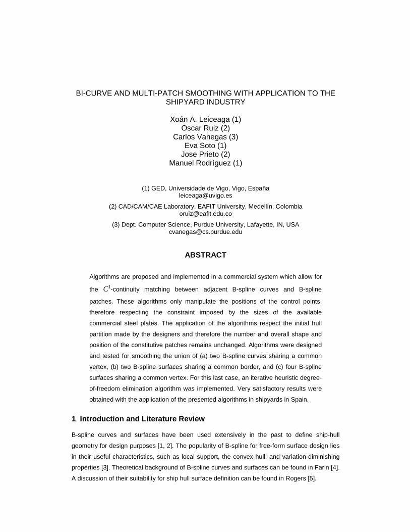
BI-CURVE AND MULTI-PATCH SMOOTHING WITH APPLICATION TO THE SHIPYARD INDUSTRY
Xoán A. Leiceaga (1)
Oscar Ruiz (2) Carlos Vanegas (3)
Eva Soto (1) Jose Prieto (2)
Manuel Rodríguez (1)
(1) GED, Universidade de Vigo, Vigo, España [email protected]
(2) CAD/CAM/CAE Laboratory, EAFIT University, Medellín, Colombia [email protected]
(3) Dept. Computer Science, Purdue University, Lafayette, IN, USA [email protected]
ABSTRACT
Algorithms are proposed and implemented in a commercial system which allow for
the C1-continuity matching between adjacent B-spline curves and B-spline
patches. These algorithms only manipulate the positions of the control points,
therefore respecting the constraint imposed by the sizes of the available
commercial steel plates. The application of the algorithms respect the initial hull
partition made by the designers and therefore the number and overall shape and
position of the constitutive patches remains unchanged. Algorithms were designed
and tested for smoothing the union of (a) two B-spline curves sharing a common
vertex, (b) two B-spline surfaces sharing a common border, and (c) four B-spline
surfaces sharing a common vertex. For this last case, an iterative heuristic degree-
of-freedom elimination algorithm was implemented. Very satisfactory results were
obtained with the application of the presented algorithms in shipyards in Spain.
1 Introduction and Literature Review
B-spline curves and surfaces have been used extensively in the past to define ship-hull
geometry for design purposes [1, 2]. The popularity of B-spline for free-form surface design lies
in their useful characteristics, such as local support, the convex hull, and variation-diminishing
properties [3]. Theoretical background of B-spline curves and surfaces can be found in Farin [4].
A discussion of their suitability for ship hull surface definition can be found in Rogers [5].

Applications of e.g. Computational Fluid Dynamics use single patch representations, which
solve the issue of smoothness by itself [6], but do not reflect that the manufacture and assembly
are performed with smaller standard plates, as produced in the steel mills. Also, fitting the
complex surface of a ship hull with a single B-spline patch may lead to either an inaccurate
representation, or a designer-unfriendly representation i.e. a single patch with a high number of
control points. On the other hand, since a single B-spline patch can only represent surfaces of
simple topological type, a surface of arbitrary topological type (see Figures 1(a) and 1(b)) must
be defined as a set of B-spline patches [7]. The set of patches must constitute a partition of the
ship hull surface and must also maintain tangent plane continuity (C1 continuity) across
neighboring patches. Enforcing C1 continuity between adjacent patches while at the same time
fitting the patch network to the points (of the ship hull surface in this case) is a challenging
problem [7].
(a) Partition of a 2-genus 2-Manifold (double donnut)
(b) Partition of Ship Bow
Figure 1: Non-rectangular Partition of 2-manifolds with Rectangular Patches
Loop [8] presents an algorithm for creating a smooth set of rectangular and triangular spline
surfaces, starting with an irregular mesh of polygonal flat faces. The algorithm takes into
consideration curvature parameters to decide the tiling or merging of patches. The final result
may have spline patches of sizes and shapes dictated by the curvature criteria. Because of this
characteristic, the algorithm is not suitable to be applied in the problem at hand, in which one
must respect the constraint posed by the predefined plates with which the hull is to be
constructed.
Ball [9] and Peters [10] derive continuity conditions for the subdivision of surfaces. Ball uses
Fourier transform-based techniques to do so. Peters presents a method for verifying
smoothness of subdivided B-spline surfaces generated using Doo-Sabin [11] and Catmull-Clark
[12] subdivision algorithms. In our case, subdivision is not only unnecessary but also not
allowed, since the steel plates to manufacture the hull are pre-defined. Our goal is to respect the
collection of B-spline patches, and to slightly modify their control points to achieve C1 continuity
among them.
Bardis [3] presents an algorithm for C1 continuity between adjacent patches which requires

the merging of all the knot vectors of the B-spline patches, the unification of the order and of the
number of vertices of the control polygons, and the use of arbitrarily selected scalar functions
called bias. Hence, it was not compliant with our goal of smoothing B-splines by modifying only
their control points.
For the making of software for the shipbuilding industry no explicit algorithms for B-spline
curve and surface smoothing were found in the reviewed literature. It thus became necessary to
design and implement own algorithms for this task. It is the purpose of this paper to present the
designed algorithms for B-spline curve and surface smoothing, together with the results
obtained to smooth real ship B-spline surface patches. The paper is structured as follows:
Section 2 presents a brief description of the ship hull surface modeling process using B-spline
curves and surfaces. Section 3 presents an algorithm for B-spline curves smoothing. Section 4
presents two algorithms for B-spline surfaces smoothing: one for two adjacent surfaces sharing
a common border, and one for four surfaces incident to a common vertex. Conclusions are
presented in section 6.
2 Hull surface modeling using a set of B-spline su rfaces
The computer modeling of a ship hull is performed, in our case, from the ship hull lines. These
lines are planar curves in 3� resulting from the intersection of the ship hull surface against
cross sections perpendicular to the axes of the ship coordinate system. The modeling process is
roughly as follows: (i) A set of B-spline curves is manually fitted to ship hull lines. Several
rectangular regions on the ship hull surface result from this process, as shown in figure 1. (ii)
Rectangular B-spline patches are generated from the four B-spline curves that enclose each of
these regions. An initial model of the ship hull surface, constituted by a network of C0-
continuous rectangular B-spline patches is thus obtained. (iii) Each pair of adjacent patches is
smoothed using the implementation of the algorithm described in section 4.2.1. Every set of four
patches sharing a common vertex is also smoothed using the implementation of the algorithm
described in section 4.2.2. The final result of the process is a set of rectangular B-spline patches
whose union is C1-continuous, and constitutes the final model of the ship hull surface (see
Figure 8).
Figure 2: Set of B-spline curves interpolating the ship lines and local 0C B-Spline patches

3 Methodology. Smoothing of B-spline curves in sha red vertices
3.1 Condition for C1 continuity between B-Spline curves
Let P and Q be two B-Spline curves in 3� . Let { }0 1, ,...,P mS = p p p and { }0 1, ,...,Q nS = q q q ,
3,i i ∈p q � , be the sequences of control points of P and Q, respectively. If pm=q
0, i.e. P and Q
are C0-continuous at pm
, then P and Q are also C1-continuous at mp if pm-1
, pm
, and q1 are
collinear, and pm
lies between pm-1
and q1, i.e. if there exists ( )0,1λ ∈ ⊂ � such that
pm=q
0= ( )1-λ p
m-1+λq
1 (1)
3.2 Algorithm for C1 continuity between curves
Given two separate B-Spline curves P and Q in 3� connected at a common endpoint p
m=q
0
(see figure 2), the goal of a curve smoothing process is to determine new positions for the
control points of P and Q so that the two curves become C1-continuous at pm
, i.e. the
normalized direction vectors of P and Q at pm
are equal. If the union of the curves P and Q is
required to be smoothed at point pm
, and pm-1
, pm
and q1 are not collinear, at least one of these
three points must be moved in order to do so. Although infinite solutions to this problem exist
(there are infinite ways of arranging three points to lie in a same line), some of them are more
suitable for design and construction purposes. For instance, sometimes the shared control point
is desired to remain fixed (see figure 3(b)).
Suppose that we want to force pm-1
, pm
, and q1 to lie in the same line, by moving p
m-1 and
q1 to new positions *
1m−p and q*1, and leaving p
m fixed. A way to calculate p
*m-1 and q
*1 is as
follows: Let L be the line passing through pm-1
and q1, and L* be the line passing through p
m
and parallel to L. Let 1m−
Πp and Πq
1 be the planes with normal vector n̂ and respective pivot
points pm-1
and q1, where 1 1 1 1ˆ ( ) /( )m m− −= − −n q p q p . It can be seen that possible values for
p*m-1 and q
*1 that satisfy equation 1 are given by
1
* *1 mm L
−− = Π ∩pp and q*1=Π
q1
∩L*.
(a) B-Spline with C0 continuity at pm=q
0 (b) B-Spline with 1C continuity at p
m=q
0
Figure 3: C1 Continuity between adjacent B-Spline curves by adjusting pm-1
and q1
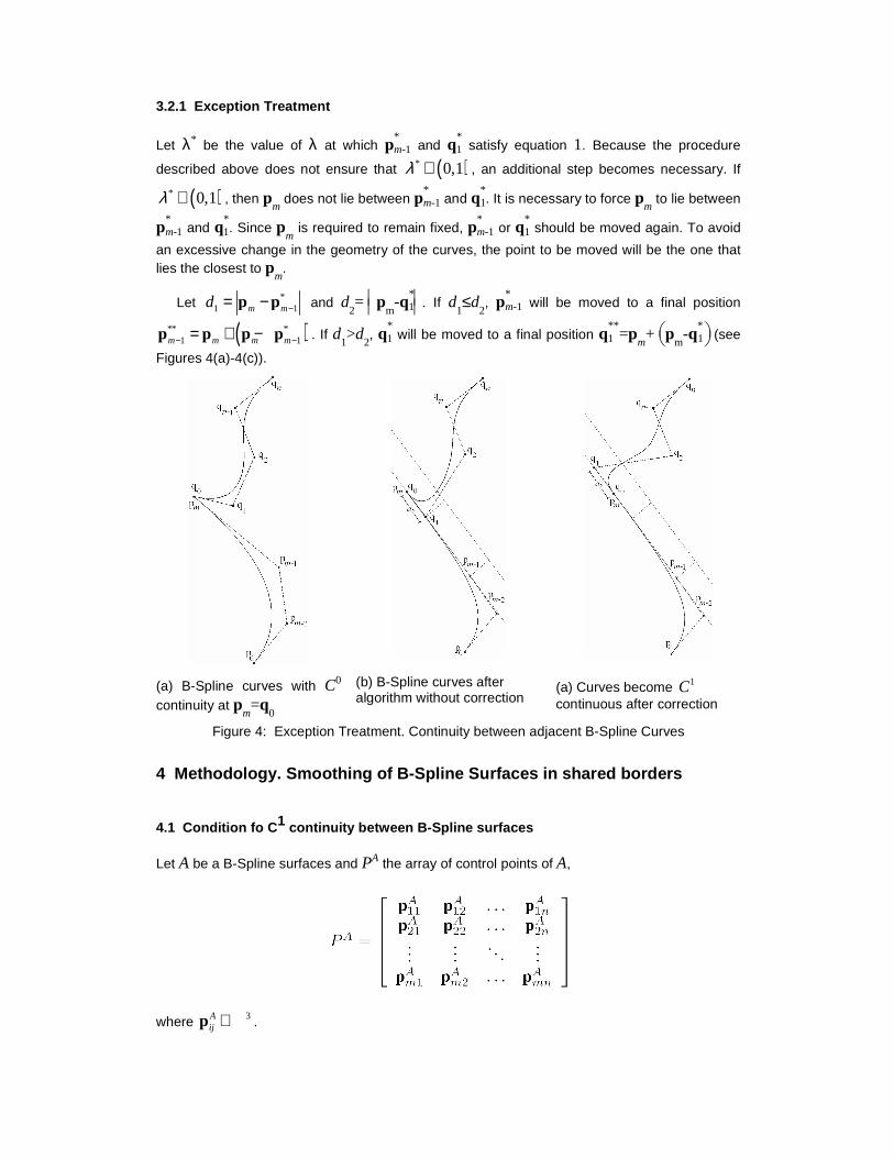
3.2.1 Exception Treatment
Let λ* be the value of λ at which p*m-1 and q
*1 satisfy equation 1. Because the procedure
described above does not ensure that ( )* 0,1λ ∈ , an additional step becomes necessary. If
( )* 0,1λ ∉ , then pm
does not lie between p*m-1 and q
*1. It is necessary to force p
m to lie between
p*m-1 and q
*1. Since p
m is required to remain fixed, p
*m-1 or q
*1 should be moved again. To avoid
an excessive change in the geometry of the curves, the point to be moved will be the one that lies the closest to p
m.
Let *1 1m md −= −p p and d
2=
p
m-q
*1 . If d
1≤d
2, p
*m-1 will be moved to a final position
( )** *1 1m m m m− −= + −p p p p . If d
1>d
2, q
*1 will be moved to a final position q
**1 =p
m+
p
m-q
*1 (see
Figures 4(a)-4(c)).
(a) B-Spline curves with C0 continuity at p
m=q
0
(b) B-Spline curves after algorithm without correction
(a) Curves become 1C continuous after correction
Figure 4: Exception Treatment. Continuity between adjacent B-Spline Curves
4 Methodology. Smoothing of B-Spline Surfaces in s hared borders
4.1 Condition fo C1 continuity between B-Spline surfaces
Let A be a B-Spline surfaces and PA the array of control points of A,
where 3Aij ∈p � .

Definition . Alignment of PL curves.
Let [ ]1 11 12 1, ,..., nE = p p p , [ ]2 21 22 2, ,..., nE = p p p and [ ]3 31 32 3, ,..., nE = p p p be three
sequences of control points, where pij∈R3. We say that E
1, E
2 and E
3 are aligned if for all
j=1,2,...,n, the points p1j
, p2j
and p3j
are collinear exactly in that order, i.e. satisfy equation
p2j= ( )1-λ p
1j+λp
3j with ( )0,1λ ∈ .
The boundary control point sequences for A are 1 11 12 1, ,...,A A A AnE = p p p ,
2 1 2, ,...,A A A Am m mnE = p p p , 3 11 21 1, ,...,A A A A
mE = p p p and 4 1 2, ,...,A A A An n mnE = p p p . Let B be
another B-Spline surface. We say that the control points of the i-th border of A are equal to the
control points of the j-th border of B, if there exist { }, 1,2,3,4i j ∈ , such that EAi =E
Bj or E
Ai =E
*Bj ,
where E*Bj is the reverse-order vesion of E
Bj . A necessary but not sufficient condition for A to be
C0-continuous with B at the i-th border of A and the j-th border of B is that the control points of these two borders be equal.
Let us also define a sequence of control points E'Ai associated to each border E
Ai , for
i=1,2,3,4, as per figure 5. '1 21 22 2, ,...,A A A A
nE = p p p , '2 1,1 1,2 1,, ,...,A A A A
m m m nE − − − = p p p ,
'3 12 22 2, ,...,A A A A
mE = p p p and '4 1, 1 2, 1 , 1, ,...,A A A A
n n m nE − − − = p p p .
(a) Sequences of control points E0A i associated to each EAi , for i = 1, 2, 3, 4
(b) Control points governing C0 and C1 continuity
Figure 5: Sequences of control points in A
Let A be C0-continuous with B, at the i-th border of A and the j-th border of B. This implies
that EAi =E
Bj or E
Ai =E
*Bj . Unless otherwise stated, two surfaces "being C0-continuous" means
that they meet at border i (in A) and j (in B). Also we assume WLOG that EAi =E
Bj (the vertices
are enumerated in identical order). The same observation holds for C1 continuity. We say that A
is C1-continuous with B, if (i) E'Ai , E
Ai , and E
'Bj are aligned exactly in that order, and (ii) the rows
of aligned control points are parallel to each other.
4.2 Algorithms for surface C1 continuity
Two different smoothing processes are identified here. The basic surface-smoothing process
consists in achieving C1 continuity between two surfaces at their common border, i.e. the border
at which the surfaces are C0-continuous. A second process consists in achieving C1 continuity
between four pairwise-C0-continuous surfaces sharing a vertex, at their common borders.
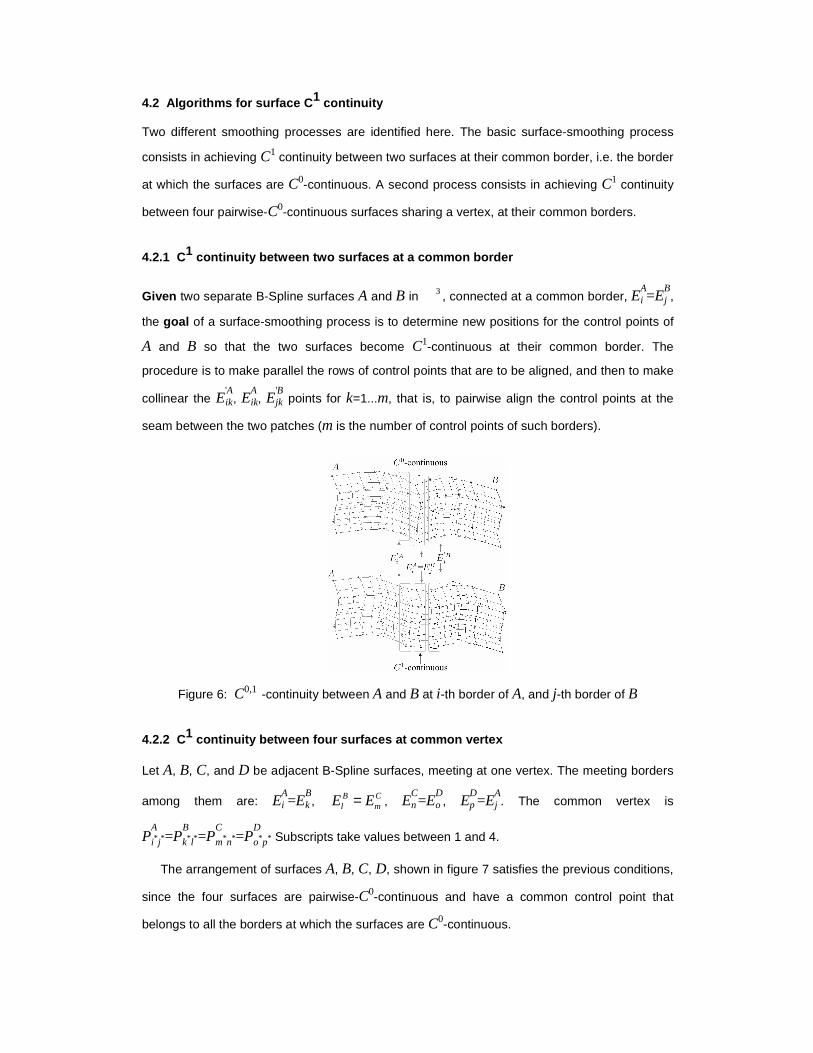
4.2.1 C1 continuity between two surfaces at a common border
Given two separate B-Spline surfaces A and B in 3� , connected at a common border, E
Ai =E
Bj ,
the goal of a surface-smoothing process is to determine new positions for the control points of
A and B so that the two surfaces become C1-continuous at their common border. The
procedure is to make parallel the rows of control points that are to be aligned, and then to make
collinear the E'Aik, E
Aik, E
'Bjk points for k=1...m, that is, to pairwise align the control points at the
seam between the two patches (m is the number of control points of such borders).
Figure 6: C0,1 -continuity between A and B at i-th border of A, and j-th border of B
4.2.2 C1 continuity between four surfaces at common vertex
Let A, B, C, and D be adjacent B-Spline surfaces, meeting at one vertex. The meeting borders
among them are: EAi =E
Bk , B C
l mE E= , ECn =E
Do , E
Dp =E
Aj . The common vertex is
PA
i* j*=PB
k*l*=PC
m*n*=PD
o*p* Subscripts take values between 1 and 4.
The arrangement of surfaces A, B, C, D, shown in figure 7 satisfies the previous conditions,
since the four surfaces are pairwise-C0-continuous and have a common control point that
belongs to all the borders at which the surfaces are C0-continuous.
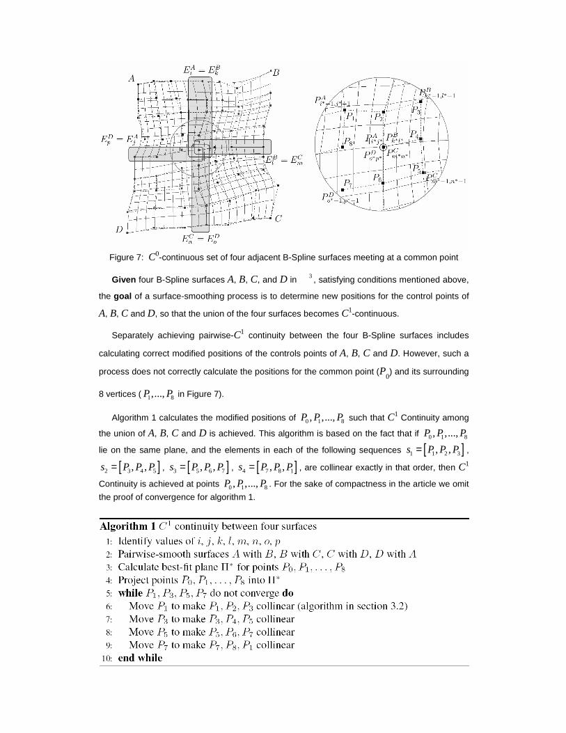
Figure 7: C0-continuous set of four adjacent B-Spline surfaces meeting at a common point
Given four B-Spline surfaces A, B, C, and D in 3� , satisfying conditions mentioned above,
the goal of a surface-smoothing process is to determine new positions for the control points of
A, B, C and D, so that the union of the four surfaces becomes C1-continuous.
Separately achieving pairwise-C1 continuity between the four B-Spline surfaces includes
calculating correct modified positions of the controls points of A, B, C and D. However, such a
process does not correctly calculate the positions for the common point (P0) and its surrounding
8 vertices ( 1 8,...,P P in Figure 7).
Algorithm 1 calculates the modified positions of 0 1 8, ,...,P P P such that C1 Continuity among
the union of A, B, C and D is achieved. This algorithm is based on the fact that if 0 1 8, ,...,P P P
lie on the same plane, and the elements in each of the following sequences [ ]1 1 2 3, ,s P P P= ,
[ ]2 3 4 5, ,s P P P= , [ ]3 5 6 7, ,s P P P= , [ ]4 7 8 1, ,s P P P= , are collinear exactly in that order, then C1
Continuity is achieved at points 0 1 8, ,...,P P P . For the sake of compactness in the article we omit
the proof of convergence for algorithm 1.
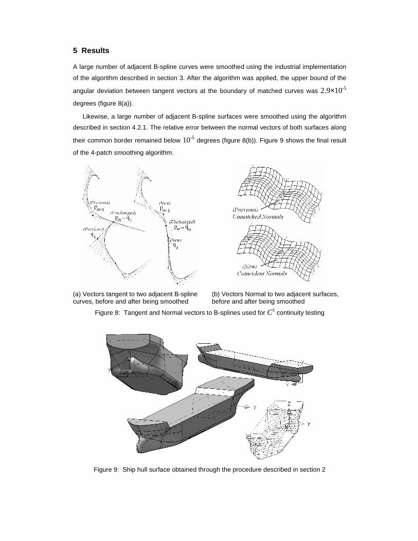
5 Results
A large number of adjacent B-spline curves were smoothed using the industrial implementation
of the algorithm described in section 3. After the algorithm was applied, the upper bound of the
angular deviation between tangent vectors at the boundary of matched curves was 2.9×10⁻⁵
degrees (figure 8(a)).
Likewise, a large number of adjacent B-spline surfaces were smoothed using the algorithm
described in section 4.2.1. The relative error between the normal vectors of both surfaces along
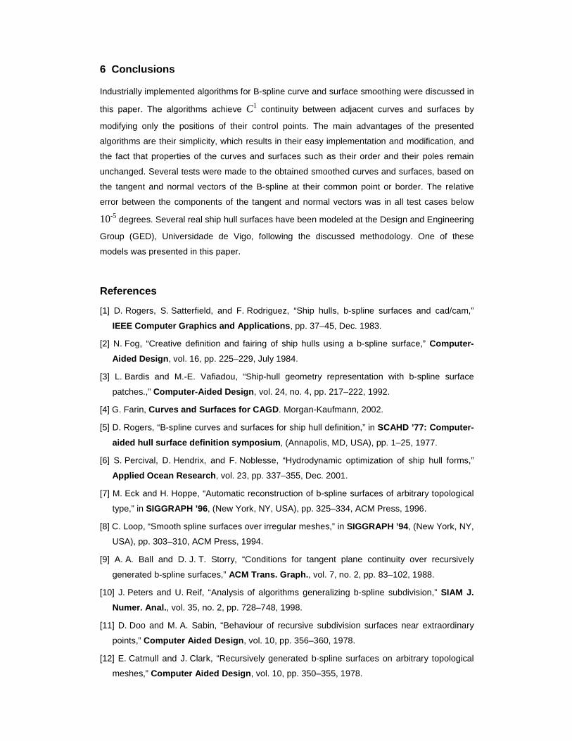
their common border remained below 10-5 degrees (figure 8(b)). Figure 9 shows the final result
of the 4-patch smoothing algorithm.
(a) Vectors tangent to two adjacent B-spline curves, before and after being smoothed
(b) Vectors Normal to two adjacent surfaces, before and after being smoothed
Figure 8: Tangent and Normal vectors to B-splines used for C1 continuity testing
Figure 9: Ship hull surface obtained through the procedure described in section 2
6 Conclusions
Industrially implemented algorithms for B-spline curve and surface smoothing were discussed in
this paper. The algorithms achieve C1 continuity between adjacent curves and surfaces by
modifying only the positions of their control points. The main advantages of the presented
algorithms are their simplicity, which results in their easy implementation and modification, and
the fact that properties of the curves and surfaces such as their order and their poles remain
unchanged. Several tests were made to the obtained smoothed curves and surfaces, based on
the tangent and normal vectors of the B-spline at their common point or border. The relative
error between the components of the tangent and normal vectors was in all test cases below
10-5 degrees. Several real ship hull surfaces have been modeled at the Design and Engineering
Group (GED), Universidade de Vigo, following the discussed methodology. One of these
models was presented in this paper.
References
[1] D. Rogers, S. Satterfield, and F. Rodriguez, “Ship hulls, b-spline surfaces and cad/cam,”
IEEE Computer Graphics and Applications , pp. 37–45, Dec. 1983.
[2] N. Fog, “Creative definition and fairing of ship hulls using a b-spline surface,” Computer-
Aided Design , vol. 16, pp. 225–229, July 1984.
[3] L. Bardis and M.-E. Vafiadou, “Ship-hull geometry representation with b-spline surface
patches.,” Computer-Aided Design , vol. 24, no. 4, pp. 217–222, 1992.
[4] G. Farin, Curves and Surfaces for CAGD . Morgan-Kaufmann, 2002.
[5] D. Rogers, “B-spline curves and surfaces for ship hull definition,” in SCAHD ’77: Computer-
aided hull surface definition symposium , (Annapolis, MD, USA), pp. 1–25, 1977.
[6] S. Percival, D. Hendrix, and F. Noblesse, “Hydrodynamic optimization of ship hull forms,”
Applied Ocean Research , vol. 23, pp. 337–355, Dec. 2001.
[7] M. Eck and H. Hoppe, “Automatic reconstruction of b-spline surfaces of arbitrary topological
type,” in SIGGRAPH ’96 , (New York, NY, USA), pp. 325–334, ACM Press, 1996.
[8] C. Loop, “Smooth spline surfaces over irregular meshes,” in SIGGRAPH ’94 , (New York, NY,
USA), pp. 303–310, ACM Press, 1994.
[9] A. A. Ball and D. J. T. Storry, “Conditions for tangent plane continuity over recursively
generated b-spline surfaces,” ACM Trans. Graph. , vol. 7, no. 2, pp. 83–102, 1988.
[10] J. Peters and U. Reif, “Analysis of algorithms generalizing b-spline subdivision,” SIAM J.
Numer. Anal. , vol. 35, no. 2, pp. 728–748, 1998.
[11] D. Doo and M. A. Sabin, “Behaviour of recursive subdivision surfaces near extraordinary
points,” Computer Aided Design , vol. 10, pp. 356–360, 1978.
[12] E. Catmull and J. Clark, “Recursively generated b-spline surfaces on arbitrary topological
meshes,” Computer Aided Design , vol. 10, pp. 350–355, 1978.
Copyright © 2022 FDOKUMEN