BHARAT GAS RESOURCES LIMITED (BGRL)
88
TECHNICAL SPECIFICATION - ELECTRIC MOTOR DRIVEN RECIPROCATING CNG ON-LINE COMPRESSOR PACKAGE (600 SCMH) P.013751 D11077 022 BHARAT GAS RESOURCES LIMITED (BGRL) CITY GAS DISTRIBUTION PROJECT TECHNICAL SPECIFICATION FOR THE PROJECT
-
Upload
khangminh22 -
Category
Documents
-
view
2 -
download
0
Transcript of BHARAT GAS RESOURCES LIMITED (BGRL)
TECHNICAL SPECIFICATION - ELECTRIC MOTOR DRIVEN RECIPROCATING CNG ON-LINE
COMPRESSOR PACKAGE (600 SCMH)
P.013751 D11077
022
BHARAT GAS RESOURCES LIMITED (BGRL)
CITY GAS DISTRIBUTION PROJECT
TECHNICAL SPECIFICATION FOR THE PROJECT

TECHNICAL SPECIFICATION - ELECTRIC MOTOR DRIVEN RECIPROCATING CNG ON-LINE
COMPRESSOR PACKAGE (600 SCMH)
P.013751 D11077
022
Rev. 0 Supply of Electric Motor Driven CNG On-Line Compressor Package for CGD Project
Page 2 of 89
TABLE OF CONTENTS
1.0 GENERAL ........................................................................................................................ 3
2.0 SCOPE ............................................................................................................................. 3
3.0 CODES AND STANDARDS ............................................................................................ 7
4.0 SCOPE OF SUPPLY FOR EACH COMPRESSOR PACKAGE ......................................... 9
5.0 BATTERY LIMITS ........................................................................................................ 11
6.0 UTILITIES .................................................................................................................... 11
7.0 GENERAL DESCRIPTION............................................................................................ 11
8.0 SAFETY ......................................................................................................................... 13
9.0 BASIC DESIGN OF COMPRESSOR ............................................................................ 16
10.0 INSTRUMENTATION & CONTROLS .......................................................................... 23
11.0 SKID AND ENCLOSURE .............................................................................................. 27
12.0 PAINTING AND PROTECTION: ................................................................................. 28
13.0 INSPECTION & TESTING ........................................................................................... 28
14.0 GUARANTEE, LOADING AND PENALTY CRITERIA ................................................. 30
15.0 SPECIAL TOOLS AND TACKLES ................................................................................. 32
16.0 DOCUMENTATION ...................................................................................................... 32 ANNEXURE – I : GUARANTEED PARAMETERS........................................................................36
ANNEXURE – II : COMPRESSOR DATA SHEET FOR 600 SM3/HR .........................................37
ANNEXURE - III - DATA SHEET FOR ELECTRIC MOTOR ...........................................................45
ANNEXURE – IV: LIST OF MOTORS ...........................................................................................47
ANNEXURE – V: SPECIFICATIONS OF INSTRUMENTS ..............................................................48
ANNEXURE – VI: VENDOR LIST ...............................................................................................58
ANNEXURE – VII : VENDOR DATA REQUIRED .......................................................................65
ANNEXURE – VIII: DEVIATION SCHEDULE FOR CNG ON-LINE COMPRESSOR PACKAGE ........69
ANNEXURE – IX : M.R. COMPLIANCE SCHEDULE ...................................................................70
ANNEXURE –X: EXPERIENCE PROFORMA RECORD ..................................................................72
ANNEXURE – XI : PARAMETERS FOR SCADA ...........................................................................76
ANNEXURE – XII : QUALITY ASSURANCE PLAN .......................................................................78
ANNEXURE – XIII : DATA SHEET ..............................................................................................82
DATA SHEET: MEDIUM VOLTAGE SQUIRREL CAGE INDUCTION MOTOR ELECTRICAL DESIGN DATA .83
TECHNICAL SPECIFICATION - ELECTRIC MOTOR DRIVEN RECIPROCATING CNG ON-LINE
COMPRESSOR PACKAGE (600 SCMH)
P.013751 D11077
022
Rev. 0 Supply of Electric Motor Driven CNG On-Line Compressor Package for CGD Project
Page 3 of 89
1.0 GENERAL
OWNER is responsible for distribution of Natural Gas for household/commercial sectors including setting up CNG refuelling stations for vehicles etc.
2.0 SCOPE
2.1 The intent of this tender is to outline minimum requirement for Design, Engineering, Manufacturing, Assembly, Inspection, Testing, Packaging, Supply, Erection & Commissioning including Performance Acceptance Test at site along with operation and comprehensive AMC during 1 (One) year warranty period and subsequent 9 (Nine) year period including supply of all spares and consumable items for “ ELECTRIC MOTOR DRIVEN RECIPROCATING CNG ON-LINE COMPRESSOR PACKAGES ” as required for dispensing CNG to vehicles at various locations in allotted GA as per this technical specification and applicable codes as referred. Various parts of this specification shall be read in conjunction with each other and in case where the different parts of this specification differ, the more stringent requirement shall govern.
2.2 Online Compressors have to be installed at the CNG outlets of OWNER and other Oil Marketing Company (OMC) retail Outlets located in allotted GA as per the instructions of Engineer in charge to increase the pressure of natural gas for dispensing in vehicles.
2.3 Bidder shall be responsible for supply, erection, commissioning and field trial run. Noise level test and performance test of all packages at sites. The field trial run of the compressor will be for minimum of 4 hours (can be in multiple runs) and the package should be kept under observation for 72 hours for stable operation and no major breakdown in which satisfactory performance of the package together with all accessories auxiliaries and controls shall be established for satisfactory performance for specified operating conditions.
2.4 It will be the endeavour of all the parties to get the performance acceptance test (PAT) at site conducted within a period of 20 days from the start of commercial operation of a particular package. The bidder has to keep the compressors operational round the clock in three shifts or as defined by EIC and all the expenditures including spares and consumables, oil etc. to make the compressors operational shall have to be borne by the bidder. The power required to run the compressors will be provided by OWNER/ OMC. The contractor shall maintain the compressors in sound mechanical condition at all times. The contractor shall rectify the defects notified by OWNER immediately and should submit all the history log sheets and spares availability status along with the report in the format mutually agreed between OWNER and the bidder.
2.5 The bidder shall depute adequate numbers of qualified, experienced and competent persons and supervisors for smooth maintenance of the compressors. The maintenance staffs have to be available round the clock daily throughout the year.
2.6 Periodic inspections of Safety Valves, Transmitters, Pressure vessel gauge and any other equipment as per statutory norms of State Factory rules. SMPV and Gas Cylinder Rules shall have to be carried out by the bidder at his own cost during the period of maintenance by the bidder. The inspections have to be carried out by competent persons as per advice of Engineer-in-Charge and certificates have to be submitted to OWNER.
2.7 The bidder has to maintain an office at site with telephone and fax facility and keep his services personnel ready to attend problems any time of the day. Name and mobile phone number of in-charge of the services team has to be provided to Engineer-in-Charge / his representatives.
2.8 The bidder shall allow weekly rest and restrict daily working hours of his workmen as per relevant Act/Law/and Rule made there under. However no work shall be left incomplete/ in dismantled condition on any holiday/weekly rest. Technician provided shall have minimum qualification of ITI. The bidder in person or his authorized representative shall be available on regular basis to interact with Engineer –in-charge.
2.9 The work force deployed by the bidder for the maintenance services at the CNG installation in at site shall be of sound relevant technical professional expertise which is otherwise also essential from the safety point of view of the personnel of the contractor as well as for the installation.
2.10 All personnel of the bidder entering on work premises shall be properly and neatly dressed while working on premises of the company including work sites.
TECHNICAL SPECIFICATION - ELECTRIC MOTOR DRIVEN RECIPROCATING CNG ON-LINE
COMPRESSOR PACKAGE (600 SCMH)
P.013751 D11077
022
Rev. 0 Supply of Electric Motor Driven CNG On-Line Compressor Package for CGD Project
Page 4 of 89
2.11 Bidder shall maintain proper record of his working employee’s attendance and payment made to them.
2.12 The bidder’s representative/supervisor shall report on regular basis to the Shift-in-charge at OWNER control rooms for day to day working.
2.13 All the safety rules and regulations prevailing and applicable from time to time at the installations as directed by OWNER will be strictly adhered to by the Contractor and his workforce.
2.14 The bidder shall plan schedule maintenance in consultation and prior permission of Engineer in-charge or his representatives.
2.15 The bidder shall be responsible for the discipline and good behaviour of all his personnel deployed to carry out the services. In case of any complaint received against any of his employee, he shall arrange to replace such persons within 24 hrs of notice issued by the Engineer-in-charge. The decision of the Engineer-in-charge in this matter shall be final and binding on the Contractor.
2.16 The bidder shall arrange to provide identity cards to his workforce at his own cost. The contractor’s personnel shall be required to carry their respective identity cards while on duty and produce on demand. Without valid identity cards, they will not be allowed to enter into the CNG station.
2.17 Engineer-in-charge shall have authority to issue instructions to the Contractor from time to time during the contract period necessary for the purpose of proper and safe execution of the contract and the Contractor shall carry out and bound by the same. In case of non fulfilment of any obligations under the contract and /or non execution of any instruction issued by Engineer-in-charge as per terms and conditions of the contract, Engineer-in-charge shall have power to withhold payment for an amount equivalent to the amount to be spent for execution the obligations/instructions issued by him. The decision of engineer-in-charge in this regard will be final and binding to the Contractor.
2.18 Receipt at site, storage in warehouse as per manufacturer’s recommendation and safety and security from theft and breakage/damage during transportation, handling including security guard at site.
2.19 Submission of drawings & documents.
2.20 Erection, O&M and all others relevant manuals for compressor & its accessories, priority panel, electrical motor & all instrumentation.
2.21 GENERAL
The contractor must follow the OPERATION & MAINTENANCE REQUIREMENT as stated below but not limited to and ensure to provide trouble free services as defined in the bid documents.
A. ACCOMMODATION/ TRANSPORTATION/ MEDICAL
The contractor shall make his own arrangement for the accommodation of his personnel at respective locations and subsequent transportation arrangement for them from their place of residence to work place or any other place as required and owner shall have no obligation in this respect.
B. DISCIPLINE
The contractor shall be responsible for the discipline and good behaviour of all his personnel deployed in the services contracted out and should any complaint be received against any of his employee, he shall arrange to replace such persons within 24 hours of notice issued by the Engineer-in-Charge. The decision of the Engineer –in-Charge in this matter shall be final and binding on the contractor.
C. GATEPASS / IDENTITY CARD
The contract shall arrange to supply / renew identity card to his workforce at his own cost, if so required by OWNER for security or for any other reasons. Those contractor’s personnel shall be required to carry their respective identity cards while on duty and produce on demand.
D. RIGHT TO GET SERVICES CARRIED OUT THROUGH OTHER AGENCIES
TECHNICAL SPECIFICATION - ELECTRIC MOTOR DRIVEN RECIPROCATING CNG ON-LINE
COMPRESSOR PACKAGE (600 SCMH)
P.013751 D11077
022
Rev. 0 Supply of Electric Motor Driven CNG On-Line Compressor Package for CGD Project
Page 5 of 89
Nothing contained herein shall restrict OWNER from accepting similar service from other agencies, at its discretion and at the risk and cost of the contractor, if the contractor fails to provide the said services any time.
The maintenance services shall be provided in terms of shift pattern or the round the clock basis as mentioned in the bid document.
E. OWNER will notify the start date for operation and Comprehensive Maintenance services
i. After the successful completion of test run & commissioning, system taking over certificate shall be issued by the owner.
2.22 OPERATION AND MAINTENANCE OF COMPRESSOR PACKAGES
i. The contractor shall deploy adequate number of technicians / supervisors / Engineers / helpers as well as tools, spares, consumables and equipment for smooth and proper maintenance of the Compressor supplied in terms of the contract. In case required to meet operational requirements, the contractor shall augment the same as per direction of `Engineer–in-Charge. Contractor to submit a detailed organogram with key person details before starting maintenance of the compressor package.
ii. The contractor is required to carry out all services as mentioned in the Scope of Services and Schedule of Rates on all the 365 days including Sunday and all Holiday & around the clock.
iii. The contractor shall allow weekly rest and daily working hours to his workmen as per the relevant Act/Law/and Rule made there under. However, no work shall be left incomplete/unattended on any holiday/weekly rest. Technician/operators provided shall have minimum qualification of ITI. Contract in person or his authorized representative shall provide the services on daily basis to interact with Engineer-in-charge and deployed workman.
iv. The work force deployed by the contractor for maintenance service of Compressors, shall be of sound relevant technical professional expertise which is otherwise also essential from the safety point of view of the personnel of the contractor as well as for the installation.
v. Contractor has to ensure the safety of man and machine all the times. Damages to equipment due to negligence will be recovered as per the decision of Engineer-in-Charge, which will be final.
vi. Regarding work completion, the decision of the Engineer-in-Charge will be final and binding.
vii. The contractor shall make his own arrangements to provide all facilities like lodging, boarding and transport etc. to his workmen.
viii. All personnel of the contractor entering on work premises shall be properly and neatly dressed and shall wear uniform, badges while working on premises of the Owner including work sites.
ix. Contractor shall maintain proper record of his working employee’s attendance and payment made to them.
x. The contractor’s representative/supervisor shall report daily to the Shift-in-Charge for day to day working.
xi. All the safety rules and regulations prevailing and applicable from time to time at the installations as directed by OWNER will be strictly adhered to by the contractor.
xii. It will be the responsibility of the contractor to pay as per the minimum wages of the appropriate government applicable under the Minimum Wage Act 1948.
xiii. The services shall be provided in terms of shift pattern on the round the clock basis. The contractor is responsible to provide effective and efficient services in all shifts and assure that there is no disruption in the services for want of any resources.
xiv. The contractor shall establish a central control room to operate 24 hours, seven days a week where complaint regarding non-performance of the Compressors in terms of the contract can be lodged. Further, the contractor shall deploy adequate number of technicians/ supervisors / engineers at various site offices in consultation with Engineer-in-Charge to provide trouble free maintenance of the Compressors.
TECHNICAL SPECIFICATION - ELECTRIC MOTOR DRIVEN RECIPROCATING CNG ON-LINE
COMPRESSOR PACKAGE (600 SCMH)
P.013751 D11077
022
Rev. 0 Supply of Electric Motor Driven CNG On-Line Compressor Package for CGD Project
Page 6 of 89
xv. All arrangements for communication from control room to the contract person working on job under the services shall be the responsibility of the contractor, viz. cell phone / walky-talky.
xvi. The successful bidder shall indemnify the Owner from any claim of the contract labour.
xvii. - The successful bidder shall comply to all the rules regarding PF,ESI etc. as stated in the tender document All the jobs mentioned under scope of services shall be carried out as per sound engineering practices, work procedure documentation, recommendation of the manufacturer and as per the guidelines/direction of engineer-in-charge of authorized representative.
xviii. Summary of breakdown hours station wise with analysis shall be submitted to CNG control room on a fortnightly basis both in hard and soft form as per OWNER format.
xix. The contractor has to submit the following documents on monthly basis along with the bill:
xx. Preventative maintenance compliance report for that month along with the detailed service report.
xxi. Details of the compressor breakdown, summary of break down hours for that month and the cumulative break down hours along with breakdown response time.
xxii. Compressor parameter log book for the month.
xxiii. Certificate to be given by the bidder stating that they have complied with all the labour regulations and are following the minimum wages act.
xxiv. All consumables, lubricating oil, coolant required for carrying out preventive / any type of maintenance shall be in the scope of supplier during the warranty period. The warranty spares shall be supplied by the vendor during the warranty period as per warranty clause.
xxv. All tools, tackles and fixtures required for carrying out the above maintenance of the compressor shall be in scope of the bidder. The scope will also include handling equipment’s like crane, forklift, chain pulley block, etc required during any maintenances activity.
xxvi. Any correspondence required to be made with the company or OEM or various offices shall be made by the bidder or bidder’s agent. All arrangements like phone, fax, computer, Internet etc required for above correspondences shall be arranged by the bidder at his own cost.
xxvii. The periodic maintenance required to be done as per OEM recommendation shall be taken up promptly. The bidder shall provide the detailed preventative maintenance schedule along with
a) Estimated down time required for each type of maintenance schedule.
b) List of spares and their quantities required for each type of maintenance schedule per compressor.
c) Type and number of man days required for each type of maintenance schedule per compressor.
xxviii. The bidder shall plan such maintenances during non-peak hours and in consultancy with the Engineer In Charge (EIC) of OWNER. Any maintenance that needs to be taken up shall be well planned in advance with due approval of the EIC.
xxix. The bidder shall use only OEM’s certified spares during maintenances. All spares shall be kept in sealed OEM stamped packages. The packages shall be opened in front of OWNER representative during maintenance. In case, the schedule maintenance of the OEM manual recommends to check and replace parts like valve spring, valve plates, piston rings etc. after certain time interval, same shall replaced or used further only on approval from the OWNER’s representative. However any untoward consequences for non-replacement of such parts shall be the responsibility of the bidder and spares, repair required to put back the unit into operation will be to bidders account.
xxx. All routine and periodic checks / inspections required to be done as per OEM recommendation shall be done by the bidder. Instruments required for above inspection like vernier calliper, micrometer screw gauge, fill gauges, bore gauge etc shall be in scope of the bidder and these instruments shall be calibrated every year.
xxxi. All parts replaced by the bidder during the above contract period shall be properly packed and handed over to OWNER, on replacement.
TECHNICAL SPECIFICATION - ELECTRIC MOTOR DRIVEN RECIPROCATING CNG ON-LINE
COMPRESSOR PACKAGE (600 SCMH)
P.013751 D11077
022
Rev. 0 Supply of Electric Motor Driven CNG On-Line Compressor Package for CGD Project
Page 7 of 89
xxxii. The contractor shall submit a copy of the daily / weekly / fortnightly / monthly / bimonthly / quarterly and yearly performance report to the EIC in both soft and hard form. All stationery including the printed material such as compressor parameter log book, complaint log book, service report, break down summary report etc. shall be in scope of the bidder.
xxxiii. All the maintenance / inspection job carried out by the bidder shall be recorded in a service report and the report of the same shall be jointly signed by OWNER representative and submitted immediately after carrying out the maintenance. Service report format shall be approved by OWNER.
xxxiv. The EIC will be final authority to take decision with regards to maintenance or replacement of parts or any disagreement between the bidder and OWNER, during the execution of the contract.
xxxv. The bidder shall carryout calibration of gas detectors and flame detectors every six months or earlier as per requirement or instruction of EIC of OWNER. Also yearly calibration of all instruments such as pressure gauges, transmitters, switches, mass flow meters etc shall be in the scope of the bidder. In addition to the above all safety relief valves shall also be tested and calibrated every year.
xxxvi. Calibration shall be done from government-approved laboratories and shall be carried out at least 15 days prior to the calibration due date.
xxxvii. The bidder shall keep 1 set of safety relief valves in spare for the purpose of calibration.
xxxviii. The bidder shall carry out retesting of pressure vessels including blowdown vessel periodically i.e. every year or earlier as per Gas Cylinder rules 2016 / Static & Mobile Pressure Vessels Rules.
xxxix. All spares, consumables, oil and lubricants required for carrying out the Operation and Maintenance of the complete compressor packages including periodic breakdown and any other materials required for operation and maintenance of the compressor packages, shall be provided by the bidder.
xl. All tools, tackles including special tools and tackles and fixtures required for carrying out the above maintenance of the compressor shall be in scope of the bidder. The scope will also include handling equipments like crane, forklift, chain pulley block, etc required during the any maintenances activity.
xli. Any correspondence required to be made with the principal company or OEM or various offices shall be made by the bidder or bidder’s agent. All arrangements like phone, fax, computer, internet etc required for above correspondences shall be arranged by the bidder at his own cost.
xlii. The periodic maintenance required to be done as per OEM recommendation shall be taken up promptly. The bidder shall plan such maintenances during non peak hours and in consultancy with the Engineer-In-Charge (EIC) of OWNER. Any maintenance that needs to be taken up shall be well planned in advance with due approval of the EIC. The scope shall include preparation of maintenance schedule for carrying out the maintenance during the contract period.
xliii. In case, the schedule maintenance of the OEM manual recommends to check and replace parts like valve spring, valve plates, piston rings etc. after certain time interval, same shall replaced or used further only on approval from the OWNER’s representative.
xliv. All routine and periodic checks / inspections required to be done as per OEM recommendation shall be done by the bidder. Instruments required for above inspection like vernier calliper, micrometer screw gauge, fill gauge, bore gauge etc shall be in scope of the vender.
xlv. Bidder to provide Preventive maintenance schedule based on running hours / periodicity of the compressor package.
xlvi. All parts replaced by the bidder during the above contract period shall be properly packed and handed over to OWNER, on replacement.
xlvii. The contractor shall submit a copy of the daily / weekly / fortnightly / monthly / bimonthly / quarterly and yearly performance report to the EIC in both soft and hard form.
3.0 CODES AND STANDARDS
The following National & International Codes & Standards of Latest editions shall be applicable.
OISD 179, NFPA-52: 1995 or equivalent
TECHNICAL SPECIFICATION - ELECTRIC MOTOR DRIVEN RECIPROCATING CNG ON-LINE
COMPRESSOR PACKAGE (600 SCMH)
P.013751 D11077
022
Rev. 0 Supply of Electric Motor Driven CNG On-Line Compressor Package for CGD Project
Page 8 of 89
NFPA – 37: STANDARD FOR THE INSTALLATION AND USE OF STATIONARY COMBUSTION ENGINES AND GAS TURBINES NFPA – 12: STANDARD ON CO2 EXTINGUISHING SYSTEM
IS: 325/ IEC or International standards. : THREE PHASE INDUCTION MOTORS - SPECIFICATION
IS: 6382 : CODE OF PRACTICE FOR DESIGN AND INSTALLATION OF FIXED CO2 FIRE EXTINGUISHING SYSTEM
Applicable ANSI, ASTM, NEC, NEMA code.
API – 618 : RECIPROCATING COMPRESSORS FOR PETROLEUM, CHEMICAL AND GAS INDUSTRY SERVICES
API – 11P 2nd edition : SPECIFICATION FOR PACKAGED RECIPROCATING COMPRESSORS FOR OIL AND GAS PRODUCTION SERVICES
API – 661 : SPECIFICATIONS FOR AIR COOLED EXCHANGERS
ASME Section – VIII Div – 1/2 : DESIGN CODES FOR PRESSURE VESSELS.
Gas Cylinder Rules 2016.
Standard Specifications of Bureau of Indian Standards (BIS).
Specifications/Recommendations of IEC.
Indian Electricity Rules.
Indian Explosives Act.
TEMA – C - Water cooled heat exchangers
ASME / ANSI – B-31.3 Code for Process Piping
3.1 Precedence
In case of any conflict among the various documents, the following preferential order shall govern:
1. Data sheets/drawings 2. Technical Specification 3. International standards/codes as applicable 4. Indian Standards / codes as applicable Compliance with these specifications shall not relieve the bidder of the responsibility of furnishing equipment and accessories of proper design, material and workmanship to meet the specified operating conditions.
No deviations to the technical requirements and to the scope of supply specified in this enquiry document shall be accepted and offers not in compliance to the same shall be rejected. In case a deviation is required due to inherent design of the equipment offered, the bidder shall list all such deviations at one place giving reasons thereon.
Bidder shall necessarily furnish the following along with the bid, without which the offer shall be considered incomplete:
(1) Proven Track Record Formats, duly filled in along with general reference list shall be submitted for the earlier supplied CNG compressor packages as per the BEC requirements.
(2) Checklist duly filled in with regards to scope of supply
(3) Completely filled in Data Sheets of compressor, motor
(4) Deviations if any to this Technical Specification
(5) Tentative Lay out/key plan/General Arrangement Drawing indicating size of skids, center distance between skids and space required along with maintenance requirements
(6) (a) Utilities requirements (b) Electrical Load summary
(7) Data Sheets of compressor, motor, instrumentation & controls
TECHNICAL SPECIFICATION - ELECTRIC MOTOR DRIVEN RECIPROCATING CNG ON-LINE
COMPRESSOR PACKAGE (600 SCMH)
P.013751 D11077
022
Rev. 0 Supply of Electric Motor Driven CNG On-Line Compressor Package for CGD Project
Page 9 of 89
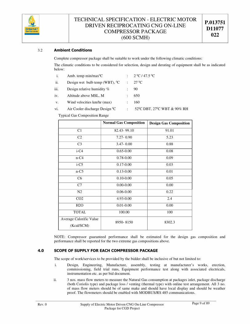
3.2 Ambient Conditions
Complete compressor package shall be suitable to work under the following climatic conditions:
The climatic conditions to be considered for selection, design and derating of equipment shall be as indicated below:
i. Amb. temp min/max0C : 2 0C / 47.5 0C
ii. Design wet bulb temp (WBT), 0C : 27 0C
iii. Design relative humidity % : 90
iv. Altitude above MSL, M : 650
v. Wind velocities km/hr (max) : 160
vi. Air Cooler discharge Design 0C : 520C DBT, 270C WBT & 90% RH
Typical Gas Composition Range
Normal Gas Composition Design Gas Composition
C1 82.43- 99.10 91.01
C2 7.27- 0.90 5.23
C3 3.47- 0.00 0.88
i-C4 0.65-0.00 0.08
n-C4 0.78-0.00 0.09
i-C5 0.17-0.00 0.03
n-C5 0.13-0.00 0.01
C6 0.10-0.00 0.05
C7 0.00-0.00 0.00
N2 0.06-0.00 0.22
CO2 4.93-0.00 2.4
H2O 0.01-0.00 0.00
TOTAL 100.00 100
Average Calorific Value
(Kcal/SCM) 8950- 8150 8302.3
NOTE: Compressor guaranteed performance shall be estimated for the design gas composition and performance shall be reported for the two extreme gas compositions above.
4.0 SCOPE OF SUPPLY FOR EACH COMPRESSOR PACKAGE
The scope of work/services to be provided by the bidder shall be inclusive of but not limited to:
i. Design, Engineering, Manufacture, assembly, testing at manufacturer’s works, erection, commissioning, field trial runs, Equipment performance test along with associated electricals, instrumentation etc. as per bid document.
ii. 3 nos. mass flow meters to measure the Natural Gas consumption at packages inlet, package discharge (both Coriolis type) and package loss / venting (thermal type) with online test arrangement. All 3 no. of mass flow meters should be of same make and should have local display and should be weather proof. The flowmeters should be enabled with MODBUS/RS 485 communications.
TECHNICAL SPECIFICATION - ELECTRIC MOTOR DRIVEN RECIPROCATING CNG ON-LINE
COMPRESSOR PACKAGE (600 SCMH)
P.013751 D11077
022
Rev. 0 Supply of Electric Motor Driven CNG On-Line Compressor Package for CGD Project
Page 10 of 89
iii. Instrumentation and control system as specified on data sheets, P&ID including Local panel, Console/Local gauge boards, PLC.
iv. Common structural steel skid for the compressor- Motor combination and for all auxiliary systems
v. Air-cooled heat exchanger for inter stage and discharge gas.
vi. 7 line for 600 SCMH (3 bank) Priority Panel at Package Discharge.
vii. All interconnecting oil, gas, water, air piping within the compressor package.
viii. Impulse and pneumatic piping/Tubing for all valves, fittings as specified & required for mounting the instruments. Block and bleed valves to be provided for Pressure gauges and pressure Transmitters.
ix. Separate junction boxes for different type of signals like intrinsically safe signals, alarm, shutdowns, thermocouples, RTDs etc. for interfacing to local panel.
x. NRV at final discharge
xi. Structural supports within the compressor package for all piping, instruments etc.
xii. One no. relief valve at each stage discharge, first (1st) stage suction and Blow Down Vessel.
xiii. Y- type strainers, valves, sight flow indicators, check valves, auto & manual drain traps etc. as required for various auxiliary systems i.e. frame lube oil, cylinder lubrication system, cooling water systems etc.
xiv. Coupling/V-belts/pulleys.
xv. Acoustic enclosure for Compressor package, with two number L.E.L detectors and two UV detectors in one enclosure.
xvi. Common CO2 extinguishing system consisting of two cylinders, piping, valves and control systems as per details given in this specification.
xvii. Inlet and outlet manual and automatic isolating valves for maintenance & emergency.
xviii. Complete Erection, Testing & Commissioning of compressor packages.
xix. Run test and Performance acceptance test at site
xx. Supply of all essential spares as specified, erection & commissioning spares.
xxi. One set of priced spare parts catalogue along with the priced bid (Commercial bid), as built drawings and Operation & Maintenance catalogue with each compressor package.
xxii. An oil drain pot outside of the package shall be provided to collect all drains from packing, distance pieces, processes etc. The capacity of the drain pot should not be more than 2.5 Litres.
xxiii. Only air cooled and lubricated compressor with suction/discharge volume bottles (dampers) for each stage (separators) with manual drains and automatic drain system, lube oil system, closed circuit cooling water system (console type)/Air cooled as required.
xxiv. Priority refuelling system outside of the package or as per vendors design.
xxv. Drive belt, if used shall be anti-static fire retardant type.
xxvi. Duplex suction filters to be provided at the inlet of package with Differential Pressure gauge after Y- type strainer.
xxvii. Two stage filtration at discharge so as to limit oil carryover is to be provided.
xxviii. Three no. Emergency stop button (push type) along with one hooter in office/customer interface room.
xxix. Wires mesh type guard for heat exchanger fan.
xxx. The provision for overhead mounting of cascade (3000 Water Litre capacity with approximate weight of 7 tons) should be there & same should be of enough strength having working space and with ladder arrangement. However, cascade supply and its mounting on the structure shall be in scope of purchaser. Structure Stability compliance Certificate of the unit where cascade will be mounted to be submitted during detail engineering.
TECHNICAL SPECIFICATION - ELECTRIC MOTOR DRIVEN RECIPROCATING CNG ON-LINE
COMPRESSOR PACKAGE (600 SCMH)
P.013751 D11077
022
Rev. 0 Supply of Electric Motor Driven CNG On-Line Compressor Package for CGD Project
Page 11 of 89
xxxi. Secondary lubrication system with check valve protector, HP (High Pressure) Filter (for all lubricating points) & DNFT (Digital No Flow Timer) flow switches with standby pump. Secondary lubrication system with divider block shall be provided.
xxxii. Erection, O&M and all others relevant manuals for compressor & its accessories, priority panel, electrical motor & all field instruments.
xxxiii. Annual Operation and comprehensive maintenance services for a period of 1 year during the warranty period, including supply of all spares and consumable items.
xxxiv. Annual Operation and comprehensive Maintenance services for a period of 9 (nine) years after the warranty period including supply of all spares and consumable items.
4.1 Exclusions
The following are excluded from the scope of the bidder:
i. All civil works and foundation design, however the bidder shall furnish all the relevant data for design of any pedestal if required.
ii. All piping beyond battery limits except from air compressor & air piping for air and piping from CO2 cylinders up to the enclosure.
iii. Three banks Cascades.
iv. CNG Dispensers and Interconnected SS tubes & fittings.
5.0 BATTERY LIMITS
4.1 Supplier shall arrange its own UPS supply for testing, installation and commissioning compressor control circuitry. UPS of adequate rating along with battery backup to be part of vendors scope.
4.2 All customer interface connections (i.e. Gas inlet & gas outlet) shall be brought out to the package edge. Gas inlet shall be terminated in nozzles with isolation valves having flange connections and gas outlet (priority panel outlet connection) shall be terminated through high-pressure ¾” full bore ball valves with 3/4” end connectors.
4.3 As and where specified on the data sheets all vents (i.e. Relief valve, distance piece, packing and starting air) shall be manifolded and terminated at skid edge outside the enclosure and vented to safe height at package roof. Silencer has to be provided in the starting air vent line.
4.4 All drains from different process equipments, distance piece and packing shall be manifolded and terminated as single point for customer interface duly flanged with isolation valve. Drains should be through a common header and discharge to be allowed in a pit to avoid spillage around compressor package.
6.0 UTILITIES i. Any auxiliary motor above 10 hp shall be provided with star delta/ soft starter (three phase controlled)
type starter. Single phase motor will be not acceptable above 1 hp rating.
ii. Bidder shall make his own provision for Instrument air if required with an electric motor driven air compressor with a suitably sized receiver & Refrigerant type air drier system. Air Compressor motor should be 415 V squirrel cage motor L&T make DOL / star delta starter having overload protection, single phase preventer.
iii. Oil Drain should be through a common header and discharge to be allowed in pot outside the package (capacity not more than 2.5 litres) to avoid spillage around the compressor package.
iv. All electrical and instrumentation terminals shall be as specified.
v. Purchaser shall provide 415 V, 3Ph, 50Hz, 4 wire electric power for compressor motor drive at a single point.
vi. Purchaser shall provide the 230V, 50Hz, 1Ph UPS, for LCP at single point in the electrical room.
7.0 GENERAL DESCRIPTION The CNG Compressor is to be installed at CNG station. The gas will be tapped from OWNER pipeline. The gas composition is as detailed in this document.
TECHNICAL SPECIFICATION - ELECTRIC MOTOR DRIVEN RECIPROCATING CNG ON-LINE
COMPRESSOR PACKAGE (600 SCMH)
P.013751 D11077
022
Rev. 0 Supply of Electric Motor Driven CNG On-Line Compressor Package for CGD Project
Page 12 of 89
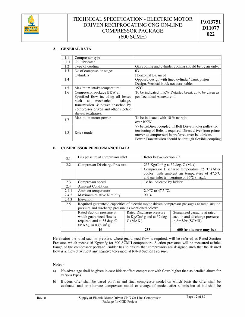
A. GENERAL DATA
1.1 Compressor type 1.1.1 Oil lubricated 1.2 Type of cooling Gas cooling and cylinder cooling should be by air only. 1.3 No of compression stages 03
1.4 Cylinders Horizontal Balanced
Opposed design with lined cylinder/ trunk piston Design. Vertical block not acceptable.
1.5 Maximum intake temperature 350C 1.6 Compressor package BKW at
Specified flow including all losses such as mechanical, leakage, transmission & power absorbed by compressor driven and other electric driven auxiliaries.
To be indicated in KW Detailed break up to be given as per Technical Annexure –I
1.7 Maximum motor power To be indicated with 10 % margin over BKW
1.8 Drive mode
V- belts/Direct coupled. If Belt Driven, idler pulley for tensioning of Belts is required. Direct drive (from prime mover to compressor) is preferred over belt driven. Power Transmission should be through flexible coupling.
B. COMPRESSOR PERFORMANCE DATA
2.1 Gas pressure at compressor inlet Refer below Section 2.5
2.2 Compressor Discharge Pressure 255 Kg/Cm2 g at 52 deg. C (Max)
Compressor Discharge temperature 52 ºC (After
cooler) with ambient air temperature of 47.5ºC and gas inlet temperature of 35ºC (max.).
2.3 Compressor speed To be indicated by bidder. 2.4 Ambient Conditions
2.4.1 Ambient temperature 2.0 0C to 47.5 ºC. 2.4.2 Maximum relative humidity 90 % 2.4.3 Elevation 2.5 Required guaranteed capacities of electric motor driven compressor packages at rated suction
pressure and discharge pressure as mentioned below: Rated Suction pressure at
which guaranteed flow is required, and at 35 deg. C (MAX), in Kg/Cm2 g.
Rated Discharge pressure in Kg/Cm2 g and at 52 deg C (MAX.)
Guaranteed capacity at rated suction and discharge pressure in Sm3/hr (SCMH)
16 255 600 (as the case may be)
Hereinafter the rated suction pressure, where guaranteed flow is required, will be referred as Rated Suction Pressure, which means 16 Kg/cm2g for 600 SCMH compressors. Suction pressures will be measured at inlet flange of the compressor package. Bidder has to ensure that compressors are designed such that the desired flow is achieved (without any negative tolerance) at Rated Suction Pressure.
Note: -
a) No advantage shall be given in case bidder offers compressor with flows higher than as detailed above for various types.
b) Bidders offer shall be based on firm and final compressor model on which basis the offer shall be evaluated and no alternate compressor model or change of model, after submission of bid shall be
TECHNICAL SPECIFICATION - ELECTRIC MOTOR DRIVEN RECIPROCATING CNG ON-LINE
COMPRESSOR PACKAGE (600 SCMH)
P.013751 D11077
022
Rev. 0 Supply of Electric Motor Driven CNG On-Line Compressor Package for CGD Project
Page 13 of 89
entertained / considered. This is very important and all bidders shall take full cognizance of this matter before submitting the bid.
c) Bidder to indicate the capacity and absorbed power of the offered compressors at various suction conditions starting from 14 Kg/Cm2 g to 19 Kg/Cm2 g (Temperature 40 deg C max.) and 255 Kg/Cm2g and 52 deg. C (max) discharge condition.
Performance curves and tables i.e. Flow versus suction pressure and temperature and power curves i.e. absorbed power versus suction pressure and temperature at specified discharge conditions shall be furnished. In addition to above, flow capacity and absorbed power values for suction conditions from 14 Kg/Cm2 g to 19 Kg/Cm2 g in steps of 0.5 Kg/Cm2 shall also be given in tabular form. The graph shall be plotted at various suction pressures ranging from 14 Kg/Cm2g to 19 Kg/Cm2g and at various suction temperatures ranging from 20o to 40o C. Similarly the graphs shall be plotted at various discharge pressures ranging from 200 Kg/Cm2g to 255 Kg/Cm2g, however at 520 C (max) discharge conditions.
d) Bidder to note that the compressor package required shall be suitable for operating at a suction pressure from 14 Kg/Cm2g to 19 Kg/Cm2g at 40 deg. C. Reduction of suction pressure by means of pressure regulating valve (PRV) is to be achieved. Gas inlet pressure regulator of 300# class rating with inlet pressure range of 10 kg/cm2 to 45 kg/cm2 with an outlet discharge range of 10 Kg/Cm2 g to 30 Kg/Cm2 g adjustable.
Bidder to note that negative tolerance on the guaranteed capacity will not be acceptable. Also no advantage shall be given for positive tolerance of the capacity
8.0 SAFETY
a) All controls shall operate in a fail-safe mode i.e. failure of any control shall not lead to running of equipment in unsafe mode.
b) The hazardous area classification Class-I, Division I, Group D as per NEC or Zone I, Group II A/ II B as per IS/ IEC. Certificate from recognized agency to the effect that equipment supplied and/or installed conform to above area classification. All Devices shall meet the requirement for the specified area classification in which they are installed, including instrumentation leads.
c) Bidder needs to submit the copy of valid type approval for compressor packages from PESO before completion of techno-commercial evaluation
d) All exposed rotating parts shall be provided with adequate guards of non-sparking type.
e) Driver belt if used shall be of anti-static and fire resistant type.
f) Piping shall be arranged in a manner so as to provide clear headroom and accessibility within the package. Adequate clearances shall be provided for all the engineered components.
g) Each package ENCLOSURE shall have two nos. (2) LEL detectors (IR Type) and two nos. (2) Ultra Violet (UV) fire detectors to cover the enclosure effectively as already spelt in the scope of supply.
h) All material used in the package shall be flame retardant.
i) Relief valves shall be provided at suction and discharge and each inter stages of compressor with setting as per cl.7.20.4 of API-11P with R.V. venting as per cl. 7.20.4 of API-11P.All vented to common relief valve header.
8.1 Carbon Dioxide (CO2) Flooding System
a) CO2 flooding system should be installed for the protection of CNG compressor by automatic actuation system. The package should be protected by automatic operated CO2 flooding system designed as per NFPA-12.
b) Gas Detection by installation of hydrocarbon gas detector (IR type) with self check function and transmitter with adjustable alarm levels (0-100% of flammability range) with preset of 10%, 20% and 50%.
TECHNICAL SPECIFICATION - ELECTRIC MOTOR DRIVEN RECIPROCATING CNG ON-LINE
COMPRESSOR PACKAGE (600 SCMH)
P.013751 D11077
022
Rev. 0 Supply of Electric Motor Driven CNG On-Line Compressor Package for CGD Project
Page 14 of 89
c) Installation of flame detector (UV-IR type) with self check function and transmitter, alarm & shutdown on detection of flame.
d) CO2 flooding system will consist of 2 nos. brand new CO2 cylinders of 45 Kg capacity. One cylinder will act as main & other as stand by, which shall have identical arrangement and connected to the system. The cylinders should be placed in a shed raised above ground level to protect from weather and direct sunrays as per Gas Cylinder Rules, 2016. Cylinders shall be fitted with automatic actuated Valves, Solenoid valves.
No extra utility as air, inert Gas shall be made available by OWNER/used by the supplier to operate the system other than the UPS.
Cylinder should be ISI marked as per IS: 7285 and CCOE approved.
e) The System shall be designed to operate on 24 V DC supply. FRLS (Fire resistant low smoke) cables shall be used for the wiring of the system.
f) Interlock of CO2 Flooding system with compressor as per following sequence:
g) Compressor shall trip on detection of gas at preset level and close the inlet & Outlet valve
h) Compressor shall trip on detection of flame at preset level and automatic discharge of CO2 gas shall take place from the main cylinder simultaneously.
i) Compressor shall not start if the CO2 Flooding System is faulty or Pressure is low, not working, SWITCHED OFF etc. The compressor shall be able to start only when the CO2 Flooding System is in healthy working condition.
j) Maintenance Override Switch shall be provided to keep the system off during maintenance.
k) Selector switch shall be provided to put Main/Stand by Cylinder in line at the turn of a switch as per requirement.
l) Alarm panel for CO2 Flooding System shall be integral with the main compressor panel. Necessary displays as system ON, OFF, FAULT, RESET, Gas/ Flame indication, Remote actuation of solenoid valve, distinguished hooter etc., shall be provided for CO2 flooding system.
m) CO2 Cylinders shall be provided outside the package at a safe place, minimum 4.5 meters away (aerial distance), where it is not exposed to fire in case of fire in the compressor. Facility shall be made to operate the system both manually from remote with the help of a switch/ call point and with help of pull down lever on cylinders.
n) Suitable online weight (CO2) loss monitoring/ indication device to be provided to ascertain the health of the CO2 flooding system.
o) All installation shall be compatible for hazardous area Class 1, Division 1, Group-D for Methane Gas.
p) The system designed by the supplier shall be duly approved by Owner/ Owner’s representative.
q) Technical specifications, Operation and Maintenance Manual, CCOE Certificate, Approval/ Manufacturing certificates for cylinders and cylinder valves, gas detectors, flame detectors, solenoid valves etc. shall be furnished by the supplier along with system. Software and hardware, calibration procedure shall be provided by the supplier along with the supply sufficient enough to handle the system independently. Necessary tools (1 set ) shall be provided with the system.
r) System shall be offered for testing to OWNER by the supplier after commissioning at site by creating actual Gas leak and Gas fire situations and actual discharge of CO2 Gas from the Cylinders. This shall form a part of performance test and thereby acceptance of the package. The cylinders have to be refilled by the vendor at no extra cost to OWNER after performance test. If the system fails during testing, subsequent testing and refilling would be at vendor’s cost.
s) Warning and Operating instructions to be displayed at equipment as per the statutory/ safety regulations.
t) Piping of CO2 flooding system shall be seamless high pressure pipe of Schedule 40 of 50 mm dia of appropriate length with a minimum safe distance of 4.5 Meter from CNG Compressor, The fittings like
TECHNICAL SPECIFICATION - ELECTRIC MOTOR DRIVEN RECIPROCATING CNG ON-LINE
COMPRESSOR PACKAGE (600 SCMH)
P.013751 D11077
022
Rev. 0 Supply of Electric Motor Driven CNG On-Line Compressor Package for CGD Project
Page 15 of 89
elbows, Tees, Union, sockets should be of same schedule and capacity for installation in a high pressure system as per NFPA-12.
u) Flameproof online weighing system, complete frame with shed and all accessories should be of good quality, weighing scale should be of reputed make.
v) Specifications:
Non Return Valve for CO2 High Pressure Hose:
i. As per BIS specifications
ii. Operating Media: CO2
iii. Body Material: Brass, BIS: 319
iv. Ball: SS 316
v. Pin: SS 316
vi. Seal: Teflon (PTFE - Polytetrafluoroethylene)
vii. Working Pr.: 60Bars
viii. Test Pressure: 90 Bars for 1 min
ix. Weight: 70gm
x. Outlet Size: ¾ BSP (British Standard Pipe Parallel) at manifold end --
xi. Inlet Size: ½” BSP (British Standard Pipe Parallel) at CO2 Discharge Hose end
xii. Temp. Range: -29° C to 66° C
Hose Adopter:
i. As per BIS specifications
ii. Operating Media: CO2
iii. Body Material: Mainly Brass
iv. Test Pressure: 250 Bar
v. Max. Working Load: 150 Bar
vi. Temp. Range: -29° C to 66° C
Discharge Nozzle:
i. As per BIS specifications
ii. Operating Media: CO2
iii. Body Material: Leaded Tin Bronze as per BIS: 318:1981
iv. Design Nozzle Pr.: Not less than 20.6 kgf/cm2 at 27° C
v. Test Pressure: 140 kgf/cm2
vi. Marking for Code No. (on the basis of equivalent single orifice dia.): As per BIS: 6382:1982
vii. Temp. Range: -29° C to 66° C
High Pressure Hoses:
i. As per BIS 7285:1974
ii. Operating Media: CO2
iii. Hose Type: Double wire breaded (perforated) rubber covered
iv. Min. Bursting Pr.: 420 kgf/ cm2 at 54° C
v. Length: 40 cm
vi. Cross-section: ½”
vii. End Connection: ½” BSP (F) xW21.614 TPI
viii. End Fittings: Brass
TECHNICAL SPECIFICATION - ELECTRIC MOTOR DRIVEN RECIPROCATING CNG ON-LINE
COMPRESSOR PACKAGE (600 SCMH)
P.013751 D11077
022
Rev. 0 Supply of Electric Motor Driven CNG On-Line Compressor Package for CGD Project
Page 16 of 89
ix. Temp. Range: -29° C to 66° C
8.2 Following warning and caution signage shall be marked on the housing/package:
“No Smoking”
Caution notice “This Machine may automatically start at any time”.
“Flammable Gas”
9.0 BASIC DESIGN OF COMPRESSOR
9.1 Following specification is intended to give the bidder the technical and operating conditions the compressor must fulfil.
9.2 The bidder shall meet all applicable statutory codes, national law and local regulation for safety and environment protection.
9.3 The design shall conform to API 618 / API 11P, 2nd edition / other relevant reputed international standards (bidders to indicate).
9.4 Cylinders of compressor should be horizontal balanced/ trunk piston design. Vertical blocks are not acceptable. Compressor shall utilize preferably separate suction and discharge valves. Valve should be of preferably plate or spring type (non-metallic type) developed specifically for Natural gas.
9.5 Compressor cylinder shall be provided preferably with removable liners.
9.6 Latest technology shall be applied to the piston ring to ensure reliability and oil control with polymer rings fitted to the final stage. The bidder to indicate the life of piston rings of all stages in terms of running hours.
9.7 Each pressurized component of the compressor package shall be subjected to hydraulic proving test and the final assembly shall be performance tested and certified.
9.8 The inter stage and final stage cooler tube material shall be carbon steel. Bidder to submit cooler sizing calculation for review.
9.9 All gas piping shall be designed, fabricated and tested in accordance with ANSI B 31.3.
9.10 The relief valve sizing shall be in accordance to IBR, ASME code for boiler & pressure vessel and API RP-520. The relief valve and associated piping shall be sized for full block discharge.
9.11 Compressor maximum vibrations of cylinders shall not exceed 10 mm/sec. unfiltered peak velocity. Maximum vibration level installed compressor frame shall not exceed an unfiltered peak velocity of 5 mm/sec or as per IEC codepenalty unfiltered peak to peak vibration whichever is less. The bidder shall provide for all structural support within the package so that these levels can be achieved.
9.12 In case of lubricated cylinder & packing design, single plunger per point force feed mechanical lubricator shall provide lubrication to compressor cylinders. Lubricators with double ball check valve shall be provided at each lubricator point. Digital no flow timer shall be provided to stop the compressor in case of loss of cylinder lubrication.
9.13 The bidder along with the offer shall furnish the recommended lubricating oil type, grades & specification along with their quantity and frequency of change. The recommended oil shall be compatible with gaskets, O-ring, seals, packing, lubricator parts and other parts coming into contact.
TECHNICAL SPECIFICATION - ELECTRIC MOTOR DRIVEN RECIPROCATING CNG ON-LINE
COMPRESSOR PACKAGE (600 SCMH)
P.013751 D11077
022
Rev. 0 Supply of Electric Motor Driven CNG On-Line Compressor Package for CGD Project
Page 17 of 89
9.14 Coolant tank must be provided with proper opening for flush/ clean of the tank, so that coolant level trip system works properly. Switch position should be such that sludge doesn’t deposit on float sensor. Material of coolant make up tank should be SS304.
9.15 Gauge panel with physical gauges for temperature and pressure shall be provided and should be visible from outside of the package. LCD display as an extension of PLC display is not acceptable.
9.16 Proper oil draining system for the package is required. Packager should provide proper pocket system in package structure for draining coolant/ oil from inside the package. Package base frame block must be interconnected & slope must be provided.
9.17 Level trips of oil & coolant must be provided with wire open alarm.
9.18 All package flow meters should have isolation valve in upstream and NRV/Valve at downstream of flow meter. Flow meters which are on piping should be connected with flexible hoses and should have proper clamping support to avoid vibration so that correct reading are observed.
9.19 All cables entries should be from bottom in the FLP boxes (local control panel). There should be no cabling from the bottom of the package. All the cables should be routed from the side or top for easy trouble shooting.
9.20 All instruments and their cables should be at appropriate distances from the exhaust line/hot parts as per applicable codes & standards
9.21 Status of all field instruments viz. switches should be displayed on PLC.
9.22 Direction of flow should be marked on the pipe line and nomenclature of all vessel (e.g. 1st stage discharge dampener etc.) should be written on them. Cross head inspection windows should be transparent for easy of inspection during running. Set values should be prominently marked on the gauges.
9.23 Part / Equipment / Accessories to be included
a) Gas tight crankcase.
b) Packing case & pressure packing.
c) Drive motor with pulley/flywheel
d) Inter-stage coolers for all stages.
e) Final cooler.
f) Oil pump, oil filter
g) Oil cooler.
h) Crankcase breather piped back to suction.
i) Oil/moisture separators appropriate for selected cylinder configuration.
j) Automatic condensate drains system for all separators to remove oil / moisture periodically and ease starting.
k) Separator drain valves piped to collection drain block suitable for connection to gas recovery system.
l) Safety relief valve on each stage of compression.
m) Safety relief valve discharges connected to common manifold suitable to allow dispersion of gas via a vent stack and flame arrestor / trap.
n) PRV (Pressure Reilef Valve) at the inlet of the system.
o) BDV (Blow Down Vessel) at the inlet of the system.
p) Interconnecting piping between cylinders, coolers and separators.
q) Pulsation dampeners.
r) Interconnecting water piping between radiator and compressor.
s) Interconnecting instrumentation piping.
TECHNICAL SPECIFICATION - ELECTRIC MOTOR DRIVEN RECIPROCATING CNG ON-LINE
COMPRESSOR PACKAGE (600 SCMH)
P.013751 D11077
022
Rev. 0 Supply of Electric Motor Driven CNG On-Line Compressor Package for CGD Project
Page 18 of 89
t) Suction & Discharge Mass flow meter
u) Thermal Mass flow meter for vent loss
v) Priority panel with SS tubing
9.24 Offered package shall be complete with compressor, electric motor, piping, cooling system, suction and discharge filters, priority fill system, control panel safety and control devices and other accessories required for automatic and safe operation of the system. The supply shall include all interconnecting piping/tubing/cables. Cooling system shall be of closed circuit type. Only lubricated and air cooled compressor block is acceptable.
9.25 The compressor package control system shall be designed for unattended safe operation in automatic mode and shall unload, start, load, stop safely. The compressor shall start in auto in case high bank storage pressure falls below 200 barg and stop once the pressure in all three banks of storage cascade reaches 250 barg.
9.26 7 line (3 bank - Cascade) priority fill system, for 600 SCMH to be provided. The priority fill system shall ensure filling as per following sequence:
FOR 600 SCMH (ON-LINE STATION) : 7 Line
A : When Compressor is running
i. Priority no.1: Car dispenser Low bank
ii. Priority no.2: Car dispenser Medium bank
iii. Priority no.3: Car dispenser High bank
iv. Priority no.4: Bus dispenser (Single bank filling)
v. Priority no.5: High bank of storage Cascade
vi. Priority no.6: Medium bank of Storage Cascade
vii. Priority no.7: Low bank of storage cascade
B : When Compressor is not running
When the compressor is not running, the valves of priority panel shall take the position so that gas available in the stationary car cascade and bus cascade can be dispensed. The priority of dispensing from car cascade shall be as follows;
i. Priority no.1: Low bank of storage cascade
ii. Priority no.2: Medium bank of Storage Cascade
iii. Priority no.3: High bank of storage Cascade
9.27 Priority system should be designed so that the gas flow from mobile cascade to dispenser is possible even with
the Compressor shutdown & de-energized
Compressor shall be designed to ensure flow capacity as follows:
S No Suction Pressure Flow Capacity
1. Minimum flow capacity as on-line compressor at suction pressure of 16 barg at 35 Degree C.
600 sm3/hr
Maximum BKW = As per bidders design
Motor Rating = To be indicated by the Bidder
Maximum power requirement including the accessories to be indicated by the bidder and shall be minimum for the requested performance.
TECHNICAL SPECIFICATION - ELECTRIC MOTOR DRIVEN RECIPROCATING CNG ON-LINE
COMPRESSOR PACKAGE (600 SCMH)
P.013751 D11077
022
Rev. 0 Supply of Electric Motor Driven CNG On-Line Compressor Package for CGD Project
Page 19 of 89
Noise level shall not exceed 75+3dBA at 1m from the compressor package enclosure at any point.
9.28 Framework shall be mounted on a suitable skid type base, external-lifting lugs shall be provided at each corner. For 600 scmh, bidder should quote their most optimised footprint area package. PLC can be placed separately (outside of the canopy) for optimisation of the foot print area. Maximum footprint of compressor Package shall be as under,
a) For 600 SCMH, the foot print of the package shall be limited to 8m2
9.29 The compressor package control system shall be so designed that the first item to go into alarm condition shall ”Lock out” to indicate the cause of the trip though the cause of the trip may have disappeared. The lock out condition shall be manually reset.
9.30 An automatic restart shall be provided on restoration of power with a 10-second delay after temporary interruption. Existing alarm condition shall remain indicated.
9.31 The compressor shall be vented into BDV before restarting in order to avoid overload to the main drive. In any case venting of gas to atmosphere is not allowed. There is need to have a blow down vessel so that gas is vented to vessel. The size of the BDV should be the sufficient to allow main drive to start. BDV volume to be designed in such a way that gas accumulated in the process should not be vented out in any case of stopping/ emergency push of package. Calculation for BDV volume shall be considering 20% higher than calculated volume and it should be calculated on higher range (19 bar) of the operating pressure (14 bar to 19 bar). Bidder shall submit calculation for same at the time of designing/drawing approval to client. BDV should be preferably placed on top of package and if placed inside package, it should be in vertical position.
9.32 Prime mover (Electric Motor)
The motor shall be flame proof/ explosion proof and confirm to IS: 2148 suitable for zone 1 group II area as per IS/IEC. The Motor shall be of standard frame size as per IS/IEC and rated for continuous duty with high efficiency and shall be designed for star-delta starting. The Motor shall be provided with class ‘F’ insulation, however, temperature rise shall be limited to the temperature specified for class ’B’ insulation as per IS and shall be suitable for voltage variation of 415V+ 10%. The bidder shall indicate the guaranteed total power requirement in KW. The motor rating shall be 110% of the greatest BKW required by the compressor.
9.33 Motor Specification (To be provided for 600 scmh)
i. Electric Motor
a) Type of drive Totally Enclose Fan Cooled (TEFC) high efficiency as per IEEMA standard-19-2000
b) Protection Flame proof & weather proof enclosure
c) Insulation Class F however winding temperature limited to class B
d) Mounting Horizontal Foot Mounting
e) Specification standard By Bidder
f) Supply Voltage(assumed) 415+ 10% volt, 3 phases,50+ 5%Hz
g) Synchronous speed By bidder
h) Motor rating By Bidder
i) Motor Efficiency By Bidder
j) Power factor By Bidder
k) Speed of motor By Bidder
l) Nos. of hot starts of motor minimum 4 per hours
m) Coupling Type By Bidder
n) Torque speed cure By Bidder
TECHNICAL SPECIFICATION - ELECTRIC MOTOR DRIVEN RECIPROCATING CNG ON-LINE
COMPRESSOR PACKAGE (600 SCMH)
P.013751 D11077
022
Rev. 0 Supply of Electric Motor Driven CNG On-Line Compressor Package for CGD Project
Page 20 of 89
o) Starting torque speed, thermal withstand curve load, current speed curve, Efficiency power factor vs load curve by Bidder
ii. Motor Accessories
a) Compressor grooved flywheel (if any)
b) Motor grooved drive pulley (if any)
c) Drive VEE belts (if any)
d) Flexible coupling for direct drive
e) Drive guard
f) Adjustable motor slide rails for belts tensioning to be used (if any)
Note:
1) Motor shall be three phase, AC, asynchronous, flameproof, high efficiency (IE# or better, as per IEC60034-30), Ex’d’ rated, continuous duty, service factor 1.1, on IEC standard type. Designing shall be done on basis of 50 degrees package ambient temperature. Motor shall be suitable for VFD starter. Service factor shall not play any role in finalizing the rating of motor.
2) Main Motor Starter: Variable Frequency Drive (Heavy Duty) with input line and DC choke, along with other safety measures.
3) Considering all de-rating factors as applicable, rating of VFD (at 50 degree Celsius) shall match or be greater than the selected main motor rating.
4) VFD panel, LCP or any other power/ control panel need to be appropriately forced cooled to maintain the temperature favorable for switch gear employed in panel.
5) Appropriate cable (wrt: size, material, and shielding) to be used for VFD drive.
6) Routing of VFD and power cable shall be separated from control supply/ instrument cables.
7) Some of the items indicate only Indian makes. Successful foreign bidders may take prior approval of any other make also for which complete technical credentials of the proposed vendors shall be required to be submitted for evaluation by Purchaser/ Consultant
iii. Cooling system
a) Each compressor package shall be complete with its own cooling system. The cooler shall be air-cooled heat exchanger. The gas temperature after after-cooler shall not exceed 52 degree C.
b) Special attention to be given while designing the gas cooler considering the local conditions. Bidders shall ensure that final delivered gas temperature is less than 520C.
c) Direction of flow should be marked on the pipe line and nomenclature of all vessels (e.g. 1st stage discharge dampener etc.) should be written on them. Cross head inspection windows if applicable should be transparent for ease of inspection during running. Set values should be prominently marked on the gauges.
d) Packages design should be such that its vent should not go upward (package vent in vertical direction not required) i.e opening of package vent should be in horizontal directional with duct arrangement.
9.34 Oil Filter
The ingress of oil into CNG adversely effects vehicle emission and storage system. Only lubricated cylinder compressors are allowed and vendor shall supply oil separators after cooler at each stage with automatic and manual drain. The maximum permissible oil content in CNG is 5 PPM.
Contractor to supply a proven, maintenance free oil removal system after after–cooler to remove oil from compressed gas. The offered oil mist removal system shall restrict the oil to less than 5PPM in discharge of compressor during the entire life cycle of compressor package operation.
TECHNICAL SPECIFICATION - ELECTRIC MOTOR DRIVEN RECIPROCATING CNG ON-LINE
COMPRESSOR PACKAGE (600 SCMH)
P.013751 D11077
022
Rev. 0 Supply of Electric Motor Driven CNG On-Line Compressor Package for CGD Project
Page 21 of 89
9.35 Gas recovery system
If required, the Contractor shall provide gas recovery system with gas recovery vessel. The gas recovery vessel shall be provided with pressure relief valve and necessary instrumentation to avoid cold flaring of gas. Gas recovery vessel shall be ASME/IBR code designed.
9.36 Piping & Appurtenances
The materials for gas piping shall be seamless carbon steel of ASTM A-106 Grade B. The piping / tubing at the outlet of the compressor and of priority fill system shall be of seamless stainless steel of proper pressure rating and specifications as under:
SS TUBING SPECIFICATIONS:
a) Seamless SS Tubing
b) Material of construction Stainless Steel 316L
c) Tube hardness shall be less than 80 RB
d) Sizes : Metric system (inch)
e) Max Working Pressure : 350 barg
SS FITTINGS & VALVES SPECIFICATIONS:
a) Material of construction Stainless Steel 316
b) Sizes : Metric/SI
c) Standard : ASTM/ ASME/ DIM
d) End connections : Single or Double ferrule Compression type / NPT
e) Max Working Pressure : 350 barg
f) PSV Vent Line to be extended above the package to safe height.
g) Dedicated Air compressor of adequate capacity
9.37 Electrical System
a) All electrical equipment of compressor package shall be installed in accordance with NFPA 70, NEC for Class 1, Division 1, Group D, and IS 5571 and shall have approval of a recognized certifying authority.
b) OWNER shall provide 415+/- 10% volts, 3 phase and 50+/- 3% Hz electrical connection at CNG station electrical panel only. Vendor shall distribute electrical power to all equipment and control system by providing cables and suitable switch-gear distribution panel.
c) The electrical power supply distribution panel, switch gear panel and starter shall be in flame proof construction. Certificate from recognized agency to the effect that equipment supplied and or installed conform to above area classification. All devices shall meet the requirement for the specified area classification in which they are installed, including instrumentation leads.
d) Heavy duty on-load phase changeover should be provided for H.T motor.
e) Semiconductor fuses to be provided, where applicable.
f) All illumination fittings should be single phase AC supply based.
g) All wire/ cable to be used in compressor and panel shall be of copper conductor and FRLS type through proper cable tray conduit etc.
h) Compressor package should always start on NO-LOAD of compressor for all start method (AUTO or MANUAL mode), selected for operation of compressor, no matter whatever may be the last stopping mode of the compressor viz, programmed or un-programmed. Loading in motor in no manner shall be more than the value as defined by motor manufacturer in motor characteristic curves.
i) Sufficient space to be provided for Motor JB for cable glanding work.
TECHNICAL SPECIFICATION - ELECTRIC MOTOR DRIVEN RECIPROCATING CNG ON-LINE
COMPRESSOR PACKAGE (600 SCMH)
P.013751 D11077
022
Rev. 0 Supply of Electric Motor Driven CNG On-Line Compressor Package for CGD Project
Page 22 of 89
j) Chain pulley to be provided in package for easy extraction of motor from package
k) Multifunction meter to be provided for metering of package total energy and other parameters (viz; KVAH, KWH, Voltage, current, PF, Frequency, MDI (KVA), MD (KWH).
l) Multifunction meter also required for fan motor electrical parameters monitoring.
m) Bidder to ensure that spares and service support of all switchgears, VFD, instruments, or meter etc used in package/ panel, shall be available in Indian market.
n) The power factor (PF) of the whole electrical system should not be below 0.95. Motor feeder shall be provided with energy meter, heavy duty switch, HRC link type with single phase presenter fuses, contactor (AC-3 Duty), bi-metal relay switch fuse unit, voltmeter, push buttons, earth leakage relays, indication lamps for start/stop/trip/ etc. Ammeters shall be provided for all motors above 3.7. KW rating. Stop push buttons shall be lockable and have stay put except in case of critical devices such as lube oil pumps etc.
9.38 Earthing System
The design & installation of earthing system shall be as per IS 3043 or equivalent international specification. One or more no of earth plates with provision of inter connection to main earth grid shall be provided. All hardware used for earthing system shall be hot dip galvanized or zinc passivated.
All cables shall be terminated at equipment by means of double compression type compression glands and shall be flame proof cable glands if located in hazardous area.
9.39 Phase sequence preventer (Current based) shall be provided
9.40 Vibration
Compressor maximum vibration of cylinders shall not exceed 10 mm/sec unfiltered peak velocity. Maximum vibration level of installed compressor frame shall not exceed an unfiltered peak velocity of 5mm/sec or 200 micron unfiltered peak-to-peak vibration whichever is less. The bidder shall provide for all structural support within the package so that these levels can be achieved.
TECHNICAL SPECIFICATION - ELECTRIC MOTOR DRIVEN RECIPROCATING CNG ON-LINE
COMPRESSOR PACKAGE (600 SCMH)
P.013751 D11077
022
Rev. 0 Supply of Electric Motor Driven CNG On-Line Compressor Package for CGD Project
Page 23 of 89
10.0 INSTRUMENTATION & CONTROLS
10.1 All the instruments and control shall be suitable for area Class I, Group D, Division1
10.2 All package mounted transmitters & temperature elements shall be intrinsic safe as per IEC 79-11 and solenoid valves, switches and related junction boxes shall be flame proof ‘d’ as per IEC 79-1. Other special equipment / instrument, where intrinsic safety is not feasible or available, shall be flame proof/ explosion proof as per IEC 79-1. All pressure gauges shall have an accuracy of +/- 1% of FSD (full scale division) and 100mm dial size. Pressure sensing elements shall be minimum of SS316 and movement of SS304. All pressure gauges on process lines having range more than 40kg / cm2g shall be with two isolation valves
10.3 There shall be provision of two, Coriolis based mass flow meters inside the compressor package one for suction and one for discharge . Flow meters shall be suitably installed and clamped as per OEM guidelines/ recommendations to avoid measurement errors due to external vibration. Relevant calibration certificates to be provided. Flow meters must have integral display to show instantaneous values of mass flow. The totalizer readings from the flow meter should be communicated to PLC and PLC shall record the flow readings. Shift wise, day wise and month wise flow totalizer readings should be available in PLC display.
10.4 The temperature gauge shall be generally mercury in steel field type. Capillary tubing shall be min. SS304 with SS flexible armouring. The gauge shall have an accuracy of +/-1% FSD and 100mm dial size. The range shall be 1.5 times of operating temperature. Skin type temperature gauges shall not be used. In PLC pressure process values should be taken from pressure transmitters and should be independent from pressure gauges installed on local gauge panel. Temperature process values should be taken from temperature transmitters and should be independent from temperature gauges installed on local gauge panel. The compressor package instrumentation & control is to be configured for manual as well fully automatic control system including starting, shutdown as applicable for unattended operation.
10.5 Individual (2/3 core) cabling is required for each field instrument from field JB to avoid multiple JB’s and multicore cables in field for easy trouble shooting & replacement.
10.6 Each cable shall be neatly tagged & dressed for each instrument with ferrule.
10.7 There shall be provision of relay for DO cards between PLC & SOV & barriers/ isolators for DI cards between field & PLC. The barriers and isolators should be either single or double channel in place of multichannel for easier replacement.
10.8 All the instrumentation shall be capable or operating for full range of operation.
10.9 Separate junction boxes shall be provided for each type of signal i.e. analog, digital, solenoids RTD, thermocouple, intrinsic safe and for power supply. No cable shall share power & signal.
10.10 Suitable bypass for interlocks shall be provided for start-up.
10.11 Compressor package shall be provided with the following indicators:
i. Pressure indicator each stage suction and discharge.
ii. Oil pressure indicator on each pressure lubrication system
iii. Oil levels indicator, field mounted
iv. Hour meter
v. Non- resettable electromechanical hour meter on local control panel.
vi. Compressor jacket water coolant temperature indicator on local gauge panel
vii. Hydraulic oil cooler inlet & outlet temperature on local gauge panel (if required)
viii. Hydraulic oil pressures each stage on local gauge panel (if required) The Compressor package shall be provided with the following trip devices:
a. Low oil level protection devices
b. High oil temperature devices
TECHNICAL SPECIFICATION - ELECTRIC MOTOR DRIVEN RECIPROCATING CNG ON-LINE
COMPRESSOR PACKAGE (600 SCMH)
P.013751 D11077
022
Rev. 0 Supply of Electric Motor Driven CNG On-Line Compressor Package for CGD Project
Page 24 of 89
c. Low suction pressure protection devices
d. High discharge temperature protection device
e. Coolant flow low devices
ix. Flame detection
x. Gas detection
xi. Emergency stop devices
xii. Fail safe/ wire break alarm for safe operation
xiii. Interlocking provision in PLC program for tripping of machine
xiv. The compressor package shall be furnished with the following trip logic that shall stop the compressor and suction of compressor shall be isolated:
a) On high oil temperature
b) On low suction gas pressure
c) On high discharge pressure
d) On high discharge gas temperature
e) On coolant flow low
f) On fire detection
g) On gas detection
h) On pressing manual sop button at local control panel
i) On pressing emergency stop devices
10.12 Compressor package shall be furnished with following tripping circuit (the motor shall stop and suction of compressor shall be isolated)
On actuation of gas detector alarm.
On actuation of flame detection alarm.
On pressing of manual stop button at compressor package
On pushing of emergency stop button
10.13 Each compressor package shall be provided with an audible and visual alarm system for annunciation on compressor abnormalities.
10.14 Junction box shall be of explosion proof type with 10-20% extra terminal strip & cable gland shall be of double compression type.
10.15 Gas detectors and flame detectors should be mounted within the canopy.
10.16 ESD button (3 Nos.) shall be provided (Customer Interface room, locally mounted on package and Panel room). A separate hooter for customer interface room shall be provided with annunciation window alarm of individual protection device.
10.17 Emergency shut down devices
The emergency shut down (ESD) system is also in scope of vendor. This shall be in accordance with NZS 5425. A fail safe system shall be designed and incorporated to isolate cascades storage from dispensers, stop compressor isolate the compressor suction storage line and cut off power supply on activation of ESD switch. This ESD switch shall have to be manually reset to restart the compressor package again.
10.18 Local Control Panel
a) There shall be three independent ports available in the PLC with all the parameters available on each individual port.
TECHNICAL SPECIFICATION - ELECTRIC MOTOR DRIVEN RECIPROCATING CNG ON-LINE
COMPRESSOR PACKAGE (600 SCMH)
P.013751 D11077
022
Rev. 0 Supply of Electric Motor Driven CNG On-Line Compressor Package for CGD Project
Page 25 of 89
b) Out of three ports, from first port there shall be an arrangement to retrieve the data in external storage device such as memory card/ pen drive. Data may be required in suitable format as per OWNER engineer in charge discretion. This will include critical temperature, pressure, flow, running hour information etc. Depending upon the parameters calculation of gas loss, efficiency, normalized efficiency etc. is also required.
c) Second port shall be for remote monitoring of the parameters. Besides PLC display, all the parameters which are measured should be monitored on a HMI/ MMI for remote monitoring as well as of remote operation. Data should be stored at 2 places simultaneously, in case of failure of one device data can be retrieved from second device. Trends, alarms, events should be logged for at least 3 months on day/ hour/ minutes/ basis.
d) PLC shall have facility to store the data & event upto to 15 days in case of communication break between PLC & SCADA system. All the stored data shall be downloaded in SCADA system automatically with time stamping after establishment of communication.
e) Third port shall be available for any third party interface which shall be OPC compliant for networking or SCADA. The recorded data or part of the data may be required to transmit to remote locations over open/ secured network through internet/ Ethernet using local cable/ data card/ sim card (GPRS/LTE). Modem/ router or any other medium to transmit the data should be available. Vendor shall provide protocol details to OWNER and also provide necessary support for third party interface for remote data connectivity.
f) Redundancy in PLC is required. PLC shall incorporate all process parameters (specified elsewhere) and status of compressor, engine & priority panels and shall be modular in construction with 100% redundancy with respect to CPU, Power supply, Interface. PLC components/ system shall be tropicalized, MIL standard adopted with complete wiring and necessary terminals. Wiring to be color coded with cross ferruling in position. PLC shall be capable of carrying out on line routines for at least ten separate loops without affecting the scan, cycle & updating time etc. PLC shall be configured as a remote terminal unit of supervisory computer and data acquisition system complete with GPRS and Ethernet connectivity. One card for transferring and accessing data from minimum twenty devices with RS485 port shall be provided. In case of failure of master/ active controller/ CPU, standby controller/ CPU should take over the control in seamless and bumpless manner. All values & data should be available through both the controllers immediately, i.e. there should be no data loss.
g) Successful bidder to include in scope live demonstration of remote monitoring of all PLC logged parameters in one machine at his works. OWNER may ask for the same. However, this may be required to be demonstrated at site.
h) PLC based logic circuits shall be used for control & interlock of the compressor package with RS485 SCADA Connectivity as per details in Annexure-IX.
i) Local control panel shall be furnished with annunciation window alarm of individual protection device and a common hooter for audible alarm.
j) Local panel should have separate push button for start, stop, emergency stop, alarm acknowledge, alarm rest & test button for checking healthiness of annunciation system.
k) PLC shall be housed inside flameproof IIA/ IIB (Ex’d’). Local operator panel shall also be provided on the flameproof enclosure. The operator panel is provided for parameterization, indication, monitoring, and alarms and first out sequence of the system. PLC system shall have memory modules for storing user programs, symbol lists, program comments and should facilitate debugging/ trouble shooting without the application program. Program shall be as per IEC 61131 and communication shall be in English for each run. Program should have signal/ parameter tags as labels for easy identification/ troubleshooting. Each section of the program whether it is in the form of rung or page or network should have comment to classify the interlock being executed. A soft copy of the program should be sent by email/ portable hard disc/pen drive.
l) PLC & electronic shall be housed in flameproof control panel & shall be mounted on compressor skid itself. Main cable entry shall be bottom to up. Also control panel shall have 2 nos. spare 2.5 sq mm slots with copper gland arrangement.
TECHNICAL SPECIFICATION - ELECTRIC MOTOR DRIVEN RECIPROCATING CNG ON-LINE
COMPRESSOR PACKAGE (600 SCMH)
P.013751 D11077
022
Rev. 0 Supply of Electric Motor Driven CNG On-Line Compressor Package for CGD Project
Page 26 of 89
m) Bidder to quote for complete package with all relevant panels required for the compressor to perform as desired. The electric panel shall consist of electric MCC, switchgear, contractors, power supply distribution panel etc. and shall be located in hazardous area. The compressor package with control panel (including PLC and other controls) and other electric/ electronic instruments etc. shall meet hazardous area classification of Class I, Division I, Group D as per NEC or Zone I, Group IIA/ IIB as per IS/ IEC.
10.19 Priority fill system
Contractor shall supply 3-bank of cascade (7 line for 600 scmh ) priority fill system with compressor top-up facility inclusive of regulating valves, check, by pass valves & liquid filled pressure gauges all mounted in a stainless steel panel. All fittings and tubes used in priority system shall be of stainless steel 316 of suitable pressure rating. The priority fill system is to be installed to ensure that vehicle filling takes priority over cascade filling and direct CNG to three storage banks in correct sequence. The compressor shall shut down once all three-cascade storage banks are filled to 250 barg g. Compressor shall start on pressing of manual start push button & automatically when the cascade storage high bank pressure of compressor falls to 200 barg and shutdown automatically when all 3 stages of stationery cascade are filled to a pressure of 250barg.
10.20 Documents to be provided with package
a. Operation and Maintenance Manual (In English) – 02 Copies
b. Calibration certificates of all instruments & devices
c. P&ID Diagrams
d. Interlock Block Diagrams
e. Bill of Material with Tag No & Technical Specifications
f. Wiring Diagram of Electrical & Instrument Panel
g. Electrical Power & Control Diagram
h. Specifications of Electric Motor & Characteristic Curves
i. Foundation Drawings
j. Capacity vs. Suction Pressure curve
k. Capacity vs. Energy Consumption curve
l. List of spares for two years of operation and maintenance. The list of spares should include ordering specification and manufacturer’s catalogues and price.
m. List of special tools & tackles to be provided along with the bid.
TECHNICAL SPECIFICATION - ELECTRIC MOTOR DRIVEN RECIPROCATING CNG ON-LINE
COMPRESSOR PACKAGE (600 SCMH)
P.013751 D11077
022
Rev. 0 Supply of Electric Motor Driven CNG On-Line Compressor Package for CGD Project
Page 27 of 89
11.0 SKID AND ENCLOSURE
11.1 Each compressor module shall be housed within a purpose built SS 304 acoustic enclosure or in case of mild steel the surface shall be treated with anti-rust coatings followed by UV resistant epoxy paint for durability and rust protection. The units shall incorporate a rigid framework with a combination of fixed and removable panels. Filling of Class A melamine self-extinguishing polyurethane (PU) foam specifying the maximum burn extent, with UL certification or better shall be used in acoustic enclosure.
11.2 The enclosure shall be assembled onto the package base plate at the supplier’s works to give a fully transportable unit.
11.3 Enclosures shall be designed to include cooling air inlet and outlet louvers together with a forced ventilation system to prevent the possibility of gas build up inside the enclosure. Suitable interlocks shall be built in for clearing entrapped gases (if any) within the enclosures before the startup of the electric motor / compressor. Packages design should be such that its vent should not go upward (package vent in vertical direction not required) i.e. opening of package vent should be in horizontal directional with duct arrangement.
11.4 The maximum temperature within the enclosure shall be limited to ambient + 80C. Adequate ventilation fans shall be provided to meet the above and also to account heat dissipation of the coolers/ all other components.
11.5 Enclosures shall be engineered to give a noise level of maximum 75+3 dBA measured at 1 meter as standard, utilizing Melamine filled self-extinguishing, low smoke Polyurethane (PU) foam. Specifying maximum burn extent with UL certification covering aluminum or steel with perforated steel inner face. Materials shall be non-combustible to deter spread of flame requirements.
11.6 The enclosure shall be designed for ease of access to the equipment within and has suitable entry doors.
11.7 To prevent the discharge of gas into the enclosure, all safety relief valves within to be connected to a manifold. From this connection a single pipe passes through the enclosure roof to a vent stack to allow satisfactory dispersion of gas at a height of minimum 3m above ground level.
11.8 A viewing window at operating level to be fitted to allow monitoring of gauges, etc. without entering the enclosure.
11.9 External emergency stop push-button shall be fitted to wall of enclosure close to main access door. Total 3 Nos. of Emergency shut off push buttons with hooter. One to be provided local at package mounted area, one in panel room and one in customer interface room (control / sales room). Bidder to assume that the sales / control room and compressor area, each, will be max 50 Mtrs away from the compressor. Bidders to include the cables along with cable trays / flexible PVC ducts for Emergency stop push buttons and have to install the same at the site. Cables shall be PVC insulated with steel armored and of 1.1 KV grade. Any unutilized cables shall be returned to OWNER with no extra cost.
11.10 Enclosure shall have gas detection & Fire detection system consisting of 2 nos. Infrared type LEL detectors and 2 nos. flame detectors (UV type) shall be provided. The detectors shall be re- calibrated at site during commissioning. Also the performance of the detectors shall be demonstrated at the time of commissioning.
11.11 Adequate fixed flameproof lighting (minimum at 2 locations) shall be provided inside the enclosure.
11.12 Bidder shall optimize the compressor package for minimum possible space requirements considering space constraints of sites where the compressors are proposed for installation.
11.13 Suitable gradient shall be provided on the enclosure roof for rain drainage and to avoid water pockets. Enclosures shall be designed with proper rain protection in the ducting or any other cut out to protect the inside equipment from rain water.
11.14 For handling of all heavy parts for maintenance purpose suitable lifting arrangement shall be provided i.e. beam fitted with chain hoist arrangement. The chain hoist arrangement i.e. chain pulley block shall be removable type, which can be disassembled and shifted onto the other machines. 1no. each shall be provided for tendered quantity of compressors. Eye bolt arrangement shall be provided on heavier components like electric motor, cylinder crankcase, and wherever felt necessary for lifting during maintenance.
11.15 The bidder shall also provide 1 nos. monkey ladder for safe climbing on the top of the canopy along with hand railing on the top for ease of maintenance and operation.
TECHNICAL SPECIFICATION - ELECTRIC MOTOR DRIVEN RECIPROCATING CNG ON-LINE
COMPRESSOR PACKAGE (600 SCMH)
P.013751 D11077
022
Rev. 0 Supply of Electric Motor Driven CNG On-Line Compressor Package for CGD Project
Page 28 of 89
11.16 Jack arrangement required for alignment of the motor.
11.37 All FLP lighting inside enclosure should have LED lamp.
11.38 The bidder shall be providing a degree of protection equivalent to IP44 as defined in AS 1939.
11.39 All the pressure temperature & level indicators shall be visible from outside of enclosure.
11.40 The package shall be protected by automatically operated CO2 flooding system designed as per NFPA-12, which should have minimum following features as stated clause 4.1 of technical specification.
12.0 PAINTING AND PROTECTION:
Packing shall be sufficiently robust to withstand rough handling during ocean shipment & inland journey. Sling points shall be clearly indicated on crates.
Painting of Internal process piping should be as per international colour coding standard, e.g- Gas line-Yellow, Water line- green, Air line-Blue, Fire suppressing system – Red etc. The paint shall be chosen, primed and applied to have a service life of ten years the exterior of equipment and enclosure is required to be corrosion free for ten years.
13.0 INSPECTION & TESTING
a) For all the shop inspection & tests specified to be witnessed by OWNER or OWNER’s authorized representative. The bidder has to provide 15 days advance notice prior to said inspection & test. The bidder shall be responsible for all sub bidders of specified inspection & testing requirements.
b) Bidder shall keep following data available for at least 5 years for examination by purchaser.
c) All necessary certification of materials, such as mill test reports.
d) Purchaser specification for all items on bills of materials.
e) Test data to verify that requirement of the specification have been met
f) Result of quality control test.
g) Pressure retaining parts including auxiliaries shall be hydrostatically tested with water at following minimum test pressure for a minimum period of 1 hour :
Cylinder: 1-1/2 times maximum allowable working pressure.
Cylinder cooling jacket & packing case 1-1/2 times coolant pressure but not less than 8 barg effective.
13.1 Mechanical Running Test (MRT)
a) These tests shall have mechanical operation of compressor, driver and accessories, Instruments, control system and the coolers.
b) The MRT for the 25% compressors block of the lot shall be carried out with job or shop driver including complete job driving system i.e., job driven V-belt, job pulleys etc., for 4 hours continuously at the premises of compressor block OEM. The compressor need not be pressure loaded for MRT test. During this test following shall be recorded at agreed intervals (as applicable).
i. Vibration levels measured on cylinders and frame
ii. Bearing temperature
iii. Oil cooler inlet and outlet temp
iv. Subsequent to satisfactory run the compressor shall be examined as per standard procedure & following shall be examined as minimum:
v. Bore & other parts by opening a valve
vi. Piston & cylinder clearance
vii. Visual examination of position rod, cylinder guide bore without dismantling
TECHNICAL SPECIFICATION - ELECTRIC MOTOR DRIVEN RECIPROCATING CNG ON-LINE
COMPRESSOR PACKAGE (600 SCMH)
P.013751 D11077
022
Rev. 0 Supply of Electric Motor Driven CNG On-Line Compressor Package for CGD Project
Page 29 of 89
If any of part found damaged, all similar components shall be stripped for inspection. The MRT test shall be repeated after replacement of such parts.
13.2 Mechanical String Test
Mechanical String Test for 4 hrs is a mandatory requirement to be performed at packager’s shop before despatch in presence of Owner’s representatives (or a third party as arranged by OWNER). This test can be clubbed up with the Mechanical Run Test of compressor as specified above, provided the job driver & lube Oil system is used for the test. At least 25% of the package lot ordered shall be string tested. String test on N2 or air is not acceptable. It shall be on natural gas.
13.3 Erection, Testing & commissioning at Site
The bidder shall be responsible for erection, testing, commissioning & performance test and noise level test of all packages at site. Commissioning of various equipment and systems shall be carried out by the bidder as per the accepted procedures and as per the instruction of the manufactures of the equipment. The units will be considered commissioned only after the successful performance tests are carried out by the bidder.
The bidder shall ensure integrity of compressor package and safety of electrical supply system available at back end while testing package, at site. Also, bidder shall arrange its own control/ single phase (UPS supply) for testing and commissioning of package.
13.4 Field Trial Run
Bidder shall conduct a field trial run of each online compressor package for minimum 4 (four) hrs. (can be in multiple runs) in which satisfactory operation of complete package together with all accessories controls shall be established for specified operation conditions. In case of any defect, discrepancies under specified site conditions, bidder shall first rectify the same and repeat the field trial run. The bidder shall record data of field trial run.
13.5 Noise Level Test
During the field trial run, noise level test shall be carried out and bidder shall demonstrate /achieve the granted noise level. All necessary instruments /accessories required for fields trial run and noise level test shall be arranged by the bidder.
13.6 Performance Acceptance Test (PAT)
Before conducting performance acceptance test at site, Bidder is required to clear all punch points (if any) raised by OWNER / OWNER’s authorized representative.
Compressor Package Performance test at sites shall be carried out as per ASME PTC9. All necessary instruments/accessories required for this test at site shall be arranged by the bidder and repatriated after successful performance test by the bidder.
All such instrument shall be pre-calibrated. In case any defect/deficiency is noticed under the specified site conditions bidder shall first rectify the same and repeat the performance test. Bidder to quote for performance test per compressor package separately at site inclusive of boarding, lodging office space, local transport for bidder personnel and hiring ;of local contractor, crane etc. bidder shall be liable to pay all local taxes, levies applicable and strictly comply with rules, laws prevailing in India.
TECHNICAL SPECIFICATION - ELECTRIC MOTOR DRIVEN RECIPROCATING CNG ON-LINE
COMPRESSOR PACKAGE (600 SCMH)
P.013751 D11077
022
Rev. 0 Supply of Electric Motor Driven CNG On-Line Compressor Package for CGD Project
Page 30 of 89
14.0 GUARANTEE, LOADING AND PENALTY CRITERIA
The bidder shall furnish the guaranteed value for the following:
a) Compressor Capacity: Compressor shall guarantee the capacity as mentioned in Guaranteed Parameters.
b) Compressor BKW: Bidder shall indicate guaranteed BKW including all losses such as mechanical, transmission etc.
c) Motor Power Output of the prime mover (KW)
d) Total power required for the package including power consumed by accessories.
Compressor Capacity (As applicable for 600 SCMH)
a) Bidder shall guarantee 600 SCM/hr capacity (as the case may be) of compressor with design case gas composition, at suction pressure of 16 kg/cm2g, suction temperature of 35°C, discharge pressure of 255 kg/cm2g with the negative tolerance for errors in instruments and measurements.
b) Since the compressor suction pressure varies from 14 kg/cm²g to 19 kg/cm²g the compressor shall be sized / selected for specified capacity of 600 SCMH at 16 kg/cm²g (with no -ve tolerance) whereas the driver shall be selected on the basis of compressor BkW with either 14 kg/cm²g or 19 kg/cm²g whichever is higher.
c) For calculation purpose 1kg of CNG =1.33 SCM
d) The same shall be used to establish the capacity at test bed during package performance test.
14.1 LOADING AGAINST ENERGY CONSUMPTION:
The compressor package shall be designed in such a way that Energy Consumption (KWH/Kg) should be minimum for production of CNG.
Bidder shall indicate actual energy consumption for their compressor package. This quoted figure will be used for evaluation and total quoted price for all compressors towards supply, special tools & tackles, erection and commissioning will be loaded as per following formulas:
For 600 SCMH Compressor
F = (G-72) x H x I x N
Where,
F = Loading amount in Rs.
G = Bidder’s Energy consumption rate quoted in KWH for producing 600 SCMH of CNG
G-72 = Bidder’s energy consumption rate over and above 72 KWH
H = Cost of Energy INR 8/Kwh
I = Factor towards lifecycle in hours @ 36,500 hours
N = Number of machines
Note: Bidder shall not be given any advantage/credit for quoting power consumption below 72KWH for 600 SCMH
14.2 PENALTY TOWARDS EXCESS GAS LOSS:
At the start of O&M period or even at any point of time during the O&M period, cost towards excess gas loss beyond the quoted figure shall be deducted from O&M bills.
Following calculations shall be used for deduction towards excess gas loss:
TECHNICAL SPECIFICATION - ELECTRIC MOTOR DRIVEN RECIPROCATING CNG ON-LINE
COMPRESSOR PACKAGE (600 SCMH)
P.013751 D11077
022
Rev. 0 Supply of Electric Motor Driven CNG On-Line Compressor Package for CGD Project
Page 31 of 89
F = [G- (Q * D)] * H
Where,
F = Penalty in Rupees to be deducted from O&M bill
G = Monthly Vent/Leakage loss observed during O&M period
Q = Vent / Leakage loss quoted in percentage
H = Cost of Natural Gas/Kg – Rs. 38/- per Kg
D = Production during the month (Discharge meter)
Considering:
G above shall be taken as (Suction – Discharge) OR Reading from Vent Mass Flow Meter, whichever is higher.
14.3 PENALTY TOWARDS EXCESS ENERGY CONSUMPTION:
At the start of O&M period or even at any point of time during the O&M period, cost towards excess power consumption beyond quoted figure shall be deducted from O&M bills.
Following calculations shall be used for deduction towards excess power consumption.
F = (G-Q) x H
Where,
F = Monthly Penalty in Rs.
G = Monthly Actual power consumption
Q = Guaranteed consumption rate quoted by supplier for every 451 Kg of CNG X CNG produced during the month 451 (for 600 SCMH)
H = Cost of power Rs 8/Kwh
14.4 PENALTY TOWARDS PACKAGE EFFICIENCY LOSS
This penalty shall be imposed on compressor blocks not capable of delivering rated capacity of 600 SCMH
Following calculations shall be used for penalty towards package efficiency loss:
F = 2 x {(600 x H x RD x AD) – M}
Where,
F = Penalty Amount in Rupees
H = Hours clocked in a month
RD = Average RD for the month using GC Data
AD = Air Density = 1.22541
M = Discharge mass flow during the month in Kgs
Note:
1) Gauge Pressure at Station Inlet shall be used as benchmark for imposition of penalties and not suction pressure being displayed at the PLC.
2) Pressure regulator shall not be used to reduce the pressure at the compressor block inlet below 16 Kg/Cm2.
3) In case pipeline pressure at the station itself is less than 16 Kg/Cm2, then the penalty shall be imposed if the package delivery falls below discharge values corresponding to the station pressure.

TECHNICAL SPECIFICATION - ELECTRIC MOTOR DRIVEN RECIPROCATING CNG ON-LINE
COMPRESSOR PACKAGE (600 SCMH)
P.013751 D11077
022
Rev. 0 Supply of Electric Motor Driven CNG On-Line Compressor Package for CGD Project
Page 32 of 89
Penalty for Non-Performance during One Year Period of Operation & Maintenance
Details of Penalty for non performance of equipments
a. On normal day (i.e. the day other than the schedule maintenance day):
i. The party has to ensure that the equipments are available for operation for minimum 20 hours per day and on an average the equipment availability has to be 98% in a month.
ii. If the equipment is down for more than 4 hours on any day or availability is less than 98% in a month. Penalty would be applicable as follows:
upto 12 hours : Rs. 20,000/-
Beyond 12 hours: Rs. 40,000/- per day.
In case of daily availability is 20 hrs. but monthly average availability is below 98%. Then penalty @ of 10,000 per % or part thereof shall be applicable.
b. On schedule maintenance day:
i. The party would be required to carry out the recommended schedule/preventive maintenance of the equipments for which the party has to indicate the time required for each type of schedule maintenance.
ii. If the equipment is down for more than 4 hours & upto 12 hours beyond the time indicated for the agreed schedule maintenance, the party would be penalized Rs. 20,000/- and for more than 12 hours Rs. 40,000/- per day.
iii. In any case, the maximum penalty imposed in a month for non-performance of the equipment turns out be 50% or more of the amount of O&M charges to be paid to the party per month per compressor (a complete cost break up of O&M charges need to be furnished by the bidder during bid), OWNER will take necessary actions as per terms and conditions of the contract for such non-performance.
15.0 SPECIAL TOOLS AND TACKLES
15.1 Special tools & tackles for erection and commissioning and for operation & maintenance are required to be arranged by successful bidder.
15.2 Vendor shall maintain sufficient spares to fulfill the warranty & subsequent nine years period requirements. In case of additional requirement during the warranty period, if any spare part is taken from OWNER, the same shall be replaced to OWNER with new part supported by necessary document for its authenticity of being new & original spare part
16.0 DOCUMENTATION
i. The drawings/documents to be submitted by the bidder shall be divided in three categories:
a. Drawing documents to be supplied with the bid.
b. Drawing /document to be submitted for approval (After award of work).
c. Drawing/document to be submitted for information (After award of work).
ii. The bidder shall submit list of drawings, which shall be submitted by them in above three categories. All drawing /document shall be submitted in 6 sets of soft copy in pen drive/hard drive
iii. Title block of each drawing shall contain at least following information:
Name of the Owner :
Name of the Consultant :
Name of the Project :
Name of Bidder :
Descriptive title :
TECHNICAL SPECIFICATION - ELECTRIC MOTOR DRIVEN RECIPROCATING CNG ON-LINE
COMPRESSOR PACKAGE (600 SCMH)
P.013751 D11077
022
Rev. 0 Supply of Electric Motor Driven CNG On-Line Compressor Package for CGD Project
Page 33 of 89
Drg. No :
Revision No :
Sheet No./ Total No. of sheet in the drawing :
iv. Bidder shall furnish relevant calculation and protection relay setting table for the equipment /system being supplied by them, It shall also contain the manufacture’s catalogue, operation and maintenance manuals for all types of relays/components used,
v. The bidder shall submit all drawing within specified time, in requisite number, for each equipment/item for approval.
vi. Approval of drawings by Owner.
vii. The bidder shall submit furnish drawings as indicated/agreed for each item for approval of the Owner/Consultant.
viii. Owner/Consultant will scrutinize drawing/data furnished by Bidder and comments, if any, will be communicated to the Bidder within 2 weeks from the date of receipt.
ix. The Bidder shall submit all the drawings/documents in six (6) sets. All the drawing of sub-bidder/bidders etc. shall be checked by Bidder for correctness and compliance with requirement of order/contract and signed before submission to Owner.
x. The drawings shall be stamped in either of following category and one print shall be returned to the Bidder.
i. “APPROVED”
ii. “APPROVED SUBJECT TO INCORPORATION OF COMMENTS”
iii. “NOT APPOVED”
iv. “FOR INFORMATION ONLY”
xi. Wherever drawings are returned to the Bidder with the marking “Approved subject to incorporation of comments” the bidder shall make the necessary modifications/corrections and resubmit the revised drawings and data for final approval.
xii. Bidder shall be responsible for correctly incorporating all the points conveyed to him and resubmit the drawings to the Owner for final approval. Specified number of copies of approval drawing and reproducible of specified quality shall be submitted after the final approval of drawings.
xiii. Approval of drawing by owner shall not relieve the suppliers of his contractual obligations and responsibility for engineering design, workmanship, materials and performance of equipment, Work shall be carried out exactly as indicated on the approved drawings and data and no alterations shall be made without the written approval of the Owner,
xiv. If any subsequent alterations are found necessary and approved by the Owner, all drawings and data affected by such alterations shall be duly revised and re-submitted for the approval.
xv. Bidder shall incorporate/cause to incorporate all change made in the drawings from approval stage to the handing over of equipment and submit as built drawings in the requisite sets (these will be in addition to the sets submitted at the time of approval/for information and up to commissioning). The drawing to be submitted shall include all the drawings submitted for approval, information as also the drawings required for normal operations, trouble shooting repair, and maintenance and testing of equipment etc.
xvi. Bidder shall submit the following drawings/data/document in bound volume prior to submission of final bill to the Owner in soft and hard copies (2 Sets).
xvii. All drawings submitted to Owner for approval information
xviii. Equipment manufacturing drawings submitted for information of Owner.
xix. Equipment drawings required for operation and maintenance.
xx. Fault calculations, protection relay setting calculations and recommended settings.
xxi. Inspection reports, factory and site test certificates in bounded volume.
TECHNICAL SPECIFICATION - ELECTRIC MOTOR DRIVEN RECIPROCATING CNG ON-LINE
COMPRESSOR PACKAGE (600 SCMH)
P.013751 D11077
022
Rev. 0 Supply of Electric Motor Driven CNG On-Line Compressor Package for CGD Project
Page 34 of 89
xxii. As built drawings incorporating all site modifications.
xxiii. Instruction manuals
xxiv. List of spares for nine years operation and maintenance. The list of spares should include ordering specification and manufacture’s catalogues and price.
xxv. Operation and maintenance procedures for individual equipment and total system.
TECHNICAL SPECIFICATION - ELECTRIC MOTOR DRIVEN RECIPROCATING CNG ON-LINE
COMPRESSOR PACKAGE (600 SCMH)
P.013751 D11077
022
Rev. 0 Supply of Electric Motor Driven CNG On-Line Compressor Package for CGD Project
Page 35 of 89
ANNEXURES
(BIDDER TO SUBMIT FILLED UP ANNEXURES FOR 600 SCMH)
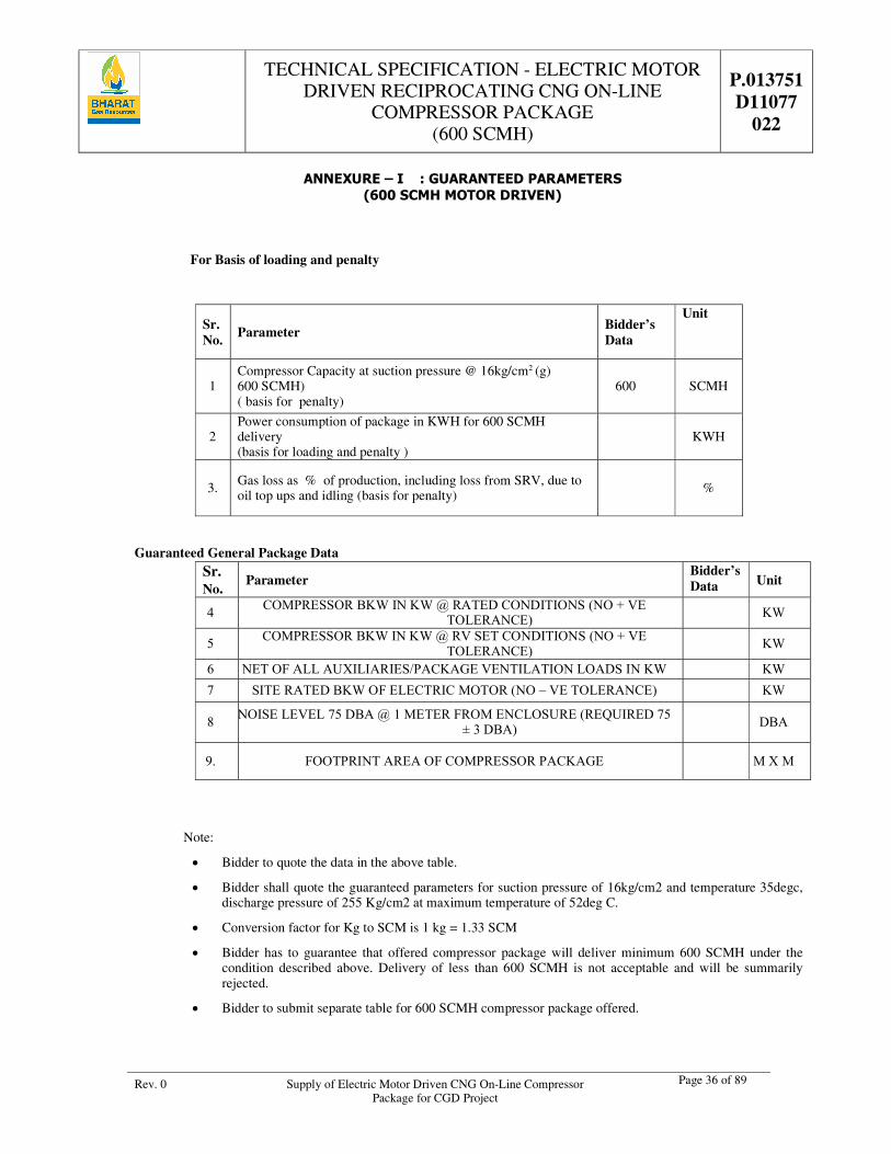
TECHNICAL SPECIFICATION - ELECTRIC MOTOR DRIVEN RECIPROCATING CNG ON-LINE
COMPRESSOR PACKAGE (600 SCMH)
P.013751 D11077
022
Rev. 0 Supply of Electric Motor Driven CNG On-Line Compressor Package for CGD Project
Page 36 of 89
ANNEXURE – I : GUARANTEED PARAMETERS (600 SCMH MOTOR DRIVEN)
For Basis of loading and penalty
Guaranteed General Package Data
Note:
Bidder to quote the data in the above table.
Bidder shall quote the guaranteed parameters for suction pressure of 16kg/cm2 and temperature 35degc, discharge pressure of 255 Kg/cm2 at maximum temperature of 52deg C.
Conversion factor for Kg to SCM is 1 kg = 1.33 SCM
Bidder has to guarantee that offered compressor package will deliver minimum 600 SCMH under the condition described above. Delivery of less than 600 SCMH is not acceptable and will be summarily rejected.
Bidder to submit separate table for 600 SCMH compressor package offered.
Sr. No.
Parameter Bidder’s Data
Unit
1 Compressor Capacity at suction pressure @ 16kg/cm2 (g) 600 SCMH) ( basis for penalty)
600 SCMH
2 Power consumption of package in KWH for 600 SCMH delivery (basis for loading and penalty )
KWH
3. Gas loss as % of production, including loss from SRV, due to oil top ups and idling (basis for penalty)
%
Sr. No.
Parameter Bidder’s Data Unit
4 COMPRESSOR BKW IN KW @ RATED CONDITIONS (NO + VE TOLERANCE)
KW
5 COMPRESSOR BKW IN KW @ RV SET CONDITIONS (NO + VE TOLERANCE)
KW
6 NET OF ALL AUXILIARIES/PACKAGE VENTILATION LOADS IN KW KW
7 SITE RATED BKW OF ELECTRIC MOTOR (NO – VE TOLERANCE) KW
8 NOISE LEVEL 75 DBA @ 1 METER FROM ENCLOSURE (REQUIRED 75
± 3 DBA)
DBA
9. FOOTPRINT AREA OF COMPRESSOR PACKAGE
M X M
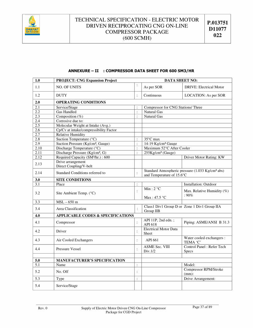
TECHNICAL SPECIFICATION - ELECTRIC MOTOR DRIVEN RECIPROCATING CNG ON-LINE
COMPRESSOR PACKAGE (600 SCMH)
P.013751 D11077
022
Rev. 0 Supply of Electric Motor Driven CNG On-Line Compressor Package for CGD Project
Page 37 of 89
ANNEXURE – II : COMPRESSOR DATA SHEET FOR 600 SM3/HR
1.0 PROJECT: CNG Expansion Project DATA SHEET NO:
1.1 NO. OF UNITS : As per SOR DRIVE: Electrical Motor
1.2 DUTY : Continuous LOCATION: As per SOR
2.0 OPERATING CONDITIONS 2.1 Service/Stage : Compressor for CNG Stations/ Three 2.2 Gas Handled : Natural Gas 2.3 Composition (%) : Natural Gas 2.4 Corrosive due to: 2.5 Molecular Weight at Intake (Avg.) 2.6 Cp/Cv at intake/compressibility Factor 2.7 Relative Humidity 2.8 Suction Temperature (°C) : 35°C max 2.9 Suction Pressure (Kg/cm², Gauge) : 14-19 Kg/cm² Gauge 2.10 Discharge Temperature (°C) : Maximum 52°C After Cooler 2.11 Discharge Pressure (Kg/cm², G) : 255Kg/cm² (Gauge) 2.12 Required Capacity (SM³/hr.) : 600 Driver Motor Rating: KW
2.13 Drive arrangement Direct Coupling/V-belt
2.14 Standard Conditions referred to : Standard Atmospheric pressure (1.033 Kg/cm² abs) and Temperature of 15.6°C
3.0 SITE CONDITIONS 3.1 Place : Installation: Outdoor
3.2 Site Ambient Temp. (°C) :
Min : 2 °C Max : 47.5 °C
Max. Relative Humidity (%) : 90%
3.3 MSL – 650 m
3.4 Area Classification : Class1 Div1 Group D or Zone 1 Div1 Group IIA Group IIB
4.0 APPLICABLE CODES & SPECIFICATIONS
4.1 Compressor : API 11P, 2nd edn. ; API 618
Piping: ASME/ANSI B 31.3
4.2 Driver : Electrical Motor Data Sheet
4.3 Air Cooled Exchangers : API 661 Water cooled exchangers : TEMA ‘C’
4.4 Pressure Vessel : ASME Sec. VIII Div.1/2
Control Panel : Refer Tech Specs
5.0 MANUFACTURER’S SPECIFICATION 5.1 Name : Model:
5.2 No. Off : Compressor RPM/Stroke (mm):
5.3 Type : Drive Arrangement:
5.4 Service/Stage
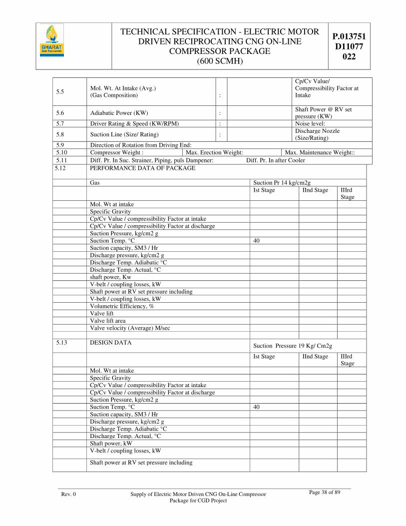
TECHNICAL SPECIFICATION - ELECTRIC MOTOR DRIVEN RECIPROCATING CNG ON-LINE
COMPRESSOR PACKAGE (600 SCMH)
P.013751 D11077
022
Rev. 0 Supply of Electric Motor Driven CNG On-Line Compressor Package for CGD Project
Page 38 of 89
5.5 Mol. Wt. At Intake (Avg.) (Gas Composition)
:
Cp/Cv Value/ Compressibility Factor at Intake
5.6 Adiabatic Power (KW) : Shaft Power @ RV set pressure (KW)
5.7 Driver Rating & Speed (KW/RPM) : Noise level:
5.8 Suction Line (Size/ Rating) : Discharge Nozzle (Size/Rating)
5.9 Direction of Rotation from Driving End: 5.10 Compressor Weight : Max. Erection Weight: Max. Maintenance Weight:: 5.11 Diff. Pr. In Suc. Strainer, Piping, puls Dampener: Diff. Pr. In after Cooler 5.12 PERFORMANCE DATA OF PACKAGE
Gas Suction Pr 14 kg/cm2g Ist Stage IInd Stage IIIrd
Stage Mol. Wt at intake Specific Gravity Cp/Cv Value / compressibility Factor at intake Cp/Cv Value / compressibility Factor at discharge Suction Pressure, kg/cm2 g Suction Temp. °C 40 Suction capacity, SM3 / Hr Discharge pressure, kg/cm2 g Discharge Temp. Adiabatic °C Discharge Temp. Actual, °C shaft power, Kw V-belt / coupling losses, kW Shaft power at RV set pressure including V-belt / coupling losses, kW Volumetric Efficiency, % Valve lift Valve lift area Valve velocity (Average) M/sec 5.13 DESIGN DATA Suction Pressure 19 Kg/ Cm2g
Ist Stage IInd Stage IIIrd Stage
Mol. Wt at intake Specific Gravity Cp/Cv Value / compressibility Factor at intake Cp/Cv Value / compressibility Factor at discharge Suction Pressure, kg/cm2 g Suction Temp. °C 40 Suction capacity, SM3 / Hr Discharge pressure, kg/cm2 g Discharge Temp. Adiabatic °C Discharge Temp. Actual, °C Shaft power, kW V-belt / coupling losses, kW
Shaft power at RV set pressure including
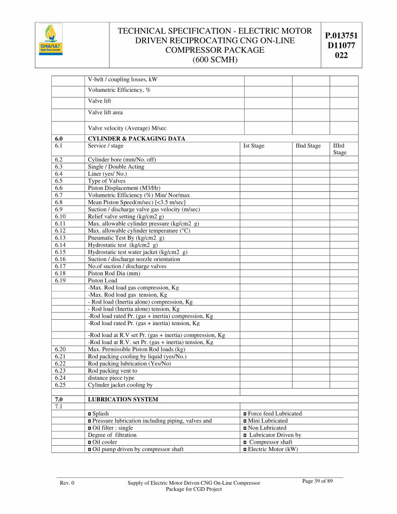
TECHNICAL SPECIFICATION - ELECTRIC MOTOR DRIVEN RECIPROCATING CNG ON-LINE
COMPRESSOR PACKAGE (600 SCMH)
P.013751 D11077
022
Rev. 0 Supply of Electric Motor Driven CNG On-Line Compressor Package for CGD Project
Page 39 of 89
V-belt / coupling losses, kW
Volumetric Efficiency, %
Valve lift
Valve lift area
Valve velocity (Average) M/sec
6.0 CYLINDER & PACKAGING DATA 6.1 Service / stage Ist Stage IInd Stage IIIrd
Stage 6.2 Cylinder bore (mm/No. off) 6.3 Single / Double Acting 6.4 Liner (yes/ No.) 6.5 Type of Valves 6.6 Piston Displacement (M3/Hr) 6.7 Volumetric Efficiency (%) Min/ Nor/max 6.8 Mean Piston Speed(m/sec) [<3.5 m/sec] 6.9 Suction / discharge valve gas velocity (m/sec) 6.10 Relief valve setting (kg/cm2 g) 6.11 Max. allowable cylinder pressure (kg/cm2 g) 6.12 Max. allowable cylinder temperature (°C) 6.13 Pneumatic Test By (kg/cm2 g) 6.14 Hydrostatic test (kg/cm2 g) 6.15 Hydrostatic test water jacket (kg/cm2 g) 6.16 Suction / discharge nozzle orientation 6.17 No.of suction / discharge valves 6.18 Piston Rod Dia (mm) 6.19 Piston Load -Max. Rod load gas compression, Kg -Max. Rod load gas tension, Kg - Rod load (Inertia alone) compression, Kg - Rod load (Inertia alone) tension, Kg -Rod load rated Pr. (gas + inertia) compression, Kg -Rod load rated Pr. (gas + inertia) tension, Kg
-Rod load at R.V set Pr. (gas + inertia) compression, Kg -Rod load at R.V. set Pr. (gas + inertia) tension, Kg 6.20 Max. Permissible Piston Rod loads (kg) 6.21 Rod packing cooling by liquid (yes/No.) 6.22 Rod packing lubrication (Yes/No) 6.23 Rod packing vent to 6.24 distance piece type 6.25 Cylinder jacket cooling by 7.0 LUBRICATION SYSTEM 7.1 Splash Force feed Lubricated Pressure lubrication including piping, valves and Mini Lubricated Oil filter : single Non Lubricated Degree of filtration Lubricator Driven by Oil cooler Compressor shaft Oil pump driven by compressor shaft Electric Motor (kW)
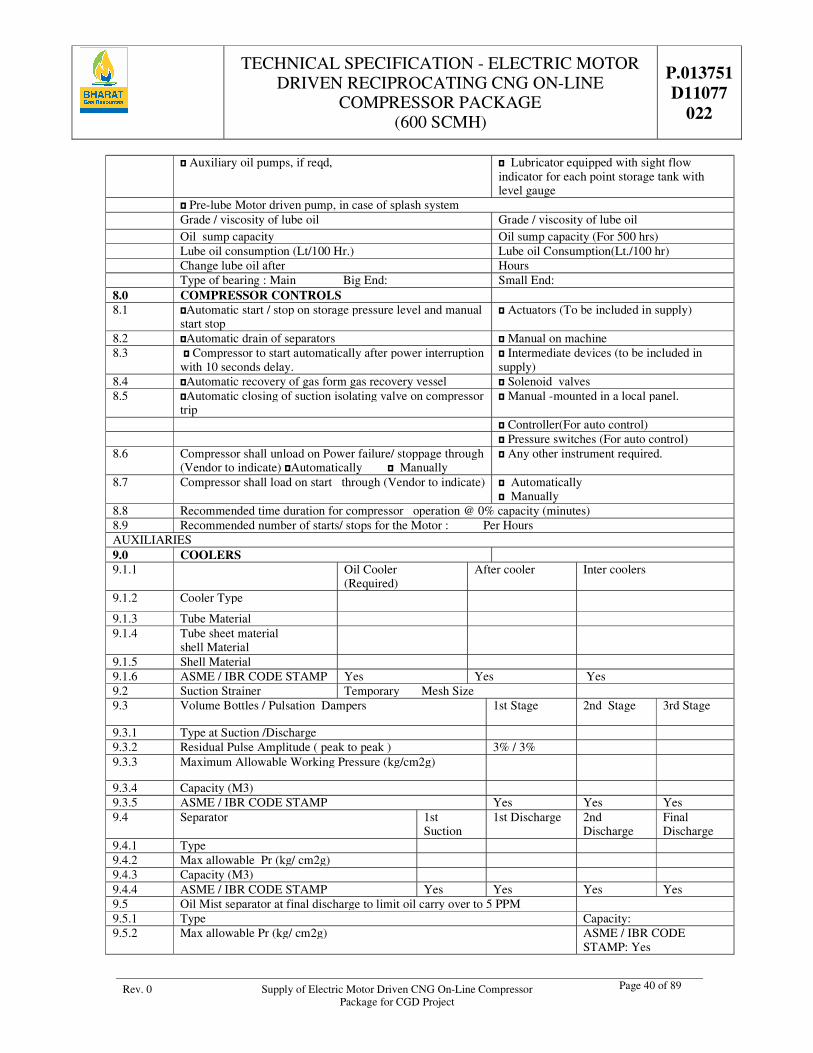
TECHNICAL SPECIFICATION - ELECTRIC MOTOR DRIVEN RECIPROCATING CNG ON-LINE
COMPRESSOR PACKAGE (600 SCMH)
P.013751 D11077
022
Rev. 0 Supply of Electric Motor Driven CNG On-Line Compressor Package for CGD Project
Page 40 of 89
Auxiliary oil pumps, if reqd, Lubricator equipped with sight flow indicator for each point storage tank with level gauge
Pre-lube Motor driven pump, in case of splash system Grade / viscosity of lube oil Grade / viscosity of lube oil Oil sump capacity Oil sump capacity (For 500 hrs) Lube oil consumption (Lt/100 Hr.) Lube oil Consumption(Lt./100 hr) Change lube oil after Hours Type of bearing : Main Big End: Small End: 8.0 COMPRESSOR CONTROLS 8.1 Automatic start / stop on storage pressure level and manual
start stop Actuators (To be included in supply)
8.2 Automatic drain of separators Manual on machine 8.3 Compressor to start automatically after power interruption
with 10 seconds delay. Intermediate devices (to be included in supply)
8.4 Automatic recovery of gas form gas recovery vessel Solenoid valves 8.5 Automatic closing of suction isolating valve on compressor
trip Manual -mounted in a local panel.
Controller(For auto control) Pressure switches (For auto control) 8.6 Compressor shall unload on Power failure/ stoppage through
(Vendor to indicate) Automatically Manually Any other instrument required.
8.7 Compressor shall load on start through (Vendor to indicate) Automatically Manually
8.8 Recommended time duration for compressor operation @ 0% capacity (minutes) 8.9 Recommended number of starts/ stops for the Motor : Per Hours AUXILIARIES 9.0 COOLERS 9.1.1 Oil Cooler
(Required) After cooler Inter coolers
9.1.2 Cooler Type
9.1.3 Tube Material 9.1.4 Tube sheet material
shell Material
9.1.5 Shell Material 9.1.6 ASME / IBR CODE STAMP Yes Yes Yes 9.2 Suction Strainer Temporary Mesh Size 9.3 Volume Bottles / Pulsation Dampers 1st Stage 2nd Stage 3rd Stage
9.3.1 Type at Suction /Discharge 9.3.2 Residual Pulse Amplitude ( peak to peak ) 3% / 3% 9.3.3 Maximum Allowable Working Pressure (kg/cm2g)
9.3.4 Capacity (M3) 9.3.5 ASME / IBR CODE STAMP Yes Yes Yes 9.4 Separator 1st
Suction 1st Discharge 2nd
Discharge Final Discharge
9.4.1 Type 9.4.2 Max allowable Pr (kg/ cm2g) 9.4.3 Capacity (M3) 9.4.4 ASME / IBR CODE STAMP Yes Yes Yes Yes 9.5 Oil Mist separator at final discharge to limit oil carry over to 5 PPM 9.5.1 Type Capacity: 9.5.2 Max allowable Pr (kg/ cm2g) ASME / IBR CODE
STAMP: Yes
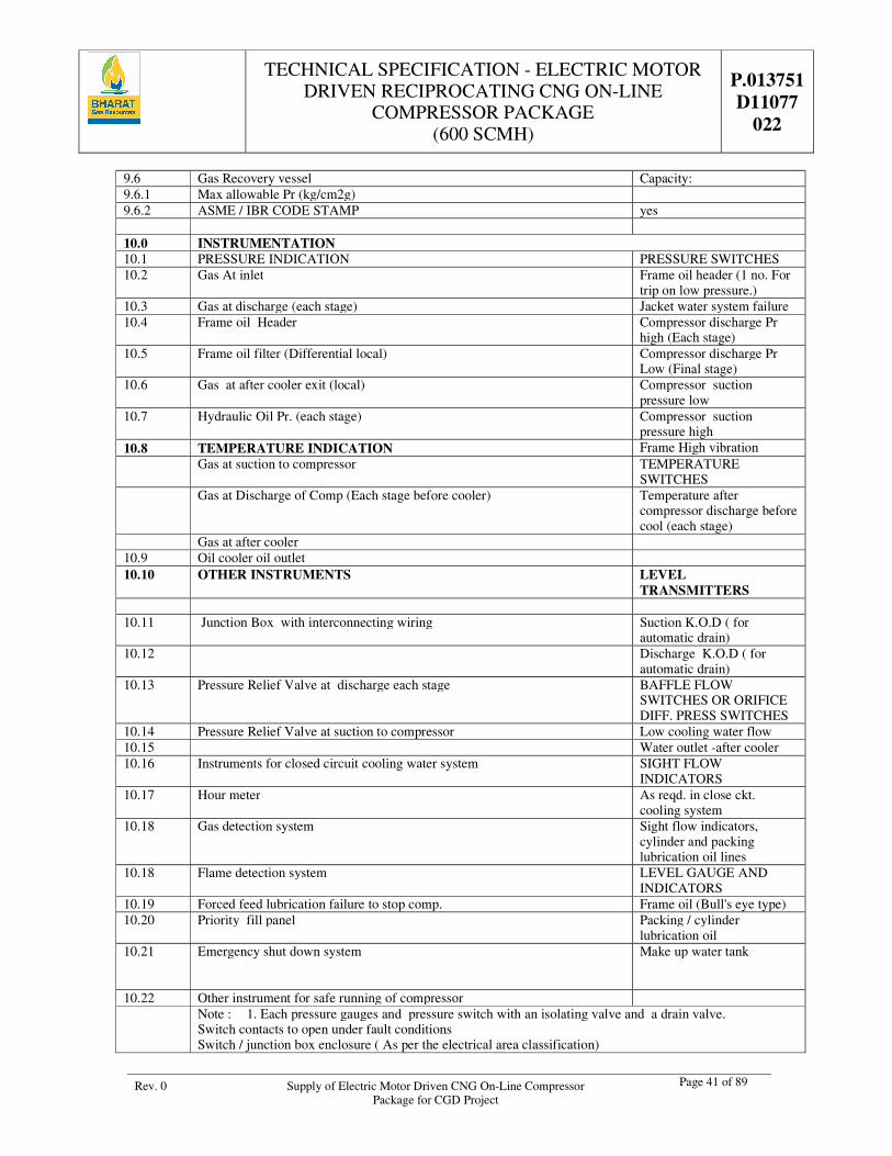
TECHNICAL SPECIFICATION - ELECTRIC MOTOR DRIVEN RECIPROCATING CNG ON-LINE
COMPRESSOR PACKAGE (600 SCMH)
P.013751 D11077
022
Rev. 0 Supply of Electric Motor Driven CNG On-Line Compressor Package for CGD Project
Page 41 of 89
9.6 Gas Recovery vessel Capacity: 9.6.1 Max allowable Pr (kg/cm2g) 9.6.2 ASME / IBR CODE STAMP yes 10.0 INSTRUMENTATION 10.1 PRESSURE INDICATION PRESSURE SWITCHES 10.2 Gas At inlet Frame oil header (1 no. For
trip on low pressure.) 10.3 Gas at discharge (each stage) Jacket water system failure 10.4 Frame oil Header Compressor discharge Pr
high (Each stage) 10.5 Frame oil filter (Differential local) Compressor discharge Pr
Low (Final stage) 10.6 Gas at after cooler exit (local) Compressor suction
pressure low 10.7 Hydraulic Oil Pr. (each stage) Compressor suction
pressure high 10.8 TEMPERATURE INDICATION Frame High vibration Gas at suction to compressor TEMPERATURE
SWITCHES Gas at Discharge of Comp (Each stage before cooler) Temperature after
compressor discharge before cool (each stage)
Gas at after cooler 10.9 Oil cooler oil outlet 10.10 OTHER INSTRUMENTS LEVEL
TRANSMITTERS 10.11 Junction Box with interconnecting wiring Suction K.O.D ( for
automatic drain) 10.12 Discharge K.O.D ( for
automatic drain) 10.13 Pressure Relief Valve at discharge each stage BAFFLE FLOW
SWITCHES OR ORIFICE DIFF. PRESS SWITCHES
10.14 Pressure Relief Valve at suction to compressor Low cooling water flow 10.15 Water outlet -after cooler 10.16 Instruments for closed circuit cooling water system SIGHT FLOW
INDICATORS 10.17 Hour meter As reqd. in close ckt.
cooling system 10.18 Gas detection system Sight flow indicators,
cylinder and packing lubrication oil lines
10.18 Flame detection system LEVEL GAUGE AND INDICATORS
10.19 Forced feed lubrication failure to stop comp. Frame oil (Bull's eye type) 10.20 Priority fill panel Packing / cylinder
lubrication oil 10.21 Emergency shut down system
Make up water tank
10.22 Other instrument for safe running of compressor Note : 1. Each pressure gauges and pressure switch with an isolating valve and a drain valve.
Switch contacts to open under fault conditions Switch / junction box enclosure ( As per the electrical area classification)
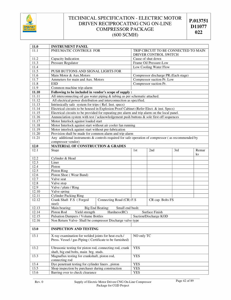
TECHNICAL SPECIFICATION - ELECTRIC MOTOR DRIVEN RECIPROCATING CNG ON-LINE
COMPRESSOR PACKAGE (600 SCMH)
P.013751 D11077
022
Rev. 0 Supply of Electric Motor Driven CNG On-Line Compressor Package for CGD Project
Page 42 of 89
11.0 INSTRUMENT PANEL 11.1 PNEUMATIC CONTROLS FOR TRIP CIRCUIT TO BE CONNECTED TO MAIN
DRIVER CONTROL SWITCH 11.2 Capacity Indication Cause of shut down 11.3 Pressure Regulator Frame Oil Pressure-Low 11.4 Low Cooling Water Flow 11.5 PUSH BUTTONS AND SIGNAL LIGHTS FOR 11.6 Main Motor & Aux.Motors Compressor discharge PR.(Each stage) 11.7 Ammeters for main and Aux. Motors Compressor suction Pr. Low 11.8 ESD Compressor suction Pr. 11.9 Common machine trip-alarm 11.10 Following to be included in vendor's scope of supply : 11.11 All interconnecting oil gas water piping & tubing as per schematic attached. 11.12 All electrical power distribution and interconnection as specified. 11.13 Intrinsically safe system for trips ( Ref. Inst. specs) 11.14 Electrical circuits to be housed in Explosion Proof Cabinet (Refer Elect. & inst. Specs) 11.15 Electrical circuits to be provided for repeating pre alarm and trip alarm on the local panel. 11.16 Annunciation system with test / acknowledgement push buttons & sole first off sequences 11.17 Motor Interlock against loaded start 11.18 Motor Interlock against start without air cooler fan running 11.19 Motor interlock against start without pre-lubrication 11.20 Provision shall be made for common alarm and trip alarm 11.21 Any additional instruments & controls required for safe operation of compressor ( as recommended by
compressor vendor) 12.0 MATERIAL OF CONSTRUCTION & GRADES 12.1 Stage 1st 2nd 3rd Remar
ks 12.2 Cylinder & Head 12.3 Liner 12.4 Piston 12.5 Piston Ring 12.6 Piston Shoe ( Wear Band) 12.7 Valve seat 12.8 Valve stop 12.9 Valve / plate / Ring 12.10 Valve spring 12.11 Cylinder Packing Ring 12.12 Crank Shaft F.S ( Forged
steel) Connecting Road (CR) F.S CR cap. Bolts FS
12.13 Main bearing: Big End Beating: Small end bush: 12.14 Piston Rod Yield strength Hardness(RC) Surface Finish 12.15 Pulsation Dampers / Volume Bottles Suction/Discharge KOD 12.16 Non Return Valve- Shall be compressor Discharge valve type 13.0 INSPECTION AND TESTING
13.1 X-ray examination for welded joints for heat exch./ Press. Vessel / gas Piping ( Certificate to be furnished)
NO only TC
13.2 Ultrasonic testing for piston rod, connecting rod, crank shaft, big end bolts, main brg. studs.
YES
13.3 Magnaflux testing for crankshaft, piston rod, connecting rod
YES
13.4 Dye penetrant testing for cylinder liners , piston YES 13.5 Shop inspection by purchaser during construction YES 13.6 Barring over to check clearance YES
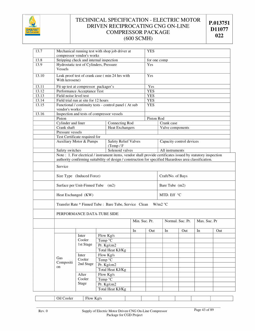
TECHNICAL SPECIFICATION - ELECTRIC MOTOR DRIVEN RECIPROCATING CNG ON-LINE
COMPRESSOR PACKAGE (600 SCMH)
P.013751 D11077
022
Rev. 0 Supply of Electric Motor Driven CNG On-Line Compressor Package for CGD Project
Page 43 of 89
13.7 Mechanical running test with shop job driver at compressor vendor's works
YES
13.8 Stripping check and internal inspection for one comp 13.9 Hydrostatic test of Cylinders, Pressure
Vessels Yes
13.10 Leak proof test of crank case ( min 24 hrs with With kerosene)
Yes
13.11 Fit up test at compressor packager’s Yes 13.12 Performance Acceptance Test YES 13.13 Field noise level test YES 13.14 Field trial run at site for 12 hours YES 13.15 Functional / continuity tests - control panel ( At sub
vendor's works) YES
13.16 Inspection and tests of compressor vessels Piston Piston Rod Cylinder and liner Connecting Rod Crank case Crank shaft Heat Exchangers Valve components Pressure vessels Test Certificate required for Auxiliary Motor & Pumps Safety Relief Valves
(Temp / F Capacity control devices
Safety switches Solenoid valves All instruments
Note : 1. For electrical / instrument items, vendor shall provide certificates issued by statutory inspection authority confirming suitability of design / construction for specified Hazardous area classification.
Service
Size Type (Induced Force) Craft/No. of Bays
Surface per Unit-Finned Tube (m2) Bare Tube (m2)
Heat Exchanged (KW) MTD. Eff °C
Transfer Rate * Finned Tube : Bare Tube, Service Clean W/m2 °C
PERFORMANCE DATA-TUBE SIDE
Min. Suc. Pr. Normal. Suc. Pr. Max. Suc. Pr
In Out In Out In Out
Gas Composition
Inter Cooler 1st Stage
Flow Kg/s Temp °C Pr. Kg/cm2 Total Heat KJ/Kg
Inter Cooler 2nd Stage
Flow Kg/s Temp °C Pr. Kg/cm2 Total Heat KJ/Kg
After Cooler Stage
Flow Kg/s Temp °C Pr. Kg/cm2 Total Heat KJ/Kg
Oil Cooler Flow Kg/s
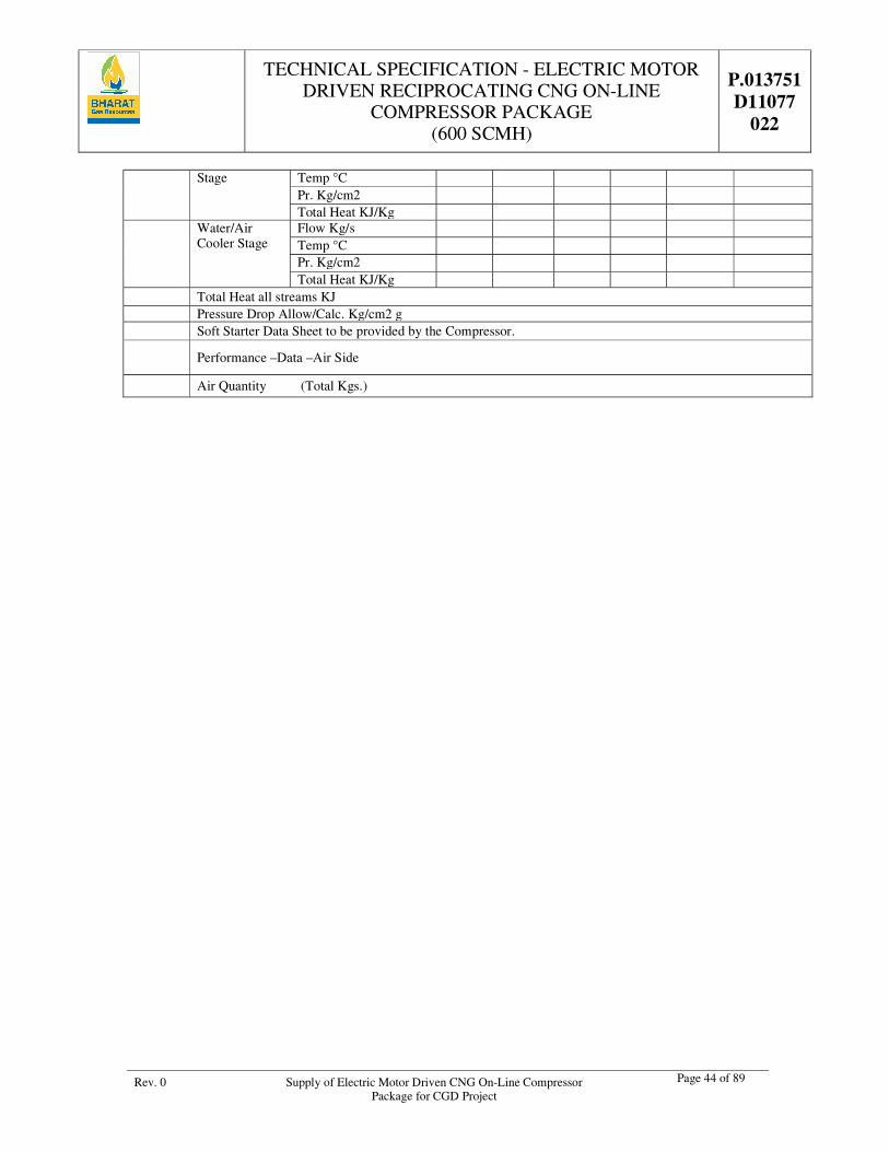
TECHNICAL SPECIFICATION - ELECTRIC MOTOR DRIVEN RECIPROCATING CNG ON-LINE
COMPRESSOR PACKAGE (600 SCMH)
P.013751 D11077
022
Rev. 0 Supply of Electric Motor Driven CNG On-Line Compressor Package for CGD Project
Page 44 of 89
Stage Temp °C Pr. Kg/cm2 Total Heat KJ/Kg
Water/Air Cooler Stage
Flow Kg/s Temp °C Pr. Kg/cm2 Total Heat KJ/Kg
Total Heat all streams KJ Pressure Drop Allow/Calc. Kg/cm2 g Soft Starter Data Sheet to be provided by the Compressor.
Performance –Data –Air Side
Air Quantity (Total Kgs.)
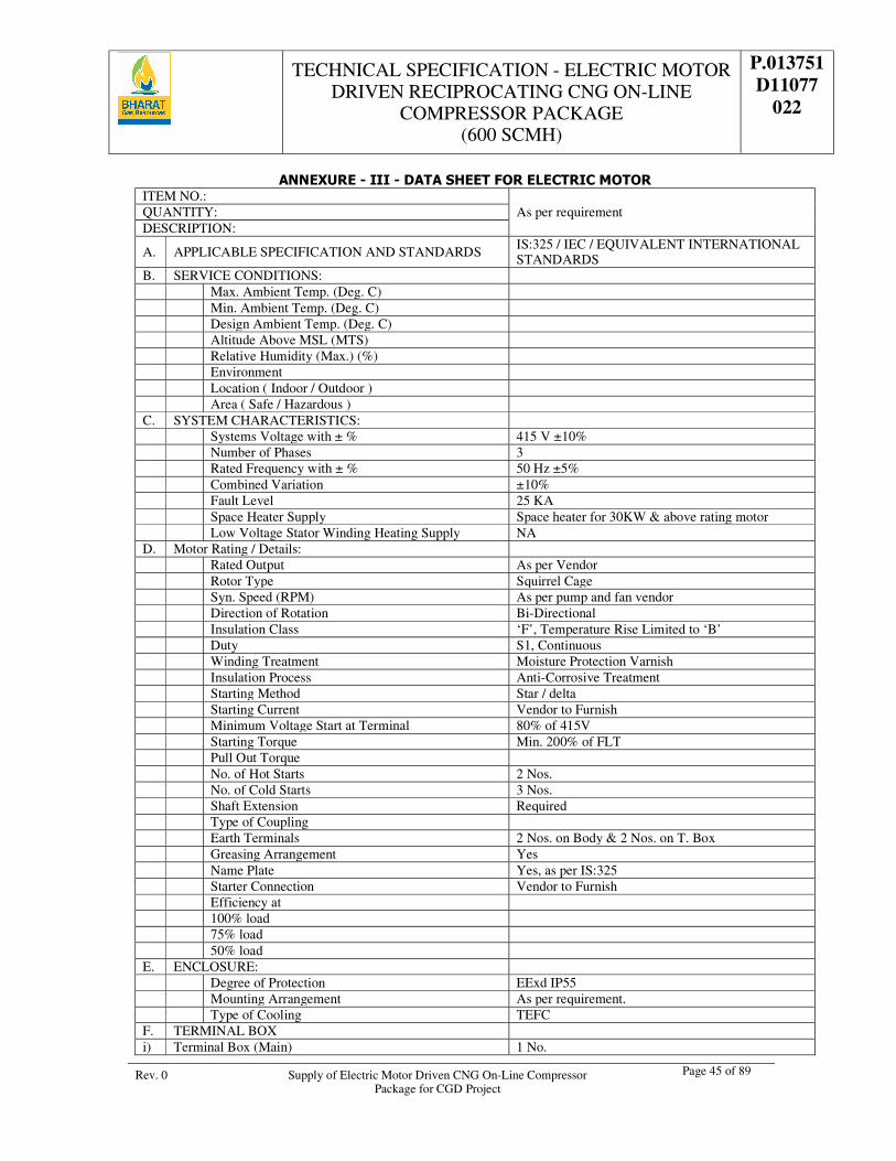
TECHNICAL SPECIFICATION - ELECTRIC MOTOR DRIVEN RECIPROCATING CNG ON-LINE
COMPRESSOR PACKAGE (600 SCMH)
P.013751 D11077
022
Rev. 0 Supply of Electric Motor Driven CNG On-Line Compressor Package for CGD Project
Page 45 of 89
ANNEXURE - III - DATA SHEET FOR ELECTRIC MOTOR ITEM NO.:
As per requirement QUANTITY: DESCRIPTION:
A. APPLICABLE SPECIFICATION AND STANDARDS IS:325 / IEC / EQUIVALENT INTERNATIONAL STANDARDS
B. SERVICE CONDITIONS: Max. Ambient Temp. (Deg. C) Min. Ambient Temp. (Deg. C) Design Ambient Temp. (Deg. C) Altitude Above MSL (MTS) Relative Humidity (Max.) (%) Environment Location ( Indoor / Outdoor ) Area ( Safe / Hazardous ) C. SYSTEM CHARACTERISTICS: Systems Voltage with ± % 415 V ±10% Number of Phases 3 Rated Frequency with ± % 50 Hz ±5% Combined Variation ±10% Fault Level 25 KA Space Heater Supply Space heater for 30KW & above rating motor Low Voltage Stator Winding Heating Supply NA D. Motor Rating / Details: Rated Output As per Vendor Rotor Type Squirrel Cage Syn. Speed (RPM) As per pump and fan vendor Direction of Rotation Bi-Directional Insulation Class ‘F’, Temperature Rise Limited to ‘B’ Duty S1, Continuous Winding Treatment Moisture Protection Varnish Insulation Process Anti-Corrosive Treatment Starting Method Star / delta Starting Current Vendor to Furnish Minimum Voltage Start at Terminal 80% of 415V Starting Torque Min. 200% of FLT Pull Out Torque No. of Hot Starts 2 Nos. No. of Cold Starts 3 Nos. Shaft Extension Required Type of Coupling Earth Terminals 2 Nos. on Body & 2 Nos. on T. Box Greasing Arrangement Yes Name Plate Yes, as per IS:325 Starter Connection Vendor to Furnish Efficiency at 100% load 75% load 50% load E. ENCLOSURE: Degree of Protection EExd IP55 Mounting Arrangement As per requirement. Type of Cooling TEFC F. TERMINAL BOX i) Terminal Box (Main) 1 No.

TECHNICAL SPECIFICATION - ELECTRIC MOTOR DRIVEN RECIPROCATING CNG ON-LINE
COMPRESSOR PACKAGE (600 SCMH)
P.013751 D11077
022
Rev. 0 Supply of Electric Motor Driven CNG On-Line Compressor Package for CGD Project
Page 46 of 89
Type Fault Withstand No. of Terminals 6 Nos. Side of Terminal Box seen from the Driven End RHS ii) Auxiliary Terminal Box -- 1. Separate Terminal Box for Space Heaters YES Thermistors -- G. TESTS TO BE WITNESSED Type Tests CMRS test certificate to be furnished Routine Tests As per IS:325 H. ACCESSORIES Anti-condensation Heaters Yes PTC Thermistors NA Voltage Rating of Space Heaters 230V Foundation Bolt Yes Cable Glands Required Earthing Terminals Body & T. Box
Motor peak Amplitude Vibration at no Load at Bearing should not exceed
40 Microns for 1500 RPM 15 Microns for 3000 RPM
Max. Motor Noise Level Measured at a Distance of 1.5 Mts. from Motor
85 dB
I. CABLES 1. Type & Size - Motor Vender to furnish - Space Heater Vender to furnish - Thermister NA 2. Cable Lugs - For Motor Copper - Space Heater Copper - Control Cables NA 3. Cable Glands – Type Material - Motor FLS-Double Compression, Ni-Cd Plated - Space Heater FLS-Double Compression, Ni-Cd Plated - Control Cables FLS – Double Compression Ni-Cd Plated J. PAINTING TYPE Epoxy SHADE (AS PER IS:5) 692 (Smoke Grey)
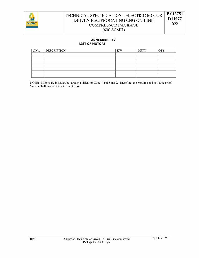
TECHNICAL SPECIFICATION - ELECTRIC MOTOR DRIVEN RECIPROCATING CNG ON-LINE
COMPRESSOR PACKAGE (600 SCMH)
P.013751 D11077
022
Rev. 0 Supply of Electric Motor Driven CNG On-Line Compressor Package for CGD Project
Page 47 of 89
ANNEXURE – IV LIST OF MOTORS
S.No. DESCRIPTION KW DUTY QTY.
NOTE:- Motors are in hazardous area classification Zone 1 and Zone 2. Therefore, the Motors shall be flame proof. Vendor shall furnish the list of motor(s).
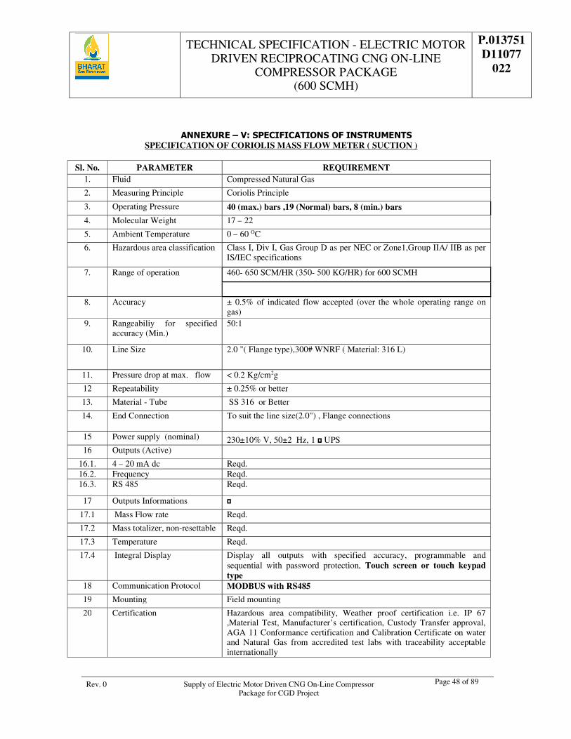
TECHNICAL SPECIFICATION - ELECTRIC MOTOR DRIVEN RECIPROCATING CNG ON-LINE
COMPRESSOR PACKAGE (600 SCMH)
P.013751 D11077
022
Rev. 0 Supply of Electric Motor Driven CNG On-Line Compressor Package for CGD Project
Page 48 of 89
ANNEXURE – V: SPECIFICATIONS OF INSTRUMENTS SPECIFICATION OF CORIOLIS MASS FLOW METER ( SUCTION )
Sl. No. PARAMETER REQUIREMENT
1. Fluid Compressed Natural Gas
2. Measuring Principle Coriolis Principle
3. Operating Pressure 40 (max.) bars ,19 (Normal) bars, 8 (min.) bars
4. Molecular Weight 17 – 22
5. Ambient Temperature 0 – 60 OC
6. Hazardous area classification Class I, Div I, Gas Group D as per NEC or Zone1,Group IIA/ IIB as per IS/IEC specifications
7. Range of operation 460- 650 SCM/HR (350- 500 KG/HR) for 600 SCMH
8. Accuracy ± 0.5% of indicated flow accepted (over the whole operating range on gas)
9. Rangeabiliy for specified accuracy (Min.)
50:1
10. Line Size 2.0 "( Flange type),300# WNRF ( Material: 316 L)
11. Pressure drop at max. flow < 0.2 Kg/cm2g
12 Repeatability ± 0.25% or better
13. Material - Tube SS 316 or Better
14. End Connection To suit the line size(2.0") , Flange connections
15 Power supply (nominal) 230±10% V, 50±2 Hz, 1 UPS 16 Outputs (Active)
16.1. 4 – 20 mA dc Reqd. 16.2. Frequency Reqd. 16.3. RS 485 Reqd.
17 Outputs Informations
17.1 Mass Flow rate Reqd.
17.2 Mass totalizer, non-resettable Reqd.
17.3 Temperature Reqd.
17.4 Integral Display Display all outputs with specified accuracy, programmable and sequential with password protection, Touch screen or touch keypad type
18 Communication Protocol MODBUS with RS485
19 Mounting Field mounting
20 Certification Hazardous area compatibility, Weather proof certification i.e. IP 67 ,Material Test, Manufacturer’s certification, Custody Transfer approval, AGA 11 Conformance certification and Calibration Certificate on water and Natural Gas from accredited test labs with traceability acceptable internationally
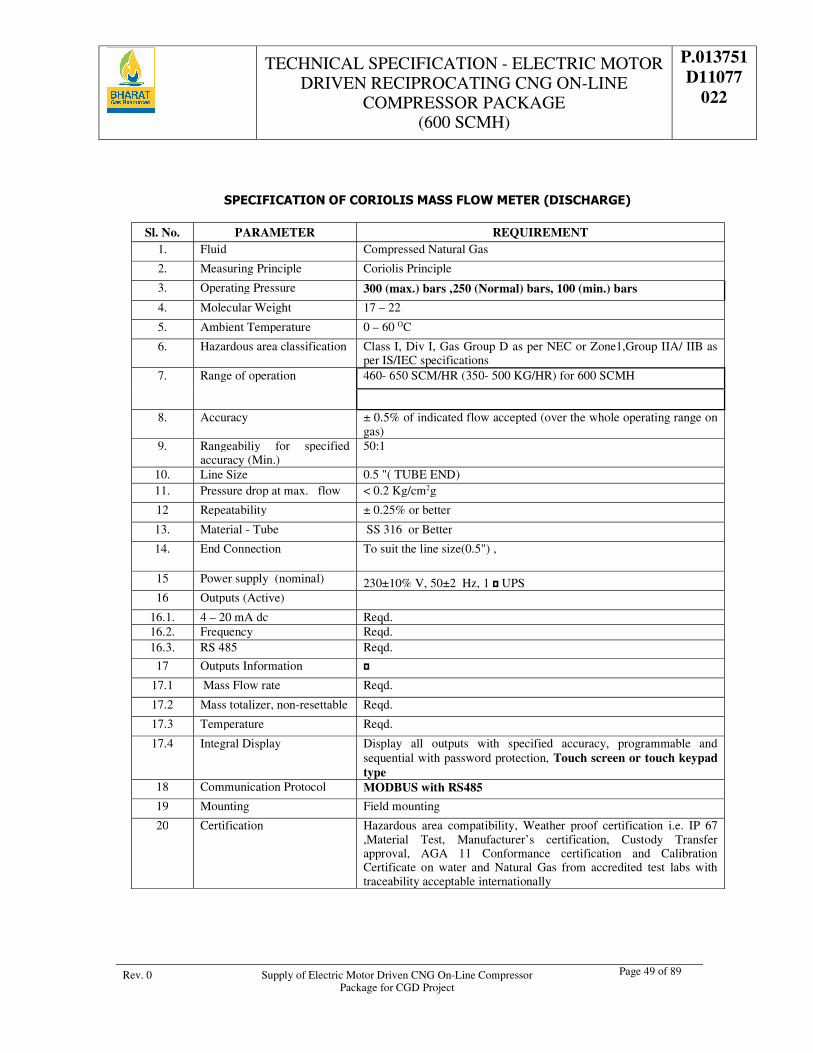
TECHNICAL SPECIFICATION - ELECTRIC MOTOR DRIVEN RECIPROCATING CNG ON-LINE
COMPRESSOR PACKAGE (600 SCMH)
P.013751 D11077
022
Rev. 0 Supply of Electric Motor Driven CNG On-Line Compressor Package for CGD Project
Page 49 of 89
SPECIFICATION OF CORIOLIS MASS FLOW METER (DISCHARGE)
Sl. No. PARAMETER REQUIREMENT 1. Fluid Compressed Natural Gas
2. Measuring Principle Coriolis Principle
3. Operating Pressure 300 (max.) bars ,250 (Normal) bars, 100 (min.) bars
4. Molecular Weight 17 – 22
5. Ambient Temperature 0 – 60 OC
6. Hazardous area classification Class I, Div I, Gas Group D as per NEC or Zone1,Group IIA/ IIB as per IS/IEC specifications
7. Range of operation 460- 650 SCM/HR (350- 500 KG/HR) for 600 SCMH
8. Accuracy ± 0.5% of indicated flow accepted (over the whole operating range on gas)
9. Rangeabiliy for specified accuracy (Min.)
50:1
10. Line Size 0.5 "( TUBE END) 11. Pressure drop at max. flow < 0.2 Kg/cm2g
12 Repeatability ± 0.25% or better
13. Material - Tube SS 316 or Better
14. End Connection To suit the line size(0.5") ,
15 Power supply (nominal) 230±10% V, 50±2 Hz, 1 UPS 16 Outputs (Active)
16.1. 4 – 20 mA dc Reqd. 16.2. Frequency Reqd. 16.3. RS 485 Reqd.
17 Outputs Information
17.1 Mass Flow rate Reqd.
17.2 Mass totalizer, non-resettable Reqd.
17.3 Temperature Reqd.
17.4 Integral Display Display all outputs with specified accuracy, programmable and sequential with password protection, Touch screen or touch keypad type
18 Communication Protocol MODBUS with RS485
19 Mounting Field mounting
20 Certification Hazardous area compatibility, Weather proof certification i.e. IP 67 ,Material Test, Manufacturer’s certification, Custody Transfer approval, AGA 11 Conformance certification and Calibration Certificate on water and Natural Gas from accredited test labs with traceability acceptable internationally
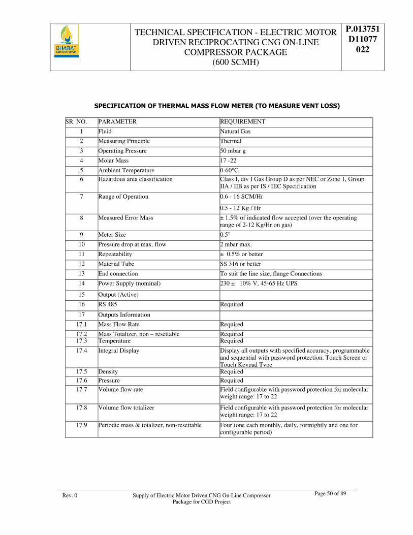
TECHNICAL SPECIFICATION - ELECTRIC MOTOR DRIVEN RECIPROCATING CNG ON-LINE
COMPRESSOR PACKAGE (600 SCMH)
P.013751 D11077
022
Rev. 0 Supply of Electric Motor Driven CNG On-Line Compressor Package for CGD Project
Page 50 of 89
SPECIFICATION OF THERMAL MASS FLOW METER (TO MEASURE VENT LOSS)
SR. NO. PARAMETER REQUIREMENT
1 Fluid Natural Gas
2 Measuring Principle Thermal
3 Operating Pressure 50 mbar g
4 Molar Mass 17 -22
5 Ambient Temperature 0-60°C 6 Hazardous area classification Class I, div I Gas Group D as per NEC or Zone 1, Group
IIA / IIB as per IS / IEC Specification
7 Range of Operation 0.6 - 16 SCM/Hr
0.5 - 12 Kg / Hr
8 Measured Error Mass ± 1.5% of indicated flow accepted (over the operating range of 2-12 Kg/Hr on gas)
9 Meter Size 0.5"
10 Pressure drop at max. flow 2 mbar max.
11 Repeatability ± 0.5% or better
12 Material Tube SS 316 or better
13 End connection To suit the line size, flange Connections
14 Power Supply (nominal) 230 ± 10% V, 45-65 Hz UPS
15 Output (Active)
16 RS 485 Required
17 Outputs Information
17.1 Mass Flow Rate Required
17.2 Mass Totalizer, non – resettable Required 17.3 Temperature Required
17.4 Integral Display Display all outputs with specified accuracy, programmable and sequential with password protection. Touch Screen or Touch Keypad Type
17.5 Density Required
17.6 Pressure Required
17.7 Volume flow rate Field configurable with password protection for molecular weight range: 17 to 22
17.8 Volume flow totalizer Field configurable with password protection for molecular weight range: 17 to 22
17.9 Periodic mass & totalizer, non-resettable Four (one each monthly, daily, fortnightly and one for configurable period)

TECHNICAL SPECIFICATION - ELECTRIC MOTOR DRIVEN RECIPROCATING CNG ON-LINE
COMPRESSOR PACKAGE (600 SCMH)
P.013751 D11077
022
Rev. 0 Supply of Electric Motor Driven CNG On-Line Compressor Package for CGD Project
Page 51 of 89
18. Programmer Calibration software, perpetual licence with portable hardware platform complete with all connectors, power adopter, batteries. System should be suitable for effecting calibration changes, configuring the flow meter / transmitter, storing test result, plotting and storing graphs, diagnostics, password protection etc. Carrying case, easily installable in the field for calibration set up
19 Communication MODBUS with RS 485,
20 Mounting Field mounting, (Vertical)
21 Certification CCOE
SPECIFICATION SHEET FOR FLAME DETECTORS
Flame detector Type: UV and IR Detector
Wave Length UV radiation over the range of 185 to 260 nanometers (1850 to 2600 angstroms)
IR radiation in the 4.35 micron range
Field of View 120° cone of vision (or) Better.
Sensitivity Approved Performance Specification-50 feet (15.2m) distance for a 1 sq. ft (0.092m2)heptane fire.
Response Time: Less than 5 seconds
Status Indicator: LEDs indicate status of Healthy, fault, and alarm conditions
Operating Medium Natural Gas.
Nominal supply voltage: 24 VDC
Supply voltage range: 20 to 36 VDC
Maximum supply current: 400 mA during COPM only
Typical current: 80 to 150 mA Depends on relays ETC
Maximum output signal load: 600 Ohms
Electrical Specifications [OUTPUT: mA, Relay, Hart ]
(all 3 below mentioned outputs must be available in separate connectors/ ports)
1. Analog (mA):
Output signal range: 0 to 20 mA *
FAULT signal: 0 to 0.2 mA *
COPM fault signal: 2.0 ± 0.2 mA *
Ready signal: 4.0± 0.2 mA
IR only signal: 8.0 ± 0.2 mA
UV only signal : 12.0 ±0.2 mA
WARN signal: 16.0 ±0.2 mA
ALARM signal: 20.0 ± 0.2 mA
2.Relay Contacts: (Alarm, Fault and Auxiliary)
Fire relay (alarm)- Both Contact output NO and NC required. Fault relay - Contact output NO and NC required. Contact rating 30 VDC, 2 A or 125 VAC, 1 A
3. HART
Protocol HART protocol and Modbus with RS485
External HART Port connector (without opening of Housing cover of Flame Detector) is required in transmitter for calibration and parameter accessing.
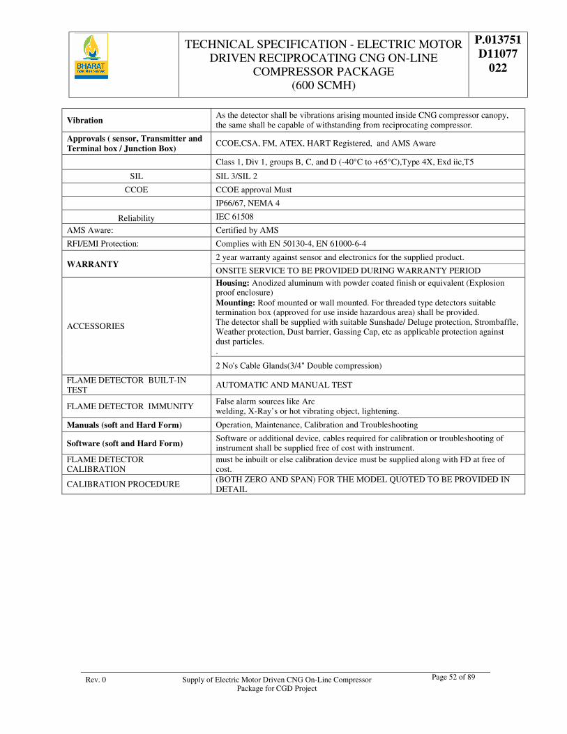
TECHNICAL SPECIFICATION - ELECTRIC MOTOR DRIVEN RECIPROCATING CNG ON-LINE
COMPRESSOR PACKAGE (600 SCMH)
P.013751 D11077
022
Rev. 0 Supply of Electric Motor Driven CNG On-Line Compressor Package for CGD Project
Page 52 of 89
Vibration As the detector shall be vibrations arising mounted inside CNG compressor canopy, the same shall be capable of withstanding from reciprocating compressor.
Approvals ( sensor, Transmitter and Terminal box / Junction Box)
CCOE,CSA, FM, ATEX, HART Registered, and AMS Aware
Class 1, Div 1, groups B, C, and D (-40°C to +65°C),Type 4X, Exd iic,T5
SIL SIL 3/SIL 2
CCOE CCOE approval Must
IP66/67, NEMA 4
Reliability IEC 61508
AMS Aware: Certified by AMS
RFI/EMI Protection: Complies with EN 50130-4, EN 61000-6-4
WARRANTY 2 year warranty against sensor and electronics for the supplied product.
ONSITE SERVICE TO BE PROVIDED DURING WARRANTY PERIOD
ACCESSORIES
Housing: Anodized aluminum with powder coated finish or equivalent (Explosion proof enclosure) Mounting: Roof mounted or wall mounted. For threaded type detectors suitable termination box (approved for use inside hazardous area) shall be provided. The detector shall be supplied with suitable Sunshade/ Deluge protection, Strombaffle, Weather protection, Dust barrier, Gassing Cap, etc as applicable protection against dust particles. .
2 No's Cable Glands(3/4" Double compression)
FLAME DETECTOR BUILT-IN TEST
AUTOMATIC AND MANUAL TEST
FLAME DETECTOR IMMUNITY False alarm sources like Arc welding, X-Ray’s or hot vibrating object, lightening.
Manuals (soft and Hard Form) Operation, Maintenance, Calibration and Troubleshooting
Software (soft and Hard Form) Software or additional device, cables required for calibration or troubleshooting of instrument shall be supplied free of cost with instrument.
FLAME DETECTOR CALIBRATION
must be inbuilt or else calibration device must be supplied along with FD at free of cost.
CALIBRATION PROCEDURE (BOTH ZERO AND SPAN) FOR THE MODEL QUOTED TO BE PROVIDED IN DETAIL
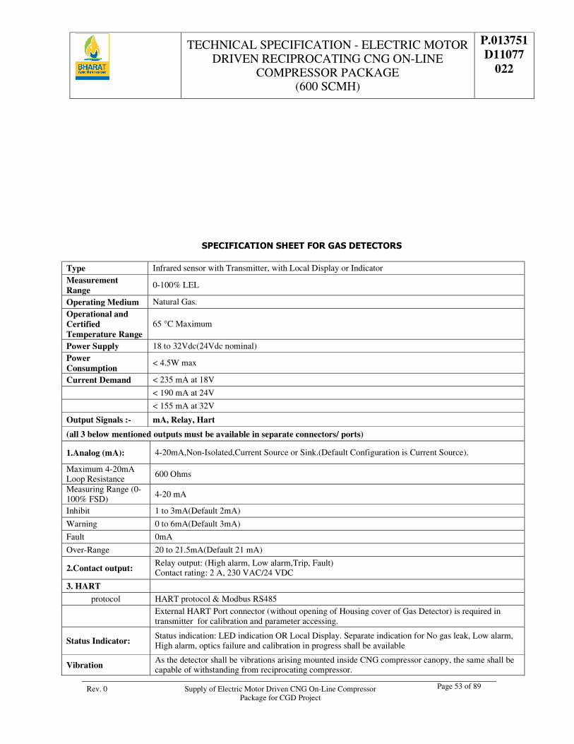
TECHNICAL SPECIFICATION - ELECTRIC MOTOR DRIVEN RECIPROCATING CNG ON-LINE
COMPRESSOR PACKAGE (600 SCMH)
P.013751 D11077
022
Rev. 0 Supply of Electric Motor Driven CNG On-Line Compressor Package for CGD Project
Page 53 of 89
SPECIFICATION SHEET FOR GAS DETECTORS
Type Infrared sensor with Transmitter, with Local Display or Indicator Measurement Range
0-100% LEL
Operating Medium Natural Gas.
Operational and Certified Temperature Range
65 °C Maximum
Power Supply 18 to 32Vdc(24Vdc nominal) Power Consumption
< 4.5W max
Current Demand < 235 mA at 18V
< 190 mA at 24V
< 155 mA at 32V
Output Signals :- mA, Relay, Hart
(all 3 below mentioned outputs must be available in separate connectors/ ports)
1.Analog (mA): 4-20mA,Non-Isolated,Current Source or Sink.(Default Configuration is Current Source).
Maximum 4-20mA Loop Resistance 600 Ohms
Measuring Range (0-100% FSD) 4-20 mA
Inhibit 1 to 3mA(Default 2mA)
Warning 0 to 6mA(Default 3mA)
Fault 0mA
Over-Range 20 to 21.5mA(Default 21 mA)
2.Contact output: Relay output: (High alarm, Low alarm,Trip, Fault) Contact rating: 2 A, 230 VAC/24 VDC
3. HART
protocol HART protocol & Modbus RS485
External HART Port connector (without opening of Housing cover of Gas Detector) is required in transmitter for calibration and parameter accessing.
Status Indicator: Status indication: LED indication OR Local Display. Separate indication for No gas leak, Low alarm, High alarm, optics failure and calibration in progress shall be available
Vibration As the detector shall be vibrations arising mounted inside CNG compressor canopy, the same shall be capable of withstanding from reciprocating compressor.
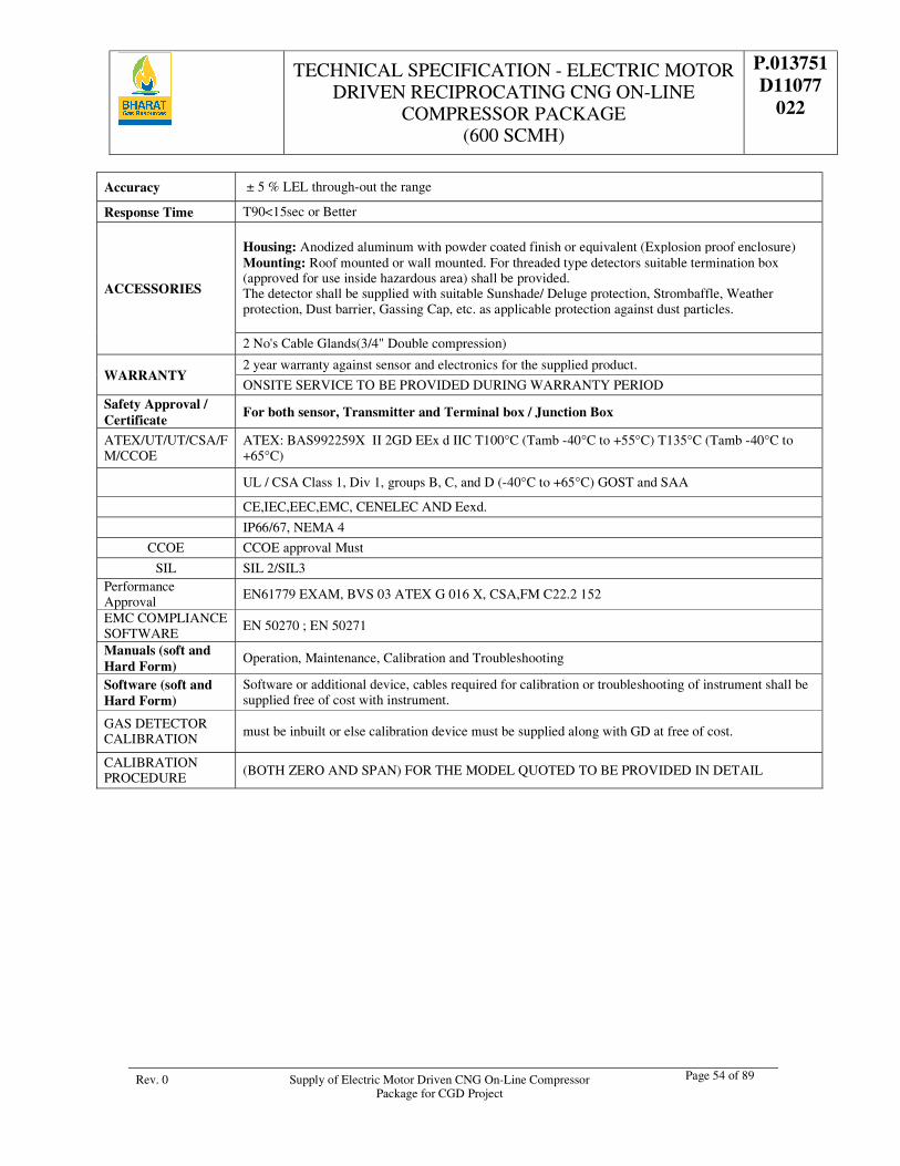
TECHNICAL SPECIFICATION - ELECTRIC MOTOR DRIVEN RECIPROCATING CNG ON-LINE
COMPRESSOR PACKAGE (600 SCMH)
P.013751 D11077
022
Rev. 0 Supply of Electric Motor Driven CNG On-Line Compressor Package for CGD Project
Page 54 of 89
Accuracy ± 5 % LEL through-out the range
Response Time T90<15sec or Better
ACCESSORIES
Housing: Anodized aluminum with powder coated finish or equivalent (Explosion proof enclosure) Mounting: Roof mounted or wall mounted. For threaded type detectors suitable termination box (approved for use inside hazardous area) shall be provided. The detector shall be supplied with suitable Sunshade/ Deluge protection, Strombaffle, Weather protection, Dust barrier, Gassing Cap, etc. as applicable protection against dust particles. 2 No's Cable Glands(3/4" Double compression)
WARRANTY 2 year warranty against sensor and electronics for the supplied product.
ONSITE SERVICE TO BE PROVIDED DURING WARRANTY PERIOD Safety Approval / Certificate
For both sensor, Transmitter and Terminal box / Junction Box
ATEX/UT/UT/CSA/FM/CCOE
ATEX: BAS992259X II 2GD EEx d IIC T100°C (Tamb -40°C to +55°C) T135°C (Tamb -40°C to +65°C)
UL / CSA Class 1, Div 1, groups B, C, and D (-40°C to +65°C) GOST and SAA
CE,IEC,EEC,EMC, CENELEC AND Eexd.
IP66/67, NEMA 4
CCOE CCOE approval Must
SIL SIL 2/SIL3 Performance Approval
EN61779 EXAM, BVS 03 ATEX G 016 X, CSA,FM C22.2 152
EMC COMPLIANCE SOFTWARE
EN 50270 ; EN 50271
Manuals (soft and Hard Form)
Operation, Maintenance, Calibration and Troubleshooting
Software (soft and Hard Form)
Software or additional device, cables required for calibration or troubleshooting of instrument shall be supplied free of cost with instrument.
GAS DETECTOR CALIBRATION must be inbuilt or else calibration device must be supplied along with GD at free of cost.
CALIBRATION PROCEDURE (BOTH ZERO AND SPAN) FOR THE MODEL QUOTED TO BE PROVIDED IN DETAIL
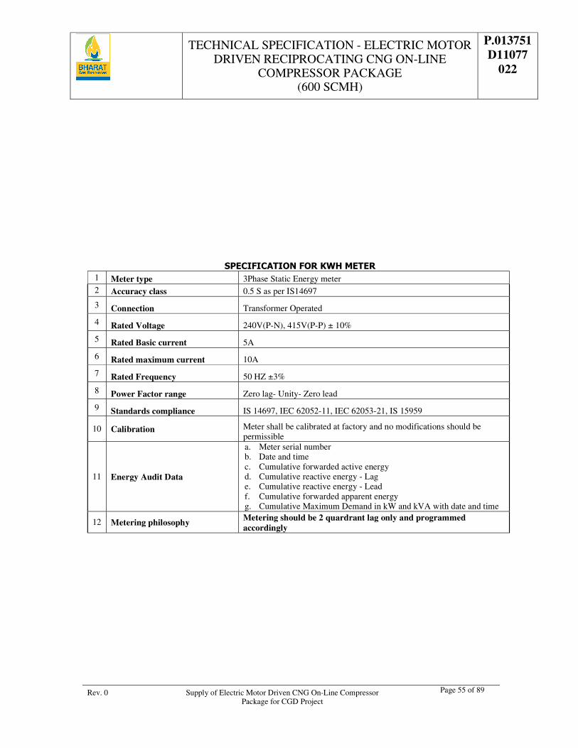
TECHNICAL SPECIFICATION - ELECTRIC MOTOR DRIVEN RECIPROCATING CNG ON-LINE
COMPRESSOR PACKAGE (600 SCMH)
P.013751 D11077
022
Rev. 0 Supply of Electric Motor Driven CNG On-Line Compressor Package for CGD Project
Page 55 of 89
SPECIFICATION FOR KWH METER 1 Meter type 3Phase Static Energy meter 2 Accuracy class 0.5 S as per IS14697
3 Connection Transformer Operated
4 Rated Voltage 240V(P-N), 415V(P-P) ± 10%
5 Rated Basic current 5A
6 Rated maximum current 10A
7 Rated Frequency 50 HZ ±3%
8 Power Factor range Zero lag- Unity- Zero lead
9 Standards compliance IS 14697, IEC 62052-11, IEC 62053-21, IS 15959
10 Calibration Meter shall be calibrated at factory and no modifications should be permissible
11 Energy Audit Data
a. Meter serial number b. Date and time c. Cumulative forwarded active energy d. Cumulative reactive energy - Lag e. Cumulative reactive energy - Lead f. Cumulative forwarded apparent energy g. Cumulative Maximum Demand in kW and kVA with date and time
12 Metering philosophy Metering should be 2 quardrant lag only and programmed accordingly
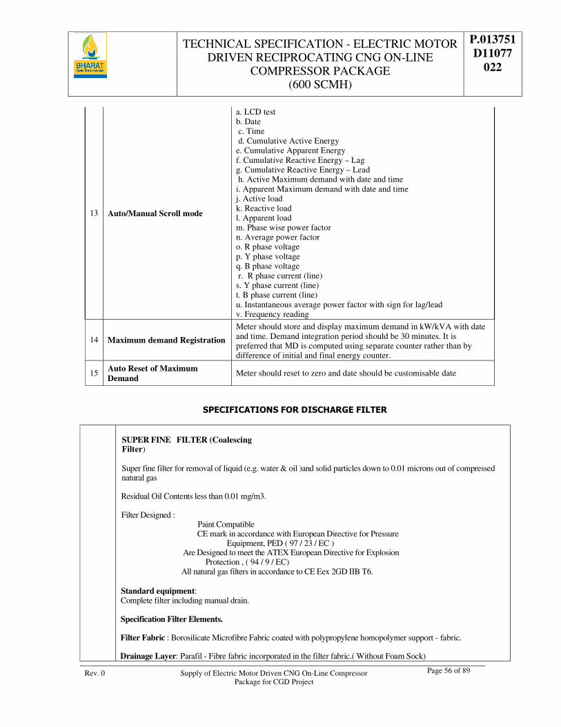
TECHNICAL SPECIFICATION - ELECTRIC MOTOR DRIVEN RECIPROCATING CNG ON-LINE
COMPRESSOR PACKAGE (600 SCMH)
P.013751 D11077
022
Rev. 0 Supply of Electric Motor Driven CNG On-Line Compressor Package for CGD Project
Page 56 of 89
13 Auto/Manual Scroll mode
a. LCD test b. Date c. Time d. Cumulative Active Energy e. Cumulative Apparent Energy f. Cumulative Reactive Energy – Lag g. Cumulative Reactive Energy – Lead h. Active Maximum demand with date and time i. Apparent Maximum demand with date and time j. Active load k. Reactive load l. Apparent load m. Phase wise power factor n. Average power factor o. R phase voltage p. Y phase voltage q. B phase voltage r. R phase current (line) s. Y phase current (line) t. B phase current (line) u. Instantaneous average power factor with sign for lag/lead v. Frequency reading
14 Maximum demand Registration
Meter should store and display maximum demand in kW/kVA with date and time. Demand integration period should be 30 minutes. It is preferred that MD is computed using separate counter rather than by difference of initial and final energy counter.
15 Auto Reset of Maximum Demand
Meter should reset to zero and date should be customisable date
SPECIFICATIONS FOR DISCHARGE FILTER
SUPER FINE FILTER (Coalescing Filter) Super fine filter for removal of liquid (e.g. water & oil )and solid particles down to 0.01 microns out of compressed natural gas
Residual Oil Contents less than 0.01 mg/m3.
Filter Designed : Paint Compatible CE mark in accordance with European Directive for Pressure
Equipment, PED ( 97 / 23 / EC ) Are Designed to meet the ATEX European Directive for Explosion Protection , ( 94 / 9 / EC) All natural gas filters in accordance to CE Eex 2GD IIB T6.
Standard equipment: Complete filter including manual drain.
Specification Filter Elements.
Filter Fabric : Borosilicate Microfibre Fabric coated with polypropylene homopolymer support - fabric.
Drainage Layer: Parafil - Fibre fabric incorporated in the filter fabric.( Without Foam Sock)
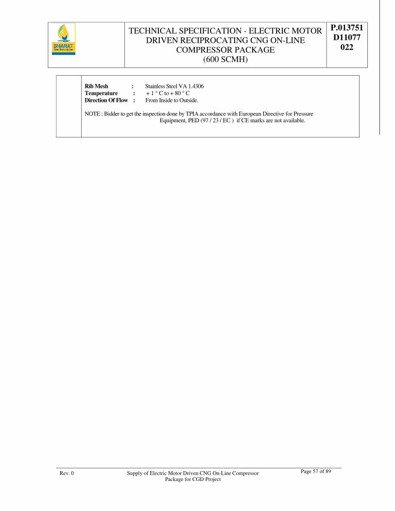
TECHNICAL SPECIFICATION - ELECTRIC MOTOR DRIVEN RECIPROCATING CNG ON-LINE
COMPRESSOR PACKAGE (600 SCMH)
P.013751 D11077
022
Rev. 0 Supply of Electric Motor Driven CNG On-Line Compressor Package for CGD Project
Page 57 of 89
Rib Mesh : Stainless Steel VA 1.4306 Temperature : + 1 ° C to + 80 ° C Direction Of Flow : From Inside to Outside. NOTE : Bidder to get the inspection done by TPIA accordance with European Directive for Pressure
Equipment, PED (97 / 23 / EC ) if CE marks are not available.
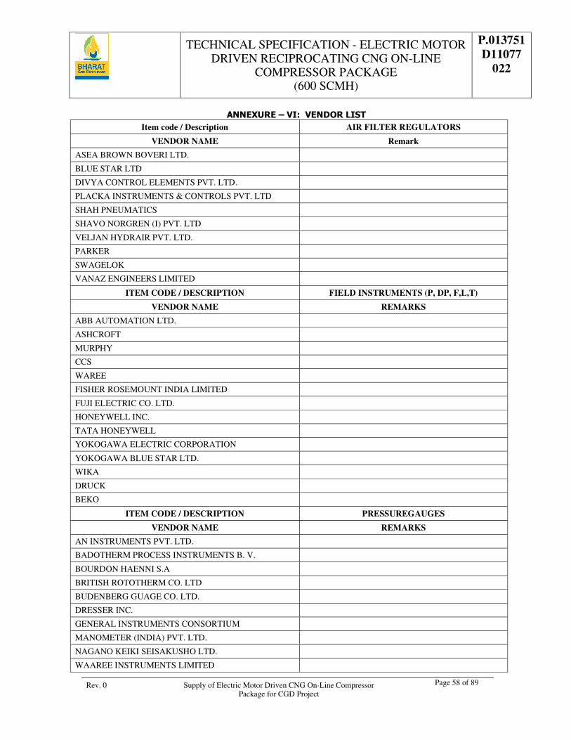
TECHNICAL SPECIFICATION - ELECTRIC MOTOR DRIVEN RECIPROCATING CNG ON-LINE
COMPRESSOR PACKAGE (600 SCMH)
P.013751 D11077
022
Rev. 0 Supply of Electric Motor Driven CNG On-Line Compressor Package for CGD Project
Page 58 of 89
ANNEXURE – VI: VENDOR LIST Item code / Description AIR FILTER REGULATORS
VENDOR NAME Remark
ASEA BROWN BOVERI LTD.
BLUE STAR LTD
DIVYA CONTROL ELEMENTS PVT. LTD.
PLACKA INSTRUMENTS & CONTROLS PVT. LTD
SHAH PNEUMATICS
SHAVO NORGREN (I) PVT. LTD
VELJAN HYDRAIR PVT. LTD.
PARKER
SWAGELOK
VANAZ ENGINEERS LIMITED
ITEM CODE / DESCRIPTION FIELD INSTRUMENTS (P, DP, F,L,T)
VENDOR NAME REMARKS
ABB AUTOMATION LTD.
ASHCROFT
MURPHY
CCS
WAREE
FISHER ROSEMOUNT INDIA LIMITED
FUJI ELECTRIC CO. LTD.
HONEYWELL INC.
TATA HONEYWELL
YOKOGAWA ELECTRIC CORPORATION
YOKOGAWA BLUE STAR LTD.
WIKA
DRUCK
BEKO
ITEM CODE / DESCRIPTION PRESSUREGAUGES
VENDOR NAME REMARKS
AN INSTRUMENTS PVT. LTD.
BADOTHERM PROCESS INSTRUMENTS B. V.
BOURDON HAENNI S.A
BRITISH ROTOTHERM CO. LTD
BUDENBERG GUAGE CO. LTD.
DRESSER INC.
GENERAL INSTRUMENTS CONSORTIUM
MANOMETER (INDIA) PVT. LTD.
NAGANO KEIKI SEISAKUSHO LTD.
WAAREE INSTRUMENTS LIMITED
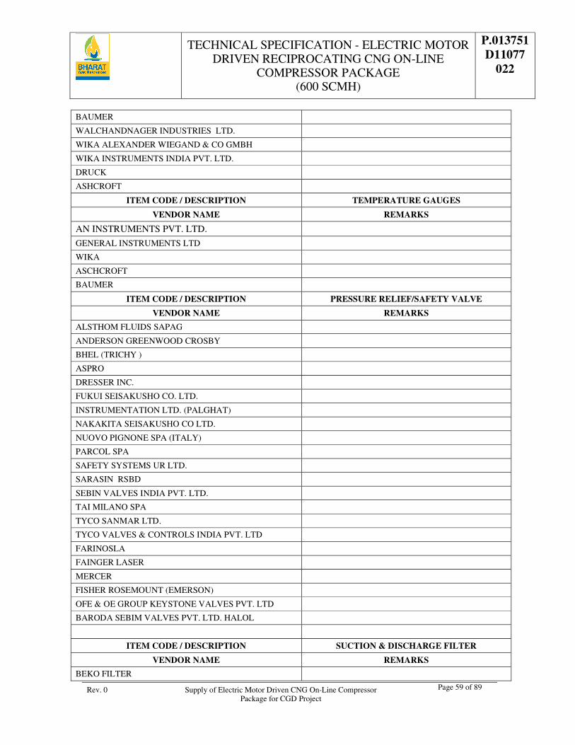
TECHNICAL SPECIFICATION - ELECTRIC MOTOR DRIVEN RECIPROCATING CNG ON-LINE
COMPRESSOR PACKAGE (600 SCMH)
P.013751 D11077
022
Rev. 0 Supply of Electric Motor Driven CNG On-Line Compressor Package for CGD Project
Page 59 of 89
BAUMER
WALCHANDNAGER INDUSTRIES LTD.
WIKA ALEXANDER WIEGAND & CO GMBH
WIKA INSTRUMENTS INDIA PVT. LTD.
DRUCK
ASHCROFT
ITEM CODE / DESCRIPTION TEMPERATURE GAUGES
VENDOR NAME REMARKS
AN INSTRUMENTS PVT. LTD.
GENERAL INSTRUMENTS LTD
WIKA
ASCHCROFT
BAUMER
ITEM CODE / DESCRIPTION PRESSURE RELIEF/SAFETY VALVE
VENDOR NAME REMARKS
ALSTHOM FLUIDS SAPAG
ANDERSON GREENWOOD CROSBY
BHEL (TRICHY )
ASPRO
DRESSER INC.
FUKUI SEISAKUSHO CO. LTD.
INSTRUMENTATION LTD. (PALGHAT)
NAKAKITA SEISAKUSHO CO LTD.
NUOVO PIGNONE SPA (ITALY)
PARCOL SPA
SAFETY SYSTEMS UR LTD.
SARASIN RSBD
SEBIN VALVES INDIA PVT. LTD.
TAI MILANO SPA
TYCO SANMAR LTD.
TYCO VALVES & CONTROLS INDIA PVT. LTD
FARINOSLA
FAINGER LASER
MERCER
FISHER ROSEMOUNT (EMERSON)
OFE & OE GROUP KEYSTONE VALVES PVT. LTD
BARODA SEBIM VALVES PVT. LTD. HALOL
ITEM CODE / DESCRIPTION SUCTION & DISCHARGE FILTER
VENDOR NAME REMARKS
BEKO FILTER
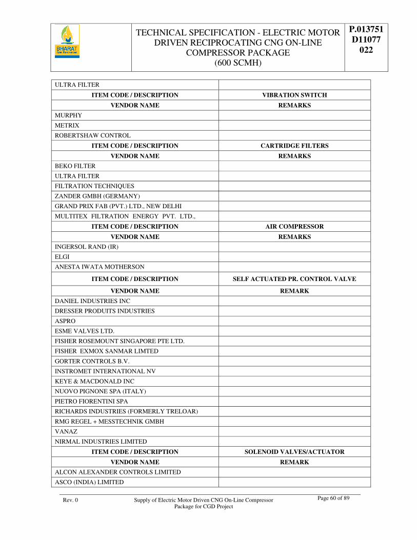
TECHNICAL SPECIFICATION - ELECTRIC MOTOR DRIVEN RECIPROCATING CNG ON-LINE
COMPRESSOR PACKAGE (600 SCMH)
P.013751 D11077
022
Rev. 0 Supply of Electric Motor Driven CNG On-Line Compressor Package for CGD Project
Page 60 of 89
ULTRA FILTER
ITEM CODE / DESCRIPTION VIBRATION SWITCH
VENDOR NAME REMARKS
MURPHY
METRIX
ROBERTSHAW CONTROL
ITEM CODE / DESCRIPTION CARTRIDGE FILTERS
VENDOR NAME REMARKS
BEKO FILTER
ULTRA FILTER
FILTRATION TECHNIQUES
ZANDER GMBH (GERMANY)
GRAND PRIX FAB (PVT.) LTD., NEW DELHI
MULTITEX FILTRATION ENERGY PVT. LTD.,
ITEM CODE / DESCRIPTION AIR COMPRESSOR
VENDOR NAME REMARKS
INGERSOL RAND (IR)
ELGI
ANESTA IWATA MOTHERSON
ITEM CODE / DESCRIPTION SELF ACTUATED PR. CONTROL VALVE
VENDOR NAME REMARK
DANIEL INDUSTRIES INC
DRESSER PRODUITS INDUSTRIES
ASPRO
ESME VALVES LTD.
FISHER ROSEMOUNT SINGAPORE PTE LTD.
FISHER EXMOX SANMAR LIMTED
GORTER CONTROLS B.V.
INSTROMET INTERNATIONAL NV
KEYE & MACDONALD INC
NUOVO PIGNONE SPA (ITALY)
PIETRO FIORENTINI SPA
RICHARDS INDUSTRIES (FORMERLY TRELOAR)
RMG REGEL + MESSTECHNIK GMBH
VANAZ
NIRMAL INDUSTRIES LIMITED
ITEM CODE / DESCRIPTION SOLENOID VALVES/ACTUATOR
VENDOR NAME REMARK
ALCON ALEXANDER CONTROLS LIMITED
ASCO (INDIA) LIMITED
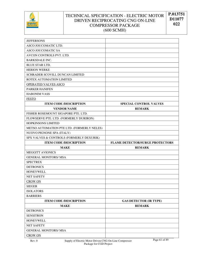
TECHNICAL SPECIFICATION - ELECTRIC MOTOR DRIVEN RECIPROCATING CNG ON-LINE
COMPRESSOR PACKAGE (600 SCMH)
P.013751 D11077
022
Rev. 0 Supply of Electric Motor Driven CNG On-Line Compressor Package for CGD Project
Page 61 of 89
JEFFERSONS
ASCO JOUCOMATIC LTD.
ASCO JOUCOMATIC SA
AVCON CONTROLS PVT. LTD.
BARKSDALE INC.
BLUE STAR LTD.
HERION WERKE
SCHRADER SCOVILL DUNCAN LIMITED
ROTEX AUTOMATION LIMITED
OPERATED VALVES ASCO
PARKER HANIFEN
HABONIM VASS
FESTO
ITEM CODE /DESCRIPTION SPECIAL CONTROL VALVES
VENDOR NAME REMARK
FISHER ROSEMOUNT SIGAPORE PTE. LTD.
FLOWSERVE PTE. LTD. (FORMERLY DURIRON)
HOPKINSONS LIMITED
METSO AUTOMATION PTE LTD. (FORMERLY NELES)
NUOVO PIGNONE SPA (ITALY)
SPX VALVES & CONTROLS (FORMERLY DEXURIK)
ITEM CODE /DESCRIPTION FLAME DETECTOR/SURGE PROTECTORS
MAKE REMARK
MEGGITT AVIONICS
GENERAL MONITORS/ MSA
SPECTREX
DETRONICS
HONEYWELL
NET SAFETY
CROW ON
SIEGER
ISOLATORS
BARRIERS
ITEM CODE /DESCRIPTION GAS DETECTOR (IR TYPE)
MAKE REMARK
DETRONICS
SENSITRON
HONEYWELL
NET SAFETY
GENERAL MONITORS/ MSA
CROW ON
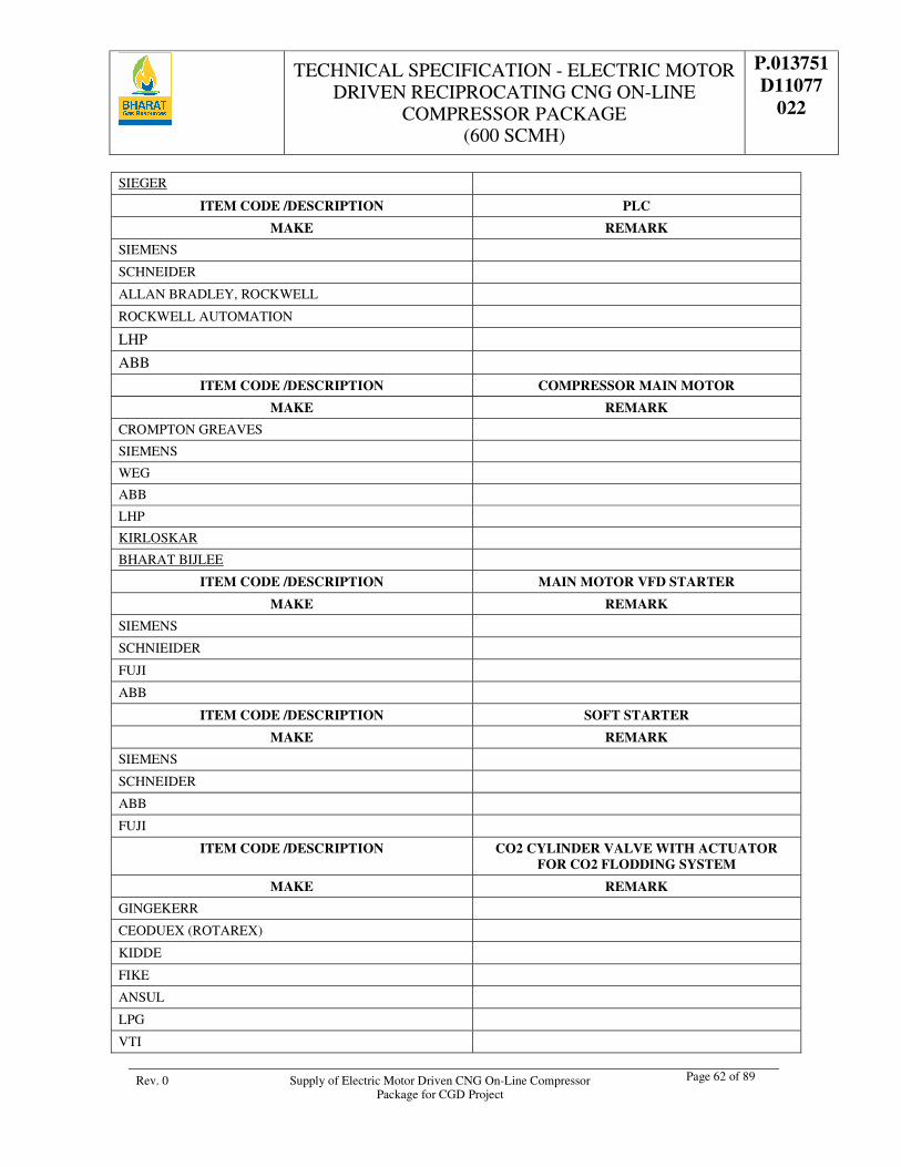
TECHNICAL SPECIFICATION - ELECTRIC MOTOR DRIVEN RECIPROCATING CNG ON-LINE
COMPRESSOR PACKAGE (600 SCMH)
P.013751 D11077
022
Rev. 0 Supply of Electric Motor Driven CNG On-Line Compressor Package for CGD Project
Page 62 of 89
SIEGER
ITEM CODE /DESCRIPTION PLC
MAKE REMARK
SIEMENS
SCHNEIDER
ALLAN BRADLEY, ROCKWELL
ROCKWELL AUTOMATION
LHP
ABB
ITEM CODE /DESCRIPTION COMPRESSOR MAIN MOTOR
MAKE REMARK
CROMPTON GREAVES
SIEMENS
WEG
ABB
LHP
KIRLOSKAR
BHARAT BIJLEE
ITEM CODE /DESCRIPTION MAIN MOTOR VFD STARTER
MAKE REMARK
SIEMENS
SCHNIEIDER
FUJI
ABB
ITEM CODE /DESCRIPTION SOFT STARTER
MAKE REMARK
SIEMENS
SCHNEIDER
ABB
FUJI
ITEM CODE /DESCRIPTION CO2 CYLINDER VALVE WITH ACTUATOR FOR CO2 FLODDING SYSTEM
MAKE REMARK
GINGEKERR
CEODUEX (ROTAREX)
KIDDE
FIKE
ANSUL
LPG
VTI
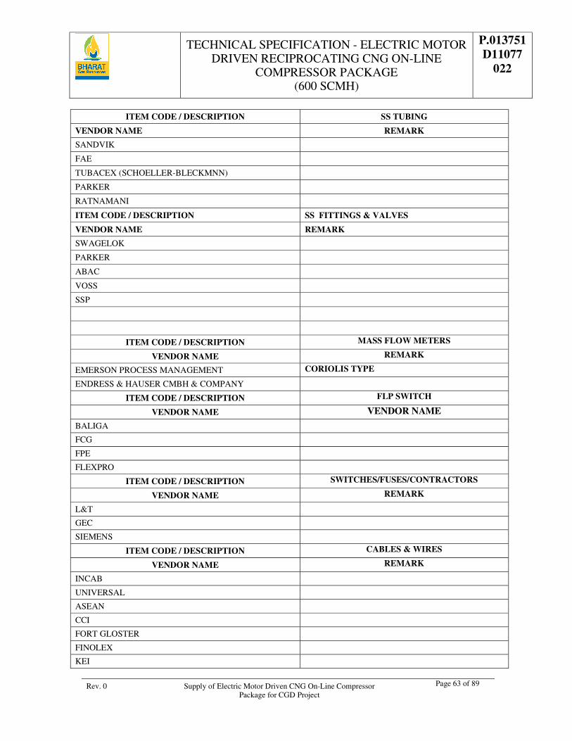
TECHNICAL SPECIFICATION - ELECTRIC MOTOR DRIVEN RECIPROCATING CNG ON-LINE
COMPRESSOR PACKAGE (600 SCMH)
P.013751 D11077
022
Rev. 0 Supply of Electric Motor Driven CNG On-Line Compressor Package for CGD Project
Page 63 of 89
ITEM CODE / DESCRIPTION SS TUBING
VENDOR NAME REMARK
SANDVIK
FAE
TUBACEX (SCHOELLER-BLECKMNN)
PARKER
RATNAMANI
ITEM CODE / DESCRIPTION SS FITTINGS & VALVES
VENDOR NAME REMARK
SWAGELOK
PARKER
ABAC
VOSS
SSP
ITEM CODE / DESCRIPTION MASS FLOW METERS
VENDOR NAME REMARK
EMERSON PROCESS MANAGEMENT CORIOLIS TYPE
ENDRESS & HAUSER CMBH & COMPANY
ITEM CODE / DESCRIPTION FLP SWITCH
VENDOR NAME VENDOR NAME
BALIGA
FCG
FPE
FLEXPRO
ITEM CODE / DESCRIPTION SWITCHES/FUSES/CONTRACTORS
VENDOR NAME REMARK
L&T
GEC
SIEMENS
ITEM CODE / DESCRIPTION CABLES & WIRES
VENDOR NAME REMARK
INCAB
UNIVERSAL
ASEAN
CCI
FORT GLOSTER
FINOLEX
KEI
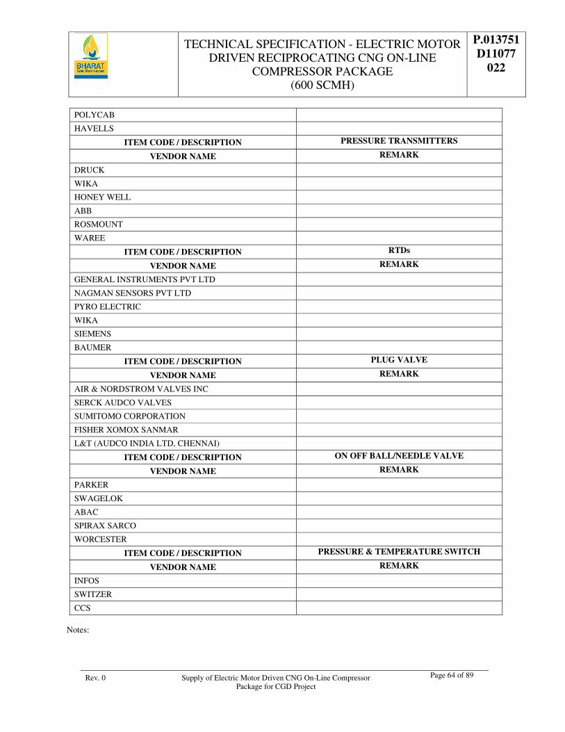
TECHNICAL SPECIFICATION - ELECTRIC MOTOR DRIVEN RECIPROCATING CNG ON-LINE
COMPRESSOR PACKAGE (600 SCMH)
P.013751 D11077
022
Rev. 0 Supply of Electric Motor Driven CNG On-Line Compressor Package for CGD Project
Page 64 of 89
POLYCAB
HAVELLS
ITEM CODE / DESCRIPTION PRESSURE TRANSMITTERS
VENDOR NAME REMARK
DRUCK
WIKA
HONEY WELL
ABB
ROSMOUNT
WAREE
ITEM CODE / DESCRIPTION RTDs
VENDOR NAME REMARK
GENERAL INSTRUMENTS PVT LTD
NAGMAN SENSORS PVT LTD
PYRO ELECTRIC
WIKA
SIEMENS
BAUMER
ITEM CODE / DESCRIPTION PLUG VALVE
VENDOR NAME REMARK
AIR & NORDSTROM VALVES INC
SERCK AUDCO VALVES
SUMITOMO CORPORATION
FISHER XOMOX SANMAR
L&T (AUDCO INDIA LTD, CHENNAI)
ITEM CODE / DESCRIPTION ON OFF BALL/NEEDLE VALVE
VENDOR NAME REMARK
PARKER
SWAGELOK
ABAC
SPIRAX SARCO
WORCESTER
ITEM CODE / DESCRIPTION PRESSURE & TEMPERATURE SWITCH
VENDOR NAME REMARK
INFOS
SWITZER
CCS
Notes:
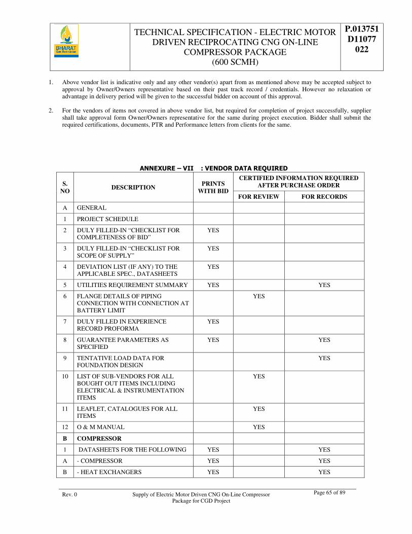
TECHNICAL SPECIFICATION - ELECTRIC MOTOR DRIVEN RECIPROCATING CNG ON-LINE
COMPRESSOR PACKAGE (600 SCMH)
P.013751 D11077
022
Rev. 0 Supply of Electric Motor Driven CNG On-Line Compressor Package for CGD Project
Page 65 of 89
1. Above vendor list is indicative only and any other vendor(s) apart from as mentioned above may be accepted subject to approval by Owner/Owners representative based on their past track record / credentials. However no relaxation or advantage in delivery period will be given to the successful bidder on account of this approval.
2. For the vendors of items not covered in above vendor list, but required for completion of project successfully, supplier
shall take approval form Owner/Owners representative for the same during project execution. Bidder shall submit the required certifications, documents, PTR and Performance letters from clients for the same.
ANNEXURE – VII : VENDOR DATA REQUIRED
S. NO
DESCRIPTION PRINTS
WITH BID
CERTIFIED INFORMATION REQUIRED AFTER PURCHASE ORDER
FOR REVIEW FOR RECORDS
A GENERAL
1 PROJECT SCHEDULE
2 DULY FILLED-IN “CHECKLIST FOR COMPLETENESS OF BID”
YES
3 DULY FILLED-IN “CHECKLIST FOR SCOPE OF SUPPLY”
YES
4 DEVIATION LIST (IF ANY) TO THE APPLICABLE SPEC., DATASHEETS
YES
5 UTILITIES REQUIREMENT SUMMARY YES YES
6 FLANGE DETAILS OF PIPING CONNECTION WITH CONNECTION AT BATTERY LIMIT
YES
7 DULY FILLED IN EXPERIENCE RECORD PROFORMA
YES
8 GUARANTEE PARAMETERS AS SPECIFIED
YES YES
9 TENTATIVE LOAD DATA FOR FOUNDATION DESIGN
YES
10 LIST OF SUB-VENDORS FOR ALL BOUGHT OUT ITEMS INCLUDING ELECTRICAL & INSTRUMENTATION ITEMS
YES
11 LEAFLET, CATALOGUES FOR ALL ITEMS
YES
12 O & M MANUAL YES
B COMPRESSOR
1 DATASHEETS FOR THE FOLLOWING YES YES
A - COMPRESSOR YES YES
B - HEAT EXCHANGERS YES YES
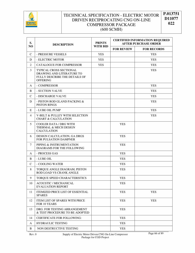
TECHNICAL SPECIFICATION - ELECTRIC MOTOR DRIVEN RECIPROCATING CNG ON-LINE
COMPRESSOR PACKAGE (600 SCMH)
P.013751 D11077
022
Rev. 0 Supply of Electric Motor Driven CNG On-Line Compressor Package for CGD Project
Page 66 of 89
S. NO
DESCRIPTION PRINTS
WITH BID
CERTIFIED INFORMATION REQUIRED AFTER PURCHASE ORDER
FOR REVIEW FOR RECORDS
C - PRESSURE VESSELS YES YES
D - ELECTRIC MOTOR YES YES
2 CATALOGUE FOR COMPRESSOR YES YES
3 TYPICAL CROSS SECTIONAL DRAWING AND LITERATURE TO FULLY DESCRIBE THE DETAILS OF OFFERING
YES
A - COMPRESSOR YES
B - SUCTION VALVE YES
C - DISCHARGE VALVE YES
D - PISTON ROD GLAND PACKING & PISTON RINGS
YES
E - LUBE OIL PUMP YES
4 V-BELT & PULLEY WITH SELECTION CHART & CALCULATION
YES
5 COOLER DATA / DRG WITH THERMAL & MECH DESIGN CALCULATION
YES
6 DESIGN CALCULATION, GA DRGS FOR PULSATION DAMPNER
YES
7 PIPING & INSTRUMENTATION DIAGRAMS FOR THE FOLLOWING
YES
A - PROCESS GAS YES
B - LUBE OIL YES
C - COOLING WATER YES
8 TORQUE ANGLE DIAGRAM, PISTON ROD LOAD VS CRANK ANGLE
YES
9 TORQUE SPEED CHARACTERISTICS YES
10 ACOUSTIC / MECHANICAL EVALUATION REPORT
YES
11 ITEMIZED PRICE LIST OF ESSENTIAL SPARES
YES YES
12 ITEM LIST OF SPARES WITH PRICE FOR 10 YEARS
YES YES
13 DRG. FOR TESTING ARRANGEMENT & TEST PROCEDURE TO BE ADOPTED
YES
14 CERTIFICATE FOR FOLLOWING: YES
A HYDRAULIC TESTING YES
B NON DESTRUCTIVE TESTING YES
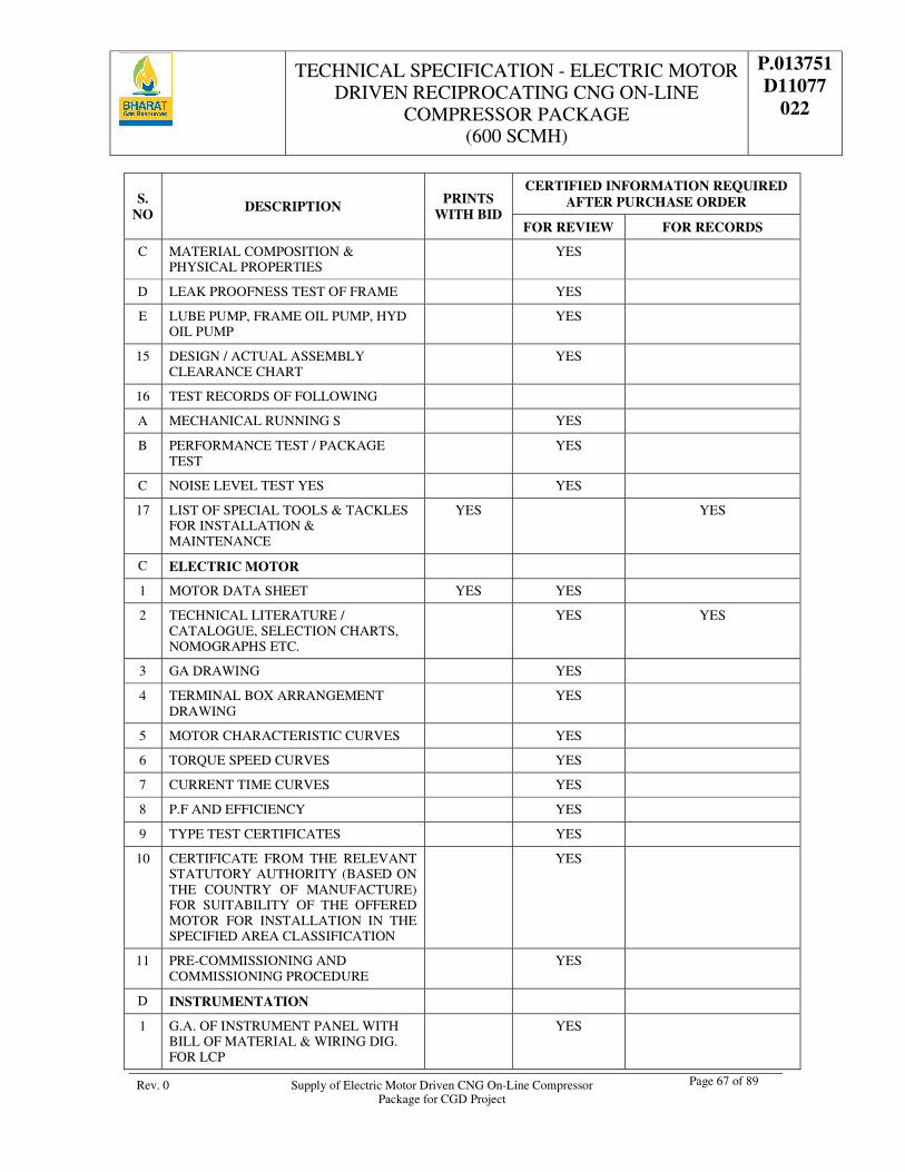
TECHNICAL SPECIFICATION - ELECTRIC MOTOR DRIVEN RECIPROCATING CNG ON-LINE
COMPRESSOR PACKAGE (600 SCMH)
P.013751 D11077
022
Rev. 0 Supply of Electric Motor Driven CNG On-Line Compressor Package for CGD Project
Page 67 of 89
S. NO
DESCRIPTION PRINTS
WITH BID
CERTIFIED INFORMATION REQUIRED AFTER PURCHASE ORDER
FOR REVIEW FOR RECORDS
C MATERIAL COMPOSITION & PHYSICAL PROPERTIES
YES
D LEAK PROOFNESS TEST OF FRAME YES
E LUBE PUMP, FRAME OIL PUMP, HYD OIL PUMP
YES
15 DESIGN / ACTUAL ASSEMBLY CLEARANCE CHART
YES
16 TEST RECORDS OF FOLLOWING
A MECHANICAL RUNNING S YES
B PERFORMANCE TEST / PACKAGE TEST
YES
C NOISE LEVEL TEST YES YES
17 LIST OF SPECIAL TOOLS & TACKLES FOR INSTALLATION & MAINTENANCE
YES YES
C ELECTRIC MOTOR
1 MOTOR DATA SHEET YES YES
2 TECHNICAL LITERATURE / CATALOGUE, SELECTION CHARTS, NOMOGRAPHS ETC.
YES YES
3 GA DRAWING YES
4 TERMINAL BOX ARRANGEMENT DRAWING
YES
5 MOTOR CHARACTERISTIC CURVES YES
6 TORQUE SPEED CURVES YES
7 CURRENT TIME CURVES YES
8 P.F AND EFFICIENCY YES
9 TYPE TEST CERTIFICATES YES
10 CERTIFICATE FROM THE RELEVANT STATUTORY AUTHORITY (BASED ON THE COUNTRY OF MANUFACTURE) FOR SUITABILITY OF THE OFFERED MOTOR FOR INSTALLATION IN THE SPECIFIED AREA CLASSIFICATION
YES
11 PRE-COMMISSIONING AND COMMISSIONING PROCEDURE
YES
D INSTRUMENTATION
1 G.A. OF INSTRUMENT PANEL WITH BILL OF MATERIAL & WIRING DIG. FOR LCP
YES
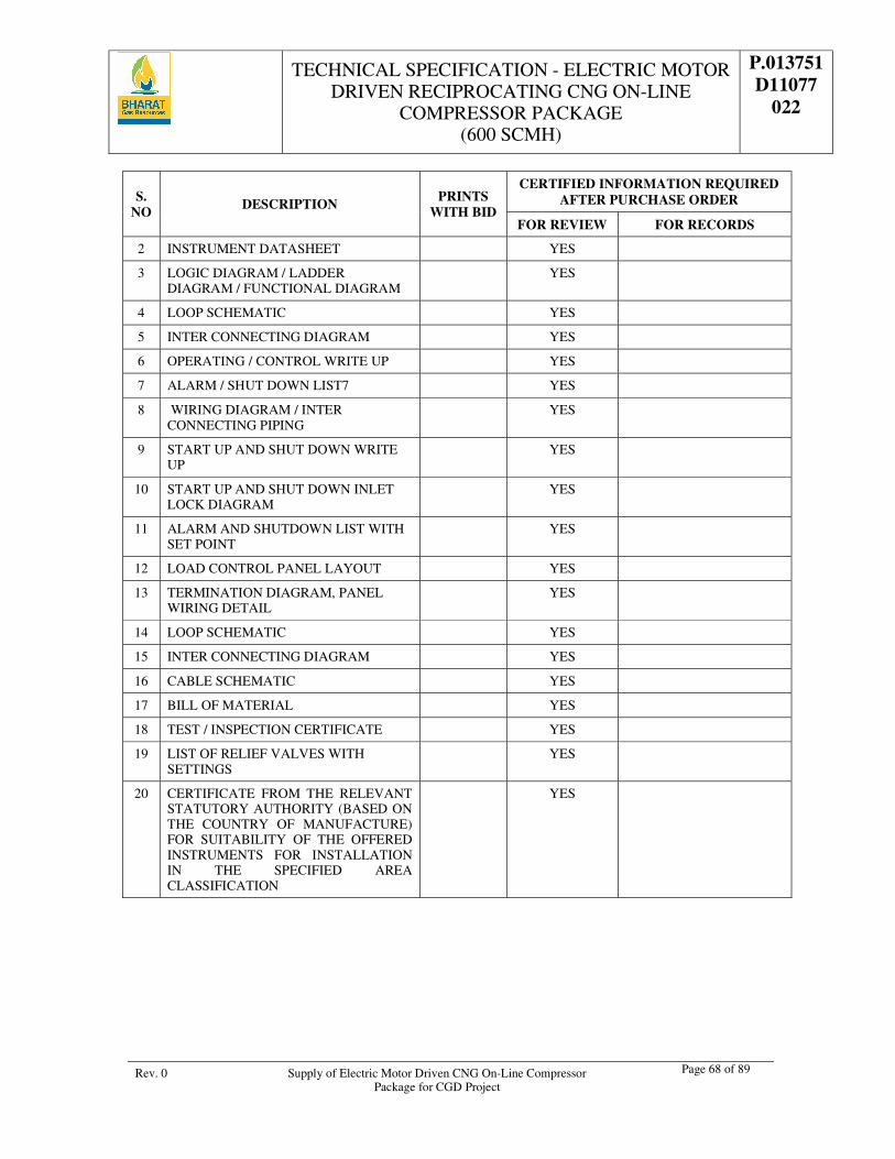
TECHNICAL SPECIFICATION - ELECTRIC MOTOR DRIVEN RECIPROCATING CNG ON-LINE
COMPRESSOR PACKAGE (600 SCMH)
P.013751 D11077
022
Rev. 0 Supply of Electric Motor Driven CNG On-Line Compressor Package for CGD Project
Page 68 of 89
S. NO
DESCRIPTION PRINTS
WITH BID
CERTIFIED INFORMATION REQUIRED AFTER PURCHASE ORDER
FOR REVIEW FOR RECORDS
2 INSTRUMENT DATASHEET YES
3 LOGIC DIAGRAM / LADDER DIAGRAM / FUNCTIONAL DIAGRAM
YES
4 LOOP SCHEMATIC YES
5 INTER CONNECTING DIAGRAM YES
6 OPERATING / CONTROL WRITE UP YES
7 ALARM / SHUT DOWN LIST7 YES
8 WIRING DIAGRAM / INTER CONNECTING PIPING
YES
9 START UP AND SHUT DOWN WRITE UP
YES
10 START UP AND SHUT DOWN INLET LOCK DIAGRAM
YES
11 ALARM AND SHUTDOWN LIST WITH SET POINT
YES
12 LOAD CONTROL PANEL LAYOUT YES
13 TERMINATION DIAGRAM, PANEL WIRING DETAIL
YES
14 LOOP SCHEMATIC YES
15 INTER CONNECTING DIAGRAM YES
16 CABLE SCHEMATIC YES
17 BILL OF MATERIAL YES
18 TEST / INSPECTION CERTIFICATE YES
19 LIST OF RELIEF VALVES WITH SETTINGS
YES
20 CERTIFICATE FROM THE RELEVANT STATUTORY AUTHORITY (BASED ON THE COUNTRY OF MANUFACTURE) FOR SUITABILITY OF THE OFFERED INSTRUMENTS FOR INSTALLATION IN THE SPECIFIED AREA CLASSIFICATION
YES
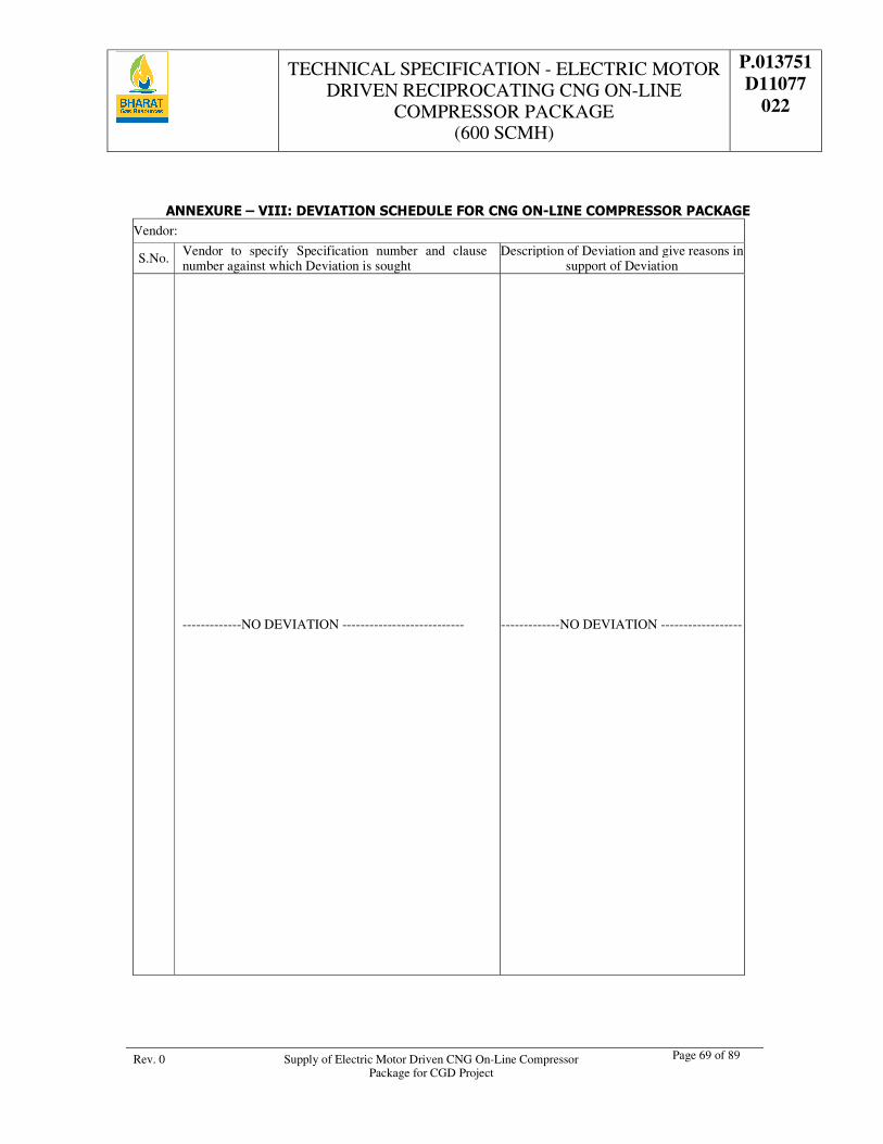
TECHNICAL SPECIFICATION - ELECTRIC MOTOR DRIVEN RECIPROCATING CNG ON-LINE
COMPRESSOR PACKAGE (600 SCMH)
P.013751 D11077
022
Rev. 0 Supply of Electric Motor Driven CNG On-Line Compressor Package for CGD Project
Page 69 of 89
ANNEXURE – VIII: DEVIATION SCHEDULE FOR CNG ON-LINE COMPRESSOR PACKAGE Vendor:
S.No. Vendor to specify Specification number and clause number against which Deviation is sought
Description of Deviation and give reasons in support of Deviation
-------------NO DEVIATION --------------------------- -------------NO DEVIATION ------------------
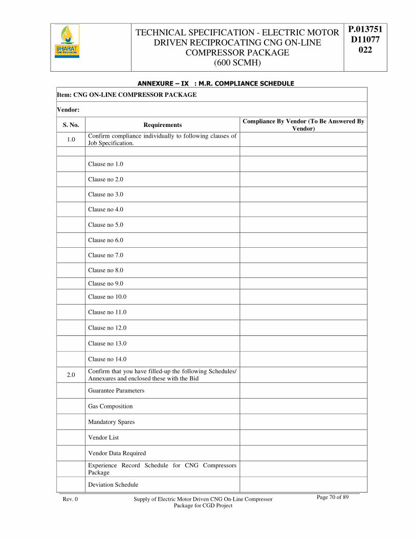
TECHNICAL SPECIFICATION - ELECTRIC MOTOR DRIVEN RECIPROCATING CNG ON-LINE
COMPRESSOR PACKAGE (600 SCMH)
P.013751 D11077
022
Rev. 0 Supply of Electric Motor Driven CNG On-Line Compressor Package for CGD Project
Page 70 of 89
ANNEXURE – IX : M.R. COMPLIANCE SCHEDULE
Item: CNG ON-LINE COMPRESSOR PACKAGE
Vendor:
S. No. Requirements Compliance By Vendor (To Be Answered By
Vendor)
1.0 Confirm compliance individually to following clauses of Job Specification.
Clause no 1.0
Clause no 2.0
Clause no 3.0
Clause no 4.0
Clause no 5.0
Clause no 6.0
Clause no 7.0
Clause no 8.0
Clause no 9.0
Clause no 10.0
Clause no 11.0
Clause no 12.0
Clause no 13.0
Clause no 14.0
2.0 Confirm that you have filled-up the following Schedules/ Annexures and enclosed these with the Bid
Guarantee Parameters
Gas Composition
Mandatory Spares
Vendor List
Vendor Data Required
Experience Record Schedule for CNG Compressors Package
Deviation Schedule
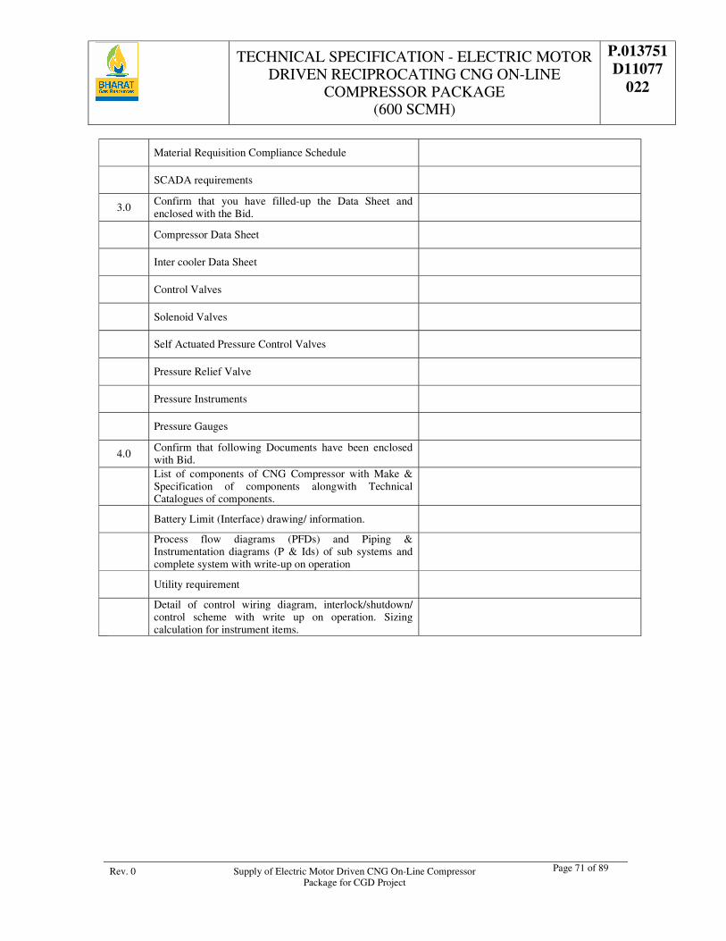
TECHNICAL SPECIFICATION - ELECTRIC MOTOR DRIVEN RECIPROCATING CNG ON-LINE
COMPRESSOR PACKAGE (600 SCMH)
P.013751 D11077
022
Rev. 0 Supply of Electric Motor Driven CNG On-Line Compressor Package for CGD Project
Page 71 of 89
Material Requisition Compliance Schedule
SCADA requirements
3.0 Confirm that you have filled-up the Data Sheet and enclosed with the Bid.
Compressor Data Sheet
Inter cooler Data Sheet
Control Valves
Solenoid Valves
Self Actuated Pressure Control Valves
Pressure Relief Valve
Pressure Instruments
Pressure Gauges
4.0 Confirm that following Documents have been enclosed with Bid.
List of components of CNG Compressor with Make & Specification of components alongwith Technical Catalogues of components.
Battery Limit (Interface) drawing/ information.
Process flow diagrams (PFDs) and Piping & Instrumentation diagrams (P & Ids) of sub systems and complete system with write-up on operation
Utility requirement
Detail of control wiring diagram, interlock/shutdown/ control scheme with write up on operation. Sizing calculation for instrument items.
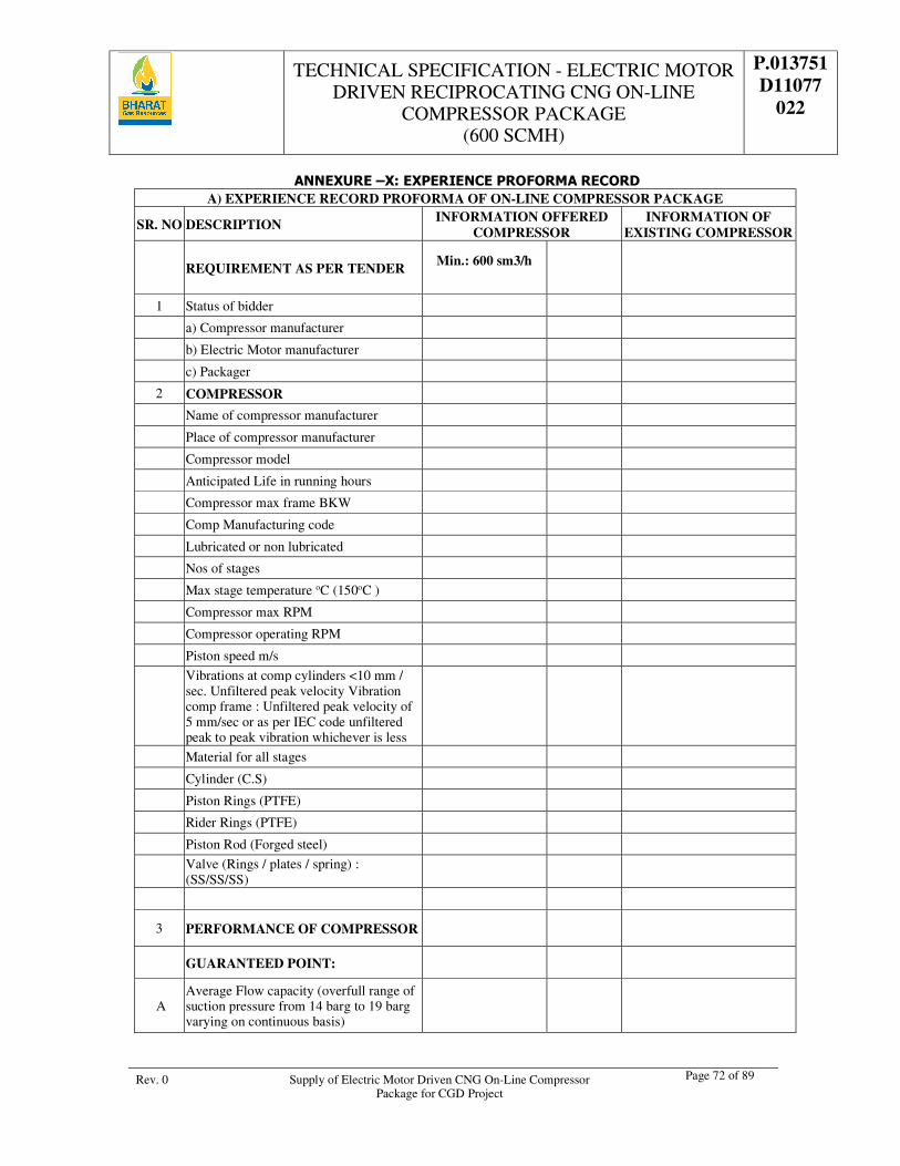
TECHNICAL SPECIFICATION - ELECTRIC MOTOR DRIVEN RECIPROCATING CNG ON-LINE
COMPRESSOR PACKAGE (600 SCMH)
P.013751 D11077
022
Rev. 0 Supply of Electric Motor Driven CNG On-Line Compressor Package for CGD Project
Page 72 of 89
ANNEXURE –X: EXPERIENCE PROFORMA RECORD A) EXPERIENCE RECORD PROFORMA OF ON-LINE COMPRESSOR PACKAGE
SR. NO DESCRIPTION INFORMATION OFFERED
COMPRESSOR INFORMATION OF
EXISTING COMPRESSOR
REQUIREMENT AS PER TENDER Min.: 600 sm3/h
1 Status of bidder
a) Compressor manufacturer
b) Electric Motor manufacturer
c) Packager
2 COMPRESSOR
Name of compressor manufacturer
Place of compressor manufacturer
Compressor model
Anticipated Life in running hours
Compressor max frame BKW
Comp Manufacturing code
Lubricated or non lubricated
Nos of stages
Max stage temperature oC (150oC )
Compressor max RPM
Compressor operating RPM
Piston speed m/s
Vibrations at comp cylinders <10 mm / sec. Unfiltered peak velocity Vibration comp frame : Unfiltered peak velocity of 5 mm/sec or as per IEC code unfiltered peak to peak vibration whichever is less
Material for all stages
Cylinder (C.S)
Piston Rings (PTFE)
Rider Rings (PTFE)
Piston Rod (Forged steel)
Valve (Rings / plates / spring) : (SS/SS/SS)
3 PERFORMANCE OF COMPRESSOR
GUARANTEED POINT:
A Average Flow capacity (overfull range of suction pressure from 14 barg to 19 barg varying on continuous basis)
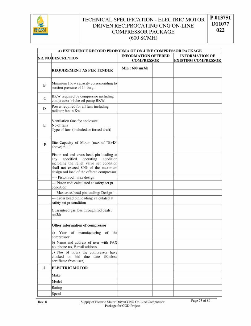
TECHNICAL SPECIFICATION - ELECTRIC MOTOR DRIVEN RECIPROCATING CNG ON-LINE
COMPRESSOR PACKAGE (600 SCMH)
P.013751 D11077
022
Rev. 0 Supply of Electric Motor Driven CNG On-Line Compressor Package for CGD Project
Page 73 of 89
A) EXPERIENCE RECORD PROFORMA OF ON-LINE COMPRESSOR PACKAGE
SR. NO DESCRIPTION INFORMATION OFFERED
COMPRESSOR INFORMATION OF
EXISTING COMPRESSOR
REQUIREMENT AS PER TENDER Min.: 600 sm3/h
B Minimum Flow capacity corresponding to suction pressure of 14 barg.
C BKW required by compressor including compressor’s lube oil pump BKW
D Power required for all fans including radiator fan in Kw
E Ventilation fans for enclosure No of fans Type of fans (included or forced draft)
F Site Capacity of Motor (max of “B+D” above) * 1.1
Piston rod and cross head pin loading at any specified operating condition including the relief valve set condition shall not exceed 80% of the maximum design rod load of the offered compressor
---- Piston rod : max design
--- Piston rod: calculated at safety set pr condition
--- Max cross head pin loading: Design ‘
--- Cross head pin loading: calculated at safety set pr condition
Guaranteed gas loss through rod deals; sm3/h
Other information of compressor
a) Year of manufacturing of the compressor
b) Name and address of user with FAX no, phone no, E-mail address
c) Nos of hours the compressor have clocked on bid due date (Enclose certificate from user)
4 ELECTRIC MOTOR
Make
Model
Rating
Speed
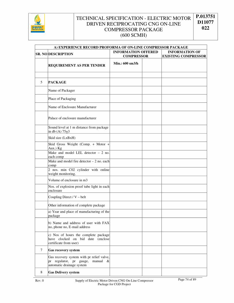
TECHNICAL SPECIFICATION - ELECTRIC MOTOR DRIVEN RECIPROCATING CNG ON-LINE
COMPRESSOR PACKAGE (600 SCMH)
P.013751 D11077
022
Rev. 0 Supply of Electric Motor Driven CNG On-Line Compressor Package for CGD Project
Page 74 of 89
A) EXPERIENCE RECORD PROFORMA OF ON-LINE COMPRESSOR PACKAGE
SR. NO DESCRIPTION INFORMATION OFFERED
COMPRESSOR INFORMATION OF
EXISTING COMPRESSOR
REQUIREMENT AS PER TENDER Min.: 600 sm3/h
5 PACKAGE
Name of Packager
Place of Packaging
Name of Enclosure Manufacturer
Palace of enclosure manufacturer
Sound level at 1 m distance from package in db (A) 75+3
Skid size (LxBxH)
Skid Gross Weight (Comp. + Motor + Aux.) Kg
Make and model LEL detector – 2 no. each comp
Make and model fire detector – 2 no. each comp
2 nos. min C02 cylinder with online weight monitoring.
Volume of enclosure in m3
Nos. of explosion proof tube light in each enclosure
Coupling Direct / V – belt
Other information of complete package
a) Year and place of manufacturing of the package
b) Name and address of user with FAX no, phone no, E-mail address
c) Nos of hours the complete package have clocked on bid date (enclose certificate from user)
7 Gas recovery system
Gas recovery system with pr relief valve, pr regulator, pr gauge, manual & automatic drainage system
8 Gas Delivery system
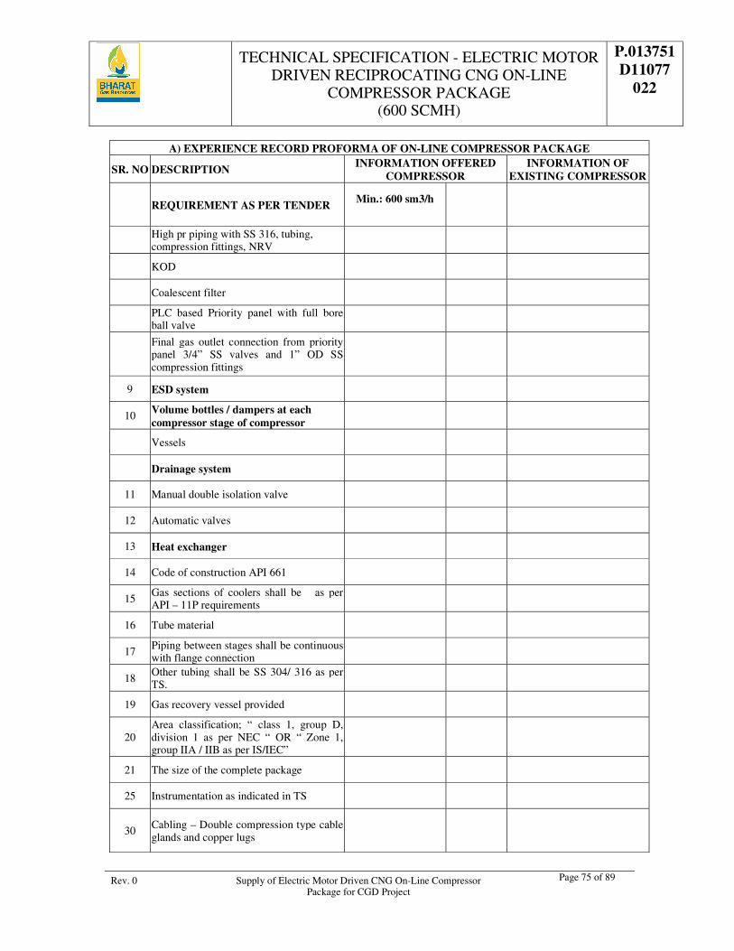
TECHNICAL SPECIFICATION - ELECTRIC MOTOR DRIVEN RECIPROCATING CNG ON-LINE
COMPRESSOR PACKAGE (600 SCMH)
P.013751 D11077
022
Rev. 0 Supply of Electric Motor Driven CNG On-Line Compressor Package for CGD Project
Page 75 of 89
A) EXPERIENCE RECORD PROFORMA OF ON-LINE COMPRESSOR PACKAGE
SR. NO DESCRIPTION INFORMATION OFFERED
COMPRESSOR INFORMATION OF
EXISTING COMPRESSOR
REQUIREMENT AS PER TENDER Min.: 600 sm3/h
High pr piping with SS 316, tubing, compression fittings, NRV
KOD
Coalescent filter
PLC based Priority panel with full bore ball valve
Final gas outlet connection from priority panel 3/4” SS valves and 1” OD SS compression fittings
9 ESD system
10 Volume bottles / dampers at each compressor stage of compressor
Vessels
Drainage system
11 Manual double isolation valve
12 Automatic valves
13 Heat exchanger
14 Code of construction API 661
15 Gas sections of coolers shall be as per API – 11P requirements
16 Tube material
17 Piping between stages shall be continuous with flange connection
18 Other tubing shall be SS 304/ 316 as per TS.
19 Gas recovery vessel provided
20 Area classification; “ class 1, group D, division 1 as per NEC “ OR “ Zone 1, group IIA / IIB as per IS/IEC”
21 The size of the complete package
25 Instrumentation as indicated in TS
30 Cabling – Double compression type cable glands and copper lugs
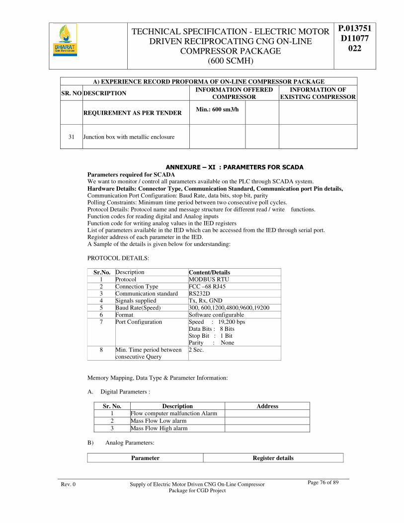
TECHNICAL SPECIFICATION - ELECTRIC MOTOR DRIVEN RECIPROCATING CNG ON-LINE
COMPRESSOR PACKAGE (600 SCMH)
P.013751 D11077
022
Rev. 0 Supply of Electric Motor Driven CNG On-Line Compressor Package for CGD Project
Page 76 of 89
A) EXPERIENCE RECORD PROFORMA OF ON-LINE COMPRESSOR PACKAGE
SR. NO DESCRIPTION INFORMATION OFFERED
COMPRESSOR INFORMATION OF
EXISTING COMPRESSOR
REQUIREMENT AS PER TENDER Min.: 600 sm3/h
31 Junction box with metallic enclosure
ANNEXURE – XI : PARAMETERS FOR SCADA Parameters required for SCADA We want to monitor / control all parameters available on the PLC through SCADA system. Hardware Details: Connector Type, Communication Standard, Communication port Pin details, Communication Port Configuration: Baud Rate, data bits, stop bit, parity Polling Constraints: Minimum time period between two consecutive poll cycles. Protocol Details: Protocol name and message structure for different read / write functions. Function codes for reading digital and Analog inputs Function code for writing analog values in the IED registers List of parameters available in the IED which can be accessed from the IED through serial port. Register address of each parameter in the IED. A Sample of the details is given below for understanding: PROTOCOL DETAILS:
Sr.No. Description Content/Details
1 Protocol MODBUS RTU 2 Connection Type FCC –68 RJ45 3 Communication standard RS232D 4 Signals supplied Tx, Rx, GND 5 Baud Rate(Speed) 300, 600,1200,4800,9600,19200 6 Format Software configurable 7 Port Configuration Speed : 19,200 bps
Data Bits : 8 Bits Stop Bit : 1 Bit Parity : None
8 Min. Time period between consecutive Query
2 Sec.
Memory Mapping, Data Type & Parameter Information:
A. Digital Parameters :
Sr. No. Description Address 1 Flow computer malfunction Alarm 2 Mass Flow Low alarm 3 Mass Flow High alarm
B) Analog Parameters:
Parameter Register details
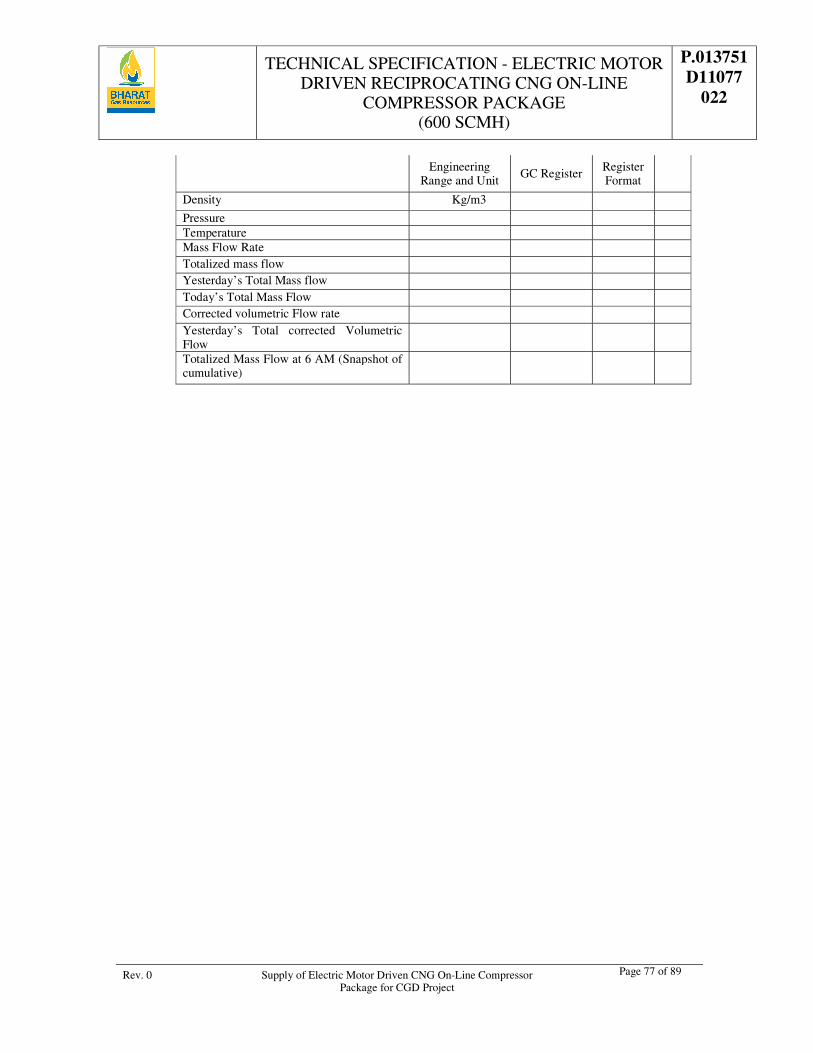
TECHNICAL SPECIFICATION - ELECTRIC MOTOR DRIVEN RECIPROCATING CNG ON-LINE
COMPRESSOR PACKAGE (600 SCMH)
P.013751 D11077
022
Rev. 0 Supply of Electric Motor Driven CNG On-Line Compressor Package for CGD Project
Page 77 of 89
Engineering Range and Unit
GC Register Register Format
Density Kg/m3
Pressure Temperature Mass Flow Rate Totalized mass flow Yesterday’s Total Mass flow Today’s Total Mass Flow Corrected volumetric Flow rate Yesterday’s Total corrected Volumetric Flow
Totalized Mass Flow at 6 AM (Snapshot of cumulative)
TECHNICAL SPECIFICATION - ELECTRIC MOTOR DRIVEN RECIPROCATING CNG ON-LINE
COMPRESSOR PACKAGE (600 SCMH)
P.013751 D11077
022
Rev. 0 Supply of Electric Motor Driven CNG On-Line Compressor Package for CGD Project
Page 78 of 89
ANNEXURE – XII
QUALITY ASSURANCE PLAN
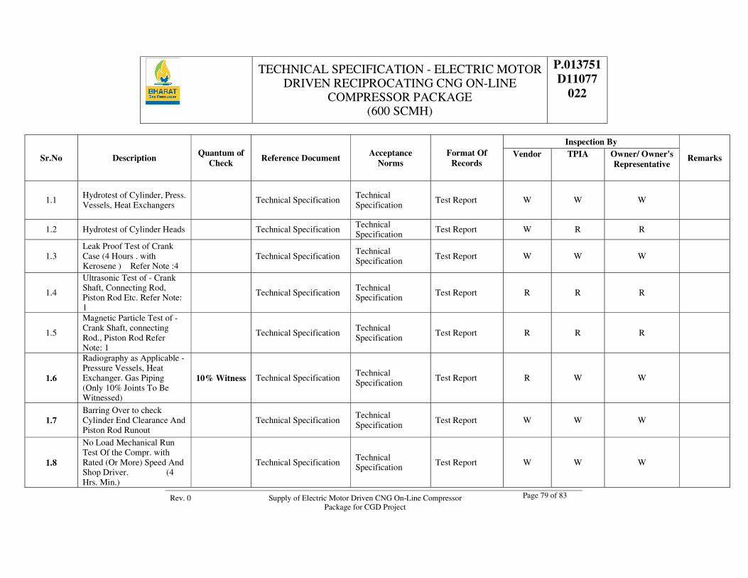
TECHNICAL SPECIFICATION - ELECTRIC MOTOR DRIVEN RECIPROCATING CNG ON-LINE
COMPRESSOR PACKAGE (600 SCMH)
P.013751 D11077
022
Rev. 0 Supply of Electric Motor Driven CNG On-Line Compressor Package for CGD Project
Page 79 of 83
Sr.No Description Quantum of Check Reference Document Acceptance
Norms Format Of
Records
Inspection By
Remarks Vendor TPIA Owner/ Owner's Representative
1.1 Hydrotest of Cylinder, Press. Vessels, Heat Exchangers
Technical Specification Technical Specification
Test Report W W W
1.2 Hydrotest of Cylinder Heads Technical Specification Technical Specification
Test Report W R R
1.3 Leak Proof Test of Crank Case (4 Hours . with Kerosene ) Refer Note :4
Technical Specification Technical Specification Test Report W W W
1.4
Ultrasonic Test of - Crank Shaft, Connecting Rod, Piston Rod Etc. Refer Note: 1
Technical Specification Technical Specification Test Report R R R
1.5
Magnetic Particle Test of - Crank Shaft, connecting Rod., Piston Rod Refer Note: 1
Technical Specification Technical Specification
Test Report R R R
1.6
Radiography as Applicable - Pressure Vessels, Heat Exchanger. Gas Piping (Only 10% Joints To Be Witnessed)
10% Witness Technical Specification Technical Specification
Test Report R W W
1.7 Barring Over to check Cylinder End Clearance And Piston Rod Runout
Technical Specification Technical Specification Test Report W W W
1.8
No Load Mechanical Run Test Of the Compr. with Rated (Or More) Speed And Shop Driver. (4 Hrs. Min.)
Technical Specification Technical Specification Test Report W W W
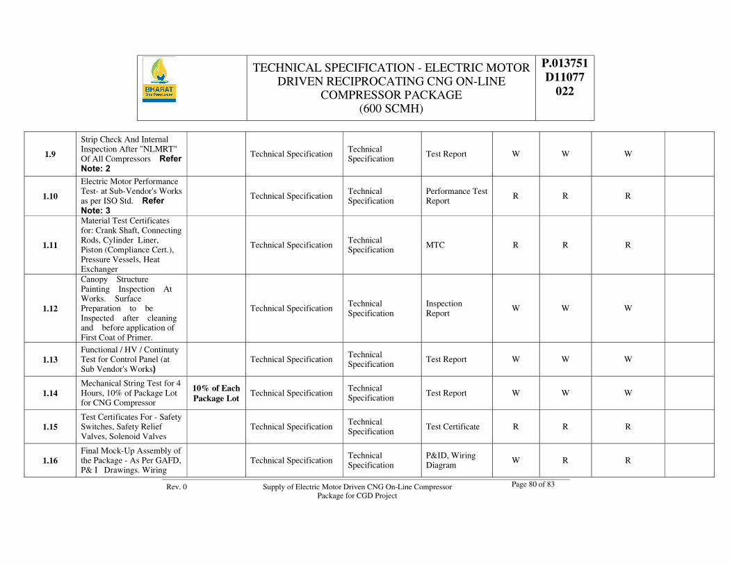
TECHNICAL SPECIFICATION - ELECTRIC MOTOR DRIVEN RECIPROCATING CNG ON-LINE
COMPRESSOR PACKAGE (600 SCMH)
P.013751 D11077
022
Rev. 0 Supply of Electric Motor Driven CNG On-Line Compressor Package for CGD Project
Page 80 of 83
1.9
Strip Check And Internal Inspection After "NLMRT" Of All Compressors Refer Note: 2
Technical Specification Technical Specification
Test Report W W W
1.10
Electric Motor Performance Test- at Sub-Vendor's Works as per ISO Std. Refer Note: 3
Technical Specification Technical Specification
Performance Test Report
R R R
1.11
Material Test Certificates for: Crank Shaft, Connecting Rods, Cylinder Liner, Piston (Compliance Cert.), Pressure Vessels, Heat Exchanger
Technical Specification Technical Specification MTC R R R
1.12
Canopy Structure Painting Inspection At Works. Surface Preparation to be Inspected after cleaning and before application of First Coat of Primer.
Technical Specification Technical Specification
Inspection Report
W W W
1.13 Functional / HV / Continuty Test for Control Panel (at Sub Vendor's Works)
Technical Specification Technical Specification
Test Report W W W
1.14 Mechanical String Test for 4 Hours, 10% of Package Lot for CNG Compressor
10% of Each Package Lot
Technical Specification Technical Specification
Test Report W W W
1.15 Test Certificates For - Safety Switches, Safety Relief Valves, Solenoid Valves
Technical Specification Technical Specification
Test Certificate R R R
1.16 Final Mock-Up Assembly of the Package - As Per GAFD, P& I Drawings. Wiring
Technical Specification Technical Specification
P&ID, Wiring Diagram W R R
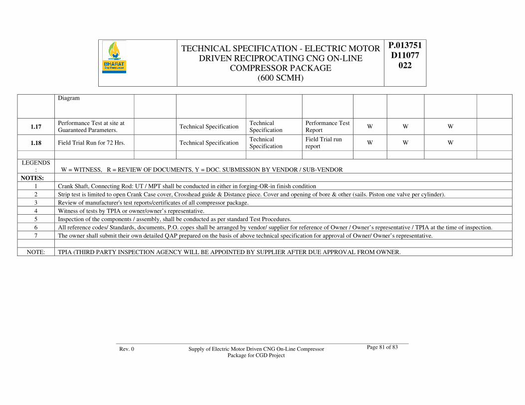
TECHNICAL SPECIFICATION - ELECTRIC MOTOR DRIVEN RECIPROCATING CNG ON-LINE
COMPRESSOR PACKAGE (600 SCMH)
P.013751 D11077
022
Rev. 0 Supply of Electric Motor Driven CNG On-Line Compressor Package for CGD Project
Page 81 of 83
Diagram
1.17 Performance Test at site at Guaranteed Parameters. Technical Specification
Technical Specification
Performance Test Report
W W W
1.18 Field Trial Run for 72 Hrs. Technical Specification Technical Specification
Field Trial run report W W W
LEGENDS
: W = WITNESS, R = REVIEW OF DOCUMENTS, Y = DOC. SUBMISSION BY VENDOR / SUB-VENDOR NOTES:
1 Crank Shaft, Connecting Rod: UT / MPT shall be conducted in either in forging-OR-in finish condition 2 Strip test is limited to open Crank Case cover, Crosshead guide & Distance piece. Cover and opening of bore & other (sails. Piston one valve per cylinder). 3 Review of manufacturer's test reports/certificates of all compressor package. 4 Witness of tests by TPIA or owner/owner’s representative. 5 Inspection of the components / assembly, shall be conducted as per standard Test Procedures. 6 All reference codes/ Standards, documents, P.O. copes shall be arranged by vendor/ supplier for reference of Owner / Owner’s representative / TPIA at the time of inspection. 7 The owner shall submit their own detailed QAP prepared on the basis of above technical specification for approval of Owner/ Owner’s representative.
NOTE: TPIA (THIRD PARTY INSPECTION AGENCY WILL BE APPOINTED BY SUPPLIER AFTER DUE APPROVAL FROM OWNER.
TECHNICAL SPECIFICATION - ELECTRIC MOTOR DRIVEN RECIPROCATING CNG ON-LINE
COMPRESSOR PACKAGE (600 SCMH)
P.013751 D11077
022
Rev. 0 Supply of Electric Motor Driven CNG On-Line Compressor Package for CGD Project
Page 82 of 89
ANNEXURE - XIII DATA SHEET

TECHNICAL SPECIFICATION - ELECTRIC MOTOR DRIVEN RECIPROCATING CNG ON-LINE
COMPRESSOR PACKAGE (600 SCMH)
P.013751 D11077
022
Rev. 0 Supply of Electric Motor Driven CNG On-Line Compressor Package for CGD Project
Page 83 of 89
DATA SHEET: MEDIUM VOLTAGE SQUIRREL CAGE INDUCTION MOTOR ELECTRICAL DESIGN DATA 1. Motor tag no. 2. Voltage (V) 415V + 10% Phase 3 Frequency (Hz.) 50 Hz+3% 3. Fault level (KA) NOT APPLICABLE 4. Method of starting VFD 5. Phase THREE Connection –
VFD Starter No. of terminal – 6
6. Design Ambient temp (0c) 50 0C (IN ACCOUSTIC ENCLOSURE) Temp. rise (0c) 70 0C (Maximum)
7. Cable size (mm2) AS PER SPEC ATTACHED Type CU. COND. PVC INS. 8. Enclosure type IP 55, Ex-d, IIA,
IIB,T3 Cooling TEFC
9. Insulation class CLASS-F with temperature rise of CLASS B 10. Haz. Area classification/ Gas
Group ZONE-1, GROUP-IIA, IIB, Temp Class T3 as per IS/IEC
11. Type of explosion protection: Ex (d) Applicable standards: IS/IEC Technical particulars from Driven equipment manufacturer
12. Suggested Motor Rating in KW/ Manufacturer # / # 13. Shaft kw/kw at end of curve # / # 14. Speed/ rotation of equipment from Coupling End # / # 15. Starting/ max. Torque required (mkg) # / # 16. WK2 of equipment including/ excluding lywheel
(kgm2) # / #
17. Thrust up/ down (kg) # / # 18. Equipment/ coupling type # / # 19. Starting Condition-On no load/ Under loaded condition #
Technical particulars from motor manufacturer 20. Manufacturer * 21. KW Rating * No. of poles * 22. Frame designation * Mounting (Horizontal) * 23. Full load speed (Max. 1500 rpm) * Full load Torque (mkg) * 24. Starting torque as % of full load torque * 25. Full load current (A) * 26. Starting current at 100% Voltage (A) * 27. Breakdown or pull out torque % * 28. Rotation viewed from coupling end * 29. Starting time at 75%V * (sec.) Starting time at 100%V * (sec) 30. Time (Te) for increased safety motors at 100% Voltage
(secs.) NOT APPLICABLE
31. Locked rotor with stand time cold/ hot at 75% V(sec)
* At 100% V(sec) *
32. WK2 of motor (kg m2) * 33. Power factor at 100% load * Power Factor at 75% load * 34. Efficiency at 100% load * Efficiency at 75% load * 35. Space heater watts/ volts */ 240V AC 36. Bearing type/ no. DE */* Bearing type/ no. NDE */* 37. Type of Lubrication * 38. Weight of motor (kg) * 39. Canopy required/ Not required NOT REQUIRED
# TO BE FILLED BY BIDDER BASED ON THE PACKAGE DESIGN * TO BE FILLED BY MOTOR MANUFACTURER Bidder must quote for only one make of motor. Bidder shall submit filled up data sheet for the selected make of motor only.
Motor Terminal Box must be suitable for the cable size indicated on data sheet.
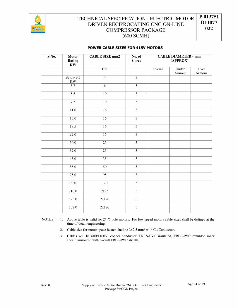
TECHNICAL SPECIFICATION - ELECTRIC MOTOR DRIVEN RECIPROCATING CNG ON-LINE
COMPRESSOR PACKAGE (600 SCMH)
P.013751 D11077
022
Rev. 0 Supply of Electric Motor Driven CNG On-Line Compressor Package for CGD Project
Page 84 of 89
POWER CABLE SIZES FOR 415V MOTORS
S.No. Motor Rating
KW
CABLE SIZE mm2 No. of Cores
CABLE DIAMETER - mm (APPROX)
CU
Overall Under Armour
Over Armous
Below 3.7 KW
4 3
3.7 6 3
5.5 10 3
7.5 10 3
11.0 16
3
15.0 16 3
18.5 16 3
22.0 16 3
30.0 25 3
37.0 25 3
45.0 35 3
55.0 50 3
75.0 95 3
90.0 120 3
110.0 2x95 3
125.0 2x120 3
132.0 2x120 3
NOTES: 1. Above table is valid for 2/4/6 pole motors. For low speed motors cable sizes shall be defined at the
time of detail engineering.
2. Cable size for motor space heater shall be 3x2.5 mm2 with Cu Conductor.
3. Cables will be 600/1100V, copper conductor, FRLS-PVC insulated, FRLS-PVC extruded inner sheath armoured with overall FRLS-PVC sheath.
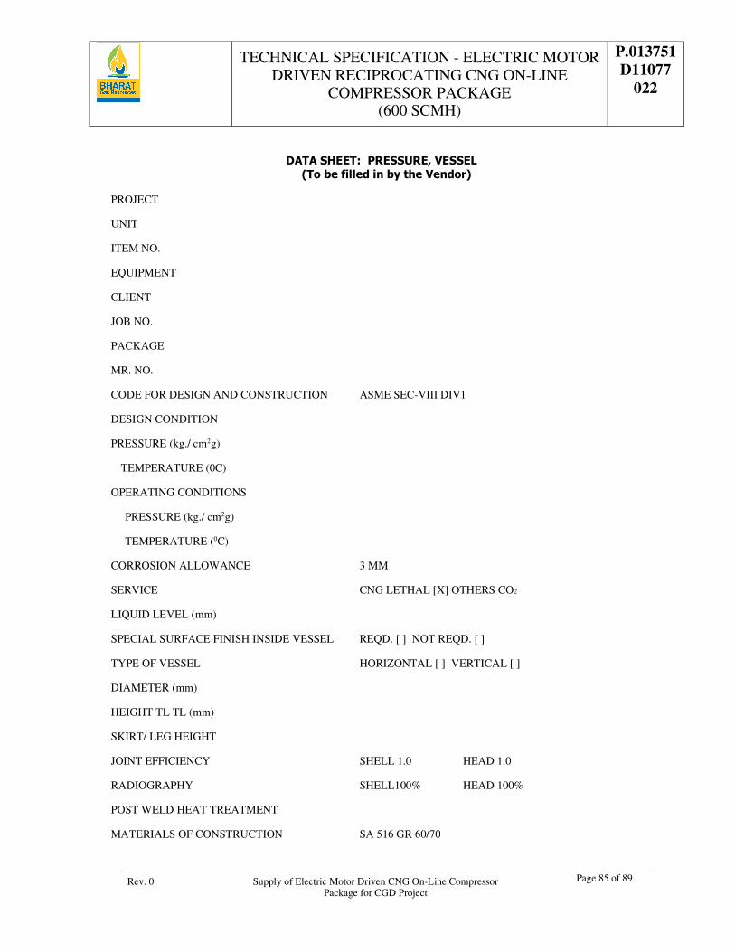
TECHNICAL SPECIFICATION - ELECTRIC MOTOR DRIVEN RECIPROCATING CNG ON-LINE
COMPRESSOR PACKAGE (600 SCMH)
P.013751 D11077
022
Rev. 0 Supply of Electric Motor Driven CNG On-Line Compressor Package for CGD Project
Page 85 of 89
DATA SHEET: PRESSURE, VESSEL
(To be filled in by the Vendor) PROJECT
UNIT
ITEM NO.
EQUIPMENT
CLIENT
JOB NO.
PACKAGE
MR. NO.
CODE FOR DESIGN AND CONSTRUCTION ASME SEC-VIII DIV1
DESIGN CONDITION
PRESSURE (kg./ cm2g)
TEMPERATURE (0C)
OPERATING CONDITIONS
PRESSURE (kg./ cm2g)
TEMPERATURE (0C)
CORROSION ALLOWANCE 3 MM
SERVICE CNG LETHAL [X] OTHERS CO2
LIQUID LEVEL (mm)
SPECIAL SURFACE FINISH INSIDE VESSEL REQD. [ ] NOT REQD. [ ]
TYPE OF VESSEL HORIZONTAL [ ] VERTICAL [ ]
DIAMETER (mm)
HEIGHT TL TL (mm)
SKIRT/ LEG HEIGHT
JOINT EFFICIENCY SHELL 1.0 HEAD 1.0
RADIOGRAPHY SHELL100% HEAD 100%
POST WELD HEAT TREATMENT
MATERIALS OF CONSTRUCTION SA 516 GR 60/70
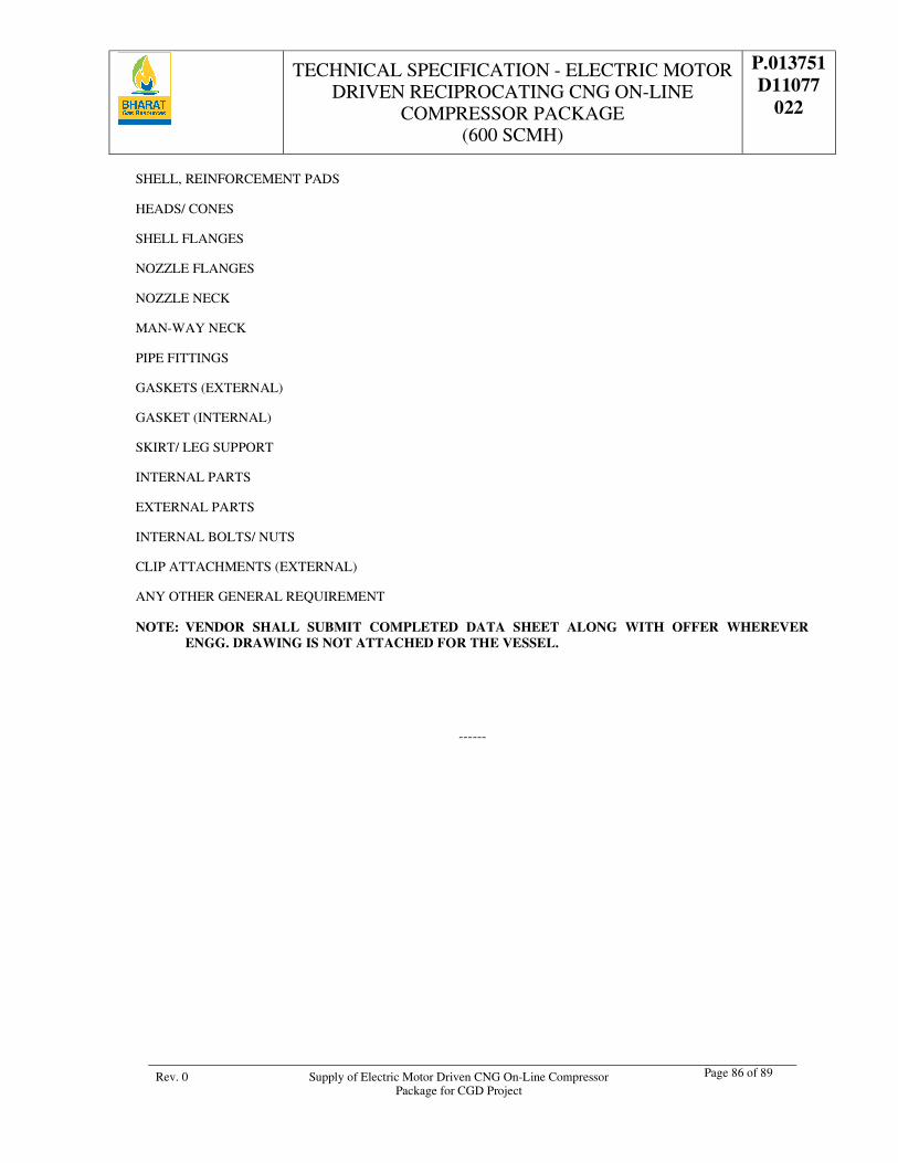
TECHNICAL SPECIFICATION - ELECTRIC MOTOR DRIVEN RECIPROCATING CNG ON-LINE
COMPRESSOR PACKAGE (600 SCMH)
P.013751 D11077
022
Rev. 0 Supply of Electric Motor Driven CNG On-Line Compressor Package for CGD Project
Page 86 of 89
SHELL, REINFORCEMENT PADS
HEADS/ CONES
SHELL FLANGES
NOZZLE FLANGES
NOZZLE NECK
MAN-WAY NECK
PIPE FITTINGS
GASKETS (EXTERNAL)
GASKET (INTERNAL)
SKIRT/ LEG SUPPORT
INTERNAL PARTS
EXTERNAL PARTS
INTERNAL BOLTS/ NUTS
CLIP ATTACHMENTS (EXTERNAL)
ANY OTHER GENERAL REQUIREMENT
NOTE: VENDOR SHALL SUBMIT COMPLETED DATA SHEET ALONG WITH OFFER WHEREVER ENGG. DRAWING IS NOT ATTACHED FOR THE VESSEL.
------
TECHNICAL SPECIFICATION - ELECTRIC MOTOR DRIVEN RECIPROCATING CNG ON-LINE
COMPRESSOR PACKAGE (600 SCMH)
P.013751 D11077
022
Rev. 0 Supply of Electric Motor Driven CNG On-Line Compressor Package for CGD Project
Page 87 of 89
1. DOCUMENT DISTRIBUTION SCHEDULE
1.1. Documents and drawings under column no. 3 shall be submitted with each copy of the bid.
1.2. Documents listed under column 4 are to be submitted in 4 copies
1.3. Documents listed in column 5 are to be submitted as hard bound indexed book containing the following details in Two (2) copies and to be submitted within 4 weeks of release note/dispatch of materials/ equipment from vendor's works.
2. DETAILS TO BE INCLUDED IN FINAL DOCUMENTS BOOKS
2.1. Copy of P.O. and all amendments.
2.2. Copy of Purchase Requisition and all amendments.
2.3. Manufacturing Data Book containing all test certificates of components, raw materials, stage manufacturing tests and inspections, final tests & inspection documents including welders' qualification & welding procedure qualification, repairs & reworking carried out in shops. All raw material test certificates must be correlated to the P.O. Item No. & component to which they relate by clear noting on the certificates.
2.4. Spares details including assembly drawings, part numbers, delivery, prices and ordering information.
2.5. All design calculations carried out by the vendor.
2.6. Final Drawing Index and all as-built drawings reduced to A3/ A4 size and wherever reduction is not possible, full size copies duly folded and placed in plastic pockets.
2.7. Catalogues/leaflets of sub-vendors/suppliers of various bought out components highlighting the components actually supplied correlated to P.O. Item Numbers.
2.8. Operating and maintenance instructions including lubrication schedules with details of suppliers for procurement by OWNER for subsequent needs.
2.9. Release Note and Packing List.
2.10. Any other documents asked for in the Purchase Requisition.
2.11. All final drawings shall also be given to purchaser in digitized form on CD-ROM compatible to AUTOCAD software.
2.12. Final documents including operation and maintenance manual should be submitted, one copy per package plus one original.
2.13. Operation and maintenance manual shall include assembly and disassembly, specification (torque chart), parts manual, complete list of bill of material, bought out spares and accessories. One original plus individual copies for the no. of compressor packages supplied.
3. SPECIAL INSTRUCTIONS FOR SUBMISSION OF DWGS./DOCUMENTS:
3.1. Fold all prints to 216 MM x 279 MM size & roll transparencies.
3.2. Contractor to forward the drawings and documentation to OWNER (Attention vendor prints control department) clearly specifying purchasers Job no. & Req. No.
3.3. The drawing/Document no. with Rev. No. is essential. The number may be upto a maximum of 28 characters in length.
3.4. Each Drawing/Document submitted to OWNER must be checked and signed/stamped by contractor before it is submitted to OWNER.
3.5. Revision number must change during subsequent submission of vendor document.
3.6. Multi-sheet documents other than drawings must be submitted in their entirety in the event of a re-submission even if only a few sheets are revised.
TECHNICAL SPECIFICATION - ELECTRIC MOTOR DRIVEN RECIPROCATING CNG ON-LINE
COMPRESSOR PACKAGE (600 SCMH)
P.013751 D11077
022
Rev. 0 Supply of Electric Motor Driven CNG On-Line Compressor Package for CGD Project
Page 88 of 89
3.7. Final submission in bound volumes shall necessarily have a cover page giving project title, Item name, P.O. No. particulars of owner, consultant & vendor and an index giving list of drawings & documents included (with revision no.).
3.8. All vendor drawings to be provided with a blank space measuring 75 mm W x 38 mm H for marking of review codes etc. by OWNER.
3.9. The review of the vendor drawings shall be done by OWNER, as applicable, under the following review codes:
R Review Code 1 N No comments.
R Review Code 2 P Proceed with manufacture/fabrication as per commented drawings.
Revise drawings required
R Review Code 3 D Document does not conform to basic requirements.
3.10. Review of vendor drawings by OWNER would be only to check compatibility with basic designs & concepts & would in no way absolve the contractor/vendor of his responsibility to meet applicable codes, specifications & statutory rules/regulations.
Vendor shall submit within 10 days after placement of FOI, the complete list of drawings/ documents with submission dates against each. Critical drawings, only, the list of which will be agreed during kick-off meeting shall be reviewed jointly at OWNER's office.