ELECTRONIC MECHANIC - Bharat Skills
162
(i) NATIONAL INSTRUCTIONAL MEDIA INSTITUTE, CHENNAI Post Box No. 3142, CTI Campus, Guindy, Chennai - 600 032 DIRECTORATE GENERAL OF TRAINING MINISTRY OF SKILL DEVELOPMENT & ENTREPRENEURSHIP GOVERNMENT OF INDIA TRADE PRACTICAL SECTOR: Electronics & Hardware ELECTRONIC MECHANIC NSQF LEVEL - 5 2 nd Year (Volume II of II) Copyright Free Under CC BY Licence
-
Upload
khangminh22 -
Category
Documents
-
view
1 -
download
0
Transcript of ELECTRONIC MECHANIC - Bharat Skills

(i)
NATIONAL INSTRUCTIONALMEDIA INSTITUTE, CHENNAI
Post Box No. 3142, CTI Campus, Guindy, Chennai - 600 032
DIRECTORATE GENERAL OF TRAINING MINISTRY OF SKILL DEVELOPMENT & ENTREPRENEURSHIP
GOVERNMENT OF INDIA
TRADE PRACTICAL
SECTOR: Electronics & Hardware
ELECTRONIC MECHANICNSQF LEVEL - 5
2nd Year (Volume II of II)
Copyright Free Under CC BY Licence

(ii)
Sector : Electronics and HardwareDuration : 2 - YearTrade : Electronic Mechanic 2nd Year (Volume II of II) - Trade Practical - NSQF level 5
First EditionFirst Reprint : February 2019 Copies : 2,000
: November 2018 Copies : 1,000
Rs. 170/-
All rights reserved.
No part of this publication can be reproduced or transmitted in any form or by any means, electronic or mechanical, includingphotocopy, recording or any information storage and retrieval system, without permission in writing from the NationalInstructional Media Institute, Chennai.
Published by:
NATIONAL INSTRUCTIONAL MEDIA INSTITUTEP. B. No.3142, CTI Campus, Guindy Industrial Estate,
Guindy, Chennai - 600 032.Phone : 044 - 2250 0248, 2250 0657, 2250 2421
Fax : 91 - 44 - 2250 0791email : [email protected], [email protected]
Website: www.nimi.gov.in
Copyright Free Under CC BY Licence

(iii)
FOREWORDThe Government of India has set an ambitious target of imparting skills to 30 crores people, one out of every four Indians, by 2020 to help them secure jobs as part of the National Skills Development Policy. Industrial Training Institutes (ITIs) play a vital role in this process especially in terms of providing skilled manpower. Keeping this in mind, and for providing the current industry relevant skill training to Trainees, ITI syllabus has been recently updated with the help of Mentor Councils comprising various stakeholders viz. Industries, Entrepreneurs, Academicians and representatives from ITIs.
The National Instructional Media Institute (NIMI), Chennai, has now come up with instructional material to suit the revised curriculum for Electronic Mechanic, 2nd Year (Volume II of II) Trade Practical NSQF Level - 5 in Electronics & Hardware Sector under Semester Pattern. The NSQF Level - 5 Trade Practical will help the trainees to get an international equivalency standard where their skill proficiency and competency will be duly recognized across the globe and this will also increase the scope of recognition of prior learning. NSQF Level - 5 trainees will also get the opportunities to promote life long learning and skill development. I have no doubt that with NSQF Level - 5 the trainers and trainees of ITIs, and all stakeholders will derive maximum benefits from these Instructional Media Packages IMPs and that NIMI's effort will go a long way in improving the quality of Vocational training in the country.
The Executive Director & Staff of NIMI and members of Media Development Committee deserve appreciation for their contribution in bringing out this publication.
Jai Hind
RAJESH AGGARWALDirector General/ Addl.Secretary
Ministry of Skill Development & Entrepreneurship,Government of India.
New Delhi - 110 001
Copyright Free Under CC BY Licence

(iv)
PREFACEThe National Instructional Media Institute (NIMI) was established in 1986 at Chennai by then DirectorateGeneral of Employment and Training (D.G.E & T), Ministry of Labour and Employment, (now under DirectorateGeneral of Training, Ministry of Skill Development and Entrepreneurship) Government of India, with technicalassistance from the Govt. of Federal Republic of Germany. The prime objective of this Institute is to developand provide instructional materials for various trades as per the prescribed syllabi under the Craftsman andApprenticeship Training Schemes.
The instructional materials are created keeping in mind, the main objective of Vocational Training underNCVT/NAC in India, which is to help an individual to master skills to do a job. The instructional materials aregenerated in the form of Instructional Media Packages (IMPs). An IMP consists of Theory book, Practicalbook, Test and Assignment book, Instructor Guide, Audio Visual Aid (Wall charts and Transparencies) andother support materials.
The trade practical book consists of series of exercises to be completed by the trainees in the workshop.These exercises are designed to ensure that all the skills in the prescribed syllabus are covered. The tradetheory book provides related theoretical knowledge required to enable the trainee to do a job. The test andassignments will enable the instructor to give assignments for the evaluation of the performance of a trainee.The wall charts and transparencies are unique, as they not only help the instructor to effectively present atopic but also help him to assess the trainee's understanding. The instructor guide enables the instructor toplan his schedule of instruction, plan the raw material requirements, day to day lessons and demonstrations.
IMPs also deals with the complex skills required to be developed for effective team work. Necessary carehas also been taken to include important skill areas of allied trades as prescribed in the syllabus.
The availability of a complete Instructional Media Package in an institute helps both the trainer andmanagement to impart effective training.
The IMPs are the outcome of collective efforts of the staff members of NIMI and the members of the MediaDevelopment Committees specially drawn from Public and Private sector industries, various training institutesunder the Directorate General of Training (DGT), Government and Private ITIs.
NIMI would like to take this opportunity to convey sincere thanks to the Directors of Employment & Trainingof various State Governments, Training Departments of Industries both in the Public and Private sectors,Officers of DGT and DGT field institutes, proof readers, individual media developers and coordinators, but forwhose active support NIMI would not have been able to bring out this materials.
R. P. DHINGRAROTCERID EVITUCEXE 230 006 - iannehC
Copyright Free Under CC BY Licence

(v)
ACKNOWLEDGEMENTNational Instructional Media Institute (NIMI) sincerely acknowledges with thanks for the co-operation and contributionextended by the following Media Developers and their sponsoring organisation to bring out this IMP (Trade Practical)for the trade of Electronic Mechanic under the Electronics & Hardware Sector for ITIs.
MEDIA DEVELOPMENT COMMITTEE MEMBERS
Shri. N.P Bannibagi - Assistant Director of TrainingNSTI Ramanthapur campusHyderabad.
Smt. K. Arul Selvi - Training OfficerNSTI (W)Trichy.
Shri. K. Hemalatha - Vocational InstructorNSTIChennai - 32
rotcurtsnI lanoitacoV-dnanA .C .irhSGovt. ITI for women,Puducherry.
Shri. A. Jayaraman - Training Officer (Rtd),Govt. of IndiaCTI, GuindyChennai - 32.
Shri. R.N. Krishnasamy - Vocational Instructor (Rtd)Govt. of India (VRC)Guindy, Chennai -32.
Shri. S. Gopalakrishnan _ Assistant Manager,NIMI, Chennai - 32
NIMI records its appreciation of the Data Entry, CAD, DTP Operators for their excellent and devoted services inthe process of development of this Instructional Material.
NIMI also acknowledges with thanks, the invaluable efforts rendered by all other staff who have contributed for thedevelopment of this Instructional Material.
NIMI is grateful to all others who have directly or indirectly helped in developing this IMP.
Shri. K. Srinivasa Rao _ General Manager, NIMI, Chennai - 32
NIMI COORDINATOR
Copyright Free Under CC BY Licence

(vi)
INTRODUCTION
TRADE PRACTICAL
The trade practical manual is intented to be used in workshop . It consists of a series of practical exercisesto be completed by the trainees during the Fourth Semester course of the Electronic Mechanic tradesupplemented and supported by instructions/ informations to assist in performing the exercises. These exer-cises are designed to ensure that all the skills in compliance with NSQF LEVEL - 5
The manual is divided into Eight modules. The distribution of time for the practical in the Eight modules aregiven below.
Module 1 Fiber Optic Communication 25 Hrs
Module 2 Digital Panel Meter 50 Hrs
Module 3 SMPS & Inverter 75 Hrs
Module 4 UPS 75 Hrs
Module 5 Solar Power (Renewable Energy) 75 Hrs
Module 6 Cell Phones 50 Hrs
Module 7 LED Lights 50 Hrs
Module 8 LCD & LED TV 125 Hrs
Project work/Industrial visits 50 Hrs
Total 575 Hrs
The skill training in the shop floor is planned through a series of practical exercises centred around somepractical project. However, there are few instances where the individual exercise does not from a part ofproject.
While developing the practical manual a sincere effort was made to prepare each exercise which will be easyto understand and carry out even by below average trainee. However the development team accept that thereis a scope for further improvement. NIMI, looks forward to the suggestions from the experienced trainingfaculty for improving the manual.
TRADE THEORY
The manual of trade theory consists of theoretical information for the Fourth Semester course of theElectronic Mechanic Trade. The contents are sequenced according to the practical exercise contained in themanual on Trade practical. Attempt has been made to relate the theortical aspects with the skill covered ineach exercise to the extent possible. This co-relation is maintained to help the trainees to develop theperceptional capabilities for performing the skills.
The Trade theory has to be taught and learnt along with the corresponding exercise contained in the manualon trade practical. The indicating about the corresponding practical exercise are given in every sheet of thismanual.
It will be preferable to teach/learn the trade theory connected to each exercises atleast one class beforeperforming the related skills in the shop floor. The trade theory is to be treated as an integrated part of eachexercise.
The material is not the purpose of self learning and should be considered as supplementary to class roominstruction.
Copyright Free Under CC BY Licence

(vii)
CONTENTS
Exercise No. Title of the Exercise Page No.
Module 1 : Fiber Optic Communication
4.1.243 Identify the resources and their need on the given fiber optic trainer kit. 1
4.1.244 Make optical fiber set up to transmit and receive analog and digital data 3
4.1.245 Set up the OFC trainer kit to study AM, FM, PWM modulationand demodulation 4
4.1.246 Perform FM modulation and demodulation using OFC trainer kit using 10audio signal and voice link.
4.1.247 Perform PWM modulation and demodulation using OFC trainer kit 13using audio signal and voice link.
4.1.248 Perform PPM modulation and demodulation using OFC trainer kit 15using audio signal and voice link.
Module 2: Digital Panel Meter
4.2.249 Identify LED display module and its decoder/driver ICs. 17
4.2.250 Display a word on a two line LED. 19
4.2.251 Measure current flowing through a resistor and display it on a LED module 21
4.2.252 Measure current flowing through a sensor and display it on a LED module 22
4.2.253 Identify LCD display module and its decorder/driver ICs. 24
4.2.254 Measure current flowing through a resistor and display it. 26
Module 3 : SMPS and Inverter
4.3.255 Identify the components/devices of SMPS and draw their correspondingSymbols. 27
4.3.256 Dismantle the given voltage stabilizer and find major sections/ICscomponents 30
4.3.257 List the defect and symptom in the faulty SMPS. 31
4.3.258 Measure/monitor major test points of computer SMPS. 34
4.3.259 Troubleshoot the fault in the given SMPS unit. Rectify the defect andverify the output with load (Record your procedure followed fortroubleshooting the defects). 39
4.3.260 Use SMPS used in TVs and PCs for practice. 45
4.3.261 Install and test the SMPS in PC. 48
4.3.262 Install and test a Inverter. 49
Copyright Free Under CC BY Licence

(viii)
Exercise No. Title of the Exercise Page No.
4.3.263 Troubleshoot the fault in the given inverter unit. Rectify the defect andverify the output with load. 51
4.3.264 Construct and test IC based DC-to-DC converter for different votlages. 53
4.3.265 Construct and test a switching step down regulator using LM2576. 56
4.3.266 Construct and test a switching step down regulator using MC34063. 57
Module 4: UPS
4.4.267 Connect battery stack to the UPS 58
4.4.268 Identify front panel controls & indicators of UPS. 59
4.4.269 Connect battery & load to UPS and test on battery mode. 61
4.4.270 Open top cover of a UPS, idenify its isolation transformers, the UPStransformer and various circuit boards in UPS. 64
4.4.271 Identify the various test points and verify the voltages on these 66
4.4.272 Identify various circuit boards in UPS and monitor voltages at varioustest points. 67
4.4.273 Perform load test to measure backup time 69
4.4.274 Perform all above experiment for three phase UPS. 71
Module 5: Solar Power (Renewable Energy System)
4.5.275 Install a solar panel to a roof. 73
4.5.276 Wire a solar charge controller to a battery storage station. 77
4.5.277 Install solar power 500 panel directly to 12 VDC appliances. 79
4.5.278 Connect storage batteries to a power inverter. 81
4.5.279 Connect and test solar panel to the inverter and run the load 83
4.5.280 Install a solar panel to charge a rechargeable 12VDC battery and findout the charging time 86
4.5.281 Install a Solar inverter 87
Module 6: Cell phones
4.6.282 Dismantle, identify the parts and assemble different types of smart phones 90
4.6.283 Dismantle the cell phone/smart phone remove the key pad and clean it,test for the continuity of the matrix/track. 95
Copyright Free Under CC BY Licence

(ix)
Exercise No. Title of the Exercise Page No.
4.6.284 Interface the cell phone/smart phone to the PC and transfer the data card 97
4.6.285 Flash the various brands of cell phone/smart phone (at least 3) 100
4.6.286 Format the cell phone/smart phone for virus (approach the mobile repairshop/service centre) 102
4.6.287 Unlock the handsets through codes and software 104
4.6.288 Perform the interfacing of cell phone/smart phone to the PC anddismantle the cell phone and identify the power section and testits healthiness. 106
4.6.289 Find out the fault of basic cell phone system. Rectify the fault in ringersection and check the perfromance. 109
4.6.290 Replace various faulty parts like microphone, speaker, data/chargingaudio jack etc. 117
Module 7: LED Lights
4.7.291 Dismantle the LED light, identify the connections of LED stacks,protection circuits, regulator. 119
4.7.292 Identify the rectifier, controller part of LED light 121
4.7.293 Make series string connection of six LEDs and connect four seriesstrings in parallel 123
4.7.294 Connect to such parallel sets in series to create a matrix of LEDs 125
4.7.295 Apply suitable voltage and check voltage across series strings 126
Module 8 : LCD & LED TV
4.8.296 Identify and operate different controls on LCD and LED TV 127
4.8.297 Identify components and different sections of LCD and LED TV 129
4.8.298 Dismantle, identify the parts of the remote control 131
4.8.299 Dismantle the given LCD/LED to find faults with input stages throughconnectors. 134
4.8.300 Detect the defect in a LED/LCD receiver given to you. Rectifythe fault. 136
4.8.301 Troubleshoot the fault in the given LCD/LED TV receiver. Locate andrectify the faults. 138
4.8.302 Test the LED/LCD after troubleshooting the defects 141
4.8.303 Identify various connectors and connect the cable operators externaldecorder (set top box) to the TV 144
Copyright Free Under CC BY Licence

(x)
LEARNING / ASSESSABLE OUTCOME
On completion of this book you shall be able to
• Prepare fiber optic setup and execute transmission and reception.
• Plan and Interface the LCD, LED, DPM panels to various circuitsand evaluate performance.
• Detect the faults and troubleshoot SMPS, UPS and inverter.
• Install a solar panel, execute testing and evaluate performance byconnecting the panel to the inverter.
• Dismantle, identify the various parts and interface of a cell phoneto a PC. Estimate and troubleshoot.
• Identify various parts of LED lights & stacks and troubleshoot.
• Identify, operate various controls, troubleshoot and replacemodules of the LCD/LED TV & its remote control.
Copyright Free Under CC BY Licence
WeekNo.
LearningOutcome Reference
Professional Skills(Trade Practical)with Indicative hrs.
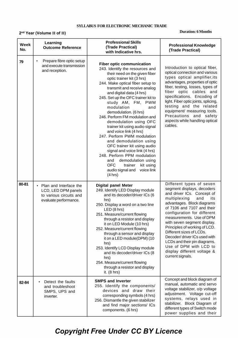
Fiber optic communication243. Identify the resources and
their need on the given fiberoptic trainer kit (3 hrs)
244. Make optical fiber setup totransmit and receive analogand digital data (4 hrs)
245. Set up the OFC trainer kit tostudy AM, FM, PWMmodulation anddemodulation. (6 hrs)
246. Perform FM modulation anddemodulation using OFCtrainer kit using audio signaland voice link (4 hrs)
247. Perform PWM modulationand demodulation usingOFC trainer kit using audiosignal and voice link (4 hrs)
248. Perform PPM modulationand demodulation usingOFC trainer kit usingaudio signal and voice link(4 hrs)
Professional Knowledge(Trade Practical)
Introduction to optical fiber,optical connection and varioustypes optical amplifier,itsadvantages, properties of opticfiber, testing, losses, types offiber optic cables andspecifications. Encoding oflight. Fiber optic joints, splicing,testing and the relatedequipment/ measuring tools.Precautions and safetyaspects while handling opticalcables.
• Prepare fibre optic setupand execute transmissionand reception.
SYLLABUS FOR ELECTRONIC MECHANIC TRADE
2nd Year (Volume II of II) Duration: 6 Months
79
80-81 • Plan and Interface theLCD, LED DPM panelsto various circuits andevaluate performance.
Digital panel Meter249. Identify LED Display module
and its decoder/driver ICs (6hrs)
250. Display a word on a two lineLED (8 hrs)
251. Measure/current flowingthrough a resistor and displayit on LED Module (10 hrs)
252. Measure/current flowingthrough a sensor and displayit on a LED module(DPM) (10hrs)
253. Identify LCD Display moduleand its decoder/driver ICs (8hrs)
254. Measure/current flowingthrough a resistor and displayit. (8 hrs)
Different types of sevensegment displays, decodersand driver ICs. Concept ofmultiplexing and itsadvantages. Block diagramsof 7106 and 7107 and theirconfiguration for differentmeasurements. Use of DPMwith seven segment display.Principles of working of LCD.Different sizes of LCDs.Decoder/ driver ICs used withLCDs and their pin diagrams.Use of DPM with LCD todisplay different voltage ¤t signals.
82-84 • Detect the faultsand troubleshootSMPS, UPS andinverter.
SMPS and Inverter255. Identify the components/
devices and draw theircorresponding symbols (4 hrs)
256. Dismantle the given stabilizerand find major sections/ ICscomponents. (6 hrs)
Concept and block diagram ofmanual, automatic and servovoltage stabilizer, o/p voltageadjustment. Voltage cut-offsystems, relays used instabilizer. Block Diagram ofdifferent types of Switch modepower supplies and their
Copyright Free Under CC BY Licence

257. List the defect and symptom inthe faulty SMPS. (5 hrs)
258. Measure / Monitor major test pointsof computer SMPS. (8 hrs)
259. Troubleshoot the fault in the givenSMPS unit. Rectify the defect andverify the output with load. Recordyour procedure followed for troubleshooting the defects (10 hrs) 260.Use SMPS used in TVs and PCsfor Practice. (6 hrs) 261. Install andtest the SMPS in PC (6 hrs) 262.Install and test a inverter. (6 hrs)263. Troubleshoot the fault in thegiven inverter unit. Rectify thedefects and verify the output withload. (6 hrs)
264. Construct and test IC Based DC-DC converter for different voltages(6 hrs)
265. Construct and test a switching stepdown regulator using LM2576 (6hrs)
266. Construct and test a switchingstep up regulator using MC 34063(6 hrs)
working principles. Varioustypes of chopper circuits.Inverter; principle of operation,block diagram, power rating,change over period.Installation of inverters,protection circuits used ininverters. Battery level,overload, over charging etc.Various faults and itsrectification in inverter. Blockdiagram of DC-DC convertersand their working principals.
85-87 • Detect the faultsand troubleshootSMPS, UPS andinverter.
UPS267.Connect battery stack to the UPS.
(4 hrs) 268. Identify front panel control &
indicators of UPS. (4 hrs)269. Connect Battery & load to UPS &
test on battery mode. (6 hrs)270. Open top cover of a UPS; identify its
isolator transformers, the UPStransformer and various circuit boardsin UPS. (10 hrs)
271. Identify the various test point andverify the voltages on these (7hrs.)
272. Identify various circuit boards in UPSand monitor voltages at various testpoints (7 hrs)
273. Perform load test to measure backuptime. (7 hrs)
Concept of Uninterruptedpower supply. Differencebetween Inverters and UPS.Basic block diagram of UPS& operating principle. Typesof UPS : Off line UPS, Online UPS, Line interactiveUPS & their comparisonUPS specifications. Loadpower factor & types ofindications & protectionsUPS circuit description andworking - controlling circuits,Micro controller circuits,power circuits, chargingcircuits, alarm circuits,Indicator circuits. Installationof single phase & threephase UPS.
88-90 • Install a solarpanel, executetesting ande v a l u a t eperformance byconnecting thepanel to theinverter.
274. Perform all above experiment forthree phase UPS (30 hrs)
Solar Power (Renewable EnergySystem)
275. Install a solar panel to a roof. (25hrs)
276. Wire a solar controller to a batterystorage station. (5 hrs)
Need for renewable energysources, Solar energy as arenewable resource.Materials used for solar cells.Principles of conversion ofsolar light into electricity.Basics of photovoltaic’s cell.Module, panel and Arrays.Factors that influence the
Copyright Free Under CC BY Licence

277. Install solar power 500 panelto directly 12 V DCappliances (15 hrs)
278. Connect storage batteriesto a power inverter (5 hrs)
279. Connect and test solarpanel to the Inverter and runthe load. (5 hrs)
280. Install a solar power tocharge a rechargeable 12 VDC battery and find out thecharging time (15 hrs)
281. Install a Solar Inverter. (5hrs)
output of a PV module.SPV systems and the keybenefits. Differencebetween SPV andconventional power. Solarcharge controller orregulator and its role.Safety precautions whileworking with solarsystems.
• Dismantle, identifythe various parts andinterface of a cellphone to a PC.Estimate andtroubleshoot.
Cell phones282. Dismantle, identify the parts and
assemble different types of smartphones (6 hrs)
283. Dismantle the cell phone/smartphone remove the key pad andclean it, test for the continuity ofthe matrix/tracks (10 hrs)
284. Interface the cell phone/smartphone to the PC and transfer thedata card (6 hrs)
285. Flash the various brands of cellphone/smart phone (at least 3)(5 hrs)
286. Format the cell phone/smartphone for virus (approach themobile repair shop/servicecentre) (5 hrs)
287. Unlock the handsets throughcodes and software (3 hrs)
288. Perform the interfacing of cellphone/smart phone to the PCand dismantle the cell phone andidentify the power section andtest its healthiness (6 hrs)
289. Find out the fault of basic cellphone system. Rectify the faultin ringer section and check theperformance (6 hrs)
290.Replace various faulty parts likemic, speaker, data/ charging/audio jack etc. (5 hrs)
Introduction to mobilecommunication.
Concept cell site, hand off,frequency reuse, blockdiagram and working of cellphones, cell phone features.
GSM and CDMA technology.
Use IEMI number to tracelost/misplaced mobile phone.
91-92
93-94 • Identify the variousparts of a LED lights& stacks andtroubleshoot.
LED Lights 291. Dismantle the LED light, identify
the connections of LEDs stacks,protection circuits, regulator (12hrs)
292. Identify the rectifier, controller partof LED lights (8 hrs)
293. Make series string connection ofsix LED’s and connect four Seriesstrings in parallel. (8 hrs)
Types of LED panels usedin various lightingapplications.
Stacking of LEDs.
Driving of LED stacks.
Copyright Free Under CC BY Licence

294. Connect to such parallelsets in Series to create amatrix of LED’s. (14 hrs.)
295. Apply suitable voltage andcheck Voltage acrossseries strings. (8 hrs)
• Identify, operate variouscontrols, troubleshootand replace modules ofthe LCD/LED TV & itsremote
95-99 LCD and LED TV296. Identify and operate different
Controls on LCD, LED TV (10 hrs)297. Identify components and different
sectors of LCD and LED TV. (20hrs)
298. Dismantle; Identify the parts ofthe remote control (10 hrs)
299. Dismantle the given LCD/LED TVto find faults with input stagesthrough connectors. (20 hrs)
300. Detect the defect in a LED/LCDTV receiver given to you. Rectifythe fault. (25 hrs)
301. Troubleshoot the faults in thegiven LED/LCD TV receiver.Locate and rectify the faults. (25hrs)
302. Test LED/LCD TV aftertroubleshooting the defects (10hrs)
303. Identify various connectors andconnect the cable operatorsexternal decoder (set top box )to the TV. (5 hrs.)
Difference between aconventional CTV with LCD& LED TVs. Principle ofLCD and LED TV andfunction of its differentsection. Basic principle andworking of 3D TV. IPSpanels and their features.Different types of interfaceslike HDMI, USB, RGB etc.TV Remote Control –Types,parts and functions, IR Codetransmitter and IR CodeReceiver. Working principle,operation of remote control.Different adjustments,general faults in RemoteControl.
100-101Project work / Industrial visitBroad areas:1 Remote control for home appliances
2 Solar power inverter
3 Musical light chaser
4 7 segment LED display decoder drive circuit
Revision
Examination
102-103
104
Copyright Free Under CC BY Licence

1
Electronics & Hardware Sector Exercise 4.1.243Electronic Mechanic - Fiber Optic communication
Identify the resources and their need on the given fiber optic trainer kitObjectives: At the end of the exercise you shall be able to• identify different cables used in OFC• identify different connectors used in OFC• identify various sections in the OFC trainer kit.
Requirements
Tools/ Equipments/ Instruments
• Optical fiber trainer kit withInstruction manual - 1 Set
Materials/ Components• Assorted OFC cables - as required• Assorted OFC connectors - as required• OFC data manual - as required
Note : The instructor has to label the OFCcables used for this task and also for the OFCconnectors.
PROCEDURE
TASK 1 : Identify different cables used in OFC
1 Pick any one of the labelled optical fiber cable fromthe given assorted cables.
2 Identify the name/type of cables used by referring tothe data manual.
3 Record the name and its application in the TABLE 1.
4 Repeat above steps for all other labelled cables.
TABLE 1
Sl. No. Name/Type of the cable Application
TASK 2 : Identify different connectors used in OFC
1 Pick any one of the connector from the given assortedOFC connectors.
2 Identify the name / type of connectors by referring thedata manual used in OFC.
3 Record the name and its application in the TABLE 2.
4 Repeat above steps for all other connectors.
TABLE 2
Sl. No. Name/Type of the cable Application
TASK 3 : Identify various sections of the OFC trainer kit
1 Identify each section of the OFC trainer kit by observingthe kit and refer to the Instruction manual. (Fig 1)
2 Record these names and its descriptions in theTABLE 3.
Various types of OFC trainer kits available inthe market. The sections may be differentdepending upon the manufacturers.
Fig 1
EM
4101
H1
Copyright Free Under CC BY Licence

2
3 Get the recorded observations checked by theInstructor.
TABLE 3
Sl. No. Name of the section Description
E&H - Electronic Mechanic (NSQF LEVEL - 5) - Exercise 4.1.243
Copyright Free Under CC BY Licence

3
Electronics & Hardware Sector Exercise 4.1.244Electronic Mechanic - Fiber Optic Communication
Make optical fiber set up to transmit and receive analog and digital dataObjectives: At the end of the exercise you shall be able to• prepare the set-up of optical fiber trainer kit to transmit and receive analog and digital data• observe the input and output waveforms at different sections.
Requirements
Tools/Equipments/Instruments• Optical fiber trainer kit with - 1 set.
Instruction manual• CRO 20 MHz (Dual trace) with
probe kit - 1 No.• Trainees tool kit - 1 set.• Digital multimeter with probes - 1 No.
Materials/ Components• OFC cables - as required• Patch cords - as required• OFC data manual - as required
PROCEDURE
TASK 1 : Setting up of optical fiber trainer kit to transmit and analog receive signal
1 Check and confirm the given trainer kit is in workingcondition. (Fig 1)
2 Use patch cord and connect the function generator1kHz/1Vp-p sine wave output to input of photo emittercircuit input as shown in Fig 1 (Emitter circuit convertselectrical input into light/ optical output Fig.2).
3 Use the optical fiber cable and connect betweenphoto emitter circuit output and input of photo detectorcircuit. (Photo detector circuit converts the light inputinto electrical output Fig.2)
4 Connect the output of photo detector circuit to ACamplifier input using patch cord.
5 Connect the function generator output to CH1 andamplifier output to CH2 of CRO.
6 Turn the mode selector switch SW1 in the photoemitter circuit to analog mode.
7 Switch ON the trainer kit and prepare CRO formeasurement.
8 Observe and trace the analog signal at CH1 andtransmitted output signal at CH2 of CRO.
9. Modify the connection of CH1 of CRO to photo detectoroutput, and observe the ouput signal of photo detectorcircuit.
10 Record the observed waveforms in the TABLE 1 andcompare with the amplifier output signal.
If the input and output waveforms are same,optical link has been established between thetransmitter and the receiver.
Table 1
Photo emitter input Photo detector ouput signal AC amplifier output - Vp-pSignal waveform waveform
Copyright Free Under CC BY Licence

4
TASK 2 : Setting up of optical fiber trainer kit to transmit and receive and digital signal
1 Check and confirm the given trainer kit is in workingcondition. (Fig 3) & (Fig 4)
2 Use patch cord and connect the function generator1kHz/1Vp-p square wave output to the input of photoemitter input as shown in Fig 1.
3 Use the optical fiber cable (OFC) and connect ouputof photo emitter circuit to the input of photo detectorcircuits as shown in Fig1.
4 Use patch cord and connect the detector circuit’soutput to the input of comparator circuits; connect thecomparator circuits output to AC amplifier input usingpatch cord
5 Connect the function generator output to CH1 andamplifier output to CH2 of CRO.
6 Get the circuit connections checked by the instructor.
7 Turn the mode selector switch SW1 in the photoemitter circuit to digital mode.
8 Switch ON the trainer kit and prepare the CRO formeasurement.
9 Observe and trace the digital square wave Input atCH1 and output signal at CH2 on CRO.
10 Modify the connection of CH1 of CRO to photo detectoroutput and observe the signal waveform.
11 Now connect CH1 of CRO to comparator output andobserve the (received digital) output signal ofcomparator.
12 Record the observed waveforms in TABLE 2 andcompare with the amplifier output signal.
If the input and output waveforms are same,optical link has been established between thetransmitter and the receiver.
E&H - Electronic Mechanic (NSQF LEVEL - 5) - Exercise 4.1.244
Photo Emitter Photo Detector11 Get the work checked by the instructor.
Copyright Free Under CC BY Licence

5 E&H - Electronic Mechanic (NSQF LEVEL - 5) - Exercise 4.1.244
TABLE 2Photo Emitter Photo detector AC amplifierinput signal waveform Output signal waveform Output waveform
Photo Emitter Photo Detector
13 Get the work checked by the Instructor.
Copyright Free Under CC BY Licence
6
Electronics & Hardware Sector Exercise 4.1.245Electronic Mechanic - Fiber optic communication
Set up the OFC trainer kit to study AM, FM, PWM modulation and demodulationObjectives: At the end of the exercise you shall be able to• demonstrate amplitude modulation and demodulation using OFC trainer kit• demonstrate frequency modulation and demodulation using OFC trainer kit• demonstrate pulse width modulation and demodulation using OFC trainer kit.
Requirements
Tools/Equipments/Instruments• Optical fiber trainer kit with - 1 set.
instruction manual• CRO 0-50MHz (Dual trace) with
probe kit - 1 No.• Trainees tool kit - 1 set.• Digital multimeter with probes - 1 No.• Microphone(Dynamic) - 1 No.• Loud speaker/ Head phone - 1 No.• AM/FM signal generator - 1 No.
Materials/ Components• OFC cable - 1 No.• Patch cords - as required.• OFC data manual - as required.
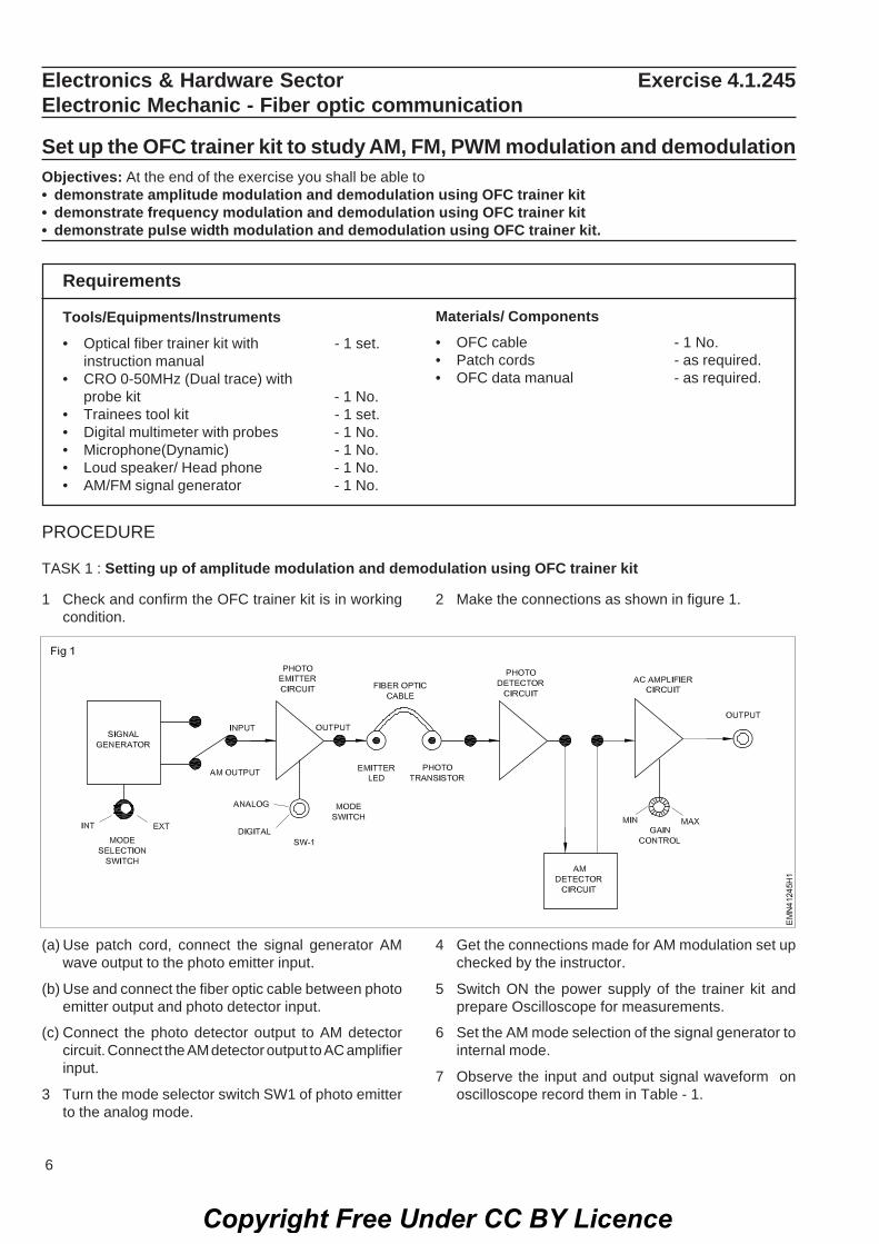
PROCEDURE
TASK 1 : Setting up of amplitude modulation and demodulation using OFC trainer kit
1 Check and confirm the OFC trainer kit is in workingcondition.
2 Make the connections as shown in figure 1.
(a) Use patch cord, connect the signal generator AMwave output to the photo emitter input.
(b) Use and connect the fiber optic cable between photoemitter output and photo detector input.
(c) Connect the photo detector output to AM detectorcircuit. Connect the AM detector output to AC amplifierinput.
3 Turn the mode selector switch SW1 of photo emitterto the analog mode.
4 Get the connections made for AM modulation set upchecked by the instructor.
5 Switch ON the power supply of the trainer kit andprepare Oscilloscope for measurements.
6 Set the AM mode selection of the signal generator tointernal mode.
7 Observe the input and output signal waveform onoscilloscope record them in Table - 1.
Copyright Free Under CC BY Licence

7 E&H - Electronic Mechanic (NSQF LEVEL - 5) - Exercise 4.1.245
Table-1
SI. No. Name of Input/output Remarksthe section Waveform
8 Get the work checked by the instructor.
TASK 2 : Setting up of frequency modulation and demodulation using OFC trainer kit
1 Check and confirm the OFC trainer kit is in workingcondition. (Fig 2)
2 Note down the sections of the OFC trainer kit in theTable-1.
3 Use patch cord, connect the output of functiongenerator to the input of FM modulator section.
4 Use OFC cable, connect the output of light emittercircuit to FM detector input terminal.
Note: The instructor may follow the step as perthe trainer kit available in the section.
5 Use patch cords, connect the detector output to theinput of comparator.
6 Connect the comparator output to PLL detector input.and connect PLL detector output to low pass filterinput.
7 Connect low pass filter output to AC amplfier input asshown Fig 2 and Fig 3.
8 Prepare the CRO for measurement and connect thefunction generator output to channel - 1 and amplifieroutpur to the channel -2 of CRO.
9 Switch ON power and set the function generator for 1kHz/1 Vp - p Sine wave signal output.
10 Set the mode selector switch SW1 in the emittercircuit to analog mode and observe the input andoutput signals on CRO; record the observation inTable-2.
Copyright Free Under CC BY Licence

8
Table - 3
Mode switch Emitter circuit Waveform A/C amplifier Waveform Remarkposition Input signal output
Vp-p signal Vp-p
Digital mode
E&H - Electronic Mechanic (NSQF LEVEL - 5) - Exercise 4.1.245
11 Repeat the step 11 & 12 with mode switch set at digitalposition.
Table-2
D
igita
lA
nalo
g
M
ode
switc
h
p
ositi
on
TASK 3 : Setting up of pulse width modulation and demodulation using OFC trainer kit
i/p signal Wave Output WaveVp-p form signal form
Vp-p
1 Check and confirm the OFC trainer kit is in workingcondition. (Fig 4)
2 Set the function generator to 1 kHz/1Vp-p sine wavesignal output.
3 Use patch cords and connect
- the function generator to the input of pulse widthmodulator;
- pulse width modulator output to the light emittercircuits input.
- Use the OFC cable between emitter circuits outputand detector circuits input.
- Use patch cord and connect detector circuit outputto comparator circuit input; comparator circuitsoutput to low pass filter input and low pass filteroutput to AC amplifier input as shown in Fig 4.
4 Connect the function generator output & amplifieroutput to the CH-1 and CH-2 of CRO.
5 Turn the mode selector switch in the emitter circuits todigital mode.
6 Switch ON the trainer kit and CRO.
7 Observe and trace the input and output signal onCRO; record the observations in Table - 3
12 Get the work checked by the Instructor.
Copyright Free Under CC BY Licence

9 E&H - Electronic Mechanic (NSQF LEVEL - 5) - Exercise 4.1.245
8 Get the work checked by the Instructor.
Copyright Free Under CC BY Licence

10
Electronics & Hardware Sector Exercise 4.1.246Electronic Mechanic - Fiber optic communication
Perform FM modulation and demodulation using OFC trainer kit using audiosignal and voice linkObjectives: At the end of the exercise you shall be able to• demonstrate frequency modulation and demodulation using OFC trainer kit by audio signal• demonstrate frequency modulation and demodulation using OFC trainer kit by voice link signal.
RequirementsTools/Equipments/Instruments• Optical fiber trainer kit with - 1 set.
instruction manual• CRO 20 MHz (Dual trace) with
probe kit - 1 No.• Trainees tool kit - 1 set.• Digital multimeter with probes - 1 No.• Microphone(Dynamic) - 1 No.• Loud speaker/ Head phone - 1 No.• Audio signal source - 1 No.
Materials/ Components• OFC cables - 1 No.• Patch cards - as reqd.• OFC data manual
3.5 mm stereo EP to EP cable - 1 No.6 mm to 3.5 mm phono adapter - 1 No.
PROCEDURE:
TASK 1 : Frequency modulation and demodulation of audio signal using OFC trainer kit
1 Check and confirm the OFC trainer kit is in workingcondition. (Fig 1) & (Fig 2)
2 Use patch cords and connect the audio amplifieroutput to the input of frequency modulator; frequencymodulator output to the emitter input.
Note: The instructor has to provide audio signalfrom any available signal sources like/CDplayer/mobile phone - connect audio signalsource to the input amplifier.
3 Use OFC cable connect it between photo emitteroutput and photo detector's input; connect photodetector output to comparator input using patch cord.
4 Use patch cord and connect the comparator output toPLL detector input; PLL detector output to low passfilter input and low pass filter output to AC amplifierinput. (Fig 2)
5 Connect the audio signal output to the input of audioinput amplifier.
6 Put the mode switch SW1 in the emitter circuit todigital mode.
5 Prepare the CRO for measurements and switch ONthe trainer kit.
6 Observe the input output signals on CRO and recordthem in Table 1.
7 Get the work checked by the instructor.
Table - 1
Mode switch Frequency Waveform AC amplifier Waveformposition modulator output signal
input signal Vp-pVp-p
Copyright Free Under CC BY Licence

11
TASK 2 : Frequency modulation and demodulation of voice link signal using OFC trainer kit1 Keep the settings/ connections as per steps 1 to 4 of
TASK 1.
2 Disconnect the audio signal and CRO from the circuit.
3 Using the phone adapter connect the externalmicrophone into the input of audio input circuit.
4 Use patch cord and connect the output of audio inputcircuit to input of frequency modulator; use OFCcable, connect between emitter circuit and input of
detector circuit, upto AC amplifier as shown in Fig 1and 2.
5 Connect the Ac amplifier output to the input of theaudio output circuit (Louds speaker).
If built-in speaker is not available connectspeaker or headphone externally to audiooutput block.
E&H - Electronic Mechanic (NSQF LEVEL - 5) - Exercise 4.1.246
Copyright Free Under CC BY Licence

12 E&H - Electronic Mechanic (NSQF LEVEL - 5) - Exercise 4.1.246
6 Get the connections checked by the instructor.
7 Swith ON the trainer kit, speak in the microphone andlisten to the speech sound through the loudspeaker/headphone.
8 Get the work checked by the Instructor.
Copyright Free Under CC BY Licence

13
Electronics & Hardware Sector Exercise 4.1.247Electronic Mechanic - Fiber optic communication
Perfrom PWM modulation and demodulation using OFC trainer kit using audiosignal and voice linkObjectives : At the end of this exercise you shall be able to• demonstrate pulse width modulation and demodulation using OFC trainer kit by using analog signal• demonstrate pulse width modulation and demodulation using OFC trainer kit by using voice link signal.
RequirementsTools/Equipments/Instruments• Optical fiber trainer kit with - 1 set.
instruction manual• CRO 20 MHz (Dual trace) with
probe kit - 1 No.• Trainees tool kit - 1 set.• Digital multimeter with probes - 1 No.• Microphone(Dynamic) - 1 No.• Loud Speaker/ Head phone - 1 No.• Audio signal source - 1 No.
Materials/Components• OFC cables - 1 No.• Patch cards - as reqd.• OFC data manual - 1 No.• 3.5mm stereo EP to EP cable - 1 No.• 6mm to 3.5mm phono adapter - 1 No.
Copyright Free Under CC BY Licence

14
PROCEDURE:
TASK 1 :Pulse Width Modulation of audio signal and demodulation using OFC trainer kit
1 Check and confirm the OFC trainer kit is in workingcondition. (Fig 1)
2 Use patch cords and connect the audio signal sourceto the input amplifier; connect the audio input amplifieroutput to the input of pulse width modulator.
3 Connect the pulse width modulator output to thephoto emitter circuits input using patch cord.
4 Use OFC cable between photo emitter circuits outputand photo detector circuits input; connect the photodetector output to comparator circuits input, usingpatch cord.
Note: The instructor has to provide audio signalfrom any available signal source like CD/DVDplayer/Mobile phone.
5 Use patch cords and connect comparator circuit andoutput to low pass filter input; low pass filter ouput toAC amplifier input as shown in Fig 2.
6 Connect the input amplifier & ouput of AC amplifier tothe CH 1 and CH 2 of CRO.
7 Turn the mode switch SW1 in the photo emittercircuits to digital mode.
8 Switch ON the trainer kit, prepare the CRO formeasurements.
9 Observe the input and output signal on CRO andrecord them in Table - 1.
Table - 1
Mode PWM input Waveform AC amplifier Wavefrom switch Signal Position
TASK 2 :Pulse width frequency Modulation of voice link signal and demodulation using OFC trainer kit.
1 Keep the settings connections done in TASK 1.
2 Disconnect the audio signal source and CRO from thecircuit.
3 Use the phono adapter and connect the externalmicrophone into the input of audio input circuit.
4 Use patch cords, connect the output of audio inputcircuit to the input of pulse width modulator and photoemitter cirucuit.
5 Use OFC cable, connect between the photo emitteroutput to photo detector input.
6 Use patch cord connect the comparator, low passfilter and AC amplifier as shown in Fig 1 and 2.
7 Switch ON the trainer kit and speak in the microphoneand listen the speech sound through the speaker /headphone.
If built-in speaker is not available connectspeaker or headphone externally to the audiooutput block.
6 Get the work checked by the instructor.
E&H - Electronic Mechanic (NSQF LEVEL - 5) - Exercise 4.1.247
10 Get the work checked by the Instructor.
Copyright Free Under CC BY Licence

15
PROCEDURE:
Note: The instructor has to provide audio signalfrom any available signal source like CD/DVDplayer mobile phone.
TASK 1 : Pulse Position Modulation and demodulation of audio signal using OFC trainer kit.
Electronics & Hardware Sector Exercise 4.1.248Electronic Mechanic - Fiber optic communication
Perform PPM modulation and demodulation using fiber optic communicationtrainer kit using audio signal and voice linkObjectives: At the end of the exercise you shall be able to• Identify the different cables used in OFC demonstrate pulse position modulation and demodulation using
audio signal• Identify the different connectors used in OFC demonstrate pulse position modulation and demodulation
using voice link signal.• Identify the various sections in the OFC trainer kit.
RequirementsTools/Equipments/Instruments• Optical fiber trainer kit with - 1 set.
instruction manual• CRO 20 MHz (Dual trace) with
probe kit - 1 No.• Trainees tool kit - 1 set.• Digital multimeter with probes - 1 No.• Microphone(Dynamic) - 1 No.
• Loud Speaker/ Head phone - 1 No.• Audio signal source - 1 No.
Materials/ Components• OFC cables - 1 No.• Patch cards - as reqd• OFC data manual• 3.5mm stereo EP to EP cable - 1 No.• 6mm to 3.5mm phono adapter - 1 No.
1 Check and confirm the given OFC trainer kit is inworking condition.
2 Use patch cords refer to Fig 1 and connect the audiosignal source to the input amplifier; the functiongenerator output to the input of Pulse PositionModulator and Pulse position modulator output to thephoto emitter input as shown in Fig 1.
3 Use OFC cable, connect the photo emitter output tothe input of photo detector; use patch cord and connectPhoto detector output to comparator input.
4 Use patch cords, connect comparator output to PLLdetector input; PLL detector output to low pass filterinput and Low pass filter output to AC amplifier inputas shown in Fig 1 & 2.
Note: The instructor has to provide audio signalfrom any available signal source like CD/DVDplayer mobile phone etc.
3 Connect the function generator output to Ch1 andamplifier output to Ch 2 of CRO inputs.
4 Set the mode selector switch to digital mode.
5 Prepare the CRO for measurements and switch ONthe trainer kit.
6 Observe the input output signal on CRO and rocord inTable 1.
Table - 1Waveform Waveform Waveform Amplifierat PPM at PPM at Photo outputinput Output Detector
output
Copyright Free Under CC BY Licence

16
TASK 2 : Pulse Position Modulation and demodulation of voice link signal using OFC trainer kit.
If built-in speaker is not available connectspeaker or headphone externally to the audiooutput block using patch cords.
1 Keep the settings as same in TASK 1.
2 Disconnect the Audio signal source remove theCh 1 & Ch 2 connections to the CRO.
3 Use the phono adapter and connect the microphoneto the input of audio input circuit. Use patch cords,connect the output of AC amplifier circuit to input ofaudio output circuit. (loudspeaker)
E&H - Electronic Mechanic (NSQF LEVEL - 5) - Exercise 4.1.248
4 Get the circuit connections checked by the instructor.
5 Switch ON the trainer kit.
6 Speak in the microphone and listen to the speechsound through the speaker / Headphone.
7 Get the work checked by the Instructor.
7 Get the work checked by the Instructor.
Copyright Free Under CC BY Licence

17
Electronics & Hardware Sector Exercise 4.2.249Electronic Mechanic - Digital Panel Meter
Identify LED display module and its decoder/driver ICsObjectives: At the end of the exercise you shall be able to• identify the type of LED display used in the Digital Panel Meter• identify various decoder/driver IC in digital panel meter.
RequirementsTools/Equipments/Instruments• Digital panel meter with
different driver ICs - as reqd.• Trainees tool kit - 1 Set.• Digital Multimeter with probes - 1 No.
Materials/ Components• Operating / Instruction manual
Safety precaution1 Keep the work area dry and clean.
2 Use proper tools for opening the DigitalPanel Meter.
PROCEDURE:
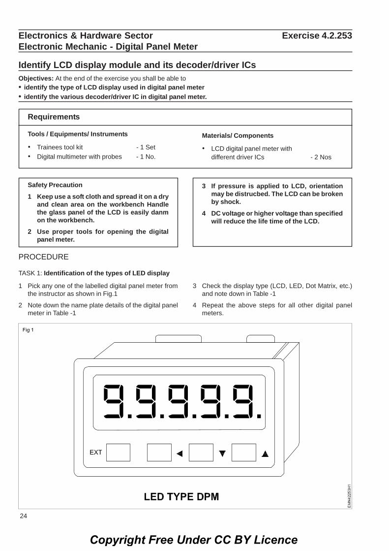
TASK 1 : Identification of the type of LED display1. Pick any one of the labelled digital panel meter from
the instructor
2 Note down the name plate details of the digital panelmeter as shown in Fig 1.
3 Check the display type (LCD, LED, Dot matrix, etc.)and note down in Table-1.
4 Repeat the above steps for all other digital panelmeter.
Copyright Free Under CC BY Licence
18 E&H - Electronic Mechanic (NSQF LEVEL - 5) - Exercise 4.2.249
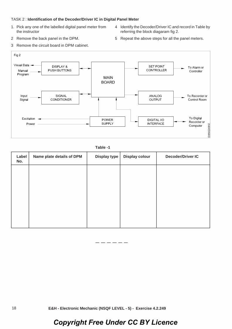
TASK 2 : Identification of the Decoder/Driver IC in Digital Panel Meter
1. Pick any one of the labelled digital panel meter fromthe instructor
2 Remove the back panel in the DPM.
3 Remove the circuit board in DPM cabinet.
4 Identify the Decoder/Driver IC and record in Table byreferring the block diagaram fig 2.
5 Repeat the above steps for all the panel meters.
Table -1
Label Name plate details of DPM Display type Display colour Decoder/Driver ICNo.
Copyright Free Under CC BY Licence

19
4 Adjust the pre-set VR of astable multivibrator tochange the clock frequency of decade counter to varythe display time.
5 Observe the display output for the time/sequence ofLED letters.
1 Collect all the components required and test them forgood working condition.
Use heat sink for the power transistor T3
2 Plan the layout and assemble the circuit as shown inFig 1 on the breadboard/ general purpose PCB.
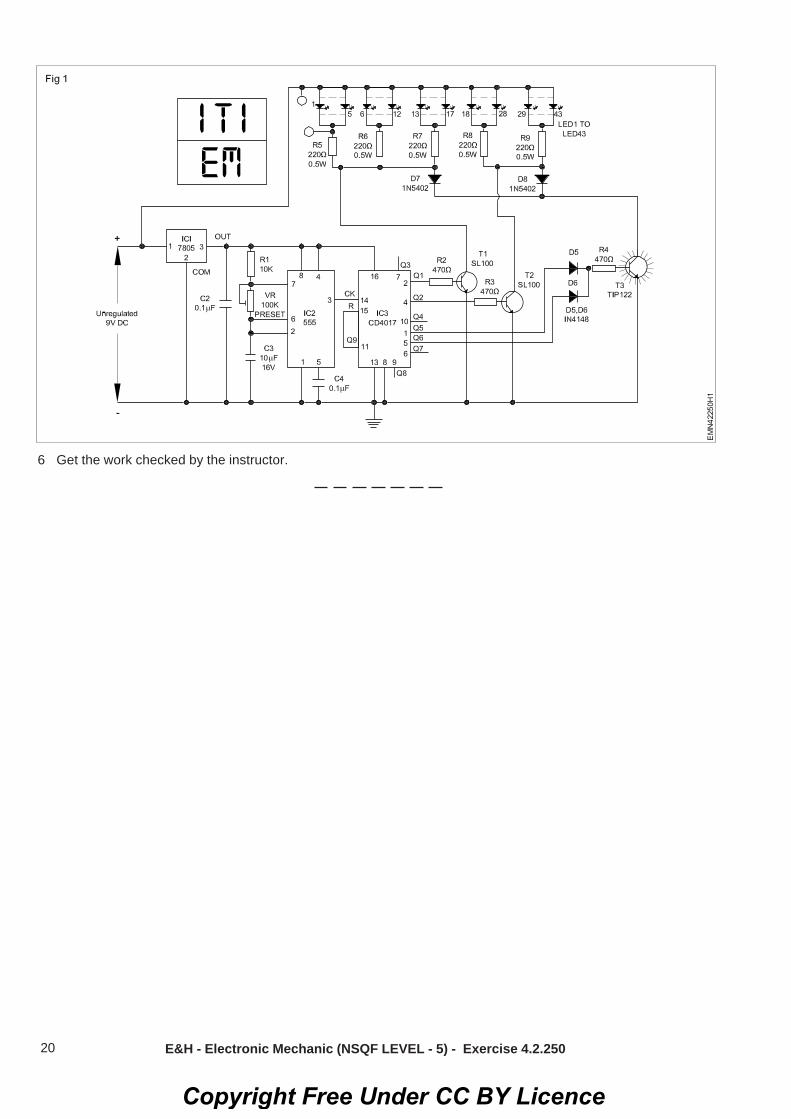
Electronics & Hardware Sector Exercise 4.2.250Electronic Mechanic - Digital Panel Meter
Display a word on a two line LEDObjectives: At the end of the exercise you shall be able to• construct a two line LED circuit• Test the two line LED circuit.
Requirements
Tools/Equipments/Instruments
• Trainees tool kit - 1 Set.• Digital multimeter with probes - 1 Set.• Regulator DC Power supply
0-30V/ 2A - 1 No.• Soldering iron 25W/230V - 1 No.
Materials/ Components• Breadboard/PCB-GP - 1 No.• Decade counter IC CD4017 - 1 No.• Timer IC 555 - 1 No.• Positive regulator IC 7805 - 1 No.• Diode, IN5402 - 2 Nos.
• Diode, IN4148 - 2 Nos.• Transistor, SL100 - 2 Nos.• Transistor, TIP 122 with
heat sink - 1 No.• Capacitor, 10ΩF, 16V - 1 No.• Capacitor, 0.1ΩF - 1 No.• Capacitor, 0.01ΩF - 1 No.• Pre-set, 100KΩ (Horizontal type) - 1 No.• Resistor, 10KΩ, 0.5W - 1 No.• Resistor, 470Ω, 0.5W - 3 Nos.• Resistor, 220Ω, 0.5W - 5 Nos.• LED, 5mm, Red - 43 Nos.• Connecting wires - as reqd.• Hookup wire - as reqd.• Rosin cored solder - as reqd.
PROCEDURE
TASK 1 : Construction of a two line LED circuit to display a word
The arrangement of LED1 through LED5 isused to display ‘I’ as shown in Fig.1. Theanodes of LED1 through LED5 are connectedto point-A and the cathodes of these LEDs areconnected to point-B. Similarly, connect theother letters as shown in Fig.1.
3. Get the assembled circuit checked by the Instructor.
TASK 2: Testing the two line LED circuit1 Apply 230V, 50Hz, single phase AC supply to the
primary of the transformer.
2 Switch ON the 9V DC power supply and check thecircuit operation.
3 Observe the output LED display cycle.
The display board displays ‘ITI,’ and ‘EM’ oneafter another for one second each. After that,the message “ITI EM” is displayed for 4 seconds(because Q5 and Q6 are connected to resistorR4 via diodes D5 and D6).At the next clock input output Q9 goes high,and IC3 is reset and the display is turned off forone second. Thereafter the cycle repeats.
Copyright Free Under CC BY Licence
20 E&H - Electronic Mechanic (NSQF LEVEL - 5) - Exercise 4.2.250
6 Get the work checked by the instructor.
Copyright Free Under CC BY Licence

21
Electronics & Hardware Sector Exercise 4.2.251Electronic Mechanic - Digital Panel Meter
Measure current flowing through a resistor and display it on LED moduleObjectives: At the end of the exercise you shall be able to• measure the voltage in simple circuit using LED module of DPM• measure the current in simple circuit using LED module of DPM.
RequirementsTools /Equipments/Instruments
• DPM with LED display 0-250 mA - 1 No.• DPM with LED display 0-50V - 1 No.• Regulated DC power supply - 1 No.
0-30V/2A• Digital multimeter with probes - 1 No.• Trainees tool kit - 1 Set.
Materials/ Components
• Breadboard - 1 No.• Resistor 500 Ω/2W - 1 N• Hook up wires - as reqd.
Safety precaution1 Avoid loose connections
PROCEDURE
1 Collect the components required and check them forgood working condition.
2 Make the simple test set-up of the circuit as shown inFig 1.
3 Switch ON the DC power supply, increase to 5VDC.
4 Measure the voltage of variable power supply outputand current through the load.
5 Record the observations in Table-1.
6 Increase the supply voltage in steps of 5V upto 25VDCand repeat steps 4 and 5.
Table-1
SI Value of load resistor Voltage across load Current through the circuitNo. Resistor
1
2
3
4
5
7 Get the work checked by the Instructor.
Copyright Free Under CC BY Licence

22
Electronics & Hardware Sector Exercise 4.2.252Electronic Mechanic - Digital panel meter
Measure current flowing through sensor and display it on LED ModuleObjectives: At the end of the exercise you shall be able to• measure the current flowing through the digital panel meter.
Requirements
Tools / Equipments/ Instruments
• Trainees tool kit - 2 Nos• Multimeter with probes - 1 No.• Regulator power supply 0-30V/2A - 1 No.• Rectangular battery 9V - 1 No.
Materials/ Components
• Shunt resistor 0.1 Ω - 1 No.• Shunt resitor 0.01 Ω - 1 No.
Safety precaution1 Keep the work area dry and clean.
PROCEDURE1 Connect the shunt resistor to digital panel/meter as
shown in the Fig.1
2 Usse proper tools for opening the digitalpanel meter.
2 The shunt resistor is placed in series with the appliedcurrent which causes a voltage deop to occur acrossthe shunt.
3 The shunt value depends on the maximum currentflow that will be encountered. For relatively small cur-rent values (below 1 Amp) a 0.1 ohm shunt resistor isadequate. This value will minimise any loading in thecircuit but will procedure a reasonable reading on theDPM. If higher current levels will be encountered, 0.01ohm or lower value should be used.
4 Connect the battery to circuit as shown in the diagram.
5 Connect the Pin No.3 to Pin No.6 of DPM for properdecimal point display.
6 Note that the current value displayed on the metercan be fine-tuned by adjusting the trimmer potenti-ometer on the back of the DPM.
7 Short Pin No.8 and pin No.10 together and connectedto the negative end of the shunt resistor.
8 Connect Rshunt across Pin No.7 and Pin No.8 and willbe connected in series with the load .
9 Note down the actual and indicated current readingsand record in Table-1.
Calculation
• All digital panel meters, the full scale deflection are200 mV full- scale.
• For the measurement of 1 Amps current through DPM,correct power rating of the shunt resistor can be de-termined by using the Ohm’s Law power formula.
P (Power) = V (Voltage) x I (Current)P = Vmax x Imax = (0.200) x (1.0) = 0.1 Watt
• So we should use a 1/2 watt 1% resistor to be safe.
Copyright Free Under CC BY Licence

23 E&H - Electronic Mechanic (NSQF LEVEL - 5) - Exercise 4.2.252
Table - 1
Value of RShunt Actual Current Reading Indicated Reading on DPM Voltage & cross Rshunt
Copyright Free Under CC BY Licence
24
Electronics & Hardware Sector Exercise 4.2.253Electronic Mechanic - Digital Panel Meter
Identify LCD display module and its decoder/driver ICsObjectives: At the end of the exercise you shall be able to• identify the type of LCD display used in digital panel meter• identify the various decoder/driver IC in digital panel meter.
Requirements
Tools / Equipments/ Instruments
• Trainees tool kit - 1 Set• Digital multimeter with probes - 1 No.
Materials/ Components
• LCD digital panel meter withdifferent driver ICs - 2 Nos
Safety Precaution1 Keep use a soft cloth and spread it on a dry
and clean area on the workbench Handlethe glass panel of the LCD is easily danmon the workbench.
2 Use proper tools for opening the digitalpanel meter.
PROCEDURE
TASK 1: Identification of the types of LED display
3 If pressure is applied to LCD, orientationmay be distrucbed. The LCD can be brokenby shock.
4 DC voltage or higher voltage than specifiedwill reduce the life time of the LCD.
1 Pick any one of the labelled digital panel meter fromthe instructor as shown in Fig.1
2 Note down the name plate details of the digital panelmeter in Table -1
3 Check the display type (LCD, LED, Dot Matrix, etc.)and note down in Table -1
4 Repeat the above steps for all other digital panelmeters.
Copyright Free Under CC BY Licence

25
Table - 2
Pin No. Short form Description
1 VSS Ground2 VDD +5V Supply3 VEE Set LCD Contrast4 RS LCD Controlling Pins
5 RW6 E7 D0
8 D1
9 D2 Data Pins10 D3
11 D4
12 D5
13 D6
14 D7
15 LEDA Back light LED anode +5V16 LEDK Back light LED cathode
ground
Terminal details of LCD DPM
E&H - Electronic Mechanic (NSQF LEVEL - 5) - Exercise 4.2.253
TASK 2: Identification of the Decorder/Driver IC in digital panel meter
1 Pick any one of the labelled digital panel meter.
2 Remove the back panel in the DPM.
3 Remove the circuit board in DPM cabinet.
4 Identify the Decoder/Driver IC and record in Table -2
5 Repeat the above steps for all other panel meters.
Table - 1
Label No. Name plate details of DPM Display Type Display colour Decorder/Driver IC
1
2
3
Copyright Free Under CC BY Licence

26
Electronics & Hardware Sector Exercise 4.2.254Electronic Mechanic - Digital Panel Meter
Measure current flowing through a resistor and display itObjectives: At the end of the exercise you shall be able to• measure the voltage in single circuit using LCD module• measure the current in simple circuit using LCD module.
Requirements
Tools / Equipments/ Instruments
• DPM with display - 2 Nos• Regulated DC power supply
0-30V/2A - 1 No.• Digital multimeter with probes - 1 No.• Trainees tool kit - 1 Set.
Materials/ Components
• Breadboard - 1 No.• Resistor 500Ω/2W - 1 No.• Hookup wires - as reqd.
Safety precaution1 Avoid loose connections
PROCEDURE1 Collect the components and check the items for its
good working condition.
2 Make the simple test set-up on the Lug board/Breadbard as shown in Fig.1
3 Switch ON the variable power supply.
4 Measure the voltage varying the voltage step by stepand current
5 Record it on the table-1.
6 Repeat steps 5 & 6 with five different position ofreheostat.
7 Switch OFF the Regulated DC Power supply and getthe work checked by the instructor.
Table-1
SI. No. Value of Load Voltage across Load Current through the circuitResistor Resistor Resistor
1
2
3
4
5
Copyright Free Under CC BY Licence

27
2 Identify the location of wires with colour codescomming out of SMPS unit as shown in Fig 2.
3 Notedown the connections of SMPS going to varioussections of mother board and other devices insidethe CPU, put tags with label for each connector.
4 Draw the layout of mother board and mark thesections/ location of connectors with label number init.
Electronics & Hardware Sector Exercise 4.3.255Electronic Mechanic - SMPS and Inverter
Identify the components/devices of SMPS and draw their correspondingsymbolsObjectives: At the end of the exercise you shall be able to• dismantle the SMPS unit from CPU cabinet and identify major section/ components of SMPS unit• draw the symbols of observed components of SMPS unit.
Safety precaution1 Ensure the power cord is removed from the
CPU.2 Before opening CPU cabinet, touch the
cabinet outer cover by wearing wrist bandto discharge ESP.
Requirements
Tools / Equipments/ Instuments
• ESD wrist band - 1 No.• Trainees tool kit - 1 Set.• Digital multimeter with probes - 1 No.• Aids: Block diagram of SMPS - 1 No.• Chart showing all types of connectors used in
SMPS of PC - 1 No.
Materials/ Components
• SMPS unit used in personal computer - 1 No.
PROCEDURETASK 1: Dismantling the SMPS unit from CPU cabinet and identification of sections
1 Open the computer cabinet cover, by removing thedoor screws as shown in Fig 1.
5 Record the name of the connector, type and numberof pins in Table-1.
6 Remove/Unplug the connectors from HDD, DVD, FANand mother board carefully.
7 Unscrew the fixing screws and remove the SMPSunit from the CPU cabinet and open it as shown inFig 3.
8 Draw the layout of the assembly and mark the majorsections/components/devices
Fig 1
Fig 2
Copyright Free Under CC BY Licence

28
Keep the fixing screws seperately forassembling the SMPS after completion of thisexercise.
Table - 1
SI.No. Name of the No. of wires Type of connector Connected to which Remark connector section/device
E&H - Electronic Mechanic (NSQF LEVEL - 5) - Exercise 4.3.255
TASK 2: Identification of type of connectors in SMPS unit
Note : The instructor has to label the majorcomponents /devices in each section of theSMPS before issuing to trainees for this task
1 Refer to the chart, identify the connector/sections andmajor components/devices in each section.
2 Record the name of the component/device inTable - 2.
Fig 3
3 Repeat the steps for all the labelled components/devices.
4 Draw the symbol of each component in the respectiveplaces in Table-2.
9 Get the work checked by the instructor.
Table- 2
SI. Label No. Name of the section Name of the component Circuit symbol RemarkNo.
Copyright Free Under CC BY Licence

29 E&H - Electronic Mechanic (NSQF LEVEL - 5) - Exercise 4.3.255
Fig 4
5 Get the work checked by the instructor.
Chart - 1Chart showing types of connectors used in SMPS unit of personal computer system
Power Connectors
Copyright Free Under CC BY Licence

30
Electronics & Hardware Sector Exercise 4.3.256Electronic Mechanic - SMPS and Inverter
Dismantle the given voltage stabilizer and find the major sections/ICs/ComponentsObjectives: At the end of the exercise you shall be able to• dismantle the given voltage stabilizer• identify sections of voltage stabilizer• locate the major components of various sections.
Requirements
Tools/ Equipments/ Instruments
• Trainees tool kit - 1 Set.• DMM with probes - 1 Set.• Voltage stabilizer (automatic
type with instruction manual) - 1 No.500VA to 1KVA
Materials/ Components
• Nil
Note: The instructor may guide the trainees tohandle the bulky/weight of the voltagestabilizer. Alert them to avoid any accidentalwound by the sharp edge/corner of the metalchassis/frame etc. Remove the power cordfrom the A/C mains supply.
PROCEDURE1 Note down the name plate details of the voltage
stabilizer and record them in Table-1
2 Identify the fitting screws/fasteners used on the sidesof the chasis /frame of the voltage stabilizer.
3 Remove the cover fitting screws/nut bolt etc. and keepthem safely in a box seperately
4 Observe various sections of the stabilizer unit &identify the sections. Trace the layout of componentsand identify and important components.
5 Use pencil roughly sketch the layout of the assemblyand the voltage stabilizer on your observation record.
6 Note down the connections of major/importantcomponents/parts on each section.
7 Record the observations on the Table-4.
Table-4
SI.No. Major/important component/parts Name of section Remarks
1. Auto transformer2. relay switching contacts3. Driver transistors4. integrated circuits voltage adj5. Presets diodes/zener status indicators6. Fuse, 7. output terminal socket
8 Get the work checked by the Instructor.
Copyright Free Under CC BY Licence

31
Electronics & Hardware Sector Exercise 4.3.257Electronic Mechanic - SMPS and Inverter
List the defect and symptom in the faulty SMPSObjectives: At the end of the exercise you shall be able to• list the physical defects identified in the faulty SMPS (in cold condition) without switching ON• identify sections of voltage stabilizer• locate the major components of various sections.
Requirements
Tools / Equipments/ Instruments
• Trainees tool kit - 1 Set.• Multimeter with probes - 1 No.• Adjustable type table lamp - 1 No.• Magnifying Lens - 1 No.• A faulty SMPS kit - 1 No.• Oscilloscope, 20 MHZ - 1 No.
Materials/ Components
• Spare components - as reqd.• Rosincored solder - as reqd.
Safety precautions1 Disconnect the SMPS unit from the mains
before remvoing from the PC.2 Do not touch the PCB with bear hand
without discharging the DC storageelectroytic capacitor.
3 Discharge the storage capacitor by usingan incandescent-bulb connected with wiresacross the capacitor
PROCEDURE
TASK 1: List the defect in the faulty SMPS in cold condition
1 Record the specifications on the cover of SMPS.
2 Verify whether mains supply voltage is disconnectedfrom the SMPS.
3 Initially perfrom cold check by keeping SMPS in OFFcondition (components on PCB of the defective)
Observe the SMPS and list out the physical defectsnoticed as shown below:
• Charred/smoke smell on PCB
• Any component like resistor, diode, black (or) charred/damage.
• Capacitor top bulged (or) not.
• PCB board darkened due to short
• Wire broken
• PCB track cut
• Connector broken
• Dry soldering
• Switching transistor blown
• Fuse blown.
4 Perform warm check of SMPS and measure outputvoltages
• Observe whether the SMPS fan is working or not.
• Observe the voltages at the connectors and varioustest points and record the observations in Table 1 &Table 2.
4 Do not use screw drivers to short thecapacitor terminals for discharging staticcharge.
5 Measure the voltage and make sure it iszero before proceeding for test.
Copyright Free Under CC BY Licence

32
TASK 2: Find the probable symptoms of the given faulty SMPS
1 Observe the symptoms noticed on the defectiveSMPS in ON condition and determine which sectionor junction could be faulty.
2 Ref to the list of symptoms and remedy given in Table-1 and prepare a list symptoms noticed in your faultySMPS units.
Probable faults and remedy
SI. Faults Cause RemedyNo.
1 SMPS dead, fuse Shorted switching transistor or Test the switching transistorblown semiconductors, power cord or semiconductor switch. If it fails
defective, or switch , open fusible replace it.resistor, other bad parts. Actual If the semiconductor switch is good,cause of failure may be power check and replace the primarysurge/brownout/lightning strikes, diodes.random failure, or primary side Replace the fusible resistor.electrolytic capacitor (s) with greatlyreduced capacity or entirely open
2 Supply dead, fuse Bad startup circuit - open startup Test the switching transistor ornot blown resistors or open fusible resistors semiconductor switch. If it fails
due to shorted semicondutors, bed replace it.controller components. Replace the fusible resistor
3 Supply mostly dead Bad electrolytic capacitors. Visually If any one bad capacitors are foundor takes a long time inspect for capacitors with bulging replace all electrolytic capacitors.to come alive tops or that have leaked.
4 More ripple at the Dried up main filter capacitor(s) on Check the filter capacitor and replaceline frequency rectified AC input it(50/60 Hz) or twicethe line frequency(100/120 Hz)
5 No output supply Switching transistor or semiconductor Test the switching transistor orand 300V persists in switch short and fusible resistor or semiconductor switch. If it failsthe filter capacitor starting resistor open. replace it.after switching OFFthe supply
6 SMPS output is low If SMPS givess low voltage output Measure voltages and comparethen the fault is mostly in the error them with normal voltage given theamplifier, and oscillator stage. Ouput circuit diagram.loading may also affect the output Probable parts may be faultyvoltage some time zener diode in the error amp,
faulty control circuit parts, transistor,IC, opto-coupler faulty.
7 SMPS output is high If SMPS output is high first shut Check fauult either in switch offdown set. Fault in the error amplifier, condition or by giving input supplyIC, oscillator section of SMPS. through a variac or low voltage
transformer.
E&H - Electronic Mechanic (NSQF LEVEL - 5) - Exercise 4.3.257
Copyright Free Under CC BY Licence

33
SI. Faults Cause RemedyNo.
Disonnect TV/computer othersections by diconnecting base oroutput transistor. Never keep on inthis fault it may danage other partsalso.Check for - error amp circuit, zenerdiode, opto-couoler, filters on erroramplifier line, transistor, IC, oscillator.Replace the faulty components.
8 Combusted coil A winding coil is present on the This problem can be identified esailyboard which sometimes gets burnt by the smell or you can identifydue to excessive flow of current. through the burnt marks located on
the external section of the windingcoil. It may be possible that internalloop is damaged.
Note: In all cases, bad solder connections area possibility as well since there are usuallylarge components in these supplies andsoldering to their pins may not always beperfect. An excessive load can also result inmost of these symptoms or may be the originalcause of the failure.
E&H - Electronic Mechanic (NSQF LEVEL - 5) - Exercise 4.3.257
3 Get the work checked by the instructor.
Copyright Free Under CC BY Licence

34
Electronics & Hardware Sector Exercise 4.3.258Electronic Mechanic - SMPS and Inverter
Measure/ Monitor at major test points of computer SMPS unitObjectives: At the end of the exercise you shall be able to• prepare the computer SMPS unit for voltage measurements• measure/monitor voltages at various test points of the SMPS unit.
Requirements
Tools / Equipments/ Instruments
• Computer SMPS working - 1 No.• Trainees tool kit - 1 Set.• Digital multimeter with probes - 1 No.
Materials/ Components
• AIDS: Chart showing various voltagesof connects in smps unit of PC
• Computer power cord - 1 No.• Hook-up wire - as reqd.
Safety precatutionsMake sure you conduct this test on a table withyourself standing a rubber that any insulatedmaterial to avoid static electricity destroyingthe computer components
PROCEDURE
TASK 1: Preparation of computer SMPS unit for voltage measurements
1 Remove the SMPS from the computer cabinet byfollow the procedure given in the Exercise: 4.3.256
2 Identify the green colour wire (power good signal testpoint) from the bunch of wires on the 24 pin molexconnector as shown in Fig 1.
3 Use a piece of hookup wire, bend it as ‘U’ shape,connect it across the green and black wire terminalsas shown in Fig 2.
4 Connect the power cord to the SMPS unit and switchON power.
5 Observe the fan is running to confirm the working ofSMPS unit.
6 Remove the hook up wire and re-insert if the fan isnot rotating.
Fig 1
Fig 2
7 Get the work checked by the instructor.
Copyright Free Under CC BY Licence

35
TASK 2: Measurement/monitoring voltages at various test points.
1 Start measurement of AC voltage across the threeterminal mains cord and record the readings inTable-1.
Table-1
SI. Parameter to measure Voltage (AC) RemarksNo.
1 Phase to Neutral --------------------
2 Phase to Earth --------------------
3 Neutral to Earth --------------------
2 Switch OFF supply and plug the mains cord intoSMPS unit, and select the P-4 power cable connectorused for CPU cooler fan.
Table -2
SI. No. Description Wire colour Measured voltage
1 Ground Black
2 Ground Black
3 +12 VDC Yellow
4 +12 VDC Yellow
E&H - Electronic Mechanic (NSQF LEVEL - 5) - Exercise 4.3.258
3 Switch ON SMPS supply and measure the DC voltageacross the P-4 cable connector and record thereadings in Table-2.
4 Refer to the chart showing voltages at various testpoints on power cable connector and record theobservations in Table-3.
Table-3
SI. No. Wire colour Description Measured voltage Remarks
1
2
3....24
5 Refer to the chart details and measure test pointvoltage at the 4 pin molex peripheral connector andrecord observation in Table-4.
Copyright Free Under CC BY Licence

36
Table-4
SI. No. Wire colour Description Measured voltage Remarks
1 Yellow
2 Black
3 Black
4 Red
6 Get the work checked by the instructor.
E&H - Electronic Mechanic (NSQF LEVEL - 5) - Exercise 4.3.258
Note: The instructor has to guide the traineesto measure voltage at additional connectorsfor SATA, Aux power connector etc. withpreparation of suitable tables to recordmeasurements according to the SMPS modelavailable in the section.
Chart showing voltages at various connectors of SMPS units of personal computer system Fig 3
PIN DESCRIPTION OF THE 24-PIN POWER CABLE CONNECTOR
Pin Name Colour Description/voltage level Measuredvoltage
1 3.3V Orange +3.3 VDC
2 3.3V Orange +3.3 VDC
3 COM Black Ground
4 5V Red +5 VDC
5 COM Black Ground
6 5V Red +5 VDC
7 COM Black Ground
8 PWR_OK Grey Power Ok is a status signal generated bythe power supply ON, disconnect fromGND to switch OFF.
9 5VSB Purple +5 VDC Standby voltage (max 10mA)
10 12V Yellow +12 VDC
11 12V Yellow +12 VDC
12 3.3V Orange +3.3 VDC
13 3.3V Orange +3.3 VDC
14 -12V Blue -12 VDC
15 COM Black Ground
16 PS_ON Green Power supply on (active low), short this pin to GNDto switch power supply ON, disconnect from GNDto switch OFF.
Fig 3
Copyright Free Under CC BY Licence

37
17 COM Black Ground
18 COM Black Ground
19 COM Black Ground
20 -5 V White Ground
21 +5V Red +5 VDC
22 +5V Red +5 VDC
23 +5V Red +5 VDC
24 COM Black Ground
PIN description of the P-4 power cable connector
Pin Name Colour Description/Voltage MeasuredLevel Voltage
1 GND Black Ground
2 GND Black Ground
3 12V DC Yellow +12 VDC
4 12V DC Yellow +12 VDC
PIN description of the 4-PIN molex peripheral connector
Pin Name Colour Description/Voltage MeasuredLevel Voltage
1 12V DC Yellow +12 VDC
2 GND Black Ground
3 GND Black Ground
4 +5V Red +5 VDC
Ac input voltage measurement (at the mains socket)
Table - 5
SI. No Parameters to measure Voltage (AC) Remarks
1 Phase to neutral voltage
2 Phase to earth
3 Neutral to earth
Fig 4
Fig 5
E&H - Electronic Mechanic (NSQF LEVEL - 5) - Exercise 4.3.258
Copyright Free Under CC BY Licence

38
Pin Pin DescriptionNumber Name
1 +5V
2 GND
3 +5V
4 GND
5 PG +5V When powergood
6 +5V STB Stand-by power
7 +12V
8 -12V
9 GND
10 GND
11 PWR_ON Connect to groundto power on
12 GND
13 GND
14 GND
15 -5V
16 +5V
17 +5V
18 +5V
19 TFSC Thermal Fanspeed control.
20 +5V
Another type of 20 Pin power connector used in newPCs.
Cable colors may differ between power supplies.
TFSC mainboard puts 0.7-1.4V there to control voltagesupplied to power supply’s fan
(Fan voltage increases when TFSC increases).
Fig 6
Fig 6
Fig 7
E&H - Electronic Mechanic (NSQF LEVEL - 5) - Exercise 4.3.258
Copyright Free Under CC BY Licence

39
Electronics & Hardware Sector Exercise 4.3.259Electronic Mechanic - SMPS and Inverter
Troubleshoot the fault in the given SMPS unit, rectify the defect and verify theoutput with load (Record your procedure followed for troubleshooting thedefects)Objectives : At the end of this exercise you shall be able to• discharge the filter capacitor of SMPS unit• identify the physical faulty component and replace it and test the output with load.
RequirementsTools/Equipments/Instruments• ESD work bench - 1 No.• Safety gloves - 1 No.• Trainees tool kit - 1 set.• Digital multimeter with probes - 1 set.• LCR Meter - 1 No.
Materials/ Components• 100 watt/230V bulb with holder - 1 No.• Wire wound resistor
(1.8kΩ or 2.2kΩ/10W) - 1 No.
Safety precaution1 Keep the place dry and clean2 Make sure you conduct this test test on a
table with yourself standing on a rubber mator any insulated material to avoid staticelectricity destroying the computerperipherals.
3 Please note that some connections of theSMPS connectors contain a clip attached toit. Make sure to remove the clips beforeremoving the connection.
Fig 1
PROCEDURE
TASK 1 : Discharging the filter capacitorA. Discharge using bulb method
Make sure the power cord is removed from theSMPS to avoid Electrical shock.
1 Dismantle the SMPS by referring to the proceduregiven in the previous exercises.
2 Connect 100 watt bulb wire across the leads of thecapacitor as shown in Fig 1 & 2. Filter capacitors willbe discharged.
Fig 2
2 Connect 100 watt bulb wire across the leads of thecapacitor as shown in Fig 1 & 2. Filter capacitors willbe discharged.
Copyright Free Under CC BY Licence
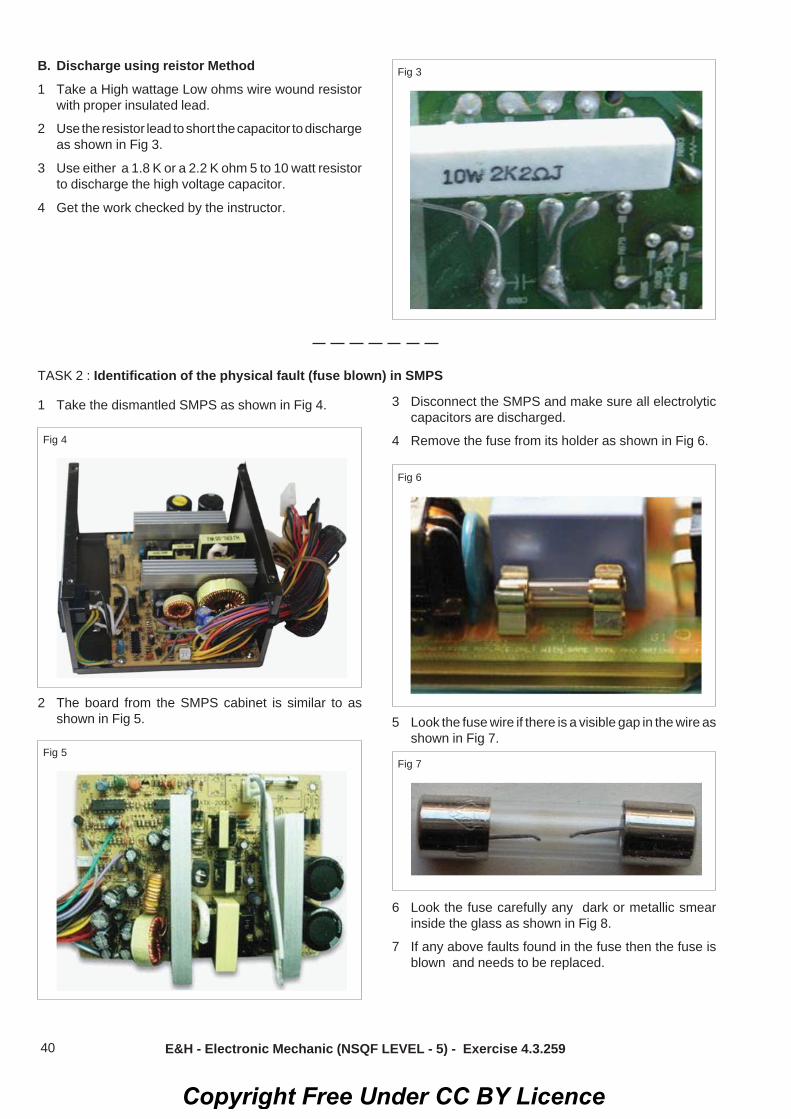
40
B. Discharge using reistor Method1 Take a High wattage Low ohms wire wound resistor
with proper insulated lead.
2 Use the resistor lead to short the capacitor to dischargeas shown in Fig 3.
3 Use either a 1.8 K or a 2.2 K ohm 5 to 10 watt resistorto discharge the high voltage capacitor.
4 Get the work checked by the instructor.
Fig 3
TASK 2 : Identification of the physical fault (fuse blown) in SMPS
1 Take the dismantled SMPS as shown in Fig 4.
Fig 4
Fig 6
Fig 7Fig 5
2 The board from the SMPS cabinet is similar to asshown in Fig 5.
3 Disconnect the SMPS and make sure all electrolyticcapacitors are discharged.
4 Remove the fuse from its holder as shown in Fig 6.
5 Look the fuse wire if there is a visible gap in the wire asshown in Fig 7.
6 Look the fuse carefully any dark or metallic smearinside the glass as shown in Fig 8.
7 If any above faults found in the fuse then the fuse isblown and needs to be replaced.
E&H - Electronic Mechanic (NSQF LEVEL - 5) - Exercise 4.3.259
Copyright Free Under CC BY Licence

41
Fig 8
8 If there is no physical fault observed in fuse then usemultimeter to check it.
9 Set a multimeter (Fig 9) to the continuity setting.
10 Place one of the multimeter leads on one end of thefuse. Place the other lead on the other end of the fuseas shown in the Fig 9.
11 If the meter shows continuity, as shown in Fig 9(a) thenthe fuse is good.
12 If the multimeter reading is OL(Over Limit) as shownin Fig 9(b), then the fuse is blown. If the fuse is blown,replace the fuse with one that is exactly having thesame current rating.
13 Record the observations in TABLE 1.
14 Get the work checked by the instructor.
TABLE 1
Observed Condition
TASK 3 : Identification of the short circuit fault using bulb
1 Connect the 100W bulb across the fuse holder asshown in Fig 10.
Fig 10
Fig 11
2 Power ON the SMPS unit.
3 The bulb will be initially glowing bright then for a goodSMPS bulb glowing turns off, SMPS is in good /working condition.
4 The light bulb will glow bright even after you havewaited for couple of minutes as shown in Fig 11, thenit indicates there is problem in the SMPS.
a) Immediately switch off the AC main.
b) Discharge the big filter capacitor as given in TASK 1.
5 Record the observation in the TABLE 2.
6 Get the work checked by the instructor.
E&H - Electronic Mechanic (NSQF LEVEL - 5) - Exercise 4.3.259
Copyright Free Under CC BY Licence

42
TABLE 2
Observed bulb status SMPS status
B Identification the fault in short circuitedcomponents using Resistance method
3 Set the DMM to resistance unit.
4 Keep the red probe to the cold ground and black probeto each of the secondary diode as shown in Fig 12.
Fig 13
Fig 12
i) If any one of the component shows same resistancereading (low readout) on both polarity, then suspectthat there is a problem in that component.
ii) If the multimeter shows different values on bothpolarities then the component is good.
5 Get the work checked by the instructor.
C Isolation method1 Identify the B+ line of the Back/Boost sections and
break/disconnect the B+ line from the circuit as shownin Fig.14
Fig 14
2 Connect the 100 W bulb between the B+ line to coldground.
3 Power ON and verify the bulb glowing condition.
4 There are five possibilities that can be expected fromthe light bulb.
a) The light bulb lit with a constant brightness and allof the output voltage measured normal at thesecondary side this indicates the SMPS is workingfine and the cause of the power problem in the loadside. It maybe fly back transformer, yoke coils etc.
b) No light from the light bulb and no voltage measuredat the output of the power supply, this indicates theproblem is in the SMPS.
c) The light bulb glows intermittently this could indicatecomponents failure in the power supply like badfilter capacitor ,current sense resistor higher ohm,etc. (value would have been increased)
d) The light bulb become extra bright and all theoutput voltages have increased .this indicates theproblem is in the regulation circuit like an openresistor in feedback circuit , bad opto isolator ICfaulty TLC431 IC, etc.
e) The light bulb keeps cycling ( continuously ON andOFF). This could indicate problem in the SMPSarea and it can also mean the OPTO IC is sendingan Error signal to the primary circuit of powersupply through opto isolator IC causing the powersupply to cycle.
5 Record the observation in the TABLE 3.
E&H - Electronic Mechanic (NSQF LEVEL - 5) - Exercise 4.3.259
Copyright Free Under CC BY Licence

43
TABLE 3
Sl. No. Probable defect Tick
6 Get the work checked by the instructor.Fig 15
Fig 16
TASK 4 : Identification of the short circuited components
Capacitor checking1 Disconnect the power card.
2 Discharge the main(large) capacitor.
Fig 17
3 Test the healthyness of diodes and capacitors atsecondary section using multimeter.
4 Open the lead of capacitor and measure capacitanceusing LCR meter.
5 Apply the supply to board and check the output voltagewith out capacitor.
6 If the output voltage is less (or) no output measured,then fault may be in capacitor.
7 Switch OFF the supply and replace the capacitor.
Fig 18
8 Switch ON the supply and check the output voltage.
9 Record the observation in TABLE 4.
E&H - Electronic Mechanic (NSQF LEVEL - 5) - Exercise 4.3.259
Copyright Free Under CC BY Licence

44
Fig 19
TABLE 4
Measured output voltage
Without capacitor With capacitor
Note: To confirm fault with switching transistorcheck the charge voltage across big filtercapacitor in the input section. (after switchingOFF the SMPS).a) If the capacitor shows voltage considerabily
then the fault could be in the switchingtransistor.
b) If the capacitor shows No voltage then thefault could be in some other components/section.
10 Get the work checked by the instructor.
TASK 5 : Connection of SMPS the circuit for performing load test
1 Connect the circuit as shown in Fig 20 across 5Vterminals.
2 Keep the rheostat in max resistance position.
3 Power ON the circuit.
4 Increase the current in steps of 200mA, note down thecorresponding voltage and tabulate the reading in theTABLE 5.
5 Observe that even when the current is varied by theload, the output of SMPS remains constant at the ratedvoltage.
TABLE 5
Sl.No. Load current(mA) Voltage(V)
6 Get the work checked by the instructor.
E&H - Electronic Mechanic (NSQF LEVEL - 5) - Exercise 4.3.259
Copyright Free Under CC BY Licence

45
Electronics & Hardware Sector Exercise 4.3.260Electronic Mechanic - SMPS and Inverter
Use SMPS used in TVs and PCs for practiceObjectives : At the end of this exercise you shall be able to• trace and test the different types of SMPS.
Requirements
Tools / Equipments/ Instruments
• Trainees tool kit - 1 Set.• Digital Multimeter with probe - 1 No.
Materials/ Components• Different type of SMPS - as reqd.
(TV SMPS, PC SMPS,Laptop SMPS, Mobilechange (SMPS) etc)
• Sketch per - as reqd.
PROCEDURE
1 Pick any one of the SMPS from assorted SMPS unitsand label it, as shown in Fig 1.
2 Unscrew the case/cover of the SMPS unit.
3 Note down the specification of SMPS and record
4 Identify the sections of SMPS units and itscorrespondings major components/devices.
5 Trace the circuit and identify the type of SMPS unit byreferring the components/devices available in theunit.
6 Mark the test points on the PCB using sketch pen.
7 Power ON the SMPS unit.
8 Measure and record the voltage at various test points/connectors as shown in table - 1.
9 Repeat the above steps for all other SMPS units.
Table-1
SI.No Description Voltage
1 Ac input voltage
2 AC input voltage after fuse
3 Rectified output voltage ofinput section.
4 Switching transistor (VCE)/MOSFET votlages(VDs)
5 Rectified DC output of outputsection
Note: For measurement of primary voltagesuse primary ground (Hot side-input section)and use secondary ground (cold side - outputsection) for secondary voltage.
Copyright Free Under CC BY Licence

46 E&H - Electronic Mechanic (NSQF LEVEL - 5) - Exercise 4.3.260
Fig 1 Fig 2
Cell phone charger
SMPS cell phone charger circuit
Fig 4 Fig 5
LCD TV SMPS
DVD Player SMPS
Copyright Free Under CC BY Licence

47 E&H - Electronic Mechanic (NSQF LEVEL - 5) - Exercise 4.3.260
Fig 6 Fig 7
Computer SMPS Laptop SMPS
10 Get the work checked by the Instructor.
Copyright Free Under CC BY Licence

48
Electronics & Hardware Sector Exercise 4.3.261Electronic Mechanic - SMPS and Inverter
Install and test the SMPS in PCObjectives : At the end of this exercise you shall be able to• install and test the SMPS unit in the given PC• power ON the PC and check its working condition.
Requirements
Tools / Equipments/ Instruments
• Trainees tool kit - 1 Set• Digital Multimeter - 1 No.
Materials/ Components• Tested SMPS - 1 No.• PC with all peripherals - 1 Set.
PROCEDURE
TASK 1 : Install the tested SMPS unit in the PC1 Place the SMPS in the PC cabinet as shown in Fig.1
and screw it
2 By referring the layout diagram shown in exercise4.3.258 and with the help of tags & labels, place theconnectors in appropriate locations.
3 Press firmly by holding the SMPS connectors to getproper contact with mother board and peripherals byreferring Fig.2
4 Close the computer cabinet cover, by fixing doorscrews.
5. Get the work checked by the instructor.
TASK 2 : Checking the working condition of PC with Power ON.
1 Connect the SMPS power cord to the mains andswitch ON the supply
2 Switch ON the PC, wait few minutes for booting andcheck the display on the monitor.
Fig 1
Fig 2
3 Get the work checked by the instructor.
Copyright Free Under CC BY Licence

49
Electronics & Hardware Sector Exercise 4.3.262Electronic Mechanic - SMPS and Inverter
Install and test an inverterObjectives : At the end of this exercise you shall be able to• connect the external battery to inverter unit• test the inverter by connecting to mains power.
Requirements
Tools / Equipments/ Instruments
• Trainees tool kit - 1 Set• Digital Multimeter with probes - 1 No.• Line tester - 1 No.• Hand gloves - 1 Set.• Double ended spanner - as reqd.• Inverter - 1 No.• Battery, 12V, 150AH - 1 No.
Materials/ Components• 240V/16A, SPST switch - 2 Nos.• 240V/16A, 3Pin scoket - 2 Nos.• Connecting wires -as reqd.• 100W/240V Test lamp - 1 No.
Safety precaution
• Do not make contact with both the batteryterminals simultaneously with metal partslike screw driver, spanners and bare hand
PROCEDURE
TASK 1 : Connection of the external battery to the inverter unit
• Sparking may occur during connection ofbattery cables to battery terminals.
• Use only the battery cables provided withthe inverter unit to connect the externalbattery.
1 Read the user manual of the given inverter unit andcheck the capacity of battery given for inverter.
2 Identify the colour code used for the battery cablesand polarity marked on the terminals of the battery.
3 Select the ref colour cable and terminals of thebattery to the +Ve terminals of the UPSusing bolt & nuts as shown in Fig 1.
4 Take the black colour cable from the UPS, connect itto the battery using bolt & nut as shown in Fig.
Copyright Free Under CC BY Licence

50 E&H - Electronic Mechanic (NSQF LEVEL - 5) - Exercise 4.3.262
5 Use double ended spanners, tighten the bolt & nutswith correct force.
TASK 2: Testing the inverter by connecting to mains power and load
6 Get the connections checked by the Instructor.
1 Measure the voltage across the battery terminals,record the readings in Table-1.
Note: Take care while handling 230V AC mainsvoltage.Ensure that the inverter start/Run switch is inOFF condition before doing output connec-tion.
2 Connect the AC mains supply to the inverter unitthrough 16A, switch & socket by referring Fig.1
3 Connect the power cord of the inverter to the ACmains supply, switch ON and measure the DC volt-age across battery terminals; record the readings inTable-1.
4 Connect the test lamp across the output terminals,switch ON the UPS and observe the lamp is glowing.
5 Measure the AC voltage across the output of UPS,the DC voltage across the battery and record thereadings in Table.
6 Switch OFF AC mains and measure output voltagebattery voltage and record the readings in Table - 1
Table-1
AC input supply AC output supply Battery voltageP-N P-E N-E P-N P-E N-E UPS OFF UPS OFF Load ON Load ON
AC OFF AC ON AC ON AC OFF
7 Get the work checked by the Instructor and SwitchOFF the UPS.
Copyright Free Under CC BY Licence

51
Electronics & Hardware Sector Exercise 4.3.263Electronic Mechanic - SMPS and Inverter
Troubleshoot the fault in the given inverter unit, rectify the defects and verifythe output with loadObjectives : At the end of this exercise you shall be able to• identify the faulty components/section in the inverter• rectify the defects in the inverter unit• verify the output with load.
Requirements
Tools / Equipments/ Instruments
• Trainees tool kit - 1 Set• Digital multimeter with probes - 1 No.• Line tester - 1 No.• Magnifying glass - 1 No.• Oscilloscope, 100MHz - 1 No.
Materials/ Components• Defective inverter - 1 No.
with battery• Test lamp with 230V, - 1 No.
100W bulb• Sketch pen - 1 No.
PROCEDURE
TASK 1 : Identification of the faulty components/section in the inverter
1 Open the inverter cover and carry out the visualinspection of the board and connectors with the helpof magnifying glass.
2 Identify if any damaged components or connectorsare seen.
3 Remove the damaged component and check thecondition
4 Trace the circuit by referring the circuit diagram (Fig.1)and identify the sections
5 Mark the different test points by using sketch pen.
6 Apply supply to the inverter unit and measure voltageat marked test points.
7 Observe the waveforms using CRO at switchingdevice input/ouput
8 Record the measured readings in the table-1
Table - 1
Section Test point Description Voltage
Battery TP1 Battery voltage
Inverter TP2 Inverter feedback voltage from inverter output transformer
TP3 Rectified feedback DC voltage
PWM TP3 Sensed DC Voltage to PWM section
section TP5 Trigger pulse from PWM IC to upper switching device (AC)
TP7 Output AC waveform of upper switching device (AC)
Switching TP8 Output AC waveform of lower switching device (AC)section
Inverter TP9 Inverter output voltage (also observe output waveform)output
9. Get the work checked by the Instructor
Copyright Free Under CC BY Licence

52
TASK 2: Rectification of the defects in the inverter unit
1 Based on the observed readings obtained from themarked test points and waveforms, identify the faultysection/component in the inverter.
2 Remove the suspected component from PCB andtest it.
E&H - Electronic Mechanic (NSQF LEVEL - 5) - Exercise 4.3.263
3 Replace the defective components.
TASK 3: Verification of the output terminal with lamp load
1 Connect a 240V, 100W lamp load at the outputterminal
2 Switch ON the inverter, observe the lamp light
3 Measure the output AC voltage and confirm that itremains constant.
4 Get the work checked by the instructor
4 Get the work checked by the Instructor.
Copyright Free Under CC BY Licence

53
Table - 1
Input DC Output DC voltage IC pin voltages Voltage ILIM VIN SW1 SW2 GND FB/SENCE
(PIN-1) (PIN-2) (PIN-3) (PIN-4) (PIN-5) (PIN-8)
Voltage across Voltage acrossinductor diode
Electronics & Hardware Sector Exercise 4.3.264Electronic Mechanic - SMPS and Inverter
Construct and test IC based DC to DC converter for different voltagesObjectives : At the end of this exercise you shall be able to• construct and test IC based 5V to 12V step up converter• construct and test IC based 9V to 5V step-down converter.
Requirements
Tools / Equipments/ Instruments
• Trainees tool kit - 1 Set.• Regulated DC Power supply
0-30V/2A - 1 No.• Digital multimeter - 1 No.
with probes
Materials/ Components• Bread board/General
purpose PCB - 1 No.• IC LT 1073-12 - 1 No.• IC LT 1073-5 - 1 No.• Schottky diode 1N5818 - 1 No.• Resistor, 50Ω - 1 No.• Resistor 220Ω - 1 No.• Inductor, 150μH - 1 No.• Capacitor, 100μF/25V - 2 Nos.• Hook-up wires - as reqd.
PROCEDURE
TASK 1 : Construction and testing IC based 5V to 12V step up converter
1 Collect the components and check them for its goodworking condition
2 Connect the components and construct a 5V to 12Vstep up convertor by referring the circuit diagram(Fig.1)
3 Set the power supply voltage to + 5V DC and apply tothe circuit.
Once the supply is switched ON check if anycomponents or the IC LT1073 is getting heated- up; if yes, switch OFF DC supply and checkthe circuit.
4 Measure and record the input and output voltage intable-1
5 Measure the pin voltages of IC and voltage acrossinductors, and diode in the circuit unit record inTable - 1
Copyright Free Under CC BY Licence

54
TASK 2 : Construction and testing IC based 9V to 5V step- down converter
1 Replace the Step-up converter IC with LT-1073-5
2 Modify the step-up converter circuit into step-downconverter by referring the circuit diagram (Fig.3)
3 Set the power supply voltge to +9V DC and apply tothe circuit.
4 Measure and record the input and output voltage ofstep-down converter in table-2.
5 Measure the pin voltages of IC and voltage acrossinductor, and diode in the ciruit and record in table-2.
Table - 2
Input Output IC PIN voltage Voltage VoltageDC voltage DC voltage across across
ILIIM VIN SW1 SW2 GND SENSE inductor diode(PIN-1) (PIN-2) (PIN-3) (PIN-4) (PIN-5) (PIn-8)
E&H - Electronic Mechanic (NSQF LEVEL - 5) - Exercise 4.3.264
6 Get the work checked by the instructor.
Copyright Free Under CC BY Licence

55 E&H - Electronic Mechanic (NSQF LEVEL - 5) - Exercise 4.3.264
6 Get the work checked by the instructor.
Copyright Free Under CC BY Licence

56
Electronics & Hardware Sector Exercise 4.3.265Electronic Mechanic - SMPS and Inverter
Construct and test a switching step down regulator using LM 2576Objectives : At the end of this exercise you shall be able to• construct and test the regulated power supply using IC LM 2576.
RequirementsTools/Equipments/Instruments• Regulated DC Power supply
(0-30V/2A) - 1 No.• Digital multimeter with probes - 1 No.• Trainees tool kit - 1 set.• Soldering iron 25W/230V - 1 No.• Semiconductor/IC LM 2576
data sheet - as reqd.
Materials/ Components• IC LM2576 (5V) - 1 No.• Inductor 100μH 2 Amps - 1 No.• Diode 1N5822 - 1 No.• Capacitor 1000μF/16V,
100μF/63V - 1 No. each• Breadboard/PCB-GP - 1 No.• Hook up wire - as required• Rosin cored solder - as required
PROCEDURE:
1 Collect all the components, required and check them.
2 Refer to the data sheet of the IC 2576, identify pins andtest the condition.
3 Prepare the layout on the GPCB and assemble thecircuit as per the diagram shown in Fig 1&2.
4 Get the assembled circuit checked by the Instructor.
5 Switch ON the DC supply to the input DC voltmeteracross the output.
6 Increase the input voltage from 7V upto 30V in stepsof 5 Volts.
TABLE 1
Sl. No. Input voltage Output voltage1 5V
2 10V
3 15V
4 20V
5 25V
6 30V
sl1
7 Note down the corresponding output voltage andrecord the readings in TABLE 1.
Ensure that the output voltage remainsconstant.
6 Get the work checked by the instructor.
Copyright Free Under CC BY Licence

57
Electronics & Hardware Sector Exercise 4.3.266Electronic Mechanic - SMPS and Inverter
Construct and test a switching step up regulator using MC34063Objective : At the end of this exercise you shall be able to• construct and test the step up regulated power supply using IC MC34063.
Requirements
Tools/Equipments/ Instruments• Regulated DC Power supply unit
0-30V/2A - 1 No.• Trainees toolkit - 1 set.• Digital multimeter with probes - 1 No.• Data sheet of the IC MC34063 - as reqd.• Soldering iron 25W/230V - 1 No.
Materials/ Components• IC MC34063 - 1 No.• Resistor CR25
(0.22Ω, 180Ω,1.5k,12kΩ) - 1 No each.• Inductor 100μH - 1 No each.• Diode MBR 340 - 1 No.• Capacitor
(100μF/25V,0.001μF,2200μF/25V) - 2 Nos.• Trimmer pot 1KΩ - 1 No.• Bread board/PCB-GP - 1 No.• Hook up wire - as required• Rosin core solder - as required
PROCEDURE
TASK 1 : Construction and testing of regulated power supply
1 Collect all components required and check them forgood condition.
2 Refer to the data sheet of the IC MC34063, identify pinnumber, test them.
3. Prepare the layout on the GPCB and assemble thecircuit as per the diagram shown in Fig 1 &2.
4 Get the assembled circuit checked by the Instructor.
Ensure that the output voltage remainsconstant.
TABLE 1
Sl. No. Input voltage Output voltage1 5V
2 10V
3 15V
4 20V
5 25V
6 30V
sl1
5 Switch ON the DC power supply to the input andconnect DC voltmeter across the output.
6 Increase the input voltage from 5V upto 30V in stepsof 5 volts.
7 Note down the corresponding output voltage andrecord the readings in TABLE 1. 8 Get the work checked by the instructor.
Copyright Free Under CC BY Licence

58
Electronics & Hardware Sector Exercise 4.4.267Electronic Mechanic - UPS
Connect battery stack to the UPSObjectives: At the end of the exercise you shall be able to• interconnect the batteries to prepare a battery stack for the UPS• connect abd test the battery stack of UPS
Requirements
Tools /Equipments/ Instruments
• Trainees tool kit - 1 set.• Safety gloves - 1 No.• Digital multimeter with probes - 1 No.• Single phase UPS, 6KVA - 1 No.• Double ended spanners - as reqd.
Materials/ Components• 100W/ 230V/test lamp - 1 No.• Battery 12V, 40AH - 13 Nos.• Operating manual - 1 No.• Battery connecting wires - as reqd.• Bolt & Nuts for battery - as reqd.• cable connection - as reqd.• Rack for battery - as reqd.
PROCEDURE
TASK 1 : Interconnection of batteries to prepare a battery stack for the UPS
6 Check the battery voltage Fig.3 at the batteryconnector of the UPS.
7 Close the rear side cover and get the work checkedby the instructor
1 Read the operating manual of the UPS and find therequired battery back up voltage & current rating.
2 Calculate to the required level of voltage/current,arrange the batteries on the battery rack.
Electrical hazard: Do not make contact withboth of the battery terminals simultaneouslywith metal parts like screw driver or spanners.
3 Prepare and place the battery connecting cables
4 Check the battery voltage individually and confirm itsgood working condition.
• For series connection of batteries -ve ter-minal of one battery should be connectedwith +ve terminal other battery by referringFig.1
• For parallel connection of series stack ofbatteries connect +ve and -ve terminals ofone series battery stack to the +ve and -veterminal of the another series battery stackby referring Fig.2.
• Sparking may occur during connection ofbattery cables to battery terminals.
• Use only the battery cables provided withthe unit to connect the external battery. Donot exted the length of these cables.
3 Connect the cable terminals of battery to the +ve and-ve terminal of the UPS carefully.
• Do not interchange the polarity• Do not connect the battery stack to the UPS
directly. First charge the UPS filter capacitorthrough a incandescent lamp (Fig.3) andthen connect the battery stack. 8 Get the work checked by the Instructor.
Copyright Free Under CC BY Licence

59
Electronics & Hardware Sector Exercise 4.4.268Electronic Mechanic - UPS
Identify front panel controls & indicators of UPSObjectives : At the end of this exercise you shall be able to• identify front panel indicators of UPS• identify different sockets and connectors on the rear panel on the rear panel of UPS.
Requirements
Tools / Equipments/ Instruments
• Trainees tool kit - 1 Set.• Single phase UPS, 6KVA
with manual - 1 No.
Materials/ Components• Cotton waste - as reqd.
Safety precaution1 Keep the place dry and clean
PROCEDURE
TASK 1 : Identification of different controls and indicators on front panel of UPS
1 Note down and record the specifications of the UPS.
2 Draw the sketch of front panel of the UPS with allindicators and switches
3 Identify each indicator and control on the front panelby referring to Fig.1/ Operating manual.
4 Record the observations in Table-1
5 Repeat the above steps for all indicators and controlson the front panel and record them.
6 Referring to the manual, record a brief function ofthe switches and the indicators.
Table - 1
SI.No. Name of the Purposeindicator/control
1
2
3
4
5
Copyright Free Under CC BY Licence
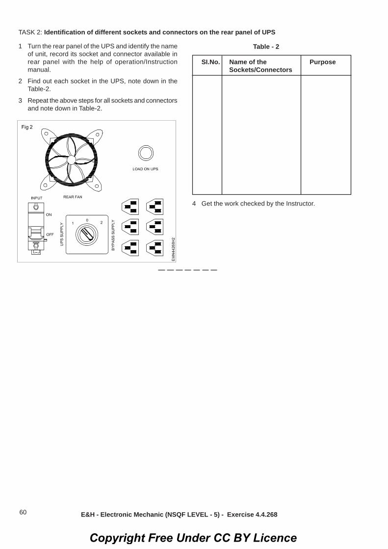
60
TASK 2: Identification of different sockets and connectors on the rear panel of UPS
1 Turn the rear panel of the UPS and identify the nameof unit, record its socket and connector available inrear panel with the help of operation/Instructionmanual.
2 Find out each socket in the UPS, note down in theTable-2.
3 Repeat the above steps for all sockets and connectorsand note down in Table-2.
Table - 2
SI.No. Name of the PurposeSockets/Connectors
E&H - Electronic Mechanic (NSQF LEVEL - 5) - Exercise 4.4.268
4 Get the work checked by the Instructor.
Copyright Free Under CC BY Licence

61
Electronics & Hardware Sector Exercise 4.4.269Electronic Mechanic - UPS
Connect battery & load to UPS & test on battery modeObjectives : At the end of this exercise you shall be able to• measure the total voltage of the battery stack using voltmeter• connect the UPS and load test the battery.
Requirements
Tools / Equipments/ Instruments
• Trainees tool kit - 1 set• Safety gloves - 1 set• Voltmeter 0-600V - 2 Nos.• Digital multimeter with probes - 1 No.
• UPS of 5 KVA with battery stack - 1 Set.• Double ended spanner 10mm - 2 No.
Material/ Components• 100W/230V Test lamp with holder - as reqd.
PROCEDURE
TASK 1 : Measurement of the total voltage of the battery stack using voltmeter
SafetyElectrical hazard: Do not make contact withboth of the battery terminals simultaneouslywith metal parts like screw drivers or spanners.Sparking may occur during connection ofbattery cables to may burn the skin seriously.
1 Disconnect the battery stack from main supply andremove the cable from main switch to the battery.
2 Prepare labels serially from 1 to N and paste them oneach of the batteries
3 Get the work checked by the Instructor.
4 Connect the DC voltmeter acorss battery stack asshown in the Fig.1, and notedown the observation inthe Table-1.
5 Note down the first label of the battery stack, connectthe DC voltmeter to the battery as shown in the Fig.2
6 Measure the voltage of the battery and note down theobserved voltage on table-1.
7 Repeat step 4 to 6 for measuring the voltage on all thebatteries
Note: In case any variation in measured voltageof the batteries, record in the remarks column
9 Add all the voltages from label - 1 to N comparewith the stack voltage.
Voltage across battery stack.....V Table 1
SI.No. Label No Measured voltage Remarks
1 Battery 1
2 Battery 2
3 Battery 3
4 Battery 4
5 Battery 5
N Battery N
Total voltageof stack
Copyright Free Under CC BY Licence

62 E&H - Electronic Mechanic (NSQF LEVEL - 5) - Exercise 4.4.269
TASK 2: Connection of UPS and load testing of the battery
Safety precaution1 Before connecting the battery to the UPS,
verify the electrode terminals symbol/ colourcodes on the battery
2 Ensure that the UPS is kept in switched OFFcondition
3 Connect the leads with correct polarity andtighten them.
1 Check the battery voltage (for 12V battery minimumvoltage from 9.5V to 12V)
2 Take out the terminals of the battery cable from theUPS.
3 Observe the colour code of the cable and tightlyconnect the battery with correct polarity.
4 Connect the DC voltmeter across the battery, measurethe voltage and record the observation in Table-2 asno load voltage.
5 Connect two lamps in parallel as full load to the UPSoutput as shown in Fig 3 (Keep the lamps safely as theheat may damage the surface - avoid it).
6 Keeping the voltage probes across the battery, switchON the UPS, observe the readings on the meter.
7 Record the observations in table-2 as voltage with fullload
10 Get the work checked by the Instructor.
Copyright Free Under CC BY Licence

63 E&H - Electronic Mechanic (NSQF LEVEL - 5) - Exercise 4.4.269
8 Remove on lamp and repeat the step as light load.
Table - 2
SI.No Status of UPS Battery voltage Full load(200W)No load Light load (100W)
1 UPS OFF
2 UPS ON
9 Get the work checked by the Instructor
Copyright Free Under CC BY Licence

64
Electronics & Hardware Sector Exercise 4.4.270Electronic Mechanic - UPS
Open top cover of a UPS; identify its isolation transformers, the UPStransformer and various circuit boards in UPS.Objectives : At the end of this exercise you shall be able to• identify the major section in computer UPS• identify the components used in computer UPS.
RequirementsTools/Equipments/ Instruments• Computer UPS(650 VA) - 1 set• Trainees tool kit - 1 set.
Nil
Note: The instructor has to label the majorcomponents/parts and sections of the UPS
Fig 1
PROCEDURE
TASK 1 : Identification of major sections in computer UPS
Sl.No. Major section in UPS
1.
2.
4.
5.
6.
TABLE 1
2 Unscrew the battery clamp pull out/ remove the batteryterminal connectors and take out the battery.
Before opening CPU case touch cabinet outercover to discharge ESD power.
3 Note down the wirings and carefully lift the circuitboard. Remove from its position.
4 Find out the major section in UPS as shown in Fig 2.Note down your observations in TABLE 1.
5 Get the work checked by the instructor.
Material/ Components
1 Disconnect the power cable from the mains supply.Remove the screws that are present in the side paneland open the UPS unit as demonstrated by the instructoras shown in Fig 1.
Fig 2
Copyright Free Under CC BY Licence

65
TASK 2 : Identification of components used in computer UPS
TABLE 2
Sl.No. Name of sections Components/Parts/Devices Remarks
1.
2.
3.
4.
5.
6.
7.
8.
9.
10.
E&H - Electronic Mechanic (NSQF LEVEL - 5) - Exercise 4.4.270
1 Remove the circuit board(PCB) from the UPS cabinet.
2 Identify the listed components in the circuit board asshown in Fig 3. Record the label of the identifiedcomponents in TABLE 2 by referring to related theory
Fig 3
3 Repeat steps for all the other major components.
4 Get the work checked by the instructor.
Copyright Free Under CC BY Licence

66
Electronics & Hardware Sector Exercise 4.4.271Electronic Mechanic - UPS
Identify the various test points and verify the voltages on the UPSObjective : At the end of this exercise you shall be able to• measure the voltage at various test points of the UPS.
Requirements
Tools/Equipments/Instruments• Trainees tool kit - 1 set.• Digital multimeter with probes - 1 No.
Materials/Components• Safety gloves - 1 set• UPS with battery• and intruction manual - 1 set
Note: Remove the power cord from the ACmains supply before starting this taskThe Instructor has to mark the test pointsnumbers using permanent marker pen.
Sl.No. Name of the test Voltage Remarks point
1 AC input supply
2 Transformer secondary
3 Rectifier output
4 Battery voltage
5 UPS output
6
7
TABLE 1
PROCEDURE:
TASK 1 : Measurement of the voltages at various test points of UPS
1 Open the UPS unit as demonstrated by the instructor.
2 Identify the major components/devices and sectionson the assembled circuit board of UPS.
3 Draw the sketch of layout of the sections and mark themajor/important test points in each section.
4 Connect the power cord to mains supply and switchON the UPS.
5 Measure the AC input voltage in the wall socket asshown in Fig 1.
6 Measure the voltage at transformer output sectionand the readings in TABLE 1.
7 Select the DC voltage function on multimeter andmeasure the rectifier voltage and note down inTABLE 1.
8 Measure the battery voltage by referring the Fig 1 andnote down in TABLE 1.
9 Get the work checked by the Instructor.
Copyright Free Under CC BY Licence

67
Electronics & Hardware Sector Exercise 4.4.272Electronic Mechanic - UPS
Identify various circuit boards in UPS and monitor voltages at various testpointsObjectives: At the end of the exercise you shall be able to• Identify various sectionsof UPS and locate test points on the circuit boards.• measure the voltage/waveform at various circuit boards in UPS.
Requirements
Tools/Equipments• Trainees tool kit - 1 set.• Digital multimeter with probes - 1 No.• CRO 0-20MHz - dual channel
Materials/ Components• UPS with battery - 1 set• Safety gloves - 1 set• UPS with battery and mark - 1 set
Note: The Instructor has to select and marknumber of test points in each section based onthe importance/functions on the UPS availablein Lab.
PROCEDURE
1 Keep the power cord disconnectedf from mains supplyand open the UPS unit as demonstrated by theinstructor.
2 Identify the major sections on the circuit the boards ofUPS referring circuit (Fig.1)
3 Trace the circuit and identify/ loacate the test pointson the UPS by referring to the circuit diagram andrecord them in Table -1.
Table - 2
Name of the Test Description/ Function of the Voltage/ RemarksSection Point section/circuit waveform
number
Mains to TP-1 AC mains inputInverter change TP-2 Rectified DC outputover section TP-3 Battery voltageBattery status TP-4 Battery status indicator sectionindicator section
4 Mark the test points on each board/section usingsketch pen.
5 Connect AC mains supply to UPS and measure testpoint voltages of each section and record in Table-2.
6 Prepare the CRO for measurements and check theoutput waveform at the oscillator section.
7 Get the work done checked by the Instructor.
Table-1
Type of UPS
SI.No. Name of the Board/Section Purpose
Copyright Free Under CC BY Licence

68
Name of the Test Description/ Function of the section/ Voltage RemarksSection Point Circuit
Number
Oscillator TP-5 Input to regulator ICand driver TP-6 Regulator IC outputsection TP-7 Oscillator out voltage (AC)
(observe waveform usingCRO)
TP-8 Triggering pulse input to upperbank driver (AC)
TP-9 Triggering pulse input to upperbank driver (AC)
TP-10 Triggering pulse input to upperbank switching transistor (AC)
TP-11 Triggering pulse input to lowerbank switching transistor (AC)
Inverter TP-12 DC input to inverter sectionsection (upper bank)
TP-13 DC input to inverter section(lower bank)
TP-14 Output inverter voltagesat transformer secondarytappings
TP-15
TP-16
TP-17
TP-18
TP-19
7 Get the work checked by the Instructor.
E&H - Electronic Mechanic (NSQF LEVEL - 5) - Exercise 4.4.272
Copyright Free Under CC BY Licence

69
Electronics & Hardware Sector Exercise 4.4.273Electronic Mechanic - UPS
Perform load test to measure backup timeObjectives: At the end of the exercise you shall be able to• perform load test of battery using UPS• measure the back-up time of the UPS with battery.
Requirements
Tools / Equipments/Instruments
• Trainees tool kit - 1 Set.• Computer UPS
(around 600VA) withoperating instruction manual - 1 No.
• DMM with probes - 1 Set.• Voltmeter 0-30VDC - 1 No.• Safety gloves - 1 Pair.• Stop watch - 1 No.
Materials/ Components• 100W/240V incandescent
lamp (Test lamp) - 1 No.• 12V/7AH, maintenance
free rechargeable battery - 1 No.
Safety precaution1 Before connecting the battery to UPS, in
spect the electrode terminals for symbols/colour codes on the battery.
2 Ensure that the UPS is kept in switched OFFcondition
3 Connect the leads with correct polarity andtighten them.
PROCEDURE
1 Use Dc voltmeter measure the terminal voltage andverify with the specification on the battery.
2 Take out the terminals of the battery cable from theUPS.
3 Observe the colour code of the cables and tightlyconnect the battery with correct polarity.
4 Connect the DC voltmeter across the battery, measurethe voltage and record the observation in Table-1 asno load voltage.
5 Connect the lamp load to the UPS output as shown inFig.1
6 Reset the stop watch at starting point.
7 Start the stop watch and switch ON the UPSsimulataneously, with voltmeter probes kept acrossthe battery terminals.
8 Observe the readings on the meter and terminalsrecord in Table-1.
9 Observe the lamp glow with beep sound carefully andstop the clock immediately when the lamp goes off.
10 Note down the readings on the voltmeter and stopwatch in Table-1.
Table - 1
Status of UPS Battery voltage Full loadNo load Light load
UPS OFF
UPS ON
Copyright Free Under CC BY Licence

70 E&H - Electronic Mechanic (NSQF LEVEL - 5) - Exercise 4.4.273
11 Get the work checked by the Instructor.
Copyright Free Under CC BY Licence

71
Electronics & Hardware Sector Exercise 4.4.274Electronic Mechanic - UPS
Perform all above experiment for three phase UPSObjectives: At the end of the exercise you shall be able to• identify front and rear pound controls & indicators of 3∅ UPS• measure the input and output voltages• perform load test using lamp loads.
Requirements
Tools / Equipments/ Instruments
• Trainees tool kit - 1 Set.• 3∅UPS with operating manual - 1 No.• Digital multimeter with probes - 1 No.• Safety gloves - 1 No.
Materials/ Components• Cotton waste - 1 No.• Incandescent 230V,
100W - 3 Nos.• Pendent holder - 3 Nos.• Connecting wires - as reqd• Hook up wires - as reqd
Safety precaution1 Earth conection is critical before
connecting the input supply. Hence, ensureproper earth connection.
2 Wait five minutes before opening the UPSto allow the capacitor to dicharge
3 Do not kept open the terminal block coverwhile the inverter is ON.
PROCEDURE
TASK 1 : Identify front and rear panel controls
1 Note down and record the specification of the UPS
2 Draw the front panel of the UPS with all indicators andswitch.
3 Identify each indicator and control on the front panelby referring to Fig.1
4 Record the observation in Table-1.
Table - 1 (Front side)
SL. No Name of the indicator Purpose& switch
5 Identify and record the rear panel switches andconnectors in Table - 2 by referring to Fig.2
Table - 2 (Rear side)
SL. No Name of the switch Purpose& connector
Copyright Free Under CC BY Licence

72
6 Referring to the operating mounted record a brieffunction of the indicators, controls, switches andconnectors.
7 Get the work checked by the Instructor.
TASK 2 : Measurement of the input and output voltages
1 Open the rear panel cover of the UPS under supervisionof the instructor.
2 Switch ON the input and output switch
3 Switch ON the inverter of the UPS
4 Measure the AC input voltage and AC output voltage.
5 Measure the battery voltage and record the values inthe table-3.
6 Get the work checked by the instructor.
Table - 3
Sl.No Various test point Voltage levels
E&H - Electronic Mechanic (NSQF LEVEL - 5) - Exercise 4.4.274
TASK 3 : Performing load test using lamp loads1 Connect the lamp load to the UPS output terminals as
shown in Fig.3
2 Switch ON the input & output switch and start theinverter.
3 Check and observe the condition of the lamp load.
Incandescent groups deliver core heat radiationhence keep the lamp on a separate metal tablewith proper ventilation.
4 Switch OFF the input mains supply now the UPS loadis under battery voltage.
5 Observe the performance of the load and batteryvoltage
6 Get the work checked by the instructor.
Copyright Free Under CC BY Licence

73
Remove all metallic jewellery prior to installation to reduce the chance ofaccidental exposure to live circuits.
Use electrical insulated tools to reduce the risk of electric shock.
Cover the front of the modules in the PV array with an opaque materialto halt production of electricity when installing or working with a moduleor wiring.
Electronics & Hardware Sector Exercise 4.5.275Electronic Mechanic - Solar power (Renewable energy system)
Install a solar panel to a roofObjectives : At the end of this exercise you shall be able to• select the suitable location on the roof to install solar PV panel• prepare frame setup to mount the SPV panel• select the correct position/angle and install the solar panel on a roof.
Requirements
Tools/ Equipments/ Instruments• Power drilling/hammering machine
with suitable drill bits - 1 set.• Trainees tool kit - 1 set.• Solar panel - 1 No.• Safety helmet - 1 No.• Safety harness - 1 No.• Safety gloves - 1 No.
Material/ Components• Base pipe - as required• Contact pipe - as required• Supporting pipe - as required• Rail splice - as required• Rail - as required• Rail contract AC - as required• End clamp - as required• Mid clamp - as required• M8 x 25 mm screws - as required• Bolt x Nuts - as required
PROCEDURE
Safety precaution:
All instructions should be read and understood before attempting toinstall, wire, operate and/or maintain the PV module and the otherelectrical equipments. PV Module interconnects pass direct current (DC)when exposed to sunlight or other light sources. Contact with electricallyactive parts of the module, such as terminals, can result in injury or death,whether the module andthe other electrical equipments are connected ordisconnected.
Wear suitable protection (non-slip gloves, clothes, etc.) to prevent directcontact with 30V DC or greater, and to protect your hands from sharpedges during the installation.
TASK 1 : Selection of location on the roof to install solar PV panel
1 Select the roof without shading for the solar panelinstallation.
2 Leave a safe working area between the edge of theroof and the external edge of the solar array forinstallation.
Copyright Free Under CC BY Licence

74
3 Make sure the direction of installation of the solarpanels takes sun into consideration.
4 Pick an area of your roof to install the solar panels thatgets the sun light rays as long as possible each day.
5 The solar panels can either be mounted flush on theroof or stand, or mounted at an angle to maximize theposition of accessibility to the sun's direct rays.
6 Get the work checked by the Instructor.
TASK 2 : Preparation of frame setup to mount the SPV panel
1 Contact pipe with M8 x 25 contact base pipe as shownin Fig 1.
2 Use M8 x 25 contact support pipe as shown in Fig 2.
5 Slide the splice on the rear side of thepre-assembled rails. Fasten the first bolt. Then slidethe next rail into the splice as shown in Fig 5.
6 Put one panel on the rack, use 2 end clamps to holdand fix by following the picture as shown in Fig 6(Attention: End of Rail distance must < 25 mm to 30mm).
E&H Electronic Mechanic (NSQF LEVEL - 5) - Exercise 4.5.275
3 Rail AC with M8 x 25 fixed on contact pipe as shownin Fig 3.
4 Take 2 fixed tile rack and position them with rail asshown in Fig 4.
7 Install the method for mid clamp and end clamp asshown in Fig 7.
8 Follow and use mid clamp fixed between panels asshown in picture of Fig 8.
Copyright Free Under CC BY Licence

75
9 Get the work checked by the instructor.
TASK 3 : Selection of correct position of solar panel and installation
1 Select the best/perfect angle for solar panels with thehelp of manual to produce the maximum power.
2 Refer to the perfect angle for standard roof pitchangle as shown in Fig 9.
Fig 11
Fig 10
Fig 12
3 Mark the holes as shown in Fig 10 after selecting theplace and angle of inclination.
4 Drill the hole on the roof with the help of drillingmachine as shown in Fig 11.
5 Fix the frame with the help of screw as shown in Fig12.
6 Place the panel on frame as shown in Fig 13.
E&H Electronic Mechanic (NSQF LEVEL - 5) - Exercise 4.5.275
Copyright Free Under CC BY Licence

76
Fig 13
E&H Electronic Mechanic (NSQF LEVEL - 5) - Exercise 4.5.275
7 Get the work checked by the instructor.
Copyright Free Under CC BY Licence

77
Electronics & Hardware Sector Exercise 4.5.276Electronic Mechanic - Solar power (Renewable energy system)
Wire a solar controller to a battery storage stationObjective : At the end of this exercise you shall be able to• prepare wires for connection• wire the terminals of charge controller & batteries properly.
RequirementsTools/ Equipments/ Instruments• Trainees tool kit - 1 set.• Solar panel 12V - 3 Nos.• Solar charge controller - 1 No.
(with operating instruction leaflet)
Material/ Components• Connecting wires with lug - as required• Battery 12V /10AH(minimum) - 3 Nos.
PROCEDURE
TASK 1 : Wiring of charge controller to battery station1 Pick the solar charge controller available in the lab.
2 Select Lead-Acid or Gel-cell battery as perrequirement.
3 Connection details of the controller as shown inFig 1.(Refer to the instructions provided by themanufacturer)
PV Negative(-)
PV Positive(+)
Fig 1
Battery Negative(-) Battery Positive(+)
Load Negative(-)
Load Positive(+)
4 Connect the terminal marked battery negative (-) onthe solar charge controller to the negative (-) of batteryterminal and tighten the screw.
5 Install a DC Breaker or a DC fuse holder in the positivewire as shown in Fig 2.
6 Use two battery cables. Remove insulation sleeve12 mm and insert conductor into cable lug terminal asshown in Fig 3.
7 Connect the terminal marked battery positive (+) onthe solar charge controller to the positive (+) batteryterminal and tighten the screw.
8 If more voltage is required, connect the batteries, inseries as shown in Fig 4.
Copyright Free Under CC BY Licence

78 E&H Electronic Mechanic (NSQF LEVEL - 5) - Exercise 4.5.275
10 Get the work checked by the instructor.
9 If more current is required, connect batteries in parallelas shown in Fig 5.
Copyright Free Under CC BY Licence

79
Electronics & Hardware Sector Exercise 4.5.277Electronic Mechanic - Solar Power (Renewable Energy System)
Install a solar power 500 Wp panel to directly 12V DC applicationsObjectives: At the end of the exercise you shall be able to• install a solar power panel 500 Wp for 12V DC application.• construct an application circuit for 12V DC application.
Requirements
Tools/ Equipments/ Instruments
• Digital multimeter with probes - 1 No• Trainees tool kit - 1 Set.• Solar application trainer kit with PV panel
500Wp - 1 No.
Material/ Components• Connecting wires
and patch cords - as reqd.• LED lamps -3W - 2 Nos.• CFL lamps -15W - 2 Nos.
Insulation tape - as reqd.
PROCEDURE
1 Follow connection details of the controller as shown infig.1.
2 Connect the PV array’s positive (+) output to theterminal marked PV positive (+) on the solar chargecontroller and tighten the screw as shown in Fig.2
4 Similarly connect the DC output load terminals positive(+) to positive (+) terminal of DC load LED/CFL bulbsand negative (-) terminal to negative terminal (-) of DCload LED/CFL bulbs to as per instruction manual ofthe solar application trainer kit as shown in Fig.3
Fig1
3 Connect the PV array’s negative (-) output to theterminal marked PV negative (-) on the solar chargecontroller and tighten the screw.
Copyright Free Under CC BY Licence

80
Table 1SI.No. Solar PV panel Output Load output Remarks
(Volts) (Lamp status - ON/OFF)
1
2
3
4
5 Record the results in the observation table 1.
E&H Electronic Mechanic (NSQF LEVEL - 5) - Exercise 4.5.277
6 Get the work checked by the instructor.
Copyright Free Under CC BY Licence

81
Electronics & Hardware Sector Exercise 4.5.278Electronic Mechanic - Solar power (Renewable energy system)
Connect storage batteries to a power inverterObjectives: At the end of the exercise you shall be able to• install the storage battery and charge controller to inverter.
RequirementsTools/Equipments/ Instruments• Trainees tool kit - 1 set.• Solar charge controller - 1 No.• Solar inverter with user manual - 1 No.
Materials/ Components• Battery 6V/10A - 1 No.• Fuse 1A - 1 No.• Circuit breaker - 1 No.• Connecting wires with lugs - as required
PROCEDURE
2 Connect the fuse holder to DC circuit breaker one endas shown in Fig 2.
3 Remove wiring cover in the inverter ,you will see asshown in Fig 3.
Attention
• The wire connection can only be done after theinverter is fixed in proper position on the wall.
• Make sure the max. open circuit voltage andshort circuit current of solar arrays are notexceeded the stipulated range of the inverter.
TASK 1 : Connection of storage battery and charge controller to inverter
Note: Before connecting to PV modules, installseparately a DC circuit breaker between inverterand PV modules.
1 Connect the battery +ve terminal to fuse holder asshown in Fig 1.
• Choose proper cable for power input and outputlines.
• While connecting the inverter, make sure noconnection among AC, DC and any powerresources are disconnected.
• Identify the polarity of wires and connectionports first, then connect the inverter with solararrays in proper polarity.
Copyright Free Under CC BY Licence

82
4 Check the nominal voltage of batteries.
5 Use two battery cables. Remove insulation sleeve 12mm and insert conductor into cable lug terminals, asshown in Fig 4 and fix it on both cables.
6 Connect the terminal marked battery negative (-) onthe Solar inverter to the negative (-) battery terminaland tighten the screw.
7 Connect the DC breaker one end to solar inverter (+)terminal and tighten the screw as shown in Fig 5.
8 Make sure the wires are securely connected.
9 Get the work checked by the instructor.
E&H Electronic Mechanic (NSQF LEVEL - 5) - Exercise 4.5.278
Copyright Free Under CC BY Licence

83
Electronics & Hardware Sector Exercise 4.5.279Electronic Mechanic - Solar power (Renewable energy system)
Connect and test solar panel and run the loadObjectives: At the end of the exercise you shall be able to• install the storage battery and charge controller to inverter.
RequirementsTools/ Equipments/ Instruments• Trainees tool kit - 1 set.• Solar charge controller - 1 No.• Solar inverter with user manual - 1 No.• DC load - 1 No.• Solar panel - 1 Set.• Digital multimeter with probes - 1 No.• AC load - 1 No.
Materials/ Components• Battery 6V/10A - 1 No.• Fuse 1A - 1 No.• Circuit breaker - 1 No.• Connecting wires with lugs - as required• Solar panel 12V with manual - 1 No.
PROCEDURE
TASK 1 : Connect solar panel to the inverter
1 Before connecting to PV modules, please installseparately a DC circuit breaker between inverter andPV modules.
2 Connect the battery +ve terminal to fuse holder asshown in Fig 1.
3 Connect the fuse holder to DC circuit breaker one endas shown in Fig 2.
4 Remove wiring cover in the inverter ,you will see asshown in Fig 3.
Attention
• The wire connection can only be done after theinverter is fixed in proper position on the wall.
• Make sure the max. open circuit voltage andshort circuit current of solar arrays are notexceeded the stipulated range of the inverter.
• Choose proper cable for power input and outputlines.
• While connecting the inverter, make sure noconnection among AC, DC and any powerresources are disconnected.
• Identify the polarity of wires and connectionports first, then connect the inverter with solararrays in proper polarity.
Copyright Free Under CC BY Licence
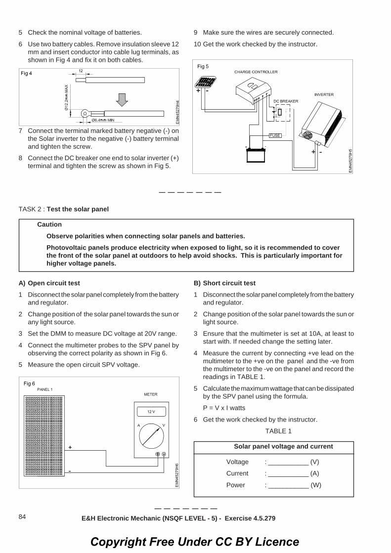
84
5 Check the nominal voltage of batteries.
6 Use two battery cables. Remove insulation sleeve 12mm and insert conductor into cable lug terminals, asshown in Fig 4 and fix it on both cables.
7 Connect the terminal marked battery negative (-) onthe Solar inverter to the negative (-) battery terminaland tighten the screw.
8 Connect the DC breaker one end to solar inverter (+)terminal and tighten the screw as shown in Fig 5.
9 Make sure the wires are securely connected.
10 Get the work checked by the instructor.
TASK 2 : Test the solar panel
CautionObserve polarities when connecting solar panels and batteries.Photovoltaic panels produce electricity when exposed to light, so it is recommended to coverthe front of the solar panel at outdoors to help avoid shocks. This is particularly important forhigher voltage panels.
A) Open circuit test1 Disconnect the solar panel completely from the battery
and regulator.
2 Change position of the solar panel towards the sun orany light source.
3 Set the DMM to measure DC voltage at 20V range.
4 Connect the multimeter probes to the SPV panel byobserving the correct polarity as shown in Fig 6.
5 Measure the open circuit SPV voltage.
B) Short circuit test1 Disconnect the solar panel completely from the battery
and regulator.
2 Change position of the solar panel towards the sun orlight source.
3 Ensure that the multimeter is set at 10A, at least tostart with. If needed change the setting later.
4 Measure the current by connecting +ve lead on themultimeter to the +ve on the panel and the -ve fromthe multimeter to the -ve on the panel and record thereadings in TABLE 1.
5 Calculate the maximum wattage that can be dissipatedby the SPV panel using the formula.
P = V x I watts
6 Get the work checked by the instructor.
TABLE 1
Solar panel voltage and current
Voltage : ___________ (V)
Current : ___________ (A)
Power : ___________ (W)
E&H Electronic Mechanic (NSQF LEVEL - 5) - Exercise 4.5.279
Copyright Free Under CC BY Licence

85
TASK 3 : Run the AC load1 Remove wiring cover in the inverter as shown in Fig
1.
2 Connect the AC output socket to circuit breaker asshown in Fig 2.
3 Connect the circuit breaker to the load as shown inFig 3.
4 Get the work checked by the instructor.
TASK 4 : Run the DC load1 Carryout the steps 1 to 5 from exercise 4.4.18
2 Follow the connection details of the controller asshown in Fig 4.
Fig 4
Battery Negative(-) Battery Positive(+)
Load Negative(-)
Load Positive(+)
PV Negative(-)
PV Positive(+)
3 Connect the terminal marked load negative (-) on thesolar charge controller to the negative (-) load terminaland tighten the screw.
4 Connect the terminal marked load positive (+) on thesolar charge controller to the positive (+) battery terminaland tighten the screw as shown in Fig 5.
5 Switch ON the charge controller and observe the bulb.The bulb should be illuminated.
6 Get the work checked by the instructor.
E&H Electronic Mechanic (NSQF LEVEL - 5) - Exercise 4.5.279
Copyright Free Under CC BY Licence

86
Electronics & Hardware Sector Exercise 4.5.280Electronic Mechanic - Solar power (Renewable energy system)
Install a solar panel to charge a rechargeable 12V DC battery and find out thecharging timeObjectives: At the end of the exercise you shall be able to• install a solar power panel for 12V DC application• assemble an application circuit for 12V DC application.
Requirements
Tools / Equipments/ Instruments
• Trainees tool kit - 2 Nos• Digital multimeter with probes - 1 No.• Solar charge controller trainer
with manual - 1 No.• Solar battery 12V DC/ 100 AH - 1 No.
Materials/ Components• Wires with lugs and patch cords - 1 Set.• Insulation tape - 1 No.
PROCEDURE
Note: Before connecting to PV modules, pleaseinstall separately a DC circuit breaker betweeninverter and PV modules.
1 Connect the battery +ve terminal to fuse holder asshown in fig.1
2 Connect the fuse holder to DC circuit breaker asshown in Fig.2
3 Check the nominal voltage of batteries.
4 Use two battery cables. Remove insulation sleeve12mm and insert conductor into cable lug terminals,as shown in Fig 3 and fix it on both cables.
5 Connect the terminal marked battery negative (-) onthe solar inverter to the negative (-) battery terminaland tighten the screw.
6 Connect the DC breaker one end to solar inverter (+)terminal and tighten the screw as shown in Fig.4
7 Make sure the wires are securely connected.
8 Get the work checked by the instructor.
Copyright Free Under CC BY Licence

87
Electronics & Hardware Sector Exercise 4.5.281Electronic Mechanic - Solar power (Renewable energy system)
Install a solar inverterObjectives : At the end of this exercise you shall be able to• install the solar inverter• connect the solar inverter to grid(AC)• commission the solar inverter.
Requirements
Tools/ Equipments/ Instruments• Trainees tool kit - 1 set.• Electric drilling machine with drill bit - 1 set.• Solar inverter with user
manual - 1 No.• Digital multimeter with probes - 1 No.
Materials/ Components• Ruler or measuring tape - 1 No.• Pencil - 1 No.• Connecting wires - as required• User manual of given solar inverter- 1 set.
PROCEDURE
TASK 1 : Install the solar inverterPlanning the installation: (Fig 1)
1 Choose your installation location carefully.
2 Check that the wall is capable of bearing the heavyload of the device and vibration-free to avoid disruptivevibrations.
3 Lift and move the solar inverter with the help of atleasttwo to three people.
4 Select correct size of dowels and screws that aresuitable for the wall material and the heavy weight.
Do not mount the inverter on flammableconstruction materials.Always use the mounting plate supplied withthe solar inverter.This inverter can make noises during operationwhich may be perceived as a nuisance in aliving area.
5 Measure the dimension of the solar inverter and markthe hole in wall.
6 Drill four holes in the marked location with four screwsas shown in Fig 2.
7 Place the unit on the surface and align the mountingholes with the four screws as shown in Fig 3 andmount the solar inverter.
8 Check if the solar inverter is firmly secured as shownin Fig 4.
Fig 1
9 Get the work checked by the instructor.
Copyright Free Under CC BY Licence

88
TASK 2 : Connecting the solar inverter to the grid (AC)
1 Read label and note down rated voltage and currentof the given solar inverter.
2 Check the grid voltage and frequency with DMM itshould be the same to "VAC" value on the productlabel.
3 Turn off the circuit breaker.
4 Remove the insulation sleeve 8 mm for threeconductors, and shorten the phase L and neutralconductor N 3 mm as shown in Fig 5.
5 Connect wires according to polarities indicated onterminal block, be sure to connect PE protective earth
conductor first.
L - LINE ( brown or black ) next
- ground (yellow - green) and
N - Neutral (blue)
6 Make sure the wires are securely connected. thereference tightening torque is 0.82N.M
Its only allowed to connect load to "AC outputconnector". Do NOT connect the utility to "ACoutput connector".Be sure to connect L terminal of load to Lterminal of "AC output connector" and Nterminal of load to N terminal of "AC outputconnector". The G terminal of "AC outputconnector" is connected to grounding of theload. Do NOT interchange the wires.This inverter is not allowed to operate in parallel.Please do NOT parallel connect more than oneunit in AC output connector. Otherwise, it willdamage this inverter.
7 Get the work checked by the instructor.
TASK 3 : Commissioning of solar inverter1 Connect power either by AC (the grid) or DC (the solar
modules) to the inverter for commissioning.2 Select after powering up the inverter for the first time,
the language dialog as shown in Fig 6. E&H Electronic Mechanic (NSQF LEVEL - 5) - Exercise 4.5.281
Copyright Free Under CC BY Licence

89
Fig 6
Fig 7
Fig 9
Fig 8
3 Use the buttons and to select language English.To confirm your selection, press the button .
4 Use the buttons and to select the entry YES. Toconfirm your selection, press the button . If youwant to change your selection, press the button .
The inverter starts a self-test which takesapproximately 2 minutes. A countdown showsthe remaining time on the display. (Fig 8)
5 The basic setup is finished. The standard menu isshown in Fig 9.
E&H Electronic Mechanic (NSQF LEVEL - 5) - Exercise 4.5.281
6 Get the work checked by the instructor.
Copyright Free Under CC BY Licence

90
Electronics & Hardware Sector Exercise 4.6.282Electronic Mechanic - Cell phones
Dismantle, Identify the parts and assemble different types of smart phonesObjectives : At the end of this exercise you shall be able to• dismantle the given cell phone/smart phone• identify the different sections/parts of the cell phone/smart phone• list the different sections/parts of the cell phone/smart phone• reassemble the given cell phone/smart phone.
RequirementsTools/Equipments/Instruments• Cell phone/ Smart phone - 1 No.• Precision screw driver set - 1 set.• Trainees tool kit - 1 set.• Digital multimeter with probes - 1 No.• User manual - as reqd.
Materials/ ComponentsNil
PROCEDURE
TASK 1 : Dismantling the cell phone / smart phone
1 Switch OFF the cell phone/smart phone and locatesmall hole next to headphone jack. Push the tip of aneedle or paperclip into hole to eject sim tray. (Fig 1)
Fig 1
Fig 2
Fig 3
2 Hold your device on end to locate two small screws oneither side of the back cover. Remove the screwsusing a small star screwdriver. (Fig 2)
3 Insert a spudger between the chrome ring and frontpanel glass directly above one of the screw holes. Trygently to separate the display from the back panel.(Fig 3)
4 Lift the panel up from the back cover end be carefulnot to tear or break any ribbons connected near theother end.(Fig 4)
5 Continue to hold the display panel with one hand, anduse your other hand and a spudger to disconnect theblack ribbon cable labeled "1".(Fig 5) 6 Rotate the display assembly up until it is roughly
vertical. This will allow easier access for removing theremaining cables. (Fig 6)
Copyright Free Under CC BY Licence

91
7 Use a spudger to disconnect the black ribbon cablelabeled "2." (Fig 7)
8 Use a spudger to flip up the white plastic tab holdingthe remaining ribbon cable in place. The white tab willrotate up 90 degrees, releasing the ribbon cable. (Fig8)
9 Slide the black ribbon cable out of its connector, andremove the display assembly from the cell phone.(Fig 9)
Fig 4
Fig 5
Fig 6
Fig 7
Fig 8
Fig 9
10 Remove the screws surrounding the motherboard:Remove the screws 2-3 mm star screws with partialthreads securing the logic board to the rear panel.(Fig 10)
11 Remove the screws using 2-3 mm star screws withfull threads securing the logic board and camera.(Fig 11)
12 Remove the screws using 2-3 mm star screw frombeneath the "Do not remove" sticker. (Fig 12)
E&H Electronic Mechanic (NSQF LEVEL - 5) - Exercise 4.6.282
Copyright Free Under CC BY Licence

92
Fig 10
Fig 11
Fig 12
13 Unplug ribbon,whcih is connected to display andother parts.(Fig 13)
14 Unplug this connecting ribbon and place the motherboard aside. (Fig 14)
15 Use a spudger to gently pull the camera up and outof its housing in the rear panel. The camera cannot beremoved entirely yet because its connected to thebottom of the logic board. (Fig 15)
16 Use a spudger to gently try up the end of the logicboard closest to the dock connector. If the board won'tlift up, double check to make sure all the screwssecuring the logic board have been removed.(Fig 16)
Fig 13
Fig 14
Fig 15
Fig 16
E&H Electronic Mechanic (NSQF LEVEL - 5) - Exercise 4.6.282
Copyright Free Under CC BY Licence

93
17 Slide the logic board towards the back side connectorand out of the cell phone.(Fig 17)
Fig 17
Fig 18
Fig 19
18 Use a little force, pull up and remove the attached tabon the battery. (Fig 18)
19 Replace battery and repeat steps in reverse toreassemble! (Fig 19)
20 Dismantling of the cell phone has been completed.
21 Get the work checked by the Instructor.
TASK 2 : Assembling the cell phone / smart phone
Fig 20
1
4
3
2
E&H Electronic Mechanic (NSQF LEVEL - 5) - Exercise 4.6.282
Copyright Free Under CC BY Licence

94
1 Identify the parts of a cell phone given in Fig 20 andrecord names of each part in the TABLE 1.
2 Follow the step by step procedure done in TASK 1 inthe reverse order to re-assemble the cell phone/smartphone.
3 Observe correct position and insert the ribbon cable/connector,etc. carefully. [They are very delicate andwill get damaged easily.]
4 Ensure that the assembling is done correctly and allthe boards are fixed in their respective positions.
5 Switch on the cell phone and check the workingcondition.
TABLE 1
Sl. No. Type of phone / smartphone Section/Part
E&H Electronic Mechanic (NSQF LEVEL - 5) - Exercise 4.6.282
6 Get the work checked by the Instructor.
Copyright Free Under CC BY Licence

95
Electronics & Hardware Sector Exercise 4.6.283Electronic Mechanic - Cell phones
Dismantle the cell phone / smart phone remove the keypad and clean it , test thecontinuity of the matrix/tracksObjectives : At the end of this exercise you shall be able to• remove key pad of the cell phone and clean it• replace the display and keypad of the given cell phone• remove touch screen of the smart phone and clean it.
Requirements
Tools/Equipment/Instruments• Cell phone/ Smart phone - 1 No.• Precision screw driver set - 1 set.• Tweezers with antistatic wrist strap
and hand gloves• Digital multimeter with probes - 1 No.
Materials/ Components• Cotton cloth - as required• CTC/IPA Solution - as required• User manual - as required
PROCEDURE
TASK 1 : Remove the keypad and clean it
1 Dismantle the cell phone by referring the previousexercise.
2 Make a mixer of half rubbing alcohol and half distilledwater.
3 Wipe the phones keypad with a soft cloth and removedust.
4 Allow the cell phone to dry before reinserting thebattery or putting it back in its case.
5 Check the continuity of row and column pins usingDMM.
6 Place the key pad in the right position while closing thefront cover for the reassembly. Do not assemble thephone of display has to be replaced.
7 Switch ON the phone and check the working condition.
TASK 2 : Replace the display
1 Dismantle the cell phone by referring the previousexercise.
2 Remove the display by removing the small star headscrew and lift the LCD display out of the cell phone.
3 Install the new display into your cell phone and followthe procedure in reverse order.
4 Insert the battery and battery cover. Switch ON thephone and check for its working.
TASK 3 : Removing and cleaning the touch screen
1 Turn the device off.
2 Cover the whole screen with some clear packagingtape.
3 Remove the back cover.
Removing the broken glass panel1 Heat the glue holding the glass in place.
2 Use the painter's tape to take out flecks of glass.
3 Gently lift the edges of the glass off.
4 Work your way downward.
5 Remove the touch buttons carefully.
6 Remove the glass.
7 Take out the metal earpiece from the old glass.
Copyright Free Under CC BY Licence

96
Applying the new glass panel1 Wipe away the remaining glue on the edges of the
front of the phone.
2 Apply double-sided tape to the top and bottom of thefront panel.
3 Wipe the display with a lens cleaner.
4 Remove the protective cover from your replacementglass carefully.
5 Put the touch buttons back in place.
6 Connect the metal earpiece to the new glass.
7 Apply the replacement glass onto your phone.
8 Heat the panel again.
9 Get the work checked by the instructor.
E&H Electronic Mechanic (NSQF LEVEL - 5) - Exercise 4.6.283
Copyright Free Under CC BY Licence

97
Electronics & Hardware Sector Exercise 4.6.284Electronic Mechanic - Cell phones
Interface the cell phone/smart phone to PC and transfer the data card.Objectives : At the end of this exercise you shall be able to• transfer data from phone memory to SD card• transfer data from phone to PC.
Requirements
Tools/Equipments/Instruments• Cell phone/ Smart phone
with SD card - 1 No.• Personal computer - 1 No.
Materials/ Components• USB cable - 1 No.• User manual - as required
PROCEDURE
TASK 1 : Transfer app from phone memory to SD card1 Select the setting tab on screen. (Fig 1 & 2)
Fig 1
Fig 2
Fig 3
Fig 4
Setting can access from tab scrolling also.
2 Scroll the settings menu and select manage applicationtab -> Settings. (Fig 3)
3 Now select app needed to move from phone to SDmemory card.
4 Now select move to SD card option tab.(Fig 4)
Copyright Free Under CC BY Licence

98
5 Press tab and select OK button on warning menu.
6 Now observe tab changing move to phone.Same can repeat for moving, app from memoryto phone.
TASK 2 : Moving data (Files and Folder) from phone to SD memory card and vice versa
1 Go to the home screen.
2 Then select the File manager and then tap on local.
3 Choose the external SD folder.
4 Tap on the folder or file to which you want to move tothe SD card.
5 Copy the folder or file to the external SD folder byclicking on paste option.
6 Tap on the STORAGE on setting menu scroll thescreen for SD card.
7 Check the file/folder is copied into SD card.
TASK 3 : Transfer data from phone to PC using data card / USB port
1 Use a data cable to connect your phone to yourcomputer's USB port. (Fig 5)
3 Touch the USB Connected notification on your phone'sscreen. (Fig 7)
Fig 5
Fig 6
2 Make sure your memory card is in your phone. (Fig 6)
Fig 7
Fig 8
4 Turn on USB storage in some model the screen asshown in Fig 9 will appear and select the option as perrequire menu in the PC. (Fig 8)
E&H Electronic Mechanic (NSQF LEVEL - 5) - Exercise 4.6.284
Copyright Free Under CC BY Licence

99
5 Click on My Computer and find removable storage.(Fig 9)
Fig 9
Fig 10
6 Drag and drop the files you want from your phone toyour computer. (Fig 10)
7 If the files are transformed go to Notifications andselect Turn Off USB Storage.
8 Disconnect the data cable from your phone and yourcomputer.
E&H Electronic Mechanic (NSQF LEVEL - 5) - Exercise 4.6.284
Copyright Free Under CC BY Licence

100
Electronics & Hardware Sector Exercise 4.6.285Electronic Mechanic - Cell phones
Flash the various brands of cell phones/smart phonesObjectives : At the end of this exercise you shall be able to• identify the flashing tools• perform a flashing process• flash the various brands of cell phones/ smart phones.
RequirementsTools/Equipment/Instruments• Cell phone/ Smart phone with SD card - 1 No.• Data connection to the Cell phone - 1 No.
Materials/ Components• User Manual - as required
PROCEDURE
TASK 1 : Flashing the various brands of cell phone/smart phone
1 Download and install Android USB driver on yourcomputer.
In case Android USB drivers are alreadyinstalled on your computer then do the step 2.
2 Power off your Android smartphone and remove thebattery. (If it is removable)(Fig 1)
Fig 1
Precaution1. Brand and model must be same you can verify/
net confirm your smart phone.
2. Never downgrade android version of your smartphone.
3. Before trying anything make a complete backupof your data in a computer.
4. The above tutorial only works with the stockfirmware or custom ROM which comes with thescatter file in it.
5. Take a backup of your important data beforeusing the smart phone flash tool because duringthe flashing process your personal data will beremoved permanently.
3 Download the stock ROM or custom ROM softwarethat you want to flash on your Android smartphoneand copy it on your computer.
4 Download and copy smart phone flash tool on yourcomputer. (Fig 2)
5 Now open Flash_tool.exe (Fig 3)
6 Click on the Download tab.(Fig 4)
7 In the download tab, now click on the scatter-loadingbutton.(Fig 5)
8 Now, locate the scatter file (you will find the scatter filein the stock rom folder).
9 Now, click on the download button to begin the flashingprocess.(Fig 6)
10 Now, connect your smartphone to the computer usingUSB cable (without battery - if it is removable).
Copyright Free Under CC BY Licence

101
TASK 4 : Connect a smartphone in Wi-Fi / hotspot1 Goto setting as shown in Fig 5.
Fig 5
2 Click personel hotspot.
3 Click on wi-fi password enter password (first timeconnect, you enter the password and save) as shownin Fig 6.
4 Click to connect using Wi-Fi shown in Fig 7.
5 Now the internet is connected.
6 Browse the internet, the same way as do in computer.
7 Get the work checked by the instructor.
Fig 6
Fig 7
E&H Electronic Mechanic (NSQF LEVEL - 5) - Exercise 4.6.285
Copyright Free Under CC BY Licence

102
Electronics & Hardware Sector Exercise 4.6.286Electronic Mechanic - Cell phones
Format the cell phone/smart phone for virus(approch the mobile repair shop,service center)Objectives : At the end of this exercise you shall be able to• format the android phones using basic reset option• format the android phone using recover reset option.
Requirements
Tools/Equipments/Instruments• Cell phone/ Smart phone with SD card- 1 No.• Precision screw driver set - 1 set.
Materials/ Components• User Manual - as required
PROCEDURE
TASK 1 : Formatting the android phones using basic reset option
Fig 2
Fig 1
Fig 3
Caution : Backup all data before resettingoperation.
1 Press menu button and select setting option. (Fig 1)
Setting can access from tab scroll also.
2 Scroll the menu and select the privacy option. (Fig 2)
3 Scroll the menu and select factory reset option. (Fig 3)
4 Press the warning message OK.
5 Select SD card if it need format and select everythingerase option.(Fig 5 and 6)
6 After few seconds, phone will reset.
7 Check the screen. It looks like new phone memory.
Copyright Free Under CC BY Licence

103
Fig 5 Fig 6
TASK 2 : Format the android smart phone by using recovery reset option
1 Press the ON/OFF button for the power OFF option toappear on your device as shown in Fig 7.
Before you begin the reset procedure, you willneed to completely power your device off.
2 Press and hold the recovery buttons. (Fig 8)
Buttons will vary from device to device. So yourefer to the instruction for a particular phone.If you want to press and hold the buttons for afew seconds. Some common buttoncombinations include:Volume Up + Home + PowerVolume Down + PowerHome + Power
3 Select factory reset option.
Once the recovery menu opens, you cannavigate the menu with the volume buttons.You may need to open the recovery menu tofind the factory reset mode. Use the powerbutton, some models use the camera button,to select your menu options.
4 Select to confirm the factory reset.
5 Wait for the restore process to compete. After yourphone resets, it will be set back to factory defaults andwill be like new phone.
6 Get the work checked by the instructor.
Fig 8
Fig 7
E&H Electronic Mechanic (NSQF LEVEL - 5) - Exercise 4.6.286
Copyright Free Under CC BY Licence

104
Electronics & Hardware Sector Exercise 4.6.287Electronic Mechanic - Cell phones
Unlock the handsets through codes and softwareObjectives : At the end of this exercise you shall be able to• perform different types of locks in cell phone / android cell phone• make user lock functions and unlock functions in your cell phone / android cell phone• make provide lock functions and unlock functions in your cell phone / android cell phone.
Requirements
Tools/Equipments/Instruments• Cell phone / Android mobile - 1 No.• Sim card - 1 No.
Material/ Components• User Manual - as required
Caution : Lock buttons are different from phoneto phone.
PROCEDURE
TASK 1 : Lock and unlock keypad of a cell phone
Lock function1 Press the menu key and the same time press the #
key.
2 Now your keypad has been locked.
Unlock function1 Press the menu key and the same time press
the # key.
2 Now your keypad has been unlocked.
TASK 2 : Lock and unlock sim cardLock function1 Go to settings in your cell phone menu function.
2 Go to security settings in the setting menu.
3 Enter a new code number.
4 Switch ON the security settings.
5 Now your SIM card has been locked by security code.
Unlock function1 Go to settings in your cell phone menu function.
2 Go to security settings in the setting menu.
3 Enter the same security code that you have enteredwhile locking the SIM card.
4 Switch OFF the security settings.
5 Now your SIM card has been unlocked.
TASK 3 : Lock and unlock the cell phoneLock function1 Go to settings in your cell phone menu function.
2 Go to call settings.
3 Fix dial.
4 Switch ON the fix dial.
5 Now your phone has been locked, you can receiveincoming calls but you cannot make outgoing call afteryour phone has been locked.
Unlock function1 Go to settings in your cell phone menu function.
2 Go to call settings.
3 Then go to Fix dial.
4 Switch OFF the fix dial.
5 Now your phone has been unlocked.
Copyright Free Under CC BY Licence

105
TASK 4 : Lock and unlock PUK (Provider lock)
Lock function
• If you enter wrong security code 3 times,then your phone becomes locked.
• If you enter wrong security code 10 times,then your SIM card becomes locked.
• If you enter wrong security code 10 to 100times, then your cell phone locked by PUKcode.
Keep ready SIM card or SIM box for information.
Unlock function1 Make call to the service provider. (customer care)
2 Explain them about your problem, they will ask yourSIM number.
3 Tell the SIM number (first 20 numbers), which isprinted in your SIM card.
4 The service provider will give some code number.
5 Enter the code number which was given by the serviceprovider, first time the phone shows enter a newnumber, second time follow the same code number,third time the PUK lock will be open.
E&H Electronic Mechanic (NSQF LEVEL - 5) - Exercise 4.6.287
Copyright Free Under CC BY Licence

106
Electronics & Hardware Sector Exercise 4.6.288Electronic Mechanic - Cell phones
Perform the interfacing of Cell phone/Smart phone to the PC and dismantle thecell phone and identify the power section and test its healthinessObjectives: At the end of the exercise you shall be able to• perform the interfacing of cell phone/smart phone to the PC• dismantle the cell phone and identify the power section• test its healthiness of power section of smart phone.
Requirements
Tools / Equipments/ Instruments
• Trainees tool kit - 1 Set.• Digital multi-meter with probes - 1 Set.• Mobile opener tools - 1 Set.
Materials/ Components• Smart phone with data cable - 1 No.• PC/Laptop - 1 No.
PROCEDURE
TASK 1 : Perform the interfacing of Cell phone/Smart phone to the PC
1 Switch ON the PC and install the “Phone companion”App in your PC. The phone companion app is builtdirectly into window 10.
If windows 10 version is not available,download the app from internet and use it forexercise.
2 Enter your phone number for registering/adding yourphone in the app. Then one time automated messagewill be sent from the microsoft to your registered cellphone number. Consent is not necessary to get oruse the app.
3 When the app launches, you will see the first phonecompanion screen, as shwon in Fig.1 on the monitor.
4 Click on your type of phone (like, windows/android/IPhone), and then connect your cell phone to yourcomputer. After selection of the phone type, phonecompanion app will show the display as shown inFig.2.
Fig 1
Fig 2
Fig 3
Copyright Free Under CC BY Licence

107
5 Select the desired application say onenote to set upin the PC sign into that one application, phonecompanion will identify that you are signed into yourwindows system with a microsoft account and promptyou to confirm, as shown in Fig.3.
6 Verify your microsoft account, you will be promptedto begin the procedure of getting the one note appfor the smart phone, as shown in Fig.4
7 Access all the notes that you have created in windows,the onenote app is synched up.
8 Get the work checked by the Instructor.
TASK 2 : To synchronise the photos and folders of the cell phone to the PC
1 Connect the USB data cable from your computer’sUSB port to your cell phone. The phone companionlists you phone’s available storage space andavailable apps as shown in the Fig.5 to synch thephotos & folders.
2 Choose which app to install, and whether to transferphotos or files. The phone companion leaves you withthree options.
Install Apps: The phone companion lists thewindows apps available your phone. Install theonedrive app, for example, to give yout phoneaccess to your onedrive files. You can alsoinstall cortana, music, onenote, skype, word,Excel, powerpoint, and outlook - the sameapps that work on your PC. By installing theapps, you can edit your onedrive files withword, both on your phone and your PC.Import photos and videos: Choose this optionto copy your photos and videos from yourphone or tablet to your PC.Transfer other files: This option brings up fileexplorer, where you can view the files andfolders on your tablet. Then you can transferitems from your phone or tablet to your PC orvice versa.
TASK 3: Dismantle the cell phone and identify the power section
1 Switch OFF the cell phone and remove the batterycover and back facial of the cell phone.
The screws must be kept very carefully forreassemble the cell phone
2 Remove the battery, SIM card and memory cardcarefully.
3 Using suitable screwdriver, unscrew and remove allthe screws and keep them in a safe box.
4 Once all the screws are open, remove the front coveror the front fascia of the mobile phone.
The phone PCB is attached with the internalfasica or skeleton of the mobile phone usingscrews.
5 Unscrew and open all the screws of the mainassembly.
E&H Electronic Mechanic (NSQF LEVEL - 5) - Exercise 4.6.288
Fig 4
Fig 5
Copyright Free Under CC BY Licence

108
Safety: It is very delicate part, handle with care.6 Remove connectors for display, camera and pull the
display and the camera out as shown in Fig.6
7 Identify the power IC, and other supporting ICs.
8 Record the IC numbers/details in Table-1.
9 Get the work checked by the instructor.
The IC around which there are severalcapacitors is called power IC. In some cellphones there are 2 power ICs.
TASK 3: Test the healthiness of cell phone power1 Keep the battery separately and set it down on flat
surface such that the terminals are facing you.
2 Note the specification of the battery and identify thetwo terminals on the battery that are labeled with ‘+’and ‘-’ sign as shown in Fig.7
3 Measure and record the battery voltage, using multi-meter in Table-1.
4 Compare with the rating of battery and observe thehealthiness of the power supply of the cell phone.
5 Get the work checked by the instructor.
6 Carefully insert the display, camera and its connectorscarefully.
7 Reassemble the cell phone, with respective screws.
8 Insert the memory card, SIM card and battery.
9 Switch ON the cell phone and check its workingcondition.
10 Get the work checked by the instructor.
Table 1
SI.No IC No. Function Remarks
E&H Electronic Mechanic (NSQF LEVEL - 5) - Exercise 4.6.288
Table 2
Battery voltage Rating Measured voltage of battery Remarks
Fig 6
Fig 7
Copyright Free Under CC BY Licence

109
Electronics & Hardware Sector Exercise 4.6.289Electronic Mechanic - Cell phones
Find out the fault of basic cell phone system. Rectify the fault in ringer sectionand check the performanceObjectives : At the end of this exercise you shall be able to• identify the defective parts of cell phone/smart phone• rectify the defective parts of cell phone/smart phone• replace the defective parts of cell phone/smart phone.
Requirements
Tools/Equipments/Instruments• Cell phone/ Smart phone with SD card - 1 No.• Precision screw driver set - 1 set.• Soldering and desoldering station - 1 No.• Digital multimeter with probes - 1 No.• Trainees tool kit - 1 Set.
Materials/ Components• IPA solution - 1 bottle.• Elma solution bottle - 1 No.• Required materials - as required• Jumper wire - as required• User manual - as required
PROCEDURE
TASK 1 : Fault finding on phone1 Pick the defective phone and its manual.
2 Check the physical defects and problems on phonenote and record your observations in TABLE 1.
3 Note the symptoms given by instructor. (or customer)
4 Switch ON the phone [For possible phones only]
5 Observe the health function like sound, speaker,screen, keypad, etc.
TABLE 1
Make _______ Model No _______
Sl. No. Observed Defects/Problems
6 Note down the observed problems/defects.
7 Refer to the troubleshooting chart TSC-1 comprisingof list of probable faults and their remedies.
8 Now refer the given table for tracing the fault.
9 Switch OFF the phone and remove the battery.
10 Dismantle the phone as given in previous exercise
11 Trace the section and defective parts.
12 Replace them.
13 Assemble the phone and check the function/workingcondition.
14 Get the work checked by the instructor.
Copyright Free Under CC BY Licence

110
Bla
nk d
ispl
ay a
nd•
Che
ck &
cha
nge
disp
lay.
Blu
e di
spla
y•
Cle
an th
e di
spla
y co
nnec
tor i
n ca
se, i
f fou
ndan
y dr
y-so
lder
, sol
der a
gain
.•
Hea
t the
dis
play
IC.
•If
not o
k th
en c
hang
e th
e di
spla
y IC
.• C
heck
the
disp
lay
rela
ted
track
s.
•If
track
s ar
e op
en th
en jo
in th
e tra
ck.
•If
all t
rack
s ar
e ok
but
pro
blem
is s
ame
then
heat
the
CP
U IC
(20
Sec
to 3
0 S
ec)
Set
the
sold
erin
g st
atio
n te
mp
at 2
50ºC
Blo
wer
at 5
.
Sl.n
oFa
ults
Rem
edie
sSe
ctio
n fig
ures
1
.D
ispl
ay re
late
d co
mpl
aint
s• C
hang
e th
e di
spla
y di
rect
ly.
Ink
disp
lay
• Che
ck &
cha
nge
the
disp
lay.
Line
dis
play
Hal
f dis
play
Mirr
or d
ispl
ay
Blin
k di
spla
y
Bla
nk d
ispl
ay a
nd b
lue
disp
lay
• Cle
an th
e di
spla
y co
nnec
tor i
n ca
se if
foun
dan
y dr
y-so
lder
, sol
der a
gain
.• I
n sl
idin
g or
fold
ing
hand
set.
Cha
nge
the
strip
.
TSC
-1
LIST
OF
PR
OB
AB
LE F
AU
LTS
AN
D T
HEI
R R
EMED
IES
Copyright Free Under CC BY Licence

111
Bac
k Li
ght f
ault
(For
all
type
)•
If tra
cks
are
open
then
to jo
in th
e tra
cks.
•If
all t
rack
s ar
e ok
but
pro
blem
s sa
me
then
hea
tth
e lig
ht IC
.•
If no
t ok
then
cha
nge
the
light
IC.
2.K
eypa
d re
late
d co
mpl
aint
s• C
heck
& C
hang
e O
uter
and
Inne
r Key
pad.
• Key
pad
Not
Wor
king
• Cle
an th
e K
eypa
d Ti
ps b
y us
ing
Rub
ber.
• Che
ck K
eypa
d tip
vol
tage
= 1
.7V
to 1
.82V
•If
no v
olta
ge in
Key
pad
tips
it m
eans
key
pad
ICis
dam
aged
. Th
en c
hang
e th
e ke
ypad
IC
3.B
ack
Ligh
t fau
lt•
Cha
nge
disp
lay.
•C
heck
& c
hang
e LE
D.
•C
lean
the
disp
lay
conn
ecto
r in
case
if fo
und
any
dry-
sold
er, s
olde
r aga
in.
•C
heck
the
LED
trac
ks.
Copyright Free Under CC BY Licence
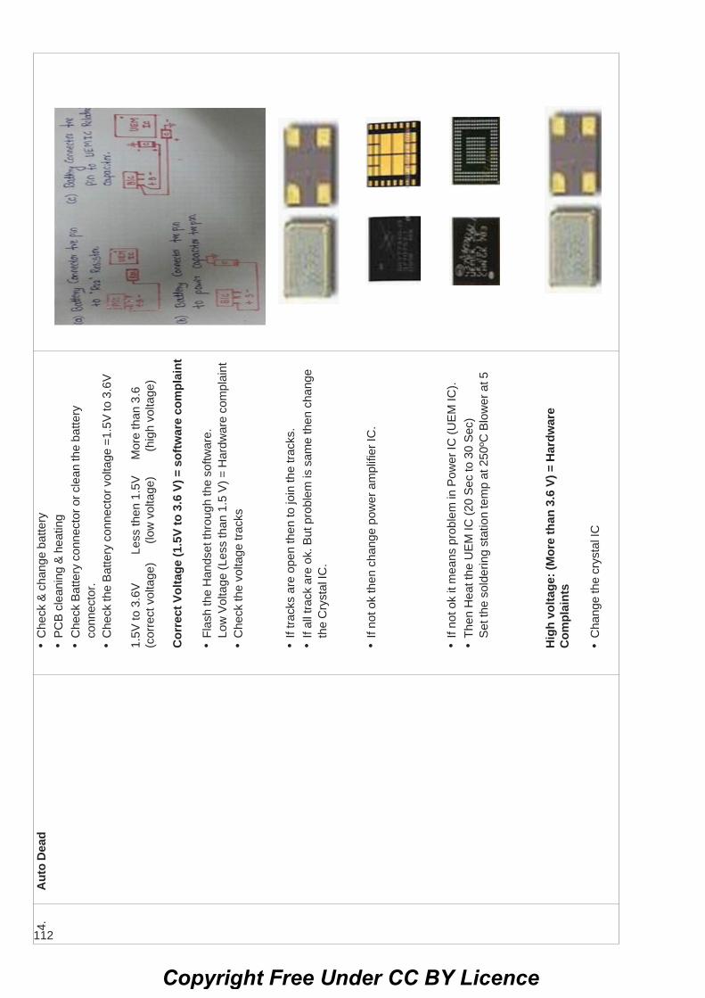
112
•If
track
s ar
e op
en th
en to
join
the
track
s.•
If al
l tra
ck a
re o
k. B
ut p
robl
em is
sam
e th
en c
hang
eth
e C
ryst
al IC
.
4.A
uto
Dea
d•
Che
ck &
cha
nge
batte
ry•
PC
B c
lean
ing
& h
eatin
g•
Che
ck B
atte
ry c
onne
ctor
or c
lean
the
batte
ryco
nnec
tor.
•C
heck
the
Bat
tery
con
nect
or v
olta
ge =
1.5V
to 3
.6V
1.5V
to 3
.6V
Le
ss th
en 1
.5V
M
ore
than
3.6
(cor
rect
vol
tage
)
(low
vol
tage
)
(h
igh
volta
ge)
Cor
rect
Vol
tage
(1.5
V to
3.6
V) =
sof
twar
e co
mpl
aint
•Fl
ash
the
Han
dset
thro
ugh
the
softw
are.
Low
Vol
tage
(Les
s th
an 1
.5 V
) = H
ardw
are
com
plai
nt•
Che
ck th
e vo
ltage
trac
ks
Hig
h vo
ltage
: (M
ore
than
3.6
V) =
Har
dwar
eC
ompl
aint
s
•C
hang
e th
e cr
ysta
l IC
•If
not o
k th
en c
hang
e po
wer
am
plifi
er IC
.
•If
not o
k it
mea
ns p
robl
em in
Pow
er IC
(UE
M IC
).•
Then
Hea
t the
UE
M IC
(20
Sec
to 3
0 S
ec)
Set
the
sold
erin
g st
atio
n te
mp
at 2
50ºC
Blo
wer
at 5
Copyright Free Under CC BY Licence

113
4.A
uto
Dea
d•
Che
ck &
cha
nge
Bat
tery
(For
low
vol
tage
)•
PC
B c
lean
ing
& h
eatin
g by
usi
ng IP
A s
olut
ion.
•C
heck
Bat
tery
con
nect
or v
olta
ge =
3.6
V
Less
than
3.6
V•
Sof
twar
e co
mpl
aint
.•
Flas
h th
e ha
rdse
t thr
ough
the
softw
are.
•C
hang
e th
e B
atte
ry c
onne
ctor
.•
Cha
nge
crys
tal I
C.
•C
heck
and
cha
nge
the
pow
er c
apac
itor.
If no
t ok
then
rem
ove
the
UE
M IC
rela
ted
capa
cito
r.
•A
fter r
emov
ing
capa
cito
r, ch
eck
the
Bat
tery
con
nect
orV
olta
ge.
If v
olta
ge is
dro
p th
en s
witc
h on
the
Han
dset
.If
not o
k it
mea
ns p
robl
em is
in p
ower
IC (U
EM
IC)
•H
eat t
he U
EM
IC (2
0 S
ec to
30
Sec
). S
et th
eso
lder
ing
stat
ion
tem
p at
250
ºC B
low
er a
t 5
•C
heck
and
repl
ace
the
PA
IC
Copyright Free Under CC BY Licence

114
•If
not o
k th
en re
mov
e th
e P
ower
Am
plifi
er IC
.
•If
not o
k th
en h
eat t
he p
ower
IC.(2
0sec
to 3
0sec
)S
et th
e so
lder
ing
stat
ion
tem
p at
250
ºC B
low
er a
t 5.
•H
eat t
he p
ower
IC.(2
0 se
c to
30
sec)
.S
et th
e so
lder
ing
stat
ion
tem
p at
250
ºC B
low
er a
t 5.
5.W
ater
Dam
aged
Dea
d (P
CB
Sho
rt)
Che
ck b
atte
ry c
onne
ctio
n sh
ort
•P
CB
cle
anin
g &
hea
ting
by u
sing
Elm
a &
IPA
sol
utio
n1st
tim
e =
Elm
a
2nd ti
me
= IP
A s
olut
ion
•C
hang
e th
e B
atte
ry c
onne
ctor
•C
hang
e cr
ysta
l IC
.
•If
Not
ok
then
cha
nge
the
pow
er c
apac
itor.
Copyright Free Under CC BY Licence

115
9.Fo
rmat
Mem
ory
Car
d•
Che
ck a
nd c
hang
e m
emor
y ca
rd.
•Fo
rmat
the
hand
set
.•
If no
t ok
then
hea
t the
mem
ory
card
gla
ss ty
pe ic
(gre
y co
lour
)•
If no
t ok
then
cha
nge
the
mem
ory
card
gla
ss ty
pe ic
(gre
y co
lour
)
8.N
o m
emor
y ca
rd o
ptio
n an
d M
emor
y•
Che
ck a
nd c
hang
e m
emor
y ca
rd.
card
Cur
rupt
ed•
Form
at th
e ha
nd s
et.
•If
not o
k th
en h
eat t
he m
emor
y ca
rd c
eram
ic ic
(bla
ck).
•If
not o
k th
en c
hang
e th
e m
emor
y ca
rd c
eram
ic ic
(bla
ck)
6.Si
m R
elat
ed C
ompl
aint
•C
heck
& c
hang
e si
m c
ard.
•C
heck
bad
con
tact
of s
im c
ard
and
sim
slo
t pin
s.•
Cle
an th
e ba
ttery
con
nect
or s
enso
r pin
if fo
und
any
dry
sold
er p
rope
rly.
•If
not o
k th
en H
eat t
he s
im IC
.
•If
not o
k th
en c
hang
e th
e si
m IC
.
7.M
emor
y C
ard
Rel
ated
com
plai
nt.
Inse
rt M
emor
y C
ard
•C
heck
& c
hang
e m
emor
y ca
rd.
•C
heck
bad
con
tact
of m
emor
y ca
rd a
nd m
emor
yca
rd s
lot p
ins.
•If
not o
k th
en h
eat t
he m
emor
y ca
rd G
lass
Typ
e IC
(Gre
y C
olou
r).•
If no
t ok
then
cha
nge
mem
ory
card
Gla
ss T
ype
IC(G
rey
Col
our)
Copyright Free Under CC BY Licence

116
10.
Touc
h Sc
reen
Com
plai
nt•
Che
ck a
nd c
hang
e To
uch
pad.
Touc
h pa
d no
t wor
king
.
•C
lean
touc
h pa
d co
nnec
tor f
or d
ry s
oldr
ing.
•Fl
ash
the
hand
set t
hrou
gh th
e S
oftw
are.
•If
not o
k th
en C
hang
e th
e to
uch
pad
IC.
Copyright Free Under CC BY Licence

117
Electronics & Hardware Sector Exercise 4.6.290Electronic Mechanic - Cell phones
Replace various faulty parts like mic, Speaker, charging/audio jack etc.Objectives: At the end of the exercise you shall be able to• identify the nature of audio related fault in the given cell phones• dismantle the faulty cell phone/smart phone• torubleshoot/ replace the defective parts of given cell phone.
Requirements
Tools/Equipments/Instruments• Cell phone/ Smart phone with SD card- 1 No.• Precision screw driver set - 1 set.• Digital multimeter with probes - 1 No.• Trainees tool kit - 1 set.
Materials/ Components• Ultrasonic tub - 1 No.• IPA or CTC solution - as required• User manual - as required• Spare parts(Speaker/Mic/Jack) - as required
PROCEDURE
TASK 1 : Checking and replacing the speaker of a cell phone
1 Switch ON the cell phone and operate volume keys,check speaker sound by play any sound file like music.
2 Switch OFF the phone now and dismantle the phoneby referring Exercise 4.5.03
3 Remove the speaker connection and check thecontinuity.
4 Replace the speaker with similar one if found defective.
5 Check the tracks of speaker upto the audio IC.
6 Clean the track using CTC solution.
7 Check the continuity of track using multimeter.
8 Join the defective tracks.
9 Warm the audio IC by using test lamp or by solderingstation temp. at 250ºC and blower at 5.
10 Now assemble the phone and switch ON.
11 Check phone sound. If not proper discuss with theinstructor for replacing of IC.
TASK 2 : Testing and replacing of mic1 Check the mic healthness by recording voice or by
making a call.
2 Switch OFF the phone and dismantle the phone byreferring exercise 4.5.03
3 Remove the MIC connection and clean the dust usingpump blower.
4 Check the continuity of MIC with the help of yourinstructor.
Condenser MIC will not give continuity.
5 Check tracks of MIC upto the audio IC.
6 Replace the MIC with similar one if found defective.
7 Clean the track using CTC or IPA solution.
8 Check the continuity of track using multimeter.
9 Join the defective tracks.
10 Warm the audio IC by using test lamp or by solderingstation temp. at 250ºC and blower at 5.
11 Now assemble the phone and switch ON.
12 Check the phone sound. If sound is not proper contactinstructor for replace IC.
For audio IC defect, mostly speaker and MICwill not functioning.
Copyright Free Under CC BY Licence

118
TASK 3 : Testing and replacing data/charging/audio jack
1 Connect the charger to phone and check the signal ofcharging indication on the screen.
2 Transfer the data from phone to PC using data cableby referring exercise 4.5.04(TASK 3).
3 Switch OFF the phone if the jack is found to bedefective and dismantle by referring the previousexercise.
4 Desolder the audio jack and replace it with similar one.
5 Switch ON the phone and check the healthyness ofphone.
6 Get the work checked by the instructor.
E&H Electronic Mechanic (NSQF LEVEL - 5) - Exercise 4.6.290
Copyright Free Under CC BY Licence
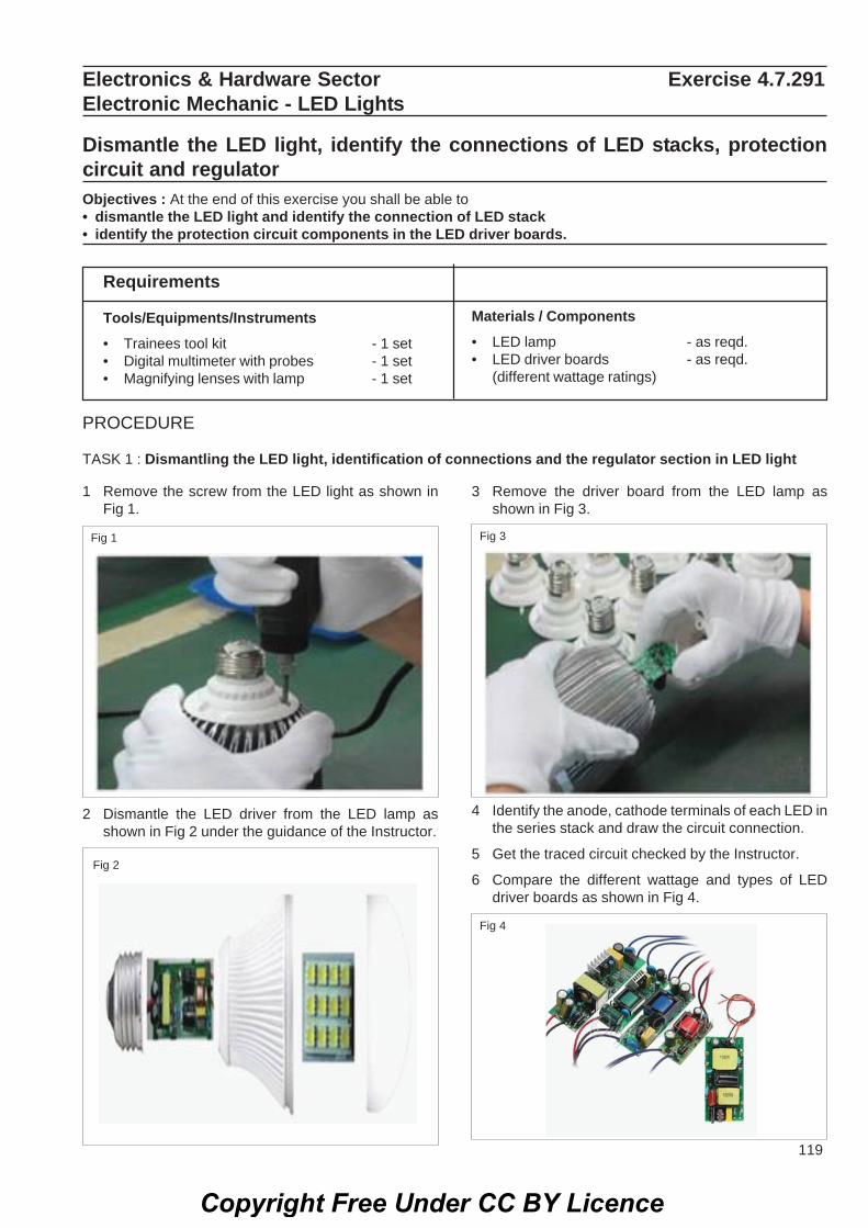
119
Electronics & Hardware Sector Exercise 4.7.291Electronic Mechanic - LED Lights
Dismantle the LED light, identify the connections of LED stacks, protectioncircuit and regulatorObjectives : At the end of this exercise you shall be able to• dismantle the LED light and identify the connection of LED stack• identify the protection circuit components in the LED driver boards.
Requirements
Tools/Equipments/Instruments• Trainees tool kit - 1 set• Digital multimeter with probes - 1 set• Magnifying lenses with lamp - 1 set
Materials / Components• LED lamp - as reqd.• LED driver boards - as reqd.
(different wattage ratings)
PROCEDURE
TASK 1 : Dismantling the LED light, identification of connections and the regulator section in LED light
1 Remove the screw from the LED light as shown inFig 1.
Fig 3Fig 1
Fig 2
2 Dismantle the LED driver from the LED lamp asshown in Fig 2 under the guidance of the Instructor.
3 Remove the driver board from the LED lamp asshown in Fig 3.
4 Identify the anode, cathode terminals of each LED inthe series stack and draw the circuit connection.
5 Get the traced circuit checked by the Instructor.
6 Compare the different wattage and types of LEDdriver boards as shown in Fig 4.
Fig 4
Copyright Free Under CC BY Licence

120
7 Identify the regulator IC/ Protection IC and otherdevices in the LED driver boards record theobservations in Table - 1.
8 Repeat the step 1 to step 7 for all other LED driver.
9 Get the work checked by the instructor.
Sl.No. Name of the regulator IC/ Protection IC or diode
TABLE 1
E&H Electronic Mechanic (NSQF LEVEL - 5) - Exercise 4.7.291
Copyright Free Under CC BY Licence

121
Electronics & Hardware Sector Exercise 4.7.292Electronic Mechanic - LED Lights
Identify the rectifier, controller part of LED lightsObjectives : At the end of this exercise you shall be able to• dismantle the LED lamp identify the rectifier circuit• identify the Controller/ Regulator part of LED light.
Requirements
Tools/Equipments/Instruments• Trainees tool kit - 1 Set• Digital multimeter with probes - 1 No.• Magnifying lenses with lamp - 1 No.
Materials / Components• Different type and wattage LED - as required• LED driver circuit - 1 No.• LED Lamp - 1 No.
PROCEDURE
TASK 1 : Dismantle the LED lamp and identify the rectifier section
1 Follow the step 1 to 5 of Task 1 in the Exercise4.7.291.
2 Identify the AC input section in given LED stack ordriver.
3 Check if any current limiting resistor is available in thecircuit board. Note the value of resistor as shown inFig 1 otherwise take the multimeter set ranges inresistor mode to measure the value of resistor and
Fig 1
Fig 2
note down value and wattage in TABLE 1.
4 After the current limiting resistor section if any diodeor bridge rectifier IC present means note down thediode name or IC name in TABLE 1.
5 Observe the other driver circuit as shown in Fig 2 andrecord your observations in TABLE 1.
6 Repeat the steps for all other LED stacks or driver.
7 Get the work checked by the instructor.
TABLE 1
Sl.No. Current limiting resistor value Rectifier IC name Rectifier diode
Copyright Free Under CC BY Licence

122
TASK 2 : Identify the control section/ regulator in LED driver PCB
1 Identify the rectifier circuit as shown in Fig 3 and notedown the parts name in TABLE 2.
Fig 3
TABLE 2 Sl.No. Control section part name/number
E&H Electronic Mechanic (NSQF LEVEL - 5) - Exercise 4.7.292
2 Get the work checked by the instructor.
Copyright Free Under CC BY Licence

123
Electronics & Hardware Sector Exercise 4.7.293Electronic Mechanic - LED Lights
Make series strings connection of six LEDs and connect four series strings inparallelObjectives: At the end of the exercise you shall be able to• construct a series string connection of 6 LEDs and connect 4 series strings is parallel• test and observe the circuit operation.
Requirements
Tools / Equipments/ Instruments
• Trainees tool kit - 1 Set.• Digital multimeter with probes - 1 No.
Materials/ Components• Step down transformer
230V/24V, 1A - 1 No.• Diode - IN4007 - 4 Nos.
Electrolytic capacitor 1000μF/50V - 1 No.White LED 5mm - 24 Nos.Resistor 120Ω, 1/2 W - 4 Nos.Power cord, 2 mtrs - 1 No.Hook - up wire - as reqd.General purpose PCB/BreadBoard - 15W.
PROCEDURE
1 Collect the components and check them for its goodworking condition.
2 Connect the components and construct a series stringconnection of six LEDs and connect four series stringsin parallel as shown in Fig.1
Table 1
Voltage across LED Voltage across series string Voltage across parallel stringA B C D
3 Avoid loose connections when connecting the LEDstrings.
4 Connect AC mains to the transformer and switch ONthe mains.
5 Measure and record the LED voltage and stringvoltage in the Table -1
Retain the wired 6x4 matrix LED circuit as thesoure is required to carry out the exercise4.7.294. You may disconnect the transformerand bridge circuit as these are not required.
Copyright Free Under CC BY Licence

124
6 Get the work checked by the instructor.
Copyright Free Under CC BY Licence

125
Electronics & Hardware Sector Exercise 4.7.294Electronic Mechanic - LED Lights
Connect to such parallel sets in series to create a matrix of LEDsObjectives: At the end of the exercise you shall be able to• construct a 6x4 matrix LEDs (End product of Ex.4.7.293)• assemble 4 Nos. of 6x4 matrix LEDs to create a LED array.
Requirements
Tools / Equipments/ Instruments
• End product of Ex.4.7.293• Regulated DC power supply unit
(0-30)V, 2A - 1 No.• Digital multimeter with probes - 1 No.
Materials/ Components• Connecting wires - as reqd.
PROCEDURE
1 Construct four number of 6x4 matrix LEDs
Use end products of exercise 4.7.293/PreviousExercise
2 Interconnect the matrix LEDs using Hook up wires byreferring the Fig.1
3 Set the DC PSU voltage at 24V and connect with thewired LED array.
4 Switch ON the DC PSU and check the uniform intensityof the LED.
Do not dismantle the circuit use the same as-sembled a circuit for exercise 4.7.295
5 Get the work checked by the instructor.
Copyright Free Under CC BY Licence

126
Electronics & Hardware Sector Exercise 4.7.295Electronic Mechanic - LED Lights
Apply suitable voltage and check voltage across series stringsObjectives: At the end of the exercise you shall be able to• construct 4 numbers of 6x4 matrix LEDs to create a LED array• apply suitable voltage to the LED array and check voltage across series strings.
Requirements
Tools / Equipments/ Instruments
• End product of Ex.4.7.293• DC power supply 0-30V/2A - 1 No.• Digital multimeter with probes - 1 No.
Materials/ Components• Connecting wires - as reqd.• Patch cords - as reqd.
PROCEDURE
1 Construct four number of 6x4 matrix LEDs to createa LED array by referring the Fig.1
2 Set the DC PSU voltage at 24 V and apply to the wiredcircuit.
3 Measure and record the following
a Circuit input DC voltage
b Voltage across each 6x4 matraix LED
c Voltage across series strings
d Voltage across LEDs.
4 Tabulate the readings and observe voltage levels atdifferent points of the circuit.
5 Switch OFF the DC power supply unit.
Table - 1
Input DC voltage Voltage across Voltage across Voltage acrossseries string any LED.
A B C D
Copyright Free Under CC BY Licence

127
Electronics & Hardware Sector Exercise 4.8.296Electronic Mechanic - LCD & LED TV
Identify and operate different controls on LCD, LED TVObjectives : At the end of this exercise you shall be able to• identify the different indicators/controls on LCD and LED TV• identify the different connectors in LCD and LED TV.
Requirements
Tools/Equipments/Instruments• LCD or LED TV with user manual - 1 No.
PROCEDURE
TASK 1 : Identify the different front panel indicators/controls LCD and LED TV
1 Pick up any one of the TV from the Lab, see the frontpanel as shown in Fig 1.
2 Identify the various front panel indicators/controlsavailable in TV note down in the TABLE 1.
3 Get the work checked by the instructor.
4 Repeat the above steps for other TVs.
TABLE 1
Sl.No. Front panel Controls name
*/**
1
2
3
4
5
6
7
TASK 2 : Identify the different input and output or audio and video connectors in LCD TV
1 Pick up any one of the TV from the lab, see the backside and side view of the TV panel as shown in Fig 2.
2 identify the input and output connector or audio andvideo connectors in TV note down your observationsin the TABLE 2.
3 Get the work checked by the instructor.
4 Repeat the above steps for other TVs.
Materials/ ComponentsNil
Copyright Free Under CC BY Licence

128
TABLE 2
Sl.No. Connector name
1
2
3
4
5
6
7
8
9
10
11
12
E&H Electronic Mechanic (NSQF LEVEL - 5) - Exercise 4.8.296
Copyright Free Under CC BY Licence

129
Electronics & Hardware Sector Exercise 4.8.297Electronic Mechanic - LCD & LED TV
Identify components and different sections of LCD and LED TVObjectives : At the end of this exercise you shall be able to• dismantle the back panel cover of the LCD TV• identify the internal sections in LCD TV.
Requirements
Tools/Equipments/Instruments
• LCD TV with user manual - 1 No.• Trainees tool kit - 1 set.• ESD table - 1 No.
Materials/ Components• Soft cloth (to keep the screen protected from
scratches) - as required
PROCEDURE
TASK 1 : Remove the back panel cover of the LCD TV and identify the sections
1 Unplug the LCD TV from its power supply and removeany other cables from the TV as shown in Fig 1.
Fig 1
Fig 2Fig 4
Fig 3
2 Prepare the ESD table or any other flat surface and laythe soft cloth on it.
3 Turn the LCD TV face down on the soft cloth, toprotect the screen from being damaged.
4 Remove the four screws that hold the base in place.The screws are located in the centre of the TV nearthe bottom as shown in Fig 2.
5 Remove the stand from the back of the LCD TV andkeep it aside.
6 Place the screw driver in between the covers asshown in Fig 3 and with little force twist and open agap.
7 Turn the screw driver to unlock/and open the panel.Use this technique around all the sides of the TVmonitor as shown in Fig 4.
Copyright Free Under CC BY Licence

130
8 Remove the outer cover to show the main body of theTV monitor as shown in Fig 5.
Fig 5Fig 6
9 Remove the side panel screws as shown in Fig 6.
10 Get the work checked by the instructor.
TASK 2 : Identify the different components used in LCD TV
1 Identify the different internal section in LCD TV asshown in Fig 7.
2 Note down the name of different section in TABLE 1.
Don't remove any cables from the TV.
3 Get the work checked by the instructor.
TABLE 1
Sl.No. Name of the Section1
2
3
....
....
14
Fig 7
E&H Electronic Mechanic (NSQF LEVEL - 5) - Exercise 4.8.297
Copyright Free Under CC BY Licence

131
Electronics & Hardware Sector Exercise 4.8.298Electronic Mechanic - LCD & LED TV
Dismantle, identify the parts of TV remote controlObjective : At the end of this exercise you shall be able to• identify the remote control model and the function keys• dismantle the TV remote control handset• identify the internal section of TV remote control and assemble it.
Requirements
Tools/Equipments/Instruments• Trainees tool kit - 1 Set.• Magnifier lens - 1 No.• TV Remote control handset with
user manual - 1 No.
Materials/ Components• Cleaning brush - 1 No• Remote control checker, tester - 1 No.• IPA cleaning solution - 1 bottle.
Note: The instructor has to label all the remotecontrol handsets used for this exercise
PROCEDURE
TASK 1 : Identify the remote control model and the function keys
1 Pick any one of the labeled TV remote control from thelab.
2 Note down the model number of the TV remotecontrol record the observations in TABLE 1.
TABLE 1
Sl. Label Model/Serial No TypeNo. No.
1
2
3
4
5
3 Repeat the above step for the remaining labeleditems
4 Take one of the labeled remote control handset,identify the name/function of the keys as shown inFig.1 with reference to the user manual.
5 Record the name of each key on the remote controlkeypad and its function in TABLE 2.
Copyright Free Under CC BY Licence
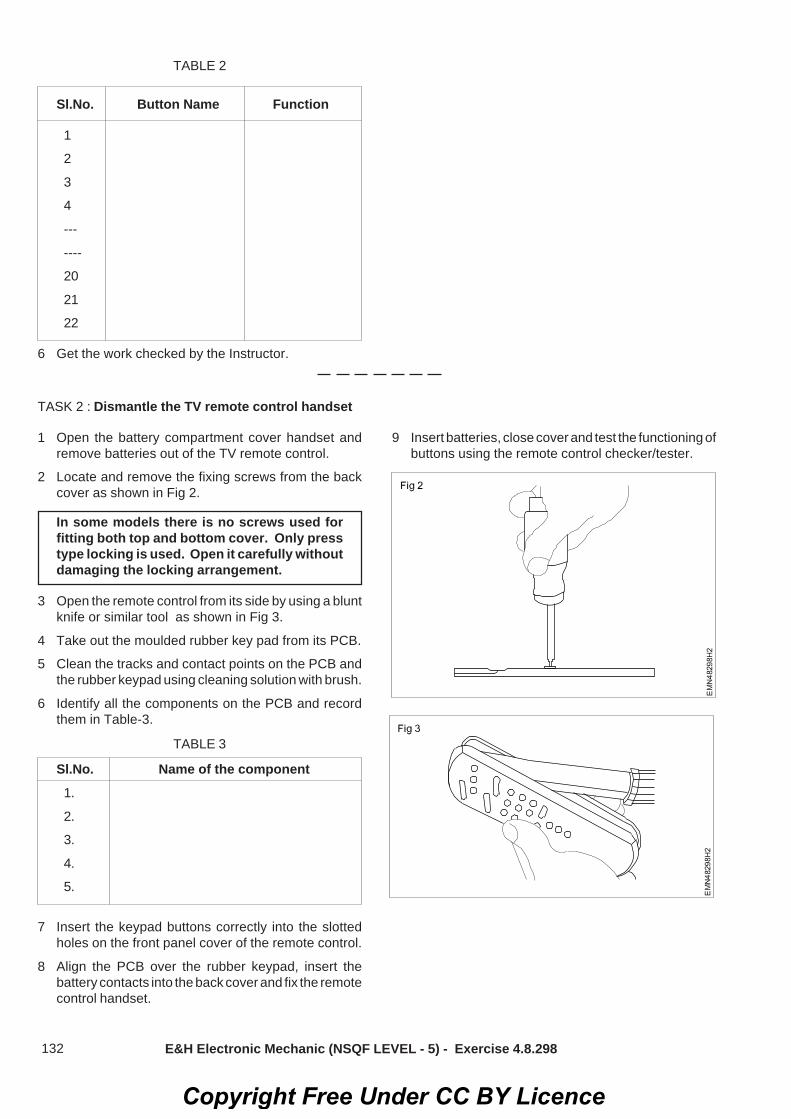
132
TABLE 3
Sl.No. Name of the component1.
2.
3.
4.
5.
TASK 2 : Dismantle the TV remote control handset
E&H Electronic Mechanic (NSQF LEVEL - 5) - Exercise 4.8.298
Sl.No. Button Name Function
1
2
3
4
---
----
20
21
22
TABLE 2
6 Get the work checked by the Instructor.
1 Open the battery compartment cover handset andremove batteries out of the TV remote control.
2 Locate and remove the fixing screws from the backcover as shown in Fig 2.
In some models there is no screws used forfitting both top and bottom cover. Only presstype locking is used. Open it carefully withoutdamaging the locking arrangement.
3 Open the remote control from its side by using a bluntknife or similar tool as shown in Fig 3.
4 Take out the moulded rubber key pad from its PCB.
5 Clean the tracks and contact points on the PCB andthe rubber keypad using cleaning solution with brush.
6 Identify all the components on the PCB and recordthem in Table-3.
7 Insert the keypad buttons correctly into the slottedholes on the front panel cover of the remote control.
8 Align the PCB over the rubber keypad, insert thebattery contacts into the back cover and fix the remotecontrol handset.
9 Insert batteries, close cover and test the functioning ofbuttons using the remote control checker/tester.
Copyright Free Under CC BY Licence

133 E&H Electronic Mechanic (NSQF LEVEL - 5) - Exercise 4.8.298
Fig 4
11 Get the work checked by the instructor.
Copyright Free Under CC BY Licence

134
Electronics & Hardware Sector Exercise 4.8.299Electronic Mechanic - LCD & LED TV
Dismantle the given LCD/LED TV to find faults with input stages throughconnectorsObjectives : At the end of this exercise you shall be able to• remove the back panel cover of LCD/LED TV• Identify the input terminals and check them• troubleshoot the input terminal through connectors.
RequirementsTools/Equipments/Instruments• Trainees tool kit - 1 Set.• Magnifier lens - 1 No.• LCD/LED TV - 1 No.• Home theatre system - 1 Set.• DVD player with remote controls &
user manual - 1 Set.• Set-top box with user manuals - 1 No.
Materials/ Components• HDMI cable - 2 Nos• RCA cable 3RCA - 3RCA - 1 set• Optical cable(S/PDIF) - 1 No• Coaxial cable 2RCA - 2RCA - 1 set
Note: The instructor has to provide the LCD/LED TV with known faults in input stages
PROCEDURE
TASK 1 : Remove the back panel cover of the LCD/LED TV
1 Unplug the LCD/LED TV from its power supply andremove any other cables from the TV as shown inFig 1.
Fig 1
2 Prepare the ESD table or any other flat surface and laythe soft cloth on it.
3 Turn the LCD/LED TV face down on the soft cloth, toprotect the screen from damage.
4 Select the correct size tip for screw driver and removethe four screws that hold the base stand in place. Thescrews are located in the centre of the TV near thebottom as shown in Fig 2.
Keep the screws and stand aside carefully
Fig 2
5 Place the screw driver in between the covers asshown in Fig 3 and with little force twist and open agap.
6 Turn the screw driver to unlock/and open the panel.Use this technique around all the sides as shown inFig 4.
7 Remove the outer cover to show the main body of theTV as shown in Fig.5 and remove the side panelscrews as shown in Fig 6.
8 Get the work checked by the Instructor.
Copyright Free Under CC BY Licence

135
TASK 2 : Identify different type terminals/connectors of input stage of LCD/LED TV
1 Note down the type of socket/connector provided onthe input stage of LCD/LED
2 Record your observations in Table-1 for all the inputsockets.
Table-1
SI. Name of the Uses/Purpose RemarksNo scoket/connector
1
2
3
4
5
3 Use magnifying lens and locate the fault by visualinspection for any desoldered/disonnected wires atthe terminal sockets/connecting wires to themotherboard of the LCD/LED TV.
4 Resolder/rectify the identified fault and get the workchecked by the instructor.
5 Lift the LCD/LED TV and position it firmly at 45 with fullsupport.
6 Connect the signal source using the particular type ofconnecting cable to the input stage of LCD/LED TV.
Note: DVD player/set top book/laptop computerwith HDMI output may be selected as the signalsource for the above step
7 Switch ON the setup and confirm the reception of theLCD/LED TV.
8 Get the approval of the instructor, switch OFF thesetup, diconnect the signal source/cable.
9 Reposition, close the back cover on the LCD/LED TVand fix the base stand.
10 Get the work checked by the instructor.
E&H Electronic Mechanic (NSQF LEVEL - 5) - Exercise 4.8.299
Fig 3 Fig 4
Fig 5 Fig 6
Copyright Free Under CC BY Licence

136
Electronics & Hardware Sector Exercise 4.8.300Electronic Mechanic - LCD & LED TV
Detect the defect in a LED/LCD TV receiver given to you. Rectify the fault.Objectives : At the end of this exercise you shall be able to• identify the internal sections in LCD/LED TV• dismantle the back panel cover of the LCD/LED TV.
Requirements
Tools / Equipments/ Instruments• LCD/LED TV - 1 No.• Trainees tool kit - 1 Set.• Digital multimeter with probes - 1 No.• User manual of LCD/LED TV - 1 No.
Precaution1 Remove the power cord from the mains
before attempting to remove the back coverof LCD TV/ Trainer kit.
2 Note down the colours of wires andposition/location of connectors on the mainboard.
3 Avoid touching the screen at all times asthis may result in damage to the screen.
4 Use soft cloths to keep the screen protectedfrom scratches.
PROCEDURE
TASK 1: Back panel cover removing
1 Unplug the LCD/LED TV from its power supply andremove any other cables from the TV.
2 Prepare the ESD table or any other flat surface andlay the soft cloth on it.
3 Turn the LCD/LED TV face down on the soft cloth toprotect the screen from being damaged.
4 Remove the four screws that hold the base in place.The screws are located in the centre of the TV nearthe button.
5 Remove the stand from the back of the LCD/LED TVand keep it aside.
6 Place the screw driver in between the covers and withlittle force twist and open a gap.
7 Turn the screw driver to unlock/and open the panel.Use this technique around all the sides of the TVmonitor.
8 Remove the outer cover to show the main body ofthe TV monitor.
9 Remove the side panel screws.
TASK 2: Internal sections identifications1 Identify the different internal sections in LCD/LED TV
as shown in Fig.1
2 Note down the name of different sections in Table-1.
Note: Don’t remove any cables from the TV.
3 Assemble the cover after identifications and checkits working condition.
Table-1
SI.No. Name of the Descriptioninternal section
1 SMPS Board
2 Main Board
3 T-CON Board
Materials/ ComponentsNil
Copyright Free Under CC BY Licence

137
4 Soft touch keyboard
5 Speakers
6 IR/LED board
E&H Electronic Mechanic (NSQF LEVEL - 5) - Exercise 4.8.300
Fig 1
Copyright Free Under CC BY Licence

138
Electronics & Hardware Sector Exercise 4.8.301Electronic Mechanic - LCD & LED TV
Troubleshook the faults in the given LED/LCD TV receiver - Locate and rectifythe faultsObjectives : At the end of this exercise you shall be able to• identify the faults in the LED TV• rectify the fault in LCD/LED TV using flowchart method.
Requirements
Tools/ Equipments/ Instruments
• LCD/LED TV - 1 No.• Trainees tool kit - 1 Set.• RF cable/set top box with DTH &
remote - 1 Each.• Digital multimeter with pipe - 1 No.
• Pattern generator withoperating/instruction manual - 1 No.
• ESD table - 1 No.• User manual of LCD/LED TV- 1 No.
Materials/ ComponentsNil
PROCEDURE
TASK 1 : No power1 Connect the colour pattern generator output to LCD/
LED TV.
2 Switch ON this setup and observe the screen whetherany display present or not.
3 Switch OFF this setup and remove the back cover ofthe LCD/LED TV.
4 Unscrew the chassis/main PCB fitting screw, keep allscrews, nuts, fasteners, etc. satisfy in a transparentcover.
5 Detach the connectors wherever possible and takethe PCB out of the cabinet without stretching thesoldered wire too much.
6 Position the PCB such that all components side facetowards you.
7 Refer the circuit diagram of the SMPS stages of theLCD/LED TV and follow the troubleshooting flowchart shown in figure.
8 Locate the components of SMPS stage & check theoutput voltage 24V is present.
9 Check SMPS output voltages and record theobservations in Table-1.
Table - 1No power Yes/No
Whether display present
Power board output
Power key under control
IR receiver normal
Fig 1
Fig 2
Copyright Free Under CC BY Licence

139
Other trouble shooting chart for general faults
SI. No Symptom Solutions
1 No picture on screen but LCD/LED The problem is cause by defective SMPS/PS board andTV still has sound. replacing SMPS/Power supply board will solve the problem
2 Screen flash ON and OFF between The problem is caused by defective mother board1/2 to a few seconds, but powerindicator light stays ON and TV stillhas sound.
3 Blue screen but no picture. The problem is caused by defective main board (ADboard). In some cases, this problem may cause bydefective screen controller board. (I CON) board T CONboard this board is mounting on the back of LCD TVscreen.
4 Power light stays ON but no display The problem is caused by defective main board.and sound. (AD board) or power supply board.
5 No power or power indicator light The problem could either by defective power supplydoes not lits. board or defective main board (AD board).
TASK 2 : No picture and sound1 Connect the colour pattern generator output to LCD/
LED TV.
2 Switch ON this set up and check whether sound andvisual display present or not.
3 Switch OFF and remove the back cover of LCD/LEDTV and unscrew the chassis/main PCB fitting screw,keep all screw, nuts, fasteners, etc. safely in atransparent cover.
4 Detach the speaker wire and check the speaker.
5 Check the speaker cable if it is not connected well,connect it.
6 Check the corresponding IC voltages if voltages notavailable, replace it.
7 Follow the given troubleshooting chart and rectify thepossible fault in the given TV set.
E&H Electronic Mechanic (NSQF LEVEL - 5) - Exercise 4.8.301
Fig 3
Fig 4
Copyright Free Under CC BY Licence

140 E&H Electronic Mechanic (NSQF LEVEL - 5) - Exercise 4.8.301
6 No picture but TV still has sound Check the driver output voltage to side LED/Backlight LED. If there is no voltage from the driver board.check the test point at the board and replace itIf voltage is available in the driver board, then problemin display. Replace the suitable display
Check the power supply T-COW board and mainboard and replace it.
8 Get the work checked by the Instructor.
Copyright Free Under CC BY Licence

141
Electronics & Hardware Sector Exercise 4.8.302Electronic Mechanic - LCD & LED TV
Test LED/LCD TV after troubleshooting the defectsObjectives : At the end of this exercise you shall be able to• switch ON TV and setting the primary information• connect and test the LCD/LED TV with media device using HDMI, RCA, USB cable.
Requirements
Tools / Equipments/ Instruments
• LCD/LED TV - 1 No.• Trainees tool kit - 1 Set.• Media source
with HDMI,RCA, USB output - as reqd.
• Digital multimeter with probes - 1 No
Safety precaution1 Make sure to connect mains cable is
properly connected with ground earth pin.2 Do not plug too many electrical devices into
a single multiple electrical outlet.Otherwise, this may result in fire due toover-heating.
3 Install the TV where there is properventilation. Do not cover the product withcloth or other materials while plugged.
4 Prevent “images burn” or “Burn - in” onthe TV screen. (If a fixed image displays on
the TV screen for a long period of time, itwill be imprinted and become a permanentdisfigurement on the screen. This is calledas “ image burn” or “burn-in”).
5 Avoid touching the screen at all time, asthis may result in damage to the screen.
6 Disconnect the power card from the poweroutlet when you do not use the TV for longperiod of time.
7 To prevent the damage of TV, never plugthe power cords until finished the work.
PROCEDURE
TASK 1 : Turning the TV ON for the first time1 Connect the power cord to a power outlet. The power
indicator turns red and the TV switches to standby.
2 In standby mode, press the power button on theremote control or local key to turn the TV ON. Theinitial setting screen appears if you turn the TV ON forthe first time.
Note: You can also access inital setting byaccessing Option in the main menu.
3 Follow the on-screen instructions to customize the TVsettings according to the preferences.
4 When the basic setting are complete, press the OK.
5 To turn the TV OFF, press the power button on theremote control.
Watching TV1 In standby mode, press /I (power) to turn the TV ON.
2 Press Input and select TV
3 To turn the TV OFF, press /I(Power). The TVswitches to standby mode.
Materials/ComponentsNil
Copyright Free Under CC BY Licence

142
Managing programmes:a Automatically setting up programme1 Press Settings and the navigation buttons to scroll to
Setup and press OK.
2 Press the navigation buttons to scroll to Auto tuningand press OK.
3 Press the navigation buttons to scroll to ‘To start’ andselect ‘To start’ to begin auto tuning. The TV scansand saves available programmes automatically.
4 When you return to the previous menu, press,Back.
b Manually setting programme1 Press settings and the navigation buttons to scroll to
setup and press OK.
2 Press the navigation buttons to scroll to manualtuning.
3 Press the navigation buttons to scroll to storage.
4 Press the navigation buttons or number buttons toselect the desired programme number.
5 Press the navigation buttons to scroll to system.
6 Press the navigation buttons to scroll to TV system
7 Press the navigation butttons to scroll to band.
8 Press the navigation buttons to scroll to channel.
9 Press the navigation buttons to scroll to V/UHF orCable.
10 Press the navigation buttons and then select thedesired channel number with the navigations buttonsor numbers.
11 Press the navigation buttons to scroll search.
12 Press the navigation buttons to scroll and startsearching.
13 Press the OK to store it.
14 When you return to the previous menu, press,Back.
15 To store another programme, repeat steps 3 to 13.
Customizing TV setting1 Practice and familiarize the following customize setting
a Picture settings
b Audio settings
c Time settings
d Option settings
e Lock settings
Other functions1 Practice and familiarize the following functions in the
LED television
a Assigning a Station Name
b Fine tuning
c Adjusting aspect ratio
d Browsing files from USB
1 Connecting LED television with an antenna orcable as shwon in Fig.1
2 HDMI cable connection as show in Fig.2
• Connect the HDMI cable in the input position of theTV.
• Take one end of the HDMI cable and plug terminal atthe HDMI output on the media device.
• Connect the other end of HDMI cable to the HDMIinput on TV.
3 RCA cable connection as shown in Fig.3 and 4
• To connect TV using RCA (Composite video) matchthe colours of the cable and the connector of the TV.
E&H Electronic Mechanic (NSQF LEVEL - 5) - Exercise 4.8.302
Fig 1
Fig 2
Copyright Free Under CC BY Licence

143
4 Component connection
• Transmits analog video and audio signals from anexternal device to the TV.
5 Connecting to a USB Fig.5
6 Connecting SET-Top box as shown in Fig.6
• Connect the cable TV coaxial cable to the input of theset-top box.
RCA cable method
• Select the 3 RCA cable, follow colour coding for audioand video signal
HDMI cable method
• Connect the HDMI cable into the HDMI output terminalof set-top box to the TV.
• Power ON both devices and select the input of TVeither RCA or HDMI.
• Tune the set-top box to the desired channel.
• Get the work checked by the Instructor.
E&H Electronic Mechanic (NSQF LEVEL - 5) - Exercise 4.8.302
Fig 4
Fig 3
Fig 7
Fig 6
Copyright Free Under CC BY Licence

144
Electronics & Hardware Sector Exercise 4.8.303Electronic Mechanic - LCD & LED TV
Identify various connectors and connect the cable operators external decoder(Set-top box) to the TVObjectives : At the end of this exercise you shall be able to• identify different input/output connectors in set-top box• identify different front panel indicators/controls on set-top box.• connect the set top box to the TV.
Requirements
Tools / Equipmments/ Instruments
• Trainees tool kit - 1 Set.• Set - top box with user manual - 1 Set.
and cable set (3 RCA to 3 RCA/ HDMI cable)- as reqd.
Materials/ Components• LCD/LED TV with remote - 1 Set.
control handset• DTH connectivity - as reqd.
Note: The Instructor has to label the input/out-put connectors on the front panel/rear panelof the set top box using permanent marker pen
PROCEDURE
TASK 1 : Identification of different input/output connectors in set-top box
Fig 1
1 Pick any one of the set-top box from the lab, see therear panel as shown in Fig 1.
2 Identify different input /output connectors labelled foraudio/ video connectors in set-top box and note downin TABLE 1.
3 Repeat the above steps for other set-top box if availablein the lab.
TABLE 1
Sl.No. Name of the rear Remarksconnector/socket
1
2
3
4
5
6
7
8
9
10
11
4 Get the work checked by the Instructor.
Copyright Free Under CC BY Licence

145
Fig 2 TABLE 2
Sl.No. Name of the front panel Remarkscontrol/indicator
1
2
3
4
5
6
7
TASK 3: Connecting the set-top-box to the TV1 Place the set-top box near the TV receiver at a
convenient location.
2 Use the 3RCA to 3RCA cable, connect the output ofset-top box following the colour code, connect thevideo input, left channel and right channel of audioinputs on the TV as shown in Fig.3
If HDMI terminal is available on the set-top box,use HDMI cable and connect it to the HDMI-1input of LCD/LED TV.
3 Connect the coaxial cable from dish antennaterminated with the F-connector to the set-top boxand plug the mains cord to AC supply.
4 Get the connections checked by the instructor.
5 Switch ON the LCD/LED TV and Set-top box, use theremote control and select the AV input/HDMI-1 mode.
6 Use the remote control of the set-top box and selectthe organize button, view the channel on the LCD/LED TV
7 Change channels using the remote control of theset-top box and get the work checked by the instructor.
8 Switch OFF both the set-top box and LCD/LED TV.
E&H Electronic Mechanic (NSQF LEVEL - 5) - Exercise 4.8.303
Copyright Free Under CC BY Licence

Copyright Free Under CC BY Licence

Copyright Free Under CC BY Licence

Copyright Free Under CC BY Licence