BGE Metering Manual_ Full Version.pdf - Baltimore Gas and ...
316
BALTIMORE GAS AND ELECTRIC Gas & Electric Metering Manual
-
Upload
khangminh22 -
Category
Documents
-
view
1 -
download
0
Transcript of BGE Metering Manual_ Full Version.pdf - Baltimore Gas and ...

BALTIMORE GAS AND ELECTRIC
Gas & Electric Metering Manual

This blank page is inserted for two-sided printing
This blank page is inserted for two-sided printing

Page 1
TECHNICAL SERVICES DIVISION
Engineering & Standards Section
TO: Holders of the BGE Gas & Electric Metering Manual
FROM: Smart Metering & Technology Unit
SUBJECT: Manual Revisions – 8.0
DATE: January 2022
Revisions have been made to the BGE Gas & Electric Metering Manual and are noted in the Revision
History. Due to formatting changes, it is recommended that you re-print these sections. Please
update your manual with the revised pages detailed below.
**Please note: to allow for easier web navigation, bookmarks have been added to the pdf file. **
If you have any questions concerning these revisions, please refer to the Foreword Section for
contact information.

This blank page is inserted for two-sided printing
This blank page is inserted for two-sided printing

REVISION HISTORY
Gas & Electric Metering Manual January 2022 Baltimore Gas and Electric Company
The following table details revisions made to this manual.
Revision Date Description
1.0 April 2003 Initial Release of Gas and Electric Metering Manual
1.01 May 14, 2003 Revised drawing in Section 502 (3-phase, 4-wire Wye, 120/208V Service)
to show 120V from B phase to neutral.
Removed 803 chapter title from page 800-11, section 802-6
Removed "Appliance Repair" from tables 106-1 and 701-5
1.1 Sept 2003 Revised Table of Contents
Revised COMAR definition to include "electric"
Revised text in 206
Revised text and drawing in 208
Revised text in 209
Revised dimensions in drawing for 211
Revised text in drawing 213
Revised text in 220, 221, 222, 224, 225, 226, 227, and 311
Revised text and drawing in 312
Revised drawing for 314
Revised text in 321, 402, 406, 407, and 413
Added drawing in 502 (120/240/240V 4-Wire Delta)
Revised “Fixed Factor Billing” column in table 702-2
Revised text in 705-8 and 706-4
Updated "Meters-General Rules" in section 706-4
Revised service pressure in drawings 802-1, 803-1, 803-5, 804-10, 804-11,
805-5, and 805-6
2.0
Oct 2004 Revised Foreword, Table of Contents and Definitions
Sections 100, 200, 300 and 400 – All references to 66” minimum clearance
from meter to driveway were changed to 36” minimum.
Added text in 105-2
Revised text change in drawing in 201-5D
Revised contents of 203: added 203-1, 203-2 and 203-3
Revised drawing in 220
Revised drawing in 223
Revised drawing in 227
Revised text in 322
Revised text in 327
Added 328 – Existing Town House Installations
Revised text and table in 402
Revised text in 403-407
Revised text in Drawing 14061-C
Revised text in Drawing 14060-C
Revised text in 409
Revised text in 411-1 and 411-2
Revised text in 413
Revised text and drawings in 408-2
Revised text and drawing in 412
Revised text in 412
Added Section 603-4 Separated (Meter) Installation
Added Section 610 Metering Configuration for Town Houses (Only)
** Continued on the following page **

REVISION HISTORY
Gas & Electric Metering Manual January 2022 Baltimore Gas and Electric Company
Revision Date Description
2.0 Oct 2004 Added Section 620 Typical Town House Indoor Meter Drawings
Renumber Section 607-1 to 690-1 Improper Installation
Section 700 Renamed from Industrial & Commercial to Commercial &
Industrial
Removed Table 702-1, same information in Table 702-2
Revised Table 702-2 to show new MP specifications
Revised text from 27.7" to 22.7" and changed wording from "guarantee" to
"minimum" in section 702-2
Added Table 702-3
Section 703-6 corrected Tariff section from 4.1 to 6.1
Updated Sections 704-1 & 704-2
Added Town House Meter Location exception in Section 705-1
Added “Notes” to Section 705-1
Rewrote Service and Vent wall opens in Section 705-3
Added 3 Foot Meter Protection requirement in Section 705-4
Added removable bollards in Section 705-4
Rewrote AMR Policy in Section 705-5
Combined Service Renewals into Section 705-7
Rewrote Meter Locations and Sources of Ignitions in Section 705-8
Added text for gas vents in flood plane areas on section 705-8
Added Section 706-2 Underground Piping After the Meter - Residential
Renumber Sections 706-3, 4 and 5
Added Section 706-6 BGE Procedure for Re-Connection of Existing Gas
Service Installation (Relocations & Meter Increases)
Removed Section 780 Residential High Rise Distribution Application
2.1 August 2005 Added website information to the Foreword
Updated Table of Contents
Updated gas design standards in the Scope
Corrected the meter mounting height reference to “final grade to centerline
of meter” and updated the reference sections on page 100-7.
Added text to define a high-rise building and the text “every other floor” in
Section 105-3.
Updated the map to show George Spitzler’s contact information and
coverage area in Section 106-2.
Defined how to install thru-wall conduit connected from the LB fitting and
the conduit from the splice box to LB fitting in Section 203-1.
Defined customer responsibility for line conductors over 12” in Sections
215, 216, 217, 218, 226, 318, 319 and 320.
Underlined Item (6) in Section 219.
Added text box “For Outdoor Use Only” on the drawing in Section 227.
Revised service loop height clearances in Section 303.
Added an illustration of an equivalent pipe support in Section 307.
Updated the list of manufacturers in Sections 401, 403, 404 and 405.
Created Section 414 for “Approved Indoor Service Termination Cabinet
3Ø, 4W 1600-3000 Amps”.
Created Section 415 for “Approved Indoor Service Termination Cabinet
3Ø, 4W Above 3000 Amps”.
Corrected text in Section 408-2.
** Continued on the following page **

REVISION HISTORY
Gas & Electric Metering Manual January 2022 Baltimore Gas and Electric Company
Revision Date Description
2.1
August 2005 Added suggested footer in Section 606-1
Defined how to install thru-wall conduit connected from the LB fitting
and the conduit from the splice box to LB fitting in Section 620-6.
Remove 1 PSIG delivery option from MP system, Updated the ½ PSIG
delivery from 1,000 to 23,000 cfh in Section 702-2
Updated minimum line pressure delivery to 1.46 psig in Section 702-2
Updated BGE’s “Standard Designs” installation to 23,000 cfh for
standard delivery and 25,875 cfh for 2 PSIG delivery in Section 702-2
Updated system allowable pressure drop in Section 702-3
Updated customer “Scratch-and-Sniff” card in Section 703-5
Added suggested footer in Section 705-4
Updated to match internal BGE policies in Section 705-8
Added new Section 706-2 of “Added or Converted Equipment” from
other fuel sources and renumbered the following Sections
Added C&I customer responsibility for underground piping after the
meter in Section 706-3
Updated meter assembly insulation requirement in all of Section 800
Updated increase meter assembly dimensions and drawings due to ERT
module in all of Section 800
Removed “Ten Pound” information from Section 800
Consolidated drawings and delivery information in Sections 800-3 & -4
Updated meter assembly insulation requirement in all of Section 900
Removed “Ten Pound” information from Section 900
Added 23M232 Meter Assembly Details
Created “How to Read Your Meter” to Section 1000-1
Created “Pressure Factor Chart” to Section 1000-3
Created “Clocking a Meter” to Section 1000-4
2.2 October 2006 Revised text and rearrange the terms alphabetically in DEFINITIONS.
Added an excerpt from BGE Electric Service Tariff that defines “Supply
Points” to Section 102-1 and renumbered the whole section
Revised “Building/Hazards Clearances” drawing to show 36” distance to
driveway and added “Deck Installation Clearances” to Section 105-2
Revised drawing in Section 202 and 302 to define meter clearance
requirements if close to driveway
Added text reference about Section 600 and splice box mech number (for
BGE reference) in Section 203
Modified drawing to define use of service trough for line conductors in
Sections 215, 216 and 218
Specified customer’s responsibility for line conductors inside trough in
Sections 215, 216, 217, 218, 226, 318, 319 and 320
Created Section 228 “Cellular Site Installation Current Transformer (CT)
Rated Meter”
Created Section 229 “Cellular Site Installation Self-Contained Meters
and/or CT-Rated Meter”
Created Section 230 “Cellular Site Installation Meter Stack and/or CT-
Rated Meter”
Added Note “(N3)” concerning eaves dimension and removed table
“Service Drop Size According to Service Ampacity” in Section 307
Added Meter Socket Box dimensions in Sections 309, 310, 311 and 312
** Continued on the following page **

REVISION HISTORY
Gas & Electric Metering Manual January 2022 Baltimore Gas and Electric Company
Revision Date Description
2.2 October 2006 Updated model number for pedestal box in Section 401
Updated stud kit catalog number in Section 402
Revised the dimensions format of the cabinet and updated the list of
manufacturers in Sections 403, 404, 405
Changed the Title of Section 406 to “Approved Service Entrance
Compartment” and added the list of manufacturers and drawing numbers
Edited text and updated table in Section 410
Correct the height to be 6’-3” or 75” instead of 73” in Section 610-3 &
610-4
Updated C&I contacts in Section 701-4
Removed 10# gas system indication in Section 704-2
Updated reference to the National Fuel Gas Code in all of Section 700
Updated “Curtailment of Supply” information in Section 702-4
Updated “New Gas Service” tag in Section 706-5
Added BGE Reference Numbers to specific drawings in Section 800
Updated 3M and 5M C&I Meter Set drawings in Section 900
2.3 March 2007 Updated Foreword
Updated Table of Contents
Added information re: Metering in a Flex Space Building in Section 503
Added information re: Portable Generators and Transfer Switches in
Section 504
Updated MM701-4 to match new service territory representatives
Updated MM704-1 building requirements to meet International Building
Code and Local Code requirements
Added outlet piping size chart to MM900-1
Added outlet piping dimensions to C&I Meter Set drawings in Sec 901
through 904
Added MM905-3 C&I Meter Set drawing to show requirements for
metering in a Flex Space Building
2.4
March 2009
Edited Forward contact information electric metering and first paragraph
Edited format and revised text in Section 102-1-B
Edited 103-3 to reflect current tariff language
Added maximum secondary fault current to Section 103-6
Updated reference in Section 104-9
Updated 106-2 contact information
Revised 201-4 and 201-5 to show current requirements
Edited Section 204 drawing
Added Section 205 Single Outdoor Meter with Utility Disconnect
Changed maximum voltage and added note to Section 211
Edited Section 215-218, 220-222, and 224-226
Revised 228 and 229 to reflect new rules regarding cellular tower
metering. Deleted 230.
Edited Section 301-2 to include decks
Revised Section 303 moved H under B and deleted letter H
Revised 303 to reflect current standards in OH Construction Standards
Revised Section 307 table for > 48in, included note, added Note (N4)
Added Section 310-2 Single Outdoor Meter With Utility Disconnect
** Continued on the following page **

REVISION HISTORY
Gas & Electric Metering Manual January 2022 Baltimore Gas and Electric Company
Revision Date Description
2.4
March 2009 Added dual and single meter table to Section 401
Edited format in Section 402-1, added line item and Note (2)
Added Section 402-2 Approved Modular Metering Equipment Various
Services (400 Amp/ 320 Amp Continuous)
Added S.A.R phone number to Sections 403 – 405 and 415 – 416
Added Section 416 Service Entrance Trough Requirements
Updated reference to the National Electric Safety Code in all of Section
600
Edited 620-2 drawing with current style regulator
Edited 620-3 drawing with current style regulator
Edited 620-7 drawing with current style regulator
Updated BGE Gas Service Tariff throughout Section 700
Updated reference to the National Fuel Gas Code in all of Section 700
Update 701-1 Customer Care Center name
Updated 701-4 Contact information
Updated 701-5 contact information
Revised COMAR reference in 703-4
Updated 703-5 with latest Scratch and Sniff mailer
Updated Gas Turn on Procedure in Section 703-10 from National Fuel
Gas Code 2009 Edition
Updated 704-1 to keep definition of “building” the same as the IBC
Updated 704-2 reference to National Electric Safety Code
Updated 705-3 unit name
Revised 705-6 with expanded explanation of Bonding policy
Revised 705-8 Reg/Relief vents and clearance
Edit 706-2 to make bold
Added re-light general practice to 706-7
Revised 800 & 900 to reflect typical service height above grade
Edit 800-1 grammar
Changed 750 Meter to 800 Meter in all of Section 800
Edited drawing to reflect change from ½” CTS service to ¾” IPS in
Section 800
Added pad thickness to all of Section 900
Added “(MP)” to keep descriptions standard in Section 900
Edited 902-3 to utilize the 40D49 pre-fab with Fisher 133 regulation
Added 902-7 3M line pressure assembly
Added 902-7 5M line pressure assembly
Added 902-7 7M line pressure assembly
Added 902-7 11M line pressure assembly
Added 902-7 16M/23M232 line pressure assembly
Numbering revision to 903-8
Numbering revision to 903-9
2.4.1 December 2009 Revised contact information in the Foreword
Revised Approved Modular Metering Equipment in Section 402
Revised contact information in Section 701-4
Updated Meter Protection Policy in Sections 412, 603-1, 606-1, 610, 703,
and 705-4
2.4.2 November 2010 Added section 104-10 Pulse Metering

REVISION HISTORY
Gas & Electric Metering Manual January 2022 Baltimore Gas and Electric Company
2.4.2 November 2010 Revised contact information on Meter Inspection Districts map
Revised drawing and text for compliance in Section 303
Revised drawing and text for compliance in Section 307
Revised Approved Modular Metering Equipment in Sections 402
Revised Electric Meter Protection drawing in Section 412
Revised Indoor Service Termination Cabinet and Service Entrance
Trough Requirements in Sections 406, 414 - 416
Updated contact information in Section 701-4
Added Section 703-9
Combined Sections 802-4 and 802-5
2.5 December 2011 Revised contact information in the Foreword
Updated Where to Call Service Information
Revised contact information on Meter Inspection Districts map
Revised wording of Service Conductors in Section 205
Deleted 3Ø,3W from Service in Sections 218 and 219
Revised Max Amps and deleted “DRAFT” from drawing in Section 228
Updated drawing and text; Added drawing and definitions in Section 303
Service Drop Clearances for Residential and Commercial Properties
Updated drawing and text; Added drawing and text for multi-tiered decks
in Section 307 Typical Service Mast Installations
Revised Service Conductors in Section 310-2
Adjusted Max. Amps in Section 312
Adjusted wording to clarify table location in Section 316
Deleted blank page for former Section 317; adjusted numbering in all
subsequent sections to follow sequential order
Deleted 3Ø,3W for Service in Section 320
Adjusted chart and text in Section 402-2
Adjusted text in Note in Section 415
2.5.1 April 2013 Updated Contact Information
Updated the Table of Contents
Added Dual Electric Service specifications
Added Dual Gas Service specifications
Added Customer Owned Gas Booster/Compressor requirements
2.5.2 June 2013 Adjusted text in Section 601-1
Adjusted text in Section 602-1; Clarified note specifying use of bollards
Adjusted text in Section 602-2; Clarified definition of “front of building”
Corrected language error in Section 603-1
Corrected language error in Section 603-4
Corrected mismatching figures in Section 605-1, #2
Adjusted text in Section 606-1
Adjusted text in Section 610-3; Corrected reference to section 602-2.
Adjusted text in Section 610-4; Corrected reference to section 602-2.
2.5.3 July 2013 Adjusted text in Sections 101-2, 103-3, 105-1, 105-2
Added depth dimension for N1 in diagrams in Section 105-2.4.C
Removed outdated emergency phone number in Section 106-1
Updated all contact info for Meter Inspection districts, Section 106-2
Added 811 for Miss Utility, Section 106-4. Also added complete color
codes.
2.5.4 September 2013 Updated contact info in Foreword.
Adjusted text in Purpose & Scope
Adjusted text in Section 303

REVISION HISTORY
Gas & Electric Metering Manual January 2022 Baltimore Gas and Electric Company
2.5.4 September 2013 Corrected swimming pool clearance values in Section 304
Added reference in Section 304
Adjusted text in Section 304
Cleaned formatting in Section 307 (Service Masts)
Adjusted text in Section 307 (Decks)
Corrected kcmil in Section 312
Removed outdated BGE phone number in Section 701-1
Updated MISS Utility phone number in Section 701-2
Updated color codes in Section 701-2
Updated contact info in Section 701-4
Updated contact info in Section 701-5
Added common settings in Section 702-2
Adjusted text in Section 703-7
Updated NFPA Code references throughout Sections 703
Adjusted text in Section 703-9, 11, & 12
Adjusted text in Section 704-2, Paragraph C.4
Updated NFPA Code reference in Section 704-3
Adjusted text in Section 705-2
Updated NFPA Code reference in Sections 705-3, 6, & 8
Updated NFPA Code reference in Sections 706-2, 4
2.5.5 October 2013 Removed 750 and added 800 to Section 900-1, Table G.
Corrected CFH in Section 903-7.
Added 23M232 to Sections 903-9, 10.
Removed redundant Sections 903-11, 12.
Added 23M232 to Sections 904-4, 6.
Removed redundant Sections 904-7, 8.
2.5.6
November 2013 Adjusted contact info in cover letter / forward
Removed non-standard 3Ø,3W service from Section 219
Added note (8) to Section 226 and updated figure
Corrected some language throughout MM200
Adjusted text in 801-2, 3
Removed redundant Section 802-5
3.1
March 2014 Corrected language in Definitions Page 3
Updated drawings for new meter box dimensions page 100-13&14
Updated contact info page 100-17, Renumbered sections MM100
Updated drawings for meter box dimensions sections MM200, 300 & 600
Added approved pedestal page 400-1, Added model # to table 401, Added
note #5 to table 402-1, Moved sections 411, 412 to MM100 section 106
Renumbered sections MM600
3.2
July 2014
Minor Revisions made to section MM500
Section 706-7 updated to reflect P.O.S. program
Section 701-4 contact info updated, other minor revisions
3.3 August 2014 BGE New Business address updated in section MM100
3.4 December 2014 Updated page 700-21 to include deck exception for build-overs of
existing gas services
MM 900: Added new drawing to 902-12 for 3M meter, 14” water column
delivery, off of medium pressure main.
MM 900: Revised drawings 903-8/9 and 904-4/5
** Continued on the following page **

REVISION HISTORY
Gas & Electric Metering Manual January 2022 Baltimore Gas and Electric Company
Revision Date Description
3.5
July 2015
Cover Letter and Foreword: Updated Contacts
Added pedestals for Commercial and MDOT use (400-1)
Revised wording for clarification, including changing from “portable
generator” to “backup generator”
4.0
October 2015
Changed format of the Table of Contents (uses Word’s self-update feature)
Added fire pump and elevator under Dual Services; Removed requirement
for totalizers (102-2)
Added requirements for installation of electric meters in a flood zone (105-
2); specified PVC duct requirement for service cables that are installed
underneath an overbuild, e.g. patio/deck/paving (105-3); removed arrow to
Front of Building figure (105-3)
Updated contacts (701-4)
Clarified requirements for installations of gas meters in a flood zone (705-
8)
4.1 March 2016 Added Millbank U5136-O-**** and U5137-O-**** model numbers in
Section 400-1
Consolidated Meter Protection for Electric, Combined Gas and Electric,
and Gas Metering into one Meter Protection Section and inserted after
Definitions. Removed meter protection standards paragraphs from
Sections 100, 400, 600 and 700
Added to Meter Protection section Figures 11-14 for Options A and B
specifying relocation requirements for elevating indoor gas meter within
garages
Added BGE Outdoor Metering Location Standard as Sections 105-2,
601-2, 705-1. Removed outdoor metering location standards paragraphs
from Sections 100, 600 and 700
Revised ‘not normal conditions’ to Exceptions to the BGE Outdoor
Metering Location Standard in Sections 105-3, 601-2 and 705-1
Removed Indoor Metering Configurations B and C from Section 603
Removed “Typical Townhouse Indoor Meter Drawings” from Section 603
and relocated content to new Section 605 and retitled heading to
Specifications for Meter Installation Meeting One or More Exceptions
to the BGE Outdoor Metering Location Standard
Revised Section 705-5 Meters - General Rules paragraph ‘H.’ to “Gas
metering assemblies located indoors will not be installed in garages.”
5.0 December
2018
Revised Section 107-2 Map of Electric Meter Inspector Responsibilities:
Change in contact information
Revised Section 406 Approved Service Entrance Compartment: From “A
pit is required where eight (8) or more ducts are provided for the
installation of Company Underground wiring” to “A pit is required to be
installed below the metering compartment” as part of a Safety Council
initiative
Added Section 506 Meter Requirements Review: Small Generator
Interconnection as part of Exelon Reporting Commitment
Revised Sections 602 Outdoor Metering Installation Options and MM800
Typical Residential & Small Commercial Gas Meter Set Drawings:
minimum clear space in front of meter(s) from wall to be 56’’ instead of
54’’ as a correction per field measurement. The minimum work space
required is 69’’ H
** Continued on the following page **

REVISION HISTORY
Gas & Electric Metering Manual January 2022 Baltimore Gas and Electric Company
Revision Date Description
5.0
December 2018 Revised MM700 Gas General: Updated edition of National Fuel Code to
2015 and National Electric Safety Code to 2017
6.0 May 2019 Revised Section 414, Service Entrance Trough Requirements, to indicate
a minimum 6” clearance is required above floor line for trough installs.
Pages 400-19 and 400-20 updated. Meter Protection Section is updated to
reflect these changes as well
6.1 December 2019 Revised Section 107-2 Map of Electric Meter Inspector Responsibilities:
Change in contact information
7.0 April 2020 Added Meter Cabinet with Current Transformers and Approved
Commercial Pedestals and Cabinets for Public EV Charging Stations
to Sections 231 and 416
Updated date of last confirmation in Section 506
7.1 December 2020 Updated contacts in Foreword
Added: 104-11 Maximum Number of Disconnects; 408-3 5G Antenna on
a Customer-Owned Metal Pole; 408-4 Communication Service on a BGE
or Joint-Owned Distribution Wooden Pole
Revised 401 and 408-2 to include 5G antenna installations
Revised Approved Commercial Pedestals and Cabinets for Public EV
Charging Stations to include 100 amps and 200 amps commercial
pedestals
Revised 601-2 BGE Outdoor Metering Location Standard with outdoor
regulator requirement
Revised CFH in Section 902-1 to 1201 – 3000; Section 902-7 to 1200 –
3270; Section 903-1 to 1201 – 3000; Section 903-2 to 1351 – 3375;
Section 904-1 to 1201 – 3000 or 1351 – 3375
7.2 April 2021 Added: Checklist Guide for Switchboard Submittals at end of Section 407
Revised catalog number in Section 416 due to design changes
7.3 May 2021 Revised gate valves to ball valves in Sections 800 and 900
8.0 January 2022 Revised Section 601-2 BGE Outdoor Meter Assembly Location Policy to
address MD legislation
Revised Section 705-1 BGE Outdoor Meter Assembly Location Policy to
address MD legislation
Revised contact information on M&I – Natural Gas Responsibilities
Deleted Additional Services under Section 102-2 Dual Service; Added
clarification to separate service and meter for fire pumps to Section 410
Fire Pump Installations
Revised contact information on Meter Inspection Districts Map
Added Section 417 Approved Commercial Pedestals and Cabinets

This blank page is inserted for two-sided printing
This blank page is inserted for two-sided printing

FOREWORD
Gas & Electric Metering Manual January 2022 Baltimore Gas and Electric Company
Dear Metering Manual Holder,
This Baltimore Gas and Electric (BGE) Gas & Electric Metering Manual supersedes all previous
editions. Please take time to familiarize yourself with the manual by reviewing all of the sections.
The current version of the Metering Manual is available for download at the following address:
www.bge.com/meteringmanual
If you would like to be included on our mailing list to receive revision notifications, please make sure
that BGE has your current email address. If you have contacted BGE for revision notifications in the
past, you will continue to automatically receive notifications of future releases. You may update your
contact information by the following:
1. Submit a new email address at www.bge.com/meteringmanual
2. Send an email directly to [email protected]
For technical questions concerning this manual, please call one of the following:
Andrew Ober 410-470-1737 (Manager, Smart Metering & Technology)
Sean Gorman 410-470-2296 (Electric and Gas Metering)
Kam Kit Yiu 410-470-7992 (Electric Metering)
Jeffrey Chiucchi 410-470-0266 (Gas Metering)
Sincerely,
BGE Smart Metering & Technology Unit

This blank page is inserted for two-sided printing
This blank page is inserted for two-sided printing

TABLE OF CONTENTS Page TOC-1
Gas & Electric Metering Manual January 2022 Baltimore Gas and Electric Company
PURPOSE AND SCOPE .....................................................................................................P&S-1
DEFINITIONS .....................................................................................................................Definitions-1
Meter Protection Page
Electric Meter Protection
Traffic Protection ........................................................................................................................................................... 1
Concrete Curb Barriers / Pipe Guard (Typical Installation) ........................................................................................... 1
Electric Meter Protection- Service Entrance Trough Standards ..................................................................................... 1
Combined Gas and Electric Meter Protection
Townhome (Combined Gas and Electric) Residential Meter Protection Requirements ................................................. 8
Single Family Home Residential Gas Meter Protection Requirements .......................................................................... 8
Gas Meter Protection Standards
Meter & Riser Protection ............................................................................................................................................... 12
Commercial & Industrial Gas Meter Protection ............................................................................................................ 13
Commercial and Industrial Meter Protection Requirements .......................................................................................... 13
100 – ELECTRIC GENERAL
101 Characteristics of Supply
101-1 General ............................................................................................................................................................. 100-1
101-2 Standard Service at Secondary
Distribution System Voltages .......................................................................................................................... 100-1
102 Conditions of Supply
102-1 Supply Points ................................................................................................................................................... 100-2
102-2 Dual Services ................................................................................................................................................... 100-3
103 Conditions of Use
103-1 Avoidance of Injury to Equipment ................................................................................................................... 100-4
103-2 Loss or Damage from Use of Electricity .......................................................................................................... 100-4
103-3 Installations Requiring Special Consideration ................................................................................................. 100-4
103-4 Load Balancing ................................................................................................................................................ 100-5
103-5 Superposition of Electric Energy on the Company’s Electric System ............................................................. 100-5
103-6 Available Fault Currents .................................................................................................................................. 100-5
104 Customer’s Installation
104-1 Governing Rules .............................................................................................................................................. 100-6
104-2 Certificate of Approval .................................................................................................................................... 100-6
104-3 Space Provisions for Company Equipment ...................................................................................................... 100-6
104-4 Protection Against Loss of Service and Damage to Company Metering Equipment ....................................... 100-6
104-5 Point of Service Connection ............................................................................................................................ 100-6
104-6 Change in Class of Service .............................................................................................................................. 100-7
104-7 Grounding ........................................................................................................................................................ 100-7
104-8 Provisions for Sealing ...................................................................................................................................... 100-7
104-9 Customer-Owned Metering Equipment — See 106-5 ..................................................................................... 100-8
104-10 Pulse Metering ................................................................................................................................................. 100-8
105 Location of Metering Equipment
105-1 General Provisions ........................................................................................................................................... 100-9
105-2 Outdoor Locations ........................................................................................................................................... 100-10
105-3 Indoor Location - NON-STANDARD ............................................................................................................. 100-11
105-4 Residential Meters in a Flood Zone ................................................................................................................. 100-17
106 Electric Enclosures Protection
106-1 Protection Enclosures ....................................................................................................................................... 100-18
106-2 Conditions for Applying the Guidelines .......................................................................................................... 100-19
106-3 Types of Enclosures ......................................................................................................................................... 100-19
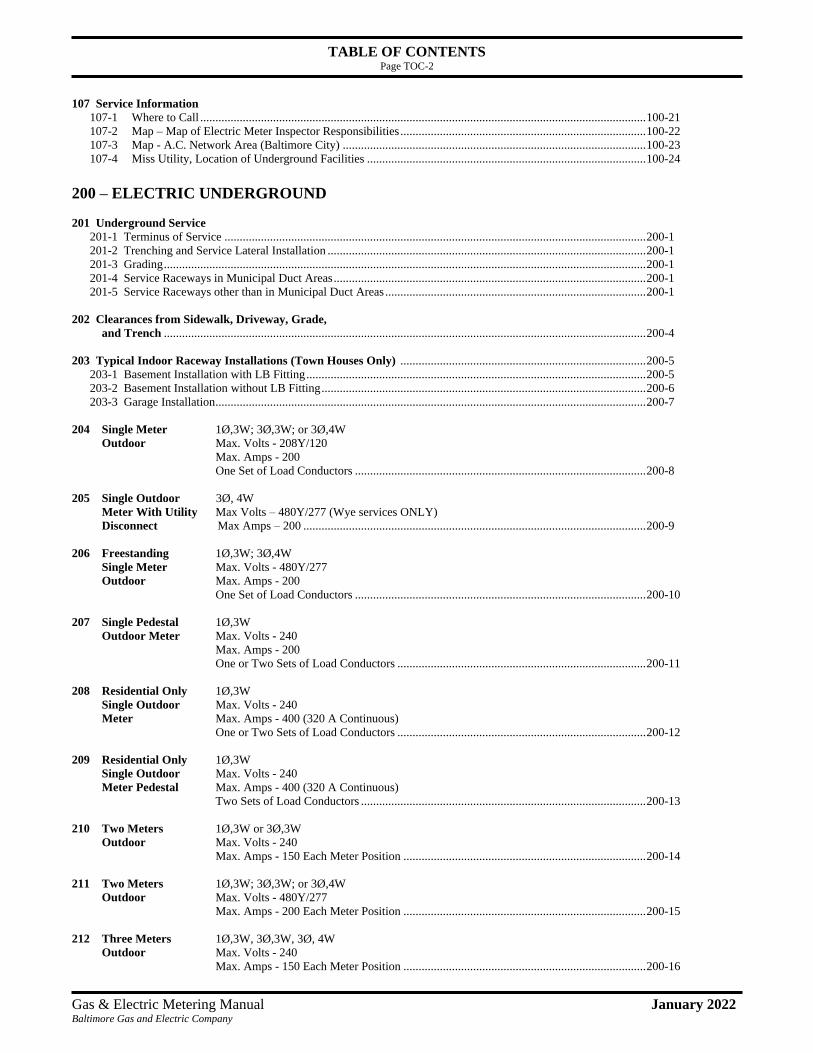
TABLE OF CONTENTS Page TOC-2
Gas & Electric Metering Manual January 2022 Baltimore Gas and Electric Company
107 Service Information
107-1 Where to Call ................................................................................................................................................... 100-21
107-2 Map – Map of Electric Meter Inspector Responsibilities ................................................................................. 100-22
107-3 Map - A.C. Network Area (Baltimore City) .................................................................................................... 100-23
107-4 Miss Utility, Location of Underground Facilities ............................................................................................ 100-24
200 – ELECTRIC UNDERGROUND
201 Underground Service
201-1 Terminus of Service ........................................................................................................................................... 200-1
201-2 Trenching and Service Lateral Installation ......................................................................................................... 200-1
201-3 Grading ............................................................................................................................................................... 200-1
201-4 Service Raceways in Municipal Duct Areas ....................................................................................................... 200-1
201-5 Service Raceways other than in Municipal Duct Areas ...................................................................................... 200-1
202 Clearances from Sidewalk, Driveway, Grade,
and Trench ............................................................................................................................................................... 200-4
203 Typical Indoor Raceway Installations (Town Houses Only) ................................................................................. 200-5
203-1 Basement Installation with LB Fitting ................................................................................................................ 200-5
203-2 Basement Installation without LB Fitting ........................................................................................................... 200-6
203-3 Garage Installation .............................................................................................................................................. 200-7
204 Single Meter 1Ø,3W; 3Ø,3W; or 3Ø,4W
Outdoor Max. Volts - 208Y/120
Max. Amps - 200
One Set of Load Conductors ................................................................................................ 200-8
205 Single Outdoor 3Ø, 4W
Meter With Utility Max Volts – 480Y/277 (Wye services ONLY)
Disconnect Max Amps – 200 ................................................................................................................. 200-9
206 Freestanding 1Ø,3W; 3Ø,4W
Single Meter Max. Volts - 480Y/277
Outdoor Max. Amps - 200
One Set of Load Conductors ................................................................................................ 200-10
207 Single Pedestal 1Ø,3W
Outdoor Meter Max. Volts - 240
Max. Amps - 200
One or Two Sets of Load Conductors .................................................................................. 200-11
208 Residential Only 1Ø,3W
Single Outdoor Max. Volts - 240
Meter Max. Amps - 400 (320 A Continuous)
One or Two Sets of Load Conductors .................................................................................. 200-12
209 Residential Only 1Ø,3W
Single Outdoor Max. Volts - 240
Meter Pedestal Max. Amps - 400 (320 A Continuous)
Two Sets of Load Conductors .............................................................................................. 200-13
210 Two Meters 1Ø,3W or 3Ø,3W
Outdoor Max. Volts - 240
Max. Amps - 150 Each Meter Position ................................................................................ 200-14
211 Two Meters 1Ø,3W; 3Ø,3W; or 3Ø,4W
Outdoor Max. Volts - 480Y/277
Max. Amps - 200 Each Meter Position ................................................................................ 200-15
212 Three Meters 1Ø,3W, 3Ø,3W, 3Ø, 4W
Outdoor Max. Volts - 240
Max. Amps - 150 Each Meter Position ................................................................................ 200-16

TABLE OF CONTENTS Page TOC-3
Gas & Electric Metering Manual January 2022 Baltimore Gas and Electric Company
213 Freestanding 1Ø,3W
Multiple Max. Volts - 240
Outdoor Meters Max. Amps - 150 Each Meter Position ................................................................................ 200-17
214 Doubtful 1Ø,3W; 3Ø,3W; or 3Ø,4W
Permanency Max. Volts - 480Y/277
Service from Max. Amps - 200 .................................................................................................................. 200-18
Pad-Mounted
Transformer
Single Outdoor Meter
215 Multiple Meters 1Ø,3W or 3Ø,3W
Customer’s Max. Volts - 240
Trough Max. Amps - 100 or 200 Each
(Outdoor/Indoor) Meter Position ...................................................................................................................... 200-19
216 Multiple Meters 3Ø,4W
Customer’s Max. Volts - 480Y/277
Trough Max. Amps - 200 Each
(Outdoor/Indoor) Meter Position ................................................................................................................. 200-20
217 Six or fewer 1Ø,3W or 3Ø,3W
Indoor Meters Max. Volts - 240
Company’s Max. Amps - 150 Each
Horizontal Meter Position ..................................................................................................................... 200-21
2- or 3-Position
Meter Sockets
218 Multiple Indoor 1Ø,3W or 3Ø,3W
Meters Company’s Max. Volts - 240
Vertical Max. Amps - 150 Each
2- or 3-Position Meter Position ..................................................................................................................... 200-22
Meter Sockets
219 Modular Meters 1Ø,3W; 3Ø,3W; or 3Ø,4W
Outdoor / Indoor Max. Volts - 480Y/277
Customer’s Max. Amps - 200
Equipment Each Meter Position ............................................................................................................ 200-23
220 Outdoor/Indoor 1Ø,3W
Instrument Current Max. Volts - 240
Transformer Max. Amps - 201 to 800 ....................................................................................................... 200-24
(C.T. Meter)
221 Outdoor/Indoor 1Ø ,3W ,3Ø, 3W or 3Ø,4W
Instrument Current Max. Volts - 480Y/277
Transformer Max. Amps - 201 to 1600 ..................................................................................................... 200-25
(C.T. Meter)
222 Outdoor/Indoor 3Ø,3W or 3Ø,4W
Instrument Current Max. Volts - 480Y/277
Transformer Max. Amps - 201 to 3000 ..................................................................................................... 200-26
(C.T. Meter)
223 Outdoor 1Ø,3W; 3Ø,3W; or 3Ø,4W
Instrument Current Max. Volts - 480Y/277
Transformer Max. Amps, 1Ø - 1000
(C.T. Meter) (Demand)
Max. Amps, 3Ø - 3000 ........................................................................................................ 200-27
224 Outdoor/Indoor 1Ø,3W; 3Ø,3W
Delta Service Max. Volts – 120/208/240
Self-Contained Max. Amps, 200 .................................................................................................................. 200-28

TABLE OF CONTENTS Page TOC-4
Gas & Electric Metering Manual January 2022 Baltimore Gas and Electric Company
225 Outdoor/Indoor 1Ø,3W; 3Ø,3W
Delta Service Max. Volts – 120/208/240
Current Transf. Max. Amps, 201-1600 ......................................................................................................... 200-29
226 Combination 1Ø,3W; 3Ø,3W
Self-contained Max. Volts – 480Y/277
and CT Meters Max. Amps, 201-1200 ......................................................................................................... 200-30
227 Outdoor
C.T. / Service 1Ø,3W; 3Ø,3W
Termination Max. Volts – 480Y/277
Cabinet Max. Amps, 201-1200 ......................................................................................................... 200-31
228 Cellular Site
Installation 1Ø,3W
For Transmission Max. Volts – 120/240
Towers Max. Amps, 200 .................................................................................................................. 200-32
229 Cellular Site
Installation 1Ø,3W or 3Ø,4W
For Communication Max. Volts – 480Y/277
Towers Max. Amps, 100-3000 ......................................................................................................... 200-33
230 Commercial
Pedestals 1Ø,3W or 3Ø,4W
For Public EV Max. Volts – 120/240 or 480Y/277
Charging Stations Max. Amps – 400 ................................................................................................................. 200-35
231 Meter Cabinets with 3Ø,4W
CTs for Public EV Max. Volts – 480Y/277
Charging Stations Max. Amps – 400 ................................................................................................................. 200-36
300 – ELECTRIC OVERHEAD
301 Overhead Service
301-1 Terminus ............................................................................................................................................................ 300-1
301-2 Service Drop ....................................................................................................................................................... 300-1
302 Clearances from Sidewalk, Driveway, and Grade ................................................................................................. 300-2
303 Service Drop Clearances for Residential and
Commercial Properties ............................................................................................................................................ 300-3
304 Swimming Pool Clearances ...................................................................................................................................... 300-6
305 Length of Service Conductor at Service Head ........................................................................................................ 300-8
306 Clearances of Service Drops Over Roofs ................................................................................................................ 300-9
307 Typical Service Mast Installation ............................................................................................................................ 300-10
308 Typical Layout of Service Entrance Wiring on a Customer’s Pole ....................................................................... 300-14
309 Single Outdoor 1Ø,3W; or 3Ø,3W
Meter Max. Volts - 240
Max. Amps - 100
One Set of Load Conductors ................................................................................................ 300-15
310-1 Single Outdoor 1Ø,3W; 3Ø,3W; or 3Ø,4W
Meter Max. Volts - 480Y/277
Max. Amps - 200
One Set of Load Conductors ................................................................................................ 300-16

TABLE OF CONTENTS Page TOC-5
Gas & Electric Metering Manual January 2022 Baltimore Gas and Electric Company
310-2 Single Outdoor 3Ø, 4W
Meter with Max. Votls – 480Y/277 (Wye services ONLY)
Utility Disconnect Max Amps – 200 ................................................................................................................. 300-17
311 Single Outdoor 1Ø,3W
Meter Max. Volts - 240
Max. Amps - 200
One or Two Sets of Load Conductors .................................................................................. 300-18
312 Residential Only 1Ø,3W
Single Meter Max. Volts - 240
Outdoor Max. Amps - 320 (400 A Continuous)
One or Two Sets of Load Conductors .................................................................................. 300-19
313 Two Meters 1Ø,3W or 3Ø,3W
Outdoor Max. Volts - 240
Max. Amps - 150 Each Meter Position ................................................................................ 300-20
314 Two Meters 1Ø,3W; 3Ø,3W; or 3Ø,4W
Outdoor Max. Volts - 480Y/277
Max. Amps - 200 Each Meter Position ................................................................................ 300-21
315 Three Meters 1Ø,3W or 3Ø,3W
Outdoor Max. Volts - 240
Max. Amps - 150 Each Meter Position ................................................................................ 300-22
316 Doubtful 1Ø,3W
Permanency Max. Volts - 240
Service Max. Amps - 200 .................................................................................................................. 300-23
Single Meter
(Max. 2 Years)
317 Multiple Indoor 1Ø,3W; 3Ø,3W; or 3Ø,4W
Meters Max. Volts - 480Y/277
Customer’s Max. Amps - 200 Each Meter Position ................................................................................ 300-24
Trough
318 Six or fewer 1Ø,3W or 3Ø,3W
Indoor Meters Max. Volts - 240
Company’s Max. Amps - 150 Each Meter Position ................................................................................ 300-25
Horizontal
2- or 3-Position
Meter Sockets
319 Multiple Indoor 1Ø,3W or 3Ø,3W
Meters Company’s Max. Volts - 240
Vertical Max. Amps - 150 Each Meter Position ................................................................................ 300-26
2- or 3-Position
Meter Sockets
320 Modular Meters 1Ø,3W; 3Ø,3W; or 3Ø,4W ...
Outdoor / Indoor Max. Volts - 480Y/277
Customer Max. Amps - 200 Each Meter Position ................................................................................ 300-27
Equipment
321 Outdoor/Indoor 1Ø,3W
Instrument Current Max. Volts - 240
Transformer Max. Amps - 201 to 400 ....................................................................................................... 300-28
(C.T. Meter)
322 Outdoor/Indoor 1Ø,3W; 3Ø,3W; or 3Ø,4W
Instrument Current Max. Volts - 480Y/277
Transformer Max. Amps - 201 to 1600 ..................................................................................................... 300-29
(C.T. Meter)

TABLE OF CONTENTS Page TOC-6
Gas & Electric Metering Manual January 2022 Baltimore Gas and Electric Company
323 Instrument 3Ø,3W or 3Ø,4W
Current Max. Volts - 480Y/277
Transformer Max. Amps - 201 to 3000 ..................................................................................................... 300-30
(C.T. Meter)
324 Outdoor 1Ø,3W
Instrument Current Max. Volts - 240
Transformer Max. Amps – N/A ................................................................................................................ 300-31
(C.T. Meter)
Wall Mounted
325 Outdoor 3Ø,3W NON-STANDARD
Instrument Current Max. Volts - 480
Transformer Max. Amps – N/A ................................................................................................................ 300-32
(C.T. Meter)
Wall Mounted
326 Outdoor 3Ø,4W
Instrument Current Max. Volts - 480Y/277
Transformer Max. Amps - N/A ................................................................................................................. 300-33
(C.T. Meter)
Wall Mounted
327 Existing Town House Installations ......................................................................................................................... 300-34
400 – ELECTRIC METERING
401 Approved Pedestal Metering Equipment (Freestanding) ................................................................................. 400-1
402-1 Approved Modular Metering Equipment (200 Amp) ....................................................................................... 400-2
402-2 Approved Modular Metering Equipment Various Services (400 Amp/320 Amp Continous) ...................... 400-3
403 Approved Current Transformer Cabinet
1Ø, 3W 201-400 A ................................................................................................................................................. 400-4
404 Approved Current Transformer Cabinet
1Ø, 3W, 3Ø, 4W 201-1600A ................................................................................................................................. 400-5
405 Approved Current Transformer Cabinet
3Ø, 4W 201-3000 A ............................................................................................................................................... 400-6
406 Approved Switchgear Termination/Current Transformer Compartment
3Ø, 4W 6000A (service supplied by underground cable) ...................................................................................... 400-7
407 Approved Switchgear Currrent Transformer Compartment
3Ø, 4W 6000A ....................................................................................................................................................... 400-9
408-1 Communication Service 1Ø,3W
On Company or Max. Volts - 240
Joint-Owned Pole Max. Amps - 30 .......................................................................................................... 400-12
408-2 5G or CATV Service 1Ø,3W
From Underground Max. Volts - 240
Service Max. Amps - 200 ........................................................................................................ 400-13
408-3 5G Antenna on a 1Ø,3W
Customer-Owned Max. Volts - 240
Metal Pole Max. Amps - 125 ........................................................................................................ 400-17

TABLE OF CONTENTS Page TOC-7
Gas & Electric Metering Manual January 2022 Baltimore Gas and Electric Company
408-4 Communication 1Ø,3W
Service on a BGE Max. Volts - 240
Or Joint-Owned Max. Amps - 125 .......................................................................................................... 400-20
Dist. Wooden Pole
409 Typical Wiring of Single Meter Socket .............................................................................................................. 400-24
410 Fire Pump Installations ....................................................................................................................................... 400-25
411 Approved Outdoor C.T./Termination Cabinet
3Ø, 4W 4000 A ...................................................................................................................................................... 400-26
412 Approved Indoor Service Termination Cabinet 3Ø, 4W 1600-3000 A ............................................................................................................................................. 400-27
413 Approved Indoor Service Termination Cabinet
3Ø, 4W Above 3000 A .......................................................................................................................................... 400-28
414 Service Entrance Trough Requirements ............................................................................................................ 400-29
415 Meter Pedestals 1Ø,3W
For Traffic Control Max. Volts - 240
Signals with Lever Max. Amps - 200 ........................................................................................................ 400-31
Bypass
416 Approved Commercial Pedestals and Cabinets for EV Charging Stations
1Ø3W, 3Ø4W 200 – 400 A ................................................................................................................................... 400-32
417 Approved Commercial Pedestals and Cabinets
1Ø3W, 3Ø4W 100 – 600 A ................................................................................................................................... 400-31
500 - MISC. ELECTRIC
501 Metering Calculations
501-1 Table I - Formulas for Determining Amps, HP, KW, kVA .......................................................................... 500-1
501-2 Table II - Full-Load Currents 1Ø ................................................................................................................... 500-1
501-3 Table III - Full-Load Currents 3Ø ................................................................................................................... 500-2
502 Electric Service Diagrams ......................................................................................................................................... 500-3
503 Flex Space Metering 503-1 Typical Metering Installation in a Dedicated Metering Room of a Flexible Space Building ........................... 500-5
503-2 Typical Outdoor Metering Installation for a Flexible Space Building ............................................................. 500-8
503-3 Minimum Space Requirements for Electric Metering Equipment ................................................................... 500-9
504 Backup Generators and Transfer Switches ............................................................................................................. 500-10
505 Small Generator Interconnection ............................................................................................................................. 500-11
506 Meter Requirements Review – Small Generator Interconnection ......................................................................... 500-12
600 - RESIDENTIAL GAS & ELECTRIC COMBINED METERING
601 Combined Gas and Electric Metering
601-1 Combined Metering - General ......................................................................................................................... 600-1
601-2 BGE Outdoor Meter Assembly Location Policy .............................................................................................. 600-2
601-3 Town House Combined Meter Locations Requirements.................................................................................. 600-4
602 Outdoor Metering Installation Options
602-1 Stacked Gas & Electric Installation ................................................................................................................. 600-6
602-2 Side - by - Side Installation .............................................................................................................................. 600-7
602-3 Separated Installation ....................................................................................................................................... 600-9
602-4 Minimun Building Clearance Requirements for Combined Metering ............................................................. 600-12

TABLE OF CONTENTS Page TOC-8
Gas & Electric Metering Manual January 2022 Baltimore Gas and Electric Company
602-5 Proposed Penetration Zones ............................................................................................................................. 600-13
603 Metering Configurations for Town Houses (Only)
603-1 General ............................................................................................................................................................. 600-16
603-2 Standard Construction: Both Gas and Electric Meters Intalled Outdoors ........................................................ 600-16
604 Improper Installations
604-1 Improper Installations ...................................................................................................................................... 600-17
700 - GAS SERVICE & METERING
701 Gas General
701-1 Gas General ..................................................................................................................................................... 700-1
701-2 Location of Underground Facilities ................................................................................................................. 700-2
701-3 Properties of Natural Gas ................................................................................................................................. 700-2
701-4 Metering Services Units - Natural Gas Responsibilities .................................................................................. 700-3
701-5 Other BGE Contacts ........................................................................................................................................ 700-4
702 Gas Supply Conditions
702-1 Characteristic of Supply ................................................................................................................................... 700-5
702-2 Delivery Pressure ............................................................................................................................................. 700-6
702-3 Capacity Design ............................................................................................................................................... 700-7
702-4 Conditions of Supply ....................................................................................................................................... 700-8
702-5 Dual Services ................................................................................................................................................... 700-10
703 Gas Ownership/Responsibilities
703-1 Ownership Responsibilities .............................................................................................................................. 700-11
703-2 Company's Installation ..................................................................................................................................... 700-11
703-3 Customer's Installation ..................................................................................................................................... 700-12
703-4 Company's Responsibilities ............................................................................................................................. 700-14
703-5 Customer's Responsibilities ............................................................................................................................. 700-14
703-6 Meter & Riser Protection ................................................................................................................................. 700-15
703-7 Qualified Agency ............................................................................................................................................. 700-15
703-8 Interruptions of Service beyond the Meter ....................................................................................................... 700-15
703-9 Inspection and Testing ..................................................................................................................................... 700-16
703-10 Before Turning Gas On .................................................................................................................................... 700-16
703-11 Test for Leakage .............................................................................................................................................. 700-17
703-12 Placing Equipment in Operation ...................................................................................................................... 700-17
703-13 Premises Test for Gas Leakage ........................................................................................................................ 700-17
704 Gas Construction
704-1 Building Requirements .................................................................................................................................... 700-18
704-2 Gas Service Piping Location Requirements ..................................................................................................... 700-19
704-3 Gas Metering Assembly Support ..................................................................................................................... 700-27
705 Meter Locations
705-1 BGE Outdoor Meter Assembly Location Policy .............................................................................................. 700-30
705-2 Outside Meter Locations Requirements ........................................................................................................... 700-32
705-3 Remote Reading Devices ................................................................................................................................. 700-34
705-4 Corrosion Protection ........................................................................................................................................ 700-34
705-5 Service Renewals & Relocations ..................................................................................................................... 700-37
705-6 Meters - General Rules .................................................................................................................................... 700-38
706 Gas Inspection, Testing and Service Activation
706-1 Customer Piping Activation ............................................................................................................................. 700-38
706-2 Added or Converted Equipment ....................................................................................................................... 700-38
706-3 Underground Piping After the the Meter – Residential .................................................................................... 700-39
706-4 Pressure Testing ............................................................................................................................................... 700-39
706-5 Purging ............................................................................................................................................................ 700-39
706-6 BGE Procedure for Activation of New Gas Service Installations .................................................................... 700-40
706-7 BGE Procedures for Re-Connection of Existing Gas Service Installation (Relocations & Meter Increases) ... 700-42

TABLE OF CONTENTS Page TOC-9
Gas & Electric Metering Manual January 2022 Baltimore Gas and Electric Company
800 - TYPICAL RESIDENTIAL & SMALL COMMERCIAL GAS METER SET DRAWINGS
800 General Comments
800-1 General Comments........................................................................................................................................... 800-1
801 Residential & Small Commercial Low Pressure (LP)
801-1 0 - 275 CFH ..................................................................................................................................................... 800-2
801-2 276 - 450 CFH ................................................................................................................................................. 800-3
801-3 451 - 630 CFH ................................................................................................................................................. 800-4
801-4 631 - 750 CFH ................................................................................................................................................. 800-5
802 Residential & Small Commercial Medium Pressure (MP)
802-1 0 - 295 CFH (compact outside installation) ..................................................................................................... 800-6
802-2 0 - 295 CFH (outside installation) .................................................................................................................... 800-7
802-3 0 - 295 CFH (stacked installation) ................................................................................................................... 800-8
802-4 296 - 600 / 601 - 800 CFH ............................................................................................................................... 800-9
802-5 801 - 1200 CFH ............................................................................................................................................... 800-10
803 Residential & Small Commercial High Pressure (HP)
803-1 0 - 295/330 CFH (compact outside installation - std or 2 psig delivery) .......................................................... 800-11
803-2 0 - 295/330 CFH (outside installation – std or 2 psig delivery) ....................................................................... 800-12
803-3 0 - 295/330 CFH (stacked installation - std or 2 psig delivery) ........................................................................ 800-13
803-4 296 - 600/800 CFH (std delivery) .................................................................................................................... 800-14
803-5 331 - 675/999 CFH (2 psig delivery) ............................................................................................................... 800-15
803-6 801 - 1200 CFH (std delivery) ......................................................................................................................... 800-16
803-7 1000 - 1350 CFH (2 psig delivery) .................................................................................................................. 800-17
804 Residential & Small Commercial Over High Pressure (OHP)
804-1 0 - 295/330 CFH (std or 2 psig delivery) ......................................................................................................... 800-18
804-2 296/331 – 600/675 CFH (std or 2 psig delivery) .............................................................................................. 800-19
804-3 601/676 – 800/999 CFH (std or 2 psigdelivery) ............................................................................................... 800-20
804-4 801 - 1200 CFH (std delivery) ......................................................................................................................... 800-21
804-5 976 - 1350 CFH (2 psig delivery) .................................................................................................................... 800-22
900 - TYPICAL INDUSTRIAL & COMMERCIAL GAS METER SET DRAWINGS
900 General Comments
900-1 General Comments........................................................................................................................................... 900-1
901 Industrial & Commercial Low Pressure (LP)
901-1 631 - 800 CFH ................................................................................................................................................. 900-2
901-2 801 - 2580 CFH ............................................................................................................................................... 900-3
901-3 2581 - 3975 CFH ............................................................................................................................................. 900-4
901-4 3976 - 5400 CFH ............................................................................................................................................. 900-5
901-5 5401 - 7300 CFH ............................................................................................................................................. 900-6
901-6 7301 – 9950 / 10950 CFH ................................................................................................................................ 900-7
902 Industrial & Commercial Medium Pressure (MP)
902-1 1201 - 3000 CFH ............................................................................................................................................. 900-8
902-2 3001 - 5000 CFH ............................................................................................................................................. 900-9
902-3 5001 - 7000 CFH ............................................................................................................................................. 900-10
902-4 7001 - 11000 CFH ........................................................................................................................................... 900-11
902-5 11001 - 16000 CFH ......................................................................................................................................... 900-12
902-6 16001 - 23000 CFH ......................................................................................................................................... 900-13
902-7 1200 - 2279 CFH ............................................................................................................................................. 900-14
902-8 3271 - 5450 CFH ............................................................................................................................................. 900-15
902-9 5451 – 7630 CFH ............................................................................................................................................. 900-16
902-10 7631 - 11990 CFH ........................................................................................................................................... 900-17
902-11 11991 - 25070 .................................................................................................................................................. 900-18
902-12 1200 - 3070 ...................................................................................................................................................... 900-19
903 Industrial & Commercial High Pressure (HP)
903-1 1201 - 3000 CFH (std delivery) ....................................................................................................................... 900-20

TABLE OF CONTENTS Page TOC-10
Gas & Electric Metering Manual January 2022 Baltimore Gas and Electric Company
903-2 1351 - 3375 CFH (2 psig delivery) .................................................................................................................. 900-21
903-3 3001 - 5000 CFH (std delivery) ....................................................................................................................... 900-22
903-4 3375 - 5625 CFH (2 psig delivery) .................................................................................................................. 900-23
903-5 5001 - 7000 CFH (std delivery) ....................................................................................................................... 900-24
903-6 5656 - 7875 CFH (2 psig delivery) .................................................................................................................. 900-25
903-7 7001 - 10000 CFH (std delivery) ..................................................................................................................... 900-26
903-8 9001 - 16000 CFH (std delivery) ..................................................................................................................... 900-27
903-9 7876 - 12375 CFH (2 psig delivery) ................................................................................................................ 900-27
903-10 12376 - 18000 CFH (std delivery) ................................................................................................................... 900-28
904 Industrial & Commercial Over High Pressure (OHP)
904-1 1201 - 3000 or 1351 - 3375 CFH (std or 2 psig delivery) ................................................................................ 900-29
904-2 3001 - 5000 or 3376 - 6525 CFH (std or 2 psig delivery) ................................................................................ 900-30
904-3 5001 - 7000 or 5625 - 7875 CFH (std or 2 psig delivery) ............................................................................... 900-31
904-4 7001 - 16000 CFH (std delivery) ..................................................................................................................... 900-32
904-5 7876 - 12375 CFH (2 psig delivery) ................................................................................................................ 900-32
904-6 12376 - 18000 CFH (std delivery) ................................................................................................................... 900-33
905 Multi-Meter Manifold (HP)
905-1 0 - 4950 CFH (outside installation - std or 2 psig delivery) ............................................................................. 900-34
905-2 0 - 4950 CFH (inside installation - std or 2 psig delivery) ............................................................................... 900-35
905-3 Flex Office Space – 0 - 7000 CFH (inside/outside installation - std or 2 psig delivery) .................................. 900-36
1000 – GAS MISCELLANEOUS
1001 How to Read Your Meter
1001-1 Reading a Gas Meter Dial Index ...................................................................................................................... 1000-1
1002 Cubic Rate Charts
1002-1 Cubic Rate Chart - Std Delivery read from a 1/2 & 1 and 2 & 5 cubic feet dials ............................................. 1000-2
1002-2 Cubic Rate Chart - 2 psig Delivery read from a 1/2 & 1 and 2 & 5 cubic feet dials ........................................ 1000-4
1003 Pressure Factor Chart
1003-1 Pressure Factor Chart ....................................................................................................................................... 1000-6
1004 Clocking a Meter
1004-1 Clocking a Meter ............................................................................................................................................. 1000-7

This blank page is inserted for two-sided printing
This blank page is inserted for two-sided printing

PURPOSE and SCOPE Page P&S-1
Gas & Electric Metering Manual March 2014 Baltimore Gas and Electric Company
Purpose
The purpose of this manual is provide a clear and concise reference to architects, engineers, builders, developers,
plumbers, HVAC contractors, electricians, and BGE personnel, as well as anyone else concerned with the
planning and construction of gas and electric meter installations. It is intended to clarify BGE installation
requirements and facilitate coordination between the building community and BGE. The standards contained in
this manual should be taken into account during the planning and design stages of all residential, commercial, and
industrial facilities. This manual was not written to cover all conditions; however, BGE has representatives who
will discuss unusual or special needs with its customers. To obtain contact information, please refer to Section
100 or Section 700.
It is the policy of BGE to assist its customers in securing a more beneficial use of gas and electricity. Experience
has shown that certain rules and regulations governing customer’s meter installations are necessary to enable BGE
to serve all its customers in a consistent manner. These rules and regulations will serve to expedite service
connections by establishing uniform standards for gas and electric service.
Where new gas and electrical installations, additions, or alterations are contemplated, inquiry should be made in
advance of construction or equipment purchase to assure that service will be available at the time required. This
will also allow BGE to review characteristics and conditions of supply, conditions of use, and location of
equipment.
Per BGE’s gas and electric tariffs, BGE may refuse or discontinue service and remove its property for customer’s
failure to comply with any of the applicable rules and practices currently in effect. For further information, BGE’s
rules and regulations are contained in tariffs as filed with the Public Service Commission of the State of
Maryland.

PURPOSE and SCOPE Page P&S-2
Gas & Electric Metering Manual March 2014 Baltimore Gas and Electric Company
Scope
This manual details BGE’s standards for nearly all types of gas and electric metering installations deployed in its
service territory. The manual is broken down into three primary areas: electric metering, gas and electric
combined metering, and gas metering.
Within the electric meter portion of this manual, all aspects of customer usage, from single phase, 120/240 VAC
residential installations through three phase, 277/480 Volts Alternating Current (VAC) industrial and commercial
(I&C) installations are covered. Primary voltage (greater than 4,000 volts) metering installations are engineered
on a case by case basis and are not included in this manual.
This manual also outlines BGE requirements to safely provide adequate and reliable electric service to our
Customers. The standards, practices and procedures described in this manual apply to BGE electric metering
installations and the work associated with providing service. An electric metering installation is defined as the
wiring and equipment which transports electricity and measures its usage from the service termination to the
connection with the Customer’s equipment (e.g. service panel, disconnect switch, transformer, etc.).
The electric section of this manual does not cover the design or installation of electrical wiring or equipment on
the Customer’s premises (house wiring). Construction and permitting requirements beyond the point of
connection to the Customer’s equipment are dependent upon the local permitting agency and/or building codes.
Found within the combined residential gas and electric metering section of this manual are the installation
requirements for side-by-side gas and electric meter installations on residential dwellings. This section
specifically targets town houses and single-family homes.
The gas section of this manual covers nearly all residential and most I&C gas meter and regulator installations
with standard delivery. Typical delivery is 7” water column (w.c.) or 2 pounds per square inch gauge (psig),
depending on which BGE pressure system you are being serviced from. New gas metering installations are
covered, as well as, replacements for existing gas metering installations. All standard delivery installations up to
23,000 Cubic Feet per Hour (CFH) at standard delivery or 25,875 CFH at 2 psig delivery capacity are subject to
“Standard Designs”. Capacities in excess of 23,000 / 25,875 CFH or greater than 7” w.c. or 2 psig delivery
pressures require individual designs by BGE. Pressure systems able to supply other than 7” w.c. or 2 psig are not
available in all areas; please check with your BGE Representative.
The gas metering installation section outlines BGE requirements to safely provide adequate and reliable gas
service to customers. The standards, practices and procedures described in this manual apply to BGE gas metering
installations and the work associated with providing service. A gas metering assembly is defined as the piping and
equipment which transports and measures gas from the service termination to the connection with the customer’s
piping (Point of Service). This construction is often called a meter/regulator set. Construction and permitting
requirements beyond the "Point of Service" are dependent upon the local permitting agency and/or building codes
and are not covered in this manual.
DEFINITIONS Page Definitions-1
Gas & Electric Metering Manual March 2014 Baltimore Gas and Electric Company
Definitions This section sets forth the definitions for various terms used in this manual and their source or sources where appropriate. Where no reference is provided, the definition provided is that applicable to the Company’s practices. AGA: American Gas Association ANSI: American National Standards Institute ASTM: American Society for Testing Materials Accessible, Readily: (Readily Accessible) Capable of being reached quickly for operation, maintenance, or inspections, without requiring those to whom ready access is requisite to climb over or remove obstacles (such as panels or doors) or to resort to portable ladders, chairs, etc. Appliance (Equipment): Any device that utilizes gas as a fuel or raw material to produce light, heat, power or air conditioning. Approved: refers to materials and methods meeting the requirements of the current editions of the BGE’s Gas & Electric Metering Manual, the Code of Maryland Regulations, the D.O.T. Office of Pipeline Safety CFR 49 Regulations Part 192, the National Electrical Code, the National Electrical Safety Code, the National Fuel Gas Code, or the inspection authority having jurisdiction, or of a recognized laboratory test. Authority Having Jurisdiction: The organization, office or individual responsible for “approving” equipment, an installation or a procedure.
Note: The phrase “authority having jurisdiction” is used in this standard in a broad manner since jurisdictions and “approval” agencies vary as do their responsibilities. Where public safety is primary, the “authority having jurisdiction” may be a federal, state, local or other regional department or individual such as a fire chief, fire marshal, chief of a fire prevention bureau, labor department, health department, building official, electrical inspector, or others having statutory authority. For insurance purposes, an insurance inspection department, rating bureau or other insurance company representative may be the “authority having jurisdiction.” In many circumstances the property owner or his or her delegated agent is the “authority having jurisdiction”; at government installations, the commanding officer or departmental official may be the “authority having jurisdiction.”
BGE: Baltimore Gas and Electric Company BTU: British Thermal Unit Barrel Lock: A cylindrical, barrel shaped lock used by utilities to prevent unauthorized use of utility services. Barrel Lock Key: A special key used by utilities to unlock the barrel lock. Building: Is a "permanent structure that is enclosed within exterior walls or fire walls” as described in an architectural drawing based on the latest International Building Code and Local Code and stamped by the architect on record with the State of Maryland. C & I: Commercial and Industrial CFH: Cubic Feet Per Hour

DEFINITIONS Page Definitions-2
Gas & Electric Metering Manual March 2014 Baltimore Gas and Electric Company
CFR: Code of Federal Regulation is a publication which contains the performance standards for pipeline safety as established through the Office of Pipeline Safety by the Research and Special Programs Administration of the Federal Department of Transportation (DOT). COMAR: Code of Maryland Regulations is a compilation of the State’s Administrative Regulations including Public Service Commission Regulations regarding service supplied by gas and electric companies. CT (or C.T.): Current transformer Cabinet: An enclosure designed either for surface or flush mounting and provided with a frame, mat, or trim in which a swinging door or doors are or may be hung. Company: Baltimore Gas and Electric Company Concealed Gas Piping: Gas piping installed in a finished building would require removal of permanent construction to gain access to the piping. Customer: Any person, partnership, association, corporation or governmental agency being supplied with gas and/or electric service by a utility. (Ref. COMAR 20.55.01.04) Customer Main Gas Valve: Valve installed at the outlet of the meter set, this valve serves as the connection point between utility piping and customer piping - that is “Point of Service”. DOT or D.O.T.: Federal Department of Transportation Delivery Pressure: The gas pressure which BGE provides to the customer and upon which the customer’s piping and equipment must be sized. Delivery Pressure (2 PSIG): For design purposes it has been established as 2 pounds per square inch gauge with a plus / minus of 1% at the outlet of the meter (at the customer’s main gas valve). Delivery Pressure (Standard): For design purposes it has been established as 3” w.c. to 10” w.c. at the outlet of the meter (at the customer’s main gas valve). Distribution Line: A pipeline other than a gathering or transmission line. (Ref.49 CFR 192.3) Distribution System: The mains, services, regulating and metering equipment and appurtenances used to distribute gas from the source of supply (Gate Station) to customers. Doubtful Permanency Service: refers to a service intended for two (2) years or less, such as for construction, exhibit, or carnival purposes. The temporary facility will be removed at the completion of its use. Emergency Standby Generator: refers to generators that normally operate when BGE service is unavailable and which are connected in such a manner that no interconnection can exist. Front of the Building: is defined by the structure of the building facing the street that BGE is planning to install the utilities, the direction of the service lateral. Front Distribution: is defined by BGE distributing its utilities from the street side to the location on the building closest to that side.
DEFINITIONS Page Definitions-3
Gas & Electric Metering Manual March 2014 Baltimore Gas and Electric Company
High Pressure (HP): Refers to that part of the Company’s distribution system where the maximum allowable operating pressure is established as 99 psig and the minimum actual operating pressure is 25 psig on the main I&C: Industrial and Commercial Leak Check or Leak Test: An operation performed on a complete gas piping system and connected equipment prior to placing it into operation following initial installation and pressure testing or interruption of gas supply to verify that the system does not leak. Low Pressure (LP): Refers to that part of the Company’s distribution system where the maximum actual operating pressure is established as 10 inches Water Column and the minimum actual operating pressure is 3 inches Water Column on the main MSS: Manufacturers Standardization Society of the Valve and Fitting Industry Main: A distribution line that serves as a common source of supply for more than one service line. (Ref. 49 CFR 192.3) and (Ref. COMAR 20.55.01.04) Master Meter: The meter through which the public utility supplies gas to a customer who in turn distributes the gas by pipeline to the ultimate users of the gas who may or may not be individually metered. (Ref. Preamble Amdt. 192.3, Docket OPS-9, April 5, 1973 Federal Register). Medium Pressure (MP): Refers to that part of the Company’s distribution system where the maximum allowable operating pressure is 10 psig and the minimum actual operating pressure is 2 psig on the main. Metal-Clad Switchgear: refers to a metal structure containing a main switching and interrupting device and other associated equipment. A separate grounded metal compartment is required for the metering transformers, busses and connections. Meter, Electric: Unless otherwise qualified, a device of the utility used in measuring watts, vars, var-hours, volt-amperes, or volt-ampere-hours. (Ref. COMAR 20.50.01.03) Meter, Gas: Without other qualification, shall mean any device, which is used by a utility in measuring a quantity of gas. (Ref. COMAR 20.55.01.04) Meter Assembly, Gas: That part of the Company’s distribution system from the end of the service line to the Point of Service and comprises all pipe, valves, fittings, meters, regulators and appurtenances required. NEC: National Electrical Code NESC: National Electric Safety Code NFGC: National Fuel Gas Code NFPA: National Fire Protection Association Over High Pressure (OHP): Refers to the part of the Company’s distribution system where the maximum allowable operating pressure is typically established as 300 psig, but may be lower dependent upon specific line’s qualification report, and the minimum actual operating pressure is 125 psig on the main P.S.C.: Public Service Commission of Maryland

DEFINITIONS Page Definitions-4
Gas & Electric Metering Manual March 2014 Baltimore Gas and Electric Company
PSIA: Pounds per square inch, absolute. Includes the gauge reading and atmospheric pressures together. PSIG: Pounds per square inch, gauge Pipeline: All parts of those physical facilities through which gas moves in transportation, including pipe, valves, and other appurtenances attached to pipe, compressor stations, metering stations, regulation stations, deliver stations, holders and fabricated assemblies. (Ref. 49 CFR 192.3) (Ref. COMAR 20.55.01.04) Places of Public Assembly: Any building or portions of a building used for gathering together 100 or more persons, such capacity being designated by the Fire Department for common purposes of deliberation, worship or services, such as, but not limited to, churches, schools, hospitals, halls, theaters and municipal facilities. (Ref. COMAR 20.55.01.04) Point of Connection: is that point external to the building where facilities installed by BGE are connected to the customer’s facilities.
a. The point of connection for overhead secondary services is at the service head on the customer’s building or structure and adjacent to the first point of attachment of the service drop to the building or structure. b. The point of connection for underground secondary services including URD from underground mains is (1) for outdoor meter locations - at the meter mounting equipment, or (2) for indoor meter locations - just within the building wall at the point where the service run enters the building or at the splice box just outside the building.
Point of Service (P.O.S.): Location at the outlet side of the Company’s meter assembly where the connection between the customer’s piping and the Company’s meter assembly is made. Premises: A tract of land or real estate, including buildings and other appurtenances on it. Pressure Test: An operation performed to verify the gas tight integrity of gas piping following its installation or modification. Purge: To free a gas pipeline of air or gas, or a mixture of gas and air. Readily Accessible: See Accessible, Readily Regulator, Service: A pressure regulator installed by the serving gas supplier to reduce and limit the service line gas pressure to delivery pressure. Regulator Vent: The opening in the atmospheric side of the regulator housing permitting the in and out movement of air to compensate for the movement of the regulator diaphragm. Seals: A device to allow visual evidence of tampering. Seals, Provisions for: The Customer shall, before service is supplied, equip all cabinets, switches or circuit breakers, fittings and other enclosures giving access to unmetered wiring, for the application of seals which will be provided by the Company and which, together with the meter seal, shall be readily accessible to the Company. By the application of a Company seal, BGE assumes no ownership of, liability, or responsibility for maintenance of said equipment. Secondary Service: refers to service metered at nominal voltages of 600 volts or less.

DEFINITIONS Page Definitions-5
Gas & Electric Metering Manual March 2014 Baltimore Gas and Electric Company
Service, Electric: refers to the supply of electricity to the customer. Service, Gas: Means a distribution line that transports gas from a common source of supply (main) to the meter assembly. Service Drop: refers to the portion of an overhead service run from the last pole to the point of connection to the customer’s facilities. Source of Ignition: Devices or equipment that, because of their intended mode of use or operation, are capable of providing sufficient thermal energy to ignite flammable gas-air mixtures. Splice Box: A subsurface enclosure that is used for the purpose of installing, operating or maintaining underground conductors, splices and terminations. Tariff: The Electric Service Tariff Comprises the rules and rates, as filed with the PSC, under which electric service is supplied by BGE to its customers. The Gas Service Tariff Comprises the rules and rates, as filed with the PSC, under which gas service is supplied by BGE to its customers. U.L.: Underwriters Laboratory Underground Residential Distribution (URD): refers to the system in which the distribution lines and service conductors, with minor exceptions, are buried directly in earth. Requirements are governed by The Maryland Public Service Commission. w.c.: Water Column

This blank page is inserted for two-sided printing
This blank page is inserted for two-sided printing

METER PROTECTION Page 1
Gas & Electric Metering Manual December 2020 Baltimore Gas and Electric Company
Meter Protection
The purpose of this section is to address the meter protection standards for residential and commercial gas and electric meters. However, this section is to be used in conjunction with the other sections in this manual. Please be familiar with the other sections as well.
Electric Meter Protection
Traffic Protection The following are general rules for pipe bollards used to provide protection for electric meters subject to vehicle traffic.
Electric Meters - Residential Locations
1. Steel pipe bollards, 2" nominal diameter and 36" from final grade filled with concrete. 2. Each bollard to be set in a footer consisting of a 3 ½ gallon bucket (11.75”D x 11”H),
filled with concrete or Company approved equivalent. 3. The bollards should be located two (2) feet from the wall. This is an exception to the
requirement that the customer shall maintain at least three (3) feet of unobstructed space in front of the meter.
4. The bollards should not be placed directly over the gas or electric service.
Note: If bollards are to be installed call Miss Utility before any digging.

METER PROTECTION Page 2
Gas & Electric Metering Manual December 2020 Baltimore Gas and Electric Company
Figure 1
Concrete Curb Barriers / Pipe Guard (Typical Installation)
Meter Protection - For one residential meter Concrete curb barrier or pipe guard for meter installed over a residential sidewalk. Note: If multiple meters are installed, add space for each additional meter at the centerline, so
that the configuration remains as shown with the additional width provided. For more than three meters, a center pipe support should be installed.

METER PROTECTION Page 3
Gas & Electric Metering Manual December 2020 Baltimore Gas and Electric Company
Figure 2

METER PROTECTION Page 4
Gas & Electric Metering Manual December 2020 Baltimore Gas and Electric Company
Pipe Guard Specifications
Pipe guards shall be fabricated from threaded or welded steel pipe. They should be mounted below meter sockets to allow meter inspection and removal.
Note: Pipe guards should not be used to provide protection from vehicles. In cases where a meter(s) is susceptible to damage from cars and trucks, such as parking lots and driveways, bollards must be installed.
Figure 3

METER PROTECTION Page 5
Gas & Electric Metering Manual December 2020 Baltimore Gas and Electric Company
Electric Meter Protection- Service Entrance Trough Standards
BGE has implemented new service entrance trough requirements to protect utility and contract personnel from electrical injury. These requirements focus on protecting, supporting and training service entrance cables. They also include new requirements for trough support and trough covers. New trough access procedures are also detailed below. The company has pre-approved specifications for service entrance troughs with the vendors listed below.
14”(W) x 14” (H) Service Entrance Trough (various lengths)
Manufacturer Phone number J.M. Gillin Corp. 410-728-8700
S.A.R Metal Products 410-780-5434 Atlantic Sheet Metals 410-391-8066
See drawing (following page) for details of service entrance trough requirements. Customer Furnishes and Installs
(1) 14” (W) x 14” (H) service entrance trough (various lengths) to be constructed of 14-gauge steel or 10-gauge aluminum.
(2) Trough cover(s) – maximum 48” in length. Two handles per cover (see drawing). (3) Trough support brackets – affixed to wall every 48”. A minimum 6” clearance is required below trough support brackets. (4) See Notes (N1), (N2), (N3), and (N4).
Company Furnishes and Installs:
(A) Terminal Blocks (Not Shown) Notes:
(N1) Enclosed channel to prevent screw penetration into trough as shown in drawing. Use blunt point sheet metal screws or machine screws no longer than 3/4”. Design may vary by manufacturer. Any variations from drawing must be approved by BGE.
(N2) Wire tie channel with 1/4” inch slot inside trough every 24” for cable training and support. (N3) Guide pins or tabs to align and support trough cover. Two guide pins or tabs minimum per
trough cover. They should also provide provisions for sealing trough. (N4) Guide pin holes.
See Sections 215-218, 220-222, 224-226, and 228-230 for underground installation. See sections 318-320, 322-324 for overhead installation.

METER PROTECTION Page 6
Gas & Electric Metering Manual December 2020 Baltimore Gas and Electric Company
Trough Access Procedure (effective April 2009) 1. Master or Licensed Electrician calls BGE (G&E New Business Line: 410-637-8713/800-233-
1854) to inform BGE of planned worked involving an electrical trough. 2. Call is routed to appropriate M&I Meter Inspector based on geographic responsibility. 3. Meter Inspector discusses job with electrician to obtain necessary information (e.g. Work Order#
(if available), address, customer, reason for access, electrician’s name, expected date of completion, etc.)
4. Meter Inspector notes request in Asset Suite (if job exists at this location) or meter inspection reports (if job does not exist in Asset Suite) maintained by M&I.
5. If necessary, Meter Inspector travels to job site for pre-work inspection and contacts the electrician.
6. Master or Licensed Electrician performs work on the trough and calls Meter Inspector to indicate work is complete.
7. If BGE follow up work remains, field crew will reseal trough. If follow up BGE work is not required, Meter Inspector reseals trough. If Meter Inspector has not heard from electrician within 10 days after expected completion date, he contacts electrician to follow-up on job status.

METER PROTECTION Page 7
Gas & Electric Metering Manual December 2020 Baltimore Gas and Electric Company
Figure 4

METER PROTECTION Page 8
Gas & Electric Metering Manual December 2020 Baltimore Gas and Electric Company
Combined Gas and Electric Meter Protection
The following are general rules for pipe bollards used to provide protection for combined gas and electric metering assemblies subject to vehicle traffic. The assembly requires protection from vehicle traffic in either direction, which may require utilization of multiple bollards. For example, an assembly located next to a driveway needs to be protected from cars either pulling in or backing out of that driveway.
A. Townhome (Combined Gas and Electric) Residential Meter Protection
Requirements Meters, regulators and risers require protection on each side from vehicle traffic. For example, meter and/or regulator assemblies located next to a driveway requires protection from cars pulling into or backing out of that driveway. Figures 5 through 7 show bollard placement requirements for meters, regulators, and compact meter & regulator assemblies next to a driveway, respectively. The following are general rules for bollards (pipe guards) to provide protection for residential meters:
1. Steel-pipe bollards, 2-1/2" diameter and filled with concrete.
2. Each bollard to be set in a footer consisting of a 3 ½ gallon bucket, filled with concrete, or Company approved equivalent.
3. The bollards should be located two (2) feet from the finished wall. This is an
approved exception to the rule requiring customers to maintain at least three (3) feet of unobstructed space in front of the meter.
4. The bollards shall extend at least 36" above final grade and at least 12" below grade.

METER PROTECTION Page 9
Gas & Electric Metering Manual December 2020 Baltimore Gas and Electric Company
Property
Line
Driveway
Property
Line
Driveway
Figure 5 – Meter Set
Figure 6 – Regulator Set

METER PROTECTION Page 10
Gas & Electric Metering Manual December 2020 Baltimore Gas and Electric Company
B. Single Family Home Residential Gas Meter Protection Requirements
1. Steel pipe bollards, 2 1/2" diameter and filled with concrete, shall extend at least
36" above final grade and at least 12" below grade
2. Each bollard to be set in a footer consisting of a 3 ½ gallon bucket (11.75”D x 11”H), filled with concrete or Company approved equivalent.
3. The bollards should be located two (2) feet from the wall. This is an exception to the customer shall maintain at three (3) feet of unobstructed space in front of the meter.
4. The bollards should not be placed directly over the gas or electric service.
5. If the gas metering assembly is located so that a building wall can provide adequate
protection, only one bollard is required.
Property
Line
Driveway
Figure 7 – Compact Meter & Regulator Assembly

METER PROTECTION Page 11
Gas & Electric Metering Manual December 2020 Baltimore Gas and Electric Company
Figure 8

METER PROTECTION Page 12
Gas & Electric Metering Manual December 2020 Baltimore Gas and Electric Company
Gas Meter Protection Standards
Meter & Riser Protection
Measures shall be taken to protect gas metering assemblies from vandalism, damage and unauthorized tampering with assembly. It is the responsibility of the Customer to provide protection for the meter assembly. Please contact a BGE representative in advance of BGE running services to confirm if proper protection is required. (Reference: BGE Gas Service Tariff, Section 2.4(a), 4.1, 5.3, and 6.1) If metering equipment is to be installed within three (3) feet of an area subject to vehicular traffic (driveway, alley, roadway, garage, etc.), a meter protection bollard is required. Effective for any Extension Relocation Contracts (ERC) issued after August 1, 2009, BGE will install the required traffic protection for residential single family homes at the expense of the customer. This does not include multi-meter manifolds for apartment/condo installations, that requirement is covered under Commercial & Industrial installations. Note: If bollards are to be installed call Miss Utility before any digging.

METER PROTECTION Page 13
Gas & Electric Metering Manual December 2020 Baltimore Gas and Electric Company
Commercial & Industrial Gas Meter Protection
For Commercial & Industrial or multi-meter installations (apartment / condo buildings) the Customer/Builder will be required to provide protection for the equipment -- typically a concrete-filled steel bollard or bollards -- at their expense. If necessary, the Customer is notified in advance that they must provide protective equipment. The protection levels and parameters are specified by BGE for the Customer. The preferred method is that the customer arrange for this. If the Customer cannot provide the protection, the Company will provide it and charge the Customer the full cost on a charge-order. The Company does not include meter or regulator protection costs into the total capital cost of the project, and will apply the actual cost the amount charged. There is also an important distinction between meter or regulator protection and transformer protection. The above policy only covers meter / regulator protection. Other requirements may apply, please consult with your BGE representative for further details. (Reference: BGE Gas Service Tariff, Customer's Installation, Section 6.1.)
Commercial and Industrial Meter Protection Requirements
For a gas metering assembly with the BGE gas service riser on the left side, follow the general rules listed below. For an assembly with the service on the right side, just reverse the bollard locations.
1. Steel pipe bollards 4" diameter that extend at least 48" from final grade and filled with concrete are adequate protection.
2. Each bollard to be placed in a minimum of a 12" x 12" x 36" high concrete footer. At least 24" of the bollard is to be encased in the footer.
3. From the piece of equipment protruding furthest from the metering assembly, the bollards should be located a minimum of two (2) feet outwards from this point.
4. The first bollard should start one (1) foot from the center of the service riser.
5. The last bollard should be about one (1) foot from the center of the metering assembly.
6. There should be not more than three (3) feet center-to-center spacing between each bollard. If required, additional bollards should be installed between the two outer bollards to provide additional protection.

METER PROTECTION Page 14
Gas & Electric Metering Manual December 2020 Baltimore Gas and Electric Company
7. Do not install a bollard in-line with gas meter in order to ensure proper access for maintenance.
8. If bollards are to be installed where they may be restricting access to equipment, BGE requires “removable” bollards to be installed. See Figure 1001-3C on the next page.
Figure 9

METER PROTECTION Page 15
Gas & Electric Metering Manual December 2020 Baltimore Gas and Electric Company
Figure 10

MM100 - ELECTRIC GENERAL Page 100-1
Gas & Electric Metering Manual January 2022 Baltimore Gas and Electric Company
101 Characteristics of Supply
101-1 General
The Customer shall consult the Company as to the characteristics and availability of the Company’s
service at a particular location before proceeding with plans for any installation, whether it be a new
one, an addition, a replacement, or a transfer from one location within the territory to another.
101-2 Standard Service at Secondary Distribution System Voltages
The characteristics of standard service, namely alternating current at 60 hertz, are as follows (voltages
are nominal):
A. Single-phase, three-wire, 120/208 volts — For a service not exceeding 60 amps when supplied
from the Network secondary distribution system, which supplies the central business district of
Baltimore City, or for a service not exceeding 200 amps when supplied from the radial
distribution system, which supplies the territory beyond the Network. – See Map in Section 107-
3.
B. Single-phase, three-wire, 120/240 volts — For lighting, appliances, and small motors (refer to
Section103-3).
C. Three-phase, four-wire, 208Y/120 volts — For all requirements.
D. Three-phase, four-wire, 480Y/277 volts — For all requirements where the Customer’s connected
load exceeds 150 kW or for connected loads less than 150 kW where approved by the Company.
E. Three-phase, three-wire, 240 volts — For all requirements in combination with single-phase,
120/240 volts, used as an alternative to the voltages noted in C and D.
NOTE: Delta (power wire) System is not a standard service. Single-phase, two-wire, 120 volts is
not a standard service.
Refer to Section 502 for diagrams of the various electrical services.

MM100 - ELECTRIC GENERAL Page 100-2
Gas & Electric Metering Manual January 2022 Baltimore Gas and Electric Company
102 Conditions of Supply
102-1 Supply Points
BGE provides electric service to customers based on the conditions set forth by the Maryland Public
Service Commission – BGE Electric service Tariff. The following excerpt is the “Conditions of
Supply” of the BGE Electric Service Tariff, Part 2 that discusses “Supply Points”.
The Company will supply:
A. One Service Connection
1. For all the requirements of a Customer on a single property, centrally located, whenever
supplying a group of buildings.
2. For the entire requirements of any one of a group of buildings on a Customer’s property,
upon request.
3. For any building occupied by one or more Customers.
BGE Electric Service Tariff, Part 2
Section 2: Conditions of Supply
2.2 Supply Points: It is the standard practice of the company to provide (subject to the provisions of
Section 8 Extensions):
(a) One service connection
1. for all the requirements of the Customer on a single property; where the supply is for his use in
a group of buildings, the supply point is located, wherever practicable, at a location central to
the group;
2. for any separate building of a group on a Customer’s property, upon request, provided such
service is for the entire requirements of that building;
3. for any separate building occupied by one or more Customers.
Where practicable, a single loop is provided for a pair of adjoining buildings.
(b) One meter installation – for all requirements of each Customer at each supply point; where two or
more Customers are supplied from one service connection, a centralized meter location is required
wherever practicable. Each meter installation shall have a separate application of the rate
schedule.
The company provides and considers as “one service connection” and as “one meter installation” –
the combination of single-phase and three-phase services (as stated in Section. 1.21 (e)); and two or
more service connections of the same characteristics where required for a single Customer by reason of
the size of the load (such as lighting load in excess of the capacity of one phase distribution) or by
reason of the character of the load (such as welders and X-rays where a combination on the same
service with lighting is impracticable).
Where, under unusual conditions, more than one service connection to a single building is required for
supply to a separate customer within the building, and the additional connection is permitted under
Sec. 4.3, the Company provides such connection upon request under standard extension provisions and
the service use therefrom is billed on separate application of the rate schedule.

MM100 - ELECTRIC GENERAL Page 100-3
Gas & Electric Metering Manual January 2022 Baltimore Gas and Electric Company
B. One Meter Installation
1. For each Customer at a service connection, centrally located, whenever the service
connection is supplying more than one Customer.
Note: The Company considers as one service connection and as one meter installation, the
combination of single-phase and three-phase services as stated in Section 101-2E.
Two or more service connections of the same characteristics where required by the Company:
1. By reason of the size of the load.
2. By reason of the character of the load such as where a combination of a welder or any X-ray
on the same service with lighting is impracticable.
3. Will normally permit more than one meter per Customer on the same class of service where
the Customer takes over more than one meter area and wiring is existing and wiring changes
are not planned. If the combined load exceeds 30,000 kWH per month, the meters must be
totalized so that coincidental demand can be captured. Customer must pay based on BGE
calculations from customer provided load estimates for any required wiring and totalizing
equipment.
4. Will not permit more than one meter on the same class of service in new construction or
where building is being rewired.
102-2 Dual Services
Change of Service
BGE provides more than one service connection where warranted by exception for special conditions,
special occupancies and capacity requirements. During new construction or renovation, BGE will
provide a new service connection of different characteristics and allow the original service connection
to remain for up to five (5) days. After five (5) days, the original service connection will be
removed. Extensions for large industrial and commercial projects may be considered upon review
and with written consent from BGE. This policy does not apply for Doubtful Permanency services.

MM100 - ELECTRIC GENERAL Page 100-4
Gas & Electric Metering Manual January 2022 Baltimore Gas and Electric Company
103 Conditions of Use
103-1 Avoidance of Injury to Equipment
The Customer shall not use equipment to injuriously affect the Company’s equipment or the
Company’s service to other Customers. Any protective devices necessary to attain that end shall be
furnished, installed, and maintained by the Customer, subject to the approval of the Company.
103-2 Loss or Damage from Use of Electricity
The Company is not liable to any party for any loss , damage, or expense resulting from the use or
presence of current, potential, or an electric appliance on the Customer’s premises. Where the normal
utilization and operation of its facilities, the Customer utilizes equipment or apparatus which is
adversely affected by variations in the Company’s supply, the Customer shall furnish, install and
maintain, subject to the approval of the Company, any corrective devices necessary for the
satisfactory utilization of the Company’s service.
103-3 Installation Requiring Special Consideration
The Company shall be consulted (BGE New Business Planning) prior to the preparation of plans for
the installation of any of the following:
A. A single-phase motor with 3 or more horse-power.
B. A three-phase motor with 25 or more horse-power.
C. A motor requiring frequent starting.
D. A synchronous motor. (Motors of this type are recommended for large installations for power
factor correction.)
E. A single-phase motor on a three-phase service..
F. Group operated motors started automatically. (Sequence starting may be required.)
G. Certain AC equipment such as welders, X-rays, radio transmitters, rectifiers, signal systems and
air conditioning.
H. Service at Primary Systems voltages.
I. A sign, phone booth, CATV, etc., Company supplies 1Ø,3W 120/240 volts line side, Customer
connects 1Ø,2W 120 volts load side, one 20 ampere circuit or two 15 ampere circuits.
Where this equipment requires other than standard construction by the Company to prevent
objectionable interference with the Company’s service to any of its Customers, the Customer shall
install and maintain any corrective measure to prevent this interference or, as compensation, pay the
Company the estimated cost for special construction.

MM100 - ELECTRIC GENERAL Page 100-5
Gas & Electric Metering Manual January 2022 Baltimore Gas and Electric Company
103-4 Load Balancing
The Customer’s load shall be balanced over the phases as equally as commercial practice will permit,
and the Customer shall maintain this balance.
103-5 Superposition of Electric Energy on the Company’s Electric System
Where the Customer’s equipment couples electric energy to his electric system for equipment control,
carrier current transmission, signal systems, broadcasting, communication, or any other purpose, the
Customer shall install equipment suitable to prevent this energy from being imposed upon or entering
the Company’s electric system.
103-6 Available Fault Currents
A. Single (Detached) Residences – Overhead or Underground Supply:
1. Service Ampacity Not Exceeding 200 - Available fault currents at the service equipment will
be more than 5,000 amps but will not exceed 10,000 amps.
2. Service Ampacity Exceeding 200 - The magnitude of maximum available fault currents at the
service equipment, which may exceed 10,000 amps, will be furnished by the Company upon
request.
B. Townhouse, Semi-Detached or Duplex Residences – Overhead or Underground Supply:
The magnitude of maximum available fault currents at the service equipment, which may exceed
10,000 amps, will be furnished by the Company upon request. However, the available secondary
fault current will not exceed 22,000 amps.
C. Commercial and Industrial Occupancies and Apartment Buildings - Overhead or
Underground Supply:
Consult the Company for available fault currents since they will vary for each installation.

MM100 - ELECTRIC GENERAL Page 100-6
Gas & Electric Metering Manual January 2022 Baltimore Gas and Electric Company
104 Customer’s Installation
104-1 Governing Rules
All wiring upon the Customer’s premises shall be installed and maintained in accordance with
applicable laws and the rules of the governmental authority having jurisdiction and the Company. The
rules of the Company are in addition to, not a waiver of, the rules of the inspection authority having
jurisdiction.
104-2 Certificate of Approval
The Customer shall obtain such certificates of approval as may be legally prescribed for wiring upon
the premises. Before service is supplied to the Customer, the Company must be notified of such
approval in writing, by either the inspection department of the governmental authority having
Jurisdiction or its authorized inspection agency.
104-3 Space Provisions for Company Equipment
The Customer shall provide, acceptable to the Company, suitable space and sufficient supporting
structure for the Company’s metering and service equipment. Where applicable, the Customer shall
provide, acceptable to the Company, suitable space (including a vault, if required) for the Company’s
transformers and auxiliary equipment.
104-4 Protection Against Loss of Service and Damage to Company Metering Equipment
The Customer, where required, shall furnish and install traffic protection barriers and/or an enclosure
of sufficient size (made of a minimum 12-gauge sheet metal) for meter and meter device at certain
otherwise unprotected, outdoor installations. See Section 106.
104-5 Point of Service Connection
The Customer shall bring the service wiring to a point of service connection specified by the
Company. If it becomes necessary to change the point of connection, the Customer shall bring the
wiring to the new point.
ALL CONNECTIONS TO AND DISCONNECTIONS FROM THE COMPANY’S SYSTEM
SHALL BE MADE BY THE COMPANY.
104-6 Change in Class of Service
Where the class of service is to be changed, the Customer shall be responsible for all necessary
changes in the wiring and equipment to comply with the governing rules (refer to Section 104-1).

MM100 - ELECTRIC GENERAL Page 100-7
Gas & Electric Metering Manual January 2022 Baltimore Gas and Electric Company
104-7 Grounding
The Customer shall install and connect the grounding electrode conductor on the line side of the
Customer’s main disconnecting means, for each service supplied by the Company.
Gas piping systems shall not be used as grounding electrodes. All other grounding electrodes and
grounding and bonding conductors shall be used as required by the National Electrical Code®.
104-8 Provisions for Sealing
The Customer shall, before service is supplied, equip all cabinets, switches or circuit breakers, fittings
and other enclosures giving access to unmetered wiring, for the application of seals which will be
provided by the Company and which, together with the meter seal, shall be readily accessible to the
Company. By the application of a Company seal, BGE assumes no ownership, liability, or
responsibility for maintenance of said equipment.
The main disconnecting means, when installed on the supply side (line side) of the meter, shall be so
designed that the unmetered conductors are inaccessible without breaking the Company seal, even
during the renewal of fuses or the operation of circuit breaker trip handles.
Note: The fusible pull-out type shall not be installed without prior approval of Meter Engineering.
104-9 Customer-Owned Metering Equipment
The Company will accept specific UL approved metering equipment for use on its electrical system.
Equipment from various sources was evaluated for construction quality, accessibility, and provisions
for sealing. The following list describes the equipment and references sections in the manual where
additional information can be found.
A. Current Transformer Cabinet - See Section 400 - Electric Metering.
B. Switchgear - Company approved compartments in switchgear to house Company metering
instrument transformers, unmetered service equipment, or cable termination facilities.
Note: Prior to manufacture of the switchgear, the Customer shall submit at least three sets of the
switchgear drawings (the Company will retain two sets) for Company approval
C. Modular Metering - Company approved modular (group) metering units are listed in Table 402.
Note: See Sections 219, 321 and 402 for modular metering equipment.
D. Pedestal Metering - Company approved pedestal units are listed in Table 401.

MM100 - ELECTRIC GENERAL Page 100-8
Gas & Electric Metering Manual January 2022 Baltimore Gas and Electric Company
104-10 Pulse Metering
At the request of the Customer, the Company will provide pulse-metering service. Pulse metering is
available to Customers who want near real time data for load management. A pulse output from the
meter is available which allows the Customer or the Customer's Electricity Supplier to monitor total
load of the service or building.
A junction box is provided by the Company to interface with the Customer’s wiring. The Company
will make all wiring connections from the metering equipment to the junction box.
The Customer is responsible for providing the required voltage input (less than 120 Volts,
75 VA MAX,) and the wiring from the interface box to their computer/load management system.
104-11 Maximum Number of Disconnects
No more than six service disconnects shall be permitted for one service connection, as defined by
102-1. When more than six service disconnects are required, a main disconnect shall be provided
ahead of the service disconnects.

MM100 - ELECTRIC GENERAL Page 100-9
Gas & Electric Metering Manual January 2022 Baltimore Gas and Electric Company
105 Location of Metering Equipment
105-1 General Provisions
Locations for metering equipment are mutually agreed upon by the Customer and the Company,
subject to final approval by the Company.
These locations shall be free of any conditions detrimental to the Company’s metering equipment,
and the equipment or its location shall not create a hazard or an inconvenience. No metering
equipment shall be located on a marina (boat) pier. Also, see Section105-3 regarding indoor
installations, which are non-standard.
Where more than one Customer is to be supplied, each meter shall be readily accessible to the
Customer served by it and the Company. All meters shall be grouped at one location.
Each Customer’s service disconnect shall be legibly and durably marked to designate the specific area
served. Durable, legible labeling (with paint) denoting area/unit(s) served by each meter and
disconnecting device. Experience shows that failure to provide proper identification on multiple meter
installations (area/unit(s) served; apartments, offices, or stores) often results in meters being installed
that supply other than the area/unit(s) for which intended.
Therefore, electric meters will not be installed on such installations until you have properly identified
the area/unit(s) and sub-panel(s) on the meter socket and disconnecting device.
105-2 BGE Outdoor Metering Location Standard
In conjunction with the BGE Electric Service Tariff, BGE has developed a "BGE Outdoor
Metering Location Standard". All meters are to be installed on the outside of buildings, except as
provided for in the Exceptions to the BGE Outdoor Metering Location Standard section below.
All meter locations are agreed upon by the Customer and the Company in advance of construction and
are subject to final approval by the Company. Contact your BGE representative before any
construction begins.
Failure to comply with the BGE Outdoor Metering Location Standard will prevent
BGE from providing electric service to the requested service location.
Note: An acceptable meter location shall be free of any conditions detrimental to the metering
equipment, and such location shall not create a hazard or inconvenience. The customer shall
maintain at least three (3) feet of unobstructed space in front of the meter, and such space shall
be free of any source of ignition or heat which may damage the meter or related equipment.
The sole exception to the three (3) feet of unobstructed space in front of the meter is the use of
bollards for protection from vehicular traffic where required; see Meter Protection Section of
this manual.
The space provided for meters, regulators and service risers shall be clear of all obstructions,
such as shutters, doors, and rainspouts, and the placement of obstructions such as concrete
equipment pads, shrubbery, porches, patios, decks and gardens shall not interfere with the
installation and servicing of the metering equipment or reading of the meter. Meters shall not
normally be located over porches or patios.

MM100 - ELECTRIC GENERAL Page 100-10
Gas & Electric Metering Manual January 2022 Baltimore Gas and Electric Company
The following excerpt is the “Location of Service Equipment” from the BGE Electric Service Tariff;
Part 2, Section 6. This is provided for reference in outlining the BGE Outdoor Metering Location
Standard.
Exceptions to the BGE Outdoor Metering Location Standard
The BGE Electric Service Tariff allows for certain indoor locations:
Meter rooms with greater than 6 meters from a single service point are allowed.
Exception Approval Requirements
Any other request for indoor locations requires the BGE representative to obtain formal written
approval from the COO, VP of Gas Operations and the VP of Electric Operations prior to
construction.
BGE Electric Service Tariff; Section 6
6. Location of Metering Equipment
6.1 Service at Secondary Distribution Systems Voltages
6.11 General
Meter locations are agreed upon by the Customer and the Company, subject to
final approval by the Company. Under normal conditions an outdoor location is required.
These locations shall be free of any conditions detrimental to the metering equipment, and such
equipment or its location shall not create a hazard or an inconvenience. Meters shall be so situated
that there is not less than 3 feet of unobstructed space in front thereof. The Company may require
that the Customer provide, at his expense, suitable meter protection equipment.
In the event it becomes necessary to change the service entrance wiring or meter installation, the
meter location shall conform with these rules.
6.12 Outdoor Location
An outdoor location is generally required for meter installations notexceeding six meters. Space shall
be provided for meters clear of all obstructions such as shutters, doors and rainspouts, and so that the
placement of shrubbery, flower beds and gardens will not interfere with installing, servicing or
reading. Where, in the Company's judgment, an outdoor location in the municipal duct area is
impracticable, or where instrument current transformers for either an existing or a new installation are
indoors, or where an outdoor location would result in metering equipment extending over a public
right-of-way, an indoor location may be required. No meter is permitted on any pole owned by the
Company or jointly used by it and another public utility. Where the location of a meter on a building is
impracticable, it may be installed according tothe provisions of Sec. 9.2121(b).

MM100 - ELECTRIC GENERAL Page 100-11
Gas & Electric Metering Manual January 2022 Baltimore Gas and Electric Company
105-3 Outside Meter Locations Requirements
All efforts should be made to utilize outside locations. When locating gas and electric meters outside,
there are specific requirements that should be followed. Typically the meters are set at the location
where the service terminates at the building being served.
Outside metering location must be used if one of the following conditions exists:
• Clear wall space is available: 24” W x 57” H (stacked meter configuration – wall mount
electric meter socket). See Section 601-5.
OR
• Clear wall space is available: 36” W x 47” H (side by side meter configuration – pedestal
electric meter socket). See Section 601-6.
OR
• There is adequate clear wall space to split the meters and install them separate from each
other. The gas meter requires 15” W x 36” H and the electric meter requires 17” W x 57” H
(200 Amp wall mount box) or 16” W x 47” H (200 Amp pedestal box) of clear wall space.
See Section 601-7.
Standard service line extension to a residence shall extend not more than 75 feet for a single family
home and 30 feet for a town house from the property line where the service enters the property to be
served to the nearest corner of the building. Distances greater than these are non-standard and all
additional costs will be borne by the customer/builder. For additional information, please consult
with your BGE Representative. (Reference: BGE Electric Service Tariff, Section 8.23)

MM100 - ELECTRIC GENERAL Page 100-12
Gas & Electric Metering Manual January 2022 Baltimore Gas and Electric Company
Note: The "front of the building" is defined by the portion of the building facing the utilities, which
typically run along the street.
A. Authorized Residential Meter Installation Zones (New Construction)

MM100 - ELECTRIC GENERAL Page 100-13
Gas & Electric Metering Manual January 2022 Baltimore Gas and Electric Company
B. Building/Hazard Clearances (Meter Socket Locations)
Shown below are minimum clearances required by the Company for installations of a watt-hour
meter without requiring the Customer to supply mechanical protection for it.
See beginning of the manual for meter protection requirements.
Clearance dimensions:
(A) Final grade to deck or overhang - 6’-3”
(B) Final grade to center of meter - Refer to Sections 200, 300 and 400.
(C) Top or bottom of steps to side/front of meter socket - 6’
(D) Side of any grounded object to side of meter socket - 18”
(E) Side of meter socket to side of window well or any opening - 18”
(F) 18” minimum unpaved to sidewalk
(G) 36” minimum to driveway (less than 36” requires traffic protection – See Section 412)
(H) Where one or more service cable is installed underneath a build-over, such as a deck,
patio, or paving, a 4” PVC conduit extending a minimum of 2’ beyond the edge of the
build-over, is required for the underground cables.
Note: Generally, a meter should not be installed under any first floor window and must
have sufficient clearance from the side of windows to allow room for shutters. Metering
equipment must not be installed on an unfinished wall.
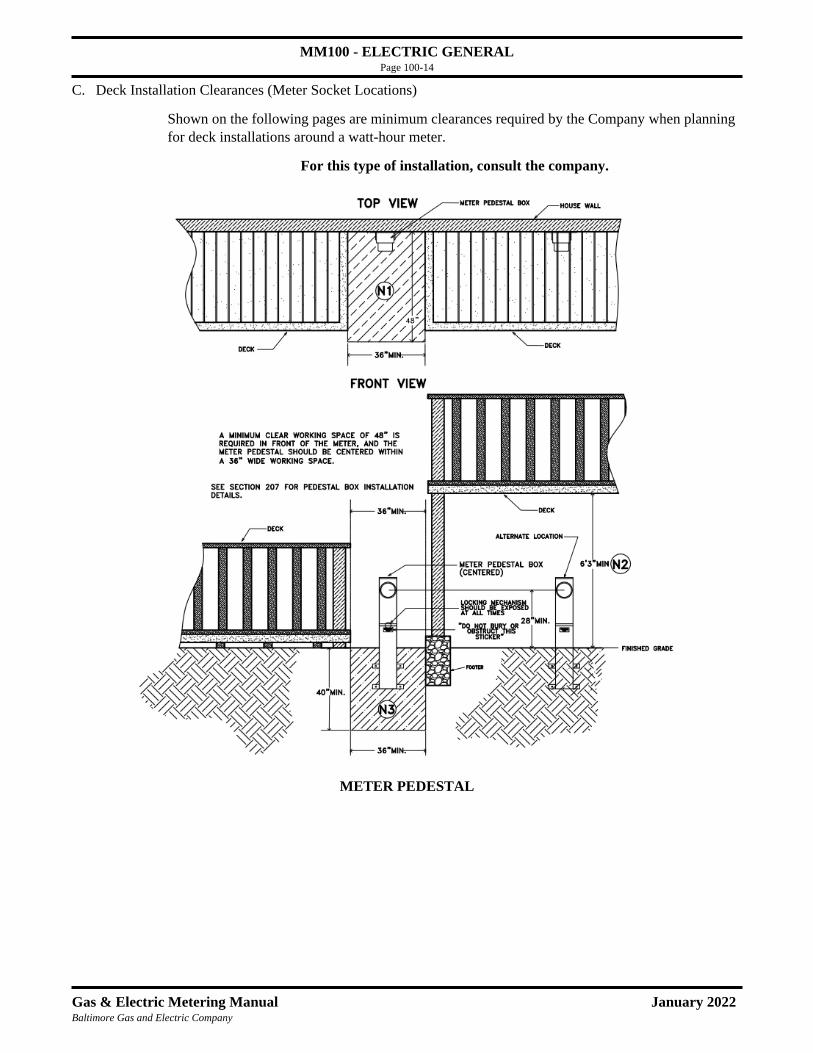
MM100 - ELECTRIC GENERAL Page 100-14
Gas & Electric Metering Manual January 2022 Baltimore Gas and Electric Company
C. Deck Installation Clearances (Meter Socket Locations)
Shown on the following pages are minimum clearances required by the Company when planning
for deck installations around a watt-hour meter.
For this type of installation, consult the company.
METER PEDESTAL

MM100 - ELECTRIC GENERAL Page 100-15
Gas & Electric Metering Manual January 2022 Baltimore Gas and Electric Company
Note:
(N1) A minimum clear working space of 36”W x 48”D shall be provided in front of the meter.
(N2) When a deck is built over or above the meter box, a minimum head room of 6’3” shall be maintained. (N1)
and other clearances shown above still apply. Also, the space under the deck shall be easily accessible. Do not
install any barrier, gate or any means that will prevent ready access to the meter box and cable connections.
(N3) A clear space of 36”W x 40”D shall be provided underground for service lateral. A clear path above ground
shall be maintained for the service lateral.
* See beginning of the manual for meter protection requirements.
For this type of installation, consult the company.

MM100 - ELECTRIC GENERAL Page 100-16
Gas & Electric Metering Manual January 2022 Baltimore Gas and Electric Company
METER SOCKET BOX
Note:
(N1) A minimum clear working space of 36”W x 48”D shall be provided in front of the meter.
(N2) When a deck is built over or above the meter box, a minimum head room of 6’3” shall be maintained. (N1)
and other clearances shown above still apply. Also, the space under the deck shall be easily accessible. Do not
install any barrier, gate or any means that will prevent ready access to the meter box and cable connections.
(N3) A clear space of 36”W x 26”-40”D shall be provided underground for service lateral. A clear path above
ground shall be maintained for the service lateral.
* See beginning of the manual for meter protection requirements.
48”

MM100 - ELECTRIC GENERAL Page 100-17
Gas & Electric Metering Manual January 2022 Baltimore Gas and Electric Company
105-4 Residential Meters in a Flood Zone
Electric meter installations for new residential construction in areas defined as a flood zone1 by local,
state, or federal authorities are required to meet the following criteria:
1. Elevation of Meter Equipment2
a. Electric meter sockets must be installed at a minimum of one (1) foot above the greater of the
following two elevations:
i. The base flood elevation (BFE)3, or
ii. The design flood elevation (DFE), which is determined by the local authority having
jurisiction.
b. The meter may be installed at the standard maximum height of 60 inches if it meets
requirement 1a.
2. Meter Accessibility
a. For outdoor electric meter installations that are higher than 60 inches, an elevated platform
must be installed with a minimum of three (3) feet of clear space in front of the electric meter.
i. A railing, gate and staircase must be provided on the platform (see Figure 1 below).
ii. If an existing elevated platform, such as a porch or deck exists, the meter may be installed
at a height not to exceed 60 inches beyond the platform and requirement 1 is met.
Note(s): (1) flood hazard areas with 1-percent chance of annual flood; flood zones include Zone A
and Zone AE (Flood Zones | FEMA.gov); (2) requirement 1a is in alignment with ASCE (American
Society of Civil Engineers) Standard 24-14, which is deemed by FEMA to meet or exceed the
minimum National Flood Insurance Program (NFIP) requirements for buildings and structures
(Highlights of ASCE 24 Flood Design Resistant and Construction | FEMA.gov); (3) BFE is the
computed elevation to which flood water is anticipated to rise and shown on the Flood Insurance Rate
Maps (FIRMs) or on the flood profiles (Floodplain Management | FEMA.gov).
Figure 105-4: construction setup for electric and gas meter installations in a flood zone

MM100 - ELECTRIC GENERAL Page 100-18
Gas & Electric Metering Manual January 2022 Baltimore Gas and Electric Company
106 Electric Enclosures Protection
106-1 Protection Enclosures
Protection enclosures are required for new, outdoor metering installations that are:
A. Remote and unattended to the extent that an act of vandalism such as the breaking of meter glass
would not likely be observed or detected most of the time by the customer, general public, or any
responsible party. Examples of remote and unattended meter locations are those where service is
provided at:
a. Signboards
b. Recreation areas
c. Public parks
d. Neighborhood/school ball fields
e. Pumping stations
f. Railroad crossing gates and signals
g. Off-the-road installations for highway and highway sign lighting
B. Highly visible and the equipment installation constitute an attractive target for vandals. Examples of
highly visible meter locations are those where service is provided at:
a. Apartment, condominium, cooperative, or townhouse buildings with multiple meters (three or more)
installed in an assembly or in a group close together on an outside wall.
b. Roadside installations for highway and highway sign lighting.
C. Obscure; that is, not generally in the view of the customer or occupant, and where an act of vandalism
would not likely be observed or detected most of the time by the customer, general public, or any
responsible party. Examples of obscure meter locations are those where service is provided at:
a. Shopping centers
b. Fast food/convenience stores
c. Business areas, generally, if subject to vandalism.
Meter protection enclosures are not required for the overwhelming majority of new installations. Also, it is
not required for those new metering installations cited above which are screened from view of passersby and
where the meter(s) is (are) located within a secured fenced or walled area, in a guarded property, or in an area
not normally accessible to the public.
Design of Protecting Devices
The protecting enclosure shall be of sufficient size to cover the metering equipment. It shall be made of
sheet metal (minimum of 12-gauge) with a full-sized hinged door and hasp to accommodate a Company
lock.

MM100 - ELECTRIC GENERAL Page 100-19
Gas & Electric Metering Manual January 2022 Baltimore Gas and Electric Company
106-2 Conditions for Applying the Guidelines
A. For new metering installations judged to be vulnerable to damage by vandals, the customer shall
provide, at his expense, suitable meter protection equipment.
B. For existing metering installations that have suffered damage by vandals and where future protection is
considered necessary, the Company shall bear the cost of adding suitable protecting devices.
C. The Meter Inspector - Meter & Installation shall make the judgment whether or not protection is
required for each metering installation. The Supervisor - Meter & Installation shall be the arbiter of any
disputes that may arise regarding the need for metering protection.
The enclosures can be provided by many contractors and are obtainable from various sheet metal
fabricators. The customer’s architect or contractor should obtain the size of enclosure by contacting the
responsible Distribution Department Designer who will coordinate with appropriate Meter Inspector -
Meter Installation to determine the enclosure size. (For phone numbers, refer to Section 106-1). No meters
shall be installed until the enclosures are in place.
106-3 Types of Enclosures
Applicable to Figures 1 and 2.
• Enclosures shall be minimum 12-gauge galvanized steel or equivalent.
• Back may be omitted on wall mounted enclosure and 1¼” mounting flange provided instead.
• Wall mounted enclosure may be used for overhead or underground supply; support mounted
enclosure for underground only.
• Supports for support mounted enclosure shall be furnished and installed by customer and shall not
be smaller than 2” galvanized conduit set in concrete.
Applicable to Figure 3.
• Pad-mounted enclosure on concrete base shall be used for underground supply.
• Enclosure shall be minimum 10-gauge galvanized steel or equivalent.
Applicable to Figures 1, 2 and 3.
• Enclosure shall be provided, installed, and maintained by customer.
• Customer is responsible for the enclosure and supports being structurally adequate.
• Customer shall provide ¾” exterior plywood equipment mounting board, except where mounting
flange is provided.
• Weather tight construction is not required for enclosure sizes given in table.
• Drainage means shall be provided by the customer.
• Door edges shall be formed for telescopic fit with enclosure.
• The maximum single door width shall be 20”. The door opening shall be not less than the
dimensions given in the table below.
• All doors shall be equipped with tamperproof hinges.
• A hasp for 2 locks shall be provided if customer equipment is enclosed (See Detail “A”).
Otherwise, only a hasp for the Company lock is needed.
• Consult the Company for quantity, size, and spacing of supply conduits.
• Dimensions in the table provide space for one meter and socket, with line and load conductors
entering bottom of socket. Dimensions shall be increased appropriately if customer equipment is
enclosed. For multiple meters or multiple sets of service entrance wiring, consult the Company.

MM100 - ELECTRIC GENERAL Page 100-20
Gas & Electric Metering Manual January 2022 Baltimore Gas and Electric Company
106-3 Types of Enclosures (continued)
Max. conductor size,
line side of meter
Total Ampacity,
Customer Service
Entrance Wiring
Class of Service
Inside
dimension/Meter
Equipment space (in
inches)
X
Y
Z
No. 2 0-100 1Ø 3W 18 18 13
3Ø 3W 18 18 15
4/0 0-100 3Ø 4W 20 24 15
1Ø 3W 20 24 13
4/0 101-200 3Ø 3W 20 24 15
3Ø 4W 20 24 15
Over 4/0 Over 200 Consult the
Company

MM100 - ELECTRIC GENERAL Page 100-21
Gas & Electric Metering Manual January 2022 Baltimore Gas and Electric Company
107 Service Information
107-1 Where to call
For inquiries, arrangements or
Information pertaining to:
New services - Gas or Electric
Pending jobs or construction
Relocation of Company equipment
Removal of Company equipment
Meter Locations
Certificates of Inspection
Significant increases in load
Increase in service entrance size
Fault current Values
Voltage Problems
Planned Outages
Customer-owned metering equipment
Residential, Commercial, & Industrial
New Business and Customer Contact
410-637-8713 (7:00 AM - 4:30 PM)
800-233-1854 (7:00 AM - 4:30 PM)
Fax 410-712-9323
Baltimore Gas & Electric Company
New Construction Services
1068 N. Front Street
Baltimore, Maryland 21202
Emergency service
Turn on, turn off meters
Meter reading
800-685-0123
Residential:
General Conservation Information
Efficient utilization of energy
Insulation
410-265-4000 or
410-265-4100

MM100 - ELECTRIC GENERAL Page 100-22
Gas & Electric Metering Manual January 2022 Baltimore Gas and Electric Company
107-2 Map of Electric Meter Inspector Responsibilities
*See 107-1 for other Company phone numbers. *See 701-4 for Gas M&I district info.

MM100 - ELECTRIC GENERAL Page 100-23
Gas & Electric Metering Manual January 2022 Baltimore Gas and Electric Company
107-3 Map of Network Territory (Baltimore City)

MM100 - ELECTRIC GENERAL Page 100-24
Gas & Electric Metering Manual January 2022 Baltimore Gas and Electric Company
107-4 Location of Underground Facilities
Call Miss Utility: 811, or 1-800-257-7777 (7:00 AM - 5:00 PM) 24 hr. service in case of
emergency.
Call at least 48 hours before you dig, plant, drill, blast, or grade. A utility representative will mark
underground facilities at your site free of charge.
Color codes appearing on wire flags or as spray painted stripes on the grass, sidewalk or street mark
underground utility lines. Whether you’re planning a large construction project or minor landscaping,
call Miss Utility at 811 or 1-800-257-7777 before you dig and exercise caution where you see these
codes:

MM200 - ELECTRIC UNDERGROUND Page 200-1
Gas & Electric Metering Manual December 2020 Baltimore Gas and Electric Company
201 Underground Service 201-1 Terminus of Service
The terminus of the Company’s service is the point of attachment of the underground service cable at or within a building or at Company equipment. The Customer provides the service conductors beyond that point.
201-2 Trenching and Service Lateral Installation
For single phase residential installations, the Company shall trench for and install its service lateral. For commercial installations, the customer shall trench for and install duct on the line side of the meter.
201-3 Grading
The Customer must clear obstructions from and grade the property within six (6) inches of final grade before the Company will begin construction of its extension to meet the Customer’s service requirements.
201-4 Service Raceways in Municipal Duct Areas
A. Within public rights-of-way: The Company shall be consulted to determine who will furnish and install the raceway. The Customer may be required to install the raceway in concrete.
B. On private property: The Customer shall furnish and install the raceway. Note: Under certain conditions where mechanical protection of a vertical cable rise is necessary, the
Company will furnish and install a raceway of standard flexible metal conduit.
201-5 Service Raceways in Areas Other Than Those With Municipal Duct A. Within public rights-of-way: The Company shall be consulted to determine who will furnish and
install the raceway. If the customer is required to install a raceway from the manhole to the meter enclosure (e.g. Baltimore City), the raceway should connect directly to the meter enclosure.
B. On private property: 1. For an existing residence with meter(s) to be located outdoors, the Company will furnish and
install the vertical raceway at the meter location. Under paved or other hard surface areas such as driveways, sidewalks, patios, concrete slabs or equipment pads, etc., the Customer shall furnish and install all Company-required raceways.
2. For an existing residence with meter(s) to be located indoors, the Customer shall furnish and install any raceway.
3. For a new residence, excluding multiple-occupancy buildings (see Note 1), with meter(s) to be located outdoors, the Company will furnish and install the vertical raceway at the meter location (including one ell). Under paved or other hard surface areas such as driveways, sidewalks, patios, concrete slabs or equipment pads, etc., the Customer shall furnish and install all Company-required raceways.
4. For a new residence, excluding multiple-occupancy buildings (see Note 1), with meter(s) to be located indoors, under paved or other hard surface areas such as driveways, sidewalks, patios, concrete slabs or equipment pads, etc., the Customer shall furnish and install all Company-required raceways. The Customer shall furnish and install the raceway from the point of building entrance to the terminus of service.
5. For new or existing commercial, industrial or multiple-occupancy building (see Note 1), with meter(s) to be located indoors or outdoors, the Customer shall furnish and install any raceway. Conduits shall extend 4” above floor line and shall be in square configuration (rather than linear) unless otherwise shown in detail.

MM200 - ELECTRIC UNDERGROUND Page 200-2
Gas & Electric Metering Manual December 2020 Baltimore Gas and Electric Company
Note 1: A multiple-occupancy building is a structure designed to contain four or more individual units. Note 2: A meter enclosure/box shall NOT be entered through the back wall or top.
C. Required Number of Secondary Service Conduits (Consult the Company before installation)
1. The duct system must be concrete encased if a vertical (or stacked) configuration is installed 2. A maximum of 180 degrees of bend is allowed. Total bends exceeding 180 degrees require a
splice or pull box. 3. All bends must be concrete encased to prevent duct separation during cable installation.
Number of Ducts (Sized by Disconnect Nameplate Capacity (in Amps):
Single Phase # of Ducts Three Phase # of Ducts 0-200 201-400 401-1200
2 3 6
0-200 201-400 401-600 601-800 801 -1 000 1001 -1 600 1601-2400 2401-3000 3001-4000
2 2 3 4 4 4 6 8 12
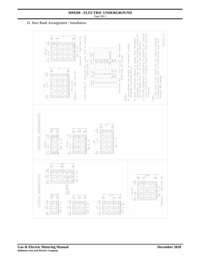
MM200 - ELECTRIC UNDERGROUND Page 200-3
Gas & Electric Metering Manual December 2020 Baltimore Gas and Electric Company
D. Duct Bank Arrangement / Installation

MM200 - ELECTRIC UNDERGROUND Page 200-4
Gas & Electric Metering Manual December 2020 Baltimore Gas and Electric Company
202 Clearances from Sidewalk, Driveway, Grade, and Trench
Note: If metering equipment is to be installed within 36” of an area subject to vehicular traffic (driveway, alley, roadway, etc.), the Customer will be required to provide protection for the equipment in the form of concrete filled bollard(s). See Sections 201-4 and 201-5 for Raceway Installations. See Sections 411 and 412 for Protection of Metering Installations * Except meter pedestal.

MM200 - ELECTRIC UNDERGROUND Page 200-5
Gas & Electric Metering Manual December 2020 Baltimore Gas and Electric Company
203 Indoor Raceway Installations (For Town Houses Only) See Section 600 for a summary of construction practices for gas and electric meter installations. See Sections 201-4 and 201-5 for additional details concerning raceway installations.
203-1 Basement Installation with LB Fitting
This configuration should be used when the electric meter will be installed indoors in a town house basement. To minimize the chance for water leakage, the conduit turns vertically, and transitions from an “LB” fitting, before penetrating the foundation wall (or band joist). For indoor installations on town houses, this is the preferred installation method. Note: This installation requires 18” vertically from final grade to top edge of band joist as
shown in diagram. If this requirement is not met, the installation detailed in 203-2 should be used.
Customer Furnishes and Installs: (1) 3” PVC LB fitting (Approved models: Cantex 5133670, Picoma ME986L or Carlon E986L). Bottom
of edge of LB fitting must be above final grade. Note: If the length of unfused cable inside the house from wall penetration to meter enclosure will be greater than five (5) feet, disconnecting means (see Section 104-8) may be required outdoors. If so, it may be substituted for the LB fitting.
(2) 3” PVC conduit (through-wall). Sleeve may be installed prior to concrete pouring or core-drilled for prefabricated wall.
(3) 6” x 6” trough with screw-on lid (length is field to fit). (4) Nipple – minimum 2” diameter. (5) Meter enclosure (Company furnished – 200 amp model is BGE Mech# 13-582). Company Furnishes and Installs: (A) Heavy-duty underground splice box (BGE Mech #291-7). Top edge will be set to level of final grade.
(B) 3” PVC conduit and fittings from splice box to bottom of LB fitting. PVC conduit must be installed perpendicular to face of building and not on an angle.

MM200 - ELECTRIC UNDERGROUND Page 200-6
Gas & Electric Metering Manual December 2020 Baltimore Gas and Electric Company
203-2 Basement Installation without LB Fitting This configuration should be used when the electric meter will be indoors in a town house basement and exterior wall space prohibits the use of an LB fitting. An example of such an installation would be a town house with a full front porch. Note: If adequate clear wall space exists outdoors and the vertical distance from final grade to the top edge of the band joist will be 18” or greater, the installation detailed in Section 203-1 should be used.
Customer Furnishes and Installs:
(1) 3” PVC through-wall conduit, that extends a minimum of 60” beyond foundation, and coupling. (2) 6” x 6” trough with screw-on lid (length is field to fit). (3) Nipple – minimum 2” diameter. (4) Meter enclosure (Company furnished – 200 amp model is BGE Mech# 13-582). Company Furnishes and Installs: (A) Heavy-duty underground splice box. Top edge will be set to level of final grade. (B) 3” PVC conduit from splice box to through-wall conduit stub.
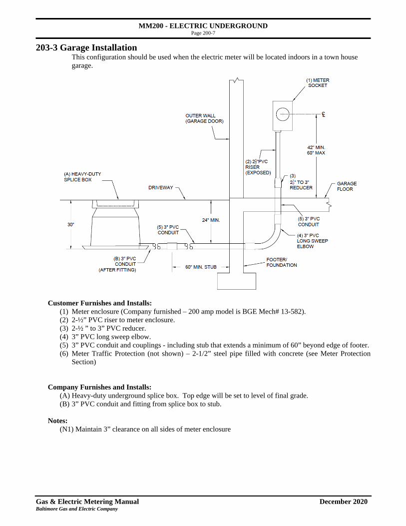
MM200 - ELECTRIC UNDERGROUND Page 200-7
Gas & Electric Metering Manual December 2020 Baltimore Gas and Electric Company
203-3 Garage Installation This configuration should be used when the electric meter will be located indoors in a town house garage.
Customer Furnishes and Installs: (1) Meter enclosure (Company furnished – 200 amp model is BGE Mech# 13-582). (2) 2-½” PVC riser to meter enclosure.
(3) 2-½ ” to 3” PVC reducer. (4) 3” PVC long sweep elbow. (5) 3” PVC conduit and couplings - including stub that extends a minimum of 60” beyond edge of footer.
(6) Meter Traffic Protection (not shown) – 2-1/2” steel pipe filled with concrete (see Meter Protection Section)
Company Furnishes and Installs: (A) Heavy-duty underground splice box. Top edge will be set to level of final grade. (B) 3” PVC conduit and fitting from splice box to stub. Notes:
(N1) Maintain 3” clearance on all sides of meter enclosure
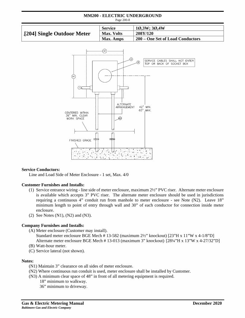
MM200 - ELECTRIC UNDERGROUND Page 200-8
Gas & Electric Metering Manual December 2020 Baltimore Gas and Electric Company
[204] Single Outdoor Meter Service 1Ø,3W; 3Ø,4W Max. Volts 208Y/120 Max. Amps 200 – One Set of Load Conductors
Service Conductors:
Line and Load Side of Meter Enclosure - 1 set, Max. 4/0
Customer Furnishes and Installs: (1) Service entrance wiring - line side of meter enclosure, maximum 2½” PVC riser. Alternate meter enclosure
is available which accepts 3” PVC riser. The alternate meter enclosure should be used in jurisdictions requiring a continuous 4” conduit run from manhole to meter enclosure - see Note (N2). Leave 18” minimum length to point of entry through wall and 30” of each conductor for connection inside meter enclosure.
(2) See Notes (N1), (N2) and (N3).
Company Furnishes and Installs: (A) Meter enclosure (Customer may install).
Standard meter enclosure BGE Mech # 13-582 (maximum 2½” knockout) [23”H x 11”W x 4-1/8”D] Alternate meter enclosure BGE Mech # 13-013 (maximum 3” knockout) [28¼”H x 13”W x 4-27/32”D]
(B) Watt-hour meter. (C) Service lateral (not shown). Notes:
(N1) Maintain 3” clearance on all sides of meter enclosure. (N2) Where continuous run conduit is used, meter enclosure shall be installed by Customer. (N3) A minimum clear space of 48” in front of all metering equipment is required.
18” minimum to walkway. 36” minimum to driveway.

MM200 - ELECTRIC UNDERGROUND Page 200-9
Gas & Electric Metering Manual December 2020 Baltimore Gas and Electric Company
[205] Single Outdoor Meter with Utility Disconnect 277/480V Services Only
Service 3Ø,4W Max. Volts 480Y/277 Max. Amps 200
Indoor Location – NON-STANDARD – See Section 105-3. Consult Baltimore Gas and Electric Company.
Service Conductors: Line Side of Disconnect and Load Side of Meter Enclosure – 1 set, Max. 4/0
Customer Furnishes and Installs:
(1) Service Entrance Wiring from load side of meter enclosure (leave 18” minimum length to point of entry through wall and 30” of each conductor for connection inside meter enclosure).
(2) See Notes (N1), (N2) and (N3)
Company Furnishes and Installs: (A) Meter Enclosure/Utility Disconnect Enclosure.
Maintenance disconnects (left side of enclosure) will be locked for BGE exclusive use only. Meter side (right side of enclosure) will be sealed. BGE Mech # 13-591 [28”H x 26”W x 4-27/32”D]
(B) Watt-hour meter (C) Service lateral (not shown) (D) See Note (N2)
Notes:
(N1) Maintain 3” clearance on all sides of meter enclosure & disconnect enclosure. (N2) Service raceway. See sections 201-4 and 201-5 for details. (N3) A minimum clear space of 48” in front of all metering equipment is required.
18” minimum to walkway. 36” minimum to driveway.

MM200 - ELECTRIC UNDERGROUND Page 200-10
Gas & Electric Metering Manual December 2020 Baltimore Gas and Electric Company
[206] Freestanding Single Outdoor Meter
Service 1Ø,3W; 3Ø,4W Max. Volts 208Y/120 Max. Amps 200 – One Set of Load Conductors
COMMERCIAL USE ONLY
A Company-approved meter pedestal is a recommended alternate to this installation (single phase only). See 401 for approved pedestals.
Service Conductors: Line and Load Side of Meter Enclosure — 1 set, Max. 4/0 Customer Furnishes and Installs:
All material except. See Note (N2). (1) Two 2” hot dip galvanized conduit standards and install Company meter enclosure. (2) PVC conduit raceway (EPC 40) for line and load wiring. Ells should be a minimum 36” radius. See Note (N2). (3) Assembly must be installed in concrete as shown. (4) Service entrance wiring from load side of meter enclosure (Leave 30” of each conductor for connection inside meter enclosure). (5) 1-1/2” x 1-1/2” Kindorf for mounting enclosure boxes. Use non-corrosive mounting bolts. (6) See Notes (N1), (N2), and (N3)
Company Furnishes and Installs:
(A) Meter Enclosure (Customer shall install) Standard meter enclosure BGE Mech # 13-582 (maximum 2½” knockout) [23”H x 11”W x 4-1/8”D] Alternate meter enclosure BGE Mech # 13-013 (maximum 3” knockout) [28¼”H x 13”W x 4-27/32”D]
(B) Watt-hour meter. (C) Service lateral. (D) See Note (N1).
Notes:
(N1) Maintain 3” clearance on all sides of meter enclosure. (N2) Service raceway. See Sections 201-4 and 201-5 for details. (N3) A minimum clear space of 48” in front of all metering equipment is required.
18” minimum to walkway. 36” mininum to driveway.

MM200 - ELECTRIC UNDERGROUND Page 200-11
Gas & Electric Metering Manual December 2020 Baltimore Gas and Electric Company
[207] Single Outdoor Meter Pedestal
Service 1Ø,3W Max. Volts 240 Max. Amps 200 - One or Two Sets of Load Conductors
Service Conductors:
Line Side of Meter Enclosure - 1 set, Max. 350 kcmil Load Side of Meter Enclosure - 1 set, Max. 4/0
Customer Furnishes and Installs:
(1) Service Entrance Wiring from load side of meter pedestal (leave 18” minimum length to point of entry through wall and 30” of each conductor for connection inside meter enclosure).
(2) See Notes (N1) and (N2) Company Furnishes and Installs:
(A) Meter Enclosure: BGE Mech # 13-247 [62”H x 9-1/2”W x 4-1/8”D] (B) Watt-hour meter. (C) Service lateral.
Notes:
(N1) 36” minimum clear work space. (N2) A minimum clear space of 48” in front of all metering equipment is required.
18” minimum to walkway. 36” mininum to driveway.

MM200 - ELECTRIC UNDERGROUND Page 200-12
Gas & Electric Metering Manual December 2020 Baltimore Gas and Electric Company
[208] Residential Only Single Outdoor Meter
Service 1Ø,3W Max. Volts 240 Max. Amps 400 (320A Continuous)
Service Conductors:
Line and Load Side of Meter Enclosure - 1 set, Max. 350 kcmil 2 sets, Max. 4/0
Customer Furnishes and Installs:
(1) Service Entrance Wiring from load side of meter enclosure (leave 18” minimum length to point of entry through wall and 30” of each conductor for connection inside meter enclosure).
(2) See Notes (N1), (N2) and (N3). Company Furnishes and Installs:
(A) Meter Enclosure (Customer may install). BGE Mech # 13-009 [30”H x 15”W x 4-27/32”D] (B) Watt-hour meter. (C) Service lateral (not shown). (D) See Note (N2).
Notes:
(N1) Maintain 3” clearance on all sides of meter enclosure. (N2) Service raceway. See Sections 201-4 and 201-5 for details. (N3) A minimum clear space of 48” in front of all metering equipment is required. 18” minimum to walkway. 36” mininum to driveway.

MM200 - ELECTRIC UNDERGROUND Page 200-13
Gas & Electric Metering Manual December 2020 Baltimore Gas and Electric Company
[209] Residential Only Single Outdoor Meter Pedestal
Service 1Ø,3W Max. Volts 240 Max. Amps 400 (320A Continuous)
Service Conductors:
Line Side of Meter Enclosure - 1 set, Max. 350 kcmil Load Side of Meter Enclosure - 2 sets, Max. 4/0 2 sets, Max. 1-4/0 and Max. 1-2/0
Customer Furnishes and Installs:
(1) Service Entrance Wiring from load side of meter pedestal (leave 18” minimum length to point of entry through wall and 24” of each conductor for connection inside meter enclosure). Residential Only - 2 sets.
(2) See Notes (N1) and (N2) Company Furnishes and Installs:
(A) Meter Enclosure. BGE Mech # 13-250 [64”H x 13-1/4”W x 4-7/8”D] (B) Watt-hour meter. (C) Service lateral.
Notes:
(N1) 36” minimum clear work space. (N2) A minimum clear space of 48” in front of all metering equipment is required. 18” minimum to walkway.
36” mininum to driveway

MM200 - ELECTRIC UNDERGROUND Page 200-14
Gas & Electric Metering Manual December 2020 Baltimore Gas and Electric Company
[210] Two Outdoor Meters
Service 1Ø,3W Max. Volts 240 Max. Amps 150 Each Meter Position - One Set of Load
Conductors at Each Meter Position
Service Conductors: Line Side of Meter Enclosure - 1 set, Max. 350 kcmil Load Side of Meter Enclosure - 1 set, Max. 2/0 to each meter position
Customer Furnishes and Installs:
(1) Service Entrance Wiring from load side of meter enclosure (leave 18” minimum length to point of entry through wall and 30” of each conductor for connection inside meter enclosure).
(2) See Notes (N1), (N2) and (N3). Company Furnishes and Installs:
(A) Meter Enclosure (Customer may install). Horizontal 2-Gang 150A Meter Enclosure BGE Mech # 13-165 [17½” H x 20-5/16” W x 4½”D] Vertical 2-Gang 150A Meter Enclosure BGE Mech # 13-166 [27”H x 16”W x 4-27/32”D]
(B) Watt-hour meter. (C) Service lateral (not shown). (D) See Note (N2).
Notes:
(N1) Maintain 3” clearance on all sides of meter enclosure. (N2) Service raceway. See Sections 201-4 and 201-5 for details. (N3) A minimum clear space of 48” in front of all metering equipment is required. 18” minimum to walkway, 36” mininum to driveway.

MM200 - ELECTRIC UNDERGROUND Page 200-15
Gas & Electric Metering Manual December 2020 Baltimore Gas and Electric Company
[211] Two Outdoor Meters
Service 1Ø,3W; 3Ø,4W Max. Volts 208Y/120 Max. Amps 200 Each Meter Position - One Set of Load
Conductors at Each Meter Position
For 480Y/277V Services – Consult Baltimore Gas and Electric Company
Service Conductors:
Line Side of 2-Position Meter Enclosure - 1 set, Max. 500 kcmil Load Side of Each Meter Position - 1 set, Max. 4/0
Customer Furnishes and Installs:
(1) Service Entrance Wiring from load side of meter enclosure (leave 18” minimum length to point of entry through wall and 24” of each conductor for connection inside meter enclosure).
(2) See Notes (N1), (N2) and (N3). Company Furnishes and Installs:
(A) 2-Position Meter Enclosure. (Customer may install). Single Phase BGE Mech # 13-067 [30-1/8”W x 20”H x 4-27/32”D] Three Phase BGE Mech # 13-122 [30-1/8”W x 19”H x 5½”D]
(B) Watt-hour meters. (C) Service lateral (not shown). (D) See Note (N2).
Notes:
(N1) Maintain 3” clearance on all sides of meter enclosure. (N2) Service raceway. See Sections 201-4 and 201-5 for details. (N3) A minimum clear space of 48” in front of all metering equipment is required. 18” minimum to walkway. 36” mininum to driveway.

MM200 - ELECTRIC UNDERGROUND Page 200-16
Gas & Electric Metering Manual December 2020 Baltimore Gas and Electric Company
[212] Three Outdoor Meters
Service 1Ø,3W Max. Volts 240 Max. Amps 150 Each Meter Position - One Set of Load
Conductors at Each Meter Position
Service Conductors:
Line Side of 3-Position Meter Enclosure - 1 set, Max. 350 kcmil Load Side of Each Meter Position - 1 set, Max. 2/0
Customer Furnishes and Installs:
(1) Service Entrance Wiring from load side of meter enclosure (leave 18” minimum length to point of entry through wall and 24” of each conductor for connection inside meter enclosure).
(2) See Notes (N1), (N2) and (N3). Company Furnishes and Installs:
(A) 3-Position Meter Enclosure. (Customer may install). Horizontal 3-Gang 150A Meter Enclosure BGE Mech # 13-181 [17½” H x 28½” W x 4½”D] Vertical 3-Gang 150A Meter Enclosure BGE Mech # 13-182 [37½”H x 16”W x 4-27/32”D]
(B) Watt-hour meters. (C) Service lateral (not shown). (D) See Note (N2).
Notes:
(N1) Maintain 3” clearance on all sides of meter enclosure. (N2) Service raceway. See Sections 201-4 and 201-5 for details. (N3) A minimum clear space of 48” in front of all metering equipment is required. 18” minimum to walkway. 36” mininum to driveway.

MM200 - ELECTRIC UNDERGROUND Page 200-17
Gas & Electric Metering Manual December 2020 Baltimore Gas and Electric Company
[213] Freestanding Multiple Outdoor Meters
Service 1Ø,3W Max. Volts 240 Max. Amps 150 Each Meter Position - One Set of Load
Conductors at Each Meter Position
Service Conductors:
Line Side of 2- or 3-Position Meter Enclosure – 1 set, Max. 350 kcmil Load Side of Each Meter Position – 1 set, Max. 2/0
Customer Furnishes and Installs:
(1) 2” galvanized steel pipe. (2) 1-1/2” x 1-1/2” Kindorf channel for mounting enclosure boxes. (3) 3/8” galvanized or stainless steel bolts. (4) Supports – rigid and free from vibration, embedded in concrete, minimum of 24” deep and 8” square. (5) Rain-tight disconnecting means. (6) Service entrance wiring from load side of each meter position to disconnecting means (leave 24” of each conductor for
connection inside meter enclosure). (7) Grounding electrode conductor – terminated in Customer’s equipment. (8) Feeder to Customer’s load. (9) See Notes (N1) and (N2).
Company Furnishes and Installs:
(A) 2- or 3-Position Meter Enclosure (Customer may furnish and install Company-approved rain-tight stack or pedestal type meter equipment). Horizontal 2-Gang 150A Meter Enclosure BGE Mech # 13-165 [17½” H x 20-5/16” W x 4½”D] Horizontal 3-Gang 150A Meter Enclosure BGE Mech # 13-181 [17½” H x 28½” W x 4½”D]
(B) Watt-hour meters. (C) Service lateral spliced for back-to-back enclosures.
Notes: (N1) Service raceway. Ells should be a minimum of 36” radius. See Sections 201-4 and 201-5 for details. (N2) A minimum clear space of 48” in front of all metering equipment is required. 18” minimum to walkway. 36” mininum to driveway. 10’ minimum to utility pole. 5’ minimum to padmount transformer.

MM200 - ELECTRIC UNDERGROUND Page 200-18
Gas & Electric Metering Manual December 2020 Baltimore Gas and Electric Company
[214] Doubtful Permanency (Max. 2 years) Service Pad-Mounted Transformer Single Outdoor Meter
Service 1Ø,3W; 3Ø,4W Max. Volts 480Y/277 Max. Amps 200 - One Set of Load
Conductors
NOTE: Overhead wires shall not be attached to the same support on which meter is mounted Service Conductors:
Line Side of Meter Enclosure – 1 set, Max. 4/0 Load Side of Meter Enclosure – 1 set, Max. 4/0
Customer Furnishes and Installs:
(1) 6” x 6” or 3 – 2” x 6” pressure treated timber(s) set at right rear edge of transformer pad (as viewed from front). (2) Disconnecting means. (3) Service entrance wiring from load side of meter enclosure to disconnecting means (leave 24” of each conductor for
connection inside meter enclosure). (4) 2” x 4” board at transformer knockout height. (5) Service entrance cable or conduit; if for 480Y/277 volts, it must be a complete conduit system, made of steel or
Scheduled 40 PVC, from meter to transformer (leave 60” of each conductor for connection inside transformer. (6) Grounding electrode conductor connected to driven rod. (7) See Notes (N1) and (N2).
Company Furnishes and Installs:
(A) Meter Enclosure. (Customer may install). (B) Watt-hour meter. (C) Service entrance cable connector. (D) Pad-Mounted Transformer.
Notes:
(N1) Overhead wires shall not be attached to same support on which meter is mounted. (N2) A minimum clear space of 48” in front of all metering equipment is required. 18” minimum to walkway. 36” mininum to driveway. (N3) Doubtful permanency good for 2 years maximum.

MM200 - ELECTRIC UNDERGROUND Page 200-19
Gas & Electric Metering Manual December 2020 Baltimore Gas and Electric Company
[215] Multiple Meters Customer’s Trough (Indoor/Outdoor)
Service 1Ø,3W Max. Volts 240 Max. Amps
100 or 200 Each Meter Enclosure - One Set of Load Conductors at Each Meter Enclosure
Consult Baltimore Gas and Electric Company.
Service Conductors:
Line Side of Meters (in trough) - Governed by Size of Main Load Side of Disconnecting Means - Each Meter Enclosure – 1 set, Max. 4/0
Customer Furnishes and Installs:
(1) When required by inspection authority having jurisdiction, main disconnecting means which shall be a sealable circuit breaker or a fused switch with sealable barriers which enclose all unmetered conductors/connections except the fuses.
(2) Sealable wire trough, 14” x 14” minimum size, with guide pin studs and handles. Conductors from load terminals of main disconnecting means shall extend the full length of the wire trough. Consult Company for length of trough. Trough shall be installed below meter enclosures. See Section 416 for service entrance trough requirements.
(3) Grounding electrode conductor. (4) Conductors from load side of each meter position and connectors as required (leave 30” of each conductor for connection inside
each meter enclosure). (5) Individual disconnecting means durably and legibly marked with paint as to area served. See Sections 105-1. (6) Company-approved terminal blocks, when the total capacity of one or more main disconnecting means exceeds 1000 amps. (7) Line conductors from trough to 200A meter enclosures. The customer is responsible for all wiring after landing block in trough. (8) See Notes (N1), (N2), (N3), (N4) and (N5).
Company Furnishes and Installs:
(A) Meter enclosures (Customer may install) and miscellaneous materials to make connections. 100A: BGE Mech #13-594 or 13-068 [10½”H x 8”W x 3-5/16”D] 200A: BGE Mech # 13-582 [23”H x 11”W x 4-1/8”D]
(B) Watt-hour meters. (C) Service lateral (not shown). (D) See Note (N2).
Notes:
(N1) 28” minimum, 60” maximum. (N2) Service raceway. See Sections 201-4 and 201-5 for details. (N3) Maintain 3” clearance on all sides of meter enclosure. (N4) A minimum clear space of 48” in front of all metering equipment is required. (N5) A minimum clearance of 36” shall be provided from the finished floor line to the bottom terminals of the main disconnect switch.
OPTION 1 OPTION 2

MM200 - ELECTRIC UNDERGROUND Page 200-20
Gas & Electric Metering Manual December 2020 Baltimore Gas and Electric Company
[216] Multiple Meters Customer’s Trough (Outdoor/Indoor)
Service 3Ø,4W Max. Volts 480Y/277 Max. Amps 200 Each Meter Enclosu–e - One Set of Load
Conductors at Each Meter Enclosure
Indoor Location - NON-STANDARD - See Section 105-3. Consult Baltimore Gas and Electric Company.
Service Conductors:
Line Side of Meters (in trough) - Governed by Size of Main Load Side of Disconnecting Means Each Meter Enclosure - 1 set, Max. 4/0
Customer Furnishes and Installs:
(1) When required by inspection authority having jurisdiction, main disconnecting means which shall be a sealable circuit breaker or a fused switch with sealable barriers which enclose all unmetered conductors/connections except the fuses.
(2) Sealable wire trough, 14” x 14” minimum size, with guide pin studs and handles. Conductors from load terminals of main disconnecting means shall extend the full length of the wire trough. Consult Company for length of trough. Trough shall be installed below meter enclosures. See Section 416 for service entrance trough requirements.
(3) Grounding electrode conductor. (4) Conductors from load side of meters and connectors as required (leave 30” of each conductor for connection inside each meter
enclosure). (5) Individual disconnecting means durably and legibly marked with paint as to area served. See Sections 105-1. (6) Company-approved terminal blocks, when the total capacity of one or more main disconnecting means exceeds 1000 amps. (7) Line conductors from trough to 200A meter enclosure. The customer is responsible for all wiring after landing block in trough. (8) See Notes (N1), (N2), (N3), (N4) and (N5).
Company Furnishes and Installs:
(A) Meter enclosures (Customer may install) and miscellaneous materials to make connections. BGE Mech # 13-013 [28-1/4”H x 13”W x 4-27/32”D]
(B) Watt-hour meters. (C) Service lateral (not shown). (D) See Note (N2).
Notes:
(N1) 28” minimum, 60” maximum. (N2) Service raceway. See Sections 201-4 and 201-5 for details. (N3) Maintain 3” clearance on all sides of meter enclosure. (N4) A minimum clear space of 48” in front of all metering equipment is required. (N5) A minimum clearance of 36” shall be provided from the finished floor line to the bottom terminals of the main disconnect switch.
OPTION 2 OPTION 1

MM200 - ELECTRIC UNDERGROUND Page 200-21
Gas & Electric Metering Manual December 2020 Baltimore Gas and Electric Company
[217] Six or Fewer Indoor Meters Company’s Horizontal 2 or 3 Position Meter Enclosures
Service 1Ø,3W Max. Volts 240 Max. Amps 150 Each Meter Position - One Set of
Load Conductors at Each Meter Position Indoor Location - NON-STANDARD - See Section 105-3. Consult Baltimore Gas and Electric Company.
Service Conductors:
Line Side of 3-Position Meter Enclosure - 1 set, Max. 350 kcmil Load Side of Each Meter Position - 1 set, Max. 2/0
Customer Furnishes and Installs:
(1) Sealable wire trough, 14” x 14” x 48” minimum size, with guide pin studs and handles. Service entrance conductors shall extend the full length of the wire trough. See Section 416 for service entrance trough requirements.
(2) Grounding electrode conductor. (3) Load conductors in raceway or cable and connectors as required (leave 24” of each conductor for connection inside
each meter enclosure). (4) Individual disconnecting means durably and legibly marked with paint as to area served. See Section
Sections 105-1. Shall not be installed above enclosure box. (5) Company-approved terminal blocks, when the total capacity of one or more main disconnecting means exceeds
1000 amps. Trough shall not be installed above meter enclosures. (6) Line conductors from trough to 200A meter enclosure. The customer is responsible for all wiring after landing
block in trough. (7) See Notes (N1), (N2) and (N3).
Company Furnishes and Installs:
(A) 2- or 3-Position meter enclosures (Customer may install) and miscellaneous materials to make connections. Horizontal 2-Gang 150A Meter Enclosure BGE Mech # 13-165 [17½” H x 20-5/16” W x 4½”D] Horizontal 3-Gang 150A Meter Enclosure BGE Mech # 13-181 [17½” H x 28½” W x 4½”D]
(B) Watt-hour meters. (C) Service lateral (not shown). (D) See Note (N2).
Notes:
(N1) Service raceway. See Sections 201-4 and 201-5 for details. (N2) A minimum clear space of 48” in front of all metering equipment is required.

MM200 - ELECTRIC UNDERGROUND Page 200-22
Gas & Electric Metering Manual December 2020 Baltimore Gas and Electric Company
[218] Multiple Outdoor/Indoor Meters Company’s Vertical 2 or 3 Position Meter Enclosures
Service 1Ø,3W Max. Volts 240 Max. Amps 150 Each Meter Position - One Set of
Load Conductors at Each Meter Position
Indoor Location – NON-STANDARD – See Section 105-3. Consult Baltimore Gas and Electric Company.
Service Conductors:
Line Side of Meters (in trough) – Governed by Size of Main Load Side of Disconnecting Means Each Meter Enclosure – 1 set, Max. 2/0
Customer Furnishes and Installs: (1) When required by inspection authority having jurisdiction, main disconnecting means which shall be a sealable circuit breaker or
a fused switch with sealable barriers which enclose all unmetered conductors/connections except the fuses. (2) Sealable wire trough, 14” x 14” minimum size, with guide pin studs and handles. Conductors from load terminals of main
disconnecting means shall extend the full length of the wire trough. Consult Company for length of trough. Trough shall be installed below meter enclosures. See Section 416 for service entrance trough requirements.
(3) Grounding electrode conductor. (4) Conductors from load side of each meter position and connectors as required (leave 24” of each conductor for connection inside
each meter enclosure). (5) Individual disconnecting means durably and legibly marked with paint as to area served. See Section 105-1. (6) Company-approved terminal blocks, when the total capacity of one or more main disconnecting means exceeds 1000 amps. (7) Line conductors from trough to 200A meter enclosure. The customer is responsible for all wiring after landing block in trough. (8) See Notes (N1), (N2) and (N3).
Company Furnishes and Installs: (A) 2- or 3-position meter enclosures (Customer may install) and miscellaneous materials to make connections.
Vertical 2-Gang 150A Meter Enclosure BGE Mech # 13-166 [27”H x 16”W x 4-27/32”D] Vertical 3-Gang 150A Meter Enclosure BGE Mech # 13-182 [37½”H x 16”W x 4-27/32”D]
(B) Watt-hour meters. (C) Service lateral (not shown). (D) See Note (N1).
Notes: (N1) Service raceway. See Sections 201-4 and 201-5 for details. (N2) A minimum clear space of 48” in front of all metering equipment is required. (N3) minimum clearance of 36” shall be provided from the finished floor line to the bottom terminals of the main disconnect switch. (N4) Maintain 3” clearance on all sides of meter enclosure.
OPTION 2 OPTION 1

MM200 - ELECTRIC UNDERGROUND Page 200-23
Gas & Electric Metering Manual December 2020 Baltimore Gas and Electric Company
[219] Modular Meters Outdoor/Indoor Customer’s Equipment
Service 1Ø,3W or 3Ø,4W Max. Volts 480Y/277 Max. Amps 200 Each Meter Position (400A/320A
continuous up to 240V)
Indoor Location - NON-STANDARD - See Section 105-3. Not for use on the Company’s 240/120 delta (power wire) system. See Section 101-2
Consult Baltimore Gas and Electric Company.
Customer Furnishes and Installs:
(1) When required by inspection authority having jurisdiction, main disconnecting means which shall be a sealable circuit breaker or a fused switch equipped with sealable barriers which enclose all unmetered conductors/connections except the fuses.
(2) Approved group metering equipment and is responsible for all maintenance. See Section 402 for listing of approved equipment. (3) Grounding electrode conductor. (4) Individual disconnecting device. (5) Durable, legible labeling (with paint) denoting area/unit(s) served by each meter and disconnecting device. Experience shows that
failure to provide proper identification on multiple meter installations (area/unit(s) served; apartments, offices, or stores) often results in meters being installed that supply other than the area/unit(s) for which intended. Therefore, electric meters will not be installed on such installations until you have properly identified the area/unit(s) to be served; 1. meter enclosure and disconnecting device, 2. the sub-panel in the area/unit served. See Section 105-1.
(6) A lever type bypass for each meter which supplies other than a residential occupancy. (7) A fifth jaw (potential terminal) on each meter enclosure supplying other than 1Ø, 3W, 120 volt metering. The fifth jaw shall be
installed in the 9 o’clock position. (8) Service raceway for underground. See Sections 201-4 and 201-5. (9) See Notes (N1), (N2) and (N3).
Company Furnishes and Installs:
(A) Watt-hour meters. (B) Service lateral (not shown).
Notes:
(N1) Consult the Company for details regarding underground cable entry and termination. (N2) Outdoor installations may require enclosures for mechanical protection, consult Company. See Sections 411 and 412 for details. (N3) A minimum clear space of 48” in front of metering equipment is required.
18” minimum to walkway, 36” mininum to driveway.

MM200 - ELECTRIC UNDERGROUND Page 200-24
Gas & Electric Metering Manual December 2020 Baltimore Gas and Electric Company
[220] Outdoor / Indoor Instrument Current Transformer (C.T. Meter)
Service 1Ø,3W Max. Volts 240 Max. Amps 201 - 400
Consult Baltimore Gas and Electric Company.
See Section 403 for C.T. Cabinet details.
Service Conductors:
Line and Load Side of C.T. Cabinet – Max. 1 set 500 kcmil Customer Furnishes and Installs:
(1) C.T. Cabinet. See Section 403 for details. (2) Three-sided trough, minimum 10” x 10”, with 1” flanges to be constructed of 14-gauge steel or 10-gauge aluminum to enclose
service conductors. If installed on a combustible surface, a sheet metal plate against the wall is required. The trough may be located at either left or right as shown.
(3) Minimum 10” x 10” trough secured and bonded to C.T. cabinet. Load wiring from C.T. cabinet may be out of top or bottom, near either end, but shall be on opposite end from supply wiring. See Section 416 for service entrance trough requirements.
(4) Load conductors – leave 36” of each conductor inside C.T. cabinet. (5) See Notes (N1), (N2), (N3), and (N4). (6) Concrete pad (4” thick) to provide insect/rodent barrier (outdoor only). (7) Disconnecting means. (8) 2” minimum galvanized steel pipe. (9) 1-1/2” x 1-1/2” Kindorf channel.
Company Furnishes and Installs:
(A) Current transformer rated meter enclosure. (B) Watt-hour meter. (C) Current transformers (not shown).
(D) Raceway between C.T. cabinet and meter enclosure (not more than 3”). For indoor locations greater than 3”, 1-1/4” rigid conduit is required. For alternate locations, greater than 50’, consult with Company. Notes:
(N1) Service raceway. See Sections 201-4 and 201-5 for details. (N2) A minimum clear space of 48” in front of C.T. Cabinet is required. (N3) Space required for C.T. rated meter enclosure. (N4) Minimum clear space of 6” on both sides of C.T. cabinet is required. If meter is to be installed adjacent to the C.T. Cabinet, see
Note 3.

MM200 - ELECTRIC UNDERGROUND Page 200-25
Gas & Electric Metering Manual December 2020 Baltimore Gas and Electric Company
[221] Outdoor / Indoor Instrument Current Transformer (C.T. Meter)
Service 1Ø,3W; 3Ø,3W; or 3Ø,4W Max. Volts 480Y/277 Max. Amps 201 - 1600
Indoor Location - NON-STANDARD - See Section 105-3. Consult Baltimore Gas and Electric Company.
See Section 404 for C.T. Cabinet details.
Service Conductors:
Line and Load Side of C.T. Cabinet - Min. 2 sets 1/0 Max. 5 sets 500 kcmil
Max. 4 sets 600 kcmil Customer Furnishes and Installs:
(1) C.T. Cabinet. See Section 404 for details. (2) Three-sided trough, minimum 12” x 12”, with 1” flanges to be constructed of 14-gauge steel or 10-gauge aluminum to enclose
service conductors. If installed on a combustible surface, a sheet metal plate against the wall is required. The trough may be located at either left or right as shown. See Section 416 for service entrance trough requirements.
(3) Minimum 12” x 12” trough secured and bonded to C.T. cabinet. Load wiring from C.T. cabinet may be out of top or bottom, near either end, but shall be on opposite end from supply wiring.
(4) Load conductors - leave 60” of each conductor inside C.T. cabinet. (5) See Notes (N1), (N2), (N3), and (N4). (6) Holes in CT cabinet for line and load wires to be maximum 10” x 10”. (7) Concrete pad (4” thick) to provide insect/rodent barrier (outdoor only) (8) Disconnecting means. (9) 2” minimum galvanized steel pipe. (10) 1-1/2” x 1-1/2” Kindorf channel.
Company Furnishes and Installs:
(A) Current transformer rated meter enclosure. (B) Watt-hour meter. (C) Current transformers (not shown). (D) Raceway between C.T. cabinet and meter enclosure (not more than 3”). For indoor locations greater than 3”,
1-1/4” rigid conduit is required. For alternate locations, greater than 50’, consult with Company. Notes:
(N1) Service raceway. See Sections 201-4 and 201-5 for details. (N2) A minimum clear space of 48” in front of C.T. Cabinet is required. (N3) Space required for C.T. rated meter enclosure. (N4) Minimum clear space of 6” on both sides of C.T. cabinet is required. If meter is to be installed adjacent to the cabinet, see (N3).

MM200 - ELECTRIC UNDERGROUND Page 200-26
Gas & Electric Metering Manual December 2020 Baltimore Gas and Electric Company
[222] Outdoor / Indoor Instrument Current Transformer (C.T. Meter)
Service 3Ø,3W; or 3Ø,4W Max. Volts 480Y/277 Max. Amps 201 – 3000
Indoor Location - NON-STANDARD - See Section 105-3. Consult Baltimore Gas and Electric Company.
See Section 405 for C.T. Cabinet details.
Service Conductors:
Line and Load Side of C.T. Cabinet - Max. 9 sets 500 kcmil Max. 8 sets 600 kcmil
Customer Furnishes and Installs:
(1) C.T. Cabinet. See Section 405 for details. (2) Three-sided trough, with 1” flanges to be constructed of 14-gauge steel or 10-gauge aluminum to enclose service conductors. If
installed on a combustible surface, a sheet metal plate against the wall is required. (3) Minimum 12” x 12” trough secured and bonded to the top of the C.T. cabinet. Bus duct may be used in lieu of trough. See
Section 416 for service entrance trough requirements. (4) Load conductors - leave 48” of each conductor inside C.T. cabinet. (5) Disconnecting means. (6) See Notes (N1), (N2), (N3), (N4) and (N5). (7) Cut out top and bottom 10” x 34” to mate with trough. (8) Concrete pad (4” thick) to provide insect/rodent barrier (outdoor only).
Company Furnishes and Installs:
(A) Current transformer rated meter enclosure. (For alternate locations, consult the Company). (B) Watt-hour meter. (C) Current transformers (not shown). (D) Service lateral (not shown). (E) Raceway between C.T. cabinet and meter enclosure (not more than 3”). For indoor locations greater than 3”,
1-1/4” rigid conduit is required. For alternate locations, greater than 50’, consult with Company. Notes:
(N1) Service raceway. See Sections 201-4 and 201-5 for details. (N2) Space required for C.T. rated meter enclosure. (N3) A minimum clear space of 48” in front of C.T. Cabinet is required. (N4) Minimum clear space of 6” on both sides of C.T. cabinet is required. (N5) Installation may be inverted for top feed to cabinet.

MM200 - ELECTRIC UNDERGROUND Page 200-27
Gas & Electric Metering Manual December 2020 Baltimore Gas and Electric Company
[223] Outdoor Instrument Current Transformer (C.T. Meter)
Service 1Ø,3W; 3Ø,3W; or 3Ø,4W Max. Volts 480Y/277 Max. Amps 1Ø – 800; 3Ø – 3000
Consult Baltimore Gas and Electric Company.
Service Conductors:
Line Side of Current Transformer - Max. 9 sets 500 kcmil Load Side of Current Transformer - Max. 9 sets 500 kcmil Max. 8 sets 600 kcmil
Customer Furnishes and Installs:
(1) Three-sided trough effectively bonded (additional plate on wall required for installation against combustible surface), constructed of 14-gauge rust resistant steel and painted, or 10-gauge aluminum. All joints on trough must be welded. A weather-tight C.T. cabinet or a weather-tight enclosure for a Company-supplied C.T. cabinet may be used in lieu of this trough.
(2) 1” flange on 3-sided trough. (3) Guide pins (studs). (4) Minimum of two sealing screws for
provision of Company seals. (5) Two handles, 4” from each side. (6) Rust-resistant fastening devices. (7) Conductors from load side of current
transformer. (8) Concrete pad. (9) See Notes (N1), (N2), (N3) and
(N4). Company Furnishes and Installs:
(A) Current transformer rated meter enclosure. (B) Watt-hour meter. (C) Current transformers (not shown). (D) Terminal blocks (not shown).
Notes:
(N1) Service raceway. See Sections 201-4 and 201-5 for details. 90º elbows are required on bottom of compacted trench, turned up inside mechanical protection, 4” above pad.
(N2) Meter enclosure may be set on either side. Where 1Ø and 3Ø meters are installed, arrange enclosures to be set between current transformer compartments, allowing space (18”) between the meter enclosures for totalizi–g - pulse accumulating time-of-use equipment.
(N3) Space required for C.T. rated meter enclosure. (N4) A minimum clear space of 48” in front of C.T. cabinet is required.

MM200 - ELECTRIC UNDERGROUND Page 200-28
Gas & Electric Metering Manual December 2020 Baltimore Gas and Electric Company
[224] Outdoor/Indoor Delta Service Self-Contained Meter
Service 1Ø,3W; 3Ø,3W Max. Volts 120/240/240 Delta (U.G. Radial) Max. Amps 200
Indoor Location – NON-STANDARD – See Section 105-3. Consult Baltimore Gas and Electric Company.
Service Conductors:
Line Side of Meter Enclosure – Sized by the Company Load Side of Meter Enclosure – 1 Set, Max. 4/0
Customer Furnishes and Installs:
(1) Conductors from load side of meter enclosure (leave 30” of each conductor for connection inside meter enclosure).
(2) Disconnecting means (3) Wiring trough (sized per code). See Section 416 for service entrance trough requirements. (4) See Notes (N1), (N2) and (N3).
Company Furnishes and Installs:
(A) Meter Enclosure. 100A: BGE Mech #13-594 or 13-068 [10½”H x 8”W x 3-5/16”D] 200A: BGE Mech # 13-582 [23”H x 11”W x 4-1/8”D]
(B) Watt-hour meter. (C) Service lateral (not shown). (D) See Note (N2).
Notes:
(N1) Maintain 3” clearance on all sides of the meter enclosure. (N2) Service raceway. See Sections 201-4 and 201-5 for details.

MM200 - ELECTRIC UNDERGROUND Page 200-29
Gas & Electric Metering Manual December 2020 Baltimore Gas and Electric Company
[225] Outdoor/Indoor Delta Service Current Transformer (C.T. Meter)
Service 1Ø,3W; 3Ø,3W Max. Volts 120/240/240 Delta (U.G. Radial) Max. Amps 201 – 1600
Indoor Location - NON-STANDARD - See Section 105-3. Consult Baltimore Gas and Electric Company.
See Section 404 for C.T. Cabinet details.
Service Conductors:
Line Side of C.T. Cabinet – Sized by the Company Load Side of C.T. Cabinet – Sized per local authority
Customer Furnishes and Installs:
(1) C.T. Cabinet. See Section 404 for details. (2) Trough secured and bonded to C.T. cabinet. See Section 416 for service entrance trough requirements. (3) Load conductors - leave 60” of each conductor inside C.T. cabinet. (4) Disconnecting means. (5) See Notes (N1), (N2), (N3), and (N4).
Company Furnishes and Installs:
(A) Current transformer rated meter enclosure. (B) Watt-hour meter. (C) Current transformers (not shown). (D) Raceway between C.T. cabinet and meter enclosure (not more than 3”). For indoor locations greater than
3”, 1-1/4” rigid conduit is required. For alternate locations, greater than 50’, consult with Company.
(E) Service lateral. Notes:
(N1) Service raceway. See Sections 201-4 and 201-5 for details. (N2) A minimum clear space of 48” in front of C.T. Cabinet is required. (N3) Space required for C.T. rated meter enclosure. (N4) Minimum clear space of 6” on both sides of C.T. cabinet is required. If meter is to be installed adjacent
to the C.T. Cabinet, see (N3).

MM200 - ELECTRIC UNDERGROUND Page 200-30
Gas & Electric Metering Manual December 2020 Baltimore Gas and Electric Company
[226] Combination Self-Contained and Current Transformer (C.T.) Meters
Service 1Ø,3W; 3Ø,3W Max. Volts 480Y/277 Max. Amps 201 – 1200
Indoor Location – NON-STANDARD – See Section 105-3. Consult Baltimore Gas and Electric Company.
See Section 404 for C.T. Cabinet details. Service Conductors:
Line Side Conductors before landing block in trough – Sized by the Company Line Side Conductors after landing block in trough – Sized per local authority Load Side of C.T. Cabinet – Sized per local authority
Customer Furnishes and Installs:
(1) C.T. Cabinet. See Section 404 for details. (2) 14” x 14” line side trough secured and bonded to C.T. cabinet. See Section 416 for service entrance trough requirements. (3) Load conductors – leave 60” of each conductor inside C.T. cabinet. (4) Disconnecting means. (5) Line conductors from landing blocks to CT cabinet. (6) Line conductors from trough to 200A meter socket. The customer is responsible for all wiring after landing block in trough. (7) See Notes (N1), (N2), (N3), and (N4). (8) 12” x 12” load side trough secured and bonded to C.T. cabinet.
Company Furnishes and Installs:
(A) Current transformer rated meter enclosure. (B) Watt-hour meter. € Current transformers (not shown). (D) Self-contained meter enclosur€(E) Raceway between C.T. cabinet and meter enclosure (not more than 3”). For indoor locations
greater than 3”, 1-1/4” rigid conduit is required. For alternate locations, greater than 50’, consult with Company.
(F) Raceway between trough and self-contained meter enclosure (2” diameter minimum). (G) Service lateral (not shown).
Notes:
(N1) Service raceway. See Sections 201-4 and 201-5 for details. (N2) A minimum clear space of 48” in front of C.T. Cabinet is required. (N3) Space required for C.T. rated meter enclosure. (N4) Minimum clear space of 6” on both sides of C.T. cabinet is required. If meter is to be installed adjacent to the cabinet, see (N3).

MM200 - ELECTRIC UNDERGROUND Page 200-31
Gas & Electric Metering Manual December 2020 Baltimore Gas and Electric Company
[227] Outdoor C.T./Service Termination Cabinet
Service 3Ø,4W Max. Volts 480Y/277 Max. Amps 4000
See 413 for C.T./Service Termination Cabinet details.
Service Conductors:
Line Side of C.T./Termination Cabinet - Max. 12 sets 500 kcmil Load Side of C.T./Termination Cabinet - Sized per local authority
Customer Furnishes and Installs:
(1) Outdoor C.T./service termination cabinet. See Section 413 for details. (2) Raceway(s) to Customer equipment. (3) 6’-6” L x 4’-0” W x 4” thick concrete pad (24” deep pit required for 8 or more conduits – Company end). (4) Raceway between meter enclosure and cabinet. (5) 1-1/2” x 1-1/2” Kindorf (galvanized) for meter enclosure mounting. (6) Eight (8) foot ground rod (½” dia.) with #4 bar copper wire tied to ground lug on customer side of cabinet (7) See Notes (N1) and (N2).
Company Furnishes and Installs:
(A) Current transformer rated meter enclosure. (B) Watt-hour meter. (C) Current transformers (not shown).
Notes:
(N1) Service raceway from transformer. Conduit should extend 4” above pad or into bottom of pit. See Sections 201-4 and 201-5 for details.
(N2) A minimum clear space of 48” in front of door on Company end of cabinet is required.
FOR OUTDOOR USE ONLY

MM200 - ELECTRIC UNDERGROUND Page 200-32
Gas & Electric Metering Manual December 2020 Baltimore Gas and Electric Company
[228] Cellular Site Installation for Transmission Towers
Service 1Ø,3W; 3Ø,4W Max. Volts 240 Max. Amps 400A/320A continuous per position in
Meter Stack at 240V Max.
Consult Baltimore Gas and Electric Company for this type of installation.
Service Conductors: Line Side Conductors – Sized by the Company Load Side Conductors – Sized per local authority Customer Furnishes and Installs:
(1) Approved three (3) position Modular Metering Equipment (see section 402) (2) Disconnecting means (3) 1-1/2” x 1-1/2” Kindorf channel. (4) Concrete footer 12” x 12” x 24” minimum (5) 2” minimum galvanized steel pipe (6) Galvnized Caps (7) See Notes (N1)
Company Furnishes and Installs: (A) Watt-hour meter (B) Service entrance cables (not shown)
Notes:
(N1) Service raceway. See Sections 201-4 and 201-5 for details.

MM200 - ELECTRIC UNDERGROUND Page 200-33
Gas & Electric Metering Manual December 2020 Baltimore Gas and Electric Company
[229] Cellular Site Installation for Communication Towers
Service 1Ø,3W or 3Ø,4W Max. Volts 480Y/277 Max. Amps 3000A with CT Cabinet; 400A/320A
continuous per position in Meter Stack at 240V Max.
Consult Baltimore Gas and Electric Company for this type of installation.
See Section 402 for Modular Metering Equipment details. See Section 416 for Trough details.
Service Conductors:
Line Side Conductors before landing block in trough - Sized by the Company Line Side Conductors after landing block in trough – Sized per local authority Load Side of C.T. Cabinet - Sized per local authority
Customer Furnishes and Installs:
(1) Approved six (6) position Modular Metering Equipment (see Section 402) with main disconnecting means ahead of meters. Individual meter positions may be 200 or 400 amp (320 amp continuous).
(2) PVC conduit(s) – maximum 4” diameter. (3) Minimum 14” x 14” trough secured and bonded to modular metering equipment and/or C.T. cabinet. Load wiring from C.T.
cabinet may be out of top or bottom, near either end, but shall be on opposite end from supply wiring. (4) If required - C.T. Cabinet – for service requirements exceeding 400 amps (320 amps continuous). See Section 404 for details. (5) Load conductors - leave 60” of each conductor inside C.T. cabinet. (6) Disconnecting means for C.T. cabinet. (7) Holes in C.T. cabinet for line and load wires to be maximum 10” x 10”. (not shown) (8) Concrete footer 12” x 12” x 24” minimum. (9) 2” minimum galvanized steel pipe. (10) 1-1/2” x 1-1/2” Kindorf channel. (11) 4” minimum diameter of connector from trough to C.T. cabinet. (12) See Notes (N1), (N2), (N3), (N4) and (N5).
Company Furnishes and Installs:
(A) Current transformer rated meter enclosure. (if required) (B) Watt-hour meters. (C) Current transformers and landing blocks in C.T. cabinet. (if required) (D) Raceway from C.T. Cabinet to transformer rated meter enclosure. (E) Landing blocks inside trough.
Notes: (N1) Service raceway. See Sections 201-4 and 201-5 for details. (N2) A minimum clear space of 48” in front of metering equipment is required. (N3) Space required for transformer rated meter enclosure. (N4) Minimum clear space of 6” on both sides of C.T. cabinet is required. If meter is to be installed adjacent to the cabinet, see (N3). (N5) Pipe or trough. Maximum of 2 conduits inside trough.

MM200 - ELECTRIC UNDERGROUND Page 200-34
Gas & Electric Metering Manual December 2020 Baltimore Gas and Electric Company
Rules for Expanding Existing Communication Tower Installations
A. No greater than six (6) main disconnects are allowed per supply (Reference 2017 NEC 225.33). B. If less than six (6) main disconnects exist, and a new customer requests service, a metering position with
main disconnect may be added to the existing trough. The new equipment may be mounted on the existing wood backboard or steel structure if space is available. The backboard or steel structure must be deemed safe by the Company. All existing meters, services and disconnects will be left in place.
C. If six (6) main disconnects exist and are serving active Customers OR the existing installation cannot be expanded the new Customer must: 1. Install a 10’L x 14”W x 14”H trough adjacent to the existing trough mounted to galvanized steel pipe
risers with Kindorf cross members as detailed in this section. The new trough must meet design requirements detailed in Section 416.
2. Install meter stack with main disconnect and three (3) 200 amp meter positions (400 amp also allowed) on new trough.
3. For existing installations with six (6) main disconnects, a minimum of one (1) meter/disconnect must be transferred from the existing installation to the new installation. The equipment vacated by the transferred customer will be made safe and abandoned in place. The new equipment and the transfer of the existing Customer (typically the Customer whose meter location is closest to the new trough installation) is the responsibility of the new Customer. See drawing below.
4. If required by new Customer, install CT cabinet with main disconnet on trough for services exceeding 400 Amps. BGE will provide meter enclosure for CT cabinet. The Customer must also install a new meter stack to accommodate the transferred meters from the old trough. The drawing below illustrates this scenario. Note, meters #5 and 6 have been moved to the new meter stack to meet the six (6) main disconnect rule. Their original enclosures and switches will be abandoned in place.
[229] Cellular Site Installation for Communication Towers (Continued)
Service 1Ø,3W or 3Ø,4W Max. Volts 480Y/277 Max. Amps 100 - 3000

MM200 - ELECTRIC UNDERGROUND Page 200-35
Gas & Electric Metering Manual December 2020 Baltimore Gas and Electric Company
Service Conductors:
Line Side Conductors before landing block – Sized by the Company. Line Side Conductors after landing block – Pre-wired by Manufacturer. Load Side Conductors after load center – Sized by the Company.
Company Furnishes and Installs: (A) Approved Commercial Pedestals and Cabinets (see Section 416). Dimensions vary with each option. (B) Watt-hour meter - individual meter 200 amp or 320 amp continuous. (C) Hinged meter cover with window. Padlockable. (D) 180 degrees hinged meter cover. (E) Utility termination landing. (F) Padlock bracket. (G) Lift off service cover with pad-lockable handle (H) Hinged exterior door.
Notes: (N1) Minimum 1’’ slope. (N2) 6" Minimum but should encase anchor bolts, or 17" minimum for CP-ABK5/8. (N3) Service conduit – 4’’ minimum. (N4) Load conduits – 1 set of two 4’’ minimum conduits. (N5) Ground rod with ground clamp 3/4’’ x 120’’.
[230] Commercial Pedestals for Public EV Charging Stations
Service 1Ø,3W or 3Ø,4W Max. Volts 120/240 or 480Y/277 Max. Amps 320 (Continuous)

MM200 - ELECTRIC UNDERGROUND Page 200-36
Gas & Electric Metering Manual December 2020 Baltimore Gas and Electric Company
Service Conductors: Line Side Conductors before landing block - Sized by the Company. Line Side Conductors after landing block – Pre-wired by Manufacturer. Load Side Conductors after load center – Sized by the Company.
Company Furnishes and Installs: (A) Approved Commercial Pedestals and Cabinets (see Section 416). (B) Watt-hour meter – Individual meter 20 amp continuous. (C) Utility termination landing – CT Rack. (1/4-20 voltage taps available for A,B,C & N on Rack) (D) Additional inner enclosure for 480V step-down transformer (see Section 416).
Notes: (N1) 6’’ minimum but should encase anchor bolts. (N2) Service conduit – 4’’ minimum. (N3) Load conduit – 4’’ minimum. (N4) Concrete foundation.
[231] Meter Cabinets with Current Transformers for Public EV Charging Stations
Service 3Ø,4W Max. Volts 480Y/277 Max. Amps 400

MM300 - ELECTRIC OVERHEAD Page 300-1
Gas & Electric Metering Manual August 2018 Baltimore Gas and Electric Company
301 Overhead Service 301-1 Terminus of Service
The terminus of the Company’s service is the point of attachment of its service drop from which the Customer runs his service wiring.
301-2 Service Drop A. Location:
The service drop and service entrance head shall be located so as to be out of reach from doors, windows, porches, etc. and, where practicable, out of the way of snow slides. The point of attachment of the service drop for adjoining buildings shall be located, where applicable, above the second-floor window and, where practicable, at the common property line so as to supply both buildings. Where there is no rear exit from the first-floor level and the basement floor is at ground level, the service drop may be located above the first-floor windows. Where the adjoining buildings have an open area between them not over 10 ft. wide, one of the buildings may be supplied by a sub-drop across the rear opening of the area
Where decks, porches, awnings or other obstructions render the point of attachment to a building inaccessible by extension ladder for installation and maintenance, suitable provisions for attaching the drop at a location accessible by extension ladder and usually at the outer edge of the above-mentioned obstructions, shall be provided by the Customer.
The point of attachment shall be readily accessible to the Company at all times for installation and maintenance.
B. Support:
The support or supporting structure provided by the Customer for the point of attachment shall be sufficient to withstand the maximum pull for the required service drop.
Where a building is of insufficient height to provide the required clearance for the service drop, the Customer shall furnish and through-bolt to the building a service mast (support). See Section 307.
Where the service drop cannot be attached to a building or service mast or where there is no building to attach the service drop, the Customer shall furnish and erect an approved pole or structure to provide the required clearance for the service drop. See Section 308.
Note: No Customer’s wiring or equipment shall be located on poles owned by the Company or jointly used by the Company and another public utility.
Note: A meter enclosure/box shall NOT be entered through the back wall or top.

MM300 - ELECTRIC OVERHEAD Page 300-2
Gas & Electric Metering Manual August 2018 Baltimore Gas and Electric Company
302 Clearances from Sidewalk, Driveway and Grade
Note:
If metering equipment is to be installed within 36” of an area subject to vehicular traffic (driveway, alley, roadway, etc.), the Customer will be required to provide protection for the equipment in the form of concrete filled bollard(s).
See Sections 411 and 412 for Protection of Metering Installations.

MM300 - ELECTRIC OVERHEAD Page 300-3
Gas & Electric Metering Manual August 2018 Baltimore Gas and Electric Company
303 Service Drop Clearances for Residential and Commercial Properties
Notes:
(A) The height of the service loop attachment must be of sufficient height to provide the required loop clearances listed below. On two story semi-attached and row houses, the point of attachment must be above the second-floor windows. Where both single and three phase service loops are present, the clearance requirements must be maintained from the three-phase loop, which occupies the lower position.
(B) Lawns and walkways subject to pedestrian traffic only must maintain a minimum clearance of 12 ft.-6 in. (open wire) and 12 ft.-0 in. (multiplex).
(C) Over a readily accessible roof, open wire and multiplex loops must maintain a minimum clearance of 11 ft.-6 in. (open wire) and 11ft.-0 in. (multiplex). Open wire loops must maintain a minimum vertical clearance of 10 ft.-6 in. over an inaccessible roof. Multiplex loops may have a clearance of 3 ft.-6 in. over an inaccessible roof.
A roof or balcony is considered readily accessible if it can be casually accessed through a doorway, ramp, window, stairway, or permanently mounted ladder. A permanently mounted ladder is not accessible if the bottom rung is 8 ft. or more above the ground or other permanently mounted surface. A roof or balcony is inaccessible if a person exerts extraordinary effort or employs tools to gain entry.
(D) Above residential driveways, a clearance of 16 ft.-6 in.(open wire) and 16 ft.-0 in. (multiplex) must be maintained. The clearance may be reduced to 12 ft.-6 in. (open wire) and 12 ft.-0 in. (multiplex) where the height of the building does not permit the loop to meet the initial open wire and multiplex requirement.
(E) Above streets, alleys, parking lots, etc., a clearance of 16 ft.-6 in. (open wire) and 16 ft-0 in. (multiplex) must be maintained.
(F) Wire holder (bracket) furnished and installed by company. The bottom of service head shall be higher than loop wire at building. Where it is necessary to place the house bracket or wire holders at an elevation above the customer’s service head, sufficient loop wire must be allowed to connect the customer’s service wires to the loop wires at a point between the service head and the bottom of the drip loop. Connectors on the covered wire must be taped.

MM300 - ELECTRIC OVERHEAD Page 300-4
Gas & Electric Metering Manual August 2018 Baltimore Gas and Electric Company
303 Service Drop Clearances for Residential and Commercial Properties (cont.)
Definitions: Accessible – Roof can be casually accessed through a doorway, window, ramp, stairway, or permanently mounted ladder** by a person who neither exerts extraordinary physical effort nor employs tools or devices to gain entry. (NESC 234C3d1) **A permanently mounted ladder is not considered a means of access if its bottom rung is 8 foot or more from the ground or other permanently installed accessible surface. Inaccessible – Roof can only be accessed using a piece of equipment (i.e. portable ladder or scaffolding) or through extraordinary effort. Walkable- The roof has a slope less than 4" (rise) in 12" (run). (NEC 225.19A) Non Walkable – The roof has a slope greater than 4" (rise) in 12" (run). (NEC 225.19A) Multiplex (all voltages)
Open Wire (120/240V) Open Wire (all remaining voltages)

MM300 - ELECTRIC OVERHEAD Page 300-5
Gas & Electric Metering Manual August 2018 Baltimore Gas and Electric Company
303 Service Drop Clearances for Residential and Commercial Properties (cont.)
*Although no clearance is required, thought should be given to ladder accessibility. Notes:
A 3’-0” clearance must be maintained in any direction from windows, doors, porches, and fire escapes or similar locations. 120/240V single phase, 120/208V three phase, and 277/480V three phase multiplex loops are exempt from this requirement when installed above the top of window. For windows designed not to open, no minimum clearance is required.
All clearances apply to the service drop and service drip loop.
Maintain Clearance Multiplex (ft) Open Wire (ft)
Above no clearance required* 3Below 3 3Sides 3 3

MM300 - ELECTRIC OVERHEAD Page 300-6
Gas & Electric Metering Manual August 2018 Baltimore Gas and Electric Company
304 Swimming Pool Clearances The National Electrical Code gives the following definitions and regulations concerning swimming pools.
Permanently Installed Swimming, Wading, and Therapeutic Pools: Those that are constructed in the ground, on the ground, or in a building in such a manner that the pool cannot be readily disassembled for storage, whether or not served by electrical circuits of any nature.
Storable Swimming or Wading Pool: Pool with a maximum dimension of 18 feet and a maximum wall height of 42 inches and so constructed that it may be readily disassembled for storage and reassembled to its original integrity.
The following parts of swimming and wading pools shall not be placed under existing service-drop conductors or any other open overhead wiring; nor shall such wiring be installed above the following:
(1) Swimming and wading pools and the area extending 10 feet horizontally from the inside of the walls of the pool.
(2) Diving structure. (3) Observation stands, towers, or platforms.
Exception No. 1:
Structures listed in (1), (2), and (3) above shall be permitted under utility-owned, -operated, and -maintained supply lines or service drops where such installations provide the following clearances:
Insulated communication conductors, messengers, neutral and triplex Open wire bus and loops
A B D V
22’-6” 14’-6” 10’-0”
Note (B)
23’-0” 15’-0” 23’-0”
Note (B) A = Vertical clearance over the water level, edge of the pool, or the anchored raft. B = Vertical clearance over the diving platform or tower. D = Horizontal clearance from the edge of the pool or base of the diving platform. V = Vertical clearance over adjacent land. Notes: (A) Clearances from pools, which are fully enclosed by a solid or screened permanent structure, may be the same
as those given for buildings.
(B) When the conductors are outside the area required by D, they shall be governed by the nature of the surface underneath the conductor. Refer to Section 303.

MM300 - ELECTRIC OVERHEAD Page 300-7
Gas & Electric Metering Manual August 2018 Baltimore Gas and Electric Company
304 Swimming Pool Clearances (continued) Therefore, current Company practices are:
A. Pools shall be clear of overhead conductors, and the installation of new pools under existing wiring is not permitted, except when it is not practicable to either:
1. Select another location for the pool. 2. Relocate or remove the existing wiring. 3. Relocate the point of attachment of the service drop. Note: The electrical inspection authority having jurisdiction shall be contacted so that mutual agreement
may be obtained regarding the question of impracticability. B. The Company will not install any new overhead wiring above a swimming pool or in area extending 10
feet horizontally from the inside of the walls of the pool, as specified in the Code. C. The Code is prospective, not retroactive; therefore, the replacement, renewal, or upgrading of existing
service drops (loops) over or near a swimming pool is permitted, provided the clearances required in the utility exception are obtained. Triplex wire, without splices, shall be used in such replacements, renewals, or upgrading.
Relocation or modification to Company facilities occasioned by these rules is subject to BGE’s approval based on its Overhead Construction Standards. Note: Primary conductors must not cross over swimming pools.

MM300 - ELECTRIC OVERHEAD Page 300-8
Gas & Electric Metering Manual August 2018 Baltimore Gas and Electric Company
305 Length of Service Conductor at Service Head
Size of Conductor X Inches #8 to 1/0 24 2/0 to 4/0 36
250 kcmil to 500 kcmil 48 500 kcmil to 1000 kcmil 60

MM300 - ELECTRIC OVERHEAD Page 300-9
Gas & Electric Metering Manual August 2018 Baltimore Gas and Electric Company
306 Clearances of Service Drops Over Roofs
600 Volts or Less - Service drop shall have a clearance of not less than 11’-6” from the highest point of roofs over which it passes, with the following exceptions:

MM300 - ELECTRIC OVERHEAD Page 300-10
Gas & Electric Metering Manual August 2018 Baltimore Gas and Electric Company
307 Typical Service Mast Installations Customer Furnishes and Installs:
(1) Service entrance head. (2) Service mast. See table for size. (3) Neoprene collar and flash plate. (4) Service entrance conductors (leave 24” beyond service head). (5) Galvanized steel ring bolts (Blackburn type PS2-TB or equivalent pipe supports) (min. of 2) through
wall. (6) Wood blocking. (7) See Note (N1) and (N2).
Company Furnishes and Installs:
(A) Service drop deadends. (B) Service drop attachment (clamp type wire-holder). (C) Service connectors. (D) Service drop.
Notes: (N1) Not less than X dimension. See table for service drop and service mast sizes. (N2) No coupling allowed above lowest point of attachment, unless welded. No Kindorf or two (2) hole
bands may be used to attach the mast to the wall. (N3) Eaves dimension greater than 36”, consult company.
Equivalent Pipe Support
Blackburn PS2-TB

MM300 - ELECTRIC OVERHEAD Page 300-11
Gas & Electric Metering Manual August 2018 Baltimore Gas and Electric Company
307 Typical Service Mast Installations (continued)
Service Mast Size For Pipes
Length OF X * <=24” 30” 36” 42” 48” > 48”
Length Of Triplex Service
Drop Not Exceeding
Size of Triplex Service
Drop
Trade Sizes (Inside Diameter)
of Galvanized Pipe or Galvanized Rigid Metal Conduit **
60’ #2 2” 2” 2” 2” 2”
Consult Electric
Distribution Engineering
and Standards
3/0 2” 2” 2” 2½” 2½” 70’ #2 2” 2” 2” 2” 2½”
3/0 2” 2” 2½” 2½” 2½” 80’ #2 2” 2” 2” 2½” 2½”
3/0 2” 2½” 2½” 2½” 2½” 90’ #2 2” 2” 2” 2½” 2½”
3/0 2” 2½” 2½” 2½” 2½” 100’ #2 2” 2” 2½” 2½” 2½”
3/0 2½” 2½” 2½” 2½” 3” 110’ #2 2” 2” 2½” 2½” 2½”
3/0 2½” 2½” 2½” 2½” 3” 120’ #2 2” 2½” 2½” 2½” 2½”
3/0 2½” 2½” 2½” 3” 3” 130’ #2 2” 2½” 2½” 2½” 3”
3/0 2½” 2½” 2½” 3” 3” 140’ #2 2” 2½” 2½” 2½” 3”
3/0 2½” 2½” 3” 3” 3”
* X is the distance between the highest point of attachment of the mast to the building and the point of attachment of the top service drop to the mast.
** Where both single-phase and three-phase service drops are necessary, increase the size of the mast as
follows: If both service drops are #2 triplex, increase the size listed for #2 triplex by ½“. If one or both service drops are 3/0 triplex, increase the size listed for 3/0 triplex by 1”.
Note: Consult with Electric Distribution Engineering & Standards before using I-beams as service masts.

MM300 - ELECTRIC OVERHEAD Page 300-12
Gas & Electric Metering Manual August 2018 Baltimore Gas and Electric Company
307 Typical Service Mast Installations (continued) Deck Installations
Specific Notes:
(A) This clearance shall be governed by the nature of the surface underneath the conductor. Refer to Section 303. General Notes:
(N1) All clearances are minimum values, and apply to the service drop and service drip loop. (N2) A minimum of 3’-0” horizontal clearances from decks and similar structures is preferred to allow space for ladder
access to the ground. (N3) Area for loop wire attachment at building must be accessible, from the ground, by extension ladder. (N4) If the loop is less than 3’-0” horizontally from the outer edge of the deck, a minimum 10’-0” distance shall be
maintained from the deck floor to the service drip loop. (N5) Either horizontal or vertical clearance must be met. (N6) The service mast shall be continuous 6” x 6” timber and be sufficient length to maintain minimum height
requirements, and extend to the ground, not to exceed 10’ below the deck surface. (N7) The service mast shall be secured to the base pillar by no fewer than two ½” through bolts beginning within 6”-12”
of the base of the deck. (N8) Individual through bolts shall be spaced with a minimum of 12” vertical separation. (N9) For service masts which are secured to base pillars not embedded in concrete, please contact a BGE meter inspector
to ensure all structural requirements are met. As field conditions may not be exactly as shown, if you have any concerns or questions, contact BGE prior to any installation of new equipment. Should you encounter any problems, contact BGE New Business Planning or the Meter Inspector for your District (Refer to Section 106).
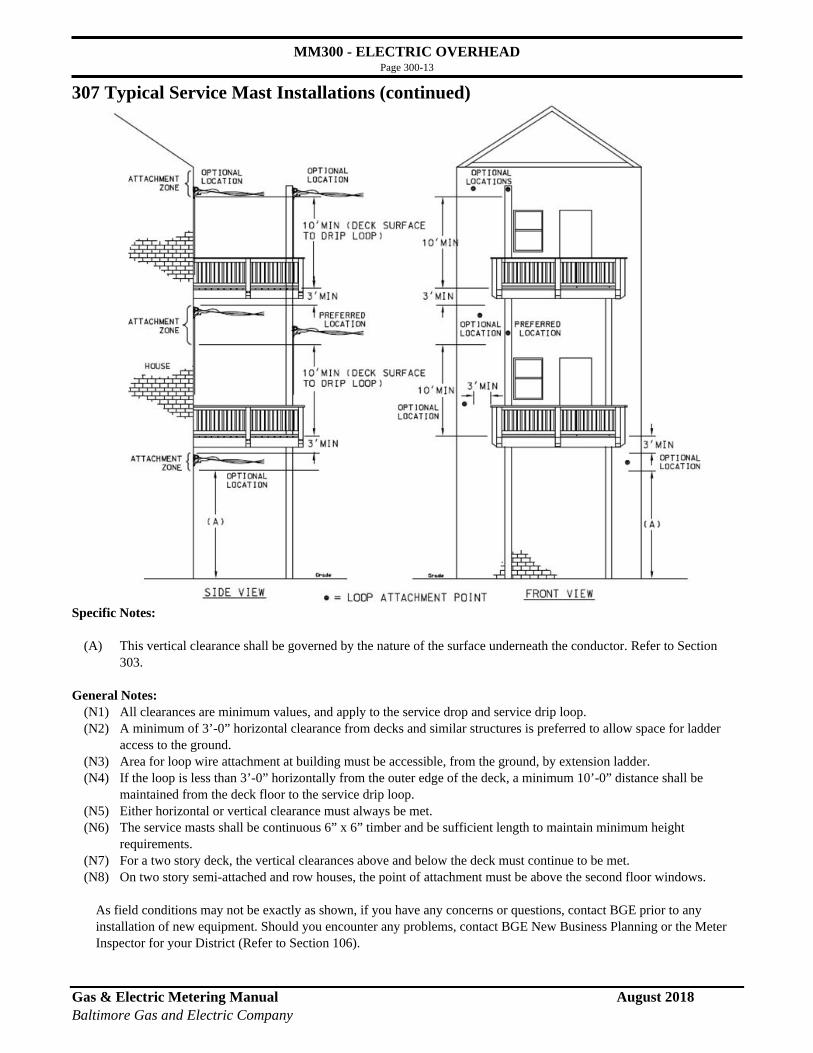
MM300 - ELECTRIC OVERHEAD Page 300-13
Gas & Electric Metering Manual August 2018 Baltimore Gas and Electric Company
307 Typical Service Mast Installations (continued)
Specific Notes:
(A) This vertical clearance shall be governed by the nature of the surface underneath the conductor. Refer to Section 303.
General Notes:
(N1) All clearances are minimum values, and apply to the service drop and service drip loop. (N2) A minimum of 3’-0” horizontal clearance from decks and similar structures is preferred to allow space for ladder
access to the ground. (N3) Area for loop wire attachment at building must be accessible, from the ground, by extension ladder. (N4) If the loop is less than 3’-0” horizontally from the outer edge of the deck, a minimum 10’-0” distance shall be
maintained from the deck floor to the service drip loop. (N5) Either horizontal or vertical clearance must always be met. (N6) The service masts shall be continuous 6” x 6” timber and be sufficient length to maintain minimum height
requirements. (N7) For a two story deck, the vertical clearances above and below the deck must continue to be met. (N8) On two story semi-attached and row houses, the point of attachment must be above the second floor windows.
As field conditions may not be exactly as shown, if you have any concerns or questions, contact BGE prior to any installation of new equipment. Should you encounter any problems, contact BGE New Business Planning or the Meter Inspector for your District (Refer to Section 106).

MM300 - ELECTRIC OVERHEAD Page 300-14
Gas & Electric Metering Manual August 2018 Baltimore Gas and Electric Company
308 Typical Layout of Service Entrance Wiring on a Customer’s Pole
Consult Baltimore Gas and Electric Company. Service Conductors:
Line Side of Meter Enclosure -1 set, Max. 4/0 Load Side of Meter Enclosure - 1 set, Max. 4/0
Customer Furnishes and Installs:
(1) Treated Class 7 pole, properly guyed, or a treated Class 4 pole, unguyed, in well-tamped earth. See dimensions below.
(2) Service entrance head (shall be located above the service drop).
(3) Service entrance wiring - line side of meter enclosure.
(4) Service entrance wiring - load side of meter enclosure.
Company Furnishes and Installs:
(A) Wireholder. (B) Service drop. (C) Watt-hour meter. (D) Meter enclosure (Customer may install). (E) Service connectors.
Notes: (N1) Between these points, all wiring shall be
covered with Schedule 40 PVC conduit, or other approved shields.
Service 1Ø,3W or 3Ø,3W
Pole Dimensions
Diameter
Class Length Top of Pole 6’ from Butt Setting Depth
4
30’ 6.7” 9.5” 5.0’ 35’ 6.7” 10.2” 5.5 40’ 6.7” 10.8” 6.0’ 45’ 6.7” 11.5” 6.5’
7
25’ 4.7” 6.9” 5.0’ 30’ 4.7” 7.6” 5.0’ 35’ 4.7” 8.0” 5.5’ 40’ 4.7” 8.5” 6.0’ 45’ 4.7” 9.0” 6.5’

MM300 - ELECTRIC OVERHEAD Page 300-15
Gas & Electric Metering Manual August 2018 Baltimore Gas and Electric Company
[309] Single Outdoor Meter Max. Volts 240 Max. Amps 100 - One Set of Load Conductors
Service Conductors: Line and Load Side of Meter Enclosure — 1 set, Max. #2
Customer Furnishes and Installs:
(1) Service entrance wiring - line side of meter enclosure. (2) Service entrance wiring from load side of meter enclosure (leave 12” minimum length to point of entry
through wall and 24” of each conductor for connection inside meter enclosure). (3) See Notes (N1) and (N2).
Company Furnishes and Installs:
(A) Meter Enclosure (Customer may install). BGE Mech # 13-068 [10½”H x 8”W x 3-5/16”D] (B) Watt-hour meter.
Notes:
(N1) Maintain 3” clearance on all sides of the meter enclosure. (N2) A minimum clear space of 48” in front of all metering equipment is required. 18” minimum to walkway. 36” minimum to driveway.

MM300 - ELECTRIC OVERHEAD Page 300-16
Gas & Electric Metering Manual August 2018 Baltimore Gas and Electric Company
[310-1] Single Outdoor Meter Service 1Ø,3W; 3Ø,4W Max. Volts 240 Max. Amps 200 - One Set of Load Conductors
Service Conductors:
Line and Load Side of Meter Enclosure — 1 set, Max. 4/0
Customer Furnishes and Installs: (1) Service entrance wiring - line side of meter enclosure. (2) Service entrance wiring from load side of meter enclosure (leave 18” minimum length to point of entry
through wall and 30” of each conductor for connection inside meter enclosure). (3) See Notes (N1) and (N2).
Company Furnishes and Installs: (A) Meter Enclosure (Customer may install).
Single Phase BGE Mech # 13-582 (maximum 2½” knockout) [23”H x 11”W x 4-1/8”D] Three Phase BGE Mech # 13-013 (maximum 3” knockout) [28¼”H x 13”W x 4-27/32”D]
(B) Watt-hour meter.
Notes: (N1) Maintain 3” clearance on all sides of the meter enclosure. (N2) A minimum clear space of 48” in front of all metering equipment is required.
18” minimum to walkway. 36” minimum to driveway.

MM300 - ELECTRIC OVERHEAD Page 300-17
Gas & Electric Metering Manual August 2018 Baltimore Gas and Electric Company
[310-2] Single Outdoor Meter with Utility Disconnect 277/480V Wye Services Only
Service 3Ø,4W Max. Volts 480Y/277 Max. Amps 200
Indoor Location - NON-STANDARD - See Section 105-3. Consult Baltimore Gas and Electric Company.
Service Conductors:
Line Side of Disconnect and Load Side of Meter Enclosure - 1 set, Max. 4/0
Customer Furnishes and Installs: (1) Service entrance wiring - line side of meter enclosure. (2) Service entrance wiring from load side of meter enclosure (leave 18” minimum length to point of entry
through wall and 30” of each conductor for connection inside meter enclosure). (3) See Notes (N1) and (N2).
Company Furnishes and Installs:
(A) Meter Enclosure/Utility Disconnect Enclosure. Maintenance disconnect (left side of enclosure) will be locked for BGE exclusive use only. Meter side (right side of enclosure) will be sealed. BGE Mech # 13-591 [28”H x 26”W x 4-27/32”D]
(B) Watt-hour meter
Notes: (N1) Maintain 3” clearance on all sides of meter enclosure and 12” clearance for service entrance. (N2) A minimum clear space of 48” in front of all metering equipment is required.
18” minimum to walkway. 36” minimum to driveway.

MM300 - ELECTRIC OVERHEAD Page 300-18
Gas & Electric Metering Manual August 2018 Baltimore Gas and Electric Company
[311] Single Outdoor Meter Service 1Ø,3W Max. Volts 240 Max. Amps 200 - One or Two Sets of Load Conductors
Service Conductors:
Line and Load Side of Meter Enclosure - 1 set, Max. 250 kcmil Customer Furnishes and Installs:
(1) Service entrance wiring - line side of meter enclosure, maximum 2½” conduit. Alternate meter enclosure is available which accepts 3” conduit. See Note (N1).
(2) Service entrance wiring from load side of meter enclosure (leave 18” minimum length to point of entry through wall and 30” of each conductor for connection inside meter enclosure).
(3) See Notes (N1), (N2) and (N3).
Company Furnishes and Installs: (A) Meter Enclosure (Customer may install).
Standard meter enclosure BGE Mech # 13-582 (maximum 2½” knockout) [23”H x 11”W x 4-1/8”D] Alternate meter enclosure BGE Mech # 13-013 (maximum 3” knockout) [28¼”H x 13”W x 4-27/32”D]
(B) Watt-hour meter.
Notes: (N1) Where conduit is used, meter enclosure shall be installed by Customer.
(N2) Maintain 3” clearance on all sides of meter enclosure and 12” clearance for service entrance. (N3) A minimum clear space of 48” in front of all metering equipment is required.
18” minimum to walkway. 36” minimum to driveway.

MM300 - ELECTRIC OVERHEAD Page 300-19
Gas & Electric Metering Manual August 2018 Baltimore Gas and Electric Company
[312] Residential Only Single Outdoor Meter Service 1Ø,3W Max. Volts 240 Max. Amps 400 (320A Continuous)
Service Conductors:
Line and Load Side of Meter Enclosure - 1 set, Max. 500 kcmil 2 sets, Max. 4/0
Customer Furnishes and Installs: (1) Service entrance wiring - line side of meter enclosure, maximum 3” conduit - see Note (N1). (2) Service entrance wiring from load side of meter enclosure (leave 18” minimum length to point of entry
through wall and 36” of each conductor for connection inside meter enclosure). (3) See Notes (N1), (N2) and (N3).
Company Furnishes and Installs: (A) Meter Enclosure (Customer may install). BGE Mech # 13-009 [30”H x 15”W x 4-27/32”D] (B) Watt-hour meter.
Notes: (N1) Where conduit is used, meter enclosure shall be installed by Customer. (N2) Maintain 3” clearance on all sides of meter enclosure and 12” clearance for service entrance. (N3) A minimum clear space of 48” in front of all metering equipment is required. 18” minimum to walkway.
36” minimum to driveway.

MM300 - ELECTRIC OVERHEAD Page 300-20
Gas & Electric Metering Manual August 2018 Baltimore Gas and Electric Company
[313] Two Outdoor Meters Service 1Ø,3W or 3Ø,3W Max. Volts 240 Max. Amps 150 Each Meter Position - One Set of Load
Conductors at Each Meter Position
Service Conductors:
Line Side of 2-Position Meter Enclosure - 1 set, Max. 350 kcmil Load Side of Each Meter Position - 1 set, Max. 2/0
Customer Furnishes and Installs:
(1) Service entrance wiring - line side of meter enclosure, maximum 2½” conduit - see Note (N1). (2) Service entrance wiring from load side of each meter position (leave 18” minimum length to point of entry through wall and 24” of each conductor for connection inside meter enclosure). (3) See Notes (N1), (N2) and (N3).
Company Furnishes and Installs:
(A) 2-Position Meter Enclosure (Customer may install). Horizontal 2-Gang 150A Meter enclosure BGE Mech #13-165 [17½” H x 20-5/16” W x 4½”D] Vertical 2-Gang 150A Meter nnclosure BGE Mech #13-166 [27”H x 16”W x 4-27/32”D]
(B) Watt-hour meters. Notes:
(N1) Where conduit is used, 2-position meter enclosure shall be installed by Customer. (N2) Maintain 3” clearance on all sides of meter enclosure and 12” clearance for service entrance. (N3) A minimum clear space of 48” in front of all metering equipment is required.
18” minimum to walkway. 36” minimum to driveway.

MM300 - ELECTRIC OVERHEAD Page 300-21
Gas & Electric Metering Manual August 2018 Baltimore Gas and Electric Company
[314] Two Outdoor Meters Service 1Ø,3W or 3Ø,4W Max. Volts 480Y/277 Max. Amps 200 Each Meter Position - One Set of Load
Conductors at Each Meter Position
Service Conductors:
Line Side of 2-Position Meter Enclosure - 1 set, Max. 500 kcmil 2 sets, Max. 4/0 Load Side of Each Meter Position - 1 set, Max. 4/0
Customer Furnishes and Installs: (1) Service entrance wiring - line side of meter enclosure, maximum 4” conduit - see Note (N1). (2) Service entrance wiring from load side of each meter position (leave 18” minimum length to point of
entry through wall and 24” of each conductor for connection inside meter enclosure). (3) See Notes (N1), (N2) and (N3).
Company Furnishes and Installs: (A) 2-Position Meter Enclosure (Customer may install).
Single Phase BGE Mech # 13-067 [30-1/8”W x 20”H x 4-27/32”D] Three Phase BGE Mech # 13-122 [30-1/8”W x 19”H x 5½”D]
(B) Watt-hour meters.
Notes: (N1) Where conduit is used, 2-position meter enclosure shall be installed by Customer. (N2) Maintain 3” clearance on all sides of meter enclosure and 12” clearance for service entrance. (N3) A minimum clear space of 48” in front of all metering equipment is required.
18” minimum to walkway. 36” minimum to driveway.
Service 1Ø,3W or 3Ø,3W

MM300 - ELECTRIC OVERHEAD Page 300-22
Gas & Electric Metering Manual August 2018 Baltimore Gas and Electric Company
[315] Three Outdoor Meters Max. Volts 240 Max. Amps 150 Each Meter Position - One Set of Load
Conductors at Each Meter Position
Service Conductors:
Line Side of 3-Position Meter Enclosure — 1 set, Max. 350 kcmil Load Side of Each Meter Position — 1 set, Max. 2/0
Customer Furnishes and Installs:
(1) Service entrance wiring - line side of meter enclosure, maximum 2½” conduit - see Note (N1). (2) Service entrance wiring from load side of each meter position (leave 18” minimum length to point of
entry through wall and 24” of each conductor for connection inside meter enclosure). (3) See Notes (N1), (N2) and (N3).
Company Furnishes and Installs:
(A) 3-Position Meter Enclosure (Customer may install). Horizontal 3-Gang 150A Meter Enclosure BGE Mech # 13-181 [17½” H x 28½” W x 4½”D] Vertical 3-Gang 150A Meter Enclosure BGE Mech # 13-182 [37½”H x 16”W x 4-27/32”D]
(B) Watt-hour meters. Notes:
(N1) Where conduit is used, 3-position meter enclosure shall be installed by Customer. (N2) Maintain 3” clearance on all sides of meter enclosure and 12” clearance for service entrance. (N3) A minimum clear space of 48” in front of all metering equipment is required.
18” minimum to walkway. 36” minimum to driveway.

MM300 - ELECTRIC OVERHEAD Page 300-23
Gas & Electric Metering Manual August 2018 Baltimore Gas and Electric Company
[316] Doubtful Permanency (Max. 2 years) Service Single Outdoor Meter
Service 1Ø,3W Max. Volts 240 Max. Amps 200 - One Set of Load Conductors
Service Conductors: Line and Load Side of Meter Enclosure - 1 set, Max. 4/0
Customer Furnishes and Installs: (1) 6” x 6” timber or three 2” x 6” boards spiked together (no splices), to be set in well-tamped earth at a minimum
depth of 4’ and to be located at a distance not exceeding 140’ from Company pole. All lumber shall be sound. NOTE: If you are using a pole, see table in Section 308 for specifications.
(2) 2” x 4” wood braces (no splices). If the service drop exceeds 100’, a ¼” steel wire back-guy is also required. (3) 2” x 4” x 36” wood stakes. (4) Disconnecting means. (5) Grounding electrode conductor. (6) Service entrance wiring. (7) See Notes (N1), (N2), (N3), (N4) and (N5).
Company Furnishes and Installs: (A) Meter Enclosure. (B) Watt-hour meter (C) Wireholder. (D) Service drop.
Notes: (N1) Service drop must run in angle between wood braces. (N2) Guy wire — two wraps around timber or thru-bolted to timber. (N3) Clamps or grips and guy anchor. (N4) Minimum of four 16-penny nails in each joint. (N5) A minimum clear space of 48” in front of all metering equipment is required. (18” minimum to walkway, 36”
minimum to driveway).

MM300 - ELECTRIC OVERHEAD Page 300-24
Gas & Electric Metering Manual August 2018 Baltimore Gas and Electric Company
[317] Multiple Indoor Meters Customer’s Trough
Service 1Ø,3W; 3Ø,3W; or 3Ø,4W Max. Volts 480Y/277 Max. Amps 200 Each Meter Enclosure - One Set of Load
Conductors at Each Meter Enclosure
Consult Baltimore Gas and Electric Company.
Service Conductors:
Line Side of Meters (in trough) — Determined by Size of Main Load Side of Disconnecting Means Each Meter Enclosure — 1 set, Max. 4/0
Customer Furnishes and Installs:
(1) Service entrance wiring. (2) When required by inspection authority having jurisdiction, main disconnecting means which shall be a sealable
circuit breaker or a fused switch with sealable barriers which enclose all unmetered conductors/connections except the fuses.
(3) Sealable wire trough, 14” x 14” minimum size, with guide pin studs and handles. Conductors from load terminals of main disconnecting means shall extend the full length of the wire trough. Consult Company for length of trough. Trough shall be installed below meter enclosures.
(4) Grounding electrode conductor. (5) Conductors from load side of meters and connectors as required (leave 30” of each conductor for connection inside
each meter enclosure). (6) Individual disconnecting means durably and legibly marked with paint as to area served. See Section 105-1. (7) Company-approved terminal blocks, when the total capacity of one or more main disconnecting means exceeds
1000 amps. (8) Line conductors from trough to 200A meter enclosures. The customer is responsible for all wiring after landing
block in trough. (9) See Notes (N1), (N2) and (N3).
Company Furnishes and Installs:
(A) Meter enclosures (Customer may install) and miscellaneous materials to make connections. BGE Mech # 13-013 [28¼”H x 13”W x 4-27/32”D]
(B) Watt-hour meters. Notes:
(N1) 28” minimum, 60” maximum. (N2) Maintain 3” clearance on all sides of meter enclosure and 12” clearance for service entrance. (N3) A minimum clear space of 48” in front of all metering equipment is required.

MM300 - ELECTRIC OVERHEAD Page 300-25
Gas & Electric Metering Manual August 2018 Baltimore Gas and Electric Company
[318] Six or Fewer Indoor Meters Company’s Horizontal; 2 or 3 Position Meter Enclosures
Service 1Ø,3W or 3Ø,3W Max. Volts 240 Max. Amps 150 Each Meter Position - One Set of Load
Conductors at Each Meter Position
Indoor Location - NON-STANDARD - See Section 105-3. Consult Baltimore Gas and Electric Company.
Service Conductors:
Line Side of 3-Position Meter Enclosure - 1 set, Max. 350 kcmil Load Side of Each Meter Position - 1 set, Max. 2/0
Customer Furnishes and Installs:
(1) Service entrance wiring. (2) Sealable wire trough, 14” x 14” x 48” minimum size, with guide pin studs and handles. Conductors from load
terminals of main disconnecting means shall extend the full length of the wire trough. Trough shall not be installed above meter enclosures.
(3) Grounding electrode conductor. (4) Load conductors in raceway or cable and connectors as required (leave 24” of each conductor for connection inside
each meter enclosure). (5) Individual disconnecting means durably and legibly marked with paint as to area served. See Section 105-1.
Shall not be installed above enclosure box. (6) Company-approved terminal blocks, when the total capacity of one or more main disconnecting means exceeds
1000 amps. (7) Line conductors from trough to 200A meter enclosures. The customer is responsible for all wiring after landing
block in trough. (8) See Note (N1).
Company Furnishes and Installs:
(A) 2- or 3-Position meter enclosures (Customer may install) and miscellaneous materials to make connections. Horizontal 2-Gang 150A Meter Enclosure BGE Mech # 13-165 [17½” H x 20-5/16” W x 4½”D] Horizontal 3-Gang 150A Meter Enclosure BGE Mech # 13-181 [17½” H x 28½” W x 4½”D]
(B) Watt-hour meters. Notes:
(N1) A minimum clear space of 48” in front of all metering equipment is required.

MM300 - ELECTRIC OVERHEAD Page 300-26
Gas & Electric Metering Manual August 2018 Baltimore Gas and Electric Company
[319] Multiple Indoor Meters Company’s Vertical 2 or 3 Position Meter Enclosures
Service 1Ø,3W or 3Ø,3W Max. Volts 240 Max. Amps 150 Each Meter Position - One Set of Load
Conductors at Each Meter Position
Indoor Location - NON-STANDARD - See Section 105-3. Consult Baltimore Gas and Electric Company.
Service Conductors:
Line Side of Meters (in trough) — Governed by Size of Main Load Side of Disconnecting Means Each Meter Enclosure — 1 set, Max. 2/0
Customer Furnishes and Installs:
(1) Service entrance wiring. (2) When required by inspection authority having jurisdiction, main disconnecting means which shall be a sealable circuit breaker or
a fused switch with sealable barriers which enclose all unmetered conductors/connections except the fuses. (3) Sealable wire trough, 14” x 14” minimum size, with guide pin studs and handles. Conductors from load terminals of main
disconnecting means shall extend the full length of the wire trough. Consult Company for length of trough. Trough shall be installed below meter enclosures.
(4) Grounding electrode conductor. (5) Conductors from load side of each meter position and connectors as required (leave 24” of each conductor for connection inside
each meter enclosure). (6) Individual disconnecting means durably and legibly marked with paint as to area served. See Section 105-1. (7) Company-approved terminal blocks, when the total capacity of one or more main disconnecting means exceeds 1000 amps. (8) Line conductors from trough to 200A meter enclosures. The customer is responsible for all wiring after landing block in trough. (9) See Note (N1).
Company Furnishes and Installs:
(A) 2- or 3-position meter enclosures (Customer may install) and miscellaneous materials to make connections. Vertical 2-Gang 150A Meter Enclosure BGE Mech # 13-166 [27”H x 16”W x 4-27/32”D] Vertical 3-Gang 150A Meter Enclosure BGE Mech # 13-182 [37½”H x 16”W x 4-27/32”D]
(B) Watt-hour meters. Notes:
(N1) A minimum clear space of 48” in front of all metering equipment is required. (N2) Maintain 3” clearance on all sides of meter enclosure.

MM300 - ELECTRIC OVERHEAD Page 300-27
Gas & Electric Metering Manual August 2018 Baltimore Gas and Electric Company
[320] Modular Meters Outdoor Indoor Customer’s Equipment
Service 1Ø,3W; or 3Ø,4W Max. Volts 480Y/277 Max. Amps 200 Each Meter Position (400A/320A
continuous up to 240V)
Not for use on Company’s 240/120 delta (power wire) system. See Section 101-2. Indoor Location - NON-STANDARD - See Section 105-3.
Consult Baltimore Gas and Electric Company.
Customer Furnishes and Installs:
(1) When required by inspection authority having jurisdiction, main disconnecting means which shall be a sealable circuit breaker or a fused switch with sealable barriers which enclose all unmetered conductors/connections except the fuses.
(2) Approved group metering equipment and is responsible for all maintenance. See Section 402 for listing of approved equipment.
(3) Grounding electrode conductor. (4) Individual disconnecting device. (5) Durable, legible labeling (with paint) denoting area/unit(s) served by each meter and disconnecting device.
Experience shows that failure to provide proper identification on multiple meter installations (area/unit(s) served; apartments, offices, or stores) often results in meters being installed that supply other than the area/unit(s) for which intended. Therefore, electric meters will not be installed on such installations until you have properly identified the area/unit(s) to be served; 1. meter enclosure and disconnecting device, 2. the sub-panel in the area/unit served. See Section 105-1.
(6) A lever type bypass for each meter which supplies other than a residential occupancy. (7) The Company requires a fifth jaw, installed and wired at the 9 o’clock position, on each enclosure with 1Ø, 3W
Network metering (120/208V). (8) Service entrance wiring. (9) See Notes (N1), and (N2).
Company Furnishes and Installs:
(A) Watt-hour meters. Notes:
(N1) Outdoor installations may require enclosures for mechanical protection, consult Company. See Section 411. (N2) A minimum clear space of 48” in front of mounting surface is required.
18” minimum to walkway, 36” minimum to driveway.

MM300 - ELECTRIC OVERHEAD Page 300-28
Gas & Electric Metering Manual August 2018 Baltimore Gas and Electric Company
[321] Outdoor / Indoor Instrument Current Transformer (C.T. Meter)
Service 1Ø,3W Max. Volts 240 Max. Amps 201 - 400
Indoor Location - NON-STANDARD - See Section 105-3. Consult Baltimore Gas and Electric Company.
See Section 403 for CT Cabinet details.
Service Conductors: Line and Load Side of C.T. Cabinet — Max. 1 set 500 kcmil
Customer Furnishes and Installs:
(1) C.T. Cabinet. See Section 403 for details. (2) Service entrance wiring — trough, minimum 10” x 10”, to be constructed of 14-gauge steel or 10-gauge aluminum
to enclose service conductors. The trough may be located at either left or right as shown. (3) Minimum 10” x 10” trough secured and bonded to C.T. cabinet. Load wiring from C.T. cabinet may be out of top or
bottom, near either end, but shall be on opposite end from supply wiring. (4) Load conductors - leave 36” of each conductor inside C.T. cabinet. (5) See Notes (N1), (N2), and (N3).
Company Furnishes and Installs:
(A) Current transformer rated meter enclosure. (B) Watt-hour meter. (C) Current transformers (not shown). (D) Raceway between C.T. cabinet and meter enclosure (Not more than 3”. For indoor locations greater than 3”,
1-1/4” rigid conduit is required. For alternate locations, greater than 50’, consult with Company.) Notes:
(N1) Space required for C.T. rated meter enclosure. (N2) A minimum clear space of 48” in front of C.T. Cabinet is required. (N3) Minimum clear space of 6” on both sides of CT cabinet is required. If meter is to be installed adjacent to the C.T.
Cabinet, see (N1).

MM300 - ELECTRIC OVERHEAD Page 300-29
Gas & Electric Metering Manual August 2018 Baltimore Gas and Electric Company
[322] Outdoor / Indoor Instrument Current Transformer (C.T. Meter)
Service 1Ø,3W; 3Ø,3W; or 3Ø,4W Max. Volts 480Y/277 Max. Amps 201 - 1600
Indoor Location - NON-STANDARD - See Section 105-3
See Section 404 for C.T. Cabinet details Consult the Baltimore Gas and Electric Company.
Service Conductors:
Line and Load Side of C.T. Cabinet - Max. 5 sets 500 kcmil Max. 4 sets 600 kcmil
Customer Furnishes and Installs:
(1) C.T. Cabinet. See Section 404 for details. (2) Service entrance wiring — trough, minimum 12” x 12”, to be constructed of 14-gauge steel or 10-gauge aluminum to
enclose service conductors. The trough may be located at either left or right as shown. (3) Minimum 12” x 12” trough secured and bonded to C.T. cabinet. Load wiring from C.T. cabinet may be out of top or
bottom, near either end, but shall be on opposite end from supply wiring. (4) Load conductors - leave 60” of each conductor inside C.T. cabinet. (5) See Notes (N1), (N2), and (N3).
Company Furnishes and Installs:
(A) Current transformer rated meter enclosure. (For alternate locations, consult Company). (B) Watt-hour meter. (C) Current transformers (not shown). (D) Raceway between C.T. cabinet and meter enclosure (not more than 3”). For indoor locations greater than 3”,
1-1/4” rigid conduit is required. For alternate locations, greater than 50’, consult with Company. Notes:
(N1) Space required for C.T. rated meter enclosure. (N2) A minimum clear space of 48” in front of C.T. Cabinet is required. (N3) Minimum clear space of 6” on both sides of CT cabinet is required. If meter is to be installed adjacent to the C.T. Cabinet,
see (N1).

MM300 - ELECTRIC OVERHEAD Page 300-30
Gas & Electric Metering Manual August 2018 Baltimore Gas and Electric Company
[323] Outdoor / Indoor Instrument Current Transformer (C.T. Meter)
Service 3Ø,3W or 3Ø,4W Max. Volts 480Y/277 Max. Amps 201 - 3000
Consult Baltimore Gas and Electric Company.
Indoor Location - NON-STANDARD - See Section 105-3 See Section 405 for C.T. Cabinet details
Service Conductors: Line and Load Side of C.T. Cabinet - Max. 9 sets 500 kcmil
Max. 8 sets 600 kcmil Customer Furnishes and Installs:
(1) C.T. Cabinet. See Section 405 for details. (2) Service entrance wiring in trough — may enter back (maximum 4” above floor line) or bottom of trough. (3) Three-sided trough, with 1” flanges to be constructed of 14-gauge steel or 10-gauge aluminum to enclose service conductors. If
installed on combustible surface, a sheet metal plate against the wall is required. (4) Minimum 12” x 12” trough secured and bonded to the top of the C.T. cabinet. Bus duct may be used in lieu of trough. (5) Load conductors - leave 48” of each conductor inside C.T. cabinet. (6) Disconnecting means. (7) See Notes (N1), (N2), (N3) and (N4). (8) Cut out top and bottom 10” x 34” to mate with trough.
Company Furnishes and Installs:
(A) Current transformer rated meter enclosure. (For alternate locations, consult Company). (B) Watt-hour meter. (C) Current transformers (not shown). (D) Raceway between C.T. cabinet and meter enclosure (not more than 3”). For indoor locations greater than 3”,
1-1/4” rigid conduit is required. For alternate locations, greater than 50’, consult with Company. Notes:
(N1) Installation may be inverted for top feed to cabinet. (N2) Space required for C.T. rated meter enclosure. (N3) A minimum clear space of 48” in front of C.T. Cabinet is required. (N4) Minimum clear space of 6” on both sides of CT cabinet is required.

MM300 - ELECTRIC OVERHEAD Page 300-31
Gas & Electric Metering Manual August 2018 Baltimore Gas and Electric Company
[324] Outdoor Instrument Current Transformer (C.T. Meter) Wall Mounted
Service 1Ø,3W Max. Volts 240 Max. Amps N/A
Consult Baltimore Gas and Electric Company.
Service Conductors: Line Side (Customer’s Service Wiring) - Determined by size of service. Customer Furnishes and Installs:
(1) Service entrance wiring, leave 36” of each conductor for connection to service loop. (2) 1¼” rigid conduit (outdoor/indoor) or Schedule 40 PVC (outdoor only) (with pull-wire if necessary), with service head
and fittings to C.T. rated meter enclosure, not to exceed 50’. (3) See Notes (N1), (N2), (N3), and (N4).
Company Furnishes and Installs:
(A) Current transformer rated meter enclosure. (For alternate locations, consult Company). (B) Watt-hour meter. (C) Current transformer mounting plate (if necessary). (D) Current transformer. (E) Current transformer wiring between service loop and current transformer rated meter enclosure. (F) Necessary connectors to terminate Customer’s wiring to service loop and instrument transformer wiring.
Notes:
(N1) Space required for C.T. rated meter enclosure. (N2) A minimum clear space of 48” in front of all metering equipment is required. (N3) See Section 302 for meter clearances. (N4) See Section 303 for loop clearances. (N5) Refer to 412-1 and 412-2 concerning protection of meter.

MM300 - ELECTRIC OVERHEAD Page 300-32
Gas & Electric Metering Manual August 2018 Baltimore Gas and Electric Company
[325] Outdoor Instrument Current Transformer (C.T. Meter) Wall Mounted
Service 3Ø,3W Max. Volts 480 Max. Amps N/A
NON-STANDARD - Consult the Baltimore Gas and Electric Company.
Service Conductors: Line Side (Customer’s Service Wiring) - Determined by size of service. Customer Furnishes and Installs:
(1) Service entrance wiring, leave 48” of each conductor for connection to service loop. (2) 1¼” rigid conduit (outdoor/indoor) or Schedule 40 PVC (outdoor only) (with pull-wire if necessary), with service head and
fittings to C.T. rated meter enclosure, not to exceed 50’. (3) See Notes (N1), (N2), (N3), (N4), and (N5).
Company Furnishes and Installs:
(A) Current transformer rated meter enclosure. (For alternate locations, consult Company). (B) Watt-hour meter. (C) Current transformer mounting plate. (D) Current transformers. (E) Current transformer wiring between service loop and current transformer rated meter enclosure. (F) Necessary connectors to terminate Customer’s wiring to service loop and instrument transformer wiring.
Notes:
(N1) Space required for C.T. rated meter enclosure. (N2) A minimum clear space of 48” in front of all metering equipment is required. (N3) See Section 302 for meter clearances. (N4) See Section 303 for loop clearances. (N5) Consult Company for details of larger services than shown using a wall bus. (N6) Refer to 412-1 and 412-2 concerning protection of meter.

MM300 - ELECTRIC OVERHEAD Page 300-33
Gas & Electric Metering Manual August 2018 Baltimore Gas and Electric Company
[326] Outdoor Instrument Current Transformer (C.T. Meter) Wall Mounted
Service 3Ø,4W Max. Volts 480Y/277 Max. Amps N/A
Consult Baltimore Gas and Electric Company.
Service Conductors: Line Side (Customer’s Service Wiring) - Determined by size of service. Customer Furnishes and Installs:
(1) Service entrance wiring, leave 60” of each conductor for connection to service loop. (2) 1¼” rigid conduit (outdoor/indoor) or Schedule 40 PVC (outdoor only) (with pull-wire if necessary), with service
head and fittings to C.T. rated meter enclosure, not to exceed 50’. (3) See Notes (N1), (N2), (N3), (N4), and (N5).
Company Furnishes and Installs:
(A) Current transformer rated meter enclosure. (For alternate locations, consult Company). (B) Watt-hour meter. (C) Current transformer mounting plate. (D) Current transformers. (E) Current transformer wiring between service loop and current transformer rated meter enclosure. (F) Necessary connectors to terminate Customer’s wiring to service loop and instrument transformer wiring.
Notes:
(N1) Space required for C.T. rated meter enclosure. (N2) A minimum clear space of 48” in front of all metering equipment is required. (N3) See Section 302 for meter Clearances. (N4) See Section 303 for loop clearances. (N5) Consult Baltimore Gas and Electric Company for details of larger services than shown using a wall bus. (N6) Refer to 412-1 and 412-2 concerning protection of meter.

MM300 - ELECTRIC OVERHEAD Page 300-34
Gas & Electric Metering Manual August 2018 Baltimore Gas and Electric Company
327 Existing Town House Installations
Indoor Location - NON-STANDARD - See Section 105-3. Consult Baltimore Gas and Electric Company.
Town (row) house meter installations, particularly in Baltimore City, involving load increases, rehabs, renovations, etc. require unique wiring and meter enclosure configurations. The following diagram illustrates one of the more common situations and shows the Company’s preferred installation method. This configuration is not for new buildings since as they will be fed by an underground service line (See Section 602 for additional details).
Service Conductors: Line and Load Side of Meter Enclosure - Determined by size of service (typically 100 – 200 A)
Customer Furnishes and Installs: (1) Service entrance cable. (2) Main disconnecting means which shall be a sealable circuit breaker or a fused switch with sealable
barriers which enclose all unmetered conductors/connections except the fuses. (3) Conduit (can be rigid, PVC or EMT) – diameter determined by size of service. Four (4) individual
conductors are required – two hot, one neutral and one ground – between the disconnecting means and the meter enclosure.
(4) Meter Enclosure (BGE furnishes). (5) See Note (N1).
Company Furnishes and Installs:
(A) Meter Enclosure (Customer installs). (B) Watt-hour meter.
Notes:
(N1) A minimum clear space of 48” in front of all metering equipment is required.

MM400 - ELECTRIC METERING
Page 400-1
Gas & Electric Metering Manual January 2022 Baltimore Gas and Electric Company
401 Approved Pedestal Metering Equipment (Freestanding)
Catalog Designations
200 Amp
Pedestal Metering Equipment
Service/Voltage
Model Numbers
Manufacturer Pedestal Stabilizer Feet
1Ø, 3 Wire
120/240 V
Midwest Electric
(507-345-2543)
M281C1P6H (single meter)
M282E1P6H (single meter)
M281C1B6H (dual meter)
SFEM6
Milbank
(816-483-5314)
U5300-0
CP3B52115BMLBGE1 K5415
RV Park
Hookups, Inc.
(800-723-8009)
Powerhouse PH3050201 Direct Burial
Mounting Stand
Millbank
(816-483-5314) U5136-O-**** (ringless; single meter) N/A
Millbank
(816-483-5314) U5137-O-**** (ringless; dual meter) N/A
Millbank
(816-483-5314)
U6221-O-1002 (ringless with lever bypass)
U6221-O-2002 (ringless with lever bypass) N/A
Millbank
(816-483-5314)
U6226-O-100 (ring type)
U6226-O-200 (ring type) N/A
Milbank
(816-483-5314) CP3B52519BMLBGE1 N/A
3Ø, 4 Wire
120/208 V
* Mounts on customer installed concrete pad.
Pedestals for applications such as mobile homes, public area lighting, traffic signs, CATV amplifier,
and 5G antenna installations.
1. Meter protection required. See Section 412.
2. Pedestal shall be for electric use only.
Customer supplies, installs and maintains all materials (except underground lateral and meter).
1. Maximum capacity per meter position - 200 amps.
2. Stabilizer foot required for units installed in the ground.
3. For Powerhouse:
• Meter socket shall be of ring type.
• Provide hasp to seal bottom cover.
Note(s): 1. Height to C/L of meters - min. 36”, max. 42”
2. For Commericial and Maryland Department of Transportation (MDOT) use

MM400 - ELECTRIC METERING
Page 400-2
Gas & Electric Metering Manual January 2022 Baltimore Gas and Electric Company
402-1 Approved 200 Amp Modular Metering Equipment
Catalog Designations
Modular Metering Equipment
Class of Service at Meter
Model Numbers
1Ø,3W 3Ø,3W 3Ø,4W
Manufacturer 120/240V 120/208V 240V(1) 208/120V 480/277V
General Electric
(800-431-7867) TMMTPP TMP
New
Modular
Metering
Equipment
Not Permitted
Consult BGE.
TMPR
Siemens
(ITE Electrical)
(800-964-4114)
HM
PAK
WMM
MMWMM W3MM
Square D (2)
(888-778-2733)
EZ
MP(3)
EZ
MP(3) EZ
Eaton (4)(5)
Cutler/Hammer
(800-888-0211)
1MM
1MP
35MM
1MM
35MM
3MM
37MM PRLC-WCMS
Additional Requirements:
1. Main disconnect devices shall comply with the Company’s sealing requirements. See Section 104-8.
2. Bypass Requirements (meter can be pulled without disrupting service):
(a) Three-phase -manual (lever type) bypass is required on all three-phase meter sockets supplying
industrial and commercial customers. Meter cover must be ringless.
(b) Single phase commercial - one of the following bypass configurations is required for all single
phase meter sockets supplying commercial customers:
– lever bypass with ring-less cover (preferred)
– horn bypass with ring-less cover (acceptable)
– slide bypass with ring-type cover (acceptable)
3. Maximum capacity per meter position - 200 amps
4. Height to center line of meters - minimum 20” (lowest position), maximum 72”(highest position).
5. The Company requires a fifth jaw, installed and wired at the 9 o’clock position with 1Ø, 3W network
metering (120/208V).
6. If an item is not on the list, or to make changes, notify the Company for approval.
7. Stud and lay-in connections are permissible.
Notes:
(1) Not for use on 240/120V delta (power wire) systems (see Section 101-2). Not for use on jobs
involving modifications (service relocation, heavy up, etc.) to 240V delta services.
(2) Square D stud kit for MP series is MMSK2. See note 7 above.
(3) For commercial installations which require bypass capability.
(4) Eaton, Cutler/Hammer studkit is MPSC2-TB.
(5) 6 position switchboard (this is switchboard metering)

MM400 - ELECTRIC METERING
Page 400-3
Gas & Electric Metering Manual January 2022 Baltimore Gas and Electric Company
402-2 Approved 400 Amp Modular Metering Equipment (320 Amp Continuous)
Catalog Designations
Modular Metering Equipment
Class of Service at Meter
Model Numbers
1Ø,3W 3Ø,4W
Manufacturer 120/240V 120/208V
General Electric
(800-431-7867) MPR
Siemens
(ITE Electrical)
(800-964-4114)
W1MM
W3MM
Square D (2)
(888-778-2733) EZM EZML
Eaton (1)(3)
Cutler/Hammer
(800-888-0211)
37MM
Additional Requirements:
1. Main disconnect devices shall comply with the Company’s sealing requirements. See Section 104-8.
2. Bypass Requirements (meter can be pulled without disrupting service): Manual (lever type) bypass is
required on all meter sockets supplying industrial and commercial customers. Meter cover must be
ringless.
3. Maximum capacity per meter position - 400 amps (320 amps continuous)
4. Height to center line of meters - minimum 20” (lowest position), maximum 72”(highest position).
5. If an item is not on the list, or to make changes, contact the Company for approval.
6. Stud and lay-in connections are permissible.
Notes:
(1) Eaton, Cutler/Hammer studkit is MPSC2-TB. (2) Square D Stud Kit for MP Series is MMSK2.
(3) Only available in Two-breaker model.

MM400 - ELECTRIC METERING
Page 400-4
Gas & Electric Metering Manual January 2022 Baltimore Gas and Electric Company
403 Approved Current Transformer Cabinet; 1Ø, 3W; 201-400 Amps
Dimensions
(20”H x 30”W x 12”D)
Catalog Designations
1Ø,3W 201-400 Amps
Current Transformer Cabinet
Manufacturer Model Number
Atlantic Sheet Metal
(410-391-8066) ATL 400
J. M. Gillin Corp.
(410-728-8700) G-203012-UCT(A) or (G)
Meter Devices Co.
(888-367-6383) 507U6523 (Steel)
S.A.R. Metal Products (410-780-5434)
SAR003G (Galv.)
Hoffman Enclosures
(763-422-2181) A203012BGECT
Company-approved, Customer-supplied cabinet to house Company metering current transformers.
The following criteria must be used:
1. Customer supplied current transformer cabinet may be purchased from local suppliers that handle this
C.T. cabinet. The Company has pre-approved specifications for this cabinet. The cabinet must comply
with NEMA Type 3R standards.
2. Main disconnecting device, when ahead of the instrument transformers, shall comply with the
Company’s sealing requirements. See Section 104-8
3. Company shall furnish and install an approved terminal board in the C.T. cabinet to provide for stud
type/compression terminals provided and installed by the Company.
4. Customer shall install a 1¼” rigid conduit from the C.T. cabinet to the meter up to a maximum of 50’
to facilitate a remote meter. The Company will install the #10 meter wiring. For distances greater
than 50’, consult the Company.
Note: Height to C/L of meter - min. 42”, max. 60”.
Consult the Company.
See Sections 220 for underground or 322 for overhead installation clearances.

MM400 - ELECTRIC METERING
Page 400-5
Gas & Electric Metering Manual January 2022 Baltimore Gas and Electric Company
404 Approved Current Transformer Cabinet; 1Ø, 3W; 3Ø, 4W; 201-1,600 Amps
Dimensions
(36”H x 42”W x 14”D)
Catalog Designations
1Ø,3W, 3Ø,4W 201-1600 Amps
Current Transformer Cabinet
Manufacturer Model Number
Atlantic Sheet Metal
(410-391-8066) ATL 1600
J. M. Gillin Corp.
(410-728-8700) G-364214-U.C.T.
Meter Devices Co.
(888-367-6383) 507U6521
S.A.R. Metal Products
(410-780-5434) SAR001A
Hoffman Enclosures
(763-422-2181) A364214BGECT
Company-approved, Customer-supplied cabinet to house Company metering current transformers.
The following criteria must be used:
1. Customer supplied current transformer cabinet may be purchased from local suppliers that handle this
C.T. cabinet. The Company has pre-approved specifications for this cabinet. The cabinet must comply
with NEMA Type 3R standards.
2. Main disconnecting device, when ahead of the instrument transformers, shall comply with the
Company’s sealing requirements. See Section 104-8
3. Company shall furnish and install an approved terminal board in the C.T. cabinet to provide for stud
type/compression terminals provided and installed by the Company.
4. Customer shall install a 1¼” rigid conduit from the C.T. cabinet to the meter up to a maximum of 50’
to facilitate a remote meter. The Company will install the #10 meter wiring. For distances greater than
50’, consult the Company.
Note: Height to C/L of meter - max. 60”.
Consult the Company.
See Sections 221 for underground or 323 for overhead installation clearances.

MM400 - ELECTRIC METERING
Page 400-6
Gas & Electric Metering Manual January 2022 Baltimore Gas and Electric Company
405 Approved Current Transformer Cabinet; 3Ø, 4W; 201-3,000 Amps
Dimensions
(42”H x 36”W x 14”D)
Catalog Designations
3Ø, 4W 201-3000 Amps
Current Transformer
Cabinet
Manufacturer Model Number
Atlantic Sheet Metal
(410-391-8066) ATL 3000
J. M. Gillin Corp.
(410-728-8700) G-423614-U.C.T.
Meter Devices Co.
(888-367-6383) 507U6532
S.A.R. Metal Products
(410-780-5434) SAR002A
Hoffman Enclosures
(763-422-2181) A423614BGECT
Company-approved, Customer-supplied cabinet to house Company metering current transformers.
The following criteria must be used:
1. Customer supplied current transformer cabinet may be purchased from local suppliers that handle this
C.T. cabinet. The Company has pre-approved specifications for this cabinet. The cabinet must comply
with NEMA Type 3R standards.
2. Main disconnecting device, when ahead of the instrument transformers, shall comply with the
Company’s sealing requirements. See Section 104-8
3. Company shall furnish and install an approved terminal board in the C.T. cabinet to provide for stud
type/compression terminals provided and installed by the Company.
4. Customer shall install a 1¼” rigid conduit from the C.T. cabinet to the meter up to a maximum of 50’
to facilitate a remote meter. The Company will install the #10 meter wiring. For distances greater
than 50’, consult the Company.
Note: Height to C/L of meter - min. 42”, max. 60”.
Consult the Company.
See Sections 222 for underground or 324 for overhead installation clearances.

MM400 - ELECTRIC METERING
Page 400-7
Gas & Electric Metering Manual January 2022 Baltimore Gas and Electric Company
406 Approved Service Entrance Compartment; 3Ø, 4W; Up to 6,000 Amps
Service Supplied by Underground Cable
Drawing No. 14061-C (next page)
Company-approved manufacturers of compartments in switchgear to house Company metering
instrument transformers or cable termination facilities.
Name of Manufacturer Drawing No.
Cutler-Hammer 8451C89
General Electric 75C323034A
Siemens Electric DJN14061-C
Square D Company B43-0036-175
The following criteria must be used:
1. Prior to manufacture of the switchgear, the Customer shall submit at least three sets of the switchgear
drawings (the Company will retain two sets) for Company approval to the responsible Gas and
Electric New Business Department, I&C Customer Representative. Drawing should include the front
elevation, one line diagram, and details of the metering/termination compartment. Submittals may be
e-mailed to SMT for review at SmartMetering&[email protected].
2. The instrument transformer compartment shall have two doors that are latched with a sealable handle.
Handle must not contain a key.
3. Customer shall install a 1¼” rigid conduit from the compartment to the meter up to a maximum of 50’
to facilitate a remote meter. The Company will install the #10 meter wiring. For distances greater
than 50’, consult the Company.
4. Meter socket may be installed on side of the compartment with 1-1/2” x 1-1/2” Kindorf (galvanized).
Note: Height to C/L of meter - min. 42”, max. 60”. Meter may be adjacent to the instrument transformer
compartment, or remote from the switchgear equipment. Consult the Company.
See Drawing No. 14061-C (next page) for details of typical arrangement for current transformer
compartment constructed in customer’s switchgear when supplied by underground cable. Invert
drawing for top entry.
Note: A pit is required for the installation of Company Underground wiring. This pit shall be
beneath the underground section of the C.T. compartment in the switchgear. This pit shall
be two (2) feet deep and measure one (1) inch less than the width and depth of the
compartment to facilitate shaping of the underground cables. The walls of the pit shall be of
solid material (concrete or fiberglass). Duct to enter bottom of pit in a vertical position and
extend to 4” into pit. Consult the Company. If a pit cannot be installed, the Customer shall
consult with the Metering Inspector for a suitable arrangement.

MM400 - ELECTRIC METERING
Page 400-8
Gas & Electric Metering Manual January 2022 Baltimore Gas and Electric Company
Drawing No. 14061-C

MM400 - ELECTRIC METERING
Page 400-9
Gas & Electric Metering Manual January 2022 Baltimore Gas and Electric Company
407 Approved Switchgear Current Transformer Compartment; 3Ø, 4W; Up to
6,000 Amps
Drawing No. 14060-C (next page)
Company-approved compartments in switchgear to house Company metering instrument transformers or
unmetered service equipment.
The following criteria must be used:
1. Prior to manufacture of the switchgear, the Customer shall submit at least three sets of the switchgear
drawings (the Company will retain two sets) for Company approval to the responsible Gas and Electric
New Business Department, I&C Customer Representative.
2. Main disconnecting device, when ahead of the instrument transformers, shall comply with the
Company’s sealing requirements. See Section 104-8
3. The instrument transformer compartment shall have two doors that are latched with a sealable handle.
Handle must not contain a key.
4. Customer shall install a 1¼” rigid conduit from the C.T. compartment to the meter up to a maximum
of 50’ to facilitate a remote meter. The Company will install the #10 meter wiring. For distances
greater than 50’, consult the Company.
5. Meter socket may be installed on side of the C.T. compartment with 1-1/2” x 1-1/2” Kindorf
(galvanized).
Note: Height to C/L of meter - min. 42”, max. 60”. Meter may be adjacent to the instrument transformer
compartment, or remote from the switchgear equipment. Consult the Company.
See Drawing No. 14060-C (next page) for details of typical arrangement for current transformer
compartment constructed in customer’s switchgear.

MM400 - ELECTRIC METERING
Page 400-10
Gas & Electric Metering Manual January 2022 Baltimore Gas and Electric Company
Drawing No. 14060-C

MM400 - ELECTRIC METERING
Page 400-11
Gas & Electric Metering Manual January 2022 Baltimore Gas and Electric Company
A checklist guide is provided below and may be used optionally for ensuring the low-voltage switchgear
submittal is approved in a timely manner.
Checklist
Guide for
Switchboard
Drawings
Submittal
Address:
Work Order #:
Date:
M&I Inspector:
Customer Name:
Required Drawings
1. Front Elevation View – Front View of Switchgear 2. One Line Diagram 3. Submittal references BGE’s standard drawing 4. Top View Drawing with width & depth requirements 5. Are installing current transformers (CTs) in each of the
switchboard’s incoming cable termination and/or CT
compartment?
Yes
No
5a. If yes to #5, switchboard utility termination compartment
meets BGE-approved drawing specifications.
Yes
N/A
6. Are submitting only one switchboard? Yes
No
7. If no to either #5 or #6,
• Provide Riser diagram Yes
N/A
• Determine metering location, i.e., modular metering
or trough with multiple meters, etc.
Yes
N/A

MM400 - ELECTRIC METERING
Page 400-12
Gas & Electric Metering Manual January 2022 Baltimore Gas and Electric Company
[408-1] Communication Service on Company or
Joint-Owned Pole
Service 1Ø,3W
Max. Volts 240
Max. Amps 30
Service Conductors:
Line Side of Meter Socket — 1 set, Max. #2
Load Side of Meter Socket — 1 set, Max. #8
Customer Furnishes and Installs:
Communication Company furnishes and
installs all material and equipment (except
meter socket and meter).
Communication Company installs the
Company furnished meter socket.
(1) Service entrance wiring - line side of
meter. Must be 3-wire.
Note: Service head shall be nine (9) inches
below the lowest wire of the secondary
bus, 1Ø or 3Ø.
(2) Service entrance wiring from load side of
meter socket.
(3) Main disconnect shall be three (3) wire, to
permit the installation of a three-wire
meter.
(4) Grounding electrode conductor.
(5) Metal bracket made in one piece, fastened
to the pole with a thru-bolt at the top and
bottom of bracket. All equipment shall be
fastened to this bracket. This design is to
facilitate the transfer of equipment. Thru-
bolts are to be cut off flush with the nut.
(6) All cables run vertically on the pole, shall
be covered with conduit, PVC-EPC 40, for
cable protection. PVC conduits are to be
fastened with two-(2)-hole bands.
(7) See Notes (N1) and (N2).
Company Furnishes and Installs:
(A) Meter Socket 100A (Communication Company shall install).
(B) Watt-hour meter.
(C) Makes connection to secondary bus.
Notes:
(N1) Meter and other equipment to be installed on field side of pole.
(N2) A minimum clear space of 48” in front of all metering equipment is required.
18” minimum to walkway.
36” minimum to driveway.
Note: For an underground installation, see Section 408-2.

MM400 - ELECTRIC METERING
Page 400-13
Gas & Electric Metering Manual January 2022 Baltimore Gas and Electric Company
[408-2] 5G or CATV Service from
Underground Service
Service 1Ø,3W
Max. Volts 240
Max. Amps 125 – 200 (Continuous)
NOTE: There are two approved configurations for metering CATV amplifiers and wireless antenna sites fed from underground service
laterals. With wireless antenna sites, the wireless service provider’s (WSP) equipment is housed in a padmounted/ground mounted cabinet.
Alternate designs or configurations shall be reviewed and approved by BGE EDES and SM&T Units prior to installation. See following
pages for alternate configuration.
Service Conductors:
Line and Load Side of Meter Socket — 1 set, Max. 4/0
Customer Furnishes and Installs:
WSP or CATV Company furnishes and installs all material and equipment, including meter socket (except meter).
(1) Appropriate equipment cabinet for 5G; cabinet with amplifier and power supply for CATV. Cabinet to be mounted on a concrete
(or other suitable material) base.
(2) Company-approved freestanding meter pedestal (See Section 401 for requirements).
(3) Service entrance wiring from load side of meter pedestal. Must be installed in flexible conduit.
(4) Main disconnect shall be three (3) wire, to permit the installation of a three-wire meter.
(5) Grounding electrode conductor.
(6) See Notes Section below.
Company Furnishes and Installs:
(A) Watt-hour meter.
(B) Makes connections in meter pedestal.
(C) Underground lateral service cable. Cable to be installed and spliced by BGE Crews or a BGE approved contractor.
Notes:
(N1) Meter equipment to be installed on field side of WSP equipment or CATV unit.
(N2) A minimum clear space of 48” in front of all metering equipment is required.
18” minimum to walkway.
36” minimum to driveway.
(N3) Service conduit from transformer/main shall be 4” PVC Conduit.
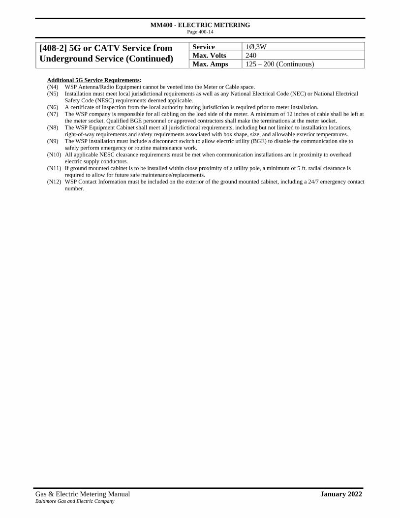
MM400 - ELECTRIC METERING
Page 400-14
Gas & Electric Metering Manual January 2022 Baltimore Gas and Electric Company
[408-2] 5G or CATV Service from
Underground Service (Continued)
Service 1Ø,3W
Max. Volts 240
Max. Amps 125 – 200 (Continuous)
Additional 5G Service Requirements:
(N4) WSP Antenna/Radio Equipment cannot be vented into the Meter or Cable space.
(N5) Installation must meet local jurisdictional requirements as well as any National Electrical Code (NEC) or National Electrical
Safety Code (NESC) requirements deemed applicable.
(N6) A certificate of inspection from the local authority having jurisdiction is required prior to meter installation.
(N7) The WSP company is responsible for all cabling on the load side of the meter. A minimum of 12 inches of cable shall be left at
the meter socket. Qualified BGE personnel or approved contractors shall make the terminations at the meter socket.
(N8) The WSP Equipment Cabinet shall meet all jurisdictional requirements, including but not limited to installation locations,
right-of-way requirements and safety requirements associated with box shape, size, and allowable exterior temperatures.
(N9) The WSP installation must include a disconnect switch to allow electric utility (BGE) to disable the communication site to
safely perform emergency or routine maintenance work.
(N10) All applicable NESC clearance requirements must be met when communication installations are in proximity to overhead
electric supply conductors.
(N11) If ground mounted cabinet is to be installed within close proximity of a utility pole, a minimum of 5 ft. radial clearance is
required to allow for future safe maintenance/replacements.
(N12) WSP Contact Information must be included on the exterior of the ground mounted cabinet, including a 24/7 emergency contact
number.

MM400 - ELECTRIC METERING
Page 400-15
Gas & Electric Metering Manual January 2022 Baltimore Gas and Electric Company
[408-2] 5G or CATV Service from
Underground Service (Continued)
Service 1Ø,3W
Max. Volts 240
Max. Amps 125 – 200 (Continuous)
NOTE: There are two approved configurations for metering CATV amplifiers and wireless antenna sites fed from underground service
laterals. With wireless antenna sites, the wireless service provider’s (WSP) equipment is housed in a padmounted/ground mounted
cabinet. Alternate designs or configurations shall be reviewed and approved by BGE EDES and SM&T Units prior to installation. See
preceding pages for alternate configuration.
Service Conductors:
Line and Load Side of Meter Socket — 1 set, Max. 4/0
Customer Furnishes and Installs:
(WSP or CATV) Company furnishes and installs all material and equipment, including meter socket (except meter).
(1) Appropriate equipment cabinet for 5G; cabinet with amplifier and power supply for CATV Cabinet to be mounted on a concrete
(or other suitable material) base.
(2) Two 2” hot dip galvanized conduit standards and install meter socket.
(3) Service entrance wiring from load side of meter socket. Must be installed in flexible conduit.
(4) PVC conduit raceways (EPC 40) for line wiring. Ell should be a minimum of 36” radius. See Sections 201-4 and 201-5 for
details.
(5) Main disconnect shall be three (3) wire, to permit the installation of a three-wire meter.
(6) Grounding electrode conductor.
(7) See Notes Section below.
Company Furnishes and Installs:
(A) Watt-hour meter.
(B) 200 Amp meter socket box (Customer shall install).
(C) Makes connections in socket box.
(D) Underground lateral cable. Cable to be installed and spliced by BGE Crews or a BGE approved contractor.
Notes:
(N1) Meter equipment to be installed on field side of WSP equipment or CATV unit.
(N2) A minimum clear space of 48” in front of all metering equipment is required.
18” minimum to walkway.
36” minimum to driveway.

MM400 - ELECTRIC METERING
Page 400-16
Gas & Electric Metering Manual January 2022 Baltimore Gas and Electric Company
[408-2] 5G or CATV Service from
Underground Service (Continued)
Service 1Ø,3W
Max. Volts 240
Max. Amps 125 – 200 (Continuous)
5G Service Requirements:
(N4) WSP Antenna/Radio Equipment cannot be vented into the Meter or Cable space.
(N5) Installation must meet local jurisdictional requirements as well as any National Electrical Code (NEC) or National Electrical
Safety Code (NESC) requirements deemed applicable.
(N6) A certificate of inspection from the local authority having jurisdiction is required prior to meter installation.
(N7) The WSP company is responsible for all cabling on the load side of the meter. A minimum of 12 inches of cable shall be left at
the meter socket. Qualified BGE personnel or approved contractors shall make the terminations at the meter socket.
(N8) The WSP Equipment Cabinet shall meet all jurisdictional requirements, including but not limited to installation locations,
right-of-way requirements and safety requirements associated with box shape, size, and allowable exterior temperatures.
(N9) The WSP installation must include a disconnect switch to allow electric utility (BGE) to disable the communication site to
safely perform emergency or routine maintenance work.
(N10) All applicable NESC clearance requirements must be met when communication installations are in proximity to overhead
electric supply conductors.
(N11) If ground mounted cabinet is to be installed within close proximity of a utility pole, a minimum of 5 ft. radial clearance is
required to allow for future safe maintenance/replacements.
(N12) WSP Contact Information must be included on the exterior of the ground mounted cabinet, including a 24/7 emergency contact
number.

MM400 - ELECTRIC METERING
Page 400-17
Gas & Electric Metering Manual January 2022 Baltimore Gas and Electric Company
[408-3] 5G on a Customer-Owned Metal Pole Service 1Ø,3W
Max. Volts 240
Max. Amps 125 (Continuous)
Service Conductors:
Line and Load Side of Meter Socket — 1 set, Max. #2 Cu
Customer Furnishes and Installs:
Wireless Service Provider (WSP) furnishes and installs all material and equipment to support their installation including the
following:
(1) WSP installs the Company approved/furnished meter socket (except meter).
(2) Main disconnect shall be three (3) wire, to permit the installation of a three-wire meter.
(3) Multi chambered metal pole mounted on concrete base. Other means of separating communication, underground service
and/or streetlight cables may be used to establish separate raceways within the pole per NEC (National Electrical Code)
requirements.
(4) Mounting provision for communication cabinet, meter, and disconnect switch shall be provided. To facilitate possible
transfer of equipment, a single mounting bracket is recommended for all equipment but not required.
(5) Antenna and antenna mounting bracketry.
(6) Any WSP specific equipment not listed above including power cable and fiber/coax.
(7) All subsurface enclosures and conduit to support communication, electric service, and ODL (Outdoor Lighting) cable
(when applicable). This may include up to three separate subsurface enclosures and accompanying duct between the
enclosures and the pole. Electric service, streetlight, and communication circuits shall be in separate subsurface
enclosures.
(8) All conduit runs must be unique for each cable, no shared conduits are permitted.
(9) 3’’ to 2’’ conduit reducer above foundation. Service conduit to meter box shall be 2.0’’ max. Flexible conduits above
foundation is recommended.
(10) Streetlight fuse inside handhole. Alternate location for the streetlight fuse is the streetlight hand box. Note, conduit is still
required after fuse.

MM400 - ELECTRIC METERING
Page 400-18
Gas & Electric Metering Manual January 2022 Baltimore Gas and Electric Company
[408-3] 5G on a Customer-Owned Metal Pole
(Continued)
Service 1Ø,3W
Max. Volts 240
Max. Amps 125 (Continuous)
Company Furnishes and Installs:
(A) Meter Socket 100A: 13-594 (Communication Company shall install).
(B) Watt-hour meter.
(C) Makes all meter connections.
(D) Installs electric service cable from energy source to the meter.
General Requirements:
(GR1) Only one pole mounted antenna installation per pole
(GR2) Installation must meet local jurisdictional requirements as well as any National Electrical Code (NEC) or National
Electrical Safety Code (NESC) requirements deemed applicable.
(GR3) A structural loading analysis and/or letter of approval supplied by the pole owner guaranteeing all BGE attachments
to the non-BGE owned structure are approved. The letter of approval and/or structural analysis shall give
consideration to the impact of attachment points, holes drilled, weight, dimensions of attachments, etc.
(GR4) To support BGE electric service to all devices and equipment being attached to the structure, the pole installation
design must be agreed upon with BGE prior to start of construction. This includes electrical loading requirements,
any equipment or material changes that impact structural or electrical loading of the asset must be communicated to
BGE prior to the installation.
Meter/Service requirements:
(MS1) A minimum clear space of 48” in front of all metering equipment is required.
(MS2) The preferred location for the meter and all pole mounted communication equipment associated with the installation
facing the roadway, unless equipment is less than 4’ from the roadway. Exceptions are permitted given they do not
create a hazard or clearance issue to foot traffic or extend over any roadway.
(MS3) The preferred mounting height from the base of the meter socket to the ground line is a minimum of 7’6’’ from
grade. 10’ clearance shall be maintained from the antenna. This allows for easy and safe access for maintenance and
reading. If the meter socket obstructs pedestrian walkways, vehicle traffic, or vehicle parking, the installation
location is not acceptable.
(MS4) A minimum of 4 ft. (48 inches) of clear level space must exist around the base of the pole below the meter socket to
allow for a ladder to be placed for safe access to the equipment.
(MS5) A certificate of inspection from the local authority having jurisdiction is required prior to meter installation.
(MS6) The WSP is responsible for all cabling beyond the meter. A minimum of 12 inches of cable shall be left at the meter
socket. Qualified BGE personnel shall make the terminations at the meter socket.
(MS7) Electric service duct sizes will be as follows;
• A maximum 2-inch schedule 40 duct shall be installed by customer between meter box and 3’’ to 2’’ conduit
reducer.
• A minimum 3-inch schedule 40 duct shall be installed by customer between the pole and adjacent subsurface
enclosure to provide an isolated raceway for the service to the meter.
• A minimum 4-inch schedule 40 duct from the electric source to the subsurface enclosure.
(MS8) Conduit between meter socket to disconnect shall be 1.5’’ max.
(MS9) No vertical runs of electric supply and/or streetlight cable are permitted on the exterior of the pole.
Grounding Requirements
(GRR1) Internal pole grounding provision shall be provided that is accessible via the streetlight hand hole access location
near the base of the pole.
(GRR2) All conductive equipment supporting WSP installations (cabinet, antenna assembly, mounting brackets, etc.) and
any ancillary equipment shall be grounded and bonded by the customer.
(GRR3) The customer shall extend an equipment grounding conductor not less than a no. 6 Covered CU to a driven ground
rod in virgin soil in base of the communication subsurface enclosure.

MM400 - ELECTRIC METERING
Page 400-19
Gas & Electric Metering Manual January 2022 Baltimore Gas and Electric Company
[408-3] 5G on a Customer-Owned Metal Pole
(Continued)
Service 1Ø,3W
Max. Volts 240
Max. Amps 125 (Continuous)
Outdoor Lighting Requirements
(OL1) A 4-inch-wide by 9-inch-tall hand hole located approximately 18 inches above the ground line on the
field side or side opposite traffic on the pole.
(OL2) A simplex double bolt mounting hub shall be located on the street side of the pole. The mounting
location shall allow the lights to be mounted no higher than 30 ft. above ground line, with the rise of the
arm included. Contact BGE for simplex mounting specification. Attachment point should allow
luminaire mounting height above ground to match that of neighboring installations.
(OL3) Wire entrance way into pole shall be able to accommodate a 3-inch duct with 36-inch radius upsweep.
(OL4) Streetlight duct size will be as follows;
• A minimum 3-inch schedule 40 duct to be installed by customer between streetlight hand box and
pole location.
(OL5) No WSP equipment shall be installed between a luminaire and a surface (road, parking lot, sidewalk, etc.)
intended to be illuminated, as this may interfere with the required illumination pattern.
(OL6) If non BGE approved luminaires are expected to be maintained by BGE, they must be approved by BGE.
Customer shall supply the following:
• sample luminaire
• manufacturers specification
• appropriate LM79 report focused on wattage consumption
• Order code
• review of overcurrent protection and grounding
(OL7) Any change in luminaire energy consumption must be reported to BGE outdoor lighting unit.
(OL8) All access points to lighting equipment on pole such as hand hole covers shall be labeled as “Street
Lighting”.
(OL9) See ODL 4-1, 4-2, and 4-3 for hand box installation requirements.
• Local jurisdiction hand box requirements may exceed ODL hand box rating
• Complete Outdoor Lighting Information Request form at
https://secure.bge.com/myaccount/myservice/pages/outdoorlighting.aspx to acquire a street light
hand box
(OL10) National Electrical Manufacturers Association (NEMA) stickers to be applied to fixture indicating High
Intensity Discharge (HID) comparable size.
Safety Requirements
(SR1) An RF warning sign shall be mounted on the wireless receiver cabinet or other external surface of the
pole. The sign shall indicate the safe approach distance from the antenna based on the maximum
permissible OSHA exposure limits. The WSP’s name and 24-hour contact number will be identified on
the sign. Its dimensions will be a minimum of 9 in. high by 11 in. wide.
(SR2) The WSP’s installation must include a disconnect switch to allow the electric utility (BGE) to disable the
WSP site to safely perform emergency or maintenance work.
(SR3) All applicable NESC clearance requirements must be met when WSP installations are in proximity to
overhead electric supply conductors.
(SR4) All applicable OSHA working clearance requirements and the Maryland High Voltage Line Act must be
met when WSP installations are in proximity to overhead electric supply conductors. No unqualified
worker is permitted within 10 ft. of electric supply conductors. For additional details, go to
https://www.bge.com/safetycommunity/safety/pages/marylandhighvoltagelineact.aspx

MM400 - ELECTRIC METERING
Page 400-20
Gas & Electric Metering Manual January 2022 Baltimore Gas and Electric Company
[408-4] Communication Service on a BGE or Joint-
Owned Distribution Wooden Pole
Service 1Ø,3W
Max. Volts 240
Max. Amps 125 (Continuous)
Figure 1: Antenna and mounting bracket
Figure 2: Top view of pole
Figure 3: Overhead-Fed Secondary Pole
Figure 4: Overhead-Fed Primary Pole

MM400 - ELECTRIC METERING
Page 400-21
Gas & Electric Metering Manual January 2022 Baltimore Gas and Electric Company
[408-4] Communication Service on a BGE or Joint-
Owned Distribution Wooden Pole (Continued)
Service 1Ø,3W
Max. Volts 240
Max. Amps 125 (Continuous)
Service Conductors:
Line Side of Meter Socket — 1 set, Max. #2 Cu
Load Side of Meter Socket — 1 set, Max. #2 Cu
Customer Furnishes:
Communication Company furnishes all material and ancillary equipment to support their installation
including but not limited to the following;
Installed (and/or assembled) by Customer
(1) Service entrance cable - line side of meter. Must be 3-wire. Note: Service head shall be nine (9) inches
below the lowest wire of the secondary bus, 1Ø or 3Ø. The service entrance cable will be preassembled
by the customer/WSP, then installed on the pole by qualified BGE field personnel or a qualified BGE
contractor.
(2) All service entrance wiring from load side of meter socket.
(3) Main disconnect shall be three (3) wire, to permit the installation of a three-wire meter.
(4) If ground rod is present, use existing ground rod. If no ground rod is present, install ground rod and
extend minimum #6 Covered CU ground wire to all communication equipment.
(5) A minimum 4-inch metal standoff bracket made in one piece (Unistrut or C-Channel), fastened to the
pole with a 5/8 inch thru-bolt at the top and bottom of bracket. All equipment shall be fastened to this
bracket. This design is to facilitate the transfer of equipment. Thru bolts are to be cut off flush with the
nut.
(6) All cables run vertically on the pole below communication, shall be covered with conduit, PVC-EPC 40,
for cable protection. PVC conduits are to be fastened with two-(2)-hole bands every 10 ft.
(7) Communication Company installs the BGE approved/furnished 100A meter socket (except meter).
(8) Any communication specific equipment (antenna, antenna bracketry, cable/fiber, etc.) not listed above
including power cable and fiber/coax.
Customer-supplied equipment, Installed by BGE
(9) Antenna and antenna mounting bracketry.
(10) Any equipment/cable that must be installed/extend above the communication space must be installed
by qualified BGE field personnel.
Company Furnishes and Installs:
In support of the installation, BGE furnishes and installs the items listed below:
(A) 100A meter.
(B) Makes all meter connections.
(C) Makes connection to secondary bus.
(D) Install 5/8-inch double arming bolts at 4 inches and 12 inches from pole top. This is done to prevent pole
top failure due to splitting.
(E) Service conduit to side of meter socket shall be 2.0’’ max.
(F) Conduit from side of meter socket to disconnect shall be 2.0’’ max.
Notes:
(N1) Triplex or top wire of open wire secondary buss.
(N2) Use separate connector for each connection to common neutral.
(N3) All third-party equipment attachments to the pole must be secured with 5/8 inch through bolts.

MM400 - ELECTRIC METERING
Page 400-22
Gas & Electric Metering Manual January 2022 Baltimore Gas and Electric Company
[408-4] Communication Service on a BGE or Joint-
Owned Distribution Wooden Pole (Continued)
Service 1Ø,3W
Max. Volts 240
Max. Amps 125 (Continuous)
General Requirements (GR):
(GR1) Only one pole mounted antenna installation per pole
(GR2) Installation must meet local jurisdictional requirements.
(GR3) All Wireless Service Provider (WSP) equipment shall be designed and assembled to meet all
requirements of current version of the National Electrical Safety Code (NESC) and National Electric
Code (NEC).
(GR4) WSP installations must not create an Americans with Disabilities Act (ADA) violation.
(GR5) All installation locations must be bucket truck accessible and mounted on 40, 45, or 50 ft. poles with
maximum 43 ft. of pole above grade.
(GR6) All pole mounted equipment and vertical runs of cable, both new and existing, must be installed or re-
located to the same 120° quadrant on the pole circumference to preserve climbing space. The 120°
quadrants circumference varies based on pole class and mounting height above ground line.
(GR7) To preserve pole space and increase mounting options, a minimum 4 in. standoff bracket is required for
communication cabinet and all ancillary equipment located below communication space.
(GR8) The installation of the WSP equipment mounted below the communication space shall not result in a
readily climbable pole to unauthorized persons. Fences and other structures in proximity to the
communication cabinet shall not create a stepped climbing opportunity.
(GR9) All vertical runs of communication cable (fiber/coaxial) must be covered with riser shield.
(GR10) A transformer is not depicted in this standard, but may be installed if space can be obtained, where
service is not available from an existing 120/240v secondary bus or secondary bus cannot be extended
from adjacent or nearby existing poles.
Meter/Service requirements (MS):
(MS1) A minimum of 4 ft. (48 inches) of clear level space must exist around the base of the pole below meter
socket to allow for a ladder to be placed for safe access to the equipment.
18” minimum to walkway
36” minimum to driveway
(MS2) The preferred location for the meter and all pole mounted communication equipment associated with
the installation is on the field side of the pole. Exceptions are permitted given they do not create a
hazard or clearance issue to foot traffic or extend over any roadway.
(MS3) A certificate of inspection from the local authority having jurisdiction is required prior to meter
installation.
(MS4) The preferred mounting height from the base of the meter socket to the ground line is a minimum of
7’6’’ above grade. This allows for easy and safe access for maintenance and reading. If the meter
socket obstructs pedestrian walkways, vehicle traffic, or vehicle parking, the installation location is not
acceptable.
(WSP5) WSP is responsible for the assembly of the conduit with service entry cable inside from the weather
head to the line side of the 100-amp meter socket including the disconnect switch. Leave a minimum of
36 inches of cable at the service head and a minimum of 12 inches at the meter socket. Qualified BGE
personnel shall make the terminations at the secondary bus and the meter.

MM400 - ELECTRIC METERING
Page 400-23
Gas & Electric Metering Manual January 2022 Baltimore Gas and Electric Company
[408-4] Communication Service on a BGE or Joint-
Owned Distribution Wooden Pole (Continued)
Service 1Ø,3W
Max. Volts 240
Max. Amps 125 (Continuous)
Grounding Requirements (GRR):
(GRR1) All conductive equipment supporting communication installations (cabinet, antenna assembly, mounting
brackets, etc.) and any ancillary equipment shall be grounded and bonded by the customer.
(GRR2) The WSP shall extend an equipment grounding conductor not less than a no. 6 covered CU to a driven
ground rod in virgin soil. If an existing BGE grounding conductor is present the WSP grounding
conductor must be bonded to it.
(GRR3) The WSP shall bond to all foreign communication messengers in the communication space.
(GRR4) The WSP shall cover their equipment grounding conductor with a riser shield.
Clearance Requirements (CR):
The vertical clearance at the pole shall be:
(CR1) A minimum of 40 inches between the secondary electric supply conductors (or neutral) including
the service drip loop and to any communication cables or associated attachments.
The vertical clearance within the span shall be:
(CR2) A minimum of 30 inches must be maintained between the secondary or system neutral and
communications cables.
Outdoor Lighting Requirements (OL):
(OL1) No communication equipment shall be installed between a luminaire and a surface (road, parking lot,
sidewalk, etc.) intended to be illuminated, as this may interfere with the required illumination pattern.
Safety Requirements (SR):
(SR1) An RF warning sign shall be mounted on the wireless receiver cabinet or other external surface of the
pole. The sign shall indicate the safe approach distance from the antenna based on the maximum
permissible exposure limits. The wireless service providers name and 24-hour contact number will be
identified on the sign. Its dimensions will be a minimum of 9 in. high by 11 in. wide.
(SR2) The wireless service providers installation must include a disconnect switch to allow electric utility
(BGE) to disable the communication site to safely perform emergency or maintenance work.
(SR3) All applicable NESC clearance requirements must be met when communication installations are in
proximity to overhead electric supply conductors.
(SR4) No maintenance work shall be performed by the WSP inside the supply space. If any work is needed that
would encroach on the supply space, the WSP must contact BGE.

MM400 - ELECTRIC METERING
Page 400-24
Gas & Electric Metering Manual January 2022 Baltimore Gas and Electric Company
409 Typical Wiring Method for a Single Meter Socket

MM400 - ELECTRIC METERING
Page 400-25
Gas & Electric Metering Manual January 2022 Baltimore Gas and Electric Company
410 Fire Pump Installations
NOTE: All fire pump installations must be in a CT-rated meter.
The AHJ determines whether the building requires a fire pump. The fire pump can be made in accordance
with the NEC or or a separate service and meter provided per utility. A tap for the fire pump requires approval
by the AHJ.
Acceptable documentation to BGE for showing the fire pump supply are the following:
• Switchboard diagram
• Power riser diagram
The attached table provides the related sizing of fire pump services and their associated metering needs. Use
of this table will help ensure consistent application of service cable and metering equipment for these
installations.
Fire Pump
Horsepower
Rating
Motor FLA
Amperes
Motor
Starting
Amperes
KVA LoadLocked Rotor
Amperes
Locked
Rotor KVA
Type of
InstallationCT Size
Service
Conductors
by From 2005 NEC FLA x 125% From 2017 NEC Up to
Voltage Class Table 430.250 Table 430.251(B) 100 ft
120/208V
7.5 24 30 9 140 50 CT-Rated 500/5 4/0
10 31 39 11 179 64 CT-Rated 500/5 4/0
15 46 58 17 257 84 CT-Rated 500/5 4/0
20 59 74 21 321 104 CT-Rated 500/5 4/0
25 75 94 27 404 146 CT-Rated 500/5 4/0
30 88 110 32 481 173 CT-Rated 500/5 4/0
40 114 143 41 641 231 CT-Rated 500/5 4/0
50 143 179 52 802 289 CT-Rated 500/5 1 set 500 kcmil
60 169 211 61 962 347 CT-Rated 500/5 1 set 500 kcmil
75 211 264 76 1200 432 CT-Rated 500/5 1 set 500 kcmil
100 273 341 98 1603 577 CT-Rated 500/5 1 set 500 kcmil
125 343 429 124 2007 723 CT-Rated 500/5 2 sets 500 kcmil
150 396 495 143 2400 865 CT-Rated 500/5 2 sets 500 kcmil
200 528 660 190 3207 1155 CT-Rated 500/5 3 sets 500 kcmil
277/480V
7.5 11 14 9 63.5 53 CT-Rated 500/5 4/0
10 14 18 12 81 67 CT-Rated 500/5 4/0
15 21 26 17 116 96 CT-Rated 500/5 4/0
20 27 34 22 145 121 CT-Rated 500/5 4/0
25 34 43 28 183 152 CT-Rated 500/5 4/0
30 40 50 33 218 181 CT-Rated 500/5 4/0
40 52 65 43 290 241 CT-Rated 500/5 4/0
50 65 81 54 363 302 CT-Rated 500/5 4/0
60 77 96 64 435 362 CT-Rated 500/5 4/0
75 96 120 80 543 451 CT-Rated 500/5 4/0
100 124 155 103 725 603 CT-Rated 500/5 4/0
125 156 195 130 908 755 CT-Rated 500/5 1 set 500 kcmil
150 180 225 150 1085 902 CT-Rated 500/5 1 set 500 kcmil
200 240 300 200 1450 1205 CT-Rated 500/5 2 sets 500 kcmil
Reference NEC Article 695 - Fire Pumps
Fire Pump
Cabinet and Conductor Sizing

MM400 - ELECTRIC METERING
Page 400-26
Gas & Electric Metering Manual January 2022 Baltimore Gas and Electric Company
411 Approved Outdoor C.T./Service Termination Cabinet
3Ø, 4W 4000 Amps
Dimensions
(72”W x 54”H x 43”D)
Catalog Designations
1Ø,3W, 3Ø,4W 4000 Amps
Service Termination Cabinet
Manufacturer Model Number
J. M. Gillin Corp.
(410-728-8700) G-544372-STC
Company-approved, Customer supplied free-standing service termination cabinet to house Company
metering current transformers. Use of this cabinet is detailed in Section 227. This cabinet contains two
(2) separate compartments, one for the Company and the other for the Customer. The Company side will
provide a termination area for cables running underground from the secondary side of the Company
transformer. It will also house the current transformers. The Customer side will provide a termination
area for load cables. The watthour meter socket will be attached to the exterior of the cabinet on the
Company’s side using 1-1/2” x 1-1/2” Kindorf (galvanized).
The following criteria must be used:
1. Customer supplied service termination transformer cabinet may be purchased from one of the pre-
approved local suppliers listed above. The cabinet comes supplied with copper bus bars that are
attached to copper termination strips. It must comply with NEMA Type 3R standards.
2. Customer shall furnish and install a 1-1/4” raceway that runs from the bottom of the meter socket
through the side of the cabinet into the Company compartment.
3. Customer shall furnish and install a 4” thick concrete pad. If 8 or more ducts are required between
the transformer and the cabinet, a 24” pit will be required on the Company end of the pad. See
Section 226 for further details.
4. Customer shall furnish and install eight (8) foot ground rod with #4 bare copper wire tied to ground
lug on customer side of cabinet.

MM400 - ELECTRIC METERING
Page 400-27
Gas & Electric Metering Manual January 2022 Baltimore Gas and Electric Company
412 Approved Indoor Service Termination Cabinet; 3Ø, 4W; 1,600-3,000 Amps
Catalog Designations
3Ø, 4W 1600-3000 Amps
Service Termination Cabinet
Manufacturer Dimensions Model Number
J. M. Gillin Corp.
(410-728-8700) (72”H x 60”W x 14”D) G-726014-STC
Company-approved, Customer-supplied cabinet to house Service Terminations of underground line and
load cables.
The following criteria must be used:
1. Customer supplied service termination cabinet may be purchased from local suppliers. The Company
has pre-approved specifications for this cabinet.
2. Termination Cabinet shall comply with the Company’s sealing requirements. See Section 104-8
3. Company shall furnish and install an approved terminal board.
4. Service cables can only enter from the bottom of the cabinet.
Note: For this type of installation, consult the Company.
See Section 222 for underground installation clearances.

MM400 - ELECTRIC METERING
Page 400-28
Gas & Electric Metering Manual January 2022 Baltimore Gas and Electric Company
413 Approved Indoor Service Termination Cabinet; 3Ø, 4W; Above 3,000 Amp
Catalog Designations
3Ø, 4W Above 3000 Amps
Service Termination Cabinet
Manufacturer Dimensions Model Number
S.A.R. Metal Products
(410-780-5434) (84”H x 60”W x 48”D) Custom made
J.M. Gillen Corp (84”H x 60”W x 48”D Custom made
Note: For this type of installation, consult the Company.
Company-approved, Customer-supplied cabinet to house Service Terminations of underground line and
load cables. This cabinet is not design to house BGE metering equipment.
The following criteria must be used:
1. Customer supplied service termination cabinet may be purchased from local suppliers. The Company
has pre-approved specifications for this cabinet. Note that bars and cabinet must be UL approved.
• Copper bars are 3’9”L x 6”W.
• Connector holes are 2” on center and 9/16” in diameter.
• Bracket bolts are 1” off end of bar and center bracket is 22” from end.
2. Termination Cabinet shall comply with the Company’s sealing requirements. See Section 104-8
3. Service cables can only enter from the bottom of the cabinet.
See Section 222 for underground installation clearances.

MM400 - ELECTRIC METERING
Page 400-29
Gas & Electric Metering Manual January 2022 Baltimore Gas and Electric Company
414 Service Entrance Trough Requirements BGE has implemented new service entrance trough requirements to protect utility and contract personnel from electrical
injury. These requirements focus on protecting, supporting and training service entrance cables. They also include new
requirements for trough support and trough covers. New trough access procedures are also detailed below.
The company has pre-approved specifications for service entrance troughs with the vendors listed below.
14”(W) x 14” (H) Service Entrance Trough
(various lengths)
Manufacturer Phone number
J.M. Gillin Corp. 410-728-8700
S.A.R Metal Products 410-780-5434
Atlantic Sheet Metals 410-391-8066
See drawing (following page) for details of service entrance trough requirements.
Customer Furnishes and Installs
(1) 14” (W) x 14” (H) service entrance trough (various lengths) to be constructed of 14-gauge steel or
10-gauge aluminum.
(2) Trough cover(s) – maximum 48” in length. Two handles per cover (see drawing).
(3) Trough support brackets – affixed to wall every 48”. A minimum 6” clearance is required below trough support
brackets.
(4) See Notes (N1), (N2), (N3), and (N4).
Company Furnishes and Installs:
(A) Terminal Blocks (Not Shown)
Notes:
(N1) Enclosed channel to prevent screw penetration into trough as shown in drawing. Use blunt point sheet metal screws
or machine screws no longer than 3/4”. Design may vary by manufacturer. Any variations from drawing must be
approved by BGE.
(N2) Wire tie channel with 1/4” inch slot inside trough every 24” for cable training and support.
(N3) Guide pins or tabs to align and support trough cover. Two guide pins or tabs minimum per trough cover. They
should also provide provisions for sealing trough.
(N4) Guide pin holes.
See Sections 215-218, 220-222, 224-226, and 228-230 for underground installation. See sections 318-320, 322-324 for
overhead installation.
Trough Access Procedure (effective April 2009)
1. Master or Licensed Electrician calls BGE (G&E New Business Line: 410-637-8713/800-233-1854) to inform us of
planned worked involving an electrical trough.
2. Call is routed to appropriate M&I Meter Inspector based on geographic responsibility.
3. Meter Inspector discusses job with electrician to obtain necessary information (e.g. WMS# (if available), address,
customer, reason for access, electrician’s name, expected date of completion, etc.)
4. Meter Inspector notes request in WMS (if job exists at this location) or meter inspection reports (if job does not exist
in WMS) maintained by M&I.
5. If necessary, Meter Inspector travels to job site for pre-work inspection and contacts with electrician.
6. Master or Licensed Electrician performs work on the trough and calls Meter Inspector to indicate work is complete.
7. If BGE follow up work remains, field crew will reseal trough. If follow up BGE work is not required, Meter
Inspector reseals trough. If Meter Inspector has not heard from electrician within a week or so after expected
completion date, he contacts electrician to follow-up on job status.

MM400 - ELECTRIC METERING
Page 400-30
Gas & Electric Metering Manual January 2022 Baltimore Gas and Electric Company
414 Service Entrance Trough Requirements (cont)

MM400 - ELECTRIC METERING
Page 400-31
Gas & Electric Metering Manual January 2022 Baltimore Gas and Electric Company
Meter pedestals that are used for traffic light signals shall have a lever bypass.
Customer Furnishes and Installs:
(1) Meter Pedestal with a Lever Bypass
Customer shall install one of the following meter pedestals, depending on loading:
For 100A: Milbank, U6221-O-100 [80’’H x 9-11/16’’W x 4-3/4’’D]
For 200A: Milbank, U6221-O-200 [80’’H x 9-11/16’’W x 4-3/4’’D]
(2) See Notes (N1) and (N2)
Company Furnishes and Installs:
(A) Watt-hour meter.
(B) Underground lateral.
Notes:
(N1) 36” minimum clear work space.
(N2) A minimum clear space of 48” in front of all metering equipment is required.
18” minimum to walkway.
36” mininum to driveway.
[415] Meter Pedestals for Traffic Control Signals
with Lever Bypass
Service 1Ø,3W
Max. Volts 240
Max. Amps 200

MM400 - ELECTRIC METERING
Page 400-32
Gas & Electric Metering Manual January 2022 Baltimore Gas and Electric Company
416 Approved Commercial Pedestals and Cabinets for Public EV Charging
Stations
Cabinets and Pedestals
Metering Equipment
Catalog Designations
200 Amp and 400 Amp Service/Voltage
Manufacturer Model Numbers
Milbank
(816-483-5314) *CP3B5411GKDGSP41,2 1Ø, 3 Wire
120/240 V
Milbank
(816-483-5314) *CP3BC481XW14ADGSP13 3Ø, 4 Wire
480/277 V
Milbank
(816-483-5314) *CP3BC481XW35APBGE23,4
3Ø, 4 Wire
480/277 V
Milbank
(816-483-5314) *CP3B5281FB14DGCSSP12,5
3Ø, 4 Wire
480/277 V
Milbank
(816-483-5314) *CP3B5281XD14DGCSSP12,4,5
3Ø, 4 Wire
480/277 V
Milbank
(816-483-5314) *CP3B51115A22P13SP16 1Ø, 3 Wire
120/240 V
Milbank
(816-483-5314) *CP3B52115ADGSP65 1Ø, 3 Wire
120/240 V
* Mounts on concrete pad.
Cabinets for public EV charging stations.
BGE supplies, installs and maintains all materials (except underground lateral and meter).
Notes:
1. Maximum capacity – 400 amps (320 amps meter)
2. Self-contained meter pedestal.
3. CT-rated cabinet.
4. Contains an inner enclosure for a 480V step-down transformer that is used for applications with
both level 2 and level 3 charging stations.
5. Maximum capacity – 200 amps
6. Maximum capacity – 100 amps
Additional Requirements:
1. Height to C/L of meters - min. 36”, max. 42”
2. If metering equipment is to be installed within 36’’ of an area subject to vehicular traffic
(driveway, roadway, etc.), Customer shall provide protection in the form of concrete-filled
bollards. See Meter Protection section for bollard requirements.

MM400 - ELECTRIC METERING
Page 400-33
Gas & Electric Metering Manual January 2022 Baltimore Gas and Electric Company
417 Approved Commercial Pedestals and Cabinets
Cabinets and
Pedestals
Metering
Equipment
Catalog
Designations
Service/Voltage Amperage Comments
Manufacturer Model Numbers
Milbank
(816-483-5314) CP3B511xxxxBGE
1Ø, 3 Wire
120/240 V 100A Self-Contained
Milbank
(816-483-5314) CP3B521xxxxBGE
1Ø, 3 Wire
120/240 V 200A Self-Contained
Milbank
(816-483-5314) CP3B541xxxxBGE
1Ø, 3 Wire
120/240 V 320A Self-Contained
Milbank
(816-483-5314) CP3FC61xxxxBGE
1Ø, 3 Wire
120/240 V 600A
CT-Rated
U7446-O-WC-111-BGE
Milbank
(816-483-5314) CP3B518xxxxBGE
3Ø, 4 Wire
480/277 V 100A Self-Contained
Milbank
(816-483-5314) CP3B528xxxxBGE
3Ø, 4 Wire
480/277 V 200A
Self-Contained
Cold Sequenced
Milbank
(816-483-5314) CP3FC48xxxxBGE
3Ø, 4 Wire
480/277 V 400A
CT-Rated
UC7449-O-WC-41-BGE
Milbank
(816-483-5314) CP3FC68xxxxBGE
3Ø, 4 Wire
480/277 V 600A
CT-Rated
UC7449-O-WC-41-BGE
Milbank
(816-483-5314) CP3B515xxxxBGE
3Ø, 4 Wire
120/208 V 100A Self-Contained
Milbank
(816-483-5314) CP3B525xxxxBGE
3Ø, 4 Wire
120/208 V 200A Self-Contained
Milbank
(816-483-5314) CP3B545xxxxBGE
3Ø, 4 Wire
120/208 V 320A Self-Contained
Milbank
(816-483-5314) CP3FC65xxxxBGE
3Ø, 4 Wire
120/208 V 600A
CT-Rated
UC7449-O-WC-41-BGE
* Mounts on concrete pad.

MISCELLANEOUS ELECTRIC Page 500-1
Gas and Electric Metering Manual January 2022 Baltimore Gas and Electric Company
501 Metering Calculations
501-1 Table I - Formulas for Determining Amps, HP, KW, and kVA
E = Voltage eff = Efficiency hp = Horsepower
I = Current pf = Power Factor
TO FIND SINGLE-PHASE
(AC)
THREE-PHASE
(AC)
Amps when
horsepower
is known
hp x 746
E x eff x pf
hp x 746
1.73 x E x eff x pf
Amps when
kilowatts is known
kW x 1000
E x pf
kW x 1000
1.73 x E x pf
Amps when kVA is
known kVA x 1000
E
kVA x 1000
1.73 x E
Kilowatts I x E x pf
1000
I x E x 1.73 x pf
1000
kVA I x E
1000
I x E x 1.73
1000
Horsepower
(output)
I x E x eff x pf
746
I x E x 1.73 x eff x pf
746
501-2 Table II - Full-Load Currents in Amps for Single-Phase Circuits
Voltage kVA 120V 240V
3 25.0 12.5
5 41.7 20.8
10 83.3 41.7
15 125.0 62.5
25 208.0 104.0
37.5 313.0 156.0
50 417.0 208.0
75 625.0 313.0
100 833.0 417.0
167 1392.0 696.0
250 2083.0 1042.0
333 2775.0 1388.0
500 4167.0 2083.0
voltageLineLine
kVAAmpsCurrentLoadFull
−
=−
1000)(

MISCELLANEOUS ELECTRIC Page 500-2
Gas and Electric Metering Manual January 2022 Baltimore Gas and Electric Company
501-3 Table III - Full-Load Currents in Amps for Three-Phase Circuits
Voltage
kVA 208V 240V 480V 4160V 7200V 13200V
9 25.0 21.7 10.8 1.25 .72 .39
15 41.6 36.1 18.0 2.08 1.20 .66
30 83.3 72.2 36.1 4.17 2.41 1.31
45 125.0 108.0 54.1 6.25 3.61 1.97
75 208.0 180.0 90.2 10.40 6.01 3.28
112.5 312.0 271.0 135.0 15.60 9.02 4.92
150 416.0 361.0 180.0 20.80 12.00 6.56
225 625.0 541.0 271.0 31.30 18.00 9.84
300 833.0 722.0 361.0 41.70 24.10 13.10
500 1388.0 1203.0 601.0 69.40 40.10 21.90
750 2082.0 1804.0 902.0 104.00 60.10 32.80
1000 2776.0 2406.0 1203.0 139.00 80.20 43.70
1500 4164.0 3608.0 1804.0 208.00 120.30 65.60
2000 5552.0 4811.0 2406.0 278.00 160.40 87.40
VoltageLineLine
kVAAmpsCurrentLoadFull
−
=−
73.1
1000)(

MISCELLANEOUS ELECTRIC Page 500-3
Gas and Electric Metering Manual January 2022 Baltimore Gas and Electric Company
502 Electric Service Diagrams
240V
240V
CØ
BØ
AØ
240V
120V
120V
NEUTRAL
LINE
LINE
240V
Single Phase, 2-Wire, 120 Volt ServiceSingle Phase, 2-Wire, 120 Volt ServiceSingle Phase, 2-Wire, 120 Volt ServiceSingle Phase, 2-Wire, 120 Volt Service
Single Phase, 3-Wire, 120/240 Volt Service
Single Phase, 3-Wire, 120/208 Volt "Network" Service
Three Phase, 3-Wire, 240 Volt Service
120V
120V
NEUTRAL
LINE
LINE
120V
NEUTRAL
LINE
B A
N
208V
A C
B

MISCELLANEOUS ELECTRIC Page 500-4
Gas and Electric Metering Manual January 2022 Baltimore Gas and Electric Company
502 Electric Service Diagrams (Continued)
A
B
C
N
480V
480V
NEUTRAL
BØ
CØ
480V
AØ
480V
277V 277V 277V
240V
240V
NEUTRAL
BØ
CØ
AØ
240V
120V 120V208V
A C
N
B
A
B
C
Three Phase, 3-Wire, 480 Volt Service
Three Phase, 4-Wire Wye, 120/208 Volt Service
Three Phase, 4-Wire Wye, 277/480 Volt Service
BØ
CØ
AØ
480V 480VA C
B
NEUTRAL
BØ
CØ
AØ
120V
208V208V
120V120V
208V
Three Phase, 4-Wire Delta, 120/240/240 Volt Service

MISCELLANEOUS ELECTRIC Page 500-5
Gas and Electric Metering Manual January 2022 Baltimore Gas and Electric Company
503 Flex Space Metering The purpose of this section is to address the need for adequate space for future electric metering installation in
Flexible Space Buildings. The customer is responsible for allocation of this adequate space. Consult the
company for this type of installation.
503-1 Typical Metering Installation in a Dedicated Metering Room of a Flexible Space Building

MISCELLANEOUS ELECTRIC Page 500-6
Gas and Electric Metering Manual January 2022 Baltimore Gas and Electric Company

MISCELLANEOUS ELECTRIC Page 500-7
Gas and Electric Metering Manual January 2022 Baltimore Gas and Electric Company
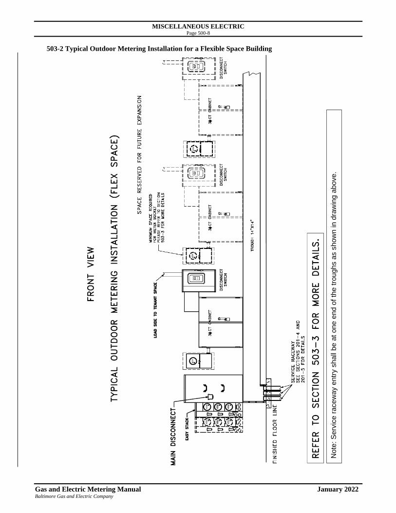
MISCELLANEOUS ELECTRIC Page 500-8
Gas and Electric Metering Manual January 2022 Baltimore Gas and Electric Company
503-2 Typical Outdoor Metering Installation for a Flexible Space Building
Note
: S
erv
ice r
acew
ay e
ntr
y s
hall
be a
t o
ne
en
d o
f th
e tro
ugh
s a
s s
how
n in d
raw
ing
abo
ve
.

MISCELLANEOUS ELECTRIC Page 500-9
Gas and Electric Metering Manual January 2022 Baltimore Gas and Electric Company
503-3 Space requirements for electric metering equipment
The requirements specified in this table shall be followed when planning and allocating space in the metering
room.

MISCELLANEOUS ELECTRIC Page 500-10
Gas and Electric Metering Manual January 2022 Baltimore Gas and Electric Company
504 Backup Generators and Transfer Switches
During power outages some customers utilize backup (portable or permanently installed) electric generators to
provide emergency power to their business or residence. To ensure the safety of field personnel, BGE requires
that these generators do not back feed our electric distribution system. Back feed conditions can be prevented
with the installation of a transfer switch after the BGE metering device. A properly installed transfer switch
isolates generator supplied power from the BGE service conductors. Installation of a transfer switch should be
made by a qualified electrician and must comply with all applicable laws, the National Electrical Code (NEC) and
be inspected by the local authority having jurisdiction.
NOTE: Currently, socket-based transfer switches that install between the meter and meter socket are not
approved for use on BGE’s electrical distribution system.
Isolation between the generator and service conductors is required because BGE utilizes transformers to reduce or
“step down” voltage on our service conductors before providing power to the customer’s premise. These
transformers can also work in reverse and “step up” voltage if fed in the opposite direction from a generator that is
not isolated from BGE wiring. An electrical back feed can cause equipment and property damage, and may result
in severe injury to utility personnel.
In addition to protecting BGE employees and equipment, a properly installed transfer switch also protects the
customer’s electrical system. Improperly connecting a generator output directly into a panel box or an electrical
outlet can be dangerous. This could cause damage to existing premise wiring and also result in significant
damage to the generator once BGE power is restored.
Shown below is a typical residential transfer switch installation:

MISCELLANEOUS ELECTRIC Page 500-11
Gas and Electric Metering Manual January 2022 Baltimore Gas and Electric Company
505 Small Generator Interconnection
Small generator interconnection is a general name for the process of registering and connecting
small scale power generation equipment to BGE’s electric utility distribution system. Therefore, the
customer may back feed BGE’s distribution system. In addition, special metering, often referred to
as “net metering”, may be required to comply with tariff requirements associated with some of these
installations.
Small generator interconnection equipment may include:
• Wind turbines
• Photovoltaics (PV) or solar panels
• Micro-turbines
• Small gas-turbine generator
• Fuel cells
• Small internal combustion-engine generator (ICE)
• Small steam turbine units (cogeneration)
Refer to www.bge.com, Choosing a Supplier/Your Energy Supply Options/Customer-Generated
Power under My Account for more information. This website provides detailed information
regarding the application process and specific technical requirements.
Notes (disconnect requirements for small generator interconnections):
1. Outdoor disconnecting means shall be accessible to BGE personnel and capable of being locked
in the open position. Its status (open or closed), must be clearly indicated.
2. Disconnecting means should be located within ten (10) feet of the meter socket.
3. Indoor meter: Consult BGE for appropriate disconnect location.
A typical small generator interconnection installation (solar panel in this example) is shown below.

MISCELLANEOUS ELECTRIC Page 500-12
Gas and Electric Metering Manual January 2022 Baltimore Gas and Electric Company
506 Meter Requirements Review - Small Generator Interconnection
• If standard metering requirements have been modified, determine if BGE/Exelon
Commitment verification is required to be completed. If it needs to be completed, follow
instructions below.
• Otherwise, follow schedule below.
o Last confirmation: March 2020. Kam Yiu, Senior Engineer.
o Next confirmation required: February 2020.
THE EXELON REPORTING COMMITMENT
Applicable to Smart Metering & Technology (SMT), a verification shall be performed to determine
if there has been changes to BGE’s standards that would require additional metering equipment or
monitoring equipment for customers with behind the meter storage. This verification shall be
performed on a three-year period.
INSTRUCTIONS FOR VERIFICATION
Send form, “BGE-Exelon Commitment Verification 06.045 - Behind the Meter Solar Storage,” to
the Sr. Business Analyst/Commitment Tracking administrator in Energy Efficient Programs.
Click here for the location of the form.
Review this section annually as part of the yearly review of this Manual. Customers with
behind-the-meter storage should be treated the same as net-metering customers without behind-
the-meter storage.

MM600 - RESIDENTIAL GAS & ELECTRIC METERING COMBINED Page 600-1
Gas & Electric Metering Manual January 2022 Baltimore Gas and Electric Company
601 Combined Gas and Electric Metering
601-1 Combined Metering – General
Meter Protection
FOR METER PROTECTION STANDARDS, REFER TO THE METER PROTECTION
SECTION IN THE BEGINNING OF THE MANUAL.
General Information
The purpose of this section is to address the location and installation of combined metering equipment
for town houses and single-family homes.
This combined metering equipment is for conditions which have loads up to, but not larger than:
• Electric Service: 120/240 volts at 200 amps
AND / OR
• Natural Gas Service: 295 CFH at standard delivery or 330 CFH at 2 PSIG delivery
However, this section is to be used in conjunction with the other sections in this manual. Please be
familiar with the other sections as well. If the loads are larger than those listed above, then follow the
information in the other sections of this manual.

MM600 - RESIDENTIAL GAS & ELECTRIC METERING COMBINED Page 600-2
Gas & Electric Metering Manual January 2022 Baltimore Gas and Electric Company
601-2 BGE Outdoor Meter Assembly Location Policy
In conjunction with the BGE Gas Service Tariff and Maryland Legislation (Gas Service Regulator
Safety), BGE has developed a “BGE Outdoor Meter Assembly Location Policy". All meters and
regulators are to be installed on the outside of buildings, except as detailed below. All meter locations
are agreed upon by the Customer and the Company in advance of construction and are subject to final
approval by the Company. Contact your BGE representative before any construction begins.
Failure to comply with the BGE Outdoor Meter Assembly Location Policy will prevent
BGE from providing electric/natural gas to the requested service location.
New Services
New services are defined as a gas service installation for a premise that has not previously had gas
delivery from BGE. Meter Assemblies (aka Meter Sets) consist of both the Meter(s) and Regulator(s)
For new service work, the following applies:
• Meters and regulators must be installed outdoors
• Meter Assemblies with 6 or more meters are allowed to be located indoors per the Gas
Service Tariff (regulators still need to be outdoors).
In all other cases, meter assemblies must be located outdoors. If a situation exists which prevents the
installation of a newly installed meter and/or regulator outdoors, refer to your BGE representative.
Existing Services
Existing services are defined as a gas service installation for a premise that has previously had gas
delivery from BGE prior to the current work being performed.
For existing service work, the following applies:
• Regulators must be installed outdoors
• Meters are preferred to be installed outdoors if feasible
For existing indoor gas meters, the Gas Service Tariff allows the meters to remain indoors. However,
it is strongly encouraged that existing indoor gas meters also be relocated to an outdoor location when
the existing gas service is to be replaced, renewed, sleeve inserted, size changed (heavy-up), pressure
increased, or relocated. Regardless of final meter location, it is required that all regulators be installed
outdoors.
If a situation exists which prevents the installation of a regulator outdoors, refer to your BGE
representative.
Note: The customer shall maintain at least three (3) feet of unobstructed space in front of the meter,
and such space shall be free of any source of ignition or heat which may damage the meter or
related equipment. The sole exception to the three (3) feet of unobstructed space in front of
the meter is the use of bollards for protection from vehicular traffic where required; see Meter
Protection Section of this manual.
The space provided for meters, regulators and service risers shall be clear of all obstructions,
such as shutters, doors, and rainspouts, and the placement of obstructions such as concrete
equipment pads, shrubbery, porches, patios, decks and gardens shall not interfere with the
installation and servicing of the metering equipment or reading of the meter. Metering
equipment shall not normally be located over porches or patios.

MM600 - RESIDENTIAL GAS & ELECTRIC METERING COMBINED Page 600-3
Gas & Electric Metering Manual January 2022 Baltimore Gas and Electric Company
The following excerpt is the “Location of Service Equipment” from the BGE Gas Service Tariff; Part
2, Section 6. This is provided for reference in outlining the BGE Metering Location Standard.
BGE Gas Service Tariff; Section 6
6. Location of Service Equipment
6.1 General: Under normal conditions an outdoor location is required. Meter locations are agreed
upon by the Customer and the Company, subject to final approval by the Company.
An acceptable meter location shall be free of any conditions detrimental to the metering
equipment, and such location shall not create a hazard or inconvenience. The Customer shall
maintain at least three (3) feet of unobstructed space in front of the meter, and such space shall be
free of any source of ignition or heat which may damage the meter or related equipment. The
Company may require the Customer to provide, at the Customer's expense, suitable protective
equipment for the meter or exposed service riser.
Where more than one Customer is to be supplied, each meter shall be readily accessible to
the Customer served by it and to the Company. The fuel lines shall be so installed that the meters
may be grouped at one location.
In the event it becomes necessary to change an existing service entrance or meter installation
the location shall conform to these rules except that existing indoor meters may remain indoors.
6.11 Outdoor Location: An outdoor location is generally required for meter installations not
exceeding six (6) meters.
Space shall be provided for meters, regulators and service risers clear of all
obstructions such as shutters, doors and rainspouts, and so that the placement of
shrubbery, flower beds and gardens will not interfere with meter installation, servicing,
or reading. In no event shall meter equipment extend beyond the Customer's property
line.

MM600 - RESIDENTIAL GAS & ELECTRIC METERING COMBINED Page 600-4
Gas & Electric Metering Manual January 2022 Baltimore Gas and Electric Company
601-3 Town House Combined Meter Locations Requirements Combined outside metering is BGE’s required construction standard. All efforts should be made to
utilize outside locations. When locating gas and electric meters outside, there are specific
requirements that should be followed. Typically, the meters are set at the location where the service
terminates at the building being served. See Figure 601-3.
Outside metering location must be used if one of the following conditions exists:
• Clear wall space is available: 24” W x 57” H (stacked meter configuration – wall mount
electric meter socket). See Section 601-5.
OR
• Clear wall space is available: 36” W x 47” H (side by side meter configuration – pedestal
electric meter socket). See Section 601-6.
OR
• There is adequate clear wall space to split the meters and install them separate from each
other. The gas meter requires 15” W x 36” H and the electric meter requires 17” W x 57” H
(200 Amp wall mount box) or 16” W x 47” H (200 Amp pedestal box) of clear wall space.
See Section 601-7.

MM600 - RESIDENTIAL GAS & ELECTRIC METERING COMBINED Page 600-5
Gas & Electric Metering Manual January 2022 Baltimore Gas and Electric Company
Standard service line extension to a residence shall extend not more than 75 feet for a single-family
home and 30 feet for a town house from the property line where the service enters the property to be
served to the nearest corner of the building. Distances greater than these are non-standard, and all
additional costs will be borne by the customer/builder. For additional information, please consult
with your BGE Representative. (Reference: BGE Electric Service Tariff, Section 8.23)
A. The outdoor residential customer meters shall be placed as close to the exterior building wall as
possible for both new service lines and service lines that are replaced.
(Reference: COMAR 20.55.09.07.D.)
B. The residential gas metering assembly installed outside shall be located on a building either one
(1) foot inward from the building edge along the "front", or no more than five (5) feet deep on the
building side(s). See Figure 601-4.
Note: The "front of the building" is defined by the portion of the building facing the utilities, which
typically run along the street.
Figure 601-4

MM600 - RESIDENTIAL GAS & ELECTRIC METERING COMBINED Page 600-6
Gas & Electric Metering Manual January 2022 Baltimore Gas and Electric Company
602 Outdoor Metering Installation Options
602-1 Stacked Gas & Electric Installation The following are general requirements for combined meters in a stacked installation. See Figure
602-2, for specific installation requirements, reference the electric and/or the gas metering sections of
this manual.
• This installation is for mounting on a "rigid" wall surface such as concrete, brick, or stone. The
installation may also be allowed on a "flexible" wall surface such as siding only if a backer board
is applied. Please contact your BGE representative for details if a backer board is used.
• The above final grade MINIMUM clear space requirements are 24" W x 57" H x 58" out from the
finished wall.
• The below final grade MINIMUM clear space requirements are 24" W x 40" H x 58" out from the
finished wall.
• A minimum of a 12" radial separation between the gas line and the electric, CATV,
communication…lines is required.
(Reference: National Electric Safety Code - 2017 Edition, Section 354.A.2)
• Finishing wall products such as siding, brick, stone or other materials shall protrude no more than
one (1) inch from the vertical face of the foundation. This will provide adequate clearance
between the BGE gas meter bracket / electric riser and the foundation wall.
Note: See Section 602 for Proposed Penetration zones to bring the house lines to the BGE metering
equipment.
56"
57"
40"40"
24"
57"
12"
12"
42''
FINAL GRADE
Figure 602-1: Stacked Installation

MM600 - RESIDENTIAL GAS & ELECTRIC METERING COMBINED Page 600-7
Gas & Electric Metering Manual January 2022 Baltimore Gas and Electric Company
602-2 Side-by-Side Installation The following are general requirements for combined meters in a Side-by-Side installation. BGE
offers two versions for Side-by-Side installations. See Figures 602-1A and 602-1B on the following
page. For specific installation requirements, reference the electric and/or the gas metering sections of
this manual.
• Use this installation standard when 24” W x 57" H of clear, rigid wall space above the final grade
is not available. A typical example of this is a masonry foundation that transitions to vinyl,
aluminum, or wood siding within 3-4’ of grade. Note that the bracket for the meters is mounted
to the "rigid" building foundation.
• The above final grade MINIMUM clear space required is 36" W x 47" H x 58" out from the
finished wall.
• The below final grade MINIMUM clear space requirements are 36" W x 40" H x 58" out from the
finished wall
• A minimum of a 12" radial separation between the gas line and the electric, CATV,
communication…lines is required.
(Reference: National Electric Safety Code - 2017 Edition, Section 354.A.2)
• Finishing wall products such as siding, brick, stone or other materials shall protrude no more than
one (1) inch from the vertical face of the foundation. This will provide adequate clearance
between the BGE gas meter bracket / electrical pedestal box and the foundation wall.
Note: See Section 602 for proposed penetration zones to bring the house lines (gas and electric) to
the BGE metering equipment.

MM600 - RESIDENTIAL GAS & ELECTRIC METERING COMBINED Page 600-8
Gas & Electric Metering Manual January 2022 Baltimore Gas and Electric Company
A. Electric Meter on the Left Option:
Figure 602-2A
B. Electric Meter on the Right Option:
Figure 602-2B

MM600 - RESIDENTIAL GAS & ELECTRIC METERING COMBINED Page 600-9
Gas & Electric Metering Manual January 2022 Baltimore Gas and Electric Company
602-3 Separated Installation The following are general requirements for meters installed separately (not in combination) from
each other. See Figures 602-3, plus 602-3A and 602-3B on the following pages.
Figure 602-3 shows a typical town house design which does not allow enough clear wall space
for either the stacked or the side-by-side “combined” meter installations. For more specific
installation requirements in addition to this section, reference the gas and electric metering
sections of this manual.
Figure 602-3
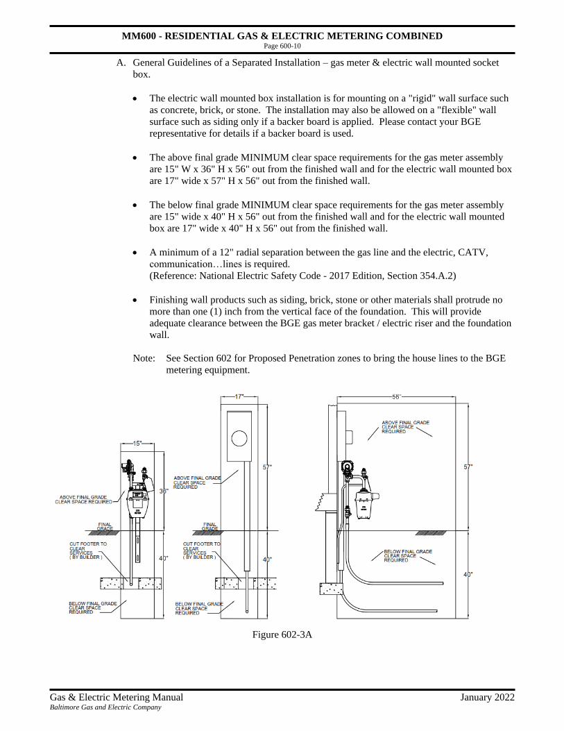
MM600 - RESIDENTIAL GAS & ELECTRIC METERING COMBINED Page 600-10
Gas & Electric Metering Manual January 2022 Baltimore Gas and Electric Company
A. General Guidelines of a Separated Installation – gas meter & electric wall mounted socket
box.
• The electric wall mounted box installation is for mounting on a "rigid" wall surface such
as concrete, brick, or stone. The installation may also be allowed on a "flexible" wall
surface such as siding only if a backer board is applied. Please contact your BGE
representative for details if a backer board is used.
• The above final grade MINIMUM clear space requirements for the gas meter assembly
are 15" W x 36" H x 56" out from the finished wall and for the electric wall mounted box
are 17" wide x 57" H x 56" out from the finished wall.
• The below final grade MINIMUM clear space requirements for the gas meter assembly
are 15" wide x 40" H x 56" out from the finished wall and for the electric wall mounted
box are 17" wide x 40" H x 56" out from the finished wall.
• A minimum of a 12" radial separation between the gas line and the electric, CATV,
communication…lines is required.
(Reference: National Electric Safety Code - 2017 Edition, Section 354.A.2)
• Finishing wall products such as siding, brick, stone or other materials shall protrude no
more than one (1) inch from the vertical face of the foundation. This will provide
adequate clearance between the BGE gas meter bracket / electric riser and the foundation
wall.
Note: See Section 602 for Proposed Penetration zones to bring the house lines to the BGE
metering equipment.
Figure 602-3A

MM600 - RESIDENTIAL GAS & ELECTRIC METERING COMBINED Page 600-11
Gas & Electric Metering Manual January 2022 Baltimore Gas and Electric Company
B. General Guidelines for a Separated Installation – gas meter & electric pedestal box
• Use this installation standard when 24" W x 57" H of clear, rigid wall space above the
final grade is not available. A typical example of this is a masonry foundation that
transitions to vinyl, aluminum, or wood siding within 3’ to 4’ of finished grade. Note
that the brackets for the meter pedestal are mounted to the "rigid" building foundation.
• The above final grade MININUM clear space required for the gas meter assembly are
15" W x 36" H x 56’’ out from the finished wall and for the electric pedestal are
16” W x 47” H x 56” out from the finished wall.
• The below final grade MINIMUM clear space requirements for the gas meter assembly
are 15" W x 40" H x 56" out from the finished wall and for the electric pedestal are 16”
W x 40” H x 56” out from the finished wall.
• A minimum of a 12" radial separation between the gas line and the electric, CATV,
communication…lines is required.
(Reference: National Electric Safety Code - 2017 Edition, Section 354.A.2)
• Finishing wall products such as siding, brick, stone or other materials shall protrude no
more than one (1) inches from the vertical face of the foundation. This will provide
adequate clearance between the BGE gas meter bracket / electric pedestal box and the
foundation wall.
Note: See Section 602 for proposed penetration zones to bring the house lines (gas and
electric) to the BGE metering equipment.
Figure 602-3B

MM600 - RESIDENTIAL GAS & ELECTRIC METERING COMBINED Page 600-12
Gas & Electric Metering Manual January 2022 Baltimore Gas and Electric Company
602-4 Minimum Building Clearance Requirements for Combined Metering When the gas and the electric meter are installed in combination on an outside wall, specific space
requirements and clearances must be met. BGE offers three (3) meter options for these installations:
Stacked, Side-by-Side and Separated. The following (Figure 602-4) illustrates the various space
requirements and clearances for each option.
The Figure and Table 602-4 shows locations on the building(s) that has a dimension “H” and "W".
Depending on which option is selected, the following minimum space is required. Note that only one
combined meter installation area is required for each residence.
Table 602-4
Installation Options
(both meters outdoors)
Minimum Width
Required (W)
Minimum Height
Required (H)
Minimum Clear
Space Required
in Front of Meter(s)
(from wall)
Stacked 24" 57" 56"
Side-by-Side 36" 47" 56"
Separated gas with
electric socket box
Gas = 15”
Electric = 17”
Gas = 36”
Electric = 57”
56”
Separated gas with
electric pedestal
Gas = 15”
Electric = 16”
Gas = 36”
Electric = 47”
56”
Figure 602-4

MM600 - RESIDENTIAL GAS & ELECTRIC METERING COMBINED Page 600-13
Gas & Electric Metering Manual January 2022 Baltimore Gas and Electric Company
602-5 Proposed Penetration Zones
To aid in the installation of stacked or side-by-side gas and electric meters, proposed penetration
zones are provided as a reference for service contractors. These zones detail areas in which
electricians and plumbers should bring electric load cables (service entrance on load side of meter)
and gas fuel lines through exterior walls so that they interface easily with combined BGE metering
equipment. See Figures 602-5-A, 602-5-B, and 602-5-C on the following pages.
The following are general requirements for the penetration zones:
1. Electric load cables should be in the electric zone and the gas fuel line should be in the gas zone.
Neither the electric load cable nor the gas fuel line shall be in the same zone.
2. Side-by-Side installation:
a. If the electric pedestal box is mounted to the right of the gas meter, the electric load cables
must exit on the right side of the pedestal. See Figure 602-5-B.
b. If the electric pedestal box is mounted to the left of the gas meter, the electric load cables can
exit either side of the pedestal. See Figure 602-5-C.
3. Gas fuel line:
a. If rigid piping is used, the line should not extend more than 4" horizontally from the finished
wall surface. This distance will provide adequate clearance for the addition of elbows and
fittings to reach the Customer’s Main Gas Valve (point of service connection).
b. If flexible piping is used, it should be of adequate length to prevent kinking when connected
to the Customer’s Main Gas valve (point of service connection). Plumbers should be fully
aware of, and follow, the installation requirements associated with the flexible piping they are
installing.
4. For the electric load cable, electricians should provide adequate length to extend from the
finished wall surface to allow a minimum bending radius of 4" to be achieved when it is installed
inside of the meter box.
5. Follow the appropriate codes such as the National Fuel Gas Code (NFPA 54), the National
Electrical Code (NEC), and the codes of the local jurisdiction when placing electrical load and/or
gas fuel lines through the building walls.
The rules of BGE for the customer’s installation are in addition to and in no way a waiver of the rules
of the inspection authority having jurisdiction. (Reference: Electric & Gas Tariff Sections 4.3)

MM600 - RESIDENTIAL GAS & ELECTRIC METERING COMBINED Page 600-14
Gas & Electric Metering Manual January 2022 Baltimore Gas and Electric Company
A. Proposed "Penetration Zones" for a Stacked Installation or Separated Installation (Electric Socket Box)
Figure 602-5-A

MM600 - RESIDENTIAL GAS & ELECTRIC METERING COMBINED Page 600-15
Gas & Electric Metering Manual January 2022 Baltimore Gas and Electric Company
B. Proposed "Penetration Zones" for a Side-by-Side Installations or Separated Installation (Electric Pedestal)
Figure 602-5-B
Figure 602-5-C
MM600 - RESIDENTIAL GAS & ELECTRIC METERING COMBINED Page 600-16
Gas & Electric Metering Manual January 2022 Baltimore Gas and Electric Company
603 Metering Configuration for Town House (Only)
603-1 General This section is a summary of BGE’s construction practices for gas and electric meter installations for
town houses.
Please contact your BGE Representative before construction.
603-2 Standard Construction: Both Gas and Electric Meters Installed Outdoors
This is BGE’s required configuration. All construction efforts should be made to use this
configuration.
Meters will be installed on the front of the building (side facing service lateral), or within five feet of
the front corners.
Configuration A will be used if one of the following conditions exists:
• Clear wall space is available: 24” W x 57” H (stacked meter configuration – wall mount
electric meter socket). See Section 602-1.
OR
• Clear wall space is available: 36” W x 47” H (side by side meter configuration – pedestal
electric meter socket). See Section 602-2.
OR
• There is adequate clear wall space to split the meters and install them separate from each
other. The gas meter requires 15” W x 36” H and the electric meter requires 17” W x
57” H (200 Amp wall mount box) or 16” W x 47” H (200 Amp pedestal box) of clear wall
space. See Section 602-3.

MM600 - RESIDENTIAL GAS & ELECTRIC METERING COMBINED Page 600-17
Gas & Electric Metering Manual January 2022 Baltimore Gas and Electric Company
604 Improper Installations
The following pictures are examples of improper combined meter installations.
A. In the picture below, there are several improper installation practices shown. The cause was the
back-fill or final grade was placed higher than the local jurisdictional requirement.
• Riser valve is buried
• Regulator vent has less than 12" clearance to final grade
• Gas meter is buried
• Electric meter box cover opening is buried
• Due to incorrect meter placement to grading, the downspout can cause freezing issues

MM600 - RESIDENTIAL GAS & ELECTRIC METERING COMBINED Page 600-18
Gas & Electric Metering Manual January 2022 Baltimore Gas and Electric Company
B. The following example shows two gas meters with improper frontal clearances.
• The clearance in front of the meter on the left is inadequate. The fence impedes the 3’ space
requirement.
• The clearance in front of the meter on the right is also inadequate. A clear space of 3’ between
mature shrubbery and the meter is required. By the time the shrubbery matures, it is likely to
cover the meter.

MM600 - RESIDENTIAL GAS & ELECTRIC METERING COMBINED Page 600-19
Gas & Electric Metering Manual January 2022 Baltimore Gas and Electric Company
C. In the following picture, a meter is shown that was mounted improperly.
• The meter is located on the neighbor's wall. Metering equipment from one customer may not
be attached to or located on another’s property.
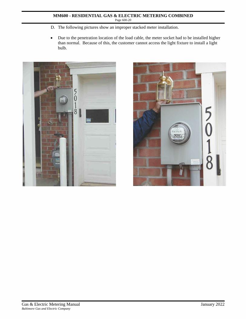
MM600 - RESIDENTIAL GAS & ELECTRIC METERING COMBINED Page 600-20
Gas & Electric Metering Manual January 2022 Baltimore Gas and Electric Company
D. The following pictures show an improper stacked meter installation.
• Due to the penetration location of the load cable, the meter socket had to be installed higher
than normal. Because of this, the customer cannot access the light fixture to install a light
bulb.
MM700 - GAS SERVICE & METERING Page 700-1
Gas & Electric Metering Manual January 2022 Baltimore Gas and Electric Company
701 Gas General
701-1 Gas General BGE supplies natural gas service to customers throughout Central Maryland. Service is provided to
residential, commercial, and industrial customers. Each customer is supplied gas service through a
service line, which terminates at a gas metering assembly. It is BGE's policy to locate meters outside
and as close to the service side of the building (generally the front) as practical.
BGE owns and maintains all service piping and facilities (including the gas metering assembly) up to
the “Point of Service”. This maintenance includes, but is not limited to, leak survey, corrosion
monitoring, painting, and relocation of the piping to accommodate building renovations. This is
applicable whether the gas metering assembly is located outside or inside the building being served.
Note: The customer may repaint the exposed piping and meter for aesthetic reasons but must take
care not to paint over any dials, reading devices, or vent line openings. If you have questions,
please call our Customer Care Center at 1-800-685-0123.
BGE only uses new materials in the installation of gas metering assemblies. The reuse of materials
and components is prohibited except where reconditioned for use under the direction of Smart
Metering & Technology.
BGE gas metering assemblies always consist of uniform steel pipe and steel or malleable fittings.
Plastic, cast iron, lead or copper pipe/tubing are not used for gas metering assemblies. Please check
with the applicable county/city codes as to allowable materials for customer piping.
Prior to beginning construction please review the Meter Protection section in the beginning of
this manual.

MM700 - GAS SERVICE & METERING Page 700-2
Gas & Electric Metering Manual January 2022 Baltimore Gas and Electric Company
701-2 Location of Underground Facilities Call at least 48 hours before you dig, plant, drill, blast, or grade. A utility representative will mark
underground facilities at your site free of charge.
Call Miss Utility at 811 or 1-800-257-7777 (7:00 AM - 5:00 PM) 24 hr. service in case of
emergency.
Color codes appearing on wire flags or as spray painted stripes on the grass, sidewalk or street mark
underground utility lines. Whether you’re planning a large construction project or minor landscaping,
call Miss Utility at 811 or 1-800-257-7777 before you dig and exercise caution where you see these
codes:
701-3 Properties of Natural Gas
• Natural Gas contains no toxic material before being burned; however, it will not support life.
• BGE's natural gas is rated at 1040 BTU per cubic foot; vapor density 0.6 (air is 1.0).
• Natural gas requires a temperature of 1200oF to ignite.
• The flammability range of natural gas is between 5 and 15 percent in air.
• Natural gas requires 10 times as much air as gasoline to burn properly.
• The products of combustion of natural gas will contain carbon dioxide, nitrogen, and water vapor.
All are harmless.
• Any hydrocarbons that lack air while burning will produce carbon monoxide.
• Carbon monoxide is colorless, odorless, tasteless, and very deadly.

MM700 - GAS SERVICE & METERING Page 700-3
Gas & Electric Metering Manual January 2022 Baltimore Gas and Electric Company
701-4 Meter & Installation Unit - Natural Gas Responsibilities The following is a list of contacts with groups involved
Gas Meter & Installation Unit Supervisor:
Mike Simmons, 410-470-7095, [email protected]
Measurement Specialist for (North) grids 1 & 2:
Brian Brest, 410-470-6885, [email protected]
Measurement Specialist for (South) grids 3 & 4:
Kevin Kline, 410-470-9021, [email protected]
Supervisor, Field Meter Test – Gas:
John Shrader, 410-470-0430, [email protected]
Measurement Specialist for grids 1, 2, 3, & 4:
Al Brazil, [email protected]
1 2
3 4
Zone 1&2 and 3&4 are divided
• North and South by Baltimore Street
• East and West by Charles Street

MM700 - GAS SERVICE & METERING Page 700-4
Gas & Electric Metering Manual January 2022 Baltimore Gas and Electric Company
701-5 Other BGE Contacts
For inquiries, arrangements or
Information pertaining to:
New services - Gas or Electric
Pending jobs or construction
Relocation of Company equipment
Removal of Company equipment
Meter Locations
Certificates of Inspection
Significant increases in load
Increase in service entrance size
Fault current Values
Voltage Problems
Planned Outages
Customer-owned metering equipment
Residential, Commercial, & Industrial
New Business and Customer Contact
410-637-8713 (7:00 AM - 4:30 PM)
800-233-1854 (7:00 AM - 4:30 PM)
Fax 410-712-9323
Baltimore Gas & Electric Company
New Construction Services
1068 N. Front St.
Baltimore, MD 21203
Emergency service
Turn on, turn off meters
Meter reading
800-685-0123
Residential:
General Conservation Information
Efficient utilization of energy
Insulation
800-265-6177 or
410-265-4100

MM700 - GAS SERVICE & METERING Page 700-5
Gas & Electric Metering Manual January 2022 Baltimore Gas and Electric Company
702 Gas Supply Conditions
702-1 Characteristics of Supply BGE has a contract with the State of Maryland to supply natural gas to customers in our service
territory. This contract is in a form of a tariff. The following excerpt from the BGE Gas Service
Tariff; Part 2, Section 1 describes the characteristics of this supply.
BGE Gas Service Tariff; Section 1
1. Characteristics of Supply
1.1 General: The Customer should consult the Company as to the availability of the Company's
service at a particular location before proceeding with plans for any installation whether new,
additional, replacement, or a transfer from one location within the territory to another.
1.2 Standard Service: The heating value of the gas supplied will vary from time to time due to
changes in the composition of the Company's sendout. The composition of the gas sendout will
consist of natural gas, liquefied natural gas, propane-air gas, and synthetic gas in varying
proportions depending upon the gas supply situation at any given time. The normal range of
heating value will be from 1000 to 1200 Btu per cubic foot (cu. ft.) of gas.
Standard delivery to the Customer is at low pressure. Where, at the discretion of the
Company, gas is supplied at higher than standard delivery pressure, the meter reading is
corrected from the absolute delivery pressure (14.7 atmospheric pressure) in pounds per square
inch absolute to a pressure base of 14.85 pounds per square inch absolute. This correction is
accomplished by applying a fixed pressure correction factor to the meter reading or by a base
pressure corrector attached directly to the meter.
BGE has six pressure systems to deliver natural gas which are detailed later in this section. The Low
Pressure system requires no regulator. Meter sizing capacity must meet or exceed customer’s gas
demand with 0.5” w.c. allowable pressure drop across the meter assembly. Other pressure systems
require regulator(s) to control delivery pressure at prescribed level for all flow rates up to maximum
demand.

MM700 - GAS SERVICE & METERING Page 700-6
Gas & Electric Metering Manual January 2022 Baltimore Gas and Electric Company
702-2 Delivery Pressure The gas pressure which BGE provides to the customer and upon which the customer’s piping must be
sized is called the “Delivery Pressure”. For a summary of the BGE pressure deliveries, see Table
702-2 below. The following text provides more detailed information.
Table 702-2
BGE
Pressure
Systems
BGE Standard
Delivery Pressure
(3" w.c. guarantee)
Higher than
Standard Delivery
Pressure* -
Non-Fixed Factored
Billing
Higher than
Standard Delivery
Pressure -
Fixed Factored
Billing
Higher than
Standard Delivery
Pressure** -
Line Pressure
Delivery
LP 3" w.c - 10" w.c. (max) Not available Not available Not available
MP 3" w.c - 10" w.c. (max)
14" w.c.,
1,200 to 23,000cfh
Not available 1.46 psig to 10 psig
(1.46 psig minimum)
HP
3" w.c - 10" w.c. (max)
14" w.c. to 15 psig
2 psig, 0 to 12,375cfh
or
5 psig, 0 to 14,600 cfh
20 to 99 psig
(20 psig minimum)
OHP
3" w.c - 10" w.c. (max)
14" w.c. to 100 psig
2 psig, 0 to 12,375cfh
or
5 psig, 0 to 14,600 cfh
120 to 300 psig
(120 psig minimum)
436
3" w.c - 10" w.c. (max)
14" w.c. to 300 psig
2 psig, 0 to 12,375cfh
or
5 psig, 0 to 14,600 cfh
345 to 436 psig
(345 psig minimum)
720
3" w.c - 10" w.c. (max)
14" w.c. to 300 psig
2 psig, 0 to 12,375cfh
or
5 psig, 0 to 14,600 cfh
345 to 720 psig
(345 psig. minimum)
* Higher than Standard Delivery Pressure Non-Fixed Factored Billing requires Pressure-
Compensating Instrument, which is only available for Rotary class metering.
** BGE does not provide any pressure regulation on Line Pressure Delivery
Note: 27.7” water column (w.c.) = 1 PSIG (Pounds Per Square Inch Gauge)
A. Standard Delivery Pressure - for design purposes Standard Delivery Pressure has been established
as 3” w.c. minimum at the outlet of the gas metering assembly when service is provided off of the
Low Pressure System. When gas is supplied to the customer from other than the Low Pressure
System a regulator(s) must be used by BGE to control the delivery pressure at a minimum of 3”
w.c. at the Customer’s Main Gas Valve (point of service connection). Common settings are 6”
w.c. for residential customers and 7” w.c. for commercial and industrial customers. For all
pressure systems, Standard Delivery Pressure shall not exceed 10” w.c. at the outlet of the meter.
Standard Delivery Pressure assemblies up to 23,000 CFH demand are shown in this manual and
are subject to “Standard Designs”. Capacities in excess of 23,000 CFH require individual designs
by BGE.
(Reference: National Fuel Gas Code - 2015 Edition - Section 5.8.1)
B. Above Standard Delivery Pressure - For loads of 1,200 cfh and greater, BGE may supply gas to a
customer at higher than Standard Delivery Pressure (greater than 10” w.c.) from other than the
Low Pressure Gas Distribution System.
• From the Medium Pressure System, delivery pressure may be 14” w.c. (0.5 PSIG) for
capacities from 1,200 to 23,000 cfh or available main pressure. For capacities requirements
greater than 23,000 cfh the Customer must take available line pressure.
• From the High Pressure and Over High Pressure System, delivery pressure can be up to the
service terminal pressure. Certain guidelines apply to availability; please refer to your BGE
representative for current criteria.

MM700 - GAS SERVICE & METERING Page 700-7
Gas & Electric Metering Manual January 2022 Baltimore Gas and Electric Company
Capacities of meters and regulators operating at Above Standard Delivery Pressure will
incorporate the use of fixed factor billing with regulators approved by BGE Smart Metering &
Technology (SMT) for this purpose. Where a SMT approved regulator is not available, meters
must be equipped with a pressure-compensating instrument. All instrumentation must be of a type
approved by SMT and designed to compensate to a pressure base of 14.85 PSIA.
C. Two and Five PSIG Delivery Pressure - The Company shall provide 2 and 5 PSIG delivery
pressure to customers without the design limitations that restrict the availability of other elevated
delivery pressures. As stated, 2 and 5 PSIG delivery pressure can be obtained from the High
Pressure and Over High Pressure gas distribution systems. In order to provide 2 and 5 PSIG
delivery pressure the customer’s interior piping system requires approval from the local authority
having jurisdiction. Delivery Pressures of 2 and 5 PSIG assemblies up to 25,875 CFH demand are
shown in this manual and are subject to “Standard Designs”. Capacities in excess of 25,875 CFH
require individual designs by BGE. These pressure systems are not available in all areas, please
check with your BGE Representative.
702-3 Capacity Design The capacity design of a gas metering assembly is predicted on the ability to meet two conditions:
A. To provide adequate flow at sufficient delivery pressure to meet the customer’s expected gas load
under BGE’s minimum service terminal pressures. See Table 702-3.
B. To provide safe emergency levels of customer house-line pressure under the worst conditions,
namely, BGE’s maximum main/service terminal pressure, and complete regulator failure.
Protection may be afforded by pressure relief or monitor control. Maximum main/service
terminal pressure is taken to be maximum allowable operating pressure of the main.
Table 702-3
BGE
Pressure
System
BGE
Minimum Main
Pressure
BGE
Maximum Main
Pressure
BGE
Minimum Service
Terminal Pressure
Allowable
Pressure Drop
LP 4.0" w.c. 10" w.c. 3.5" w.c. (0.13 psig) 0.5" w.c.
MP 2 psig 10 psig 1.46 psig 0.54 psig
HP 25 psig 99 psig 20 psig 5 psig
OHP 125 psig 300 psig (varies) 120 psig 5 psig
436 350 psig 436 psig 345 psig 5 psig
720 350 psig 720 psig 345 psig 5 psig
MM700 - GAS SERVICE & METERING Page 700-8
Gas & Electric Metering Manual January 2022 Baltimore Gas and Electric Company
702-4 Conditions of Supply
BGE provides gas service to customers based upon the conditions set forth in the Maryland Public
Service Commission - BGE Gas Service Tariff. The following excerpt is the “Conditions of Supply”
of the BGE Gas Service Tariff; Part 2, Section 2. This is provided for Reference in outlining our
general conditions of service.
BGE Gas Service Tariff; Section 2
2. Conditions of Supply
2.1 Limitations on Extensions: Service is supplied only where, in the opinion of the Company,
adequate service is available or can be made available under the provisions of these rules.
The Company’s obligation to extend its facilities is limited to the assumption of new
investment to the extent warranted by the revenue anticipated from the business to be supplied.
Where the business in prospect does not warrant the expenditure required to serve it, the
Company determines from the circumstances of each case, what financing shall be required of the
Customer, subject to the approval of the Commission.
2.2 Supply Points: It is the standard practice of the Company to provide (subject to the provisions of
Sec. 8 Extensions):
(a) One service
1. for all requirements of the Customer on a single property; where the supply is for his
use in group of buildings, the supply point is located, wherever practicable, at a
location central to the group;
2. for each building on the Customer’s property, upon request, provided the service to
any building is in each instance for the major requirements of that building;
3. for any building occupied by two or more Customers;
(b) One meter (or metering unit) - for each Customer at each supply point; where two or
more Customers are supplied from one service, a centralized meter location is required
wherever practicable. Each meter shall have a separate application of the schedule.
Where, in the Company’s judgment and under conditions specified by it, more than one
service is required for a building or pair of adjoining buildings, the Company provides such
additional service upon request and upon payment by the Customer to the Company of the charges
stated in Sec 8.32. Each meter shall have a separate application of the rate schedule.
A group of buildings with interconnected passageways is considered as one building.
Where, under unusual conditions, more than one service (supply point) is necessary to supply
the Customer’s requirements for large connected loads on property comprising single or
contiguous land parcels, the Company provides such service upon request under standard
extension provisions. Whenever the Customer requests and the Company in its judgment finds it
practicable to provide more than one service on his property, the service use is metered at each
supply point. The registrations of these meters are combined and the Customer is billed for the
total use, computed as if all service had been furnished through one service on a single
application of Schedule C, provided one of the supply points requires metering capacity of not less
than 150 therms per hour and each additional supply point requires metering capacity of not less
than 50 therms per hour. In determining contiguity hereunder of parcels abutting opposite sides of
public or private roads or other ways, the boundaries of such parcels shall be considered as
extending to the center of such roads or ways.

MM700 - GAS SERVICE & METERING Page 700-9
Gas & Electric Metering Manual January 2022 Baltimore Gas and Electric Company
2.3 Curtailment of Supply: The supply of gas is subject to any orders of Federal or State
authorities establishing any priority of or limitations to service. In the event a curtailment is
required, the Company will implement limitations to supply in accordance with the Natural Gas
Curtailment Plan in Appendix A.
2.4 Refusal or Discontinuance of Supply Cause: The Company may refuse or discontinue service
and remove its property without being liable to the Customer, or to tenants or occupants of the
premises served, for any loss, cost, damage or expense occasioned by such refusal, discontinuance
or removal, for any of the following reasons.
(a) Customer’s failure to comply with any of the provisions of the contract, or any applicable
regulations of the Commission, or any of the Company’s applicable rules or practices
currently in effect.
(b) Customer’s nonpayment of bill within the net-payment period, and then after reasonable
attempt to effect collection of the bill plus the applicable Late Payment Charge, including
written notice of at least 3 days exclusive of Sundays and holidays.
(c) Customer’s failure to provide a deposit to insure payment of bills, when requested by the
Company under the provisions of Sec. 7.7.
(d) Customer’s failure to pay any of the regular monthly installments under payment plans
for extensions. (The unpaid deferred charges shall thereupon become due and payable.)
(e) Customer’s failure to maintain his equipment in safe condition, in the judgment of the
Company.
(f) Customer’s failure to permit Company or its agents reasonable access to its equipment
located on or in the customer’s premises.
(g) Withdrawal or termination of the proper permits, certificates or rights-of-way.
(h) Removal of the Customer.
(i) Evidence of fraud, by any method, including the diversion of gas around the meter.
(j) Unauthorized adjustment of or tampering with Company’s equipment.
(l) Customer’s use of his equipment in a manner judged by the Company to adversely affect
its equipment or its service to others.
The Company may discontinue service without notice for reasons (e), (i), (j), and (l) above.
2.41 Reconnection Charge: Where the Company has discontinued service for nonpayment of
bill or for other reasons listed in Sec. 2.4, the Customer is subject to the following charge,
payable at a Company business office, as a condition of resuming service at the same location
or at a different location:
(a) Where the disconnection was made at the meter location without the necessity of legal
action-
$20.00 where the reconnection can be made under routine scheduled working conditions,
or

MM700 - GAS SERVICE & METERING Page 700-10
Gas & Electric Metering Manual January 2022 Baltimore Gas and Electric Company
$30.00 where the Customer requires reconnection on the same day on which, before 1
p.m., cause for discontinuance is removed, except on Saturday and on the day before a
Company holiday,
(b) where the Company was unable to obtain access to the meter and the disconnection was
made at other than the meter location or at the meter location as a result of legal action,
$70.00 without regard to the conditions of reconnection but, other than on Saturday and
the day before a Company holiday, cause for discontinuance must be removed before 1
p.m. to have service reconnected on the same day.
2.42 Field Collection Fee: Where the Customer makes a payment to a Company Representative at
the Customer’s premises to avoid discontinuance of service, the Customer is subject to a
$15.00 fee per occurrence. Payment to maintain service must be in the form of a check or
credit card. No cash will be accepted by the Company Representative.
Effective February 4, 2015, for Customers served under rate Schedules C (Daily
Metered Customers only), IS, EG, or ISS, payments to a Company Representative at the
Customer’s premise to avoid discontinuance of service shall only be allowed one time over
the duration of the account. Thereafter, no payments at the Customer’s premise will be
accepted from Customers served under these Rate Schedules.
2.5 Loss or Damage From Failure to Supply: The Company is not liable for any loss, cost, damage
or expense to any Customer occasioned by any failure to supply gas according to the terms of the
contract or by any interruption of the supply of gas, if such failure or interruption is due to storm,
lightning, fire, flood, drought, strike, or any cause beyond the control of the Company, or any
cause except willful default or neglect on its part.
702-5 Dual Services BGE provides more than one supply point where, in BGE’s judgment and under conditions specified
by BGE, more than one service is required. During new construction or renovation, BGE will not
provide dual services. Upon installation of the new service, the original service must be disconnected.
For large industrial and commercial installations, the BGE Meter Inspector may waive this policy and
provide up to 10 days of dual services before the original service must be disconnected.

MM700 - GAS SERVICE & METERING Page 700-11
Gas & Electric Metering Manual January 2022 Baltimore Gas and Electric Company
703 Ownership Responsibilities
703-1 Ownership Responsibilities The Maryland Public Service Commission provides the regulations which govern the conditions of
service supplied by Gas Companies. (Ref. COMAR Title 20 - Subtitle 55)
These regulations are intended to promote safe and adequate service to the public, to provide
standards for uniform and reasonable practices by utilities, and to outline the responsibility of the
public in requesting and receiving service from the utilities.
The BGE Gas Service Tariff is supplementary to the “Regulations Governing Service Supplied by
Gas Companies” of the Public Service Commission of Maryland, and comprises the rules and rates
under which gas service is supplied to its customers by Baltimore Gas and Electric Company
(Hereafter Referred to as “The Company”).
The following requirements cover the ownership of gas service equipment and responsibilities of each
party.
703-2 Company’s Installation For a list of BGE's installation responsibilities, the following excerpt is from the BGE Gas Service
Tariff; Part 2, Section 5. In addition to the requirements below in the BGE Gas Service Tariff, BGE
also has a Point Of Service (P.O.S.) Policy that must be followed. BGE installs a valve at its expense
at the outlet (or "back") of the meter. This valve is called the Customer’s Main Gas Valve, or P.O.S.
valve. After BGE installs and checks for leaks and proper operation, the valve becomes the property
of the customer.
BGE Gas Service Tariff; Section 5
5. Company's Installation
5.1 Service Equipment Furnished by the Company: For the purpose of determining the amount of
gas used, a meter is installed by the Company upon the Customer’s premises.
The Company also furnishes, installs and maintains:
A. the line from the end of the “service” to the meter including a valve or cock at the inlet (or
“front”) connection of each meter, and where more than one meter is installed, the inlet
manifold.
B. the outlet (or “back”) connection from each meter [Point of Service], and where two or more
meters are used as a metering unit, the outlet manifold including a valve or cock on each
“back”[Point of Service] connection.
C. the pipe from the connection between the end of the service and the meter, described in (a)
above, to the opposite side of the foundation wall between basements of adjoining buildings
where one service is branched [inside a building] to supply two [attached] buildings
[houses].
D. one or more pressure regulators where they are deemed by the Company to be necessary.
E. in accordance with Federal regulations, eligible customers may request to have the Company
install, at the Customer’s expense, an excess flow valve on an existing Service Line supplying
the Customer. The charge to the Customer shall be the estimated installed cost for the excess
flow valve installation that exceeds the related material costs. The Company does not
guarantee or warrant the operation of the excess flow valve (see Sec. 3.4).

MM700 - GAS SERVICE & METERING Page 700-12
Gas & Electric Metering Manual January 2022 Baltimore Gas and Electric Company
F. any necessary valves, cocks and piping associated with the Company's installation.
Where a meter with a capacity of 450 cubic feet per hour or less is located indoors and the
electric meter is also read outdoors, where requested by the Customer, the Company will install a
remote index reading device at the Customer's expense. The charge for such device is $75.
5.2 Ownership: All meters and other equipment furnished by the Company, [except the customer’s
main gas valve] remains its [BGE's] property.
5.3 Responsibility for Damage or Loss: The Customer is responsible for all damages to, or loss of,
the Company’s property located upon his premises unless occasioned by fire or the Company’s
negligence, or any cause beyond the control of the Customer.
5.4 Access to Company’s Equipment: Permission is given the Company to enter the Customer’s
premises at all reasonable times, for the purpose of reading its meters, and operating, inspecting,
modifying and keeping in repair or removing any or all of its apparatus used in connection with
the supply of gas, and for said purposes the Customer authorizes and requests his landlord, if any,
to permit the Company to enter said premises.
5.5 Tampering Charge: In the event of unauthorized service use resulting from unauthorized
adjustment to, reconnection of, or tampering with Company equipment, the Customer receiving
the unauthorized service shall pay a charge to cover the Company costs of tampering
investigations, inspections, billing, and corrective action on unsafe equipment. The Tampering
Charge is $90 for confirmed tampering by a residential Customer and $45 per hour of
investigation for confirmed tampering by a non-residential Customer.
703-3 Customer’s Installation
For lists of the Customer's Installations responsibilities, the following excerpt is from the BGE Gas
Service Tariff; Part 2, Section 4.
BGE Gas Service Tariff; Section 4
4. Customer’s Installation
4.1 Service Equipment Furnished by the Customer: The Customer provides within his premises,
without charge, suitable space for the Company’s metering and service equipment.
All service equipment other than that specifically stated in Section 5.1 below [Company’s
Installation] as furnished by the Company, is furnished, installed and maintained by the Customer
(or owner, if more than one Customer in the building), subject to the approval of the Company.
This includes the pipe to the appliance (the fuel line) from the outlet connection referred to in
Sec.5.1.[Point of Service]. Where the meter has been installed, the fuel line is brought to the
meter location, or to the point of connection of the Company's installation downstream from the
meter outlet [and connected by the customer at the Point of Service]. Where the meter is not
installed, the fuel line is brought to within 2 feet of the designated meter outlet location, and
within the meter room where provided. It also includes any meter enclosure required by the
Customer, and acceptable to the Company, where the meter is installed outdoors. The service
equipment furnished, installed and maintained by the Customer also includes a dedicated
telephone line where an Automated Meter Reading device is installed by the Company for
Delivery Service purposes.
4.11 Customer’s Responsibility to Maintain Service Equipment: The Customer is responsible
for maintaining all service equipment provided by them in proper working order. In the
event that a malfunction with the Customer’s dedicated telephone line results in the need
for the Company to visit the Customer’s premises to manually download data from an
Automated Meter Reading device to prevent loss of the data, the Customer shall pay the
cost of the site visit, unless the Customer has taken timely action to resolve the telephone
line problem through its telephone service provider.

MM700 - GAS SERVICE & METERING Page 700-13
Gas & Electric Metering Manual January 2022 Baltimore Gas and Electric Company
4.2 Point of Connection to Company's Service: The piping upon the Customer’s premises is brought
by the Customer to any point of service connection specified by the Company and if it becomes
necessary to change such point of [service] connection, the Customer brings such piping to the
new point of [service] connection.
Where the meter is installed with a meter outlet valve, the fuel line is brought to the meter
location and connected by the Customer. All other connections to or work of any kind on the
Company’s system, which is defined in Section 5.1[which terminates at the Point of Service], is
done by the Company.
4.3 Rules Governing Customer’s Installation: All piping and gas appliances upon the Customer’s
premises shall be installed and maintained in accordance with applicable laws and the rules of the
governmental authority having jurisdiction, the National Fire Prevention Association, the
applicable standards of the American National Standards Institute, and the Company. The rules
of the Company are in addition to and in no way a waiver of the rules of the inspection authority
having jurisdiction.
4.4 Certificates of Approval Required: The Customer obtains such certificates of approval of piping
and gas appliances upon his premises as may be legally prescribed, and before service is
supplied, the Company shall be so notified in writing by the inspection authority. In the absence of
a certificate of approval being required by the governmental authority having jurisdiction, such
piping and gas appliances shall be acceptable to the Company.
4.5 Access to Customer’s Equipment: Permission is given the Company to enter the Customer’s
premises at all reasonable times, for the purpose of service test, and for such purpose the
Customer authorizes and requests his landlord, if any, to permit the Company to enter said
premises.
4.6 Wastage of Gas and Adjustment of Appliances: Upon notice by the Customer, the Company
investigates suspected gas leakage or improper adjustment of gas appliances.
Leakage inspections are made without charge, and where such leakage in a residential
Customer’s piping or appliances is found to have caused gas wastage, allowance for a share of
such gas wastage is made by the Company where the occurrences is without the knowledge of the
Customer. Adjustments of appliance burners and pilots are made by the Company without charge
where the adjustment can be made within a reasonable time.
A. Customer Owned Gas Booster/Compressor (In reference to section 4.1 above):
Gas Booster/Compressors shall be allowed for Low Pressure (LP) and Line Pressure Delivery
(Unregulated) customers only. A LP cut-off device which is acceptable to BGE shall be installed
with each customer owned gas booster/compressor installation (NFPA 54-Z223.1 Para 5.11).
The LP cut-off device should be connected as close as is practical to the customer side of the
point of service valve. A back pressure protection device shall be required where the design of
the gas booster/compressor could potentially force pressure back into BGE’s distribution system
(NFPA 54-Z223.1 Para 5.10).
The minimum set points for LP cut-off devices listed below are typical but not limited to these
settings. Contact the Gas Distribution Planning Unit to determine the appropriate setting.
Low Pressure System (LP) – 3.0” w.c.
Medium Pressure System (MP) – 40.4” w.c. (1.46 psig)
High Pressure System (HP) – 20 psig
OHP System (OHP) – 120 psig

MM700 - GAS SERVICE & METERING Page 700-14
Gas & Electric Metering Manual January 2022 Baltimore Gas and Electric Company
703-4 Company Responsibilities The Company maintains and monitors all gas piping and equipment up to the Point of Service (POS),
or customer’s main gas valve. These facilities are monitored for leaks and corrosion on a prescribed
basis.
Based upon Public Service Commission guidelines, BGE performs an In-Service Performance Test
Program for gas meters. This program involves the replacement of selected Group I, II, and III meters
on a scheduled basis for performance testing. It is the responsibility of BGE to coordinate any
customer service issues to ensure safety and minimize impact to customers.
(Reference: COMAR 20.55.07.07).
The Public Service Commission requires a gas leakage test to be conducted whenever work is
performed on the service or meter installation.
(Reference: COMAR 20.55.09.05)
703-5 Customer Responsibilities Based upon U.S. Department of Transportation Regulations, all natural gas utilities must provide
notification to their customers of the customer’s responsibility in monitoring and maintaining their
piping and facilities. BGE has provided this notification through inclusion in our system-wide mailing
of the “Scratch-and-Sniff” insert in all bills as required by the Maryland Public Service Commission.
The following is the notification wording as printed on the “Scratch-and-Sniff” billing insert:

MM700 - GAS SERVICE & METERING Page 700-15
Gas & Electric Metering Manual January 2022 Baltimore Gas and Electric Company
703-6 Qualified Agency Installation and replacement of customer gas piping, gas utilization equipment, or accessories, and
repair and servicing of equipment, shall only be performed by a qualified agency. The term “qualified
agency” means any individual, firm, corporation, or company that either in person or through a
representative is engaged in and is responsible for (1) the installation, testing, or replacement of gas
piping or (2) the connection, installation, testing, repair, or servicing of equipment, that is experienced
in such work, familiar with all precautions required, and has complied with all the requirements of the
authority having jurisdiction.
(Reference: National Fuel Gas Code - 2018 Edition; Section 3.3.81)
703-7 Interruptions of Service beyond the Meter
Notification of Interrupted Service: When the gas supply is to be turned off, it shall be the duty of the
qualified agency to notify all affected users. Where two or more users are served from the same
supply system, precautions shall be exercised to ensure that only service to the proper user is turned
off.
Exception: In cases of emergency, affected users shall be notified as soon as possible of the actions
taken by the qualified agency.
(Reference: National Fuel Gas Code - 2018 Edition; Section 4.2.1)
Before Turning Gas Off: Before turning off the gas to the premises, or section of piping to be
serviced, for the purpose of installation, repair, replacement, or maintenance of gas piping or gas
utilization equipment, all equipment shutoff valves shall be turned off.
Please refer to the applicable codes of the governmental jurisdiction and/or The National Fuel Gas
Code - 2018 Edition for guidance and requirements of Customer piping installation, repair and safety
procedures.
703-8 Inspection and Testing It is the customer’s responsibility to provide evidence that prior to acceptance and initial operation, all
piping installations have been inspected and tested to determine that the materials, design, fabrication,
and installation practices comply with the requirements of the local jurisdiction having authority.
(Reference: COMAR 20.55.09.03 Customer Piping)
Code of Maryland Regulations
20.55.09.03
Customer Piping:
A. Before permitting the use of gas at any location, the piping shall be tested for tightness and leaks in
accordance with Part 4 of the American National Standard "National Fuel Gas Code", ANSI Z223.1
(1998) [latest version is dated 2009], which is incorporated by reference under COMAR 20.50.02.02.
B. Pressure Test. Before any system of gas piping is finally put in service, it shall be tested for tightness
and certified by the proper inspection authority that the test has been made.
C. Leakage Test. Before turning gas into any piping, it shall be tested for leaks.
The test procedure used shall be capable of disclosing all leaks in the section being tested and shall be
selected after giving due consideration to the volumetric content of the section and to its location.
In accordance with the local jurisdictional requirements, the customer piping test should incorporate
the following practices: (Reference: National Fuel Gas Code - 2018 Edition, Section 8)

MM700 - GAS SERVICE & METERING Page 700-16
Gas & Electric Metering Manual January 2022 Baltimore Gas and Electric Company
A. The [customer] piping system shall withstand the test pressure specified without showing any
evidence of leakage or other defects. Any reduction of test pressures as indicated by pressure
gages shall be deemed to indicate the presence of a leak unless such reduction can be readily
attributed to some other cause.
(Reference: National Fuel Gas Code - 2018 Edition; Section 8.1.5.1)
B. The leakage shall be located by means of an approved gas detector, a non-corrosive leak detection
fluid (soap and water), or other approved leak detection methods. Matches, candles, open
flames, or other methods that could provide a source of ignition shall not be used.
(Reference: National Fuel Gas Code - 2018 Edition; Section 8.1.5.2)
Where leakage or other defects are located, the affected portion of the piping system shall be
repaired or replaced and re-tested.
(Reference: National Fuel Gas Code – 2018 Edition; Section 8.1.5.3)
C. All testing of piping systems shall be done with due regard for the safety of employees and the
public during the test.
(Reference: National Fuel Gas Code - 2018 Edition; Section 8.1.3.6)
703-9 Turning Gas On
During the process of turning gas on into a system of new gas piping, the entire system shall be
inspected to determine that there are no open fittings or ends and that all valves at unused outlets are
closed and plugged or capped.
(Reference: National Fuel Gas Code - 2018 Edition; Section 8.2.2)
703-10 Test for Leakage Immediately after the gas is turned on [by the qualified agency] into a new system [or into a system
that has been initially restored after an interruption of service,] the piping system should be checked
for leakage. Where leakage is indicated, the gas supply shall be shut-off until the necessary repairs
have been made.
(Reference: National Fuel Gas Code - 2018 Edition; Section 8.2.3)
703-11 Placing Equipment in Operation Gas utilization equipment shall not be placed in operation [by the qualified agency] until after the
piping system has been checked for leakage in accordance with 8.2.3, the piping system purged in
accordance with 8.3, and connections to the appliances checked for leakage.
(Reference: National Fuel Gas Code - 2018 Edition; Section 8.2.4, 8.2.3, 8.3)
703-12 Premises Test for Gas Leakage Prior to any connection of customer piping to BGE facilities, which could facilitate the introduction
of natural gas into a customer’s premises, a premises test for gas leakage must be performed. The
leakage test must be performed by a licensed plumber or qualified agency.
A. The Public Service Commission requires a gas leakage test to be conducted whenever work is
performed on the service or gas metering assembly. The appropriate excerpts from these
regulations are as follows:

MM700 - GAS SERVICE & METERING Page 700-17
Gas & Electric Metering Manual January 2022 Baltimore Gas and Electric Company
Code of Maryland Regulations
20.55.09.05.c.2
Customer’s Premises:
When a utility service person enters a customer’s premise for the purpose of inspecting or serving any
gas equipment (excluding meter reading) a leakage survey shall be conducted at appropriate locations,
including atmosphere samples and at all utility service entrances. In multiple - occupancy buildings, an
individual apartment or dwelling unit shall constitute the customer’s premises specified above. The
customer shall cooperate with the Company in the conduct of such tests as regards to accessibility to
meters and service lines.
B. The leakage test will be conducted using a combustible gas indicator. A smell and soap test,
although used as supplementary means to pinpoint leaks, will not be considered adequate to
conduct the actual test. Take readings across the wall through which the service enters at all
utility entrances, i.e. water, sewer, electric, etc. and at any cracks or openings in the walls.

MM700 - GAS SERVICE & METERING Page 700-18
Gas & Electric Metering Manual January 2022 Baltimore Gas and Electric Company
704 Construction
704-1 Building Requirements The Company's policy is to locate distribution facilities in the front of buildings. Rear distribution is
permitted only in shopping centers or apartment/condominium (multiple occupancy buildings)
complexes where our facilities are made readily accessible to vehicles and construction equipment for
operating or maintenance purposes. Rear distribution is not normally permitted for individual or
multiple-attached dwellings where the property is individually owned or has potential for occupant
improvement/impact over our facilities.
All new gas services shall terminate at an outside location. If extenuating circumstances exist and
an outside termination is not feasible, please consult with your BGE representative.
A. One service will be installed for all the requirements of the customer on a single property. Where
supply is for his use in a group of buildings the supply point is located wherever practical at a
location central to the group, or
B. One service will be installed for each building on Customer's property, or
C. One service will be installed for any building occupied by two or more customers.
(Reference: BGE Gas Service Tariff, Conditions of Supply, Section 2.2).
D. A central meter location for all leased areas within a horizontally constructed nonresidential
multiple occupancy building is preferred. If this is impractical, two or more centralized meter
locations are acceptable. The least preferred method to supply service is via services to individual
areas. However, service may be provided to any leased area of the building that:
1. Has one or more exterior wall(s) at least 25 feet in length, or 8 inch masonry fire walls (the
25 feet requirement may be satisfied by taking the average exterior width of all rental areas
which meet the condition in 2. and 3. below); and
2. Satisfies all applicable code(s) requirements for classification as a separate building; and
3. Has an automatic alarm and recloser on all fire doors which activates when the door is
opened; and
4. The occupancy and gas usage is established for the leased area to be supplied and a gas
certificate is pending.
5. In areas to be paved, gas services (or mains) may be installed to prospective lease areas at the
Owner's request (subject to tariff charges) even if occupancy and gas usage are not known.
However, such services (or mains) shall not be connected to the source of gas until
occupancy and gas usage is determined and a gas certificate is received. Facilities will be
sized based on the best available information. Service risers, when appropriate, will be
installed as part of the initial installation. Gas service piping will not be installed until a
permanent building wall is constructed at the Point Of Service.
E. Although not stated in the Gas Service Tariff, the Company definition of a building is a
"permanent structure that is enclosed within exterior walls or fire walls” as described in an
architectural drawing based on the latest International Building Code and Local Code and
stamped by the architect on record with the State of Maryland.

MM700 - GAS SERVICE & METERING Page 700-19
Gas & Electric Metering Manual January 2022 Baltimore Gas and Electric Company
F. Location of Service Equipment - Multiple Occupancy Buildings
1. Under normal conditions, a separate meter is required for each customer served within a
building. A single service and central meter location is preferred to service a structure
enclosing one or more buildings unless each wall separating adjoining buildings is based on
the latest International Building Code and Local Code. In that event, services to each
building may be provided.
a. A commercial or I&C building within a structure enclosing one or more buildings, as
defined by the latest International Building Code and Local Code, may be served by a
separate service provided the service is constructed with an exposed outside riser
terminating in a valve. Note: This is not applicable to residential or public occupancy
buildings.
b. A structure, regardless of whether standing alone or separated into areas classified as
buildings may be supplied by one service to a central meter location or one service for
each building.
c. Meter locations on multiple occupancy residential buildings, may be at one central
location supplied by one service or may be in small groups located around the building
with each location supplied by a service. Design of the service location and route should
be the most economical while allowing access for surveys and maintenance. Construction
of services beyond the building wall nearest the main shall be as described in section
704-2,A.
Note: For a flex warehouse building gas service is provided by a single service to a central meter
location.
704-2 Gas Service Piping Location Requirements
A. Gas Service Piping Location
Gas services will generally be installed perpendicular from the gas main being tapped directly to
the service entrance of the building being served. An offset, if required, will be made at and
parallel to the front property line. From there the service will run perpendicular from the property
line to the building. See Figure 704-2A.
1. Preferably services should not extend more than 5 feet beyond the building wall nearest the
gas main. Where it is necessary to extend the service more than five feet beyond the wall, the
service will be installed parallel to the building and no closer than 5 feet to it. Cover of at
least 24 inches must be maintained.
a. If the service is steel, all joints on this portion of the service must be welded. All joints
on a plastic service must be fused (if IPS size); and if the service is plastic tubing, the
couplings should be kept to a minimum. Extension of the service around a building to a
rear meter location is prohibited, except for multiple occupancy residential buildings.

MM700 - GAS SERVICE & METERING Page 700-20
Gas & Electric Metering Manual January 2022 Baltimore Gas and Electric Company
B. Conduit Requirements and Encasement
Gas services shall not be installed directly under a building or roofed passageway or an enclosed
or limiting structure, such as storage tanks or pools.
1. Gas services shall not be installed under enclosed auxiliary structures attached to a building
(i.e., porches) that have less than 36 inches of clearance above ground, unless installed in a
steel casing pipe, for inside meter installations, that is vented outside and sealed inside the
building or structure to prevent escaping gas inside the casing from entering the building.
(Ref: D.O.T., Office of Pipeline Safety, CFR 49 Regulation 192.361). See Figure 704-2B.
a. Gas services requiring regulator vents (MP & HP) must have a 2-1/2 inch Schedule 40
PVC or steel casing pipe installed under the enclosed structure. The sleeve will facilitate
installation of the regulator vent piping so that escaping gas will vent away from the
building. For pipe and casing sizes contact your BGE Representative. (Ref: D.O.T.,
Office of Pipeline Safety, CFR 49 Regulation 192.355)
Figure 704-2A
tt
Figure 704-2B

MM700 - GAS SERVICE & METERING Page 700-21
Gas & Electric Metering Manual January 2022 Baltimore Gas and Electric Company
2. Gas services shall not be installed under or near steps, retainer walls, footers or certain
equipment that are within an area defined by a 45 degree slope from the bottom corner of the
gas main trench to the base of these structures, unless installed in an encasement pipe. See
Figure 704-2B2.
3. Encasement of existing services is not required when the following are constructed over the
service (minimum cover requirements apply):
a. Driveways, sidewalks, patios, and concrete slabs at ground level that are not enclosed by
walls, and/or roof as long as separated from the building wall by at least an expansion
joint.
b. Decks at ground level that are not enclosed by walls and/or roof.
c. Residential HVAC units that can be moved and having a minimum clearance of 36” from
the face of gas and electric metering installations.
4. Encasement required for new services/new business:
a. In order to facilitate service installation, encasement is required, of the homebuilder, for
new services, which encounter the above situations.
C. Service Piping Installation - Site Requirements
Services will be installed where they are accessible for maintenance purposes (repairs, leak
surveys, etc.) and not subject to undue stresses or hazardous conditions. Where an obstruction
hinders the company’s ability to conduct surveys or effect repairs, the obstruction may require
removal.
1. The planting of shrubs, hedges or flowers over the service shall be avoided. The planting of
trees over the service pipe is prohibited. Installation of storage tanks such as propane or oil
tanks, or swimming pools, or other fixed equipment or structures is also strictly prohibited.
Figure 704-2B2

MM700 - GAS SERVICE & METERING Page 700-22
Gas & Electric Metering Manual January 2022 Baltimore Gas and Electric Company
2. Services will not be encased in concrete, brick or timber foundations for steps, retaining walls
or similar structures.
Note: This includes the building's footer, and the builder shall provide a clear area for the
service piping. This clear space may either be cast when the footer is poured or cut
away before the gas service is installed.
3. Services will be installed in locations free of erosion of the ground surface or the ponding of
water. Areas subject to blasting operations or anticipated settlement from dewatering or
tunneling operations are also to be avoided.
4. Common trench occupancy of gas services is a preferred practice whenever feasible. For
examples of common trenching, see Figures 704-2C4A and 704-2C4B. The installation of
gas services in a common trench is prohibited where:
a. The operating voltages of electric cables are in excess of 15 kV.
b. The gas service is larger than 6" in diameter.
c. Vertical separation of at least 12” between gas and electric, streetlight, or communication
lines cannot be maintained.
(Reference: National Electric Safety Code - 2017 Edition, Section 354.A.2 - Radial
separation of supply and communication cables or conductors from steam lines, gas, and
other lines that transport flammable materials shall be not less than 300mm (12in) and
shall meet Rule 353)
d. The gas service is O.H.P. (in excess of 99 psig) and 18” of vertical clearance cannot be
maintained from electric primary or secondary cable.

MM700 - GAS SERVICE & METERING Page 700-23
Gas & Electric Metering Manual January 2022 Baltimore Gas and Electric Company
Common Trench Configuration for Services –
Low Pressure, Medium Pressure, High Pressure
(common trench is not permitted with gas lines larger than 6” in diameter)
Common Trench Configuration for Services - LP, MP, HP. See the below requirements.
a. Depth of trench shall provide a minimum of 24” of cover for gas pipe.
b. The service trench depth must be 38 inches plus the pipe diameter.
c. Plastic services require #8 wire - tracer (BGE material #40-B08) and warning tape (BGE
material #66-579). Steel services require warning tape only.
Figure 704-2C4A
Trench Cross Section Sketch

MM700 - GAS SERVICE & METERING Page 700-24
Gas & Electric Metering Manual January 2022 Baltimore Gas and Electric Company
Common Trench Configuration for Services –
Over-High Pressure
(common trench is not permitted with gas lines larger than 6” in diameter)
Common Trench Configuration for Services - OHP. See the below requirements.
a. Depth of trench shall provide a minimum of 24” of cover for gas pipe.
b. The service trench depth must be 44 inches plus the pipe diameter.
c. Steel services require warning tape (BGE material #66-579).
Figure 704-2C4B
Trench Cross Section Sketch

MM700 - GAS SERVICE & METERING Page 700-25
Gas & Electric Metering Manual January 2022 Baltimore Gas and Electric Company
5. Gas services will not be installed in a common trench above or below other utilities, i.e.,
water, sewer or storm drain. When gas services are to be installed parallel to other utilities,
horizontal clearance must be maintained to provide space for the maintenance of the gas
service as well as the other utilities. As a rule of thumb, the separation should equal at least
the depth, "d", of the other utility as indicated in the following Figure 704-2C5.
6. When crossing other underground structures (non-current carrying) not used in conjunction
with the installation, gas mains and services will have the following vertical clearances:
a. Steel mains and services sized 6 inches and smaller: 3" clearance. If the required 3"
clearance cannot be maintained, the steel gas pipe will be insulated from other structures
by inserting an approved non-conductive material between the two.
b. Steel mains and services sized 8 inches and larger: 12" clearance.
c. Plastic mains and services all sizes: 12” clearance.
d. When crossing stream mains or services only steel piping is permitted with minimum
clearance of 12” measured from piping O.D.’s
7. Above ground service piping outside buildings will be protected from damage by external
forces and atmospheric corrosion.
8. Where practical, the gas service should be designed to enter buildings above ground, in a
ventilated location and away from windows or other wall openings.
Note: Meters and/or regulators shall not be installed near building openings used as
outside air intakes where a gas leak or venting gas could allow the gas to be drawn
into the building.
9. The gas service piping, when entering buildings, shall terminate immediately inside the
customer meter/regulator set assembly nor shall it be concealed as in a chase, by wall
paneling or ceiling tile. (Note: Extensions of the service line greater than 5-feet within
buildings must be approved by the Gas Standards and Engineering Unit, Gas Planning and
Engineering Department.).
a. The installation of a branch service from one gas service through a common wall to
supply an adjacent customer is prohibited. However, if an inside branch service exists
it may be renewed, if necessary provided there is no customer objection.
Figure 704-2C5

MM700 - GAS SERVICE & METERING Page 700-26
Gas & Electric Metering Manual January 2022 Baltimore Gas and Electric Company
b. Outside branching of a gas service may be used with discretion for economic reasons,
e.g., avoid extensive paving cuts or extraordinary service construction, provided no
more than two customers are supplied by the gas service, all other requirements of
these standards are met, and only with the direct approval of Gas Engineering &
Standards. Outside valves must be installed on each branch to control the flow of gas
independently to each building. Outside branches should normally be made only
from a gas service located on the dividing property line between two abutting
customers at or adjacent the front property line. An effort should be made to utilize
main piping (or re-classify existing service pipe) for this type of installation. An
outside-branched service may also be utilized to supply no more than two buildings
of a customer on his premises.
10. In order to allow for future main extensions gas services shall not be connected within 10
feet of the end of the main.
11. PVC conduit (solid wall, not split) may be used as a sleeve installed in advance of paving
to facilitate future installation of small size (2" and smaller) gas services where a casing is
not required, provided it is more economical than alternatives. The PVC conduit should be
at least two sizes larger than the outside diameter of the service pipe. The ends of the
sleeve should not be sealed after insertion of the carrier pipe to avoid containment of gas in
case of a gas leak. However, the end of a sleeve on a service line nearest the building
should be sealed after installation of the carrier pipe and the opposite end of the sleeve left
open.
The following is a list of solid wall PVC casing that may be used for gas services.
Service Size Duct Size BGE Material No.
1/2", 1”, 1-1/4”, or 2” 4” 12-746
4” 6” 12-640
12. The use of plastic pipe and tubing within the City of Baltimore is restricted as detailed
herein:
a. In the downtown area the use of plastic pipe or tubing is prohibited within 8’ of any
steam distribution piping (mains or services). This clearance must be maintained even
if the plastic main or service is inserted in casing or duct. All installations closer than
8’ must be made using steel pipe with minimum separations of 1’ vertically (from
outside of piping to outside of steam main/service pipe) and 2’ horizontally.
b. Within public rights-of-way in the City of Baltimore, plastic pipe and tubing must be
backfilled with sand 6 inches above the top of the plastic pipe or tubing.
13. The gas service and associated metering equipment shall not be located where it may cause
an obstruction to a Siamese fire connection. An area with a 36” radius measured from the
center of the connection and extending downward to grade, shall be kept clear of all
associated piping and equipment.

MM700 - GAS SERVICE & METERING Page 700-27
Gas & Electric Metering Manual January 2022 Baltimore Gas and Electric Company
704-3 Gas Metering Assembly Supports BGE gas metering assemblies are installed with enough flexibility to prevent thermal expansion or
contraction from causing excessive stresses in the pipe or components. The gas metering assembly
will be supported or anchored to protect pipe joints from the maximum end force caused by internal
pressure and any external forces caused by persons using exposed piping as a step stool, etc. See
Figures 704-3A and 704-3B on the following pages.
(Reference: National Fuel Gas Code – 2018 Edition - Section 5.7.3)
Note: The customer is responsible for all damages to company property as stated in
Ownership/Responsibilities Section of the manual.
It is the customer’s responsibility to provide adequate, safe and accessible space for the BGE gas
metering assembly. Please consult with your BGE representative prior to designing the meter
location in any building construction plans.

MM700 - GAS SERVICE & METERING Page 700-28
Gas & Electric Metering Manual January 2022 Baltimore Gas and Electric Company
Required Space and Location for Service and Meter Brackets - Left Building Corner
Figure 704-3A
If the meter is located at the front of the building starting from the Left Building Corner
Then the distance needs to be no less than Dimension "A" = 12" minimum.
If the meter is located at the Right Side Wall from the Front Building Corner
Then the distance shall be Dimension "A" = 12" minimum to 60" maximum.
The indicated hatched area shown on the foundation wall is clear space to be provided by the
builder. This space shall be located below final grade with the dimensions of 24" wide by
24" deep and it shall be relatively flat and smooth so as to facilitate the installations of the
support brackets.

MM700 - GAS SERVICE & METERING Page 700-29
Gas & Electric Metering Manual January 2022 Baltimore Gas and Electric Company
Required Space and Location for Service and Meter Brackets - Right Building Corner
Figure 704-3B If the meter is located at the front of the building starting from the Right Building Corner
Then the distance needs to be no less than Dimension "A" = 30" minimum.
If the meter is located at the Right Side Wall from the Front Building Corner
Then the distance shall be Dimension "A" = 30" minimum to 60" maximum.
The indicated hatched area shown on the foundation wall is clear space to be provided by the
builder. This space shall be located below final grade with the dimensions of 24" wide by 24" deep
and it shall be relatively flat and smooth so as to facilitate the installations of the support brackets.

MM700 - GAS SERVICE & METERING Page 700-30
Gas & Electric Metering Manual January 2022 Baltimore Gas and Electric Company
705 Metering Locations
705-1 BGE Outdoor Meter Assembly Location Policy
In conjunction with the BGE Gas Service Tariff and Maryland Legislation (Gas Service Regulator
Safety), BGE has developed a “BGE Outdoor Meter Assembly Location Policy". All meters and
regulators are to be installed on the outside of buildings, except as detailed below. All meter locations
are agreed upon by the Customer and the Company in advance of construction and are subject to final
approval by the Company. Contact your BGE representative before any construction begins.
Failure to comply with the BGE Outdoor Meter Assembly Location Policy will prevent
BGE from providing natural gas to the requested service location.
New Services
New services are defined as a gas service installation for a premise that has not previously had gas
delivery from BGE. Meter Assemblies (aka Meter Sets) consist of both the Meter(s) and Regulator(s)
For new service work, the following applies:
• Meters and regulators must be installed outdoors
• Meter Assemblies with 6 or more meters are allowed to be located indoors per the Gas
Service Tariff (regulators still need to be outdoors).
In all other cases, meter assemblies must be located outdoors. If a situation exists which prevents the
installation of a newly installed meter and/or regulator outdoors, refer to your BGE representative.
Existing Services
Existing services are defined as a gas service installation for a premise that has previously had gas
delivery from BGE prior to the current work being performed.
For existing service work, the following applies:
• Regulators must be installed outdoors
• Meters are preferred to be installed outdoors if feasible
For existing indoor gas meters, the Gas Service Tariff allows the meters to remain indoors. However,
it is strongly encouraged that existing indoor gas meters also be relocated to an outdoor location when
the existing gas service is to be replaced, renewed, sleeve inserted, size changed (heavy-up), pressure
increased, or relocated. Regardless of final meter location, it is required that all regulators be installed
outdoors.
If a situation exists which prevents the installation of a regulator outdoors, refer to your BGE
representative.
Note: The customer shall maintain at least three (3) feet of unobstructed space in front of the meter,
and such space shall be free of any source of ignition or heat which may damage the meter or
related equipment. The sole exception to the three (3) feet of unobstructed space in front of
the meter is the use of bollards for protection from vehicular traffic where required; see Meter
Protection Section of this manual.
The space provided for meters, regulators and service risers shall be clear of all obstructions,
such as shutters, doors, and rainspouts, and the placement of obstructions such as concrete
equipment pads, shrubbery, porches, patios, decks and gardens shall not interfere with the

MM700 - GAS SERVICE & METERING Page 700-31
Gas & Electric Metering Manual January 2022 Baltimore Gas and Electric Company
installation and servicing of the metering equipment or reading of the meter. Metering
equipment shall not normally be located over porches or patios.
The following excerpt is the “Location of Service Equipment” from the BGE Gas Service Tariff; Part 2,
Section 6. This is provided for reference in outlining the BGE Metering Location Standard.
BGE Gas Service Tariff; Section 6
6. Location of Service Equipment
6.1 General: Under normal conditions an outdoor location is required. Meter locations are agreed
upon by the Customer and the Company, subject to final approval by the Company.
An acceptable meter location shall be free of any conditions detrimental to the metering
equipment, and such location shall not create a hazard or inconvenience. The Customer shall
maintain at least three (3) feet of unobstructed space in front of the meter, and such space shall be
free of any source of ignition or heat which may damage the meter or related equipment. The
Company may require the Customer to provide, at the Customer's expense, suitable protective
equipment for the meter or exposed service riser.
Where more than one Customer is to be supplied, each meter shall be readily accessible to the
Customer served by it and to the Company. The fuel lines shall be so installed that the meters may
be grouped at one location.
In the event it becomes necessary to change an existing service entrance or meter installation
the location shall conform to these rules except that existing indoor meters may remain indoors.
6.11 Outdoor Location: An outdoor location is generally required for meter installations not
exceeding six (6) meters.
Space shall be provided for meters, regulators and service risers clear of all
obstructions such as shutters, doors and rainspouts, and so that the placement of
shrubbery, flower beds and gardens will not interfere with meter installation, servicing,
or reading. In no event shall meter equipment extend beyond the Customer's property
line.

MM700 - GAS SERVICE & METERING Page 700-32
Gas & Electric Metering Manual January 2022 Baltimore Gas and Electric Company
705-2 Outside Meter Locations Requirements
All efforts should be made to utilize outside locations. When locating gas and electric meters outside,
there are specific requirements that should be followed. Typically the meters are set at the location
where the service terminates at the building being served.
Outside metering location must be used if one of the following conditions exists:
• Clear wall space is available: 24” W x 57” H (stacked meter configuration – wall mount
electric meter socket). See Section 602-1.
OR
• Clear wall space is available: 36” W x 47” H (side by side meter configuration – pedestal
electric meter socket). See Section 601-2.
OR
• There is adequate clear wall space to split the meters and install them separate from each
other. The gas meter requires 15” W x 36” H and the electric meter requires 17” W x 57” H
(200 Amp wall mount box) or 16” W x 47” H (200 Amp pedestal box) of clear wall space.
See Section 601-3.
Standard service line extension to a residence shall extend not more than 75 feet for a single family
home and 30 feet for a town house from the property line where the service enters the property to be
served to the nearest corner of the building. Distances greater than these are non-standard and all
additional costs will be borne by the customer/builder. For additional information, please consult
with your BGE Representative. (Reference: BGE Electric Service Tariff, Section 8.23)
The assembly will be installed at the location indicated on the customer service agreement or the gas
service drawing in accordance with Section 704-2.A.1 (Gas Service Piping Location) and Section
705-8 (Meters - General Rules) of this manual below:
A. The outdoor residential customer meter shall be placed as close to the exterior building wall as
possible for both new service lines and service lines that are replaced.
(Reference: COMAR 20.55.09.07.D.)
B. The residential gas metering assembly installed outside shall be located on a building either one
(1) foot inward from the building edge along the "front", or no more than five (5) feet deep on the
building side(s). See Figure 705-2B.

MM700 - GAS SERVICE & METERING Page 700-33
Gas & Electric Metering Manual January 2022 Baltimore Gas and Electric Company
Note: The "front of the building" is defined by the portion of the building facing the utilities, which
typically run along the street.
Figure 705-2B
C. Commercial and Industrial gas meter assemblies may be located in places other than the "front of
the building", provided that BGE can readily access the assembly. A general rule of thumb is if a
commercial service vehicle (BGE truck, fire engines, etc.) can access the proposed location, the
location is accessible. Please contact a BGE representative in advance of the building's
construction to confirm if the proposed location is "readily accessible".
D. On Over High-Pressure assemblies, two service regulators will be installed as part of gas
metering assembly.
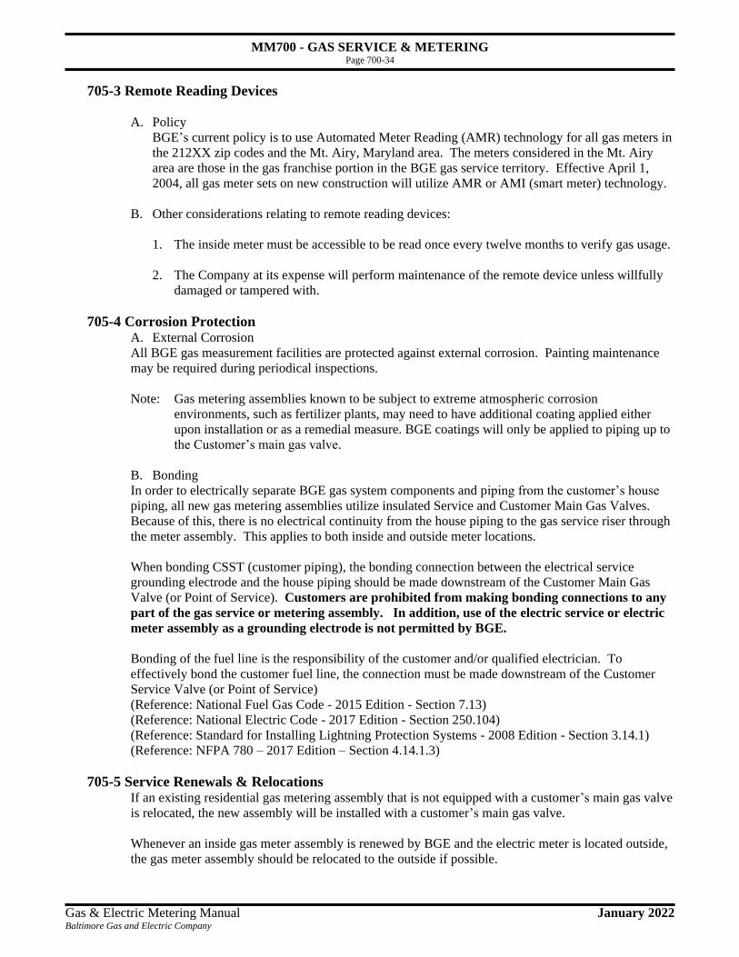
MM700 - GAS SERVICE & METERING Page 700-34
Gas & Electric Metering Manual January 2022 Baltimore Gas and Electric Company
705-3 Remote Reading Devices
A. Policy
BGE’s current policy is to use Automated Meter Reading (AMR) technology for all gas meters in
the 212XX zip codes and the Mt. Airy, Maryland area. The meters considered in the Mt. Airy
area are those in the gas franchise portion in the BGE gas service territory. Effective April 1,
2004, all gas meter sets on new construction will utilize AMR or AMI (smart meter) technology.
B. Other considerations relating to remote reading devices:
1. The inside meter must be accessible to be read once every twelve months to verify gas usage.
2. The Company at its expense will perform maintenance of the remote device unless willfully
damaged or tampered with.
705-4 Corrosion Protection A. External Corrosion
All BGE gas measurement facilities are protected against external corrosion. Painting maintenance
may be required during periodical inspections.
Note: Gas metering assemblies known to be subject to extreme atmospheric corrosion
environments, such as fertilizer plants, may need to have additional coating applied either
upon installation or as a remedial measure. BGE coatings will only be applied to piping up to
the Customer’s main gas valve.
B. Bonding
In order to electrically separate BGE gas system components and piping from the customer’s house
piping, all new gas metering assemblies utilize insulated Service and Customer Main Gas Valves.
Because of this, there is no electrical continuity from the house piping to the gas service riser through
the meter assembly. This applies to both inside and outside meter locations.
When bonding CSST (customer piping), the bonding connection between the electrical service
grounding electrode and the house piping should be made downstream of the Customer Main Gas
Valve (or Point of Service). Customers are prohibited from making bonding connections to any
part of the gas service or metering assembly. In addition, use of the electric service or electric
meter assembly as a grounding electrode is not permitted by BGE.
Bonding of the fuel line is the responsibility of the customer and/or qualified electrician. To
effectively bond the customer fuel line, the connection must be made downstream of the Customer
Service Valve (or Point of Service)
(Reference: National Fuel Gas Code - 2015 Edition - Section 7.13)
(Reference: National Electric Code - 2017 Edition - Section 250.104)
(Reference: Standard for Installing Lightning Protection Systems - 2008 Edition - Section 3.14.1)
(Reference: NFPA 780 – 2017 Edition – Section 4.14.1.3)
705-5 Service Renewals & Relocations If an existing residential gas metering assembly that is not equipped with a customer’s main gas valve
is relocated, the new assembly will be installed with a customer’s main gas valve.
Whenever an inside gas meter assembly is renewed by BGE and the electric meter is located outside,
the gas meter assembly should be relocated to the outside if possible.

MM700 - GAS SERVICE & METERING Page 700-35
Gas & Electric Metering Manual January 2022 Baltimore Gas and Electric Company
705-6 Meters - General Rules The following general rules govern the location of gas metering assembly. If the location for the gas
metering assembly does not meet these specifications, consult your BGE representative.
A. Gas metering assemblies will not be installed in unventilated spaces. If an enclosed gas metering
assembly is required, the enclosure is to be a tightly constructed compartment to prevent the
uncontrolled migration of gas into building walls. Provision must be made for ventilation
openings in the door of the enclosure that permits access to the assembly for maintenance.
(Reference: National Fuel Gas Code - 2018 Edition - Section 5.7.2.1)
B. Gas metering assemblies will not be installed in places where it may be subjected to damage,
such as driveways & sidewalks (without suitable protection), public passages, halls, coal bins,
chimneys, under porches, in crawl spaces, etc. or where it will be subjected to excessive
corrosion, extreme temperature or sudden changes in temperatures.
(Reference: National Fuel Gas Code - 2018 Edition - Section 5.7.2.2, 5.7.2.3, 5.8.3, 5.8.4)
C. Gas metering assemblies located indoors will not be installed within three (3) feet of any
equipment with an open flame or subject to electric arcing; such as: circuit breaker panel boxes,
water heaters, house heating, furnaces, boilers, A/C compressors, etc. It is recommended that gas
meter assemblies be located outdoors and be at least three (3) feet from any equipment with an
open flame or subject to electric arcing.
(Reference: D.O.T., Office of Pipeline Safety, CFR 49 Regulation 192.353 (c)).
D. Gas metering assemblies will not be installed on walls or partitions subject to excessive vibration;
nor any wall or partition which appears to have structural defects of any kind.
E. Gas metering assemblies will not be installed in areas where the clearance from the front of the
meter to the opposite wall is less than three (3) feet; nor where it will be necessary to remove one
meter to make possible the removal of another. Gas meters will be installed so that there is at
least four (4) feet clearance from the front of the meter to the wall directly opposite where an
electric meter is located.
F. Gas metering assemblies will not be installed under a non-insulated, combustible stairway or at
the foot of a stairway where the distance between the bottom step and the meter will be less than
four (4) feet measured horizontally.
G. Gas metering assemblies will not be installed in bath or toilet rooms (Existing installations found
in bathrooms will not be relocated except at the customer's request, in which case the relocation
will be made at our regular schedule of prices.) Toilet rooms where hazards exist are an
exception.
H. Gas metering assemblies located indoors will not be installed in garages, unless approved as an
exception to the BGE Outdoor Meter Location Standard per section 705-1 and with sufficient
protection.
I. If the gas metering assembly is to supply more than one apartment in an existing dwelling, there
must be a stop-cock or valve in each fuel line near the meter so that maintenance work on the fuel
line may be done without interrupting the supply to any other line served by the meter.

MM700 - GAS SERVICE & METERING Page 700-36
Gas & Electric Metering Manual January 2022 Baltimore Gas and Electric Company
J. Regulator/Relief valve vents
(Reference: National Fuel Gas Code - 2018 Edition – Section 5.8.5.1 and 5.9.8)
1. Must be vented to the outside and terminate at least 12” above grade.
2. Two or more regulator/relief vent lines may be manifolded to a single vent provided the
manifold flow area equals or exceeds the combined flow area of the relief valve outlets. The
minimum combined line size allowed is 1-1/2”.
3. All vent lines must be designed and installed to prevent the entry of water, insects, or other
foreign material.
K. Gas metering assemblies will not be located where the clearance between the floor and any
overhead structure is less than 6'-3" for Residential or eight (8) feet for Industrial & Commercial.
L. Outdoor gas metering assemblies or vent lines from inside regulators shall not be installed within
three (3) feet of an opening (excluding windows) used as an outside air intake (forced or gravity)
for ventilation, where venting gas could be drawn into a building or an enclosed space under an
occupied portion of a building. Regulator/relief valve vents located within 10 feet (measured
horizontally) of an air intake shall terminate at least three (3) feet above the highest point of the
air intake, see Figure 705-8L. Dryer vents and windows are not considered air intakes, but a
reasonable distance should be allowed between them and a gas metering assembly and/or
regulator/relief vent. This rule does not apply to the combustion air intake of a direct vent
appliance.
The preferred location of a gas meter is not under a window, but maybe allowed if all other
possible locations are not available.
(Reference: D.O.T., Office of Pipeline Safety, CFR 49 Regulation 192.355 (b)).
(Examples: Louvers installed in a foundation intended to provide air circulation for a crawl
space under an occupied portion of a home, such as a family room or a bedroom, would require
the 10 foot clearance. The intake of a direct vent appliance does not require the 10 foot
clearance.)
M. If a gas metering assembly is to be located in the proximity of a combustion air intake, the
manufacturers installation instruction or the local authority having jurisdiction should be
consulted for minimum clearance requirements. In the absence of specific requirements by the
aforementioned, BGE recommends a horizontal clearance of four (4) feet. This recommendation
will in no way supersede any requirements to be or currently established by the authorities having
jurisdiction.
Figure 705-8L

MM700 - GAS SERVICE & METERING Page 700-37
Gas & Electric Metering Manual January 2022 Baltimore Gas and Electric Company
N. Where more than one customer is to be supplied, the gas metering assemblies will be grouped at
one location and located so that each assembly is readily accessible to the customer served by it
and the Company. Each assembly shall measure all the gas to be used in the individual occupancy
unit. Central source heating, cooling and hot water systems or combinations thereof for the
building are permitted.
O. On outside gas metering assemblies it is preferred for the assembly to be installed in the vicinity
of the electric meter.
P. The gas service and the gas metering assembly will not be located where it may cause an
obstruction to a Siamese fire connection. An area with a 36” radius measured from the center of
the connection and extending downward to grade shall be kept clear of all associated piping and
the gas metering assembly.
Q. In areas subject to flooding and possible tidal surges (Zone “A” or Zone “AE”, based on flood
maps), the regulator vent(s) shall terminate at least one (1) foot above the 100-year base flood
elevation.1 BGE will consider the Base Flood Elevation (BFE)2 in the design process, and is
subject to enforcement by the authority having jurisdiction. If the height of the vent is greater
than five (5) feet from grade, a plugged tee should be installed about one (1) foot above the
regulator. Gas assemblies may be required to have additional protection from damage due to
floating debris during a flood. BGE is responsible for determining if additional protection is
needed; the customer is responsible for the associated costs for additional protection.
Note(s): (1) All vent lines must be designed and installed to prevent the entry of water, insects, or
other foreign material. Pipe dope shall be utilized on all threaded pipe and joints will be wrench-
tightened; (2) BFE is the computed elevation to which flood water is anticipated to rise and
shown on the Flood Insurance Rate Maps (FIRMs) or on the flood profiles (Floodplain
Management | FEMA.gov).
Figure 705-8S
R. A minimum of 1” clearance must be maintained between all meters and any structural materials
(i.e. building wall).

MM700 - GAS SERVICE & METERING Page 700-38
Gas & Electric Metering Manual January 2022 Baltimore Gas and Electric Company
706 Gas Inspection, Testing, and Service Activation
706-1 Customer Piping Activation
The appropriate inspections and leakage tests are approved by the inspecting agency. The following
items are presented as informational and best practices. Introducing gas into the customer fuel
line(s) is the responsibility of the licensed plumber/qualified agency. BGE may re-introduce gas
into the customer’s fuel line(s) under certain conditions, see Section 706-7.
Over the years the pressure test required for new piping systems, including additions to existing
systems, has been confused with the test for leakage. As specified, the pressure test is required only
for new piping systems or new additions, not including equipment shutoff valves, equipment
connection, or equipment.
Before gas is introduced into a system of new gas piping by the qualified agency, or back into an
existing system after being shut off, the entire system will be inspected to determine that there are no
open fittings or ends and that all manual valves at outlets on equipment are closed and all unused
valves at outlets are closed and plugged or capped.
The test for leakage is applicable whenever a gas piping system is placed in service either initially or
after being shut off. The medium used for the test is the gas supplied at its supply pressure. The gas is
applied to the piping, equipment, and equipment connections and valves.
Immediately after turning on the gas, the piping system will be leak tested to ascertain that no gas is
escaping. If leakage is indicated, the gas supply will be shut off until the necessary repairs have been
made.
706-2 Added or Converted Equipment When additional or replacement equipment is installed, or an appliance is converted to gas from
another fuel, the location in which the equipment is to be operated shall be checked to verify that it
meets the requirements of the National Fuel Gas Code. BGE will not release set a meter until we
receive a certification from the local jurisdiction that the equipment has met these requirements.
(Reference: National Fuel Gas Code - 2015 Edition - Section 9.1.2)

MM700 - GAS SERVICE & METERING Page 700-39
Gas & Electric Metering Manual January 2022 Baltimore Gas and Electric Company
706-3 Underground Piping After the Meter – Residential The Code of Maryland Regulations prevents gas utilities from providing gas service to residential
customers with underground piping after the gas meter.
Code of Maryland Regulations
20.55.09.07.D2
Location of Residential Service Lines and Meters:
Gas service may not be provided to new or renewed service lines if there is any underground pipeline after
the meter, unless the pipeline carries gas only to gas utilization equipment located outdoors.
BGE will provide gas service to a meter if the underground piping is to supply gas utilization
equipment such as pool heaters or gas grills. BGE will not provide or may revoke service if the gas
line runs underground after the meter and then enters back into a building or structure with a living
space.
This regulation does not apply to commercial and industrial customers. Gas service can be provided
to commercial and industrial customers with underground piping after the meter. For commercial or
industrial customers, it is their responsible to meet the State of Maryland’s requirements for leak
survey of their lines. Consult with the State for their requirements.
706-4 Pressure Testing All new customer piping systems will be tested to insure integrity. The tests will be conducted by the
customer’s qualified representative and witnessed by the appropriate personnel of the local
jurisdiction having authority if deemed necessary. The following requirements are based on typical
National Fuel Gas Code procedures (check with the local inspection authority for specific test
requirements).
Test Pressure: Test pressure will be measured with a manometer or with a pressure measuring
device designed and calibrated to read, record, or indicate a pressure loss due to leakage during the
pressure test period. The source of pressure will be isolated before the pressure tests are made. The
test pressure to be used will be no less than 1-1/2 times the proposed maximum working pressure, but
not less than 3 psig (20 kPa gauge), irrespective of design pressure.
(Reference: National Fuel Gas Code - 2018 Edition - Section 8.1.4)
Test duration will be 1/2 hour for each 500 cubic feet (14 m3) of pipe volume or fraction thereof.
When testing a system having a volume less than 10 cubic feet (0.28 m3) or a system in a single-
family dwelling, the test duration may be reduced to 10 minutes. For piping systems having a volume
of more than 24,000 cubic feet (680 m3), the duration of the test will not be required to exceed 24
hours.
(Reference: National Fuel Gas Code - 2018 Edition - Section 8.1.4.3)
Test Medium: The test medium will be air, nitrogen, or carbon dioxide.
OXYGEN SHALL NEVER BE USED
(Reference: National Fuel Gas Code - 2015 Edition - Section 8.1.2)
706-5 Purging When applicable the service piping may require purging with inert gas prior to activation. Please
consult with your BGE representative.
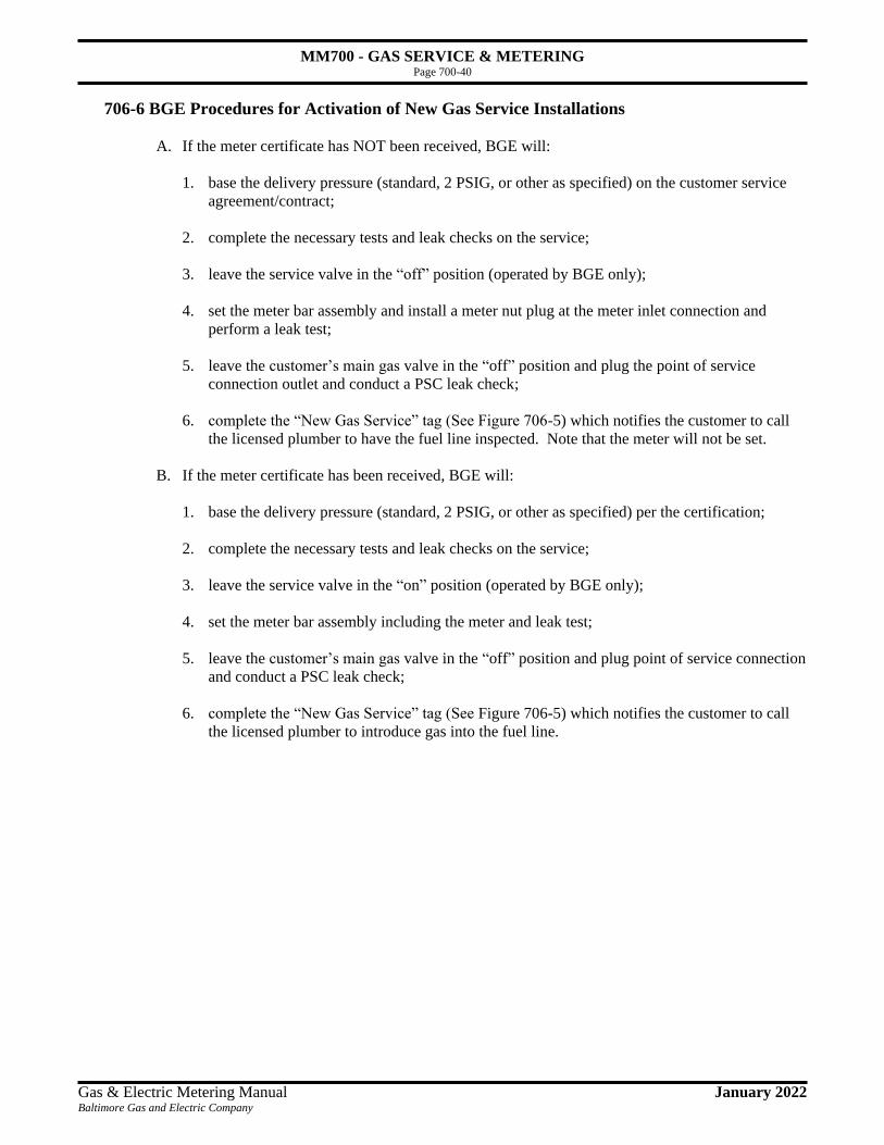
MM700 - GAS SERVICE & METERING Page 700-40
Gas & Electric Metering Manual January 2022 Baltimore Gas and Electric Company
706-6 BGE Procedures for Activation of New Gas Service Installations
A. If the meter certificate has NOT been received, BGE will:
1. base the delivery pressure (standard, 2 PSIG, or other as specified) on the customer service
agreement/contract;
2. complete the necessary tests and leak checks on the service;
3. leave the service valve in the “off” position (operated by BGE only);
4. set the meter bar assembly and install a meter nut plug at the meter inlet connection and
perform a leak test;
5. leave the customer’s main gas valve in the “off” position and plug the point of service
connection outlet and conduct a PSC leak check;
6. complete the “New Gas Service” tag (See Figure 706-5) which notifies the customer to call
the licensed plumber to have the fuel line inspected. Note that the meter will not be set.
B. If the meter certificate has been received, BGE will:
1. base the delivery pressure (standard, 2 PSIG, or other as specified) per the certification;
2. complete the necessary tests and leak checks on the service;
3. leave the service valve in the “on” position (operated by BGE only);
4. set the meter bar assembly including the meter and leak test;
5. leave the customer’s main gas valve in the “off” position and plug point of service connection
and conduct a PSC leak check;
6. complete the “New Gas Service” tag (See Figure 706-5) which notifies the customer to call
the licensed plumber to introduce gas into the fuel line.

MM700 - GAS SERVICE & METERING Page 700-41
Gas & Electric Metering Manual January 2022 Baltimore Gas and Electric Company
The following notification cards will be provided to the customer or left at the meter location, if the
customer is not present, in the case of BGE encountering the above two conditions.
Figure 706-5
Attention:
Licensed Plumber
Only a licensed plumber or qualified
agency shall tie in and introduce natural gas into this building.
Per the National Fuel Gas Code and local regulations, the licensed plumber is responsible for performing a leak test immediately after turning on the gas.
BGE has installed a 2 PSIG meter bar regulator assembly; if this is incorrect, contact BGE prior to introducing natural gas into the customer's building.
BGE has installed a standard pressure meter bar regulator assembly; if this is incorrect, contact BGE prior to introducing natural gas into the customer's building.
✓ Do NOT remove the Customer’s Main Gas
Valve
✓ Multi-meter manifold installations, VERIFY customer’s fuel lines match the customer’s meter
✓ Meter assembly MUST remain plumb
Attention: Customer, Gas Service Installed
Your new natural gas service
has been installed.
Meter not installed. Contact your licensed plumber to have your fuel line inspected and approved by your local jurisdiction.
Meter installed. Contact your licensed plumber to introduce natural gas into the fuel line.
If you have any questions, please call BGE at 410-850-4620 or 1-800-233-1854 outside the Baltimore metropolitan area.
Attention: Licensed Plumber
Please read the other
side of this card

MM700 - GAS SERVICE & METERING Page 700-42
Gas & Electric Metering Manual January 2022 Baltimore Gas and Electric Company
706-7 BGE Procedures for Re-Connection of Existing Gas Service Installations (Relocations &
Meter Increases)
A. Customer initiated jobs:
1. BGE will install a customer’s main gas valve (P.O.S. valve) at the outlet of the meter,
which is plugged and placed in the "closed" position.
2. The customer is responsible for retaining a licensed plumber or qualified agency to bring
(connect) the fuel line (piping) to the customer’s main gas valve (P.O.S.), re-introduce
gas into the customer’s fuel line, and re-light the customer’s equipment at the completion
of the job.
3. The licensed plumber or qualified agency shall NOT tie in a new fuel line until after the
meter and/or service has been increased by BGE.
B. BGE initiated jobs:
1. BGE will introduce gas into the customer’s fuel line, and re-light the customer’s
equipment at the completion of the job.
(Reference: BGE Gas Service Tariff, Customer’s Installation, Section 4.2)
C. Re-Lights: Proper Practices
1. Master valves to items such as furnaces and water heaters should be turned off before starting
any work on the customer’s fuel line.
2. The job should be properly pressure and leak tested upon completion.
3. All necessary documentation should be completed.
4. Do not re-light appliances if the delivery pressures are different between the BGE metering
equipment and the customer’s fuel line (piping) and/or equipment.
5. Do not re-use old fittings.
6. Do not use a series of nipples and couplings to achieve the proper length needed.
7. Do not apply pipe dope to the female threads of a fitting, apply it to all male threads.
8. Do not cut off a branch service unless all meters can be turned off, or there is an emergency.
9. Do not re-light appliances if they are found to be in an unsafe condition.

MM800 - TYPICAL RESIDENTIAL & SMALL COMMERCIAL GAS METER SET DRAWINGS Page 800-1
Gas & Electric Metering Manual May 2021 Baltimore Gas and Electric Company
800 Typical Residential & Small Commercial Gas Meter Sets
800-1 General Comments This section was developed to show drawings of typical meter sets that BGE may install. These
drawings are to be used as reference for understanding the size of the meter sets. In addition, the
following are general rules for the meter assemblies shown in this section.
A. A 6" minimum of exposed pipe from the bottom of the service riser valve or service flange
connection to final grade must be allowed.
B The vents from the regulators must face downwards. If the vent is not facing downwards, then
piping shall be installed to direct the vent downwards.
C. A 12" minimum between final grade and the regulator's vent shall be maintained.
D. BGE uses insulated unions on the Service Valve and at the Point of Service on the Customer’s
Main Gas Valve, therefore all gas meter assemblies are electrically insulated from the houseline.
Do not electrically bond the houseline to the metering equipment.
E. Be sure that the respective clear work space is provided for each meter installation.
F. There must be a minimum of at least 1" between the back of the meter and the finished wall.
G. Inside meter installations are shown ONLY for locations that do not meet the BGE Outside
Metering Policy. The regulator, if needed, shall be vented outside of the building.

MM800 - TYPICAL RESIDENTIAL & SMALL COMMERCIAL GAS METER SET DRAWINGS Page 800-2
Gas & Electric Metering Manual May 2021 Baltimore Gas and Electric Company
801 Residential & Small Commercial Low Pressure (LP)
801-1 Single Meter Set; 275;
Outside
Service Pressure Low Pressure (LP)
Delivery Pressure Standard
CFH 0 - 275
Approximate Space Requirement: 14" W x 32" H (min.) x 16" D
Minimum Clear Work Space Required: 38" W x 44" H x 52" D
Important: Gas Meter Assembly Must Be Insulated From House Piping

MM800 - TYPICAL RESIDENTIAL & SMALL COMMERCIAL GAS METER SET DRAWINGS Page 800-3
Gas & Electric Metering Manual May 2021 Baltimore Gas and Electric Company
801-2 Single Meter Set; 415;
Outside
Service Pressure Low Pressure (LP)
Delivery Pressure Standard
CFH 276 - 425
Approximate Space Requirement: 17" W x 37" H (min.) x 16" D
Minimum Clear Work Space Required: 41" W x 49" H x 52" D
Important: Gas Meter Assembly Must Be Insulated From House Piping

MM800 - TYPICAL RESIDENTIAL & SMALL COMMERCIAL GAS METER SET DRAWINGS Page 800-4
Gas & Electric Metering Manual May 2021 Baltimore Gas and Electric Company
801-3 Single Meter Set; 630;
Outside
Service Pressure Low Pressure (LP)
Delivery Pressure Standard
CFH 426 - 630
Approximate Space Requirement: 17" W x 37" H (min.) x 16" D
Minimum Clear Work Space Required: 41" W x 49" H x 52" D
Important: Gas Meter Assembly Must Be Insulated From House Piping

MM800 - TYPICAL RESIDENTIAL & SMALL COMMERCIAL GAS METER SET DRAWINGS Page 800-5
Gas & Electric Metering Manual May 2021 Baltimore Gas and Electric Company
801-4 Single Meter Set; 800;
Outside
Service Pressure Low Pressure (LP)
Delivery Pressure Standard
CFH 631 - 800
Approximate Space Requirement: 29" W x 36" H (min.) x 16" D
Minimum Clear Work Space Required: 53" W x 48" H x 52" D
Important: Gas Meter Assembly Must Be Insulated From House Piping

MM800 - TYPICAL RESIDENTIAL & SMALL COMMERCIAL GAS METER SET DRAWINGS Page 800-6
Gas & Electric Metering Manual May 2021 Baltimore Gas and Electric Company
802 Residential & Small Commercial Medium Pressure (MP)
802-1 Single Meter Set; 275;
Outside - Compact
Service Pressure Medium Pressure (MP)
Delivery Pressure Standard
CFH 0 - 295
Approximate Space Requirement: 13" W x 34" H x 20" D
Minimum Clear Work Space Required: 37" W x 46" H x 56" D
Important: Gas Meter Assembly Must Be Insulated From House Piping
BGE Reference Only 31-538
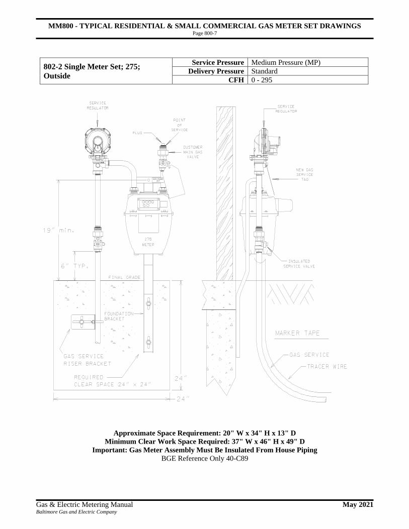
MM800 - TYPICAL RESIDENTIAL & SMALL COMMERCIAL GAS METER SET DRAWINGS Page 800-7
Gas & Electric Metering Manual May 2021 Baltimore Gas and Electric Company
802-2 Single Meter Set; 275;
Outside
Service Pressure Medium Pressure (MP)
Delivery Pressure Standard
CFH 0 - 295
Approximate Space Requirement: 20" W x 34" H x 13" D
Minimum Clear Work Space Required: 37" W x 46" H x 49" D
Important: Gas Meter Assembly Must Be Insulated From House Piping BGE Reference Only 40-C89

MM800 - TYPICAL RESIDENTIAL & SMALL COMMERCIAL GAS METER SET DRAWINGS Page 800-8
Gas & Electric Metering Manual May 2021 Baltimore Gas and Electric Company
802-3 Single Meter Set; 275;
Stacked Installation
Service Pressure Medium Pressure (MP)
Delivery Pressure Standard
CFH 0 - 295
Approximate Space Requirement: 24" W x 57" H (min.) x 20" D
Minimum Clear Work Space Required: 48" W x 69" H (min) x 56" D
Important: Gas Meter Assembly Must Be Insulated From House Piping

MM800 - TYPICAL RESIDENTIAL & SMALL COMMERCIAL GAS METER SET DRAWINGS Page 800-9
Gas & Electric Metering Manual May 2021 Baltimore Gas and Electric Company
802-4 Single Meter Set; 415/630;
Outside
Service Pressure Medium Pressure (MP)
Delivery Pressure Standard
CFH 296 – 600 / 601 – 800
Approximate Space Requirement: 30" W x 38" H x 17" D
Minimum Clear Work Space Required: 66" W x 50" H x 54" D
Important: Gas Meter Assembly Must Be Insulated From House Piping
If Installed Inside, Vent Must Be Extended Outside
BGE Reference Only 31-840

MM800 - TYPICAL RESIDENTIAL & SMALL COMMERCIAL GAS METER SET DRAWINGS Page 800-10
Gas & Electric Metering Manual May 2021 Baltimore Gas and Electric Company
802-5 Single Meter Set; 800;
Outside
Service Pressure Medium Pressure (MP)
Delivery Pressure Standard
CFH 801 - 1200
Approximate Space Requirement: 40" W x 38" H (min.) x 18" D
Minimum Clear Work Space Required: 64" W x 44" H x 54" D
Important: Gas Meter Assembly Must Be Insulated From House Piping
If Installed Inside, Vent Must Be Extended Outside

MM800 - TYPICAL RESIDENTIAL & SMALL COMMERCIAL GAS METER SET DRAWINGS Page 800-11
Gas & Electric Metering Manual May 2021 Baltimore Gas and Electric Company
803 Residential & Small Commercial High Pressure (HP)
803-1 Single Meter Set; 275;
Compact Outside
Service Pressure High Pressure (HP)
Delivery Pressure Standard or 2 PSIG
CFH 0 – 295 (std) or 0 – 330 (2 PSIG)
Approximate Space Requirement: 13" W x 34" H x 20" D
Minimum Clear Work Space Required: 37" W x 46" H x 56" D
Important: Gas Meter Assembly Must Be Insulated From House Piping BGE Reference Only 31-802 (std) or 31-801 (2 PSIG)

MM800 - TYPICAL RESIDENTIAL & SMALL COMMERCIAL GAS METER SET DRAWINGS Page 800-12
Gas & Electric Metering Manual May 2021 Baltimore Gas and Electric Company
803-2 Single Meter Set; 275;
Outside
Service Pressure High Pressure (HP)
Delivery Pressure Standard or 2 PSIG
CFH 0 – 295 (std) or 0 – 330 (2 PSIG)
Approximate Space Requirement: 20" W x 34" H x 13" D
Minimum Clear Work Space Required: 37" W x 46" H x 49" D
Important: Gas Meter Assembly Must Be Insulated From House Piping BGE Reference Only 31-060 (std) or 31-054 (2 PSIG)

MM800 - TYPICAL RESIDENTIAL & SMALL COMMERCIAL GAS METER SET DRAWINGS Page 800-13
Gas & Electric Metering Manual May 2021 Baltimore Gas and Electric Company
803-3 Single Meter Set; 275;
Stacked Installation
Service Pressure High Pressure (HP)
Delivery Pressure Standard or 2 PSIG
CFH 0 – 295 (std) or 0 –330 (2 PSIG)
Approximate Space Requirement: 24" W x 57" H x 20" D
Minimum Clear Work Space Required: 48" W x 69" H (min) x 56" D
Important: Gas Meter Assembly Must Be Insulated From House Piping

MM800 - TYPICAL RESIDENTIAL & SMALL COMMERCIAL GAS METER SET DRAWINGS Page 800-14
Gas & Electric Metering Manual May 2021 Baltimore Gas and Electric Company
803-4 Single Meter Set; 415/630;
Outside
Service Pressure High Pressure (HP)
Delivery Pressure Standard
CFH 296 – 600 / 601 – 800
Approximate Space Requirement: 30" W x 38" H x 17" D
Minimum Clear Work Space Required: 54" W x 50" H x 53" D
Important: Gas Meter Assembly Must Be Insulated From House Piping
BGE Reference Only 31-842

MM800 - TYPICAL RESIDENTIAL & SMALL COMMERCIAL GAS METER SET DRAWINGS Page 800-15
Gas & Electric Metering Manual May 2021 Baltimore Gas and Electric Company
803-5 Single Meter Set; 415/630;
Outside
Service Pressure High Pressure (HP)
Delivery Pressure 2 PSIG
CFH 331 – 675 / 676 – 999
Approximate Space Requirement: 30" W x 38" H x 17" D
Minimum Clear Work Space Required: 54" W x 50" H x 50" D
Important: Gas Meter Assembly Must Be Insulated From House Piping BGE Reference Only 40-C67

MM800 - TYPICAL RESIDENTIAL & SMALL COMMERCIAL GAS METER SET DRAWINGS Page 800-16
Gas & Electric Metering Manual May 2021 Baltimore Gas and Electric Company
803-6 Single Meter Set; 800;
Outside
Service Pressure High Pressure (HP)
Delivery Pressure Standard
CFH 801 – 1200
Approximate Space Requirement: 32" W x 38" H x 18" D
Minimum Clear Work Space Required: 56" W x 50" H x 54" D
Important: Gas Meter Assembly Must Be Insulated From House Piping

MM800 - TYPICAL RESIDENTIAL & SMALL COMMERCIAL GAS METER SET DRAWINGS Page 800-17
Gas & Electric Metering Manual May 2021 Baltimore Gas and Electric Company
803-7 Single Meter Set; 800;
Outside
Service Pressure High Pressure (HP)
Delivery Pressure 2 PSIG
CFH 1000 – 1350
Approximate Space Requirement: 32" W x 38" H x 18" D
Minimum Clear Work Space Required: 56" W x 50" H x 54" D
Important: Gas Meter Assembly Must Be Insulated From House Piping

MM800 - TYPICAL RESIDENTIAL & SMALL COMMERCIAL GAS METER SET DRAWINGS Page 800-18
Gas & Electric Metering Manual May 2021 Baltimore Gas and Electric Company
804 Residential & Small Commercial Over High Pressure (OHP)
804-1 Single Meter Set; 275;
Outside
Service Pressure Over High Pressure (OHP)
Delivery Pressure Standard or 2 PSIG
CFH 0 – 295 (std) or 0 – 330 (2 PSIG)
Approximate Space Requirement: 24" W x 36" H x 16" D
Minimum Clear Work Space Required: 48" W x 48" H x 52" D
Important: Gas Meter Assembly Must Be Insulated From House Piping
BGE Reference Only 31-533 (std) or 31-909 (2 PSIG)

MM800 - TYPICAL RESIDENTIAL & SMALL COMMERCIAL GAS METER SET DRAWINGS Page 800-19
Gas & Electric Metering Manual May 2021 Baltimore Gas and Electric Company
804-2 Single Meter Set; 415;
Outside
Service Pressure Over High Pressure (OHP)
Delivery Pressure Standard or 2 PSIG
CFH 296 – 600 (std) or 331 – 675 (2 PSIG)
Approximate Space Requirement: 28" W x 39" H x 17" D
Minimum Clear Work Space Required: 48" W x 51" H x 53" D
Important: Gas Meter Assembly Must Be Insulated From House Piping
BGE Reference Only 31-844 (std) or 40-C68 (2 PSIG)

MM800 - TYPICAL RESIDENTIAL & SMALL COMMERCIAL GAS METER SET DRAWINGS Page 800-20
Gas & Electric Metering Manual May 2021 Baltimore Gas and Electric Company
804-3 Single Meter Set; 630;
Outside
Service Pressure Over High Pressure (OHP)
Delivery Pressure Standard or 2 PSIG
CFH 601 – 800 (std) or 676 – 999 (2 PSIG)
Approximate Space Requirement: 30" W x 38" H x 17" D
Minimum Clear Work Space Required: 54" W x 50" H x 53" D
Important: Gas Meter Assembly Must Be Insulated From House Piping
BGE Reference Only 31-844 (std) or 40-C68 (2 PSIG)

MM800 - TYPICAL RESIDENTIAL & SMALL COMMERCIAL GAS METER SET DRAWINGS Page 800-21
Gas & Electric Metering Manual May 2021 Baltimore Gas and Electric Company
804-4 Single Meter Set; 800;
Outside
Service Pressure Over High Pressure (OHP)
Delivery Pressure Standard
CFH 801 - 1200
Approximate Space Requirement: 32" W x 39" H x 18" D
Minimum Clear Work Space Required: 54" W x 51" H x 54" D
Important: Gas Meter Assembly Must Be Insulated From House Piping

MM800 - TYPICAL RESIDENTIAL & SMALL COMMERCIAL GAS METER SET DRAWINGS Page 800-22
Gas & Electric Metering Manual May 2021 Baltimore Gas and Electric Company
804-5 Single Meter Set; 800;
Outside
Service Pressure Over High Pressure (OHP)
Delivery Pressure 2 PSIG
CFH 976 -1350
Approximate Space Requirement: 32" W x 39" H x 18" D
Minimum Clear Work Space Required: 54" W x 51" H x 54" D
Important: Gas Meter Assembly Must Be Insulated From House Piping

MM900 - TYPICAL COMMERCIAL & INDUSTRIAL GAS METER SET DRAWINGS Page 900-1
Gas & Electric Metering Manual May 2021 Baltimore Gas and Electric Company
900 Typical Commercial & Industrial Gas Meter Sets
900-1 General Comments This section was developed to show drawings of typical meter sets that BGE may install. These
drawings are to be used as reference for understanding the size of the meter sets. In addition, the
following are general rules for the meter assemblies shown in this section.
A. A 6" minimum of exposed pipe from the bottom of the service riser valve or service flange
connection to final grade must be allowed.
B. The vents from the regulators must face downwards. If the vent is not facing downwards, then
piping shall be installed to direct the vent downwards.
C. A 12" minimum between final grade and the regulator's vent shall be maintained.
D. BGE uses insulated unions on the Service Valve and at the Point of Service on the Customer’s
Main Gas Valve, therefore all gas meter assemblies are electrically insulated from the houseline.
Do not electrically bond the houseline to the metering equipment.
E. Be sure that the respective clear work space is provided for each meter installation.
F. There must be a minimum of at least 1" between the back of the meter and the finished wall.
G. BGE connections (outlet) sizes per meter size.
Meter Size Outlet Piping Size
250 3/4"
415, 630 1 ¼”
800 1 ½”
3M 2”
5M & 7M 3”
11M, 16M & 23M232 4”
23M & 38M 6”
56M 8”
102M 10”
H. Inside meter installations are shown ONLY for locations that do not meet the BGE Metering
Location Standard. The regulator, if needed, shall be vented outside of the building.
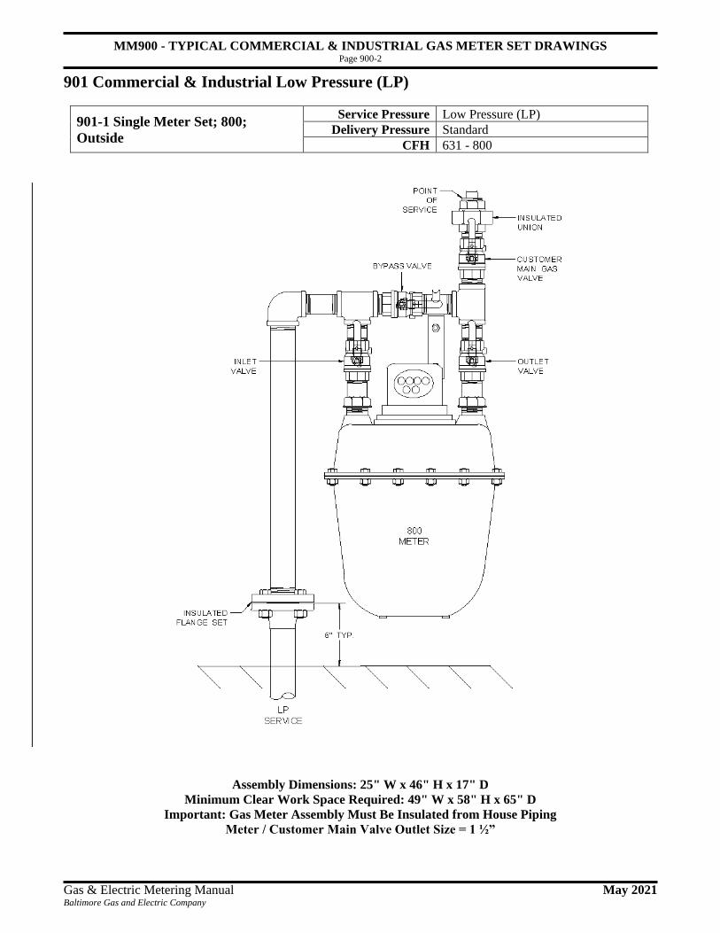
MM900 - TYPICAL COMMERCIAL & INDUSTRIAL GAS METER SET DRAWINGS Page 900-2
Gas & Electric Metering Manual May 2021 Baltimore Gas and Electric Company
901 Commercial & Industrial Low Pressure (LP) 901-1 Single Meter Set; 800; Outside
901-1 Single Meter Set; 800;
Outside
Service Pressure Low Pressure (LP)
Delivery Pressure Standard
CFH 631 - 800
Assembly Dimensions: 25" W x 46" H x 17" D
Minimum Clear Work Space Required: 49" W x 58" H x 65" D
Important: Gas Meter Assembly Must Be Insulated from House Piping
Meter / Customer Main Valve Outlet Size = 1 ½”

MM900 - TYPICAL COMMERCIAL & INDUSTRIAL GAS METER SET DRAWINGS Page 900-3
Gas & Electric Metering Manual May 2021 Baltimore Gas and Electric Company
901-2 Single Meter Set; 3M; Outside
901-2 Single Meter Set; 3M; Outside
Service Pressure Low Pressure (LP)
Delivery Pressure Standard
CFH 801 - 2580
Assembly Dimensions: 26" W x 50" H x 24" D
Minimum Clear Work Space Required: 50" W x 62" H x 72" D
Important: Gas Meter Assembly Must Be Insulated from House Piping
Meter / Customer Main Valve Outlet Size = 2"

MM900 - TYPICAL COMMERCIAL & INDUSTRIAL GAS METER SET DRAWINGS Page 900-4
Gas & Electric Metering Manual May 2021 Baltimore Gas and Electric Company
901-3 Single Meter Set; 5M; Outside
901-3 Single Meter Set; 5M; Outside
Service Pressure Low Pressure (LP)
Delivery Pressure Standard
CFH 2581 - 3975
Assembly Dimensions: 35" W x 57" H x 26" D
Minimum Clear Work Space Required: 59" W x 69" H x 74" D
Important: Gas Meter Assembly Must Be Insulated from House Piping
Meter / Customer Main Valve Outlet Size = 3"

MM900 - TYPICAL COMMERCIAL & INDUSTRIAL GAS METER SET DRAWINGS Page 900-5
Gas & Electric Metering Manual May 2021 Baltimore Gas and Electric Company
901-4 Single Meter Set; 7M; Outside
901-4 Single Meter Set; 7M; Outside
Service Pressure Low Pressure (LP)
Delivery Pressure Standard
CFH 3976 - 5400
Assembly Dimensions: 32" W x 50" H x 24" D
Minimum Clear Work Space Required: 56" W x 62" H x 72" D
Pad Size Required: 3' x 4' (min.) 4” – 6” Thick
Important: Gas Meter Assembly Must Be Insulated from House Piping
Meter / Customer Main Valve Outlet Size = 3"

MM900 - TYPICAL COMMERCIAL & INDUSTRIAL GAS METER SET DRAWINGS Page 900-6
Gas & Electric Metering Manual May 2021 Baltimore Gas and Electric Company
901-5 Single Meter Set; 11M; Outside
901-5 Single Meter Set; 11M;
Outside
Service Pressure Low Pressure (LP)
Delivery Pressure Standard
CFH 5401 - 7300
Assembly Dimensions: 50" W x 72" H x 28"
Minimum Clear Work Space Required: 74" W x 84" H x 76" D
Pad Size Required: 3' x 4' (min.) 4” – 6” Thick
Important: Gas Meter Assembly Must Be Insulated from House Piping
Meter / Customer Main Valve Outlet Size = 4"

MM900 - TYPICAL COMMERCIAL & INDUSTRIAL GAS METER SET DRAWINGS Page 900-7
Gas & Electric Metering Manual May 2021 Baltimore Gas and Electric Company
901-6 Single Meter Set; 16M/23M232; Outside
901-6 Single Meter Set;
16M/23M232; Outside
Service Pressure Low Pressure (LP)
Delivery Pressure Standard
CFH 7301 – 9950 / 7301 – 10950
Assembly Dimensions: 50" W x 72" H x 32" D
Minimum Clear Work Space Required: 74" W x 84" H x 80" D
Pad Size Required: 3' x 4' (min.) 4” – 6” Thick
Important: Gas Meter Assembly Must Be Insulated from House Piping
Meter / Customer Main Valve Outlet Size = 4"
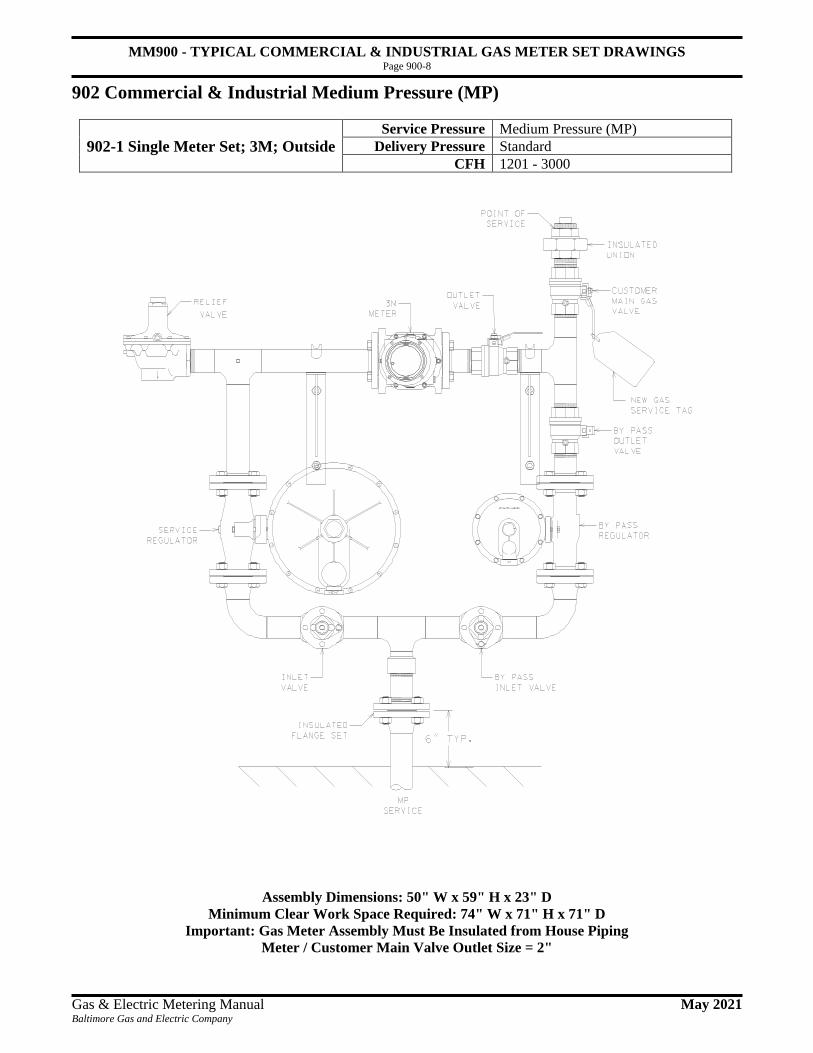
MM900 - TYPICAL COMMERCIAL & INDUSTRIAL GAS METER SET DRAWINGS Page 900-8
Gas & Electric Metering Manual May 2021 Baltimore Gas and Electric Company
902 Commercial & Industrial Medium Pressure (MP) 902-1 Single Meter Set; 3M; Outside
902-1 Single Meter Set; 3M; Outside
Service Pressure Medium Pressure (MP)
Delivery Pressure Standard
CFH 1201 - 3000
Assembly Dimensions: 50" W x 59" H x 23" D
Minimum Clear Work Space Required: 74" W x 71" H x 71" D
Important: Gas Meter Assembly Must Be Insulated from House Piping
Meter / Customer Main Valve Outlet Size = 2"

MM900 - TYPICAL COMMERCIAL & INDUSTRIAL GAS METER SET DRAWINGS Page 900-9
Gas & Electric Metering Manual May 2021 Baltimore Gas and Electric Company
902-2 Single Meter Set; 5M; Outside
902-2 Single Meter Set; 5M; Outside
Service Pressure Medium Pressure (MP)
Delivery Pressure Standard
CFH 3001 - 5000
Assembly Dimensions: 55" W x 65" H x 26" D
Minimum Clear Work Space Required: 79" W x 77" H x 74" D
Important: Gas Meter Assembly Must Be Insulated from House Piping
Meter / Customer Main Valve Outlet Size = 3"

MM900 - TYPICAL COMMERCIAL & INDUSTRIAL GAS METER SET DRAWINGS Page 900-10
Gas & Electric Metering Manual May 2021 Baltimore Gas and Electric Company
902-3 Single Meter Set; 7M; Outside
902-3 Single Meter Set; 7M; Outside
Service Pressure Medium Pressure (MP)
Delivery Pressure Standard
CFH 5001 – 7000
Assembly Dimensions: 82" W x 66" H x 24" D
Minimum Clear Work Space Required: 106" W x 78" H x 72" D
Pad Size Requirement: 3' x 6' (min.) 4” – 6” Thick
Important: Gas Meter Assembly Must Be Insulated from House Piping
Meter / Customer Main Valve Outlet Size = 3"

MM900 - TYPICAL COMMERCIAL & INDUSTRIAL GAS METER SET DRAWINGS Page 900-11
Gas & Electric Metering Manual May 2021 Baltimore Gas and Electric Company
902-4 Single Meter Set; 11M; Outside
902-4 Single Meter Set; 11M;
Outside
Service Pressure Medium Pressure (MP)
Delivery Pressure Standard
CFH 7001 – 11000
Assembly Dimensions: 106" W x 66" H x 24" D
Minimum Clear Work Space Required: 130" W x 78" H x 72" D
Pad Size Requirement: 3' x 8' (min.) 4” – 6” Thick
Important: Gas Meter Assembly Must Be Insulated from House Piping
Meter / Customer Main Valve Outlet Size = 4"

MM900 - TYPICAL COMMERCIAL & INDUSTRIAL GAS METER SET DRAWINGS Page 900-12
Gas & Electric Metering Manual May 2021 Baltimore Gas and Electric Company
902-5 Single Meter Set; 16M; Outside
902-5 Single Meter Set; 16M;
Outside
Service Pressure Medium Pressure (MP)
Delivery Pressure Standard
CFH 11001 - 16000
Assembly Dimensions: 132" W x 66" H x 28" D
Minimum Clear Work Space Required: 156" W x 78" H x 76" D
Pad Size Requirement: 4' x 10' (min.) 4” – 6” Thick
Important: Gas Meter Assembly Must Be Insulated from House Piping
Meter / Customer Main Valve Outlet Size = 4"

MM900 - TYPICAL COMMERCIAL & INDUSTRIAL GAS METER SET DRAWINGS Page 900-13
Gas & Electric Metering Manual May 2021 Baltimore Gas and Electric Company
902-6 Single Meter Set; 23M232; Outside
902-6 Single Meter Set; 23M232;
Outside
Service Pressure Medium Pressure (MP)
Delivery Pressure Standard
CFH 16001 - 23000
Assembly Dimensions: 132" W x 66" H x 32" D
Minimum Clear Work Space Required: 156" W x 78" H x 80" D
Pad Size Requirement: 4' x 10' (min.) 4” – 6” Thick
Important: Gas Meter Assembly Must Be Insulated from House Piping
Meter / Customer Main Valve Outlet Size = 4"

MM900 - TYPICAL COMMERCIAL & INDUSTRIAL GAS METER SET DRAWINGS Page 900-14
Gas & Electric Metering Manual May 2021 Baltimore Gas and Electric Company
902-7 Single Meter Set; 3M; Outside
902-7 Single Meter Set; 3M; Outside
Service Pressure Medium Pressure (MP)
Delivery Pressure Line Pressure
CFH 1200 - 3270
Assembly Dimensions: 26" W x 50" H x 24" D
Minimum Clear Work Space Required: 50" W x 62" H x 72" D
Important: Gas Meter Assembly Must Be Insulated from House Piping
Meter / Customer Main Valve Outlet Size = 2"

MM900 - TYPICAL COMMERCIAL & INDUSTRIAL GAS METER SET DRAWINGS Page 900-15
Gas & Electric Metering Manual May 2021 Baltimore Gas and Electric Company
902-8 Single Meter Set; 5M; Outside
902-8 Single Meter Set; 5M; Outside
Service Pressure Medium Pressure (MP)
Delivery Pressure Line Pressure
CFH 3271 - 5450
Assembly Dimensions: 35" W x 57" H x 26" D
Minimum Clear Work Space Required: 59" W x 69" H x 74" D
Important: Gas Meter Assembly Must Be Insulated from House Piping
Meter / Customer Main Valve Outlet Size = 3"

MM900 - TYPICAL COMMERCIAL & INDUSTRIAL GAS METER SET DRAWINGS Page 900-16
Gas & Electric Metering Manual May 2021 Baltimore Gas and Electric Company
902-9 Single Meter Set; 7M; Outside
902-9 Single Meter Set; 7M; Outside
Service Pressure Medium Pressure (MP)
Delivery Pressure Line Pressure
CFH 5451 - 7630
Assembly Dimensions: 32" W x 50" H x 24" D
Minimum Clear Work Space Required: 56" W x 62" H x 72" D
Pad Size Required: 3' x 4' (min.) 4” – 6” Thick
Important: Gas Meter Assembly Must Be Insulated from House Piping
Meter / Customer Main Valve Outlet Size = 3"

MM900 - TYPICAL COMMERCIAL & INDUSTRIAL GAS METER SET DRAWINGS Page 900-17
Gas & Electric Metering Manual May 2021 Baltimore Gas and Electric Company
902-10 Single Meter Set; 11M; Outside
902-10 Single Meter Set; 11M;
Outside
Service Pressure Medium Pressure (MP)
Delivery Pressure Line Pressure
CFH 7631 - 11990
Assembly Dimensions: 50" W x 72" H x 28"
Minimum Clear Work Space Required: 74" W x 84" H x 76" D
Pad Size Required: 3' x 4' (min.) 4” – 6” Thick
Important: Gas Meter Assembly Must Be Insulated from House Piping
Meter / Customer Main Valve Outlet Size = 4"

MM900 - TYPICAL COMMERCIAL & INDUSTRIAL GAS METER SET DRAWINGS Page 900-18
Gas & Electric Metering Manual May 2021 Baltimore Gas and Electric Company
902-11 Single Meter Set; 16M/23M232; Outside
902-11 Single Meter Set;
16M/23M232; Outside
Service Pressure Medium Pressure (MP)
Delivery Pressure Line Pressure
CFH 11991 - 17440 / 17441 - 25070
Assembly Dimensions: 50" W x 72" H x 32" D
Minimum Clear Work Space Required: 74" W x 84" H x 80" D
Pad Size Required: 3' x 4' (min.) 4” – 6” Thick
Important: Gas Meter Assembly Must Be Insulated from House Piping
Meter / Customer Main Valve Outlet Size = 4"

MM900 - TYPICAL COMMERCIAL & INDUSTRIAL GAS METER SET DRAWINGS Page 900-19
Gas & Electric Metering Manual May 2021 Baltimore Gas and Electric Company
902-12 Single Meter Set; 3M;
Outside
Service Pressure Medium Pressure (MP)
Delivery Pressure 14” water column (½ psi)
CFH 1200 - 3070
902-12 Single Meter Set; 3M; Outside
Assembly Dimensions: 50" W x 59" H x 23" D
Minimum Clear Work Space Required: 74" W x 71" H x 71" D
Important: Gas Meter Assembly Must Be Insulated from House Piping
Meter / Customer Main Valve Outlet Size = 2"

MM900 - TYPICAL COMMERCIAL & INDUSTRIAL GAS METER SET DRAWINGS Page 900-20
Gas & Electric Metering Manual May 2021 Baltimore Gas and Electric Company
903 Commercial & Industrial High Pressure (HP) 903-1 Single Meter Set; 3M; Outside
903-1 Single Meter Set; 3M; Outside
Service Pressure High Pressure (HP)
Delivery Pressure Standard
CFH 1201 - 3000
Assembly Dimensions: 50" W x 68" H x 23" D
Minimum Clear Work Space Required: 74" W x 80" H x 71" D
Important: Gas Meter Assembly Must Be Insulated from House Piping
Meter / Customer Main Valve Outlet Size = 2"

MM900 - TYPICAL COMMERCIAL & INDUSTRIAL GAS METER SET DRAWINGS Page 900-21
Gas & Electric Metering Manual May 2021 Baltimore Gas and Electric Company
903-2 Single Meter Set; 3M; Outside
Service Pressure High Pressure (HP)
Delivery Pressure 2 psig
CFH 1351 - 3375
903-2 Single Meter Set; 3M; Outside
Assembly Dimensions: 50" W x 68" H x 23" D
Minimum Clear Work Space Required: 74" W x 80" H x 71" D
Important: Gas Meter Assembly Must Be Insulated from House Piping
Meter / Customer Main Valve Outlet Size =2"

MM900 - TYPICAL COMMERCIAL & INDUSTRIAL GAS METER SET DRAWINGS Page 900-22
Gas & Electric Metering Manual May 2021 Baltimore Gas and Electric Company
903-3 Single Meter Set; 5M; Outside
Service Pressure High Pressure (HP)
Delivery Pressure Standard
CFH 3001 - 5000
903-3 Single Meter Set; 5M; Outside
Assembly Dimensions: 50" W x 72" H x 26" D
Minimum Clear Work Space Required: 74" W x 84" H x 74" D
Important: Gas Meter Assembly Must Be Insulated from House Piping
Meter / Customer Main Valve Outlet Size = 3"

MM900 - TYPICAL COMMERCIAL & INDUSTRIAL GAS METER SET DRAWINGS Page 900-23
Gas & Electric Metering Manual May 2021 Baltimore Gas and Electric Company
903-4 Single Meter Set; 5M;
Outside
Service Pressure High Pressure (HP)
Delivery Pressure 2 psig
CFH 3376 - 5625
903-4 Single Meter Set; 5M; Outside
Assembly Dimensions: 50" W x 72" H x 26" D
Minimum Clear Work Space Required: 74" W x 84" H x 74" D
Important: Gas Meter Assembly Must Be Insulated from House Piping
Meter / Customer Main Valve Outlet Size = 3"

MM900 - TYPICAL COMMERCIAL & INDUSTRIAL GAS METER SET DRAWINGS Page 900-24
Gas & Electric Metering Manual May 2021 Baltimore Gas and Electric Company
903-5 Single Meter Set; 7M;
Outside
Service Pressure High Pressure (HP)
Delivery Pressure Standard
CFH 5001 - 7000
903-5 Single Meter Set; 7M; Outside
Assembly Dimensions: 82" W x 66" H x 24" D
Minimum Clear Work Space Required: 106" W x 78" H x 72" D
Pad Size Requirement: 3' x 6' (min.) 4” – 6” Thick
Important: Gas Meter Assembly Must Be Insulated from House Piping
Meter / Customer Main Valve Outlet Size = 3"

MM900 - TYPICAL COMMERCIAL & INDUSTRIAL GAS METER SET DRAWINGS Page 900-25
Gas & Electric Metering Manual May 2021 Baltimore Gas and Electric Company
903-6 Single Meter Set; 7M; Outside
903-6 Single Meter Set; 7M; Outside
Service Pressure High Pressure (HP)
Delivery Pressure 2 psig
CFH 5626 - 7875
Assembly Dimensions: 82" W x 66" H x 24" D
Minimum Clear Work Space Required: 106" W x 78" H x 72" D
Pad Size Requirement: 3' x 6' (min.) 4” – 6” Thick
Important: Gas Meter Assembly Must Be Insulated from House Piping
Meter / Customer Main Valve Outlet Size = 3"

MM900 - TYPICAL COMMERCIAL & INDUSTRIAL GAS METER SET DRAWINGS Page 900-26
Gas & Electric Metering Manual May 2021 Baltimore Gas and Electric Company
903-7 Single Meter Set; 11M; Outside
903-7 Single Meter Set; 11M;
Outside
Service Pressure High Pressure (HP)
Delivery Pressure Standard
CFH 7001 - 9000
Assembly Dimensions: 84" W x 66" H x 28" D
Minimum Clear Work Space Required: 108" W x 78" H x 72" D
Pad Size Requirement: 3' x 6' (min.) 4” – 6” Thick
Important: Gas Meter Assembly Must Be Insulated from House Piping
Meter / Customer Main Valve Outlet Size = 4"

MM900 - TYPICAL COMMERCIAL & INDUSTRIAL GAS METER SET DRAWINGS Page 900-27
Gas & Electric Metering Manual May 2021 Baltimore Gas and Electric Company
903-8 Single Meter Set; 11M;
Outside
Service Pressure High Pressure (HP)
Delivery Pressure 2 psig
CFH 7876 - 12375
903-8 Single Meter Set; 11M; Outside
903-9 Single Meter Set;
16M/23M232; Outside
Service Pressure High Pressure (HP)
Delivery Pressure Standard
CFH 9001 – 16000 / 16001 – 23000
903-9 Single Meter Set; 16M/23M232; Outside
Assembly Dimensions: 104" W x 66" H x 32" D
Minimum Clear Work Space Required: 128" W x 78" H x 80" D
Pad Size Requirement: 3' x 8' (min.) 4” – 6” Thick
Important: Gas Meter Assembly Must Be Insulated from House Piping
Meter / Customer Main Valve Outlet Size = 4"

MM900 - TYPICAL COMMERCIAL & INDUSTRIAL GAS METER SET DRAWINGS Page 900-28
Gas & Electric Metering Manual May 2021 Baltimore Gas and Electric Company
903-10 Single Meter Set; 16M/23M232; Outside
903-10 Single Meter Set;
16M/23M232; Outside
Service Pressure High Pressure (HP)
Delivery Pressure 2 psig
CFH 12376 – 18000 / 18001 – 25875
Assembly Dimensions: 104" W x 66" H x 32" D
Minimum Clear Work Space Required: 128" W x 78" H x 80" D
Pad Size Requirement: 3' x 8' (min.) 4” – 6” Thick
Important: Gas Meter Assembly Must Be Insulated from House Piping
Meter / Customer Main Valve Outlet Size = 4"

MM900 - TYPICAL COMMERCIAL & INDUSTRIAL GAS METER SET DRAWINGS Page 900-29
Gas & Electric Metering Manual May 2021 Baltimore Gas and Electric Company
904 Commercial & Industrial Over High Pressure (OHP) 904-1 Single Meter Set; 3M; Outside
904-1 Single Meter Set; 3M; Outside
Service Pressure Over High Pressure (OHP)
Delivery Pressure Standard or 2 psig
CFH 1201 - 3000 or 1351 - 3375
Assembly Dimensions: 45" W x 62" H x 23" D
Minimum Clear Work Space Required: 64" W x 74" H x 71" D
Important: Gas Meter Assembly Must Be Insulated from House Piping
Meter / Customer Main Valve Outlet Size = 2"

MM900 - TYPICAL COMMERCIAL & INDUSTRIAL GAS METER SET DRAWINGS Page 900-30
Gas & Electric Metering Manual May 2021 Baltimore Gas and Electric Company
904-2 Single Meter Set; 5M; Outside
904-2 Single Meter Set; 5M; Outside
Service Pressure Over High Pressure (OHP)
Delivery Pressure Standard or 2 psig
CFH 3001 – 5000 or 3376 – 5625
Assembly Dimensions: 46" W x 68" H x 26" D
Minimum Clear Work Space Required: 70" W x 80" H x 74" D
Important: Gas Meter Assembly Must Be Insulated from House Piping
Meter / Customer Main Valve Outlet Size = 3"

MM900 - TYPICAL COMMERCIAL & INDUSTRIAL GAS METER SET DRAWINGS Page 900-31
Gas & Electric Metering Manual May 2021 Baltimore Gas and Electric Company
904-3 Single Meter Set; 7M; Outside
Service Pressure Over High Pressure (OHP)
Delivery Pressure Standard or 2 psig
CFH 5001 – 7000 or 5626 – 7875
904-3 Single Meter Set; 7M; Outside
Assembly Dimensions: 102" W x 66" H x 24" D
Minimum Clear Work Space Required: 126" W x 78" H x 24" D
Pad Size Requirement: 3' x 8' (min.) 4” – 6” Thick
Important: Gas Meter Assembly Must Be Insulated from House Piping
Meter / Customer Main Valve Outlet Size = 3"

MM900 - TYPICAL COMMERCIAL & INDUSTRIAL GAS METER SET DRAWINGS Page 900-32
Gas & Electric Metering Manual May 2021 Baltimore Gas and Electric Company
904-4 Single Meter Set; 11M/16M/23M232; Outside
904-4 Single Meter Set;
11M/16M/23M232; Outside
Service Pressure Over High Pressure (OHP)
Delivery Pressure Standard
CFH 7001 – 11000 / 11,001 – 16,000 /
16001 – 23000
904-5 Single Meter Set; 11M; Outside
904-5 Single Meter Set; 11M;
Outside
Service Pressure Over High Pressure (OHP)
Delivery Pressure 2 psig
CFH 7876 - 12375
Assembly Dimensions: 110" W x 66" H x 32" D
Minimum Clear Work Space Required: 134" W x 78" H x 80" D
Pad Size Requirement: 3' x 9' (min.) 4” – 6” Thick
Important: Gas Meter Assembly Must Be Insulated from House Piping
Meter / Customer Main Valve Outlet Size = 4"

MM900 - TYPICAL COMMERCIAL & INDUSTRIAL GAS METER SET DRAWINGS Page 900-33
Gas & Electric Metering Manual May 2021 Baltimore Gas and Electric Company
904-6 Single Meter Set; 16M/23M232; Outside
904-6 Single Meter Set;
16M/23M232; Outside
Service Pressure Over High Pressure (OHP)
Delivery Pressure 2 psig
CFH 12376 – 18000 / 18001 – 25875
Assembly Dimensions: 110" W x 66" H x 34" D
Minimum Clear Work Space Required: 134" W x 78" H x 80" D
Pad Size Requirement: 3' x 9' (min.) 4” – 6” Thick
Important: Gas Meter Assembly Must Be Insulated from House Piping
Meter / Customer Main Valve Outlet Size = 4"

MM900 - TYPICAL COMMERCIAL & INDUSTRIAL GAS METER SET DRAWINGS Page 900-34
Gas & Electric Metering Manual May 2021 Baltimore Gas and Electric Company
905 Multi-Meter Manifold (HP) 905-1 6 – 12 – 18 Meter; Multi-Meter-Manifold; Outside
905-1 6 - 12 - 18 Meter; Multi-
Meter-Manifold; Outside
Service Pressure Various
Delivery Pressure Standard or 2 psig
CFH 0 - 1650, 3300, 4950
Assembly Dimensions: 76" W x 90" H x 16" D
Minimum Clear Work Space Required: 100" W x 102" H x 54" D
Important: Gas Meter Assembly Must Be Insulated from House Piping

MM900 - TYPICAL COMMERCIAL & INDUSTRIAL GAS METER SET DRAWINGS Page 900-35
Gas & Electric Metering Manual May 2021 Baltimore Gas and Electric Company
905-2 6 – 12 – 18 Meter; Multi-Meter Manifold; Inside
905-2 6 - 12 - 18 Meter; Multi-
Meter Manifold; Inside
Service Pressure Various
Delivery Pressure Standard or 2 psig
CFH 0 - 1650, 3300, 4950
Assembly Dimensions: 128" W x 90" H x 16" D
Minimum Clear Work Space Required: 152" W x 102" H x 54" D
Important: Gas Meter Assembly Must Be Insulated from House Piping

MM900 - TYPICAL COMMERCIAL & INDUSTRIAL GAS METER SET DRAWINGS Page 900-36
Gas & Electric Metering Manual May 2021 Baltimore Gas and Electric Company
905-3 Flex Office Space Various
Meters; Multi-Meter Manifold;
Outside/Inside
Service Pressure Various
Delivery Pressure Standard or 2 psig
CFH 0 - 7000
905-3 Flex Office Space Various Meters; Multi-Meter Manifold; Outside/Inside
* Note 1: Customer to provide opening in walls if the manifold is located inside the building.
Assembly Dimensions: 168" W x 90" H x 16" D
Minimum Clear Work Space Required: 192" W x 102" H x 54" D
Important: Gas Meter Assembly Must Be Insulated from House Piping

MM1000 - GAS MISCELLANEOUS Page 1000-1
Gas & Electric Metering Manual April 2013 Baltimore Gas and Electric Company
1001 How to Read Your Meter
1001-1 Reading a gas meter dial index. The following are instructions of how to read gas meter dial indexes. Most BGE meters have either four or five dials with pointers.
Note: The pointers rotate clockwise or counterclockwise as indicated in the illustration.
1. Always begin with the dial on the far right. 2. Record the lowest number the pointer has passed, even if the pointer has almost reached the
next number. 3. Follow the same procedure for each dial. Note that as you move from right to left, each dial
rotates in the direction opposite the one before it. If the first dial rotates clockwise, the next will rotate counterclockwise, the third clockwise, and so on.
4. The four- or five-digit number that you record is all we need to measure your energy use for the
month. In our example, the correct reading is 85900. The pointer on dial A moving clockwise has passed 0. The pointer moving counterclockwise on dial B has passed 0. The pointer on dial C has just passed 9. Dial D is 5 and E is 8. Record the numbers in reverse order, so the reading is 85900. Remember, you can always tell if a pointer has passed a number by looking at the dial immediately to the right of it. If the pointer on that dial has passed 0 on the top, the pointer on the dial to its left has passed the number that it is closest to. Note: If your meter has a digital readout, simply record this number.

MM1000 - GAS MISCELLANEOUS Page 1000-2
Gas & Electric Metering Manual April 2013 Baltimore Gas and Electric Company
1002 Cubic Rate Charts
1002-1 Cubic Rate Charts - Cubic Feet per Hour at Standard Delivery
Read from a 1/2 & 1 and 2 & 5 cubic feet dials
Cubic Rate Chart - Cubic Feet Per Hour at Standard Delivery
Seconds for One
Revolution
Size of Test Dial
Seconds for One
Revolution
Size of Test Dial
1/2 cu. ft.
1 cu. ft.
1/2 cu. ft.
1 cu. ft.
10 180 360 35 51 103 11 164 327 36 50 100 12 150 300 37 49 97 13 138 277 38 47 95 14 129 257 39 46 92 15 120 240 40 45 90 16 113 225 41 44 88 17 106 212 42 43 86 18 100 200 43 42 84 19 95 189 44 41 82 20 90 180 45 40 80 21 86 171 46 39 78 22 82 164 47 38 77 23 78 157 48 38 75 24 75 150 49 37 73 25 72 144 50 36 72 26 69 138 51 35 71 27 67 133 52 35 69 28 64 129 53 34 68 29 62 124 54 33 67 30 60 120 55 33 65 31 58 116 56 32 64 32 56 113 57 32 63 33 55 109 58 31 62 34 53 106 59 31 61 35 51 103 60 30 60
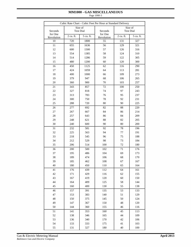
MM1000 - GAS MISCELLANEOUS Page 1000-3
Gas & Electric Metering Manual April 2013 Baltimore Gas and Electric Company
Cubic Rate Chart - Cubic Feet Per Hour at Standard Delivery
Seconds for One
Revolution
Size of Test Dial
Seconds for One
Revolution
Size of Test Dial
2 cu. ft. 5 cu. ft. 2 cu. ft. 5 cu. ft.
10 720 1800 55 131 327 11 655 1636 56 129 321 12 600 1500 57 126 316 13 554 1385 58 124 310 14 514 1286 59 122 305 15 480 1200 60 120 300 16 450 1125 62 116 290 17 424 1059 64 113 281 18 400 1000 66 109 273 19 379 947 68 106 265 20 360 900 70 103 257 21 343 857 72 100 250 22 327 818 74 97 243 23 313 783 76 95 237 24 300 750 78 92 231 25 288 720 80 90 225 26 277 692 82 88 220 27 267 667 84 86 214 28 257 643 86 84 209 29 248 621 88 82 205 30 240 600 90 80 200 31 232 581 92 78 196 32 225 563 94 77 191 33 218 545 96 75 188 34 212 529 98 73 184 35 206 514 100 72 180 36 200 500 102 71 176 37 195 486 104 69 173 38 189 474 106 68 170 39 185 462 108 67 167 40 180 450 110 65 164 41 176 439 112 64 161 42 171 429 116 62 155 43 167 419 120 60 150 44 164 409 125 58 144 45 160 400 130 55 138 46 157 391 135 53 133 47 153 383 140 51 129 48 150 375 145 50 124 49 147 367 150 48 120 50 144 360 155 46 116 51 141 353 160 45 113 52 138 346 165 44 109 53 136 340 170 42 106 54 133 333 175 41 103 55 131 327 180 40 100

MM1000 - GAS MISCELLANEOUS Page 1000-4
Gas & Electric Metering Manual April 2013 Baltimore Gas and Electric Company
1002-2 Cubic Rate Charts - Cubic Feet per Hour at 2 psig Delivery
Read from a 1/2 & 1 and 2 & 5 cubic feet dials
Cubic Rate Chart - Cubic Feet Per Hour at 2 psig Delivery
Seconds for One
Revolution
Size of Test Dial
Seconds for One
Revolution
Size of Test Dial
1/2 cu. ft.
1 cu. ft.
1/2 cu. ft.
1 cu. ft.
10 203 405 35 58 116 11 184 368 36 56 113 12 169 338 37 55 109 13 156 312 38 53 107 14 145 289 39 52 104 15 135 270 40 51 101 16 127 253 41 49 99 17 119 238 42 48 96 18 113 225 43 47 94 19 107 213 44 46 92 20 101 203 45 45 90 21 96 193 46 44 88 22 92 184 47 43 86 23 88 176 48 42 84 24 84 169 49 41 83 25 81 162 50 41 81 26 78 156 51 40 79 27 75 150 52 39 78 28 72 145 53 38 76 29 70 140 54 38 75 30 68 135 55 37 74 31 65 131 56 36 72 32 63 127 57 36 71 33 61 123 58 35 70 34 60 119 59 34 69 35 58 116 60 34 68

MM1000 - GAS MISCELLANEOUS Page 1000-5
Gas & Electric Metering Manual April 2013 Baltimore Gas and Electric Company
Cubic Rate Chart - Cubic Feet Per Hour at 2 psig Delivery Seconds for One
Revolution
Size of Test Dial
Seconds for One
Revolution
Size of Test Dial
2 cu. ft. 5 cu. ft. 2 cu. ft. 5 cu. ft. 10 810 2025 55 147 368 11 736 1841 56 145 362 12 675 1688 57 142 355 13 623 1558 58 140 349 14 579 1446 59 137 343 15 540 1350 60 135 338 16 506 1266 62 131 327 17 476 1191 64 127 316 18 450 1125 66 123 307 19 426 1066 68 119 298 20 405 1013 70 116 289 21 386 964 72 113 281 22 368 920 74 109 274 23 352 880 76 107 266 24 338 844 78 104 260 25 324 810 80 101 253 26 312 779 82 99 247 27 300 750 84 96 241 28 289 723 86 94 235 29 279 698 88 92 230 30 270 675 90 90 225 31 261 653 92 88 220 32 253 633 94 86 215 33 245 614 96 84 211 34 238 596 98 83 207 35 231 579 100 81 203 36 225 563 102 79 199 37 219 547 104 78 195 38 213 533 106 76 191 39 208 519 108 75 188 40 203 506 110 74 184 41 198 494 112 72 181 42 193 482 116 70 175 43 188 471 120 68 169 44 184 460 125 65 162 45 180 450 130 62 156 46 176 440 135 60 150 47 172 431 140 58 145 48 169 422 145 56 140 49 165 413 150 54 135 50 162 405 155 52 131 51 159 397 160 51 127 52 156 389 165 49 123 53 153 382 170 48 119 54 150 375 175 46 116 55 147 368 180 45 113

MM1000 - GAS MISCELLANEOUS Page 1000-6
Gas & Electric Metering Manual April 2013 Baltimore Gas and Electric Company
1003 Pressure Factor Charts
1003-1 Pressure Factor Charts for commonly evaluated delivery. Some customers require a higher than Standard Delivery (about 6” w.c. or ¼ PSIG) for their equipment. A higher delivery pressure will allow more natural gas to flow through a pipe. Therefore a correction factor needs to be applied. Each elevated pressure above Standard Delivery needs to be multiplied by a correction factor in order to account for the “extra” gas. The table below shows correction factors for set elevated delivery pressures.
Example: If a section of pipe with a set diameter and length would allow 100 cfh of gas flow at
Standard Delivery, what would happen if the same pipe now had 2 PSIG delivery? To find this, multiply the Standard Delivery of 100 cfh by the 2 PSIG correction factor of 1.125. The pipe could now pass 112.5 cfh.
Pressure Correction Factor
Elevated Delivery Pressure (in PSIG)
Correction Factor
Elevated Delivery Pressure (in PSIG)
Correction Factor
1 1.057 15 2.005 2 1.125 20 2.345 5 1.328 25 2.684
10 1.666 100 7.847

MM1000 - GAS MISCELLANEOUS Page 1000-7
Gas & Electric Metering Manual April 2013 Baltimore Gas and Electric Company
1004 Clocking a Meter
1004-1 Clocking a meter is a simple way of knowing what a specific piece of equipment or all the equipment is consuming. To determine the consumption, we need to locate the smaller measureing dial on the gas meter. For this example, we will focus on a the ½ cubic foot dial. With consumption on the meter, pick a location on the ½ cubic foot dial while it is on the up swing (counter-clockwise position from 6 o’clock to 12 o’clock). With a stop watch and your known location on the up swing of the ½ cubic foot, start recording the time it takes the ½ cubic foot hand to travel one full cycle around the dial till it reaches the start location again. Record the number of seconds it takes for the dial to make one full revolution. With this time reading from the stop watch, now take 3600 and divide it by the seconds it took to make one full revolution, this will give you the capcaity. Since your used the ½ cubic foot dial, now divide the capacity by the ½. This is give you cubic feet per hour (cfh) consumed.
Example: Starting with the dial at “4”, measure the time it takes the dial to travel around once. If
the dial took 20 seconds, then the gas consumed was 90cfh, assuming standard delivery*.
This is how the cfh was determined: 3600 sec/hour x 1 cubic foot hour = 90 cfh
20 sec 2
*If the delivery pressure was 2 psig, then 90 cfh would be multiplied by the correction factor of 1.125, which would give 101.25 cfh.