Beyond the classic correction system: a numerical nonrigid approach to the scoliosis brace
8
Technical Report Beyond the classic correction system: a numerical nonrigid approach to the scoliosis brace Jean-Philippe Berteau, PT a , Martine Pithioux, PhD a, * , Serge Mesure, PT, PhD a , G erard Bollini, MD, PhD b , Patrick Chabrand, PhD a a Institute of Movement Science (ISM), University of the Mediterranean, CP 910, Ave. de Luminy, F-13288 Marseille Cedex 09, France b Department of Paediatric Orthopaedics, Timone Children’s Hospital, 264, Rue St Pierre, 13385 Marseille, France Received 6 April 2010; revised 13 December 2010; accepted 26 January 2011 Abstract BACKGROUND CONTEXT: Adolescent idiopathic scoliosis (AIS) causes a spine and rib cage three-dimensional (3D) deformity previously treated by bracing. Whatever the manufacturing pro- cess, this rigid system acts biomechanically on the patient through the ‘‘three-point bending’’ mechanical principle. It applies corrective forces to a limited area and acts especially in the frontal plane. It seemed to us that a nonrigid system, called ‘‘Cbrace,’’ with 3D action allowing distribution of forces could increase compliance and provide better long-term correction prospects. PURPOSE: The aim of this study was to design a nonrigid brace by numerically testing in a finite- element model developed here. STUDY DESIGN: A finite-element model has been developed to simulate brace effect on AIS right thoracic deformation of a 10-year-old patient. METHODS: A two-step method was needed; first, the reliability of our model is evaluated, and then, the ability to use distributed forces to correct scoliosis deformation is tested. To obtain a 3D correction, several treatments are experimented, leading to a comparison test between the best combination to the ‘‘three-point bending’’ principle. RESULTS: The numerical model developed here shows good qualitative answers for the treatment of brace forces. The first results demonstrate numerically that distributed forces may be of interest in brace treatment design. Overall force of 40 N above cartilage of the last nonfloating ribs asso- ciated to two posterior asymmetrical areas appears to be the best way to correct scoliosis deforma- tion with nonrigid action. CONCLUSION: The results show numerical efficacy of distributed forces to correct spinal defor- mities and raises the prospect that a new numerical brace, called ‘‘Cbrace,’’ could be a starting point in the search for a nonrigid system. Ó 2011 Elsevier Inc. All rights reserved. Keywords: Scoliosis; Numerical modeling; Distributed forces; Nonrigid orthopedic treatment; Brace design Introduction Adolescent idiopathic scoliosis (AIS), the most common type of scoliosis, is a musculoskeletal disease that causes a spine and rib cage three-dimensional (3D) deformity [1]. Although surgical intervention can reduce it, the main clini- cal goal of orthopedic or physiotherapy treatment is to pre- vent spinal deformity from increasing. This is the greatest problem in scoliosis treatment [2], and a corrective brace is usually suggested. Although designed in different manners, they are still based on dated concepts, proposed and tested decades ago when the 3D nature of AIS was rarely considered or incorporated into brace design. The Boston Brace System is one of the most widely used types of thoracolumbosacral orthosis (TLSO) in North America to correct Cobb angle (frontal deformity) and to work toward reducing gibbosity (horizontal deformity), and the Cheneau-Toulouse-Munster is its equivalent in FDA device/drug status: not applicable. Author disclosures: JPB: Nothing to disclose. MP: Nothing to dis- close. SM: Nothing to disclose. GB: Nothing to disclose. PC: Nothing to disclose. * Corresponding author. Institute of Movement Science (ISM), Univer- sity of the Mediterranean, CP 910, Ave. de Luminy, F-13288 Marseille Cedex 09, France. Tel.: (33) 4-91-26-61-77; fax: (33) 4-91-41-16-91. E-mail address: [email protected] (M. Pithioux) 1529-9430/$ - see front matter Ó 2011 Elsevier Inc. All rights reserved. doi:10.1016/j.spinee.2011.01.019 The Spine Journal 11 (2011) 424–431
-
Upload
independent -
Category
Documents
-
view
1 -
download
0
Transcript of Beyond the classic correction system: a numerical nonrigid approach to the scoliosis brace
The Spine Journal 11 (2011) 424–431
Technical Report
Beyond the classic correction system: a numerical nonrigid approachto the scoliosis brace
Jean-Philippe Berteau, PTa, Martine Pithioux, PhDa,*, Serge Mesure, PT, PhDa,G�erard Bollini, MD, PhDb, Patrick Chabrand, PhDa
aInstitute of Movement Science (ISM), University of the Mediterranean, CP 910, Ave. de Luminy, F-13288 Marseille Cedex 09, FrancebDepartment of Paediatric Orthopaedics, Timone Children’s Hospital, 264, Rue St Pierre, 13385 Marseille, France
Received 6 April 2010; revised 13 December 2010; accepted 26 January 2011
Abstract BACKGROUND CONTEXT: Adolescent idi
FDA device/drug
Author disclosure
close. SM: Nothing t
to disclose.
* Corresponding a
sity of the Mediterra
Cedex 09, France. Te
E-mail address: m
1529-9430/$ - see fro
doi:10.1016/j.spinee.2
opathic scoliosis (AIS) causes a spine and rib cagethree-dimensional (3D) deformity previously treated by bracing. Whatever the manufacturing pro-cess, this rigid system acts biomechanically on the patient through the ‘‘three-point bending’’mechanical principle. It applies corrective forces to a limited area and acts especially in the frontalplane. It seemed to us that a nonrigid system, called ‘‘Cbrace,’’ with 3D action allowing distributionof forces could increase compliance and provide better long-term correction prospects.PURPOSE: The aim of this study was to design a nonrigid brace by numerically testing in a finite-element model developed here.STUDY DESIGN: A finite-element model has been developed to simulate brace effect on AISright thoracic deformation of a 10-year-old patient.METHODS: A two-step method was needed; first, the reliability of our model is evaluated, andthen, the ability to use distributed forces to correct scoliosis deformation is tested. To obtaina 3D correction, several treatments are experimented, leading to a comparison test between the bestcombination to the ‘‘three-point bending’’ principle.RESULTS: The numerical model developed here shows good qualitative answers for the treatmentof brace forces. The first results demonstrate numerically that distributed forces may be of interestin brace treatment design. Overall force of 40 N above cartilage of the last nonfloating ribs asso-ciated to two posterior asymmetrical areas appears to be the best way to correct scoliosis deforma-tion with nonrigid action.CONCLUSION: The results show numerical efficacy of distributed forces to correct spinal defor-mities and raises the prospect that a new numerical brace, called ‘‘Cbrace,’’ could be a starting pointin the search for a nonrigid system. � 2011 Elsevier Inc. All rights reserved.
Keywords: Scoliosis; Numerical modeling; Distributed forces; Nonrigid orthopedic treatment; Brace design
Introduction
Adolescent idiopathic scoliosis (AIS), the most commontype of scoliosis, is a musculoskeletal disease that causesa spine and rib cage three-dimensional (3D) deformity [1].
status: not applicable.
s: JPB: Nothing to disclose. MP: Nothing to dis-
o disclose. GB: Nothing to disclose. PC: Nothing
uthor. Institute of Movement Science (ISM), Univer-
nean, CP 910, Ave. de Luminy, F-13288 Marseille
l.: (33) 4-91-26-61-77; fax: (33) 4-91-41-16-91.
[email protected] (M. Pithioux)
nt matter � 2011 Elsevier Inc. All rights reserved.
011.01.019
Although surgical intervention can reduce it, the main clini-cal goal of orthopedic or physiotherapy treatment is to pre-vent spinal deformity from increasing. This is the greatestproblem in scoliosis treatment [2], and a corrective brace isusually suggested. Although designed in different manners,they are still based on dated concepts, proposed and testeddecades agowhen the 3Dnature ofAISwas rarely consideredor incorporated into brace design.
The Boston Brace System is one of the most widely usedtypes of thoracolumbosacral orthosis (TLSO) in NorthAmerica to correct Cobb angle (frontal deformity) and towork toward reducing gibbosity (horizontal deformity),and the Cheneau-Toulouse-Munster is its equivalent in
425J.-P. Berteau et al. / The Spine Journal 11 (2011) 424–431
Europe. Both act to decrease frontal deformity but do notreestablish physiological thoracic sagittal curves [3,4]; theyreduce spinal deformity through a ‘‘three-point bending’’mechanical action, applying corrective forces to a limitedarea (single-point forces). However, this brace treatmentfalls short of its goals because of its limited effect on theplane of maximum deformity; moreover, it has no signifi-cant derotational effect on the horizontal plane [3]. Further-more, these rigid systems of correction decrease children’squality of life [5], leading to poor compliance and disturbedbone growth. Thus, they are not an optimal long-termsolution.
However, before clinical experimentations, it wouldseem judicious to perform numerical tests evaluating thechances of successful design of a bracing system, thusanalyzing the effect and influence of a single componentwithin the construct investigated. Some specific models ofthe spine and rib cage use time increments [6,7], simulatinggrowth to mirror the scoliosis mechanism; others [8–11],including ligamentoskeletal models, aim at a quantitativeevaluation of brace treatment or optimize the location ofTLSO brace action, but none of them have been used toprovide a new strategy of scoliosis treatment.
An examination of the anatomy of thoracic vertebraereveals their high capacity for horizontal rotation in hypo-kyphosis (80% in thoracic scoliosis); that is why, to avoidthe 3D deformity increasing, a promising way to decreasethis rotational potential is to reestablish physiological sag-ittal spinal curves in the thoracic area. One possible hypoth-esis is that instead of single-point force, a nonrigid systemusing straps allowing distribution of forces could yielda more flexible brace able to increase compliance and offerbetter long-term correction prospects.
The aim of this study was to numerically evaluatemechanical effects of a potential nonrigid brace, called‘‘Cbrace,’’ in a finite-element model developed here. Thisconcept of the nonrigid brace is intended to correct a typicalspine and rib cage deformity of a standard right thoracic sco-liosis. The study is numerical, is limited to a single-curvetype, and evaluates only the immediate effect of this newbrace system. The reliability of this modeling of the ‘‘virtualpatient’’ is first evaluated, and then, the efficacyof distributedforces to correct scoliosis deformity is tested. Finally, toobtain ‘‘Cbrace,’’ several treatments are tested and comparedwith the classic treatment.
Method
General
A two-step method for nonrigid brace design is used.First, a finite-element modeling of a ‘‘virtual patient’’ isbuilt, and second, several numerical simulations are per-formed in three parts. First, correction via distributed forcesis tested; second, several spine corrections are evaluated in
each dimension; and third, the most efficient combinationof the previous treatment is compared with the classic.
Step 1. Model building and evaluationThe ‘‘virtual patient’’ is a 10-year-old (with Risser
Level 0) with a ‘‘regular’’ right thoracic scoliosis with a riskof progression of 95% [12] that requires brace treatment,the ideal configuration for a clinical research protocol [13].
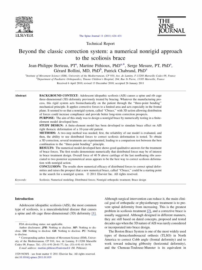
Themodel includes bones and intervertebral discs (IVDs).Muscles were not considered in the model as they have notbeen proven to actively contribute to brace correction [14].Modeling software Hypermesh (Altair Hyperworks, Troy,MI, USA) was used for building and meshing the geometryof the scoliosis. For simulation of the brace treatment,Abaqus finite-element software was used (Simulia, DassaultSystems, Velizy Villacoublay Cedex, France). These soft-wares are general displacement-based finite-element codesand used to calculate the 3D nodal displacement (Fig. 1).
Geometric parameters
The spine size and the bone morphology (as rib cage, ver-tebrae, sternum, and cartilage) were obtained by one X-rayscoliosis imaging (CHU Marseille-Timone) of a 10-year-old girl before puberty (Risser Level 0). Rib curves in the sag-ittal plane and rib-cartilage curves (7th to 10th) were takenfrom Stokes et al. [15], and distribution of vertebra rotationin the horizontal plane was taken from Berthonnaud andDimnet [16]. In this model, the equivalence of a horizontalrotation is a rib rotation (maximum of 8� at the apex level).The different angle values are shown in Table 1. The spineis composed of bones and IVDs, and the rib cage is composedof bones and cartilage. All rib-sternumand rib-vertebra jointswere considered as embedded.
Components model
To imitate the geometry of a scoliosis deformity (spineand rib cage), the model includes the following:
- 17 vertebrae (5 lumbar and 12 thoracic): A meshingdisc of hexahedral elements is extruded to reach theheight of each vertebral corpus. The diameter of eachdisc is twice the corresponding vertebral corpus (to takeinto account the spinous process).
- 10 ribs (floating ribs were excluded from the model):An extrusion line of eight hexahedral elements extendsfrom the vertebra to the sternum. This line followsa curve plotting the posterior rib arch.
- The sternum is a hexagonal volume of the rib thickness,meshed with hexahedral elements.
- Sagittal and frontal spine curves are modeled throughdifferences in IVD height. The finite-element modelcontains 90,406 nodes, 89,361 free degrees, and70,304 mesh elements.
Fig. 1. Parameters evaluated.
426 J.-P. Berteau et al. / The Spine Journal 11 (2011) 424–431
Boundary conditions and mechanical properties
To simulate eye stabilization, displacements are al-lowed only in the Z direction of the top of T1 (thoracicvertebra 1) and to simulate brace restraint on the pelvison the bottom of L5 (lumbar vertebra 5), no displacementis allowed (embedded). The model requires 5 degrees offreedom to be fixed to reach a satisfactory solution. It isa finite-element modeling technique using isotropic linearmechanical properties, taken from experimental and pub-lished data on cadaveric spines by Descrimes et al. [8](Table 2). The method of calculation is based on the Hooklaw for isotropic materials.
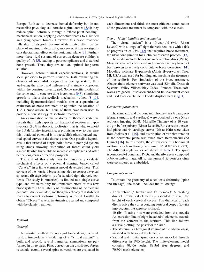
Preliminary evaluation of the ‘‘virtual patient’’
The simulation of Gignac et al. [17] was used to test theTLSO action described in Fig. 2:
1. Limited force of 40 N applied at the apex level onanterior gibbosity.
2. Limited force of 40 N applied on convex curve.3. Reactive force on gibbosity.
Step 2. Three-part numerical simulation protocolThe numerical protocol first tests the efficacy of straps
in correcting scoliosis deformity; these straps distributeforces instead of applying forces to a limited area, as withthe TLSO brace. An overall corrective force of 40 N [18]is applied with 6-cm–wide straps in all the treatments(Fig. 3). The second part of the simulation seeks an opti-mization of straps’ position to correct spinal deformity inthree dimensions; all positions were evaluated in eachplane. Finally, the third part compares the efficacy ofa combination of these straps’ positions with the classic(TLSO configuration) and control (model withoutcorrection).
The treatment objective is to decrease Cobb angle (fron-tal deformity in degrees), gibbosity (horizontal deformity inmillimeters), and horizontal rotation at the thoracic apicallevel (horizontal deformity in degrees) and to increase tho-racic angle.
Part 1: evaluation of distributed forces
A classic TLSO correction (three single-point forces),called A, is compared with ‘‘distributed forces’’ (B), also
Table 1
Scoliosis values
Levels
Values of scoliosis
Clinical data Numerical
Cobb angle ( �) 25 24.4
Lumbar lordosis ( �) 40 40.9
Kyphosis ( �) 20 20
Gibbosity (mm) 14 13.6
Table 2
Mechanical properties
Elements Young modulus (MPa) Poisson ratio
Ribs 5,000 0.1
Sternum 10,000 0.2
Vertebrae 1,000 0.3
IVDs 15 0.45
Rib cartilage 480 0.1
IVDs, intervertebral discs.
427J.-P. Berteau et al. / The Spine Journal 11 (2011) 424–431
representing a TLSO configuration but applied over a largearea. B is composed of Treatment 1 (a pair of straps, front/back location) to reduce horizontal deformity and Treat-ment 2 (one lateral strap on convex curve) to reduce frontaldeformity.
Part 2: evaluation of several treatments per correction tooptimize 3D action
� Frontal correction
Treatment 3: area on lateral part of thorax with hori-zontal direction.
� Sagittal and horizontal corrections:
Treatment 4: areas horizontally above bone cartilage(last nonfloating rib) in variable directions: Z,�cos(40�)Yþsin(40�)Z, or �cos(65�)Yþsin(65�)Z.Treatment 5: areas horizontally above cartilage boneon last left rib with direction: cos(65�)Yþsin(65�).
� Horizontal correction
Treatment 6: one or two posterior (asymmetrical)areas in Y direction.
� Three-dimensional action
Treatment 7: posterior harness above the top of pos-terior gibbosity.Treatment 8: forces distributed on left shoulder(direction �Z ).Treatment 9: anterior harness crossing on sternum(force direction �Y ).
Part 3: evaluation of a 3D action
The most effective combination from the above treat-ments (Part 2), named ‘‘C’’ is compared with both the initialand the TLSO configurations with distributed forces (B).
Fig. 2. Evaluation.
Results
For the same intensity, position, and mechanical proper-ties, the results of Step 1 show similar corrective trends inCobb angle reduction, gibbosity decrease, and action on
sagittal angle (Fig. 4). Our model can be used to compareclinical indices for brace simulations, and qualitative datacan be analyzed. Calculation time of our model is less than1 hour.
Results for the first part of Step 2 show a downwardtrend in gibbosity and Cobb angle for both treatments,but the reduction is sharper for the rib hump when the cor-rective forces are distributed (7 mm instead of 9.5 mm).Treatments 1 and 2 meet their own objectives of correction,but neither treatment obtains a specific impact on sagittalcurve.
In the second part, to reduce frontal deformity, Treat-ment 3 produces similar decreases in Cobb angle to Treat-ment 2 (differing in strap direction) without impact onsagittal curves. For sagittal and horizontal corrections, nei-ther Treatment 4 nor Treatment 5 is able to reduce gibbosityand increase sagittal curve at the same time without squash-ing the rib cage. To prevent harm to the rib cage, lessintense distributed forces (20 N) were applied; the sametrends are observed, with slighter rib cage deformities.Treatment 6 achieves its goal of reducing the horizontaldeformity specifically (rib hump: 10.2 mm). To reduce
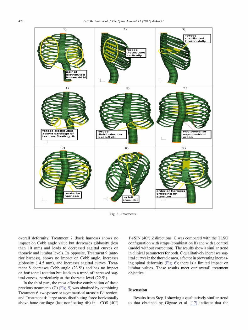
Fig. 3. Treatments.
428 J.-P. Berteau et al. / The Spine Journal 11 (2011) 424–431
overall deformity, Treatment 7 (back harness) shows noimpact on Cobb angle value but decreases gibbosity (lessthan 10 mm) and leads to decreased sagittal curves onthoracic and lumbar levels. Its opposite, Treatment 9 (ante-rior harness), shows no impact on Cobb angle, increasesgibbosity (14.5 mm), and increases sagittal curves. Treat-ment 8 decreases Cobb angle (23.5�) and has no impacton horizontal rotation but leads to a trend of increased sag-ittal curves, particularly at the thoracic level (22.5�).
In the third part, the most effective combination of theseprevious treatments (C) (Fig. 5) was obtained by combiningTreatment 6: two posterior asymmetrical areas in Y direction,and Treatment 4: large areas distributing force horizontallyabove bone cartilage (last nonfloating rib) in �COS (40�)
YþSIN (40�) Z directions. C was compared with the TLSOconfiguration with straps (combination B) and with a control(model without correction). The results show a similar trendin clinical parameters for both. C qualitatively increases sag-ittal curves in the thoracic area, a factor in preventing increas-ing spinal deformity (Fig. 6); there is a limited impact onlumbar values. These results meet our overall treatmentobjective.
Discussion
Results from Step 1 showing a qualitatively similar trendto that obtained by Gignac et al. [17] indicate that the

Fig. 4. Evaluation results.
429J.-P. Berteau et al. / The Spine Journal 11 (2011) 424–431
model presented here can be used to design an alternativebrace treatment for right thoracic scoliosis. When distrib-uted corrective forces and single-point forces are comparedin Step 2, the results show similar reductions for bothapproaches (A and B) in Cobb angle, gibbosity, and sagittalangulation. Using a nonrigid brace design with straps, it isthus numerically demonstrated that straps inducing distrib-uted forces (B) may be of clinical interest because they leadto improved patient comfort and compliance.
Findings from Part 2 of the second step suggest that thesame results can be obtained for different directions (Treat-ments 2 and 3) using lateral straps, offering a flexibility inbrace design. Furthermore, because Treatments 4 and 5scratched the cage, a decrease in intensity (20 N) wastested for each strap. However, because our model yieldsonly trends in correction, and results must be comparedin the same conditions, this optimization method wasrejected.
To prevent the common increase in deformity, thoracicangles need to be corrected to physiological values, espe-cially for thoracic angles of more than 20�. The present
Fig. 5. The most effective combination (C).
3D analysis enables different treatments’ action on sagittalthoracic curves to be compared. Thus, from an analysis ofseveral treatments (Treatments 4–9), the combination ofTreatments 4 and 6 appears the best way to correct frontalhorizontal deformities (Cobb angle and gibbosity) and sag-ittal thoracic values simultaneously. This most effectivecombination is called (C).
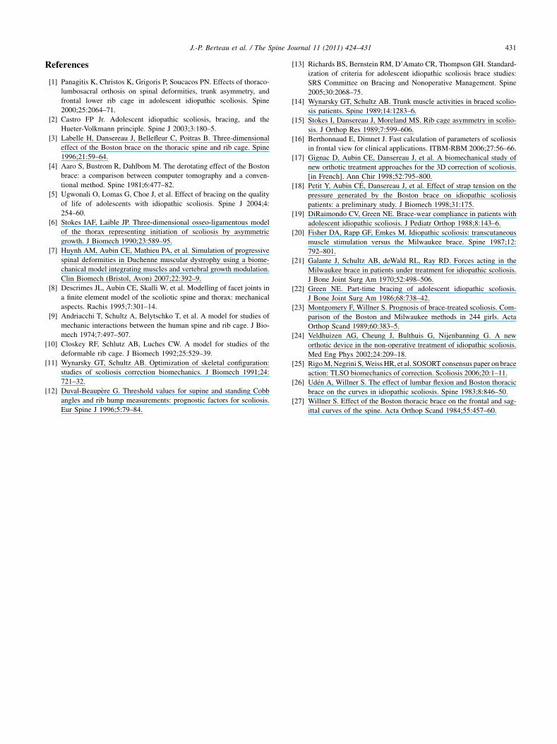
The comparison of (C) and (B) shows similar numericaltrends for the scoliosis model; (C) appears as a numericalequivalent to the TLSO brace. Even if some authors showonly a slight difference in effect between part-time(12–16 hours) and full-time (23 hours) wearing of a brace[19–22], the usual rigid brace design leads to poor adoles-cent compliance, a major cause of treatment failure. The(C) combination, unlike either the classic rigid Boston orCheneau-Toulouse-Munster braces [23] or nonrigid bracelike Trial C [24], leaves the breast development zone andthe scapula area free to move. Using the (C) nonrigidnumerically defined strap brace concept: ‘‘Cbrace’’ (Figs.7 and 8) acts on single-curve deformity, and its design couldallow trunk movement and offer a greater patient comfort.To prove a better compliance, after development step, a clin-ical investigation is needed.
In the Society on Scoliosis Orthopaedic and Rehabilita-tion Treatment consensus paper on brace action [25],a force vector pushing the thoracic convexity was recom-mended by most participants, together with a ‘‘pair offorces’’ to derotate in the axial plane and a couplingmechanism to increase thoracic kyphosis. ‘‘Cbrace,’’applying distributed forces on the anterior part of the lastnonfloating ribs and an asymmetric pair of distributedforces on each side of the spine at the apex level, reachesthis goal numerically and goes some way toward reestab-lishing physiological sagittal thoracic curve. But accordingto some reports on the effect of a change in sagittal align-ment, better brace correction can be provided in scoliosisby ‘‘lumbar flexion (delordosation)’’ [26,27]. The modelpresented here has no pelvis and lower segment and,therefore, has no notable impact on lumbar segment; thiswould be a useful avenue for future research.
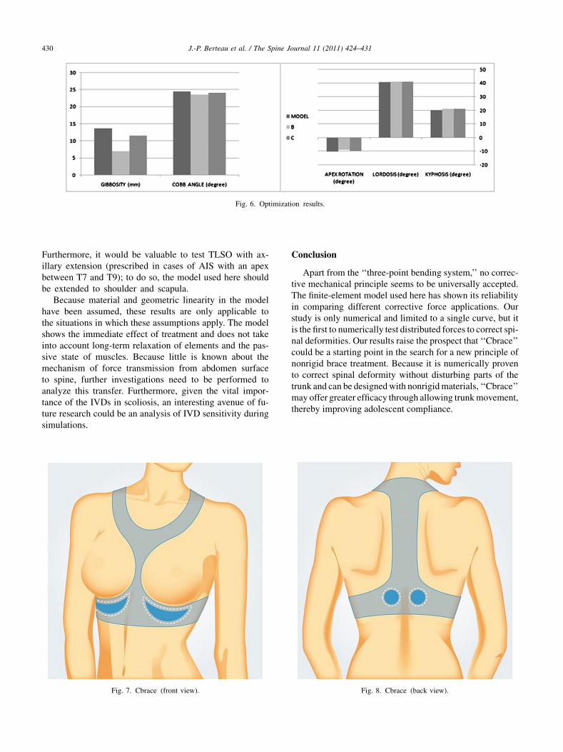
Fig. 6. Optimization results.
430 J.-P. Berteau et al. / The Spine Journal 11 (2011) 424–431
Furthermore, it would be valuable to test TLSO with ax-illary extension (prescribed in cases of AIS with an apexbetween T7 and T9); to do so, the model used here shouldbe extended to shoulder and scapula.
Because material and geometric linearity in the modelhave been assumed, these results are only applicable tothe situations in which these assumptions apply. The modelshows the immediate effect of treatment and does not takeinto account long-term relaxation of elements and the pas-sive state of muscles. Because little is known about themechanism of force transmission from abdomen surfaceto spine, further investigations need to be performed toanalyze this transfer. Furthermore, given the vital impor-tance of the IVDs in scoliosis, an interesting avenue of fu-ture research could be an analysis of IVD sensitivity duringsimulations.
Fig. 7. Cbrace (front view).
Conclusion
Apart from the ‘‘three-point bending system,’’ no correc-tive mechanical principle seems to be universally accepted.The finite-element model used here has shown its reliabilityin comparing different corrective force applications. Ourstudy is only numerical and limited to a single curve, but itis the first to numerically test distributed forces to correct spi-nal deformities. Our results raise the prospect that ‘‘Cbrace’’could be a starting point in the search for a new principle ofnonrigid brace treatment. Because it is numerically provento correct spinal deformity without disturbing parts of thetrunk and can be designedwith nonrigidmaterials, ‘‘Cbrace’’may offer greater efficacy through allowing trunkmovement,thereby improving adolescent compliance.
Fig. 8. Cbrace (back view).
431J.-P. Berteau et al. / The Spine Journal 11 (2011) 424–431
References
[1] Panagitis K, Christos K, Grigoris P, Soucacos PN. Effects of thoraco-
lumbosacral orthosis on spinal deformities, trunk asymmetry, and
frontal lower rib cage in adolescent idiopathic scoliosis. Spine
2000;25:2064–71.
[2] Castro FP Jr. Adolescent idiopathic scoliosis, bracing, and the
Hueter-Volkmann principle. Spine J 2003;3:180–5.
[3] Labelle H, Dansereau J, Bellefleur C, Poitras B. Three-dimensional
effect of the Boston brace on the thoracic spine and rib cage. Spine
1996;21:59–64.
[4] Aaro S, Bustrom R, Dahlbom M. The derotating effect of the Boston
brace: a comparison between computer tomography and a conven-
tional method. Spine 1981;6:477–82.
[5] Ugwonali O, Lomas G, Choe J, et al. Effect of bracing on the quality
of life of adolescents with idiopathic scoliosis. Spine J 2004;4:
254–60.
[6] Stokes IAF, Laible JP. Three-dimensional osseo-ligamentous model
of the thorax representing initiation of scoliosis by asymmetric
growth. J Biomech 1990;23:589–95.
[7] Huynh AM, Aubin CE, Mathieu PA, et al. Simulation of progressive
spinal deformities in Duchenne muscular dystrophy using a biome-
chanical model integrating muscles and vertebral growth modulation.
Clin Biomech (Bristol, Avon) 2007;22:392–9.
[8] Descrimes JL, Aubin CE, Skalli W, et al. Modelling of facet joints in
a finite element model of the scoliotic spine and thorax: mechanical
aspects. Rachis 1995;7:301–14.
[9] Andriacchi T, Schultz A, Belytschko T, et al. A model for studies of
mechanic interactions between the human spine and rib cage. J Bio-
mech 1974;7:497–507.
[10] Closkey RF, Schlutz AB, Luches CW. A model for studies of the
deformable rib cage. J Biomech 1992;25:529–39.
[11] Wynarsky GT, Schultz AB. Optimization of skeletal configuration:
studies of scoliosis correction biomechanics. J Biomech 1991;24:
721–32.
[12] Duval-Beaup�ere G. Threshold values for supine and standing Cobb
angles and rib hump measurements: prognostic factors for scoliosis.
Eur Spine J 1996;5:79–84.
[13] Richards BS, Bernstein RM, D’Amato CR, Thompson GH. Standard-
ization of criteria for adolescent idiopathic scoliosis brace studies:
SRS Committee on Bracing and Nonoperative Management. Spine
2005;30:2068–75.
[14] Wynarsky GT, Schultz AB. Trunk muscle activities in braced scolio-
sis patients. Spine 1989;14:1283–6.
[15] Stokes I, Dansereau J, Moreland MS. Rib cage asymmetry in scolio-
sis. J Orthop Res 1989;7:599–606.
[16] Berthonnaud E, Dimnet J. Fast calculation of parameters of scoliosis
in frontal view for clinical applications. ITBM-RBM 2006;27:56–66.
[17] Gignac D, Aubin CE, Dansereau J, et al. A biomechanical study of
new orthotic treatment approaches for the 3D correction of scoliosis.
[in French]. Ann Chir 1998;52:795–800.
[18] Petit Y, Aubin C�E, Dansereau J, et al. Effect of strap tension on the
pressure generated by the Boston brace on idiopathic scoliosis
patients: a preliminary study. J Biomech 1998;31:175.
[19] DiRaimondo CV, Green NE. Brace-wear compliance in patients with
adolescent idiopathic scoliosis. J Pediatr Orthop 1988;8:143–6.
[20] Fisher DA, Rapp GF, Emkes M. Idiopathic scoliosis: transcutaneous
muscle stimulation versus the Milwaukee brace. Spine 1987;12:
792–801.
[21] Galante J, Schultz AB, deWald RL, Ray RD. Forces acting in the
Milwaukee brace in patients under treatment for idiopathic scoliosis.
J Bone Joint Surg Am 1970;52:498–506.
[22] Green NE. Part-time bracing of adolescent idiopathic scoliosis.
J Bone Joint Surg Am 1986;68:738–42.
[23] Montgomery F, Willner S. Prognosis of brace-treated scoliosis. Com-
parison of the Boston and Milwaukee methods in 244 girls. Acta
Orthop Scand 1989;60:383–5.
[24] Veldhuizen AG, Cheung J, Bulthuis G, Nijenbanning G. A new
orthotic device in the non-operative treatment of idiopathic scoliosis.
Med Eng Phys 2002;24:209–18.
[25] RigoM,Negrini S,Weiss HR, et al. SOSORT consensus paper on brace
action: TLSO biomechanics of correction. Scoliosis 2006;20:1–11.
[26] Ud�en A, Willner S. The effect of lumbar flexion and Boston thoracic
brace on the curves in idiopathic scoliosis. Spine 1983;8:846–50.
[27] Willner S. Effect of the Boston thoracic brace on the frontal and sag-
ittal curves of the spine. Acta Orthop Scand 1984;55:457–60.