Behavior of multi-story steel buildings under dynamic column loss scenarios
20
Transcript of Behavior of multi-story steel buildings under dynamic column loss scenarios

Steel and Composite Structures, Vol. 11, No. 2 (2011) 149-168 149
Behavior of multi-story steel buildings under dynamiccolumn loss scenarios
Seth T. Hoffman1 and Larry A. Fahnestock2*
1Peter Kiewit Sons’ Inc., Omaha, NE, USA2 University of Illinois at Urbana-Champaign, Urbana, IL, USA
(Received August 30, 2010, Accepted February 14, 2011)
Abstract. This paper presents a computational study of column loss scenarios for typical multi-story steelbuildings with perimeter moment frames and composite steel-concrete floors. Two prototype buildings (three-story and ten-story) were represented using three-dimensional nonlinear finite element models and explicitdynamic analysis was used to simulate instantaneous loss of a first-story column. Twelve individual columnloss scenarios were investigated in the three-story building and four in the ten-story building. This studyprovides insight into: three-dimensional load redistribution patterns; demands on the steel deck, concrete slab,connections and members; and the impact of framing configuration, building height and column loss location.In the dynamic simulations, demands were least severe for perimeter columns within a moment frame, but thestructures also exhibited significant load redistribution for interior column loss scenarios that had no momentconnectivity. Composite action was observed to be an important load redistribution mechanism followingcolumn loss and the concrete slab and steel deck were subjected to high localized stresses as a result of thecomposite action. In general, the steel buildings that were evaluated in this study demonstrated appreciablerobustness.
Keywords: multi-story buildings; steel frames; structural integrity; progressive collapse; connections;composite beams; dynamic response; finite element method.
1. Introduction
The collapses of the World Trade Center Twin Towers in 2001 have generated an extensive focus in
the United States on the issues of structural robustness, integrity and collapse resistance. Owing to the
uncertainty related to events that could trigger collapse, such as blast or impact loading, and the wide
range of methods that can be used to evaluate structural response, study of collapse resistance has
spanned a broad spectrum. However, the most common approach for evaluating collapse resistance is
the alternate path method that is presented in the United States Department of Defense (DoD) document
Design of Buildings to Resist Progressive Collapse (DoD 2009). This is classified as a threat-independent
approach since it does not define the initiating event but considers loss of a primary structural element
and evaluates the ability of the structure to redistribute load around the damaged region. Although the
alternate path method uses a simplistic representation of a damaging event, it is a versatile method that
allows for a variety of damage scenarios to be examined and compared. The research presented in this
* Corresponding author, Assistant Professor, E-mail: [email protected]

150 Seth T. Hoffman and Larry A. Fahnestock
paper employs the alternate path method to evaluate the dynamic behavior of multi-story steel buildings
with perimeter moment frames and composite steel-concrete floors when subjected to various column
loss scenarios. This study provides insight into: three-dimensional load redistribution patterns; demands
on the steel deck, concrete slab, connections and members; and the impact of framing configuration,
building height and lost column location.
Recent research on robustness of steel buildings has focused on a variety of important issues.
Khandelwal and El-Tawil (2007) conducted computational simulations of bare steel moment-resisting
beam-column connection subassemblies under column loss scenarios and demonstrated the ductility of
seismically-designed connections and their ability to deform in catenary mode. Sadek et al (2009)
developed computational models and conducted full-scale tests of bare steel moment-resisting beam-
column connection subassemblies under column loss scenarios, which demonstrated large monotonic
rotation capacity without strength degradation. Sadek et al (2008) and Alashker et al (2010) focused on
one-floor two-bay square composite steel-concrete floor system subassemblies with shear connections
under column loss scenarios. These studies demonstrated the significant contribution of the floor
system to collapse resistance and identified the steel deck as the primary contributor, but also found that
the load-carrying capacity is less than specified by progressive collapse guidelines (DoD 2009).
Izzuddin et al (2008) developed a simplified framework for progressive collapse assessment of multi-
story buildings and demonstrated its applicability through case studies considering perimeter and
corner column loss in a typical composite steel-concrete floor system subassembly (Vlassis et al 2008).
These macro-model simulations indicate that such floor systems can be prone to progressive collapse
and that tying force requirements alone cannot comprehensively ensure structural robustness.
Khandelwal et al (2008, 2009) used macro-model simulations to evaluate collapse resistance of
seismically-designed steel moment frames and braced frames, and these simulations indicated that
system strength and member layout play a larger role than ductile detailing in improving collapse
resistance. Several recent studies have employed three-dimensional finite element models to evaluate
robustness of steel buildings. Alashker and El-Tawil (2010) compared two-dimensional and three-
dimensional simulations of column loss in a ten-story steel building and illustrated the substantial
difference between them, largely due to the contribution of the floor system in the three-dimensional
model, which created alternate load paths that can reduce the effect of column loss. Kwasniewski
(2010) used a detailed finite element model to study collapse behavior of an eight-story steel building,
Fu (2009, 2010) used a detailed finite element model to study collapse behavior of a twenty-story steel
building, Main and Sadek (2009) used a macro-model to study collapse behavior of a ten-story steel
building, and Foley et al (2007) used frame element models to study collapse behavior of three-story,
nine-story and twenty-story steel buildings. Krauthammer and Yim (2009) used frame element models
that included shell elements to represent the concrete slab to study the effect of simultaneous multiple
column loss in a ten-story steel building. Across a range of modeling complexity, these studies
concluded that the buildings exhibited robust performance and that there was low potential for
progressive collapse. Although the studies conducted to date give important insight into the behavior of
steel buildings under column loss scenarios, there are still a wide range of issues remaining to be
explored related to the collapse resistance of steel buildings when subjected to severe localized damage.
The present study was initiated with the intent of providing new knowledge about three-dimensional
steel building response and factors that influence load redistribution and collapse resistance under
dynamic column loss scenarios.

Behavior of multi-story steel buildings under dynamic column loss scenarios 151
2. Prototype buildings and numerical models
For this study, two buildings representative of typical low and mid-rise steel construction in a low
seismic region of the United States were selected: the three-story and ten-story Boston pre-Northridge
buildings from the SAC suite of prototype buildings (FEMA 2000a). The three-story and ten-story
buildings have plan dimensions of 36.6 m × 54.9 m and 45.7 m × 45.7 m as shown in Figures 1(a) and
1(c), respectively. The buildings have interior gravity-only framing with perimeter moment frames for
lateral load resistance. Gravity beams and girders are attached with ASTM A36 steel single plate shear
connections welded to the supporting member and bolted to the supported member with 19 mm
diameter ASTM A325 high strength bolts. Moment frame beams and girders are connected to the
columns with welded unreinforced-flange moment connections and single plate shear connections.
Elevation views of the three-story and ten-story moment frames are shown in Figures 1(b) and 1(d),
respectively. All beams, girders and columns are wide-flange shapes comprised of ASTM A992 steel.
The floor system consists of 51 mm corrugated steel deck topped with 76 mm of normal-weight
concrete with a compressive strength of 35 MPa. ASTM A615 Grade 60 6 × 6-W1.4 × 1.4 wire mesh is
Fig. 1. Prototype building descriptions: (a) three-story plan, (b) three-story elevation, (c) ten-story plan, (d) ten-storyelevation

152 Seth T. Hoffman and Larry A. Fahnestock
included in the slab. The slab is composite with all beams and girders through 19 mm diameter ×
102 mm long ASTM A108 shear connectors spaced at 305 mm. Applied loadings are typical for office
occupancy and include the structural steel and concrete weight, superimposed dead load of 1200 Pa for
floor finishes and mechanical/electrical/plumbing systems and 960 Pa for interior partitions. Cladding
loads of 1200 Pa are used on the perimeter surface of the building including a 1.1 m parapet wall at the
roof. Live loading is 2400 Pa on all floors and the roof.
The prototype structures were modeled using the commercial finite element package Abaqus
(Simulia 2010). The wide-flange beams, columns, and girders were modeled using three-node (Abaqus
element type S3) and four-node (Abaqus element type S4R) shell elements, which had dimensions in
the range of 75 mm to 100 mm. These are general-purpose conventional shell elements that allow
transverse shear deformation and consider finite membrane strain and large rotations. The S4R
formulation employs reduced integration with hourglass control, and S3 is a degenerated version of
S4R. Material nonlinearities were incorporated through the von Mises material model with associated
flow rule and steel stress-strain properties were based on experimental data (Fahnestock et al 2006).
The steel deck and concrete slab were modeled using individual planar layers of four-node S4R shell
elements. For the steel deck, representative shell element patch models of the actual fluted deck
geometry were used to develop an orthotropic constitutive matrix that was implemented in the planar
element layer representing the steel deck, which was offset to the centroid of the physical deck location
(25 mm above the steel framing). The concrete below the top of the deck flutes was neglected, so an
effective thickness of 76 mm was applied to the shell element layer representing the concrete slab,
which was offset to the centroid of the area of the concrete above the flutes (89 mm above the steel
framing). This idealization is shown in Figure 2. In the steel deck shell elements, three integration
points were used through the thickness and in the concrete slab shell elements, five integration points
were used through the thickness. The steel reinforcement within the concrete slab was modeled as a
smeared isotropic layer. An elastic perfectly-plastic constitutive relationship was used for the steel deck
with a yield stress of 207 MPa, which correlated well to the patch test of the physical geometry when
analyzed with typical experimental deck material properties. A smeared cracking model was used for
the concrete slab with linear-elastic compression behavior and tension-stiffening tensile behavior.
Composite action between the steel framing and steel deck and concrete slab was modeled by applying
coupling constraints between nodes in the top flanges of the steel framing, the steel deck layer, and the
concrete slab layer, effectively tying the three components together. Element sizes were 305 mm for the
steel deck and 152 mm for the concrete slab, which were found to be sufficient when a mesh
convergence study was conducted. The approach used to model the steel deck and concrete slab is
consistent with the techniques employed in other studies of collapse resistance for structures with steel-
concrete composite floors (Alashker and El-Tawil 2010, Fu 2009 and 2010, Krauthammer and Yim
Fig. 2. Steel-concrete composite deck model geometry: (a) physical, (b) model idealization

Behavior of multi-story steel buildings under dynamic column loss scenarios 153
2009, Kwasniewski 2010, Main and Sadek 2009).
The bolted shear tab connections were represented with a component model consisting of nonlinear
springs joining each bolt location on the beam or girder to the supporting member. The configuration
for the shear connection model is shown in Figure 3. Bolt tear-out was the governing limit state for the
axial capacity of the connections and the force-deformation relationship from Sadek et al (2008) was
used. This relationship is shown in Figure 4 for the connection sizes used in the models. After the point
of peak strength, further tensile displacement causes a damage variable to increase, which degrades the
capacity of the connection up to a failure. In the shear direction, the same force-deformation relationship
was applied without degradation. Nonlinear springs with initial gaps were also included between the
top and bottom flanges of the beams and the supporting member to account for flange binding. After
the 13 mm initial gap in the spring closes, rigid normal contact is modeled between the beam flange and
the supporting member. For the welded flange moment connections, the flanges were rigidly connected
to the supporting columns by tying coincident nodes in the beams and columns. The bolted shear tab
connection model described above was also used within the welded unreinforced flange moment
connections.
The finite-element models were constructed with the first-story portion of a single column omitted.
At the location of the omitted column, a fixed vertical boundary condition was applied. Loads were
introduced by defining appropriate material densities for all structural components and applying
superimposed dead and live loads as distributed nonstructural masses to the floor slabs. These
accounted for the full dead load and 25% of the live load. The models were then analyzed in two steps
Fig. 3. Bolted shear tab connection model geometry: (a) physical, (b) model idealization
Fig. 4. Shear tab bolt tear-out behavior

154 Seth T. Hoffman and Larry A. Fahnestock
employing the Abaqus/Explicit dynamic analysis engine. In the first step, a uniform gravitation field
was gradually applied to the entire model over an analysis period of one second to reach the static
loading condition. Mass scaling was used to reduce dynamic effects and to decrease the computational
time for this analysis step. The internal forces in the model after the first step were validated against
static analysis to confirm that the mass scaling parameters were appropriate and did not affect the
response. Following gravity load application, the vertical boundary condition at the removed column
was turned off instantaneously and the model was run for one second to capture the critical response
following column loss.
3. Simulation results
A total of sixteen individual column loss simulations were performed, consisting of twelve for the
three-story building and four for the ten-story building. These simulations captured nearly all possible
variations of surrounding structural geometry and connectivity in the three-story building and the most
significant variations in the ten-story building. Since some critical limit states, such as fracture of the
deck, shear connectors, members and connections, are not included in the models, these simulations
should not be used primarily to judge collapse or non-collapse, but to make relative comparisons
between the various cases. However, the column loss scenarios that led to structural collapse, both in
the three-story building, are certainly very vulnerable. Out of the sixteen simulations performed, two
are presented first as case studies. Both are from the three-story building and they consist of a perimeter
column connected with moment framing on one side and gravity framing on the other, and an interior
column connected only with gravity framing. These two simulations did not indicate collapse, but the
demands are significant and collapse is not precluded owing to the limitations of the model noted
above. The results from all sixteen simulations are then used to study the general behavior and trends
following column loss in the three-story and ten-story buildings. Overall system response, load
redistribution mechanisms and patterns, and performance of the connections, steel deck and concrete
slab are discussed.
3.1 Case studies
3.1.1 Three-story building, column A2 loss
Prior research has shown that multistory steel buildings have the capacity to bridge over the loss of a
column within a moment frame (Foley et al 2007, Khandelwal et al 2008), but the response following
loss of a perimeter column with moment connections only on one side is less clear. Simulation of
Column A2 loss in the three-story building, which is located on the building perimeter with gravity
framing on one side and moment framing on the other, provides some insight into this case. Following
column loss, the simulation indicates that collapse was arrested with a peak vertical displacement of
610 mm as shown in Table 1 and Figure 5. However collapse is not precluded owing to the limitations
of the model noted above. As shown in Figure 6, the displacement distribution was contained within the
two compromised panels and largely symmetrical surrounding the lost column, despite the unbalanced
framing with moment connections on one side and simple shear connections on the other. Figure 7
illustrates that at column A2 the panel zones, which did not have doubler plates, experienced severe
demands and plastic hinge development in the adjacent beams attached with moment connections was

Behavior of multi-story steel buildings under dynamic column loss scenarios 155
Table 1 Peak vertical displacements at lost column
Building height Column location Lost column Displacement (mm)
Three-story
CornerA1 NA - collapse
A5 320
Perimeter
A2 610
A3 120
A4 130
B1 NA - collapse
C1 380
D1 120
Interior
B2 440
B3 370
C2 350
C3 320
Ten-story
Corner A1 43
PerimeterB1 41
A2 53
Interior B2 350
Fig. 5. Vertical displacement at missing column: (a) three-story building perimeter, (b) three-story building interior,(c) ten-story building

156 Seth T. Hoffman and Larry A. Fahnestock
limited. Note that in this figure, the separation shown between the beams and column on the North side
of Column A2 indicates significant deformation of the connector elements that represent the shear
connections. Away from the lost column near column A3, the beams attached to the column with
moment connections developed more pronounced plastic hinges, but lateral-torsional buckling
occurred due to compression in the unbraced bottom flange. Although fracture was not directly
modeled, the high demands in the moment connections and adjacent panel zones indicate that fracture
may occur. The primary load-redistribution mechanism was cantilever action provided by the moment
frame along Column Line A. As seen in Figure 8, Column A3 experienced the highest increase in axial
force, with a ratio of 2.41 referenced to the force prior to column loss, while the surrounding columns
connected by gravity framing showed significantly smaller increases. The Column A1 axial force ratio
was 1.79, illustrating the importance of the moment connections compared to the shear connections.
However, the force carried by Column A1 illustrates the contribution of positive flexural composite
action, where the slab is in compression and the beam is in tension, that developed across the lost
column and allowed two-bay single-span redistribution to occur between Columns A1 and A3.
Fig. 6. Displacement contours for Column A2 loss in three-story building (legend shown is in, 1 in = 25.4 mm)
Fig. 7. Effective stress contours for Column A2 loss in three-story building (legend shown is ksi, 1 ksi = 6.895 MPa)

Behavior of multi-story steel buildings under dynamic column loss scenarios 157
However, the limited axial tensile capacity of the simple shear connections on the north side of Column
A2 prevented this from being mobilized to its full potential as the connections reached their peak
strength and began degrading prior to peak displacement of the lost column, as illustrated in Figure 9.
In a similar manner, the infill beams developed flexural composite action while functioning in a two-
bay single-span configuration. As will be demonstrated in more detail below, this behavior is facilitated
when the infill beams are oriented parallel to the edge of the building where column loss occurs, but
this type of flexural composite action cannot be mobilized when the infill beams are oriented
perpendicular to the edge of the building where column loss occurs.
Fig. 8. Column axial force ratios following Column A2 loss in three-story building
Fig. 9. Shear connection axial forces following Column A2 loss in three-story building

158 Seth T. Hoffman and Larry A. Fahnestock
3.1.2 Three-story building, column C3 lossPrior research related to interior column loss has focused on isolated one-floor two-bay square
subassemblies (Sadek et al 2008, Alashker et al 2010), so examination of interior column loss within a
full building context is valuable. Interior columns in both the three-story and ten-story buildings did not
have adjacent moment frames available for load redistribution, but flexural composite action through
the shear connections at the lost column allowed two-bay single-span action to provide the capacity to
arrest collapse. Column C3 loss in the three-story building provides the best example of this mechanism,
as it represents a full interior condition, with negligible effects from the building perimeter. The peak
displacement at the lost column was 320 mm as shown in Figure 5. In the center of the compromised
panels at the lost column, significant positive flexural composite action, where the concrete slab was in
compression and the steel beams and girders were in tension, developed in both directions of framing
across the lost column on all floors. The infill beams in the compromised panels also displayed this
behavior in their connections to girders along Column Line 3. An example of the tension force that
developed to create the composite flexural action is shown in Figure 10. Although the connections to
Column C3 accumulated some damage due to the axial demand, the ductile tear-out limit state provided
post-peak capacity and complete connection failure did not occur.
At the perimeter of the compromised panels, some negative flexural composite action was developed
through tension in the slab reinforcement and steel deck and compression in the shear connections. An
example of the increased axial compressive force is shown in Figure 11. The compressive force reached
a peak and declined slightly before the peak displacement was reached due to bottom beam flange
binding. This binding effect, illustrated in Figure 12, was beneficial as it introduced additional compressive
capacity for mobilizing flexural composite action. The combination of positive flexural composite
action through Column C3 Line 3 with the more limited negative flexural composite action at the
outside edges of the compromised panels allowed load to be redistributed to adjacent intact columns. As
Figure 13 shows, the directly-connected columns experienced the highest peak force increases, with
column axial force ratios ranging from roughly 1.5 to 1.75. Columns C2 and C4 participated most
significantly in force redistribution due to two-bay single-span action of the infill beams in the affected
panels carrying load into girders along Column Lines 2 and 4. This load path also resulted in the
columns at the corners of the four affected panels (Columns B2, B4, D2 and D4) carrying increased
loads.
Fig. 10. Shear connection axial forces at Column C3following Column C3 loss in three-storybuilding
Fig. 11. Shear connection axial forces at Column D3following Column C3 loss in three-storybuilding

Behavior of multi-story steel buildings under dynamic column loss scenarios 159
3.2 Overall behavior and trends
3.2.1 System response
Of the sixteen column loss scenarios considered in this research, only loss of Columns A1 and B1 in
the three-story building resulted in collapse. As noted above, since some critical limit states, such as
fracture of the steel deck, shear connectors, members and connections, are not considered in the
models, collapse prevention in the other cases is not assured, but the two collapse scenarios are clearly
the worst cases. The key difference between the two cases that led to collapse and the remaining cases
was the surrounding connectivity. Both Columns A1 and B1 were located on the building perimeter
(and Column A1 is at the corner of the building) with no moment connections to the compromised
column. All other corner and perimeter column locations analyzed in both buildings had moment
connections on at least one side. The interior column loss scenarios that were examined did not have the
Fig. 12. Shear connection bottom flange binding forces at Column D3 following Column C3 loss in three-storybuilding
Fig. 13. Column axial force ratios following Column C3 loss in three-story building

160 Seth T. Hoffman and Larry A. Fahnestock
benefit of moment connections, but the additional framing continuity in the two orthogonal in-plane
directions provided bridging capacity through flexural composite action.
As shown in Table 1 and Figure 5, the peak vertical displacements at the compromised column for
scenarios that did not collapse varied widely, from less than 50 mm to over 600 mm. In the three-story
building, loss of a perimeter column with a moment frame on one side and gravity frame on the other
(Columns A2 and C1) led to the highest peak displacement. The loss of a corner column with one
adjacent moment frame (Column A5) resulted in smaller peak displacements, and the loss of perimeter
columns with moment frames on both sides (Columns A3, A4, and D1) resulted in the smallest peak
displacements. Lost interior columns exhibited more consistent peak displacements, which were in the
300 mm to 460 mm range. In the ten-story building, the corner and perimeter column locations
(Columns A1, A2 and B1) exhibited similar peak displacements, around 50 mm, which is much smaller
than for similar locations in the three-story building. However, the loss of an interior column in the ten-
story building led to similar displacements as observed for interior column loss in the three-story
building.
The number of stories in the building subjected to column loss did not appreciably affect the
performance. Although the ten-story building behaved much more favorably for corner and perimeter
column loss scenarios, this was due to the much larger moment frame members, which were required
for lateral load resistance, not the number of stories in the building. Each floor primarily redistributed
its own loads from the compromised region out to surrounding intact columns and there was little
redistribution up or down the building. This conclusion is illustrated by comparing the interior column loss
scenarios between the three-story and ten-story buildings and noting that they are essentially the same.
The first peak of vertical displacement at the lost column typically represented the point of maximum
structural demand on the system. In the following discussions of structural capacity and behavior, the
maximum values from the entire analysis are used, but these generally occurred at the time of first peak
displacement. Response and demands for a single column loss were essentially the same for all floors in
the structures, so behavior will be discussed using averages across all individual floors.
3.2.2 Load redistribution
The dominant load redistribution mechanism that was observed in nearly all column loss scenarios
was flexural composite action. Both positive and negative flexural composite action developed during
column loss, but positive flexural composite action was more significant. Flexural composite action
was the only appreciable load-redistribution mechanism mobilized through simple shear connections,
but it was also significant in moment connections, particularly in positive flexure. For the cases of
corner column loss, flexural composite action was observed, but flexural capacity within the moment
connections was the dominant load-transfer mechanism. Positive flexural composite action developed
through a force couple with compression in the concrete slab and tension in the steel framing, which
was transferred through the remaining portion of the lost column via the beam-column connections. In
negative flexure, the sign of the force couple was reversed. Since the concrete slab did not carry
significant tension, the tension side of the negative moment couple was provided by the steel deck and
the welded wire mesh in the slab, with the former contributing most significantly.
To quantify and compare flexural composite action in a simple manner, composite moment indices
were calculated. For positive flexure, a moment was calculated based on the tensile force in the steel
connection acting at the centroid of the connection and the compressive force acting at the centroid of
the portion of the slab above the top of the deck flutes. For negative flexure, a moment was calculated
based on the compressive force acting at the centroid of the steel connection and the tensile force acting

Behavior of multi-story steel buildings under dynamic column loss scenarios 161
at the centroid of the steel deck. In both cases, these moments were normalized by the plastic moment
capacity of the associated steel framing to provide composite moment indices that demonstrate the
relative contribution of flexural composite action. Although negative composite moment can be
affected by bottom flange binding, for more straightforward comparison, this behavior was neglected
when calculating the composite moment indices. The aggregate composite moment indices discussed
below are average values over the height of the building at the noted locations.
For non-corner perimeter and interior column loss cases, positive flexural composite action allowed
load redistribution by providing a two-bay single span across the compromised column location. As
shown in Figure 14(a), the highest composite moments were mobilized through the lost column for
perimeter column loss cases in the three-story building with moment frames on both sides (Columns
A3 and D1). In these cases, the composite moment indices were around 0.8. Moment connection axial
forces are plotted in Figure 15 for the Column A3 loss scenario. Despite experiencing larger peak
displacements, as shown in Table 1, loss of Columns A2 and C1 mobilized much smaller composite
moments through the lost column. These columns were located at the ends of moment frames and had
gravity framing on the opposite side, so the simple shear connections were unable to develop the same
axial capacity as the welded moment connections. This resulted in composite moment indices around
0.15. The two perimeter column-loss cases in the ten-story building had moment frames on both sides
Fig. 14. Aggregate composite moment indices: (a) positive moment, (b) negative moment
Fig. 15. Moment connection axial forces at Column A3 following Column A3 loss in three-story building

162 Seth T. Hoffman and Larry A. Fahnestock
of the lost column, but the composite moment indices were only about 0.20, as the much larger beam
sections (relative to the three-story building) significantly reduced peak displacements and carried more
moment in the steel beam sections.
The perpendicular gravity framing at the lost column also developed some positive-bending moment,
as seen in Figure 14(a), but the composite moment indices were less than 0.1 due to the lack of
continuity at the edge of the building. For removal of Columns A2 and A3 in the three-story building,
the first row of infill beams, parallel to the building perimeter, also developed composite flexural
capacity, due to two-bay single-span action, with composite moment indices around 0.15. In the three-
story building, the column removal scenarios (Columns B1 and C1) with infill beams oriented
perpendicular to the building perimeter developed negligible composite action since the two-bay
single-span condition was not present. In the 10-story building, little variation was noted based on
orientation of infill beams since the vertical displacements were limited and there was little opportunity
for composite action to be mobilized. These trends indicate that, particularly for low-rise buildings,
infill beams oriented parallel to the edge of a building provide greater robustness and more opportunity
for load redistribution.
At locations away from the perimeter lost columns, negative composite moments also developed, as
shown in Figure 14(b). This mechanism was limited by the tensile strength of the steel deck and the
welded wire mesh reinforcement in the concrete slab, but composite moment indices between 0.05 and
0.1 were typically observed with the largest values around 0.3. In interior column-loss scenarios for
both the three-story and ten-story buildings, the peak positive composite moment indices were
approximately 0.16 for both directions of framing at the lost column as well as the closest row of panel
infill beams. The negative composite moment indices for interior column-loss scenarios in both
buildings were consistently just above 0.10 for connections at the far end of both directions of framing
to the lost column as well as at the far ends of the nearest rows of panel infill beams.
The pattern of load redistribution varied considerably depending on the location of the lost column
and the configuration of the structure surrounding it. The largest load increases were seen in the
adjacent columns that were directly connected to the lost column by framing members, whereas the
columns in the corners of the compromised panels saw much smaller load increases. This pattern was
consistent for corner, perimeter and interior column loss scenarios. The load redistributed to adjacent
columns varied based on the connection types. As expected, columns with beams attached by moment
connections saw higher loads than those connected only with shear connections. Figure 16 plots
Fig. 16. Column force redistribution index for intact columns adjacent to lost column
Behavior of multi-story steel buildings under dynamic column loss scenarios 163
column force redistribution index, which is defined as the change in force for an individual column
adjacent to a lost column, normalized by the force that had been carried by the lost column. For
perimeter column-loss cases, the adjacent columns in the moment frames (South or East) carried the
most redistributed force, with redistribution indices typically greater than 1.0. Smaller forces were
transferred into the adjacent perimeter column in the North or West direction, as they were either
connected to the lost column with only gravity framing, or did not have continuing moment framing on
the opposing side of the column to provide additional rotational stiffness as the adjacent South or East
columns did. The adjacent interior columns had redistribution indices ranging from 0.1 to over 0.7. For
columns at the outlying corners of the compromised panels, load redistribution was smaller, with
redistribution indices ranging from 0.1 to 0.2. This redistribution was facilitated by slab two-way action
and by the panel infill beams carrying load into girders at the edges of the compromised panels, which
then carried the load into the corner columns.
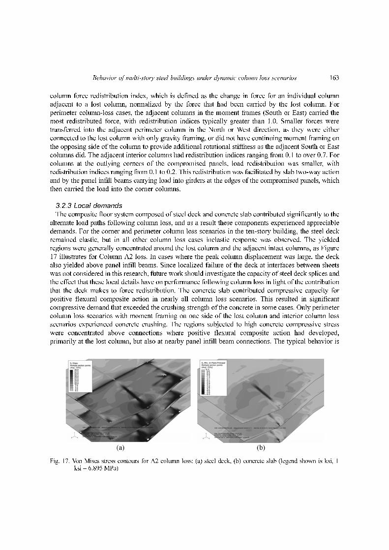
3.2.3 Local demandsThe composite floor system composed of steel deck and concrete slab contributed significantly to the
alternate load paths following column loss, and as a result these components experienced appreciable
demands. For the corner and perimeter column loss scenarios in the ten-story building, the steel deck
remained elastic, but in all other column loss cases inelastic response was observed. The yielded
regions were generally concentrated around the lost column and the adjacent intact columns, as Figure
17 illustrates for Column A2 loss. In cases where the peak column displacement was large, the deck
also yielded above panel infill beams. Since localized failure of the deck at interfaces between sheets
was not considered in this research, future work should investigate the capacity of steel deck splices and
the effect that these local details have on performance following column loss in light of the contribution
that the deck makes to force redistribution. The concrete slab contributed compressive capacity for
positive flexural composite action in nearly all column loss scenarios. This resulted in significant
compressive demand that exceeded the crushing strength of the concrete in some cases. Only perimeter
column loss scenarios with moment framing on one side of the lost column and interior column loss
scenarios experienced concrete crushing. The regions subjected to high concrete compressive stress
were concentrated above connections where positive flexural composite action had developed,
primarily at the lost column, but also at nearby panel infill beam connections. The typical behavior is
Fig. 17. Von Mises stress contours for A2 column loss: (a) steel deck, (b) concrete slab (legend shown is ksi, 1ksi = 6.895 MPa)

164 Seth T. Hoffman and Larry A. Fahnestock
shown in Figure 17 for the case of Column A2 loss. Although the material constitutive relationship for
the concrete slab was linear elastic in compression and did not model the crushing and subsequent
degradation in strength, the effect of crushing is judged to be minimal since the regions of crushing
were small.
For corner and perimeter column locations, moment connections were critical to successful force
redistribution following column loss. In the ten-story building, moment connections remained in the
elastic range for all column loss scenarios, so the perimeter column loss scenarios for the three-story
building best illustrate moment connection demands including significant inelastic response, and the
three-story building will be used in the discussion below. Since the concrete slab provided significant
additional compressive axial capacity for connections in positive flexure and the steel deck and slab
reinforcing mesh provided some additional tensile capacity for connections in negative flexure, the
bottom flanges of the moment connections consistently had higher demands than the top flanges.
Aggregate flange yield indices, which are maximum flange forces averaged over the three floor levels
for a given location and normalized by the flange yield forces, are presented in Figure 18. These data
show that the top flanges only exceeded yield for the loss of Columns A2 and C1, while all column loss
scenarios had beam bottom flanges that were loaded into the inelastic range. The large inelastic
demands are of concern since they may lead to connection fracture (FEMA 2000b). While significant
research has been conducted on welded moment connections for seismic loading (FEMA 2000a,
2000b), limited experimental investigation has been conducted for the distinctly different demands that
arise following column loss. Several research programs have studied moment connections under simulated
column loss scenarios (Khandelwal and El-Tawil 2007, Sadek et al 2008), but the effect of the
composite slab has not been fully explored. As the results of the column loss simulations in this
research have demonstrated, flexural composite action appreciably changes the behavior of the moment
connections, and the implications of this behavior require additional investigation.
As discussed above, shear connections can play an important role in collapse resistance, primarily by
working in conjunction with the concrete slab to mobilize flexural composite action. However, the
appreciable demands that are placed on shear connections following column loss can cause localized
damage and failure. In the ten-story building perimeter column loss cases, all shear connections
remained in the elastic range since the large moment frames effectively redistributed the load from the
lost column and limited the vertical deflection. In the three-story building perimeter column loss cases,
the moment frames had much smaller members and as a result the shear connections experienced much
Fig. 18. Aggregate flange yield indices: (a) top flanges, (b) bottom flanges

Behavior of multi-story steel buildings under dynamic column loss scenarios 165
larger demands. Table 2 summarizes the shear connection performance for the four primary perimeter
column loss cases (Columns A2, A3, C1 and D1) in the three-story building by noting the connection
locations where the modeled axial and/or shear capacities of the connections were reached. Of these
four cases, Column A3 loss led to the smallest demands on the shear connections and they remained
essentially elastic due to the moment frame action and the favorable orientation of the infill beams
(parallel to the building perimeter). In comparison, Column D1 loss, which is similar to Column A3
except the infill beams are oriented perpendicular to the building perimeter, led to shear damage in the
connection at the far end of the infill beam that was attached to the lost column. This difference further
illustrates the variation in behavior associated with the orientation of infill framing, which was noted
above. Similarly, comparison of the loss scenarios for Columns A2 and C1, where the primary
difference is infill framing orientation, reveals significantly more inelastic connection response for the
Column C1 scenario owing to the infill framing being oriented perpendicular to the building perimeter.
Table 3 summarizes the shear connection performance for the interior column loss cases and illustrates
the increase in demand on the shear connections due to the lack of moment connections. In all cases,
multiple shear connections reached axial and shear capacity and exhibited inelastic response, and the
three-story and ten-story buildings behaved similarly. In the three-story building, the loss scenarios for
Columns C2 and C3 exhibited the least number of connections with inelastic response since they were
further away from the building perimeter and had the benefit of additional slab continuity.
4. Summary and conclusions
Dynamic column loss simulations were conducted for three-story and ten-story prototype steel
Table 2 Shear connection demands for three-story perimeter column loss scenarios
Lost Col.
Connection location*
Perimeter at far end of lostcolumn (North or East)
Perimeter at lostcolumn
Perpendicular interior at far end of lost column
Perpendicular interior atlost column
A2 - Axial - -
A3 NA - moment conn. NA - moment conn. - -
C1 Shear Axial Shear -
D1 NA - moment conn. NA - moment conn. Shear -
*Axial = axial capacity of connection reached; Shear = shear capacity of connection reached
Table 3 Shear connection demands for interior column loss scenarios
Building height
Lostcol.
Connection location*
Girder at lostcolumn
Infill beam at far endof lost column (North)
Infill beam atlost column
Infill beam at farend of lost column
(South)
Nearestinfill
beams
Three-Story
B2 Axial - Axial, Shear Shear Axial
B3 Axial Shear Axial, Shear Shear -
C2 Axial - - Shear -
C3 Axial - - Shear -
Ten-Story B2 Axial - Axial, Shear Shear -
*Axial = axial capacity of connection reached; Shear = shear capacity of connection reached

166 Seth T. Hoffman and Larry A. Fahnestock
buildings with perimeter moment frames and composite steel-concrete floors. Sixteen column loss
scenarios were considered and the results from these simulations provide the following key
conclusions:● Corner and perimeter column loss scenarios with only shear connections led to localized collapse,
although propagation through the remaining intact portion of the building did not occur.● Composite flexural response was a significant load redistribution mechanism following column
loss. This was most prevalent at the lost column, where connection axial capacity allowed positive
flexural composite action to develop. This composite action allowed two adjacent beam spans to
act as one span over two bays. Negative flexural composite action also developed at intact columns
adjacent to the compromised column.● The concrete slab and steel deck were subjected to inelastic demands as a result of flexural
composite action. For interior column loss scenarios where positive flexural composite action was
mobilized, small regions of the concrete slab were loaded to crushing. In most column loss cases,
the steel deck was loaded beyond yield. The deck was modeled as continuous, so it did not capture
possible damage or failure of splices. Future research should evaluate the impact of failure modes
at deck splices.● For interior column loss scenarios, load redistribution to adjacent columns was roughly 50%
greater for intact columns connected to the compromised column by beams when compared to
intact columns connected to the compromised column by girders. This was a result of the two-bay
single span created by the panel infill beams, which carried load away from the girders in the center
of the compromised panels to girders on the perimeter of the compromised two bay square region.
Similarly, for perimeter column loss scenarios, more favorable performance was observed when
the infill beams were oriented parallel to the adjacent edge of the building.● Moment connections to a compromised column and to adjacent intact columns experienced
significant flexural and axial demands. Moment connection flanges also experienced appreciable
localized shear and moment, in addition to the axial forces. Owing to the appreciable impact that
composite action has on the behavior of moment connections under column loss scenarios, the
implications of this behavior require additional investigation.● Shear connections were subjected to significant demands following column loss and many were
damaged due to large axial forces. Positive flexural composite action mobilized high tensile forces
in shear connections, which often led to some degree of bolt tear-out damage in the connections.
This was the cause of one of the two collapse scenarios when the shear connections on one side of
the lost column failed entirely. In most cases where flexural composite action placed large axial
demands on shear connections, damage occurred but degradation was limited. Compressive forces
developed in shear connections where negative flexural composite action was mobilized. However,
these forces never exceeded the connection capacity since lower-flange binding occurred between
the beam and the supporting element, which isolated the shear connection from further
compression. Owing to the significant load redistribution following column loss, shear demand
exceeded the design capacity for some shear connections, particularly at infill beams connecting an
intact column to a lost interior column. ● Building height does not significantly alter behavior following column loss. Response following
interior column loss was essentially the same for the three-story and ten-story buildings. Demands
for corner and perimeter column loss scenarios were significantly smaller for the ten-story building
when compared to the three-story building, but this trend was not due to the building height, but
rather due to the much larger moment framing in the ten-story building. Thus, it can be concluded

Behavior of multi-story steel buildings under dynamic column loss scenarios 167
for the framing configurations that were studied, each floor acted independently to redistribute its
gravity load.● Overall, this study indicates that multi-story steel buildings with perimeter moment frames and
composite steel-concrete floors have appreciable robustness and may potentially be capable of
arresting collapse in column loss scenarios. However, large demands on the connections, steel deck
and concrete slab indicate potential for localized failure modes that are challenging to capture in
computational models. Large-scale experimental investigations are needed to explore the complex
three-dimensional load redistribution and localized demands that arise following column loss.
Acknowledgements
This research was partially funded by the American Institute of Steel Construction. The computational
simulations described herein were conducted using an allocation through the TeraGrid Advanced
Support Program. All opinions, findings, and conclusions expressed are those of the authors.
References
Alashker, Y., El-Tawil, S. and Sadek, F. (2010), “Progressive collapse resistance of steel-concrete compositefloors,” J. Struct. Eng., 136(10), 1187-1196, 10.1061/(ASCE)ST.1943-541X.0000230.
Alashker, Y. and El-Tawil, S. (2010), “Robustness of steel buildings: 3-D modeling, simulation and evaluation.”Proc., ASCE Struct. Cong. Orlando, FL.
DoD (2009), “Design of buildings to resist progressive collapse: UFC 4-023-03,” United States Department ofDefense. Washington, DC.
Fahnestock, L.A., Sause, R. and Ricles, J.M. (2006), “Analytical and large-scale experimental studies ofearthquake-resistant bucking-restrained braced frame systems,” ATLSS Report No. 06-01. Lehigh University,Bethlehem, PA.
FEMA (2000a), State of the Art Report on Systems Performance of Steel Moment Frames Subject to EarthquakeGround Shaking: FEMA-355C. Federal Emergency Management Agency. Washington, DC.
FEMA (2000b), State of the Art Report on Connection Performance: FEMA 355D. Federal EmergencyManagement Agency, Washington, DC.
Foley, C.M., Martin, K. and Scheenman, C. (2007), “Robustness in structural steel framing systems,” Report No.MU-CEEN-SE-07-01, Marquette University, Milwaukee, WI.
Fu, F. (2009), “Progressive collapse analysis of high-rise building with 3-D finite element modeling method,” J.Const. Steel. Res., 65(6), 2369-1278.
Fu, F. (2010), “3-D nonlinear dynamic progressive collapse analysis of multi-storey steel composite framebuildings,” Parametric study. Eng. Struct., 32, 3974-3980.
Izzuddin, B.A., Vlassis, A.G., Elghazouli, A.Y. and Nethercot, D.A. (2008), “Progressive collapse of multi-storeybuildings due to sudden column loss - Part I: Simplified assessment framework.” Eng. Struct., 30, 1308-1318.
Khandelwal, K. and El-Tawil, S. (2007) “Collapse behavior of steel special moment resisting frameconnections.” J. Struct. Eng., ASCE, 134(5), 646-655.
Khandelwal, K., El-Tawil, S., Kunnath, S.K. and Lew, S.H. (2008), “Macromodel-based simulation ofprogressive collapse: steel frame structures.” J. Struct. Eng., ASCE, 134(7), 1070-1078.
Khandelwal, K., El-Tawil, S. and Sadek, F. (2009), “Progressive collapse analysis of seismically designed steelbraced frames.” J. Const. Steel. Res., 65, 699-708.
Krauthammer, T, Yim, H.C. (2009), “Localized damage effects on building robustness.” Proceedings, ASCEStruct. Cong. Austin, TX.
Kwasniewski, L. (2010), “Nonlinear dynamic simulations of progressive collapse for a multistory building.” Eng.

168 Seth T. Hoffman and Larry A. Fahnestock
Struct., 32, 1223-1235.Main, J.A. and Sadek, F. (2009), “Development of 3D models of steel moment-frame buildings for assessment
of robustness and progressive collapse vulnerability.” Proceedings, ASCE Structures Congress 2009, Austin,TX.
Sadek, F., El-Tawil, S. and Lew, H.S. (2008), “Robustness of composite floor systems with shear connections:modeling, simulation, and evaluation.” J. Struct. Eng., ASCE, 134(11), 1717-1725.
Sadek, F., Main, J.A. and Lew, H.S. (2009), “Testing and analysis of steel beam-column assemblies undercolumn-removal scenarios.” Proceedings, ASCE Structures Congress, Austin, TX.
Simulia (2010), Abaqus FEA.Vlassis, A.G., Izzuddin, B.A., Elghazouli, A.Y. and Nethercot, D.A. (2008), “Progressive collapse of multi-storey
buildings due to sudden column loss- Part II: Application.” Eng. Struct., 30(5), 1424-1438.
CC