Behavior of concrete cylinders confined by carbon-composite tapes and prestressed yarns 1....
20
BEHAVIOR OF CONCRETE CYLINDERS CONFINED BY CARBON-COMPOSITE TAPES AND PRESTRESSED YARNS 1. EXPERIMENTAL DATA V. Tamuzs,* R. Tepfers,** Chi-Sang You,*** T. Rousakis,**** I. Repelis,* V. Skruls,* and U. Vilks* Keywords: concrete, cylindrical specimens, composite confinement, compressive loading, plasticity, damage, strength The results of a comprehensive test program for the mechanical behavior of round concrete specimens con- fined by carbon-fiber epoxy tapes and prestressed carbon yarns are reported. Five different concrete batches of compressive strength from 20 to 100 MPa and the confinement of various thickness and pretension level were investigated. The specimens, which were subjected to monotonic or repeated compressive loadings, showed a nonlinear stress–strain behavior with a significant ductility and increased ultimate strength, in con- trary to the brittle behavior of plain concrete. The limit of linearity on the stress–strain diagrams of the con- fined concrete roughly coincided with the ultimate strength of plain concrete. Above this limit, the damage accumulation and plastic deformations proceeded in the confined specimens. This fact was evidenced by the increasing slope of deformation diagrams in unloadings and repeated loadings and by the pronounced resid- ual strains. The limit of linearity could be raised significantly by pretension of the carbon yarns during their winding. Introduction During the last decades, the field application projects have been concentrated on the repair and reinforcement of con- crete columns by using composite materials. The repair and strengthening of reinforced concretes are some of the applications where the FRP (fiber-reinforced plastic) reinforcement serves better than the conventional steel one. The use of composite ma- terials can upgrade civil engineering structures and can be the most effective step to introduce composites into the common civil engineering practice. Many industrial companies and university research groups have been active in research and demon- stration works to assess the performance, durability, and cost of the composites for the repair and strengthening of reinforced concrete structures [1-5]. 13 0191-5665/06/4201-0013 © 2006 Springer Science+Business Media, Inc. * Institute of Polymer Mechanics, University of Latvia, Riga, Latvia. ** Chalmers University of Technology, Göteborg, Sweden. *** Pohang University of Korea, visiting the Institute of Polymer Mechanics. **** Dept. of Civil Eng., Demokritus Uni- versity of Thrace, Xanthi, Greece. Russian translation published in Mekhanika Kompozitnykh Materialov, Vol. 42, No. 1, pp. 21-44, January-February, 2006. Original article submitted November 21, 2005. Mechanics of Composite Materials, Vol. 42, No. 1, 2006
Transcript of Behavior of concrete cylinders confined by carbon-composite tapes and prestressed yarns 1....

BEHAVIOR OF CONCRETE CYLINDERS CONFINED
BY CARBON-COMPOSITE TAPES AND PRESTRESSED YARNS
1. EXPERIMENTAL DATA
V. Tamuzs,* R. Tepfers,**
Chi-Sang You,*** T. Rousakis,****
I. Repelis,* V. Skruls,* and U. Vilks*
Keywords: concrete, cylindrical specimens, composite confinement, compressive loading, plasticity, damage,
strength
The results of a comprehensive test program for the mechanical behavior of round concrete specimens con-
fined by carbon-fiber epoxy tapes and prestressed carbon yarns are reported. Five different concrete batches
of compressive strength from 20 to 100 MPa and the confinement of various thickness and pretension level
were investigated. The specimens, which were subjected to monotonic or repeated compressive loadings,
showed a nonlinear stress–strain behavior with a significant ductility and increased ultimate strength, in con-
trary to the brittle behavior of plain concrete. The limit of linearity on the stress–strain diagrams of the con-
fined concrete roughly coincided with the ultimate strength of plain concrete. Above this limit, the damage
accumulation and plastic deformations proceeded in the confined specimens. This fact was evidenced by the
increasing slope of deformation diagrams in unloadings and repeated loadings and by the pronounced resid-
ual strains. The limit of linearity could be raised significantly by pretension of the carbon yarns during their
winding.
Introduction
During the last decades, the field application projects have been concentrated on the repair and reinforcement of con-
crete columns by using composite materials. The repair and strengthening of reinforced concretes are some of the applications
where the FRP (fiber-reinforced plastic) reinforcement serves better than the conventional steel one. The use of composite ma-
terials can upgrade civil engineering structures and can be the most effective step to introduce composites into the common
civil engineering practice. Many industrial companies and university research groups have been active in research and demon-
stration works to assess the performance, durability, and cost of the composites for the repair and strengthening of reinforced
concrete structures [1-5].
130191-5665/06/4201-0013 © 2006 Springer Science+Business Media, Inc.
*Institute of Polymer Mechanics, University of Latvia, Riga, Latvia. **Chalmers University of Technology, Göteborg,
Sweden. ***Pohang University of Korea, visiting the Institute of Polymer Mechanics. ****Dept. of Civil Eng., Demokritus Uni-
versity of Thrace, Xanthi, Greece. Russian translation published in Mekhanika Kompozitnykh Materialov, Vol. 42, No. 1,
pp. 21-44, January-February, 2006. Original article submitted November 21, 2005.
Mechanics of Composite Materials, Vol. 42, No. 1, 2006
FRP is being utilized for the flexural and shear strengthening of reinforced concrete, masonry, steel, and wood struc-
tures, but one of their most attractive applications is the use in confining concrete columns. The FRP reinforcement is linearly
elastic up to the final failure and exerts a growing confining pressure on the concrete core. This behavior results in a consider-
ably increased strength and ductility of concrete when loaded axially.
As a confinement of concrete, FRP can be used in the form of yarns, wraps, or tubes. In yarn winding, resin-impreg-
nated yarns are wound around columns by using mechanical devices. In the manual strengthening of columns, one or more lay-
ers of FRP tapes are glued to the resin-impregnated column surface. In our paper, experimental results obtained in testing round
concrete specimens of height 0.3 m and diameter 0.15 m are presented. The program comprised tests of five concrete batches
with different compressive strengths, confined by a unidirectional carbon-fiber composite of three different thicknesses. Tests
on the plain concrete were also performed. The influence of yarn pretension was investigated for all the five concretes, which
were confined by a carbon yarn at three different pretension levels. Altogether, 60 concrete specimens were tested.
Characteristic of Concrete and the CFRP used as Confinement
Composite properties. The concretes were confined by wrapping with a CFRP tape and by winding with carbon
yarns. As the carbon tape, the unidirectional Grafil Inc. 340-700 carbon reinforcement by was used, whose mechanical proper-
ties, as indicated by the supplier, are: strength 4500 MPa, elastic modulus 234 GPa, density 1.8 g/cm3, elongation 1.9%, yarn
diameter 7 �m, and thickness 0.17 mm.
For the pretensioned confinement, carbon filament yarns were used. The yarn was PANEX 33 continuous carbon fi-
bers 7.2 �m in diameter produced by Zoltek. The mechanical properties of the yarn are: strength 3800 MPa, elastic modulus
228 GPa, density 1.8 g/cm3, average cross-sectional area of tow 1.86 mm2, fiber diameter 7.2 �m, and yield 278 m/kg.
The carbon reinforcements were impregnated with an epoxy resin consisting of two components — the base resin NM
BPE Composite System 417 and the hardener NM Härdare 417B, which were mixed in the ratio 100/44 by weight.
14
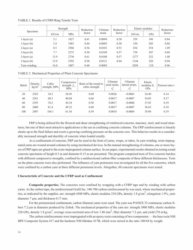
TABLE 1. Results of CFRP-Ring Tensile Tests
SpecimenStrength Reduction
factorUltimatestrain
Reductionfactor
Elastic modulus ReductionfactorkN/cm MPa kN/cm GPa
1-layer (à) 3.1 1827 0.41 0.0094 0.50 359 196 0.84
1-layer (b) 3.4 1985 0.44 0.0095 0.50 330 205 0.88
2-layer (à) 8.5 2506 0.56 0.0101 0.53 834 254 1.09
2-layer (b) 7.7 2272 0.50 0.0109 0.57 728 207 0.88
3-layer (à) 13.9 2730 0.61 0.0108 0.57 1277 252 1.08
3-layer (b) 13.9 2592 0.58 0.0121 0.64 1144 220 0.94
Yarn winding 16.8 1807 0.48 0.0085 2050 218 0.96
TABLE 2. Mechanical Properties of Plain Concrete Specimens
BatchDensity,kg/m3
Cubicstrength, ÌPà
Compressivestrength fc,
ÌPà
Ratio of the round tocubic strength
Ultimateaxial strain,
�cz
Ultimatelateral strain,
�c1
Elasticmodulus E,
GPaPoisson ratio �
20 2282 34.2 20.45 0.60 0.0026 –0.0003 24.40 0.14
40 2361 60.5 40.04 0.66 0.0017 –0.0007 34.03 0.17
60 2393 76.2 44.34 0.58 0.0017 –0.0006 37.83 0.19
80 2400 81.4 49.22 0.60 0.0017 –0.0007 36.65 0.18
100 2407 104.1 61.56 0.59 0.0018 –0.0004 39.09 0.19

It is well known that the strength of unidirectional composites depends not only on the strength of fibers, but also on
their volume fraction and adhesion [6]. Therefore, the true strength of the confinement was determined in a split-disc test ac-
cording to the ASTM standard D 2290.
The test specimens were fabricated in the shape of rings with a diameter of 150 mm, equal to that of the round concrete
specimens, and a width of 20 mm. For the wrapped confinements, three kinds of specimens (one, two, and three layers of the
CFRP tape) were prepared with a 150-mm overlap length. For the wound confinement, only one specimen was prepared by
hand-winding with a carbon yarn (5 cycles/cm) impregnated with the base resin. The results of the CFRP split-disc tests are
shown in Table 1.
The reduction factor is the ratio of the experimental tensile property of CFRP to the tensile property of CFRP in uniax-
ial tension following from the technical data given by the manufacturer. The strength given in the first column of Table 1 is the
direct test result. The second column was obtained assuming the cross section of carbon fibers per one cm according to the data
of the manufacturer. The intensity of winding was five yarns on one cm — the same as for the actual confined specimens. The
results obtained indicate that the strength of carbon fibers realized in the confinement was only about half of the fiber strength
indicated by the manufacturer, whereas the elastic moduli roughly coincided.
15
� �0 001 0 0.001 0.002 0.003
70
60
50
40
30
20
10
0
�33, MPa
A
BC
D
E
A
BC
D
E
�33� ��� ��
Fig. 1. The compressive behavior of cylindrical specimens of initial concretes of batches 100
(A), 80 (B), 60 (C), 40 (D), and 20 (E).
Winding
Tensioning
Feeding
1
2
34
P
Fig. 2. Winding scheme: bobbin (1); application of resin (2); pretension weight (3); winding on
concrete cylinders (4).

Concrete Mixtures and Specimens
Five different concrete mixtures were designed to obtain strengths ranging from 20 to 100 MPa, so that five batches
could be distinguished by the concrete strength. For the mix, Portland cement and a granite aggregate with the maximum gravel
size of 16 mm were used. For fabricating the 80 and 100 MPa concretes, silica fume and some additives were used. The addi-
tives were the Sikament-56 superplasticizer and the Sika retarder, and both were added as a percent of the binder (cement and
silica fume). All the mixtures were prepared within a period of three weeks. After casting, every batch was placed into water for
one week and then cured under laboratory conditions (20C and 50% relative humidity) until testing, which was run after a
lapse of at least one month.1
Test Results for Plain Concrete Specimens
A total of 15 cylindrical specimens of plain concrete were tested in a monotonic compressive loading. The specimens
were divided into five batches of different strength, with three identical specimens in each.
All the cylindrical specimens were of diameter 150 mm and height 300 mm, but the cubic specimens had the size 150 �
150 � 150 mm.
In Table 2, a comparison between the compressive strength of concrete cylinders with teflon interlays at their ends
(four teflon sheets) and that of standard concrete cubes with a side length of 150 mm without an interlay is given. It is seen that
the strength of the round specimens with the interlays was about ~60% of the cubic strength. Typical stress–strain curves for the
round cylinders of all the plain concretes considered are shown in Fig. 1, where �33 is the axial stress, �33 is the axial strain,
and � �11 22 is the lateral strain.
16
Fig. 3. Experimental setup of a 5000-kN press and the data acquisition system.
TABLE 3. Values of the Parameter k for all the Tape-Confined Specimens Tested
ConfinementConcrete batches
20 40 60 80 100
1-layer 0.0213 0.0153 0.0138 0.0141 0.0133
2-layer 0.0426 0.0306 0.0276 0.0282 0.0266
3-layer 0.0639 0.0459 0.0414 0.0423 0.0399
1 All the cylindrical and cubic concrete specimens were produced at the Chalmers University of Technology by T. Rousakiswithin the frame of EC Network ConFibreCrete and then transported to the Institute of Polymer Mechanics for confining andtesting.

Most of the plain concretes showed a brittle behavior, except the specimens of batch 20, and failed with splitting in the
vertical direction, which may be explained by abrupt propagation of an internal crack into the axial direction with lateral dila-
tion. At the beginning of loading, there was no sign of internal damage. As the load grew, a sound caused by generation of an in-
ternal crack was heard, and the secant modulus decreased slightly. In the behavior of most plain concretes, the lateral strain in-
creased just before the final failure, which was caused by the growth of internal cracks. Then the full failure occurred with
vertical cracking.
Preparation of Confined Concrete Specimens
Before wrapping with a carbon-fiber tape, the surface of concrete specimens was treated — a primer resin was applied
to the cleaned concrete surface, so that a high performance of the CFRP confinement be achieved. A water-based NM
17
D
� � �0 010 0.005 0 0.005 0.010 0.015
A
B
C
A
B
C
70
60
50
40
30
20
10
0
àà�33, MPa
�33� ��� ��
100
80
60
40
20
0� � �0 010 0.005 0 0.005 0.010 0.015
A
B
C C
B
Abb
D
�33, MPa
�33� ��� ��
� � �0 001 0.005 0 0.005 0.010
120
100
80
60
40
20
0
A
BC
A
BC
cc
D
�33, MPa
�33� ��� ��
A
BC
A
BBC
� �0.0050 0.0025 0 0.0025 0.0050 0.0075
100
80
60
40
20
0
dd
D
�33, MPa
�33� ��� ��
� �0 004 0 002 0 0 002 0 004. . . .
120
100
80
60
40
20
0
AB
C C
BA
ee�33, MPa
�33� ��� ��
D
Fig. 4. Compressive behavior of the concretes of batches 20 (à), 40 (b), 60 (c), 80 (d), and 100
(e) confined by three (A), two (B), and one (C) layers of CFRP under monotonic loading. D —
the initial concrete.

Grundering BP50 SUPER resin type, wetted with a NM Härdare 50 hardener, was used. After the treatment of concrete sur-
faces, a layer of the main NM BPE Composite System 417 resin was coated on them. Then, a carbon tape was attached to the
concrete surface. During the application, the tape was pressed and slightly stretched. In such a way, full impregnation and the
elimination of waving and air voids occurring underneath the tape were ensured. Another layer of the impregnation resin was
applied to the outer surface of the carbon tape and served as an underlay for the next tape or as a protective exterior resin lay.
Each lay was applied to the concrete in a continuous way. The overlap area of the external layer was impregnated with a special
care. The specimens after wrapping were left to stand under laboratory conditions (20C and 50% relative humidity) at least for
a week, so that the resin-carbon tape system be hardened completely. Specimens with one, two, and three layers of the carbon
tape were prepared.
In the winding process, the main epoxy resin was the same as that used in wrapping, namely NM BPE Composite Sys-
tem 417. The continuous reinforcement in the form of yarns was fed from a creel. The yarn from the creel went to a forcing de-
18
20 40 60 80 100
120
100
80
60
40
20
0
fcc, MPa
batch
àà
bb
20 40 60 80 100
3.5
3.0
2.5
2.0
1.5
1.0
f fcc c/
batch
cc
20 40 60 80 100
0.010
0.008
0.006
0.004
0.002
0
� lcc
batch
Fig. 5. Comparison of compressive strengths (a), normalized compressive strengths (b), and
ultimate lateral strains (c) of concretes confined by one (o), two ( ), and three ( ) layers of
CFRP in compression loading. (n) — initial concrete.

vice, where a weight creating the designed pretension level was suspended on the yarn, and then the winding process was con-
ducted over the rotating concrete specimen (Fig. 2).
The resin was applied to the concretes surface and yarns before winding. The placement of the yarns was controlled by
means of specially designed machines traversing at a step up to 4 mm per rotation. At the beginning of winding, the yarns were
fastened to the end of rotating disk. After the entire concrete surface had been covered two times, including the return path
19
� � �0 010 0.005 0 0.005 0.010 0.015 0.020
50
40
30
20
10
0
àà�33, MPa
� ��� �� ���
� � �0 010 0.005 0 0.005 0.010 0.015 0.020
70
60
50
40
30
20
10
0
bb�33, MPa
� ��� �� ���
� � �0 010 0.005 0 0.005 0.010 0.015 0.020
80
70
60
50
40
30
20
10
0
cc�33, MPa
� ��� �� ���
Fig. 6. Compressive behavior of the concrete of batch 20 confined by one (a), two (b), and three
(c) layers of CFRP under repeated loadings. (m) — stress–strain curves in monotonic loading.
(The compressive strain and stress are shown as positive quantities and tensile as negative.)

(which resulted in a final winding step equal to 2 mm), the end of the yarn was tied to its other end without losing the pretension
force. This process was conducted very carefully lest the yarns be damaged in the course of winding.
The regular tensile force applied to the yarn during winding was about 70 N, which corresponded to a weight P equal
to 14 kg. The maximum pretension level of the yarn was chosen equal to 400 N, which corresponded to the weight P = 80 kg. In
such a way, three winding confinements with a yarn step equal to 2 mm on the cylindrical concrete surface and yarn pretension
forces of about 150, 300, and 400 N were produced. Such pretension levels corresponded to pretension of the confinement
equal to 0.75, 1.5, and 2 kN/cm.
20
� � �0 010 0.005 0 0.005 0.010
90
80
70
60
50
40
30
20
10
0
bb�33, MPa
� ��� �� ���
� � �0 010 0.005 0 0.005 0.010
70
60
50
40
30
20
10
0
àà�33, MPa
� ��� �� ���
� � �0 010 0.005 0 0.005 0.010 0.015
100
80
60
40
20
0
cc�33, MPa
� ��� �� ���
Fig. 7. The same for the concrete of batch 40.

Methodology of Experiments
In our test, a vertical hydraulic column-testing machine with a capacity of 5000 kN (Fig. 3) was used, which had been
checked and certified by the Latvian Certification Agency before the test program was carried out.
The specimens were centered on the plate of the loading machine to avoid any loading eccentricity. Four teflon sheets
of dimensions 200 � 200 mm were used to reduce the friction between specimen end faces and the loading plates. Three linear
variable displacement transducers were employed to determine variations in the measuring length, which was equal to 200 mm.
For measuring the axial and lateral strains, four strain gages of type PL-60-11 (by Tokyo Sokki Kenkyujo Co., Ltd.)
with a resistance of 120 were glued with a P-2 adhesive to each specimen after a proper treatment of the rough surface of the
21
� � �0 004 0.002 0 0.002 0.004 0.006
90
80
70
60
50
40
30
20
10
0
bb�33, MPa
� ��� �� ���
������ ������ � �0.004 0.002 0 0.002 0.004 0.006
80
70
60
50
40
30
20
10
0
àà�33, MPa
� ��� �� ���
� � �0 008 0.004 0 0.004 0.008 0.012
120
100
80
60
40
20
0
cc�33, MPa
� ��� �� ���
Fig. 8. The same for the concrete of batch 60.

confinement. Two of the strain gages were located perpendicularly to each other in order to measure the axial and lateral strains
at the specimen midheight, and the other two were arranged on the opposite side. The strain gages were placed away from the
CFRP sheet overlap layer to acquire reliable measurement data.
All signals from the strain gages were amplified by a Spider 8 amplifier system, and then the data were collected by a
Cat software.
The loading rate was 10 MPa/min according to the ASTM C 39/C39M-99 standards. The cyclic response of the
CFRP-sheet-confined concrete was investigated by applying load-unload cycles related to the compressive strengths of plain
concrete, fc , and confined concrete, fcc . The load in each cycle was increased successively to 0.5 fc , 0.8 fc , fc , fc + 0.33( fcc –
fc), fc + 0.66( fcc + fc), and finally up to the full failure. For the case of concrete wound with pretensioned yarns, the load lev-
22
� � � �0 003 0.002 0.001 0 0.001 0.002 0.003 0.004
100
80
60
40
20
0
bb�33, MPa
� ��� �� ���
������ ������ � �0.004 0.002 0 0.002 0.004 0.006
90
80
70
60
50
40
30
20
10
0
àà�33, MPa
� ��� �� ���
� � � �0 006 0.004 0.002 0 0.002 0.004 0.006 0.008
120
100
80
60
40
20
0
�33, MPa
� ��� �� ���
cc
Fig. 9. The same for the concrete of batch 80.

els were assigned with only fc , followed by 0.5 fc , 0.8 fc , fc , 2 fc , 3 fc ,… until the total failure. The loading rate in the repeated
and monotonic loadings was the same.
Experimental Results
a) Concrete confined by CFRP tapes. Monotonic loading. The experimental investigations were performed on
concrete specimens confined by CFRP tapes. In all, 30 specimens (150 mm in diameter and 300 mm in height) with different
concrete strengths and volumetric ratios of carbon layers ranging from 0.45% (one layer) to 1.35% (three layers) were tested.
The efficiency of the confinement can be characterized by the parameter
23
� � � �0 006 0.004 0.002 0 0.002 0.004 0.006
120
100
80
60
40
20
0
�33, MPa
� ��� �� ���
cc
� �0.002 0.001 0 0.001 0.002 0.003
100
80
60
40
20
0
bb�33, MPa
� ��� �� ���
� �0.002 0.001 0 0.001 0.002 0.003
90
80
70
60
50
40
30
20
10
0
àà�33, MPa
� ��� �� ���
Fig. 10. The same for the concrete of batch 100.

kE
E
h
R
c
b
c ,
where hc and Ec are the thickness and the elastic modulus of the composite confinement, Eb is the elastic modulus of concrete,
and R is the radius of specimens; k � � if the confinement is absolutely stiff, and k = 0 in the absence of confinement. Using
data of the carbon sheet and the elastic modulus of different concrete batches, the values of k were obtained, which are shown in
Table 3.
24
�0 01 0 0 01 0 02 0 03. . . .
120
100
80
60
40
20
0
bb�33, MPa
� ��� �� ���
� �0 010 0 005 0 0 005 0 010 0 015 0 020 0 025 0 030. . . . . . . .
120
100
80
60
40
20
0
àà�33, MPa
�� ������ ���� ���
� �0 01 0 0.01 0.02 0.03
120
100
80
60
40
20
0
cc�33, MPa
� ��� �� ���
Fig. 11. Compressive behavior of the concrete of batch 20 wound with carbon yarns under
repeated loadings. Tensioning levels are 80 (a), 160 (b), and 210 MPa (c). (m) — stress–strain
curves of the initial concrete. (The compressive strain and stress are shown as positive
quantities and the tensile ones as negative.)

From the test results it follows that the strength increased 1.3-3.1 times, the axial strain 1.5-7.8 times, and the lateral
strain 5-26 times in comparison with the corresponding values for the plain concrete. Figure 4 shows the compressive behavior
of the tape-confined concrete samples.
In the early loading stage, up to the elastic limit, the behavior of the confined concretes was almost the same as that of
the plain concretes. The difference in the elastic modulus and the Poisson ratio was negligible.
When the load exceeded the elastic limit, a sound caused by the initiation of internal damage of concrete was heard,
the slope of the deformation diagram increased, and the stress–strain relationship in loading became nonlinear. Thus, the con-
fined concretes displayed a distinct nonlinear response, with a transition zone at the level of ultimate strength of the unconfined
concrete.
25
�0 01 0 0 01 0 02 0 03. . . .
160
140
120
100
80
60
40
20
0
cc�33, MPa
� ��� �� ���
�0 01 0 0 01 0 02 0 03. . . .
160
140
120
100
80
60
40
20
0
bb�33, MPa
�� ������ ���� ���
�0 01 0 0 01 0 02 0 03. . . .
160
140
120
100
80
60
40
20
0
àà�33, MPa
� ��� �� ���
Fig. 12. The same for the concrete of batch 40.

The same CFRP-sheet confinement seems to give about the same strength rise for all the concretes considered, as seen
in Fig. 5a, which also means that it is less effective for stronger concretes, Fig. 5b.
It could be expected that the specimens would fail at the same lateral strain of the CFRP sheet as that measured in the
ring tests (Table 1). However, the measured lateral strains at the failure of cylinders were less than those in the ring tests and
showed a wide scatter, which can be explained by the improper failure modes occurring in some cases (the failure began close
to specimen ends, away from the gage of lateral strains). The nonuniform pressure from the fragmented concrete within the
CFRP confinement, leading to stress concentrations, might also cause the increased scatter and the early failure.
b) Repeated loading. Two specimens of the same type in each batch were prepared for testing in monotonic and re-
peated compressive loadings, respectively. The load levels were assigned based on the results of previous tests, namely the
26
� �0 010 0 005 0 0 005 0 010 0 015 0 020. . . . . .
160
140
120
100
80
60
40
20
0
cc�33, MPa
� ��� �� ���
� �0 010 0 005 0 0 005 0 010 0 015 0 020. . . . . .
160
140
120
100
80
60
40
20
0
bb�33, MPa
� ��� �� ���
� �0 010 0 005 0 0 005 0 010 0 015 0 020. . . . . .
160
140
120
100
80
60
40
20
0
àà�33, MPa
� ��� �� ���
Fig. 13. The same for the concrete of batch 60.

compressive strengths of plain concrete fc and the confined concrete of the same type fcc , followed by 0.5 fc , 0.8 fc , fc ,
f f fc cc c� �033. ( ), f f fc cc c� �066. ( ) and up to the final failure. Figures 6-10 show the compressive behavior of concrete
specimen confined by CFRP tapes under repeated load-unload cycles for all the concretes considered. For a better comparison,
the stress–strain relationships for both the loading modes (monotonic and repeated) are presented in the same figure.
Under repeated loading, the envelope stress–strain curves usually followed the curves of monotonic loading (Figs.
6-10). Only some specimens showed a small degradation in the strength and ductility as a result of the improper fracture of
specimens. The unloading below the yield point revealed no changes in the elastic modulus, but some decrease in it was ob-
served above the elastic limit during unloading.
27
� �0 010 0 005 0 0 005 0 010 0 015 0 020. . . . . .
180
160
140
120
100
80
60
40
20
0
cc�33, MPa
� ��� �� ���
� �0 010 0 005 0 0 005 0 010 0 015 0 020. . . . . .
180
160
140
120
100
80
60
40
20
0
bb�33, MPa
� ��� �� ���
� �0 010 0 005 0 0 005 0 010 0 015 0 020. . . . . .
180
160
140
120
100
80
60
40
20
0
àà�33, MPa
� ��� �� ���
Fig. 14. The same for the concrete of batch 80.

The experimental graphs obtained give a basis for estimating the plastic deformation and the change in the characteris-
tics of concrete under the lateral compression caused by the confinement. The corresponding model of plasticity coupled with
damage will be the subject of next papers.
c) Repeated loading of concrete cylinders confined by a prestressed composite shell. The pretension of a yarn was
achieved by suspending a weight on it, as shown in Fig. 2. The maximum suspended weight applied for pretension level 3 was
80 kg, which gave the yarn a tensile stress of 210 MPa. The weights of 30 and 60 kg were used for the level 1 and 2 tensile
stresses 80 and 160 MPa, respectively. The volumetric ratio of carbon yarns in all the confined concretes was 2.48%, and they
were divided into five batches according to the concrete strength. Thus, the tests were performed altogether on 15 specimens of
5 concretes, with three different pretension levels in each batch. The specimens were compressed under a successively increas-
28
� �0 010 0 005 0 0 005 0 010 0 015. . . . .
180
160
140
120
100
80
60
40
20
0
c�33, MPa
� ��� �� ���
� �0 010 0 005 0 0 005 0 010 0 015. . . . .
180
160
140
120
100
80
60
40
20
0
b�33, MPa
� ��� �� ���
� �0 010 0 005 0 0 005 0 010 0 015. . . . .
180
160
140
120
100
80
60
40
20
0
à�33, MPa
� ��� �� ���
Fig. 15. The same for the concrete of batch 100.

ing repeated load, assigned based on the compressive strength of plain concretes, followed by 0.5 fc , 0.8 fc , fc , 2 fc , 3 fc , …. up
to the final failure. The results obtained are shown on Figs. 11-15 for all the concrete batches tested.
The behavior of plain concrete specimens on Figs. 8-12 is marked by open dots. It is remarkable that the limit of linear-
ity for the specimens significantly exceeds the strength of plain concrete, in contrary to that for the specimens confined by a car-
bon composite tape without pretensioning (see for comparison Fig. 4).
The pretensioning did not give a detectable growth in ultimate strength. The reason for this is that the ultimate strength
of confined concrete is determined by the strength of the composite shell; but this strength depends on the thickness of confine-
ment, which was the same for all the pretension levels used.
The measured ultimate lateral strain (Fig. 16) for the prestressed specimens occured in the range of that measured in
the ring tests, Table 1. The data scatter was less than that observed for the CFRP-tape-confined specimens (Fig. 5c). The pre-
29
20 40 60 80 100
200
180
160
140
120
100
80
0
fcc , MPa
batch
à
20 40 60 80 100
6
5
4
3
2
1
f fcc c/
b
batch
20 40 60 80 100
0.014
0.012
0.010
0.008
0.006
0.004
0.002
0
�lcc c
batch
Fig. 16. Comparison of compressive strengths (a), normalized compressive strengths (b), and
ultimate lateral strains (c) of concretes wound with tensioned carbon yarns at various tensioning
levels: low ( o ), moderate ( ), and high ( ).

stress of the composite equalizes the stretch in fibers, whereas the manual wrapping with tapes most likely leads to
nonuniformly stressed fibers under a load.
Repeated Loading After Tearing off the Composite Shell
The acoustic sound arising in the confined specimens at a compression stress exceeding the elastic limit points to the
formation of damage in concrete. The damage level can be estimated by the decreased elastic modulus and the residual
strength. Special tests were carried out to register these changes. The reduction in the modulus of the confined specimens can
be obtained from loading-unloading curves (Figs. 5-15), but for determining the residual strength of concrete, it is necessary to
test the damaged concrete after tearing off the composite confinement. A specimen after the removal of the shell is shown in
Fig. 17. Two special tests were carried out on cylindrical concrete specimen with initial cubic strengths 50 (batch 50) and 25
MPa (batch 25).
A confined specimen was loaded above the limit of linearity without reaching the total failure. Then the specimen was
unloaded, the composite shell was cut and torn off, and the specimen was prepared for a repeated compression test, which was
continued up to the complete failure. The results obtained are displayed in Fig. 18, where the registered stress–strain behavior
of the undamaged plain concrete from the same batch is also seen. Curves 1 and 2 show the behavior of two different confined
specimens, and curves 3 and 4 correspond to the unloading and repeat loading of the specimen after tearing off the confine-
ment. Curve 5 shows a typical stress–strain diagram in compression for the undamaged plain concrete.
It is remarkable that reduction in the elastic modulus for both the specimens is roughly the same, and the ultimate com-
pression strain after the damage is the same as for the undamaged material, or even slightly greater.
30
Fig. 17. A concrete specimen after the first loading above the limit of linearity and tearing off
the composite shell.

Summary and Conclusions
The objective of this study was to investigate the compressive behavior of concrete confined by CFRP. The investiga-
tions were carried out on concretes of five different strengths, and the varied parameters of the confinement were the number of
layers for wrapping with a carbon tape and the pretension level for winding with pretensioned carbon yarns.
From test results for the CFRP-sheet-confined concretes, an increase in the strength and ductility was seen for all the
confined concretes, which resulted in a higher load-carrying capacity. The confined concretes displayed a distinct nonlinear re-
sponse with a transition zone around the ultimate strength of the unconfined concrete.
The maximum increase in strength caused by the confinement was obtained for the concrete specimen of batch 20
wrapped with three layers of a tape with a normalized strength of 3.08; this specimen showed the maximum ratio of lateral
stress to the axial stress. The normalized effect of confinement, at the same number of CFRP tapes, decreased with increasing
concrete strength, which is natural, because the ultimate strength of a specimen is determined by the strength of the composite
confinement.
The confined concretes failed by fracture of the FRP confinement, which occurred at a lower lateral strain of concrete
specimens than the ultimate uniaxial tensile strain of carbon yarns indicated by the producer. The CFRP-ring test (ASTM stan-
dard D2290) revealed the actual ultimate tensile strain of the confinement, which also exceeded the ultimate lateral strain. The
lower values can be explained by the improper failure modes occurring in some cases.
The repeated loading revealed the plastic behavior of confined concrete. The stress–strain curve in the monotonic
loading formed the envelope of that in the repeated loading.
The confining action of pretensioned carbon yarns was much more effective than that of CFRP tapes, but this could
partially be caused by the larger carbon confinement ratio, 2.48%, while the three-layer tape confinement contained only
1.35% carbon.
A significantly higher elastic limit was observed for the specimens confined under pretension in comparison with that
for the plain concrete and the specimens confined by a carbon tape.
The repeated loading revealed the plastic behavior of confined concrete specimens, which was coupled with a reduc-
tion in the elastic modulus and with damage accumulation. The creation of an appropriate mechanical model describing these
effects is the subject of next papers.
The present paper comprises only concise results of the experimental study. The full text and the results in a digital
form are given in [7] and are also available in the internet http://www.pmi.lv/... .
31
0.1 0.2 0.3 0.4 0.5 0.6 0.70
80
70
60
50
40
30
20
10
�33, MPa
1
2
3
45
�33, %
Fig. 18. Stress–strain curves for the concrete of batch 50: 1 and 2 — compression of confined
concrete specimens above the limit of linearity; 3 and 4 — repeated compression of specimens
1 and 2 after unloading and tearing off the composite shell; 5 — compression of the initial
concrete up to the final failure.

Acknowledgment. This investigation is a joint project of the Division of Building Tehnology, Chalmers University of
Technology in Göteborg, Sweden and of the Institute of Polymer Mechanics, University of Latvia, Riga, Latvia. The project
was sponsored by Åke och Greta Lissheds Stiftelse, SEB Enskilda Banken SE 10640, Stockholm. The investigation was coor-
dinated within the frames of European Comission TMR Network ConFibreCrete and Marie Curie Network En-Core. The other
contributors are mentioned in [7]. We express most sincere thanks to all contributors who supported this research.
REFERENCES
1. S. G. Lim and T. Hahn, “Composite materials in repairing and strengthening of civil engineering,” Korean Soc. Com-
pos. Mater., 9, No. 4, 1-12 (1996).
2. M. Samaan, A. Mirmiram, and M. Shahawy, “Model of concrete confined by fiber composites,” ASCE J. Struct. Eng.,
124, No. 9, 1025-1031 (1998).
3. S. Matthys, L. Taerwe, and K. Audenaert, “Tests on axially loaded concrete columns confined by fiber-reinforced poly-
mer sheet wrapping,” in: 4th International Symposium on Fiber Reinforced Polymer Reinforcement for Reinforced
Concrete Structures (1999), pp. 217-228.
4. M. Saafi, H. A. Toutanji, and Z. Li, “Behavior of concrete columns confined with fiber-reinforced polymer tubes,” ACI
Mater. J., 96, No. 4, 500-509 (1999).
5. L. De Lorenzis and R. Tepfers, “Comparative study of models on confinement of concrete cylinders with fiber-rein-
forced polymer composites,” ASCE J. Compos. Construct., 219-237 (August, 2003).
6. Yu. G. Korobel’nikov, O. F. Siluyanov, V. P. Tamuzh, A. N. Shiryaev, I. L. Kumok, and M. T. Azarova, “Basic laws
governing the mechanical properties of filler fibers in a unidirectional composite,” Mech. Compos. Mater., 23, No. 2,
194-198 (1987).
7. V. Tamuzs, C. S. You , and R. Tepfers, Experimental Investigation of CFRP-Confined Concretes under Compressive
Load, Institute of Polymer Mechanics, University of Latvia, Aizkraukles 23, LV-1006, Riga, Latvia and Division of
Building Technology, Chalmers University of Technology, S-412 96 Göteborg, Sweden (December, 2001),
http://www.pmi.lv/Assets/Files/ CFRP-confined-concrete.pdf
32