Barco Overture User Manual
113
Barco Overture User Manual Copyright © 2017 Barco, Inc., all rights reserved Version: 3.0.4 Revision: 1.0 Date: July 31, 2017
-
Upload
khangminh22 -
Category
Documents
-
view
1 -
download
0
Transcript of Barco Overture User Manual

Barco Overture User ManualCopyright © 2017 Barco, Inc., all rights reservedVersion: 3.0.4Revision: 1.0Date: July 31, 2017

1 EULAOverture
Product Specific End User License Agreement
THIS PRODUCT SPECIFIC USER LICENSE AGREEMENT (EULA) TOGETHER WITH THE BARCO GENERAL EULAATTACHED HERETO SET OUT THE TERMS OF USE OF THE SOFTWARE.
PLEASE READ THIS DOCUMENT CAREFULLY BEFORE OPENING OR DOWNLOADING AND USING THE SOFTWARE.
DO NOT ACCEPT THE LICENSE, AND DO NOT INSTALL, DOWNLOAD, ACCESS, OR OTHERWISE COP Y OR USE ALLOR ANY PORTION OF THE SOFTWARE UNLESS YOU CAN AGREE WITH ITS TERMS AS SET OUT IN THIS LICENSEAGREEMENT.
1.1 1. Metrics
Applicable prices for Barco Overture (the “Software”) shall be invoiced and paid as per the applicablepurchase order acknowledged by Barco.
1.1.0.1 a) Term
Barco Overture is available in 2 models offered “on-premises” (installed and run on computers on yourpremises):
Perpetual license;
Subscription license (yearly basis);
At the end of this time period, all rights associated w ith the use of the Software (including any associatedupdates or upgrades) cease.
1.1.0.1 b) Deployment
A single license is either
restricted to the agreed number of Rooms, where a “Room” is defined as a collection of devicesgrouped in 1 virtual container, w ith a maximum of 40 devices per Room;restricted to the agreed number of control servers;or a combination of (i) and (ii).
You shall ensure that the Software connects through the internet w ith Barco and you acknowledge that theSoftware w ill send through such connection, at regular intervals a history of thumbprint of the rooms anddevices actually connected, which may be used by Barco for license management and compliance.
1.1.0.1 c) Use
The Overture solution consists of (i) a UX server that may only be used on one (1) Machine and (ii) a Controlserver that may be used on multiple Machines.
A “Machine” means the smallest data processing unit on which it is possible to run the Software w ithin asingle computer device.
Any Device Drivers, GUI templates and CSS styling included in the Software may be modified by you as youdeem required for your Intended Use of the Software.
1.2 2. Support
1.2.0.1 a) Perpetual Based
Maintenance, including the provision of upgrades and updates to the Software, and helpdesk support areavailable at your option on the terms of Barco’s then current maintenance contract. Software maintenancemay be included in the initial transaction if ordered and paid for additionally.
Updates and upgrades are not available otherw ise. It is strongly suggested to maintain the softwaremaintenance contract w ithout interruption. Barco reserves the right not to restart maintenance follow ing aninterruption by the customer.

1.2.0.1 b) Subscription based
1.2.0.1 The provision of updates, upgrades and helpdesk support are included in the subscription license forthe Term thereof.
1.3 3. Terms of Use
The Software can be used as set out in the Barco EULA attached hereto.
Any reference therein to the DRM is relevant only if and when the Software is licensed otherw ise than on an“on premises” basis.
The provisions of this Product Specific EULA override the Barco generic EULA in case of conflicts orinconsistencies.
In case of (inadvertent or other) non-compliance (e.g. where the actual use overshoots the use authorizedhereunder), Barco shall have the option to (i) cause you to procure such additional licenses required as perthe actual usage and (ii) to suspend access to the Software until the non-compliance is remedied, failing ofwhich Barco may terminate the License Agreement as set out herein.
1.4 4. Privacy
You are the controller (as defined under applicable privacy laws) for personal data which are being processedvia the Software. Therefore, you remain solely responsible for complying w ith all applicable data protectionlaws and for implementing and maintaining privacy protection and security measures (especially forcomponents that you provide or control). Barco disclaims any liability in this regard.
1.5 5. Other Terms
1.5.0.1 a) Other License Terms
The Overture solution contains software components released under an Open Source license.
A list of the third party software components used (open source and other) is available in the Software’sREADME files, through the “My Barco” section of the Barco website or through other (online) means. Theapplicable license terms, copyright notices and, as relevant, source code access apply as set out in the BarcoEULA attached hereto.
1.5.0.1 b) Safe and proper use of Devices
You remain solely responsible to operate any device which is controlled, monitored or analysed by theSoftware in accordance w ith the operating instructions and safety guidelines as intended and/orrecommended by the relevant device manufacturers for a regular and routine usage of any such devices.Barco disclaims any liability resulting from an improper use of a device, even if such device is being controlled,monitored or analysed by the Software.
BARCO END USER LICENSE AGREEMENT
By accepting these terms (through a tick box or other mechanism designed to acknowledge agreement to theterms of an electronic copy of this License Agreement), or by installing, downloading, accessing, or otherw isecopying or using all or any portion of the Software (as defined below), (i) you accept this License Agreementon behalf of the entity for which you are authorized to act (e.g., your employer) and you agree to act in amanner consistent w ith this License Agreement (or, if there is no such entity for which you are authorized toact, you accept this License Agreement on behalf of yourself as an individual and acknowledge that you arelegally bound by this Agreement), and (ii) you represent and warrant that you have the right, power andauthority to act on behalf of and bind such entity.
These terms apply to your use of the Software as of and for the original Term of your license. When yourenew or purchase an additional license, or when Barco introduces elements that were not previouslyincluded in the Software, the then current license terms shall apply and w ill remain unchanged during theterm of that license and/or in respect of such changed elements. The Product Specific EULA you accept appliesin addition to these terms, and may evolve accordingly. You acknowledge that an electronic copy of thisAgreement shall have the same proving value as a hard copy signed by the parties.
If you are unwilling to accept this License Agreement on these terms, or you do not have the right, power andauthority to act on behalf of and bind such entity (or yourself as an individual if there is no such entity), DO

NOT SELECT THE “I ACCEPT” BUTTON OR OTHERWISE CLICK ON ANY BUTTON OR OTHER MECHANISMDESIGNED TO ACKNOWLEDGE AGREEMENT, AND DO NOT INSTALL, DOWNLOAD, ACCESS, OR OTHERWISE COP YOR USE ALL OR ANY PORTION OF THE SOFTWARE.
Definitions
“Affiliate” means any corporation or other entity directly or indirectly, controlling, controlled by or undercommon control w ith such corporation or entity.
For the purpose of the above, “control” shall mean (i) the ownership or control, directly or indirectly, of fiftypercent (50%) or more of the equity capital or the shares or voting rights in the corporation or other entity inquestion or (ii) the control of the composition of the board of directors of the corporation or other entity inquestion.
“Barco” means Barco NV (company number 0473.191.041) w ith company address at Beneluxpark 21, 8500Kortrijk, Belgium, or its designated Affiliate licensing to you the proprietary software which is the subjectmatter of this Agreement.
“Documentation” means all technical, reference and installation manuals, user guides, published performancespecifications and other written documentation provided by Barco generally to its licensees w ith respect tothe Software, along w ith any modifications and updates thereto;
“DRM” means Barco’s digital rights management platform used to provide access to and access conditions ofthe Software.
“License Agreement” means this Barco End User License Agreement (EULA), incorporating the terms of theProduct Specific EULA, and any modifications thereof as set out herein.
“Product Specific EULA” means the supplemental software terms applicable
“Software” means the Barco proprietary software which is being licensed hereunder, released in object codeonly.
“Term” means the period set out in article 9.1 hereof.
“you” means the entity on behalf of which these terms are accepted, and any of its representatives havingaccess to the Software.
License Grant
2.1 License Scope. Subject to compliance w ith all license terms and payment of applicable fees, Barco grantsyou a limited, non-exclusive, non-assignable, non-transferable user license (w ithout the right to grantsublicenses). Save for the Product Specific EULA or any broader license terms confirmed through the DRM tool,(i) the license under this License Agreement applies to one (1) copy of the Software to be used on one singlecomputing device and (ii) installation on a computing device that may be concurrently accessed by more thanone user shall not constitute a permitted use and a separate license is required for each active userconnected to a computing device on which the Software is being used
2 .2 License Type . The applicable license type, and your rights in time, deployment and usage, are furtherdetailed in the Product Specific EULA (in the absence of which the scope shall be as set in article2.1 hereof).
2.3 License restrictions.
Intended Use. You agree to use the Software solely as permitted by this License Agreement (and any ProductSpecific EULA made part of it) and in a matter consistent w ith its design and Documentation.
No Transfer (License Agreement). You agree not to transfer, assign or sublicense your license rights to anyother person or entity, unless Barco’s prior written consent is obtained (which consent shall be reasonablygiven, but may come w ith a fee).
No Transfer (Software). If you deactivate or uninstall the Software from the computer device on which it wasoriginally installed, this w ill terminate this License Agreement unless otherw ise and specifically approved byBarco. You agree not to use the Software in association w ith other hardware or software that allows to poolconnections, reroute information, reduce the number of devices or users that directly access or use theSoftware, or reduce the number of devices or users the Software directly manages (sometimes referred to as“multiplexing” or “pooling”) or otherw ise attempt to reduce the number of licenses of any type that you need.
Authorized Users. The use of the Software is restricted to persons w ithin your organization, or any third partyrepresentatives operating under your responsibility and control, provided any such persons have acceptedthe terms of this License Agreement. You agree not to use or permit the Software to be used to performservices for third parties, whether on a service bureau or time sharing basis or otherw ise, w ithout the priorwritten authorization of Barco. You shall not lease, rent, or otherw ise transfer or grant a security or otherinterest in the Software.
No Modifications. You shall not make error corrections to or otherw ise modify or adapt the Software or createderivative works based upon the Software, or permit third parties to do the same.
No Reverse Engineering. You agree not to reverse engineer or decompile, decrypt, disassemble or otherw isereduce the Software to human-readable form, except to the extent otherw ise expressly permitted underapplicable law notw ithstanding this restriction, or except to the extent Barco is legally required to permit such

specific activity pursuant to any applicable open source license.
Code required to ensure interoperability. To the extent required by law, and at your written request, Barco shallprovide you w ith the interface information needed to achieve interoperability between the Software andanother independently created program used by you, on payment of Barco’s applicable fee (if any). You shallobserve strict obligations of confidentiality w ith respect to such information and shall use such information incompliance w ith terms and conditions which Barco makes applicable.
No Unbundling. The Software may include various applications and components, may support multipleplatforms and languages, and may be provided on multiple media or in multiple copies. Nonetheless, theSoftware is designed and provided to you as a single product to be used as a single product on devices aspermitted herein. You agree not to unbundle the component parts of the Software for use on differentcomputer devices.
Territory. You agree to use the Software solely in the territory or region where you obtained the Softwarefrom Barco or its authorized reseller or as otherw ise stated in the Documentation. Any export if permittedshall comply w ith any applicable (export) laws and regulations.
2 .4 Your Infrastructure. You remain responsible to procure and maintain hardware, operating system,network and other infrastructure (the “Infrastructure”) required to operate the Software and to keep suchInfrastructure functioning and virus-free. You acknowledge that the Software is a complex computer softwareapplication, and that the performance thereof may vary depending hardware platform, software interactionsand configuration. You acknowledge that the Software is not designed and produced specifically to meet yourspecific requirements and expectations and the selection of the Software by you is entirely your own choiceand decision.
Intellectual Property Rights.
3.1 Ownership. Any Software is licensed, not sold to you, on a non-exclusive basis for use only under theterms of this License Agreement, and Barco and its suppliers reserve all rights not expressly granted to you.You may own the carrier on which the Software is provided, but the Software is owned and copyrighted byBarco or by third party suppliers. Your license confers no title or ownership and is not a sale of any rights inthe Software or its Documentation.
3 .2 Third Party Materials. The Software may contain or require the use of certain third party technology(whether proprietary or open source software), identified by Barco in the Documentation, readme file, third-party click-accept, on www.barco.com or elsewhere (the “Identified Components”). Identified Componentsmay be subject to additional and/ or different terms and you agree that the Identified Components arelicensed under the terms, disclaimers and warranties of their respective licenses which in the forthcomingcase shall override the provisions of this License Agreement.
3 .3 Source Code Access. To the extent required under third party (open source) license terms, and for aperiod of 36 months follow ing your acceptance of this License Agreement, Barco shall provide access to thesource code controlled by a third party (open source) license, via email or download link. If the relevantlicense terms require so, you may require Barco (attn. its legal department, at the address stated above) toobtain such code on tangible medium against payment of the cost of media, shipping and handling.
3.4 Copyright. The Software is protected by national and international laws and treaty provisions. Copyrighton the Software components belongs to the respective initial copyright holder, each additional contributorand/or their respective assignee(s), as may be identified in the Software Documentation, source code,README file, or otherw ise. You shall not remove or obscure or otherw ise alter the respective copyrights.
3 .5 Trademarks. Brand and product names mentioned in relation to the Software may be trademarks,registered trademarks or copyrights of their respective (third party) holders. All such brand and productnames mentioned in relation to the Software serve as comments or examples and are not to be understoodas advertising for the products or their manufacturers.
3.6 Trade Secrets . You agree not to disclose, provide or otherw ise make available trade secrets containedwithin the Software and Documentation in any form to any third party w ithout the prior written consent ofBarco. You shall implement reasonable security measures to protect such trade secrets.
Support
4.1 Principle. Barco is under no obligation to provide support in respect of the Software, except as included ina Product Specific EULA and/or the extent you have entered into a separate maintenance agreement. Anyunauthorized use of the Software may prohibit Barco from providing such support.
4.2 Support policy. Barco may provide to you maintenance releases to address bugs or security issues in theSoftware and you agree to install the same. Any other updates or upgrades can be obtained under the termsof a separate software maintenance which is being offered to you. You may have a right to downgrade yourlicensed Software application to (only) such earlier version of the same Software application as agreed byBarco in the forthcoming case.
Additional functionality may be licensed to you w ith and subject to additional or different terms.
Warranty
EXCEPT FOR THE LIMITED WARRANTY THAT MAY APPLY AS PER THE PRODUCT SPECIFIC EULA, YOU

UNDERSTAND THAT THE SOFTWARE IS BEING PROVIDED TO YOU "AS IS". BARCO DOES NOT MAKE NORINTENDS TO MAKE ANY WARRANTIES OR REPRESENTATIONS, EXPRESS OR IMPLIED AND SPECIFICALLYDISCLAIMS ALL IMPLIED WARRANTIES OF MERCHANTABILITY, FITNESS FOR A PARTICULAR PURPOSE AND NON-INFRINGEMENT OF INTELLECTUAL PROPERTY AND DOES NOT WARRANT THAT THE SOFTWARE WILL BE FREEFROM ERRORS OR THAT YOU WILL BE ABLE TO OPERATE THE SOFTWARE WITHOUT INTERRUPTIONS OR THATSUCH ERRORS WILL BE CORRECTED BY BARCO. EXCEPT FOR ANY MAINTENANCE AND SUPPORT OBLIGATIONSSEPARATELY AGREED, YOU ARE SOLELY RESPONSIBLE FOR ALL COSTS AND EXPENSES ASSOCIATED WITHRECTIFICATION, REPAIR OR DAMAGE CAUSED BY SUCH ERRORS. in the forthcoming case, THE WARRANTYDISCLAIMER FOUND IN APPLICABLE OPEN SOURCE LICENSES shall override the provisions of this LicenseAgreement.
Compliance and Enforcement
6.1 Reporting and Audit. In addition to good practice record-keeping obligations, you agree to report the useof the Software and relating billing metrics in the DRM or otherw ise as agreed. You grant to Barco and itsdesignated auditors, at Barco’s expenses, the right to verify your Software deployments and to examine yourbooks, records and accounts during your normal business hours so as to verify your compliance w ith theLicense Agreement. In the event such audit discloses non-compliance w ith your payment obligationshereunder, you shall promptly pay to Barco the appropriate license fees plus the reasonable cost ofconducting the audit.
6 .2 Enforcement. Barco shall notify the then known user through the DRM (failing of which, otherw ise inwriting) of a substantial non-compliance, based on the triggers as per the Product Specific EULA. The non-compliance may result in an immediate or graduate denial of service (i.e. termination of the rights grantedunder the License Agreement), in part or in full, all based on the level of severity of the non-compliance [asper the Product Specific EULA].
6.3 Indemnification. YOU HEREBY AGREE TO INDEMNIFY, DEFEND AND HOLD HARMLESS BARCO AND BARCO’SAFFILIATES FROM AND AGAINST ANY AND ALL ACTIONS, PROCEEDINGS, LIABILITY, LOSS, DAMAGES, FEES ANDCOSTS (INCLUDING ATTORNEY FEES), AND OTHER EXPENSES INCURRED OR SUFFERED BY BARCO ARISING OUTOF OR IN CONNECTION WITH ANY BREACH BY YOU OF THE TERMS OF THIS SOFTWARE LICENSE.
Limitation of Liability
TO THE MAXIMUM EXTENT PERMITTED BY LAW, BARCO ACCEPTS NO LIABILITY FOR ANY DAMAGES, LOSSES ORCLAIMS YOU OR ANY THIRD PARTY MAY SUFFER AS A RESULT OF YOUR USE OF THE SOFTWARE. INJURISDICTIONS WHERE BARCO’S LIABILITY CANNOT BE EXCLUDED, BARCO’S LIABILITY FOR DIRECT DAMAGESSHALL BE LIMITED TO AN AMOUNT OF 250 EURO IN THE AGREGATE (OR TO THE MAXIMUM EXTENT PERMITTEDBY LAW WHERE NO FURTHER EXCLUSION IS LEGALLY ALLOWED).
TO THE MAXIMUM EXTENT PERMITTED BY LAW, IN NO EVENT WILL BARCO BE LIABLE FOR ANY INDIRECT,SPECIAL, PUNITIVE, INCIDENTAL OR CONSEQUENTIAL LOSS OR DAMAGES OF ANY KIND WHICH MAY ARISE OUTOF OR IN CONNECTION WITH THE SOFTWARE, THIS SOFTWARE LICENSE OR THE PERFORMANCE ORPURPORTED PERFORMANCE OF OR FAILURE IN THE PERFORMANCE OF BARCO’S OBLIGATIONS UNDER THISSOFTWARE LICENSE OR FOR ANY ECONOMIC LOSS, LOSS OF BUSINESS, CONTRACTS, DATA, GOODWILL,PROFITS, TURNOVER, REVENUE, REPUTATION OR ANY LOSS ARISING FROM WORK STOPPAGE, COMPUTERFAILURE OR MALFUNCTION OF THE SOFTWARE AND ANY AND ALL OTHER COMMERCIAL DAMAGES OR LOSSESWHICH MAY ARISE IN RESPECT OF USE OF THE SOFTWARE, EVEN IF BARCO HAS BEEN ADVISED OF THEPOSSIBILITY OF THEIR OCCURRENCE.
Confidentiality
8.1 Confidential Information. You w ill be receiving information which is proprietary and confidential to Barcoduring the negotiation and Term of this License Agreement. “Confidential Information” shall include (i) theunderlying logic, source code and concepts of the Software or other trade secrets (the access to which isstrictly limited as expressly set out herein), (ii) any information designated as confidential by Barco or whichhas the necessary quality of confidence about it and (iii) any license key provided by Barco to you hereunder.
8 .2 Non-Disclosure. You agree not to divulge any Confidential Information to any persons w ithout Barco'sprior written consent provided that this article 8 shall not extend to information which was rightfully in yourpossession prior to the commencement of the negotiations leading to this License Agreement, which isalready public knowledge or becomes so at a future date (otherw ise than as a result of a breach of thisarticle 8), to the extent it is required to be disclosed by law or which is trivial or obvious. You agree not to useany Confidential Information except for the authorized purpose hereunder. The foregoing obligations as toconfidentiality shall survive the Term of this License Agreement.
Term and Termination
9 .1 Term. The duration of this License Agreement w ill be from the date of your acceptance (as set forthabove) of the Software (whereby you acknowledge that use of the Software implies acceptance), until youde-activate the Software, discontinue the use of the device on which the Software was first installed for itsintended use or the expiration of the limited time period set out in the Product Specific EULA, whichevercomes first.
9 .2 Termination. You may terminate this License Agreement at any time by destroying all copies of theSoftware then in your possession and returning all Documentation and associated materials, to Barco or the

appointed Barco reseller that sold or provided these to you. Barco may terminate this License Agreement,immediately or gradually in accordance w ith article 6 hereof, by informing you at any time if any user is inbreach of any of the License Agreement's terms.
9.3 Consequences of Termination . All rights associated w ith the use of the Software and the acquisition ofupdates and upgrades cease once the contract is terminated or expires. Cancelling your license w ill stoprecurring fees going forward, but w ill not retroactively refund current or past payments.
Other relevant terms
10.1 Personal Data. Whether or not Barco assumes the role of processor of personal data (as stated in theProduct Specific EULA), you remain solely responsible for complying w ith all applicable data protection lawsand for implementing and maintaining privacy protection and security measures (especially for componentsthat you provide or control). Barco disclaims any liability for any data not provided by Barco, or any use of theSoftware outside the intended use as per this License Agreement or an applicable data processing annex.
1 0 .2 Functional Information. Via the Software, Barco may gather technical information about (i) thefunctionality of the products which are connected through the Software, and/or (ii) as provided by you(“Functional Information”). Barco may make use of such Functional Information for purposes of analytics,providing services to your organization, allow ing third party to access to such Functional Information and/orto provide services to your organization based on the legitimate interest of Barco.
Final Clauses
11.1 Entire Agreement. This License Agreement is the only understanding and agreement between you andBarco for use of the Software. This License Agreement supersedes all other communications, understandingsor agreements we had prior to this License Agreement (w ith the exception of any continuing confidentialityagreement).
11.2 Notices. Notices can be validly delivered to the parties’ last known address.
11.3 Severability. This License Agreement shall not be altered, amended or varied. If any provision of thisLicense Agreement is determined to be illegal, void or unenforceable, or if any court of competent jurisdictionin any final decision so determines, this License Agreement shall continue in full force save that such provisionshall be deemed to be deleted w ith effect from the date of such decision, or such earlier date, and shall bereplaced by a provision which is acceptable by law and which embodies the intention of this LicenseAgreement a close as possible.
11 .4 Export. You acknowledge that this Software may be subject to U.S. or other governments ExportJurisdiction. You agree to comply w ith all applicable international and national laws that apply to theSoftware, including the U.S. Export Administration Regulations, as well as end-user, end-use, and destinationrestrictions issued by the U.S. or other governments.
11.5 Survival. The provisions of articles 3, 5, 6, 7 and 8 w ill survive the termination of this License Agreement,howsoever caused, but this w ill not imply or create any continued right to use the Software after terminationof this License Agreement.
11.6 Assignment. Barco shall be entitled to sub-contract all or any of Barco's obligations hereunder to a thirdparty and/or any of Barco's Affiliates.
11.7 Law and Jurisdiction. The construction, validity and performance of this License Agreement shall begoverned in all respects by the laws of Belgium, w ithout recourse to its conflict of law principles. All disputesarising in any way out of or affecting this License Agreement shall be subject to the exclusive jurisdiction ofthe courts of Kortrijk, w ithout prejudice to enforcement of any judgment or order thereof in any otherjurisdiction. The United Nations Convention on Contracts for the International Sale of Goods (the"Convention") shall not apply to this License Agreement, however, if the Convention is deemed by a court ofcompetent jurisdiction to apply to this License Agreement, Barco shall not be liable for any claimed non-conformance of the Software under Article 35(2) of the Convention.
YOU HEREBY ACKNOWLEDGE TO HAVE READ, UNDERSTOOD AND ACCEPTED TO BE BOUND BY ALL THETERMS AND CONDITIONS OF THIS LICENCE AGREEMENT AS INDICATED ABOVE

Table of Contents
1. EULA2. Overview
2.1. Control Server2.2. User Experience(UX) Server
2.2.1. Home2.2.2. Magic Menu
3. System Architecture3.1. Protocols3.2. Single Control Server3.3. Multiple Control Servers
4. Setup4.1. Virtualized Install
4.1.1. Installing Guide4.1.2. Requirements4.1.3. Attention:4.1.4. Oracle Virtual Box Installation4.1.5. VMware Player Installation4.1.6. VMware or Virtual Box Tools4.1.7. VMware vSphere Installation4.1.8. VM Advanced Settings4.1.9. VM Migration4.1.10. Starting The Machine
4.2. Installing Separate Control Servers4.2.1. Using Windows Installer4.2.2. Using Docker
4.3. Next Steps5. Configurator
5.1. System Configuration5.1.1. Licensing5.1.2. Control Server Links
5.2. Points5.2.1. Parent-Child-Sibling Relationships5.2.2. Point Attributes5.2.3. Devices5.2.4. Rooms5.2.5. Locations5.2.6. Map Fie lds5.2.7. Tasks / User Variables5.2.8. Plugins View5.2.9. Assets View
5.3. Access Rights5.3.1. Basic Rights5.3.2. Multiple Users/Groups/Roles5.3.3. One Point With Multiple Roles5.3.4. One User In Multiple Groups5.3.5. Users/Groups5.3.6. Roles
5.4. Logs5.5. Alarms
5.5.1. Setting Up An Alarm5.5.2. Assigning Alarms5.5.3. Alarm Notifications5.5.4. Interacting with Alarms
6. GUI Editor6.1. Assets
6.1.1. Default Assets6.1.2. Uploading Assets6.1.3. Assets Explorer
6.2. Menu Builder6.2.1. Sections6.2.2. Options
6.3. Expert Mode6.3.1. Scratch Pad6.3.2. Database Points
6.4. Live Preview6.4.1. Size Options
7. Additional Information7.1. Backups/Restoring
7.1.1. Backups7.1.2. Restoring
7.2. Updating Overture7.2.1. Updating UX And CS Server7.2.2. Updating Extra Control Servers
7.3. Linking To Specific Maps Or Pages7.3.1. Magic Menu

7.3.2. Home7.4. Home Extras
7.4.1. Widgets7.4.2. Branding
7.5. HTTPS7.6. Translations Quick Reference
7.6.1. Introduction7.6.2. Getting Started7.6.3. Fallbacks
8. APPENDIX A8.1. Using Overture with Version 1 Control Servers (including Manager V6, Showmaster V2, and Overture CS1)
8.1.1. Control Server Setup8.1.2. Overture Setup8.1.3. Ingesting The Project
9. APPENDIX B9.1. Expert Mode Programming
9.1.1. Tags9.1.2. Attributes9.1.3. AngularJS Items
10. APPENDIX C10.1. Tasks / User Variable Programming10.2. Tasks
10.2.1. Control Server Type 110.2.2. Control Server Type 210.2.3. Task General Format
10.3. Variables10.3.1. Control Server Type 110.3.2. Control Server Type 2

2 OverviewMedialon Overture is effective enterprise-w ide A/V control software. It controls, monitors, and automatesthousands of AV devices in multiple locations, integrates w ith IT services, and delivers highly interactive userinterfaces.
Medialon Overture, as Enterprise Class software, is designed to run in a virtualized fault tolerant environmentand is made of two main software components:
Control Server, which controls devices, andUser Experience Server, which generates and serves all the user interfaces (Help desk, BYOD, In-roomGUI).
A User Experience Server can be connected to one or several Control Servers, depending on the architecturerequired or the size of the project. A large venue may use one User Experience Server w ith one ControlServer to manage all devices in the same building, while a corporation may use one User Experience Server atits headquarters, connected to 20 Control Servers—one in each branch or country—to centrally manage andcontrol all its AV devices worldw ide.
2.1 Control Server
The Control Server controls audiovisual devices via TCP/IP and other protocols using IP to serial or I/Oconverters and includes drivers for industry standard audiovisual equipment.
Devices, such as projectors, displays, video conferencing , audio, lighting and HVAC systems, are controlledand monitored giving full building control.
It includes a graphical element for controlling devices directly and a complete SDK for developing customdrivers.
2.2 User Experience(UX) Server

The User Experience Server categorizes all controlled A/V equipment in an infrastructure database by type,location, and an unlimited number of sub-categories and tags. It automatically generates all graphical userinterfaces for the help desk, mobile devices, and in-room control interfaces using information from theinfrastructure database.
Graphical user interfaces are served as HTML5 and use CSS to manage look and feel, delivering a consistentuser experience throughout the system, anywhere in the world, supporting multiple language versions. Thehelp desk dashboard displays live data about device status, such as video projector lamp usage, rack roomtemperatures, or device failures, while the map interface uses a familiar graphical building plan model togeographically access remote room control interfaces as well as device control panels.
The UX Server consists of two major GUIs:
Home is the first interface into Overture. It houses facility maps, room or device based control panels,and a front-end dashboard for view ing helpful details at a moment's notice.Magic Menu is the mobile device GUI. It consists of multiple pages used for specific room or devicebased controls.
and two administration tools:
Configurator is a gateway into the UX Server database. It’s used for creating maps, rooms, devicesand adding meta-data to those items. It’s also used to create access rights for the system, and errornotifications.
GUI Editor is the assets management tool for the UX Server. It allows you to add your own files, suchas images, and file structure to Overture. It also is used to create or edit HTML templates used by theinterfaces
2.2.1 Home
Home is the main GUI in the Overture system. You first access Home by opening up a web browser and typingthe IP address of your UX HTTP server. (Example: http://10.0.50.231/)
Your Home w ill consist of four main components to help you monitor and control devices: Maps, Dashboard,Control Panels and Logs
2.2.1.1 Maps

Maps are images that are displayed w ithin the interface. Inside of a map, you can create links to controlpanels or other maps for a layered monitoring service.
2.2.1.2 Control Panels
Control panels are HTML templates displayed w ithin the interface. Inside of control panels is where you w illinteract and monitor your devices directly.
2.2.1.3 Dashboard

Dashboard is a view of multiple monitoring w idgets. You can add graphs to track temperature, tables todisplay occupancy, or add bookmarks to open layered panels in one click.
2.2.1.4 Logs
Logs inside of the interface give detailed accounts of how devices inside your system are being used andwhat each user is doing w ithin the system.
2.2.2 Magic Menu

(This is an example of a Magic Menu page)
Magic Menu is the second GUI in the Overture system. This is used for mobile and tablet devices. You canaccess it through Home, by going into the user menu, or by opening a browser and going to the URL of yourUX Server and adding '/magicmenu'. (Example: http://10.0.50.231/magicmenu)
Magic Menu pages, like control panels, are written HTML pages that provide a way to monitor or controldevices on the Overture system. They can also be used to provide links to other pages, giving your user-interface an organized layout.
W ith Overture, the HTML pages you write can function as both a Magic Menu page and a control panel.

3 System ArchitectureAs enterprise class software, Overture is installed in a virtual environment. The needs of the systemdetermine how the network topology is done.
Each topology w ill use the same components just in a different configuration.
Browser: This is the web browser, whether it is on a PC or mobile device, that connects to UX Serverand displays dynamically created content to the user.CS: A Control Server. It contains custom drivers for devices, opens TCP/IP communication w ith thedevices, sends/receives information from the devices, and packages the information in a readable wayback to the UX Server.UX: The User Experience Server. It contains a database for storing all of the information about thesystem, a file server for storing the HTML, CSS, and image files, and serves web pages directly to users.
3.1 Protocols
These protocols determine how each component(s) talk to each other in a common Overture installation.The browser talks w ith the UX Server via HTTP and WebSockets on port 80. If the connection is set to HTTPS,WebSocket Secure and port 443 are used instead.The UX Server talks w ith the Control Servers also w ith WebSockets on port 80. If the connection is set toHTTPS, WebSocket Secure and port 443 are used instead.The Control Servers w ill speak to the various devices on the network each w ith their own TCP, UDP, or HTTPbased protocols. This includes things like JSON over TCP, REST, SNMP. ArtNet, etc.
3.2 Single Control Server
In the basic setup, the virtual machine containing both the UX Server and the Control Server is installed onthe network. The browser connects to the UX Server via HTTP(S), then starts a WS(S) connection to the UXServer, allow ing information to be constantly updated in the browser. The Control Server also starts a WS(S)connection to the UX Server
3.3 Multiple Control Servers

When dealing w ith multiple control servers, the topology is very similar. The main difference is extra ControlServers w ill be installed on separate PCs across the network. The Control Servers still starts the connectionto the UX Server via WS(S).

4 SetupOverture is run inside of a virtual environment. The two components are installed together in one virtualmachine. Additional Control Servers can also be setup and installed via a Windows installer or Dockercontainer.
4.1 Virtualized Install
Overture's virtualized install is done via a provided OVA file. This file contains the virtual machine w ith both UXServer, and a Control Server that optionally may be used. This file must be imported in to your specificenvironment and set up.
4.1.1 Installing Guide
Follow the steps below to install
4.1.2 Requirements
1. 64bit OS2. One of the follow ing virtualized environment:
Oracle VirtualBox v.5.1.12 +VMware Workstation 12 PlayerVMware Workstation 12 ProVMware vSphere/vServer 6+
4.1.3 Attention:
Overture VM uses 172.17.0.1/16 subnet internally. If this conflicts w ith your network, please follow the stepsin Docker section.
If you use a 32 bits machine, be aware that it must have Hardware Virtualization enabled at the BIOS level inorder for a 64 bits virtual machine (like the Overture VM) to run.
4.1.4 Oracle Virtual Box Installation
1. Open "Oracle VM VirtualBox Manager"
2. Click "File"
3. Click "Import Appliances"

4. Browse to the path of the Overture.ova file.
5. Click Next6. Configure the VM settings or leave them as default
7. Click Import

8. The VM is now installed .
Note: You w ill notice that the storage space is almost 300 Gb.
This is an estimated size and is not provisioned in advance. The VM is allowed to potentially grow up to300Gb. You can see the actual size as shown below.
4.1.4.1 Oracle VirtualBox Hardware Clock Synchronization

1. Select your VM from the list.2. Click Settings > System3. Tick the check box "Hardware Clock in UTC time."
4. Click OK. * See how to set VM Timezone Section.
4.1.4.2 Oracle VirtualBox Network Configuration
To access Overture, the VM must be connected to a network. You need to setup one of the follow ingnetworks. You can setup more than one, if you need.
Bridged Network
1. Select the Overture VM and click Settings

2. Click Network and Select Bridged Adapter (select which interface card to use)
3. Optional step - Click on Refresh next to MAC Address. This w ill generate a new MAC for this machine.You should do it if you plan to run more than one VM on a network.
Host-Only Network
1. Click Adapter 2 if you want to add another Network Card. The VM w ill be available on multiple networks.

2. Click OK
NAT Network
1. Select "NAT" in Attached to drop-down:
2. Click OK3. Boot the VM

4. Note the server IP
5. Return to Settings
6. Click Advanced and Port Forwarding
7. Create three port forwarding rules as shown below. Replace HOST-IP w ith your host's network IP.Make sure the HOST ports are not already used by other applications. Guest Ports are 80, 8080 and443

8. Click OK and OK.
4.1.5 VMware Player Installation
1. Open "VMWare Workstation 12 Player"2. Click Player
3. Click File and Open
4. Select Overture.ova and click Open5. Click Import
Note: You w ill notice that the storage space is almost 300Gb.
This is an estimated size and is not provisioned in advance. The VM is allowed to potentially grow up to300Gb.

4.1.5.1 VMware Player/Workstation
1. Select your VM from the list.2. Click "Edit virtual machine settings"3. Click "Options" > VMware Tools4. Tick the checkbox "Synchronize guest time w ith host"
5. Click OK.
4.1.5.2 VMware Player and VMware Workstation Pro Network Adapter Configuration
1. Click on "Edit virtual machine settings"
2. Click on "Network Adapter"
Bridged Network
1. Select "Bridged: Connected directly to the physical network"

2. Optional Step - Click advance and regenerate Mac Address. You need this if you plan on hosting morethan one VM on a network.
Host-Only Network
1. Add another network adapter if you want to make this VM available on more than one network.

2. Select Host-Only

3. Click Finish.4. Boot up the VM and note the new IP. This IP is only accessible from the host
NAT Network
1. Add a new Network Adapter.
2. Select NAT
3. Click Finish4. Boot Up the VM

5. Note the IP address.6. Open VMware Virtual Network Editor. On Windows you must be Administrator. Start> Programs>
VMware > Virtual Network Editor
7. Select NAT Settings
8. Create three ports that w ill map from host to VM. Ports 80, 8080 and 443. Make sure other applicationsdon't use these ports on the HOST. Otherw ise, you can replace them with other ports of your choice.

9. Click OK and Apply. NAT settings w ill be reloaded.
10. Use your Host IP:80, HOST IP:8080 in a browser to access Overture and its Control Server.
4.1.6 VMware or Virtual Box Tools
It is possible you w ill see a message asking you to install VMware/Vbox Tools. Please ignore it, the virtualmachine does not need them.
4.1.7 VMware vSphere Installation
The exact steps could be different from version to version. Please refer to VMware documentation. Thefollow ing steps are for vSphere v 5.5.0
1. Login in vSphere Client2. Click File
3. Click Deploy OVF Template ...

4. Select the ova file
5. If you're prompted w ith a warning about the operating system is not supported. Click Yes.

6. Optional - Rename VM Name, Otherw ise click Next
7. Click Thin Provision. This w ill not pre-allocate disk space upfront. Instead the VM w ill be allowed to growas needed.

8. Depending on your VMware vSphere configuration, choose the network mapping that allows VM toaccess Internet and be accessed by your users. The follow ing screenshot is just an example.

9. Verify the settings and click Finish. The deployment w ill take a few minutes depending on your networkspeed.
10. Power On the VM.11. Click on the VM.12. Click on Console.
13. Note the IP.
14. If you need to perform static IP setup, follow the instructions from VM Advanced Settings.
4.1.8 VM Advanced Settings
1. Boot up the VM

2. Login: administrator
3. Password: Adm1n1str@t0r!
4.1.8.1 Alternative access to Administrator's menu
Another option to access the administrator's menu is via an SSH client (i.e. powershell, PuTty, or defaultclients on Linux, MacOs). Below are the steps for PowerShell, but they w ill be almost the same in otherclients. This option is preferable for users w ith non-English keyboard layouts.
1. Boot up the VM2. Open your ssh client3. type 'ssh administrator@your-vm-ip'4. Accept authenticity of host, if you are prompted.5. Press Enter when asked "Enter passphrase for key"6. Enter administrator's password. Adm1n1str@t0r!7. You w ill be presented w ith the same menu as in the previous section.
4.1.8.2 Name servers configurations
This option allows you to set or change DNS servers.
If you have DHCP setup, the nameservers w ill be automatically populated.

4.1.8.3 Network Configuration
Here you can check the VM Network configuration or change them. Follow the instructions.
4.1.8.4 Hostname
Change the VM Network name here.
4.1.8.5 Time Zone
Default (ETC/UTC). You should change the TimeZone to where your VM is located.
4.1.8.6 Password
It is recommended to change administrator’s password.
4.1.8.7 Reboot
Reboots the VM
4.1.8.8 Shutdown
Shutdowns the VM.
4.1.8.9 Docker
If your networks reserve 172.17.0.1 and 172.18.0.1, you w ill need to change VM's Docker network to avoidconflicts. This section allows you to do the configuration.
1. Click 1: Change Docker subnet

2. Enter new Docker0 IP. It is important to select a subnet that w ill not conflict w ith any of your existingsubnets.
3. Enter Administrator's Password.
4. You w ill see the new configuration after a short delay.
5. Reboot the VM.
4.1.8.10 Proxy
This section explains how to configure the Virtual Appliance to connect to a HTTP Proxy.
1. Log on as Administrator inside the VM console.
2. Type 10 for Proxy.
Set HTTP Proxy

1. Type 2 to Set HTTP Proxy.
2. You w ill be asked to login as administrator .3. Enter http_proxy and https_proxy addresses.
4. Press Enter . Notice the changes.
5. Click q to Quit.6. Click 7 to Reboot. After the reboot, both the UXServer and Control Server w ill have their http traffic
redirected to your proxy.
Note: If your proxy is user and password protected. The format is : http://[USERNAME]:[PASSWORD]@[PROXYIP]:[PROXYPORT]
Update Control Server link to Overture
Both an UXServer and a Control Server run inside the VM. If you elect to use VM's Control Server w ith Proxy,you w ill need to update the UXServer address in the Control Server or add http://uxserver to your DNSserver. This w ill allow your Proxy to correctly route traffic between applications.
To update the address of the UXServer in the ControlServer shipped w ith the VM:
1. Open http://[VM_IP]:8080 in a browser.2. Click Edit , in Server tab.3. Replace http://uxserver w ith http://[VM_IP] or http://[UXSERVER-DNS]4. Click Save .
After a few seconds, the Control Server w ill reconnect to the UXServer.
4.1.8.11 Quit

Logs out the administrator.
4.1.9 VM Migration
This section explains how to migrate virtual machine and Overture to a new version.
You would need to migrate your VM if you want to benefit from new Virtual Appliance version.
You cannot simply install a new VM and restore the backup of the previous one, because your license mightbe detected as an attempt of fraud (double usage).
So if you need to move from one VM to another your Overture installation, please follow the migrationprocedure.
Warning: Once the migration is initiated, the older version w ill become unavailable and cannot be used again.This is needed in order to prevent double license usage detection.
4.1.9.1 Generate Migration Package
1. Download and deploy a new VM. Follow one of the installation guides from above. The belowscreenshot is just for the sake of an example, and could differ for you.
2. Login in Configurator w ith System:Admin privileges in your production VM. Back up your Overture. Thisstep is optional and needed in case migration fails. (Configurator > Backups View > Backup up now >Download backup)
3. Go to Configurator > Views > Ux Server Config.
4. Click "Generate Package: Generate ..." button in the Migration section.

5. Read the migration message , accept the conditions and click 'OK'.
6. After a moment, the package w ill be ready to download.
Note: Once the download is completed, UX Server w ill self shutdown. Click "Migrate UX Server" whenready!

7. When Download Completed you're ready to import it in the new VM.
You can now shutdown and delete the current VM. It w ill not be usable anymore.
4.1.9.2 Import Migration Package
1. Login in Configurator w ith System:Admin privileges in your new VM.
2. Go to Configurator > Views > UXserver Config
3. Click on "Import Package: Import ..." button in Migration section.

4. Select the package you created in the previous guide.
5. Click "Open"
6. Read the instructions, and accept the conditions, and click "OK".

7. The Server w ill restart after a few minutes.
8. The migration is now completed.
The license has been restored w ith this migration backup, no need to re-import it.
Domain Name Resolution:
If you access your Overture by a domain name, you w ill need to update the DNS entry w ith a new IP. You canalso, change the VM IP to what the same IP that the old VM had.
4.1.10 Starting The Machine
Once the virtual machine has been powered on, a boot screen w ill give you details on your machine IP. Youwill need this to access and further configure your Overture system.
4.2 Installing Separate Control Servers
Additional Control Servers can be installed on Windows PCs or run in a seperate Docker installation.
4.2.1 Using Windows Installer
A Windows Installer can be run to install Control Server as a service on the PC. When running the installeryou w ill need to configure a few settings.
There are two settings to configure:
HTTP Port: The port you w ish to access the Control Server debugger on. 8080 by default.UX Server URL: The URL of the UX Server. This is generally the IP address of your virtual machine,unless you assigned a domain name to it. Cannot end w ith a '\'. (Example: http://192.168.1.10)
After installing, the installer w ill provide you w ith follow ing information:
CS ID: The unique ID needed for the Control Server and UX Server to talk.CS URL: The URL to access the Control Server debugger.
Control Server is installed as a service on the PC. It is named 'OvertureCS'.
4.2.2 Using Docker
To install a new Docker containing the Control Server, you w ill need to load the proper container and then runthe container.
4.2.2.1 Loading

An archive w ill be provided w ith the container inside. To load this container, in your docker environment usethe follow ing command:
docker load -i myarchive.tar
4.2.2.2 Running The Container
The Docker container can be run using docker-compose and a YML containing the configuration information.
version: '2'
services:
felix: image: barcooverture/controlserver:latest ports: - 8080:8080 environment: - driverPath=/data/controlserver/drivers - data=/data volumes: - data:/data restart: always
volumes: data:
The port maybe mapped differently if needed, but all other settings should remain. Once, configured usedocker-compose up to run.
4.3 Next Steps
To fully get the system online, you w ill need to configure the system. Please see System Configuration in theConfigurator section to finalize the configuration.
Default credentials to login in apps are:
username: medialonpassword: medialon

5 Configurator
Configurator is the tool for interfacing w ith five parts of the Overture system:
System Configuration: The Overture system configuration. This includes licensing, HTTP(S) settings,and Control Server links.Points: The various buildings, floors, rooms, devices, and variables across Overture that you canmonitor or control.Access Rights: The Overture system's users, groups, and roles that control what users can see andcontrol on the system.Assets: The panels and maps that the dashboard displays and provides links to.Alarms: Notifications set up in the system that monitor and alert users of abnormal operating events.
The Configurator can be accessed through Home by clicking on the user menu (top-right portion of thescreen) or by going directly to its URL inside of a browser. (Example: http://10.0.50.231/configurator)
You may need to log in to the system using your user credentials. If this is your first time logging in, use thedefault user name and password. (Default username/password: medialon/medialon)It is highly recommended you change the password for this user once you have set up the system.
Inside Configurator, the top of the screen is the main control bar. This is where most interaction w ith itemsoccurs. Each view inside Configurator uses the control bar to create new items, save changes, or changewhich view of items you are looking at. Each view also has a search bar that helps to find items when thereare a lot of items in the database.
The User Menu displays an overview of the currently logged in user's roles, links to user interfaces andadministration tools w ithin Overture, and tells you what version of Configurator you are using.
The Views Menu is how you navigate to the management tools for each of the various types of items in theConfigurator.
5.1 System Configuration
Overture's System Configuration is in two parts of the Configurator.
The first part is the UX Server Config view. Here you can between HTTP and HTTPS, restart/update theserver, license your system, and find other settings for the server.
5.1.1 Licensing
When first starting the system, you w ill need to license it. To license the server or update the exisitinglicense, find the "Browse" button next to the "Update license file:".

Click the button, and select a valid license file. You w ill then need to accept the terms and agreementprovided. After that, the license w ill be updated.
If you receieve any errors, please see the logs for a more detailed description of the issue.
NOTE: You must be connected to the internet to validate a new license.
5.1.2 Control Server Links
In order to create and control devices w ithin the system, you must link the UX Server together w ith theControl Server(s) on the network.
5.1.2.1 Control Server

The first step is making sure the Control Server is pointed at the UX Server. To do this, you must first openthe Control Server debugger interface. To access the debugger, open a web browser and go to the CS URL.The CS URL is 'http://' plus the IP address of the Control Server machine, plus the HTTP port (default: 8080).The URL w ill look similar to this: http://192.168.1.10:8080 .
Click the 'Edit' button, and change the UX Server URL to the appropriate URL if needed. The URL should notend w ith a '\'. Click Save.
Make note of the OvertureCS ID as w ill need this information in the UX Server.
5.1.2.2 UX Server
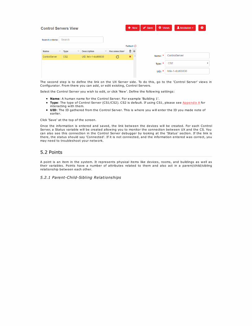
The second step is to define the link on the UX Server side. To do this, go to the 'Control Server' views inConfigurator. From there you can add, or edit existing, Control Servers.
Select the Control Server you w ish to edit, or click 'New'. Define the follow ing settings:
Name: A human name for the Control Server. For example 'Building 1'.Type: The type of Control Server (CS1/CS2). CS2 is default. If using CS1, please see Appendix A forinteracting w ith them.UID: The ID gathered from the Control Server. This is where you w ill enter the ID you made note ofearlier.
Click 'Save' at the top of the screen.
Once the information is entered and saved, the link between the devices w ill be created. For each ControlServer, a Status variable w ill be created allow ing you to monitor the connection between UX and the CS. Youcan also see this connection in the Control Server debugger by looking at the 'Status' section. If the link isthere, the status should say 'Connected'. If it is not connected, and the information entered was correct, youmay need to troubleshoot your network.
5.2 Points
A point is an item in the system. It represents physical items like devices, rooms, and buildings as well astheir variables. Points have a number of attributes related to them and also act in a parent/child/siblingrelationship between each other.
5.2.1 Parent-Child-Sibling Relationships

One of the main features of the Overture system is how points relate to each other. A point can be defined asparent of another point. In the above example, a projector's status and lamp hour variables are children ofthat device, the projector device is a child of Room A. Both Room A and Room B are children of Building A.When the system creates points, like device variables, it w ill automatically assign the parenting to them.
Parenting is how devices are displayed in rooms, and rooms are displays in locations.
5.2.2 Point Attributes
Id: The unique id of a point inside the database. Can be used as a reference when programming wherethe exact id is needed. This is not editable.Human Name: The name your point is displayed as anywhere in Overture.Short Name: Short name is used for helping create labels. Example: 'Projector A's Status' short namemight be 'Status' for an easy label inside of a panel or page.Alternative Name: Alternative name is used for the secondary language of the system.Variable Name: This is the link between the point and the control server if needed. It should be uniqueand contain no spaces.Point-Order: Used for changing view order of a point when multiple points are selected w ithin thesame template. If not specified , ID is used for determining order.Type: Defines whether the point is a variable, device, room, etc.Sub-type: Further distinction of the type. (Example: "integer" for the type variable, "projector" for thetype device) Used for grouping and determining default settings.Unit: Used to create suffix added to the end of a point's value when it's displayed to provide context tonumbers. Example: db, %, etc.Parent: The parent of the point. Used to define inheritance, or show assets on a map.Server: The link to what Control Server the point is stored on if it is tied to one. Only used for devices,tasks, and user variables.Roles: The access rights associated w ith the point. Example: If a point has a 'Security' role, only userswho have access to 'Security' are able to see it displayed.Tags: Advanced grouping and search method for when multiple points share something in common butnot a type or sub-type. Example: An 'Audio' tag might be created and assigned to both an audiovolume point, and an audio source point. Use of tags allows for special template needs.Alarms: Triggered events that are displayed in the system when this point is behaving abnormally.Metadata: Extra information, added in the form of JSON, that can be used to help w ith special templateneeds.License: Whether or not the point needs a license, and if that license is valid.

5.2.3 Devices
Devices are a specific type of point in the system. They represent devices on the network that are beingmonitored or controlled. They must be linked to a Control Server and have a variable name.
To create a device in the system, follow these steps:
Create a new point by clicking 'New' in the points view.Give the device a human name and variable name of your choosing.Select 'Device' from the type field.Select an appropriate sub-type for the device. If the default ones are not appropriate, you can addmore in the 'Sub-Type' view of Configurator.Click the magnifying glass next to 'Driver/Setup'.Select the appropriate driver from the Plugin Selection. If your driver is not listed, see 'Plugins' view formore info.Fill out the required setup information for your device, this w ill be different depending on the driver. Youcan change the setup information, by selecting the gear next to 'Driver/Setup'Select which Control Server this device w ill be created on.Optionally, you may fill in any extra information you have such as parent, roles, tags, etc.Click 'Save'. The device, and variables associated w ith that device w ill be created in the database.
It's important to know that the device and its variables w ill not be licensed until you select a parent that is anappropriate type like Room, Building, or Floor.
5.2.4 Rooms

Rooms are another special type of point in the system. They represent rooms or large areas in your systemthat contain devices. Rooms, by default, have an associated template to them that displays all of the devicesw ithin it.
To create a room in the system, follow these steps:
Create a new point, by clicking 'New' in the 'Points' view.Give the room a human name.Select 'Room' from the type field.Optionally, you may fill in any extra information you have such as parent, sub-type, etc.Click 'Save'. The room is created in the database.
You should now change the 'Parent' attribute of any devices that are this room, to this point.
5.2.5 Locations
Locations refer to points that display an image (map) on the Home section. They are normally have a type ofFloor, Building, Site, etc. but can be any type. These points normally are parents to rooms, devices, or othermaps, but this may be different depending on need.

To create a location, you w ill need to upload and asset and create the point.
To upload the asset:
Go to 'Assets' view.(More information on the 'Assets' view can be found here.). Click 'New'.Give the location a name.Click 'Show uploading section'. You may skip this step and the next, if the image you want is alreadyuploaded to your assets.Select which folder of your assets the image w ill be uploaded to ('images' is good choice.) by clickingthe magnifying glass. Then click 'Upload Asset' to select which image on your computer you want touse.Select the image in your assets folder by clicking the magnifying glass next to 'URL'. This information isauto populated if you uploaded your image.Select type 'image', if it's not done automatically. Click 'Save'.
When uploading an image, the follow ing applies:
The Home map is calibrated to images of size 1876 x 830 px, a ratio of ~2.25. Map images w ith ratios as lowas 2.1 are not perfect, but they are workable. Size differences can be significant as well, up to a couplehundred pixels (as long as the ratio is nearly the same).
To create the point:
Go to the 'Points' view and follow the steps for creating a Room listed above, but selecting theappropriate type for this location (Floor, Building, Site, etc.).Under 'Maps Fields', select the asset you created from the 'Map' drop down. This point w ill now beassociated w ith this image in Home.
If a map has no parent, it w ill be the first map displayed in Home. If multiple maps have no parents, Homedisplays the map w ith the lowest ID first. If you would like multiple locations w ith no parents, but would liketo define which map gets shown first you can select the 'Default' check box and that location w ill be the firstdisplayed.
To sw itch to other locations, use the breadcrumb menu on the right.
5.2.6 Map Fields
A point is only visible on a map if the point's parent is a location w ith a map or has a location w ith a map in itshierarchy. Once visible, the 'Map Fields' section tells Home where to display the point on the parent map.

You can either define a point's x and y value on the map or you can click the magnifying glass icon next to the'x' field. This w ill allow you to see the parent map and select the x and y values by clicking anywhere on themap.
You can also define a z access for the point. This allows the point to only show up on the map as you zoom in.This is useful when you have a lot of points in a small area. The higher the number the more zoomed in youmust be. The value should be between 0 and 1000. The amount of zooming needed to see the point dependson the map image size and view port of the browser.
Points can have also control panels assigned to them. These control panels w ill be how your points w ill bedisplayed in Overture. By default, a list of basic templates are provided. Devices w ithout control panelsassigned to them will use their sub-type control panel by default. Rooms w ithout control panels w ill use theroom control panel by default.
In case you want to have another control panel than the default one, choose the point you want to assign acontrol panel to. This point can be a device, room, or other type of point. Under 'Map Fields' select the controlpanel you w ish to assign to the point. Click Save .
Existing control panels can be edited (See: GUI Editor) , or you can create your own depending on yourneeds. (See: Assets view).Default control panels for sub-types and types, are found in the views/common folder of the assets and arenamed for the type or sub-type they are (Example: Sub-Type projector's default control panel isprojector.html).
NOTE: A point can have both a map and a control panel. In this case, clicking the name w ill display the controlpanel while clicking the icon w ill display the map.
5.2.7 Tasks / User Variables
A task is a sequence of commands which are executed by a Control Server. It is a way to automate actions inOverture.User variables are variables that are not tied to devices and can be effected by tasks (like a room status).
The creation of tasks and user variables are for advanced programmers only. To create them, See: TaskProgramming
5.2.8 Plugins View

The 'Plugins' view is used to manage your drivers for devices. From here, you can add new drivers as well asupdate existing drivers.
There are two ways to create or update drivers:
You can select a driver from the online plugin repository by selecting 'Browse Online Library'. All availabledrivers w ill populate the list, giving a brief description of themselves. You can also create or update a driverw ith a zip file from your computer by selecting 'Select From Local Device'. This w ill open a file prompt, askingwhich zip to select.
When creating a new driver w ith either method, select 'New' at the top. Once a driver is selected from the listor a zip is provided, the driver w ill show up in the list and be available in the 'Points' view.
If a driver is part of the online plugin repository and has a new version, the version field w ill be red anddisplay the newest version available. To update an existing driver w ith either method, select the driver in the

list. Then provide a new zip, or select the appropiate driver from the online repository.
5.2.9 Assets View
The 'Assets' view is used to create maps or control panels, that can then be associated to points in thedatabase.
In this view, you can create a new map or a control panel by clicking 'New'. You w ill need to select anappropriate image or html file on the server. You can also upload an image or html file directly to the serverfrom this view. However, creating, renaming, deleting, and other management of the assets must be done inGUI Editor
5.3 Access Rights
Overture's built in access rights allow various level of controls to help both security and organization of userson the system.
Access rights have three major components:
Users are the people on your system. You can give each person who w ill access your system aseparate username and password to login.Groups are groups of users. Rather than needing to assign read/write privileges for each user,Overture assigns those privileges to each group of users.Roles are definitions, assigned to points in the system, that control whether that point isread/writeable by a group.
5.3.1 Basic Rights
This is a basic example of access rights in the Overture system. Mike is a user who is assigned the Techsgroup. He w ill be able to control the Audio point because the Techs group has Write access to the A/V role.

5.3.2 Multiple Users/Groups/Roles
This more advanced example shows multiple groups and multiple roles on the system. Bob and Bill, who areboth in the Managers group, can see points that have the Security and Lighting roles but cannot controlthem. Joe and Mike, both in the Techs group, can control points w ith the Lighting role but cannot see pointsw ith the Security role.
5.3.3 One Point With Multiple Roles
This is an example of a point having two roles defined to it. The Techs group needs to be able to control theCamera point to be able to fix it but doesn't need to be able to see the Door point. Groups can access pointsif any of the point's Roles match the Group's access rights.
5.3.4 One User In Multiple Groups

This example shows how a user can be assigned to two different groups that each have access to differentroles. Bill is a user who can only see the Dimmer point, but not change it. Mike can change the Dimmer point,but cannot see the Cameras point. Bob is a member of both the Managers group and the Techs group,allow ing him to change the Dimmer point (via the Write access of the Techs group) and also see the Camerapoint (via the Read access of the Managers group).
5.3.5 Users/Groups
Under 'Users' in 'Views', a list of users on the system is shown. You can create new users for the system hereor change passwords for current users in the system.
Creating groups or adding users to existing groups is done in the 'Groups' section of 'Views'. You should usegroups to organize users who w ill need similar access rights on the system. (IT, Maintenance, Executives,etc.)
5.3.6 Roles
Inside the 'Roles' section of 'Views', is where you w ill create new roles and define how each group caninteract w ith it.
None: Points w ith this role w ill not show up in any GUI for that group.Read: Users are able to see the point and its value but are not able to change it in any way. Example:Seeing what the audio volume is set at, but not being able to change it.Write: Users have full control of this point in any GUI that it's in.
You w ill also see options related to alarms:
See: The group can see alarms triggered by points w ith this role, but cannot affect them in any way.Acknowledge: The group can acknowledge an alarm, clearing it from the current list of active alarms.
If group has neither of the alarm items selected, alarms w ill not show up for points associated w ith that role.
As well as user defined roles, there is an already created 'System' role that changes how users interact w iththe Overture software itself. Inside of this role you can determine if a user can see the Configurator, GUIEditor, or change points inside of the Configurator. The follow ing defines what each item means:

5.4 Logs
Inside 'System Logs' users can see what is happening w ithin the Overture system itself. You can search tosee just what certain users are doing, or just what points are being changed. Logs w ill also help youtroubleshoot the system when you aren't getting the expected result you wanted from your control panels orpages. A user's access to the logs are based on their access to the 'System' role.
5.5 Alarms
Alarms are triggered events that notify users of abnormal system operations. They can be set up for a varietyof things including when a projector is at a high temperature, a PLC has gone offline, or a door has been leftopen for longer than 10 minutes. A user's access to alarms are based on their access to the role associatedto that alarm's point.
Alarms can be separated into two parts:
Setting Alarms Up In The SystemInteracting w ith Alarms
5.5.1 Setting Up An Alarm

To setup an alarm, go to the 'Alarms' view inside of Configurator.
Next, you w ill need to define what triggers it. This is known as the alarm expression. The alarm expression isthe logic the system uses to see whether an alarm should be triggered and relates directly to the point.For example, if you are writing an alarm that triggers when a projector is above 90 degrees, your expressionwould be: value > 90 . This tells the system whenever the point associated w ith this alarm has a value over90, trigger an alarm.
When writing your alarms you w ill have the follow ing options related to points:
value: or point.value. This is the value of the point stored in the Control Server. It may be a string, or anumber depending on what type of variable the point is. If the point is an enum, the value is thecurrent index of the enum.string: or point.string. This is the string associated w ith the current index of an enum. For example,Projector.Power might be an enum with 'Off and 'On'. If the Projector is off, the value would be 0, butthe string would be 'Off'.
Next, you w ill need to write the comparison. <, >,<=, =>, == all work. Then you w ill need to write a value(For example: 42 or "On").
Expressions, can be combined w ith && or || for AND/OR comparisons. For example, value > 100 || value <20 . The alarm would be triggered if the point's value was above 100 or below 20.
An expression can also directly reference a value of another point w ithin the system. For example, you canattach an alarm to Room1_Projector.Power and for the alarm expression useServer1.Room1_Projector.Power.string == "On" && Server1.Room2_Projector.Power.string=="On" . In thatcase, the alarm w ill only trigger if both Projectors are on at the same time. Note The logs only indicate an alarm to points that are tied to the alarm even if other points are referenced inthose alarm expressions.
Expressions can also use some of the inheritance w ithin the system. If the point tied w ith this alarm is adevice variable, you can check the value or string of any sibling device variables by callingparent.variableName.value(or.string). For example, if you need to check the shutter and power of the projector you can set an alarm to theProjector.Power point and and use an alarm expression : string == "On" && parent.Shutter.string =="Closed" . Now, you have an alarm that w ill trigger only when both the Projector Power is on, and the shutteris closed.
Alarm expressions also have an advanced function called replace() that can be used when you want tocheck other device variables in the system but also use the alarm expression as a template, so you can applyit to multiple points. For example, if you have multiple rooms that have projectors and occupancy sensors andyou want have one complex alarm that monitors these attributes together you can use replace() . Your alarm expression would be something like this : value > 40 && replace('Projector.Temperature','HVAC.Occupancy').string == 'Occupied'
This complex alarm only works when variable names of the points have the same prefix (ex:Room1_Projector.Temperature & Room1_HVAC.Occupancy). In this example, the alarm must be tied to theProjector.Temperature point. When that point's value is above 40 and then the point w ith a similar name butHVAC.Occupancy string is equal to 'Occupied' the alarm w ill trigger. This allows you to create template alarmsfor devices that exist in the same room or other scenarios where more information is needed for the alarm.
Inside of the Alarms view, an alarm can have a specific amount of time associated w ith it before it alerts in thesystem. For example, the room temperature becoming 90 degrees once for 2 seconds might not matter butstaying that way for 2 minutes may indicate a problem.
You can enter a Delay value in seconds to indicate how long the alarm expression must remain true beforealerting the system. A floating point number can be given to increase precision.
5.5.2 Assigning Alarms

To assign an alarm to a point, go to the 'Points' view. Click on a point and specify the name of the alarm in thealarms section. Typing a space, w ill bring up all available alarms.For example, you could specify an OverTemp alarm you've created to .Temperature variable points.
5.5.3 Alarm Notifications
Alarms that are triggered can automatically send notifications out to users on the system. This is set-up in theNotifications view.
A single alarm can have multiple notifications.
There are a few options when setting up a new notification:
Name: The name of notification. Alarms can have multiple notifications tagged to it.Type: For now, the only type is Email.Send To: The Overture user group that should receive the notification.Subject: Subject of the notification.Plain Text/ HTML: If writing an HTML notification, you w ill need to write all the HTML. (Since v3.0.3, theformat is determined automatically)Body: The actual message being sent to the users. This message as well as the subject can usevariables, as described in the next section.
5.5.3.1 Variables In The Subject/Body
The subject and body can have the follow ing variables used in them for a more dynamic email:

%pointname%: The name of the point which has triggered the alarm%pointvalue%: The value of the point on which the alarm triggered.%alarmname%: The name of the alarm%date%: The date the trigger condition has been detected. (Format: Thu Jun 22 2017 17:47:47GMT+0000 (UTC) .)%trigger%: The alarm expression
5.5.3.2 Setting Up Email
You w ill need to set-up the SMTP server that Overture should use for sending emails out. You can specify froman existing list of common email services, or you specify a custom email service.
This setting is common for all email notifications. If you apply a change to any of the notifications, it w ill beused for all existing notifications.
The follow options are available for a custom email service:

Account: Sender name.User: Username to login to the email server.Password: Password to login to the email server.Account Email Address: Sender email address. (Mandatory)Host: Host name or IP of the SMTP server. (Mandatory)Port: Port for the server. (Mandatory)Secure: Whether to use SSL or not.Ignore TLS: Turns off STARTTLS if true.Alias: Aliases that maybe needed by the email serverDomains: Domains that maybe needed by the email server.Auth Method: Defines the preferred authentication method.TLS: Which encryption to use if using TLS.Name: Optional hostname of the client, used for identifying to the server, defaults to hostname of themachine.
Once set up, you can send a test email by clicking the send button. This allows you to make sure the emailserver is working correctly.
5.5.4 Interacting with Alarms
Alarms appear as specialized logs in the system. In Home, they appear in logs, at the top bar, and also onthe maps. Clicking that number w ill take you to the 'Alarms' view of the logs.Here you can see the alarm name, the time it first happened, the time it last happened, the number of times ithas triggered, the name and expression of the alarm, the point the alarm happened on, and the current valueof that point.The same alarm number shows up next to views in Home, in case you have logs hidden. In MagicMenu, thealarms show up as a red number in the title bar.
If you know an item should be shown as an alarm, but isn't, make sure your access rights for that point allowyou to see alarms.
Alarms have four different states:
Triggered and Active: This means the alarm expression has become true, is still true, and no one hasacknowledged it.Triggered and Non-Active: This means the alarm expression has become true, no one hasacknowledged it, but the expression is no longer true.Acknowledged and Active: This means the alarm expression has become true, a user hasacknowledged it, but the expression is still true. This w ill clear it from the current list of alarms but thesystem w ill know it's still active.Acknowledged and Non-Active: This means the alarm expression has become true, is no longer true,and the user has acknowledged it. This clears the alarm from the system. If the alarm is re-triggeredit's counted as a new instance of the alarm.

6 GUI Editor
The GUI Editor is the asset management tool of Overture. It interacts w ith the Overture file system andallows for view ing, editing, and creating of templates. There are two different versions of the tool:
Menu Builder: An easy to use template building w izard.Expert Mode: A text editor that allows direct editing of the templates.
It can be accessed by adding '/guieditor/' to your server URL or through the user menu in the top right corner.You must have sufficient access rights in order to use GUI Editor.
6.1 Assets
Assets are the important pieces to the Overture project and relate directly to how things are shown in theGUI. Every asset, whether it be an HTML file, a CSS document, or an image must be stored in the assetsfolder of your project.
Assets are stored in your assets folder of the UX Server. The main assets for your project include:
Images: Images used as maps or displayed inside of html pages. (Use the follow ing formats: .jpeg,.png, .bmp )Styles: CSS files used to style the HTML inside the browser.Views: HTML files that are displayed either as control panels or Magic Menu pages. The same HTML filecan be used as both a control panel and a Magic Menu page.
6.1.1 Default Assets
Overture provides a set of starting assets available for use right after installation. The follow ing items existand can are used in the follow ing ways:
6.1.1.1 Images
The only image provided by default is the one used for the Magic Menu's background. Overwriting this imagewith new one, w ill change the background image.
6.1.1.2 Views
The follow ing types of HTML are provided by default for your use:
Device Templates: These are files have are used to control or view data from specific devices based onthe subtype (projector.html, lighting.html, etc). To use these, assign them in the Configurator via'Control Panel' selection.Room Templates: This is the room.html in the views/common folder. This file w ill create a room controlpanel based on the devices that are children of the room point. This is assigned in the Configurator via

'Control Panel' selection.Home Page: This file is called as the starting page to Magic Menu.
6.1.2 Uploading Assets
Files can be uploaded directly in the assets folder from the GUI Editor. To do so, select 'Upload' from the Filemenu.
From there, select which sub-folder to upload your file into. You w ill then select the files to upload and click'Upload Files'.
6.1.3 Assets Explorer
Files in the assets folder can be altered via GUI Editor using the Asssets Explorer. The Assets Explorer can beaccessed from the File menu.

Once there, you can create new sub-folders, move files, rename files, or delete files. If you are in the MenuBuilder mode, you w ill only see from 'assets/views' and lower.
Note: views/home.html cannot be moved, renamed, or deleted as it is necessary for Magic Menu to function.
6.2 Menu Builder
Menu Builder is one tool to build your templates. While in this mode, you can build templates using drop downselections and view it in live preview.
Menu Builder can only create new html files, or open files already created by the Menu Builder. Trying to opena file that wasn't created by the Menu Builder w ill display an error and not allow you to edit the file. To edit orcreate non Menu Builder pages see the Advanced Programming section.
6.2.1 Sections
6.2.1.1 Intro
In order to create your Magic Menu page, you w ill need to add sections each w ith their own unique options.When adding a section, you can click the expand icon to see all available options. You can also hide thesection panel, still adding it to the page, by clicking the eye. Sections are deleted by clicking the X.

6.2.1.2 Display
Displays the value of a variable.
Options:
Point: The point to be displayed. See Points.Label: The text displayed to the left of the value. See Labels.Suffix: The suffix to be appended to the point's value. Overrides a point's unit from the database ifspecified.Size: The size of the text.Date Format: The format a time variable should be displayed. See Date Format .Icon : The icon displayed next to the label. See Icons.
6.2.1.3 Button
Creates a button that triggers an action when clicked (or tapped). It can also change its appearancedepending on the value of a specified point.
Options:
Point: The point to be monitored. See Points.Label: The text displayed in the button. See Labels.Click: The action triggered when the button is clicked. See Actions.OnState: The value of the point that causes the button to appear highlighted. (Example: ‘1’ wouldmean when the point's value is equal to 1, the button w ill highlight.)Icon : The icon displayed next to the label. See Icons.
6.2.1.4 Slider
Creates a slider that sends commands when the user moves it. The position of the slider marker isdetermined by the value of a point.
Options:
Label: The text displayed w ith the slider. See Labels.Point: The point to be monitored. See Points.Change: The action triggered when the slider is moved. See Actions.Step: The amount moved ‘up’ and 'down' icons. Defaults to 1.Min: The minimum value of the slider. Uses the min attribute of the point if not specified.Max: The maximum value of the slider. Uses the max attribute of the point if not specified.Suffix: The suffix to be appended to the point's value. Overrides a point's unit from the database ifspecified.IconUp: The icon displayed to the right of the slider. See IconsIconDown: The icon displayed to the left of the slider. See Icons
6.2.1.5 Select
Creates a muliple-choice selection box, which allows the user to select an item from a list. It is intended to beused w ith enum type variables.

Options:
Point: The point associated to the list. Intended to be sub-type enum . See Points.Label: The text displayed above the selection. See Labels.Change: The action triggered when an item is selected. See Actions.Icon : The icon displayed above the label. See Icons.
6.2.1.6 Checkbox
Creates a checkbox, allow ing the toggling of values.
Options:
Label: The text displayed w ith the checkbox. See Labels.Point: The point to be monitored. See Points.Change: The action triggered when the box is checked or unchecked. See Actions.ChangeOn: The action triggered when the box is checked. See Actions.ChangeOff: The action triggered when the box is unchecked. See Actions.
6.2.1.7 Toggle
Creates a sw itch style button, allow ing the toggling of values.
Options:
Label: The text displayed w ith the button. See Labels.LabelOn: The text displayed in the button when on. See Labels.LabelOff: The text displayed in the button when off. See Labels.Point: The point to be monitored. See Points.Change: The action triggered when the button is sw itched on or off. See Actions.ChangeOn: The action triggered when the button is sw itched on. See Actions.ChangeOff: The action triggered when the button is sw itched off. See Actions.
6.2.1.8 Tabs
Tabs are special containers that show or hide content based on which container is selected. It consists of twocomponents: Tab Control and Tab Content. Tab Control creates the tab bar that has links to the containers. Tab Contents are the containers themselves.

Tab Control Options:
App: The application the tab control bar shows up in.MagicMenu Position Small: The position to place in tab control bar when the MagicMenu interface issmall.MagicMenu Position Medium: The position to place in tab control bar when the MagicMenu interface issmall.MagicMenu Position Large: The position to place in tab control bar when the MagicMenu interface issmall.
Tab Content Options:
Point: The point to associate the tab container to. See Points.Label: The text displayed in tab control bar link. See Labels.Icon: The icon displayed next to the label. See Icons.
6.2.1.9 Header
Creates a name at the top of the Magic Menu page or Control Panel. If no header is specified, the paneldefaults to the name of the point.
Options:
Title: The text displayed at the top of the page.
6.2.1.10 Page Link
Magic Menu Only
Creates a button which displays a new page when clicked. This page must be an html document that exists inthe views section of the assets folder.

Options:
Go To Page: The HTML document you w ish to load when the link is clicked. Must be format ofFOLDER/NAME and no file type after. If not specified, the page loads the med-point/med-repeat’s HTMLfile associated to the 'Control Panel' section of the Configurator.Point: The point associated w ith the page loaded. See Points.Label: The text displayed in the button. See Labels.Context: Extra information you w ish to pass into the new html page. Must be in form of an object{item: value} .Roles: The specific roles that can see the page link button. Example: `med-roles="A/V,Building,IT"'. Thename or the IDs of the roles may be specified.Icon : The icon displayed in the button. See Icons.
6.2.1.11 Include
Th e med-include tag loads another HTML file in the control panel. It is useful for creating templates byallow ing small portions of code to be reused in many panels.
Options:
Include Page: The HTML document you w ish to include. Must be format of FOLDER/NAME and no file typeafter. If not specified, the page lincludes the med-point/med-repeat 's HTML file spcified in the 'ControlPanel' section of the Configurator.Point: The point associated w ith the page included. See Points.Context: Extra information you w ish to pass into the included page. Must be in form of an object {item:value} .
6.2.2 Options
6.2.2.1 Intro
Some options exist for multiple sections, and have specialized ways they can be used.
6.2.2.2 Points

Points can be selected and add context to items.
Single Point Selection
When assigning a single point to an item, you can type the variable name into the field or human name ifthere is no variable name. You can also use the magnifying glass to select an existing point from yourdatabase.
Repeat Point Selection
When assigning points using repeat, the Menu Builder w ill dynamically create a number of items based on therules added. These rules w ill find points based on database criteria. The follow ing rules can be used:
Child Of : the parent of the point(s) you want to find.Child Depth : how far down the hierarchy the point could be.Name Contains : the string contained in the human name of the point(s) you want to find.Short Name Contains : the string contained in the short name of the point(s) you want to find.Variable Name Contains : the string contained in the variable name of the point(s) you want to find.Has Type: the type of the point(s) you want to find.Has Subtype: the sub type of the point(s) you want to find.Has Role(s): the roles associated to the point(s) you w ish to find.Has Tag(s): the tags associated to the point(s) you w ish to find.
6.2.2.3 Labels
Labels provide text to items on the page.
You can provide text, or use a label context variable to provide dynamic information. The follow ing variableswork:

$humanname: The human name of the point associated to the item.$shortname: The short name of the point associated to the item.$parent.name: The human name of the parent of the point associated to the item.$parent.shortname: The short name of the parent of the point associated to the item.
Labels w ill default when no information is provided. The system w ill go down the follow ing hierarchy, usingthe associated point, until it finds something:
Label -> Point's Short Name -> Point's Human Name -> Point's Variable Name -> Blank
6.2.2.4 Actions
Actions are how interactive items interact w ith the system. The action is called when the item is interactedwith (For example, clicking a button or moving a slider). They are JavaScript functions that normally interactw ith the Control Server. The follow ing actions can be used:
setVariable(): This is used to change the value of a variable type point. It's the default action whennone is provided.perform(): This is used to interact w ith tasks or devices directly. It performs a device command directly,or starts/stops a task on the Control Server.openUrl(): This is used for buttons that need to open other web pages.
Set Variable
Used to set a variable to a desired value. When using a Control Server Version 2 or above, this action w illgenerally be enough to tell the driver which device command to perform.
setVariable(point, value) has two parameters:
point : The name of the point you want to change the value of.value : The value to change the point to.
Example:
setVariable('Projector.Brightness', 50)
Perform
It can be set up two ways. The first way interacting w ith a task.
perform(task, command) has two parameters:
task: The name of the task to interact w ith.command: The command to perform on the task. Must be either 'starttask' or 'stoptask'.
Example:
perform('Room_On', 'starttask')
It can also be used to directly perform a device command.
perform(device, command,[parameters]) has two required parameters and one optional parameter:
device: The name of the device to interact w ith.command: The command to perform on the device. The command name comes from the driverdocumentation.parameters: The command parameters if needed. Must be in the form of an object ({name1:value1,name2:value2, etc.}). This information is in the driver documentation.
Example:
perform('Projector', 'Set Power', {'Status': 'On'})
Open Url
Used to open a web page in a new tab on the browser.
openUrl(url) has one parameter:
url : The URL to open in a new tab.
Example:
openUrl("http://www.barco.com")
Action Context Variables

Actions have context variables that can be used inside of their functions to help build more dynamic pages.
point
point is used to describe the point of the current page. It's useful for substituting the device parameter in aperform() .
Example: perform(point, 'Set Power', {'Status': 'On'}) .
$point
$point is used to describe the point associated to the item. See Points.
Examples: perform($point, 'starttask') . setVariable($point, 50) .
$value
$value is used to describe the value of the point associated to the item. For example, when you move theslider to 50. $value becomes 50 before it is passed into the function.
Examples: perform(point, 'Set Level', {'Level': $value}) . setVariable($point, $value)(This is calledwhen no action is provided).
$string
$string is used to describe the string value of an enum variable point associated to the item. For example if anenum variable point has the enums of "Off" and "On" in that order, the $value is the index (0 or 1) and the$string w ill be "On" or "Off". It's needed for most device commands that interact w ith enums.
Example: perform(point, 'Select Source', {'Name': $string}) .
$parent
$point is used to describe the parent of the point associated to the item.
Example: perform($parent, 'Play') .
6.2.2.5 Icons
Some items have an Icon option. This allows you to add or change icons on tags w ithin the system.
You can select an icon from the Icon Browser by using the magfyining glass to the right. The icon name w illauto-populated.
Icons w ill default when no information is provided. The system w ill go down the follow ing hierarchy, using theassociated point, until it finds something:
Icon -> Point's Icon -> Point's Sub-Type Icon -> Point's Type Icon* -> Blank**
6.2.2.6 Date
Some tags w ill have a Date Format option. This allows the incoming value to be formatted in more userfriendly way. For example, time variables may come in w ith values like: "09:00:00/00", where as you mightjust want to tell the user "09:00 AM". The drop down w ill provide an example of each style and w ill

automatically fill in the appropriate information.
6.3 Expert Mode
Expert Mode is used for editing HTML files directly. It is recommended only if you comfortable w ith HTML andJavaScript programming. To access Expert Mode, go to the User menu, and under Advanced Options andselect Expert Mode.
For more information on how to use Expert Mode, see the Advanced Programming section.
Note: If you edit a Menu Builder file in Expert Mode, and then go back to Menu Builder Mode you may losesome of your work due to the conversion.
You can customize the way Expert Mode looks and feels for you by going to 'Views':
6.3.1 Scratch Pad

Scratch Pad allows you to auto fill some of the programming when using Expert Mode. A drop down w ill showall of the possible HTML tags available and insert it directly into the Expert Mode editor.
6.3.2 Database Points
Database Points w ill show a hierarchy view of your database. From there, you can directly select points,commands, and variables to fill attributes in the Scratch Pad.
6.4 Live Preview

GUI Editor has a built live preview. This allows you to check what was done in Menu Builder or Expert Mode bygiving you a live view of the Magic Menu. If you would like to put a point context in to the live preview, youcan add it into the Page Reference Point field. Using the magnifying glass allows you to select it from thedatabase.
Note The preview w ill only update the current page being edited and not any pages clicked in the preview.
6.4.1 Size Options

The live preview can be sized according to which device and position you w ill be view ing the Magic Menu. There is also a custom option to specify your exact dimensions.

7 Additional InformationAfter the system has been programmed, Overture has some nice extra features to help build a better userexperience w ithin the system.
7.1 Backups/Restoring
UX Server has the ability to backup all of your data and allow restoration in case of data corruption or error.
7.1.1 Backups
There are two ways to back up your data in the UX Server. The first way to backup your data is manuallythrough the Configurator's 'Backups' view.
In this view, you can see the current list of backups in the file server as well as adding one manually byclicking 'Back Up Now'.
You can also upload a backup from your PC, restore a backup, download a backup to your PC, or delete anybackup in the list.
Any non-backup files found in this view w ill have a strike through them, but can still be downloaded ordeleted.
Backups are also created automatically through the 'Automatic Backup Settings'. This is found in the 'UXServer Config' view in the Configurator.
Here you can specify, whether or not to backup, how frequent, and on what date and time to do the backup.You can also specify how long the backups should stay before the system deletes them.
7.1.2 Restoring
You can restore any of the backups in the Backups view of Configurator.
Each backup in the list of backups has the option to be restored, as long as the database version of thatbackup is not greater than the current database.
Click the restore icon. Once done, you w ill need to confirm the process. Restoring w ill overwrite your currentassets and database information w ith the backups assets and information.
After the update process, your server w ill be restarted.

7.2 Updating Overture
Depending on your installation there are a few ways to update your system. Always make a back up, anddownload it before updating the system
7.2.1 Updating UX And CS Server
When updating the UX and CS in the virtual enviroment, you w ill need to upload a new yml in theConfigurator. To do so, go to the 'UX Server Config' view and click the 'Update Server' button.
You w ill need to provide the new yml file, once it has been validated the server w ill update and restart. Notethe server will need to be connected to the internet to update.
7.2.2 Updating Extra Control Servers
If you are updating an extra Windows PC Conrol Server, you w ill need to install the newest version of thesowftware w ith an executable.
If you are using Docker, you w ill need to load the newest archive file (or have an internet connection) and rerun the compose file. Please see Setup for more info on those processes.
7.3 Linking To Specific Maps Or Pages
Overture links can be sent to users that only allow them a certain layer of access.
W ith Magic Menu, this is a specific HTML page created. W ith Home, this w ill be a specific map layer.
7.3.1 Magic Menu
Besides allow ing only a certain level of access, Magic Menu links can be used to create different interfaces. You may want mobile users to have the normal Magic Menu, but also want to create very specific in-roominterfaces meant for tablets.
In that scenario you can write another HTML page (inRoom.html for example) and use the linking systemprovided below to only launch that page w ith the browser.
7.3.1.1 Page
You can access directly to a specific page using home parameter referencing the file after views folder.
For example, to go to the room page in common folder, you can write:
http://localhost/magicmenu/?home=common+room
7.3.1.2 Point context
You can give the context to a page using the point parameter. You could do this to gain direct access to aroom even if that room is just a template.
For example to go to the room page in common folder, using Malaga_Room as context, you can write:
http://localhost/magicmenu/?point=Malaga_Room&home=common+room
7.3.1.3 Style
You can specify a custom CSS file to be used by Overture Magic Menu. By default, Magic Menu w ill load thestylesheet in the path assets\styles\magicmenu.css . Adding a theme=<filename> parameter in the URI that

directs to the Magic Menu, you can specify an alternative filename w ithin assets\styles\ .
For example, to use an alternative CSS file w ith the path assets\styles\red.css , add ?theme=red to theMagic Menu's URI in the address bar:
http://localhost/magicmenu/?theme=red
7.3.2 Home
Map links reference map layers in Home. By providing a link, you w ill be bypassing a certain amount of maplayers. The map linked, w ill be the first map loaded.Example:
http://localhost/?map=BuildingB1
7.4 Home Extras
7.4.1 Widgets
Home's dashboard is used to display information at a quick glance, or display data in a graph for easycomparisons. Each user is able to set up their own dashboard. Changing the definition of w idgets in oneuser's login does not affect the w idgets for other users.
By clicking "Add Widget", you can specify what type of w idget you would like to see on the screen. Oncechosen, you must decide what points to display w ith the w idget. Each user is only able to specify points thathe has 'read' access to. No other points are shown.
Table w idgets are used to display information. If the point specified is also connected to a control panel ,clicking the name of the point in the Table w idget acts like a bookmark. The map jumps to where that controlpanel is and opens it up.
Graph w idgets show information of points relative to each point. This is used when you need to trackinformation against other information, like Projector Temperatures. Clicking on a point's name in a graph typewidget hides that point's information.
7.4.2 Branding
Company branding can be added to Home to make the project more unique. To do so, you must add an HTMLfile in the assets named home.branding.html (formerly dashboard.branding.html; see below).
This HTML is only meant to have images and basic inline styling (i.e., no med-* tags):
<span style="font-size: 24px; color: teal;"> MyCompanyName</span>
<img src="assets/images/banner.jpg">
N.B. For users updating to 3.0.3 and later who have already configured dashboard.branding.html :
You can continue to use and update dashboard.branding.html as usual so long as either home.branding.htmldoes not exist or is empty (ignoring HTML comments and whitespace). It is however recommended that youuse home.branding.html in anticipation of future versions.
7.5 HTTPS

If you w ish to sw itch communication over to HTTPS, you can do so from the Configurator. You w ill need to have key, cert, and ca files provided by a trusted certifying company or else the browser w illerror and claim the Overture to be insecure.
To sw itch to HTTPS:
First, sw itch the communication to HTTPS. Than, uploap the key, cert, and CA files using the respectivebuttons.
If the files are proper, the browser w ill no longer give errors when connecting. If not, please see your trustedcertifying company.
7.6 Translations Quick Reference
7.6.1 Introduction
Th e translations.json file in the assets directory contains translation information for the alternativelanguage used in Overture. This file is provided by default and can be edited at any time.
7.6.2 Getting Started
Open the translations.json file in Overture Editor. The top-level keys provided in the translations.json fileprovided w ith the installation are as follows:
7.6.2.1 language
This portion of the JSON represents some basic language information.Under "name" , you can edit the language's internal name.Under "label" , you can edit the name of the language that is displayed in the UI (in Overture Homeunder Views for example).Under "locale" , you can edit the locale code used in the MomentJs library. This library is used byOverture for the purposes of date and time reporting (e.g. for logs). Please visit http://momentjs.com/under the section Multiple Locale Support as a reference for supported country codes.
7.6.2.2 \ (e.g.: dashboard, magicmenu)
This is where the Overture client app-specific translations can be found.The keys of this portion of JSON correspond either to literal text found in the UI, or labels correspondingto things like menu item text, etc.The values of this portion correspond to the desired translation of each of these terms/labels found in

the UI.The translations.json file included in the installation contains translations to English to be used as atemplate that can be edited w ith desired values.
7.6.3 Fallbacks
English UI text is currently built into all Overture client applications. If the translations.json file isunreadable or missing, English text w ill be used as a fallback.If the translation for a particular 'key' cannot be found (i.e. neither the key or value exist), English w illautomatically be used as the fallback language for that particular piece of UI text.This means that you are able to provide partial translations to the UI; any omitted translation key-value pairs w ill silently default to English.

8 APPENDIX A
8.1 Using Overture with Version 1 Control Servers (including Manager V6,Showmaster V2, and Overture CS1)
Overture can work w ith directly w ith Version 1 Control Server products. However, setting up these productsas your controller is different then working directly w ith Version 2 Control Server.
8.1.1 Control Server Setup
Version 1 Control Server products each have their own standalone interface for the creation andprogramming of devices, tasks, and user variables. These products have an extensive knowledge base forprogramming your project that can be found in the "Medialon Control System Reference Manual" that comeswith the products.
To work w ith Overture, these products all need a link to the UX Server. To create this link, you w ill need tocreate and share a user group. You can name the user group however you w ish, the easiest is ‘Shared’. Makesure the ‘Shared’ property is checked.
Inside that user group you w ill need to create three separate groups: one for devices, one for tasks, and onefor variables you w ish to share w ith the UX Server.
Once those groups are created, drag devices, tasks, or variables you want the UX Server to interact w ith intoits respective folder. It's important to know you must share the device variables into the variables sub folderin order for Overture to interact w ith them. Sharing just the device itself is not enough.
UX Server w ill need this shared group in order to populate your database, and have it's own link established.
8.1.2 Overture Setup
Once the project file is finished, you w ill need to populate the database w ith all the information you placed inthe user group. The first thing you must do is tell Overture you are using a Version 1 Control Server product.
To do so, go into the 'Control Server' view of the Configurator. Change the existing default Control Server byselecting the "Type", and sw itching it to "CS1". After doing so, you w ill need to enter information related tothe Control Server 1 product you are using:
Address: The IP address or host name of the PC the software is installed on, or the Showmaster.Port: The port used to talk to the CS1 product. The default port is 9255, but this is changeable in thepreferences in the product.Shared Group: The name of the user group you created to share information. As explained earlier,"Shared" is the easiest.
Optionally, you may enter some advanced settings if needed:
Login User: The user name needed to connect to the CS1 Product. This is not needed by default andsetup in the CS1 product.Login Password: The password needed to connect to the CS1 Product. This is not needed by defaultand setup in the CS1 product.Proxy Address: The IP address or host name of the PC where the special WS Proxy is if installedseparately.

Proxy Port: The port used to talk to the WS Proxy if installed separately.
This process is repeated for each CS1 type product you are using.
8.1.3 Ingesting The Project
Overture allows you to ingest your Control Server project, which automatically fills the database w ith pointsbased on what you have programmed.
Overture UX's ingest engine reads the XML data of the project file, creating a point for each shared device,variable, and task. The information is not retrieved from the Control Server in real time; the ingest must bemanually initiated using the CS project file.
Ingesting automatically adds as much metadata about the points as it can. For example, Devices are givenDevice type, Variables are given Variable type and specific sub-type of Integer, Real, Enum, etc. DeviceVariables are assigned the corresponding Device point as their parent. By default, points that are associatedwith the selected Server but do not exist in the ingested CS project file are erased during the ingest process.This helps to clean up the database when re-ingesting projects where devices, tasks, or variables have beendeleted.
To ingest a project, select the Control Server that the project is running on from the drop down.
Next, click the "Upload Overture CS Project..." button. Find your project file and click open. Then click the"Update Database" button to the right. The ingest engine uploads the project file, extracts the informationfrom the Shared user group, and updates the database, adding or deleting points as needed.
If you need to make changes to the Control Server project, such as adding a variable, you can ingest theproject again and the database updates, adds, or deletes points accordingly.
Note: If you do not want the ingest engine to automatically delete points associated w ithvariables/devices/tasks that are no longer shared in the CS project, you can modify the default behavior inthe 'UX Server Config' settings. Points w ithout the type variable, device, or task w ill not be modifiedregardless of the settings.
Once the project is ingested, you can continue setting up UX Server as the User Manual explains. Make surethe CS1 product is in a run mode and Overture w ill interact w ith it completely.

9 APPENDIX B
9.1 Expert Mode Programming
This section is for advanced programmers who are looking for things to help them specialize theirprogramming. We recommend to read this section when you are comfortable with Overture coreconcepts.
The follow ing section w ill explain how make your own templates, or edit existing templates in Expert Mode.Overture panels and pages are written in HTML. More precisely, they are written in a slightly customizedversion of HTML that uses pieces of JavaScript to help control things. It is highly recommended you have agood foundation in those languages to proceed.
9.1.1 Tags
9.1.1.1 Intro
Tags are the HTML elements needed to create graphical elements on the page. While most standard HTMLtags work as well, Overture has specialized tags meant to interact w ith the system. Please note that eventhough most standard HTML tags work, Overture is not a pure web-site designer. JavaScript libraries andextra frameworks cannot be added to the system.
9.1.1.2 Display
Displays the value of a variable.
Example
<med-display med-label="Audio Volume" med-point="Player1.AudioVolume" med-suffix="dB"></med-display>
Attributes
med-label: The text displayed to the left of the value. See Labels.med-point/med-repeat: The point to be displayed. See Points.med-suffix: The suffix to be appended to the point's value. Overrides a point's unit from the databaseif specified.med-big: Specifies whether the value should be displayed using a larger character in Magic Menu. .Defaults to false .med-date-format: The format a manager time variable should be displayed. See Date Format foroptions.med-icon : The icon displayed next to the label. See Icons.
9.1.1.3 Point Table
Displays a list of point values. Useful when gathering all the data from a single device.
Example

<med-point-table med-point="Projector1" med-subpoints=".Power,.Shutter,.HoursLamp1"></med-point-table>
Attributes
med-point/med-repeat: The parent of the point to be displayed. See Points.med-subpoints: The name of the subpoints, separated by a comma, which, combined w ith the rootname, lists the points you want to display. If nothing is specified it displays all children of the point.med-date-format: The format a time variable should be displayed. See Date Format .
9.1.1.4 Progress Bar
Creates a gauge that monitors a variable. This is used for comparing the current value against a minimum ormaximum value.
Example
<med-progress med-point="Room_2_Projector.LampHours" med-min="0" med-max="1000"></med-progress>
Attributes
med-label: The text displayed to the left of the value. See Labels.med-point/med-repeat: The point to be displayed. See Points.med-suffix: The suffix to be appended to the point's value. Overrides a point's unit from the databaseif specified.med-icon : The icon displayed next to the label. See Icons.med-max: The maximum value of the progress bar. Uses the max attribute of the point if not specified.med-min: The minimum value of the progress bar. Uses the min attribute of the point if not specified.
9.1.1.5 LED
Creates an LED that changes color based on the value provided to it. It's useful for monitoring enums orintegers and providing a color index to their values.
Example

<med-led med-label="Power" med-point="Projector.Power" med-colors="red, #0000FF, #FFFF00, green"></med-led><med-led med-label="Shutter" med-point="Projector.Shutter" med-colors="red, green"></med-led>
Note: In the above example, the Projector's power is an enum with a value of 3, and the shutter is an enumwith a value of 0.
Attributes
med-label: The text displayed to the left of the LED. See Labels.med-point/med-repeat: The point to be displayed. See Points.med-icon : The icon displayed next to the label. See Icons.med-label: the text which is displayed at the left of the LED . Defaults to the name of the point.med-point/med-repeat: the point to display.med-colors: The comma separated list of colors relating to the value of the point being monitored. Ifthe value is not a number, the color w ill default to the zero index(First item in the list). If the value ofthe point is greater than number of colors listed, it w ill take the last color specified in the list. (Bydefault colors are red(0) and green(1))
9.1.1.6 Button
Creates a button that triggers an action when clicked (or tapped). It can also change its appearancedepending on the value of a specified point.
Example
<med-button med-label="Power On" med-click="perform('PowerOn', 'starttask')" med-point="Projector.PowerStatus" med-on-state="1"></med-button>
Attributes
med-label: The text displayed in the button. See Labels.med-click: The action triggered when the button is clicked. See Actions.med-point/med-repeat: The point to be monitored. See Points.med-on-state: The value of the point that causes the button to appear highlighted.med-icon: The icon displayed in the button. See Icons
9.1.1.7 On/Off Button
Creates two buttons, inline w ith each other, monitoring the same point.
Example

<med-on-off med-point="Projector.PowerStatus" med-label="Power" med-label-on="On" med-state-on="1" med-click-on="perform('Projector','Power On')" med-label-off="Off" med-state-off="0" med-click-off="perform('Projector','Power Off')" ></med-on-off>
Attributes
med-point/med-repeat: The point to be monitored. See Points.med-label-on: The text displayed in the left button. See Labels.med-state-on: The value of the point that causes the left button to appear highlighted.med-click-on: The action triggered when the left button is clicked. See Actions.med-label-off: The text displayed in the right button. See Labels.med-state-off: The value of the point that causes the right button to appear highlighted.med-click-off: The action triggered when the right button is clicked. See Actions.med-label: The text displayed above both buttons. See Labels.
9.1.1.8 Button Bar
A container that holds other buttons. It displays the contained buttons inline instead of vertically, one afterthe other.
Example
<med-button-bar> <med-button med-label="HDMI" med-point="Room_2_Projector.Input" med-click="perform('Room_2_Projector','Set Input',{ Input:'HDMI 1' })" med-on-state="0" ></med-button> <med-button med-label="DVI" med-point="Room_2_Projector.Input" med-click="perform('Room_2_Projector','Set Input',{ Input:'DVI' })" med-on-state="1" ></med-button> <med-button med-label="VGA" med-point="Room_2_Projector.Input" med-click="perform('Room_2_Projector','Set Input',{ Input:'VGA' })" med-on-state="2" ></med-button></med-button-bar>
Attributes
There are no specific attributes for the button bar.
9.1.1.9 Slider
Creates a slider that sends commands when the user moves it. The position of the slider marker isdetermined by the value of a point.

Example
<med-slider med-label="Volume" med-point="Player1.AudioVolume" med-change="perform('Player1', 'Set Volume', {Volume: value('Player1.AudioVolume')})" med-max="0" med-min="-80" med-step="1"></med-slider>
Attributes
med-label: The text displayed w ith the slider. See Labels.med-point/med-repeat: The point to be monitored. See Points.med-change: The action triggered when the slider is moved. See Actions.med-max: The maximum value of the slider. Uses the max attribute of the point if not specified.med-min: The minimum value of the slider. Uses the min attribute of the point if not specified.med-step: The amount moved ‘up’ and 'down' icons. Defaults to 1.med-suffix: The suffix to be appended to the point's value. Overrides a point's unit from the databaseif specified.med-big: Specifies whether the value should be displayed using a larger character in Magic Menu.Defaults to false .med-icon-up: The icon displayed to the right of the slider. See Iconsmed-icon-down: The icon displayed to the left of the slider. See Icons
9.1.1.10 Select
Creates a muliple-choice selection box, which allows the user to select an item from a list. It is intended to beused w ith enum type variables.
Example
<med-select med-label="Presets" med-point="Room_2_DSP.Presets" med-change="perform('Room_2_DSP','Recall Preset',{Name: $string})"></med-select>
Attributes
med-label: The text displayed above the selection. See Labels.med-point/med-repeat: The point associated to the list. Intended to be sub-type enum . See Points.med-change: The action triggered when an item is selected. See Actions.med-icon: The icon displayed above the label. See Icons.

9.1.1.11 List
Displays a list of items, and highlights the selected item in the list. It is intended to be used w ith 'enum' typevariables.
Example 1
<med-list med-label="Presets" med-point="Room_1_VC.Presets" med-change="perform('Room_1_DSP','Recall Preset',{Name: $string})"></med-list>
Attributes
med-label: The text displayed above the list. See Labels.med-point/med-repeat: The point associated to the list. Intended to be sub-type enum . See Points.med-change: The action triggered when an item is selected. See Actions.med-count: The number of list items displayed w ithout needing to scroll. Defaults to 10.
9.1.1.12 Text Input
Creates an input box that changes a variable when you type into it. It is used when precision is needed.There are two modes for this tag.
The default mode has a confirm button and clear button and w ill only perform the med-change when theconfirm button is pressed. The second mode, eliminates the confirm and clear boxes and performs the med-change whenever the input box is changed(w ith each character entered).
Example 1
<med-text-input med-label="Number To Dial" med-point="Room_1_VC.NumberToDial" med-change="perform('Room_1_VC','Dial',{Number: $value})"></med-text-input>
Example 2

<med-text-input med-label="Conference Number" med-point="Room_1_VC.Key" med-change="perform('Room_1_VC','Key Press',{Number: $value})" med-confirm="0"></med-text-input>
Attributes
med-label: The text displayed w ith the input. See Labels.med-change: The action triggered when the input is modified. See Actions.med-point/med-repeat: The point(s) to be monitored. See Points.med-confirm : The mode in which the input is operating. Can be 1 or 0. Defaults to 1(w ith Confirm/Clearbuttons).
9.1.1.13 Checkbox
Creates a checkbox, allow ing the toggling of values.
Example
<med-checkbox med-label="Auto Mode" med-point="AutoMode" med-change-on="perform('SetAutoModeOn','starttask')" med-change-off="perform('SetAutoModeOff','starttask')"></med-checkbox>
Attributes
med-label: The text displayed w ith the checkbox. See Labels.med-point/med-repeat: The point to be monitored. See Points.med-change: The action triggered when the box is checked or unchecked. See Actions.med-change-on: The action triggered when the box is checked. See Actions.med-change-off: The action triggered when the box is unchecked. See Actions.
9.1.1.14 Toggle
Creates a sw itch style button, allow ing the toggling of values.
Example
<med-toggle med-label="Auto Mode" med-label-on="On" med-label-off="Off" med-point="Projector.Power" med-change-on="perform('Projector’, ‘Set Power', {Status: 'On'})" med-change-off="perform('Projector’, ‘Set Power', {Status: 'Off'})"></med-toggle>

Attributes
med-label: The text displayed w ith the button. See Labels.med-label-on: The text displayed in the button when on. See Labels.med-label-off: The text displayed in the button when off. See Labels.med-point/med-repeat: The point to be monitored. See Points.med-change: The action triggered when the button is sw itched on or off. See Actions.med-change-on: The action triggered when the button is sw itched on. See Actions.med-change-off: The action triggered when the button is sw itched off. See Actions.
9.1.1.15 Set Up/Down
Creates a component composed of two variables to display and two arrows (up and down). It is useful foradjusting a target value while also monitoring the actual value of a variable.
Example
<med-up-down med-point=".CurrentTemperature" med-label="Temperature" med-target-point=".TargetTemperature" med-change-up="perform('HVAC', 'Set Temperature', { Mode: 'Up'})" med-change-down="perform('HVAC', 'Set Temperature', { Mode: 'Down'})"></med-up-down>
Attributes
med-point: The point to be monitored in the left display. See Points.med-label: The text displayed w ith the left display. See Labels.med-target-point: The point to be monitored in the right display. See Points.med-change-up: The action triggered when the up arrow is clicked. See Actions.med-change-down: The action triggered when the down arrow is clicked. See Actions.med-suffix: The suffix to be appended to the point's value. Overrides a point's unit from the databaseif specified.med-target-suffix: The suffix to be appended to the target point's value. Overrides a point's unit fromthe database if specified.
9.1.1.16 Keypad
Creates a display of buttons for making a call or for entering number based information. It's useful forinterfacing w ith a video conference system.

Example 1
<med-keypad med-point="Room_1_VC.NumberToDial" med-change="perform('Room_1_VC','Dial',{Number: $value})" med-type="dialer"></med-keypad>
Example 2

<med-keypad med-point="Room_1_VC.Key" med-change="perform('Room_1_VC','Key Press',{Number: $value})" med-type="keypad"></med-keypad>
Attributes
med-point/med-repeat: The point to be monitored. See Points.med-change: The action triggered when the 'Call' or 'Ok' buttons are pressed. See Actions.med-type : The configuration of the buttons. The 'keypad' type displays only buttons 0-9, w ith a Clearand Ok button. The 'keypad+' type is like 'keypad' but adds '.' and ':' buttons. The 'keypad+' type is like'keypad' but adds '*' and '#' buttons. The 'dialer' type is the default type.
9.1.1.17 Remote
Creates a set of buttons for controlling a camera or a TV. The buttons shown are customized based on if thecommands are needed.
Example
<med-remote med-label="Camera" med-x-point=".Pan" med-y-point=".Tilt" med-z-point=".Zoom" med-up-click="perform(point, 'Set Tilt', {Position: ($value + 5)})" med-down-click="perform(point, 'Set Tilt', {Position: ($value - 5)})" med-left-click="perform(point, 'Set Pan', {Position: ($value + 5)})" med-right-click="perform(point, 'Set Pan', {Position: ($value - 5)})" med-button-a-click="perform(point, 'Set Zoom', {Position: ($value - 1000)})" med-button-b-click="perform(point, 'Set Zoom', {Position: ($value + 1000)})"></med-remote>
Attributes
med-point: Associates the remote to a point, giving it the same access rights as that point. See Points.med-x-point: Associates the med-left-click and med-right-click to a point so that $value can beused in the perform. Also associates the left and right arrows w ith the point's access rights.med-y-point: Associates the med-up-click and med-down-click to a point so that $value can be usedin the perform. Also associates the up and down arrows w ith the point's access rights.med-z-point: Associates the med-button-a-click and med-button-b-click to a point so that $valuecan be used in the perform. Also associates the a and b buttons w ith the point's access rights.med-img: The image used in between the arrows. Example: "assets/images/camera.png" If nothing isprovided defaults to a security camera. If no image is desired, provide attribute w ith no value.

med-up-click: The action triggered when the up arrow is clicked. If not provided, no up arrow isshown. See Actions.med-down-click: The action triggered when the down arrow is clicked. If not provided, no down arrowis shown. See Actions.med-left-click: The action triggered when the left arrow is clicked. If not provided, no left arrow isshown. See Actions.med-right-click: The action triggered when the right arrow is clicked. If not provided, no right arrow isshown. See Actions.med-button-a-click: The action triggered when the bottom left button is clicked. If not provided, nobottom left button is shown. See Actions.med-button-b-click: The action triggered when the bottom right button is clicked. If not provided, nobottom right button is shown. See Actions.med-button-a-icon: The icon for the button left button. Default is 'glyphicons-minus-sign'. See Icons.med-button-b-icon: The icon for the button right button. Default is 'glyphicons-plus-sign'. See Icons.
9.1.1.18 Tabs
Tabs are special containers that show or hide content based on which container is selected. It consists of twocomponents: Tab Control and Tab Content. Tab Control creates the tab bar that has links to the containers. Tab Contents are the containers themselves.
Example
<med-tab-control></med-tab-control>
<med-tab-content med-tab-name="Lights" med-icon="ion-lightbulb"> <med-point-table med-point="Room_2_Lighting"></med-point-table></med-tab-content>
<med-tab-content med-tab-name="Audio" med-icon="ion-levels"> <med-point-table med-point="Room_2_Audio"></med-point-table></med-tab-content>
<med-tab-content med-tab-name="Video" med-icon="ion-play"> <med-point-table med-point="Room_2_Player"></med-point-table></med-tab-content>
Tab Control Attributes
med-app: This allows the tabs to only show up in a specific app. Options are 'magicmenu' or'dashboard'. Shows in both, if not specified.med-position-small: The position to place in tab control bar when the MagicMenu interface is small.Can be “top", "bottom", "left", "right". Default is "bottom".

med-position-medium: The position to place in tab control bar when the MagicMenu interface is mediumsized. Can be “top", "bottom", "left", "right". Default is "left".med-position-large: The position to place in tab control bar when the MagicMenu interface is large.Can be “top", "bottom", "left", "right". Default is "left".
Tab Content Attributes
med-point/med-repeat: The point to associate the tab container to. See Points.med-tab-name: The text displayed in tab control bar link. See Labels.med-icon: The icon displayed next to the label. See Icons.med-auto-include: If set to '1', the tab content w ill automatically be filled w ith the Control Panel linkw ith the med-point/med-repeat .
9.1.1.19 Container
Creates a container that groups items. The container can be hidden/shown or organized based on theattributes supplied to it.
Example
This example shows a group of displays that w ill organize the displays horizontally based on the size of thescreen.
<med-container med-flex="1" med-label="Dimmers"> <med-display med-point="Room_2_Lighting.Dimmer1Value" med-label="Dimmer 1"></med-display> <med-display med-point="Room_2_Lighting.Dimmer2Value" med-label="Dimmer 2"></med-display> <med-display med-point="Room_2_Lighting.Dimmer3Value" med-label="Dimmer 3"></med-display></med-container>
Attributes
med-point/med-repeat : The point to associate the container to. See Points.med-roles : The specific roles that can see the contents of this container. Example: `med-roles="A/V,Building,IT"'. The name or the IDs of the roles may be specified.med-app : The app to show the contents of the container in. Options are 'magicmenu' or 'dashboard'.Shows in both, if not specified.med-flex : If true, groups items inside of it for automatic column display on tablets or mobile devices.Things specified w ithin the tag are equally sized, and create a number of columns equal to how many ofthem fit on the page orientation. For example, a tablet in landscape might hold three columns, butwhen you go to portrait the items rearrange themselves into two columns.med-label : The text displayed above the container. See Labels.med-visible : Whether the container is expanded or retracted when the page loads. Can be "true" or"false". If not specified, the container is not retractable.
Note: If med-point and med-roles are both used, the user w ill need to have access rights to both the roleand the point for the container to be visible. If neither are used, the container w ill also be visible.
9.1.1.20 Frame
Creates a container that shows another website w ithin the container. This is similar to HTML iFrame tag butallows dynamic changing of the source. It is useful when displaying camera feeds into your templates.

Example
<med-frame med-src="http://localhost?panel=WebPanel_1" med-height="400" med-width="400"></med-frame>
Attributes
med-src: The web page to display in the container. Example "http://192.168.1.10/?panel=WebPanel_1".med-height: The height of the container in pixels. Defaults to 300px.med-width: The w idth of the container in pixels. Defaults to the w idth of the control panel or magicmenu page.med-point/med-repeat: The point to associate the container to. See Points.
9.1.1.21 Header

Creates a name at the top of the Magic Menu page or Control Panel. If no header is specified, the paneldefaults to the name of the point.
Example
<med-header med-title="Room 101"></med-header>
Attributes
med-title: The text displayed at the top of the page.
9.1.1.22 Page Link
Magic Menu Only
Creates a button which displays a new page when clicked. This page must be an html document that exists inthe views section of the assets folder.
Example
<med-page-link med-page="common/room" med-point="Room 1"></med-page-link><med-page-link med-page="common/room" med-point="Room 2"></med-page-link>
Attributes
med-label: The text displayed in the button. See Labels.med-page: The HTML document you w ish to load when the link is clicked. Must be format of FOLDER/NAMEand no file type after. If not specified, the page loads the med-point/med-repeat’s HTML file associatedto the 'Control Panel' section of the Configurator.med-point/med-repeat: The point associated w ith the page loaded. See Points.med-context: Extra information you w ish to pass into the new html page. Must be in form of an object{item: value} .med-roles: The specific roles that can see the page link button. Example: `med-roles="A/V,Building,IT"'.The name or the IDs of the roles may be specified.med-icon : The icon displayed in the button. See Icons.
9.1.1.23 Include

Th e med-include tag loads another HTML file in the control panel. It is useful for creating templates byallow ing small portions of code to be reused in many panels.
Example
<med-include med-point="Room_1_Projector" med-file="common/proj"></med-include><med-include med-repeat="{parent: point, subtype: 'lighting'}" med-file="common/lx"></med-include>
Attributes
med-file: The HTML document you w ish to include. Must be format of FOLDER/NAME and no file typeafter. If not specified, the page includes the med-point/med-repeat 's HTML file spcified in the 'ControlPanel' section of the Configurator.med-point/med-repeat:The point associated w ith the page included. See Points.med-context: Extra information you w ish to pass into the included page. Must be in form of an object{item: value} .
9.1.1.24 Footer
Magic Menu Only
Creates a container that is displayed at the bottom of the magic menu. This is used to create a bottomnavigation bar, or always available content like a slider.

Example

<!-----room.html------> <med-tab-content med-tab-name="Room" med-icon="ion-home"> <img src="/assets/images/room1.jpg"> <med-button med-point="roomStatus" med-label="Room On" med-click="perform(roomOn, 'starttask')" med-on-state="1" ></med-button> <med-button med-point="roomStatus" med-label="Room Off" med-click="perform(roomOff, 'starttask')" med-on-state="0" ></med-button>
</med-tab-content>
<med-tab-content med-repeat="{parent: point, type: 'device'}" med-auto-include="1" med-icon="ion-levels"></med-tab-content>
<med-footer med-file="pages/footer"></med-footer>
<!-----footer.html------> <med-tab-control ></med-tab-control><!--------------------->
Attributes
med-file: The HTML document you w ish to include. Must be format of FOLDER/NAME and no file typeafter.med-height: The height of the footer in pixels. If not specified, the footer has the default height of44px.
9.1.2 Attributes
9.1.2.1 Intro
Some options exist for multiple tags, and have specialized ways they can be used.
9.1.2.2 Points
Points can be selected and add context to items.
When assigning a single point, med-point can be used and specified in a few ways:
Full Name: This is the full variable name found in the configurator. For example,'Malaga_Projector.Status'.Device Variable: The device variable name. This only works if the page is associated to a device. Forexample, '.Status'.Point keyword: The keyword ‘point’. This is used when needing to refer the point associated to thepage.
Instead, you can also use med-repeat . It is used to dynamically find points related to a filter, and repeat a taga number of times equal to the number of points found.

Example:
<med-slider med-repeat="{parent: point, variablename: '.Dimmer'}" med-min="0" med-max="100"></med-slider>
The follow ing filters are available:
name: Select the points whose name contains the string specified.shortname: Select the points whose short name contains the string specified.roles: Select the points which have all of the specified roles. Must be listed as an array. ex: roles:['Building','Energy']tags: Select the points which have all of the specified tags . Must be listed as an array. ex: tags:['Lights','Audio']variablename: Select the points whose variable name contains the string specified.type: Select the points whose type is specified.subtype: Select the points whose sub-type is specified.parent: Select points whose parent is specified.depth : How far down the hierarchy the point you want to find is. depth: 1 , would be a direct children.'server': Select the points only in the listed control server.
9.1.2.3 Labels
Labels provide text to items on the page.
You can provide text, or use a label context variable to provide dynamic information. The follow ing variableswork:

$humanname: The human name of the point associated to the item.$shortname: The short name of the point associated to the item.$parent.name: The human name of the parent of the point associated to the item.$parent.shortname: The short name of the parent of the point associated to the item.
Labels w ill default when no information is provided. The system w ill go down the follow ing hierarchy, usingthe associated point, until it finds something:
Label -> Point's Short Name -> Point's Human Name -> Point's Variable Name -> Blank
9.1.2.4 Actions
Actions are how interactive items interact w ith the system. The action is called when the item is interactedwith (For example, clicking a button or moving a slider). They are JavaScript functions that normally interactw ith the Control Server. The follow ing actions can be used:
setVariable(): This is used to change the value of a variable type point. It's the default action whennone is provided.perform(): This is used to interact w ith tasks or devices directly. It performs a device command directly,or starts/stops a task on the Control Server.openUrl(): This is used for buttons that need to open other web pages.
Set Variable
Used to set a variable to a desired value. When using a Control Server Version 2 or above, this action w illgenerally be enough to tell the driver which device command to perform.
setVariable(point, value) has two parameters:
point : The name of the point you want to change the value of.value : The value to change the point to.
Example:
setVariable('Projector.Brightness', 50)
Perform
It can be set up two ways. The first way interacting w ith a task.
perform(task, command) has two parameters:
task: The name of the task to interact w ith.command: The command to perform on the task. Must be either 'starttask' or 'stoptask'.
Example:
perform('Room_On', 'starttask')
It can also be used to directly perform a device command.
perform(device, command,[parameters]) has two required parameters and one optional parameter:
device: The name of the device to interact w ith.command: The command to perform on the device. The command name comes from the driverdocumentation.parameters: The command parameters if needed. Must be in the form of an object ({name1:value1,name2:value2, etc.}). This information is in the driver documentation.
Example:
perform('Projector', 'Set Power', {'Status': 'On'})
Open Url
Used to open a web page in a new tab on the browser.
openUrl(url) has one parameter:
url : The URL to open in a new tab.
Example:
openUrl("http://www.barco.com")
Action Context Variables

Actions have context variables that can be used inside of their functions to help build more dynamic pages.
point
point is used to describe the point of the current page. It's useful for substituting the device parameter in aperform() .
Example: perform(point, 'Set Power', {'Status': 'On'}) .
$point
$point is used to describe the point associated to the item. See Points.
Examples: perform($point, 'starttask') . setVariable($point, 50) .
$value
$value is used to describe the value of the point associated to the item. For example, when you move theslider to 50. $value becomes 50 before it is passed into the function.
Examples: perform(point, 'Set Level', {'Level': $value}) . setVariable($point, $value)(This is calledwhen no action is provided).
$string
$string is used to describe the string value of an enum variable point associated to the item. For example if anenum variable point has the enums of "Off" and "On" in that order, the $value is the index (0 or 1) and the$string w ill be "On" or "Off". It's needed for most device commands that interact w ith enums.
Example: perform(point, 'Select Source', {'Name': $string}) .
$parent
$point is used to describe the parent of the point associated to the item.
Example: perform($parent, 'Play') .
9.1.2.5 Icons
Some tags have a med-icon attribute. This allows you to add or change icons on tags w ithin the system.
To add the icon, in the attribute specify the full name of the icon: med-icon="ion-home" . There are two sets oficons: Ionicons: http://ionicons.com/Glyphicons: http://glyphicons.com/
Please use the Icon Browser or individual websites to see all available icons.
Example

<med-tab-content med-tab-name="Home" med-icon="ion-home"> <med-button med-label="Open Media" med-icon="ion-clipboard" med-click="perform(point, 'Open Media')" ></med-button> <med-button med-icon="ion-play" med-click="perform(point, 'Play')" ></med-button> <med-display med-point=".Mode" med-label="Mode" med-icon="ion-information-circled" ></med-display></med-tab-content>
Icons w ill default when no information is provided. The system w ill go down the follow ing hierarchy, using theassociated point, until it finds something:
Icon -> Point's Icon -> Point's Sub-Type Icon -> Point's Type Icon* -> Blank**
9.1.2.6 Date
Some tags w ill have a med-date-format attribute. This allows the incoming value to be formatted in more userfriendly way. For example, time variables may come in w ith values like: "09:00:00/00", where as you mightjust want to tell the user "09:00 AM". The follow ing options can apply:
medium: equivalent to 'MMM d, y h:mm:ss a' for en_US locale (e.g. Sep 3, 2010 12:05:08 PM)short: equivalent to 'M/d/yy h:mm a' for en_US locale (e.g. 9/3/10 12:05 PM)fullDate: equivalent to 'EEEE, MMMM d, y' for en_US locale (e.g. Friday, September 3, 2010)longDate: equivalent to 'MMMM d, y' for en_US locale (e.g. September 3, 2010)mediumDate: equivalent to 'MMM d, y' for en_US locale (e.g. Sep 3, 2010)shortDate: equivalent to 'M/d/yy' for en_US locale (e.g. 9/3/10)mediumTime: equivalent to 'h:mm:ss a' for en_US locale (e.g. 12:05:08 PM)shortTime: equivalent to 'h:mm a' for en_US locale (e.g. 12:05 PM)
Example
<med-display med-label="Current Time" med-point="Overture.CurrentTime" med-date-format="shortTime"></med-display>
9.1.3 AngularJS Items
9.1.3.1 Intro
The framework for providing HTML panels is AngularJS. As a result, some built in AngularJS attributes for tagsare available for your use in creating panels.
9.1.3.2 ng-init
The ng-init is used to add items to the scope. This can be finding points from the database, or adding virtualvariables that you may reference.
Example

<div ng-init=" vol = findPoint({parent: point, variableName: '_Audio_Volume'}); "></div><med-display med-point="vol"></med-display>
Direct Assignment
ng-init can be used to assign values directly or create virtual objects.
<div style ng-init=" myPoint = {name : 'Created Point', value: 100}; "></div><med-display med-point="myPoint"></med-display>
This allows you to store some information that isn't tied to a control server variable and use it while the panelis open. The value resets once the panel is closed, as this type of point is only used while the control panel isopen. This behaves like a normal point, which means its value can be dynamically affected by med-change ormed-click attributes.
Functions
ng-init also has a set of defined functions that can be used.
setPoint()
setPoint() is used in Magic Menu and sets the current page to refer to whatever point you specify. This isuseful in giving home.html some type of beginning context.
<div ng-init="setPoint('Room 1'); "></div><med-page-link med-repeat="{parent: point, type: 'device'}"></med-page-link>
findPoint / findPoints
The findPoint()/findPoints() functions are used to find a group or groups of points and store them into avariable used by the page. The findPoint() function only returns the first point object that matches the filterapplied. The findPoints() function returns an array of points, that is used w ith ng-repeat to access eachpoint in the array. These functions should be set up w ith the follow ing format:
ng-init="result= findPoint(filter, subscribe);" or ng-init="result = findPoints(filter,subscribe);"

result is the name of the item added to the scope. For example, myPoints = findPoints(filter) .filter should be passed as an object w ith any filter parameters in it. For example {parent: point,variablename: '_Audio'}subscribe is an optional boolean. If set to false, the point/s value w ill not be updated automaticallyunless added to a tag. If true or left out, the point/s value w ill be updated automatically.
<div ng-init="dimmers = findPoints({parent: point, variablename: 'Dimmer'});"></div><med-slider ng-repeat="dim in dimmers" med-point="dim"></med-slider>
The follow ing items can be used as filtering objects for both findPoint and findPoints .
parent : the parent of the point you want to find.depth : how far down the hierarchy the point you want to find is. depth: 1 , would be a direct children.name : the string contained in the human name of the point you want to find.shortname : the string contained in the short name of the point you want to find.variablename : the string contained in the variable name of the point you want to find.type : the type of the point you want to find. Refer to the types view in Configurator for availablenames.subtype : the sub type of the point you want to find. Refer to the types view in Configurator foravailable names.tags : the tags associated to the point you w ish to find. Must be in an array Example: [tag1, tag2].roles: the roles associated to the point you w ish to find. Must be in an array Example: [role1, role2].'server': the control server id or name the point is associated w ith.
createEnum()
createEnum can be used to take an array of items, and then create a virtual enum with it. This allows thatarray to be put into a med-select w ithout needing to manipulate the enumStrings property.

<div ng-init="dimmers = findPoints({parent: point, variablename: 'Dimmer'}); dimmerEnum = createEnum(dimmers, 'short_name');"></div><med-select med-label="Dimmer" med-point="dimmerEnum"></med-select>
createEnum() has two items that it can take in. First is the array you w ish to create the enum from. Thesecond item is optional. It is the property from the points you w ish to create the enumStrings from. If nothingis specified, the name property is used.
9.1.3.3 ng-repeat
The ng-repeat attribute can be used to iterate through an array. It w ill create elements equal to the length ofthe array. It allows for each element to have an item from the array passed into it.
Example
<div style ng-init=" myColors = ['Red', 'Green', 'Blue'] "></div>
<div ng-repeat ="color in myColors" style="color: {{color}};"> {{color}}</div>
Attributes
ng-repeat: must be specified in 'item in arrayName' format. The 'item' object represents the object inthe array. The 'arrayName' object is the array you w ish to iterate through.

10 APPENDIX C
10.1 Tasks / User Variable Programming
This section is for advanced programmers who are looking for things to help them specialize theirprogramming. We recommend to read this section when you are comfortable with Overture coreconcepts.
10.2 Tasks
A task is a sequence of commands which are executed by a Control Server. It is a way to automate actions inOverture.
Both Control Server 1 and Control Server 2 can execute tasks but they do it a different way.
10.2.1 Control Server Type 1
Tasks managed by Control Servers of type 1 (a.k.a CS1) cannot be edited via Overture Configurator. They areprogrammed using the Control Server 1 programming environment. These tasks are added to the databasewhen a CS1 project is ingested in Overture Configurator.
10.2.2 Control Server Type 2
On the other hand, Overture Configurator allows creating, modifying and deleting taks manages by a ControlServer of type 2 (a.k.a CS2).
10.2.2.1 Creating a CS2 task
click the "Add" buttonselect type "Task"select the Control Server which w ill execute the taskclick on the "Edit Metadata" buttonenter the task content (see: Task General Format)click OK in order to close the Metadata dialog boxclick the "Save" button to save the task
10.2.2.2 Modifying a CS2 task
click on the "Edit Metadata" buttonenter the task content (see: Task General Format)click OK in order to close the Metadata dialog boxclick the "Save" button to save the task
10.2.2.3 Deleting a CS2 task
select the task point in the Points Viewclick the "Delete" button
10.2.3 Task General Format
A task is defined by a JSON formatted text. The JSON text describes:
the name of the taskan array of 'cues'.
Example of a simple task:

{ "name": "Malaga_On", "cues": [ "command": "exp", "exp": "perform('Malaga_DSP','Recall Preset',{Name:'Meeting'})" }, { "command": "exp", "exp": "perform('Malaga_Lighting','Recall Preset',{Name:'Meeting'})" } ]}
10.2.4 Referencing variable points in a task expression
Expressions can refer variable points managed by the same control server by using the dom namespace andthe variable_name of the point. For example: dom.Malaga_HVAC.CurrentTemperature . Expressions can thenuse the .value or .required properties of the variable.
.value: represents the actual (monitored) value of the variable
.required: represents the required value of the variable
Examples:
This test whether the current temperature of the Malaga Room is over 80.
if (dom.Malaga_HVAC.CurrentTemperature.value > 80)
This sets the required value of the target temperature of the Malaga Room
dom.Malaga_HVAC.TargetTemperature.required = 75
10.2.5 Cue syntax
Cue can be of 4 different types:
exp: simple JavaScript expressionsif/else/end: if/then/else control flowwhile/endwhile: while/endwhile control flowwait: pauses the task for the specified time
The type od the cue is specified using the command property of the cue.
10.2.5.1 Expression cues
Expression cues are simple Javascript expressions. They can be used to set variable values or to sendcommands to devices.
Setting a setting a variable required value:
dom.Malaga_HVAC.TargetTemperature.required = 75
Sending a command to a device using the perform() function:
perform('Malaga_DSP','Recall Preset',{Name:'Meeting'})
The perform command format is exactly the same as the one used in the Control Panels templates.

Example of a task which recalls a 'Meeting' preset in both Malaga Room and Sevilla Room:
{ "name" : "example", "cues" : [ { "command": "exp", "exp": "perform('Malaga_DSP','Recall Preset',{Name:'Meeting'})" }, { "command": "exp", "exp": "perform('Sevilla_DSP','Recall Preset',{Name:'Meeting'})" } ]}
10.2.5.2 If/Then/Else cues
If/Then/Else cues allow to test a condition and to take decisions depending on the condition.
The overall format is:
if test_expressiondo something if the expression is trueelsedo something else if the condition is falseendif
If/Then/Else cues are written by the specifying 3 different types of command:
if: this cue tests the condition expressed in the exp property. This cue starts the block of actionswhich must be executed if the condition is true.else: (optional) this cue starts the block of cues which must be executed when the condition is falseendif: this cues ends the block opened by the if cue.
Note that If/Then/Else cues can be nested.
Example:
{ "name": "If_Example", "cues": [ { "command": "if", "exp": "dom.Malaga_HVAC.CurrentTemperature.value > 80" }, { "command": "exp", "exp": "perform('Malaga_Lighting','Recall Preset',{Name:'Meeting'})" }, { "command": "else" } { "command": "exp", "exp": "perform('Malaga_Lighting','Recall Preset',{Name:'Night'})" }, { "command": "endif" }
The condition of the if statement is a simple JavaScript expression which uses the same format as noted inthe previous sections. The expression is described in the exp property of the cue.
Note that test expressions can use all of the Javascript operators like:
== or ===: is equal!= or !==: is different&&: and||: or

>: greater thanetc.
10.2.5.3 While/Endwhile cues
While/Endwhile cues allows performing loops of cues.
The overall format is:
while test_expressiondo something if the expression is trueendwhile
While/Endwhile cues are written by the specifying 2 different types of command:
while: this cue tests the condition expressed in the exp property. This cue starts the block of actionswhich must be executed if the condition is true.endwhile: this cue ends the block of cues which must be executed. The task execution jumps to thematching while cue.
Note that While/Endwhile cues can be nested.
Example: changing the level of the first 10 channels of a Lighting System to 100:
{ "name": "While_Example", "cues": [ { "command": "exp", "exp": "local.index = 1" }, { "command": "while", "exp": "local.index <= 10" }, { "command": "exp", "exp": "perform('Malaga_Lighting','Set Level',{ Channel : local.index, Value: 100})" }, { "command": "exp", "exp": "local.index = local.index + 1" }, { "command": "endwhile" }
10.2.5.4 Wait cues
Wait cues allows the task to pause for the specified time and then resume. The command property is wait . Thetime the task w ill pause for is specified in milliseconds in the delay property.
Example: powering a projector on, waiting 2 secs and recalling a light preset
{ "name": "Wait_Example", "cues": [ { "command": "exp", "exp": "perform('Malaga_Projector','Set Power',{ Value : 'On' })" }, { "command": "wait", "delay": 2000 }, { "command": "exp", "exp": "perform('Malaga_Lighting','Set Level',{ Channel : 2, Value: 100})" }

10.2.5.5 Using local task variables
A task can use the local object in order to manage task local variables.
Local task variable are created w ith expression which sets the value of a property of the local object. Forexample the follow ing line create a local task variable of w ith the name counter w ith an initial value of 0 .
{ "command": "exp", "exp": "local.counter = 0"}
A task can use the value of a local task variable by merely referencing the variable. The follow ing exampleshows how to test a local variable value.
{ "command": "if", "exp": "local.counter === 0"},{ "command": "exp", "exp": "local.counter = 1"},{ "command": "endif"}
10.3 Variables
The user can define points of type 'variable' which are managed by a Control Server.
The way these points are handled depends on the type of Control Server.
10.3.1 Control Server Type 1
Variables managed by Control Server of type 1 are defined in the Control Server project itself. These variablescannot be edited via Overture Configurator and are added to the Overture database when the CS1 project isingested.
10.3.2 Control Server Type 2
On the other hand, Overture Configurator allows creating, modifying and deleting variables managed by aControl Server of type 2.
10.3.2.1 Creating a CS2 Variable
on the Configurator Points Viewclick on the 'Add' buttonselect type 'Variable'select the subtype of the variable point:
integerstringenum. See Enum Variable Metadatarealtimedata
select the Control Server which w ill manage this variableclick the 'Save' button to save the variable
10.3.2.2 Modifying a CS2 Variable
on the Configurator Points View

select the variable point to modifychange the subtype of the variable point (if required)change the Control Server which manages this variable (if required)for variable point w ith subtype 'enum', edit the Metadata if required. See Enum Variable Metadata.click the 'Save' button to save the variable.
10.3.2.3 Deleting a CS2 Variable
on the Configurator Points Viewselect the variable point to deleteclick the 'Delete' button
10.3.2.4 Enum Variable Metadata
A User must further configure variable points w ith have a subtype 'Enum' by specifying the point metadata asa JSON text.
on the configurator Points Viewselect the variable point to deleteclick the 'Edit Metadata' buttonenter variable points metadata in JSON formatclick OK in order to close the Metata dialogclick the 'Save' button to save the point
The format of the metadata describing an enum variable is:
{ "enums": [ "Off", "On" ]}
The JSON must have a root property named enums which is an array of strings. Each string of the array is thestring which w ill be associated to an index value of the enum variable. The first string is associated to thevalue 0 , the second string is associated to the value 1 and so on.