Bar Code Reader V550-A20 - Octopart
20
Fixed Position Bar Code Reader with Integrated Decoder ■ Compact size for confined installations ■ Use as a bar code reader or verifier ■ Automatically adjusts for deviations in bar code color, quality and reflectance ■ Raster functions compensate for poorly printed or damaged labels ■ Configurable communications protocal for RS-232, RS-422, RS-485 applications ■ FDA, IEC Class II laser light source Ordering Information ■ BAR CODE READERS Description Part number BCR with standard optics V550-A20 BCR with high density optics V550-A20HD BCR with standard optics and high speed motor V550-A20HS BCR with standard optics and reconstruction technology (DRX) V550-A20-X BCR with high density optics and reconstruction technology (DRX) V550-A20HD-X BCR with standard optics, high speed motor and reconstruction technology (DRX) V550-A20HS-X BCR with standard optics and 1/2" raster at 10" V550-A20-R0.5 BCR with high density optics and 1/2" raster at 10" V550-A20HD-R0.5 BCR with standard optics, high speed motor and 1/2" raster at 10" V550-A20HS-R0.5 BCR with standard optics and 1" raster at 10" V550-A20-R1 BCR with high density optics and 1" raster at 10" V550-A20HD-R1 BCR with standard optics, high speed motor and 1" raster at 10" V550-A20HS-R1 Bar Code Reader V550-A20 ■ ACCESSORIES Description Part number Minature DIN-rail mounting power supply, 3 watts, 5VDC out, 120 VAC in S82K-00305 Right angle exit attachment V559-A24 Programming kit (120 VAC) V559-A25C Mounting plate V559-A26A Cradle mounting bracket V559-A26B Picket fence mounting bracket V559-A26D Ladder mounting bracket V559-A26E Mounting clips V559-A26F (This table continues on the next page)
-
Upload
khangminh22 -
Category
Documents
-
view
2 -
download
0
Transcript of Bar Code Reader V550-A20 - Octopart

Fixed Position Bar Code Readerwith Integrated Decoder
■ Compact size for confined installations
■ Use as a bar code reader or verifier
■ Automatically adjusts for deviations inbar code color, quality and reflectance
■ Raster functions compensate for poorlyprinted or damaged labels
■ Configurable communications protocal forRS-232, RS-422, RS-485 applications
■ FDA, IEC Class II laser light source
Ordering Information■ BAR CODE READERS
Description Part number
BCR with standard optics V550-A20
BCR with high density optics V550-A20HD
BCR with standard optics and high speed motor V550-A20HS
BCR with standard optics and reconstruction technology (DRX) V550-A20-X
BCR with high density optics and reconstruction technology (DRX) V550-A20HD-X
BCR with standard optics, high speed motor and reconstruction technology (DRX) V550-A20HS-X
BCR with standard optics and 1/2" raster at 10" V550-A20-R0.5
BCR with high density optics and 1/2" raster at 10" V550-A20HD-R0.5
BCR with standard optics, high speed motor and 1/2" raster at 10" V550-A20HS-R0.5
BCR with standard optics and 1" raster at 10" V550-A20-R1
BCR with high density optics and 1" raster at 10" V550-A20HD-R1
BCR with standard optics, high speed motor and 1" raster at 10" V550-A20HS-R1
Bar Code Reader V550-A20
■ ACCESSORIES
Description Part number
Minature DIN-rail mounting power supply, 3 watts, 5VDC out, 120 VAC in S82K-00305
Right angle exit attachment V559-A24
Programming kit (120 VAC) V559-A25C
Mounting plate V559-A26A
Cradle mounting bracket V559-A26B
Picket fence mounting bracket V559-A26D
Ladder mounting bracket V559-A26E
Mounting clips V559-A26F
(This table continues on the next page)

V550-A20 V550-A20
2
Specifications
Part Number V550-A20 V550-A20HD V550-A20HSV550-A20-X V550-A20HD-X V550-A20HS-XV550-A20-R0.5 V550-A20HD-R0.5 V550-A20HS-R0.5V550-A20-R1 V550-A20HD-R1 V550-A20HS-R1
Type Standard High density High speed
Applicable bar Detectable bar Code 39, Code 128, UPC-A, UPC-E, EAN-8, EAN-13, Codabar, Interleavedcode symbols code types 2 of 5, Straight 2 of 5 (See note 1.), AS-10, 10-bit periodic binary, Code 93,
Extensionsfor UPC and EAN types, Pharmacode (See note 2.).
Readable digits Symbology dependent
Reading Resolution 0.25 mm (0.009 in) 0.13 mm (0.005 in) 0.25 mm (0.009 in)characteristics Reading distance 25-305 mm (1-12 in) 51-152 mm (2-6 in) 25-305 mm (1-12 in)
Max. scan window 244 mm (9.6 in) 122 mm (4.8 in) 244 mm (9.6 in)
Scan rate 500 scans/sec 300 scans/sec 700 scans/sec
Light source 0.95 mW visible red laser diode; 670 nm wavelength, Class II
Decoder Auto decode installed
Skewed label correction DRX data reconstruction technology on -X models
Poor label quality Raster scanning of 1/2" or 1" at 10" on -R0.5 or -R1 models respectively
Indicator Multi-status LED
Interface D subminiature male 15 pin connector (RS-232, RS-422, RS-485)
Programming External computer or terminal
Trigger input 5 V TTL or dry contact
Outputs 2 (open collector - 5 V, 100 mA max.)
Power supply 5 VDC (4.85 VDC minimum, 5.25 VDC maximum)
Current consumption 500 mA typical (600 mA maximum)
Vibration resistance 10 to 150 Hz, 0.5 mm double amplitude for 8 min in each X, Y, and Zdirection. Completed 4 times with an acceleration of 7G.
Shock resistance 20 G, 3 times in each ±X, ±Y, and ±Z directions.
Weight 142 g (5 oz)
Environment Operating temperature 0° to 40°C (32° to 104°F)
Operating humidity 10% to 90% non-condensing
Enclosure rating NEMA 12
■ MANUALS
Description Part number
V550-A20 Operation Manual Q01BAZ2
V550-A20 Programming Manual (BCSETUP manual) - includes BCSetup software disk Q02BAZ2
Accessories Table - continued from previous page
Description Part number
BCR-PLC cable (9-pin RS-232), 2m. Requires external power supply. V559-A32A-2M
BCR-PLC cable (9-pin RS-232), 5m. Requires external power supply. V559-A32A-5M
Programming cable (9-pin RS-232), 2m. Requires external power supply. V559-A32B-2M
(This table continues on the next page)
Note: 1. Straight 2 of 5 symbology only available on models with DRX.2. Pharmacode symbology not available on models with DRX.
3
V550-A20 V550-A20
Notes■ DRX® TECHNOLOGY—X ModelsDRX Technology enables the V550-A20 bar code reader to reconstruct an entire bar code from partial scans of that code. Models thatinclude DRX can read labels that non-DRX models may not.
■ HIGH DENSITY VERSIONS—HD ModelsModels with high density optics are designed to read bar codes with elements as small as 5 mils at a scan rate of 300 scans persecond.
■ HIGH SPEED VERSION—HS ModelsHigh speed versions are designed to read at speeds up to 700 scans per second and feature a high speed brushless DC motor.
■ RASTER VERSIONS—R0.5 and R1 ModelsRaster is the process of projecting the laser beam at varied angles spaced evenly from each other. Typically, the mirror wheel surfacesare angled to create multiple scan lines instead of a single beam. Height of the raster feature, when measured at 10" from the opticalwindow, is either 1/2" or 1" depending on the model.
Specifications Table - continued from previous page
Approvals UL/CSA Listed (USA) NRTL/C (Canada) file number E134951 (when used with a ULlisted Class II power supply).
CE EN60950, EN55022, EN50082-1 (SELV power supply required).
Dimensions 65 mm x 54 mm x 36 mm (2.56 in x 2.14 in x 1.43 in)
External devices • Interface cable• Power supply• PLC and/or host computer
Note: 1. Straight 2 of 5 symbology only available on models with DRX.2. Pharmacode symbology not available on models with DRX.

V550-A20 V550-A20
4
Engineering Data■ OPERATING RANGE CHARTS
V550-A20
Narrow element width Reading distance Maximum scan window
10.0 mil (0.25 mm) 2.5"-6.0" (64-153 mm) 4.8" (122 mm)
15.0 mil (0.38 mm) 1.0"-7.0" (25-178 mm) 5.6" (142 mm)
20.0 mil (0.5 mm) 1.0"-9.0" (25-228 mm) 7.2" (183 mm)
30.0 mil (0.76 mm) 1.0"-11.0" (25-279 mm) 8.8" (224 mm)
≥40.0 mil (1 mm) 1.0"-12.0" (25-305 mm) 9.6" (244 mm)
Scan Rate: 500 scans per second
76.2mm(3.00 in)
101.6mm(4.00 in)
50.8mm(2.00 in)
0.00mm(0.00 in)
Scan Window
127mm(5.00 in)
76.2mm(3.00 in)
25.4mm(1.00 in)
25.4mm(1.00 in)
50.8mm(2.00 in)
101.6mm(4.00 in)
127mm(5.00 in)
Narrow Element Width
25.4mm(1.00 in)
50.8mm(2.00 in)
76.2mm(3.00 in)
101.6mm(4.00 in)
127mm(5.00 in)
152.4mm(6.00 in)
0.00mm(0.00 in)
177.8mm(7.00 in)
203.2mm(8.00 in)
228.6mm(9.00 in)
254mm(10.00 in)
279.4mm(11.00 in)
304.8mm(12.00 in)
Read Distance
10.0 mil (0.25 mm)
15.0 mil (0.38 mm)
20.0 mil (0.5 mm)
30.0 mil (0.76 mm)
≥40.0 mil (≥1 mm)
Note: These read ranges were obtained using quality bar codes (rated 'A' by ANSI standards). Results may vary depending on qualityof bar codes.

5
V550-A20 V550-A20
V550-A20HS
Narrow element width Reading distance Maximum scan window
10.0 mil (0.25 mm) 2.5"-5.0" (64-127 mm) 4.0" (102 mm)
15.0 mil (0.38 mm) 1.0"-7.0" (25-178 mm) 5.6" (142 mm)
20.0 mil (0.5 mm) 1.0"-9.0" (25-228 mm) 7.2" (183 mm)
30.0 mil (0.76 mm) 1.0"-11.0" (25-279 mm) 8.8" (224 mm)
≥40.0 mil (1 mm) 1.0"-12.0" (25-305 mm) 9.6" (244 mm)
Scan Rate: 700 scans per second
76.2mm(3.00 in)
101.6mm(4.00 in)
50.8mm(2.00 in)
0.00mm(0.00 in)
Scan Window
127mm(5.00 in)
76.2mm(3.00 in)
25.4mm(1.00 in)
25.4mm(1.00 in)
50.8mm(2.00 in)
101.6mm(4.00 in)
127mm(5.00 in)
Narrow ElementWidth
25.4mm(1.00 in)
50.8mm(2.00 in)
76.2mm(3.00 in)
101.6mm(4.00 in)
127mm(5.00 in)
152.4mm(6.00 in)
0.00mm(0.00 in)
177.8mm(7.00 in)
203.2mm(8.00 in)
228.6mm(9.00 in)
254mm(10.00 in)
279.4mm(11.00 in)
304.8mm(12.00 in)
Read Distance
10.0 mil(0.25 mm)
15.0 mil (0.38 mm)
20.0 mil (0.5 mm)
30.0 mil (0.76 mm)
≥40.0 mil (≥1 mm)
Note: These read ranges were obtained using quality bar codes (rated 'A' by ANSI standards). Results may vary depending on qualityof bar codes.

V550-A20 V550-A20
6
V550-A20HD
Narrow element width Reading distance Maximum scan window
5.0 mil (0.13 mm) 2.0"-4.0" (51-102 mm) 3.2" (81 mm)
7.5 mil (0.19 mm) 2.0"-4.25" (51-108 mm) 3.4" (86 mm)
10.0 mil (0.25 mm) 2.0"-4.5" (51-114 mm) 3.6" (91 mm)
15.0 mil (0.38 mm) 2.0"-5.0" (51-127 mm) 4.0" (102 mm)
≥20.0 mil (≥0.51 mm) 2.0"-6.0" (51-152 mm) 4.8" (122 mm)
Note: These read ranges were obtained using quality bar codes (rated 'A' by ANSI standards). Results may vary depending on qualityof bar codes.
Standard Scan Head–Optical Performance (Model V550-A20)
Sca
n W
indo
wRead Distance
76.2mm(3.00 in)
50.8mm(2.00 in)
0.00mm(0.00 in)
76.2mm(3.00 in)
25.4mm(1.00 in)
25.4mm(1.00 in)
50.8mm(2.00 in)
25.4mm(1.00 in)
50.8mm(2.00 in)
76.2mm(3.00 in)
101.6mm(4.00 in)
127mm(5.00 in)
152.4mm(6.00 in)
Narrow Element Width
0.00mm(0.00 in)
5.0 mil (0.13 mm)7.5 mil (0.19 mm)
10.0 mil (0.25 mm)15.0 mil (0.38 mm)
≥ 20.0 mil ≥ (0.51 mm)
Scan Rate: 300 scans per second

7
V550-A20 V550-A20
Connection■ V550-A20 PIN ALLOCATION
Pin No. Signal Description
1 GND Signal ground
2 TXD Transmit data (RS-232)
3 RXD Receive data (RS-232)
4 OUT 0 NVC/No match output
5 OUT 1/CTS/TACH GO/Match output/Clear to send (RS-232)/Tachometer connection
6 SD+ Send data (RS-422)/Non-inverting line (RS-485)
7 RD+ Receive data (RS-422)
8 SD- Send data (RS-422)/Inverting line (RS-485)
9 RD- Receive data (RS-422)
10 N/C No connection
11 GND Ground
12 Analog code Analog signal output
13 Trigger Trigger input
14 +5V Power input
15 +5V Power input
V550-A20 Connector15 Pin male "D"
■ PINOUT DIAGRAMSRS-232 With No Handshaking
V550-A20
156
1TXDRXD
GND
+5VDCGND
S. GNDRXDTXD
HOST
RS-422 (Point to Point)
S. GND
V550-A20
SD+
SD-
HOST
156
1
6
7
1SD+
RD+
GND
9
8
RD-
SD- RD-RD+
220Termination
220Termination
Note: Termination resistors may be placed inside the connector strain relief. The termination resistor value is 220 OHM, 1/4 watt. WithRS-422, the receive lines on both sides must be terminated.
V550-A20 V550-A20
8
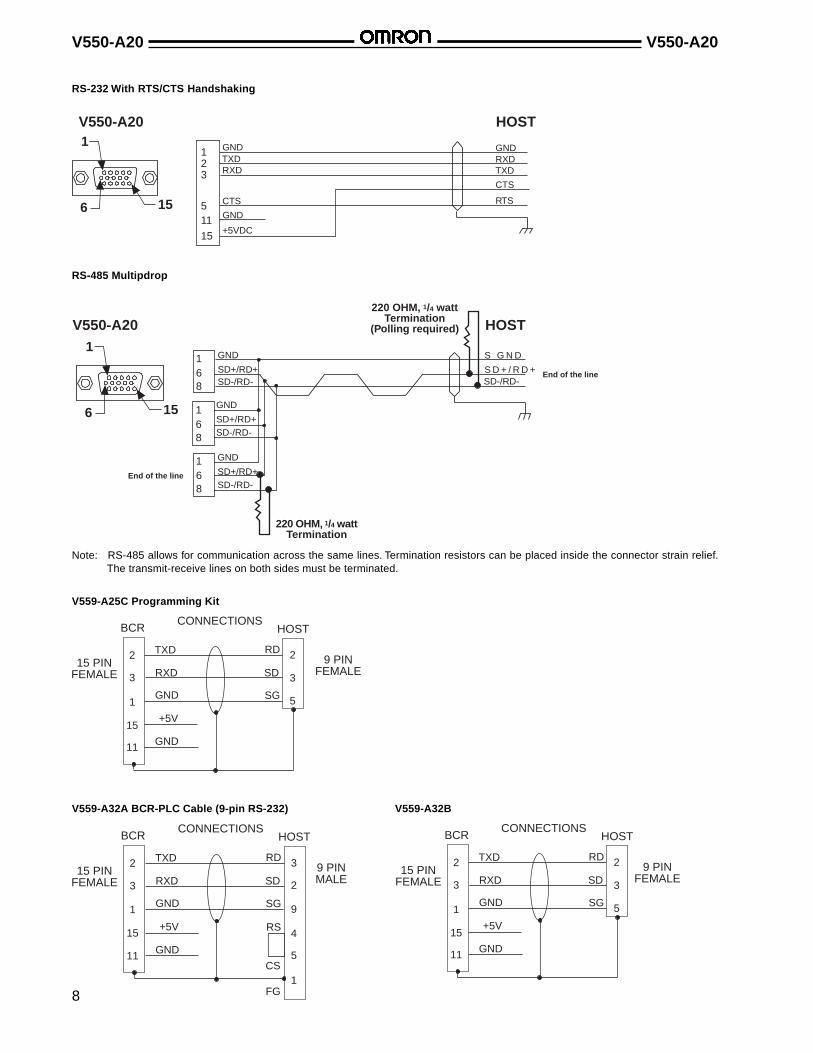
RS-232 With RTS/CTS Handshaking
V550-A20
GNDRXDTXD
HOST
156
1
23
1
15
11
TXDRXD
GND
+5VDC
GND5 CTS
CTS
RTS
RS-485 Multipdrop
SD+/RD+
V550-A20
S D + / R D +
HOST
156
1
68
SD+/RD+SD-/RD-
68
68
End of the line
SD+/RD+SD-/RD-
SD-/RD-
End of the line
220 OHM, 1/4 wattTermination
(Polling required)
220 OHM, 1/4 wattTermination
SD-/RD-
1
1
1 S G N DGND
GND
GND
Note: RS-485 allows for communication across the same lines. Termination resistors can be placed inside the connector strain relief.The transmit-receive lines on both sides must be terminated.
V559-A32A BCR-PLC Cable (9-pin RS-232)
V559-A25C Programming Kit
CONNECTIONSHOSTBCR
15 PINFEMALE
9 PINMALE
TXD
RXD
GND
+5V
GND
RD
SD
SG
RS
CS
FG
2
3
1
15
11
2
3
1
5
4
9
CONNECTIONSHOSTBCR
15 PINFEMALE
9 PINFEMALE
TXD
RXD
GND
+5V
GND
RD
SD
SG
2
3
1
15
11
3
2
5
V559-A32B
CONNECTIONSHOSTBCR
15 PINFEMALE
9 PINFEMALE
TXD
RXD
GND
+5V
GND
RD
SD
SG
2
3
1
15
11
3
2
5

9
V550-A20 V550-A20
Configuration■ SETTING UP BCR WITH PERSONAL COMPUTER
1
2
3
4
1 Configuration BCSETUPsoftware
2 Laptop computer
3 Bar code reader V550-A20
4 Programming kit V559-A25C
■ TEST SETUP PROCEDURETo retrieve settings from device:
• Confirm that the bar code reader (BCR) is communicatingwith device. Select menu option "Retrieve Setup from Device"and press <Enter>.
To change the No Read Message to question marks:
• Select the menu option "Communication Setup" and use thedown arrow key to highlight the "No Read Message"selection.
• Enter "?". Delete any remaining message. Press <Esc> toreturn to the Main Menu.
To deactivate code quality functions:
• Select the menu option "Communication Setup" and use thedown arrow key to highlight the "Delimiter Between Data andCode Quality" selection.
• Enter "X". Press <Esc> to return to the Main Menu.
To change the Trigger to Serially Controlled Trigger:
• Select the menu option "Trigger Setup" and use the downarrow key to highlight the "Scanner Trigger Type" selection.
• Use <space bar> to toggle through choices until "SeriallyControlled" is selected. Press <Esc> to return to the MainMenu.
■ INSTALLING BCSETUP CONFIGURATION SOFTWARETo install BCSetup on PC's hard drive, follow instructions on diskette label.
To change the Bar Code to 8 character Code 39 with noModulus Check:
• Select the menu option "Bar Code Setup" and highlight the"Bar Code #1" selection.
• Use <space bar> to toggle to "Code 39".
• Press down arrow key (or <Enter>) once to highlight "Numberof Characters" selection. Enter "00" in "Number of Characters"selection.
• Highlight "Modulus Check Character" selection. Toggle to"Disabled".
• Press <Esc> to return to Main Menu.
To program the V550-A20 with the new settings:
• Select the menu option "Program Mode" and highlight "SelectProgramming Command".
• Toggle to "Transfer Settings to Device and Use". (Note:settings will remain active until unit is powered down. Whenpower is restored, original settings will be in effect.)
• Press <Enter>.
• Press <Esc> to return to Main Menu.
To read sample bar codes from this datasheet:
• Select menu option "CRT Mode" and press <Enter>.
• Press S (upper case) to start trigger cycle and turn on laser.
• Hold sample Code 39 bar code in front of BCR.
• Press E (upper case) to end trigger cycle and turn off laser.
• The bar code reader will send the bar code message (alongwith a space and the number of times it read the bar code) tothe computer screen.

V550-A20 V550-A20
10
PLC Connection Examples■ SYSMAC SERIES CQM1 CONTROLLER WITH RS-232 CONNECTION
1 Power supply unit CQM1-PA206
2 CPU unit CQM1-CPU21
3 Programming CQM1-PROconsole
4 Bar code reader V550-A20
5 Connecting cable V559-A32A-2M
6 BCR power supply S82S-0305(5V, 0.6A)(see note)
7 Trigger switch Relay or switch
Note: Not rated for UL Class II operation.
■ OPERATIONSwitch ON trigger switch 7 shown above to execute V550-A20to read and send data to the data memory area of CQM1. Usethe program console 3 to confirm the data. In the event thedata was not read, press "?" after the trigger switch is OFF.
■ V550-A20 SETUP• Communication condition (setup):
Baud rate: 9600 bpsWord length: 7 bitParity: EVENStop bit: 2 bit
• Trigger Requirements:Start code: SStop code: EData output mode: Single outputScan trigger type: Serially controlledTrigger stage: Standard
■ CQM1 SETUP• Communication condition:
Set OFF dip switch 5 of CQM1 and set [1000] on DM6645 tomatch the communication condition with BCR (refer to theCQM1 programming manual for the detailed way to changethe condition).
• Setting of Start code and Stop code:Set [2000] on DM6648.
• On the DM, set the ASCII code [S] to Start Reading and [E] toStop Reading.
• Connection of trigger switch:Connect the trigger switch to the input port [00000] terminalon the CPU unit to be able to send [S] or [E] through theRS-232C line when the BCR is ON or OFF, respectively.
• Save the received data from the BCR in the order from upperdigit, DM0200 must be the top, to down.
■ CONFIRMATION OF OPERATION• After programming, set RUN mode and set the trigger switch
ON to execute the reading with the LED on the BCR lighting.
• Press the key in the order below in order to confirm the datawith the console:1 CLEAR ➝ 2 FUN ➝ 3 MONITOR
• The "?" is indicated, in the event that the data can't be readuntil the trigger switch is OFF.
■ CQM1 PROGRAMMING
00000
00000
00003
00007
00010
DIFU(13)00101
00101
00102
AR0805
AR0806
AR0805
Trigger switch ON(DIFFERENTIATE UPon rising pulse)
Trigger switch OFF(DIFFERENTIATE DOWNon falling pulse)
DIFU(14)00102
Send 1 byte of DM0100[Set to 5300](S: send command tostart reading)
TXD(48)DM0100#0000#0001
BSET(71)#0000
DM0200DM0220
RXD(47)DM0200#0000AR09
DM0200-DM0220clear (assume 20readable digits)
Store data fromDM0200 buffer
MSG(46)DM0200
Indicate 16 levels ofDM0200 toprogrammablecontroller
TXD(48)DM0101#0000#0001
Send 1 byte ofDM0101[Set to 4500](E: send command tostop reading)
3 1 2 7 4 6
5

11
V550-A20 V550-A20
3 5
4
2 1
7
6
■ SYSMAC SERIES C200HS OR C200H ALPHA WITH RS-232 CONNECTION:
1 CPU unit C200HS-CPU21
2 Communicatons C200HW-COM04,board C200HW-COM05
3 Bar code reader V550-A20
4 Connecting cable V559-A32A-2M
5 Power supply S82S-0305(5V, 0.6A)(see note)
6 Programming C200H-PRO27console
7 Trigger switch
Note: Not rated for UL Class II operation.
■ OPERATIONSwitch ON trigger switch 7 shown above to execute V550-A20to read and send data to the data memory area of C200o. Usethe program console 6 to confirm the data. In the event thedata was not read, press "?" after the trigger switch is OFF.
■ V550-A20 SETUP• Communication condition (setup):
Baud rate: 9600 bpsWord length: 7 bitParity: EVENStop bit: 2 bit
• Trigger Requirements:Start code: SStop code: EData output mode: Single outputScan trigger type: Serially controlledTrigger stage: Standard
■ C200HS OR C200Hα SETUP• Communication condition:
Set OFF dip switch 5 of C200HS or C200Hα and set [1000]on DM6645 to match the communication condition with BCR(refer to the Reference Manual for the detailed way to changethe condition).
• Setting of Start code and Stop code:Set [2000] on DM6648.
• On the DM, set the ASCII code [S] to Start Reading and [E] toStop Reading.
• Connection of trigger switch:Connect the trigger switch to the input port [00000] terminalon the CPU unit to be able to send [S] or [E] through theRS-232C line when the BCR is ON or OFF, respectively.
• Save the received data from the BCR in the order from upperdigit, DM0200 must be the top, to down.
■ CONFIRMATION OF OPERATION• After programming, set RUN mode and set the trigger switch
ON to execute the reading with the LED on the BCR lighting.
• Press the key in the order below in order to confirm the datawith the console:1 CLEAR ➝ 2 FUN ➝ 3 MONITOR
• The "?" is indicated, in the event that the data can't be readuntil the trigger switch is OFF.
■ C200HS OR C200Hα PROGRAMMING
00000
00000
00003
00007
00010
DIFU(13)00101
00101
00102
26405
26406
26405
Trigger switch ON(DIFFERENTIATE UPon rising pulse)
Trigger switch OFF(DIFFERENTIATE DOWNon falling pulse)
DIFD(14)00102
Send 1 byte of DM0100[Set to 5300](S: send command tostart reading)
TXD(48)DM0100#0000#0001
BSET(71)#0000
DM0200DM0220
RXD(47)DM0200#0000
265
DM0200-DM0220clear (assume 20readable digits)
Store data fromDM0200 buffer
MSG(46)DM0200
Indicate 16 levels ofDM0200 toprogrammablecontroller
TXD(48)DM0101#0000#0001
Send 1 byte ofDM0101[Set to 4500](E: send command tostop reading)

V550-A20 V550-A20
12
PLC Master/Slave System■ SYSMAC SERIES C200Hα. . . RS-485 MULTIDROP
1 CPU C200H . . .
2 Bar code reader V550-A20
3 Power supply unit S825-0305(5V, 0.6A)(see note)
4 Communications C200HW-COM04,board C200HW-COM05
Note: Each bar code reader requires a minimum of 500 mA to operate. If your system contains more than 1 bar code reader in parallel,select a power supply rated for a higher output current.
2 31
4
RS-232to
RS-485
PROTOCALCONVERTER
■ CONNECTION WITH MULTIPLE READERS:Up to 32 slaves can be connected for each serial port on themaster (depending upon line length and required responsetime).
• Operation:The master device, C200H . . ., sends poll messages to theslave BCRs requesting them to respond with data. THe BCRsrespond to the polls. There is no response if they are notpolled by the master.
• Message formats:
V550-A20 Communication setting
Basic setting READ trigger Level trigger
Read mode Single
Communication Baud rate 9600 bps
Condition Word length 7 bit
(default) Parity EVEN
Stop bit 2 bit
Header STX
Footer CR
RS/CS Control OFF
Framing for all messages sent by any device on the multipdropline: FF, STX, ID, TYPE, SEQ, DATA, LRC, CR.
Code Description Notes
FF (hex) Guard character Ignored by receiver
STX (02hex) Start of text Indicates start of acharacter message
ID (2 ASCII Unit identifier Indicates BCRdigits identification number
TYPE Message type Describes purpose of(2 ASCII the messagedigits)
SEQ Sequence Starts at 0 at powernumber up; incremented by 1
for each datamessage sent
DATA Content of data May or may notfield contain characters
LRC Linear Checks to ensure that(2 ASCII redundancy message is validdigits) check
CR Carriage return Indicates end ofmessage

13
V550-A20 V550-A20
■ C200Hα COMMUNICATIONS BOARD CONNECTIONS:The connections from the bar code reader connectors to the C200Hα COM board are shown below.
V550-A20Bar Code Reader
SD+/RD+
SD-/RD-
SD+/RD+
SD-/RD-
SD+/RD+
SD-/RD-
6
8
6
8
6
8
(–) (+) PROTOCALCONVERTER
C200HCOM BOARD
RS-232
RS-485 1
5
6
9V550 pin configuration
C200HalphaCOM boardpinout
DimensionsUnit: mm (inch)
Note: The above connection is shown using the C200Hα PLC with protocol macro function. Contact Omron for the latest V550-A20protocol macro.
■ READERS AND ACCESSORIESV550-A20 Bar Code Reader
63°
30(1.18)
60(2.36)
70(2.76)
FRONT OF SCANNER
BEAM PATH
OPTIONAL RIGHT ANGLE EXIT ATTACHMENTV559-A24
S82S-0305 Power Supply
37.5 (1.48)
9.8 (0.38)
7.5(2.95)
6.1(2.40)
Six, M3, 5
6.5 (2.56)4
(0.16)
3.5(1.38)
7.3(0.29)
V550-A20 V550-A20
14
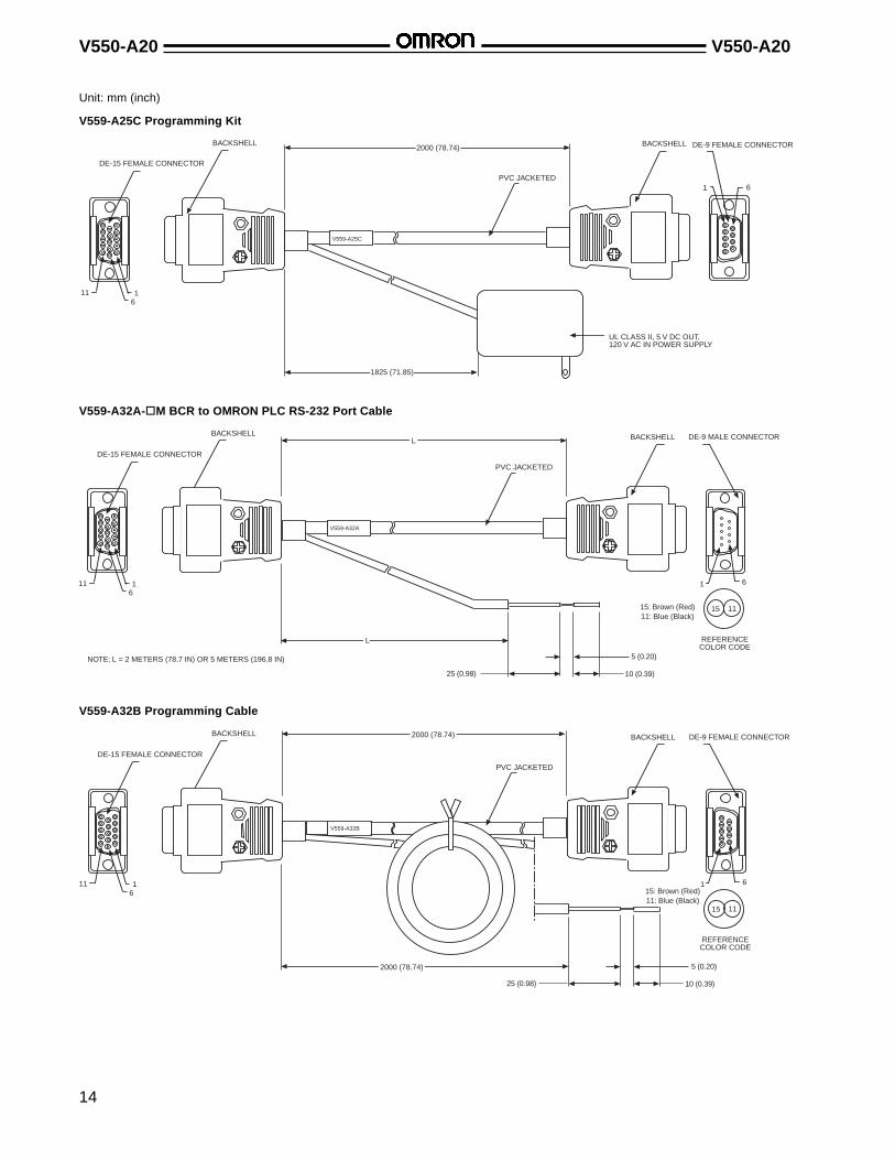
V559-A25C Programming Kit
UL CLASS II, 5 V DC OUT,120 V AC IN POWER SUPPLY
BACKSHELL
DE-15 FEMALE CONNECTOR
1161
BACKSHELL2000 (78.74)
PVC JACKETED
1825 (71.85)
V559-A25C
DE-9 FEMALE CONNECTOR
1 6
V559-A32A-oM BCR to OMRON PLC RS-232 Port Cable
Unit: mm (inch)
DE-15 FEMALE CONNECTOR
1161
BACKSHELL L
PVC JACKETED
L
V559-A32A
DE-9 MALE CONNECTOR
1 6
25 (0.98) 10 (0.39)
5 (0.20)
15: Brown (Red)11: Blue (Black)
15 11
REFERENCECOLOR CODE
BACKSHELL
NOTE: L = 2 METERS (78.7 IN) OR 5 METERS (196.8 IN)
V559-A32B Programming Cable
DE-15 FEMALE CONNECTOR
1161
BACKSHELL 2000 (78.74)
PVC JACKETED
V559-A32B
DE-9 FEMALE CONNECTOR
1 6
10 (0.39)
5 (0.20)
15: Brown (Red)11: Blue (Black)
15 11
REFERENCECOLOR CODE
BACKSHELL
25 (0.98)
2000 (78.74)

15
V550-A20 V550-A20
■ MOUNTING BRACKETS
Unit: mm (inch)
V559-A26F Mounting Clip V559-A26A Mounting Plate
0.156 x 0.281 SLOT
19.1 (0.75)
9.7 (0.38)
7.1 (0.28)
18.3 (0.72)
5.3 (0.21)
2.3 (0.09)
3.0 (0.12)
7.36 (0.29) 62.23 (2.45)
8.63 (0.34)
PEM FH-632-6
37.34 (1.47)
25.15(0.99)
6.35 (0.25)
8.13 (0.32) 72.14 (2.84)
86.87 (3.42)
1.52(0.06)
24.64(0.97)
27.94(1.10)
11.18 (0.44)
50.01 (1.97)
0.156 x 0.281 SLOT4 PL
62.23 (2.45)
3.30 (0.13)
6.86 (0.27)
2.29 (0.09)

V550-A20 V550-A20
16
Unit: mm (inch)
V559-A26D Picket Fence Mounting Bracket V559-A26E Ladder Mounting Bracket
6.35(0.25)
57.15 (2.25)
19.05 (0.75)9.65
(0.38)
0.156 x 0.2812 PL
69.85 (2.75)
26.92(1.06)
15.75(0.62)
55.88(2.20)
53.34(2.10)
15.24(0.60) 39.37 (1.55)
19.05(0.75) 9.65
(0.38)
6.35 (0.25)
0.156 x 0.2812 PL
76.20 (3.0)
88.90 (3.50)
25.40(1.00)
31.75(1.25)
37.59(1.48)
35.30(1.39)
15.24(0.60) 58.42 (2.30)

17
V550-A20 V550-A20
Unit: mm (inch)
V559-A26B Cradle Mounting Bracket
6.10 (0.24)
36.07(1.42)
50.04(1.97)
6.10(0.24)
35.56(1.40)
11.68(0.46)PEM S-632
4PL
50.04 (1.97)
24.89 (0.98)
50.04 (1.97)
11.94(0.47)
19.05(0.75)
25.91(1.02)
■ BAR CODE SCANNING EXAMPLESRaster ScanSingle Line Scan
Successive andparallel raster laserscan lines
Either 1/2" or 1" at 10"depending on rasterbar code model
Single scan line

V550-A20 V550-A20
18
Symbologies■ BAR CODE SAMPLES / NARROW ELEMENT WIDTHS

19
V550-A20 V550-A20
Precautions■ LASER BEAM SAFETY"Low power" lasers are by definition incapable of causing eyeinjury within the duration of the blink, or aversion response(0.25 s) and must be visible (400 nm to 700 nm). Therefore, anocular hazard can only exist if an individual overcomes his/hernatural aversion to bright light and stares directly into the laserbeam. There are two product requirements for these lasers: tohave a CAUTION label and to have an indicator light to indicatelaser emission.
The two operational safety rules are:
• Do not permit a person to stare at the laser from withinthe beam.
• Do not point the laser at a person's eye at close range.
FDA, IEC Laser class I IIa II IIIa IIIb IV
Remote interlock connector N/A N/A N/A N/A R R
Key Control N/A N/A N/A N/A R R
Emission indicator N/A N/A R R R R
Beam attenuator N/A N/A N/A R R1 R1
Note: In the chart above: R = require; N/A = not applicable; R1 = delay required between indication and emission.
■ LASER CONTROL REGULATIONSThe V550-A20 Bar Code Reader meets the standards requiredby the U.S. Food and Drug Administration (FDA). This readeralso has been reported to the Center for Devices and Radiologi-cal Health (CDRH). Any service performed on this device shouldbe done so as to not violate compliance with the Code ofFederal Regulations, Title 21, Part 1040, Section 10 (21 CFR1040.10).
Labels (FDA Regulations)Laser radiation warning and information labels are located onthe top side of the bar code reader.
LASER RADIATIONDO NOT STARE INTO BEAM
.95 mW SEMICONDUCTOR670 NANOMETERSCLASS II LASER PRODUCT
Follow the instructions on this datasheet for the adjustmentand mounting of the V550-A20.
Make sure that the laser beam will not be directly or indirectlyreflected into human eyes. The safety distance is approxi-mately 1 m for the V550-A20. If there is a possibility of laserbeam reflection by any objects around the emitter at the time ofadjustment, apply paint with a low light reflection ratio to theobjects.
The sensor incorporates a laser emission warning light and a"scanning safeguard" feature which shuts off the laser power ifthe mirror wheel fails to rotate. This ensures that a stationarylaser beam cannot emanate from the scan head.
■ INSTALLATIONInstall the bar code reader in a location where the laser beamwill not enter the operator's eyes directly or from reflection by amirrored surface. Also, mount the operation indicator (LED) in aclearly visible location. Avoid interference from ambient lightshining into BCR's window. Avoid excessive dust on window.Avoid scratching window. Avoid subjecting the bar code readerto heavy vibration.
■ MAINTENANCE AND REPAIR DANGER!
Never disassemble the reader. Users expose themselves to the risk of laser radiation if they disassemble the device.
Do not attempt repairs or maintenance of the V550-A20. TheV550-A20 contains no user serviceable parts. Refer all servicingto an authorized Omron representative.

V550-A20 V550-A20
20
OMRON ELECTRONICS, INC. OMRON CANADA, INC.One East Commerce Drive 885 Milner AvenueSchaumburg, IL 60173 Scarborough, Ontario M1B 5V81-800-55-OMRON 416-286-6465
Cat. No. V550-E3-3 3/99 Specifications subject to change without notice. Printed in the U.S.A.
NOTE: DIMENSIONS SHOWN ARE IN MILLIMETERS. To convert millimeters to inches, divide by 25.4.
DRX is a registered trademark of Accu-Sort Systems, Inc.