BACCARA WATER 2 0 1 9 Irrigation Products Catalog
88
When Everything Connects BACCARA WATER 2019 Irrigation Products Catalog Pneumatics, Automation & Control Solutions
-
Upload
khangminh22 -
Category
Documents
-
view
1 -
download
0
Transcript of BACCARA WATER 2 0 1 9 Irrigation Products Catalog

W h e n E v e r y t h i n g
C o n n e c t s
B A C C A R A W A T E R 2 0 1 9I r r i g a t i o n P r o d u c t s C a t a l o g
Pneumatics, Automation & Control Solutions

WHEN EVERYTHING CONNECTS
BACCARA was established in 1964 in Kibbutz Geva, Jezreel Valley, Israel.
We are a leading company in the fields of irrigation, automation and control
solutions. Our irrigation product lines include a vast range of solenoid valves,
electric and hydraulic valves, controllers and operators. We have ISO-9001
certification for all our products and ISO-14001 certification for environmental
quality control.
In addition to our standard range, Baccara is dedicated to offering customized
solutions, implementing 50 years of experience and intelligent technology.
Such solutions offer versatility and optimize water systems management
and control, thus improving irrigation efficiency and performance.
During our 50 years of activity we have earned an impressive reputation; today
you can find Baccara products in every sector of irrigation and automation.
Baccara’s global network covers most of the world with subsidiaries and
distributors in Australia, USA, Central and South America, Europe and Asia.

Certification 2
Solenoid Valves 5
Solenoid Manifolds 25
Isolated / Fertilizer Solenoids 31
Electric & Hydraulic Valves
GEM & G75 39
G500 67
Controllers & Special Valves 83
Spare Parts 101
Technical Information 117
INDEX

3BACCARA WATER IRRIGATION CATALOG2
CERTIFICATEThis is to certify that the Occupational Health and Safety Management System of
BACCARA GEVA AGRICULTURE COORPORATIONSOCIETY LTD.
Kibbutz Geva, Israel
Has been audited and registered by SII-QCD as conforming to the requirements of :
OHSAS 18001:2007This Certificate is Applicable to
Design, production, testing and marketing of solenoid valves and automation control equipment.
Certificate No.: 64762 Certificate Issue Date: 31/12/2016Initial Certification Date: 30/06/2010 Certification Expiry Date: 27/12/2019
SII-QCD assumes no liability to any party other than the client, and then only in accordance with the agreed upon Certification Agreement.This certificate’s validity is subject to the organization maintaining their system in accordance with SII-QCD requirements for system certification. Thecontinued validity may be verified via scanning the code with a smartphone, or via website www.sii.org.il. This certificate remains the property of SII-QCD.
Pinhas ShaharDirector General
Eli Cohen-KaganDirector, Quality & Certification Division
Page 1 of 1 Our Vision: To Enhance Both Global Competitiveness of our Services, with our Uncompromised Quality and Integrity
CERTIFICATEThis is to certify that the Quality Management System of
BACCARA GEVA AGRICULTURE COORPORATIONSOCIETY LTD.
Kibbutz Geva, Israel
Has been assessed and complies with the requirements of :
ISO 9001:2015This Certificate is Applicable to
Design, production, testing and marketing of solenoid valves and automation control equipment.
Certificate No.: 97540 Certificate Issue Date: 17/05/2018Initial Certification Date: 01/10/1998 Certification Expiry Date: 27/12/2019
SII-QCD assumes no liability to any party other than the client, and then only in accordance with the agreed upon Certification Agreement.This certificate’s validity is subject to the organization maintaining their system in accordance with SII-QCD requirements for system certification. Thecontinued validity may be verified via scanning the code with a smartphone, or via website www.sii.org.il. This certificate remains the property of SII-QCD.
Ilan CarmitActing Director General R.N 570041970
Eli Cohen-KaganDirector, Quality & Certification Division
Page 1 of 1 Our Vision: To Enhance Both Global Competitiveness of our Services, with our Uncompromised Quality and Integrity
CERTIFICATEThis is to certify that the Environmental Management System of
BACCARA GEVA AGRICULTURE COORPORATIONSOCIETY LTD.
Kibbutz Geva, Israel
Has been assessed and complies with the requirements of :
ISO 14001:2015This Certificate is Applicable to
Design, production, testing and marketing of solenoid valves and automation control equipment.
Certificate No.: 97543 Certificate Issue Date: 17/05/2018Initial Certification Date: 03/01/2010 Certification Expiry Date: 27/12/2019
SII-QCD assumes no liability to any party other than the client, and then only in accordance with the agreed upon Certification Agreement.This certificate’s validity is subject to the organization maintaining their system in accordance with SII-QCD requirements for system certification. Thecontinued validity may be verified via scanning the code with a smartphone, or via website www.sii.org.il. This certificate remains the property of SII-QCD.
Ilan CarmitActing Director General R.N 570041970
Eli Cohen-KaganDirector, Quality & Certification Division
Page 1 of 1 Our Vision: To Enhance Both Global Competitiveness of our Services, with our Uncompromised Quality and Integrity
CERTIFICATION
C E R T I F I C A T E O F C O M P L I A N C E
Certificate Number 20130305-MH12494 Report Reference MH12494 -19850306
Issue Date 2013 -MARCH -05
William R. Carney, Director, North American Certification Programs UL LLC Any information and documentation involving UL Mark services are provided on behalf of UL LLC (UL) or any author ized licensee of UL. For questions, please contact a local UL Customer Service Representative at www.ul.com/contactus
Page 1 of 2
Issued to: BACCARA GEVA AGRICULTURE CORPORATION SOCIETY LTD KIBBUTZ GEVA 18915 KVUTZAT GEVA ISRAEL
This is to certify that representative samples of
COMPONENT - VALVES, ELECTRICALLY OPERATED See next page
Have been investigated by UL in accordance with the Standard(s) indicated on this Certificate.
Standard(s) for Safety: UL 429 STANDARD FOR ELECTRICALLY OPERATED VALVES Additional Information: See the UL Online Certifications Directory at
www.ul.com/database for additional information
Only those products bearing the UL Recognized Component Mark should be considered as being covered by UL's Recognition and Follow-Up Service. The UL Recognized Component Mark generally consists of the manufacturer’s identification and catalog number, model number or other product designation as specified under “Marking” for the particular Recognition as published in the appropriate UL Directory. As a supplementary means of identifying products that have been produced under UL’s Component Recognition Program, UL’s Recognized Component Mark: , may be used in conjunction with the required Recognized Marks. The Recognized Component Mark is required when specified in the UL Directory preceding the recognitions or under “Markings” for the individual recognitions. Recognized components are incomplete in certain constructional features or restricted in performance capabilities and are intended for use as components of complete equipment submitted for investigation rather than for direct separate installation in the field. The final acceptance of the component is dependent upon its installation and use in complete equipment submitted to UL LLC. Look for the UL Recognized Component Mark on the product.
ISO 9001:2015Quality Management System : Design, production, testing and marketing of solenoid valves and automation control equipment
OHSAS 18001:2007Occupational Health & Safety Management System : Design, production, testing and marketing of solenoid valves and automation control equipment
EN55011 Group1 – Class A / EN61000-6-1 / CFR 47 FCC Class AEMC - SII Certificate of Conformity
UL 429Standard for electrically operated valves
ISO 14001:2015Environmental Management System : Design, production, testing and marketing of solenoid valves and automation control equipment
CEEC Declaration of ConformityComplies with the requirements and provisions of the Council Directive 2014/35/EU
FCCProduct certification from The Federal Communications Commission
AS/NZS 4020:2005 *Certificate of Conformity : Testing of products for use in contact with drinking water
NSF/ANSI 61 & 372 * NSF/ANSI 61 & 372 and all applicable requirements Drinking Water System Components :Lead Content | Health Effects
AS/N
ZS 4
020
Australian
WaterQualityCentre
* For enquiries regarding this certification, please contact BACCARA sales engineers at water@baccara-geva com
For details of all NSF certified Baccara products, please take the following steps :• Visit NSF Public Health & Safety Organization : www.nsf.org• Click on SEARCH CERTIFIED PRODUCTS & SYSTEMS >>
• Type "Baccara" in the "search company" field > Enter

4 5
SOLENOID VALVES
G75-A3P | 1/8” Latch 2W, 3W NC, NO 6G75-VSA | Stand-alone solenoid 3W NC, NO 8G75-A | 1/8”, 1/4” 2W, 3W NC, NO 10GALIT | 3W NC, NO 12GEM-A | 1/8", 1/4" 2W NC, NO 14GEM-A | 1/8", 1/4" 3W NC, NO 18GEM-A3P | Latch 3 positioning manual override 22

7BACCARA WATER IRRIGATION CATALOG6
G75-A3P | 1/8” Latch 2 Way, 3 Way NC, NO
How to Order
Dimensions
G75-A3P - TYPE PORT FUNCTION ORIFICE - LATCH TYPE (1) WIRES
with flange 1 1/8" BSP 10 2W NC 1 2.6 5a 1ΩΩΩ PA two Null
1/8" NPT 11 3W NC 3 4ΩΩΩ PB three a
3W NO 4
Example : G75-A3P-11015a-PAG75-A3P, with flange, 1/8"BSP, 2W NC, 2.6 orifice, 1Ω latch with two wires
(1) Refer to coil resistance vs input voltage table
G75-A3P 1 10 1 5a PA
Resistance [Ω] Suitable input voltage range [V]
1 8 - 12
4 12 - 18
Coil resistance vs input voltage range
* To order valves manufactured according to your specific requirements, please contact our technical sales department
Manual Override Operation
OPEN
CLOSE
AUTO
To manually open the valve : turn selector switch to OPEN
NO : To change from OPEN to AUTO: turn the selector switch to AUTO
NC : To change from OPEN to AUTO: turn the selector switch to CLOSE, and then to AUTO
G75-A3P | 1/8” Latch 2 Way, 3 Way NC, NO
SOLENOID VALVES
Technical DataFunction 2 Way NC, 3 Way NC, NO
Ports size 1/8” BSP & NPT
Orifice size 2.6 mm
Pressure rangeNC 2 Way : 10 barNC 3 Way : 8 bar NO 3 Way : 10 bar
Temperature range Fluid : 5ºC to 50ºC (no freezing)Ambient : 10ºC to 50ºC
Materials in contact with media
Manual override: PlasticMain Valve:UV Stabilized - Reinforced Nylon 6 30% GFSolenoid Operator:Stainless Steel AISI 300 & 400 seriesSeals:NBR
Mounting 2 x Ø6 mm holes
Manual override 3 positions (Open/Auto/Close)
Media Air, water
Coil voltage Latch
Switching time 40-60 msec
Electric connection 22AWG cable
Standard protection class IP66
* Can only be operated with supplied coil
3W(1)(2)
OUTNC/NO
EX NO
EX NC
NOIN
NCIN
62.6
1/8'' BSP / NPTTYPx3
50
80
6 THROUGH
TYPx2
15
25
6 23
2W
62.6
15
6
6THROUGH
TYPX2
23
25
1/8" BSP \ NPTTYPX3
50
89.
9
3W
2W(1)(2)
OUT NCIN NC

9BACCARA WATER IRRIGATION CATALOG8
G75-VSA | Stand-alone solenoid 3 Way NC, NO
How to Order
Dimensions
* To order valves manufactured according to your specific requirements, please contact our technical sales department
G75-VSA - BODY PORT FUNCTION MANUAL OVERRIDE ORIFICE SEALS - LATCH TYPE (1) OUTLET (2) WIRES
Plastic 4 1/8" BSPT 10 3W NC 3 Plastic 1 1 8 3a EPDM E 4ΩΩΩ SB COM 1 1 two Null
1/8" NPT 11 3W NO 4 9ΩΩΩ SC COM 2 2 three a
12ΩΩΩ SD
23ΩΩΩ S6
Example : G75-VSA-410313aE-SB1G75-A stand-alone solenoid, plastic, 1/8" BSPT, 3W NC, plastic manual override, 1 8 orifice, EPDM seals, 4Ω latch, COM 1 outlet, two wires
(1) Refer to coil resistance vs input voltage table(2) A plug will be fitted on the other outlet port
SB 1G75-VSA 4 10 3 1 3a E
Resistance [Ω] Suitable input voltage range [V]
4 6 - 9
9 12 - 14
12 14 - 16
23 18 - 21
Coil resistance vs input voltage range
57
58.2 1/8" BSPT \ NPT
1/8
" BSP
T \
NPT
1/8" BSPT \ NPT
44
13
119
1/8" BSPT \ NPT
1/4" BSPT
Technical Data
G75-VSA | Stand-alone solenoid 3 Way NC, NO
SOLENOID VALVES
Function 3 Way NC, NO
Ports size 1/8” BSPT & NPT
Orifice size 1 8 mm
Pressure range 0 to 8 bar
Switching time 30-50 ms
Temperature range Fluid : 0ºC to 50ºC (no freezing)Ambient : -10ºC to 50ºC
Materials in contact with media
Manual override: Plastic (Reinforced Nylon)Main Valve:Plastic (Reinforced Nylon & POM)Solenoid Operator:Stainless Steel AISI 300 & 400 seriesSeals:EPDM
Mounting Lock nut on the bottom COM port
Manual override 3 positions latch : Auto, Close, Open
Media Air, water
Coil voltage Latch
Standard protection class IP66
PORT NO NC
1 Exhaust Pressure
3 Pressure Exhaust
COM Out Out
COM 2
COM 1
(1)
(3)
* Can only be operated with supplied coil

11BACCARA WATER IRRIGATION CATALOG10
Max. Pressure (bar) tableTechnical Data
G75-A | 1/8", 1/4" 2 Way, 3 Way NC, NO
Function Orifice (mm) AC DC DC Latch
2W NC up to 2 0 12 12 12
3W NC
1 16 12 16
1 2 11 9 11
1 6 6 5 6
3W NO
1 0 16 16 16
1 2 12 12 12
1 6 10 10 10
Function 2 Way, 3 Way NC, NO
Ports size 1/8" and 1/4" BSP & NPT
Orifice size See table
Pressure range See table
Temperature rangeFluid : 5ºC to 50ºC (no freezing)Ambient : -10ºC to 50ºC
Materials in contact with media
Manual override:Reinforced NylonMain Valve:Brass or Reinforced NylonSolenoid Operator:Stainless Steel AISI 300 & 400 seriesSeals:EPDM
Coil voltage • Voltage and power consumption - see table
Standard protection class IP66
• Available with brass adaptor upon request
AC (W)DC (W)
50 Hz
V 2 4 512 • •24 • •
110 • 2W only
Voltage & Power Consumption
(2) (1)
NC/NO
OUT
NC IN
NO Exhaust
NC EX NO IN
• Available options
G75-A Brass G75-A | 2W | Plastic
Solenoid Voltage Inrush [A] Holding [A]2W 50 Hz
+10%
n-20%
0 3 0 192W 60 Hz 0 2 0 143W 50/60 Hz * 0 125 0 125DC 4 5W
V
Voltage & Current table
G75-A | 3W | Plastic
SOLENOID VALVESG75-A | 1/8", 1/4" 2 Way, 3 Way NC, NO
How to Order
Dimensions
* To order valves manufactured according to your specific requirements, please contact our technical sales department
G75-A - TYPE PORT FUNCTION MANUAL OVERRIDE ORIFICE - VOLTAGE (3) WIRES
with flange 1 1/8" BSP 10 2W NC 1 None 0 1 0 1 24V AC 1 two null
without flange 2 1/8" NPT 11 3W NC 3 Plastic (2) 1 1 2 2 24V AC
w/out Diode (4) 1R three (5) a
Brass 3 1/4"BSP (1) 20 3W NO 4 1 6 3 12V AC 3
1/4"NPT (1) 21 2 0 4 12V DC 4
24V DC 5
23Ω 6
110V AC 7
4Ω B
9Ω C
12Ω D
Example : G75-A-110302-1G75 with flange, 1/8" BSP, 3W NC, no manual override, 1 2 orifice, 24V AC coil, two wires
(1) Brass only(2) Recommended for AC and continuous DC only(3) For Latch : Refer to coil resistance vs input voltage table (4) 3W NO 1 6 mm : Max pressure is 8 bars(5) For Latch only
G75-A 1 10 3 0 2 1
A B C
2W NC - 59 65
3W 1/8 70 77
M5 x0.8 DEEP 8TYPx2
22
22
1/8" or 1/4"BSP/NPTTYPx2
52C
ManualOverride
32
B
CABLE LENGTH350 (mm) Ø30
20
735251
Ø6 THRUTYPx2
A
1/8" BSP/NPTBOTH ENDS
48.3
51
1/8" BSP/NPTBOTH ENDS
35.8
B
AØ30
For tapping screwNo. 6
7.3
51
Brass Plastic
* Except 24V AC without Diode
Resistance [Ω] Suitable input voltage range [V]
4 6 - 9
9 12 - 14
12 14 - 16
23 18 - 21
Coil resistance vs input voltage range

12
GALIT - PORT VOLTAGE (1) MOUNTINGBRACKET WIRES
1/8" BSP 10 24V AC 1 without 0 two null
1/8" NPT 11
24V ACw/out Diode
1R with 1 three (2) a
12V AC 3
12V DC 4
24V DC 5
23Ω 6
4Ω B
9Ω C
12Ω D
Technical DataFunction 3 Way NC, NO
Ports size 1/8" BSP & NPT
Orifice size 5mm
Pressure range 1 to 10 bar
Temperature range Fluid : 5ºC to 50ºC (no freezing)Ambient : -10ºC to 50ºC
Materials in contact with media
Main Valve:Reinforced NylonSolenoid Operator:Stainless Steel 300 & 400 seriesSeals:NBRSpring:Stainless Steel AISI 300 series
Manual override
Manual override with 3 positions :• AUTO - for automatic operation (valve isopen when solenoid is energized)• MANUAL - valve is kept open• CLOSE - valve is kept closed
Solenoid Assembled with 3W NO 1.2mm G75 operator
Coil voltage • Voltage and power consumption - see table
Standard protection class IP66
Voltage & Power ConsumptionAC (W)
DC (W)50 Hz
V 2 4.512 • •24 • •
• Available options
How to Order
GALIT 10 1 1
Example : GALIT-1011GALIT pilot operated, 1/8" BSP, 24V AC with mounting bracket, two wires
(1) For Latch : Refer to coil resistance vs input voltage table(2) For Latch only
OUTEX N.O
56 33
151
1/8" BSP / NPT
IN N.C2 4
IN
IN N.O
EX N.C
CLOSEAUTO
OPEN
3W NOØ1.2
3W NOØ1.2
* To order valves manufactured according to your specific requirements, please contact our technical sales department
Technical Data
GALIT | 3 Way pilot operated NC, NO
SOLENOID VALVES
Solenoid Voltage Inrush [A] Holding [A]2W 50 Hz
+10%
n-20%
0.3 0.192W 60 Hz 0.2 0.143W 50/60 Hz * 0.125 0.125DC 4.5W
V
Voltage & Current table
* Except 24V AC without Diode
Resistance [Ω] Suitable input voltage range [V]
4 6 - 9
9 12 - 14
12 14 - 16
23 18 - 21
Coil resistance vs input voltage range
13BACCARA WATER CATÁLOGO DE RIEGO
GEM-GALIT | 3 Vías pilotada NC, NA
GEM-GALIT - CONEXIÓN - VOLTAJE ALIM CONECTOR MONTAJE
SOPORTE
1/8"BSP 10 sin
bobina 0 Sin bobina 0 sin 0 sin 0
1/8"NPT 11 6 1 CA 8 W
50 Hz 1 con 1 con (2) 1
12 2 CA 8 W 60 Hz 2 con LED 2
24 3 CC 10 W 3con LED bicolor 3
48 4 CA 5,5 W 50 Hz 4 cables 4
110 5 CA 5,5 W 60 Hz 5
con concen-trador 1/2”
5
120 6 CA 2,5 W50/60 Hz 6
protec-tor de so-breten-sión con LED
6
220 7A CC 5,5 W 7conector con cable moldeado
7
230 7 CC 3,5 W 8 otro 9
240 8
Latch/otro (1) 9
Características técnicas
Voltaje y consumo de energía
Función 3 Vías NC, NA
Tamaño de conexión 1/8” BSP y NPT
Tamaño orificio 5 mm
Rango de presión De 1 a 10 bar
Rango de temperatura Fluido: 5 ºC a 50 ºC (no congelado)Ambiente: -10 ºC a 50 ºC
Materiales en contacto con el medio
Válvula principal:Nailon reforzadoOperador del solenoide:Juntas acero inoxidable serie 300 y 400Juntas:NBRResorteAcero inoxidable AISI serie 300
Mando manual
Mando manual con 3 posiciones:• AUTO - para funcionamiento automático (la válvula se abre cuando se energiza el solenoide)
• MANUAL - la válvula se mantiene abierta• CLOSE - la válvula se mantiene cerrada
Solenoide Montada con accionador de 3 Vías NA GEM-OG, 1,6
Voltaje de bobina• Voltaje y consumo de energía: véase tabla• T odos los voltajes de bobina de Baccara son
± 10 % del nominal
Clase de protección estándar IP66
• Opciones disponibles
GEM-GALIT 10 3 1
Cómo realizar un pedido
Ejemplo: GEM-GALIT-10-3110GEM-GALIT pilotada de 3 Vías, 1/8" BSP, 24V CA 8 V 50 Hz,con conector, sin soporte de montaje.
(1) Para definir tipo de bobina Latch, véase Válvula GEM-A3P - Tabla Cómo realizar un pedido (2) Sólo para Latch
SALIDAESCAPE N.O
56 33
ENTRADA N.C2 4
ENTRADA N.O
ESCAPE N.C
CERRADOAUTO
ABIERTO151
1/8" BSP / NPTENTRADA PILOTO
Ø6.
8
CA (W)CC (W)
50 Hz 60 Hz
V 8 5,5 2,5 8 5,5 2,5 10 5,5 3,56 • • •12 • • • • •24 • • • • • • • •48 • • •110 • • • •120 • •220 • • • • •230 • • • •240 • • •
1 0
* Si desea solicitar válvulas fabricadas según requisitos específicos, por favor, póngase en contacto con nuestro departamento técnico de ventas
Resistencia de la bobina vs rango de voltaje de entrada

®15BACCARA WATER IRRIGATION CATALOG14
GEM-A | 1/8”, 1/4” 2 Way NC, NO
Max. Pressure (bar) 2W NO table
Function 2 Way NC, NO
Ports size 1/8" and 1/4" BSP & NPT
Orifice size See table
Pressure range• See table• Valves for pressure higher than 25 bar cannot be supplied with manual override
Kv (l/min) See table
Temperature range Fluid : -10ºC to 80ºC (no freezing)Ambient : -10ºC to 50ºC
Materials in contact with media
Manual override:Plastic, Brass screw or Brass finger knob,Stainless Steel for Stainless Steel valves(1) Plastic manual override : Maximum pressure : 16 bar (2) Manual override is unavailable in 2W NO through base applications Main Valve:Brass or Stainless Steel AISI 316Solenoid Operator:Stainless Steel AISI 300 & 400 seriesSeals:NBR, FKM, EPDM, FFKM, PTFE
Media Air, water, oil
Coil voltage• Voltage and power consumption - see table• All Baccara coil voltages are ± 10% of nominal
Standard protection classIP65 with connector* Option : IP68 (please refer to GEM-BP Coil)
• Latch valves are available upon request
OUT
OUT
IN
2W NC 2W NO
P(2)
A(1)
P(2)
IN
Coil Current/Power
Orifice (mm)
0 8 1 2 1 6 2 0 2 4 3 0 4 0
ADC * 60 50 35 20 15 10 5
AC8W, DC/10W 80 80 60 38 30 18 10
AC5 5W 80 60 40 28 20 15 6
AC2 5W 60 50 35 20 15 9 5
DC5 5W 60 30 18 12 9 6 3
DC3 5W 40 20 12 8 6 4 2
Flow factor Kv(l/min) 0 5 1 1 1 7 2 5 3 5 4 5 5
Coil Current/Power
Orifice (mm)
0 8 1 2 1 6 2 0 2 4 3 0
ADC * 25 25 25 20 15 10
Flow factor Kv(l/min) 0 5 1 1 1 4 2 5 3 0 3 5
Max. Pressure (bar) 2W NC table
* ADC valves are only suitable for use with AC8W or DC10W coils
GEM-A | 1/8”, 1/4” 2 Way NC, NO
SOLENOID VALVES
Dimensions
rass / Stainless Steel
Optional Mounting Bracket
BSP / NPT 1/8" or 1/4"TYPx2
Technical Data
GEM-A | 2W | Stainless Steel GEM-A | 2W | Brass

®17BACCARA WATER IRRIGATION CATALOG16
VOLTAGE POWER CONNECTOR
No coil 0 No coil 0 None 0
6 1 AC8W 50Hz 1 with 1
12 2 AC8W 60Hz 2 with LED 2
24 3 DC10W 3 with bi-color LED 3
48 4 AC5 5W50Hz 4 flying leads coil 4
110 5 AC5 5W60Hz 5 with 1/2" Hub 5
120 6 AC2 5W50/60Hz 6 surge protection
with LED 6
220 7A DC5 5W 7 connector with moulded cable 7
230 7 DC3 5W 8 other 9
240 8
Latch/other (4) 9
GEM-A - BODY PORT FUNCTION ORIFICE SEALSMANUAL
OVERRIDE -
Brass 2 1/8" BSP 10 2W NC 1 0 8 1 NBR N None 0
1/8" NPT 11 2W NO 2 1 2 2 FKM V Plastic (3) 1
1/4" BSP 202WNO (1)
through base
2a 1 6 3 EPDM E Slot 2
1/4" NPT 21 2 0 4 FFKM (2) K Knob 3
2 4 5 PTFE T
3 0 6
4 0 7
GEM-A - BODY PORT FUNCTION ORIFICE SEALSMANUAL
OVERRIDE -
SST 3 1/8" BSP 10 2W NC 1 0 8 1 NBR N None 0
1/8" NPT 11 2W NO 2 1 2 2 FKM V Plastic (3) 1
1/4" BSP 202WNO (1)
through base
2a 1 6 3 EPDM E Slot 2
1/4" NPT 21 2 0 4 FFKM (2) K Knob 3
2 4 5 PTFE T
3 0 6
4 0 7
* For available options, please refer to VOLTAGE & POWER CONSUMPTION table below
3GEM-A 2 10 1 5 N 2 1 1
Example : GEM-A-21015N2-311GEM-SOL direct operated brass, 1/8"BSP, 2W NC, 2 4 orifice, NBR, slot manual override, 24V AC8W 50Hz with connector
(1) Option 2a : manual override is not available(2) FFKM O-ring is available only upon request When ordering FFKM seals, please consult
with our technical sales department about O-ring compound(3) Maximum pressure : 16 bar(4) For specifying Latch type coil, please refer to GEM-A3P valve - How to Order table
* Note: When ordering without coil, please define what current and pressure rating is needed (DC, AC or ADC),otherwise an ADC valve will be supplied
Voltage & Power ConsumptionAC (W)
DC (W)50 Hz 60 Hz
V 8 5 5 2 5 8 5 5 2 5 10 5 5 3 56 • • •12 • • • • •24 • • • • •48 • • •110 • • •120 • •220 • • • • •230 • • •240 • • •
Available options : STANDARD• SEMI-STANDARD
SPECIAL
* To order valves manufactured according to your specific requirements, please contact our technical sales department
GEM-A | 1/8”, 1/4” 2 Way NC, NO
SOLENOID VALVES
Model Selection
STANDARD | Reduced lead times, No MOQ Please refer to Standard Items Ordering Chart
SEMI-STANDARD | Normal lead times, No MOQ
SPECIAL | Extended lead times, Non-stock items, MOQ may be applicable For a quote, please contact our sales department
GEM-A | 1/8”, 1/4” 2 Way NC, NO
Ordering ChartSTANDARD ITEMS | Reduced lead times, No MOQADC operator only
PART NO. PER VOLTAGE & POWER*Standard coils are not vacuum impregnated
24VDC 10W 24VAC 8W 50Hz 110VAC 8W 60Hz 230VAC 8W 50Hz
GEM-A
BRASS
1/8” BSP
2W NC
1 6
NBR Slot with
35 1253820062 GEM-A-21013N2-331 ADC
1253820063GEM-A-21013N2-311 ADC
1253820064GEM-A-21013N2-521 ADC
1253820065GEM-A-21013N2-711 ADC
2 0 20 1253820218GEM-A-21014N2-331 ADC
1253820203GEM-A-21014N2-311 ADC
1253820219GEM-A-21014N2-521 ADC
1253820220GEM-A-21014N2-711 ADC
2 4 15 1253830041GEM-A-21015N2-331 ADC
1253830048GEM-A-21015N2-311 ADC
1253830049GEM-A-21015N2-521 ADC
1253830050GEM-A-21015N2-711 ADC
1/8” NPT
1 6 35 1253820066GEM-A-21113N2-331 ADC
1253820067GEM-A-21113N2-311 ADC
1253820068GEM-A-21113N2-521 ADC
1253820069GEM-A-21113N2-711 ADC
2 0 20 1253820221GEM-A-21114N2-331 ADC
1253820222GEM-A-21114N2-311 ADC
1253820223GEM-A-21114N2-521 ADC
1253820224GEM-A-21114N2-711 ADC
2 4 15 1253830051GEM-A-21115N2-331 ADC
1253830052GEM-A-21115N2-311 ADC
1253830053GEM-A-21115N2-521 ADC
1253830054GEM-A-21115N2-711 ADC
1/4” BSP
1 6 35 1255820108GEM-A-22013N2-331 ADC
1255820031GEM-A-22013N2-311 ADC
1255820109GEM-A-22013N2-521 ADC
1255820110GEM-A-22013N2-711 ADC
2 0 20 1255820301GEM-A-22014N2-331 ADC
1255820302GEM-A-22014N2-311 ADC
1255820303GEM-A-22014N2-521 ADC
1255820304GEM-A-22014N2-711 ADC
2 4 15 1255830201GEM-A-22015N2-331 ADC
1255830202GEM-A-22015N2-311 ADC
1255830203GEM-A-22015N2-521 ADC
1255830580GEM-A-22015N2-711 ADC
1/4” NPT
1 6 35 1255820111GEM-A-22113N2-331 ADC
1255820112GEM-A-22113N2-311 ADC
1255820113GEM-A-22113N2-521 ADC
1255820114GEM-A-22113N2-711 ADC
2 0 20 1255820305GEM-A-22114N2-331 ADC
1255820306GEM-A-22114N2-311 ADC
1255820307GEM-A-22114N2-521 ADC
1255820308GEM-A-22114N2-711 ADC
2 4 15 1255830205GEM-A-22115N2-331 ADC
1255830206GEM-A-22115N2-311 ADC
1255830207GEM-A-22115N2-521 ADC
1255830208GEM-A-22115N2-711 ADC
GEM-A
SST
1/4” BSP
2W NC
1 6
FKM Slot with
35 1255820311GEM-A-32013V2-331 ADC
1255820312GEM-A-32013V2-311 ADC
1255820313GEM-A-32013V2-521 ADC
1255820314GEM-A-32013V2-711 ADC
2 0 20 1255820315GEM-A-32014V2-331 ADC
1255820316GEM-A-32014V2-311 ADC
1255820317GEM-A-32014V2-521 ADC
1255820318GEM-A-32014V2-711 ADC
2 4 15 1255830211GEM-A-32015V2-331 ADC
1255830531GEM-A-32015V2-311 ADC
1255830213GEM-A-32015V2-521 ADC
1255830214GEM-A-32015V2-711 ADC
1/4” NPT
1 6 35 1255820321GEM-A-32113V2-331 ADC
1255820322GEM-A-32113V2-311 ADC
1255820323GEM-A-32113V2-521 ADC
1255820324GEM-A-32113V2-711 ADC
2 0 20 1255820325GEM-A-32114V2-331 ADC
1255820326GEM-A-32114V2-311 ADC
1255820327GEM-A-32114V2-521 ADC
1255820328GEM-A-32114V2-711 ADC
2 4 15 1255830215GEM-A-32115V2-331 ADC
1255830216GEM-A-32115V2-311 ADC
1255830217GEM-A-32115V2-521 ADC
1255830218GEM-A-32115V2-711 ADC
Three Product Ordering Categories availableSTANDARD | Reduced lead times, No MOQSEMI-STANDARD | Normal lead times, No MOQ SPECIAL | Extended lead times, Non-stock items, MOQ may be applicable
MOD
EL
PORT
FUNC
TION
ORIFI
CE (m
m)
SEAL
MAT
ERIA
LM
ANUA
L OVE
RRID
ECO
NNEC
TOR
MOP
D (b
ar)
•

®19BACCARA WATER IRRIGATION CATALOG18
(continued on next page)
Three Product Ordering Categories availableSTANDARD | Reduced lead times, No MOQSEMI-STANDARD | Normal lead times, No MOQ SPECIAL | Extended lead times, Non-stock items, MOQ may be applicable
GEM-A | 1/8”, 1/4” 3 Way NC, NO
24VDC 10W 24VAC 8W 50Hz 110VAC 8W 60Hz 230VAC 8W 50Hz
GEM-A
BRASS
1/8” BSP
3W NC
1 6
NBR Slot with
15 1253088030GEM-A-21033N2-331 ADC
1253088201GEM-A-21033N2-311 ADC
1253088202GEM-A-21033N2-521 ADC
1253088203GEM-A-21033N2-711 ADC
2 0 10 1253090201GEM-A-21034N2-331 ADC
1253090202GEM-A-21034N2-311 ADC
1253090203GEM-A-21034N2-521 ADC
1253090204GEM-A-21034N2-711 ADC
2 4 8 1253093201GEM-A-21035N2-331 ADC
1253093202GEM-A-21035N2-311 ADC
1253093203GEM-A-21035N2-521 ADC
1253093204GEM-A-21035N2-711 ADC
1/8” NPT
1 6 15 1253088204GEM-A-21133N2-331 ADC
1253088205GEM-A-21133N2-311 ADC
1253088206GEM-A-21133N2-521 ADC
1253088207GEM-A-21133N2-711 ADC
2 0 10 1253090205GEM-A-21134N2-331 ADC
1253090206GEM-A-21134N2-311 ADC
1253090632GEM-A-21134N2-521 ADC
1253090207GEM-A-21134N2-711 ADC
2 4 8 1253093205GEM-A-21135N2-331 ADC
1253093206GEM-A-21135N2-311 ADC
1253093207GEM-A-21135N2-521 ADC
1253093208GEM-A-21135N2-711 ADC
1/8” BSP
3W NO
1 6 15 1253127251GEM-A-21043N2-331 ADC
1253127536GEM-A-21043N2-311 ADC
1253127252GEM-A-21043N2-521 ADC
1253127587GEM-A-21043N2-711 ADC
2 0 11 1253130201GEM-A-21044N2-331 ADC
1253130202GEM-A-21044N2-311 ADC
1253130203GEM-A-21044N2-521 ADC
1253130204GEM-A-21044N2-711 ADC
2 4 8 1253138201GEM-A-21045N2-331 ADC
1253138202GEM-A-21045N2-311 ADC
1253138203GEM-A-21045N2-521 ADC
1253138204GEM-A-21045N2-711 ADC
1/8” NPT
1 6 15 1253127253GEM-A-21143N2-331 ADC
1253127254GEM-A-21143N2-311 ADC
1253127556GEM-A-21143N2-521 ADC
1253127255GEM-A-21143N2-711 ADC
2 0 11 1253130205GEM-A-21144N2-331 ADC
1253130206GEM-A-21144N2-311 ADC
1253130207GEM-A-21144N2-521 ADC
1253130208GEM-A-21044N2-711 ADC
2 4 81253138042
GEM-A-21145N2-331 ADC1253138205
GEM-A-21145N2-311 ADC1253138206
GEM-A-21145N2-521 ADC1253138207
GEM-A-21145N2-711 ADC0
1/4” BSP
3W NC
1 6 151255088333
GEM-A-22033N2-331 ADC1255088202
GEM-A-22033N2-311 ADC1255088203
GEM-A-22033N2-521 ADC1255088204
GEM-A-22033N2-711 ADC
2 0 101255091030
GEM-A-22034N2-331 ADC1255091202
GEM-A-22034N2-311 ADC1255091203
GEM-A-22034N2-521 ADC1255091204
GEM-A-22034N2-711 ADC
2 4 81255093030
GEM-A-22035N2-331 ADC1255093202
GEM-A-22035N2-311 ADC1255093203
GEM-A-22035N2-521 ADC1255093204
GEM-A-22035N2-711 ADC
1/4” NPT
1 6 151255088032
GEM-A-22133N2-331 ADC1255088352
GEM-A-22133N2-311 ADC1255088205
GEM-A-22133N2-521 ADC1255088382
GEM-A-22133N2-711 ADC
2 0 101255091205
GEM-A-22134N2-331 ADC1255091206
GEM-A-22134N2-311 ADC1255091207
GEM-A-22134N2-521 ADC1255091208
GEM-A-22134N2-711 ADC
2 4 81255093205
GEM-A-22135N2-331 ADC1255093206
GEM-A-22135N2-311 ADC1255093207
GEM-A-22135N2-521 ADC1255093208
GEM-A-22135N2-711 ADC
1/4” BSP
3W NO
1 6 151255127201
GEM-A-22043N2-331 ADC1255127530
GEM-A-22043N2-311 ADC1255127203
GEM-A-22043N2-521 ADC1255127580
GEM-A-22043N2-711 ADC
2 0 111255130030
GEM-A-22044N2-331 ADC1255130530
GEM-A-22044N2-311 ADC1255130203
GEM-A-22044N2-521 ADC1255130581
GEM-A-22034N2-711 ADC
2 4 81255138201
GEM-A-22045N2-331 ADC1255138202
GEM-A-22045N2-311 ADC1255138203
GEM-A-22045N2-521 ADC1255138204
GEM-A-22045N2-711 ADC
1/4” NPT
1 6 151255127032
GEM-A-22143N2-331 ADC1255127534
GEM-A-22143N2-311 ADC1255127207
GEM-A-22143N2-521 ADC1255127584
GEM-A-22143N2-711 ADC
2 0 111255130205
GEM-A-22144N2-331 ADC1255130533
GEM-A-22144N2-311 ADC1255130207
GEM-A-22144N2-521 ADC1255130208
GEM-A-22134N2-711 ADC
2 4 81255138205
GEM-A-22145N2-331 ADC1255138206
GEM-A-22145N2-311 ADC1255138207
GEM-A-22145N2-521 ADC1255138208
GEM-A-22145N2-711 ADC
MOD
EL
PORT
FUNC
TION
ORIFI
CE (m
m)
SEAL
MAT
ERIA
LM
ANUA
L OVE
RRID
ECO
NNEC
TOR
MOP
D (b
ar)
Ordering ChartSTANDARD ITEMS | Reduced lead times, No MOQADC operator only
SOLENOID VALVES
• Latch valves are available upon request
Technical Data
Dimensions
* Available on selected models only
IN NC
OUTNC/NO
NC EXNO IN
EX NO
P(NC)(1)
A(2)
Function 3 Way NC, NO
Ports size 1/8" and 1/4" BSP & NPT
Orifice size See table
Pressure range• See table• Valves for pressure higher than 25 bar
cannot be supplied with manual override
Kv (l/min) See table
Temperature range Fluid : -10ºC to 80ºC (no freezing)Ambient : -10ºC to 50ºC
Materials in contact with media
Manual override:Plastic, Brass screw or Brass finger knob, Stainless Steel for Stainless Steel valves(1) Plastic manual override :
Maximum pressure : 16 bar(2) Manual override is unavailable in 3W NO through base applications Main Valve:Brass or Stainless Steel AISI 316Solenoid Operator:Stainless Steel AISI 300 & 400 seriesSeals:NBR, FKM, EPDM, FFKM, PTFE
Media Air, water, oil
Coil voltage• Voltage and power consumption - see table• All Baccara coil voltages are ± 10% of nominal
Standard / Certification• UL 429* Available on selected models only Contact our technical sales department for details
Standard protection classIP65 with connector* Option : IP68 (please refer to GEM-BP Coil)
Optional Mounting Bracket
B / S
BSP / NPT 1/8" or 1/4"TYPx2
Coil Current/Power
Orifice (mm)
0 8 1 2 1 6 2 0 2 4 3 0
ADC * 25 20 15 11 8 6
AC/8W DC/10W 30 22 17 12 10 7
AC/5 5W,DC/5 5W 25 20 15 11 8 6
AC/2 5W,DC/3 5W 20 18 12 8 6 4
Flow factor Kv(l/min) 0 6 1 1 4 2 2 3 0 3 5
Coil Current/Power
Orifice (mm)
0 8 1 2 1 6 2 0 2 4 3 0
ADC * 23 20 15 10 8 5 5
AC8W, DC10W 35 30 17 14 10 6
AC5 5W 23 20 15 10 8 5 5
AC2 5WDC5 5WDC3 5W
20 16 10 9 5 4
Flow factor Kv(l/min) 0 6 1 1 1 7 2 5 3 5 4 5
Max. Pressure (bar) 3W NO table
Max. Pressure (bar) 3W NC table
* ADC valves are only suitable for use with AC8W or DC10W coils
GEM-A | 1/8”, 1/4” 3 Way NC, NO
GEM-A | 3W | Stainless Steel GEM-A | 3W | Brass
PART NO. PER VOLTAGE & POWER*Standard coils are not vacuum impregnated

®21BACCARA WATER IRRIGATION CATALOG20
3GEM-A 2 10 3 5 N 2 1 1
Example : GEM-A-21035N2-311GEM-SOL direct operated brass, 1/8"BSP, 3W NC, 2 4 orifice, NBR, slot manual override, 24V AC8W 50Hz with connector
(1) Option 4a : manual override is not available(2) FFKM O-ring is available only upon request When ordering FFKM seals, please consult
with our technical sales department about O-ring compound(3) Maximum pressure : 16 bar(4) For specifying Latch type coil, please refer to GEM-A3P valve - How to Order table
* Note: When ordering without coil, please define what current and pressure rating is needed (DC, AC or ADC),otherwise an ADC valve will be supplied
GEM-A - BODY PORT FUNCTION ORIFICE SEALS MANUAL OVERRIDE -
Brass 2 1/8" BSP 10 3W NC 3 0 8 1 NBR N None 0
1/8" NPT 11 3W NO 4 1 2 2 FKM V Plastic (3) 1
1/4" BSP 203WNO (1)
through base
4a 1 6 3 EPDM E Slot 2
1/4" NPT 21 2 0 4 FFKM (2) K Knob 3
2 4 5 PTFE T
3 0 6
GEM-A - BODY PORT FUNCTION ORIFICE SEALSMANUAL
OVERRIDE -
SST 3 1/8" BSP 10 3W NC 3 0 8 1 NBR N None 0
1/8" NPT 11 3W NO 4 1 2 2 FKM V Plastic (3) 1
1/4" BSP 203WNO (1)
through base
4a 1 6 3 EPDM E Slot 2
1/4" NPT 21 2 0 4 FFKM (2) K Knob 3
2 4 5 PTFE T
3 0 6
VOLTAGE POWER CONNECTOR
No coil 0 No coil 0 None 0
6 1 AC8W 50Hz 1 with 1
12 2 AC8W 60Hz 2 with LED 2
24 3 DC10W 3 with bi-color LED 3
48 4 AC5 5W50Hz 4 flying leads coil 4
110 5 AC5 5W60Hz 5 with 1/2" Hub 5
120 6 AC2 5W50/60Hz 6 surge protection
with LED 6
220 7A DC5 5W 7 connector with moulded cable 7
230 7 DC3 5W 8 other 9
240 8
Latch/other(4) 9
* For available options, please refer to VOLTAGE & POWER CONSUMPTION table below
Model Selection
STANDARD | Reduced lead times, No MOQ Please refer to Standard Items Ordering Chart
SEMI-STANDARD | Normal lead times, No MOQ
SPECIAL | Extended lead times, Non-stock items, MOQ may be applicable For a quote, please contact our sales department
GEM-A | 1/8”, 1/4” 3 Way NC, NO
* To order valves manufactured according to your specific requirements, please contact our technical sales department
24VDC 10W 24VAC 8W 50Hz 110VAC 8W 60Hz 230VAC 8W 50Hz
GEM-A
SST
1/4” BSP
3W NC
1 6
FKM Slot with
15 1255088211GEM-A-32033V2-331 ADC
1255088212GEM-A-32033V2-311 ADC
1255088213GEM-A-32033V2-521 ADC
1255088214GEM-A-32033V2-711 ADC
2 0 10 1255091211GEM-A-32034V2-331 ADC
1255091212GEM-A-32034V2-311 ADC
1255091213GEM-A-32034V2-521 ADC
1255091214GEM-A-32034V2-711 ADC
2 4 8 1255093211GEM-A-32035V2-331 ADC
1255093212GEM-A-32035V2-311 ADC
1255093213GEM-A-32035V2-521 ADC
1255093214GEM-A-32035V2-711 ADC
1/4” NPT
1 6 15 1255088215GEM-A-32133V2-331 ADC
1255088216GEM-A-32133V2-311 ADC
1255088217GEM-A-32133V2-521 ADC
1255088218GEM-A-32033V2-711 ADC
2 0 10 1255091215GEM-A-32034V2-331 ADC
1255091216GEM-A-32134V2-311 ADC
1255091217GEM-A-32134V2-521 ADC
1255091218GEM-A-32134V2-711 ADC
2 4 81255093215
GEM-A-32135V2-331 ADC1255093216
GEM-A-32135V2-311 ADC1255093217
GEM-A-32135V2-521 ADC1255093218
GEM-A-32135V2-711 ADC
1/4” BSP
1 6 151255127211
GEM-A-32043V2-331 ADC1255127074
GEM-A-32043V2-311 ADC1255127213
GEM-A-32043V2-521 ADC1255127214
GEM-A-32043V2-711 ADC
2 0 111255130211
GEM-A-32044V2-331 ADC1255130212
GEM-A-32044V2-311 ADC1255130213
GEM-A-32044V2-521 ADC1255130214
GEM-A-32044V2-711 ADC
3W NO 2 4 8
1255138049GEM-A-32045V2-331 ADC
1255138212GEM-A-32045V2-311 ADC
1255138213GEM-A-32045V2-521 ADC
1255138214GEM-A-32045V2-711 ADC
1/4” NPT
1 6 151255127149
GEM-A-32143V2-331 ADC1255127215
GEM-A-32143V2-311 ADC1255127216
GEM-A-32143V2-521 ADC1255127217
GEM-A-32143V2-711 ADC
2 0 111255130215
GEM-A-32144V2-331 ADC1255130216
GEM-A-32144V2-311 ADC1255130217
GEM-A-32144V2-521 ADC1255130218
GEM-A-32144V2-711 ADC
2 4 81255138215
GEM-A-32145V2-331 ADC1255138216
GEM-A-32145V2-311 ADC1255138217
GEM-A-32145V2-521 ADC1255138218
GEM-A-32145V2-711 ADC
MOD
EL
PORT
FUNC
TION
ORIFI
CE (m
m)
SEAL
MAT
ERIA
LM
ANUA
L OVE
RRID
ECO
NNEC
TOR
MOP
D (b
ar)
Ordering ChartSTANDARD ITEMS | Reduced lead times, No MOQADC operator only
SOLENOID VALVESGEM-A | 1/8”, 1/4” 3 Way NC, NO
Voltage & Power ConsumptionAC (W)
DC (W)50 Hz 60 Hz
V 8 5 5 2 5 8 5 5 2 5 10 5 5 3 56 • • •12 • • • • •24 • • • • •48 • • •110 • • •120 • •220 • • • • •230 • • •240 • • •
Available options : STANDARD• SEMI-STANDARD
SPECIAL
PART NO. PER VOLTAGE & POWER*Standard coils are not vacuum impregnated
•

®23BACCARA WATER IRRIGATION CATALOG22
GEM-A3P - BODY PORT FUNCTION ORIFICE SEALS - LATCH TYPE (1) CONNECTOR
Brass 2 1/8" BSP 10 2W NC 1 0 8 1 NBR N 2ΩΩΩ LDO without 0
1/8" NPT 11 2W NO 2 1 2 2 FKM V 5ΩΩΩ IL with 1
1/4" BSP 20 3W NC 3 1 6 3 EPDM E 13ΩΩΩ EL flying leads coil 4
1/4" NPT 21 3W NO 4 2 0 4 FFKM K 20ΩΩΩ OL with 1/2" Hub 5
2 4 5 PTFE T 53ΩΩ DLconnector with moulded cable
7
3 0 6 other 9
4 0 7
3W2W
Note : C - ClosedO - OpenA - AutomaticTo change from "O" to "A", the manual override must be turned from "O" to "C" and then to "A" : "O""C""A"
71.2
1/8” BSP/NPT
1/8” OR 1/4” BSP/NPTTYP x 2
15
40
5.72
6.57
33
22
22
M5 DEEP 7TYP x 2
33
1/8” OR 1/4” BSP/NPTTYP x 2
71.2
22
M5 DEEP 7TYP x 2
6.57
22
15
40
5.72
How to Order
Example : GEM-A3P-21015N-LDO1GEM-SOL latch 3 positioning manual override, brass, 1/8"BSP, 2W NC, 2 4 orifice, NBR, 2Ω latch with connector
(1) Choose latch type according to which latch system you have
1GEM-A3P 2 10 1 5 N LDO
GEM-A3P | Latch 3 positioning manual override2 Way, 3 Way NC, NO
Dimensions
* To order valves manufactured according to your specific requirements, please contact our technical sales department
Function 2/2, 3 Way NC, NO
Ports size 1/8" and 1/4" BSP & NPT
Orifice size See table
Pressure range See table
Kv (l/min) See table
Temperature range Fluid : -10ºC to 80ºC (no freezing)Ambient : -10ºC to 50ºC
Materials in contact with media
Manual override:PlasticMain Valve:BrassSolenoid Operator:Stainless Steel AISI 300 & 400 seriesSeals:NBR, FKM, EPDM, FFKM or PTFE
Media Air, water, oil
Coil type Latch
Standard protection classIP65 with connector* Option : IP68 (please refer to GEM-BP Coil)
Orifice (mm) 0 8 1 2 1 6 2 0 2 4 3 0 4 0
Pressure (bar) 16 16 16 16 16 16 8
Flow factor Kv(l/min) 0 5 1 1 1 7 2 5 3 5 4 5 5
Orifice (mm) 0 8 1 2 1 6 2 0 2 4 3 0
Pressure (bar) 16 16 16 16 15 10
Flow factor Kv(l/min) 0 5 1 1 1 7 2 5 3 5 4 5
Orifice (mm) 0 8 1 2 1 6 2 0 2 4 3 0
Pressure (bar) 16 16 16 14 10 6
Flow factor Kv(l/min) 0 5 1 1 1 7 2 5 3 5 4 5
Orifice (mm) 0 8 1 2 1 6 2 0 2 4 3 0
Pressure (bar) 16 16 16 12 10 7
Flow factor Kv(l/min) 0 5 1 1 1 7 2 5 3 5 4 5
Max. Pressure (bar) 2W NC tableTechnical Data
Max. Pressure (bar) 2W NO table
Max. Pressure (bar) 3W NC table
Max. Pressure (bar) 3W NO table
2W
(1)(2)
OUTIN
3W
(1)(2)
OUTNC/NO
EX NO
IN NC
NOIN
NCEX
GEM-A3P | Latch 3 positioning manual override2 Way, 3 Way NC, NO
SOLENOID VALVES

24 25
G75-VM | Modular Manifold 26
G75-M | Manifold 28
GEM-M | Manifold 29
SOLENOID MANIFOLDS

27BACCARA WATER IRRIGATION CATALOG26
G75-VM | Modular Manifold
Dimensions
* To order manifolds manufactured according to your specific requirements, please contact our technical sales department
G75-VM - No OF STATIONS (1) BODY PORT FUNCTION MANUAL
OVERRIDE ORIFICE SEALS - LATCH TYPE (2)
MOUNTINGBRACKET
OUTLET (3) WIRES
Specify quantity:
2 - 10
Plastic 4 1/8" BSPT 10 3W NC 3 Plastic 1 1 8 3a EPDM E 4ΩΩΩ SB with 1 COM 1 1 two Null
1/8" NPT 11 3W NO 4 9ΩΩΩ SC COM 2 2 three a
12ΩΩΩ SD
23ΩΩΩ S6
G75-VM - TYPE BODY PORT FUNCTION MANUAL OVERRIDE ORIFICE SEALS - LATCH TYPE (1) OUTLET (2) WIRES
Left L Plastic 4 1/8" BSPT 10 3W NC 3 Plastic 1 1 8 3a EPDM E 4ΩΩΩ SB COM 1 1 two Null
Right R 1/8" NPT 11 3W NO 4 9ΩΩΩ SC COM 2 2 three a
Middle M 12ΩΩΩ SD
23ΩΩΩ S6
How to Order | Manifold
How to Order | Manifold Components
Example : G75-VM-L410313aE-SB1G75-VM Left component, plastic, 1/8" BSPT, 3W NC, plastic manual override 1 8 orifice, EPDM seals, 4Ω latch, COM 1 outlet, two wires
(1) Refer to coil resistance vs input voltage table(2) A plug will be fitted on the other outlet port
E SBG75-VM L 4 10 3 1 3a
Example : G75-VM-3410313aE-SB11G75-VM manifold, 3 stations, plastic, 1/8" BSPT, 3W NC, plastic manual override, 1 8 orifice, EPDM seals, 4Ω latch, with mounting bracket, COM 1 outlet, two wires
(1) Manifold designed for a maximum of 10 stations, the use of more will reduce the outlet flow rate to all(2) Refer to coil resistance vs input voltage table(3) A plug will be fitted on the other outlet port
E SBG75-VM 3 4 10 3 1 3a 1
Resistance [Ω] Suitable input voltage range [V]
4 6 - 9
9 12 - 14
12 14 - 16
23 18 - 21
Coil resistance vs input voltage range
1
Mounting Bracket
1 4
110
56.
2
T YPx
2
15 TYPx2
85
T YPx
4 5
8
9
9 TYPx4
42
42
2
TYP
• For 2, 4 or 6 stations• For 8-10 stations, 2 brackets are supplied
42
2
TYP
42
TYPx
31 4
160
56.
2 5
6.2
15 TYPx3
58
85
9 TYPx4
• For 3, 5 or 7 stations
44
13
1/8" BSPT \ NPT
119
56 X Number of stations
1/8" BSPT \ NPT
1/8" BSPT \ NPT
1/8
" BSP
T \
NP
T
5756 1/4" BSPT
Technical Data
SOLENOID MANIFOLDS
Function 3 Way NC, NO
Orifice size 1 8 mm
Pressure range 0 to 8 bar
Temperature range Fluid : 0ºC to 50ºC (no freezing)Ambient : -10ºC to 50ºC
Materials in contact with media
Manual override: Plastic (Reinforced Nylon)Main Valve:Plastic (Reinforced Nylon & POM)Solenoid Operator:Stainless Steel AISI 300 & 400 seriesSeals:EPDM
Mounting With bracket
Modular connection type Thread type connection
Modular connection assembly recommendation
• Manually tighten one station to another• Using tools and/or excessive torques may lead to irreversible damage
Manual override 3 positions latch : Auto, Close, Open
Media Air, water
Coil voltage Latch
Standard protection class IP66
G75-VM | Modular Manifold
PORT NO NC
1 Exhaust Pressure
3 Pressure Exhaust
COM Out Out
COM 2
COM 1
(1)
(3)
* Can only be operated with supplied coil
1
28
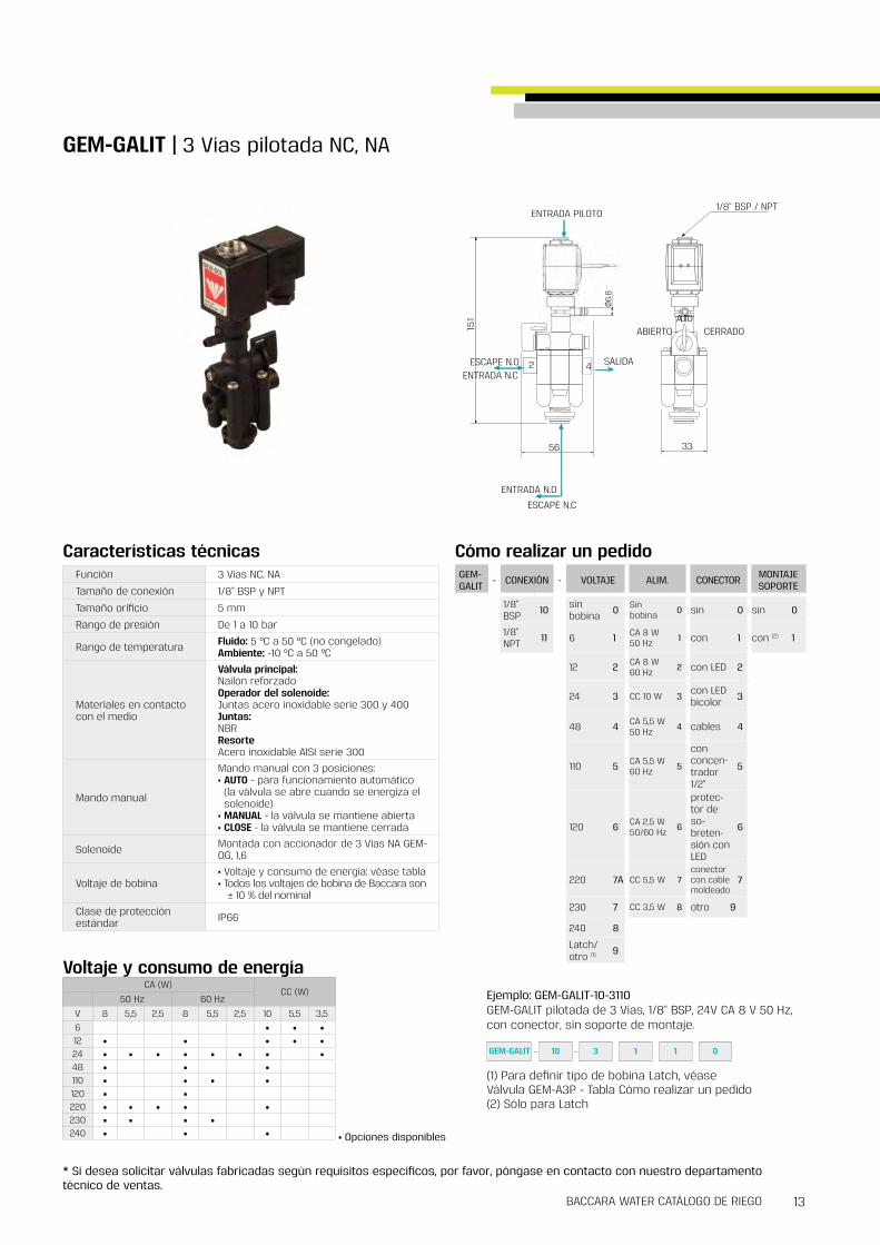
How to Order
SOLENOID MANIFOLDSG75-M | Manifold
GALIT G75-A
G75-M - TYPE #STATIONS
Please refer to the "How to Order" definitions of GALIT or G75-A valve
G75-A 1 2 2
GALIT 3 3 3
4 4
5 5
6 6
7 7
8 8
9 9
10 10
Example : G75-M-15-G75-A-110320-1G75 manifold installation, G75-A type, 5 stations, with G75 solenoid valves with flange, 1/8"BSP, 3W NC 1/2" orifice, no manual override, 24V AC coil
G75-M 1 5 G75-A 1 10 3 2 0 1

29BACCARA WATER IRRIGATION CATALOG
* To order manifolds manufactured according to your specific requirements, please contact our technical sales department
GEM-M - TYPE #STATIONS
Please refer to the "How to Order" definitions of GEM-A valve
GEM-SOL 2 2 23 34 45 56 67 78 89 910 10
Dimensions#Stations 3 4 5 6 7 8 9 10 11 12
A 261 348 435 522 609 696 783 870 957 1044
B 130 5 174 217 7 261 304 5 348 391 5 435 478 5 522
How to Order
Example : GEM-M-25-GEM-A-21035N0GEM-SOL manifold installation, 5 stations with GEM-A direct operated, brass 1/8"BSP, 3W NC, 2 4 orifice, NBR, no manual override
GEM-M 5 GEM-A 2 10 3 5 N 02
A
Nx87
9 (x4)
58
13.5 (x2) )4x( 9
B
43.5
20.3
40
68.3
321
GEM-M | Manifold
SOLENOID MANIFOLDS

®30 31
GEM-CPR | Precise Isolated Proportional 2W NC 32
GEM-C | Chem-Sol 1/4" 2W NC, NO 34
GEM-C | Chem-Sol 1/2" 2W NC 36
ISOLATED FERTILIZER SOLENOIDS

®33BACCARA WATER IRRIGATION CATALOG32
GEM-CPR | Precise Isolated Proportional 2 Way NC
Dimensions
* To order valves manufactured according to your specific requirements, please contact our technical sales department
GEM-CPR | Precise Isolated Proportional 2 Way NC
ISOLATED/FERTILIZER SOLENOIDS
92.6
TYPX
214
85.5
1/2" BSP 15or
1/2" NPT GuageTYPX2
62
32
22
22
32
M4 10TYPX2
(Optional inserts)
60
52
6.8
13.6
How to Order
Example : GEM-CPR-4011E1-11Precise Isolated proportional valve, 1/2" BSP, 2W NC, Vacuum, EPDM seals, plastic manual override with 0-5V control signal, 12-24VDC
GEM-CPR - PORT FUNCTION PRESSURE SEALS MANUAL OVERRIDE - CONTROL
SIGNAL VOLTAGE
1/2" BSP 40 2W NC 1 Vacuum 1 FKM V Plastic 1 0-5 V 1 12-24 VDC 1
1/2" NPT 41 Pressure(1) 2 EPDM E 4-20 mA 2 12-24 VAC 2
1 1GEM-CPR 40 1 1 E 1
*Please specify the working pressure range when placing an order(1) Maximum inlet pressure : 1 bar
Technical Data
Flow direction
Typical performance graphFunction 2 Way NC (with back-up battery)
Ports size 1/2" BSP & NPTOrifice size 8mm (Up to 600 l/hour)
Pressure range
• Vacuum applications : (-1) - 0 Bar• Pressure applications : 0 - (+1) Bar*For other pressures, please consult our technical sales department
Temperature range Fluid : -10º to 45ºC (no freezing)Ambient : -10ºC to 45ºC
Materials
In contact with media :Valve body : • Standard : PVC (UV Protection)• Optional : According to customer demand or application (e g Stainless steel) Diaphragm & seals : FKM, EPDM
Not in contact with media :Operator housing : PP (UV protection)Manual override : Acetal (Manual override is standard)
Media
• Liquids & Gases*Please consult our technical sales department for a specific media• Application examples : • Irrigation fertilizing systems • Medical devices
Control signal 0-5V or 4-20mAValve stroke resolution < 0 01mmValve stroke accuracy < ± 0 01 mmFull stroke duration 0 6 sec, each direction
Current consumption• Standby Mode (Holding position): 25 [mA]• Active Control Mode: Up to 120 [mA]• Full Open/Close Mode (starting current): Up to 600 [mA]
Supply voltage
12-24 [V] ±5% AC (50 or 60Hz) Or 12-24[V] ±10% DC*For other supply voltages, please consult our technical sales department*Current and voltage spikes protections might be required Please consult our technical sales department
Connection
5 wires cable (3m length) :• Black & red : Supply voltage (polarity is not restricted) • Green : 0-5 V analog control signal• Blue : 4-20 mA analog control signal• Yellow : Analog control signal common
Recommended control signal resolution Voltage : 20 mV | Current : 0 064 mA
Standard / Certification
CE • EMC : EN55011 Group 1 - Class A | EN61000-6-1 CFR 47 FCC Class A• SAFETY : IEC/EN61010-1
Standard protection class IP67
0
100
200
300
400
500
600
700
460
480
500
540
580
620
660
700
740
780
820
860
900
940
980
1020
1060
1100
1160
1220
1280
1340
1400
1460
1520
1580
1640
1700
1760
1820
1880
1940
2000
2100
2200
2300
2400
2500
2600
2700
2800
2900
3000
3100
3200
3300
3400
3500
3600
3700
3800
3900
4000
4100
4200
4300
4400
4500
4600
4700
4800
4900
5000
Q Up
Q Down
Input Signal Vs Flow
Flow
[LPH
]
Input Signal [mV]
Media : Waterp : 0 9 [bar]Temp : 200C

®35BACCARA WATER IRRIGATION CATALOG34
GEM-C | Chem-Sol 1/4”, 2 Way NC, NO
Dimensions
* To order valves manufactured according to your specific requirements, please contact our technical sales department
GEM-C | Chem-Sol 1/4”, 2 Way NC, NO
ISOLATED/FERTILIZER SOLENOIDS
GEM-C - BODY PORT FUNCTION PRESSURE SEALS MANUAL OVERRIDE(1) - VOLTAGE POWER CONNECTOR
Plastic 1 1/4" BSP 20 2W NC 1 Vacuum 1 FKM V None 0 W/out coil 0 No coil 0 without 0
1/4" NPT 21 2W NO 2 Pressure 2 EPDM E Plastic 1 6 1 AC8W 50Hz 1 with 1
Silicone S 12 2 AC8W 60Hz 2 with LED 2
24 3 DC10W 3 with bi- color LED 3
48 4 AC5 5W 50Hz 4 flying leads coil 4
110 5 AC5 5W 60Hz 5 with 1/2" Hub 5
120 6 DC5 5W 7 surge protection with LED 6
220 7A connector with moulded cable 7
230 7 other 9
240 8
Latch/other (2) 9
(1) NO - manual override is not available(2) For specifying Latch type coil, please refer to GEM-A3P valve - How to Order table
* Note: When ordering without coil, please define what current and pressure rating is needed (DC, AC or ADC), otherwise an ADC valve will be supplied
Type Valve Description H
NC GEM-C-12 1 81
NO GEM-C-12 2 84 5
Notes
22
For tapping screwNo. 4 x 1/2”
19
30
40
66
01
1/4
BS
P /
NP
T
H22
3GEM-C 1 20 1 2 V 1 2 1
How to Order
Example : GEM-C-12012V1-321GEM-SOL Chem-Sol, PPA, 1/4"BSP, 2W NC, Pressure, FKM, plastic manual override, 24V AC 8W 60 Hz with connector
Flow directionPressure
Flow directionVacuum
NCNO
Coil Flow direction not restricted
Flow direction restricted
ADC * 0 to 2 5 bar 0 to 0 6 bar
AC 8W 0 to 2 5 bar 0 to 0 7 bar
AC 5 5W 0 to 2 bar 0 to 0 5 bar
DC 5 5W 0 to 1 5 bar 0 to 0 4 bar
Coil Flow direction not restricted minimum p
ADC * -1 to 0 bar
1 barAC 5 5W -1 to 0 bar
DC 5 5W -1 to 0 bar
Coil & power rating Flow direction not restricted
Flow direction restricted (1)
ADC*, AC 8W or DC10W 0 to 1 bar 0 to 0 5 bar
5 5W AC/DC 0 to 1 bar 0 to 0 5 bar
(1) Higher input pressure of up to 1atm can be achieved with minimal pressure drop on the valve of 0 3atm
Function 2 Way NC, NO
Ports size 1/4" BSP & NPT
Orifice size 4 5mm
Pressure range See table
Kv (l/min) 5 l/min
Temperature range Fluid : 5º to 50ºC (no freezing)Ambient : -10ºC to 50ºC
Materials in contact with media
Manual override: NC : PlasticNO : Manual override is not availableMain Valve:Reinforced PPASeals:FKM, EPDM, Silicone
Applications• Chemical process• Water treatment• Analysis device etc
Coil voltage• Voltage and power consumption - see table• All Baccara coil voltages are ± 10% of nominal
Standard protection class IP65 with connector* Option : IP68 (please refer to GEM-BP coil)
* ADC valves are only suitable for use with AC8W or DC10W coils
Pressure (bar) table NC Technical Data
Voltage & Power Consumption
Vacuum (bar) table NC
Pressure (bar) table NO
AC (W)DC (W)
50 Hz 60 Hz
V 8 5 5 2 5 8 5 5 2 5 10 5 5 3 56 • •12 • • • •24 • • • • •48 • • •110 • • • •120 • •220 • • • •230 • • • •240 • • •
• Available options

®37BACCARA WATER IRRIGATION CATALOG36
GEM-C | Chem-Sol 1/2”, 2 Way NC
Dimensions
* To order valves manufactured according to your specific requirements, please contact our technical sales department
GEM-C - PORT FUNCTION PRESSURE SEALS MANUAL OVERRIDE - VOLTAGE POWER CONNECTOR
1/2" BSP 40 2W NC 1 Vacuum 1 FKM V None Null W/out coil 0 No coil 0 without 0
1/2" NPT 41 Pressure 2 EPDM E Plastic (1) 1 6 1 AC8W 50Hz 1 with 1
12 2 AC8W 60Hz 2 with LED 2
24 3 DC10W 3 with bi- color LED 3
48 4 AC5 5W 50Hz 4 flying leads coil 4
110 5 AC5 5W 60Hz 5 with 1/2" Hub 5
120 6 surge protec-tion with LED 6
220 7A connector with moulded cable 7
230 7 other 9
240 8
Latch/other (2) 9
22
1/2" BSP / NPT Deep 15both sides
32 62
22
87
standard : without threadoptional : M4x0 7 Deep 10 inserts TYPx2
1GEM-C 40 1 1 V 1 3 2
How to Order
Example : GEM-C-4011V1-321GEM-SOL Chem-Sol, 1/2"BSP, 2W NC for vacuum, FKM, plastic manual override, 24V AC 8W 60Hz with connector
(1) Available for Vacuum application only(2) For specifying Latch type coil, please refer to GEM-A3P valve - How to Order table
32
14
TYPx
2
98
.05
1/2" BSP / NPT TYPx2
62
22
22
standard : without threadoptional : M4x0 7 Deep 10 inserts TYPx2
With Manual Override
* When ordering without coil, please define what current and pressure rating is needed (DC, AC)
GEM-C | Chem-Sol 1/2” 2 Way NC
ISOLATED/FERTILIZER SOLENOIDS
Coil Flow direction not restricted
Flow direction restricted
AC 8W, DC10W 0 to 0 7 bar Min dp 0 3 bar
Coil Flow direction not restricted
Flow direction restricted
AC 8W -1 to 0 5 bar -1 to 0 5 bar
AC 5 5W -0 5 to 0 5 bar -0 8 to 0 5 bar
DC 10W -0 4 to 0 5 bar -0 6 to 0 5 bar
Function 2 Way NC
Ports size 1/2" BSP & NPT
Orifice size 8mm
Pressure range See table
Kv (l/min) 18 l/min
Temperature range Fluid : 5ºC to 50ºC (no freezing) Ambient : -10ºC to 50ºC
Materials in contact with media
Manual override: Plastic* Available for vacuum application onlyMain Valve:PVCSeals:FKM, EPDM
Applications• Chemical process• Water treatment• Analysis device etc
Coil voltage• Voltage and power consumption - see table• All Baccara coil voltages are from -5% to ±10% of nominal
Standard protection classIP65 with connector* Option : IP68 (please refer to GEM-BP coil)
Pressure (bar) table NCTechnical Data
Voltage & Power Consumption
Vacuum (bar) table NC
AC (W)DC (W)
50 Hz 60 Hz
V 8 5 5 2 5 8 5 5 2 5 10 5 5 3 56 • •12 • • • • • •24 • • • • • • • •48 • • • • • •110 • • • • • • •120 • • • •220 • • • • • • • •230 • • • • • • •240 • • • • • •
Available options :
• Vacuum• Pressure
• Supplied with mounting threads on request, please specify
Flow direction
vacuum

39
GEM & G75GEM-S | 1/4" - 1" 2W NC, NO 40
GEM-S | 1/4" - 1/2" 3W NC, NO 44
GEM-S | 3/8" - 2" 2W NC, NO 46
GEM-S-4 | Upstream pilot control with Gem-Sol operator 3/4”, 1” 2W NC, NO 50
G75-S | 3/8" - 2" 2W NC 52
GEM-Z | Zero Differential 1/4" - 3/4" 2W NC, NO 56
G75-Z | Zero Differential 3/4" - 2" 2W NC, NO 58
G75-S | 3W Integral solenoid 3/4" - 2" NC 60
G75-SE | 3W External solenoid 3/4" - 2" NC, NO 61
G75-SM | 3W Manual selector 3/4" - 2" NC, NO 62
G75-PR | Pressure reducing 3/4" - 2" 2W NC 63
G75-S | Hydraulic 3/4" - 2" 2W 64
ELECTRIC & HYDRAULIC VALVES

®41BACCARA WATER IRRIGATION CATALOG40
Size Orifice(mm)
Pressure (bar) Kv(l/min)AC, DC ADC
1/2" 160 5 to 20 0 5 to 15
60
3/4" 16 80
Pressure (bar) & Flow table NO/NCGEM-S--20....41
PortConnection
Orifice(mm)
Pressure range (bar)AC, DC & ADC
Kv(l/min)
3/4" 20 0 3 to 15 130
1" 25 0 5 to 15 200
Size Orifice(mm)
Pressure (bar) Kv(l/min)AC, DC ADC
1/4" 8
0 5 to 20 0 5 to 15
12
3/8" 8 16
1/2" 12 35
Pressure (bar) & Flow table NO/NCGEM-S--50....60
Pressure (bar) & Flow table NO/NCGEM-S--r
NO without tube
NC NO
Flow direction Flow direction
(NOa)
GEM-S | 1/4” - 1” 2 Way NC, NO
Function 2 Way NC, NO
Ports size 1/4", 3/8", 1/2", 3/4", 1" BSP & NPT
Pressure rangeSee table* Minimum pressure differential of 0 3 or 0 5 is required
Kv (l/min) See table
Temperature range Fluid : -10ºC to 80ºC (no freezing)Ambient : -10ºC to 50ºC
Materials in contact with media
Manual override: NC/NO - Brass screwNOa* - manual override is not available*pressure is supplied through the baseMain Valve:Brass, Stainless Steel AISI 316Solenoid Operator:Stainless Steel AISI 300 & 400 seriesSeals:NBR, FKM, EPDM
Coil voltage• Voltage and power consumption - see table• All Baccara coil voltages are ± 10% of nominal
Standard / Certification
• UL 429* Available on selected models only Please contact our technical sales department for details
Standard protection classIP65 with connector* Option : IP68 (please refer to GEM-BP Coil)
Technical Data Voltage & Power ConsumptionAC (W)
DC (W)50 Hz 60 Hz
V 8 5 5 2 5 8 5 5 2 5 10 5 5 3 56 •12 • • •24 • • •48 • • •110 • • •120 • •220 • • •230 • • •240 • • •
• Slow closing system to prevent water hammer effect
• Available options
Brass | 1/2" | NOBrass | 1/4" | NC Stainless Steel | 1" | NCStainless Steel | 3/4" | NC
* Available on selected models only
GEM-S | 1/4” - 1” 2 Way NC, NO
ELECTRIC/HYDRAULIC VALVES | GEM & G75

®43BACCARA WATER IRRIGATION CATALOG42
GEM-S - BODY PORT FUNCTION SEALS MANUAL OVERRIDE - VOLTAGE POWER CONNECTOR
Brass 2 1/4" BSP 20 2W NC 1 NBR N None 0 W/out coil 0 No coil 0 without 0
Stainless Steel 3 1/4" NPT 21 2W NO (1) 2 FKM V Slot 2 6 1 AC8W
50Hz 1 with 1
3/8" BSP 30 2W NO (2)
w/out tube 2a EPDM E Knob 3 12 2 AC8W 60Hz 2 with LED 2
3/8" NPT 31 24 3 DC10W 3 with bi- color LED 3
1/2" BSP 40 48 4 flying leads coil 4
1/2" NPT 41 110 5 with 1/2" Hub 5
3/4" BSP 50 120 6 surge protec-tion with LED 6
3/4" NPT 51 220 7A connector with moulded cable 7
1" BSP 60 230 7 other 9
1" NPT 61 240 8
Latch/other (3) 9
GEM-S | 1/4” - 1” 2 Way NC, NO
GEM-S - BODY PORT FUNCTION SEALS MANUAL OVERRIDE - VOLTAGE POWER CONNECTOR
Brass 2 1/2" BSP 40r 2W NC 1 NBR N None 0 W/out coil 0 No coil 0 without 0
1/2" NPT 41r 2W NO 2 FKM V Slot 2 6 1 AC8W 50Hz 1 with 1
3/4" BSP 50r 2W NO (1)
w/out tube 2a EPDM E Knob 3 12 2 AC8W 60Hz 2 with LED 2
3/4" NPT 51r 24 3 DC10W 3 with bi- color LED 3
48 4 flying leads coil 4
110 5 with 1/2" Hub 5
120 6 surge protec-tion with LED 6
220 7Aconnectorwith moulded cable
7
230 7 other 9
240 8
Latch/other (2) 9
(1) Without manual override (2) For specifying Latch type coil, please refer to GEM-A3P valve - How to Order table
* Note: When ordering without coil, please define what current and pressure rating is needed (DC, AC or ADC), otherwise an ADC valve will be supplied
Example : GEM-S-2202V2-321GEM-SOL pilot operated, brass, 1/4"BSP, 2W NO, FKM seals, slot manual override, 24V AC8W 60Hz with connector
(1) Option available in 1/4" - 1/2"(2) Without manual override(3) For specifying Latch type coil, please refer to GEM-A3P valve - How to Order table* Note: When ordering without coil, please define what current and pressure rating is needed (DC, AC or ADC), otherwise an ADC valve will be supplied
2 2GEM-S 2 40r 1 V 3 1
Example : GEM-S-240r1V2-321 (16mm orifice size)GEM-SOL pilot operated, brass, 1/2"BSP, 2W NC, FKM seals, slot manual override, 24V AC8W 60Hz with connector
How to Order
2GEM-S 2 20 2 V 2 3 1
How to Order
* To order valves manufactured according to your specific requirements, please contact our technical sales department
GEM-S | 1/4” - 1” 2 Way NC, NO
ELECTRIC/HYDRAULIC VALVES | GEM & G75
Size A B C D E H L I J
3/4" BSP/NPT 90 106 32 55 32 17 15 25 103
1" BSP/NPT 100 112 5 38 5 65 34 21 16 29 5 109 50
NC / NOa NO
GEM - r 16mm orificeNC / NOa
B
M5 DEEP 8TYPx2
22
2210
8.1
70
ManualOverride
67.64435
81
1/2” or 3/4” BSP/NPT
NC / NOa NO
GEM - r 16mm orificeNC / NOa
B
M5 DEEP 8TYPx2
22
2210
8.1
70
ManualOverride
67.64435
81
1/2” or 3/4” BSP/NPT
Size A B C D E F G H J K Weightwith coil
1/4"-3/8" 58 89 22 32 62 1/4"-3/8"BSP/NPT 125 11 M5x0 8 22 466gr
1/2" 70 95 27 38 70 1/2" BSP/NPT 135 13 5 M5x0 8 22 562gr
Dimensions

®45BACCARA WATER IRRIGATION CATALOG44
J
(1) For NO only(2) For NC only(3) For specifying Latch type coil, please refer to GEM-A3P valve - How to Order table
* Note: When ordering without coil, please define what current and pressure rating is needed (DC, AC or ADC), otherwise an ADC valve will be supplied
GEM-S - BODY PORT FUNCTION SEALS MANUAL OVERRIDE BRACKET - VOLTAGE POWER CONNECTOR
Brass 2 1/4" BSP 20 3W NC 3 NBR N None 0 without 0 W/out coil 0 No coil 0 without 0
1/4" NPT 21 3W NO 4 FKM V Slot (1) 2 with 1 6 1 AC8W 50Hz 1 with 1
3/8" BSP 30 EPDM E Push lock (2) 5 12 2 AC8W 60Hz 2 with LED 2
3/8" NPT 31 24 3 DC10W 3 with bi- color LED 3
1/2" BSP 40 48 4 flying leads coil 4
1/2" NPT 41 110 5 with 1/2" Hub 5
120 6 surge protec-tion with LED 6
220 7Aconnector with moulded cable
7
230 7 other 9
240 8
Latch/other (3) 9
Optional Mounting Bracket
Size A B C D E F G Weightwith coil
1/4" 124 5 58 25 32 5 1/4" M4x0 7Deep 6 32 540gr
3/8" 1/2" 134 69 30 32 5 1/2" M5x0 8
Deep 7 38 758gr
Size H I J K L M N O P Q
1/4" 15 25 Ø4 5 11 5 14 4 20 25 32
3/8" 1/2" 20 30 Ø6 13 6 22 4 25 33 40
3GEM-S 2 20 4 V 2 1 1 1
How to Order
Example : GEM-S-2204V21-311GEM-SOL pilot operated, brass, 1/4"BSP, NO, FKM, slot manual override with bracket, 24V AC 8W 50Hz with connector
Optional Mounting Bracket
GEM-S | 1/4” - 1/2” 3 Way NC, NO
Dimensions
* To order valves manufactured according to your specific requirements, please contact our technical sales department
NO NC
EX EX
In InOut Out
Size Orifice(mm)
Pressure(bar) Kv(l/min)
1/4" 80 8 to 12
18
3/8", 1/2" 12 50
Function 3 Way NC, NO
Ports size 1/4", 3/8", 1/2" BSP & NPT
Pressure range See table
Kv (l/min) See table
Temperature range Fluid : -10ºC to 80ºC (no freezing)Ambient : -10ºC to 50ºC
Materials in contact with media
Manual override:NC : Push in lock hydraulic bypassNO : Brass screw or finger knobMain Valve:Brass Solenoid Operator:Stainless Steel AISI 300 & 400 seriesSeals:NBR, FKM, EPDM
Media Air, water, light oil
Coil voltage• Voltage and power consumption - see table• All Baccara coil voltages are ± 10% of nominal
Standard protection classIP65 with connector* Option : IP68 (please refer to GEM-BP Coil)
Pressure (bar) & Flow tableTechnical Data
Voltage & Power ConsumptionAC (W)
DC (W)50 Hz 60 Hz
V 8 5 5 2 5 8 5 5 2 5 10 5 5 3 56 •12 • • •24 • • •48 • • •110 • • •120 • •220 • • •230 • •240 • • •
• Available options
GEM-S | 1/4” - 1/2” 3 Way NC, NO
ELECTRIC/HYDRAULIC VALVES | GEM & G75

®47BACCARA WATER IRRIGATION CATALOG46
GEM-S - BODY PORT FUNCTION SEALS MANUAL OVERRIDE - VOLTAGE POWER CONNECTOR
Plastic 4 3/8" BSP 30 2W NC 1 NBR N None 0 W/out coil 0 No coil 0 without 0
3/8" NPT 31 2WNO 2a FKM V 6 1 AC8W 50Hz 1 with 1
1/2" BSP 40 EPDM E 12 2 AC8W 60Hz
2 with LED 2
1/2" NPT 41 24 3 DC10W 3
with bi-colorLED 3
48 4 flying leadscoil 4
110 5 with 1/2" Hub 5
120 6 surge protec-tion with LED 6
220 7Aconnector with moulded 7 cable
230 7 other 9
240 8
Latch/other (1) 9
How to Order
Example : GEM-S-4401N0-321GEM-SOL pilot operated, 1/2" BSP, 2W NC, NBR, no manual override, 24V AC 8W 60Hz with connector
GEM-S 4 40 1 N 0 3 2 1
A
E
B
C
D
F
F
Function A B C D E F
NC 70 90 42 5 13 3/8" & 1/2" 34
NO 70 93 4 42 5 13 3/8" & 1/2" 34
(1) For specifying Latch type coil, please refer to GEM-A3P valve - How to Order table
* When ordering without coil, please define what current and pressure rating is needed (DC, AC)
GEM-S | Pilot operated 3/8”, 1/2” 2 Way NC, NO
Dimensions
* To order valves manufactured according to your specific requirements, please contact our technical sales department
Technical DataFunction 2 Way NC, NO
Ports size 3/8", 1/2" BSP & NPT
Orifice size 12mm
Pressure range 0 5 to 12 bar
Kv (l/min) 35 l/min
Temperature rangeFluid : 5ºC to 50ºC (no freezing) Ambient : -10ºC to 50ºC
Materials in contact with media
Main Valve:Reinforced NylonSolenoid Operator:Stainless Steel AISI 300 & 400 seriesSeals:NBR, FKM, EPDM
Solenoid GEM-SOL 2W NC solenoids, all voltages
Coil voltage• Voltage and power consumption - see table• All Baccara coil voltages are ± 10% of nominal
Standard protection classIP65 with connector* Option : IP68 (please refer to GEM-BP Coil)
Voltage & Power Consumption
• Available options
AC (W)DC (W)
50 Hz 60 Hz
V 8 5 5 2 5 8 5 5 2 5 10 5 5 3 56 •12 • • •24 • • •48 • • •110 • • •120 • •220 • • •230 • •240 • • •
NC NO
Flow direction
GEM-S | Pilot operated 3/8”, 1/2” 2 Way NC, NO
ELECTRIC/HYDRAULIC VALVES | GEM & G75

®49BACCARA WATER IRRIGATION CATALOG48
GEM-S - BODY PORT FUNCTION SEALS MANUAL OVERRIDE
FLOW CONTROL - VOLTAGE POWER CONNECTOR
Plastic 4 3/4" BSPT 50 2W NC 1 NR N None 0 with 1 W/out coil 0 No coil 0 without 0
3/4" NPT 51 2WNO 2a Plastic 1 without (1) 2 6 1 AC8W 50Hz 1 with 1
1" BSPT 60 12 2 AC8W 60Hz 2 with LED 2
1" NPT 61 24 3 DC10W 3 with bi- color LED 3
1-1/2"BSPT 70 48 4 AC5 5W 50Hz 4 flying
leads coil 4
1-1/2"NPT 71 110 5 AC5 5W 60Hz 5 with 1/2"
Hub 5
2" BSPT 80 120 6surge protectionwith LED
6
2" NPT 81 220 7Aconnector with moulded cable
7
230 7 other 9
240 8
Latch/other (2) 9
(1) 3/4", 1" valves only(2) For specifying Latch type coil, please refer to GEM-A3P valve - How to Order table
Size A B C
3/4" 108 110 81
1" 135 5 110 81
1-1/2" 180 160 126
2" 190 170 126
with flow control
without flow control
Size A B C
3/4" 128 5 110 81
1" 135 5 110 81
1-1/2" 168 160 126
2" 179 5 170 126
How to Order
Example : GEM-S-4501N11-331GEM-SOL pilot operated, nylon body, 3/4" BSPT, 2W NC, NR, plastic manual override, with flow control, 24V DC 10W with connector
3GEM-S 4 50 1 1 1 3 1N
* When ordering without coil, please define what current and pressure rating is needed (DC, AC)
GEM-S | Pilot operated 3/4” - 2” 2 Way NC, NO
Dimensions
* To order valves manufactured according to your specific requirements, please contact our technical sales department
Function 2 Way NC, NO
Ports size 3/4", 1", 1-1/2", 2" BSPT & NPT
Connection Female BSPT or NPT thread
Pressure range 0 3 to 10 bar
Temperature range Fluid : 5ºC to 50ºC (no freezing) Ambient : -10ºC to 50ºC
SolenoidGEM-SOL 3/4" UNEF, 2 Way NC or NO solenoids All voltages
Materials in contact with media
Manual override:Reinforced NylonBody & cover:Reinforced NylonSpring:Stainless Steel AISI 302Diaphragm:NRSeals:NBRScrews:Stainless Steel AISI 304Solenoid:Stainless Steel AISI 300 & 400 series
Coil voltage• Voltage and power consumption - see table• All Baccara coil voltages are ± 10% of nominal
Standard protection class IP65 with connector* Option : IP68 (please refer to GEM-BP Coil)
Technical Data
• Progressive opening and shut off that prevents water hammer
AC (W)DC (W)
50 Hz 60 Hz
V 8 5 5 2 5 8 5 5 2 5 10 5 5 3 56 •12 • • •24 • • • • •48 • • •110 • • • •120 • •220 • • • •230 • • • •240 • • •
• Available options
Head loss for fully open valve
Q (m3/h)
∆H (kg/cm2)
RECOMMENDED WORKING ZONE
"4/3
"1
∆H (kg/cm2)
RECOMMENDEDWORKING ZONE
"2/1-1 "2
Q (m3/h)
Head loss for fully open valve
Size Orifice(mm)
Kv(l/min)
3/4" 27 140
1" 27 200
1-1/2" 55 520
2" 55 600
Flow & Orifice table
Voltage & Power Consumption
Flow direction
GEM-S | Pilot operated 3/4” - 2” 2 Way NC, NO
ELECTRIC/HYDRAULIC VALVES | GEM & G75

®51BACCARA WATER IRRIGATION CATALOG50
(1) 3/4", 1" valves only(2) For specifying Latch type coil, please refer to GEM-A3P valve - How to Order table
GEM-S - BODY PORT FUNCTION SEALS MANUAL OVERRIDE
FLOW CONTROL - VOLTAGE POWER CONNECTOR
Plastic 4 3/4" BSPT 50 2W NC 1 NBR N None 0 with 1 W/out coil 0 No coil 0 without 0
3/4" NPT 51 2WNO 2a EPDM E Plastic 1 without 2 6 1 AC8W 50Hz 1 with 1
1" BSPT 60 12 2 AC8W 60Hz 2 with LED 2
1" NPT 61 24 3 DC10W 3 with bi- color LED 3
48 4 AC5 5W 50Hz 4 flying
leads coil 4
110 5 AC5 5W 60Hz 5 with 1/2"
Hub 5
120 6surge protectionwith LED
6
220 7Aconnector with moulded cable
7
230 7 other 9
240 8
Latch/other (1) 9
How to Order
Example : GEM-S-4501E11-331GEM-SOL pilot operated upstream, nylon body, 3/4" BSPT, 2W NC, EPDM, plastic manual override, with flow control, 24V DC 10W with connector
3GEM-S 4 50 1 1 1 3 1E
* When ordering without coil, please define what current and pressure rating is needed (DC, AC)
GEM-S-4 | Upstream pilot control integrated with Gem-Sol operator 3/4”, 1” 2 Way NC, NO
Dimensions
* To order valves manufactured according to your specific requirements, please contact our technical sales department
Function 2 Way NC, NO
Ports size 3/4”, 1”, 1-1/2”, 2” BSPT & NPT
Connection Female BSPT or NPT thread
Pressure range 0 3 to 10 bar
Temperature range Fluid : 5ºC to 50ºC (no freezing) Ambient : -10ºC to 50ºC
SolenoidGEM-SOL 3/4" UNEF, 2 Way NC or NO solenoids All voltages
Materials in contact with media
Manual override:Reinforced NylonBody & cover:Reinforced NylonSpring:Stainless Steel AISI 302Diaphragm:NR, EPDM (check which material)Seals:NBR, EPDMScrews:Stainless Steel AISI 304Solenoid:Stainless Steel AISI 300 & 400 series
Coil voltage• Voltage and power consumption - see table• All Baccara coil voltages are ± 10% of nominal
Standard protection class IP65 with connector* Option : IP68 (please refer to GEM-BP Coil)
Technical Data
• Progressive opening and shut off that prevents water hammer
AC (W)DC (W)
50 Hz 60 Hz
V 8 5 5 2 5 8 5 5 2 5 10 5 5 3 56 •12 • • •24 • • • • •48 • • •110 • • • •120 • •220 • • • •230 • • • •240 • • •
• Available options
Head loss for fully open valve
Q (m3/h)
∆H (kg/cm2)
RECOMMENDED WORKING ZONE
"4/3
"1
∆H (kg/cm2)
RECOMMENDEDWORKING ZONE
"2/1-1 "2
Q (m3/h)
Head loss for fully open valve
Flow & Orifice table
Voltage & Power Consumption
Flow direction
GEM-S-4 | Upstream pilot control integrated with Gem-Sol operator 3/4” - 2” 2 Way NC, NO
ELECTRIC/HYDRAULIC VALVES | GEM & G75
133
108.5 92.4
80.4
Flow direction
Size Orifice(mm)
Kv(l/min)
3/4" 27 140
1" 27 200
1-1/2" 55 520
2" 55 600

®53BACCARA WATER IRRIGATION CATALOG52
How to Order
G75-S - BODY PORT FUNCTION SEALS MANUAL OVERRIDE - VOLTAGE (1) WIRES
Plastic 4 3/8" BSP 30 2W NC 1 NBR N None 0 24V AC 1 two null
3/8" NPT 31 FKM V 12V AC 3 three (2) a
1/2" BSP 40 EPDM E 12V DC 4
1/2" NPT 41 24V DC 5
23Ω 6
110V AC 7
4Ω B
9Ω C
12Ω D
Example : G75-S-4401N0-1G75 pilot operated, 1/2" BSP, 2W NC, NBR, no manual override, 24V AC, two wires
(1) For Latch : Refer to coil resistance vs input voltage table(2) For Latch only
G75-S 4 40 1 N 0 1
G75-S | Pilot operated 3/8”, 1/2” 2 Way NC
Dimensions
* To order valves manufactured according to your specific requirements, please contact our technical sales department
Technical DataFunction 2 Way NC
Ports size 3/8", 1/2" BSP & NPT
Orifice size 12mm
Pressure range 0 5 to 12 bar* Minimum pressure differential of 0 5 is required
Kv (l/min) 35 l/min
Temperature rangeFluid : 5ºC to 50ºC (no freezing) Ambient : -10ºC to 50ºC
Materials in contact with media
Main Valve:Reinforced NylonSolenoid Operator:Stainless Steel AISI 300 & 400 seriesSeals:NBR, EPDM, FKMSpring:Stainless Steel AISI 300 series
Solenoid G75 2W NC solenoids, all voltages
Coil voltage• Voltage and power consumption - see table• All Baccara coil voltages are ± 10% of nominal
Standard protection class IP65
Voltage & Power ConsumptionAC (W)
DC (W)50 Hz
V 2 4 512 • •24 • •110 •
2W only
• Available options
Solenoid Voltage Inrush [A] Holding [A]2W 50 Hz
+10%
n-20%
0 3 0 192W 60 Hz 0 2 0 143W 50/60 Hz 0 125 0 125DC 4 5W
V
Voltage & Current table
Flow direction
G75-S | Pilot operated 3/8”, 1/2” 2 Way NC
ELECTRIC/HYDRAULIC VALVES | GEM & G75
Resistance [Ω] Suitable input voltage range [V]
4 6 - 9
9 12 - 14
12 14 - 16
23 18 - 21
Coil resistance vs input voltage range

55BACCARA WATER IRRIGATION CATALOG54
G75-S - PORT FUNCTION MANUAL OVERRIDE
FLOW CONTROL VOLTAGE (3) WIRES
3/4" BSPT 50 2W NC 1 None 0 with 5 24V AC 1 two null
3/4" NPT 51 Plastic 1 without (2) 6 12V AC 3 three (1) a
1" BSPT 60 Handle (1) 2 12V DC 4
1" NPT 61 24V DC 5
1-1/2" BSPT 70 23Ω 6
1-1/2" NPT 71 110V AC 7
2" BSPT 80 4Ω B
2" NPT 81 9Ω C
12Ω D
How to Order
Example : G75-S-501051G75 electric valve, 3/4" BSPT, 2W NC, no manual override, with flow control, 24V AC, two wires
With flow control
Without flow control
3/4" & 1"
1-1/2" & 2" with integrated solenoid
Size A B C D Weight (gr)3/4" 105 110 105 81 230
1" 112 110 112 81 2301-1/2" 180 160 126 127 740
2" 190 170 126 127 790
(1) For Latch only(2) 3/4", 1" valves only(3) For Latch : Refer to coil resistance vs input voltage table
G75-S 50 1 0 5 1
G75-S | Electric 3/4” - 2” 2 Way NC
Dimensions
* To order valves manufactured according to your specific requirements, please contact our technical sales department
Head loss for fully open valveTechnical DataFunction 2 Way NC
Ports size 3/4", 1", 1-1/2", 2" BSPT & NPT
Pressure range 0 3 to 10bar
Temperature range (Fluid : 5ºC to 50ºC (no freezingAmbient : -10ºC to 50ºC
Materials in contact with media
Manual override: Reinforced NylonMain Valve:Reinforced NylonSolenoid Operator:Stainless Steel AISI 300 & 400 seriesDiaphragm:NRSeals:NBRSpring:Stainless Steel AISI 300 series
Solenoid• G75, 2W NC solenoids, all voltages • AC, DC and Latch
Coil voltage• Voltage and power consumption - see table• All Baccara coil voltages are ± 10% of nominal
Q (m3/h)
∆H (kg/cm2)
RECOMMENDED WORKING ZONE
"4/3
"1
∆H (kg/cm2)
RECOMMENDEDWORKING ZONE
"2/1-1 "2
Q (m3/h)
Head loss for fully open valve
Voltage & Power ConsumptionAC (W)
DC (W)50 Hz
V 2 4 512 • •24 • •110 •
2W only
• Available options
G75-S | 2" | NC Latch withhandle manual override
G75-S | 1" | NC with plastic manual override
Solenoid Voltage Inrush [A] Holding [A]2W 50 Hz
+10%
n-20%
0 3 0 192W 60 Hz 0 2 0 143W 50/60 Hz 0 125 0 125DC 4 5W
V
Voltage & Current table
with flow control without flow control
Flow direction
G75-S | Electric 3/4” - 2” 2 Way NC
ELECTRIC/HYDRAULIC VALVES | GEM & G75
Resistance [Ω] Suitable input voltage range [V]
4 6 - 9
9 12 - 14
12 14 - 16
23 18 - 21
Coil resistance vs input voltage range

®57BACCARA WATER IRRIGATION CATALOG56
GEM-Z - BODY PORT FUNCTION SEALS - VOLTAGE POWER CONNECTOR
Brass 2 1/4" BSP 20 2W NC 1 NBR N W/out coil 0 No coil 0 without 0
Stainless Steel (1) 3 1/4" NPT 21 2W NO (4) 2a FKM V 6 1 AC8W
50Hz 1 with 1
Plastic (2) 4 3/8" BSP 30 EPDM E 12 2 AC8W 60Hz 2 with LED 2
3/8" NPT 31 24 3 DC10W 3 with bi- color LED 3
1/2"BSP 40 48 4 flying leads coil 4
1/2"NPT 41 110 5 with 1/2" Hub 5
1/2"BSP 40r 120 6surge protec-tion with LED 6
1/2"NPT 41r 220 7A connector with moulded cable 7
3/4"BSP 50r 230 7 other 9
3/4"NPT (3) 51r 240 8
Latch/other (5) 9
Size A B C D E F Weightwith coil
1/4" 22 22 32 58 89 1/4" BSP/NPT 415gr
3/8" 22 22 38 70 95 3/8" BSP/NPT 530gr
1/2" 22 22 38 70 95 1/2" BSP/NPT 530gr
(1) Not available for GEM-Z-r(2) Only available in 3/8” and 1/2”(3) 16mm orifice(4) NO function without M/O, not available for GEM-Z-r(5) For specifying Latch type coil, please refer to GEM-A3P valve - How to Order table
1GEM-Z 2 40 1 N 2 2
How to Order
Example : GEM-Z-2401N-221GEM-SOL zero differential, brass, 1/2" BSP, 2W NC, NBR, 12V AC8W 60Hz with connector
1/2” or3/4”BSP/NPT
GEM-Z- r16mm orifice - 1/2", 3/4"
GEM-Z-4....Nylon Valve Body
4.5931
42.567.4
70
"8/3 ro "2/1
* When ordering without coil, please define what current and pressure rating is needed (DC, AC)
GEM-Z | Zero differential pressure 1/4” - 3/4” 2 Way NC, NO
Dimensions
* To order valves manufactured according to your specific requirements, please contact our technical sales department
Size Orifice (mm)Pressure (bar)
Kv (l/min)AC DC
1/4" 8 0 to 14 0 to 7 12
3/8" 12 0 to 14 0 to 8 17
1/2" 12 0 to 14 0 to 8 18
Size Orifice (mm)Pressure (bar)
Kv (l/min)AC DC
1/2" 16 0 to 10 0 to 6 60
3/4" 16 0 to 10 0 to 6 80
Size Orifice (mm)
Pressure (bar)Kv (l/min)
AC DC
1/4" 8 0 to 8 0 to 8 12
3/8",1/2" 12 0 to 8 0 to 8 20
Function 2 Way NC, NO
Ports size 1/4", 3/8", 1/2", 3/4" BSP & NPT
Pressure rangeSee table* For plastic body, maximum working pressure is 4 bar
Kv (l/min) See table
Temperature range Fluid : -10ºC to 80ºC (no freezing) Ambient : -10ºC to 50ºC
Materials in contact with media
Main Valve:Brass, Stainless Steel AISI 316, Nylon** Plastic : only available in 3/8” and 1/2”Solenoid Operator:Stainless Steel AISI 300 & 400 seriesSeals:NBR, FKM, EPDM
Media Air, water, oil
Coil voltage• Voltage and power consumption - see table• All Baccara coil voltages are ± 10% of nominal
Standard protection class IP65 with connector* Option : IP68 (please refer to GEM-BP Coil)
• When switching from an AC to a DC coil, the solenoid operator must be changed as well • Can be used in vacuum application from -1 bar to maximum pressure - see tables
Pressure (bar) & Flow table NC (GEM-Z)Technical Data
Voltage & Power Consumption
Pressure (bar) & Flow table NC (GEM-Z-r)
Pressure (bar) & Flow table NO (GEM-Z)
AC (W)DC (W)
50 Hz 60 Hz
V 8 5 5 2 5 8 5 5 2 5 10 5 5 3 56 •12 • • •24 • • •48 • • •110 • • •120 • •220 • • •230 • • •240 • • •
Flow direction
• Available options
Brass | 1/2" | NC Plastic | 1/2" | NC Stainless Steel | 1/2" | NC
GEM-Zr
GEM-Z | Zero differential pressure 1/4” - 3/4” 2 Way NC, NO
ELECTRIC/HYDRAULIC VALVES | GEM & G75

®58
G75-Z - PORT FUNCTION MANUAL OVERRIDE FLOW CONTROL VOLTAGE (3) WIRES
3/4" BSPT 50 2W NC 1 None 0 with 5 without 0 two null
3/4" NPT 51 Plastic 1 without (1) 6 24V AC 1 three (2) a
1" BSPT 60 Handle(2) 2 24V ACw/out Diode 1R
1" NPT 61 12V AC 3
1-1/2" BSPT 70 12V DC 4
1-1/2" NPT 71 24V DC 5
2" BSPT 80 23Ω 6
2" NPT 81 110V AC 7
4Ω B
9Ω C
12Ω D
Technical Data
Pilot pressure
3W NOØ1.2
Valve in closed position
Function 2 Way NC
Ports size 3/4", 1", 1-1/2", 2" BSPT & NPT
Pressure range Line: 0-6 bar | Pilot: 1 5 bar above line pressure
Temperature range Fluid : 5ºC to 50ºC (no freezing)
Materials in contact
with media
Manual override:
Reinforced Nylon
Main Valve:
Reinforced Nylon
Solenoid Operator:
Stainless Steel AISI 300 & 400 series
Diaphragm:
NR
Seals:
Buna-N
Spring:
Stainless Steel AISI 300 series
Solenoid Supplied with G75 1 2mm 3 Way NO solenoid
AC (W)DC(W)
50 Hz
V 2 4 512 • •24 • •
Voltage & Power Consumption
• Available options
How to Order
Example : G75-Z-601151G75 electric valve, 1" BSPT, 2WNC, plastic manual override with flow control, 24V AC, two wires
(1) 3/4", 1" valves only(2) For latch only(3) For Latch : Refer to coil resistance vs input voltage table
G75-Z 60 1 1 5 1
• For overall dimensions, refer to G75-S | Electric 3/4” - 2” 2 Way NC
Solenoid Voltage Inrush [A] Holding [A]2W 50 Hz
+10%
n-20%
0 3 0 192W 60 Hz 0 2 0 143W 50/60 Hz * 0 125 0 125DC 4 5W
V
Voltage & Current table
Flow direction
ELECTRIC/HYDRAULIC VALVES | GEM & G75
* To order valves manufactured according to your specific requirements, please contact our technical sales department
G75-Z | Electric zero differential pressure 3/4” - 2” 2 Way NC
* Except 24V AC without Diode
Resistance [Ω] Suitable input voltage range [V]
4 6 - 9
9 12 - 14
12 14 - 16
23 18 - 21
Coil resistance vs input voltage range

59BACCARA WATER IRRIGATION CATALOG
G75-Z - PORT FUNCTION FLOW CONTROL
3/4" BSPT 50 2W NO 2 with 5
3/4" NPT 51 without (1) 6
1" BSPT 60
1" NPT 61
1-1/2" BSPT 70
1-1/2" NPT 71
2" BSPT 80
2" NPT 81
Technical DataFunction 2 Way NO
Ports size 3/4", 1", 1-1/2", 2" BSPT & NPT
Pressure range Line: 0-6 bar | Pilot: 1 5 bar above line pressure
Temperature range Fluid : 5ºC to 50ºC (no freezing)
Materials in contact with media
Main Valve:Reinforced NylonDiaphragm:NRSeals:Buna-NSpring:Stainless Steel AISI 300 series
How to Order
Example : G75-Z-6025G75 inline hydraulic valve, 1" BSPT, 2W NO with flow control
(1) 3/4", 1" valves only
G75-Z 60 2 5
• For overall dimensions, refer to G75-S | Hydraulic 3/4”- 2” 2 Way
B
A
C
Size A B C
3/4" 77 110 81
1" 84 110 81
1-1/2" 98 160 127
2" 98 170 127
Flow direction
* To order valves manufactured according to your specific requirements, please contact our technical sales department
G75-Z | Hydraulic zero differential pressure 3/4” - 2” 2 Way NO

®60
G75-S - PORT FUNCTION MANUAL OVERRIDE FLOW CONTROL VOLTAGE (3) WIRES
3/4" BSPT 50 External pilot 4 None 0 with 5 24V AC 1 two null
3/4" NPT 51 Upstream pilot 4H Plastic 1 without (1) 6 24V ACw/out Diode 1R three (2) a
1" BSPT 60 Handle (2) 2 12 V AC 3
1" NPT 61 12 V DC 4
1-1/2" BSPT 70 24V DC 5
1-1/2" NPT 71 23Ω 6
2" BSPT 80 4Ω B
2" NPT 81 9Ω C
12Ω D
Technical DataSolenoid Supplied with 3W NO 1 2mm G75 operator
AssemblyUpstream pilot control valve is supplied with finger filter and accessories
Example : G75-S-704151G75 1-1/2" BSPT, external pilot, plastic manual override, with flow control, 24V AC, two wires
How to Order
(1) For 3/4", 1" valves only(2) For Latch only(3) For Latch : Refer to coil resistance vs input voltage table
• For technical information, refer to G75-S | Electric 3/4” - 2” 2 Way NC
External pilot control Upstream pilot control External pilot control
G75-S 70 4 1 5 1
Upstream pilot control
* To order valves manufactured according to your specific requirements, please contact our technical sales department
ELECTRIC/HYDRAULIC VALVES | GEM & G75G75-S | 3 Way Integral solenoid pilot control 3/4” - 2” NC
Resistance [Ω] Suitable input voltage range [V]
4 6 - 9
9 12 - 14
12 14 - 16
23 18 - 21
Coil resistance vs input voltage range

61BACCARA WATER IRRIGATION CATALOG
G75-SE - PORT FUNCTION (3) MANUAL OVERRIDE FLOW CONTROL VOLTAGE (4) WIRES
3/4" BSPT 50 2W NC 1 None 0 with 5 24V AC 1 two null
3/4" NPT 51 2W NO 2 Plastic 1 without (1) 6 24V ACw/out Diode 1R three (2) a
1" BSPT 60 12 V AC 3
1" NPT 61 12 V DC 4
1-1/2" BSPT 70 24V DC 5
1-1/2" NPT 71 23Ω 6
2" BSPT 80 4Ω B
2" NPT 81 9Ω C
12Ω D
G75-SE | 3 Way External solenoid pilot control 3/4” - 2” NC, NO
NC valve NO valve
Example : G75-SE-702151G75 1-1/2" BSPT, 2W NO, plastic manual override, with flow control, 24V AC, two wires
How to Order
(1) For 3/4", 1" valves only(2) For Latch only(3) Refers to the valve : 3W NC solenoid = NO valve 3W NO solenoid = NC valve(4) For Latch : Refer to coil resistance vs input voltage table
G75-SE 70 2 1 5 1
Technical Data
NO valve NC valve
Solenoid Supplied with 3W 1 2mm G75 solenoid
Assembly Supplied with finger filter and accessories
• For technical information, refer to G75-S | Electric 3/4” - 2” 2 Way NC
* To order valves manufactured according to your specific requirements, please contact our technical sales department
Resistance [Ω] Suitable input voltage range [V]
4 6 - 9
9 12 - 14
12 14 - 16
23 18 - 21
Coil resistance vs input voltage range

®62
G75-SM - PORT FUNCTION (1) FLOW CONTROL VOLTAGE (4) WIRES
3/4" BSPT 50 2W NC 1 with 5 No solenoid (hydraulic) 0 two null
3/4" NPT 51 2W NO 2 without (2) 6 24V AC 1 three (3) a
1" BSPT 60 24V ACw/out Diode 1R
1" NPT 61 12V AC 3
1-1/2" BSPT 70 12V DC 4
1-1/2" NPT 71 24V DC 5
2" BSPT 80 23Ω 6
2" NPT 81 4Ω B
9Ω C
12Ω D
Solenoid Supplied with 3W 1 2mm G75 solenoid
Assembly Supplied with finger filter and accessories
Manual override
Manual override with 3 positions :• AUTO - for automatic operation (valve is open when solenoid is energized)• MANUAL - valve is kept open• CLOSE - valve is kept closed
Pressure A minimum pressure differential of 1 bar is required
Technical Data
How to Order
G75-SM 70 1 5 1
Example : G75-SM-70151G75 3 Way manual selector valve, 1-1/2" BSPT, 2W NC with flow control, 24V AC, two wires
• For technical information, refer to G75-S | Electric 3/4” - 2” 2 Way NC
3W Manual selector | 1" 3W Manual selector | 2" with solenoid
(1) Refers to the valve : 3W NC solenoid = NO valve 3W NO solenoid = NC valve(2) For 3/4", 1" valves only(3) For Latch only(4) For Latch : Refer to coil resistance vs input voltage table
3W Manual selector Manual selector with external3W NO solenoid
Flow direction
* To order valves manufactured according to your specific requirements, please contact our technical sales department
ELECTRIC/HYDRAULIC VALVES | GEM & G75G75-SM | 3 Way Manual selector 3/4” - 2” NC, NO
Resistance [Ω] Suitable input voltage range [V]
4 6 - 9
9 12 - 14
12 14 - 16
23 18 - 21
Coil resistance vs input voltage range

63BACCARA WATER IRRIGATION CATALOG
G75-PR - PORT FUNCTION FLOW CONTROL VOLTAGE (3) WIRES PRESSURE RANGE
3/4" BSPT 50 2W NC 1 with 5 No solenoid (hydraulic) 0 two null 0 5-5 bar Y
3/4" NPT 51 without (1) 6 24V AC 1 three (2) a 1-10 bar G
1" BSPT 60 24V ACw/out Diode 1R
1" NPT 61 12V AC 3
1-1/2" BSPT 70 12V DC 4
1-1/2" NPT 71 24V DC 5
2" BSPT 80 23Ω 6
2" NPT 81 4Ω B
9Ω C
12Ω D
Technical Data
How to Order
Voltage & Power Consumption
Example : G75-PR-70151YG75 pressure reducing valve, 1-1/2" BSPT, 2W NC with flow control, 24V AC, two wires, 0 5-5 bar
Solenoid Supplied with 3W NO 1 2mm G75 operator
Assembly Supplied with finger filter
Manual override
The XR100 has a manual override with 3 positions :• AUTO - for automatic operation (valve is open when solenoid is energized)• MANUAL - valve is kept open• CLOSE - valve is kept closed
Pressure• Pilot pressure must be equal to, or higher than line pressure• A minimum pressure differential of 1 bar is required
AC (W) DC (W)50 HzV 2 4 512 • •24 • • • Available options
• For technical information, refer to G75-S | Electric 3/4” - 2” 2 Way NC
(1) For 3/4", 1" valves only(2) For Latch only(3) For Latch : Refer to coil resistance vs input voltage table
Pressure Reducing | PR Pressure Sustaining | PSQuick Pressure Relief | QR
DESCRIPTION
a Self flushing filter
b Isolation ball valve (optional)
c 3W Manual selector valve
d Multi-functional pilot valve
Main Components
G75-PR 70 1 5 1 Y
2" | Electric pressure reducing |0 5-5 bar
* To order valves manufactured according to your specific requirements, please contact our technical sales department
G75-PR | Pressure reducing 3/4” - 2” 2 Way NC
Resistance [Ω] Suitable input voltage range [V]
4 6 - 9
9 12 - 14
12 14 - 16
23 18 - 21
Coil resistance vs input voltage range

®65BACCARA WATER IRRIGATION CATALOG64
How to Order
Example : G75-S-5015G75 hydraulic valve, 3/4" BSPT, 1/8" upstream inline pilot port, with flow control
G75-S 50 1 5
G75-S - PORTFUNCTION
INLINE PILOT PORTS
FLOW CONTROL
3/4" BSPT 50 none 0 with 5
3/4" NPT 51 upstream only 1 without (1) 6
1" BSPT 60 downstreamonly 2
1" NPT 61 both 3
1-1/2" BSPT 70
1-1/2" NPT 71
2" BSPT 80
2" NPT 81
(1) 3/4", 1" valves only
Size A B C D E ØG Weight (gr )
3/4" 105 110 77 81 52 5 1/8"NPT/BSP 230
1" 112 110 84 81 48 5 1/8"NPT/BSP 230
1-1/2" 180 160 98 127 92 1/4"NPT/BSP 740
2" 190 170 98 127 94 1/4"NPT/BSP 790
Without flow controlE
Thread(G)
1-1/2" & 2" With Integrated Solenoid
B
E Thread
A
(G)
D
A
E
B
THREAD(G)
1/8" BSP / NPT
With flow control
3/4" & 1"
Downstream port (G) Upstream port (G)
* To order valves manufactured according to your specific requirements, please contact our technical sales department
Dimensions
G75-S | Hydraulic 3/4”- 2” 2 Way
Technical Data Head loss for fully open valve
Q (m3/h)
∆H (kg/cm2)
RECOMMENDED WORKING ZONE
"4/3
"1
∆H (kg/cm2)
RECOMMENDEDWORKING ZONE
"2/1-1 "2
Q (m3/h)
Head loss for fully open valve
Function 2 Way
Ports size 3/4", 1", 1-1/2", 2" BSPT & NPT
Pressure range 0 3 to 10bar
Temperature range Fluid : 5ºC to 50ºC (no freezing)
Materials in contact with media
Main Valve:Reinforced NylonDiaphragm:NRSeals:Buna - NSpring:Stainless Steel AISI 300 series
1-1/2" | upstream inline pilot port | with flow control
1" | no inline pilot port | with flow control
with flow control without flow control
Flow direction
G75-S | Hydraulic 3/4”- 2” 2 Way
ELECTRIC/HYDRAULIC VALVES | GEM & G75

®66 67
500 Series | Hydraulic Control Valves 68
Operating Principals 69
Available Models 70
Hydraulic Performance 71
G500 4” Hydraulic Valves 72
G500-S | Hydraulic with Manual Selector 1-1/2" - 4" 74
G500-EL | Electric Solenoid Control Valve 1-1/2" - 4" 75
G500-C | DC Battery Controller 1-1/2" - 4" 76
G500-PR | Pressure Reducing 1-1/2" - 4” 77
G500-PREL | Solenoid Controlled Pressure Reducing 1-1/2" - 4” 78
G500-PRPS | Pressure Reducing & Sustaining Control Valve 1-1/2" - 4” 79
G500-QR | Quick Pressure Relief 1-1/2" - 4” 80
G500-PS | Pressure Sustaining Control Valve 1-1/2" - 4” 81
ELECTRIC & HYDRAULIC VALVES
G500

®68
ELECTRIC/HYDRAULIC VALVES | G500
General Description
General Features
500 series valves are direct diaphragm closing automatic hydraulic control valves which work with line pressure They ensure easy and smooth flow with minimum pressure losses thanks to excellent design of the valve body and diaphragm No wearable parts such as stem, bearing and seat exist in the main valve body and valve life is much longer than other competitor valves The only movable part of the valve is the valve diaphragm
500 series hydraulic control valves are designed so that they can be used in portable water force network, agricultural irrigation, filtration and industrial applications by even unskilled personnel
• Easy use and maintenance due to simple design
• Low cost
• Operation in wide pressure range
• Perfect modulation even in lower flow rates
• Anti-surge closing and opening with flexible diaphragm
• Full tightness thanks to reinforced diaphragm and inner spring
• Long life with Glass Reinforced Polyamide material
• Wide control application range by using different pilot valves
• Operation in both horizontal and vertical positions in application areas
500 Series | Hydraulic Control Valves

69BACCARA WATER IRRIGATION CATALOG
It is an automatic hydraulic control valve designed to make desired modulation in main valve network line as full hydraulically by means of line pressure without requiring different energy sources such as electric, pneumatic or mechanical energy
Valve opening mode
Modulation mode
Valve closing mode
When the pilot valve located on the main valve being in closed position, is brought into relief position, pressurized water within control chamber on main valve diaphragm is released When line pressure (P1) reaches to a value which will overcome spring force, water carries valve to fully open position by applying a hydraulic force to valve diaphragm from bottom
Pilot valves which are connected to main valve actuator ensure that main valve works in modulated mode According to flow rate or pressure conditions, it ensures that main valve works in modulation mode by controlling pressure of fluid within main valve actuator (control chamber)
Pilot valves which are connected to main valve actuator ensure that main valve works in modulated mode According to flow rate or pressure conditions, it ensures that main valve works in modulation mode by controlling pressure of fluid within main valve actuator (control chamber)
Operating Principals

®70
Available Models
Dimensions
Technical DataPressure range Standard 0 7 - 10 bar (10 - 160 psi)
Temperature range Fluid Ambient
(-10ºC to 60ºC (no freezing-10ºC to 60ºC
Connection Threaded BSPT-NPT
Hydraulic connections StandardReinforced Nylon (Air Brake) Hydraulic Pipe-SAE J 844
Actuator type StandardDiaphragm Closing Type with Single Control Chamber and Diaphragm Actuator
MODEL G500
Connection Threaded
Material Glass reinforced polyamide
Body Globe
Maximum working pressure 10 bar 160psi
Available sizes
inch mm
1-1/2" 40
2" 50
2-1/2" 65
3" 80
H
D
L
DN D L H
inch mm inch mm inch mm inch mm
1-1/2" 40 2-1/2" 62 7-7/8" 200 4-3/8" 110
2" 50 3" 75 7-7/8" 200 4-3/8" 110
2-1/2" 65 3-3/4" 95 9-7/8" 250 5-3/8" 138
3" 80 4-1/4" 109 9-7/8" 250 5-3/8" 145
Order InformationPlease submit following information to our sales department when ordering :
Maximum flow rate m3/hMaximum network/line pressure barMain line size mmValve connection type Maximum upstream pressure barMinimum upstream pressure barDesired downstream pressure barElectric voltage value to be used volt
model G500
ELECTRIC/HYDRAULIC VALVES | G500Available Models

71BACCARA WATER IRRIGATION CATALOG
Head Loss Chart
Main Parts
Hydraulic Performance Chart
VALVE SIZEmm 40 50 65 80
inch 1-1/2" 2" 2-1/2" 3"
Kv m3/h @ 1 bar 60 70 80 90
Cv gpm @ 1 psi 70 85 95 105
• Kv : Valve Flow Coefficient (fluid passing under 1 bar pressure difference in m3/h @ 1 bar)• Cv : Valve Flow Coefficient (fluid passing under 1 bar pressure difference in gpm @ 1 bar)• Q : Flow Rate (m3/h)• P : Head Loss (bar)• G : Specific weight of water (1 0 for water)
Kv, (Cv) =Q
Cv=1,155 Kv
√GP
NO PART NAME MATERIAL
1 Body Glass reinforced polyamide
2 Bonnet Glass reinforced polyamide
3 Diaphragm Natural Rubber
4 Spring thrust ring Glass reinforced polyamide
5 Spring SST302
6 Bolt SST304
7 Nut Brass 1
6
2
5
4
3
7
10
10 1001
DN40DN50DN65DN80
Hea
dLos
s (m
SS)
Flow Rate (m3/h)
DN40
DN50
DN65
DN80
Hydraulic Performance

®73BACCARA WATER IRRIGATION CATALOG72
Hydraulic Specifications
Dimensions
L1 280 mm
L2 350 mm
H1 220 mm
H2 180 mm
W1 213 mm
W2 172 mm
Port Connections 1/4” BSP, 1/4” NPT
Weight (Flange type) 2 6 kg
Weight (Threaded type) 1 9 kg
Maximum continuous flow 100 m3/h
Maximum intermittent flow 145 m3/h
Minimum working pressure 0 7 bar
Maximum working pressure 10 bar
Kv 115 m3/h @ 1 bar
Available applicationsBasic valve B
Manual control valve M
Solenoid control valve EL
Electric control valve + control device (1 outlet) EL/C
Pressure reducing control valve PR
Solenoid controlled pressure reducing valve PREL
Pressure reducing & sustaining control valve PRPS
Quick pressure relief control valve QR
Pressure sustaining valve PS
Float level control valve FL
Electric float level control valve FLEL
Flow rate control valve FR
L2
H2
L1
H1
G500 4” Hydraulic Valves
1
10
10 100
Hea
d lo
ss (
mw
c)
Flow Rate (m3/h)
DN10
0
Technical DataGeneral Specifications
Pressure range 0 7~10 bar / 9~145 Psi
Temperature range -10ºC to 80ºC (no freezing)
Valve size 4” (100 mm)
Material Properties
Body | Cover PA GFR
Diaphragm NR
Spring thrust ring PA GFR
Spring Stainless Steel AISI 302
Bolts Stainless Steel A2
Flange, Flange adaptor PA GFR
Threaded adaptor PA GFR
O-rings NBR
Connection
Flanged ISO, ANSI
Threaded BSP, NPT
Typical Applications• Agricultural irrigation• Landscaping applications• Greenhouse applications• Mining process• Industrial process
Head loss chart
ELECTRIC/HYDRAULIC VALVES | G500G500 4” Hydraulic Valves

®74
ELECTRIC/HYDRAULIC VALVES | G500G500-S | Hydraulic with Manual selector 1-1/2” - 4”
G500 - TYPE - PORT
Hydraulic S 1-1/2" BSPT 70with Manual Selector SM 1-1/2" NPT 71
2" BSPT 80
2" NPT 81
2-1/2"BSPT 85
2-1/2" NPT 86
3" BSPT 90
3" NPT 91
4" BSPT 100
4" NPT 101
4" Flange 100F
G500-S model valve is the hydraulic control valve operated by line pressure and designed to ensure opening/closing process by means of a 3 Way selector valve Minimum opening pressure of valve is 0 7 bar Thanks to its flexible diaphragm, it makes easy and fast control process in high pressure applications and is closed completely tight without causing surge It may be used in different applications by adding different pilot valves on its main body
Applications Use G500-S for local operation of hydraulic valve by a manual command Use G500-S for water distribution and field
Standards G500-S : manual control valve with 3 Way selector valve, polyethylene plastic tubing and nylon fittings
Description
How to Order
G500 SM 80
a 3W selector valveb In-line finger filterc Plug
Example : G500-SM-80G500 Hydraulic with manual selector, 2" BSPT
* To order valves manufactured according to your specific requirements, please contact our technical sales department

75BACCARA WATER IRRIGATION CATALOG
G500-EL | Electric Solenoid Control Valve 1-1/2” - 4”
G500 - TYPE - PORT VOLTAGE WIRES
Electric EL 1-1/2" BSPT 70 No solenoid (hydraulic) 0 two null
with Manual Selector ELM 1-1/2" NPT 71 24V AC 1 three(1) a
2" BSPT 80 24V ACw/out Diode 1R
2" NPT 81 12V AC 3
2-1/2" BSPT 85 12V DC 4
2-1/2" NPT 86 24V DC 5
3" BSPT 90 23Ω 6
3" NPT 91 4Ω B
4" BSPT 100 9Ω C
4" NPT 101 12Ω D
4" Flange 100F
G500-EL model valve is the hydraulic control valve operated by line pressure and designed to ensure opening/closing process by means of built-in 3 Way solenoid pilot valve controlled remotely with electric signal Electric signal for solenoid pilot valve is ensured by means of a control device, time relay, main switch and PLC control units etc Opening/Closing process may be realized easily thanks to manual control on solenoid pilot valve, depending on requirements, 24V AC 50Hz/60Hz or 12V DC, 9V Latch and 12V DC Latch normally open (NO) or normally closed (NC), solenoids coils may be used on main valve
Applications Use G500-EL to remove operation of hydraulic valve by an electric command Use G500-EL for water distribution
Standards G500-EL : 3 Way NO Solenoid, polyethylene plastic tubing system and nylon fittings G500-ELM : 3 Way NO Solenoid, polyethylene plastic tubing system, nylon fittings and 3 Way selector
Description
How to Order
G500 ELM 80 1
a 3W selector valveb In-line finger filterc Plugd Solenoid Pilot Valve
Example : G500-ELM-801G500 Electric with manual selector, 2" BSPT, 24V AC, two wires
(1) For Latch only
* To order valves manufactured according to your specific requirements, please contact our technical sales department

®76
ELECTRIC/HYDRAULIC VALVES | G500G500-C | DC Battery Controller 1-1/2” - 4”
* To order valves manufactured according to your specific requirements, please contact our technical sales department
G500-C - TYPE - PORT
One valve null 1-1/2" BSPT 70
Window W 1-1/2" NPT 71
Window + W+ 2" BSPT 80
2" NPT 81
2-1/2" BSPT 85
2-1/2" NPT 86
3" BSPT 90
3" NPT 91
4" BSPT 100
4" NPT 101
4" Flange 100F
G500-C model valve is the hydraulic control valve operated by line pressure and designed to ensure opening/closing process by means of built-in solenoid pilot valve controlled remotely with electric signal at required time or required duration Electric signal for solenoid pilot valve is ensured by means of a control device, time relay, main switch and PLC control units etc Opening/Closing process may be realized easily thanks to manual control on solenoid pilot valve, depending on requirements The controller irrigates in cycles, during a window of time according to your needs
Applications Use G500-C for programmed irrigation Use G500-C for water distribution
Standards G500-C : 9V DC Latch solenoid, Control Unit (1 Outlet), polyethylene plastic tubing system, nylon fittings and 3 Way selector
Description
How to Order
G500-C W 90
a 3W selector valveb In-line finger filterc Plugd Solenoid Pilot Valvee Controller
Example : G500-C-W-90G500 DC Battery controller,Window, 3" BSPT

77BACCARA WATER IRRIGATION CATALOG
G500-PR | Pressure reducing 1-1/2” - 4”
* To order valves manufactured according to your specific requirements, please contact our technical sales department
G500 - TYPE - PORT PRESSURE RANGE
without Manual Selector PR 1-1/2" BSPT 70 0 5-5 bar Y
with Manual Selector PRM 1-1/2" NPT 71 1-10 bar G
2" BSPT 80
2" NPT 81
2-1/2" BSPT 85
2-1/2" NPT 86
3" BSPT 90
3" NPT 91
4" BSPT 100
4" NPT 101
4" Flange 100F
G500-PR model pressure reducing control valve is the hydraulic control valve which reduces high upstream pressure value to desired lower pressure value by means of built-in pressure reducing pilot valve Pressure reducing control valve controls downstream pressure value continuously and maintains it constant without being affected from flow rate and upstream pressure values When no flow exists in the system, it closes itself automatically When valve upstream pressure value is lower than set point, it is opened fully by itself Valve may be used in vertical or horizontal positions in the system
Applications Use G500-PR for irrigation, water distribution and filtration systems Smart designed G500-PR provides high corrosion resistance
Standards G500-PR : 3 Way plastic pressure reducing pilot, polytethylene plastic tubing system and nylon fittings G500-PRM : 3 Way plastic pressure reducing pilot, polytethylene plastic tubing system, nylon fittings and 3 Way selector Standard pressure adjustment from factory : 2 5 bar
Description
How to Order
G500 PR 80 G
a 3W selector valveb Plastic Pilotc In-line finger filter
Example : G500-PR-80GG500 pressure reducing without manual selector, 2" BSPT, 1-10 bar

®78
G500 - TYPE - PORT VOLTAGE WIRES PRESSURE RANGE
without Manual Selector PREL 1-1/2" BSPT 70 No solenoid
(hydraulic) 0 two null 0 5-5 bar Y
with Manual Selector PRELM 1-1/2" NPT 71 24V AC 1 three(1) a 1-10 bar G
2" BSPT 80 24V ACw/out Diode 1R
2" NPT 81 12V AC 3
2-1/2" BSPT 85 12V DC 4
2-1/2" NPT 86 24V DC 5
3" BSPT 90 23Ω 63" NPT 91 4Ω B4" BSPT 100 9Ω C
4" NPT 101 12Ω D
4" Flange 100F
G500-PREL model pressure reducing valve is the hydraulic control valve which reduces high upstream pressure value into desired lower pressure value Control of main valve is achieved by means of built-in solenoid pilot valves Electric signal for solenoid pilot valves is ensured by means of a control device, time relay, main switch and PLC control units etc Automated control may be easily ensured by this way in application systems
Applications Use G500-PREL for water distribution, where downstream pressure should be reduced, the valve is commanded to open
Standards G500-PREL : 3 Way plastic pressure reducing pilot, solenoid 24V AC NO, polytethylene plastic tubing system and nylon fittings G500-PRELM : 3 Way plastic pressure reducing pilot, solenoid 24V AC NO, polytethylene plastic tubing system and nylon fittings and 3 Way selector Standard pressure adjustment from factory : 2 5 bar
Description
How to Order
G500 PRELM 85 1
a 3W selector valveb Plastic Pilotc In-line finger filterd Solenoid Pilot Valve
Example : G500-PRELM-851GG500 Solenoid controlled pressure reducing, with manual selector, 2-1/2" BSPT, 24V AC, two wires, 1-10 bar
(1) For Latch only
G
ELECTRIC/HYDRAULIC VALVES | G500G500-PREL | Solenoid controlled pressure reducing 1-1/2” - 4”
* To order valves manufactured according to your specific requirements, please contact our technical sales department

79BACCARA WATER IRRIGATION CATALOG
G500-PRPS - PORT PRESSURE RANGE
1-1/2" BSPT 70 0 5-5 bar Y
1-1/2" NPT 71 1-10 bar G
2" BSPT 80
2" NPT 81
2-1/2" BSPT 85
2-1/2" NPT 86
3" BSPT 90
3" NPT 91
4" BSPT 100
4" NPT 101
4" Flange 100F
G500-PRPS model pressure reducing/sustaining hydraulic control valve reduces valve downstream pressure to desired value by sustaining upstream pressure Two pilot valves exist on the valve Pilot valve on upstream side is the pressure sustaining pilot valve and sustains upstream pressure The other pilot valve is pressure reducing pilot valve and keeps downstream pressure constant by reducing it to desired value Reducing/sustaining control valve pumps fluid downwards; it ensures that the system works within normal values by regulating overflow and high pressure in pumping systems It controls upstream and downstream pressure continuously and keeps them within constant values
Applications Use G500-PRPS for protecting booster pumps and preserving set pressure downstream
Standards G500-PRPS : 3 Way plastic pressure reducing pilot, 3 Way plastic pressure sustaining valve, polytethylene plastic tubing system, nylon fittings and 3 Way selector
Description
How to Order
G500-PRPS 80
a 3W selector valveb In-line finger filterc1 Plastic Pressure Sustaining Pilotc2 Plastic Pressure Reducing Pilot
Example : G500-PRPS-80GG500 pressure reducing & sustaining 2" BSPT, 1-10 bar
G
G500-PRPS | Pressure reducing & sustaining control valve 1-1/2” - 4”
* To order valves manufactured according to your specific requirements, please contact our technical sales department

®80
G500 - TYPE - PORT VOLTAGE WIRES PRESSURE RANGE
without Manual Selector QR 1-1/2" BSPT 70 No solenoid
(hydraulic) 0 two null 0 5-5 bar Y
with Manual Selector QRM 1-1/2" NPT 71 24V AC 1 three(1) a 1-10 bar G
2" BSPT 80 24V ACw/out Diode 1R
2" NPT 81 12V AC 3
2-1/2" BSPT 85 12V DC 4
2-1/2" NPT 86 24V DC 5
3" BSPT 90 23Ω 6
3" NPT 91 4Ω B
4" BSPT 100 9Ω C
4" NPT 101 12Ω D
4" Flange 100F
G500-QR model quick pressure relief valve is the safety control valve designed to protect the system by releasing pressure surges,which are caused by sudden changes in water speed due to pumps put into/out of service, in water network elevation lines to the atmosphere quickly When network pressure exceeds set point, the valve opens by itself quickly and protects the system by releasing over pressure When the line pressure decreases to normal level, it is tightly closed slowly and automatically without causing a surge
Applications Use G500-QR when wishing to avoid unwanted high pressure
Standards G500-QR : 3 Way plastic pilot, polytethylene plastic tubing system and nylon fittings G500-QRM : 3 Way plastic pilot, polytethylene plastic tubing system and nylon fittings and 3 Way selector
Description
How to Order
a 3W selector valveb In-line finger filterc Plastic Pilotd Plug
Example : G500-QR-701GG500 quick pressure relief, without manual selector, 1-1/2" BSPT, 24V AC, two wires, 1-10 bar
G500 QR 70 1
(1) For Latch only
G
ELECTRIC/HYDRAULIC VALVES | G500G500-QR | Quick pressure relief 1-1/2” - 4”
* To order valves manufactured according to your specific requirements, please contact our technical sales department

81BACCARA WATER IRRIGATION CATALOG
G500 - TYPE - PORT VOLTAGE WIRES PRESSURE RANGE
without Manual Selector PS 1-1/2" BSPT 70 No solenoid
(hydraulic) 0 two null 0 5-5 bar Y
with Manual Selector PSM 1-1/2" NPT 71 24V AC 1 three(1) a 1-10 bar G
2" BSPT 80 24V ACw/out Diode 1R
2" NPT 81 12V AC 3
2-1/2" BSPT 85 12V DC 4
2-1/2" NPT 86 24V DC 5
3" BSPT 90 23Ω 6
3" NPT 91 4Ω B
4" BSPT 100 9Ω C
4" NPT 101 12Ω D
4" Flange 100F
G500-PS model pressure sustaining hydraulic control valve maintains valve upstream pressure value constant Valve is opened when line pressure reaches the preset pressure level It ensures that pump motor within pumping systems will start without load It also prevents positive pressure waves caused by pump during start-up The valve controls upstream pressure value continuously and keeps it at a constant value without being affected from changes in flow rate When no flow exists, it closes tightly by itself
Applications Use G500-PS for maintaining a constant upstream pressure or to avoid unwanted high pressure
Standards G500-PS : 3 Way plastic pressure sustaining pilot, polytethylene plastic tubing system and nylon fittings G500-PSM : 3 Way plastic pressure sustaining pilot, polytethylene plastic tubing system, nylon fittings and 3 Way selector Standard pressure adjustment from factory : 2 5 bar
Description
How to Order
a 3W selector valveb In-line finger filterc Plastic Pilotd Plug
G500 PSM 80 1 G
Example : G500-PSM-801GG500 pressure sustaining with manual selector, 2" BSPT, 24V AC, two wires, 1-10 bar
G500-PS | Pressure sustaining control valve 1-1/2” - 4”
* To order valves manufactured according to your specific requirements, please contact our technical sales department

®82 83
ii.ri-C | Smart Irrigation Controller 2W 84
ii.ri-C-VSA | Smart Irrigation Controller 3W 86
G75-C | 1, 2 & 4 Valve Controllers 88
G75-C-1W &1W+ | Window Controller 90
G75-DP | Differential Pressure Gauge Switch 92
G75-DFC-DC | Filtration Controller Set 93
G75-BWM | Water Meter Controller 94
G75-DLS | Digital Level Switch 95
G75-ADP | Analog Differential Pressure Sensor 96
GEM-LDO | GEM-SOL Long distance operators 97
G75-LDO | G75 Long distance operator 99
CONTROLLERS & SPECIAL VALVES

®85BACCARA WATER IRRIGATION CATALOG84
How to Order
Weekly Interval Days Even / Odd Days Window
Irrigation each day of the week
Periodical days up to 98 periods
Even / odd calendar dates
Repeated cycles within a defined time frame
Set up to 6 cycles per day Set cycle On and Off duration
Option to set different irrigation durations per cycle Set start and end times for irrigation
Programming key features
• Four different irrigation plans
Example : ii ri-C-51-6-CLOUDii ri smart irrigation controller with 3/4" NPT valve, without flow control, color CLOUD
ii.ri-C 51 6
ii ri-C - PORT - FLOW CONTROL - COLOR
None Null with 5 Off-white SNOW
3/4" BSPT 50 without (1) 6 Grey CLOUD
3/4" NPT 51 Sky blue SKY
1" BSPT 60 Sea blue SEA
1" NPT 61 Green LEAVES
1-1/2" BSPT 70
1-1/2 NPT 71
2" BSPT 80
2" NPT 81
(1) For 3/4" and 1" valves only
CLOUD
ii.ri-C | Smart Irrigation Controller 2 Way
* To order controllers manufactured according to your specific requirements, please contact our technical sales department
Function 2 Way Latch
Pressure range 0 to 8 bar
Temperature rangeFluid : 5º to 50ºC (no freezing)Ambient : -5º to 50ºC
Communication protocol Wireless BLE
App Downloading
Pairing code Not required
Communication range Up to 10 m (32 8 feet)
Battery type CR123
Mounting Direct mounting on UNEF 3/4"
Standard / Certification• CE• Federal Communications Commission (FCC)
Standard protection class • Dust and watertight IP68
Technical Data
• Single station Irrigation Controller• Wireless operated by smart device• Four irrigation program types• Minimum required iOS 7 or Android V4 3• Battery included
97
68
68
8.4
3/4” UNEF
ii.ri-C | Smart Irrigation Controller 2 Way
CONTROLLERS & SPECIAL VALVES

®87BACCARA WATER IRRIGATION CATALOG86
How to Order
Weekly Interval Days Even / Odd Days Window
Irrigation each day of the week
Periodical days up to 98 periods
Even / odd calendar dates
Repeated cycles within a defined time frame
Set up to 6 cycles per day Set cycle On and Off duration
Option to set different irrigation durations per cycle Set start and end times for irrigation
Programming key features
• Four different irrigation plans
Example : ii ri-C-VSA-4103Eii ri smart irrigation controller with 1/8" BSP valve, 3W NC, EPDM seals
ii.ri-C-VSA 4 10 3 E
ii.ri-C-VSA | Smart Irrigation Controller 3 Way
* To order controllers manufactured according to your specific requirements, please contact our technical sales department
Function 3 Way Latch
Pressure range 0 to 8 bar
Temperature rangeFluid : 5º to 50ºC (no freezing)Ambient : -5º to 50ºC
Communication protocol Wireless BLE
App Downloading
Pairing code Not required
Communication range Up to 10 m (32 8 feet)
Battery type CR123
Mounting Direct mounting on UNEF 3/4"
Standard / Certification• CE• Federal Communications Commission (FCC)
Standard protection class • Dust and watertight IP68
Technical Data
• Single station Irrigation Controller• Wireless operated by smart device• Four irrigation program types• Minimum required iOS 7 or Android V4 3• Battery included
ii.ri-C-VSA | Smart Irrigation Controller 3 Way
CONTROLLERS & SPECIAL VALVES
Dimensions
PORT NO NC
1 Exhaust Pressure
3 Pressure Exhaust
COM Out Out
COM 2
COM 1
(1)
(3)
ii ri-C-VSA - BODY PORT FUNCTION SEALS
Plastic 4 1/8" BSP 10 3W NC 3 EPDM E
1/8" NPT 11 3W NO 4

®89BACCARA WATER IRRIGATION CATALOG88
TYPE PORT FUNCTION MANUAL OVERRIDE ORIFICE
with flange 1 1/8" BSP 10 2W NC 1 None 0 1 0 1
without flange 2 1/8" NPT 11 3W NC 3 1 2 2
Brass 3 1/4" BSP (1) 20 3W NO 4 1 6 3
1/4" NPT (1) 21
* G75-A
How to OrderG75-C - TYPE OF
CONTROLLER - VALVE 1 - VALVE 2 - VALVE 3 - VALVE 4 - MASTER VALVE (2)
One valve 1 No valve 00 No valve 00 No valve 00 No valve 00 No valve 00
Two valves 2 3/8" BSP 30 3/8" BSP 30 3/8" BSP 30 3/8" BSP 30 3/8" BSP 30
Four valves 4 3/8" NPT 31 3/8" NPT 31 3/8" NPT 31 3/8" NPT 31 3/8" NPT 31
1/2" BSP 40 1/2" BSP 40 1/2" BSP 40 1/2" BSP 40 1/2" BSP 40
1/2" NPT 41 1/2" NPT 41 1/2" NPT 41 1/2" NPT 41 1/2" NPT 41
3/4" BSP 50 3/4" BSP 50 3/4" BSP 50 3/4" BSP 50 3/4" BSP 50
3/4" NPT 51 3/4" NPT 51 3/4" NPT 51 3/4" NPT 51 3/4" NPT 51
1" BSP 60 1" BSP 60 1" BSP 60 1" BSP 60 1" BSP 60
1" NPT 61 1" NPT 61 1" NPT 61 1" NPT 61 1" NPT 61
1-1/2"BSP 70 1-1/2"BSP 70 1-1/2"BSP 70 1-1/2"BSP 70 1-1/2"BSP 70
1-1/2"NPT 71 1-1/2"NPT 71 1-1/2"NPT 71 1-1/2"NPT 71 1-1/2"NPT 71
2" BSP 80 2" BSP 80 2" BSP 80 2" BSP 80 2" BSP 80
2" NPT 81 2" NPT 81 2" NPT 81 2" NPT 81 2" NPT 81
G75-A * G75-A * G75-A * G75-A * G75-A *
One Valve Two Valves Four Valves
Once daily, at the same time Up to three starts per day Up to three starts per day
Once daily on selected days Starts select Starts select
Three starts per day Day select Day select
OFF Season adjustment 10% - 200% Season adjustment 10% - 200%
OFF OFF
Master valve will be opened for each command
(1)Brass only(2) For Four Valves controller only
Programming key features
G75-C 2 50 60
1) Example : G75-C-2-50-60GEVA 75 Two Valves controller :Valve 1 : 3/4" BSP, Valve 2 : 1" BSP
2) Example : G75-C-4-50-70-80-00-60GEVA 75 Four Valves controller :Valve 1 : 3/4" BSP, Valve 2 : 1-1/2"BSP, Valve 3 : 2" BSP, Valve 4 : No Valve, Master Valve : 1" BSP
3) Example : G75-C-2-60-G75-A-110102GEVA 75 Two Valves controller :Valve 1 : 1" BSP, Valve 2 : G75-A with flange, 1/8" BSP, 2W NC, no manual override, 1 2 orifice
G75-C 4 50 70 80 00 60
G75-C 2 60 G75-A 1 10 1 0 2
* To order controllers manufactured according to your specific requirements, please contact our technical sales department
G75-C | Irrigation controller | 1, 2 & 4 Valves
Mounting optionsTechnical Data
G75 One Valve G75 Two Valves G75 Four Valves
Wall mounting
Horizontalmounting
Operating temperature -10º to 60ºC
Mounting
Various mounting options :• Directly on a 28mm diameter solenoid in horizontal or vertical position with adaptor • Wall mounting with four screws • Accessories provided
Electrical
Powered by single 9V alkaline battery; use best quality to ensure at least one year's autonomous operation • Back-up memory• Low battery warning• Power saving LCD• Battery included
Solenoid Compatible with G75 4Ω latch operator
ValveCan operate any valve equipped with 3/4" UNEF solenoid cavity (Richdel® type)
Software• 24 hours real time clock• See 'Programming key features' table
Options• Solar panel • Charger• Accurate clock (low time drift)
Standard / Certification CE
Standard protection class• Dust and watertight• IP67 and NEMA 4X
Size A B C
3/4" 145 110 81
1" 153 110 81
1-1/2" 166 160 127
2" 166 170 127
B
A
C
G75-C | Irrigation controller | 1, 2 & 4 Valves
CONTROLLERS & SPECIAL VALVES

®91BACCARA WATER IRRIGATION CATALOG90
How to Order : G75 WindowG75-C-1W - VALVE
No valve 00
3/8" BSP 30
3/8" NPT 31
1/2" BSP 40
1/2" NPT 41
3/4" BSP 50
3/4" NPT 51
1" BSP 60
1" NPT 61
1-1/2"BSP 70
1-1/2"NPT 71
2" BSP 80
2" NPT 81
G75-A *
* This controller will only operate with G75 operators
Set start and end hours
Set On time (1 second to 12 hours)
Set Off time (1 min to 12 hours)
Day select
OFF
Programming key features
G75-C-1W+ - VALVE
Refer to How to Order section of GEM-SOL valves Consult with us to discuss your specific requirements
Example : G75-C-1W-50GEVA 75 Window controller with 3/4" BSP valve
TYPE PORT FUNCTION MANUAL OVERRIDE ORIFICE
with flange 1 1/8" BSP 10 2W NC 1 None 0 1 0 1
without flange 2 1/8" NPT 11 3W NC 3 1 2 2
Brass 3 1/4" BSP (1) 20 3W NO 4 1 6 3
1/4" NPT (1) 21
* G75-A
(1)Brass only
G75-C 1W 50
How to Order : G75 Window+
Example : G75-C-1W+-GEM-A-21045N0GEVA 75 Window+ controller with : GEM-A valve, brass, 1/8" BSP, 3W NO,2 4 orifice, NBR, no manual override
G75-C-1W+ GEM-A 2 10 4 5 N 0
* To order controllers manufactured according to your specific requirements, please contact our technical sales department
G75-C-1W & 1W+ | Irrigation window controller
Technical Data
G75 Window G75 Window +
Mounting options
Wall mounting
Horizontal mounting
Operating temperature -10º to 60ºC
Mounting
Various mounting options :• Directly on a 28mm diameter solenoid in horizontal or vertical position with adaptor • Wall mounting with four screws • Accessories provided
Electrical
Powered by single 9V alkaline battery; use best quality to ensure at least one year's autonomous operation • Back-up memory• Low battery warning• Power saving LCD• Battery included
Solenoid
Both Window and Window+ controllers have identical programming • Window : compatible with G75 4Ω latch operator • Window+ : has a stronger output to operate G80 latch and GEM-SOL 'IL' latch coils
Valve
• Window : can operate any valve equipped with 3/4" UNEF solenoid cavity (Richdel® type)• Window+ : only with Baccara latch valve
Software• 24 hours real time clock• See 'Programming key features' table
Options• Solar panel • Charger• Accurate clock (low time drift)
Standard / Certification CE
Standard protection class• Dust and watertight• IP67 and NEMA 4X
66
39 21
71
106
Irrigation cycles within a defined time frame
G75-C-1W & 1W+ | Irrigation window controller
CONTROLLERS & SPECIAL VALVES

®92
G75-DP - TYPE ACCESSORIES
Stand alone 1 Mounting bracket B
Latch solenoiddriver D
How to Order
Example : G75-DP-1BDBaccara Differential Pressure Gauge Switch, stand alone with mounting bracket and latch solenoid driver
Technical Data
Mechanical
• Operating temperature : -10ºC to 60ºC (no freezing)• Outdoor UV protection• Front panel cover protection• "H" proof pressure : 14 bar (203 PSI)• "H" pressure must be ≥ "L" pressure
Electrical
• Power supply : 6-24V DC or 12-24V AC• RED + BLK power supply• GRN / WHT N O contact• Low power detect• Dry contact (N O) 0 5A at 24V AC• Internal memory to retain "set-up data" at power down
Mounting
• 2" (52mm) diameter• 2ft (60cm) 4 wires cable• Pressure ports 1/8" BSP/NPT (male)• High pressure port is marked by the letter "H" on the housing• Connect high pressure before low pressure• Disconnect low pressure before high pressure
Software See 'Programming key features' table
Display
The LCD display :• DIF : measured differential pressure • SET : pressure differential trigger setting• ON : displayed when the switch contacts are closedDisplay resolution : 1 PSI in the range 0 - 99 psi0 1 bar in the range 0 0 - 7 bar
Standard protection class• Dust and watertight • IP66
Manual operation
PSI or bar display
Time interval between pressure measurements
Contact closed time
Time interval between contact closure
Zero calibration
Programming key features
G75-DP 1 B D
89.5
58.8
(60)
8.
52
14
1/8
”BSP
/NPT
TYPx
2
43
M5
TYPx
2
Ø 6
0Ø
57.
7
"L"
"H"
Optional Mounting Bracket
• Reads and reacts to pressure differential between two reading points• Suitable to work with both media - air and liquid• Main applications : filters backwash, pumps control, pressure control
G75-DP | Baccara Differential Pressure Gauge Switch
CONTROLLERS & SPECIAL VALVES
* To order special valves manufactured according to your specific requirements, please contact our technical sales department

93BACCARA WATER IRRIGATION CATALOG
G75-DFC-DC - TYPE - MOUNTING BRACKET
3 Valves 0 without 0
3 Valves + 1 Main Valve 1 with 1
How to Order
Controller Set | Supplied with DFC controller, suitable for DC only, and one analog sensor
Mechanical
• Operating temperature : -10ºC to 60ºC• Outdoor UV protection• Front panel cover protection• "H" proof pressure : 14 bar (203 PSI)• "H" pressure must be ≥ "L" pressure
Electrical
DC units are powered by single 9V alkaline battery; use best quality to ensure at least one year's autonomous operation • Back-up memory• Low battery warning• Power saving LCD
Mounting
• Pressure ports 1/8" BSP/NPT (male)• High pressure port is marked by the letter "H" on the housing• Connect high pressure before low pressure• Disconnect low pressure before high pressureController : • Directly on a 28mm diameter solenoid in horizontal or vertical position with adaptor • Wall mounting with four screws • Accessories provided | Sensor : 2" (52 mm diameter)
Software See 'Programming key features' table
Options Option to change default factory settings
Standard protection class • IP66 | Dust and watertight
Solenoid G75-A, GALIT Latch 4Ω, G75-A3P 1Ω
Example : G75-DFC-DC-1-1GEVA 75 DFC-DC, 3 Valves + 1 Main valve, with mounting bracket
G75-DFC-DC 1 1
Technical Data
• Filtration backwash controller 1-3 stations• Main valve output is optional• Backwash by DP or time interval• The assembly includes controller and differential pressure sensor• Mounting bracket optional
Manual operation
Valve ON time
Maximum time interval between washes
Valve selection
Programming key features
G75-DFC-DC | Baccara Filtration Controller Set (DFC)
* To order controllers manufactured according to your specific requirements, please contact our technical sales department
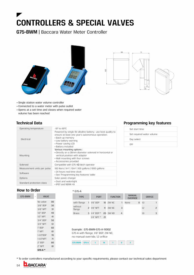
®94
TYPE PORT FUNCTION MANUAL OVERRIDE ORIFICE
with flange 1 1/8" BSP 10 2W NC 1 None 0 1 0 1
without flange 2 1/8" NPT 11 3W NC 3 1 2 2
Brass 3 1/4" BSP (1) 20 3W NO 4 1 6 3
1/4" NPT (1) 21
Example : G75-BWM-G75-A-110102G75-A with flange, 1/8" BSP, 2W NC, no manual override, 1 2 orifice
How to OrderG75-BWM - VALVE
No valve 00
3/8" BSP 30
3/8" NPT 31
1/2" BSP 40
1/2" NPT 41
3/4" BSP 50
3/4" NPT 51
1" BSP 60
1" NPT 61
1-1/2"BSP 70
1-1/2"NPT 71
2" BSP 80
2" NPT 81
G75-A *
* G75-A
G75-BWM G75-A 1 10 1 0 2
Technical DataOperating temperature -10º to 60ºC
Electrical
Powered by single 9V alkaline battery; use best quality to ensure at least one year's autonomous operation • Back-up memory• Low battery warning• Power saving LCD• Battery included
Mounting
Various mounting options :• Directly on a 28mm diameter solenoid in horizontal or vertical position with adaptor • Wall mounting with four screws • Accessories provided
Solenoid Compatible with G75 4Ω latch operator
Measurement units per pulse 100 liters | 1m3 | 10m3 | 100 gallons | 1000 gallons
Software• 24 hours real time clock• See 'Programming key features' table
Options Solar panel, charger
Standard protection class• Dust and watertight• IP67 and NEMA 4X
Set start time
Set required water volume
Day select
OFF
Programming key features
66
39 21
71
106
• Single station water volume controller• Connected to a water meter with pulse outlet• Opens at a set time and closes when required water volume has been reached
G75-BWM | Baccara Water Meter Controller
CONTROLLERS & SPECIAL VALVES
* To order controllers manufactured according to your specific requirements, please contact our technical sales department

95BACCARA WATER IRRIGATION CATALOG
• Measuring level of two set points : top and bottom • Gives a signal to pump or valve• Dry installation - no elements inside the tank• Main applications : filling or draining of water reservoir and tanks
G75-DLS - TYPE ACCESSORIES
Stand alone 1 Mounting bracket B
Latch solenoiddriver D
G75-DLS 1 B
How to Order
Digital Level Switch, stand alone, with mounting bracket and latch solenoid driver
Technical Data
Mechanical
• Operating temperature : -10ºC to 60ºC (no freezing)• Outdoor UV protection• Front panel cover protection
Electrical
• Power supply : 6-24V DC or 12-24V AC• RED + BLK power supply• GRN / WHT N O contact• Low power detect• Dry contact (N O) 0 5A at 24V AC• Internal memory to retain "set-up data" at power down
Mounting
• 2" (52mm) diameter• 2ft (60cm) 4 wires cable• Pressure ports 1/8" BSP/NPT (male)• High pressure port is marked by the letter "H" on the housing• Connect the water tank to the "H" port only
Software See 'Programming key features' table
Display
• The LCD display shows the water level above the DLS mounting place• "ON" is displayed when the switch contacts are closedDisplay resolution : • 10 cm in a range of 0 0 - 70 0m• 0 01 bar in the range 0 0 - 7 bar
Standard protection class• Dust and watertight• IP66
Manual operation
Time interval between level measurements function
Function : "SET" for fill "RESET" for empty
Zero calibration
Programming key features
D
89.5
58.8
(60)
8.
5214
1/8
”BSP
/NPT
TYPx
2
43
M5
TYPx
2
Ø 6
0Ø
57.
7
"L"
"H"
Optional Mounting Bracket
G75-DLS | Digital Level Switch
* To order special valves manufactured according to your specific requirements, please contact our technical sales department

®96
G75-ADP - TYPE MOUNTING BRACKET
Stand alone 1 without 0
with 1
Example : G75-ADP-10Baccara Analog Differential Pressure Sensor,stand alone, without mounting bracket
How to Order
Mechanical
• Operating temperature : -10ºC to 60ºC (no freezing)• Outdoor UV protection• Measuring pressure range : 0-7 bar (0-101 5 PSI)• "H" proof pressure : 14 bar (203 PSI)• "H" pressure must be ≥ "L" pressure
Electrical
• Power supply : 5V DC • RED : (+) 5V• BLACK : (-)5V • ORANGE : analog output• Analog output value : 0 2V to 4 7V, [V out = (0 006429xKpa+0 2)± Error]• Ouput accuracy : 2 5% of full scale
Mounting
• 2" (52mm) diameter• 2ft (60cm) 3 wires cable• Pressure ports 1/8" BSP/NPT (male)• High pressure port is marked by the letter "H" on the housing• Connect high pressure before low pressure• Disconnect low pressure before high pressure
Standard protection class • IP66
Technical Data
65.7
1/8
” BSP
TYPx
2
Ø 6
.5 ±
0.1
TYP
x2Ø
52
±0.1
6610
70
A R 35
A45
1.541
25.8
“L”
“H” M 5
TYPx
2
Ø 6
0
OptionalMounting Bracket
G75-ADP - 1 0
• Differential pressure to current transducer• Suitable to work with both media - air and liquid• Main application : analog sensor for filters backwash
G75-ADP | Baccara Analog Differential Pressure Sensor
CONTROLLERS & SPECIAL VALVES
* To order controllers manufactured according to your specific requirements, please contact our technical sales department

97BACCARA WATER IRRIGATION CATALOG
68
39 91.2
5.19
AC (W)DC(W)50
Hz60 Hz
V 0 3 0 3 0 05 0 112 •24 • • •
Voltage Distance(km)
Conduit section (mm2)
Delay Time (sec)
On Off
12/24 0 3 1
12 5 0 5 12 1
24 5 0 5 8 1
* Max conduit resistance 390Ω at nominal voltage
Voltage & Power Consumption
• Available options
Function 2 Way, 3 Way NC, NO
Current Holding 4mA
Pressure rangeRefer to working pressure definitions of the valve that the GEM-LDO is assembled on, with DC10W/AC8W
Power• DC12V (0 05W) up to DC24V (0 1W)• 24V AC: 0 3W
Connection Red/Black - power supply | Green/Black - coilLead wire length - 28cmPVC coated AWG 18 UL 1007
Ambient temp -10ºC to 70ºC
Operation Only with GEM-BL-LDO coil and Baccara valve
Applications
• Cost saving wiring for remote solenoid operation• Power saving and heat prevention on continuous energized solenoid
Voltage Voltage and power consumption - see table
Standard protection class IP67 (LDO only)
GEM-LDO - VOLTAGE -Please refer to the "How to
Order" definitions of the assembled GEM-SOL valve
24 VAC &12-24 VDC 9
GEM-LDO 9 GEM-A N2 10 3 5 0
How to Order
Example : GEM-LDO-9-GEM-A-21035N0GEM-LDO is attached to a GEM-SOL latch coil direct operated, brass1/8"BSP, 3W NC, 2 4 orifice, NBR, no manual override
Technical Data
A small section conductor can be used at a distance of up to 5 kms
Assembled with GEM-A solenoid
LDO unit
Assembled with GEM-S solenoid
* For recommended wire parameters, please refer to Long distance operators charts
GEM-LDO | Long distance operator 2 Way, 3 Way NC, NO
* To order special valves manufactured according to your specific requirements, please contact our technical sales department

®98
Assembled with GEM-A solenoid
LDOS - VOLTAGE - Please refer to the "How to Order" definitions of the assembled GEM-SOL valve
24V AC 1
12V DC 2
How to Order
Pressure (bar) table
Voltage & Power ConsumptionAC (W)
DC (W)50 Hz
60 Hz
V12 •24 • •
• Available options
LDOS 1 GEM-A N2 10 3 5 0
Function Orifice (mm) Pressure
3W NC
1 6 16
2 0 10
2 4 8
3W NO
1 6 16
2 0 12
2 4 8
Delay time (sec) at a nominal voltage
Distance(Km)
Conduit Section(mm)
4-5
2 4 0 5
4 8 1 0
7 5 1 5
Example : LDOS-1-GEM-A-21035N0LDOS 24V AC is attached to a GEM-SOL latch coil direct operated, brass,1/8"BSP, 3W NC, 2 4 orifice, NBR, no manual override
Current 24V AC : Inrush 210mA | Holding 18mA 12V DC : Inrush 120mA | Holding 5mA
Pressure range See table
Delay time See table
Connection DIN 43650 Connecting box
Ambient temp -10ºC to 70ºC
Operation Only with a Baccara valve
Applications
• Cost saving wiring for remote solenoid operation• Power saving and heat prevention on continuous energized solenoid
Voltage• Voltage and power consumption - see table• +10% -10% of nominal
Standard protection class IP65 with connector
Technical Data
A small section conductor can be used at a distance of up to 5 kms
22
22
2xM5X0.8DEEP 8
28
90.8
72
68
32
Assembled with GEM-S solenoid
LDOS unit
* For recommended wire parameters, please refer to Long distance operators charts
LDOS | Long distance operating solenoid
CONTROLLERS & SPECIAL VALVES
* To order special valves manufactured according to your specific requirements, please contact our technical sales department

99BACCARA WATER IRRIGATION CATALOG
50.5 38.5
83
63.2
79 87
05
94
2W 3W
AC (W)DC(W)50
Hz60 Hz
V 0 3 0 3 0 312 •24 • •
Technical Data
Voltage & Power Consumption
Voltage Distance (km)
Conduitsection
(mm2)
Delay time (sec)
On Off
12/24 0 0 5 3 1
12 5 0 5 12 1
24 5 0 5 8 1
Max conduit resistance 390Ω at nominal voltage
• Available options
Function 2 Way, 3 Way NC, NO
Current Holding 4mA
Pressure range Refer to G75 Latch operator
Power DC12V (0 05W) up to DC24V (0 1W)
Connection Red/Black - power supply | Green/Black - coil
Ambient temp -10ºC to 60ºC
Solenoid Compatible with G75 4Ω latch operator
ValveCan operate any valve equipped with 3/4" UNEF solenoid cavity (Richdel® type)
Applications
• Cost saving wiring for remote solenoid operation• Power saving and heat prevention on continuous energized solenoid
Voltage Voltage and power consumption - see table
Standard protection class IP67 (LDO only)
How to Order
Example : G75-LDO-9-G75-A-11032B-1G75-LDO 24V AC is attached to a G75-A with flange, 1/8" BSP, 3W NC 1 2 orifice, no manual override, 4Ω latch coil, two wires
G75-LDO 9 G75-A B1 10 3 2 1
A small section conductor can be used at a distance of up to 5 kms
* For recommended wire parameters, please refer to Long distance operators charts
G75-LDO | Long distance operator 2 Way, 3 Way NC, NO
* To order special valves manufactured according to your specific requirements, please contact our technical sales department
LDO unit assembled with G75-A operator and solenoid
G75-LDO - VOLTAGE -Please refer to the "How to
Order" definitions of the assembled G75 valve
24 VAC &12-24 VDC 9

®100 101
GEM-B | GEM-SOL Coil 102
GEM-BL | GEM-SOL Latch Coil 104
GEM-BP | GEM-SOL IP68 Coil 106
GEM-O | GEM-SOL Operator 108
GEM-OG | GEM-SOL Operator UNEF 110
G75-O | AC/DC Operator 112
G75-O | Latch Operator 114
SPARE PARTS

®103BACCARA WATER IRRIGATION CATALOG102
GEM-B - VOLTAGE POWER CONNECTOR
6 1 AC8W 50Hz 1 without 0
12 2 AC8W 60Hz 2 with 1
24 3 DC10W 3 with LED 2
48 4 AC5.5W 50Hz 4 with bi- color LED 3
110 5 AC5.5W 60Hz 5 flying leads coil 4
120 6 AC2.5W50/60Hz 6 with 1/2" hub 5
220 7A DC5.5W 7 surge protection with LED 6
230 7 DC3.5W 8 connector with moulded cable 7
240 8 other 9
Latch/other (1) 9
GEM-B 3 4 1
How to Order
Example : GEM-B-341GEM-SOL Coil 24V AC 5.5W 50Hz with connector
330
(1) For specifying Latch type coil, please refer to GEM-A3P valve - How to Order table
GEM-B | Coil
* To order coils manufactured according to your specific requirements, please contact our technical sales department
Dimensions
Type
10W
5.5W
2.5W
Type Inrush Holding
8W 26VA-13W 16VA-8W
5.5W 16VA-8W 12VA
2.5W 2.5W 2.5W
Coil winding insulation H 180ºC
Temperature range Coil : -20ºC to 150ºC | Ambient : -20ºC to 70ºC
Duty cycle * 100% ED
Electrical connection• AMP pins, DIN 46242, 2 poles + 1 earth• 2 flying leads, 18 AWG (0.75mm2), 330 mm length
Connector
• DIN 43650• PG9 or 1/2" NPT* Max. tightening torque for the connector screw : 0.5 Nm
Assembly In any position
Coil fixing One nut G1/4" hexagonal 19mm
Impregnation Optional
Coil voltage• Voltage and power consumption - see table• All Baccara coil voltages are ±10% of nominal
Standard / Certification CE
Standard protection classIP65 with connector* Option : IP68 (please refer to GEM-BP coil)
Power Consumption table (AC)Technical Data
Power Consumption table (DC)
AC (W)DC (W)
50 Hz 60 Hz
V 8 5.5 2.5 8 5.5 2.5 10 5.5 3.56 • • •12 • • • • •24 • • • • • • • •48 • • •110 • • • •120 • •220 • • • • •230 • • • •240 • • •
Voltage & Power Consumption
• Available options
DIN Connector Flying Leads LED Connector
• The coil should not be energized without being assembled on the operator* Please consult with our technical sales department : • for further information on using different power coils (not shown in the table) • for long term operation
GEM-B | Coil
SPARE PARTS

®105BACCARA WATER IRRIGATION CATALOG104
GEM-BL | Latch coil
* To order coils manufactured according to your specific requirements, please contact our technical sales department
Dimensions
How to Order
GEM-SOL with
Flying Leads
GEM-B-3124V 50Hz 8W
9
330
GEM-BL - LATCH TYPE (1) CONNECTOR
2ΩΩΩ LDO without 0
5ΩΩΩ IL with 1
13ΩΩΩ EL flying leads coil 4
20ΩΩΩ OL with 1/2" Hub 5
53ΩΩ DLconnector with moulded cable
7
other 9
Example : GEM-BL-LDO1GEM-SOL latch coil, 2Ω latch with connector
(1) Choose latch type according to which latch system you have
1GEM-BL LDO
GEM-BL | Latch coil
SPARE PARTS
Example : 12V DC, Capacitor, ≤1, 4700, ≤50ms
VOLTAGE OPERATING METHOD
MAXCURRENT [A]
ON COIL
CAPACITOR[µF]
SWITCHING TIME[ms]
3 Direct ≤2 None ≤25
6 Capacitor ≤1 2200 ≤50
9 ≤0.5 4700 ≤100
12 ≤0.1 other other
24 other
230
Other
12V Capacitor ≤1 4700 ≤50ms
Coil winding insulation H 180ºC
Temperature range Coil : -20ºC to 150ºC | Ambient : -20ºC to 70ºC
Electrical connection• AMP pins, DIN 46242, 2 poles + 1 earth• 2 flying leads, 18 AWG (0.75mm2), 330 mm length
Connector
• DIN 43650• PG9 or 1/2" NPT* Max. tightening torque for the connector screw : 0.5 Nm
Assembly In any position
Coil fixing One nut G1/4" hexagonal 19mm
Typical pulse time 30~50ms
Impregnation Optional
Standard / Certification CE
Standard protection classIP65 with connector* Option : IP68 (please refer to GEM-BP coil)
Technical Data
• The coil should not be energized without being assembled on the operator• The coil, including its magnetic circuit and permanent magnets, is encapsulated in high temperature resistant nylon to withstand humidity and meet heavy duty requirements.
When ordering for a new application, please inform us of your requirements according to the table below. This will enable us to determine the most suitable coil.

®107BACCARA WATER IRRIGATION CATALOG106
GEM-BP | IP68 coil
* To order coils manufactured according to your specific requirements, please contact our technical sales department
Dimensions
Example : GEM-BP-31IP68 GEM-SOL coil 24V AC 8W 50Hz
GEM-BP - VOLTAGE POWER
12 2 AC8W 50Hz 1
24 3 AC8W 60Hz 2
DC10W 3
AC5 5W 50Hz 4
AC5 5W 60Hz 5
AC2 5W50/60Hz 6
DC5 5W 7
DC3 5W 8
GEM-BP 3 1
How to Order
62
2m conduit
32
83
Tightening torque2.5 ± 0.5 [N-m]
GEM-BP | IP68 coil
SPARE PARTS
Type Inrush Holding
8W 26VA-13W 16VA-8W
5 5W 16VA-8W 12VA
2 5W 2 5W 2 5W
Type
10W
5 5W
3 5W
Construction Housing : encapsulated polyurethane
Coil winding insulation H 180ºC
Temperature range Ambient : -5ºC to 50ºC (no icing)
Duty cycle 100% ED
Protection IP68 infinite time immersion under water, up to 2m depth
Electrical connection3x18 AWG (0 75mm2), hook up wire, 200cm* other lengths are available
Assembly In any position
Coil fixing One nut G1/4" hexagonal 19mm
Standard / Certification European Standards IEC 60529 code IP68
Coil voltage• Voltage and power consumption - see table• All Baccara coil voltages are ±10% of nominal
Power Consumption table (AC)Technical Data
Voltage & Power Consumption
Power Consumption table (DC)
AC (W)DC (W)
50 Hz 60 Hz
V 8 5 5 2 5 8 5 5 2 5 10 5 5 3 5612 • • • • •24 • • • • • • • • •48110120220230240
• Available options
• The coil should not be energized without being assembled on the operator

109BACCARA WATER CATÁLOGO DE RIEGO108®
GEM-O | Operador 2 Vías, 3 Vías NC, NA
* Si desea solicitar actuadores fabricados según unos requisitos específicos, póngase en contacto con nuestro departamento técnico de ventas
Medidas
JUNTAS - VOLTAJE ALIM CONECTOR
NBR N Sin bobina 0 Sin bo-
bina 0 sin 0
FKM V 6 1 CA 8W 50 Hz 1 con 1
EPDM E 12 2 CA 8 W 60 Hz 2 con LED 2
PTFE (3) T 24 3 CC 10 W 3 con LED bicolor 3
FFKM (2) K 48 4 CA 5,5 W 50 Hz 4 cables 4
110 5 CA 5,5 W 60 Hz 5 con concen-
trador 1/2” 5
120 6 CA 2,5 W50/60 Hz 6
protector de sobretensión con LED
6
220 7A CC 5,5 W 7conector con cable moldeado
7
230 7 CC 3,5 W 8 otro 9
240 8
Latch/otro (4) 9
GEM-O - CONEXIÓN FUNCIÓN ORIFICIO
1/8"BSP 10 2 Vías NA 2 0,8 1
1/8"NPT 11 3 Vías NC 3 1,2 2
3 Vías NA 4 1,6 3 3 Vías NA (1) 4a 2,0 4
2,4 5
3,0 6
Ejemplo: GEM-O-2W1-N-341Operador GEM-SOL 2 Vías NC, NBR, 24 V CA 5,5 W 50 Hz con conector.
Ejemplo: GEM-O-1034-V-341Operador GEM-SOL, 1/8"BSP, 3 Vías NC, Orificio 2,0, FKM, 24 V CA 5,5 W 50 Hz con conector.
2 V
3 W
(1) Se suministra presión a través de la base.(2) Sello FFKM disponible sólo bajo pedido. Al solicitar juntas FFKM, consulte con nuestro departamento técnico de ventas en referencia al compuesto del sello.(3) Para las juntas PTFE, el sello es de FKM estándar. Póngase en contacto con nosotros si requiere un material diferente para el sello.(4) Para definir tipo de bobina Latch, véase la tabla «Cómo realizar un pedido» de la válvula GEM-A3P.* Nota: Al realizar el pedido sin bobina, defina qué valores de corriente y presión necesita (CC, CA o ADC), de lo contrario se suministrará una
válvula ADC
GEM-O - 2 V FUNCIÓN
2 Vías NC 1 2 Vías NA (1) 2a
Cómo realizar un pedido
43V4310GEM-O 1
2 VÍAS/3 VÍAS NA por la base
Asiento del operario
5.36
GEM-B-3124V 50Hz 8W
2 VÍAS/3 VÍAS NC, NA
GEM-B-3124V 50Hz 8W
7.51.0±1/8 BSP/NPT
1/8 BSP/NPT
1.6+0
.1
4GEM-O 2 V 1 N 3 1
GEM-O | Operador 2 Vías, 3 Vías NC, NAApto para válvulas GEM-A, GEM-S y GEM-Z
REPUESTOS
• Los operadores ADC y las válvulas pueden usarse con CA 8 W o CC 10 W
Función 2 Vías, 3 Vías NC, NA
Tamaño orificio 0,8 a 3 mm
Rango de presión (bar) Véase rendimientos de la válvula solenoide
Rango de temperaturaFluido: -10 ºC a 80 ºC (no congelado) Ambiente: -10 ºC a 50 ºC
Tiempo de respuesta 16 a 36 ms en ciclo completo
Materiales en contacto con el medio
OperadorAcero inoxidable AISI serie 300 y 400Vuelta de cortocircuito:estándar - cobrebajo pedido: plata y aluminioNota: El actuador para CC no dispone de vuelta de cortocircuito y no puede usarse para CAOrificio:Acero inoxidableResorte:Acero inoxidable AISI serie 300
Medio Aire, gas, agua, combustible, aceite, etc.
Roscas en tubo del actuadorG1/4" macho y G1/8" o 1/8" NPT hembra para conectar a escapes, silenciador, etc.
Montaje del accionador
Atornillado de M20x1 hexagonal de 22 mm al cuerpo de la válvula y fijando la bobina con una tuerca G1/4" hexagonal de 19 mm metálica o de plástico. • Par de apriete máx : 3 N/m
Fijación de bobinaCualquier posición, puede girarse 360° alrededor del actuador.
Datos de la bobinaConsultar los datos técnicos de la bobina GEM-SOL
Voltaje de bobina• Voltaje y consumo de energía: véase tabla• Todos los voltajes de bobina de Baccara son ± 10 % del nominal
Características técnicas Voltaje y consumo de energíaCA (W)
CC (W)50 Hz 60 Hz
V 8 5,5 2,5 8 5,5 2,5 10 5,5 3,56 • • •12 • • • • •24 • • • • • • • •48 • • •110 • • • •120 • •220 • • • • •230 • • • •240 • • •
2 VÍAS NC 2 VÍAS NAa por la base
3 VÍAS 3 VÍAS NAa por la base
• Opciones disponibles
NA a través de base Estándar 2 Vías/3 Vías

111BACCARA WATER CATÁLOGO DE RIEGO110®
GEM-OG | Operador 3/4" UNEF 2 Vías, 3 Vías NC, NA
* Si desea solicitar actuadores fabricados según unos requisitos específicos, póngase en contacto con nuestro departamento técnico de ventas
Medidas
JUNTAS - VOLTAJE ALIM CONECTOR
NBR N Sin bobina 0 Sin
bobina 0 sin 0
FKM V 6 1 CA 8W 50 Hz 1 con 1
EPDM E 12 2 CA 8 W 60 Hz 2 con LED 2
24 3 CC 10 W 3 con LED bicolor 3
48 4 CA 5,5 W 50 Hz 4 cables 4
110 5 CA 5,5 W 60 Hz 5 con concentra-
dor 1/2” 5
120 6 CA 2,5 W50/60 Hz 6
protector de sobretensión con LED
6
220 7A CC 5,5 W 7conector con cable mold-eado
7
230 7 CC 3,5 W 8 otro 9
240 8
Latch/otro (2) 9
Ejemplo: GEM-OG-2W1-N-341Operador GEM-SOL 3/4" UNEF, 2 Vías NC, NBR, 24 V CA 5,5 W 50 Hz con conector.
Ejemplo: GEM-OG-1034-V-341Operador GEM-SOL 3/4" UNEF, 1/8"BSP, 3 Vías NC, 2.0, FKM, 24 V CA 5,5 W 50 Hz con conector.
2 V
3 V
GEM-OG - CONEXIÓN FUNCIÓN ORIFICIO
1/8"BSP 10 2 Vías NA 2 0,8 1
1/8"NPT 11 3 Vías NC 3 1,2 2
3 Vías NA 4 1,6 3
2,0 4
2,4 5
3,0 6
GEM-OG - 2 V FUNCIÓN
2 Vías NC 12 Vías NA (1) 2a
Cómo realizar un pedido
3/4”-20 UNEF-28Recorrido del émbolo 1.1±0.1mm
31
1/8”BSP/NPT19
752.8
1.2 15 35
61
Asiento del operario
3/4" 20TPI UNEF
Ø12
2.0+2 01
5.65.5
MaxØ3.0Asiento del operario
GEM-OG 10 3 4 V 3 4 1
GEM-OG 2 V 1 N 3 4 1
(1) Se suministra presión a través de la base(2) Para definir tipo de bobina Latch, véase la tabla «Cómo realizar un pedido» de la válvula GEM-A3P.* Nota: Al realizar el pedido sin bobina, defina qué valores de corriente y presión necesita (CC, CA o ADC), de lo contrario se
suministrará una válvula ADC
GEM-OG | Operador 3/4" UNEF 2 Vías, 3 Vías NC, NAApto para válvulas GEM-GALIT, GEM-S-4
REPUESTOS
Función 2 Vías, 3 Vías NC, NA y Latch
Tamaño orificio 0,8 a 3 mm
Rango de presión (bar) Véase rendimientos de la válvula solenoide
Rango de temperaturaFluido: -10 ºC a 80 ºC (no congelado)Ambiente: -10 ºC a 50 ºC
Tiempo de respuesta 16 a 36 ms en ciclo completo
Materiales en contacto con el medio
OperadorAcero inoxidable AISI serie 300 y 400Vuelta de cortocircuito:estándar - cobrebajo pedido: plata y aluminioNota: El actuador para CC no dispone de vuelta de cortocircuito y no puede usarse para CAOrificio:Acero inoxidableResorte:Acero inoxidable AISI serie 300 y 400
Latch • Opcional
Medio Aire, gas, agua, combustible, aceite, etc.
Roscas en tubo del actuadorG1/4" macho y G1/8" o 1/8" NPT hembra para conectar a escapes, silenciador, etc.
Montaje del accionador
Atornillado de 3/4"-20 UNEF-28 hexagonal de 22 mm al cuerpo de la válvula y fijando la bobina con una tuerca G1/4" hexagonal de 19 mm metálica o de plástico.• Par de apriete máx : 3 N/m
Fijación de bobinaCualquier posición, puede girarse 360° alred-edor del actuador.
Datos de la bobinaConsultar los datos técnicos de la bobina GEM-SOL
Voltaje de bobina• Voltaje y consumo de energía: véase tabla• Todos los voltajes de bobina de Baccara son ± 10 % del nominal
• Los operadores ADC y las válvulas pueden usarse con CA 8 W o CC 10 W
Características técnicas Voltaje y consumo de energíaCA (W)
CC (W)50 Hz 60 Hz
V 8 5,5 2,5 8 5,5 2,5 10 5,5 3,56 • • •12 • • • • •24 • • • • • • • •48 • • •110 • • • •120 • •220 • • • • •230 • • • •240 • • •
• Opciones disponibles
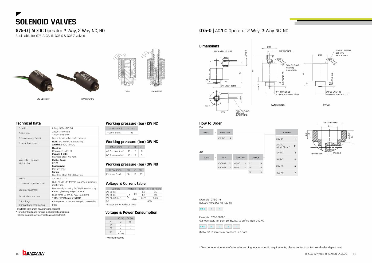
®113BACCARA WATER IRRIGATION CATALOG112
G75-O - PORT FUNCTION ORIFICE
1/8" BSP 10 3W NC 3 1 0 1
1/8" NPT 11 3W NO 4 1 2 2
1 6 3
VOLTAGE
24V AC 1
24V ACw/out Diode (1) 1R
12V AC 3
12V DC 4
24V DC 5
110V AC 7
110V with 1/2 NPT TP
N"2/1
45
3/4"-UNEF-20TPI
9
NO
DIO
NEL
OS
2.1
Ø33.5
29.8 CABLE LENGTH350 (mm)BLACK WIRE
42Ø
2WNC
Ø30
NO
DIO
NEL
OS
2.1
CABLE LENGTH350 (mm)BLACK WIRE
3/4"-20 UNEF-2BPLUNGER STROKE 1 0.1+-
74
9
85
CABLE LENGTH350 (mm)BLACK/RED
NO
DIO
NEL
OS
2.1
Ø30
3/4"-20 UNEF-2BPLUNGER STROKE 1 0.1+-
3WNC/3WNO
9
1/8" BSP/NPT
3/4" 20TPI UNEF
Ø12
01
5.65.5
MaxØ2.0Operator seat
2.2
+0.1
How to Order
Example : G75-O-1-1G75 operator, 2W NC, 24V AC
2W
3W
G75-O 1 1
G75-O 10 3 2 1
G75-O - FUNCTION
2W NC 1
(1) 3W NO 1 6 mm : Max pressure is 8 bars
Example : G75-O-1032-1G75 operator, 1/8" BSP, 3W NC, DC, 1 2 orifice, NBR, 24V AC
Orifice (mm) up to 2 0
Pressure (bar) 12
Working pressure (bar) 2W NC
Orifice (mm) 1 0 1 2 1 6
AC Pressure (bar) 16 11 6
DC Pressure (bar) 12 9 5
Working pressure (bar) 3W NC
Orifice (mm) 1 0 1 2 1 6
Pressure (bar) 16 12 10
Working pressure (bar) 3W NO
Technical Data
Voltage & Power Consumption
2WNC 3WNC/3WNO
Solenoid Voltage Inrush [A] Holding [A]2W 50 Hz
+10%
n-20%
0 3 0 192W 60 Hz 0 2 0 143W 50/60 Hz * 0 125 0 125DC 4 5W
V
• Available with brass adaptor upon request * For other fluids and for use in abnormal conditions,
please contact our technical sales department
Voltage & Current table
AC (W) DC (W)
V 2 4 512 • •24 • •110 •
2W only
Function 2 Way, 3 Way NC, NO
Orifice size2 Way : No orifice3 Way : See table
Pressure range (bars) See solenoid valve performances
Temperature rangeFluid : 5ºC to 50ºC (no freezing)Ambient : -10ºC to 50ºC
Materials in contactwith media
Housing:Reinforced Nylon 66Plunger & pole:Stainless Steel AISI 430F Rubber Seals:EPDMEncapsulate:PolyurethaneSpring:Stainless Steel AISI 300 series
Media Air, water, oil *
Threads on operator tubeG1/8" or 1/8" NPT female to connect exhaust, muffler etc
Operator assemblyBy manually screwing 3/4" UNEF to valve body • Max tightening torque : 2 N/m
Electrical connectionLead wires 35 cm, 18 AWG (0 75mm2)* other lengths are available
Coil voltage • Voltage and power consumption - see table
Standard protection class IP66
• Available options
3W Operator2W Operator
G75-O | AC/DC Operator 2 Way, 3 Way NC, NOApplicable for G75-A, GALIT, G75-S & G75-Z valves
SOLENOID VALVESG75-O | AC/DC Operator 2 Way, 3 Way NC, NO
* To order operators manufactured according to your specific requirements, please contact our technical sales department
Dimensions
* Except 24V AC without Diode

®115BACCARA WATER IRRIGATION CATALOG114
G75-O | Latch Operator 2 Way, 3 Way NC, NO
* To order operators manufactured according to your specific requirements, please contact our technical sales department
Dimensions
85
CABLE LENGTH350 (mm)BLACK/GREEN
NO
DIO
NEL
OS
2.1
Ø30
3/4"-20 UNEF-2BPLUNGER STROKE 1± 0.1
3WNC/3WNO
9
1/8" BSP/NPT
2WNC
74
3/4" 20TPI UNEF
Ø12
2.2+0
.1
01
5.65.5
MaxØ2.0Operator seat
How to Order
Example : G75-O-1-BaG75 latch solenoid operator, 2W NC, 4Ω, 3 wires
2W
3W
Example : G75-O-1042-CaG75 latch solenoid operator, 1/8" BSP, 3W NO, 1 2 orifice, 9Ω, 3 wires
G75-O - FUNCTION
2W NC 1
VOLTAGEVDC (1) WIRES
4Ω B two null
9Ω C three a
12Ω D
23Ω 6G75-O - PORT FUNCTION ORIFICE
1/8" BSP 10 3W NC 3 1 0 1
1/8" NPT 11 3W NO 4 1 2 2
1 6 3
G75-O 1 B a
G75-O 10 4 2 C a
Resistance [Ω] Suitable input voltage range [V]
4 6 - 9
9 12 - 14
12 14 - 16
23 18 - 21
Coil resistance vs input voltage range
(1) Refer to coil resistance vs input voltage table
G75-O | Latch Operator 2 Way, 3 Way NC, NOApplicable for G75-A, GALIT, G75-S & G75-Z valves
SOLENOID VALVES
3W Operator
Orifice (mm) up to 2 0
Pressure (bar) 12
Working pressure (bar) 2W NC
Orifice (mm) 1 0 1 2 1 6
AC Pressure (bar) 16 11 6
Working pressure (bar) 3W NC
Orifice (mm) 1 0 1 2 1 6
Pressure (bar) 16 12 10
Working pressure (bar) 3W NO
Technical Data
2WNC 3WNC/3WNO
Function 2 Way, 3 Way NC, NO Latch
Orifice size2 Way : No orifice3 Way : See table
Pressure range (bars) See solenoid valve performances
Capacitors• 4700µF for 9V DC• 2200µF for 12V DC
Switching time 25-50 ms
Temperature rangeFluid : 5ºC to 50ºC (no freezing)Ambient : -10ºC to 50ºC
Materials in contactwith media
Housing:Reinforced Nylon 66Plunger & pole:Stainless Steel AISI 430F Rubber Seals:EPDMEncapsulate:PolyurethaneSpring:Stainless Steel AISI 300 series
Threads on operator tubeG1/8" or 1/8" NPT female to connect exhaust, muffler etc
Two wire operator One coil with exit of 2 lead wires To pull the plunger up, connect the black wire (-) and the green to the (+)
Three wire operator
One coil and an integrated electrical circuit To pull plunger up, pulse is given to the red wire (-) To release the plunger, pulse is given to the black wire (-) Operate only by a controller
Electrical connection• Lead wires 35 cm, 18 AWG (0 75mm2)
(black/green)• Lead wires : red, white, black for 3 wires
Voltage 9, 12V DC (coils for other voltages available)
Standard protection class IP66
• Available with brass adaptor
2W Operator

®116 117
Valve functions 118
Operating mechanism 119
Valve sizing 120
Electrical parameters 121
Manual overrides 122
GEM-SOL Special assembly procedures 122
GEM-SOL Elastomer materials 123
Flow charts for liquids & gases 124
Operation driver for latch coils 126
Conduits sizing 127
Long distance operators charts 128
TECHNICAL INFORMATION

®118
Valve Functions
TECHNICAL INFORMATION
Two way valves have one orifice and two ports : one inlet and one outlet They are available with the following functions :• Normally Closed (NC) Fig 1 - valve is closed for flow through the valve when the coil is de-energized • Normally Open (NO) Fig 2 - valve is open for flow through the valve when the coil is de-energized
Fig. 1 Fig. 2
Three way valves have two orifice and three ports : inlet, outlet and exhaust They are available with the following functions :• Normally Closed (NC) Fig 3 - no flow from inlet port, flow is from outlet port to the exhaust • Normally Open (NO) Fig 4 - flow from inlet port, no flow from the exhaust port
de-energized energized
IN OUT IN
de-energized energized
Fig. 3 Fig. 4de-energized energized
INOUT OUT
de-energized energized
OUT
EXIN
EX
Also available are the following non-standard functions : Divertor Fig 5 - one inlet pressure with two outlets, one outlet is NO and the other NC Selector Fig 6 - two inlet pressures, one inlet is NO and the other NC
Fig. 5 Fig. 6de-energized energized
OUT 2IN OUT
de-energized energized
OUT 1 IN 1
IN 2

119BACCARA WATER IRRIGATION CATALOG
Operating mechanismA solenoid valve is a combination of two functional units :• A solenoid (electromagnet) with a moving core (plunger) • A valve body containing the right orifices and seals mechanism The plunger in a solenoid valve moves and changes the flow direction when a current is supplied to the electromagnet
There are two basic types of Baccara GEM-SOL valves :
Direct operated solenoid valvesWhen the solenoid is energized in a direct acting valve, the plunger moves and directly acts on the valve disc to open, close or change the flow direction Direct acting valves' performance depends directly on the orifice pressure and the magnetic power The increase of line pressure or the orifice size requires more power from the electromagnet
Pilot operated solenoid valvesThese valves are recommended for applications where high flow at high pressure is required A pilot chamber is used which is controlled by a direct acting solenoid valve The movement of the plunger changes the pressure in the pilot chamber When there is pressure in the pilot chamber the valve is closed GEM-SOL pilot valves are equipped with diaphragm, according to the valve function • Two way valves have a bleeding passage in the diaphragm, through which the pilot pressure flows into the pilot chamber; and one orifice to release the pressure when the solenoid is energized • Three way valves have a three way pilot solenoid to control the pilot chamber pressure • Pilot operated valves require a minimum operating pressure
Zero differential valvesWe also manufacture a two way pilot operated valve which works without differential pressure For this type of valve,a mechanical spring helps to lift the diaphragm
Two way
IN
de-energized
energized
OUT
EX
de-energized
Diaphragm
IN OUT
EXenergized
Three way Zero differential
Bleeding orifice

®120
Valve Sizing
TECHNICAL INFORMATION
GeneralIt is not recommended to select a solenoid valve according to its pipe connection port or its orifice size The valve selection depends on the knowledge of the following factors:pressure range minimum and maximum, differential pressure, minimum and maximum flow rate, the specific gravity of the fluid, temperature, viscosity, etc
PressureThe pressure is generally measured above the atmosphericpressure and is expressed in kg/cm2 or bars of relative pressure The value of pressure terms in this catalog corresponds to the relative pressure
Pressure drop P This is the difference of pressure between the upstream P1 and the downstream P2 of the valve when it is crossed by the fluid
Differential pressureMinimum - maximumThis is the minimum or maximum difference of pressure between the upstream P1 and the downstream P2 which secures perfect functioning of the device Only a pilot operated solenoid valve requires the minimum differential pressure to operate
Flow - the flow factor Kv (Cv)The flow of a solenoid valve is the quantity of fluid per time units crossing the valve under certain conditions It is this factor which determines its size To obtain a simpler method of calculation and comparison between the various types of valves, all variables permitting the calculation of the flow have been reduced to a common denominator : the flow factor Kv (without units) The Kv factor can be determined by the flow chart or by calculation When the Kv factor is determined, select the solenoid valve which has the equivalent flow factor The flow factor values given in this catalog have been set up according to the following method :
Fluid is water, specific gravity 1 kg/dm3 the pressure drop P1, P2 is 1Kg/cm2 in a way that the Kv is equal to the flow in liter/min
When several valves are mounted in series, the resulting flow factor is equal to :
When several valves are mounted in parallel, the resulting flow factor is equal to :
ViscosityPractically, the flow Kv is identical for a valve crossed by water or a medium having up to 3ºE viscosity The flow/pressure characteristic is effected above this limit It is necessary to consider factor above 3ºE - the flow factor Kv will be :
δ = kinematic viscosity (in centistrokes) of the fluidQ = flow in liter/minKv = flow factor given in catalog
This calculation leads to a choice of a valve with a higher flow factor value than the one which would have been chosen for a fluid having a viscosity of 3ºE
TemperatureThe limits of temperature of use of a solenoid valve depend essentially upon the nature of the discs and the desgn of the coil The temperature developed in a solenoid valve is a function of the electrical characteristics of the coil, the duty cycle, the fluid and ambient temperatures These parameters determine the “temperature of use” For each type of solenoid valve, the temperature range is given in the technical data, however these figures are only a general guide If temperature of use might extend the given limits, please contact our technical sales department
Response timeThe response time of a solenoid valve is the lapse of time between the electric signal and the outlet of fluid signal The response time is effected by the following parameters:Valve function, operating mode, orifice size, inlet pressure and pressure differential, fluid, temperature and coil characteristics The C E T O P defines the test of conditions as follows:Test pressure : air at 6Kg/cm2 - 85 PSIAmbient temperature : 200 C - 680 F
Response time at energizingResponse time at energizing of the solenoid and until the outlet pressure reaches 90% of the test pressure
Response time at de-energizingLapse of time between de-energizing of the solenoid and until the pressure outlet drops to 10% of the test pressure, see schemas of measure method and resulting curves for AC and DC current Average response time for GEM-SOL valves can be assumed as follows:• Direct acting solenoids 16 to 36 ms for complete cycle • Large direct acting solenoids 40 to 80 ms for complete cycle • Pilot operated valve 20 to 80 ms for complete cycle
Cycling rateThe cycling rate of a solenoid depends directly on its response time It is the number of cycles per minutes calculated for continuous operation The valve should not be reversed at less than 90% or above 10% at discharging of reference pressure
The cycling rate is the maximum possible cycles per minute of the solenoid valve It varies when the valve is mounted in a circuit and depends then upon the installation pressure drop
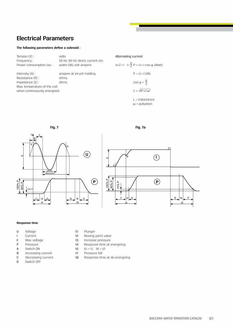
121BACCARA WATER IRRIGATION CATALOG
Electrical ParametersThe following parameters define a solenoid :
Tension (V) : volts Alternating currentFrequency : 50 Hz, 60 Hz direct current etc Power consumption (w) : watts (VA) volt ampere U=Z • I I= P = U • I cos ϕ (Watt)
Intensity (A) : ampere at inrush holding P = U • I (VA)Resistance (R) : ohmsImpedance (Z) : ohms cos ϕ = Max temperature of the coilwhen continuously energized Z = √R2+L2ω2
L = inductance ω = pulsation
UZ
RZ
Response time
U VoltageI CurrentE Max voltageP PressureA Switch ONB Increasing currentC Decreasing currentD Switch OFF
E1 Plungert2 Moving parts valvet3 Increase pressuret4 Response time at energizingt5 t5 = t1, t6 = t2t7 Pressure fallt8 Response time at de-energizing
Fig. 7 Fig. 7a
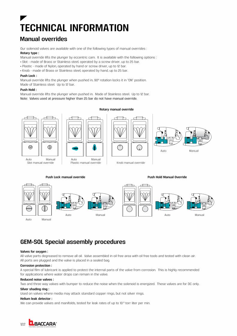
®122
Auto ManualSlot manual override
Auto ManualPlastic manual override Knob manual override
Auto Manual
Auto Manual
Auto Manual Auto Manual
Our solenoid valves are available with one of the following types of manual overrides :Rotary type :Manual override lifts the plunger by eccentric cam It is available with the following options :• Slot - made of Brass or Stainless steel, operated by a screw driver, up to 25 bar • Plastic - made of Nylon, operated by hand or screw driver, up to 12 bar • Knob - made of Brass or Stainless steel, operated by hand, up to 25 bar
Push Lock :Manual override lifts the plunger when pushed in, 90º rotation locks it in "ON" position Made of Stainless steel Up to 12 bar
Push Hold :Manual override lifts the plunger when pushed in Made of Stainless steel Up to 12 bar Note: Valves used at pressure higher than 25 bar do not have manual override
Rotary manual override
Push Lock manual override Push Hold Manual Override
GEM-SOL Special assembly proceduresValves for oxygen :All valve parts degreased to remove all oil Valve assembled in oil free area with oil free tools and tested with clean air All ports are plugged and the valve is placed in a sealed bag
Corrosion protection :A special film of lubricant is applied to protect the internal parts of the valve from corrosion This is highly recommended for applications where water drops can remain in the valve
Reduced noise valves :Two and three way valves with bumper to reduce the noise when the solenoid is energized These valves are for DC only
Silver shading ring :Used on valves where media may attack standard copper rings, but not silver rings
Helium leak detector :We can provide valves and manifolds, tested for leak rates of up to 10-9 torr liter per min
Manual overrides
TECHNICAL INFORMATION

123BACCARA WATER IRRIGATION CATALOG
General information
GEM-SOL solenoid valves can be used for many fluid types including acids, gases, solvents etc To ensure appropriate functioning of the valve, particular care must be taken with the selection of the valve and seals materials The information below summarizes the elastomers materials used for GEM-SOL valves
Please contact our technical department for further information
NBR or BUNA-N• NBR is a copolymer of butadiene and acrylonitrile It is the most used elastomer in the seals industry and is the standard elastomer for GEM-SOL valves
• NBR is suitable for use from -200 C to 850C It has benefits over other elastomers with its compression set, tear and abrasion resistance
• Air, cold water and inert gases are some of the materials NBR is recommended for
EPDM - Ethylene Propylene Rubber• EPDM is an elastomer made from ethylene and propylene monomers It has a wider temperature range than NBR, -400 C to 1490C Its main disadvantage is that it cannot be used with petroleum oils
• Water, alcohol and acetone are some of the materials EPDM is recommended for
Neoprene• Neoprene is homopolymers of chloroprene It has a temperature range of -200 C to 850C Neoprene is unusual because it is resistant to both oxygen and petroleum
• Refrigerants, oxygen and petroleum oils are some of the materials Neoprene is recommended for
FKM• FKM is a very important elastomer due to its wide compatibility to chemicals It has a temperature range of -20ºC to 180ºC This gives FKM a significant advantage over NBR, but it is still not the ultimate elastomer
• Diesel oil, gasoline, some acids and trichlorethylene are some of the materials FKM is recommended for
GEM-SOL Elastomer materials

®125BACCARA WATER IRRIGATION CATALOG124
Flow chart for gases
Spec gravity
γ N (Kg/m3)
Flow factor
Kv
Flow rate
QN (Nm3/h)
Pressure drop
p (bar)
t (ºC)
QN = ?t = 25γN = 1 3 (air)Kv = 3p1 = 5p = 1 8QN = 12 Nm3/h
Kv = ?t = 25γN = 1 3 (air)QN = 12p1 = 5p = 1 8Kv = 3
Inlet pressurep1 = (bar)
Flow chart for liquids
TECHNICAL INFORMATION
Q = Kvpγ Kv = Q p
γ
Q = ?γ = 1 (water)Kv = 40p= 4Q = 801/m
Kv = ?γ = 1 (water)p = 4Q = 80Kv = 40
Spec gravity
γ (Kg/dm3)
Flow factor
Kv
Flow rate
Q (l/min)
Pressure drop
p (bar)
Kinematic viscosity : Max. 3º Engler

®126
Operation driver for latch coils
TECHNICAL INFORMATION
Non-direct operation with two switches (or four transistors)
Tvc is the time to charge the capacitor In order to reduce the time, use a similar resistor but never less than 100Ω C = 4700µFTvc = 5 • R • C [sec]ton/off = 30 ÷ 50 ms
Non-direct operation with one switch (or transistor)
C = 4700µFton/off = 30 ÷ 50 ms
Direct operation

127BACCARA WATER IRRIGATION CATALOG
Conduits sizing
Solenoid type : GEM-SOL 5 5W 24V ACNo of solenoids 1 2 3 4 Distance
Cross-section[mm2]
0 75 1 5 2 5 2 5 100m1 5 2 5 4 0 6 0 200m2 5 4 0 6 0 300m2 5 6 0 400m4 0 500m4 0 600m6 0 700m6 0 800m6 0 900m
1000m
GEM-SOLWires cross-section selection for distance installation of GEM-SOL solenoids
Solenoid type : GEM-SOL 8W 24V ACNo of solenoids 1 2 3 4 Distance
Cross-section[mm2]
1 0 1 5 2 5 4 0 100m1 5 4 0 6 0 6 0 200m2 5 6 0 300m4 0 6 0 400m4 0 500m6 0 600m6 0 700m6 0 800m
900m1000m
Max conduits resistance 4Ω
Max conduits resistance 5Ω
Solenoid type : G75 latch 4ΩNo of solenoids 1 2 3 4 Distance
Cross-section[mm2]
0 75 1 5 1 5 2 5 10m1 5 2 5 4 0 6 0 20m1 5 4 0 6 0 6 0 30m2 5 6 0 6 0 40m4 0 6 0 50m4 0 60m4 0 70m6 0 80m6 0 90m6 0 100m
G75Wires cross-section selection for distance installation of G75 solenoids
Solenoid type : G75 24V AC No of solenoids 1 2 3 4 Distance
Cross-section[mm2]
0 5 0 5 0 75 1 0 100m0 5 1 0 1 5 2 5 200m
0 75 1 5 2 5 2 5 300m1 0 2 5 2 5 4 0 400m1 5 2 5 4 0 6 0 500m1 5 4 0 4 0 6 0 600m2 5 4 0 6 0 6 0 700m2 5 4 0 6 0 800m2 5 4 0 6 0 900m2 5 6 0 1000m
Max conduits resistance 15Ω
Max conduits resistance 0 6Ω

®128
GEM-LDO | assembled with GEM-A solenoid
G75-LDO | assembled with G75-A operator
& solenoid
G75-LDO | Long distance operator 2 Way, 3 Way NC, NOGEM-LDO | Long distance operator 2 Way, 3 Way NC, NO
Number of solenoids that operate simultaneously as a function of wire cross-sectional [mm2]area and distance [mt] from energy source
Distance in meters from
energy source
WIRE CROSS-SECTIONAL AREA [mm2]
0 50 1 00 1 50 2 50
200 12 25 38 65400 6 12 19 40600 4 8 12 21800 3 6 9 16
1,000 2 5 7 131,500 1 3 5 92,000 1 2 3 62,500 1 2 3 53,000 1 2 43,500 1 2 44,000 1 2 35,000 1 1 26,000 1 27,000 1 18,000 1 19,000 110,000 1
Wire's maximum resistance for one solenoid is 175ΩFor further technical information, please refer to product pages in Controllers & Special section
Number of solenoids that operate simultaneously as a function of wire cross-sectional [mm2]area and distance [mt] from energy source
Distance in meters from
energy source
WIRE CROSS-SECTIONAL AREA [mm2]
0 50 1 00 1 50 2 50
200 24 56 78 130400 12 28 39 65600 8 18 26 43800 6 14 19 32
1,000 4 11 15 261,500 3 7 10 172,000 2 5 7 132,500 2 4 6 103,000 1 3 5 83,500 1 3 4 74,000 1 2 3 65,000 1 2 3 56,000 1 2 47,000 1 2 38,000 1 1 39,000 1 1 210,000 1 1 2
Wire's maximum resistance for one solenoid is 390ΩFor further technical information, please refer to product page in Controllers & Special section
LDOS | assembled with GEM-S solenoid
LDOS | Long distance operating solenoid
Long distance operators charts
TECHNICAL INFORMATION

129BACCARA WATER IRRIGATION CATALOG

®
Baccara SpainC/ Marqués de Monteagudo, No 24, 4a Derecha, C P 28028, Madrid, SpainT. +34 91 3446310 | F. +34 91 3446311 www.baccara-geva.com
W H E NE V E R Y T H I N G C O N N E C T S
Baccara USA 4301 South Federal Boulevard, Unit 103, Sheridan, CO 80110T. +1 720 221 4502 www.baccarausa.com
Baccara Australia15/347 Bay Road, Cheltenham, Victoria 3192, AustraliaT. +61 3 9553 4963 | F. +61 3 9553 4965 www.baccarageva.com.au
Baccara IsraelFactory & Head Office, Kvutzat Geva, 1891500, IsraelT. +972 4 6535 960 | F. +972 4 6531 445 www.baccara-geva.com


![(2Z,N 0 0 0 E)-N 0 0 0 -[(2-Hydroxy-1-naphthyl)- methylidene]furan-2-carbohydrazonic acid](https://static.fdokumen.com/doc/165x107/631360d4b033aaa8b2100e91/2zn-0-0-0-e-n-0-0-0-2-hydroxy-1-naphthyl-methylidenefuran-2-carbohydrazonic.jpg)