Autonomous exploration by robot teams: Coordination ...
154
Dipl.-Ing. Torsten Andre Autonomous Exploration by Robot Teams: Coordination, Communication, and Collaboration DISSERTATION zur Erlangung des akademischen Grades Doktor der technischen Wissenschaften Alpen-Adria-Universität Klagenfurt Fakultät für Technische Wissenschaften Erstgutachter: Univ.-Prof. Dr.-Ing. Christian Bettstetter Institut für Eingebettete und Vernetzte Systeme Alpen-Adria-Universität Klagenfurt Zweitgutachter: Prof. Dr. Gaurav S. Sukhatme Department of Computer Science University of Southern California Klagenfurt, Juni 2015
-
Upload
khangminh22 -
Category
Documents
-
view
1 -
download
0
Transcript of Autonomous exploration by robot teams: Coordination ...

Dipl.-Ing. Torsten Andre
Autonomous Exploration by Robot Teams:
Coordination, Communication, and Collaboration
DISSERTATION
zur Erlangung des akademischen Grades
Doktor der technischen Wissenschaften
Alpen-Adria-Universität Klagenfurt
Fakultät für Technische Wissenschaften
Erstgutachter:
Univ.-Prof. Dr.-Ing. Christian Bettstetter
Institut für Eingebettete und Vernetzte Systeme
Alpen-Adria-Universität Klagenfurt
Zweitgutachter:
Prof. Dr. Gaurav S. Sukhatme
Department of Computer Science
University of Southern California
Klagenfurt, Juni 2015


Eidesstattliche Erklärung
Ich versichere an Eides statt, dass ich
• die eingereichte wissenschaftliche Arbeit selbstständig verfasst und andere alsdie angegebenen Hilfsmittel nicht benutzt habe;
• die während des Arbeitsvorganges von dritter Seite erfahrene Unterstützung,einschließlich signifikanter Betreuungshinweise, vollständig offengelegt habe;
• die Inhalte, die ich aus Werken Dritter oder eigenen Werken wortwörtlich odersinngemäß übernommen habe, in geeigneter Form gekennzeichnet und den Ur-sprung der Information durch möglichst exakte Quellenangaben (z.B. in Fuß-noten) ersichtlich gemacht habe;
• die Arbeit bisher weder im Inland noch im Ausland einer Prüfungsbehördevorgelegt habe und dass
• die zur Plagiatskontrolle eingereichte digitale Version der Arbeit mit der ge-druckten Version übereinstimmt.
Ich bin mir bewusst, dass eine tatsachenwidrige Erklärung rechtliche Folgen habenwird.
(Unterschrift) (Ort, Datum)


ACKNOWLEDGMENTS
First of all I would like to thank my advisor Univ.-Prof. Dr.-Ing. Christian Bettstetter for hisguidance and support. He left me the freedom to pursue my interests which finally led to thisthesis. I would like to also thank the secondary reviewer of my thesis Prof. Dr. Gaurav S.Sukhatme at the University of Southern California. Without hesitation he agreed to reviewmy thesis and I feel honored to be among his students.
I would like to extend my deep gratitude especially to the current and former members ofthe Mobile Systems Group and the Institute of Networked and Embedded Systems. I abstainfrom writing endless lists of names. It wouldn’t do justice to the ones I had to leave outwere I not to write the lists I mean to avoid in the first place. Thanks go to various membersof the faculty of technical sciences and the Alpen-Adria-Universität Klagenfurt for havingthoughtful, hilarious, and joyful moments. Many people enriched my professional and privatelife in some way or another. If I was able to return some of the experience and joy I had withothers, I’d be more than satisfied.
It is a pleasure to meet and be able to work with people who share common interests andthe drive to change things. Special thanks go to the original members of the teaching meetingwith whom I had the pleasure to discuss and hopefully improve teaching (not always) overbreakfast. I thank the co-founders of the IEEE Student Branch Klagenfurt and all past andcurrent active members who keep this organization alive.
I would like to thank my students and interns who did noteworthy jobs implementingmany parts of the multi-robot system. They spent more time struggling with software andhardware bugs alike than anybody should have to.
Special thanks go to Kornelia Lienbacher. She did an incredible job to relieve me of mostof the important work that needs to be done though does not fall into the research category.
Finally, I’d like to thank my girl friend Lisa for all the joy, love, and encouragement sheshared with me.
Klagenfurt, June 2015 Torsten Andre
v

vi
AUTONOMOUS EXPLORATION BY ROBOT TEAMS:COORDINATION, COMMUNICATION, AND
COLLABORATION
Robot systems may be used to support humans to scout indoor environments forreasons of mapping a building or to search for victims, e.g., in hazardous areas after adisaster. Generally, it cannot be assumed that environments are known to robots. Beforerescuing victims, robots need to explore.
Multi-robot systems for exploration have been demonstrated before. But previousworks relied on tightly coupled robots requiring central controllers and reliable commu-nication between robots and the controller. Instead, we envision a self-organizing systemthat is robust to robot or communication failure and scalable with respect to the numberof robots. Robustness against robot failure allows operation in hazardous environmentswith increased risk for the robots. Additionally, it allows usage of less robust individu-al robots. High robustness of individual robots in all situations may be hard to achievedue to complex environments such as buildings demolished after a disaster. Scalabilityallows deployments in large environments such as industry complexes or ramified cavesystems. The performance of the system, determined by the time required to fully explorean environment, may benefit from easy integration of additional explorers. By allowinga networked robot system to split into multiple teams operating independently of eachother, robots may be able to cover larger areas more quickly than when being requiredto be interconnected to a central controller. We specify, implement, and demonstrate asystem architecture allowing self-organized exploration.
Multiple robots may be used to speed up the exploration by distributing the explo-ration area between robots. We raise the question for the need of explicit coordination.Instead of implementing a coordination algorithm, is it sufficient to distribute robots byother means? How much gain can one expect from implementing explicit coordinationcompared to, e.g., random movement?
While for exploration explicit coordination may not be required in all circumstances,to allow forms of cooperation in which robots support each other to accomplish spe-cified tasks, communication is required. We propose a protocol architecture in whichrobots form a mobile ad hoc network (MANET) enabling reliable data dissemination.Cooperative relaying is used to improve the communication reliability making use of thespatial distribution of robots required during exploration. Further, we discuss connectivi-ty within the multi-robot system or between robots and, e.g., a base station. Connectivitymay be established using multi-hop networks in which robots serve as stationary relaysto propagate data. Alternatively, relay robots may carry data between communicationend-points reducing the number of relays while increasing the number of explorers. Wemodel their impact on exploration to quantitatively approximate their performances.
vii

AUTONOME ERKUNDUNG DURCH TEAMS VON ROBOTERN:KOORDINATION, KOMMUNIKATION UND
KOLLABORATION
Im Fall von Naturkatastrophen können Robotersysteme nach vermissten Personenoder Gegenständen suchen. Helfer müssen ein strukturell beschädigtes Gebäude garnicht betreten oder die Zeit, die sie sich im Gebäude einer möglichen Gefahr aussetzen,wird reduziert. Ein anderes Beispiel ist die Vermessung von Industrieanlagen zur Pla-nung einer Neuinstallation von Maschinen. Mehrere Roboter erlauben die Arbeit zu be-schleunigen. Generell kann jedoch nicht davon ausgegangen werden, dass der Grundrisseines Gebäudes für die Roboter (digital) verfügbar ist. Roboter müssen daher zunächstdie ihnen unbekannte Umgebung erkunden.
Solche Robotersysteme zur Erkundung wurden bereits demonstriert. Sie bedurf-ten jedoch einer engen und zuverlässigen Vernetzung der Roboter zu einer zentralenSteuereinheit. Die enge Vernetzung macht die Systeme fehleranfällig und begrenzt dieSkalierbarkeit. Im Gegensatz zu einem zentralisierten System hat ein selbstorganisieren-des System drei Vorteile. Erstens ist es weniger anfällig gegen Ausfälle von Robotern.Die Resistenz erlaubt den Einsatz in Gefahrenzonen, in denen Ausfälle von Roboternwahrscheinlich sind. Außerdem erlaubt sie den Einsatz weniger zuverlässiger Roboter.Bei einer Vielzahl und unvorhersehbaren Situationen erleichtert dies die Konstruktionder Roboter, da sie nicht zwangsläufig jederzeit zuverlässig funktionieren müssen. Zwei-tens lassen sich neue Roboter prinzipiell einfacher in das System integrieren, welchesden Einsatz in weitläufigen Industriekomplexen oder verwinkelten Höhlensystemen er-laubt. Drittens ist ein verteiltes System flexibler. Die Fähigkeit, sich von einer zentralenSteuereinheit loslösen zu können und somit das Netzwerk aufzuteilen, führt zu weiterenFreiheitsgraden bei der Erkundung. Verglichen zu einem System, in dem die Roboterstets miteinander verbunden sein müssen, können diese Freiheitsgrade die Erkundungs-zeit weiter verringern. Wir spezifizieren, implementieren und demonstrieren solch einSystem zur autonomen, verteilten Erkundung von unbekannten Gebäuden.
Es stellt sich die Frage, ob Roboter explizit koordiniert werden müssen, um die Er-kundungszeit zu verringern. Ist ein Algorithmus zur expliziten Koordination notwendigoder besteht die Möglichkeit der impliziten Koordination durch andere Verfahren? Wieviel Leistungssteigerung kann man durch ein explizit koordiniertes Robotersystem imVergleich zu einem zufällig navigierenden System erwarten?
Für Kooperationen zwischen Robotern ist es hingegen notwendig, Roboter explizitzu koordinieren. Diese Koordination bedingt die Möglichkeit zur Kommunikation. Wirschlagen eine Protokollarchitektur zum zuverlässigen Datenaustausch vor. Des Weite-ren werden Formen der Kooperation zwischen Robotern diskutiert, um Daten zwischenRobotern innerhalb und z.B. Helfern außerhalb einer Gefahrenzone auszutauschen. Wirmodellieren und vergleichen die Auswirkung zweier Ansätze auf die autonome Erkun-dung.
viii

CONTENTS
1 Introduction 1
2 Autonomous Exploration 5
2.1 Preliminaries . . . . . . . . . . . . . . . . . . . . . . . . . . . . . . . . . 6
2.2 Multi-Robot Exploration . . . . . . . . . . . . . . . . . . . . . . . . . . . 7
2.3 Assumptions . . . . . . . . . . . . . . . . . . . . . . . . . . . . . . . . . 9
2.4 Exploration Process . . . . . . . . . . . . . . . . . . . . . . . . . . . . . . 10
2.5 Communication during Exploration . . . . . . . . . . . . . . . . . . . . . 14
2.6 Performance Metrics . . . . . . . . . . . . . . . . . . . . . . . . . . . . . 16
3 Overview of the Multi-Robot System 19
3.1 Development Process . . . . . . . . . . . . . . . . . . . . . . . . . . . . . 20
3.2 System Requirements . . . . . . . . . . . . . . . . . . . . . . . . . . . . . 21
3.3 System Architecture . . . . . . . . . . . . . . . . . . . . . . . . . . . . . . 23
3.4 System Specification . . . . . . . . . . . . . . . . . . . . . . . . . . . . . 28
3.5 System Evaluation . . . . . . . . . . . . . . . . . . . . . . . . . . . . . . 40
4 Coordination in Multi-Robot Systems 45
4.1 Problem Statement . . . . . . . . . . . . . . . . . . . . . . . . . . . . . . 46
4.2 Influence of Robot Perception . . . . . . . . . . . . . . . . . . . . . . . . 47
4.3 Markov Model . . . . . . . . . . . . . . . . . . . . . . . . . . . . . . . . 47
4.4 Performance Comparison by Parameter . . . . . . . . . . . . . . . . . . . 50
4.5 Multi-Robot Systems in Office Corridors . . . . . . . . . . . . . . . . . . . 56
4.6 Value of Coordination . . . . . . . . . . . . . . . . . . . . . . . . . . . . . 58
5 Communication in Multi-Robot Systems 59
5.1 Information Flow . . . . . . . . . . . . . . . . . . . . . . . . . . . . . . . 60
5.2 Cooperative Relaying . . . . . . . . . . . . . . . . . . . . . . . . . . . . . 65
5.3 Protocol Architecture . . . . . . . . . . . . . . . . . . . . . . . . . . . . . 75
ix

5.4 Reliable Communication . . . . . . . . . . . . . . . . . . . . . . . . . . . 80
5.5 Evaluation . . . . . . . . . . . . . . . . . . . . . . . . . . . . . . . . . . . 84
6 Collaboration in Multi-Robot Systems 89
6.1 Network Connectivity through Collaboration . . . . . . . . . . . . . . . . 90
6.2 Model . . . . . . . . . . . . . . . . . . . . . . . . . . . . . . . . . . . . . 91
6.3 Performance Comparison by Parameter . . . . . . . . . . . . . . . . . . . 103
6.4 Guidelines for Designing Optimized Strategies . . . . . . . . . . . . . . . 109
7 Conclusions 111
Bibliography 113
x

LIST OF FIGURES
2.1 Illustration of multi-robot exploration. White space and dotted areas rep-resent unknown and known space, respectively. The map is taken fromstage [Vau08]. . . . . . . . . . . . . . . . . . . . . . . . . . . . . . . . . . 7
3.1 Robot components for autonomous exploration for single- and multi-robotsystems organized in four high-level modules. This thesis contributes tocomponents with a gray background. . . . . . . . . . . . . . . . . . . . . . 24
3.2 Four possible forms of organization: (a) strong centralization (b) weak cen-tralization (c) split centralization (d) distributed. . . . . . . . . . . . . . . . 27
3.3 UML state diagram of ROS Explorer node. . . . . . . . . . . . . . . . . . 29
3.4 The frontier assignment process. . . . . . . . . . . . . . . . . . . . . . . . 30
3.5 UML state diagram of Robot Operating System (ROS) Map Merger states. . 32
3.6 Activity diagram of merging local maps of all known robots. . . . . . . . . 34
3.7 Activity diagram Merging of local map. . . . . . . . . . . . . . . . . . . . 34
3.8 UML activity chart illustrating the update of the transformation function. . 35
3.9 Organization of multi-robot system: (a) Central master manages interprocesscommunication (b) each robot runs its own master managing local commu-nication. Global communication is handled by a special ROS package. . . . 36
3.10 Integration of the Ad Hoc Communication package in ROS. . . . . . . . . 38
3.11 Robot Operations Center: GUI for (a) listing robots and (b) teleoperation ofrobots. . . . . . . . . . . . . . . . . . . . . . . . . . . . . . . . . . . . . . 39
3.12 Global maps created by (a) two Pioneer 3-DX robots with laser range scan-ners in a real-world environment and (b) by four robots in a simulation eachequipped with a laser range scanner. The light areas are the local maps over-layed on the global map for better illustration. . . . . . . . . . . . . . . . . 40
3.13 Exploration progress for environment in Fig. 3.12b. . . . . . . . . . . . . . 43
3.14 CDF of exploration progress for environment in Fig. 3.12b. . . . . . . . . . 43
xi
4.1 Impact of robot perception: (a) Layout of indoor environment with segmentss1, s2, and s3. Segments s1 and s2 are connected by a passage of width w1,s2 and s3 with one of width w2. L1 and L2 mark two possible positionsof the robot. (b) and (c) show the robot’s perception of the environmentfrom position L1 and L2, respectively, for w1 = w2. (d) shows the robot’sperception from position L1 with w2 ≫ w1. . . . . . . . . . . . . . . . . . 47
4.2 Frontiers are weighted with transition probabilities. . . . . . . . . . . . . . 49
4.3 Example environment: (a) Map of a corridor with a total of Ψ segments.(b) The state representation in the Markov process with a total of Ψ segments. 50
4.4 Impact of dominant frontier on expected coordination gain for a team of Rrobots in an environment with F frontiers. . . . . . . . . . . . . . . . . . . 51
4.5 Coordination gain for various pdom depending on the number of robots R.Markers are connected to improve readability. . . . . . . . . . . . . . . . . 52
4.6 Comparison of expected number of segments explored parallel for variousnumber of uncoordinated robots. . . . . . . . . . . . . . . . . . . . . . . . 53
4.7 Coordination gain depending on � for (a) pdom = 0.0 (b) 0.2 (c) 0.4 (d) 0.6and (e) 0.8. . . . . . . . . . . . . . . . . . . . . . . . . . . . . . . . . . . 54
4.8 Relative coordination gain for pdom = 0.6. . . . . . . . . . . . . . . . . . . 55
4.9 Probability Pr(Z = z) for densities � = 1, 3∕2, 2 and F = 4. . . . . . . . . . 56
4.10 Coordination gain depending on pdom for (a) F = 4 (b) F = 6 (c) F = 8 (d)F = 10 frontiers. . . . . . . . . . . . . . . . . . . . . . . . . . . . . . . . 57
4.11 Exploration efficiency of the office corridor withR = 2, 3 robots (see Fig. 4.3for illustration). . . . . . . . . . . . . . . . . . . . . . . . . . . . . . . . . 57
5.1 Intra-robot information dependency between components. Dependencies fora multi-robot system are illustrated by the inter-robot comm. component. . . 61
5.2 Approximated network capacity and goodput demand depending on the num-ber of robots in the system. . . . . . . . . . . . . . . . . . . . . . . . . . . 63
5.3 Route establishment: (a) Route discovery and detection of neighborhoodbased on RREQ packets. (b) Selection of route and multihop-aware coop-erative relaying. . . . . . . . . . . . . . . . . . . . . . . . . . . . . . . . . 66
5.4 Route discovery and deduction of potential relays. The prefix b: indicatesbroadcast transmissions which are not supported by MSCs. . . . . . . . . . 67
5.5 Relay selection. . . . . . . . . . . . . . . . . . . . . . . . . . . . . . . . . 68
5.6 Cooperative retransmission. . . . . . . . . . . . . . . . . . . . . . . . . . . 69
5.7 Erristor circuit of a multi-hop link with H hops. . . . . . . . . . . . . . . . 70
5.8 Illustration of (a) a single hop with M cooperative relays and (b) the corre-sponding erristor circuit. . . . . . . . . . . . . . . . . . . . . . . . . . . . 71
5.9 Illustration of (a) possible relay node positions and (b) schematically zoomedin. . . . . . . . . . . . . . . . . . . . . . . . . . . . . . . . . . . . . . . . 72
5.10 Probability of a redundant transmission. . . . . . . . . . . . . . . . . . . . 73
xii

5.11 Number of expected redundant retransmissions for both trigger types. . . . 74
5.12 Probability of a successful retransmission. . . . . . . . . . . . . . . . . . . 75
5.13 Example of a network from the perspective of node n1. . . . . . . . . . . . 78
5.14 Probability for destination to receive at least one frame with i.i.d. frame losses. 82
5.15 Probability for destination to receive at least one frame with correlated framelosses. . . . . . . . . . . . . . . . . . . . . . . . . . . . . . . . . . . . . . 83
5.16 Scheduling of cooperative retransmissions for multicast using (a) ACKs and(b) NACKs. . . . . . . . . . . . . . . . . . . . . . . . . . . . . . . . . . . 83
5.17 Setup for communication experiments in office corridor. Dimensions in me-ters. Dashed lines indicate neighborhood of robots. . . . . . . . . . . . . . 85
5.18 Reliability for unicast transmissions. . . . . . . . . . . . . . . . . . . . . . 85
5.19 Empirical PDF of the outage duration in number of frames. . . . . . . . . . 86
6.1 Environment model: (a) 1D representation (b) frontier representation (c)multi-hop strategy (d) rendezvous. . . . . . . . . . . . . . . . . . . . . . . 92
6.2 Exploration times at the end of completing exploration of the environment�e and reporting the data back to the BS �r . . . . . . . . . . . . . . . . . . 94
6.3 Environment with different complexities. . . . . . . . . . . . . . . . . . . . 95
6.4 Exploration times for three environment complexities and varying environ-ment sizes according to Fig. 6.3. . . . . . . . . . . . . . . . . . . . . . . . 97
6.5 Gain through multiple robots for various interference factors �. Markers areconnected to improve readability. . . . . . . . . . . . . . . . . . . . . . . . 98
6.6 Exploration time for � = 0. . . . . . . . . . . . . . . . . . . . . . . . . . . 99
6.7 Number of rendezvous during exploration for � = 0. . . . . . . . . . . . . . 99
6.8 Last rendezvous before completing exploration for SRV with (a) short and (b)long update intervals. . . . . . . . . . . . . . . . . . . . . . . . . . . . . . 100
6.9 Number of relays required to allow regular updates in specified intervals �. . 100
6.10 Time spent traveling by explorers to and from rendezvous for � = 0 relativeto exploration time �e. . . . . . . . . . . . . . . . . . . . . . . . . . . . . . 101
6.11 Impact of communication range on SRV. . . . . . . . . . . . . . . . . . . . 102
6.12 Impact number of robots on both strategies. Markers are connected to im-prove readability. . . . . . . . . . . . . . . . . . . . . . . . . . . . . . . . 104
6.13 Impact robot density: (a) Normalized exploration time for SRV and (b) � forvarious �. . . . . . . . . . . . . . . . . . . . . . . . . . . . . . . . . . . . 104
6.14 Impact environment size: (a) Normalized exploration time for SRV and (b) �for � =
1
2and various environment sizes. . . . . . . . . . . . . . . . . . . . 105
6.15 Impact robot densities: (a) Exploration progress and (b) number of explorersavailable over exploration time for � = 0.2. Both exploration times (x-axis)are normalized by the reference strategy. . . . . . . . . . . . . . . . . . . . 106
6.16 Impact of communication range � on (a) �r for � and (b) �. . . . . . . . . . 107
xiii

6.17 Impact of � for R = 15 and A0 = 1 on (a) ratio � and (b) relative travel timewith respect to �e. . . . . . . . . . . . . . . . . . . . . . . . . . . . . . . . 108
6.18 Impact of inter-robot interference. . . . . . . . . . . . . . . . . . . . . . . 108
xiv

LIST OF TABLES
3.1 Error e for resulting global maps at the end of explorations compared to thereference map. . . . . . . . . . . . . . . . . . . . . . . . . . . . . . . . . . 41
3.2 Exploration performance: (a) Cumulative travel distance for multi-robotteam of size R in meters. (b) Team exploration time �e in seconds. . . . . . 42
5.1 Data types exchanged in a multi-robot network. . . . . . . . . . . . . . . . 61
5.2 Traffic modeling including size and transmission interval based on real-worldexperiments. 0+ indicates values slightly above zero. . . . . . . . . . . . . 62
5.3 Examples of link probabilities corresponding to pEE. . . . . . . . . . . . . 72
5.4 Overview protocol architecture. . . . . . . . . . . . . . . . . . . . . . . . . 76
5.5 Mean delivery ratio including 0.05- and 0.95-quantiles for STL = 5 kb forboth individual hops and E2E. Other data sizes yield quantitatively compa-rable results. . . . . . . . . . . . . . . . . . . . . . . . . . . . . . . . . . . 86
6.1 Parameters having an impact on multi-hop and rendezvous strategies. . . . 95
6.2 Exploration times �e (minutes and seconds) for different environment com-plexities. . . . . . . . . . . . . . . . . . . . . . . . . . . . . . . . . . . . . 96
xv

xvi

LIST OF SYMBOLS
� Path loss coefficient.� Ratio strategy performances exploration time �r for SRV and SMH. Received signal-to-noise ration.� Factor to model level of inter-robot interference.� Conditional probability to receive consecutive frames.� Number of missed beacons before connection is assumed to be lost.! Trigger type for cooperative retransmission.Ψ Number of segments to explore.� Robot density.Θ Minimal signal-to-noise ratio required by a receiver.� Communication range.∅ Empty set.� Complexity factor of an environment.Δft,t+1 Progress of frontiers between rendezvous at time t and t + 1.
� Update interval during exploration.�e Exploration time of complete area, but not yet reported to BS.�r Time exploration finished and reported to BS.Λ Erristor.Λ Cumulative erristance of E2E route.Λℎ Erristance of hop ℎ.Λℎ Cumulative erristance of hop ℎ.Λm1 Erristance of the first hop of a cooperative route.Λm2 Erristance of the second hop of a cooperate route.
A0 Environment size (ground truth).A∞ Size of the explored area having completed exploration.A Cooperative relaying area.A(t) Area explored at time t.
c Contour of a transformed external map.Cr Cooperative relay.c Contour of a transformed external map.
xvii

c Contour of a temporarily transformed external map.Ci Cluster of robots.c(⋅) Cost function.
D Destination.d Distance.�D Duration of a transmission burst.
e Alignment error of the current map transformation.e Alignment error of a new map transformation.e Global map error.eq Global map error for simulation run q.E(⋅) Expected value.
F Set of frontiers to traverse.F Number of frontiers.FT Number of frames transmitted.FR Number of successfully received frames.f Frontier.
gc Absolute coordination gain.gc Relative coordination gain.gmr Gain achieved by using multiple robots compared to a single one.g(⋅) Gain function returning a gain value.
H Length of a multi-hop route.ℎ Hop number in a multi-hop route.
Ii Intermediate communication node.i Iterator or temporary variable.
J! Number of successful retransmissions for trigger type !.j Iterator or temporary variable.
K Number of rooms.k0 Constant.Kh Probability of a successful direct transmission.
L Location of a robot.l Number of hops data is propagated.
m Internal local map.m External local map.M Number of cooperative relays.
xviii

MT Number of relays triggered for retransmission.
N Natural numbers.N Number of simulations.n Node.NTL Number of datagrams.N0 Noise level.
O(⋅) Big O notation.
p Probability.P Number of pixels in a map.p1 Probability of successful transmission from S to Cr .pT,! Retransmission probability of trigger type !.
P Transition matrix.p2 Probability of successful transmission from Cr to D.P (e) Number of free space pixels in a map.
P (e) Reference number of free space pixels in a map.
P(e)n Number of free space pixels in a map for run n.
P (o) Number of obstacle pixels in a map.PT Transmission power.pdom Probability of the dominant path.pEE End-to-end delivery probability.pℎ Delivery probability of a single hop.pr Probability that data is received successfully.pR,! Redundant retransmission distribution.pthr Threshold probability for reliable reception.Pr(⋅) Probability.
Q Number of explorable segments.q Iterator or temporary variable.
R Number of robots.r Robot.RE Number of robot explorers during exploration.RR Number of robot relays during exploration.ℜ Set of robots.
S Set of segments to explore.S Source.si Segment i.Sdata Size of data transmission.STL Size of a datagram.SMH Strategy multi-hop.
xix

Sref Reference strategy.SRV Strategy rendevzous.
t Time.t(⋅) Transformation between two local maps.TRREQ Timeout for route discovery.Tneigh Timeout for neighborhood discovery.TRSel Timeout for relay selection.TACK Timeout for retransmission.Te Number of free space tiles in a occupancy map.Te(t) Number of tiles in a occupancy map which represent free space.Te Number of free space tiles in a occupancy map.TNACK NACK timeout.To Number of obstacle tiles in a occupancy map.t(⋅) Temporary transformation.
u Utility value.u(f ) Utility value for a given frontier f .
vr Position vector of robot r.
v(s)r Probabilistic robot locations for robot r for sector s.
v Robot velocity.
W Capacity of a single wireless link.W Maximum theoretical capacity of a single wireless link.wf Size of a frontier f .
X Distribution of robots over segments.
Ys Number of robots in segment s.y Instance of RV Y .
Z Number of segments explored.z Instance of RV Z.
xx
LIST OF ACRONYMS
Symbols
1D one-dimensional . . . . . . . . . . . . . . . . . . . . . . . . . . . . . . . . . . . . . . . . . . . . . . . . . . . . . . . . . . . . 91
2D two-dimensional . . . . . . . . . . . . . . . . . . . . . . . . . . . . . . . . . . . . . . . . . . . . . . . . . . . . . . . . . . . . 25
3D three-dimensional . . . . . . . . . . . . . . . . . . . . . . . . . . . . . . . . . . . . . . . . . . . . . . . . . . . . . . . . . . . 32
6LoWPAN IPv6 over Low power Wireless Personal Area Network . . . . . . . . . . . . . . . . . . . . . . . . . 76
A
ACK acknowledgment . . . . . . . . . . . . . . . . . . . . . . . . . . . . . . . . . . . . . . . . . . . . . . . . . . . . . . . . . . . . 68
AODV Ad hoc On-Demand Distance Vector . . . . . . . . . . . . . . . . . . . . . . . . . . . . . . . . . . . . . . . . . . 37
ARQ automatic repeat request . . . . . . . . . . . . . . . . . . . . . . . . . . . . . . . . . . . . . . . . . . . . . . . . . . . . . 37
B
BS base station . . . . . . . . . . . . . . . . . . . . . . . . . . . . . . . . . . . . . . . . . . . . . . . . . . . . . . . . . . . . . . . 111
C
CDF cumulative density function . . . . . . . . . . . . . . . . . . . . . . . . . . . . . . . . . . . . . . . . . . . . . . . . . . 43
CTS Clear to Send . . . . . . . . . . . . . . . . . . . . . . . . . . . . . . . . . . . . . . . . . . . . . . . . . . . . . . . . . . . . . . . 67
D
DDS Data Distribution Service . . . . . . . . . . . . . . . . . . . . . . . . . . . . . . . . . . . . . . . . . . . . . . . . . . . . 26
DSDV Destination-Sequenced Distance-Vector . . . . . . . . . . . . . . . . . . . . . . . . . . . . . . . . . . . . . . . 76
DSR Dynamic Source Routing . . . . . . . . . . . . . . . . . . . . . . . . . . . . . . . . . . . . . . . . . . . . . . . . . . . . 66
DTN delay-tolerant network . . . . . . . . . . . . . . . . . . . . . . . . . . . . . . . . . . . . . . . . . . . . . . . . . . . . . . . 90
E
E2E end-to-end . . . . . . . . . . . . . . . . . . . . . . . . . . . . . . . . . . . . . . . . . . . . . . . . . . . . . . . . . . . . . . . . . 60
F
FER frame error rate . . . . . . . . . . . . . . . . . . . . . . . . . . . . . . . . . . . . . . . . . . . . . . . . . . . . . . . . . . . . . 15
xxi

G
GUI graphical user interface . . . . . . . . . . . . . . . . . . . . . . . . . . . . . . . . . . . . . . . . . . . . . . . . . . . . . . . 3
I
IP Internet Protocol . . . . . . . . . . . . . . . . . . . . . . . . . . . . . . . . . . . . . . . . . . . . . . . . . . . . . . . . . . . . 26
ISO International Organization for Standardization . . . . . . . . . . . . . . . . . . . . . . . . . . . . . . . . . 75
L
LBAP linear bottleneck assignment problem . . . . . . . . . . . . . . . . . . . . . . . . . . . . . . . . . . . . . . . . . 14
LAN local area network
LOS line-of-sight . . . . . . . . . . . . . . . . . . . . . . . . . . . . . . . . . . . . . . . . . . . . . . . . . . . . . . . . . . . . . . . . 25
LQI link quality indicator . . . . . . . . . . . . . . . . . . . . . . . . . . . . . . . . . . . . . . . . . . . . . . . . . . . . . . . . 15
M
MAGIC Multi-Autonomous Ground robot International Challenge . . . . . . . . . . . . . . . . . . . . . . . . 9
M2M machine-to-machine . . . . . . . . . . . . . . . . . . . . . . . . . . . . . . . . . . . . . . . . . . . . . . . . . . . . . . . . . 26
MAC medium access control . . . . . . . . . . . . . . . . . . . . . . . . . . . . . . . . . . . . . . . . . . . . . . . . . . . . . . 38
MCS modulation and coding scheme . . . . . . . . . . . . . . . . . . . . . . . . . . . . . . . . . . . . . . . . . . . . . . . 84
MDP Markov decision process . . . . . . . . . . . . . . . . . . . . . . . . . . . . . . . . . . . . . . . . . . . . . . . . . . . . . 13
MANET mobile ad hoc network . . . . . . . . . . . . . . . . . . . . . . . . . . . . . . . . . . . . . . . . . . . . . . . . . . . . . 112
MAODV Multicast Ad hoc On-Demand Distance Vector (AODV) . . . . . . . . . . . . . . . . . . . . . . . . 37
MSC Message Sequence Chart . . . . . . . . . . . . . . . . . . . . . . . . . . . . . . . . . . . . . . . . . . . . . . . . . . . . 80
N
NACK negative acknowledgment (ACK) . . . . . . . . . . . . . . . . . . . . . . . . . . . . . . . . . . . . . . . . . . . . . 81
O
OLSR Optimized Link State Routing Protocol . . . . . . . . . . . . . . . . . . . . . . . . . . . . . . . . . . . . . . . . 76
OSI Open Systems Interconnection . . . . . . . . . . . . . . . . . . . . . . . . . . . . . . . . . . . . . . . . . . . . . . . 75
P
PDF probability density function . . . . . . . . . . . . . . . . . . . . . . . . . . . . . . . . . . . . . . . . . . . . . . . . . . 87
Q
QoS quality of service . . . . . . . . . . . . . . . . . . . . . . . . . . . . . . . . . . . . . . . . . . . . . . . . . . . . . . . . . . 111
R
RAT radio access technology . . . . . . . . . . . . . . . . . . . . . . . . . . . . . . . . . . . . . . . . . . . . . . . . . . . . . . 14
RFID radio-frequency identification . . . . . . . . . . . . . . . . . . . . . . . . . . . . . . . . . . . . . . . . . . . . . . . . 14
ROC Robot Operations Center . . . . . . . . . . . . . . . . . . . . . . . . . . . . . . . . . . . . . . . . . . . . . . . . . . . . . 28
ROS Robot Operating System . . . . . . . . . . . . . . . . . . . . . . . . . . . . . . . . . . . . . . . . . . . . . . . . . . . . 111
RPC remote procedure call . . . . . . . . . . . . . . . . . . . . . . . . . . . . . . . . . . . . . . . . . . . . . . . . . . . . . . . .26
RSSI received signal strength indicator . . . . . . . . . . . . . . . . . . . . . . . . . . . . . . . . . . . . . . . . . . . . . 15
xxii

RTDB Real-Time Database . . . . . . . . . . . . . . . . . . . . . . . . . . . . . . . . . . . . . . . . . . . . . . . . . . . . . . . . . 37
RTS Request to Send . . . . . . . . . . . . . . . . . . . . . . . . . . . . . . . . . . . . . . . . . . . . . . . . . . . . . . . . . . . . . 67
RV random variable . . . . . . . . . . . . . . . . . . . . . . . . . . . . . . . . . . . . . . . . . . . . . . . . . . . . . . . . . . . . 55
S
SLAM simultaneous localization and mapping . . . . . . . . . . . . . . . . . . . . . . . . . . . . . . . . . . . . . . . . . 9
SPF social potential field . . . . . . . . . . . . . . . . . . . . . . . . . . . . . . . . . . . . . . . . . . . . . . . . . . . . . . . . . 12
T
TCP Transmission Control Protocol . . . . . . . . . . . . . . . . . . . . . . . . . . . . . . . . . . . . . . . . . . . . . . . 26
TDMA time division multiple access . . . . . . . . . . . . . . . . . . . . . . . . . . . . . . . . . . . . . . . . . . . . . . . . . 37
TRM terminal . . . . . . . . . . . . . . . . . . . . . . . . . . . . . . . . . . . . . . . . . . . . . . . . . . . . . . . . . . . . . . . . . . . . . 8
TSP traveling salesman problem . . . . . . . . . . . . . . . . . . . . . . . . . . . . . . . . . . . . . . . . . . . . . . . . . . 14
U
UDP User Datagram Protocol . . . . . . . . . . . . . . . . . . . . . . . . . . . . . . . . . . . . . . . . . . . . . . . . . . . . . 26
UML Unified Modeling Language . . . . . . . . . . . . . . . . . . . . . . . . . . . . . . . . . . . . . . . . . . . . . . . . . . 28
W
WLAN wireless LAN . . . . . . . . . . . . . . . . . . . . . . . . . . . . . . . . . . . . . . . . . . . . . . . . . . . . . . . . . . . . . . . . 9
Z
ZRP Zone Routing Protocol . . . . . . . . . . . . . . . . . . . . . . . . . . . . . . . . . . . . . . . . . . . . . . . . . . . . . . .76
xxiii

xxiv

1INTRODUCTION
Through the advancements in autonomous mobile systems, robots may relieve humans of dullor dangerous work. One such example is searching indoor environments. Generally, theseenvironments cannot be assumed to be known to robots, i.e., the search has to be performedin parallel to an exploration. Exploration refers to the process of navigating an unknownenvironment while simultaneously keeping track of already visited areas. If time is of im-portance or the size of an environment requires deployment of more than one robot, multiplerobots may be used to distribute exploration. They explore distinct areas to decrease the timerequired to fully explore an environment. For example, companies refitting industrial build-ings with new machines often spend valuable time creating floor plans, because the originalplans may not be trustworthy. A system consisting of multiple robots may quickly exploreeven large industry complexes in a comparably short time. Further examples of potentiallydangerous tasks include the detection of gas leaks in general [HDLS09, SWB+14] or specif-ically in coal mines [ZL11] and the search for fires [MNMdA09] or victims in hazardousenvironments [MT04, LEPDG11].
We envision a system empowering (heterogeneous) robots through reliable (possibly highthroughput) communication to explore unknown environments autonomously, cooperatively,and in a self-organized manner to perform predefined but arbitrary tasks. The thesis at handcontributes to this vision fourfold:
Firstly, it quantitatively derives the need for coordination of multiple robots to efficientlyand systematically explore unknown environments. While explicit coordination may not berequired for exploration, to allow robots to cooperate on specific tasks, communication isindispensable. Secondly, the thesis contributes a protocol architecture allowing reliable datadissemination in multi-robot networks. It uses cooperative relaying to improve link reliabilitymaking use of the spatial distribution of robots required for exploration. Thirdly, two differentstrategies are compared to establish connectivity between robots. Multi-hop communicationrequires robots serving as stationary relays to propagate data between communication end-points. The relays cannot contribute to exploration, thus increasing exploration time. Instead,rendezvous has been suggested to have relay robots carry the data between endpoints, freeing
1

up robots for exploration at the cost of increasing communication delay. Fourthly, a systemarchitecture for multi-robot systems is specified. The capabilities are based on requirementsformulated by potential users of such a system and include fully distributed exploration con-sidering coordination and communication.
Multi-robot systems for autonomous exploration have been demonstrated before [HPS06,OSG+13, BDK+12, RCM+13]. These systems require centralized control assuming reliablecommunication between the robots and a central controller to be available. Centralized con-trol may not be appropriate for all scenarios. Distributed systems increase the reliabilityagainst robot failure. They allow the deployment of robot systems in hazardous environ-ments in which robots may be likely to be destroyed or fail. Alternatively, they may allowto use of less robust individual robots. Due to the complexity of environments and a greatnumber of unforeseeable events, it may be infeasible to construct robots which perform wellin any given situation. Additionally, distributed systems should allow better scalability com-pared to centralized systems. Scalability becomes important for large environments in whichadditional robots or swarms may be deployed to reduce mission time.
This work relies on two premises that distinguish it from the aforementioned projects.
Premise 1. Robots are likely to fail, malfunction, or to be destroyed. Therefore, robots shallnot rely on each other but be capable of accomplishing complete exploration on their own.
This does not prevent robots from coordinating, e.g., by distributing the exploration, butprevents robots from relying on other robots. Coordination requires a form of communicationleading to the second premise:
Premise 2. Communication is volatile, i.e., robots shall not depend on communication tocomplete their mission.
While measures may be taken to improve the reliability of communication, it cannot beguaranteed to be available at all times or if so, only at high costs.
The design of the mobile robot system as well as the structure of the thesis are motivatedby [AHS+14]. An application centric approach around the exploration of indoor environ-ments is selected to assure the applicability of the system. Nevertheless, results presented inthe thesis may be abstracted to more general cases. Especially the system and communica-tion architectures can be applied to a wide range of applications though possibly requiringsmall modifications.
Specifically, the thesis is structured as follows. Chapter 2 gives a general overview onautonomous exploration, the terminology, related work, and possible performances metrics.It lists general assumptions and illustrates an exploration process on an indoor example.
Chapter 3 follows a top-down approach to specify the robot system. It lists requirementsobtained from potential users of the robot system and derives a system architecture. Thearchitecture is implemented using the Robot Operating System (ROS) [QGC+09]. Parts ofthe system architecture, which we contribute in this thesis, are made publicly available forother researchers. This includes components to set up ad hoc networking in robot systems,
2
CHAPTER 1. INTRODUCTION
coordinate explorers, build joined maps composed of the contributions of all explorers, anda graphical user interface (GUI) to monitor the progress of the robot system.
Chapter 4 quantifies the need for coordination of robot systems consisting of multiplerobots. In large environments, exploration may be distributed to multiple robots to decreasethe exploration time: either multiple, independently operating single-robot systems may beused or a multi-robot system, i.e., a system in which robots are aware of each other and shareinformation. Systems consisting of multiple single-robot systems can easily be deployed. Incomparison, multi-robot systems require additional components increasing system complex-ity. Additionally, capabilities to manage, exchange, and process information between robotsare required.
Chapter 5 focuses on a protocol architecture designed to allow the efficient dissemina-tion of data in multi-robot systems. Robots form a mobile ad hoc network (MANET). Weidentify information flows and quantify them to specify a suitable protocol architecture usingmulti-hop networks. The coordination algorithms used by the robot system require reliabletransmission. We use cooperative relaying to improve the reliability in multicast routingflows. Cooperative relaying can be incorporated seamlessly and is shown to outperform timediversity transmissions.
While Chapter 5 describes how to reliably disseminate data in connected multi-robot net-works, it does not discuss how to establish connectivity between robots. Chapter 6 comparesmulti-hop communication to the concept of rendezvous. Instead of constant connectivityduring exploration, robots meet periodically to exchange information. While the rendezvousconcept increases the delay of data delivery, it allows a decrease in exploration time becausemore robots may support the exploration instead of relaying data to a base station (BS).
3

4

2AUTONOMOUS EXPLORATION
Contents2.1 Preliminaries . . . . . . . . . . . . . . . . . . . . . . . . . . . . . . . . 6
2.2 Multi-Robot Exploration . . . . . . . . . . . . . . . . . . . . . . . . . . 7
2.3 Assumptions . . . . . . . . . . . . . . . . . . . . . . . . . . . . . . . . 9
2.4 Exploration Process . . . . . . . . . . . . . . . . . . . . . . . . . . . . . 10
2.4.1 Keeping Track . . . . . . . . . . . . . . . . . . . . . . . . . . . 11
2.4.2 Determining Next Goal . . . . . . . . . . . . . . . . . . . . . . . 11
2.4.3 Coordinating Robots . . . . . . . . . . . . . . . . . . . . . . . . 13
2.5 Communication during Exploration . . . . . . . . . . . . . . . . . . . . 14
2.5.1 Multi-hop Communication . . . . . . . . . . . . . . . . . . . . . 14
2.5.2 Rendezvous . . . . . . . . . . . . . . . . . . . . . . . . . . . . . 15
2.6 Performance Metrics . . . . . . . . . . . . . . . . . . . . . . . . . . . . 16
This chapter sets the stage for the next chapters. It motivates a possible application ofautonomous exploration and identifies aspects of robot systems that require special attention.
Definition 2.1. A robot system generally describes systems consisting of one or more robots.
Assumptions, which are made throughout this work, reflect the current state of the art andare discussed in detail next to performance indicators which are used to evaluate the system.
Further, it reviews related work with respect to autonomous exploration and wirelesscommunication in robot systems. The literature uses different terminologies to describe robotsystems and the interaction between robots. We harmonize and define the terminology ac-cordingly.
5

2.1. PRELIMINARIES
2.1 Preliminaries
Different definitions and understandings of (multi-)robot systems and how they work togetherexist in the literature. For example, Farinelli et al. do not explicitly define multi-robot sys-tems [FIN04]. But their classification of robot systems only allows the conclusion that anysystem consisting of multiple robots is a multi-robot system. This does not allow to dis-tinguish a multi-robot system from multiple single-robot systems, which has implicationswhen describing entities of a system (not) working together. They rely on the definition from[Nor93] to describe a cooperative system as “robots that operate together to perform someglobal task”. Operating together implies awareness which contradicts the classification ofFarinelli et al. of unaware cooperative robots.
This inconsistency can be circumvented when distinguishing multi-robot systems frommultiple single-robot systems.
Definition 2.2. A single-robot system is a system in which a single robot operates to achievea specified goal unaware of any other robots possibly operating in the same environment.
Accordingly, robots in a multi-robot system must be aware of each other to set it apartfrom multiple single-robot systems. The awareness is used for robots to work together by aform of coordination. We slightly modify the definition of coordination given by Iocchi et
al. [INS01]:
Definition 2.3. Coordination enables robots working together by taking into account actionsperformed by other robots when planning their own actions with the intent to improve systemperformance. We distinguish local coordination in dedicated parts of a multi-robot systemin which robots may coordinate locally, e.g., robots form clusters in which robots coordinatelocally. In comparison, global coordination refers to coordination within the complete multi-robot system, i.e., the coordination of all known robots within a multi-robot system.
Accordingly, multiple single-robot systems may be converted into a multi-robot systemby making the robots aware of each other and having a coordination function attemptingto improve performance. The literature distinguishes between cooperation and collabora-tion [SG10] while both terms are also used interchangeably [CKF97, DJMW96, RDM01,RSSK04, AH10].
Scott London evaluates collaboration and coordination in a sociological way and definesboth terms [Lon95]. He states that “collaboration, then, involves articulating a shared pur-pose and direction and working toward joint decisions” implying a common motivation. Hecontinues: “This distinguishes it from other forms of cooperation which may involve com-mon interests but are not based on a collectively articulated goal or vision.” We transferhis definitions to multi-robot systems in accordance with the distinction made by Suresh et
al. [SG10].
Definition 2.4. Robots are said to cooperate if they coordinate their actions benefiting fromeach other based on pre-established interests.
6

CHAPTER 2. AUTONOMOUS EXPLORATION
BS 2
BS 1 TRM
Figure 2.1: Illustration of multi-robot exploration. White space and dotted areas representunknown and known space, respectively. The map is taken from stage [Vau08].
An example for cooperation is distributed multi-robot exploration. The goal to explore anunknown environment is a pre-established interest. Robots benefit from each other becausethey exchange maps.
Definition 2.5. In comparison, robots are said to collaborate if they collectively define goalsand coordinate their actions in order to achieve a common goal.
An example for collaboration is for robots to switch roles from explorers to relays sincecollectively it was decided to establish connectivity between two or more endpoints.
Both cooperation and collaboration are forms of working together while collaborationimplies a closer form than cooperation due to the collectively defined goal. Based on theprevious definition we define multi-robot systems.
Definition 2.6. A multi-robot system consists of two or more robots being aware of each otherand coordinating their actions to achieve a mission objective in a cooperative or collaborativemanner.
We set the multi-robot system apart from swarms and multi-agent systems. Swarmsare usually characterized by many simple agents collectively exhibiting intelligent behav-ior [CKF97] (and references therein). Multi-agent systems are characterized by intelligentagents though work focuses on theoretical and abstract domains. While swarms and multi-agent systems may easily reach sizes of hundreds of thousands of agents, multi-robot systemsare limited in size. Experiments have been done with up to 100 robots [KOV+04, Par03].
2.2 Multi-Robot Exploration
Fig. 2.1 illustrates a multi-robot exploration of an environment unknown to the robots (whitespace). Robots map areas they have visited (dotted areas). We assume robots are deployed
7

2.2. MULTI-ROBOT EXPLORATION
through doors or windows in communication range of a BS. The BSs are positioned at a savedistance. Two independent robot systems consisting of five and three robots are deployed atBS 1 and BS 2, respectively. System users, symbolized by pictographs outside the building,stay out of harm’s way.
Robots explore fully autonomously, i.e., no interaction with system users is required.They do not depend on a central controller and operate completely distributed. Robots incommunication range of each other, indicated by dashed lines, form clusters C i, i = 1, 2, 3.Within a cluster, robots communicate using the protocol architecture described in Chapter 5.The robots in clusters C1 and C3 are connected using multi-hop routes allowing direct com-munication with their BSs. Multi-hop connectivity limits the exploration radius given a lim-ited number of robots. However, the autonomy of the robots allows them to penetrate deeperinto environments where communication to a BS is not possible, e.g., cluster C2. Chap-ter 6 compares multi-hop connectivity to rendezvous to determine the respective impacts onexploration time. In rendezvous, a relay may deliver the data between C2 and BS 1.
Clusters C1 and C2 are deployed at BS 1. Clusters may merge if two clusters come intocommunication range of each other. New clusters may emerge, if one or more robots splitfrom an existing cluster. It is possible for clusters of different robot teams to merge. If clusterC2 moves further to the right it may exchange data with C3 and form a new cluster. Robots ofC2 are unaware of the robots in C3 and vice versa. They have to introduce themselves to eachother. Robots may exchange information about, e.g., types of robots and their capabilitieswithin the systems, already explored areas to prevent redundant exploration, and possiblyrequired sensor data.
Despite the complete autonomy of the robots, users may want to observe the status of theexploration or manually control robots for various reasons using terminals (TRMs). Theyallow users to receive systems statuses such as maps, robot positions, or, depending on theapplication, various sensor values such as pictures or live video-feeds. Usually, a TRM ispresent at BSs. TRMs may be mobile and should allow automatic connection to robot clus-ters within communication range. If the user carrying the TRM decides to walk around thebuilding close to cluster C2, the TRM should automatically connect to the cluster and receivemission updates.
Robots within the same cluster are in direct communication range. They locally coordi-nate the assignment of frontiers [Yam97], i.e., transition from known to unknown space, torobots within their neighborhood. Nevertheless, they need to coordinate with other clustersto prevent redundant exploration of areas already covered by other clusters. Two communi-cation strategies have been suggested and are discussed in more detail in Chapter 6.
While multi-robot systems for exploration have been demonstrated before, they aremostly centralized and do not allow the flexibility described above. In the Centibotsproject [KOV+04, VFK+08] the system consisted of up to 100 robots though exploration wasdone only by up to six robots. Once the area had been explored, the additional robots dis-tributed in the environment for search and surveillance. The project considered limited com-munication range and partially distributed, but fully autonomous organization of the robots.The explorers formed hierarchically organized clusters if in communication range. Clustersallow robots to exchange maps pairwise. A cluster leader coordinates the exploration with
8

CHAPTER 2. AUTONOMOUS EXPLORATION
the intention to reduce exploration time. In case no communication is possible, robots con-tinue to explore the area individually becoming their own leaders. Large parts of the projectfocused on joined map building between the explorers and the coordination of robots duringsurveillance after exploration.
In 2006 Howard presented four robots autonomously exploring unknown indoor envi-ronments. Though the analysis focused on multi-robot simultaneous localization and map-ping (SLAM) [HPS06]. The system did not include any means for coordination and robotspicked their destinations randomly. Howard noted that high level coordination seems to benecessary for efficient multi-robot exploration.
In 2010 the Multi-Autonomous Ground robot International Challenge (MAGIC) com-petition was held to demonstrate autonomous exploration of unknown environments in in-door and outdoor environments. In the final round six teams competed for the champi-onship. In comparison to Centibots, the systems were centralized and only partially au-tonomous [OSG+13]. Planning and mapping ran centralized at a BS which allowed humanoperators to manually tweak system parameters or to intervene with the system in case ofdeadlocks or malfunctions [BDK+12, RCM+13]. Communication was assumed to be avail-able through wireless LAN (WLAN) access points allowing reliable communication betweenrobots and the BS.
The most recent multi-robot exploration was published by Nieto-Grand et al.
2014 [NGIC14]. Up to nine robots autonomously explore an unknown indoor environment.Robot control including coordination is centralized. Information on the communication in-frastructure is not available.
Another notable project is the Swarmanoid project [DFG+13]. The project did not focuson exploration but on heterogeneous multi-robot systems. While it is not directly in the scopeof this work, it implements concepts allowing robots to cooperate overcoming the limitationsof a single robot.
The Centibots project is closest to the work at hand. With its high degree of autonomyof the robots and consideration of the limited communication range, it aimed at high robust-ness and flexibility of the explorers. This work is different from the Centibots project as itconcentrates on communication and organization of multi-robot systems while large parts ofthe Centibots project focused less on the exploration process but on multi-robot SLAM andthe coordination during surveillance after exploration.
2.3 Assumptions
The main modeling assumptions for the multi-robot system reflect the current state of theart for autonomous systems and predict future developments likely to occur. It is assumedthat robots are capable of on-board data processing, communication, SLAM, collision de-tection and avoidance, object recognition and the maneuverability of robots allows them topass/move/overfly debris or obstacles. Further, we assume no models of the search space areavailable prior to the exploration.
We do not make any assumption on the robot platform used, though we will use wheeledrobots to demonstrate the system. Depending on the environment and the application, snake-
9

2.4. EXPLORATION PROCESS
like robots [WJP+07], flying robots such as quadroters [GGB11], or other types are thinkable.We do not make assumptions on homogeneity or heterogeneity.
2.4 Exploration Process
We start by formally defining the exploration.
Definition 2.7. Exploration is the process of searching an unknown but bounded environ-ment to perform a specific but arbitrary task. We distinguish systematic exploration fromunsystematic exploration. Systematic exploration refers to robots keeping track of alreadyvisited space, e.g., by creating a map of already visited places. In unsystematic exploration
robots cannot distinguish already visited from unvisited spaces.
A common task is information retrieval such as the aforementioned detection of gas leaksor fires. The position of e.g. a gas leak is made available to service personal who can repairthe leak later on. But robots may also be used to interact with the environment and fix thegas leak themselves, extinguish a fire, or rescue persons or objects.
Depending on the application, exploration continues until all (accessible) space issearched or the mission objective is reached. For example, in case robots have the task tofind a number of lost objects known before exploration, robots may return once all objectsare found. In comparison, robots may have to find an unknown number of objects of a giventype requiring them to search the environment completely.
In the simplest case robots wander randomly in a given environment to fulfill the specifiedtask [WLB98]. Systematic exploration requires keeping track of already explored areas toprevent redundant exploration. Knowledge of an environment is increased by traveling to asyet unexplored space. Accordingly, the exploration process can be generalized to a three stepprocess:
1. Identification of areas that allow to increase knowledge of the environment. We denotesuch areas as frontiers.
2. Evaluation of goals according to specified metrics as discussed later. The order inwhich goals are traversed may have an impact on system performance often determinedby exploration time.
3. Coordination of goal assignments to robots in case of multi-robot systems. Again,metrics may be used to evaluate assignments.
The evaluation of the goals is subject to the exploration strategy.
Definition 2.8. The exploration strategy evaluates and determines the next goal from a setof possible goals according to a performance metric.
Exploration strategies have an impact on exploration time and need to consider con-straints and/or requirements depending on the application. Possible constraints are connec-tivity between robots, energy consumption, or exploration progress.
In case of multi-robot systems, the assignment of goals to robots is subject to a coordi-
nation method.
10

CHAPTER 2. AUTONOMOUS EXPLORATION
Definition 2.9. A coordination method implements an algorithm to coordinate robots.
In multi-robot exploration, coordination mainly refers to the assignment of frontiers torobots to prevent redundant exploration of areas. But coordination may also refer to coordi-nation of robots with different roles as will be discussed in Chapter 4.
In the following the exploration process is elaborated in more detail and exceptions arediscussed.
2.4.1 Keeping Track
Most commonly robots keep track of already explored space by creating a map of the envi-ronment and marking already visited spaces accordingly. The problem of creating maps ofunknown environments is commonly referred to as SLAM [APSL08]. Though maps may alsobe created based on existing, invisible barcodes [HCNC07]. Numerous types of maps havebeen suggested in the literature. Maps allow to distinguish free space from obstacles. Mostcommonly used today are metric maps in the form of occupancy grids [Elf87, Kon97]. Oc-cupancy grids evenly divide environments into cells. In the simplest case a boolean variableindicates whether a cell is occupied of free. In more complex implementations a random vari-able represents the belief (expressed through probabilities) of the presence of an obstacle in agiven cell. While occupancy grids discretize environments, metric continuous maps [HB10]approximate obstacles by polygons which are positioned in the map. Other forms of mapsinclude topological maps [CB00] or feature maps [NBL03]. Feature maps allow orientationbased on already given features in the environment or by adding artificial features. All typesof maps may be enriched by meta information. Semantic maps [SMB06, JBB+11], e.g., ob-tained through object detection [VSLM10, EKRS13], may be used to ease orientation in anunknown environment.
Besides maps, the deployment of beacons is suggested to allow orientation in an envi-ronment [CMXB10, BCMGX11]. Beacons are deployed at crossings storing details of thepaths followed by robots. Every time a robot passes a beacon it follows paths still markedunknown. If a robot returns from a path having explored the area behind it, the robot uses thebeacon to indicate the completion to inform other robots not to follow the same path again.
In the following we will only consider the autonomous creation of maps during explo-ration. Beacons have limitations in large environments, i.e., robots need to carry a largeamount of beacons. While beacons can be used efficiently in tree-like environments, i.e., allpaths lead to a dead end, in graph-like environments in which environments include loops,robots need to store relevant information in the beacons to prevent endless exploration. Incomparison, maps allow loop closing and are not limited by physical resources.
2.4.2 Determining Next Goal
To determine the next goal based on maps, the most commonly used approach is to determinefrontiers. Robots determine the list of known frontiers and select the next frontier as goal tooptimize system performance based on defined performance metrics1. Frontier selection mayconsider a number of criteria.
1We discuss performance metrics in Sec. 2.6.
11

2.4. EXPLORATION PROCESS
Maximizing information gain [GBL02, SPH04, VAC14] may refer to two distinct con-cepts. The first interpretation selects frontiers and/or paths to maximize the entropy learnedwhen traveling to a goal [SB03]. The belief of cell occupancies can be strengthened in prob-abilistic occupancy grids. The second interpretation aims at selecting frontiers which areexpected to unveil more information than others [GBL02].
Safe navigation aims at considering the costs of a path to a frontier. Frontiers are selectedconsidering the danger of a path [ESH11] or the difficulty of the path [WP07] from a robot’scurrent position and the goal point. Danger may refer to hazardous spots on the path such asfires. The difficulty of the path considers e.g. narrow paths which are more challenging totraverse than open spaces.
Frontiers may be assigned according to travel distance or energy consumption to reacha frontier [MLHL06, OS09]. The intention is to minimize the total travel distance or totalenergy consumption.
Especially in multi-robot systems, but also in single-robot systems in which robots mayreport to a base station, communication capability may be of importance. Robots considerconnectivity during frontier selection based on connectivity maps aiming to model wirelesssignal propagation in environments [Mos08]. In [YHTS10], robots select frontiers only ifthey are likely to be connected to other robots at their new destination. A similar approach istaken in [ABK09] in which robots plan paths to frontiers attempting not to loose connectivityon the way to the frontier.
Utility functions may be used to combine multiple criteria by weighting them individu-ally [BL11]. Holz et al. compare different forms of frontier navigation [HBAB10]. Selectingthe closest frontier and a form of segmentation yields the best results.
A similar approach is taken by the next-best-view principle [GBL02, SB03, PS14]. Itshall minimize the uncertainty of a robot’s position while minimizing the number of measure-ments or travel distance. Schmidt et al. suggest wall-following robots to continue explorationof unknown environments.
Stirling et al. suggest a form of beacon deployment [SWF10]. Robots are deployedconsecutively [HM02] and not simultaneously. Newly deployed robots move to the front ofthe network. Once reached, robots stay in their position until the mission is over. If robots atthe front detect further unknown space, they inform a base station which deploys additionalrobots to fill the gaps. Newly deployed robots follow a gradient field to reach the front. Thisapproach requires large number of robots. It is comparably slow in the deployment of robotssince they are deployed a few at a time.
Balch and Arkin [Bal93] suggest for robots not to drive to unknown space, but away fromalready explored space. Already visited places emit a repulsive force driving an explorer tounknown space. This concept is also applied in social potential fields (SPFs). While obstaclesemit a repelling force on robots, frontiers emit an attracting force [RW99, RM10]. The closera robot is to the source of a force, the stronger the affect of the force on the robot. The sameapproach can be extended to allow multi-robot coordination.
Instead, we use frontier detection. Evaluation of frontiers considers the travel distancebetween a robot’s current position and frontiers. The shorter the travel distance, the more
12

CHAPTER 2. AUTONOMOUS EXPLORATION
favorable the frontier. Note, however, that criteria mentioned above can easily be integratedusing a utility function allowing to weight the different criteria.
2.4.3 Coordinating Robots
To decrease the exploration time, multiple robots may be utilized to search in parallel. Re-search focuses mainly on multi-robot systems discussing different methods to explicitly co-ordinate robots. Amigoni et al. suggest [ABQL12] and Chapter 4 shows that multiple single-robot systems may perform sufficiently well depending on the application.
The deployment of (robot) beacons suggested by [CMXB10, SWF10] allows to store notonly if a path was taken, but also how many robots have already followed the path. Thisinformation can be used to coordinate multiple robots.
The concept of SPFs is extended for multi-robot systems by additionally introducing re-pulsive forces among robots [HV03, MT04]. For exploration, the general goal is to spatiallydistribute robots to prevent redundant exploration of areas. Especially in the multi-robotcase, SPF have a number of drawbacks. Robots may be trapped in local minima or dead-locks. Forces must then be adjusted to allow continued exploration. The same drawbackmay prevent robots from entering areas. The computation of the forces requires robots toknow the constantly changing positions of the other robots. Also, forces are more suitablefor homogeneous systems. In heterogeneous systems, some robots may be more suitable forcertain tasks than others, which requires forces optimized with respect to a robot’s capabil-ities. Matignon et al. use a decentralized Markov decision process (MDP) to assign robotsto frontiers [MJM12]. A similar drawback of their approach is that coordination is solelybased on the position of the robots, which each robot is required to know of all others. Simi-larly, Heo and Varshney coordinate sensors in a wireless sensor network by distributing themevenly spatially [HV03].
In an extension using frontiers, each robot sends its updated map and position in regularintervals to a centralized controller which assigns new frontiers to the robots [BL11]. Otherapproaches are motivated from operations research. Wurm et al. treat frontiers as depots androbots as resources which need to be distributed among the depots minimizing costs usingthe Hungarian method [WSB08]. Comparable to SPFs, Sheng et al. include a measure ofnearness between the robots to spatially spread robots in a distributed way when allocatingfrontiers [SYCX04].
Also motivated by economics, others use centralized bidding algorithms in which fron-tiers are interpreted as goods auctioned among available robots [SAB+00, ZSDT02, SYTX06,DZKS06]. Whenever a robot has finished exploring a frontier, it requests a new assignment.A central controller opens a new auction in which other robots, which have finished theirexploration while the auction is still open, join the bidding process. Further, Berhault et al.
auction bundles of frontiers to decrease the bidding rate [BHK+03].
We select auctioning to coordinate assignment of frontiers to robots for three reasons.Firstly, auctioning prevents deadlock situations which may occur in coordination strategiessuch as SPFs. Secondly, auctioning yields good results compared to various forms of coor-dination evaluated in [JGR12]. Thirdly, it allows to scale the number of robots [GM02].
13

2.5. COMMUNICATION DURING EXPLORATION
2.5 Communication during Exploration
Communication is important for two reasons. Firstly, it is a requirement for coordinationof multi-robot systems. Secondly, communication to a BS allows to update users of a robotsystem to receive status reports or to interact with robots. Depending on the degree of au-tomation, more or less interaction between users and robot systems is necessary, yieldingdifferent requirements on quality of service (QoS).
Approaches with both direct and indirect communication between robots have been pro-posed. Indirect communication makes use of beacons [CMX12] or radio-frequency iden-tification (RFID) tags [KPN06] suitable to coordinate robots. Beacons or RFID tags aredeployed allowing robots to exchange necessary information [FTL07]. We focus on directcommunication in which robots establish communication links using a wireless radio accesstechnology (RAT) such as WLAN [IEE12], Bluetooth [Blu14, Sie06], or ZigBee [Zig08] toexchange information directly. Direct communication is more flexible than indirect commu-nication and is not restricted by limited resources like number of beacons or tags.
The premiere RAT for robot systems is WLAN. It is widely available, allows high datarates, and is compatible to a wide range of devices increasing flexibility of interaction withrobots. For aerial networks, a common RAT is XBee [Fal10]. Like ZigBee, XBee buildsupon IEEE 802.15.4 [IEE11] allowing data rates of up to 250 kbps, which is too low for mostrobotic applications. From here on we only consider WLAN for wireless communication.
Two forms of direct communication are suggested. Robots may form MANETs propa-gating data over multiple hops if necessary. Robots form a daisy chain to deliver data [SJK08,STM10]. The second form makes use of rendezvous [RD01] in which robots propagate databy driving between communicating entities2.
2.5.1 Multi-hop Communication
Wireless direct communication is considered in [YHTS10, BMSS05] by considering thecommunication range of robots when assigning frontiers. Radio connectivity maps intendto allow the consideration of connectivity of robots during motion. Connectivity is to beestablished between robots and a BS [HCKT08, YM12]. In [RB07, STM10, SP10, Yan12],multi-hop connectivity between a base station and a frontier robot is achieved to relay infor-mation to a predefined place, for example the outside of a building.
More realistic channel modeling is considered in [Mos08, GM09]. The authors suggesta learning algorithm allowing robots to predict channel characteristics to avoid fading dips.
Further Pei et al. allow QoS [PMX10] and consider optimal placement of relaying robots[PM11]. They handle throughput using the set cover problem. To optimally position re-lays they solve the linear bottleneck assignment problem (LBAP) and Steiner tree problem.Connectivity is also considered when solving the traveling salesman problem (TSP) whensweeping an unknown environment [MML08].
2Related to the concept of rendezvous are concepts called ferrying or data muling. Often, all terms are usedinterchangeably in the literature [dHCV10b].
14
CHAPTER 2. AUTONOMOUS EXPLORATION
While the quality of a wireless link is usually determined by frame error rate (FER),throughput, link quality indicator (LQI), or received signal strength indicator (RSSI), theFiedler value has been proposed to determine the connectivity of the network. Mobile robotsare suggested to move in order to maximize the Fiedler value to strengthen network connec-tivity [SJK08, SCS11, ZEP11]. A general analysis of the performance of MANETs can befound in [PRB00, EE09].
So far the goal was to establish constant connectivity between robots or robots and BSs.Hollinger and Singh suggest to allow temporary disconnection of the network [HYS+15].Frontiers are selected to reconnect the network once all robots have reached their destina-tions. Their approach is a form of rendezvous though connection is not guaranteed at therobots’ destinations. In comparison, rendezvous ensures that robots achieve connectivityunless robots are prevented from reaching the rendezvous location due to changes in the en-vironment or malfunctions.
2.5.2 Rendezvous
The literature distinguishes two different forms of rendezvous. Alpern and Gal call themasymmetric and symmetric rendezvous [AG03]. The authors illustrate the symmetric ren-dezvous on the example of two astronauts landing on a spherical planet without any com-mon reference point. The astronauts’ task is to minimize the time taken to rendezvous. Themajority of rendezvous strategies discussed in the literature focuses on the symmetric prob-lem [KKR06, HHJ14]. We consider the asymmetric rendezvous problem focusing on com-munication in which two robots meet first and plan a rendezvous to return to:
Definition 2.10. Rendezvous describes a form of communication in which a mobile robot,the relay, carries data between two or more communicating entities by driving back and forthbetween the entities. Before departing from one communicating entity, the entity and therelay agree on a location and a time when to meet again, i.e., the rendezvous. Having agreedupon a rendezvous, the relay travels to the other communicating entity to possibly meet it inanother rendezvous to deliver the data.
An important aspect of rendezvous is the selection of the rendezvous location. Hoog et al.
consider structured environments and determine rendezvous locations to improve explorationefficiency [dHCV10b]. They consider exploring robots to pass data on to relays to carry thedata back to a BS. Different metrics to determine the rendezvous location are discussedin [MD11].
Multiple explorers may meet simultaneously with a relay to exchange data [ZLV07,MD14]. Alternatively, the relay may meet all exploring robots consecutively. Litus et al.
minimize the travel path of the relay to meet all robots [LZV09].
Further, Hoog et al. consider robots that switch their roles from explorers to relays upondemand [dHCV09]. Relays have the duty to assist explorers in keeping up a connected net-work [dHCV10a].
So far a mathematical model to quantitatively determine the impact of various param-eters on rendezvous strategies is missing. Instead, strategies are designed by trial and er-
15

2.6. PERFORMANCE METRICS
ror [dHCV10b]. Chapter 6 presents a model of rendezvous and quantifies the performanceof multi-hop and rendezvous strategies and their impact on exploration time.
2.6 Performance Metrics
To evaluate the performance of autonomous exploration, a number of metrics have beensuggested. A robot system has to explore an environment of size A0. We list common per-formance metrics to evaluate explorations:
Completeness A boolean value indicates completeness if the explored area A∞ equals theground truth of an environmentA0, i.e.,A0 = A∞, otherwise exploration is incomplete.Instead of a boolean value, the ratio A0∕A∞ may be used to indicate the area that wasexplored.
Exploration progress The progress of exploration over time, i.e., the absolute area A(t) orrelative area A(t)∕A∞ explored.
Exploration time The total exploration time taken �e to explore an environment and prob-ably the most often used metric.
Map accuracy The exploration strategy may have an impact on the map quality, i.e., thequality of the generated map compared to the ground truth. Especially next-best-viewstrategies or strategies using information gain consider the map quality during explo-ration.
Failure rate Robots may fail to complete exploration. The failure rate determines the num-ber of failures over the total number of attempts to explore an environment.
System scalebility The scalability of a system determines the system’s capability to copewith increasing environment sizes or the capability to include new robots. Explorationstrategy and coordination function have an impact on the scalability of the system.Systems that scale well are more flexible to team size or environment size.
Connectivity In the sense of graph theory connectivity may refer to how connected a wire-less network is, e.g., the previously discussed Fiedler value is one such metric. Con-nectivity may also refer to the duration a robot is connected to other robots or BSs.Connectivity may be further refined by considering QoS parameters for communica-tion such as reliability, throughput, or delay.
Travel distance The travel distance may refer to the distance traveled by an individual robotduring an exploration mission. It may also refer to the cumulative distance traveled byall robots.
Mean time between observations Especially in pursuit evasion scenarios [CHI11] themean duration between two consecutive visits to or observations of the same area is ofimportance. Also, dynamic environments may require revisiting places.
16

CHAPTER 2. AUTONOMOUS EXPLORATION
Coverage Yanmaz and Bettstetter consider temporal and spatial components of cover-age [YB10]. Spatial coverage refers to the exploration progress, i.e., the area coveredduring exploration. Temporal coverage refers to the time spent observing an area. Thisis important for sensors whose quality depends on the observation time.
Redundancy For static environments it is sufficient to explore every space once. The degreeof redundancy indicates how much space or how often space was explored multipletimes. Redundant exploration does not necessarily improve or add information andshould be avoided.
17

2.6. PERFORMANCE METRICS
18

3OVERVIEW OF THE MULTI-ROBOTSYSTEM
Contents3.1 Development Process . . . . . . . . . . . . . . . . . . . . . . . . . . . . 20
3.1.1 Implementation in ROS . . . . . . . . . . . . . . . . . . . . . . 20
3.1.2 Verification by Simulation . . . . . . . . . . . . . . . . . . . . . 21
3.1.3 Validation by Experimentation . . . . . . . . . . . . . . . . . . . 21
3.2 System Requirements . . . . . . . . . . . . . . . . . . . . . . . . . . . . 21
3.3 System Architecture . . . . . . . . . . . . . . . . . . . . . . . . . . . . . 23
3.3.1 Single- or Multi-Robot System? . . . . . . . . . . . . . . . . . . 23
3.3.2 Modules and Components . . . . . . . . . . . . . . . . . . . . . 23
3.3.3 System Organization . . . . . . . . . . . . . . . . . . . . . . . . 27
3.4 System Specification . . . . . . . . . . . . . . . . . . . . . . . . . . . . 28
3.4.1 Explorer . . . . . . . . . . . . . . . . . . . . . . . . . . . . . . . 28
3.4.2 Map Merger . . . . . . . . . . . . . . . . . . . . . . . . . . . . . 31
3.4.3 Ad Hoc Communication . . . . . . . . . . . . . . . . . . . . . . 36
3.4.4 Robot Operations Center . . . . . . . . . . . . . . . . . . . . . . 39
3.5 System Evaluation . . . . . . . . . . . . . . . . . . . . . . . . . . . . . 40
3.5.1 Map Merger . . . . . . . . . . . . . . . . . . . . . . . . . . . . . 41
3.5.2 Explorer . . . . . . . . . . . . . . . . . . . . . . . . . . . . . . . 41
This chapter gives an overview of the development and capabilities of the distributedmulti-robot system for autonomous exploration. Specifically, it illustrates the developmentprocess and lists system requirements which were identified in interviews with potential sys-tem users. A system architecture considering the requirements is derived based on the dis-cussion of possible design choices. The architecture consists of four modules each includ-ing various components implementing functionalities required for the multi-robot system.
19
3.1. DEVELOPMENT PROCESS
While components required for single-robot systems are available through ROS, the mod-ule for multi-robot exploration is contributed in this chapter. Three components, namelyAd Hoc Communication, Map Merger, and Explorer, are specified and evaluated by simula-tion. The description of the components and their evaluation have been published previouslyin [ANB14].
Contributed ROS packages implement the architecture and are tested in real-world sce-narios. While the architecture allows scalability, simulations show that errors during map-ping limit the number of robots. Map errors decrease the efficiency of the coordinated ex-ploration yielding increased exploration times.
3.1 Development Process
Development is based on requirements for a robot system for exploration. The requirementsare gathered in interviews with fire fighters. They serve as guidance to assure applicabilityof the derived concepts in real-world applications.
The design process uses a combination of top-down and bottom-up approaches. Thearchitecture and its components are derived through a top-down approach starting with thesystem requirements. Based on the requirements, capabilities of the system are derived andevaluated. Analytical models are used where appropriate to support designing the architec-ture of the system and its components. Dependencies and information flows between com-ponents are modeled and specified. The component for inter-robot communication is derivedthrough a bottom-up approach. While the information flows can be identified, their requiredQoS requirements are hard to predict. We solve the problem by first specifying all othercomponents and focusing on their implementation. Deploying the system with a skeletonimplementation of the communication component allows to determine communication QoSrequirements. The communication component is specified in Chapter 5.
3.1.1 Implementation in ROS
For implementation of the robot system we use the Robot Operating System (ROS) forthree reasons. Firstly, ROS is established as the de facto standard for robot programmingused for research [CGCG10], teaching [CWC13, APCR15], and industrial robot deploy-ments [ROS15]. Secondly, ROS supports a wide range of robots. Thirdly, it allows to use thesame code for simulation and deployment on real hardware. Being able to use the same codedecreases development time and ensures validation of the code used in simulation, strength-ening the simulation results.
ROS, despite its name, is a middleware to implement robot systems [QGC+09]. It in-cludes development tools, hardware drivers for various robot platforms, implementations ofbasic functionalities such as mapping or navigation, and infrastructure to host documenta-tion1. ROS is open-source, supports multiple programming languages such as C++ andPython and runs on Ubuntu Linux, though ports for OS X and other Linux distributions arein development. ROS is organized in packages. They implement independent functionalities
1Documentation is hosted on http://wiki.ros.org.
20

CHAPTER 3. OVERVIEW OF THE MULTI-ROBOT SYSTEM
and are combined to make up a robot system. For example, packages implement navigation,mapping, or localization. Packages may include libraries; resources such as pictures, sounds,etc.; and binaries, which are referred to as ROS nodes. ROS implements a communicationframework allowing ROS nodes to exchange data. It allows distributed execution of the nodesnot requiring them to execute on the same machine. However, the organization of ROS isstrictly centralized. All nodes running in the same robot system are practically required tohave a reliable connection to the ROS master which manages the individual ROS nodes andsets up communication links between them.
3.1.2 Verification by Simulation
We use simulation for development of the system especially reducing the time required for de-bugging. Additionally, simulations allow to determine system performance on a wider rangeon input parameters than is practically feasible with real-world experiments. The system issimulated using ROS tools.
3.1.3 Validation by Experimentation
Real-world experiments outside of simulations are conducted with mainly three intentions:
1. validation of results outside of software simulators,
2. checking and confirming assumptions about environments and robots made for simu-lation, and
3. unveiling problems which are not considered in simulation.
The behavior of the system depends on many factors with partly significant impact. Whilesimulators are not yet sophisticated enough to consider all significantly impacting factors,real-world experiments are the only way to validate correct system behavior.
3.2 System Requirements
In two interviews with Gerfried Bürger, fire brigade commander (German: Bezirksfeuer-wehrkommandant) and member of the volunteer fire department Töschling, Austria in therank of Oberbrandrat and Franz Habich, member of the volunteer fire department in Reifnitz,Austria in the rank of Brandmeister, possible requirements for a robot system to explore un-known environments are determined. We neglect any other potential stake holders or usersof the system and limit ourselves to the requirement elicitation.
According to Bürger, the main applications for a robot system are buildings or buildingcomplexes hit by a flood, earthquake, or an explosion. Often the structure of a building isdamaged, making it risky for any person to enter the building. Time is not critical but robotsmay deliver valuable information on the building structure. Information of interest includessensor data such as high resolution pictures or a live video stream; measurements of tem-perature or gas concentration; or the identification of the types of gases. The measurements
21

3.2. SYSTEM REQUIREMENTS
become more valuable if the position of the measurement can be located in a map of thebuilding.
Usually, the floor plan of a building is known to fire departments but not in digital formusable by robots. Though especially for old buildings the floor plan may not be available,not readable, or not up to date. The floor plan allows to structure the mission and plan nextactions and is of high importance for the fire fighters. Since it cannot be assumed that floorplans are generally (digitally) available, the system should be capable of mapping.
Time is a limiting factor for fire fighters during operations but also in training. A robotsystem assisting fire fighters should be easy to use and deploy because men and women onlyhave limited time to learn how to operate equipment. Additionally, operations are stresssituations. Equipment complicated to operate is likely to be rejected. The system is requiredto be easy to set up and configure. In the optimal case robots operate autonomously updatingusers in an easy to understand manner about mission progress, status, and sensor data. Itshall still be possible for users to interact with the robots and to control them manually. Thisallows fire fighters to steer robots to specific places to get additional pictures of a point ofinterest, for example.
In case of fires such a system is unlikely to be deployed. For family houses, comparablysmall buildings, or tunnels, according to Bürger, success or failure fighting fires is often de-cided within approx. 20minutes: either the fire is under control or the fire is out of control.In the latter case fire fighters may only retreat and try to prevent collateral damage. In indus-trial facilities such systems may be of interest to get an overview of the situation. The samerequirements apply.
We list the requirements in detail:
Req. 1 Delivery of sensor data: Sensor data is recorded in regular intervals, for example,gas concentrations every five meters or temperatures every ten meters and finallypropagated to users. The Visual data such as high resolution pictures or live video-streams allow first responders to get an overview of the environment. Sensor datashould be transmitted immediately. If instantaneous transmission is impossible, sen-sor values may be stored and transmitted at the earliest possible opportunity.
Req. 2 Mapping: The system shall be capable of operating in unknown environments. Dur-ing operation a floor plan of the complete environment is to be created. The systemshall be capable to map environments of any size.
Req. 3 Status reporting: Users need to be informed in regular intervals of the system statusif communication is possible. Special events like system failures are to be commu-nicated immediately if communication is available.
Req. 4 Independence: The system shall include all components required to achieve the mis-sion objective.
Req. 5 Auto-configuration: The system is required to set itself up. Users of the systemshould only have to specify the mission objective and start the mission. The extentof auto-configuration depends on the specific system used. In the optimal case thesystem operates fully autonomously, easing the operation of the system.
22
CHAPTER 3. OVERVIEW OF THE MULTI-ROBOT SYSTEM
Req. 6 Manual control: Teleoperation of the system is important allowing users to takemanual control of robots.
Req. 7 Mapping Time It shall be possible to map large areas such as factory buildings inreasonable time.
Req. 8 Reliability In hazardous environments robots are likely to fail. The system shall actreliably also in case of a failing robot.
3.3 System Architecture
Multiple design choices may be made to implement a multi-robot system. We discuss pos-sible choices and derive a possible system architecture including required components andtheir dependencies.
3.3.1 Single- or Multi-Robot System?
From Req. 7 we derive the need for multiple robots to split the exploration work to reachreasonable exploration time for larger areas. We may consider multiple single-robot sys-tems or a multi-robot system as defined in Sec. 2.1 on page 6. While a multi-robot systemis more complicated to develop than a single-robot system, it allows coordination of robots.Explicit coordination of robots allows to spatially distribute them to decrease the explorationtime. Multiple single-robot systems may also spatially distribute without explicit coordina-tion though distribution is not guaranteed. Chapter 4 (page 45) determines possible gains ofmulti-robot system compared to multiple single-robot systems in greater detail. It concludesthat multi-robot systems yield a coordination gain compared to uncoordinated single-robotsystems assuming optimal coordination. In beneficial conditions multiple single-robot sys-tems may achieve comparable performance to coordinated systems depending on the numberof robots and the environment. In the worst case, it behaves like a single-robot system. Forthe general case, multi-robot systems should be favored compared to multiple single-robotsystems.
3.3.2 Modules and Components
Fig. 3.1 illustrates the architecture of the robot system. It consists of the four modules In-
terface, Navigation, Hardware, and Multi-Robot System. Each module may include multiplecomponents. The components are partly based on the organization of ROS.
The category navigation includes all components required to move in an unknown envi-ronment while keeping track of already visited places.
Finally, the category multi-robot system includes additional components required whenusing multi-robot systems to allow coordination. This thesis contributes components witha gray background color. They will be discussed in more detail in Sec. 3.4 on page 28.Components with a white background are already available in ROS.
23

3.3. SYSTEM ARCHITECTURE
Hardware
Intra-robot communication
GUIPath
planning
Local
mapping
Global
mapping
Coordi-
nationSensors
Manipu-
latorsMotion
Inter-robot
Comm.
Exploration
Navigation
Multi-Robot System
Interface
Figure 3.1: Robot components for autonomous exploration for single- and multi-robot sys-tems organized in four high-level modules. This thesis contributes to components with a graybackground.
3.3.2.1 Human Interface
The module human interface includes components allowing the interaction between usersand the multi-robot system. The GUI allows the retrieval of information from the system(Req. 1) and the transmission of commands from users to the system (Req. 6).
3.3.2.2 Hardware Controllers
Controllers for motion, sensors, and manipulators are grouped in the category hardware. Themotion component includes motion controllers which process commands to move a robot.
Manipulators may be used to interact with the environment. The multi-robot system maybe extended to not only explore an unknown environment, but to also search and possiblyinteract with a detected object. For example, if the objective of the multi-robot system is toretrieve an object, a manipulator may grasp the object and return it to the BS. Other reasonsto interact with the environment may be to clear paths by opening doors or clearing debris.
Sensors are used to perceive the environment. Typical sensors for navigation are LIDARs,ultra-sound, infrared sensors, or cameras. The latter are also used for visual inspection of theenvironment by pictures or video (Req. 1). Robots may be equipped with additional sensorssuch as temperature, gas, or sound sensors.
3.3.2.3 Navigation
The path planning component computes a trajectory for the robot to follow to arrive at a traveldestination. The trajectory is processed by the motion controller to move the robot along theprecomputed trajectory. Path planning also includes the processing of sensor values to allowthe modification of precomputed trajectories to consider changes in the environment such asmobile objects, e.g., other robots.
24

CHAPTER 3. OVERVIEW OF THE MULTI-ROBOT SYSTEM
Mapping allows to save the progress by autonomously creating a map of unknown en-vironments which often implements SLAM [CMNT99]. Based on sensor data each robotautonomously creates a two-dimensional (2D) map of its surroundings. We distinguish localfrom global mapping with the following definition.
Definition 3.1. A local map refers to the map created by an individual robot based on thesurroundings it has perceived. In comparison a global map includes multiple local maps, i.e.,a global map may include areas that were explored by different robots.
The default mapping package for ROS creates a metric map of the environment distin-guishing between already explored space (free space), obstacles, and unexplored space. Themetric map is used by the explorer component to increase the robot’s knowledge about anarea. Note that ROS uses local and global maps in a different context which does not applyhere.
Exploration is the process of extending the current knowledge about the environmentby traveling to as yet unknown areas. During exploration a map is created to keep track ofalready explored areas. The exploration component processes the map and identifies as yetunmapped areas. It uses the path planner to navigate the robot to as yet unknown areas.Exploration concludes if no more unknown areas can be reached.
3.3.2.4 Multi-Robot System
A multi-robot system extends a single-robot system by coordination as defined above. Ac-cordingly, a multi-robot system requires communication capability of its robots to allowefficient coordination [DJMW96]. The communication may be direct using communica-tion infrastructure such as WLAN [BMSS05]; or indirect by manipulating the environ-ment [CMX12, BCMGX11] or observing other robots [SWF10]. Visual observation ofrobots has the drawback that robots need to be within sight. Deploying beacons may be prob-lematic in large environments. Coordination is limited by the number of devices when de-ploying hardware [CMX12] or the environment must allow manipulation, i.e., leaving marksmay not be suitable for all scenarios. The drawback of direct communication is the require-ment of a common understanding of the environment. For example, when exchanging coor-dinates or identifying rooms, all robots are required to have the same understanding of thecoordinates. A map shared by all robots is a suitable solution. We only consider coordina-tion by direct communication using radio. The robot system is not limited as in the lattertwo cases. Communication using radio is commonly available on robots and computers andallows robots to spatially distribute beyond line-of-sight (LOS).
Many aspects of a multi-robot system may be coordinated. We focus on two aspects inparticular, namely coordination of
1. frontiers to prevent redundant exploration, and
2. robots with distinct roles such as robots to support communication of explorers with aBS.
Global mapping allows to include local maps received by other robots to be integrated intoa robot’s own local map. Global mapping allows all robots to have a common understandingof the environment required for coordination.
25

3.3. SYSTEM ARCHITECTURE
3.3.2.5 Communication
We distinguish intra- and inter-robot communication.
Definition 3.2. Intra-robot communication allows various components located on the samerobot to exchange data within this single-robot system. In comparison inter-robot communi-
cation allows communication between multiple robots and/or BSs.
ROS implements intra-robot communication using a central master to set up connectionswhile nodes communicate directly. ROS uses the Internet Protocol (IP) in combination witheither the Transmission Control Protocol (TCP) or User Datagram Protocol (UDP). Threeforms of intra-robot communication are defined:
Topics make use of the publish/subscribe communication pattern. Nodes offering data im-plement a publisher which is registered at the ROS master with a given topic nameand a specific type. Consumers of this data implement a corresponding subscriberwith the same topic and corresponding data type. The ROS master maps publishersand subscribers. Once mapped, communication between publisher and subscriber ishandled directly using TCP/IP or UDP/IP. The communication patterns one-to-one,one-to-many, many-to-one, and many-to-many are supported.
Services implement synchronous remote procedure calls (RPCs). Service users may senda request to a service provider optionally returning a response. Both requests and re-sponses are typed. Service discovery is managed by the master.
Action servers are comparable to services with asynchronous calls. The server may bequeried for the process of the request or the request may be canceled. Requests andresponses are also typed.
The communication infrastructure of ROS is designed primarily for intra-robot commu-nication to connect various processes possibly operating on different processing units on thesame robot connected by wire. QoS such as reliability and throughput rely on high capacitywired links such as Gigabit Ethernet. In its current state ROS does not allow QoS though us-age of communication middlewares such as Data Distribution Service (DDS) [Gro07] are inthe discussion to supersede the current intra-robot communication [Woo]. DDS is designedfor machine-to-machine (M2M) communication allowing scalable real-time data exchange.Building upon TCP/IP or UDP/IP ROS requires communication to be already set up at lowerlayers.
The communication infrastructure described in the previous paragraph may in principlebe used for inter-robot communication with a number of drawbacks. ROS communication re-lies on a single master. It allows service discovery and matching publishers and subscribers.New communication channels between components can only be established if both compo-nents can communicate with the master. The resulting system is highly centralized and proneto connection loss. The high degree of centrality is suitable for wired networks on a robot orreliable wireless networks as offered in many building but conflicts with Req. 8. A dedicatedcomponent allowing inter-robot communication shall therefore be developed.
26

CHAPTER 3. OVERVIEW OF THE MULTI-ROBOT SYSTEM
(a) (b) (c) (d)Figure 3.2: Four possible forms of organization: (a) strong centralization (b) weak central-ization (c) split centralization (d) distributed.
3.3.3 System Organization
Components of the multi-robot system may be centralized or distributed. While componentsmay be organized individually due to their high dependency on each other described in theprevious section, we only discuss the multi-robot system to be centralized or distributed. Ina centralized system, a single controller (master) steers the robots. In a distributed system,robots operate on their own exchanging information in order to cooperate. We use the defi-nition from [INS01] to distinguish two forms of centralization.
Definition 3.3. Centralization is said to be strong if a leader makes decisions and remainsthe same during the entire mission; it is said to be weak if the leader may change during themission.
Additionally, we distinguish two forms of centralized solutions. In the first form, thedecision process and execution of a following action are both centralized. In the second form,the decision process is centralized while the execution may be distributed. For example, thedecision to steer a robot to a coordinate is centralized. Path planning and motor controls mayalso be centralized, i.e., transmission commands are sent to the robot; or the robot receivesthe coordinate and plans the path itself.
Fig. 3.2 illustrates the different organizational forms. The advantage of a strongly cen-tralized system (Fig. 3.2a) is easier development and maintenance of a single controller. Thecontroller may be positioned at the BS or in one of the robots. The latter option conflictswith Req. 8 depending on a single robot. The former solution limits the system’s radiusof operation by the number of robots. Robots need to form a daisy chain propagating databetween the BS and the foremost explorers which conflicts with Req. 2. Also, communica-tion redundancy would be required in order to avoid violating Req. 8 possibly significantlyincreasing the number of required robots especially with respect to Req. 7.
A weakly centralized system (Fig. 3.2b) fulfills Req. 8 but comes at the expense of havingto implement the controller on every robot. Additionally, a system for consensus to (de)selecta master in case of master failure or combination/splitting of the multi-robot system.
27
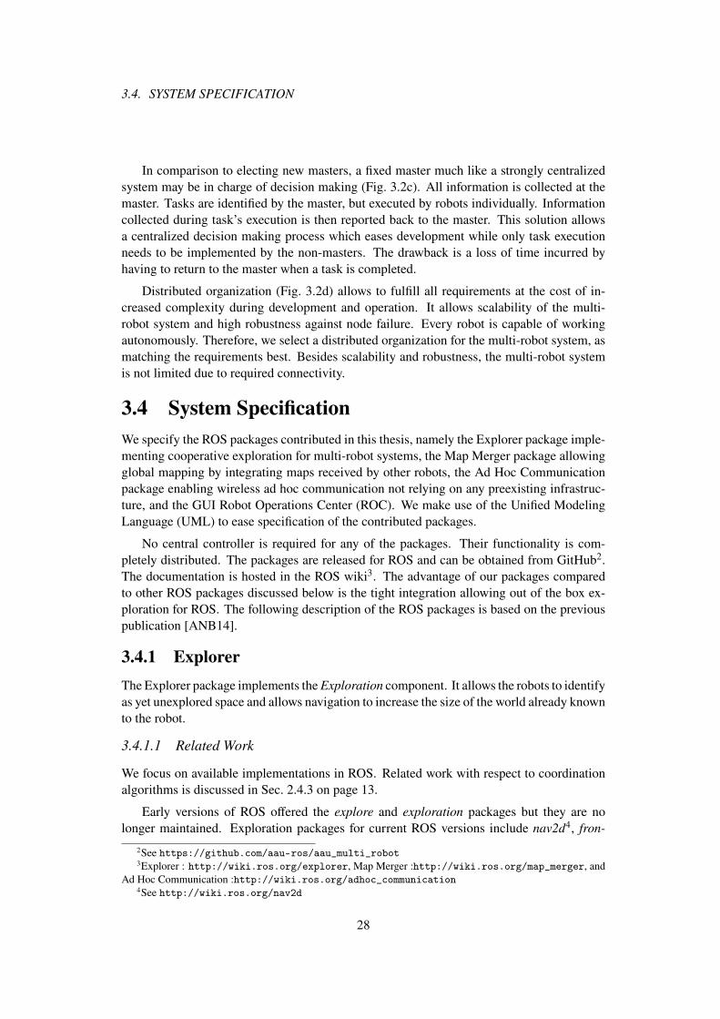
3.4. SYSTEM SPECIFICATION
In comparison to electing new masters, a fixed master much like a strongly centralizedsystem may be in charge of decision making (Fig. 3.2c). All information is collected at themaster. Tasks are identified by the master, but executed by robots individually. Informationcollected during task’s execution is then reported back to the master. This solution allowsa centralized decision making process which eases development while only task executionneeds to be implemented by the non-masters. The drawback is a loss of time incurred byhaving to return to the master when a task is completed.
Distributed organization (Fig. 3.2d) allows to fulfill all requirements at the cost of in-creased complexity during development and operation. It allows scalability of the multi-robot system and high robustness against node failure. Every robot is capable of workingautonomously. Therefore, we select a distributed organization for the multi-robot system, asmatching the requirements best. Besides scalability and robustness, the multi-robot systemis not limited due to required connectivity.
3.4 System Specification
We specify the ROS packages contributed in this thesis, namely the Explorer package imple-menting cooperative exploration for multi-robot systems, the Map Merger package allowingglobal mapping by integrating maps received by other robots, the Ad Hoc Communicationpackage enabling wireless ad hoc communication not relying on any preexisting infrastruc-ture, and the GUI Robot Operations Center (ROC). We make use of the Unified ModelingLanguage (UML) to ease specification of the contributed packages.
No central controller is required for any of the packages. Their functionality is com-pletely distributed. The packages are released for ROS and can be obtained from GitHub2.The documentation is hosted in the ROS wiki3. The advantage of our packages comparedto other ROS packages discussed below is the tight integration allowing out of the box ex-ploration for ROS. The following description of the ROS packages is based on the previouspublication [ANB14].
3.4.1 Explorer
The Explorer package implements the Exploration component. It allows the robots to identifyas yet unexplored space and allows navigation to increase the size of the world already knownto the robot.
3.4.1.1 Related Work
We focus on available implementations in ROS. Related work with respect to coordinationalgorithms is discussed in Sec. 2.4.3 on page 13.
Early versions of ROS offered the explore and exploration packages but they are nolonger maintained. Exploration packages for current ROS versions include nav2d4, fron-
2See https://github.com/aau-ros/aau_multi_robot3Explorer : http://wiki.ros.org/explorer, Map Merger :http://wiki.ros.org/map_merger, and
Ad Hoc Communication :http://wiki.ros.org/adhoc_communication4See http://wiki.ros.org/nav2d
28

CHAPTER 3. OVERVIEW OF THE MULTI-ROBOT SYSTEM
Explorer States
do / Assign frontier
FrontierAssignment
do / Navigate to base station
Returnentry / Start timer
do / Wait for new frontiers
exit / Process new frontiers
AwaitingFrontiers
do / Travel and map
exit / Update data
Travel
Idle
Timeout
Frontier assigned
No frontiers left
No unassigned frontiers left
Frontiers received
Navigation completed
Figure 3.3: UML state diagram of ROS Explorer node.
tier_exploration5, and hector_exploration_node6, which implement single robot exploration.They identify frontiers as navigation goals for a robot. In comparison, our package allowsdistributed coordination of multiple robots aiming to prevent robots from exploring identicalareas.
3.4.1.2 Exploration Process
During exploration a robot may be in any of the four states illustrated in Fig. 3.3. Uponstarting the node it begins in the state Idle until the command to commence exploration isreceived. The node transitions into the state Frontier Assignment. In this state a three-stepprocess determines frontiers to be assigned to robots:
• Frontier detection identifies transitions from free space to unknown space in the map,so called frontiers [Yam97].
• Frontier assessment evaluates frontiers according to a given metric. Here, frontiersare ranked in ascending order according to travel distance between a robot’s currentposition and a frontier.
• Frontier assignment assigns frontiers to a robot. In a multi-robot system the assign-ment is coordinated. Due to the dependency of exploration and coordination, the Ex-plorer package additionally includes the component Coordination.
Frontiers are coordinated based on auctioning [SAB+00] yielding good results com-pared to other methods [JGR12]. The assignment of robots to clusters is performedbased on the Hungarian method [WSB08].
Fig. 3.4 illustrates the frontier assignment process. First, new frontiers are detected, stored,
5See http://wiki.ros.org/frontier_exploration6See http://wiki.ros.org/hector_exploration_node
29

3.4. SYSTEM SPECIFICATION
Frontier Assignment
Assign frontier
Detectfrontiers
Distributefrontiers
Assess allfrontiers
<<datastore>>
Frontiers
Receive bids
Send
<<centralBu er>>
Unassigned frontiers <<centralBu er>>
Bids
Send auction
Bids
Frontier
Unassignedfrontiers
New frontiers{create}
[else]
[Unassigned frontiers left]
Assign frontiers
Bids{rcvd}
Unassigned frontiers
Assigned frontier
Navigate to frontier
Unassigned frontiers
Figure 3.4: The frontier assignment process.
and distributed to other robots. All available and as yet unassigned frontiers are assessedand ranked. If unassigned frontiers are left, an auction is started indicating these frontiersfor auction. Robots participating in the auction assess the auctioned frontiers based on theirlocation and compute their bids. The bids are returned to the auctioneer including its ownbid. The auctioneer assigns frontiers based on the Hungarian method [WSB08]. Finally, theauctioneer informs the bidding robots which frontier it has assigned to itself before transi-tioning to the state Travel. The bidding robots are aware of the selected frontier and removeit from their lists of unassigned frontiers.
While traveling to the next frontier, robots continue to map their environment. A robotmay reach a frontier successfully or abort traveling because no path can be found. In bothcases the frontier is updated accordingly and the robot’s position is updated. The frontierassignment process starts anew.
If during frontier assignment no unassigned frontiers are left, a robot waits for other robotsto finish exploration of their currently assigned frontiers. While other robots continue toexplore, new frontiers may be detected, which can then be assigned to idle robots. Reception
30

CHAPTER 3. OVERVIEW OF THE MULTI-ROBOT SYSTEM
of new frontiers restarts the assignment process. If no new frontiers are received within aspecified interval, a robot will automatically return to its BS. If no frontiers are left, robotsreturn to their BS.
3.4.1.3 Features
Features of the Explorer package are:
• Integration Ad Hoc Communication package and
• Integration Map Merger package allow out of the box deployment. All topics andsettings are pre-configured.
• Coordinated exploration including frontier identification and coordinated assignmentas described above.
• Frontier detection and evaluation automatically detects frontiers in the global map,evaluates their costs, and disseminates them in the network.
• Clustering groups frontiers to optimize coordination.
• Frontier coordination coordinates the assignment of frontiers using the Hungarianmethod.
• Bid interpolation aims to interpolate bids of other robots which did not send their bidsfor an auctioned cluster by considering their last known location.
3.4.2 Map Merger
The task of the Map Merger node is threefold. Firstly, it is responsible for distributing andcollecting local maps. On the side of the sender it implements protocols to disseminate localmaps to other robots. At the receiver, it allows to keep track of received updates and automat-ically request missing updates. It uses the Ad Hoc Communication node for dissemination.Secondly, it constructs a global map by integrating the local maps received from other robotsin a robot’s own local map. The global map is used by the robots to navigate, explore, andcoordinate. Mapping of unknown environments is performed in the local map only to reducethe impact of map merging errors. Thirdly, it allows to translate between coordinate systems.Every robot uses its own coordinate system relative to its starting position. Frontier coordi-nation as described above requires robots to exchange coordinates. The Map Merger nodeimplements the transformation function allowing to translate coordinates between differentcoordinate systems of the robots.
The Map Merger node may be distributed or centralized. If executed centrally, each robotwill have to send its local map to the central instance where the Map Merger constructs theglobal map. The global map needs to be disseminated to the robots. If distributed, robotsshare their local maps. The Map Merger node merges the local maps and delivers the resultingglobal map only locally, i.e., to the robot it is executed on.
31

3.4. SYSTEM SPECIFICATION
Map Merger States
do / Store map update
MapUpdate
do / Merge all maps
exit / Publish global map
PublishGlobalMap
HandleRequest
ManageRobot
RobotPositionUpdate
TransformUpdate
SendMap
Topic update
Control data received
Robot detected
TimeoutInit
Exit
Idle
Timeout
TimeoutTimeout
Figure 3.5: UML state diagram of ROS Map Merger states.
The package is inspired by the mapstitch package7, but extends and improves it in nu-merous ways. Our package allows execution during exploration and implements protocols toexchange maps between robots.
3.4.2.1 Related Work
Various algorithms for distributed SLAM are discussed in the literature [How06, CPD10,CND+10, SPT+14] but no implementations for ROS are available. In comparison, the map-
stitch package and cg_mrslam8 packages already allow distributed mapping. While the for-mer requires extension, the latter is not maintained any longer. Using the mapstitch packagehas the advantage of being able to build upon already tested software compared to having toimplement an algorithm presented in any of the aforementioned papers.
A number of ROS packages allow mapping of unknown environments in either2D metric maps, e.g., hector_mapping9; three-dimensional (3D) metric maps, e.g., oc-
tomap_mapping10; or topological maps, e.g., laser_slam_mapper11. The latter is not avail-able for current ROS versions. We use the standard mapping package gmapping12, whichcreates a metric occupancy grid. Its advantage is the continuous integration and develop-ment with ROS.
3.4.2.2 Map Merger States
Fig. 3.5 illustrates the state diagram of the Map Merger node. Once started, the node initial-izes by allocating memory and subscribing to channels on which map changes are communi-cated. Having initialized the node remains idle until the detection of predefined events. The
7See http://wiki.ros.org/mapstitch8See https://github.com/mtlazaro/cg_mrslam9See http://wiki.ros.org/hector_mapping
10See http://wiki.ros.org/octomap_mapping11See http://wiki.ros.org/laser_slam_mapper12See http://wiki.ros.org/gmapping
32

CHAPTER 3. OVERVIEW OF THE MULTI-ROBOT SYSTEM
majority of transitions into states are triggered by timers. Triggering transitions by the re-ception of new data does not scale well with increasing numbers of robots. In larger groups,updates are received more frequently than data can be processed due to limited computationalresources. Triggering transitions by timers allows better scalability at the cost of delayed in-formation processing. We explain the different states in more detail.
• In state HandleRequest protocol messages exchanged between different instances ofthe Map Merger node are processed, i.e., (re-)transmission of missing updates betweenrobots. Updates are identified by an increasing sequence number allowing to detectmissing updates. Also, only missing updates may be requested for retransmission pre-venting redundant dissemination of updates as suggested in [SYZW05].
• Map updates processes new incoming maps triggered by the reception of local mapsby either other robots or the robot’s own map. Changes in the map are tracked andstored for later processing during the activity Merge all maps (see Sec. 3.4.2.3).
• PublishGlobalMap handles construction of the global map. In this state the globalmap is constructed by merging all local maps. Upon exit, the global map is published.The state is triggered by a timer due to the comparably high computation load causedby the state’s activities. Reacting upon each change in local maps exceeds the compu-tational resources available on many robot systems. Further, consecutive changes in amap are often only minimal and not significant for coordination. The activity Merge
all maps (see Sec. 3.4.2.3) is executed before publishing the updated global map.
• SendMap is the counterpart to MapUpdate and is triggered by a timer. If the eventfires and changes in the local map have occurred, these changes will be distributedin the network. If no changes have occurred, the package will return to idle withoutdistributing map updates.
• TransformationUpate is triggered by a timer. Merging maps requires to transformbetween the individual robots’ coordinate systems. The computation of the transfor-mation is elaborated in Sec. 3.4.2.4 on page 35. The transformation is updated inregular intervals to make use of newly received map data which generally improvesthe transformation’s accuracy.
• Manage robots handles the discovery of new robots by allocating additional resourcesand initiating map exchange. The local maps of newly identified robots are automati-cally included in the global map. Rediscovery of robots triggers the retransmission ofmissing map updates and automatic inclusion in the global map.
• Robot positions are transmitted in regular intervals. The package automatically con-verts other robots’ positions to the correct coordinate system.
3.4.2.3 Merging Process
Birk et al. describe the merging process conceptually and mathematically in [BC06]. TheMap Merger node computes the transformation between two local maps M1 and M2. It con-structs the global map by joining the local maps while maximizing the match of overlappingareas.
33

3.4. SYSTEM SPECIFICATION
Merge all
<<datastore>>
Robots
Robot r
[false]
Merge local map
<<decisionInput>>
Unprocessed robots?
[true]
Figure 3.6: Activity diagram of merging local maps of all known robots.
Map Merging
Merge Local Map
Robot r
Robot r
Own map m
Robot map m(r)
Transformation t(r)[false]
[true]
Load maps
[false]
Transformation t(r)
Robot r
Load transformation
<<decisionInput>>
Local map update since last merger?
Map m(r)
Compute transformation
Merge maps
<<decisionInput>>
Transformation available?
[false]
[true]
<<decisionInput>>
Transformation
available?
Figure 3.7: Activity diagram Merging of local map.
Fig. 3.6 illustrates the merging process. The node iterates over all known robots andattempts to merge any updates on the local maps into the global map. Fig. 3.7 depicts theprocess of merging a local map. If updates to the local map of robot r are received, thetransformation is loaded. Otherwise, no new data may be merged. If no transformation isavailable, the computation of a transformation is attempted. If no new transformation can becomputed, the local map of r cannot be merged at this point in time. Additional updates to thelocal map may allow to compute the transformation at a later time. Once the transformationis available, the updates to the local map of r are merged to the global map.
The transformation between coordinate systems is computed with OpenCV. By convert-ing the ROS occupancy grid to a bitmap file, OpenCV’s estimateRigitTransform methodis used. It tries to match patterns within the local maps to determine the transformation. Thedecision to use OpenCV instead of models based on Bayesian updates [KFL+03] or filters[ÖA10] was made in the light of its easy implementation. A drawback is that overlappinglocal maps are required. However, in exploration missions it is meaningful to assume robotsstart at the same position, e.g., the entrance of a building, so that maps overlap from the
34
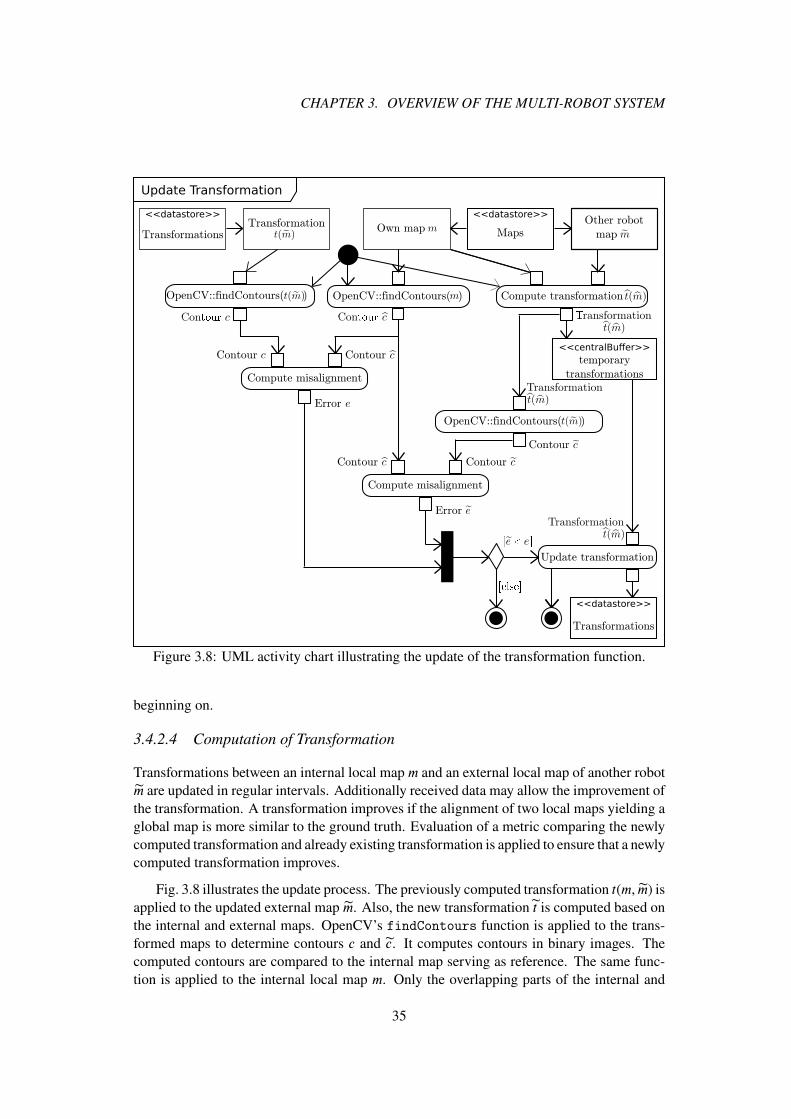
CHAPTER 3. OVERVIEW OF THE MULTI-ROBOT SYSTEM
Update Transformation
<<datastore>>
Transformations
OpenCV::findContours( )
Cont��� Cont���
[ � ]
Other robot
map
<<datastore>>
Maps
<<datastore>>
TransformationsTransformation Own map
<<centralBuffer>>
temporary
transformations
Compute transformation OpenCV::findContours( )
Contour
OpenCV::findContours( )
Contour
Error
Contour
Compute misalignment
Contour
Error
Contour
Compute misalignment
Update transformation
[����]
Transformation
Transformation
Transformation
Figure 3.8: UML activity chart illustrating the update of the transformation function.
beginning on.
3.4.2.4 Computation of Transformation
Transformations between an internal local map m and an external local map of another robotm are updated in regular intervals. Additionally received data may allow the improvement ofthe transformation. A transformation improves if the alignment of two local maps yielding aglobal map is more similar to the ground truth. Evaluation of a metric comparing the newlycomputed transformation and already existing transformation is applied to ensure that a newlycomputed transformation improves.
Fig. 3.8 illustrates the update process. The previously computed transformation t(m, m) isapplied to the updated external map m. Also, the new transformation t is computed based onthe internal and external maps. OpenCV’s findContours function is applied to the trans-formed maps to determine contours c and c. It computes contours in binary images. Thecomputed contours are compared to the internal map serving as reference. The same func-tion is applied to the internal local map m. Only the overlapping parts of the internal and
35
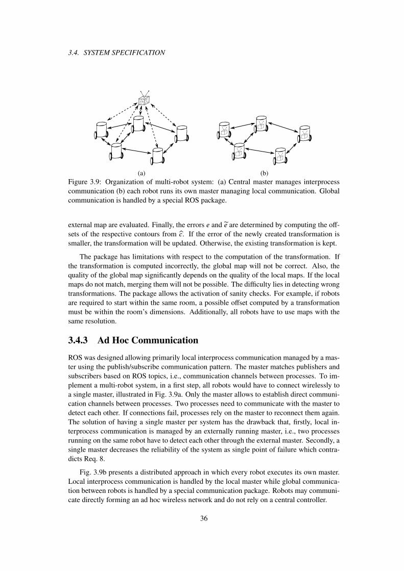
3.4. SYSTEM SPECIFICATION
(a) (b)Figure 3.9: Organization of multi-robot system: (a) Central master manages interprocesscommunication (b) each robot runs its own master managing local communication. Globalcommunication is handled by a special ROS package.
external map are evaluated. Finally, the errors e and e are determined by computing the off-sets of the respective contours from c. If the error of the newly created transformation issmaller, the transformation will be updated. Otherwise, the existing transformation is kept.
The package has limitations with respect to the computation of the transformation. Ifthe transformation is computed incorrectly, the global map will not be correct. Also, thequality of the global map significantly depends on the quality of the local maps. If the localmaps do not match, merging them will not be possible. The difficulty lies in detecting wrongtransformations. The package allows the activation of sanity checks. For example, if robotsare required to start within the same room, a possible offset computed by a transformationmust be within the room’s dimensions. Additionally, all robots have to use maps with thesame resolution.
3.4.3 Ad Hoc Communication
ROS was designed allowing primarily local interprocess communication managed by a mas-ter using the publish/subscribe communication pattern. The master matches publishers andsubscribers based on ROS topics, i.e., communication channels between processes. To im-plement a multi-robot system, in a first step, all robots would have to connect wirelessly toa single master, illustrated in Fig. 3.9a. Only the master allows to establish direct communi-cation channels between processes. Two processes need to communicate with the master todetect each other. If connections fail, processes rely on the master to reconnect them again.The solution of having a single master per system has the drawback that, firstly, local in-terprocess communication is managed by an externally running master, i.e., two processesrunning on the same robot have to detect each other through the external master. Secondly, asingle master decreases the reliability of the system as single point of failure which contra-dicts Req. 8.
Fig. 3.9b presents a distributed approach in which every robot executes its own master.Local interprocess communication is handled by the local master while global communica-tion between robots is handled by a special communication package. Robots may communi-cate directly forming an ad hoc wireless network and do not rely on a central controller.
36

CHAPTER 3. OVERVIEW OF THE MULTI-ROBOT SYSTEM
Ad hoc networks are a class of networks that do not rely on preexisting infrastructure. Allrobots participate in routing using routes that are adapted or created anew when the topologyof the underlying network changes. The high degree of flexibility of these networks makesthem ideal for mobile multi-robot systems. A well known ad hoc routing protocol is Ad hocOn-Demand Distance Vector (AODV) [PBRD03]. Communication routes between robotsare created on demand. If a route fails, i.e., the connection between source and destinationis lost, the route will be repaired or a new route established. AODV is designed for mobilenetworks such as indoor robot systems.
Chapter 5 (pages 59 to 89) discusses the requirements and capabilities of the communi-cation network in more detail. This section gives an overview of the implemented ROS nodeallowing distributed inter-robot communication.
3.4.3.1 Related Work
The majority of ROS packages implementing inter-robot communication in ROS rely on ex-isting infrastructure in form of WLAN access points which robots connect to. Communica-tion packages focus on communication with short delays using UDP at the cost of decreasedreliability. Currently available packages differ with respect to their functionalities and or-ganization of communicated data. The rocon_multimaster13 package implements buildingblocks that can be used by other packages to enable inter-robot communication, but does notoffer communication itself. The multimaster_fkie14 package allows the discovery of robotsas well as unicast and multicast transmissions based on UDP. The socrob_multimaster15
handles medium access using a time division multiple access (TDMA) scheme within therobot network. The Real-Time Database (RTDB) middleware [SAPL09] follows the conceptof distributed shared memory where local databases are replicated to other robots allowinglocal, non-blocking access. TDMA is also used by Tardioli et al. [TSV15]. The authorsimplement a real-time protocol focusing on support of traffic priorities and delay.
The cg_mrslam package sets up an ad hoc network though it does not seem to implementany routing protocols or diversity transmissions to increase reliability [LPP+13]. UDP isused on the transport layer.
In comparison, our ROS package implements AODV for unicast and Multicast AODV(MAODV) for multicast transmission. It uses automatic repeat request (ARQ) on data linkand transport layers for unicast and multicast allowing reliable transmissions. The advan-tage is that applications using the communication package do not have to ensure reliabilitythemselves. Developers may focus on their application and do not need to implement retrans-mission protocols themselves.
3.4.3.2 Features
Features of the Ad Hoc Communication package are as follows:
13See http://wiki.ros.org/rocon_multimaster/14See http://wiki.ros.org/multimaster_fkie15See http://wiki.ros.org/socrob_multicast
37
3.4. SYSTEM SPECIFICATION
Wireless transmission
Robot A
Map Merger Ad hoc Comm
Robot B
Map MergerAd hoc Comm(1)
(2)
(3)
Figure 3.10: Integration of the Ad Hoc Communication package in ROS.
• Routing allows robots to communicate via multiple hops to other robots which are notin the immediate neighborhood. Routing supports reliable unicast, reliable multicast,and unreliable broadcast transmissions.
• Reliability is increased by ARQ and cooperative relaying. Both hop-by-hop and end-to-end ARQ are supported.
• Segmentation allows to split data packets into multiple frames of smaller size. TheIEEE 802.11a/g/n medium access control (MAC) layer supports payloads up to 2304octets [IEE12]. On the receiver side the frames are ordered and combined.
• Ordering ensures that frames and packets are delivered in the correct order.
• Simulation requires the implementation of a channel model to simulate real-worldwireless channels. The Ad Hoc Communication package includes the well known log-distance path loss model [Rap01]. The parameterization is done based on real-worldmeasurements in an industrial building [ABMB12]. Its strength is the easy implemen-tation and the abstraction from the actual environment. Other models simulate thewireless channel more realistically, but require detailed information of the environ-ment. The current implementation can easily be extended to implement these models.
• Traffic generators are used to simulate traffic. The included generator allows to trans-mit data of variable and arbitrary size with random intervals between transmissions. Itcan be freely configured to simulate various kinds of traffic.
3.4.3.3 Integration into ROS
Fig. 3.10 illustrates the integration into ROS. In this example, robots A and B do not com-municate directly but utilize the Ad Hoc Communication package using a service call (1).The service call includes destination, data to be transmitted, and a topic on which to publishthe data at the destination. The Ad Hoc Communication package wraps the data into an ex-tended MAC frame and transmits the frame using a raw socket (2). Using raw sockets allowsthe implementation of AODV and MAODV and easy modifications for future improvementsrunning in user space and not in kernel space. Once robot B has received the frame suc-cessfully, the Ad Hoc Communication package publishes the received data under the topicspecified within the packet (3). This implementation is flexible with respect to communi-cation partners and completely transparent to ROS. Furthermore, this approach follows theROS principle of communication by subscribing to topics.
38

CHAPTER 3. OVERVIEW OF THE MULTI-ROBOT SYSTEM
(a) (b)Figure 3.11: Robot Operations Center: GUI for (a) listing robots and (b) teleoperation ofrobots.
3.4.4 Robot Operations Center
The Robot Operations Center (ROC) is a plug-in for the ROS graphical tool rqt. It illustratespossible features and design of a GUI for system users. It allows to monitor the multi-robotsystem and to manually operate robots. ROC is intended to run on a TRM which does notrequire to implement the complete architecture as specified in Fig. 3.1 on page 24. The TRMrequires the ROC plug-in, the Ad Hoc Communication package to allow communication, andthe Map Merger package. The latter is required to receive map updates from other robots.It attempts to construct a global map from the received local maps and allows to display theglobal may using the map visualization plug-in rviz. ROC is completely decentralized. Anynumber of TRMs may run ROC.
3.4.4.1 Status Updates
Fig. 3.11a illustrates the list of all robots currently known in the multi-robot system. Upondetection of a new robot by receiving a robot beacon, the robot is automatically added to thelist of robots. Beacons include basic information about robots. For each robot its dimensions,remaining battery power, and capabilities are displayed. The list allows to filter for robotsaccording to remaining battery power, status, or control.
39

3.5. SYSTEM EVALUATION
(a) (b)Figure 3.12: Global maps created by (a) two Pioneer 3-DX robots with laser range scannersin a real-world environment and (b) by four robots in a simulation each equipped with a laserrange scanner. The light areas are the local maps overlayed on the global map for betterillustration.
3.4.4.2 Control
Robots may be controlled manually. One instance of ROC allows teleoperation of up totwo robots simultaneously though control can be extended to steer any number of robots.Fig. 3.11b illustrates the interface to control robots, e.g., joy and marley. Due to the lack ofcameras on the robots, the current version does not allow to depict live-video streams fromthe robots. Without live-video, manual steering of robots is only meaningful if robots are inviewing range. Having the available hardware, the system can easily be extended to supportvideo streams.
3.5 System Evaluation
The packages are tested in real-world experiments using Turtlebot and Pioneer 3-DX robotsin office corridors, labs, and partly in environments built for demonstration. All packagesshow reliable behavior, especially on the Pioneer robots. The Map Merger node benefitsfrom the precise mapping of the Pioneer robots using laser range scanners and improvedodometry. The Turtlebot is equipped with a Kinect in which map errors occur more oftencompared to the laser range scanner. Fig. 3.12a illustrates merged maps in our labs. The AdHoc Communication package is tested separately in Chapter 5 on page 59.
We use simulations to quantitatively determine the performances of the multi-robot sys-tem, verify the correct implementation of the packages, and determine possible improve-ments for future work. Simulations are performed using the ROS stage simulator [Vau08].Robot teams consist of R = 1, 2, 3, 4 robots. Simulations are performed N = 40 times foreach robot team. Fig. 3.12b depicts a global map of the simulation environment. The maphas dimensions of 26m by 15m. Rooms have dimensions of 4m by 4.9m. Robots start inthe upper left corner of the map facing to the right. To solely determine the performance ofthe exploration package, we use error free communication.
40
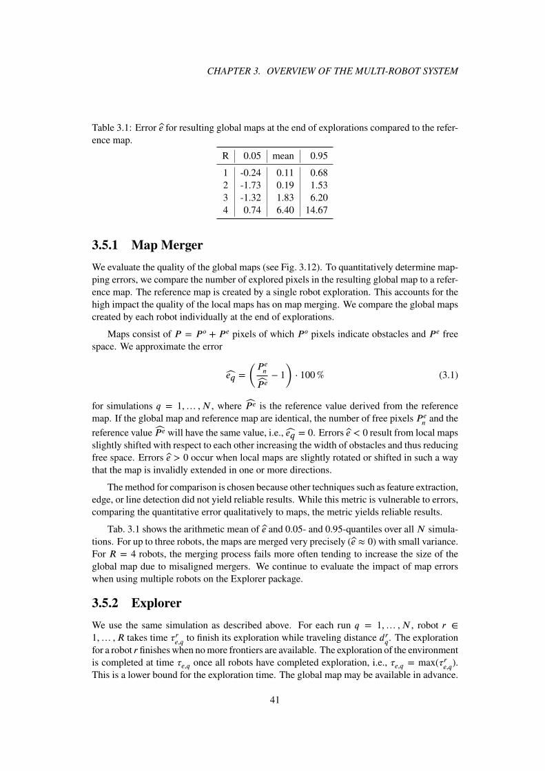
CHAPTER 3. OVERVIEW OF THE MULTI-ROBOT SYSTEM
Table 3.1: Error e for resulting global maps at the end of explorations compared to the refer-ence map.
R 0.05 mean 0.95
1 -0.24 0.11 0.682 -1.73 0.19 1.533 -1.32 1.83 6.204 0.74 6.40 14.67
3.5.1 Map Merger
We evaluate the quality of the global maps (see Fig. 3.12). To quantitatively determine map-ping errors, we compare the number of explored pixels in the resulting global map to a refer-ence map. The reference map is created by a single robot exploration. This accounts for thehigh impact the quality of the local maps has on map merging. We compare the global mapscreated by each robot individually at the end of explorations.
Maps consist of P = P o + P e pixels of which P o pixels indicate obstacles and P e freespace. We approximate the error
eq =
(P en
P e− 1
)⋅ 100% (3.1)
for simulations q = 1,… , N , where P e is the reference value derived from the referencemap. If the global map and reference map are identical, the number of free pixels P e
n and the
reference value P e will have the same value, i.e., eq = 0. Errors e < 0 result from local mapsslightly shifted with respect to each other increasing the width of obstacles and thus reducingfree space. Errors e > 0 occur when local maps are slightly rotated or shifted in such a waythat the map is invalidly extended in one or more directions.
The method for comparison is chosen because other techniques such as feature extraction,edge, or line detection did not yield reliable results. While this metric is vulnerable to errors,comparing the quantitative error qualitatively to maps, the metric yields reliable results.
Tab. 3.1 shows the arithmetic mean of e and 0.05- and 0.95-quantiles over all N simula-tions. For up to three robots, the maps are merged very precisely (e ≈ 0) with small variance.For R = 4 robots, the merging process fails more often tending to increase the size of theglobal map due to misaligned mergers. We continue to evaluate the impact of map errorswhen using multiple robots on the Explorer package.
3.5.2 Explorer
We use the same simulation as described above. For each run q = 1,… , N , robot r ∈
1,… , R takes time �re,q to finish its exploration while traveling distance drq. The exploration
for a robot r finishes when no more frontiers are available. The exploration of the environmentis completed at time �e,q once all robots have completed exploration, i.e., �e,q = max(�re,q).This is a lower bound for the exploration time. The global map may be available in advance.
41
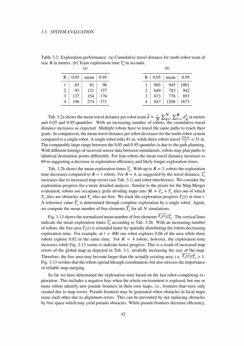
3.5. SYSTEM EVALUATION
Table 3.2: Exploration performance: (a) Cumulative travel distance for multi-robot team ofsize R in meters. (b) Team exploration time �e in seconds.
(a)
R 0.05 mean 0.95
1 65 81 962 93 121 1573 127 154 1764 196 274 371
(b)
R 0.05 mean 0.95
1 865 945 10012 649 783 9423 673 776 8934 847 1208 1673
Tab. 3.2a shows the mean travel distance per robot team d =1
N
∑Nq=1
∑Rr=1 d
rq in meters
and 0.05 and 0.95-quantiles. With an increasing number of robots, the cumulative traveldistance increases as expected. Multiple robots have to travel the same paths to reach theirgoals. In comparison, the mean travel distance per robot decreases for the multi-robot systemcompared to a single robot. A single robot treks 81m, while three robots travel 154m
3≈ 51m.
The comparably large range between the 0.05 and 0.95-quantiles is due to the path planning.With different timings of received sensor data between simulations, robots may plan paths toidentical destination points differently. For four robots the mean travel distance increases to69m suggesting a decrease in exploration efficiency and likely longer exploration times.
Tab. 3.2b shows the mean exploration times �e. With up to R = 3, robots the explorationtime decreases compared to R = 1 robots. For R = 4, as suggested by the travel distance, �eincreases due to increased map errors (see Tab. 3.1) and robot interference. We consider theexploration progress for a more detailed analysis. Similar to the pixels for the Map Mergerevaluation, robots use occupancy grids dividing maps into M = To + Te tiles out of whichTo tiles are obstacles and Te tiles are free. We track the exploration progress Te(t) at time t.A reference value Te is determined through complete exploration by a single robot. Again,we compute the mean number of free elements Te for all N simulations.
Fig. 3.13 shows the normalized mean number of free elements Te(t)∕Te. The vertical linesindicate the mean exploration times �e according to Tab. 3.2b. With an increasing numberof robots, the free area Te(t) is extended faster by spatially distributing the robots decreasingexploration time. For example, at t = 400 one robot explores 0.66 of the area while threerobots explore 0.82 in the same time. For R = 4 robots, however, the exploration timeincreases while Fig. 3.13 seems to indicate faster progress. This is a result of increased maperrors of the global map as depicted in Tab. 3.1, invalidly increasing the size of the map.
Therefore, the free area may become larger than the actually existing area, i.e. Te(t)∕Te > 1.Fig. 3.13 verifies that the robots spread through coordination, but also stresses the importanceof reliable map merging.
So far we have determined the exploration time based on the last robot completing ex-ploration. This includes a negative bias when the whole environment is explored, but one ormore robots identify new pseudo frontiers in their own maps, i.e., frontiers that were onlycreated due to map errors. Pseudo frontiers may be generated when obstacles in local mapserase each other due to alignment errors. This can be prevented by not replacing obstaclesby free space which may yield pseudo obstacles. While pseudo frontiers decrease efficiency,
42
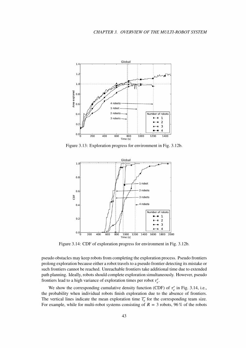
CHAPTER 3. OVERVIEW OF THE MULTI-ROBOT SYSTEM
Figure 3.13: Exploration progress for environment in Fig. 3.12b.
Figure 3.14: CDF of exploration progress for environment in Fig. 3.12b.
pseudo obstacles may keep robots from completing the exploration process. Pseudo frontiersprolong exploration because either a robot travels to a pseudo frontier detecting its mistake orsuch frontiers cannot be reached. Unreachable frontiers take additional time due to extendedpath planning. Ideally, robots should complete exploration simultaneously. However, pseudofrontiers lead to a high variance of exploration times per robot �re .
We show the corresponding cumulative density function (CDF) of �re in Fig. 3.14, i.e.,the probability when individual robots finish exploration due to the absence of frontiers.The vertical lines indicate the mean exploration time �e for the corresponding team size.For example, while for multi-robot systems consisting of R = 3 robots, 96% of the robots
43

3.5. SYSTEM EVALUATION
finish exploration within t = 900 s, for R = 1 only 21% finish exploration in the giventime. With an increasing number of up to three robots, the probability to finish explorationearlier increases supporting previous results of faster exploration and verifying the correctimplementation of the packages. Only in case of R = 4 robots does the probability decreasessignificantly for two reasons. The first reason is the existence of aforementioned pseudofrontiers. The map error e can be correlated to long exploration times. With increasing maperror e for increasing numbers of robots, robots are more likely to take a long time to finishexploration. For example, for R = 4 robots 50% of all robots require exploration timeslonger than 1021 s. Secondly, increased robot interference decreases efficiency because theenvironment is too small and simple for four robots to efficiently distribute.
44

4COORDINATION IN MULTI-ROBOTSYSTEMS
Contents4.1 Problem Statement . . . . . . . . . . . . . . . . . . . . . . . . . . . . . 46
4.2 Influence of Robot Perception . . . . . . . . . . . . . . . . . . . . . . . 47
4.3 Markov Model . . . . . . . . . . . . . . . . . . . . . . . . . . . . . . . 47
4.3.1 State Transition Matrix . . . . . . . . . . . . . . . . . . . . . . . 47
4.3.2 Performance Metrics . . . . . . . . . . . . . . . . . . . . . . . . 48
4.3.3 Transition Probabilities . . . . . . . . . . . . . . . . . . . . . . . 49
4.3.4 Example Environment . . . . . . . . . . . . . . . . . . . . . . . 50
4.4 Performance Comparison by Parameter . . . . . . . . . . . . . . . . . . 50
4.4.1 Dominant Frontier . . . . . . . . . . . . . . . . . . . . . . . . . 51
4.4.2 Team Size . . . . . . . . . . . . . . . . . . . . . . . . . . . . . . 52
4.4.3 Robot Density . . . . . . . . . . . . . . . . . . . . . . . . . . . 53
4.4.4 Dominant Frontier and Team Size . . . . . . . . . . . . . . . . . 55
4.5 Multi-Robot Systems in Office Corridors . . . . . . . . . . . . . . . . . . 56
4.6 Value of Coordination . . . . . . . . . . . . . . . . . . . . . . . . . . . . 58
In this chapter we address the value of multi-robot systems compared to multiple single-robot systems. Amigoni et al. suggest in experiments that the gain of coordination in multi-robot teams is in some scenarios not as important as one might intuitively assume. Thedrawback of evaluating the necessity of coordination in real-world scenarios is that it doesnot allow to derive a general statement without a large number of experiments in differ-ent environments, which is infeasible to conduct. Due to varying perceptions of the sameenvironment caused by sensor noise, slightly different starting positions, or changes in the
45
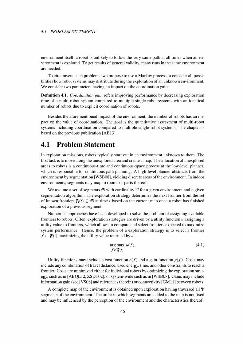
4.1. PROBLEM STATEMENT
environment itself, a robot is unlikely to follow the very same path at all times when an en-vironment is explored. To get results of general validity, many runs in the same environmentare needed.
To circumvent such problems, we propose to use a Markov process to consider all possi-bilities how robot systems may distribute during the exploration of an unknown environment.We consider two parameters having an impact on the coordination gain.
Definition 4.1. Coordination gain refers improving performance by decreasing explorationtime of a multi-robot system compared to multiple single-robot systems with an identicalnumber of robots due to explicit coordination of robots.
Besides the aforementioned impact of the environment, the number of robots has an im-pact on the value of coordination. The goal is the quantitative assessment of multi-robotsystems including coordination compared to multiple single-robot systems. The chapter isbased on the previous publication [AB13].
4.1 Problem Statement
In exploration missions, robots typically start out in an environment unknown to them. Thefirst task is to move along the unexplored area and create a map. The allocation of unexploredareas to robots is a continuous-time and continuous-space process at the low-level planner,which is responsible for continuous path planning. A high-level planner abstracts from theenvironment by segmentation [WSB08], yielding discrete areas of the environment. In indoorenvironments, segments may map to rooms or parts thereof.
We assume a set of segments S with cardinality Ψ for a given environment and a givensegmentation algorithm. The exploration strategy determines the next frontier from the setof known frontiers F(t) ⊆ S at time t based on the current map once a robot has finishedexploration of a previous segment.
Numerous approaches have been developed to solve the problem of assigning availablefrontiers to robots. Often, exploration strategies are driven by a utility function u assigning autility value to frontiers, which allows to compare and select frontiers expected to maximizesystem performance. Hence, the problem of a exploration strategy is to select a frontierf ∈ F(t) maximizing the utility value returned by u:
argmaxf∈F(t)
u(f ) . (4.1)
Utility functions may include a cost function c(f ) and a gain function g(f ). Costs mayinclude any combination of travel distance, used energy, time, and other constraints to reach afrontier. Costs are minimized either for individual robots by optimizing the exploration strat-egy, such as in [ABQL12, ZSDT02], or system-wide such as in [WSB08]. Gains may includeinformation gain (see [VS08] and references therein) or connectivity [GM11] between robots.
A complete map of the environment is obtained upon exploration having traversed all Ψsegments of the environment. The order in which segments are added to the map is not fixedand may be influenced by the perception of the environment and the characteristics thereof.
46

CHAPTER 4. COORDINATION IN MULTI-ROBOT SYSTEMS
(a) (b) (c) (d)Figure 4.1: Impact of robot perception: (a) Layout of indoor environment with segments s1,s2, and s3. Segments s1 and s2 are connected by a passage of width w1, s2 and s3 with one ofwidth w2. L1 and L2 mark two possible positions of the robot. (b) and (c) show the robot’sperception of the environment from position L1 and L2, respectively, for w1 = w2. (d) showsthe robot’s perception from position L1 with w2 ≫ w1.
4.2 Influence of Robot Perception
A given environment may be perceived differently by a robot at different points in time.The perception is mainly influenced by two factors: the robot’s current position and noisysensor readings. Furthermore, the interpretation of such perceptions may suffer from mapinaccuracies. Let us explain with an example that environment perception has an impact onmap creation.
Fig. 4.1a illustrates the layout of a segment s2 at a corridor’s end connecting two segmentss1 and s3. The openings to the segments s1 and s3 have sizes w1 and w2, respectively. Forillustration, the robot heading towards the corridor’s end is positioned at either location L1
or L2, where L1 is at the horizontal center of the corridor while L2 is shifted to the right.To assign a utility value to frontiers, we assume without loss of generality that the robot iscapable of deducing the information gain of a segment by its expected unexplored area, assuggested in [GBL02]. If the robot is located at position L1, the perceived sensor readingswill appear as in Fig. 4.1b. In this case, the inferred areas are likely to be identical, becauses1 and s3 are assumed to be of identical size and the same area of both segments has alreadybeen explored. If the robot is located at L2, under the same assumption of identical segmentsizes, the information gain of segment s3 will be larger, because a larger area of segments1 has already been explored (see Fig. 4.1c). Therefore, the assignment of the next frontierdepends on the robot’s position. The same holds for any utility function that considers costs(such as travel distance), gains, or combinations thereof.
Also the characteristics of the environment influence in which order segments are tra-versed. Fig. 4.1d shows the same environment, but this time with different door widths(w2 ≫ w1). It can be seen that, independent of the robot’s position L1 or L2, the exploredarea of segment s3 is larger than that of s1. Therefore, s1 becomes more likely to be assignedas next frontier.
4.3 Markov Model
4.3.1 State Transition Matrix
A Markov process is used to determine the likelihood of a robot’s progress in its explorationtask in an unknown environment. We consider the high level planner operating on spatially
47

4.3. MARKOV MODEL
discrete segments. Robots change from segment to segment at discrete time steps. This is acommon assumption used in many publications such as [ABQL12, ZSDT02, SYTX06]. Weassume that exploration takes approximately the same time for each segment. This enablesus to model the exploration process by a discrete-time, first-order Markov process.
Given is an environment consisting of Ψ segments obtained through segmentation. Atany discrete time instance t, a subset F(t) ⊆ S with cardinality F (t) frontiers is known.Exploration ends when F(t) = ∅. The environment’s segments are the state space of theMarkov process having cardinality S = |S|. The set of robots is denoted by ℜ; the numberof robots is |ℜ| = R ∈ N.
The state transition matrix P of dimension Ψ × Ψ models the utility function and theimpact of the environment. It allows for a non-deterministic order of traversed segments asexplained in Section 4.2. If there is no path between two segments si and sj , i ≠ j, the
corresponding transition probability in P is zero. Self-loops are not allowed in the model,i.e., P i,i = 0, because robots may not stall in an area after having finished exploration. Eachsegment takes a given time period, here set to one time unit.
The position of a robot r ∈ ℜ at discrete time t is described by the row vector vr(t) bysetting the s-th entry corresponding to the sth segment, s ∈ S, in which the robot is located,to one. The initial position of robot r is called vr(0). With the Markov assumption, theprobability of a robot’s location at time t = 1, 2,… time unit(s) can then be computed by
vr(t) = vr(0) P r(t) . (4.2)
The probability of a robot to be at a segment s ∈ S at time t corresponds to the s-th entry invr(t). Since we assume that no coordination between robots is present, robots move indepen-dently from each other making them stochastically independent and, therefore, it is possibleto compute each robot’s location distribution individually.
4.3.2 Performance Metrics
In order for a segment to be explored, it needs to be visited by at least one robot. Let X(t)
denote the binary random variable that segment s is explored at time instant t by at least onerobot. The probability Pr(X(t) = s) that at least one robot is at segment s at time t is
Pr(X(t) = s
)= 1 −
R∏r=1
[1 − v
(s)r (t)
](4.3)
where v(s)r (t) is the s-th entry of robot r’s state vector v at time t.
This model enables us to compute the expected level of parallelization by consideringthe expected number of segments explored in parallel. Generally, robots shall be assigneduniquely to frontiers. Such motivation may be twofold. First, we would like to prevent pos-sible self-interference among robots during mapping. Second, multiple robots in the samearea may decrease efficiency during exploration due to redundant exploration of the samesegment causing an overall delay. Therefore, we assume that the system performs most ef-ficiently if a single robot only operates at any assigned frontier. The expected number of
48

CHAPTER 4. COORDINATION IN MULTI-ROBOT SYSTEMS
...
Figure 4.2: Frontiers are weighted with transition probabilities.
frontiers explored simultaneously at time t is
E[X(t)] =
Ψ∑s=1
Pr (X(t) = s) . (4.4)
We normalize the total explored area to compute the efficiency of the exploration by
�(t) ∶=E[X(t)]
Q(t)∈ [0, 1] , (4.5)
where Q(t) is the number of segments which could have been explored at time t. The cumu-lative efficiency is
�(t) ∶=
∑ti=0 E[X(i)]
∑ti=0Q(i)
. (4.6)
To compare uncoordinated and coordinated robots we use the coordination gain
gc(t) ∶=min (F (t), R)
E[X(t)], (4.7)
which is the ratio of frontiers explored assuming perfect coordination and the expected num-ber of explored frontiers without coordination.
4.3.3 Transition Probabilities
Setting the probabilities in the transition matrix P allows to model the impact of the envi-ronment on the frontier assignments to robots. We consider robots with memory. Markovprocesses do not easily allow to keep track of already visited states, here segments, due totheir Markov property. To model a robot’s memory, the transition graph must not includeany loops preventing robots from reaching any state more than once. In principle (4.2) canbe used to model heterogeneous robots running different utility functions leading to differenttransition probabilities. Here, we only consider homogeneous robots using the same utilityfunction.
To model the impact of the perception of the environment, the transitions from a givensegment to all potential succeeding segments are weighted with the corresponding transitionprobabilities (see Fig. 4.2). Frontiers fi (i = 1…F ) are possible succeeding frontiers to s
with probabilities pi (i = 1…F ,∑Fi=1 pi = 1).
We consider the non-deterministic order of traversed segments and distinguish two cases.We assume a robot’s position in a segment to be uniformly distributed, making adjacentfrontiers equally likely to be selected as next frontier (case I). The probabilities for each
49

4.4. PERFORMANCE COMPARISON BY PARAMETER
(a) (b)Figure 4.3: Example environment: (a) Map of a corridor with a total of Ψ segments. (b) Thestate representation in the Markov process with a total of Ψ segments.
frontier to be assigned as next frontier are equally distributed: pi = pj , i, j = 1…F . Incase II, it is assumed that, being at a segment si, one frontier is more likely to be selectedthan the others. We denote such frontiers as dominant frontiers and assume a single dominantfrontier to ease analysis. A dominant frontier may be selected with probability pdom, theremaining frontiers are assumed to be selected with a uniform distribution for the sake ofsimplicity. The following results may be adopted to realistic non-uniform distributions. In
the example, let f 1 be the dominant frontier, thus p1 = pdom, then pi =1−pdomF−1
, i = 2…F .
4.3.4 Example Environment
We apply the model in an environment such as a corridor in an office building. Fig. 4.3illustrates the corridor’s map and its exemplified representation in the model. We assume thecorridor to be equally segmented (illustrated by the dotted lines). Each segment is assumedto take approximately the same time to be explored/searched. Differences in travel costsfor various robots are considered to be comparably small and are neglected. Segments aremapped to rooms, thus each room Ki corresponds to a segment si in the state space of theMarkov process. The robots start out in the same segment positioned at the very left corridor’send and sweep to the right.
4.4 Performance Comparison by Parameter
Three parameters have an impact on the coordination gain:
1. number of robots,
2. number of frontiers to choose from F ,
3. dominant frontier.
We start by discussing the impact of the aforementioned parameters and omit the index t.Afterwards we apply the model to the office corridor scenario.
50

CHAPTER 4. COORDINATION IN MULTI-ROBOT SYSTEMS
0.0 0.2 0.4 0.6 0.8 1.0
pdom
1.0
1.2
1.4
1.6
1.8
2.0
2.2
gc
R = 2
R = 4
R = 6
R = 8
(a) F = 2
0.0 0.2 0.4 0.6 0.8 1.0
pdom
1.0
1.5
2.0
2.5
3.0
3.5
4.0
gc
R = 2
R = 4
R = 6
R = 8
(b) F = 4
0.0 0.2 0.4 0.6 0.8 1.0
pdom
1
2
3
4
5
6
gc
R = 2
R = 4
R = 6
R = 8
(c) F = 6
0.0 0.2 0.4 0.6 0.8 1.0
pdom
1
2
3
4
5
6
7
8gc
R = 2
R = 4
R = 6
R = 8
(d) F = 8
Figure 4.4: Impact of dominant frontier on expected coordination gain for a team of R robotsin an environment with F frontiers.
4.4.1 Dominant Frontier
As mentioned before, some frontiers have in general higher likelihoods to be explored beforeothers (see Fig. 4.1d on page 47). We determine the influence of such dominant frontiers.
Fig. 4.4 shows the expected coordination gain according to (4.7) for different F and R.The coordination gain is minimal if robots are uniformly distributed among available fron-tiers, which is the case for pdom =
1
F. The maximum gain is reached for pdom = 1, i.e., the
uncoordinated multi-robot system behaves like a single robot. In such cases coordination ismost useful. In conclusion, robot systems tend to profit from coordination if the environmentleads to multiple frontiers of which one or a few are more likely to be selected.
The authors of [ABQL12] come to similar qualitative conclusions comparing an indoorenvironment to an open environment. Robots in less structured environments tend to selectthe same frontier making one or a few frontiers more prominent than others, which preventsthe robots from spatially spreading. In comparison, structured environments are less likelyto contain a dominant frontier allowing for implicit coordination by design of the utilityfunction.
51
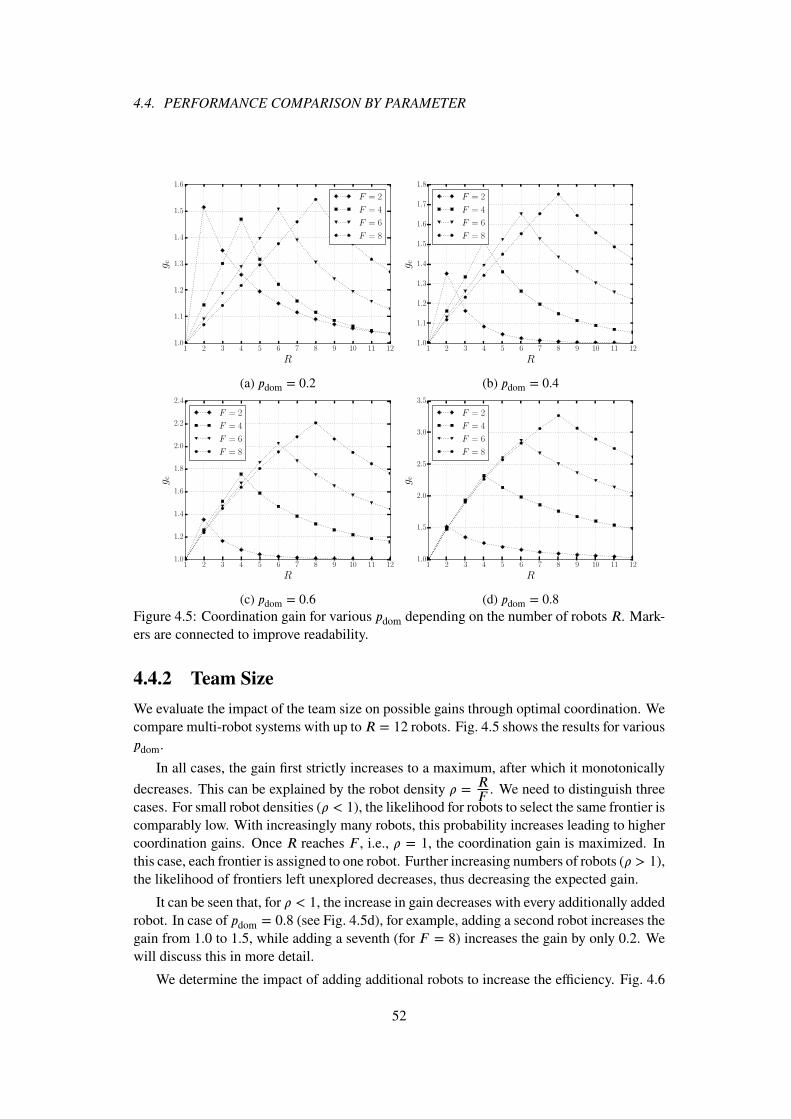
4.4. PERFORMANCE COMPARISON BY PARAMETER
1 2 3 4 5 6 7 8 9 10 11 12
R
1.0
1.1
1.2
1.3
1.4
1.5
1.6
gc
F = 2
F = 4
F = 6
F = 8
(a) pdom = 0.2
1 2 3 4 5 6 7 8 9 10 11 12
R
1.0
1.1
1.2
1.3
1.4
1.5
1.6
1.7
1.8
gc
F = 2
F = 4
F = 6
F = 8
(b) pdom = 0.4
1 2 3 4 5 6 7 8 9 10 11 12
R
1.0
1.2
1.4
1.6
1.8
2.0
2.2
2.4
gc
F = 2
F = 4
F = 6
F = 8
(c) pdom = 0.6
1 2 3 4 5 6 7 8 9 10 11 12
R
1.0
1.5
2.0
2.5
3.0
3.5gc
F = 2
F = 4
F = 6
F = 8
(d) pdom = 0.8
Figure 4.5: Coordination gain for various pdom depending on the number of robots R. Mark-ers are connected to improve readability.
4.4.2 Team Size
We evaluate the impact of the team size on possible gains through optimal coordination. Wecompare multi-robot systems with up to R = 12 robots. Fig. 4.5 shows the results for variouspdom.
In all cases, the gain first strictly increases to a maximum, after which it monotonically
decreases. This can be explained by the robot density � =RF
. We need to distinguish threecases. For small robot densities (� < 1), the likelihood for robots to select the same frontier iscomparably low. With increasingly many robots, this probability increases leading to highercoordination gains. Once R reaches F , i.e., � = 1, the coordination gain is maximized. Inthis case, each frontier is assigned to one robot. Further increasing numbers of robots (� > 1),the likelihood of frontiers left unexplored decreases, thus decreasing the expected gain.
It can be seen that, for � < 1, the increase in gain decreases with every additionally addedrobot. In case of pdom = 0.8 (see Fig. 4.5d), for example, adding a second robot increases thegain from 1.0 to 1.5, while adding a seventh (for F = 8) increases the gain by only 0.2. Wewill discuss this in more detail.
We determine the impact of adding additional robots to increase the efficiency. Fig. 4.6
52

CHAPTER 4. COORDINATION IN MULTI-ROBOT SYSTEMS
1 2 3 4 5 6 7 8 9 10 11 12
R
1
2
3
4
5
6
7
E[X
]
F = 2
F = 4
F = 6
F = 8
Figure 4.6: Comparison of expected number of segments explored parallel for various num-ber of uncoordinated robots.
shows the expected number of segments explored in parallel for various team sizes andF withpdom =
1
F. With each additional robot added, the increase in efficiency for the next robot
decreases. To address the issue of how many robots to add, we can compute the number ofuncoordinated robots required to achieve comparable results to optimally coordinated ones.We assume no dominant frontiers and homogeneous robots, thus all frontiers are exploredwith equal probability independent of the robot. It follows vr is independent of r and f :v(s)r =
1
F. We can rewrite (4.4) along with (4.3) to
E [X] = F ⋅ Pr(X) = F
(1 −
(1 −
1
F
)R), (4.8)
which can be rearranged to
R =log(1 − �)
log(1 −1
F), where � =
E [X]
F≤ 1 (4.9)
is the ratio of the expected number of explored frontiers to available frontiers accordingto (4.5) with Q(t) = F . For � → 1, R goes to infinity because an unlimited number ofuncoordinated robots is required for Pr(X) → 1. For example, consider � = 0.75 and F = 4,a total of R = ⌈4.82⌉ = 5 robots is required compared to 3 coordinated ones. This is a lowerbound. If one considers dominant frontiers, the number of robots will increase further.
With increasing ratio �, the number of robots required to achieve an expected level ofexploration certainty (indicated by E [X]) increases exponentially making coordination nec-essary without the need for a vast number of robots.
4.4.3 Robot Density
Fig. 4.7 summarizes the impact of team and environment sizes for various pdom. Further, itshows the impact of the robot density �. Within each row and column the gain is maximal if� = 1, i.e., F = R. The coordination gain does not solely depend on the density, but also onthe environment size and the number of robots. For a fixed density, the absolute coordinationgain increases with increasing environment/team size.
53

4.4. PERFORMANCE COMPARISON BY PARAMETER
2 4 6 8 10
R
2
4
6
8
10F
1.20 1.35 1.50 1.65 1.80 1.95
gc
(a)
2 4 6 8 10
R
2
4
6
8
10
F
1.12 1.20 1.28 1.36 1.44 1.52
gc
(b)
2 4 6 8 10
R
2
4
6
8
10
F
1.1 1.2 1.3 1.4 1.5 1.6 1.7 1.8
gc
(c)
2 4 6 8 10
R
2
4
6
8
10
F
1.2 1.4 1.6 1.8 2.0 2.2
gc
(d)
2 4 6 8 10
R
2
4
6
8
10
F
1.2 1.5 1.8 2.1 2.4 2.7 3.0 3.3
gc
(e)
2 4 6 8 10
R
2
4
6
8
10
F
2 3 4 5 6 7 8 9 10
gc
(f)Figure 4.7: Coordination gain depending on � for (a) pdom = 0.0 (b) 0.2 (c) 0.4 (d) 0.6 and(e) 0.8.
54
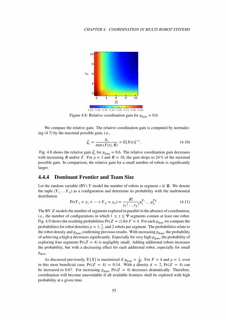
CHAPTER 4. COORDINATION IN MULTI-ROBOT SYSTEMS
2 4 6 8 10
R
2
4
6
8
10
F
0.24 0.30 0.36 0.42 0.48 0.54 0.60 0.66
Figure 4.8: Relative coordination gain for pdom = 0.6.
We compare the relative gain. The relative coordination gain is computed by normaliz-ing (4.7) by the maximal possible gain, i.e.,
gc =gc
min (F (t), R)= E[X(t)]−1 . (4.10)
Fig. 4.8 shows the relative gain gc for pdom = 0.6. The relative coordination gain decreaseswith increasing R and/or F . For � = 1 and R = 10, the gain drops to 24% of the maximalpossible gain. In comparison, the relative gain for a small number of robots is significantlylarger.
4.4.4 Dominant Frontier and Team Size
Let the random variable (RV) Y model the number of robots in segment s ∈ S. We denotethe tuple (Y 1… Y s) as a configuration and determine its probability with the multinomialdistribution
Pr(Y 1 = y1 ∧⋯ ∧ Y s = ys) =R!
y1!… ys!py1
1… p
yss . (4.11)
The RVZ models the number of segments explored in parallel in the absence of coordination,i.e., the number of configurations in which 1 ≤ z ≤ Ψ segments contain at least one robot.Fig. 4.9 shows the resulting probabilities Pr(Z = z) forF = 4. For each pdom we compare theprobabilities for robot densities � = 1, 3
2, and 2 robots per segment. The probabilities relate to
the robot density and pdom confirming previous results. With increasing pdom, the probabilityof achieving a high � decreases significantly. Especially for very high pdom, the probability ofexploring four segments Pr(Z = 4) is negligibly small. Adding additional robots increasesthe probability, but with a decreasing effect for each additional robot, especially for smallpdom.
As discussed previously, E [X] is maximized if pdom =1
F. For F = 4 and � = 1, even
in this most beneficial case, Pr(Z = 4) = 0.14. With a density d = 2, Pr(Z = 4) canbe increased to 0.67. For increasing pdom, Pr(Z = 4) decreases dramatically. Therefore,coordination will become unavoidable if all available frontiers shall be explored with highprobability at a given time.
55

4.5. MULTI-ROBOT SYSTEMS IN OFFICE CORRIDORS
0.1 0.2 0.3 0.4 0.5 0.6 0.7 0.8 0.9 1.0
pdom
0.0
0.2
0.4
0.6
0.8
1.0
1.2
P(Z
=z)
4 6 8R =
4 6 8R =
4 6 8R =
4 6 8R =
4 6 8R =
4 6 8R =
4 6 8R =
4 6 8R =
4 6 8R =
4 6 8R =
z=1
z=2
z=3
z=4
Figure 4.9: Probability Pr(Z = z) for densities � = 1, 3∕2, 2 and F = 4.
Note that apart from the underlying assumptions for this model, all frontiers will be ex-plored in a multi-robot exploration. Frontiers that were not explored at time t1 remain in theset F(t) for t2 > t1. They will be explored at a later time, possibly increasing the costs. Ifthese costs are not mission critical, it may be sufficient to have a high enough probabilityPr(Z) to explore frontiers.
Fig. 4.10 combines pdom and R. The gain increases significantly with increasing domi-nant probability. For pdom ⪅ 0.8, the coordination gain is comparably small independent ofthe number of robots or segments. It only reaches about 30% of the maximal possible gainaccording to (4.7). The probability of robots to implicitly distribute is comparably high.
4.5 Multi-Robot Systems in Office Corridors
We apply the model to the exploration of an office corridor depicted in Fig. 4.3 consideringR = 2 and 3 robots allowing a complete exploration for coordinated robots. Fig. 4.11 showsthe efficiencies for the corridor environment depicted in Fig. 4.3. We consider the same prob-abilities for pdom with two and three robots having densities � =
2
3and 1. The cumulative
efficiency � decreases significantly for t → ∞ requiring coordination if additional sweeps arenot feasible. The efficiency � for three uncoordinated robots lies at � = 0.71 > 0.67, which isthe achievable efficiency of an optimally coordinated two-robot system. Thus, conforming toexpectations, three uncoordinated robots on average outperform two optimally coordinatedrobots for environments comparable to the office corridor. In the case of optimally coor-dinated robots, the cumulative efficiency � is 1.0 and 0.67 in case of three and two robots,respectively. In such cases less efforts may be spent on the coordination function while stillobtaining comparable results at slightly increased deployment costs.
It is unlikely that a whole environment consists of dominant frontiers only, but at leastsingle junctions with dominant frontiers may occur, thus reducing the efficiency of multiple
56

CHAPTER 4. COORDINATION IN MULTI-ROBOT SYSTEMS
0.0 0.2 0.4 0.6 0.8 1.0
pdom
2
4
6
8
10
R
1.2 1.6 2.0 2.4 2.8 3.2 3.6 4.0
gc
(a)
0.0 0.2 0.4 0.6 0.8 1.0
pdom
2
4
6
8
10
R
1.5 2.0 2.5 3.0 3.5 4.0 4.5 5.0 5.5 6.0
gc
(b)
0.0 0.2 0.4 0.6 0.8 1.0
pdom
2
4
6
8
10
R
1.6 2.4 3.2 4.0 4.8 5.6 6.4 7.2 8.0
gc
(c)
0.0 0.2 0.4 0.6 0.8 1.0
pdom
2
4
6
8
10
R
2 3 4 5 6 7 8 9 10
gc
(d)Figure 4.10: Coordination gain depending on pdom for (a) F = 4 (b) F = 6 (c) F = 8 (d)F = 10 frontiers.
0 2 4 6 8 10
Time t
0.4
0.5
0.6
0.7
0.8
0.9
1.0
Efficiency
η
R = 2, pdom = 0.40
R = 2, pdom = 0.80
R = 3, pdom = 0.40
R = 3, pdom = 0.80
(a)
0 2 4 6 8 10
Time t
0.1
0.2
0.3
0.4
0.5
0.6
0.7
0.8
0.9
1.0
Cumulativeeffi
ciency
θ
R = 2, pdom = 0.40
R = 2, pdom = 0.80
R = 3, pdom = 0.40
R = 3, pdom = 0.80
(b)Figure 4.11: Exploration efficiency of the office corridor with R = 2, 3 robots (see Fig. 4.3for illustration).
single-robot systems. Note, however, that these analyses consider expected values. In theworst case, multiple single-robot systems may behave as single robots, which is highly un-likely but not impossible. In comparison, explicit coordination eliminates the possibility ofthe worst case to occur increasing system efficiency in any case. Here we assume optimalcoordination to be achievable at all times. This may not hold for scenarios where the optimalcoordination cannot be determined due to missing knowledge of as yet unexplored segments.
57

4.6. VALUE OF COORDINATION
4.6 Value of Coordination
The gain of coordination mainly depends on two factors: the density of the robots and theenvironment or the perception thereof. Coordination is most efficient if the number of robotsequals the average number of frontiers available. In contrast, if the robot density is very smallor large, depending on the application, the small coordination gain may not justify the use ofexplicit coordination in the absence of dominant frontiers. Note that in the model we assumeperfect coordination which may not be achievable at all times.
Despite possible doubts, there is a need for coordination in multi-robot systems for mainlyfour reasons:
1. In the model we considered expected gain, i.e., the mean achievable gain for an infinitenumber of trails. Fig. 4.9 discusses the likelihood of the worst case, i.e., the multi-robot system behaves like a single-robot system. Using explicit coordination allows toprevent the worst case.
2. The coordination gain significantly depends on the number of robots and the environ-ment. Especially in cases when system users are unaware of the environment them-selves, parameterization of the multi-robot system to fit the environment is not possible.Explicit coordination allows coordination gains independent of the system parameters.
3. Coordination allows to spatially distribute robots so they do not interfere with eachother. In case of failed coordination, inter-robot interference may significantly increasethe exploration time. Explicit coordination helps to prevent inter-robot interference.
4. Returning to previously unexplored areas may be very time consuming, having a com-parable effect as the pseudo frontiers discussed in Sec. 3.5.2 on page 41. The effect canpossibly be reduced by spatially limiting robots to first explore a dedicated area beforeprogressing to new areas. But this requires more detailed analysis, which is beyondthe scope of this thesis.
Accordingly, the proposed multi-robot system makes use of explicit coordination.
58
5COMMUNICATION INMULTI-ROBOT SYSTEMS
Contents5.1 Information Flow . . . . . . . . . . . . . . . . . . . . . . . . . . . . . . 60
5.1.1 Data Dependencies . . . . . . . . . . . . . . . . . . . . . . . . . 60
5.1.2 Data Management . . . . . . . . . . . . . . . . . . . . . . . . . 62
5.1.3 Communication Patterns . . . . . . . . . . . . . . . . . . . . . . 64
5.1.4 Routing and Data Flow . . . . . . . . . . . . . . . . . . . . . . . 64
5.2 Cooperative Relaying . . . . . . . . . . . . . . . . . . . . . . . . . . . . 65
5.2.1 Relay Selection . . . . . . . . . . . . . . . . . . . . . . . . . . . 66
5.2.2 Trigger Model . . . . . . . . . . . . . . . . . . . . . . . . . . . 69
5.2.3 Triggering Cooperative Retransmissions . . . . . . . . . . . . . . 72
5.3 Protocol Architecture . . . . . . . . . . . . . . . . . . . . . . . . . . . . 75
5.3.1 Overview . . . . . . . . . . . . . . . . . . . . . . . . . . . . . . 75
5.3.2 Routing . . . . . . . . . . . . . . . . . . . . . . . . . . . . . . . 76
5.3.3 Data Dissemination and Node Roles . . . . . . . . . . . . . . . . 77
5.3.4 Node Discovery and Configuration . . . . . . . . . . . . . . . . . 80
5.3.5 Address Resolution . . . . . . . . . . . . . . . . . . . . . . . . . 80
5.4 Reliable Communication . . . . . . . . . . . . . . . . . . . . . . . . . . 80
5.4.1 Reliable Unicast . . . . . . . . . . . . . . . . . . . . . . . . . . 80
5.4.2 Reliable Multicast . . . . . . . . . . . . . . . . . . . . . . . . . 81
5.5 Evaluation . . . . . . . . . . . . . . . . . . . . . . . . . . . . . . . . . . 84
5.5.1 Setup . . . . . . . . . . . . . . . . . . . . . . . . . . . . . . . . 84
5.5.2 Unicast . . . . . . . . . . . . . . . . . . . . . . . . . . . . . . . 85
5.5.3 Multicast . . . . . . . . . . . . . . . . . . . . . . . . . . . . . . 87
59

5.1. INFORMATION FLOW
In this chapter, we focus on the information flow between system components derivedand described in Sec. 3.3 on page 23. A protocol architecture to allow reliable inter-robotcommunication supporting routing schemes based on the information flow is derived andevaluated. Different data types require different routing schemes. The communication com-ponent needs to implement unicast, multicast, and broadcasting routing schemes.
Reliability on data link layer is achieved by cooperative relaying, which has been shownto outperform time diversity [NL11, VDLK12]. A third node Cr , the cooperative relay, over-hears the communication between a sourceS and a destinationD making use of the broadcastcharacteristic of the wireless medium. In case of direct link failure between S and D, Cr re-transmits instead of S improving the likelihood of a successful retransmission. Cooperativerelaying allows high end-to-end (E2E) reliability on data link layer reducing the number ofretransmissions at transport layer which increase overhead otherwise.
The communication architecture is completely distributed and does not rely on centralcontrollers. It is implemented and evaluated on our robot system and allows auto-detectionof robots and auto-configuration of communication routes according to data types.
The communication component implementing the architecture is required by all systementities that need to communicate, i.e., robots, BSs, and TRMs. We denote such entities asnodes. Parts of this chapter have been published in [And13].
5.1 Information Flow
Coordination in multi-robot systems requires the exchange of data. Based on the multi-robotarchitecture described in Chapter 3, this section identifies the data to be exchanged and itsflow within the network.
5.1.1 Data Dependencies
In the distributed multi-robot system, every robot implements the components of the systemarchitecture defined in Sec. 3.3 on page 23. Fig. 5.1 lists intra-robot data dependencies.The columns and rows depict the components of the architecture and their dependenciesamong each other within an individual robot. To model inter-robot dependencies, the inter-robot communication component is added. Dependencies of a component are listed withincolumns. For example, the coordination component depends on the global map outputted bythe global mapping component, the frontiers identified by the exploration component, andthe inter-robot communication component to deliver data from other robots. The componentsglobal mapping, exploration, coordination, motion, and human interface receive data fromother robots using inter-robot communication.
More specifically, Tab. 5.1 lists the exchanged data types including a brief description.The additional columns are listed for the sake of completeness and are discussed in the fol-lowing sections.
Auto-configuration of the multi-robot system is required to minimize the workload ofsystem users (Req. 5). Firstly, robots and users need to be detected and information about
60

CHAPTER 5. COMMUNICATION IN MULTI-ROBOT SYSTEMS
Local mapping x
Global mapping x x x x
Path planning x
Exploration x x x
Coordination x x
Sensors x x
Motion
Human interface x
Inter�robot comm.
ocal
map
png
loba
l map
png
aplan
nng
plor
aton
oord
naton
enso
rsM
oon
uman
nterface
nter
robo
tco
mm
Figure 5.1: Intra-robot information dependency between components. Dependencies for amulti-robot system are illustrated by the inter-robot comm. component.
Table 5.1: Data types exchanged in a multi-robot network.
Data Description Pattern Routing
Beacon Regular packet to allow discovery Send n/aSystem status Information about new or lost robots in the system Send BroadcastCoordination Coordination function to assign frontiers to robots
for autonomous explorationPush/Query
Multicast
Map Exchange of local maps to construct global map Push MulticastTeleoperationcommands
Manual control of a robot from BS Send Unicast
Sensor Video stream send to a human operator possibly atthe entrance of a building
Push Multicast
Auto-configuration
Data exchanged between robots to set up commu-nication paths
Push Multicast
their presence in the system needs to be disseminated. Especially in heterogeneous sys-tems, robots shall be aware of other robots’ capabilities. For example, if a large robot cannotreach a frontier due to its size, it may request support from smaller robots [SF93]. Secondly,auto-configuration requires communication routes to be set up. To detect each other, robotsregularly transmit beacons. Compared to visual detection [SWF10], using radio does notrequire robots to be in LOS. If a new robot is detected which has not been known before, astatus report is generated and the basic information about the new robot is disseminated inthe multi-robot system. Status reports may also include information on robots disconnecting
61

5.1. INFORMATION FLOW
Table 5.2: Traffic modeling including size and transmission interval based on real-worldexperiments. 0+ indicates values slightly above zero.
Data Size (kB) Interval (s) Thr(kbps)
5% Median 95% 5% Median 95%
Coordination 0+ 1 32 0+ 1 4 240Map 0+ 29 97 7 11 25 60Auto-configuration 0+ 1 1 1 1 1 10System status 0+ 0+ 0+ 0+ 0+ 0+ 0+
or rejoining the system.
Explicit coordination is achieved by negotiating the assignment of frontiers to robots tooptimize their travel paths. To be able to coordinate, robots rely on a globally shared map.Additionally, the map is required to be transmitted to the BSs.
Teleoperation commands allow to take manual control of one or more robots (Req. 6).Sensor data is mission dependent (Req. 1). In case of teleoperation, a video stream is requiredto ease teleoperation of robots.
5.1.2 Data Management
Standards such as IEEE 802.11ac increase wireless link capacity significantly [vN11]. Datadissemination by flooding information into the network may be a suitable alternative to morecomplicated routing protocols using unicast or multicast. When flooding, the number ofsupported robots is limited by the broadcast storm problem [TNS03] and network capacity.We approximate the number of supported robots in a wireless network using flooding for datadissemination as a less complex alternative to more sophisticated routing schemes.
5.1.2.1 Traffic Modeling
We use the multi-robot system described in Chapter 3 to determine the required throughputfor the different data types listed in Tab. 5.1. Tab. 5.2 summarizes the median of the data sizetransmitted and intervals between two consecutive transmissions including 5%- and 95%-quantiles. Data size and interval significantly depend on the environment and how fast robotsprogress. The values should be considered as rough estimates indicating their order of mag-nitude.
Coordination includes the updates of frontiers among robots which leads to high fre-quency traffic of small size yielding a mean throughput of 240 kbps. Map updates are trans-mitted less often with a median interval of 14 s but of larger size. The mean throughput is60 kbps. In our implementation, robots only share parts of their local map which has lo-cal changes. Assuming robots to explore non-overlapping areas, no redundant map data istransmitted between robots. Status updates including position updates are transmitted oncea second, yielding a mean throughput of about 10 kbps. The mean total throughput per robotamounts to 310 kbps.
62

CHAPTER 5. COMMUNICATION IN MULTI-ROBOT SYSTEMS
0 10 20 30 40 50 60 70 80 90 100
Number of robots R
10−1
100
101
102
103
104
Th
rou
gh
pu
t(M
bp
s)
500 kbps
310 kbps
100 kbps
Capacity IEEE 802.11ac
Capacity IEEE 802.11n
Figure 5.2: Approximated network capacity and goodput demand depending on the numberof robots in the system.
5.1.2.2 Data Dissemination by Broadcasting
Gupta and Kumar determined the capacity of wireless networks in the optimal case to bein the range O
(W∕
√R)
[GK00], where W is the link capacity in bits per second and R
the number of nodes. Current IEEE 802.11n supports peak data rates of W = 300Mbpsbut maximal throughput using UDP has been measured to be W = 170Mbps [FRM10].Measurements for the IEEE 802.11ac standard determined a throughput of W = 700Mbpsfor UDP [DRP14].
When using flooding, each transmission of a node triggers R − 1 further transmissionsleading to the broadcast storm problem. To address this problem, probabilistic and topolog-ical routing protocols have been suggested [SM10]. Probabilistic protocols do not guaranteereliable transmission to all receivers [PY13], which conflicts with our requirements. Topo-logical protocols use l-hop neighborhood information, where l is the radius in number ofhops around a node in which information about network topology are exchanged, increasingthe complexity of the protocol.
Fig. 5.2 depicts the required goodput R2 and the decreasing capacity in W∕√R. The
required throughput per robot is assumed to be 310 kbps. For comparison, throughputs perrobot of 100 and 500 kbps are included. Assuming the values above and using IEEE 802.11nand 802.11ac, the number of supported robots is in the range of 10 and 30 robots, respectively.While capacity and required throughput are rough estimates, consider that UDP does notensure reliable transmission. Retransmissions need to be handled at higher layers and arenot considered. Also, additional transmissions such as video streams or sensor data are notincluded. Considering protocol overhead, retransmissions, other data, and fading channels,broadcasting information is only suitable in small networks.
Instead of propagating all data in the network, dissemination of data can be restricted in
63

5.1. INFORMATION FLOW
time or space. Consider the system depicted in Fig. 2.1 on page 7. The robots forming clusterC2, for example, may coordinate locally at comparably high frequency. They are not requiredto coordinate frontier assignment with clusters which operate at different locations. However,explored areas need be exchanged between clusters to prevent redundant exploration. Forexample, C1 in Fig. 2.1 needs to be informed about areas explored by C2. But updates maybe propagated at much lower rate than local coordination1. Spatially constrained multicastgroups may be used to disseminate map and frontier coordination data requiring comparablyhigh capacity.
5.1.3 Communication Patterns
Based on the defined data types, we continue to derive communication patterns to ease spec-ification of the communication stack to support all required functionalities listed in Tab. 5.1.Patterns have the advantage of abstracting from the actual data, decreasing complexity duringspecification of the protocol stack. Additionally, they allow flexibility with respect to otherdata types that use the same pattern and thus increase portability.
Schlegel lists a set of generic communication patterns he suggests to use for intra-robotcommunication [Sch06]. The following modified subset of the patterns is sufficient to modelinter-robot and robot to BS communications.
1. Send (one-way communication)
2. Push (publish/subscribe)
3. Query (two-way request/response)
Tab. 5.1 lists the mapping of data types to the patterns. Beacons, system statuses, and tele-operation commands use the send pattern. Beacons are sent without specified receivers. Forsystem statuses, receivers are known implicitly through auto-configuration, while for teleop-eration commands the receiver is addressed explicitly. Frontier coordination using auctioningfollows the query pattern [JGR12]. A robot requiring newly assigned frontiers queries otherrobots to send their bits. The set of robots receiving coordination requests and map updatesis determined using the push pattern. Since global coordination is only feasible for smallnetworks, robots may form local clusters which coordinate and, hence, exchange maps lo-cally. The clusters are formed using the push pattern in which robots subscribe to each otherlocally. Map updates are then pushed to the subscribed robots.
5.1.4 Routing and Data Flow
The push pattern is realized using multicast routing. Robots, which may coordinate locally,join multicast groups in which the data is disseminated. Robots may join multicast groupsas appropriate, for example when within a certain range of one another or depending on net-work load. For the sake of loose coupling and robot-centric design, management of multicastgroups should be decentralized and should not depend on single robots. Multicast may be
1Global coordination is discussed in Chapter 6.
64

CHAPTER 5. COMMUNICATION IN MULTI-ROBOT SYSTEMS
organized in a decentralized manner if each robot manages its own multicast group. Central-ized approaches, in which one robot manages a single multicast group within a cluster, defythe design goal of a distributed system.
Sensor data is sent via a dedicated multicast group based on the publish/subscribe pattern.Robots and/or TRMs may subscribe to specific robots to receive sensor data.
Teleoperation commands are transmitted via unicast between a BS and a robot. Sys-tem statuses are broadcasted in the network. Beacons on data link layer, while broadcasted,are not propagated in the network and only serve to detect robots locally and to determineconnectivity.
5.2 Cooperative Relaying
ARQ is intended to mitigate the effects of short fading durations. While ARQ using timediversity may suffer from correlated channels, cooperative relaying makes use of space-time diversity improving the reliability of transmissions [MAB+14]. It has been shownto outperform time diversity, requiring less resources while improving reliability signifi-cantly [NL11, VDLK12].
Yanmaz et al. show that the rate adaptation in IEEE 802.11 outperforms multi-hoplinks [YHSB14]. Multi-hop links yield better throughput until the error rate for the directlink increases dramatically. Cooperative relaying allows to use the minimum number of hopsand only increases the number of hops temporarily when necessary.
In the absence of rate adaptation, e.g., multicast transmissions, the propagation delay be-tween two nodes directly correlates to the number of required transmissions, i.e., hop counthas a direct impact on the delay. To consider unreliable hops, metrics such as estimated num-ber of transmissions (ETX) or estimated transmission time (ETT) have been shown to yieldbetter throughput than hop count [HK13, SK14]. Longer, more reliable routes are favored toshorter, unreliable routes. Due to the varying nature of fading, the reliability of shorter routesmay improve, outperforming longer routes. Choosing short routes to begin with, cooperativerelaying allows to extend them on demand without additional delay compared to the longerroute.
In case of longer or permanent link failures, different forms of spatial diversity using alter-native routes on the network layer have been suggested [NCD01, LG01, HOYK05, BDG+08].They decrease the spectral efficiency by transmitting multiple copies simultaneously or takesignificant time to react to link failures. Cooperative relaying offers spatial diversity on datalink layer allowing a rapid response to temporary and permanent link failures. The coop-erative relay implicitly becomes part of the route upon longer or permanent link failure. Ifthe direct link S-D is not in outage any more, it will automatically be used again. Thus,cooperative relaying can be interpreted as on-demand rerouting, allowing to combine timeand space diversity in the data link layer and not relying on higher layers.
The downside of cooperative relaying is the increased energy consumption due to con-stant data buffering, which can be neglected for motorized robot systems [MLHL05]. Ad-ditionally, cooperative relaying requires a third node, the cooperative relay, to overhear atransmission between a source and sink. However, to allow efficient exploration, robots are
65

5.2. COOPERATIVE RELAYING
(a) (b)Figure 5.3: Route establishment: (a) Route discovery and detection of neighborhood basedon RREQ packets. (b) Selection of route and multihop-aware cooperative relaying.
coordinated to distribute spatially. Simulations of our multi-robot system in indoor environ-ments show that the spatial distribution of robots during exploration supports cooperativerelaying.
5.2.1 Relay Selection
The selection of cooperative relays generally consists of two steps: first, potential relays,i.e., nodes which are capable of overhearing communications between two communicatingnodes, need to be identified. Second, among the set of potential relays, one or multiple nodesare selected as cooperative relays. We illustrate the selection of relays on the example of aroute discovery based on flooding as used by AODV, Dynamic Source Routing (DSR), orMAODV.
5.2.1.1 Relay Identification
The route discovery process allows to easily identify potential relays. We illustrate the iden-tification of relays, depicted in Fig. 5.4, on the network depicted in Fig. 5.3a.
S has initiated a route discovery to determine a route to D. The figure shows the networkafter the route discovery has reached D. Arrows indicate connectivity between nodes. Forexample, an arrow from S to I1 indicates that a route request RREQ sent by S is received byI1. When propagating the request, S receives it again from I1. For illustration only, here weassume no transmissions are lost, i.e., every node knows its complete neighborhood.
In our example, D selects the route S-I1-I2-D and propagates the information back in aRREP packet. Nodes on the route broadcast this information to inform nodes not on the routeabout source-destination pairs of local links. For example, when I2 broadcasts the RREP, I4determines to be a potential relay for link I1-I2, I2-D and vice versa, i.e., I2-I1 and D-I2.Additionally, I4 is also multihop-aware [ABS09], see Fig. 5.3b. Assume a packet addressedto D is lost during the transmission from I1 to I2. The unaware cooperative relay I4 forwardsthe lost packet to I2. The multihop-aware cooperative relay knows about I2’s next node androutes the packet directly to D accordingly. Relays become multihop-aware by comparingtheir neighborhood and the selected route extracted from the RREP packet.
5.2.1.2 Relay Selection
Consider the network in Fig. 5.3b. Nodes I3 and I4, called R1 and R2, have deduced to bepotential relays for hop 2. In comparison to having all potential relay nodes retransmit auto-
66

CHAPTER 5. COMMUNICATION IN MULTI-ROBOT SYSTEMS
S I D
TRREQb:RREQ b:RREQ
Tneigh Route selection
Determine neighborhood
b:RREPb:RREP
Relay Deduction
Cr
Potential relay I
msc Relay identification
Figure 5.4: Route discovery and deduction of potential relays. The prefix b: indicates broad-cast transmissions which are not supported by MSCs.
matically, relays are selected for three reasons. Firstly, in networks with high node density,too many relays may lead to congestion if all retransmit. While Adam et al. suggest a reactiveselection protocol for such high node densities, the protocol is not applicable in the absenceof Request to Send (RTS)/Clear to Send (CTS) messages when using multicast [AYB14].Secondly, the selecting node may keep track of changes in the neighborhood with respectto relays. Using beacons, the selecting node can determine relays which are no longer con-nected to react upon by initiating a relay update procedure discussed in Sec. 5.2.1.3. Thirdly,retransmissions by relays can be scheduled deterministically and do not require probabilisticbehavior, decreasing the probability of channel access collisions.
Relays are selected by all intermediate nodes to allow management of relays. For exam-ple, for hop 2 node I1 selects relays to transmit to I2 while I2 selects relays independentlyto transmit to I1. If a node I1 or I2 determines connection loss with a relay, it may initializea relay update procedure. If R1, being a relay for I1, detects loss of connectivity with I2,it informs I1 about no longer being able to relay. Again, I1 may react upon loss of a relayusing a relay update procedure. Up to three relays may be selected to increase the deliveryratio [MAB+14, Kim14]. The first potential relay nodes to advertise themselves are selectedin a confirmation message as relays.
Fig. 5.5 illustrates the relay selection process. Once an intermediate node has deduced itspotential to relay, it switches its role accordingly. Note that intermediate nodes will never be
67

5.2. COOPERATIVE RELAYING
Cr I
Potential relayIntermediate
TRSel Advertisement
Select relay(s)
ConfirmationACK
Coop. relay Store Cr
msc Relay selection
Figure 5.5: Relay selection.
relays. The potential relay advertises itself to I . The intermediate node then selects relays inthe order of advertisement and confirms their selection. Finally, the potential relay confirmsits selection and I stores it as a relay. Also, in case no relays are available to retransmit, thesender will retransmit itself.
5.2.1.3 Mobility and Relay Update
Relays may be updated if relay nodes move out of communication range or the achievedreliability falls below a predefined threshold. Nodes keep track of their neighborhood usingregularly broadcasted data link layer beacons. To reselect relays, a modified route discoveryis used. If a node i wants to update the relays associated with itself and a node i + 1, nodei starts a route discovery with destination i + 1 and sets the maximum propagation radiusto l = 1 to prevent other nodes from propagating the request. A special RelaySelect bitindicates updating relays causing the destination to immediately send back the RREP. Therelay selection continues as described in Sec. 5.2.1.2.
5.2.1.4 Cooperative Retransmission
Fig. 5.6 illustrates unicast transmissions using implicit triggering, i.e., a cooperative relayretransmits if TACK expires before the acknowledgment (ACK) is received by D. The fol-lowing section discusses two methods of triggering cooperative retransmissions in detail. Incase of a cooperative retransmission, the relay will also forward the corresponding ACK toimprove reliability in case of reciprocal channels.
68
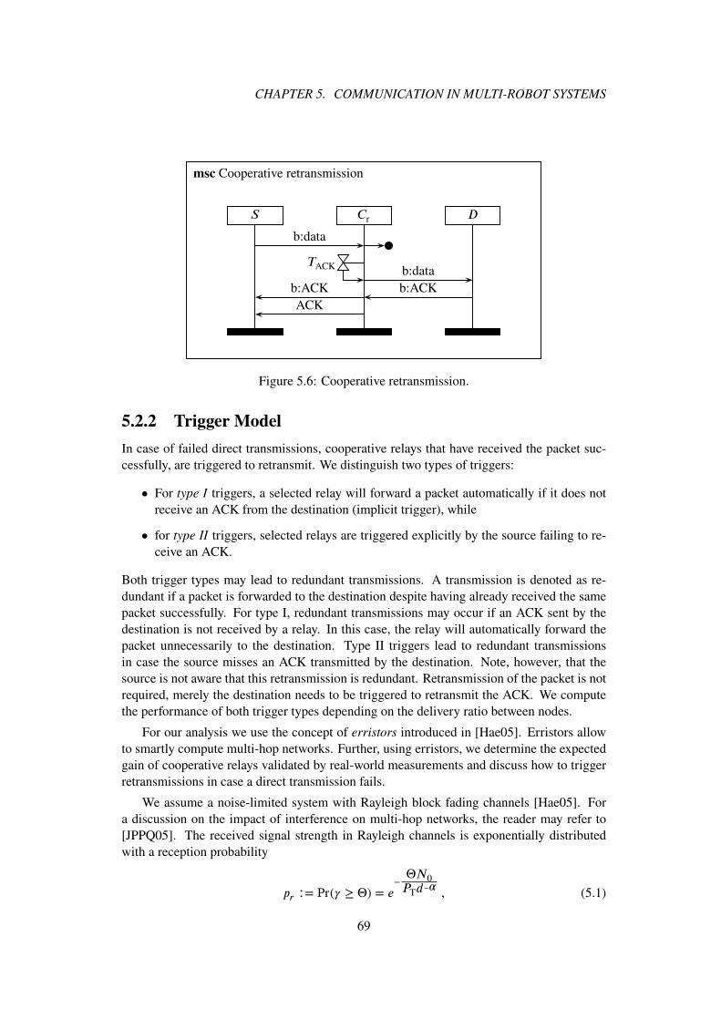
CHAPTER 5. COMMUNICATION IN MULTI-ROBOT SYSTEMS
S Cr D
b:data
TACK b:datab:ACKb:ACK
ACK
msc Cooperative retransmission
Figure 5.6: Cooperative retransmission.
5.2.2 Trigger Model
In case of failed direct transmissions, cooperative relays that have received the packet suc-cessfully, are triggered to retransmit. We distinguish two types of triggers:
• For type I triggers, a selected relay will forward a packet automatically if it does notreceive an ACK from the destination (implicit trigger), while
• for type II triggers, selected relays are triggered explicitly by the source failing to re-ceive an ACK.
Both trigger types may lead to redundant transmissions. A transmission is denoted as re-dundant if a packet is forwarded to the destination despite having already received the samepacket successfully. For type I, redundant transmissions may occur if an ACK sent by thedestination is not received by a relay. In this case, the relay will automatically forward thepacket unnecessarily to the destination. Type II triggers lead to redundant transmissionsin case the source misses an ACK transmitted by the destination. Note, however, that thesource is not aware that this retransmission is redundant. Retransmission of the packet is notrequired, merely the destination needs to be triggered to retransmit the ACK. We computethe performance of both trigger types depending on the delivery ratio between nodes.
For our analysis we use the concept of erristors introduced in [Hae05]. Erristors allowto smartly compute multi-hop networks. Further, using erristors, we determine the expectedgain of cooperative relays validated by real-world measurements and discuss how to triggerretransmissions in case a direct transmission fails.
We assume a noise-limited system with Rayleigh block fading channels [Hae05]. Fora discussion on the impact of interference on multi-hop networks, the reader may refer to[JPPQ05]. The received signal strength in Rayleigh channels is exponentially distributedwith a reception probability
pr ∶= Pr( ≥ Θ) = e−ΘN0PTd−�
, (5.1)
69

5.2. COOPERATIVE RELAYING
... ...
Figure 5.7: Erristor circuit of a multi-hop link with H hops.
where PT is the transmission power, N0 the noise level, d the distance between two commu-nicating nodes, � the path loss coefficient, and Θ the minimum signal-to-noise ratio requiredby the receiver. An erristor Λ is derived from (5.1) and defined as
Λ ∶=Θ
, where =
PTd−�
N0
(5.2)
is the mean received signal-to-noise ratio. Erristors simplify the analysis of wireless net-works with diversity and multi-hop communications using rules comparable to those in elec-tronic circuits. Serial circuits correspond to multi-hop communication. The total erristanceis computed by the sum of the single hops’ erristances (Fig. 5.7). Diversity transmissions aremodeled by parallel circuits. Each transmission increases the delivery ratio, thus decreas-ing the corresponding erristance. The joint erristance of multiple diversity transmissions iscomputed by the product of the individual transmissions’ erristances (Fig. 5.8). We derivethe erristor circuit for a cooperative relaying assisted multi-hop network.
Fig. 5.7 illustrates the erristor model for a multi-hop transmission between R robots withH = R − 1 hops. The end-to-end delivery probability pEE is computed by
pEE =
H∏ℎ=1
pℎ , (5.3)
where pℎ is the delivery probability of hop ℎ = 1…H . Using erristors, the product canbe transformed into a sum of erristances. The relation between reception probability p anderristance Λ is given by
p = e−Λ ⇔ Λ = − ln p . (5.4)
For our analysis, we assume that neighboring nodes have equal distances d and the deliv-ery probabilities between nodes are statistically independent. In a network of homogeneousnodes, it is assumed that nodes transmit with equal transmission power. It follows from (5.1)that all hops have the same delivery probability pℎ = H√pEE. Thus, given an end-to-enddelivery probability pEE, the total erristance Λ = − ln pEE is the sum of H erristors withequal erristances:
Λ =
H∑ℎ=1
Λℎ = H ⋅ Λℎ. (5.5)
5.2.2.1 Cooperative Relaying Assisted Links
Cooperative relaying improves the link delivery probability by diversity transmissions.Fig. 5.8 illustrates a single link, which is supported by M cooperative relays, which retrans-mit packets when lost during the direct transmission. A cooperative relaying link consists of
70

CHAPTER 5. COMMUNICATION IN MULTI-ROBOT SYSTEMS
...
(a)
...
(b)Figure 5.8: Illustration of (a) a single hop with M cooperative relays and (b) the correspond-ing erristor circuit.
two links. Firstly, the relay has to receive the initial transmission from node n successfully.Then, secondly, the relay will forward the packet to node n+1. The erristance of the cooper-ative relay path is the sum of these two links’ erristances. According to the rules of erristorcircuits, the cumulative erristance Λℎ of hop ℎ including direct and diversity transmission is
Λℎ = Λℎ
M∏m=1
(Λm1 + Λm2) . (5.6)
The end-to-end erristance Λ of the multi-hop network with H assisted hops is computed by
Λ =∑Hℎ=1 Λℎ.
According to (5.1), the delivery probability between two nodes depends on their distance.We determine the expected erristance of a cooperative relay to circumvent the need to makeassumptions about relay node positions.
5.2.2.2 Expected Erristance of Cooperative Relays
We only consider relays which benefit from a multi-hop gain, i.e. the distances betweensource-relay and relay-destination are smaller than the source-destination distance. Previ-ous measurements have shown that nodes, which benefit from a multi-hop gain, are morelikely to be selected for relaying than others [ABMB12]. In dense networks, where nodesgenerally have a high node degree, it can be assumed that such nodes are available.
Nodes that benefit from the multi-hop gain are only located in the area enclosed by twocircles with radii d as illustrated in Fig. 5.9a. We determine the expected erristance by in-tegrating over all possible locations and normalizing by the area. Due to symmetry, it issufficient to compute the expected gain for the gray area A. The size of A depends on the dis-tance between two nodes i and i+1 and can be computed by A(d) = 1
4
(2k0d
2 − d2 sin(2k0))
with k0 = arccos(0.5).
Fig. 5.9b illustrates the integration over A. A cooperative relayCr may be positioned withdistances d1 and d2 to nodes i and i+1, respectively. Thus, the erristance of the cooperativepath depends on the location of Cr . Accordingly, considering M cooperative relays, (5.6) is
71

5.2. COOPERATIVE RELAYING
(a) (b)Figure 5.9: Illustration of (a) possible relay node positions and (b) schematically zoomed in.
Table 5.3: Examples of link probabilities corresponding to pEE.
pℎ pr p1 p2 pT,I pT,II
0.73 0.89 0.94 0.94 0.94 0.890.85 0.97 0.98 0.98 0.98 0.970.99 1.00 1.00 1.00 1.00 1.00
modified to
Λℎ = Λℎ
⎛⎜⎜⎝1
A ∫k0
−k0∫
d
d2
cos�
(Λ(d1(r)) + Λ(d2(r, �))
)r dr d�
⎞⎟⎟⎠
M
(5.7)
with d1(r) = r and d2(r, �) =√d2 + r2 − 2 ⋅ d ⋅ r cos(�).
To model various pℎ = H√pEE, the distance d between neighboring nodes is modified.With decreasing pℎ, the distance d increases and, therefore, the average distance to a relayalso increases. This decreases the link delivery probability of the cooperative path as well.Tab. 5.3 gives examples of the expected link probabilities for various pℎ. The probabilitiescorrespond to erristances according to (5.7) where pℎ=Λℎ, pr=Λ1 +Λ2, p1=Λ1, and p2=Λ2.pT,I and pT,II will be explained below and are included for the sake of completeness. Theprobabilities reflect experimental results obtained in [AMB+13]. Due to symmetry it is as-sumed that p1 = p2. pr ≥ pℎ can be reached, for example, with an adaptive relay selectionscheme as investigated in [AMB+13].
5.2.3 Triggering Cooperative Retransmissions
We determine the probability of redundant transmissions due to falsely triggered relays. LetpT,! model the probability of a successful trigger of type !. For type I relays pT,I = p1, fortype II pT,II = p1
2. Let the RV pR,! model the probability of a retransmission for trigger type!. The Bernoulli distributed RV Kh models the direct successful packet delivery at hop ℎ
with Pr(Kh = 1) = pℎ and Pr(Kh = 0) = 1− pℎ. The probability of redundant transmissions
72

CHAPTER 5. COMMUNICATION IN MULTI-ROBOT SYSTEMS
0.0 0.2 0.4 0.6 0.8 1.0ph
0.0
0.2
0.4
0.6
0.8
1.0
Pr(pR,ω
|Kh=1)
M=1, ω=I
M=1, ω=II
M=2, ω=I
M=2, ω=II
M=5, ω=I
M=5, ω=II
Figure 5.10: Probability of a redundant transmission.
Pr(pR,!|Kh = 0) is then computed by
Pr(pR,1 ∣ Kh = 1) =(1 −
(1 − p1 ⋅ (1 − p2)
)M), (5.8a)
Pr(pR,2 ∣ Kh = 1) = (1 − pℎ) ⋅
(1 −
(1 − (p1
2))M)
, (5.8b)
where M is the number of relay nodes. For type I, relays are triggered if they receive thepacket from the source with probability p1 and do not receive the ACK from the destinationwith 1− p2 given a successful transmission with pℎ. For type II triggers, the source does notreceive the ACK from the destination with probability 1−pℎ, while relay nodes are triggeredwhen both data and trigger packets are received with probability p1
2. Fig. 5.10 illustratesPr(pR,!) for various M .
Type I triggers benefit from a higher relay-destination delivery probability p2 than thesource-destination probability pℎ (see Tab. 5.3). This leads to a decreased probability forredundant transmissions for small M and high pℎ. With increasing M , Pr(pR,1) increasessignificantly, because relays are triggered independently of each other with probability 1−p2.In comparison, the probability of redundant transmissions by type II triggered relays mainlydepends on the source not receiving the ACK with 1−pℎ. Increasing M raises the probabilitythat relays receive the trigger from the source, which adds only marginally to Pr(pR,2). Also,with increasing M , the advantage of higher delivery ratios p2 ≥ pℎ for type I triggers isconsumed quickly due to the increased number of relay-destination links. This shifts the pointwhere type II triggers outperform type I triggers to larger pℎ. For a qualitative conclusion,we determine the expected number of redundant transmissions to consider the impact ofchanging M and the characteristics of both trigger types.
Let the RV MT denote the number of relays which have received the packet from the
73

5.2. COOPERATIVE RELAYING
0.0 0.2 0.4 0.6 0.8 1.0ph
0.0
0.2
0.4
0.6
0.8
1.0
1.2
1.4
1.6
1.8
E[M
T]
M=1, ω=I
M=1, ω=II
M=2, ω=I
M=2, ω=II
M=5, ω=I
M=5, ω=II
Figure 5.11: Number of expected redundant retransmissions for both trigger types.
source and are triggered successfully. MT is binomially distributed with
Pr(MT = m) =
(M
m
)(1 − pT,!)
M−m⋅ pT,!
m . (5.9)
The expected number of redundant transmissions
E[MT] =
M∑m=1
mPr(MT = m) (5.10)
is illustrated in Fig. 5.11 for both trigger types. The intersection between both trigger typeswith equal M is shifted to lower pℎ. Type I triggers have a comparably high probability ofredundant transmissions for large M , but the number of triggered relays is small. In casetype II relays are triggered, the number of triggered relays is high due to a high source-relaydelivery probability p1. While Pr(pR,2) < Pr(pR,1), the number of triggered relays MT isexpectedly larger for type II triggers than for type I. For pℎ → 0, the probability of having alarge number MT for type II triggers decreases, thusly outperforming type I triggers in termsof redundant transmissions.
Finally, let the RV J! model successful retransmissions using cooperative relaying fortrigger type !. Pr(J!) is computed by
Pr(J! = 1) =
MT∑m=1
Pr(DI = 1|MT,I = m) ⋅ Pr(MT,I = m) , (5.11)
where Pr(J! = 1 ∣ MT = m) = (1 − (1 − p2)m) for both types. Pr(J! = 1) is computed
accordingly. Fig. 5.12 illustrates the corresponding delivery probabilities with cooperativerelaying for various M . The type I trigger automatically forwards a lost transmission andcannot fail, because it does not rely on additional transmissions. In comparison, type II
74

CHAPTER 5. COMMUNICATION IN MULTI-ROBOT SYSTEMS
0.0 0.2 0.4 0.6 0.8 1.0ph
0.0
0.2
0.4
0.6
0.8
1.0
1.2
Pr(Dt)
M=1, ω=I
M=1, ω=II
M=2, ω=I
M=2, ω=II
M=5, ω=I
M=5, ω=II
Figure 5.12: Probability of a successful retransmission.
triggered relays need to receive the additional request from the source. Relays which do notreceive the trigger from the source do not participate in retransmissions. This is a problem,especially for protocols which only select a small number of relays.
Given the assumptions in Tab. 5.3, type I triggers outperform type II triggers in termsof redundant transmissions and delivery probability in the relevant interval of pℎ ⪆ 0.75
[ABMB12]. The assumptions comply with results from previous measurements. We usetype I triggers.
5.3 Protocol Architecture
The focus of the protocol architecture is to disseminate information enabling the robots tocoordinate the exploration. Due to limitations of wireless capacity, coordination and therequired data transfer is limited spatially requiring multicast routing. Unicast routing is re-quired for the transmission of teleoperation commands and possibly retransmissions. Eventsrelevant to all robots such as new robots in the system or mission updates are broadcasted toall robots.
5.3.1 Overview
Tab. 5.4 summarizes the functions implemented in the various layers of the protocol ar-chitecture and links to the sections in which they are described. We use the terminologyaccording to the International Organization for Standardization (ISO)/Open Systems Inter-connection (OSI) reference model [IT94], which allows the unambiguous description of theprotocols and their functions.
The network layer, in charge of addressing and routing according to the reference model,has minor functionality since routing and addressing are handled by the data link layer. Thetransport layer ensures reliability, ordering, and multiplexing among segments, while the
75

5.3. PROTOCOL ARCHITECTURE
Table 5.4: Overview protocol architecture.
Layer Functions Section (page)
Application auto-configuration 5.3.4 (80)Transport segmentation 5.4.2.1 (81)
reliability (ACK/NACK) 5.4.2.2 (82)ordering 5.4.2.3 (82)
Network addressing, address resolution 5.3.5 (80)Data link cooperative relaying 5.2 (65)
unicast routing 5.3.2.1 (76)multicast routing 5.3.2.2 (77)broadcast routing 5.3.2.3 (77)beacons 5.3.3.1 (78)segmentation 5.4.2.1 (81)
application layer handles detection of robots in the neighborhood and network configurationto manage multicast group membership.
5.3.2 Routing
Many routing protocols for the transmission schemes unicast, multicast, and broadcast havebeen suggested. We formulate requirements for the selection of routing protocols and selectsuitable protocols accordingly.
5.3.2.1 Unicast
The unicast protocol is selected considering the following criteria:
• reliable transmission,
• high resilience against node failure in hazardous environments,
• smooth integration of cooperative relaying to increase reliability,
• support for topologies which change slowly due to comparably inert movement of mo-bile robots operating indoors
• well documented and tested, and
• reuse of code for multicast routing.
Multi-robot systems form a MANET. Numerous protocols for MANETs have been devel-oped [WBII06] and tested [KM07]. Among the set of considered proactive routing pro-tocols (Optimized Link State Routing Protocol (OLSR), Destination-Sequenced Distance-Vector (DSDV), Babel), reactive protocols (AODV, DSR), and hybrid protocols like ZoneRouting Protocol (ZRP) and their respective derivatives, AODV [PBRD03] was selected asmatching all criteria best. Versions of AODV are also used in 802.11s [IEE12], IPv6 overLow power Wireless Personal Area Network (6LoWPAN) [SB09], and ZigBee [Zig08].
76

CHAPTER 5. COMMUNICATION IN MULTI-ROBOT SYSTEMS
While robot locations may be known, position-based routing protocols [MWH01] havenot been considered due to positioning errors. Robots may locate themselves with largeerrors rendering position-based routing protocols useless. While robot positioning is not yetreliable, we avoid coupling positioning and routing.
5.3.2.2 Multicast
The criteria for the multicast protocol are identical to the unicast case plus the require-ment of distributed group management to allow loose coupling of robots. Numerous de-terministic [Obr98, MA99, LK03, VE03, DMCGA03, OBD08] and probabilistic multicast[VE03, CJKK07, KHW12, LYGV14] routing protocols have been proposed in the literature.
The required reliability for multicast dissemination suggests the use a deterministic pro-tocol compared to a probabilistic one. The advantage of deterministic protocols is their in-creased reliability. While probabilistic protocols also allow high reliability, it generally takeslonger until all data has been delivered successfully [VE03]. Deterministic protocols do notscale as well as probabilistic ones. But reliable data dissemination can be limited locally asdiscussed in the previous section to allow scalability.
In order to allow reuse of concept and code, MAODV [RP00] is selected. Tree-basedprotocols such as MAODV allow easy integration of cooperative relaying to increase thereliability at the data link layer. They are shown to perform worse than mesh-based protocolswhen the topology changes frequently [DMCGA03]. Though the topology is expected to varyslowly. Further, multiple routes can be set up to increase reliability through route diversity[NCD01]. Finally, cooperative relaying can mitigate connection losses through topologychanges. If a direct link between two nodes fails because of the movement of one or bothnodes, chances are a cooperative relay will continue to allow connectivity without having toissue a new route discovery.
5.3.2.3 Broadcast
Only very little data of low priority is broadcasted in the network. We use l-hop flood-ing where nodes maximal l hops from the source rebroadcast received data. Reliability isachieved, though not guaranteed, by repetitive flooding. Note that broadcasting events occurrarely and do not require significant capacity to justify the implementation of more advancedbroadcasting protocols.
5.3.3 Data Dissemination and Node Roles
Fig. 5.13 illustrates a possible network including unicast and multicast transmissions.
For example, n1 and n5 communicate via unicast through link b via node n4. While thelink b2 is not supported by a cooperative relay, n2 is a cooperative relay for b1. For example,if a direct transmission between n1 and n4 fails, n2 retransmits the lost frame.
Multicast groups are used to deploy data one-to-many. They may be used to allow robotsto coordinate locally or to disseminate sensor data to BSs or TRMs. Robots offer differentmulticast groups for various services to allow different destinations. For example, the multi-cast group for local coordination only includes robots in the neighborhood. In comparison,
77
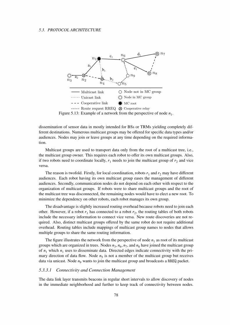
5.3. PROTOCOL ARCHITECTURE
Node in MC group
Node not in MC group
MC root
Cooperative relay
Multicast link
Unicast link
Cooperative link
Route request RREQ
a1
a2
b1
b2
c1d1
e1
Figure 5.13: Example of a network from the perspective of node n1.
dissemination of sensor data in mostly intended for BSs or TRMs yielding completely dif-ferent destinations. Numerous multicast groups may be offered for specific data types and/oraudiences. Nodes may join or leave groups at any time depending on the required informa-tion.
Multicast groups are used to transport data only from the root of a multicast tree, i.e.,the multicast group owner. This requires each robot to offer its own multicast groups. Also,if two robots need to coordinate locally, r1 needs to join the multicast group of r2 and viceversa.
The reason is twofold. Firstly, for local coordination, robots r1 and r2 may have differentaudiences. Each robot having its own multicast group eases the management of differentaudiences. Secondly, communication nodes do not depend on each other with respect to theorganization of multicast groups. If robots were to share multicast groups and the root ofthe multicast tree was disconnected, the remaining nodes would have to elect a new root. Tominimize the dependency on other robots, each robot manages its own group.
The disadvantage is slightly increased routing overhead because robots need to join eachother. However, if a robot r1 has connected to a robot r2, the routing tables of both robotsinclude the necessary information to connect vice versa. New route discoveries are not re-quired. Also, distinct multicast groups offered by the same robot do not require additionaloverhead. Routing tables include mappings of multicast group names to nodes that allowsmultiple groups to share the same routing information.
The figure illustrates the network from the perspective of node n1 as root of its multicastgroups which are organized in trees. Nodes n3, n6, n7, and n8 have joined the multicast groupof n1 which n1 uses to disseminate data. Directed edges indicate connectivity with the pri-mary direction of data flow. Node n5 is not a member of the multicast group but receivesdata via unicast. Node n9 wants to join the multicast group and broadcasts a RREQ packet.
5.3.3.1 Connectivity and Connection Management
The data link layer transmits beacons in regular short intervals to allow discovery of nodesin the immediate neighborhood and further to keep track of connectivity between nodes.
78

CHAPTER 5. COMMUNICATION IN MULTI-ROBOT SYSTEMS
Beacons include the transmission interval of each node. Connectivity is assumed to be lostif � consecutive beacons are missed. The connectivity is used for connection management ofmulticast routes and to determine the continuous suitability of cooperative relays as discussedlater.
If no route is known, unicast and multicast protocols will initialize a route discovery.Route entries learned through route discoveries are shared between unicast and multicastroutes. If a multicast route to a destination D is known, the source S of a unicast transmissionwill not initialize a new route discovery but will use the existing route. Upon a request tojoin a multicast group, a new route discovery is always initiated. Unicast connections areclosed after all data has been transmitted. The corresponding unicast route is deleted upona period of inactivity. Multicast connections are kept alive once connected to a multicastgroup to support the push pattern. Accordingly, if a connection between two members of amulticast group is lost, the node further away from the root will attempt to reconnect, e.g.,n2 will attempt a reconnection, if the connection between n1 and n2 is lost. If reconnectionis not possible, the information about the lost connection will be propagated to all nodes atlower levels in the tree, e.g., n3. They may attempt to reconnect themselves.
5.3.3.2 Multicast Group Management
In MAODV information about nodes joining a multicast group is propagated to the root ofthe multicast group allowing to keep track of connected nodes [RP00]. While bookkeepingof connected nodes at the root of a multicast group allows end-to-end acknowledgments,it increases the overhead of managing the multicast group, especially in mobile networks.The primary objective of the multicast group is to reliably disseminate data from a root toconnected nodes. Bookkeeping or end-to-end acknowledgments are not required. Node n5(and then n4, n2) continues to propagate the RREQ not being a member while n6 replies with aRREP. Node n9 will select the route received by n6 being the shortest route to the root. Noden1 will not be informed.
5.3.3.3 Multicast Data Dissemination
Reliability is not achieved end-to-end but between group members. For example, if noden6 acknowledges the reception of data to n1, it will be in charge of further disseminationto its children, i.e., nodes n7, n8, and n9. In cases where applications require end-to-endacknowledgment, a recursive acknowledgment is implemented in which a node acknowledgesto its parent once all its children have acknowledged. Recursive acknowledgments come atsignificant costs with respect to delay and throughput and are not considered further in thisarchitecture.
5.3.3.4 Node Roles
Nodes may take on various roles. Members of a multicast group consume received data and,if applicable, ensure reliable propagation. Nodes not part of a group, e.g., n2, n4, propagatedata in case of unicast and multicast. Additionally, nodes may be cooperative relays. Forexample, during route discovery, node n4 was selected as a cooperative relay retransmittingfailed data link layer transmissions for the link n1-n2. Simultaneously, n2 is a cooperative
79

5.4. RELIABLE COMMUNICATION
relay for link n1-n4. Note that nodes n7 and n8 are cooperative relays for each other, i.e., n8is a cooperative relay for n6-n7 and vice versa.
5.3.4 Node Discovery and Configuration
The application layer includes a protocol to allow node discovery and handles events withrespect to auto-configuration. In regular intervals robots broadcast application layer bea-cons for a maximum of l hops including basic information such as identification, address,capabilities, position, offered multicast groups, etc. Once a robot n1 detects a previously un-known robot n2, n1 retrieves n2’s capabilities and broadcasts the information in the completenetwork. This is especially important in heterogeneous networks, when robots may requirespecific capabilities of other robots. Robots join multicast groups based on distance. Cur-rently, the distance is determined by the number of hops, though may be computed based onthe location of robots.
5.3.5 Address Resolution
Due to the mobility of robots, data link layer addresses, here the MAC address of the networkcards, must be unique within the system to allow unambiguous delivery of data. Since allrouting is handled in the data link layer, additional addressing schemes are not required withinthe network. For reasons of convenience, applications making use of the network stack mayuse the operating system’s host name as an alias for the MAC address. Accordingly, the hostname must be unique within the network. The network stack includes a table mapping hostnames to data link addresses. Entries within the table are learned from the node discovery.
5.4 Reliable Communication
The protocols implemented by the Map Merger and Explorer packages described in Sec. 3.4.2(page 31) and Sec. 3.5.2 (page 41), respectively, require reliable communication to work effi-ciently. If messages are lost, coordination will not work as reliably as it will if map and coor-dination is received. With respect to the limited network capacity as discussed in Sec. 5.1.2.2(page 63), the number of retransmissions should be reduced.
5.4.1 Reliable Unicast
Unicast transmissions between nodes are end-to-end acknowledged with data link layer ac-knowledgments for the individual hops. In case a direct transmission between nodes fails, ifavailable, a cooperative relay will retransmit the frame as depicted in the Message SequenceChart (MSC) in Fig. 5.6 on page 69 using implicit triggering.
The source node of a transmission may keep track of its cooperative relays using thedata link layer beacon discussed in Sec. 5.3.3.1 on page 78. If during a route discovery nocooperative relay could be selected or connectivity to cooperative relays is lost, the nodeinitiates a new relay selection as discussed in Sec. 5.2.1.2 on page 66. If still no cooperativerelay is available, the node may fall back to retransmissions using time diversity.
80

CHAPTER 5. COMMUNICATION IN MULTI-ROBOT SYSTEMS
5.4.2 Reliable Multicast
Reliable multicast protocols discussed in [Obr98, LK03, VE03, DMCGA03, CJKK07] im-plement reliability on network or transport layer. But the majority of losses are temporary[RMR+06] to which comparably inert high level protocols cannot react quickly. In case ofTCP, Balakrishnan et al. conclude that data link layer retransmissions with in-order deliverycan increase performance of end-to-end connections significantly [BPSK97]. Cooperativerelaying allows in-order delivery by quick retransmissions upon failing ACKs.
However, acknowledgments on the data link layer are not supported in the current stan-dard of IEEE 802.11. Hassen et al. conceptually include acknowledgments in data link layerbroadcasts [HVS11] (and references therein). Their simulations indicate an improvement ofreliability and throughput, but their proposed solution requires modification to the hardwarenot realizable in commodity hardware. To allow reliable multicast on the data link layer, weimplement our own acknowledgments as discussed below.
5.4.2.1 Data Link Layer Acknowledgment
Reliable multicast protocols may suffer from ACK implosions [VE03], i.e., the problem ofreceiving transmission feedback from multiple receivers in a very short time. In case ofreliable data link transmissions, ACK implosions may lead to an increased collision prob-ability when accessing the medium. Generally, to reduce the likelihood of medium accesscollisions, the number of feedback transmissions shall be reduced. If the delivery ratio isabove 50%, using negative ACKs (NACKs) yields less transmissions compared to usingACKs. For delivery ratios below 50%, ACKs reduce the overhead. In wired networks us-ing NACKs reduces the risk of implosions due to the small error probability. In wirelesssensor networks the majority of links has been shown to have higher delivery ratios than50% [MAB+14, RMR+06, ABMB12], i.e., use NACKs for feedback. Using NACKs requiresthe destination to be aware of transmissions. While in wired networks the error probability iscomparably small, wireless links may suffer from long fading durations dropping a numberof consecutive frames. If no frame is received, the destination is unaware of the transmissionand unable to send NACKs.
Consider data transmission of length Sdata. Generally, the transport layer segments thedata into
NTL = 1,… , ⌈Sdata
STL
⌉ (5.12)
datagrams of size STL. The data link layer may segment each datagram into FT frames to betransmitted. To allow reliable detection of transmissions, FT must be chosen to be larger thanthe expected link outage duration. Let the RV FR model the number of successfully receivedframes. For a destination to detect a transmission, FR ≥ 1 is required.
Where the wireless characteristics of an environment are available, one may determineFT
according to the distribution of outage lengths. For example, given the setup in [ABMB12],outages of length 23 frames or longer only occur with a probability of 5%. We continue todescribe a model for a general analysis.
81

5.4. RELIABLE COMMUNICATION
0 5 10 15 20
F
0.60
0.65
0.70
0.75
0.80
0.85
0.90
0.95
1.00
Pr(f≥
1)
pEE = 0.2
pEE = 0.4
pEE = 0.6
pEE = 0.8
Figure 5.14: Probability for destination to receive at least one frame with i.i.d. frame losses.
Let pEE be the probability of successfully receiving a single frame. In case of i.i.d. framelosses, Pr(FR) is computed by
Pr(FR ≥ 1) = 1 − (1 − pEE)FT . (5.13)
Fig. 5.14 illustrates Pr(FR) for various pEE. Assuming a minimal temporal frame deliveryratio of pthr = 0.6, at least four frames need to be transmitted for the destination to detect thetransmission with a probability of 0.95. Delivery ratios below 0.6 occur rarely [ABMB12].
We continue to consider the case where frames transmitted at time t and t + 1 are corre-lated. Given the conditional probability � = Pr(FR,t+1|FR,t), Pr(FR ≥ 1) can be computedby
Pr(FR ≥ 1) = (1 − pEE)(1 − �f ) + pEE(1 − (1 − �)�f ) . (5.14)
Fig. 5.15 shows the resulting probabilities for various probabilities �. Again, we consider thethreshold probability pthr = 0.6. For highly correlated channels FT needs to be increased.To allow reliable feedback by a destination, NACKs are used if FT ≥ 10, ACKs otherwise.
5.4.2.2 Transport Layer Acknowledgment
Datagrams may not be detected by a node if all frames are lost. In case lost datagrams aredetected at transport layer, NACKs are transmitted to the source requesting retransmissionusing unicast. Intermediate nodes not members of a multicast group, which do not storeall datagrams, cannot reply to this request, but forward it to the next higher multicast groupmember.
5.4.2.3 Cooperative Retransmission
Cooperative retransmissions work analogously to the unicast transmissions, thoughmultihop-aware retransmissions are not supported because intermediate nodes circumvented
82

CHAPTER 5. COMMUNICATION IN MULTI-ROBOT SYSTEMS
0 10 20 30 40 50
FT
0.60
0.65
0.70
0.75
0.80
0.85
0.90
0.95
1.00
Pr(FR
≥1)
pEE = 0.2, µ = 0.75
pEE = 0.2, µ = 0.85
pEE = 0.2, µ = 0.95
pEE = 0.6, µ = 0.75
pEE = 0.6, µ = 0.85
pEE = 0.6, µ = 0.95
Pr(Fl,r) = 0.95
Figure 5.15: Probability for destination to receive at least one frame with correlated framelosses.
Transport
Data Link
Physical
(a) (b)Figure 5.16: Scheduling of cooperative retransmissions for multicast using (a) ACKs and (b)NACKs.
by a multihop-aware retransmission may be subscribed to the multicast group.
Fig. 5.16 illustrates the scheduling of the cooperative retransmissions for positive andnegative acknowledgments, respectively.
Positive Acknowledgments
Cooperative retransmissions happen immediately and implicitly as in unicast transmissions.An additional random offset Tmult is added to the medium access delay to compensate forotherwise multiple relays attempting to access the medium simultaneously. The drawback ofimmediate acknowledgments is that the transmission rate is limited by the retransmissions,i.e., transmission of the next frame is not started before all nodes have acknowledged allframes or timed out. Koutsonikolas et al. suggest to continue transmission and postponeretransmissions [KHW12] to improve rate control. Postponing retransmissions requires co-operative relays to buffer data for a long time significantly increasing the required bufferspace. Since delay is not critical, we disregard postponement of retransmissions in favor ofreliability.
Negative Acknowledgments
NACKs require the transmissions of bursts to allow a destination D to detect incoming data.Retransmissions are postponed to the end of the burst as indicated in Fig. 5.16b. The duration
83

5.5. EVALUATION
of a burst �D is approximated to set the NACK request timer TNACK . After TNACK expires,possibly required retransmissions need to be triggered explicitly by D. The NACK indicatesall lost frames. TNACK is updated upon the reception of every frame. If the i-th frame of a
burst is received, TNACK will be updated to TNACK =i⋅�D10
.
5.5 Evaluation
The proposed architecture is based on IEEE 802.11, the most common radio interface onrobots, though other RATs allowing ad hoc networking may be used. Accordingly, the datalink layer handles medium access according to IEEE 802.11. IEEE 802.11s [IEE12] (in-tegrated into the 2012 version of the IEEE 802.11 standard) enables ad hoc networking inIEEE 802.11 networks in the absence of access points, but it has limitations with respect tolink capacity [YHSB14] and does not support cooperative relaying. While IEEE 802.11 hasbeen extended to use cooperative relaying [NL11, VDLK12], previous implementations areoutdated or not compatible with our hardware and cannot be used.
We implement the protocol architecture described previously in C++ using Linux sock-ets. Data is broadcasted to allow cooperative relays to overhear transmissions. Accordingly,RTS and CTS are disabled.
The current implementation has limitations with respect to throughput. For easy mod-ification and implementation, the protocols run in user space requiring constant contextswitches between user and kernel space. These switches consume significant time limit-ing the achievable throughput. This is a general trade-off between ease of implementationand performance [SAPL09]. However, the comparably slow processing of data is expectedto have little impact on the protocol performance. Retransmission through time diversitysuffer from correlated channels. If impact of the current implementation is to be expected,it improves time diversity because the channel is less correlated over time, i.e., a protocolimplementation in kernel space will decrease the performance of time diversity.
5.5.1 Setup
We run experiments to determine the reliability of the protocol architecture for inter-robotcommunication. Fig. 5.17 illustrates the setup of five nodes in an office environment. Eachnode runs ROS and the Ad Hoc Communication node implementing the previously describedprotocol architecture. Tests are performed on three different days during working hours foreight hours each. The transmission power is reduced to 0 dBm to prevent direct connectivitybetween nodes.
Frames have a maximal size of 1500 bytes including a 14 bytes Ethernet header and a 45bytes custom header including additional information for routing, relaying, ordering, etc.
We send data segments of sizes STL and deactivate acknowledgments on transport layerto determine the impact of the data link layer. Note that with activated transport layer ac-knowledgments, the delivery ratio increases to 100%. With increased reliability at data linklayer, overhead by higher layer retransmissions can be saved.
The modulation and coding scheme (MCS) is fixed to a throughput of 1Mbps. Becausedata is broadcasted, rate adaptation is not supported by IEEE 802.11. Note, however, that
84

CHAPTER 5. COMMUNICATION IN MULTI-ROBOT SYSTEMS
Figure 5.17: Setup for communication experiments in office corridor. Dimensions in meters.Dashed lines indicate neighborhood of robots.
0 20 40 60 80 100
Data size (kB)
0.70
0.75
0.80
0.85
0.90
0.95
1.00
Deli
very
rati
o
Direct
Time
CR
Figure 5.18: Reliability for unicast transmissions.
cooperative relaying has been shown to improve reliability also in the case of rate adapta-tion [VDLK12]. In case of multicast transmissions, the MCS is fixed by default. Using afixed MCS, the throughput is proportional to the number of data frames transmitted overtime. Accordingly, reliability and throughput correlate directly. Instead of determining thethroughput limited by the implementation, we focus on reliability instead.
5.5.2 Unicast
Nodes n1 and n5 in Fig. 5.17 serve as source S and destination D, respectively. The othertwo nodes serve as cooperative relays. Fig. 5.18 shows the delivery ratio at the destinationn5 using unicast transmissions. In the absence of diversity transmissions, the delivery ratiodrops to 0.82 with increasing data size. Larger data sizes require more frames to be transmit-ted increasing the probability to loose single frames. Retransmission through time diversityallows to increase the mean delivery ratio to up to 0.9 for larger data sizes. Due to corre-lated channels, a single retransmission does not allow to increase reliability significantly. In
85

5.5. EVALUATION
Table 5.5: Mean delivery ratio including 0.05- and 0.95-quantiles for STL = 5 kb for bothindividual hops and E2E. Other data sizes yield quantitatively comparable results.
Mode h E2E1 2
0.05 mean 0.95 0.05 mean 0.95 0.05 mean 0.95
Direct 0.89 0.92 0.95 0.85 0.87 0.92 0.84 0.89 0.90Time diversity 0.91 0.94 0.96 0.92 0.95 0.96 0.91 0.93 0.94Cooperative diversity 0.97 0.99 1.00 0.99 0.99 1.00 0.97 0.98 1.00
0 2 4 6 8 10 12 14
Outage duration (# frames)
0.0
0.2
0.4
0.6
0.8
1.0
Em
pir
ica
lP
DF
Figure 5.19: Empirical PDF of the outage duration in number of frames.
comparison, with a single cooperative retransmission, almost no packets are lost.
Cooperative relaying outperforms time diversity especially for multi-hop links. Tab. 5.5illustrates the delivery ratios of both individual hops. The mean delivery ratios for the directtransmission are 0.92 and 0.87 for the first and second hop, respectively. Time diversity al-lows to improve the reliability for the individual hops to acceptable levels. Cumulatively, theE2E delivery ratio decreases more than for the cooperative case. For cooperative retransmis-sion, the individual hops achieve reliabilities close to 1.0.
For large environments, the robot system may form communication chains longer thantwo hops, if sensor data needs to be propagated from explorers deep in the environment toa BS. Compared to time diversity, cooperative relaying allows higher reliabilities at the linklayer. This allows to improve E2E reliability decreasing the need for retransmissions ontransport layer reducing the corresponding overhead [And13]. The E2E delivery ratio canfurther be improved by increasing the number of retransmissions on data link layer at the costof increased overhead.
86

CHAPTER 5. COMMUNICATION IN MULTI-ROBOT SYSTEMS
5.5.3 Multicast
The setup is the same as depicted in Fig. 5.17. Node n1 serves as source S. Nodes n4 and n5serve as destinations. Node n2 is a cooperative relay for the link n1-n3. Note that nodes n4and n5 serve as cooperative relays for each other.
Fig. 5.19 depicts the probability density function (PDF) of the outage duration for directtransmissions to n4. The vast majority of outages is of length three frames or shorter. Ac-cordingly, the threshold of ten frames to switch from ACK to NACK is chosen conservatory.However, industrial environments are subject to more severe fading than office environmentslike this. Accordingly, outages durations may increase [ABMB12].
Finally, the mean E2E reliability does not drop below 0.97 independent of the data size us-ing cooperative relaying yielding comparable results as for unicast transmissions. Therefore,cooperative relaying allows to significantly improve the reliability if available. It does notconsume more time resources than retransmission through time diversity though increasesthe energy consumption. Relays have to constantly overhear transmission and buffer receiveddata. The consumed energy is neglectable compared to the energy consumed for the compo-nents of the robot.
87

5.5. EVALUATION
88

6COLLABORATION INMULTI-ROBOT SYSTEMS
Contents6.1 Network Connectivity through Collaboration . . . . . . . . . . . . . . . 90
6.2 Model . . . . . . . . . . . . . . . . . . . . . . . . . . . . . . . . . . . . 91
6.2.1 Environment . . . . . . . . . . . . . . . . . . . . . . . . . . . . 91
6.2.2 Communication Strategies . . . . . . . . . . . . . . . . . . . . . 92
6.2.3 Exploration Progress . . . . . . . . . . . . . . . . . . . . . . . . 93
6.2.4 Assumptions . . . . . . . . . . . . . . . . . . . . . . . . . . . . 94
6.2.5 Parameters . . . . . . . . . . . . . . . . . . . . . . . . . . . . . 94
6.3 Performance Comparison by Parameter . . . . . . . . . . . . . . . . . . 103
6.3.1 Number of Robots . . . . . . . . . . . . . . . . . . . . . . . . . 103
6.3.2 Communication Range . . . . . . . . . . . . . . . . . . . . . . . 106
6.3.3 Environment Complexity . . . . . . . . . . . . . . . . . . . . . . 107
6.3.4 Inter-Robot Interference . . . . . . . . . . . . . . . . . . . . . . 108
6.4 Guidelines for Designing Optimized Strategies . . . . . . . . . . . . . . 109
So far we have silently assumed connectivity between robots, BSs, or TRMs to be given.In Fig. 2.1 on page 7, which depicts different clusters of robots operating independently,robots within the same cluster are connected and coordinated. While connectivity betweenclusters and BSs/TRMs is not necessarily given, it may nevertheless be required. Firstly,robots may have to report sensor data in regular intervals to BSs/TRMs. Secondly, clustersneed to coordinate exploration globally to prevent redundant exploration of areas by multipleclusters. Robots may collaborate to establish connectivity between arbitrary communicationendpoints.
89

6.1. NETWORK CONNECTIVITY THROUGH COLLABORATION
Req. 1 and Req. 6 require robots to be connected to a BS. For teleoperation requiringinstantaneous data delivery, robots need to form a daisy chain propagating data between theforemost explorers and a BS. This way robots have a limited exploration radius determinedby the number of robots and the communication range of robots. Req. 2, which requiresexploration of the complete environment, conflicts with a limited exploration radius. Sec. 2.5on page 14 lists two concepts to establish connectivity, namely multi-hop communication andrendezvous. The strategies fulfill either one of the previous requirements. In the end the userwill have to decide which requirement is more important in conflicting situations.
While both strategies have been analyzed separately as discussed in Sec. 2.5, no formalattempt to compare them has been made. Previous results were obtained by trial and er-ror [dHCV10b]. We model both strategies mathematically to quantitatively compare theirperformances with respect to exploration time (Req. 7) and list ten guidelines supporting thedesign of better strategies. The impact of parameters such as number of robots, environ-ment size, environment complexity, communication range, and others on exploration time isdetermined allowing the improved design of both strategies.
6.1 Network Connectivity through Collaboration
Compared to traditional MANETs, in which communication protocols have no effect on themobility of nodes, robot systems may actively support communication by planning theirmovement accordingly.
Definition 6.1. We define communication-aware mobility as a robot’s capability to considercommunication during its mission, i.e., robots plan their mobility to support communicationwith others.
In comparison to concepts of communication-aware mobility, delay-tolerant networks(DTNs) have been suggested to connect clusters of mobile nodes [PBSJ05]. It is assumedthat DTNs have no impact on mobility, i.e., routing protocols for DTNs attempt to deliverdata from a source to a destination capable or not capable of predicting connectivity [Fal03].DTNs are an example for mobility-aware communication.
Definition 6.2. Protocols are said to be mobility-aware if they (attempt to) anticipate themovement of the mobile platform to improve communication between nodes. Communica-tion protocols may not control the mobility of the node.
We only consider concepts for communication-aware mobility in which robots cooperateto achieve network connectivity.
For example, a cluster of robots is required to establish connectivity with a BS/TRM toreport new sensor data in regular intervals. In the multi-hop strategy SMH, robots becomerelays and form a daisy chain between a robot within the cluster and the BS in a way that relaysare in communication range to their neighbors. Data is propagated along the multi-hop routebetween the communication endpoints with negligible delay.
90

CHAPTER 6. COLLABORATION IN MULTI-ROBOT SYSTEMS
In comparison, in the rendezvous strategy SRV1, one or more robots serving as relays
travel back and forth between communication endpoints to deliver data. Before departing,relays and explorers agree upon a time and location before the next rendezvous to exchangethe meantime newly acquired data. The relay drives to the BS carrying the data. Once incommunication range of the BS, it delivers the data and returns to the next rendezvous spotto meet with the explorer again. For both strategies we assume that robots may switch rolesfrom explorers to relays and vice versa on demand.
Qualitatively, the strategies can be assessed easily, both having strengths and weaknesses.Multi-hop communication can only connect two communication endpoints of limited dis-tance. The distance depends on the communication range of individual robots and the num-ber of available relays. In comparison, rendezvous may connect endpoints at arbitrary dis-tances at increased communication delay. Because relays actually travel the distance betweenexplorers and BSs, the delay depends on the relay’s speed, maneuverability and the travel dis-tance. Further, rendezvous frees robots to explore instead of relaying, because less relays arerequired compared to multi-hop. The communication delay for multi-hop routes is negligiblecompared to the travel time of relays. If minimal delays are required, for example in case oflive-video or manual robot control, SRV is no alternative to SMH.
6.2 Model
We consider a multi-robot system consisting of R robots which are either explorers or relays.Explorers do not support communication but increase the knowledge of the environment.They may use relays to propagate information to other robots and/or BSs. We do not considerthe case in which relays may contribute to the exploration as suggested in [HHJ14]. Robotsmay switch roles during an exploration. Accordingly, R robots are split into RE(t) explorersand RR(t) relays at time t with R = RE(t) + RR(t),∀t.
6.2.1 Environment
Environments are modeled in one dimension representing the exploration progress and thetraveled distance as depicted in Fig. 6.1a. This implies a correlation between explorationprogress and traveled distance which we will confirm later. The reference environment sizeA0 is of unity area, i.e., A0 = 1 if not stated otherwise. Bottom and top of Fig. 6.1a refer tothe beginning and end of the exploration, respectively. A BS is placed at the bottom, whichis to be updated regarding the exploration status or the map created of the environment. Thetop represents complete exploration, i.e., the whole environment is mapped. The advantageof this one-dimensional (1D) representation is the abstraction from environment structures.It eases mathematical modeling and allows to make general statements over a wide rangeof environments. We use the environment complexity discussed below to model variousenvironments. We abandon the style in Fig. 6.1a and continue to represent the environmentas depicted in Fig. 6.1b for better illustration.
We distinguish explored and unexplored areas separated by a frontier. Robots start at theBS having explored 0% of the environment. They explore the as yet unknown environment,
1To distinguish variables for both strategies we use the subscript (⋅)MH and (⋅)RV for the multi-hop and ren-dezvous strategies, respectively.
91

6.2. MODEL
BS0%
100%
0
(a)
BS
unexplored
explored
(b)
BS
(c)
BS
Seq.Par.
RV
(d)Figure 6.1: Environment model: (a) 1D representation (b) frontier representation (c) multi-hop strategy (d) rendezvous.
constantly pushing the frontier towards 100%. Further, f t is the exploration progress at timet. We denote the difference between two frontiers at times t and t+1 asΔft,t+1 = ft+1−ft ≥0. Relay robots allow to exchange data between the explorers and the BS. Robots and/orBSs may communicate with each other if they are within communication range �. � ∈ [0, 1]
models the communication range relative to the environment size, i.e., � = 0.5 means robots,which are a distance equivalent to half the environment’s size apart, can communicate.
6.2.2 Communication Strategies
6.2.2.1 Multi-Hop Strategy
For the multi-hop strategy environments are split into sectors. Fig. 6.1c illustrates the en-vironment with five sectors. The height of each sector corresponds to the communicationrange �, here � = 0.2. Robots position themselves between two sectors to relay data. Forexample, a robot on the border of sectors I and II allows to relay data from robots in sectorII to the BS. We assume that all explorers in sector II can communicate with the relay. Ifthe explorers continue to sector III , a new relay needs to be deployed on the border betweensectors II and III to ensure connectivity between explorers and the BS.
In the first sector, all robots can communicate directly with the BS. When continuingexploration to sector II , one of the explorers is required to switch its role to relay to allowfurther connectivity between explorers and BSs. With each additional sector explored, thenumber of explorers decreases. While in the first sector RE = 4 out of R = 4 robots mayexplore, in the second sector only three robots may explore as one needs to relay. To beable to fully explore the environment, at least as many robots as sectors are required. Thelimited exploration radius is a general drawback of SMH. We only consider cases where bothstrategies succeed in fully exploring an environment, i.e., R ≥ A0∕�.
6.2.2.2 Rendezvous Strategy
Fig. 6.1d illustrates the rendezvous strategy SRV. Explorers and relays meet in regular updateintervals �. The update interval defines the interval in which a BS receives new information
92

CHAPTER 6. COLLABORATION IN MULTI-ROBOT SYSTEMS
from the robots. Simultaneously it defines the interval in which relays and explorers meet.Note that the interval does not specify the delay of data which mainly depends on the traveltime of the relay between a frontier and a BS. The update interval may be set by the systemusers appropriate for the given application.
The location of a rendezvous is always set at the current frontier. Consider Fig. 6.1d. Ex-plorers and a relay meet for rendezvous at ft at time t. Prior to the rendezvous, the explorerspushed the frontier to ft+� . The newly explored area Δft,t+� is shared between explorersand relays to allow relays to navigate to the next frontier location.
With increasing distance between f and BSs, the interval in which the BS receives newdata increases. If increasing intervals are unacceptable, additional explorers have to switchroles to relays. More relays allow to decrease the update interval by pipelined data delivery.To allow a specific update interval, the number of relays is determined by
RR(t) =
⌈(f t + f t+1 − 2 ⋅ �) ⋅ v
�
⌉. (6.1)
We distinguish two types of relaying depicted in Fig. 6.1d. Referring to electrical circuitswe distinguish parallel relays (see Fig. 6.1d left) from sequential relays (right). Their impactis discussed in Sec. 6.2.5.4 on page 101.
6.2.2.3 Reference Strategy
To allow convenient comparison of exploration times for the strategies SMH and SRV, wecompare them to a reference strategy Sref in which all robots are explorers and � = 0. Sref
equals SRV for � → ∞, i.e., robots explore the environment non-stop. Once the whole areais completed, they return to the BS to deliver the data.
6.2.3 Exploration Progress
The performance of the strategies is determined based on the exploration progress and theexploration time. The exploration progress refers to the additionally explored area relative tothe total area of the environment during a time period. We distinguish between the progressmade by the explorers, i.e., how far robots progressed mapping the environment, and theprogress reported to the BS. Let �e be the time the complete environment is explored, i.e.,A = 1, while the data may not have been relayed back to the BS. Time �r refers to the timeonce the complete data has been received by the BS. Fig. 6.2 illustrates the exploration timesgraphically. Especially for SRV, the progress will be reported to a BS with higher delay thanfor SMH.
For SMH, we assume the exploration progress is strictly monotonically increasing, i.e.,explorers never have to interrupt exploration. For SRV, explorers usually have to interruptin order to meet with a relay at the rendezvous point at regular intervals �. The progressachievable by explorers during the interval � has a significant impact on the performance ofthe strategy.
93

6.2. MODEL
t0
Figure 6.2: Exploration times at the end of completing exploration of the environment �e andreporting the data back to the BS �r .
6.2.4 Assumptions
The model makes the following assumptions:
1. Robot navigation and mapping are free of errors.
2. It is not possible for the explorers to determine how much unexplored space is left.
3. Traveling times include all times not spent traveling due to computations, sensing, etc.
4. When exploring, explorers continuously increase the knowledge of the environmentexplored, i.e., ft+1 > ft. For SRV, explorers may have to travel back to the locationof a rendezvous. During these times, explorers do not increase knowledge.
5. Communication is free of errors. Delays caused by wireless communication are negli-gible compared to travel times. Accordingly, for SMH, �e = �r while for SRV, �e < �r .
6.2.5 Parameters
The upper part of Tab. 6.1 summarizes all parameters used and discussed above and liststheir applicability to the strategies. While the update interval and the relaying type onlyapply to the rendezvous strategy, the other parameters apply to both. We continue to discussadditional parameters at the bottom of the table.
For the analysis below, the parameters are set according to the default values specified inTab. 6.1 if not specified otherwise.
6.2.5.1 Environment Complexity
The complexity of an environment allows to model the impact the structure of an environmenthas on the exploration. It is an indicator for how far robots progress during explorationcompared to traveling in known space. The ratio of traveling progress to exploration progressis of special importance for SRV.
94
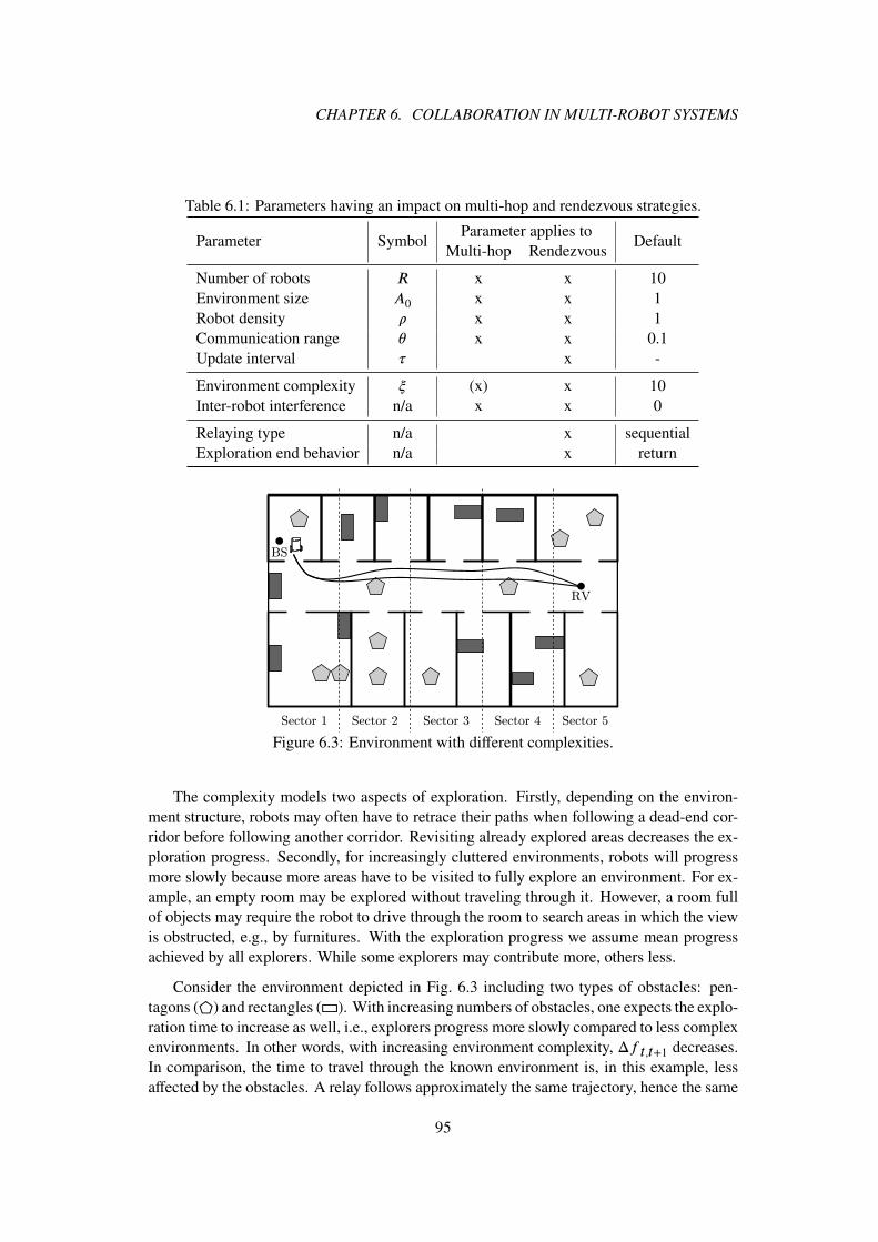
CHAPTER 6. COLLABORATION IN MULTI-ROBOT SYSTEMS
Table 6.1: Parameters having an impact on multi-hop and rendezvous strategies.
Parameter SymbolParameter applies to
DefaultMulti-hop Rendezvous
Number of robots R x x 10
Environment size A0 x x 1
Robot density � x x 1
Communication range � x x 0.1
Update interval � x -
Environment complexity � (x) x 10
Inter-robot interference n/a x x 0
Relaying type n/a x sequentialExploration end behavior n/a x return
Sector 1 Sector 2 Sector 3 Sector 4 Sector 5
RV
BS
Figure 6.3: Environment with different complexities.
The complexity models two aspects of exploration. Firstly, depending on the environ-ment structure, robots may often have to retrace their paths when following a dead-end cor-ridor before following another corridor. Revisiting already explored areas decreases the ex-ploration progress. Secondly, for increasingly cluttered environments, robots will progressmore slowly because more areas have to be visited to fully explore an environment. For ex-ample, an empty room may be explored without traveling through it. However, a room fullof objects may require the robot to drive through the room to search areas in which the viewis obstructed, e.g., by furnitures. With the exploration progress we assume mean progressachieved by all explorers. While some explorers may contribute more, others less.
Consider the environment depicted in Fig. 6.3 including two types of obstacles: pen-tagons (⬠) and rectangles (▭). With increasing numbers of obstacles, one expects the explo-ration time to increase as well, i.e., explorers progress more slowly compared to less complexenvironments. In other words, with increasing environment complexity, Δft,t+1 decreases.In comparison, the time to travel through the known environment is, in this example, lessaffected by the obstacles. A relay follows approximately the same trajectory, hence the same
95

6.2. MODEL
Table 6.2: Exploration times �e (minutes and seconds) for different environment complexi-ties.
Complexity 0.05 Mean 0.95
w/o obstacles 7m35 s 9m23 s 12m11 s
w/ obstacles ▭ 17m31 s 20m27 s 25m58 s
w/ obstacles ▭ & ⬠ 25m33 s 30m50 s 42m46 s
travel time to move between the BS and a possible rendezvous.
We simulate the environment in Fig. 6.3 using the system described in Chapter 3.3
1. without,
2. only with rectangular, and
3. with rectangular and pentagonal obstacles.
Tab. 6.2 summarizes the mean exploration times including 0.05- and 0.95-quantiles for atotal of 50 simulations. With increasing number of obstacles, the exploration time increaseswhile the travel time between BS and rendezvous remains approximately the same. Whilethis has little impact on SMH, we will show that the environment complexity has a significantimpact on SRV.
We determine the dependency of exploration progress on travel progress. Instead ofcomparing exploration progress, we compare exploration times �e, which are easier to han-dle. The environment in Fig. 6.3 is split into five sectors of equal size and simulated withincreasing number of sectors. For example, the first environment only includes sector 1, thesecond environment sectors 1 − 2, etc. Again, each environment size is simulated 50 times.
Fig. 6.4 illustrates the exploration times for increasing environment size for one explorerand required travel times for one relay. With increasing environment size, both the travel andexploration time increase linearly. The travel time yields the smallest slope. With increasingnumbers of obstacles, the slope of the exploration time increases.
We conclude that, for environments similar to Fig. 6.3, the dependency between the timerequired by a relay navigating through known environments and explorers exploring the samedistance in unknown environments is linear. Using the robot’s velocity v to convert from timeto distance, we state that relays travel longer distances than explorers progress in the sametime. Accordingly, we define
�(d) =d
�, � ≥ 1 , (6.2)
where � is the complexity factor modeling the complexity of an environment, d the distancetraveled by a relay and � the progress made by one explorer in the same time.
Multiple robots may increase the exploration progress by distributing the explorationarea. The multi-robot gain gmr allows R robots to progress more quickly than a single
96

CHAPTER 6. COLLABORATION IN MULTI-ROBOT SYSTEMS
[1] [1-2] [1-3] [1-4] [1-5]
Segments
0
5
0
5
0
5
0
5
40
45
Explorationtime
e(m
in.)
Fitted w/ rect
Fitted w/o obstacles
Fitted w/ rect + hexagon
w/ rect
w/o obstacles
w/ rect + hexagon
Travel time
Figure 6.4: Exploration times for three environment complexities and varying environmentsizes according to Fig. 6.3.
robot. Assuming favorable environments, perfect coordination, and no inter-robot interfer-ence, gmr = R, i.e., R robots explore an environment R-times faster than a single robot.Considering multiple explorers, (6.2) is modified to
�(d) = min
[d ⋅ gmr
�, d
]gmr=R=
[d ⋅ R
�, d
]. (6.3)
The minimum ensures that robots do not progress more quickly than they can travel and setsa limit to the speedup due to increased numbers of robots.
While dependencies other than the linear kind are thinkable (environments can be con-structed accordingly), we focus on linear progress as we expect this to be the general case.
6.2.5.2 Inter-Robot Interference
With increasing robot density, exploration times may stop to decrease or may even increase.The reason is twofold: Once as many explorers are in the system as dedicated areas forexploration are available, adding additional robots does not decrease the exploration time(see Sec. 4.4.2 on page 52). Additionally, robots start to interfere with each other, increasingthe complexity of navigation.
Juliá et al. compare various coordination methods for different numbers ofrobots [JGR12]. They show that the exploration time decreases linearly with increasing num-bers of robots. We use their results to model the performance of multi-robot system morerealistically. Instead of (6.3), considering inter-robot interference we define the gain throughadditional robots
gmr = R − �(R − 1) , (6.4)
where � models the degree of interference. Fig. 6.5 illustrates the exploration gain for various�. For example, with � = 0.5, a multi-robot system with R robots performs approximately
like a system with R2
robots with respect to exploration progress.
97

6.2. MODEL
0 5 10 15 20
Number of robots R
0
5
10
15
20
Mu
lti-
rob
ot
ga
inG
MR
κ
0.00
0.30
0.50
0.70
Figure 6.5: Gain through multiple robots for various interference factors �. Markers areconnected to improve readability.
6.2.5.3 End of Exploration Behavior
For SRV it is necessary to define how robots behave once they have completed mapping anenvironment at �e. This parameter applies only to the rendezvous strategy. We distinguishtwo alternatives:
1. Wait: Explorers wait for the arrival of the next relay and indicate complete exploration.
2. Return: Explorers return immediately to the BS.
If explorers cannot deduce the time left to complete exploration (as assumed), robots maycomplete the exploration shortly after the last rendezvous, therefore, wasting time waitingfor the relay to return.
Returning immediately has implications for the relay(s). If robots do not meet with relayson the way back, relays are unaware that the exploration is complete. Relays may wasteenergy and time traveling to a rendezvous without any explorers to meet. To ensure theorderly completion of the exploration, explorers need to meet relays allowing them to indicatecomplete exploration, e.g., by sharing the travel path between the rendezvous and the BStaken by the relays.
If the explorers can approximate the time left to complete exploration, the rendezvousshall be planned accordingly.
Fig. 6.6 shows the exploration time �r for various update intervals � and compares theexploration end behaviors to wait for a relay or to return immediately. The update interval isnormalized to the exploration time of reference strategy Sref . For � → ∞ and the parametersgiven in Tab. 6.1, SRV ≡ Sref . For example, � = 0.1 refers to an interval of 1∕10-th of theexploration time, i.e., the BS is updated ten times. We continue to explain the dependencyin parts I-V depicted in Fig. 6.6.
98
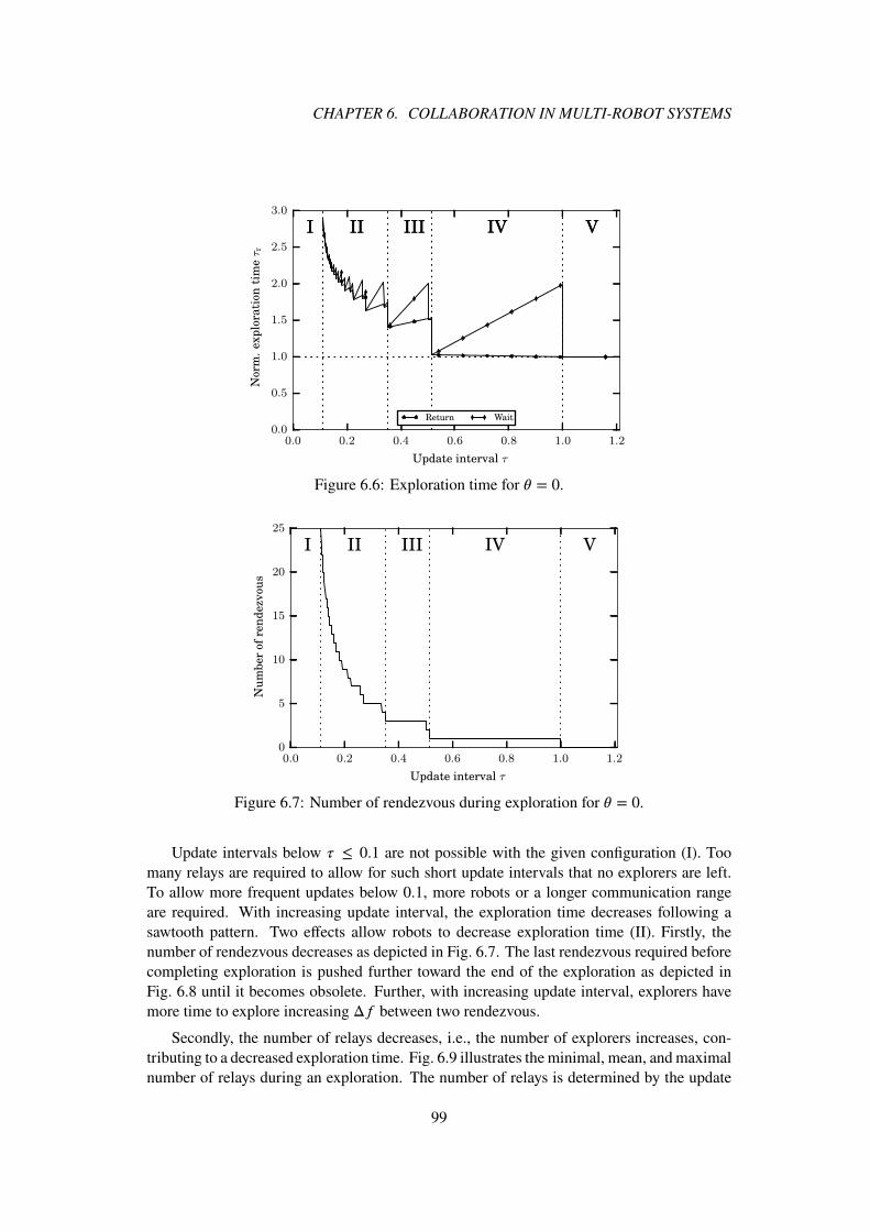
CHAPTER 6. COLLABORATION IN MULTI-ROBOT SYSTEMS
0.0 0.2 0.4 0.6 0.8 1.0 1.2
Update interval τ
0.0
0.5
1.0
1.5
2.0
2.5
3.0
Norm
.exp
lora
tion
tim
eτr
I II III IV VI II III IV V
Return Wait
Figure 6.6: Exploration time for � = 0.
0.0 0.2 0.4 0.6 0.8 1.0 1.2
Update interval τ
0
5
10
15
20
25
Nu
mb
er
of
ren
dezvou
s
I II III IV V
Figure 6.7: Number of rendezvous during exploration for � = 0.
Update intervals below � ≤ 0.1 are not possible with the given configuration (I). Toomany relays are required to allow for such short update intervals that no explorers are left.To allow more frequent updates below 0.1, more robots or a longer communication rangeare required. With increasing update interval, the exploration time decreases following asawtooth pattern. Two effects allow robots to decrease exploration time (II). Firstly, thenumber of rendezvous decreases as depicted in Fig. 6.7. The last rendezvous required beforecompleting exploration is pushed further toward the end of the exploration as depicted inFig. 6.8 until it becomes obsolete. Further, with increasing update interval, explorers havemore time to explore increasing Δf between two rendezvous.
Secondly, the number of relays decreases, i.e., the number of explorers increases, con-tributing to a decreased exploration time. Fig. 6.9 illustrates the minimal, mean, and maximalnumber of relays during an exploration. The number of relays is determined by the update
99

6.2. MODEL
BS
RV
(a)
BS
RV
(b)Figure 6.8: Last rendezvous before completing exploration for SRV with (a) short and (b)long update intervals.
0.0 0.2 0.4 0.6 0.8 1.0 1.2
Update interval τ
0
2
4
6
8
10
Nu
mb
er
of
rela
ysR
R
I II III IV V
Avg
Max
Min
Figure 6.9: Number of relays required to allow regular updates in specified intervals �.
interval according to (6.1). The minimal number of relays is always one except in parts I andV. In part I, exploration is not possible given the configuration, while in part V the updateinterval is greater than the exploration time, i.e., no relays are required.
The sawtooth pattern in part II and III of Fig. 6.6 has two reasons. Firstly, the robotshave more time to explore with increasing update interval. This allows them to push thefrontier further away from the rendezvous location, leading to increased Δft,t+1 between twoconsecutive rendezvous. Fig. 6.1d on page 92 illustrates Δf . The farther robots penetrateinto the unknown, the farther they have to travel back and forth to the rendezvous. Fig. 6.10depicts the relative time explorers spend traveling.
A way to mitigate the effect is to select rendezvous points in a way to reduce the traveldistance for explorers as suggested in [dHCV10b]. Though optimal selection significantlydepends on the environment. We assume the worst case in which relays do not contribute tothe exploration.
100

CHAPTER 6. COLLABORATION IN MULTI-ROBOT SYSTEMS
0.0 0.2 0.4 0.6 0.8 1.0 1.2
Update Interval τ
0.0
0.2
0.4
0.6
0.8
1.0
Rel.
travel
tim
e
I II III IV V
Figure 6.10: Time spent traveling by explorers to and from rendezvous for � = 0 relative toexploration time �e.
Secondly, for robots waiting at the end of an exploration, the slope is greater than forrobots returning immediately. The reason is the increased time spent waiting at the last ren-dezvous for the relay to return. The farther the last rendezvous is pushed toward the end ofthe exploration (see Fig. 6.8), the less time explorers may explore but the longer they haveto wait. If explorers return immediately, they carry the data towards the BS, decreasing theexploration time compared to waiting.
In part IV of Fig. 6.6 on page 99, the travel time for waiting robots increases due to thesame reason as discussed before. For immediate return, however, the travel time constantlydecreases. In part IV robots meet for only a single rendezvous requiring one relay. The longerthe update interval, the longer all robots may explore before one robot has to return to the BSto deliver the data.
Finally, in part V, the update interval is equal to or greater than the exploration time, i.e.,explorers never meet for a rendezvous. Instead, they complete exploration before returningto the BS delivering complete data. This yields the minimum exploration time for � = 0.
From here on, we only consider the case of explorers returning immediately once theyhave completed exploration.
6.2.5.4 Parallel vs. Sequential Relaying
For the rendezvous strategy, relays may carry data between the frontier and a BS in twomodes. If relays operate in parallel, they will oscillate independently between the commu-nication end points. If they operate in sequential mode, relays form a daisy chain and willoscillate only between neighboring relays (see Fig. 6.1d). Both modes have implications onthe coordination function.
In parallel mode, the coordination effort between relays may be reduced because relaysoperate independently. Though two drawbacks arise. Firstly, relays barely profit from com-munication range � > 0. In sequential mode, data may be propagated wirelessly between
101

6.2. MODEL
0.0 0.2 0.4 0.6 0.8 1.0 1.2
Update interval τ
0.0
0.5
1.0
1.5
2.0
2.5
3.0
Norm
.exp
lora
tion
tim
eτr
I II III IV V
θ=0.0 θ=0.1
Figure 6.11: Impact of communication range on SRV.
relays benefiting from the communication range. Relays form a daisy chain comparable tothe multi-hop case. However, the relays are not in communication range but have to traveltowards each other. In comparison, in parallel mode relays only profit when exchanging datawith the explorers and the BS. Secondly, rendezvous cannot be scheduled at the foremostfrontier, because only the relay which met most recently with the explorers has the updatedmap data. All other relays are not aware of the most recent progress. Accordingly, explorershave to return further towards the relay to meet.
The advantage of parallel relays is an increased robustness against relay failure. Sincerelays operate independently, connectivity is still maintained between explorers and a BS atthe cost of an increased update interval. For sequential relays, the malfunctioning robot cutsthe daisy chain, disconnecting the explorers from the BS. Relays need to coordinate to detecta malfunctioning relay and have to reorganize to fill the gap.
We only consider sequentially operating relays to gain from the communication rangeexpected to significantly speed up exploration as discussed in the next section.
6.2.5.5 Impact of Communication Range on Rendezvous
Communication ranges � > 0 have significant impact on the exploration time. Fig. 6.11 com-pares the normalized exploration time for � = 0 and � = 0.1. Three things are noteworthy:
1. The increased communication range allows the system to support shorter update inter-vals. For � = 0, update intervals � < 0.1 are not feasible (I). With increased communi-cation range, relays have to travel less, allowing to propagate data over longer distancesin shorter time due to the negligible delay in wireless transmission.
2. Exploration time has a local minimum at � = 0.07. While comparably many relaysare required to realize such a short update interval, the relays benefit from the com-munication range allowing to propagate the data more quickly until �e. With further
102
CHAPTER 6. COLLABORATION IN MULTI-ROBOT SYSTEMS
increasing �, the number of explorers increases, allowing to explore the environmentmore quickly. In the end, however, fewer relays are available to propagate the databack to the BS. Therefore, each relay has to travel more, increasing the time until thedata is reported at �r .
3. While for � = 0 the minimum exploration time can be reached if explorers do not meetfor rendezvous, rendezvous can help to decrease �r . For � > 1.0 and � = 0.1, �r isbelow the exploration time for � = 0. Again, relays have to travel less because theycan propagate the data earlier using the communication range.
Considering communication range, determining the optimal � to minimize �r becomes morecomplicated considering constellations of number of relays and the benefit of quicker prop-agation of data once the exploration is complete.
6.3 Performance Comparison by Parameter
We compare both strategies for each parameter individually to determine their impact on thestrategies. Based on the comparisons general results are deduced in Sec. 6.4 to guide thedesign of improved strategies for connectivity establishment.
6.3.1 Number of Robots
While SRV allows to fully explore any environment, SMH is limited by the number of robots.The minimal R for SMH to be able to fully explore an environment is determined by
RMH ≥ A0
�. (6.5)
Using the default parameters in Tab. 6.1, at least ten robots are required.
Fig. 6.12 depicts the impact of team size on the normalized exploration time �r for SMH
and SRV for � = 0.2, 0.6. � = optimal refers to the � that minimizes the exploration time fora given R. For R < 10, complete exploration can be achieved only by SRV at significantlyincreased exploration times and possibly large �. For � = 0.2, for example, a completeexploration is not feasible for less than five robots.
For R = 10 and SMH, the exploration time �r is 1.5-times higher than the reference strat-egySref due to decreased number of explorers. Propagating newly acquired data immediatelyto the BS comes at the increased cost of a reduced number of explorers increasing total ex-ploration time �r . For SRV, the optimal � allows to decrease the exploration time, optimizingthe ratio of explorers to relays.
With increasing numbers of robots especially SMH benefits. SRV does not benefit signif-icantly from more robots, because additional explorers do not decrease the exploration timeaccording to (6.3). Though additional robots allow to increase the number of relays (as in thecase of optimal �). The more relays are available at �e, the quicker the data may be propagatedto the BS decreasing �r achieving comparable results to SMH for the given configuration. Inthe optimal case, both strategies allow to halve �r .
103

6.3. PERFORMANCE COMPARISON BY PARAMETER
0 5 10 15 20
Number of robots R
0.0
0.5
1.0
1.5
2.0
2.5
3.0
3.5
4.0
Norm
.exp
lora
tion
tim
eτr
SMH
SRV τ=0.20
SRV τ=0.60
SRV τ=optimal
Figure 6.12: Impact number of robots on both strategies. Markers are connected to improvereadability.
0.0 0.2 0.4 0.6 0.8 1.0
Update interval τ
0.0
0.5
1.0
1.5
2.0
2.5
3.0
Norm
.exp
lora
tion
tim
eτr
N/A0=10/1.0
N/A0=12/1.0
N/A0=20/1.0
N/A0=5/1.0
(a)
0.0 0.2 0.4 0.6 0.8 1.0
Update interval τ
0.0
0.5
1.0
1.5
2.0
Ra
tioδ
N/A0=10/1.0
N/A0=11/1.0
N/A0=12/1.0
N/A0=20/1.0
(b)Figure 6.13: Impact robot density: (a) Normalized exploration time for SRV and (b) � forvarious �.
6.3.1.1 Impact of Robot Density
We continue to determine the impact of the robot density � on the behavior of SRV for en-vironments of equal size depicted in Fig. 6.13a. For � =
1
2, �r doubles for a wide range of
update intervals due to decreased mean number of explorers. Small update intervals are notfeasible, as they require more robots. In comparison, � ≥ 1 has little impact on explorationtimes independent of �. Because many robots are already available, adding additional robotshas only limited impact on �r . The minimal �r , however, decreases with additional robots.For very short update intervals, �r continues to decrease forSRV. For large numbers of robots,additional explorers contribute only little to the overall exploration. Turning these robots intorelays helps to decrease the propagation time at the end of the exploration, decreasing �r .
104

CHAPTER 6. COLLABORATION IN MULTI-ROBOT SYSTEMS
0.0 0.2 0.4 0.6 0.8 1.0
Update interval τ
0.0
0.5
1.0
1.5
2.0
2.5
3.0
Norm
.exp
lora
tion
tim
eτr
N/A0=10/1.0
N/A0=20/2.0
N/A0=5/0.5
(a)
0.0 0.2 0.4 0.6 0.8 1.0
Update interval τ
0.0
0.5
1.0
1.5
2.0
Ra
tioδ
N/A0=10/1.0
N/A0=20/2.0
N/A0=5/0.5
(b)Figure 6.14: Impact environment size: (a) Normalized exploration time for SRV and (b) � for� =
1
2and various environment sizes.
Fig. 6.13b compares SMH and SRV for various robot densities using the ratio � defined as
� =�r,MH
�r,RV, (6.6)
i.e., for � > 1, SRV performs better, SMH otherwise. The figure supports a previous result inwhich SMH starts to outperform SRV for R ≥ 12 robots. For eleven robots, the ratio dependson �. For great �, SRV continues to outperform SMH. The higher the robot density, the betterthe performance of SMH compared to SRV.
6.3.1.2 Impact of Environment Size
A similar effect can be observed for equal densities but increasing numbers of robots andenvironment sizes. Fig. 6.14a illustrates �r for SRV and � = 1 for half, equal, and doubleenvironment sizes compared to the reference environment size. In environments with halfthe size of the reference environment, it takes approximately 75% of �r , because the ratio ofrelays to explorers is low. With increasing numbers of robots, the ratio improves reducing �rsignificantly up to a density of � = 1.
For R = 20 and A0 = 2 and � → 1, exploration time �r doubles compared to R = 20
and A0 = 1. However, for update intervals � ∈ [0.2, 0.9], �r more than doubles and becomesmore sensitive to the update interval. While for R = 10 and A0 = 1 minimal and maximal �rdiverge by approximately 30%, for R = 20 and A0 = 2 they diverge by more than 100%. Forincreased densities, the selection of an appropriate update interval becomes more important.
Finally, we compare the two strategies for equal densities in Fig. 6.14b. For small en-vironments and � ≲ 1.2, SRV outperforms SMH with respect to �r . For larger environmentswhich require many robots, SMH decreases the exploration time �r significantly compared toSRV. Due to the high number of robots, the additional explorers in the SRV do not allow tosignificantly decrease the exploration time.
105
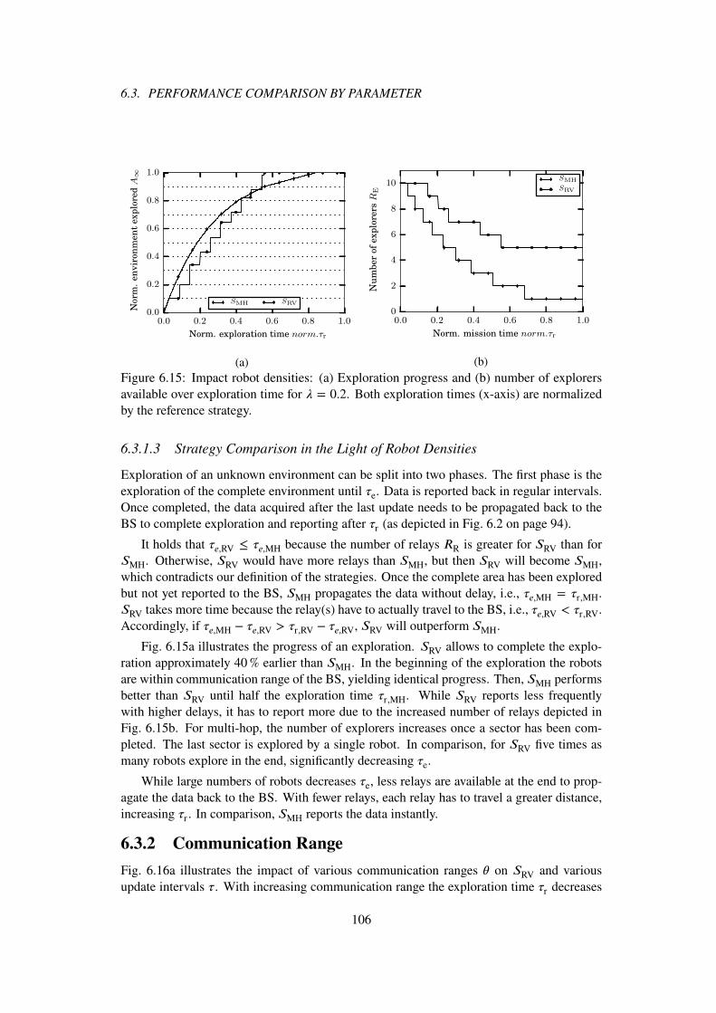
6.3. PERFORMANCE COMPARISON BY PARAMETER
0.0 0.2 0.4 0.6 0.8 1.0
Norm. exploration time norm.τr
0.0
0.2
0.4
0.6
0.8
1.0
Norm
.en
vir
on
men
texp
lore
dA
∞
SMH SRV
(a)
0.0 0.2 0.4 0.6 0.8 1.0
Norm. mission time norm.τr
0
2
4
6
8
10
Nu
mb
er
of
exp
lore
rsR
E
SMH
SRV
(b)
Figure 6.15: Impact robot densities: (a) Exploration progress and (b) number of explorersavailable over exploration time for � = 0.2. Both exploration times (x-axis) are normalizedby the reference strategy.
6.3.1.3 Strategy Comparison in the Light of Robot Densities
Exploration of an unknown environment can be split into two phases. The first phase is theexploration of the complete environment until �e. Data is reported back in regular intervals.Once completed, the data acquired after the last update needs to be propagated back to theBS to complete exploration and reporting after �r (as depicted in Fig. 6.2 on page 94).
It holds that �e,RV ≤ �e,MH because the number of relays RR is greater for SRV than forSMH. Otherwise, SRV would have more relays than SMH, but then SRV will become SMH,which contradicts our definition of the strategies. Once the complete area has been exploredbut not yet reported to the BS, SMH propagates the data without delay, i.e., �e,MH = �r,MH.SRV takes more time because the relay(s) have to actually travel to the BS, i.e., �e,RV < �r,RV.Accordingly, if �e,MH − �e,RV > �r,RV − �e,RV, SRV will outperform SMH.
Fig. 6.15a illustrates the progress of an exploration. SRV allows to complete the explo-ration approximately 40% earlier than SMH. In the beginning of the exploration the robotsare within communication range of the BS, yielding identical progress. Then, SMH performsbetter than SRV until half the exploration time �r,MH. While SRV reports less frequentlywith higher delays, it has to report more due to the increased number of relays depicted inFig. 6.15b. For multi-hop, the number of explorers increases once a sector has been com-pleted. The last sector is explored by a single robot. In comparison, for SRV five times asmany robots explore in the end, significantly decreasing �e.
While large numbers of robots decreases �e, less relays are available at the end to prop-agate the data back to the BS. With fewer relays, each relay has to travel a greater distance,increasing �r . In comparison, SMH reports the data instantly.
6.3.2 Communication Range
Fig. 6.16a illustrates the impact of various communication ranges � on SRV and variousupdate intervals �. With increasing communication range the exploration time �r decreases
106
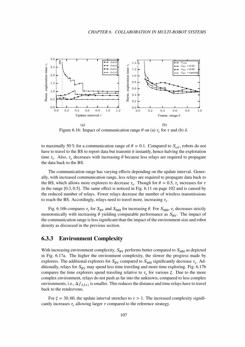
CHAPTER 6. COLLABORATION IN MULTI-ROBOT SYSTEMS
0.0 0.2 0.4 0.6 0.8 1.0 1.2
Update interval τ
0.0
0.5
1.0
1.5
2.0
2.5
3.0
Norm
.exp
lora
tion
tim
eτr I θ=0.0
θ=0.2
θ=0.5
θ=1.0
(a)
0.0 0.2 0.4 0.6 0.8 1.0
Comm. range θ
0.0
0.2
0.4
0.6
0.8
1.0
1.2
1.4
Norm
.exp
lora
tion
tim
eτr
SMH
SRV τ=0.20
SRV τ=0.60
SRV τ=optimal
(b)Figure 6.16: Impact of communication range � on (a) �r for � and (b) �.
to maximally 50% for a communication range of � = 0.1. Compared to Sref , robots do nothave to travel to the BS to report data but transmit it instantly, hence halving the explorationtime �r . Also, �e decreases with increasing � because less relays are required to propagatethe data back to the BS.
The communication range has varying effects depending on the update interval. Gener-ally, with increased communication range, less relays are required to propagate data back tothe BS, which allows more explorers to decrease �e. Though for � = 0.5, �r increases for �in the range [0.3, 0.5]. The same effect is noticed in Fig. 6.11 on page 102 and is caused bythe reduced number of relays. Fewer relays decrease the number of wireless transmissionsto reach the BS. Accordingly, relays need to travel more, increasing �r .
Fig. 6.16b compares �r for SRV and SMH for increasing �. For SMH, �r decreases strictlymonotonically with increasing � yielding comparable performance as SRV. The impact ofthe communication range is less significant than the impact of the environment size and robotdensity as discussed in the previous section.
6.3.3 Environment Complexity
With increasing environment complexity, SRV performs better compared to SMH as depictedin Fig. 6.17a. The higher the environment complexity, the slower the progress made byexplorers. The additional explorers for SRV compared to SMH significantly decrease �e. Ad-ditionally, relays for SRV may spend less time traveling and more time exploring. Fig. 6.17bcompares the time explorers spend traveling relative to �e for various �. Due to the morecomplex environment, relays do not push as far into the unknown, compared to less complexenvironments, i.e., Δft,t+1 is smaller. This reduces the distance and time relays have to travelback to the rendezvous.
For � = 30, 60, the update interval stretches to � > 1. The increased complexity signifi-cantly increases �r allowing larger � compared to the reference strategy.
107

6.3. PERFORMANCE COMPARISON BY PARAMETER
0.0 0.2 0.4 0.6 0.8 1.0
Update interval τ
0.0
0.5
1.0
1.5
2.0
Ra
tioδ
ξ=10
ξ=20
ξ=60
(a)
0.0 0.5 1.0 1.5 2.0
Update interval τ
0.0
0.2
0.4
0.6
0.8
1.0
Rel.
travel
tim
e
ξ=10
ξ=30
ξ=60
(b)Figure 6.17: Impact of � for R = 15 and A0 = 1 on (a) ratio � and (b) relative travel timewith respect to �e.
0.0 0.2 0.4 0.6 0.8 1.0
Update interval τ
0.0
0.5
1.0
1.5
2.0
Ra
tioδ
λ=0.0
λ=0.4
λ=0.8
Figure 6.18: Impact of inter-robot interference.
6.3.4 Inter-Robot Interference
Inter-robot interference limits the progress made by explorers comparable to the effect causedby environment complexity. According to (6.4) on page 97, with increasing interferencefactor � the number of explorers contributing to the exploration progress decreases. Fig. 6.18compares the impact of inter-robot interference on both strategies. With increasing inter-robot interference factor �, the ratio � decreases, i.e., SMH performs comparably better thanSRV. Since SRV has more explorers than SMH, robots suffer from increased interference.Therefore, exploration progress for rendezvous suffers more than for multi-hop.
108

CHAPTER 6. COLLABORATION IN MULTI-ROBOT SYSTEMS
6.4 Guidelines for Designing Optimized Strategies
Generally, SRV outperforms SMH if additional explorers are available for SRV, decreasing theexploration time �e more than rendezvous looses when propagating the data back to the BSat the end of the exploration. This applies if
1. explorers progress slowly and benefit from additional robots due to
• high environment complexity,
• small number of robots, or
2. relays for SRV do not have to travel much distance after �e because
• the environment is small,
• many sequential relays profit from the communication range.
Additional guidelines for the design of strategies include:
3. If not enough robots according to (6.5) are available, SMH will not allow to fully explorethe environment. SRV, however, allows to completely explore arbitrary environmentsat the cost of increased update intervals.
4. While SRV benefits from the higher number of explorers, SMH benefits from fast datapropagation at the end of the exploration. Increasing the number of relays towards theend of the exploration for SRV allows to profit from both strategies. This requires todeduct the end of the exploration.
5. High inter-robot interference affects SRV more severely due to increased number ofexplorers compared to SMH. If system performance decreases significantly with in-creasing numbers of robots, SMH should be given preference.
6. For the rendezvous strategy, relays shall return immediately once they finish explo-ration at �e. Especially for long update intervals, the waiting time for the explorersmay have significant impact on the exploration time �r . Explorers should be enabledto inform relays on their way back about the canceled rendezvous to save additionaltime.
7. For SRV, relays should work sequentially, i.e., propagating the data from relay to relay,for two reasons. Firstly, sequential relaying allows to benefit more often from wirelesscommunication range compared to parallel relaying. Because wireless communica-tion can be assumed to transport data faster than traveling relays, wireless propagationallows to decrease �r . Secondly, for more than one relay, it is always the same relaythat meets with the explorers. In parallel mode, explorers have to travel further backto a rendezvous because only the relay which met last with the explorers has the mostrecent data. Sequential relaying comes at the cost of being more error prone comparedto parallel operating relays.
109

6.4. GUIDELINES FOR DESIGNING OPTIMIZED STRATEGIES
8. The update interval � has a significant impact on the exploration time. The impactincreases with larger environment sizes. For communication ranges � > 0, smallupdate intervals, i.e., many relays, decrease exploration time �r . In sequential mode,additional relay robots decrease the travel distance of each relay due to the gain ofwireless transmissions.
9. If more explorers are available than can contribute to the exploration, SMH outperformsSRV with respect to �r . The advantage of rendezvous is the faster exploration of theenvironment until �e. If many explorers are available, SRV does not allow significantlyfaster exploration than SMH. Many explorers are available for large environments withmany relays or high robot densities with low inter-robot interference or environmentcomplexity. Increased communication frees up additional robots serving as explorers.
10. SRV is suitable for environments with high complexity.
The guidelines are intended to help designing improved strategies to establish connectiv-ity between communication end points. Note that, especially in the case for SRV, sequentialrelaying with immediate return significantly improves the performance of the strategy. How-ever, the it needs to be determined how to efficiently realize this behavior with respect toreliability.
110

7CONCLUSIONS
The aim of this dissertation has been to present a system architecture supporting autonomousexploration by multiple, self-organizing robots. The thesis at hand contributes to the organi-zation of multi-robot systems suggesting terminology, architectures, and models to describe,implement and evaluate distributed multi-robot systems.
While centralized systems for exploration have been presented before, they may not besuitable for all applications. In general, distributed systems should perform equally well com-pared to centralized systems while allowing better scalability and offering greater resilienceagainst malfunctions. Scalability is required for large environments while reliability allowsthe usage of less robust individual robots or deployment in hazardous environments, in whichrobot failure is likely. Accordingly, the derived architecture is based on the two premises as-suming unreliable robots and volatile communication. It is discussed with potential users toensure applicability to real-world applications and implemented using the Robot OperatingSystem (ROS) to ensure functionality in real-world environments.
The main research questions addressed in this thesis are:
1. What is a suitable architecture for autonomous and distributed multi-robot exploration?
2. Is coordination necessary in robot systems consisting of multiple robots and how muchperformance gain can be expected through coordination?
3. Which communication protocol architecture fulfills the required quality of service(QoS) for coordinated exploration?
4. Should connectivity between clusters of robots and/or base stations (BSs) be estab-lished by means of multi-hop routing or by rendezvous?
Multiple robots may reduce the time required to fully explore an unknown environmentcompared to a single robot. Robots parallelize exploration by exploring distinct areas. The
111

individually created maps are then combined. Many coordination algorithms have been pro-posed and compared. They aim at spatially distributing robots considering various formsof constraints to prevent redundant exploration of the same area by multiple robots. Com-parisons show that they perform equally well. But their efficiency has hardly been doubteddespite their implementation overhead. The coordination of multi-robot systems as definedabove requires additional modules in the system architecture increasing complexity signifi-cantly. The findings of Chapter 4 suggest that explicit coordination is not required in everycase but can be substituted by efficient frontier selection strategies. On average, multiplesingle-robot systems may achieve good coverage. If exploration time and complete coverageare not of high priorities, coordination may not be required.
Instead, coordination may be important for two reasons. Firstly, simulations in Chapter 3show that revisiting areas increases costs significantly in terms of exploration time and energysignificantly. Therefore, coordination may ensure that a local area is fully explored beforeprogressing to the next area. For example, before moving on to a different floor or wingof a building, exploration of the current area should be completed. Secondly, coordinationis required for cooperation or collaboration of multiple robots. Heterogeneous multi-robotsystems may benefit from their robots’ individual special capabilities. For example, largerrobots may request smaller robots to explore areas which cannot be reached by the larger ones.Robots need to have a common understanding of their environment to meet intentionally,requiring a global map shared among all robots and communication capabilities to exchangemaps and coordinate their actions.
The multi-robot system is self-supporting and does not depend on existing infrastruc-ture. Robots form a mobile ad hoc network (MANET). Distributed systems yield differentinformation flows compared to centralized systems. Multi-robot exploration requires mainlyreliable wireless multi-cast or broadcast transmissions for which the standard TCP/IP pro-tocol suite is not designed. The spatial distribution of robots allows space-time diversitytransmission to improve reliability while saving wireless channel resources. We introducea complete protocol architecture designed for reliable data dissemination in multi-robot net-works integrating cooperative relaying. Previous solutions to achieve reliable multicast eithersignificantly increased the transmission overhead or focused on isolated protocol layers oftenneglecting impacts of interacting layers. The architecture is designed for the specific needsof reliable data dissemination via multicast for mobile nodes. It updates routes and allows toadjust group membership.
The protocol architecture assumes connectivity between robots. The concept ofcommunication-aware mobility allows mobile robots to consider their communication needsduring task or path planning. Two strategies have been suggested in the literature, namelymulti-hop communication and rendezvous. While multi-hop communication is well under-stood, rendezvous concepts have received less attention. Rendezvous strategies were de-signed based on the trial and error principle. Comparisons of both strategies were not donesystematically but were based on strategies that were believed to perform well. In two obviouscases the selection of the correct strategy is straightforward. If the number of available robotsis not sufficient to span a multi-hop route between a BS and the foremost explorers, multi-hopwill not allow complete exploration of an environment. Connectivity by rendezvous allowsrobots to penetrate further into the environment reporting back in intervals. In comparison,
112
CHAPTER 7. CONCLUSIONS
if small communication delays and frequent updates are required, e.g., for teleoperation ofrobots, only multi-hop may offer the required QoS. To support the decision process in allother cases, Chapter 6 models both strategies and quantitatively determines impacting pa-rameters. A checklist of ten items supports the future design of rendezvous and multi-hopstrategies and allows to assess which strategy may be appropriate for a given application.
Future research may be directed in three directions. Firstly, the models suggested inChapters 4 and 6 have limitations with respect to their application in real-world environ-ments. It is not always obvious how to map parameters evaluated in the abstract modelsto real-world deployments. Further research is required to validate the models. Researchshould aim for a systematic and possibly formal way to allow a better understanding of dis-tributed multi-robot systems and their sensitivity to system parameters. Current research ondistributed multi-robot systems is often guided by trial and error. Secondly, system reliabilityand the capability of error recovery needs to be addressed separately. The presented architec-ture is designed to allow autonomous operation of robots to decrease dependencies on otherrobots. But current protocols do not specify how to reorganize a multi-robot system in caseof malfunctions. Robots may be adaptive and switch their roles on demand. Especially forconnectivity management, reorganizing robots may become necessary to recover from robotfailures. The third research question considers collaborative, heterogeneous multi-robot sys-tems. Robots may collaborate for tasks, switching positions or joining at the same location,constantly changing the topology of the system. The selection of robots and determination ofsuitable times when to collaborate are expected to have a significant impact on the multi-robotsystem.
113

114

BIBLIOGRAPHY
[AB13] T. Andre and C. Bettstetter. Assessing the value of coordination in mobilerobot exploration using a discrete-time markov process. In Proc. IEEE/RSJ
Int. Conf. on Intelligent Robots and Systems (IROS), Nov. 2013.
[ABK09] P. Abichandani, H. Y. Benson, and M. Kam. Multi-vehicle path coordina-tion in support of communication. In Proc. IEEE Int. Conf. on Robotics and
Automation (ICRA), May 2009.
[ABMB12] T. Andre, G. Brandner, N. Marchenko, and C. Bettstetter. Measurement-basedanalysis of cooperative relaying in an industrial wireless sensor network. InProc. IEEE GLOBECOM, Dec. 2012.
[ABQL12] F. Amigoni, N. Basilico, and A. Quattrinie Li. How much worth is coordina-tion of mobile robots for exploration in search and rescue? In Proc. RoboCup
Int. Symp., June 2012.
[ABS09] H. Adam, C. Bettstetter, and S. Senouci. Multi-hop-aware cooperative relay-ing. In Proc. IEEE Vehicular Technology Conference (VTC), Apr. 2009.
[AG03] S. Alpern and S. Gal. The Theory of Search Games and Rendezvous. SpringerScience & Business Media, 2003.
[AH10] M. Awais and D. Henrich. Human-robot collaboration by intention recogni-tion using probabilistic state machines. In Proc. Int. Workshop on Robotics in
Alpe-Adria-Danube Region (RAAD), June 2010.
[AHS+14] T. Andre, K. Hummel, A. Schoellig, E. Yanmaz, M. Asadpour, C. Bettstetter,P. Grippa, H. Hellwagner, S. Sand, and S. Zhang. Application-driven design ofaerial communication networks. IEEE Commun. Mag., 52(5):129–137, May2014.
[AMB+13] T. Andre, N. Marchenko, G. Brandner, W. Masood, and C. Bettstetter.Measurement-based analysis of adaptive relay selection in industrial wirelesssensor networks. In Proc. Int. Symp. on Modeling Optimization in Mobile, Ad
Hoc Wireless Networks (WiOpt), May 2013.
115
BIBLIOGRAPHY
[ANB14] T. Andre, D. Neuhold, and C. Bettstetter. Coordinated multi-robot exploration:Out of the box packages for ROS. In Proc. IEEE GLOBECOM WiUAV Work-
shop, Dec. 2014.
[And13] T. Andre. Multi-hop networks with cooperative relaying assisted links. InProc. IEEE GLOBECOM, Dec. 2013.
[APCR15] A. Araújo, D. Portugal, M. S. Couceiro, and R. P. Rocha. Integrating arduino-based educational mobile robots in ROS. Journal of Intelligent & Robotic
Systems, 77(2):281–298, Feb. 2015.
[APSL08] J. Aulinas, Y. Petillot, J. Salvi, and X. Lladó. The SLAM problem: A survey.In Proc. Int. Conf. of the Catalan Association for Artificial Intelligence, 2008.
[AYB14] H. Adam, E. Yanmaz, and C. Bettstetter. Medium access with adaptive re-lay selection in cooperative wireless networks. IEEE Trans. Mobile Comput.,13(9):2042–2057, Sept. 2014.
[Bal93] T. Balch. Avoiding the past: a simple but effective strategy for reactive nav-igation. In Proc. IEEE Int. Conf. on Robotics and Automation (ICRA), May1993.
[BC06] A. Birk and S. Carpin. Merging occupancy grid maps from multiple robots.Proceedings of the IEEE, 94(7):1384–1397, July 2006.
[BCMGX11] P. Brass, F. Cabrera-Mora, A. Gasparri, and J. Xiao. Multirobot tree and graphexploration. IEEE Trans. Robot., 27(4):707 –717, Aug. 2011.
[BDG+08] J. Butterfield, K. Dantu, B. Gerkey, O. Jenkins, and G. Sukhatme. Au-tonomous biconnected networks of mobile robots. In Proc. Modeling and Op-
timization in Mobile, Ad Hoc, and Wireless Networks and Workshops (WiOpt),Apr. 2008.
[BDK+12] J. Butzke, K. Daniilidis, A. Kushleyev, D. D. Lee, M. Likhachev, C. Phillips,and M. Phillips. The University of Pennsylvania MAGIC 2010 multi-robotunmanned vehicle system. Journal of Field Robotics, 29(5):745–761, Sept.2012.
[BHK+03] M. Berhault, H. Huang, P. Keskinocak, S. Koenig, W. Elmaghraby, P. Griffin,and A. Kleywegt. Robot exploration with combinatorial auctions. In Proc.
IEEE/RSJ Int. Conf. on Intelligent Robots and Systems (IROS), Oct. 2003.
[BL11] J. Butzke and M. Likhachev. Planning for multi-robot exploration with mul-tiple objective utility functions. In Proc. IEEE/RSJ Int. Conf. on Intelligent
Robots and Systems (IROS), Sept. 2011.
[Blu14] Bluetooth Special Interest Group. Specification of the Bluetooth System, Dec.2014.
116

BIBLIOGRAPHY
[BMSS05] W. Burgard, M. Moors, C. Stachniss, and F. E. Schneider. Coordinated multi-robot exploration. IEEE Trans. Robot., 21(3):376–386, June 2005.
[BPSK97] H. Balakrishnan, V. Padmanabhan, S. Seshan, and R. Katz. A comparison ofmechanisms for improving TCP performance over wireless links. IEEE/ACM
Trans. Netw., 5(6):756–769, Dec. 1997.
[CB00] H. Choset and J. W. Burdick. Sensor-based exploration: The hierarchical gen-eralized voronoi graph. Int. Journal of Robotic Research, 19(2):96–125, Feb.2000.
[CGCG10] S. Cousins, B. Gerkey, K. Conley, and W. Garage. Sharing software with ROS[ROS Topics]. IEEE Robot. Autom. Mag., 17(2):12–14, June 2010.
[CHI11] T. Chung, G. Hollinger, and V. Isler. Search and pursuit-evasion in mobilerobotics. Autonomous Robots, 31(4):299–316, Nov. 2011.
[CJKK07] S. Chachulski, M. Jennings, S. Katti, and D. Katabi. Trading structure forrandomness in wireless opportunistic routing. SIGCOMM Comput. Commun.
Rev., 37(4):169–180, Aug. 2007.
[CKF97] Y. Cao, A. Kahng, and A. Fukunaga. Cooperative mobile robotics: An-tecedents and directions. In R. Arkin and G. Bekey, editors, Robot Colonies,pages 7–27. Springer US, 1997.
[CMNT99] J. Castellanos, J. Montiel, J. Neira, and J. Tardos. The SPmap: a probabilis-tic framework for simultaneous localization and map building. IEEE Trans.
Robot., 15(5):948–952, Oct. 1999.
[CMX12] F. Cabrera-Mora and J. Xiao. A flooding algorithm for multirobot exploration.IEEE Trans. Syst., Man, Cybern. B, 42(3):850–863, Jan. 2012.
[CMXB10] F. Cabrera-Mora, J. Xiao, and P. Brass. Multi-robot flooding algorithm forthe exploration of unknown indoor environments. In Proc. IEEE Int. Conf. on
Robotics and Automation (ICRA), May 2010.
[CND+10] L. Carlone, M. Ng, J. Du, B. Bona, and M. Indri. Rao-blackwellized particlefilters multi robot SLAM with unknown initial correspondences and limitedcommunication. In Proc. IEEE Int. Conf. on Robotics and Automation (ICRA),May 2010.
[CPD10] A. Cunningham, M. Paluri, and F. Dellaert. DDF-SAM: Fully distributedSLAM using constrained factor graphs. In Proc. IEEE/RSJ Int. Conf. on In-
telligent Robots and Systems (IROS), Oct. 2010.
[CWC13] N. Correll, R. Wing, and D. Coleman. A one-year introductory robotics cur-riculum for computer science upperclassmen. IEEE Trans. Educ., 56(1):54–60, Feb. 2013.
117

BIBLIOGRAPHY
[DFG+13] M. Dorigo, D. Floreano, L. Gambardella, F. Mondada, S. Nolfi, T. Baaboura,M. Birattari, M. Bonani, M. Brambilla, A. Brutschy, D. Burnier, A. Campo,A. Christensen, A. Decugniere, G. Di Caro, F. Ducatelle, E. Ferrante,A. Forster, J. Martinez Gonzales, J. Guzzi, V. Longchamp, S. Magnenat,N. Mathews, M. Montes de Oca, R. O’Grady, C. Pinciroli, G. Pini, P. Re-tornaz, J. Roberts, V. Sperati, T. Stirling, A. Stranieri, T. Stutzle, V. Trianni,E. Tuci, A. Turgut, and F. Vaussard. Swarmanoid: A novel concept for thestudy of heterogeneous robotic swarms. IEEE Robot. Autom. Mag., 20(4):60–71, Dec. 2013.
[dHCV09] J. de Hoog, S. Cameron, and A. Visser. Role-based autonomous multi-robotexploration. In Proc. Computation World: Future Computing, Service Com-
putation, Cognitive, Adaptive, Content, Patterns, Nov. 2009.
[dHCV10a] J. de Hoog, S. Cameron, and A. Visser. Dynamic team hierarchies incommunication-limited multi-robot exploration. In Proc. IEEE Int. Safety Se-
curity and Rescue Robotics (SSRR) Workshop, July 2010.
[dHCV10b] J. de Hoog, S. Cameron, and A. Visser. Selection of rendezvous points formulti-robot exploration in dynamic environments. In Proc. Int. Conf. on Au-
tonomous Agents and Multi-Agent Systems (AAMAS), May 2010.
[DJMW96] G. Dudek, M. R. M. Jenkin, E. Milios, and D. Wilkes. A taxonomy for multi-agent robotics. Autonomous Robots, 3(4):375–397, Dec. 1996.
[DMCGA03] C. De Morais Cordeiro, H. Gossain, and D. Agrawal. Multicast over wirelessmobile ad hoc networks: present and future directions. IEEE Netw., 17(1):52–59, Jan. 2003.
[DRP14] M. Dianu, J. Riihijärvi, and M. Petrova. Measurement-based study of theperformance of IEEE 802.11ac in an indoor environment. In Proc. IEEE Int.
Conf. on Communications (ICC), June 2014.
[DZKS06] M. Dias, R. Zlot, N. Kalra, and A. Stentz. Market-based multirobot coordina-tion: A survey and analysis. Proceedings of the IEEE, 94(7):1257–1270, July2006.
[EE09] G. Egeland and P. Engelstad. The availability and reliability of wireless multi-hop networks with stochastic link failures. IEEE J. Sel. Areas Commun.,27(7):1132 –1146, Sept. 2009.
[EKRS13] P. Espinace, T. Kollar, N. Roy, and A. Soto. Indoor scene recognition by amobile robot through adaptive object detection. Robotics and Autonomous
Systems, 61(9):932 – 947, May 2013.
[Elf87] A. Elfes. Sonar-based real-world mapping and navigation. IEEE J. Robot.
Autom., 3(3):249–265, June 1987.
118

BIBLIOGRAPHY
[ESH11] J. C. Espino, B. Steux, and O. E. Hamzaoui. Safe navigating system for indoorenvironments. In Proc. Int. Conf. on Automation, Robotics and Applications
(ICARA), Dec. 2011.
[Fal03] K. Fall. A delay-tolerant network architecture for challenged internets. InProc. Conf. on Applications, Technologies, Architectures, and Protocols for
Computer Communications, SIGCOMM, pages 27–34. ACM, 2003.
[Fal10] R. Faludi. Building Wireless Sensor Networks with ZigBee, XBee, Arduino,
and Processing. O’Reilly Media, 2010.
[FIN04] A. Farinelli, L. Iocchi, and D. Nardi. Multirobot systems: a classificationfocused on coordination. IEEE Trans. Syst., Man, Cybern. B, 34(5):2015–2028, Oct. 2004.
[FRM10] S. Fiehe, J. Riihijärvi, and P. Mähönen. Experimental study on performanceof IEEE 802.11N and impact of interferers on the 2.4 GHz ISM band. In Proc.
Int. Wireless Communications and Mobile Computing Conf., June 2010.
[FTL07] E. Ferranti, N. Trigoni, and M. Levene. Brick & mortar: an on-line multi-agent exploration algorithm. In Proc. IEEE Int. Conf. on Robotics and Au-
tomation (ICRA), Apr. 2007.
[GBL02] H. H. González-Baños and J.-C. Latombe. Navigation strategies for exploringindoor environments. Int. Journal of Robotic Research, 21(10-11):829–848,Oct. 2002.
[GGB11] S. Grzonka, G. Grisetti, and W. Burgard. A fully autonomous indoor quadro-tor. IEEE Trans. Robot., 28(1):90–100, Aug. 2011.
[GK00] P. Gupta and P. Kumar. The capacity of wireless networks. IEEE Trans. Inf.
Theory, 46(2):388–404, Mar 2000.
[GM02] B. Gerkey and M. Mataric. Sold!: Auction methods for multirobot coordina-tion. IEEE Trans. Robot., 18(5):758–768, Oct. 2002.
[GM09] A. Ghaffarkhah and Y. Mostofi. Communication-aware navigation functionsfor cooperative target tracking. In Proc. American Control Conf. (ACC), July2009.
[GM11] A. Ghaffarkhah and Y. Mostofi. A communication-aware framework forrobotic field estimation. In Proc. IEEE Conf. Decision and Control and Eu-
ropean Control Conf. (CDC-ECC), Dec. 2011.
[Gro07] O. M. Group. Data Distribution Service for Real-time Systems (v1.2), 01 2007.
[Hae05] M. Haenggi. Analysis and design of diversity schemes for ad hoc wirelessnetworks. IEEE J. Sel. Areas Commun., 23(1):19–27, Jan. 2005.
119

BIBLIOGRAPHY
[HB10] D. Holz and S. Behnke. Sancta simplicitas - On the efficiency and achievableresults of SLAM using ICP-based incremental registration. In Proc. IEEE Int.
Conf. on Robotics and Automation (ICRA), May 2010.
[HBAB10] D. Holz, N. Basilico, F. Amigoni, and S. Behnke. Evaluating the efficiencyof frontier-based exploration strategies. In Proc. German Conference on
Robotics (ROBOTIK), 2010.
[HCKT08] M. A. Hsieh, A. Cowley, V. Kumar, and C. J. Taylor. Maintaining networkconnectivity and performance in robot teams. Journal of Field Robotics, 25(1-2):111–131, Jan. 2008.
[HCNC07] J. Huh, W. S. Chung, S. Y. Nam, and W. K. Chung. Mobile robot exploration inindoor environment using topological structure with invisible barcodes. ETRI
Journal, 29(2):189–200, Apr. 2007.
[HDLS09] F. He, Z. Du, X. Liu, and Y. Sun. Indoor dangerous gas environment detectedby mobile robot. In Proc. IEEE Int. Conf. on Robotics and Biomimetics (RO-
BIO), pages 396–401, Dec. 2009.
[HHJ14] H. Hourani, E. Hauck, and S. Jeschke. Serendipity rendezvous as a mitigationof exploration’s interruptibility for a team of robots. In S. Jeschke, I. Isenhardt,F. Hees, and K. Henning, editors, Automation, Communication and Cybernet-
ics in Science and Engineering, pages 645–663. Springer International Pub-lishing, Dec. 2014.
[HK13] S. Hatti and M. Kamakshi. Performance analysis of ETX and ETT routingmetrics over AODV routing protocol in WMNs. In N. Chaki, N. Meghanathan,and D. Nagamalai, editors, Computer Networks & Communications (Net-
Com), volume 131 of Lecture Notes in Electrical Engineering, pages 817–826.Springer New York, Feb. 2013.
[HM02] A. Howard and M. J. Mataric. Cover me! a self-deployment algorithm formobile sensor networks. In Proc. IEEE Wireless Communications and Net-
working (WCNC), May 2002.
[How06] A. Howard. Multi-robot simultaneous localization and mapping using particlefilters. Int. Journal of Robotics Research, 25(12):1243–1256, Dec. 2006.
[HOYK05] Y. Hirayama, H. Okada, T. Yamazato, and M. Katayama. Time-dependentanalysis of the multiple-route packet combining scheme in wireless multihopnetworks. Int. Journal of Wireless Information Networks, 12(1):35–45, Jan.2005.
[HPS06] A. Howard, L. E. Parker, and G. S. Sukhatme. Experiments with a large hetero-geneous mobile robot team: Exploration, mapping, deployment and detection.International Journal of Robotics Research, 25(5-6):431–447, May 2006.
120

BIBLIOGRAPHY
[HV03] N. Heo and P. K. Varshney. A distributed self spreading algorithm for mo-bile wireless sensor networks. In Proc. IEEE Wireless Communications and
Networking (WCNC), Mar. 2003.
[HVS11] M. Hassan, H. Vu, and T. Sakurai. Performance analysis of the IEEE 802.11MAC protocol for DSRC safety applications. IEEE Trans. Veh. Technol.,60(8):3882–3896, Oct. 2011.
[HYS+15] G. Hollinger, S. Yerramalli, S. Singh, U. Mitra, and G. Sukhatme. Distributeddata fusion for multirobot search. IEEE Trans. Robot., 31(1):55–66, Feb. 2015.
[IEE11] IEEE. IEEE std 802.15.4-2011: Low-rate wireless personal area networks(LR-WPANs), June 2011.
[IEE12] IEEE. IEEE std 802.11-2012: Wireless LAN medium access control (MAC)and physical layer (PHY) specifications, Mar. 2012.
[INS01] L. Iocchi, D. Nardi, and M. Salerno. Reactivity and deliberation: a surveyon multi-robot systems. In Balancing reactivity and social deliberation in
multi-agent systems, volume 2103, pages 9–32. Springer, July 2001.
[IT94] ITU-Telecommunication. Information technology - open systems intercon-nection - basic reference model: The basic model, July 1994.
[JBB+11] I. Jebari, S. Bazeille, E. Battesti, H. Tekaya, M. Klein, A. Tapus, D. Fil-liat, C. Meyer, Sio-Hoi, Ieng, R. Benosman, E. Cizeron, J.-C. Mamanna, andB. Pothier. Multi-sensor semantic mapping and exploration of indoor environ-ments. In Proc. IEEE Conf. on Technologies for Practical Robot Applications
(TePRA), Apr. 2011.
[JGR12] M. Juliá, A. Gil, and O. Reinoso. A comparison of path planning strategies forautonomous exploration and mapping of unknown environments. Autonomous
Robots, 33(4):427–444, Nov. 2012.
[JPPQ05] K. Jain, J. Padhye, V. N. Padmanabhan, and L. Qiu. Impact of interference onmulti-hop wireless network performance. Wireless Networks, 11(4):471–487,July 2005.
[KFL+03] K. Konolige, D. Fox, B. Limketkai, J. Ko, and B. Stewart. Map mergingfor distributed robot navigation. In Proc. IEEE/RSJ Int. Conf. on Intelligent
Robots and Systems (IROS), Oct. 2003.
[KHW12] D. Koutsonikolas, Y. C. Hu, and C.-C. Wang. Pacifier: High-throughput, reli-able multicast without "crying babies" in wireless mesh networks. IEEE/ACM
Trans. Netw., 20(5):1375–1388, Oct. 2012.
[Kim14] S. Kim. Cooperative communications with unreliable relays. IEEE Trans.
Mobile Comput., 13(11):5932–5939, Nov. 2014.
121

BIBLIOGRAPHY
[KKR06] E. Kranakis, D. Krizanc, and S. Rajsbaum. Mobile agent rendezvous: A sur-vey. In Structural Information and Communication Complexity, volume 4056of Lecture Notes in Computer Science. Springer Berlin Heidelberg, 2006.
[KM07] W. Kiess and M. Mauve. A survey on real-world implementations of mobilead-hoc networks. Ad Hoc Networks, 5(3):324 – 339, Apr. 2007.
[Kon97] K. Konolige. Improved occupancy grids for map building. Autonomous
Robots, 4(4):351–367, Oct. 1997.
[KOV+04] K. Konolige, C. Ortiz, R. Vincent, B. Morisset, A. Agno, M. Eriksen, D. Fox,B. Limketkai, J. Ko, B. Stewart, and D. Schulz. Centibots: Very large scaledistributed robotic teams. In R. Jacquart, editor, Building the Information
Society, volume 156 of IFIP International Federation for Information Pro-
cessing, pages 761–761. Springer US, 2004.
[KPN06] A. Kleiner, J. Prediger, and B. Nebel. RFID technology-based explorationand SLAM for search and rescue. In Proc. IEEE/RSJ Int. Conf. on Intelligent
Robots and Systems (IROS), Oct. 2006.
[LEPDG11] C. Luo, A. P. Espinosa, D. Pranantha, and A. De Gloria. Multi-robot searchand rescue team. In Proc. IEEE Int. Symp. on Safety, Security, and Rescue
Robotics (SSRR), Nov. 2011.
[LG01] S.-J. Lee and M. Gerla. Split multipath routing with maximally disjoint pathsin ad hoc networks. In Proc. IEEE Int. Conf. on Communications (ICC), June2001.
[LK03] C. Liu and J. Kaiser. A survey of mobile ad hoc network routing protocols.Technical Report 2003-08, University of Ulm, Oct. 2003.
[Lon95] S. London. Collaboration and community.http://www.upperskeena.ca/storytellers/CCL%20research/
ccl/themes/micro-macro/collaboration.pdf, 1995.
[LPP+13] M. Lazaro, L. Paz, P. Pinies, J. Castellanos, and G. Grisetti. Multi-robotSLAM using condensed measurements. In Proc. IEEE/RSJ Int. Conf. on In-
telligent Robots and Systems (IROS), Nov. 2013.
[LYGV14] P. Li, S. Yu, S. Guo, and A. Vasilakos. Reliable multicast with pipelinednetwork coding using opportunistic feeding and routing. IEEE Trans. Parallel
Distrib. Syst., 99, 2014. Preprint.
[LZV09] Y. Litus, P. Zebrowski, and R. Vaughan. A distributed heuristic for energy-efficient multirobot multiplace rendezvous. IEEE Trans. Robot., 25(1):130–135, Feb. 2009.
[MA99] J. Macker and R. Adamson. The multicast dissemination protocol (mdp)toolkit. In Proc. IEEE Military Communications Conference (MILCOM), vol-ume 1, pages 626–630 vol.1, 1999.
122

BIBLIOGRAPHY
[MAB+14] N. Marchenko, T. Andre, G. Brandner, W. Masood, and C. Bettstetter. An ex-perimental study of selective cooperative relaying in industrial wireless sensornetworks. IEEE Trans. Ind. Informat., 10(3):1806–1816, Aug. 2014.
[MD11] M. Meghjani and G. Dudek. Combining multi-robot exploration and ren-dezvous. In Proc. Canadian Conf. Computer and Robot Vision (CRV), May2011.
[MD14] M. Meghjani and G. Dudek. Multi-agent rendezvous on street networks. InProc. IEEE Int. Conf. on Robotics and Automation (ICRA), May 2014.
[MJM12] L. Matignon, L. Jeanpierre, and A.-I. Mouaddib. Distributed value functionsfor multi-robot exploration. In Proc. IEEE Int. Conf. on Robotics and Automa-
tion (ICRA), May 2012.
[MLHL05] Y. Mei, Y.-H. Lu, Y. Hu, and C. Lee. A case study of mobile robot’s energyconsumption and conservation techniques. In Proc. Int. Conf. Adv. Robotics
(ICAR), July 2005.
[MLHL06] Y. Mei, Y.-H. Lu, Y. Hu, and C. Lee. Deployment of mobile robots with energyand timing constraints. IEEE Trans. Robot., 22(3):507–522, June 2006.
[MML08] A. R. Mosteo, L. Montano, and M. G. Lagoudakis. Multi-robot routing un-der limited communication range. In Proc. IEEE Int. Conf. on Robotics and
Automation (ICRA), May 2008.
[MNMdA09] A. Marjovi, J. G. Nunes, L. Marques, and A. de Almeida. Multi-robot explo-ration and fire searching. In Proc. IEEE/RSJ Int. Conf. on Intelligent Robots
and Systems (IROS), Oct. 2009.
[Mos08] Y. Mostofi. Communication-aware motion planning in fading environments.In Proc. IEEE Int. Conf. on Robotics and Automation (ICRA), May 2008.
[MT04] Y. Matsuo and Y. Tamura. Tree formation multi-robot system for victim searchin a devastated indoor space. In Proc. IEEE/RSJ Int. Conf. on Intelligent
Robots and Systems (IROS), Sept. 2004.
[MWH01] M. Mauve, J. Widmer, and H. Hartenstein. A survey on position-based routingin mobile ad hoc networks. IEEE Netw., 15(6):30–39, Nov. 2001.
[NBL03] P. Newman, M. Bosse, and J. Leonard. Autonomous feature-based explo-ration. In Proc. IEEE Int. Conf. on Robotics and Automation (ICRA), Sept.2003.
[NCD01] A. Nasipuri, R. Castañeda, and S. Das. Performance of multipath routingfor on-demand protocols in mobile ad hoc networks. Mobile Networks and
Applications, 6(4):339–349, Aug. 2001.
123

BIBLIOGRAPHY
[NGIC14] C. Nieto-Granda, J. G. R. III, and H. I. Christensen. Coordination strategiesfor multi-robot exploration and mapping. Int. Journal of Robotic Research,33(4):519–533, Apr. 2014.
[NL11] V. Nikolyenko and L. Libman. Coop80211: Implementation and evaluationof a SoftMAC-based linux kernel module for cooperative retransmission. InProc. IEEE Wireless Comm. and Net. Conf. (WCNC), Mar. 2011.
[Nor93] F. R. Noreils. Toward a robot architecture integrating cooperation betweenmobile robots: Application to indoor environment. The International Journal
of Robotics Research, 12(1):79–98, 1993.
[ÖA10] N. E. Özkucur and H. L. Akın. Cooperative multi-robot map merging usingfast-SLAM. In RoboCup: Robot Soccer World Cup XIII. Springer, Jan. 2010.
[OBD08] K. Ostrowski, K. Birman, and D. Dolev. Quicksilver scalable multicast(QSM). In Proc. IEEE Int. Symp. on Network Computing and Applications
(NCA), July 2008.
[Obr98] K. Obraczka. Multicast transport protocols: a survey and taxonomy. IEEE
Commun. Mag., 36(1):94–102, Jan. 1998.
[OS09] C. Ooi and C. Schindelhauer. Minimal energy path planning for wirelessrobots. Mobile Networks and Applications, 14(3):309–321, June 2009.
[OSG+13] E. Olson, J. Strom, R. Goeddel, R. Morton, P. Ranganathan, and A. Richard-son. Exploration and mapping with autonomous robot teams. Communica-
tions of the ACM, 56(3):62–70, Mar. 2013.
[Par03] L. E. Parker. The effect of heterogeneity in teams of 100+ mobile robots.In Multi-Robot Systems Volume II: From Swarms to Intelligent Automata.Kluwer, 2003.
[PBRD03] C. Perkins, E. Belding-Royer, and S. Das. Ad hoc On-Demand Distance Vec-tor (AODV) Routing. RFC 3561 (Experimental), July 2003.
[PBSJ05] P. Pathirana, N. Bulusu, A. Savkin, and S. Jha. Node localization using mo-bile robots in delay-tolerant sensor networks. IEEE Trans. Mobile Comput.,4(3):285–296, May 2005.
[PM11] Y. Pei and M. W. Mutka. Joint bandwidth-aware relay placement and routingin heterogeneous wireless networks. In Proc. IEEE Int. Conf. on Parallel and
Distributed Systems (ICPADS), Dec. 2011.
[PMX10] Y. Pei, M. W. Mutka, and N. Xi. Coordinated multi-robot real-time explo-ration with connectivity and bandwidth awareness. In Proc. IEEE Int. Conf.
on Robotics and Automation (ICRA), pages 5460–5465, 2010.
124

BIBLIOGRAPHY
[PRB00] K. Paul, R. RoyChoudhuri, and S. Bandyopadhyay. Survivability analysis ofad hoc wireless network architecture. In C. Omidyar, editor, Mobile and Wire-
less Communications Networks, volume 1818 of Lecture Notes in Computer
Science, pages 31–46. Springer Berlin / Heidelberg, 2000.
[PS14] C. Potthast and G. S. Sukhatme. A probabilistic framework for next best viewestimation in a cluttered environment. Journal of Visual Communication and
Image Representation, 25(1):148 – 164, Jan. 2014.
[PY13] S. Park and S.-M. Yoo. An efficient reliable one-hop broadcast in mobile adhoc networks. Ad Hoc Networks, 11(1):19 – 28, Jan. 2013.
[QGC+09] M. Quigley, B. Gerkey, K. Conley, J. Faust, T. Foote, J. Leibs, E. Berger,R. Wheeler, and A. Ng. ROS: An open-source robot operating system. InProc. IEEE Int. Conf. on Robotics and Automation (ICRA) - Workshop on
Open Source Robotics, May 2009.
[Rap01] T. Rappaport. Wireless Communications: Principles and Practice. PrenticeHall PTR, 2nd edition, 2001.
[RB07] M. N. Rooker and A. Birk. Multi-robot exploration under the constraints ofwireless networking. Control Engineering Practice, 15(4):435 – 445, Aug.2007.
[RCM+13] R. Reid, A. Cann, C. Meiklejohn, L. Poli, A. Boeing, and T. Braunl. Cooper-ative multi-robot navigation, exploration, mapping and object detection withROS. In IEEE Intelligent Vehicles Symposium (IV), June 2013.
[RD01] N. Roy and G. Dudek. Collaborative robot exploration and rendezvous:Algorithms, performance bounds and observations. Autonomous Robots,11(2):117–136, Sept. 2001.
[RDM01] I. Rekleitis, G. Dudek, and E. Milios. Multi-robot collaboration for robustexploration. Annals of Mathematics and Artificial Intelligence, 31(1-4):7–40,Oct. 2001.
[RM10] A. Renzaglia and A. Martinelli. Potential field based approach for coordinateexploration with a multi-robot team. In Proc. IEEE Int. Safety Security and
Rescue Robotics (SSRR) Workshop, July 2010.
[RMR+06] C. Reis, R. Mahajan, M. Rodrig, D. Wetherall, and J. Zahorjan. Measurement-based models of delivery and interference in static wireless networks. SIG-
COMM Comput. Commun. Rev., 36(4):51–62, Aug. 2006.
[ROS15] ROS-Industrial Consortium. http://rosindustrial.org, 2015. AccessedApr. 13th 2015.
[RP00] E. M. Royer and C. Perkins. Multicast Ad hoc On-Demand Distance Vector(MAODV) Routing. Internet Draft, July 2000.
125

BIBLIOGRAPHY
[RSSK04] P. Rani, N. Sarkar, C. A. Smith, and L. D. Kirby. Anxiety detecting roboticsystem – towards implicit human-robot collaboration. Robotica, 22(1):85–95,1 2004.
[RW99] J. H. Reif and H. Wang. Social potential fields: A distributed behavioral con-trol for autonomous robots. Robotics and Autonomous Systems, 27(3):171–194, May 1999.
[SAB+00] R. Simmons, D. Apfelbaum, W. Burgard, M. Fox, D. an Moors, S. Thrun, andH. Younes. Coordination for multi-robot exploration and mapping. In Proc.
of the AAAI National Conference on Artificial Intelligence, July 2000.
[SAPL09] F. Santos, L. Almeida, P. Pedreiras, and L. Lopes. A real-time distributedsoftware infrastructure for cooperating mobile autonomous robots. In Proc.
of Int. Conf. on Advanced Robotics (ICAR), June 2009.
[SB03] C. Stachniss and W. Burgard. Exploring unknown environments with mo-bile robots using coverage maps. In Proc. Int. Conf. on Artificial Intelligence
(IJCAI), Aug. 2003.
[SB09] Z. Shelby and C. Bormann. 6LoWPAN: The Wireless Embedded Internet. JohnWiley & Sons, Nov. 2009.
[Sch06] C. Schlegel. Communication patterns as key towards component-basedrobotics. Int. Journal of Advanced Robotic Systems, 3(1), 2006.
[SCS11] L. Sabattini, N. Chopra, and C. Secchi. Distributed control of multi-robotsystems with global connectivity maintenance. In Proc. IEEE/RSJ Int. Conf.
on Intelligent Robots and Systems (IROS), Sept. 2011.
[SF93] K. Singh and K. Fujimura. Map making by cooperating mobile robots. InProc. IEEE Int. Conf. on Robotics and Automation (ICRA), May 1993.
[SG10] M. Suresh and D. Ghose. Role of information and communication in re-defining unmanned aerial vehicle autonomous control levels. Proc. Institu-
tion of Mechanical Engineers, Part G: Journal of Aerospace Engineering,224(2):171–197, Feb. 2010.
[Sie06] T. Siep. How to Find What You Need in the Bluetooth Spec: An IEEE Guide.IEEE Press, 2006.
[SJK08] E. Stump, A. Jadbabaie, and V. Kumar. Connectivity management in mobilerobot teams. In Proc. IEEE Int. Conf. on Robotics and Automation (ICRA),May 2008.
[SK14] R. Sheshadri and D. Koutsonikolas. An experimental study of routing met-rics in 802.11n wireless mesh networks. IEEE Trans. Mobile Comput.,13(12):2719–2733, Dec. 2014.
126
BIBLIOGRAPHY
[SM10] M. Slavik and I. Mahgoub. Statistical broadcast protocol design for unreli-able channels in wireless ad-hoc networks. In Proc. IEEE GLOBECOM, Dec.2010.
[SMB06] C. Stachniss, O. M. Mozos, and W. Burgard. Speeding-up multi-robot explo-ration by considering semantic place information. In Proc. IEEE Int. Conf. on
Robotics and Automation (ICRA), May 2006.
[SP10] S. Scone and I. Phillips. Trade-off between exploration and reporting victimlocations in USAR. In Proc. IEEE Int. Symp. on World of Wireless Mobile
and Multimedia Networks (WoWMoM), June 2010.
[SPH04] B. Si, K. Pawelzik, and J. M. Herrmann. Robot exploration by subjectivelymaximizing objective information gain. In Proc. IEEE Int. Conf. Robotics and
Biomimetics (ROBIO), Aug. 2004.
[SPT+14] S. Saeedi, L. Paull, M. Trentini, M. Seto, and H. Li. Group mapping: Atopological approach to map merging for multiple robots. IEEE Robot. Autom.
Mag., 21(2):60–72, June 2014.
[STM10] H. Sugiyama, T. Tsujioka, and M. Murata. Autonomous chain network for-mation by multi-robot rescue system with ad hoc networking. In Proc. IEEE
Int. Safety Security and Rescue Robotics (SSRR) Workshop, July 2010.
[SWB+14] S. Soldan, J. Welle, T. Barz, A. Kroll, and D. Schulz. Towards autonomousrobotic systems for remote gas leak detection and localization in industrialenvironments. In K. Yoshida and S. Tadokoro, editors, Field and Service
Robotics, volume 92 of Springer Tracts in Advanced Robotics, pages 233–247. Springer Berlin Heidelberg, 2014.
[SWF10] T. Stirling, S. Wischmann, and D. Floreano. Energy-efficient indoor searchby swarms of simulated flying robots without global information. Swarm In-
telligence, 4(2):117–143, June 2010.
[SYCX04] W. Sheng, Q. Yang, S. Ci, and N. Xi. Multi-robot area exploration withlimited-range communications. In Proc. IEEE/RSJ Int. Conf. on Intelligent
Robots and Systems (IROS), Sept. 2004.
[SYTX06] W. Sheng, Q. Yang, J. Tan, and N. Xi. Distributed multi-robot coordination inarea exploration. Robotics and Autonomous Systems, 54(12):945–955, Dec.2006.
[SYZW05] W. Sheng, Q. Yang, S. Zhu, and Q. Wang. Efficient map synchronization in adhoc mobile robot networks for environment exploration. In Proc. IEEE/RSJ
Int. Conf. on Intelligent Robots and Systems (IROS), Aug. 2005.
[TNS03] Y.-C. Tseng, S.-Y. Ni, and E.-Y. Shih. Adaptive approaches to relieving broad-cast storms in a wireless multihop mobile ad hoc network. IEEE Trans. Com-
put., 52(5):545–557, May 2003.
127
BIBLIOGRAPHY
[TSV15] D. Tardioli, D. Sicignano, and J. L. Villarroel. A wireless multi-hop proto-col for real-time applications. Computer Communications, 55(0):4 – 21, Jan.2015.
[VAC14] J. Vallvé and J. Andrade-Cetto. Potential information fields for mobile robotexploration. Robotics and Autonomous Systems, Sept. 2014.
[Vau08] R. Vaughan. Massively multi-robot simulation in stage. Swarm Intelligence,2(2-4):189–208, Dec. 2008.
[VDLK12] T. Volkhausen, K. Dridger, H. Lichte, and H. Karl. Efficient cooperative re-laying in wireless multi-hop networks with commodity wifi hardware. In Int.
Symp. on Modeling and Optimization in Mobile, Ad Hoc and Wireless Net-
works (WiOpt), May 2012.
[VE03] E. Vollset and P. Ezhilchelvan. A survey of reliable broadcast protocols formobile ad-hoc networks. Technical Report CS-TR-792, University of New-castle upon Tyne, 2003.
[VFK+08] R. Vincent, D. Fox, J. Ko, K. Konolige, B. Limketkai, B. Morisset, C. Or-tiz, D. Schulz, and B. Stewart. Distributed multirobot exploration, mapping,and task allocation. Annals of Mathematics and Artificial Intelligence, 52(2-4):229–255, Apr. 2008.
[vN11] R. van Nee. Breaking the gigabit-per-second barrier with 802.11AC. IEEE
Wireless Commun. Mag., 18(2):4–4, Apr. 2011.
[VS08] A. Visser and B. A. Slamet. Including communication success in the esti-mation of information gain for multi-robot exploration. In Proc. Int. Symp.
Modeling and Optimization in Mobile, Ad Hoc, and Wireless Networks and
Workshops (WiOPT), Apr. 2008.
[VSLM10] P. Viswanathan, T. Southey, J. J. Little, and A. Mackworth. Automated placeclassification using object detection. In Proc. Canadian Conf. on Computer
and Robot Vision (CRV), May 2010.
[WBII06] S. Waharte, R. Boutaba, Y. Iraqi, and B. Ishibashi. Routing protocols in wire-less mesh networks: challenges and design considerations. Multimedia Tools
and Applications, 29(3):285–303, June 2006.
[WJP+07] C. Wright, A. Johnson, A. Peck, Z. McCord, A. Naaktgeboren, P. Gianfortoni,M. Gonzalez-Rivero, R. Hatton, and H. Choset. Design of a modular snakerobot. In Proc. IEEE/RSJ Int. Conf. on Intelligent Robots and Systems (IROS),Oct. 2007.
[WLB98] I. Wagner, M. Lindenbaum, and A. Bruckstein. Robotic exploration, brownianmotion and electrical resistance. In M. Luby, J. Rolim, and M. Serna, editors,Randomization and Approximation Techniques in Computer Science, volume
128
BIBLIOGRAPHY
1518 of Lecture Notes in Computer Science, pages 116–130. Springer BerlinHeidelberg, 1998.
[Woo] W. Woodall. ROS on DDS.http://design.ros2.org/articles/ros_on_dds.html. Accessed: Jan.2015.
[WP07] S. Wirth and J. Pellenz. Exploration transform: A stable exploring algorithmfor robots in rescue environments. In Proc. IEEE Int. Workshop on Safety,
Security and Rescue Robotics (SSRR), Sept. 2007.
[WSB08] K. M. Wurm, C. Stachniss, and W. Burgard. Coordinated multi-robot explo-ration using a segmentation of the environment. In Proc. IEEE/RSJ Int. Conf.
on Intelligent Robots and Systems (IROS), Sept. 2008.
[Yam97] B. Yamauchi. A frontier-based approach for autonomous exploration. In Proc.
Symposion IEEE Int. Computational Intelligence in Robotics and Automation
(CIRA), July 1997.
[Yan12] E. Yanmaz. Connectivity versus area coverage in unmannded aerial vehiclenetworks. In Proc. IEEE Int. Conf. on Communications (ICC), June 2012.
[YB10] E. Yanmaz and C. Bettstetter. Area coverage with unmanned vehicles: Abelief-based approach. In Proc. IEEE Vehicular Technology Conference
(VTC), May 2010.
[YHSB14] E. Yanmaz, S. Hayat, J. Scherer, and C. Bettstetter. Experimental performanceanalysis of two-hop aerial 802.11 networks. In Proc. IEEE Wireless Comm.
and Netw. Conf. (WCNC), Apr. 2014.
[YHTS10] J. Yuan, Y. Huang, T. Tao, and F. Sun. A cooperative approach for multi-robot area exploration. In Proc. IEEE/RSJ Int. Conf. on Intelligent Robots
and Systems (IROS), Oct. 2010.
[YM12] Y. Yan and Y. Mostofi. Robotic router formation in realistic communicationenvironments. IEEE Trans. Robot., 28(4):810–827, Aug. 2012.
[ZEP11] M. M. Zavlanos, M. B. Egerstedt, and G. J. Pappas. Graph-theoretic connec-tivity control of mobile robot networks. Proc. IEEE, 99(9):1525–1540, Sept.2011.
[Zig08] ZigBee Standards Organization. ZigBee specification, Jan. 2008.
[ZL11] N. Zhigang and W. Lu. Hazardous gas detecting method applied in coal minedetection robot. In Proc. Int. Conf. on Measuring Technology and Mechatron-
ics Automation (ICMTMA), Jan. 2011.
[ZLV07] P. Zebrowski, Y. Litus, and R. Vaughan. Energy efficient robot rendezvous.In Proc. Canadian Conf. on Computer and Robot Vision(CRV), May 2007.
129

BIBLIOGRAPHY
[ZSDT02] R. M. Zlot, A. Stentz, M. B. Dias, and S. Thayer. Multi-robot explorationcontrolled by a market economy. In Proc. IEEE Int. Conf. on Robotics and
Automation (ICRA), May 2002.
130