Automotive Transmission Systems Session Objectives
34
1 PEMP AEL2501 Automotive Transmission Systems Automotive Transmission Systems Lecture delivered by: Lecture delivered by: M.S Ramaiah School of Advanced Studies - Bangalore A.C.Meti MSRSAS Prof. Ashok Prof. Ashok C.Meti C.Meti MSRSAS MSRSAS-Bangalore Bangalore PEMP AEL2501 Session Objectives • Through this session, the students will understand- – The need for transmission in an automobile – How the engine power is modified and transmitted to the road wheel – Functions of the transmission different configurations of transmission in MT and ATs. – New developments in the transmissions M.S Ramaiah School of Advanced Studies - Bangalore A.C.Meti MSRSAS
-
Upload
khangminh22 -
Category
Documents
-
view
3 -
download
0
Transcript of Automotive Transmission Systems Session Objectives
1
PEMP
AEL2501
Automotive Transmission SystemsAutomotive Transmission Systems
Lecture delivered by:Lecture delivered by:
M.S Ramaiah School of Advanced Studies - Bangalore
A.C
.Met
i MSR
SAS
Prof. Ashok Prof. Ashok C.MetiC.MetiMSRSASMSRSAS--BangaloreBangalore
PEMP
AEL2501
Session Objectives• Through this session, the students will understand-
– The need for transmission in an automobile
– How the engine power is modified and transmitted to the road wheel
– Functions of the transmission different configurations of transmission in MT and ATs.
– New developments in the transmissions
M.S Ramaiah School of Advanced Studies - Bangalore
A.C
.Met
i MSR
SAS
2
PEMP
AEL2501
Topics– Drivetrain – introduction
– Layouts of powertrain
– Functions of transmission
– Types of transmission and other drive train elements
– Manual Transmission and clutches
– Automatic Transmission and Torque converter
– New developments in transmissions - CVTs and DCTs
M.S Ramaiah School of Advanced Studies - Bangalore
A.C
.Met
i MSR
SAS
PEMP
AEL2501
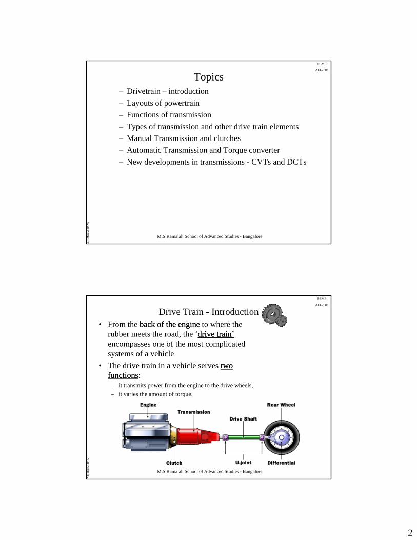
Drive Train - Introduction• From the backback of the engineof the engine to where the
rubber meets the road, the ‘drive train’drive train’encompasses one of the most complicated systems of a vehicley
• The drive train in a vehicle serves two two functionsfunctions:– it transmits power from the engine to the drive wheels,
– it varies the amount of torque.
M.S Ramaiah School of Advanced Studies - Bangalore
A.C
.Met
i MSR
SAS
3
PEMP
AEL2501
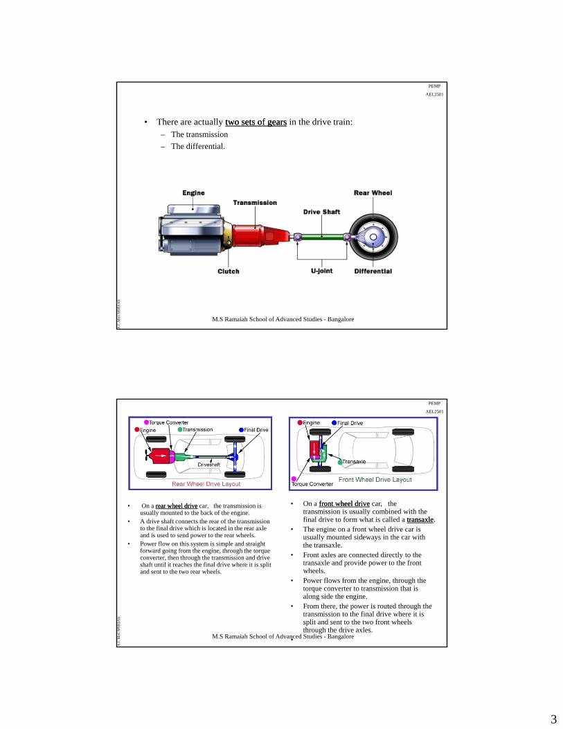
• There are actually two sets of gearstwo sets of gears in the drive train:– The transmission
– The differential.
M.S Ramaiah School of Advanced Studies - Bangalore
A.C
.Met
i MSR
SAS
PEMP
AEL2501
• On a rear wheel driverear wheel drive car, the transmission is usually mounted to the back of the engine.
• A drive shaft connects the rear of the transmission to the final drive which is located in the rear axle and is used to send power to the rear wheels.
• Power flow on this system is simple and straight forward going from the engine, through the torque converter, then through the transmission and drive shaft until it reaches the final drive where it is split
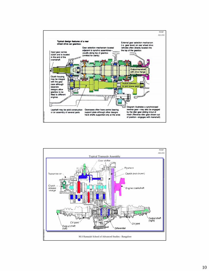
• On a front wheel drivefront wheel drive car, the transmission is usually combined with the final drive to form what is called a transaxletransaxle.
• The engine on a front wheel drive car is usually mounted sideways in the car with the transaxle.
• Front axles are connected directly to the transaxle and provide power to the front
M.S Ramaiah School of Advanced Studies - Bangalore
A.C
.Met
i MSR
SAS
shaft until it reaches the final drive where it is split and sent to the two rear wheels.
transaxle and provide power to the front wheels.
• Power flows from the engine, through the torque converter to transmission that is along side the engine.
• From there, the power is routed through the transmission to the final drive where it is split and sent to the two front wheels through the drive axles.
•
4
PEMP
AEL2501
The layout of the Powertrain
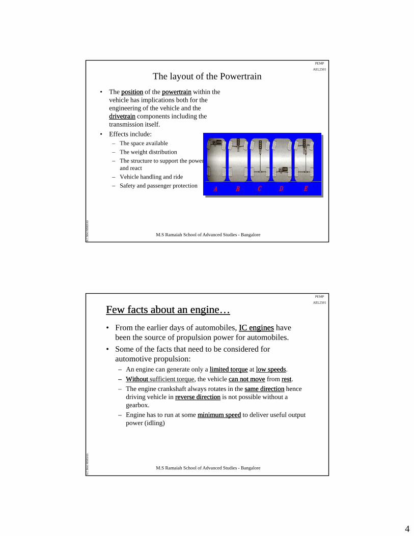
• The positionposition of the powertrainpowertrain within the vehicle has implications both for the engineering of the vehicle and the drivetraindrivetrain components including the transmission itself.
• Effects include:– The space available
– The weight distribution
– The structure to support the powertrain and react
– Vehicle handling and ride
M.S Ramaiah School of Advanced Studies - Bangalore
A.C
.Met
i MSR
SAS
– Safety and passenger protection
PEMP
AEL2501
Few facts about an engine…Few facts about an engine…
• From the earlier days of automobiles, IC enginesIC engines have been the source of propulsion power for automobiles.
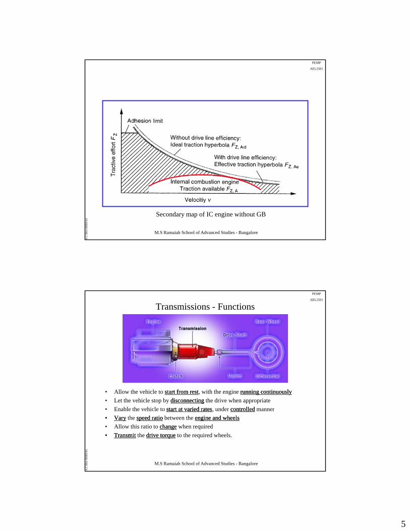
• Some of the facts that need to be considered for automotive propulsion:– An engine can generate only a limited torquelimited torque at low speedslow speeds.
–– Without Without sufficient torque, the vehicle can not movecan not move from restrest.
– The engine crankshaft always rotates in the same directionsame direction hence driving vehicle in reverse directionreverse direction is not possible without a gearbox.
Engine has to run at some minimum speedminimum speed to deliver useful output
M.S Ramaiah School of Advanced Studies - Bangalore
A.C
.Met
i MSR
SAS
– Engine has to run at some minimum speedminimum speed to deliver useful output power (idling)
5
PEMP
AEL2501
M.S Ramaiah School of Advanced Studies - Bangalore
A.C
.Met
i MSR
SAS
Secondary map of IC engine without GB
PEMP
AEL2501
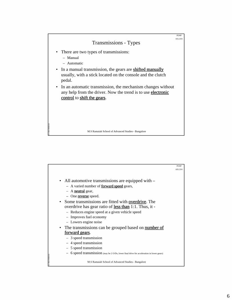
Transmissions - Functions
• Allow the vehicle to start from reststart from rest, with the engine running continuouslyrunning continuously
• Let the vehicle stop by disconnectingdisconnecting the drive when appropriate
• Enable the vehicle to start at varied ratesstart at varied rates, under controlledcontrolled manner
M.S Ramaiah School of Advanced Studies - Bangalore
A.C
.Met
i MSR
SAS
Enable the vehicle to start at varied ratesstart at varied rates, under controlledcontrolled manner
•• VaryVary the speed ratiospeed ratio between the engine and wheelsengine and wheels
• Allow this ratio to changechange when required
•• TransmitTransmit the drive torquedrive torque to the required wheels.
6
PEMP
AEL2501
Transmissions - Types
• There are two types of transmissions:– Manual
– Automatic
• In a manual transmission, the gears are shifted manuallyshifted manuallyusually, with a stick located on the console and the clutch pedal.
• In an automatic transmission, the mechanism changes without any help from the driver. Now the trend is to use electronic electronic controlcontrol to shift the gearsshift the gears.
M.S Ramaiah School of Advanced Studies - Bangalore
A.C
.Met
i MSR
SAS
PEMP
AEL2501
• All automotive transmissions are equipped with –– A varied number of forward speedforward speed gears, – A neutralneutral gear,– One reversereverse speed.
• Some transmissions are fitted with overdriveoverdrive. The overdrive has gear ratio of less thanless than 1:1. Thus, it -– Reduces engine speed at a given vehicle speed– Improves fuel economy– Lowers engine noise
• The transmissions can be grouped based on number of number of forward gearsforward gears
M.S Ramaiah School of Advanced Studies - Bangalore
A.C
.Met
i MSR
SAS
forward gearsforward gears.– 3 speed transmission– 4 speed transmission– 5 speed transmission– 6 speed transmission (may be 2 O/Ds, lower final drive for acceleration in lower gears)
7
PEMP
AEL2501
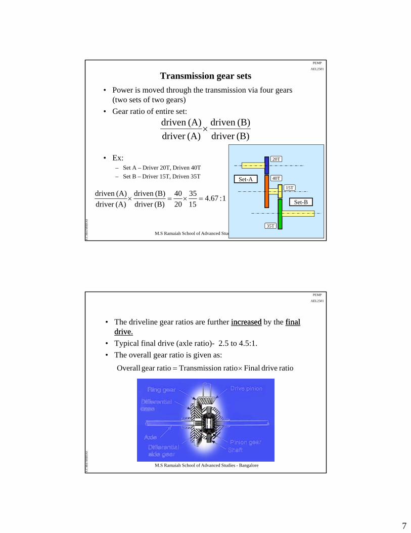
Transmission gear sets
• Power is moved through the transmission via four gears (two sets of two gears)
• Gear ratio of entire set:
(B)d i(A)d i
• Ex: – Set A – Driver 20T, Driven 40T
– Set B – Driver 15T, Driven 35T
(B)driver
(B)driven
(A)driver
(A)driven
Set-A
20T
40T
M.S Ramaiah School of Advanced Studies - Bangalore
A.C
.Met
i MSR
SAS
1:67.415
35
20
40
(B)driver
(B)driven
(A)driver
(A)driven
Set A
Set-B
15T
35T
PEMP
AEL2501
• The driveline gear ratios are further increasedincreased by the final final drive.drive.
• Typical final drive (axle ratio)- 2.5 to 4.5:1.
h ll i i i• The overall gear ratio is given as:
ratio drive Finalratioon Transmissiratiogear Overall
M.S Ramaiah School of Advanced Studies - Bangalore
A.C
.Met
i MSR
SAS
8
PEMP
AEL2501
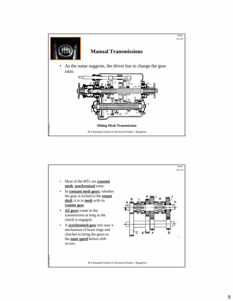
Manual Transmissions
• As the name suggests, the driver has to change the gear gg , g gratio.
M.S Ramaiah School of Advanced Studies - Bangalore
A.C
.Met
i MSR
SAS
Sliding Mesh Transmission
PEMP
AEL2501
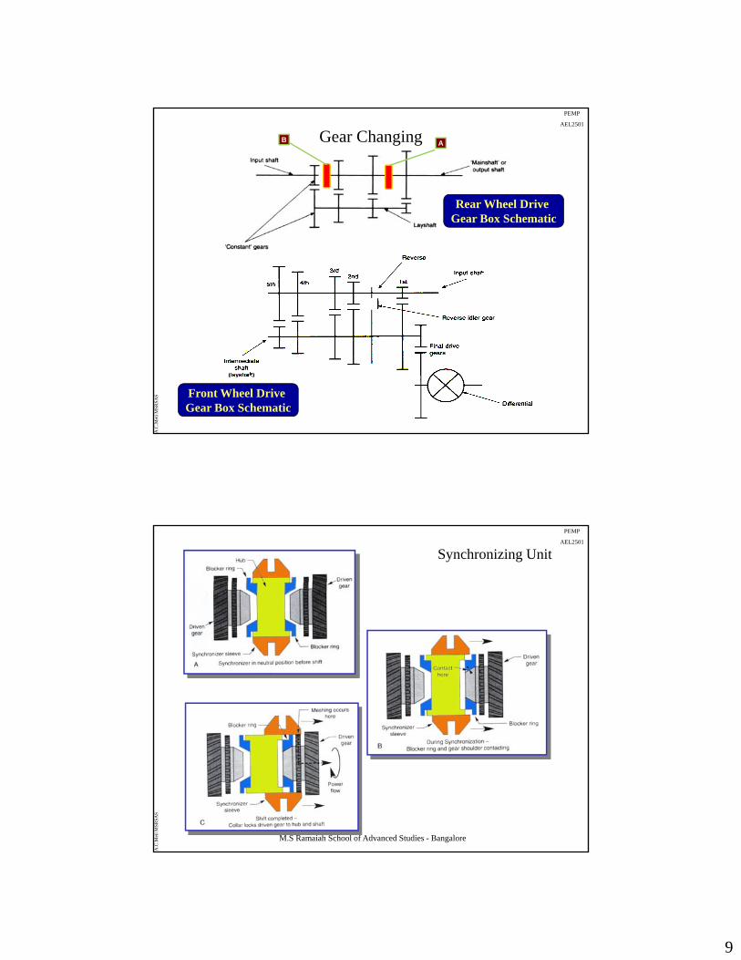
• Most of the MTs are constant constant meshmesh, synchronizedsynchronized units.
• In constant mesh gearsconstant mesh gears, whether the gear is locked to the output output shaftshaft, it is in meshmesh with its counter gearcounter gear.
•• All gearsAll gears rotate in the transmission as long as the clutch is engaged.
• A synchromesh gearsynchromesh gear unit uses a mechanism of brass rings and l h b i h
M.S Ramaiah School of Advanced Studies - Bangalore
A.C
.Met
i MSR
SAS
clutches to bring the gears to the same speedsame speed before shift occurs.
9
PEMP
AEL2501
Gear Changing
Rear Wheel Drive G B S h ti
B A
Gear Box Schematic
M.S Ramaiah School of Advanced Studies - Bangalore
A.C
.Met
i MSR
SAS Front Wheel Drive
Gear Box Schematic
PEMP
AEL2501
Synchronizing Unit
M.S Ramaiah School of Advanced Studies - Bangalore
A.C
.Met
i MSR
SAS
10
PEMP
AEL2501
M.S Ramaiah School of Advanced Studies - Bangalore
A.C
.Met
i MSR
SAS
PEMP
AEL2501
Typical Transaxle Assembly
M.S Ramaiah School of Advanced Studies - Bangalore
A.C
.Met
i MSR
SAS
11
PEMP
AEL2501
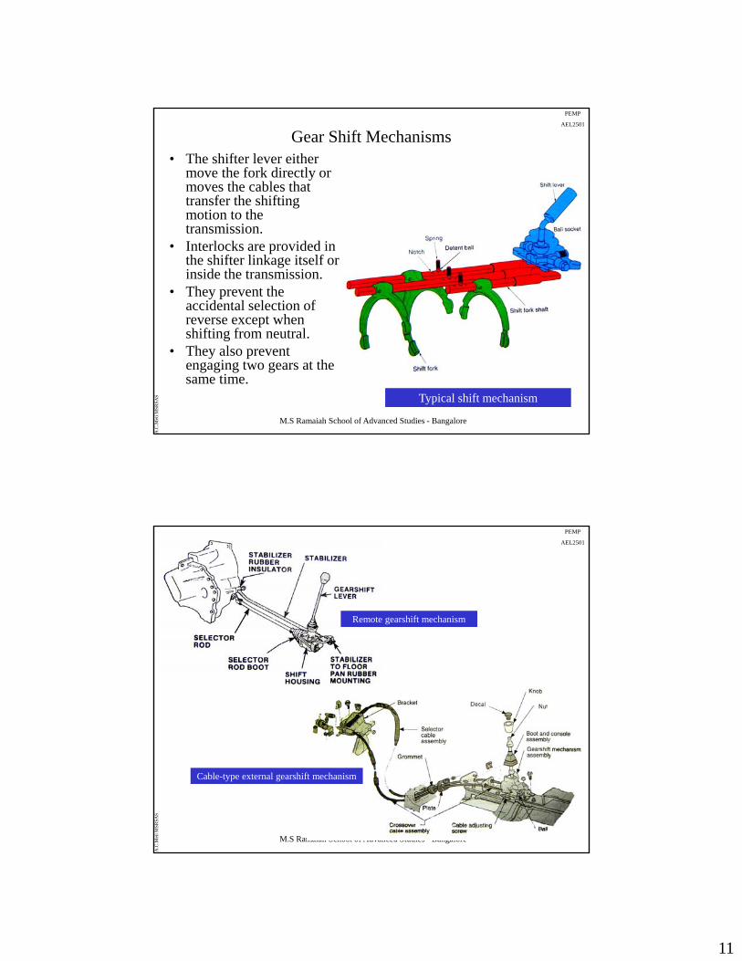
Gear Shift Mechanisms• The shifter lever either
move the fork directly or moves the cables that transfer the shifting motion to themotion to the transmission.
• Interlocks are provided in the shifter linkage itself or inside the transmission.
• They prevent the accidental selection of reverse except when
M.S Ramaiah School of Advanced Studies - Bangalore
A.C
.Met
i MSR
SAS
pshifting from neutral.
• They also prevent engaging two gears at the same time.
Typical shift mechanism
PEMP
AEL2501
Remote gearshift mechanism
M.S Ramaiah School of Advanced Studies - Bangalore
A.C
.Met
i MSR
SAS
Cable-type external gearshift mechanism
12
PEMP
AEL2501
Advantages (MT):• Usually have high mechanical efficiency• Arguably the most fuel efficient type of transmission,
although this depends on the driver selecting the most appropriate gear.
• Relatively cheap to produce (50%)• Relatively cheap to produce (50%) • Light weight (50-70%)• Easier to package in the vehicleDisadvantages (MT):• Some driver skill is required• Emission and fuel consumption can be heavily influenced
by the driver’s gear selection
M.S Ramaiah School of Advanced Studies - Bangalore
A.C
.Met
i MSR
SAS
• Clutch operation and changing the gears can be tiring (In heavy traffic).
• Not suitable for all drivers.
PEMP
AEL2501
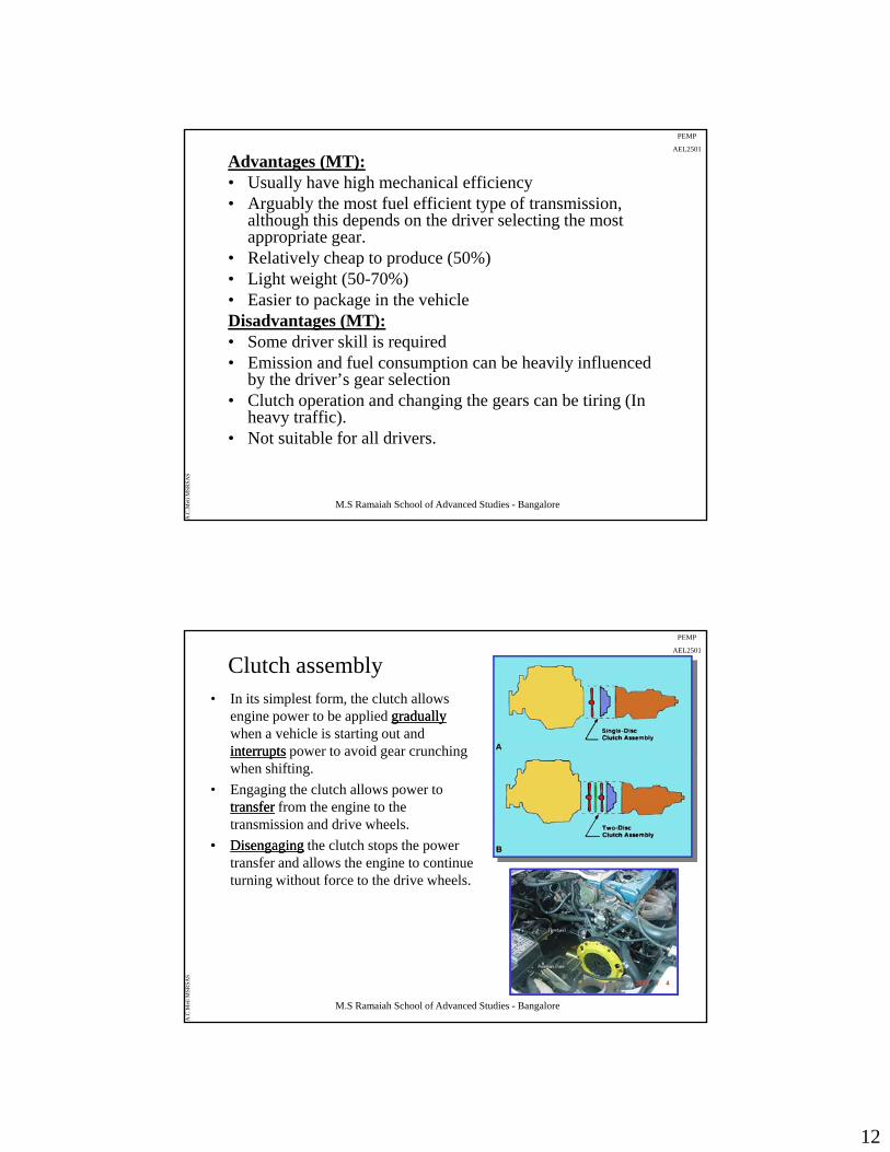
Clutch assembly• In its simplest form, the clutch allows
engine power to be applied graduallygraduallywhen a vehicle is starting out and interruptsinterrupts power to avoid gear crunching when shifting.
• Engaging the clutch allows power to transfertransfer from the engine to the transmission and drive wheels.
•• DisengagingDisengaging the clutch stops the power transfer and allows the engine to continue turning without force to the drive wheels.
M.S Ramaiah School of Advanced Studies - Bangalore
A.C
.Met
i MSR
SAS
13
PEMP
AEL2501
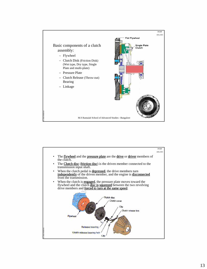
Basic components of a clutch assembly:– Flywheel
Clutch Disk (Friction Disk)– Clutch Disk (Friction Disk) (Wet type, Dry type, Single Plate and multi-plate)
– Pressure Plate
– Clutch Release (Throw-out)Bearing
– Linkage
M.S Ramaiah School of Advanced Studies - Bangalore
A.C
.Met
i MSR
SAS
PEMP
AEL2501
• The flywheelflywheel and the pressure platepressure plate are the drivedrive or driverdriver members of the clutch.
• The Clutch discClutch disc (friction discfriction disc) is the driven member connected to the transmission input shaft.
• When the clutch pedal is depresseddepressed, the drive members turn independentlyindependently of the driven member, and the engine is disconnecteddisconnectedfrom the transmissionfrom the transmission.
• When the clutch is engagedengaged, the pressure plate moves toward the flywheel and the clutch disc isdisc is squeezedsqueezed between the two revolving drive members and forced to turn at the same speedforced to turn at the same speed.
M.S Ramaiah School of Advanced Studies - Bangalore
A.C
.Met
i MSR
SAS
14
PEMP
AEL2501
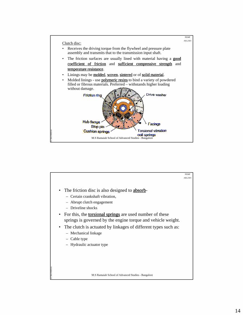
Clutch disc:• Receives the driving torque from the flywheel and pressure plate
assembly and transmits that to the transmission input shaft.
• The friction surfaces are usually lined with material having a goodgoodcoefficientcoefficient ofof frictionfriction and sufficientsufficient compressivecompressive strengthstrength andtemperaturetemperature resistanceresistance.pp
• Linings may be moldedmolded, wovenwoven, sinteredsintered or of solid materialsolid material.• Molded linings - use polymeric resinspolymeric resins to bind a variety of powdered
filled or fibrous materials. Preferred – withstands higher loading without damage.
M.S Ramaiah School of Advanced Studies - Bangalore
A.C
.Met
i MSR
SAS
PEMP
AEL2501
• The friction disc is also designed to absorbabsorb-– Certain crankshaft vibration,
– Abrupt clutch engagement
Driveline shocks– Driveline shocks
• For this, the torsional springstorsional springs are used number of these springs is governed by the engine torque and vehicle weight.
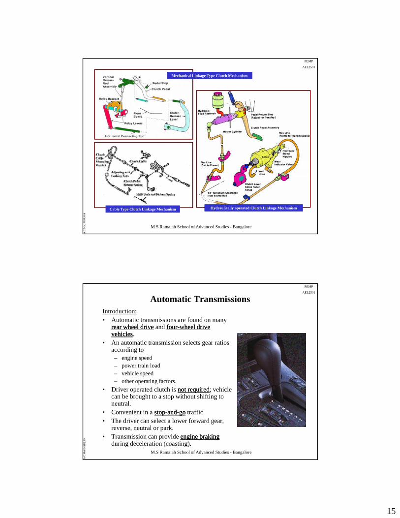
• The clutch is actuated by linkages of different types such as:– Mechanical linkage
– Cable type
H d li t t t
M.S Ramaiah School of Advanced Studies - Bangalore
A.C
.Met
i MSR
SAS
– Hydraulic actuator type
15
PEMP
AEL2501
Mechanical Linkage Type Clutch MechanismMechanical Linkage Type Clutch Mechanism
M.S Ramaiah School of Advanced Studies - Bangalore
A.C
.Met
i MSR
SAS
Cable Type Clutch Linkage MechanismCable Type Clutch Linkage Mechanism Hydraulically operated Clutch Linkage MechanismHydraulically operated Clutch Linkage Mechanism
PEMP
AEL2501
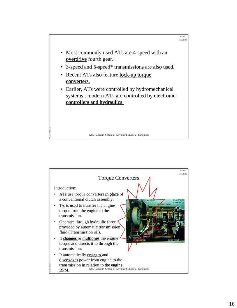
Automatic TransmissionsIntroduction:• Automatic transmissions are found on many
rear wheel driverear wheel drive and fourfour--wheel drive wheel drive vehiclesvehicles.
• An automatic transmission selects gear ratios• An automatic transmission selects gear ratios according to
– engine speed– power train load– vehicle speed– other operating factors.
• Driver operated clutch is not requirednot required; vehicle can be brought to a stop without shifting to
M.S Ramaiah School of Advanced Studies - Bangalore
A.C
.Met
i MSR
SAS
neutral.• Convenient in a stopstop--andand--gogo traffic.• The driver can select a lower forward gear,
reverse, neutral or park.• Transmission can provide engine brakingengine braking
during deceleration (coasting).
16
PEMP
AEL2501
• Most commonly used ATs are 4-speed with an overdriveoverdrive fourth gear.
• 3-speed and 5-speed* transmissions are also used.p p
• Recent ATs also feature locklock--up torque up torque converters.converters.
• Earlier, ATs were controlled by hydromechanical systems ; modern ATs are controlled by electronic electronic controllers and hydraulics.controllers and hydraulics.
M.S Ramaiah School of Advanced Studies - Bangalore
A.C
.Met
i MSR
SAS
yy
PEMP
AEL2501
Torque Converters
Introduction:
• ATs use torque converters in placein place of a conventional clutch assembly.
• T/c is used to transfer the engine torque from the engine to the transmission.
• Operates through hydraulic force provided by automatic transmission fluid (Transmission oil).
• It changeschanges or multipliesmultiplies the engine
M.S Ramaiah School of Advanced Studies - Bangalore
A.C
.Met
i MSR
SAS
• It changes changes or multipliesmultiplies the engine torque and directs it to through the transmission.
• It automatically engages engages and disengagesdisengages power from engine to the transmission in relation to the engine engine RPM.RPM.
17
PEMP
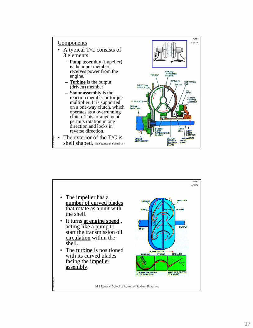
AEL2501Components• A typical T/C consists of
3 elements:–– Pump assemblyPump assembly (impeller)
is the input member, receives power from the pengine.
–– TurbineTurbine is the output (driven) member.
–– Stator assemblyStator assembly is the reaction member or torque multiplier. It is supported on a one-way clutch, which operates as a o err nning
M.S Ramaiah School of Advanced Studies - Bangalore
A.C
.Met
i MSR
SAS
operates as a overrunning clutch. This arrangement permits rotation in one direction and locks in reverse direction.
• The exterior of the T/C is shell shaped.
PEMP
AEL2501
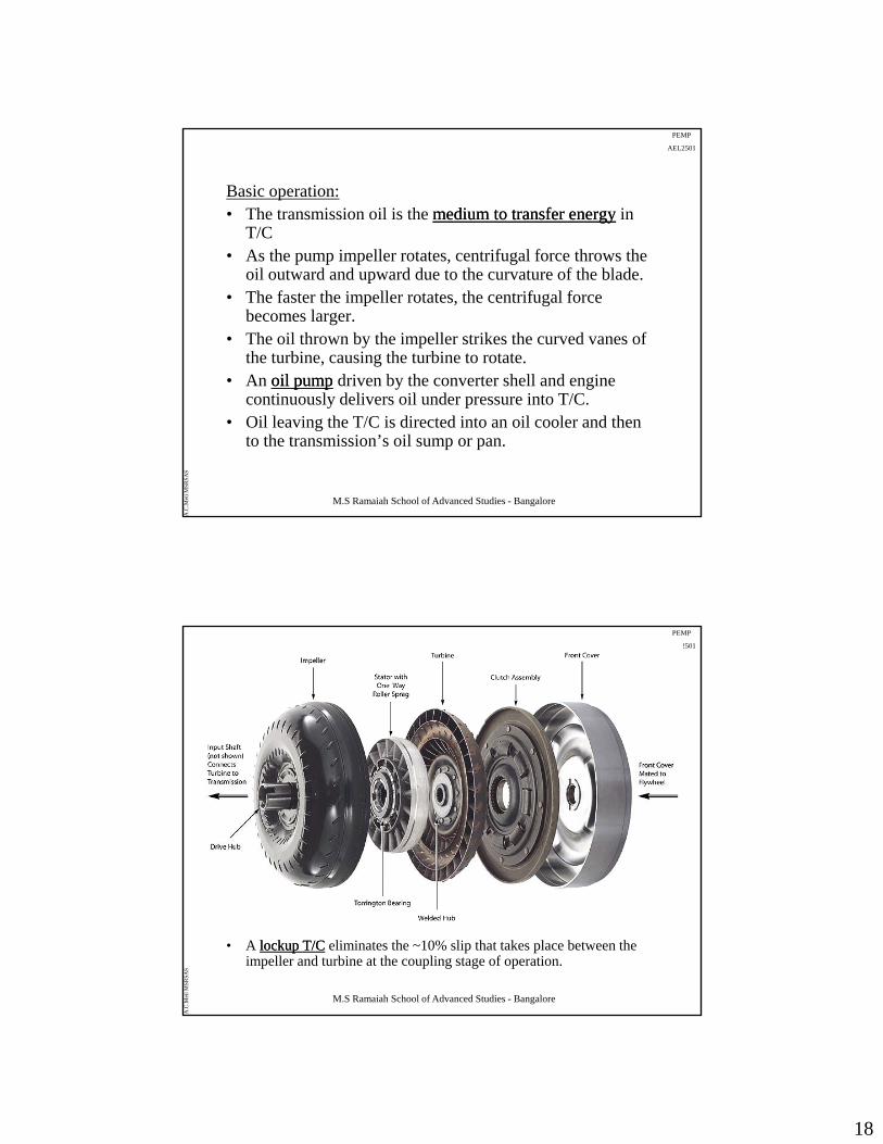
• The impellerimpeller has a number of curved bladesnumber of curved bladesthat rotate as a unit with the shell.
• It turns at engine speedat engine speed , acting like a pump to start the transmission oil circulationcirculation within the shell.
• The turbine turbine is positioned i h i d bl d
M.S Ramaiah School of Advanced Studies - Bangalore
A.C
.Met
i MSR
SAS
with its curved blades facing the impeller impeller assemblyassembly.
18
PEMP
AEL2501
Basic operation:• The transmission oil is the medium to transfer energymedium to transfer energy in
T/C• As the pump impeller rotates centrifugal force throws theAs the pump impeller rotates, centrifugal force throws the
oil outward and upward due to the curvature of the blade.• The faster the impeller rotates, the centrifugal force
becomes larger.• The oil thrown by the impeller strikes the curved vanes of
the turbine, causing the turbine to rotate.• An oil pumpoil pump driven by the converter shell and engine
M.S Ramaiah School of Advanced Studies - Bangalore
A.C
.Met
i MSR
SAS
p pp p y gcontinuously delivers oil under pressure into T/C.
• Oil leaving the T/C is directed into an oil cooler and then to the transmission’s oil sump or pan.
PEMP
AEL2501
Lockup Torque Converter
M.S Ramaiah School of Advanced Studies - Bangalore
A.C
.Met
i MSR
SAS
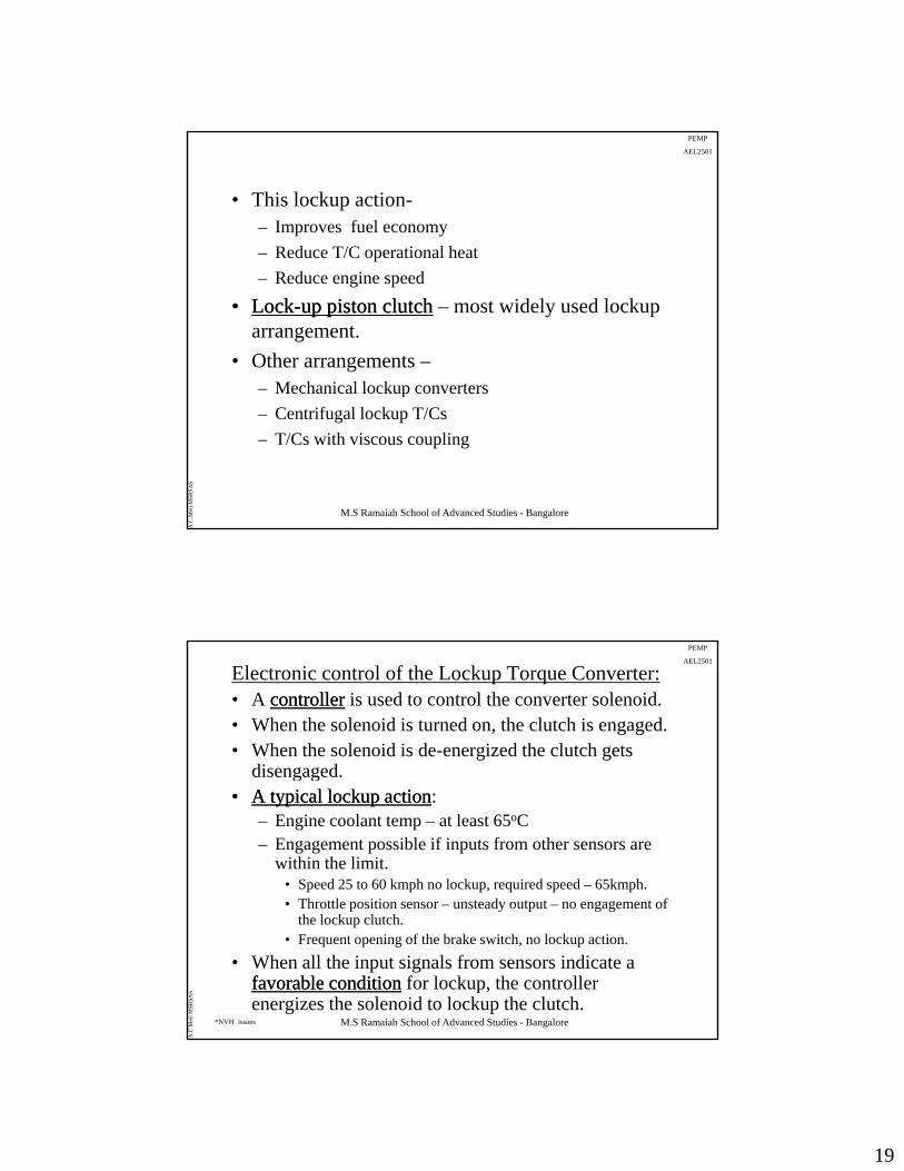
• A lockup T/Clockup T/C eliminates the ~10% slip that takes place between the impeller and turbine at the coupling stage of operation.
19
PEMP
AEL2501
• This lockup action-– Improves fuel economy
– Reduce T/C operational heat
– Reduce engine speed
•• LockLock--up piston clutchup piston clutch – most widely used lockup arrangement.
• Other arrangements –– Mechanical lockup converters
M.S Ramaiah School of Advanced Studies - Bangalore
A.C
.Met
i MSR
SAS
p
– Centrifugal lockup T/Cs
– T/Cs with viscous coupling
PEMP
AEL2501
Electronic control of the Lockup Torque Converter:• A controllercontroller is used to control the converter solenoid.• When the solenoid is turned on, the clutch is engaged.• When the solenoid is de-energized the clutch gets
disengageddisengaged.•• A typical lockup actionA typical lockup action:
– Engine coolant temp – at least 65oC– Engagement possible if inputs from other sensors are
within the limit.• Speed 25 to 60 kmph no lockup, required speed – 65kmph.• Throttle position sensor – unsteady output – no engagement of
M.S Ramaiah School of Advanced Studies - Bangalore
A.C
.Met
i MSR
SAS
Throttle position sensor unsteady output no engagement of the lockup clutch.
• Frequent opening of the brake switch, no lockup action.
• When all the input signals from sensors indicate a favorable conditionfavorable condition for lockup, the controller energizes the solenoid to lockup the clutch.
*NVH issues

20
PEMP
AEL2501Planetary GearsIntroduction:
• Almost all ATs rely on planetary gearsets for transfer of power and multiply engine torque to the drive axle.
• A simple planetary gear setsimple planetary gear setconsists of –– A sun gear
– A carrier with planetary pinions mounted on it
M.S Ramaiah School of Advanced Studies - Bangalore
A.C
.Met
i MSR
SAS
– Annulus – an internally toothed ring gear
•• Compound gearsCompound gears combine two simple planetary gearsets - greater load spreadgreater load spread and larger number of gear ratios.larger number of gear ratios.
Simple Planetary Gear Train
PEMP
AEL2501
M.S Ramaiah School of Advanced Studies - Bangalore
A.C
.Met
i MSR
SAS
21
PEMP
AEL2501
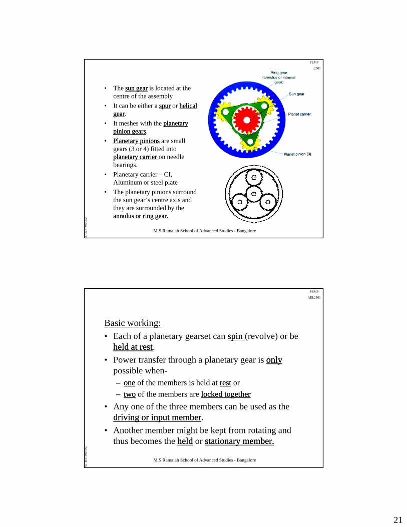
• The sun gearsun gear is located at the centre of the assembly
• It can be either a spurspur or helical helical geargear.
• It meshes with the planetary planetary pinion gearspinion gears.
•• Planetary pinionsPlanetary pinions are small gears (3 or 4) fitted into planetary carrier planetary carrier on needle bearings.
• Planetary carrier – CI,
M.S Ramaiah School of Advanced Studies - Bangalore
A.C
.Met
i MSR
SAS
Aluminum or steel plate
• The planetary pinions surround the sun gear’s centre axis and they are surrounded by the annulus or ring gear.annulus or ring gear.
PEMP
AEL2501
Basic working:
• Each of a planetary gearset can spin spin (revolve) or be held at restheld at restheld at restheld at rest.
• Power transfer through a planetary gear is onlyonlypossible when-–– oneone of the members is held at restrest or
–– twotwo of the members are locked togetherlocked together
• Any one of the three members can be used as the
M.S Ramaiah School of Advanced Studies - Bangalore
A.C
.Met
i MSR
SAS
Any one of the three members can be used as the driving or input memberdriving or input member.
• Another member might be kept from rotating and thus becomes the heldheld or stationary member.stationary member.
22
PEMP
AEL2501
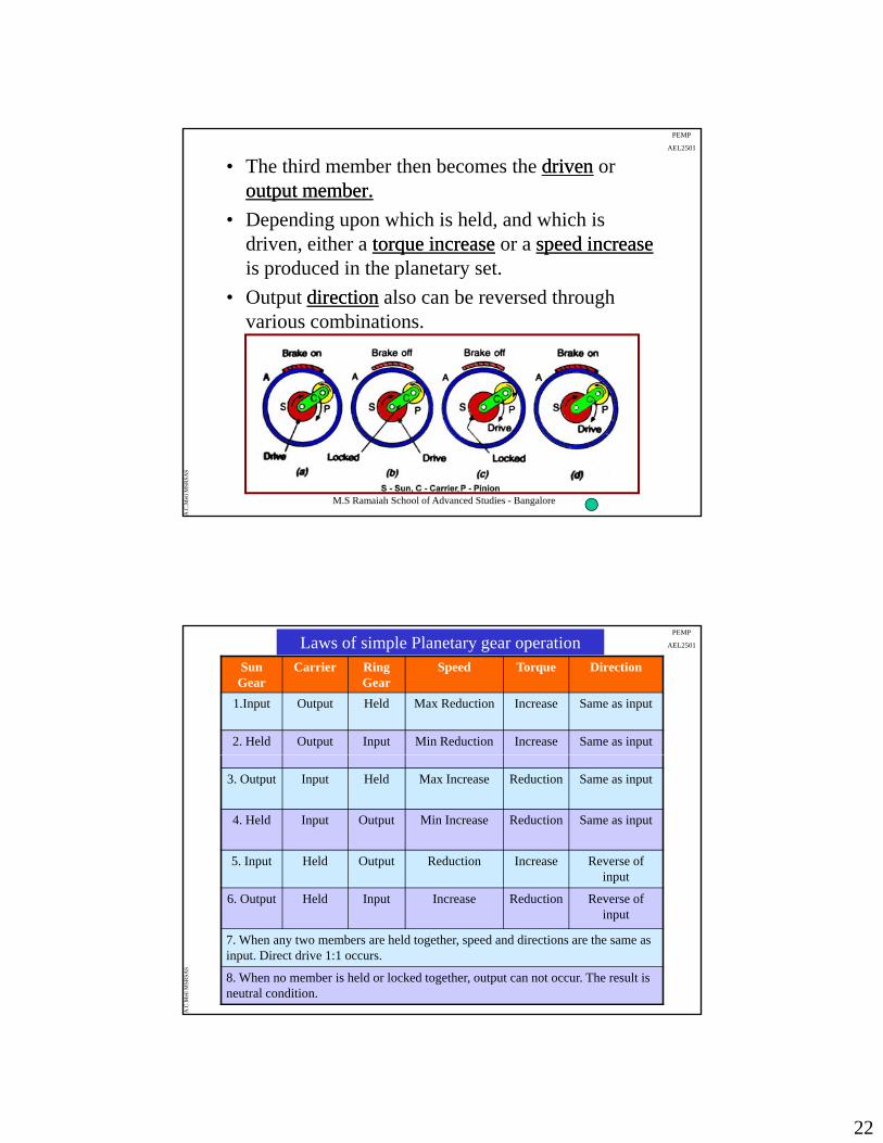
• The third member then becomes the drivendriven or output member.output member.
• Depending upon which is held, and which is driven, either a torque increasetorque increase or a speed increasespeed increaseis produced in the planetary set.
• Output directiondirection also can be reversed through various combinations.
M.S Ramaiah School of Advanced Studies - Bangalore
A.C
.Met
i MSR
SAS
PEMP
AEL2501
Sun Gear
Carrier Ring Gear
Speed Torque Direction
1.Input Output Held Max Reduction Increase Same as input
2. Held Output Input Min Reduction Increase Same as input
Laws of simple Planetary gear operation
3. Output Input Held Max Increase Reduction Same as input
4. Held Input Output Min Increase Reduction Same as input
5. Input Held Output Reduction Increase Reverse of input
M.S Ramaiah School of Advanced Studies - Bangalore
A.C
.Met
i MSR
SAS
6. Output Held Input Increase Reduction Reverse of input
7. When any two members are held together, speed and directions are the same as input. Direct drive 1:1 occurs.
8. When no member is held or locked together, output can not occur. The result is neutral condition.
23
PEMP
AEL2501
Compound Planetary Gearsets
• To increase the number of available gear ratios, gear sets can be compounded.
• A typical automotive transmission with 3 or 4 ypforward speeds has at least two planetary gearsetsat least two planetary gearsets.
•• CommonlyCommonly used compound planetary gear sets:–– Simpson gearsetSimpson gearset
–– Ravingeaux* gearsetRavingeaux* gearset
M.S Ramaiah School of Advanced Studies - Bangalore
A.C
.Met
i MSR
SAS
*Pronounced Raveno
PEMP
AEL2501
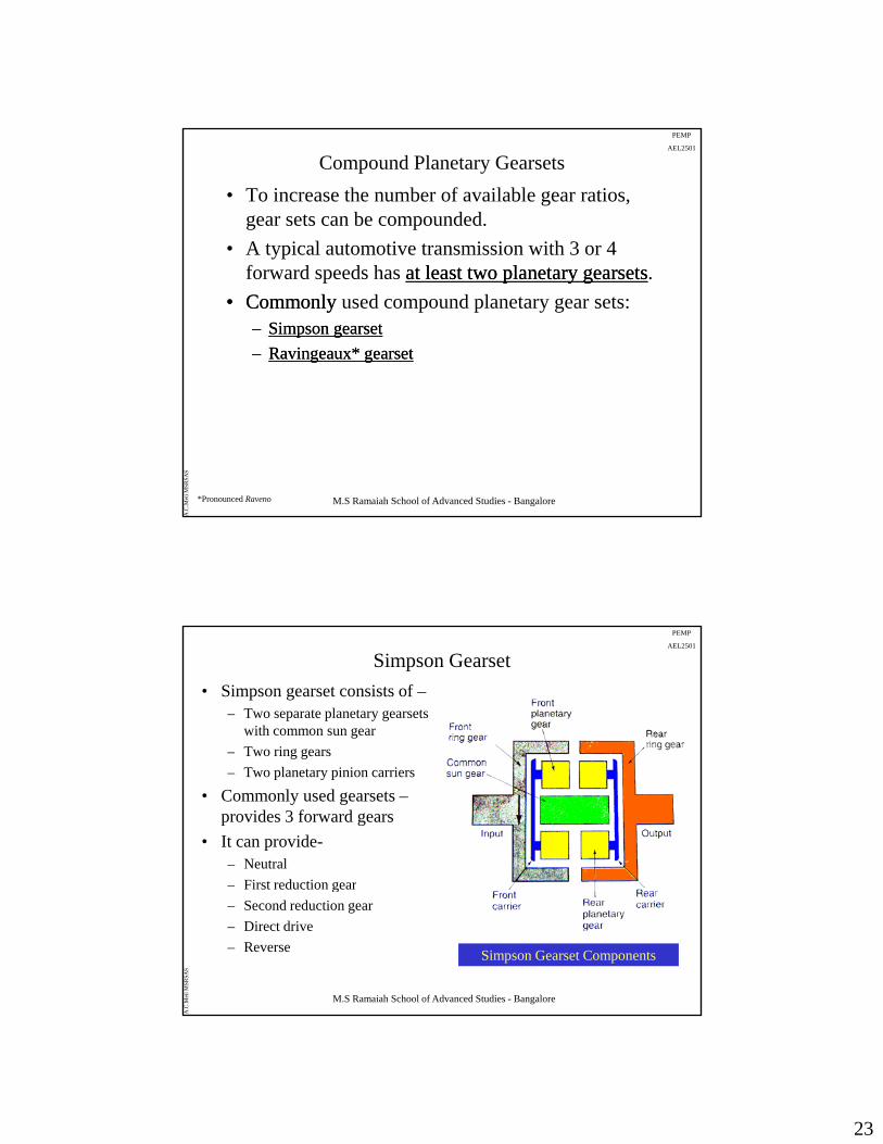
Simpson Gearset
• Simpson gearset consists of –– Two separate planetary gearsets
with common sun gear
– Two ring gearsTwo ring gears
– Two planetary pinion carriers
• Commonly used gearsets –provides 3 forward gears
• It can provide-– Neutral
First reduction gear
M.S Ramaiah School of Advanced Studies - Bangalore
A.C
.Met
i MSR
SAS
– First reduction gear
– Second reduction gear
– Direct drive
– Reverse Simpson Gearset Components
24
PEMP
AEL2501
• The two planetary gear set need not be same size or have the same number of teeth
• The actual gear ratio is determined by the size and g ynumber of gear teeth in the gear assembly.
• Gear ratios and direction of rotation are the result of applying torque to one member of eithereitherplanetary unit, holding at least one member of the gearset, and using another member as output.
M.S Ramaiah School of Advanced Studies - Bangalore
A.C
.Met
i MSR
SAS
PEMP
AEL2501
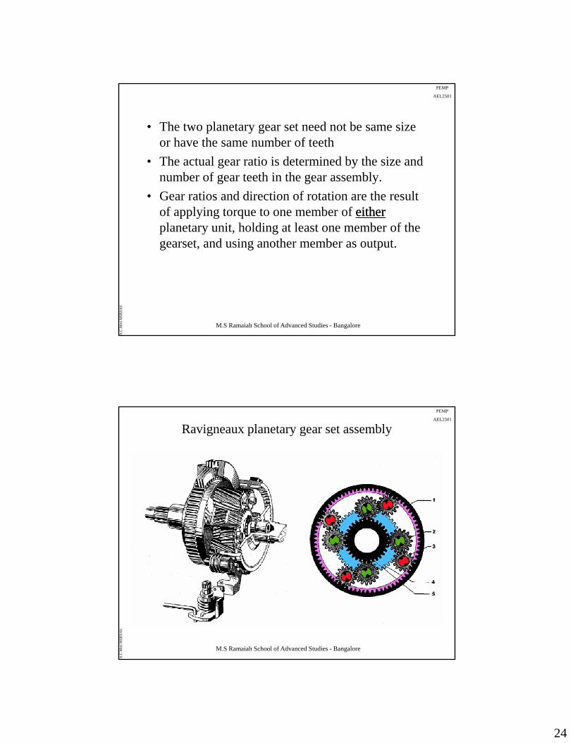
Ravigneaux planetary gear set assembly
M.S Ramaiah School of Advanced Studies - Bangalore
A.C
.Met
i MSR
SAS
25
PEMP
AEL2501
M.S Ramaiah School of Advanced Studies - Bangalore
A.C
.Met
i MSR
SAS
PEMP
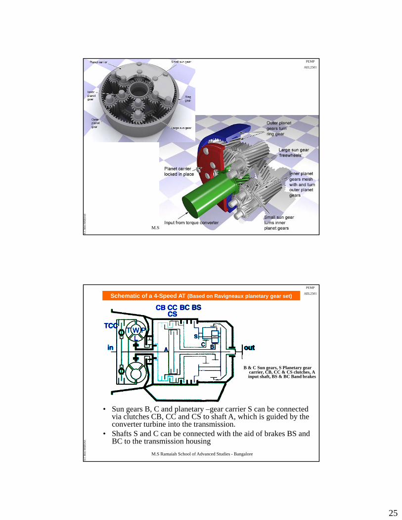
AEL2501Schematic of a 4-Speed AT (Based on Ravigneaux planetary gear set)
B & C Sun gears, S Planetary gear carrier, CB, CC & CS clutches, A input shaft, BS & BC Band brakes
M.S Ramaiah School of Advanced Studies - Bangalore
A.C
.Met
i MSR
SAS
• Sun gears B, C and planetary –gear carrier S can be connected via clutches CB, CC and CS to shaft A, which is guided by the converter turbine into the transmission.
• Shafts S and C can be connected with the aid of brakes BS and BC to the transmission housing
26
PEMP
AEL2501
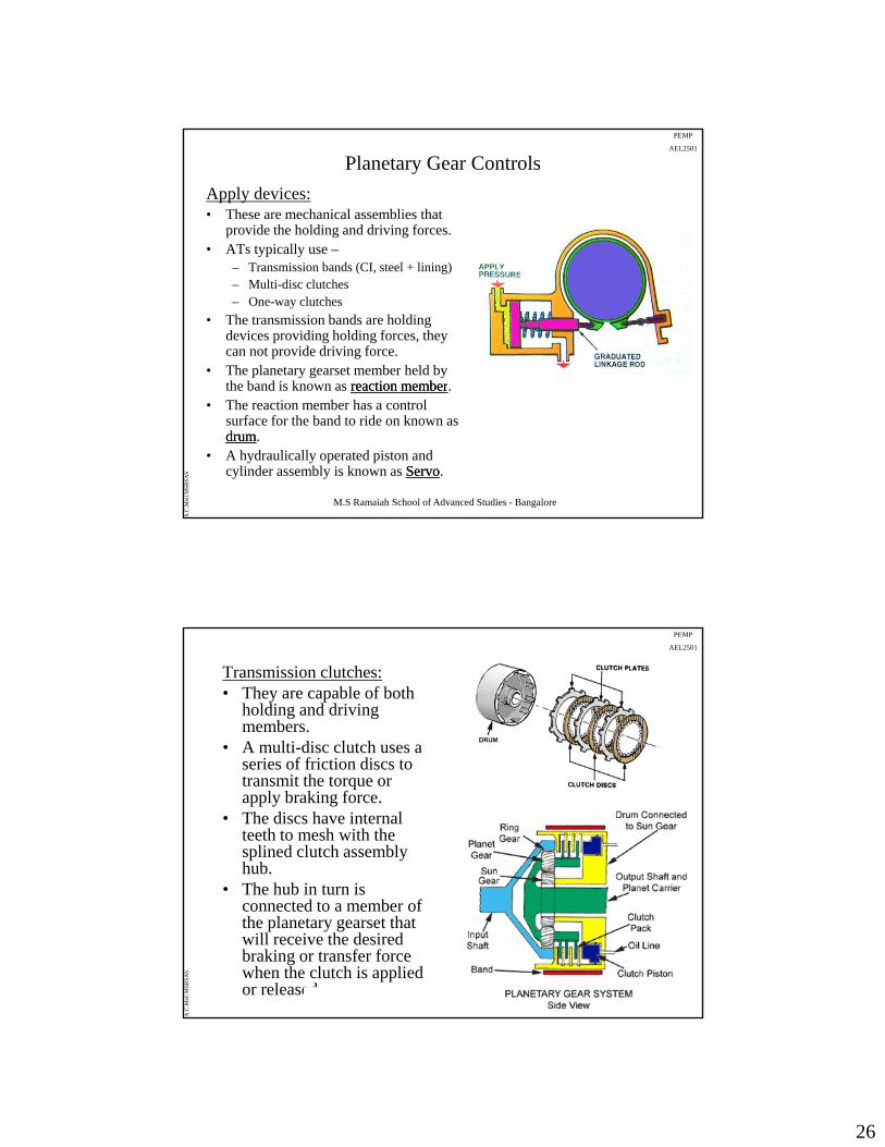
Planetary Gear Controls
Apply devices:• These are mechanical assemblies that
provide the holding and driving forces.• ATs typically use –
– Transmission bands (CI, steel + lining)– Multi-disc clutches– One-way clutches
• The transmission bands are holding devices providing holding forces, they can not provide driving force.
• The planetary gearset member held by the band is known as reaction memberreaction member
M.S Ramaiah School of Advanced Studies - Bangalore
A.C
.Met
i MSR
SAS
the band is known as reaction memberreaction member.• The reaction member has a control
surface for the band to ride on known as drumdrum.
• A hydraulically operated piston and cylinder assembly is known as ServoServo.
PEMP
AEL2501
Transmission clutches:• They are capable of both
holding and driving members.
• A multi-disc clutch uses a i f f i i diseries of friction discs to
transmit the torque or apply braking force.
• The discs have internal teeth to mesh with the splined clutch assembly hub.
• The hub in turn is
M.S Ramaiah School of Advanced Studies - Bangalore
A.C
.Met
i MSR
SAS
• The hub in turn is connected to a member of the planetary gearset that will receive the desired braking or transfer force when the clutch is applied or released.
27
PEMP
AEL2501
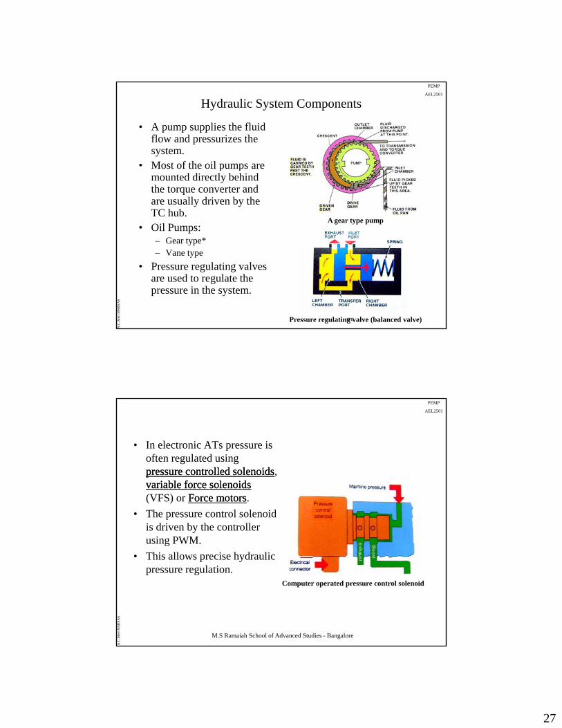
Hydraulic System Components
• A pump supplies the fluid flow and pressurizes the system.
• Most of the oil pumps are• Most of the oil pumps are mounted directly behind the torque converter and are usually driven by the TC hub.
• Oil Pumps:– Gear type*
A gear type pump
M.S Ramaiah School of Advanced Studies - Bangalore
A.C
.Met
i MSR
SAS
– Vane type
• Pressure regulating valves are used to regulate the pressure in the system.
Pressure regulating valve (balanced valve)
PEMP
AEL2501
• In electronic ATs pressure is often regulated using pressure controlled solenoidspressure controlled solenoids,
i bl f l idi bl f l idvariable force solenoidsvariable force solenoids(VFS) or Force motorsForce motors.
• The pressure control solenoid is driven by the controller using PWM.
• This allows precise hydraulic
M.S Ramaiah School of Advanced Studies - Bangalore
A.C
.Met
i MSR
SAS
pressure regulation.Computer operated pressure control solenoid
28
PEMP
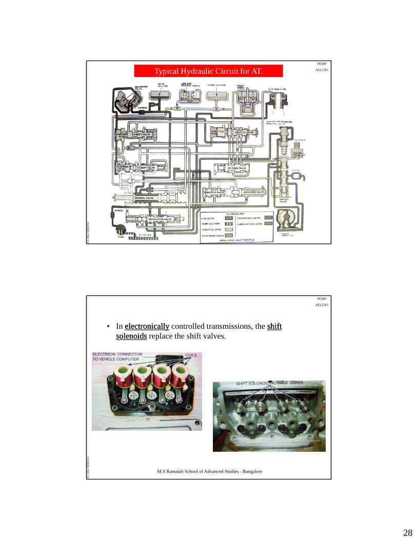
AEL2501Typical Hydraulic Circuit for AT.
M.S Ramaiah School of Advanced Studies - Bangalore
A.C
.Met
i MSR
SAS
PEMP
AEL2501
• In electronicallyelectronically controlled transmissions, the shift shift solenoidssolenoids replace the shift valves.
M.S Ramaiah School of Advanced Studies - Bangalore
A.C
.Met
i MSR
SAS
29
PEMP
AEL2501
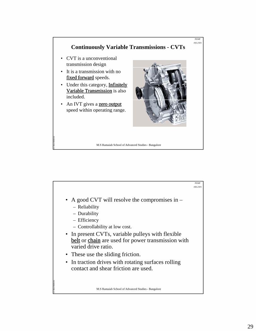
Continuously Variable Transmissions - CVTs
• CVT is a unconventional transmission design
• It is a transmission with no fixed forwardfixed forward speeds.
• Under this category, Infinitely Infinitely Variable TransmissionVariable Transmission is also included.
• An IVT gives a zero outputzero outputspeed within operating range.
M.S Ramaiah School of Advanced Studies - Bangalore
A.C
.Met
i MSR
SAS
p p g g
PEMP
AEL2501
• A good CVT will resolve the compromises in –– Reliability– Durability
Effi i– Efficiency– Controllability at low cost.
• In present CVTs, variable pulleys with flexible beltbelt or chainchain are used for power transmission with varied drive ratio.
• These use the sliding friction.
M.S Ramaiah School of Advanced Studies - Bangalore
A.C
.Met
i MSR
SAS
ese use t e s d g ct o .• In traction drives with rotating surfaces rolling
contact and shear friction are used.

30
PEMP
AEL2501
Variable Pulley CVTs
• The CVTs use belt (steel)belt (steel)and pulleys pulleys to provide drive ratios.
• One pulley is the driven member and the other is the driver.
• Each pulley has a movable face and a fixed face.
• When the movable face 1:1
M.S Ramaiah School of Advanced Studies - Bangalore
A.C
.Met
i MSR
SAS
moves, effective diameter is changed
• This change in effective diameter changes effective pulley (gear) ratio.
1:1
PEMP
AEL2501
Van Doorne Type CVT
• One of the most commonly used CVT
• Uses two variable pulley assemblies and a steel belt.
• The belt is a segmented steel belt or a push belt system.
• It consists of a set of belt elements about 2 mm thick, with slots on each side to fit two high-tensile steel bands which hold them together.
M.S Ramaiah School of Advanced Studies - Bangalore
A.C
.Met
i MSR
SAS

31
PEMP
AEL2501
• The belt transmits power power by compressive forcecompressive forcebetween the belt elementsbetween the belt elementsi d f iiinstead of tensiontension.
• The Van DoorneVan Doorne system is efficient and has lower noise and wear.
• It is suitable for low power applications like
M.S Ramaiah School of Advanced Studies - Bangalore
A.C
.Met
i MSR
SAS
small size passenger cars and snowmobiles.
PEMP
AEL2501
CVT Featuers• No gear shift• Continuous transmission of torque• Control of engine speed independent of vehicle speed.• Ability to operate engine at peak power over wider range• Ability to operate engine at peak power over wider range
of vehicle speeds• Operation at most fuel efficient point for required output
power.• Mechanical efficiency of variator: losseslosses appear as a speed speed
or slipor slip in addition to torque losstorque loss due to internal friction.• The hydraulic pumphydraulic pump draws power from engine
M.S Ramaiah School of Advanced Studies - Bangalore
A.C
.Met
i MSR
SAS
The hydraulic pumphydraulic pump draws power from engine.• Compromise between fuel economy and torque margin to
achieve driveability (avoid elastic band feel). i.e less torque available immediately with a CVT than with a gear transmission.
32
PEMP
AEL2501
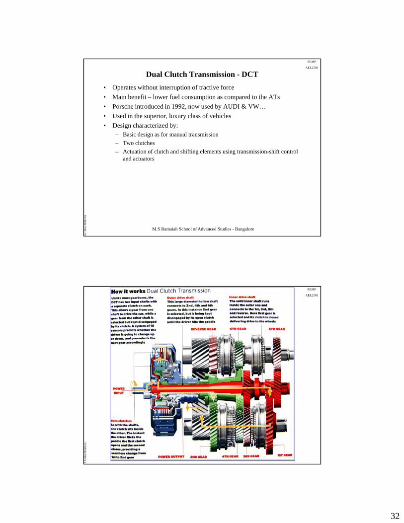
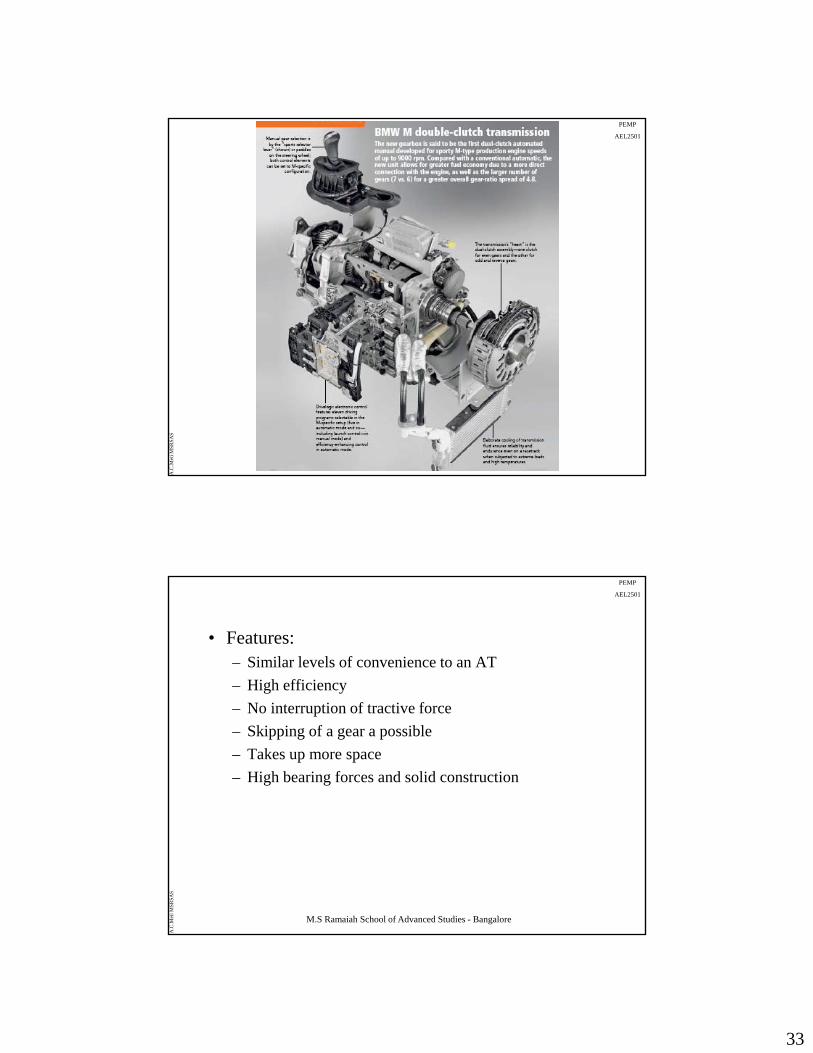
Dual Clutch Transmission - DCT
• Operates without interruption of tractive force
• Main benefit – lower fuel consumption as compared to the ATs
• Porsche introduced in 1992, now used by AUDI & VW…
• Used in the superior, luxury class of vehiclesUsed in the superior, luxury class of vehicles
• Design characterized by:– Basic design as for manual transmission
– Two clutches
– Actuation of clutch and shifting elements using transmission-shift control and actuators
M.S Ramaiah School of Advanced Studies - Bangalore
A.C
.Met
i MSR
SAS
PEMP
AEL2501
M.S Ramaiah School of Advanced Studies - Bangalore
A.C
.Met
i MSR
SAS
33
PEMP
AEL2501
M.S Ramaiah School of Advanced Studies - Bangalore
A.C
.Met
i MSR
SAS
PEMP
AEL2501
• Features:– Similar levels of convenience to an AT
– High efficiency
– No interruption of tractive force
– Skipping of a gear a possible
– Takes up more space
– High bearing forces and solid construction
M.S Ramaiah School of Advanced Studies - Bangalore
A.C
.Met
i MSR
SAS
34
PEMP
AEL2501
Summary
– Various types of drivetrain layouts used in automobiles and functions of transmissions have been discussed.
– Manual Transmission for RWD, FWD vehicles and single plate and multi plate clutches have beensingle plate and multi plate clutches have been discussed
– The constructional details and working of typical Automatic Transmission and Torque converter have been discussed
– Advanced transmissions such as CVTs and DCTs have b l i d
M.S Ramaiah School of Advanced Studies - Bangalore
A.C
.Met
i MSR
SAS
been explained