
Automatic target detection in forward-looking infrared imagery via probabilistic neural networks
13
Automatic target detection in forward-looking infrared imagery via probabilistic neural networks Jesmin F. Khan, 1, * Mohammad S. Alam, 2 and Sharif M. A. Bhuiyan 1 1 Department of Electrical and Computer Engineering, University of Alabama in Huntsville, Huntsville, Alabama 35899, USA 2 Department of Electrical and Computer Engineering, University of South Alabama, Mobile, Alabama 36688, USA *Corresponding author: [email protected] Received 30 May 2008; revised 28 November 2008; accepted 7 December 2008; posted 15 December 2008 (Doc. ID 96784); published 12 January 2009 This paper presents a technique for automatic detection of the targets in forward-looking infrared (FLIR) imagery. Mathematical morphology is applied for the preliminary selection of possible regions of interest (ROI). An efficient clutter rejecter module based on probabilistic neural network is proposed, which is trained by using both target and background features to ensure excellent classification performance by moving the ROI in several directions with respect to the center of the detected target patch. Experimental results using real-life FLIR imagery confirm the excellent performance of the detector and the effective- ness of the proposed clutter rejecter module. © 2009 Optical Society of America OCIS codes: 040.2480, 100.4996. 1. Introduction In several scientific as well as engineering disci- plines, the challenges of automatic target recognition (ATR) have been researched [1]. The fundamental step of ATR is the automatic target detection (ATD) technique, which determines whether an unknown input image contains a desired object and, if it does, estimates the pixel location of that object in the im- age. The main tasks of ATR is to analyze an interest- ing candidate object identified by an ATD algorithm, determine whether that object is a target or a clutter, and finally assign a class label to that object. The first stage of an ATD system is a preprocessing stage in which a target detector extracts possible re- gions of interest (ROI) containing potential targets. The second stage is the feature extraction, which should be done in such a way that the selected fea- tures are able to represent the target image effec- tively. By using a confidence measure, the third stage—a clutter-rejection stage—rejects the false targetlike objects (clutter) and retains true targets. This stage mainly classifies each candidate target image provided by the detector into clutter or desired target by using the features calculated at the second stage. In this paper, we focus on all three stages. An ideal ATD system will exhibit the properties of a low false alarm rate (conferring a nontarget as a target) and miss rate (presenting a target as a non- target) and, at the same time, obtain a high true po- sitive rate (the detection and confirmation of a true target). The target detector operates on the whole im- age and usually finds the correct target as well as se- lects a number of background regions as potential targets (false alarms or clutter). Therefore a well- defined clutter rejecter must be devised and attached to reject most of the false alarms or clutter produced by the detector, and clutter-rejection techniques play a very important role in ATD, because overall ATD performance greatly depends on correct classifica- tion results. We demonstrate an ATD algorithm in forward- looking infrared (FLIR) imagery based on nonlinear morphological operators, feature-extraction techni- que by means of a set of Daubechies low-pass wavelet 0003-6935/09/030464-13$15.00/0 © 2009 Optical Society of America 464 APPLIED OPTICS / Vol. 48, No. 3 / 20 January 2009
Transcript of Automatic target detection in forward-looking infrared imagery via probabilistic neural networks
Automatic target detection in forward-looking infraredimagery via probabilistic neural networks
Jesmin F. Khan,1,* Mohammad S. Alam,2 and Sharif M. A. Bhuiyan1
1Department of Electrical and Computer Engineering, University of Alabama in Huntsville,Huntsville, Alabama 35899, USA
2Department of Electrical and Computer Engineering, University of South Alabama,Mobile, Alabama 36688, USA
*Corresponding author: [email protected]
Received 30 May 2008; revised 28 November 2008; accepted 7 December 2008;posted 15 December 2008 (Doc. ID 96784); published 12 January 2009
This paper presents a technique for automatic detection of the targets in forward-looking infrared (FLIR)imagery. Mathematical morphology is applied for the preliminary selection of possible regions of interest(ROI). An efficient clutter rejecter module based on probabilistic neural network is proposed, which istrained by using both target and background features to ensure excellent classification performance bymoving the ROI in several directionswith respect to the center of the detected target patch. Experimentalresults using real-life FLIR imagery confirm the excellent performance of the detector and the effective-ness of the proposed clutter rejecter module. © 2009 Optical Society of America
OCIS codes: 040.2480, 100.4996.
1. Introduction
In several scientific as well as engineering disci-plines, the challenges of automatic target recognition(ATR) have been researched [1]. The fundamentalstep of ATR is the automatic target detection (ATD)technique, which determines whether an unknowninput image contains a desired object and, if it does,estimates the pixel location of that object in the im-age. The main tasks of ATR is to analyze an interest-ing candidate object identified by an ATD algorithm,determine whether that object is a target or a clutter,and finally assign a class label to that object.The first stage of an ATD system is a preprocessing
stage in which a target detector extracts possible re-gions of interest (ROI) containing potential targets.The second stage is the feature extraction, whichshould be done in such a way that the selected fea-tures are able to represent the target image effec-tively. By using a confidence measure, the thirdstage—a clutter-rejection stage—rejects the false
targetlike objects (clutter) and retains true targets.This stage mainly classifies each candidate targetimage provided by the detector into clutter or desiredtarget by using the features calculated at the secondstage. In this paper, we focus on all three stages.
An ideal ATD system will exhibit the properties ofa low false alarm rate (conferring a nontarget as atarget) and miss rate (presenting a target as a non-target) and, at the same time, obtain a high true po-sitive rate (the detection and confirmation of a truetarget). The target detector operates on the whole im-age and usually finds the correct target as well as se-lects a number of background regions as potentialtargets (false alarms or clutter). Therefore a well-defined clutter rejecter must be devised and attachedto reject most of the false alarms or clutter producedby the detector, and clutter-rejection techniques playa very important role in ATD, because overall ATDperformance greatly depends on correct classifica-tion results.
We demonstrate an ATD algorithm in forward-looking infrared (FLIR) imagery based on nonlinearmorphological operators, feature-extraction techni-que by means of a set of Daubechies low-pass wavelet
0003-6935/09/030464-13$15.00/0© 2009 Optical Society of America
464 APPLIED OPTICS / Vol. 48, No. 3 / 20 January 2009
filters, and clutter-rejection system based on prob-abilistic neural network (PNN). The combined ATD,effective feature extraction, and clutter-rejection al-gorithms maximize detection-classification perfor-mance on FLIR imagery and exhibit excellentdetection performance for both hot and cold targetspresent in complex backgrounds. The techniques de-scribed in this paper for detection, clutter rejection,and classification are tested on FLIR image data.The theme of this research is to perform an initial
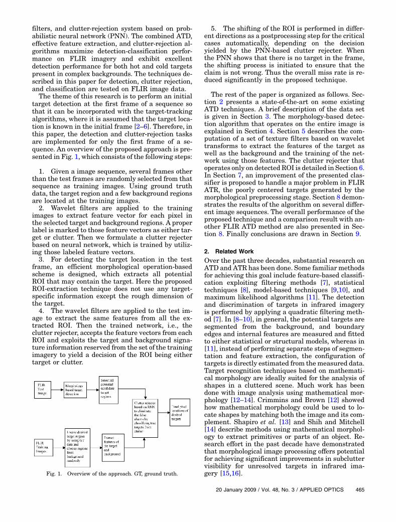
target detection at the first frame of a sequence sothat it can be incorporated with the target-trackingalgorithms, where it is assumed that the target loca-tion is known in the initial frame [2–6]. Therefore, inthis paper, the detection and clutter-rejection tasksare implemented for only the first frame of a se-quence. An overview of the proposed approach is pre-sented in Fig. 1, which consists of the following steps:
1. Given a image sequence, several frames otherthan the test frames are randomly selected from thatsequence as training images. Using ground truthdata, the target region and a few background regionsare located at the training images.2. Wavelet filters are applied to the training
images to extract feature vector for each pixel inthe selected target and background regions. A properlabel is marked to those feature vectors as either tar-get or clutter. Then we formulate a clutter rejecterbased on neural network, which is trained by utiliz-ing those labeled feature vectors.3. For detecting the target location in the test
frame, an efficient morphological operation-basedscheme is designed, which extracts all potentialROI that may contain the target. Here the proposedROI-extraction technique does not use any target-specific information except the rough dimension ofthe target.4. The wavelet filters are applied to the test im-
age to extract the same features from all the ex-tracted ROI. Then the trained network, i.e., theclutter rejecter, accepts the feature vectors from eachROI and exploits the target and background signa-ture information reserved from the set of the trainingimagery to yield a decision of the ROI being eithertarget or clutter.
5. The shifting of the ROI is performed in differ-ent directions as a postprocessing step for the criticalcases automatically, depending on the decisionyielded by the PNN-based clutter rejecter. Whenthe PNN shows that there is no target in the frame,the shifting process is initiated to ensure that theclaim is not wrong. Thus the overall miss rate is re-duced significantly in the proposed technique.
The rest of the paper is organized as follows. Sec-tion 2 presents a state-of-the-art on some existingATD techniques. A brief description of the data setis given in Section 3. The morphology-based detec-tion algorithm that operates on the entire image isexplained in Section 4. Section 5 describes the com-putation of a set of texture filters based on wavelettransforms to extract the features of the target aswell as the background and the training of the net-work using those features. The clutter rejecter thatoperates only on detected ROI is detailed in Section 6.In Section 7, an improvement of the presented clas-sifier is proposed to handle a major problem in FLIRATR, the poorly centered targets generated by themorphological preprocessing stage. Section 8 demon-strates the results of the algorithm on several differ-ent image sequences. The overall performance of theproposed technique and a comparison result with an-other FLIR ATD method are also presented in Sec-tion 8. Finally conclusions are drawn in Section 9.
2. Related Work
Over the past three decades, substantial research onATD and ATR has been done. Some familiar methodsfor achieving this goal include feature-based classifi-cation exploiting filtering methods [7], statisticaltechniques [8], model-based techniques [9,10], andmaximum likelihood algorithms [11]. The detectionand discrimination of targets in infrared imageryis performed by applying a quadratic filtering meth-od [7]. In [8–10], in general, the potential targets aresegmented from the background, and boundaryedges and internal features are measured and fittedto either statistical or structural models, whereas in[11], instead of performing separate steps of segmen-tation and feature extraction, the configuration oftargets is directly estimated from themeasured data.Target recognition techniques based on mathemati-cal morphology are ideally suited for the analysis ofshapes in a cluttered scene. Much work has beendone with image analysis using mathematical mor-phology [12–14]. Crimmins and Brown [12] showedhow mathematical morphology could be used to lo-cate shapes by matching both the image and its com-plement. Shapiro et al. [13] and Shih and Mitchell[14] describe methods using mathematical morphol-ogy to extract primitives or parts of an object. Re-search effort in the past decade have demonstratedthat morphological image processing offers potentialfor achieving significant improvements in subcluttervisibility for unresolved targets in infrared ima-gery [15,16].Fig. 1. Overview of the approach. GT, ground truth.
20 January 2009 / Vol. 48, No. 3 / APPLIED OPTICS 465
A number of target detection tasks in FLIR ima-gery based on neural network have already been pro-posed as well, both by the scientists and by theresearchers working in academia and industry. Asurvey on neural-network technology for ATR is pre-sented in [17], and an evaluation of neural-network-based ATR is performed in [18]. Some researchersapproached through a set of intuitive image featuresto form a confidence image and a multiple-layer per-ceptron (MLP) network, where most of the detectionefforts is expended in a few attractive regions high-lighted by the preprocessing stage [19,20]. There aretechniques of utilizing a neural-network-based tar-get detector after the combination of images from dif-ferent band [21,22] or fusing the detection resultsfrom several neural-network-based algorithms [23].In [23], a modular neural-network classifier has beenapplied to the problem of ATR in FLIR imagerybased on several independently trained neural net-works, where each neural network makes a decisionbased on local features extracted from a specific por-tion of the target image. Finally, the classification de-cisions of the individual networks are combined todetermine the final classification. ATD algorithmsbased on the feed-forward neural network have beenreported in [24], where conventional image proces-sing algorithms, such as hit/miss filtering, differenceof Gaussian filtering, and region clustering in con-junction with a neural network (MLP) for classifica-tion are used to form a complete ATR system. In [25],a hybrid neural-network system is presented, calledthe pulse coupled neural net, for ATR, which is aniterative neural network in which a gray scale inputimage results in a one-dimensional time signal thatis the input of a feed-forward pattern recognition net.Besides, an ATD algorithm based on the time-delayneural network [26] and other neural architectures[27–29] have been proposed as well.
3. Description of the Forward-Looking Infrared ImageData Set
Our FLIR image sequences supplied by ArmyMissileCommand are acquired by an infrared camera in-stalled in a moving platform, and the pedestal, onwhich the camera is lodged, is an aircraft. As theimaging system platform is not stable during the ex-posure time, all the objects in the image sequence areaffected by the motion of the platform, and as a re-sult, the recorded image would be blurred, and min-ute details of the desired image would be lost. Thusreal-life FLIR imagery demonstrates a number ofwell-known challenges that have been previouslywell documented in [1,30,31] and make targetdetection in FLIR imagery a very challengingresearch topic [32].For our experiment, we have 50 different se-
quences, where each sequence composes of a numberof frames (130 to 779 frames per sequence), and eachframe has 8 bit resolution of 128 × 128pixels withone or more targets posed somewhere. In general,the image sequences are closing sequences, i.e., the
target is at the farthest distance from the sensorand then gradually becomes closer to the observeras the later frames appear in the scene. Thus the tar-get is rarely visible at the first frame because of beingvery small with no distinguishable target signature.The size and signature as well as the orientation ofthe target change from one frame to the next. Forthose sequences, ground truth data are availablefor all the targets at each frame, which includesthe location of the targets and their height andwidth. In all those sequences together, there are a to-tal of 103 targets of 10 different types, such as tank,truck, mantruck, M60, armored personnel carrier(APC), bradley, pickup, target, testvan, and van, thatneed to be detected.
4. Morphology-Based Target Detection
In this paper, a detection process based on the appli-cation of simple nonlinear gray-scale morphologicaloperations has been utilized that leads to real-timeimplementations [33]. Morphological operations de-compose the given input image into a filtered image.Here the proposed procedure for detection has sev-eral stages within morphological framework. Thebasic morphological operations of dilation, erosion,opening, and closing for gray-scale images areexploited to accomplish the different phases in theprogression or development of our ROI extraction al-gorithm. In doing so, we have formulated an efficientand distinctive combination with proper ordering ofthose operators for extracting targets from FLIRimagery, where targets happen to appear as brightobjects.
The two most basic operations in mathematicalmorphology are erosion and dilation [34]. The basiceffects of the dilation and erosion operators on an im-age are to gradually enlarge the boundaries of re-gions of foreground pixels and to erode away theboundaries of regions of foreground pixels, respec-tively. Other than dilation and erosion, openingand closing are two important basic morphologicaloperators [34], which are a combination of erosionand dilation and often used to select or suppress fea-tures of a certain shape, e.g., to remove noise fromimages or to select objects with a particular direction.Very simply, the opening and closing are defined asan erosion followed by a dilation and a dilation fol-lowed by an erosion, respectively, using the samestructuring element (SE) for both operations.
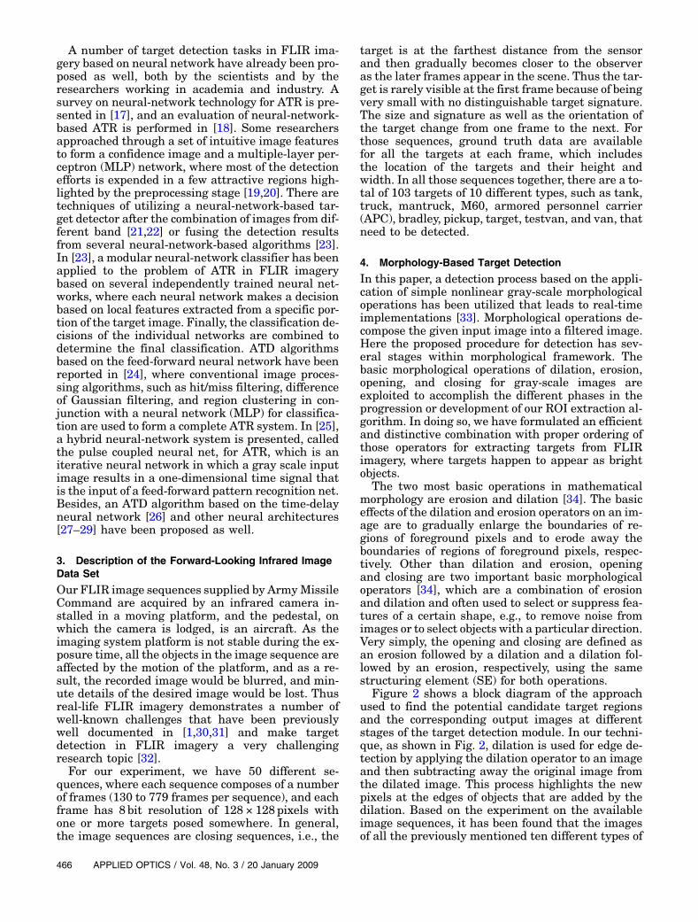
Figure 2 shows a block diagram of the approachused to find the potential candidate target regionsand the corresponding output images at differentstages of the target detection module. In our techni-que, as shown in Fig. 2, dilation is used for edge de-tection by applying the dilation operator to an imageand then subtracting away the original image fromthe dilated image. This process highlights the newpixels at the edges of objects that are added by thedilation. Based on the experiment on the availableimage sequences, it has been found that the imagesof all the previously mentioned ten different types of
466 APPLIED OPTICS / Vol. 48, No. 3 / 20 January 2009
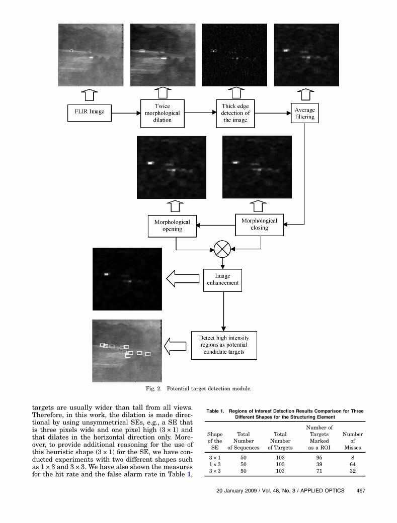
targets are usually wider than tall from all views.Therefore, in this work, the dilation is made direc-tional by using unsymmetrical SEs, e.g., a SE thatis three pixels wide and one pixel high (3 × 1) andthat dilates in the horizontal direction only. More-over, to provide additional reasoning for the use ofthis heuristic shape (3 × 1) for the SE, we have con-ducted experiments with two different shapes suchas 1 × 3 and 3 × 3. We have also shown the measuresfor the hit rate and the false alarm rate in Table 1,
Fig. 2. Potential target detection module.
Table 1. Regions of Interest Detection Results Comparison for ThreeDifferent Shapes for the Structuring Element
Shapeof theSE
TotalNumber
of Sequences
TotalNumberof Targets
Number ofTargetsMarkedas a ROI
Numberof
Misses
3 × 1 50 103 95 81 × 3 50 103 39 643 × 3 50 103 71 32
20 January 2009 / Vol. 48, No. 3 / APPLIED OPTICS 467
which is generated by applying the method on 50 dif-ferent sequences with 103 total targets posed some-where in the first frame.In FLIR images, the object is often so small that it
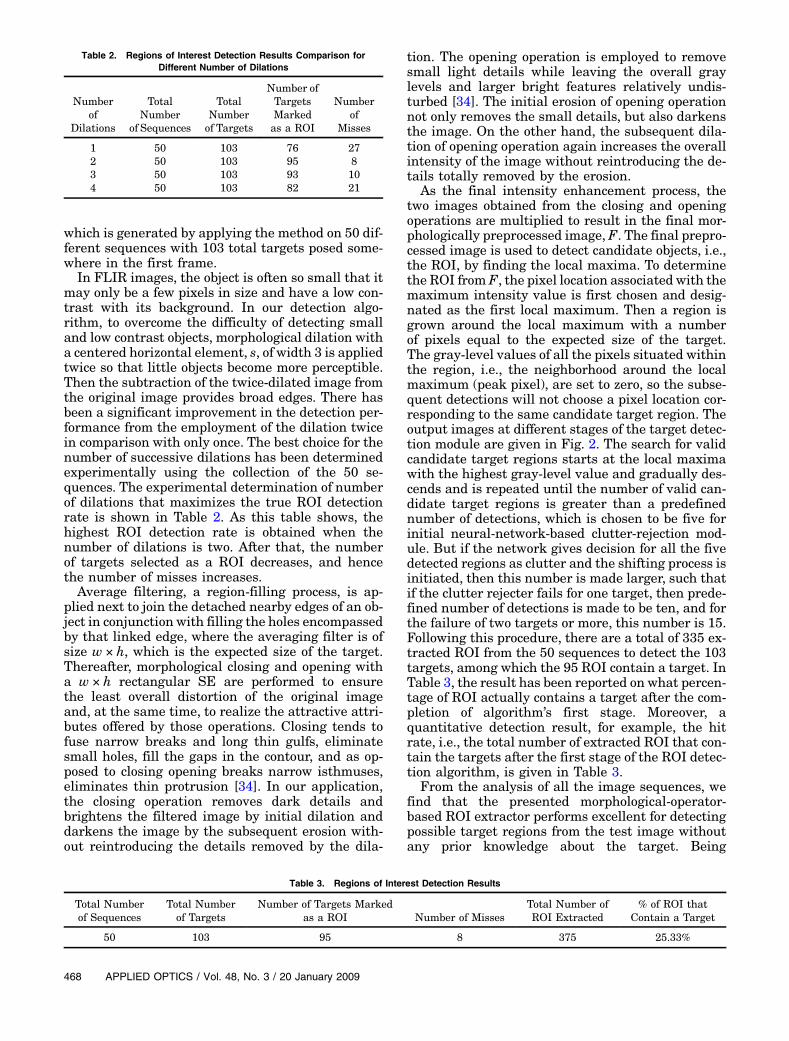
may only be a few pixels in size and have a low con-trast with its background. In our detection algo-rithm, to overcome the difficulty of detecting smalland low contrast objects, morphological dilation witha centered horizontal element, s, of width 3 is appliedtwice so that little objects become more perceptible.Then the subtraction of the twice-dilated image fromthe original image provides broad edges. There hasbeen a significant improvement in the detection per-formance from the employment of the dilation twicein comparison with only once. The best choice for thenumber of successive dilations has been determinedexperimentally using the collection of the 50 se-quences. The experimental determination of numberof dilations that maximizes the true ROI detectionrate is shown in Table 2. As this table shows, thehighest ROI detection rate is obtained when thenumber of dilations is two. After that, the numberof targets selected as a ROI decreases, and hencethe number of misses increases.Average filtering, a region-filling process, is ap-
plied next to join the detached nearby edges of an ob-ject in conjunction with filling the holes encompassedby that linked edge, where the averaging filter is ofsize w × h, which is the expected size of the target.Thereafter, morphological closing and opening witha w × h rectangular SE are performed to ensurethe least overall distortion of the original imageand, at the same time, to realize the attractive attri-butes offered by those operations. Closing tends tofuse narrow breaks and long thin gulfs, eliminatesmall holes, fill the gaps in the contour, and as op-posed to closing opening breaks narrow isthmuses,eliminates thin protrusion [34]. In our application,the closing operation removes dark details andbrightens the filtered image by initial dilation anddarkens the image by the subsequent erosion with-out reintroducing the details removed by the dila-
tion. The opening operation is employed to removesmall light details while leaving the overall graylevels and larger bright features relatively undis-turbed [34]. The initial erosion of opening operationnot only removes the small details, but also darkensthe image. On the other hand, the subsequent dila-tion of opening operation again increases the overallintensity of the image without reintroducing the de-tails totally removed by the erosion.
As the final intensity enhancement process, thetwo images obtained from the closing and openingoperations are multiplied to result in the final mor-phologically preprocessed image, F. The final prepro-cessed image is used to detect candidate objects, i.e.,the ROI, by finding the local maxima. To determinethe ROI from F, the pixel location associated with themaximum intensity value is first chosen and desig-nated as the first local maximum. Then a region isgrown around the local maximum with a numberof pixels equal to the expected size of the target.The gray-level values of all the pixels situated withinthe region, i.e., the neighborhood around the localmaximum (peak pixel), are set to zero, so the subse-quent detections will not choose a pixel location cor-responding to the same candidate target region. Theoutput images at different stages of the target detec-tion module are given in Fig. 2. The search for validcandidate target regions starts at the local maximawith the highest gray-level value and gradually des-cends and is repeated until the number of valid can-didate target regions is greater than a predefinednumber of detections, which is chosen to be five forinitial neural-network-based clutter-rejection mod-ule. But if the network gives decision for all the fivedetected regions as clutter and the shifting process isinitiated, then this number is made larger, such thatif the clutter rejecter fails for one target, then prede-fined number of detections is made to be ten, and forthe failure of two targets or more, this number is 15.Following this procedure, there are a total of 335 ex-tracted ROI from the 50 sequences to detect the 103targets, among which the 95 ROI contain a target. InTable 3, the result has been reported on what percen-tage of ROI actually contains a target after the com-pletion of algorithm’s first stage. Moreover, aquantitative detection result, for example, the hitrate, i.e., the total number of extracted ROI that con-tain the targets after the first stage of the ROI detec-tion algorithm, is given in Table 3.
From the analysis of all the image sequences, wefind that the presented morphological-operator-based ROI extractor performs excellent for detectingpossible target regions from the test image withoutany prior knowledge about the target. Being
Table 2. Regions of Interest Detection Results Comparison forDifferent Number of Dilations
Numberof
Dilations
TotalNumber
of Sequences
TotalNumberof Targets
Number ofTargetsMarkedas a ROI
Numberof
Misses
1 50 103 76 272 50 103 95 83 50 103 93 104 50 103 82 21
Table 3. Regions of Interest Detection Results
Total Numberof Sequences
Total Numberof Targets
Number of Targets Markedas a ROI Number of Misses
Total Number ofROI Extracted
% of ROI thatContain a Target
50 103 95 8 375 25.33%
468 APPLIED OPTICS / Vol. 48, No. 3 / 20 January 2009
extremely small and not having enough signature ofthe target in the formulated morphological frame-work, the application of the dilation operator twiceenhances the determination of the edges. Moreover,the overall combination and ordering of those opera-tors has been found to be very successful for extract-ing targets from FLIR imagery where targets happento appear as bright objects.
5. Feature Extraction
To extract image features and to enhance those fea-tures with respect to their surroundings, wavelet-based processing algorithms are superior due to theirabilities to discriminate different frequencies and topreserve signal details at different resolutions [35].In this paper, we exploit useful properties of waveletfilters [36–38] to provide a robust method for objectdetection, even when the target is very small in sizeand not apparent to human eye in the image se-quence due to its low contrast. For our purposes offeature extraction, the image is described in termsof wavelet decomposition since wavelets encapsulateinformation on discontinuities in a very succinctway [39]. Wavelets are mathematical functions,and each wavelet is associated with a scalingfunction, ϕðxÞ, via two-scale equations: ϕðxÞ ¼ P
n∈ℵhnϕð2x − nÞ and ψðxÞ ¼ P
n∈ℵgnϕð2x − nÞ, whereℵ≡ the set of real integers.Each wavelet can be characterized by a finite set of
coefficients, hn and gn, which constitute low-pass andhigh-pass filters, respectively [36]. The advantage ofusing these wavelet filters is that they are robustto noise.Our purpose in this work is to design a wavelet-
based feature extraction algorithm that measurestexture quality along the most perceptual dimen-sions. The approach we have adopted uses a seriesof Daubechies wavelet filters hn of lengths 4, 6, 8,and 10. The objective of the feature extraction is tocompute the horizontal and vertical directionality,where texture directionality along the x axis is basedon the horizontal convolution with the coefficients offour wavelet bases, and similarly, the directionalityfunction along the y axis is based on the vertical con-volution with those wavelet coefficients. The direc-tionality along the x axis represents the verticaledges, while directionality along the y axis repre-sents the horizontal edges. The horizontal and verti-cal convolution with the four wavelet bases generatesa set of eight texture features [40,41].
6. Probabilistic Neural Network Clutter Rejecter
The function of a clutter rejecter is to further exam-ine the locations indicated by the ROI yielded by themorphology-based detector. Neural network is themost versatile tool for the classification task, where,for most cases, only the samples of the desired targetimages are used for the training purposes. But onlytarget-sample-based training is not adequate for thepresent case, because (1) the target is almost blendedwith the background, (2) there is only a limited diver-
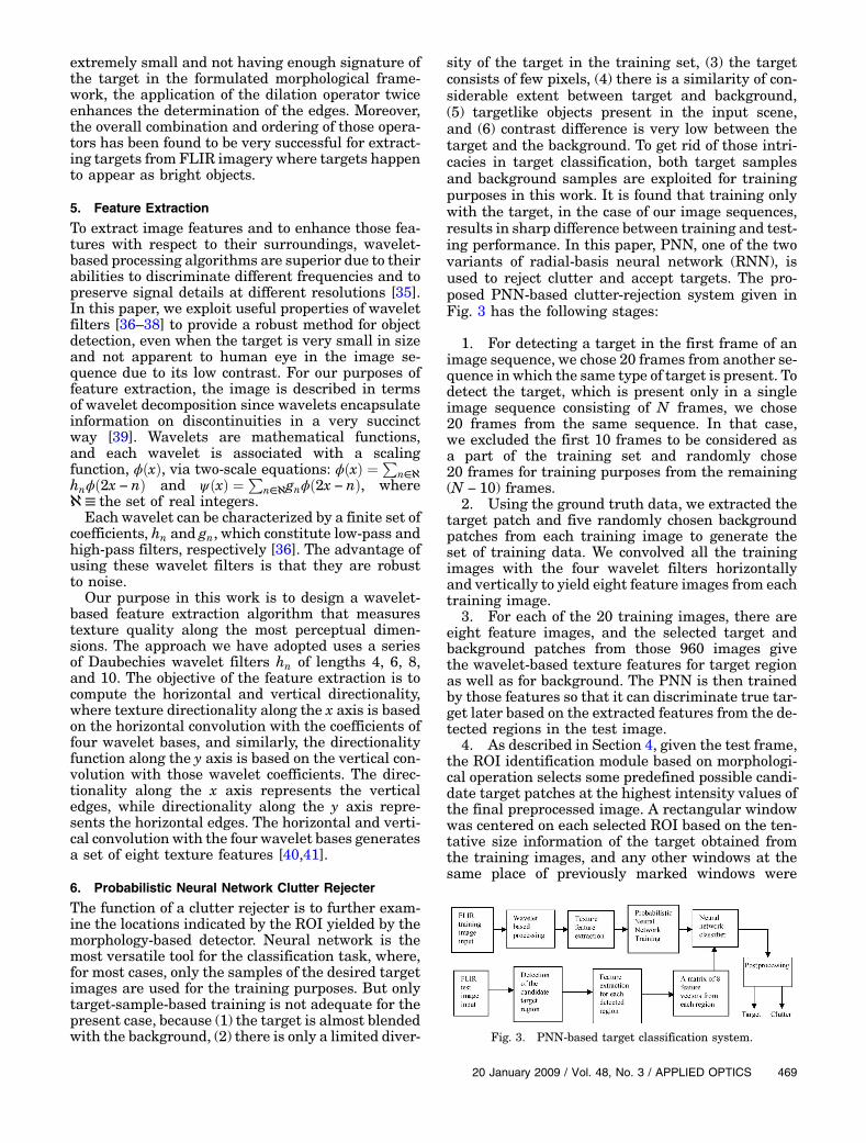
sity of the target in the training set, (3) the targetconsists of few pixels, (4) there is a similarity of con-siderable extent between target and background,(5) targetlike objects present in the input scene,and (6) contrast difference is very low between thetarget and the background. To get rid of those intri-cacies in target classification, both target samplesand background samples are exploited for trainingpurposes in this work. It is found that training onlywith the target, in the case of our image sequences,results in sharp difference between training and test-ing performance. In this paper, PNN, one of the twovariants of radial-basis neural network (RNN), isused to reject clutter and accept targets. The pro-posed PNN-based clutter-rejection system given inFig. 3 has the following stages:
1. For detecting a target in the first frame of animage sequence, we chose 20 frames from another se-quence in which the same type of target is present. Todetect the target, which is present only in a singleimage sequence consisting of N frames, we chose20 frames from the same sequence. In that case,we excluded the first 10 frames to be considered asa part of the training set and randomly chose20 frames for training purposes from the remaining(N − 10) frames.
2. Using the ground truth data, we extracted thetarget patch and five randomly chosen backgroundpatches from each training image to generate theset of training data. We convolved all the trainingimages with the four wavelet filters horizontallyand vertically to yield eight feature images from eachtraining image.
3. For each of the 20 training images, there areeight feature images, and the selected target andbackground patches from those 960 images givethe wavelet-based texture features for target regionas well as for background. The PNN is then trainedby those features so that it can discriminate true tar-get later based on the extracted features from the de-tected regions in the test image.
4. As described in Section 4, given the test frame,the ROI identification module based on morphologi-cal operation selects some predefined possible candi-date target patches at the highest intensity values ofthe final preprocessed image. A rectangular windowwas centered on each selected ROI based on the ten-tative size information of the target obtained fromthe training images, and any other windows at thesame place of previously marked windows were
Fig. 3. PNN-based target classification system.
20 January 2009 / Vol. 48, No. 3 / APPLIED OPTICS 469
ignored. The test frame was then convolved with thesame wavelet filters for extracting features fromeach ROI.5. Finally, the clutter-rejection module deals with
each ROI separately for extracting features and re-turns a classification matrix of eight feature vectorsfor each ROI. As the network has already beentrained, it is ready to make classification decision.The network accepts the feature matrix yielded fromeach ROI as an input and produces an output rowvector corresponding to that ROI. The desired outputis chosen to be a row vector of eight 1s for proper tar-get class and a row vector of eight 10s for nontargetor clutter class. But for some ROI, the output rowvector contains less than eight 1s with a 10 for theremaining elements or less than eight 10s with a 1for the remaining elements of the output row vector.In that case, the output of the network for that ROI isinterpreted as the probability of being in either tar-get class or clutter class, depending on the number of1s or 10s in output. If there is no 1 in any of the rowvectors of the network output, then it means thatthere is no target in that test frame, which may beeither a correct decision or a miss.
The details of the proposed PNN clutter-rejectionscheme are further discussed in the following sub-sections.
A. Preparation of Training Data
The following three steps should be carried out forclassifying target:
• Describe the target and the background usinga model.• Optimize both models using training data.• Find true targets by examining each ROI to
check if it is accurately described by the models.
The first step, therefore, is to generate a model of thetarget and the background by computing n ¼ 8 fea-tures for each pixel in the known target regionand also in the randomly chosen background regionsin a training image. The feature-extraction moduleuses information from the eight filtered images foreach image in the training set. For every training im-age from the target and background regions, we ob-tain feature matrices f t and fb, respectively:
f t ¼ ½f 1t f 2t f 3t…f 8t �;fb ¼ ½f 1b1 f 2b1…f 8b1 f
1b2 f
2b2…f 8b2……f 1b5 f
2b5…f 8b5�:
f 1t ; f2t ;…; f 8t are the vectorized images of the eight fil-
tered target patches, and f 1bi; f2bi;…; f 8bi are the eight
filtered vectorized images of the ith backgroundpatch.Each feature vector of target and background can
be defined as f it ¼ ½xi1; xi2; xi3;…; xip� and f ibk ¼ ½yik1;yik2; y
ik3;…; yikp�, where i ¼ 1; 2; 3…; 8; k ¼ 1; 2; 3…; 5;
p is the number of pixels in the target or background
patch such as p ¼ w × h, wherew and h are the widthand height of the target window; xij is the target pixelvalue in the ith filtered image; yikj is the backgroundpixel value of the kth randomly chosen backgroundpatch in the ith filtered image; and j ¼ 1; 2; 3…;p.
Thus, for each of the training images, there are 8feature vectors from the target and 40 from the back-ground, i.e., in total there are 48 feature vectors.Since in our application we have selected 20 imagesas our training set, the feature training set contains960 training feature vectors (8 × 20 ¼ 160 from thetarget area and 5 × 8 × 20 ¼ 800 from the back-ground area). These feature vectors are collected intoamatrix,X ¼ ½f t fb�, and each feature vector is labeledwith an appropriate class. The classes are as follows:
1. Desired target.2. False target, i.e., clutter.
B. Training the Network
Neural networks have been used with great successin the past on target recognition problems [17–29].Neural networks can be trained by data with appro-priate class labels (each output represents one class)and then used directly as a classifier of new data.Back-propagated delta rule networks (BPNs) (some-times known as MLPs) and RNNs are both well-known developments of the delta rule for single layernetworks (itself a development of the perceptronlearning rule). Both can learn arbitrary mappingsor classifications. Further, the inputs (and outputs)can have real values. Like BPNs, RNNs can learn ar-bitrary mappings, and the primary difference be-tween BPNs and RNNs is in the hidden layer. RNNhidden layer units have a receptive field with a cen-ter, which is a particular input value at which theyhave a maximal output. Their output tails off asthe input moves away from this point. Generally,the hidden unit function is a Gaussian RNN and istrained by
• deciding on how many hidden units thereshould be and
• deciding on their centers and the sharpness(standard deviation) of their Gaussians.
RNNs have the advantages that they are more ro-bust in dealing with poor training sets than theMLPs, and one can add extra units with centers nearparts of the input, which are difficult to classify.
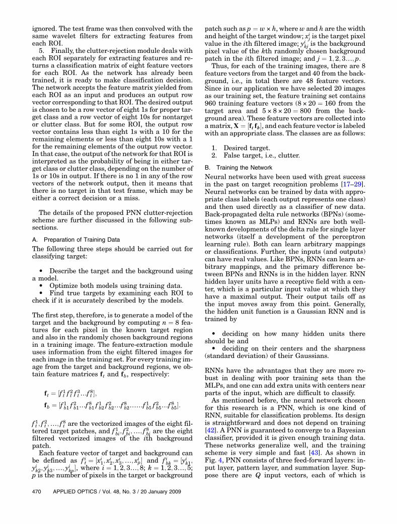
As mentioned before, the neural network chosenfor this research is a PNN, which is one kind ofRNN, suitable for classification problems. Its designis straightforward and does not depend on training[42]. A PNN is guaranteed to converge to a Bayesianclassifier, provided it is given enough training data.These networks generalize well, and the trainingscheme is very simple and fast [43]. As shown inFig. 4, PNN consists of three feed-forward layers: in-put layer, pattern layer, and summation layer. Sup-pose there are Q input vectors, each of which is
470 APPLIED OPTICS / Vol. 48, No. 3 / 20 January 2009
p dimensional and sampled from K categories. ThePNN for this case consists of p input units comprisingthe input layer, where each unit is connected to eachof the Q pattern units; each pattern unit is, in turn,connected to one and only one of the K summation/category units. The connections from the input topattern units represent modifiable weights, IW,which will be trained. Each category unit computesthe sum of the pattern units connected to it.The network architecture is given in Fig. 5. It is
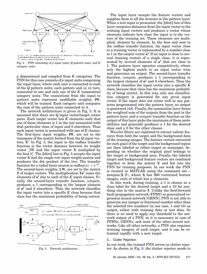
assumed that there are Q input vector/target vectorpairs. Each target vector has K elements such thatone of these elements is 1 in the row associated withthat particular class of input and 0 elsewhere. Thuseach input vector is associated with one of K classes.The first-layer input weights, IW, are set to thetranspose of the matrix formed from the Q input vec-tors, Xt. In Fig. 5, the input to the radbas transferfunction is the vector distance between its weightvector jIW and the input vector X multiplied bythe bias b1j . The ‖dist‖ box in Fig. 5 accepts the inputvector X and the single row input weight matrix andproduces the dot product of the two. The transferfunction for a radial basis neuron is radbasðnÞ ¼ e−n
2.The second-layer weights, LW, are set to the matrixT of target vectors. The multiplication Ta1 sums theelements of a1 due to each of the K input classes. Fi-nally, the second-layer transfer function, compete,produces a 1 corresponding to the largest elementof n2 and 0 elsewhere. Thus the network classifiesthe input vector into a specific K class because thatclass has the maximum probability of being correct.
The input layer accepts the feature vectors andsupplies them to all the neurons in the pattern layer.When a test input is presented, the ‖dist‖ box of thislayer computes distances from the input vector to thetraining input vectors and produces a vector whoseelements indicate how close the input is to the vec-tors of the training set. These elements are multi-plied, element by element, by the bias and sent tothe radbas transfer function. An input vector closeto a training vector is represented by a number closeto 1 in the output vector a1. If an input is close to sev-eral training vectors of a single class, it is repre-sented by several elements of a1 that are close to1. The pattern layer operates competitively, whereonly the highest match to an input vector winsand generates an output. The second-layer transferfunction, compete, produces a 1 corresponding tothe largest element of n2 and 0 elsewhere. Thus thenetwork classifies the input vector into a specific Kclass, because that class has the maximum probabil-ity of being correct. In this way, only one classifica-tion category is generated for any given inputvector. If the input does not relate well to any pat-terns programmed into the pattern layer, no outputis generated [44]. Finally, the summation layer formsthe weighted sum of the outputs from the pool in thepattern layer, and a compete transfer function on theoutput of this layer picks themaximum of these prob-abilities and generally produces a 1 for the desiredclass and a 0 for the other classes.
Wavelet filters are exploited to extract salient fea-tures from both the target and the background dataof the training images. The feature vectors extractedfor each pixel of the target and the background regionare then labeled as either target or nontarget, de-pending on whether the original pixel belongs tothe target or background area. Finally, the labeledtarget and background feature vectors are combinedtogether to form the matrix X and fed into thePNN for training purposes. In our work the PNNis created in MATLAB using the command net ¼newpnnðX;TÞ, where X has 960 vectorized featureimages, each of which has p elements.
In this work, during training, a 1 is chosen as aclass label for the desired target and a 10 for any-thing else in the matrix T. Unlike the feed-forwardback-propagation network (FFBN) or generalized re-gression neural network (GRNN), PNN is not able togenerate any integer or fractional number other thanthe selected two numbers (in our case, 1 and 10) asoutput, either with training data or test data. Sothere is no need to apply any threshold to the net-work output of a PNN, as it is necessary in case ofFFBNs, GRNNs, and most of the other neural net-works. Like all other networks, a PNN also requirestraining imagery of each target, and it can be re-trained rapidly with a new target.
C. Clutter Rejection
In our work, the trained PNN serves as clutter rejec-ter. As shown in Fig. 6, the clutter rejecter needs to
Fig. 4. PNN consisting of p input units, Q pattern units, and Kcategory units.
Fig. 5. Network architecture.
20 January 2009 / Vol. 48, No. 3 / APPLIED OPTICS 471
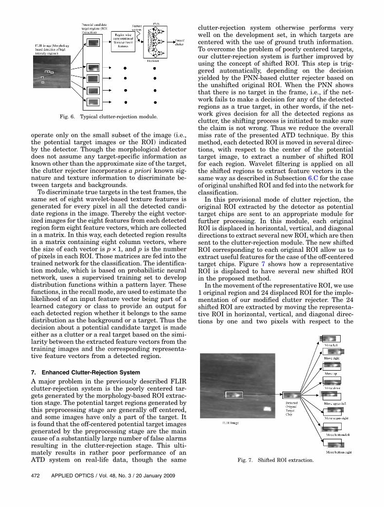
operate only on the small subset of the image (i.e.,the potential target images or the ROI) indicatedby the detector. Though the morphological detectordoes not assume any target-specific information asknown other than the approximate size of the target,the clutter rejecter incorporates a priori known sig-nature and texture information to discriminate be-tween targets and backgrounds.To discriminate true targets in the test frames, the
same set of eight wavelet-based texture features isgenerated for every pixel in all the detected candi-date regions in the image. Thereby the eight vector-ized images for the eight features from each detectedregion form eight feature vectors, which are collectedin a matrix. In this way, each detected region resultsin a matrix containing eight column vectors, wherethe size of each vector is p × 1, and p is the numberof pixels in each ROI. Those matrices are fed into thetrained network for the classification. The identifica-tion module, which is based on probabilistic neuralnetwork, uses a supervised training set to developdistribution functions within a pattern layer. Thesefunctions, in the recall mode, are used to estimate thelikelihood of an input feature vector being part of alearned category or class to provide an output foreach detected region whether it belongs to the samedistribution as the background or a target. Thus thedecision about a potential candidate target is madeeither as a clutter or a real target based on the simi-larity between the extracted feature vectors from thetraining images and the corresponding representa-tive feature vectors from a detected region.
7. Enhanced Clutter-Rejection System
A major problem in the previously described FLIRclutter-rejection system is the poorly centered tar-gets generated by the morphology-based ROI extrac-tion stage. The potential target regions generated bythis preprocessing stage are generally off centered,and some images have only a part of the target. Itis found that the off-centered potential target imagesgenerated by the preprocessing stage are the maincause of a substantially large number of false alarmsresulting in the clutter-rejection stage. This ulti-mately results in rather poor performance of anATD system on real-life data, though the same
clutter-rejection system otherwise performs verywell on the development set, in which targets arecentered with the use of ground truth information.To overcome the problem of poorly centered targets,our clutter-rejection system is further improved byusing the concept of shifted ROI. This step is trig-gered automatically, depending on the decisionyielded by the PNN-based clutter rejecter based onthe unshifted original ROI. When the PNN showsthat there is no target in the frame, i.e., if the net-work fails to make a decision for any of the detectedregions as a true target, in other words, if the net-work gives decision for all the detected regions asclutter, the shifting process is initiated to make surethe claim is not wrong. Thus we reduce the overallmiss rate of the presented ATD technique. By thismethod, each detected ROI is moved in several direc-tions, with respect to the center of the potentialtarget image, to extract a number of shifted ROIfor each region. Wavelet filtering is applied on allthe shifted regions to extract feature vectors in thesame way as described in Subsection 6.C for the caseof original unshifted ROI and fed into the network forclassification.
In this provisional mode of clutter rejection, theoriginal ROI extracted by the detector as potentialtarget chips are sent to an appropriate module forfurther processing. In this module, each originalROI is displaced in horizontal, vertical, and diagonaldirections to extract several new ROI, which are thensent to the clutter-rejection module. The new shiftedROI corresponding to each original ROI allow us toextract useful features for the case of the off-centeredtarget chips. Figure 7 shows how a representativeROI is displaced to have several new shifted ROIin the proposed method.
In the movement of the representative ROI, we use1 original region and 24 displaced ROI for the imple-mentation of our modified clutter rejecter. The 24shifted ROI are extracted by moving the representa-tive ROI in horizontal, vertical, and diagonal direc-tions by one and two pixels with respect to the
Fig. 6. Typical clutter-rejection module.
Fig. 7. Shifted ROI extraction.
472 APPLIED OPTICS / Vol. 48, No. 3 / 20 January 2009
center of the potential target chip. After drawing outthe shifted ROI, wavelet-filter-based texture featureextraction is performed in spatial domain. Like be-fore, each shifted region generates eight feature vec-tors, which are arranged to form a matrix. Thismatrix of feature vectors is supplied to the PNN clut-ter rejecter to be categorized as either clutter or realtarget. It is not unusual that there may be one ormore shifted ROI extracted from the same originalROI (which contains the off-centered target), whichwould appear as true target simultaneously withequal degree of probability. For such cases, fusion ofthe classification decisions from several shifted ROIis required to result in the final decision about thepixel location of the target in the input scene butnot about the identity of the target in the originalROI. However, fusing the decisions, for that reason,is not crucial, because the applied shifting in any di-rection is not more than two pixels from the originallocation.
8. Experimental Results
In the experiments, there are 20 target and 100 clut-ter patches extracted for each sequence from the ran-domly selected 20 training frames utilizing themethod discussed in Section 6, which are used forPNN training. The proposed system is applied toall the sequences of the given FLIR image databasefirst with no shifting of ROI. For some cases, it isfound that the potential target regions generatedby the preprocessing stage are not well centered,and the performance of the clutter-rejection systemdeteriorates accordingly. However, the application
of ROI shifting to these cases can successfully makea correct decision. Here results are shown for some ofthese sequences comparing the performance withand without shifting the ROI.
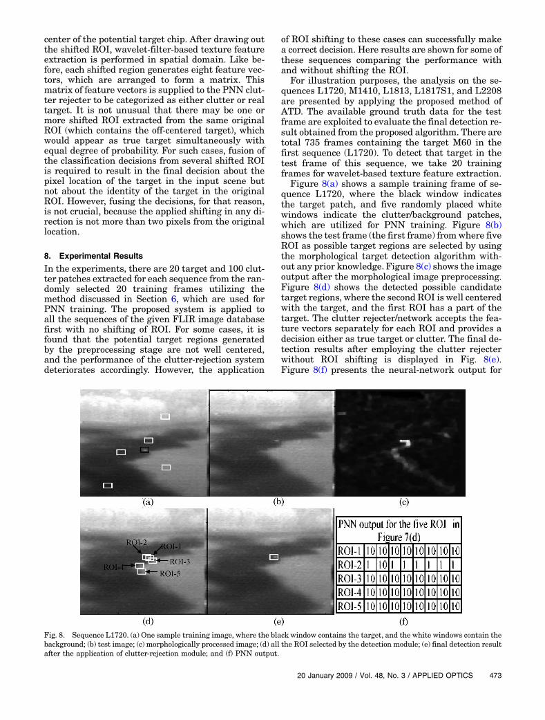
For illustration purposes, the analysis on the se-quences L1720, M1410, L1813, L1817S1, and L2208are presented by applying the proposed method ofATD. The available ground truth data for the testframe are exploited to evaluate the final detection re-sult obtained from the proposed algorithm. There aretotal 735 frames containing the target M60 in thefirst sequence (L1720). To detect that target in thetest frame of this sequence, we take 20 trainingframes for wavelet-based texture feature extraction.
Figure 8(a) shows a sample training frame of se-quence L1720, where the black window indicatesthe target patch, and five randomly placed whitewindows indicate the clutter/background patches,which are utilized for PNN training. Figure 8(b)shows the test frame (the first frame) fromwhere fiveROI as possible target regions are selected by usingthe morphological target detection algorithm with-out any prior knowledge. Figure 8(c) shows the imageoutput after the morphological image preprocessing.Figure 8(d) shows the detected possible candidatetarget regions, where the second ROI is well centeredwith the target, and the first ROI has a part of thetarget. The clutter rejecter/network accepts the fea-ture vectors separately for each ROI and provides adecision either as true target or clutter. The final de-tection results after employing the clutter rejecterwithout ROI shifting is displayed in Fig. 8(e).Figure 8(f) presents the neural-network output for
Fig. 8. Sequence L1720. (a) One sample training image, where the black window contains the target, and the white windows contain thebackground; (b) test image; (c) morphologically processed image; (d) all the ROI selected by the detection module; (e) final detection resultafter the application of clutter-rejection module; and (f) PNN output.
20 January 2009 / Vol. 48, No. 3 / APPLIED OPTICS 473
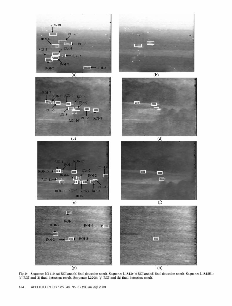
Fig. 9. Sequence M1410: (a) ROI and (b) final detection result. Sequence L1813: (c) ROI and (d) final detection result. Sequence L1815S1:(e) ROI and (f) final detection result. Sequence L2208: (g) ROI and (h) final detection result.
474 APPLIED OPTICS / Vol. 48, No. 3 / 20 January 2009
all the five preliminary detected regions, where thesecond region (ROI-2) shows up as target (M60),while the other regions show up as clutter or back-ground. For each ROI there are eight feature images,and therefore the PNN generates a 1 × 8 output vec-tor for each candidate ROI. For any ROI, if all theeight feature vectors match to the target feature vec-tors of the training set, the PNN output correspond-ing to that ROI will contain eight 1s. Similarly, forthe matches with the background feature vectors ofthe training set, the PNN output will have 10s. Forexample, as shown in Fig. 8(f), ROI-1 matches withthe background for all the eight features, and ROI-2agrees with the target for all the features except thesecond feature. At the final step, if center location ofthe detected ROI-2 is within two pixels differencefrom the target’s true center location provided inthe ground truth data, the detection result is countedas a successful estimation. The detection results offour other sequences are demonstrated in Fig. 9.We have compared our detection result with an-
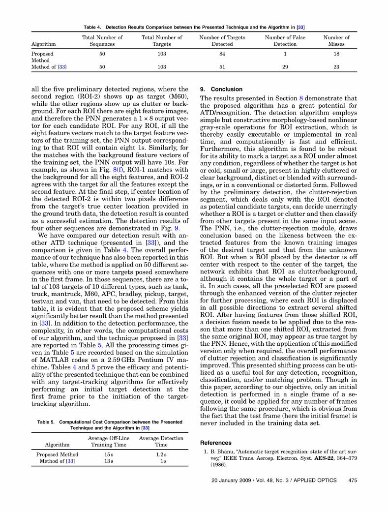
other ATD technique (presented in [33]), and thecomparison is given in Table 4. The overall perfor-mance of our technique has also been reported in thistable, where the method is applied on 50 different se-quences with one or more targets posed somewherein the first frame. In those sequences, there are a to-tal of 103 targets of 10 different types, such as tank,truck, mantruck, M60, APC, bradley, pickup, target,testvan and van, that need to be detected. From thistable, it is evident that the proposed scheme yieldssignificantly better result than themethod presentedin [33]. In addition to the detection performance, thecomplexity, in other words, the computational costsof our algorithm, and the technique proposed in [33]are reported in Table 5. All the processing times gi-ven in Table 5 are recorded based on the simulationof MATLAB codes on a 2:59GHz Pentium IV ma-chine. Tables 4 and 5 prove the efficacy and potenti-ality of the presented technique that can be combinedwith any target-tracking algorithms for effectivelyperforming an initial target detection at thefirst frame prior to the initiation of the target-tracking algorithm.
9. Conclusion
The results presented in Section 8 demonstrate thatthe proposed algorithm has a great potential forATD/recognition. The detection algorithm employssimple but constructive morphology-based nonlineargray-scale operations for ROI extraction, which isthereby easily executable or implemental in realtime, and computationally is fast and efficient.Furthermore, this algorithm is found to be robustfor its ability to mark a target as a ROI under almostany condition, regardless of whether the target is hotor cold, small or large, present in highly cluttered orclear background, distinct or blended with surround-ings, or in a conventional or distorted form. Followedby the preliminary detection, the clutter-rejectionsegment, which deals only with the ROI denotedas potential candidate targets, can decide unerringlywhether a ROI is a target or clutter and then classifyfrom other targets present in the same input scene.The PNN, i.e., the clutter-rejection module, drawsconclusion based on the likeness between the ex-tracted features from the known training imagesof the desired target and that from the unknownROI. But when a ROI placed by the detector is offcenter with respect to the center of the target, thenetwork exhibits that ROI as clutter/background,although it contains the whole target or a part ofit. In such cases, all the preselected ROI are passedthrough the enhanced version of the clutter rejecterfor further processing, where each ROI is displacedin all possible directions to extract several shiftedROI. After having features from those shifted ROI,a decision fusion needs to be applied due to the rea-son that more than one shifted ROI, extracted fromthe same original ROI, may appear as true target bythe PNN. Hence, with the application of this modifiedversion only when required, the overall performanceof clutter rejection and classification is significantlyimproved. This presented shifting process can be uti-lized as a useful tool for any detection, recognition,classification, and/or matching problem. Though inthis paper, according to our objective, only an initialdetection is performed in a single frame of a se-quence, it could be applied for any number of framesfollowing the same procedure, which is obvious fromthe fact that the test frame (here the initial frame) isnever included in the training data set.
References1. B. Bhanu, “Automatic target recognition: state of the art sur-
vey,” IEEE Trans. Aerosp. Electron. Syst. AES-22, 364–379(1986).
Table 4. Detection Results Comparison between the Presented Technique and the Algorithm in [33]
AlgorithmTotal Number of
SequencesTotal Number of
TargetsNumber of Targets
DetectedNumber of False
DetectionNumber ofMisses
ProposedMethod
50 103 84 1 18
Method of [33] 50 103 51 29 23
Table 5. Computational Cost Comparison between the PresentedTechnique and the Algorithm in [33]
AlgorithmAverage Off-LineTraining Time
Average DetectionTime
Proposed Method 15 s 1:2 sMethod of [33] 13 s 1 s
20 January 2009 / Vol. 48, No. 3 / APPLIED OPTICS 475

2. A. Mahalanobis, “Correlation filters for object tracking targetre-acquisition and smart aimpoint selection,” Proc. SPIE3073, 25–32 (1997).
3. A. Bal and M. S. Alam, “Dynamic target tracking using fringe-adjusted joint transform correlation and template matching,”Appl. Opt. 43, 4874–4881 (2004).
4. M. S. Alam and A. Bal, “Improved multiple target tracking viaglobal motion compensation and optoelectronic correlation,”IEEE Trans. Ind. Electron. 54, 522–529 (2007).
5. A. Dawoud, M. S. Alam, A. Bal, and C. Loo, “Target tracking ininfrared imagery using weighted composite reference func-tion-based decision fusion,” IEEE Trans. Image Process. 15,404–410 (2006).
6. A. Bal andM. S. Alam, “Automatic target tracking in FLIR im-age sequences using intensity variation function and templatemodeling,” IEEE Trans. Instrum.Meas. 54, 1846–1852 (2005).
7. S. R. F. Sims and A. Mahalanobis, “Performance evaluation ofquadratic correlation filters for target detection and discrimi-nation in infrared imagery,” Opt. Eng. 43, 1705–1711 (2004).
8. D. Casasent and R. Shenoy, “Feature space trajectory for dis-torted object classification and pose estimation in SAR,” Opt.Eng. 36, 2719–2728 (1997).
9. B. Bhanu and J. Ahn, “A system for model-based recognition ofarticulated objects,” in Proceedings of the International Con-ference on Pattern Recognition (IEEE, 1998), Vol. 2,pp. 1812–1815.
10. S. Z. Der, Q. Zheng, R. Chellappa, B. Redman, andH. Mahmoud, “View based recognition of military vehiclesin LADAR imagery using CADmodel matching,” in Image Re-cognition and Classification, Algorithms, Systems and Appli-cations, B. Javidi, ed. (Marcel Dekker, 2002), pp. 151–187.
11. A. D. Lanterman, M. I. Miller, and D. L. Snyder, “Automatictarget recognition via the simulation of infrared scenes,” inProceedings of the 6th Annual Ground Target Modeling andValidation Conference (Keweenaw Research Center, MichiganTech. University, 1995), pp. 195–204.
12. T. R. Crimmins and W. M. Brown, “Image algebra and auto-matic shape recognition,” IEEE Trans. Aerosp. Electron. Syst.AES-21, 60–69 (1985).
13. L. G. Shapiro, R. S. MacDonald, and S. R. Sternberg, “Shaperecognition with mathematical morphology,” in Proc. 8th Int.Conference on Pattern Recognition, Paris, France, 27–31 Octo-ber 1986.
14. F. Y. Shih and O. R. Mitchell, “Automated fast recognition andlocation of arbitrarily shaped objects by image morphology,” inProceedings of IEEE Conference on Computer Vision and Pat-tern Recognition (IEEE, 1988), pp. 774–779.
15. V. Tom and T. Joo, “Morphological detection for scanning IRSTsensor,” Final Report TR-1167-90-1 (Atlantic Aerospace Elec-tronics Corporation, 1990).
16. V. Tom and T. Joo, “Morphological-based front-end processingfor IR-based ATR systems,” Final Report (Atlantic AerospaceElectronics Corporation, 1992).
17. M. W. Roth, “Survey of neural network technology for auto-matic target recognition,” IEEE Trans. Neural Netw. 1, 28–43(1990).
18. K. W. Przytula and D. Thompson, “Evaluation of neural net-works for automatic target recognition,” in Proc. IEEE Conf.Aerospace (IEEE, 1997), Vol 3, pp. 423–439.
19. A. L. Chan, S. Z. Der, and N. M. Nasarabadi, “Multistage in-frared target detection,” Opt. Eng. 42, 2746–2754 (2003).
20. S. Z. Der, A. L. Chan, N. M. Nasarabadi, and H. Kwon, “Auto-mated vehicle detection in forward-looking infrared imagery,”Appl. Opt. 43, 333–348 (2004).
21. A. L. Chan, S. A. Rizvi, and N. M. Nasarabadi, “DualbandFLIR for automatic target recognition,” Information Fusion4, 35–45 (2003).
22. D. Borghys, P. Verlinde, C. Perneel, and M. Acheroy, “Multile-vel data fusion for the detection of targets using multispectralimage sequences,” Opt. Eng. 37, 477–484 (1998).
23. W. Lie-Chan, S. Z. Der, and N. M. Nasarabadi, “Automatictarget recognition using feature-decomposition and data-decomposition modular neural network,” IEEE Trans. ImageProcess. 7, 1113–1121 (1998).
24. B. Ernisse, S. K. Rogers, M. P. DeSimio, and R. A. Ranies,“Complete automatic target cuer/recognition system fortactical forward-looking infrared images,” Opt. Eng. 36,2593–2603 (1997).
25. J. Waldemark, V. Becanovic, T. Lindblad, and C. S. Lindsey,“Hybrid neural networks for automatic target recognition,”in Systems, Man, and Cybernetics, IEEE Int. Conf. Computa-tional Cybernetics and Simulation (IEEE, 1997), Vol. 4,pp. 4016–4021.
26. S. Rogers, J. Colombi, C. Martin, J. Gainey, K. Fielding,T. Burns, D. Ruck, M. Kabrisky, and M. Oxley, “Neural net-works for automatic target recognition,” Neural Networks8, 1153–1184 (1995).
27. G. A. Carpenter, “Neural network models for patternrecognition and associative memory,” Neural Networks 2,243–257 (1989).
28. I. E. Dror, M. Zagaeski, and C. F. Moss, “Three-dimensionaltarget recognition via sonar: a neural network model,” NeuralNetworks 8, 149–160 (1995).
29. A. Ravichandran and B. Yegnanarayana, “Studies on objectrecognition from degraded images using neural networks,”Neural Networks 8, 481–488 (1995).
30. B. Bhanu and T. Jones, “Image understanding research forautomatic target recognition,” in IEEE Trans. Aerospaceand Electronic Systems Magazine (IEEE, 1993), pp. 15–22.
31. S. A. Rizvi and N. M. Nasarabadi, “Amodular clutter rejectiontechnique for FLIR imagery using region based principalcomponent analysis,” Pattern Recogn. 35, 2895–2904 (2002).
32. S. A. Rizvi and N. M. Nasarabadi, “Fusion of FLIR automatictarget recognition algorithms,” Information Fusion 4, 247–258(2003).
33. J. F. Khan and M. S. Alam, “Target detection in cluttered for-ward-looking infrared imagery,” Opt. Eng. 44, 076404 (2005).
34. R. C. Gonzalez and R. E. Woods,Digital Image Processing (Ad-dison-Wesley, 1992).
35. T. C. Wang and N. B. Karayiannis, “Detection of microcalcifi-cations in digital mammograms using wavelets,” IEEE Trans.Med. Imaging 17 (1998).
36. I. Daubechies, Ten Lectures on Wavelets (SIAM, 1992).37. C. K. Chui, An Introduction to Wavelets (Academic, 1992).38. G. Strang and T. Nguyen, Wavelets and Filter Banks (Welles-
ley Cambridge, 1996).39. D. Davies, P. Palmer, and M. Mirmehdi, “Detection and track-
ing of very small low contrast objects,” in Proceedings of the9th British Machine Vision Conference (BMVA, 1998),pp. 599–608.
40. I. Daubechies, “Orthonormal bases of compactly supportedwavelets,” Commun. Pure Appl. Math. 41, 909–996 (1988).
41. K. Messer, D. de Ridder, and J. Kittler, “Adaptive texture re-presentation methods for automatic target recognition,” inProceedings of the 10th British Machine Vision Conference(BMVA, 1999), pp. 443–452.
42. D. F. Specht, “Probabilistic neural networks,” Neural Net-works 3, 109–118 (1990).
43. G. S. Gill and J. S. Sohal, “Battlefield decision making: a neur-al network approach,” J. Theoret. Appl. Inform. Technol. 4,697–699 (2008).
44. T. Sando, “Modeling highway crashes using Bayesisn beliefnetworks and GIS,” Ph.D dissertation (Florida State Univer-sity, 2005).
476 APPLIED OPTICS / Vol. 48, No. 3 / 20 January 2009