Automatic Code Generation For Autonomous Vehicles
22
1 DRIVING EVOLUTION Automatic Code Generation For Autonomous Vehicles Anthony Matarazzo Bodo Seifert Director ADAS - HMI DURA Automotive Systems
-
Upload
khangminh22 -
Category
Documents
-
view
0 -
download
0
Transcript of Automatic Code Generation For Autonomous Vehicles

1
DRIVING EVOLUTIONAutomatic Code Generation For Autonomous Vehicles
Anthony Matarazzo Bodo Seifert
Director ADAS - HMI
DURA Automotive Systems

A LYNN TILTON COMPANY
AGENDA
DURA COMPANY OVERVIW SIL Testing0
1
0
4
Requirements Modeling in SysML0
2
0
5
Conclusion
0
3
Application Code Generation Using
SCADE

DURA AUTOMOTIVE SYSTEMS LLC
D U R A AT A G L A N C E
3
1 4
C O U N T R I E S
9 , 5 0 0
E M P L O Y E E S
3 6
L O C A T I O N S* 2017 DURA + GAS
$ 1 . 4 B
S A L E S

DURA AUTOMOTIVE SYSTEMS LLC
Agenda
41 0 / 1 1 / 2 0 1 8
• Requirements Modeling in SysML
• Application Code Generation Using SCADE
• SIL Testing
• Conclusion

SYSTEMS ENGINEERING & USE CASE METHODOLOGY
Rhapsody: Use Case Diagram
Doors NG: Requirements
• Use cases are utilized for creation of System Requirements (Use Case and Supplemental)• SYSML Diagrams are developed and traced to use case requirements via rational model manager, the
diagrams allow for a System Architecture to be generated. • Systems team delivers package to the application team for development.• System Integration Testing is performed through MIL, SIL and HIL. All test cases are stored in Rational
Quality Manager and traced back to each supplemental requirement.
Rhapsody: IBD DiagramSystem Architecture
Systems Engineering Process
Model based systems engineering utilizes SysML following the IBM Harmony process to define the system behavior and interfaces in the IBM Jazz platform.
Harmony Process
5
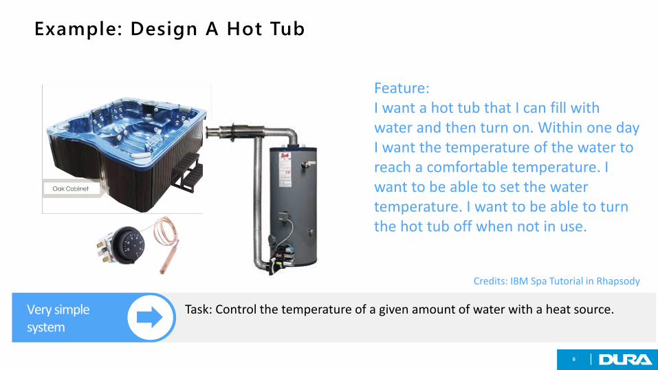
Example: Design A Hot Tub
6
Feature:I want a hot tub that I can fill with water and then turn on. Within one day I want the temperature of the water to reach a comfortable temperature. I want to be able to set the water temperature. I want to be able to turn the hot tub off when not in use.
Very simple system
Task: Control the temperature of a given amount of water with a heat source.
Credits: IBM Spa Tutorial in Rhapsody

Defining Requirements In IBM Rhapsody: Use Cases
7
Use CasesContains use cases and requirements.Also contains Rationales (e.g. results from other projects that determine a design constraint).
*) The screenshots are part of the IBM Spa Tutorial
Use cases can be used to decompose

Defining Requirements In IBM Rhapsody
8
IBM stores all individual elements in packages.The actor package contains all actors.The requirements analysis package includes the use cases and the requirements. Use cases are defined graphically.
Requirements Analysis Package
Contains use cases and requirements.Also contains Rationales (e.g. results from other projects that determine a design constraint).
*) The screenshots are part of the IBM Spa Tutorial
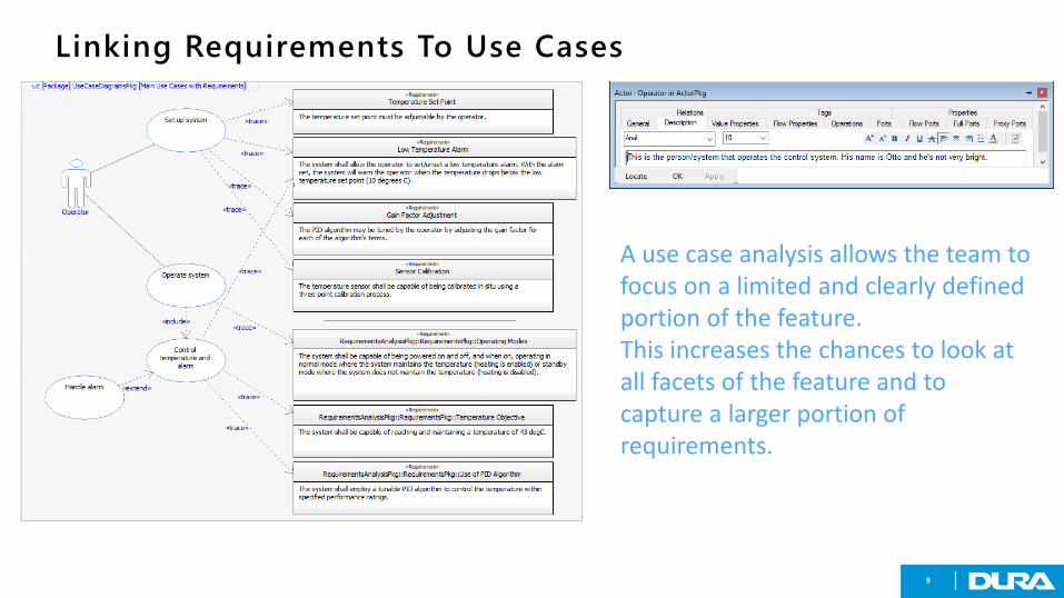
Linking Requirements To Use Cases
9
A use case analysis allows the team to focus on a limited and clearly defined portion of the feature.This increases the chances to look at all facets of the feature and to capture a larger portion of requirements.

USE IBD To DESCRIBE THE SYSTEM
10
Rhapsody uses an Internal Block Diagram to describe the system. In this case we chose a model that describes the System Under Control with one input (heat) and one output (temperature).The other model describes the Control System with one output (heat) and one input (temperature). Both models are black boxes in this representation but we can drill down into both models.This is an example for a simple system architecture with only 2 blocks and 2 Interfaces.
System Architecture
After requirement analysis we are able to define a system architecture with blocks that define functionality and well defined interfaces.

Define System Context
11
Define system context
Define required value types.Define main elements described in the model
The context is defined by the use cases, the system under control, the control system and physical constraints:
We need to transfer into the time discrete domain by using the heat output of the heater with 19 kJ/s for Q.

State Charts for the Elements
12
Define BehaviorState charts can be used to define the behavior of the blocks in the system architecture.

Simulating State Charts
131 0 / 1 1 / 2 0 1 8Disclosure or duplication without consent is prohibited
Simulate Behavior
Since we modeled the requirements we can now evaluate how the model behaves and get buy-in from stakeholders.
A panel allows to visualize variables and enables user interaction.Here we have a simple control panel on the bottom of the screen that allows us to turn the system on and off and to change the system mode. The LED show the system state and the temperature display shows the simulated water temperature.The state chart provides an overview of the logic we defined and we can either run it or set break points or step through it.

Simulating State Charts: SystemUnderControl
141 0 / 1 1 / 2 0 1 8Disclosure or duplication without consent is prohibited
Complete System Overview
Rhapsody allows the developer to understand the state of the complete system by visualizing each sequence, state and activity diagram.

APPLICATION SOFTWARE ENGINEERING
Apps Software Engineering Process
The Application SW defines the SW requirements and SW architecture traced to the system architecture. The generated code is ISO26262 certified. V&V is handled through MIL and SIL and HIL.
Process Overview1. Application Team create software requirements and software design stored in DOORS Next
Generation and traces to system requirements2. Application Team uses the Internal Block Diagram generated by systems engineering to import
to ANSYS SCADE3. The ANSYS SCADE model is enhanced and traced to the system requirements in Doors NG4. The ANSYS SCADE code generator produces the ISO 26262 compliant code in .c, .h, .m files, and
s-functions that can be ported into a Matlab/Simulink s-function5. The s-function is then run in SIL (e.g. ANSYS VRX or TASS Prescan) for “System Integration Tests”
ANSYS SCADE Model Matlab/Simulink TASS Prescan or ANSYS VRX (Vehicle Simulation)
15

16
Import IBD to SCADE
Rhapsody SCADE
1. Efficient2. Traceable3. Consistence
Strong Integration >>

Develop the Application Model in SCADE
17
Verify functional safety and accuracy of the model.
Automated HMI Display design-level connection for rapid
prototyping of behavioral logic and graphic components in
embedded applications

18
Model
Source Code
Compile into 26262 compliant code
» One Click »
All application code is generated using an ISO 26262 complaint and qualified code generator by TUV (no additional certs needed)

Port Code to different targets/development tools
19
All generated code is portable (ANSI C, compiler, platform and OS independent, MISRA compliant)
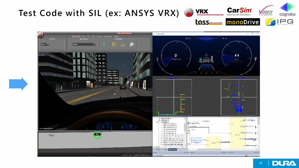
Test Code with SIL (ex: ANSYS VRX)
20

Summary
211 0 / 1 1 / 2 0 1 8Disclosure or duplication without consent is prohibited
• Use cases aid requirements development• Requirements are defined as executable SysML models• The Internal Block Diagram can be ported to other modeling tools (SCADE)• SCADE allows code definition through models• Models are evaluated for FuSa• Code is automatically MISRA compliant• The SCADE S-Function can be integrated in MatlabSimulink• A number of tools can be used for SIL (e.g. TASS Prescan)

THANK YOU
22
Address The Challenge Of Unexpected Behavior In Modern Vehicles
Director ADAS - HMI
DURA Automotive Systems
Bodo SeifertDirector
ADAS / HMI