Automated external defibrillator (AED) FRED easy - Safelincs
94
FRED easy® User Guide Automated external defibrillator (AED) FRED easy® - SD Card - Ethernet/Online - Life Art. no.: 0-48-0013 Rev. m *0-48-0013*
-
Upload
khangminh22 -
Category
Documents
-
view
2 -
download
0
Transcript of Automated external defibrillator (AED) FRED easy - Safelincs
FRED easy®
User Guide
Automated external defibrillator (AED)FRED easy® - SD Card
- Ethernet/Online- Life
Art.
no
.: 0-
48-0
013
Rev.
m *0-48-0013*

Manufacturer and responsible for the marking (first declaration 2002)
SCHILLER Medical S.A.S. Tel.: +33 (0) 388 63 36 00
4, rue Louis Pasteur Fax: +33 (0) 388 94 12 82
F- 67162 Wissembourg E-mail: [email protected] ; [email protected]
Web: www.schiller-medical.com
Address Headquarters
SCHILLER AG Phone: +41 (0) 41 766 42 42
Altgasse 68 Fax: +41 (0) 41 761 08 80
CH-6341 Baar, Switzerland E-mail: [email protected]
Web: www.schiller.ch
Sales and service information
The SCHILLER sales and service centre network is world-wide. For the address of yourlocal distributor, contact your nearest SCHILLER subsidiary. In case of difficulty, a complete list of all distributors and subsidiaries is provided on ourinternet site: http://www.schiller.chSales information can also be obtained from:[email protected]
Article no.: 0-48-0013 Rev. mIssue date: 13.01.15FRED easy® 2G software ≥ 07.04(except 20.00)FRED easy® 1G software ≥ 9.08

Page 1
User GuideFRED easy
Art.
no
.: 0-
48-0
013
Rev.
m
Table of Contents1 Safety Notes .............................................. 51.1 User profiles.......................................................................... 5
1.2 Responsibility of the User ................................................... 5
1.3 Intended Use ......................................................................... 6
1.4 Organisational Measures..................................................... 7
1.5 Safety-Conscious Operation ............................................... 7
1.6 Operation with other Devices.............................................. 8
1.7 Maintenance.......................................................................... 8
1.8 General Notes Regarding the Unit ...................................... 8
1.9 Additional Terms .................................................................. 91.9.1 Implied authorisation .......................................................................... 91.9.2 Terms of Warranty ............................................................................. 9
1.10 Display Symbols/Indicators............................................... 101.10.1 Symbols used in this user guide ...................................................... 101.10.2 Symbols used on the device ............................................................ 101.10.3 Symbols used on the battery............................................................ 111.10.4 Symbols used on the electrode packaging ...................................... 12
2 Components and Operation .................. 132.1 General Information ........................................................... 13
2.2 Design.................................................................................. 14
2.3 Function .............................................................................. 162.3.1 Overview on the configurable settings ............................................. 17
2.4 Operating and Display Elements ...................................... 182.4.1 Overview on versions and operating modes.................................... 182.4.2 Operation and display ...................................................................... 202.4.3 Display ............................................................................................. 212.4.4 Symbols used on the display ........................................................... 21
3 Initial operation ....................................... 223.1 Inserting the battery ........................................................... 223.1.1 Switching device On and Off............................................................ 23
3.2 Battery monitoring ............................................................. 243.2.1 Sufficient battery capacity ................................................................ 243.2.2 Low battery capacity during use ...................................................... 253.2.3 Battery depleted during use, limited mode (CPR)............................ 26
Page 2
FRED easy
Art.
no
.: 0-
48-0
013
Rev.
m
4 Defibrillation ............................................274.1 Instructions and Safety Notes ........................................... 274.1.1 Instructions ...................................................................................... 274.1.2 Safety notes for AED use................................................................. 27
4.2 Defibrillation procedure ..................................................... 29
4.3 Applying the adhesive electrodes..................................... 344.3.1 General information ......................................................................... 344.3.2 Apply the adhesive electrodes and connect them to the device ...... 354.3.3 Checking the electrodes .................................................................. 37
4.4 Semi-automatic defibrillation ............................................ 38
4.5 Automatic defibrillation...................................................... 404.5.1 Functional description of automatic AEDs ....................................... 404.5.2 Safety notes for automatic defibrillation ........................................... 40
4.6 Manual Defibrillation (option) ............................................ 434.6.1 Manual defibrillation - description .................................................... 444.6.2 Manual defibrillation procedure........................................................ 454.6.3 Switching to semi-automatic operational mode ............................... 46
4.7 Internal safety discharge ................................................... 47
4.8 Finishing the therapy ......................................................... 47
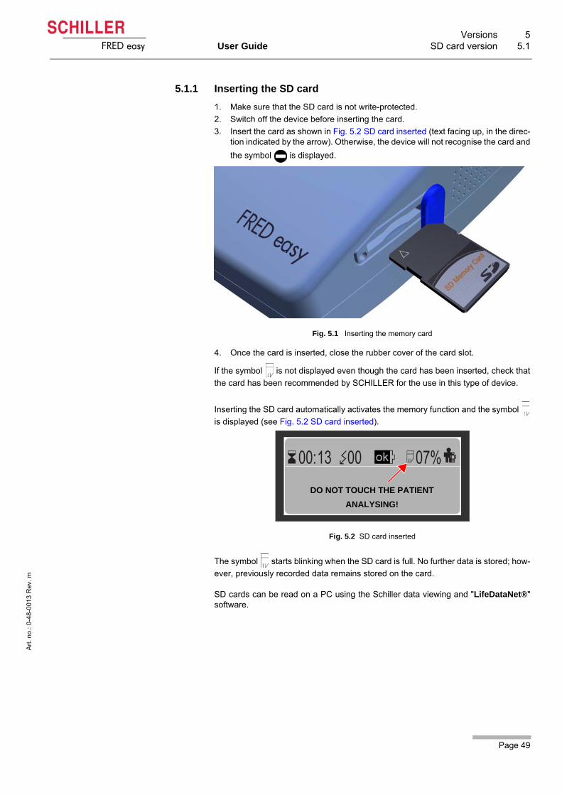
5 Versions ...................................................485.1 SD card version .................................................................. 485.1.1 Inserting the SD card ....................................................................... 49
5.2 Ethernet version ................................................................. 505.2.1 Connecting the Ethernet adapter ..................................................... 505.2.2 Data transmission procedure ........................................................... 515.2.3 Installing the ferrite core................................................................... 53
5.3 Online version..................................................................... 545.3.1 Ensuring data transmission.............................................................. 555.3.2 Placing the FRED easy® in the docking station.............................. 565.3.3 Activating the maintenance mode.................................................... 57
5.4 Configuration Ethernet/Online using FRECO .................. 585.4.1 Configuring the "Network" tab.......................................................... 585.4.2 Configuring the "Online" Tab ........................................................... 605.4.3 Configuring the date and time as well as IP addresses without
using FREDCO® ............................................................................. 61
6 Options ....................................................626.1 ECG display......................................................................... 62
6.2 Metronome .......................................................................... 62
6.3 Rechargeable NiCd battery................................................ 63
6.4 Silent mode ......................................................................... 646.4.1 Silent mode...................................................................................... 646.4.2 Switching to silent mode .................................................................. 656.4.3 Deactivating silent mode.................................................................. 666.4.4 Erasing the memory card................................................................. 66
6.5 Special operating conditions............................................. 676.5.1 Maritime use .................................................................................... 67
Page 3
User GuideFRED easy
Art.
no
.: 0-
48-0
013
Rev.
m
7 Maintenance ............................................ 697.1 Maintenance Intervals ........................................................ 697.1.1 Visual inspection of the device and accessories.............................. 697.1.2 Green indicator................................................................................. 707.1.3 Functional check .............................................................................. 707.1.4 Internal backup battery..................................................................... 70
7.2 Cleaning and disinfection.................................................. 71
7.3 Accessories and disposables ........................................... 71
7.4 Disposal information.......................................................... 727.4.1 Battery Disposal ............................................................................... 727.4.2 Disposal of accessories that come into contact with the patient ...... 727.4.3 Disposal at the end of its useful life.................................................. 72
7.5 Trouble Shooting................................................................ 737.5.1 Error messages................................................................................ 737.5.2 Transmission error Ethernet/Online FRED easy®........................... 757.5.3 Trouble Shooting.............................................................................. 787.5.4 Measures to prevent electromagnetic interferences ........................ 80
8 Technical Data ........................................ 818.1 System Specifications ....................................................... 81
8.2 Classification and safety standards ................................. 82
8.3 Defibrillation pulse ............................................................. 83
8.4 Electromagnetic interferences .......................................... 858.4.1 Electromagnetic emissions .............................................................. 858.4.2 Electromagnetic immunity ................................................................ 858.4.3 Recommended minimum distances ................................................. 87
9 Appendix ................................................. 889.1 Order Information ............................................................... 88
9.2 Required accessories ........................................................ 88
9.3 Literature ............................................................................. 89
9.4 Glossary .............................................................................. 89
9.5 Inspection report ................................................................ 90
10 Index ........................................................ 92
Page 4
FRED easy
Art.
no
.: 0-
48-0
013
Rev.
m
Page 5
Safety Notes 1User Guide User profiles 1.1
Art
. no
.: 0
-48
-001
3 R
ev.
m
FRED easy
1 Safety Notes
1.1 User profiles
The following people may use the FRED easy:
• Physicians or other trained medical personnel
• other people (non-professionals) trained in early defibrillation
• other people not trained in early defibrillation, as long as they can understand andfollow the spoken and displayed instructions.
1.2 Responsibility of the User
Even though untrained people may use the device, training and instructions are rec-ommended to guarantee an optimal resuscitation procedure.
Regulations on who is allowed to use devices like the FRED easy® and whichtraining is required, are country-specific. In any case, legal regulations have tobe observed.
Before using the device, a SCHILLER representative must perform a presenta-tion on the device's operation and safety measures, if it's required by the localregulations.
The indications given by this equipment are not a substitute for the regularchecking of vital functions.
The numerical and graphical results as well as any interpretation suggested bythe device must be examined with respect to the patient's overall clinical condi-tion and the quality of the recorded data.
Make sure that the user has read and understood the user guide, and especiallythese safety notes.
Damaged or missing components must be replaced immediately.
The device must be stored in a place inaccessible to children.
Properly dispose of the packaging material and make sure it is out of children'sreach.
1 Safety Notes1.3 Intended Use
Page 6
Art
. no
.: 0
-48
-001
3 R
ev.
m
FRED easy
1.3 Intended Use
The FRED easy® is an automated external defibrillator (AED) used for the treat-ment of ventricular fibrillation (VF) and ventricular tachycardia (VT).
The device may be used with the appropriate electrodes on either adults or chil-dren.
The device must only be used if the following symptoms are found:
– not responsive– no respiration– no pulse
The device must not be used if the patient:
– is responsive– is breathing– has pulse
The FRED easy® is an emergency device and must be ready for operation atany time and in all situations. Make sure that
– the device is always equipped with a sufficiently charged battery and that aspare battery is at hand
– An empty battery must not be reused and must be disposed of immediately. Only operate the device in accordance with the specified technical data.
Do not use this device in areas where there is any danger of explosion or in thepresence of flammable liquids, flammable anaesthetic agents or in places wherethe ambient air's oxygen concentration is higher than 25 %.
Page 7
Safety Notes 1User Guide Organisational Measures 1.4
Art
. no
.: 0
-48
-001
3 R
ev.
m
FRED easy
1.4 Organisational Measures
1.5 Safety-Conscious Operation
Before using the unit, ensure that an introduction regarding the unit functionsand the safety precautions has been provided and understood.
Keep these operating instructions in an accessible place for reference when re-quired. Make sure that they are always complete and legible.
Danger of electric shock! - Danger for user, rescuer and patient.The energy applied to the patient can be conducted through the patient to otherpersons, who may suffer a lethal electric shock. Therefore:
– do not touch the patient, the electrodes or other conducting objects during defi-brillation.
– do not defibrillate the patient in a puddle of water or on other conducting surfac-es,
– switch the device off when it is no longer used. Danger of explosion! — The device must not be used in areas where there is
any danger of explosion . There might be a danger of explosion in areas whereflammable products (petrol), flammable anaesthetic agents or products for skincleaning/disinfection are in use, or where the ambient air's oxygen concentrationis higher than 25 %.
Immediately report any changes that impair safety (including operating behav-iour) to the responsible person.
Only use original SCHILLER electrodes.
Before switching on, check that the unit's casing and electrode connections arenot damaged.
Immediately replace a damaged unit, or damaged cables and connections.
Operating the device with a defective casing or damaged cables constitutes adanger to life. Therefore:
– immediately replace a damaged unit or damaged cables and connections.
1 Safety Notes1.6 Operation with other Devices
Page 8
Art
. no
.: 0
-48
-001
3 R
ev.
m
FRED easy
1.6 Operation with other Devices
1.7 Maintenance
1.8 General Notes Regarding the Unit
Accessory equipment connected to the analogue and digital interfaces must becertified according to the respective IEC standards (e.g. IEC/EN 60950 for dataprocessing equipment and IEC/EN 60601-1 for medical equipment). Further-more, all configurations shall comply with the valid version of the system standardIEC/EN 60601-1-1. Everybody who connects additional equipment to the signalinput part or signal output part configures a medical system and is therefore re-sponsible that the system complies with the requirements of the valid version ofthe system standard IEC/EN 60601-1-1. If in doubt, consult the technical servicedepartment or your local representative.
Magnetic and electrical fields from X-ray or tomographic devices, portable radio
equipment, HF radios and devices labelled with the symbol can affect the
operation of this device (see section 8.4) . Avoid using such devices or keep asufficient distance from them.
A 16.7 Hz filter allows to operate the FRED easy in the vicinity of a mains networkwith a frequency of 16.7 Hz (railway lines in some countries).
FRED easy® is not intended to be operated while using high-frequency surgicaldevices.
Interference with other devices - The charging of energy and the release of thedefibrillation impulse can disturb other devices. Check these devices before theirfurther use.
Sensors and devices that are not defibrillation-proof must be disconnected fromthe patient before a shock is triggered.
If the patient has an implanted pacemaker, be sure not to position the electrodesdirectly on top of it.
Danger of electric shock! Do not open the device. No serviceable parts inside.Refer servicing to qualified personnel only.
Before cleaning, switch the unit off and remove the battery.
Do not use high-temperature sterilisation processes (such as autoclaving). Donot use E-beam or gamma radiation sterilisation.
Do not use aggressive or abrasive cleaners.
Do not, under any circumstances, immerse the device or cable assemblies in liq-uid.
To ensure patient safety, the accuracy of displayed values and interference-freeoperation, only use original SCHILLER accessories. The user is responsible forthe use of third-party accessories. The warranty does not cover damage result-ing from the use of accessories or consumables other than those marketed bySCHILLER.
A defibrillation can fail with certain disease patterns.

Page 9
Safety Notes 1User Guide Additional Terms 1.9
Art
. no
.: 0
-48
-001
3 R
ev.
m
FRED easy
1.9 Additional Terms
1.9.1 Implied authorisation
Possession or purchase of this device does not convey any express or implied licenseto use the device with replacement parts which would alone, or in combination withthis device, fall within the scope of one or more patents relating to this device.
1.9.2 Terms of Warranty
Your SCHILLER FRED easy® is warranted against defects in material and manufac-ture for the duration of one year (as from date of purchase). Excluded from this war-ranty is damage caused by an accident or as a result of improper handling. The war-ranty entitles to free replacement of the defective part. Any liability for subsequentdamage is excluded. The warranty is void if unauthorised or unqualified persons at-tempt to make repairs.
In case of a defect, send the device to your dealer or directly to the manufacturer. Themanufacturer can only be held responsible for the safety, reliability, and performanceof the apparatus, and assume the warranty, if:
• assembly operations, extensions, readjustments, modifications, or repairs arecarried out by persons authorised by him,
• spare parts used for assembly operations, extensions, readjustments, modifica-tions or repairs are recommended or supplied by SCHILLER, and,
• the SCHILLER FRED easy® and approved attached equipment is used in ac-cordance with the manufacturer's instructions.
There are no express or implied warranties which extend beyond the warranties here-inabove set forth. SCHILLER makes no warranty of merchantability or fitness for aparticular purpose with respect to the product or parts thereof.
1 Safety Notes1.10 Display Symbols/Indicators
Page 10
Art
. no
.: 0
-48
-001
3 R
ev.
m
FRED easy
1.10 Display Symbols/Indicators
1.10.1 Symbols used in this user guide
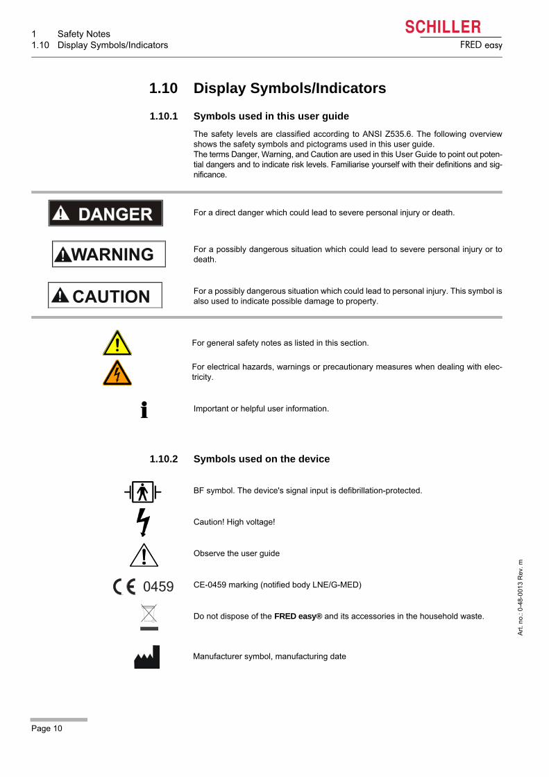
The safety levels are classified according to ANSI Z535.6. The following overviewshows the safety symbols and pictograms used in this user guide.The terms Danger, Warning, and Caution are used in this User Guide to point out poten-tial dangers and to indicate risk levels. Familiarise yourself with their definitions and sig-nificance.
1.10.2 Symbols used on the device
For a direct danger which could lead to severe personal injury or death.
For a possibly dangerous situation which could lead to severe personal injury or todeath.
For a possibly dangerous situation which could lead to personal injury. This symbol isalso used to indicate possible damage to property.
For general safety notes as listed in this section.
For electrical hazards, warnings or precautionary measures when dealing with elec-tricity.
Important or helpful user information.
BF symbol. The device's signal input is defibrillation-protected.
Caution! High voltage!
Observe the user guide
CE-0459 marking (notified body LNE/G-MED)
Do not dispose of the FRED easy® and its accessories in the household waste.
Manufacturer symbol, manufacturing date

Page 11
Safety Notes 1User Guide Display Symbols/Indicators 1.10
Art
. no
.: 0
-48
-001
3 R
ev.
m
FRED easy
1.10.3 Symbols used on the battery
The battery is recyclable
Do not recharge
Do not short-circuit
Do not incinerate
Do not cut
Do not crush
Battery storage:
– unlimited storage duration between +15°C and +25°C (within the limit of thespecified expiry date),
– max. 48 hours between +25 °C and +60 °C as well as between +15 °C and 0 °C.
Battery must not be disposed of in the household waste.
Observe the user guide
Battery expiry date
1 Safety Notes1.10 Display Symbols/Indicators
Page 12
Art
. no
.: 0
-48
-001
3 R
ev.
m
FRED easy
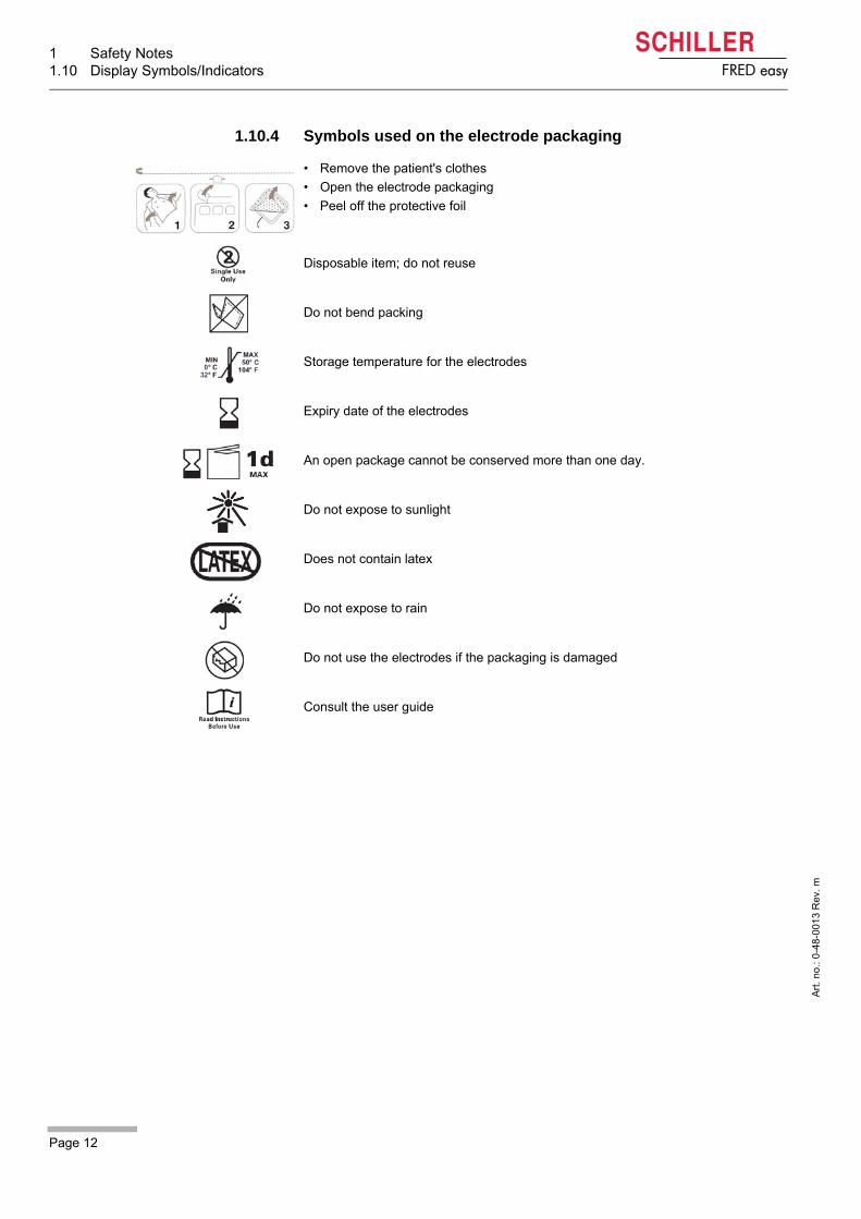
1.10.4 Symbols used on the electrode packaging
• Remove the patient's clothes
• Open the electrode packaging
• Peel off the protective foil
Disposable item; do not reuse
Do not bend packing
Storage temperature for the electrodes
Expiry date of the electrodes
An open package cannot be conserved more than one day.
Do not expose to sunlight
Does not contain latex
Do not expose to rain
Do not use the electrodes if the packaging is damaged
Consult the user guide
Page 13
Components and Operation 2User Guide General Information 2.1
Art
. no
.: 0
-48
-001
3 R
ev.
m
FRED easy
2 Components and Opera-tion
2.1 General Information
FRED easy® is an automated external defibrillator (AED).
AEDs are semi-automatic defibrillators or fully automatic defibrillators to be used bynon-physicians.
FRED easy® is available as a semi- or fully automatic defibrillator.
The regulations governing the use and training requirements for AEDs such asFRED easy® differ from country to country. The laws and regulations for the use ofautomatic defibrillators need to be strictly observed.
Typical sites of operation for a FRED easy® are much-frequented places such as:
– airports– train stations– shopping centres– public swimming pools– sport centres– public institutions
Local laws and regulations regarding the use of an AED differs from country to coun-try. While some countries allow laypersons to use AEDs without any special training,other countries restrict the use of AEDs to EMTs or First Responders after they haveundergone special training. For training purposes, SCHILLER offers the FRED easy® TRAINER.
Biocompatibility
The parts of the product described in this user guide, including all accessories, thatcome in contact with the patient during the intended use, fulfil the biocompatibility re-quirements of the applicable standards. If you have any questions in this matter,please contact SCHILLER.

2 Components and Operation2.2 Design
Page 14
Art
. no
.: 0
-48
-001
3 R
ev.
m
FRED easy
2.2 Design
Defibrillator FRED easy® is a defibrillator featuring the biphasic pulsed defibrillation impulse,Multipulse Biowave®. The patient is defibrillated using disposable electrodes. TheECG signal is analysed using the same electrodes. Moreover, the user is guided with acoustic and written instructions (display/loud-speaker). The device recognises the connected electrodes (adult or children elec-trodes) and selects the defibrillation energy accordingly.
Metronome When the "metronome" is activated, the FRED easy® sets a configurable pace for thecardiopulmonary resuscitation (CPR).
Data memory The device is equipped with a memory card (SD card). During the intervention, datacan therefore be saved, including the analysed ECG data, ambient noise and events(see 5.1 SD card version, 5.2 Ethernet version and 5.3 Online version).
Data transmission The FRED easy® SD card version features a removable SD memory card, facilitatingdata transmission to other devices. For the Ethernet and Online versions, data trans-mission is performed via Ethernet network (for these device versions, the memorycard cannot be removed).
Power supply (standard) The device is operated with a non rechargeable, disposable lithium battery. The bat-tery capacity is sufficient for:
– 180 shocks at maximum energy (if the self-test is performed weekly), or,– 3.75 hours operating (alternately 30 minutes ON and 30 minutes OFF).
Power supply (option) A rechargeable NiCd battery is available as option. The capacity of a new and fullycharged battery is sufficient for:
– 45 shocks at maximum energy, or– 40 min operating
Page 15
Components and Operation 2User Guide Design 2.2
Art
. no
.: 0
-48
-001
3 R
ev.
m
FRED easy
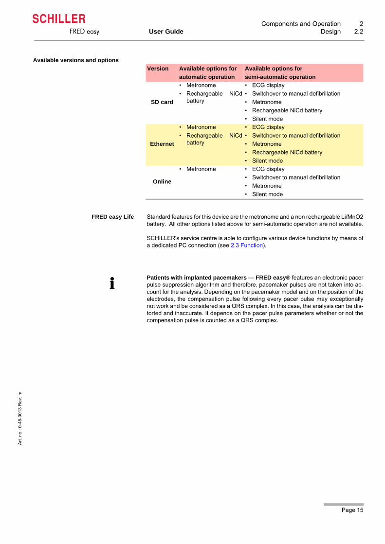
Available versions and options
FRED easy Life Standard features for this device are the metronome and a non rechargeable Li/MnO2battery. All other options listed above for semi-automatic operation are not available.
SCHILLER's service centre is able to configure various device functions by means ofa dedicated PC connection (see 2.3 Function).
Version Available options for
automatic operation
Available options for
semi-automatic operation
SD card
• Metronome
• Rechargeable NiCdbattery
• ECG display
• Switchover to manual defibrillation
• Metronome
• Rechargeable NiCd battery
• Silent mode
Ethernet
• Metronome
• Rechargeable NiCdbattery
• ECG display
• Switchover to manual defibrillation
• Metronome
• Rechargeable NiCd battery
• Silent mode
Online
• Metronome • ECG display
• Switchover to manual defibrillation
• Metronome
• Silent mode
Patients with implanted pacemakers — FRED easy® features an electronic pacerpulse suppression algorithm and therefore, pacemaker pulses are not taken into ac-count for the analysis. Depending on the pacemaker model and on the position of theelectrodes, the compensation pulse following every pacer pulse may exceptionallynot work and be considered as a QRS complex. In this case, the analysis can be dis-torted and inaccurate. It depends on the pacer pulse parameters whether or not thecompensation pulse is counted as a QRS complex.
2 Components and Operation2.3 Function
Page 16
Art
. no
.: 0
-48
-001
3 R
ev.
m
FRED easy
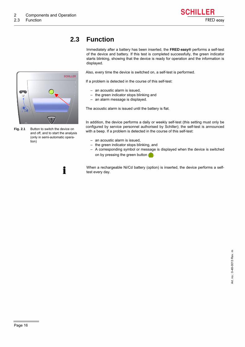
2.3 Function
Immediately after a battery has been inserted, the FRED easy® performs a self-testof the device and battery. If this test is completed successfully, the green indicatorstarts blinking, showing that the device is ready for operation and the information isdisplayed.
Also, every time the device is switched on, a self-test is performed.
If a problem is detected in the course of this self-test:
– an acoustic alarm is issued,– the green indicator stops blinking and– an alarm message is displayed.
The acoustic alarm is issued until the battery is flat.
In addition, the device performs a daily or weekly self-test (this setting must only beconfigured by service personnel authorised by Schiller); the self-test is announcedwith a beep. If a problem is detected in the course of this self-test:
– an acoustic alarm is issued,– the green indicator stops blinking, and– A corresponding symbol or message is displayed when the device is switched
on by pressing the green button .
Fig. 2.1 Button to switch the device on and off, and to start the analysis (only in semi-automatic opera-tion)
When a rechargeable Ni/Cd battery (option) is inserted, the device performs a self-test every day.

Page 17
Components and Operation 2User Guide Function 2.3
Art
. no
.: 0
-48
-001
3 R
ev.
m
FRED easy
2.3.1 Overview on the configurable settings
SCHILLER's service centre can configure the following parameters:
Important!
The “FRED CO” software is only available to service centres authorised by Schil-
ler. Modifications that can be made via "FRED CO" are only performed if requested
by the customer, or if required by legal requirements.
These modifications need to be registered in the device documentation as wellas communicated to all users.
Configurable parameters (by means of FREDCO®)
• Volume of language output
• Energy level for 1st, 2nd and 3rd shock (separate settings for adults and children)
• Manual or automatic start of the ECG signal analysis (only in semi-automatic op-eration)
• Activation/deactivation of the 16.7 Hz filter
• aSound recording Yes/No
a. Sound recording — The owner needs to inform users that the devicerecords ambient noise during interventions.
• Number of chest compressions for children (15 or 30)
• Self-test frequency (daily or weekly)
• Entering the device name
• Choice between "continuous chest compressions" or "alterning chest compres-sions/breathes" during CPR cycles
• Time and date On
• Update the software/change the device language
2 Components and Operation2.4 Operating and Display Elements
Page 18
Art
. no
.: 0
-48
-001
3 R
ev.
m
FRED easy
2.4 Operating and Display Elements
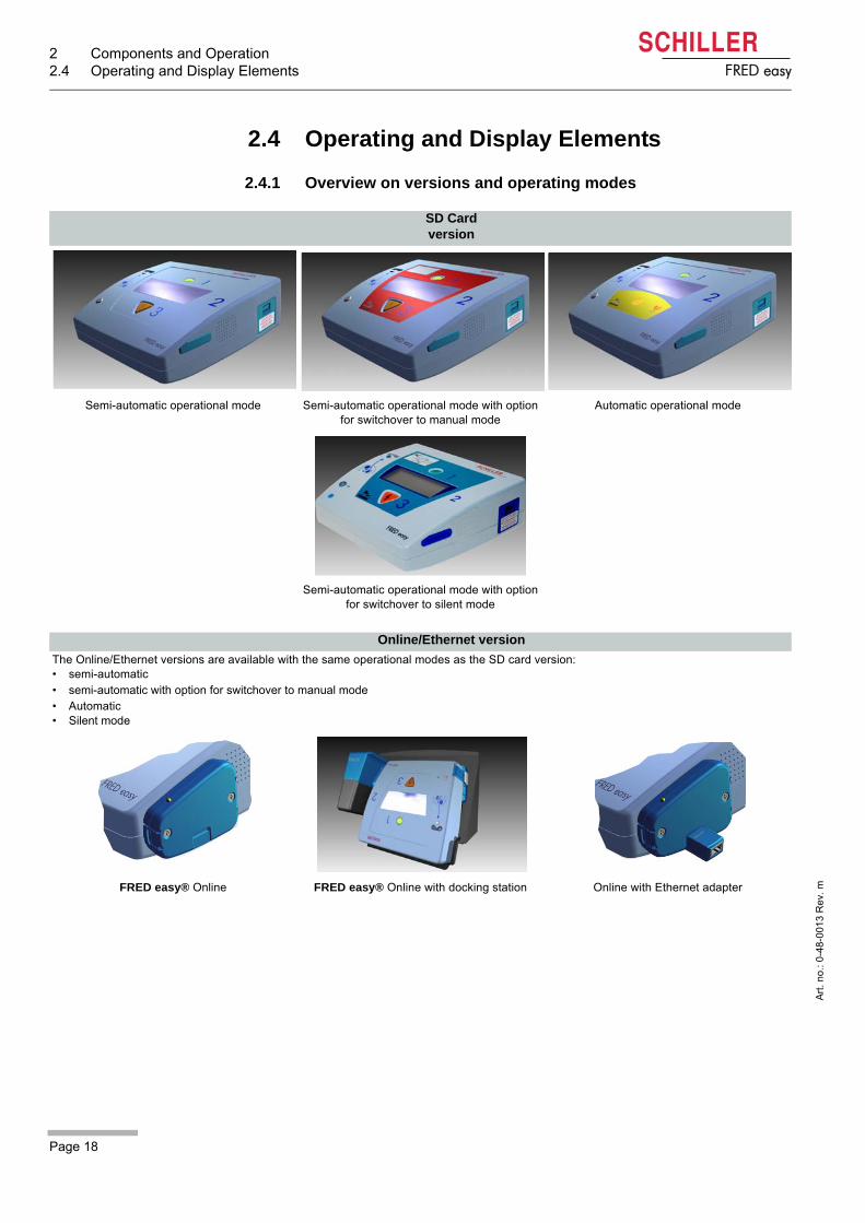
2.4.1 Overview on versions and operating modes
SD Card version
Semi-automatic operational mode Semi-automatic operational mode with option for switchover to manual mode
Automatic operational mode
Semi-automatic operational mode with option for switchover to silent mode
Online/Ethernet version
The Online/Ethernet versions are available with the same operational modes as the SD card version:• semi-automatic• semi-automatic with option for switchover to manual mode• Automatic• Silent mode
FRED easy® Online FRED easy® Online with docking station Online with Ethernet adapter

Page 19
Components and Operation 2User Guide Operating and Display Elements 2.4
Art
. no
.: 0
-48
-001
3 R
ev.
m
FRED easy
FRED easy Life
FRED easy Life has got the same functions as the versions listed above; the only ex-ceptions are: different printing on the foil, not possible to switch to manual or silentmode.
SD card-Online-Ethernet version
SD card, semi-automatic operation Online/Ethernet SD card, automatic operation

2 Components and Operation2.4 Operating and Display Elements
Page 20
Art
. no
.: 0
-48
-001
3 R
ev.
m
FRED easy
2.4.2 Operation and display
The FRED easy® versions SD Card (removable memory card), ETHERNET (with Ether-net adaptor) and ONLINE (with docking station) only differ from each other in point 8.
Fig. 2.2 Green indicator blinking
(1) The green indicator is blinking if no problem was detected during the last self-test (see Fig. 2.2 Green indicator blinking).
(2) The yellow indicator is lit when the device has not detected an acceptable resist-ance between the electrodes (i.e. when the electrodes are not applied and/or theelectrode cable is not connected).
(3) Port for the adhesive pads.
(4) Display.
(5) The green button has got the following functions:
– Switch on the device (press for max. 1 second) – Switch the device off (press and hold for 3 seconds)– Start the analysis in semi-automatic mode (only press the button for 1 second!)
(6) Battery.
(7) Speaker.
(8) SD card slot.The Ethernet interface (8a) is used to connect the Ethernet adapter(Ethernet version) and to connect the device to the docking station (8b) (Onlineversion).
(9) Orange button to trigger the defibrillation shock (in semi-automatic mode on-
ly).
2
1
5
6
7
3
89
4
8a 8b

Page 21
Components and Operation 2User Guide Operating and Display Elements 2.4
Art
. no
.: 0
-48
-001
3 R
ev.
m
FRED easy
2.4.3 Display
Fig. 2.3 FRED easy® display
(1) Symbol display line.
(2) Text display lines. The written instructions issued by the FRED easy® are dis-played on these 3 lines.
2.4.4 Symbols used on the display
DO NOT TOUCH THE PATIENT
ANALYSING!
1
2
Number of shocks delivered since the device was turned on.
Sufficient battery capacity (see 3.1 Inserting the battery).
Low battery capacity (see 3.1 Inserting the battery).
SD card detected, percentage of memory used.
SD card not recognised (see 5.1 SD card version).
Adult pads detected.
Paediatric pads detected.
Time elapsed since device was turned on (minutes : seconds).

3 Initial operation3.1 Inserting the battery
Page 22
Art
. no
.: 0
-48
-001
3 R
ev.
m
FRED easy
3 Initial operation
3.1 Inserting the battery
Danger of explosion — The FRED easy® must not be used in areas where there is anydanger of explosion. Areas may be susceptible to explosion if flammable substances(gas), flammable anaesthetics, or products used to clean or disinfect the skin are used.Moreover, the defibrillator must not be used in an environment that is favourable to com-bustion. This is the case when ambient air contains more than 25% oxygen or nitrous ox-ide (laughing gas). Oxygenation in the vicinity of the defibrillation pads must be strictlyavoided. Less than 25% oxygen in the ambient air is considered safe. Dangerous, highoxygen concentrations can only occur in oxygen masks or in enclosed areas, such as hy-perbaric chambers.
Danger of explosion! The battery must not be exposed to high temperatures ordisposed of with household waste.
Do not expose the battery to chemicals that could dissolve ABS, polypropylene,polyvinyl chloride, nickel, mylar or steel.
Do not short-circuit, cut, destroy, burn or charge (Li/MnO2 battery) a battery.
Patient hazard! — Incorrect battery capacity indication
A new battery is initialised by the device when inserting it and is allocated to thisdevice. It must not be inserted in another device.
Replace the battery if the device indicates a battery problem. A defective batterymust not be used.
Turn off the device before removing the battery.
Patient hazard — Ensuring operational readiness!
Make sure that the device is always equipped with a sufficiently charged batteryand keep a spare battery on hand.
The expiration date of a new battery, stored in its original packaging at a temper-ature of 25°C, is indicated on its packaging. It must not be used beyond this date.
The battery must remained packed in its original plastic packaging (blister) dur-ing the entire storage time. The plastic packaging must only be removed whenthe battery is used.
Do not expose the FRED easy® to direct sunlight or to extreme hot or cold. Anambient temperature higher than 25°C has an adverse effect on the battery life.
Li/MnO2

Page 23
Initial operation 3User Guide Inserting the battery 3.1
Art
. no
.: 0
-48
-001
3 R
ev.
m
FRED easy
3.1.1 Switching device On and Off
Switching ON Press the green button for max. 1 second.
Switching OFF Press the green button and hold for 3 second.
• The device is normally operated with a non rechargeable lithium battery.
• Alternatively, a rechargeable NiCd battery can be used (see 6.3 RechargeableNiCd battery).
• Each time the device is turned on, it verifies that the battery is functioning proper-ly.
Equipment damage —
The connector in the battery compartment must only be used for maintenancepurposes.
Do not use rechargeable batteries to operate the FRED easy® TRAINER be-cause its voltage is not suitable for this device.
Do not use the lithium battery to power the FRED easy® TRAINER, because itsvoltage is not adapted to this device.
Insert the battery as indicated in the illustration on the left.
– Firmly press the battery into the battery compartment until it clicks into place.– As soon as the battery is inserted, the FRED easy® runs a self-test to check the
condition of the device and the battery.– After this self-test, the date, time and IP configuration for the FRED easy Ether-
net/Online can be set (see section 5.4.2 page 60).If this test does not reveal any problems, the green indicator starts blinking and theinformation is displayed.
Fig. 3.1 Inserting the battery
Forced shutdown procedure
If the device cannot be switched off via the above procedure, remove the battery andinserting again.

3 Initial operation3.2 Battery monitoring
Page 24
Art
. no
.: 0
-48
-001
3 R
ev.
m
FRED easy
3.2 Battery monitoring
3.2.1 Sufficient battery capacity
The FRED easy®symbol remains displayed on the screen for as long as the bat-tery capacity is "sufficient".
Fig. 3.2 Sufficient battery capacity
• The FRED easy® checks the capacity of the rechargeable NiCd battery or the lith-ium battery and warns the user when the battery is "low" or "depleted".
• The lithium battery ensures that the device stays fully operative (and performs theself-test) for several years (at a temperature between 15 °C and 25 °C), providedthat the device is not being used.
• Battery service life depends on device use and ambient conditions.
Whatever its remaining capacity, the battery must be replaced once the expira-tion date (indicated on the packaging) has been reached.
The old battery must be recycled in accordance with local regulations.
FRED easy® displays the symbol to indicate that the battery capacity is "suffi-cient".
DO NOT TOUCH THE PATIENT
ANALYSING!
Page 25
Initial operation 3User Guide Battery monitoring 3.2
Art
. no
.: 0
-48
-001
3 R
ev.
m
FRED easy
3.2.2 Low battery capacity during use
• Despite the acoustic and written warnings, the device can still be used as normaland is still able to perform defibrillations.
• Always switch off the device before removing the battery.
• The remaining battery capacity depends on the use and ambient conditions.
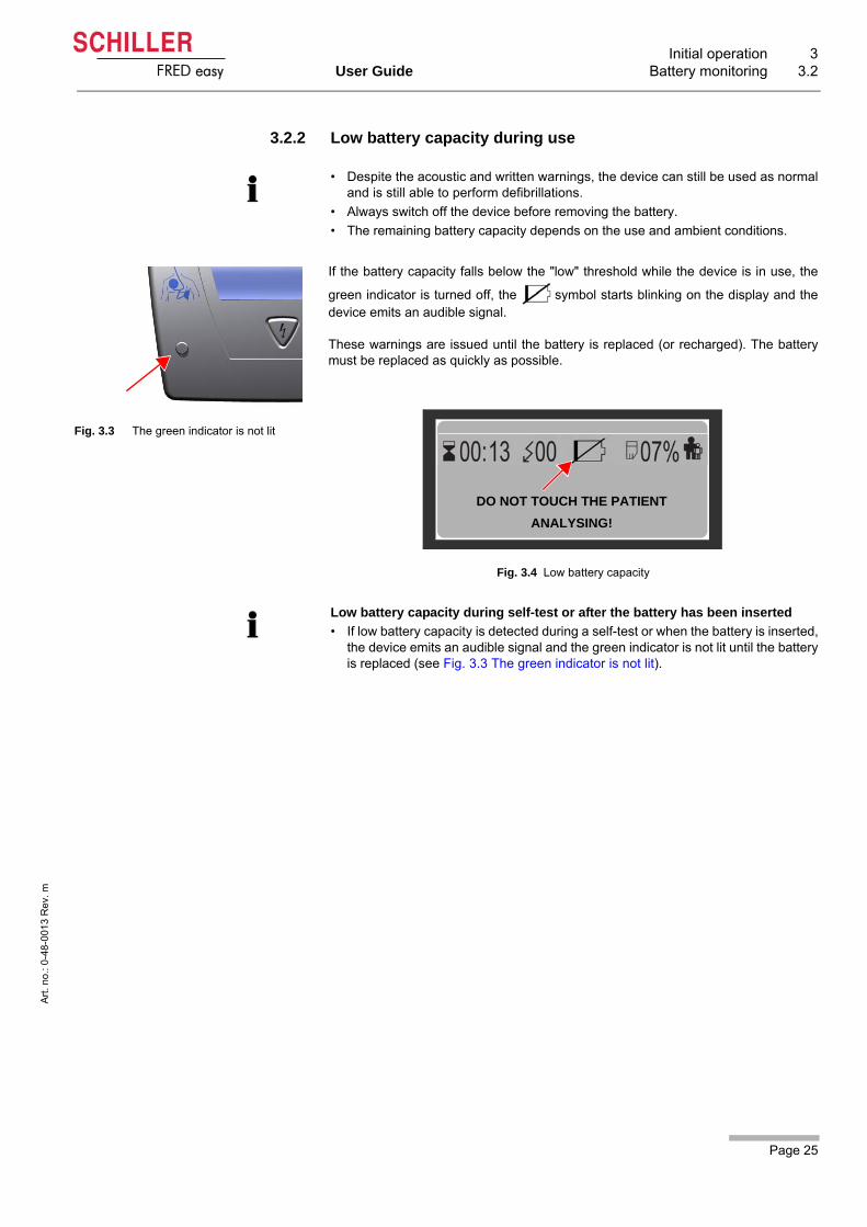
Fig. 3.3 The green indicator is not lit
If the battery capacity falls below the "low" threshold while the device is in use, the
green indicator is turned off, the symbol starts blinking on the display and thedevice emits an audible signal.
These warnings are issued until the battery is replaced (or recharged). The batterymust be replaced as quickly as possible.
Fig. 3.4 Low battery capacity
Low battery capacity during self-test or after the battery has been inserted
• If low battery capacity is detected during a self-test or when the battery is inserted,the device emits an audible signal and the green indicator is not lit until the batteryis replaced (see Fig. 3.3 The green indicator is not lit).
DO NOT TOUCH THE PATIENT
ANALYSING!

3 Initial operation3.2 Battery monitoring
Page 26
Art
. no
.: 0
-48
-001
3 R
ev.
m
FRED easy
3.2.3 Battery depleted during use, limited mode (CPR)
If a depleted battery is detected while the device is in use, a message is displayedprompting the user to replace the battery and to perform CPR. An audible signal isemitted and the indicator remains off until the battery is replaced (or charged).
The message stays displayed until the battery is replaced.
Patient hazard — Defibrillation is no longer possible if a depleted battery is detected.The battery needs to be replaced immediately.
REPLACE BATTERY
30 CHEST COMPRESSIONS THEN
2 RESCUE BREATHS
Depleted battery during self-test
• When a depleted battery has been detected, the green indicator is off and an au-dible signal is emitted.
• When the device is next switched on, a message is displayed, prompting the userto replace the battery and continue with CPR until the device is fully operationalagain.
Depleted battery after the battery has been inserted
• If a battery inserted in the device is identified as depleted, an audible signal is emit-ted, the green indicator is turned off and a message indicating that the battery mustbe replaced is displayed.
Green indicator is off

Page 27
Defibrillation 4User Guide Instructions and Safety Notes 4.1
Art
. no
.: 0
-48
-001
3 R
ev.
m
FRED easy
4 Defibrillation
4.1 Instructions and Safety Notes
4.1.1 Instructions
4.1.2 Safety notes for AED use
• FRED easy® is a high-voltage electrotherapy device. Only personnel authorised bylocal law are permitted to use these devices. Improper use can endanger life.
• Non medical personnel is only permitted to use an AED such as the FRED easy® iflocal law approves of this practice. Make sure that the FRED easy® is only accessi-ble to persons who are legally authorised to use an AED.
• The success of the defibrillation depends on the correct application of the defibril-lator but also on the heart's condition. It is the physician's responsibility to decideabout any additional measures (e.g. adrenaline).
• According to AHA/ERC guidelines, even children under 8 years may be defibrillat-ed.
• The electrodes should be applied in the anterior-anterior position. With infants, an-terior-posterior placement can be advised to prevent a short-circuit between thetwo defibrillation electrodes.
• A defibrillation can fail with certain disease patterns.
Before each use, the user must verify that the device operates reliably and is inproper working order. It is especially important to check that connection cablesare not damaged. Damaged cables and connectors must be replaced immedi-ately.
Changes, including concerning operational behaviour, affecting safety must beimmediately reported to the responsible.
Equipment damage! Sensors and devices that are not defibrillation-proof mustbe disconnected from the patient before a shock is triggered.
Shock hazard — for patients
In unfavorable situations, the possibility of ECG analysis errors should not bedismissed. The device must therefore only be used if the following symptoms arefound:
– not responsive,– no respiration,– no pulse.
If, in the course of treatment, a patient spontaneously regains consciousness, adefibrillation shock that may have been advised just before must not be deliv-ered.
4 Defibrillation4.1 Instructions and Safety Notes
Page 28
Art
. no
.: 0
-48
-001
3 R
ev.
m
FRED easy
Shock hazard — for user and assistants
Wear gloves when performing a defibrillation, if possible.
Position the patient flat on a firm, electrically insulated surface.
Make sure that there are no conductive connections between the patient andother persons during ECG analysis and defibrillation.
The patient must not come into contact with metal parts, e.g. a bed or stretcher,in order to prevent secondary contacts or paths for the defibrillation current thatcould endanger the assistants. For the same reason, do not position the patienton a wet surface (rain, swimming pool accidents).
Do not allow the defibrillation electrodes to come into contact with other elec-trodes or metal parts which are in contact with the patient.
The patient's chest must be dry because moisture can cause unwanted path-ways for the defibrillation current. For safety, wipe off flammable skin cleansingagents.
The user and all assistants must be briefed regarding the defibrillation procedure(preparation and execution). The assistants' tasks must be clearly defined.
• During ECG analysis:
– suspend CPR,– ensure that the patient lies as motionless as possible,– do not touch the patient, otherwise, artefacts may lead to incorrect analysis re-
sults.• Immediately prior to the shock:
– stop chest compressions and artificial respiration (CPR),– instruct bystanders to not touch the patient or conducting objects.
Risk of skin burns — for the patient
Due to the high currents, there is a risk of skin burns at the electrode applicationsite. This is why the electrodes must not be placed on or above:
– the sternum, – the clavicle or,– the nipples.
Risk of malfunction of implanted pacemaker!
Defibrillating a patient with an implanted pacemaker is likely to impair the pace-maker function or cause damage to the pacemaker. For this reason:
– defibrillation pads must not be positioned near the pacemaker,– have an external pacemaker at hand.
The pacemaker must be checked for proper functioning as soon as possible af-ter defibrillation.

Page 29
Defibrillation 4User Guide Defibrillation procedure 4.2
Art
. no
.: 0
-48
-001
3 R
ev.
m
FRED easy
4.2 Defibrillation procedure
The user is informed of each step by a voice prompt as well as a text instruction onthe display.
Both the voice prompts and text instructions can be issued as "long instructions" aswell as "short instructions".
The following procedure is applicable when "long instructions" have been config-ured.
Switch on the device and call the emergency medical service
Once the device is turned on (by pressing thre green button ), an instruction textreminds the user to call the emergency medical service.
Assess the patient's condition The device then prompts the user to assess the patient’s condition.
Preparing the patient Once you made sure that the patient does not show any signs of circulation, you areprompted to remove the clothes from the patient's upper body.
Contact your SCHILLER distributor for more information.
The device must only be used if the following symptoms are found:
– not responsive,– no respiration,– no pulse.
The patient’s chest may be shaved, if necessary.

4 Defibrillation4.2 Defibrillation procedure
Page 30
Art
. no
.: 0
-48
-001
3 R
ev.
m
FRED easy
Open the electrode packaging and connect the electrodes
Open the electrode packaging and connect the electrodes to the device (unless theelectrodes are pre-connected).
Applying the electrodes FRED easy® prompts the user to apply the electrodes on the patient’s chest.
• The yellow indicator is lit and the device repeats the instructions twice until theelectrodes are applied, or until the electrode connector is connected to the device,respectively, and the electrode-skin resistance (impedance) has reached an ac-ceptable level.
• After the second prompt to apply the electrodes, the device recommends to per-form a cardiopulmonary resuscitation cycle. The device will switch off if it has notdetected an acceptable impedance between the two electrodes after 5 minutes ofCPR.
Page 31
Defibrillation 4User Guide Defibrillation procedure 4.2
Art
. no
.: 0
-48
-001
3 R
ev.
m
FRED easy
ECG analysis Before each analysis, the device informs the user that the patient must not betouched.
In semi-automatic mode, the device prompts the user to start an ECG analysis by
pressing the green button .
In automatic as well as semi-automatic mode (with automatic analysis activated), theFRED easy® informs the user that the analysis is going to be performed. The ECGanalysis is started without any intervention by the user.
The analysis takes approximately 10 seconds.
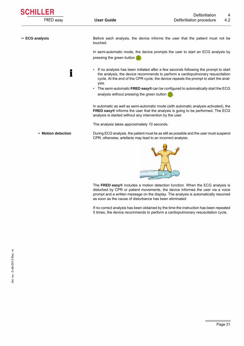
• Motion detection During ECG analysis, the patient must lie as still as possible and the user must suspendCPR; otherwise, artefacts may lead to an incorrect analysis.
The FRED easy® includes a motion detection function. When the ECG analysis isdisturbed by CPR or patient movements, the device informes the user via a voiceprompt and a written message on the display. The analysis is automatically resumedas soon as the cause of disturbance has been eliminated.
If no correct analysis has been obtained by the time the instruction has been repeated5 times, the device recommends to perform a cardiopulmonary resuscitation cycle.
• If no analysis has been initiated after a few seconds following the prompt to startthe analysis, the device recommends to perform a cardiopulmonary resuscitationcycle. At the end of the CPR cycle, the device repeats the prompt to start the anal-ysis.
• The semi-automatic FRED easy® can be configured to automatically start the ECG
analysis without pressing the green button .
4 Defibrillation4.2 Defibrillation procedure
Page 32
Art
. no
.: 0
-48
-001
3 R
ev.
m
FRED easy
Shock advised The device has detected a shockable rhythm.
Before each shock delivery, the device warns the user not to touch the patient.
If the analysis algorithm detects a shockable rhythm, the device will automaticallycharge the required defibrillation energy. Once the energy is charged, the user is
prompted to deliver the shock by pressing the orange button (only in semi-auto-
matic mode).
In automatic mode, the device alerts the user that the shock will be delivered, andthen delivers the shock without user intervention.
Then the FRED easy® informs the user via spoken and written message that theshock has been delivered.
Shockable conditions include:
– ventricular fibrillation or– ventricular tachycardia with a rate higher than 150 bpm.
• Each shock is followed by CPR
The FRED easy® informs the user that the patient can be touched again and promptsthe user to perform a cardiopulmonary resuscitation cycle.
According to the configuration of the device, a CPR cycle consists of:
– performing chest compressions during the set period of time, or – performing alternatively 30 chest compressions and 2 breathes during the set
period of time. Before each CPR cycle, the device informs the user that the patient can be touched.
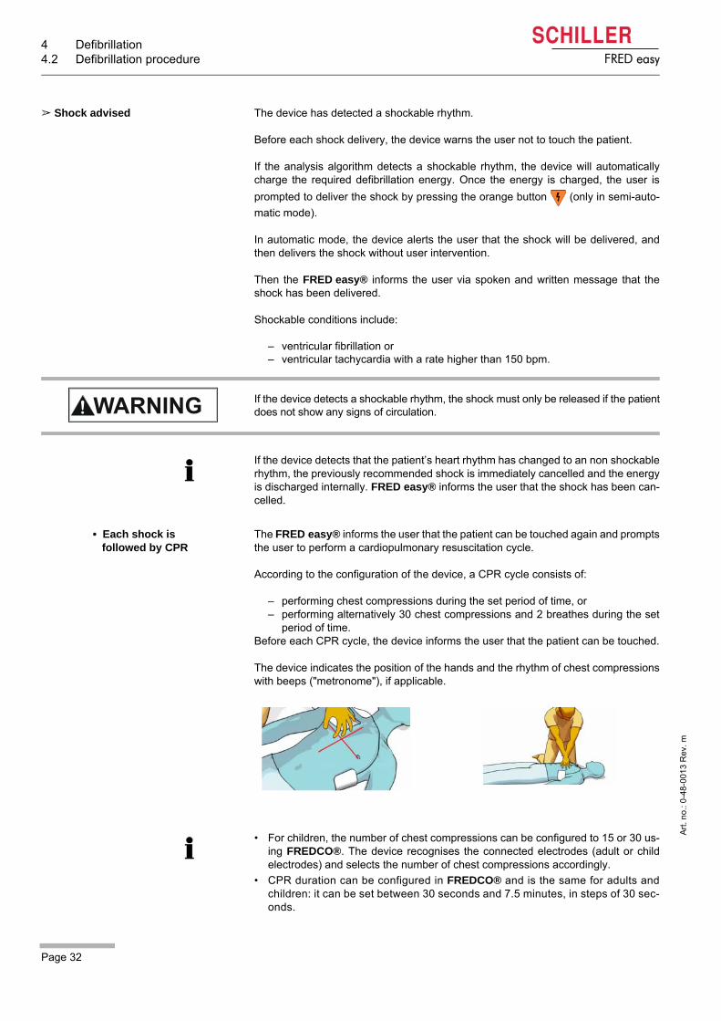
The device indicates the position of the hands and the rhythm of chest compressionswith beeps ("metronome"), if applicable.
If the device detects a shockable rhythm, the shock must only be released if the patientdoes not show any signs of circulation.
If the device detects that the patient’s heart rhythm has changed to an non shockablerhythm, the previously recommended shock is immediately cancelled and the energyis discharged internally. FRED easy® informs the user that the shock has been can-celled.
• For children, the number of chest compressions can be configured to 15 or 30 us-ing FREDCO®. The device recognises the connected electrodes (adult or childelectrodes) and selects the number of chest compressions accordingly.
• CPR duration can be configured in FREDCO® and is the same for adults andchildren: it can be set between 30 seconds and 7.5 minutes, in steps of 30 sec-onds.

Page 33
Defibrillation 4User Guide Defibrillation procedure 4.2
Art
. no
.: 0
-48
-001
3 R
ev.
m
FRED easy
• Followed by a new analysis
Once the CPR cycle has been finished, the device prompts the user to run a new ECGanalysis (in semi-automatic mode).
In automatic as well as semi-automatic mode (with automatic analysis activated), thisnew analysis starts without any intervention required of the user.
If the device again detects a shockable rhythm, it will automatically charge the defi-brillation energy necessary for the 2nd or 3rd shock. For all subsequent shocks, the
energy remains the same for the 3rd shock.
The energy levels can be configured by SCHILLER's customer service (see8 Technical Data).
• Successful shock followed by CPR
After a successful shock (no further shocks advised by the ECG analysis),FRED easy® prompts the user to perform CPR.
No shock advised The device has not detected a shockable rhythm.
If the analysis algorithm does not detect a shockable rhythm, the FRED easy® in-forms the user that no shock is necessary and prompts him or her to perform CPR.
Finishing the therapy Once the therapy has been finished, the defibrillation pads must be removed from thepatient's chest and disconnected from the device. The defibrillation pads are not re-usable.
The device can then be switched off by pressing and holding the green button for3 seconds.
According to the configuration of the device, the user may be asked to check the pres-ence of pulse before performing the CPR cycle.
4 Defibrillation4.3 Applying the adhesive electrodes
Page 34
Art
. no
.: 0
-48
-001
3 R
ev.
m
FRED easy
4.3 Applying the adhesive electrodes
4.3.1 General information
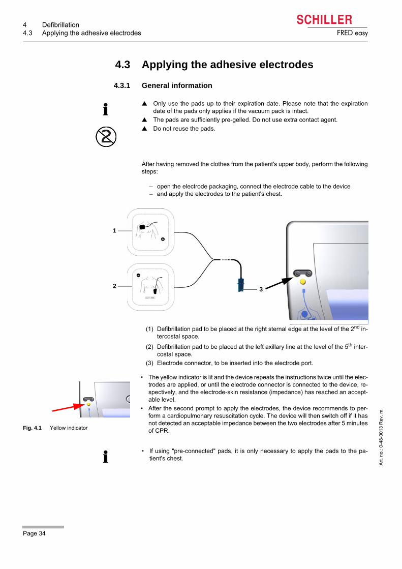
After having removed the clothes from the patient's upper body, perform the followingsteps:
– open the electrode packaging, connect the electrode cable to the device– and apply the electrodes to the patient's chest.
(1) Defibrillation pad to be placed at the right sternal edge at the level of the 2nd in-tercostal space.
(2) Defibrillation pad to be placed at the left axillary line at the level of the 5th inter-costal space.
(3) Electrode connector, to be inserted into the electrode port.
Only use the pads up to their expiration date. Please note that the expirationdate of the pads only applies if the vacuum pack is intact.
The pads are sufficiently pre-gelled. Do not use extra contact agent.
Do not reuse the pads.
1
2 3
Fig. 4.1 Yellow indicator
• The yellow indicator is lit and the device repeats the instructions twice until the elec-trodes are applied, or until the electrode connector is connected to the device, re-spectively, and the electrode-skin resistance (impedance) has reached an accept-able level.
• After the second prompt to apply the electrodes, the device recommends to per-form a cardiopulmonary resuscitation cycle. The device will then switch off if it hasnot detected an acceptable impedance between the two electrodes after 5 minutesof CPR.
• If using "pre-connected" pads, it is only necessary to apply the pads to the pa-tient's chest.
Page 35
Defibrillation 4User Guide Applying the adhesive electrodes 4.3
Art
. no
.: 0
-48
-001
3 R
ev.
m
FRED easy
4.3.2 Apply the adhesive electrodes and connect them to the device
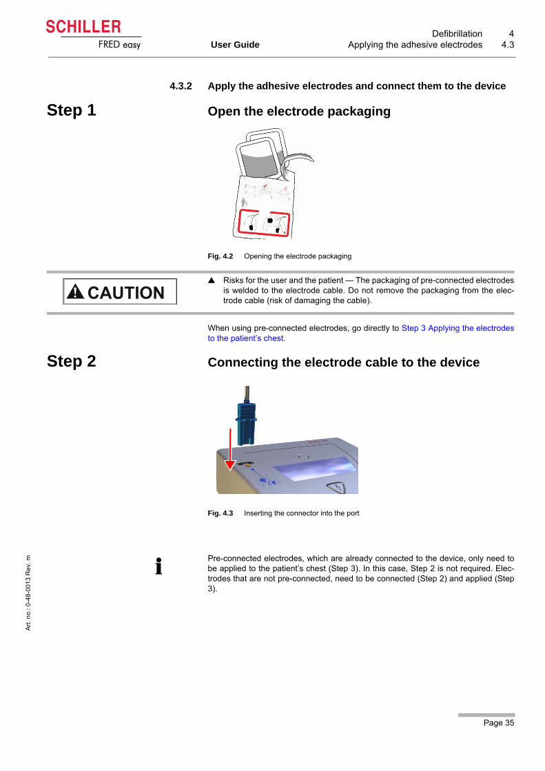
Step 1 Open the electrode packaging
Fig. 4.2 Opening the electrode packaging
When using pre-connected electrodes, go directly to Step 3 Applying the electrodesto the patient’s chest.
Step 2 Connecting the electrode cable to the device
Fig. 4.3 Inserting the connector into the port
Risks for the user and the patient — The packaging of pre-connected electrodesis welded to the electrode cable. Do not remove the packaging from the elec-trode cable (risk of damaging the cable).
Pre-connected electrodes, which are already connected to the device, only need tobe applied to the patient’s chest (Step 3). In this case, Step 2 is not required. Elec-trodes that are not pre-connected, need to be connected (Step 2) and applied (Step3).

4 Defibrillation4.3 Applying the adhesive electrodes
Page 36
Art
. no
.: 0
-48
-001
3 R
ev.
m
FRED easy
Step 3 Applying the electrodes to the patient’s chest
Adult and paediatric electrodes
Large electrodes The large adult electrodes with a surface area of 80 cm² are used for adults and chil-dren weighing 25 kg or more.
Small electrodes The small paediatric electrodes with a surface area of 42 cm² are used for children
weighing less than 25 kg (younger than 8 years of age).
Risk of skin burns/equipment damage — Do not apply the defibrillation pads ontop of:
– the sternum or clavicle,– the nipples,– an implanted pacemaker or defibrillator device.
Skin covered in sea water, sand, sunscreen, or skin or body care products mayimpair electrode contact or cause the electrodes to become disconnected.
Fig. 4.4 Electrode application sites
Fig. 4.5 Electrode application sites for children
Electrode placement is the same for adults and for children (see Fig. 4.5 Electrodeapplication sites for children). The device automatically distinguishes between adultelectrodes and paediatric electrodes.
1. Before applying the adhesive electrodes, verify that the application sites on thepatient’s chest are clean and dry.
2. The skin must be cleaned by rubbing the application points vigorously with a drycloth. Do not use alcohol or alcohol wipes. This could significantly increase thecontact impedance between the electrodes and the skin.
3. Carefully shave the application sites if the patient’s chest is hairy.
4. Apply the positive electrode at the right sternal edge at the level of the 2nd inter-costal space. Do not apply the positive electrode on top of the clavicle (unevensurface).
5. Apply the negative electrode on the left axillary line at the level of the 5th intercos-tal space.
The electrodes must have good contact with the patient’s skin. Air bubbles under theelectrodes must be avoided. To avoid air bubbles, place one edge of the adhesiveelectrode to the patient's chest, then gradually smooth it out toward the other edge toremove any air.
6. Place the electrodes on the patient's chest so that the connections point to eitherside of the patient in order not to hinder CPR.
Fig. 4.6 Application sites for small chil-dren
When defibrillating small children, it is recommended to choose the anterior-posteriorposition to avoid short-circuiting the electrodes.
Page 37
Defibrillation 4User Guide Applying the adhesive electrodes 4.3
Art
. no
.: 0
-48
-001
3 R
ev.
m
FRED easy
4.3.3 Checking the electrodes
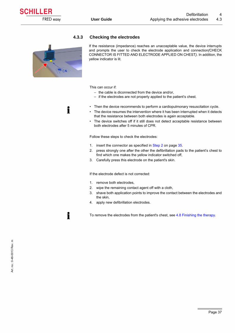
This can occur if:
– the cable is diconnected from the device and/or, – if the electrodes are not properly applied to the patient’s chest.
Follow these steps to check the electrodes:
1. insert the connector as specified in Step 2 on page 35.
2. press strongly one after the other the defibrillation pads to the patient’s chest tofind which one makes the yellow indicator switched off,
3. Carefully press this electrode on the patient's skin.
If the electrode defect is not corrected:
1. remove both electrodes,
2. wipe the remaining contact agent off with a cloth,
3. shave both application points to improve the contact between the electrodes andthe skin,
4. apply new defibrillation electrodes.
If the resistance (impedance) reaches an unacceptable value, the device interruptsand prompts the user to check the electrode application and connection(CHECKCONNECTOR IS FITTED AND ELECTRODE APPLIED ON CHEST). In addition, theyellow indicator is lit.
• Then the device recommends to perform a cardiopulmonary resuscitation cycle.
• The device resumes the intervention where it has been interrupted when it detectsthat the resistance between both electrodes is again acceptable.
• The device switches off if it still does not detect acceptable resistance betweenboth electrodes after 5 minutes of CPR.
To remove the electrodes from the patient's chest, see 4.8 Finishing the therapy.

4 Defibrillation4.4 Semi-automatic defibrillation
Page 38
Art
. no
.: 0
-48
-001
3 R
ev.
m
FRED easy
4.4 Semi-automatic defibrillation
Semi-Automatic Defibrillation
Step 1 Switching on and preparing the device
Step 2 Analysing the ECG signal
5. Briefly press the green button (max. 1 second). A message prompts the userto stay clear of the patient.
Patient hazard — The guidelines given in 4.1 Instructions and Safety Notes must beobserved.
Fig. 4.7 Button to turn the device on/off and to start analysis
1. Briefly press the green button (max. 1 second) to switch on the device.
2. Assess the patient's condition (see 4.2 Defibrillation procedure).
3. Connect the electrode cable to the device (see 4.3 Applying the adhesive elec-trodes).
4. Apply the defibrillation electrodes to the patient's chest (see 4.3 Applying the ad-hesive electrodes).
Briefly press the green button (max. 1 second) to start the analysis. Otherwise, the de-vice will switch off.
• The semi-automatic version of the FRED easy® can be configured so that the ECGanalysis is initiated automatically. In this case, the device prompts the user to con-nect the electrodes and then automatically runs the analysis without any interven-tion by the user.
• If the device detects ventricular fibrillation or ventricular tachycardia with a heartrate exceeding 150 bpm, Step 3 Shock delivery follows; otherwise, continue withStep 4, Performing cardiopulmonary resuscitation.

Page 39
Defibrillation 4User Guide Semi-automatic defibrillation 4.4
Art
. no
.: 0
-48
-001
3 R
ev.
m
FRED easy
Step 3 Shock delivery
6. Deliver the shock by pressing the button .
After the shock delivery, proceed with Step 4 Performing cardiopulmonary resus-citation.
Step 4 Performing cardiopulmonary resuscitation
7. Perform a CPR cycle. According to the configuration of the device, a CPR cycleconsists of:
– performing chest compressions for the set period of time, or– alternately performing 30 chest compressions and 2 breathes for the set period
of time.After the CPR cycle, the device continues with Step 2 Analysing the ECG signal.
Finishing the therapy See 4.8 Finishing the therapy.
When the energy is charged, the user is prompted to trigger the shock by pressing the
lit orange button.
Shock hazard!
Do not, under any circumstances, touch the patient during shock delivery.
Make sure that the patient does not touch any conducting objects.Fig. 4.8 Button to deliver the shock
If the device is configured to start the ECG analysis automatically, the device will notrequire any action from the user to run the ECG analysis.

4 Defibrillation4.5 Automatic defibrillation
Page 40
Art
. no
.: 0
-48
-001
3 R
ev.
m
FRED easy
4.5 Automatic defibrillation
4.5.1 Functional description of automatic AEDs
4.5.2 Safety notes for automatic defibrillation
The laws and regulations for the use of automatic defibrillators differ from country tocountry. While some countries allow laypersons to use automatic defibrillators withoutany special training, other countries restrict the use of AEDs to EMTs or First Re-sponders who have undergone special training.
Fig. 4.9 FRED easy® Automatic
This device delivers defibrillation shocks automatically, i.e. there is no need to startthe analysis or trigger the shock.
Voice and text prompts displayed on the screen keep the user informed regarding thetherapy.
If a shock is advised, the energy is automatically charged. A countdown accompanies thelast 3 seconds before the shock is delivered.
Risks for patient, users and assistants!
Once the device has been switched on with the green button and the electrodeshave been applied, the ECG analysis is started automatically and a shock is deliveredautomatically if a shockable rhythm is present. The user is informed of an ongoinganalysis or shock release via written and acoustic messages.
Touching or transporting the patient during analysis may lead to an incorrectanalysis. Analysis results are only valid if the patient remained unconscious dur-ing the entire analysis and was not touched.
For this reason, chest compressions and artificial respiration must be suspendedduring the analysis.
The patient must not be touched or transported (e.g. stretcher) during analysisand shock delivery.
The notes in section 4.1 Instructions and Safety Notes page 27 must be ob-served.
Page 41
Defibrillation 4User Guide Automatic defibrillation 4.5
Art
. no
.: 0
-48
-001
3 R
ev.
m
FRED easy
Automatic defibrillation
Step 1 Switching on and preparing the device
Step 2 Automatic ECG analysis
The analysis is automatically triggered, without user intervention. A message promptsthe user not to touch the patient.
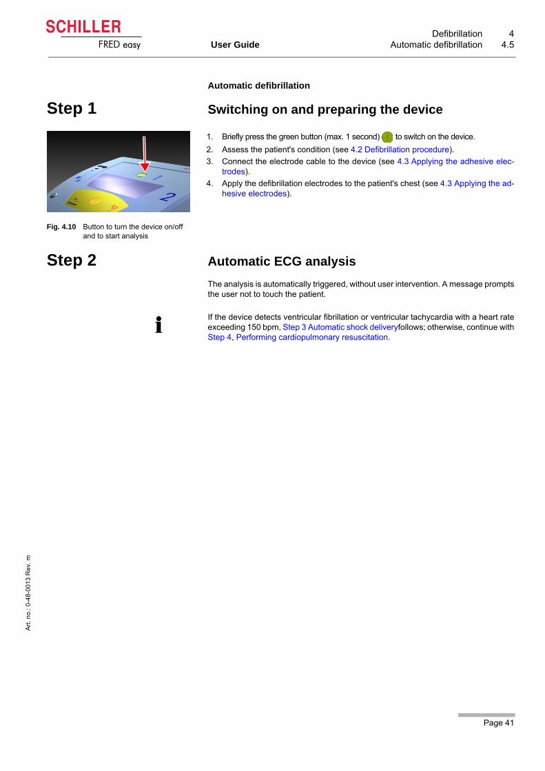
Fig. 4.10 Button to turn the device on/off and to start analysis
1. Briefly press the green button (max. 1 second) to switch on the device.
2. Assess the patient's condition (see 4.2 Defibrillation procedure).
3. Connect the electrode cable to the device (see 4.3 Applying the adhesive elec-trodes).
4. Apply the defibrillation electrodes to the patient's chest (see 4.3 Applying the ad-hesive electrodes).
If the device detects ventricular fibrillation or ventricular tachycardia with a heart rateexceeding 150 bpm, Step 3 Automatic shock deliveryfollows; otherwise, continue withStep 4, Performing cardiopulmonary resuscitation.

4 Defibrillation4.5 Automatic defibrillation
Page 42
Art
. no
.: 0
-48
-001
3 R
ev.
m
FRED easy
Step 3 Automatic shock delivery
As soon as the energy charge is completed, the device automatically delivers theshock, without user intervention. A countdown is displayed on the screen and the or-
ange button blinks until the shock is delivered.
After the shock delivery, proceed with Step 4 Performing cardiopulmonary resuscita-tion.
Step 4 Performing cardiopulmonary resuscitation
5. Perform a CPR cycle. According to the configuration of the device, a CPR cycleconsists of:
– performing chest compressions for the period of time configured, or– performing alternatively 30 chest compressions and 2 breathes during the peri-
od of time configured.After the CPR cycle, the device proceeds with Step 2 Automatic ECG analysis.
Finishing the therapy
See 4.8 Finishing the therapy.
Shock hazard!
Do not, under any circumstances, touch the patient during shock delivery.
Make sure that the patient does not touch any conducting objects.

Page 43
Defibrillation 4User Guide Manual Defibrillation (option) 4.6
Art
. no
.: 0
-48
-001
3 R
ev.
m
FRED easy
4.6 Manual Defibrillation (option)
The option to switchover to manual mode is only available for the semi-automatic ver-sion of FRED easy®.
The FRED easy® with manual mode is indicated by a red foil on the casing. If the userdoes not activate the manual mode after switchon, the unit remains in semi-automaticmode. The defibrillation will then be carried out as described in section 4.4.
Even though non physicians are legally authorised to use semi-automatic defibrilla-tors, the FRED easy® must not be used by non physicians when it is in manual mode.
In some countries, however, the option to switch from semi-automatic mode to manualmode is made available to EMTs and medical personnel (non physicians). In this sit-uation, individual protocols must be determined in cooperation with the EMTs. Theseprotocols must be based on AHA or ERC protocols or on the regulations of the countryin question. Furthermore, the emergency service is required to ensure that the proce-dures established are observed and that the staff is trained accordingly.
Fig. 4.11 FRED easy® semi-automatic with manual option
• The device cannot be turned on directly in manual mode.
• It is not possible to switch to manual mode while the device is powering on. There-
fore, do not press the orange button while the device is powering on.
• It is not possible to switch the defibrillator to manual mode while a defibrillation pro-cedure is in progress (analysis, charging, shock delivery).
• The patient's ECG signal is automatically displayed when the FRED easy® isswitched to manual mode.
4 Defibrillation4.6 Manual Defibrillation (option)
Page 44
Art
. no
.: 0
-48
-001
3 R
ev.
m
FRED easy
4.6.1 Manual defibrillation - description
The user is informed of each step by a voice prompt as well as text instructions on thedisplay.
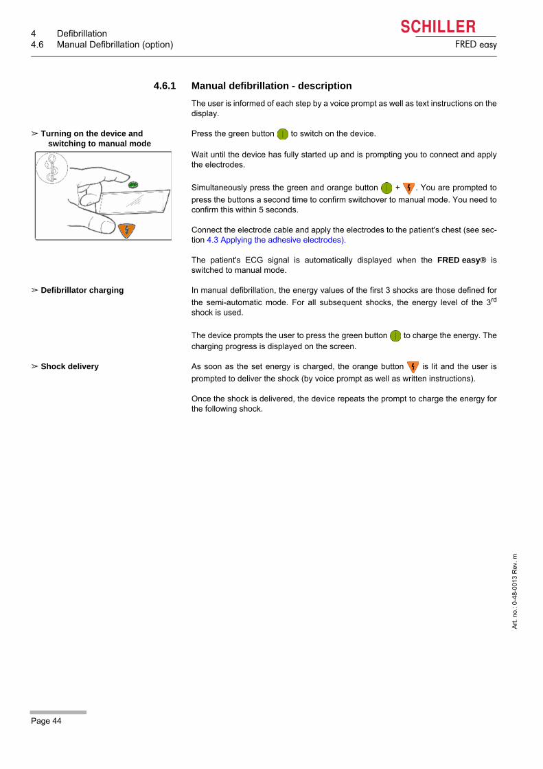
Turning on the device and switching to manual mode
Press the green button to switch on the device.
Wait until the device has fully started up and is prompting you to connect and applythe electrodes.
Simultaneously press the green and orange button + . You are prompted to
press the buttons a second time to confirm switchover to manual mode. You need toconfirm this within 5 seconds.
Connect the electrode cable and apply the electrodes to the patient's chest (see sec-tion 4.3 Applying the adhesive electrodes).
The patient's ECG signal is automatically displayed when the FRED easy® isswitched to manual mode.
Defibrillator charging In manual defibrillation, the energy values of the first 3 shocks are those defined for
the semi-automatic mode. For all subsequent shocks, the energy level of the 3rd
shock is used.
The device prompts the user to press the green button to charge the energy. Thecharging progress is displayed on the screen.
Shock delivery As soon as the set energy is charged, the orange button is lit and the user is
prompted to deliver the shock (by voice prompt as well as written instructions).
Once the shock is delivered, the device repeats the prompt to charge the energy forthe following shock.

Page 45
Defibrillation 4User Guide Manual Defibrillation (option) 4.6
Art
. no
.: 0
-48
-001
3 R
ev.
m
FRED easy
4.6.2 Manual defibrillation procedure
Step 1 Switching on and preparing the device
1. Briefly press the green button (max. 1 second) to switch on the device.
2. Switch to manual mode by simultaneously pressing the green and orange buttons
+ . Confirm the switching by simultaneously pressing these same buttons
a second time.
3. Connect the electrode cable to the device.
4. Apply the electrodes on the patient's upper body (see 4.3 Applying the adhesiveelectrodes).
Step 2 Charging the energy
5. Briefly press the green button (max. 1 second).
Patient hazard — Only a physician is allowed to enable manual mode. Observe theinstructions given in section 4.1 Instructions and Safety Notes.
Patient hazard — Press the green button only briefly (max. 1 second) to start theenergy charging. If you press the button for too long, the device is switched off.
4 Defibrillation4.6 Manual Defibrillation (option)
Page 46
Art
. no
.: 0
-48
-001
3 R
ev.
m
FRED easy
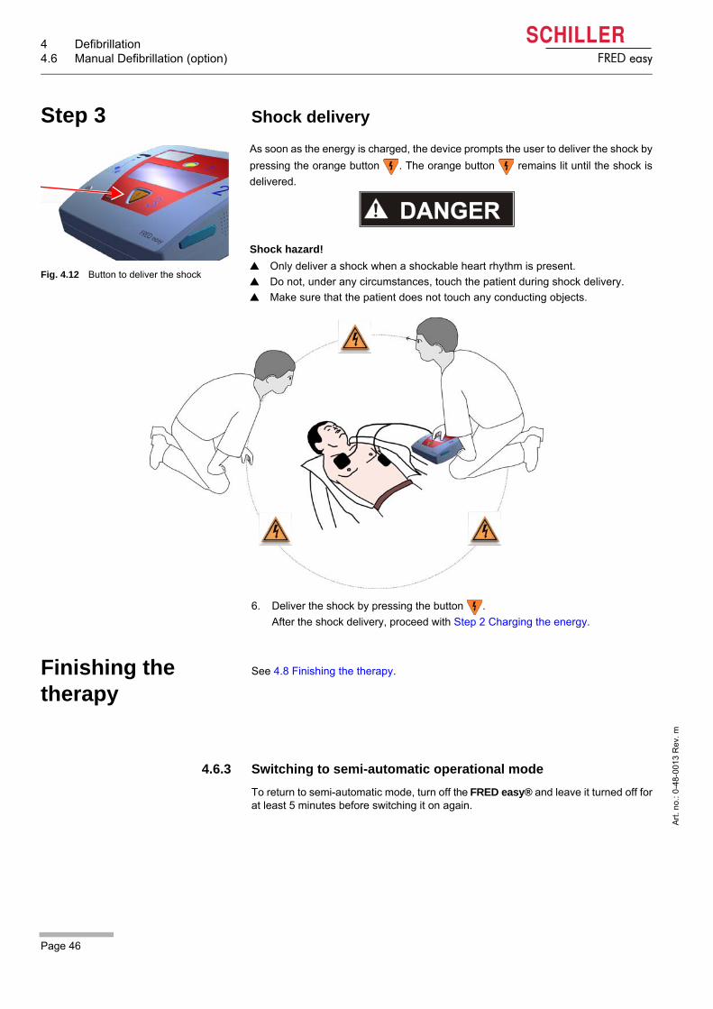
Step 3 Shock delivery
6. Deliver the shock by pressing the button .
After the shock delivery, proceed with Step 2 Charging the energy.
Finishing the therapy
See 4.8 Finishing the therapy.
4.6.3 Switching to semi-automatic operational mode
To return to semi-automatic mode, turn off the FRED easy® and leave it turned off forat least 5 minutes before switching it on again.
As soon as the energy is charged, the device prompts the user to deliver the shock by
pressing the orange button . The orange button remains lit until the shock is
delivered.
Shock hazard!
Only deliver a shock when a shockable heart rhythm is present.
Do not, under any circumstances, touch the patient during shock delivery.
Make sure that the patient does not touch any conducting objects.
Fig. 4.12 Button to deliver the shock
Page 47
Defibrillation 4User Guide Internal safety discharge 4.7
Art
. no
.: 0
-48
-001
3 R
ev.
m
FRED easy
4.7 Internal safety discharge
An internal safety discharge ensures that the stored energy is discharged within thedevice every time a defibrillation shock was not delivered correctly. An internal dis-charge is performed if:
– after the defibrillation energy has been charged, the heart rate changes into anon shockable rhythm
– the shock has not been delivered within the 20 seconds following the end of de-fibrillation energy charging
– an electrode error is detected– the battery voltage is insufficient– the device is defective– the device is switched off before the shock is delivered.
4.8 Finishing the therapy
• Switch off the device once the therapy has been completed (press and hold the
green button for approx. 3 seconds).
• Disconnect the electrode cable.
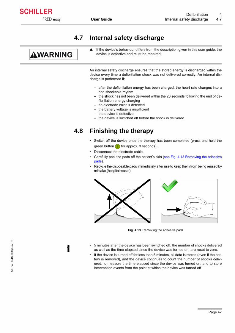
• Carefully peel the pads off the patient’s skin (see Fig. 4.13 Removing the adhesivepads).
• Recycle the disposable pads immediately after use to keep them from being reused bymistake (hospital waste).
Fig. 4.13 Removing the adhesive pads
If the device's behaviour differs from the description given in this user guide, thedevice is defective and must be repaired.
• 5 minutes after the device has been switched off, the number of shocks deliveredas well as the time elapsed since the device was turned on, are reset to zero.
• If the device is turned off for less than 5 minutes, all data is stored (even if the bat-tery is removed), and the device continues to count the number of shocks deliv-ered, to measure the time elapsed since the device was turned on, and to storeintervention events from the point at which the device was turned off.

5 Versions5.1 SD card version
Page 48
Art
. no
.: 0
-48
-001
3 R
ev.
m
FRED easy
5 Versions
5.1 SD card version
Operating principle
This version records all defibrillation-related events on a removable SD card.
The SD card is able to record:
– 2 hours of ECG signal,– 2 hours of sound recording (if this parameter has been activated using FRED-
CO® and unless ambient noises are too loud).– 500 events concerning the intervention (see table below).
Equipment damage hazard —
The memory card slot must always be covered with the rubber cover. This is toprevent moisture penetrating the device.
Always turn off the device before inserting or removing the SD card.
Do not insert the Ethernet adapter into the SD card slot.
Malfunction hazard —
The SD card must only be used in one single device. Before being used in another device, the SD card must be reformated with theSchiller data viewing software; otherwise, the recorded information will be incor-rect.
Only use SD cards supplied by SCHILLER.
Overview of recorded events, with date and time:
• Power on
• Movement detection (beginning and end)
• Operating mode
• Start of analysis
• Analysis result
• Defibrillator charging
• Defibrillation shock
• Defibrillation shock cancelled
• Internal dischargea
a. This event is only recorded when the defibrillator has switched to "limited mode"due to a technical problem.
• Electrode alarm
• "Battery low" alarm
• Critical error
• Power off
Page 49
Versions 5User Guide SD card version 5.1
Art
. no
.: 0
-48
-001
3 R
ev.
m
FRED easy
5.1.1 Inserting the SD card
1. Make sure that the SD card is not write-protected.
2. Switch off the device before inserting the card.
3. Insert the card as shown in Fig. 5.2 SD card inserted (text facing up, in the direc-tion indicated by the arrow). Otherwise, the device will not recognise the card and
the symbol is displayed.
Fig. 5.1 Inserting the memory card
4. Once the card is inserted, close the rubber cover of the card slot.
If the symbol is not displayed even though the card has been inserted, check that
the card has been recommended by SCHILLER for the use in this type of device.
Inserting the SD card automatically activates the memory function and the symbol
is displayed (see Fig. 5.2 SD card inserted).
Fig. 5.2 SD card inserted
The symbol starts blinking when the SD card is full. No further data is stored; how-
ever, previously recorded data remains stored on the card.
SD cards can be read on a PC using the Schiller data viewing and "LifeDataNet®"software.
DO NOT TOUCH THE PATIENT
ANALYSING!

5 Versions5.2 Ethernet version
Page 50
Art
. no
.: 0
-48
-001
3 R
ev.
m
FRED easy
5.2 Ethernet version
5.2.1 Connecting the Ethernet adapter
The Ethernet adapter needs to be inserted in the Ethernet interface (see Fig.5.5 Inserting the Ethernet adapter in the Ethernet interface).
Fig. 5.5 Inserting the Ethernet adapter in the Ethernet interface
Fig. 5.3 Ethernet version
Operating principle
This version is able to send intervention data (stored on the internal memory) as wellas detailed device configuration data to the LifeDataNet® web server.
The data is transmitted via a network infrastructure.
The internal memory is able to record:
– 2 hours of ECG signal,– 2 hours of ambient noise (if the sound recording parameter is activated using
FREDCO®),– 500 events concerning the intervention.
Once the internal memory (SD card) is full, the symbol starts blinking and no more
data can be stored. Stored data will be cleared once it has been transmitted. Trans-mitted data can be viewed using LifeDataNet®.
• The memory card cannot be removed for the FRED easy® Ethernet version.
• All events transmitted by the device are listed on page 48.
• In order to protect other electrical devices from interference during data transmis-sion, a ferrite core must be placed on the Ethernet cable in close proximity to theEthernet adapter (see 5.2.3 Installing the ferrite core).
To ensure correct data transmission:
1. the "Network" and "Online" sections of the device settings must first be configuredusing the FREDCO® software program (see 5.2.1 Connecting the Ethernetadapter and 5.4.2 Configuring the "Online" Tab),
2. the Ethernet adapter must be connected to the network hosting the LifeDataNet®web server, via an Ethernet cable,
3. the Ethernet adapter must be inserted in the Ethernet interface of the device (see5.2.1 Connecting the Ethernet adapter).
Fig. 5.4 Ethernet adapter
1 2
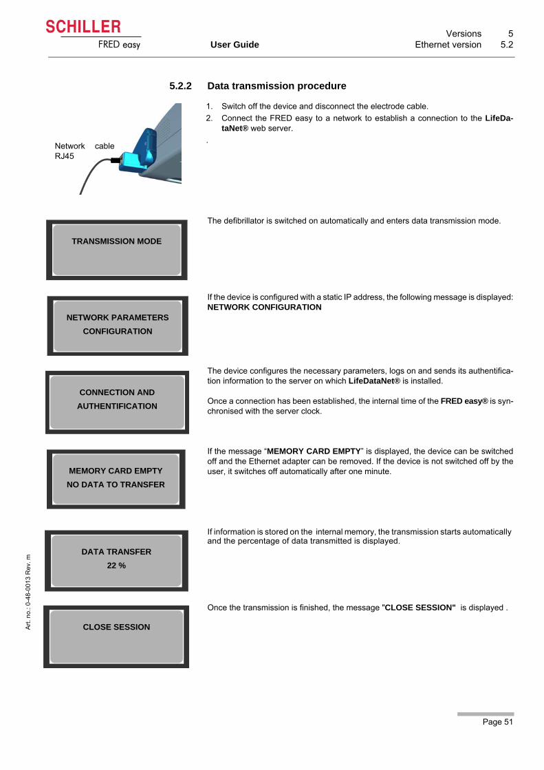
Page 51
Versions 5User Guide Ethernet version 5.2
Art
. no
.: 0
-48
-001
3 R
ev.
m
FRED easy
5.2.2 Data transmission procedure
The defibrillator is switched on automatically and enters data transmission mode.
If the device is configured with a static IP address, the following message is displayed:NETWORK CONFIGURATION
The device configures the necessary parameters, logs on and sends its authentifica-tion information to the server on which LifeDataNet® is installed.
Once a connection has been established, the internal time of the FRED easy® is syn-chronised with the server clock.
If the message “MEMORY CARD EMPTY” is displayed, the device can be switchedoff and the Ethernet adapter can be removed. If the device is not switched off by theuser, it switches off automatically after one minute.
If information is stored on the internal memory, the transmission starts automatically and the percentage of data transmitted is displayed.
Once the transmission is finished, the message "CLOSE SESSION" is displayed .
1. Switch off the device and disconnect the electrode cable.
2. Connect the FRED easy to a network to establish a connection to the LifeDa-taNet® web server.
. Network cableRJ45
TRANSMISSION MODE
NETWORK PARAMETERS
CONFIGURATION
CONNECTION AND
AUTHENTIFICATION
MEMORY CARD EMPTY
NO DATA TO TRANSFER
DATA TRANSFER
22 %
CLOSE SESSION

5 Versions5.2 Ethernet version
Page 52
Art
. no
.: 0
-48
-001
3 R
ev.
m
FRED easy
After transmission, the data is deleted from the internal memory. The percentage ofdata removed is indicated.
At the end of the transmission procedure, the following message is displayed:You can switch off the device and remove the Ethernet adapter.
MEMORY ERASING
25 %
The data stored on the internal memory is deleted once the transfer of the entire datarecord is completed. If the transfer is interrupted, data remains stored on the internal memory and thetransfer can be restarted.
TRANSMISSION COMPLETE
FRED easy automatically aborts the connection 5 minutes after the data transfer hasbeen completed, or if the Ethernet connection is interrupted.

Page 53
Versions 5User Guide Ethernet version 5.2
Art
. no
.: 0
-48
-001
3 R
ev.
m
FRED easy
5.2.3 Installing the ferrite core
FRED easy® Ethernet accessories
Fig. 5.6 Installing the cable within the fer-rite core
Fig. 5.7 Reducing the loop
Fig. 5.8 Correctly installed ferrite core
1. Form a loop and route the Ethernet cable through the open ferrite core (see Fig.5.6 Installing the cable within the ferrite core).
2. Shut the ferrite core – without closing it completely – and check the cable position.
3. Reduce the size of the loop to place the ferrite core as closely as possible to theEthernet plug. To do so, pull the long end of the cable (see Fig. 5.7 Reducing theloop).
4. Close the ferrite core (see Fig. 5.8 Correctly installed ferrite core).
Part No. Description
1-58-5303 Ethernet adapter
5-30-0003 Ethernet cable (3 m, category 5)
4-33-0002 Ferrite core
0-05-0026 Ethernet cable (3 m, with ferrite core)

5 Versions5.3 Online version
Page 54
Art
. no
.: 0
-48
-001
3 R
ev.
m
FRED easy
5.3 Online version
The internal memory is able to record:
– 2 hours of ECG signal,– 2 hours of ambient noise (if the sound recording parameter is activated using
FREDCO®),– 500 events concerning the intervention.
Once the internal memory is full, the symbol starts blinking and no more data can
be stored. Stored data will be cleared once it has been transmitted.
Operating principle
This version is intended to ensure communication between the device and the LifeD-ataNet® web server.
Just as with the Ethernet version, this version is able to send intervention data (storedon the internal memory) as well as detailed device configuration data to the LifeDa-taNet® web server. It also allows a total remote control of the FRED easy® using Life-DataNet® (see table below).
Communication takes place via a network infrastructure using the SNMP (Simple Net-work Management Protocol) communication protocol.
Fig. 5.9 Online version with docking sta-tion
• The SD card is not removable in the FRED easy® Online version.
• All events transmitted by the device are listed on page 48.
Overview of actions that may be performed remotely, using LifeDataNet®:
• Monitoring of battery capacity and self-test result
• Update of device’s software
• Modification of device configuration
• Modification of device language
• Triggering of audible alarms or visual indications on the devices
• Viewing the device status
• Geographic location of devices (Google Maps)

Page 55
Versions 5User Guide Online version 5.3
Art
. no
.: 0
-48
-001
3 R
ev.
m
FRED easy
5.3.1 Ensuring data transmission
• The "Network" and "Online" sections of the device settings must be configured us-ing the FREDCO® software program,
• The FRED easy® Online needs to be inserted in the docking station (see section5.3.2 page 56).
• Only use lithium batteries with the Online version. Do not use rechargeable NiCdbatteries.
• Do not remove the battery from the device while the device is inserted in the dock-ing station.
• Turn off the device before inserting it in the docking station. Otherwise, no data willbe transmitted.
The user and installation handbook for the docking station (part no. 0-48-0156) pro-vides further information on the use of the docking station and configuration of theFRED easy® Online.

5 Versions5.3 Online version
Page 56
Art
. no
.: 0
-48
-001
3 R
ev.
m
FRED easy
5.3.2 Placing the FRED easy® in the docking station
1. Switch off device.
2. Position the device as shown in illustration (1).
3. Push the device into the docking station (2) until it clicks into place (3).
Fig. 5.10 Inserting the device into the docking station
– The device switches on and starts transmitting the data from its internal memoryin the same way as the Ethernet version (see 5.2.2 Data transmission proce-dure).
– The indicator (see Fig. 5.11 Communication indicator) is blinking when the de-vice is able to communicate with the data network.
– The same screens are displayed as during data transmission with the Ethernetversion (see 5.2.2 Data transmission procedure).
Once all data has been transmitted, the display illumination switches off and the mes-sage "FREDeasy Online READY" is displayed. This message is displayed wheneverthe device is able to communicate with the data network. In addition, the indicator isblinking (see Fig. 5.11 Communication indicator).
Fig. 5.11 Communication indicator
If communication is interrupted, the message "NO SERVER" is displayed and the indicator remains lit.
You can read and edit the transmitted data using the LifeDataNet® web server.
21 3
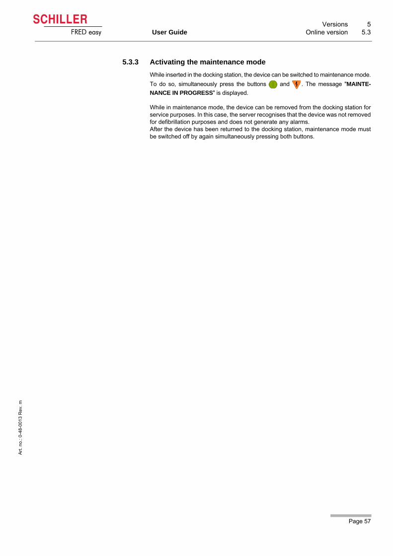
Page 57
Versions 5User Guide Online version 5.3
Art
. no
.: 0
-48
-001
3 R
ev.
m
FRED easy
5.3.3 Activating the maintenance mode
While inserted in the docking station, the device can be switched to maintenance mode.
To do so, simultaneously press the buttons and . The message "MAINTE-
NANCE IN PROGRESS" is displayed.
While in maintenance mode, the device can be removed from the docking station forservice purposes. In this case, the server recognises that the device was not removedfor defibrillation purposes and does not generate any alarms.After the device has been returned to the docking station, maintenance mode mustbe switched off by again simultaneously pressing both buttons.

5 Versions5.4 Configuration Ethernet/Online using FRECO
Page 58
Art
. no
.: 0
-48
-001
3 R
ev.
m
FRED easy
5.4 Configuration Ethernet/Online using FRECO
5.4.1 Configuring the "Network" tab
• Start the FREDCO® software program and select the "Network" tab (1).
Fig. 5.12 Network configuration ("Network" tab)
• Check that the "MAC Address" (8) displayed on the screen is identical to the ad-dress indicated on the underside of the device.
A password provided by SCHILLER must be entered to access the network parameters.
1
823
4
5
6
7
9
10
11
12
Fig. 5.13 Configuring the dynamic mode
(1) "Network" tab in FREDCO®
(2) IP address configuration section
(3) Selection of IP address configuration mode: dynamic or static
(4) IP address of the FRED easy® Ethernet version
(5) IP address of the network mask (depends on the network infrastructure)
(6) IP address of the network gateway (depends on the network infrastructure)
(7) IP address of the domain name system (depends on the network infrastructure)
(8) MAC address of the FRED easy® Ethernet version (located on the label on theunderside of the device)
(9) IP address of the server's network interface, used by FRED easy® to connectand transmit data
(10) Login of a user with access to the server on which LifeDataNet® is installed
(11) User password
(12) Confirmation of "Network" tab configuration
• The parameters of the "IP Configuration" section (2) depend on the network infra-structure:
– in "Static" mode (3), your network administrator will provide this information andyou are required to fill in (4), (5), (6), and (7).
– In "Dynamic" mode (3), the 4 parameters are automatically configured (see Fig.5.13 Configuring the dynamic mode).

Page 59
Versions 5User Guide Configuration Ethernet/Online using FRECO 5.4
Art
. no
.: 0
-48
-001
3 R
ev.
m
FRED easy
• Fill in the Server IP address field (9).
• Enter a login (10).
• Enter the password (11).
• Click the "Update" button (12) to apply any changes.
• Login (10) and password (11) can be freely changed but they must be the same asthose specified in the "SNMP Parameters" tab of LifeDataNet® (see user manuelof LifeDataBox/LifeDataNet® (0-48-0117)). By default, the login is "fredeasy" andthe password is "schiller".
• To apply any changes to the parameters, click the "Update" button (12).
• Once the battery is inserted, FRED easy® Ethernet offers the option to manuallyconfigure the IP addresses without using FREDCO®, if configured so.

5 Versions5.4 Configuration Ethernet/Online using FRECO
Page 60
Art
. no
.: 0
-48
-001
3 R
ev.
m
FRED easy
5.4.2 Configuring the "Online" Tab
• Start the FREDCO® software program and select the "Online" tab (1).
Fig. 5.14 Network configuration ("Online" tab)
(1) "Online" tab in FREDCO®.
(2) "RO and RW Community" password.
(3) Confirmation of "Online" tab configuration.
• Enter the "RO and the RW Community" password (2). You can choose any pass-word, but it must be identical to the password entered in the "FREDeasy®" sectionof the "SNMP Parameters" tab in LifeDataNet® (see Fig. 5.15 SNMP parameterin LifeDataNet®).
Fig. 5.15 SNMP parameter in LifeDataNet®
• Click the "Update" button (3) to apply any changes.
A password provided by SCHILLER must be entered to access the network parameters.
1
2
3
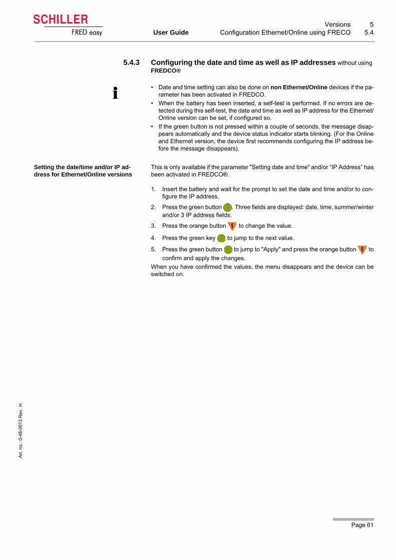
Page 61
Versions 5User Guide Configuration Ethernet/Online using FRECO 5.4
Art
. no
.: 0
-48
-001
3 R
ev.
m
FRED easy
5.4.3 Configuring the date and time as well as IP addresses without using FREDCO®
Setting the date/time and/or IP ad-dress for Ethernet/Online versions
This is only available if the parameter "Setting date and time" and/or “IP Address” hasbeen activated in FREDCO®.
1. Insert the battery and wait for the prompt to set the date and time and/or to con-figure the IP address.
2. Press the green button . Three fields are displayed: date, time, summer/winterand/or 3 IP address fields.
3. Press the orange button to change the value.
4. Press the green key to jump to the next value.
5. Press the green button to jump to "Apply" and press the orange button to
confirm and apply the changes.
When you have confirmed the values, the menu disappears and the device can beswitched on.
• Date and time setting can also be done on non Ethernet/Online devices if the pa-rameter has been activated in FREDCO.
• When the battery has been inserted, a self-test is performed. If no errors are de-tected during this self-test, the date and time as well as IP address for the Ethernet/Online version can be set, if configured so.
• If the green button is not pressed within a couple of seconds, the message disap-pears automatically and the device status indicator starts blinking. (For the Onlineand Ethernet version, the device first recommends configuring the IP address be-fore the message disappears).
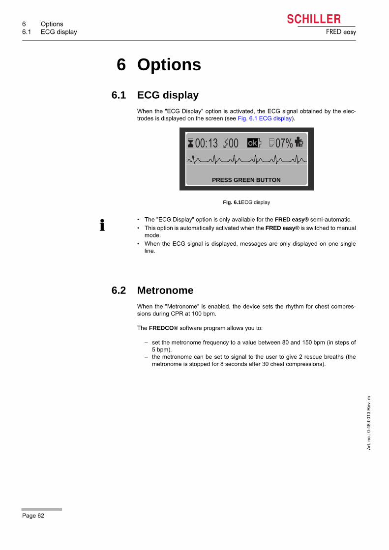
6 Options6.1 ECG display
Page 62
Art
. no
.: 0
-48
-001
3 R
ev.
m
FRED easy
6 Options
6.1 ECG display
When the "ECG Display" option is activated, the ECG signal obtained by the elec-trodes is displayed on the screen (see Fig. 6.1 ECG display).
Fig. 6.1ECG display
6.2 Metronome
When the "Metronome" is enabled, the device sets the rhythm for chest compres-sions during CPR at 100 bpm.
The FREDCO® software program allows you to:
– set the metronome frequency to a value between 80 and 150 bpm (in steps of5 bpm).
– the metronome can be set to signal to the user to give 2 rescue breaths (themetronome is stopped for 8 seconds after 30 chest compressions).
PRESS GREEN BUTTON
• The "ECG Display" option is only available for the FRED easy® semi-automatic.
• This option is automatically activated when the FRED easy® is switched to manualmode.
• When the ECG signal is displayed, messages are only displayed on one singleline.

Page 63
Options 6User Guide Rechargeable NiCd battery 6.3
Art
. no
.: 0
-48
-001
3 R
ev.
m
FRED easy
6.3 Rechargeable NiCd battery
For further details, see 3.1 Inserting the battery.
When charging NiCd batteries, make sure to observe the values 100 – 240 V, 50 – 60Hz (see 9.1 Order Information). The charging time is max. 1 hour.
When the device is equipped with a NiCd battery, it runs a daily self-test.
The battery must remained packed in its original plastic packaging (blister) during thewhole storage time. The plastic packaging must only be removed when the battery isused.
Danger of explosion! The battery must not be incinerated, exposed to hightemperatures, or disposed with household waste.
Do not expose the battery to chemicals that could dissolve ABS, polypropylene,polyvinyl chloride, nickel, mylar, or steel.
Do not short-circuit, cut, destroy or incinerate the battery.
As an alternative, a rechargeable NiCd battery (12 V, 650 mAh) is available for thedefibrillator. The capacity of a new, fully charged battery is sufficient for:
– 45 shocks at maximum energy, or– 40 minutes operating
Like the lithium battery, the device warns the user when the NiCd battery has reachedthe "low" battery threshold. The device will still allow the user to perform defibrillation,but the battery must be recharged/replaced as soon as possible.
The FRED easy® also detects when the NiCd battery is "depleted". In this case, thedevice does not allow the user to perform defibrillation and instead prompts him or herto perform CPR. The battery must be recharged/replaced immediately.
Fig. 6.2 NiCd battery charging unit
• This option is only available for the FRED easy® SD Card and Ethernet versions.
• This option is only available for FRED easy® devices that have a 2nd generationCPU board.These devices can be recognised by their 12-digit serial number.
Battery service life — Unused batteries (whether or not inserted in the device) shouldbe charged at least every 2 months.

6 Options6.4 Silent mode
Page 64
Art
. no
.: 0
-48
-001
3 R
ev.
m
FRED easy
6.4 Silent mode
6.4.1 Silent mode
The FRED easy with silent mode option is intended for locations where a quick trans-ferral to a hospital cannot be guaranteed. If in Silent mode a change in the cardiacrhythm is detected the device reactivates the AED mode and the user will be promptto check the patient.
In silent mode, operating time is approx. 6.5 hours if no analysis or defibrillation is per-formed.
If a patient has been successfully defibrillated or if the device does not detect a shock-able rhythm, the device can be switched to silent mode in order to detect changes ofthe patient's cardiac rhythm without the user or patient being disturbed by the AED'srepeated voice prompts.
If the device detects a change in the cardiac rhythm or if the green button is pressed,silent mode is abandoned and voice prompts instruct the user about the next steps tobe taken.
Moreover, the heart rhythm is recorded and can be transmitted via network with theFRED easy Ethernet/Online (see 5.2.2 Data transmission procedure).
Even though the device issues voice prompts if a change in rhythm occurs, thisis not a substitute for the regular checking of the patient's vital functions.
Silent mode must only be activated if the device does not detect a shockablerhythm and if the patient is responsive.
The silent mode must not be carried out while the device is starting up.
The silent mode must not be carried out during an analysis or defibrillation.
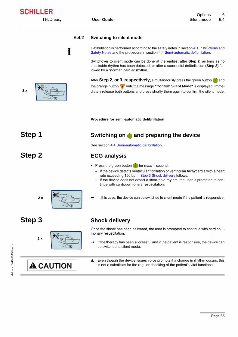
Page 65
Options 6User Guide Silent mode 6.4
Art
. no
.: 0
-48
-001
3 R
ev.
m
FRED easy
6.4.2 Switching to silent mode
Procedure for semi-automatic defibrillation
Step 1 Switching on and preparing the device
See section 4.4 Semi-automatic defibrillation.
Step 2 ECG analysis
• Press the green button for max. 1 second.
– If the device detects ventricular fibrillation or ventricular tachycardia with a heartrate exceeding 150 bpm, Step 3 Shock delivery follows.
– If the device does not detect a shockable rhythm, the user is prompted to con-tinue with cardiopulmonary resuscitation.
In this case, the device can be switched to silent mode if the patient is responsive.
Step 3 Shock delivery
Once the shock has been delivered, the user is prompted to continue with cardiopul-monary resuscitation.
If the therapy has been successful and if the patient is responsive, the device canbe switched to silent mode.
Defibrillation is performed according to the safety notes in section 4.1 Instructions andSafety Notes and the procedure in section 4.4 Semi-automatic defibrillation.
Switchover to silent mode can be done at the earliest after Step 2, as long as noshockable rhythm has been detected, or after a successful defibrillation (Step 3) fol-lowed by a "normal" cardiac rhythm.
After Step 2, or 3, respectively, simultaneously press the green button and
the orange button until the message "Confirm Silent Mode" is displayed. Imme-
diately release both buttons and press shortly them again to confirm the silent mode.2 x
2 x
2 x
Even though the device issues voice prompts if a change in rhythm occurs, thisis not a substitute for the regular checking of the patient's vital functions.
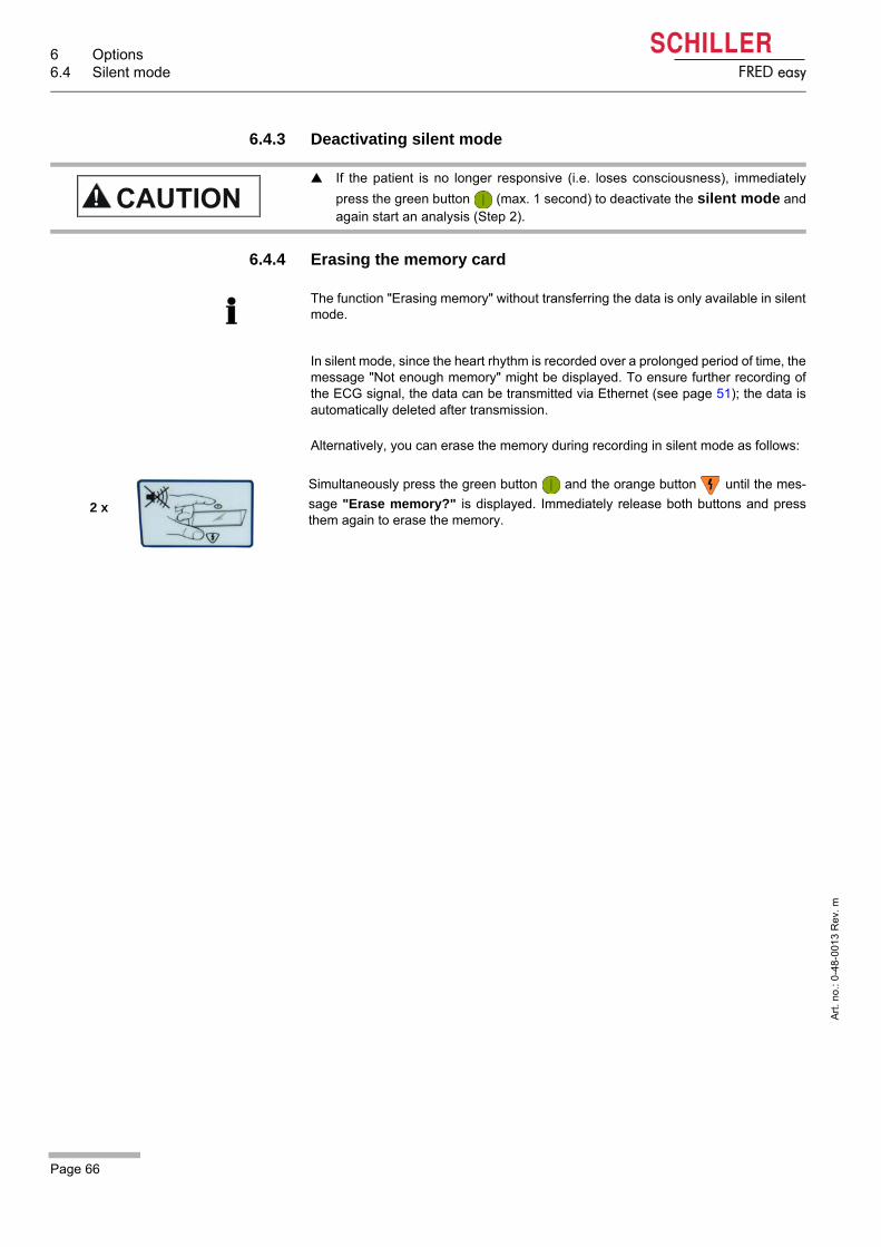
6 Options6.4 Silent mode
Page 66
Art
. no
.: 0
-48
-001
3 R
ev.
m
FRED easy
6.4.3 Deactivating silent mode
6.4.4 Erasing the memory card
In silent mode, since the heart rhythm is recorded over a prolonged period of time, themessage "Not enough memory" might be displayed. To ensure further recording ofthe ECG signal, the data can be transmitted via Ethernet (see page 51); the data isautomatically deleted after transmission.
Alternatively, you can erase the memory during recording in silent mode as follows:
If the patient is no longer responsive (i.e. loses consciousness), immediately
press the green button (max. 1 second) to deactivate the silent mode andagain start an analysis (Step 2).
The function "Erasing memory" without transferring the data is only available in silentmode.
Simultaneously press the green button and the orange button until the mes-
sage "Erase memory?" is displayed. Immediately release both buttons and pressthem again to erase the memory.
2 x

Page 67
Options 6User Guide Special operating conditions 6.5
Art
. no
.: 0
-48
-001
3 R
ev.
m
FRED easy
6.5 Special operating conditions
The device may be approved for special operating conditions in consultation with themanufacturer and/or the inspecting authority, as long as all guidelines and regulationsare observed (e.g. for the maritime sector).
6.5.1 Maritime use
The following device is approved for maritime use:
• FRED easy with silent mode
• Basic wall mounting without mains connection
• Sufficient spare batteries
• LAN cable for the transmission of the ECG
Accessory that is not included in the scope of delivery and needs to be provided bythe owner:
• Insulating mat for defibrillation on conducting surfaces.
Ambient conditions for storage before use
In order to guarantee operational readiness of the device and accessories, the devicepreferably needs to be stored in a climatised room below deck, in the following climat-ic conditions:
Temperature 15...25 °C Ensures operational readiness as well as maximum battery life.
Temperature -5...40 °C Ensures operational readiness but reduces battery life. (This is compensated byspare batteries).
Ambient conditions for operation
Temperature -5...40 °C Operation is guaranteed if the storage conditions listed above are met for the storagebefore use.
If higher or lower temperatures prevail during use, a limited operation time of up toone hour is possible if the device incl. electrodes has been stored at a temperature of15...25 °C. It is recommended to store spare batteries and spare electrodes at a tem-perature of 15...20 °C.
Operating conditions on deck
• For the defibrillation, the patient needs to be placed on a dry and non conductingsurface to prevent leakage currents that could endanger the rescuers. Therefore,the patient needs to be placed on an insulating mat.
• If the patient's skin is wet, it needs to be dried completely with a cloth so as not toreduce the shock's efficiency.
• In extreme weather conditions such as rain and wind, the patient must not be treat-ed on deck.
The device needs to be stored before use (incl. inserted battery, electrodes and sparebatteries) according to the technical data.
6 Options6.5 Special operating conditions
Page 68
Art
. no
.: 0
-48
-001
3 R
ev.
m
FRED easy
Operating conditions below deck
In addition to the operating conditions on deck, the following regulations apply:
• If the patient is lying on a conducting surface (e.g. metal floor in the engine or stor-age room), the patient needs to be positioned on an insulating mat prior to defibril-lation.
• Make sure that even the patient's arms and legs are positioned on the insulatingmat.

Page 69
Maintenance 7User Guide Maintenance Intervals 7.1
Art
. no
.: 0
-48
-001
3 R
ev.
m
FRED easy
7 Maintenance
7.1 Maintenance Intervals
7.1.1 Visual inspection of the device and accessories
Before each use, inspect visually the device and the cables in order to detect pos-sible mechanical damages.
Check that he important safety labels are legible. The lacking or illegible ones mustbe replaced.
If you observe damages or dysfunctions which can endanger the safety of the patientor user, only use the device once it has been serviced.
Points to inspect: • Check that the green indicator is blinking, see 7.1.2 Green indicator
• Device casing undamaged?
• Cables not twisted, without wear signs due to friction or deterioration?
• No excessive clogging or damage?
• All the signal inputs in perfect condition?
• Legible nameplate at the rear of the device?
• Legible inscriptions on the front face of th device?
• Expiration date of the accessories elapsed?
Electrodes past their expiration date must be replaced immediately.
Defective units or damaged cables must be replaced immediately.
• FRED easy® is an emergency device that must always be in proper working or-der. The device must be serviced on a regular basis. The test results must be re-corded and compared to the values in the accompanying documents (see9.5 Inspection report).
• These checks and replacements can be performed within the framework of a main-tenance contract by SCHILLER technical department or an authorised distributor.
• The following table indicates the intervals and competence of the maintenancework required.
Interval Maintenance - replacement Responsible
Before each use• Visual inspection of the device and accessories, see 7.1.1 Visual in-
spection of the device and accessories.
• Check that the green indicator is blinking, see 7.1.2 Green indicator
User
Once a Week/Month• Visual inspection of the device and accessories.
• Check that the green indicator is blinking, see 7.1.2 Green indicator. User
Every 3 years• Technical safety inspections according to SCHILLER documenta-
tion (available for technical departments authorised by SCHILLER),see 7.1.3 Functional check.
Service staff authorised by SCHILLER
Every 6 years • Replacement of internal backup battery. Service staff authorised
by SCHILLER
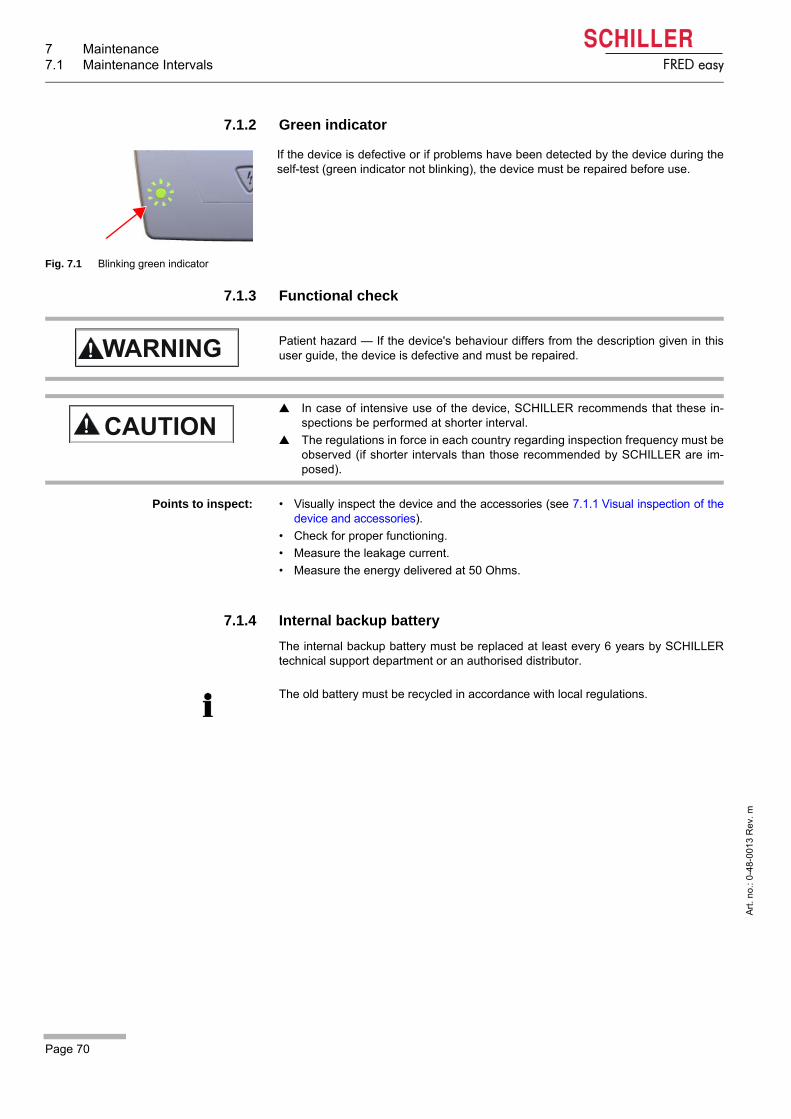
7 Maintenance7.1 Maintenance Intervals
Page 70
Art
. no
.: 0
-48
-001
3 R
ev.
m
FRED easy
7.1.2 Green indicator
7.1.3 Functional check
Points to inspect: • Visually inspect the device and the accessories (see 7.1.1 Visual inspection of thedevice and accessories).
• Check for proper functioning.
• Measure the leakage current.
• Measure the energy delivered at 50 Ohms.
7.1.4 Internal backup battery
The internal backup battery must be replaced at least every 6 years by SCHILLERtechnical support department or an authorised distributor.
Fig. 7.1 Blinking green indicator
If the device is defective or if problems have been detected by the device during theself-test (green indicator not blinking), the device must be repaired before use.
Patient hazard — If the device's behaviour differs from the description given in thisuser guide, the device is defective and must be repaired.
In case of intensive use of the device, SCHILLER recommends that these in-spections be performed at shorter interval.
The regulations in force in each country regarding inspection frequency must beobserved (if shorter intervals than those recommended by SCHILLER are im-posed).
The old battery must be recycled in accordance with local regulations.
Page 71
Maintenance 7User Guide Cleaning and disinfection 7.2
Art
. no
.: 0
-48
-001
3 R
ev.
m
FRED easy
7.2 Cleaning and disinfection
Device casing Wipe the device with dampened cloth; make sure no liquid enters the device. Allcleaning or disinfection products commonly used in hospitals and containing al-cohol (maximum 70 %) are appropriate. If liquids enter the device, it can only bere-operated after it has been checked by the technical support department.
Cables, electrodes Discard the disposable electrodes immediately after use to prevent their reuse(hospital waste).
7.3 Accessories and disposables
Your local representative stocks all the consumables and accessories for theFRED easy®. A full list of all SCHILLER representatives can be found on the SCHIL-LER website (www.schiller.ch). In case of difficulty, contact our head office in Switzer-land. Our staff will be pleased to help process your order or to provide details for allSCHILLER products.
Shock hazard — Remove the battery before cleaning the device. This ensures thatthe device will not be turned on inadvertently while you are cleaning it. Risk of death! Disconnect the defibrillation pads before cleaning the device.
Risk of shock, equipment damage — Liquids must not enter the device. If a liquid haspenetrated the device, it must not be reused until it has been checked by a servicetechnician.
Equipment damage! Do not clean the surface of the device with phenol-baseddisinfectants or peroxide compounds.
Risk to Persons, Equipment Damage — Always use SCHILLER replacement partsand disposables, or products approved by SCHILLER. Failure to do so may endangerlife and/or invalidate the warranty.
7 Maintenance7.4 Disposal information
Page 72
Art
. no
.: 0
-48
-001
3 R
ev.
m
FRED easy
7.4 Disposal information
7.4.1 Battery Disposal
7.4.2 Disposal of accessories that come into contact with the patient
7.4.3 Disposal at the end of its useful life
Danger of explosion! The battery must not be incinerated, exposed to high tem-peratures or disposed of with household waste.
Do not expose the battery to chemicals that could dissolve ABS, polypropylene,polyvinyl chloride, nickel, mylar or steel.
Do not cut, destroy, or incinerate the battery.
Danger of acid burns! Do not open or heat up the battery.
The battery is to be disposed of in municipally approved areas or sent back to SCHIL-LER AG.
Disposable articles (e.g. pads, etc.) must be disposed of as hospital waste.
At the end of their service life, the device and its accessories must be recycled incompliance with local regulations. Apart from the internal and plug-in batteries, thedevice does not contain hazardous material and can be recycled like any other pieceof electronic equipment. In accordance with national law, the battery must be dis-posed of at an appropriate waste disposal station or returned to SCHILLER.
According to European legislation, this device is considered as electronic wasteequipment. It can be returned to the distributor or manufacturer where the device willbe disposed of in compliance with legal requirements. The customer must bear theshipping costs. This unit must be disposed of in a municipally approved collectionpoint or recycling centre when no longer used.
If no such collection point or recycling centre is available, you can return the unit toyour distributor or the manufacturer for proper disposal. In this way, you contribute tothe recycling and other forms of utilisation of old electrical and electronic equipment.Improper disposal harms the environment and human health due to the presence ofdangerous substances in electrical and electronic equipment.

Page 73
Maintenance 7User Guide Trouble Shooting 7.5
Art
. no
.: 0
-48
-001
3 R
ev.
m
FRED easy
7.5 Trouble Shooting
7.5.1 Error messages
• If it is not possible to get the device back into operating condition within a reason-able period of time, continue cardiopulmonary resuscitation until the rescue servicearrives.
• If the device switches to Limited mode (CPR) due to an error, the alarm messagesmay differ.
Forced shutdown procedure
• If the device cannot be switched off via normal OFF procedure (press and hold thegreen button for approx. 3 seconds), remove the battery and inserting again.
Error message Possible cause Remedy
• xxx =
– ADC– EEPROM– RTC– LCD– OKI– DSP– SHOCK BUTTON– CHARGE
DEFIBRILLATOR– COMMUNICATION
DEFIBRILLATOR– 5 WEEKS
CHARGE 150J
• Technical errors that may occurduring function tests:
Switch the unit off and then on again to con-firm. If the message still appears, the device must be repaired immediately.
• xxx =
– CPU DEFI– CRC DEFI– SAFETY DEFI– REF VOLTAGE DEFI– ADC DEFI– DEFI DISCHARGE– DEFI EPROM– DEFI SHOCK KEY
• Technical problems that can oc-cur during defibrillation
Switch the unit off and then on again to con-firm. If the message still appears, the device must be repaired immediately. Continue cardiopulmonary resuscitation until the res-cue service arrives.
Error
INFO: XXX
PERFORM
CHEST COMPRESSIONS
TEST FAILURE
XXX
Error
INFO: XXX
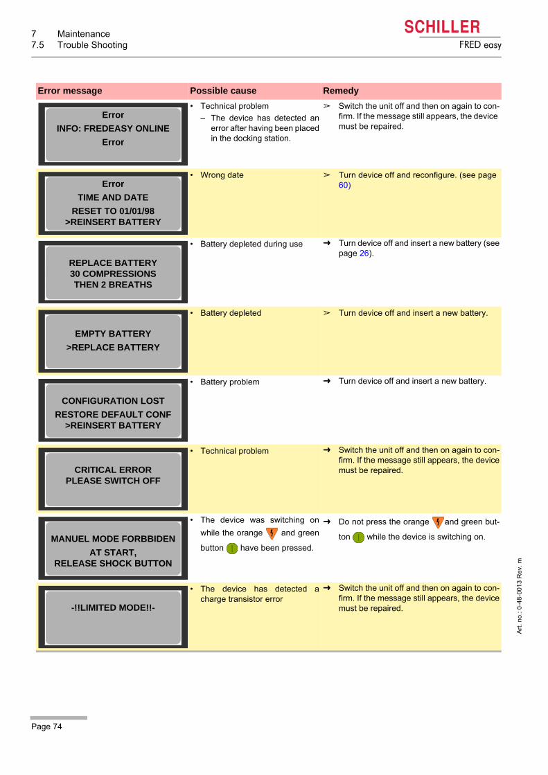
7 Maintenance7.5 Trouble Shooting
Page 74
Art
. no
.: 0
-48
-001
3 R
ev.
m
FRED easy
• Technical problem
– The device has detected anerror after having been placedin the docking station.
Switch the unit off and then on again to con-firm. If the message still appears, the device must be repaired.
• Wrong date Turn device off and reconfigure. (see page 60)
• Battery depleted during use Turn device off and insert a new battery (seepage 26).
• Battery depleted Turn device off and insert a new battery.
• Battery problem Turn device off and insert a new battery.
• Technical problem Switch the unit off and then on again to con-firm. If the message still appears, the devicemust be repaired.
• The device was switching on
while the orange and green
button have been pressed.
Do not press the orange and green but-
ton while the device is switching on.
• The device has detected acharge transistor error
Switch the unit off and then on again to con-firm. If the message still appears, the devicemust be repaired.
Error message Possible cause Remedy
Error
INFO: FREDEASY ONLINE
Error
Error
TIME AND DATE
RESET TO 01/01/98 >REINSERT BATTERY
REPLACE BATTERY30 COMPRESSIONS THEN 2 BREATHS
EMPTY BATTERY
>REPLACE BATTERY
CONFIGURATION LOST
RESTORE DEFAULT CONF>REINSERT BATTERY
CRITICAL ERRORPLEASE SWITCH OFF
MANUEL MODE FORBBIDEN
AT START,RELEASE SHOCK BUTTON
-!!LIMITED MODE!!-

Page 75
Maintenance 7User Guide Trouble Shooting 7.5
Art
. no
.: 0
-48
-001
3 R
ev.
m
FRED easy
7.5.2 Transmission error Ethernet/Online FRED easy®
If the connection to the network fails, an error message is issued. Potential error mes-sages include the following:
Error message Cause Remedy
• Error reading SD card Disconnect and reconnect the device to confirm. If the message still appears, the de-vice must be repaired.
• Technical problem Disconnect and reconnect the device to confirm. If the message still appears, the de-vice must be repaired.
• Incorrect network IP configura-tion or DHCP server not availa-ble
Verify the network configuration; if message is still displayed, the device must be re-paired.
• Ethernet adapter not inserted in the Ethernet interface case
Turn device off and connect the Ethernet adapter; if the message is still displayed, re-place the Ethernet adapter. If the message still appears, the device must be repaired.
• The pads are connected to the device and are placed to the pa-tient
Disconnect the pads from the device.
• Battery is empty Insert a new battery.
• Device not used for more than 3 minutes
Disconnect and reconnect the device to confirm. If the message still appears, the de-vice must be repaired.
• The device is not able to con-nect to the server
Check the connection to the server and the network configuration, then restart data transmission; if the message is still dis-played, the device must be repaired.
TRANSMISSION FAILURE
ERROR CODE : 001
SD CARD READING
TRANSMISSION FAILURE
ERROR CODE : 002
NOT ENOUGH MEMORY
TRANSMISSION FAILURE
ERROR CODE : 003
NETWORK CONFIGURATION
TRANSMISSION FAILURE
ERROR CODE : 004
ADAPTER DISCONNECTED
TRANSMISSION FAILURE
ERROR CODE : 005
PATIENT DETECTED
TRANSMISSION FAILURE
ERROR CODE : 006
BATTERY LEVEL
TRANSMISSION FAILURE
ERROR CODE : 007
TIME OUT INACTIVITY
TRANSMISSION FAILURE
ERROR CODE : 008
SESSION OPENING

7 Maintenance7.5 Trouble Shooting
Page 76
Art
. no
.: 0
-48
-001
3 R
ev.
m
FRED easy
• The device is not able to con-nect to the server
Check the connection to the server, the net-work configuration and check that the device is added in the "Device Manager" of LifeDa-taNet® ; if the message is still displayed, the device must be repaired.
• The device is not able to con-nect to the server
Check the connection to the server and the network configuration, then restart data transmission; if the message is still dis-played, the device must be repaired.
• The device is not able to con-nect to the server
Check the connection to the server and the network configuration, then restart data transmission; if the message is still dis-played, the device must be repaired.
• The device is not able to con-nect to the server
Check the connection to the server, the net-work configuration and check that the device is added in the "Device Manager" of LifeDa-taNet®; if the message is still displayed, the device must be repaired.
• Erroneous data transmission Check the connection to the server and the network configuration, then restart data transmission; if the message is still dis-played, the device must be repaired.
• Erroneous data transmission Check the connection to the server, the net-work configuration, and the LifeDataNet® configuration, then restart data transmis-sion; if the message is still displayed, the de-vice must be repaired.
• Erroneous data transmission Check the connection to the server, the net-work configuration, and the LifeDataNet® configuration, then restart data transmis-sion; if the message is still displayed, the de-vice must be repaired.
• Erroneous erasing of the SD card
Disconnect and reconnect the device to con-firm. If the message still appears, the device must be repaired.
Error message Cause Remedy
TRANSMISSION FAILURE
ERROR CODE : 009
SESSION OPENING
TRANSMISSION FAILURE
ERROR CODE : 010
SESSION OPENING
TRANSMISSION FAILURE
ERROR CODE : 011
SESSION CLOSING
TRANSMISSION FAILURE
ERROR CODE : 012
SESSION CLOSING
TRANSMISSION FAILURE
ERROR CODE : 013
DATA TRANSMISSION
TRANSMISSION FAILURE
ERROR CODE : 014
DATA TRANSMISSION
TRANSMISSION FAILURE
ERROR CODE : 015
DATA TRANSMISSION
TRANSMISSION FAILURE
ERROR CODE : 017
DATA ERASING

Page 77
Maintenance 7User Guide Trouble Shooting 7.5
Art
. no
.: 0
-48
-001
3 R
ev.
m
FRED easy
• The device is not able to con-nect to the server
Check the connection to the server, the net-work configuration, and the LifeDataNet® configuration, then restart data transmis-sion; if the message is still displayed, the de-vice must be repaired.
• The device is not able to con-nect to the server
Check the connection to the server, the net-work configuration, and the LifeDataNet® configuration, then restart data transmis-sion; if the message is still displayed, the de-vice must be repaired.
• The device is not able to con-nect to the server
Check the connection to the server, the net-work configuration, and the LifeDataNet® configuration, then restart data transmis-sion; if the message is still displayed, the de-vice must be repaired.
• The device is not able to con-nect to the server
Check the connection to the server, the net-work configuration, and the LifeDataNet® configuration, then restart data transmis-sion; if the message is still displayed, the de-vice must be repaired.
Error message Cause Remedy
TRANSMISSION FAILURE
ERROR CODE : 021
SUPERVISION START REQ
TRANSMISSION FAILURE
ERROR CODE : 022
SUPERVISION START ACK
TRANSMISSION FAILURE
ERROR CODE : 023
SUPERVISION STOP REQ
TRANSMISSION FAILURE
ERROR CODE : 024
SUPERVISION STOP ACK
• These errors are not applicable for the FRED easy® SD Card version.
• Error 004 (ADAPTER DISCONNECTED) only applies to the FRED easy® Ethernetversion.
• Errors 023 and 024 (SUPERVISION STOP REQ and SUPERVISION STOP ACK)only apply to the FRED easy® Online version.

7 Maintenance7.5 Trouble Shooting
Page 78
Art
. no
.: 0
-48
-001
3 R
ev.
m
FRED easy
7.5.3 Trouble Shooting
Forced shutdown procedure
If the device cannot be switched off via normal OFF procedure (press and hold thegreen button for approx. 3 seconds), remove the battery and inserting again.
Problem Possible causes RemedyThe green "OK" standby indi-cator does not blink and/orthe device cannot be turnedon.
• Battery defect.
• No battery inserted, or battery not correctly inserted.
• Device defective.
Replace the battery.
Insert the battery correctly.
Have the device repaired.
The yellow indicator at the electrode connector does not go out.
• The pads are past their expiration date.
• Dry contact agent.
• High contact impedance between the pads and the skin.
• Device defective.
Use new electrodes.
Use new electrodes.
Apply the pads exactly as described. Shave the elec-trode application area.
Have the device repaired.
The device prompts the userto check that the electrodesare properly applied and con-nected.
• Short-circuit between the pads.
• Poor pad contact.
• The pads are past their expiration date.
• Dry contact agent.
• Device defective.
Apply the pads exactly as described.
Firmly press down on the pads.
Use new electrodes.
Use new electrodes.
Have the device repaired.
The device cannot be turned off.
• On/Off button was pressed less than 3 seconds.
• Software hangs
• Device defective.
Hold down the on/off button for at least 3 seconds.
Remove battery and inserting again
Have the device repaired.
Incorrect analysis result (e.g. the device does not detect a shockable rhythm, even though the patient exhibits ventricular fibrillation).
• Insufficient ECG signal quality.
• Electromagnetic waves disturb the ECG signal.
• Patient moved during analysis.
• Device defective.
Repeat chest compressions.
Turn off the source of interference (e.g. radio transmitter,cellular telephone). Position the patient outside therange of interference.
Do not move patient during the analysis.
Have the device repaired.
Defibrillation shock cannot bedelivered.
• Insufficient battery charge level.
• CPR caused a pad error.
• Cardiac rhythm has changed.
• Device defective.
Replace the battery.
Re-apply the pads.
Repeat the analysis.
Have the device repaired.
The alarm tone does notstop.
• Battery defect.
• Device defective.
Replace the battery.
Have the device repaired.
Message "ERROR xxx". • Device defective. Have the device repaired.
Battery capacity indicatorblinks.
• Battery almost depleted. Replace the battery.
No data recorded on the SDcard.
• Card defect.
• Device defective.
Replace the card.
Have the device repaired.

Page 79
Maintenance 7User Guide Trouble Shooting 7.5
Art
. no
.: 0
-48
-001
3 R
ev.
m
FRED easy
The SD card symbol is not
displayed, or the symbol
is displayed.
• No SD card is inserted.
• The card is inserted the wrong way.
• The card was inserted with the device turned on.
• SD card write-protected.
• Device defective.
Switch the device off and insert the card the right wayaround.
Switch the device off and insert the card the right wayaround.
Switch the device off and then on again.
Turn off the device, remove the SD card, unlock the writeprotection, and re-insert the card. Then, restart the de-vice.
Have the device repaired.
Incorrect date and timestored on SD card.
• Internal clock error.
• Device defective.
Have the system parameters updated by an authorisedperson using the configuration/downloading kit.
Have the device repaired.
Problem Possible causes Remedy
7 Maintenance7.5 Trouble Shooting
Page 80
Art
. no
.: 0
-48
-001
3 R
ev.
m
FRED easy
7.5.4 Measures to prevent electromagnetic interferences
Further measures to prevent electromagnetic interferences:
The user can take the following measures to prevent electromagnetic interferences:
• Increase distance to the source of interference
• Turn the device to change the angle of radiation.
• Only use original accessories.
“Non-ionic electromagnetic radiation"
The user can help avoid electromagnetic disturbances by keeping the minimum dis-tance between portable and mobile HF telecommunication devices (transmitters) andthe FRED easy®. The distance depends on the output performance of the communi-cation device as indicated below.
HF source Transmitter fre-quency[MHz]
Power P[W]
Distance d [m]
Radio telephone (microcellular) CT1+, CT2, CT3 885-887 0.010 0.23
Cordless DECT telephone, WLAN, UMTS phone 1880-2500 0.25 1.17
Mobile phone USA 850/1900 0.6 1.8
Mobile phone- GSM900, - GSM850, NMT900, DCS 1800
900850,900,1800
21
3.32.3
Walkie-talkie (rescue service, police, fire bri-gade, service)
81-470 5 2.6
Mobile telephone system (rescue service, po-lice, fire brigade)
81-470 100 11.7
It can be deducted from the table that portable HF telecommunication devices mustnot be used within a radius of 3 m from the FRED easy® and its cables.
For more detailed information, please refer to page 85.
If the devices are used in the vicinity of power networks operating at a frequency of 16.7Hz (railway systems in some countries), the 16.7 Hz filter must be activated via the con-figuration software before use. The filter is by default activated.

Page 81
Technical Data 8User Guide System Specifications 8.1
Art
. no
.: 0
-48
-001
3 R
ev.
m
FRED easy
8 Technical Data
8.1 System Specifications
Unless otherwise stated, all specifications are valid at a temperature of 25 °C.
Manufactured by SCHILLER MEDICAL
Device name FRED easy®
Dimensions
SD card version
Ethernet/Online Versions
70 x 230 x 220 mm (h x l x w)70 x 237 x 220 mm (h x l x w)
Weight Approx. 1.5 kg
Protection class of the device housing
IP54 (protection against dust and splashing water)
Recorded data ECG signal recording (2 hours)Ambient noise recording (2 hours)Event recording (500 events)
Power supply
Standard battery type
Battery life
Optional battery type
Battery life
Internal power supply, suitable for continuous operation with intermittent loading
Lithium/MnO2 12 V, 2.8 Ah
• 180 shocks at maximum energy, or 3.75 hours of operating (alternately 30 minutes ON and 30 minutes OFF)
• Several years in standby (standby duration corresponding to laboratory tests at 25°C: 5years with weekly self-tests)
NiCd 12 V, 650 mAh, rechargeable
• 45 shocks at maximum energy, or operating for 1 h 20 min.
Environmental conditionsa
Device
Operation
Storage befor use
Storage and transport
Battery and Electrodes
Storage and Transport temper-ature battery LiMnO2
Storage and transport temper-ature electrode pads
a. For additional information about operating and storage conditions see page 67 Chapter 6.5 Special operating conditions.
• -5...40 °C at a relative humidity of 30 to 95% (no condensation)
• -5...40 °C with the battery inserted and incl. electrodes at a relative humidity of 30to 95 % (no condensation) but resulting in a reduced battery life; optimal condi-tions: 15...25 °C to ensure maximum battery life.
• Atmospheric pressure 700 to 1060 hPa• -20 ... 50 °C at a relative humidity of 0 to 95% (no condensation)• Atmospheric pressure 500 to 1060 hPa
• 0 ... 60 °C (48h max. between 0...15 °C and 25°...60°C)
• 0 ... 50 °C
8 Technical Data8.2 Classification and safety standards
Page 82
Art
. no
.: 0
-48
-001
3 R
ev.
m
FRED easy
8.2 Classification and safety standards
Display
Type
Dimensions
High-resolution LCD screen, electroluminescent backlighting, text and symbol display100 x 37 mm
Standards FRED easy® complies with IEC standard 60601-2-4.According to IEC standard 60601-2-4, FRED easy® is a device for frequent use.
EMC See 8 Technical Data.
Compliance • FRED easy® bears the (Notified Body LNE/G-MED) mark indicating its
compliance with the provisions of the Directive 93/42/EEC (modified by the Direc-tive 2007/47/EEC) regarding medical devices and fulfils the essential require-ments of Annex I of this directive.
• FRED easy® is a class IIb device.
Patient Protection BF type, resistant to defibrillation shocks.
Explosions protection FRED easy® is not designed to be used in the presence of flammable mixtures ofanaesthetic agents with air or oxygen.
The SCHILLER quality management system complies in full with the internationalstandards ISO 9001 and ISO 13485.
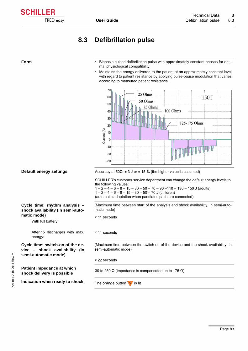
Page 83
Technical Data 8User Guide Defibrillation pulse 8.3
Art
. no
.: 0
-48
-001
3 R
ev.
m
FRED easy
8.3 Defibrillation pulse
Form • Biphasic pulsed defibrillation pulse with approximately constant phases for opti-mal physiological compatibility.
• Maintains the energy delivered to the patient at an approximately constant levelwith regard to patient resistance by applying pulse-pause modulation that variesaccording to measured patient resistance.
Default energy settings Accuracy at 50Ω: ± 3 J or ± 15 % (the higher value is assumed)
SCHILLER's customer service department can change the default energy levels to the following values:1 – 2 – 4 – 6 – 8 – 15 – 30 – 50 – 70 – 90 –110 – 130 – 150 J (adults)1 – 2 – 4 – 6 – 8 – 15 – 30 – 50 – 70 J (children)(automatic adaptation when paediatric pads are connected)
Cycle time: rhythm analysis –shock availability (in semi-auto-matic mode)
With full battery:
After 15 discharges with max.energy:
(Maximum time between start of the analysis and shock availability, in semi-auto-matic mode)
< 11 seconds
< 11 seconds
Cycle time: switch-on of the de-vice – shock availability (insemi-automatic mode)
(Maximum time between the switch-on of the device and the shock availability, insemi-automatic mode)
< 22 seconds
Patient impedance at which shock delivery is possible
30 to 250 Ω (Impedance is compensated up to 175 Ω)
Indication when ready to shock The orange button is lit

8 Technical Data8.3 Defibrillation pulse
Page 84
Art
. no
.: 0
-48
-001
3 R
ev.
m
FRED easy
Shock delivery • With the orange button (in semi-automatic or manual mode)
• Via disposable pads applied to the patient in an anterior-anterolateral or anteri-or-posterior position
Safety discharge when: • A non shockable rhythm has been detected• The shock is not delivered within the 20 seconds after charging• An electrode problem is detected • Battery voltage is insufficient• The device is defective • The device is turned off.
Defibrillation pad connection BF type
Defibrillation electrodes
Adult pads
Paediatric pad
Electrode cable, 2 m in length
• 80 cm² active surface• 42 cm² active surface
VF/VT detection
Conditions for ECG analysis
Shock recommendation
VF/VT detection is based only on the ECG signal.
Minimum amplitude for signals suitable for analysis > 0.15 mV, signals < 0.15 mVare considered asystole.
For VF and VT (VT > 150 B/min).
VF VT Non shockable rhythms
NSR/N/Asystole
Shock 148 100 2
No Shock 2 2 1395
Performance criteria Sensitivity > 90 % Sensitivity > 75 % Specificity > 95 %
Observed performance 98.67 % 98.04 % 99.86 %
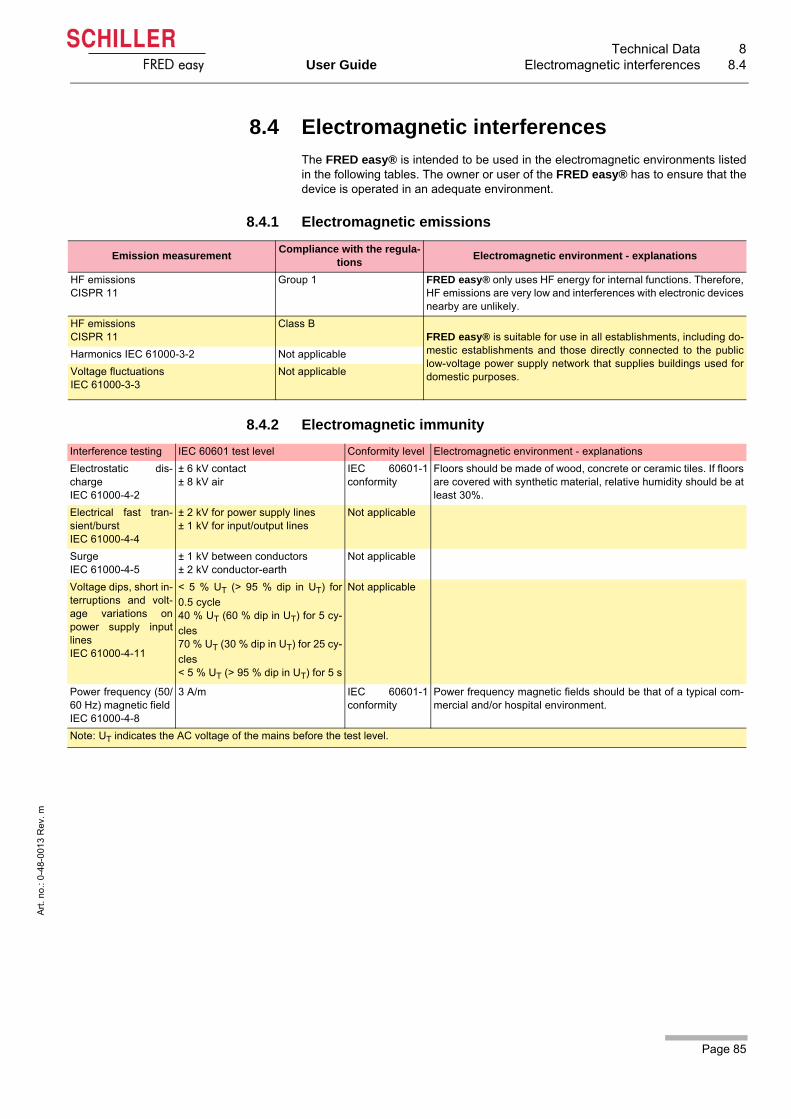
Page 85
Technical Data 8User Guide Electromagnetic interferences 8.4
Art
. no
.: 0
-48
-001
3 R
ev.
m
FRED easy
8.4 Electromagnetic interferences
The FRED easy® is intended to be used in the electromagnetic environments listedin the following tables. The owner or user of the FRED easy® has to ensure that thedevice is operated in an adequate environment.
8.4.1 Electromagnetic emissions
8.4.2 Electromagnetic immunity
Emission measurementCompliance with the regula-
tionsElectromagnetic environment - explanations
HF emissionsCISPR 11
Group 1 FRED easy® only uses HF energy for internal functions. Therefore,HF emissions are very low and interferences with electronic devicesnearby are unlikely.
HF emissionsCISPR 11
Class BFRED easy® is suitable for use in all establishments, including do-mestic establishments and those directly connected to the publiclow-voltage power supply network that supplies buildings used fordomestic purposes.
Harmonics IEC 61000-3-2 Not applicable
Voltage fluctuationsIEC 61000-3-3
Not applicable
Interference testing IEC 60601 test level Conformity level Electromagnetic environment - explanations
Electrostatic dis-chargeIEC 61000-4-2
± 6 kV contact ± 8 kV air
IEC 60601-1conformity
Floors should be made of wood, concrete or ceramic tiles. If floorsare covered with synthetic material, relative humidity should be atleast 30%.
Electrical fast tran-sient/burst IEC 61000-4-4
± 2 kV for power supply lines ± 1 kV for input/output lines
Not applicable
SurgeIEC 61000-4-5
± 1 kV between conductors ± 2 kV conductor-earth
Not applicable
Voltage dips, short in-terruptions and volt-age variations onpower supply inputlines IEC 61000-4-11
< 5 % UT (> 95 % dip in UT) for
0.5 cycle 40 % UT (60 % dip in UT) for 5 cy-
cles 70 % UT (30 % dip in UT) for 25 cy-
cles < 5 % UT (> 95 % dip in UT) for 5 s
Not applicable
Power frequency (50/60 Hz) magnetic field IEC 61000-4-8
3 A/m IEC 60601-1conformity
Power frequency magnetic fields should be that of a typical com-mercial and/or hospital environment.
Note: UT indicates the AC voltage of the mains before the test level.

8 Technical Data8.4 Electromagnetic interferences
Page 86
Art
. no
.: 0
-48
-001
3 R
ev.
m
FRED easy
Interference testing IEC 60601 test level Conformity level
Electromagnetic environment - explanations
Recommended minimum distancesPortable and mobile HF telecommunication devices mustkeep the recommended minimum distance from theFRED easy® and all its components, incl. cables; the recom-mended minimum distance is calculated based on the trans-mitter's frequency.
Conducted HFIEC 61000-4-6
3 Veff between 150 kHz and 80 MHz outside of the ISM fre-
quency bandsa
10 Veff between 150 kHz and
80 MHz in ISM frequency bands a
Not applicable
Not applicable
Radiated HFIEC 61000-4-3
10 V/m Batterie 80 MHz to 2.5GHz
10 V/m between 80 MHz and 800 MHz
between 800 MHz and 2.5 GHz
where P is the maximum transmitting power of the transmitter in Watt (W) according to manufacturer data, and d the recom-
mended minimum distance in metres (m)b.
The field strength of stationary HF transmitters (according to
an on-location measurement c) must not exceed the conform-
ity level for each frequency range d.
When operating the device near devices bearing the symbol “ionising radiation”, interferences can occur.
Note 1 For 80 MHz to 800 MHz, the higher frequency range applies. Note 2 These guidelines might not always be applicable. Electromagnetic radiation is influenced by absorption and reflection on struc-
tures, objects and people.
a. The ISM frequency bands (ISM = industrial, scientific, medical) between 150 kHz and 80 MHz are 6.765 MHz to 6.795 MHz; 13.553 MHzto 13.567 MHz; 26.957 MHz to 27.283 MHz; and 40.66 MHz to 40.70 MHz.
b. The conformity levels within the ISM frequency bands between 150 kHz and 80 MHz and between 80 MHz and 2.5 GHz serve to minimisethe probability of interferences caused by mobile/portable communication equipment that accidentally happens to be in the patient environ-ment. The formula for the calculation of the recommended distance has been adapted by the factor 10/3 for transmitters in this frequencyrange.
c. The field strength of stationary transmitters, e.g. base stations for radio telephones (mobile or cordless) and portable radio equipment, am-ateur radios, AM and FM radios and TV signals cannot be predicted accurately in a theoretical way. In order to analyse electromagneticenvironments caused by stationary HF transmitters, an electromagnetic analysis on site should be considered. If the measured fieldstrength exceeds the HF conformity level, it needs to be checked whether the FRED easy® can be used in this environment. If an abnormalbehaviour is detected, additional measures need to be taken, e.g. reorientation or change of location of the FRED easy®.
d. For the frequency range between 150 kHz and 80 MHz, the field strength must be lower than 3 V/m.
d 1210------ P=
d 2310------ P=

Page 87
Technical Data 8User Guide Electromagnetic interferences 8.4
Art
. no
.: 0
-48
-001
3 R
ev.
m
FRED easy
8.4.3 Recommended minimum distances
The FRED easy® is intended to be used in electromagnetic environments in which itis possible to control radiated HF interferences. The user of the FRED easy® can pre-vent electromagnetic interferences by always keeping a minimum distance betweenportable/mobile HF communication devices (transmitters) and the FRED easy®. Therecommended minimum distances are listed in the following table according to thetransmitters' max. transmitting power.
Max. transmitting power of the
transmitter (W)
Distances according to the transmitter's frequency (m)
between 150 kHz and 80 MHz outside of the ISM
frequency band
between 150 kHz and 80 MHz within the ISM
frequency band
between 80 MHz and 800 MHz
between 800 MHz and 2.5 GHz
0,01
Not applicable Not applicable
0,12 0,23
0,1 0,38 0,73
1 1,2 2,3
10 3,79 7,27
100 12 23
For transmitters with a max. transmitting power that is not listed in the above table, the recommended minimum distance d in metres (m) canbe calculated using a formula based on the transmitter's frequency, where P is the max. transmitting power of the transmitter in Watts (W) (ac-cording to manufacturer data).
Note 1 These guidelines might not always be applicable. Electromagnetic radiation is influenced by absorption and reflection on structures, ob-jects and people.
Note 2 To calculate the recommended minimum distance of transmitters in the ISM frequency bands between 150 kHz and 80M Hz andin the frequency band between 80 MHz and 2.5 GHz, the additional factor 10/3 is used to minimise the probability of interferenc-es caused by mobile/portable communication equipment that accidentally happens to be in the patient environment.
d 3 5,3
------- P= d 1210------ P= d 12
10------ P= d 23
10------ P=

9 Appendix9.1 Order Information
Page 88
Art
. no
.: 0
-48
-001
3 R
ev.
m
FRED easy
9 Appendix
9.1 Order Information
Devices
Accessories
9.2 Required accessories
• User Guide
• One pair of adhesive pads
• 1 lithium batteries
• One SD card (only for the SD Card version)
Part No. Description
1-58-9913 FRED easy® SD Card, semi-automatic
1-58-9100 FRED easy® SD Card, automatic
1-58-9301 FRED easy® Ethernet/Online, semi-automatic
1-58-9401 FRED easy® Ethernet/Online, automatic
EASY T2 FRED easy® TRAINER
Part No. Description
1-58-5303 Ethernet adapter
0-80-0013 Accessory bag for Online version
5-30-0003 Ethernet cable (3 m, category 5)
4-33-0002 Ferrite core
0-05-0026 Ethernet cable (3 m, with ferrite core)
EASY ELEC 1 pair of disposable adhesive defibrillation pads for adults, 80 cm²
0-21-0000 1 pair of disposable adhesive defibrillation pads for children, 42 cm²
0-21-0020 1 pair of disposable adhesive defibrillation pads for adults, 80 cm², "pre-connected"
0-21-00211 pair of disposable adhesive defibrillation pads for children, 42 cm², "pre-connected"
0-48-0013 User Guide, English
EASY BAT Disposable lithium battery
0-02-0003 Rechargeable NiCd battery
3-55-0030 Battery charger, 100 – 240 V, 50 – 60 Hz, UE
3-55-0033 Battery charger, 100 – 240 V, 50 – 60 Hz, UK
3-55-0034 Battery charger, 100 – 240 V, 50 – 60 Hz, US
EASY S Instrument bag
0-80-0008 Instrument bag, reinforced
EASY CARD Formatted SD card
5-35-0037 Formatted SD card (for FRED easy® with software version ≥ 06.00)
Page 89
Appendix 9User Guide Literature 9.3
Art
. no
.: 0
-48
-001
3 R
ev.
m
FRED easy
9.3 Literature
European Resuscitation Council (2010)
European Resuscitation Council Guidelines for Resuscitation 2010 (doi:10.1016/j.re-suscitation.2010.08.021).
American Heart Association (2010) International Consensus on Cardiopulmonary Resuscitation and Emergency Cardi-ovascular Care Science With Treatment Recommendations (DOI: 10.1161/CIRCU-LATIONAHA.110.971010).
Cansell A. Effectiveness and Safety of New Transthoracic Cardiac Defibrillation Waveforms – Bi-phasic Pulses In "La Revue des SAMU 20": 280 - 294. 2000.
9.4 Glossary
ABCD The primary ABCD
A = Airways (check if airways are free)B = Breathing (artificial respiration)C = Circulation (circulatory signs or cardiac massage)D = Defibrillation
AED Automated external defibrillator. This term is also used for semi-automatic defibrilla-tors
BLS Basic Life Support (artificial respiration and cardiac massage)CPR is frequently used synonymously
CPR Cardiopulmonary resuscitation
VT Ventricular tachycardia
VF Ventricular fibrillation
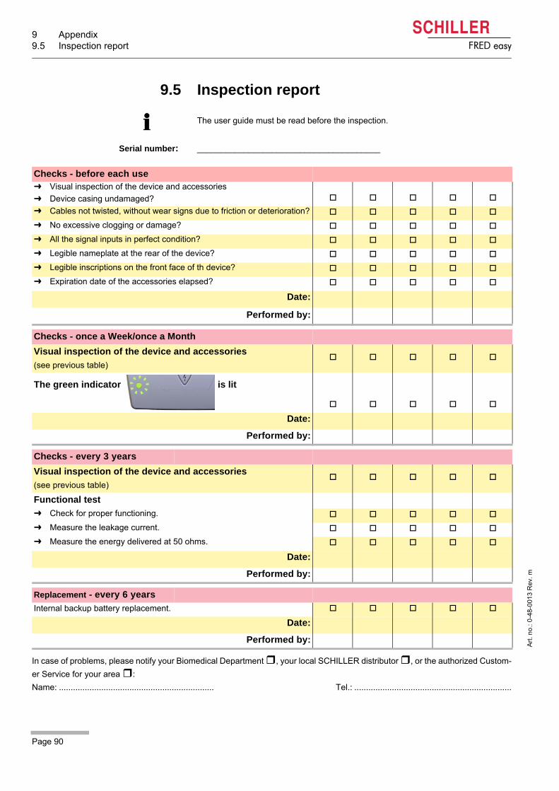
9 Appendix9.5 Inspection report
Page 90
Art
. no
.: 0
-48
-001
3 R
ev.
m
FRED easy
9.5 Inspection report
Serial number: _______________________________________
The user guide must be read before the inspection.
Checks - before each use Visual inspection of the device and accessories
Device casing undamaged?
Cables not twisted, without wear signs due to friction or deterioration?
No excessive clogging or damage?
All the signal inputs in perfect condition?
Legible nameplate at the rear of the device?
Legible inscriptions on the front face of th device?
Expiration date of the accessories elapsed?
Date:
Performed by:
Checks - once a Week/once a Month
Visual inspection of the device and accessories
(see previous table)
The green indicator is lit
Date:
Performed by:
Checks - every 3 years
Visual inspection of the device and accessories
(see previous table)
Functional test
Check for proper functioning.
Measure the leakage current.
Measure the energy delivered at 50 ohms.
Date:
Performed by:
Replacement - every 6 years
Internal backup battery replacement.
Date:
Performed by:
In case of problems, please notify your Biomedical Department , your local SCHILLER distributor , or the authorized Custom-
er Service for your area :
Name: .................................................................. Tel.: ...................................................................
Page 91
Appendix 9User Guide Inspection report 9.5
Art
. no
.: 0
-48
-001
3 R
ev.
m
FRED easy
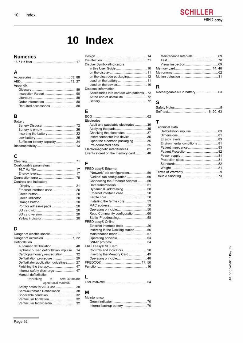
10 Index
Page 92
FRED easy
Art.
no
.: 0-
48-0
013
Rev.
m
10 IndexNumerics16.7 Hz filter ............................................... 17
AAccessories.......................................... 53, 88AED...................................................... 13, 27Appendix
Glossary ................................................ 89Inspection Report .................................. 90Literature............................................... 89Order information .................................. 88Required accessories............................ 88
BBattery
Battery Disposal .................................... 72Battery is empty .................................... 26Inserting the battery .............................. 22Low battery............................................ 25Sufficient battery capacity ..................... 24
Biocompatibility .......................................... 13
CCleaning ..................................................... 71Configurable parameters
16.7 Hz filter .......................................... 17Energy levels......................................... 17
Connection error ........................................ 75Controls and indicators
-Display ................................................. 21Ethernet interface case ......................... 20Green button ......................................... 20Green indicator...................................... 20Orange button ....................................... 20Port for adhesive pads .......................... 20SD card slot........................................... 20SD card version..................................... 20Yellow indicator ..................................... 20
DDanger of electric shock!.............................. 7Danger of explosion ............................... 7, 22Defibrillation
Automatic defibrillation .......................... 40Biphasic pulsed defibrillation impulse ... 14Cardiopulmonary resuscitation.............. 32Defibrillation procedure ......................... 29Defibrillator application guidelines......... 27Finishing the therapy............................. 47Internal safety discharge ....................... 47Manual defibrillation
Switching to semi-automaticoperational mode46
Safety notes for AED use...................... 28Semi-automatic Defibrillation ................ 38Shockable condition .............................. 32Ventricular fibrillation............................. 32Ventricular tachycardia.......................... 32
Design.........................................................14Disinfection .................................................71Display Symbols/Indicators
in this User Guide ..................................10on the display.........................................11on the electrode packaging....................12used on the battery ................................11used on the device.................................10
Disposal informationAccessories into contact with patients ...72At the end of useful life ..........................72Battery ...................................................72
EECG ............................................................62Electrodes
Adult and paediatric electrodes .............36Applying the pads ..................................35Checking the electrodes ........................37Insert connector into device...................35Open the electrode packaging...............35Pre-connected pads...............................35
Electromagnetic interferences ....................81Events stored on the memory card .............48
FFRED easy® Ethernet
"Network" tab configuration....................50"Online" tab configuration ......................60Connecting the Ethernet Adapter ..........50Data transmission ..................................51Dynamic IP addressing..........................58Ethernet interface case..........................20Ferrite core ............................................50Installing the ferrite core ........................53MAC address .........................................58Operating principle.................................50Read Community configuration..............60Static IP addressing...............................58
FRED easy® OnlineEthernet interface case..........................20Inserting in the Docking station..............56Maintenance mode ................................57Operating principle.................................54SNMP protocol.......................................54
FRED easy® SD CardControls and indicators ..........................20Inserting the Memory Card ....................49Operating principle.................................48
FREDCO® ........................................... 17, 50Function ......................................................16
LLifeDataNet® ..............................................54
MMaintenance
Green indicator ......................................70Internal backup battery ..........................70
Maintenance Intervals ...........................69Test........................................................70Visual inspection....................................69
Memory card.........................................14, 48Metronome..................................................62Motion detection .........................................31
RRechargeable NiCd battery ........................63
SSafety Notes ................................................. 5Self-test.......................................... 16, 20, 63
TTechnical Data
Defibrillation impulse .............................83Dimensions............................................81Energy levels .........................................83Environmental conditions ......................81Patient impedance.................................83Patient Protection ..................................82Power supply .........................................81Protection class .....................................81Standards ..............................................82Weight ...................................................81
Terms of Warranty ........................................9Trouble Shooting ........................................73