AUTOMATED BARTENDER FINAL REPORT - Course Websites
25
AUTOMATED BARTENDER FINAL REPORT May 3, 2017 Greg Wajda, Max Dribinsky, Austin Gram UIUC ECE 445
-
Upload
khangminh22 -
Category
Documents
-
view
0 -
download
0
Transcript of AUTOMATED BARTENDER FINAL REPORT - Course Websites

AUTOMATED BARTENDER
FINAL REPORT
May 3, 2017
Greg Wajda, Max Dribinsky, Austin Gram
UIUC
ECE 445

UIUC gjwajda2, dribins2, gram2
Abstract
Hearing the issue of sexual assault discussed so much lately, we sought to face the issue head
on and designed a device which would receive an order for a drink, prepare it quickly and
efficiently, and securely provide it to the user. Although similar devices exist allowing the
automated preparation of a beverage, our emphasis on security and authentication will prevent
any unwanted tampering with beverages in a crowded, noisy, and public setting such as a
campus bar.
i

Contents
Introduction . . . . . . . . . . . . . . . . . . . . . . . . . . . . . . . . . . . . . . . . . . . 1
Objective . . . . . . . . . . . . . . . . . . . . . . . . . . . . . . . . . . . . . . . . . . 1
High Level Requirements . . . . . . . . . . . . . . . . . . . . . . . . . . . . . . . . 1
Block Diagram . . . . . . . . . . . . . . . . . . . . . . . . . . . . . . . . . . . . . . . 2
Design . . . . . . . . . . . . . . . . . . . . . . . . . . . . . . . . . . . . . . . . . . . . . . 4
Design Procedure . . . . . . . . . . . . . . . . . . . . . . . . . . . . . . . . . . . . . 4
Design Details . . . . . . . . . . . . . . . . . . . . . . . . . . . . . . . . . . . . . . . 8
Verification . . . . . . . . . . . . . . . . . . . . . . . . . . . . . . . . . . . . . . . . . . . . 12
Cost . . . . . . . . . . . . . . . . . . . . . . . . . . . . . . . . . . . . . . . . . . . . . . . . 14
Conclusions . . . . . . . . . . . . . . . . . . . . . . . . . . . . . . . . . . . . . . . . . . . 15
Bibliography . . . . . . . . . . . . . . . . . . . . . . . . . . . . . . . . . . . . . . . . . . . 17
APPENDIX . . . . . . . . . . . . . . . . . . . . . . . . . . . . . . . . . . . . . . . . . . . . 18
Requirements and Verification Table . . . . . . . . . . . . . . . . . . . . . . . . . . 18
Stepper Motor Driver Schematic . . . . . . . . . . . . . . . . . . . . . . . . . . . . 22
ii
UIUC gjwajda2, dribins2, gram2
INTRODUCTION
Objective
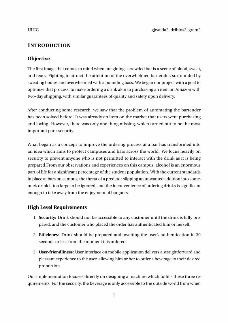
The first image that comes to mind when imagining a crowded bar is a scene of blood, sweat,
and tears. Fighting to attract the attention of the overwhelmed bartender, surrounded by
sweating bodies and overwhelmed with a pounding bass. We began our project with a goal to
optimize that process, to make ordering a drink akin to purchasing an item on Amazon with
two-day shipping, with similar guarantees of quality and safety upon delivery.
After conducting some research, we saw that the problem of automating the bartender
has been solved before. It was already an item on the market that users were purchasing
and loving. However, there was only one thing missing, which turned out to be the most
important part: security.
What began as a concept to improve the ordering process at a bar has transformed into
an idea which aims to protect campuses and bars across the world. We focus heavily on
security to prevent anyone who is not permitted to interact with the drink as it is being
prepared.From our observations and experiences on this campus, alcohol is an enormous
part of life for a significant percentage of the student population. With the current standards
in place at bars on campus, the threat of a predator slipping an unwanted addition into some-
one’s drink it too large to be ignored, and the inconvenience of ordering drinks is significant
enough to take away from the enjoyment of bargoers.
High Level Requirements
1. Security: Drink should not be accessible to any customer until the drink is fully pre-
pared, and the customer who placed the order has authenticated him or herself.
2. Efficiency: Drink should be prepared and awaiting the user’s authentication in 30
seconds or less from the moment it is ordered.
3. User-friendliness: User interface on mobile application delivers a straightforward and
pleasant experience to the user, allowing him or her to order a beverage to their desired
proportion.
Our implementation focuses directly on designing a machine which fulfills these three re-
quirements. For the security, the beverage is only accessible to the outside world from when
1

UIUC gjwajda2, dribins2, gram2
the user has authenticated, until the moment the door shuts. If a user authenticates but
does not claim their drink within a few seconds, the drink is dumped. This may be an in-
convenience to users if they are ready to pick up their order. However, we are confident that
there exists a timing solution which will preserve the safety and security of the drink without
making the experience frustrating for the user.
As far as efficiency, our second requirement, our program loops endlessly and never halts.
Although in the first version it will only be able to service one request at a time and will not
have any sort of request queue, we feel that in a later version, this aspect would be straightfor-
ward to implement with threading and multiprocessing. More machines could also be added
which could divide up the labor. There would be some sort of routing protocol to forward
the requests to the individual machines from some central server. Currently, however, this
machine is designed to serve one request at a time, which should be approximately as fast as
an average human bartender.
Finally, our third requirement requires a flawless design of our mobile application. We
deliver a user-friendly and intuitive experience by offering the user several options. They
have a few choices between suggested beverage proportions, or have the option to customize
their beverage, and choose any proportion they’d like. In a later version of the project there
would be more options of beverages, and the mobile application would provide more com-
binations and mixes, as well as more customization if a user wanted to create their own
mixture.
Block Diagram
Figure 1 shows our high level block diagram, split into four main modules: the mobile app,
the control mechanisms, the electromechanical components, and the power system.
Electromechanical components run on 12V, while control components operate at 5V, both of
which are regulated by the power system, which plugs into any 110V wall outlet. Customizable
drink orders are made from the mobile application which sends data to the microcontroller,
which is listening on the network on a constant IP address through the WiFi module.
The microcontroller then operates the electromechanical and control components, using the
motor to move the cup on a conveyor belt, the sensor to detect its position, the air pumps to
2

UIUC gjwajda2, dribins2, gram2
Figure 1: Block Diagram
pour the drinks, the barcode scanner to authenticate the user, the door circuit to detect if the
the door has been opened or closed, and the lock to ensure the drink’s accessibility is limited.
Our main block-level change since the design review was a modification in our pouring
system. Rather than using a high-powered valve and gravity to control our liquid flow, we
decided to implement an air pump system which relied on pressure to pour the drinks.
3

UIUC gjwajda2, dribins2, gram2
DESIGN
Design Procedure
Looking at one block at a time, it is important to dissect the decisions that were made in
the design of our device. On a high level, we chose to undertake this project for the sake of
providing a feeling of safety and security when ordering a beverage. In order to accomplish
that, we wanted a simple interface with minimal interaction. Hence, we decided the only
exposed feature to the user should be a door, and the entire mechanism would be built into
the side of a wall. We also knew that there had to be some micro-controller which would
operate the various devices required for the preparation of the drink.
In order to make the process as hassle-free as possible for the user, we decided to pro-
gram an Android application, which would connect to the micro-controller and generate
requests. Having the mobile interface with the user would also simplify any future plans for
payment, authentication, and user-friendliness.
The next step was to begin choosing parts which would satisfy our requirements. Since
everything stemmed from the micro-controller, we chose that first. One member on our
team had previous experience with Arduino, and specifically, working with the microproces-
sor on it independently of the Arduino platform, so we investigated the options that Atmel
provided. We established some baseline requirements and decided to use the ATmega328p
micro-processor, with the Arduino bootloader flashed. Another option would have been the
ATmega168 micro-processor, but the higher end 328p micro-processor was not expensive,
and we were not certain of our processing power or flash memory needs, so we decided to
be safe and invest in the more powerful chip. Having the Arduino bootloader flashed saved
us the step of manually flashing it, and allowed us to utilize the Arduino platform and the
existing libraries and tools that have been developed for it.
Next, we began considering how we would actually make the beverage. There had to be
some movement involved so that new cups could be placed and after discuss with our TA,
we agreed we could define cup-placement outside the scope of our project as long as we
could recover from it by detecting its position. Hence, we needed a mechanism to move cups
into a desired position for pouring and retrieval. Being by no means mechanical experts, we
decided that a conveyor belt would suit our needs with the least complexity. For this, we had
to reach out to the Machine Shop.
4

UIUC gjwajda2, dribins2, gram2
The Machine Shop was extremely helpful for our purposes. After several discussions, and
once we provided the initial physical design as shown in Figures 2 and 3, they had a good
idea of what would work best for our conveyor belt and frame, and suggested we invest in a
stepper motor, although they did not specify what size would be sufficient. We purchased
a stepper motor and a driver and configured it, guessing at the required current and step-
ping increment. Unfortunately, the hardwired configuration we had for the driver was not
sufficient to move the belt. We increased the current delivered to the motor and decreased
the step size to improve the motor’s torque, and had it working briefly. However, the driver
ultimately gave out under the new load and we did not have an opportunity to replace it
before the demo.
Figure 2: Back View
5

UIUC gjwajda2, dribins2, gram2
Figure 3: Front and Side View
The drink pouring system started as a pair of electronic valves, as shown in Figures 3 and
2, which opened when 12V was applied across the leads, and consumed almost 1.5A each.
We did not want to have to worry about pressurizing the pouring system, so we planned to
pour using gravity and opening and closing these valves. However, once one of the valves
arrived, we realized it was extremely bulky and inefficient, so we considered other ways to
pour the beverage. After exploring what other similar systems used, we found that we could
use lightweight mini air pumps, provided that all the seals were airtight. These air pumps
would inject air into a bottle until the pressure was high enough for liquid to exit through
a separate tube. This system proved to be power-efficient, provided a constant rate of flow
without bubbling, and was easy to set up, so we added it to our final design.
The other electromechanical component was the electromagnetic lock. We chose this device
because it provided electronic control with minimal mechanical complexity. We operated
this device and the other 12V on/off devices With a signal from our micro-controller, which
toggled the base voltage of an array of power transistors which would either provide 12V or
0V to the device, thus turning it on and off.
Finally, the barcode scanner and door circuit were both deemed necessary for ensuring
the security of the drink. Initially we were exploring the idea of generating QR codes, but
after looking at the market, we found the only scanners available for a reasonable price were
6

UIUC gjwajda2, dribins2, gram2
one-dimensional barcode scanners, with either USB or PS/2 interfaces. We were then able
to locate a PS/2 keyboard Arduino library so we decided to proceed with the PS/2 barcode
scanner. The door circuit was essential when considering that the machine would serve
customers one after another. There had to be a way to ensure the door was closed before
proceeding with preparation of a beverage. As a result, we knew there had to be one lead
on the door, and one lead on the frame, which when connected, the micro-processor would
detect.
7
UIUC gjwajda2, dribins2, gram2
Design Details
Our program flow maps our program’s execution from listening for a request from the mobile
application, through each step of the pouring process, to the moment of delivery.
Before an order is made, there is a listener program running on the ATmega, which interfaces
with the WiFi module using the SPI protocol and listens for a request being made from a
mobile device on the same network. Once a connection is established, we are able to commu-
nicate with the client directly and securely. The Adafruit ATWINC1500 WiFi module was the
natural choice for connecting to the WiFi network from the ATmega as it is an Arduino-native
device which has several example programs written and full Arduino support.
The program flow leads through the procedure of pouring a beverage and generating a
barcode. It sends this barcode to the user via TCP, and begins scanning for barcodes in the
near vicinity. The security requirement is satisfied through our authentication procedure.
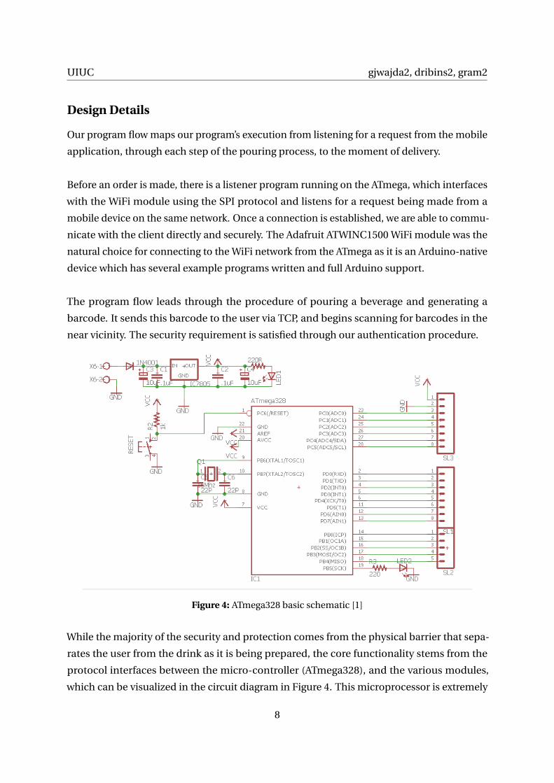
Figure 4: ATmega328 basic schematic [1]
While the majority of the security and protection comes from the physical barrier that sepa-
rates the user from the drink as it is being prepared, the core functionality stems from the
protocol interfaces between the micro-controller (ATmega328), and the various modules,
which can be visualized in the circuit diagram in Figure 4. This microprocessor is extremely
8

UIUC gjwajda2, dribins2, gram2
Figure 5: Pouring Rate
versatile in that it natively offers SPI, I 2C , USART, as well as several analog and digital GPIO
pins from which we can read, and to which we can write values. The ATmega328 is the
processor used in many Arduino applications, which allows programming and developing
with it to be straightforward and well-documented. The basic breakout functionality is shown
in Figure 4, with each available pin serving as GPIO.
With such a flexible layout, we were able to add and remove our modules very easily, allowing
for extremely modular and streamlined testing and development. All modular components
can be represented as black boxes with their corresponding inputs and outputs attached to
the correct protocols of the ATmega. A PCB was made to contain all of the micro-controller
and electromechanical components. Beyond the layout, the microprocessor utilizes its GPIO
pins to control the air pumps, as well as the electronic devices including the lock and open-
door sensor as shown in Figure 6. These signals are easy to manipulate and read. The door
circuit will have a pull-down resistor so that when the circuit is open, the GPIO pin reading
will see 0V, and when the door closes, the circuit is complete and it will read 5V. The air pumps
are enabled according to the proportion that the user requests on a timer, according to the
graph in Figure 5.
For communication with the scanner and WiFi module, we chose to design for the PS/2
protocol when transferring serial data to and from the microprocessor. There exists an Ar-
duino library which implements a PS/2 keyboard reader, and the scanner we found serves
the same purpose.
With all of these libraries incorporated, we began having troubles running our code. When it
9

UIUC gjwajda2, dribins2, gram2
began running nondeterministically and halting in the middle of execution with no errors, we
examined the memory situation closely and discovered that we were approaching capacity
both in program memory and in stack memory. We began eliminating unnecessary static
variables in our imported libraries, as well as print statements that were not needed. After
some time, the program began running normally again, and we were extremely cautious
afterwards in adding new variables.
The power system involved some complexity as well. We had two power different power lines,
with some devices operating at 12V and others at 5V. We needed a method of allowing our
5V micro-controller to control these high-voltage parts, when the GPIO pins are limited to
40 mA. We decided to implement a circuit involving power transistors as shown in Figure
6 for each 12V component. The diode exists in order to prevent current kickback into the
micro-controller (represented as the blue chip on the left).
Figure 6: Circuit design for TIP120 Power transistor [3]
We utilized a bipolar 12V stepper motor to move our conveyor belt. We then purchased an
appropriate driver chip for this motor which allowed us to use the PWM signals from the
ATmega and a 12V power supply to turn our belt. The driver determines the current allowed
to the motor using a reference voltage (Vr e f ) and sense resistor (Rs). In our PCB, we set Vref
to 2V and Rs to 0.75 ohms. The current is determined by the equation I = Vr e f
8Rs. This sets
the current to 0.3333A, which is its rated current on the website we purchased it from [6].
Unfortunately, with this setting, we weren’t able to get enough power for the motor to move
in one direction (it would simply move back and forth), so we began playing around with the
current settings. We were able to get the motor to move a full water bottle of water well within
our requirement time, but the next day our circuit wasn’t working. Due to time constraints,
10

UIUC gjwajda2, dribins2, gram2
we weren’t able to debug this issue.
Below are our calculations in determining the power supply to purchase. We knew that
it had to plug into a wall socket for simplicity and finality of setup, and that it had to convert
the socket’s 110V AC into 12V DC.
Power Requirements
Part Voltage Rated Current
Air pump 12V 80mA
Air pump 12V 80mA
Stepper Motor 12V 0.33A
Lock 12V 0.10A
Voltage Regulator 5V 1A Max
P = IV
Worst Case Power = I1V1 + I2V2, we assume maximum current across regulator.
= 12V · (.08+ .08+0.33+0.1)A+5V ·1A = 12.08W
Power supply is 12V, so we need it to handle 12.08W12V = 1.007A. We found an inexpensive
wall-to-car cigarette lighter AC/DC converter and cut off the output to have 12V leads from
the converter, which was rated up to 5A, so it met all of our needs. As mentioned previously,
we found it actually output closer to 14V DC but all of the necessary high-voltage devices
worked at that voltage, so we used it in our final design.
11

UIUC gjwajda2, dribins2, gram2
VERIFICATION
The complete table of low-level requirements and verifications can be found in the Appendix.
In it, we break down each main physical component and describe the required inputs and
outputs it must consume and produce, as well as any internal components that must exhibit
specific behavior.
The main requirements for the high level modules can be categorized by their inputs and
outputs in the block diagram in Figure 1. We can break down these requirements on a high
level below:
1. The mobile app must be able to maintain a TCP connection to the server, allow a user
to order a drink according to a customized template, and be able to render a 10-byte
string into a Code128 barcode.
2. The control module must be able to provide control logic to the electromechanical
components and interface over the WiFi network, while controlling the program flow,
and authenticating the user when a drink is ready.
3. The electromechanical module is fully responsible for physical creation of the beverage
and protecting it until it is ready.
4. The power system must provide at least 2A to the 12V decides, as well as at least 1A to
the 5V devices through a voltage regulator.
We can verify the success of each module not only by seeing the system as a whole perform
its task, but also by evaluating them individually. Isolating each module from the others
and simulating the inputs and outputs, we can see how it behaves in an ideal environment,
assuming the others are working.
For the mobile application, we can verify the connection by running a basic TCP server
on a laptop, connecting to it from the Android application, sending over the desired order
packet, and printing the output. To verify the barcode rendering, we can use a separate
Android application from the app store to scan the generated barcode and make sure that it
is encoded properly.
Verifying the requirements is more difficult for the micro-processor and control module
since there are many internal components that must function in order for the system to work
12

UIUC gjwajda2, dribins2, gram2
as a whole. Ultimately, we can be sure the control module is working by first verifying that a
barcode is being generated and sent to the mobile application. We can simulate this from
a simple TCP client running on the computer which displays the returned barcode. Next,
we can ensure that the microprocessor is able to control the electromechanical devices by
writing to the GPIO pins and reading the output. It has to be 5V in order to activate the power
transistors and turn on an electromechanical component.
The electromechanical module consists of several devices running on 12V, each of which
must be tested individually to ensure they are functioning properly. The air pumps and lock
simply require a 12V differential to begin working. However, the motor and motor driver must
be specifically configured and tested while connected to the conveyor belt rig, with varying
PWM inputs. Unfortunately, we were not able to complete thorough testing of the conveyor
belt setup. We were only able to retrieve it from the machine shop one week before our
demonstrate date, and by the time we got it working, there were only a few days remaining.
When the driver burned out, we could not continue using it and were therefore forced to
abandon the requirement.
Lastly, the power system requirements were straightforward to verify. Although the AC/DC
converter we purchased provided approximately 14V differential instead of the rated 12V,
our voltage regulator was rated to handle a range of input voltages so the output was still a
steady 5V, which was sufficient to power the 5V system. We also tested the electromechanical
components at the 14V rating and found them all to function equally well.
13

UIUC gjwajda2, dribins2, gram2
COST
Labor
Name Hourly Rate Hours Invested Multiplier Total ($)
Austin $30.00 150 x2.5 11,250
Greg $30.00 150 x2.5 11,250
Max $30.00 150 x2.5 11,250
Total 450 x2.5 33,750
Parts
Description Source Part Number Quantity Cost ($) Total ($)
ATmega328 Sparkfun ATmega328 1 6.00 6.00
WiFi Module Adafruit Adafruit ATWINC1500 1 25.00 25.00
Barcode Scanner Amazon Unitech AS10-P 1 30.00 30.00
Lock Amazon UHPPOTE UT0511-130NO 1 23.00 23.00
12V Air Pump American Science & Surplus 40666P1 2 2.50 5.00
Infrared Proximity Sensor Digikey GP2A200LCS0F 1 7.11 7.11
Motor Sparkfun ROB-09238 1 14.95 14.95
12V 5A Power Supply Walmart 550877401 1 14.67 14.67
100ft Plastic Tubing Amazon N/A 1 8.13 8.13
Atmega Holders Cutedigi N/A 1 3.45 3.45
Transistors Amazon TIP120 10 8.00 8.00
Circuit miscellany ECEB N/A N/A ∼30.00 ∼30.00
Physical Frame and Belt Machine Shop N/A 1 ∼100.00 ∼100.00
Table Total
Labor $33,750
Parts $275.31
Total ∼$34,025.31
14

UIUC gjwajda2, dribins2, gram2
CONCLUSIONS
The ethical aspect of this project is what makes it stand out among the others. Our prod-
uct is designed to make the world a safer place by removing the opportunity for malicious
bartenders or patrons to inject someone’s drink with a potentially harmful substance. By
automating the drink preparation process and ensuring that only the person who ordered
the drink is coming in contact with it, we successfully eliminate any uninvited interactions
between the drink and a stranger.
The first rule stated on the IEEE Code of Ethics [4] describes an individual’s responsibil-
ity to the welfare of the public in all circumstances. In our scenario, we have observed a
dangerous process that occurs frequently, and thus it is our responsibility to do everything in
our power to rectify it. We can thus improve the safety of bars, which are so often known to
be dangerous places.
In our design, we are extremely diligent so that there is no harm. We accomplish this by
including all the necessary security precautions to ensure that tampering with our device is
difficult, if not impossible. These precautions include our mobile application establishing a
secure connection with the client, and preventing our messages from being tampered with or
falsified. As for the machine itself, all circuitry is shielded from the user by a strong wooden
frame, and our design will not use enough power to start a fire. Although fluids may be
splashed by user error in grabbing the drink, all of our hardware is protected and insulated by
foam.
Finally, we need to take into consideration the legislation surrounding consumption of
alcohol in the United States. Currently there are laws in place to limit the consumption to
only be allowed for those aged twenty-one years or older. Especially considering the legal age
of bar entry for campus town is nineteen, this factor needs to be taken into consideration.
One solution use is a registration system using Facebook which requires users to authorize
their age to be twenty-one or older before allowing them to make a purchase. In the future
we would put a more secure feature that better authenticates. It will also be up the bar’s
discretion to ID people entering the bar. It will be unlawful to lie about one’s age during the
registration process, and offenders will be prosecuted to the fullest extent of the law. The
process will be very similar to how bars and the Champaign Police coexist on campus, with
occasional raids to ensure everyone is complying. Additionally, we recognize that there are
15

UIUC gjwajda2, dribins2, gram2
FDA requirements for using plastic tubing to serve beverages, and we will be sure to adhere to
these. The policies presented are to protect the safety of our customers and ensure a business’
compliance with the law.
Ultimately, our main objective was to design a machine which will allow party-goers to
have a good time and ensure their safety, while saving the bar itself money in the long run.
We realize that this will not stop all sexual assaults from occurring, as tragically there are
countless more situations in which these incidents occur, but we hope to make a dent in
what seems, at first glance, to be a daunting problem.
16

Bibliography
[1] A. Sanjeev, "How to Make Arduino Board: The Easy Way - DIY Hacking", DIY Hacking,
2014. [Online]. Available: https://diyhacking.com/make-arduino-board-and-bootload/.
[Accessed: 16- Feb- 2017].
[2] "8-bit AVR Microcontrollers ATmega328/P DATASHEET COMPLETE", Atmel, 2016. [On-
line]. Available: http://www.atmel.com/Images/Atmel-42735-8-bit-AVR-Microcontroller-
ATmega328-328P_Datasheet.pdf. [Accessed: 22- Feb- 2017].
[3] "M. Currey, "Controlling a Solenoid Valve from an Arduino | Martyn Currey", Mar-
tyncurrey.com, 2017. [Online]. Available: http://www.martyncurrey.com/controlling-
a-solenoid-valve-from-an-arduino/. [Accessed: 14- Apr- 2017].
[4] "IEEE IEEE Code of Ethics", Ieee.org, 2017. [Online]. Available:
https://www.ieee.org/about/corporate/governance/p7-8.html. [Accessed: 22- Feb-
2017].
[5] LM78XX/LM78XXA 3-Terminal 1A Positive Voltage Regulator, 1st ed. Fairchild, 2017, p. 1.
[Accessed: 24- Feb- 2017].
[6] "Stepper Motor With Cable - ROB-09238 - Sparkfun Electronics". Sparkfun.com. N.p.,
2017. Web. 2 May 2017. [Accessed: 1- May- 2017]
17

UIUC gjwajda2, dribins2, gram2
APPENDIX
Requirements and Verification Table
Micro-processor: ATmega328
Requirement Verification
Must be able to run at 5V ±10% Using voltage generator, we will run simple pro-
grams at 5V and evaluate the performance.
Must be able to provide modifiable PWM sig-
nals with varying duty cycle and frequency
Running the PWM signal at 0, 25, 50, and 100
percent duty cycles, as well as changing fre-
quency from 0 to 31,250 Hz.
Must be able to provide a timer interface to the
programmer, and time events up to 30 seconds.
Write a function which will light up an LED at
a certain sequence of time steps and compare
it against a stopwatch.
Must be able to generate 10 random bytes and
send them to the mobile device in less than .5
seconds
Generate 10 bytes and send to mobile device
to see if correctly displayed.
Must be able to compare two 10-byte strings
to determine if they are equal in less than .5
seconds
Hardcode several strings for the ATmega to
compare, and display the results on an LED
(1 if same, 0 if different), and compare timing
against a stopwatch.
Must be able to interface with WiFi module and
scanner, both of which require clock synchro-
nization and logic more complicated than "5V
on, 0V off"
Compare barcode scanned with barcode gen-
erated and sent over WiFi to mobile device to
see if there are discrepancies
Must provide control logic to standard 5V com-
ponenets (door circuit, power transistors con-
trolling 12V devices)
All standard 5V components behaving as speci-
fied in flowchart
18

UIUC gjwajda2, dribins2, gram2
WiFi Module: Adafruit ATWINC1500 WiFi
Requirement Verification
Must be able to maintain a connection to the
wireless network and maintain a constant IP
address
Display IP address on startup, and connect to
it from a mobile client
Must be able to receive a formatted string (6
bytes, desired drink ratio) as a request, and
respond with a 10 byte string (generated bar-
code)
Successful server/client exchange. Server will
print the ratio it recieved, and client will dis-
play the barcode the server sent
Barcode Scanner: Unitech AS10-P AS10
Requirement Verification
Must be able to scan a 10 byte Code128 barcode
with 95% accuracy.
Scan a 10 byte barcode and check if read cor-
rectly on ATmega.
Must be able to interface with ATmega through
PS/2 interface.
Barcode scanner uses PS/2 interface so if suc-
cessful scan the requirement is verified.
UHPPOTE UT0511-130NO Magnetic Lock
Requirement Verification
Must be able to handle 100lbs of force pulling
against the lock.
Fasten both lock components and lock by ap-
plying 12V differential. Clamp the mobile com-
ponent, pull with a spring scale. Our design
will not allow enough grip for humans to pro-
vide that kind of pulling force.
Must only have 2lbs or less of resistance when
unlocked.
Fasten both lock components. Unlock by ap-
plying 0V. Pull with spring scale.
Mini Air Pumps
Requirement Verification
Pumps 12oz within 30 seconds Apply 12V differential across terminals for 30
sec to pump. Measure if liquid dispensed is ≥12oz.
Draws < 1A current at 12V Use multimeter to measure current while
pump is in operation.
19

UIUC gjwajda2, dribins2, gram2
Infrared Proximity Sensor: Sharp GP2A200LCS0F
Requirement Verification
Must emit digital signal when an opaque cup
is at a distance of 2cm or less.
Wire up sensor. Hold opaque cup at distance
2cm or closer and measure output.
Must emit digital signal when a glass cup at a
distance of 2cm or less.
Wire up sensor. Hold glass cup at distance 2cm
or closer and measure output.
Android Application
Requirement Verification
Allow users to select or create drinks with a cus-
tom proportion between two mixtures (any ra-
tio from 100%:0% to 0%:100% with increments
of 10%).
Create user interface that allows such options.
Test functionality works as intended.
Must be able to receive 10 bytes of barcode data
in under 1 second.
Create socket connection on ATmega to send
packets of data. Test sending data from AT-
mega to Phone.
Must be able to send 6 bytes of user/drink data
in under 1 second.
Create socket connection on app to send pack-
ets of data. Test sending data from Phone to
ATmega.
Must be able to execute on Android Phone run-
ning Lollipop.
Test app launch on Phone or emulator with
Lollipop.
Must be able to display barcode data on screen
to be read by barcode scanner.
Test receiving and display of barcode data.
Must be able to display barcode data on the
screen and must be able to be scanned by the
barcode scanner.
Test receiving and displaying barcode.
Must sign on to Facebook to verify account be-
fore being able to order.
Try ordering when logged on and not logged
on.
Door Circuit
Requirement Verification
Must be able to detect when door is opened Ouput pin will show 0V when door is opened
Must be able to detect when door is closed Ouput pin will show 5V when door is closed
20

UIUC gjwajda2, dribins2, gram2
Power System
Requirement Verification
Regulator - Provide up to 0.5A current at 5V With regulator set up, put 10 Ohm resistor be-
tween high and ground. Measure current - suc-
cess condition is ∼5V
Transistors - Operate using ATmega328 control
signal and 12V power component that draws <
1A
Wire up transistor circuit using 5V input and
most power-hungry 12V part in project. Assure
that part turns on from control signal and then
use multimeter to measure voltage across part
(should be 12V).
Power Supply - Provide up to 5A current at 12V Put 2.4 Ohms of resistance between terminals.
Measure current.
Must provide wall socket interface for one-time
setup
Plugging in the power cord must begin the op-
eration and setup of the device.
Physical Design
Requirement Verification
Insulates circuits from contact with liquids Test barrier between conveyor belt and PCBs by
gratuitously splashing water (potentially with
food coloring) next to it. Measure how far the
liquid goes. Ideally doesn’t make it half way,
but we only require it to not make it entirely
across.
Figure 7: Requirements and Verification Table
21

UIUC gjwajda2, dribins2, gram2
Stepper Motor Driver Schematic
Figure 8: EasyDriver - Stepper Motor Driver schematic from Sparkfun
22