AUTHORITY THIS PAGE IS UNCLASSIFIED - DTIC
189
UNCLASSIFIED AD NUMBER CLASSIFICATION CHANGES TO: FROM: LIMITATION CHANGES TO: FROM: AUTHORITY THIS PAGE IS UNCLASSIFIED ADA800189 unclassified secret Approved for public release; distribution is unlimited. Distribution authorized to DoD only; Administrative/Operational Use; 01 NOV 1943. Other requests shall be referred to Office of Scientific Research and Development, Washington, DC. Pre-dates formal DoD distribution statements. Treat as DoD only. SOD memo dtd 2 Aug 1960; SOD memo dtd 2 Aug 1960
-
Upload
khangminh22 -
Category
Documents
-
view
1 -
download
0
Transcript of AUTHORITY THIS PAGE IS UNCLASSIFIED - DTIC

UNCLASSIFIED
AD NUMBER
CLASSIFICATION CHANGESTO:FROM:
LIMITATION CHANGESTO:
FROM:
AUTHORITY
THIS PAGE IS UNCLASSIFIED
ADA800189
unclassified
secret
Approved for public release; distribution isunlimited.
Distribution authorized to DoD only;Administrative/Operational Use; 01 NOV 1943.Other requests shall be referred to Office ofScientific Research and Development,Washington, DC. Pre-dates formal DoDdistribution statements. Treat as DoD only.
SOD memo dtd 2 Aug 1960; SOD memo dtd 2 Aug1960

Reproduced by
R DOCUMENTS DIVISION
• *
c I o
HEADQUARTERS AIR MATERIEL COMMAND
WRIGHT FIELD, DAYTON, OHIO

IS ABSOLVED
FROM ANY LITIGATION WHICH MAY
ENSUE FROM THE CONTRACTORS IN -
FRINGING ON THE FOREIGN PATENT
RIGHTS WHICH MAY BE INVOLVED.
u
WRIGHT FIELD, DAYTON, OHIO
/

E*3H

Continuously Coded TDS - $>eeeh Privacy Equipment - Final Report
Mechling, E. B. Bell Telephone Labs., Inc., New York, N. Y,
Office of Scientific Research and Development, NDRC, Dlv. 13
(None)
(None)
2068
Nov '43 Seer. U.S. Eng. 187 photos, tables, diagrs
Laboratory models of a two-way telephone ppivacy system comprising continuously coded TDS equipment have been built add tested. The coding method provides independent interlaced and relatively displaced codes each of which is changed automatically every 3/4 of a second. The terminals are independently synchronized, and no synchronizing pulses are transmitted. The restored speech is of good quality. The quiponeat which generates the codes provides so many different code sequences and so many ways of entering each sequence that it would be prH?&eaUy impossible to employ a captured machine to break in on a conversation.
Copies of this report obtainable from Air Documents Division; Atta: MCl8£& Electronics (3) Communications (1) _ . ^ . CT . ,ftBArt« om Communication systems, Secret (23992*87)
S-8-1
/ ;r Documents Division, T*2 AMC, Wright Field
fticrnfilrp r'i

•n
«5
O
T3 -i o#
"5* o
n i
o
n o 3 -*•
5' c o c
n o a. a> a.
ö 01
SECRET NATIONAL DEFENSE RESEARCH COMMITTEE - , /,
OFFICE OF SCIENTIFIC RESEARCH AND DEVELOPMENT
D I V I S I O N. 13 s E C T I O N 3
?;•
OEMsr-490
FINAL REPORT
ON
PROJECT C-50
CONTINUOUSLY CODED TDS
SPEECH PRIVACY EQUIPMENT
c/> •ü
<D CD n 3-
-u ~i
<* 0 n
*< m
Si c
•5' 3 3 I
"THIS DOCUMENT CONTAINS INFORMATIV AFFECT-
ING THE NATIONAL DEFr..v?. c '•«E UNITED STATES
WITHIN THE MEANING OF THfc. ^i. /NAGE ACT,
U.S.C. 50:31 AND 32, ITS TRANSMISSION OR THE REVELATION OF ITS CONTENTS IN ANY MANNER TO
AN UNAUTHORIZED PERSON IS PROHIBITED BY LAW."
z o <
3 a- o -i
CO
O.S.R.D. NO.. .SECTION NO.. .COl'Y NO. & ^_DATE November T, 1943
BELL TELEPHONE LABORATORIES, INCORPORATED
NEW YORK N. Y.
SECR 3£^

SECRET
DIVISION 13 SECTION 5
NATIONAL DEFENSE RESEARCH COMMITTEE
OF THE
OFFICE OF SCIENTIFIC RESEARCH AND DEVELOPMENT
FINAL REPORT .. ON
PROJECT Cr-50
CONTINUOUSLY CODED TDS
SPEECH PRIVACY EQUIPMENT
Report prepared by: EUGENE B. MECHLING Transmission Engineering De~ ir tment Bell Teiepnone Laboratories, Inc.
Date of Report NOVEMBER 1, 1945
Contract No, 0ELIsr~490_ Expiration Date of Contract APRIL 30, 1943
Contractor: Western Electric Co., Inc. 19b Broadway New York, N. Y.
Serial No» 29 SECRET

SECRE'.
N.D.R.C. SECTION 13.3
PROJECT C-50 CONTINUOUSLY CODED TDS
SPEECH, PRIVACY EQUIPMENT
SUMMARY OF FINAL REPORT
Laboratory nodeIs of a two-way telephone privacy system comprising continuously coded TDS equipment have been built and tested» The coding method provides independent interlaced and relatively displaced codes each of which is changed automatically every 3/4 of a second» The terminals are independently synchronized and no synchronizing pulses are transmitted. The restored speech is of good quality.
The equipment which generates the codes provides so many different code sequences and so many ways of enter- ing each sequence that it would be practically impossible for an enemy to employ a captured machine to break in on a conversation^ Methods employed by Project C-43 have as yet failed to decode speech scrambled by the system*
It has been found, however, that some trained indi- viduals under favorable circumstances are able to understand some of the scrambled speech» Less is understood with fast talkers than with slow talkers but the amount understood by such trained observers at normal speech rates leads to the conclusion that in a system intended to provide long term privacy the TDS principle should not be used singly but in combination with other principles»
A combined system should be so devised that direct listening is of no value and should be arranged so that an interceptor can not disentangle the two types of scramble and obtain intelligence by listening directly to one of them. Such a system is provided by the C-50 TDS combined with and controlling a rapidly switched A5 (frequency band shifting) privacy system fc-hen arranged so that the C-50 TDS coding equipment controls the sequence of A3 codes. In this ar- rangement the.A3 codes may be switched as often as every 37*5 milliseconds« No useful intelligence has been extracted from the scramble in direct listening tests on this combi- nation and furthermore the difficulty of decoding the scram- bled speech by other methods is expected to be materially increased. While the combined C-50 TDS and A3 system weighs about 2200 lbs and requires about 1500 watts of power its probable privacy and its availability are such as to deserve serious consideration for use in Corps to Division Communi- cations and in similar Navy situations,
SECRET

SECRET
FINAL REPORT ~ NDRC PROJECT 0-50
TABLE OF CONTENTS
SECTION
0, 1. 2. 5.
3 ,1 3 »3 3 ,3
4 4 1 4. a
5. 5 l o, p
6.
7S 8.
TITLE
PREFACE OBJECTIVES TDS SYSTEM EQJJTP1iwT ARRANGEI.1SNT
TDS Equipment Bay Continuous Coding Equipment Bay- Power Requirements
EQUIPMENT PERFORIIANCE Transmission Performance Mechanical Performance
PRIVACY TESTS Laboratory Methods Direct Listening
RECOMMENDED COMBINATION OF C-50 TDS WITH Ao (FRE ,;UEi:CY BAND SHIFTING)
APPLICATION TO TLLEGRAPir.: KLCOiiD OF YORK
PHOTOGRAPHS OF 1.10DEL EQUIPMENT
Appendix A Appendix B Appendix C Appendix D Appendix E Appendix F Appendix G
Basic TDS Principles Automatic Code Generating Number of Codes and Code Sequences Detailed Description of Equipment Operating Instructions C-50 and A3 Systems Combined C-50 Project Drawings
PAGE
1 1 2 4 0 6 7 8 8 8 9 9 9
11 IS IE
13
SECRET
CONTINUOUSLY CODED TDS
SPEECH PRIVACY EQUIPMENT
FINAL REPORT - NDRC PROJECT C-50
0. PREFACE
This report covers work carried oat for the National Defense Research Committee under contract No. OEMsr-490 with the Western Electric Company, Inc., by the Bell Telephone Laboratories, Inc.
The main body of the report treats the principal topics briefly, but references are made to several attached appendices in whicii various aspects of the equipment are covered in detail*
1. OBJECTIVES
This project was undertaken to provide model equip- ment in order to study the privacy to be obtained by elabor- ating the TDS principle to its practical limit,
The two groups of privacy equipment which have been constructed are provided with automatic coding apparatus by which changes in key are made at intervals of less than half a second. The key is double in that alternate speech elements are keyed according to two independent systems. Each of these systems is changed at intervals of 3/4- second, but the times at which the two keys change are displaced relative to one another by half this interval. Cryptograph- ically there is a close correspondence to a double interlaced transposition cipher in which the transposition scheme in each of the interlaced systems is changed every 10 letters.
The automatic keying, or coding, equipment provides a large number of very long sequences" of changing transposi- tions and a large number of points of entry to each sequence. The general objective in the design was to make the coding equipment so corrrplex that photograph matching techniques would be more attractive to'an interceptor than an attempt to solve any of the sequences'of transpositions.
Sufficient equipment has been built for two voice frequency terminals, thus providing a complete twoMvay tele- phone system.
SECRET

Page 2 SECRET
2. TDS SYSTEM
A TDS system provides privacy by creating a Division-Scramble, In this process speech at the transmit- ting terminal is stored for a sufficient length of time to permit its division into speech elements of very short dura- tion. These speech elements are then rearranged in a scram- bled order before transmission over a radio or wire communi- cation channel. At the receiving terminal of the circuit the scrambled elements are rearranged in their original order cy a similar time division piocess.
The speech is stored by recording it on a moving magnetic tape. Scrambling takes place in the process of reproducing it from the tape. Nine evenly spaced pole-pieces are provided for this purpose and the order in which they are used is governed by the key-. The object in using different ones of the various pole-pieces is to retard, or delay, successive elements of the speech by different amounts» If the pole-piece nearest to the recording pole-piece is se- lected, the speech is retarded in its transmission only by the time taken for the tspe to travel between the recording pole-piece arid this first reproducing pole-piece. This gives the minimum delay to the stored speech. If the pole- piece farthest from the recording pole-piece is used, the maximum delay is given to the speech. Intermediate pole^- pieces give intermediate delays, ",/hen two speech elements which were originally in succession are delayed by different amounts they are displaced in time with respect to each other. They may be simply interchanged or they may be separated widely with other speech elements inserted between them.
The scrambled spoech-ejements- are returned to their proper order in the unscrambling process by delaying each one in a selective manner, so that the total delay contributed by scrambling and unscrambling is the same for each element. Elements scrambled with the minimum delay are unscrambled with maximum delay, and vice versa. Elements scrambled with intermediate delays are similarly unscramuled with complemen- tary delays. The speech when reassembled has been delayed by the sura of the minimum and maximum delays. In the G-50 TDS system this total delay is 700 milliseconds.
The order in which the reproducing pole-pieces are used in the scrambler depends m the order of their connec- tion to the 20 segments of a commutator, is. brush moves over these segments and causes the pole-pieces associated with the segments to be connected to the transmission line. The
SECRS

Page 5 SECRET
pattern of the interconnection of pole-pieces and coxaaulator segments constitutes the key. The word "code" has been more frequently used than "key" in previous reports on TDS, and will he adopted in the remainder of the present report»
If the interconnection of pole-pieces and segments remains fixed the key, or code, is fixed and the transposi- tion scheme is repeated with each revolution of the brush over the 20 segments. This takes place in 750 milliseconds. The C-50 TDS can be operated in tnis fashion if desired, using punched code cards.
The continuous coding equipment makes two changes in the interconnection of pole-pieces to segments in each revolution. The connections to odd-numbered segments remain fixed until the commutator brush leaves the nineteenth seg- ment; when the brush starts on segment No. 1 an entirely different set of interconnections is used in the next revo- lution by the odd-numbered segments. The pattern for the even-numbered segments begins with the twelfth segment and extends around the commutator through the tenth segment; when the brush reaches tne twelfth segment again a new pattern is ready for the even segments. In tnis way the coding for alternate segments constitutes two independent systems of transpositions, each changing every 750 milli- seconds, but displaced fron each other by 57o milliseconds.
The odd-numbered and the even-numbered commutator segments can be treated separately becsuae the time oaken for the brush to cover one segment, 57.5 milliseconds, is exactly half the time required for the magnetic tape to move from one reproducing pole-piece to the next. The portions of speech, available for reproduction when the brush is on odd segments are therefore never available when the brush is on even segments.
The patterns of interconnection between pole-pieces and commutator segments must follow certain rules in order that the TDS generate a transposition which is valid, in the sense that eacn speech element is transmitted once and only once. Since speecu on the magnetic tape remains there as it goes past all nine reproducing pole-pieces, a random choice of reproducing pole-pieces might pick up the same element of speech twice or more, and some other element would be omitted for each repetition.
The kinds of interconnections which give useful codes are discussed in .Appendix A, attached. The rules worked out in that appendix are basic in the design of the
SECRET
Page 4 SUCHET
automatic coding equipment, which must be so arranged that the semi-random series of choices called for in one part of the coding equipment is scrutinised in another part and re- vised until the interconnection finally set up is a valid transposition.
Translation of the principles discussed in .Appen- dix A into a form which can be utilized with automatic equipment is covered in Appendix B, attached, The mechan- ical and electrical features of the whole system, including both the TDS magnetic tape machine with its associated cir- cuits and the continuous coding equipment, ere described in Appendix D, attached»
The complexity of the coding systems generated by the automatic coding equipment in the C-50 TDS may be il- lustrated by the fact that there are 1,625,702,400 different sequences of codes for- each of the two interlaced systems or (1,623, 702,400) 2 for the combination. The choice of the. particular sequence to be used is governed by four punched cards. The initial settings of ten selector switches then determine the point in the sequence at which the sequence will start. Tue re are {'3,'elBü, 37f')2 such starting points for each sequence, i'rom tue point of view of those operating the equipment the four punched cards and tne ten selector switch settings constitute the key, since these choices must be agreed upon at both ends of the circuit.
V:hen the cards and the initial settings have been chosen, tne equipment can be started» after which it provides, in each of the interlaced systems, an irregular order of valid codea from a possible number of 60,ol6 codes. In a single message, or even in a whole day's use with the same initial settings, only an extremely small fraction of any code cycle would ever be used. Each particular sequence runs so long that it would not begin to repeat before 6,400,000 years. The derivation of these numbers is discussed in the attached Appendix C.
3. EQUIPI.IENT ARRANGEMENT
Each model C-50 TBS terminal is composed of two equipment groups occupying two bays. One of these is called the TDS equipment bay and the other is called the Continuous Coding equipment bay. The general appearance of these bays is shown on photographic .Fig. 1 a""cb£ched.
The TBS equipment bay contains the magnetic tape machine, the speed control, and all of the talking and lis- tening circuits. It can be used as a separate unit providing
SECRE •pm
Page 5 SECFET
a repeated TDS code. The Continuous Coding, equipment bay- contains the switching circuits which convert tue TDS bay fron repeated to non-repeated operation. These equipment groups will be described superficially in terms of photo- graphs in the following sections, and reference should be made to Appendix D, attached, for a description of the me- chanical and electrical features. The instructions for operating the e equipment are given in Appendix E, attached,
19 inch relay floor space of
y.l TDg Equipment Day
The TDS equipment is mounted on a rack which is 54 inches high and occupies a about 21" x 25" over-all. The estimated weight of this bay is 200 pounds.
The TDS equipment is divided between six panels which are shown in photographic Fig. 2 with the panel covers removed. The uppermost panel contains the equipment which controls the speed of the TDS machine. It includes a crystal and a heater unit for maintaining a constant crystal temper- ature .
An important feature of the speed control equip- ment should be noted. This has been designed so as to pro- vide sufficiently close regulation to permit independent operation of the two terminals. Ho synchronising pulses of any I-rind t-re transmitted over the line. This not only avoids the annoyance of hearing the vestiges of the synchronising pulse but it also prevents loss of operation because of transmission difficulties with the synchronizing pulse.
The machine panel is mounted directly below the speed control panel. There are two code connectors on this panel in which punched cards can be inserted for operating the TDS equipment on a repeated code basis.
A small handwheel located on the machine panel below the right-hand code connector permits adjustment of the receiving commutator of the TDS machine to allow for cir- cuit delay. Such an adjustment is necessary because the scrambled speech which is arriving and ready to be restored is unscrambled by signals from the coding equipment which governs the outgoing speech from the same terminal. Since the incoming speech has been delayed by the propagation time of the communication circuit, the signals from the coding equipment must also be delayed before being used. The hand- wheel which provides this adjustment connects to the TDS machine through a delay indicator and a gear box which is shown on photographic Fig. 5.
SECRET

Page 6 SECRET
The TDS nachine contains the magnetic tape, the pole-pieces used for recording, reproducing and erasing and the commutators which govern the time actions. It is shown mounted on the back of the machine panel on photographic Fig. 4, Certain details of the machine are shown on Fig, 5.
A coding control panel, mounted below the machine panel, contains jacks for telephone instruments and jacks for the transmission line, It also contains push-to-talk relays end a transfer switch which permits a choice either of repeated code operation or of the continuously recycled code.
The amplifier panel contains transmitting and re- ceiving amplifiers. The gain controls for the receiving amplifiers are shown in Fig. 1. No gain control is required for the transmitting amplifier since it automatically adjusts its gain (within relatively wide limits) to the correct value for properly recording speech signals on the magnetic tape. Details of the arrangement of apparatus in the amplifier panel may be seen in photographic Figs, 'd, 3 and 4.
The switcning circuit panel just below the ampli- fier panel contains the sealed switch relays which connect the magnetic pole pieces to the line in the proper order as controlled by the commutator brushes and the coding equip- ment. An oscillator to provide a-c bias and erase current for the magnetic tape is also mounted on this panel,
A high voltage regulated rectifier is mounted at the bottom of the bay. This rectifier supplies 250 volts d-c to the amplifiers end to the oscillator. It also supplies energy to operate the sealed switch relayst
5.2 Continuous 3oding Equipment Bay
The Continuous Coding equipment is mounted on a standard 26 inch PBX relay rack which is about 72 inches high and occupies a floor space of about £1 x r6Z inches. It weighs about 700 pounds complete with covers. Its appearance with covers in plo.ee is shown in photographic Fig. 4. Since this photograph was taken,certain modifications have been made in the cover to permit the operator to have access to the control buttons and tc see the settings of the selectors without removing the covers,. This bay is shown with covers removed in Fig. 2 and with the individual covers removed from the relays in Fig. 5.
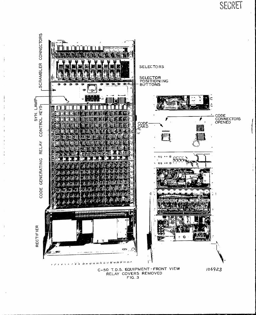
The selector switcaes which are used to generate the codes may be seen in Fig. G near the top of the bay, The wiring of the selectors is thoroughly scrambled and in
SECRET
Page 7 SECEE?
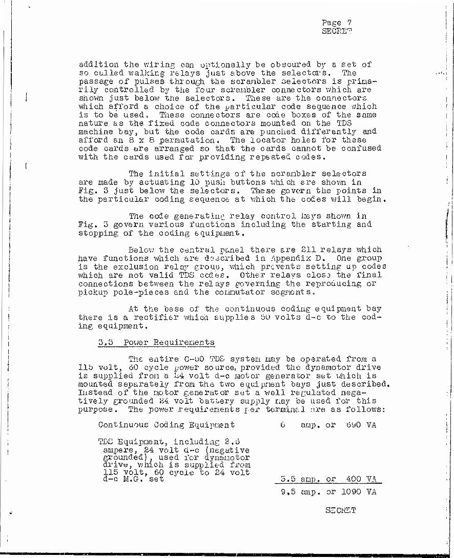
addition the wiring can optionally be obscured by a set of so called walking relays just above the selectors. The passage of pulses through the scrambler selectors is prima- rily controlled by the four scrambler connectors which are
I | shown just below the selectors. These are the connectors ! which afford a choice of the particular code sequence which I is to be used. These connectors are code boxes of the same
nature as the fixed code connectors mounted on the TDS I machine bay, but the code cards are punched differently and | afford an 8 x 8 permutation. The locator holes for these i code cards are arranged so that the cards cannot be confused | with the cards used for providing repeated codes.
( The initial settings of the scrambler selectors
are made by actuating 10 push buttons which are shown in I Fig. 3 just below the selectors. These govern the points in
the particular coding sequence at which the codes will begin,
The code generating relay control keys shown in Fig. 3 govern various functions including the starting and stopping of the coding equipment.
Below the central panel there are 211 relays which have functions which are described in Appendix D. One group is the exclusion relay group, which prevents setting up codes which are not valid TDS cedes. Other relays clos3 the final connections between the relays governing the reproducing or pickup pole-pieces and the commutator segments.
At the base of the continuous coding equipment bay there is a rectifier which supplies 50 volts d-c to the cod- ing equipment.
3,3 Power Requirements
The entire C-oO TDS system may be operated from a lib volt, 60 cycle power source, provided the dynamotor drive is supplied from a k4 volt d-c motor generator set which is mounted separately from the two equipment bays just described. Instead of the motor generator set a well regulated nega- tively grounded 24 volt battery supply may be used for this purpose. The power requirements per terminal are as follows:
Continuous Coding Equipment 6 amp. or 690 VA
TDS Equipment, including 2.3 ampere, 24 volt d-c (negative grounded)} used for dynamotor drive, which is supplied from 115 volt, 60 cycle to 24 volt d-c M.Gr. set 5.5 amp. or 400 VA
9,5 amp. or 1090 VA
SZCHET

page 8 SECRET
4 • EQUIPMENT PEKFOKi 'AN'JE
4c 1 Transmission Performance
The process of chopping up a speech wave- in time, then scrambling these chopped up speech elements, transmit- ting them and reassembling then, naturally leaves some traces in the over-all transmission. However, the quality of the restored speech in this system is reasonably good and indi- vidual voices are readily recognizable over the system, AS measured by consonant articulation errors it is equivalent to the performance of a circuit which transmits a bandwidth of 3000 cycles per second and which has a signal-to-noise ratio of hQ db.
Some background noise is generated in the equip- ment by the scrambling-unscrambling process, consisting principally of soft, slightly noticeable clicks. These measure about 50 db below the received signal. It is be- lieved that the clicks can be further reduced, by a factor ranging from 15 to 20 db, by making certain changes in the switching and receiving amplifier circuits.
The system has not been operated over actual radio circuits but its probable performance under conditions of multi-path transmission has been tested by ope rating it over wire circuits in which large amounts of selective fading wer artificially introduced. Even when the fading was increased to such a point that the signals were momentarily lost the system operated satisfactorily and stayed in proper synchro- nism because the terminals are completely independent of each other. It is to be expected that the system can be employed with any type of transmission circuit which will satisfac- torily handle normal speech,
4,8 llechanical Performance
The entire C-50 TDS system has been operated suc- cessfully several hundred hours. Llany runs of seven or eight hours of continuous operation have been made and at one time the system ran continuously for 18 hours without trouble.
The TJb tape machines in the two terminals have been run about 550 hours. The magnetic tape and reproducing coils have given no trouble in this time though there were two instances of difficulty with short circuits in the regu- lating field winding of the dynamotors. The maintenance measures required for tue TDS tape machines have been con- fined to cleaning the commutators and to lubrication of the
SECRET
e
Page 9 SECRET
main driving ^eer^, It was round that the commutators do not require cleaning oftoner than once every oO hours of operation and lubrication of the main drive gears not oftener than every 60 days,
The coding equipment has in general operated satis- factorily when the initial troubles in the circuit were once cleared out. It may be noted that certain troubles in the
timing circuits. Only one relay trouble has been encountered which required the relay to be replaced. The scrambler selec- tors have been found to require inspection and lubrication of bearing pins at approximately 24 hour operating intervals. Occasionally selectors have required adjustment and this was true at the end of the 18 hour run mentioned above.
The speed control circuit functions somewhat better than originally expected. With reasonably good regulation on the 24 volt d-c supply which operates-the driving dynamotors, and with reasonable care in phasing adjustments, the machine at one terminal may be expected to stay in satisfactory syn- chronism with the. machine at the other terminal for periods of at least one hour without interveninp adjustments. In exceptional cases these periods have approached four and five hours duration. This degree of speed stability is contingent upon the control crystals being at their final operating temperature. This requires that the crystals in their as- sociated ovens be energized for a period of from IS to 24 hours before the system is placed in operation.
b. PRIVACY TESTS
5.1 Laboratory Methods
Phonograph records of the scrambled speech from the C-50 TDS system have been made using several different voices. These were turned over on March 1, l»4b to IT.D.R.C Project C-43 for decoding by the laboratory methods employed by that project, at the present time, October 2, l'j^o, these records have not been decoded by any method.
5.2 Direct Listening
Privacy tests have also been made in which trained observers attempted to obtain information from the scrambled speech by listening directly to it. These tests have indi- cated that speech scrambled by the TDS alone is not proof
SECRET

Page 10 SECRET
against direct listening to tiie degree originally antici- pated. The fact that the codes are changing continuously makes no particular difference with respect to direct listening and the relatively good transnission quality of the C-50 equipment contributes adversely to the security of the scramble.
The proportion of words understood is a function of the rate of speech. If words are spoken very slowly many of then are understood by skilled observers while if words are spoken very rapidly practically none are understood. At speech rates approaching normal most individuals cannot understand the scrambled speech, but certain individuals with continued practice have demonstrated their ability under favorable circumstances to understand an undesirably large proportion of it.
In the direct listening tests sentences of 10 or 12 words in length were spoken and the observers wrote down the words which thev believed they understood. Particularly favorable testing conditions were used, as follows: (1) A very slow speech rate of two syllables per second; (2) quiet listening conditions; (5) no added circuit noise and (4) observers adept at interpreting a TDS type of scramble. It was found that these observers could understand on the sverage 65 per cent of the words transmitted. In individual cases this percentage ranged fron 45 to So per cent. In circumstances more nearly approaching normal it is to be expected that a very much smaller percentage of the words scrambled by the C-50 TDS system would be understood. As an indication of this, it may be pointed out that the records of scrambled speech (made at ordinary talking speeds) which were furnished to Project C-43 have not been "broken" by direct listening methods nor has any significant sense of their contents been determined.
While it would bo tempting to draw the conclusion from this experience with recorded scrambles that the pro- cess of recording and reproducing introduces sufficient dis- tortion to make direct listening useless, this would not be a prudent decision to make in connection with a privacy system intended to be adequate for the situations contemplated when the C-50 project was originally planned«. Further tests were therefore made to find what modifications of the system would eliminate the possibility of information being obtained by direct listening.
The simple addition of a frequency inverter to the scramble would, of cours3, be of no value s inot an interceptor could easily reinvert the speech. However, it was thought
SECRET

SEGRET
that the introduction of an inverter at ran dorn times under the control of the C-50 TDS coding equipment might accomplish the desired purpose in such a way as to make removal of the inverter "by the interceptor a very difficult matter without cracking the code. Tests were made in which approximately 50 per cent of the speech units transmitted were inverted in this coded manner. This was found to decrease the number of words which a trained observer can understand by about 50 per cent. However, a 50 per cent improvement was not re- garded as satisfactory and a search was made for another method which would remove entirely the possibility of direct listening. This vail be described in the next section.
6 • RECOISENDED C0IIBINATI0N OF C-50 TDS WITH A3 (FREQUENCY BMP SHIFTING)
A privacy system in which the TDS principle is com- bined with some other principle should be so devised that direct listening is of no value and should be arranged so that an interceptor cannot disentangle the two types of scramble and obtain intelligence oy listening directly to one of them. It is believed tnat these requirements are both met by a combination of the C-50 TDS and the A3 (frequency band shifting) privacy system when arranged so that the C-50 TDS coding equipment controls the sequence of the A3 codes» By this arrangement the A3 codes may he switched as often as every 37.5 milliseconds.
The combined system has been set up in a number of ways. In tests with direct listening no useful intelligence was extracted from the scramble.
Spectrograms showing the kindß of scramble provided by the combination of the C-50 TDS and the A-3 system are given in the final report of Project C-66, entitled "Frequency- Time Division Speech Privacy System", The coding system used in connection with the A3 privacy device shown in those spec- trograms was found susceptible of improvement and the recom- mended method of controlling the codes of the A3 system by means of the C-50 coding equipment is described and illustrated in Preliminary Report 21, dated July 21, 1945, of Project C-43 entitled "A Coding Arrangement for C-50 - A3 Privacy System". Appendix F, of the present report, also describes the pro- posed combined system. Phonograph records of one of the scrambles provided by combining the C-50 TDS and the A3 have been turned over to Project C-43 for study»
While the combined C-50 TDS and A3 system weighs about 2200 pounds and requires about 1500 watts of power, its
SECRET

Page 12 SECRET
probable privacy and its availability are such as to deserve serious consideration for use in corps-to-division coL-niunica- tions and in similar Navy situations. It is believed that this combination would operate satisfactorily under field conditions with ordinary maintenance measures although special training would be needed for the technical operators. Some design changes would be required to make the model equip- ment suitable for field service but this could be done and the equipment put inbo production in an appreciably shorter time than would be required for the development and produc- tion of any other known type of privacy system.
7 . APPLICATION TO TEIEGRAPBT
In addition to scrambling speech signals the C-50 TDS system could also be used to cipher voice frequency tele- graph signals. As discussed in the final report on N.D.R.G. Project C-55, "Telegraphy Applied to TDS Speech Secrecy System", telegraph signals scrambled by TDS have not been unscrambled by direct listening. It is to be expected that the scramble of telegraph signals produced by the C-50 system would be difficult to solve by laboratory methods since the codes do not repeat. The simple on-off character of tele- graph signals provides few, if any, clues \iien the transpo- sition scheme is continuously changed. As a telegraph system the C-50 TDS offers the possibility of a long term privacy system,
8. RECORD OF WORK
The laboratory work on Project C-50 is recorded in numbered notebooks Nos. T-5184, T-505£i, T-5521, T-5523, T-5557, T-7859 and T-9097.
Only tnose drawings have been attached to the pre- sent report whicn are considered essential to an understanding of the principles of the system or which are of value to oper- ating or maintenance forces. These drawings are listed in Section 1 of .appendix G and are bound at the end of the report in numerical order. Reference is made to them in several of the appendices. A complete list of all of the C— 50 project drawings is incorporated in Section 2 of Appendix G. Drawings not included with the report will be made available upon re- quest of proper authority.
Report Prepared By E. E. Llechling
Bell Telephone Laboratories, Inc., 463 "test Street Hew York, New York
SECRET

Page 15 SECRET
FINAL REPORT - NDRC PilOJECT C-50
PHOTOGRAPHS OF MODEL EQUIPMENT
Fig.• Title
1 C-50 TDS Equipment - Front View
2 C-i-50 TDS Equipment - Front View - Cover Removed
3 C-50 TDS Equipment - Front View - Relay Covers Removed
4 C-rbO TDS Equipment - Rear View - TDS Bay
5 C-50 TDS Equipment - TDS Ilachine
SECRET

SECRET
CONTINUOUS CODING EQUIPMENT BAY
TD.S. EQUIPMENT BAY
PHASING CONTROLS
^CIRCUIT DELAY CONTROL CODING TRANSFER S'w i i CH
£- SPEECH GAIN
• CONTROLS
SECRET C-50 TD.S. EQUIPMENT-FRONT VIEW
FIG. I
it s « 'il t1 'V 'iC'il ' io ii' {j jj'fV'k' \6 ii' it ta i« i\'ti v, • I0b<?2f

0 NECRET
« II II II I 11 I a I B I II «y-r:-•-..••-.•
WALKING RELAYS
•7V,y,V'VV,y,V',B',7d,il''iSi,ii''i!i,,i!s,Ä,'i,>,A'A'iii'^'Ä'A'«
'EC^FT C-50T.D.S. EQUIPMENT-FRONT VIEW COVERS REMOVED
FIG. 2
I06<?2J
SECRET
SELECTORS
SELECTOR POSITIONING BUTTONS
T CODE- CARD
CODE CONNECTORS OPENED
\*
Of. • • ©
~> t?o »* © :»l»r»i»"
Vl
"" • ^ <* l
j"«- 'j
nfyOgb/T L"^"i/fcjBaBe*k H0*
•' j!o 7i' 2? ?5 ? 't !•' i i h t. I '«' 9 10 II I? u'iVii I'O i' ''o >'9
C-50 T.D.S. EQUIPMENT-FRONT VIEW RELAY COVERS REMOVED
FIG. 3
/06<?£3

SECRt
PANELS
24 V D.C. SUPPLY
I i5V^60~ SUPPLY-
DRIVING MOTOR
T.D.S MACHINE
RECEIVING - AMPLIFIER
TRANSMITTING AMPLIFIER
BIAS AND ERASE- OSC. (20KC)
24 V D.C.- SUPPLY
SPEED CONTROL
MACHINE
CODING CONTROL
AMPLIFIER
SWITCHING CIRCUIT
CODING EQPT.
Z 5 4 *> 6 I 6
\0 ^ \Z *> \t, *>
fc******
C-50 T.D.S. EQUIPMENT REAR VIEW TD.S. BAY
/06^2O
FIG.4

EGRET
a. 1 h-
O (/) u. h- T' < Ru< X yzS (/)
^DH> < -3 Zuh-C 3 Q ->-Za 3 < >_UüJ
UJZUJU c 2 5 8 Q<C/K o u
50 T.D.S. E( 2UIPMENT T.D.S. MA CHINE
FIG. 5
UJ a: o
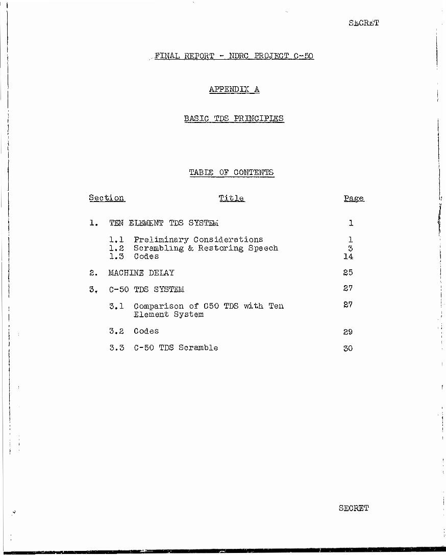
FINAL REPORT - NDRC PROJECT G-50
APPENDIX A
BASIC TDS PRINCIPLES
TABLE OE CONTENTS
SECRET
Section Title Page.
1. TEN ELEMENT TDS SYSTEM
1.1 Preliminary Considerations 1.2 Scrambling & Restoring Speech 1.3 Codes
2. MACHINE DELAY
3. C-50 TDS SYSTEM
3.1 Comparison of C50 TDS with Ten Element System
3.2 Codes
3.3 C-50 TDS Scramble
1 3 14
25
27
27
29
30
SECRET
App. A Page 1 SECRET
FINAL rSx>ORT - xJDRC PROJECT C-LQ APPENDIX A
BASIC TDf. PKlNCIi'Ifif;
!« TEN ELEMENT TDS SYSTEM
1.1 Preliminary Considerations
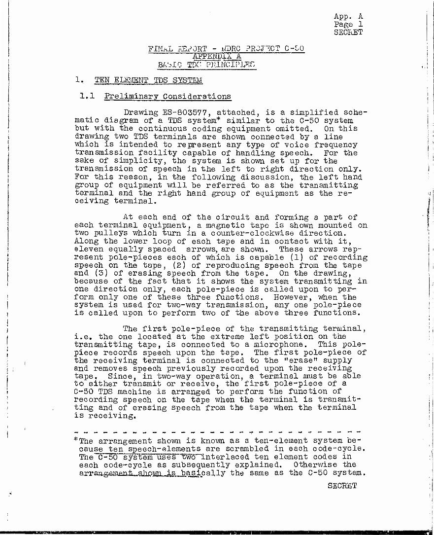
Drawing ES-805577, attached, is a simplified sche- matic diagram of a TDS system* similar to the C-50 system but with the continuous coding equipment omitted. On this drawing two TDS terminals are shown connected by a line which is intended to represent any type of voice frequency transmission facility capable of handling speech. For the sake of simplicity, the system is shown set up for the transmission of speech in the left to right direction only. For this reason, in the following discussion, the left hand group of equipment will be referred to as the transmitting terminal and the right hand group of equipment as the re- ceiving terminal.
At each end of the circuit and forming a part of each terminal equipment, a magnetic tape is shown mounted on two pulleys which turn in a counter-clockwise direction. Along the lower loop of each tape and in contact with it, eleven equally spaced arrows, are shown. These arrows rep- resent pole-pieces each of which is capable (1) of recording speech on the tape, (2) of reproducing speech from the tape and (3) of erasing'speech from the tape. On the drawing, because of the fact that it shows the system transmitting in one direction only, each pole-piece is called upon to per- form only one of these three functions. However, when the system is used for two-way transmission, any one pole-piece is called upon to perform two of the above three functions.
The first pole-piece of the transmitting terminal, i.e.. the one located at the extreme left position on the transmitting tape, is connected to a microphone. This pole- piece records speech upon the tape. The first pole-piece of the receiving terminal is connected to the "erase" supply and removes speech previously recorded upon the receiving tape. Since, in two-way operation, a terminal must be able to either transmit or receive, the first pole-piece of a C-50 TDS machine is arranged to perform the function of recording speech on the tape when the terminal is transmit- ting and of erasing speech from the tape when the terminal is receiving.
*The arrangement shown is known as a ten-element system be- cause ten speech-elements are scrambled in each code-cycle. The C-50 system uses "Wohinterlaced ten element codes in each code-cycle as subsequently explained. Otherwise the arranmameniilahoiiiaLJLR basically the same as the C-50 system.
SECRET
1MB

App. A Page 2 SEGRET
The next nine pole-pieces, designated on the drawing "a" to "i", respectively, are arbitrarily called "coding" pole-pieces because, as subsequently explained, they are employed in the speech scrambling process at the transmitting terminal and in the speech restoring process at the receiving terminal. In performing these respective operations, the coding pole-pieces at the transmitting terminal reproduce from the tape speech previously re- corded upon it by the first pole-piece. This operation
| has been termed "coding on reproduce". The coding pole- 1 pieces at the receiving terminal record speech incoxaing
from the line upon the receiving tape in its correct or unscrambled order. This latter operation has been termed "decoding on record". In two-way operation, therefore, the coding pole-pieces perform two functions; namely, that of reproducing speech when transmitting and of recording speech when receiving.
The last, or eleventh, pole-piece at the trans- mitting end is connected to the "erase" supply. It erases speech previously recorded upon the transmitting tape by the first pole-piece and thereby prepares the tape so that subsequent speech may be recorded upon it. At the receiv- ing end, the last pole-piece reproduces, from its assoc- iated tape, speech which has been previously restored and recorded upon the tape by the coding pole-pieces, and im- presses it upon a connected receiver. In two-way operation of the system, this last pole-piece also is called upon to perform a dual function, namely, that of erasing speech when its terminal is transmitting and of reproducing it when receiving.
On the drawing, immediately below each of the arrows representing the coding pole-pieces "a" to "i", are shown groups of three arrows - two vertical and one horizontal. Each group represents a relay, known as a sealed switch relay. The vertical arrows represent a simple make and break contact on the switch which connects the associated pole-piece to the line under control of the horizontal arrow. This may be visualized somewhat more easily by picturing the horizontal arrow as being connected to one terminal of the sealed switch relay winding (not shown on the drawing) and a battery, or other suitable ener- gizing source, as being connected between the other relay winding terminal and ground. Thus, if ground is applied to any horizontal arrow, the sealed switch operates and con- nects its associated pole-piece to the line.
.Each horizontal arrow associated with a sealed switch relay is connected to an interconnecting SECRET

App. A Page 3 SECRET
device called a "code connector". In the code connector shown on the drawing, any one of the nine sealed switch relays may be connected to any one of ten commutator seg- ments. A grounded rotating brush, associated with the commutator successively contacts each of the commutator segments and thereby operates the sealed switch relays in whatever combination and order is determined by the con- nections in the code connector. For the sake of drafting simplicity, the commutator segments shown on the drawing are arranged in a straight line. Actually, however, they are arranged in a circular path with segment 10 adjacent to segment 1„
The code connectors used in the C-50 system are of two types. One, known as a "fixed code connector", is used for fixed code operation and is arranged much the same as indicated on the drawing. In it connections be- tween commutator segments and sealed switch relays are made through holes punched in code cards. Such connections are illustrated on the drawing by crosses which have been placed at certain intersections of horizontal and vertical conductors in the code connector.
The general appearance of a fixed code connector may be seen by reference to photographic Jigs. 1, 2 and 3, where two of them are shown mounted upon the machine panel of the TDS equipment bay. In the first of these figures, the connectors are in a closed position while in the latter two figures they are in an opened position. A punched code card will also be seen in place in one of the opened con- nectors.
In fixed code operation, i.e« when the fixed code connector is used, the same connections between commutator segments and sealed switches are used repeatedly for each revolution of the commutator brush. In continuously coded operation, the second type of code connector used with the C-50 System is employed. This code connector, which consists of contacts in a group of relays, known as code relays, re- peatedly, and at every revolution of the commutator brush, changes the connections between commutator segments and sealed switches. In the C-50 System one revolution of the brush requires 0,75 second. Consequently, when the contin- uous coding equipment is in operation speech is scrambled differently during each succeeding 0.75 second interval«
1.8 Scrambling and Restoring Speech
The preceding section explained the functions of certain individual components which comprise the simplified TDS System shown on ES-803577, This section further con- siders this drawing and describes the manner in which such components function collectively to form a speech scrambling and restoring system.
SECRET

App. A Page 4- SECRET
In order for the TDS terminals to perform proper- ly the operations required of them, it is necessary that certain requirements be met. These requirements are stated below. As the explanation proceeds, the need for them will become increasingly evident, The requirements are:
(1) The speed of the magnetic tape and the speed of the commutator brush, located in a common terminal, must be such that, within very close limits, the time required for any given point on the tape to pass from one coding pole-piece to the next coding pole-piece is the same* as that required for the commutator brush to sweep over any one given commutator segment.
(2) The absolute speeds of tape and of brush at a receiving termxnal must be the same, likewise within very close limits, as those at the trans- mitting terminal.
(3) The brush at the receiving terminal must contact the correspondingly same commutator segment that the brush at the transmitting terminal contacts, at a time interval later, very nearly equal to the circuit delay. Circuit delay is the time re-
j quired, because of finite velocity of propagation, for the voice signals to be transmitted from
( transmitting to receiving terminal, Thus if the transmission path between the two terminals is
| electrically so short that circuit delay is negligible, the receiving brush must contact
' segment 1, for example, at the same time within ! olose limits, as the transmitting brush contacts ; its segment 1, etc. On the other hand, if the | circuit delay is, for example, fifty milliseconds, I the receiving brush must contact segment 1 fifty t milliseconds after the transmitting brush contacts
segment 1, etc.
Now let it be supposed that the system shown on the drawing is set up and operating in accordance with the above requirements and, in this particular instance, that the circuit delay is negligibly small. Furthermore,
j let it arbitrarily be supposed, for the sake of explana- j tion, that a talker starts speaking at the same instant i
| *Notei -This is the rule for the non-interlaced coding ' given by the simplified TDC of the present discus-
sion; in the C50 TDC the segment time is half the travel time of the tape between two consecutive pole-pieces.
SECRET
i - i
App. A Page 5 SECRET
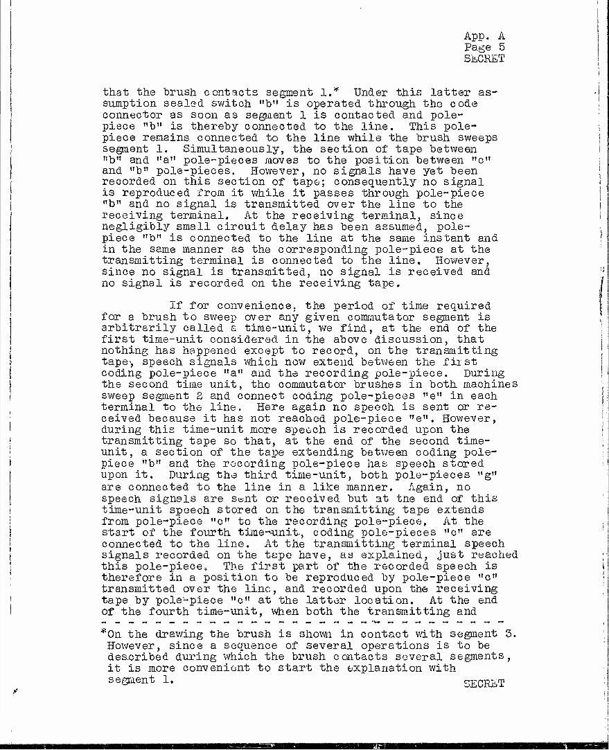
that the brush contacts segment 1.* Under this latter as- sumption sealed switch "b" is operated through the code connector as soon as segment 1 is contacted and pole- piece "b" is thereby connected to the line. This pole- piece remains connected to the line while the brush sweeps segment 1. Simultaneously, the section of tape between "b" and "a" pole-pieces moves to the position between "c" and "b" pole-pieces. However, no signals have yet been recorded on this section of tape; consequently no signal is reproduced from it while it passes through pole-piece "b" and no signal is transmitted over the line to the receiving terminal. At the receiving terminal, since negligibly small circuit delay has been assumed, pole- piece "b" is connected to the line at the same instant and in the same manner as the corresponding pole-piece at the transmitting terminal is connected to the line. However, since no signal is transmitted, no signal is received and no signal is recorded on the receiving tape.
If for convenience, the period of time required for a brush to sweep over any given commutator segment is arbitrarily called a time-unit, we find, at the end of the first time-unit considered in the above discussion, that nothing has happened except to record, on the transmitting tape-, speech signals which now extend between the first coding pole-piece "a" and the recording pole-piece. During the second time unit, the commutator brushes in both machines sweep segment 2 and connect coding pole-pieces "e" in each terminal to the line. Here again no speech is sent or re- ceived because it has not reached pole-piece "e". However, during this time-unit more sx>eech is recorded upon the transmitting tape so that, at the end of the second time- unit, a section of the tape extending between coding pole- piece "b" and the recording pole-piece has speech stored upon it. During the third time-unit, both pole-pieces "g" are connected to the line in a like manner. Again, no speech signals are sent or received but at the end of this time-unit speech stored on the transmitting tape extends from pole-piece "c" to the recording pole-piece, At the start of the fourth time-unit., coding pole-pieces "c" are connected to the line. At the transmitting terminal speech signals recorded on the tape have, as explained, just reached this pole-piece. The first part of the recorded speech is therefore in a position to be reproduced by pole-piece "c" transmitted over the line, and recorded upon the receiving tape by pole-piece "c" at the latter location. At the end of the fourth time-unit, when both the transmitting and
*0n the drawing the brush is shown in contact with segment 3. However, since a sequence of several operations is to be deacribed during which the brush contacts several segments, it is more convenient to start the explanation with segment 1. SECRET
»aa

App. A "Do fJQ Q
SECRET
receiving pole-pieces "c" are disconnected from the line, the small portion of speech, which at the start of the fourth time-unit occupied the region between coding pole- pieces "c" and "b" on the transmitting tape, has been reproduced and transmitted to and recorded upon the re- ceiving tape» This small portion of speech, which is of one time-unit duration, may be called a speech-element or a speech-unit.
Speech-units are numbered in consecutive order, commencing at the time the talker starts speaking. All of them are of one time-unit duration. In the particular case selected for this discussion it so happens that speech- unit 1 is the first speech unit to be transmitted over the line. As will be subsequently shown, it is not necessary that speech-unit 1 always be sent first.
At the start of the fifth time-unit, speech re- corded on the transmitting tape extends from pole-piece "d" to the recording pole-piece. Of course, that unit of speech which occupies the section of tape between "d" and "c" has been reproduced as speech unit 1. However, in the process of reproduction it is not erased and therefore is still recorded on the tape. Coincidentally, speech-units 2, 3 and 4 are located, respectively, between "c" and "b", "b" and "a" and "a" and the recording pole-piece. At the receiving terminal, the tape has nothing recorded upon it, except speech-unit 1 which likewise occupies the region between pole-pieces "d" and "c". Furthermore, as the commutator brush contacts segment 5 of the commutator at the start of the fifth time-unit, the sealed switch relay associated with "b" pole-piece operates. Speech-unit 3 is just starting under this pole-piece, so it is in position to be reproduced, transmitted and recorded on the receiving tape during the fifth time-unit. At the end of this time-unit, speech element 1, on both tapes, has advanced to occupy the region between "e" and "d" and speech-unit 3, likewise on both tapes, has advanced to the region between "c" and "b"r It is thus evident that each of these speech units occupies identically corresponding positions on the transmitting and receiving tapes.
Following a manner similar to that previously indicated, it is evident that during the sixth time-unit nothing is transmitted to the receiving terminal, because, at the start of this time-unit, no speech signals have reached pole-piece "h". At the start of the seventh time- unit, speech-unit 1 has reached pole-piece "f" (having ad- vanced to that position during the sixth time-unit), pole- piece "b" is again connected to the line and speech-unit 5 is transmitted and recorded on the receiving tape. At the end of the seventh time-unit, speech-elements 1, 3 and 5 are on the receiving tape occupying, respectively, the posi- tions "A" to "f" "e" to "d" and "c" to "b". During the
SECRET

Page 7 SECRET
eighth time-unit, again, nothing is transmitted. However, all speech units have advanced with the tapes during this interval to tne next pole-piece so that, at the end of the time-unit, speech-unit 1 on both tapes has just reached pole-piece "h".
During the ninth time-unit, the blank space between speech units 1 and 3 on the receiving tape is filled in with speech-unit 2 because pole-pieces "g" are connected to the line throughout this interval. Up to the end of the ninth time-unit, it will be observed that speech units have been transmitted over the line in the sequence (neglecting blanks) 1, 3, 5, 2. Upon the receiving tape, however, they are ar- ranged in the order 1, 8, 3, "blank", 5. Thus, speech-units which have been transmitted over the line in an unnatural sequence are appearing on the receiving tape rearranged in their original order. This situation is further clarified during the next or tenth time-unit. At the start of this time-unit, speech-unit i on the transmitting tape has reached pole-piece "f". This pole-piece in both terminals is con- nected to the line by action of the commutator brush on commutator segment 10. The fourth speech-unit is reproduced from the transmitting tape and recorded upon the receiving tape between speech-units 3 and 5. At the end of the tenth time-unit, therefore, speech-elements have been transmitted in the sequence 1, 3, 5, 3, 4 but are recorded on the re- ceiving tape in their natural order 1, 2, 3, 4, 5 without blanks between.
At the end of the tenth time-unit, or at the start of the eleventh time-unit, when the commutator brush has completed one revolution and again starts contact with segment 1, speech-unit 1 on the transmitting- tape is starting under the erasing pole-piece. At the same instant speech- unit 1 on the receiving tape is starting under the repro- ducing pole-piece and is thus ready to be reproduced from the tape and impressed upon the receiver.
As the brushes leave the tenth commutator segment a code-cycle is completed. The above explanation therefore has been carried through the first code-cycle» If desired it may be carried further, through succeeding code-cycles, in a manner similar to that employed above. As a matter of interest, Table I, below, has been prepared which summarizes the sequence of operations for the second code-cycle as well as for the first.
SECRLT

App. A Page 8 SECRET
TABLE I
Sequence of Operations Throughout Two Code-Cycles For Arrangement Shown on ES-805577
Speech Assumed to Start as Brush Contacts First Commutator Segment
S, .U.* S.U.* S.U.* During Pole-Piece Advances Trans. Arrives Time In to And at Unit Operation Pole- Piece Rec. Listener
1 b S.U.l to P.P .a None None 2 e It T
-i. to u b Hone None 3 g
11 1 to tt c None None 4 c " 1 to tt d 1 None 5 b " 1 to it e 3 None 6 h " 1 to it f None None 7 b " 1 to it g 5 None 8 h 11 1 to tt h None None 9 S » 1 to tl i 2 None
10 f " 1 to It T-.*# 4 None 11 b " 2 to tl E 9 1 12 e " 3 to It E 7 2 13 g ii 4 to It E 6 3 14 c " 5 to tt E 11 4 15 b *' 6 to ft E 13 5 16 h ti 7 to II E 8 6 17 b " 8 to tl E 15 7 18 h II g to tt E 10 8 19 g » 10 to tt E 12 9 20 f " 11 to It E 14 10
* S.U. designates Speech.-?Unit ** E designates Eras ing Pole-Piec e in Transmitting
Machine
SECRET

App. A Page 9 SECRET
Tiie above table has been constructed tu ; show what happens during two code-cycles or more : specifically during each of the first twenty time- j units after speech, starts. .For example, during the first time-unit pole-pieces "b" are connected ! to the line and the first speech unit advances to I pole-piece "a" so that at the end of this time- j unit the first increment of speech*4unit 1 has just reached pole-piece "a". No speech units are j transmitted or received. During the eleventh time- unit, for further example, pole-pieces "b" are again connected to the line and speech-unit 9 is j reproduced from the transmitting tape, transmitted ' and recorded on the receiving tape. Simultaneously, speech-unit 1 on the transmitting tape, which had reached the erasing pole-piece at the end of the previous time unit, is being erased as the second speech-unit advances to the erasing pole*piece. Furthermore, speech-unit 1 on the receiving tape reaches the listener, it having arrived at the reproducing pole-piece at the end of the tenth time-unit,,
At this time two things, which are illustrated in Table I, are worthy of note. First, it will be observed, since the pole-pieces are equally spaced, that ten time-units elapse after the talker starts speaking before restored speech arrives at the listener. This is always true, re- gardless of the code used. Second, during this first ten time-unit interval only five speech- units of the ten recorded on the transmitting tape have been transmitted and recorded on the receiving tape. This is not always true but depends upon the code (connections in the code-connector) in use at the time. In this connection, it may be stated that during the first ten time-units after the talker starts speaking not more than nine speech- units nor less than one speech-unit can be trans- mitted to and recorded upon the receiving tape. These two characteristics of TDSare discussed in subsecuent sections.
SECRET

App. A Pago 10 SZCRKT
In all of tue preceding explanation of basic TDS principles and in Table I, above, it arbitrarily lies been assumed, for the sake of illustration, that the talker started speaking at the start of a code-cycle or just as the commutator brushes contacted segment 1. The successful operation of the system is not, however, contingent upon such a condition. In fact the talker can stert speaking at any time during a code-cycle regardless of which commutator segment is being contacted by the brushes* and the system will still satisfactorily scramble and restore speech. However, the "scramble", that is the sequence of speech- units sent over the line to the receiving terminal, is materially affected by the position of the brushes with re- spect to commutator segments at the instant the talker starts speaking. As a step in illustrating this statement, Table II, below, has been prepared using in each instance
TABLE II
Illustration of Effect on "Scramble" Resulting From Successive Positions JSL C oromutator Brushes At the Instant the Talker Starts Speaking.
| Talker J Starts
Speaking As Brush Contacts "Scramble" Cora. Seg. • or
No. Sequence of Speech-'Jnits Transmitted Over the Line
1 b b b 1 5 b 5 b 2 4 4 9 7 S 11 15 8 15 10 12 14- 2 bbb2b4bl3-8 3 bblb3bb2~7 5 4 bbb2bbl-&43 5 bblbbb-5 327 6** bbbbb-42168 7 bbbb-3 1b57 2 8 bbb-2bb4618 S bb~lbb35b72
10 b-bbb24b615
6 5 10 12 7 14 9 11 13-18 4 9 11 6 13 S 10 12-17 15 8 10 5 12 7 9 11-16 14 13 9 4 11 6 8 10-15 13 12 17 3 10 5 7 9-14 12 11 16 18 9 4 6 8-13 11 10 15 17 IS 3 5 7-12 10 9 14 15 11 18 4 6-11 9 8 13 15 10 17 12 5-10 8 7 32 14 9 16 11 13
Note: 1. "b" represents a usable blank. 2« Column of colons represent end of ten time-units after
speech starts. 3. Diagonals composed of hyphens mark the end of one code
cycle and the start of another code-cycle. **This, is the condition satisfying the code slioun on HS-803577.
*This, of course* assumes that the brushes at both transmitting and receiving terminals arc on corresponding portions of lilce numbered commutator segments at the same instant.
SXHST

App. A Page Ji SECRET
the same code (that is the same connections in the code- connector) as shown on ES-805577. This table shows for twenty consecutive time-units the sequence in which speech- units are transmitted over the line, if the talker starts speaking just as the brush contacts one of the commutator segments indicated.
It will be noted from this table that the "scramble" (a term often used to designate the unnatural sequence in which speech-units are transmitted over the line) is different for each condition shown even though the same code (i.e. the same connections in the code-connector) is employed throughout. It will also be noted, again at the end of the tenth time-unit after talking started (indicated on the table by a column of colons), that five speech-units, not always of the same identity but always five in number, have been transmitted over the line. As previously explained, the-exact number of speech units tiansmitted by the end of the tenth time-unit after talking starts may vary from one to nine depending upon the code used and in this instance happens to be five. However, for any given code-, the number of speech units transmitted during the first ten time-units interval is independent of commutator brush positions at the time 'talking starts.
Up to the present, "scramble" has been considered in terms of numbered speech-units. In order to further il- lustrate how speech is scrambled by the application of TDS principles, the speech-units will be considered in terms of their "speech material" contents. In this connection, sup- pose, simply for the sake of illustration, that part of a military order transmitted over the system shown on ES-805577 reads, "The sixth armored division will support the assault." Furthermore, for convenience in illustration, suppose that the talker's speech rate is such that the sounds represented by each two successive letters fall into successive speech-units. The speech may then be divided into speech-units"as shown by the first line (A) of Diagram I, below, in which colons have been employed to represent such division. These units have been assigned successive numbers as indicated by line (P). For clarity the spaces between words have been treated as letters.
The next three lines are again based upon the arbitrary assumption that transmitting commutator segment 1 is contacted by its brush as the talker starts speaking. Line (C-, ) therefore shows the position of the commutator brush as each speech-unit is recorded on the trans- mitting tape. Lines (E-,) and (Fn) show, respectively, the sequence of and speech material in each of the speech- units as they are transmitted over the line.
SujCrCEl

App. A Page12 SECRET
The last three lines (Cg), (E&) and (?ß) are the same as the previous three except thai: they are based on the assumption that commutator segment 6, instead of segment 1, is contacted at the instant the talker starts speaking.
It will be noted that the "scramble", which is, in effect, a transposition cipher of speech sounds, is ap- preciably different in each case. It will also be noted, in the first case, that three time-units elapse after speech starts to be recorded on the transmitting tape before the first speech signal starts to be sent out on the line. In the latter case, five time-units elapse. Furthermore, in the first case, all of the sentence has been transmitted after the elapse of thirty time-units, while in the second case, thirty-three time-units are required before it is all transmitted,
It is not to be understood from that it takes more time for the listener to sent out under the second condition than it out under the first condition. In each ins not evident from Diagram I, the listener wi first speech sound ten time-units after the (still assuming zero circuit delav) and the sound of the sentence ten time-units after finished or thirty-five time-units after he
DIAORAII I
this, however, receive speech does when sent
tance, although 11 receive the talker starts last speech
the talker started.
Illustration of Speeeii Scrambled by IQ-Clement TDS
Speech Divided into Units St>eecli-Unit Numbers
(A):TE:E :SI:23?:H :AR:I.IO:KD: D:IV: (B): 1: 2: 5: 4: 5: 6: 7: 8: 9:10:
Order of Commutator Segments (C^hl: 3: 5: 4: 5: 6: 7: 8: 9:10: Q .. (S. Unit. No. (En):-: -: -: 1: 5: -: 5: -: 2: 4: Scramble^ yJnit# (]?1):_: _. _STHJSIJ _.H . _.E .^
Order of Commutator Segments (C6):6: 7: 8: 9:10: 1: 2: 3: 4: 5: (S. Unit. No. (£6):-: -: -: -' -' 4: 2: 1: 6: 8:
Scramble(s# aiti (Fi). . . . o
:XT:E :TE:AR:3D:
(A) (B)
(«,) (K) (J?l)
(o6) (36) (F6)
I3:10:N :UI:1L: S:UT:?0:IiT: T:IE: A:SS:AU:LT: 11:12:15:14:15:16:17:18:19; 20;31:22;25;24:25:
1: 2: 5: 4: 5: 6: 7: 8: 9:10: 1: 2: 5: 4: 5: 6: 7; 8: 9:10: 9: 7: 6:11:13: 8:15:10:12:14:19:17:16:21:23:18:25:20:22:24: D:UD:AR:IS:I1 :3D:LL:IV:I0:TrI:RT:UP: S:HE:SS:P0:LT: T: A:AU:
6: 7: 8: 9:10: 1: 2: 3: 4: 5: 6: 7: 8: 9:10: 1: 2: 3: 4: 5: 3:10: 5: 7: 9:14:12:11:16:18:13:20:15:17:19:24:22:21: ~: -:*
SI:IV: H:H0: D:UI:I0:IS: S:P0:H : T:LL:TT:ÄT:AU: A:HE: ~: -:* *Units 23 and 25 will follow successively with a blank
speech-unit between the:.-»., i.e.:3S:-:LT:
Note: The "e" in "armored" has been purposely omitted because it is silent in the pronunciation of the word. gxRJT
KB
App. A Page 03 SECRET
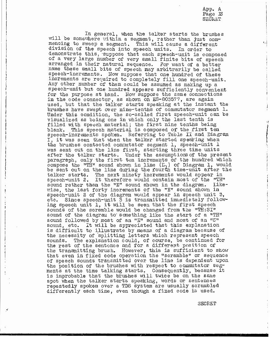
±n general, when the talker starts the brushes will be somewhere within a segment, rather than just com- mencing to sweep a segment. This will cause a different division of the speech into speech units. In order to demonstrate this, suppose that each speech-unit is composed of a very large number of very small finite bits of speech arranged in their natural sequence. For want of a better name these small bits of speech may arbitrarily be called speech-increments. How suppose that one hundred of these increments are required to completely fill one speech-unit. Any other number of them could be assumed as making up a speech-unit but one hundred appears sufficiently convenient for the purpose at hand. How suppose the same connections in the code connector, as shown on ES-803577, are again used, but that the talker starts speaking at the instant the brushes have swept over nine-tenths of commutator segment 1. Under this condition, the so-called first speech-unit can be visualized as being one in which only the last tenth is filled with speech material; the first nine tenths being blank. This speech material is composed of the first ten speech-increments spoken. Referring to Table II and Diagram I, it was seen that when the talker started speaking when the brushes contacted commutator segment 1, speech-unit 1 was sent out on the line first, starting three time units after the talker starts. Under the assumptions of the present paragraph, only the first ten increments of the hundred which compose the "TH" sound shown in line (E-, ) of Diagram 1, would be sent out on the line during the fourth time-unit after the talker starts. The next ninety increments would appear in speech-''unit 3. It therefore would contain most of the "TH" sound rather than the "E" sound shown in the diagram. Like- wise, the last forty increments of the "E" sound shown in speech-unit 2 of the diagram would appear in speech unit 3, etc, Since speech-unit 3 is transmitted immediately follow- ing speech unit 1, it will be seen that the first speech sounds of the scramble would be changed from the "TH:SI" sound of the diagram to' something like the start of a "TH" sound followed by most of an "E" sound and most of an "S" sound, etc. It will be appreciated that this explanation is difficult to illustrate by means of a diagram because of the necessity of "splitting letters which represent speech sounds. The explanation could, of course, be continued for the rest of the sentence and for a different position of the transmitting brush. However, this is sufficient to show that even in fixed code operation the "scramble" or sequence of speech sounds transmitted over the line is dependent upon the position of the brushes with respect to commutator seg- ments at the time talking starts. Consequently, because it is improbable that the brushes will twice be on the same spot when the talker starts speaking, words or sentences repeatedly spoken over a TDS system are usually scrambled differently each time, even though a fixed code is used.
SECRET

App. A Page lit SECRET
Listening tests made with words spoken over TDS systems at a normal "or at a higher than normal rate of speech bear this out.
It has previously "been mentioned that TDS "scramble" is vulnerable to direct listening, particularly at low speech rates. The reason for this will now be con- sidered. Suppose, for example, 1000-cycle tone is trans- mitted over the system. In this case, speech-units, each composed of what might be called "sections" of 1000 cycle tone are displaced with respect to each other. This, of course, makes no difference to the ear because the result- ant "scramble" is still 1000-cycle tone even though the sections of 1000 cycle tone have been rearranged in a dif- ferent order than that in which they originally occurred. Row consider, for example the word "two". It is composed of the staccato "t" sound and of the relatively long drawn out vowel sound "o-o-o-o". The latter becomes very pro- nounced if the word is spoken slowly. In this case, the situation is much the same as with 1000-cycle tone, the long drawn out sound of the "o" is broken up into speech- units which are transposed among each other with no ap- preciable change in the sound. The scramble of the whole word might sound, for example, like "o-t-o-o-o" or it might even sound like "t-o-o-o-o", which is the same as the ori- ginal word.
In general, words composed of few and relatively long drawn out sounds are more vulnerable to direct listen- ing than are those composed of many and relatively staccato sounds. Examples of the former are "when", "where" and "why" and of the latter "rectification" and "technique".
Ic3 Codes
As will have previously been noted, the term "scramble", when used in connection with TDS systems, re- fers to the unnatural sequence in which speech elements are sent from transmitting to receiving terminals. On the other hand, the term "code" refers to the order in which pole-pieces are connected to the line (or other transmission medium) by the commutator. Codes are determined by connec-
1 tions established in the code-connectors.
In general, TDS codes may be considered under two classifications - (1) usable codes and (B) unusable codes. With usable codes, the transmitting TDS terminal will scramble speech in such a manner that the receiving terminal can completely and satisfactorily restore it. With un- usable codes, the trän Quitting terminal will scramble speech but in such a way that it cannot be properly restored by the receiving terminal. Jor this reason, consideration of un- usable codes would ordinarily be of no further interest.
SECRET
i

App. A Page_ 15
However, a knowledge of them is helpful if they ere to be avoided in the setting up of usable codes.
The requirements to be met by codes in order that they be usable are: (1) no speech-unit can be transmitted more than once, (2) speech-units cannot be superposed one on top of the other and (3) no speech-unit can be exempted from transmission. Of these conditions, the first must be observed because in any one code-cycle ten time-units only are available for the transmission of ten speech-units. If one or more of the speech-units were to be transmitted more than once it could only be done either at the expense of not transmitting other speech-units or of superposing them upon other speech units. This would violate conditions (8) and (3). Condition (2) is necessary because it is impossible to again separate the single unit resulting from superposition* into its original components. Condition (5) is obvious, since if one or more speech-units are not transmitted, it is not possible to restore the speech in its entirety.
At this point, it is desirable to add ,to the con- ception of a speech-^unit. It is, of course, evident that in any conversation pauses of variable duration are bound to develop between words and between sentences. v/hen con- versation is carried on over a TDS system, these pauses may be sufficient^ long for one or more speech-units to be either partially or entirely void of speech material. For this reason, the conception of a speech-unit must include those which are entirely blank as well as those which are either partially or completely filled with speech material. Furthermore, since usable codes require that all speech- units be transmitted, it is necessary that blank speech- units be, in effect, transmitted as well ss those which are either partially or completely filled with speech material. The blank units may be considered as room noise which is • also picked up and coded.
Unusable codes violate any one or any combination of the three conditions, stated above, which pertain to usable codes. Some obviously unusable code connections will be given. Assume for example that less than ten
*In this connection, it is, of course, possible to visualize a frequency conversion or one of the speech units so that it would occupy a different frequency band than the other.
. These then could be superposed, in the sense that they would occupy the same time-unit, and could again be separated. This, however, is not true superposition of common frequencies and, tnerefore, is not in accoi'd with the meaning intended in this explanation of TDS coding principles.
SECRET

App. A Page 16 SECRET
interconnections are provided in the code connectors. Under such a condition, one or more of the commutator segments are idle. Consequently, when the "brush contacts such segments certain speech-units are not impressed upon the line.. This, of course, -violates the previously stated condition (3), for usable codes. Next, assume that ten interconnections are provided, but that they are so arranged that certain commutator segments are idle and other commutator segments are involved in multiple connections to sealed switch re- lays, lor example, suppose that the connection between segment 1 and sealed switch "b", as shown on ES-805577, is shifted horizontally so that commutator segment 1 is not connected to anything and commutator segment 2 is connected to both the "b" and "e" sealed switches. Under this as- sumed arrangement an unusable blank is produced when the brush contacts segment 1. *;/hen it contacts segment 2 the two speech-units which at the moment lie, respectively, between "e" and "d" and between "b" and "a" on the trans- mitting tape are superposed and transmitted over the line as a single unit. Consequently, with code connections of such character both conditions (2) and (3) for usable codes are violated. As a third illustration, assume that more than ten interconnections are provided in the code- connectors. Obviously under such an assumption, since there are only ten segments, some of the segments must be involved in multiple connections to sealed switch relays. Since, as previously explained, the connection of more than one sealed switch relay to a single commutator segment re- sults in superposition of speech-units, it is evident that the use of more than ten connections in a code connector violates condition (2) for usable codes.
The first rule to be followed in setting up usable codes, therefore, may be stated as follows: "Each com- mutator segment, individually, must be_ connected to some one, but to only one, of the nine sealed switch relays". If this rule is followed conditions (2) and (3) for usable codes will not be violated, but it is not sufficient to satisfy condition (1).
A rule will be developed next to assure that con- dition (1) for usable codes will be met. Examination of the code connections shown on ES-803577 discloses, first, that of the nine horizontal conductors "a" to "i""in the code connectors only certain ones are connected to commuta- tor segments and, second, that certain others (more specific- ally "b", "g" and "h") are connected to more than one seg- ment. Thus more than one commutator segment is connected to the same sealed switch relay. This in no way violates the provisions of the rule just stated which requires that each commutator segment must be connected to one"relay only. In fact, the rule makes the use of multiple horizontal connec- tions necessary because ton connections must be provided in the code connector and there are only nine sealed switch relays available., It is evident, therefore, that one of the relays must be connected to at least two commutator segments.
SECRET

App. A Page 17 SECRET
Vfliile multiple connections on the individual horizontally arranged conductors in the code-connectors do not necessarily produce unusable codes, these multiple con- nections must be arranged properly with respect to each other or else unusable codes will result. To illustrate an improper arrangement, assume that connections are ar- ranged as shown in Diagram II, below.
DIAGRAM II
Illustration of Unusable Code Which Meets ffirst Rule for Setting Up Usable Codes
i xx h x g x f x e x d x c x b x a "x
125456789 10
"NOTE x's represent connections in code-connectors.
It will be noted that the first nine of these connections are arranged along a common diagonal, which starts in the lower left-hand corner of the code-connector at the "1-a" intersection and extends upward to the right to the "9-i" intersection. This arrangement satisfies the first rule which has been established for usable codes because each commutator segment is connected to one and only ono sealed switch relay. However, this assumed code is unusable. The reason becomes evident as the action of the terminals is examined.
To show this, suppose a talker starts speaking as the brush contacts segment 1. (If desired, any other position of the brush can be assumed for that instant with comparable results). As the brush sweeps commutator seg- ment 1, the first speech-unit is recorded upon the trans- mitting tape, and pole-piece "a" is connected to thy line. As the brush contacts segment 8, the first speech-unit has reached pole-piece "a" but at this instant pole-piece "a" is disconnected from the line and pole-piece "b" is connected thereto. As soon as the first speech-unit reaches pole-piece "b" it is disconnected and pole-piece "c" is connected. This process continues, with the first speechr unit "chasing" a pole-piece which is connected to the line but not reaching one until the start of the tenth time- unit. During the tenth time-unit, pole-piece "i",•. which
SECRET
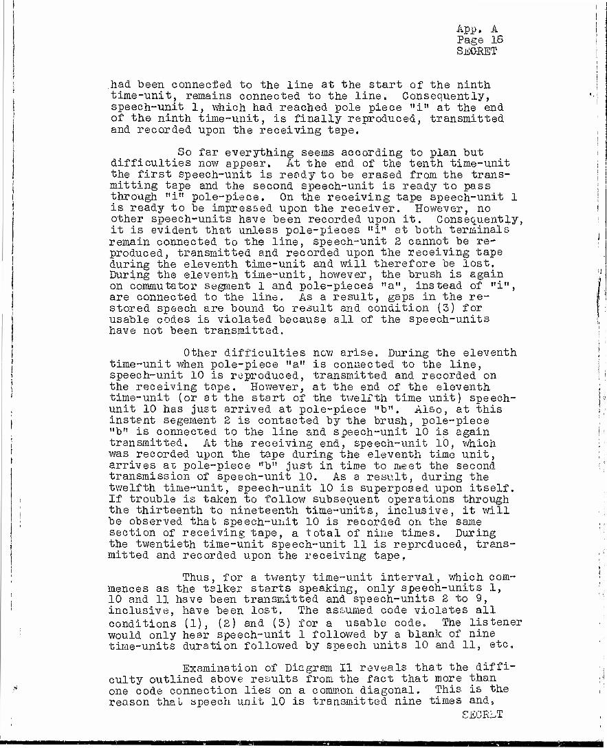
App. A Page IS STÖBET
.had been connected to the line at the start of the ninth time-unit, remains connected to the line. Consequently, speech-unit 1, which had reached pole piece "i" at the end of the ninth time-unit, is finally reproduced, transmitted and recorded upon the receiving tape.
So far everything seems according to plan but difficulties now appear. At the end of the tenth time-unit the first speech-unit is ready to be erased from the trans- mitting tape and the second speech-unit is ready to pass through "i" pole-piece. On the receiving tape speech-unit 1 is ready to be impressed upon the receiver. However, no other speech-units have been recorded upon it. Consequently, it is evident that unless pole-pieces "i" at both terminals remain connected to the line, speech-unit 2 cannot be re- produced, transmitted and recorded upon the receiving tape during the eleventh time-unit and will therefore be lost. During the eleventh time-unit, however, the brush is again on commutator segment 1 and pole-pieces "a", instead of "i", are connected to the line. As a result, gaps in the re- stored speech are bound to result and condition (3) for usable codes is violated because all of the speech-units have not been transmitted.
Other difficulties now arise. During the eleventh time-unit when pole-piece "a" is connected to the line, speech-unit 10 is reproduced, transmitted and recorded on
i the receiving tape. However, at the end of the eleventh * time-unit (or at the start of the twelfth time unit) speech- , unit 10 has just arrived at pole-piece "b". Also, at this j instant segement 2 is contacted by the brush, pole-piece
"b" is connected to the line and speech-unit 10 is again ; transmitted. At the receiving end, speech-unit lb, which j was recorded upon the tape during the eleventh time unit,
arrives az pole-piece "b" just in time to meet the second transmission of speech-unit 10. As a result, during the twelfth time-unit, speech-unit 10 is superposed upon itself. If trouble is taken to follow subsequent operations through
j the thirteenth to nineteenth time-units, inclusive, it will \ be observed thab speech-unit 10 is recorded on the same
section of receiving tape, a total of nine times. During I the twentieth time-unit speech-unit 11 is reproduced, trans- j mitted and recorded upon the receiving tape.
; Thus, for a twenty time-unit interval, which com- mences as the talker starts speaking, only speech-units 1,
j 10 and 11 have been transmitted and speech-units 2 to 9, ' inclusive, have been lost. The assumed code violates all
conditions (1), (2) and (3) for a usable code. The listener would only hear speech-unit 1 followed by a blank of nine time-units duration followed by speech units 10 and 11, etc.
Examination of Diagram II reveals that the diffi- culty outlined above results from the fact that more than
•-••' one code connection lies on a common diagonal. This is the reason that speech unit 10 is transmitted nine times and»
CECRLT

App. A Page 19 SEGRET
furthermore, is transmitted this number of times at the expense of not transmitting speech-units 2 to 9, which should have been transmitted» Now suppose another code is assumed. This one also meets the requirements of rule 1 for usable codes, but it has only two connections on a common diagonal. This is shown in Diagram III.
Diagram III
Illustration of Code Which keets First Rule For Setting Up Usable Codes But Which Sends Out a Speech-Unit. Twice
i :-x— h-~— :x > g x—x—x f-x: — e-:-- x- dx x • c--— b- a—'X 1234567890
NOTE: JZ' S represent connections in code connector. Colons are shown to mark the diagonal which is involved in double connections. Dashes re- represent no connection.
In this diagram two code connections are shown on the common diagonal indicated by colons. The connections are "1 to d" and "4 to g". To show that one of the speech units is reproduced, transmitted and recorded upon the re- ceiving tape twice with this code, it is unnecessary to completely trace the sequence of operations through as has been previously done. It is evident from previous discus- sion that some one speech-unit is reproduced, transmitted and recorded upon the receiving tape when the brush contacts segment 1 and connects pole-piece "d" to the line. As the brush contacts segment 2, this same speech-unit has advanced to pole-piece "e", but, in this instance, it is not re- produced because pole-piece "f" is connected to the line. Likewise, when the brush contacts segment 3, this speech- unit has advanced to pole-piece "f" but "a" is connected to the line. When the brush contacts segment 4-, this speech- unit has arrived at pole-piece "g". in this case, however, pole-piece "g" is connected to the line. Thus, it will be observed, this same speech-unit is again reproduced, trans- mitted and finally recorded upon itself ax, the receiving terminal.- This same line of reasoning can be followed for any arrangement of codes in which two or more connections appear on a common diagonal and it vail always be found that certain speech units will be transmitted more than once.
SECRET
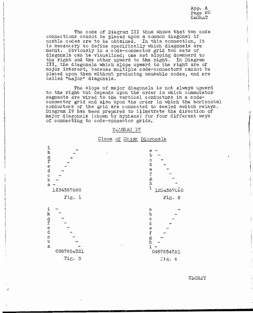
App, A Page 20 SJICRCT
The code of Diagram III thus shows that two code connections cannot be placed upon a common diagonal if usable codes are to be obtained. In this connection, it is necessary to define specifically which diagonals are meant. Obviously in a code-connector grid two sets of diagonals can be visualized; one set sloping downward to the right and the other upward to the right. In Diagram III, the diagonals which slope upward to the right are of major interest, because multiple code-connectors cannot be placed upon them without producing unusable codes, and are called "major" diagonals.
The slope of major diagonals is not always upward to the right but depends upon the order in which commutator segments are wired to the vertical conductors in a code- connector grid and also upon the order in which the horizontal conductors of the grid are connected to sealed switch relays. Diagram IV has been prepared to illustrate the direction of major diagonals (shown by hyphens) for four different ways of connecting to code-connector grids.
DIAGRAM IV
i h
e d c b -
Slope of Mo,ior Diagonals
a - b - c d e f
1234567890 1 123*567890
Pig. 1 Fig. 2
i - a h b g c f d e e d - f c e b h a - i -
098765-^321 0987654321
7ig. 3 Jig. 4
« - !
SLCRET

App. A Page SI SECRET
Wiring arrangements other than those illustrated by the above four figures of Diagram IV may be visualized., The direction of major diagonal slope for any other wiring arrangement may be determined from the respective directions of vertical and horizontal components; one component taking the direction in which the commutator segment numbers in- crease and the other component taking the direction in which
j the sealed switch relay letters follow the normal alphabetical J sequence, i.e. in the direction from "a" towards "i".
It is now possible to establish a second rule | for setting up usable codes. This rule is "Only single code ! connections, of the ten required, shall appear upon ma j or j diagonals of a code-connector grid". The first rule together
with the second rule completely specifies the requirements j for usable codes. I
In the application of these two rules, however, the meaning of the term "major diagonal" must be enlarged to include the portions of the diagonal which extend beyond the diagram. The need for this extension is seen when it is realized that in certain respects a code-connector is nothing more than a time-position coordinate system for speech units, in which time is reckoned in time-units as the brush sweeps each commutator segment, and in which position along the magnetic tape, is determined by the locations of the various coding pole-pieces. A speech-unit first appears below pole- piece "a". At the next time-unit it moves up one step. As time proceeds the speech-unit rises through the diagram, and its path is a major diagonal, Only two of the diagonals lie wholly within the code connector diagram, and the other sixteen diagonals extend outside of the code"connector, This is necessarily so because the "useful" life (nine time^ units) of any speech-unit is represented by the period re- quired for it to move through all nine of the coding pole- pieces. The fact that most of the diagonals extend beyond the limits of the code connector grid means that the speech- units which travel along such diagonals are available for reproduction in more than one code-cycle. A speech-unit must be reproduced only once, however, and therefore there can be only one code connection on the whole diagonal which represents the path of the speech-unit.
The two previously developed rules for usable codes may be combined into one general rule which follows:
"To set up a usable code each individual commutator segment must be connected to some one of the nine sealed switch relays but to not more than one of them. Of these connections between segments and relays, only one may be placed upon any major diagonal of the code connector grid including such portions of the major diagonals as_ extend beyond the limits of the c ode-cbnnector." " SECRET

App. A Page 22 SECRET
Usable codes may be divided into two general classifications, which may be called "Non-consecutive Element1' and "Consecutive Element" codes. In a ten- element TDS system such as that shown on drawing ES-803577, ":Mon-consecutive Element" codes are such that, the ten speech-units scrambled in one code-cycle are not selected from a single group of ten consecutively numbered speech-units. For example, it is possible to arrange a usable code so as to transmit, during one code cycle, speech elements in the order: 4, 2, 1, 9, 8, 10, 7, 6, 15, 15. If these speech-elements are arranged in their natural sequence, they do not form a group of ten consecutively numbered speech-elements. Speech-elements 5 and 5 were transmitted during the previous code-cycle and speech- elements 11 and 12 are not transmitted until the next suc- ceeding code cycle.
"IJon-consecutive Element" codes constitute a substantial fraction of the codes used with repeated code TDS machines. They are not convenient to use if codes are to be changed automatically each code cycle. This is be- cause some of the speech^units would be lost when the code is changed, unless the automatic equipment is supplied with a memory.
With "Consecutive Element" codes the ten speech- units transmitted each code^cycle are selected from a group of consecutively numbered speech-units. For example, during a given code-cycle, such a code might transmit speech- elements as follows: 3, 1, 7, 6, 2, 10, 5, 4, 8,"9-. If these speech-units are arranged in their proper sequence, they form a group of consecutively numbered speech-units from 1 to 10, inclusive.
"Consecutive Element" codes are the general type employed when different codes are used during each successive code-cycle. However, even these codes require that certain restrictions be placed upon their selection, if they are to be suitable for such use.
The code connections of a "Consecutive Clement" code lie upon ten successive major diagonals of the grid. Eor fixed code operation, it makes no difference which ten of the eighteen major diagonals of a code-connector grid are selected for use, providing that the ten which are selected are adjacent to each other, 'tfhen automatically changing codes are used it does make a difference. Two successive codes might each be usable separately as fixed codes, but as successive codes in automatic operation the second code might repeat speech elements already transmitted by the first code. Such a situation is shown in Diagram V. The reason is that the second code encroaches on major diagonals which were used in the first code. The speech- unit picked up at the eighth segment in the first code will be picked up again at the fourth segment of the second code. Two other such overlaps are also indicated. As a result,
SECRET
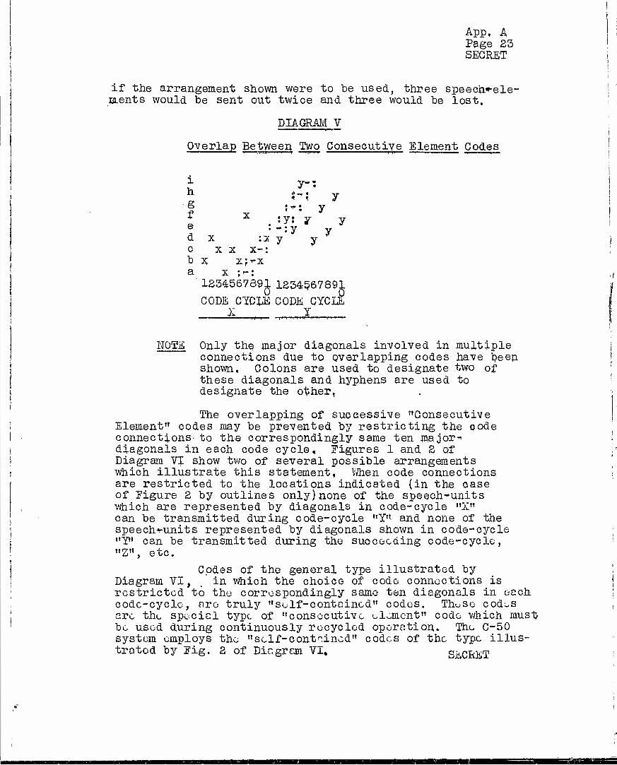
I
App, A Page 23 SECRET
if the arrangement shown were to he used, three speech*-ele- ULents would be sent out twice and three would be lost.
DIAGRAM V
Overlap Between Two Consecutive Element Codes
1 v-- t f y
f v ''""• Y l x . :y: y y e •-:y y d x :x y y • c xx x-:
i
b x x?"X a x ;":
1234567891 123456789^ CODE CYCEE CODE CYC
X Y 3 I
NOTE Only the major diagonals involved in multiple connections due to overlapping codes have been shown. Colons are used to designate two of these diagonals and hyphens are used to designate the other,
The overlapping of successive "Consecutive Element" codes may be prevented by restricting the code connections to the correspondingly same ten major" diagonals in each code cycle. Figures 1 and 2 of Diagram VI show two of several possible arrangements which illustrate this statement, When code connections are restricted to the locations indicated (in the case of Figure 2 by outlines only)none of the speech-units which are represented by diagonals in code-cycle "X" can be transmitted during code-cycle "Y" and none of the speech^units represented by diagonals shown in code-cycle "Y" can be transmitted during the succeeding code-cycle, "Z", etc.
Codes of the general type illustrated by Diagram VI, . in which the choice of code connections is restricted to the correspondingly same ten diagonals in each code-cycle, are truly "self-contained" codes, Th^se cod^s arc the special type, of "consecutive element" code which must be used during continuously recycled operation. The C-50 system employs the "sclf-contnined" codes of the type illus- trated by Fig. 2 of Diagram VI* SECRET
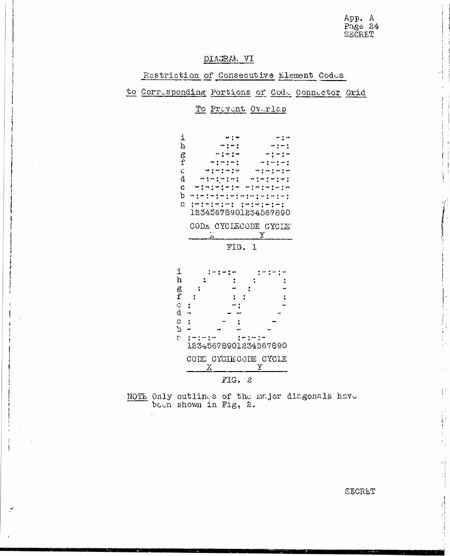
App. A Page 24 SECRET
DIAGRAL VI
Restriction of Consecutive Element Codes
to Corresponding Portions of Cod^ Connector Grid
To Prevent Overlap
1 ** ! *? *
h -: -:
f -:-:-: -:-
e * *** « « • * *
I i
12345678901234567890
COD& CYC LEG ODE CYCLE' . 1 Y
FIG. 1
h
d -
123^5678901234567890
CODE CYCIECODE CYCLE X Y
EIG. 2
NOTE Only outlines of the major diagonals hsv^ be oil shown in Eigf 2.
c-rr ECRET

App. A Pr.gc 25 SECRET
The totr.l number of usablu codus for a ten-element system which is not restricted is 1,344,961. All of these are available for fixed code-operation, Ifor continuously recycled opera- tion, with the code connections restricted to the major-diagonals indicated by Fig. 2 of Diagram VI there are 95,401 codes available. Of these 60,316 can be generated by the continuous coding equip-
i ment. (See Appendix C).
2» MACHINE DELAY
Llachine-delay is an arbitrary term which is used to differentiate delay in the transmission of speech resulting from the TDS "scrambling- unscrambling" process from circuit delay which is caused by a finite velocity of propagation of speech signals over transmission facilities which connect the TDS terminals.
i.iachine-delay may be divided into four components which are respectively called (1) re- cording delay, (2) scrambling delay, (3) restoring delay and (4) reproducing delay.
Recording delay, which occurs in prepara- tion for scrambling, is the time required for speech to travel from the recording pole-piece to the first coding pole-piece "a".
Scrambling delay is the delay which re- sults from arranging speech-units in an unnatural sequence. It is always equal to some whole multiple of a time-unit, from zero to eight, inclusive.
Restoring delay is the delay which results j from rearranging the scrambled speech-units into j their original natural sequence. It is., likewise, ; always equal to some whole multiple of a time unit,
from eight to zero, inclusive.
'.i
SECRET
rf

App« A Page 26 SECRET
Furthermore,, restoring delay, for an individual speech- I element, is complementary to scrambling delay so that the sum of the two is always equal to eight time-units. For , j this reason, scrambling and restoring delay components ''i are usually considered collectively and are designated by the term "coding delay" even though both the "scrambling- unscrambling" processes are involved in it. [
Reproducing delay is the time required for speech to travel fron the last coding pole-piece "i" to the re- | producing pcle-piece, when the machine is arranged for un- | scrambling,, I
In transmission through a TDS system, each speech- unit is individually subjected to all of these delays and each speech~unit is subjected to the same total delay. J
Code connections have a direct influence upon scrambling and restoring delay. It is possible to predict « from the code used, in any particular case, how many speech- | units will be transmitted by the end of each ten time-units j{ after a talker starts speaking. This can be done by assign- ing "to each code connection a number which corresponds to its location above, (in terms of horizontal conductors of the code-connector) the "a" conductor. The average of these numbers will be the average scrambling delay for the code used, For example, in the case of the code shown on ES-803577, the number assigned to the first code-connection would be 1, to the second would be 4, to the third 6, etc. The average of all ten such numbers, in this case, is 4*. This is the average scrambling delay for the code in question expressed in time-units. The average recording delay, in the TDS illustrated, is 1, consequently the total average transmitting machine de.lay for the code is 5 time-units. At the end of each ten time^units after a talker starts speaking, the number of speech-units transmitted is equal to the total time in time-units minus the average transmit- ting delay. In the case under consideration, therefore, by the end of ten time-units after the talker starts, five speech- units are transmitted; at the end of twenty time-units fifteen speech-units are transmitted, etc, Examination of Table II bears this out.
*Inciaentally, with usable codes, such averages can only be either zero, or any whole number between 1 and 8, inclusive, If any other value such as 3-1/2 or 13, for example, is obtained the code is unusable. This provides another good check for usable codes.
SECRET
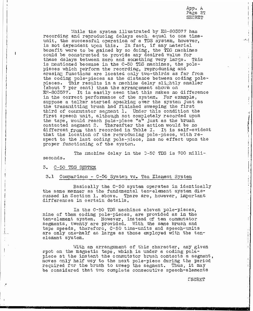
App. A Page 27 SEC-RET
7/hile the system illustrated by ES-80357 7 has recording and reproducing delays each, equal to one time- unit, the successful operation of a TDS system, however, is not dependent upon this» In fact, if any material benefit were to be gained by so doing, the TDS machines could be constructed to provide any desired value for these delays between zero and something very large. This is mentioned because in the C-50 TDS machines, the pole- pieces which perform the recording, reproducing and erasing functions are located only two-thirds as far from the coding pole-pieces as the distance between coding pole- pieces. This results in a machine delay slightly smaller (about 7 per cent) than the arrangement shown on ES-803577. It is easily seen that this makes no difference in the correct performance of the system. For example, suppose a talker started speaking over the system just as the transmitting brush had finished sweeping the first third of commutator segment 1, Under this condition the first speech unit, although not completely recorded upon the tape, would reach pole-piece "a" just as the brush contacted segment 2. Thereafter the action would be no different from that recorded in Table I. It is self-evident that the location of the reproducing pole-piece, with re- spect to the last coding pole-piece, has no effect upon the proper functioning of the system.
The machine delay in the 0-50 TDS is 700 milli- seconds,
3' C-50 TDS SgSTEML
3,1 Comparison - C-50 System vs. Ten Element System
Basically the C-50 system operates in identically the same manner as the fundamental ten-element system dis- cussed in Section 1. above. There are, however, important differences in certain details,
In the C-50 TDS machines eleven pole-pieces, nine of them coding pole-pieces, are provided as in the ten-element system. However, instead of ten commutator segments, twenty are provided. With the same brush and tape speeds, therefore, C-50 time-units and speech-units are only one-half as large as those employed with the ten- element system.
With an arrangmment of this character, any given spot on the magnetic tape, which is under a coding pole- piece at the instant the commutator brush contacts a segment, moves only half way to the next pole-piece during the period required for the brush to sweep the segment. Thus, it may be considered that two complete consecutive speech-elements
SECRET

App. A Page 28 SECRET
occupy a region on the tape which extends between adjacent coding pole-pieces at the instant the commutator brush contacts some commutator segment. If it is now arbitrarily- assumed that odd-numbered speech-elements are just entering the coding pole-pieces as the brush contacts an odd- numbered segment, it is evident that during the time-unit required for the brush to sweep the segment, one of the odd-numbered speech-elements will be reproduced at the transmitting terminal, transmitted to the receiving ter- minal and recorded upon the receiving tape. At the end
| of the time-unit when the brush leaves the segment, tue i received speech-unit will occupy the same corresponding
position on the receiving tape as the same unit occupies on the transmitting tape. During this time-unit the even- numbered speech-elements hove advanced to the coding pole- pieces so that in a similar manner any one of them is ready to be reproduced, transmitted and recorded while the brush sweeps the next segment.
Fundamentally, the action is similar to that of two independent ten-element systems, one of which codes odd-numbered speech-units and the other even-numbered speech-units. In effect, therefore, the C-50 system is a special type of 20-element system in which two similar but completely independent ten-element code-connectors are employed. One of them, called the "odd" code-connector, is wired to odd-numbered commutator segments and the other, called the "even" code connector, is wired to even-numbered segments. This general arrangement may be seen on ES-803576 where odd-numbered segments of a receiving com- mutator are shown connected, through back contacts of relay PT5 and through contacts of key CCI to the odd fixed code- connector (code box odd) and even-numoered segments are shown connected to tue even fixed code-connector (code box even).*
Since, with an arrangement of this character, alternate speech-units are coded by a set of connections in one code-connector and the remaining speech-units, which are interleaved between them, are coded by another set of connections in another completely independent c oder-connect or , the C-50 codes are known as interlaced codes. One of them is called the odd (or regular) code and the other is called the even (or interlace) code.
*The two fixed code-connectors may be seen in photographic Figures 1 and 2, mounted on the machine panel of the TDS equipment bay.
SECRET

App. A Page 29 SECRET
3.2 Codes
For fixed code operation,any of the 1,344,961 usable ten-element codes can be used in each code-connector» The total number of usable C-50 codes available for fixed code operation is, therefore (1,344,961)2, or about 1,8 x 10*2.
For continuously recycled code operation, any of the 95,401 self-contained codes of a type illustrated by Fig.. 2 of Diagram VI are theoretically available for each of the two code-connectors. However* in order to simplify the design and construction of the automatic coding equip- ment, these have been restricted, as previously mentioned, to 60,316 per connector. This restriction results from the method employed in setting-up codes, The automatic coding equipment sets up the odd code-connections for commutator seg- ments 1, 3, 5, 7, 19, 17, 15, 13 in that order and sets up the even codes for commutator segments 12, 14, 16, 18, 10., 8, 6, 4 in that order. Odd commutator segments 9 and 11 and even commutator segments 20 and 2 remain to be assigned. Eight of ten major diagonals in both the odd and.the even codes have been chosen and, two major diagonals, in each, remain to be chosen. In an unrestricted coding system either one of the two remaining major diagonals in the odd code-connector could be chosen for segment 9, for example, in which event the re- maining diagonal would contain the code-connection for segment 11. Likewise, there would be two remaining choices of diagonals for segments 20 and 2 of the even code. The automatic coding equipment, however, is constructed so that of the two remaining choices for odd and even codes only one is possible in each particular case. These choices are such that commutator segment 9, in certain of the odd codes, is connected to a higher let- tered sealed switch relay (in the sense that ni" is higher let- tered than "a") than is commutator segment 11, while in the re- maining codes commutator segment 9 is connected to a lower let- tered sealed switch relay than is segment 11» In certain of the even codes, commutator segment 20 is connected to a higher lettered sealed switch relay than is segment 2, while in the remaining even codes it is connected to a lower lettered sealed switch relay than is segment 2. The total number of usable codes available for continuous operation of the C-50 system is (60,316)2 or about 3.6 x 10⁹. (See Appendix C)
The codes employed by the C-50 system arc known as "displaced interlace" codes. With displaced interlace codes, the starting points of the regular and interlace code-cycles do not correspond, "that is, if commutator segment 1 marks the start of the odd code cycles, some commutator segment other than segment 2 is used to mark the start of the even code-cycles. In the C-50 system, commutator segment 1 marks the start of odd code cycles but commutator segment 12 is used to mark the start of even code cycles. Vith an arrangement of this character, if commutator segment 1 is arbitrarily designated as the start of a 20-element code cycle, the consecutive ten
SECRET
i
f !

App. A Page 30 SECRET
element (self contained) even code is converted to a non- consecutive ten element code. Thus, in effect, a non- consecutive element code is used in continuously recycled code operation. Tile reason that this can be done is that the last half of a self-contained even code is interlaced with the first half of a self-contained odd code and the first half of e completely new self-contained even code is interlaced with the last half of the odd code. This permits a somewhat wider dispersion of speech-units in the "scramble" than could otherwise be obtained.
3.3 C-50 Scramble
Diagram I illustrated the scramble produced by a ten element system of the C-50 type operating on fixed coding. In order that a comparison might be made, Diagram VIIhas been prepared to illustrate speech scrambled by the C-50 system operating on continuous coding. The sentence chosen for •illustration is the same as that used for Diagram I.
SitCRüT
KB

App. A Page 51 SECRET
DIAGRAM VJ.1
Illustration of Speech Scrambled by C-50 TDS System
Operating on Continuous Coding
Speech. Divided into Units
Speech Unit Numbers
(A) :T:H:E: :S:I:X:T:H: :A:R ( 1:2:3:4:5:6:7:8:9:1:1:1
(E)( :0:1:2 (:l:l:l:lel:l:l:l:2jls223
Order of Commutator Segments (C)(«2-3*4-5*6*7•&•9°0* Pole-piece Used !3:8:6':7:1:6:7:5:6:S:3:5
(Unit No.
Scrambled >Unit Speech [
Unit No, (
( (Unit
(D)-
U12J<
(P1B):-:-
-:-:3:-:-:-:-i6:7:E
:1:
T;
M:0:R 1:1:1 3:4;5 4:5:6
4:1:8
5:1:-
6:
:I:
(A)
(B)
(C)
(D)
(E1E
(*12
(E
(F
18
18
(A
(B
(C
(D
<E12
^12
(E
(E 18
18
:D: :D:I:V;I:S:I:0:K: :Y/:I:L:L! :S:U:P:P:0:R:T: :T:H: (:1:1:1:1:2:2:2:2:2:2:2:2:2:2:5:S:5:5:5:5:5:5:5:5:4:4: (:6:7:S:9:0:1:3:5:4:5:6:7:6:9:0:1:2:5:4:5:6:7:8:9:0:1: (:7:8:9:1:1:1:1:1:1:I:1:1:1:2:1:2:3:4:5:6:7:8:9:1:1:1:
:0-1:2:3:4:5:6:7:8:9:0: •10:1:
4: 5:
1:1:1:1 3:4:5:6 (_
:4:4:9:9-8:l:5:5:5:2:4:8:9:7:5:5:1:3:6:9:4:7:6:6:2:5:9:4:5:5 (: 8: 9: -: 1:4:1:1:1:1 f 2:1:1:1:1:2": 2:3:2:2:1:2:2:2:2:3:3 ( :9i6:3:4:l:8:l:0:5:0:5:0:9:2:7:8:3:6:7:6:1 :T:H:-:T:-:I'.l-:M;0:I:D:A:-:K:Vi;i:L:L:S:-:l:I:-:ViO:-:
4:5:4:9 0:P:P:-
(:2:3:-:-'.-:l: 1:7:8:1:1:5; 4: 9 ( :3:0: :5:2: :H:E:-:-:-:M:-:X:T;h:R:S:-:H
4:9:4:5:6:1:2:7:0:1:0:5:8:.9:8:3: 0:I:0:I:D:A:S:-:Y:I:L:N:D:L:I:U:
(( 5: 0:
(:l; (:'7:
1:1:2: 8:9:0:
1:2:3:4:5:6 0:
7:8:9 1: 0:
r 4:2:8:8:4:7:1:2:1:4:1:6:9:9: 5: 8: T:
;5: :5: ;U;
:5: :7: :R:
:5:
«^ • 7:6 :7 i 6:1: R;-:17:0:-:-;.-•:•
4: 0: T:
4: 1: H:
5:5: 9:4: -:P:
5:3 5:8 P:T
:-*:4 i :0 :-:T
SECRET
EH
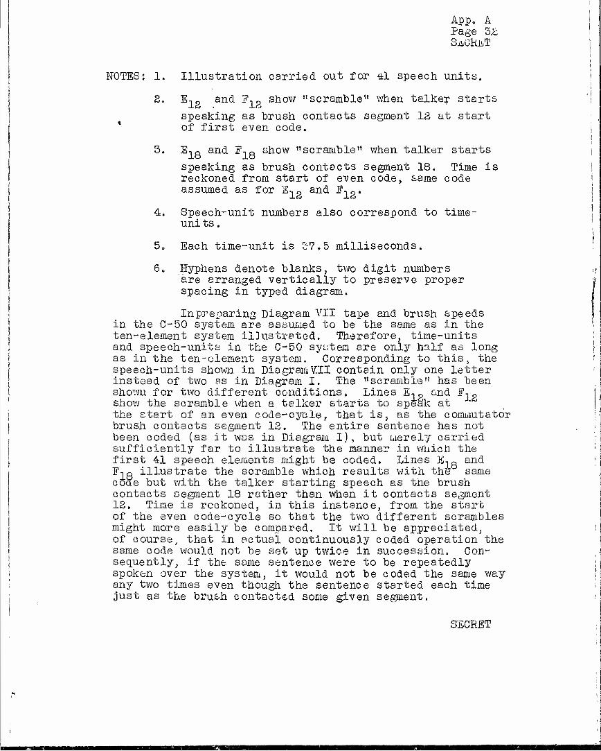
App. A Page 3.2 SaCküT
NOTES: 1. Illustration carried out for il speech units.
2. Elg and F-,? show "scramble" when talker starts
speaking as brush contacts segment 12 at start of first even code.
3. E-jo and F-,8 show "scramble" when talker starts
speaking as brush contacts segment 18. Time is reckoned from start of even code, same code assumed as for E-,« and E.g.
4. Speech-unit numbers also correspond to time- uni ts.
5„ Each time-unit is 37.5 milliseconds.
6* Hyphens denote blanks, two digit numbers are arranged vertically to preserve proper spacing in typed diagram.
In preparing Diagram VII tape and brush speeds in the C-50 system are assumed to be the same as in the ten-element system illustrated. Therefore, time-units and speech-units in the C-50 system are only half as long as in the ten-element system. Corresponding to this, the speech-units shown in DiagramVII contain only one letter instead of two as in Diagram I. The "scramble" has been shown for two different conditions. Lines E-,p and F-,g show the scramble when a talker starts to speak at the start of an even code-cycleT that is; as the commutator brush contacts segment 12. The entire sentence has not been coded (as it was in Diagram I), but merely carried sufficiently far to illustrate the manner in which the first 41 speech elements might be coded. Lines E-,8
a&d F-JQ illustrate the scramble which results with the same code but with the talker starting speech as the brush contacts segment 18 rather than when it contacts segment 12. Time is reckoned, in this instance, from the start of the even code-cycle so that the two different scrambles might more easily be compared. It will be appreciated, of course, that in actual continuously coded operation the same code would not be set up twice in succession. Con- sequently;, if the same sentence were to be repeatedly spoken over the system, it would not be coded the same way any two times even though the sentence started each time just as the brush contacted some given segment.
SECRET

FINAL REPORT - KDRC PROJECT C-50
APPENDIX B
AUTOMATIC CODE GENERATING
TABLE OF CONTENTS
SECRET
a ection
0 -
1.
1 1
1. ,2
1 .3
2k
3,
4,
Title
GENERAL
AUTOMATIC GENERATION OF TDS CODES
Ten-Element Codes
Exclusion of Unusable Codes
C-50 TDS Codes
COMMUTATOR ADJUSTMENTS
BRUSH PHASING ADJUSTMENTS
SPEED CONTROL REQUIREMENTS
Page
1
1
1
5
6
8
11
12
SECRET

App. B Page 1 SECRET
FINAL ESPORT - NDRC PROJECT C-50
APPENDIX B
AUTOMATIC CODE GENERATING
0. GENERAL
The present appendix translates the general prin- ciples of Appendix A into equipment functions which must he realized in an automatically coding TDS. The discussion covers the arrangements for excluding unusable codes, the way in which circuit delay is compensated for decoding and the effect of circuit delay on the time available for coding and decoding. A statement of the requirements on S£>eed con- trol for independently operated terminals is also included. The discussion in this appendix is still somewhat general, and the specific equipment is described in Appendix D.
1, AUTOMATIC GENERATION Off 'IDS CODES
1.1 Ten Element Codes
In Section 1.3 of Appendix A of this report, it is shown that only consecutive element codes of the "self-con- tained" type can be used for continuously recycled code op- eration. In Section 3.2 of Appendix A it is explained that the C-50 system employs self-contained codes of a type which is based upon the "major diagonal" diagram illustrated by Fig. 2 of Diagram VI, This type of diagram was chosen for the basis of continuously recycled C-50 codec, rather than another type, such as that illustrated by Fig. 1 of the same diagram, because, of all possible diagrams, it affords the greatest number of self-contained codes. The ensuing discussion, therefore, is confined to codes derived from that diagram.
Drawing ES-803578 is useful in explaining require- ments which must be observed in the automatic generation of ten-element TDS codes, ihe diagram shown on the drawing is nothing more than a time-position diagram of speech units. Fundamentally, it is no different from time-position dia- grams discussed in Appendix A, but the method of representa- tion is different. First, all speech-units have been shown located in squares and have arbitrarily been numbered -5 to -10, 1 to 10 and +1 to +5. Second, the pole-pieces (termed
i •
o EGRET

App. B Page 2 SECRET
coils on the drawing) are arranged with "a" at the top and "i" at the bottom. As a result, the major diagonals, as designated by lines formed of the same numeral, slope down- ward to the right. This is in accord with the explanation of the slope of major diagonals as discussed in Section 1.5 of Appendix A and as illustrated by Fig. 2 of Diagram IV. Third, ten major diagonals are enclosed by a heavy line. Ihis heavy line enclosure marks the ten major diagonals which are employed, during each successive code-cycle, in constructing self-contained codes of a type used by the C-50 system. Its significance, therefore, is the same as the major diagonal outlines illustrated by Fig. 2 of Diagram VI in the main body of this report. It will be noted that the general shapes of the outlines are the same in the two cases tut the one shown on the drawing is skewed downward to the right uhile those shown in Fig« 2 of Diagram VI are skewed upward to the right. This differ- ence in skew is due only to the different arrangement of pole-pieces in the diagrams in the two cases.
The generation of a self-contained code for use during any one particular code-cycle, such as, code-cycle "Y", will now be discussed. This code-cycle starts as the commutator brush of the TDS machine contacts commutator segment 1 at the start of its "Yth" revolution and ends as the brush leaves segment 10. Since the duration of time- units is determined by the length of time required for the commutator brush of a TIB machine to sweep a commutator segment, it is evident that the code-cycle is of ten time- units duration. The time-units for code-cycle "Y" may ar- bitrarily be designated "m" to "v"*, respectively, i.e., during time-unit "m", the brush in its "Yth" revolution sweeps commutator segment 1, during time-unit V1n1? it sweeps segment 2, etc., until at the end of time-unit "v" it leaves commutator segment 10 and recontacts segment 1 at the start of its "Zth"revolution or at the start of code- cycle nZ".
Now suppose speech is being recorded upon the magnetic tape of a transmitting machine and further, sup- pose, the timing has been such that a unit of speech, which will arbitrarily be called speech-unit 1, has just arrived at •xO-'i- piece Vat the start of code-cycle "Y". -It will be seen from ES-803578 that other speech units are available
^Time-units have not been designated on the drawing, but as explained^units "m" to "v" correspond respectively to com- mutator segments 1 to 10.
SECRET

App. B Page 3 SECRET
on the tape and have arrived at different pole-pieces, as shown. It will be observed that these speech-units are numbered so as to show their relative .locations with respect to pole-pieces at the start of each time-unit. Ihus, at the start of time-unit "m", speech-units 5 to 1 have arrived at pole-pieces "a", "b", "o", "d" and "e", respectively, and speech-units -10, -9, -8 and -7, which were redorded pre- viously to speech-unit 1, have arrived at pole-pieces "f",
i «g», "h" and "I", respectively.
During each successive time-unit, the speech-^- units advance to the next succeeding pole-piece so that at the start of time-unit "q", (i.e., brush starting on commuta- tor segment 5), for example, speech-units 9 to 1, inclusive, have respectively advanced to pole-pieces "i" to "a". 'Uhis action continues until at the start of time-unit "v" (i.e., the brush starting on commutator segment 10) speech-units 10 to 6 have arrived at pole-pieces "e" to "i", respectively, and speech-units +4 to +1 have arrived at pole-pieces "a" to "d", respectively.
In Section 1.3 of Appendix A it was shown, in con- nection with Diagram vT, that the generation of self-con- tained codes requires the use of the correspondingly same major diagonals from code-cycle to code-cycle. Since the ten major diagonals, which are under present consideration for code-cycle Y, mark the locations of speech-units 1 to 10 on the drawing, it is evident that speech-units preceded by minus signs are involved with the correspondingly same major diagonals but during the preceding code-cycle X. Such speech-units, therefore, will have been reproduced and transmitted during that previous code-cycle. Likewise, those speech-units preceded by plus signs are involved with the correspondingly same major diagonals during the suc- ceeding code-cycle "Z" and they will be reproduced and transmitted during that succeeding code-cycle. In the present discussion concerning code-cycle "Y", speech-units preceded by plus or minus signs are, therefore, of no interest and may be disregarded in this particular discus- sion.
It will now be noted from drawing ES-803578 that, during the time-unit '!,mn, (commutator brush starting on segment 1) a choice of any of speech-units 1 to 5, inclu- sive, is offered. 'Jhat is, any one of them may be selected as the first speech-unit to be transmitted to the receiving terminal during code-cycle "Y". Suppose speech-unit 4 is selected for this, the first code connection would be com- mutator segment 1 to pole-piece (sealed switch) b.
SEOEEr

xipp • J3 Page 4 SECRET
Since, as explained in Section 1.3 of Appendix A, it is necessary that no speech-unit be transmitted more than once, it is evident that commutator segment 2 must
j not be connected to pole-piece Mc" during time-unit "n", I likewise commutator segment 3 must not be connected to I pole-piece "dfl during time-unit "o", etc. In other words, j multiple code-connections must not be placed upon major i diagonals. In automatic code generation, therefore, it is j necessary, once a given code-connection is set up, to block ! the establishment of any other code-connection which might | otherwise fall upon the particular major diagonal involved.
This is done in the G-50 coding equipment by a process known as exclusion« Exclusion is further discussed in Section 1.2 of this appendix.
Following the selection of speech-unit 4 for transmission-during time-unit "m", it is evident from drawing ES-803578 that one of speech-units 1, 2, 3, 5 or 6 might be selected for transmission during the second time- unit of code-cycle "Y", i.e., during time-unit "n". Sup- pose speech-unit 2 is selected for this purpose. The second code-connection would then be commutator segment 2
I to sealed switch "c". This process can be continued until | all ten code-connections are established. In doing so, it j must of course be kept in mind, that only one code-connec-
tion can be placed upon any one of the ten major diagonals.
Diagram B-I, below, shows one of the 95,401 self- ! contained codes which may be constructed in this manner. | In this diagram speech-units are^transmitted in the sequence i indicated by the top line. The-'second line shows the order j of commutator segments and the third line designates the j pole-pieces which would be connected to each commutator
segment by the code-connections to produce the unnatural sequence of speech-units shown by the first line*
j DIAGRAM BTI
j CONSTRUCTION OF C-50 TYPE OF SELF-CONTAINED CODE i
j Sequence of Speech Units in Scramble 4 2 1683 10 579
| ' Code (Commutator Segment 1 2 3456789 10 Connections >,.,.?? , ,_,,_,.« ( .role-Piece b e gcbhbhgf
The code shown in the above diagram is the same as that shown in the fixed code connectors of ES-803577.
•SECRET

App. B Page 5 SECRET
1. 2 Exclusion, of Unusable Codes
Referring to ES-805578 let it be assumed that speech-unit 4 is selected to be the first of the ten speech- units to be sent out on the line during a given code-cycle. Code-connection 1-b, therefore, would be made. This speech- unit must not be sent out again. Consequently, code-connec- tions 2-c, 3-d, 4-c, 5-f, 6-g, 7-h and 8-i cannot be em- ployed, subsequently, during this code-cycle» Thus, in any automatic code producer, automatic supervision must be pro- vided which will exclude, once a given code-connection is established, the setting up of any other code-connections which would produce unusable codes. As an aid in explain- ing how such supervision, which is called exclusion, is applied to the C-50 code producer another time diagram is shown on drawing ES-805579.
This diagram is a simple replofc of the diagram on ES-805578. Speech-units are plotted in the vertical dimension, time is shown increasing from left to right and commutator bars are shown at the top, whereas the pole- piece, which must be connected to the line by means of a given commutator segment to associate any speech-unit with any code position, is shown in the center portion of the diagram. Thus, for example, if it is desired to put speech- unit 1 in position 1, from ES-803578, it is evident that pole-piece "e" must be connected to commutator bar 1. Thus, pole-piece "e" in ES-803579 is associated with commutator bar 1 and speech-unit 1. Similarly, to put speech-unit 1 in the second, third, fourth or fifth position, pole-pieces "f", "g", "h" or "i" would be used.
It can now be shown how unusable codes may be avoided. If it is assumed, that speech-unit 4 is to be sent first, in the "scramble" produced during a given code-cycle, it is evident that pole-piece "b" must be controlled by com- mutator bar 1. Using the diagram, it will be seen that pole-pieces "c", "d", "e", "f", "g", "h" and "i" must be excluded, respectively, fron connection to commutator seg- ments 2, 3, 4, 5, 6, 7 and 8, i0e., on ES-803579 the exclu- sion must take place in a horizontal line on the same level as the speech-unit under consideration.*
''This is the same as excluding along the major diagonals of ES-803578 and is therefore the same as exclusion along the major diagonals of a code-connector grid. Drawings of the coding equipment show code relays arranged in a manner indicated by ES-803579. This drawing, therefore, has been introduced for convenience, although it establishes no new principles.
SECRET
rasa

App. B Page 6 SECRET
A relay circuit, described more fully in Section 1.3 of Appendix D, performs the above-mentioned functions. In it code relays, arranged much the same as shown on ES-803579, are arranged in columns. The columns are desig- nated in accordance with commutator segments. Thus, column 1 contains five code relays designated 1-a to l-?e, inclusive. One contact on each relay is multipled (with the correspond- ing contacts of the other code relays in that column] to commutator segment 1, The other contact of relay "a" con- nects to sealed switch nan, that of relay "b" to sealed switch *'b", etc. Thus, if any code relay is operated, the commutator segment corresponding to the column in which the relay is located is connected to the sealed switch which cor- responds to the designating letter of the relay. For example, if code relay 5-^d is operated, commutator segment 5 is con- nected to sealed switch "d". Consequently, when the commuta- tor brush contacts segment 5 pole-piece "d" is connected to the line.
In addition to code relays, certain relays called exclusion relays are provided to prevent the operation of more than one code relay in any given line of code relays. For example, if code relay 5-d were to be operated during a given code-cycle, the exclusion relay, associated with the line of relays in which code relay 5-d is located, would pre- vent subsequent operation of any other code relay in that line until the start of a new code-cycle. In other words, code relays 2-a, 3-b, 4-c, 6-e, 7-f, 8-g, 9-h and 10-i in the sixth line from the top of the diagram of ES-803579 could not be operated in this code-cycle after code relay 5-d had been operated. This "exclusion" arrangement pre- vents the establishment of multiple connections on major diagonals and thereby prevents the setting up of unusable codes.
1.5 C-50 TDS Codes
So far, in this appendix, the discussion of IDS codes has been confinea to ten-element codes of a type which ordinarily would be employed in conjunction with TIB machines having nine coding pole-pieces and ten commutator segments. The C-50 ITS machines are equipped with nine coding pole- pieces j but have twenty, instead of ten, commutator segments» In this latter respect, therefore, they are different.
In general, the number of speech units involved in the ,,scrambling-unscramblingv' process during any TES code- cycle jLs exactly the same as the number of commutator seg- ments "provided in the TIB machines, so that the C-50 system employs twenty-element ITS codes. These codes compose a
SECRET
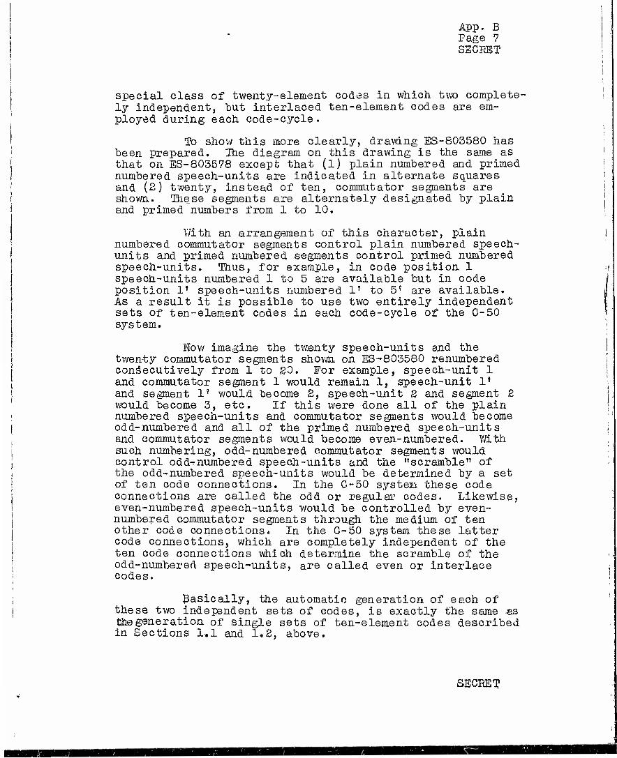
App. B Page 7 SECFdüT
special class of twenty-element codes in which two complete- ly independent, but interlaced ten-element codes are em- ployed during each code-cycle.
To show this more clearly, drawing ES-803580 has been prepared. Ihe diagram on this drawing is the same as that on ES-803578 except that (1) plain numbered and primed numbered speech-units are indicated in alternate squares and (2) twenty, instead of ten, commutator segments are shown. These segments are alternately designated by plain and primed numbers from 1 to 10.
With an arrangement of this character, plain numbered commutator segments control plain numbered speech- units and primed numbered segments control primed numbered speech-units. Thus, for example, in code position 1 speech-units numbered 1 to 5 are available but in code position 1* speech-units numbered 1T to 5{ are available. As a result it is possible to use two entirely independent sets of ten-element codes in each code-cycle of the 0-50 system.
Now imagine the twenty speech-units and the twenty commutator segments shown on ES-803580 renumbered consecutively from 1 to SO. For example, speech-unit 1 and commutator segment 1 would remain 1, speech-unit lf
and segment 1? would become 2, speech-unit S and segment 2 would become 3, etc. If this were done all of the plain numbered speech-units and commutator segments would become odd-numbered and all of the primed numbered speech-units and commutator segments would become even-numbered. With such numbering, odd-numbered commutator segments would control odd-*numbered speech-units and the "scramble" of the odd-numbered speech-units would be determined by a set of ten code connections. In the C-50 system these code connections are called the odd or regular codes. Likewise, even-numbered speech-units would be controlled by even- numbered commutator segments through the medium of ten other code connections. In the C-50 system these latter code connections, which are completely independent of the ten code connections which determine the scramble of the odd-numbered speech-units, are called even or interlace codes.
Basically, the automatic generation of each of these two independent sets of codes, is exactly the same as the generation of single sets of ten-element codes described in Sections 1,1 and 1,2, above.
SECRET

App. B Page 8 SECRET
In the C-50 system, the interlace codes employed are known as displaced interlace codes "because each odd (or regular) code-cycle starts with commutator segment 1 while each even (or interlace) code-cycle starts with com- mutator segment 12 (segment 6' on drawing ES-803580).
In Section 3,2 of Appendix A and in Section 1.1 above, it was stated that 95401 self-contained ten-element codes are possible. It was also pointed out that, due to certain simplification in design and construction of the G-50 automatic coding equipment, it generates only 60,316 of the total 95401 possible codes. However, since it can do this for both the odd ana the even ten-element codes, the automatic coding equipment is capable of generating (60,316)2 twenty-element codes, See Appendix C.
2. COMMUTATOR ASJUSMSNrS
Drawing ES-803581 is a simplified schematic of a two-way circuit with TD3 applied to both directions of transmission and with a line having a delay of D. It is necessary for the receiving commutator brush to contact each commutator segment at the time when the proper speech- unit arrives to be laid down on the tape. Thus, if there is delay in the line? it is necessary that the receiving brush be delayed or set back of the transmitting brush by an amount of time equal to the circuit delay. This is indicated in ES-803581 by the receiving brush lagging behind the transmitting brush by an amount equal to D.
It is evident that means must be provided to adjust this amount of lag to take care of lines with dif- ferent delays. In this drawing, the two transmitting brushes are shown in exactly the same relative position and each receiving brush is set behind its respective transmitting brush by a delay of D. As subsequently ex- plained, this is the most desirable setting. If, for ex- ample the receiving brush at one terminal was set with its associated transmitting brush and not lagging it by D L.S shown on the drawing, the receiving brush at the other terminal would then have to be set back of its associated transmitting brush by an amount equivalent to 2D. Since the same coding equipment is used for both transmitting and receiving, and since it is operated from cycling seg- ments provided for this purpose on the receiving commuta- tor only, this latter setting would seriously limit the ability of the coding equipment, depending, of course, on the value of D, to set up satisfactory codes in time lor both transmitting and receiving. Further explanation will be helpful in this connection.
SECRET
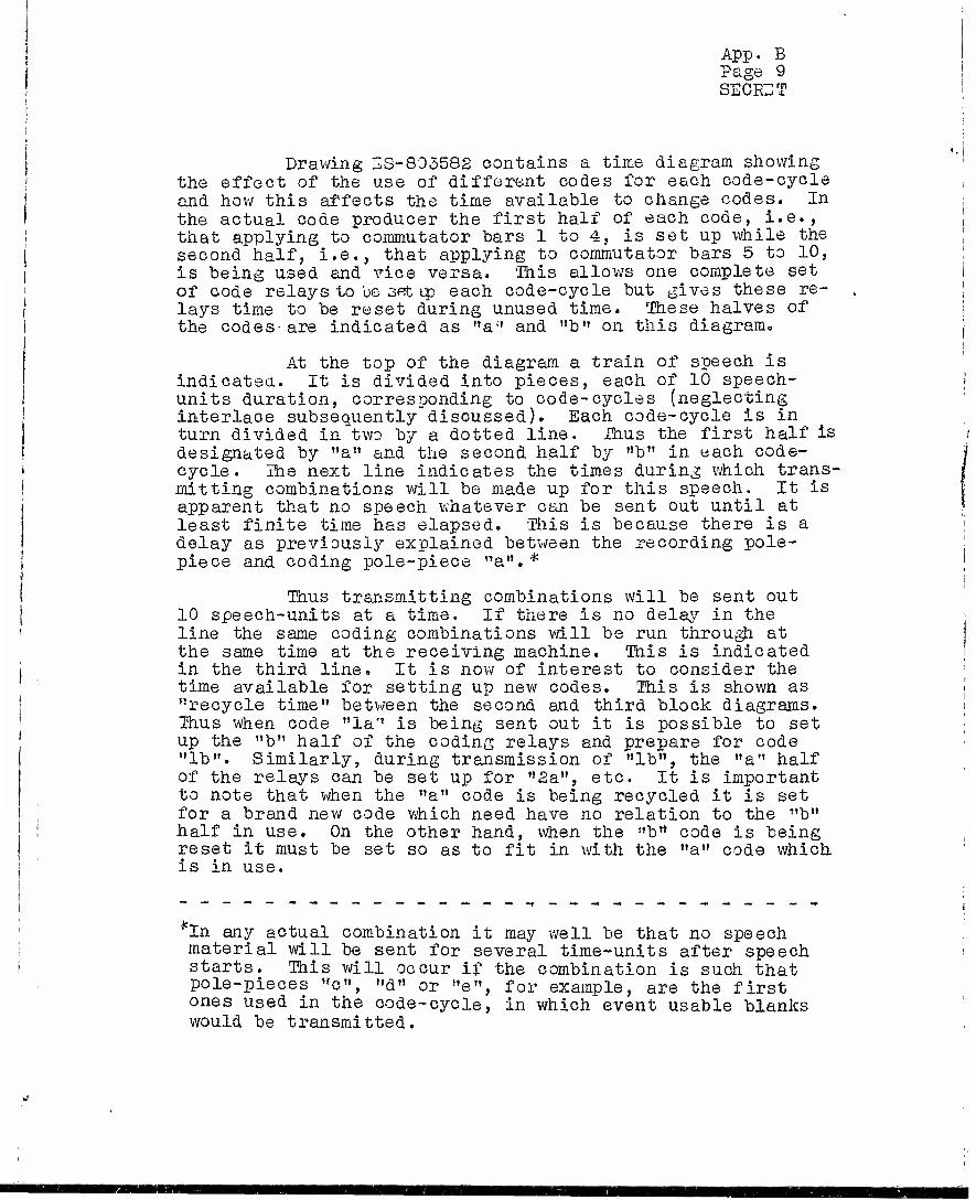
App. B Page 9 SEGIGT
Drawing SS-803582 contains a time diagram showing the effect of the use of different codes for each code-cycle and how this affects the time available to change codes. In the actual code producer the first half of each code, i.e., that applying to commutator bars 1 to 4, is set up while the second half, i.e., that applying to commutator bars 5 to 10, is being used and vice versa. 'This allows one complete set of code relays to be set up each code-cycle but gives these re- lays time to be reset during unused time. These halves of the codes•are indicated as "a" and "b" on this diagram«
At the top of the diagram a train of speech is indicated. It is divided into pieces, each of 10 speech- units duration, corresponding to code-cycles (neglecting interlace subsequently discussed). Each code-cycle is in turn divided in two by a dotted line. Thus the first half is designated by "a" and the second half by "b" in each code- cycle. The next line indicates the times during which trans- mitting combinations will be made up for this speech. It is apparent that no speech whatever can be sent out until at least finite time has elapsed. This is because there is a delay as previously explained between the recording pole- piece and coding pole-piece "a",*
Thus transmitting combinations will be sent out 10 speech-units at a time. If there is no delay in the line the same coding combinations will be run through at the same time at the receiving machine. Tnis is indicated in the third line. It is now of interest to consider the time available for setting up new codes. This is shown as "recycle time" between the second and third block diagrams. Thus when code "la'' is being sent out it is possible to set up the "b" half of the coding relays and prepare for code "lb". Similarly, during transmission of "lbn, the "a" half of the relays can be set up for "2a", etc. It is important to note that when the "a" code is being recycled it is set for a brand new code which need have no relation to the "b" half in use. On the other hand, when the "b" code is being reset it must be set so as to fit in with the "a" code which
j is in use.
'In any actual combination it may well be that no speech material will be sent for several time-units after speech starts. Tnis will occur if the combination is such that pole-pieces "o", "d" or "e", for example, are the first ones used in the code-cycle, in which event usable blanks would be transmitted.

App. B Page 10 SECRET
Ttie fourth block diagram from the top indicates the time relation of the receiving combinations if there is a line or circuit delay equal to two time-units or the dura- tion of two speech-units. In this case each code must be run through at the receiving end just two .time-units later than the codes were sent out at the transmitting end. The recycle time for this condition is shown between the third and fourth block time diagrams.
It is apparent that circuit delay limits the re- cycle time. Code "b" cannot be reset while it is being used either for sending or receiving, simply because the same code relays are used both for transmitting and receiving.*
As indicated, the recycling time instead of being a full half code-cycle or 5 units is now only 3 units. Furthermore, if one receiving brush were to be set behind its associated transmitting brush by 2D, as previously dis- cussed, the coding equipment used with that machine would have available only one time unit for recycling. In other words »recycling time for that machine would be equivalent to half a cpdG-"cycle minus twice the circuit delay. On the other hand, if each receiving brush is set back from its transmitting brush by an amount equal to the circuit delay the recycling time at each terminal is equivalent to half a code-cycle less the circuit delay.
It is apparent that this sort of a system is sub- ject to a definite limit to the amount of circuit delay which can be tolerated. Too large a circuit delay reduces the re- cycling time to such a small value that it is impossible to release the old code and set up a new one. In this machine a circuit delay of over 150 milliseconds can be tolerated.
The diagram at the bottom of ES-803582 shows in a very schematic manner now the same TES machine and same set of switches and code relays are used for both transmitting and receiving. Double throw switches are indicated for changing from transmit to receive conditions. In the actual machine these functions are accomplished by relays operated from a push-to-talk key.
The upper group of switches control the microphone and receiver connections, connections to the outgoing and incoming line and connections to the switches operated by the commutators. They change the machine from a "code on repro- duce" condition for transmitting to a "decode on record"
*The use of code relays for both purposes results in a large saving of equipment.
SECRET

App. B Page 11 SEGRET
condition for receiving. Hie lower group of switches trans- fers the code relays from the transmitting commutator Ci to a receiving commutator Cg. In the latter the brush is shown as lagging by an amount assumed to be correct fox the cir- cuit delay. Commutator G3 in which the brush is given the same position as that for C2 accomplishes the code recycling.
As may be seen, each of the commutators is divided into two sections corresponding to the two halves of the code, In the recycling commutator C3 a single rather long segment is provided at the beginning of each half cycle. "When the commutator brush first gets into the "a" cycle, the "b,f sec- tion of the code relays is reset and similarly the "a" code relajrs are reset when the commutator brush reaches the first part of the 1,b" cycle, Extra segments shown on C3 are used when transmitting over a circuit having considerable delay. These segments cause the recycling to start sooner when the terminal is in the transmitting condition than when it is in the receiving condition. This helps to make up for the fact that the transmitting brush may be considerably ahead of the receiving brush and is necessary in order to permit the machines to be used on circuitshaving over 150 milli- seconds delay.
These extra segments, however, cannot be used when little or no receiving delay is present because the trans- mitting combinations would probably be released before the machine had finished using them.
B« BRUSH PHASING ADJUSTMENTS
It will be noted above that it is necessary to ad- just the receiving brush or receiving commutator to take care of circuit delay. It is also true, however, that in most cases it will be necessary, when placing the terminals in operation, to make an over-all phase adjustment at one ov the other terminal to get the two into synchronism. Thus, unless the two motors are started with the brushes exactly at their proper positions at exactly the same time and un- less they come up to speed in exactly the same way, the two brushes would probably not be very close to their respective correct positions.
Both this over-all phasing adjustment and the ad- justment of the receiving commutator are accomplished by ar- rangements which are shown schematically on ES-803583.
SECRET
IJÜ
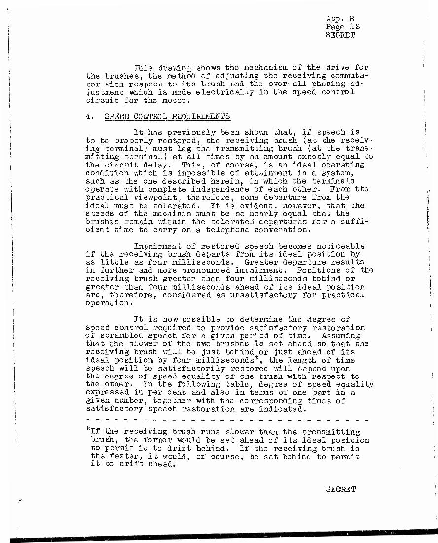
App. B Page 12 SECRET
Ulis drawing shows the mechanism of the drive for the brushes, the method of adjusting the receiving commuta- tor with respect to its brush and the over-all phasing ad- justment which is made electrically in the speed control circuit for the motor.
4. SPEED CONTROL REQUIREMENTS
It has previously been shown that, if speech is to be properly restored, the receiving brush (at the receiv- ing terminal) must lag the transmitting brush (at the trans- mitting terminal) at all times by an amount exactly equal to the circuit delay. This, of course, is an ideal operating condition which is impossible of attainment in a system, such as the one described herein, in which the terminals operate with complete independence of each other. From the practical viewpoint; therefore, some departure from the ideal must be tolerated. It is evident, however, that the speeds of the machines must be so nearly equal that the brushes remain within the tolerated departures for a suffi- cient time to carry on a telephone converation.
Impairment of restored speech becomes noticeable if the receiving brush departs from its ideal position by as little as four milliseconds. Greater departure results in further and more pronounced impairment. Positions of the receiving brush greater than four milliseconds behind or greater than four milliseconds ahead of its ideal position are, therefore, considered as unsatisfactory for practical operation.
Tt is now possible to determine the degree of speed control required to provide satisfactory restoration of scrambled speech for a given period of time. Assuming that the slower of the two brushes is set ahead so that the receiving brush will be just behind or just ahead of its ideal position by four milliseconds*, the length of time speech will be satisfactorily restored will depend upon the degree of speed equality of one brush with respect to the other. In the following table, degree of speed equality expressed in per cent and also in terms of one part in a given number, together with the corresponding times of satisfactory speech restoration are indicated.
:If the receiving brush run brush, the former would be set to permit it to drift behind.
slower than the transmitting ahead of its ideal position If the receiving brush is
the faster, it would, it to drift ahead.
of course, be set behind to permit
SECRET

App. B Page 13 SECRET
TABLE B-I
Degree of Speed Equality Duration of Per Cent One Part in Satisfaotorily Restored Speech
0.1 10s 8 sec, Oi01 10* 1 min. EO sec. 0;001 105 13 min. 20 sec. 0.0005 5 x 10ö Ihr. 7 min. 0.0001 106 2 hr. 13 min.
In the practical case, it is possible that the operator may not set the slower of the two brushes ahead of the faster. Experience indicates a tendency upon the part of operators to adjust the brushes initially to a point where restored speech sounds best. If this is done, the slower of the two brushes may be set very near to its ideal position or, unless care is taken, it may even be set slightly behind its ideal position. Under such cir- cumstances, of course, speech would not be satisfactorily restored for as long a period as it would be if the slower of the two brushes was to be set slightly ahead of its ideal position. As a result» the duration of satisfactorily restored speech might range from slightly less than one-half to about one-half of the values indicated in the table.
In view of the above and since it is considered desirable to insure a minimum conversation time of from fifteen to twenty minutes without intervening hand-phasing adjustments, a circuit which provides speed equality of not poorer than two parts in a million (1 part in "500,000} is considered necessary. In service the speed control cir- cuits incorporated in each C-50 terminal have at times provided a precision of speed equality of one part in two million. Such jjrecision, however, is not to be expected except under certain ideal conditions. As a rule, however, phasing adjustments are not required oftener than once an hour.
SECRET

App, C SECHST
i
FINAL REPORT - NDRC PROJECT C-50
APPENDIX C
NJMBER OF CODES AMD LENGTHS OF CODE SEQUENCES
| Section Title Page
GENERAL 1
CODES AND CODE SEQUENCES 2
Summarising Statement 2
Points at which Initial Settings Can be Made 3
Effect of Card Choices 3
Point of Beginning in a Sequence 3
Total Number of Initial Settings 3
Number of Codes in a Sequence 3
Times of Duration of .sequences 4
._. . Number of Different Individual Codes 4
i
Section
0.
1,
1 »0
1 .1
1 .2
1
1 A '
1 *5
1 .6
1 .7
SECRET

App, c Page 1 SECRET
FIIT^L REPORT - NDRC PROJECT C-oO
APPENDIX C
NUMBER OF CODES AND LENGTHS OF CODE SEQUENCES
0. GENERAL
This a-opendix covers such factors in the develop- ment of Project C-50 TD3 speech privacy equipment as the types of codes, their number, the numbers of sequences of codes generated by the automatic coding equipment and the lengths of time covered by these sequences«
The automatic coding equipment was given a degree of complexity which reflected the desire to make sure that no attempt would be made to solve the sequences of codes* That is, if we suppose unauthorized persons to have seized a C-50 machine, they would have two alternatives to try in attempting to unscramble an intercepted message. They could reassemble a record of the speech in correct order, speech element by speech element, and then reproduce it by some play-back method. Or the:/ could attempt to find the initial settings to make on the coding equipment, so that the cap- tured machine would unscramble the message. The objective in the coding equipment was to make the speech element by speech element procedure a more attractive alternative than the attempt to start the coding equipment at the proper point in the proper sequence of codes.
It is quite possible that a greater degree of complexity was worked out than was necessary to ensure this choice by the unauthorized interceptors» If less elaborate code sequences were used the bulk of the coding bay would be reduced. Whether a reduction still within the bounds of prudence with rest>ect to security would save a significant amount of weight and size is a matter of doubt.
It should be recalled in this connection that not all of the coding bay is taken UD by the scrambling mechanism. The power supplj*- is a fairly heavy item, for one thing. Aside from this, there are a good many relay chains in the exclusion circuits. These are the circuits -which police the codes called for by the scrambler. The scrambler often attempts to set up codes v/hich are not usable in TDS machines: that is, it may attempt to set up codes which would omit speech elements and repeat other elements. The exclusion circuits see to it that unusable codes are rejected and usable ones substituted. These circuits would be needed even if the scrambler were simplified.
SECRET

App» C Page 2 SECRET
1. CODES AflD CODE SENTENCES
1,0 Summarizing Statement
As developed, the C-50 TD3 is characterized by the following properties :
1. The automatic coding equipment can be given ini- tial settings at 14 different points in the cir- cuit, 7 for each of the two interlaced codes,
2. lour of these initial settings amount to choosing which sequence of codes will be used; there are 1,625,702,400 such sequences for each of the two interlaced codes, or (1,685,702,400}* for the combination.
3. Having chosen a sequence the remaining initial settings determine the point in the sequence at which the particular sequence will start. In each sequence there are 3,282,972 such starting points, for9each of the two interlaced codes, or (3,282,972)2 for the combination,
4. The total number of initial settings is the pro- duct of the corresponding numbers in items 2 and 3, which, for the combination of the two interlaced codes, is:
(5,337,135,459,532,800)° 5. In each sequence the number of codes which occur
before the sequence begins to repeat is difficult to determine because of the behavior of a selector switch which moves only when certain events occur; the number, for the combination of two interlaced codes, is considerably greater than (16,414,860)^, \
6. At three quarters of a second per code cycle 16,414,860 codes fill 142 days"; for the combina- tion of interlaced codes the corresponding time is about 6,400,000 years.
7. The number of different individual codes used is 60,316 in each of the two interlaces; correspond- ing to (60,516)2 = 3,638,019,856 different 20 j element codes, i
The derivation of the above numbers will be given in subsections of section 1 numbered to correspond with the paragraphs above, ,
SECRET

App» 0 Page 3 SECRET
1.1 Points at Which Initial Settings Can be Made
Initial settings are provided in each of the two interlaced codes by two punched"cards and five selector switches» The cards permute eight wires, that is a pattern of eight paths entering can be converted into any other pattern of eight paths leaving a card box. The selector switches have different numbers of positions, of which four are prime to each other. These have 22, 81, 19 and 17 points* The fifth selector has 22 points but operates in an erratic manner, discussed later»
1.2 Effect of Card Choices
Each card box allows all permutations of eight, or 81 =» 40320, but there are two in series, one at the input of the scrambler and one at the output, giving (81}s * 1,625,703,400 choices for each of the interlaced codes. Each choice deter** mines v/hich sequence of codes will be used, and thus measures the number of such sequences»
1.3 Point of Beginning in a Sequence
Having chosen the cards the other initial settings are those of the 5 selector switches. There are 22*22«21*19»17= 3,282,972 choices for each of the interlaced codes.
1.4 Total Number of Initial Settings
Since the cards and the selector points are inde- pendent the total number of choices of initial settings is (8!)8e22*22«21*19*17, giving the number under item 4, section 1,0.
1.5 Number of Codes in a Sequence
The number of codes in a sequence is not the same as the number of points of beginning a sequence because of two considerations. One is a set of five "walking'- relays through which the scrambler paths can be sent, on an optimal basis. Each relay is operated in succession, "walking" one step per code c3>-cle, These might be included in the initial settings, but such controls have not been thought needed-
The second consideration is the erratic behavior of one of the 22-point selector switches. The other four selectors move regularly, one step per cycle. This remaining selector moves only when codes of a certain nature come up. The nature of the code causing the selector to move can be changed in a variety of ways by changing soldered connections, and such changes could also, if desired, be included among the initial settings. In view of the number in item 4, section 1.0 this
SECRET

I than:
App. C Page 4 SSCEST
hardly seems needed. At present this erratic selector is arranged to step once when the scramble for either the odd (regular) or even (interlace) ten-element code is such that the sixth speech element of any code-cycle is controlled by the tenth commutator position» That is, for the coding of the odd numbered commutator segments, speech-element Mo. 11 must be associated with the 19th segment. For the even code, because of the displacement of the interlace, speech element Wo. IS of any interlace code must be associated with the 10th segment. Stated otherwise, if the code calls for the last pole-piece (i. e. pole piece "i") to be connected to the last segment, either in the even or the odd codes, then the erratic 22 point selector steps once.
This progression is called erratic because the occurrence of such special codes is difficult to predict. Of the 60,316 possible codes, the number of codes having speech element'6 in the last position is 8,888. Thus this switch moves about once in each 7 codes, but not exactly once and only on the average. The selector may move twice in succession and then remain quiescent for a good many code cycles. Such a control would appear to increase its effect on the total length of the sequence by more than its 22 steps The precise way to treat its effect is an unsolved problem. Consequently the statement is made that the number is greater
5»22'22'21'19'17 = 16,414,860 and for the two combined codes, is considerably greater than (16,414,860)2. The figure 5 is for the walking relays, the others are the various numbers of selector points.
lf6 Times of Duration of Sequences
The figures in item 6, section 1,0 are self- explanatory. They are, of course, trivial in importance, since the initial settings in practice would probably be changed once a day or oftenere In other words nonsequence, out of the great number possible, would be followed more than a small fraction of its course without alteration.
1.7 Number of Different Individual Codes
Computation of the number 60,516, which is the number of different scrambles of speech elements, or indivi- dual codes in each of the two interlaces, can be presented ia either of two ways. One is highly compact but expressed in mathematical terms from the theory of partitions, which is not widely known. The other method, which will be used here, is less neat, but it breaks the problem down into classes and subclasses which can be handled by straightforward arithmetic.
SECEET

App, c Page 5 SECRET
Certain information concerning the nature of the G-50 TDS codes may be reviewed first. The odd commutator segments are coded independently of the even segments, giving interlaced coding. Both the odd codes and the even codes follow precisely the same rules, so that either can be con- sidered separately. On this basis, the codes are 10 element codes giving scrambles of speech elements which are self- contained, that is, each code is a permutation of 10 successive speech elements. In this respect the C-50 TDS differs from the D-150285 TDS although they have the same number of coils and segments and both use interlaced codes. In a large fraction of the D-150285 TDS codes the scrambles of speech elements are dispersed,, that is, no group of 10 can be found which is a permutation of 10 since elements of preceding and succeeding groups of 10 will be inserted. In the case of the C-50 TD3 it is desirable to use self-contained scrambles, thereby making the time relations less exacting for the process of changing codes automatically every cycle. While one code is being used the next is being set up; with self-contained codes the choices can be made without reference to Dreceding codes.
The total number of nermutations of 10 elements is 10*9«8* 7*6«5*4,3«2«1, since the first element can be chosen in 10 ways, the next in 9 ways, etc. This is factorial 10, or 101, or 3,628,800. TDS equipment giving this large number would require 19 pole-pieces, instead of 9. The reason for 19 pole-pieces may be seen by considering the requirement for a scramble which would put speech element 10 in the first position and speech element I in the last position^ This situation would account for 8! or 40,320 of the 3,628,800 codes. To get element 10 when the brush is on segment 1 the code would connect pole-piece 1 to segment 1. At this instant, speech element 1 would be 9 spaces along on the tape or starting through pole-piece 10. HS the brush leaves segment 1, speech element 1 is leaving pole-piece 10 and reaching pole-piece 11. When the brush finally reaches seg- ment 10, speech element 1 is reaching pole-piece 19, and to capture it the code would connect segment 10 to pole-piece 19. A TDS could be built with 19 pole-pieces, but the circuit com- plications would obviously be great.
The fact that the C-50 device has 9 pick-ups instead of 19 restricts the codes to certain kinds of permutations of the numbers 1 to 10c This in itself would reduce the number of permutations (for each of the codes, odd and even) to 95,401» The coding equipment adds one further restriction, to avoid circuit complications, which reduces the number to 60,316.
The number 60,316 may be derived by consideration of the spee.ch elements which the circuit permits to be assigned
SECRET

App. C Page 6 SEGLET
to each commutator segment. This is shown graphically in the following basic diagram C-I, below:
DIAGRAM C-I*
1 S 3 4 5 6 18 3 4 5 6 7
12345678 123456789
123456789 10 23456789 10. 3456789 10, . 4 5 6 7 8 9 10 . . . 5 6 7 8 9 10 e . * .
Segments 12 3456789 io
The commutator segments are shown inrnmerical order at the bottom of the diagram. The numbers applied to the segments should be understood as designating the first, second, - - - tenth odd segment, for the odd codes; or the first, second, — •- - tenth even segment for the even codes. That is, for the odd codes the successive segments on the actual commutator are:
1 3 5 7 9 11 13 15 17 19
For the even codes, because of the displaced interlace, the successive segments are:
12 14 16 18 20 2 4 6 8 10
In what followsfthe numbers 1 to 10 will be used for conven- ience to represent either type of code.
The speech elements which may be chosen for each segment are shown in the columns above each segment number. Thus segment 1 may be assigned to a pole-piece which picks up speech element 1, P., 3, 4 or 5 but not 6, 7, 8, 9 or 10; segment 2 may take off 1, 2, 3, 4. 5 and 6; etc.
The shape of the diagram is a result of the fact that 9 pole-pieces, instead of 19, are used. The diagram may also be shown as follows :
*This diagram is essentially the same as those used in Appendix A.
SECRET

It
Tt
tt
SI
tt
ft
n it
tt a it it ,t
II 3 tt tt «i
It 4 it ti n tt 5 tt ti tt
tt 6 n ;t ti
tt 7 ;t it •i
II 8 >t tt » ft 9 ti ii St
10
(t
ft
tt
tt
It
II
II
II
App. C Page 7 SLOE^T
he first 5 segments (i tt 6 tt
tt M 7 tt
n tt 8 it
tt it 9 n tt last 9 tt
ii tt 8 it
it ti 7 ti
it it 6 II
Tiiere are two rules governing the allowable per- mutations of speech elements:
« 1» Each speech element from 1 to 10 must be
represented.
2. The speech element assigned to segment 5 must be lower numerically than the speech element assigned to segment 6.*
The second rule stated above is a result of a circuit simpli- fication. The machine actually chooses in a certain order; first, speech elements are assigned to segments 1 to 4, then inversely to segments 10 to 7. The two speech elements left over are then assigned mechanically according to the second rule to segments 5 and 6.
Examples of possible and impossible codes will il- lustrate these points. The following is a possible code:
Segments 125456789 10 Speech Elements 4617255 10 98
The following is a permutation of 10 but is not a code because it associates element 2 with segment 7, possible
which is forbidden by Diagram C-I.
Segments 125456789 10 Speech Elements 4617352 10 98
The following is also a permutation of 10 which is not a possible code because the speech elements assigned to segments 5 and 6 are not in the correct order.**
* See Addendum to this Appendix covering a change in the auto- matic coding equipment v;hich has been made since this Appendix was written.
** In order to simplj.^v thr automatic coding equipment, onlv one, of the two remaining choices, is available for assignment to commutator segments 5 and 6, The reverse sequence, i.e.., speech-units 2> 5, controlled by segments 5 and 6, respectively, would provide o usable code but due to the above mur.tioned simplification;-., the coding equipment is incapable of making such a choice. Seu Addendum to this Appendix.
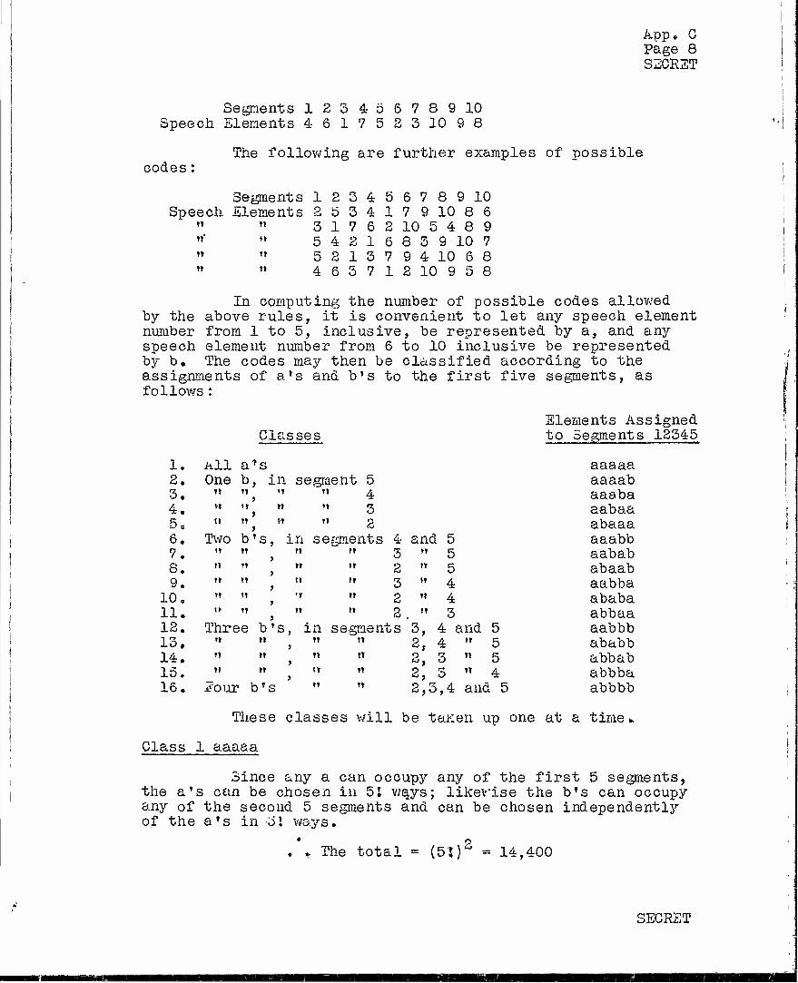
App. G Page 8 SECRET
Segments 123 4 56789 10 Speech Elements 4 617523 10 98
codes: The following are further examples of possible
Segments 1 2 3 4 5 6 7 8 9 10 Speech Elements 2 5 3 4 1 7 9 10 8 6
tT »t 3 17 6 2 10 5 4 8 9 t»' tt 5 4 2 1 6 8 3 9 10 7 tt t» D 2 13 7 9 4 10 6 8 " " 465712 10 958
In computing the number of possible codes allowed by the above rules, it is convenient to let any speech element number from. 1 to 5, inclusive, be represented by a, and any speech element number from 6 to 10 inclusive be represented by b. The codes may then be classified according to the assignments of a»s and b's to the first five segments, as follows :
Elements Assigned Classes to Segments 12345
1. All a*s aaaaa 2. One b, in segment 5 aaaab 3. n II '1 tt A aaaba 4. Vt tt It It <Z aabaa 5 = i» »t »i it g abaaa 6. Two b's, in segments 4 and 5 aaabb 7. ti tt tt n 3 »t 5 aabab 8. t» •t tt tt 2 tt 5 abaab 9. it tt tt tt 3 »t 4 aabba
10. »i it 'i tt 2 tt 4 ababa 11. n »t tt tt 2 tt 3 abbaa 12. Three b's, in segments '3, 4 and 5 aabbb 13, Tt t» tt t»
> 2, 4 tt 5 ab abb 14. M t» tt tt
> 2, 3 tt 5 abbab 15. tt tt it tt
> 2, 3 t» 4 abbba 16. lour b's " " 2,3,4 and 5 abbbb
These classes will be taKen up one at a time».
Class 1 aaaaa
Since any a can occupy any of the first 5 segments, the a's can be chosen in 51 ways; likewise the b's can occupy any of the second 5 segments and can be chosen independentli^ of the a's in 5! ways.
. » The total = (5'J)2 = 14,400
SECRET

App« C Page 9 SECRET
Class 2 aaaab
The b in segment 5 excludes, by the second rule, all the a's from segment 6, The diagram shows 6 remaining positions for an a in segments 7, 8 and 9, namely, 3, 4 or 5 in segment 7; 4 or 5 in segment 8; 5 in segment 9.- No matter which of these 6 locations is chosen for this a, the remaining 4 a*s, in the first 4 segments can be permuted in 4! ways. The total number of ways of choosing the a's is therefore 6*41
The ways of arranging the bTs depends on which b is in segment 5, since the b in segment 6 must be larger than the one in segment 5. These can be studied one at a time in sub- classes :
Subclass aaaa6
The 4 remaining bfs are unrestricted and hence can be chosen in 41 \^a,js} no matter how the a is assigned to segments 7, 8 and 9,
Subclass aaaa7
Element 6 is excluded from segment 6, but each of the 3 remaining b's (8,9,10) can be assigned to segment 6, and in each case the 3 other bTs can permute, no piatter how the a is assigned to segments 7, 8 and 9. The subtotal is therefore 3,3J
Subclass aaaa8
Speech elements 9 and 10 are admitted to segment 6j for each assignment there are 31 arrangements of the remaining b*s, giving a subtotal of 2„31
Subclass aaaa9
Only speech element 10 may be nut in segment 6-, the remaining three b's may be permuted, giving a subtotal of 31
There is no other subclass since element 10 is not admitted to segment 5 by the basic diagram*
The total for the class is the product of the possible assignments of the a's and the possible assignments of the bTs or
Total = 6«4i (4 +3+2+1) > 31 = 6*4i'io»3: = 8640
SECRET

App , C Page 10 SECRET
Class 5 aaaba
Any b can be in segment 6 since all b's are larger than any a, therefore the b's assignments of b to segment 4 3 ways (elements 6, 7 and 8). however assigned, so that the is 3«4!
are limited only by the possible The diagram shows this to be
The other 4 b's can permute, total ways the b *s can be chosen
The a*s in segment 6 depend on the a assigned to segment 5. These will be studied by subclasses:
Subclass aaabl
There is no restriction on the a in segment 6, therefore the a assigned to segments 6 to 9 may be chosen in 10 ways, according to the diagram. The 3 remaining a's can be permuted, giving a subtotal of 10°3!
Subclass aasb2
Element 2 is excluded from segment 6, leaving 9 ways to assign the a to segments 6 to 9 incl. The other afs permute, giving a subtotal of 9°3J
Subclass aapbS
Elements 2 and 3 are excluded from segment 6, also element 3 cannot be used again, so that 7 ways are left to assign the a to segments 6 to 9 incl. The other a's permute, giving a subtotal of 7*31
Subclass aaab4
Elements 2 and 3 are excluded from segment 6, and element 4 cannot be used again, so that 5 ways are left to assign the a to segments-6 to 9 incl. The other a's permute, giving a subtotal of 5*3;
Subclass aaabS
Elements 2, 5 and 4 are excluded from segment 6, and element 5 cannot be used again; this leaves only 3 ways to assign the a to segments 6 to 9 incl. These ways are element 3 or 4 to segment 7, or element 4 to segment 8. The other a's permute, giving a subtotal of 3e3J
SECRET
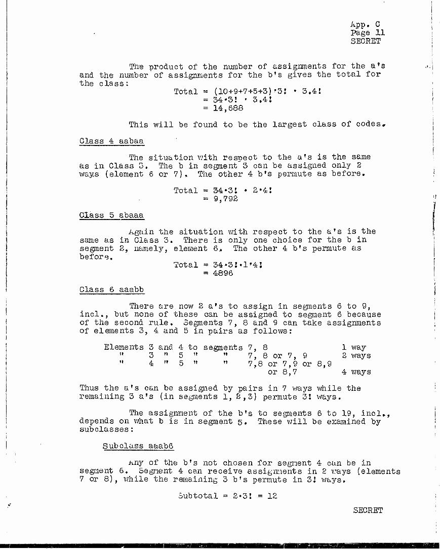
App. C Page 11 SECRET
The product of the number of assignments for the a's and the number of assignments for the b's gives the total for the class:
Total = (10+9+7+5+3)'3! • 3,4! = 34*3! • 3,41 = 14,688
This will be found to be the largest class of codes.
Class 4 aabaa
The situation with respect to the a's is the same as in Class 3, The b in segment 3 can be assigned only 2 ways (element 6 or 7), The other 4 b's permute as before.
Total = 34»3l • 2*4J = 9,792
Class 5 abaaa
Again the situation with respect to the a's is the same as in Class 3. There is only one choice for the b in segment 2, namely, element 6., The other 4 b's permute as before.
Total = 34-3!»l'4i = 4896
Class 6 aaabb
There are now 2 a's to assign in segments 6 to 9, incl., but none of these can be assigned to segment 6 because of the second rule. Segments 7, 8 and 9 can take assignments of elements 3, 4 and 5 in pairs as follows:
Elements 3 and 4 to segments 7,8 1 way " 3 " 5 " » 7, 8 or 7, 9 3 ways 11 4 " 5 " " 7,8 or 7,9 or 8,9
or 8,7 4 ways
Thus the a's can be assigned by pairs in 7 ways while the remaining 3 a's (in segments 1, 2,3) permute 3! ways.
The assignment of the b's to segments 6 to 19, incl., depends on what b is in segment 5, These will be examined by subclasses :
Subclass aaab6
Any of the b's not chosen for segment 4 can be in segment 6. Segment 4 can receive assignments in 2 ways (elements 7 or 8), while the remaining 3 b's permute in 31 ways.
Subtotal = 2*31 = 12
SECRET

App, C Page 12 SECRET
Subclass aaab7
If elements 9 or 10 are assigned to segment 6, then 6 or 8 can be assigned to segment 4 ana the remaining 2 b's can permute, making 2*2*2 = 8 choices. In addition element 8 can be assigned to segment 6, which requires element 6 to be assigned to segment 4, but elements 9 and 10 can permute»
. » Subtotal = 8 + 2 = 10
Subclass aaabs
Only elements 9 or 10 can be assigned to segment 6, element 6 or 7 to segment 4, while the 2 remaining b's permute 2 ways,
. . Subtotal = 2«2-2 = 8
Subclass aaab9
Only element 10 can be assigned to segment 6, but elements 5, 7 or 8 can be assigned to segment 4, while the remaining b's permute in 2 ways«,
. • Subtotal = 1'3»2 = 6
The product of the number of choices for the a*s and the number of choices for the b's is:
Total =7*31 (12+10+8+6) = 7*31 «36 = 1512
Glass 7 aabab
The a's are restricted as in Class 6, giving 7»3 2 choices»
Eor the b's the reasoning is similar to that for class 67 but with the difference that fewer assignments can be made to segment 3 than to segment 4„ This can be seen by subclasses:
Subclass aabaö
The b in segment 3 must be 7; the remaining 3 b's permute, giving 31 = 6 choicesP
SECRET

App„ C Page 13 SECRET
Subclass aaba? • ••m^mimiiw.- — i—n..-n.i • —
The b in segment 3 must be 6; the remaining 3 b»s are greater than 7 and therefore permute, also giving 3! - 6 choices.
Subclass aaba8
Only elements 9 or 10 can be assigned to segment 6, elements 6 or 7 to element 4, while the remaining b's permute 5 ways. This gives 2«2e2 = 8 choices.
Subclass aaba9
Only element 10 can be assigned to segment 6, element 6 or 7 to element 4, while the remaining b's permute 2 ways. This gives 1*2*2 = 4 choices,
The product of the number of choices for the a*s and the number" of choices for the bfs is:
Total = 7-3! (6+Ö.+8+4) = 7*31*24 = 1008
Glass 8 abaab
The b in segment 2 must be 6, by the diagram.
The positions for the a's are the same as for Types 6 and 7, giving 7*31 choices.
The choices for the b's may be studied by subclasses:
Subclass a6aa7
The three remaining b's are unrestricted, giving 31 = 6 choices.
Subclass a6aa8
Elements 9 or 10 must be assigned to segment 6, but the remaining 2 b's permute in 2 ways, giving 2,2 = 4 choices.
Subclass a6aa9
Only element 10 can be assigned to segment 6, the remaining 2 b's permute in ? ways, giving 2 choices.
SECRET

App. C Page 14 SECRET
The product of the number of choices for the a's and the number of choices for the bTs is:
Total = 7»3! (6+4+2) = 7-3J'12 = 504
Class 9 aabba
The assignment of the 2 a's to segments 6 to 9, incl., depends on what a is in segment 5. Using subclasses:
Subclass aabbl
There are no restrictions on the assignment of a's to segment 6. The number of ways 2 a's can be assigned to segments 6 to 9 incl., may be worked out from the basic diagram. Elements 2, 3, 4 and 5 can be assigned by pairs to segments 6 to 9, incl«, as follows:
25
With each of these choices the 2 a's in segments 1 and 2 can permute 2 ways, giving 25*2 = 50 choices for the a's.
Subclass aabb2
Since element 2 cannot be assigned to segment 6, being already used in segment 5, the 6 choices involving element 2 must be deducted from the 25 found for the preceding subclass, giving 19'2 = 38 choices for the a's.
Subclass aabb3
Now neither element 2 nor element 3 can be in segments 6 to 9 incl, which reduces the 25 found above to 9, giving 9.2 = 18 choicesfor the a's.
Elements Sesjnents Choices jt
2,3 can be assigned to 6,7 1 2,4 U t» it t? 6,7 6,8 2 | 2,5 ft tt i» tt 6,7 6,8; 6,9 3 3,4 It ir rt t» 6,7 6,8; 7,8; 7,6 4 I 3,5 tt tt tt tt 6,7
7,9 6,8; 7,6
6,9; 7,8; 6
4,5 tt tt tt tt 6,7 7,8 8,9
, 6,8; 7,9;
6,9; 8,6;
7,6; 8,7;
9
SECRET

App. C Page 15 SECRET
Subclass aabM
Element 3 can be in segment 7, with element 5 in segments 6, 8 or 9, giving 3*2 = 6 choices for the a's.
Subclass aabb5
No a can be in segment 6, but elements 3 and 4 can be assigned to segments 7 and 8; this subclass has only the two choices obtained from permuting the a's in segments 1 and 2..
The b's are not restricted by an a in segment 5, and are governed by the choices permitted by the diagram for segments 3 and 4» These are 2 choices for segment 3, leaving 2 choices for segment 4, while the 3 remaining b's permute; this makes 2*2*3t
The product of the number of choices for the a's and the number of choices for the bTs is therefore:
Total - (50+38+18+6+2)•2»2.31 = 114'2»2.3! = 2736
Class 10 ababa
The a's to be assigned to segments 6 to 9, incl,, are subject to the same restrictions as in Class 9,
The b's are restricted by the diagram to 1 choice for segment 2, leaving 2 choices for segment 4, while the 3 remaining b's permute; this makes l«2t3l
0
• . Total = (50+38+18+6+2)»l«2*3J = 1368
Class 11 abbaa
The a's have the same choices as in Class 9,
The b's are restricted by the diagram to one choice for segment 2, leaving only one choice for segment 3, while the 3 remaining b's permute; this makes 31
Total = (50+38+18+6+2)»31 = 684
Class 12 aabbb
No a can be in segment 6, The diagram shows that the only 3 a's which can be assigned to segments 7 to 9, incl.
SECRET

App. C Page 16 SECRET
are elements 3, 4 and 5 to segments 7, 8 and 9. The only- choice comes from the 2 permutations of the aTs in segments 1 and 2.
The choices for the b's depends on what b. is assigned to segment b. By subclasses:
Subclass aabb6
This requires aa786 since elements 9 and 10 cannot be assigned to segments 3 and 4. Elements 9 and 10 can permute, giving 2 choices.
Subclass aabb7
Similarly this rnust be aa687 • Again elements 9 and 10 permute, giving 3 choices.
Subclass aabb8
This can be either aa678 or aa768, and elements 9 and 10 permute, giving 2 »2 = 4 choices.
Subclass aabb9
Element 10 must now go into segment 6, without permutations.- The possible assignments to segments 3 and 4 are elements 6,7-; 6,8; 7,6; 7,8 making a total of 4 choices.
Combining the 2 choices for the a's with the choices for the bTs!
Total = 2 (2+2+4+4) = 2'12 = 24
Class 13 ababb
As in Class 12, no a can be in segment 6, therefore the only choice for 3 a*s in segments 6 to 9, incl., is elements 3, 4 and ü in segments 7, 8 and 9, The a's in segments 1 and 3 can be permuted, -jiving 2 choices for the a's. There are few choices for the b's since the b in segment 2 must be 6* If the b in segment 5 is 7 or 8, then the b in segment 4 must be 8 or 7, and the remaining brs are 9 and 10 which can permute, giving 2*2 = 4 choices. In addition element 9 can be assigned to segment 5, which requires 10 to be in segment 6, leaving only 2 choices, as to whether 7 or 8 is in segment 4. The choices for the bTs are therefore 4+2 =6.
. . Total « 2*6 = 12
SECRET

App. G Page 17 SECRET
Class 14 abbab
The choices for the a's are restricted as in Classes 13 and 14, giving 2 ehoic'es.
As to the b's, the assignments to segments 2 and 3 must be elements 6 and 7, by the diagram. If element 8 is assigned to segment 5, then elements 9 and 10 are left and can be assigned in 2 ways. If element 9 is assigned to segment 5, then element 10 must be put in segment 6, so that there is only one choice. The choices for the b*s are therefore 2+1=3.
/• Total = 2k3 = 6
Class 15 abbba
The diagram requires that elements 6, 7 and 8 be assigned to segments 2, 3 and 4, which leaves elements 9 and 10 for higher segments. These two can permute, so that there are 2 choices for the bfs.
The arrangement of a's in depends on the a assigned to segment must be 1 or 2, since only elements assigned to the higher segments. If to segment 5, then element 2 would b to the higher segments; but element and this would not be permissible si elements 3, 4 or 5. There are there
segments 6 to 9, incl., 5. The a in segment 5
2, 3, 4 and 5 can be 3, 4 or 5 were assigned
e needed to assign 3 a's 2 must go to segment 6, nee it then would follow fore two subclasses:
Subclass abbbl
Each of the remaining a's may be assigned to segment 6, if desired, so that the restriction is only that of the diagram with respect to the choice of three elements from
Choices
elements 2, 3, 4 and 5. These are:
Elements Segments
234 may be assigned to 6,7,8, 235 i» ?• T7 *• 6,7,8; 6,7,.9 845 It tl tt tt 6,7,8; 6,7,9 345 r» tt tt tt 6,7,8; 6,7,9
7,6,8; 7,6,9
1 <3
6,8,9; 6,8,7 4 6,8,9; 6,8,7 7,8,9; 7,8,6 8
Total 15
SECRET
SBH

App „ G Page 18 SZCRET
Subclass abbbS
This requires element 1 to be assigned to segment 1, leaving elements 3, 4 and 5. These can be arranged in the same ways as 3, 4 and 5 were arranged in the preceding subclass.
The total ways of arranging the a's in these sub- classes is therefore 15 + 8 = So
The total number of choices for the class is accord- ingly 2 • S3 = 46.
Class 16 abbbb
This class has no members, since four a*s are to be assigned to segments 6 to 9, incl. No a can be assigned to segment 6 since b is greater than a.
Summary for all Classes:
Collecting the results for each of the 16 classes, the figures are:
Class
1 a 3 4 5 6 7 8 9
10 11 IS 13 14 15 16
Type
aaaaa aaaab aaaba aabaa abaaa aaabb aabab abaab aabba ababa abbaa aabbb ababb abbab abbba abbbb
Total
Cho i ce s
14,000 8,640
14,688 9,792 4,896 1,512 1,008
504 2,736 1,368
684 24 12
6 46 0 60,316
It may be added that the same total has been found by an independent method of solution. It should also be pointed out again that the solution is the same for each of the inter- laced codes, since they are independent. Throughout the deri- vation references to segment 1, 2 10 should be understood as being to the first, second, tenth even segments for even codes, or to the first, second, tenth odd segment for the odd codes.
Appendix C prepared by: C. IV. CARTER
SECRET

App. C Page 19 SECRET
FINAL REPORT - NDRC PROJECT C-50
ADDENDUM TO APPENDIX C
Originally, the automatic coding equipment was de- signed always to connect a higher lettered pole-piece (in the sense that "i" is higher lettered than "a") to commrtater segment 5 than to commutator segment 6. \s a result segment 5 always controlled a lower numbered speech-unit than segment 6* As carried out in Appendix C, the computations pertaining to the number of individual ten-element codes, capable of being set up by the automatic coding equipment, are based upon such a design. Since the Appendix was written, however, the equipment has been arranged so that sometimes a lower lettered pole-piece is connected to segment 5 than to segment 6 and sometimes a higher lettered pole-piece is connected to segment 5 than to segment 6, Cee Table D-I of Appendix D,
In an unrestricted coding system, there are a total of eighty-one possible ways in which commutator segments 5 and 6 of a ten-element system (segments 9 and 11 for odd codes and segments 20 and 2 for even codes of the C-50 System) might be connected to the nine pole-pieces. Eight of these cannot be used because they would place two connections upon a common major diagonal« Another twenty-eight of them are incapable of being established by the automatic coding equipment because of certain simplifications which have been built into it and which result in an appreciable saving of apparatus. As a result, only forty-five of the eighty-one possibilities are capable of being set up. The possibilities are such that commutator segments 5 and 6 (9 and 11 and 20 and 2 for the C-50 System) control speech-elements, involved in each code-cycle, in some one of the orders indicated in Table C-I, below.
TABLE C-I
Commutator Segments .Speech-Elements
5:6 5:6 5;6 5;6 1:2 3:2 4:8 7:3 1:3 3:5 4:9 7:5 1:4 3:6 4:10 7:6 1:5 3:8 5:8 7:8 1:6 3:9 5:10 7:9 1:7 3:10 6:2 7:10 1:8 4:2 6:5 8:10 1:9 4:3 6:8 9:2 1:10 4:5 6:9 9:5 2:5 4:6 6:10 9:8 2:8 4:7 7:2 9:10 2:10
SECRET
BRSH

App. C Page 20 SECRET
The change, described above} in the coding equipment contributes appreciably to the work of "breaking" C-50 codes but it does not alter the total number of individual codes
reason, the figure 60,316 as the total in
possible. For this number of different individual ten-element codes derived Section 1.7 of the Appendix is not changed; although, if carried out, the details of the derivation would be changed.
One other benefit re change in the coding equipment the scrambler called for the o which was not furnished in the code relay which occupied the code relay which had previousl code relay in the order 1, £, a closed chain, would operate, distribution of pole-piece use oftener than others»
suits from the above mentioned As originally designed, if
peration (1) of a code relay code relay group or (2) a
same major diagonal as another been set, the next usable
5, 6, 7, 8, 9, 10, in resulted in an undesired
some being used appreciably
, 4, This
With the changes incorporated in the coding equip- ment, if the scrambler calls for either of the two conditions, indicated above, the next code relay, in the order 1, 4, 7, 10, 3, 6, 9, 2, 5, 8 in a closed chain, will operate. This provides a more even distribution in the use of pole-pieces, and to some extent adds to the difficulty of "breaking" the codes.
SECRET

SEGRET
FINAL REPORT - MDRC PROJECT C-50
APPENDIX D
DETAILED DESCRIPTION OF EQUIPMENT
TABLE OF GOJjTENTS
SECTION TITLE PAGE
0 GENERAL 1
1, CODING EQUIPMENT 1 1.0 General 1 1.1 Code Relays 2 1.2 Column Relays 4 1.3 "" Exclusion Relays 6 1»4 Scrambler 8 1.5 Scrambler Connectors 9
2. TDS EPUIFMEET 10 2.1 TDS Machine 10 2.10 General 10 2.11 Dynamotor 11 2.12 Quill Assembly 11 2.13 Gear Housing 14 2.14 Reduction Gears and Mesh 16
Adjusting Eccentrics 2.15 Pole-Piece Mounting I late 18
Assembly and Associated Housing 2.16 Receiving Commutator Assembly 19 2.17 Transmitting Commutator Assembly 20 2.18 Rotor Assemblies 20
2.2 Speed Control 20 2.3 Transmission and associated 24
Apparatus 2.30 General 24 2„31 Transmitting Amplifier 25 2.52 Receiving Amplifier 27 2.33 20 l:c Bias and Erase Oscillator 28 2.34 Bias and Voice Frequency 29
Switching Circuits 2.35 Sealed Switch Relay Gap and 31
Overlap Adjusting Circuit 2.4 TDS Power Supply Equipment 32 2.5 Arrangement and Interconnection 33
of Component Parts
SECRET

App. D Page 1 SEGRET
FINAL REPORT - NDRC PROJECT C-50
APPENDIX D
DETAILED DESCRIPTION OF EQUIPMENT
0. GENERAL
The general appearance of a complete C-50 TDS terminal may be seen by examination of photographic Figs. 1, 2 and 3. In the first figure all covers are shown in place; while in the latter two the covers have been removed. Fig. 4 shows the appearance of the TDS'bay from the rear.
The coding equipment is mounted on a standard PBX 26" relay rack« The over-all bay occupies floor space of about 18 x 33 inches and has a height of about 78 inches. It weighs approximately 700 pounds complete with covers. The TDS equipment is mounted on a special 19" relay rack which occupies a floor space of about 21 by 23 inches, over-all. This could be appreciably decreased by a redesign of the supporting base. The over-all height is about 54 inches and the weight is estimated at 200 pounds. Location of the various apparatus components in these bays is indicated on photographic Figs. 1, 2, 3 and 4.
Attention is called to the scrambler connectors and the fixed code connectors shown in Figs* 2 and 3. In order to illustrate their general construction, two of the former have been shown closed and two have been shown open with connector cards in place. Of the latter, both have been shown opened but with a code card in place in only one. Physically, the scrambler connectors and the fixed code connectors are identical.
1. CODING EQUIPMENT
1.0 General
The coding enuipment sets up usable codes, one after the other in 0.75 second cycles, for use in the TDS equipment by following the basic principles discussed in Appendices A and B. The circuits of the coding equipment are so arranger* that one half of the code (10 of the ele- ments of any one code cycle) is used while the other half is set up. This permits a large saving in equipment,
SECRET

App. D Page 3 SECHST
Functionally, the coding equipment may be divided into several basic component groups, as follows:
(a) Code relays (b) Column relays (c) Exclusion relays (d) Scrambler (e) Scrambler connectors
Interconnection of these groups is schematic form on ES-803576.
shown in simplified
The number of codes generated by the coding equip- ment, together with the number of code sequences and the lengths of time covered by these seauences are discussed in Appendix C.
Drawings covering the equipment have not been at- tached to this report because of their large size» A list of then is, however, indicated in Appendix G. If needed, they will be furnished upon request of proper authority.
1.1 Code Relays
The function of the code relays is to connect commutator segments in the TDS machine to the sealed switch relays which in turn connect the pole-pieces into the trans- mission circuit. In effect the code relays serve the same purpose in continuously coded operation as the fixed code connectors serve in fixed code operation»
In general, the code relays may be considered to be divided into two main groups. One group functions with odd numbered (regular) commutator segments and the other with even numbered (interlace) commutator segments. Each of these main groups may be considered to be subdivided in- to two subgroups: one of which is set up during the half code cycle in which connections provided by the other are used (and vice versa).
The code relays in each subgroup may be pictured as being arranged in columns which correspond to certain commutator segments. The number of code relays provided in each column varies from column to column; consequently, the number of sealed switch relays controlled by code relays also varies from column to column. This may be better pic- tured by examination of Diagram E-I, below. In this diagram,
SECRET
MB SM
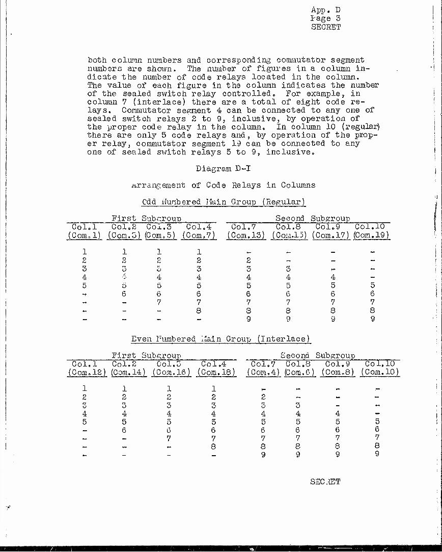
App. D Page 3 SECRET
both column numbers and corresponding commutator segment numbers are shown.. The number of figures in a column in- dicate the number of code relays located in the column. The value of each figure in the Column indicates the number of the sealed switch relay controlled „ For example, in column 7 (interlace) there are a total of eight code re- lays. Commutator segment 4 can be connected to any one of sealed switch relays 2 to 9. inclusive, by operation of the proper code relay in the column» In column 10 (regular) there are only 5 code relays and, by operation of the prop- er relay, commutator segment 19 can be connected to any one of sealed switch relays 5 to 9, inclusive»
Diagram D-I
.arrangement of Code Relays in Columns
Odd ifrinbered Hain Group (Regular)
First Subgroup Col.l Col.2 Col,5 Col,4
(Com, 1) (Com.5) (Com.5) (Com,7)
Second Subgroup ^__ Colo7 Col.8 Col79 Col,10
(Com.13) (Com.15) (Com.17) (Com. 19)
2 3 4 5
2
o 6
o 4 5 6 7
1 2 2 -
3 3 3 4 4 4 0 5 6 6 6 i
re I
re /
8 8 8 — 9 9
4 5 6 7 8 9
5 6 7 8 9
Even Fumbered Main Group (Interlace)
.First Subgroup Col, 1 Col. 2 C ol. 3 C ol,4
(Com« 12) (Com. 14) (c om. 16) (C om.18)
1 1 1 1 2 2 2 2
3 3 4 4 4 4 5 5 5 5 - 6 6 6 - - 7 7 - -, ~ 8
Second Subgroup Col.7 Col.8 (Com,4) (Com.6)
Col.9 (CoiiuS)
Co 1,10 (Com. 10)
ö 4 5 6 7 8 9
4 5 6 7 8 9
4 5 6 7 8 9
5 6 7 8 9
SECRET

App. D tage 4 SECRET
In the foregoing diagram, it has been shown how, by proper operation of the code relays, commutator segments may be connected in various combinations to the sealed switch relays. It will be noted, however, that commutator segments 9, 10, 11 and 12 have not been included in the diagram. This is because certain exclusion relays and not code relays are used to connect these particular commutator segments to the sealed switch relays«, This will be subse- quent ly e xp lai ned ,
1•s Column Relays
Column relays are associated with each column of code relays and are numbered correspondingly, The primary function of the column relays is to connect windings of code relays (in associated columns) to the exclusion re- lays and to the scrambler.
Operation of the column relays, as designated by bhe columns which they control, is in the sequence 1, 2, 3, 4, 10, 9, 8, 7«, This sequence of setting up the column relays insures that there will be at least one code relay in each column that can be used.
This may be better illustrated by first setting up the rule for code relay operation which insures usable codes. This will be done by illustration rather than by definition because the former method provides a clearer picture than the latter. Diagram D-II, below, shows the odd main group (regular) columns of code relays as shown in Diagram D-I, However, two other columns of relays which provide connec- tions between commutator segments 9 and 11 and the sealed switch relays are included with them in order of commutator segments. These latter relays are not code relays but ex- clusion relays and are indicated by columns E and En. It shouid be explained that 2 columns of exclusion relays are not actually provided in the circuit, as shown in the dia- gram, because one column serves to do the work of both. For the sake of simplicity in illustration, two have been shown in the diagram.
SECRET
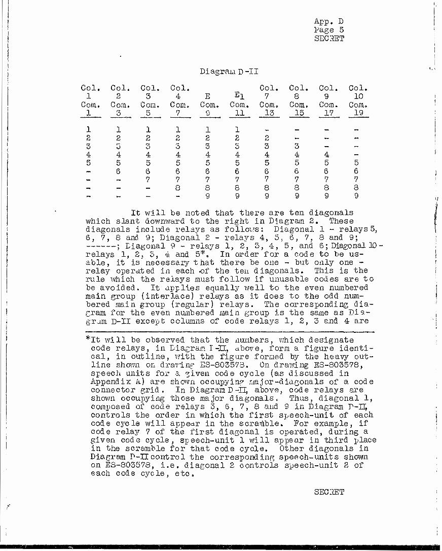
App. D Page 5 SECRET
Diagram D-II
Col. Col. Col. Col. Col. Col, » Col. Col. 1 2 3 4 E El 7 8 9 10
Com. Com. Com. Com. Com. Com. Com. Com Com. Com. 1 3
1
5
1
7
1
1/ 11
1
13 15 17 19
1 1 ^_
2 2 2 2 2 2 2 — — - 3 r- T7
O b 3 5 3 3 - - 4 4 4 4 4 4 4 4 4 - 5 5 0 5 5 5 5 5 5 5 _ 6 6 6 6 6 6 6 6 6 ~ — 7 7 7 7 7 7 7 7 - — — 0 8 8 8 8 8 8 ~ - — - 9 9 9 9 9 9
It will be not ed. that the re are ten diagonals which sla nt downward to the right in Dia* •cram 2 . The se diagonals include relays as follows: Diagonal 1 - relays 5, 6, 7, 8 and 9; Diagonal 2 - relays 4, 5, 6, 7, 8 and 9; ; Diagonal 9 - relays 1, 2, 3, 4, 5, and 6; Diagonal 3D relays 1, 2, 5, 4 and 5*. In order for a code to be us- able, it is necessary that there be one - but only one - relay operated in each of the ten diagonals. This is the rule which the relays must follow if unusable codes are to be avoided. It applies equally well to the even numbered main group (interlace) relays as it does to the odd num- bered main group (regular) relays. The corresponding dia- gram for the even numbered main group is the same as Dia- gram D-II except columns of code relays 1, 2, 3 and 4 are
*It will be observed that the numbers, which designate code relays, in Diagram I —II, above, form a figure identi- cal, in outline, with the figure formed by the heavy out- line shown on drawing SS-803573. On drawing E8-803578, speech units for a »iven code cycle (as discussed in Appendix k) are. shown occupying major-diagonals of a code connector grid. In Diagram D-II, above, code relays are shown occupying those major diagonals. Thus, diagonal 1, composed of code relays 5, 6, 7, 8 and 9 in Diagram V-U, controls the order in which the first speech-unit of each code cycle will appear in the scramble. For example, if code relay 7 of the first diagonal is operated, during a given code cycle, speech-unit 1 will appear in third place in the scramble for that code cycle. Other diagonals in Diagram P-Ucontrol the corresponding speech-units shown on ES-803578, i.e. diagonal 2 controls speech-unit 2 of each code cycle, etc,
SEC 1ST
App. D läge 6 SECHST
associated with commutator bars 12, 14, 16 and 18, re- spectively, and columns 7, 8, 9 and 10 are associated with commutator "bars 4, 6, 8 and 10, respectively while the ex- clusion relays are associated with commutator bars 20 and 2.
It is now possible to demonstrate why code relays must be operated in sequence of columns 1, 2, 5, 4, 10, 9, 8, 7. Suppose, on the contrary, for example, that the code relays were to be operated in sequence of columns 1, 2, 3, 4, 7, 8, 9, 10 and suppose that the scrambler called for operation of code relays 1, 1, 1, 1, 3 and 5 in columns 1, 2, 3, 4, 7 and 8, respectively. These code relays would be set up because so far the rule for usable codes has not been violated. However, it would be impossible to set code relays in columns 9 and 10 without producing an unusable code because the only ones available lie on common diagonals with the code relays alreadjr set. If on the other hand, the code relays are operated in sequence of columns, 1, 2, 3, 4, 10, 9,8, 7 and the scrambler calls for operation of code relays 1, 1, 1, 1, 5, 3 as before, the first four re- lays are set. Columns 10 and 9 are not equipped with code relays numbered 3 but code relays 5 and 6 in column 10 and 4 and 5 in column 9 are still available (usable). These then would be operated by means of a reassigner circuit associated with the exclusion relays. Under the conditions assumed above, if 5 is operated in column 10, 5 also must be operated in column 9; but if 6 is operated in column 10, 4 must be operated in column 9. Usable relays, i.e. relays located on unused diagonals, are still available in columns 8 and 7 as well as in the two excision relay columns and the code could be completed.
Other functions of the column relays are (a) to operate transfers on the exclusion relays so that unusable cede digits generated by the scrambler may be by-passed and (b) to make effective the random number reassigner.
1.3 Exclusion Relays
The scrambler sets up connections which operate the code relays. However, iO exercises no supervision over such connections. Consequently, as previously explained, it is possible for the scrambler to call for operation of a code relay combination which would result in an unusable code. It is the function of the exclusion relays to prevent this by keeping a record of code relay operations called for by the scrambler and by substituting usable code relays for unusable code relays when necessary.
SECRET
App. D Page 7 SECRET
Temporarily, it may be considered that one set of exclusion relaj^s is used for the odd, or regular, code and one set for the even, or interlace, code. Later it will be shown that two sets are required because of the manner of setting up codes* In effect, it may be considered that one exclusion relay is associated with each of the pre- viously explained diagonals of Diagram D-II. Consequently, for example, if code relay 1 in column 1 is operated an exclusion relay associated with the corresponding diagonal operates and blocks operation of code relays 2~Col.2, 3-C0I.3, 4-Col.4, 7-Col.7, 8-C0I.8, 9-Col.9.
Connections from the scrambler, except for column 1, are fed thro\jgh transfers on the exclusion relays before being directed to code relays. If the exclusion relay on aii3r diagonal is normal (i.e. in the non-operated position), any code relay on that diagonal which is called for by the scrambler will operate. However, if the exclusion relay is operated, the next usable code relay, in the order 1, 4, 7, 10, 3, 6, 9, 2, 5, 8, will operate. If a code relay which has not been provided in a given column, is called for by the scrambler, a make contact on the column relay by- passes the unequipped position to some other usable relay which has been provided in that column.
In section 1.2 of this appendix, it was stated that code-connections between sealed switch relays and com- mutator segments 9 and 11 of the regular code and 20 and 2 of the interlace code are established by means of exclusion relays rather than code relays. This is accomplished by providing ten exclusion relays in each exclusion chain. Thus, as eight code relays in columns 1 to 4 and 10 to 7 are operated in setting up a code, eight of the ten exclusion relays are operated and two of them remain non-operated. Oppositely directed transfer conbacts are provided on the exclusion relays. The back contacts of these transfers are connected in a certain Way to the sealed switch relays and the armature contacts of these transfers are connected in a series chain through front contacts of the transfers to commutator segments 9 and 11 (corresponding to columns E and Ei of diagram D-II), in the case of the odd exclusion group, and to commutator segments 20 and 2, in the case of the even exclusion group. Sealed switch relays are there- by connected through the back contacts of the two non-op- erated exlcusion relays to the props r commutator segments through the front contacts of the transfers on the operated
SECRET

App. D tage 9 SECRET
codes generated by the two will not follow the same general pattern. Each scrambler is made up of two scrambler con- nectors, five rotary selectors (which may be seen in photographic Eigs. 2 and 3) and five walking relays. The walking relays are of aid in disguising the arc wiring of the selectors by changing the order in which individual codes of the total code group would otherwise be used.
In effect the coding equipment generates a series of 10 digit numbers, each digit of which corresponds to a speech element. Of the ten digits, eight are generated by the scrambler and two are generated by exclusion relays, the latter as previously described. Digits generated by the scrambler, may only have numbered values corresponding to the number of code relays in each column. Eor example, the first digit of the eight digit group can only be one of the numbers 1 to 5, inclusive, the second 1 to 6, in- clusive, the third 1 to 7, inclusive, the fourth 1 to 8, inclusive, the fifth 1 to 8, inclusive, the sixth 1 to 7, inclusive, the seventh 1 to 6, inclusive, and the eighth 1 to 5, inclusive, The first four of the eight digits govern the operation of code relays in the first four columns of code relays in their respective orders and the last four digits govern the operation of code relays in columns 10, 9, 8, 7, respectively, unless as previously explained, they are modified by action of the exclusion and column relays.
1.5 Scrambler Connectors
The scrambler connectors are the same physically as the fixed code connectors used for fixed code operation of the TD3 equipment. These connectors are provided so that the order in which the scrambler generates codes may be readily changed from time to time. The leads with which the scrambler deals are closed by the column relays. There are eight feeder leads, one per column of code re- lays. They are fed to the scrambler through the "In" scrambler connector where oj means of one of variously punched cards, they may be reassigned to eight leads outgoing from the connector.
The cards for this connector have eight holes punched in them, one for each lead. They provide a per- mutation of the numbers 1 to 8, inclusive. The. rule for punching these cards is that there shall be one hole in each of the eight horizontal rows and each of the vertical columns corresponding to the incoming and outgoing leads. If this rule is followed each lead will be fed through the scrambler in a different circuit from any other lead.
SECRET
App. D tage 10 SECRET
The leads from the code box are fed through the contacts of the walking relays (which are associated with the scrambler) which mix them up further before they go to the selector arcs of the scrambler. The eight leads out- going from the "In" connector having been closed through by the contacts of one of the walking relays are connected to the brushes of selector arcs, thence to terminals of the arcs to other selector brushes and so on thr ough from three to five arcs. The terminals of the final arcs are all wired to eight leads which connect to the "Out" scrambler connector»
The "Out" scrambler connector mixes the eight leads from the scrambler in the same manner as the "In" connector and thereby also serves to disguise the arc wiring and change the code cycle in the same manner as the "In" connector. The rule for punching the "In" cards also applies to the "Out" cards and it is assumed that the same group of cards will be used for bcch sets of connectors.
2. TDS EQ,iriP?!Ei:T
2.1 TDS Machine
2.10 General
The TDS machine consists of suitable housings which -.iOuxio the drive motor, speed reduction gears, mag- netic tape; polepieces and commutators. Complete with dynamotor it weighs 55 pounds and has over-all dimensions of 12 and 13/16 by 11 and 7/8 by 8 and 3/64 inches. Its general appearance is shown on photographic Figs. 4 and 5,
The design provides over-all rigidity and accurate alignment of shafts and associated bearings. It also attempts to minimize non-uniformity of tape speed which may result from several sources, including improper gear tooth action (called "gear tooth flutter"). Design fea- tures affecting the latter will be discussed, subsequent- ly, in detail«, Ifesh adjustment and continuous lubrication of the main drive gears and main bearings is provided.. All .moving parts are enclosed to minimize troubles re- sulting from the action of dust. Commutators are easily accessible for cleaning when necessary.
For convenience in description, the machine has been divided into several component groups. These groups are indicated in the order in which the complete machine would ordinariljr be assembled. They are as follows:
SECRET

App. D Page 11 SECRET
(a) Dynamotor (b) Quill Assembly (c) Gear Housing (d) Reduction Gears and Mesh Adjusting
Eccentrics (e) Pole-Piece Mounting Plate .assembly and
Associated Housing (f) Receiving Commutator Assembly (g) Transmitting Commutator Assembly (h) Rotor Assemblies
2.11 Dynamotor
The function of the dynamotor is threefold. It is driven from a 24 V d-c supply and furnishes (a) mechan- ical power,-at a normal speed of 7200 r.p.m., for TDS drive, (b) 2 50 V d-c supply to the plate of a vacuum tube in the speed control circuit and (c) 720 c.p0s, pilot frequency to the speed control circuit. The latter two functions will be described in Section 2.2 below.
A small centrifugal type blower, mounted on the end of the shaft opposite to the drive end, forces air through the dynamotor for cooling purposes.
Physically, the dynamotor is mounted in the Pinion Quill and forms part of the Quill Assembly.
2.12 Quill Assembly
Reference to E3-803540 will facilitate descrip- tion of the Quill Assembly. This assembly consists pri~ marily of a "funnel shaped" part known as the Pinion Quill (2). The large end of~this part is counterbored to accept the shaft end of the dynamotor housing. A shoulder, formed by the counterbore, acts as a seat against which the outer edge of the dynamometer housing bears. This seat governs the depth to which the dyna- motor may be inserted into the quill.
The dynamotor is fastened to the quill by means of three motor fasteners (4) the ends of which engage Woodruff key slots milled into the dynamotor housing.
SECRET
App. D page 12 SECRET
''Jhen the cap screws (16) are drawn up, the dynamotor housing is jammed tightly against the above mentioned shoulder in the quill and the two are held rigidly to- gether«, In so far as machining tolerances permit, the count erhöre, which accepts the dynamotor housing, is concentric with the cent erline of the quill and the plane of the shoulder, against which the dynamotor housing seats, is normal to the centerline of the quill«, This arrangement insures that the axis of the dynamotor shaft is closely coincident, throughout its length, with the centerline of the quill.
In the small or "spout" section of the quill, two shielded ball bearings (14 and 15) are mounted«, These bearings fit into counterbores and are seated against shoulders in the quill in the same general manner as described for the dynamotor mounting. The axes of the bearings are thus likewise closely coincident with the centerline of the quill. Bearing retainers (18), exter- nally threaded at one end, engage internal threads in the quill.. When seated, these retainers force the outer races of the ball bearings tightly against the counterbored shoulders in the quill and hold them rigidly in place.
The helical pinion (3), which is described in Section 2,14 is mounted in the above mentioned bearings. Close alignment of the centerline of this pinion with that of the motor shaft results from the previously de- scribed method of mounting the dynamotor and the pinion bearings» The fit of the pinion in the internal races of its bearings is adjusted to what may be described as a "light push fit" and a pre-load of about 12 pounds is applied to the bearings by means of pre-load springs (19). The compression of these springs is adjusted so that the pinion is permitted to move axially in its bearings - the location of the cone shaped shoulders on each end of the pinion being approximately equidistant from their respective bearings. This method of mounting, although somewhat unconventional, provides a radial rigidity which could be obtained neither with plain bearings nor with non-pre-loaded ball bearings and at the same time permits axial movement of the pinion under the influence of the springs and neoprene flexible coupling (13).
SECHET
em

App. D Page 13 SECRET
A relatively large moment of inertia, about its axis, has been built into the helical gear (described in Section 2.14) which is driven by the pinion. This gear, therefore, resists non-uniformity of rotation produced by gear tooth irregularities between the two. If the pinion were to be mounted with axial rigidity, relatively severe gear tooth stresses, sufficient either to force non-uniform motion of the driven gear, or to produce mechanical failure, would be developed. The former, of course, would be the more probable. This is avoided by permitting relatively small axial shifts in the location of the pinion which relieve these stresses and permit more uniform motion of the driven gear than would other- wise result.
The flexible coupling (15) is composed of three metallic details bonded together with neoprene. One of the details, termed "sleeve", is bonded externally to the neoprene and prevents undesired expansion of the latter under the action of centrifugal force. The other two de- tails, termed "bushings" connect, respectively, to the motor shaft and to the pinion. The former is provided with set screws which bind it to the motor shaft. The latter, however, is provided with internal threads which mate with threads provided on the motor end of the pinion. Threads instead of set screws are employed, in this in- stance, because the latter would not satisfactorily re- sist the relatively heavy thrust of the adjacent pre- load spring. The primary function of the flexible coup- ling is, of course, to transmit mechanical power from motor to pinion and to reconcile the minor misalignment in motor and pinion axes resulting from machining toler- ances. In addition, however, the coupling acts as an energy absorbing element for the prev.i ously described axial shifts of the pinion and thereby minimizes the possibility of mechanical resonance effects which might otherwise be set up.
The Pre-Load Spring Ring Nut (20) screws to the end of the pinion remote from the motor and compresses its associated pre-load spring. This ring nut is threaded and subsequently slotted, -after slotting, the two ends
SECRET

App* D page 14 SECRET
are forced slightly together, thus misplacing the threads on either side of the slot with respect to each other. When screwed upon the pinion, the threads are forced in- to proper relationship and a clamping action, which re- sists possible tendency of the nut to work loose under normal operating conditions, is thereby provided.
Excess lubrication of ball bearings, operated at high speed, may produce a condition known as "burbling", which results from violent agitation of the lubricant. Mechanical energy is thereby converted to heat energy, which is lost. This loss, in itself, is undesirable0 Of greater importance, however, bearing temperatures may be raised to undesirably high values in the process of dissipation, For this reason, the pinion bearings are of the shielded type, Upper Pinion Bearing (15), mount- ing the motor end of the pinion,is of the double shielded type. One shield minimizes the entrance of gritty par- ticles which might otherwise drop into the bearing from the motor end and the other minimizes the entrance of excess lubricant, resulting from gear tooth "splash", Lower Pinion Bearing (14) is provided with only one shield which is assembled toward the toothed portion of the pinion. It likewise prevents the entrance of excess lubricant. Double shielding was not specified for this bearing because it was not desired to impede drainage of oil which might get into the bearing via the upper shield. Furthermore, since this bearing is not subject to the possible entrance of dirt from without the housing (as the upper bearing is), a lower shield is not considered necessary.
Holes are provided in the motor end of the quill to permit easy access to the dynamotor brushes and to permit free circulation of cooling air,
Z.13 Gear Housing
The following description will be facilllated by reference to ES-803546.
The gear housing (1) is the foundation casting of the TDS machine. Its general shape is that of a rela- tively short hollow cylinder, A mounting base and a cylindrical shaped lug (known as the quill housing), lo- cated externally and on opposite sides of its cylindrical
SECRET

App. D Page 15 SECRET
surface, are cast integrally with it. Bolting flanges, j reenforced by stiffeners, have also been cast onto the «.I ends of the cylinder» Its general appearance may be seen \ on photographs Figs« 4 and 5, where it appears as the center portion of the machine. (
t
Two circular shaped bearing plates (3) are j equipped with locating shoulders which fit into the open j ends of the gear housing- These plates, together with j associated gaskets (25); form an oil tight housing for i continuous lubrication of the main drive gears» !
! The bearing plates are provided with bearing |
cups which receive and support the nain shaft bearings (lo). The bearing cups are machined concentrically with j the shoulders on the plates which assures accurate align- ment of the bearings. Integrally cast radial stiffeners support the bearing cups and minimize deflection of the bearing plates resulting from the relatively heavy thrust (about £5 pounds) of the bearing pre-load spring (15). The thrust of the pre-load spring, eliminates radial play in the bearings and prevents axial play in the main shaft (12) by forcing it tightly against the bearing in the right hand bearing plate. At the same time, the shaft is free to expand and contract with temperature changes without producing binding or excessive bearing pressures.
A small annular slot is machined in the" bearing plate externally adjacent to the bearing cup, This slot is connected to the inside of the case by means of a small oil return hole (not evident in -ehe assembly draw- ing). A slinger (17) mounted on the main shaft turns with it and throws oil, which has leaked through the sealed bearing, into the slot and thus returns it to the gear housing."
The drum hub (20), which mounts thetape drum assembly (19) upon the shaft, is mounted directly adja- cent to one of the main bearings. This construction pro- vides relatively very great radial, axial and torsional rigidity; all of which contribute toward the provision of uniform circular motion of the tape.
SECRET
App. D Page 16 SECRET
2.14 deduction Gears and Mesh Adjusting Eccentrics
As previously mentioned, the driving dynamotor runs at a normal speed of 7200 r.p.rn. Since the code cycle is 0.75 second, it is necessary that the brushes and main shaft operate at a speed of 80 r.p.m. The first requirement of the drive gears, therefore, is that they provide a speed reduction of 90:1.
Before taking up further gear design requirements it may he well to consider briefly effects which may he expected to result from improper gear action. The tape moves at a linear speed of about 16.5 inches per second. Consequently, with perfectly uniform tape velocity a single" cycle of a 1650 c.p.s. wave, for example, will oc- cupy a distance of only 0.010 inch along the tape. Higher frequencies, of course, will occupy a smaller distance than 0.01 inch and lower frequencies a greater distance. From this it will be seen that periodic oscillations of the tape (about its mean speed) of extremely small magni- tude will produce an undesired frequency modulation of the reproduced signal. In this connection, suppose for example that the tape is subject to an oscillation of 0.0005 inch amplitude, which, of course, is extremely small. Under this assumption, the previously assumed 1650 c.p.s. wave would fluctuate between the limits of about 1570 and 1730 c.p.s. and thu 3300 c.p.s. wave would fluctuate between 3155 and 3465 c.p.s.
Non-uniformity of tape speed (called "flutter") may be caused by several things, such as, (a) minor im- perfections in gear tooth form and slight non-uniformity in gear tooth spacing, (b) excess lash between gears and (c) "run-out" of gear pitch circles with respect to their axes. These factors, therefore, are important in estab- lishing requirements for the gears.
In order to minimize flutter, caused by item (a) above, the pitch diameter of helical gear (item 13, ES-803546) is as large, compared to the diameter of the magnetic tape circle, as is reasonably possible* and an involute tooth form is used**.
*The magnitude of flutter at the tape, produced by non- uniform tooth spacing, is proportional to the diameter of the tape circle and inversely proportional to the pitch diameter of the helical gear,
**With teeth of involute form, conjugate action between two gears is not dependent upon tangency of their re- spective pitch circles as it is with teeth of cycloidal form,
SECRET

.App. D "tage 17 SECRET
A minimum of lash (item (b), above) is assured by providing the necessary 90:1 speed reduction in a single pair of gears, rather than in a multiple train, and in addition by providing for mesh adjustment between the two. Mesh adjustment is accomplished by means of a compound eccentric which positions the quill assembly in the quill housing portion of the gear housing. The com- pound eccentric is made up of two sleeves known, respec- tively, as the Type A Eccentric Sleeve and the Type B Eccentric Sleeve (items 31 and 32, ES-803546). The Type A sleeve fits into the quill housing but has the axis of its internal cylindrical surface offset 0.01 inch to the right of the axis of its external surface. The Type B sleeve fits into the Type A sleeve but has the axis of its cylindrical internal surface offset 0.01 inch to the left of the axis of its external sur^ face. The quill assembly in turn fits into the Type B sleeve. When the offsets in the two sleeves are dia- metrically opposite each other, the centerline of the quill assembly coincides with the centerline of the 'j quill housing. If, however, starting with the two off- sets diametrical^ opposite each other and parallel to J the axis of the helical gear (item 13, 33-803546), the Type A sleeve is rotated a given number of degrees clock- wise (from its lower end) and the Type B sleeve is ro- tated the same number of degrees count erclockwise (from its lower end), the whole quill assembly, including the pinion mounted therein, will be moved directly toward the ! helical gear and the gear mesh will be tightened. If the ; sleeves are rotated in the opposite direction the mesh • : will be loosenedc Locking lugs have been milled onto ;
the lower ends of the sleeves so that they may be locked in place, once the desired mesh is obtained„
In obtaining a reduction of 90:1 in a single pair of gears, the driving pinion must be small compared to the driven gear. If "flutter" due to "run out" (item (c), above) is to be minimized, it is evident that the gears I must not only be machined with great care, but the small pinion must be adequately supported so that it does not deflect appreciably under load« For this reason, the j pinion is "skewed" 15 degrees out of the plane of the j driven gear's pitch circle. This permits closer mounting !
SECRET

App. D Page 18 SECRET
of the bearings which support the pinion and thereby ap- preciably stiffens the latter. Furthermore, this skew increases the lead angle of the helical gear teeth thus providing appreciably higher mechanical efficiency in gear operation than could be obtained without the skew. Design of the gears is shown on ES-803510.
To further minimize the possibility of flutter, helical gear (ES-803510-1 and item 13, ES-803546) has been equipped with a heavy integrally cast rim. This rim provides the gear with a relatively great moment of iner- tia about its axis which resists undesired accelerations produced by imperfections in the gear train. In order to avoid enforced accelerations of this gear, in spite of its large moment of insrtia (with resultant heavy gear tooth stresses) the driving pinion is permitted to slide axially in its bearings under control of the flexible coupling, as described in Section 2.12.
2015 lole-Piece Mounting Plate Assembly and Associated Housing "
Refer to drawing ES-803546. The pole-piece housings (4) bolt to previously described bearing plates (3), The former are centered in place by means of shoul- ders on the latter and, in turn, they support and center the transmitting and receiving commutator assemblies (6 and 7). In addition, the housing on the left hand side of the gear housing, supports the pole-piece mount- ing plate assembly (21) and positions it properly with respect to the tape. Threaded lugs are provided on the inside surfaces of these housings (not particularly evi- dent from the drawing but may be seen in the housing lo- cated on the right side). These lugs govern the depth to which the mounting plate assembly may be inserted into the housing and also afford moans whereby both the mount- ing plate and commutator assemblies may be bolted in place.
Design of the pole-piece mounting plate assembly is shown on ES-803525. This drawing shows the method of mounting the pole-pieces (2 and 3) in the mounting plate (8) and the method of bringing out the pole-piece wiring (Sect C-C). It will be noted that the pole-pieces are so mounted that they are free to swivel about the pole pin assembly (7) and thereby to follow irregularities in the magnetic tape.
SECRET
i
j
App, D Page 19 SECRET
The pole-piece jaws are held in contact with the tape by means of small U-shaped springs (6), Side play of the pole-pieces in their mountings is eliminated by means of the pole-piece pin spring (1) . This method of mounting permits the swiveling action described above but prevents chatter of the pole pieces as the tape slides between the jaws«,
2,16 .Receiving Commutator Assembly
The receiving commutator assembly (item 6, ES-803546) is shown in detail on ES-803541. This assem- bly consists principally of a housing (1) which mounts the receiving commutator (4) together with a worm and worm gear (5 and 7). The appearance of the commutator and its housing is shown in photographic Fig. 5.
The receiving commutator incorporates a needle bearing race, a commutator ring, a code cycling ring, two slip rings and a hub into a single unit. These parts are molded together with Tenite II, The commutator, cycling and slip rings are faced with heat treated palladium- copper to provide low electrical resistance and high re- sistance to brush abrasion.
The hub is bored out at its commutator end, to form a bearing pocket for a main shaft outboard bearing (item 22, ES-803546). In addition, the hub, at its other end accepts a split worm gear (5). This worm gear, to- gether with its driving worm (7) affords means for ad- justing the commutator with respect to its associated brushes, which, as previously explained, is necessary in making proper allowance for circuit delay,
A bearing plate (8), located by shoulders in the commutator housing, supports the worm gear and prevents axial play and canting of the commutator, Free circular movement of the commutator is permitted, without radial play, by means of needle rollers (14) which ride between the needle bearing race (which forms the outer circum- ference of the commutator) and a properly machined race in the housing.
Wiring, connecting to the various segments and rings of the commutator, is formed into a cable which is coiled around the commutator hub in the form of a clock spring (See ES-803541 Section A-A). This permits circular adjustment of the commutator.
SECRET
App. D Page 20 SECRET
2.17 Transmitting Commutator Assembly
The transmitting commutator assembl3>- is much the same eis the receiving commutator assembly except that no provision for adjustment of the commutator with respect to its associated brushes is required. The commutator therefore fits snugly in its housing and is held in place by small machine screws«
Details of this assembly are shown on ES-803542, and its position in the machine is shown on ES-803546.
2.18 Rotor Assemblies
The rotor assemblies are mounted on the ends of the main shaft and carry the contact spring assemblies. Details of the rotor assemblies are shown on ES-803533 and their position in the main assembly is shown on ES-803546. The receiving rotor assembly may be seen in photographic Fig. 5,
The rotor assemblies are held on the shaft be- tween two clamp discs which are forced together by means of a nut which threads onto the end of the shaft. The inner disc (item 1, 3S-803533) abuts against the inner race of sealed bearings (item 22, ES-803546) and jams the latter against a shoulder provided on the shaft. The bearing is thus held tightly on the shaft, but its outer race is free to slide axially in the bearing pocket of the commutator hub, This avoids undue stresses which might otherwise result from unequal expansion and con- traction of the various members under temperature changes.
The contact spring assemblies are insulated from the rotors, in order that the various commutator segments and cycling segments may be grounded through their as- sociated slip rings, only» Two grounding slip rings, have been provided on the receiving commutator (one for the cycling segments and one for the commutator segments). Interaction between sealed switch coding relays and the control relays for the continuously recycled coding equip- ment, which might result from a common ground conductor, is thereby avoided,
2.2 Speed Control
The general physical appearance of the speed con- trol equipment will be seen by examination of photographs Figs. 1 to 4.
SECRET

App. D Page 21 SECRET
A. schematic diagram of the speed control circuit, which provides a d-c motor with synchronous motor char- acteristics, is shown on ES-804317, Functionally, this circuit may be divided, exclusive of the dynamotor which it controls, into three main component groups, as follows:
1, A bridge stabilized oscillator which employs a 720 c.p.s, quarts crystal in a thermostat for frequency control«
2, A "motor-control" bridge in which the crystal oscillator is coupled to the dynamotor.
3, A thermal control device for stabilizing the temperature of the crystal in item 1, above.
The bridge stabilized oscillator consists of a two stage amplifier with a twin triode in the last stage. One of these triode units acts as a "buffer" stage. The output of the other is connected to a bridge circuit made up of a D-161645 Crystal with series trimming condenser, a D-163736 Thermistor and resistors of 0.5 megohm and 5000 ohms, respectively. The output terminals of this bridge are connected respectively to the grid and cathode of a 6SF5 tube used as the first amplifier stage.
When the bridge is unbalcinced by an amount equal to the gain of the amplifier, regenerative feedback is suf- ficient to produce oscillation at a frequency controlled by the crystal. The amplitude of the oscillation is con- trolled by the thermistor, which reduces its resistance to approach bridge balance as the amplitude of oscillation increases.
A condenser (marked "As req." on the drawing) provides a fine adjustment of frequency. Due to thermal lag in the vacuum mounted crystal, the oscillator should be operated for at least 24 hours, before attempting final frequency adjustment.
The theory of this tyue of oscillator is given by L. A. Ifeacham, 1-roc. I.R.E. V26, Oct. 1938, p. 1278, "Bridge Stabilized Oscillator",
SECRET

App. Ti Page 22 SECRET
The "Motor-control" bridge is a three-arm fre- quency bridge which is the full circuit equivalent of the four-arm frequency bridge described and analyzed in U. S. patent*1,695,035. One arm of the "motor-control" bridge (terminals 3-4 of the D-163407 Bridge Unit) is a parallel tuned circuit which is equivalent to a resistance when in resonance. This arm is balanced by a resistance network (terminals 2-3 of the bridge unit) composed of two fixed resistors and a thermistor. The effective resistance of this latter arm varies with temperature so that it matches that of the tuned circuit arm closely at all usual temperatures. The third arm, (terminals 1-^2 of the bridge unit) is a coil having high mutual coupling with the coil in the first arm of the bridge (terminals 3-4). This high mutual coupling makes it unnecessary to provide a tuning condenser or a balancing resistor for the third arm, since, in effect, they are consolidated with the condenser and balancing resistance of winding 3-4. This makes the three- arm bridge the equivalent of a four>-arm bridge.
When the uilot-frequency from the dynamotor (ap- plied to the bridge through winding 3-4 of the KS-8699 transformer) is such that the bridge balances, there is no output voltage across bridge terminals 3-3. If the pilot frequency and, hence, dynamotor speed, is off normal the bridge will deliver an output. The bridge, therefore, serves as a speed measuring device which delivers an a-c voltage of varying phase angle (with respect to an arbi- trary reference) depending upon whether the speed is high or low and of magnitude proportional to the difference between actual speed and desired speed.
In order to make use of the above described bridge characteristics, it is necessary that the bridge output voltage be compared to a reference, The dynamotor pilot frequency is also used for this latter purpose by im- pressing it upon the plate circuit of a 6J5 vacuum tube (known as the phase detector) which has its grid circuit energized from the bridge output. The detector tube plate current is thereby dependent upon the relative phase and amplitude between its grid and plate voltages, the former being maximum when the two are in phase and minimum when the two are in phase opposition.
SECRET

App. D Page 23 SECRET
The phase detector is coupled to the grid circuit of a 6V6 vacuum, tube through a resistance-capacitance fil- ter. The filter assures proper initial phase relations, reduces pulsations and, by properly modifying the gain- phase shift characteristics of the regulator, operates as a damping network to prevent hunting of the system about its mean speed.
The plate circuit of the 6V6 vacuum tube contains the dynamo tor regulating field winding. Its plate current thereby adjusts the motor field to hold its speed constant.
The "motor-control" bridge, described above, is capable in itself of controlling the dynamotor speed to within about 1 part in 1000, under varying conditions of load and power supply. When, however, an external voltage of suitable frequency and magnitude is impressed upon the motor-control bridge, the motor runs in synchronism with the external voltage and its speed stability is thereby dependent upon the frequency stability of the latter. The bridge stabilized oscillator, previously described, is used for this purpose.
In order to obtain the degree of frequency sta- bility desjred, it is necessary to closely control the temperature of the quartz crystal. This is accomplished by mounting the crystal, together with resistance elements (which serve in the dual capacity of heater and thermostat) in a Dewar flask« (This flask can be seen in the photo- graphic Fig. 2 and 5.)
Power for the resistors, which serve as heaters, is obtained from another bridge-type oscillator. In ad- dition to their function as heaters, the resistors form two control arms of the bridge which govern the oscillator and thus act, in effect, as a thermostat. These resistors are incorporated in a single unit (ESL--574650) and are wound on a brass tube which encloses both the crystal and thermistor of the previously described bridge stabilized oscillator. One resistor (1-2) is of nickel wire and the other resistor (3-4) is of advance wire. The nickel wire has a relatively high temperature coefficient which bal- ances the bridge and thus limits or stops oscillation when the operating temperature is reached. With this arrange- ment, the quartz crystal is held at a temperature of about 140 F with variations of less than 0.2 F»
SECRET
-'.i

App. D Page 24 SECRET
In order to afford means whereby the brushes in the machine of one terminal may be set in the proper posi- tion with respect to those in the other terminal, manually operated speed changing controls are incorporated in the speed control circuit. These controls are in the form of keys whose function, when held off normal, is to short- circuit the output of the controlling bridge-stabilized oscillator and to change the tuning in the motor-control bridge by adding or subtracting capacitance from the tuning condenser which is used for normal speed. With these con- trols the djrnamotor can be made to operate either faster or slower than normal with either relatively small or large speed shifts. The change produced by the fine con- trol is about 0,1 per cento That produced by the course control is appreciably greater»
2.3 Transmission and Associated Apparatus
2.50 General
The following sections describe the transmitting and receiving amplifiers. Descriptions of the bias and erase oscillator, bias and voice frequency switching cir- cuits and the gap and overlap adjusting circuits are also included in this section because, although not strictly falling within the transmission apparatus classification, thejr are directly involved in the transmission process.
The general appearance of these pieces of appara- tus is shown by photographs, Figs. 1 to 4.
The over-all transmission-freouency characteris- tic of two terminals in tandem, one transmitting and the other receiving, as measured between 600 ohm impedances is indicated on ES-824308, The low frequency response of the system is deliberately reduced, by a predistorting network located between the transmitting amplifier and the recording pole-pieces, in order to avoid serious low frequency wave-form distortion produced by the tape. At the high frequency end, response decreases with frequency. This is not intentional but results from the relatively poor high frequency response characteristics of the repro- ducing pole-pieces. Some improvement in over-all high frequenc}?- characteristics is afforded by an equalizer, used in the output of the receiving amplifiers, to raise the magnitudes of the higher frequencies with respect to the lower frequencies.
SECRET
App. D Fage 25 SEGxlET
2.31 Transmitting Amplifier
"Transmitting Amplifier" is an arbitrary designa- tion applied to one of the two terminal amplifiers. It is always utilized for recording voice signals upon the magnetic tape, With the terminal in the transmitting condition, it raises the microphone output and, with the terminal in the receiving condition, it raises the in- coming line signal to a value approaching the overload point of the tape. This insures a more favorable signal to noise ratio than could otherwise be obtained. In order to work the tape at its optimum load point this amplifier is of the limiting type, changes in the input level being amplified linearly until a predetermined in- put level is reached. Above this predetermined point the gain of the amplifier is regulated in such a manner that the output is held to a constant value.
The characteristics of the amplifier together with associated input and output networks are such that with an input of -20 dbin, the amplifier starts to limit the current in the recording pole-pieces to the approxi- mate values shown in the following table.
Table II
Record Coil Current in Frequency Milliamperes
300 0o8 500 1.2 700 1.7
1000 2,3 1500 3.3 2000 3»9 3000 4.6
This delayed amplitude control is accomplished in such a manner as to introduce practically no wave shape distortion.
The limiting range is from -20 to +10 dbm at which point wave shape distortion due to amplifier over- loading occurs.
The amplifier circuit is shown on ES-803592, It consists of two push-pull stages of amplification in tan- dem. Limiting action is obtained by d eriving a d-c voltage
SECHST

App. D Page 26 SECHET
proportional to the signal input and applying it as a bias voltage to the input stage to decrease its gain in proportion to the signal increase» This action is pre- vented until the predetermined value of input level has been reached by proper biasing of the control circuit. The second stage operates at a fixed gain.
The first amplifier stage, consisting of two 61,7 multi-electrode tubes in push-pull, receives incoming signals through a 500 ohm to push-pull grid step-up trans- former* Output from this stage is coupled to the final stage, a 6SN7GT with its two triode sections connected in push-pull, by means of a balanced resistance-capacity in- terstage network. Output is obtained through a push-pull triode plate to 50 ohm output transformer. Feedback volt- age for the delayed amplitude control circuit is obtained from the output circuit of the push-pull 6L7 stage through a bridged high impedance resistance-capacity coupling net- work and is amplified by a triode push-pull stage utiliz- ing both triode sections of a single 6SC7 tube. The plate circuit of the 6SC7 amplifier stage is coupled through the usual resistance-capacity network to the cathodes of a full wave 6H6 rectifier. Since the extra control grids (No. 3) provided in the input stage 6^7 tubes are connected to the negative side of the 636 recti- fier circuit load resistance, the amplified control volt^ age will appear as a negative bias that will decrease the gain of the first stage in proportion to the inorease in the input level. The control circuit is rendered inef- fective until the predetermined input level has been reached by inserting a positive bias in the rectifier cathode circuit. This bias will cause the rectifier tube to be nonconducting until the negative peaks of the ampli-r fied control signal exceed the bias in magnitude. When the control voltage is greater, a rectified current pro- duces a negative control bias which is applied to the 6L7 grids (Ho. 3) and the over-all gain of the amplifier is correspondingly reduced. The bias voltage also charges the capacitance across the load resistance. The time con- stant of this combination is such that, once the limiting circuit is operative, gain fluctuations will be slowed down and will not follow individual speech peaks.
SECRET

App. JJ Page 27 SECRET
The balanced input circuit of the amplifier is switched, through two sets of transfer contacts appear- ing on push-to-talk relay FT-1, to either the local mi- crophone circuit or to the incoming line. By the same operation the unbalanced output circuit, also switched on relay PT-1, is connected to the proper recording pole- piece (terminal transmitting) or to the coding pole- pieces (terminal receiving),
2.32 Receiving Amplifier
The term "Receiving Amplifier" is arbitrarily used to designate that terminal amplifier which is always used to amplify signals reproduced from the magnetic tape. With the terminal in a transmitting condition, it raises the low level energy received from the tape to a level suitable for transmission on the line and with the ter- minal in the receiving condition it raises low level energy taken from the tape to suitable values for the operation of a receiver.
The receiving amplifier circuit is shown on E3-803593. It consists of two stages of amplification. The first stage, a 6S0"7 pentode voltage amplifier, re- ceives its input from the particular reproducing coil in use at any given moment through a 50 ohm to grid step-up transformer« Output voltage from this stage is coupled to the grid of a 6C5 triode, which comprises the second stage of amplification, by means of a resistance-capacity interstage network. Plate circuit filtering (in addition to that provided in the power supply) is provided in the first stage to minimize the effect of disturbances pro- duced by other apparatus operating from the same power source. Controls that permit an independent adjustment of output power for the transmitting and receiving con- ditions are obtained by providing two paralleled grid potentiometers as the output element of the interstage network. The 6C5 grid connection is switched to the ad- justable arm of the proper potentiometer by means of a set of transfer contacts on push-to-talk relay PT-2. Out- put from the amplifier is obtained by means of a step-down transformer that matches the output stage to a 500 ohm line. Both sides of the amplifier output circuit are switched from the handset receiver (receiving condition) to the transmission line (transmitting condition) through transfer contacts also on push-to-talk relay PT-2. The unbalanced amplifier input is correspondingly switched from pole-piece 10 to the proper bus conductors on the voice frequency switching circuits by means of another transfer contact on PT-2.
SECRET
App. D Page 28 SECRET
2.33 20 KC Bias and Erase Oscillator
! The purpose of this oscillator is to supply 20 KC bias and erase voltage to the appropriate pole-piece coils of the magnetic tape recording system. When the T.D.S. circuit is operated in the transmitting condition the os- cillator output is connected, "by operation of the various push to talk (iT) relays, through a fixed condenser to the recording coil (No. 11), and, hy means of a step^down transformer, to the erase coil (No. 10). In the receiv-
, ing condition the oscillator output is applied directly to the input of the nine bias switching circuits supply- ing coils of coding pole-pieces 1 to 9 and by means of the previously mentioned step-down transformer to the erase coil (No. II).* These circuits are shown in princi- ple on drawing E3-803588, The switching details are shown on drawing ES-804366.
The oscillator circuit is a simple tuned plate feedback circuit employing a 6Yo tube, A schematic cir- cuit of the oscillator unit is shown on drawing ES-803589 Grid-plate circuit feedback is obtained through mutual coupling of the rrid and plate circuit inductances. Fre- quency of oscillation is determined by tuning the plate circuit inductance to approximately 20 kc with a fixed condenser. Provision for a tuning range of approximately 1000 cycles is made by utilizing a small adjustable air trimmer condenser in parallel with the fixed condenser. This flexibility is necessar3r in order that the oscilla- tor frequency may be set to the frequency of maximum response of the bias switching circuits used in the re- ceiving condition of the T.D.S. circuit. A 50,000 ohm resistance is shunted across the oscillator tank circuit to make its impedance small with respect to the input impedances of the bias switching circuits that are suc- cessively connected to the oscillator output. This is necessary to prevent momentary drops in bias voltage should the bias switching circuits be so adjusted to produce overlap**and thus connect two circuits to the oscillator during the overlap period»
*As previously explained, in the transmitting condition pole-piece 10 erases and pole-piece 11 records; in the receiving condition pole-piece 10 reproduces and pole-
11 erases.
SECRET
App. D Page 29 SECRET
2.34 Bias and Voice Frequency Switching Circuits
As explained in Section 4.1, in order to utilize the same code at the transmitting and receiving terminals, the receiving TDS circuit must he arranged for "decode on record." With this arrangement the incoming scrambled speech elements are recorded on the magnetic tape, one at a time, in the same order as they are selected from the transmitting tape. When the series of recorded speech elements pass under the receiving circuit reproduce coil* they are in the proper sequence and the message is re- produced in its original form. Hence, when a TDS ter- minal is receiving signals, provision must be made for utilizing coding coils one to nine as recording coils to be selected one at a time in accordance with the particu- lar code in use. This involves connection of the re- cording coil (selected at a given time by the code) to the incoming transmission circuit and to the 20 kc bias supply.** Bias voltage must be removed from these coils when not in use» Otherwise, speech increments previously recorded on the tape would be partially erased, For example, if bias were applied continuously to all nine coding coils a cumulative erasing effect vould result.
Various circuit details necessary to accomplish the above end may now be considered. Since it is neces- sary to switch both the signal and bias for each of the nine coding coils, a separate voice transmission circuit and a separate bias circuit must be provided for each of the nine coils» This is necessary in order to provide a filtering circuit in the bias leg which will suppress voice frequency transiexits produced by switching the relatively high level (2„5V~) 20 kc bias on and off the coding coils. Such transients, otherwise, are recorded and reproduced as clicks.
*The term "coil" herein refers to coils on the pole- pieces. It is therefore used synonymously therewith; un- less obviously otherwise»
**Signals cannot be properly recorded on magnetic tape without bias.
SECRET

App. D Page 30 SECRET
Reference to the simplified schematic drawing ES-803588 (assuming the push to talk (FT) relays to be in the non-operated or R position) will indicate how the various coding coils are energized from their respective transmission and bias circuits.
The relays, indicated as being under the control of the code producer and commutator, are fast operating switches of the reed type known as "glass sealed switches," Each switch consists of a pair of magnetic reeds sealed in a glass tube with the reed terminals brought out from opposite ends of the tube» When placed in a magnetic field of the proper intensity the reeds are magnetized and are attracted to each other, thereby closing the cir- cuit. When the field collapses, the reeds restore to their normally open position. Operating time for these switches is in the order of one millisecond. The three switches associated with a given coil circuit are ener- gized by one relay winding which has its battery circuit completed to ground by the commutator through either the fixed code connector or through the connection provided by the code producing apparatus» The other groups of three switches are similarly controlled.
Coils 1-9 are connected to' the junction of the . individual bias and transmission circuits by back con- tacts of relays PT3 and PT4. When the TDS circuit is used in the transmitting condition, the nine coding coils are used as reproduce coils and are connected to the third sealed switch in each coil group by push to talk operation of relays PT3 and PT4. In this condition, the output of any one of the coding coils will be connected to the input of the receiving amplifier by the closure of the proper sealed switch as governed by code connec- tors and transmitting commutator.
The individual coil bias and voice frequency switching circuits used in the receiving- condition of the TDS circuit are shown schematically on drawing ES-803590. This schematic illustrates the circuit for only one of the coding coils; the circuit is duplicated for each of the other coils of the 1 to 9 group. The bias leg, con- sisting of a sealed switch, coupling condenser, grid cir- cuit anti-resonant network, 6K6GT vacuum tube and series resonant loose-coupled output circuit, is in effect a
SECRET

App. D Page 31 SECHST
band-pass impedance transforming filter which permits the ' SO kc bias to be applied to the record coil and, by vir- tue of its loss at frequencies other than 20 kc sup- j presses, to a large extent, voice frequency transients f that result from switching the 20 kc bias. Signal trans- 1 mission from the transmitting amplifier is through the ! second sealed switch end an unsynetrical 40-500 ohm pad j to the recording coil, at which point the bias is applied. The pad is necessary in this leg of the circuit in order { to limit'the amount of 20 kc current that otherwise would j be set up in the sealed switch which controls the voice j circuit. Voice frequency transients resulting from the switching of stray bias current in the latter circuit are ! thereby largely avoided. In addition to the above, the pad terminates the transmitting amplifier output in 40 ohms and its 500 ohm leg provides a "constant current vs. frequency" feed* to the recording coil. The latter is necessary if the higher voice frequencies are to be re- corded on the taj.e with the relative magnitude desired. This is simply because the impedance of the recording coil increases with frequency, producing, for any given applied voltage, a decrease with frequency of recording ampere turns,
2.35 Sealed Switch Relay Gap and Overlap Adjusting Circuit.
In order to permit a small range of adjustment in the length of the speech segments as determined by indi- vidual operate-release characteristics of the sealed switch relays, a gap-overlap adjusting circuit has been provided for each relay coil» This permits some adjust- ment in the length of speech increments recorded on and reproduced from the tape by each coding coil.
The circuit, shown schematically on drawing ES-803591, consists of an adjustable capacity-resistance network made up of a 500 ohm protective resistance and a 5000 ohm potentiometer in series with the sealed switch coil on its power supply side, and a 0,75 mfd* condenser connected from the commutator side of the sealed switch coil to the potentiometer slider.
*The impedances of the pole-pieces are small compared to 500 ohms.
SEGEET
App» D i-age 32 SECHST
When the potentiometer slider is adjusted to con- nect the condenser direötly across the relay coil* the condition of maximum gap is realized since, in this con- dition, the voltage across the coil builds up relatively slowly when the brush contacts the associated commutator segment and decays relatively rapidly when the brush leaves the segment» In the other extreme position, with 5000 ohms between the condenser and relay coil, the volt- age buildup across the coil is relatively rapid and its decay relatively slow* Hence, maximum overlap is obtained by this latter condition* The proper operating adjustment has been found to be with the potentiometers so set that almost all of the resistance between condenser and relay is cut out of circuit.
Resistance-capacity filters, shown on the machine panel portion of the drawing are provided to suppress com- mutator sparking and radio frequency noise which might otherwise be generated by inductive surges from the relay coils. Wiring between the machine panel and switching circuit panel, shown dotted on drawing ES-803591, repre- sents the cross-connections set up either by the fixed code connectors or by the code producing equipment,
2.4 TDS lower Supply Equipment,
The TDS equipment (exclusive of coding equipment) requires about 2a of 24V d-c power and about 225 milliam- peres of 250V d-c power» Both of the above are supplied from an a-c 60 cydle 115V power source; the former by means of a small conventional motor generator set which needs no description and the latter by means of a rectifier.
The rectifier is of conventional design. Elec- tronic regulation is employed and a manual voltage adjust- ment has been provided to enable the output voltage to be set accurately at 250 volts. The range covered by this adjustment is approximately 200 to 300 volts.
The circuit, shown schematically on drawing ES-804300, utilizes an RCA 5U4G- full wave rectifier, W,E. 310A control tube, two W,E. 300B tubes in parallel as series regulators and two W.E, 313CA cold cathode gas tubes .
A divider network has been added at the output of the supply to provide taps for the sealed switch relay cir- cuit ana the push to talk relay circuit (relays PT1 to
SECRET

App. i> Fage 33 SECRET
1*8).' Plate supply for the 6IC6GT tubes used in the bias switching circuits is obtained through a series resistor and is switched off when the TDS circuit is in the trans- mitting condition* The bias and erase oscillator is also supplied through a series resistor. Tubes in the trans- • mit ting and receiving amplifiers receive their plate sup- ply directly from the S50 volt terminals of the power unit. This unit also supplies heater power to the tubes used in the bias oscillator and switching circuits,
2.5 Arrangement and Interconnection of Component Farts
Previous sections have described TDS components individually. This section describes the method of com- bining such components into panel units and the manner in which they are interconnected to form a complete TDS unit»
Reference to drawing ES-803595 (Bay Layout) indi- cates the arrangement of these panels and the location.of the various interconnecting points of the component cir- cuits. Each panel on the bay is given a number which ap- pears at the upper right hand corner of each panel on the drawing» Terminal strips and other connecting units such as keys and relays, are also numbered. Hence, to deter- mine the location of terminal strips shown on the panel wiring schematic drawings, refer to the bay layout drawing ES-803595. For example, T.S. II-3 would be terminal strip number 3 on the machine panel (designated as II). The complete panel wiring is shown in schematic form on the following drawings:
Coding Control Panel >~ ES-804365 Voice Frequency Amplifier Panel - ES-804368 Switching Circuit panel - SS-80436'7 Power Supply Panel - ES-804300 Connections to Terminal Strips
(Machine Panel) - ES-804305
The speed control and machine panels are described in other sections of this report/ Panel interwiring is shown on drawing ES-804369 - "Panel Interwiring Schematic.'*
The coding control panel, shown on drawing ES-804365, consists of two groups of circuits; talking and coding control. The talking circuits include trans-4
mitter and receiver, line and push-to-talk relay control
SECRET

App. D Tage 34 SECRET
circuits. Coding control circuits consist of the CC1 to CC4 key circuits which are used in switching the system from fixed to continuously recycled coding, and the trans- mit-receive commutator transfer circuits (relays PT-5 to 1T-8). This drawing, in addition to showing the detailed panel wiring, also indicates the connections to the com- mutator segments, sealed switch coils, code boxes and Jones connector (to recycled code producer) thereby en- abling the T D S pair cf the coding circuit to be fol- lowed through from the one drawing.
The circuits on the voice frequency amplifier panel, shown on drawing ES-804368, include the transmit- ting and receiving amplifiers, slow release circuit for the PT relays and the various circuits associated with the pushnto-talk relays I Tl and 1-'T2. This panel also in- cludes a transformer for vacuum tube heater supply.
The switching circuit panel, shown on drawing ES-804367, consists of the 20 kc bias and erase oscillator, the nine switching circuits with their associated sealed switches and gap-overlap adjustment, and the transmit-re- ceive transfer circuits associated with push-to-talk re- lays PT5-4.
Drawing ES-804300 is a schematic wiring diagram of the power supply panel. Included on this panel is the filament supply for the tubes in the bias and erase os- cillator and the nine voice and bias switching circuits and divider circuits to provide the various voltage taps for elements of the TES circuit, This unit does not supply power to the speed control panel,
Panel interwiring of the transmission and asso- ciated circuits is shown on drawing ES-304369. The coding circuits are shown schematically on this drawing since they have already been covered in detail on ES-804365.
Wiring from the machine pole-pieces, commutator and cycling segments to terminal strips on the machine panel is indicated on SS-804305.
SECRET

FINAL REPORT - NDRC PRO .TEC T C-50
APPENDIX E
OPERATING INSTRUCTIONS
TABLE OF CONTENTS
SECRET
SECTION TITLE
1. PRELIMINARY OPERATING STEPS
2. OVER-ALL PHASING AND CIRCUIT
DELAY ADIUSTLiENT
3. OPERATION OF CODING EQUIPMENT
4. TRANSMISSION ADJUSTMENTS
5. SUHLARY OF STEPS TO BE TAKEN IN LINING
IIP THE C-50 TDS SYSTEM
PAGE
1
2
3
4
5
SECRET
App. E Page 1 SECRET
FINAL REPORT NDRG PROJECT C-50
APPENDIX E
OPERATING INSTRUCTIONS
1, Preliminary Operating Steps
Since it is impossible for the TDS equipment to transmit intelligible speech unless the motors of each unit are running at the same speedy it is necessary that the cry- stal ovens be energized for a considerable length of time be- fore operation is started» Therefore, the first step in set- ting up the TDS equipment is to connect the TDS baj*-, shown on photographic Fig. 1 to a 110-volt, 60-cycle source and oper- ate the oven switch located on the "Speed Control Panel" to the "ON" position. The power cord for the 110 volts comes out at the bottom of the TDS bay and is shown on photographic Fig« 4. The oven should be turned on at least twelve and preferably twenty-four hours before the equipment is to be used to transmit speech.
When the ovens have been heated for the proper length of time, the equipment is ready to be lined up for transmitting speech. The operator should now turn on the other power switches on the TDS bay. First the power cord labeled "24 V d-c supply" shown on photographic Fig, 4 should be connected to a suitable 24-volt d-c source, negative side grounded. The rectifier, lower panel of the TDS bay, which supplies the power for the amplifiers, oscillator, and relays of the TDS is put in operation by the power switch indicated on the lower panel of photographic Fig. 1, The TDS motor is started by the motor switch on the upper panel of the TDS bay, indicated on the same picture, The circuit over which the speech is to be transmitted should be connected to the four line terminals shown on photographic FigT 1. On the same picture two jacks are shown labeled "TR" and "Bee", these designate the jacks into which the push-to-talk handset should be plugged. The "Coding Control Switches" shown on the same panel should be in the "Fixed Coding" position, as shown on this picture. When these connections have been com- pleted, the operator should place code cards, which have been agreed upon previousljr, in the "Fixed Code Connector" boxes, shown on photographic Fig. 1, The delay indicator, labeled "Delay Ms»" shown on the same figure should be set to read zero by turning the "Circuit Delay Control" wheel»
SBCR1CT

App. E Page 2 SECHST
s« Over-All Phasing and Circuit Delay Adjustment
Upon completion of the above operations at each ter- minal, the TDS system is ready for over-all phasing adjust- ments. Previously, however, the operator of the A terminal and the operator of the B terminal shall have agreed upon which shall talk first over the system» Assume that B oper- ator has been so designated. He will, at the appointed time, start to talk through his TDS unit by pressing the push-to- talk button of his handset and will call continuously for ap- proximately three minutes, preferably using reading material of a nonsecret nature,, When A operator, listening at his TDS unit, hears the scrambled speech from B operator, he should immediately begin the phasing operation.
Phasing is accomplished by operating the fine speed control key, shown on photographic Fig» 1, to either its fast or slow position while listening to incoming scrambled speech. This key should be held continuously in whichever position the A operator selects until the incoming scrambled speech from the B operator becomes restored. The key may now be operated alternately between its fast and slow positions until an ad- justment, which makes the restored speech sound best, is ob- tained, This phasing operation will require a time ranging from a few seconds to a maximum of about a minute and a half after the speed control key is operated.
By the time the B operator has finished his 3- minute period of calling, the circuit should be properly phased for speech transmission from B to A, To obtain two- way transmission, the A operator in turn will call through his TD3 unit in the same manner as B operator called, this procedure having been agreed upon previously. While the A operator is calling, for a similar 3-mlnute period, the B operator will slowly turn his "Delay Control" wheel, shown on photographic Fig, 1, in a counterclockwise direction until restored speech is received from A» He will then adjust the "Delay Control" wheel until the restored speech sounds best. The reading then indicated by the counter labeled "Delay Ms," is twice the circuit delay. The receiving commutators at each terminal must be set for the circuit delay. Consequent- ly, as soon as the A operator has finished his 5-minute call- ing period, the L operator calls him over the circuit and ad- vises him of the circuit delay (half of the reading observed on his delay indicator). Both operators now set their re- spective receiving commutators for the circuit d.elay and the system is ready for speech.
SECRET

Ap^. E Page 3 SECHET
The above-described process is necessary only if the circuit delay is not known before phasing adjustments start. If accurate knowledge of the circuit delay is avail- able beforehand^ it is simply necessary to set the receiving commutators at each terminal initially with the proper delay setting. The two terminals may then be phased by one opera- tor talking while the other adjusts the speed of his machine until restored speech is received.
"All of the above adjustments are made with the ter- minals operating on fixed codee
3. Operation of Coding Equipment
The above procedure lines up the two TDS terminals for fixed code operation. The next step is to change the machines from fixed coding to continuous coding. The first step in accomplishing this is to connect each TDS bay to its "Continuous Coding Bay" shown on photographic Pig. 1, by the cable indicated on photographic Fig, 4. Pre-selected cards should be inserted in the "Coae Scrambling Connectors", shown on photographic Fig. 2. The power lead of each "Continuous Coding Bay" should be connected to a 110-volt, eO-cj^cle source. Approximately one minute is required for a time delay switch, incorporated in the rectifier, to energize the plates of the mercury vapor rectifier tubes. The rectifier voltage should be checked by operating the button designated "V" on the "Control Panel" shown. The meter on this panel indicates the rectifier voltage. It should be adjusted to 50 volts by the screwdriver adjuster labeled "R" shown on the same panel. If the meter does not indicate voltage, a longer time for the rectifier tubes to heat should be allowed.
When tiie voltage adjustment has been completed the two toggle switches, one on each side of the "Control Switches", should be set on their "ON" positions and the control s\dtch key labeled "Syn" should be operated to its downward position. The ten selector switches, shown on photographic Fig. 3, shall be set on previously agreed upon positions. These selectors may be set on such positions by using the "Selector Switch Buttons" shown on photographic Fig» 3, Operating and releasing each button will cause its associated selector switch to step one position. Repeated operation of the but- ton, steps the selector to any desired position. These but- tons are numbered to correspond to the number of the selector switch which they control.
SECRET
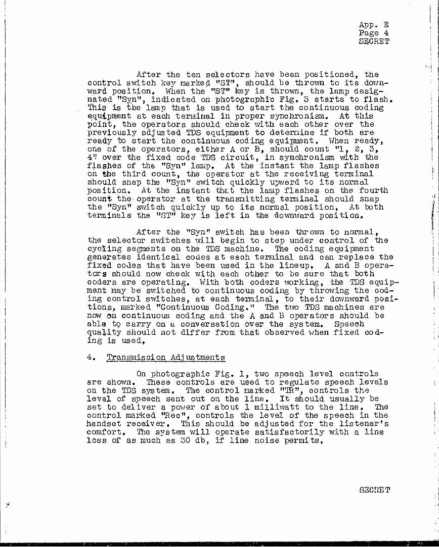
App. E Page 4 SECRET
After the ten selectors have been positioned, the control switch key marked "ST", should be thrown to its down- ward position. When the "ST" key is thrown, the lamp desig- nated "Syn", indicated on photographic Fig. 3 starts to flash. This is the lamp that is used to start the continuous coding equipment at each terminal in proper synchronism. At this point, the operators should check with each other over the previously adjusted TDS equipment to determine if both are ready to start the continuous coding equipment. When ready, one of the operators, either A or B, should count "1, 8, 3, 4'? over the fixed code TDS circuit, in synchronism with, the flashes of the "Syn" lamp. At the instant the lamp flashes on the third count, the operator at the receiving terminal should snap the "Syn" switch quickly upward to its normal position. At the instant that the lamp flashes on the fourth count the- operator at the transmitting terminal should snap the "Syn" switch quickly up to its normal position. At both terminals the "ST" key is left in the downward position»
After the "Syn" switeh has been thrown to normal, the selector switches will begin to step under control of the cycling segments on the TDS machine. The coding equipment generates identical codes at each terminal and can replace the fixed codes that have been used in the lineup. A and B opera- tors should now check with each other to be sure that both coders are operating. With both coders working, the TDS equip- ment may be switched to continuous coding by throwing the cod- ing control switches, at each terminal, to their downward posi- tions, marked "Continuous Coding." The two TDS machines are now on continuous coding and the A and B operators should be able to carry on a conversation over the system. Speech quality should not differ from that observed when fixed cod- ing is used,
4« Transmis si on Ad.j us tment s
On photographic Fig. 1, two speech level controls are shown. These controls are used to regulate speech levels on the TDS system. The control marked "TR", controls the level of speech sent out on the line. It should usually be set to deliver a power of about 1 milliwatt to the line. The control marked "Rec", controls the level of the speech in the handset receiver. This should be adjusted for the listener's comfort. The system will operate satisfactorily with a line loss of as much as 30 db, if line noise permitsf
SECRET
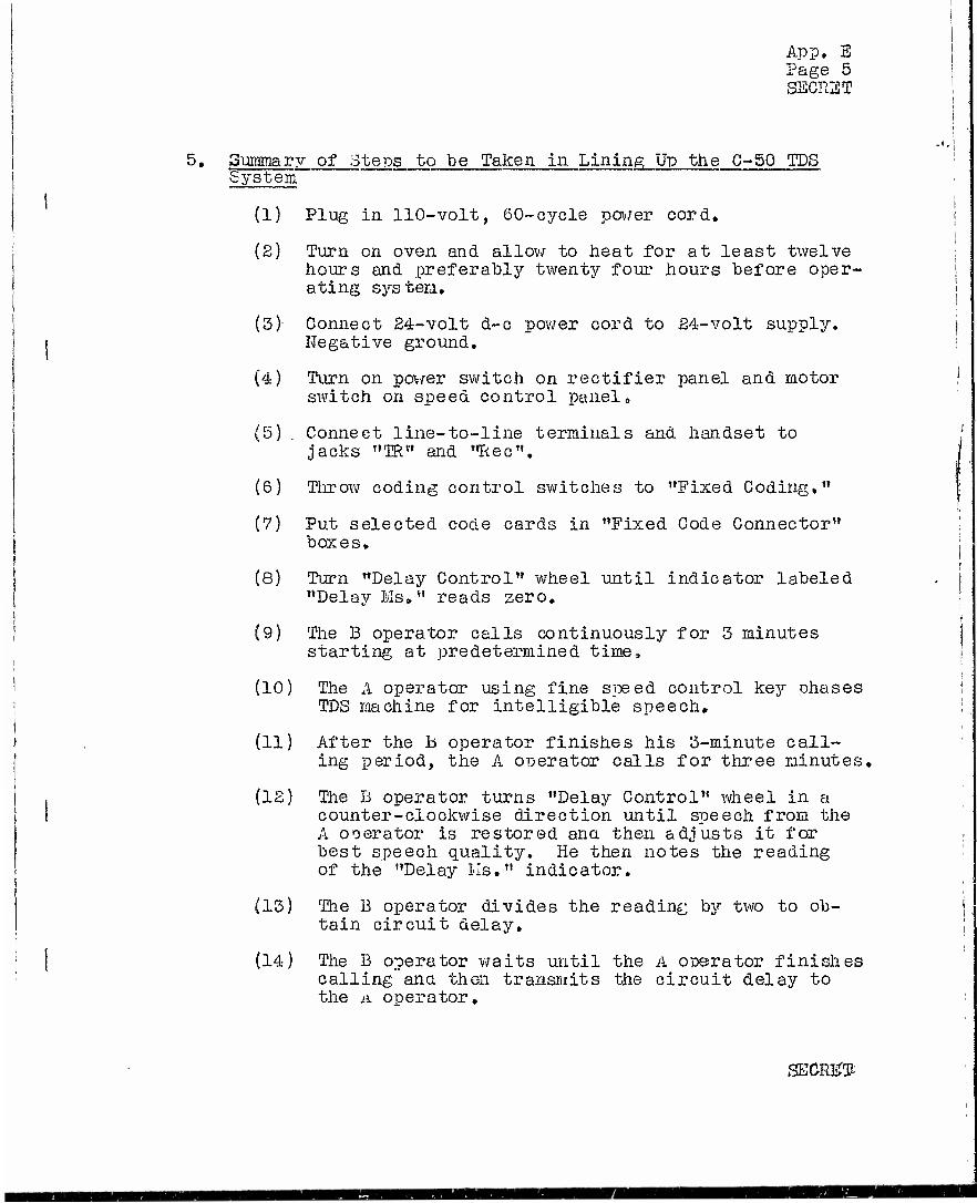
App. S iJage 5 SECHST
5» Summary of Steps to be Taken in Lining; Up the C-50 TDS System
(1) Plug in 110-volt, 60-cycle power cord.
(2) Turn on oven and allow to heat for at least twelve hours and .preferably twenty four hours before oper- ating S3rsten.
(3) Connect 24-volt d-c power cord to 24-volt supply. Negative ground.
(4) Turn on power switch on rectifier panel and motor switch on speed control panel»
(5) . Connect line-to-line terminals and handset to jacks "TR" and "Rec".
(6) Throw coding control switches to "Fixed Coding,"
(7) Put selected code cards in "Fixed Code Connector" boxes»
(8) Turn "Delay Control" wheel until indicator labeled "Delay Ms»" reads zero.
(9) The B operator calls continuously for 3 minutes starting at predetermined time,
(10) The A operator using fine speed control ke3r phases TDS machine for intelligible speech,
(11) After the h operator finishes his 3-minute call- ing period, the A operator calls for three minutes,
(12) The D operator turns "Delay Control" wheel in a counter-clockwise direction until speech from the A operator is restored ana then adjusts it for best speech quality. He then notes the reading of the "Delay Us." indicator»
(13) The B operator divides the reading by two to ob- tain circuit delay,
(14) The B operator waits until the A operator finishes calling and then transmits the circuit delay to the A operator»
SECRET-

App. E Page 6 SECKCT
(15) Both operators set receiving commutators for cir- cuit delay.
(16) The S3rsteri should now satisfactorily transmit speech in either direction.
Steps to be Taken to Put TDS on Continuous Coding
(I) Connect TDS bay to "Continuous Coding Bay" "by ~ cable supplied for this purpose,
{£) Set all of the "Coding Control" switches of "Con- tinuous Coding Bay" on their normal positions.
(3) Connect power cord of "Continuous Coding Bay" to 110-volt, 60-cycle supply.
(4) Put pre-selectee! cards in the "Code Scramling Connectors.*'
(5) Check rectifier voltage and adjust to 50 volts if necessary»
(6) Throw both toggle switches, on each side of "Control Switches", to "OH".
(7) Put "Syn" switch in downward position.
(8) Set selectors by means of "Selector Switch Buttons" until the selectors are on previously agreed posi- tions.
(9) Throw "3T" key to its downward position.
(10) The A operator counts "1, 2, 3, 4" over the TDS equipment operating on fixed code, to the B operator, in tine with the flashes of the "SYN" lamp.
(II) At the count "three" the "B" operator throws the "SYN" key to normal, in synchronism with the flash of the "31" lamp. The "A" operator holds over the operation of his "SYR" key until the count "four" at which time and in synchronism with the flash of his "SYN" lamp he snaps the "GYII" key to normal.
SECHST

SECRET
FINAL REPORT - NDRC PROJECT C-50
APPENDIX F
C-50 AND A-5 SYSTEMS COIffilNED
TABLE OF CONTENTS
Section
0.
1.
Title
2,
2.1
2.2
GENERAL
OPERATING PRINCIPLES OF THE A-3 PRIVACY SYSTEM
COMBINED C-50 A-3 SYSTEM
Switching of A-3 Codes
Time Actions
Page
1
1
4
4
6
SECRET

App. F Page 1 SECRET
FINAL REPORT - NDRG PROJECT C-50
APPENDIX F
C-50 AND A-3 SYSTEMS COMBINED
0, GENERAL
This appendix discusses a time-division speech privacy system in which a rapidly switched A-3 privacy system, is combined with and controlled by the C-50 system. This combined system is also discussed in the final report of Project C-66, and in Preliminary Report No, 21 of Project C-43 "A Coding Arrangement for C30-A3 Privacy Systems".
1» OPERATING PRINCIPLES OF THE A-5 PRIVACY SYSTEM
The A-3 system operates upon tne principle of shifting frequency bands. Speech impressed upon the system is first divided into five parallel paths. The speech waves in four of these parallel paths are first limited in frequency by 2450 cps low pass filters in each of these paths and then modulated by one of the following frequen- cies: 3250, 3300, 4350 and 4900 cps. Tue resulting four sets of modulation products plus the unmodulated speech component in the fifth path are then individually impressed upon one of five similar 2450 to 3000 cps band pass filters. The frequency components at tue outputs of these filters all lie in the 2450 to 3000 cps range but individually and respectively they correspond to 550 cps bands of the origin- al speech as follows:
A - 250 to 800 cps band inverted. B - 800 to 1350 cps band inverted. C -1350 to 1900 cps band inverted• D -1900 to 2450 cps band inverted. E -2450 to 3000 cps band not inverted*
The equipment used to perform the above frequency conversions may "be referred to as the "drop equipment" of an A-3 terminal.
Following the drop equipment a duplicate set of equipment is provided which may be referred to as the "line equipment" of an A-3 terminal. This equipment is
SECRET

App. F Page 2 SECRET
provided with five sets of input terminals just as the drop equipment is provided with five sets of output terminals. Each of four sets of these terminals is successively con- nected to a £450 to 3000 cps band pass filter, a modulator and a 2450 cps low pass filter. Respectively, the modula-r tors are supplied with modulating frequencies of 3250, 3800, 4350 and 4900 cps. The fifth and remaining set of terminals is connected to a 2450-3000 cps band pass filter and then to a pad so that the transmission loss through this leg may be adjusted to approximate that of the other legs» These five branches are then combined into a single branch which is connected to the line. With this arrangement, if a band of frequencies, which includes the 2450 to 3000 cps range, were to be impressed upon the first set of terminals, that is, the one which contains the 3250 cps modulator, it will be observed that frequencies which lie in tne 2450 to 3000 cps range will be inverted and relocated in the 800 to 250 cps range for transmission over tiie line. If all of the input legs to the line equipment are designated V to Z, successively, each leg would convert frequencies which lie in the 2450 to 3000 cps range to other frequency ranges as follows:
V - 250 to 800 cps band inverted. W - 800 to 1350 cps band inverted, X - 1350 to 1900 cps band inverted. Y - 1900 to 2450 cps band inverted» Z - 2450 to 3000 cps band non-inverted.
It will now be seen, that if the A set of output terminals of the drop equipment were to be connected, for example, -to the Z set of input terminals of the line equip- ment, speech components originally in tue 250 to 800 cps band would be inverted and shifted to the 2450 to 3000 cps band for transmission over the line. In a similar manner, for further example, if the C set of output terminals were to be connected to the V set of input terminals speech com- ponents originally lying within the 1350 to 1900 cps band would be converted to the 250 to 800 cps band without in- version for transmission over the line. If all five sets of drop equipment terminals are individually connected in some random fashion to the five sets of input terminals to the line equipment, it is evident that the system would transmit frequencies which occupy a 250 to 3000 cycle band, but v/ithin this band groups of frequencies which originally occupied a given one of the five original 550 cycle bands would be shifted to some other 550 cps band location. To illustrate this letters A to Z, inclusive, which were used to designate 550 cps bands of the original speech may be combined with letters V to Z, inclusive, which were used to designate 550 cps bands of converted speech, as shown, for example, below:
SECRET

App, I Page 3 SECRET
AZ BV CY DW EX
Since, as previously indicated, the A and Y bands, the B and W bands, the C and X bands, the D and Y bands and the E and 2 bands, respectively, cover identical frequency ranges, the designation of A-3 codes may be simplified by employing the single set of letters A to E instead of the two sets, A to E and V to Z. Thus, a new and simplified designation for the immediately preceding example would be:
AE BA CD DB EC
The above is one example of an A-3 code and indi- cates that original speech components lying within the 250- 800 cps r?i-]ge are moved to the £450-5000 cps range, those in the 800 to 1350 cps range are inverted and moved to the 250 to 800 cps range, those in the 1350 to 1900 cps range are inverted and moved to the 1900-2450 cps range, etc.
It will be seen, that in some respects, this is similar to a transposition cipher of frequency bands. How- ever, because of the fact that some of the bands are in- verted it is also, in a sense, a substitution cipher of speech frequencies.
If the A to E, inclusive, output terminals of the drop equipment are permuted with the V to Z input terminals of the line equipment, it is evident that 120 Ä-3 codes may be set up. Of these 120 combinations, however, many are not particularly suitable for use because only two of the original frequency bands are shifted in location.
In order to provide an increased number of A-3 codes and thereby to make available a larger number which are suit- able for use, five inverters have been provided so that each of the 550 cps frequency bands might be sent out on the line either inverted or non-inverted. The inverters are modula- tors supplied with a 5450 cps modulating frequency. If a 2450 to 3000 cps. frequency band is fed into any of these modulators, two sidebands, extending, respectively, from 7 900 to 8450 cps and from 3000 to 2450 cps, result. Elec- trically, these inverters are located between the drop and line equipment, so that any one or all five of the drop
SECRET

App. F Page 4 OTl r«T*iT75 m
equipment output legs may, if desired, be connected through an inverter to the line equipment input legs. With this arrangement, the 2450-3000 cps band pass filters, in the line equipment legs, suppress the 7900 to 8450 cps upper sideband and the 5450 cps modulating frequency of the in- verters. As a result any one of th6 original 550 cps bands may not only be moved to any other 550 cps band but each of them may be inverted or left non-inverted, as described, be- fore being transmitted. Using primed letters to indicate inverted bands and non-primed letters to indicate non-in- verted bands, A-3 codes may now be designated as shown in the following example:
A D« B E
0' D A E B
In this case, frequencies originally in the 250 to 800 cps range would be inverted and shifted to tne 1900 to 2450 cps range, those originally in the 800 to 1350 cps range would be shifted without inversion to the E450 to 3000 cps range, etc.
By permuting the five output legs of the drop equipment with the ten input legs (five with inverters and five with pads) to the line equipment, a total of 3840 A-3 codes may be set up. Many of this number, of course, can- not be considered suitable for practical use because they do not sufficiently interchange or scramble the frequency bands. However, a large number remain which are satis- factory for use with the 0-50 system.
Principles governing tne operation of the A-3 Privacy System are more thoroughly discussed in tne final report of Project C-66, entitled "Frequency-Time Division Speech Privacy System".
2. COMBINE) C-50 A-5 SYSTEM
2*1 Switching of A-5 Codes
When used in conjunction with the C-50 system, it is proposed to make about 50 of the better A-3 codes available for use. These would be set up in a connector of some type, such as, for example, a set of five, ten position-five element* switches of the Yaxley type. Each position on each switca would provide one A-3 code. Thus,
* A ten position-five element switch is a switch equipped with five poles which can be set upon any one of the ten positions;
SECRET

App. F Page 5 SECRET
the five switones would permit the selection of any five of fifty available codes for use during any predetermined period of operation. During such periods of operation, the five selected codes would be automatically switoned among themselves in a random fashion as determined by and controlled by the G-50 equipment.
Automatic switching of the A-3 codes would be ac- complished by five code changing relays» Each of these re- lays v;ould be provided with a set of five make contacts. One side of the five make contacts on each individual relay would be wired to the five movable contacts on one of the five Yaxley switches. The other side of the five make con- tacts would be wired to the five output legs of the A-3 drop equipment in t.ie following fashion: Contact 1 of relays 1 to 5 would be multipled and connected to output leg A, contact 2 of the five relays would be connected to output leg 13, contacts 3 to output leg C, contacts 4 to output leg D and contacts 5 to output leg E. The operation of any one of the code changing relays would thereby con- nect into the speech path an A-3 code, as determined (1) by the setting of its associated Yaxley switch and (2) by the manner of wiring the fixed contacts of the Yaxley switcn to the input legs of the A-3 line equipment.
In the operation of the A-3 system, it is essen- tial that only a single A-3 code relay be operated at one time. Otherwise, frequencies originally falling within a given band will be converted to two or more bands with the result that the scrambled speech cannot be restored at trie receiving end. Furthermore, if gaps in transmitted speech are to be avoided wnen A-3 codes are cnanged, it is essen- tial that the operation of any A-3 code relay coincide, within very close limits, with the release of its predeces- sor.
The nine sealed switches which insert the coding pole-pieces in tne voice paths of the C-50 system operate and release very quickly (in tne order of one millisecond). Also, it will be recalled from otner sections of this re- port, that only one sealed switch is operated during any one 37.5 millisecond time-unit. Furthermore, on continu- ously recycled operation, taese sealed switcnes operate in a very irregular sequence, as determined by tne C-öO TD3 coding equipment. TVnat is proposed is to add another con- tact to each of the sealed switcnes in tue C-50 equipment for the purpose of controlling the A-3 code relays..
Since it is proposed to use only five A-3 code relays and since txiere are nine sealed switcnes in the C-50 equipment, it is evident that .nore than one of the added
SEGRET

App. F Page 6 SECRET
contacts in the sealed switches would necessarily be multi- pled to a given A-3 code relay» For example, one possible •wiring arrangement would be to connect added contacts in sealed switches "a" and "c" (sometimes designated 1 and 3) tc A-3 code relay 1, added contacts in sealed switches "b" and "i" (sometimes designated 2 and 9) to A-3 code relay 2, ne" and "h" (5 and 8) to relay 3, "d" and "g" (4 and 7) to relay 4, and "f" (6) to relay 5.
A wiring arrangement of the above type would pro- vide an irregular switching sequence for A-3 codes, as de- sired,, but it is open to the serious objection that given A-3 codes would be associated with certain sealed switches and thereby with corresponding C-50 pole-pieces throughout an;/ given operating period, This, of course, would be un- safe because determination of the A-3 codes by an enemy might provide him with a clue for the solution of the TD3 scr arable.
In order to avoid the above objection, it is pro- posed to wire the added contacts on the sealed switches to the A-3 code relays tnrough transfers on the C-50 code re- lays, which are at present unused. This wiring would be ar- ranged in such a manner that no one of the five A-3 code re- lays would be associated with any particular sealed switcn relay, but would be shifted from sealed switch to sealed switch, in an irregular fashion, as determined by the C-50 code relays»
Preliminary Report w'o. 21 of Project C-43, dated July 31, 1943 and entitled "A Coding Arrangement for C-50 A-3 Privacy Systems" discusses the arrangement in detail. Drawing ES-S24443 attacned to tnat report shows the proposed method of connecting C-50 sealed switch contacts to A-3 code relays through tne spare transfers on the C-50 code relays.
S«2 Time Actions
Speech signals are delayed a total of 23 milli- seconds, closely, by transmitting and receiving A-3 terminals. Therefore, with A-3 terminals employed on the line sides of C-50 terminals, it is necessary That the receiving commuta- tors of the TDS macnines be set for a delay equal to circuit delay plus 23 milliseconds«. The necessity of adjusting re- ceiving commutators in the C~50 TDS machines in order to compensate for over-all transmission delay between transmit- ting and receiving terminals is explained in Section 2.2 of Appendix A.
Since it is proposed to operate the A-3 code relays by means of contacts in the sealed switches of the C-50
SECRET
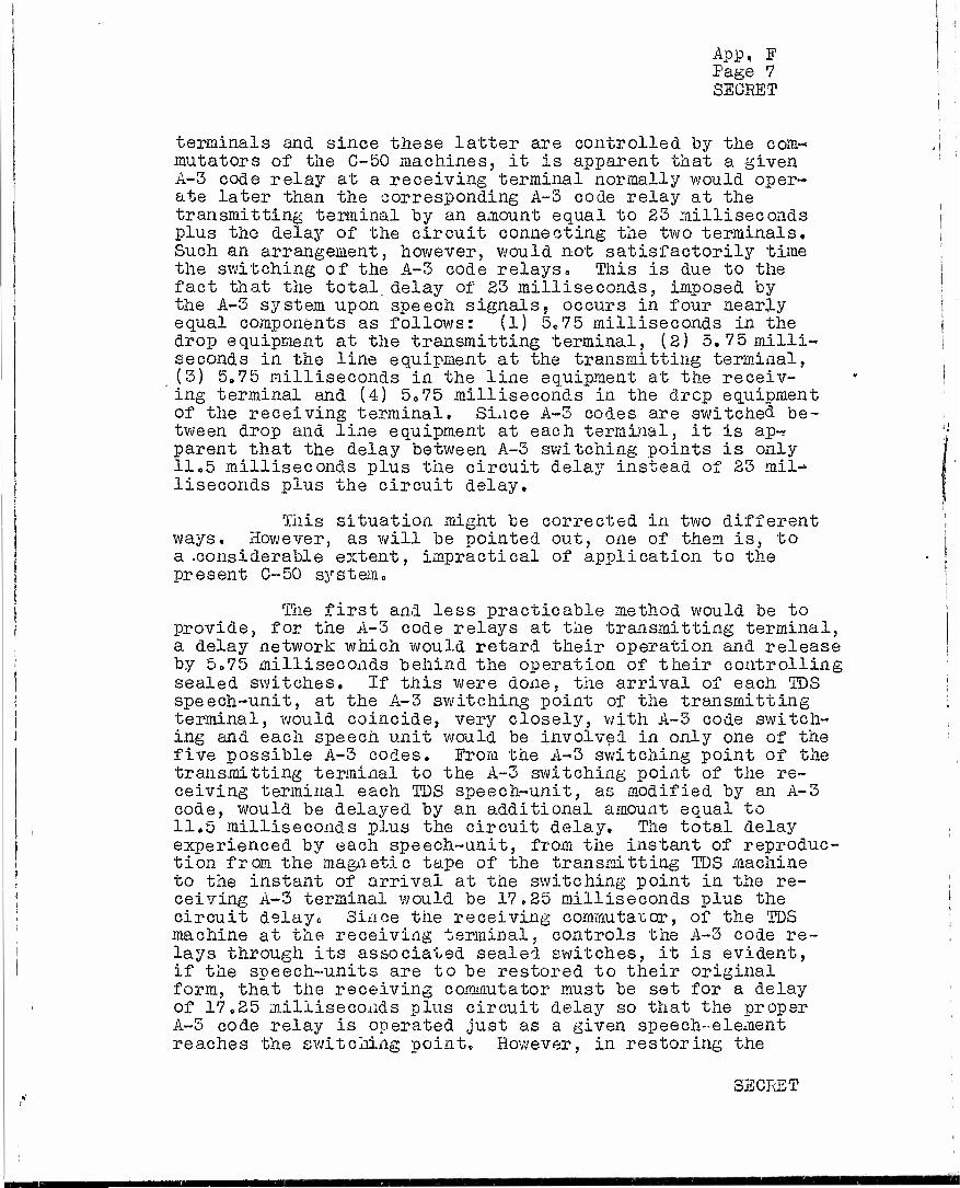
App, F Page 7 SECRET
terminals and since these latter are controlled by the com-« imitators of the C-50 machines, it is apparent that a given A-3 code relay at a receiving terminal normally would oper- ate later than the corresponding A-3 code relay at the transmitting terminal by an amount equal to 23 milliseconds plus the delay of the circuit connecting the two terminals. Such an arrangement, however, would not satisfactorily time the switching of the A-3 code relays«, This is due to the fact that the total delay of 23 milliseconds, imposed by the A-3 system upon speech signals9 occurs in four nearly equal components as follows: (1) 5e75 milliseconds in the drop equipment at the transmitting terminal, (2) 5,75 milli- seconds in the line equipment at the transmitting terminal, (3) 5,75 milliseconds in the line equipment at the receiv- ing terminal and (4) 5„75 milliseconds in the drcp equipment of the receiving terminal. Since A-3 codes are switched be- tween drop and line equipment at each terminal, it is ap-r parent that the delay between A-3 switching points is only 11«5 milliseconds plus the circuit delay instead of 23 mil- liseconds plus the circuit delay.
This situation might be corrected in two different ways. However, as will be pointed out, one of them is, to a .considerable extent, impractical of application to the present C-50 system.
The first and less practicable method would be to provide, for the A-3 code relays at the transmitting terminal, a delay network which would retard their operation and release by 5,75 milliseconds behind the operation of their controlling sealed switches. If this were done, the arrival of each TDS speech-unit, at the A-3 switching point of the transmitting terminal, would coincide, very closely, with A-3 code switch- ing and each speech unit would be involve! in only one of the five possible A-3 codes. From the A-3 switching point of the transmitting terminal to the A-3 switching point of the re- ceiving terminal each TDS speech-unit, as modified by an A-3 code, would be delayed by an additional amount equal to 11,5 milliseconds plus the circuit delay. The total delay experienced by each speech-unit, from the instant of reproduc- tion from the magnetic tape of the transmitting TDS machine to the instant of arrival at the switching point in the re- ceiving A-3 terminal would be 17.25 milliseconds plus the circuit delayo Since the receiving commutator, of the TDS machine at the receiving terminal, controls the A-3 code re- lays through its associated sealed switches, it is evident, if the speech-units are to be restored to their original form, that the receiving commutator must be set for a delay of 17.25 milliseconds plus circuit delay so that the proper A-3 code relay is operated just as a given speech-element reaches the switching point, However, in restoring the
SECRET

App. F Page 8 SEGRET
speech"element to its original form, it is delayed another 5.75 milliseconds in passing through the drop equipment of the receiving A-3 terminal. The speech-elements, therefore, would arrive at the sealed switches of the TDS machine 5.75 milliseconds after these switches had operated and the TDS scramble would not he properly restored. To overcome this difficulty it would be necessary to provide each sealed switch which connects TDS pole-pie3es to the A-3 system with a delay network which would retard their opera- tion and release by 5.75 milliseconds behind the operation of the commutator. These sealed switches, therefore, could not be used also to operate A-3 code relays. It, therefore, would be necessary to provide an additional set of sealed switches in order that the A-3 codes could be switched at the proper time.
The second and feasible method for properly timing the switcning of the A-3 system is to provide at the trans- mitting terminal delay networks which will retard the opera-- tion and the release of each of the A-3 code relays, behind the operation of their controlling sealed switch contacts, by 11,5 milliseconds more than they would normally be re- tarded without delay networks. At the receiving terminal no delay networks would be provided between the A-3 relays and their controlling sealed switches so that they would be retarded behind the operation of their controlling sealed switch contacts only by an amount equal to their normal operate and release time.
If "d" is now used to represent circuit delay in milliseconds and "n" is used to represent the normal operate and release tine of a sealed switch in tandem with an A-3 code relay in milliseconds, it is known, from previous ex- planation, that the receiving commutator of the receiving TDS machine must necessarily be set 23 + d milliseconds be- hind the transmitting commutator. The A-3 code relays at the transmitting end will operate and release 11.5 + n milliseconds after these operations are called- for by the transmitting commutator and the A-3 code relays at the re- ceiving end will operate and release n milliseconds after these operations are called for by the receiving commutator, or 23 + d + n milliseconds after the corresponding operations are called for at the transmitting end. It is thus evident that the A-3 code relays at the receiving end will operate and release(23 + d + n) - (11.5 + n) or 11.5 + d milliseconds after the corresponding A-3 code relays at the transmitting end operate and release. This is, of course, exactly equal to the number of milliseconds required for a voice signal to be transmitted from the switching point of the transmitting A-3 terminal to the switching point of the receiving A-3 terminal. The A-3 codes will thus be properly switcned with
SECRET

App. E Page 9 SECRET
respect to each otner and, since tne tine required for a voice signal to be transmitted from transmitting IDS mach- ine to receiving TDS machine is 23 + d milliseconds, the IDS speech elements will likewise he properly switched.
With this arrangement, the A-3 codes (unless n is excessively large and is exactly equal to 23 milli- seconds) are very apt to overlap IDS speech elements. This, however, appears to be an advantage because it makes "crack- ing" of the combined C-50 A-3 "scramble", by manipulation of spectrograms, appreciably more difficult than if the A-3 codes were to be switched so that they would precisely coincide with TDS speech elements.
In order to make the above arrangement satis- factory for two way operation of a terminal, the delay net- works, between the A-3 code relays and their controlling contacts on the sealed switches, would be switched into circuit with the terminal in the transmitting condition and out of circuit with the terminal in tue receiving condition. This would be accomplished by spare transfer contacts on the push-to-talk relays of tne C-50 system.
Tiie weignt of an A-3 system, suitable for use with the C-50 system, is estimated at about 1400 pounds„ The total weight of a combined C-50 A-3 system, together with rectifiers to permit operation from a 115 volt-oO cycle power source mounted on suitable shock resisting mountings for truck transportation is estimated at B500 pounds. The xotal power requirement for the combined system is estimated ! at 1.4 kva. i
SECRET

App. G Page 1 SECRET
FINAL REPORT - NDRC PROJECT C-50
APPENDIX G
PROJECT DRAWINGS
I. .PROJECT DRAWINGS FURNISHED WITH FINAL REPORT
Drawing No, Title
ES0-8O3510 - Main Drive Reduction Gears
ESR-803525 - Pole Piece Mounting Plate Assembly
ESO-803533 - Rotor Assemblies
ESR-803540 - Quill Assembly
ESX-805541 - , Receiving Commutator Assembly
ESR-805542 - Transmitting Commutator Assembly
ESR-803546 - TDS Machine Assembly
ES-803576 - TDS With Recycled Codes
- TDS Coding Connections ES-803577
ES-803578
ES-803579
ES-8O3560
ES-803581
ES-803582
ES-803583
ES-803588
ES-803589
ES-803590
TDS Codes - Diagram Showing Method of Generat- ing 10-Unit Self Contained Codes
- TDS Codes - Exclusion Diagram Showing How Unusable Codes can be Avoided
- TDS Codes - Time Diagram Showing how Interlaced Codes are Generated
- TDS Machines - Effect of Line Delay on Commutator Settings
TDS Machines - Time Diagram
- TDS Machine - Schematic of Commutator and Drive
- C-50 TDS Equipment - Over-all Schematic
- C-50 TDS Equipment - 20 Kc Bias and Erase Oscillator Schematic
- C-50 TDS Equipment - Bias and Voice Frequency Switching Circuit Schematic
SECRET

App, G Page 2 SECRET
Continued
Drawing No»
ES-803591 -
ES-803592 -
ES-803593 -
ES-803595 -
ES-804300 -
ES-804305 ~
ES-804317 -
ES-804365 -
ES-804366 -
ES-804367 -
ES-804368 -
ES-804369 -
ES-8B4308 -
Title
C*-50 TDS Equipment - Sealed Switch Qoil Circuit - Gap and Overlap Adjustment
C-50 TDS Equipment - Transmitting Amplifier
C-50 TDS Equipment - Receiving Amplifier
C-50 TDS Equipment - Bay Layout
C-50 TDS Equipment - Wiring Schematic for Modified PEC 800 Plate and Filament Supply
Connections to Terminal Strips - Machine Panel
Motor Control Circuit - Crystal Oscillator
C-50 TDS Equipment - Coding Control Panel Wiring Diagram
C-50 TDS Equipment - Detailed Over-all Schematic
C-50 TDS Equipment f Switching Circuit Panel - Circuit Schematic
C-50 TDS Equipment - Voice Frequency Amplifier Panel - Circuit Schematic
C-50 TDS Equipment - Panel Interwiring Schematic
C-50 TDS Equipment - Over-all Frequency Charac- teristic of Two Terminals
SECRET
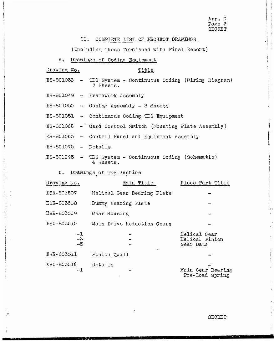
App. G Page 3 SECRET
II. COMPLETE LIST OF PROJECT DRAWINGS
(Including those furnished with Final Report)
a» Drawings of Coding Equipment
Drawing No» Title
ES-80103S - TDS System - Continuous Coding (Wiring Diagram) 7 Sheets.
ES-801049 - Framework Assembly
ES-801050 - Casing Assembly - 3 Sheets
ES-801051 -* Continuous Coding TDS Equipment
ES-801068 - Card Control Switch (Mounting Plate Assembly)
ES-801063 - Control Panel and Equipment Assembly
ES-801075 - Details
ES-801093 - TDS System - Continuous Coding (Schematic) 4 Sheets.
b. Drawings of TDS Machine
Drawing Ho«
ESR-803507
ESR-803508
ESR-803509
ES0-803510
Main Title
Helical Gear Bearing Plate
Dummy Bearing Plate
Gear Housing
Main Drive Reduction Gears
-1 -3 -3
ESR-803511
ES0-803512
Pinion Quill
Details -1
Piece Part Title
Helical Gear Helical Pinion Gear Data
Main Gear Bearing Pre-Load Spring
SECRET
aaam
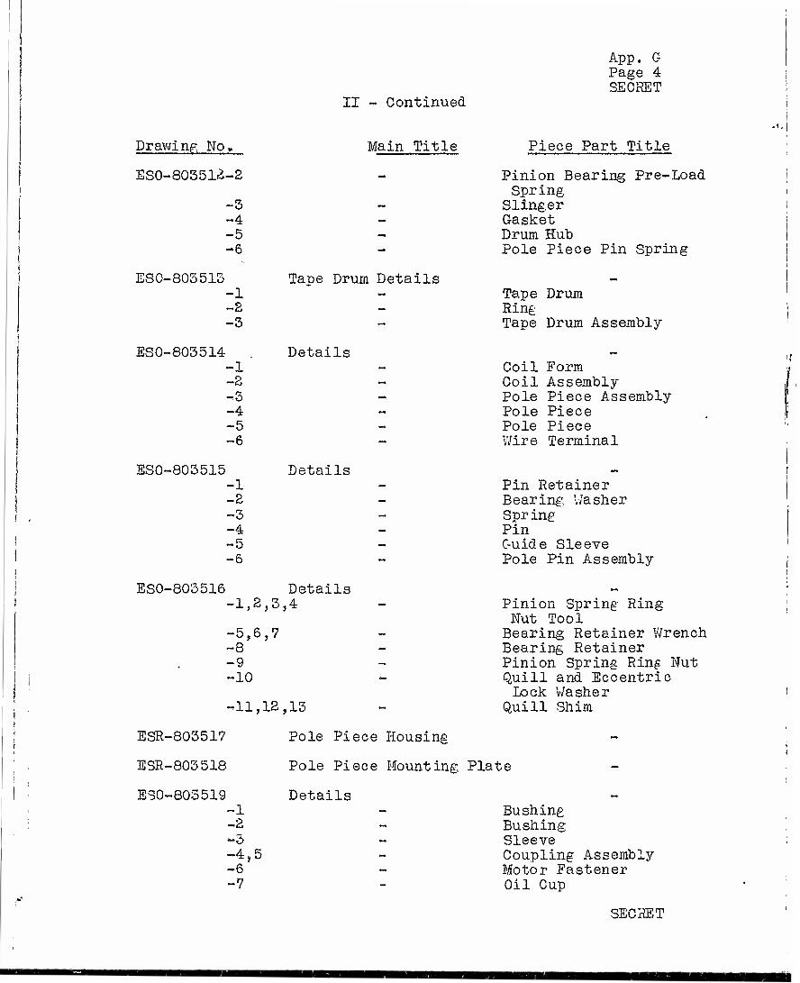
II - Continued
App. G Page 4 SECRET
Drawing No,
ESO-803512-2
-3 -4 -5 -6
Main Title
ESO-803513 -1 ~2 -3
ESO-805514 -1 -2 -3 -4 -5 -6
ESO-803515
Tape Drum Details
Details
Details -1 ~2 -3 -4 -5 ~6
ESO-803516 Details ~1,2,3,4
-5,6,7 -8 ~9 -10
T11,12,13
ESR-803517
ESR-803 518
ESO-805519
Piece Part Title
Pinion Bearing Pre-Load Spring
Slinger Gasket Drum Hub Pole Piece Pin Spring
Tape Drum Ring Tape Drum Assembly
Coil Form Coil Assembly Pole Piece Assembly Pole Piece Pole Piece Wire Terminal
Pin Retainer Bearing Washer Spring Pin Guide Sleeve Pole Pin Assembly
Pinion Spring Ring Nut Tool Bearing Retainer Wrench Bearing Retainer Pinion Spring Ring Nut Quill and Eccentric Lock Washer
Quill Shim
-1 -2 -5 «4,5 -6 -7
Pole Piece Housing
Pole Piece Mounting Plate
Details Bushing Bushing Sleeve Coupling Assembly Motor Fastener Oil Cup
SECRET

II - Continued
App. G Page 5 SECRET
Drawing Mo.
ESO-803520
Main Title
-1 -2
ESO-803521 -1 -2
ESO-803522 -1 -2 -3
ESO-803523 -1 -2 -3 -4,5,6 -7 -8
ES0-80S524 -1
-2.
-3
E3R-803525
ESO-803526
-1 -2,3
-4,5,6
ESO-803527 -1 -2
-3 -4,5 -6,7 -8
C«B. Details
C.B. Details
Details
Details
Details
Piece Part Title
Upper Block Spacer
Cover Assembly Block Assembly
Mounting Block Wiring Cover Plate Not Assigned
Bushing Bushing quill Ring Nut Quill Ring Nut Wrench quill Housing Plug Pinion Coupling Tool
Type "A" Eccentric Sleeve
T3>-pe "B" Eccentric Sleeve
Commutator Worm Gear
Pole Piece Mounting Plate Assembly
Mesh Adjusting Eccentric Tools
Commutator Details
Tool Handle Type "A" Eccentric Sleeve Adjusting Tool
Type MB" Eccentric Sleeve Adjusting Tool
Commutator Hub Commutator Needle Bearing Ring Commutator Ring Material Commutator Ring Commutator Ring Mold Ring
SECRET

'II - Continued
App. G Page 6 SECRET
Drawing No»
ESO-805528 -1,2 -3,4
ESO-803529 -1 -2 -3
ES0-803530
ESX-803531
ESX-803532
ESO-803533
-1 -2
-1,2 -3 -4
ESO-803534 -1 -2,3 -4 -5
ESO-803535 -1 -2 -3 -4 -5 -6
ES0-805556 -1 -2 -3 ~4 -5,6 -7
Main Title
Commutator Moldings
Commutator Mold Plates
Commutators
Piece Part Title
Commutator Molding Commutator Molding
Bottom Mold Plate Top Mold Plate Not Assigned
Receiving Commutator Transmitting Commutator
Receiving Commutator Housing
Transmitting Commutator Housing
Assemblies
Details
Details
Details
Contact Spring Assembly- Receiving Rotor Assembly- Transmitting Rotor Assembly
Bearing Plate Release Tool Assembly Release Tool Pin Worm Gear Bushing
Slinger Retainer Worm Gear Alignment Tool Housing Cover Cover Clip Housing Cover Assembly Roll Retainer
Inside Clamp Disc Outside Clamp Disc Clamp Disc Nut Clamp Disc Key Rotors Worm Bushing
SECRET

II - Continued
App. G Page 7 SECRET
Drawing No. Main Title
ES0-80Ö537 -1 -2 -3 -4 -5 -6
Details
ESO-803538 -1 -2 -3
Details
ESO-803539 -1 ~2 -3 -4 ~5 -6
Details
ESR-803540 Quill Assembly
Piece Part Title
Insulator Rotor Screw Plate Bushing Contact Shoe Quill Locking Pin v/orm Gear Stop Pin
Main Shaft Commutator Cover Detail Commutator Cover Assembly
Tension Spring Cover Clip Cover Ring Washer Spacer Shaft
ESX-803541
ESR-803542
ESG-803543 -1 -2 -3 »4
Receiving Commutator Assembly
Transmitting Commutator Assembly
Gear Casing Back Plate Front Plate- Dowel Pin Cam Follower
ESO-803544 Details -1 «2 -3 -4 ~5 -6 -7 -8 -9
Countershaft Bushing Countershaft Bushing Shaft Bushing- Cam Cam Assembly Shaft Shaft Assembly Countershaft Countershaft Assembly
SECRET
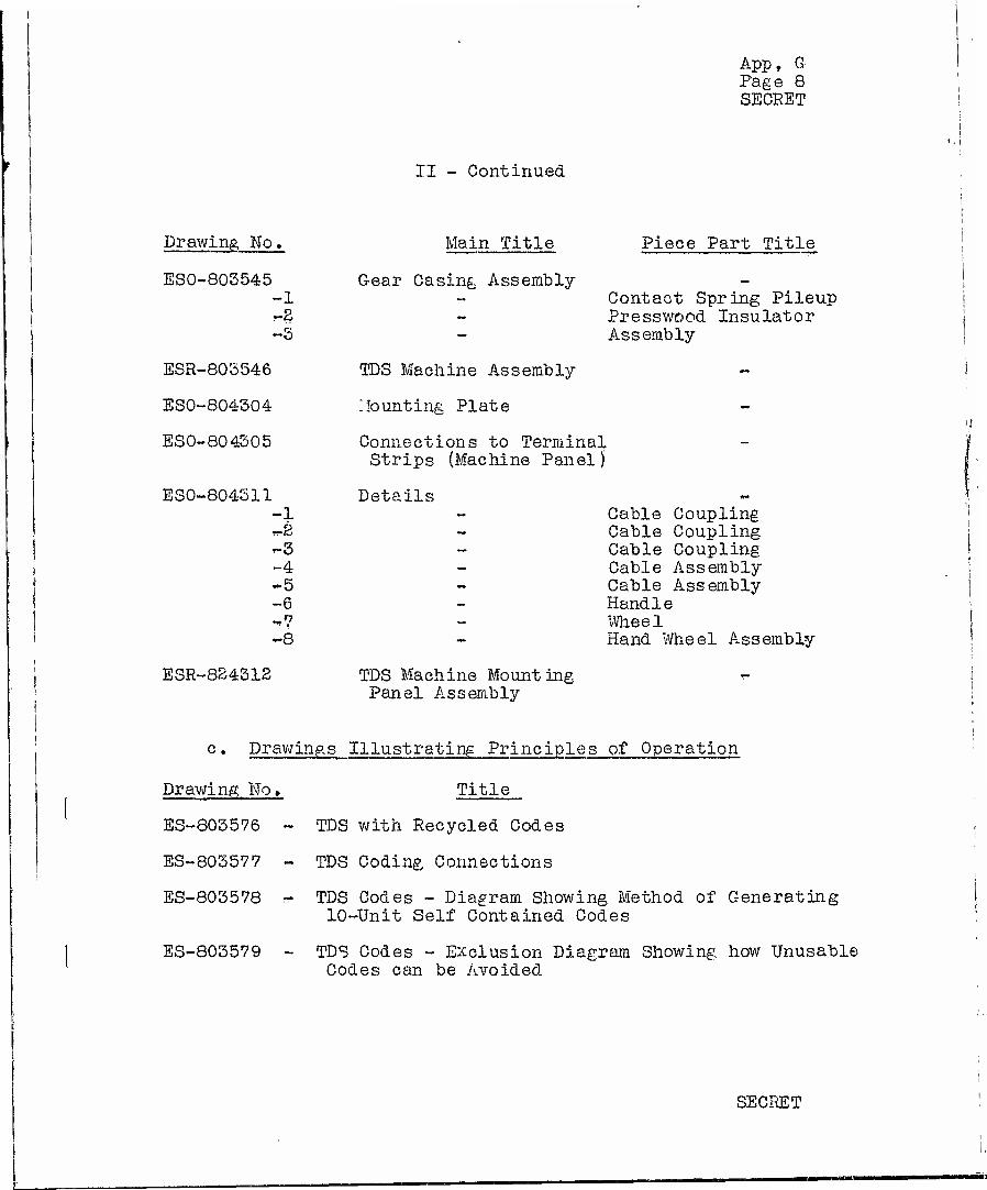
II - Continued
App, G Page 8 SECRET
Drawing No.
ESO-803545 -1 r-2
-3
ESR-803546
ESO-804304
ESO-804305
ESO-804511 -1 rr-2
»-3 -4 -5 -6 -»7 ~8
ESR-824312
Main Title
Gear Casing Assembly
TDS Machine Assembly
Counting Plate
Connections to Terminal Strips (Machine Panel)
Details
Piece Part Title
Contact Spring Pileup Presswood Insulator Assembly
Cable Coupling Cable Coupling Cable Coupling Cable Assembly Cable Assembly Handle Wheel Hand Wheel Assembly
TDS Machine Mounting Panel Assembly
c. Drawings Illustrating Principles of Operation
Drawing Ho» Title
ES-803576 ~ TDS with Recycled Codes
ES-803577 - TDS Coding Connections
ES-803578 w TDS Codes - Diagram Showing Method of Generating 10-rUnit Self Contained Codes
ES-803579 - TDS Codes - Exclusion Diagram Showing how Unusable Codes can be Avoided
SECRET

Drawing No.
ES-803580 -
ES-803581 -
ES-803588 -
ES-803583 -
App. G Page 9 SECRET
II - Continued
Title
TDS Codes - Time Diagram Showing How Interlaced Codes are Generated
TDS Machine - Effect of Line Delay on Commutator Settings
TDS Machines - Time Diagram
TDS Machine - Schematic of Commutator and Drive
d. Drawings of Voice Transmission and Associated Circuits
Drawing No» Title
ES-803588 - C-50 TDS Equipment - Over-all Schematic
ES-803589 - C-50 TDS Equipment - 20 Kc Bias and Erase Oscil- lator
ES-803590 - C-50 TDS Equipment - Bias and Voice Frequency Switching Circuit Schematic
ES-803591 - C-50 TDS Equipment - Sealed Switch Coil Circuit - Gap and Overlap Adj ustment
ES-803592 - C-50 TDS Equipment - Transmitting Amplifier
ES-805593 - C-50 TDS Equipment - Receiving Amplifier
ES-80^594 - C-50 TD3 Equipment - Low Pass Filter Associated with Receiving Amplifier (This Filter not used in present circuit).
ES-804300 - C-50 TDS Equipment - Wiring Schematic for PEC 200 Plate and Filament Supply
ES-304365 - C-50 TDS Equipment - Coding Control Panel - Wiring Diagram
ES-304066 - C-50 TDS Equipment - Detailed Over-all Schematic
ES-804367 - C-50 TDS Equipment - Switching Circuit Panel - Circuit Schematic
SECRET

App. G Page 10 SECRET
II - Continued
Drawing No. Title
ES-804368 - C-50 TDS Equipment - Voice Frequency Amplifier Panel - Circuit Schematic
ES-804-369 - C-50 TDS Equipment - Panel Interwirinfe Schematic
ES-824308 - C-50 TDS Equipment - Over-all Frequency Charac- teristic of Two Terminals
e. Drawings of Speed Control Apparatus
Drawing No, Title
ES-803599 - Motor Control Circuit - Crystal Oscillator. (Superseded by ES-804317)
ES-804317 - Motor Control Circuit - Crystal Oscillator
| f• Drawings of TDS Bay
Drawing No. Title
; ES-803 595 - C-50 TDS Equipment - Bay Layout I I
J III. LIST OF LABORATORY NOTEBOOKS COVERING C-50 PROJECT
Notebook No. T-5184 T-533S T-5521 T-5523 T-5537
I T-7859 I T-9097
SECRET

aoo ooo 400 v50O 700 IOOO i5oo aooo FREQUENCY-C.RsS.
3000

ES-S04369 SECRET
C-50 1, D.S. EQUIPMENT PANEL INTERWIR1NG SCHEMATIC
VOICE FREQUENCY PATHS
OTHER CIRCUITS
COLOR CODING OF COILS NUMBERS 1 TO 9 FROM COIL TS H-4N03 COLOR
I R-C
2 R
Z A R-3 5 S
i 7 R-BK & BK
« IO R-C II R
a 13 K-3 14 3
t> 16 R-BK 17 &K
7 1* R-C SO R
« 22 R-3 23 S
* 25 ft-BK 26 BK
TO RECYCLED CO« PRODUCER THRU CA6LE A. JONES PLUG CONNECTOR
JONES PLUG CONNECT' NS ZOUUUTATO* SEGMENT
PLUG TERMINAL COIL PLUG
TERMINAL 1 1 1(0.) 24 2 16 2Jb) 23 3 2 3(cl 24 A 17 . «W 27 S 3 s^f-
28 6 ie 6<n 29 7 4 7(9) 30 0 19 «(h) 31 9 S 9(i) 32 10 ' 20
12 11 13 7 M 12 IS 0 lb 13 17 9 IS 14 II 10 20 Gj 21
P( 22 Pi 23
NOTE! THIS DRAW^C IS MAOE
FOR A REDUCTION OF Z.S TO I.
edfc>08 -]
8E0BET
BOL TELEPHONE LABORATORIES, MC.
ES-604369
R3
"5?

r
8dfc>08-ea
C-50 IDS EQUIPMENT VOICE FREQUENCY AMPLIFIER PANEL
CIRCUIT SCHEMATIC
ES-80436& SECRET
NOTtS I CROUN& fOR CACK AMPllflER RUN TO TERMINAL STRiP
PAIR SMULOS OROUNOEO AT SAM« CO NT i •«• 1YPE RELAY UOCintO <N ACCORDANCE WltM THE
rOLtOWiNS INrORMATiON SPRINti >5»/lS9 STOP PINS - S ARM TftVL - ifl wiNOiNC -2S400 TURNS NO «OBEC WIRE *w*t»o% CONTACT METAL STC> NO 2 TEST OPR.- 12 4UA RtAOJ OPR - II 4 MA
J StOW RELEASE CKT CONTROLS RELA"<» (.PT-O1"? (,PT-61
TRANSMITTING AMPi
RICEwiNC, AUPL't'ER
OyTPoT 'RA.N5
y-- s(
6Rft-CT
J»l. "
fc. 1
HI— '300Ö«
T*~r i 1
«^ «J * - TO POWER
SUPPLY SIDE Of MCV.A-CIINE
?OB<AS ANP TOOKiULATOR ERASE C.R0 11RM.NO4,
OSCILLATOR (SEE C*"«>43»7) OUTPUT TERM
NOS
THIS DRAWING WAS MADE FOR A REDUCTION OF 2 TO I .
SECHE1
ES'604366
C-50 T 0,3 EQUIPMENT VOICE FREQUENCY AMPLIFIER PANEL
CIRCUIT SCHEMATIC
ES-8043f
<#

C-50 T.D.S. EQUIPMENT SWITCHING CIRCUIT PANEL
CIRCUIT SCHEMATIC
ES-B04367 SECRET
)4367 *ET
CIRCUITS ©TO0 IDENTICAL WITH CIRCUITS® *® SHOWN 3EALE0 SWITCH COILS FOR CIRCUITS ©TO© APPEAR ON TERMINALS 4t TO AM \S \*S
TERMINALS OTHER THAN THOSE SHOWN ON STRIPS APPEAR ON STRIP Y-2. FOR LOCATION StE ES-M3SW GROUNDS FOR EACH STAGE BROUGHT OUT TO TERMINAIS 5 L b OP PARTICULAR STACE STACE GROUNDS STRAPPED BY GROUND 8US
RELAYS ',PT-5> R (PT-*) HAVE SAME REQUIREMENTS AS RELAYS (PT-l) l(PT-2). (SEE ES-6043&6).
TO ERASE CC*L C'RCun (ifcSA OUTPUT TTUNSj
CNVF AMPLIFIER PANEL (SEE es-eo43bs)
L NOTE:
Yd£M>8-83
•OR THIS DRAWING IS MADE
A REDUCTION OF 2 TO I.
SECRET MM 4 O» V*\* Vet»
C-50 T.D.S. EQUIPMENT SWITCHING CIRCUIT PANEL
CIRCUIT SCHEMATIC
BaL TELEPHONE LABORATORIES, INC.
-fi
ES-804367.
_ R2

~1
SU. ES-SOS 5« SEC C3-603S«. SIE CS-60SS«. SCC ES-6COS91 3CC O-SOSSf». Stt ES-RMSOO ORIENTATION OfCOILS AND DIRECTION OF ROTATION SHOWN IS NOT THE SAME AS ON ACTUAL MODEL MACHINES
10 RECYCLE PORTION Of 8RUSH IS INSULATED FROM GROUND
TRANS I
fc C-50 T,D.S. EQUIPMENT DETAILED OVERALL SCHEMATIC
ES-804366 SECRET
TRANSMITTING AMPLIFIER PTI LIMITING
I©
T^ -%
©i ©| " L CODE POX CODE BOX
ODO
— —
I<§
RECEIVING AM PUFiER
I B-'AS AND 1 ESASE I
OSCILLATOR ! Wli
r"n.Jlp •n_c
3R RCC I
TRANSI n D5
pJtfii^i |ADJ I
PART OF PT6
£ REC TRANS
TO REMAINING SWITCH CIRCUITS
It uuuuuu
dae^oa-aa
=3 REC TRANS
'CStD
Hr -*$ REC
„ LINE ±0UT
250V D-C SUPPLY SUPPLIES SEALED SWITCH C0!LSlPTlRELS,6'AS CUTS, OSCILLATOR Ä. AMPLIFIERS^
DIRECTION OF BRUSH ROTATION
SEE MOT£ it)
CC KEYS(!-4)
I . . _!_ <—h 4-h
-t— x—a 4- GP
' 'w
_ooo_
$3E
N
_CVE_M_
MECHANICAL SW OPERATED BY
SETTING CRT DELAY I | ADJUSTMENT '
if»
SECRET -r-<-
MF4n -J- Is'
® (REC
j TRANS
N '"THIS DRAWING IS MADE TOR A REDUCTION OF2.5TO I,
I I -~ZZ.1. •
:} TO CODE RELAYS
PRODUCER
SOX TEUPrlOHE LABORATORIES, UK.
ES-S04366
R3
> ._

2 RKWOÄWJ1 COW,,*M »ON-OPCTATE
TO COPE BOXES (MACHINE TO COMMUTATORS (.MACHINE «XtO
t CODING
l8ffiulHO
14365 I CRET |
ES-80436S SECRET
^de^08-^^
SECRET
FOR A REDUCTION OF 2.ST0I.
C-SOT.0.3. CQUIPUENT CODIMC COHTKX. PANtL
WIRING DIAORAU
CELL TELEPHONE UBORATOfliES, IMC.
ES -Ö 04365

FIG. I
©=§=©'
ES-804317
NOTCS i 1 RESISTANCES HOT OTHERWISE WICiriEB »MALI, ttj«
2 THIS RESISTANCE IS A SHOP ADJUSTMENT, CONNECTED ALTERN ATI VEUf BETWEEN TERMINAL ! AND TERMINAL 2 OR 3 A3 REQUJREO
MOTOR CONTROL CIRCUIT CRYSTAL OSCILLATOR
rCRET
BELL TELEPHONE LABORATORIES, INC.
ES-804317
M2
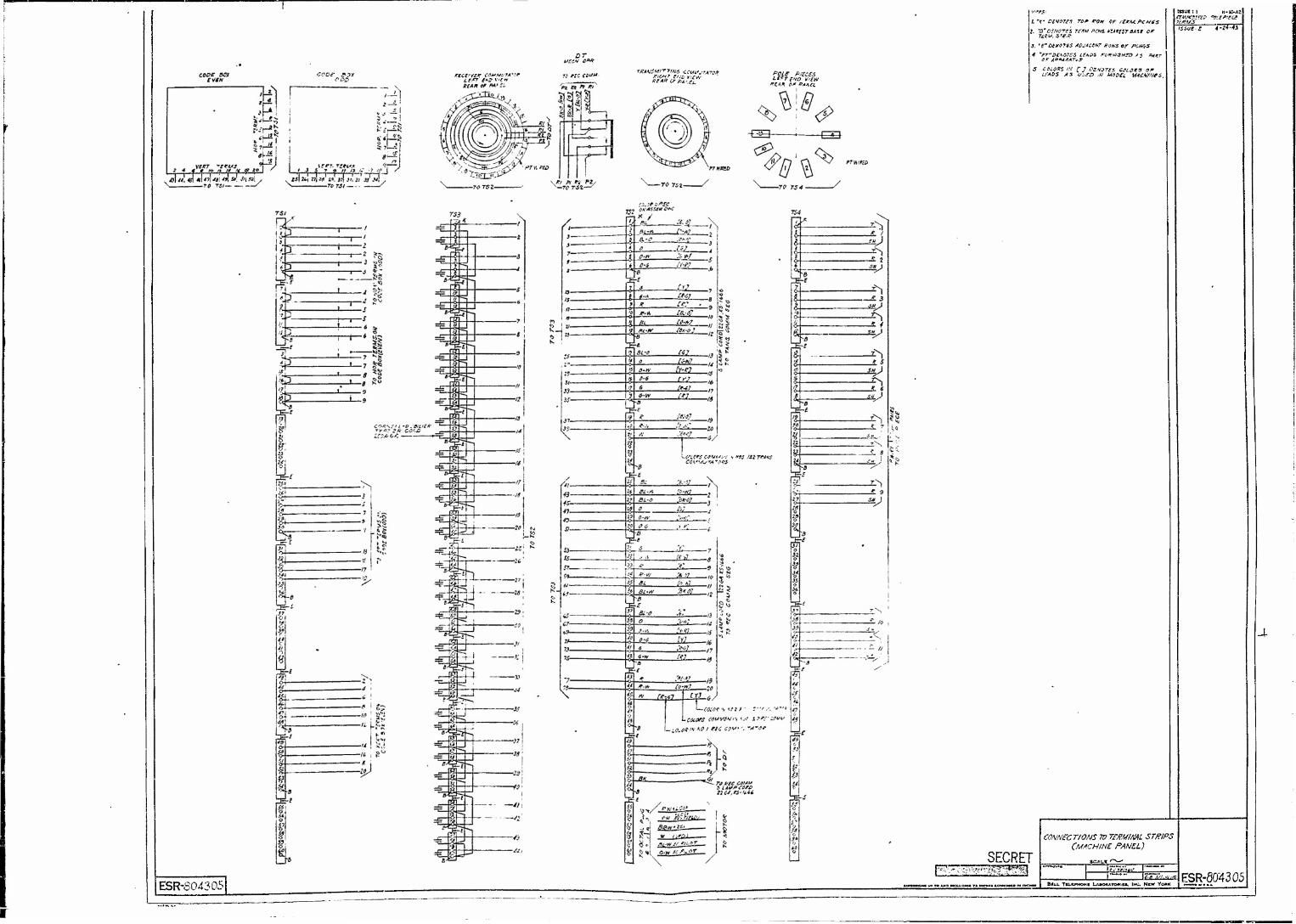
COOS $2X LtFT £*D VJfftV fi£AF Of PA* li.
DT MECH 0*R
70 MC COUM. •fffAKSMtTTtNG 4CWfjrA70*
REAR Cf AUfi. POL£ P/SCES LC?r£VD V'iW
X£AH Of BAhtL
f. '(•' O£S07f$ TOP #0W OF tEKM. PC His
•3, TMffOTSS AOJACtHT #4WS Qf PCN6S
4 mPr~t>C*G>75$ tfA&S r(/KfU3H?Q A 3 PAKT
S COLORS M C J PErtdTFS C^LCKS OF LfAOS AS </$£& ,H MS&tz MACAfWSS,
ESR-S04305 • mtmiiKwwM
Issue ;t n-vyAt
ISSUE, £ 4-z4~4S
CONNECTIONS 7Ü TffiMML ST/WPS (MACHINE PANEL)
• TKUWOH« LAXMtATOmM, INC. N«W VOUK \ ^^1ESR-80"4305
KMH- .**zrm

ES-804300
ADDED TERMINAL STRIP (T.S.3ZI-2)
SEE NOTE I
SET T0 4.4W
NOTES: I. FOR TERMINAL STRIP LOCATIONS
SEE BAY LAYOUT ES-803S95
ES-804300
C-50 T. D.S. EQUIPMENT WIRING SCHEMATIC FOR MODIFIED
PEC 200 PLATE AND FILAMENT SUPPLY
BELL TELEPHONE LABORATORIES, INC.
10-3041 £c r.\
SECRET
ES-804300
i>Ri>mc> 'N y <• A M

BELL TELEPHONE LABORATORIES, INC.
C-50 TD.S. EQUIPMENT BAY LAYOUT
TERMINAL STRIP LOCATIONS
3% TERMINAL- JONES
CONNECTOR SOCKET
(TOI)
C
lü vl'
SPEED CONTROL PANEL :'' (ES-804317) (?)
flO
r-i i—i
L_J L_J
i.i i i
I I L_J
MACHINE PANEL / ES-804305 \ VESX-803546/
CC KEYS /- i—I i—I ri r-\
r-'1 ' I I '?' 13> !4' •-1
i__i LJ LJ LJ L CODING CONTROL (ES-804365)
PT RELAYS •FFTF^-i LäJLSJ 1 röi
Ml
>ANEL
W)
PTI PT2
VOICE FREQUENCY AMPLIFIER PANEL
(ES- 804368)
1234 oooo a. oooo
T.S.—v (T)
5 678
f
PT3J PT4
SWITCWIKIG CIRCUIT PANEL (ES-8043 67)
(IE)
_J
POWER SUPPLY PANEL (ES-fiO4300) r~m
SCHEMATICS. NOTE: TERMINAL STRIPS ON CIRCUIT ~~.•-«"-- «TR,p ARE IDENTIFIED BY PANEL AND TERMINAL STRIP NUMBERS INDICATED ON ABOVE DRAWING. PANEL INTER WIRING SHOWN ON ES-804368
SECRET ES-803595 E.C.T. 3-31-43
51
°4
14
5-L 34
•i
•*
"•" "' " '• »

BELL TELEPHONE LABORATORIES, INC.
C-50 T.D.S. EQUIPMENT RECEIVING AMPLIFIER
INPUT TRANSFORMER , e ,-, (W.E. 264B) bbJ
FROM RELAY—— , pT-2 50"*1 I
WDG.' '
t-t-
10 MF =p <3000w
W
X TRANS. ± ADJ
POT. •=?
T
I I
6.3 V ii
nnnn
CONTACTS ON PUSH TO TALK RELAY PT-2
6C5
-250 V PO Ö
J_ + 250V
10V
*£ \
ES-803593 E.C.T. 9-22-42 E.C.T. 10-30-42 E.C.T. 3-25-43
OUTPUT TRANSFORMER (W.E. 178A}
G-W BR-W PIN JACKS
t\ I ' TO 500 w I RELAY • •* I PT-2
1
PRINTED IN U.S.A

BELL TELEPHONE LABORATORIES, INC. \
C-50 T.D.S. EQUIPMENT TRANSMITTING AMPLIFIER
INPUT TRANSFORMER (UTC PA-135) .01 MF
^
OUTPUT TRANSFORMER (UTC PA-I4I)
ES-803592 E.C.T. 9-22-42 E.C.T. 10-30-42 E.C.T. 3-24-43
70,000 w
1/2 W
30,000 I W
CO
.25-n- 1/2 W
=i= .006 MF
70,000 ^ l/2 W
6SC7
X"
.25-°- 1/2 W
6SN7GT
.01 MF
5^.'/2W .S-^-'^W ii—VV\ -j—AAA "
TO REL. PT-I
PIN JACKS
-' 12 '501" :WDG.
-K-
plj (STRAP 3-5 \ ' v 2-4 /
2000 w
IW
.006 MF
.1-"- .1-°-
l/2Ml/2WX.001MF
.001 =^ MF
.5-°- .5-"-
2W J i/2 w h/a
r° O + 250V
-250 V
6.3 V
UMJÜ
,1-°- IW
25,000" 1/2 W
nnnnn
MOV
PRINTED IN U.S.A.

BELL TELEPHONE LABORATORIES, INC.
2 -J m o
2 c c
r I
0) m o u MM
O50 T. D. S. EQUIPMENT SEALED SWITCH COIL CIRCUIT
GAP AND OVERLAP ADJUSTMENT
MACHINE PANEL
VVV f 100*°
I I COMMUTATOR
O-
O
O
T0 D.C.SUPPLY
ES-803591
*A~^ SWITCHING CIRCUIT PANEL*
Y
0.75 M.F. Jw
^---AAAr----^^AA^---,,--^ 500^ 5000^
T Lvw-X
T k fy^-—«^A/V
_ j- _ T
•AAAr •^WV
SEALED h SWITCH
COILS
^
#• REMAINING CIRCUITS IDENTICAL WITH THOSE SHOWN
m i
o
«0

BELL TELEPHONE LABORATORIES, INC. ES-803590
T3 so 2 H ro
FROM RELAY(PT-3) (BIAS OSC.)
FROM RELAY(PT-0 (TRANS. AMR
CIRCUIT)
0) rn
•to» 8
ÜB (RE
C-50 ID.S. EQUIPMENT BIAS AND VOICE FREQUENCY SWITCHING
• CIRCUIT SCHEMATIC
APPROX.
^ '0,M'R R
r -©•
I0M.M.F. 5
PSt .012 u. iM.F, 5MH|o -r
,400-40 § <
4-w
100 MJH.! 400-32» *
4
M.FJL n*
^3M.H. IP400-39
63V.A-C 1000*
0.25 M.E =4= «^iOOO4**
TO Dl RFI AVJPT-9^ BL
_C. AMP CIRCUIT)
•AA/V vw-
THREE SEALED SWITCHES UNDER CONTROL OF ONE COIL
PUSH TO TALK RELAY (PT 3 OR 4)
PLATE VOLTAGE BUS
FROM D-C
SUPPLY
m (/> i
0& o
• ii ii Miwmaionr

BELL TELEPHONE LABORATORIES, INC. E5-803589
C-50 T.D.S. EQUIPMENT 20KC. BIAS AND ERASE OSCILLATOR SCHEMATIC
Z -\ m o
F| I F*I
0, 5MEG^ 1 i-AAAn
6V6 3
-*- ~»
5M.H, 400-40
50M.H. 1000 400-31 ä 50,000-5 '-M p
.VI IY1.1 .
SHIELD CAN
• ft
PLATE VOLTAGE
TO PUSH TO TALK ' RELAY (PT-3)
(/) 8
oo
4.

BELL TELEPHONE LABORATORIES, INC.
C-50T.D. S EQUIPMENT OVERALL SCHEMATIC
ES-803588
RELAY PT-2
REC. AMR
(LEVEL CONTROL FOR TAND R CONDITIONS
/ INCORPORATED IN ' REC. AMR)
EACH GROUP OF THREE SEALED SWITCHES UNDER CONTROL OF ONE COIL
COILS
GAP AND OVERLAP ADJ.
"0 S3 CO •z. m m o o — 13 -<£
C m V> -A
>
COMMUTATOR / * SEGEMENTS
LINE OUT
, ,T
LINE IN
m </J i
CP o cj Oi 00 09
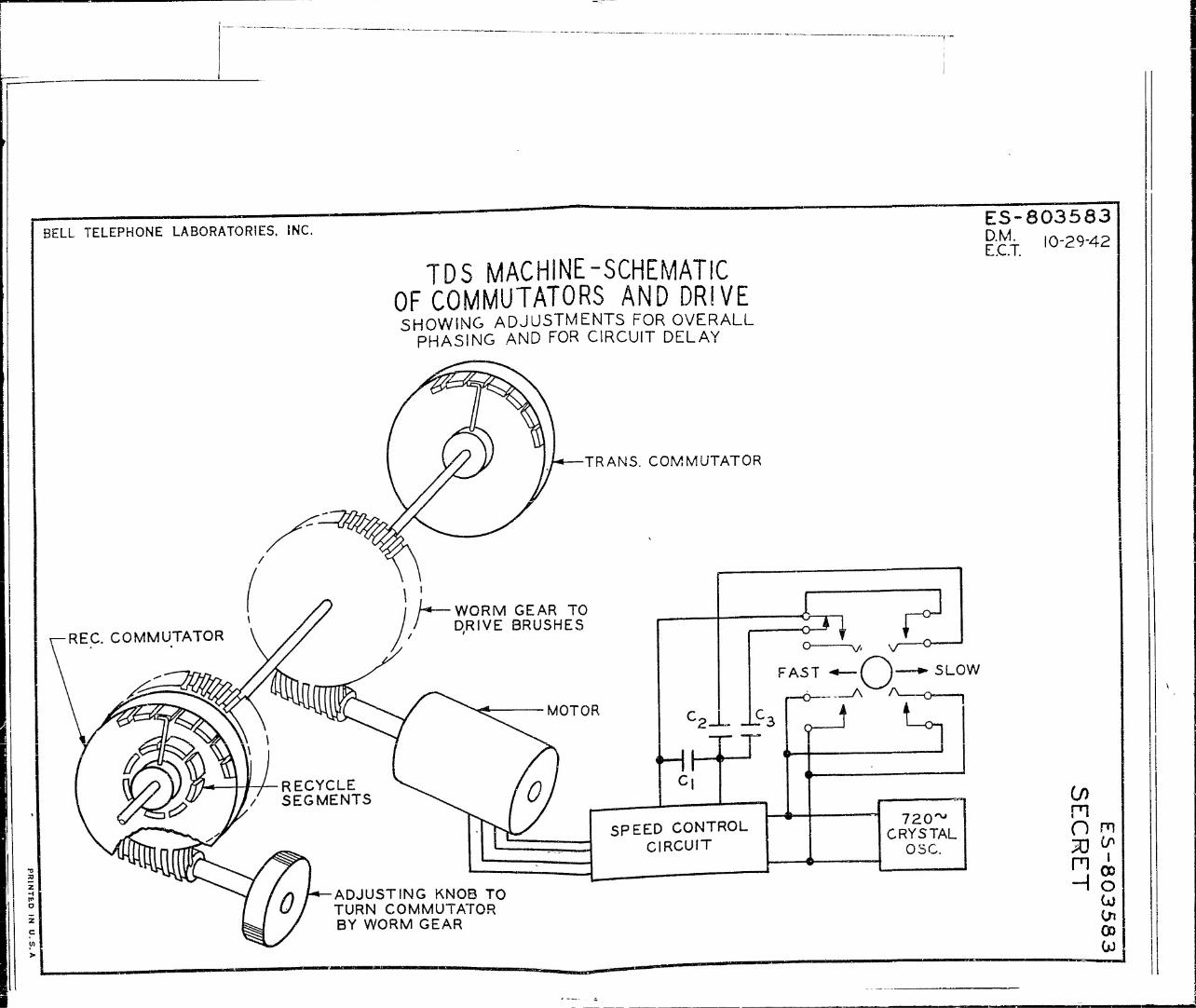
BELL TELEPHONE LABORATORIES. INC
TDS MACHINE-SCHEMATIC OF COMMUTATORS AND DRIVE SHOWING ADJUSTMENTS FOR OVERALL
PHASING AND FOR CIRCUIT DELAY
TRANS. COMMUTATOR
ES-803583 D.M. E.C.T.
10-29-42
Co n o m 70 CO
n i 00 o Cü in 03 Ui

: F F H .- m > r m
•a I 0 z m
OR IG. SPEECH
TRANS. COMB.
REC. COMB. NO DELAY
REC COMB. 2 UNITS DELAY
T.QS. MACHINES TIME DIAGRAM SHOWING
HOW LINE DELAY IS TAKEN CARE OV
TIME IN SPEECH UNITSCX>75 SEC. EACH)
5 10 15 20 25 30
la 20. 2b 30. 3b
-DELAY TO PICK-UP O.
lb
S. I lb
•-b-oj I**-*
2», 2b 3b
«—b »j»—O. -b »*—a.— -RECYCLE TIME
20. 2b rnx;:" U-b-J \~*-~A l*"bH h~°H * RECYCLE TIME
2b 30. r^r
ES-803582
ES-80358E
T)-1 • ( )o.bcd»-F^hiC y Op c^ijjiiiitiuf 0
OUT
•o-
EXTRA SCCMENTS USED ONLY WHEN THERE IS CONSIDERABLE DELAY
F1
3J P m
CD
REDUCE TO 8%X10%
ES-803582
T.DS MACHINES TIME DIAGRAM SHWINS
HOW LINE DELAY IS TAKEN CARE Or
BELL TELEPHONE LABORATORIES, INC.
SECRET
ES-803582
O ri.Nico m v » i

I s I F 5 H r m " s
•o I 0 z m
m O
> 0 S m U)
z n
:r
ES-803581 1
T.OS. MACHINES EFFECT or ru«E DELA*
ON COMMUTATOR SETTINGS
a D CR nitmtti'" [
LINE WITH DELAY
D
«o^tttmm
imittTTC^rQ
Qw2 D
ES-803581
0) P1 to
OS
»•»•«a
unmt»
Icwci LCX;
REDUCE TO 8% X10%_ SECRET
ES-803581
T»&& MACHINES FFFFCT OF LINE DELAY
^COMMUTATOR SETTINGS
BELL TELEPHONE LABORATORIES, INC.
ES-803581
ttIMT» IM U- i. fc. o

o
BELL TELEPHONE LABORATORIES, INC.
-o
z H m o z c en >
a. i e
d a/}
=! ^
8/ 5
2'
I'
3'
2'
NOTE
3'
2'
TDS CODES - TIME DIAGRAM SHOWING HOW INTERLACED CODES ARE GENERATED
SPEECH UNITS
5s
2'
I'
6'
5'
2'
7'
6'
2'
t'
8
7'
5'
4'
3'
8
9'
2'
8'
7'
D
8
10'
8'
5
4'
4 4'
8
\d
8'
2 2'
6'
8
10
8
7'
,3 4'
8 8'
0
8 8
10
9
8
TT T T'T 7 T T T 7 T "7 7 7' 8 8' 9 9' 10 10' I' 2 2' 3' 4 4' 5 5' 6 COMMUTATORS BARS
TIME
THIS DRAWING IS THE SAME AS ES-803578 EXCEPT INTERI^CE CODE fPRlME NUMBERS) IS ADDED BY CUTTING EACH COMMUTATOR BAK IN I WU
8'
10
6
ES-803580 D.M. 10-29-42 E.C.T. 4-21 -42
0
9'
8'
10 10
0 10
CO m o
m (/)
i OD
33 Ö men -^OD
o

BELL TELEPHONE LABORATORIES, INC. ES-803579 D.M. 10-29-42 E.C.T. 4--2I-43
TDS CODES - EXCLUSION DIAGRAM SHOWING
HOW UNUSABLE CODES CAN BE AVOIDED
O 01
•a a z H m D
z c v>
if) H Z D X o Ld LÜ Q.
COMMUTATOR BARS 34 5 6789.10
,i z\f i A Ä- I o
1
A / ? 4 a
3 c d s. 1 5 e, A.
A
a.
c ci 4 / ? A A.
S & c cL •e / 1 •A —
i
6 a. £r c 4 -* / y # • .c
7 o. £ c a -£ / y I
A a. -£ c d
* / f
9 a. £ c c* 4
i r\ IV
«. & £ d *
TIME
COILS TO BE CONNECTED TO A GIVEN COMMUTATOR BAR TO PUT A GIVEN SPEECH UNIT IN A PARTICULAR POINT IN THE CODE CYCLE.
n 00
CO I ma> Oo
men

o -I
p BELL TELEPHONE LABORATORIES, INC. FS-803578 D.M. 10-29-42 E.C.T. 4-21-43
TDS CODES - TIME DIAGRAM SHOWING
METHOD OF GENERATING 10-UNIT SELF-CONTAINED CODES
10 _j
o o
&
lr C
d £
i 3 n
-ft
X
\ 2 3 4 5 6 7 8 9 ioi+i +2 +3 +4 + 5
1 2 3 4 5 6 7 8 9 10 + 1 +2 +3 -+4
-10 ! 2 3 4 5 6 7 8 9 iO fl +2 +3
-9 -10 1 2 3 4 5 6 7 8 9 10 41 +2 +3
-9 -10 I 2 3 4 5 6 7 8 9 10 + 1 +2
-8 -9 -10 1 2 3 4 5 6 7 6 9 10 + 1 +2
-7 -8 -9 -10 1 2 3 4 5 6 7 8 9 10 + 1 + 2
-6 -7 -8 -9 -10 1 2 3 4 5 6 7 8 9 10 + 1
-5 -6 -7 -8 -9 -10 1 2 3 4 5 5 6 7 8 9 10
ARBITRARILY NUMBERED SPEECH UNITS AVAILABLE AT EACH COIL AT DIFFER- ENT TIMES.
o
I H PI O
2 c 5° >
! 2345 6789 10
COMMUTATOR BARS
TIME >
NOTES
CODE CYCLE MADE UP OF SPEECH UNITS I TO 10 IN ENCLOSURE SHOWN. PREVIOUS CODE CYCLE MADE UP OF -I TO -10 AND FOLLOWING ONE MADE UP OF +1
m CO
in i moo no men
00
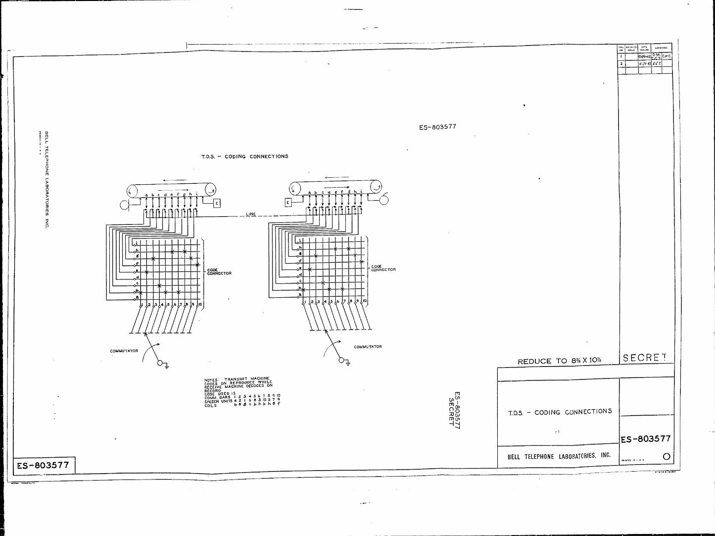
CD m r r •H r> r m •3 x 0 2 tn r > 03 0 3 > H 0
m .<* z 0
ES-803577
teM2U
•#-2/«
TOT
£fr
ES-803577
T.D.S. - CODING CONNECTIONS
V? J a b c d e f fl"h i Vry
1 ftnniwniw
a ZD EH UI III M5
1111111
COMMUTATOR
CODE CONNECTOR
COMMUTATOR
REDUCE TO 8%X10% SECRET
NOTES." TRANSMIT MACHINE COOES ON REPRODUCE WHILE RECEIVE MACHINE DECODES ON RECORD CODE USED IS COMM. BARS I2345&7S9IQ SPEECH UNITS 42 I 683 10 579 COILS bt 6 CfehbhSf
S3 OJ men H3
T.D.S. - CODING CONNECTIONS
BELL TELEPHONE LABORATORIES, INC.
ES-803577
HtHTtCi IK i* » A O^

TDS WITH RECYCLED CODES
ES-803576
Q>
0—
PUSH TO t TALK 4-
PTI
ERASE
NOTE: IS SPEECH PATH
IS RELAY CONTROL PATH
--- IS 10 RELAY CONTROL PATHS OF SIMILAR FUNCTION
aj z
TAPE
-COILS-
nt i rnrrn t rt rt rt rt rt n rt Q-
1©
11111111
CODE BOX ODD
1111111 i 11; ^ ,1111111111/ ! J
® oof
PT2 ERASE —o^
LINE OUT
LINE IN
© CC2 f
r-KEY"] I + FIXED CODE RECYCLED
CODE
Ss>§ J5 a,, jo äc
L_ i i—i-. i i
©
_CCI KEY"
I I
• J. T-
4-«l«J
1
r-J— ®_ ®
(10)
i—-6 I
PT3
re
Cio)
"r r • 4--J | i© ! ©
X I 3579ÜI3I5I7I9 24 6 8I0I2I4I6I820 'I 35791113I5I7I9V
II! 2 4 68I0I2I416I820
Mil
-~ff
i
i —r
i ©i
i
© 111111111
EXCLUSION RELAYS
y CODE RELAYS
ODD
rt-{[ Trrrr
COLUMN RELAYS
I | z
a. \S
.1.1 I I I I ! I. EXCLUSION RELAYS
CODE RELAYS EVEN
ED COLUMN RELAYS
SCRAMBLER EVEN
SCRAMBLER ODD
• I
-.-!••
I * I
T.D.S. CIRCUIT CODE PRODUCING CIRCUIT
8? ROD
my»

>i~ h -1
COVER f£^*O^E^
VIEW as
Sir 7 A -A
i F-^.. •
fCM: >j J$ ,'£( AV KlbHT) SHALL H4t€ A I t&N7/'ATEZS f/7 C'J J7CA* l£ '7SM/C, SNAIL ALSOA'AVS A P-/5H f/T wro I't -t/j, trruu, CAT „err> SCHALL HAVE A t>ot,ne/7 ON 17CM IL <yCU ZZ $f**L„ HA*£ A RJSH F/T OH J7£M'2 A*J IN /7SA4S 6* 7
,7£ts£ f>, CJ * 23 s*
1, Mf^h *•''- V** J>\ -£L'<>- PJVICHES'8Q25-*-l.iTfM3 SHALL 10 &£ *£rJt/$T?£ *?£-"-'*,*" t'VAL A3S£Af£/LK **>&£££&AS r»\.C*~" «VJJi'J.f ;-»««• 4 J..i.i$ '4 '£,!£, l&ZZA, £9/f V(C.cvC.*'!.').-/(, \^A*. -*?,S\ £X^£P7 THAT Ou'MktY S£AK '.;- ^A7£ S^- ?G-£?A bf+Uli 6f^V; tH FLAtf Of L£fT I7SM 3,M COINS Wi& Wf ro+LOA/AIO *£,3!/7%&fFS/r$ £HAU ee cDCsr^&c -?- /rosjChA*- BE -*AC£ö W/TEM* \\>TN C$2£HQ^£ £>OWHtiAf>b & 2>EC<Jit€O "J <*-AC£ M7/i 4 .•CVJ9 &- CJTC'JT MDCMMY ciAkf** f*A7£ £«Mj.. PC A55ZM&4Q JOtfARO 1T£M2 SOW Grs,* •*£*# MAY3E SßSEfitÖ AK2 3tCJ*El> M/VW/ J6*. :*r £<?****££&.'&* Of ' /W IS.WTtf AT L€AX? TOt/?C>r • TJA* JJ <* ~C**l CfALL. &£ TAWN 70 AiO'O DAMAGE V 7£{TH f > VW /,!< *" -tO '0 V£T* Of LT-a0JC4->,/TfiMJ £s*'V} ABfrE Jii-f»*«)' IV*« fl/.*y MW £}£ A^* '-' 7H) ßy T^eNiMQ •7£V£J'£.JZ V,7* TYPF J'AwVr^; S~E£\iE <,V.'SV;\'^,üß«JLa.> >««> •'•re£ma'£C(£\rf £ HC£*£ AW/$TMF\T TOOL ££ &033U-
7fM jt SHft/lb B? MS.3 * -* ~*£ *$***£>• **..f *<w\t./rw 3? rt/W lb? LATTIK A''£ » « I'/'A* TjfV/SC iV-W J/i^^K- V. $? r'dMjTS \>TC-f? £\2lAs.'> VV3>:^vVV CLöCKA £S rtfAiTS Aori*-ft"> £<J T<**"fVJ> *"-c WJ", Ttf*\"*u T"£A/
rWi /O- A TAtNT VhAti f-' , "'A'"./ 7'4 ,. "-,?.'" i»'**7'lw f1C7 W/Ti * M VJV; *s. VT 'J •' "*'', ?* f • 'Y &£~r*l£M 7H£ 7tfTH,AL^^ 7H0bf ,;<n,„ /* /7£V< J/ S jr^r WHICH AV£ fSAMt+ftCA^ &>*>:>'£ '*£'/>*' fc-yWAT * -*£ »Cftf* £(.£ Cr /7f*t 2, £•-•),» \U-£~ £*<. h 0 *ptR. WNtn AßOvE AC/Ji/£7- M£fJ7 n C0MPt£7£ WS7A-* /7£M 40 ON/T£M l+fWOJiCWiS 0\ tf£*4 40 *V-(.'.' /<«:r /r£MS /.2.J/X3Z 7SZ£TM£*,S££.K 7I4H7+T /V -&,^-r j?»' *y-V^Ä <?«** /WA/ ^ t-^ -.^ J^/.i /,'". J At/7
4-J4-4Ä
*0
*>A:~4J' MS AI ctccvifio
*& S^Ati. P'T T)4N7l7£>#S+JXafA* 3 ee,v?*-*^$ tr /r£M£o
i. F£££AS£ TOOL ASSEMBLY l^~3P<t£3*'3 IS K£QUIKED £?# AlS£>»fiL>>,6 ,TM £t ,V/'£M 4 f>*OC££0 « 'CUO*-< ^IAC£ r<??~ H t/JBJiZ?3A >7'V Zlt S£Fö>?£ /VA- 4Z S M^TAUtD OH !\ iöThAT * *S fiT« SOe^'fS/V/'C'/W Qtf'tfQLZS SCttiY T#QL ft'PtA££ C* I7e»t £/ h/TH 4 <X>-JfK','t A* H,I.MS£X 7»*c</iH .W3WÄS, AO^ »ST PM » tCg JA*S 3f MSAH? OA7461 A/MS ' l/NT/i AffA/7 '//*'£AP*A*\ C&7A H£D. TM£i,£ GAf*5 Moil Cf/ZTftP JV A Ci**.E C>r Z'XjSC "WAT Pffif PStB MA'S A *.*. Si. A <?«W 7AT M >7£A4 e M>fM9U7 CO;TA£T, SEC(/A?C /T4S Zt W/TH <T£M36, e£K*Ot'£ --6K..
iz'i
FIG. I ESR-80.3r;4fe
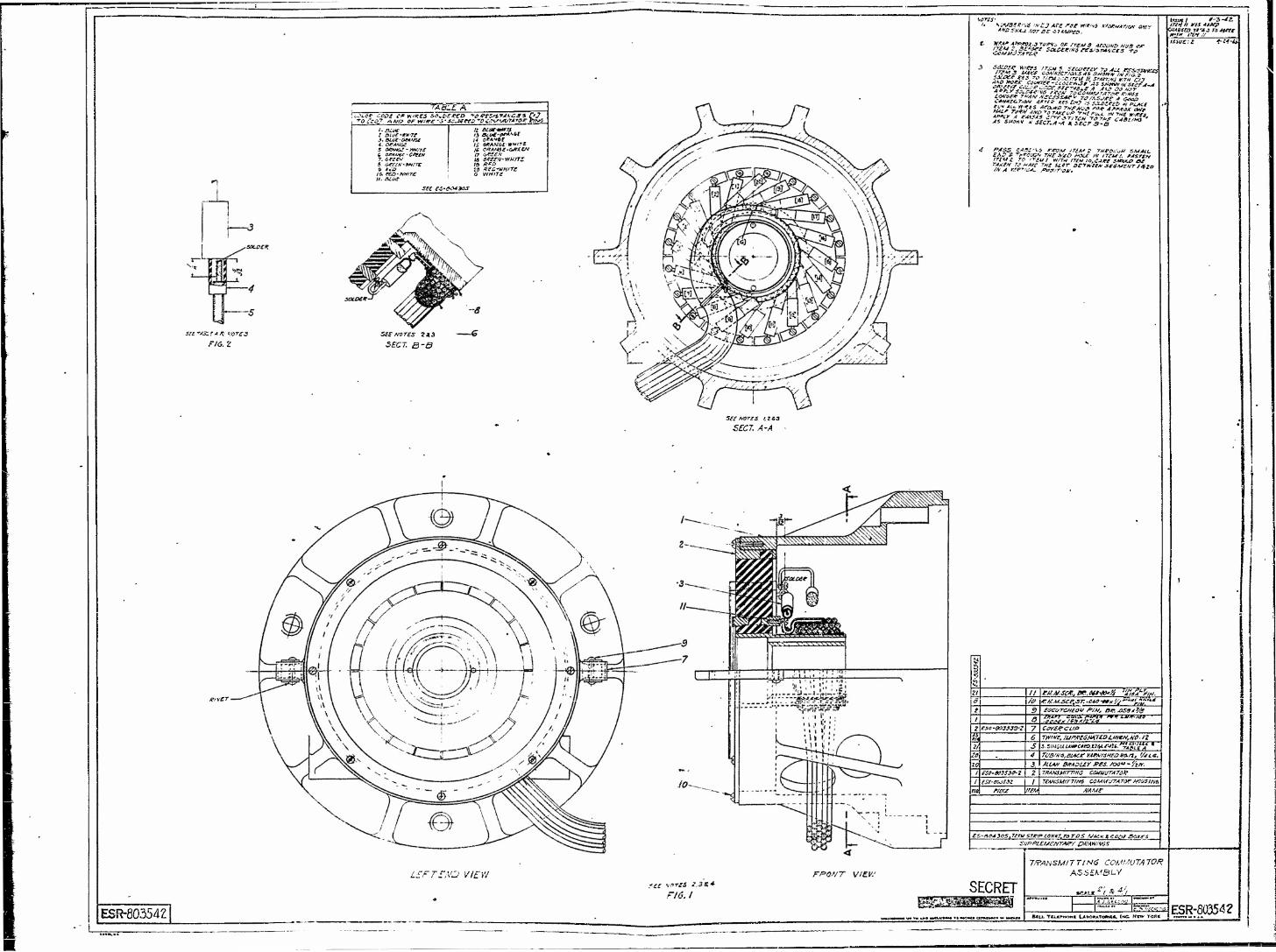
TABLE A (rJLCX CODE C* WR£S SC^OEfCD "*£ /PEZtZTAACJSS C'J
tz eiac-*t*Ti rr I DWE*W#7f J. Bi.it -OWVJf
$ o&*6£-m//T£
7. orscv
u, ait*?
14 Q*AHQ? 15 OfiAMGt'WT* 16 CKAUäE-GfllL&i [? £,*££# ts CPE&V'WH/TS
20 REC~WHlTC, Q WHITE
SEE ££'404305
F16.Z SEE NOTES 2«
SECT, B-B
SEE NOTES i.zea
SECT. A-A
SlMBtK/Vt if/CJ A?E rait IWT/W v/UCMT/ot Ott? IVCSHAU MTBC iHAfto.
<r*wrer«w we* Kt< cv,.i•%^£SEwJ S^g,,-
^^r/sECT/hr^Pf£"^'-
4 ?fis„ iJsi'l* rrof*/TEA'S THeovvu SMAU. EA3 & TpfcuGh THEV40 H0L£ I« ITEU I. fASTEH irtuz TO I-TEUI w/Tw ,TCM io,cjrr smu> ee •rjxft, TS UAVE THE U.CT orrwir/* st-SMCHTinto
i~ur/ f-3-JZ. tTiHtl W.fS 4HXP
CS0-SO3S33-2
II iffJ/H:. r.KM.see.sr.-ctettx'/E'^"^'" ESCOTCHEaU fM, on A59tJ1S
corarcup ww, lumEGnxnoi.mtw.NO- iz s.ziHäu uwctto.au.4tiU. "TATL'CA*11
T{/swa,B£+:r YArwvifoimn, '/ice. MUM BKAcur res. mo"-'Arr. T/tANSUirnNS COUUUTATO)! TEANSMlTTINi COMMUTATOR HCilSllie.
£S-ao430SJC.tu S7K!J>CQHII?.ToTi>S VACKSCOAf&aAg-i
Lfrrr.vD VIEW SEE tnrtS 2,3&*
FI6.I SECRET
ESR-80354Z
TRANSMITTING COMMUTATOR ASSEMBLY
»e*uc z'l * 4/l
BtU. TRLtM*OH* L&OORATMKCa. (KC NEW YORK E5R-ÄB542

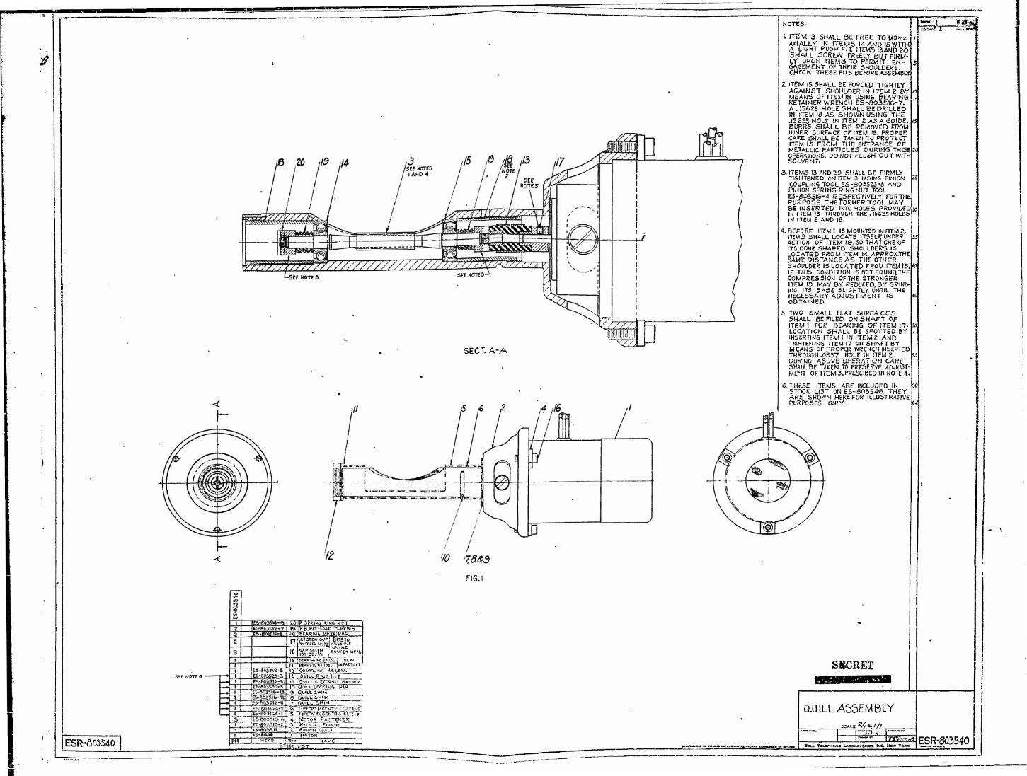
SECT. A-A
^u
NOTES:
1 ITEM 3 SMALL BE FREE TO MO'/t AXIALLY IN ITEMS 14 AND 15 WITH A Owr PUSH F/T, ITEMS SAND 20 SHALL SCREW FREELY BUT FIRM- LY UPON ITEM3 TO PERMIT EN- GAGEMENT OK THEIR SHOULDERS. CHECK THESE FITS BEFORE ASSEMBLY
2 ITEM 15 SHALL BE FORCED TIGHTLY AGAINST SHOULDER IN ITEM 2 BY MEANS OF ITEM 18 U5IN6 BEARIN6 RETAINER WRENCH ES-803516-7. A . I562S HOLE SHALL BE DRILLED IN ITEM IÖ AS SHOWN U5INS THE .15625 HOLE IN ITEM 2 AS A GUIDE. IS BURRS SHALL BE REMOVED FROM INNER SURFACE OF/TEM 18. PROPER CAKE SHALL BE TAKEN TO PROTECT ITEM 15 FROM THE ENTRANCE OF METALLIC PARTICLES DURING THESEM OPERATIONS. DO NOT FLUSH OUT WITH SOLVENT.
3. ITEMS 13 AND 20 SHALL BE FIRMLY TIGHTENED ON ITEM 3 USING PINION K* COUPLING TOOL £5-803523-3 AND PINION SPRING RINGNUT TOOL ES-6035K5-4 RESPECTIVELY FORTHE PURPOSE. THEFORMERTOOL MAY BE INSERTED INTO MOLES PROVIDED!» IN ITEM 13 THROUGH THE . I5GES HOLES IN ITEM 2 AND 18.
4. BEFORE ITEM I IS MOUNTED IN ITEM 2. ITEM3 SHALL LOCATE ITSELr UNDER-
ACTION OF ITEM 19, SO THAT ONE OF ITS CONE SHAPED SHOULDERS IS LOCATED FROM ITEM 14 APPROX-THE SAWE PISTANCE AS THE OTHFR SHOULDER IS LOCATED FROU ITEM (5 IF THIS CONDITION IS NOT FOUND,THE COMPRESSION OF THE STRONGER ITEM 19 MAY BY REDUCED, BY GRIND- ING ITS BASE SLIGHTLY, UNTIL THE NECESSARY ADJUSTMENT IS OBTAINED.
5. TWO SMALL FLAT SURFACES SHALL BE FILED ON SHAFT OF ITEM I FOR BEARING OF ITEM IT. LOCATION SHALL BE SPOTTED BY INSERTING ITEM I IN ITEM 2 AND TIGHTENING ITEM 17 ON SHAFT BY MEANS OF PROPER WRENCH INSERTED THROUGH.0937 HOLE IN ITEM 2. DURING AQOVE OPERATION CARE SHALL BE TAKEN TO PRESERVE ADJUST- MENT 0FITEM3,PRE5CIBEDINN0TE4.
6. THcSE ITEMS ARE INCLUDED IN STOCK LIST ON ES-S03546. THEY
' ARE SHOWN HERE FOR ILLUSTRATIVE PURPOSES ONLY.
IS
10
ts
v>*
FIG.
ESR-Ö03540
20|PSPg*mi R1W6 M"5T"
PWOT.ltl««*)'*! MULTIPLE " • 1PJIME.
\i ;Bw?iQfry??py.*
iqlqtfii.LLocc>>fe pin "eTfouiU. 5HIM ~~T
SSSCEET
5 JTtW'A'KCENTIlie. sin:e *TK>0TOR~^Ä^TeHER "S [VenCAu"P<moM \ : Pinion QmLV
ai)ILL ASSEMBLY
"3J,K: rmrm^s BELL Tu«fHof«s LASONAI-OMU, IMC. MCW YOMC
ESR-6Ö3540
i

"45*
T t
Is <!3'
I ui—
1
ES-803533-4 TRANSMITTING
ROTOR ASSEMBLY KUX I/,
o«- J.»f »yyu £ B.fj,
BOX TCUFHOK E U90ftlTO«r^ ttC NcwYaK
«* re <M ahwjMW ja —.nn «
raq RE«
tS- 8035-36-3
ES-aOBglll. - 4- es-ao3g;i7-3 g&-BQ3S-,>3-2.
ES-803fTa7-l E&-803S37-Z,
Es-aoss;tfc-& gS-a03J3<>-fc
gS-603334-l
PIECE
10 CLAMP PIK MUT 9 ,0m-80«3fcO Fll-H STUlStB
ITtH
CUMPDßCKET BD3HIW6 COHl'Acr SFKIH6 ASSEM- INSULATOR ROTOR SCREW PLATE OUTSIDE OAK" Ptfi
KEC. ROTOR INSIDE CLAMP CISC
NAME
STOCK LIST
P" SECRET
ASSEMBLIES
J.A.S, F 1 FSO-&03533
•5?

Iv
I
±1
7 SEE NOTES 113
7 SEE Nor« z«:!
.SECT. A-A-
ENBCUL« TO ITCM 8
5ECT B-S
• SEE NOTE 5
ALL OTHER POSITIONS DMuESS OTHERWISE SPffClFfCD AW ASSEMBLED W THIS MAHNER ISEE SECT. A-A
ser Honr A.
(TEM 7 SHRILL NOT EJMD IN MOUNT»,'' HOLES
ITEMS 2 & 3 SMALL BE FREE To •«N ON ITEM 7 WITHOUT UNDUE S'ND'N&.
ITEM II SHALL BE FLU3HSD WITH UNDER SrßE or ITCH 3,
If L0OSS IN BIKH1N6 ITEM It SHALL »5_ SECURED IH PLACE WITH CELLUuCSE M** CEMENT SUFFKIENr SLAW IN THE «ft*. MOTS WIRES SHALL BE PROYIPED ^S SLOW.», TO PERMIT* FREE NOVEMS-NJR OP ITSM Z.
iKOWB ITEM 7, THE RED AND W«lW STRAND«) KTES SHALL EE TW/SJ« TOSE.THEH AS SHOWN AND T»E TitS 1V7*S S5ALL BE SO-DERE« IN ALL POSITION« TO TIE RIJHT HAND WIRE TERMINAL MCINC FAOM THE CENTER Of ITEM i-
WALL OF ITEI-f 6.
•SHIELD OF ••'•WIRE TOM TAPE» WITH .HAT FRICTION TARfASWUtTO PDAS Flldt TERMS. AS P-FACTICAL PAINT « !A»lF<eBOH AROUHP^ ^ EACH WIRE APPROWA'AWAY «CM TERM <lg> U3WS UCOUSR INK OR EOAWALENT AND COLORS ASPSR TABLE A, WlBfl3 itiuX BE FORM* tm HOT •SOLDERED IN PLACE UNTIL AFTER, ASSEMBLY 15 INSTALLED AND ADJUSTED Af> CALLED TOR IN NOTEe,CS-eOU4e
NUMBERING IN 11 A« FOR WIR.N6 INFORUATJOM ONLY AND SHALL NOT BE STAMPED.
ITEMS 10, I« < IS SHALL NOT BE SECURED I" PIA« UNTIL AFTER ASSEMBLY » INSTALLED AND ADJUSTED Aj CALLED FOR IN NOTE«, ES-80554«
SECT.C-C
SEE NOTE i
SHOW Ttttllllf met. on nhrMis
SECTJMf AHO torn
CHIC/iao'STITlH
O METHOD or C/)BUN6SCCMtf£CT/fJ<} •f rrpr cawcToxs
•see notes 7«» /PAW? V/CW
M;
ESR-503525
rSO-SOJElA-i.
£$0-803523-2 E50-8035Z3-I
ESO-80352Z-i EJ0-P.0 -1322-1
tlO-COSSlS-i ESO-BOäS/J-S
E^Q.SOSStS-Z ESO-«03S[15-I ESO-803SI4.-A
Ua-8M5I<—3
ESO-803511-4
TWINE, IMPREGUATED LINtM.HO.12 CRAY FRICTION TAPE
P WIRE, 2 2 SA, PAIR A8"t,g WIKC TERMINAL TOOT« TYPE 10CK WASHER-PA'S NT-STL **
FLUTED SOCKET H CAP SCR-5TL M-AgxVi
FLUTED SOCKET H CAP SCÄ-5TL .W-40»'/* 6USH1N4
WIRING COVER PLATE MOUNTING BLOCK
POLE PIECE MOUNTING PLATE
POt-C PIN ASSEMBLY
BEARING WASHER.
PiN RETAINER POLE PtCCZ
POLt PUCE ASSEMBLY POLE. PECS PW SPR^S
STOCK LIST
SUPPLEMENTARY PBWIM65
^ -X^SsE-S
POLE PIECE MOUNT7N6 PLATE ASSEMBLY
Luffllirtwuui line Nc* Ye«*
mal 7iH^
Tig ISivs-3 #>&-4Z nnaaeKD TtKHS. 1
tSSV£:4 4-24-43
ESR-S035Z5-

ES 3035/0-/
SCALE P*JLL S-lE
-•ffi/tt
BEU. TELEPHONE LABORATORIES. IHC NEW YORK
OIMlN»K>N« UP TO AHO IMCLUBIN9 71 IHCH1S ÜniKMKD IN INCH»
r-
/e?ö TEETH
-4-.iifa-.ooos P.O. —4.071 & t. OOOS —
3.187*.DOS __
MATERIAL: SAE NO. &5PHOSPHOR, GEAR 3R0NZZ CASTING . COPPER MB.00 TO 90.00
TIN 10. CO TO 12.00 PHOSPHORUS O.IO TO 0,30 NICKEL o.os MAX.. LEAD, ZINC,i. OTHER MPURI77SS aSOfrlAX..
" .Jf.-,
ESÖ035/0-2
HELICAL P/N/ON
SCALE ZA
'•em.
BELL TELEPHONE LABORATORIES, INC. NEW YORK
DIMINMOMS UP TO AND INCLUOINO 7« INCH» Of«IMID IN INCH«!
1. 4S "CHAMFFER '-* «07V/ &NDS s.ffO-lZ Nf-3 SOT,' E>lDS
002. J .' , . T~ \; 'f
.? T££77/
lip- .zosst .ooos jjl>- -zsast.ooos P.O. Hi-—-Z9S/-.0OOS ao.
Z04 t. OQI
"5
-.£34 +.Wi53 -•0000
-IS
MATERIAL: STEEL SA.E. 6,/SO NORMALIZE IS7S' F
. REHEAT 70 IS7SW600'F COOL SLOWLT IH FURNACE. BETWEEN BSO'-TO 11 SO- COOL AT RATE OF 2ÜV PER HOUK. "
, ITIACHINI* • ' REHEAT TO /SZ5-IS7SF OIL QUEHCH
\ DRAW 70 I/O ROCKWELL. "C * • GKIND TEETH AID DECIMAL DIMENSIONS .
ES 60551O-3
GEAR DATA
SCALK r—"-p; "•foVHL
BELL TELEPHON? LABORATORIES, 1«C New YORK
DIMENSION« UP TO AND INCIUDINO 71 INCHKl ra^CtltO IN INCH»
GENERAL
REDUCTION RATIO 90-7 DlSWICS BETH'EUH AXES ANGLE BE7W&EN AXES IDS' FORMAL PRESSURE \NSLE (VF) 14-1* A'OR'JAL D'AMETRAL PITCH MOP 43 NORMAL FITCH t'.V P) NORMAL CIRCULAR, TOOTH THICKNESS (CTt,) CLEARANCE (t)
ADDENDUM (A.) DEDENDUM (o) WHOLE TOOTH DEPTH (KO) ~-
THE ERROR SE^Vt'EEN At. Y" ."rt 0 TEETH SHALL MOT EXCEED .OOOS
HELICAL PINION (R:SHT HAND)
HELIX ANGLE (vt,) ^0-3^^-a' .VTCU DIAMETER (Fb) AO. OF TEBTH (Nd) 2 CIRCULAR PlTCHCCp) OUTSIDE DIAMETER (Oo'J
THE PITCH DIAMBTER SHALL BE CONCEVTR'C WITH THE TWO . Z3Sr1ja^f0%
DIAMETERS W'THiW. 000&
HELICAL GEAR (RIGHT HAND)
HELIX AHSLE (VH) S4'-SO'*# PITCH DIAMETER (PO) NO. OF TEETH (Nd) ISO CIRCULAR PITCH (CP) OUTSIDE DIAItlETER (03)
AIL OIAMETSRS SHALL BE CONCENTRIC WITH THB. S0Qoi\%%%% DIAMETER YIITHIH -OO0U
INCHES
o. Ot>54-S O.0BZ7i> 0.0033 0.0ZO83 0. 0Z"-> 0.U441
0. ZS3St .OOOS
D.Z9&I * .OOOS 0. Z9JTI 2 OOOS
6.1112 "t .OOOS
.0719 t .OOOS 4,IL\IS- .OOOS
THE CQNCENTRICIT.' OF TWO CYLINDRICAL SURFACES
SHALL 35 INTERPRETED TO MEAN/ THE "RUH OUT " OF ONE SURFACE WITH R-ESFBCT TO THE OTHER.-
HUH ri&