![arXiv:2008.07486v1 [stat.AP] 17 Aug 2020](https://static.fdokumen.com/doc/165x107/631ce10276d2a4450503bd91/arxiv200807486v1-statap-17-aug-2020.jpg)
AUG COMMAG COVER - magzDB
155
A Publication of the IEEE Communications Society ® Optical Communications: Enabling Global Broadband Communications Networks IEEE Standards in Communications and Networking Industry Analyst Forum: Trends in Communications Advances in Mobile Multimedia Networking and QoS IEEE MAGAZINE July 2008, Vol. 46, No. 7 www.comsoc.org
-
Upload
khangminh22 -
Category
Documents
-
view
1 -
download
0
Transcript of AUG COMMAG COVER - magzDB

A Publication of the IEEE Communications Society®
Optical Communications: Enabling GlobalBroadband Communications Networks
IEEE Standards in Communications and Networking
Industry Analyst Forum: Trends in Communications
Advances in Mobile Multimedia Networking and QoS
IEEE
M A G A Z I N E
July 2008, Vol. 46, No. 7
www.comsoc.org

1
Director of Magazines
Editor-in-Chief
Associate Editor-in-Chief
Senior Technical Editors
Technical Editors
Series Editors
Columns
Publications Staff
Nirwan Ansari, NJIT (USA)Tom Chen, Swansea University (UK)
Roch H. Glitho, Ericsson Research (Canada)Andrzej Jajszczyk, AGH U. of Sci. & Tech. (Poland)Torleiv Maseng, Norwegian Def. Res. Est. (Norway)
Steve Gorshe, PMC-Sierra, Inc. (USA)
Nim K. Cheung, Telcordia Tech., Inc. (USA)
Steve Gorshe, PMC-Sierra, Inc. (USA)
Joseph Milizzo, Assistant PublisherEric Levine, Associate Publisher
Susan Lange, Digital Production ManagerCatherine Kemelmacher, Associate EditorJennifer Porcello, Publications Coordinator
Koichi Asatani, Kogakuin University (Japan)Mohammed Atiquzzaman, U. of Oklahoma (USA)
Tee-Hiang Cheng, Nanyang Tech. Univ.(Rep. of Singapore)
Jacek Chrostowski, Scheelite Techn. LLC (USA)Sudhir S. Dixit, Nokia Res. Ctr. (Finland)
Nelson Fonseca, State U. of Campinas (Brazil)Joan Garcia-Haro, Poly. U. of Cartagena (Spain)
Abbas Jamalipour, U. of Sydney (Australia)Vimal Kumar Kanna (India)
Janusz Konrad, Boston U. (USA)Nader Mir, San Jose State U. (USA)
Amitabh Mishra, Johns Hopkins University (USA)Sean Moore, Avaya (USA)
Sedat Ölçer, IBM (Switzerland)Algirdas Pakstas, London Met. U. (England)Michal Pioro, Warsaw U. of Tech. (Poland)
Harry Rudin, IBM Zurich Res.Lab. (Switzerland)Hady Salloum, Stevens Inst. of Tech. (USA)
Heinrich J. Stüttgen, NEC Europe Ltd. (Germany)Dan Keun Sung, Korea Adv. Inst. Sci. & Tech. (Korea)
Naoaki Yamanaka, Keio Univ. (Japan)
Book ReviewsAndrzej Jajszczyk, AGH U. of Sci. & Tech. (Poland)
Communications and the LawSteve Moore, Heller Ehrman (USA)
History of CommunicationsMischa Schwartz, Columbia U. (USA)
Regulatory and Policy IssuesJ. Scott Marcus, WIK (Germany)
Jon M. Peha, Carnegie Mellon U. (USA)Technology Leaders' Forum
Steve Weinstein (USA)Very Large Projects
Ken Young, Telcordia Technologies (USA)Your Internet Connection
Eddie Rabinovitch, ECI Technology (USA)
Ad Hoc and Sensor Networks SeriesEdoardo Biagioni, U. of Hawaii, Manoa (USA)
Silvia Giordano, Univ. of App. Sci. (Switzerland)Applications & Practice Series
Osman Gebizlioglu, Telcordia Technologies (USA)John Spencer, Optelian (USA)Design & Implementation Series
Sean Moore, Avaya (USA)Integrated Circuits for Communications
Charles Chien (USA)Jim Goodman, Advanced Micro Devices (USA)
Stephen Molloy, Qualcomm (USA)Network and Service Management Series
George Pavlou, U. of Surrey (UK)Aiko Pras, U. of Twente (The Netherlands)
Optical Communications SeriesHideo Kuwahara, Fujitsu Laboratories, Ltd. (Japan)
Jim Theodoras, Cisco Systems (USA)Radio Communications Series
Joseph B. Evans, U. of Kansas (USA)Zoran Zvonar, Analog Devices (USA)
StandardsYoichi Maeda, NTT Adv. Tech. Corp. (Japan)
Mostafa Hashem Sherif, AT&T (USA)
IEEE Communications Magazine • July 2008
IEEE
M A G A Z I N E
July 2008, Vol. 46, No. 7
www.comsoc.org/~ci
IEEE STANDARDS IN COMMUNICATIONS AND NETWORKINGSERIES EDITORS: ALEXANDER D. GELMAN, STEVEN MILLS, AND ROBERT S. FISH
GUEST EDITORIAL
THE IEEE STANDARDS ASSOCIATION AND ITS ECOSYSTEMThe author describes the IEEE Standards Association and the ecosystem that surrounds it, including the core principles and its history.F. D. (DON) WRIGHT
DEVELOPMENT OF 10 GB/S EPON IN IEEE 802.3AVThe authors examine the current development process of 10 Gb/s EPON systems in detail, standardized in the framework of the IEEE 802.3av Task Force.MAREK HAJDUCZENIA, HENRIQUE J. A. DA SILVA, AND PAULO P. MONTEIRO
IEEE 802.11N DEVELOPMENT: HISTORY, PROCESS, AND TECHNOLOGYThe author provides insight into the IEEE 802.11n standard amendment developmentprocess, beginning with a general overview of the IEEE 802.11 process.ELDAD PERAHIA
IEEE 802.20: MOBILE BROADBAND WIRELESS ACCESS FOR THETWENTY-FIRST CENTURYThe authors describe the IEEE 802.20 standard that was developed to meet the unique requirements for supporting high-speed data services while at the same time supporting full user mobility.ARNOLD GREENSPAN, MARK KLERER, JIM TOMCIK, RADHAKRISHNA CANCHI, AND JOANNE WILSON
RECENT DEVELOPMENTS IN THE STANDARDIZATION OF POWER LINECOMMUNICATIONS WITHIN THE IEEEBroadband connectivity to and within the home has been available to consumers for some time through various technologies. Among those technologies, power line communications is an excellent candidate for providing broadband connectivity as itexploits an already existing infrastructure.STEFANO GALLI AND OLEG LOGVINOV
IEEE STANDARDS SUPPORTING COGNITIVE RADIO AND NETWORKS, DYNAMICSPECTRUM ACCESS, AND COEXISTENCECognitive radio techniques are being applied to many different communications systems. They hold promise for increasing utilization of radio frequencies that are underutilized today, allowing for improved commercial data services, and allowing for new emergency and military communications services.MATTHEW SHERMAN, APURVA N. MODY, RALPH MARTINEZ, AND CHRISTIAN RODRIGUEZ, AND RANGA REDDY
INDUSTRY ANALYST FORUM: TRENDS IN COMMUNICATIONSSERIES EDITOR: PAUL A. BONENFANT
GUEST EDITORIAL
CARRIER CAPITAL EXPENDITURESThe author analyzes the size, scope, and outlook of capital expenditures among telecommunications carriers in the U.S., and assesses the significance of capital expenditures for the carriers' customers, equipment vendors, and investors.JOHN M. CELENTANO
FTTX: CURRENT STATUS AND THE FUTUREThe author reviews the current status of FTTx and analyze what is taking place in different regions of the world.LYNN HUTCHESON
A SWITCH IN TIME: THE ROLE OF SWITCHED DIGITAL VIDEO IN EASING THELOOMING BANDWIDTH CRISIS IN CABLEThe author provides an industry analyst’s perspective on the surge of interest in SDVand the implications of that surge for the future of the cable industry.ALAN BREZNICK
3032
40
48
56
64
72
8082
90
96
®
LYT-TOC-JULY 6/18/08 2:38 PM Page 1

2008 Communications Society OfficersDoug Zuckerman, President
Andrzej Jajszczyk, VP–Technical ActivitiesMark Karol, VP–Conferences
Byeong Gi Lee, VP–Member RelationsSergio Benedetto, VP–Publications
Nim Cheung, Past PresidentStan Moyer, Treasurer
John M. Howell, Secretary
Board of GovernorsThe officers above plus Members-at-Large:
Class of 2008Thomas M. Chen, Andrea GoldsmithKhaled Ben-Letaief, Peter J. McLane
Class of 2009Thomas LaPorta, Theodore RappaportCatherine Rosenberg, Gordon Stuber
Class of 2010Fred Bauer, Victor Frost
Stefano Galli, Lajos Hanzo
2008 IEEE OfficersLewis M. Terman, PresidentJohn R. Vig, President-Elect
Barry L. Shoop, SecretaryDavid G. Green, Treasurer
Leah H. Jamieson, Past PresidentJeffry W. Raynes, Executive Director
Curtis A. Siller, Jr., Director, Division III
IEEE COMMUNICATIONS MAGAZINE (ISSN 0163-6804) is published monthly by The Institute of Electricaland Electronics Engineers, Inc. Headquarters address:IEEE, 3 Park Avenue, 17th Floor, New York, NY 10016-5997, USA; tel: +1-212-705-8900; http://www.comsoc.org/ci. Responsibility for the contents rests upon authorsof signed articles and not the IEEE or its members. Unlessotherwise specified, the IEEE neither endorses nor sanc-tions any positions or actions espoused in IEEECommunications Magazine.
ANNUAL SUBSCRIPTION: $27 per year. Non-mem-ber subscription: $400. Single copy price is $25.
EDITORIAL CORRESPONDENCE: Address to: Editor-in-Chief, Nim K. Cheung, Telcordia Tech., Inc., OneTelcordia Drive, Room RRC-1B321, Piscataway, NJ08854-4157; tel: +(732) 699-5252, e-mail: [email protected].
COPYRIGHT AND REPRINT PERMISSIONS:Abstracting is permitted with credit to the source.Libraries are permitted to photocopy beyond the limits ofU.S. Copyright law for private use of patrons: thosepost-1977 articles that carry a code on the bottom of the firstpage provided the per copy fee indicated in the code ispaid through the Copyright Clearance Center, 222Rosewood Drive, Danvers, MA 01923. For other copying,reprint, or republication permission, write to Director,Publishing Services, at IEEE Headquarters. All rightsreserved. Copyright © 2008 by The Institute of Electricaland Electronics Engineers, Inc.
POSTMASTER: Send address changes to IEEECommunications Magazine, IEEE, 445 Hoes Lane,Piscataway, NJ 08855-1331. GST Registration No.125634188. Printed in USA. Periodicals postage paid atNew York, NY and at additional mailing offices. CanadianPost International Publications Mail (CanadianDistribution) Sales Agreement No. 40030962. Returnundeliverable Canadian addresses to: Frontier, PO Box1051, 1031 Helena Street, Fort Eire, ON L2A 6C7
SUBSCRIPTIONS, orders, address changes —IEEE Service Center, 445 Hoes Lane, Piscataway,NJ 08855-1331, USA; tel: +1-732-981-0060; e-mail: address.change@ ieee.org.
ADVERTISING: Advertising is accepted at thediscretion of the publisher. Address correspondenceto: Advertising Manager, IEEE CommunicationsMagazine, 3 Park Avenue, 17th Floor, New York,NY 10016.
SUBMISSIONS: The magazine welcomes tutorial orsurvey articles that span the breadth of communica-tions. Submissions will normally be approximately4500 words, with few mathematical formulas, accom-panied by up to six figures and/or tables, with up to 10carefully selected references. Electronic submissionsare preferred, and should be sumitted throughManuscript Central (http://commag-ieee.manuscriptcentral.com/). Instructions can be found at: http://www.comsoc.org/pubs/commag/sub_guidelines.html.For further information contact Steve Gorshe,Associate Editor-in-Chief ([email protected]). All submissions will be peer reviewed.
2 IEEE Communications Magazine • July 2008
PACKET TRANSPORT TRENDS: IP/MPLS SUCCESS CHALLENGED ASDEPLOYMENT FOOTPRINT EXPANDSFor most of the last decade, the prevailing industry assumption was that large public networks would migrate all services, transport, and switching to a single end-to-end IP/MPLS network — convergence. Economic forces that affect suppliers, as much asoperators, are challenging this assumption, and other scenarios now seem plausible.MARK SEERY
ADVANCES IN MOBILE MULTIMEDIA NETWORKING AND QOS: PART IIGUEST EDITORS: SASTRI L. KOTA, YI QIAN, EKRAM HOSSAIN, AND RAJAMANI GANESH
GUEST EDITORIAL
SUPERPOSITION OF BROADCAST AND UNICAST IN WIRELESS CELLULARSYSTEMSThe authors discuss the practical application of superposition coding in multiplexingbroadcast and unicast for OFDM-based mobile cellular systems.DONGHEE KIM, FAROOQ KHAN, CORNELIUS VAN RENSBURG, AND ZHOUYUE PI, AND
SEOKHYUN YOON
PERFORMANCE ENHANCEMENT IN FUTURE MOBILE SATELLITE BROADCASTINGSERVICESThe authors discuss two promising techniques that can improve the performance of amobile satellite broadcasting system with HSTN.SOOYOUNG KIM, HEE WOOK KIM, KUNSEOK KANG, AND DO SEOB AHN
A NEW PARADIGM FOR MOBILE MULTIMEDIA BROADCASTING BASED ONINTEGRATED COMMUNICATION AND BROADCAST NETWORKSThe authors provide a new paradigm to integrate the Chinese digital television/terrestrial multimedia broadcasting (DTMB) systems with existing mobile communicationsystems. ZHISHENG NIU, LONG LONG, JIAN SONG, AND CHANGYONG PAN
OPTICAL COMMUNICATIONS: ENABLING GLOBAL BROADBANDCOMMUNICATIONS NETWORKS
SERIES EDITORS: JOHN SPENCER AND OSMAN GEBIZLIOGLU
GUEST EDITORIAL
PRACTICAL DEPLOYMENT OF PASSIVE OPTICAL NETWORKSThe authors describe several real deployments of passive optical networks (PONs, the most common form of fiber to the home, FTTH) in several parts of the world, some with incumbent providers, some with other entities.JAMES O. FARMER AND KEVIN BOURG
ROADMS UNLOCK THE EDGE OF THE NETWORKSince their introduction in 2003, reconfigurable optical add/drop multiplexers have brought new flexibility and scalability to what was once a static optical telecommunications network.THOMAS A. STRASSER AND JAY TAYLOR
ROADM ARCHITECTURES AND THEIR ENABLING WSS TECHNOLOGYThe relationship is explored between reconfigurable optical add/drop multiplexers, fast becoming the standard nodal subsystem for providing flexibility in modern multichannel fiber optic networks, and wavelength selective switches, the predominanttechnology used to implement ROADMs.JONATHAN HOMA AND KRISHNA BALA
ENABLING HIGHLY SURVIVABLE AUTOMATED ON-DEMAND DYNAMICNETWORK SERVICES WITH INTELLIGENT OPTICAL CONTROL PLANESGlobalization has changed the relevance of communication networks dramatically. Communication systems have become the most significant element of mission-critical infrastructure for consumers, businesses, and governments worldwide.JAMES ZIK
HOPSMAN: AN EXPERIMENTAL TESTBED SYSTEM FOR A 10-GB/S OPTICALPACKET-SWITCHED WDM METRO RING NETWORKThe authors present the design of HOPSMAN, an experimental testbed system for a high-performance optical packet-switched WDM metro ring network.MARIA C. YUANG, I-FEN CHAO, BIRD C. LO, PO-LUNG TIEN, JASON J. CHEN, C. WEI, YU-MIN LIN, STEVEN S. W. LEE, AND CHING-YUN CHIEN
The President’s Page 4Society News/Candidate Responses 12Conference Calendar 24
Certification Corner 25New Products 28Advertisers Index 168
154
103
108110
126
118
158
134136
146
150
LYT-TOC-JULY 6/18/08 2:38 PM Page 2

IEEE Communications Magazine • July 20084
THE PRESIDENT’S PAGE
AWARDS: ACHIEVEMENT RECOGNIZED!
he Communications Society is proud ofthe accomplishments made by its mem-
bers and colleagues throughout our field.Recognition of achievement is in large partaccomplished through the Society’s extensiveportfolio of awards. In addition to recognizingindividuals, the program serves a broader pur-pose of publicizing the Society’s values andpresenting role models for young engineers.
This month, I am privileged to introducethe chair of the ComSoc Awards Committee,Dr. Stephen B. Weinstein. Steve, an IEEELife Fellow, received his SB, MS, and Ph.D.degrees in Electrical Engineering from M.I.T.,the University of Michigan, and the Universityof California at Berkeley, respectively. Hiscareer was mainly with Bell Laboratories,Bellcore (now Telcordia), and NEC ResearchLabs America. Now an independent consul-tant (Communication Theory & TechnologyConsulting LLC), he is a technical expert forlaw firms and industrial clients. As a youngengineer, he invented the echo cancellationtechnique used in voice band modems andpioneered the application of the Fast FourierTransform to OFDM/DMT modulation. Hewrote the book “Getting the Picture: A Guideto CATV and the New Electronic Media”(IEEE Press, 1986), is co-author of the text-book “Data Communication Principles”(Plenum, 1992), and is the author of “TheMultimedia Internet” (Springer, 2005) . Stevewas President (1996-97) of the IEEE Commu-nications Society and Division III Director(2002-2003) on the IEEE Board. He has heldmany other positions in IEEE including Chairof the IEEE Press Board, member of theIEEE Nominations and Elections Committee,and member of the IEEE Fellow Committee. He was alsoChair of the IEEE Honorary Member Award Committee andthe IEEE Communication Society’s Chief Information Offi-cer. He co-founded the IEEE/ACM Transactions on Network-ing, was founding Editor in Chief of the Journal ofCommunications and Networking, was co-program chair ofthree IEEE CAS/COM intersociety conferences, and was Pro-gram Chair for the 2004 IEEE Wireless Communication andNetworking Conference (WCNC). He received the IEEECentennial Medal in 1984 and the IEEE Second MillenniumMedal in 2000. He is the recipient of the Eduard Rhein Foun-dation’s (Germany) 2006 Basic Research Award for his contri-bution to OFDM.
AWARDSOne of the traditional functions of professional societies is
the recognition of outstanding accomplishments by theirmembers. The objectives are to encourage and reward highperformance, and provide evidence to the technical communi-ty and the public of high professional standards and signifi-cant accomplishments.
Our parent IEEE has a number of prestigious recognitions,most notably election to Fellow membership grade and variousprizes and field awards. Several of these are particularly rele-
vant to communications, such as the Alexan-der Graham Bell Award, which frequently isconferred on members of our Society.
Each Society, in turn, has its own set ofdistinctions. The Communications Societymakes awards in three classes: paper awards,career awards, and service awards. Many ofthem include an honorarium as well as a cer-tificate and plaque, with presentation often atComSoc’s flagship conferences, ICC andGLOBECOM.
ComSoc’s awards are fully described atwww.comsoc.org/socstr/org/operation/comm/awards.html, including the winners in recentyears, but here are capsule summaries.
PAPER AWARDSThe nomination deadline is February 15,
with presentation usually at ICC. •Best Tutorial Paper Award—for a tutori-
al paper published in any CommunicationsSociety magazine or journal in the previouscalendar year.
•Leonard G. Abraham Prize—in the fieldof communications systems for a paper pub-lished in the IEEE Journal on Selected Areasin Communications (JSAC).
•Stephen O. Rice Prize—in the field ofcommunications theory for a paper publishedin the IEEE Transactions on Communica-tions.
•William R. Bennett Prize—in the field ofcommunications networking, redefined thisyear, this prize is restricted to a paper fromthe IEEE/ACM Transactions on Networking.
•Fred W. Ellersick Prize—for a paper inany Communications Society magazine.
•Communications Society/InformationTheory Society Joint Paper Award—for a paper, relevant toboth Societies, that appeared in any publication of the Com-munications Society or the Information Theory Society.
•IEEE Marconi Prize Paper Award in Wireless Communi-cations—restricted to a paper from IEEE Transactions onWireless Communications.
•Award for Outstanding Paper on a New CommunicationTopic—this new award is for a paper in any CommunicationsSociety publication.
CAREER AWARDSThe nomination deadline is September 1, but note that
nominations for the Distinguished Industry Leader Awardmay also be submitted by February 15 for earlier considera-tion. Presentation is as soon as possible after recommenda-tion, typically at the next ICC or GLOBECOM. Note thatsome of these awards also can be interpreted as serviceawards.
•Edwin Howard Armstrong Achievement Award—for out-standing contributions over a period of years in the field ofinterest of the Society.
•Donald W. McLellan Meritorious Service Award—foroutstanding long-term service to the welfare of the Communi-cations Society.
T
DOUG ZUCKERMAN
STEPHEN B. WEINSTEIN
LYT-PRES PAGE-JULY 6/18/08 1:44 PM Page 4

IEEE Communications Magazine • July 2008 5
THE PRESIDENT’S PAGE
•Distinguished Industry Leader Award—for executiveleadership resulting in major advances and new directions inthe information and communications business area.
•Award for Public Service in the Field of Telecommunica-tions—for major contributions to the public welfare throughwork in the field of telecommunications.
SERVICE AWARDSThe nomination deadline is September 1, with presentation
typically at the next ICC or GLOBECOM.•Harold Sobol Award for Exemplary Service to Meetings
and Conferences—for exemplary service to IEEE Communi-cations Society meetings and conferences over a sustainedperiod of time.
•Publications Exemplary Service Award—for exemplaryservice to IEEE Communications Society publications over asustained period of time.
•ComSoc/KICS Exemplary Global Service Award—fordemonstrated exemplary and distinguished service in global-ization of our community.
AWARDS PROCESSThe awards process is carried out by the ComSoc Awards
Committee, a body with 12-15 members plus the Chair.
Members serve three-year terms. It now has 13 membersplus the Chair, Steve Weinstein. The Committee dependsvery heavily on recommendations made by Society mem-bers, and particularly for the paper awards, on recommen-dations coming from the editorial staffs of our variouspublications. Anyone can propose a paper or individual foran award and Steve welcomes suggestions, through the Webpage given above. Be sure to provide a one or two para-graph supporting statement (why the award is deserved)along with your suggestion.
Choosing award winners is a challenging but “rewarding”process. We all recognize the problems of too few nomina-tions and the inherent inequity in making a selection amongseveral excellent papers. Important to recognize is that theAwards Committee does its best to be as fair as possible.Thanks go to its members and others who have helped achievefair and respected results in recognition of their peers. Weencourage many more of you to suggest deserving candidatesfor our ComSoc awards and for the IEEE awards that aredescribed at http://www.ieee.org/portal/pages/about/awards/index.html.
Awards Luncheon at ICC 2008 in Beijing.
Steve Weinstein (left) and Doug Zuckerman (right) congratulat-ing Fred W. Ellersick Prize recipient Raouf Boutaba at ICC 2008Awards Ceremony.
Anniversaries always provide a good opportunity to reflecton the past. The 20th anniversary of the IEEE/IFIP NetworkOperations and Management Symposiums (NOMS) is no excep-tion. Of course, you already know — or may compute — thatthe first one was in 1988. But do you know how it all started?
The history of NOMS parallels that of the information andcommunications technology industry. In the mid-1980s, tele-phone companies were introducing digital technology into theirnetworks and were under great pressure to use computer sys-tems to automate operations to keep up with growing demandand the increasing cost of labor. The IEEE CommunicationsSociety’s flagship International Conference on Communications(ICC) and Global Telecommunications Conference (IEEEGLOBECOM, now known as the IEEE Global Communica-tions Conference) had seen an increasing number of technicalsessions on “network operations and management.” This result-ed in the creation of a new Technical Committee on NetworkOperations and Management (CNOM).
THE VERY FIRST ONE …With the rapidly growing interest in “NOM,” the timing
was perfect to launch the first Network Operations and Man-agement Symposium, NOMS ‘88 in New Orleans, an areaknown for strong support from local colleagues for ComSocactivities. The key to success was that AT&T Bell Labs andBellcore were strongly behind the launch. Indeed, the confer-ence theme, “Productivity Through Operations,” resonatedwith their business interests. The major supporters sent somany employees to NOMS ‘88 that the Sheraton New OrleansHotel’s 700-person meeting room capacity was quickly filled,and many had to be turned away from attending. Figure 1shows the Call for Papers (CFP) for this first NOMS.
Financially, the conference was a great success. Eventhough steps were taken to use the money to make the con-ference more valuable to the attendees, e.g., very nice blue“NOMS umbrellas” were distributed, the surplus achieved bythis first NOMS was unmentionably high. Amazingly, the first
TWENTY YEARS OF INTEGRATION: NETWORK OPERATIONS AND MANAGEMENT SYMPOSIUMS
BY DOUGLAS N. ZUCKERMAN AND MEHMET ULEMA
LYT-PRES PAGE-JULY 6/18/08 3:56 PM Page 5

IEEE Communications Magazine • July 20086
THE PRESIDENT’S PAGE
NOMS was pulled together in about eight months, in the daysbefore EDAS, the Internet and the World Wide Web. Thetechnical program submissions were manually tracked using aspreadsheet on the Technical Program Committee’s ViceChair’s Apple computer. Sessions were formed by stacking thepapers into piles representing each technical session. Theoriginal paper format, intentionally selected to make it easierfor industry people to contribute and use, was “visuals plusaccompanying text” — and that was before PowerPoint (andwhen “cut-and-paste” literally meant “cut” with a scissors and“paste” with glue). The proceedings were in three volumes(one per day).
The December 2007 issue of the Journal of Network and
Systems Management presents a detailed history of bothNOMS and its sister conference, IM (IFIP/IEEE Interna-tional Symposium on Integrated Network Management)[1].While NOMS had its roots in the “telecom” community, IMhad its roots in the “systems” community. The first IM(then known as ISINM) began in 1989. It was decided tohold NOMS and IM bi-annually, in alternating years. It wassoon recognized that both communities were converging,and that the many research challenges were generatinggrowing interest within academia. The IEEE Communica-tions Society became a major sponsor in 1995, and the for-mat of the NOMS proceedings was changed to use the same“journal style” format of IM’s, with commensurate upgrad-ing of quality.
THE ONES IN BETWEEN …NOMS and IM have continued to thrive, meeting all over
the world and embracing a new generation of those havinginterest in the field. Table 1 shows the dates and locations ofthese conferences, reflecting 20 years of “integration” of theworld’s networks, their management, and the supporting com-munities. If we focus on the NOMS series for a moment andlook at the themes, we see that it is a great collection of somehistorical trends in the technology and management of net-works, systems, and services.
These “historic” themes included:•“Productivity through Operations” (1988)—when the
operators were struggling to leverage operations to savemoney.
•“Networks Without Bounds” (1992) and “Managing theGlobal Information Age” (1996)—when the Global Informa-tion Infrastructure topic was hot.
“Management for the new Millennium” (1998) and “TheNetworked Planet: Beyond 2000” (2000)—when everyone wastalking about the new millennium and globalization.
•“Managing the Next Generationof Networks and Services” (2004)—when service management becamethe focal point.
Figures 2-4 show the cover pagesof the conference programs in vari-ous years.
Of course, committee memberswho have worked hard for the twoyears leading up to each event havebeen rewarded through seeing well-received NOMS and IM workshops,tutorials, technical sessions, andother attendee-focused parts of theoverall program. Occasionally they
NOMS ‘88 New OrleansIM ‘89 BostonNOMS ‘90 San DiegoIM ‘91 WashingtonNOMS ‘92 MemphisIM ‘93 San FranciscoNOMS ‘94 OrlandoIM ‘95 Santa BarbaraNOMS ‘96 Kyoto (Japan)IM ‘97 San DiegoNOMS ‘98 New Orleans
IM ‘99 BostonNOMS 2000 HonoluluIM 2001 SeattleNOMS 2002 Florence (Italy)IM 2003 Colorado SpringsNOMS 2004 Seoul (Korea)IM 2005 Nice (France)NOMS 2006 Vancouver (Canada)IM 2007 Munich (Germany)NOMS 2008 Salvador (Brazil)
TABLE 1. Dates and Locations of IMs and NOMS.
FIGURE 1. NOMS 1988 CFP as appeared in IEEE Communica-tions Magazine, Feb 1987.
FIGURE 2. The covers of the NOMS programs from 1992 to 1996. (Continued on page 8)
LYT-PRES PAGE-JULY 6/18/08 3:56 PM Page 6

IEEE Communications Magazine • July 20088
THE PRESIDENT’S PAGE
even take the time to enjoy the beau-tiful places that host our conferencesand to relax a little bit by singing anddancing. Do you recognize anyone inFigure 5?
AND THE MOST RECENT OONE …The latest edition of this premier
conference series in the field of net-work and services management, theIEEE/IFIP Network Operations andManagement Symposium (NOMS2008), was held on 7-11 April 2008 inthe exciting and lively city of Sal-vador, Bahia, Brazil. NOMS 2008 wasco-chaired by José Marcos Nogueira,Professor, Federal University ofMinas Gerais, Brazil, and MehmetUlema, Professor, Manhattan Col-lege, USA. The technical program ofNOMS 2008 was co-chaired by Mar-cus Brunner, NEC, Germany, andCarlos Becker Westphall, FederalUniversity of Santa Catarina, Brazil.
NOMS 2008 focused on the man-agement of the pervasive IT world.Accordingly, this year’s symposiumtheme was “Pervasive Managementfor Ubiquitous Networks and Ser-vices.” As predicted, there was muchinterest in this theme, as evidencedby the large number and high qualityof the papers submitted (220 submis-sions from 34 countries).
The organizing committee of NOMS 2008 put together anoutstanding program, including technical sessions, poster ses-sions, application sessions, dissertation digest sessions, soft-ware tools session, panels, workshops, and tutorials. Theprogram included three keynote speakers who are well knownleaders in their respective fields. The first keynote speakerwas Roberto Saracco, from Future Centre—Telecom ItaliaLab (TILAB). He gave a keynote entitled “From ValueChains to Ecosystem: New Opportunities for Telecommunica-tions and New Challenges for Managing Networks and Ser-vices.” The second keynote was delivered by Prof. Ian F.Akyildiz of Georgia Tech, USA. He discussed spectrum man-agement issues and network and operations management inCognitive Radio Networks. The third keynote was given byProf. Luiz Fernando Gomes of Catholic University of Rio deJaneiro (PUC-Rio). The title of his talk was “Brazilian Ter-restrial Digital TV System.” The program also included a Dis-tinguished Expert Panel that debated real new challenges inmanaging ubiquitous networks and services.
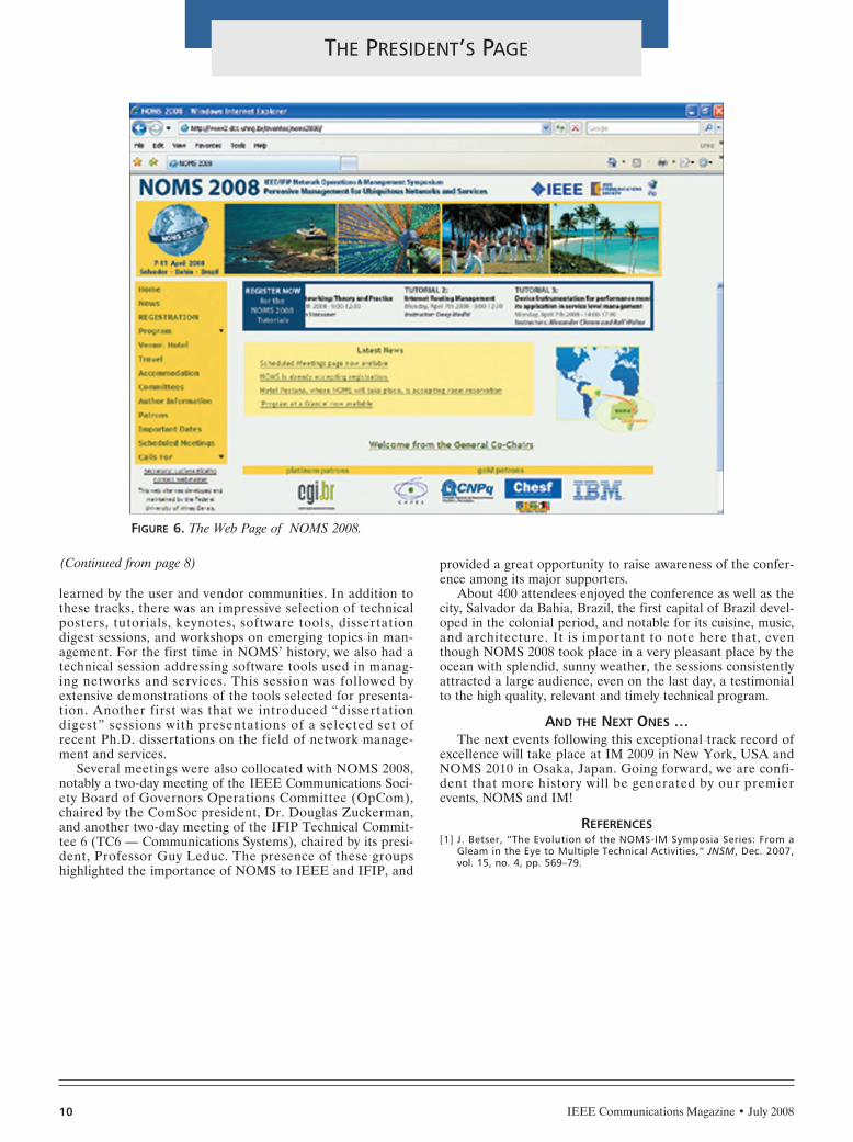
In contrast to how we did everything manually at the firstNOMS in 1988, in this latest NOMS in 2008 we did almosteverything electronically. Figure 6 shows the Web site ofNOMS 2008, the focal point for all information about theconference, including the CFP, how to submit papers, propos-als, contact points, viewing the program, etc.
The processing of the papers, including submission, review,acceptance, author rebuttal, submission of the final cameraready copy, and other tasks, were all done by using a Web-based software tool called JEMS. And nowadays we no longerpublish a hard copy of the proceedings; CDs are distributedinstead.
After a thorough review process followed by a face-to-face meeting of the Technical Program Committee, 64papers were accepted. The result of this process was anexceptional technical program consisting of 16 sessions intwo tracks that presented the latest research results on top-ics in the area. The technical program was complementedby a third track consisting of five panel sessions that provid-ed a broad forum for attendee participation, and threeapplication sessions that focused on practical lessons
FIGURE 5. A singing and dancing session in NOMS 2002 in Flo-rence, Italy (the song is “New York, New York”).
FIGURE 3. The covers of the NOMS programs from 1998, 2000, and 2002.
FIGURE 4. The covers of the NOMS programs from 2004, 2006, and 2008.
(Continued on page 10)
(Continued from page 6)
LYT-PRES PAGE-JULY 6/18/08 3:56 PM Page 8
learned by the user and vendor communities. In addition tothese tracks, there was an impressive selection of technicalposters, tutorials, keynotes, software tools, dissertationdigest sessions, and workshops on emerging topics in man-agement. For the first time in NOMS’ history, we also had atechnical session addressing software tools used in manag-ing networks and services. This session was followed byextensive demonstrations of the tools selected for presenta-tion. Another first was that we introduced “dissertationdigest” sessions with presentations of a selected set ofrecent Ph.D. dissertations on the field of network manage-ment and services.
Several meetings were also collocated with NOMS 2008,notably a two-day meeting of the IEEE Communications Soci-ety Board of Governors Operations Committee (OpCom),chaired by the ComSoc president, Dr. Douglas Zuckerman,and another two-day meeting of the IFIP Technical Commit-tee 6 (TC6 — Communications Systems), chaired by its presi-dent, Professor Guy Leduc. The presence of these groupshighlighted the importance of NOMS to IEEE and IFIP, and
provided a great opportunity to raise awareness of the confer-ence among its major supporters.
About 400 attendees enjoyed the conference as well as thecity, Salvador da Bahia, Brazil, the first capital of Brazil devel-oped in the colonial period, and notable for its cuisine, music,and architecture. It is important to note here that, eventhough NOMS 2008 took place in a very pleasant place by theocean with splendid, sunny weather, the sessions consistentlyattracted a large audience, even on the last day, a testimonialto the high quality, relevant and timely technical program.
AND THE NEXT ONES …The next events following this exceptional track record of
excellence will take place at IM 2009 in New York, USA andNOMS 2010 in Osaka, Japan. Going forward, we are confi-dent that more history will be generated by our premierevents, NOMS and IM!
REFERENCES[1] J. Betser, “The Evolution of the NOMS-IM Symposia Series: From a
Gleam in the Eye to Multiple Technical Activities,“ JNSM, Dec. 2007,vol. 15, no. 4, pp. 569–79.
FIGURE 6. The Web Page of NOMS 2008.
10 IEEE Communications Magazine • July 2008
THE PRESIDENT’S PAGE
(Continued from page 8)
LYT-PRES PAGE-JULY 6/18/08 3:56 PM Page 10

IEEE Communications Magazine • July 200812
SOCIETY NEWS
PREPARING FOR COMSOC ELECTIONS: CANDIDATE Q & A
QUESTION
RESPONSES
SERGIO BENEDETTO
The declining number of ComSoc members who are indus-trial and professional engineers is due to several factors.Among them, one that can be successfully addressed by Com-Soc leadership resides in reduced interest in ComSoc mem-bership value and, in particular, in being both actively andpassively involved in ComSoc publication and conferenceactivities.
ComSoc publications and conferences have been, sinceseveral years, mainly an academic business. Less and less sub-missions to publications and conferences come from industry,and, as a consequence, the average content of papers hasbecome hardly accessible to industry engineers and practition-ers. We need to face the problem in its several facets:
1. At the participation level, systematic action is needed toencourage more industry representatives to become membersof Editorial Boards of ComSoc publications and Technical
Committees of ComSoc conferences. Active engagement inthese activities must be recognized and valued by industryleaders. To enhance industrial participation in conferences,tutorials and workshops need to specifically address topics rel-evant to industry engineers (standards evolution, market per-spectives, etc.).
2. To increase ComSoc publication value to industry engi-neers and practitioners, some of ComSoc publications (in par-ticular the magazines) need to focus more on applications.IEEE Communications Magazine has already been reorientedin that direction, and this trend needs to be strengthened andreach a steady state.
Finally, the ongoing certification program in wireless com-munications has involved a large number of industry engineersin the whole process, and will continue to do so in the future.
VIJAY BHARGAVAImplicit in the question is the assumption that ComSoc
may not be doing this. Actually this is an issue that all IEEEtechnical societies have been addressing for some time. In thefollowing we shall see that ComSoc has made significantefforts towards engaging industry in its programs.
On the publication front, ComSoc’s continuing initiativesinclude:•Publishing highly readable articles not only in IEEE Com-
munications Magazine, which is sent to all members, butalso in special interest magazines such as IEEE WirelessCommunications and IEEE Network.
•The launching of IEEE Communications Surveys & Tuto-rials has been a success and needs to be further strength-ened.
•ComSoc has been sponsoring magazines with our sistersocieties that have been found to be of great use toindustry. These include titles such as IEEE InternetComputing and IEEE Multimedia.
•The launch of special series in IEEE CommunicationsMagazine such as Design and Implementation has beenreceived favorably by our members from industry. Clear-ly, encouraging this further is one way to go.On the conference front we must continue to enhance and
strengthen:•Plenary Talks, Panels, and Workshops that are relevant to
industry. These events were superbly organized at ICC2008 and were well attended. The secret appears to beparticipation of prominent members from industry inthese events.
Last month the first of two questions — and responses —was published as part of an initiative to familiarize votingmembers with candidates in this year’s IEEE CommunicationsSociety elections. As noted before, this election is held to fill
the position of President Elect and four Members-at-Largepositions on the Board of Governors. This issue of the maga-zine contains the second (and last) question.
What can ComSoc leadership do to increase the participation andengagement of industry in its publication, conference,
and educational activities?
COMSOC 2008 ELECTIONTAKE TIME TO VOTE
Ballots were e-mailed and/or postal mailed 30 May 2008 to allHigher Grade* IEEE Communications Society Members andAffiliates (excluding Students) whose memberships were effectiveprior to 15 April 2008.
You must have an e-ballot or paper ballot before you can vote.The e-ballot contains a link connecting that member directly to theballot site. Mail ballots contain the individual's “member number”and “ballot control number.” If eligible, you should receive eithera paper ballot *or* an electronic ballot. If you receive a paper bal-lot, then both the "member number" and "ballot control number"are needed to vote. These numbers are *not* needed if you havereceived an electronic ballot.
If you do not receive a ballot by 30 June, but you feel your membershipwas valid before 15 April 2008, you may e-mail Intelliscan ([email protected]) who will check your member status.(Provide Intelliscan with your member number, full name, and address.)
Please note IEEE Policy (Section 14.1) that IEEE mailing lists shouldnot be used for electioneering in connection with any office withinthe IEEE.
Voting for this election closes 25 July 2008 at 12 noon EDT!Please vote!
*Includes Graduate Student Members
(Continued on page 14)
CANDIDATES FOR PRESIDENT-ELECT
LYT-SOCIETY NEWS-JULY 6/18/08 1:38 PM Page 12

IEEE Communications Magazine • July 200814
SOCIETY NEWS
•Organize CEO fora along the lines of what was done atICC 2007.
•Finally, introducing key overview presentations by well-known industry participants in each track of a conferencecould be yet another way to increase the appeal of suchevents to our industrial participants.
On the educational activities front, ComSoc has severalprograms of relevance to industry. Of these two pro-grams that have met with success are:
•The Distinguished Lecturers Program as a service to ourChapters. We must continue to invite our prominentmembers from industry to participate in these tours.
•Online tutorials and tutorials presented at conferencesattract participants from industry.
•ComSoc should partner with the IEEE Educational Activ-ities Board to increase its portfolio of products that willbe relevant to industry.
HARVEY FREEMANIn the early part of this decade, the recession combined
with the dot.com bust reduced the telecommunications ranksby over 500,000 people, including about 15,000 ComSoc mem-bers from industry. I have been working since then to increasethe participation and engagement of industry in our publica-tion, conference, and educational activities.
As President, I will bring value to industry by promotingthe ComSoc certification program with its initial offering ofthe Wireless Communications Technology Certification, andgrow the program to include further certifications in broad-band and other communications specialties. Involvement ofour Chapters in ComSoc activities is paramount to involvingindustry in our Society. When we analyze where we see partic-ipation from our industry members, we find it is within theChapters. I will work to couple Chapter meetings and eventsto our mostly academic conferences, bringing groups togetherto see what the others are doing. We just started doing thislast month by bringing the Northern California Chapters toSECON 2008 for a special evening.
I am pushing the redesign of the ComSoc Web site toinclude more industry-related content, blogs, discussiongroups, and publications. In addition, I will reach out to com-panies, offering packages and programs targeted to theiremployees as an added benefit of ComSoc membership.
Vote for me for President-Elect so together we can keepincreasing the breadth and value of Society membership.
ALEXANDER GELMANIndustrial researchers and practitioners need to receive
direct benefits from ComSoc technical activities. Practicalityand relevance of technical activities will impact our publica-tions and conferences.
Conferences, to become more relevant, should include:•Practical application tracks•Prototype exhibits at smaller specialized conferences and
industrial expositions at major ones •Developers’ fora•Career fora•Discussions of international regulatory issues•Discussions of standardization work in progress
Conferences will benefit from creating technology fairs andfeature topic fora with participation of funding agencies andcorporations that look for research talent among academics.
(Continued from page 12)
(Continued on page 16)
LYT-SOCIETY NEWS-JULY 6/18/08 3:27 PM Page 14

16 IEEE Communications Magazine • July 2008
SOCIETY NEWS
Inviting participation of venture capital firms in these fora canserve as an incentive for startups and entrepreneurs to attend.
Educational activities must target practitioners by includingtopics in:•Standardization methodologies•Engineering tools and methodologies (e.g., simulation,
patent search, budgeting)•Project management
Publications need to help industrial researchers and practi-tioners in their everyday activities. Practical application sup-plements can enhance the value of publications. Timelydisclosure of technical information is often critical to practi-tioners. Publications need to contain a category of paperswhose processing cycles are within one to two months.
Standards development is IEEE’s single major valueproposition to industry. Establishing standardization as part ofComSoc’s strategy is critical. Making our publications, confer-ences, and educational activities relevant to standardizationprojects in IEEE and beyond will increase their relevance.
Recognition of industry practitioners by, for example, pro-motion to IEEE fellow grade of prominent inventors, productdevelopers, and contributors to standards will attract them toComSoc activities.
BYEONG GI LEEComSoc’s membership decrease has been greatest in the
industry sector. The reality is that industry is not aware ofwhat ComSoc is doing and views IEEE as mainly academic.Raising awareness of what ComSoc really is and what we canoffer is essential. To further engage industry in our publica-tion, conference, and educational activities, we should takethe following industry-friendly actions:
First, start publishing invited articles from respected indus-try leaders (e.g., Technology Leaders Forum) in IEEE Com-munications Magazine and other Society publications.
Second, work with industry employers to convince them topay or subsidize ComSoc membership fees for their engineers.
Third, invite more conference keynotes from industry andkeep close contact with them afterward.
Fourth, have more industry-attractive sessions at our con-ferences, in addition to the usual business application ses-sions. A good example was the “Industry/AcademicCollaboration Panel” session held at ICC 2007.
Fifth, provide more support for local chapter activities toattract more industry engineers at the grassroots level.
Sixth, make membership fees, conference fees, and publi-cation fees more affordable to industry members.
Seventh, develop more “package” programs for industrymembers. ComSoc’s IndustryNow program, started in 2007initially for India, is an exemplary package that can be welladapted to other countries.
Eighth, position our ComSoc educational products, such asvideo recordings of Distinguished Lecture Tours (DLTs) andthe newly developed certification program in Wireless Com-munications Engineering Technologies (WCET) as basic ele-ments of continuing career development of industry members.
ENDER AYANOGLUIn my opinion increasing industry participation and engage-
ment in ComSoc's publication, conference, and educationalactivities is nontrivial. There have been past attempts thatfailed, such as collocating our conferences with major trade
shows. I think perhaps the wrong crowd and activity were tar-geted then.
Although it is a difficult task, I believe it is possible toachieve this goal with a proactive approach. This will take anew initiative for information dissemination that should coex-ist with our conventional methods. As I discussed previously,ComSoc can take the role of a moderator in technology devel-opment in a significant way. A good role model for this wouldbe IEEE Spectrum, which publishes annual technologyreviews without shying away from naming winners and losers.For example, ComSoc can devote sessions at its conferencesas well as special issues of its journals and magazines to com-munications standards in development. Since such activitieswould serve as third-party and independent evaluations ofstandards proposals, it can be expected that there will beindustry participation. Such sessions at conferences can beorganized in a different format than conventional sessions,with more emphasis on discussion, essentially creating anenvironment similar to standards development but with thetechnical participation of a larger community.
Other possibilities are the publication of magazines closerin content to trade magazines, job fairs for new graduates atComSoc conferences, developing public domain simulationtools, or collocation of relevant industry events such as stan-dards meetings with ComSoc conferences.
TARIQ DURRANIPublications:
•Stimulate more practitioner/industry relevant publica-tions, using professional authors/technology translators, work-ing with IEEE societies, such as the Technology ManagementCouncil, and involving oversight by industry members. Seeknew opportunities for servicing the corporate market with dis-tinct and different publications.
•Mass customization of technological information — Pro-vision of service excellence is an important driver for success.With current readily available tools, members could beoffered information products constructed from across thecomplete range of ComSoc publications, customized to theirneeds and suiting their requirements. This will offer a newbusiness model for publications — customer-needs-driven anduser-focused.Conferences:
•Hold a CEO Forum, where leading industrialists sharetheir vision of the future. ICC 2007 in Glasgow set the trendfor this, bringing several benefits: attracting professional engi-neers to listen to leaders, making academics aware of industrydirections and needs.
•Partner with industry to showcase new products and ser-vices at related exhibitions.
•Work with the Technology Management Council to offermanagement-related tracks (parallel sessions of papers), rele-vant workshops, and tutorials to attract practicing engineers.Witness the successful management track at ICC 2008 orga-nized by the IEEE Engineering Management Society.Education:
•Encourage Distinguished Lecturers to deliver industriallyrelevant lectures at company premises.
•Exploit Webinars on hot topics.•Partner with IEEE Education Activities Board to pro-
duce IEEE Expert Now modules for practicing engineers.
JOSEPH B. EVANSTo increase the participation and engagement of industry
in its activities, ComSoc needs to offer value to industry as a(Continued on page 18)
(Continued from page 14)
CANDIDATES FOR MEMBERS-AT-LARGE
LYT-SOCIETY NEWS-JULY 6/18/08 1:38 PM Page 16

whole and our individual members in industry. ComSoc canbuild on its strengths by offering (1) improved educationaland certification opportunities, (2) insights into research andtechnology, and (3) increased engagement in standards activi-ties.
ComSoc can offer great value to industry in terms of edu-cation and certification. ComSoc has historically offered tuto-rials at conferences, and more recently Web content hasexpanded participation. These efforts should be encouraged.In order to clarify the value of these activities to industryleadership, certificates that validate the utility of particulartracks should be developed. These certifications can becomeuseful benchmarks within industry, making ComSoc’s educa-tional material more useful to our members.
ComSoc is the leading venue for dissemination of commu-nications-related research. This is our greatest strength, butresearch is inherently focused on fine points in science andtechnology. ComSoc can build on its strengths by providingopportunities to frame technology directions. For example,the Technical Committees could provide great value to indus-try by developing and updating technology roadmaps withintheir areas of expertise. Publications and meetings at ComSocconferences focused on technology evolution would encouragegreater industry involvement.
ComSoc can also engage more actively in standardsactivities. Unfortunately, IEEE standards in communica-tions are often set without direct ComSoc involvement.Standards provide direct benefit to industry by clarifyingtechnology and markets. Inclusion of standards-orientedactivities in ComSoc conferences would engage additionalindustry participation.
ROMANO FANTACCIComSoc has a large member base from industry, including
engineers in enterprises. Out of this large constituency, only afew can participate in Society conferences or Technical Com-mittee meetings, and even fewer submit papers. However, if
we look at our target industry population we see that there isstill a very large opportunity for growth, and growth wouldprovide additional wealth of experiences and knowhow to theSociety community. Industry, in fact, holds an immense wealthof knowledge in both advanced telecommunications areas,with their problems and solutions, and applications. The pri-mary goal of the Society’s leadership shall be to foster exten-sive collaboration between industry and ComSoc to share suchknowledge wealth with all Society members, including stu-dents and young engineers.
In order to increase the participation and engagement ofindustry in Society publication, conference, and educationalactivities, we have to take into account the individual engi-neer’s career expectations as well as industry needs. Thatmeans devoting more attention to overviews of hot technolo-gies, innovative applications, and experience with applications.Society publications and conferences are a tool to achieve thisgoal. A good step in this direction is the Society offer of Web-based technical seminars sponsored by companies. Improvingthe participation of industry in Society activities enhances theoverall knowledge base that can be shared by members. Inaddition, active industry participation and membership quotasare good indicators of ComSoc’s impact on the telecommuni-cations world. Increasing the former ensures the most effec-tiveness in the latter
ROBERT S. FISHI have been in industrial R&D my entire career, first at
Bell Labs, then Bellcore, then Panasonic, and now with astartup in the mobile industry, Mformation Technologies. Ican say, without doubt, that industrial participation in Com-Soc has to be based on a value proposition that makes sensein today’s hypercompetitive global technology environment.
What does business want? They want to recruit employeesand have them stay current on the latest technologies andpractical skills, they want employees to be well connected withtheir peers in order to understand emerging business andtechnology trends, they want employees to produce intellectu-al property and understand standardization, and they want
publicity and visibility for their compa-nies.
Possible ComSoc initiatives that canaddress these needs are:
Publications:1) A Web 2.0 portal that includes
online job boards, member Web pages,and social networking among members
2) Online practice-oriented contentincluding design guides, video tutorials,and rapid publication engineering notes
Conferences:3) Practice-oriented content includ-
ing technology demonstrations anddesign fora
4) A GLOBECOM Exposition thatis a premier industry-oriented event wellcovered by the technology media
5) Long-term conference patronagerelationships with leading carriers andtelecom manufacturers
Education:6) High-quality professional develop-
ment courses, offered online and/or col-located with our conferences with
18 IEEE Communications Magazine • July 2008
SOCIETY NEWS
(Continued on page 20)
(Continued from page 16)
LYT-SOCIETY NEWS-JULY 6/18/08 1:38 PM Page 18

content in such areas as new technologies and tools, standard-ization, intellectual property, and presentation skills
7) Technology skill certification independent of particularmanufacturers or product lines
Collectively, these initiatives will make ComSoc a “must-have” partner for industry-based members and their compa-nies.
NELSON FONSECATo increase the value of membership to members in indus-
try, I will strive to:•Create specialized meetings and conferences serving the
needs of members in industry•Create publications for practitioners and enhance current
ones•Make available tools for collaboration•Make available free tutorials and Web seminars•Create online tools and conferences to bridge academic
and industry members so that research results can be dis-seminated in a fast track way
•Empower standard activities with specialized meetingsand online collaboration
ABBAS JAMALIPOURThe Communications Society must show its unique
position in technological R&D. It is a fact that industry
mainly focuses on patent creation, which generates futurebusiness, rather than on writing technical papers just forthe sake of publication. Industry has shown appreciationin the past for some technical papers that have greatlyinfluenced development of key technologies. Many confer-ence and journal publications these days, however, try toachieve a small performance improvement in some partic-ular system or propose techniques that will never be usedafterward. By simply increasing the number of paperspublished in conferences and journals, we cannot increasethe interest of industry in more involvement in the pro-cess. We need instead to increase the interest in researchand publication of more fundamental aspects of communi-cations systems that could create new technologies andbusiness opportunities. ComSoc’s events should providebrainstorming fora for creation of new ideas; ideas thathave real-life use and are not just for completion of a uni-versity degree thesis.
The Society’s publications should reflect a balance betweenin-depth mathematical contents and higher-level tutorials. Weneed to use the Society’s publication venues as a means forcreation of new ideas and technologies while relating moredetailed publications to how those ideas can be realized. Weneed to connect theory to practice more than we currently do.That is how industry will see ComSoc’s relevance to its corebusiness in developing technologies and become interested inbeing more involved in the Society’s activities.
IWAO SASASEThe main role of IEEE ComSoc is
to satisfy the needs of its members byproviding access to technical informa-tion and opportunities to discuss state-of-the-art communications technologiesfrom various aspects as well as estab-lishing and keeping human networks ofprofessionals thoughout the world.Although many ComSoc members areinterested in academic activities such aspublications and conferences, othermembers require professional commu-nity services such as technical informa-tion of significant system developmentprojects in the industry, field trials andexperiments, technical knowhow, ongo-ing standardization activities, and pro-fessional networking.
In order to increase the participationand engagement of industry in its publi-cation, conference, and educationalactivities, I recommend that ComSocprovide engineers the following servicesto make society membership more valu-able to them:•Web-based seminars and tutorials
focusing on key topics and emerg-ing technologies
•Training in technical writing, pre-sentation skills, and developmentskills
•Web portal, blogs, and chat to pro-vide information on job opportuni-ties, a source of technical adviceand carrier development
20 IEEE Communications Magazine • July 2008
SOCIETY NEWS
(Continued from page 18)
(Continued on page 22)
LYT-SOCIETY NEWS-JULY 6/18/08 1:38 PM Page 20

IEEE Communications Magazine • July 200822
•Job fairs and internship program advertisement by indus-try at ComSoc conferences as well as ComSoc’s Wweb-site
•Online professional and social networking in the globaltechnical and business community
•Opportunities to get together to discuss current andfuture technologies, and exchange ideas to foster emerg-ing technologies at ComSoc conferences
•Technical presentations and update reports on communi-cation standards, evolution, and trends
•Invitation to organize seminars and tutorials, as well as toact as TPC membersService awards based on contributions to various ComSoc
activities mentioned above will be very attractive, especiallyfor young researchers and engineers in industry for theirrecognition as active professionals in the global technical andbusiness community. I am confident that these proposedComSoc activities will provide the best platform to promoteindustry-academia collaboration.
MEHMET ULEMAOnce the telecom industry is back on its feet, we should
see increased participation. However, this wait-and-seeapproach is slow and not guaranteed. Therefore, we must pre-pare the groundwork to make ComSoc an attractive place forindustry participation in ComSoc activities and publications.
For example, ComSoc can immediately establish an advisoryboard, focusing on this issue only and consisting only of peo-ple from industry. ComSoc should also review its governancestructure to determine if any change would be appropriate inaddressing this issue. We can expand the advisory board con-cept to individual technical committees. Each TC can form itsown industrial advisory board. Many of our conferences havebecome mostly academic events, addressing issues that per-haps do not concern industry in the short term. To addressthis, we can initiate new types of conferences specificallystructured to attract industry participation and/or change theformation of organizing committees by insisting on the inclu-sion of more people from industry. We can do the same forpublications by establishing advisory industrial boards to workwith the editors and marketing professionals. Finally, we canchange the fee structure for participation in ComSoc activitiesto make it more attractive for industry participants. Thisincludes membership fees, conference registration fees, andtravel costs. Organizing conferences in logistically optimal(cost-wise) places, having more regional conferences, and low-ering membership fees without lowering quality are some ofthe things we can easily accomplish.
MICHELE ZORZIIn the past few years, the involvement of industrial compa-
nies in research has diminished. This is reflected in increaseddifficulty in getting industry contributions to journals and con-ferences, which in my opinion negatively affects the scientific
community at large. Although the olddays when some industrial research lab-oratories were able to do basic researchare gone, I believe that industry shouldmaintain a key role in helping academicsidentify where research should go andwhat the relevant problems are. Manyof us have experienced how inspiring agood relationship with industry can be.
Even though industry engineers areless involved in research activities, theystill have a strong presence within Com-Soc, which can therefore reach out tothem. Some journals and conferenceshave recently tried to give room tomore application-oriented topics, andrecent trends have shown that basic andapplied research cannot be separated.ComSoc should continue creatingvenues for academic and industrialresearchers to meet and exchange ideas,organizing specific conference tracksand panels that focus on this interac-tion. Journals should try and recruiteditors and attract submissions fromindustry wherever possible. Many Com-Soc leaders have or have had promi-nent positions in industrial labs, andshould try and promote research withintheir companies, as well as encourageresearch personnel to serve in Com-Soc’s publication activities. Finally,ComSoc should continue in the direc-tion of creating tutorials and education-al material, trying to serve the needs ofindustrial researchers (e.g., by address-ing standards and practical applicationsof new technologies).
SOCIETY NEWS
(Continued from page 20)
LYT-SOCIETY NEWS-JULY 6/18/08 1:38 PM Page 22

24
2 0 0 8
J U L Y
l AIMS 2008 - 2nd Int’l. Conferenceon Autonomous Infrastructure,Management and Security, 1-3 JulyBremen, Germany. Info: http://www.aims2008.org
l RIVF 2008 - 2008 IEEE Int’l. Con-ference on Research, Innovation &Vision for the Future of Information& Communication Technologies, 13-17 JulyHo Chi Mihn City, Vietnam. Info: http://www.infres.enst.fr/~rivf/rivf2008/
l SIBIRCON 2008 - IEEE Region 8SIBIRCON 2008 Int’l. Conference onComputational Technologies inElectrical and Electronics Engineer-ing, 21-25 JulyNovosibirsk, Russia. Info: http://sibircon2008.sibutis.ru
A U G U S T
l ICCCN 2008 - 17th Int’l. Confer-ence on Computer Communicationsand Networks, 4-7 Aug.St. Thomas, VI. Info: http://www.icccn.org/icccn08/
l WHNC 2008 - IEEE Wireless HiveNetworks Conference 2008, 7-8Aug.Austin, TX. Info: http://www.ieee-whnc.org/
l MIC-CCA 2008 - Mosharaka Int’l.Conference on Communications,Computers and Applications, 7-9Aug.Amman, Jordan. Info: http://mosharaka.info/CCA
l ISSSTA 2008 - Int’l. Symposiumon Spread Spectrum Techniquesand Applications, 25-28 Aug.Bologna, Italy. Info: http://www.isssta2008.org
n IEEE PIMRC 2008 - IEEE Int’l. Sym-posium on Personal, Indoor andMobile Radio Communications, 31Aug.-4 Sept.Cannes, France. Info: http://www.ieee-pimrc.org/2008/
S E P T E M B E R
n LANMAN 2008 - 16th IEEEWorkshop on Local and Metropoli-tan Area Networks, 3-6 Sept.Cluj-Napoca, Romania. Info: http://www.ieee-lanman.org
l BROADNETS 2008 - 5th Int’l. Con-ference on Broadband Communica-tions, Networks and Systems, 8-11Sept.London, U.K. Info: http://www.broadnets.org/2008/organizingcommittee.html
l ICUWB 2008 - 2008 Int’l. Confer-ence on Ultra-Wideband, 10-12Sept.Hannover, Germany. Info: http://www.icuwb2008.org
l NGMAST 2008 - Int’l. Conferenceon Next Generation MobileApplications, Services andTechnologies, 16-19 Sept.Cardiff, Wales, U.K. Info: http://www.ngmast.com
l WiCOM 2008 - 4th Int’l. Confer-ence on Wireless Communications,Networking and Management,19-21 Sept.Dalian, China. Info: http://www.wicom-meet-ing.org
l ICI 2008 - 4th IEEE UzbekistanRegional Chapter Int’l. Conferencein Central Asia on Internet — TheNext Generation of Mobile, Wire-less and Optical CommunicationsNetworks, 23-25 Sept.Tashkent, Uzbekistan. Info: http://www.ici-conference.org/ici2008/
l NETWORKS 2008 - 13th Int’l.Telecommunications NetworkStrategy and Planning Symposium,28 Sept.-2 Oct.Budapest, Hungary. Info: http://www.net-works2008.org/
O C T O B E R
l IWSSC 2008 - Int’l. Workshop onSatellite and Space Communica-tions 2008, 1-3 Oct.Toulouse, France. Info: http://www.tesa.prd.fr/iwssc08/
IEEE Communications Magazine • July 2008
CONFERENCE CALENDAR
n Communications Society sponsored or co-sponsored conferences are indicated with a squarebefore the listing; l Communications Society technically co-sponsored or cooperating confer-ences are indicated with a circle before the listing. Individuals with information about upcomingconferences, calls for papers, meeting announcements, and meeting reports should send thisinformation to: IEEE Communications Society, 3 Park Avenue, 17th Floor, New York, NY10016; e-mail: [email protected]; fax: +1-212-705-8999. Items submitted for publication willbe included on a space-available basis.
LYT-CALENDAR-JULY 6/18/08 1:34 PM Page 24
25IEEE Communications Magazine • July 2008
CERTIFICATION CORNER
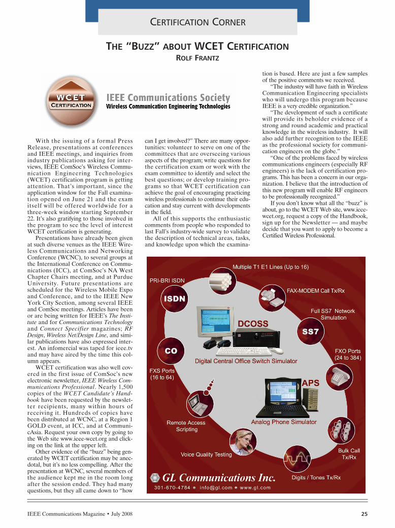
With the issuing of a formal PressRelease, presentations at conferencesand IEEE meetings, and inquiries fromindustry publications asking for inter-views, IEEE ComSoc’s Wireless Commu-nication Engineering Technologies(WCET) certification program is gettingattention. That’s important, since theapplication window for the Fall examina-tion opened on June 21 and the examitself will be offered worldwide for athree-week window starting September22. It’s also gratifying to those involved inthe program to see the level of interestWCET certification is generating.
Presentations have already been givenat such diverse venues as the IEEE Wire-less Communications and NetworkingConference (WCNC), to several groups atthe International Conference on Commu-nications (ICC), at ComSoc’s NA WestChapter Chairs meeting, and at PurdueUniversity. Future presentations arescheduled for the Wireless Mobile Expoand Conference, and to the IEEE NewYork City Section, among several IEEEand ComSoc meetings. Articles have beenor are being written for IEEE’s The Insti-tute and for Communications Technologyand Connect Specifier magazines; RFDesign, Wireless Net/Design Line, and simi-lar publications have also expressed inter-est. An infomercial was taped for ieee.tvand may have aired by the time this col-umn appears.
WCET certification was also well cov-ered in the first issue of ComSoc’s newelectronic newsletter, IEEE Wireless Com-munications Professional. Nearly 1,500copies of the WCET Candidate’s Hand-book have been requested by the newslet-ter recipients, many within hours ofreceiving it. Hundreds of copies havebeen distributed at WCNC, at a Region 1GOLD event, at ICC, and at Communi-cAsia. Request your own copy by going tothe Web site www.ieee-wcet.org and click-ing on the link at the upper left.
Other evidence of the “buzz” being gen-erated by WCET certification may be anec-dotal, but it’s no less compelling. After thepresentation at WCNC, several members ofthe audience kept me in the room longafter the session ended. They had manyquestions, but they all came down to “how
can I get involved?” There are many oppor-tunities: volunteer to serve on one of thecommittees that are overseeing variousaspects of the program; write questions forthe certification exam or work with theexam committee to identify and select thebest questions; or develop training pro-grams so that WCET certification canachieve the goal of encouraging practicingwireless professionals to continue their edu-cation and stay current with developmentsin the field.
All of this supports the enthusiasticcomments from people who responded tolast Fall’s industry-wide survey to validatethe description of technical areas, tasks,and knowledge upon which the examina-
tion is based. Here are just a few samplesof the positive comments we received.
“The industry will have faith in WirelessCommunication Engineering specialistswho will undergo this program becauseIEEE is a very credible organization.”
“The development of such a certificatewill provide its beholder evidence of astrong and round academic and practicalknowledge in the wireless industry. It willalso add further recognition to the IEEEas the professional society for communi-cation engineers on the globe.”
“One of the problems faced by wirelesscommunications engineers (especially RFengineers) is the lack of certification pro-grams. This has been a concern in our orga-nization. I believe that the introduction ofthis new program will enable RF engineersto be professionally recognized.”
If you don’t know what all the “buzz” isabout, go to the WCET Web site, www.ieee-wcet.org, request a copy of the Handbook,sign up for the Newsletter — and maybedecide that you want to apply to become aCertified Wireless Professional.
THE “BUZZ” ABOUT WCET CERTIFICATIONROLF FRANTZ
LYT-CERTIFICATION-July 6/18/08 1:39 PM Page 25

28 IEEE Communications Magazine • July 2008
NEW PRODUCTS
LTE TEST SOLUTIONAnritsu Company
Anritsu has introduced three softwarepackages for its MS269XA Signal Ana-lyzer Series that create a powerful tool tosupport fast and easy evaluation of 3GPPLTE uplink and downlink signals. Takingfull advantage of the MS269 XA Series’total level and modulaion accuracy overthe bandwidth from 50 Hz to 6 GHz, theMX269020A LTE Downlink Measure-ment Software, MX269021A LTE UplinkMeasurement Software, andMX269908A LTE IQproducer helpensure compliance of LTE devices.
The MX269020A and MX269021Asoftware measure the transmit charac-teristics of 3GPP LTE Frequency Divi-sion Duplex (FDD)-compliant signals.Both software packages are designedwith special features, such as a slidingFast Fourier Transform (FFT) analysiswindow to provide measurement flexi-bility and a user-defined reference sig-nal. 3GPP LTE compliant waveformpattern files can be generated by theMX269908A. the patterns can then beoutput as RF signals from theMS269XA’s optional signal generator
to test RF receiver characteristics, aswell as to perform transmitter andreceiver evaluations. User-defined ref-erence signals can be created and incor-porated into the waveform iles fortransmission, as well as loaded in to theMS269XA Series for quick and accu-rate analysis. www.anritsu.com
OPTISYSTEM 7.0 ADDRESSESDESIGN CHALLENGES INOCDMA-PONOptiwave Systems Inc.
OptiSystem 7.0 from Optiwave Systemsis the latest version of its optical communi-cation system design suite. This majorrelease delivers a number of exciting newfeatures, which facilitate the simulationand design of emerging optical networktechnologies. This includes Optical CodeDivision Multiple Access for Passive Opti-cal Networks (OCDMA-PON), a frame-work which provides cost-effectivetransport, provisioning, and protection ofmultiprotocol network traffic.
In addition to new functionality,OptiSystem is now available in a newlydesigned 64-bit edition, addressing com-
plex computing simulations requiring asignificant amount of memory. Theoptimized code structure results inimproved computing performance andefficient memory utilization. Users arenow capable of running large scale realworld simulations, without the memoryrestrictions limited to 32-bit operatingsystems. OptiSystem 7.0 includes a vari-ety of new component models, includ-ing reflective semiconductor opticalamplifiers (RSOA) for wavelength divi-sion multiplexed passive optical net-work (WDM-PON) architectures.
www.optiwave.com
HSPA+ TEST SOLUTION FOR3GPP-COMPLIANT COMPONENTSAgilent Technologies Inc.
Agilent’ Vector Signal Analysis (VSA)software now offers HSPA+ analysiscapability, making it the only commercial-ly available HSPA+ signal analysis testsolution in the industry. In addition, Agi-lent's Signal Studio software for 3GPP W-CDMA simplifies creation of the HSPA+higher order modulation used in testing3GPP-compliant components for base ormobile stations. Together, these software
LYT-PRODUCTS-JULY 6/18/08 3:29 PM Page 28

tools provide today's R&D engineers withthe data they require to successfully trou-bleshoot PHY layer signal problems.
Agilent's 89600 Series VSA softwareprovides a powerful R&D tool for gain-ing greater insight into the signalsemployed in today's emerging cellularand wireless networking formats such asHSPA, LTE and WiMAX(tm). Thenewly added HSPA+ functionalitiesinclude 64 QAM analysis for the down-link and 4-PAM (16QAM) analysis foruplink. Also supported are a predefinedsetup for Test Model 6 for the downlink,Code Domain Power, Composite EVM,Symbol EVM and more. Engineers canuse the software to make HSPA+ mea-surements anywhere in the block dia-gram, from baseband to antenna, ondigitized or analog signals -- both uplinkand downlink. In addition, the softwareworks with more than 30 Agilent instru-ments, using spectrum and signal analyz-ers, oscilloscopes and logic analyzers.
The Agilent N7600B Signal Studiosoftware provides a flexible, applica-tion-specific solution for generatingarbitrary waveform signals that complywith the 3GPP HSPA+ PHY layerspecification. www.agilent.com
IEEE Communications Magazine • July 2008 29
NEW PRODUCTS
WIRELESS LAN PROCESSOR MODULES WITH CONFIGURATIONOPTIONS FOR SIMPLE WI-FI TRANSITIONLaird Technologies, Inc.
Laird Technologies is offering a new range of 802.11 wireless LAN processormodules that provide a wide range of AT commands and Web configuration tomake the Wi-Fi transition simple for M2M (machine-to-machine) designers.
M2M is widely seen as the next growth area in technology, providing remotemonitoring solutions for many sectors of society. Traditionally, most M2M imple-mentations used cellular modems to provide communication; however, thesecarry a high cost and make them difficult to justify for many M2M applications.The growing popularity of Wi-Fi in-home networks, hotspots, and public Muni-Fiinstallations now enables a new era of M2M using the wireless network to trans-mit data back over the internet to monitor applications.
Because configuring devices to connect to a wireless access point is very dif-ferent from connecting to a cellular modem (a barrier to early adoption), LairdTechnologies has developed a range of wireless modules with innovative configu-ration options that address this issue and build on designers’ existing experience.
In order to cater to cellular and fixed-line modem designers, comprehensive AT com-mands are provided that allow configuration and connection to wireless access points.Another unique feature is the ability for designers to further customize and integrateadditional commands that provide the flexibility to emulate other connection devices.
Web and internet designers have the option of a Web configuration page thatallows Laird Technologies’ WLAN modules to be configured in situ. The config-uration pages include useful features such as a local scan of access points. Themodules are shipped pre-loaded with a standard configuration page that can befully customized or extended by designers. These WLAN modules also include anadvanced scripting engine, allowing users to write programmable scripts to con-trol the wireless behavior. www.lairdtech.com/wireless
LYT-PRODUCTS-JULY 6/18/08 1:38 PM Page 29

IEEE Communications Magazine • July 200830
n recent years, pursuing open global standards hasbecome a critical element of the business and product
development strategies that are used to bring new commu-nications technologies to market. High-quality consensusstandards contribute to cost savings, expand market poten-tial, and can extend the useful lifetime of a technology. Inaddition, international standards can help reduce the nega-tive business impact of complex country-oriented regulato-ry requirements. The value proposition for a company or agroup of companies in creating an international standardcan be immense. This is seen in how we are often able toobserve the intense effort expended by companies as theyorient their approach to product development, from initialresearch and intellectual property creation to branding andproduct marketing, around the creation of a globallyaccepted, widely adopted technical standard.
Given that ubiquity and interoperability are the key fac-tors in the adoption of communications and networkingstandards, such standards need to come from a technicallycredible source. In this respect, IEEE has few peers whenit comes to offering standards of the highest possible tech-nical quality because of the deep reservoir of intellectualand technical talent among its membership and constituen-cies. Global industry has long recognized the value propo-sition IEEE offers in the standardization arena. A globalscientific organization with a mission to serve its member-ship, industry, and the public good, IEEE brings to thestandardization process a sophisticated ecosystem thatenables high-quality technical standards to be created in afair, open, and timely fashion.
For networking and communications, the bedrock ofIEEE expertise lies with the Communications Society andits technical committees (TCs). The TCs serve as foci forthe accumulation of new technical knowledge and its dis-persion among ComSoc members. When this knowledgematures and is appropriate for standardization, the Com-Soc Standards Board serves as a vehicle to get standardiza-tion within the IEEE framework started. Across IEEE,technical societies, such as ComSoc and the ComputerSociety, each technical society’s TCs, the IEEE StandardsAssociation (IEEE-SA), and the cross-society standards
coordinating committees (SCCs) interact in order to bothdevelop world-class technical content and channel thatcontent into the standardization process when appropriate.This feature topic illustrates that process in the context ofa variety of communications- and networking-related tech-nologies.
In this issue, the guest editors have selected for presen-tation six articles.
The first article in this series, “The IEEE StandardsAssociation and Its Ecosystem” by F. D. Wright, providesa look into the IEEE Standards Association (IEEE-SA).Formed in 1998, the IEEE-SA assumed the responsibilitiespreviously managed by the IEEE Standards Board. TheIEEE-SA provides a standards program that serves theglobal needs of industry, government, and the public. Italso works to ensure the effectiveness and high visibility ofthis standards program both within the IEEE and through-out the global community. The article provides a thoroughoverview of the IEEE-SA, including:• Its open consensus-oriented process• Its niche in the standards development ecosystem• Its individual and entity models of standards develop-
ment• Its international presence and status
Any discussion of communications- and networking-related standards activities within the IEEE would beincomplete without a consideration of the work of theIEEE Local Area Network/Metropolitan Area NetworkStandards Committee (a.k.a. IEEE 802), and this issueincludes several articles that address the activities of thisimportant standards developing committee.
In their article “Development of 10 G/s EPON in IEEE802.3,” Hajduczenia et al. discuss the recent process bywhich IEEE 802.3 encompassed Ethernet-compatible pas-sive optical networks. In this work we can see the successof a standardization approach that has extended Ethernetthrough three orders of magnitude of improvement in bitrate.
IEEE 802.11 brought standardization to the wirelessnetworking world. In the article “IEEE 802.11n Develop-ment: History, Process, and Technology,” Eldad Perahia
GUEST EDITORIAL
I
Alexander D. Gelman Steven Mills Robert S. Fish
IEEE STANDARDS IN COMMUNICATIONS AND NETWORKING
LYT-GUESTEDIT-Gelman 6/18/08 3:33 PM Page 30

IEEE Communications Magazine • July 2008 31
provides a fascinating backstage look at the process ofdeveloping the 802.11n amendment that addressed theneed for a high-throughput (>100 Mb/s) version of thestandard. The author delves into the technical and market-driven forces that were brought to bear on the standardiza-tion process and how the group managed to drive toconsensus a standard that is now being brought to market.
In “802.20: Mobile Broadband Wireless Access for the21st Century,” Arnie Greenspan et al. detail a relativelynew project, “Local and Metropolitan Area Networks —Standard Air Interface for Mobile Broadband WirelessAccess Systems Supporting Vehicular Mobility — Physicaland Media Access Control Layer Specification.” The pur-pose of this project is to enable worldwide deployment ofcost-effective, spectrum-efficient, always on, and interoper-able multivendor mobile broadband wireless access net-works. Uniquely, it will support vehicular mobility up to250 km/h in a metropolitan area network environmentusing an efficient packet-based air interface optimized forIP. When complete, this standard will specify the physicaland media access control layers of an air interface operat-ing in licensed bands below 3.5 GHz. In the article theauthors offer an overview of the architecture and technolo-gies used to satisfy these requirements.
In our next article we see how the cross-discipline struc-ture of IEEE can facilitate the emergence of a standardthat uses the traditional electrical power infrastructure as amedium for communications and networking. In “RecentDevelopments in the Standardization of Power Line Com-munications within the IEEE,” Galli et al. describe theactivities of the IEEE P1901 working group. This group,sponsored by ComSoc as an entity standardization effort,is working toward building a standard for networking overboth access and in-home power lines. This article describeswork in progress. It offers insights into the technical issuesaddressed by the working group and the creative processof building a consensus.
Our final article, “IEEE Standards Supporting Cogni-tive Radio and Networks, Dynamic Spectrum Access, andCoexistence” by Sherman et al., discusses IEEE standard-ization activities that are related to cognitive radio tech-nologies. Cognitive radio standardization is representedby the Dynamic Spectrum Access Networks (DYSPAN)Standards Coordinating Committee (SCC41) projects andthe IEEE 802.22 Working Group. The authors present anoverview of these activities and point to other IEEE stan-dards that are relevant to cognitive radio.
In summary, we think that this collection of articlesshows the vitality and breadth of communications and net-working standardization within IEEE as well as the com-mercial relevance of these activities.
BIOGRAPHIESALEXANDER D. GELMAN [SM] ([email protected]) received his M.E. and Ph.D. inelectrical engineering from the City University of New York. Currently he isthe chief technical officer of NETovations, LLC, a networking research con-sulting group. From 1998 to 2007 he worked as chief scientist at the Pana-sonic Princeton Laboratory, managing research programs in consumercommunications and networking. During 1984–1998 he was with Bellcore,lately as director of Residential Internet Access Architectures Research. Hehas over 30 years of industrial research background. He has numerous pub-lications and several patents. He pioneered DSL-based broadband accessand holds some of the earliest DSL system patents, for example, on thexDSL access router. He has served on many IEEE and ComSoc committees,publications, and conferences (e.g., on inaugural steering committees forIEEE Transactions on Multimedia and ICME). He cofounded the ConsumerCommunications and Networking Conference (CCNC), founded the ComSocStandards Board, and initiated several standardization projects. He is pastchair of the Multimedia Communications Technical Committee, served threeterms as ComSoc Vice President, and served as member at large on theBoard of Governors of the IEEE Standards Association. Currently He is Com-Soc’s Director of Standards and a member of the IEEE Standards Board. Heis the 2006 winner of IEEE ComSoc´s Donald W. McLellan Meritorious Ser-vice Award.
STEVEN MILLS [SM] ([email protected]) has worked at Hewlett-Packard for26 years in research and development of products for the computer andtelecommunications industries. He is currently senior architect in the Indus-try Standards Program Office, where he leads HP’s participation in industryconsortia and standards development organizations. Prior to moving intothe Standards Program Office, he managed an R&D team responsible forthe development of hardware, operating systems, and middleware of con-tinuously available platforms for use in the telecommunications industry.He also spent several years as manager of a research team composed ofbusiness and technology professionals performing mid-range market andtechnology research. He has actively contributed to the governance of stan-dards development activities at the IEEE since 2001. He currently serves asChair of the IEEE Standards Association Corporate Advisory Group, Past-Chair of the IEEE-SA Standards Board, Chair of the IEEE Standards Educa-tion Committee, and a member of the IEEE-SA Standards Board PatentCommittee, the IEEE-SA Board of Governors, and the IEEE EducationalActivities Board.
ROBERT S. FISH [SM] ([email protected]) received his Ph.D from Stanford Uni-versity in 1981. Currently, he is chief product officer and senior vice presi-dent of Mformation Technologies, Inc., a company that specializes inmobile device management. From 1997 through 2006 he was vice presi-dent and managing director of the Panasonic Digital Networking Laborato-ries with laboratories in Princeton, San Jose, Santa Barbara, and San Diego.During this time, his laboratories pioneered many concepts in network-con-nected consumer electronics. Prior to that, he was executive director ofMultimedia Communications Research at Bellcore after starting his career atBell Laboratories. He is the holder of eight U.S. patents and has numerouspublications. Within ComSoc he is Secretary of the ComSoc StandardsBoard and Chair of the GLOBECOM/ICC Management and Strategy (GIMS)Committee. He co-founded IEEE CCNC and serves as Chair of the CCNCsteering committee. He was a founding member of the IEEE-SA CorporateAdvisory Group. In 2007 he received the Distinguished Service Award fromComSoc’s Multimedia Technical Committee.
GUEST EDITORIAL
LYT-GUESTEDIT-Gelman 6/18/08 1:35 PM Page 31

IEEE Communications Magazine • July 200832 0163-6804/08/$25.00 © 2008 IEEE
INTRODUCTION
“The nice thing about standards is that there areso many of them to choose from.”
–Andrew S. Tanenbaum, professor, author, andIEEE Fellow
From the perspective of effective communica-tions and on its surface, Mr. Tanenbaum’s state-ment runs counter to the requirements of aneffective communications system because with-out agreed-upon standards, meaningful commu-nications between two devices will not occur.However, because of varying media, signaling,throughput, new technologies, and other require-ments, new communications standards often arerequired to meet the wide range of communica-tions requirements in the current and everexpanding, global society. To that end, one ofthe implicit goals of the IEEE Standards Associ-ation (IEEE-SA) is to facilitate the creation ofappropriate standards, to select the best of those
technologies considered, and to enable everimproving communications between and among agrowing set of types and classes of devices. Thepurpose of this article is to describe the organi-zation of the IEEE-SA, how it fits into the struc-ture of the IEEE, and the processes by which itdevelops standards.
The IEEE-SA develops internationally imple-mented standards in the fields of interest of theCommunications Society, as well as of many ofthe other societies of the IEEE. It does this witha process accredited by the American NationalStandards Institute (ANSI) and guided by fivecore principles — due process, consensus, open-ness, balance, and the right of appeal. Note thatthe World Trade Organization’s Third TriennialReview of the Operation and Implementation ofthe Agreement on Technical Barriers to Tradeincludes many of these same core principles asthe requisites for recognized international stan-dards organizations to use in the development oftheir standards.
These five core principles are implemented ina number of policy and procedure documents ofthe IEEE societies, working groups, and sponsorgroups that develop standards. Standing abovethose documents are the policy and proceduresof the IEEE-SA Standards Board (SASB) [1],the IEEE-SA [2], and the IEEE [3] itself, respec-tively, including the IEEE Code of Ethics [4] thatgoverns the professional behavior of all IEEEmembers. The policies and procedures of theStandards Board and the SA prescribe in detailhow standards will be developed including:• Standards Association governance• Sponsor duties• Sponsor balloting procedures and require-
ments for approval• Appeal procedures• IEEE-SA patent policy
Publishing these procedures and then follow-ing them is fundamental to meeting the due pro-cess objective of the core principles of theStandard Association.
The IEEE-SA is a major organizational unitof the IEEE and as such, the President of theStandards Association sits on the Board ofDirectors of the IEEE. It is not incorporatedseparately but rather is an integral part of theInstitute.
ABSTRACT
This article describes IEEE Standards Associ-ations and the ecosystem that surrounds itincluding: • The core principles of the Standards Associ-
ation;• The history of the Standards Association
including the formation of the IndustryStandards and Technology Organization(ISTO) and the Corporate Advisory Group(CAG);
• How societies and other groups within theInstitutes sponsor the development of stan-dards;
• The process by which IEEE standards pro-jects are initiated, developed and approved;
• The Intellectual Property Rights (IPR) Poli-cy of the Standards Association and thepolicies and procedures of the variousgroup involved in standards development.
• The development of consensus and the pro-cess used to appeal decisions made duringstandards development;
• The Standards Association's relationshipwith other standards developing organiza-tions including ISO, IEC and ITU.
IEEE STANDARDS IN COMMUNICATIONSAND NETWORKING
F. D. (Don) Wright, Lexmark International
The IEEE Standards Association and ItsEcosystem
WRIGHT LAYOUT 6/18/08 1:24 PM Page 32
IEEE Communications Magazine • July 2008 33
Responsibility for the Standards Associa-tion has been delegated by the IEEE Board ofDirectors to the Standards Association Boardof Governors (BoG). This board, consisting ofapproximately 14 voting members, deals large-ly with matters of strategy, pol icy , andfinances. Standing committees of the Board ofGovernors include the Standards Board andthe Corporate Advisory Group (CAG.) TheStandards Board manages the entire processof initiating standards projects and approvingthe draft standards developed by the sponsorcommittees. The CAG manages the CorporateProgram and its activities and also can act asa sponsor.
Many IEEE societies develop standards with-in the framework of the Standards Association.Table 1 contains a partial list of the societiesthat are developing standards and some of thesponsor committees.
In addition, the SASB has created a numberof standards coordinating committees (SCCs)reporting directly to the SASB to deal with situ-ations where standardization spans the fields ofinterest of multiple societies. Some of theseSCCs include:• SCC14 — Quantities, Units, and Letter
Symbols• SCC22 — Power Quality• SCC36 — Utility Communications• SCC38 — Voting System Engineering• SCC39 — International Committee on Elec-
tromagnetic Safety• SCC41 — Dynamic Spectrum Access Net-
worksThe societies and the SCCs cover a width
swath of the communications, computer, power,and related electro-technology fields; however,there are always new opportunities emerging,and the Standards Association is evolving touncover and meet the requirements of theseopportunities.
For over 115 years, the standards develop-ment process of the IEEE has been based on anindividual approach, where any individual mate-rially interested or affected may chose to partici-pate in the creation of a standard and theballoting. In the last decade, the IEEE took twomajor steps to broaden its standards develop-ment methodology.
First, in 1999 it created the IEEE IndustryStandards and Technology Organization (IEEE-ISTO) [5], which enables like-minded companiesto join forces into industry groups or consortiato create, disseminate, and market standards.The ISTO is designed to enable this formationand creation to occur quickly and in a form thatmeets the unique requirements of the formingcompanies. Although closely aligned with theIEEE, the IEEE-ISTO is a separate, self-gov-erned, and non-profit organization incorporatedin the state of Delaware as a 501(c)(6) corpora-tion under the U.S. tax code. The IEEE-ISTOlicenses the IEEE name and makes annual roy-alty payments to the IEEE for that license. Theprocesses used by the IEEE-ISTO to developstandards are tuned to the requirements of eachof its programs, but they are not ANSI-accredit-ed. Current programs of the IEEE-ISTO include,among others, the Liberty Alliance, the
VoiceXML Forum, and the Open Mobile Ter-minal Platform (OMTP).
Second, in 2003 and 2004, work began on cre-ating a functional CAG to govern the activitiesof the corporate membership program originallyauthorized by the IEEE Board of Directors in1998. The Corporate Program allows companiesand other organizations from around the worldto join and participate in the development ofIEEE standards under a sliding fee schedulebased on the size and type of the organization.The CAG may serve as a sponsor within theIEEE-SA, developing industry-relevant stan-dards using an accredited process under whichmembers of the Corporate Program participatedirectly under a [[one company, one vote]] model(also known as the entity model) for both thestandards development phase and the final bal-loting phase.
Within the Corporate Program, a number ofnew standards were created (e.g., IEEE 1625™,Standard for Rechargeable Batteries for MobileComputers), and others are currently underdevelopment including several draft standardsrelated to power line communications or broad-band over power lines. In most cases, the CAGpartners with one of the society sponsor commit-tees in managing standards being developedunder the entity model. For example, IEEE 1625was sponsored by the Stationary Batteries Com-mittee of the Power Engineering Society, and allthe participants were corporate members of theStandards Association.
At a high level, the IEEE-SA standards devel-opment process is relatively straightforward. Astandard starts with an idea from a person or agroup often already associated with the Stan-dards Association or one of the IEEE societies;however, many times the idea arises from else-where including outside the Institute. With theexception of the creation of the draft standard,this process, as described below, is largely man-aged by the SASB (Fig. 1).
In some groups, the process of proposing anew standards project to the SASB is relativelyinformal whereas in others, such as the IEEE802 ‚ LAN/MAN Standards Committee, it ismuch more formal and rigorous. For example,before a project authorization request (PAR)can be approved for submission to the SASB,the 802 Standards Committee asks the proposerof a new standards project to address the follow-ing five criteria to the satisfaction of the 802Executive Committee. Quoting from the 802Policy and Procedures, these five criteria are:1 Broad market potential: A standards pro-
ject authorized by IEEE 802 shall have abroad market potential. Specifically, it shallhave the potential for:–Broad sets of applicability.–Multiple vendors and numerous users.–Balanced costs (LAN versus attached sta-tions).
2 Compatibility: IEEE 802 defines a family ofstandards. All standards shall be in confor-mance with the IEEE 802.1 Architecture,Management, and Interworking documentsas follows: 802. Overview and Architecture,802.1D, 802.1Q, and parts of 802.1f. If anyvariances in conformance emerge, they
A standard starts
with an idea from a
person or a group
often already
associated with the
Standards
Association or one of
the IEEE societies;
however, many
times the idea arises
from elsewhere
including outside
the Institute.
WRIGHT LAYOUT 6/18/08 1:24 PM Page 33

IEEE Communications Magazine • July 200834
n Table 1. IEEE Societies and sponsor committees.
Society Sponsor committees
Aerospace and Electronics Systems Society
Electrical Power/Energy Systems
Gyro Accelerometer
Guidance & Control Systems
Radar Systems
Ultrawideband Radar
Broadcast Technology Society
Communications Society
Personal Communications
ComSoc Standards Board
Transmission Access & Optical Systems
Transmission Systems
Computer Society
Design Automation
Foundation for Intelligent Physical Agents
Information Assurance
Local and Metropolitan Area Networks (802)
Learning Technology
Microprocessor Standards Committee
Portable Applications (POSIX)
Software & Systems Engineering Standards Committee
Standards Activities Board
Simulation Interoperability Standards Organization
Storage Systems
Test Technology
Electromagnetic Compatibility Society
Engineering in Medicine and Biology Society
Industrial Applications Society
Cement Industry
Energy Systems
Industrial & Commercial Power Systems
Petroleum & Chemical Industry
Power Systems Engineering
continued on next page...
In some groups, the
process of proposing
a new standards
project to the SASB
is relatively informal
whereas in others,
such as the
IEEE 802‚ LAN/MAN
Standards
Committee, it is
much more formal
and rigorous.
WRIGHT LAYOUT 6/18/08 1:24 PM Page 34

IEEE Communications Magazine • July 2008 35
n Table 1. continued
Society Sponsor committees
Instrumentation and MeasurementSociety
Automated Test Systems and Instrumentation
TC11 — SCC20 (ATLAS) Coordination
Connectors in Measurements
DC-LF Measurement
Emerging Technologies in Measurements
Frequency and Time
High Frequency Measurement
Sensor Technology
Measurement Precision, Sensitivity and Noise
Waveform Generation Measurement and Analysis
Power Electronics Society
Power & Engineering Society
Energy Development & Power Generation
Electric Machinery
Insulated Conductors
Nuclear Power Engineering
Power System Analysis, Computing, and Economics Committee
Power System Communications
Power System Instrumentation and Measurements
Power System Relaying
Stationary Batteries Committee
Surge Protective Devices/High Voltage
Surge Protective Devices/Low Voltage
Substations
Switchgear
Transmission and Distribution
Transformers
Vehicular Technology Society
Intelligent Transportation Systems
Land Transportation
Rail Transit
The IEEE patent
policy is consistent
with the ANSI patent
policy and as such is,
at its core, similar to
the patent policy of
many other
standards
development
organizations
including the ISO,
the IEC, and the ITU.
WRIGHT LAYOUT 6/18/08 1:24 PM Page 35

IEEE Communications Magazine • July 200836
shall be thoroughly disclosed and reviewedwith 802.Each standard in the IEEE 802 family ofstandards shall include a definition of man-aged objects that are compatible with sys-tems management standards.
3 Distinct identity: Each IEEE 802 standardshall have a distinct identity. To achievethis, each authorized project shall be:–Substantially different from other IEEE802 standards.–A unique solution to the problem (not twosolutions to a problem).–Easy for the document reader to select therelevant specification.
4 Technical feasibility: For a project to beauthorized, it must show its technical feasi-bility. At a minimum, the proposed projectshall show:–Demonstrated system feasibility.–Proven technology; reasonable testing.–Confidence in reliability.
5 Economic feasibility: For a project to beauthorized, it must show economic feasibili-ty (so far as can reasonably be estimated)for its intended applications. At a mini-mum, the proposed project must show:–Known cost factors; reliable data.–Reasonable cost for performance.–Consideration of installation costsTo facilitate its operation, the SASB has six
standing committees. These committees eachhave a unique role in managing the standardsdevelopment process:• New Standards Committee (NesCom) —
reviews and recommends action on PARs.• Standards Review Committee (RevCom) —
reviews drafts of standards after sponsorballot and if appropriate, recommendsapproval as an IEEE standard.
• Procedures Committee (ProCom) — devel-ops and maintains the policies and proce-dures of the SASB.
• Audit Committee (AudCom) — reviewsand accepts policies and procedures fromthe sponsor committees and the standardscoordinating committees.
• Patent Committee (PatCom) — deals withthe patent policy and other issues relatingto patents in IEEE standards.
• Administrative Committee (AdCom) — actsfor the Standards Board between meetingsand makes recommendations to the Stan-dards Board for its disposition at regularmeetings.The IEEE-SA patent policy [6] was recently
updated by the Patent Committee of the IEEEStandards Board to provide better assuranceas to the availability of patent licenses. SomeIEEE standards contain patented technologythat is necessarily infringed when creating acompliant implementation of that IEEE stan-dard; therefore, a l icense is required. TheIEEE patent policy is consistent with the ANSIpatent policy and as such is, at its core, similarto the patent policy of many other standardsdevelopment organizations including the Inter-national Organization for Standardization(ISO), the International ElectrotechnicalCommission (IEC), and the InternationalTelecommunications Union (ITU). This recentupdate to the IEEE-SA patent policy includesa number of clarifications, enhancements, andother changes compared to the previous poli-cy. Among these are changes to the policythat:• Consistently define a set of terms used
throughout the policy.• Encourage the optional disclosure of royalty
rates and other license terms of a potential-ly essential patented technology early in thedevelopment of a draft standard.
• Make a patent holder’s assurance irrevoca-ble after it is accepted by the IEEE andrequires the patent holder to give notice ofthe existence of the assurance when trans-ferring ownership of the patent rights.
• Bind the patent holder’s affiliates to theterms of the given assurance, unless thepatent holder explicitly identifies affiliates itdoes not wish to bind.
• Require individuals participating in devel-oping a standard to disclose the name ofthe holder of patents that are potentially
n Figure 1. The standardization process.
Publishstandard
IEEE-SAStandards
Board approvalprocess
Sponsor ballot
Normally a maximum of four years
Idea
Projectapproval
Reaffirm, revise, stabilize, orwithdraw the standard
Develop draftstandard in
working group
At every standards
development
meeting, the chair is
instructed to show a
set of slides that
contain the IEEE
patent policy and
describe the
expected behavior of
the participants with
regard to the patent
policy. These slides
are available on the
IEEE SASB Patent
Committee Web site.
WRIGHT LAYOUT 6/18/08 1:24 PM Page 36

IEEE Communications Magazine • July 2008 37
essential to the standard, based upon per-sonal knowledge.
• Require the submitter of a letter of assur-ance to agree to provide an updated letterof assurance if additional relevant informa-tion becomes known.
• Require that when an entire patent orpatent claim is sold or transferred, the sub-mitter of a letter of assurance for thatpatent or patent claim must agree to notifythe purchaser or transferee of the existenceof an IEEE letter of assurance or explicitlybind the purchaser or transferee to theterms of that letter of assurance.At every standards development meeting, the
chair is instructed to show a set of slides [7] thatcontain the IEEE patent policy and describe theexpected behavior of the participants with regardto the patent policy. These slides are availableon the IEEE SASB Patent Committee Web site.In addition to the patent policy, these slides alsocontain instructions to the working group mem-bers concerning topics and behavior to be avoid-ed. Because participants in standardsdevelopment groups are often competitors in themarketplace, antitrust concerns may arise due totheir cooperation on the standard. By followingthese instructions, the risk of anticompetitivebehavior can be reduced. For example, theseslides remind the participants of the following:• All IEEE-SA standards meetings shall be
conducted in compliance with all applicablelaws, including antitrust and competitionlaws.
• Not to discuss the interpretation, validity, oressentiality of patents or patent claims.
• Not to discuss specific license rates, terms,or conditions.–Relative costs, including licensing costs ofessential patent claims and of differenttechnical approaches may be discussed instandards development meetings.–Technical considerations remain the pri-mary focus.
• Not to discuss fixing product prices, alloca-tion of customers, or dividing sales markets.
• Not to discuss the status or substance ofongoing or threatened litigation.
• Not to be silent if inappropriate topics arediscussed… do formally object.When essential patent claims1 necessarily are
infringed by a compliant implementation of anIEEE standard, the holder of such patent isencouraged early in the standards developmentprocess to provide written assurance to theIEEE that it will license any essential patent toanyone on reasonable and non-discriminatoryrates, terms, and conditions for the purpose ofimplementing the IEEE standard. That assur-ance must be provided on a form [8] created bythe SASB; only the approved form may be used.The IEEE publishes all letters of assurances itreceives and indexes them based on the standardto which they apply. Implementers of IEEEstandards can access this information on theIEEE-SA Web site [9]. The IEEE does not war-rant that this database contains all essentialpatent claims relevant to a standard and makes asimilar disclaimer in the front of every standardit publishes.
The IEEE standards development process isopen to all materially interested parties. Thisdoes not mean that there are no participationrequirements, which often include fees thatmust be met in order to vote; however, suchparticipation requirements must be reasonableand not overly burdensome. Traditionally, theparticipants in IEEE standards developmenthave been individual engineers who apply theirskills and knowledge to create the standard. Inmost cases, these individuals were gainfullyemployed as engineers by companies who alsomight have an interest in the standard. Thisindividual model of standard developmentdownplays the role of the employer in the cre-ation of the standard. With the creation of theCorporate Program and the CAG, the alterna-tive entity model was created, where the inter-ests of the employer or company drive thecreation of the standard.
Each of these models has certain advan-tages and disadvantages. For example, whenusing the individual model and when there aremultiple acceptable technical solutions butcorporate business interests with drasticallydivergent goals , those corporations couldchoose to send large numbers of its employeesto participate in an attempt to “pack the com-mittee” and control voting. If, in this situation,the standard were to be developed under theentity model, regardless of the number ofemployees attending, each company wouldhave only one vote preventing the “pack thecommittee” scenario.
The standards development process oftencan be contentious. There are often valid andstrongly held differences of opinion about thechoice and implementation of a technical solu-tion to a problem being addressed by a stan-dard under development. These technicalopinions often are joined by opinions based oncorporate business issues and considerations, asdescribed previously, which can further enflamethe discussions. As such, the sponsors, theSASB, and even the BoG have very specificappeal procedures in place to deal with issues,both technical and procedural, raised duringthe standards development process. Althoughthe vast majority of standards development pro-jects do not involve appeals at any level, a smallnumber do.
Because the sponsor committees consists ofthe technical experts in the field of standardiza-tion of that sponsor, all appeals based on techni-cal issues must be heard at or below that leveland will not be considered by the SASB or theBoG appeal process. Appeals based on procedu-ral issues must be heard first under the proce-dures of the sponsor committee and may then beappealed to the SASB or higher. Appeals aregenerally heard by a panel of three to five impar-tial members of the body hearing the appeal(i.e., the sponsor, the SASB, or the BoG) withthe assistance of Standards Association staff orlegal counsel if required.
What these policies and procedures cannotprescribe is a methodology for gaining consensusamong the participants. In the IEEE-SA Stan-dards Board Bylaws, clause 2.1 [10], consensus isdefined the following way:
The standards
development process
often can be
contentious. There
are often valid and
strongly held
differences of
opinion about the
choice and
implementation of a
technical solution to
a problem being
addressed by a
standard under
development.
WRIGHT LAYOUT 6/18/08 1:24 PM Page 37

IEEE Communications Magazine • July 200838
Consensus is established when, in the judgmentof the IEEE-SA Standards Board, substantialagreement has been reached by directly and materi-ally affected interest categories. Substantial agree-ment means much more than a simple majority,but not necessarily unanimity. Consensus requiresthat all views and objections be considered, andthat a concerted effort be made toward their reso-lution.
It is often only through the skill and wisdomof an experienced working group chair that con-flict and disagreements are resolved successfully.Offering and accepting compromises is the key-stone of most successful standards developmentprojects.
Toward the end of the standards develop-ment process, after the drafting has been doneby the working group, the sponsor conducts whatis known as a sponsor ballot. A call goes out tothose people who have stated an interest in thesponsor’s field of standardization previously, ask-ing if they would be interested in reading, com-menting on, and balloting the draft standard.(Remember that in the case of the individualmodel, these are people representing them-selves, and in the case of the entity model, theseare companies or other organizations.) The coreprinciple of balance requires that no single inter-est group dominates the sponsor ballot body;therefore, each person responding must identifytheir interest group. The interest groupings varyfrom sponsor to sponsor but often consist of:• Producer• User• General Interest• Consultant• Government/Military• Academia
Assuming no single interest group is 50 per-cent or more of the respondents, those respond-ing affirmatively are enrolled and become theballoting body for that standard. Interest groupsare different from affiliations. Someone’s affilia-tion is commonly their employer, but their inter-est group is much broader. Note that themembers of the working group that developedthe draft standard are not automatically mem-bers of the ballot body; they too must registerand enroll.
Depending on the size and complexity of astandard, a ballot period of typically 30 to 60days then is conducted. The members of the bal-lot body are required to provide specific com-ments about that standard and then vote toeither:• Approve• Approve with comments• Disapprove with or without comments• Abstain
At least 75 percent of the members of theballot body must respond for the ballot to bevalid. For the ballot to pass, at least 75 percentof those responding must vote to approve. Ifthere are any comments, the sponsor mustattempt to respond to those comments. (Notethat disapproving ballots without comments can-not be resolved by the sponsor and do not, ofthemselves, require a recirculation.) If any ofthose responses result in a substantive (i.e., not
editorial) change to the document, the com-ments and the resulting changes must be recircu-lated to all the members of the ballot body for ashort review period and another vote. Duringthis recirculation period, the previous vote by amember of the balloting group is retained unlessthat member explicitly chooses to change it. Ifthere are new comments raised about thechanges, further iterations of the recirculationprocess must occur until 75 percent approval isreached, and no new comments concerning theprevious round of changes are received.
As previously stated, IEEE standards are typi-cally developed by the sponsor committees of theIEEE societies. One of the most well-knownsponsor committees of the IEEE is the IEEE 802LAN/MAN Standards Committee. (Although itcould be argued that local area networks (LAN)are within the fields of interest of the Communi-cations Society, they are also within the fields ofinterest of the Computer Society. As such, theIEEE 802 committee was created by and remainsa sponsor committee of the Computer Society,although many of its members are active partici-pants from the Communications Society.) Thiscommittee has guided the development of stan-dards for personal area, local area, andmetropolitan networks (MAN) for over 25 yearsand has produced more than 50 standards andinnumerable amendments to those standards fos-tering the growth of an industry with annual salesexceeding $25 billion. These standards includesuch well known standards as:• IEEE 802.3 — Carrier sense multiple access
with collision detection (CSMA/CD) accessmethod and physical layer specifications(commonly known as Ethernet)
• IEEE 802.5 — Token ring access methodand physical layer specifications
• IEEE 802.11 — Wireless LAN mediumaccess control (MAC) and physical (PHY)layer specifications (especially amendmentsa, b, and g)Many of these IEEE 802 standards were for-
mally adopted as international standards by theISO/IEC Joint Technical Committee 1 (JTC1).
When appropriate, the IEEE-SA partnerswith other standards developing organizations.Some of these partnerships are relatively short-term or related to a single standard or group ofstandards, for example, the IEEE 802 standards,whereas other partnerships are on-going andbroadly based relationships. Examples of thesebroad, on-going relationships include:• The IEEE-SA maintains a Joint Logo Agree-
ment with the IEC. A number of standardseither were jointly developed or developedby one of the organizations and adopted bythe other and bear the logos and copyrightstatements of both organizations.
• The IEEE-SA and ISO have completed aPartner Standards Development OrganizationAgreement. The PSDO agreement enablesthe joint development of standards by theIEEE and ISO providing an inherent opti-mization in the use of experts and otherresources associated with the developmentof the standards. It also enables fast-track-ing of IEEE standards into ISO and viceversa.
At least 75 percent
of the members of
the ballot body must
respond for the
ballot to be valid.
For the ballot to
pass, at least
75 percent of those
responding must
vote to approve.
If there are any
comments, the
sponsor must
attempt to respond
to those comments.
WRIGHT LAYOUT 6/18/08 1:24 PM Page 38
IEEE Communications Magazine • July 2008 39
• The IEEE-SA is a sector member of theInternational Telecommunications Union atvarious levels (telecommunication [ITU-T],radiocommunication [ITU-R], and develop-ment [ITU-D]) [11]. This enables a closerlevel of cooperation and joint work on awide variety of standards of mutual interest.
• The IEEE is a member of the ExecutiveBoard of the InterNational Committee forInformation Technology Standards(INCITS), where it serves in a number ofroles, including as the secretariat of theUnited States Technical Advisory Group(TAG) to ISO/IEC JTC1/SC7. The field ofinterest of this committee is software engi-neering, which corresponds with the field ofinterest of the Software & Systems Engi-neering Standards Committee of the Com-puter Society. By aligning the standardsdevelopment work in this technical area inthe IEEE with similar work in ISO/IECJTC1, a common library of standards cover-ing software engineering is being created.The IEEE-SA has a staff of over 55 profes-
sionals who:• Support the working groups in developing
standards.• Support the volunteer governance leader-
ship.• Provide IT, marketing, business develop-
ment, financial, and international oversight.• Edit and publish the completed standards.• Develop other supplemental and related
publications, documents, and services.Recently, the IEEE-SA staff developed a set
of Web-based tools (e.g., myBallot™ and myPro-ject™) to assist working groups and sponsors intheir standards development efforts. By usingthese common tools, working groups and spon-sors can focus on the technology of the standardrather than spending time and effort creatingtheir own unique set of tools to assist them in aprocess.
In addition, the IEEE-SA has an active pro-gram to seek and nurture emerging technologiesas candidates for future standardization. This
nurturing process is typically led by IEEE-SAstaff members in partnership with technologyexperts from within the IEEE societies and else-where.
With nearly a thousand active standards andwith hundreds of standards actively under devel-opment, the IEEE offers one of the most robustand technologically complete standards pro-grams in the world today. The convergence oftelecommunications, information technology,and consumer electronics will insure it remainsvibrant and exciting for years to come.
REFERENCES[1] http://standards.ieee.org/guides/bylaws/index.html and
http://standards.ieee.org/guides/opman/index.html[2] http://standards.ieee.org/sa/sa-om-toc.html[3] http://www.ieee.org/portal/cms_docs_iportals/iportals/
aboutus/whatis/Constitution-Bylaws-Policies.pdf[4] http://www.ieee.org/web/membership/ethics/code_
ethics.html[5] http://www.ieee-isto.org[6] IEEE-SA Standards Board Bylaws, clause 6; http://stan-
dards.ieee.org/guides/bylaws/sect6-7.html#6)[7] http://standards.ieee.org/board/pat/pat-slideset.ppt[8] http://standards.ieee.org/board/pat/loa.pdf[9] http://standards.ieee.org/db/patents/index.html[10] http://standards.ieee.org/guides/bylaws/sect1-
3.html#2.1[11] http://www.itu.int/net/home/index.aspx
BIOGRAPHYDON WRIGHT ([email protected]) has a Master’s degree inelectrical engineering (1979) from the University ofLouisville. He is director of standards at Lexmark Interna-tional, a leading developer of printing technology andproducts. He has over 29 years of experience in stan-dards, engineering, hardware and software development,and product marketing. He has worked on the develop-ment and marketing of office printing products for IBMand Lexmark. His extensive leadership roles in IEEE stan-dards work include Chair of the Standards Board, mem-ber of the IEEE-SA Board of Governors, SA Treasurer, anda member of the IEEE Finance committee. He sits on theStandards Activity Board of the Computer Society andchairs the P2600 Hardcopy Security standards committee.He previously chaired the Microprocessor Standards Com-mittee and was a founder and chair of the Printer Work-ing Group (IEEE-ISTO). He is a member of the ANSI andIEEE-ISTO Boards of Directors, and represents Lexmark atseveral other trade organizations, consortia, and stan-dards bodies.
With nearly a
thousand active
standards and with
hundreds of
standards actively
under development,
the IEEE offers one
of the most robust
and technologically
complete standards
programs in the
world today.
WRIGHT LAYOUT 6/18/08 1:24 PM Page 39

IEEE Communications Magazine • July 200840 0163-6804/08/$25.00 © 2008 IEEE
IEEE STANDARDS IN COMMUNICATIONSAND NETWORKING
Marek Hajduczenia, Nokia Siemens Networks, Portugal and University of Coimbra
Henrique J. A. da Silva, University of Coimbra
Paulo P. Monteiro, Nokia Siemens Networks Portugal S. A. and University of Aveiro
Development of 10 Gb/s EPON in IEEE 802.3av
INTRODUCTION
The current effective 1 Gb/s symmetric data ratesupported by the legacy IEEE 802.3-2005 com-pliant Ethernet passive optical networks(EPONs) [2–4] is considered sufficient for thenext one to two years [5], assuming that the cur-rently observed bandwidth demand growth ismaintained [6, 7]. Immediately after the initialcommercial deployments, service providers start-ed looking at ways to increase channel capacity,number of supported customers, and so on byadopting so-called turbo EPON solutions, wherethe downstream channel was operated at thenonstandard data rate of 2.5 Gb/s. However, dueto the proprietary nature of this particular solu-tion, it gained minimum commercial momentum,mainly due to a limited supplier base and lack ofinteroperability between various system integra-tors. When combined with the ever increasingdemand for raw bandwidth in the access net-work, the lack of a cost-effective PON systemwith bandwidth in excess of 1 Gb/s on the mar-ket finally resulted in the preparation of the 10Gb/s EPON Call For Interest, presented duringan IEEE plenary meeting in 2006 [1].
It is expected that the new PON equipment
developed in the said project will follow the pathof tenfold capacity increase at three times theport price so successfully established by Ethernethardware in the past. After a few initial meetingsof the Task Force (TF), it became apparent thatthe future 10 Gb/s EPON equipment must pro-vide a gradual evolution path from the currentlydeployed 1 Gb/s symmetric equipment, allowingin some cases for coexistence of legacy andemerging EPONs on the same PON plant. Thismeans that the emerging next-generation EPONsmust support both symmetric and asymmetricdata rates, allowing for straightforward coexis-tence of various generations of EPON equip-ment on the same PON plant. The gradualevolution from legacy through coexisting towardsymmetric 10 Gb/s EPONs presents a number oftechnical hurdles, discussed below.
The remainder of this article is organized asfollows. We provide a general and very briefoverview of EPON systems, focusing on thedeployment architecture, and upstream anddownstream channel transmission in a point-to-multipoint (P2MP) PON plant. More details canbe found in [2, 4]. We present the technical chal-lenges related to migration to a higher data rateas well as coexistence with legacy systems on thesame PON plant. We conclude the article with abrief summary.
BRIEF OVERVIEW OF1G EPON SYSTEMS
EPON networks are based on a P2MP structure,where the optical line terminal (OLT) located inthe central office (CO) of the local Internet ser-vice provider (ISP) or access network provider(depending on the local regulation/businessmodel) provides connectivity to a number ofsubscriber equipment modules (optical networkunits, ONUs), the location of which depends onthe deployment scenario (Fig. 1).
Several multipoint topologies have been sug-gested for EPONs, including tree, tree-and-branch, ring, and bus [8], while the applicationof 1 × 2 optical tap couplers and 1 × N optical
ABSTRACT
The interest in the evolution of current PONsystems toward high-data-rate systems capable ofproviding a future-proof platform for delivery oftruly subscriber-oriented and personalized triple-play services resulted in the recent kickoff of the10 Gb/s Ethernet PON system standardizationeffort in the IEEE [1]. Ethernet PON hasbecome a network of choice for low-cost sub-scriber-oriented digital service delivery, takingover the market previously dominated by DSLand cable modems. In this article we examinethe current development process of 10 Gb/sEPON systems in more detail, standardized inthe framework of the IEEE 802.3av Task Force,looking at the technical challenges, drivers, andpossible evolution scenarios of the emerginghigh-data-rate access systems..
Marek Hajduczenia andHenrique J. A. da Silvaare with the Institute ofTelecommunications,Department of Electricaland Computer Engineer-ing, University of Coim-bra, Portugal. PauloMonteiro is with the Insti-tute of Telecommunica-tions — Pólo de Aveiro,University of Aveiro, Por-tugal.
HAJDUCZENIA LAYOUT 6/18/08 3:41 PM Page 40

splitters allows for virtually any deploymentarchitecture, thus making the EPON a very flexi-ble system, capable of meeting any requirementsin terms of providing connectivity to end sub-scribers.
DOWNSTREAM TRANSMISSIONIn the downstream direction data frames broad-cast by the OLT pass through a 1 × N passivesplitter-combiner (PSC) or PSC cascade to reachthe ONUs. Each ONU receives part of the trans-mitted downstream signal. The number of con-nected ONUs typically varies between 4 and 64,with 1:16 representing a nominal split ratio spec-ified in the IEEE 802.3 standard, Clause 60. Theupper bound is limited only by the availableoptical power budget and the bandwidth demanddistribution among the connected end users.
The downstream channel properties in thisPON system make it a shared medium network:packets broadcast by the OLT are selectivelyextracted by the destination ONU, which appliessimple packet filtering rules based on medium
access control (MAC) and LLID addresses (seeIEEE 802.3, Clause 65 for details). The down-stream channel operation is best depicted in Fig.2, where packets destined to different end sub-scribers are filtered out by the ONUs from thebroadcast data flow.
UPSTREAM TRANSMISSIONIn the upstream direction (Fig. 3), from theONUs toward the OLT, the EPON operates inmultipoint-to-point (MP2P) mode; thus, the con-nected and active ONU modules transmit theirbuffered packets toward the single receiver mod-ule located in the OLT card. Since the specificPON physical constraints do not allow the ONUsto see any data transmissions originating fromother subscriber modules, the direct implemen-tation of carrier sense multiple access with colli-sion detection (CSMA/CD) is not feasible [9].The resulting connectivity is therefore similar toa point-to-point (P2P) network (actually, it is anMP2P operation mode, to be precise) operatingover a shared optical medium, where centrally
IEEE Communications Magazine • July 2008 41
n Figure 1. Standard EPON deployment with various FFTx scenarios.
LAN switch MDU
ONU
ONU
FTTB solution
FTTH solution
FTTC solutionfor residential areas
ONU
FTTC
Feeder section
Dro
p se
ctio
n
CO of SP
OLT
ONUONU
Optical linkCopper link
Servers/data serversdisk arrays
FTTO solution
PSC
n Figure 2. Downstream channel transmission in an EPON P2MP operation (broadcast) and LLID packetfiltering.
Header Payload FCS
OLT
PSC
Ethernet 802.3 frame
2 3 11
2 3 11 11
2 3 3
LAN/PAN
11
2
ONU1
ONU2
ONU3
3 2
MDUsubscribers
Residentialsubscriber
11
The downstream
channel properties in
this PON system
make it a shared-
medium network:
packets broadcast by
the OLT are
selectively extracted
by the destination
ONU, which
applies simple
packet-filtering rules
based on MAC and
LLID addresses.
HAJDUCZENIA LAYOUT 6/18/08 4:07 PM Page 41
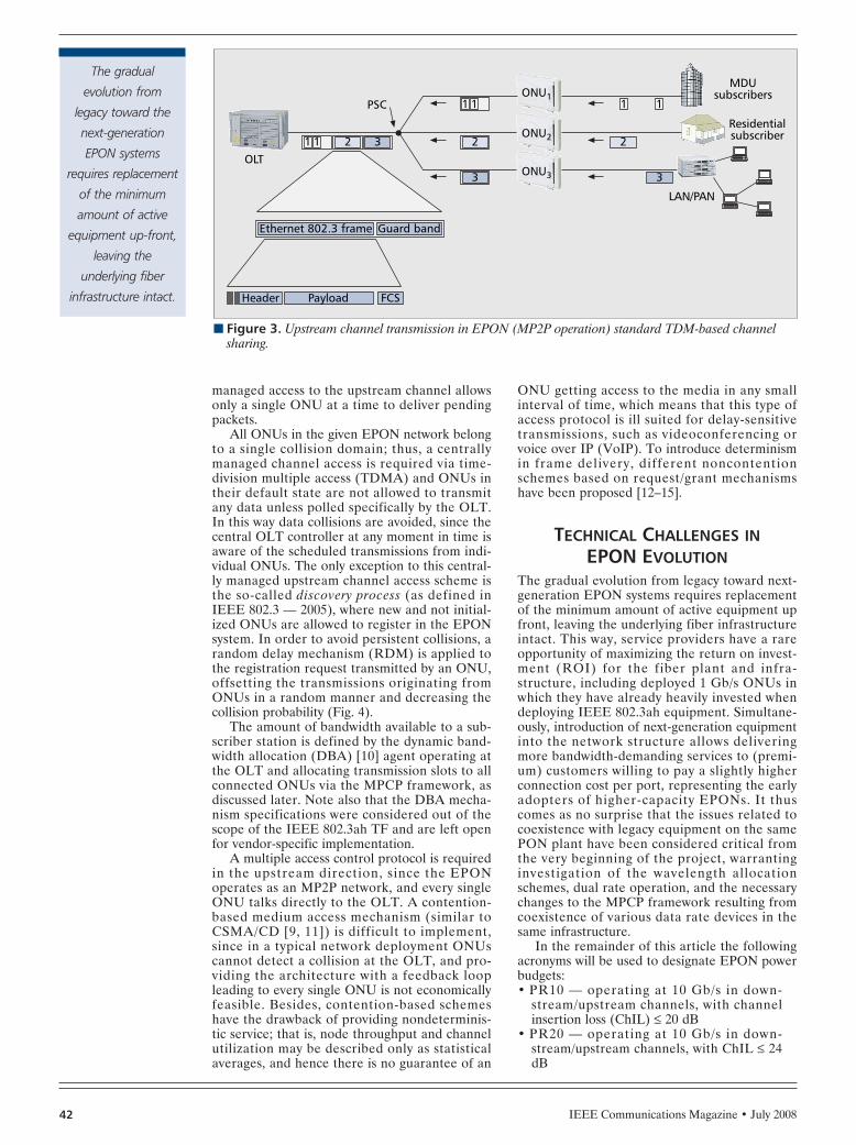
IEEE Communications Magazine • July 200842
managed access to the upstream channel allowsonly a single ONU at a time to deliver pendingpackets.
All ONUs in the given EPON network belongto a single collision domain; thus, a centrallymanaged channel access is required via time-division multiple access (TDMA) and ONUs intheir default state are not allowed to transmitany data unless polled specifically by the OLT.In this way data collisions are avoided, since thecentral OLT controller at any moment in time isaware of the scheduled transmissions from indi-vidual ONUs. The only exception to this central-ly managed upstream channel access scheme isthe so-called discovery process (as defined inIEEE 802.3 — 2005), where new and not initial-ized ONUs are allowed to register in the EPONsystem. In order to avoid persistent collisions, arandom delay mechanism (RDM) is applied tothe registration request transmitted by an ONU,offsetting the transmissions originating fromONUs in a random manner and decreasing thecollision probability (Fig. 4).
The amount of bandwidth available to a sub-scriber station is defined by the dynamic band-width allocation (DBA) [10] agent operating atthe OLT and allocating transmission slots to allconnected ONUs via the MPCP framework, asdiscussed later. Note also that the DBA mecha-nism specifications were considered out of thescope of the IEEE 802.3ah TF and are left openfor vendor-specific implementation.
A multiple access control protocol is requiredin the upstream direction, since the EPONoperates as an MP2P network, and every singleONU talks directly to the OLT. A contention-based medium access mechanism (similar toCSMA/CD [9, 11]) is difficult to implement,since in a typical network deployment ONUscannot detect a collision at the OLT, and pro-viding the architecture with a feedback loopleading to every single ONU is not economicallyfeasible. Besides, contention-based schemeshave the drawback of providing nondeterminis-tic service; that is, node throughput and channelutilization may be described only as statisticalaverages, and hence there is no guarantee of an
ONU getting access to the media in any smallinterval of time, which means that this type ofaccess protocol is ill suited for delay-sensitivetransmissions, such as videoconferencing orvoice over IP (VoIP). To introduce determinismin frame delivery, different noncontentionschemes based on request/grant mechanismshave been proposed [12–15].
TECHNICAL CHALLENGES INEPON EVOLUTION
The gradual evolution from legacy toward next-generation EPON systems requires replacementof the minimum amount of active equipment upfront, leaving the underlying fiber infrastructureintact. This way, service providers have a rareopportunity of maximizing the return on invest-ment (ROI) for the fiber plant and infra-structure, including deployed 1 Gb/s ONUs inwhich they have already heavily invested whendeploying IEEE 802.3ah equipment. Simultane-ously, introduction of next-generation equipmentinto the network structure allows deliveringmore bandwidth-demanding services to (premi-um) customers willing to pay a slightly higherconnection cost per port, representing the earlyadopters of higher-capacity EPONs. It thuscomes as no surprise that the issues related tocoexistence with legacy equipment on the samePON plant have been considered critical fromthe very beginning of the project, warrantinginvestigation of the wavelength allocationschemes, dual rate operation, and the necessarychanges to the MPCP framework resulting fromcoexistence of various data rate devices in thesame infrastructure.
In the remainder of this article the followingacronyms will be used to designate EPON powerbudgets:• PR10 — operating at 10 Gb/s in down-
stream/upstream channels, with channelinsertion loss (ChIL) ≤ 20 dB
• PR20 — operating at 10 Gb/s in down-stream/upstream channels, with ChIL ≤ 24dB
n Figure 3. Upstream channel transmission in EPON (MP2P operation) standard TDM-based channelsharing.
LAN/PAN
MDUsubscribers
Residentialsubscriber
OLT
PSCONU1
ONU2
ONU3
Time slot
Payload
Ethernet 802.3 frame Guard band
Header FCS
2 2 2
3 3
311
1 1 11
The gradual
evolution from
legacy toward the
next-generation
EPON systems
requires replacement
of the minimum
amount of active
equipment up-front,
leaving the
underlying fiber
infrastructure intact.
HAJDUCZENIA LAYOUT 6/18/08 3:41 PM Page 42

IEEE Communications Magazine • July 2008 43
• PR30 — operating at 10 Gb/s in down-stream/upstream channels, with ChIL ≤ 29dB
• PRX10 — operating at 10 Gb/s in down-stream/1 Gb/s upstream channel, with ChIL≤ 20 dB
• PRX20 — operating at 10 Gb/s in down-stream/1 Gb/s upstream channel, with ChIL≤ 24 dB
• PRX30 — operating at 10 Gb/s in down-stream/1 Gb/s upstream channel, with ChIL≤ 29 dB
Additionally, two legacy power budgets shouldbe recalled, as defined in IEEE 802.3, Clause 60:• PX10 — operating at 1 Gb/s in down-
stream/upstream channels, with ChIL ≤ 20dB
• PX20 — operating at 1 Gb/s in down-stream/upstream channels, with ChIL ≤ 24dBThe physical medium dependent (PMD) and
power budget class (PBC) naming nomenclaturefor 10 Gb/s EPONs is different than for legacyEPONs. Due to the fact that one of the symmet-ric data rate PMDs will be shared by two PBCs,the PBC and PMD names are independent:there is no 1:1 mapping between PMDs andPBCs since one of the PMDs can be used in twoPBCs. The PMD naming follows the standardIEEE naming nomenclature. In the case of sym-metric PMDs (10 Gb/s DS and US, where DSand US stand for downstream and upstreamchannel, respectively), a PMD name comprises adata rate indicator with the channel codingmethod (10GBASE, here baseband coding isused), followed by the fiber plant type indicator(P for PON) and the channel encoding indicator(R for 64b/66b), followed by the location andtype of the given PMD (D indicates OLT, Uindicates ONU). This way, a PMD located in theOLT is designated as 10GBASE-PR-D1/2/3
(there are in total three PMD types for OLTside, symmetric PMDs), while an ONU PMD isdesignated as 10GBASE-PR-D1/3 (there areonly two symmetric data rate ONU PMDs, asexplained in [16]). In the case of asymmetricdata rate PMDs, the channel encoding indicatorchanges from R to RX, denoting 64b/66b encod-ing in DS and 8b/10b encoding in US.10GBASE-PRX-D1 is an example of an asym-metric data rate OLT PMD with 20 dB ChIL.
PBC names are shorter and do not closelyfollow the legacy naming nomenclature selectedfor individual links in 1 Gb/s EPONs. Symmetricdata rate PBCs are called simply PR10, PR20,and PR30 for 20, 24, and 29 dB ChIL systems,while the asymmetric data rate PBCs are calledPRX10, PRX20, and PRX30, denoting both thedual rate operation (two different channelencoding schemes) as well as the individualChIL of the given PBC.
WAVELENGTH ALLOCATION FORDOWNSTREAM CHANNEL
Due to the requirement of complete backwardcompatibility, in the emerging IEEE 802.3avspecifications the downstream 1 Gb/s and 10Gb/s data streams will be wavelengh-divisiommultiplexed (WDM), thus creating in effect twoindependent P2MP domains. The guard bandbetween the data channels ought to be suffi-ciently large to allow for their uninterruptedoperation under any temperature conditionsprovided for in the technical specifications of theemerging hardware. The 1 Gb/s downstream linkwill therefore remain centered at 1490 ± 10 nm(in accordance with IEEE 802.3, Clause 60),while the location of the new 10 Gb/s down-stream link depends on the particular powerbudget. The downstream channel for PR10,PR20, PRX10, and PRX20 power budgets will
n Figure 4. Two ONUs with the same round-trip time (RTT): a) collision of registration requests; b) no col-lision of registration messages due to RDM.
Time
(b)(a)
Dis
cove
ryw
indo
w
OLT ONU ONU Time OLT
DiscoveryGATE
DiscoveryGATE
ONU ONU
Dis
cove
ryw
indo
w
Due to the
requirement of
complete backward
compatibility,
in the emerging
IEEE 802.3av
specifications, the
downstream 1 Gb/s
and 10 Gb/s data
streams will be
WDM multiplexed,
thus creating in
effect two
independent
P2MP domains.
HAJDUCZENIA LAYOUT 6/18/08 3:41 PM Page 43

IEEE Communications Magazine • July 200844
be centered at 1590 ± 10 nm, requiring thePON plant to have no deployed optical timedomain reflectometry (OTDR) filters. PONplants equipped with OTDR filters are compati-ble only with the PR30/PRX30 power budgets,where the downstream channel is centered at1577 ± 3 nm, requiring better optical filters aswell as tighter wavelength stability control forthe OLT laser. Figure 5 depicts the allocation ofindividual channels for legacy 1 Gb/s EPONs,emerging 10 Gb/s EPONs, and coexistence of 1and 10 Gb/s EPONs on the same PON plant.
WAVELENGTH ALLOCATION FORUPSTREAM CHANNEL
The upstream channel in any PON system isconsidered more critical than the downstreamone. WDM channel multiplexing in emerging 10Gb/s EPONs is discouraged, mainly due to thehigh sensitivity of commonly utilized directlymodulated lasers (DMLs) to chromatic disper-sion outside of the 1310 nm transmission win-dow. The said window is currently allocated tothe 1 Gb/s data channel, thus leaving apparentlyno space for introduction of a new 10 Gb/s chan-nel, as presented in Fig. 5.
Taking into consideration the fact that theexisting technical specifications for the legacysystems must not be modified in any way, caus-ing potentially some of the deployed equipmentto become standard-incompliant, only dual rateburst mode multiplexing remains a viable option.Therefore, both 1 Gb/s and 10 Gb/s upstreamchannel transmissions will share the same trans-mission window, resulting in legacy systems cen-tered around 1310 ± 50 nm and emergingsystems centered around 1270 ± 10 nm [17].The said data channel will share the very trans-mission window via time-division multiple access(TDMA), where individual bursts sent by differ-ent ONUs may be transmitted at various data
rates. In dynamic detector designs the data rateof the incoming data burst must be determinedprior to switching to the optimum receiver set-tings. In the IEEE stack the PMD layer does nothave a priori knowledge of which data rate willbe used. Therefore, some sort of data rate detec-tor circuit must be utilized. One simple methodwould be to measure the spectral energy contentof the received signal at frequencies well above1.25 GHz (e.g., 2–10 GHz). The 1 Gb/s signalhas very little energy at said frequencies, whilethe 10 Gb/s signal has ample energy there. Otherimplementation-specific methods to control theAPD-TIA speed are also possible, althoughagain the implementation cost may prove pro-hibitive for actual deployment in commercialnetworks.
In such a system configuration, the OLTreceiver will have to be equipped with new func-tionalities. The automatic gain control (AGC)required for burst mode reception, currentlyconsidered as a state-of-the-art technical feat,will be surpassed by a dual rate burst modedevice, which will have not only to ensure properpower level adjustment, but also identify theincoming data rate and perform receiver adjust-ment in such a way thatit maximizes its sensitivi-ty for each particular burst. The approved 10Gb/s upstream channel allocation centered at1270 ± 10 nm clearly reflects compliance withthe ITU-T G.984.5 specifications, allowing forlaser source sharing between IEEE and Interna-tional Telecommunicationi Union — Telecom-munication Standardization Sector (ITU-T)PON systems. However, developing an OLTdual rate burst mode receiver and implementingit in accordance with the IEEE specificationsmay prove to be a nontrivial task, requiring sig-nificant research to be conducyed by electronicsand receiver manufacturers.
MPCP FRAMEWORKDue to the strict backward compatibility require-ment, the bandwidth allocation operation of theemerging 10 Gb/s EPONs will be based on theunderlying MPCP layer, which, in the case ofvarious data rate systems’ coexistence, means aDBA agent in the OLT will be responsible forscheduling not one but two mutually cross-dependent EPON systems, sharing a singleupstream channel. Only minor changes to theMPCP protocol will be introduced, required forcoexistence between legacy and emerging equip-ment on the same PON plant, while leaving themajor part of this framework intact. Since theDBA mechanism was considered out of thescope of IEEE 802.3 in general at the time ofdevelopment of the 1 Gb/s EPON specifications,it is very unlikely that the DBA agent operationand functionality will find its way into futurereleases of IEEE 802.3, leaving its specificationsto be implementation-dependent. This way, thespecifications of the DBA client will be left openfor vendor-specific implementatio in a way simi-lar to what took place in 1 Gb/s EPONs.
In the downstream channel, since the 1 Gb/sand 10 Gb/s data paths will be separated viaWDM multiplexing, the DBA agent can sched-ule the transmission of the GATE MPCPDUs(control messages responsible for allocation of
n Figure 5. Wavelength allocation plans for EPONs with RF video overlay andOTDR service: a) 1 Gb/s EPON; b) 10 Gb/s EPON; c) combined 1 and 10Gb/s EPON.
1260
1360
US
Wavelength[nm]
(a)
1480
1500
DS
1610
1650
OTDR
1550
1560
TV
1260
10G
1G
1360
US
Wavelength[nm]
(c)
1280
1480
1500
DS
1610
1650
OTDR
1550
1560
TV
Wavelength[nm]
(b)
1574
1600
DS
1580
1260
1280
US
1610
1650
OTDR
1550
1560
TV
1G
1574
1600
DS
1580
10G
HAJDUCZENIA LAYOUT 6/18/08 3:41 PM Page 44

IEEE Communications Magazine • July 2008 45
the slots to individual ONUs) independently.However, the upstream channel is more prob-lematic, since the MPCP layer must be aware ofthe data rate used by the given ONU when trans-mitting to the OLT to ensure proper schedulingof the allocated time slot.
DUAL RATE MAC STACKThe asymmetric data rate for the upstream chan-nel results in the inherent need to implementboth IEEE 802.3av and IEEE 802.3ah stacks inthe OLT or ONUs supporting both 10 Gb/s and1 Gb/s data rates, respectively. However, in theupstream channel, the ONU can generate eithera 1 or 10 Gb/s signal, depending on which one oftwo specified transmit paths is implemented inthe system. It would seem that an overly com-plex stack structure would have to be intro-duced, and that both 1 and 10 Gb/s stacks needto be implemented, although the situation is notthat critical. An ONU is blind to any upstreamtransmissions originating from other ONUs inthe system, and it is not required to align tothem in any possible way.
This way, all the complexity of dual rate oper-ation can be concentrated in the OLT circuitry,allowing the ONU to implement only the neces-sary Tx path of the required version of the stackand send the data frames in the allocated slot.For standardization purposes, however, it isassumed that both complete MAC stacks (i.e., 1and 10 Gb/s) are implemented in the ONU, andonly required parts of them are activated. In realcommercial devices, implementation of suchredundant interfaces would not be accepted;thus, only necessary fragments of the stackswould be implemented in hardware.
Figure 6 depicts examples of symmetric andasymmetric ONU implementation and opera-tion. Please note that both presented ONUs caneasily be connected to a single dual rate capableOLT when implementing 1 and 10 Gb/s MACstacks, as depicted in the same figure.
The detailed and conceptual internal struc-ture of a new dual rate OLT is depicted in Fig.7, where the received signal is split at the PMDlayer and injected into two separate physicalcoding sublayer (PCS) stacks, which perform
n Figure 6. Examples of potential ONU implementation with dual rate MAC stack: a) 10/10 Gb/s symmet-ric data rate ONU; b) 10/1 Gb/s asymmetric data rate ONU; c) 1/1 Gb/s symmetric ONU emulating IEEE802.3ah equipment; d) 1/10 Gb/s symmetric IEEE 802.3ah ONU and its support with IEEE 802.3avOLT.
Tx Rx
GM
II
(d) (c) (b) (a)
MAC
RS
PCS
Tx RxG
MII
Tx Rx
GM
II
Tx Rx
XG
MII Tx Rx
GM
II
Tx Rx
XG
MII Tx Rx
GM
II
Tx Rx
XG
MII
Rx Tx
XG
MII
PMA
PMD
PMD
PMA
PCS
RS
MAC
1490 nm1 Gb/s
1310 nm1 Gb/s
1/1 Gb/s ONUIEEE 802.3 ah
1/1 Gb/s ONUIEEE 802.3 av
IEEE 802.3av layers
10/1 Gb/s ONUIEEE 802.3 av
10/10 Gb/s ONUIEEE 802.3 av
1310 nm1 Gb/s
1577/1590 nm10 Gb/s
1577/1590 nm10 Gb/s
1310 nm1 Gb/s
1270 nm10 Gb/s
1490 nm1 Gb/s
MAC 1/1 MAC 10/1
10/10 and 10/1 Gb/s OLTIEEE 802.3av
MAC 10/10
IEEE 802.3ah layers
Developing an OLT
dual rate burst-mode
receiver and
implementing it in
accordance with the
IEEE specifications
may prove to be a
non-trivial task,
requiring significant
research to be
conduced by the
electronics and
receiver
manufacturers.
HAJDUCZENIA LAYOUT 6/18/08 3:41 PM Page 45
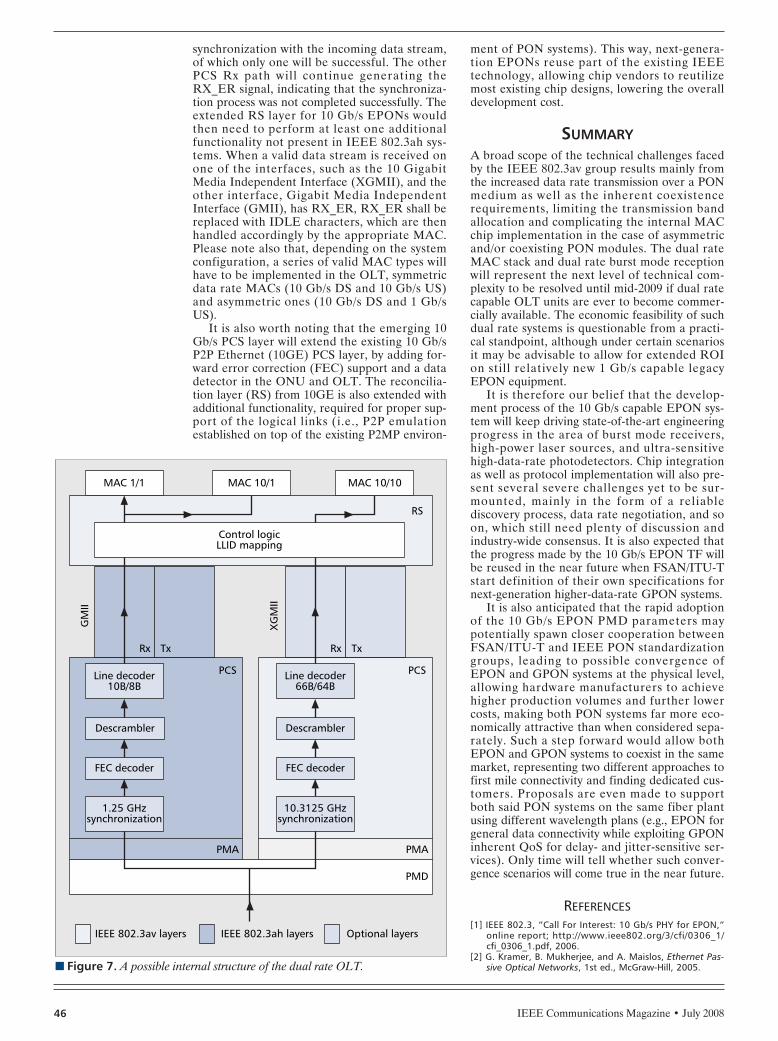
IEEE Communications Magazine • July 200846
synchronization with the incoming data stream,of which only one will be successful. The otherPCS Rx path will continue generating theRX_ER signal, indicating that the synchroniza-tion process was not completed successfully. Theextended RS layer for 10 Gb/s EPONs wouldthen need to perform at least one additionalfunctionality not present in IEEE 802.3ah sys-tems. When a valid data stream is received onone of the interfaces, such as the 10 GigabitMedia Independent Interface (XGMII), and theother interface, Gigabit Media IndependentInterface (GMII), has RX_ER, RX_ER shall bereplaced with IDLE characters, which are thenhandled accordingly by the appropriate MAC.Please note also that, depending on the systemconfiguration, a series of valid MAC types willhave to be implemented in the OLT, symmetricdata rate MACs (10 Gb/s DS and 10 Gb/s US)and asymmetric ones (10 Gb/s DS and 1 Gb/sUS).
It is also worth noting that the emerging 10Gb/s PCS layer will extend the existing 10 Gb/sP2P Ethernet (10GE) PCS layer, by adding for-ward error correction (FEC) support and a datadetector in the ONU and OLT. The reconcilia-tion layer (RS) from 10GE is also extended withadditional functionality, required for proper sup-port of the logical links (i.e., P2P emulationestablished on top of the existing P2MP environ-
ment of PON systems). This way, next-genera-tion EPONs reuse part of the existing IEEEtechnology, allowing chip vendors to reutilizemost existing chip designs, lowering the overalldevelopment cost.
SUMMARYA broad scope of the technical challenges facedby the IEEE 802.3av group results mainly fromthe increased data rate transmission over a PONmedium as well as the inherent coexistencerequirements, limiting the transmission bandallocation and complicating the internal MACchip implementation in the case of asymmetricand/or coexisting PON modules. The dual rateMAC stack and dual rate burst mode receptionwill represent the next level of technical com-plexity to be resolved until mid-2009 if dual ratecapable OLT units are ever to become commer-cially available. The economic feasibility of suchdual rate systems is questionable from a practi-cal standpoint, although under certain scenariosit may be advisable to allow for extended ROIon still relatively new 1 Gb/s capable legacyEPON equipment.
It is therefore our belief that the develop-ment process of the 10 Gb/s capable EPON sys-tem will keep driving state-of-the-art engineeringprogress in the area of burst mode receivers,high-power laser sources, and ultra-sensitivehigh-data-rate photodetectors. Chip integrationas well as protocol implementation will also pre-sent several severe challenges yet to be sur-mounted, mainly in the form of a reliablediscovery process, data rate negotiation, and soon, which still need plenty of discussion andindustry-wide consensus. It is also expected thatthe progress made by the 10 Gb/s EPON TF willbe reused in the near future when FSAN/ITU-Tstart definition of their own specifications fornext-generation higher-data-rate GPON systems.
It is also anticipated that the rapid adoptionof the 10 Gb/s EPON PMD parameters maypotentially spawn closer cooperation betweenFSAN/ITU-T and IEEE PON standardizationgroups, leading to possible convergence ofEPON and GPON systems at the physical level,allowing hardware manufacturers to achievehigher production volumes and further lowercosts, making both PON systems far more eco-nomically attractive than when considered sepa-rately. Such a step forward would allow bothEPON and GPON systems to coexist in the samemarket, representing two different approaches tofirst mile connectivity and finding dedicated cus-tomers. Proposals are even made to supportboth said PON systems on the same fiber plantusing different wavelength plans (e.g., EPON forgeneral data connectivity while exploiting GPONinherent QoS for delay- and jitter-sensitive ser-vices). Only time will tell whether such conver-gence scenarios will come true in the near future.
REFERENCES[1] IEEE 802.3, “Call For Interest: 10 Gb/s PHY for EPON,”
online report; http://www.ieee802.org/3/cfi/0306_1/cfi_0306_1.pdf, 2006.
[2] G. Kramer, B. Mukherjee, and A. Maislos, Ethernet Pas-sive Optical Networks, 1st ed., McGraw-Hill, 2005.n Figure 7. A possible internal structure of the dual rate OLT.
Tx
PCS
PMA
IEEE 802.3av layers
Rx
MAC 1/1
GM
II
XG
MII
MAC 10/1 MAC 10/10
RS
TxRx
Control logicLLID mapping
Line decoder10B/8B
1.25 GHzsynchronization
FEC decoder
Descrambler
PCS
PMA
PMD
Line decoder66B/64B
10.3125 GHzsynchronization
FEC decoder
Descrambler
IEEE 802.3ah layers Optional layers
HAJDUCZENIA LAYOUT 6/18/08 3:41 PM Page 46

IEEE Communications Magazine • July 2008 47
[3] G. Kramer and G. Pesavento, “EPON: Challenges in Buildinga Next Generation Access Network,” 1st Int’l. Wksp. Com-munity Networks and FTTH/P/x, Dallas, TX, 2003.
[4] A. Kasim et al., Delivering Carrier Ethernet: ExtendingEthernet Beyond the LAN, 1st ed., McGraw-Hill OsborneMedia, 2007.
[5] G. Kramer, “What is Next for Ethernet PON?,” 5th Int’l.Conf. Optical Internet, Jeju, South Korea, 2006.
[6] H. Steenman, “End User Perspective on Higher SpeedEthernet,” AMS-IX, online report; http://www.ieee802.org/3/hssg/public/sep06/steenman_01_0906.pdf, 2006.
[7] S. Swanson, “Ethernet Standards Evolve to Meet High-Bandwidth Networking Needs,” Lightwave, vol. 12, 2006.
[8] G. Kramer, B. Mukherjee, and G. Pesavento, “EthernetPON (ePON): Design and Analysis of an Optical AccessNetwork,” Photonic Network Commun., vol. 3, 2001,pp. 307–19.
[9] J. Zheng and H. T. Mouftah, “Media Access Control forEthernet Passive Optical Networks: An Overview,” IEEECommun. Mag., 2005, pp. 145–50.
[10] M. P. McGarry, M. Maier, and M. Reisslein, “EthernetPONs: A Survey of Dynamic Bandwidth Allocation (DBA)Algorithms,” IEEE Commun. Mag., vol. 42, 2004, pp.S8–S15.
[11] C. Chang-Joon, E. Wong, and R. S. Tucher, “OpticalCSMA/CD Media Access Scheme for Ethernet Over Pas-sive Optical Network,” IEEE Photonics Tech. Lett., vol.14, 2002, pp. 711–13.
[12] G. Kramer, B. Mukherjee, and G. Pesavento, “IPACT: ADynamic Protocol for an Ethernet PON (EPON),” IEEECommun. Mag., vol. 40, 2002, pp. 74–80.
[13] G. Kramer, B. Mukherjee, and G. Pesavento, “Inter-leaved Polling with Adaptive Cycle Time (IPACT): ADynamic Bandwidth Distribution Scheme in an OpticalAccess Network,” Photonic Network Commun., vol. 4,2002, pp. 89–107.
[14] G. Kramer et al., “Fair Queuing with Service Envelopes(FQSE): A Cousin-Fair Hierarchical Scheduler for Sub-scriber Access Networks,” IEEE JSAC, vol. 22, 2004, pp.1497–1513.
[15] M. Ma, Y. Zhu, and T. H. Cheng, "A Bandwidth Guar-anteed Polling MAC Protocol for Ethernet Passive Opti-cal Networks," IEEE INFOCOM 2003, San Francisco, CA,2003.
[16] M. Hajduczenia, "Power Budget Class (PBC) and PMDNaming," electronic report; http://www.ieee802.org/3/av/public/2007_11/3av_0711_hajduczenia_1.pdf, 2007.
[17] IEEE 802.3av TF, "Baseline Proposals," electronic report;http://www.ieee802.org/3/av/public/baseline.html, 2007.
BIOGRAPHIESMAREK HAJDUCZEN IA ([email protected])received his M.Sc. in 2003 from Technical University ofBialystok, Poland, in electronics and telecommunication,and his Ph.D. degree in telecommunication from theUniversity of Coimbra in 2008. He is currently workingat Nokia Siemens Networks on projects connected withxPONs, data security ,and optical networking. He is theAssociate Editor for the 802.3av 10G-EPON Task Forceand an observer in the IEEE 802.3ba Task Force, andparticipates in the Full Service Access Networks (FSAN)association.
HENRIQUE J. A. DA SILVA [M] received a Ph. D. degree incommunication systems engineering from the Universityof Wales, United Kingdom, in 1988. Since then he hasbeen with the Department of Electrical and ComputerEngineering at the University of Coimbra, where he isnow an associate professor. He is the leader of the Opti-cal Communications Group of the Institute of Telecom-municat ions at Coimbra, Portugal , s ince 1992. Hisresearch interests include optical and mobile communica-tion systems, with emphasis on enabling technologiesand transmission techniques. He is a member of the IEEECommunications Society and IEEE Lasers and Electroop-tics Society.
PAULO P. MONTEIRO received his diploma and Ph.D. degreesin electronics and telecommunications from the Universityof Aveiro, and his M.Sc. degree from the University ofWales. He is a research manager at Nokia Siemens Net-works Portugal,d an associate professor at the University ofAveiro, and a researcher at the Instituto de Telecomuni-cações. He is currently the project coordinator of the large-scale integration European project FUTON. He hasauthored/co-authored over 200 refereed papers and con-ference contributions.
HAJDUCZENIA LAYOUT 6/18/08 3:41 PM Page 47

IEEE Communications Magazine • July 200848 0163-6804/08/$25.00 © 2008 IEEE
INTRODUCTION
In 2002 discussions began in the IEEE 802.11Working Group (WG) to extend the data ratesof the physical layer beyond those of IEEE802.11a/g in order to address higher throughputwired applications that would benefit from theflexibility of wireless connectivity. The WG pro-ceeded through the typical steps in developing astandard. The high throughput study group (HTSG) was formed with great interest, with partici-pants at the meetings numbering well over 100.The group introduced new antenna technology,such as multiple-input multiple-output (MIMO).
Subsequently the IEEE 802.11n Task Group(TGn) began to develop an amendment to theIEEE 802.11 standard (i.e., IEEE 802.11n). Ini-tially there was large participation in TGn. Oftenvotes on TGn proposals caused other task groupsto temporarily recess their meetings, and gar-nered on the order of 250 votes. As the technol-ogy and the draft matured, interest in TGn hasdeclined to a few core participants resolvingcomments. Now the excitement in TGn has shift-ed from the standards body to the marketplace,where numerous draft IEEE 802.11n productsare becoming available to the consumer. Thesenew products enhance basic networking in thehome and office. Also, new types of products arebeginning to become available, such as IEEE
802.11n-based wireless multimedia and gamingsystems.
As described in the subsequent section, thestandard amendment process seems straightfor-ward and benign — for IEEE 802.11n it hasbeen everything but so. The process has turnedout to be as challenging as the technology itself.The history that brought us to the current phaseof the process is described in the sections onstudy group and task group activity. The propos-al process specific to IEEE 802.11n and its asso-ciated issues is outlined. We describe howcompromise was finally reached, leading to thefirst draft of the amendment. In the next sectionof the article market expectations regarding thetime to complete the IEEE 802.11n standard arediscussed. Following that we provide an overviewof the physical layer (PHY) and medium accesslayer (MAC) enhancements in IEEE 802.11n.Lastly, we highlight some lessons learned andpropose changes to the process that may reducethe duration of amendment development.
As a note, in the remainder of the article thenotation 802.11 will be used as a simplificationof IEEE 802.11 with the same intended mean-ing.
802.11 PROCESS TOAMEND THE STANDARD
The 802.11 WG follows five steps to amend the802.11 standard:• Initial discussion of new ideas in the Wire-
less Next Generation Standing Committee(WNG SC)
• Formation of an SG to formulate the pur-pose and scope of the amendment
• Creation of a TG to develop a draft of theamendment that addresses the purpose andscope
• Approval of the draft by the WG, and open-ing of a Sponsor Ballot pool for review ofthe draft by the IEEE Standards Associa-tion (IEEE-SA)
• Ratification of the draft by the IEEE-SAStandards BoardTo elaborate on the five steps above, the
standard amendment process begins in the WGwith presentations of a new concept to the WNG
ABSTRACT
This article provides insight into the IEEE802.11n standard amendment development pro-cess, beginning with a general overview of theIEEE 802.11 process. Development of require-ments and usage models in the study group andtask group is discussed. The lengthy proposaldown selection process used by 802.11n isdescribed and critiqued. We also discuss theexpected time to develop a standard from a mar-ket perspective. An overview of the physicallayer technology used to achieve the 600 Mb/sdata rate is presented. We outline the mediumaccess layer features employed to enhance usablethroughput to over 400 Mb/s. The added robust-ness afforded by techniques in the standard andissues with backward compatibility with legacyIEEE 802.11a/g devices are addressed.
IEEE STANDARDS IN COMMUNICATIONSAND NETWORKING
Eldad Perahia, Intel Corporation
IEEE 802.11n Development: History,Process, and Technology
PERAHIA LAYOUT 6/18/08 1:22 PM Page 48

IEEE Communications Magazine • July 2008 49
SC. If there is broad interest for the new idea,the WNG SC participants vote to request theWG to create a new SG. Presentations can all bemade in one 802.11 meeting or span multiplemeetings. The WG then votes on whether to cre-ate a new SG, which requires 75 percentapproval. Unlike other organizations where eachcompany gets a single vote, in 802.11 each indi-vidual participant who has achieved voting mem-ber status gets a vote (status achieved throughmeeting attendance).
With a passing vote, a new SG is created. TheSG prepares a document called the ProjectAuthorization Request (PAR), which containsthe purpose and scope of the amendment. Thesewill become the guiding requirements for theTG. The SG must also address five criteriademonstrating the need for the new amendment.These criteria include:• Broad market potential• Compatibility with the family of IEEE 802
standards• Distinct identity from other IEEE 802 stan-
dards• Technical feasibility• Economic feasibilityThe SG then votes to approve the PAR and fivecriteria, and request the WG to create a TG.This step also requires 75 percent approval. Typ-ically the WG briefly discusses the PAR and fivecriteria, and often requests modifications fromthe SG. Eventually the WG votes to approve thePAR and five criteria, which again requires 75percent approval. The WG then requests theIEEE 802 Executive Committee (EC) and afterthat the IEEE-SA Standards Board to approvethe PAR and formation of a new TG. The SGtypically lasts six months to a year. On formationof the TG, the SG dissolves. If either the WG orthe EC do not approve the PAR and five crite-ria, a TG is not created.
The primary goal of the TG is to create adraft amendment. The TG can either “design bycommittee” or issue a call for proposals. Withthe “design by committee” approach, individualspresent submissions on new features. With a 75percent vote by the TG members, the new fea-ture is adopted as part of the draft. On the otherhand, with a call for proposals, typically groupsof individuals or companies form proposal teamsand create a proposal that on acceptance wouldbecome the initial draft of the amendment. Thisapproach requires a down selection proceduresince typically numerous proposals are submittedfor consideration. Details of the down selectionprocedure are decided by the TG, but a confir-mation vote by the TG of the winning proposalis required. The confirmation vote requires 75percent approval for the final proposal tobecome the initial draft.
After a draft is created, a letter ballot pool isformed from all the voting members of the WG.The members review the draft, and a letter bal-lot vote occurs on whether the draft is accept-able for submission to the IEEE-SA as a SponsorBallot. As part of the voting process, the mem-bers create comments regarding their issues withthe draft. If there is not 75 percent approval, theTG goes back to work on a new draft addressingall the comments. This is the comment resolu-
tion phase of the TG. If the vote exceeds 75 per-cent approval but with voters still generatingmany new comments, the TG works on a revi-sion of the specific sections of the draft thataddresses the new comments. Subsequent votesare termed recirculation votes. Finally, when nonew no votes and comments are received fromthe WG, the draft is submitted to IEEE-SA for aSponsor Ballot.
The Sponsor Ballot pool is made up of mem-bers of the IEEE-SA. Any member of the IEEEmay join the IEEE-SA as an addition to annualIEEE membership. This process provides abroad review of the draft, beyond just the partic-ipants of 802.11.
The Sponsor Ballot process is similar to theletter ballot process. The Sponsor Ballot voteoccurs, and the TG receives comments and gen-erates updates to the draft that address the com-ments. When the Sponsor Ballot pool finallyapproves the draft amendment with no new novotes or comments, the draft is ratified by theIEEE-SA Standards Board. Optimistically, cre-ation of a new amendment, starting with TG for-mation to final ratification, takes two to threeyears.
WNG SC AND SG ACTIVITYIn January 2002 a presentation was given toWNG SC expressing interest in a high-data-rateextension to 802.11a [4]. The interest was in partbased on increasing data rates in wired Ethernetand wireless products emerging on the marketwith proprietary extensions to 802.11a/g. Subse-quently, other presentations were given callingfor greater than 100 Mb/s data rates by spatialmultiplexing and/or doubling the bandwidth inaddition to improving MAC efficiency. Claimswere made that new markets and applicationswould require higher throughput (e.g., wirelesshome entertainment). It is important to notethat a presentation was made describing aMIMO prototype and actual measurements [2].The goal of standards development is to fosternew commercially successful markets by interop-erable products, not to perform research. Proofof feasibility of new technology by prototyping isa reasonable starting point for standards devel-opment. For market success, the goal should bethat by the time standard development is com-plete (or mature), manufacturers are capable oflow-cost silicon implementation of the system.
The new High Throughput (HT) SG wasformed in September 2002. Beyond developmentof the PAR and five criteria, work also began inHT SG on usage model development, channelmodel development, and selection procedures.The work was then continued in TGn. A com-mittee was formed to define various market-based usage models that were used to definenetwork simulation scenarios for the perfor-mance evaluation of the proposals. The usagemodels were to be relevant to the expected usesof the technology. Furthermore, they were torequire higher throughput than was availablewith 802.11a/g. The components of the usagemodels included applications, environments, anduse cases [7]. The applications included variousforms of video and audio, Internet and local file
The Sponsor Ballot
pool is made up of
members of the
IEEE-SA. Any
member of the IEEE
may join the IEEE-SA
as an addition to
annual IEEE
membership. This
process provides a
broad review of the
draft, beyond just
the participants
of 802.11.
PERAHIA LAYOUT 6/18/08 1:22 PM Page 49
IEEE Communications Magazine • July 200850
transfer, and VoIP. Requirements in terms ofoffered load, maximum packet loss rate, maxi-mum delay, and network protocol were capturedfor each application. The main environmentsincluded home, office, and hot spots. Use caseswere collected that gave a description of howsomeone uses the application in a particularenvironment (i.e., multiple TVs running through-out the home getting their content from a singleremotely located media server). The various usecases were merged together to create a smallnumber of realistic usage models, but each capa-ble of stressing the system. Each usage modelcontained an access point (AP) and a definednumber of stations running a mix of applicationsbased on the use cases. The environment thusdictated the channel model. The usage modelswere then converted into simulation scenarios.
With MIMO one of the primary physicallayer candidate technologies, new standardizedchannel models were required in order to bench-mark different proposals. A channel model adhoc committee was created to develop indoorMIMO channel models. The channel modelingeffort incorporated a literature search for exist-ing models and measurements, new measure-ments, and the development of new models [1].
TGN PROPOSAL PROCESSTGn officially began in September 2003. TGndecided to proceed with a call for proposalsrather than a design by committee approach.The first order of business was to complete thecreation of the selection procedure. As a firststep in the selection criteria, functional require-ments and comparison criteria were defined [6].The Functional Requirements document wascreated containing a list of mandatory features,performance, and behavior [8]. The ComparisonCriteria document defined the simulation resultsthat were required of a complete proposal [9]. Acomplete proposal was one that did not violatethe PAR and met all the functional require-ments addressing the comparison criteria.
Once the usage models, channel models,functional requirements, and comparison criteriawere adopted, the task group issued a call forproposals in May 2004. The selection criteriacalled for a series of down selection votes to oneproposal. After each down selection vote, theproposal with the least number of votes waseliminated. The final proposal was required topass a confirmation vote by 75 percent. If theconfirmation vote failed, the last three proposalswould be brought back and the process restart-ed. As can be seen, only 25 percent of the groupcan force this process to repeat forever (or atleast until the defined duration of the TGexpires).
In 802.11n five complete proposals were sub-mitted for consideration along with a large num-ber of partial proposals. Three of the proposalswere created by individual companies. The othertwo proposals were each created by a team ofcompanies: TGn Sync (started by Intel, Cisco,Agere, and Sony) and WWiSE (started byBroadcom, Conexant, Texas Instruments, andAirgo Networks). Many other companies wereinvolved in the proposal process, and most ended
up joining one of these two proposal teams. Thefirst round of proposal presentations was in Sept2004, two years after the start of the study group.Partial proposals were given time to present, butwere required to merge with complete proposalsfor further consideration.
After a series of down selection votes, inMarch 2005 TGn had its final down selectionvote and first failed confirmation vote of theTGn Sync proposal. In May 2005, the secondfailed confirmation vote took place and selectionprocedure reset to the last three proposals. Thedown selection process naturally creates a con-tentious environment. Companies expend atremendous amount of resources developingtechnology and a proposal. A long drawn outdown selection process increases the tensionbetween camps, and makes compromise moreand more difficult. An attempt was made to cre-ate a joint proposal between the three proposals,but the effort was unsuccessful due to the acri-mony and lack of trust between the participants.The basic features and technologies in the vari-ous proposals were actually the same. All pro-posals included MIMO, 40 MHz bandwidthchannels, frame aggregation, and enhancedblock acknowledgment. For the most part, thedifference between the proposals was the imple-mentation details of these features. But due tothe process, it became impossible to negotiatewithin the IEEE standards development envi-ronment.
In light of the stagnation of the proposalselection process, a group of silicon providers(started by Intel and Broadcom) went outsidethe IEEE and formed the Enhanced WirelessConsortium (EWC) special interest group tocraft a basic interoperable specification such thatthey could start implementing interoperabledevices. The specification picked pieces fromeach of the top two proposals to create the firstdraft. Ultimately the EWC felt it was beneficialto the industry for the specification to becomean IEEE standard. Since EWC had no formalstanding in the IEEE, EWC was required toconvince others to adopt the EWC specificationas the TGn joint proposal. This required passingthe confirmation vote with 75 percent. Negotia-tions with more companies to garner supportresulted in many new optional features to theEWC specification. The final EWC specificationwas adopted as a joint proposal and submittedfor confirmation in TGn, where it passed unani-mously in January 2006.
Interestingly, more optional features endedup in the EWC/joint proposal than were in eitherthe TGn Sync or WWiSE proposals. Such is thenature of compromise necessary to achieve the75 percent confirmation vote. For example, TGnSync had implicit beamforming and WWiSE hadno beamforming. Yet the joint proposal con-tained implicit beamforming, explicit beamform-ing, and antenna selection.
In hindsight, there are a number of ways thedown selection process could have been stream-lined. The top two proposals (TGn Sync andWWiSE) received the largest number of votes ateach down selection. Furthermore, the top pro-posal (TGn Sync) received the largest number ofvotes at each down selection vote. TGn could
With MIMO being
one of the primary
physical layer
candidate
technologies, new
standardized channel
models were
required in order to
benchmark different
proposals. A channel
model ad hoc
committee was
created to develop
indoor MIMO
channel models.
PERAHIA LAYOUT 6/18/08 1:22 PM Page 50

IEEE Communications Magazine • July 2008 51
have held just two down selection votes, one toreduce the number of proposals to two and afinal down selection vote to select a winner.Considering the basic technology was the samebetween proposals, the down selection winnercould have been converted to a first draft of thestandard amendment, bypassing confirmationvotes. In essence, the first draft would be select-ed based on the proposal receiving greater than50 percent vote rather than 75 percent. Such anapproach would completely change the dynamicsof the proposal process. To achieve the extra 25percent for confirmation, proposal teams (andEWC) were required to incorporate featuresfrom various companies that had little generalsupport and in many cases were no more thanresearch ideas.
The letter ballot vote on the draft requires 75percent, so a super-majority vote is still requiredto approve the draft. One may argue that thefirst letter ballot would be guaranteed to fail ifthe winning proposal only achieved 50 percentapproval. On the other hand, the TGn joint pro-posal achieved unanimous support in the confir-mation vote, but still failed the first letter ballotand generated thousands of comments in largepart due to all the extra features. Once thesefeatures are in the draft, a 75 percent vote isrequired to remove them, which is almost impos-sible. Therefore, a great deal of time is requiredto fix all the extraneous features and addresstheir associated letter ballot comments. A draftbased on a proposal with only 50 percent sup-port may also fail the letter ballot, but would beguaranteed to have far fewer comments due tothe smaller number of optional features. Fur-thermore, new features would then be requiredto achieve 75 percent support, resulting in high-er-quality additions to the draft.
MARKET EXPECTATIONS ANDTIMESCALES
As the technology of 802.11a/b/g matured, sili-con and system providers were looking for newtechnology to incorporate into new products torefresh product lines. In 2004 Atheros developeda proprietary 40 MHz mode built on 802.11g. In2005 and 2006 the market saw the first wave ofproprietary MIMO-based wireless LAN prod-ucts. These were typically called “pre-n.” Inter-operability between different products was onlyguaranteed by falling back to 802.11a/g opera-tion.
Looking back at the history of TGn, the ini-tial schedule put forth by HT SG called for com-pleting the PAR in November 2002, completingthe first draft in July 2003, completing the sec-ond draft in September 2003, going to sponsorballot in March 2004, and final approval in July2004. Obviously this was a bit optimistic, buteven an additional year or two would have metthe needs of manufacturers with an IEEE stan-dard, rather than having to produce proprietaryand non-interoperable modes of operation.
Turning back to the down selection processof TGn, the issue with incorporating so many“pet features” as part of a compromise is thetime it takes to thoroughly review, edit, check,
and test each feature. This is illustrated by thenumber of comments TGn received in its firstthree letter ballots. Six thousand unique com-ments were received in the letter ballot for draft1.0. Three thousand unique comments werereceived in letter ballot for draft 2.0. Nine hun-dred comments were received in letter ballot fordraft 3.0. With comment resolution for draft 3.0expected to be completed in March 2008, com-ment resolution has thus far taken two years.The current projected completion date is June2009, approaching eight years after the first pre-sentation in WNG SC.
With the exception of coexistence between 40and 20 MHz channel bandwidth modes of opera-tion, the basic functionality of the PHY andMAC layer stabilized between drafts 1.0 and 2.0.Beyond draft 2.0, the vast majority of the com-ments and most of the time spent creating reso-lutions have been on the numerous optionalfeatures. The nature of the down selection pro-cess that results in adding many options to gar-ner 75 percent confirmation vote greatly extendsthe comment resolution process.
Having realized the market demand for stan-dards-based interoperable products, the Wi-FiAlliance considered certifying devices based onan 802.11n draft due to the slow development ofthe 802.11n amendment. Wi-Fi certified prod-ucts provide consumers with assurance of inter-operability of core functionality that was notguaranteed by proprietary modes in pre-n prod-ucts. The Wi-Fi Alliance developed a certifica-tion program based on a subset of features in802.11n draft 2.0 and began certification of802.11n draft 2.0 devices in June 2007. Part ofthe rationale was that the core functionality ofthe draft was stable, with draft 2.0 being a majorenhancement over draft 1.0. Considering thecurrent timeline for 802.11n, early release byIEEE of the 802.11n draft 2.0 amendment andWi-Fi certification of draft 2.0 was a significantstep forward in speeding up the adoption of802.11n-based WLAN technology. Additionaloptional features may be certified as the draftmatures or reaches final approval.
Early release of a draft of the standard anddraft-based certification changed the dynamics inTGn. Participants in TGn whose employer pro-duced draft 2.0 certified products are now moti-vated to maintain interoperability between theircurrent certified products and later final stan-dard-based products. It is now unlikely that anychanges will occur to the core features certifiedbased on draft 2.0. The focus of the commentresolution process has shifted to refining theoptional features that were not part of the draft2.0 based certification.
OVERVIEW OF 11N ENHANCEMENTSThe key requirement that drove most of thedevelopment in 802.11n is the capability of atleast 100 Mb/s MAC throughput. Consideringthat the typical throughput of 802.11a/g is 25Mb/s (with a 54 Mb/s PHY data rate), thisrequirement dictated at least a fourfold increasein throughput. Defining the requirement asMAC throughput rather than PHY data rateforced developers to consider the difficult prob-
It is now unlikely
that any changes will
occur to the core
features certified
based on draft 2.0.
The focus of the
comment resolution
process has shifted
to refining the
optional features
that were not part of
the draft 2.0 based
certification.
PERAHIA LAYOUT 6/18/08 1:22 PM Page 51

IEEE Communications Magazine • July 200852
lem of improving MAC efficiency. Figure 1demonstrates the achievable throughput whenthe PHY data rates are increased with anunmodified 802.11e-based MAC. The inability toachieve a throughput of 100 Mb/s necessitatedsubstantial improvements in MAC efficiencywhen designing the 802.11n MAC.
Two basic concepts are employed in 802.11nto increase the PHY data rates: MIMO and 40MHz bandwidth channels. Increasing from a sin-gle spatial stream and one transmit antenna tofour spatial streams and four antennas increasesthe data rate by a factor of four. (The term spa-tial stream is defined in the 802.11n standard [3]as one of several bitstreams that are transmittedover multiple spatial dimensions created by theuse of multiple antennas at both ends of a com-munications link.) However, due to the inherentincreased cost associated with increasing thenumber of antennas, modes that use three and
four spatial streams are optional, as indicated inFig. 2. And to allow for handheld devices, thetwo spatial streams mode is only mandatory inan access point (AP). As shown in Fig. 2, 40MHz bandwidth channel operation is optional inthe standard due to concerns regarding interop-erability between 20 and 40 MHz bandwidthdevices, the permissibility of the use of 40 MHzbandwidth channels in the various regulatorydomains, and spectral efficiency. However, the40 MHz bandwidth channel mode has become acore feature due to the low cost of doubling thedata rate from doubling the bandwidth. Almostall 802.11n products on the market feature a 40MHz mode of operation. Other minor modifica-tions were also made to the 802.11a/g waveformto increase the data rate. The highest encoderrate in 802.11a/g is 3/4. This was increased to 5/6in 802.11n for an 11 percent increase in datarate. With the improvement in radio frequency(RF) technology, it was demonstrated that twoextra frequency subcarriers could be squeezedinto the guard band on each side of the spectralwaveform and still meet the transmit spectralmask. This increased the data rate by 8 percentover 802.11a/g. Lastly, the waveform in 802.11a/gand mandatory operation in 802.11n contains an800 ns guard interval between each orthogonalfrequency-division multiplexing (OFDM) sym-bol. An optional mode was defined with a 400 nsguard interval between each OFDM symbol toincrease the data rates by another 11 percent.
Another functional requirement of 802.11nwas interoperability between 802.11a/g and802.11n. The TG decided to meet this require-ment in the physical layer by defining a wave-form that was backward compatible with802.11a and OFDM modes of 802.11g. Thepreamble of the 802.11n mixed format wave-form begins with the preamble of the 802.11a/gwaveform. This includes the 802.11a/g shorttraining field, long training field, and signalfield. This allows 802.11a/g devices to detectthe 802.11n mixed format packet and decodethe signal field. Even though the 802.11a/gdevices will not be able to decode the remain-der of the 802.11n packet, they will be able toproperly defer their own transmission based onthe length specified in the signal field. Theremainder of the 802.11n Mixed format wave-form includes a second short training field,additional long training fields, and additionalsignal fields followed by the data. These newfields are required for MIMO training and sig-naling of the many new modes of operation. Toensure backward compatibility between 20 MHzbandwidth channel devices (including 802.11nand 802.11a/g) and 40 MHz bandwidth channeldevices, the preamble of the 40 MHz waveformis identical to the 20 MHz waveform and isrepeated on the two adjacent 20 MHz band-width channels that form the 40 MHz band-width channel. This allows 20 MHz bandwidthdevices on either adjacent channel to decodethe signal field and properly defer transmission.The preamble in 802.11a has a length of 20 µs;with the additional training and signal fields,the 802.11n mixed format packet has a pream-ble with a length of 36 µs for one spatial streamup to 48 µs for four spatial streams.
n Figure 1. Throughput vs. PHY data rate assuming no MAC changes. Repro-duced with permission from [5].
PHY rate (Mb/s)0
10.0
Thro
ughp
ut (
Mb/
s)
0.0
20.0
30.0
40.0
50.0
60.0
70.0
80.0
90.0
100.0
100 200 300 400
Legacy
20 MHz,1 x 1
40 MHz, 1 x 1
40 MHz, 2x2
40 MHz, 3 x 3 40 MHz, 4 x 4
20 MHz, 2 x 2 20 MHz, 3 x 3
20 MHz, 4 x 4
500 600
40 MHz, 4 x 440 MHz, 3 x 340 MHz, 2 x 240 MHz, 1 x 120 MHz, 4 x 420 MHz, 3 x 320 MHz, 2 x 220 MHz, 1 x 1Legacy
n Figure 2. Mandatory and optional 802.11n PHY features. Reproduced withpermission from [5].
1, 2 spatial streams
20 MHz; rate 5/6;56 sub-carriers
Basic MIMO/SDM
Convolution code
Mixed format
Mandatory
3,4 spatial streams
40 MHz
Short GI
TxBF
STBC
LDPC code
Greenfield format
Optional
Throughputenhancement
Robustnessenhancement
Interoperabilitywith legacy
PERAHIA LAYOUT 6/18/08 1:22 PM Page 52

Unfortunately, MIMO training and back-ward compatibility increases the overhead,which reduces efficiency. In environments freefrom legacy devices (termed greenfield) back-ward compatibility is not required. As illustrat-ed in Fig. 2, 802.11n includes an optionalgreenfield format. By eliminating the compo-nents of the preamble that support backwardcompatibility, the greenfield format preamble is12 µs shorter than the mixed format preamble.This difference in efficiency becomes more pro-nounced when the packet length is short, as inthe case of VoIP traffic. Therefore, the use ofthe greenfield format is permitted even in thepresence of legacy devices with proper MACprotection, although the overhead of the MACprotection may reduce the efficiency gainedfrom the PHY.
Range was considered as a performance met-ric in the PAR and comparison criteria. Toincrease the data rate at a given range requiresenhanced robustness of the wireless link. 802.11ndefines implicit and explicit transmit beamform-ing (TxBF) methods and space-time block cod-ing (STBC), which improves link performanceover MIMO with basic spatial-division multiplex-ing (SDM). The standard also defines a newoptional low density parity check (LDPC) encod-ing scheme, which provides better coding perfor-mance over the basic convolutional code.
To break the 100 Mb/s throughput barrier,frame aggregation was added to the 802.11nMAC (as il lustrated in Fig. 3) as the keymethod of increasing efficiency. The issue isthat as the data rate increases, the time on airof the data portion of the packet decreases.However, the PHY and MAC overhead remainconstant. This results in diminishing returnsfrom the increase in PHY data rate, as illustrat-ed in Fig. 1. Frame aggregation increases thelength of the data portion of the packet toincrease overall efficiency.
Two forms of aggregation exist in the stan-dard: MAC protocol data unit aggregation (A-MPDU) and MAC service data unit aggregation(A-MSDU). Logically, A-MSDU resides at thetop of the MAC and aggregates multiple MSDUsinto a single MPDU. Each MSDU is prependedwith a subframe header consisting of the destina-tion address, source address, and a length fieldgiving the length of the SDU in bytes. This isthen padded with 0 to 3 bytes to round the sub-frame to a 32-bit word boundary. Multiple suchsubframes are concatenated together to form asingle MPDU. An advantage of A-MSDU is thatit can be implemented in software. A-MPDUresides at the bottom of the MAC and aggre-gates multiple MPDUs. Each MPDU is prepend-ed with a header consisting of a length field,8-bit CRC, and 8-bit signature field. These sub-frames are similarly padded to 32-bit wordboundaries. Each subframe is concatenatedtogether. An advantage of A-MPDU is that if anindividual MPDU is corrupt, the receiver canscan forward to the next MPDU by detecting thesignature field in the header of the next MPDU.With A-MSDU, any bit error causes all theaggregates to fail.
MAC throughput with frame aggregationincreases linearly with PHY data rate with traffic
conducive to aggregation, as illustrated in Fig. 4.With a PHY data rate of 600 Mb/s, a MACthroughput of over 400 Mb/s is now achievablewith 802.11n MAC enhancements.
When using block acknowledgment from802.11e, a station transmits a burst of packetsbefore receiving an acknowledgment. A simpleincrease in efficiency when not employing frame
IEEE Communications Magazine • July 2008 53
n Figure 3. Summary of 802.11n MAC enhancements. Reproduced with per-mission from [5].
Managementplane
Data plane Control plane
Aggregation
Throughput and robustness
Enhanced blockAck Capability
management
20/40 MHz BSS
40 MHz coexistence
Channel switching
Neighboring BSSsignaling
(Optional)
Protection
Phased coexistence operation (PCO)
Low power (handhelds)
Power save multi-poll (PSMP)
RIFS burst Reverse directionprotocol
Fast linkadaptation
TxBF control
n Figure 4. Throughput Vs PHY data rate with frame aggregation. Reproducedwith permission from [5].
PHY rate (Mb/s)0
50.0
Thro
ughp
ut (
Mb/
s)
0.0
100.0
150.0
200.0
250.0
300.0
350.0
400.0
100 200
Legacy20 MHz, 1 x 1
40 MHz, 1 x 1
40 MHz, 2 x 2
40 MHz, 3 x 3
40 MHz, 4 x 4
20 MHz, 2 x 2
20 MHz, 3 x 3
20 MHz, 4 x 4
300 400 500 600
Legacy20 MHz, 1 x 120 MHz, 2 x 220 MHz, 3 x 320 MHz, 4 x 440 MHz, 1 x 140 MHz, 2 x 240 MHz, 3 x 340 MHz, 4 x 4
PERAHIA LAYOUT 6/18/08 1:22 PM Page 53

IEEE Communications Magazine • July 200854
aggregation is reducing the interframe spacing(RIFS) between packets, which is possible sincethe station no longer requires additional time toswitch between transmit and receive states.Additional enhancements to the block acknowl-edgment (BA) mechanism in 802.11e includecompressing the BA frame by eliminating sup-port for fragmentation. The reverse directionprotocol was incorporated, which allows a sta-tion to share its transmit opportunity (TXOP)with another station. This increases throughputwith traffic patterns that are highly asymmetric,for example, when transferring a large file withFTP operating over TCP. Time is borrowed dur-ing the TXOP to send the short TCP Acknowl-edgment in the reserve direction. Depending onthe usage model, TCP traffic throughput mayimprove up to 40 percent.
Many new methods of control and manage-ment were added to 802.11n, as illustrated inFig. 3. In order to more rapidly track changes inthe channel, fast link adaptation assists in theselection of the optimal modulation and codingscheme (MCS). Transmit beamforming may beconsidered a PHY technique, but it requires agreat deal of control in the MAC for channelsounding, calibration, and the exchange of chan-nel state information or beamforming weights.Protection mechanisms had to be devised toensure that legacy 802.11a/g devices are notharmed by the new modes of operation and viceversa. These new modes, which may require pro-tection, include RIFS bursting and greenfieldformat transmissions.
With the introduction of the 40 MHz band-width channel came the complexity of managingcoexistence between 40 MHz bandwidth 802.11ndevices and 20 MHz bandwidth 802.11n and802.11a/g devices. This becomes especially diffi-cult when operating in the 2.4 GHz band wherethe channel numbering is incremented by 5MHz, causing complicated partial overlappingchannel conditions between neighboring APs.Rules were put in place mandating that an APscan for neighboring basic service sets (BSSs)prior to establishing a 40 MHz BSS and prevent-ing the establishment of a 40 MHz BSS whenneighboring BSSs are detected in overlappingchannels. Furthermore, during the operation ofa 40 MHz BSS in the 2.4 GHz band, active 40MHz bandwidth stations must periodically scanoverlapping channels. If conditions change disal-lowing 40 MHz operation (i.e., a new 20 MHzBSS appears in an overlapping channel), the APmust switch the BSS to 20 MHz bandwidth chan-nel operation.
With the increased interest in Wi-Fi enabledhandheld devices, Power Save Multi-Poll(PSMP) was incorporated in the 802.11n MACto provide a minor improvement of channel uti-lization and reduction in power consumptionwhen transmitting and receiving small amountsof data periodically. These conditions arise withmultiple voice over IP (VoIP) sessions in theBSS. Downlink transmissions are groupedtogether, and uplink transmissions are sched-uled. The schedule for the downlink transmis-sion is provided at the start of the PSMP phase,which allows for devices to power down theirreceivers until needed.
SUMMARY AND LESSONS LEARNED
As indicated by the rate of Wi-Fi certification ofnew wireless products, 802.11n is showing thebeginnings of being a resounding market success.Over 100 devices were certified in the first fewmonths, three times as many as with 802.11b,802.11a, or 802.11g. Consider that just 10 yearsago data rates were on the order of just a fewmegabits per second. Now products are availableto the consumer capable of hundreds of megabitsper second and able to support wireless video(e.g., two 20 Mb/s HTDV streams between adja-cent rooms). These devices include the latestadvances in wireless networking technology,including MIMO, frame aggregation, and 20/40MHz bandwidth channels.
That said, initial expectations in HT SG werefor a completed standard amendment a fewyears ago. Fundamentally we need to avoidlengthy adversarial processes. The participants inIEEE 802.15.3a went through years of fightingand political maneuvering before disbandingwithout completing a standard. Fortunately, in802.11n the technical issues did not cause aswide a divide, and a few companies from bothsides of the fence were able to come togetherand form EWC. This led to a broadly acceptedcompromise and ended the contentious proposalprocess. Mergers outside the often politicallycharged standards body should be encouragedearlier in the proposal process.
With a call for proposals and down selectionapproach, changes need to be made to the pro-posal process to guarantee conclusion and disal-low endless loops. As described, a possibleapproach to speeding up the process is to reducethe number of down selection votes and elimi-nate the confirmation vote.
When initially proposed, many of the newfeatures in 802.11n were no more than newresearch ideas, such as PSMP or coexistence of20 and 40 MHz bandwidth channel devices. Oninitial adoption there were no presentations con-taining simulation results of these features with-in an 802.11 system. Proposed features should bemore mature before being adopted into a draftof the standard to shorten the standardizationprocess. This avoids continual improvements tothe feature during the development of the draft.
For the time to develop a standards amend-ment to meet market needs, the scope of anamendment should be narrowed. 802.11n triedto address a wide scope of diverse environments.For example, to keep pace with the increasingdata rates of Ethernet requires much higher datarates emphasizing features that provide highthroughput, whereas serving VoIP handhelddevices in an outdoor Wi-Fi hotspot requiresfeatures with a focus on low power and smallform factor. As witnessed, each new feature, beit mandatory or optional (and especially newresearch ideas), results in hundreds of letter bal-lot comments that lengthen the letter ballot andcomment resolution phase. The number of newfeatures in an amendment should be limitedwithin a narrow scope to shorten the time tomarket.
The 802.11 WG has formed a new studygroup to investigate “very high throughput”
The 802.11 WG has
formed a new study
group to investigate
“very high
throughput”
potentially providing
throughput in the
order of giga-bits per
second. Hopefully
the lessons learned
from 802.11n
will result in
improvements of the
processes of future
task groups.
PERAHIA LAYOUT 6/18/08 1:22 PM Page 54

IEEE Communications Magazine • July 2008 55
potentially providing throughput on the order ofgigabits per second. Hopefully the lessonslearned from 802.11n will result in improve-ments in the processes of future task groups.
ACKNOWLEDGMENTSThe author would like to give his sincere thanksto Thomas Kenney for his comments and assis-tance with editing of the article. The author isindebted to the anonymous reviewers whoseinsightful feedback help to improve the contentand flow of the article.
REFERENCES[1] V. Erceg et al., “TGn Channel Models,” IEEE 802.11-
03/940r4, May 10, 2004.[2] A. Gorokhov et al., “MIMO-OFDM for High Throughput
WLAN: Experimental Results,” IEEE 802.11-02/708r1,Nov. 2002.
[3] IEEE P802.11n™/D3.00, “Draft Amendment to STAN-DARD for Information Technology-Telecommunicationsand Information Exchange Between Systems — Localand Metropolitan networks-Specific requirements-Part11: Wireless LAN Medium Access Control (MAC) andPhysical Layer (PHY). Amendment 4: Enhancements forHigher Throughput.”
[4] V. K. Jones, R. De Vegt, and J. Terry, “Interest for HDRExtension to 802.11a,” IEEE 802.11-02/081r0, Jan. 2002.
[5] E. Perahia and R. Stacey, Next Generation WirelessLANs: Throughput, Robustness, and Reliability in802.11n, Cambridge Univ. Press, 2008.
[6] M. B. Shoemake, “TGn Selection Criteria,” IEEE 802.11-03/665r9, Sept. 17, 2003.
[7] A. Stephens et al., “Usage Models,” IEEE 802.11-03/802r23, May 11, 2004.
[8] A. Stephens, “802.11 TGn Functional Requirements,”IEEE 802.11-03/813r13, July 21, 2005.
[9] A. Stephens, “IEEE 802.11 TGn Comparison Criteria,”IEEE 802.11-03/814r31, July 12, 2004.
BIOGRAPHYELDAD PERAHIA [SM] ([email protected]) is a principalengineer in the Wireless Standards and Technology groupat Intel Corporation. He is chair of the IEEE 802.11 VeryHigh Throughput Study Group and IEEE 802.11 liaison toIEEE 802.19. He has been actively involved in IEEE 802.11nsince its inception and is chair of the Coexistence Ad HocCommittee. Prior to Intel, he was the 802.11n lead forCisco Systems. He has 18 patents, and numerous papersand patent filings in various areas of wireless includingsatellite communications, cellular, WLAN, millimeter wavetechnology, and radar. He has a Ph.D. from the Universityof California, Los Angeles in electrical engineering specializ-ing in digital radio.
PERAHIA LAYOUT 6/18/08 1:22 PM Page 55

IEEE Communications Magazine • July 200856 0163-6804/08/$25.00 © 2008 IEEE
INTRODUCTIONThis article describes the development of — andprovides details relating to — the new highmobility standard being produced by the 802.20Working Group of the 802 Committee. Current-
ly, the draft of the 802.20 draft is in SponsorBallot. At the time of publication, the draftshould be through Sponsor Ballot and be on theStandards Association Review Committee(REVCOM) agenda prior to publication as astandard.
When published, the new standard will reflecta body of work that has been thoroughly ana-lyzed and modeled and has undergone a rigor-ous process of technology selection andrequirements definition. Unlike competing stan-dardized wireless technologies, IEEE 802.20 per-formance is fully documented in comprehensivereports that can be found on the IEEE 802.20Web site (http://ieee802.org/20). Further detailson the technology, as well as up-to-date informa-tion on the progress of the working group can befound at this location.
The authors of this article and many othersparticipate in the 802.20 Working Group. Theparticipants have produced a noteworthy,unique, efficient, and effective basis for enhance-ment in the telecommunications industry. Thecontributors of the technical elements that wereproposed to this new standard have been, inalphabetical order, Kyocera, LGE Electronics,Motorola, Qualcomm, and Samsung. The per-sonnel that melded this work into an effectiveand coherent technological standard came fromacross the telecommunications industry andincluded personnel from over fifty companies.
In brief, the new 802.20 standard is a stan-dard for high-speed, reliable, cost-effectivebroadband communication that is superior towhat is currently offered elsewhere. It is a stan-dard optimized to provide (Internet Protocol[IP]-based) broadband wireless (Internet) accessin a mobile environment, thereby affording net-work operators superior performance (e.g., high-er data rates, lower latency) and lower costs ascompared to networks built using standards thatare not optimized for that purpose. Theattributes of the 802.20 standard are designed toprovide the user affordable, mobile, broadband,wireless access.
ABSTRACT
Access to networked data and informationservices has taken on an ever increasing impor-tance to users for business, entertainment, andsocial networking applications. Users want high-speed, high-reliability, and high-quality access tothese information services to be ubiquitous andavailable when they are fully mobile. Havingthese services available in a mobile environmentalso provides additional opportunities for serviceproviders to enrich their offerings with location-based services.
This article describes the IEEE 802.20 stan-dard that was developed to meet the uniquerequirements for supporting high-speed data ser-vices while at the same time supporting full usermobility. It is a standard optimized to provide(IP-based) broadband wireless (Internet) accessin a mobile environment, thereby affording net-work operators superior performance (e.g., high-er data rates, lower latency) and lower costs ascompared to networks built using standards thatare not optimized for that purpose.
The standard includes an OFDM widebandmode and a 625k-multicarrier mode. TDDduplexing is supported by both the 625k-MCmode and the OFDM wideband mode; FDDduplexing is supported by the OFDM widebandmode. Both modes are designed to support a fullrange of QoS attributes, making this technologysuitable to support real-time streaming servicethat has low delay and jitter requirements, aswell as near-real-time data services, where lowerror rate can be traded off for delay. Thesecharacteristics of the 802.20 standard make itsuitable to meet user requirements for wirelessmobile access well into the twenty-first century.
IEEE STANDARDS IN COMMUNICATIONSAND NETWORKING
Arnold Greenspan, AROSCO, Inc.
Mark Klerer and Jim Tomcik, Qualcomm
Radhakrishna Canchi, KYOCERA Telecommunications Research Corporation (KTRC)
Joanne Wilson, Compass Rose International
IEEE 802.20: Mobile Broadband WirelessAccess for the Twenty-First Century
GREENSPAN LAYOUT 6/18/08 1:18 PM Page 56

IEEE Communications Magazine • July 2008 57
THE IMPORTANCE OF 802.20
Many people who follow wireless communica-tions have observed that possibly this industryhas too many standards. After all, they opine,wouldn’t wireless users be better off if therewas only one standard? There are a variety ofviews on this point. The reality is; however,that wireless is the most competitive segmentof the telecommunications industry. It contin-ues to grow, and wireless service providerscontinue to transition their networks fromolder to newer technologies and to embracenewly developed standards. Historically, somewireless standards succeeded, whereas othersfailed. Some operators upgrade their networkswith new revisions of older standards, whereasother operators deploy systems based onnewly developed standards. In either case, therole of standards development organizationsis to produce standards they believe have thepotential to meet the requirements of currentand future wireless service providers and net-work operators. Standards developers shouldnot and cannot decide whether there are toomany or too few standards. In a competitiveenvironment like the wireless industry, this isan issue that only the marketplace should andcan decide.
So, why do we need the 802.20 standard?To answer this question, we must recall its pur-pose and the benefits it offers. According tothe IEEE 802.20 project authorization request(PAR), the purpose of the 802.20 standards is“to enable worldwide deployment of cost-effec-tive, spectrum-efficient, ubiquitous, always-on,and interoperable multi-vendor mobile broad-band wireless access networks. It will provide anefficient packet-based air interface optimized forIP. The standard will address end-user marketsthat include access to Internet, intranet, andenterprise applications by mobile users, as well asaccess to infotainment services.”1 In this respect,802.20 is a unique standard in that the workinggroup could consider all technical optionsavailable to it without the constraint of back-ward compatibility with an existing radio inter-face, a medium access control (MAC) orphysical (PHY) layer, frame structure, chiprate, or frequency arrangement. The absenceof prior constraints enabled the working groupto pursue aggressive requirements without sub-optimizing the resultant standard for other rea-sons. This was a truly unique project thatshould provide exciting new options for wire-less service providers.
As stated in the PAR, 802.20 “targets spectralefficiencies, sustained user data rates and numbersof active users, which are all significantly higherthan those achieved by existing mobile communi-cations systems,”2 and as such, it was definedwith the intention of being submitted to theInternational Telecommunication Union (ITU)for inclusion in the international mobile telepho-ny (IMT) family of standards. With very high-
spectral efficiency, wireless operators will havethe opportunity to deploy systems that canachieve very high data rates and aggregate datacapacity in a minimum amount of spectrum.Thus, they should enjoy the benefits of reducedcapital and operational expenditures that accruefrom having reduced the number of cell sitesrequired in their network for any given servicelevel. In our highly competitive wireless market-place, with the reduced cost of deploying andoperating 802.20 networks, one can expect thatconsumers served by these networks will enjoyaccess to high-speed data services at more andmore affordable prices. This is the promise of802.20 and is the reason that this is a standardwell worth waiting for.
SYSTEM ASPECTSThe 802.20 standard specifies requirements toensure compatibil ity between a compliantaccess terminal (AT) and a similarly compliantaccess network (AN) or base station (BS), con-forming to properly selected modes of thestandard. Consistent with equipment and oper-ator requirements, 802.20 provides a frame-work for the rapid development ofcost-effective, interoperable, multi-vendor,mobile, broadband, wireless access systems.This compatibility standard is targeted for usein a wide variety of licensed frequency bandsand regulatory environments.
The specification omits details concerning aparticular access network implementation; theintent of the standard is to permit either afixed hierarchical backhaul structure (tradi-tional to the cellular environment) or a moredynamic and non-hierarchical backhaul struc-ture. The term access network itself was stan-dardized in this case to remind the reader thatboth implementations are possible. As there isno such split for AT/user terminal (UT) imple-mentation, more detailed procedures are spec-ified for AT/UT operation than for AN/BSoperation.
The architecture of the 802.20 specification isintended to provide a backward compatibilityframework for future service additions andexpansion of system capabilities without loss ofbackward compatibility and support for legacytechnology.
IEEE 802.20 specifies two modes of opera-tion, a wideband mode and a 625k-MC mode,utilizing distinct and optimized MAC and PHYlayers.
The wideband mode is based on orthogonalfrequency division multiple access (OFDMA)techniques and is designed to operate for fre-quency division duplex (FDD) and time divisionduplex (TDD) bandwidths from 5 MHz to 20MHz. For systems having more than 20 MHzavailable, the wideband mode defines a suitablemulticarrier mode that can make use of largerbandwidths, if desired.
The 625k-multicarrier (625k-MC) mode is aTDD air interface that was developed to extractmaximum benefit from adaptive, multiple-anten-na signal processing. The 625k-MC modeenables wireless broadband access using multipleradio frequency (RF) carriers with 625 kHz car-
In our highly
competitive wireless
marketplace one can
expect that
consumers served by
these networks will
enjoy access to
high-speed data
services at more and
more affordable
prices. This is the
promise of 802.20
and is the reason
that this is a
standard well worth
waiting for.
1 IEEE 802.20 Project Authorization Request, item #12.
2 Ibid, items #12 and 18.
GREENSPAN LAYOUT 6/18/08 1:18 PM Page 57
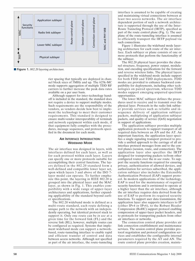
IEEE Communications Magazine • July 200858
rier spacing that typically are deployed in chan-nel block sizes of 5MHz and up. The 625k-MCmode supports aggregation of multiple TDD RFcarriers to further increase the peak data ratesavailable on a per user basis.
Although support for inter-technology hand-off is included in the standard, the standard doesnot require a device to support multiple modes.Such requirements are the responsibility of thevendors, as vendors decide how best to imple-ment the technology to meet their customerrequirements. This standard is designed toensure multi-vendor interoperability of terminalsand network equipment within each mode, ifthat equipment fully complies with the proce-dures, message sequences, and protocols speci-fied in the document for each mode.
AIR INTERFACE INTRODUCTION:WIDEBAND MODE
The air interface was designed in layers, withinterfaces defined for each layer, as well asfor each protocol within each layer. Layerscan specify one or more protocols suitable foraccomplishing their central functions. The lay-ers defined in the 802.20 standard form awell-defined and compatible lower layer set,upon which layers 3 and above of the ISO 7-layer model can operate. To further empha-size this point, the layering in IEEE 802.20 isgrouped into the physical layer and the MAClayer, as shown in Fig. 1. This enables com-patibility with a wide range of upper-layerarchitectures and applications, further expand-ing applicability of the standard beyond earli-er specifications.
The 802.20 wideband mode is defined as amulti-route standard, each route defining aunique path to the network with an indepen-dently operating, but identical protocol stack tosupport it. Only one route can be in use at agiven time for the forward link (FL) and thereverse link (RL); however, multiple routes canbe configured as required. Systems that imple-ment wideband mode can support a network-based, route-tunneling interface to enable rapidand efficient transfer of control and databetween access networks. Although not specifiedas part of the air interface, the route-tunneling
interface is assumed to be capable of creatingand maintaining virtual connections between atleast two access networks. The air interfacedependent portion of such a network architec-ture is supported through the use of the Inter-Route Tunneling Protocol (IRTP), specified aspart of the route control plane (Fig. 1). The userplane of the route-tunneling interface is assumedto efficiently transport the IRTP payload viasuch connections.
Figure 1 illustrates the wideband mode layer-ing architecture for each route of the air inter-face. Each sublayer or plane consists of one ormore protocols that perform the functionality ofthe sublayer.
The 802.20 physical layer provides the chan-nel structure, frequency, power output, modula-tion, and encoding specifications for the forwardand reverse wireless links. The physical layersspecified in the wideband mode include supportfor both FDD and TDD deployments. FDDmodes are provided to enhance backward com-patibility for deployments, including other tech-nologies on paired spectrum, whereas TDDmodes support emerging unpaired spectrumopportunities.
The lower MAC sublayer defines the proce-dures used to receive and to transmit over thephysical layer. Protocols in the radio link sublay-er provide services such as reliable and in-sequence delivery of application sublayerpackets, multiplexing of application sublayerpackets, and quality of service (QoS) negotiationin support of applications.
The application sublayer provides multipleapplication protocols to support transport of allrequired data between an AN and the AT. Animportant function, the application layer speci-fies a single signaling transport protocol to pro-vide a unified approach to the carriage of all airinterface protocol messages from and to the con-trol planes (session, route, and connection). Theapplication layer also specifies the IRTPdesigned for transporting packets to/from otherconfigured routes over the in use route. To sup-port the security functions required for ensuringprivacy, authentication of allowed devices, andauthorization for services subscribed, the appli-cation sublayer also includes the ExtensibleAuthentication Protocol (EAP) support proto-col. In modern applications of the technology,EAP is used for the maintenance of requiredsecurity functions and is envisioned to operate ata higher layer than the air interface, althoughthe air interface requires data derived from theuse of EAP to perform its required securityfunctions. To support user data transmission, theapplication layer also supports interfaces to IP(either IPv4 or IPv6), to the Robust HeaderCompression (RoHC) support protocol enablingcompression of upper-layer packet headers, andto protocols for transporting packets from otherair interfaces or networks.
The connection control plane provides airlink connection establishment and maintenanceservices. The session control plane provides pro-tocol negotiation and protocol configuration ser-vices and establishes the configurable internalparameters required by the AT and AN. Theroute control plane provides creation, mainte-
n Figure 1. 802.20 layering architecture.
PHY
Securityfunctions
Application sublayer
Radio link sublayer
Lower MAC sublayer
Physical sublayer
Rout
e co
ntro
l pla
ne
Sess
ion
cont
rol p
lane
Con
nect
ion
cont
rol p
lane
MA
C a
nd P
HY
MIB
MA
C
GREENSPAN LAYOUT 6/18/08 1:18 PM Page 58

IEEE Communications Magazine • July 2008 59
nance, and deletion of routes. Security functionsinclude functions for ciphering and messageintegrity protection.
For unicast transport, the MAC and PHYmanagement information base (MIB) providesan interface to enable operation, administration,and maintenance (OAM) systems to gatherstatistics from all protocols and managementplanes, for example, access attempts, bytes suc-cessfully transferred, dropped connections, andso on. Such information can enable suitable net-work management systems to perform theirrequired functions in a large and complex net-work deployment.
WIDEBAND MODE FEATURESPhysical Layer Features — The 802.20 wide-band mode provides physical layer support basedon OFDMA for both forward and reverse links.Supporting both FDD and TDD deployments,the PHY utilizes a similar baseband waveformfor both, thereby reducing the number of tech-nologies to be implemented by vendors. Thespecification provides modulation signal sets upto 64 QAM with synchronous hybrid automaticrepeat request (HARQ) for both forward andreverse links, to improve throughputs in dynamicenvironments. To handle different environments,several different supported coding schemesinclude convolutional codes, turbo codes, and anoptional low-density parity check (LDPC)scheme featuring performance comparable orbetter than turbo codes at all HARQ termina-tions.
Table 1 presents the 802.20 symbol numerol-ogy. As shown, the technology supports differentoperating bandwidths through the flexible use ofguard carriers. Thus, a single subcarrier spacingis utilized for deployments between 5 MHz and20MHz, with consistent sets of parameters suchas cyclic prefix duration, windowing guard inter-val, and symbol duration. Chip rates scale withthe size of the fast Fourier transform (FFT)employed, again contributing to ease of imple-mentation.
Although the RL physical layer is based onOFDMA, a portion of the signaling from AT toAN occurs over a code division multiple access(CDMA) control segment embedded in certainsubcarriers of the orthogonal frequency-divisionmultiplexing (OFDM) waveform. This uniquefeature enables robust and continuous signalingfrom AT to AN and can make use of soft hand-off techniques and other techniques developedfor CDMA cellular transmission. The result isimproved robustness of RL signaling and conti-nuity of the signaling channel even during transi-tions such as access and handoffs. Because theCDMA segment is hopped over the entire broad-band channel, the AN easily can make broad-band measurements required for improvedinterference and resource management.
Multi-Antenna Techniques for WidebandMode — From a system point of view, the802.20 technology specifies several multi-anten-na techniques for use with the FL. Both single-input single-output (SISO) and multiple-inputmultiple-output (MIMO) users can be supportedsimultaneously, thus optimizing the user experi-
ence to the best experience possible given chan-nel conditions. For users close to the accesspoint (AP), MIMO enables very high data ratetransmissions. Beamforming increases user datarates by focusing the transmit power in the direc-tion of the user, thus enabling higher receive sig-nal-to-interference and noise ratio (SINR) at theAT. Spatial division multiple access (SDMA)further increases sector capacity by enablingsimultaneous transmissions to spatially separatedusers using the same sets of subcarriers. Thus,beamforming in combination with MIMO andSDMA provides improved user data rates inboth high and lower SINR regions.
To improve reverse link performance, 802.20also enables the use of quasi-orthogonal reverselinks (QORL), without introducing additionalcomplexity at the AT. QORL enables multipleusers to be assigned RL transmissions on identi-cal carrier resources and relies on multipleantennas at the AN to suppress intra-sectorinterference. Throughput improvements on thereverse link due to QORL were shown to be sig-nificant (20–30 percent) in standardized environ-ments.3
Service Robustness of the Wideband Mode— Maintaining service robustness of OFDM-based techniques at the cell edge has long beenan important problem that the industry wasrequired to solve. 802.20 provides several tech-niques that significantly improve robustness andachievable data rates at the cell edge.
First, 802.20 allows the AT to independentlyselect the strongest FL and RL sectors, throughthe use of independent active set managementfor these data links. This property ensures theAT receives the strongest link performance
n Table 1. OFDM symbol numerology.
FTT size
Parameter 512 1024 2048 Units
Chip rate 4.9152 9.8304 19.6608 Mcps
Subcarrier spacing 9.6 9.6 9.6 kHz
Channel bandwidth 2.5–5 5–10 10–20 MHz
Cyclic prefix duration
6.5113.0219.5326.04
6.5113.0219.5326.04
6.5113.0219.5326.04
ms
Windowing guard interval 3.26 3.26 3.26 ms
OFDM symbol duration
113.93,120.44,126.95133.46
113.93120.44126.95133.46
113.93120.44126.95133.46
ms
3 27 percent gain in PedB 3km/h, 16 AT per sector, 4 RXAntennas, 5 MHz, FDD case; 24 percent gain for VehA 30 km/h, 16 AT/sector, 4Rx Antennas, 500 m cell to celldistance, 5 Mhz FDD.
GREENSPAN LAYOUT 6/18/08 1:18 PM Page 59

available and minimizes other sector interfer-ence for terminals at the sector edge.4
Additionally, 802.20 wideband mode enablesfractional frequency reuse (FFR) to improve celledge performance by partitioning available carri-ers into several sets. Thus the system can putusers at the cell edge into reuse with respect tothe strongest interfering sectors, gaining anorthogonality advantage by properly utilizing thesets of subcarriers. 802.20 actually allows thenetwork provider to go further and enablesdynamic FFR so that the AN scheduler candynamically allocate subcarriers to users for veryefficient interference control. Improvements dueto FFR at cell edges range from 35 percent towell over 100 percent under various loads andscheduling regimens.
Finally, 802.20 provides fast, distributed, RLpower control to enable the AN to tightly man-age inter-sector interference. This feature ismade possible through AP broadcasts of othersector interference data, as well as IoT data ona regular schedule. The RL serving the APmakes assignment decisions based on the ATfeedback of the QoS level, buffer size, powerheadroom, open loop power correction, othersector interference data, and IoT indicationparameters. Thus communication between theAP and the cell edges takes place with the mini-mum power (and induced interference to othercells) required to achieve communication withinthe bounds of channel conditions and therequired QoS.
Mobility Considerations for WidebandMode — The 802.20 air interface is designedfrom the ground up to provide seamless broad-band access for mobility classes from stationarythrough high-speed vehicular access in excess of200 km/hr. An optimized approach to handoffat all layers is key to providing robust service tosuch a wide range of mobility classes. Toachieve this requirement, 802.20 and the sup-porting access network provides handoffs at
layers L1/L2 and L3 (network attachmentpoint), which in combination provide a seam-less mobility experience for user services. Parti-tioning the handoff strategies in this way helpsto minimize hand-off impact on latency-sensi-tive traffic by minimizing the response time ofthe system to rapid variations in the path lossand shadowing components of the channels atvehicular speeds. Support for disjoint FLs andRLs allows the AT to achieve best cell site selec-tion gains in situations where the best servingsectors for FL and RL differ.
At L1/L2, handoff is facilitated through theuse of proven, active-set-management techniquesbased on CDMA cellular methods. Utilization ofthe active-set concept, combined with optimizedsignaling yields an average intra-cell hand-offdelay of 8.9 ms, from the point of decision to acompleted handoff of a link.
At L2, the AT makes regular measurementsof link quality and can make a hand-off requestdirectly to the target AP via a PHY layerswitching indicator embedded in signaling. Torequest FL handoff to another sector, the ATsends a reverse-channel quality indicator chan-nel (R-CQICH) with a flag set to the target APindicating the desired FL serving sector. Torequest RL handoff, the AT sends a reverserequest channel (R-REQCH) to a target APindicating the desired RL serving sector. Uponswitching a link (FL, for example), the anchorAP tunnels data to the target AP until higher-level (L3) handoff occurs. The device can nowswitch as required while at the cell boundary,providing optimal performance in varying envi-ronments. Based on these methods, the averageFL handoff is approximately 25 ms, includinghand-off signaling delay, as well as the backhauldelay. On the RL, because there is no backhauldelay, and the target AP already knows theanchor AP and can start tunneling data imme-diately, the average handoff is as low as approx-imately 10 ms.
Air Interface Introduction: 625k-MC Mode— The IEEE 802.20 625k-MC Draft Specifica-tion is an enhancement to the iBurst systembaseline specifications as given by the high-capacity spatial division multiple access (HC-SDMA) Radio Interface Standard(ATIS.0700004.2005) and fully backward com-patible to the commercially deployed systemsbased on HC-SDMA specifications.
The 625k-MC mode, which is uniquelydesigned around multiple antennas with spatialprocessing and SDMA, enables the transfer ofIP traffic, including broadband IP data, over alayered reference model as shown in Fig. 2. Thephysical (PHY) and data link layers (MAC andlogical link control [LLC]) are optimally tailoredto derive maximum benefit from spatial process-ing technologies: adaptive antenna processingand SDMA; enhanced spectral efficiency andcapacity; and wider coverage while enabling theeconomic operation, even when the availablespectrum is as small as 625 kHz. Secondly, thephysical and data link layers support higher datarates and throughputs by enabling multiple 625kHz carrier aggregation — hence the name625k-MC mode.
IEEE Communications Magazine • July 200860
n Figure 2. Protocol layer architecture of 625k-MC mode.
625k-MC PHY
625k-MCMAC/LLC
L1
L0 RF
L2 RLCRadiolink
control
L2 MACMedia access control
L3 RRCRadio
resourcecontrol
L3 MMCMobility
managementcontrol
L3 CMConnection management
L3 CMRegistration management
4 The AT is power controlled by the strongest RL sector.
GREENSPAN LAYOUT 6/18/08 1:18 PM Page 60

IEEE Communications Magazine • July 2008 61
The physical aspects of the protocol arearranged to provide spatial training data andcorrelated uplink and downlink interferenceenvironments for logical channels amenable todirectional transmission and reception such astraffic channels. Conversely, channels notamenable to directional processing, such as pag-ing and broadcast channels, have smaller pay-loads and receive a greater degree of errorprotection to balance their links with those ofthe directionally processed channels. Adaptivemodulation and channel coding, along withuplink and downlink power control, are incorpo-rated to provide reliable transmission across awide range of link conditions. Modulation, cod-ing, and power control are complemented by afast automatic repeat-reQuest (ARQ) mecha-nism to provide as reliable a link as is possible ina mobile setting. Fast, low-overhead, make-before-break, inter-cell handover is also support-ed. Differentiated and tiered services areenabled through a flexible QoS mechanism.Security for the radio access link is provided bymutual authentication of the terminals andaccess network and by encryption to ensure dataprivacy.
625K-MC MODE FEATURESThe 625k-MC mode encompasses all the fea-tures and protocols of an HC-SDMA systemwhile incorporating additional features that offerhigher data throughputs, better QoS, multicastand broadcast services, and advanced security.
Baseline Features of HC-SDMA — The physi-cal layer of the 625k-MC mode, correspondingto the layer 1 (L1) of HC-SDMA, is character-ized by a TDD/ time division multiple access(TDMA) structure with 5 ms frames, each framecontaining three uplink and three downlinkbursts (timeslots) as shown in Fig. 3.
The air interface logical channels are allmapped onto this structure. To provide highspectral efficiency, many aspects of L1 are specif-ically designed to support the effective use ofadaptive antenna arrays. For instance, trainingsequences for SDMA are incorporated in certainburst structures.
Uplink and downlink symbol rates are 500kSymbols/s in all circumstances, and a 25 per-cent root-raised cosine filter is employed thatleads to a 625 kHz carrier spacing. A single usermay aggregate multiple 625 kHz carriers.
The basic physical resource in the system is aspatial channel, which consists of a carrier, anuplink and downlink timeslot pair, and a spatialchannel index. Multiple antennas and adaptiveantenna processing make it possible to supportmultiple spatial channels simultaneously on thesame conventional channel.
A range of modulation and coding combina-tions (referred to as ModClasses) are employedto maximize throughput subject to frame errorrate (FER) and link conditions. Independentuplink and downlink power control and Mod-Class adaptation are to be performed on aburst-by-burst basis on traffic channels. Chan-nels that have lower spatial processing gain,such as broadcast and paging channels, aretransmitted with more extensive channel coding
than traffic channels, balancing the tolerablepath loss for all channel types. The PHY layeremploys spatial processing, multiple modulationand channel coding formats, and equalizationwith per-burst training data to manage the RFchallenges of a mobile non-line-of-sight(NLOS) environment.
The data l ink layer of 625k-MC modeencompasses both MAC and LLC features asdefined in L2 and L3 functional specificationsof the HC-SDMA system. The L3 of HC-SDMA creates logical sessions for the efficienttransport of IP packets that are encapsulatedin either point-to-point protocol (PPP) framesor IEEE 802.2/802.3 frames over the air inter-face. So, the L3 of HC-SDMA should not beconfused with the L3 (network layer) of theInternational Standards Organization-OpenSystems Interconnection (ISO-OSI) protocolreference model.
The L2 of HC-SDMA defines the specifica-tions for reliable transmission including theradio link control (RLC), MAC, and logicalchannel structures. The L2 RLC function mapscontrol and data messages to physicalresources and provides acknowledged mode(AM) and unacknowledged mode (UM) mes-sage delivery service to the MAC sublayer inL2. The L2 MAC sublayer provides dynamicaccess management and control functions tomap and transport logical channels onto physi-cal layer bursts.
The L3 protocol of HC-SDMA defines thefunctions for logical connection and registrationmanagement and mobility management, whichinclude efficient handovers and radio resourcecontrol to coordinate the power control and linkadaptation required to maintain an RF link.
The L3 protocol of the HC-SDMA alsoensures a robust security infrastructure withair interface confidentiality and authentica-tion. Authentication, for both the BS and UT,is based on using digital certificates signedaccording to the ISO/International Elec-trotechnical Commission (IEC) 9796 standardusing the Revist Shamir Adelman (RSA) algo-rithm as the signature primitive. The digital
n Figure 3. TDMA-TDD frame structure of 625k-MC mode.
Trai
ning
sequ
ence
Trai
ning
sequ
ence
545 µs 1090 µs
68 µs114 µs 2076 µs
ULslot 1
ULslot 2
1 frame: 5 msUL: uplinkDL: downlink
ULslot 3
DLslot 1
DLslot 2
DLslot 3
GREENSPAN LAYOUT 6/18/08 1:18 PM Page 61

IEEE Communications Magazine • July 200862
certificates present information about theowner of the certificate and its elliptic curvepublic key. Shared secret and air interfaceparameter exchange is performed using thepublic keys of the UT and the BS, based onelliptic curve cryptography (using curves K-163and K-233 in federal information processingstandard [FIPS]-186-2 standard). Finally, theencryption of traffic channel (TCH) trafficstreams is performed using a stream ciphersuch as RC4 initialized by a function of theshared secret and the temporal parameters ofa stream to be encrypted.
Enhanced Features of 625k-MC — The625k-MC mode defines several enhancements toHC-SDMA and ensures the availability of allbase-line features in the previous section.
Physical Layer Enhancements•The 625k-MC mode defines additional mod-
ulation schemes, 32QAM and 64 QAM, alongwith the corresponding puncturing patterns anderror control coding to deliver the higherthroughputs with the peak downlink data ratesof 1.493 Mb/s and peak uplink data rates of571.2kb/s in a channel bandwidth of 625 kHz.The 625k-MC mode also provides additional RFspecifications to support these additional modu-lation classes.
Data Link Layer (MAC and LLC) Enhance-ments
•Additional MAC and RLC specifications tosupport the enhanced cell edge coverage andefficient voice-over-IP (VoIP) packet transmis-sions.
To provide higher user throughput for thelower uplink modulation and coding classes,modulation classes 0 and 1 for both data users atcell edge and/or a VoIP user; an alternate formof the burst header called minimized RMUheader is defined and additional MAC and RLCprotocols are defined on top of the HC-SDMAspecifications:
•Broadcast and multicast streaming services:The 625k-MC mode defines additional proto-
cols and primitives to deliver short messagebroadcast services and multicast services.
•QoS supportThe 625k-MC mode air interface defines the
three classes of QoS, corresponding to expeditedforwarding (EF), assure forwarding (AF), andbest effort (BE) per-hop behaviors (PHBs) usingDiffServ code points (DSCP) of the DiffServmodel. The BS and UT exchange the QoS ofeach session to control the stream shutdown tim-ings based on the class of QoS.
•Secure communication based on theadvanced encryption standard (AES).
The 625k-MC mode provides a block cipheralgorithm based on the AES to support securedata communication over the air interface.• Sleep mode control
The 625k-MC mode defines five paging activ-ity levels to offer sleep mode control that enablepower conservation for the UT in idle mode.
•Radio network quality monitor and controlenhancement
The 625k-MC mode defines the MIB to pro-vide radio network quality monitoring and con-trol functionality. The MIB of the 625k-MC
mode is comprised of the managed objects,attributes, actions, and notifications required formanaging a BS.
625k-MC Support for Adaptive AntennaArrays — In a frame (Fig. 3), uplink slots pre-cede the downlink slots to provide current spa-tial training data for each downlink transmission.Each uplink slot is paired with a downlink slot.Pairing of uplink and downlink slots ensures thatthe uplink and downlink interference environ-ments will be highly correlated. The durationbetween any paired uplink and downlink slot issmall to prevent channel conditions from degrad-ing the degree of channel reciprocity existingbetween the uplink and downlink slots and hencedegrading the performance of the adaptiveantenna array. Therefore, the frame duration isalso small (5 ms). Carrier bandwidth is relativelynarrow (625 KHz) to enable low complexitymulti-antenna signal processing algorithms.
On a given carrier-timeslot pair, each user isassigned a unique training sequence. Trainingsequences are designed for appropriately accu-rate estimation of the propagation channel. EachUT sharing a conventional channel via SDMAuses a unique training sequence from a selectedset with good correlation properties. The crosscorrelation property between the trainingsequences is very low. The autocorrelation of thetraining sequences for the non-zero lags is verylow, simplifying processing of the adjacent-cellinterference.
625k-MC Mode Air Interface Handover —The air interface make-before-break handoverscheme is UT-directed. Each UT monitors thebroadcast channels from surrounding BSs andranks candidates based on signal power andother factors. A UT can perform these measure-ments, as well as register with a new candidate-serving BS, while exchanging traffic channel datawith its current serving BS. The handover foruser data is make-before-break, with the trafficchannel data being redirected to the new servingBS after successful registration.
CONCLUSIONSThe 802.20 standard provides highly optimizedOFDMA and 625 kHz multicarrier solutionswith significantly higher performance and flexi-bility than competing technologies. This is madepossible through the specification of advancedantenna techniques, superior interference man-agement techniques, and optimized reverse linktechnology. Additionally, optimized mobility andadvanced QoS mechanisms will enable leading-edge performance and user experience for real-time services such as VoIP or interactivemultimedia applications. Service providers alsowill benefit through the use of flexible mecha-nisms to deliver and differentiate their servicesas the network use increases.
ACKNOWLEDGMENTThe materials in this article are taken from thedraft 802.20 standard and the numerous contribu-tions and documents on the 802.20 Web site. For awealth of additional information regarding the
Optimized mobility
and advanced QoS
mechanisms will
enable leading-edge
performance and
user experience for
real-time services
such as VoIP or
interactive
multimedia
applications. Service
providers also will
benefit through the
use of flexible
mechanisms to
deliver and
differentiate their
services.
GREENSPAN LAYOUT 6/18/08 1:18 PM Page 62

IEEE Communications Magazine • July 2008 63
technologies, their expected performance, and fea-tures, as well as up-to-date documents on the workof the Mobile Broadband Wireless Access(MBWA) working group, see http://ieee802.org/20.
BIOGRAPHIESRADHAKRISHNA CANCHI received a D.Eng. degree from KyushuUniversity, Japan. He is a director of engineering atKYOCERA Telecommunications Research Corporation (KTRC)USA, responsible for R&D in mobile broadband wirelesssystems. He has 19 years of experience in the wireless com-munications field with an extensive background in globalwireless standards: IEEE 802.11, IEEE 802.20, and ARIB-MMAC (Japan), and has made several contributions to theIEEE 802.20 Working Group. He held key positions at theCentre for Wireless Communications and the Institute ofInfocomm Research, Singapore, at Nokia, at Kyocera inJapan, and at the Centre for Development of Telematics (C-DOT), India.
ARNOLD M. GREENSPAN ([email protected]) is agraduate of Bellevue College and Northeastern University.He is chair of the AESS standing committee on standards,and a member of the IEEE-SA Standards Board and theIEEE-SA Audit Committee. He has published widely. He waspresident and CEO of AMG Associates and vice presidentof SofTech, Inc.
MARK KLERER holds a B.S.E.E. from City College of NewYork, an M.S.S.E. from Stanford University, and an M.B.A.from Pace University. He is currently senior director of tech-
nology at Qualcomm QFT. He has been active in the devel-opment of communications standards for over 25 years. Hehas worked at Bell Laboratories, AT&T, Lucent, and Nortel,and was responsible for management of advanced technol-ogy standardization, including wireless and optical net-working. He is currently chair of IEEE 802.20.
JAMES D. TOMCIK ([email protected]) received a Ph.D.degree in electrical engineering from the University ofNotre Dame, where his work included communication andcoding theory and digital signal processing for voice. He isa director of engineering at Qualcomm, Inc., San Diego,California, where he is responsible for the Qualcomm IEEEstandards program, and R&D efforts related to standardstechnologies. He has 14 years of experience in wirelesscommunications with an extensive background in datacommunications technologies, security, and digital signalprocessing as applied to communications. Prior to his posi-tions at Qualcomm, he was a technical manager at AT&TBell Laboratories, where his focus was on internationalwireline communications technologies and prototypes.
JOANNE C. WILSON holds B.S. and M.S. degrees in electricalengineering from Southern University and A&M Collegeand Stanford University, respectively. She has more than 20years of experience in telecommunications, specializing inwireless standards, regulatory, and market access issues.She advises and assists companies, governments, andNGOs in standards and business development, policy, andregulatory matters. Formerly with ArrayComm, she devel-oped and executed successful standardization strategies inATIS, the IEEE, and ITU-R. She had a 15-year career withAT&T and Lucent.
GREENSPAN LAYOUT 6/18/08 1:18 PM Page 63

IEEE Communications Magazine • July 200864 0163-6804/08/$25.00 © 2008 IEEE
1 The mains voltage ofEurope is 230V (50Hz)because at the beginningof 1900, the GermanAEG had a virtualmonopoly on electricalpower systems, and AEGdecided to use 50 Hz.
2 The United States has anominal line voltage of120 volts (60 Hz) becausethe original light bulbinvented by Thomas Edi-son ran on 110 volts DC,and that approximatevoltage was kept evenafter converting to AC sothat it was not necessaryto buy new light bulbs.Many frequencies wereused in the nineteenthcentury for various appli-cations, with the mostprevalent being the 60 Hzsupplied by Westinghouse-designed central stationsfor incandescent lamps.
INTRODUCTION
The idea of using power lines to support datacommunications is not new; the first applicationsof power line communications (PLC) date toover 100 years ago [1]. The first reported appli-cations of PLC were remote voltage monitoringin telegraph systems and remote meter readings.Today the interest in PLC spans several impor-tant applications: broadband Internet access,indoor wired local area networks (LANs) forresidential and business premises, in-vehicle data
communications, Smart Grid applications(advanced metering and control, real-time ener-gy pricing, peak shaving, mains monitoring, dis-tributed energy generation, etc.), and othermunicipal applications, such as traffic light andstreet lighting control.
Power line networks were originally designedfor distribution of power at 501 Hz or 602 Hz.The use of this medium for data communicationat higher frequencies presents several technicalchallenges. The structure of the mains grid, aswell as indoor wiring and grounding practicesdiffer from country to country and even within acountry. Additionally, the power line channel isa harsh and noisy transmission medium that isvery difficult to model, is frequency-selective, isimpaired by colored background noise, and alsois affected by periodic and aperiodic impulsivenoise [1, 2]. The power line channel is also time-varying. The channel transfer function of thepower line channel may vary abruptly when thetopology changes, that is, when devices areplugged in or out or switched on or off. Howev-er, the power line channel also exhibits a short-term variation because the high-frequencyparameters of electrical appliances depend onthe instantaneous amplitude of the mains volt-age [3]. A fundamental property of the powerline channel is that the time-varying behaviormentioned previously is actually a periodicallytime-varying behavior, where the frequency ofthe variation is typically twice the mains frequen-cy (50 or 60 Hz). An example of this behavior,unique to the power line channel, is shown inFig. 1, where the measured time variation of anindoor power line channel-transfer function isshown. Additional challenges are due to the factthat power line cables are often unshielded andthus become both a source and a victim of elec-tromagnetic interference (EMI). As a conse-quence, PLC technology must includemechanisms to ensure successful coexistencewith wireless and telecommunication systems, aswell as be robust with respect to impulse noiseand narrow band interference.
ABSTRACT
Broadband connectivity to and within thehome has been available to consumers forsome time through various technologies.Among those technologies, power line commu-nications is an excellent candidate for provid-ing broadband connectivity as it exploits analready existing infrastructure. This infra-structure is much more pervasive than anyother wired alternative (both to and within thehome), and it allows virtually every line-pow-ered device to become the target of value-added services. Therefore, PLC may beconsidered as the technological enabler of amultitude of future applications that probablywould not be available otherwise. The mostfundamental barrier to the widespread adop-tion of broadband PLC is the current lack ofan international technical standard issued by acredible and globally recognized standards-set-ting body. Hopefully, this barrier will be elimi-nated soon through the work of the IEEEP1901 Corporate Standards Working Group.This group, which was created in June 2005, isentering a crucial phase. This article stressesthe importance of standardization in the PLCcontext, gives an overview of the current activi-ties of the IEEE P1901 working group, andalso describes some of the technical challengesthat the future 1901 standard must address toensure the success of PLC in the marketplace.
IEEE STANDARDS IN COMMUNICATIONSAND NETWORKING
Stefano Galli, Panasonic
Oleg Logvinov, Arkados
Recent Developments in theStandardization of Power LineCommunications within the IEEE
GALLI LAYOUT 6/18/08 1:15 PM Page 64

IEEE Communications Magazine • July 2008 65
Another issue is that power line cables are ashared medium. Thus, they cannot provide linksdedicated exclusively to a particular subscriber,as the twisted pair cables used by telephonecompanies do. More specifically, power linecables connect a low-voltage transformer to aset of individual homes or a set of multipledwelling units, without isolating each unit.Because power line cables are shared among aset of users, the signals that are generated byone user in one apartment or house may inter-fere with the signals generated in an adjacenthouse or apartment. Because it is difficult tolocally contain the signals generated by a user,the more users in geographical proximity thatuse PLC, the more interference is generated.As the interference increases, every user experi-ences a decrease in data rate because morepacket collisions occur. This phenomenon ofnetwork overlap is not dissimilar to what hap-pens in other, more conventional shared media,for example, coax and wireless. However, coaxand wireless devices can count on the availabili-ty of a much larger bandwidth than in the caseof power lines and therefore, can mitigate theeffects of interference by using different com-munication channels separated in frequency(frequency division multiplexing [FDM]),whereas most broadband PLC devices share thewhole frequency band (typically 2–30MHz).This makes the issue of PLC “self-interference”very challenging.
In the past, the aforementioned challengescaused skepticism about the feasibility of broad-band communication over power lines. Howev-er, now we can say that this skepticism finallyhas been overcome now that there are productsavailable on the market today for many broad-band PLC applications that have PHY datarates of up to 200 Mb/s. The only thing that iscurrently missing to enable mass-market pene-tration of PLC products is the availability of aninternational technical standard issued by acredible and globally recognized standards-set-ting body.
To overcome this fundamental drawback, inJune 2005, twenty companies agreed to form theIEEE P1901 Working Group (WG) under thesponsorship of the IEEE Communications Soci-ety (ComSoc) [4]. The scope of the P1901 WG isto develop a standard for high-speed (>100Mb/s at the PHY layer) communication devicesthrough alternating current electric power linesusing frequencies below 100 MHz.
THE PROGRESS OF THE IEEE P1901WORKING GROUP
Since the formation of the WG in June 2005,the interest in PLC technology has grown sig-nificantly and the group now includes over 50entities across the entire PLC value chain [4].As per the scope of IEEE P1901, the standardwill use transmission frequencies below 100MHz and will be usable by all classes of PLCdevices, including devices used for the first-mile/last-mile connection (<1,500 m to thepremise) to broadband services, as well asdevices used in buildings for local area net-
works (LANs) and other data distribution(<100 m between devices) applications. Theefforts of the P1901 WG are limited to thephysical (PHY) layer and the medium access(MAC) sub-layer of the data link layer, asdefined by the International Organization forStandardization (ISO) Open Systems Intercon-nection (OSI) Basic Reference Model.
DEFINING FUNCTIONAL ANDTECHNICAL REQUIREMENTS
After formalizing the creation of the group inJune 2005, the IEEE P1901 WG adopted ageneral workflow in November 2005, and asubgroup began to work on developing a setof unified functional and technical require-ments (FTRs). With technical assistance fromsome members of the IEEE ComSoc Techni-cal Committee on Power Line Communica-tions (TC-PLC) [5], channel and noise models,as well as topology descriptions were devel-oped and approved for insertion into an infor-mative annex.
Progress in the following year led to thedevelopment of hundreds of FTRs categorizedin three separate clusters:• In-home (IH) — This cluster of require-
ments is concerned with enabling low-volt-age wiring in structures to carry digitalcontent.
• Access (AC) — This cluster is concernedwith the transmission of broadband contenton the medium- and low-voltage powerlines that feed homes.
• Coexistence (CX) — This cluster focuses onrequirements that will make PLC devicescompatible even if based on different tech-nologies.The IH FTRs address the use of the power
lines in a residence or office as a digital commu-nication medium. The AC cluster contains FTRsfor bringing multimedia services to residencesvia power lines and for developing electric power
n Figure 1. Measured time variation of an indoor power line channel.
Time (ms) Frequency (MHz)
–100
–120
Gai
n (d
B)
5
5
–80
–60
–40
–20
0
010 15 20 25 30
0
10
15
GALLI LAYOUT 6/18/08 1:15 PM Page 65

IEEE Communications Magazine • July 200866
utility applications. The CX cluster involvesFTRs that govern how non-interoperable devicescan share the channel without causing harmfulinterference to each other. A coexistence proto-col is being defined in the CX cluster, and thisprotocol will define a general resource sharingmechanism that will allow non-IEEE 1901devices to share the channel with each other andwith IEEE 1901 devices. In addition to thesethree clusters, the IEEE P1901 WG also hasbegun to extend its efforts to include capabilitiesfor the transportation sector (e.g., airplanes,ships, trains, cars).
ISSUING THE CALL FOR PROPOSALSIn February 2007, the group approved the set ofFTRs defined for the baseline PLC standard andissued a call for proposals to solicit technicalsolutions for systems that met the approvedrequirements. In June 2007, a total of twelveproposals were received, four for each cluster.The next step for the IEEE P1901 WG was toselect the proposals that best met the require-ments defined in each cluster.
CURRENT STATUS AND NEXT STEPSThe IEEE P1901 WG has conducted a series ofvoting sessions following the agreed-upon downselection process. Moreover, a few voluntarilymerged proposals also were submitted. As ofApril 2008, there is only one surviving technicalproposal in each of the three clusters. Current-ly, these proposals are being refined andimproved. The next step for the IEEE P1901WG is to hold confirmation votes on the surviv-ing proposals. The surviving proposals mustachieve a 75 percent majority approval in theconfirmation vote to become part of the base-line of the standard. After that, the formal pro-cess of creating the Draft Standard from thisbaseline begins.
TECHNICAL FEATURES OF THEIN-HOME AND ACCESS PROPOSALS
SCHEDULED FOR THECONFIRMATION VOTE
The surviving IH and AC proposals that arescheduled for a confirmation vote offer a solu-tion with a common MAC layer and the flexibili-ty to support two PHY layers; one based onwavelet-orthogonal frequency-division multiplex-ing (OFDM) [7] and one on windowed fastFourier transform (FFT)-based OFDM. A con-ceptual overview of the proposals is shown inFig. 2. The common MAC layer handles the twodifferent PHY layers via an intermediate layercalled the Physical Layer Convergence Protocol(PLCP). There are two PLCPs: the O-PLCP,which handles the interaction between the com-mon MAC and the windowed OFDM PHY andthe W-PLCP, which handles the interactionbetween the common MAC and the wavelet-OFDM PHY. Another key component of theproposal is the presence of a mandatory Inter-PHY Protocol (IPP) that enables PLC devicesbased on the IEEE 1901 standards to share themedium efficiently and fairly regardless of thePHY differences. The IPP is a new element thatis unique to the power line environment becauseits requirement stems from the issue of self-interference mentioned in the introduction tothis article. Because the basic MAC and PHYfeatures contained in the submitted proposalsalready were published in some form and alsoare available online in some detail [9, 10], wefocus here on the description of some technicalcharacteristics of the IPP.
THE INTER-PHY PROTOCOLA solution based on multiple non-interoperablePHY layers with a common MAC layer is a com-mon approach in standards, for example, 802.11.However, due to the self-interference problemsmentioned previously, the definition of two non-interoperable PHY layers also leads to the neces-sity of handling the case when devices withdifferent PHY layers are in proximity and con-nected to the same shared medium. The issue ofself-interference also is addressed in the proposalsfor the case where all devices have the same PHY(described as the problem of neighbor networksoperation). However, in this case, the solution tothe problem is simpler because all devices areinteroperable and easily can exchange informa-tion. The Inter-PHY Protocol (IPP) is designedto cope specifically with the problem of non-inter-operable PHY layers, and its purpose is to enablefair sharing of resources between devicesequipped with the IEEE 1901 PHY layers.
In its initial conception, the IPP handled onlythe two IEEE 1901 PHY layers. However, sever-al members of the IEEE 1901 WG are evaluat-ing the use of the IPP as the mechanism that willregulate the simultaneous access to the powerline channel of both IEEE 1901 and future nextgeneration (NG) devices. The NG PHY will berecognized by the IPP as a third PHY that isnon-interoperable with either of the two IEEE1901 PHY layers. Although the very concept of
n Figure 2. Architecture of the IEEE P1901 WG proposal currently scheduledfor a confirmation vote. Example of functionalities present in each layer.Common MAC: frame formats, addressing, SAP, SAR, security, IPP, channelaccess, etc. W-PLCP and O-PLCP: channel adaptation, PPDU format, FEC,etc. PHY: wavelet-OFDM PHY, windowed FFT-OFDM PHY.
Windowed OFDMPHY
O-PLCP
Wavelet OFDMPHY
W-PLCP
Inte
r-PH
Y pr
otoc
ol (
IPP)
Inte
r-PH
Y pr
otoc
ol (
IPP)
Common MAC (including IPP)
GALLI LAYOUT 6/18/08 1:15 PM Page 66

coexistence becomes moot after the industryaligns behind a common technology, we believethat including the IPP in NG devices is a smallprice to pay in terms of complexity if a longerproduct life can be offered to PLC technologiesbased on the IEEE 1901 standard. An importantaspect of the IPP is that it will be compatiblewith the coexistence proposal being defined inthe CX cluster.
The IPP Waveform and the Network Status— IEEE 1901 AC and IH devices will indicatetheir presence and requirements by transmittinga set of simple IPP signals. The particular IPPwaveform included in the AC and IH proposal isbased on the commonly distributed coordinationfunction (CDCF) waveform defined in the cur-rent proposal submitted to the CX cluster. TheCDCF waveform is a baseband windowedOFDM signal lasting around 80 µs. This signal isobtained by the repetition of twelve base signals.Samples of the base signal waveforms can bestored in memory and flushed directly to theD/A, thus allowing simple implementation byeither PHY layer. Several phase vectors weredefined to create different base signals.
IPP signals will be transmitted in the IPPtime-window, a region of time used by PLCdevices for transmitting/detecting IPP signals.The IPP time-window occurs periodically everyTipp seconds and is further divided in F time sub-windows, called fields. The presence/absence ofIPP signals in a field conveys several kinds ofinformation about the presence/absence of adevice of a certain kind (AC, IH-OFDM [IH-O],IH-wavelet [IH-W]), bandwidth requirements(low, medium, high), re-synchronizationrequests, and so on. Each field in the IPP win-dow has a duration of around 250 µs, so there isa margin of around 85 µs at both ends of theIPP field. This allows handling imperfect zerocrossing detection, load induced phase shifts ofthe mains signal, and other nonidealities of thechannel. The IPP window occurs every Tipp sec-onds (allocation period) at a fixed offset Toff rel-ative to the underlying line cycle zero crossing.This is shown in Fig. 3. Because there are twozero crossings in a cycle and there are often upto three phases in a building, there are actuallysix possible zero crossing instances. Proper syn-chronization techniques also are being definedto allow all devices in range of each other to syn-chronize to a common zero crossing instance.
When a device starts operating on the powerline medium, it first determines the correct loca-tion of the IPP window, and then it scans forIPP signals to determine the network status, thatis, what type of systems are present on the sharedmedium, what are their bandwidth requirements,and so on. AC and IH devices indicate theirpresence, as well as other useful information bytransmitting IPP signals in the appropriate IPPfields of the IPP window pertaining to their sys-tem. In particular, every system will use in exclu-sivity an IPP window every Tipp seconds. Forexample, all IH devices that use the OFDMPHY (IH-O) simultaneously use an IPP window,all AC devices simultaneously use the next IPPwindow, and then all IH devices that use thewavelet-OFDM PHY (IH-W) simultaneously use
the next one, and so on in a round-robin fashion(Fig. 4). This enables all devices to unequivocallydetermine the network status every 3 ⋅ Tipp sec-onds. For example, Fig. 4 shows two cases: acase where all systems are present because IPPsignals are transmitted in all three consecutiveIPP windows and a case where an AC system ismissing because no IPP signal is transmitted dur-ing the IPP window allocated to access systems.
Support of Dynamic Bandwidth Allocation(DBA) — Depending on the status of the powerline network, different resource allocations arecarried out. Time division multiple access(TDMA) sharing between wavelet and OFDMsystems is based on allocation periods. As shownin Fig. 5a, there are N TDM units (TDMUs) perallocation period, where an allocation periodlasts Tipp. The duration of a TDMU is equal totwo power line cycles, and each TDMU containsS TDMA time slots. Each TDMA slot is exclu-sively assigned to either AC, IH-O, or to IH-Wsystems, and the allocation policy is based on thenetwork status. Fair sharing of resources isaccomplished by assigning a fair number ofTDMA slots to each system that is present onthe power line network. Sensible values forparameters N and S currently under discussionare: 3 ≤ N ≤ 10 and 8 ≤ S ≤ 12 and as a conse-quence, Tipp has a value of a few hundred mil-liseconds. An example of three possible TDMAstructures is given in Fig. 5b for the case of S =12 and for three different network statuses. Witha period equal to Tipp, devices can update thenetwork status and eventually change the uti-lized TDMA structure to ensure efficient DBA.The IPP window always occurs at the beginningof TDM unit (TDMU) #0.
The duration of a TDM slot (TDMS) is either40/S ms (50Hz) or 33.33/S ms (60Hz), and thesevalues are equal to the minimum system latencythat can be guaranteed by the network. Forexample, for the case S = 12, we have 3.33 ms(50Hz) or 2.78ms (60Hz). Similar to the case of
IEEE Communications Magazine • July 2008 67
n Figure 3. IPP time window, IPP fields, IPP field margins, and IPP signalwindow.
Field 1 Field 2 Field F
IPP field ~250 µs
IPP signal ~80 µs
IPP field margin ~85 µs
IPP window ~1 ms
Allocation period TIPP
Toff
GALLI LAYOUT 6/18/08 1:15 PM Page 67

IEEE Communications Magazine • July 200868
the IPP fields, it is required to add a margin ofsome microseconds around the TDMS bound-aries.
Support of TDMA Slot Reuse Capability —The interference generated on shared power linenetworks is a random variable that depends onmany factors, such as the transmitted power, thepower line topology, wiring and grounding prac-tices, the number of mains phases delivered tothe premises, and so on. PLC devices can inter-fere with other devices that are in close proximi-ty, but also with devices that are located fartheraway, for example, on another floor. In othercases, even within the same apartment, devicescan cause very different levels of interference,for example, depending on whether they arelocated on the same phase of the alternatingcurrent mains or not.
Algorithms for TDMA slot reuse (TSR)exploit this physical property of the power linechannel by allowing devices, either in the samenetwork or in different neighboring networks, totransmit simultaneously without causing interfer-ence to each other. Currently, no commercialPLC product has this capability. Usually, withinthe same network, nodes are either assignedorthogonal resources (e.g., different TDMAslots) or compete for resources (e.g., carriersense multiple access [CSMA]). Several mem-bers of the IEEE 1901 WG are currently defin-ing an efficient TSR algorithm that will be partof the IPP and will allow an increase of the over-all network throughput.
THE MAC AND THE TWO PLCPSThe fundamental architecture used to coordi-nate the IEEE P1901 network is master/slave.The master (quality of service [QoS] controller)authorizes and authenticates the slave stations inthe network and may assign time slots for trans-missions using either CSMA-based or TDM-based access. Network stations can communicatedirectly with each other (as opposed to an accesspoint that retransmits all traffic). This increases
the efficiency of the network and reduces theload on the master.
The MAC layer employs a hybrid access con-trol based on TDMA and CSMA/CA by defininga contention-free period (CFP) and a contentionperiod (CP) to accommodate data with differenttransmission requirements. The CFP is a portionof the total transmission cycle during which sta-tions that have low-delay/low-jitter requirementsare allowed exclusive use of the medium. Allstreams requiring transmission in the CFP aremanaged by a QoS controller. The CFP starts witha beacon, which is periodically sent by the QoScontroller and ends when all reserved streams aretransported. The rest of the beacon cycle is usedfor CP. In the CFP, data streams that have a timeallocated to them through a bandwidth reservationprocedure managed by the QoS controller aretransported. Frequency division multiplexing(FDM) also can be supported to allow for coexis-tence between in-home and access networks. Frag-mentation support, data bursting, group-acknowledgment (ACK), and selective repeatautomatic repeat-reQuest (ARQ) are also impor-tant features of the current proposal.
Intelligent TDMA also is defined in the pro-posal. Intelligent TDMA is a dynamic bandwidthallocation mechanism that exploits informationabout the amount of traffic queued in eachtransmission station. This mechanism realizesstable transmission that can cope with errors andInternet Protocol/variable bit rate (IP/VBR)traffic. In each transmitted data packet, each sta-tion inserts the number of frames pending to betransmitted. Because traffic information is direct-ly obtained from data packets, the QoS con-troller can perform accurate real-time operation.An option for line cycle synchronization also ispresent for coping with the periodically time-varying channel and cyclostationary noise.
THE FFT OFDM-BASED PHYFFT-based windowed OFDM is one of the twoproposed multichannel transmission techniques.Through the use of time-domain pulse shaping
n Figure 4. Example of determination of network status: (upper) all systems present; (lower) only two sys-tems, no AC system present. Here, only the IPP window is shown, and the time shown on the x-axis is inmultiples of the synchronization period Tipp.
Time
IH-O
0
AC
1
IH-W
2
IH-O
3
AC
4
IH-W
5
IH-O
6
AC
7
IH-W
8
Time
IH-O
0 1
IH-W
2
IH-O
3 4
IH-W
5
IH-O
6 7
IH-W
8
The fundamental
architecture used to
coordinate the IEEE
P1901 network is
master/slave. The
master (quality of
service [QoS]
controller) authorizes
and authenticates
the slave stations in
the network and
may assign time slots
for transmissions
using either
CSMA-based or
TDM-based access.
GALLI LAYOUT 6/18/08 1:15 PM Page 68

IEEE Communications Magazine • July 2008 69
of the OFDM symbols, deep frequency notchescan be achieved without the additional require-ment of transmit notch filters. The proposedOFDM PHY uses a maximum of 1893 carriersin the 1.8 to 48 MHz band for maximum datarates up to 400 Mb/s. Frequencies above 30MHz are optional and support for up to 80 MHzmay be included. Flexible spectral notching cansupport regional and application requirements.In addition, each OFDM tone can be loadedwith 1, 2, 3, 4, 6, 8, or 10 bits using QAM on thebasis of the signal to noise ratio (SNR) of eachcarrier. This PHY uses turbo convolutional cod-ing for forward error correction (FEC). Channeladaptation mechanisms, based on detecting zerocrossings and understanding where noise is mostlikely to occur, also were defined as they signifi-cantly improve system performance in the pres-ence of periodically time-varying noise.
The basic parameters of the FFT-OFDMPHY appear in Table 1a.
THE WAVELET OFDM-BASED PHY
Wavelet-OFDM [7, 8] is the second multichan-nel transmission technique contained in the cur-rent proposal. The fundamental characteristic ofwavelet-OFDM is that the usual FFT-basedtransform and the rectangular/raised-cosine win-dowing used in conventional OFDM is replacedwith critically decimated, perfect reconstructioncosine-modulated filter banks that exhibit sever-al desirable properties such as very low spectralleakage. One of the most interesting aspects ofwavelet-OFDM is that it is not necessary tointroduce a guard interval between consecutivesymbols. An extensive literature exists onwavelet-OFDM; see [6] and the references there-in.
The proposed wavelet-OFDM system speci-fied here places 512 evenly spaced carriers intothe frequency band from DC to around 30 MHz.Of these 512 carriers, 338 of them (approximate-
n Figure 5. a) General TDMA structure: N TDMUs in an allocation period, and S TDM slots per TDMU(a TDMU is two line cycles long); b) example of three possible TDMUs for the case of S = 12: (upper) theTDMSs are allocated 50 percent to the access system and 50 percent to the in-home systems (25 percent towavelet-OFDM systems and 25 percent to FFT-OFDM systems); (center) the TDMSs are allocated 50 per-cent to wavelet-OFDM systems and 50 percent to FFT-OFDM systems since no access system is present;(lower) same as the center case but for a different network status: when wavelet systems require reducedresources in the appropriate IPP field.
W O A A W O A A W O A A
W O O O W O O O W O O O
W W O O W W O O W W O O
(a)
(b)
N TDMU per allocation period (Tipp) • N value: Frequency of network status update,
and latency of DBA • Sensible range: 3–10
S TDMSs per TDMU • S value: Tradeoff BW granularity/latency • Sensible range: 8–12
IPP/CDCF window TDM unit (TDMU)
Allocation period (Tipp)
IH-O IH-WAC
Tipp
N-2 N-1 0
Slot 1
1 2 3 N-1 0 1 2 3
Time
Slot 2
TDMU = 2 AC cycles
Slot 3 ........ Slot S
TDM slot (TDMS)
Because traffic
information is
directly obtained
from data packets,
the QoS controller
can perform
accurate real-time
operation. An option
for line cycle
synchronization also
is present for coping
with the periodically
time-varying channel
and cyclostationary
noise.
GALLI LAYOUT 6/18/08 1:15 PM Page 69

IEEE Communications Magazine • July 200870
ly 2 MHz to 28 MHz) are used to carry informa-tion. With the use of an optional band above 30MHz, data rates on the order of half a Gb/s alsocan be achieved. Every carrier is loaded withreal constellations such as M-PAM (M = 2, 4, 8,16, 32). It is important to note that althoughwavelet-OFDM employs real constellations, thisdoes not mean that wavelet-OFDM has lowerspectral efficiency than conventional OFDM thatemploys 2D constellations such as QAM. In fact,the frequency resolution of wavelet-OFDM istwice that of windowed OFDM because the useof non-rectangular windowing allows for a high-er degree of spectral overlap. As a consequence,for the same total bandwidth and the same num-ber of transform points K, wavelet-OFDM usesK real carriers that employ PAM, whereasOFDM uses K/2 complex carriers that employQAM. Thus, OFDM and wavelet-OFDM havethe same spectral efficiency. Specified FECsinclude a mandatory concatenated Reed-Solomon/convolutional code scheme and an
optional LDPC code that allows easy scalabilityto high-data rates at reasonable complexity.
The basic parameters of the wavelet-OFDMPHY are shown in Table 1b.
CONCLUSIONSThe establishment of the IEEE P1901 WG inJune 2005 was a very important step toward thecreation of the required conditions forwidespread adoption of PLC technology. Theexistence of a single proposal in each of thethree clusters being evaluated by the IEEEP1901 WG also represents a very important stepforward for the industry. This is a sign that align-ment in the PLC industry is starting and that aglobal broadband PLC standard for both in-home and access applications is within closereach. Certification of interoperability amongIEEE 1901 devices, as well as between futureIEEE 1901 devices and some legacy technolo-gies, is out of the scope of the IEEE standard
n Table 1. Basic PHY parameters.
(a) FFT-OFDM PHY
Communication method Fast Fourier transform (FFT) OFDM
FFT points 3072, 6144
Sampling frequency (MHz), respectively 75, 150
Symbol length (µs) 40.96
Guard interval (µs) Variable according to line conditions: 5.56, 7.56, 47.12
Primary modulation (per subcarrier) BPSK, QPSK, 8-, 16-, 64-, 256-, 1024-, and 4096-QAM
Frequency band (MHz) 2–30 (optional bands: 2–48 and 2–60)
Error correction Turbo convolutional coding
Maximum transmission speed (Mb/s) 545 (8/9 CTC)
Diversity modes Normal ROBO, mini ROBO, high-speed ROBO, and frame control
(b) Wavelet-OFDM PHY
Communication method Wavelet OFDM
Discrete wavelet transform points 512, 1024
Sampling frequency (MHz) 62.5, 125
Symbol length (µs) 8.192
Guard interval Not necessary¨
Primary modulation (per subcarrier) BPSK, 4-, 8-, 16-, 32-PAM
Frequency band (MHz) 2–28 (optional band: 2–60)
Error correction RS, RS-CC; LDPC (optional)
Maximum transmission speed (Mb/s) (2–60 MHz band and FEC) 544 (239/255 RS)
Diversity modes MAC header, TMI/FL, payload
GALLI LAYOUT 6/18/08 1:15 PM Page 70

IEEE Communications Magazine • July 2008 71
but is within the scope of specific industry asso-ciations such as the HomePlug Alliance [9], theConsumer Electronics Powerline Communica-tions Alliance [6], and the High Definition PowerLine Communication (HD-PLC) Alliance [8].Additionally, the current approach for the IPPdesign allows a solid path for compatibility withfuture NG technologies. These efforts give cur-rent users of PLC technology a solid roadmap tothe future and pave the way for the unificationand rapid growth of the PLC industry.
We also wish to point out that the PLC indus-try was fortunate in having the IEEE Communi-cations Society as its standards project sponsor.In fact, standards cannot develop and flourish ina vacuum, and it is fundamentally important toprovide the required nourishing “humus” toenable the beneficial effects of standardizationto thrive. The IEEE Communications Societyhas been fostering technical innovation in thearea of communication systems for severaldecades and has always ensured the availabilityof a reservoir of diverse intellectual and techni-cal talent, as well as the availability of forumswhere academic and industrial researchers couldshare and debate their findings. In the past fewyears, the IEEE Communications Society hasfostered the creation of the IEEE TechnicalCommittee on Power Line Communications [5],has ensured the publication of important specialissues on PLC in leading peer-reviewed IEEEjournals [10, 11], and has provided the financialsupport and technical sponsorship for the majorconference in the area of PLC: the IEEE Inter-national Symposium on Power Line Communi-cations and Its Applications (ISPLC) [12].Because of these efforts, the IEEE Communica-tions Society has had a primary role in enablingthe topic of PLC to gain increasing visibilityacross the scientific and industrial communities.All these components will contribute substantial-ly to the technical quality of the standard thatwill be chosen by the IEEE P1901 WG and ulti-mately, to the success of PLC technology.
ACKNOWLEDGMENTSThe authors wish to express their gratitude to
the reviewers, as well as to the many people inthe PLC community for providing their valuablecontribution and feedback. A special thanks toMerav Ben-Elia, Shmuel Goldfisher (MainNetCommunications), Jim Allen, Jim Reeber, andBo Zhang (Arkados).
DISCLAIMERBecause work is still underway for the stan-
dard, it is not possible to divulge details aboutthe technical proposals submitted by the mem-bers of the IEEE 1901 WG that are accessiblesolely to members of the WG. All the informa-tion disclosed here about the activities and thegoals of the IEEE P1901 WG is public informa-tion and can be found either in official IEEEP1901 WG press releases, on the IEEE P1901WG homepage [4], or already was divulged inpublic presentations. Moreover, the points ofview expressed here are solely those of theauthors, and in no way is it implied here thatthese points of view also are shared or supportedby the IEEE P1901 WG.
REFERENCES[1] K. Dostert, Powerline Communications, Prentice-Hall,
2001.[2] E. Biglieri, “Coding and Modulation for a Horrible Chan-
nel,” IEEE Commun. Mag., vol. 31, no. 5, May 2003.[3] T. E. Sung, A. Scaglione, and S. Galli, “Time-Varying
Power Line Block Transmission Models over DoublySelective Channels,” IEEE Int’l. Symp. Power Line Com-mun., Jeju Island, Korea, Apr. 2_4, 2008.
[4] IEEE P1901, “Draft Standard for Broadband over PowerLine Networks: Medium Access Control and PhysicalLayer Specifications”; http://grouper.ieee.org/groups/1901/index.html
[5] IEEE ComSoc Technical Committee on Power Line Com-munications; http://www.comsoc.org/bopl/
[6] Consumer Electronics Powerline CommunicationAlliance (CEPCA); http://www.cepca.org/home
[7] S. Galli, H. Koga, and N. Kodama, “Advanced SignalProcessing for PLCs: Wavelet-OFDM,” IEEE Int’l. Symp.Power Line Communications, Jeju Island, Korea, Apr.2–4, 2008.
[8] High Definition Power Line Communication (HD-PLC),HD-PLC Alliance; http://www.hd-plc.org/
[9] The HomePlug Powerline Alliance; http://www.home-plug.org
[10] S. Galli, A. Scaglione, and K. Dostert, guest editorialfor the feature topic on “Broadband is Power: InternetAccess Through the Power Line Network,” IEEE Com-mun. Mag., vol. 31, no. 5, May 2003.
[11] E. Biglieri et al., Guest Editorial for the special issue on“Power Line Communications,” IEEE JSAC, vol. 24, no.7, July 2006.
[12] ISPLC; http://www.isplc.org/
BIOGRAPHIESSTEFANO GALLI [S’95, M’98, SM’05] ([email protected]) received his M.S. and Ph.D. in electrical engi-neering from the University of Rome La Sapienza, Italy, in1994 and 1998, respectively. He is currently lead scientistin the Strategic R&D Planning Office of Panasonic, SanJose, California, where he works on several projects incommunications and networking. His research efforts aredevoted to various aspects of xDSL systems, wireless/wiredhome networks, wireless communications, optical CDMA,and power line communications. His research interests alsoinclude detection and estimation, communications theory,and signal processing. He was a teaching assistant in signaltheory in the Info-Com Department of the University ofRome from 1996 to 1998 and a senior scientist at Bellcorefrom 1998 to 2006. He was elected to the position ofmember-at-large of the Board of Governors and will servefor the term 2008–2010. Currently, he also serves as Chairof the Communications and Signal Processing TechnicalCommittee Cluster and the Technical Committee on PowerLine Communications. He served as General Chair, andTechnical Program Committee Chair and member ofnumerous conferences, has served as Guest Editor for spe-cial issues of IEEE Communications Magazine and IEEEJSAC, and he also served as Associate Editor for IEEE SignalProcessing Letters (2005–2007). He is a reviewer for severaljournals and conferences, has published over 90 papers,and holds five internationally issued patents and severalpending ones.
OLEG LOGVINOV holds a Master's degree in electrical engi-neering from the Technical University of Ukraine. He ischief strategy officer and immediate past president ofthe HomePlug Powerline Alliance. He has served as presi-dent and CEO of Arkados since spring 2004. Prior tothat, from February 2000 to March 2004, he served asvice president of engineering and later as president ofEnikia LLC. From March 1998 to February 2000 he servedas senior director of product development and systemengineering at OpenCon Systems Inc., a telecommunica-tions software service provider, and later CyberPath Inc.,a venture-funded VoDSL gateway company spun off byOpenCon Systems Inc. Prior to that, he held senior man-agement positions at NITECH, Inc. from1996 to 1998 andCEM, Inc. from 1991 to 1996. He has also worked as asenior research scientist and later research team leaderat an R&D laboratory at the Technical University ofUkraine and the Ukraine Department of Energy. He holdsseveral patents and is a frequent industry speaker, repre-senting both the HomePlug Alliance and Arkados at con-ferences around the world.
The IEEE
Communications
Society has been
fostering technical
innovation in
the area of
communication
systems for several
decades and has
always ensured the
availability of a
reservoir of diverse
intellectual and
technical talent.
GALLI LAYOUT 6/18/08 1:15 PM Page 71

IEEE Communications Magazine • July 200872 0163-6804/08/$25.00 © 2008 IEEE
INTRODUCTION
Technology forecasts predict that cognitive radio(CR) will be a critical part of many future radiosystems and networks. Some regulatory domains,such as the Federal Communications Commission(FCC) in the United States and Ofcom in theUnited Kingdom, already are considering the useof CR technologies [2, 3]. A great deal of effort ispouring into cognitive radio technology and stan-dards but is scattered across many activities. Sev-eral standardization organizations such as the
Software-Defined Radio (SDR) Forum and Inter-national Telecommunications Union-Radio Sec-tor (ITU-R) are working in this area [4]. Thisarticle surveys those activities within the IEEE.
The IEEE has two well-known standardsactivities in this area — SCC41 (formerly knownas P1900) and IEEE 802.22. However, there areseveral other, lesser known, related activitieswithin IEEE as well. Before reviewing these, wepresent some background on cognitive radio andrelated technologies.
The term cognitive radio first was used pub-licly in an article by Joseph Mitola III, where itwas defined as
“The point in which wireless personal digital assis-tants (PDAs) and the related networks are suffi-ciently computationally intelligent about radioresources and related computer-to-computer com-munications to detect user communications needsas a function of use context, and to provide radioresources and wireless services most appropriate tothose needs.” [5]
The definition was developed in the context of asoftware-defined radio (SDR), where the radiocould easily be reconfigured to operate on dif-ferent frequencies with different protocols bysoftware reprogramming. Later the term wasreused and reworked to suit different require-ments by different authors. The level of cogni-tion attributed to a radio depends on thecomplexity and intelligence of its cognitiveengine, which can have learning capabilities andmake decisions based on real-time changes inthe operating conditions of the radio. Today, theterm cognitive radio generally refers to a radiosystem that has the ability to sense its radio fre-quency (RF) environment and modify its spec-trum usage based on what it detects. Note thatthe use of the term system is intentional as thecomponents of a cognitive radio system can bedistributed across multiple protocol layers anddevices in a network. Often the term system is
ABSTRACT
Cognitive radio techniques are being appliedto many different communications systems. Theyhold promise for increasing utilization of radiofrequencies that are underutilized today, allowingfor improved commercial data services, andallowing for new emergency and military commu-nications services [1]. For example, these tech-niques are being considered by the U.S. FCC forcommunications services in unlicensed VHF andUHF TV bands. Although traditionally thesetechniques are closely associated with software-defined radios, many standards such as WiFi(IEEE 802.11), Zigbee (IEEE 802.15.4), andWiMAX (IEEE 802.16) already include somedegree of CR technology today. Further advancesare occurring rapidly. IEEE 802.22 will be thefirst cognitive radio-based international standardwith tangible frequency bands for its operation.Standardization is at the core of the current andfuture success of cognitive radio. Industry stake-holders are participating in international stan-dards activities governing the use of cognitiveradio techniques for dynamic spectrum accessand coexistence, next-generation radio and spec-trum management, and interoperability in infra-structure-less wireless networks. This articleprovides a review of standardization activities forcognitive radio technologies and comments onprospects and issues for future standardization.
IEEE STANDARDS IN COMMUNICATIONSAND NETWORKING
Matthew Sherman, Apurva N. Mody, Ralph Martinez, and Christian Rodriguez, BAE Systems,
Electronics & Integrated Solutions
Ranga Reddy, U.S. Army RDECOM CERDEC S&TCD SEAMS
IEEE Standards Supporting CognitiveRadio and Networks, Dynamic SpectrumAccess, and Coexistence
SHERMAN LAYOUT 6/18/08 1:32 PM Page 72

IEEE Communications Magazine • July 2008 73
implicit when the words cognitive radio are used,but they are made explicit here for clarity. Thespecific behavior described in this paragraphalso is termed dynamic spectrum access or DSA.
Figure 1 provides a high-level view of the com-ponents that can be found in a cognitive radio sys-tem. Minimally, there must be at least onereconfigurable radio component with parameters,such as operating frequency and bandwidth,although many more parameters may exist. Asensing engine must exist that may accept inputsfrom the radio components, but many othersources also can be present, such as other net-worked nodes or data sources on the Internet anddata such as geolocation data. The system canhave a policy database that determines whatbehavior is acceptable in what circumstances. Thisdatabase can be dynamically configurable allowingfor policy changes. The system must have a rea-soning engine that accepts inputs from the sensingengine and a policy database that determines anappropriate configuration for the radio compo-nents. The reasoning engine can be capable oflearning, based on experience. Finally, a configu-ration database would maintain the current config-uration of the radio components. A simple CRsystem might have a single reconfigurable radiocomponent accepting sensing information from asingle local node and no external data sources.
Within IEEE, an area known as coexistence,which is indirectly related to cognitive radio, hasbeen considered for many years. Many radiosmust include an ability to coexist with other radiosusing different protocols in the same bands. Thisis particularly true in unlicensed bands where awide variety of unrelated protocols are applied,including such IEEE standards as IEEE 802.11,IEEE 802.15, and IEEE 802.16. In particular,techniques such as dynamic frequency selection(DFS) and power control (PC) were developedand standardized to deal with coexistence issues.The coexistence techniques developed and beingdeveloped for these bands are similar to those forDSA. In some regards, the application ofCR/DSA techniques can be thought of as an evo-lution of coexistence techniques.
Figure 2 shows a timeline for the evolution ofcognitive standards within IEEE that takes coex-istence standards as a starting point. Initial coex-istence standards provided methods of measuringinterference and mitigating interference throughmanual coordination. Human beings providedthe cognitive engine! This can be thought of as afirst generation of coexistence standards. Thesestandards started being developed as early as1999. Eventually people realized many of thesetechniques could be automated, and a secondgeneration of standards resulted, including capa-bilities such as DFS and PC. Today CR/DSAstandards are being developed that addressissues such as coexistence. The specific standardsand their timelines are depicted in Fig. 2.
In unlicensed frequency bands, coexisting pro-tocols often have equal status and share equally.But the most important application of CR todayis for secondary users, who can use only certainbands on the condition that they do not disturbthe primary users of licensed bands. A spectrumshortage often is perceived (particularly at lowerfrequencies) because the entire spectrum has
been allocated to primary users. Yet it has beenfound that in different geographic locations,large segments of the allocated spectrum are notutilized. (See, for example, [6].) CR/DSA tech-niques can permit additional (secondary) use ofspectrum while protecting primary users. Manyapplications for CR technology exist, but mini-mally include commercial data networks, emer-gency services networks (first responders), andmilitary networks. These applications of CR/DSAtechniques still can be viewed as coexistence.
As with many networking technologies, it isimportant that standards be developed for cogni-tive radio and applications such as coexistence.A great deal of standardization work has beenconducted in recent years, and more work is inprogress. This article reviews that work and isorganized as follows: we consider the standardsalready developed or in development today thatrelate to CR technology. We discuss possiblefuture directions. We summarize this article.
COGNITIVE RADIO ANDRELATED STANDARDS ACTIVITIES
Tables 1–3 provide a synopsis of standardizationwork that was or is being conducted within IEEEfor CR and related technologies. Table 1 pre-
n Figure 1. A view of the components that may exist in a cognitive radio system.
Policydatabase
Configurationdatabase
Reconfigurableradio(s)
Learningand
reasoning
SensingInformation onsystem environmentand needs
n Figure 2. The evolution of IEEE standardization activities relating to dynam-ic spectrum access starting with coexistence standards, evolving towardDFS/PC, and finally encompassing true CR/DSA techniques.
2010
Coexistence
20052000
Approved for public release and distribution
1995
Incr
easi
ng le
vels
of
cogn
itio
n
P1900.3
P1900.2
P1900.1
802.16h
802.22
Cognitive radioand
dynamicspectrum
access
Dynamicfrequency selectionand power control
802.15.4-2003
802.16a-2003
802.11h-2003
802.15.2-2003
802.16.2-2001 802.16.2-2004
Developmentof standard
Completionof standard
P1900.4
802.11y
SHERMAN LAYOUT 6/18/08 1:32 PM Page 73

IEEE Communications Magazine • July 200874
sents completed standards activities. All the com-pleted standards to date deal with coexistence ofone form or another. Coexistence standards thatdepend on manual coordination are includedbecause they defined what constitutes interfer-ence and mechanisms to mitigate it. These laidthe ground work for the automated detectionand spectrum-sharing techniques that evolvedlater. Many of these standards include DFS andtransmit power control (TPC) for the purpose offacilitating spectrum sharing. They are designedto detect the presence of other systems, dynami-cally modify their use of spectrum to protect pri-mary users, and to allow sharing between systemsusing diverse protocol sets. They are almost iden-tical in function to DSA systems and can befound within several IEEE 802 standards. Moreinformation can be found below.
The set of activities in Table 2 are ongoing activ-ities being conducted under Standards Coordinat-ing Committee (SCC) 41 (http://www.scc41.org/).This group is focused on DSA networks and hasseveral standards currently in development. Morecan be found below. They are well known for theirCR activities and have a broader scope than theprevious coexistence-oriented activities that were orare being conducted in IEEE 802.
Table 3 addresses ongoing IEEE 802 activi-ties related to CR technology. The first of theseis 802.22 (http://grouper.ieee.org/groups/802/22/).The IEEE 802.22 working group is also wellknown for its cognitive radio activities. We pro-vide greater details on this emerging standard.
Finally, there are several other IEEE 802 activi-ties that relate to cognitive standards but are lesswell known. We review some of these.
COMPLETED STANDARDS OF INTEREST FOR CRAlthough SCC 41 and IEEE 802.22 are the pri-mary cognitive standards efforts today, manycompleted IEEE 802 standards already includeCR/DSA-like capabilities or related buildingblocks. Most of these concepts have evolvedfrom coexistence activities.
IEEE 802.15 was one of the first standardsgroups to grapple with coexistence issues. Manyof the IEEE 802.15 protocols were required toshare the same unlicensed band (2.4 GHz) usedby IEEE 802.11. Systems implementing the 802.15protocols generally are unable to communicatewith systems implementing 802.11 protocols.Rather, they simply interfere with each other.
The IEEE 802.15.2 Task Group was devel-oped to grapple with coexistence issues and didseminal work in defining what it meant to coex-ist, and how coexistence could be facilitated andmeasured. A recommended practice resultedfrom their work. IEEE 802.15.2 contains a col-lection of collaborative and non-collaborativetechniques that can be applied to improve thecoexistence between systems; particularly IEEE802.11 and IEEE 802.15, but also in a more gen-eral sense. IEEE 802.15.2 defines coexistence as:
“The ability of one system to perform a task in agiven shared environment where other systems have
n Table 1. Comparison of various completed IEEE 802 standards projects relating to cognitive, dynamic spectrum access, and coexis-tence technologies.
Standard Scope
802.16.2-2001Initiation: 9/1999Completion:11/2001
One of the first coexistence standards, this recommended practice provided guidelines for minimizing interfer-ence in fixed broadband wireless access (BWA) systems. It addressed pertinent coexistence issues and recom-mended engineering practices, as well as provided guidance for system design, deployment, coordination, andfrequency usage. It covered frequencies of 10 to 66 GHz frequencies in general, but focused on 23.5 to 43.5GHz. It has been superseded by 802.16.2-2004.
IEEE 802.15.2-2003Initiation: 1/2000Completion: 6/2003
This standard provides recommended practices for coexistence of IEEE 802.15™ wireless personal area networks(WPAN) with other selected wireless devices operating in unlicensed frequency bands. It suggests recommendedpractices for IEEE Std. 802.11™, 1999 edition devices to facilitate coexistence with IEEE 802.15 devices operat-ing in unlicensed frequency bands, and suggests modifications to other IEEE 802.15 standards to enhance coex-istence with other selected wireless devices operating in unlicensed frequency bands.
IEEE 802.15.4-2003Initiation: 12/2002Completion: 5/2003
This standard defines the protocol and interconnection of devices via radio communication in a personal areanetwork (PAN). The standard uses carrier sense multiple access with a collision avoidance medium accessmechanism and supports star as well as peer-to-peer topologies. It includes dynamic channel selection (DCS)and operates at low power, among other techniques, to support coexistence with other wireless devices.
802.11h-2003Initiation: 12/2000Completion: 9/2003
This amendment to IEEE std. 802.11-1999 provides mechanisms for dynamic frequency selection (DFS) andtransmit power control (TPC) that may be used to satisfy regulatory requirements for operation in the 5 GHzband in Europe. However, it also is applied in other regulatory domains. This document has been superseded byIEEE std. 802.11-2007.
802.16a-2003Initiation: 2/2002Completion: 4/2003
This amendment to the 802.16-2001 standard expands its scope by extending the WirelessMAN air interface toaddress operational frequencies from 2–11 GHz. It also added DFS and TPC techniques (see 6.3.15 and 8.3.7.4,respectively). The standard includes an Annex (B.2) that discusses coexistence in license-exempt bands and pro-vides interference analysis.
802.16.2-2004Initiation: 9/2003Completion: 3/2004
This revision of the 802.16.2-2001 added treatment of coexistence in the 2–11 GHz bands to the 802.16.2-2001standard.
SHERMAN LAYOUT 6/18/08 1:32 PM Page 74

IEEE Communications Magazine • July 2008 75
an ability to perform their tasks and may or maynot be using the same set of rules.”
Coexistence does not require the use of cogni-tive techniques. But cognitive techniques can beused to facilitate coexistence.
Another example of prior work in IEEE 802groups relating to CR is the DFS and TPC capa-bilities added to IEEE 802.11 in IEEE 802.11h.These features deal with the fact that other sys-tems (such as military radars) may operate in theunlicensed national information infrastructure(UNII) bands and require protection. The DFSfeatures developed for 802.11 allow for thedetection of military radar and the relocation ofa potentially interfering 802.11 basic service set(BSS) to another frequency. The techniquesdeveloped for 802.11h can be applied to otherbands and other systems with similar issues andcan be leveraged by CR/DSA systems. IEEE802.16-2004 is another standard that includesDFS and TPC capabilities. IEEE 802.15.4includes dynamic channel selection (DCS),which is similar to DFS.
IEEE SCC41The SCC41 sponsors standards projects in thearea of dynamic spectrum access networks. TheSCC41/P1900 activities are co-sponsored by theIEEE Communications and ElectromagneticCompatibility Societies. New techniques andmethods of dynamic spectrum access requiremanaging interference, coordination of wirelesstechnologies, and include network managementand information sharing. The SCC41 addressesstandardization for these techniques.
The SSC41 identifies its roots as originating
with SDR technologies as a key enabler forCR/DSA [7]. It concentrates on developingarchitectural concepts and specifications for net-work management between incompatible wire-less networks rather than specific mechanismsthat can be added to the physical (PHY) ormedia access control (MAC) protocol layers.The IEEE SCC41 will provide vertical and hori-zontal network reconfiguration managementmethods for interoperability in infrastructure-less wireless networks. The SCC41 [8] is devel-oping policy-based network management fordynamic spectrum access among third/fourthgeneration (3G/4G), WiFi, and worldwide inter-operability for microwave access (WiMax) net-works.
An example of the important work that isongoing within the SCC41 is illustrated in Fig.3 and shows the SCC41 concept of operationsthat enable spectrum management betweencognitive and non-cognitive radio access net-works (RANs). The network reconfigurationmanagement (NRM) functions communicatewith the terminal radio management (TRM)function to provide interoperability between theinfrastructure-less wireless network environ-ments. The dynamic spectrum access and man-agement of these environments includedistributed decision-making via policies foreach network. Distributed decision-making forDSA management account for these capabili-ties. P1900.4-compliant infrastructure wouldallow for terminal and network reconfigurationto account for these factors and may be able touse the existing network infrastructure toenable seamless connectivity.
The individual working groups (WGs) of
n Table 2. Comparison of various ongoing IEEE SCC41 standards projects incorporating cognitive, dynamic spectrum access, andcoexistence technologies.
Standard Scope
IEEE P1900.1: Terminology and Conceptsfor Next Generation Radio Systems andSpectrum ManagementInitiation: 3/2005Completion: Est. 12/2008
This standard will provide technically precise definitions and explanations of key conceptsin the fields of spectrum management, cognitive radio, policy-defined radio, adaptiveradio, software-defined radio, and related technologies. The document goes beyond sim-ple, short definitions by providing amplifying text that explains these technologies. Thedocument also describes how these technologies interrelate and create new capabilitieswhile at the same time providing mechanisms supportive of new spectrum managementparadigms such as dynamic spectrum access.
IEEE P1900.2: Recommended Practice forInterference and Coexistence AnalysisInitiation: 3/2005Completion: Est. 12/2008
This recommended practice will provide technical guidelines for analyzing the potential forcoexistence or, in contrast, interference between radio systems operating in the same fre-quency band or between frequency bands.
IEEE P1900.3: Dependability and Evalua-tion of Regulatory Compliance for RadioSystems with Dynamic Spectrum AccessInitiation: 5/2005Completion: Est. 2/2011
This standard will specify techniques for testing and analysis to be used during complianceand evaluation of radio systems with dynamic spectrum access (DSA) capability. The stan-dard also will specify radio system design features that simplify the evaluation challenge.Note that this is the updated scope and title as modified in 12/2007.
IEEE P1900.4: Architectural BuildingBlocks Enabling Network-Device Dis-tributed Decision Making for OptimizedRadio Resource Usage in HeterogeneousWireless Access NetworksInitiation: 12/2006Completion: est. 12/2007
This standard will define the building blocks comprising 1) network resource managers, 2)device resource managers, and 3) the information to be exchanged between the buildingblocks, enabling coordinated network-device distributed decision-making which will aid inthe optimization of radio resource usage, including spectrum access control, in heteroge-neous wireless access networks. The standard will be limited to the architectural and func-tional definitions at the first stage. The corresponding protocol definitions related toinformation exchange will be addressed at a later stage.
SHERMAN LAYOUT 6/18/08 1:32 PM Page 75

IEEE Communications Magazine • July 200876
SCC41 are listed along with their scope and sta-tus in Table 2. It is anticipated that additionalstandardization activities will be conducted with-in the SCC41. The SCC41 recently proposed twonew working groups to address policy language(P1900.5) and RF sensing (P1900.6). The goal ofthese groups is to develop the policy languageframework using ontology-based languages andto address spectrum sensing functions that canbe managed in the TRMs.
IEEE 802.22In May 2004, in the landmark Notice of ProposedRule Making (NPRM) 04-113 [3], the FCCannounced the use of unlicensed wireless operationin the analog television (TV) bands. In response tothis NPRM (and proceedings leading up to it), theIEEE 802 local area network/metropolitan areanetwork (LAN/MAN) Standards committee creat-ed the 802.22 WG on wireless regional area net-works (WRANs) with a CR-based air interface for
n Figure 3. The P1900.4 concept of operations (CONOPS) where terminals use CR techniques to operateacross a variety of existing network infrastructures and maintain seamless connectivity.
Legacyterminal
Non-cognitiveradios
DSA-enabledradios
3GPP (LTE)
Network management
Post-3GPP/4GPP
Cellular systems (wide range)
WiMAX WiMAX NG(IEEE 802.16m)
Latest generationWiFi
(IEEE 802.11gor similar)
Metropolitan area systems Short-range systems
WiFi NG(IEEE802.15m,
etc.)
P190
0.4
term
inal
P190
0.4
term
inal
Terminalreconfigurationmanagement
Terminalreconfigurationmanagement
Networkreconfigurationmanagement
Radio enabler
IEEEP1900.4
n Table 3. Comparison of various IEEE standards incorporating cognitive, dynamic spectrum access, and coexistence technologies.
Standard Scope
IEEE 802.22Initiation: 9/2004Completion: Est. 9/2009
This standard specifies the air interface, including MAC and PHY layers, of fixed point-to-multipoint wire-less regional area networks operating in the VHF/UHF TV broadcast bands between 54 MHz and 862 MHz.The unique requirements of operating on a strict non-interference basis in spectrum assigned to, butunused by, the incumbent licensed services requires a new approach using purpose-designed cognitiveradio techniques that will permeate the PHY and MAC layers.
802.19Initiation: 3/2006Completion: Est. 9/2008
This recommended practice describes methods for assessing coexistence of wireless networks. The documentdefines recommended coexistence metrics and methods of computing these coexistence metrics. The focus ofthe document is on IEEE 802 wireless networks, though the methods developed may be applicable to otherstandards development organizations and development communities.
IEEE 802.16hInitiation: 12/2004Completion: Est. 9/2008
This amendment to the 802.16 standard will specify improved mechanisms (as policies and medium accesscontrol enhancements) to enable coexistence among license-exempt systems based on IEEE standard802.16 and to facilitate the coexistence of such systems with primary users.
IEEE 802.16mInitiation: 12/2006Completion: Est. 12/2009
This amendment to the 802.16 standard will provide an advanced air interface for operation in licensedbands. It will meet the cellular layer requirements of IMT-advanced next-generation mobile networks whileproviding continuing support for legacy WirelessMAN-OFDMA equipment. It is possible cognitive technolo-gy may be introduced in this amendment.
IEEE 802.11yInitiation: 3/2006Completion: Est. 12/2009
This amendment to the 802.11 standard will allow application of 802.11-based systems to the 3650–3700MHz band in the U.S. It will standardize the mechanisms required to allow shared 802.11 operations withother users. Likely required mechanisms include: specification of new regulatory classes (extending802.11j), sensing of other transmitters (extending 802.11a), transmit power control (extending 802.11h),dynamic frequency selection (extending 802.11h).
SHERMAN LAYOUT 6/18/08 1:32 PM Page 76

IEEE Communications Magazine • July 2008 77
use by license-exempt devices on a non-interferingbasis in VHF and UHF (54–862 MHz) bands.IEEE 802.22 will be the first complete cognitiveradio-based international standard with frequency
bands allocated for its use. Significant progress hasbeen made toward the PHY, MAC, and cognitivedomain definitions of the standard. A few essentialfeatures are highlighted below.
n Figure 4. a) A cognitive radio interface diagram for the IEEE 802.22 standard; b) the IEEE 802.22 framestructure, which is an extension of the IEEE 802.16e-2005 frame structure with the addition of a self-coex-istence window (SCW).
DL subframe
Tim
e bu
ffer
CNet001Time
IEEE 802.22 frame structure
(b)
Freq
uenc
y
Fram
e pr
eam
ble
US
MA
P
TTG
RTG
DS
MA
PFC
H
US
MA
P
Burs
t 2
Burs
t m
DC
DU
CD
Frame n-1 Frame n Frame n+1 Time
26 to 42 symbols corresponding to bandwidths from6 MHz to 8 MHz and cyclic prefixes from 1/4 to 1/32
10 ms
UL subframe
Coexistence Beaconing Packets (CBP)s are transmitted in the Self CoexistenceWindow (SCW) for inter and intra WRAN synchronization, backhaul message
passing, spectrum and WRAN sensing information exchange, channel sharing,interference free scheduling and dynamic resource renting and offering.
Ranging/BW request/UCS notification
Burst 1
Burst 2More than 7
OFDMA symbolsBursts
BurstBurst
Burst
BurstBurst n
Burs
ts
Self
co-
exis
tenc
e w
indo
w (
4-5
sym
bols
)
Burs
t 1
MAC
Security sublayer
PHY
Convergence sublayer /bridge (e.g., 802.1d)
Higher layers: IP, ATM,1394, etc.
Station managemententity (SME)
Managementplane
(a)
PHY SAP
CS SAP
Security sublayer
Cognitive plane
Datacontrolplane
Secu
rity
sub
laye
r
Spectrumsensingfunction
SM-SSF SAP
Geolocation
SM-GL SAP
MAC SAP
Spectrum manager
MAC layermanagement
entity(MLME)
SME-M
LME
SAP
Security sublayer
MLME-PLMESAP
PHY layermanagement
entity(PLME)
SME-PLM
ESA
P
IEEE 802.22 will be
the first complete
cognitive radio-based
international stan-
dard with frequency
bands allocated for
its use. Significant
progress has been
made toward the
PHY, MAC, and
cognitive domain
definitions of the
standard.
SHERMAN LAYOUT 6/18/08 1:32 PM Page 77

IEEE Communications Magazine • July 200878
Figure 4a shows the proposed protocol refer-enced model (PRM) for a CR node that is likelyto be adopted by the 802.22 WG. Definition of anappropriate PRM is important because it definesthe system architecture, functionalities of variousblocks, and their mutual interactions. The pro-posed PRM separates the system into the cogni-tive, data/control, and management planes. Thedata/control and management planes (non-cogni-tive components) look similar to other standardswithin the IEEE. The spectrum-sensing function(SSF) and geolocation function that interface withthe RF stage of the device provide information tothe spectrum manager (SM) on the presence ofincumbent signals, as well as its current location.The SM function makes decisions on transmissionof the information-bearing signals. The SM at thesubscriber location is called the spectrum automa-ton (SA), because it is assumed that almost all ofthe intelligence and the decision-making capabili-ty will reside at the SM of the base station. ThePHY, MAC, and convergence layers are essential-ly the same as in 802.16. Security sub-layers areadded between service access points (SAPs) toprovide enhanced protection.
Spectrum sensing was one of the major chal-lenges for this standard until recently. TV broad-casters had set a stringent limit for the TVsignals to be reliably detected (probability ofdetection > 90 percent with probability of falsealarm < 10 percent) at a signal strength of –116dBm translating to roughly –21 dB of signal-to-noise ratio (SNR) based on the receiver noisefigure (NF) of around 11 dB and the use ofomnidirectional antenna for spectrum sensing.However, there are currently at least three tech-niques that meet these stringent sensing require-ments. One of these techniques was proposed byone of the authors of this article [9].
The FCC also mandates the protection ofapproved Part 74 devices such as the wirelessmicrophones in these frequency bands. Becausewireless microphones operate with lower band-width, lower power, and anywhere in a TV chan-nel, they are difficult to detect and protect [10].To facilitate their detection, a beacon signal willbe constantly transmitted from specializeddevices that will accompany the wireless micro-phone base stations. These beacon signals con-sist of repeated pseudo noise (PN) sequencesand have a bandwidth of approximately 78 kHzwith the center frequency at approximately thesame location as that of the Advanced Televi-sion Systems Committee-Digital Television(ATSC-DTV) pilot signal of the channel cur-rently occupied by the wireless microphone.
The 802.22 WG has adopted many of thePHY, MAC, security, and quality of service(QoS) features from the IEEE 802.16-2004 and802.16e standards with some essential modifica-tions due to the different propagation and oper-ational scenario characteristics for WRANs.Because signals at VHF/UHF travel longer dis-tances than those at higher frequencies, variousWRAN cells using similar frequencies are likelyto create co-channel interference. Hence, ascompared to other standards, 802.22 has beenquite proactive in addressing the issue of self-coexistence. Figure 4b shows the proposed IEEE802.22 frame structure. The IEEE 802.22 frame
structure is an extension of the IEEE 802.16-2004 and 802.16e frame structures except for anaddition of a self coexistence window (SCW).Coexistence beaconing packets (CBPs) are trans-mitted in the SCW for inter-WRAN and intra-WRAN synchronization, backhaul messagepassing when backhaul connectivity is not avail-able, spectrum- and WRAN-sensing informationexchange, channel sharing, interference-freescheduling, dynamic resource renting and offer-ing, and if all else fails, channel contention. TheIEEE 802.22 draft standard document explainsthese functionalities in detail.
OTHER ONGOING WORK OF INTEREST FOR CRIEEE 802.19 is a technical advisory group (TAG)within IEEE 802. IEEE 802.19 was created, basedon the successes of 802.15.2, to act as a coexis-tence advisory committee across all of IEEE 802.It has spearheaded the creation of special rulesfocused on fostering coexistence within IEEE 802standards operating in unlicensed bands. Thisincludes monitoring the creation of coexistenceassurance documents for new IEEE 802 wirelessstandards that could rely on cognitive techniques.Currently, 802.19 is working on a recommendedpractice for methods of assessing coexistence ofwireless networks. When completed, these meth-ods may be of use for cognitive systems.
IEEE 802.16 is intended for use in licensedand unlicensed bands. Coexistence issues havebeen a concern almost from the beginning. How-ever, in 2004, project 802.16h was started to con-sider “improved coexistence mechanisms forlicense-exempt operation.” The resulting stan-dard likely will include cognitive capabilities andmechanisms that can be broadly applicable inmany systems. As of this date, the current draftof this standard is “D3,” and it is still being bal-loted within the 802.16 WG.
FUTURE DIRECTIONS FORCR/DSA STANDARDIZATION
Although rudimentary cognitive capabilities (detec-tion of other signals with application of dynamic fre-quency assignment, power control, and othertechniques in response) already exist, many wouldsay that existing standards have not yet risen to thepoint of being cognitive. But the promise and poten-tial value of such techniques clearly is recognized,and almost all existing and future wireless standardsare trying to incorporate cognitive radio, dynamic-spectrum access, and coexistence techniques.
In addition, as governments open and evaluateopening new bands specifically requiring the useof CR, these techniques are becoming increasinglysophisticated. There are many issues yet to befully addressed such as recognizing and definingharmful interference, inter-modulation and out-of-band impacts, providing security within cognitivesystems, and self- and inter-system coexistence.These issues must be sorted out before regulatorybodies such as the FCC will alter their policiesand rulemaking. Even then, existing standardiza-tion efforts fall far short of the original CR visionput forward by Mitola nearly ten years ago.
What is lacking is the incorporation of otherknowledge domains. Current cognitive radios
IEEE 802.16 is
intended for use in
licensed and
unlicensed bands.
Coexistence issues
have been a concern
almost from the
beginning. However,
in 2004, project
802.16h was started
to consider
“improved
coexistence
mechanisms for
license-exempt
operation.”
SHERMAN LAYOUT 6/18/08 1:32 PM Page 78

IEEE Communications Magazine • July 2008 79
account for knowledge of spectrum usage and toa limited degree, geolocation. This (spectrum uti-lization) is one knowledge domain. Other knowl-edge domains could include knowledge of thetype of information to be accessed, knowledge ofQoS and security requirements for data streams,and knowledge of available processing elementsand databases in a network. CR capabilities alsocan exist outside the radio. It is believed that ulti-mately cognitive networking or cognitive commu-nications will be more appropriate terms.Cognitive radio still is an active area of research,and as research progresses and comes into prac-tice, further standardization work will be requiredto facilitate adoption of new techniques.
CONCLUSIONSCognitive radio technology is advancing rapidly.Standardization is key to the current and futuresuccess of cognitive radio. This article hasreviewed completed and on-going standards activ-ities of interest for cognitive radio within IEEE. Italso has considered future directions and stan-dardization areas for cognitive radio technology.
ACKNOWLEDGMENTSThe authors would like to thank Steve Shellham-mer, Chair of IEEE 802.19, for his helpful inter-actions regarding this article. Several of thereviewers also provided helpful comments thatwere greatly appreciated.
REFERENCES[1] A. Mody et al., “Recent Advances in Cognitive Commu-
nications,” IEEE Commun. Mag., Special Issue on Net-work-Centric Military Communications, Oct. 2007.
[2] “Choice, Competition, Innovation: Delivering the Bene-fits of the Digital Dividend,” UK Office of Commun.,Dec. 13, 2007.
[3] FCC Notice of Proposed Rule Making FCC 04-113, May25, 2004.
[4] Matthew Sherman et al., “IEEE Standards for CognitiveRadio Technologies,” IDGA Software Radio Summit2008, Vienna, VA, Feb. 25, 2008.
[5] J. Mitola and G. Q. Maguire, “Cognitive Radio: MakingSoftware Radios More Personal,” IEEE Pers. Commun.,vol. 6, no. 4, Aug. 1999, pp. 13–18.
[6] C. R. Stevenson et al., “Tutorial on the P802.22.2 PARfor: Recommended Practice for the Installation andDeployment of IEEE 802.22 Systems,” IEEE 802, SanDiego, CA, July 17, 2006.
[7] R. V Prasad et al., “Cognitive Functionality in Next Gen-eration Wireless Networks: Standardization Efforts,”IEEE Commun. Mag., vol. 46, no. 4, Apr. 2008.
[8] J. Guenin, “IEEE Standards Coordinating Committee 41on Dynamic Spectrum Access Networks: Activities,Technical Issues, and Results,” Feb. 4, 2008.
[9] A. Mody, “Spectrum Sensing of the DTV in the Vicinity ofthe Pilot Using Higher Order Statistics” IEEE 802.22 con-trib., Doc #: IEEE 802.22-07/0370r3, Aug. 15, 2007.
[10] S. Shellhammer, “Sensitivity Requirements for SensingWireless Microphones,” IEEE 802.22 contrib., Doc #:IEEE 802.22-07/0290r3, July 10, 2007.
BIOGRAPHIESMATTHEW J. SHERMAN ([email protected])received his Ph.D. from Stevens Institute of Technology in1992. He is actively developing networking technologies andwaveforms for tactical and satellite communications. He isfocused on supporting BAE Systems’ 802.16 activities, partic-ularly MANET extensions of that standard, as well as variousDARPA pursuits such as IDMA and programs such as WIN-T.He is a member of 802.16 and Vice Chair of the IEEE 802LAN/MAN Standards Committee (LMSC). He first joined BAESystems (then Singer Kearfott) in 1984, and spent 10 yearsworking on various military spread spectrum and satellite
systems projects. In 1995 he joined that part of AT&T BellLaboratories that became AT&T Labs when the Lucentspinoff occurred in 1996. While at AT&T, he worked onmany access related projects, including the VoiceSpan satel-lite system, “Project Angel,” fixed wireless efforts, 802.14and DOCSIS cable activities, Home Phoneline Networking(HomePNA), Ultra-Wideband (UWB), power line carrier (PLC),free space optics (FSO), high altitude platforms (HAPs) andAT&T’s IEEE 802.11 activities (802.11 Tg e on QoS). In 2003,he left AT&T Labs-Research to return to BAE Systems. He haswritten many technical papers and holds many patents.
APURVA N. MODY ([email protected]) receivedhis Ph.D. in electrical engineering from Georgia Tech inDecember 2004. His research was based on receiver imple-mentation for MIMO OFDM systems. Since June 2005 hehas been working at BAE Systems Advanced Systems andTechnology on various projects involving cognitive commu-nications and networking dealing with issues such as signaldetection, parameter estimation, feature extraction, signalclassification, machine learning, game theoretical formula-tions, signal space and policy-based management, specificemitter identification, radiolocation, LPI and multi-user com-munications, tracking and jamming, resource allocation andsharing, and so on. He was awarded the President’s Fellow-ship at Georgia Tech, and he is a member of Eta Kappa Nuand Tau Beta Pi. His research work has been published in abook chapter and numerous publications, and is reflected inhis patents. He is an active participant in IEEE standards,such as 802.22 (cognitive radio in VHF–UHF bands) and802.16 (WiMAX). He is on the ballot pool of several otherstandards such as 802.11, 802.20, 802.21, and P1900.
RALPH MARTINEZ ([email protected]) is chiefscientist and technical fellow at BAE Systems, Network Sys-tems, CTN, San Diego, Virginia. He supervises and conductsreesearch projects, and applies results to new software andhardware products. He has extensive experience definingand managing R&D projects within academia, governmentagencies, and industry in the areas of optical networking,protocol engineering, modeling and simulation, mobile adhoc network protocols, waveform networking, cognitivenetworks, and security systems. He has 30 years of experi-ence in R&D. He led R&D groups at GDE Systems, SAIC,and BAE Systems, Navel Ocean Systems Center (NOSC), andthe Information Systems Engineering Command (ISEC).While at GDE, he was the lead system engineer for thedevelopment of the Global Positioning System, Phase II. Heparticipated in the following standard activities: IEEE802.3/4 Committee (1979–1984), ACR-NEMA DICOM Com-mittee (1985–1992), OMG CORBA-Med working group(1994–1996), DOD GIG QoS/CoS Working Group(2002–2005), and currently on IEEE SCC41 Next GenerationRadio and Spectrum Management Working Group (Co-ViceChair of P1900.4). He served as a professor in ECE at theUniversity of Arizona for 21 years, as director of the Com-puter Engineering Research Laboratory, and retired in 2005with the position of Associate Professor Emeritus.
CHRISTIAN RODRIGUEZ ([email protected])received his B.S. and M.S. in computer and electrical engi-neering from Carnegie Mellon University in May 2002.Since July 2002 he has been employed by BAE Systemswhere he is currently a senior engineer in the Networking& Information Processing domain of the Network Systemsbusiness unit. He has held a variety of positions within BAESystems relating to design, modeling, and simulation forsuch programs as the Joint Strike Fighter (JSF), WarfighterInformation Network — Tactical (WIN-T), and 802.16 prod-uct development. He is involved with BAE Systems effortsin policy-based network management and is the BAE Sys-tems representative to IEEE P1900.4.
RANGA REDDY ([email protected]) received his M.S.in electrical engineering from Stevens Institute of Technolo-gy in 2004. Since 2001 he has worked at the U.S. ArmyCommunications/Electronics Research & Development Engi-neering Center (CERDEC), Fort Monmouth, New Jersey, onvarious projects involving systems engineering, modeling,and simulation efforts surrounding the development andengineering of several communication technologies(MANET, IPv6, and broadband wireless communications).He is involved in wireless communication standardizationefforts within IEEE 802. He is a member of the 802.16working group and actively participates in the 802.16j and802.16m task groups. He is also a participant in the 802.22working group activities.
Cognitive radio
still is an active
area of research,
and as research
progresses and
comes into
practice, further
standardization work
will be required to
facilitate adoption of
new techniques.
SHERMAN LAYOUT 6/18/08 1:32 PM Page 79

IEEE Communications Magazine • July 200880
he communications industry is in the midst of a seachange. In the United States, two mega-carriers have
emerged from consolidation among major telco networkoperators, while on the world stage, several major equip-ment suppliers have merged into multinational mega-ven-dors. Carrier and vendor contraction has also led thenetwork to undergo fundamental changes: from circuit- topacket-switched, from wired to wireless, from labor-inten-sive to higher degrees of automation. Implications can beseen as a chain reaction network-wide as new bandwidth-intensive applications and services, including high-defini-tion television (HDTV) and high-speed Internet access,compel network operators to significantly upgrade theirnetworks. Such upgrades include access networks withdeep fiber architectures; backbone networks with reconfig-urable optical network elements, higher-speed optics, andterabit routers and switches; wireless infrastructure fromsecond generation (2G) to 3G and beyond; and deploy-ment of lower-cost network infrastructures based onIP/Ethernet technology. Telcos, cable TV providers ormultiple system operators (MSOs), and direct broadcastsatellite (DBS) providers are locked in a battle for sub-scribers as they invest in network upgrades to offer triple-or quadruple-play bundles including voice, video,data/Internet, and wireless services to residential and busi-ness customers. Web portals loom as potential entrantsinto the battle, too. Carriers must invest in their networksto remain competitive or face extinction, yet they must alsobalance investment with fiscal controls. The battle for sub-scribers impacts all aspects of the supply chain from net-work operators to system and subsystem equipmentvendors to component suppliers.
As a Wall Street financial analyst and industry veteran,I have the pleasure of introducing the first installment of afeature topic in which we aim to survey the broad trendsthat shape the future of the communications landscape,from the perspective of analysts who cover various aspectsof the industry. Financial analysts provide equity researchto institutional and individual investors, analyzing companystocks in the context of their industry to provide earningsand valuation estimates and identify investment opportuni-
ties. Industry analysts, however, have a much broader role;they focus on economic, market, regulatory, technology,competitive, and strategic analysis for clients that spanequipment manufacturers, service providers, and investors(present company included). As one author noted, “the jobof an industry analyst is to examine compelling industryissues at a level somewhere in between the press and aca-demic research, thus participating in a hierarchy of infor-mation available to the industry.” Another quipped “myjob is to tell our clients all they need to know about newtechnologies, products, and services that are emerging, andwhy they are or are not significant.”
With that as a backdrop, I hope that readers find thearticles that follow of interest, and perhaps even useful intheir day-to-day endeavors. In this first issue we featurefour articles, selected in response to our call for papers,covering a broad range of topics. The first article, “CarrierCapital Expenditures” by John M. Celentano of SkylineMarketing, sets the stage for the articles that follow. Carri-er capital expenditures spanning telco wireline, wireless,and MSO carriers serve as a bellwether for industry healthand are among the most closely watched metrics for deter-mining the direction and level of telecommunications car-rier investments in network equipment and services. As theauthor observes, U.S. carrier capital expenditure growthhas slowed in aggregate, yet spending continues to shiftfrom legacy systems to new network capacity and projectsto support higher-speed broadband services.
The second article, “FTTx: Current Status and theFuture” by Lynn Hutcheson of Ovum, provides a snapshotof today’s status of fiber to the x (FTTx), the growth rateof the technology, and what different regions of the worldare doing. By the end of 2007 there were 29 million sub-scribers connected with FTTx infrastructure, with mostreceiving service via FTTH (home) or FTTB (building), orcollectively FTTP (premises), with the number projectedto top 100 million by 2012. While telco carriers have ledFTTx deployments, the author also includes a view towardMSO approaches to offer higher-speed broadband servicesover their hybrid fiber coax (HFC) networks.
The third article, “A Switch in Time: Switched Digital
GUEST EDITORIAL
T
PAUL A. BONENFANT
INDUSTRY ANALYST FORUM: TRENDS IN COMMUNICATIONS
LYT-GUESTEDIT-Bonenfant 6/18/08 1:35 PM Page 80

IEEE Communications Magazine • July 2008 81
Video’s Role in Easing Cable’s Looming Bandwidth Cri-sis” by Alan Breznick of Heavy Reading, addresses recentinterest in SDV as an effective though perhaps temporarysolution to a growing bandwidth problem in North Ameri-can MSO networks, where subscriber demand for high-speed broadband services (especially HDTV) has outpacednearly a decade’s worth of investment in HFC networkupgrades. The author suggests that SDV may be deployedin the majority of digital cable households by the close of2008, driven by competition with telcos and DBS providersto support increased HDTV content.
In the fourth article, “Packet Transport Trends:IP/MPLS Success Challenged as Deployment FootprintExpands” by Mark Seery of Ovum, the author suggeststhat economic forces impacting equipment suppliers andoperators are challenging the nearly decade old prevailingindustry assumption that large public networks wouldmigrate all services, transport, and switching to a single“converged” end-to-end IP/multiprotocol label switching(IP/MPLS) based network. Alternatives include new tech-nologies (or, perhaps more appropriately, older technolo-gies that have evolved to serve new applications) such asEthernet, and “cost and function” reduced IP/MPLS. Theauthor posits that while some form of convergence may beinevitable, driving forces for change, which can be glacialrelative to expectations (using the migration from asyn-chronous transfer mode to IP/MPLS as an example), are
technical, organizational, and economic in nature, andnone can be ignored when assessing past, current, andfuture trends.
I would like to thank the authors for their article sub-missions, the reviewers for their constructive comments,and the IEEE publications staff for the often thankless jobof keeping us all on time and assembling the final product.In future installments under this feature topic we hope tocover a broader range of subjects, including but not limitedto wireless infrastructure and handsets, optical transportequipment and components, network security, voice andvideo service evolution, and operation and billing supportsystems (just to name a few). As always, we welcome yourfeedback.
BIOGRAPHYPAUL A. BONENFANT [SM] ([email protected]) joined Morgan Keegan &Co., Inc. in January 2005 as associate analyst for communications equip-ment, and in February 2008 assumed the role of senior analyst for commu-nications components. Prior to his move to Wall Street, he spent over 15years in the telecommunications industry. He was principal network archi-tect at Mahi Networks, chief architect at (and a founding member of) opti-cal networking startup Photuris, and a business development manager formergers and acquisitions in Lucent’s Optical Networking Group. Beforejoining Lucent, he led requirements and standards development for trans-port systems at Bell Communications Research (Bellcore, now TelcordiaTechnologies). He received both his B.S. in engineering and applied science,and his M.S. in electrical engineering from the California Institute of Tech-nology. He is a member of Eta Kappa Nu and Tau Beta Pi, and serves onthe Technical Program Committees for GLOBECOM and OFC/NFOEC.
GUEST EDITORIAL
LYT-GUESTEDIT-Bonenfant 6/18/08 1:35 PM Page 81

IEEE Communications Magazine • June 200882 0163-6804/08/$25.00 © 2008 IEEE
INTRODUCTION
Capital expenditures (capex) remain the mostclosely-watched metric for determining thedirection and level of investment that telecom-munications carriers are making in networkequipment and services.
In turn, carrier capital spending is driven bythe combination of two primary factors: thenumber of customers served by that carrier andthe volume of services provided by that carrierto those customers. For example, the base ofwireless customers in the United States hasgrown to an estimated 230 million, surpassingthe base of about 160 million wired customers.(It is interesting to note that the base of wirelesscustomers continues to grow and is around 77percent population penetration, whereas thewired customer base is declining at –7–8 percenta year.)
As consumers of wireless services, our collec-tive usage now averages around 700 minutes-of-use (MOU) per month. With large blocks ofminutes being offered by the carriers at fixedmonthly rates, customer usage is trendingtowards 1000 MOUs. More important, the mixof usage is changing from voice calling toincreasing volumes of data for text messaging,email messages, file transfers, picture exchanges,and video downloads. As a consequence, wire-less carriers must continue to invest billions in
new cell sites, data switching, and high-speedbackhaul circuits to accommodate this increasein mixed traffic volumes.
How much and how quickly the carriers willinvest is a function of the state of their installednetworks, customer demands, and competitivethreats. The common theme underlying all capi-tal investments in both wired and wireless, how-ever, is the need for widespread deployment ofhigh-speed broadband connections.
THE BIG PICTUREAggregate capital spending in 2007 among 53U.S. wireline and wireless, publicly-held carriersreached $63.9 billion, up +1 percent over the$63.5 billion spent in 2006. Over the past twoyears, aggregate capex has grown at a 3 percentcompounded annual growth rate (CAGR) from$60.4 billion in 2005.
For 2007, wired carriers spent $42.9 billion or67 percent of the aggregate. Wireless carriersaccounted for the remaining 33 percent or $21.1billion. Wireline capital expenditures for 2007were $42.9 billion, a +13 percent increase overthe $38.1 billion spent in 2006. Major broadbandinitiatives led by AT&T’s Project Lightspeed andVerizon’s Fiber Optic System (FiOS) helpedboost the wireline capital spending.
By contrast, wireless capex reached $21.1 bil-lion in 2007, down –17 percent from $25.4 bil-lion in 2005. The single biggest reason for thedrop was that AT&T Mobility completed muchof the Cingular and AT&T Wireless networkintegration activities in 2006 and so was able toscale back its 2007 capital spending.
These data indicate that capital spending isnot linear behavior and varies each year amongindividual carriers and in different product lines.Moreover, spending continues to shift dramati-cally from legacy systems to new capacity andservice growth projects that support broadbandservices.
These growth projects involve broadbanddeployments in both wired and wireless networksfor multimedia services, the so-called triple-play,that comprise voice (mainly, voice-over-IP[VoIP]), high-speed Internet data access, andincreasingly, video.
QUARTERLY SPENDING PATTERNSWhile the carriers will provide guidance on theirplanned capital investments for the coming year,it is difficult to anticipate how that capital will be
ABSTRACT
Capital expenditures (capex) remain the mostclosely-watched metric for determining thedirection and level of investment that telecom-munications carriers are making in networkequipment and services.
In turn, carrier capital spending is driven bythe combination of two primary factors: thenumber of customers served by that carrier, andthe volume of services demanded by those cus-tomers.
This article analyzes the size, scope, and out-look of capital expenditures among telecommu-nications carriers in the U.S., and assesses thesignificance of capital expenditures for the carri-ers' customers, equipment vendors, andinvestors.
Written by John Celentano, a highly-regardedtelecom marketing consultant, the paper's find-ings and conclusions are based on a study ofmore than 50 wireline and wireless carriers thatwill spend a combined US$65 billion in 2008.
INDUSTRY ANALYST FORUM
John M. Celentano, Skyline Marketing Group
Carrier Capital Expenditures
CELENTANO LAYOUT 6/18/08 1:12 PM Page 82

IEEE Communications Magazine • July 2008 83
spent on a quarter-to-quarter (QtQ) basisthroughout the year.
Going back to when the telephone industrywas made up of local telephone companies witha central office (CO) focus, QtQ capex followeda traditional cycle with a modest 1Q, a strong2Q, a slowdown in 3Q (when the industry wenton vacation), and a big uptick in 4Q, ostensiblyto complete scheduled programs and to clear thebudget. Today, the carriers comprise quite a dif-ferent mix of companies. In addition, there ismuch activity in the field away from the CO asthe wired carriers deploy broadband from out-side plant cabinets, and the wireless companieserect new cell sites. These types of constructionactivities occur year-round with most of theinstallations taking place during the monthswhen the weather is good.
In 1Q07, U.S. wireline and wireless carrierstogether spent $14.1 billion, up +1 percent from$14.0 billion spent in 1Q06 but down –24 per-cent from the $18.6 billion peak reached in4Q06. Carriers spent 22 percent of their aggre-gate full-year 2007 budgets in 1Q.
2Q07 capex totaled $15.7 billion, up +11 per-cent from 1Q07 and up +3 percent from $15.2billion spent in 2Q06. Spending in this periodaccounted for 25 percent of the budget, bringingthe cumulative capex through mid-year to 47percent of the full-year budget.
Activity held, with 3Q07 capex totaling $15.6billion, essentially flat with 2Q07 and down just–1 percent compared to 3Q06 spending. Through3Q07, carriers spent 71 percent of full-year bud-gets, the same proportion as spent through thefirst nine months of 2006.
At $18.5 billion, the 4Q07 capex jumped +19percent on a sequential basis from 3Q07 and wasdown –1 percent compared to the $18.6 billionin 4Q06. The 4Q spending in both years account-ed for 29 percent of the full-year budgets.
CAPITAL EXPENDITURE OUTLOOKWith guidance provided at year-end 2007, aggre-gate wireline and wireless capex is projected at$65.0 billion, up +2 percent over the $63.9 bil-lion spent in 2007, as shown in Fig. 1.
The chart shows that capital spending in theU.S. telecom industry has stabilized since thebubble burst in 2000–2001. From a peak of $125billion in 2000 that resulted in too many net-works with excess capacity, capital spendingnosedived for the next three years before turningthe corner in 2004. Since then, carrier budgetcapital spending is based on a “success-based”model, where network infrastructure is built asdemand dictates versus a “build it and they willcome” mentality.
For full-year 2008e (estimate), wirelineexpenditures are projected to increase +1 per-cent to $43.4 billion from $42.9 billion in 2007.Similarly, 2008e wireless capex is projected toincrease +2 percent to $21.6 billion from $21.0billion in 2007, as shown in Fig. 2.
Rationalizing network investments meanspaying closer attention to two key metrics —capex/revenues and capex/earnings before inter-est, taxes, depreciation and amortization (EBIT-DA) — as measures of capital efficiencies, that
is, how efficiently the carriers are deploying cap-ital to grow and upgrade their networks withrespect to their revenues and operating cashflow growth.
Capex/revenues of 20 percent andcapex/EBITDA of 50 percent are considered asincumbent levels that are representative of estab-lished carriers. Percentages that are higher thanthese levels indicate an expansion mode wherecapital is invested ahead of new revenues andcash flow. Percentages below incumbent levelsindicate a maintenance mode with investmentgoing for incremental new capacity or services.
In 2007, wireline carrier capex/revenues wereat 18 percent with capex/EBITDA at 55 percent.By comparison, wireless carriers registeredcapex/revenue at 15 percent and capex/EBITDAat 39 percent.
CAPEX BY CARRIER SECTORFigure 3 shows a breakdown of 2007 capex bycarrier sector.
Wireless capital spending accounted for $21.6billion or 33 percent of the 2007 total. With con-solidations and continued subscriber growth and
n Figure 1. Aggregate CapEx, 2001–2008e.
*YE2007 view
*
2001
$111.1
–11%
CapEx ($ b)
Growth (%)
2002
$65.5
–41%
2003
$53.8
–18%
2004
$54.2
1%
2005
$60.4
11%
2006
$63.5
5%
2007
Aggregate CapEx, 2001–2008e
$63.9
1%
2008e
$65.0
2%
$20.0–40
$ bi
llion
s
YIY
grow
th (
%)
–30
–20
–10
0
10
20
30
40
$0.0 –50
$40.0
$60.0
$80.0
$100.0
$120.0 50
n Figure 2. Aggregate CapEx, by wireline and wireless, 2007–2008e.
2007
$42.9
$21.0
Wireline
Wireless
+1%
+2%
2008e
$43.4
$21.6
$10.0
$ bi
llion
s
$-
$20.0
$30.0
$40.0
$50.0Aggregate CapEx, by Wireline and Wireless, 2007–2008e
CELENTANO LAYOUT 6/18/08 1:12 PM Page 83

IEEE Communications Magazine • July 200884
demand for new services, work continues toimprove call quality and coverage and to addwireless data capabilities.
The regional Bell operating companies(RBOCs) remain the big spenders with $25.7 bil-lion or 40 percent of the 2007 aggregate. RBOCspending increased on the strength of majorbroadband deployment projects.
Independent operating company (IOC) capexis proportionally small, but consistent. IOCsaccounted for 4 percent of the 2007 total. The$2.5 billion spent by the IOCs in 2007 is flat withtheir 2006 capex.
Competitive local exchange carriers (CLECs)capex accounted for a just 1 percent of 2007aggregate spending. The CLECs together spent$810 million in 2007. That figure was up +28percent from $634 million in 2006.
Cable multiple system operators (MSOs)accounted for 19 percent, or $12 billion of 2007spending. The MSO capex is driven by new digi-tal cable and voice subscriptions along with high-speed Internet access.
Interexchange carriers (IXCs) accounted for$1.8 billion or 3 percent of 2007 aggregate capex.That figure is up +10 percent over 2006 spend-ing. IXCs are steadily adding to their long dis-tance capacity for both broadband and wirelesstransport traffic. Overcapacity in long-haul net-works is burning off. IXC spending is closely tiedto RBOC strategic initiatives, especially forenterprise accounts.
CAPEX BY SECTOR OVERVIEWRegional Bell Operating Companies — During2007, RBOCs invested $25.7 billion, up +10 per-cent from $23.3 billion in 2006. Since 2005, RBOCcapex has grown at an +18 percent CAGR.
AT&T and Verizon, with the largest accessline bases, together accounted for 95 percent ofthe sector total. Qwest made up the remaining 5percent with its investment proportional to thesize of its respective networks. The concentra-tion of capital spending among the two largesttelcos is reflective of the consolidations thathave taken place in the industry since 2005.
The current spending focus among theRBOCs is on broadband involving fiber-to-the-node (FTTN) for digital subscriber line (DSL)deployments and fiber-to-the-premise (FTTP)initiatives for triple-play delivery and much lesson legacy, copper-based access, and circuitswitching as access lines continue to decline.
The companies are focusing on transmissionand switching platforms for bundled serviceofferings — voice, long distance, DSL, video,and wireless — to offset access line losses thatare averaging –7–8 percent a year. IPTV is start-ing to roll out.
Moreover, RBOCs are at the threshold of along-term circuit-to-packet (C2P) switch upgradethat is expected to ramp up through 2008–2009.
Since 2005, RBOC spending has ramped up,driven by consolidations and network transfor-mation to broadband.
RBOC capex grew to $23.8 billion in 2006, up+26 percent from $18.5 billion in 2005. Sectorinvestment increased another +10 percent in2007 to reach $25.7 billion. 2008e spending willincrease another +4 percent to $26.6 billion.
The slower pace is indicative of the comple-tion of key merger activities at AT&T and thefact that all of the RBOCs are achieving capitalefficiencies as they drive volume discounts fromtheir vendors. Customer demand for broadbandhas not slowed nor have the RBOC programs.
Collectively, the RBOCs are shifting more andmore capital dollars to new technologies and sys-tems that support new revenue streams to offsetsbasic local services losses. The primary enablingtechnology is broadband, which is being deployedin various forms — xDSL, FTTx, xPON, CODSLAM, and extended reach DSL (ERDSL).1
Figure 4 compares the RBOC capex alloca-tion between 2004 and 2008e for both broad-band capex and investments in legacy networksystems, mainly non-broadband transmission sys-tems and circuit-switching systems.
In 2004, RBOCs allocated just 18 percent oftheir collective spending to broadband projectsand 82 percent to legacy network systems. By2007, broadband capex accounted for 37 percentof the RBOC total. For 2008e, broadband pro-jects will account for 45 percent of total capitalexpenditures, whereas 55 percent will go to corenetwork systems.
INDEPENDENT OPERATINGCOMPANIES
The IOCs represent an interesting mix of incum-bent telephone companies that serve mainly tier2/3 cities and rural markets. Many IOCs are full-service providers that incorporate non- incum-bent local exchange carrier (ILEC) operations— CLEC, cable, Internet access, and in somecases, wireless.
n Figure 3. Aggregate CapEx by carrier sector, 2007.
Aggregate CapEx by carrier sector, 2007
2007 aggregate CapEx = $63.9 b
Wireless33%
IXC3%
IOC4%
CLEC1%
RBOC40%
Cable MSO19%
1 Wireline Broadbandtechnologies include: digi-tal subscriber line (DSL)available as asymmetricalDSL (ADSL) or veryhigh-speed DSL (VDSL),and delivered from a DSLaccess multiplexer(DSLAM); passive opticalnetwork (PON) availableas broadband PON(BPON) and gigabit Eth-ernet PON (GPON);fiber-to-the-x(FTTx),where x can be thenode (FTTN), premise(FTTP), home (FTTH),and so on.
CELENTANO LAYOUT 6/18/08 1:12 PM Page 84
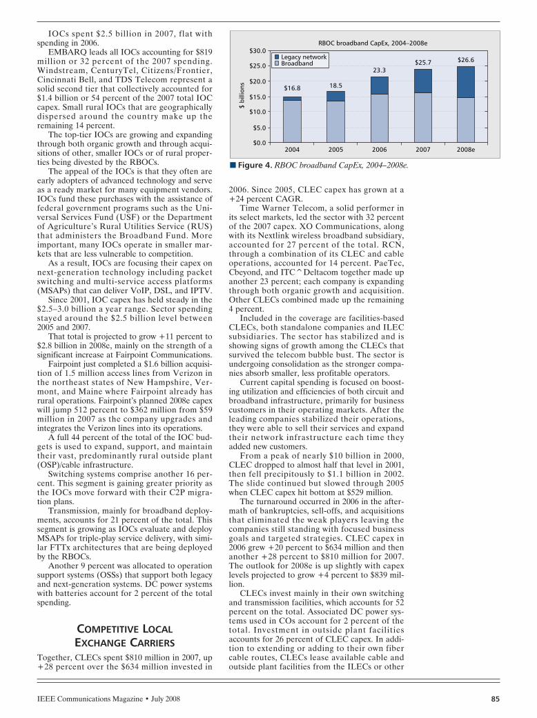
IEEE Communications Magazine • July 2008 85
IOCs spent $2.5 billion in 2007, flat withspending in 2006.
EMBARQ leads all IOCs accounting for $819million or 32 percent of the 2007 spending.Windstream, CenturyTel, Citizens/Frontier,Cincinnati Bell, and TDS Telecom represent asolid second tier that collectively accounted for$1.4 billion or 54 percent of the 2007 total IOCcapex. Small rural IOCs that are geographicallydispersed around the country make up theremaining 14 percent.
The top-tier IOCs are growing and expandingthrough both organic growth and through acqui-sitions of other, smaller IOCs or of rural proper-ties being divested by the RBOCs.
The appeal of the IOCs is that they often areearly adopters of advanced technology and serveas a ready market for many equipment vendors.IOCs fund these purchases with the assistance offederal government programs such as the Uni-versal Services Fund (USF) or the Departmentof Agriculture’s Rural Utilities Service (RUS)that administers the Broadband Fund. Moreimportant, many IOCs operate in smaller mar-kets that are less vulnerable to competition.
As a result, IOCs are focusing their capex onnext-generation technology including packetswitching and multi-service access platforms(MSAPs) that can deliver VoIP, DSL, and IPTV.
Since 2001, IOC capex has held steady in the$2.5–3.0 billion a year range. Sector spendingstayed around the $2.5 billion level between2005 and 2007.
That total is projected to grow +11 percent to$2.8 billion in 2008e, mainly on the strength of asignificant increase at Fairpoint Communications.
Fairpoint just completed a $1.6 billion acquisi-tion of 1.5 million access lines from Verizon inthe northeast states of New Hampshire, Ver-mont, and Maine where Fairpoint already hasrural operations. Fairpoint’s planned 2008e capexwill jump 512 percent to $362 million from $59million in 2007 as the company upgrades andintegrates the Verizon lines into its operations.
A full 44 percent of the total of the IOC bud-gets is used to expand, support, and maintaintheir vast, predominantly rural outside plant(OSP)/cable infrastructure.
Switching systems comprise another 16 per-cent. This segment is gaining greater priority asthe IOCs move forward with their C2P migra-tion plans.
Transmission, mainly for broadband deploy-ments, accounts for 21 percent of the total. Thissegment is growing as IOCs evaluate and deployMSAPs for triple-play service delivery, with simi-lar FTTx architectures that are being deployedby the RBOCs.
Another 9 percent was allocated to operationsupport systems (OSSs) that support both legacyand next-generation systems. DC power systemswith batteries account for 2 percent of the totalspending.
COMPETITIVE LOCALEXCHANGE CARRIERS
Together, CLECs spent $810 million in 2007, up+28 percent over the $634 million invested in
2006. Since 2005, CLEC capex has grown at a+24 percent CAGR.
Time Warner Telecom, a solid performer inits select markets, led the sector with 32 percentof the 2007 capex. XO Communications, alongwith its Nextlink wireless broadband subsidiary,accounted for 27 percent of the total. RCN,through a combination of its CLEC and cableoperations, accounted for 14 percent. PaeTec,Cbeyond, and ITC^Deltacom together made upanother 23 percent; each company is expandingthrough both organic growth and acquisition.Other CLECs combined made up the remaining4 percent.
Included in the coverage are facilities-basedCLECs, both standalone companies and ILECsubsidiaries. The sector has stabilized and isshowing signs of growth among the CLECs thatsurvived the telecom bubble bust. The sector isundergoing consolidation as the stronger compa-nies absorb smaller, less profitable operators.
Current capital spending is focused on boost-ing utilization and efficiencies of both circuit andbroadband infrastructure, primarily for businesscustomers in their operating markets. After theleading companies stabilized their operations,they were able to sell their services and expandtheir network infrastructure each time theyadded new customers.
From a peak of nearly $10 billion in 2000,CLEC dropped to almost half that level in 2001,then fell precipitously to $1.1 billion in 2002.The slide continued but slowed through 2005when CLEC capex hit bottom at $529 million.
The turnaround occurred in 2006 in the after-math of bankruptcies, sell-offs, and acquisitionsthat eliminated the weak players leaving thecompanies still standing with focused businessgoals and targeted strategies. CLEC capex in2006 grew +20 percent to $634 million and thenanother +28 percent to $810 million for 2007.The outlook for 2008e is up slightly with capexlevels projected to grow +4 percent to $839 mil-lion.
CLECs invest mainly in their own switchingand transmission facilities, which accounts for 52percent on the total. Associated DC power sys-tems used in COs account for 2 percent of thetotal. Investment in outside plant facilitiesaccounts for 26 percent of CLEC capex. In addi-tion to extending or adding to their own fibercable routes, CLECs lease available cable andoutside plant facilities from the ILECs or other
n Figure 4. RBOC broadband CapEx, 2004–2008e.
RBOC broadband CapEx, 2004–2008e
2004
$5.0
$ bi
llion
s
$0.0
$10.0
$15.0
$20.0
$25.0
$30.0
2005 2006 2007 2008e
18.5
23.3$25.7 $26.6Legacy network
Broadband
$16.8
CELENTANO LAYOUT 6/18/08 1:12 PM Page 85

IEEE Communications Magazine • July 200886
infrastructure providers in the form of capital-ized right-to-use (RTU) fees. Spending onimproving back-office systems and OSSsaccounted for another 12 percent.
CABLE MULTIPLESYSTEM OPERATORS
Cable MSO coverage comprises the top sevenpublicly-held cable MSOs. The top seven MSOsspent $12.0 billion in 2007. Comcast is the bigcat on the block and accounted for 50 percent ofthe sector total. Time Warner Cable made upanother 29 percent. Spending for both Comcastand TW Cable reflects the absorption of theacquired Adelphia assets. Cablevision Systemsand Charter Communications together account-ed for 16 percent. The remaining MSOs spent 5percent of the total.
Through 2007, the major MSOs claimed thatwith almost all of their cable plant converted tohybrid fiber coaxial (HFC), new “success-based”investment will be made in response to sub-scriber demand for bundled triple-play (voice,Internet data, video) or in some cases, quadru-ple-play (3-play + wireless) service offerings.
New MSO spending focuses on adding newsubscribers or revenue generating units (RGUs)and up selling the new service bundles to theseRGUs. These bundles can include basic and dig-ital video, premium digital and high-definition(HD) video services, high-speed Internet access,and VoIP telephony service.
The major cable MSOs, under the Spectrum-Co name, were big winners in the recent FederalCommunications Commission (FCC) spectrumauctions. We can expect that in the near future,these MSOs will offer their own branded wire-less services as they build out these licenses.
Cable MSO spending peaked at $17.5 billionin 2001. As network upgrade activity nearedcompletion, cable MSO capex declined –29 per-cent to $12.4 billion in 2002, then droppedanother –19 percent to $10.1 billion in 2003.With two-way HFC network upgrades complet-ed, MSO capex dropped another –6 percent to$9.5 billion in 2004 and a further –14 percent to$8.2 billion in 2005.
Since then, with the upgraded network inplace, the MSOs focused on capital investmentsrequired to connect new subscribers to their net-works and to add new services such as IP-basedcable telephony. Cable MSO capex grew to $9.9billion in 2006 and again to $12 billion in 2007, a+21 percent CAGR over the two years. Withcurrent guidance, cable MSO capex will decreasesomewhat by –6 percent to $11.3 billion in 2008e.
Cable MSO capex allocations for 2007 areshown in Fig. 5. Cable companies spent 47 per-cent of their 2007 budget on customer premiseequipment (CPE); comprising set-top boxes, dig-ital video recorders, and cable modems thatMSOs generally include as rental items alongwith the service charges. By contrast, the tele-phone companies do not include CPE in theircapital expenditure budgets after telco CPE wasderegulated in the 1980s.
Only 7 percent was spent on network upgradeand rebuilds reflecting the completion of thatactivity. Line extensions that are required toconnect new subscribers to the HFC backboneaccounted for another 11 percent. Investmentsin scalable infrastructure including head-endequipment and systems and packet-switching sys-tems absorbed another 19 percent. The sup-port/other category that includes call centers,back-office systems, billing systems, and fieldsupport and maintenance facilities made up theremaining 16 percent.
INTEREXCHANGE CARRIERSSprint Long Distance and Level3 Communica-tions lead this small group of publicly-heldinterexchange carriers (IXCs), each with 34 per-cent of the 2007 total capex of $1.8 billion.Together, Qwest Long Distance and GlobalCrossing account for the remaining 32 percent.
Note that the former AT&T Long Lines andMCI still provide interexchange carrier services, buttheir capital expenditures are now accounted for inthe total wireline spending of their respective par-ent companies, AT&T and Verizon, respectively.
The IXC business has been hard hit by ebbsand flows in long-haul traffic volumes that arebeing driven by flat-rate voice, unlimited Inter-net traffic, and growing wireless voice and datacall transport. Long distance carriers that builtout capacity in anticipation of a huge ramp inInternet traffic have fallen by the wayside orhave been bought for pennies on the dollar.
The remaining IXCs are adding long-hauloptical transport capacity as traffic volumes growand are gradually transforming their networkswitching through their own C2P programs. Atthe same time, these IXCs are expanding theirtraffic-management capabilities with new opticalswitches/routers, bandwidth management sys-tems, and OSSs.
n Figure 5. Cable MSO CapEx allocations, 2007.
Cable MSO CapEx allocations, 2007
2007 cable MSO CapEx = $12.0 billion
CPE47%
Supportcapital16%
Upgrade/rebuild
7%
Lineextensions
11%
Scalableinfrastructure
19%
CELENTANO LAYOUT 6/18/08 1:12 PM Page 86

IEEE Communications Magazine • July 2008 87
IXC spending peaked at $41.7 billion in 2000,driven by irrational exuberance. That leveldropped –31 percent to $28.9 billion in 2001.Both of these figures were inflated by World-com, Global Crossing, and Qwest. All threecompanies restated their financial reports forthose periods, and their executives were prose-cuted. IXC capex tumbled again by –78 percentto $6.4 billion in 2002, and declined steadilyeach year to $1.7 billion in 2006.
The turnaround took place in 2007 whencapex grew to $1.8 billion, up +10 percent on ayear-to-year basis. IXC capex is expected toremain flat at $1.8 billion for 2008e.
Current IXC investments are success-basedwith an increasing proportion shifted to enter-prise long-haul voice and data requirements; andwholesale wired and wireless voice, Internetdata, and increasingly, video transport.
Because they operate national terrestrial net-works, IXCs invest a combined 54 percent inlong-haul cable and transmission facilities.Switching systems accounted for just 9 percent in2007. We can expect a greater capex shift toswitching as the IXCs replace their aged tandemcircuit switches with packet switches.
OSSs account for 18 percent of the total. TheIXCs invest a lot of money in systems that oper-ate and maintain the network and provision andbill for services. DC power systems with back-upbatteries tallied 3 percent of the total.
WIRELESS COMPANIESU.S. wireless carriers served 232 million sub-scribers at the end of 2007. Wireless penetrationin the United States is now around 77 percent.The number of wireless subscribers surpassedwired subscribers some time ago. One wouldthink that the industry is reaching a saturationpoint and that a spending slowdown is inevitable.However, that does not appear to be the case.
On the contrary, demand for wireless servicescontinues. In their efforts to boost average rev-enue per user (ARPU) and to reduce customerchurn, wireless carriers are introducing new dataand video capabilities into their digital voice net-works.
Capital spending is concentrated among thebig four national carriers and accounted for $18billion or 85 percent of the $21 billion spent in2007.
Verizon Wireless led the pack with $6.5 bil-lion or 31 percent of the total. Sprint-Nextel fol-lowed at $5 billion or a 23 percent portion.AT&T Mobility and T-mobileUSA togethermade up another 31 percent. Regional carriersled by Alltel and US Cellular accounted for the15 percent balance.
Regional carriers affiliated with the big fourare upgrading their networks in tandem with thenational carriers to maintain roaming integrity.More important, national and regional carriersalike regularly swap or sell licenses to createcontiguous operating areas.
Consolidation continues apace across theindustry as the national carriers shore up theircoverage areas and augment their subscribercounts.
All wireless carriers, particularly the national
carriers, were big participants in the recent FCCspectrum auctions. Opening up new frequencybands holds the promise of new wireless servicesthat utilize high-speed data links.
Wireless network investment is cyclical,involving adding capacity in waves to meet cus-tomer demand. Wireless capex peaked in 2001 at$24.7 billion, then declined and subsequentlyrecovered to another peak of $27.4 billion in2005.
2006 spending declined –7 percent to $25.4billion, then dropped another –17 percent to$21.0 billion in 2007. These reductions had moreto do with the completion of network build-outsin licensed areas and less to do with scale-backsdue to economic conditions. Certainly, thebiggest drop in 2007 was due to the fact thatAT&T Mobility completed a number of invest-ment phases associated with the Cingular andAT&T Wireless integration.
The year-end 2007 view is that 2008e wirelessspending likely will grow modestly at +2 percentto $21.6 billion. Although improving quality andcoverage remains an important driver, fewer newcell sites are being added. Rolling out third gen-eration (3G) wireless services is a priority thatcan be implemented in many cases throughincremental cell site additions versus buildingnew cell sites.
Figure 6 shows how the wireless carriers col-lectively allocated the capex in 2007. Cell siteequipment is the biggest piece, absorbing 44 per-cent of the total capex, including terminal gearfor terrestrial back-haul systems. Cell site invest-ments include base station radios, the RF sub-system (antennas, coaxial cable, filters), and RFpower amplifiers, but exclude the towers andequipment shelters.
n Figure 6. Wireless CapEx allocations.
Wireless CapEx allocations
2007 wireless CapEx = $21.6 b* Includes base stations, radios,RF subsystem, RF power amps
Backhaul5% Switching
12%
Towers/shelters9%
DC power,Gensets
4%
ESI17%
Billing, OSS14%
*Cell sites39%
CELENTANO LAYOUT 6/18/08 1:12 PM Page 87

IEEE Communications Magazine • July 200888
Switching systems account for 12 percent ofthe total. An increasing proportion of switchingexpenditures are for packet switches that dis-place the original circuit switches.
Engineering and installation (E&I) servicesmake up 17 percent of the total. E&I includes asignificant amount of site location, RF interfer-ence studies, site acquisition, and site engineer-ing activity that must occur even before theequipment is installed. Billing and OSSs makeup another 14 percent.
Tower and shelters account for 9 percent ofthe total. It is becoming more difficult for theindustry to erect new towers due to municipalzoning restrictions and public objections. Morecell sites are either colocated on existing towersor are being installed on non-tower structuressuch as building roof tops.
DC power systems with batteries, and back-up generators account for roughly 4 percent ofthe total. Of necessity, wireless carriers haveboosted the back-up power reserves at cell sitesas subscribers have become increasingly depen-dent on wireless services.
WHY UNDERSTANDINGCARRIER CAPEX IS IMPORTANT
An understanding of the capital expenditures oftelecommunication carriers is important to threekey groups: customers, vendors, and investors.
Customers, whether consumers or businesses,increasingly are demanding an anywhere, any-time, and any media model for their communica-tions services. Moreover, they expect a highquality of service at a reasonable price. Cus-tomers are asking, “Are the connections therewhen and where I want them? Are they reliable?Are they fast?” Certainly, customers are less tol-erant of poor quality of service and are inclinedto switch service providers in search of better ser-vice. So the level of capital investments that thecarriers are making in their networks is an indi-cation of their commitment to delivering a richset of high-quality services to their customers.
Vendors use capex as a bellwether for futurepurchases of equipment and services by thecarriers. Many vendors try to tie their ownsales performance to their customers’ capitalexpenditures. The caveat with that approach isthat the capex mix is steadily shifting towardnext-generation systems and away from legacyproducts. So it is important for vendors tostudy the capex allocations and spending pat-terns as a way of discerning their respectiveopportunities and risks in a fluid spendingenvironment.
Investors can use capex to evaluate the per-formance of management and to decide if agiven carrier represents an investment opportu-nity or not. Comparing capex/revenues andcapex/EBITDA provides investors with insightsinto how efficiently management is using its cap-ital to expand the business, and what sort offinancial results are being achieved.
CONCLUSIONCarrier capital expenditure is a key metric foranalyzing and understanding the volume andpace of telecommunications infrastructure mod-ernization. Capex is deployed in cycles and isnever linear in its nature, whereas the mix ofspending allocations is constantly changing. Inthe end, the continual study of carrier capitalexpenditures provides valuable insights into thecritical telecom industry that are not availablefrom any other source.
BIOGRAPHYJOHN M. CELENTANO ([email protected]) holds aB.Eng in electrical engineering from McMaster University.He studied marketing at the University of California-SantaBarbara and is a graduate of the Bell System Center forTechnical Education. He is president of Skyline MarketingGroup, a Baltimore-based telecom market analysis and con-sulting firm. He is publisher of the CapEx Report™, anauthoritative source of capital expenditure analysis. He hasover 30 years of telecommunications experience in engi-neering at Bell Canada, marketing at Nortel Networks, andconsulting at NBI. In addition to publishing the CapExReport™, he writes extensively on network infrastructuremarkets.
Capex is deployed in
cycles and is never
linear in its nature,
whereas the mix of
spending allocations
is constantly
changing. In the
end, the continual
study of carrier
capital expenditures
provides valuable
insights into the
critical telecom
industry that are not
available from any
other source.
CELENTANO LAYOUT 6/18/08 1:12 PM Page 88

IEEE Communications Magazine • July 200890 0163-6804/08/$25.00 © 2008 IEEE
INTRODUCTION
The key drivers for deploying fiber to the x(FTTx) infrastructures are advanced multimediaservices (including Internet Protocol television[IPTV], high definition television [HDTV], andvideo on demand [VoD]); ultra-high-bit-rateInternet access (50–100 Mb/s); and corporatebroadband applications such as videoconferenc-ing; hosted voice-over-IP (VoIP); and IP virtualprivate networks (VPNs). Video services, in par-ticular, justify the need for the ultra-high bitrates. For some passive optical network (PON)deployments, video is driving investment intoradio frequency (RF) video for the near termand increased bandwidth on the data channels tosupport IP video in the longer term. Telecom-munication companies (telcos) and cable pro-viders appear to have settled on 100 Mb/s to theconsumer as the current target, with higher ratesto businesses (1 Gb/s).
For those densely populated regions of theworld where subscribers in high-rise multi-dwelling units (MDUs) might do a significantamount of resource sharing, traffic within onebuilding can be handled by an Ethernet switchor a remote digital subscriber line access multi-plexer (DSLAM) in the basement. In this case, adedicated single fiber link back to the centraloffice makes a lot of sense.
In this article, we give a snapshot of the cur-rent status of FTTx, the growth rate of the tech-nology, and the state of FTTx in different regionsof the world. We also take a look at next-genera-tion PON systems, as well as the environmentalimpact of gigabit passive optical network(GPON). We purposely omitted one area in thisarticle — a detailed analysis and comparison ofthe different FTTx technologies. There are num-ber of excellent articles [1–3] that cover thattopic in detail. We also take a look at what cableoperators are doing to compete with the telcos.
WHERE ARE WE TODAY ANDWHERE ARE WE GOING?
At the end of 2007, there were nearly 29 millionsubscribers connected with FTTx infrastructureworldwide. Most of the subscribers are receivingservice via fiber to the home (FTTH) or fiber tothe building (FTTB). Together, the two termscommonly are called fiber to the premise(FTTP). Figure 1 illustrates the global growth ofFTTx for the years 2005–2012. The growth isexpected to continue at a very fast pace with thenumber of FTTx subscribers expected to grow toover 100 million by the end of 2012. Today FTTxbroadband comprises 7.5 percent of all broad-band users and is expected to comprise 16 per-cent of all broadband users by 2012.
There are two fundamental FTTx architec-tures deployed in today’s access networks: pointto multipoint, which is commonly referred to asa PON and point to point (P2P, referred to asactive Ethernet). PONs have a single fiber thatruns from the central office to deep in the net-work and usually terminates at a splitter cabinet.Although the splitter cabinet typically contains a1×32 splitter, split ratios of 1×16 and 1×8 some-times are used. New standards are calling foreven larger split ratios of 1×64 and 1×128. For afuture potential upgrade to wavelength divisionmultiplexing (WDM)-PON, an arrayed waveg-uide (AWG, for wavelength multiplexing anddemultiplexing) can be colocated. From thesplitter cabinet, short runs of fiber connect eachof the homes. With the point-to-point (P2P)architecture, a single fiber runs all the way fromthe central office to the home. Both architec-tures are deployed, with P2P currently outpacingthe PON installations as can be seen in Fig. 2.The figure also shows that by 2012, PON willcatch up to P2P; and it is expected that P2P willstart to decline, and PON will continue to growand will dominate.
For those densely populated regions of theworld, MDUs can take advantage of resourcesharing through traffic aggregation with a cen-tralized Ethernet switch or DSLAM in eachbuilding. In this case, a dedicated single fiberlink back to the central office makes a lot ofsense. China-India and Asia-Pacific are currentlythe leading regions for P2P access due to theirnumerous densely populated areas. We expectWestern Europe to catch up and surpass Asia-Pacific in the future.
The PON market worldwide is expected to
ABSTRACT
By the end of 2007, there were 29 millionsubscribers to services supplied by FTTx equip-ment, and by 2012, it is expected the number willgrow to over 100 million subscribers. In thispaper, we review the current status of FTTx andanalyze what is taking place in different regionsof the world. We view the future for FTTx interms of growth and the types of FTTx productswe might see.
INDUSTRY ANALYST FORUM
Lynn Hutcheson, Ovum
FTTx: Current Status and the Future
HUTCHESON LAYOUT 6/20/08 11:34 AM Page 90
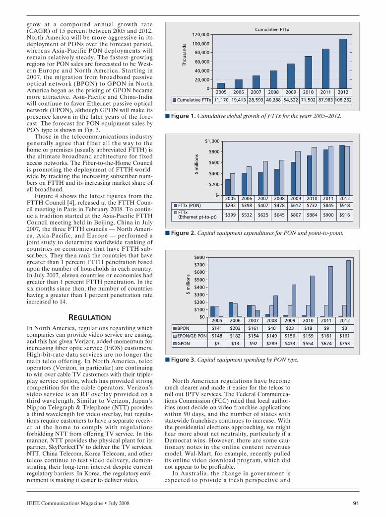
IEEE Communications Magazine • July 2008 91
grow at a compound annual growth rate(CAGR) of 15 percent between 2005 and 2012.North America will be more aggressive in itsdeployment of PONs over the forecast period,whereas Asia-Pacific PON deployments willremain relatively steady. The fastest-growingregions for PON sales are forecasted to be West-ern Europe and North America. Starting in2007, the migration from broadband passiveoptical network (BPON) to GPON in NorthAmerica began as the pricing of GPON becamemore attractive. Asia-Pacific and China-Indiawill continue to favor Ethernet passive opticalnetwork (EPON), although GPON will make itspresence known in the later years of the fore-cast. The forecast for PON equipment sales byPON type is shown in Fig. 3.
Those in the telecommunications industrygenerally agree that fiber all the way to thehome or premises (usually abbreviated FTTH) isthe ultimate broadband architecture for fixedaccess networks. The Fiber-to-the-Home Councilis promoting the deployment of FTTH world-wide by tracking the increasing subscriber num-bers on FTTH and its increasing market share ofall broadband.
Figure 4 shows the latest figures from theFTTH Council [4], released at the FTTH Coun-cil meeting in Paris in February 2008. To contin-ue a tradition started at the Asia-Pacific FTTHCouncil meeting held in Beijing, China in July2007, the three FTTH councils — North Ameri-ca, Asia-Pacific, and Europe — performed ajoint study to determine worldwide ranking ofcountries or economies that have FTTH sub-scribers. They then rank the countries that havegreater than 1 percent FTTH penetration basedupon the number of households in each country.In July 2007, eleven countries or economies hadgreater than 1 percent FTTH penetration. In thesix months since then, the number of countrieshaving a greater than 1 percent penetration rateincreased to 14.
REGULATIONIn North America, regulations regarding whichcompanies can provide video service are easing,and this has given Verizon added momentum forincreasing fiber optic service (FiOS) customers.High-bit-rate data services are no longer themain telco offering. In North America, telcooperators (Verizon, in particular) are continuingto win over cable TV customers with their triple-play service option, which has provided strongcompetition for the cable operators. Verizon’svideo service is an RF overlay provided on athird wavelength. Similar to Verizon, Japan’sNippon Telegraph & Telephone (NTT) providesa third wavelength for video overlay, but regula-tions require customers to have a separate receiv-er at the home to comply with regulationsforbidding NTT from offering TV service. In thismanner, NTT provides the physical plant for itspartner, SkyPerfectTV to deliver the TV services.NTT, China Telecom, Korea Telecom, and othertelcos continue to test video delivery, demon-strating their long-term interest despite currentregulatory barriers. In Korea, the regulatory envi-ronment is making it easier to deliver video.
North American regulations have becomemuch clearer and made it easier for the telcos toroll out IPTV services. The Federal Communica-tions Commission (FCC) ruled that local author-ities must decide on video franchise applicationswithin 90 days, and the number of states withstatewide franchises continues to increase. Withthe presidential elections approaching, we mighthear more about net neutrality, particularly if aDemocrat wins. However, there are some cau-tionary notes in the online content revenuesmodel. Wal-Mart, for example, recently pulledits online video download program, which didnot appear to be profitable.
In Australia, the change in government isexpected to provide a fresh perspective and
n Figure 1. Cumulative global growth of FTTx for the years 2005–2012.
2005
11,170Cumulative FTTx
2006
Cumulative FTTx
19,413
2007
28,593
2008
40,288
2009
54,522
2010
71,502
2011
87,983
2012
108,262
40,000
Thou
sand
s
20,000
0
60,000
80,000
100,000
120,000
n Figure 2. Capital equipment expenditures for PON and point-to-point.
2005 2006 2007 2008 2009 2010 2011 2012$292FTTx (PON) $398 $407 $478 $612 $732 $845 $918
$399 $532 $625 $645 $807 $884 $900 $916
$200
$ m
illio
ns$-
$400
$600
$800
$1,000
FTTx (Ethernet pt-to-pt)
n Figure 3. Capital equipment spending by PON type.
2005 2006 2007 2008 2009 2010 2011 2012
$141BPON $203 $161 $40 $23 $18 $9 $3
$148 $182 $154 $149 $156 $159 $161 $161
$3 $13 $92 $289 $433 $554 $674 $753
$200
$ m
illio
ns
$100
$0
$300
$400
$500
$600
$700
$800
EPON/GE-PON
GPON
HUTCHESON LAYOUT 6/20/08 11:34 AM Page 91

IEEE Communications Magazine • July 200892
urgency to Telstra’s fiber to the node/neighbor-hood (FTTN) next-generation rollout, but nag-ging questions such as competitor access andwholesale tariffs remain to be resolved.
Regulation continues to be a major factor inEurope, despite the recently released EuropeanCommission (EC) telecom reform proposals.Commissioner Viviane Reding said that, onaverage, 89.5 percent of direct access is stilldominated by incumbents in the EuropeanCommunity, still far from ideal. Therefore,Reding strongly believes in functional separa-tion — that is, separating telecom networksfrom services and having different managementstructures for each — as a last-resort remedy totackle the most persistent bottlenecks andensure fair and effective competition. Function-al separation is being opposed by the EuropeanTelecommunications Network Operators Asso-ciation (ETNO), the representative for incum-bent operators, as being too costly. Whenmentioned as a possible template of regulationacross Europe, some regulators expressed seri-ous doubts over functional separation. Howev-er, the European Regulators Group iscommitted to providing guidelines to assistnational regulatory authorities (NRAs) in mak-ing a cost/benefit analysis.
The EC strongly believes in fostering compe-tition and preventing monopolies. It accom-plished this very effectively with its local loopunbundling policy, under which incumbent oper-ators must provide competitors with access totheir copper infrastructure. Whereas that policywill continue for copper local loops, it likely willchange for FTTH. Vivian Reding spoke viavideo at the European FTTH conference [4] onFebruary 28, 2008 and announced that the ECwill be publishing a new policy on how to handleFTTH sometime near the middle of 2008. Shedid reinforce the European Union (EU)’s policyof promoting competition and stifling monopo-lies but emphasized the importance of the FTTH
role in keeping Europe competitive with the restof the world, while at the same time growing theeconomy.
The proposal before the European Parlia-ment and by member governments in the Euro-pean Council will be debated. There will be aperiod of at least two years before the NRAs areable to mandate functional separation. By then,the overseas performance of Australia and NewZealand, which are splitting up their incumbentsbased on the UK model of functional separation(Openreach), most likely will provide analyticalevidence of the successes and failures of thepractice. In the EU, the Swedish regulator iswaiting for its parliament to approve the rele-vant legislation; in Italy, the CommunicationsRegulatory Authority (AGCOM) is startingnegotiations with Telecom Italia; and Poland isconsidering similar measures. Since thesereforms are newly released, it is not clear yet towhat extent incumbents will go ahead with theirnext-generation rollout plans, but we can expectfurther delays and scaling down of deploymentsuntil this is resolved.
COSTS TO DEPLOY FTTXThere are a number of factors that affect thecost to install FTTx infrastructure and equip-ment, such as whether the installation is aerialor buried. There is not much one can do toreduce the cost of hanging or burying fibercable or reducing the actual cost of the fibercable, as they are well down the maturity curve.However, there have been some fairly simpleimprovements in reducing the amount of laborrequired to install the equipment. For example,Tellabs has started fitting its optical networkterminals (ONTs) with a single screw mountthat provides for automatic self-leveling.Another labor-saving implementation is theuse of preconnectorized fiber drops. ADCTelecommunications claims that in 2006 theirshipments for preconnectorized fixed length(the company has 13 different lengths) fiberdrops grew substantially. This replaces the tra-ditional technique of fiber splicing in the field.It also saves on wasted fiber because whensplicing in the field, the installers cut the fiberto fit the installation.
There are four network architectures current-ly being deployed for FTTx that are consideredin this analysis; BPON, GPON, EPON, and Eth-ernet point to point. The three PON architec-tures are very similar in terms of infrastructure,design, and installation. A single fiber is termi-nated at an optical line termination/terminal(OLT) in the central office and connected to apassive splitter deep in the network. Typically,the splitter is a 1×32 but can be 1×16, 1×8, or1×4. The split ratio is largely dependent on theoptical power budget and the distance from thecentral office to the furthest customer. Forexample, Verizon uses a 1×32 splitter for dis-tances of 11 km or shorter and a 1×16 splitterfor distances greater than 11 km. About 85 per-cent of Verizon’s installations fall into the short-er distance category. The standards are nowincorporating the ability to use larger split ratiossuch as 1×64, and there are discussions to go as
n Figure 4. Economies having greater than 1 percent FTTH/FTTB householdpenetration.
Economies with the highest penetration of fiber-to-the-home / building+LAN
Hong
Kong
5%Hou
seho
ld p
enet
rati
on
0%
10%
15%
20%
Year end 2007 rankingSource: Fiber-to-the-Home CouncilFebruary 2008
25%
35%
30%
Economies where majority architectureis fiber to the homeEconomies where majority architectureis fiber to the building + LAN
Sout
h Ko
rea
Japa
n
Swed
en
Taiw
an
Norway
Denm
ark
United
Stat
es
Slova
kia
Icelan
d
P. R.
Chin
a
The N
ethe
rland
sIta
ly
Singa
pore
Economies with greaterthan 1% household penetration
HUTCHESON LAYOUT 6/20/08 11:34 AM Page 92
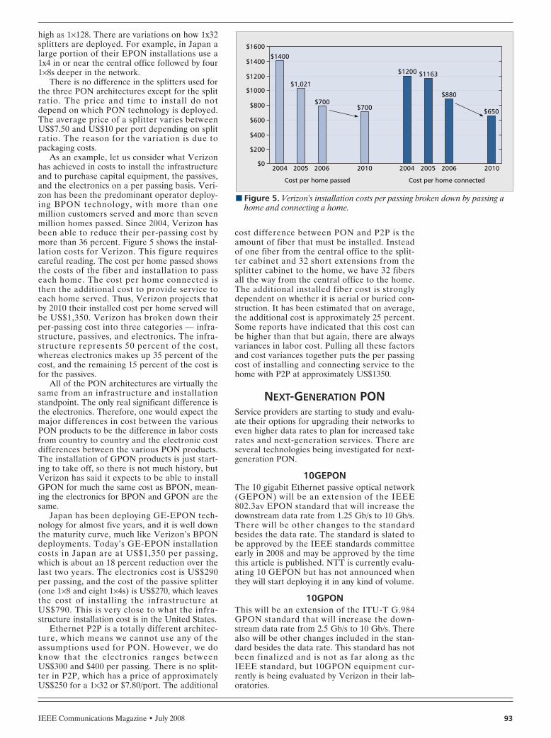
IEEE Communications Magazine • July 2008 93
high as 1×128. There are variations on how 1x32splitters are deployed. For example, in Japan alarge portion of their EPON installations use a1x4 in or near the central office followed by four1×8s deeper in the network.
There is no difference in the splitters used forthe three PON architectures except for the splitratio. The price and time to install do notdepend on which PON technology is deployed.The average price of a splitter varies betweenUS$7.50 and US$10 per port depending on splitratio. The reason for the variation is due topackaging costs.
As an example, let us consider what Verizonhas achieved in costs to install the infrastructureand to purchase capital equipment, the passives,and the electronics on a per passing basis. Veri-zon has been the predominant operator deploy-ing BPON technology, with more than onemillion customers served and more than sevenmillion homes passed. Since 2004, Verizon hasbeen able to reduce their per-passing cost bymore than 36 percent. Figure 5 shows the instal-lation costs for Verizon. This figure requirescareful reading. The cost per home passed showsthe costs of the fiber and installation to passeach home. The cost per home connected isthen the additional cost to provide service toeach home served. Thus, Verizon projects thatby 2010 their installed cost per home served willbe US$1,350. Verizon has broken down theirper-passing cost into three categories — infra-structure, passives, and electronics. The infra-structure represents 50 percent of the cost,whereas electronics makes up 35 percent of thecost, and the remaining 15 percent of the cost isfor the passives.
All of the PON architectures are virtually thesame from an infrastructure and installationstandpoint. The only real significant difference isthe electronics. Therefore, one would expect themajor differences in cost between the variousPON products to be the difference in labor costsfrom country to country and the electronic costdifferences between the various PON products.The installation of GPON products is just start-ing to take off, so there is not much history, butVerizon has said it expects to be able to installGPON for much the same cost as BPON, mean-ing the electronics for BPON and GPON are thesame.
Japan has been deploying GE-EPON tech-nology for almost five years, and it is well downthe maturity curve, much like Verizon’s BPONdeployments. Today’s GE-EPON installationcosts in Japan are at US$1,350 per passing,which is about an 18 percent reduction over thelast two years. The electronics cost is US$290per passing, and the cost of the passive splitter(one 1×8 and eight 1×4s) is US$270, which leavesthe cost of installing the infrastructure atUS$790. This is very close to what the infra-structure installation cost is in the United States.
Ethernet P2P is a totally different architec-ture, which means we cannot use any of theassumptions used for PON. However, we doknow that the electronics ranges betweenUS$300 and $400 per passing. There is no split-ter in P2P, which has a price of approximatelyUS$250 for a 1×32 or $7.80/port. The additional
cost difference between PON and P2P is theamount of fiber that must be installed. Insteadof one fiber from the central office to the split-ter cabinet and 32 short extensions from thesplitter cabinet to the home, we have 32 fibersall the way from the central office to the home.The additional installed fiber cost is stronglydependent on whether it is aerial or buried con-struction. It has been estimated that on average,the additional cost is approximately 25 percent.Some reports have indicated that this cost canbe higher than that but again, there are alwaysvariances in labor cost. Pulling all these factorsand cost variances together puts the per passingcost of installing and connecting service to thehome with P2P at approximately US$1350.
NEXT-GENERATION PONService providers are starting to study and evalu-ate their options for upgrading their networks toeven higher data rates to plan for increased takerates and next-generation services. There areseveral technologies being investigated for next-generation PON.
10GEPONThe 10 gigabit Ethernet passive optical network(GEPON) will be an extension of the IEEE802.3av EPON standard that will increase thedownstream data rate from 1.25 Gb/s to 10 Gb/s.There will be other changes to the standardbesides the data rate. The standard is slated tobe approved by the IEEE standards committeeearly in 2008 and may be approved by the timethis article is published. NTT is currently evalu-ating 10 GEPON but has not announced whenthey will start deploying it in any kind of volume.
10GPONThis will be an extension of the ITU-T G.984GPON standard that will increase the down-stream data rate from 2.5 Gb/s to 10 Gb/s. Therealso will be other changes included in the stan-dard besides the data rate. This standard has notbeen finalized and is not as far along as theIEEE standard, but 10GPON equipment cur-rently is being evaluated by Verizon in their lab-oratories.
n Figure 5. Verizon's installation costs per passing broken down by passing ahome and connecting a home.
Cost per home passed Cost per home connected
$1400
$200
$0
$400
$600
$800
$1000
$1200
$1400
$1600
2004 2005 2006 2010 2004 2005 2006 2010
$1,021
$700$700
$1200 $1163
$880
$650
HUTCHESON LAYOUT 6/20/08 11:34 AM Page 93

IEEE Communications Magazine • July 200894
WDM-PON
This has quite often been referred to as thefuture-proof FTTx network as it has the abilityto deliver >1 Gb/s symmetrical to each home orbusiness. It uses dense wavelength division mul-tiplexing (DWDM) technology that has longbeen used in the long haul and metro markets.Logically, it is a P2P system because it delivers adedicated wavelength to each premise, althoughphysically, it is point to multipoint. Korea Tele-com [5] has installed 150,000 lines of WDM-PON systems with a product from Novera Opticsand is continuing to deploy WDM-PON in limit-ed quantities.
Novera Optics [6] has taken a first step in sig-nificantly reducing the cost of the WDM-PONproducts by developing a technology that elimi-nates the requirement for a wavelength specificlaser (such as a distributed feedback [DFB]laser) in the ONT. The company uses a tech-nique known as wavelength locking, which has acontinuous wave (CW) broadband light sourcelocated at the OLT that is used to generate aseed signal for locking the wavelengths of theremotely located Fabry-Perot (FP) lasers in theONT. The seed signal is transmitted downstreamthrough a single fiber into a wavelength demulti-plexer that divides the signal into a number(equal to the number of ONTs) of narrowbandDWDM channels. Each spectral slice then istransmitted through a single distribution fiberand injected into a remotely located FP laserdiode. When the FP laser is current modulatedwith the electrical data signal, the injected seedsignal forces the laser to operate in a narrowwavelength range defined by the optical pass-band of the DWDM transmission link. Thiswavelength-locking process can be understoodeasily when one realizes that the FP laser basi-cally acts as an optical amplifier that modulates,amplifies, and reflects the injected broadbandlight source seeding signal. The FP laser is notcapable of free lasing due to the gain saturationcaused by the amplified seeding signal. Thisresults in a stable narrowband output data sig-nal, free from any of the noise associated withmode hopping found in standard free-runningFP lasers.
HYBRID WDM-PONHybrid WDM-PON basically combines a GPONtopology with a WDM-PON topology. A WDM-PON system is connected to an OLT just as inthe standard WDM-PON system. Each wave-length is then fed into its own dedicated GPONsystem. This can significantly increase the num-ber of ONTs per OLT port. If there are 16 wave-lengths and a 1×32 splitter, then the number ofONTs fed by a single port OLT can be as highas 512.
LONG REACH PONThere has been a strong desire by some coun-tries to reduce the number of central offices toconsolidate operations and reduce cost. TheUnited Kingdom started discussing this possibili-ty over 15 years ago. It has about 5,000 centraloffices and would like to reduce that number to50–100 or even less, if possible. One idea that
was promoted is extending the reach of the exist-ing PON technology from 20 km to 100 km.Alphion, a U.S. company, recently introduced along reach PON product using semiconductoroptical amplifier (SOA) technology to extendthe reach of GPON to 80–100 km.
OCDMA-PONA relatively new FTTx architecture, optical(O)CDMA, which uses code division multiplex-ing access (CDMA) has started gaining atten-tion. This is much the same technique as used inmobile wireless technology. This techniquepromises very secure signals [7] and very highdata rates. It is quite complicated and is in itsinfancy.
CABLE OPERATORS INTRODUCINGPON PRODUCTS
Much of what has been discussed in this articleis related to products and technology deployedby the telcos. What are cable operators doing tocompete with the telcos? A new data-over-cableservice interface specification (DOCSIS) 3.0standard that has the capability of providing 150Mb/s to the end user is being introduced. Thisstandard uses a technology called channel bond-ing that combines up to four 38.5 Mb/s channelsinto a single data stream. Currently, cable opera-tors are just starting to test equipment that isDOCSIS 3.0 compliant. They say full-scale roll-out will start in 2009. Another technology that isbeing introduced into the market and one thathas been around for quite some time is video ondemand (VoD). Even though VoD has beenaround for a long time, it has not received a lotof attention. However, with the introduction ofHDTV and its high bandwidth requirements,VoD appears to be a satisfactory solution to pro-viding high-data rate, triple-play services.
In the United States, cable operators havespent billions of dollars over the past couple ofdecades upgrading their networks to hybrid fibercoax (HFC) with fiber from the head end or hubto very deep in the network and then, coax forthe last kilometer to the home. The problem isthat most of the Greenfield housing develop-ments are demanding that the communicationsinfrastructure be all fiber, which means therewill be no coax for the MSOs to provide servicesin these new developments. A number of equip-ment suppliers have addressed this by introduc-ing their own brand of PON; for example, cablePON (CPON) by Motorola, DOCSIS PON(DPON) by Scientific Atlanta of Cisco, and RFover glass (RFOG) by AllOptic. This PON net-work uses the same existing cable modem termi-nation system (CMTS) and cable modemproducts that are used in the HFC networks,which means no new product development isrequired.
IT IS GREENER ON THE GPON FTTH SIDEHigher speed equals higher power consumption.With the focus on delivering much higher band-width, there has been a drastic increase in theamount of power consumed at the central office.Along with this comes a drastic increase in thecost to supply that power, both in terms of dol-
The real impact for
you and me is not
the increased cost of
higher power
consumption but the
impact this increased
power consumption
has on the
environment.
Through the analysis
performed, it can be
seen that deploying
GPON results in a
significant reduction
in carbon dioxide
emissions.
HUTCHESON LAYOUT 6/20/08 11:34 AM Page 94

IEEE Communications Magazine • July 2008 95
lars and eventually, the impact on the environ-ment. Much emphasis is being placed on globalwarming and other environmental effects today;it appears that GPON may have a much lessnegative impact than other broadband technolo-gies. A paper [8] presented by Dan Parsons ofBroadlight at IEEE Globecom 2007 elucidatesjust how environmentally friendly GPON tech-nology can be.
For example, in one European country, theincumbent service provider consumes more than2 TW-hours (2,000,000 MW-hours) of energy.With the rising cost of power, the serviceprovider is very concerned about what the impactwill be on its energy bill when implementing newhigh-speed technologies. The cost of migratingfrom asymmetric DSL (ADSL2) to very high bit-rate DSL (VDSL2) increases the power require-ment by more than a factor of two.
To put this in perspective, a service providerwith six million ADSL subscribers will draw 9,600kW-hours (1.6 W per ADSL subscriber) of ener-gy at a cost of about $8 million per year. If onemigrates to VDSL2 at 3.6 W per subscriber, thepower costs increase by more than a factor oftwo. This is probably not very significant becausethe service provider has a budget in the billionsof dollars, and it can probably recoup some or allof the additional power cost due to increased tar-iffs for additional or expanded services.
The real impact for you and me is not theincreased cost of higher power consumption butthe impact this increased power consumptionhas on the environment. At the end of 2007,there were about 250 million DSL subscribersworldwide requiring central offices (COs) todeliver about 400 MW of power. This analysis isfor equipment and does not include air condi-tioning. According to the telcos, it takes 60W ofAC to cool 100W from equipment. Thus, a 60percent premium is required every time morepower is added to the CO. This power require-ment has an energy impact which translates intoan environmental carbon footprint that can becalculated via a Web site maintained by the U.S.utility, Pacific Gas and Electric (PG&E). Theenergy consumed at the CO to power the 250million DSL subscribers contributes over 850,000tons of carbon dioxide to the environment everyyear. To put this in perspective, this figure isequivalent to the burning of 90,000,000 gallonsof gasoline or the carbon dioxide contribution of
500,000 homes in the United States over thecourse of a year.
Through the analysis performed, it can beseen that deploying GPON results in a signifi-cant reduction in carbon dioxide emissions asshown in Table 1. The table shows just howmuch the emissions are reduced per one millionGPON subscribers as compared to ADSL2,VDSL2, and Ethernet P2P.
REFERENCES[1] The Book on FTTx, ADC Telecommunications, 2005.[2] “GPON vs. EPON: The Battle Lines are Drawn”; http://
www.fibers.org, Dec. 19, 2005.[3] S. McClelland, “The FTTH Cost Challenge,” Telecommun.
Online, May 31, 2007.[4] Euro. FTTH Council Conf., Paris, France, Feb. 27–28, 2008.[5] C.-H. Lee et al., “WDM-PON Experiences in Korea,” J.
Opt. Networking, May 2007.[6] Novera Optics Web site; see whitepapers.[7] X. Wang et al., “Demonstration of Over 128-Gb/s-
Capacity (12-User x 10.71-Gb/s/User) AsynchronousOCDMA Using FEC and AWG-Based Multiport OpticalEncoder/Decoders,” IEEE Photonics Tech. Lett., Aug. 1,2006.
[8] D. Parsons, “GPON — Reversing the Power BandwidthTrend: In Other Words, Saving the Environment,” IEEEGLOBECOM ’07, Washington, DC, Nov. 28–30, 2007.
BIOGRAPHYLYNN HUTCHESON ([email protected]) is currentlyvice president, communication components at Ovum RHK.He focuses his efforts on the technology, market trends,vendors, service providers, and so on for next-generationoptical access. He has over 30 years of research, productdevelopment, and executive management experience infiber optic technologies, photonics, access networks, andHFC systems technologies.
n Table 1. Comparison of GPON vs. other high-speed access technologies forpower and emission savings.
GPON vs. Power savings Power costsavings CO2 savings
ADSL2 ~11 MWh $1.2M ~4.8M lbs CO2 or 250kgallons of gas
VDSL2 ~29 MWh $2.9M ~13.6M lbs CO2 or 700kgallons of gas
E-FTTH ~27 MWh $2.7M ~12.7M lbs CO2 or 655kgallons of gas
HUTCHESON LAYOUT 6/20/08 11:34 AM Page 95

IEEE Communications Magazine • June 200896 0163-6804/08/$25.00 © 2008 IEEE
INTRODUCTION
For more than three years, cable operators andequipment vendors have been shaking theirheads in dismay at the growing dilemma unfold-ing before them. Despite the massive, $100 bil-lion-plus investment by the industry in newhybrid fiber coax (HFC) plants and equipmentover the past dozen years, cable executives haveseen clear signs that their extensive networkupgrades to 750-MHz, and even 860-MHz, sys-tems did not create enough capacity to handleall the new digital services they wish to or mustcarry.
In fact, cable technology strategists reluctant-ly recognized that subscriber demand for pre-cious bandwidth, which has been climbing muchfaster than anyone expected, might far outstriptheir ability to meet the soaring demand quitesoon. Thanks to a diverse mix of high-definitiontelevision (HDTV) channels, video-on-demand(VoD) services, digital video recording (DVR)applications, digital must-carry requirements,Internet video downloads, and time-shifting ser-vices, among others, cable subscribers will con-tinue to guzzle bandwidth in much greateramounts than ever anticipated. In addition, withsuch prime cable rivals as DirecTV, VerizonCommunications, and Dish Network toutingtheir growing HD programming lineups, cable
operators must offer even more of these “band-width hogs” just to stay competitive in the fierce-ly contested multichannel video market.
In the face of such daunting challenges, cableoperators are increasingly turning to a wideassortment of technological tools to expand theiroverall radio frequency (RF) capacity and to usetheir existing bandwidth more efficiently. Overthe past year or so, switched digital video (SDV)has emerged as the leading choice for that pur-pose, beating such alternatives as fiber node seg-mentation (also known as node splitting),MPEG-4 video encoding, improved QAM mod-ulation, plant upgrades to 1-GHz capacity, out-of-band spectrum overlays, and deep-fiber drops,among other options. As a result, numerousmultiple-system operators (MSOs) are nowrolling out SDV technology throughout the con-tinent. The MSOs include all of the Big Fiveplayers in the United States — Comcast, TimeWarner Cable, Cox Communications, CharterCommunications, and Cablevision Systems.
SDV enables cable operators to boost thebandwidth efficiency of their limited digital spec-trum by delivering lightly viewed channels onlyto subscribers who actually request them, not totheir entire digital-cable customer base. Combin-ing the bandwidth savings of compressed digitalcontent with the efficiency gains of switching sig-nals, the technology takes advantage of the factthat just a small fraction of the several hundreddigital channels available today are viewed at thesame time within a given optical fiber node orservice group. Indeed, a good rule of thumb inthe industry is that subscribers watch less thanone-sixth of the channels available to them, evenduring prime-time hours or other peak viewingperiods.
By sending video channels only to those sub-scribers who actually ask for them, SDV freesprecious spectrum for other, high-demand digitalservices, including: more standard digital chan-nels, more HD channels, more VoD program-ming, time-shifting applications, and fasterbroadband speeds. Although spectrum savingsvary greatly depending upon how many andwhich digital channels are switched and the sizeof the MSO’s service groups, cable engineersestimate that SDV can unleash 50 percent or
ABSTRACT
Switched digital video technology, once con-sidered little more than a wild-eyed scienceexperiment by North American cable operators,has become mainstream. Indeed, we enter thesummer of 2008 projecting that cable multiple-system operators — faced with ever-tighteningbandwidth constraints as they seek to add moreHDTV programming, niche programming, andother digital offerings — will cover more thanhalf of the United States and Canada withswitched digital installations by the end of theyear and 75 percent or more of their cable foot-print by the close of 2009. This article providesan industry analyst’s perspective on the surge ofinterest in SDV and the implications of thatsurge for the future of the cable industry.
INDUSTRY ANALYST FORUM
Alan Breznick, Heavy Reading
A Switch in Time: The Role of Switched Digital Video in Easing theLooming Bandwidth Crisis in Cable
BREZNICK LAYOUT 6/18/08 1:09 PM Page 96

IEEE Communications Magazine • July 2008 97
more of the digital video spectrum for other,more profitable applications. For example, theindustry’s earliest and biggest champion of SDV— equipment and software vendor BigBandNetworks — generally promotes about a 60 per-cent gain in bandwidth efficiency.
Cable technologists also find SDV increasing-ly appealing because of the addressable advertis-ing possibilities that the technology offers. Assoon as they can send unique programmingstreams to a specific neighborhood (multicast-ing) — or, ultimately, to individual homes (uni-casting) — cable operators will be able tocustomize commercials for smaller groups of tar-geted viewers. In turn, this ability should permitMSOs to charge advertisers a higher rate forreaching these very desirable viewers.
The industry plan for widespread deploymentof SDV, however, is still far from a certainty.For one thing, the technical wizardry behind thetwo-way, real-time operation is extremely com-plicated, making the relatively complex methodused to deliver VoD seem like a much simplertechnology by comparison. As a result, somecable engineers fear that the whole technicalarchitecture could collapse if subscriber demandto switch channels proves too great.
For another, switched digital could turn outto be a relatively expensive technology for someMSOs to implement on a large scale. In a confi-dential 2006 industry report, CableLabs estimat-ed the rollout cost of SDV to be about $16 perhome passed or $23 per home served. But atleast one large North American cable companybelieves the price tag could actually be as high as$32 per home passed, or twice the estimate inthe CableLabs report.
Another potential roadblock, so far, is theunwillingness or inability of the cable industry toembrace a single, industry-wide technical stan-dard for either an integrated, end-to-end SDVsystem or the individual hardware and softwarecomponents of that system. Instead, as so oftenhappens in the still-fragmented industry, Com-cast and Time Warner have adopted separatesets of “open” standards that don’t work witheach other, leaving other MSOs to choose sidesor go it alone. Although CableLabs and its mem-bers are seeking to resolve this problem, it is notclear how soon or even whether this hurdle canbe overcome.
LEADING FACTORS BEHIND THEEMERGENCE OF SDV
Although you might never suspect it from theindustry buzz, SDV is far from the only band-width management tool available to cable opera-tors today. As cable technologists never fail tostress, MSOs have a plethora of tools at theirdisposal, including fiber node splits, analog spec-trum reclamation, digital simulcasts, MPEG-4video encoding, improved QAM modulation,plant upgrades to 1-GHz capacity, out-of-bandspectrum overlays, and deep-fiber drops. Cableoperators also could take a page out of the tele-com industry book and adopt some version offiber-to-the-premises (FTTP) technology, includ-ing architectures based on switched Ethernet,
gigabit passive optical network (GPON), orbroadband passive optical network (BPON)standards.
Although most large cable operators are pur-suing one or more of these alternatives to vary-ing degrees, SDV has steadily gained consensusand emerged as the leading choice for fast spec-trum relief today. In a large part, this develop-ment has occurred because each of the otheroptions has notable problems or limitations.Some alternatives are too expensive to carry outextensively, several are technologically or opera-tionally unfeasible right now, and others simplydo not provide enough relief to make themworth the effort.
Consider the proposed 1-GHz plant upgrades.As equipment suppliers such as Cisco’s Scientif-ic-Atlanta, Harmonic, Arris, and Aurora Net-works phase out older 750 MHz and 860 MHzplant amplifiers, transmitters, receivers, segmen-tal nodes, set-top boxes, and other gear, they areincreasingly promoting fresh 1-GHz networkequipment to cable operators. With this push,the tech vendors are encouraging hard-pressedMSOs to lay the groundwork quietly for an addi-tional 140 MHz to 250 MHz of RF spectrumsometime in the near future.
Although Cox and several other, undisclosedMSOs have begun testing and installing 1-GHzequipment in their cable systems, there has yetto be a large groundswell of support for suchplant upgrades. Skeptics cite the relatively highcost of 1-GHz upgrades (estimated to be any-where between $40 and $60 per home passed),the need to install new digital cable set-topboxes in at least some subscribers’ homes, thepossible requirement to upgrade wiring insidehomes and apartment buildings, and the lack ofupstream spectrum relief, among other factors.They also note that this kind of extensive plantupgrade still carries a huge stigma on WallStreet, where investors have been looking forMSO capital expenditure (CAPEX) budgets todecline after years of heavy plant spending.
In contrast, the installation of SDV technolo-gy promises to cost less than half as much as the1-GHz plant upgrades, create little disruptionfor most installed digital cable set-tops, bring nochange in inside wiring requirements, and pro-duce little or no inconvenience for cable cus-tomers. Although the deployment of thetechnology would produce lower overall band-width gains than 1-GHz upgrades, it would do sowith much less pain. In addition, it would notgenerate the same investor fears on Wall Streetabout rising MSO CAPEX budgets.
Switched digital technology does require theinstallation of special client software. SDV alsodoes not work for all types of digital cable set-tops, cable-ready digital TV sets, and relatedelectronics devices, such as those equipped withone-way CableCARD security modules. ButCableLabs, TiVo, Cisco, Motorola, and othermajor industry players are now developing [[tun-ing adapters]] that will enable inherently one-way digital TVs and some TiVo digital videorecorders to run two-way SDV services.
However, SDV has not emerged as the lead-ing bandwidth management tool simply bydefault. The technology also offers considerable
The installation of
SDV technology
promises to cost less
than half as much as
the 1-GHz plant
upgrades, create
little disruption for
most installed digital
cable set-tops, bring
no change in inside
wiring requirements,
and produce little or
no inconvenience for
cable customers.
BREZNICK LAYOUT 6/18/08 1:09 PM Page 97

benefits on its own, even though it does not pro-duce any noticeable change in video or servicequality for cable subscribers.
For cable operators, the biggest and mostobvious benefit of implementing SDV is that itcan produce substantial bandwidth savings byenabling them to use their existing capacity moreefficiently. The MSOs that have championed thetechnology report that so far, they are saving atleast 40 to 60 percent of the spectrum reservedfor digital video programming. With the averagelarge cable system now using about 120 MHz ofits spectrum for digital video service, that savingstranslates to a switching gain of as much as 60MHz to 70 MHz. That is enough capacity for 10to 12 more analog channels, 100 to 120 morestandard digital channels, or upwards of 20 moreHD channels.
Cable engineers contend that the bandwidthsavings should climb even higher as more nicheprogramming choices are added, the overallnumber of switched channels increases, and thesize of the subscriber service groups decreases,making it possible to offer nearly an infinitenumber of programming choices. In a recentWebinar staged by Light Reading’s Cable DigitalNews, two leading SDV equipment suppliers,Cisco’s Scientific-Atlanta and BigBand, reportedthat some of their initial MSO customers arealready saving anywhere from 60 to 80 percentof their digital video spectrum, due to the instal-lation of switched digital. As a result, cableoperators can cram as many as four times asmany digital channels into the same slice ofspectrum.
Another key benefit of SDV is that it enablescable operators to immediately add criticallyrequired high-definition TV channels. With rivalmultichannel video providers like DirecTV andVerizon gearing up to offer as many as 150 lin-ear HDTV networks by the end of 2008, MSOsare seeking ways to boost their HD offeringswithout upgrading their plant capacity, dropother channels, or replace subscribers’ existingdigital cable set-tops. Although SDV on its ownwill not enable cable operators to make the leapfrom, for instance, 30 HD channels to 100 HDchannels in a single bound, it should enablethem to add at least another 20 high-def chan-nels in the short-term.
Just as importantly, switched technologyallows cable operators to add virtually unlimitedamounts of lightly watched niche, or [[long tail,]]programming without using much more of their
precious bandwidth, sacrificing their more popu-lar networks, or disrupting their current opera-tions in any way. The beauty of the SDVarchitecture is that a channel, or video stream,consumes bandwidth only if someone in that ser-vice group actually watches that channel. There-fore, when a channel is not being watched, itfrees up bandwidth for another purpose (Fig. 1).
Unlike other bandwidth management aids,SDV also offers cable operators the tantalizingprospect of addressable advertising, leading toyet another new revenue stream. With the abilityto deliver channels to small service groups andpotentially, individual homes and viewers, MSOscan direct commercials and other sponsor mes-sages to extremely narrow demographic groupsthat are much more likely to be interested inbuying the advertised products. As a result, cableoperators can charge more for these personal-ized ads on a per eyeball basis, much as Internetcontent providers already do today.
Moreover, the widespread deployment ofSDV should bring cable operators closer to thepromised land of all IP transmission (IPTV) bycreating an advanced architecture for digitalvideo delivery. Relying on standard IP inter-faces, SDV is designed to maximize bandwidthfor small groups of homes, similar to IPTV.Thus, it can be used with other next-generationcable technologies such as data-over-cable ser-vice interface specification (Docsis) 3.0 to deliv-er IP video to IP set-top boxes and PCs.
SDV also should make it easier for cableoperators to upgrade to the MPEG-4 video com-pression standard. This is because the technolo-gy will enable them to migrate digital subscribersto the more advanced and more efficient videocodec in a careful, controlled fashion, one ser-vice group at a time, rather than all at once.
Finally, SDV can accomplish all this at a rela-tively low price. Although industry pricing esti-mates still range widely across the board, itseems clear that it will cost MSOs no more thanabout $35 per home passed to deploy the tech-nology throughout their markets and quite possi-bly much less, depending upon the size of theirservice groups and other factors. In fact, suchmajor equipment suppliers as Cisco’s Scientific-Atlanta set the price tag as low as $4 to $10 perhome passed, depending upon the number ofstreams switched, the size of the MSO servicegroups, and the number of QAM channelspumped into each group. Even for an MSO ashuge as Comcast, with close to 48 million homespassed, that amounts to a total cost of less than$500 million — far less than it would be requiredto spend on another major plant upgrade acrossthe U.S (Table 1).
MSO MOVESIn what eventually will be a one billion-plus dol-lar initiative across the industry, every largeNorth American cable operator is at least testingSDV in the lab or field right now. In fact, all ofthe five biggest U.S. MSOs — Comcast, TimeWarner, Charter, Cox , and Cablevision — havealready started deploying the technology in oneor more major markets. To cite the most notableexample, Time Warner already had launched
IEEE Communications Magazine • July 200898
n Figure 1. SDV's projected bandwidth savings (source: BigBand Networks,2006).
Subscriberadded to
exiting stream
Plantbandwidthrequired
STB STB STB STB
STBSTBSTBSTB
Only requested servicescarried on the plant
Programservices
Switchedbroadcast
system
Bandwidth saved
Switchedbroadcast
system
BREZNICK LAYOUT 6/18/08 1:09 PM Page 98

IEEE Communications Magazine • July 2008 99
SDV in nine of its 23 regional divisions, for atotal of about 20 markets, when the year began.Plans call for the nation’s second largest MSO toextend deployments to at least another nine divi-sions, and possibly all of its markets, by January2009.
Building on these early launches, we expectthat the cable industry will roll out SDV in a bigway over the course of this year. In addition tothe extensive rollout plans of Time Warner,Comcast intends to install SDV in at least 15percent of its cable systems this year, and Cable-vision already has launched the technologythroughout its sprawling New York metroregion. Both Cox and Charter, which just startedrolling out SDV last fall, aim to expand to sever-al more markets in 2008. And other large MSOssuch as Rogers Communications, Bright HouseNetworks, Shaw Communications, Cogeco Cable,and Videotron Telecom plan to follow in theirfootsteps.
Due to these plans, SDV may be employed inthe majority of digital cable households by theclose of 2008, as projected in a recent HeavyReading report. In fact, based on interviews withthe leading MSOs and equipment vendors, wenow expect that SDV deployments could covermore than 50 percent of the entire North Ameri-can cable footprint by January 2009, up fromperhaps 15 percent at the end of last year. Thiscoverage could rise to 75 percent or more byJanuary 2010, especially if Comcast acceleratesits current plans.
Spooked by the plans of DirecTV and Veri-zon to offer more than 100 linear HD channelsapiece within the next few months, MSOs willuse their digital spectrum savings primarily toadd dozens of high HD channels to their line-ups. They will start switching some high-def net-works, as well, freeing up even more capacity forHD programming. In June 2007, for instance,Cox President Patrick Esser stated his company’sgoal of creating enough shelf space for 50 HDchannels by the end of the year and up to 100high-def channels by the close of 2008. “Whetherwe do or don’t offer that many channels, I wantto have the [network] capacity to do that,” saidEsser, speaking at the SCTE Cable-Tec Exposhow in Orlando.
Cable operators also will adopt switched digi-tal to add more niche, long-tail programming asthey seek to match the increasingly elaboratespecialty video offerings of DirecTV, Verizon,AT&T, and Dish Network. In addition, they willuse SDV to clear room for a plethora of othernew digital services, including such time-shiftingapplications as Time Warner’s popular StartOver service and faster broadband servicesthrough the adoption of Docsis 3.0 technology.
While the more cautious MSOs started theyear switching as few as 60 standard digital chan-nels, the number of switched channels will multi-ply as cable operators add dozens, or evenhundreds, of niche channels to their portfolioswithout increasing overall capacity. As a result,we expect that several MSOs routinely will beswitching 200, 300, or even more standard digitalchannels on their cable systems along with anumber of HD networks by the end of 2008, upfrom a high of 170 channels at the beginning of
2008. And as cable operators become increasing-ly comfortable with the technology and switchmore and more channels, their bandwidth sav-ings will continue to climb, approaching 60 per-cent, 70 percent, and even 80 percent or more(Table 2).
VENDOR ACTIVITYIn response to the rising MSO interest in SDV,the equipment and software market for the tech-nology has heated up considerably over the past18 months. More than a dozen equipment ven-dors have jumped into the edge QAM modula-tor business alone, which accounts forapproximately 70 to 75 percent of SDV marketrevenues. The lineup of edge QAM suppliersranges from large, well-entrenched cable vendorssuch as Motorola, Cisco, Arris, and Ericsson tosmall start ups such as Casa Systems, GoBack-TV, and LiquidxStream Systems.
Several vendors have entered the SDV busi-ness because of promises by the large MSOs toopen up the market by picking and choosingproducts from different vendors, instead ofdepending upon integrated, end-to-end systemsfrom single vendors. Enticed by these promises,tech suppliers have developed key network ele-ments such as edge QAM modulators, sessionand resource managers (SRMs), and SDVservers and then sought to make them interoper-able with elements from other vendors. In oneexample, C-COR (now part of Arris) and Har-monic unveiled the integration of the former’snABLE Session and Resource Manager with thelatter’s NSG 9000 Universal Edge QAM in June2007.
However, in spite of these pledges, cableoperators might not follow through on theircommitments because of tightening time-to-mar-ket pressures. Scrambling to launch SDV asquickly and as simply as possible, cable opera-tors are more likely to go with such end-to-endsystem integrators as Cisco, Motorola, Arris, andBigBand and entrenched equipment incumbents(such as Harmonic in the edge QAM space)rather than spend time, money, and energy piec-
n Table 1. Comparing SDV cost metrics.
Company Cost metric
BigBand Networks $1 to $2 per QAM channel per home passed
CableLabs $16 per home passed, $23 per home served
Harmonic $5000 to $7000 per 500-tuner service group
Morgan Keegan & Co. $5 to $20 per home passed
Rogers Cable $32 per home passed
Scientific Atlanta $4 to $15 per home passed, $9 to $26 per digitalset-top box
Vyyo $5,175 per fiber node, $10 per home passed
Sources: Companies, Heavy Reading
BREZNICK LAYOUT 6/18/08 1:09 PM Page 99
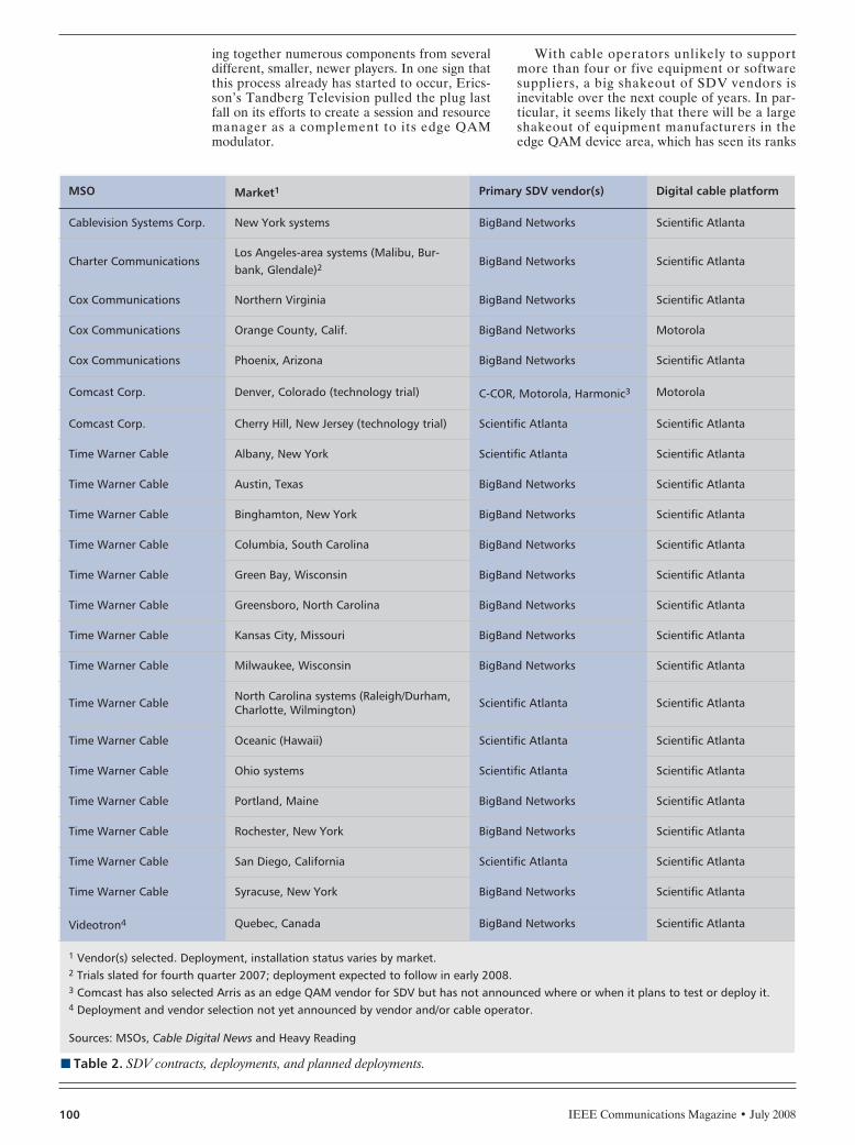
IEEE Communications Magazine • July 2008100
ing together numerous components from severaldifferent, smaller, newer players. In one sign thatthis process already has started to occur, Erics-son’s Tandberg Television pulled the plug lastfall on its efforts to create a session and resourcemanager as a complement to its edge QAMmodulator.
With cable operators unlikely to supportmore than four or five equipment or softwaresuppliers, a big shakeout of SDV vendors isinevitable over the next couple of years. In par-ticular, it seems likely that there will be a largeshakeout of equipment manufacturers in theedge QAM device area, which has seen its ranks
n Table 2. SDV contracts, deployments, and planned deployments.
MSO Market1 Primary SDV vendor(s) Digital cable platform
Cablevision Systems Corp. New York systems BigBand Networks Scientific Atlanta
Charter CommunicationsLos Angeles-area systems (Malibu, Bur-bank, Glendale)2
BigBand Networks Scientific Atlanta
Cox Communications Northern Virginia BigBand Networks Scientific Atlanta
Cox Communications Orange County, Calif. BigBand Networks Motorola
Cox Communications Phoenix, Arizona BigBand Networks Scientific Atlanta
Comcast Corp. Denver, Colorado (technology trial) C-COR, Motorola, Harmonic3 Motorola
Comcast Corp. Cherry Hill, New Jersey (technology trial) Scientific Atlanta Scientific Atlanta
Time Warner Cable Albany, New York Scientific Atlanta Scientific Atlanta
Time Warner Cable Austin, Texas BigBand Networks Scientific Atlanta
Time Warner Cable Binghamton, New York BigBand Networks Scientific Atlanta
Time Warner Cable Columbia, South Carolina BigBand Networks Scientific Atlanta
Time Warner Cable Green Bay, Wisconsin BigBand Networks Scientific Atlanta
Time Warner Cable Greensboro, North Carolina BigBand Networks Scientific Atlanta
Time Warner Cable Kansas City, Missouri BigBand Networks Scientific Atlanta
Time Warner Cable Milwaukee, Wisconsin BigBand Networks Scientific Atlanta
Time Warner Cable North Carolina systems (Raleigh/Durham,Charlotte, Wilmington) Scientific Atlanta Scientific Atlanta
Time Warner Cable Oceanic (Hawaii) Scientific Atlanta Scientific Atlanta
Time Warner Cable Ohio systems Scientific Atlanta Scientific Atlanta
Time Warner Cable Portland, Maine BigBand Networks Scientific Atlanta
Time Warner Cable Rochester, New York BigBand Networks Scientific Atlanta
Time Warner Cable San Diego, California Scientific Atlanta Scientific Atlanta
Time Warner Cable Syracuse, New York BigBand Networks Scientific Atlanta
Videotron4 Quebec, Canada BigBand Networks Scientific Atlanta
1 Vendor(s) selected. Deployment, installation status varies by market.2 Trials slated for fourth quarter 2007; deployment expected to follow in early 2008.3 Comcast has also selected Arris as an edge QAM vendor for SDV but has not announced where or when it plans to test or deploy it.4 Deployment and vendor selection not yet announced by vendor and/or cable operator.
Sources: MSOs, Cable Digital News and Heavy Reading
BREZNICK LAYOUT 6/18/08 1:09 PM Page 100
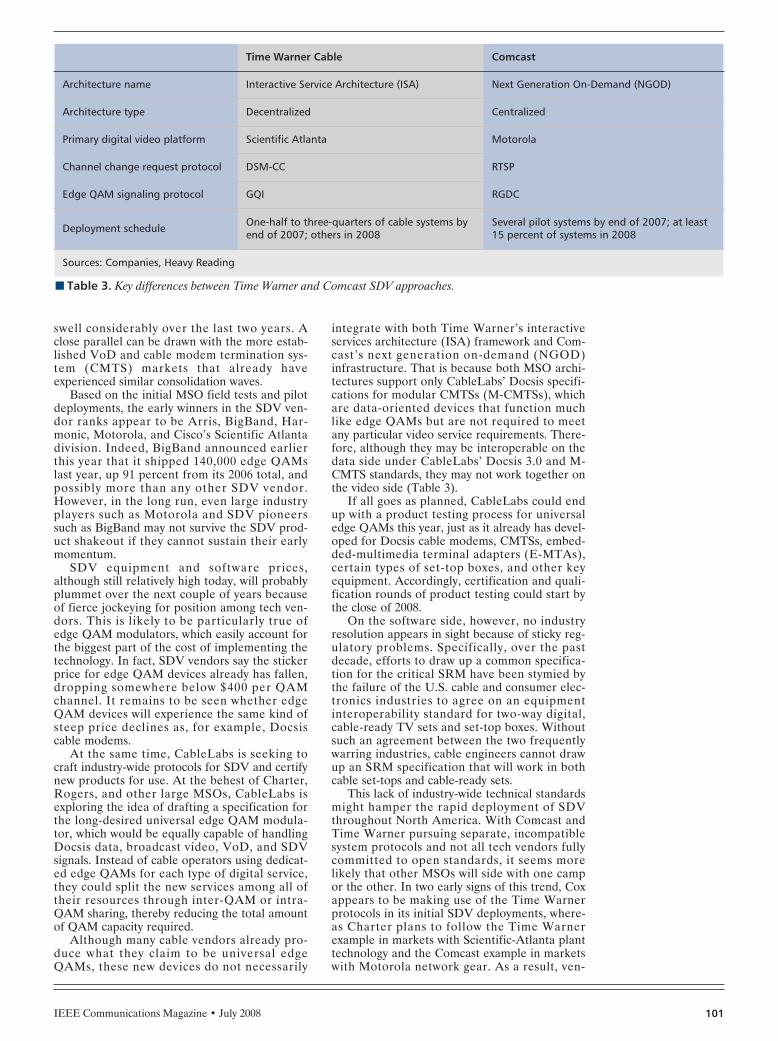
IEEE Communications Magazine • July 2008 101
swell considerably over the last two years. Aclose parallel can be drawn with the more estab-lished VoD and cable modem termination sys-tem (CMTS) markets that already haveexperienced similar consolidation waves.
Based on the initial MSO field tests and pilotdeployments, the early winners in the SDV ven-dor ranks appear to be Arris, BigBand, Har-monic, Motorola, and Cisco’s Scientific Atlantadivision. Indeed, BigBand announced earlierthis year that it shipped 140,000 edge QAMslast year, up 91 percent from its 2006 total, andpossibly more than any other SDV vendor.However, in the long run, even large industryplayers such as Motorola and SDV pioneerssuch as BigBand may not survive the SDV prod-uct shakeout if they cannot sustain their earlymomentum.
SDV equipment and software prices,although still relatively high today, will probablyplummet over the next couple of years becauseof fierce jockeying for position among tech ven-dors. This is likely to be particularly true ofedge QAM modulators, which easily account forthe biggest part of the cost of implementing thetechnology. In fact, SDV vendors say the stickerprice for edge QAM devices already has fallen,dropping somewhere below $400 per QAMchannel. It remains to be seen whether edgeQAM devices will experience the same kind ofsteep price declines as, for example, Docsiscable modems.
At the same time, CableLabs is seeking tocraft industry-wide protocols for SDV and certifynew products for use. At the behest of Charter,Rogers, and other large MSOs, CableLabs isexploring the idea of drafting a specification forthe long-desired universal edge QAM modula-tor, which would be equally capable of handlingDocsis data, broadcast video, VoD, and SDVsignals. Instead of cable operators using dedicat-ed edge QAMs for each type of digital service,they could split the new services among all oftheir resources through inter-QAM or intra-QAM sharing, thereby reducing the total amountof QAM capacity required.
Although many cable vendors already pro-duce what they claim to be universal edgeQAMs, these new devices do not necessarily
integrate with both Time Warner’s interactiveservices architecture (ISA) framework and Com-cast’s next generation on-demand (NGOD)infrastructure. That is because both MSO archi-tectures support only CableLabs’ Docsis specifi-cations for modular CMTSs (M-CMTSs), whichare data-oriented devices that function muchlike edge QAMs but are not required to meetany particular video service requirements. There-fore, although they may be interoperable on thedata side under CableLabs’ Docsis 3.0 and M-CMTS standards, they may not work together onthe video side (Table 3).
If all goes as planned, CableLabs could endup with a product testing process for universaledge QAMs this year, just as it already has devel-oped for Docsis cable modems, CMTSs, embed-ded-multimedia terminal adapters (E-MTAs),certain types of set-top boxes, and other keyequipment. Accordingly, certification and quali-fication rounds of product testing could start bythe close of 2008.
On the software side, however, no industryresolution appears in sight because of sticky reg-ulatory problems. Specifically, over the pastdecade, efforts to draw up a common specifica-tion for the critical SRM have been stymied bythe failure of the U.S. cable and consumer elec-tronics industries to agree on an equipmentinteroperability standard for two-way digital,cable-ready TV sets and set-top boxes. Withoutsuch an agreement between the two frequentlywarring industries, cable engineers cannot drawup an SRM specification that will work in bothcable set-tops and cable-ready sets.
This lack of industry-wide technical standardsmight hamper the rapid deployment of SDVthroughout North America. With Comcast andTime Warner pursuing separate, incompatiblesystem protocols and not all tech vendors fullycommitted to open standards, it seems morelikely that other MSOs will side with one campor the other. In two early signs of this trend, Coxappears to be making use of the Time Warnerprotocols in its initial SDV deployments, where-as Charter plans to follow the Time Warnerexample in markets with Scientific-Atlanta planttechnology and the Comcast example in marketswith Motorola network gear. As a result, ven-
n Table 3. Key differences between Time Warner and Comcast SDV approaches.
Time Warner Cable Comcast
Architecture name Interactive Service Architecture (ISA) Next Generation On-Demand (NGOD)
Architecture type Decentralized Centralized
Primary digital video platform Scientific Atlanta Motorola
Channel change request protocol DSM-CC RTSP
Edge QAM signaling protocol GQI RGDC
Deployment schedule One-half to three-quarters of cable systems byend of 2007; others in 2008
Several pilot systems by end of 2007; at least15 percent of systems in 2008
Sources: Companies, Heavy Reading
BREZNICK LAYOUT 6/18/08 1:09 PM Page 101
IEEE Communications Magazine • July 2008102
dors probably will be required to develop at leasttwo different versions of their products forMSOs, raising production costs and potentiallydelaying deployments.
SDV DRAWBACKSDespite its promising benefits, SDV is not thebe-all and end-all of cable technology. The tech-nology does have definite limitations and defi-ciencies. For one thing, the bandwidth savings,although substantial, are limited to the cableoperator’s digital spectrum only. The techniquedoes not directly help MSOs produce any sav-ings from their analog spectrum, which still eatsup about 60 percent of the capacity of the aver-age cable system. So, even though the spectrumsavings may amount to 60 MHz or 70 MHz, thatamount still pales in comparison to the 750 MHzor 860 MHz capacity of a large, fully upgradedcable system.
The unprecedented complexity of SDV tech-nology poses another potentially vexing problem.With so many new network elements and mov-ing parts, SDV is considered even more compli-cated than its closest technology cousin, VoD,which bedeviled the industry for years. SDV mayprove especially hard for MSOs to scale for largenumbers of customers, due to its extremelydynamic nature and the requirement to addmore intelligence to the cable hybrid fiber coaxi-al (HFC) network. Even the most bullish advo-cates of SDV fret about the many things thatcould go wrong, disrupting the subscriber’s view-ing experience.
Even if SDV is rolled out smoothly and wide-ly, it may prove to be just a temporary solutionto the cable bandwidth problem. Although SDVwill buy time for the industry by freeing digital
spectrum for other, more profitable uses, thetechnology will not actually create any newbandwidth for MSOs, particularly on the criticalupstream side. In addition, the freed digitalspectrum could be eaten up all too quickly in theend. Indeed, one veteran MSO engineeringexecutive predicts that the typical cable systemcould end up gaining enough room for no morethan another dozen or so HD channels, notenough to make a huge difference in the longrun.
In other words, SDV probably will not proveto be a big enough fix on its own. Instead, cableoperators likely will be required to combineSDV with other techniques — such as analogreclamation, node splits, MPEG-4 compression,1-GHz upgrades, and 3-GHz spectrum overlaysin at least some cable systems — to createenough bandwidth for all of the HD, niche pro-gramming, addressable advertising, and othernew digital services they wish to deliver over thenext few years. However, even if cable operatorsalso must turn to other measures, SDV undoubt-edly will be a critical part of the solution to theirgrowing bandwidth problem.
BIOGRAPHYALAN BREZNICK ([email protected]) is a senioranalyst at Heavy Reading. He has tracked the broadband,media, telecom, and consumer electronics industries formore than 20 years. Before switching over to Heavy Read-ing last year, he was the editor of Light Reading's CableDigital News and the founding author of Light Reading'sCable Industry Insider. At Heavy Reading, he primarilyfocuses on cable MSO services, technologies, and net-works, as well as IPTV infrastructure. Previously, he was abroadband analyst for Kinetic Strategies and a contributinganalyst for One Touch Intelligence. Prior to that, he report-ed for Communications Daily, Cable World, MultichannelNews, Broadband Daily, Crain's New York Business, andGenuine Article Press, among other business publications.
SDV probably will
not prove to be a
big enough fix on its
own. Instead, cable
operators likely will
be required to
combine SDV with
other techniques.
However, even if
cable operators also
must turn to other
measures, SDV
undoubtedly will be
a critical part of the
solution to their
growing bandwidth
problem.
BREZNICK LAYOUT 6/18/08 1:09 PM Page 102

IEEE Communications Magazine • July 2008 1030163-6804/08/$25.00 © 2008 IEEE
INTRODUCTION
In the 1990s numerous technologies weredeployed by network operators as the basis ofpublic data services: frame relay, ATM (asyn-chronous transfer mode), Ethernet, and IP(Internet protocol). Although some movementtoward consolidating these services on commonnetworks occurred, the conventional wisdomemerged that there was too much functionalduplication and that operators would be betteroff financially if they migrated all data servicesto a common infrastructure. The technology touse in this infrastructure was identified asIP/multiprotocol label switching (MPLS).
Significant investment in IP/MPLS was drivenby an industry-wide assumption of IP servicemanagement and multiservice convergence bene-fits. The nature and benefits of an IP/MPLS net-work have been discussed in prior IEEE articlessuch as A. Malis, “Converged Services overMPLS,” [[IEEE Communications Magazine]],Sept. 2006, and Matthew Bocci, Mustapha Aïs-saoui, and David Watkinson, “Service Conver-gence Using MPLS Multiservice Networks,”[[IEEE Communications Magazine]], June 2005.
After the telecom bust in 2000–2001, invest-ment in IP routers rebounded quickly, muchmore quickly than other networking technologiesthat are used in public networks. Riding thatwave of investment was the deployment ofMPLS-enabled routers and services. The initialusage of IP/MPLS was focused on traffic engi-neering and IP virtual private networks (VPNs).Over the last two to three years, IP/MPLS alsohas been used to deploy Ethernet business ser-
vices and for Ethernet transport of IP-basedvideo services. Whereas future network expan-sion may not be at the same rate as the recentrate of expansion, the growth in IP and Ethernetservice traffic likely will maintain network invest-ment at a strong rate (10 to 20 percent year toyear). As a simplification, the rest of this articlerefers generically to packet transport as any dataservice or data service transport technology,whether it be cell, frame, or packet-based.
As a networking technology used at the coreof networks, IP/MPLS enjoyed a price and mar-gin premium in the marketplace. As a technolo-gy that now must move much closer to serviceend points, the size of the investment operatorsare making in IP/MPLS is increasing significant-ly. Expanded investment has increased the pres-sure to reduce the cost of IP/MPLS. Equipmentsuppliers have responded to that pressure with avariety of approaches. Some equipment suppliersdeveloped cost- and function-reduced implemen-tations of IP/MPLS, whereas other equipmentsuppliers developed function- and cost-reducedimplementations of IP/MPLS alternatives suchas IEEE 802.1D MAC bridging, IEEE 802.1Qvirtual local area networks (LANs), IEEE802.1ad provider bridges, IEEE 802.1ah providerbackbone bridges (PBB), and pre-standard IEEE802.1Qay provider backbone bridge traffic engi-neering. A number of pre-standard IEEE802.1aq shortest path bridging implementationsalso are coming to market, though not alwaysfocused on the network operator market. Theequipment suppliers who are focused on cost-and function-reducing IP/MPLS often have beenwell-established IP router vendors with the addi-tion of one or two new entrants over the last fiveyears that have had some success in the IP/MPLSmarket. The equipment suppliers who focusedon IEEE standards often have been new entrantsto the market and are well-established imple-menting IEEE standards in other networkingmarkets. The clearly identifiable motivation ofthe various equipment suppliers — to leverageand market their strengths — has tended toovershadow an industry debate about economics,organizational fit, protocol design, and networkarchitecture. Although appreciating the costbenefits that the competition of ideas has real-
ABSTRACT
For most of the last decade, the prevailingindustry assumption was that large public net-works would migrate all services, transport, andswitching to a single end-to-end IP/MPLS net-work — convergence. This assumption was vali-dated by significant growth in IP/MPLSinvestment. Looking to the future, economicforces that affect suppliers, as much as opera-tors, are challenging this assumption, and otherscenarios now seem plausible.
INDUSTRY ANALYST FORUM
Mark Seery, Ovum
Packet Transport Trends: IP/MPLS Success Challenged asDeployment Footprint Expands
SEERY LAYOUT 6/18/08 1:25 PM Page 103

IEEE Communications Magazine • July 2008104
ized, network operators have for the most partbeen sitting back and observing proceedingswithout expressing strong opinions about wherethe industry goes from here. There are excep-tions, of course, and they are well knownthroughout the industry.
Although some of those that support alterna-tives to IP/MPLS always have had a vision ofbroader network issues; for most in the industry,the debate has been about cost because that is theeasiest issue to understand — and from one per-spective, the most important. As this debate goeson, however, the reactions to the economic pres-sures provided by competition lead to responsesfrom all equipment suppliers that make the largerarchitectural debates unavoidable.
In large-scale carrier transport networks,there is a tension that has emerged between thebenefits of specialization and the benefits of inte-gration. Specialization long has been recognizedby economists as a way to reduce costs, increaseproductivity, and increase quality. On the otherhand, the drive toward convergence is based onthe widely held view within the industry that con-vergence will simplify operations and reduce cen-tral office space, power, and cooling through theinstallation of fewer layers of equipment. Reusingequipment for multiple networking functions andservices is argued by some to also reduce net-work management integration costs for thoseoperators that have made large investments intheir own management systems and do not relyon management systems supplied by equipmentsuppliers. The current debate involving IP/MPLSand alternatives is, in essence, a debate about thebenefits of convergence (integration) versus thebenefits of specialization.
As a general principle, a technology that is totransport all others, must be the cheapest of all.However, determining what is the least expen-sive approach to networking is not straightfor-ward. Calculations include power, cooling, space,network management integration, organizationalfit, and ease of operation. Comparisons betweendifferent approaches are complicated by therobustness of financial models, how those mod-els are viewed by decision makers, and hard-to-predict dynamics such as how IP/MPLSequipment vendors will react to pricing pressure
from alternatives. The market is a conversation— an ongoing conversation — and the compara-tive economic advantage of one approach overanother can vary over time. The market is in themidst of a conversation that likely will continuefor the next two to three years; the answer towhich is uncertain and depends on evolving eco-nomics, organizational dynamics within networkoperators, and the overall strengths of platformsthat support different approaches.
It is important to note the debate does notencompass the full range of IP/MPLS capabili-ties such as IP layer functions (IP routing, IPVPNs, and traffic engineering for the IP layer).The debate focuses mostly on Ethernet layerfunctions (Ethernet routing, Ethernet VPNs, andtraffic engineering for the Ethernet layer).Therefore, there is no current scenario beingdiscussed or promoted where alternatives toIP/MPLS would replace MPLS for all networkfunctions. Today, the future is unknown, even ifit is clear that IP/MPLS has significant marketmomentum, incumbency, and will be difficult todisplace. What can be said is that the thesis thatit is rational to converge all services, transport,and switching functions on one equipment layer(implementing Internet Engineering Task Force[IETF] IP, MPLS, and pseudowire protocols) isunder discussion today, and it is likely to be animportant topic of discussion over the next cou-ple of years; a discussion that will have econom-ic, organizational, protocol design, andarchitectural components.
INVESTMENT TRENDSIn a culture that adheres to the mantra of “if itworks, don’t touch it”; the useful life of a tech-nology can be at least a decade and sometimeslonger. Shifts in investment trends can takemany years to become obvious and significant.Therefore, forecasting rapid investment shiftsmust be done with some caution. One recentexample of an investment shift taking longerthan expected is ATM a technology that firstwas deployed in the early 1990s to provide busi-ness services.
By the late 1990s the death of the ATM hadbeen sounded all around the industry and by 2002,some well-known industry personalities wereexpressing complete astonishment that anyone stillwas making ATM technology. Yet, as Fig. 1 shows,ATM was still a two billion dollar a year equip-ment market in 2004; and in 2007, it was still aone billion dollar a year equipment market. TheATM equipment market has remained a signifi-cant market long after many had written it off asbeing an irrelevant technology; and even in 2007and 2008, there have been new mobile operatorawards to ATM equipment vendors.
The experience with ATM provides a sober-ing reminder to industry analysts and other pun-dits not to ring the death of so-called legacytechnologies too quickly. Without question, thata technology might be in decay from an invest-ment perspective has implications, but gettingahead of the market also has implications. Sowhen considering the decay of investment in syn-chronous optical network/synchronous digitalhierarchy (SONET/SDH), there is reason to be
n Figure 1. ATM and IP/MPLS investment.
Packet transport equipment investment comparison(source: Ovum RHK)
2004
1000
$US
(mill
ion)
0
2000
3000
4000
5000
6000
7000
8000
9000
2005 2006 2007
ATMIP/MPLS
SEERY LAYOUT 6/18/08 1:25 PM Page 104

IEEE Communications Magazine • July 2008 105
cautious about dramatic forecasts, even though itdoes appear investment has either peaked or isabout to peak.
At the same time that ATM investment hasbeen slowly decaying, investment in IP/MPLS-capable equipment has been increasing dramati-cally. In the time period (2004–2007) that ATMinvestment was cut in half, IP/MPLS investmenthas doubled, with the investment slope increas-ing in 2007.
The investment is driven by IP services, aswell as Ethernet services and the use of Ethernetarchitectures (including Ethernet over IP/MPLS)to transport IP services. Figure 2 shows that theinvestment gap between the IP layer infra-structure and the Ethernet layer infrastructureclosed significantly during the period of2004–2006. The increased investment inIP/MPLS core equipment during 2007 hascaused the two investment lines to diverge a lit-tle during 2007; but core investments, being driv-en by traffic growth, often are cyclical; so it isunclear whether this divergence will continue.
The investment trends indicated by Fig. 2highlight one of the central questions of the cur-rent debate about future trends; which is, ifoperators are going to invest in Ethernet serviceinfrastructure at a rate approaching IP serviceinfrastructure, are there economic and opera-tional benefits from exploring all options forEthernet service infrastructure?
The fact that the observation can be madethat there is a fundamental economic basis tothe debate does not bias the answer; it simplyreinforces the idea that such questions areinevitable. Network operators are for profitorganizations, so to not ask such questions wouldbe more of a surprise.
Of all the investments in technologies thattransport IP packets to the first IP edge routerand Ethernet service infrastructure, Ethernetover MPLS is by far the fastest growing, havinggrown from less than 10 percent of the IP aggre-gation market in 2003 to over 30 percent in 2007.It is likely that Ethernet over MPLS will grow to70 percent of this opportunity by 2011 with theremainder going to whatever ATM investment isstill occurring, some IEEE 802.1ad MAC bridg-ing investment, as well as some of the newer Eth-ernet layer technologies such as IEEE 802.1ah(PBB) and IEEE 802.1Qay (PBB TE).
If there is a significant investment shift fromEthernet over MPLS (EoMPLS) to somethingelse, IEEE 802.1ah and IEEE 802.Qay likely willbe among those technologies that benefit. If ashift is to occur, it might take two to three yearsto emerge, given the current EoMPLS momen-tum and the relative immaturity of alternativeapproaches; and in general, as with all otherinvestment shifts, history provides a reminder tobe cautious about how rapidly the shift wouldoccur, it if occurs.
SPECIALIZATION VS. INTEGRATION
It has long been observed that specializationimproves productivity and increases quality. Tak-ing bigger problems and breaking them intosmaller problems can simplify each new problem
domain, allow for the development of equipmentoptimized to that problem domain, allow for theproductivity improvements that come from tech-nicians optimized for that problem domain, andallow for quality improvements that come fromexpert technicians, optimized equipment, andisolation from events in other problem domains.
The benefits of specialization were famouslyobserved by Adam Smith in “Of the Division ofLabor,” which was part of his book [[The Wealthof Nations]]. Smith asserted that the amount ofspecialization in an industry is limited by theextent of a market (the size of a market oppor-tunity). Turned around, this assertion suggeststhat as the size of a market grows, so too, willthe extent of the specialization. Therefore, theeventual size of the Ethernet services market willhave a significant impact on whether specializa-tion forces drive change.
From one perspective, the assumptions aboutspecialization and the actually experienced bene-fits in most modern large-scale enterprises sug-gests a force that is operating in directopposition to the thesis that all services will con-verge on one layer, because to do so would be toforgo the benefits of specialization.
In opposition to the assertions about the ben-efits of specialization lies the industry consensusthat appeared to emerge over the last decadethat deployed equipment that specialized in onlyone layer/service was not rational economically.Hence, a basic tension can be observed betweenthe benefits of specialization and the benefits ofconvergence/integration.
Discussion about this tension does not occurin a consciously articulated way within the indus-try, at least on public stages, but it is clearly oneof the background forces shaping the debateeven if it expresses itself in non-obvious ways.
ORGANIZATIONAL STRUCTURESOne of the side effects of equipment specializa-tion is organizational specialization. Before thepacket age, there were three major equipmentdomains in telephone companies: switching,transport, and access. Switching being digital sig-nal (DS) 0/voice switching; transport being trans-mission systems and T1/E1-OCx/STMxaggregation and grooming; and access being for
n Figure 2. Ethernet vs. IP investment.
Equipment investment comparison Ethernet vs. IP(source: Ovum RHK)
2004
1000
$US
(mill
ions
)
0
2000
3000
4000
5000
6000
2005 2006 2007
IPEthernet
SEERY LAYOUT 6/18/08 1:25 PM Page 105

IEEE Communications Magazine • July 2008106
the most part, a transport function with specificcost and topology challenges. Access equipmentalso integrated some voice service functionalitythat improved the economics of voice service.
Frame relay, ATM, and IP all became switch-ing overlays on the transport/access infra-structure. Frame relay service edge and ATMswitches eventually integrated, removing some ofthe redundancy; but before ATM and IP couldcompletely integrate (and there were failedattempts), IP/MPLS switching was proposed asan alternative. In this article, the term “switch-ing” is used for all technologies to simplify thediscussion and provide abstract functional com-parison. It is understood that IP routing isviewed by some as being of a completely differ-ent nature than other switching technologies.
The result of overlays is that what emergedwas operations specialization within the trans-port function, seen from a broad perspective: IP,ATM, and SONET/SDH technicians all in dif-ferent operational units.
The introduction of dense wavelength divisionmultiplexing (DWDM) technology further exac-erbated the challenge of integrating all transportoperations; partly because optical networkingremains a difficult problem requiring specialistexpertise, but also because the types of servicesenabled by each technology are so different.
As Fig. 3 shows, the amount of investment inall packet technologies is roughly equal to theamount spent on optical technologies (includingSONET/SDH). This suggests a political paritywithin organizations for some time and/or somebenefit from specialization.
As a result, despite the fact that there ismuch talk of integrating packet and optical oper-ations organizations and despite the fact that bylooking at high-level organization charts, it evenmight appear to have occurred; deep into theorganization, below a common managementpoint, there may indeed be organizational sepa-ration for some time to come. During this peri-od, Ethernet layer processing likely will becomericher within optical transport equipment, as it
has already started to, and that will be yet anoth-er force within the industry that has the poten-tial to add to the extraction of Ethernet layerprocessing from the IP/MPLS infrastructure;perhaps only in part, for example, point-to-pointlong hold-time circuits, but potentially morethan that. The reason to suspect this as a possi-bility is that there are a number of operationalsynergies in terms of methods and proceduresbetween current optical/SDH practices and aconnection-oriented Ethernet transport layer —especially a provisioned implementation.
OPERATIONAL EFFICIENCIESOne thing that defines the operations manage-ment capabilities of a technology is the manage-ment semantics embedded in protocols. WhenMPLS was being developed, the length of theheader was a very sensitive issue within the IPcommunity and as a result, there are not manyexplicit semantics within the header. It is mainly ageneric label space on which various forwardingsemantics are overloaded by the control plane,which creates the forwarding look-up tables.
The way MPLS overloads semantics is a sourceof infinite theoretical flexibility, a flexibility thathas already been demonstrated. At the sametime, the lack of explicit semantics such as sourceand destination address has been the source ofcriticism when it comes to the cost and ease ofmanaging a network. As an example, Allan et al.state, “Use of link local-path identifiers such asMPLS labels, ATM VCI/VPIs, and so forth intro-duces a ‘level of indirection’ into data-plane for-warding.” [3]. The indirection manifests itself in anumber of ways including increased potential forconfiguration errors; increased complexity inoperation, administration, and maintenance(OAM); increased complexity in multipoint-to-point merge operations; difficulty for operationspersonnel to map labels to end-point IP and Eth-ernet addresses when doing fault diagnosis at thecore of the network; and increased potential forerrors during a label-swap operation.
IP/MPLS equipment vendors are in the earlystages of exploring ways to address these criti-cisms, and on some of the issues, there appear tobe potential solutions. For example, IP/MPLSequipment vendors may be able to work withmanagement partners to trace the allocation oflabels by recording control plane operations andprovide a solution to the label to end-pointaddress-mapping criticism. Potentially, all of thecriticisms will be addressed over time. Regardless,the comparison between label-based approachesand approaches with a greater number of explicitsemantics is leading to new insights about net-working and may have long-term implications forprotocol design beyond the current debate involv-ing IP/MPLS and IP/MPLS alternatives.
THE COST OF ADDING SEMANTICSProtocols with a greater number of explicitsemantics have a cost that can be expressed bothin terms of processing resources and bandwidthutilization (protocol overhead).
At the time IP/MPLS was developed, proto-col overhead was a sensitive issue, and there was
n Figure 3. Packet vs. optical investment.
Global equipment budgets(source: Ovum RHK)
2001
5000
$US
(mill
ions
)
0
10,000
15,000
20,000
25,000
2002 2003 2004 2005 2006
Total optical transportTotal packet
SEERY LAYOUT 6/18/08 1:25 PM Page 106
IEEE Communications Magazine • July 2008 107
significant pressure to keep the MPLS label assmall as possible. A decade later, networks havemoved from 155-Mb/s links to 10-Gb/s links withsome deployment of 40 Gb/s and talk of future100-Gb/s links. There is the potential that futuretransport protocol designs will be less sensitiveto size than has been the case historically.
Today, IP/MPLS implementations are capa-ble of line-speed processing of MPLS and IP. Asa result, it is probable that transport approachesbased on protocols with more explicit semanticsthan MPLS is feasible. So whereas moving awayfrom MPLS likely is technically feasible from aprocessing perspective, at the same time, lessprocessing-intensive implementations of MPLSare under consideration, which may provide costreductions. For example, the IETF and Interna-tional Telecommunication Union (ITU) stan-dards bodies currently are working on animplementation of MPLS optimized for trans-port application (non-IP service applications) —these efforts are known as MPLS-TP within theIETF and as T-MPLS within the ITU. Therealso may be other approaches to transport-opti-mized MPLS pursued outside of the IETF andITU. So, although technology is capable of wire-rate processing of protocols such as IP and Eth-ernet that have many explicit semantics andtherefore have longer headers than MPLS; ifthere are significant capital or operationalexpense benefits from a transport optimizedimplementation of MPLS, that also will be acompetitor to the current IP/MPLS implementa-tion and to those approaches being touted todayas alternatives to IP/MPLS.
The next few years are likely to see dialogwithin the industry about whether protocol over-head is as big of a concern as it used to be froma bandwidth utilization and latency perspective,and whether or not an MPLS-optimized for-warding plane can provide significant price/per-formance advantages over either currentIP/MPLS implementations or alternative trans-port technologies. One dominant aspect of thisdebate is the observation that Ethernet has beenone of the most cost-effective technologies innetworking for a number of decades and thatextension of Ethernet-like IEEE 802.1ah andIEEE 802.1Qay would likewise be cost effective.
CONCLUSIONThe amount of investment in Ethernet layer pro-cessing to support Ethernet services and lowerthe cost of transporting IP packets between net-
work users and IP edge routers is generatingeconomic pressure on IP/MPLS equipment. Thisis leading to a variety of alternatives beingexplored including cost- and function-reducedIP/MPLS, IEEE standardized technologies suchas IEEE 802.1ah (PBB) and IEEE 802.1Qay(PBB-TE,) and possibly even MPLS-switchesthat do not support IP processing in the fastpath.
The end result of this economic force isunclear at this time. Certainly, it will continueto be the foundation for significant industrydebate about not only the pros and cons ofcompeting technologies, but also the inevitabili-ty of a single packet transport layer that stretch-es end to end.
Over the last decade the shift of investmentfrom ATM to IP/MPLS has been strong, yet theinvestment in ATM remains significant, whichhighlights how long it can take large networkoperators to fully shift from one technology toanother. The shift from SONET/SDH to Ether-net also has the potential to take a longer periodof time than originally anticipated. Likewise, ashift from EoMPLS to an alternative also maytake a significant amount of time.
Driving forces in networking are technical,organizational, and economic in nature. None ofthese forces should be overlooked when assess-ing past, current, and future trends.
REFERENCES[1] A. Malis, “Converged Services over MPLS,” IEEE Com-
mun. Mag., Sept. 2006.[2] M. Bocci, M. Aïssaoui, and D. Watkinson, “Service Con-
vergence Using MPLS Multiservice Networks,” IEEECommun. Mag., June 2005.
[3] D. Allan et al., “Ethernet as Carrier Transport Infra-structure,” IEEE Commun. Mag., Feb. 2006.
BIOGRAPHYMARK SEERY ([email protected]) has been working inthe communications industry for 26 years with experiencein the areas of network operations, network support, sys-tems programming, software development, technicalwriting, product management, product marketing, con-sulting, and industry analysis. The specific areas of tech-nology he focuses on include IP, IP/MPLS, Ethernet, andATM. He also contributes broadly as part of a larger teamat Ovum that covers optical networking and access tech-nologies. His professional interests include economicdrivers for networks, network architecture, and theoreti-cal aspects of networking. In his current role as vice presi-dent of switching and routing at Ovum he drives research,market share, forecasting, and consulting activities with afocus on switching and routing technologies while alsocontributing to a broad range of technology areas cov-ered by Ovum.
The end result of this
economic force is
unclear at this time.
Certainly, it will
continue to be the
foundation for
significant industry
debate about not
only the pros and
cons of competing
technologies, but
also the inevitability
of a single packet
transport layer that
stretches end to end.
SEERY LAYOUT 6/18/08 1:25 PM Page 107

IEEE Communications Magazine • July 2008108
obile broadcasting is intended to allow the deliv-ery of multimedia content to mobile terminals
such as cell phones and PDAs. Mobile broadcasting appli-cations target horizontal mass markets, and are expectedto have a very important impact in terms of diffusion ofvalue-added services. While the mobile broadcasting indus-try is beginning to generate interest from many sectors ofthe mobile and broadcast industries, including mobileoperators, handset vendors, broadcasters, and content pro-viders, there are still many issues and problems that needto be resolved. Among the biggest hurdles in deliveringwireless multimedia services to consumers are quality ofservice, mobility performance, cost of delivery, regulation,capacity, and spectrum planning. However, at the heart ofthe mobile broadcasting industry is the tussle betweenbroadcast and cellular networks to find the optimum solu-tion for all players to benefit in an extremely complex busi-ness environment. An integral part of any wirelessmultimedia service system is to complement existing net-works and cost-effectively deliver optimum multimediaperformance to the end user without impacting subscribedvoice and data services. Several standards and technologiesare being developed such as MBMS within 3GPP, DVB-Hin the DVB Forum, MediaFLO within TIA, S-DMB withinthe satellite community, and the ETSI S-UMTS group.The goal of this feature topic is to provide a forum forsharing knowledge on recent advances in mobile multime-dia broadcasting technology, the related research chal-lenges, and possible approaches to solve those issues.
The response to our call for papers on this feature topicof IEEE Communications Magazine was overwhelming; wereceived a very large number of articles. All the paperswere reviewed by experts in the relevant area, and the arti-cles selected for publication went through a rigorous two-round review process. The first part of this feature topic,consisting of six articles, was published in IEEE Communi-cations Magazine’s August 2007 issue; the remaining threeaccepted articles are presented herre.
The first article, “Superposition of Broadcast and Uni-cast in Mobile Cellular System” by D. Kim, F. Khan, C. V.Rensburg, S. Yoon, and Z. Pi, discusses a practical appli-
cation of superposition coding in multiplexing broadcastand unicast for orthogonal frequency-division multiplexing(OFDM)-based wireless cellular systems.
The second article, “Performance Enhancement inFuture Mobile Satellite Broadcasting Services” by S. Kim,H. W. Kim, K. Kang, and D. S. Ahn, investigates a hybridsatellite-terrestrial network (HSTN) that can provide acooperative system in such a way as to provide high-qualityseamless multimedia broadcast and multicast serviceseffectively, which can improve the performance of amobile satellite broadcasting system with HSTN.
The third article, “A New Paradigm for Mobile Multi-media Broadcasting Based on Integrated Communicationand Broadcast Networks” by Z. Niu, L. Long, J. Song, andC. Pan, provides a new paradigm to integrate the ChineseDigital Television/Terrestrial Multimedia Broadcasting(DTMB) systems with existing mobile communication sys-tems, which can support mobile multimedia broadcastingservices with carrier-grade quality.
In closing, we would like to thank all the authors fortheir excellent contributions. We also thank the reviewersfor their time dedicated to reviewing the papers, and pro-viding valuable comments and suggestions for refining thequality of the articles. We appreciate the advice and sup-port of former and current Editors-in-Chief of IEEE Com-munications Magazine Drs. Thomas Chen and Nim K.Cheung, and Sue Lange and Joseph Milizzo for their helpin the publication process.
BIOGRAPHIESSASTRI KOTA [SM’86] ([email protected]) received his B.S in physicsfrom Andhra University, his B.S.E.E. from BITS, Pilani, and his M.S.E.E. fromthe Indian Institute of Technology. He received his electrical engineer’sdegree from Northeastern University, Boston, Massachusetts, and his Ph.D.in electrical and information engineering from theUniversity of Oulu, Fin-land. Since 2003 he has been a senior scientist at Harris Corporationinvolved with corporate technologies and standards, with special emphasison wireless and mobile ad hoc networks, satellite communication networks,and standardization. He is an adjunct professor in the TelecommunicationsLaboratory, University of Oulu. His research interests include wireless andmobile Information networks, satellite IP networks, QoS and traffic man-agement, broadband satellite access, and ATM networks. Over the years hehas held technical and management positions and contributed to militaryand commercial communication systems at Loral Skynet, Lockheed Martin,SRI International, The MITRE Corp, and Xerox Corp. He has been very active
GUEST EDITORIAL
M
Sastri L. Kota Yi Qian Ekram Hossain Rajamani Ganesh
ADVANCES IN MOBILE MULTIMEDIA NETWORKING AND QOS: PART II
LYT-GUESTEDIT-Kota 6/18/08 1:36 PM Page 108

IEEE Communications Magazine • July 2008 109
in telecommunications and networking standards development. Currentlyhe is U.S. Chair for ITU-R Working Party 4B and International Rapporteurfor Ka-Band Fixed Satellite Systems. He was chair of the Wireless ATMWorking Group and has been an ATM Forum Ambassador. He was therecipient of the ATM Forum Spotlight award and Golden Quill awards fromHarris Corporation for his contributions to broadband satellite communica-tions and assured communications. He authored the book Broadband Satel-lite Communications for Internet Access (2003), co-edited EmergingLocation Aware Broadband Wireless Ad Hoc Networks (2004), and wrotechapters on “Satellite TCP/IP in High Performance Networking” and “Trendsin Broadband Networking” in Wiley Encyclopedia of Telecommunications.He has published more than 120 papers in journals and conference pro-ceedings. He has been a keynote speaker, invited speaker, and panelist atvarious international conferences. He served as the Unclassified TechnicalProgram Chair of MILCOM 2007 and Vice-Chair of QShine ’07. He alsoserved as Tutorial Chair and Assistant Technical Chair of MILCOM ’04, ’97,and ’90; Symposium Chair and Co-Chair of the Satellite Communicationssymposium of GLOBECOM 2000 and ’02; and invited session chair ofPIMRC ’04, ’05, and ’06. He was Co-Chair of the Wireless Communicationsand Networking Symposium of GLOBECOM ’06 and Technical Chair ofISWPC ’07. He has been a member of technical program committees ofseveral IEEE, AIAA, SPIE, and ACM conferences and workshops. He is anAssociate Fellow of AIAA and a member of ACM.
YI QIAN [M’95, SM’07] ([email protected]) received a Ph.D. degree in electricalengineering with a concentration in telecommunication networks fromClemson University, South Carolina. He is with the National Institute of Stan-dards and Technology, Gaithersburg, Maryland. His current research inter-ests include information assurance, network security, network management,network design, network modeling, simulation, and performance analysisfor next-generation wireless networks, wireless sensor networks, broadbandsatellite networks, optical networks, high-speed networks, and the Internet.He has publications and patents in all these areas. He was an assistant pro-fessor in the Department of Electrical and Computer Engineering, Universityof Puerto Rico at Mayaguez (UPRM) between July 2003 and July 2007. AtUPRM he taught courses on wireless networks, network design, networkmanagement, and network performance analysis. His research and curricu-lum development efforts were funded by National Science Foundation, Gen-eral Motor, IBM, and PRIDCO, among others, with more than $2 milliontotal award amount during his four years at UPRM. Prior to joining UPRM inJuly 2003, he worked for several startup companies and consulting firms inthe areas of voice over IP, fiber optical switching, Internet packet video, net-work optimizations, and network planning as a technical advisor and seniorconsultant. He also worked several years for the Wireless Systems Engineer-ing Department, Nortel Networks, Richardson, Texas, as a senior member ofscientific staff and technical advisor. While at Nortel, he was a project leaderon various wireless and satellite network product design projects, customerconsulting projects, and advanced technology research projects. He was alsoin charge of a wireless standard development and evaluation project in Nor-tel. He is a member of ACM.
EKRAM HOSSAIN [S’98, M’01, SM’06] ([email protected]) is currentlyan associate professor in the Department of Electrical and Computer Engi-neering, University of Manitoba, Winnipeg, Canada. He received his Ph.D.
in electrical engineering from the University of Victoria, Canada, in 2000.His current research interests include design, analysis, and optimization ofwireless communication networks and cognitive radio systems. He is a co-editor of Cognitive Wireless Communication Networks (Springer, 2007) andWireless Mesh Networks: Architectures and Protocols (Springer, 2007), anda co-author of An Introduction to Network Simulator NS2 (Springer, 2008).He serves as an Editor for IEEE Transactions on Mobile Computing, IEEETransactions on Wireless Communications, IEEE Transactions on VehicularTechnology, IEEE Wireless Communications, and several other internationaljournals. He has served as a guest editor for special issues of IEEE Commu-nications Magazine (Cross-Layer Protocol Engineering for Wireless MobileNetworks) and IEEE Wireless Communications (Radio Resource Managementand Protocol Engineering for IEEE 802.16). He served as Technical ProgramCo-Chair of IEEE GLOBECOM ’07 and IEEE WCNC ’08. He served as Techni-cal Program Chair for the Workshops on Cognitive Wireless Networks(CWNets ’07) and Wireless Networking for Intelligent Transportation Sys-tems’ (WiN-ITS ’07) held in conjunction with QShine ’07. He served as Tech-nical Program Co-Chair for the Symposium on Next Generation MobileNetworks ’06, ’07, and ’08 held in conjunction with ACM InternationalWireless Communications and Mobile Computing Conference ’06, ’07, and’08, and the First IEEE International Workshop on Cognitive Radio and Net-works ’08 in conjunction with IEEE International Symposium on Personal,Indoor and Mobile Radio Communications ’08.
RAJAMANI GANESH [SM’98] ([email protected]) received his Ph.D.degree in wireless communications in 1991 from Worcester PolytechnicInstitute, Massachusetts. He has more than 16 years’ work experience inthe global wireless industry where he has held many technical manage-ment and leadership positions, and successfully executed projects of allkinds and sizes. Presently, he works as senior director of technology devel-opment and marketing for Qualcomm International, currently posted inIndia. He is actively involved in helping 3G wireless operators with newtechnology roadmaps, competitive strategies, technology comparisons, net-work performance engineering, and deployment of key product offerings.Before joining Qualcomm, he was the chief engineer in a mobile location-based services startup, which he helped found in the Boston area. Previousto that he was a senior scientist at Verizon Technology Organization,Boston, Massachusetts, for about seven years, working on CDMA networkplanning, deployment, and optimization with special emphasis on capacityenhancement coupled with infrastructure cost minimization. From 1991 to1995 he was with Sarnoff Corporation, Princeton, New Jersey, working onHDTV transmission and packet CDMA systems. He has published dozens oftechnical papers in many journals and conferences, and has received manyawards, including the prestigious WARNER award, Verizon/GTE’s highestaward for outstanding technical achievement. He has 15 patents (11issued, 4 pending) in wireless network planning and optimization issues,mobile location determination systems, and Bluetooth networks. He hasalso edited three books on wireless communications and contributed tochapters in books. He has been Technical Program Co-Chair for two IEEEinternational conferences held in India on personal wireless communica-tions. He is also active in the technical program and organizing committeesof IEEE PIMRC symposia and various other conferences worldwide. He is aFellow of the Institution of Electronic and Telecommunication Engineers ofIndia.
GUEST EDITORIAL
LYT-GUESTEDIT-Kota 6/18/08 1:36 PM Page 109

IEEE Communications Magazine • July 2008110 0163-6804/08/$25.00 © 2008 IEEE
ADVANCES IN MOBILE MULTIMEDIABROADCASTING: PART II
Donghee Kim, Samsung Electronics
Farooq Khan, Cornelius Van Rensburg, and Zhouyue Pi, Samsung Telecom America
Seokhyun Yoon, Dankook University
Superposition of Broadcast and Unicast in Wireless Cellular Systems
INTRODUCTION
There is an ever increasing interest in carryingbroadcast services over existing and emergingwireless cellular systems. Broadcast services overwireless cellular systems can provide subscriber-specific services such as video on deman, off-peak downloading of multimedia content, andinteractive services to mobile users as well as tra-ditional TV/radio broadcasting. Broadcast ser-vices can be delivered to mobile users either viaan independent broadcast network such as digi-tal video broadcast-handheld (DVB-H), digitalmultimedia broadcast (DMB), and forward lnkonly (FLO), or over a mobile cellular network.When broadcast services are carried over a cel-lular system, subscriber management and billingcan be done at a single central place for bothunicast and broadcast services, resulting in oper-ating efficiencies for the service provider. More-over, single-mode terminals can receive bothbroadcast and unicast services due to synergy in
air interface transmission schemes used forbroadcast and unicast.
Broadcast capabilities have already beenintroduced in the existing third-generation (3G)mobile cellular systems. The high-rate packetdata (HRPD) system supports orthogonal fre-quency-division multiplexing (OFDM)-basedenhanced broadcast and multicast services (E-BCMCS) [1], and multimedia broadcast multi-cast service (MBMS) based on code-divisionmultiple access(CDMA) is specified for theUniversal Mobile Telecommunications System(UMTS) Release 6 standard in [2]. Broadcastservices need to be delivered cost effectively inorder for them to be popular among consumers.This demands, among other factors, extremelyhigh spectral efficiency for these services due totheir use of scarce radio spectrum. Therefore,techniques that provide increased spectral effi-ciency for broadcast services such as single-fre-quency network (SFN) operation byOFDM-based transmission from multiple syn-chronized base stations are getting acceptancein wireless standards. For example, E-BCMCSin HRPD is based on SFN operation usingOFDM transmission. Also, in the 3G Partner-ship Project 2 (3GPP2) ultra mobile broadband(UMB) and 3GPP long-term evolution (LTE)systems, both based on OFDM, support of SFN-based broadcast services is among the keyrequirements.
Most current cellular operators have limitedspectrum allocations that are already being fullyutilized with the explosive growth in the numberof wireless subscribers as well as average min-utes used per subscriber. Therefore, techniquesthat can allow wireless operators to carry broad-cast services with minimum impact on unicastservices are highly desirable. In this article atechnique based on the theory of superpositioncoding is introduced as an efficient multiplexingscheme for broadcast and unicast. The superpo-sition coding provides gain when the superposedsignals have larger differences in signal-to-inter-ference-plus-noise ratio (SINR). This aspect ofsuperposition coding is well matched with the
ABSTRACT
Practical application of superposition codingin multiplexing broadcast and unicast forOFDM-based mobile cellular systems is dis-cussed. Superposition coding, whose gain isincreased as the superposed signals have largerdifference in signal-to interference-plus-noiseratio, is well matched for unicast and broadcastin a single-frequency network configuration.Combined with interference cancellation tech-nique, broadcast signals from multiple base sta-tions can be cancelled in a single step,minimizing the interference from broadcast tounicast. Issues related with scheduling and strat-egy for time, frequency and power resourcesharing between broadcast and unicast are dis-cussed. The application of superposed broadcastand unicast is then extended to MIMO systems.Simulation results in a practical mobile cellularenvironment are also provided, showing signifi-cant throughput gain of superposed broadcastand unicast.
KIM2 LAYOUT 6/18/08 1:23 PM Page 110

fact that SFN-based broadcast signals have high-er SINR than unicast signals in most coverageareas. Compared to time-division multiplexing(TDM) or frequency-division multiplexing(FDM) that shares time or frequency resourcesorthogonally, superposition coding enables thesystems to support broadcast without reducingthe time and frequency resources assigned tounicast, and manage the transmit power moreefficiently.
SINGLE-FREQUENCY NETWORK FOR BROADCASTThe broadcast throughput, which is defined bythe maximum broadcast data rate supporting apredefined target coverage, can be maximized bySFN configuration with synchronized base sta-tions. In SFN broadcast systems, the broadcastsignals transmitted from synchronized multiplebase stations arrive at mobiles with propagationdelays that are captured within a cyclic prefix(CP). The CP should be long enough to capturemost broadcast signals. Because all the broadcastsignals from base stations are passively com-bined, providing energy and diversity gain with-out experiencing intercell interferences, SFNbroadcast achieves high SINR even around celledges, providing higher throughput.
The characteristic of no intercell interferencebetween broadcast signals introduces big differ-ences between broadcast and unicast in terms oftransmit power and achievable SINR. In anOFDM cellular system, assigning more transmitpower for unicast above a certain level does nothelp much in improving unicast throughputbecause the SINR of unicast is limited by inter-cell interference. The unicast SINR is the func-tion of P/(fP + N), where P represents the basestation transmission power, f represents theratio between intercell interferences and own-cell signal, and N represents thermal noisepower. In an interference limited situation withfP >> N, increasing power P does not helpimprove the unicast SINR. Unlike unicast,broadcast, not limited by intercell interference,can increase its throughput with more transmitpower. The average SINR in an SFN-basedbroadcast is the function of KP/N where K is thenumber of base stations from which broadcastcontent is received assuming equal receivedpower from the base stations [3]. It can be notedthat increasing transmit power results in linearincrease of broadcast SINR within practicalreceiver limits. The power sharing strategybetween broadcast and unicast should be care-fully considered in the design of multiplexing ofbroadcast and unicast.
MULTIPLEXING OF BROADCAST AND UNICASTWhen the cellular systems support both broad-cast and unicast, there can be multiple ways inthe multiplexing of these two types of traffic.According to the multiplexing methods, the wayof utilizing the available frequency, time, andpower resources for broadcast and unicast is dif-ferent. Here, we discuss three distinct ways ofmultiplexing and their characteristics regardingresource sharing between broadcast and unicast.It should be noted that the broadcast signalsfrom multiple base stations are synchronized toexploit the advantage of SFN, and the unicast
signals use the same time reference with thebroadcast signals because they are transmitted inthe same base station.
Time-division multiplexing: In time domainresource sharing between broadcast and unicastas shown in Fig. 1a, the maximum allowed powerspectral density (PSD) between broadcast andunicast is the same and is limited by the maxi-mum base station transmit power. Because theSINR of unicast is interference-limited while theSINR of broadcast can be improved with highertransmit power relative to unicast, there can beunused power in the time slots assigned for uni-cast. This problem of inefficient power consump-tion can be resolved in FDM and superposition.
Frequency-division multiplexing: In frequencydomain resource sharing between broadcastand unicast, as shown in Fig. 1b, the base sta-tion transmit power can be appropriately uti-lized. The PSD for broadcast bands can behigher than that for unicast, increasing thethroughput of broadcast. Even though thepower is utilized efficiently, the bandwidth isorthogonally shared, which means the availablebandwidth for unicast is reduced to supportbroadcast in a similar way to how the timeresource is orthogonally shared between broad-cast and unicast. In addition, the guard band isrequired between the bands assigned for broad-cast and unicast to prevent the interband inter-ference introduced from the difference in PSDsand OFDM symbol numerologies such as CPlength and subcarrier spacing.
Superposition: Both broadcast and unicastoccupy the same time and frequency resourcesin this way of multiplexing as shown in Fig. 1c [3,4]. Full bandwidth can be utilized for both broad-cast and unicast and the transmit power can beefficiently allocated. However, by superposingbroadcast and unicast, there are cross-interfer-ences between two traffic streams, unlike orthog-
IEEE Communications Magazine • July 2008 111
n Figure 1. Multiplexing of broadcast and unicast: a) TDM; b) FDM; c) super-position.
Ucast Ucast Ucast Broad-cast Ucast Ucast Ucast
(a)Broad-
cast
Broad-cast
Broad-cast
Broad-cast
Broad-cast
Broad-cast
Broad-cast
Broad-cast
Broad-cast
UcastFrequency
Time
Ucast Ucast Ucast Ucast Ucast Ucast Ucast
Ucast Ucast Ucast Ucast Ucast Ucast Ucast(b)
(c)
Ucast
Broad-cast
Broad-cast
Broad-cast
Broad-cast
Broad-cast
Broad-cast
Broad-cast
Broad-cast
KIM2 LAYOUT 6/18/08 1:23 PM Page 111

IEEE Communications Magazine • July 2008112
onal sharing of time and frequency resources.The details of interference management usinginterference cancellation and the simulationresults are discussed later in this article. Super-position can be used together with time and fre-quency multiplexing so that part of the frequencybands or time slots are used for superposition ofbroadcast and unicast while the other bands ortime slots are used for unicast-only deploymentdue to the prevalence of unicast services and thefact that not all mobile stations have the capabil-ity of interference cancellation.
SUPERPOSITION CODINGThe idea of superposition coding has been raisedas the capacity achieving solution to the degrad-ed Gaussian broadcast channel,1 where thereceiving terminal stations have different chan-nel quality, providing room for throughput gainover conventional TDM/FDM by use of super-position coding [5–7]. Consider a Gaussianbroadcast channel with one transmitter sendinga superimposed message to two mobiles receiv-ing Y1 = X + Z1 and Y2 = X + Z2, where X, Z1,and Z2 are Gaussian distributed random vari-ables with variance P, N1, and N2, respectively.The channel can be described as a cascade ofphysically degraded channels, Y1 = X + Z1 andY2 = Y1 + Z′2, with Z′2 the Gaussian randomvariable of variance, N2 – N1. The capacity regionof this channel is known such that with superpo-sition coding any rate pair (R1, R2) is achievable
where R1 ≤ C(αP/N1), R2 ≤ C((1–α)P/(αP +N2)) for any 0 ≤ α ≤ 1, C(x) = log(1 + x). TTheachievable region that can be achieved with con-ventional TDM is given by the rate pair (R′1,R′2), satisfying R′1 ≤ αC(P/N1) and R′2 ≤ (1 –a)C(P/N2) for any 0 ≤ α ≤1. Certainly, the regiongiven by (R1, R2) includes the region given by(R′1, R′2), and the two regions overlap when N2= N1.
The example above basically considers onlyunicast service and a superposition of unicastsignals, each of which targets different mobilestations. In such a case the primary figure ofmerit would be the maximization of sum ratefor a given rate constraint of each mobile sta-tion. Sometimes, however, it is more interestingto overlay unicast messages over a commonbroadcast message. According to [5], a ratetriple (R0, R1–R0, R2) with a common messagerate R0 is also achievable provided that R0 ≤min(R1, R2). For this scenario, other variantscan be considered for practical implementation.That is, the unicast messages can be eithersuperimposed together on top of broadcast mes-sage, resulting in multilayered coding scheme,or FDM/TDM on top of a broadcast message(i.e., a two-layer structure). When the broadcastservice operated in an SFN achieves a muchhigher level of SINR than unicast, superpositioncoding can provide room for much higher gainthan would be expected from the superpositionof unicast only.
n Figure 2. Basic operation of unicast/broadcast superposition at base and mobile station: a)unicast/broadcast superposition at a base station; b) unicast/broadcast interference cancellation at amobile station.
+ =
2
7
4
5
1
6
Broadcast(same content in
cells within abroadcast zone)
3
2
7
4
5
1
6
Decode and cancelbroadcast
3
2
7
4
5
1
6
Unicast signal
3
2
7
4
5
1
6
Unicast(different content in
different cells)
(b)
(a)
3
2
7
4
5
1
6
Broadcast/unicastsuperposition
3
2
7
4
5
1
6
3
=–
2
7
4
5
1
6
Broadcast/unicastsuperimposedreceived signal
3
2
7
4
5
1
6
3
When the broadcast
service operated in
SFN is achieving a
much higher level of
SINR than the
unicast,
superposition coding
can provide room for
much higher gain
than what would be
expected from the
superposition of
unicast only.
1 The term broadcastchannel should be differ-entiated from the termbroadcast service. Theformer is basically a uni-cast service, where themessages in a packet havedifferent destinations,while in the latter we havea common message to allterminals in the system.
KIM2 LAYOUT 6/18/08 1:23 PM Page 112

IEEE Communications Magazine • July 2008 113
UNICAST/BROADCASTSUPERPOSITION
The basic concept of superposition of SFN-based broadcast and unicast is shown in Fig. 2. Itis assumed that all the base stations are locatedin a broadcast zone of the same broadcast con-tents. They transmit their own unicast and super-pose the broadcast, which is the same signal forall the base stations. The data rate of super-posed broadcast service should be determined sothat it has high coverage (e.g., low outage proba-bility). Mobiles that subscribe only to broadcastservices need not be aware of whether unicasttraffic is transmitted on the same resources ornot because broadcast simply assumes unicasttransmission as background interference. Themobiles for unicast service first decode thebroadcast that has low outage probability and tryto decode unicast after canceling the interfer-ence from broadcast. By the interference cancel-lation technique, the broadcast interference tounicast traffic from both its own cell and neigh-boring cells can be eliminated. In SFN-basedbroadcast transmission, interference from all thecells in a broadcast zone is cancelled in a single
step by canceling the composite received broad-cast signal. The composite received signal isreconstructed at the mobiles for cancellationpurposes by using the composite channel esti-mates based on broadcast pilots.
TRANSMITTERThe broadcast signal is superimposed on the uni-cast signal in the frequency domain before IFFTas shown in Fig. 3a. The power gains for broad-cast and unicast are noted as gb and gu, respec-tively. The ratio between broadcast and unicastpower gb/gu can be selected considering thedesired broadcast data rate and available power.The broadcast and unicast streams are addedand fed into an inverse fast Fourier transform(IFFT). In this illustration the transmissionchain only for the data part of unicast and broad-cast is shown sharing the full bandwidth betweenbroadcast and unicast by superposition. To sup-port decoding of unicast, the data control chan-nels carrying the information for decodingunicast data such as mobile ID, modulation andcoding scheme, hybrid automatic repeatrequest(HARQ) related parameters, and so onshould be transmitted in advance of or parallelwith unicast data. It is desirable that the fre-
n Figure 3. Transceiver block diagram (scheme A): a) transmitter; b) receiver.
Broadcastinformation
block
Broadcastinformation
Unicastinformation
Broadcastencoding
TransmitAddCP
IFFT
S/P
gb
gu
Add
(b)
Buffer
Unicast pilots
Unicastdemodulationand decoding
FFTDiscard CP
(a)
IFFT
Broadcast QAMmod.
Broadcastdemodulationand decoding
Broadcast pilots
S/P
Add
Broadcast QAMmod.
–
In a SFN based
broadcast transmis-
sion, interference
from all the cells in a
broadcast zone is
cancelled in a single
step by canceling the
composite received
broadcast signal. The
composite received
signal is reconstruct-
ed at the mobiles for
cancellation purpose
by using the com-
posite channel esti-
mates based on
broadcast pilots.
KIM2 LAYOUT 6/18/08 1:23 PM Page 113

IEEE Communications Magazine • July 2008114
quency or time resources assigned to the datacontrol channel are not superposed by broadcastso that the mobile performs interference cancel-lation only when the unicast packet is scheduledfor that mobile. The other channel that shouldnot be superposed is the broadcast pilot channelbecause the quality of the broadcast pilot has adirect impact on the performance of interferencecancellation through the accuracy of channelestimation.
RECEIVERThe receiver operation for a mobile stationreceiving unicast traffic in unicast/broadcastsuperposed mode is shown in Fig. 2b. A fastFourier transform (FFT) operation is performedon the received signal after discarding CP. Thefrequency domain samples of the signal are thenbuffered for further processing. The broadcastdata is first demodulated and decoded usingchannel estimates via broadcast pilots. Thebroadcast pilots are transmitted using the sametime-frequency positions and scrambling codefrom all the base stations in a broadcast zone.This provides for an overall composite channelestimate for the signal received from multiplebase stations transmitting the same content inthe broadcast zone. The successfully decodedbroadcast signal is then reconstructed using thebroadcast channel estimates. The reconstructedbroadcast signal is cancelled from the overallreceived signal. The reconstruction of the broad-cast signal using the overall composite channelestimate ensures that all the broadcast interfer-ence, including broadcast interference fromneighboring cells to the unicast traffic, is can-celled. This results in a unicast signal free fromany broadcast interference. This unicast signal isthen further processed for unicast demodulationand decoding.
SCHEDULINGThe superposition of broadcast and unicast canbe viewed in two different ways according to thescheduler’s preference:• The broadcast signal can be superposed on
the resources assigned for unicast. Theunused transmit power for unicast in inter-ference limited cellular environments is uti-lized for broadcast so that higher sumthroughput can be achieved. The CP lengthfor broadcast should be the same as thatfor unicast because the parameters forOFDM symbols, such as CP length andsubcarrier spacing, should be assumed asthe same for broadcast and unicast toreduce the complexity of interference can-cellation. Due to the short CP length forbroadcast, the broadcast signals in a broad-cast zone cannot be fully combined, result-ing in broadcast throughput loss.
• Unicast can be superposed on the resourcesassigned for broadcast. By reallocating thefraction of transmit power that was used forbroadcast to unicast, a significant through-put gain for unicast can be achieved with arelatively small amount of degradation inbroadcast throughput. For the same reasonas in the previous case, the CP length forunicast should be the same as that for
broadcast, resulting in unnecessarily longerCP length in some cases.Another issue related to scheduling comes
from the potential high error rate of broadcastpackets. To utilize time diversity for broadcastpackets, it is generally considered in broadcastsystems that a single broadcast packet is dividedinto multiple subpackets and transmitted at dif-ferent time instants. Because broadcast coverageis defined by the probability that the packeterror rate is above a certain predefined thresh-old after combining all the subpackets, the pack-et error rate before receiving all the subpacketsis quite high, especially for mobiles located atlow geometry. If the broadcast packet is not suc-cessfully decoded, interference cancellation of abroadcast signal cannot be performed; nor canmobiles with high broadcast packet error ratesdecode unicast. To avoid such an undesirable sit-uation, the unicast packet for a mobile in lowgeometry can be scheduled in non-superposedresources assigned for unicast only.
HARQ is often used in unicast services tocombat decoding failure and improve transmis-sion reliability. Synchronous HARQ is widelyused because no additional control signaling forretransmissions is needed. With synchronousHARQ, a packet is divided into multiple sub-packets, and subpacket transmissions (e.g.,retransmissions) occur a few time slots after theprevious transmission on the same set of fre-quency resources. In that case, the frequencyresource allocation for unicast services exhibitsan interlace structure in time. For example, ifthe 0th time slot and 6th time slot belong to thesame HARQ interlace, the frequency resourceallocation for the unicast subpackets in thesetwo time slots is kept the same to accommodatesynchronous HARQ operation. This interlacestructure can also be conveniently utilized bybroadcast transmissions. The transmission of abroadcast packet can also span over multipleslots in the same interlace to increase time diver-sity, much like an HARQ operation withoutacknowledgment. However, the maximum num-ber of HARQ retransmissions for superposedunicast may be different from the number ofslots of a broadcast packet. This allows a newbroadcast packet to start while a superposed uni-cast packet is retransmitted, and vice versa. Themobile stations receiving superposed unicasttransmissions must therefore buffer one broad-cast packet for interference cancellation purpos-es. If multiple broadcast packets are transmittedin one time slot, an additional constraint thatone unicast packet only superposes with onebroadcast packet can be added to the schedulingalgorithm for superposing unicast services toreduce the implementation complexity of inter-ference cancellation at mobile stations.
SUPERPOSED MIMOThe superposition of broadcast and unicast caneasily be extended to the multiple-input multi-ple-output (MIMO) case. Figure 4a shows two-stream transmission for unicast traffic andsingle-stream for broadcast. A two-stream trans-mission for both broadcast and unicast can alsobe considered. The joint MMSE-SIC MIMOreceiver operation for the transmitted signals is
The reconstruction of
the broadcast signal
using the overall
composite channel
estimate assures that
all the broadcast
interference
including broadcast
interference from
neighboring cells to
the unicast traffic is
cancelled. This results
in a unicast signal
that is free from any
broadcast
interference.
KIM2 LAYOUT 6/18/08 1:23 PM Page 114

IEEE Communications Magazine • July 2008 115
generated from Fig. 4a. It should be noted that atotal of two interference cancellation operationsare required in this case. In two-stream transmis-sion for both broadcast and unicast, three can-cellation operations are performed.
PERFORMANCE EVALUATION
BROADCAST COVERAGE AND UNICASTTHROUGHPUT TRADE-OFF
The primary figure of merit of broadcast servicewould be the service date rate and coveragedefined as the probability that a terminal experi-ences a packet error rate below a predefined tar-get. In unicast service the sum throughput andfairness among users are the primary criteria. Infact, there is a trade-off between these perfor-mance criteria. In mixed broadcast/unicast ser-vice scenario, all four criteria have to be takeninto account to determine the system schedulingparameters. Here, we provide some simulationresults on the trade-off between broadcast cover-age and unicast sum throughput for a givenbroadcast data rate. It is shown that there is anoptimal broadcast-to-unicast power ratio thatmaximizes the unicast sum rate for a givenbroadcast data rate and coverage requirement.The fairness behavior of unicast service wouldbe straightforward as we use a generic propor-tional fair scheduler. In superposition the powerratio between broadcast and unicast signals is akey parameter that controls the broadcast cover-age and unicast throughput, and has to be deter-
mined to maximize the unicast throughput for agiven broadcast data rate and coverage require-ment. Hence, in this article we investigate thebehavior of the performance criteria as a func-tion of the broadcast-to-unicast power ratio.
In Fig. 5 we compare the superposition andFDM-based service overlay in terms of broadcastcoverage and unicast throughput with variousvalues of broadcast data rate and broadcast-to-unicast power ratio. A system simulation is per-formed following the methodology provided in[8] with 19 cells, 3 sectored structure, 40 usersper sector, and a spatial channel model (SCM)urban macro with cell radius 1 km. Adaptivemodulation and coding (AMC) has been appliedto unicast, where nine MCS levels, includingbinary phase shift keying (BPSK)-1/3, quaternaryPSK (QPSK)-1/3 and 1/2, 16-quadrature ampli-tude modulation (QAM)-1/3, 1/2, and 2/3, and64QAM-1/2, 2/3 and 4/5, have been considered.The modulation and coding scheme (MCS) levelis assigned based on the user’s channel qualityinformation (CQI) feedback. We also consideredsubchannelization, where the entire bandwidth(5 MHz) is divided into eight localized subchan-nels; that is, the total useful subcarriers, 448 inour numerology, are divided into 8 groups, eachof which consists of 56 consecutive subcarriers.For superposition all the subchannels are usedfor both broadcast and unicast sharing the trans-mission power, while for the FDM scheme fourout of eight subchannels are assigned exclusivelyto broadcast transmission and the others to uni-cast transmission. A generic proportional fair
n Figure 4. Superposed MIMO block diagram (scheme B): a) transmitter; b) MMSE-SIC receiver.
Interferencecancellation
Precoding IFFT ANT1Modulation(QPSK, 16-QAM etc.)
MMSE
Recievedsignal
TurbocodingUnicast 1
Decodebroadcast
InterferencecancellationMMSE
(b)
Decodeunicast 1 (or 2)
MMSE Decodeunicast 2 (or 1)
Modulation(QPSK, 16-QAM etc.)
TurbocodingBroadcast
Precoding
(a)
IFFT ANT2Modulation(QPSK, 16-QAM etc.)
TurbocodingUnicast 2
In superposition, the
power ratio between
broadcast and
unicast signal is a
key parameter that
controls the
broadcast coverage
and unicast
throughput and has
to be determined to
maximize the unicast
throughput for given
broadcast data rate
and coverage
requirement.
KIM2 LAYOUT 6/18/08 1:23 PM Page 115

IEEE Communications Magazine • July 2008116
scheduler is used to allocate subchannels basedon the CQI reported from each user.
For broadcast transmission occupying half ofthe total bandwidth in FDM, the modulationand code rate are set to 16-QAM-1/3, 1/2, and2/3, respectively, each of which corresponds to1.6, 2.4 and 3.2 Mb/s nominal broadcast rate.For the broadcast transmission occupying thefull bandwidth in superposition, we set modula-tion and code rate to QPSK-1/3, QPSK-1/2 and16QAM-1/3, resulting in the same nominalbroadcast rate set. The channel estimation erroreffect has been taken into account according to[8].
Figures 5a and 5b show the broadcast cover-age and unicast throughput of the superpositionand the FDM-based service overlay system,respectively. The broadcast coverage and uni-cast throughput are plotted as a function of the
broadcast-to-unicast power ratio for variousbroadcast rates. The coverage is defined as thepercentage of terminals with broadcast packeterror rate below 0.01. As shown, as more poweris assigned for broadcast (e.g., higher broadcast-to-unicast power ratio), the broadcast coverageis increased in both cases. In FDM, the unicastthroughput almost does not change at smallbroadcast to unicast power ratio region andslowly decreases with higher power ratio, e.g.,smaller unicast power. Since the unicast serviceoperates in an interference-limited situationwhere the SINR for unicast is limited not byreduced unicast power but by other-cell interfer-ence, the degradation with higher broadcast-to-unicast power ratio is very low. Forsuperposition, however, the unicast throughputbehavior is quite different, especially at lowbroadcast-to--unicast power ratio. As men-tioned, there is an optimal power ratio at whichthe unicast sum throughput is maximized. Abovethe optimal ratio, the degradation with higherbroadcast-to-unicast power ratio is a little bitfaster than that of FDM, which results from, inaddition to the reduced unicast power, theresidual interference from a broadcast signalthat has not been cancelled due to channel esti-mation error. Below this optimal ratio, on theother hand, both broadcast coverage and unicastsum throughput degrade fast as broadcast-to-unicast power ratio decreases. The reason isthat as signal-to-interference ratio (SIR) forbroadcast is roughly proportional to broadcast-to-unicast power ratio, broadcast packet errorincreases as broadcast-to-unicast power ratiodecreases, resulting in broadcast coverage degra-dation. The increased broadcast packet errorcauses unicast throughput reduction as well, aswe employ successive decoding, where a broad-cast packet is decoded first and cancelled outfor decoding of a unicast packet. In FDM, sinceunicast data is transmitted through an orthogo-nal frequency band, broadcast coverage reduc-tion does not affect the unicast sum throughput.Rather, it is increased as broadcast-to-unicastpower ratio decreases more and more. As shownin the figure, for 95 percent broadcast coverageand at the same broadcast rate, superpositionshows much higher unicast throughput thanFDM of broadcast and unicast. It would be trueeven if we take into account the additional over-head for the broadcast pilot, which is usually1/8–1/16.
MIMO SUM THROUGHPUTThe sum throughputs for the following twoschemes are shown in Table 1:• Scheme A: Superposed unicast/broadcast
with 1 × 2 single-input multiple-output(SIMO), as shown in Fig. 3
• Scheme B: Superposed unicast/broadcastwith 2 × 2 MIMO, single stream for broad-cast and two streams for unicast, as shownin Fig. 4In scheme B an MMSE-SIC receiver is used,
and the MIMO precoding consists of a fixedFourier-based precoding matrix. A macro-urbanscenario with cell radius of 250 m, where eachcell has two transmit antennas and each receiverhas two receive antennas, is assumed. The gain
n Figure 5. Broadcast coverage and unicast throughput: a) superposition; b)FDM (bandwidth ratio of unicast and broadcast = 1).
BC to UC power ratio (SC) (dB)50
80
85
BC c
over
age
(%)
90
95
100
10 15
BC to UC power ratio (SC) (dB)50
0
1
UC
thr
uput
(M
b/s)
2
3
4
10
(a)
(b)
15
RBC: 1.6 Mb/s (QPSK-1/3)RBC: 2.4 Mb/s (QPSK-1/2)RBC: 3.2 Mb/s (16QAM-1/3)
BC to UC power ratio [dB]50
80
90
BC c
over
age
(%)
85
95
100
10 15
BC to UC power ratio (dB)50
0
2
UC
thr
uput
(M
b/s)
1
3
4
10 15
RBC: 1.6 Mb/s (QPSK-1/3)RBC: 2.4 Mb/s (QPSK-1/2)RBC: 3.2 Mb/s (16QAM-1/3)
RBC: 1.6 Mb/s (QPSK-1/3)RBC: 2.4 Mb/s (QPSK-1/2)RBC: 3.2 Mb/s (16QAM-1/3)
RBC: 1.6 Mb/s (QPSK-1/3)RBC: 2.4 Mb/s (QPSK-1/2)RBC: 3.2 Mb/s (16QAM-1/3)
KIM2 LAYOUT 6/18/08 1:23 PM Page 116

IEEE Communications Magazine • July 2008 117
from the superposition varies based on the ratioof power allocated to broadcast and unicast,denoted Pb/Pu in Table 1. It is possible for anoperator to adjust the power ratio and decidebased on an ideal mix of unicast and broadcastthroughput. As shown in the table, an additionalspectral efficiency of 1.28 b/s/Hz (QAM-16, r =2/3) can be provided in the SISO case, and 1.5b/s/Hz in the MIMO case, when broadcast issuperposed on unicast resources.
CONCLUSIONSIn this article possible approaches to multiplexingbroadcast and unicast in mobile cellular systemsare discussed and evaluated. Superposition ofSFN-based broadcast and unicast shows its effi-ciency in sharing time, frequency, and powerresources to achieve sum throughput maximiza-tion. The issue related to scheduling superposedtraffic is also discussed considering the CP lengthand subpacket transmission of broadcast. Theconcept of superposition can be directly extendedto MIMO by superposing broadcast and unicastin each antenna. The system-level simulationresults show the gain in sum throughput of broad-cast and unicast as well as the trade-off betweenunicast throughput gain and broadcast coveragein practical mobile systems. Future work willfocus on the medium access control packet designof superposed broadcast considering interferencecancellation, and the sum throughput analysisconsidering MIMO broadcast.
REFERENCES[1] 3GPP2 C.S-0054-A, “cdma2000 High Rate Broadcast-
Multicast Packet Data Air Interface Specification, Revi-sion A,” Mar. 2006.
[2] 3GPP TR 25.992, “Multimedia Broadcast/Multicast Service(MBMS); UTRAN/GERAN Requirements,” Sept. 2003.
[3] F. Khan, “Broadcast Overlay on Unicast via Superposi-tion Coding and Interference Cancellation,” IEEE VTC2006-Fall, Montreal, Canada, Sept. 2006.
[4] S. Yoon and D. Kim, “System Level Performance ofBroadcast/Unicast Service Overlay Using SuperpositionCoding,” Proc. PIMRC, 2007.
[5] T. M. Cover and J. A Thomas, Elements of InformationTheory, Wiley Interscience, 1991.
[6] T. M. Cover, “Broadcast channels,” IEEE Trans. Info.Theory, vol. 18, no. 1, Jan. 1972, pp. 2–14.
[7] T. W. Sun et al., “Superposition Turbo TCM for multi-rate Broadcast,” Proc. ICC, May 2003, pp. 412–16.
[8] 3GPP2 WG3, cdma2000 Evaluation Methodology, v.1.1, July 2005.
BIOGRAPHIESDONGHEE KIM ([email protected]) received his B.S., M.S.,and Ph.D. in electrical engineering from Yonsei University,Seoul, Korea, in 1994, 1996, and 2001, respectively. Since2001 he has been with the Telecommunication R&D Cen-ter, Samsung Electronics, Suwon, Korea, where he hasbeen involved in the PHY/MAC design of the 3G evolutioncellular systems. He is an active member of the physicallayer working group in the 3GPP2 standardization body,serving as vice chair of the physical layer working groupand an editor of the evaluation methodology document.His research interests include the PHY/MAC design ofMIMO, OFDM cellular systems, and broadcasting systems.
FAROOQ KHAN ([email protected]) received his M.S.degree in electrical engineering from Ecole Supérieured’Electricité, Paris, France, and a Ph.D. degree in computerscience from Université de Versailles, France. He is currentlytechnology director at Samsung Telecom R&D Center, Dal-las, Texas. His responsibilities include design, performanceevaluation, and standardization of next-generation wirelesscommunications systems with a current emphasis on LTEand WiMAX evolution to IMT-advanced. He has publishedover 30 refereed conference and journal papers, and has 30patents issued, all in the area of wireless communications.
CORNELIUS VAN RENSBURG ([email protected])received his B.Eng. degree from the University of Stellen-bosch, South Africa, in 1988, his M.Sc. (Eng.) degree inimage processing from the University of Cape Town, SouthAfrica, in 1991, and his Ph.D. degree from the University ofCalifornia, Davis, in 2001, all in electrical engineering. From1991 to 1997 he was with Telkom SA in their VSAT busi-ness development group, and from 2001 to 2003 he waswith Metawave Communications, where he developed sig-nal processing algorithms for smart antenna systems forCDMA2000. He has been employed at Samsung Telecom-munications America for four years, where he is doingresearch on MIMO and smart antennas for CDMA2000,WiMax, and 3GPP LTE.
SEOKHYUN YOON ([email protected]) received B.S. and M.S.degrees in electronics engineering from Sung Kyun KwanUniversity, Suwon, Korea, in 1992 and 1996, respectively,and a Ph.D. degree in electrical and computer engineeringfrom the New Jersey Institute of Technology, Newark, in2003. In 1999 he was with ETRI, Deajeon, Korea and dur-ing 2003–2005 he was with the Telecommunications R&DCenter, Samsung Electronics Co., Ltd., Suwon, Korea. Cur-rently, he is an assistant professor at the Department ofElectronics and Computer Engineering, Dankook University,Yongin-si, Kyunggi-do, Korea. His research activities arefocused on PHY/MAC issues in wireless access systems.
ZHOUYUE PI ([email protected]) received his B.E. degreein automation from Tsinghua University in 1998, and hisM.S. degree from the Ohio State University in electricalengineering in 2000. After graduation, he worked at NokiaResearch Center for six years on CDMA air interface stan-dards and modem development. He is currently with Sam-sung Telecommunications America. His work focuses onradio access network research, development, and standard-ization for next-generation wireless communication.
n Table 1. MIMO sum throughput.
Modulation and code rate ofbroadcast NA 16-QAM
1/216-QAM2/3
64-QAM1/2
64-QAM2/3
64-QAM4/5
Broadcast throughput (b/s/Hz) 0 0.96 1.28 1.44 1.92 2.30
Pb/Pu (dB) –∞ 10 13 16 20 +∞
Scheme A(b/s/Hz)
Unicast throughput 1.28 1.28 1.28 1.24 1.21 0
Sum throughput 1.28 2.24 2.56 2.68 3.13 2.30
Scheme B(b/s/Hz)
Unicast throughput 1.53 1.53 1.50 1.44 1.39 0
Sum throughput 1.53 2.49 2.78 2.88 3.31 2.30
The concept of
superposition can
directly be extended
to MIMO by
superposing
broadcast and
unicast in each
antenna. The system
level simulation
results show the gain
in sum throughput
of broadcast and
unicast as well as the
trade-off between
unicast throughput
gain and broadcast
coverage in practical
mobile systems.
KIM2 LAYOUT 6/18/08 1:23 PM Page 117

IEEE Communications Magazine • July 2008118 0163-6804/08/$25.00 © 2008 IEEE
INTRODUCTION
Multimedia broadcast and multicast services(MBMS) will play an important role in futuremobile systems, and a satellite system is a veryeffective way to provide these services due to itswide area coverage, reconfigurability, and multi-cast capabilities. Adaptive transmissions, includ-ing power control and adaptive modulation andcoding (AMC), have become critical techniquesfor all wireless systems. Their purpose is to regu-late the transmitting resources in such a way thatthe signal received has the required signal-to-noise ratio (SNR) with the minimum energyconsumption. The time varying characteristics ofwireless mobile channels necessitate adaptiveradio interfaces in order to provide high-qualityand economic services.
Because satellite bandwidth is a relativelyscarce resource, adaptive usage of the resourcesoffered by the various modulation and codingschemes is mandatory for a system’s efficiencyand economy. Examples can be found in manyfuture communication standards, including digi-
tal video broadcasting via satellite (DVB-S2) [1].However, the performance enhancement gleanedfrom these kinds of techniques can only be guar-anteed when precise channel quality information(CQI) from the return link is available at thetransmitter. The unidirectional nature of MBMSprohibits the use of control commands for powercontrol and AMC. Therefore, in this situationthe downlink strategies should be focused onimproving the performance. In this article weintroduce two different downlink transmissiontechniques that can be used to improve the sys-tem performance for satellite MBMS.
The first approach is to use space-time cod-ing (STC) in order to make use of the diversitygain introduced into the signals from the differ-ent antennas by temporal and spatial correlation.This STC technique enables diversity gains to beobtained from multiple paths without increasingthe total transmitted power or transmitted band-width. In addition, it does not require any CQIat the transmitter [2]. In this article we introducea transmit diversity technique applied to hybridsatellite-terrestrial networks (HSTNs), in whicha satellite and several terrestrial repeaters, eachwith a single antenna, operate in unison to sendspace-time encoded signals so that the receivermay realize diversity gains.
The second approach is to use an adaptivetechnique; in this case the receiver should oper-ate adaptively by itself without any control com-mands. The hierarchical modulation scheme isone of the adaptive schemes that can be appliedto MBMS applications [3], but the purpose ofthis adaptability is to allow the service quality tobe upgraded for a new terminal while maintain-ing backward compatibility, rather than compen-sating for channel impairments. We introduce alayered coding scheme with concatenated errorcorrection codes. In this scheme a receiverselects a suitable demodulation/decoding schemefor the channel condition without any knowledgeof the CQI from the return link.
We first introduce the network architecturerequired to provide satellite MBMS with thepresented techniques. Then we introduce atransmit diversity scheme using STC, and show
ABSTRACT
Recently, multimedia broadcast and multicastservices have started to outpace simple data uni-cast services. A hybrid satellite-terrestrial net-work can provide a cooperative system in such away as to provide high-quality seamless MBMSeffectively. In this article we discuss two promis-ing techniques that can improve the perfor-mance of a mobile satellite broadcasting systemwith HSTN. The objective of the first techniqueis to obtain diversity gain from independent sig-nal paths; this can be achieved by using thespace-time coding technique jointly operated onboth the satellite and terrestrial repeaters. Thegoal of the second scheme is to obtain powergain by using a layered channel coding schemewith which a user terminal adapts to the channelcondition. We demonstrate various simulationresults for both schemes on the prescribed net-work structure, and the results show substantialimprovements in performance.
ADVANCES IN MOBILE MULTIMEDIABROADCASTING: PART II
Sooyoung Kim, Chonbuk National University
Hee Wook Kim, Kunseok Kang, and Do Seob Ahn, Electronics and Telecommunications
Research Institute
Performance Enhancement in FutureMobile Satellite Broadcasting Services
KIM1 LAYOUT 6/18/08 1:23 PM Page 118

some simulation results. The basic concept ofthe layered coding scheme and performance sim-ulation results obtained on a mobile satellitechannel are then presented. Finally, we draw ourconclusions.
SYSTEM ARCHITECTURE FORSATELLITE MBMS
A satellite system is one of the most effectiveways to provide mobile MBMS, and its associa-tion with an HSTN enables the formation of acooperative system by seamlessly combining themost powerful aspects of each network. Thesatellite network can provide the best and mostcomprehensive coverage for low-density popula-tions, while the terrestrial network can providethe highest bandwidth and lowest cost coveragefor high-density populations in urban environ-ments. Figure 1 shows the system architectureof an HSTN used to provide MBMS, in which amulti-spotbeam satellite in geostationary orbitand an ensemble of terrestrial cell sites withrepeaters are deployed. In the network both therepeaters and the satellite may communicatewith a user terminal using the same mobilesatellite service (MSS) bands. We assume thattwo different frequency bands are used to trans-mit information through the satellite andrepeaters. As shown in Fig. 1, frequency bandsfs and ft are used for the satellite and repeaters,respectively.
With the system architecture in Fig. 1, therepeaters and satellite may cooperate to transmitSTC signals, and the repeaters have the ability toencode signals rather than being simple ampli-fiers. A user terminal has the ability to receivethe space-time block coding (STBC)-encodedsignals. A detailed discussion of this scheme isgiven in the next section. On the other hand, theHSTN may adopt a layered coding scheme. Inthis case the user terminal can select a suitabledecoding and demodulation technique to con-sume power optimally by investigating the quali-ty of the received signals. This is discussed later.
TRANSMIT DIVERSITY USING STCFOR SATELLITE MBMS
CONCEPT OF STBCAlamouti proposed a simple and efficient trans-mit diversity scheme, STBC [4]. Figure 2 showsthe principles of transmit diversity using STBCdescribed in [4], where two complex symbols, S1and S2, are transmitted from antennas 1 and 2 toa receiving antenna. The encoded signals aretransmitted pair by pair; thus, the two symbols,S1 and S2, are sent simultaneously by antennas 1and 2 during the first symbol period T, followedby –S2* and S1* during the subsequent symbolperiod T, where Si* represents the complex con-jugate of Si. Each transmitting antenna sendshalf of the total power Pt through channels h1and h2. The signals received during the two con-secutive symbol periods 2T with noises of n1 andn2 are r1 and r2, and r1 and r2* can be expressedin terms of two mutually orthogonal channels. Inthis way, optimum decoding to obtain S1 and S2*
can be performed at the receiver using a simplelinear processor.
In the Third Generation Partnership Project(3GPP) a slightly different encoding rule wasapplied to the STBC scheme. In the first symbolperiod T, S1 and –S2* are transmitted simultane-ously by antennas 1 and 2, while S2 and –S1* aretransmitted during the subsequent symbol periodT [5]. The signals received during the period 2Talso result in two orthogonal terms, and hencecan be decoded with a linear processor. Weapply this encoding rule to HSTN. With thisencoding rule, antenna 1 sends [S1, S2] seriallyduring the symbol period 2T as if they were notencoded.
STC FOR THE HYBRID SATELLITE-TERRESTRIAL NETWORK
STC enjoys several advantages that make it veryattractive for high-rate wireless applications.Using several antennas definitely gives rise totransmit diversity gain in the terrestrial system,where it is possible to assume that the path com-ponents from other antennas are independent.On the other hand, it is difficult to expect thesame gain to be achieved in a satellite system,because the distance between the satellite andthe user terminal is much longer than thatamong the antennas, so each path seems to besimilar. In the HSTN, however, we can stillobtain diversity gains by using the signal pathsfrom the satellite and/or those from the terrestri-al repeaters. At a user terminal in the hybridnetwork, the signals from the satellite and thosefrom the repeaters will be independent of eachother. In this situation the antennas are nolonger collocated at the transmitter or receiver,but rather are distributed at relay stations, whichcooperate in order to construct the STC trans-mission.
In the proposed scenario, rather than beingsimple repeaters (i.e., simple amplifiers), weconsider the terrestrial repeaters as the antennasfor transmit diversity. We classify the channelconditions into three different cases. The first is
IEEE Communications Magazine • July 2008 119
n Figure 1. Configuration of the HSTN.
Frequency band of fsFrequency band of ft
Terrestrialrepeater with STC
Satellitegateway
PSTN/PLMN/PSDN/WWW
KIM1 LAYOUT 6/18/08 1:23 PM Page 119

IEEE Communications Magazine • July 2008120
the case where the user terminal receives thesignal from the terrestrial repeaters well, butthat from the satellite only weakly. This is thecase when the users are located in urban areas.The second is the case where the user terminalreceives the signals from both the repeaters andthe satellite, which usually occurs when the for-mer is located in a suburban area. The third isthe case where the user terminal can receive sig-nals only from the satellite.
We can utilize STC for both the first andsecond cases by using the independent signalpaths shown in Fig. 1. In order to do this, wesend signals with the encoding scheme used in[5]. We map the satellite to antenna 1; thus, asignal set consisting of [S1, S2] is transmittedserially during the period 2T through the satel-lite antenna. Therefore, it is not necessary forthe satellite to have encoding capability, since itjust passes on the signals received from thesource. Now, we map the terrestrial repeatersto either antenna 1 or antenna 2. We assumethat the repeaters randomly select a signal setconsisting of either [S1, S2] or [S2*, S1*], andsend it serially during the period 2T. Instead ofthis random selection of a signal, the repeatersmay be able to use a more intelligent algorithmto choose a signal set in order to fully utilizethe transmit diversity at the expense of highcomputational complexity. The system configu-ration is illustrated in Fig. 3. In this way a userterminal can receive various combinations ofcode sets. If the user terminal receives two dif-ferent signal sets (i.e., [S1, S2] from the satelliteor one of the repeaters and [S2*, S1*] from oneof the repeaters), it can utilize transmit diversi-ty by using an ordinary decoding algorithm for
the Alamouti scheme [4]. Otherwise, if the userterminal receives the same signal sets consistingof [S1, S2] or [S2*, S1*], they would be treated asrepetition codes, and in this case the perfor-mance would be the same as that when STC isnot employed.
PERFORMANCE COMPARISONWe simulated the performance of the proposedSTC scheme in the HSTN by applying two dif-ferent types of channel models for the pathsfrom the satellite and the terrestrial repeaters.As shown in Fig. 3, we used a mobile satellitechannel model for the paths using the frequen-cy band of fs, described in [6]. The received sig-nal level is characterized by an embeddedMarkov chain with three states including theline of sight (LOS) condition, moderate shad-owing condition, and deep shadowing condi-tion. These fading states are generated by thesteady state probabilities and state transitionprobabilities for a suburban environment. Forthe path using the frequency band of f t, weused the propagation model defined in Inter-national Telecommunication Union — Radio-communication Standardization Sector(ITU-R) Recommendation M.1225 to generatepath loss, slow fading, and fast fading. We usedthe Xia-Bertoni model for the path loss com-ponent, a log-normal distribution with a loca-tion variability of 10 dB for the slow fadingcomponent due to shadowing, and the Vehicu-lar A model for the fast fading component. Weassumed a macrocellular geometric configura-tion with a typical cell radius of 2 km coveredby a repeater and an SFN network composedof 19 cells. We estimate the performance ofthe proposed STC scheme for two differentcases: the first where signal paths from the ter-restrial repeaters are mainly available, and thesecond where the signal paths from both therepeaters and satellite are available. In eachcase we generate a power delay profile (PDP)at a given position by combining the PDPsfrom several repeaters in the 19 cells. Figure 4compares the symbol error rate (SER) perfor-mance of the quadrature phase shift keying(QPSK) scheme employing STC to the conven-tional scheme without STC, and it shows thatwe can expect diversity gains of about 5 dB and2 dB for the first and second cases, respective-ly, in an SER range of around 10–4.
n Figure 2. The concept of transmit diversity using STBC.
Decisiony2
s1
s2*^
s2, -s1* r1, -r2*
Decision
2T
STBCencoder
Antenna 2with Pt /2
Antenna 1with Pt /2
s1, s2
s1, -s2
h1n1
y1n2
h1 -h2
h2* h1*
h2 +
2T
STBCdecoder
2T 2T
n Figure 3. System model of STC for the HSTN.
[-s2* ,s1
*]
Frequency band of ft
Frequency band of fshs
ht1
ht2
Userterminal
Possible codecombinations
[s1,s2][s1,s2][s1,s2][-s2
* ,s1*][s1,s2]
[-s2* ,s1
*][-s2* ,s1
*]
Satellite[s1,s2]
Repeater 1[s1,s2] or [-s2
* ,s1*]
Repeater 2[s1,s2] or [-s2
* ,s1*]
[s1,s2][s1,s2]
KIM1 LAYOUT 6/18/08 1:23 PM Page 120
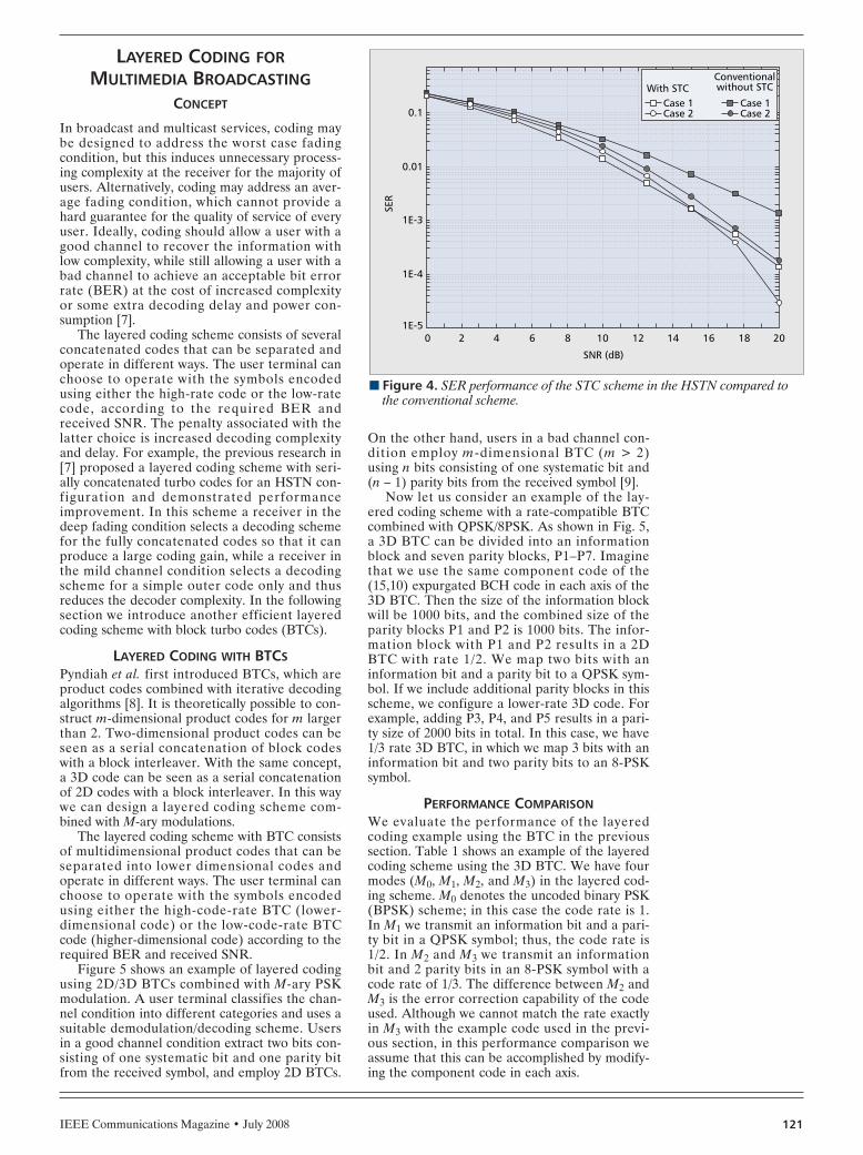
IEEE Communications Magazine • July 2008 121
LAYERED CODING FORMULTIMEDIA BROADCASTING
CONCEPT
In broadcast and multicast services, coding maybe designed to address the worst case fadingcondition, but this induces unnecessary process-ing complexity at the receiver for the majority ofusers. Alternatively, coding may address an aver-age fading condition, which cannot provide ahard guarantee for the quality of service of everyuser. Ideally, coding should allow a user with agood channel to recover the information withlow complexity, while still allowing a user with abad channel to achieve an acceptable bit errorrate (BER) at the cost of increased complexityor some extra decoding delay and power con-sumption [7].
The layered coding scheme consists of severalconcatenated codes that can be separated andoperate in different ways. The user terminal canchoose to operate with the symbols encodedusing either the high-rate code or the low-ratecode, according to the required BER andreceived SNR. The penalty associated with thelatter choice is increased decoding complexityand delay. For example, the previous research in[7] proposed a layered coding scheme with seri-ally concatenated turbo codes for an HSTN con-figuration and demonstrated performanceimprovement. In this scheme a receiver in thedeep fading condition selects a decoding schemefor the fully concatenated codes so that it canproduce a large coding gain, while a receiver inthe mild channel condition selects a decodingscheme for a simple outer code only and thusreduces the decoder complexity. In the followingsection we introduce another efficient layeredcoding scheme with block turbo codes (BTCs).
LAYERED CODING WITH BTCSPyndiah et al. first introduced BTCs, which areproduct codes combined with iterative decodingalgorithms [8]. It is theoretically possible to con-struct m-dimensional product codes for m largerthan 2. Two-dimensional product codes can beseen as a serial concatenation of block codeswith a block interleaver. With the same concept,a 3D code can be seen as a serial concatenationof 2D codes with a block interleaver. In this waywe can design a layered coding scheme com-bined with M-ary modulations.
The layered coding scheme with BTC consistsof multidimensional product codes that can beseparated into lower dimensional codes andoperate in different ways. The user terminal canchoose to operate with the symbols encodedusing either the high-code-rate BTC (lower-dimensional code) or the low-code-rate BTCcode (higher-dimensional code) according to therequired BER and received SNR.
Figure 5 shows an example of layered codingusing 2D/3D BTCs combined with M-ary PSKmodulation. A user terminal classifies the chan-nel condition into different categories and uses asuitable demodulation/decoding scheme. Usersin a good channel condition extract two bits con-sisting of one systematic bit and one parity bitfrom the received symbol, and employ 2D BTCs.
On the other hand, users in a bad channel con-dition employ m-dimensional BTC (m > 2)using n bits consisting of one systematic bit and(n – 1) parity bits from the received symbol [9].
Now let us consider an example of the lay-ered coding scheme with a rate-compatible BTCcombined with QPSK/8PSK. As shown in Fig. 5,a 3D BTC can be divided into an informationblock and seven parity blocks, P1–P7. Imaginethat we use the same component code of the(15,10) expurgated BCH code in each axis of the3D BTC. Then the size of the information blockwill be 1000 bits, and the combined size of theparity blocks P1 and P2 is 1000 bits. The infor-mation block with P1 and P2 results in a 2DBTC with rate 1/2. We map two bits with aninformation bit and a parity bit to a QPSK sym-bol. If we include additional parity blocks in thisscheme, we configure a lower-rate 3D code. Forexample, adding P3, P4, and P5 results in a pari-ty size of 2000 bits in total. In this case, we have1/3 rate 3D BTC, in which we map 3 bits with aninformation bit and two parity bits to an 8-PSKsymbol.
PERFORMANCE COMPARISONWe evaluate the performance of the layeredcoding example using the BTC in the previoussection. Table 1 shows an example of the layeredcoding scheme using the 3D BTC. We have fourmodes (M0, M1, M2, and M3) in the layered cod-ing scheme. M0 denotes the uncoded binary PSK(BPSK) scheme; in this case the code rate is 1.In M1 we transmit an information bit and a pari-ty bit in a QPSK symbol; thus, the code rate is1/2. In M2 and M3 we transmit an informationbit and 2 parity bits in an 8-PSK symbol with acode rate of 1/3. The difference between M2 andM3 is the error correction capability of the codeused. Although we cannot match the rate exactlyin M3 with the example code used in the previ-ous section, in this performance comparison weassume that this can be accomplished by modify-ing the component code in each axis.
n Figure 4. SER performance of the STC scheme in the HSTN compared tothe conventional scheme.
SNR (dB)
201E-5
1E-4
SER
1E-3
0.01
0.1
4 6 8 10 12 14 16 18 20
Case 1Case 2
With STCConventionalwithout STC
Case 1Case 2
KIM1 LAYOUT 6/18/08 1:23 PM Page 121
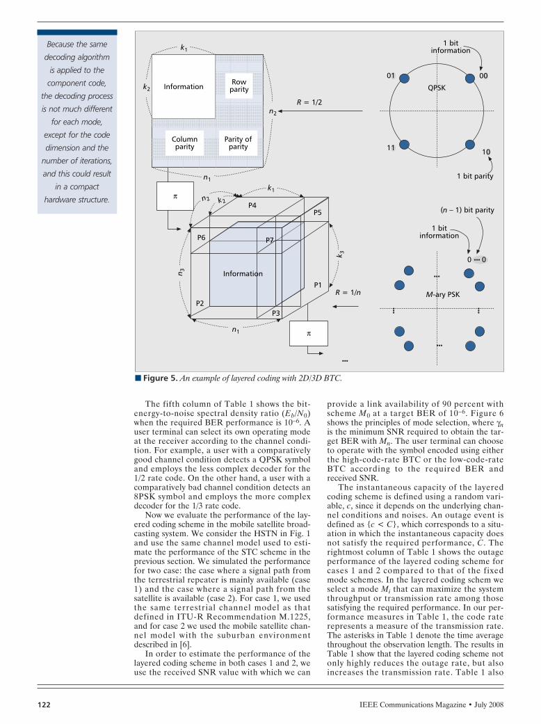
IEEE Communications Magazine • July 2008122
The fifth column of Table 1 shows the bit-energy-to-noise spectral density ratio (Eb/N0)when the required BER performance is 10–6. Auser terminal can select its own operating modeat the receiver according to the channel condi-tion. For example, a user with a comparativelygood channel condition detects a QPSK symboland employs the less complex decoder for the1/2 rate code. On the other hand, a user with acomparatively bad channel condition detects an8PSK symbol and employs the more complexdecoder for the 1/3 rate code.
Now we evaluate the performance of the lay-ered coding scheme in the mobile satellite broad-casting system. We consider the HSTN in Fig. 1and use the same channel model used to esti-mate the performance of the STC scheme in theprevious section. We simulated the performancefor two case: the case where a signal path fromthe terrestrial repeater is mainly available (case1) and the case where a signal path from thesatellite is available (case 2). For case 1, we usedthe same terrestrial channel model as thatdefined in ITU-R Recommendation M.1225,and for case 2 we used the mobile satellite chan-nel model with the suburban environmentdescribed in [6].
In order to estimate the performance of thelayered coding scheme in both cases 1 and 2, weuse the received SNR value with which we can
provide a link availability of 90 percent withscheme M0 at a target BER of 10–6. Figure 6shows the principles of mode selection, where γnis the minimum SNR required to obtain the tar-get BER with Mn. The user terminal can chooseto operate with the symbol encoded using eitherthe high-code-rate BTC or the low-code-rateBTC according to the required BER andreceived SNR.
The instantaneous capacity of the layeredcoding scheme is defined using a random vari-able, c, since it depends on the underlying chan-nel conditions and noises. An outage event isdefined as c < C, which corresponds to a situ-ation in which the instantaneous capacity doesnot satisfy the required performance, C. Therightmost column of Table 1 shows the outageperformance of the layered coding scheme forcases 1 and 2 compared to that of the fixedmode schemes. In the layered coding schem weselect a mode Mi that can maximize the systemthroughput or transmission rate among thosesatisfying the required performance. In our per-formance measures in Table 1, the code raterepresents a measure of the transmission rate.The asterisks in Table 1 denote the time averagethroughout the observation length. The results inTable 1 show that the layered coding scheme notonly highly reduces the outage rate, but alsoincreases the transmission rate. Table 1 also
n Figure 5. An example of layered coding with 2D/3D BTC.
P6 P7
P4P5
P1R = 1/n
P3P2
Information
π
1 bitinformation
(n – 1) bit parity
M-ary PSK
00
1 bit parity
1 bitinformation
QPSK
R = 1/2
01
11 10
00
k1
k2
n1
k1
k2n2
n1
n 3
k 3
n2
InformationRow
parity
Parity ofparity
Columnparity
π
Because the same
decoding algorithm
is applied to the
component code,
the decoding process
is not much different
for each mode,
except for the code
dimension and the
number of iterations,
and this could result
in a compact
hardware structure.
KIM1 LAYOUT 6/18/08 1:23 PM Page 122
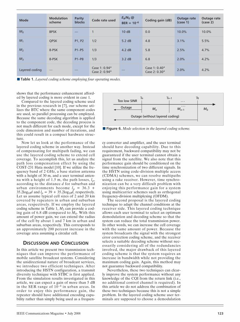
IEEE Communications Magazine • July 2008 123
shows that the performance enhancement afford-ed by layered coding is more evident in case 1.
Compared to the layered coding scheme usedin the previous research in [7], our scheme uti-lizes the BTC where the same component codesare used, so parallel processing can be employed.Because the same decoding algorithm is appliedto the component code, the decoding process isnot much different for each mode, except for thecode dimension and number of iterations, andthis could result in a compact hardware struc-ture.
Now let us look at the performance of thelayered coding scheme in another way. Insteadof compensating for multipath fading, we canuse the layered coding scheme to extend cellcoverage. To accomplish this, let us analyze thepath loss compensation effect by using theCOST-231 Hata model [10]. If we utilize the fre-quency band of 2 GHz, a base station antennawith a height of 30 m, and a user terminal anten-na with a height of 1.5 m, the path losses, lp,according to the distance d for suburban andurban environments become lp = 36.3 +35.2log10d and lp = 39 + 35.2log10d, respectively.Let us assume typical cell sizes of 2 and 20 kmcovered by repeaters in urban and suburbanareas, respectively. If we employ the layeredcoding scheme in Table 1, M3 can provide a cod-ing gain of 6.8 dB compared to M0. With thisamount of power gain, we can extend the radiusof the cell by about 1 and 7 km in urban andsuburban areas, respectively. This corresponds toan approximately 200 percent increase in thecoverage area assuming a circular cell.
DISCUSSION AND CONCLUSIONIn this article we present two transmission tech-niques that can improve the performance ofmobile satellite broadcast systems. Consideringthe unidirectional nature of broadcast services,we introduce two efficient techniques. Afterintroducing the HSTN configuration, a transmitdiversity technique with STBC is first applied.From the simulation results investigated in thisarticle, we can expect a gain of more than 5 dBin the SER range of 10–4 in urban areas. Inorder to enjoy this performance gain, therepeater should have additional encoding capa-bility rather than simply being used as a frequen-
cy converter and amplifier, and the user terminalshould have decoding capability. Due to thisrequirement, backward compatibility may not beguaranteed if the user terminal cannot obtain asignal from the satellite. We also note that thisperformance gain should be conditioned on thetime synchronization of two different signals. Inthe HSTN using code-division multiple access(CDMA) schemes, we can resolve multipathsusing a rake receiver. However, time synchro-nization can be a very difficult problem withenjoying this performance gain for a systemusing multicarrier schemes such as orthogonalfrequency-division multiplexing (OFDM).
The second proposal is the layered codingtechnique to adapt the channel conditions at thereceiver side. This layered coding techniqueallows each user terminal to select an optimumdemodulation and decoding scheme so that thesystem can reduce the total transmission power.In other words, we can increase the cell coveragewith the same amount of power. Because thesystem broadcasts the signal with the strongesterror correction coding scheme, and the receiverselects a suitable decoding scheme without nec-essarily considering all of the redundanciesinvolved, the major drawback of this layeredcoding scheme is that the system requires anincrease in bandwidth while not providing themaximum coding gain. Again, this method maynot guarantee backward compatibility.
Nevertheless, these two techniques can clear-ly improve the system performance without anyknowledge of the CQI from the return link (i.e.,no additional control channel is required). Inthis article we do not address the combination ofthese two techniques because this is not a simpleproblem. In the layered coding scheme user ter-minals are supposed to choose a demodulation
n Figure 6. Mode selection in the layered coding scheme.
Outage
Too low SINRγ0
M0Mn–1Mn
Outage (without layered coding)
γn–1γn
n Table 1. Layered coding scheme employing four operating modes.
Mode Modulationscheme
Parityblocks Code rate used
Eb/N0 @
BER = 10–6Coding gain (dB) Outage rate
(case 1)Outage rate(case 2)
M0 BPSK — 1 10 dB 0.0 10.0% 10.0%
M1 QPSK P1, P2 1/2 5.2 dB 4.8 3.1% 5.5%
M2 8-PSK P1–P5 1/3 4.2 dB 5.8 2.5% 4.7%
M3 8-PSK P1–P8 1/3 3.2 dB 6.8 2.0% 4.2%
Layered coding — — Case 1: 0.94*Case 2: 0.94* — Case 1: 0.40*
Case 2: 0.30* 2.0% 4.2%
KIM1 LAYOUT 6/18/08 1:23 PM Page 123

IEEE Communications Magazine • July 2008124
method adaptively. Because space-time encodingis processed on the modulated symbols, thespace-time encoding strategy should be carefullycustomized with respect to adaptive demodula-tion in order to combine the STC and layeredcoding schemes. We therefore leave this as afuture study item.
ACKNOWLEDGMENTThis work was partly supported by the IT R&Dprogram of MIC/IITA, Korea [2005-S-014-02,Development of satellite IMT-2000 + technolo-gy].
REFERENCES[1] ETSI TR 102 376, “Digital Video Broadcasting (DVB);
User Guidelines for the Second Generation System forBroadcasting, Interactive Services, News Gathering andOther Broadband Satellite Applications (DVB-S2).”
[2] N. Al-Dhahir et al., “Space-Time Processing for Broad-band Wireless Access,” IEEE Commun. Mag., Sept.2002, pp.136–42.
[3] H. Jiang and P. A. Wilford, “A Hierarchical Modulationfor Upgrading Digital Broadcast Systems,” IEEE Trans.Broadcasting, vol. 51, no. 2, June 2005, pp. 223–29.
[4] S. M. Alamouti, “A Simple Transmit Diversity Techniquefor Wireless Communications,” IEEE JSAC, vol. 16, no.8, Oct. 1998, pp. 1451–58.
[5] 3GPP TS 25.101 v6.7.0, “Technical Specification GroupRadio Access Network; User Equipment (UE) RadioTransmission and Reception (FDD),” Release 6.
[6] F, P. Fontan et al., “Statistical Modeling of the LMSChannel,” IEEE Trans. Vehic. Tech., vol. 50, no. 11,2001, pp. 1549–67.
[7] A. Levissianos et al., “Layered Coding for Satellite-Plus-Terrestrial Multipath Correlated Fading Channels,” Int’l.J. Satellite Commun. and Networking, vol. 22, 2004,pp. 485–502.
[8] R.M. Pyndiah, “Near-Optimum Decoding of ProductCodes: Block Turbo Codes,” IEEE Trans. Commun., vol.46, no. 88, 1998, pp. 1003–1010. .
[9] S. Ryoo, S. Kim, and D.-S. Ahn, “Layered Coding withBlock Turbo Codes for Broadcasting and MulticastingServices,” Proc. IEEE VTC-Fall, 2006.
[10] COST Action 231, “Digital Mobile Radio TowardsFuture Generation Systems, Final Report,” Tech. rep.,EC, EUR 18957, 1999.
BIOGRAPHIESSOOYOUNG KIM ([email protected]) received a B.Sdegree in electrical and electronics engineering from KoreaAdvanced Institute of Science and Technology (KAIST),Korea, in 1990. After having worked in the Satellite Com-munication Technology Division, ETRI, Korea, from February1990 to September 1991, she received her M.Sc. and Ph.D.degrees in electrical and electronics engineering from theUniversity of Surrey, United Kingdom, in 1992 and 1995,respectively. From November 1994 to June 1996 she wasemployed as a research fellow at the Centre for SatelliteEngineering Research, University of Surrey. In 1996 she re-joined the Satellite Communication Technology Division,ETRI, Korea, and worked as a team leader until February2004. She is now an associate professor at ChonbukNational University and visiting research staff at ETRI.
HEE WOOK KIM ([email protected]) received a B.S. degreein electronics from Korea University, Seoul, Korea, in 2001,and an M.S. degree in electrical engineering from KAIST in2004. He is currently a member of research staff with theGlobal Area Wireless Technology Research Department atETRI. His research interests include mobile satellite commu-nication systems, synchronization, MIMO-OFDM systems,UWB systems, and multiuser detection.
KUNSEOK KANG ([email protected]) received B.S. and M.S.degrees in electronics engineering from Kyungpook Nation-al University, Korea, in 1997 and 1999, respectively. He iscurrently a senior member of research staff in the GlobalArea Wireless Technology Research Department of ETRI andhas worked on the development of efficient transmissionalgorithms for satellite communications. His research inter-ests include satellite communications, coding techniques,and multicarrier transmission.
DO SEOB AHN ([email protected]) received B.S. and M.S.degrees in electronics engineering from Kyungpook Nation-al University in 1988 and 1990, respectively. He is currentlya principal member of research staff in the Global AreaWireless Technology Research Department of ETRI workingin the areas of stratospheric communication systems andsatellite communication systems.
Because space-time
encoding is
processed on the
modulated symbols,
the space-time
encoding strategy
should be carefully
customized with
respect to the
adaptive
demodulation, in
order to combine
the STC and layered
coding schemes.
We leave this as a
future study item.
KIM1 LAYOUT 6/18/08 1:23 PM Page 124

IEEE Communications Magazine • July 2008126 0163-6804/08/$25.00 © 2008 IEEE
INTRODUCTION
With the development of mobile communica-tions and multimedia technologies, demand forinteractive mobile multimedia services in ahigh-speed mobile reception environment hasgrown rapidly. Although existing mobile com-munication networks are good for interactiveservices, it is not easy to support broadbandmultimedia applications at high mobility. Onthe other hand, digital broadcast networks caneasily deliver broadband mobile multimediaservices to mass users, but cannot supportinteractive communications. The concept ofintegrated communication and broadcast net-works (ICBNs) was proposed in [1], takingadvantage of the best of the two heterogeneousnetworks to support interactive broadbandmobile multimedia services. An ICBN is partic-ularly suitable for asymmetric information dis-semination to a large number of subscribers.This is due mainly to the nature of broadcastnetworks, such as high volume, high data rate,
high reliability, and, most important, freedomfrom congestion.
Recently, with the vast deployment of digitalbroadcast networks worldwide, much attentionhas been paid to ICBNs, and some prototypesystems have been developed [2, 3]. But most ofthem focus only on the architecture, with littlediscussion of detailed protocol and signalingdesign.
The Chinese digital television terrestrialbroadcast standard, unofficially called digitaltelevision/terrestrial nultimedia broadcast(DTMB), was ratified in August 2006. Themulticarrier working mode is based on the timedomain synchronous orthogonal frequency-division multiplex (TDS-OFDM) modulationscheme proposed by Tsinghua University [4].Compared to coded-OFDM for digital videobroadcasting over terrestrial (DVB-T), it hasthe advantages of higher spectrum efficiency,faster channel synchronization, larger forwarderror correction (FEC) coding gain, and bettercapability of handling impulsive noise, whichmay have great impact on the performance ofICBNs. So far, there has been no study on itsapplication to ICBNs. This article proposes anew paradigm for ICBNs, where the DTMBsystem serves as downlinks and the existingmobile communication systems (third genera-tion [3G], wireless LAN [WLAN], etc.) asuplinks. By dividing the services into four cate-gories (digital TV, video on demand, data ondemand, and Internet access), a completedesign of the system architecture and signalingprotocols are provided. Specifically, a subnet-work data unit (SNDU) layer and a negativeacknowledgment (NAK)-based automaticrepeat request (ARQ) signaling protocol havebeen proposed and designed. To demonstrateand evaluate the performance of the proposeddesigns, a testbed at Tsinghua University basedon DTMB and WLAN/CDMA1x was devel-oped recently.
ABSTRACT
This article provides a new paradigm to inte-grate the Chinese digital television/terrestrialmultimedia broadcasting (DTMB) systems withexisting mobile communication systems, whichcan support mobile multimedia broadcasting ser-vices with carrier-grade quality. By dividing theservices into four categories — digital TV, videoon demand, data on demand, and Internet access— a complete design of the layered structureand signaling protocols are presented. Specifical-ly, a subnetwork data unit layer and a modifiedhybrid ARQ signaling protocol have been pro-posed. A testbed at Tsinghua University basedon DTMB and WLAN/CDMA1x has been suc-cessfully implemented, and the experimentalresults clearly show the effectiveness of the pro-posed signaling protocols.
ADVANCES IN MOBILE MULTIMEDIABROADCASTING: PART II
Zhisheng Niu, Long Long, Jian Song, and Changyong Pan, Tsinghua University
A New Paradigm for Mobile MultimediaBroadcasting Based on Integrated Communication andBroadcast Networks
PAN LAYOUT 6/18/08 2:05 PM Page 126

IEEE Communications Magazine • July 2008 127
OVERVIEW OF THE DTMBTECHNOLOGY AND KEY ISSUES OF
THE PROPOSED PARADIGM
The DTMB system under multicarrier modula-tion has the following major features:
•It uses the TDS-OFDM modulation scheme,which inserts pseudo-noise (PN) sequences asthe guard intervals of OFDM symbols to achievemuch quicker synchronization (time domain pro-cessing). This is very important for packet switch-ing at a high transmission rate. Since the PNsequence is used for both synchronization andchannel estimation, continuous and scatteredpilot insertion is avoided; therefore, the spec-trum efficiency can be improved by roughly 10percent.
•FEC code in DTMB is a concatenation ofBose, Ray-Chaudhuri, Hocquenghem (BCH)code and low density parity check (LDPC) code,providing superior error correction capability.
•It carries MPEG-2 transport streams (TS)combining video, audio, and data, and allows IPmulticast and unicast on top of MPEG-2, whichlays the foundation for interactive services.Especially in an IPv6-based network, each digitaldevice connected to the network can be assignedan IP address. DTMB devices can therefore usethe IP network for multicasting and unicasting.
•It adopts a long-time interleaver to providebetter immunization to impulsive noise.
Table 1 gives the performance comparisonsbetween DTMB and DVB-T.
ICBN is a feasible and promising scheme torealize the convergence of communication andbroadcast networks, but there are still lots oftechnical challenges. Two of the challenges areadmission control and radio resource manage-ment. Unlike dedicated networks that have beenoptimized for certain types of services, ICBN hasto provide mobile multimedia broadcasting ser-vices more efficiently. Therefore, how to per-form admission control for both delay- andloss-sensitive mobile broadcasting services is abig challenge. Moreover, the question of how toefficiently allocate the limited radio resource aswell as schedule packet transmissions is of greatimportance. So far, we have proposed two radioresource management schemes for ICBN: theSatisfaction-Oriented Bandwidth Allocation
Method (SOBAM) [5] for single-channel ICBNand Profit-Oriented Bandwidth AllocationMethod (POBAM) [6] for multichannel ICBN.We have applied them in our design and testbedimplementation.
Another challenge comes from the bandwidthasymmetry between broadcast channels andfeedback channels, and its impact on system per-formance. Usually, out-of-band feedback chan-nels (e.g., 3G, WLAN) are narrowband andunstable. Therefore, they always suffer from longdelays, resulting in bursty feedbacks of acknowl-edgments (ACKs). Thus, it is very important toinvestigate the effects of feedback delay, delayjitter, and bandwidth asymmetry on the systemperformance of ICBN. We address these issuesin the following sections.
LAYERED STRUCTURE ANDSIGNALING PROTOCOL DESIGN
Given the asymmetric and broadcast nature ofICBNs, we can divide system services into fourtypes: digital television (DTV), video on demand(VoD), data on demand (DoD), and Internetaccess (IAC). To accommodate the four types ofservice with very different traffic characteristicsand quality of service (QoS) requirements in anefficient manner, a layered structure has beendesigned as depicted in Fig. 1.
THE SNDU LAYER AND ENCAPSULATIONHere, in order to efficiently provide interactivemultimedia services in our ICBN, we have newlydesigned the SNDU as the frame format of thelink layer. In DTMB networks, the basic dataformat is MPEG-2 TS, which is designed forone-way DTV transmissions and thus not suit-able for interactive data services in ICBN. Previ-ously, the European TelecommunicationsStandards Institute (ETSI) published a standardfor data transmission over DVB-T [7], but it isnot applicable to mobile multimedia services.The Internet Engineering Task Force (IETF)has also provided requests for comments (RFCs)on transmission of IP datagrams over MPEG-2networks [8], but has failed to provide supportsfor packet data units (PDUs) and Ethernetframes. Specifically, the SNDU layer in our sys-tem is responsible for not only PDU addressing,
n Table 1. Measurement comparison between DTMB and DVB-T with FEC code rate OF 0.4.
DTMB (4K) QPSK DVB-T (2K) QPSK DTMB (4K)64-QAM
DVB-T (8K)64-QAM
Guard interval (ms) 55.56 (1/9) 56 (1/9) 55.56 (1/9) 56 (1/9)
Data throughput (Mb/s) 5.414 4.974 24.3684 23.424
Spectrum efficiency (b/s/Hz) 0.68 0.62 3.1 2.9
C/N in AWGN channel (dB) 1.9 4.7 15.2 18.6
Receiving sensitivity (dBm) –97.0 –87.1 –83.0 –78.6
Acquisition (ms) ~5 ~100 ~5 ~100
Given the
asymmetric and
broadcasting nature
of ICBN, we can
divide system services
into four types:
digital television
(DTV), video on
demand (VoD), data
on demand (DoD),
and Internet
access (IAC).
PAN LAYOUT 6/18/08 2:05 PM Page 127

IEEE Communications Magazine • July 2008128
frame formatting, and error checking, but alsobandwidth allocation and ordering.
The encapsulation process is shown in Fig.2a, where PDUs are first encapsulated intoSNDUs and then the SNDUs into TS packets. InSNDU encapsulation, a PDU is encapsulatedinto an SNDU with an SNDU header and taileradded. The length of the SNDU is variable,depending on the length of the PDU. An SNDUis usually encapsulated into several TS packetsbecause of the relatively short length of TS pack-ets (188 bytes). Padding is needed if a TS packetis partially filled. The general SNDU frame for-mat is depicted in Fig. 2b, which is compatiblewith the frame format defined in RFC 4326 [8].
Destination Address Absent (D) field: Themost significant bit of the Length field carriesthe value of the Destination Address Absent (D)field, indicating the presence of the Addressfield.
Length field: A 15-bit value that indicates thelength of the SNDU in bytes, which is the sumof the Address, PDU, and frame check sequence(FCS) fields, and any possible extension headers.
Address field: The 48-bit Address field indi-cates the SNDU destination address. It is option-al, depending on the value of the D field.Multicast address and broadcast address can alsobe assigned in this field.
PDU field: In our system PDUs can be IPdatagrams, video streams, or data files.
FCS field: The FCS field is 32 bits long con-taining an IEEE 32-bit cyclic redundancy check(CRC) for SNDU error detection.
Type field: The 16-bit Type field indicates thetype of payload carried in an SNDU, or thepresence of a next-header as an extension head-er. When it indicates the type of payload, it iscompatible with the allocations for Ethernet. Forexample, the IPv4 payload is defined as 0x0800.To comply with other systems, we extend thegeneral SNDU frame format with the SNDUextension header. The unidirectional lightweightencapsulation (ULE) [8] extension header isclassified into seven categories, one of whichindicates a mandatory extension header and canbe defined by the user. Following this conven-tion, we define the Type field as 0x0080 for VoD
service and 0x0081 for DoD service, for whichthe following two extended fields are included inthe SNDU frame header.
Application ID field: The 16-bit ApplicationID field indicates the identification of the appli-cations on the service list. The service list on thelocal server maintains this field and guaranteesthe ID for each application to be unique. Thisfield can be used to distinguish different applica-tions.
Sequence Number field: The 32-bit SequenceNumber field indicates the sequence number ofan SNDU. Each SNDU for different applica-tions is assigned a sequence number from amodulo 232 counter, starting at 0 and increment-ing by 1 for each SNDU. The sequence numberremains constant in all retransmissions of anSNDU; thus, it can be used in ARQ to distin-guish the SNDUs from different applications.The SNDU frame format with extension fields isdepicted in Fig. 2c. With the above-mentioneddesign and extensions, the bandwidth allocationand QoS management as well as multicast trans-missions can easily be provided through ournewly designed SNDU layer. In particular, theintroduction of multicast transmission canachieve high bandwidth efficiency by making fulluse of the broadcast nature of ICBN. Mean-while, there are fields for error checking andordering in the SNDU frame. Thus, the ARQscheme can also be implemented in this layer forreliable data download services.
A MODIFIED HYBRID ARQ AND THESIGNALING PROTOCOL
In broadcast networks FEC is widely used forerror detection and correction. In a wirelessenvironment, FEC should be very strong inorder to counteract the bit errors caused byattenuation, multipath fading, and so on. Forexample, the inner code rate of FEC in DTMBbroadcast networks can be 0.4. However, theintegration of feedback channels in ICBN makesARQ possible. Therefore, weaker FEC can beused in ICBN with ARQ. This hybrid ARQ(HARQ) scheme can improve system through-put greatly.
The ARQ scheme used in our system is NAK-based; that is, the terminal only sends a NAKback when it detects erroneous SNDUs, and noACK is sent back for correct SNDUs. This isdue mainly to the very low bit error rate (BER)nature of the DTMB transmission systems, whichmakes the ACK-based protocol less efficient. Atthe high transmission rate in DTMB transmis-sion systems, a number of ACKs will occupy thescarce bandwidth of the return channels, causingfurther congestion and long delays. In particular,the ARQ scheme for unicast traffic in our sys-tem is just traditional selective-repeat ARQ. Butfor multicast traffic, since the number of retrans-mitted SNDUs depends on the number of termi-nals that require multicast services, the numberof retransmitted SNDUs will increase significant-ly with an increase in terminals. Therefore, it isnecessary to reduce the number of retransmittedSNDUs.
In [9] the authors present an approach toreduce the number of retransmitted packets by
n Figure 1. Layer structure of the proposed DTMB-based ICBN.
Registration/authentication/accounting
Bandwidth allocation/QoS management
Unicast/multicast
SNDU encapsulation
MPEG-2 transport stream
TDS-OFDM/constellation mapping and interleaving/scrambling and FEC coding
L3
L2
L1
TCP/IPSignaling messages exchange
DTVprograms
Video ondemand
Datadownload
ARQ
Internetaccess
PAN LAYOUT 6/18/08 2:05 PM Page 128

IEEE Communications Magazine • July 2008 129
introducing XOR (modulo 2 addition) opera-tion. The idea is not to retransmit requestedpackets immediately upon reception of oneNAK, but gather n NAKs. Then the sender com-bines the n retransmitted packets by XORingthem and transmits to the receivers. In particu-lar, let P1, P2, …, Pn represent the n retransmit-ted packets. Then the resulting packet isobtained by Psend = P1 ⊕ P2 ⊕… ⊕ Pn. Onreceiving Psend, if the receiver needs Pk (1 ⊕ k ⊕n, k ∈ N) to be retransmitted while receiving therest n – 1 packets correctly, Pk can be obtainedby the operation Pk = Psend ⊕ P1 ⊕ … ⊕ Pk–1 ⊕Pk+1 ⊕ … ⊕ Pn.
However, this will result in two problems.First, if more than one of the n NAKs comefrom the same receiver, the receiver cannotreconstruct the packets it needs from Psend. Sec-ond, receiving n NAKs before retransmissionwill lead to much longer delay. These motivateus to propose a modified retransmission schemebased on the XOR scheme.
Let Pe be the packet that gets a NAK andneeds to be retransmitted. In our modifiedscheme, an upper limit M is introduced to indi-cate the number of packets that can be transmit-ted after Pe. That is, if the sender receives aNAK indicating that Pe needs to be retransmit-ted, the sender can at most transmit M followingpackets before it begins to retransmit Pe. Thisupper limit ensures a short delay in retransmis-sion. Specifically, the sender only needs to trans-mit Psend when it receives more than one NAKsfrom the same receiver or the upper limit M isreached. In this way we can avoid the two prob-lems described above. Here, M can be given byM = (DR – DT)RSNDU/SSNDU, in which DR, DT,RSNDU, and SSNDU represent the required delayconstraint, SNDU transmission delay, SNDUtransmission rate, and SNDU size, respectively.In particular, DR is determined by traffic charac-teristics, while DT and RSNDU depend on the spe-
cific systems and can be obtained by measure-ment.
For VoD and DoD services, signaling mes-sage exchanges between the local server and theterminals are mandatory due to their interactienature. Specifically, the local server will wait atime slice when a service request is received. Ifmore than one service request for the sameapplication are received during the time slice,multicast will be triggered; otherwise, unicastwill be used. In [10] we proposed a bandwidthallocation scheme for mixed unicast and multi-cast multimedia flows with perception-basedQoS differentiation.
The signaling messages are described as fol-lows. First the client sends out a connectionrequest to the server. Once accepted, the serverprovides a list of available services, such as filenames and file sizes. Then the client sends outits service request, and the server will use thebandwidth allocation scheme to decide whetherto accept the request. After that, the client givesa ready message to the server, indicating thatthe client is ready for data transmission. Thenthe process of data transmission through thedownlink channel is invoked. After successfuldata transmission, the server will deliver a dis-connect message. The complete process is con-trolled by a timer, and the process will beautomatically reset after waiting a certain periodof time.
PERFORMANCE EVALUATIONTHROUGH A TESTBED
To verify the concept and benefit of our ICBNdesign, we built a testbed on the campus ofTsinghua University with the DTMB system forthe downlink and WLAN for the return channelsthrough the campus network. To evaluate theperformance in a high-speed mobility environ-
n Figure 2. a) SNDU encapsulation process; b) general SNDU frame format; c) SNDU frame format with extension fields..
D Length
Octets: 2
Type
SNDU header
Address
(b)
PDU FCS
2 6 4
PDU
Payload
PDU
SNDU
TS
SNDUheader
TSheader Payload TS
header Payload
(a)
TSheader Payload
FCS
D Length
Octets: 2
Type
SNDU header
Address
(c)
ApplicationID
2
Sequencenumber
2 6 4
PDU FCS
4
PAN LAYOUT 6/18/08 2:05 PM Page 129
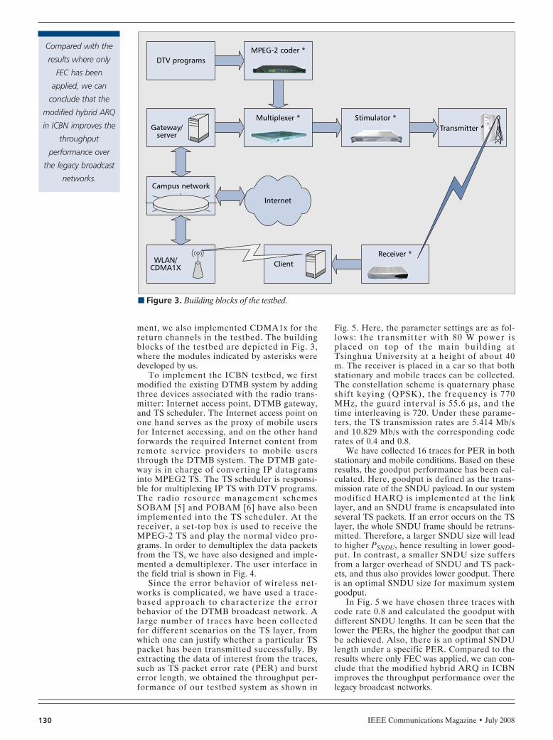
IEEE Communications Magazine • July 2008130
ment, we also implemented CDMA1x for thereturn channels in the testbed. The buildingblocks of the testbed are depicted in Fig. 3,where the modules indicated by asterisks weredeveloped by us.
To implement the ICBN testbed, we firstmodified the existing DTMB system by addingthree devices associated with the radio trans-mitter: Internet access point, DTMB gateway,and TS scheduler. The Internet access point onone hand serves as the proxy of mobile usersfor Internet accessing, and on the other handforwards the required Internet content fromremote service providers to mobile usersthrough the DTMB system. The DTMB gate-way is in charge of converting IP datagramsinto MPEG2 TS. The TS scheduler is responsi-ble for multiplexing IP TS with DTV programs.The radio resource management schemesSOBAM [5] and POBAM [6] have also beenimplemented into the TS scheduler. At thereceiver, a set-top box is used to receive theMPEG-2 TS and play the normal video pro-grams. In order to demultiplex the data packetsfrom the TS, we have also designed and imple-mented a demultiplexer. The user interface inthe field trial is shown in Fig. 4.
Since the error behavior of wireless net-works is complicated, we have used a trace-based approach to characterize the errorbehavior of the DTMB broadcast network. Alarge number of traces have been collectedfor different scenarios on the TS layer, fromwhich one can justify whether a particular TSpacket has been transmitted successfully. Byextracting the data of interest from the traces,such as TS packet error rate (PER) and bursterror length, we obtained the throughput per-formance of our testbed system as shown in
Fig. 5. Here, the parameter settings are as fol-lows: the transmitter with 80 W power isplaced on top of the main bui lding atTsinghua University at a height of about 40m. The receiver is placed in a car so that bothstationary and mobile traces can be collected.The constellation scheme is quaternary phaseshift keying (QPSK), the frequency is 770MHz, the guard interval is 55.6 µs, and thetime interleaving is 720. Under these parame-ters, the TS transmission rates are 5.414 Mb/sand 10.829 Mb/s with the corresponding coderates of 0.4 and 0.8.
We have collected 16 traces for PER in bothstationary and mobile conditions. Based on theseresults, the goodput performance has been cal-culated. Here, goodput is defined as the trans-mission rate of the SNDU payload. In our systemmodified HARQ is implemented at the linklayer, and an SNDU frame is encapsulated intoseveral TS packets. If an error occurs on the TSlayer, the whole SNDU frame should be retrans-mitted. Therefore, a larger SNDU size will leadto higher PSNDU, hence resulting in lower good-put. In contrast, a smaller SNDU size suffersfrom a larger overhead of SNDU and TS pack-ets, and thus also provides lower goodput. Thereis an optimal SNDU size for maximum systemgoodput.
In Fig. 5 we have chosen three traces withcode rate 0.8 and calculated the goodput withdifferent SNDU lengths. It can be seen that thelower the PERs, the higher the goodput that canbe achieved. Also, there is an optimal SNDUlength under a specific PER. Compared to theresults where only FEC was applied, we can con-clude that the modified hybrid ARQ in ICBNimproves the throughput performance over thelegacy broadcast networks.
n Figure 3. Building blocks of the testbed.
Stimulator *
DTV programs
Campus network
Internet
Gateway/server
MPEG-2 coder *
Multiplexer *
ClientReceiver *
WLAN/CDMA1X
Transmitter *
Compared with the
results where only
FEC has been
applied, we can
conclude that the
modified hybrid ARQ
in ICBN improves the
throughput
performance over
the legacy broadcast
networks.
PAN LAYOUT 6/18/08 2:05 PM Page 130
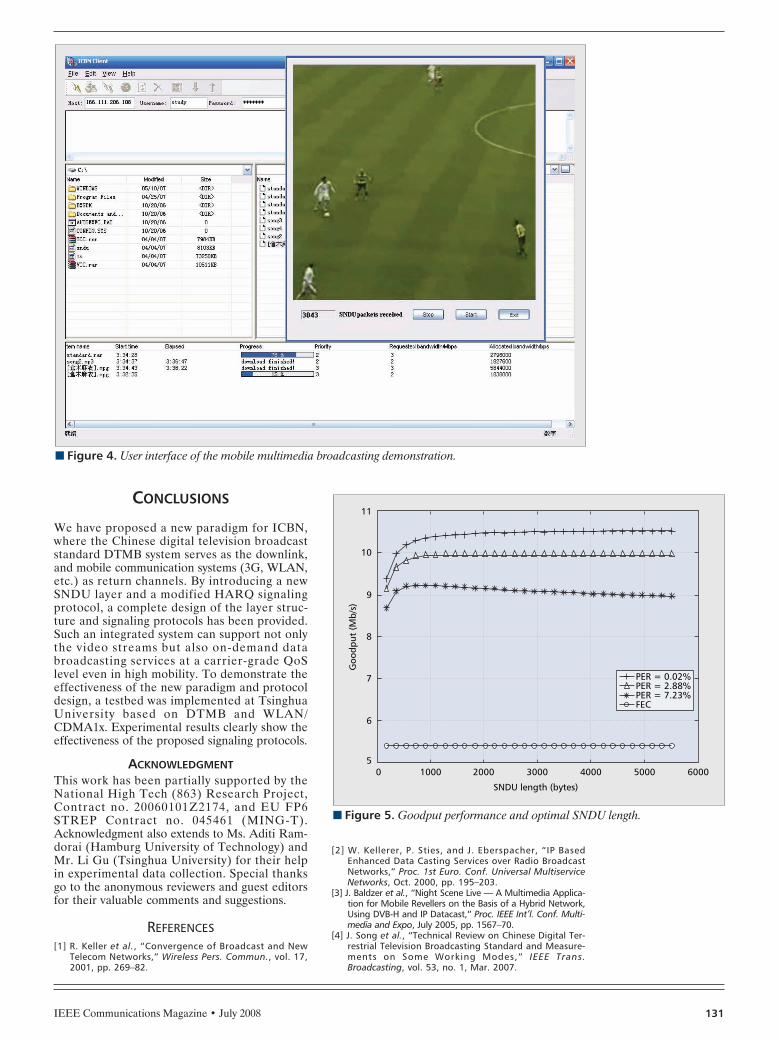
IEEE Communications Magazine • July 2008 131
CONCLUSIONS
We have proposed a new paradigm for ICBN,where the Chinese digital television broadcaststandard DTMB system serves as the downlink,and mobile communication systems (3G, WLAN,etc.) as return channels. By introducing a newSNDU layer and a modified HARQ signalingprotocol, a complete design of the layer struc-ture and signaling protocols has been provided.Such an integrated system can support not onlythe video streams but also on-demand databroadcasting services at a carrier-grade QoSlevel even in high mobility. To demonstrate theeffectiveness of the new paradigm and protocoldesign, a testbed was implemented at TsinghuaUniversity based on DTMB and WLAN/CDMA1x. Experimental results clearly show theeffectiveness of the proposed signaling protocols.
ACKNOWLEDGMENTThis work has been partially supported by theNational High Tech (863) Research Project,Contract no. 20060101Z2174, and EU FP6STREP Contract no. 045461 (MING-T).Acknowledgment also extends to Ms. Aditi Ram-dorai (Hamburg University of Technology) andMr. Li Gu (Tsinghua University) for their helpin experimental data collection. Special thanksgo to the anonymous reviewers and guest editorsfor their valuable comments and suggestions.
REFERENCES[1] R. Keller et al., “Convergence of Broadcast and New
Telecom Networks,” Wireless Pers. Commun., vol. 17,2001, pp. 269–82.
[2] W. Kellerer, P. Sties, and J. Eberspacher, “IP BasedEnhanced Data Casting Services over Radio BroadcastNetworks,” Proc. 1st Euro. Conf. Universal MultiserviceNetworks, Oct. 2000, pp. 195–203.
[3] J. Baldzer et al., “Night Scene Live — A Multimedia Applica-tion for Mobile Revellers on the Basis of a Hybrid Network,Using DVB-H and IP Datacast,” Proc. IEEE Int’l. Conf. Multi-media and Expo, July 2005, pp. 1567–70.
[4] J. Song et al., “Technical Review on Chinese Digital Ter-restrial Television Broadcasting Standard and Measure-ments on Some Working Modes,” IEEE Trans.Broadcasting, vol. 53, no. 1, Mar. 2007.
n Figure 4. User interface of the mobile multimedia broadcasting demonstration.
n Figure 5. Goodput performance and optimal SNDU length.
SNDU length (bytes)
100005
6
Goo
dput
(M
b/s)
7
8
9
10
11
2000 3000 4000 5000 6000
PER = 0.02%PER = 2.88%PER = 7.23%FEC
PAN LAYOUT 6/18/08 2:05 PM Page 131

IEEE Communications Magazine • July 2008132
[5] G. Miao and Z. Niu, “Satisfaction Oriented ResourceManagement in Integrated Internet and DVB-T NetworkProviding High Mobility Broadband Access Services,”Proc. IEEE GLOBECOM ’05, St. Louis, MO, Nov./Dec.2005, pp. 3841–45.
[6] —, “Profit Oriented Multichannel Resource Manage-ment of Integrated Communication and Broadcast net-works,” IEEE Trans. Broadcast., vol. 51, no. 4, Dec.2005, pp. 530–37.
[7] ETSI EN 301 192 V1.4.1, “Digital Video Broadcasting(DVB); DVB Specification for Data Broadcasting,” Nov.2004.
[8] G. Fairhurst and B. Collini-Nocker, “UnidirectionalLightweight Encapsulation (ULE) for Transmission of IPDatagrams over an MPEG-2 Transport Stream (TS),”IETF RFC 4326, Dec. 2005.
[9] Y. Shen and B. Lee, “XOR Retransmission in MulticastError Recovery,” Proc. IEEE Int’l. Conf. Networks, Sept.2000, pp. 336–40.
[10] G. Miao and Z. Niu, “Bandwidth Management forMixed Unicast and Multicast Multimedia Flows withPerception Based QoS Differentiation,” Proc. IEEE ICC’06, Istanbul, Turkey, June 2006, pp. 687–92.
BIOGRAPHIESZHISHENG NIU [SM] ([email protected]) graduatedfrom Northern Jiaotong University, Beijing, China, in 1985,and got his M.E. and D.E. degrees from Toyohashi Universi-
ty of Technology, Japan, in 1989 and 1992, respectively.He worked for Fujitsu Laboratories Ltd., Kawasaki, Japan,from 1992 to 1994, and currently is a professor in theDepartment of Electronic Engineering, Tsinghua University,Beijing, China. His research interests include teletraffic the-ory, mobile Internet, radio resource management of wire-less networks, and cognitive radio networks. He is a fellowof the IEICE, vice director of IEEE Asia-Pacific Board, and acouncil member of the Chinese Institute of Electronics. Heis also serving as the TPC co-chair of IEEE ICC ’08.
LONG LONG ([email protected]) graduatedfrom Nanjing University of Posts and Telecommunicationsin 2005 and is currently a Master’s degree student atTsinghua University, China. His research interest is in inte-grated communication and broadcast networks.
JIAN SONG ([email protected]) received his Ph.D.degree from Tsinghua University in 1990. He is now a pro-fessor and director of the Digital TV R&D Center ofTsinghua University. He has been actively involved in theChinese DTTB standard process as a major technical con-tributor.
CHANGYONG PAN ([email protected]) is an associate pro-fessor and deputy director of the Digital TV R&D Center ofTsinghua University. He has been actively involved in theChinese DTTB standard process as one of major technicalcontributors. He is also a key working group member onthe serial national equipment standards related to DTTB.
PAN LAYOUT 6/18/08 2:05 PM Page 132

IEEE Communications Magazine • July 2008134
pplications & Practice — Optical CommunicationsSeries is dedicated to publishing high-quality arti-
cles covering optical communications technologies that areproviding value and benefit in service provider networksand enabling major advances in broadband communica-tions. This issue features articles that address develop-ments in several segments of the optical communicationsnetwork. These segments are the access network with fiberto the premises (FTTP)/fiber to the home (FTTH) initia-tives, metro networks with reconfigurable optical add/dropmultiplexers (ROADMs), and the optical core with opticalcontrol plane technology.
An overview of several FTTP/FTTH passive optical net-work (PON) installations in the United States, the Pyre-nees region of Europe, and Denmark is presented byWave7 Optics. PONs hold great promise for providinghigh-speed voice, data, and video services (triple play) withvirtually unlimited bandwidth. This article examines someof the early successes of PONs and evaluates future oppor-tunities in several major areas such as service mix, stan-dards, quality of service (QoS), operational considerations,and ownership structure. Many entities, such as telcos,multiple service operators (MSOs) such as cable TV com-panies, municipalities, and utilities are stepping forward asFTTP/FTTH providers and have embraced variousFTTP/FTTH PON architectures. Who will be successful?The jury is still out, but the article from Wave7 Opticsgives some helpful insights as to what is down the road inhigh-speed triple play offerings.
ROADMs have brought flexibility and scalability tooptical communications networks. Since 2003 ROADMshave become an integral element of core networks andan essential feature of metro dense wavelength-divisionmultiplexing (DWDM) deployments. As demands forbandwidth and flexibility have risen, carriers have beendeploying, at an accelerating pace, ROADM-equippednodes that are well suited for ring topologies. This repre-
sents a challenging task as new nodes must accommodate40 and 100 Gb/s optical channel capacities in economi-cally viable and energy-efficient service provider net-works. ROADM suppliers have made great strides andtaken ROADM technologies closer to end users whoseek high-bandwidth applications. In this issue of theOptical Communications Series, two contributions, onefrom Nistica and another from Xtellus, provide overviewsof technologies that have advanced ROADMs to theirprominent role in today’s and tomorrow’s broadbandcommunications networks. In the contribution from Nis-tica, two technologies that have recently emerged aredescribed. Digital light processing (DLP) switches andliquid crystal on silicon (LCoS) display technologies arebeing adapted for telecom-grade usage. Xtellus, in con-trast, provides their assessment of the central role ofwavelength-selective switch (WSS) technology in theadvancement of ROADM technologies and deployments.Both contributions provide perspectives on the advancesin automated provisioning in modern multichannel fiberoptic communications networks. With such advances,while the cost of operating such networks is reduced,higher bandwidths with lower probability of manual con-figuration error are enabled.
As bandwidth demands are aggregated into the corenetwork, the timely and efficient provision of bandwidththat is scalable and survivable becomes a challenge. Theshift from a circuit-based voice network to a packet-baseddata network with varying QoS needs has changed the waycore networks are built and configured. Optical controlplane technology has changed the way capacity is activatedand the way networks automatically reconfigure them-selves in the event of a failure. Ciena has been activelyinvolved in the standards development for optical controlplane technology as well as the implementation of fullyautomated optical core networks. Their overview of opticalcontrol plane technology provides insights into the benefits
GUEST EDITORIAL
A
John Spencer Osman Gebizlioglu
OPTICAL COMMUNICATIONS: ENABLING GLOBAL BROADBAND COMMUNICATIONS NETWORKS
LYT-GUESTEDIT-Spencer 6/18/08 2:45 PM Page 134

IEEE Communications Magazine • July 2008 135
of this technology in terms of efficient use of capital,expense reduction, and revenue generation for telecomcarriers.
For future WDM metropolitan area networks (MANs),optical packet switching (OPS) has been considered to bea promising paradigm that efficiently supports a widerange of Internet-based applications having time-varyingand high-bandwidth demands and stringent delay require-ments. A contribution to this issue from National ChiaoTung University presents the design of an experimentaltestbed system for a high-performance optical packet-switched WDM metro ring network (HOPSMAN). HOPS-MAN features a scalable architecture, nodes equippedwith high-speed photonic device components, includingfast tunable receivers and optical slot erasers, capable ofperforming high-speed optical packet-switching operations,and a medium access control (MAC) scheme that embod-ies efficient and dynamic bandwidth allocation. This articlepresents the key hardware components and also a demon-stration of the feasibility of HOPSMAN.
In this second issue of the Optical CommunicationsSeries, we are very pleased to bring together contributionsthat provide overviews of key technology developmentsand deployments that have been redefining optical com-munications as the source of exciting and promising broad-band communications technologies of today and tomorrow.
BIOGRAPHIESJOHN SPENCER [SM] ([email protected]) is a telecom industry veteranwith over 36 years of experience. He worked 29 years with BellSouth with 14of those years as a member of technical staff in the Science and TechnologyDepartment. During that time he was involved in the introduction of SONETand Erbium doped fiber amplifiers (EDFAs) and had a team lead role for theintroduction of DWDM technology in the BellSouth network. He worked forfive years as regional director, product marketing engineering for Mahi Net-works, Petaluma, CA. He is currently business and technology strategist forOptelian Access Networks, where he manages industry and customer direc-tion to Optelian's product line. He was Conference Co-Chairman for NFOEC in1991 and 1998. He has served on the NFOEC Technical Program Committeefor 10 years. He served as Secretary and Chairman of ANSI accredited com-mittee T1X1, Digital Hierarchy and Synchronization. He is a graduate of Geor-gia Institute of Technology (B.E.E.) and is a registered Professional Engineer(PE) in the State of Alabama. He currently serves on the NFOEC/OFC TechnicalProgram Committee and is Co-Editor of IEEE Communications Magazine’sApplication & Practice — Optical Communications Series.
OSMAN GEBIZLIOGLU [M] ([email protected]) is director of the OpticalAnalysis Service Line at Telcordia Technologies. Since he joined Bellcore in1987 he has been involved with the development of performance and relia-bility assurance requirements for optical communications components. Inaddition to his work to support the implementation of optical communica-tions technologies in major service provider networks, he has been involvedin reliability assurance and failure analysis efforts on aerospace communica-tions networks. He holds a Ph.D in chemical engineering and materials sci-ence from Princeton University. He held postdoctoral fellow and researchscientist positions jointly between the Mechanical Engineering and Chemi-cal Engineering Departments at the Massachusetts Institute of Technologyprior to joining Bellcore. He holds six U.S. patents and chairs the TR-42.13.1Working Group on Reliability Standards of the Telecommunications IndustryAssociation (TIA) TR-42 Engineering Committee. He is a member of theMaterials Research Society and the American Chemical Society.
GUEST EDITORIAL
LYT-GUESTEDIT-Spencer 6/18/08 2:45 PM Page 135

IEEE Communications Magazine • July 2008136
GUEST EDITORIAL
LYT-GUESTEDIT-Spencer 6/18/08 2:45 PM Page 136

IEEE Communications Magazine • June 2008136 0163-6804/08/$25.00 © 2008 IEEE
INTRODUCTION TO THE TECHNOLOGY
Figure 1 is an overview of the physical layertechnology of passive optical networks (PONs).On the left is the headend or central office(CO) equipment. In the center is the PON, andto the right is the equipment located at a home.The home termination is known as an opticalnetwork terminal (ONT). The data portion at theCO is called the optical line terminal (OLT).When radio frequency (RF) video is used, theRF output of a normal cable TV headend issupplied to a 1550 nm analog optical transmitteras shown. The transmitter and associated opticalamplifiers (not shown) are sometimes called avideo OLT, or V-OLT. Note that just becausethe transmitter must be analog (in order totransport the frequency-division multiplexedvideo signals), not all the signals transmitted arenecessarily analog: it is most common today totransmit a basic tier of analog channels, usually50–80 channels, and after that to transmit digi-tal channels on the RF plant.
The OLT interfaces with the operator’sdesired data networking infrastructure, usuallyvia gigabit Ethernet connections. It formats datafor transmission on the fiber, using the chosenprotocol, and converts the formatted data tooptical form. Downstream data is transmitted on1490 nm, and upstream data on 1310 nm. The
broadcast video on 1550 nm is combined withthe two-way data transmission on 1490/1310 nmin a wavelength-division multiplexer (WDM).
Typically the PON is optically split 32 ways toserve 32 ONTs. Other splits are possible, but 32-way splitting is most common today. The split-ting can all be done at one location as implied inFig. 1, or in some cases it is more efficient to dothe splitting in two stages. For example, thePON may be split four ways at the CO in orderto serve four small pockets of subscribers. Ateach pocket the PON may be split eight ways toserve eight subscribers. The location of splittingin the PON is unimportant. The only importantthing is to make sure the total distance from theCO to the subscriber is within the limitation ofthe hardware, usually 10–20 km with today’stechnology.
At the ONT, a WDM separates the 1550nm optical signal, which is routed to an analogreceiver, the output of which is an RF spec-trum identical to that of a cable TV system(except that the performance is probably bet-ter). The data portion of the system goes to adata transceiver, which is followed by the pro-tocol chip supporting the chosen PON proto-col, then to processing that separates the dataand voice. Typically, data is presented on fastEthernet interfaces, and voice is a conventionalanalog telephone interface. Of course, IP tele-phones may be used through the Ethernetinterfaces.
Besides some prestandard systems still oper-ating, there are three PON standards in usetoday. Broadband PON (BPON) is the oldeststandard. Promulgated by the InternationalTelecommunication Union (ITU), BPON hasbeen the choice of Verizon to date, althoughthey have announced that they will be transition-ing to gigabit PON (GPON). BPON is asyn-hcronous transfer mode (ATM)-based, andoffers downstream speed of 622 Mb/s andupstream speed of 155 Mb/s. It does not supportInternet Group Management Protocol (IGMP),so putting a significant amount of video contentover BPON (as IPTV) is problematic. Broadcastvideo works fine on BPON. The next standard inthe ITU series is GPON, and features down-stream speed of 2.488 Gb/s and upstream speedof 1.2 Gb/s in the most popular form. While ithas the capability of transporting ATM, Ether-net, and time-division multiplexing (TDM), it is
ABSTRACT
This article describes several real deploy-ments of passive optical networks (PONs, themost common form of fiber to the home, FTTH)in several parts of the world, some with incum-bent providers, some with other entities. Thenetworks and service models are described,along with initial experiences with providing ser-vice. PON describes a technology whereby video,voice, and data can be delivered to residentialand business customers using fiber optics fromthe point of origination to the home. The pointof origination is called a central office, or CO, inthe telephone industry, and a headend or hub inthe cable TV industry. The headend is the mas-ter point where all signals are collected for thesubscriber interface in both directions. The hubis a secondary location that interfaces with theheadend, and then radiates connections out tosubscribers.
IEEE APPLICATIONS & PRACTICE:OPTICAL COMMUNICATIONS AND NETWORKS
James O. Farmer and Kevin Bourg, Wave7 Optics, An Enablence Technologies Company
Practical Deployment of Passive Optical Networks
FARMER LAYOUT 6/18/08 2:51 PM Page 136
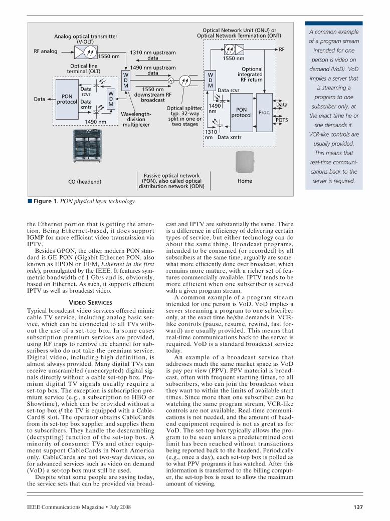
IEEE Communications Magazine • July 2008 137
the Ethernet portion that is getting the atten-tion. Being Ethernet-based, it does supportIGMP for more efficient video transmission viaIPTV.
Besides GPON, the other modern PON stan-dard is GE-PON (Gigabit Ethernet PON, alsoknown as EPON or EFM, Ethernet in the firstmile), promulgated by the IEEE. It features sym-metric bandwidth of 1 Gb/s and is, obviously,based on Ethernet. As such, it supports efficientIPTV as well as broadcast video.
VIDEO SERVICESTypical broadcast video services offered mimiccable TV service, including analog basic ser-vice, which can be connected to all TVs with-out the use of a set-top box. In some casessubscription premium services are provided,using RF traps to remove the channel for sub-scribers who do not take the premium service.Digital video, including high definition, isalmost always provided. Many digital TVs canreceive unscrambled (unencrypted) digital sig-nals directly without a cable set-top box. Pre-mium digital TV signals usually require aset-top box. The exception is subscription pre-mium service (e.g., a subscription to HBO orShowtime), which can be provided without aset-top box if the TV is equipped with a Cable-Card slot. The operator obtains CableCardsfrom its set-top box supplier and supplies themto subscribers. They handle the descrambling(decrypting) function of the set-top box. Aminority of consumer TVs and other equip-ment support CableCards in North Americaonly. CableCards are not two-way devices, sofor advanced services such as video on demand(VoD) a set-top box must still be used.
Despite what some people are saying today,the service sets that can be provided via broad-
cast and IPTV are substantially the same. Thereis a difference in efficiency of delivering certaintypes of service, but either technology can doabout the same thing. Broadcast programs,intended to be consumed (or recorded) by allsubscribers at the same time, arguably are some-what more efficiently done over broadcast, whichremains more mature, with a richer set of fea-tures commercially available. IPTV tends to bemore efficient when one subscriber is servedwith a given program stream.
A common example of a program streamintended for one person is VoD. VoD implies aserver streaming a program to one subscriberonly, at the exact time he/she demands it. VCR-like controls (pause, resume, rewind, fast for-ward) are usually provided. This means thatreal-time communications back to the server isrequired. VoD is a standard broadcast servicetoday.
An example of a broadcast service thataddresses much the same market space as VoDis pay per view (PPV). PPV material is broad-cast, often with frequent starting times, to allsubscribers, who can join the broadcast whenthey want to within the limits of available starttimes. Since more than one subscriber can bewatching the same program stream, VCR-likecontrols are not available. Real-time communi-cations is not needed, and the amount of head-end equipment required is not as great as forVoD. The set-top box typically allows the pro-gram to be seen unless a predetermined costlimit has been reached without transactionsbeing reported back to the headend. Periodically(e.g., once a day), each set-top box is polled asto what PPV programs it has watched. After thisinformation is transferred to the billing comput-er, the set-top box is reset to allow the maximumamount of viewing.
n Figure 1. PON physical layer technology.
Passive optical network(PON), also called optical
distribution network (ODN)Home
Optical Network Unit (ONU) orOptical Network Termination (ONT)
1310nm
1490nm
Data xmtr
Data rcvr
Data
1550 nm
OptionalintegratedRF return
RF
Wavelength-division
multiplexer
Optical splitter,typ. 32-way
split in one ortwo stages
CO (headend)
DatarcvrDataxmtr
WDM
WDM
1550 nm
1490 nm
1310 nm upstreamdata
Optical lineterminal (OLT)
RF analog
Analog optical transmitter(V-OLT)
WDM
1490 nm upstreamdata
1550 nmdownstream RF
broadcast
POTS
PONprotocol
PONprotocol Proc.
Data
A common example
of a program stream
intended for one
person is video on
demand (VoD). VoD
implies a server that
is streaming a
program to one
subscriber only, at
the exact time he or
she demands it.
VCR-like controls are
usually provided.
This means that
real-time communi-
cations back to the
server is required.
FARMER LAYOUT 6/18/08 2:51 PM Page 137

IEEE Communications Magazine • July 2008138
EXAMPLE 1UNITED STATES: MUNICIPAL UTILITY
COMPANY
As Tennessee’s oldest municipal electric system,and the first system in the state to receive powerfrom the Tennessee Valley Authority, PulaskiElectric System (PES) has a unique and unri-valed history of service. Pulaski, an All-AmericaCity in 1993, with its industry-friendly environ-ment and its beautiful countryside setting, islocated near the Interstate corridor betweenNashville, Tennessee and Huntsville, Alabama.Pulaski Electric System currently serves nearly15,000 customers and operates 1242 mi of linethroughout Giles County.
In 2006 PES decided to expand their serviceto include video, voice, and data. Initially theyplanned to use the GPON standard, but theirconstruction plans preceded the widespreadavailability of GPON equipment, so they decidedto go to GE-PON, with a system that wouldallow them to change later if they needed to.
PES’s system is based on conventional broad-cast video. Video is received on their own anten-na farm, and locally processed to both analogand digital broadcast video, which is modulatedonto a 1550 nm optical carrier and amplified inan Erbium doped fiber amplifier (EDFA) asshown in Fig. 2. Their contracted voice over IP(VoIP) softswitch and peering to the publicswitched telephone network are located inAtlanta, Georgia, about 220 mi to the southeast.Redundant dedicated circuits and core routers
ensure reliable connection. Quality Internet con-nectivity was available locally.
Construction on PES’s fiber to the home(FTTH) system started in winter 2006 and wascompleted by the following winter. It passes4800 homes and businesses. One year later, thesystem enjoyed a 28 percent market share and iscontinuing to connect new subscribers.
As described in conjunction with Fig. 1, theOLT in the center of Fig. 2 connects to thePONs via a WDM, one per PON, which com-bines the broadcast video on a 1550 nm opticalcarrier with the 1490/1310 nm data. The fiberoptic ring is not really used as hot standby forresidential service, but was put in several yearsearlier to serve business needs. Since fiber wasavailable, it was placed into service. The fibers inthe ring terminate in local convergence cabinets(LCCs), where the PON splitters are located. 32-way splitters provide connection to 32 homes oneach PON, with individual fibers from the LCCto the home.
Each PON terminates at an ONT at everyhome or business served. Since broadcast TV isoffered, including analog TV, it is possible toconnect directly to TVs where the only servicerequired is analog broadcast. Most homes arealready wired with the coaxial cable needed. Theremainder of the TVs are connected throughset-top boxes, which can deliver, besides the ana-log signals, digital video including high defini-tion. In order to get upstream control signalsfrom the set-tops to the headend, initially a sec-ond box is used at the home. It demodulates theupstream RF signals intended for the set-top
n Figure 2. PES system architecture.
RFreturn
VoIPsoftswitch
Ethernetswitch
Core router 2
Core router 1
Setupcontrol VPN
Receiveprogramming on 10dish antenna farm RF
combining
WDM combines1550 nm broadcastoverlay with data
Voiceservices
Analogcable TVservice
EPONONTs
2-waydata
OLT
EDFA
1490 nm down1310 nm up
Business / governmentservices
Voiceservices
Digitalcable TV
service
Multi-homedBGP protocol
Digital
Analog
Set topcontrolsystem
PON1x32
PON1x32
Fiber opticring
Internetservices
Voiceservices
Ancillaryservices
Video is received on
their own antenna
farm, and locally
processed to both
analog and digital
broadcast video,
which is modulated
onto a 1550 nm
optical carrier and
amplified in an
EDFA.
FARMER LAYOUT 6/18/08 2:51 PM Page 138
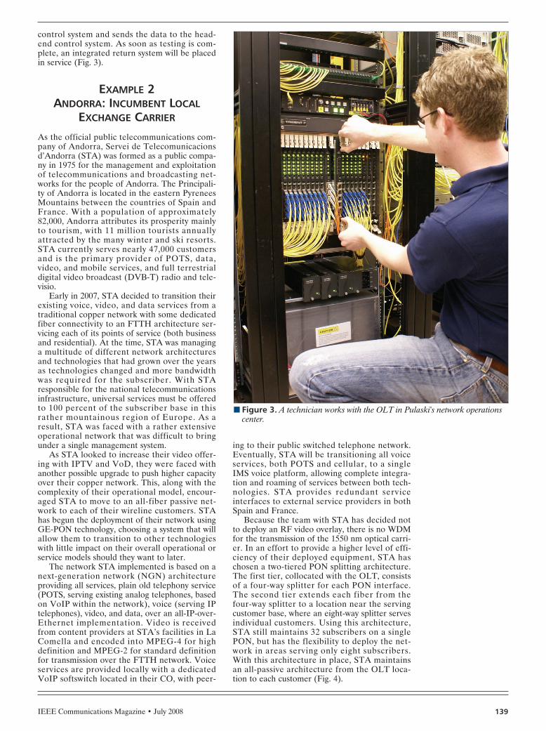
IEEE Communications Magazine • July 2008 139
control system and sends the data to the head-end control system. As soon as testing is com-plete, an integrated return system will be placedin service (Fig. 3).
EXAMPLE 2 ANDORRA: INCUMBENT LOCAL
EXCHANGE CARRIER
As the official public telecommunications com-pany of Andorra, Servei de Telecomunicacionsd’Andorra (STA) was formed as a public compa-ny in 1975 for the management and exploitationof telecommunications and broadcasting net-works for the people of Andorra. The Principali-ty of Andorra is located in the eastern PyreneesMountains between the countries of Spain andFrance. With a population of approximately82,000, Andorra attributes its prosperity mainlyto tourism, with 11 million tourists annuallyattracted by the many winter and ski resorts.STA currently serves nearly 47,000 customersand is the primary provider of POTS, data,video, and mobile services, and full terrestrialdigital video broadcast (DVB-T) radio and tele-visio.
Early in 2007, STA decided to transition theirexisting voice, video, and data services from atraditional copper network with some dedicatedfiber connectivity to an FTTH architecture ser-vicing each of its points of service (both businessand residential). At the time, STA was managinga multitude of different network architecturesand technologies that had grown over the yearsas technologies changed and more bandwidthwas required for the subscriber. With STAresponsible for the national telecommunicationsinfrastructure, universal services must be offeredto 100 percent of the subscriber base in thisrather mountainous region of Europe. As aresult, STA was faced with a rather extensiveoperational network that was difficult to bringunder a single management system.
As STA looked to increase their video offer-ing with IPTV and VoD, they were faced withanother possible upgrade to push higher capacityover their copper network. This, along with thecomplexity of their operational model, encour-aged STA to move to an all-fiber passive net-work to each of their wireline customers. STAhas begun the deployment of their network usingGE-PON technology, choosing a system that willallow them to transition to other technologieswith little impact on their overall operational orservice models should they want to later.
The network STA implemented is based on anext-generation network (NGN) architectureproviding all services, plain old telephony service(POTS, serving existing analog telephones, basedon VoIP within the network), voice (serving IPtelephones), video, and data, over an all-IP-over-Ethernet implementation. Video is receivedfrom content providers at STA’s facilities in LaComella and encoded into MPEG-4 for highdefinition and MPEG-2 for standard definitionfor transmission over the FTTH network. Voiceservices are provided locally with a dedicatedVoIP softswitch located in their CO, with peer-
ing to their public switched telephone network.Eventually, STA will be transitioning all voiceservices, both POTS and cellular, to a singleIMS voice platform, allowing complete integra-tion and roaming of services between both tech-nologies. STA provides redundant serviceinterfaces to external service providers in bothSpain and France.
Because the team with STA has decided notto deploy an RF video overlay, there is no WDMfor the transmission of the 1550 nm optical carri-er. In an effort to provide a higher level of effi-ciency of their deployed equipment, STA haschosen a two-tiered PON splitting architecture.The first tier, collocated with the OLT, consistsof a four-way splitter for each PON interface.The second tier extends each fiber from thefour-way splitter to a location near the servingcustomer base, where an eight-way splitter servesindividual customers. Using this architecture,STA still maintains 32 subscribers on a singlePON, but has the flexibility to deploy the net-work in areas serving only eight subscribers.With this architecture in place, STA maintainsan all-passive architecture from the OLT loca-tion to each customer (Fig. 4).
n Figure 3. A technician works with the OLT in Pulaski's network operationscenter.
FARMER LAYOUT 6/18/08 2:51 PM Page 139

IEEE Communications Magazine • July 2008140
Each fiber from the eight-way splitter is ter-minated within each home or business served.With the building architecture in Andorra typi-cally multidwelling or apartment style, STA haschosen an indoor ONT capable of beingdeployed similar to a digital subscriber line(DSL) modem. The ONT is installed within theresidence where the existing services are termi-nated. With TV services deployed as IPTV, eachof the televisions within the house is fitted with aset-top box capable of providing both high- andstandard-definition services. VoD and PPV ser-vices are available to each television, allowing asubscriber to request a movie or program athis/her leisure.
STA has incorporated extended video servicesto enhance penetration. As an example, incomingcalls may be screened while a customer is watch-ing television. Details of the caller, such as nameand caller ID, are displayed on the screen, allow-ing the subscriber the ability to send the caller tovoicemail if necessary. In addition, STA is look-ing toward the incorporation of social servicesover their network infrastructure for its local gov-ernment educational and welfare programs. Withthe network STA has put into place, new servicescan be added as the need arises.
As STA continues the rollout of these ser-vices to 100 percent of the people of Andorra,the existing copper network will be retired, inhopes of reaching 100 percent FTTH penetra-tion by 2011. By providing advanced services tothe subscriber base without increasing end-userfees, STA is confident that they can furtherdecrease their operational costs and continue toenhance the customer experience.
EXAMPLE 3DENMARK: MUNICIPALITY
The town of Marielyst, Denmark, is located onthe island Falster as part of the Guldborgsundmunicipality. This region occupies the south-ernmost point of Denmark, providing a resortdestination for vacationers, mainly during thesummer months. The local beaches and resortsare an attraction to vacationers, primarilyfrom the larger cities of Denmark and north-ern Germany. The municipality’s population isapproximately 63,000 year-round residents,increasing to 250,000 during the vacationmonths (Fig. 5).
The local cable provider for the town ofMarielyst was looking to update the existingplant to provide additional channels and beginoffering a high-speed data service. As the teamlooked at viable options for meeting the servicegoals, it became apparent that a new infra-structure would need to be installed throughoutthe community. During these discussions, theteam chose to move to an all-PON architecture,providing not only the ability to meet the servicegoals originally planned, but also the ability toinclude voice services with a network infra-structure that will serve the community for yearsto come.
As the team in Marielyst was focused on thedelivery of RF video services, they made a deci-sion to open up their network to a third-partyservice provider for both high-speed data andPOTS services. This allowed the Marielyst teamto focus on the installation and upgrade of their
n Figure 4. STA system architecture.
Serviceinsertionpoint
BRA S BRA S
Video Voice Data aggregation
IPTVheadend SP Solartech
OLT
OLT
MPLS corenetworkVoD
headend
Internetservice
provider A
Internetservice
provider B
Internetservices
PON×3 IPTV
cableservice
Voiceservices
IPTVcable
service
Voiceservices
PON×4
PONλ3
PONλ3
PONλ3
PONλ3
PONλ4
PONλ3
PONλ3
PONλ3
By providing
advanced services to
the subscriber base
without increasing
the end user fees,
STA is confident that
they can further
decrease their
operational costs and
continue to enhance
the customer
experience.
FARMER LAYOUT 6/18/08 2:51 PM Page 140

IEEE Communications Magazine • July 2008 141
existing video services and infrastructure whilepartnering with a leading service provider fordata and voice. Both companies worked togeth-er to identify the proper handoff point forInternet-based services, routing servicesthrough the service provider’s network forproper authentication and service level agree-ment management.
The outside plant architecture for Marielystuses a typical 1:32 PON architecture with all dis-tributed passive splits located close to the resi-dences in the network. The LCC is installed on apedestal located near the side of the road in aright-of-way. The cabinet is provisioned to allow100 percent penetration in the serving areas,with preconnectorized drops for ease of installa-tion by the civil works team when a homebecomes a subscriber (Fig. 6).
More recently, the team in Marielyst beganexploring additional services for the communityas they continue to add subscribers. As a lot ofthe European sporting content in the region isprovided by a limited number of providers, theydecided to begin offering an IP video servicethrough a separate third-party service provider.When a subscriber wishes to purchase this addi-tional service, a set-top box is provided by theservice provider and installed within the resi-dence. The set-top box(es) are connected to theONT on a dedicated interface, providing theconnectivity to the service provider’s headendnetwork. As the channel content provided by theIP service provider also includes the local cableoperator’s content, the subscriber is able tobrowse through the channel offerings using asingle electronic program guide. For those tele-
visions within the residence that are not connect-ed to the IPTV service, the traditional RF videooffering is still available.
The community of Marielyst has been con-nected to one of the region’s most advancedtriple-play networks, giving the community analternative for voice and broadband services.This has provided the developer the ability tofurther market the vacation community as a spotfor weekend getaways and to enable extendedtrips for those seeking some time away with thefamily while telecommuting to their place ofemployment.
EXAMPLE 4DENMARK: MUNICIPAL POWER UTILITYLocated in the middle of Denmark on the islandof Fyn, the city of Svendborg is the major com-mercial and tourist center for Southern Fyn. Thecity of Svendborg dates back to the early 13thcentury, and has historically been the maritimeregion of Denmark due to its ease of accessibili-ty to the shipping channels throughout NorthernEurope and the Baltic States. Svendborg is alsothe headquarters of the major Danish utilitycompany Sydfyns Elforsyning (SEF). As the pri-mary utility company for the Svendborg com-mune, SEF provides connectivity to a total of30,000 electrical customers.
Early in 2005, the Board of Directors for SEFcommissioned a separate entity to be managedby the Board to roll out telecommunication ser-vices to their servicing community. The separateentity was eventually branded Sydfyns Intranet
n Figure 5. Marielyst system architecture.
IP cableTV service
IP cableTV service
Analogcable TV service
Analogcable TV service
EDFA
WDMcombines 1550nm broadcastoverlay withdata
(Owned by outside serviceprovider)
Border gateway fordata services
IPTVheadend
Voice and dataservice provider
networkVGW SIP
VGWSIP
PON 132X
PON 232X
Analog
Dedicated IPTVtransport network
The outside plant
architecture for
Marielyst uses a
typical 1:32 passive
optical network
architecture with all
distributed passive
splits located close to
the residences in the
network. The Local
Convergence Cabinet
is installed on a
pedestal located near
the side of the road
in a right-of-way.
FARMER LAYOUT 6/18/08 2:51 PM Page 141

with a mission to provide voice, video, broad-band, and mobile services to the community ofSvendborg as an alternative to existing services.In the case of mobile services, SEF decided tomake an agreement with a local leading mobileprovider as a reseller, providing direct billingand customer support. With the remaining ser-vice options to be offered, the team at SEFmade a decision to initially outsource voice anddata services, allowing their team to focus ondeploying the network infrastructure and build-ing out an RF video headend (Fig. 7).
In the evaluation of technology choices todeploy services, the team with SEF was facedwith a number of challenges due to their uniqueservicing community. The community of SEFresides over a number of different islands thatare part of the Svendborg commune, in additionto large areas of multidwelling and single-familyresidences throughout the servicing towns. TheSEF team eventually decided on a PON deploy-ment to allow them the flexibility to service eachof the different communities.
SEF began with the installation of a core net-work utilizing their electrical substations as thevarious nodes on their network. From each ofthese nodes, the OLT equipment was installedwith an all-passive architecture from each of
these points to the customer residences. As anadditional benefit of this architecture, SEF wasable to actively monitor the health of each of thesubstations, allowing them better visibility intothe possible failure of electrical services (Fig. 8).
For the first two years of the deployment,SEF utilized a third-party service provider forboth POTS and broadband services. These twoareas of expertise were critical pieces of theirservice offering, and they did not want to takeon more than they could support as they werenew to being a telecommunications provider. Asthe network began to grow and they were able tofocus efforts on becoming a telecommunicationsprovider, SEF chose to support all servicesdirectly with the purchase of a voice softswitchand media gateway as well as providing redun-dant connections to local Internet service pro-viders in their region.
From the beginning, SEF understood theywould need to provide to their servicing commu-nity traditional RF video service supporteddirectly. This service offering would provide twooptions: a base package including all local free-to-air video content as well as national broadcastchannels, and a package including traditionalcable TV networks such as CNN, CNBC Nordic,and Discovery Channel. By offering a two-tiered
IEEE Communications Magazine • July 2008142
n Figure 6. Local convergence cabinet at Marielyst.
FARMER LAYOUT 6/18/08 2:51 PM Page 142

IEEE Communications Magazine • July 2008 143
service offering, a method of access control wasrequired to allow proper billing management.After some internal discussions and a bit of mar-ket research, the team agreed that a set-top boximplementation would not be acceptable to thepeople of Svendborg. The team decided on theuse of a low-pass filter to be installed on eachONT where a customer does not choose thecable TV network tier. The low-pass filter allowsthe lower-tiered free-to-air content to be viewed,while blocking the upper tier. If the subscriberwants to upgrade to the cable-based package,the filter is removed from the ONT. The filter islocated under a secure cover, inaccessible by thesubscriber.
As with the town of Marielyst, the SEF com-munity is serving requested additional video con-tent managed by alternative video serviceproviders in Denmark. In 2007 SEF expandedtheir service offering to include an IPTV pack-age to all subscribers. The content is provided toSEF at their Internet point of presence by DanskBroadband, and SEF is responsible for trans-porting the content to each subscriber. A sepa-rate set-top box is provided and installed in thesubscriber’s residence as in Marielyst, and thestandard RF tiered services are available forthose televisions not connected to an IPTV set-top box.
The Svendborg commune is one of the moresuccessful FTTx projects within the Nordicregion. The SEF team took the approach ofunderstanding the needs of the local market andtaking a well planned approach to ensure thatthe services offered meet the subscriber’s expec-
tations. With this approach, SEF has securedone of the highest penetrations of customers ona PON architecture in the region and continuesto grow their subscriber base on a daily basis.
FTTH ENVIRONMENT
SERVICES (VIDEO, VOICE, AND DATA)Each FTTH installation is customized to theneeds of the subscriber and owner, but nearly alloffer the triple play of video, voice, and data.Video may be provided by the system operatorand/or a third party. It may be provided as RFvideo and/or IPTV. Frequently both are used inorder to meet the needs of all parties. Voice anddata may be provided directly or by third parties.
Voice is nearly always provided internally tothe network as VoIP, using typically either theMGCP or SIP protocols, and converted to ana-log POTS service at the ONT. In addition, it ispossible to use compatible IP telephones on thenetwork. Data is becoming universally transport-ed in Ethernet packets. Additional services, suchas DS1/E1 service (over Ethernet/IP), may beprovided for businesses using external adaptors.
The trend seems to be that more of the datatraffic is video, driven by over-the-top (OTT)video, programming sent via the Internet andthe operator’s data facility, but not as part of theoperator’s service offering. Examples includeYouTube and similar services, Joost, AmazonUnboxed, Hulu, TV networks offering previouslybroadcast shows, and many others. The operatordoes not get paid for transporting OTT video,except as part of its normal charge for data ser-
n Figure 7. SEF system architecture.
Voiceservices
Voiceservices
SIP Softswitch
IPTVheadend
Internet
IPTV serviceprovidernetwork
Analog
PON 132X
PON 132X
SydfynsInternet
At this time, the
winning protocol
cannot be picked.
For the next
generation, both
IEEE and ITU are
working on 10 Gb/s
standards, using
different approaches.
There is some talk of
the possibility of at
least a partial merger
of the two
standards, but this
is not certain
at this point.
FARMER LAYOUT 6/18/08 2:51 PM Page 143

IEEE Communications Magazine • July 2008144
vice. There are a number of systems working onproviding their branded video service as IPTVrather than by broadcast. This has been moresuccessful so far in Southeast Asia than in NorthAmerica and Europe, where broadcast video ismore advanced and expectations for video ser-vice are somewhat different. In North Americathe driver has come mainly from DSL serviceproviders (including AT&T), who have no alter-native for video service, but FTTH providers arestarting to deploy IPTV more widely. In thefuture we expect to see a mix of broadcast andIPTV service for a number of years.
STANDARDSAll of the systems described herein use eitherthe IEEE GE-PON standard (IEEE 802.3ah) orpre-standard Ethernet-based solutions, depend-ing on when construction commenced. TheITU’s GPON standard is now commercially
available, and some service providers are startingto deploy it. At this time, the winning protocolcannot be picked. For the next generation, bothIEEE and ITU are working on 10 Gb/s stan-dards using different approaches. There is sometalk of the possibility of at least a partial mergerof the two standards, but this is not certain atthis point.
For present-generation services, GE-PON isthe winner in Southeast Asia. In North Americaand Europe, the situation is not as clear. Themajority of PON installations so far have beendone by Verizon, which is using BPON, the pre-decessor to GPON. Others have predominantlydeployed either GE-PON, which was availablebefore GPON was available, or prestandard sys-tems. Verizon has announced a conversion toGPON for future deployments, but timing is notcertain, at least not outside of Verizon. Manyother providers have announced GPON deploy-ments, following the lead of Verizon and possi-bly because GPON does offer the fastest speedstoday. On the other hand, 10 Gb/s systems arebeing worked on now, and if they become com-mercially available fast enough and at attractivecosts (not a sure thing), this may limit deploy-ment of GPON.
QUALITY OF SERVICEAll FTTH systems offer exceptional quality oftransmission, the ability to provide video inboth broadcast and IPTV forms, mixed andmatched to meet local requirements. FTTHalso offers support for the most common VoIPprotocols, with conversion to POTS in the ONTif desired, and incredible data speeds. GE-PONin a 32-way split configuration offers an averageof 31.25 Mb/s symmetrical to each subscriber,and GPON offers up to 78 Mb/s downstreamand 37.5 Mb/s upstream. However, note thatthese average speeds are not very meaningful,since the bandwidth is shared between sub-scribers — statistics get you a lot more speedthan this. Quality of service (QoS) mechanismsare available to make sure that critical packetsare not delayed.
Almost all FTTH systems (except for BPON)have QoS mechanisms that support IPTV includ-ing HDTV. Many operators are starting to com-press HDTV using MPEG-4 compression, whichyields the same quality at lower bandwidth thanthe more common MPEG-2. At this time we arenot seeing a limitation due to HDTV. It is truethat bandwidth demands always trend up,although a switch to MPEG-4 could reverse thistrend, at least for a while. Certainly use of boththe broadcast and data features of FTTH willoffer a lot of bandwidth — a full broadcastdownstream is equivalent to a payload broadcastto all homes of about 6 Gb/s. Cable TV hasalready developed switch digital video tech-niques to efficiently use this bandwidth in an IP-like mode.
OPERATIONAL CONSIDERATIONSAs all-dielectric passive plants, FTTH networkstend to have much lower operational expensesthan competing technologies. Except for acci-dental fiber cuts, there is little that can go wrongwith the outside plant. In addition, FTTH net-
n Figure 8. OLT and EDFAs at SEF. Only three PON blades (four PONS perblade) are installed in the OLT, with 15 free slots for future expansion. Onenetwork-side interface is in the center of the chassis, with a single 1000 Mb/sEthernet connection. More Ethernet connections are on the card, and a sec-ond blade can be added when needed. The blade on the extreme left of theOLT is the network management card. Power, alarm, and fans are above theblades. Below the OLT are the 1550 nm broadcast optical transmitter and sev-eral EDFAs to amplify the optical signal.
FARMER LAYOUT 6/18/08 2:52 PM Page 144

IEEE Communications Magazine • July 2008 145
works are immune to electromagnetic interfer-ence, both egress from the plant and ingress intothe plant. There are no corrosion issues.
Compared to cable TV hybrid fier-coax plant,FTTH eliminates the need to do required leak-age measurements and periodic rebalancing ofthe plant. It is virtually impossible to have noisefunneling out of homes, which tends to makemajor portions of cable TV’s limited upstreamspectrum unavailable, so this again can reducethe labor involved with maintaining plant.
OWNERSHIP STRUCTUREOwnership and operation of FTTH plant tendsto be varied. Because the technology becameavailable just as municipalities, either directly orthrough their owned utilities, have entered thetelecommunications market, they have beenmajor players in the deployment of FTTH plants.Private companies are also involved, eitherdirectly or through partnerships. There is anemerging trend to rebuild existing twisted pair(telephone) and coaxial cable (cable TV) plantusing FTTH, but the trend is in its earliest stages.
While FTTH operators today tend to come inas a second or third service provider, competingagainst local incumbents, their local presenceand advanced triple-play service packages tendto lift their subscriber numbers quickly. A com-mon way of setting rates is to set the break-evenpoint at around 30 percent of possible sub-scribers. Most systems go well past this point afew years after beginning service.
The future is likely a mix of service providers,both public and private. With just one revenuestream (e.g., from either TV or voice), it is diffi-cult to financially justify a number of facilities-based service providers. With each serviceprovider offering the triple play of video, voice,and data, it is feasible to have at least two enti-ties compete for business. Three may be possi-ble. At this time, we are not able to predict whatthe future model for telecommunications utilitieswill be, other than to say there will be competi-tion. In smaller areas we may well see municipalservices succeed, given their tradition of success-ful utility service in the past. Certainly many util-ities are known for superior local service, and
this is in their favor. In larger areas it may bemore of a private company market, as populousregions have the number of customers a privatecompany would need, and private companieshave the ability to move across political bound-aries with relative freedom. But these are goingto be interesting times in telecommunications.Some people will see that as a blessing, others asa curse.
CONCLUSIONThe global environment of FTTH deploymentshas seen a substantial increase in subscriberpenetration over the past years. The Asian mar-kets have continued their growth at an extraor-dinary rate, occupying the top three globalmarkets with the highest level of penetration.The North American and European marketscontinue to increase their commitment to FTTxdeployments year after year, with the UnitedStates alone adding an additional 1.4 millionhomes in 2007. Based on the geographical chal-lenges each market faces, different deploymentarchitectures are used to meet service, econom-ical, and operational conditions. With the largevolume of single-family residential homes in theUnited States, an FTTH approach is a moretypical deployment model; whereas in marketssuch as Asia where vertical residential homesare typical, deploying FTT building approachesare more common.
BIOGRAPHIESJAMES O. FARMER [F] ([email protected]) has beenin the cable TV industry since 1972. He co-authored Mod-ern Cable Television: Video, Voice and Data Communica-tions, and has also written extensively for technicalconferences and the trade press. He received his B.S.E.E.and M.S.E.E. from the University of South Florida. He is asenior member of the Society of Cable TelecommunicationsEngineers. He is a founder and CTO of Wave7 Optics.
KEVIN BOURG ([email protected]) received his B.S.in computer science from the University of SouthwesternLouisiana and his M.S. in software engineering from South-ern Methodist University. He previously worked for Norteland Nera Telecommunications, and is presently director ofInternational Sales, Engineering and Market Development,Wave7 Optics.
FARMER LAYOUT 6/18/08 2:52 PM Page 145

IEEE Communications Magazine • June 2008146 0163-6804/08/$25.00 © 2008 IEEE
EDGE NETWORK TRANSFORMATION
The edge of the telecommunications network isa natural fit for the reconfigurable opticaladd/drop multiplexer (ROADM) (Fig. 1). Newtraffic patterns resulting from the intrinsicchurn of services and the broadcast nature ofcontent delivery are colliding with the limits ofthe legacy infrastructure. Service providershave traditionally deployed fixed opticaladd/drop multiplexers (FOADMs) because oftheir low initial capital expense (CapEx) withthe understanding that their associated opera-tional costs (OpEx) would run high due to pro-visioning truck rolls and forklift upgrades.Until recently the exorbitant OpEx for thesefixed solutions was grudgingly accepted by car-riers due to the large CapEx differentialbetween FOADM and ROADM solutions, butnew low-cost, flexible modules have pushed theFOADM into obsolescence. This transforma-tion is reflected in the recent growth ofROADM infrastructure in carrier networks.Since 2007 Verizon and AT&T have deployedover 1000 ROADM nodes as the demand forhigh-speed data services and video applicationsform the main offerings in their FiOS and U-verse plans, respectively.
With the fixed nature of new network buildslargely eliminated, the focus has now shifted to
the various architectures for ROADM deploy-ments. While large mesh applications with 1 × 9and even 1 × 23 cross-connect modules are tech-nically challenging and garner a lot of attention,the underlying ring nature of deployed fibertopologies provides the majority of deployments.Ring topologies remain for three simple reasons:• The fiber plant was originally built out in
this fashion.• They offer protected service levels.• They offer the lowest cost points for back-
haul and broadcast services.As a result, the largest opportunity for ROADMapplications is the two-degree (1 × 2) ringROADMs that serve the needs of over 80 per-cent of deployments.
EDGE NETWORKSYSTEM REQUIREMENTS
ROADM vendors are challenged when trying tomeet their customers’ expectations for the metroand edge networks. In addition to providingaccepted core ROADM functionality, ROADMsuppliers are expected to provide seamless inter-operability with existing WDM system architec-tures at an attractive price point. Some of thekey benefits derived by carriers are given below.
Logistics simplification by single-codedevices: FOADM deployment on a large scale isconsidered impractical due to the need to trackmultiple product codes or part IDs. For exam-ple, a fixed filter that adds or drops a specificwavelength has to be binned and tagged as such.In a 100-GHz-spaced 40-plus-channel densewavelength-division multiplexing (DWDM) sys-tem, operations personnel have to track 40-plusproduct codes and manage the inventory as wellas the replacement parts. ROADMs provideimmediate relief because of their ability to addor drop any channel anywhere in the network.Product designers can thus order and track a sin-gle product ID and deploy the same part every-where in the network without regard to futureuncertainties in traffic patterns or networkdemands.
Ease of provisioning provided by colorlessmodules: In FOADMs and previous-generationROADMs that used planar lightwave circuits(PLCs), each port is associated with a specificwavelength. As a result, operators have to man-
ABSTRACT
Since their introduction in 2003, reconfig-urable optical add/drop multiplexers havebrought new flexibility and scalability to what wasonce a static optical telecommunications net-work. In five short years, ROADMs have becomea mainstream requirement in core networks, andare an essential feature in metro DWDM deploy-ments. As the demand for bandwidth and flexi-bility overwhelm the edge of the network, carriersare deploying ROADM-equipped nodes that arewell suited for ring topologies. This is no easytask as new nodes must accommodate 40 and 100Gb/s channel capacities, be economically viable,and be frugal in both power consumption andfootprint. ROADM vendors have made greatstrides recently and are now able to take theROADMs closer to end users with high-band-width applications.
IEEE APPLICATIONS & PRACTICE:OPTICAL COMMUNICATIONS AND NETWORKS
Thomas A. Strasser and Jay Taylor, Nistica, Inc.
ROADMS Unlock the Edge of the Network
TAYLOR LAYOUT 6/18/08 2:51 PM Page 146

IEEE Communications Magazine • July 2008 147
ually connect specific fibers to specifictransponders or service interfaces during ser-vice turn-up or provision for large fiber patchpanels that prove cumbersome and manuallyintensive. Colorless ports are now availablewith the emergence of wavelength selectiveswitch (WSS) ROADMs, where a port is notburdened with a specific wavelength. In fact,multiple wavelengths can be added to, ordropped from, a single port, thus adding to theflexibility of network expansion in multipledimensions. All wavelengths are now availableat any port, allowing operators to remotely pro-vision services via software commands andpoint-and-click provisioning.
Elimination of stranded bandwidth: In addi-tion to the operational complexity of deployingFOADMs, static systems are highly inefficient interms of bandwidth utilization. Banded filtersthat enable the add/drop of four or eight chan-nels presuppose a certain traffic demand basedon forecasts. Most network planners, on theother hand, would argue that the only certaintyin their business is that future traffic demandswould be uncertain. This disconnect manifestsitself in the form of wasted bandwidth. Veryoften, over half the channels assigned betweenlocations remain unused, and reconfiguration ofthese channels is an operational nightmare giventhe lack of optical expertise and complexity ofthe task. The ability to send any wavelength witha single-wavelength granularity from any node toany other node has considerably eased therestrictions imposed on network planners, andhas led to the complete utilization of all band-width in the network.
Despite the tremendous benefits afforded byagile ROADM-driven optical systems, the opera-tors remain focused on reducing their CapEx,while enjoying the operating expense (OpEx)cost savings provided by the ROADMs. As aresult, optical system builders or network equip-ment manufacturers are integrating theROADMs with their traditional synchronousoptical network/synchronous digital hierarchy(SONET/SDH) systems, or with the emergingEthernet and packet solutions. They are inte-grating multiple functions on single, compactline cards and utilizing a minimum number ofslots in the chassis (thus allowing the rest of theslots for use as service interfaces). As these sys-tems are deployed closer to the edge of the net-work, the economics of ROADMs are garneringsignificant attention from ROADM module sup-pliers.
ROADM MODULE FEATURESAND PERFORMANCE
With pricing pressures continuing to build in themarketplace for large-scale deployment ofROADMs, the technical community remainsfocused on delivering high-end telecom-gradeperformance to its masters. In particular, thesystem requirements of two-degree, or 1 × 2,ROADMs in ring topologies demand that theROADM modules perform at their pinnacle inmultiple dimensions. An ROADM’s most impor-tant features include:
Low insertion loss: This is a requirement forany module used in an edge environment thatexperiences many wavelength adds and drops.By limiting the insertion loss of each device,designers can greatly reduce the number of opti-cal amplifiers and, in turn, greatly reduce theoverall cost of the system.
Flat, sharp filter functions: Optical perfor-mance characteristics still reign supreme in theevaluation of ROADM performance. InFOADM-based systems, Gaussian filter shapeswould create a narrowing effect as a channelpassed through multiple nodes, creating an ultra-narrow operating window at the receiver.ROADM filters with flat tops and sharp edgeshave changed this dynamic to enable a cascadeof up to 24 nodes in a system. While most prac-tical deployments today fall short of this num-ber, carriers are planning for a future wheremultiple rings may be interconnected with all-optical interfaces.
Flexible channel plan: First-generationROADMs that used PLC technology as well asmany current-generation ROADMs are specifi-cally designed for fixed channel plans. Forexample, a system builder needs to prespecifythe channel spacing, say 50 or 100 GHz. If a100 GHz spaced system needs a future upgradeto 50 GHz channel spacing (due to bandwidthgrowth), the installed ROADM module wouldneed to be replaced. This burden is unaccept-able given the multiple channels already beingcarried through the common equipment of anode. Some of the recent ROADM offeringsprovide a flexible channel plan, a feature thatallows the operator to adapt the channel pass-band to multiple different channel spacings,generally some mix of 50 and 100 GHz. This isnot only critical for mixed traffic but also essen-tial for future upgrades to support 40 and 100Gb/s transport.
Drop and continue: As video becomes anintegral part of telcos’ and cable service pro-viders’ offerings, and the move to high-definitionbroadcasts becomes the norm, the ability to opti-cally broadcast high-bandwidth channelsbecomes a table stakes requirement. Thisrequirement translates to the ability to drop andcontinue a copy of the signal on a per wave-length basis. Several ROADM offerings providethis feature, which enables carriers to pick andefficiently distribute video channels.
Integrated optical channel monitor (OCM):As wavelength services proliferate, andROADMs enable the seamless add/drop ofchannels, carriers and system developers needto monitor and track the various wavelengths inthe network. Optical channel monitors that feedback critical health information such as channelID, optical signal-to-noise ratio, and centerwavelength are becoming increasingly deployedin the agile network. An optimum location forthese OCMs is at the site where optical chan-nels are being reconfigured. This collocationrequirement has translated into the need for anintegrated optical channel monitor in theROADM module. OCM integration into theROADM module provides tight closed-loopcontrol, in addition to cost savings and areduced footprint.
With pricing
pressures continuing
to build in the
marketplace for
large-scale
deployment of
ROADMs, the
technical community
remains focused on
delivering high-end
telecom-grade
performance to
its masters.
TAYLOR LAYOUT 6/18/08 2:51 PM Page 147
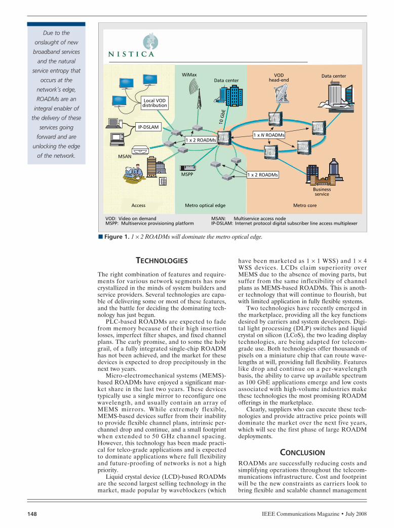
IEEE Communications Magazine • July 2008148
TECHNOLOGIES
The right combination of features and require-ments for various network segments has nowcrystallized in the minds of system builders andservice providers. Several technologies are capa-ble of delivering some or most of these features,and the battle for deciding the dominating tech-nology has just begun.
PLC-based ROADMs are expected to fadefrom memory because of their high insertionlosses, imperfect filter shapes, and fixed channelplans. The early promise, and to some the holygrail, of a fully integrated single-chip ROADMhas not been achieved, and the market for thesedevices is expected to drop precipitously in thenext two years.
Micro-electromechanical systems (MEMS)-based ROADMs have enjoyed a significant mar-ket share in the last two years. These devicestypically use a single mirror to reconfigure onewavelength, and usually contain an array ofMEMS mirrors. While extremely flexible,MEMS-based devices suffer from their inabilityto provide flexible channel plans, intrinsic per-channel drop and continue, and a small footprintwhen extended to 50 GHz channel spacing.However, this technology has been made practi-cal for telco-grade applications and is expectedto dominate applications where full flexibilityand future-proofing of networks is not a highpriority.
Liquid crystal device (LCD)-based ROADMsare the second largest selling technology in themarket, made popular by waveblockers (which
have been marketed as 1 × 1 WSS) and 1 × 4WSS devices. LCDs claim superiority overMEMS due to the absence of moving parts, butsuffer from the same inflexibility of channelplans as MEMS-based ROADMs. This is anoth-er technology that will continue to flourish, butwith limited application in fully flexible systems.
Two technologies have recently emerged inthe marketplace, providing all the key functionsdesired by carriers and system developers. Digi-tal light processing (DLP) switches and liquidcrystal on silicon (LCoS), the two leading displaytechnologies, are being adapted for telecom-grade use. Both technologies offer thousands ofpixels on a miniature chip that can route wave-lengths at will, providing full flexibility. Featureslike drop and continue on a per-wavelengthbasis, the ability to carve up available spectrumas 100 GbE applications emerge and low costsassociated with high-volume industries makethese technologies the most promising ROADMofferings in the marketplace.
Clearly, suppliers who can execute these tech-nologies and provide attractive price points willdominate the market over the next five years,which will see the first phase of large ROADMdeployments.
CONCLUSIONROADMs are successfully reducing costs andsimplifying operations throughout the telecom-munications infrastructure. Cost and footprintwill be the new constraints as carriers look tobring flexible and scalable channel management
n Figure 1. 1 × 2 ROADMs will dominate the metro optical edge.
Local VODdistribution
IP-DSLAM
MSAN
WiMax VODhead-endData center
Data center
Businessservice
Access
Video on demand Multiservice provisioning platform
VOD:MSPP:
Multiservice access node Internet protocol digital subscriber line access multiplexer
MSAN:IP-DSLAM:
Metro optical edge Metro core
MSPP
10 G
bE
1 x N ROADMs
1 x 2 ROADMs
1 x 2 ROADMs
Due to the
onslaught of new
broadband services
and the natural
service entropy that
occurs at the
network’s edge,
ROADMs are an
integral enabler of
the delivery of these
services going
forward and are
unlocking the edge
of the network.
TAYLOR LAYOUT 6/18/08 2:51 PM Page 148

IEEE Communications Magazine • July 2008 149
from the core to the edge of their networks.Because ring topologies dominate the metro andedge segment, successful ROADM solutions willembrace 1 × 2 architectures whose feature setand performance, in many cases, must be superi-or to their brethren in the core. Due to theonslaught of new broadband services and thenatural service entropy that occurs at the net-work’s edge, ROADMs are an integral enablerof the delivery of these services going forwardand are unlocking the edge of the network. DLPand LCoS technologies that offer full flexibilityand attractive price points are expected to domi-nate this industry in the next five years.
BIOGRAPHIESTHOMAS A. STRASSER [M] ([email protected]) received aPh.D. in materials science and engineering from CornellUniversity. He worked in optical fiber device research atBell Laboratories, Murray Hill, New Jersey, where his groupinvented and developed manufacturing for enabling tech-
nologies in the next-generation transmission platforms ofAT&T and Lucent Technologies. He helped develop the firstWSS ROADM-based metro core DWDM system as chieftechnologist at networking startup Photuris. He is currentlydeveloping next-generation optical subsystems as chieftechnology officer at Nistica, Inc., Bridgewater, New Jersey.He has taught several short courses, and served as OFC2004 Technical Program Co-Chair and General Co-Chair ofNFOEC/OFC 2006. He holds 37 patents, and has contribut-ed over 100 presentations and publications in the field ofoptics and communication devices.
JAY TAYLOR ([email protected]) is director of marketingand business development at Nistica, where he is responsi-ble for strategic marketing, customer and competitiveintelligence, offer management, and public relations.Before joining Nistica, he was director of corporate strate-gy and development at Lucent Technologies where he eval-uated new business opportunities for Bell Labs’ emergingtechnologies, and supervised corporate-wide product port-folio planning on a quarterly and annual basis. Prior toLucent he was with Celight, in marketing, business devel-opment, and product management roles, where he quanti-fied market/product strategies for ULH DWDM networks.He has an M.B.A. from the NYU Stern School of Businessand a B.S. in optics from the University of Rochester.
TAYLOR LAYOUT 6/18/08 2:51 PM Page 149

IEEE Communications Magazine • June 2008150 0163-6804/08/$25.00 © 2008 IEEE
ROLE AND TYPES OF ROADMS
Throughout the 100-year-plus history of telecom-munications networks, it is a truism that once acost-effective method emerges to automate amanual operation, it is implemented universally.The most dramatic example was the replacementof manual switchboards by automated switches.In the last few decades digital cross-connectsand synchronous optical network/synchonousdigital hierarchy (SONET/SDH) add/drop multi-plexers have totally replaced the practice ofmanually re-arranging individual circuits usingback-to-back channel banks. In this context thetime is now ripe for reconfigurable opticaladd/drop multiplexers (ROADMs) to automatethe rearrangement of wavelengths on multichan-nel optical fibers entering and leaving opticalnetwork nodes.
Fiber optic networks, which underlie all theworld’s communications, are expanding at a dra-matic rate to support the explosive growth ofbandwidth-rich Internet video applications alongwith traditional voice and data services. Fiberoptics is ideal for this task because it can carryinformation further and at greater density thanprevious copper-based transmission systems. Inparticular, using a scheme called dense wave-length-division multiplexing (DWDM), opticalfibers can carry up to 100 wavelengths or chan-nels of information simultaneously.
Now this all works very well when transmit-ting information between two nodes in a net-work. There is a challenge, however, in adding,dropping, and routing individual channels atindividual nodes. In the past this was done bybreaking out each and every wavelength at anode using an optical demultiplexer, manuallyrearranging wavelengths at an optical patchpanel, and then combining them again in thedesired fiber at a multiplexer for transmission tothe next node. Needless to say, this was time
consuming and, far worse, prone to human error.Enter the ROADM that today is simplifyingthese manual operations, and in the future willeliminate them completely.
There are two general types of ROADMs,two-degree and multidegree, where the degreerefers to the numbers of DWDM fibers enteringand exiting the ROADM node. (This refers totraffic moving in one direction only. In practice,pairs of fibers are generally used with each setcarrying traffic in an alternate direction, so therewould be twice as many fibers entering and exit-ing the ROADM as its degree.)
A two-degree ROADM is like a location on ahighway with off and on ramps to drop off andaccept local traffic. It terminates an incomingDWDM fiber, drops specified wavelengths, andin most cases blocks these wavelengths frompropagating further, adds local wavelengths,equalizes the combined traffic of passed-throughand added wavelengths, and provides an exit forthis traffic toward the next ROADM node.
A multidegree ROADM is like an inter-change where highways meet. It is used for inter-connecting DWDM rings or for meshnetworking. It accepts and rearranges wave-lengths from the multiple fibers entering andleaving the multidegree node, as well as addingand dropping local wavelength traffic. Themajority of ROADMs — a figure of about 75percent is most often cited — are two-degreenodes, which are less complex than their multi-degree cousins.
THE WAVELENGTH SELECTIVE SWITCHBefore delving into different ROADM configu-rations we need to introduce their key enablingtechnology, the wavelength selective switch(WSS). This is an advanced fiber optic modulethat can be used under software control todynamically select individual wavelengths frommultiple DWDM input fibers and switch these toa common output fiber. Figure 1 illustrates a 9 ×1 WSS with nine inputs. It can be seen that thefirst wavelength on the common output fiber hasbeen selected from input fiber 8, the secondwavelength from input fiber 3, the third frominput fiber 5, and so on.
An important feature of the WSS is that itcan attenuate the optical power of individualwavelengths exiting the output fiber. This
ABSTRACT
The relationship is explored between recon-figurable optical add/drop multiplexers, fastbecoming the standard nodal subsystem for pro-viding flexibility in modern multichannel fiberoptic networks, and wavelength selective switch-es, the predominant technology used to imple-ment ROADMs.
IEEE APPLICATIONS & PRACTICE:OPTICAL COMMUNICATIONS AND NETWORKS
Jonathan Homa and Krishna Bala, Xtellus
ROADM Architectures and TheirEnabling WSS Technology
HOMA LAYOUT 6/18/08 3:03 PM Page 150
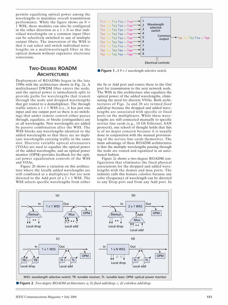
IEEE Communications Magazine • July 2008 151
permits equalizing optical power among thewavelengths to maximize overall transmissionperformance. While the figure shows an N ×1 WSS, these modules can also be configuredin the other direction as a 1 × N so that indi-vidual wavelengths on a common input fibercan be selectively switched to any of multipleoutput fibers. The innovation of the WSS isthat it can select and switch individual wave-lengths on a mult iwavelength f iber in theoptical domain without expensive electronicconversion.
TWO-DEGREE ROADMARCHITECTURES
Deployment of ROADMs began in the late1990s with the architecture shown in Fig. 2a. Amultichannel DWDM fiber enters the node,and the optical power is immediately split toprovide paths for wavelengths that transitthrough the node and dropped wavelengthsthat get routed to a demultiplexer. The throughtraffic enters a 1 × 1 WSS (i.e., it has just oneinput and one output port so there is no switch-ing) that under remote control either passesthrough, equalizes, or blocks (extinguishes) anyor all wavelengths. New wavelengths are addedby passive combination after the WSS. TheWSS blocks any wavelengths identical to theadded wavelengths so that there are no dupli-cate wavelengths carrying traffic in the sameslot. Discrete variable optical attenuators(VOAs) are used to equalize the optical powerof the added wavelengths, and an optical powermonitor (OPM) provides feedback for the opti-cal power equalization controls of the WSSand VOAs.
Figure 2b shows a variation on this architec-ture where the locally added wavelengths arestill combined at a multiplexer but are nowdirected to the Add port of a 2 × 1 WSS. TheWSS selects specific wavelengths from either
the In or Add port and routes these to the Outport for transmission to the next network node.The WSS in this architecture also equalizes theoptical power of the added wavelengths, elimi-nating the need for discrete VOAs. Both archi-tectures of Figs. 2a and 2b are termed fixedadd/drop because the dropped and added wave-lengths are associated with specific or fixedports on the multiplexers. While these wave-lengths are still connected manually to specificservice line cards (e.g., 10 Gb Ethernet, SANprotocol), one school of thought holds that thisis of no major concern because it is usuallydone in conjunction with the manual provision-ing of the service line cards themselves. Themain advantage of these ROADM architecturesis that the multiple wavelengths passing throughthe node are routed and equalized in an auto-mated fashion.
Figure 2c shows a two-degree ROADM con-figuration that eliminates the fixed physicalassociations for the dropped and added wave-lengths with the demux and mux ports. Theindustry calls this feature colorless because anycolor (frequency) of wavelength can be directedto any Drop port and from any Add port. In
n Figure 1. A 9 × 1 wavelength selective switch.
123456789
λ11λ21λ31λ41λ51λ61λ71λ81λ91
λ12λ22λ32λ42λ52λ62λ72λ82λ92
λ13λ23λ33λ43λ53λ63λ73λ83λ93
λ14λ24λ34λ44λ54λ64λ74λ84λ94
λ1Nλ2Nλ3Nλ4Nλ5Nλ6Nλ7Nλ8Nλ9N
...
...
...
...
...
...
...
...
...
Commonoutput
Electrical controls
Wavelengthselectiveswitch
λ81 λ32 λ53 λ74 ... λ6N
n Figure 2. Two-degree ROADM architectures: a, b) fixed add/drop; c, d) colorless add/drop.
OPMMux
Local add
In Out
(a)
1 x 1 WSS
(c)
In
Local drop
TR TR
Out1 x 1 WSS
OPM
Demux
Local drop
OPMAdd
Mux
Local add
In Out
(b)
2 x 1 WSS
Demux
Local drop
Local add
WSS: wavelength selective switch; TR: tunable receiver; TL: tunable laser; OPM: optical power monitor
TL TL
(d)
In
Local drop
Out1 x N WSS
OPM
Local add
TL TL
HOMA LAYOUT 6/18/08 3:03 PM Page 151

IEEE Communications Magazine • July 2008152
the figure this is achieved using tunablereceivers (that today are implemented with atunable filter feeding a fixed receiver) and tun-able lasers that are passively split from andadded to the optical path, respectively. Figure2d shows a variation on this architecture usinga 1 × N WSS to dynamically select and dropselected wavelengths. For instance, a 1 × 9 WSScan drop any eight wavelengths, with the ninthport used for the DWDM output fiber. Color-less architectures are most efficient when it isanticipated that only a limited number of wave-lengths need to be dropped and added at anode because of either the optical power lossesassociated with passive coupling or the fixedport size of the WSS.
MULTI-DEGREE ROADMARCHITECTURES
Figure 3 illustrates the incremental ability ofmultidegree ROADM nodes to send optical traf-fic to and accept optical traffic from otherDWDM fibers. Figure 3a shows a segment of amultidegree node with fixed add/drop. The firstsplitter routes DWDM fibers to the other WSSsin the node, and the second splitter drops localtraffic, as in the case of the two-degree node. AnN × 1 WSS is then used to accept traffic fromthe other DWDM fibers in the node, as well aslocal traffic. For a four-degree node, four 4 × 1WSSs are required, an eight-degree noderequires eight 8 × 1 WSSs, and so on. Figure 3bshows a variation for colorless add/drop. Here a1 × N WSS both routes the DWDM traffic tothe other WSS in the node and also drops indi-vidual local wavelengths, and an N × 1 WSS per-
forms the corollary function of accepting trafficfrom the other DWDM fibers and adding localwavelengths. This architecture has advantages interms of flexibility and reducing the opticalpower budget, but, of course, is much moreexpensive because it requires two large WSSs foreach segment of the node. An eight-degree nodeof this variety, for example, requires a total of 16WSSs.
WSS TECHNOLOGIESFrom just this brief discussion it is clear that thevariety of ROADM architectures require WSSengines of different sizes and configurations.Today there are requirements for WSSs withport counts ranging from 1 × 1 through 10 × 1(or 1 × 10), and it is projected that in a few yearsN will be greater than 20. Moreover, these needto support a stringent set of optical performancespecifications at both 50 GHz and 100 GHzwavelength spacings on the DWDM fiber.
At the heart of every WSS reside dynamicoptical core technologies that switch the wave-lengths among the ports and attenuate theiroptical power. Table 1 provides a high-levelsummary of the main technologies currentlybeing used to implement WSSs. Xtellus uses amix of these technologies to uniquely engineera complete family of scalable WSSs that cansatisfy all ROADM applications. For low portcount WSSs, including 1 × 1, 2 × 1, and 4 × 1,we use a pure liquid crystal-based design foreconomy and ease of manufacture. Our high-port WSSs use a combination of one-axisMEMS for wavelength switching (a less com-plex technology than two-axis MEMS) and liq-uid crystal for attenuation.
n Figure 3. Multidegree ROADM architectures: a) fixed add/drop; b) colorless add/drop.
OPM
Mux
Local add
(a) (b)
N x 1 WSS
Demux
Local drop
To otherfibers From
otherfibers
OPM
Localadd
Fromotherfibers
N x 1 WSS
Localdrop
To otherfibers
1 x N WSS
n Table 1. Wavelength selective switching technologies.
Technology Principle of operation Advantages Drawbacks
Liquid crystal array Manipulation of lightpolarization.
Economical. Non-complex implementation.
Optical performance degrades for high portcounts.
Liquid crystal on silicon(LCOS) Manipulation of light phase. Flexible for different
wavelength plans.Complex implementation for calibration andmaintaining performance stability.
Microelectromechanicalsystems (MEMS)
Physical displacement oflight using mirrored MEMSsurfaces.
Scalable over a widerange of port sizes.
Not economical for low port counts. Compleximplementation for maintaining performanceover attenuation, particularly for 2-axis MEMS.
HOMA LAYOUT 6/18/08 3:03 PM Page 152

IEEE Communications Magazine • July 2008 153
CONCLUSION
Reconfigurable optical add/drop multiplexersare being universally deployed to provide auto-mated provisioning in modern multichannel fiberoptic networks. They reduce costs, speed up pro-visioning time, and eliminate human error frommanual reconfiguration. Moreover, a variety ofROADM architectures are emerging to fulfilldifferent requirements for two-degree vs. multi-degree nodes, edge vs. core network applica-tions, and fixed vs. colorless add/drop. In turn,this is driving a need for a broad range of wave-length-selective switching engines to enable theROADM architectures. Xtellus is responding byusing a mix of liquid crystal and one-axis MEMScore technologies to provide a family of scalableWSSs.
BIBLIOGRAPHY[1] B. Basch et al., “Architectural Trade-Offs for Reconfigurable
Dense Wavelength-Division Multiplexing Systems,” IEEE J.Sel. Topics in Quantum Elect., July/Aug. 2006.
[2] A. Boskovic et al., “Broadcast and Select OADM NodesApplication and Performance Trade-Offs,” Proc. OFC2002, Anaheim, CA.
BIOGRAPHIESJONATHAN HOMA [M] ([email protected]) isresponsible for marketing and business development atXtellus, Morris Plains, New Jersey. An electrical engineer-ing and business administration graduate of McGill Uni-versity, he is a telecommunications market and businessdevelopment executive with 25 years of experience indefining and driving market acceptance of products andsolutions for fixed and wireless networks. Previously hewas at Nortel Networks as vice president, architecturemarketing and Telcordia relationship.
KRISHNA BALA is president and chief executive officer of Xtel-lus, and a recognized innovator and leader in optical net-working. He received his Ph.D. in electrical engineering fromColumbia University, and was a founder and chief technicalofficer of Tellium. His architecture work at Tellium revolu-tionized optical networks with the development of theworld’s first optical switch and advanced optical mesh net-working software, a networking approach now adopted bycarriers worldwide. Prior to Tellium he was the lead architectfor Bellcore’s multiwavelength optical networks project,which laid the basis for today’s ubiquitous DWDM networks.
HOMA LAYOUT 6/18/08 3:03 PM Page 153

IEEE Communications Magazine • July 2008154
HOMA LAYOUT 6/18/08 3:03 PM Page 154

IEEE Communications Magazine • June 2008154 0163-6804/08/$25.00 © 2008 IEEE
THE INTELLIGENT OPTICALCONTROL PLANE
Simply put, an intelligent control plane is thesoftware that controls the configurable featuresof a network. This software automates the dis-covery of capacity, network elements, ports, andconnectivity between ports, and disseminates thisinformation to all network elements. When anetwork is expanded, the inventory of circuitsand ports are discovered automatically andplaced in context within the entire network inwhich the control plane functions. Onceinstalled, the new capacity is made available fornew services, and any new circuits are addedautomatically.
The intelligent optical control plane enablesthe creation of a fully automated mesh opticalnetwork. The single most important feature of asurvivable network is that it be a mesh network.This is a topology that interconnects each nodeto several of its neighbors over multiple diverseconnections, which enhances scalability and pro-vides multiple routes for protection and restora-tion. When there is a disruption, the controlplane automatically calculates and creates anoptimal path to restore traffic using any one of anumber of routes.
Control-plane-enabled networks also provideon-demand dynamic network services. Thesefeature simple point-and-click configuration,
activation and deactivation of circuits, and per-formance monitoring to manage customer ser-vice agreements. To activate a service, anoperator simply needs to click on the two end-points and choose the bandwidth and servicelevel, as shown in Fig. 1. Once provisioned, thenetwork leverages the intelligent control planetechnology to automate complex restorationoperations. It also leverages routing technologiesto rapidly calculate alternative connectivity andrestore connectivity after a network outage — allof which creates the foundation for a truly “pro-grammable” network.
Mesh networks are critical to network surviv-ability because, unlike ring architectures, theycan recover quickly from multiple failures. Asshown in Fig. 2, paths are calculated in real timeusing routing protocols based on several param-eters, including the cost of the link, link failures,node exclusions, and other constraints placed onthe link. A route is then selected for the service,whether it is a restoration route or a dynamicon-demand service.
The intelligent self-awareness combined withthe dynamic inventory management of anadvanced optical control plane allows operatorsto manage large fully meshed networks that aretypically too complex to be managed manually.A critical benefit of this self-aware automatedoptical network is its ability to recover fromcatastrophic failures in milliseconds, similar tothe restoration time possible with synchronousoptical network/synchronous digital hierarchy(SONET/SDH).
Another key benefit of an intelligent opticalcontrol plane is that it enables network scala-bility. In a distributed control plane, the planeresides on the network elements and scales lin-early with the network because of parallel pro-cessing and local decision making. Acentralized control plane resides on the net-work management system (NMS), and theNMS must scale exponentially as the networkscales l inearly. Another key feature thatenables scalability is bundling. Network ele-ments (NEs) are typically connected by a largenumber of parallel links. Bundling allows par-allel links to be handled as one entity, enablingscalability of routing protocols by eliminatingunnecessary computational loads and superflu-
ABSTRACT
Globalization has changed the face and rele-vance of communication networks dramatically.Communication systems have become the mostsignificant element of mission-critical infra-structure for consumers, businesses, and govern-ments worldwide. Minimizing the risk ofdisruptions from human error, acts of war, ter-rorism, or natural disasters, while simultaneouslycreating a flexible, rapidly provisioned, on-demand network has become a business impera-tive, and requires the automation of keyfunctions within network operations. Conse-quently, network architects are building surviv-able optical networks using intelligent opticalcontrol planes.
IEEE APPLICATIONS & PRACTICE:OPTICAL COMMUNICATIONS AND NETWORKS
James Zik, Ciena Corporation
Enabling Highly Survivable AutomatedOn-Demand Dynamic Network Serviceswith Intelligent Optical Control Planes
ZIK LAYOUT 6/18/08 2:53 PM Page 154

IEEE Communications Magazine • July 2008 155
ous control traffic on the NEs. This improvesthe scalability of routing protocols by factors ofup to 20. This concept has been applied to pro-tection bundling for mesh protection andrestoration, and enables mesh networks to min-imize the computational load. In a mesh net-work this leads to subsecond protection timeswhile increasing network utilization and pro-viding six-9s network availability.
DEPLOYMENT OF SURVIVABLEDYNAMIC ON-DEMAND
MESH NETWORKS
Numerous network operators around the worldhave deployed survivable mesh networks becauseof their scalability, reliability, automation, anddynamic service provisioning. AT&T, BT, Inter-net2, Tata Communications and Verizon Busi-ness have all deployed optical controlplane-enabled mesh networks. Some have had asmany as 325 nodes with the potential of scalingto 500 nodes.
The Internet2 Dynamic Resource Allocationvia GMPLS Optical Networks (DRAGON)project has employed an optical control planeto provide dynamic on-demand network ser-vices connecting scientific instruments, compu-tation and storage facilities, high-resolutionvideo visualization environments, and othercyber resources for globally distributed applica-tions. In particular, the DRAGON networkenables application-specific networks to beestablished dynamically between optical con-
trol plane domains, enabling control planeinteroperability between worldwide networkinfrastructures.
STATE OF CONTROL PLANESTANDARDS AND INTEROPERABILITY
The International Telecommunication Union(ITU) established the qutomatically wwitchedoptical network (ASON) standard to guide thedevelopment of common optical control planesfor intelligent optical networks. G.ASONrequirements and recommendations describehow a suite of control plane protocols react toservice requests and automatically provision end-to-end network resources across a multitechnol-ogy, multivendor optical network.
n Figure 1. Optical control-plane-enabled programmable network.
C
A
Z
Customerlocations
1. Click on end point A
2. Click on end point Z
3. Choose bandwidth
4. Choose service level
5. Finished!
Programmable ports
10/100/Gb ethernet (L2)
OC-3/STM -1, OC -12/STM -4OC-48/STM -16/OTU1
10/100/Gb ethernet (L1)
FC/FICON/ESCONASI/SDI/HD -SDI
(or)OC-192/STM -64/10GbE/OTU2
Done
Service provider network
Customerlocation
Give me a 600 Mb/selectric connection withprotection level 1 from Ato Z for the next 3 days
n Figure 2. Mesh network survivability.
Fiber break
Lowest cost constrained route selected
High cost route Link fails constraints
ZIK LAYOUT 6/18/08 2:53 PM Page 155

IEEE Communications Magazine • July 2008156
The Optical Internetworking Forum (OIF)handles implementation agreements for signal-ing between network domains through the exter-nal network-to-network interface (the E-NNI)and to client devices through the optical user-to-network interface (the O-UNI), as shown in Fig.3.
It has created O-UNI specifications to allowsubtended network elements to request thesetup or teardown of light paths across a net-work. Upon receiving a request from a subtend-ed network element, the optical control planewill perform the operation automatically.Automation of the request, setup, and teardownprocesses reduces operational costs and allowsrapid response to service requests for dynamicon-demand services.
Optical control plane interoperability, basedon OIF E-NNI/ITU-T G.7713.2, expands theend-to-end automated provisioning capabilitiesof the intelligent optical network across dis-parate optical control domains. This interoper-ability allows rapid service deploymentworldwide across multiple carrier networks andvaried vendor equipment. E-NNI is an ASONstandard in progress for control plane signalingand routing of label-switched paths (LSPs)between the optical control domains of a carri-er’s network, or between the network and anoth-er carrier’s network.
The OIF sets up interoperability demonstra-tions periodically between multiple vendors withglobal carrier participation, including AT&T,China Telecom, Deutsche Telekom, FranceTelecom, KDDI, and Verizon. The last interop-erability demonstration was held in Berlin, Ger-many, in September 2007 and showcasedon-demand Ethernet over SONET/SDH withbandwidth modification starting from 300 Mb/sand ramping to 450 Mb/s. This enables an Ether-net layer client to request services from the car-rier’s SONET/SDH layer network, withoutregard to the type of transport used in the net-work.
When an Ethernet client requests a connec-tion, the ingress network O-UNI establishes aconnection in the SONET/SDH layer. The call
and connection signaling is completed first inthe lower layer to ensure that the connectionrequest can be satisfied. The Ethernet layerconnection to the destination client is then com-pleted across the heterogeneous optical net-work. The techniques defined for theSONET/SDH layers are also applicable to othernetwork layers, such as the ITU optical trans-port network (OTN) and the ITU G.709 stan-dard known as digital wrapper, a more flexiblelayer 0/1 protocol.
The internal network-to-network interface (I-NNI) defines the signaling and routing betweenNEs within a domain of the operator’s network.The I-NNI can be a proprietary implementation,the ITU-defined private network-to-networkinterface or the nascent Internet EngineeringTask Force’s (IETF’s) generalized multiprotocollabel switching implementation. Interoperabilityat this level is outside the purview of the OIF.Network operators have focused their efforts onintelligent control planes that use standardsbased on the OIF’s E-NN’s and O-UNIs toenable automated end-to-end service provision-ing through multiple carriers for global serviceactivation.
FUTURE OPTICAL CONTROL PLANEDIRECTION AND CHALLENGES
The challenges ahead for optical control planesare to extend their intelligence to the photoniclayer (layer 0) and the Ethernet layer (layer 2).The challenge for a control plane at the pho-tonic layer is to create an accurate knowledgebase of the links’ physical limitations, such asdispersion, maximum travel of a wavelengthbased on the fiber and ROADM filter charac-teristics for each rate and optical signal-to-noise ratio (OSNR), as well as otherparameters. They must also be able to discoverthese attributes for creating routes and pathcomputation when network elements are addedto the network. A control plane for carrierEthernet poses other challenges, including theability to scale the control plane to handle the
n Figure 3. Optical control-plane connection management.
E-NNI
E-NNI
I-NNI
Domain 2
Domain 1
User domain
Globalnetwork
Clientdevice
Clientdevice
NE NEI-NNI
O-UNI
O-UNI
O-UNI
Carrier-A(single domain)
NE NEI-NNIE-NNI
Carrier-B(multi-domain)
The intelligent optical
control plane that
enables network
survivability also
delivers the network
automation to
reduce both capital
and operational costs
and accelerate
delivery of services to
customers rapidly.
ZIK LAYOUT 6/18/08 2:53 PM Page 156

IEEE Communications Magazine • July 2008 157
millions of potential Ethernet connections andthe ability to provide protection and restora-tion for E-LAN point-to-multipoint connec-tions. Although these challenges are difficult,optical control planes for these layers arebeginning to emerge.
SUMMARYThe move to build intelligent optical meshnetworks is driven by increasing globalizationthat requires network operators to employ sur-vivable networks for mission-critical applica-tions with near-zero downtime. The intelligentoptical control plane that enables network sur-vivability also delivers the network automationto reduce both capital and operational costsand accelerate delivery of services to cus-tomers rapidly.
As an example, after deploying an intelli-gent optical mesh network based on Ciena’sCoreDirector Multiservice Optical Switches, amajor global service provider achieved signifi-cant business benefits and capital efficiency,including a 44 percent reduction in networkoperating personnel, an 18 percent revenueincrease ($500,000 to $600,000) per networkemployee and a reduction in average service
provisioning time from weeks, or even months,down to just minutes.
As service providers worldwide look toincrease the reliability and intelligent automa-tion of their network infrastructures, intelligentoptical control planes significantly improve scal-ability, lower costs, enable dynamic on-demandservices, and, most important, enable networksto survive single, multiple, or even catastrophicfailures.
BIOGRAPHYJAMES ZIK ([email protected]) is the senior product marketingmanager for optical transport products at Ciena Corp.,Linthicum, Maryland. A seasoned member of the telecom-munications industry with 17 years of experience, he hasengaged with many of the largest service providers, includ-ing AT&T, British Telecom, Deutsche Telecom, Level 3,Sprint, Telefonica, and Verizon in shaping, testing, and ver-ifying their networks. His areas of expertise include designengineering, system verification and testing, network engi-neering, product management, and marketing. In addition,he has extensive knowledge of GMPLS, Ethernet, ATM,PDH, SONET, SDH, OTN, optics, and other networking tech-nologies. Prior to joining Ciena, he was director of productline management at Mintera and held several other pro-gram and test management roles at JDSU-Acterna andCorvis. He holds three patents, and has published severalpapers and articles on telecommunications networks. Heholds Bachelor’s and Master’s degrees in engineering fromthe University of Wisconsin, Madison.
Broadband networks are witnessing a convergence in both technologies and delivered services. Motivated by the tremendous success of the first IEEE ANTS(2007) event which highlighted advances in systems and networking, the focus of IEEE ANTS 2008 is on communication systems and networkingtechnologies for realizing converged ubiquitous broadband connectivity. To achieve this goal, the symposium will feature a technical program of talks, papers,and panels on relevant topics bringing together experts from academia, industry, government, and the user community involved in the research, design,development, deployment, regulation, and application of communication and networking technologies. The symposium will be held in the commercial andentertainment capital of India - Bombay - on 15-17 December 2008.
Venue:IIT Bombay, F. C. Kohli Auditorium, Dept. of CSE, IIT Bombay. Paper Submission:Through EDAS (http://edas.info), Deadline: 31 July 2008. Papers:3 pages, 2 column, IEEE style, previously unpublished and not underreview elsewhere.
Panels, Keynote and Tutorial Chairs:Several panels focusing on telecommunication networks, networkdesigns, deployments, academic research in India and venture fundingwill be organized as part of the industry interaction session. Invitedtalks from industry leaders and keynotes from industry stalwarts complete the IEEE ANTS 2008 program.
Exhibit and sponsorship opportunities available, please contact Ashwin Gumaste: [email protected] • +1-214-717-4422
General Chairs and Steering Committee:Biswanath Mukherjee, UC Davis, USAAshwin Gumaste, IIT Bombay, IndiaNasir Ghani, UNM, USA
TPC Chairs:Suresh Subramaniam, GWU, USAAdmela Jukan, TU-Braunchweig, Germany
Publicity Chairs:Rudra Dutta, NCSU, USA Jianping Wang, CityU, Hong Kong, PRC
Industry Chairs:Deepak Kataria, LSI Corp., USA Samrat Ganguly, NEC, USA
Keynote and Tutorial Chairs: Girish Saraph, IIT Bombay and Vegayan, IndiaBishnu Pradhan, IIT Bombay, IndiaAbhay Karandikar, IIT Bombay, India
Local Arrangements: Gigabit Network Laboratory, IIT Bombay, India
ZIK LAYOUT 6/18/08 2:53 PM Page 157
IEEE Communications Magazine • July 2008158 0163-6804/08/$25.00 © 2008 IEEE
INTRODUCTION
Over the last decade, advances in Internet tech-nology brought about the proliferation of Inter-net-based multimedia applications, such asIPTV, remote terminal services, and onlinegaming. These applications virtually requiremeeting different time varying and high-band-width demands and stringent delay-throughputperformance. While optical circuit switching(OCS) is successful in supporting bulky steadytraffic over long-haul wavelength-division multi-plexing (WDM) networks, optical packetswitching (OPS) [1, 2] enables fine-grained on-
demand channel allocation (i.e., statistical mul-tiplexing) and has thus been considered to be apreeminent paradigm capable of supportingsuch applications over future optical WDMmetropolitan area networks (MANs) [1, 3].Note that the OPS technique studied hereexcludes the use of optical signal processingand optical buffers, a current technological lim-itation faced by OPS.
Numerous topologies and architectures[3–9] for OPS WDM MANs have been pro-posed in recent years. Of these proposals, thestructure of slotted rings [4–9] has received themost attention. Comprehensive surveys ofWDM metro slotted ring networks can befound in the literature [3]. While most of thework [8, 9] is simulation driven, only a handful[4–7] involve experimental prototypes. Becauseexperimental prototyping has been one of ourmajor tasks, we assessed two experimentaltestbed systems that are relevant to our work,focusing on three key challenges pertaining toOPS WDM slotted ring networks. They are thefollowing: the scalable design of networks, par-ticularly with respect to the number of wave-lengths; the design and implementation ofhigh-speed photonic hardware components(e.g. , fast tunable receivers, optical sloterasers); and the design and implementation ofmedium access control (MAC) schemes [3]that achieve high statistical multiplexing gain,and satisfy diverse and stringent delay-through-put requirements under a wide range of trafficloads and burstiness.
First, the hybrid optoelectronic ring network(HORNET) [4] is a bidirectional WDM slottedring network in which each node is equippedwith a tunable transmitter and a fixed-tunedreceiver (TT-FR). Note that although fast tun-able transmitters [10] with a laser tuning time upto several nanoseconds have emerged, fast tun-able receivers [11] operating on the order ofnanoseconds remain virtually unavailable. HOR-NET uses a MAC protocol, called DistributedQueue Bidirectional Ring (DQBR), which is amodified version of the IEEE 802.16 Distributed
ABSTRACT
For future WDM MANs, optical packet-switching has been considered to be a promisingparadigm that efficiently supports a wide rangeof Internet-based applications having time-vary-ing and high bandwidth demands and stringentdelay requirements. This article presents thedesign of an experimental testbed system for ahigh-performance optical packet-switched WDMmetro ring network, HOPSMAN. HOPSMANboasts three crucial features. First, it has a scal-able architecture in which the number of nodesis unconstrained by the number of wavelengths.Second, HOPSMAN nodes are equipped withhigh-speed photonic hardware components,including fast tunable receivers and optical sloterasers, capable of performing speedy opticalpacket-switching operations. Third, HOPSMANincorporates a MAC scheme that embodies effi-cient and dynamic bandwidth allocation, result-ing in exceptional delay-throughputperformance. The article presents the key hard-ware components by highlighting the challengingissues we faced and the solutions we proposedfor the testbed implementation. Finally, todemonstrate the feasibility of HOPSMAN, thearticle describes the experimental setup and pre-sents the results obtained from running a com-mercially available remote media playerapplication on the system.
IEEE APPLICATIONS & PRACTICE:OPTICAL COMMUNICATIONS AND NETWORKS
Maria C. Yuang, I-Fen Chao, Bird C. Lo, Po-Lung Tien, Jason J. Chen, and C.
Wei, National Chiao Tung University
Yu-Min Lin, Steven S. W. Lee, and Ching-Yun Chien, Industrial Technology Research Institute
HOPSMAN: An Experimental TestbedSystem for a 10-Gb/s Optical Packet-Switched WDM Metro Ring Network
YUANG LAYOUT 6/18/08 2:54 PM Page 158

Queue Dual Bus (DQDB) protocol [12]. Specifi-cally, DQBR requires each node to maintain adistributed queue via a pair of counters perwavelength. The counting system ensures thatpackets are sent in the order in which they arriveat the network. With DQBR, HORNET achievesacceptable utilization and fairness at the expenseof high control complexity for maintaining thesame number of counter pairs as wavelengths.However, due to the use of fixed-tuned receivers,HORNET statically assigns each node a wave-length as the home channel for receiving pack-ets. Such static wavelength assignment results inpoor statistical multiplexing gain, and as a result,throughput deteriorates.
Second, the ring optical network (RingO) [7]is a unidirectional WDM slotted ring networkwith no more than N nodes where N is equal tothe number of wavelengths. Each node isequipped with an array of fixed-tuned transmit-ters and one fixed-tuned receiver operating on agiven home wavelength that identifies the node.Such a design gives rise to a scalability problem.RingO employs a MAC protocol, called Syn-chronous Round-Robin with Reservations (SR3)[8]. To achieve high utilization and fairness, SR3
employs a combination of token-based accessand slot reservation mechanisms. Unfortunately,under heavy loads RingO experiences deteriorat-ing access delay as a result of an increase incycle length.
In this article we present an experimentalhigh-performance OPS WDM metro ring net-work (HOPSMAN) testbed system, particularlydesigned to meet the three challenges just men-tioned. First, it has a scalable architecture inwhich the number of nodes is unconstrained bythe number of wavelengths. Second, HOPSMANnodes are equipped with two high-speed photon-ic hardware components, fast tunable receiversand optical slot erasers. These devices can per-form speedy OPS operations, such as the drop-and-erase of data packets in nanoseconds. Third,HOPSMAN incorporates a versatile MACscheme that embodies efficient and dynamicbandwidth allocation so that exceptional delay-throughput performance can be guaranteed. Thearticle focuses on the key hardware componentsby highlighting challenging issues and our pro-
posed designs for the testbed implementation.Finally, to demonstrate the feasibility of HOPS-MAN, the article delineates the experimentalsetup and the results obtained from running acommercial remote-media-player application onthe testbed.
The article is organized as follows: We firstpresent the general network and node architec-tures of HOPSMAN. We follow this with a briefdescription of the MAC scheme. Mostly, wefocus on the hardware implementation of thetestbed and, finally, the demonstration of apotential application for HOPSMAN.
GENERAL NETWORK ANDNODE ARCHITECTURES
HOPSMAN is a unidirectional WDM slotted-ring network with multiple WDM data channels(λ1–λW, at 10 Gb/s) and one control channel (λ0,at 2.5 Gb/s), as shown in Fig. 1. Channels arefurther divided into synchronous time slots.Each data-channel slot contains a data packet inaddition to some control fields to facilitate syn-chronization. In the interest of clarity, “dataslots” and “data packets” are used interchange-ably in what follows.
Within each slot time, all data slots of Wchannels are fully aligned with the correspondingcontrol slot. Each control slot is then subdividedinto W mini-slots to carry the status of W dataslots, respectively. Moreover, there are two typesof nodes in HOPSMAN: ordinary-node (O-node) and server-node (S-node). An S-node dif-fers from an O-node by having an additionaloptical slot eraser that makes bandwidth reusableand achieves greater bandwidth efficiency for thenetwork. It is important to note that the networkattains much better bandwidth efficiency byusing only a few S-nodes. Each node of bothtypes has a fixed transmitter and receiver pairfor accessing the control channel, and a tunabletransmitter and receiver pair for accessing datachannels.
In general, with respect to accessing datachannels, the node architecture [13] falls intoone of two categories: switch-based and broad-cast-and-select-based. Basically, the switch-based
IEEE Communications Magazine • July 2008 159
n Figure 1. General architecture of the HOPSMAN network testbed.
Legend:
: Server node
: Ordinary node
Mini-slot
Control slot format
λw λw-1 λ2 λ1λwλw-1
λ1λ0
Datachannels
Controlchannel
Cyclek+1 Cyclek Cyclek-1
SlotSlot
Header
StatusDestination address
HOPSMAN metro network
HOPSMAN is a
unidirectional WDM
slotted-ring network
with multiple WDM
data channels and
one control channel.
Channels are further
divided into
synchronous time
slots. Each
data-channel slot
contains a data
packet in addition to
some control fields
to facilitate
synchronization.
YUANG LAYOUT 6/18/08 2:54 PM Page 159

IEEE Communications Magazine • July 2008160
architecture includes the use of a demultiplexerand a space-switch matrix to direct all desiredchannels to the optical receivers. Opposed tothis, the broadcast-and-select architecture usesan optical coupler to tap off a portion of theoptical signal power from the ring to make alldata channels available (“broadcast”) to thenode. The desired data channel is then “select-ed” via a tunable or band-pass filter. Whileswitch-based nodes provide high channel capaci-ty through the simultaneous access of multiplewavelengths, it becomes costly for some nodesthat demand less capacity than provided. In con-trast, the broadcast-and-select structure enablesan incremental and cost-effective upgrade of thechannel capacity. Accordingly, our HOPSMANtestbed system adopts the broadcast-and-selectarchitecture. As a result, while each O-node hasonly one optical transmitter and receiver pair, anS-node can easily be upgraded to multiple pairsof tunable transmitters and receivers.
The architecture of a node in HOPSMAN isshown in Fig. 2. It is best described as consistingof two building blocks for control channel pro-cessing and data channel access. For controlchannel processing, a fixed optical drop filter(ODF) at the input port first extracts the opticalsignal from the control channel slot by slot. Thecontrol information is electrically received by afixed-tuned receiver, and processed by the MACprocessor. While the control information isextracted and processed, data packets remaintransported optically in a fixed-length fiber delayline. The channel timing processor, in coordina-tion with the SYNC monitoring module, isresponsible for extracting the slot boundary tim-ing and subsequently providing the activationtiming for other modules. Having obtained thecontrol information (the status of W data chan-nels), the MAC processor then executes theMAC scheme (described later) to determine theadd/drop/erase operations for all W channelsand the status updates of the correspondingmini-slots in the control channel. Finally, a fixed-tuned transmitter inserts the newly updated con-
trol signal back in the fiber, which is, in turn,combined with the data channels’ signal via theoptical add filter (OAF).
Data channel access corresponds to add anddrop operations of data packets based on thebroadcast-and-select configuration describedabove. Specifically, packets of all wavelengthsare first tapped off through wideband opticalsplitters. They are in turn received via a four-wave-mixing (FWM)-based optical tunable filter/receiver (described later). To transmit a packetonto a particular wavelength, the node simplytunes the tunable transmitter [10] to the wave-length. Finally, to discontinue unneeded datapackets on any wavelengths, the slot eraser (inS-node only) employs a mux/demux pair and anarray of W SOA on/off gates to reinsert new nullsignals on the wavelengths.
THE MAC SCHEMESince each node has only one tunable receiver,receiver contention [3] occurs when there aremore than one packet destined for the samereceiver in one slot time. Thus, two packets des-tined for the same node are not allowed to becarried by different wavelengths in a single slottime. Likewise, because there is only one tunabletransmitter, any one node can make at most onepacket transmission in a single slot time. Such alimitation is referred to as the vertical access con-straint. Note that by vertical we mean the accessof different wavelengths within the same slottime.
HOPSMAN employs a MAC scheme calledProbabilistic Quota plus Credit (PQOC). First, acycle (Fig. 1) is composed of a predeterminedfixed number of slots. In general, PQOC allowseach node to transmit a maximum number ofpackets (slots), or quota, within a cycle. Mostimportant, even though the total bandwidth isequally allocated to every node via the quota,unfairness surprisingly appears when the net-work load is high. This is because upstreamnodes can access empty slots first, resulting in an
n Figure 2. General node architecture of HOPSMAN.
Burst-modereceiver
MAC processor
Channel timing processor
Legend:
Optical lineElectrical line
ODF: Optical drop filter OAF: Optical add filterSOA: Semiconductor optical amplifier
Upper layer
ODFSplitter Combiner
Splitter
Slot eraser(S-node only)
2.5Gcontrol
channel Rx
Clock
Control Timing
OAF
SOA gate
Modulator
Tunable laser
2.5Gcontrol
channel Tx
SYNCmonitoring
moduleFast tunablefilter/receiver
While switch-based
nodes provide high
channel capacity
through the
simultaneous access
of multiple
wavelengths, it
becomes costly for
some nodes that
demand less capacity
than provided. In
contrast, the
broadcast-and-select
structure enables an
incremental and
cost-effective
upgrade of the
channel capacity.
Accordingly, our
HOPSMAN testbed
system adopts the
broadcast-and-select
architecture.
YUANG LAYOUT 6/18/08 2:54 PM Page 160

IEEE Communications Magazine • July 2008 161
increasing tendency for downstream nodes toencounter empty slots that are located verticallyaround the back of the cycle. This issue, as wellas the vertical access constraint, gives rise topoorer delay-throughput performance for down-stream nodes. To resolve the unfairness prob-lem, the quota is exerted in a probabilistic ratherthan deterministic fashion, as “probabilisticquota” implies. In other words, rather thantransmitting packets immediately, each nodemakes the transmission decision according to aprobability (e.g., the quota divided by the cyclelength). Note that using the probability, a nodemay end up making fewer packet transmissionsthan its quota. The problem can be resolved sim-ply by enforcing a packet transmission in a sub-sequent slot time with an idle slot. Such anapproach evenly distributes idle slots within theentire cycle at all times and eliminates unfair-ness against downstream nodes.
Furthermore, if a node cannot finish its entirequota in a cycle (i.e., it has fewer packets thanits quota), the node yields the unused bandwidth(slots) to downstream nodes. By doing so, thenode earns the same number of slots as credits.These credits allow the node to transmit morepackets beyond its original quota in a limitednumber of upcoming cycles, called the window.That is, the credits are only valid when the num-ber of elapsed cycles does not exceed the win-dow. The rationale behind this design is toregulate fair use of unused remaining bandwidthparticularly in the metro environment with traf-fic that is bursty in nature. Notice that there aresystem trade-offs in PQOC involving cycle lengthand window size. For example, the smaller thecycle length, the better the bandwidth sharing;the larger the window size, the better the bursty-traffic adaptation, both at the cost of more fre-quent computation. The cycle length and windowsize can be dynamically adjusted in accordancewith the monitored traffic load and burstinessvia network management protocols, which arebeyond the scope of this article.
TESTBED IMPLEMENTATION ANDEXPERIMENTAL RESULTS
We built an experimental ring testbed to demon-strate the feasibility and performance of HOPS-MAN. The testbed consists of three nodes: oneS-node and two O-nodes (O1-node and O2-node). The hardware implementation of an S-node is illustrated by the functional diagrams inFig. 3. Note that the implementation for an O-node is the same as that of an S-node exceptwith the slot eraser removed. The ring testbed is38.3 km long, with 10 cycles per ring, 50 slots percycle, and each slot 320 ns long, yielding a totalof 500 time slots, or 160 ms in one ring length.The testbed uses a control channel wavelengthof 1540.56 nm, and four data channels at wave-lengths of 1551.72 nm, 1553.33 nm, 1554.94 nm,and 1556.55 nm. The input and output powerper channel is kept at –10 dBm and 0 dBm,respectively, by using attenuators and amplifierson the ring. The control channel employs contin-uous mode transmission at a rate of 2.5 Gb/s,and is processed at each node through opto-elec-
tro-optical (O-E-O) conversion. On the otherhand, data channels adopt burst mode transmis-sio at a target rate of 10 Gb/s. Due to the tech-nological immaturity of high-speed opticalburst-mode receivers (BMRs), we have deliber-ately downgraded the data channels’ bit rate to1.25 Gb/s so that commercially available BMRscould be used. It is important to note that theHOPSMAN testbed has been designed so thatthe rates of the data and control channels areindependent of each other. Because of the exten-sive use of BMRs in passive optical networks, weexpect that 10 Gb/s BMRs will be commerciallyavailable soon.
Besides a fast tunable transmitter, as shownin Fig. 3a, a node (S-node) contains three majorcomponents: an FPGA-based central processor,a fast tunable filter/receiver, and an optical sloteraser. These components are described in detailin the following sections.
CHANNEL SYNCHRONIZATION ANDMEDIUM ACCESS CONTROL
The field programmable gate array (FPGA)-based central processor consists of a controlchannel board and a data channel board, asshown in Fig. 3c. The processor is responsiblefor performing four major functions: channelsynchronization, MAC, optical device control,and data packet framing. Before describing thesefunctions, we address a number of key designfeatures for channel synchronization on HOPS-MAN. For WDM slotted ring networks, the tim-ing synchronization between the data and controlchannels must be perfectly maintained at alltimes. In the HOPSMAN testbed the channeltiming synchronization is ensured via two levelsof alignment, coarse-grained and fine-grained, aswell as guard-time-based dispersion compensa-tion.
First-level coarse-grained synchronization isachieved by inserting a fixed short fiber delayline (5 m in our case) in the optical data channelpath to accommodate the basic control computa-tion latency. Second-level fine-grained synchro-nization is accomplished by matching afixed-pattern preamble field (i.e., the SYNCfield) at the beginning of each control slot, asshown in Fig. 4a. Moreover, as a result of thefiber’s inherent chromatic dispersion, after longfiber transmissions the pre-aligned data channelsundergo different propagation delays and are nolonger synchronized with the control channel.For HOPSMAN’s ring length of less than 50 km,simply adding a guard-time field at the begin-ning and/or end of each data slot can solve theproblem. In the HOPSMAN testbed the datacan be correctly recovered without any errorwith a guard time of 40 ns. HOPSMAN’s dataand control slots were found to be perfectly syn-chronized, as shown in Fig. 4b. Note that longerrings require an in-line dispersion compensationmodule to tolerate the propagation-delay differ-ence.
The control channel board contains a XilinxVertexII FPGA chip and a 2.5 Gb/s continuous-mode optical transceiver. It is responsible for thefirst three functions (i.e., synchronization, access,and device control) of the central processor. Ini-
The FPGA-based
central processor
consists of a control-
channel board and a
data-channel board.
The processor is
responsible for
performing four
major functions:
channel
synchronization,
medium access
control, optical
device control, and
data packet framing.
YUANG LAYOUT 6/18/08 2:54 PM Page 161

IEEE Communications Magazine • July 2008162
tially, the optical transceiver strips off the con-trol slot from the ring. Each control slot (Fig.4a) contains one 16-bit SYNC field, one 16-bitheader, and four 16-bit mini-slots, respectively,carrying the states of four data channels. TheSYNC timing extractor (STE) mainly detects theSYNC field in the control slot. Upon havingmatched the SYNC field, the STE passes theprecise timing trigger to the data channel boardvia the control interface to bring the output dataslot into full alignment with the control slot.
Followed by the STE, in accordance with thestatus of each data channel, the MAC processingunit (MPU) performs the MAC scheme, PQOC,which includes the five operations describednext. Each data slot has four distinct states-BUSY, BUSY/READ (BREAD), IDLE, andIDLE/MRKD (IMRKD):• To transmit a packet from the memory
buffer into an IDLE slot on a wavelength,the MPU signals the tunable laser driver toperform the wavelength tuning, and updates
n Figure 3. Hardware implementation of the HOPSMAN testbed system: a) experimental node setup (S-node); b) four-wave-mixing-based fast tunable filter/receiver; c) FPGA-based central processor.
Burst modereceiver
Tunablelaser driver
EthernetMII-
interface
Data channel board
8B/10Bencoder/decoder
Datachannels
Framer
Control interface
Assembly
Fast Ethernet interface
Memorybuffer
Memorybuffer
Memorybuffer
SYNC timingextractor
MAC processing unit
Tumble laser
Tappedsignal
OutputTunablepumping
laser
Coupler
Legend: PBS: polarization beam splitter OBPF: optical bandpass filter
OBPF
PBS PBS
Fast tunable filter/receiver
(a)
(b)
(c)
Fast Ethernetinterface
ODF
SOA gate array
SOA gatedriver
SOA gates
2.5 Gb/scontinuous modeoptical transceiver
Controlchannel
Control channel board
FPGA-based central processor
OAF
Modulator
Tunablelaser
Fast tunablefilter/receiver
FixedRx
FixedTx
FPGA-based central processor
SOA
SOA
Tunable filters made
from mechanically
moving elements
usually require
millisecond tuning
times, which is not
feasible for optical
packet-switching
networks. New
devices that achieve
tuning times on the
order of a
microsecond have
been proposed.
YUANG LAYOUT 6/18/08 2:54 PM Page 162

IEEE Communications Magazine • July 2008 163
the state from IDLE to BUSY in the corre-sponding mini-slot.
• To receive a packet from a wavelength, theMPU directs the same wavelength-tuningoperation, but updates the slot state fromBUSY to BREAD.
• To erase a BREAD slot, the MPU of an S-node informs the slot eraser module via theSOA gate driver in the control channelboard.
• As a result of having no packet in the mem-ory buffer but with positive quota, the MPUyields an IDLE slot to downstream nodes(and earns a credit) by changing the statefrom IDLE to IMRKD.
• Thus, with a credit, the MPU transmits apacket from the memory buffer into anIMRKD slot by changing the state fromIMRKD to BUSY. Finally, the updatedcontrol slot is sent back to the ring throughthe optical transceiver.The data channel board contains a Xilinx
Spartn3A FPGA chip. It is responsible for thelast function of the central controller: data pack-et framing between Fast Ethernet and theHOPSMAN ring. Note that the testbed can sup-port any type of local area network and inter-face; we use Fast Ethernet only because of itswide availability. Specifically, for the outboundflow, the framer module first segments incomingEthernet packets into smaller 350-bit-longHOPSMAN slots. Before being sent to the ring,data packets are encoded via the 8B/10Bencoder, which enables reliable transmission andeasier burst mode reception. In the inbound flowthe framer performs the reverse function byassembling a number of data slots back to anoriginal Ethernet frame.
FAST TUNABLE FILTER/RECEIVER ANDOPTICAL SLOT ERASER
Tunable filters made from mechanically movingelements usually require millisecond tuningtimes, which is not feasible for OPS networks.New devices that achieve tuning times on theorder of 1 µs have been proposed. Among them,the electro-optic tunable filter (EOTF) [14] canachieve sub-microsecond tuning speed, butrequires a high tuning voltage. The acousto-optictunable filter (AOTF) [15] reaches microsecondspeeds but only during the selection of channels.The fiber Fabry-Perot-based tunable filter [16]also efficiently provides a response time of up toa few microseconds. In principle the microsec-ond-level tuning time is still unacceptable for anOPS network that adopts a slot as small as 320ns, as HOPSMAN does.
In the HOPSMAN testbed system we adopt-ed a polarization-insensitive four-wave-mixing(FWM)-based optical tunable filter/receiver, asshown in Fig. 3b. Based on the FWM method,by using a sampled grating distributed Bragg-reflector (SGDBR) tunable pumping laser andan SOA, the wavelength of the tapped-off datasignal can be converted to the target wavelength,which is the wavelength of the fixed filter provid-ed. The inherent polarization tracking problemof this FWM-based system is solved using polar-ization diversity [17], as illustrated in Fig. 3b.
The approach attains a conversion efficiency of18 dB. Since the system tuning time depends onthe tuning speed of the pumping laser, ourFWM-based tunable filter/receiver achieves atuning time of less than 25 ns. The experimentalresult in Fig. 5a displays the optical spectrumand eye diagram of the received signal.
The optical slot eraser was built with a mux/demux pair and an array of SOA gates, whichcan be turned on/off in 5 ns and achieve an on/off extinction ratio greater than 30 dB. Figure5b displays the two distinctive waveforms of adata channel before and after the erasing oper-ation. The SOA gates also provide a 10 dBgain to cover the nodal loss contributed by thecontrol-channel add/drop filter and mux/demuxfilters.
DEMONSTRATION OF A COMMERCIALREAL-TIME APPLICATION
We conducted a feasibility test by running com-mercially available remote media player applica-tions over a three-node HOPSMAN testbed, asshown in Fig. 6. There are three nodes in thetestbed, S-node, O1-node, and O2-node, and the
n Figure 4. Synchronization of control and data channels: a) control channelslot; b) synchronized data and control slots.
(a)
(b
SYNC HDR
Ch1 Ch2 1.0V
SLOTActiveRef Rec
Ds500 µ Ω Ω
λ 1 λ 2 λ 4 Unused ... 8 ns/div
M 40.0 ns 10 O G/s/o IT 1.0 ps/prA Ch2 / 540 mV
500 µW ΩCh1500 µW 200 ns
M 200 ns 20.0 GS/sA Ch1/310 µWB Ch2/800mV
IT 4.0 ps/ptRef1
Ds
Ref Rec Active
40ns/div
Data
Control
slot
λ 3
YUANG LAYOUT 6/18/08 2:54 PM Page 163

IEEE Communications Magazine • July 2008164
S-node and O1-node are connected to PCS andPC1, respectively, via a Fast Ethernet interface.At PC1, a video playback application, WindowsMedia Player 10, requests a 30-min-long 5.2 Mb/sMPEG-4-encoded video stream to be sent fromPCS, which runs a video server application, Win-dows Media Services 9. The third node of thetestbed, O2-node, serves as a mass traffic genera-tor, continuously sending dummy traffic to bothO1-node and S-node. The total amount of trafficto be generated is determined according to thefollowing guidelines: the normalized per-wave-length load is set as high as 0.9, and the real-timevideo-stream traffic occupies only one-forth per-cent of the total load (0.9 × 4 = 3.6). In otherwords, the video-stream traffic is only providedwith one-forth percent of quota out of the entirebandwidth. Based on our simulation results, themaximum normalized throughput of the networkwith only one single server is 0.667. Accordingly,the maximum achievable throughput for the8B/10B-encoded video stream traffic is equal to1.25 Gb/s/wavelength × (8/10) × 4 × 0.9 × 0.667 ×(0.01/4) = 6 Mb/s. Such a setting makes HOPS-MAN a potential bottleneck for the video-streamtraffic as a result of poor bandwidth allocation.With the PQOC scheme under such a heavy load,
the testbed has been shown to achieve delay- andjitter-free video playback at PC1 in the O1-node.With experiments of this sort, we concluded thatHOPSMAN is particularly advantageous for band-width-hungry and delay/jitter-sensitive applica-tions. Medical imaging, online interactive gaming,distance learning, and remote terminal servicesare among potential applications for HOPSMAN.
CONCLUSIONSIn this article we have presented the architecturaldesign and hardware implementation of HOPS-MAN, an optical packet switched metro WDMslotted ring network testbed system. It usesFWM-based fast tunable filters/receivers andoptical slot erasers that enable nanosecond-orderOPS operations. In essence, HOPSMAN employsa versatile MAC scheme that provides quota-based guaranteed bandwidth and the credit-based dynamic allocation of the remainingbandwidth. With flexible optical devices and anefficient MAC scheme, HOPSMAN was shown,by means of a feasibility test, to be capable ofachieving guaranteed delay-throughput perfor-mance particularly for bandwidth-hungry anddelay/jitter-sensitive applications.
REFERENCES[1] S. Yao et al., “All-Optical Packet Switching for
Metropolitan Area Networks: Opportunities and Chal-lenges,” IEEE Commun. Mag., vol. 39, no. 3, Mar.2001, pp. 142–48.
[2] M. Yuang et al., “Optical Coarse Packet-Switched IP-over-WDM Network (OPSINET): Technologies and Experiments,”IEEE JSAC, vol. 24, no. 8, Aug. 2006, pp. 117–27.
[3] M. Herzog et al., “Metropolitan Area Packet-SwitchedWDM Networks: A Survey on Ring Systems,” IEEE Com-mun. Surveys & Tutorials, vol. 6, no. 2, 2004, pp. 2–20.
[4] I. White et al., “A Summary of the HORNET Project: ANext-Generation Metropolitan Area Network,” IEEEJSAC, vol. 21, no. 9, Nov. 2003, pp. 1478–94.
[5] L. Dittmann et al., “The European IST Project DAVID: AViable Approach Toward Optical Packet Switching,”IEEE JSAC, vol. 21, no. 7, Sept. 2003, pp. 1026–40.
[6] C. Develder et al., “Benchmarking and Viability Assessmentof Optical Packet Switching for Metro Networks,” IEEE J.Lightwave Tech., vol. 22, no. 11, Nov. 2004, pp. 2435–51.
[7] A. Carena et al., “RingO: An Experimental WDM OpticalPacket Network for Metro Applications,” IEEE JSAC, vol.22, no. 8, Oct. 2004, pp. 1561–71.
[8] M. Marsan et al., “All-Optical WDM Multi-Rings withDifferentiated QoS,” IEEE Commun. Mag., vol. 37, no.2, Feb. 1999, pp. 58–66.
[9] C. Jeiger and J. Elmirghani, “Photonic Packet WDM RingNetworks Architecture and Performance,” IEEE Com-mun. Mag., vol. 40, no. 11, Nov. 2002, pp. 110–15.
[10] J. Simsarian et al., “Fast Switching Characteristics of aWidely Tunable Laser Transmitter,” IEEE Photonics Tech.Lett., vol. 15, no. 8, Aug. 2003, pp. 1038–40.
[11] P. Tang et al., “Rapidly Tunable Optical Add-Drop Mul-tiplexer (OADM) using a Static-Strain-Induced Gratingin LiNbO3,” IEEE J. Lightwave Tech., vol. 21, no. 1, Jan.2003, pp. 236–45.
[12] IEEE 802.6, “Distributed Queue Dual Bus (DQDB) Subnet-work of a Metropolitan Area Network (MAN),” Dec. 1990.
[13] M. Yuang et al., “HOPSMAN: An Experimental OpticalPacket-Switched Metro WDM Ring Network with High-Performance Medium Access Control,” Proc. Euro.Conf. Optical Commun., 2006.
[14] P. Tang et al., “Rapidly Tunable Optical Add-Drop Mul-tiplexer (OADM) using a Static-Strain-Induced Gratingin LiNbO3,” IEEE J. Lightwave Tech., vol. 21, Jan. 2003,pp. 236–45.
[15] S. H. Huang et al., “Experimental Demonstration ofActive Equalization and ASE Suppression of Three 2.5-Gb/s WDM-Network Channels over 2500 km UsingAOTF as Transmission Filters,” IEEE Photonics Tech.Lett., vol. 9, Mar. 1997, pp. 389–91.
n Figure 5. Experimental results with fast optical devices: a) received signal byFWM-based filter/receiver; b) experimental results with fast optical devices.
200ns/div
Wavelength (nm)
(a) Received signal by four-wave-mixing-based filter/receiver
(b) Waveforms before and after optical slot eraser
1535-70
-60
Pow
er [
dBm
]
-50
-40
-30
-20
-10
0
10
1540 1545 1550 1555 1560
Received signal
Original signal
Erased SLOTs
Before Easter
After Easter
YUANG LAYOUT 6/18/08 2:54 PM Page 164

IEEE Communications Magazine • July 2008 165
[16] A. Sneh et al., “High-Speed Wavelength Tunable Liq-uid Crystal Filter,” IEEE Photonics Tech. Lett., vol. 7,Apr. 1995, pp. 379–81.
[17] M. Mak et al., “Widely Tunable Polarization-Indepen-dent All-Optical Wavelength Converter Using a Semi-conductor Optical Amplifier,” IEEE Photonics Tech.Lett., vol. 12, no. 5, May 2000, pp. 525–27.
BIOGRAPHIESMARIA C. YUANG [SM] ([email protected]) receiveda B.S. degree in applied mathematics from National ChiaoTung University, Taiwan, in 1978; an M.S. degree in com-puter science from the University of Maryland, CollegePark, in 1981; and a Ph.D. degree in electrical engineeringand computer science from Polytechnic University, Brook-lyn, New York, in 1989. From 1981 to 1990 she was withAT&T Bell Laboratories and Bell Communications Research(Bellcore), where she was a member of technical staffworking on high-speed networking and protocol engineer-ing. In 1990 she joined National Chiao Tung University, Tai-wan, where she is currently a professor in the Departmentof Computer Science and Information Engineering. Hermain research interests include optical and broadband net-works, wireless networks, multimedia communications, andperformance modeling and analysis. She is a member ofOSA. She holds 16 patents in the field of broadband net-working, and has over 100 publications, including a bookchapter.
YU-MIN LIN received a B.S. degree in electrical engineeringfrom National Tsing-Hua University, Taiwan, in 1996 and aPh.D. degree in communication engineering from NationalChiao-Tung University, Hsinchu, Taiwan, in 2003. He joinedthe Department of Optical Communications and Networks,Industrial Technology Research Institute (ITRI), Taiwan, in2004. His research interests include broadband optical net-working and optical packet switching.
STEVEN S. W. LEE received a Ph.D. degree in electrical engi-neering from National Chung Cheng University, Taiwan, in1999. He joined the Computer and Communications Labo-ratories of the Industrial Technology Research Institute(CCL/ITRI), Taiwan, in fall 1999, where he was the leader ofthe Intelligent Optical Networking project and a sectionmanager of the Optical Communications and NetworkingTechnologies Department. Since 2004 he has been withNCTU-ITRI Joint Research Center, National Chiao Tung Uni-versity, Taiwan, where he is currently a project leader. Hisresearch interests include optical networks, network plan-ning, and network optimization.
I-FEN CHAO received B.S. and M.S. degrees in computer andinformation engineering from National Chiao Tung Univer-sity, Taiwan, in 1992 and 1994, respectively. From 1995 to1998 she was at CCL/ITRI, working on personal communi-cations systems. From 1998 to 2003 she was with FaradayTechnology Corporation, Hsinchu Science Park, Taiwan, asa technical manager working on an embedded OS/system.
n Figure 6. Feasibility test and demonstration of HOPSMAN testbed: a) experimental setup; b) snapshot ofthe system.
Windowsmedia player 10
UDP
Fast EthernetinterfacePC1
video playerPCS
video server
Windowsmedia services 9
UDP
Fast Ethernetinterface
Randomtraffic
Total load = 0.9O1-node
O2-node
S-node
(a)
(b)
Eraser
S-node O2-node O1-node
With flexible optical
devices and an
efficient MAC
scheme, HOPSMAN
was shown, by
means of a feasibility
test, to be capable
of achieving
guaranteed delay-
throughput
performance
particularly for
bandwidth-hungry
and delay/jitter-
sensitive applications.
YUANG LAYOUT 6/18/08 2:54 PM Page 165

IEEE Communications Magazine • July 2008166
In 2003 she joined Computer and Information Engineering,National Chiao Tung University, where she is currently pur-suing A Ph.D. degree. Her current research interests includehigh-speed networking, optical networking, and perfor-mance modeling and analysis.
Bird C. Lo [S’98, M’01] received B.S. and M.S. degreeS incomputer science and engineering from Yuan Zue Universi-ty, Chungli, Taiwan, in 1993 and 1996, respectively, and APh.D. degree in computer science and information engi-neering from National Chiao Tung University in 2002. Hewas with the Broadband and Optical Network Laboratory,National Chiao Tung University, as a research assistant pro-fessor from 2003 to 2007. He is currently an assistant pro-fessor in the Department of Computer and CommunicationEngineering at Asia University, Taichung, Taiwan, since2007. His current research interests include optical net-working, wireless access networking, and multimedia com-munications.
PO-LUNG TIEN received a B.S. degree in applied mathemat-ics, an M.S. degree in computer and information science,and a Ph.D. degree in computer and information engi-neering from National Chiao Tung University in 1992,1995, and 2000, respectively. In 2005 he joined NationalChiao Tung University, where he is currently an assistantprofessor in the Department of Communication Engineer-ing. His current research interests include optical network-ing, wireless networking, multimedia communications,
performance modeling and analysis, and applications ofsoft computing.
CHING-YUN CHIEN received his B.S. and M.S. degrees in elec-trical engineering from National Taiwan University of Sci-ence and Technology in 2001 and 2003. He joined theDepartment of Optical Communications and Networks,ITRI, in 2003. He is currently a system engineer in theDepartment of Optical System Networks, TECOM, Taiwan,since 2007.
JASON (JYEHONG) CHEN received his B.S. and M.S. degrees inelectrical engineering from National Taiwan University in1988 and 1990, respectively, and a Ph.D. degree in electri-cal engineering and computer science from University ofMaryland, Baltimore, in 1998. He joined JDSU in 1998 as asenior engineer and obtained 10 U.S. patents in two years.He joined the faculty of National Chiao Tung University in2003, where he is currently an associate professor in theInstitute of Electro-Optical Engineering and Department ofPhotonics.
CHIA-CHIEN WEI received his Master’s degree in electro-opti-cal eengineering from National Chiao Tung University, Tai-wan, in 2004. He is currently working toward a Ph.D.degree in optical communication with the Electro-OpticalEngineering Department of National Chiao Tung University.His current research interests include all-optical signal pro-cessing and passive optical networks.
YUANG LAYOUT 6/18/08 2:54 PM Page 166

IEEE Communications Magazine • July 2008168
Company Page
ANTS 2008 ................................................................................157
Digital Voice Systems ...............................................................18
Discovery Semiconductor.........................................................3
EADS North America ..............................................................Cover 2
ECOC 2008................................................................................19
European Microwave Week.....................................................21
GigOptix ....................................................................................22
GL Communications ................................................................20, 25
Intel Corporation ......................................................................14, 15
John Wiley & Sons, Ltd............................................................Cover 3
OPNET Technologies, Inc. ......................................................Cover 4
Pico Electronics.........................................................................24
Telogy .........................................................................................9
The Math Works .......................................................................13
ADVERTISING SALES OFFICESClosing date for space reservation:1st of the month prior to issue date
NATIONAL SALES OFFICEEric L. Levine
Advertising Sales Manager IEEE Communications Magazine
3 Park Avenue, 17th FloorNew York, NY 10016
Tel: 212-705-8920Fax: 212-705-8999
e-mail: [email protected]
PACIFIC NORTHWEST and COLORADO
Jim Olsen20660 NE Crestview Dr.
Farview, OR 97024Tel: 503-257-3117Fax: 503-257-3172
SOUTHERN CALIFORNIAPatrick Jagendorf
7202 S. Marina Pacifica DriveLong Beach, CA 90803
Tel: 562-795-9134Fax: 562-598-8242
NORTHERN CALIFORNIAGeorge Roman
4779 Luna Ridge CourtLas Vegas, NV 89129
Tel: 702-515-7247Fax: 702-515-7248Cell: 702-280-1158
SOUTHEASTScott Rickles
560 Jacaranda CourtAlpharetta, GA 30022
Tel: 770-664-4567Fax: [email protected]
EUROPERachel DiSanto
Huson International MediaCambridge House, Gogmore Lane
Chertsey, Surrey, KT16 9APENGLAND
Tel: +44 1428608150Fax: +44 1 1932564998
Email: [email protected]
ADVERTISERS’ INDEX
LYT-ADINDEX-July 6/18/08 1:34 PM Page 168

![arXiv:1808.03048v2 [math.DG] 14 Aug 2019](https://static.fdokumen.com/doc/165x107/631e372f25add517740af0db/arxiv180803048v2-mathdg-14-aug-2019.jpg)

![arXiv:2108.07031v1 [cs.PL] 16 Aug 2021](https://static.fdokumen.com/doc/165x107/63154f22c72bc2f2dd04a8d7/arxiv210807031v1-cspl-16-aug-2021.jpg)


![arXiv:1408.6595v1 [cs.SY] 27 Aug 2014](https://static.fdokumen.com/doc/165x107/6315a88daca2b42b580df0a1/arxiv14086595v1-cssy-27-aug-2014.jpg)

![arXiv:1908.05413v2 [math.MG] 2 Aug 2021](https://static.fdokumen.com/doc/165x107/631900411e5d335f8d0af8cb/arxiv190805413v2-mathmg-2-aug-2021.jpg)

![arXiv:1908.05395v1 [math.MG] 15 Aug 2019](https://static.fdokumen.com/doc/165x107/63186b911e5d335f8d0abeb4/arxiv190805395v1-mathmg-15-aug-2019.jpg)

![arXiv:2108.05516v1 [cs.SD] 12 Aug 2021](https://static.fdokumen.com/doc/165x107/6319e1401a1adcf65a0ed83f/arxiv210805516v1-cssd-12-aug-2021.jpg)

![arXiv:1807.00938v2 [cs.CL] 7 Aug 2019](https://static.fdokumen.com/doc/165x107/63185f313394f2252e02ad29/arxiv180700938v2-cscl-7-aug-2019.jpg)