Repeat subtraction-mediated sequence capture from a complex genome
Audio De-noising by Spectral Subtraction
Technique Implemented on Reconfigurable
Hardware
Tanmay Biswas∗, Chandrajit Pal∗, Sudhindu Bikash Mandal∗, Amlan Chakrabarti∗
∗A.K Choudhury School of Information Technology, University of Calcutta,
{tanmay123g, palchandrajit, sudhindu.mandal}@gmail.com, [email protected]
Abstract—This paper proposes an efficient hardware archi-tecture for the spectral subtraction algorithm applied to speechenhancement. Spectral subtraction algorithm is widely used inaudio de-noising applications. The proposed architecture usesa novel approach to estimate environmental noise from speechadaptively. After estimating the noise from the input speech thenoise samples are subtracted, making it noise free. In this designwe have two principal blocks, the noise estimation-subtractionblock and the phase block, which are executed concurrentlyexploiting the parallel logic blocks of field programmable gatearray (FPGA). We have implemented our design on Spartan6LX45 FPGA, which also meets the high speed requirements.Resource utilization and delay information for the differentblocks in our design are presented. Our proposed hardwareimplementation shows a better SNR value compared to theoriginal software implementation. To the best of our knowledge,this work is the first of its kind of implementation in regardsto FPGA based hardware design for adaptive noise filtering inspeech.
Keyword’s: Spectral Subtraction, Digital Signal Processing
(DSP), Field Programmable Gate Array (FPGA), System Gen-
erator.
I. INTRODUCTION
Stationary noise when added with speech degrades the
performance of the original speech signal. Related research
works have been done for the last three decades in regards
to noise reduction of speech signal. The spectral subtraction
algorithm is a commonly known technique, originally intro-
duced by Boll [1] for speech enhancement. A better version
was introduced by Berouti et al. [2] for the musical noise
reduction. Spectral subtraction method has low computational
complexity and can be performed in real time. The princi-
ple behind spectral subtraction technique is to subtract the
magnitude spectrum of noise from the spectrum of the noisy
speech. While this method reduces the broadband noise, it
also introduces an annoying noise. This phenomenon can be
explained by signal-to-noise ratio (SNR) estimation errors
leading to spurious peaks in the processed spectrum.
Plenty of research works have been done on noise sup-
pression for speech enhancement using spectral subtraction
algorithm for the past few years. Y. Zhang and Y. Zhao [3] has
done the real and imaginary modulation of spectral subtraction
for speech enhancement. Most of the spectral subtraction
techniques are implemented in the software platform. E.
Verteletskaya and B. Simak [9] has done noise reduction based
on the modified spectral subtraction on software platform. T.
Adiono , A. A. Purwita, R. Haryadi and E. R. Priandana [10]
has done hardware software co-design of spectral subtraction
based noise cancellation system. Speech enhancement using
the Minimum Mean Square Error (MMSE) spectral amplitude
estimator uses Wiener filtering to eliminate the noise [4].
Wiener filter reduces the mean square error between the
estimated and clean speech signal. Audio de-noising by time-
frequency block thresholding technique removes noise from
audio signals by a non-diagonal processing of time-frequency
coefficients to avoid the musical noise [5]. Wavelet based
de-noising techniques have been proposed in a new approach
for speech enhancement based on the adaptive thresholding of
the wavelet packets [6]. Speech enhancement using wavelet
packet decomposition [7] is one of the current approaches
for speech enhancement. The spectral subtraction method for
enhancement of noisy speech signals proposed by Boll [1]
implements spectral averaging for residual noise reduction.
In this work, we aim to propose an efficient hardware design
for the spectral subtraction algorithm for speech enhancement
application. Hardware execution can be carried out in two
ways: (a) off the shelf Digital Signal Processors (DSPs) and
(b) FPGAs. We have chosen FPGA as our target hardware
as it gives the opportunity of parallel computing involving
the configurable logic cells. This leads to faster execution of
hardware tasks, satisfying our primary objective. Moreover,
FPGAs are highly reconfigurable [8], which enables flexible
implementation. We have used the Xilinx System Generator
tool in the MATLAB/SIMULINK environment to design and
verify our design for FPGA target. Our design is adaptive in
nature with the only constraint that a few initial samples of
the input signal for a duration of 1.25ms is only noise, which
is a fair constraint for speech communication.
Our proposed hardware successfully eliminates constant en-
vironment and playground noise adaptively, based on spectral
subtraction method. FPGA based hardware processing showed
a considerable speed up compared to the existing software
based technique . We compared our results for hardware and
software implementations in terms of signal to noise ratio
(SNR), and we observed that hardware implementation gen-
978-1-4799-5173-4/14/$31.00 ©2014 IEEE
erated increased SNR value approximately 2.4 dB compared
to its software counterpart. This work is the first of its kind
of implementation in regards to FPGA based hardware design
for adaptive noise filtering in speech.
This paper is organized as follows. In section II, spectral
subtraction algorithm is presented. The hardware implementa-
tion is discussed in section III. The performance analysis and
experimental results are given in section IV.
II. SPECTRAL SUBTRACTION ALGORITHM
Spectral subtraction is a procedure for restoration of the
power spectrum or the magnitude spectrum of a signal ob-
served in additive noise through subtraction of an estimate of
the average noise spectrum from the noisy signal spectrum.
The noisy signal in time domain is represented as:
y(m) = x(m) + n(m) (1)
where y(m), x(m) and n(m) are the signal, additive noise and
the noisy signal respectively and m is the discrete time index.
The frequency domain noisy signal model corresponding to
equation (1) can be represented as:
Y (f) = X(f) +N(f) (2)
Where Y (f), X(f) and N(f) are the frequency domain
signals corresponding to y(m), x(m) and n(m) respectively.
The noise estimation filter is calculated N(f) from the noisy
spectrum. The magnitude of N(f) is calculated by its average
value during non speech activity. Spectral error [4] comes from
subtraction estimator. It reduces by simple modification like
magnitude averaging, half wave rectification, residual noise
reduction and additional signal attenuation during non speech
activity.
The discontinuities at the end point of the segment can be
done by the windowing of the signal and can be expressed as:
yω(m) = xω(m) + nω(m). (3)
Windowing signal can be expressed in frequency domain as:
Yω(f) = W (f) ∗ Y (f) = Xω(f) +Nω(f) (4)
where the operator * denotes the convolution.
A scaled estimate of the magnitude spectra of the noise signal
Nω(f) is subtracted from the corresponding spectra of the
noisy signal Yω(f) to give the estimate of the clean voice
Sω(f) ,
|Sω(f)|γ = |Yω(f)|
γ − |αNω(f)|γ (5)
Noise signal is estimated and the frequency dependent sub-
traction factor α is included to compensate the overestimation
of the instantaneous noise spectrum. γ = 1 for the magnitude
spectral subtraction and γ = 2 for power spectral subtraction.
The enhanced signal spectrum is obtained using the magnitude
estimate S(f) and phase φ(f) of the corrupted input signal,
S(f) = |sf |ejφ(f) (6)
Finally, the clean signal is obtained by the inverse Fourier
transform of S(f),
s(m) = F−1S(f) (7)
III. HARDWARE IMPLEMENTATION
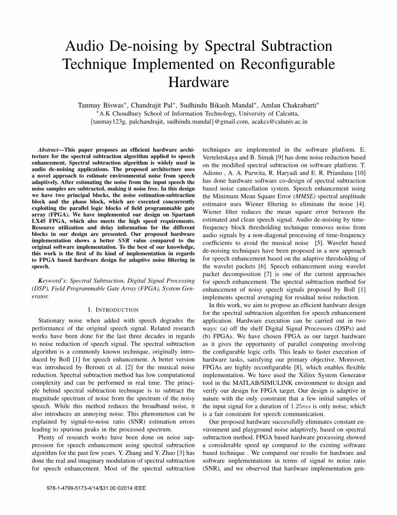
The block diagram of the hardware architecture is shown
in Fig.1. The time domain noisy signal is converted into the
frequency domain by fast Fourier transform (FFT) block and
is divided into real and imaginary components. A CORDIC
arctan block divides the frequency domain signal in their mag-
nitude and phase format. The other blocks of the architecture
are the noise estimation-subtraction block and the phase block.
Thereafter we only concentrate on the magnitude spectrum of
the signal keeping the phase spectrum constant.
Two sub-blocks are used to estimate noise and to subtract
the noise from the original signal in the noise estimation-
subtraction block. The phase block divides the phase compo-
nent into cos and sine forms using CORDIC sincos block.
Two multiplier blocks are needed to divide the phase and
clean magnitude signal, which are inputs to the inverse Fourier
Transform (IFFT) block. The IFFT block is used to generate
the signal, which is equivalent to the s(m).In our proposed architecture we considered the signal fre-
quency 22KHz and 44KHz and the sample period are set as
per depending on the signal frequency. The parameter α and
β are set to 7 and 0.002.
A. Fast Fourier Transform
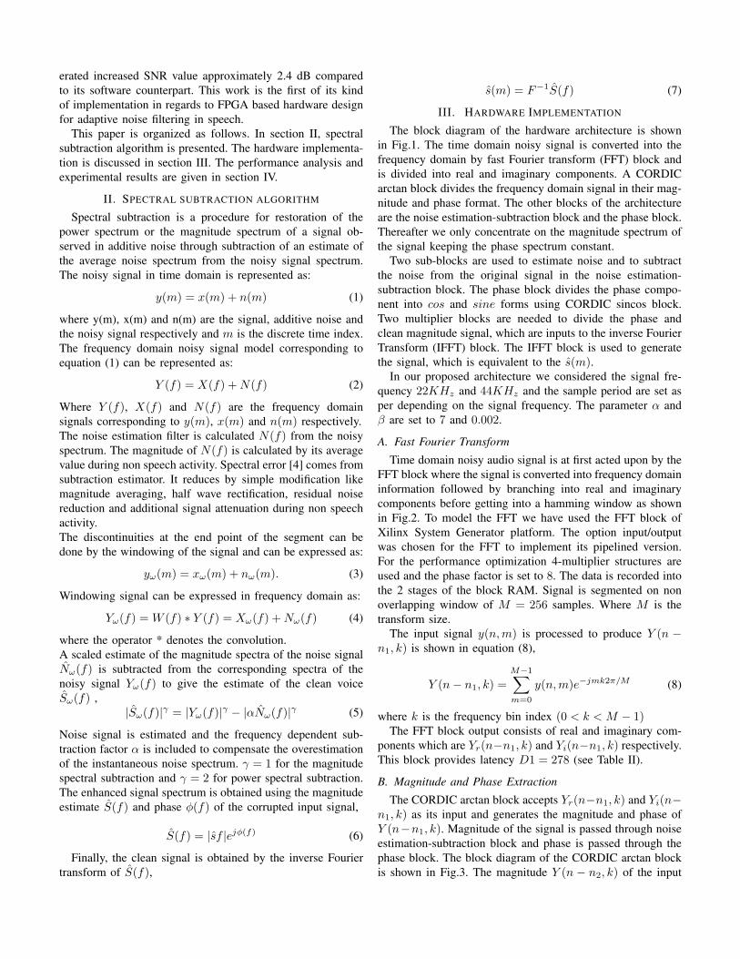
Time domain noisy audio signal is at first acted upon by the
FFT block where the signal is converted into frequency domain
information followed by branching into real and imaginary
components before getting into a hamming window as shown
in Fig.2. To model the FFT we have used the FFT block of
Xilinx System Generator platform. The option input/output
was chosen for the FFT to implement its pipelined version.
For the performance optimization 4-multiplier structures are
used and the phase factor is set to 8. The data is recorded into
the 2 stages of the block RAM. Signal is segmented on non
overlapping window of M = 256 samples. Where M is the
transform size.
The input signal y(n,m) is processed to produce Y (n −n1, k) is shown in equation (8),
Y (n− n1, k) =
M−1∑
m=0
y(n,m)e−jmk2π/M (8)
where k is the frequency bin index (0 < k < M − 1)The FFT block output consists of real and imaginary com-
ponents which are Yr(n−n1, k) and Yi(n−n1, k) respectively.
This block provides latency D1 = 278 (see Table II).
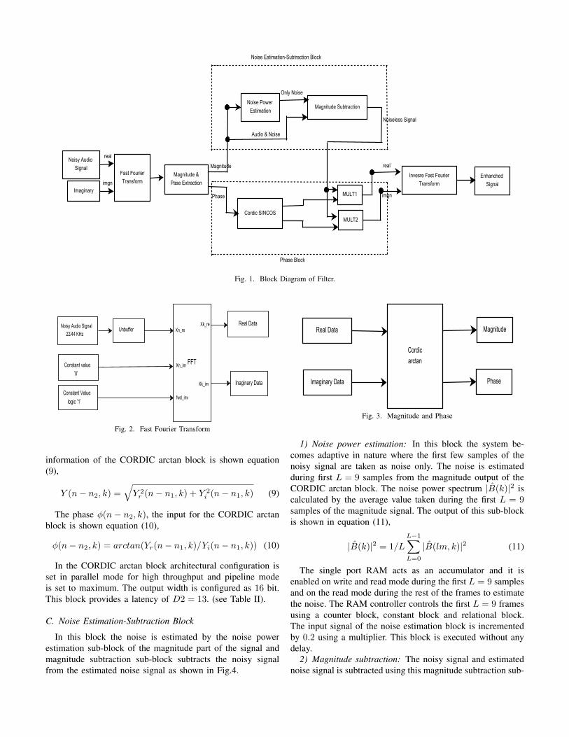
B. Magnitude and Phase Extraction
The CORDIC arctan block accepts Yr(n−n1, k) and Yi(n−n1, k) as its input and generates the magnitude and phase of
Y (n−n1, k). Magnitude of the signal is passed through noise
estimation-subtraction block and phase is passed through the
phase block. The block diagram of the CORDIC arctan block
is shown in Fig.3. The magnitude Y (n − n2, k) of the input
Noisy Audio
SignalFast Fourier
TransformMagnitude &
Pase Extraction
Invesre Fast Fourier
Transform
Noise Power
EstimationMagnitude Subtraction
Enhanched
Signal
Magnitude
Phase
Audio & Noise
Only Noise
Noiseless Signal
Cordic SINCOS
MULT1
MULT2
Imaginary
Noise Estimation-Subtraction Block
Phase Block
real
imgn
real
imgn
Fig. 1. Block Diagram of Filter.
FFT
Real Data
Inaginary Data
Noisy Audio Signal
22/44 KHzUnbuffer
Xn_im
Xn_reXk_re
Xk_im
fwd_inv
Constant value
’0’
Constant Value
logic ’1’
Fig. 2. Fast Fourier Transform
information of the CORDIC arctan block is shown equation
(9),
Y (n− n2, k) =√
Y 2r (n− n1, k) + Y 2
i (n− n1, k) (9)
The phase φ(n − n2, k), the input for the CORDIC arctan
block is shown equation (10),
φ(n− n2, k) = arctan(Yr(n− n1, k)/Yi(n− n1, k)) (10)
In the CORDIC arctan block architectural configuration is
set in parallel mode for high throughput and pipeline mode
is set to maximum. The output width is configured as 16 bit.
This block provides a latency of D2 = 13. (see Table II).
C. Noise Estimation-Subtraction Block
In this block the noise is estimated by the noise power
estimation sub-block of the magnitude part of the signal and
magnitude subtraction sub-block subtracts the noisy signal
from the estimated noise signal as shown in Fig.4.
Cordic
arctan
Real Data
Imaginary Data
Magnitude
Phase
Fig. 3. Magnitude and Phase
1) Noise power estimation: In this block the system be-
comes adaptive in nature where the first few samples of the
noisy signal are taken as noise only. The noise is estimated
during first L = 9 samples from the magnitude output of the
CORDIC arctan block. The noise power spectrum |B(k)|2 is
calculated by the average value taken during the first L = 9samples of the magnitude signal. The output of this sub-block
is shown in equation (11),
|B(k)|2 = 1/L
L−1∑
L=0
|B(lm, k)|2 (11)
The single port RAM acts as an accumulator and it is
enabled on write and read mode during the first L = 9 samples
and on the read mode during the rest of the frames to estimate
the noise. The RAM controller controls the first L = 9 frames
using a counter block, constant block and relational block.
The input signal of the noise estimation block is incremented
by 0.2 using a multiplier. This block is executed without any
delay.
2) Magnitude subtraction: The noisy signal and estimated
noise signal is subtracted using this magnitude subtraction sub-

Convert Delay
Ram Controller
AdderSingle
Port
Ram
*0.2
xk_index
edone
magnnitude of noisy signal
only noise signal
b
a
Fig. 4. Noise Power Estimation
block. Subtractor and comparator blocks are used for proper
subtraction of the two signal applied to the input section of
the sub-block. And the multiplexer is used to get the output
with proper synchronization of the noisy signal and estimated
noise signal which are applied to the input of the sub-block.
The block diagram is as shown in Fig.5. A parameter α and βare used to obtain the magnitude of the estimated noise signal
|B(k)|2.
|S(n−n2, k)|2 = max|Y (n− n2, k)|
2 − α|B(k)|2, β|B(k)|2
(12)
Subtractora<b
MUX
Alpha
noisy audio signal
only noise signal
noise free signal
Fig. 5. Magnitude Subtraction
The signal |S(n−n2, k)|2 is the noiseless magnitude of the
noisy signal and the phase articulation is added with the signal
to get the noise free signal. Where α = 7 and β = 0.002. This
block is executed without any delay.
D. Phase Block
Phase block is designed by CORDIC sincos block and two
multiplier blocks. The CORDIC sincos block divides the phase
signal, generated from the magnitude and phase extraction
block as shown in Fig.1 into cosine and sine forms. The cosine
and sine signals are articulated with the noiseless magnitude
signal using two multiplier blocks where the signal is divided
into real and imaginary part respectively.
The real signal is shown in equation (13),
Sr(n− n3, k) = Ascos(φ(n− n3, k)) (13)
The imaginary signal is shown in equation (14),
Si(n− n3, k) = Assin(φ(n− n3, k)) (14)
Where As is magnitude of the signal. In CORDIC sincos
block architectural configuration has been set in parallel mode
for high throughput, and pipeline mode is set to maximum.
The output width configured as 16 bit as same as CORDIC
arctan . This block provides latency D3 = 11.
E. Inverse Fast Fourier Transform
The inverse fast fourier transform (IFFT) block is used to
reconstruct the frequency domain desired signal. The IFFT
block takes as input Sr(n − n3, k) and Si(n − n3, k) as its
real and imaginary inputs respectively. In the Xilinx system
generator there is no specific IFFT block. But using fwd−invinput of FFT block, it can work as a IFFT block. If fwd−invinput is set to logic ′1′ it will work as a FFT block and if it is
set to logic ′0′ it will work as IFFT block. The block diagram
of this block is shown in Fig.6. The IFFT output is shown in
equation (15),
S(n− n4,m) = 1/M
M−1∑
k=0
S(n− n3, k)ejmk2π/m (15)
where S(n− n3, k) = Sr(n− n3, k) + jSi(n− n3, k). The
parameter kept same as the first FFT block used. The latency
of this block is D4 = 278.
IFFT
Real Data
Imaginary
Data Enhanched signal
Constant value
logic ’0’
Xn_re
Xn_im
fwd_inv
Xk_re
Fig. 6. Inverse Fourier Transform
IV. PERFORMANCE ANALYSIS
A Field Programmable Gate Array (FPGA) contains a ma-
trix of re-configurable logic circuitry. Because the processing
paths are parallel, different operations do not have to compete
for the same processing resources. That means multiple control
loops can run on a single FPGA device at different rates. The
re-configurability of FPGAs can provide limitless flexibility.
Most real-time systems require fast processing which are met
by the present day high speed FPGAs. The above mentioned
hardware execution has been carried out on Atlys Spartan 6
FPGA board (Xilinx Spartan-6 LX45 FPGA, 324-pin BGA
package,128Mbyte DDR2 16-bit wide data). Spartan-6 LX
FPGAs are optimized for applications that require the absolute
lowest cost. It provides up to 150K logic cells, integrated
PCI express blocks, advanced memory support, 390MHz DSP
slices, and 3.2 Gbps low-power transceivers. The device

utilization is shown in Table I and Table II shows the indi-
vidual latency required for the proposed parallel architecture.
The parallel section of the architecture is noise estimation-
subtraction block and phase block. The overall latency of this
proposed architecture is D = D1 + D2 + D3 + D4 = 580.
The comparison with respect to time requirement considering
software and hardware implementations is shown in Table III.
The hardware performance depends on the effective mapping
of circuits to the FPGA resources and on the performance
characteristics of individual hardware resources. The soft-
ware performance depends on the number of instructions the
processor must execute and the cycles per-instruction (CPI)
metric of the processor. Data in Table III shows that hardware
implementation is 276 times faster than that of software
implementation. Here we tested two kinds of signal, noisy
playground signal of frequency 22KHz and noisy musical
signal of frequency 44KHz . Also tested a noisy free signal
to the input of the system and it provide the same signal of
its output part shows in Fig.8. From this verifications we can
analyzed that our proposed design work properly with noisy
and noise free signals.
TABLE IDEVICE UTILIZATION FOR SPARTAN 6 LX 45 FPGA
Device utilization summary Available used utilization(%)
Slice Registers 184,304 8451 4Slice LUTs 92,152 7544 8
Slice memory 21,680 1,161 5Bonded IOBs 296 42 14DSP48A1S 180 43 23
TABLE IIHARDWARE EXECUTION RESULTS
Hardware architecture Delay
FFT 278Magnitude-phase Extraction 13
Phase Block 11IFFT 278
TABLE IIICOMPASSION OF EXECUTION PLATFORM
Platform Execution Time
Software Implementation 160.3msHardware Implementation 0.580ms
Fig.7 shows software and hardware implementations [11]
for the vuvuzella audio denoising (play ground signal). From
Fig.7 shows that hardware implemented system has success-
fully eliminate all the background noise. Table IV shows
that SNR values corresponding to software and hardware
implementations. It is observed from Table IV that hardware
implementation leads to an increased SNR approximately 2.4
dB w.r.t the software implementation.
Fig. 7. Vuvuzella sound denoising in software and hardware implementation
Fig. 8. Noiseless signal testing in hardware implementation
V. CONCLUSION
The performance of programmable processors is in its way
for continuous improvement. Hardware implementation of
DSP algorithms is increasingly required in several areas such
as wireless communications, multimedia systems, computer
networks, bio-medical sensors etc. The FPGA based hardware
implementation proposed in this paper gives satisfactory re-
sults in terms of noise removal from speech with a moderate
utilization of available FPGA resources. The proposed method
uses only the magnitude of the noise spectrum and phase
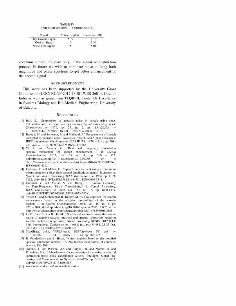
TABLE IVSNR COMPRESSION OF VARIOUS SIGNAL
Signal Software (dB) Hardware (dB)
Play Ground Signal 15.72 18.13Musical Signal 10 12.39
Noise Free Signal 15 15.04
spectrum comes into play only in the signal reconstruction
process. In future we wish to eliminate noise utilizing both
magnitude and phase spectrum to get better enhancement of
the speech signal.
ACKNOWLEDGMENT
This work has been supported by the University Grant
Commission (UGC) RGNF-2012-13-SC-WES-26014, Govt of
India as well as grant from TEQIP-II, Center Of Excellence
in Systems Biology and Bio-Medical Engineering, University
of Calcutta.
REFERENCES
[1] Boll, S., ”Suppression of acoustic noise in speech using spec-tral subtraction,” in Acoustics, Speech and Signal Processing, IEEE
Transactions on, 1979, vol. 27., no. 2, pp. 113–120,doi =
10.1109/TASSP.1979.1163209., ISSN = 0096− 3518.[2] Berouti, M. and Schwartz, R. and Makhoul, J.,” Enhancement of speech
corrupted by acoustic noise” Acoustics, Speech, and Signal Processing,IEEE International Conference on ICASSP ’79., 1979, vol. 4., pp. 208–211, doi = 10.1109/ICASSP.1979.1170788.
[3] Yi Z. and Yunxin Z., ”Real and imaginary modulationspectral subtraction for speech enhancement ,” in Speech
Communication, 2013, vol. 55, no. 4, pp. 509 – 522.doi=http://dx.doi.org/10.1016/j.specom.2012.09.005, url =”http://www.sciencedirect.com/science/article/pii/S0167639312001276”,ISSN=0167-6393.
[4] Ephraim, Y. and Malah, D., ”Speech enhancement using a minimum-mean square error short-time spectral amplitude estimator,” in Acoustics,
Speech and Signal Processing, IEEE Transactions on, 1984, pp. 1109-1121, doi= 10.1109/TASSP.1984.1164453, ISSN=0096-3518.
[5] Guoshen Y. and Mallat, S. and Bacry, E., ”Audio Denoisingby Time-Frequency Block Thresholding,” in Signal Processing,
IEEE Transactions on, 2008, vol. 56, no. 5, pp. 1830-1839,doi=10.1109/TSP.2007.912893, ISSN=1053-587X.
[6] Yasser G. and Mohammad R. Karami-M.,”A new approach for speechenhancement based on the adaptive thresholding of the waveletpackets ,” in Speech Communication, 2006, vol. 48, no. 8, pp.927 – 940, doi=http://dx.doi.org/10.1016/j.specom.2005.12.002, url =http://www.sciencedirect.com/science/article/pii/S0167639305002888.
[7] Li R., Bao C., Xia B.; Jia M., ”Speech enhancement using the combi-nation of adaptive wavelet threshold and spectral subtraction based onwavelet packet decomposition,” Signal Processing (ICSP), 2012 IEEE11th International Conference on , vol.1, no., pp.481,484, 21-25 Oct.2012 doi: 10.1109/ICoSP.2012.6491530.
[8] McAllister, John, ”FPGA-based DSP”,Springer US, doi =
10.1007/978− 1− 4419− 6345− 1− 14, pp. 363-392.[9] E. Verteletskaya and B. Simak, ”Noise reduction based on the modified
spectral subtraction method,” IAENG International journal of computerscience, Feb 2011.
[10] Adiono, T. and Purwita, AA and Haryadi, R. and Mareta, R. andPriandana, E.R., ”A hardware-software co-design for a real-time spectralsubtraction based noise cancellation system,” Intelligent Signal Pro-cessing and Communications Systems (ISPACS), pp. 5-10, Nov 2013,doi=10.1109/ISPACS.2013.6704513
[11] www.mathworks.com/products/hdl-verifier
Copyright © 2022 FDOKUMEN