
Auburn Stabling Project Stage 1 exhibit B - works brief
308
Auburn Stabling Project (Stage 1) Exhibit B Works Brief Design and Construction Contract (ASP-Q1-D&C) ; I" 'I ,
-
Upload
khangminh22 -
Category
Documents
-
view
1 -
download
0
Transcript of Auburn Stabling Project Stage 1 exhibit B - works brief

Auburn Stabling Project (Stage 1)
Exhibit B
Works Brief
Design and Construction Contract (ASP-Q1-D&C)
T"CA~ ; I" 'I ,

I
1· .;', _ ,.
icAI~

NSW GOVERNMENT
Transport' Construction Authority
South 'West RaU Link
Design and Construct Contract for
Auburn Stabling Project (Stage 1)
(ASP-01-D&C)
Works Brief
Date: 21 June 2011
Document: AARLEG-#18499703-v1-Auburn_TCA_Works_BrieC210611.DOC

I
Transport NSW Construction <=ERNMENT Authority
D&C Contract for Auburn Stabling Project (Stage 1)
Works Brief
Table of Contents
1 INTRODUCTION ••••••••••••••••••••••••••••••••••••••••••••••••.••••••••••••••••••••••••••••..••••••••••••••..• ~ •••••••••••••••• 8
1.1 WORKS BRIEF OVERVIEW ........................................................................................ 8
1.2 OVERVIEW OF THE AUBURN STABLING PROJECT (STAGE 1) .......................................... 9
1.3 OBJECTIVES OF THE AUBURN STABLING PROJECT (STAGE 1) ........................................ 9
1.4 SITE BOUNDARIES ••••••••••••••••••••••••••••••••••••••••••••••••••••••.•••••• : ••••••• ; •••....•••••••.•..•••••••• 10
1.5 DEFINITIONS AND INTERPRETATIONS •.....•••••••••••••••••••••••••••••••••••••••••••••••••••••••••••••...• 10
2 GENERAL REQUiREMENTS ••.••..•.•••••••••••••••.•.••••••••...••••••••••..•••.•....••.....••••••••••••••••••••••••••• 11
2.1 INTRODUCTION •••••••••••••••••••••••••••••••••••••••••. : •.•••••••••.......•.......•••••••••••••.••••••••••••.••••• 11
2.2 CONTRACTOR'S ACTIVITIES •••••••••••••...•••••••••••••••••••••••••••••••••••••••••.•••••••••...••••••.....•••• 11
2.3 WORKS AND TEMPORARY WORKS ....••••••••.••••••••• : .•...••••••••.•.•••••••••••.•.•.••••••••••••••••••• 12
2.3.1 Categories ......................................................................................... 12
2.3.2 Principal Items of Infrastructure to be Constructed ........................ 14
2.4 TCA STANDARD REQUIREMENTS ••.••••.•....•••••......••••••..•.•••••..•.••.•..•••••••••...••••••••••••••. 17
2.5 STANDARDS, REGULATIONS AND CODES ••••••.•..••••••••.••••••••••••••••••••••••••••••••••••••.•..••••• 18
2.6 SAFETY MANAGEMENT •.......•..••••••••....•••••••••..••••••••••••••••••.•••••••••••••••••••••••••••••••••••.•• 19
2.7 ENVIRONMENTAL ASSESSMENT AND PLANNING ApPROVAL ........................................ 19
2.8 SUSTAINABILlTY ••••••••••••.•..•.••••••••••...••••••••..•••••••......••••••••••••••••••.••....•••••••..•••••••••••. 19
2.9 SITE INVESTIGATIONS AND SURVEY •••••••••••..••••••••..•••••••••••••••••••.....••..•••.•....•••••....•••• 19
2.10 INTERFACE MANAGEMENT ••••••••••••..••••••••...•••••.•....••••••••••.••••.•••....•••••••....•••••••..•••••• 20
2.11 EFFECT OF THE WORKS •••••••••••••••..•••••••.....•••••...•.••••••..•.....•.......•••••••••••.•••••••..••••••• 20
2.12 MONITORING ••••••••••••• : •••••••••• ~ ••••••.••••••....••••••.•..•••••••...•.••••••.•••••••••• ; •..••••••••...•••••.• 21
2.13 DURABILITY ........................................................................................................... 21
2.14 FUTURE EXPANSION .............. ~ •••••••••••.•••••••••••••••••••••••••••.•.••••••••••••••••.•••••••••••••••••••• 22
3 PERFORMANCE AND DESIGN REQUiREMENTS ••.••...•••••••.•.....••••••••••••••••••••••••••..••••••.•••• 24
3.1 DESIGN OBLIGATIONS ..•..••••••••••.•..•••••• ~ ..•••••••...•••.••••••...••••••••••••••••••.••••••••..•••••••••.•• 24
3.2 COMPETENCY FOR DESIGN •••••••••...••••.....•••.....•.••••••.•....•....••••••••••••••..••••••....••••....•• 25
Page 2

1-
•• rA1t1.1 Transport 41'1. Construction ~~Y.l Authority
D&C Contract for Auburn Stabling Project (Stage 1) Works Brief
3.3 DESIGN LIFE ........................................................................................................ 25
3.4 TCA CAD PROTOCOLS .......................................................................................... 27
4 SCOPE AND TECHNICAL REQUiREMENTS ...................................................................... 28
4.1 NOT USED ........................................................................................................... 28
4.2 DEMOLITION AND RELOCATION WORKS ................................................................... 28
4.2.1 Scope ........................... , ..................................................................... 28
4.2.2 Technical Requirements .................................................................... 28
4.3 UTILITIES AND SERVICES WORKS ........................................................................... 28
4.3.1 Scope ................................................................................................. 28
4.3.2 Technical Requirements ................................................................... 29
4.4 EARTHWORKS ....................................................................................................... 30
4.4.1 Scope .................................................................................................. 30
4.4.2 Technical ~equirements ................................................................... 31
4.5 STORMWATER DRAINAGE ...................................................................................... 32
4.5.1 Scope ................................................................................................. 32
4.5.2 Technical Requirements ................................................................... 33
4.6 RETAINING WALLS ................................................................................................ 34
4.6.1 Scope ................................................................................................. 34
4.6.2 Technical Requirements ................................................................... 34
4.7 COMBINED SERVICES ROUTE ....•....................... , .................................................... 36
4.7.1 Scope ................................................................................................. 36
4.7.2 Technical Requirements ................................................................... 36
4.8 ACCESS ROADS .......................................................................................... ; ......... 37
4.8.1 Scope .................................... · ............................................................. 37
4.8.2 Technical Requirements ................................................................... 37
4.9 CROSS DRAINAGE CULVERTS ................................................................................. 39
4.9.1 Scope ................................................................................................. 39
4.9.2 Technical Requirements ................................................................... 39
AARLEG-#18499703-vlAuburn_TCA_Works_BrieC210611.DOC
Page3 .'''~ ....•
TI::\· ).; \;;.,' i
~.

I Transport Construction Authority
D&C Contract for Auburn Stabling Project (Stage 1)
Works Brief
4.10 TRAIN ACCESS PLATFORMS AND AT-GRADE WALKWAYS ••••••••••••••••••••••••••••••••••••••••••• .40
4-.10.1 Scope ................................................... ~ ............................................. 40
4.10.2 Technical Requirements ........ : .......................................................... 40
4.11 . BUILDINGS ••••••••.•....•••••••••••••....•••••••.•.•....•....••••••••••••••.......•••••••.......•••••••••.•••••••••• 41
4.11.1 Scope .... : .............................................................................. ~ ............. 41
4.11.2 Technical Requirements ................................... : ............................... 41
4.12 SIGNAGE •••••••••••.•.•...•••••••••.....•••••••.........••.••••••••••.••••.....••••••....•••••••••••.•...•.•••••••••• 44
4.12.1 Scope .................................................................................................. 44
4.12.2 Technical Requirements ................................................................... 44
4.13 SERVICE ROAD AND STAFF FACILITIES CARPARK ••••••••••..•••••••••••.•••••••••••.•..•••••••••••••••• 45
4.13.1 Scope ................................................................................................. 45
4.13.2 Technical Requirements ................................................................... 46·
4.14 NOISE WALLS •..••••••••••••••••••••••••••••••••••••••••••••••••.••••••••••••••••••••••••••••••••••••••••••.••.•••• 50
4.14.1 Scope ........................................... : ..................................................... 50
4.14.2 Technical Requirements ............................................... : ................... 50 . ,
4.15 FENCING AND GATES ••••.......••••.....•••••.•••....•.•.•.......••••••••..••••••• : ....••.••••••••••••••.•.••••• 53
4.15.1 Scope ................................................................................................. 53
4.13.2 Technical Requirements ................................................................... 53
4.16 URBAN DESIGN AND LANDSCAPING ••••••••..•••......•••••••••••.•••••••...•.•••••••.•..•••••••.•.•.•..... 55
4.16.1 Scope .......... : ...................................................................................... 55
4.16.2 Technical Requirements ....................................... ~ .......... : ................ 55
4.17 MISCELLANEOUS CIVIL STRUCTURES AND FOOTINGS .•••••••••••••.••••••.••••.• : •••••••••••••••••••• 58
4.17.1 Scope ................................................................................................. 58
4.17.2 Technical Requirements ................................................................... 58
4.18 PERMANENT WAY .•.••••.•....••••••.••••••...........••••••••••...•••••••.•....••••••...•..••.•....•••••••••..... 59
4.18.1 Scope ................................................................................................. 59
4.18.2 Technical Requirements ................................................................... 59
4.19 TRACTION POWER SUPPLY •••.•• , .••••••.•......•••••••••••.•••..••••••••••.••••.•.••••• '. ••.•..••••.•••••..•••• 62
Page 4

'e
I
Transport Construction Authority
D&C Contract for Auburn StabJing Project (Stage 1)
Works Brief
4.19.1 Scope ................................................................................................. 62
4.19.2 Technical Requirements ................................... ' ................................ 62
4.20 HIGH VOLTAGE (HV) POWER SUPPLY ...................................................................... 63
4.20.1 Scope ................................................................................................. 63
4.20.2 Technical Requirements ................................................................... 65
4.21 OVERHEAD WIRING .............................................................................................. 66
4.21.1 Scope ..................................... , ............................................................ 66·
4.21.2 Technical Requirements ................................................................... 66
4.22 SIGNALLING SYSTEM •••••••••••••••••••••••••.••••••••••••••••••••• ; •••••••••••••••••••••.••••••• : •••••••••••••• 68
4.22.1 Scope ................................................................................................. 68
4.22.2 Technical Requirements ................................................................... 69
4.23 Low VOLTAGE (LV) POWER SUPPLY AND DISTRIBUTION ............................................ 71
4.23.1 Scope ................................................................................................. 71
4.23.2 Technical Requirements ................................................................... 73
4.24 INTERNAL AND ExTERNAL liGHTING ................................................ : ....................... 76
4.24.1 Scope ................................................................................................. 76
4.24.2 Technical Requirements ................................................................... 77
4.25 EARTHING, BONDING AND ELECTROLYSIS PROTECTION ............................................. 80
4.25.1 Scope .............. · ................................................................................... 80
4.25.2 Technical Requirements ................................................................... 80
4.26 COMMUNICATIONS - BACKBONE ............................................................................. 82
4.26.1 Scope ................................................................................................. 82
4.26.2 Technical Requirements ................................................................... 83
4.27 COMMUNICATIONS - PUBLIC ADDRESS (PA) SYSTEMS ............................................... 84
4.27.1 Scope ................................................................................................. 84
4.27.2 Technical Requirements .................................................... : .............. 85
4.28 PRECISE CLOCKS •••••••••••••••••••••••••••.•. : ••.••.••••••••••••••••••••••••••••••••••••••••••••••..•••••••••••• 85
4.28.1 Scope ................................................................................................. 85
AARLEG-#18499703-v1-Au bu rn_ TCA_ Works_BrieC210611. DOC

I Transport
NSW Construction ocmRNM'NT Authority
D&C Contract for Auburn Stabling Project (Stage 1) Works Brief
4.28.2 Technical Requirements ................................................................... 85
4.29 CLOSED CIRCUIT TELEVISION SYSTEM .•••••••.••••••••••••.....••••••••••••••••.•.••••......•••••••..••... 86
4.29.1 Scope ................................................................................................. 86
4.29.2 Technical Requirements ................................................................... 86
4.30 ACCESS CONTROL SYSTEM AND INTRUSION DETECTION SYSTEM ................................. 88
4.30.1 Scope .......................... ~ ...................................................................... 88
,4.30.2 Techriical Requirements ......................•.............. , ............................. 90
4.31 TELEPHONY AND TV .............................................................................................. 90
4.31.1 Scope ................................................................................................. 90
4.31.2 Technical Requirements ................................................................ .-.. 91
4.32 COMMUNICATIONS INFRASTRUCTURE •••••.• : ..••••••.....•••••••.•..•..••••.••••••••••......•••••••••••••• 92
4.32.1" Scope ................. : ................................................................................ 92
4.32.2 Technical Requirements ................................................................... 93
4.33 RADIO COMMUNiCATIONS .••••••••••••••••••••••••••...•••••••••..••••••••••••••••••....•...••••••••••••••••••• 93
4.33~1 Train Radio ........................................................................................ 93
4.34 COMMUNICATIONS EQUIPMENT ROOM ...••••..••..••••.•.•.••••••••••••••••••••..•.••.•••••••.....••••..• 94
4.35 SIGNAL POST AND MAINTENANCE TELEPHONES .•• : •••.••.••••••••••••••••••....••••••..•••••••••.•... 94
4.35.1 Scope ................................................................................................. 94·'
4.35.2 Technical Requirements ................................................................... 95
4.36 MECHANICAL SERVICES FOR BUiLDINGS •••......•••••.•.•••••••••.•....•..•••••••••••.•.••••.•....••••••• 95
4.36.1 Scope ....................................................................•............................ 95
4.36.2 Technical Requirements .............. ~ .................................. , ................. 96
4.37 ' HYDRAULIC SERVICES (INCLUDING WATER' SUPPLY & WASTEWATER) FOR
BUILDINGS ........................................................................................................... 99
4.37.1 Scope ................................................................................................. 99
4.37.2 Technical Requirements .................................................... , ........... 100
4.38 FIRE AND LIFE SAFETY PROTECTION SERVICES ...................................................... 105
4.38.1 Scope .............................................................................................. 105
4.38.2 Technical requirements ................................................................. 106
",AjiLEG-#18499703-vl-, T VMrn_TcA_works_BrieC210611.DOC
.. ',' ., ·b~
Page 6

:-
I
Transport Construction Authority
D&C Contract for Auburn Stabling Project (Stage 1)
Works Brief
Appendices
Appendix A Standards, Regulations and Codes List
Appendix B Not Used
Appendix C Interface Schedule
Appendix D Earthing and Bonding Specification
Appendix E Signalling Functional Specification
Appendix F Signalling Plan
Appendix G Not Used
Appendix H Approved Waivers
Appendix I Room Data Sheets
AARLEG-#18499703-vlAuburn_TCA_Works_BrieC210611.DOC

.D't'11J.1 Transport 41'. Construction !i~y'y' Authority
D&C Contract for Auburn Stabling Project (Stage 1) Works Brief
1 INTRODUCTION
1.1 WORKS BRIEF OVERVIEW
This Works Brief sets out the scope of works, minimum criteria, general requirements and technical requirements for the Works, Temporary Works and Contractor's Activities for the design and construction of Auburn Stabling Project (Stage 1) which the Contractor must satisfy to fulfil its obligations under the Deed.
This Works Brief comprises:
Section 1:
Section 2:
Section 3:
Section 4:
Introduction - an outline of the structure 'of the Works Brief and its purpose, a project overview and the objectives of the Auburn Stabling Project (Stage 1);
General Requirements - a description of the Works and Contractor's Activities and the Contractor's general obligations;
Performance and Design Requirements - a description of the Contractor's design obligations and general performance requirements; and
Scope and Technical Requirements - the detailed scope and the minimum technical requirements for the Works including the minimum criteria to be used in the development of the design for each element of the Works.
The Appendices to this Works Brief comprise:
Appendix A:
Appendix B:
Appendix C:
Appendix D:
Appendix E:
Appendix F:
Appendix G:
Appendix H:
Appendix I:
Standards, Regulations and Codes;
Not Used;
Interface Schedule;
Earthing and Bonding Specification;
Signalling Functional Specification;
Signalling Plan;
Not Used; ,
Approved Waivers; and
Room Data Sheets
Page 8

•
I
Transport Construction Authority
D&C Contract for Auburn Stabling Project (Stage 1) Works Brief
1.2 OVERVIEW OF THE AUBURN STABLING PROJECT (STAGE 1)
(a) , The Auburn Stabling Project (Stage 1) will form part of RailCorp's train stabling facilities servicing th~ Sydney metropolitan area and must be compatible with the existing RailCorp system, and provide for a fully integrated operation within this system. It includes:
(i) the delivery of a stabling facility at Auburn, between Auburn and Clyde stations, capable of holding up to eleven eight-car suburban trainsets;
(ii) the stabling transfer road which connects the Works with the down relief line.
1.3 OBJECTIVES OF THE AUBURN STABLING PROJECT (STAGE 1)
(a) The fundamental purpose of the Auburn Stabling Project (Stage 1) is to house inactive trains, allow them to be cleaned and receive minor repairs and maintenance, and to protect them from vandalism.
(b) The operational objectives for the Auburn Stabling Project (Stage 1) include facilitating::
(i) overnight and between-peak stabling of train sets;
(ii) internal train cleaning by train presentation staff (includes internal graffiti removal);
(iii) spot cleaning on train exteriors by train presentation staff (includes drivers' windscreens);
(iv) shunting of train sets in preparation for departure or to accommodate arriving train sets;
(v) train preparation by train crew;
(vi) division/amalgamation of trains by train crew; and
(vii) minor rolling stock repairs by train technicians.
(c) In delivering the Auburn Stabling Project (Stage 1), the key project objectives are:
(i) to delivera high quality rail stabling facility;
(ii) to deliver the works safely;
(iii) to minimise impacts on the environment and community;
(iv) to achieve delivery dates; and
(v) to have no unplanned impact on the operation of RailCorp infrastructure, the adjacent AMC, or the adjacent MainTrain facilities.
AARLEG·#18499703·vl-Auburn_ TCA_ Works_BrieC210611. DOC
Transport Construction Authority
D&C Contract for Auburn Stabling Project (Stage 1)
Works Brief
1.4 SITE BOUNDARIES
(a) The Works must be designed and constructed to lie completely within the Asset Lands except that the Remote Works must be designed and constructed to lie completely within the Remote Sites or Extra Land.
(b) All Temporary Works must be designed and constructed to lie completely within the Site, Remote Sites and Extra Land ..
1.5 DEFINITIONS AND INTERPRETATIONS
(a) All references to 'Contract Drawings', 'Reference Design' or the 'Principal's Reference Design' must be read as a reference to the Principal's Design.
(b) Unless stated otherwise, any reference to a 'section' in this Works Brief is a reference to a section of this Works Brief. .
(c) Unless stated otherwise, any reference to an 'Appendix' in this Works Brief is a reference to an Appendix of this Works Brief. .'
(d) Th~ Works Brief must be read in conjunction with all other parts of the Deed, including the Principal's Design.
(e) Terms which have a defined meaning in the General Conditions have the. same meaning where ,used in this Works Brief unless stated otherwise.
(f) In this Works Brief:
AMC means the Auburn Maintenance Centre located to the north-east of the Auburn Stabling Project (Stage 1);
Contractor Commissioning means the activities identified in Annexure A of TSR 01 -Commissioning and Operational Readiness in the TCA Standard Requirements;
Janyon means the owner of the land located to the south and west of the Asset Lands, between the Asset Lands and Manchester Road;
LGCUP means the Lidcombe to Granville Corridor Upgrade Project;
MainTrain means the maintenance facility located to the east of the Auburn Stabling Project (Stage l);and
MainTrain Car Turning Loop means the operating rail line between MainTrain and the Asset Lands which is conr;Jected to the RailCorp network and is used by the AMC and MainTrain.
Te AAARLEG-#18499703-v1-.M~surn_TcA_works_BrieC210611.DOC
Page 10

I Transport Construction Authority
D&C Contract tor Auburn Stabling Project (Stage 1)
Works Brief
2 GENERAL REQUIREMENTS
2.1 INTRODUCTION
(a) The Contractor must undertake the Contractor's Activities in accordance with the requirements of the Deed including this Works Brief and the TCA Standard Requirements. The design, construction, testing, commissioning, integration and handover of the Works and Temporary Works must comply with the requirements of the Works Brief and the Deed.
2.2 CONTRACTOR'S ACTIVITIES
(a) Without in any way limiting the Contractor's other obligations under the Deed, the Contractor's Activities includes all things necessary to:
(i) investigate, design, construct and commission the Works and Temporary Works except that the Principal will undertake the Signalling Design;
(ii) demolish, remove and rehabilitate all existing infrastructure, structures, services and buildings:
A. that are within the Site and are made redundant by the Works; and
B. that are otherwise affected by or are made redundant by the Works or the Temporary Works;
(iii) undertake all things necessary to remediate the Site as required by this Works Brief;
(iv) undertake all things necessary to comply with the Remediation Action Plan;
(v) undertake Contractor Commissioning;
(vi) undertake Commissioning, Systems Integration and Operational Readiness;
(vii) undertake those activities set out in Appendix C and identified as the Contractor's responsibility;
(viii) handover the Works to the Principal at the Date for Completion in the specified condition;
(ix) ensure the Works comply with the minimum criteria and performance and technical requirements set out in the Works Brief;
(x) correct all Defects during the Defects Rectification Periods applicable to the relevant parts of the Works;
(xi) secure, maintain, repair, reinstate and hand back (in the specified condition) areas occupied or affected by Temporary Works;
AARLEG-#18499703-vl- Page 11 . Auburn_TCA_Works_BrieC210611.DOC
•. T~

I
Transport Construction Authority
D&C Contract for Auburn Stabling Project (Stage 1) Works Brief
(xii) prepare all Design Documentation (including detail~d construction drawings and specifications);
(xiii) coordinate the development of the Design Documentation with LGCUP;
(xiv) undertake all activities required by the Deed including this Works Brief; and
(xv) undertake all activities required by the TCA Standard Requirements.
2.3 WORKS AND TEMPORARY WORKS
2.3.1 Categories
(a) The Works and the Temporary Works include the following categories of works:
(i) The Works includes:
A. the permanent infrastructure described in section 2.3.2 of this Works Brief that lies within the Asset Lands;
B. Remote Works;
C. the items, and the configurations and locations of those items, contained in the Principal's Design, excluding the infrastructure associated with Temporary Works;
D. demolition and relocation of existing infrastructure and buildings more particularly described in section 4.2.1;
E. drainage (including subsurface drainage), earthworks, all structures, pavements, buildings, rail and rail systems, finishes and landscaping;
F. remediation of Contamination for the full extent of the Site;
G. all infrastructure necessary to operate and maintain the Works;
. H. the provision of all Services to any facility necessary to operate and maintain the Works;
I. all environmental safeguards and measures necessary to mitigate environmental impacts during operation of the Works, including those identified. in this Works Brief, the Remediation Action Plan, the TCA Standard Requirements and the Planning Approval;
J. ali measures necessary to mitigate noise and vibration during operation of the Works;
K. all works required as a consequence of the community liaison process;
L. all equipment necessary to monitor the environmental performance of the Works, asse~s the durability of all elements and assist in the maintenance of the Works; and
Page 12

1Jtrt+Jl.1 Transport •• Construction Ii~W Authority
D&C Contract for Auburn Stabling Project (Stage 1) Works Brief
M. those items identified in section 2.3.2 of this Works Brief which are on, or in, or are to be constructed on, or in the Asset Lands or Remote Sites.
(ii) The Temporary Works comprises all works necessary to complete the Works in accordance with the Deed and includes:
A. temporary measures required to meet the needs of the affected public and road users and to provide public amenity, security and safety during all stages of design and construction of the Works;
B. temporary fencing, hoarding (including overhead protection), barricades, entrances or exits, gates, lighting, and the like to provide a safe and secure site at all stages of the Works, including protection of existing RailCorp, MainTrain and AMC infrastructure and services;
. C. temporary fencing must be installed in a manner that provides for the security of the AMC at all times;
AARLEG-#18499703-v1-
D. vehicular access roads within the Site and the Remote Sites for construction of the Works;
E. acquisition, maintenance and remediation of access roads, worksites and construction compounds outside the Asset Lands and Remote Sites;
F. traffic management, as necessary, on roads affected by construction of the Works, including temporary diversions and sidetracks;
G. compounds, lay down areas, storage containers and amenities for construction personnel including temporary services;
H. scaffolding, staging, formwork and temporary access facilities;
I. temporary excavations, shoring and ground support for the erection, installation and construction of the permanent civil works and structures;
J. all environmental safeguards and controls to mitigate environmental effects, including temporary protection of watercourses, noise and dust control, temporary protection of fauna, and temporary fencing to protect trees and other vegetation to be retained on the Site;
K. measures to prevent Contamination leaving the Site;
L. temporary ~rainage works to ensure that the Works and the Asset Lands remain effectively drained and protected from flooding during all stages of construction;
M. soil and erosion control measures during the construction and landscape establishment phases;
Page 13 Auburn_ TCA_ Works_BrieC210611. DOC TCA
~

I
Transport Construction Authority
D&C Contract for Auburn Stabling Project (Stage 1)
Works Brief
N. temporary protection and relocation of utilities to allow the erection, modification, installation and construction of the permanent works and structures;
o. temporary power, communications, water, sewer and other utilities supporting the Works, including all utility permits;
P. temporary operational, regulatory, directional, warning, wayfinding, safety and informatio.n signage;
Q. temporary protection to completed Works to prevent damage, up to handover to the Principal's Representative;
R. cleaning, maintenance, repair, replacement and reinstatement, as required, of all areas occupied by the Contractor during the design and construction of the Works;
S. temporary site facilities required for the design and construction of the Works;
T. all Temporary Works identified in Schedule 3 of the Deed; and
U. decommissioning of all Temporary Works including cleaning, maintenance, repair,' replacemeRt and reinstatement' of all areas occupied by the Contractor during the Works, including Temporary Lands.
2.3.2 Principal Items of Infrastructure to. be Co.nstructed
(a) The Works includes the' permanent infrastructure which must be constructed, or modified, and commissioned and handed over by the Contractor to satisfy the requirements of the- Deed.
(b) The permanent infrastructure includes:
(i) the permanent way and associated infrastructure for the stabling yard to be constructed in the Asset Lands and more particularly described in section 4.18.1 including:
A. eleven (11) stabling roads of which none are through-roads; and
B. all other tracks and associated infrastructure;
(ii) train access platforms and at-grade walkways more particularly described in section 4.10.1;
(iii) protection, relocation and adjustment of existing utilities and installation of new services more particularly described in section 4.3.1 (some of which are Remote Works);
(iv) earthworks and formations more' particularly described in section 4.4.1, including those required for the remediation of the Site in accordance with the "Preferred Rem'ediation Strategy" identified in the Remediation Action Plan;
T ' I.r,RLEG-#18499703-V1-
... CRburn_TcA_works_srieC210611.DOC Page 14
~

-
I
Transport Construction
!i~~ Authority D&C Contract for Auburn Stabling Project (Stage 1)
Works Brief
(v) stormwater drainage (some of which are Remote Works) more particularly described in section 4.5.1;
(vi) cross drainage culvertsmore particularly described in section 4.9.1;
(vii) retaining walls mo're particularly described in section 4.6.1;
(viii) the Combined Services Route (CSR) more particularly described in section '4.7.1;
(ix) access roads more particularly described in section 4.8.1.;
(x) all buildings more particularly described in section 4.11.1 including:
A. a staff facilities building;
R a staff amenities building; and
C. a combined building for signalling equipment and compressors;
(xi) signage more particularly described in section 4.12.1;
(xii) service roads and a staff facilities carpark more particularly described in section 4.13.1;
(xiii) noise walls more particularly described in section 4.14.1;
(xiv) fenCing and gates more particularly described in section 4.15.1;
(xv) landscaping more particularly described in section 4.16.1;
(xvi) miscellaneous civil structures and footings more particularly described in section 4.17.1 including for:
A. maintenance walkways and train access platforms;
B. overhead wiring (OHW) structures (OHW);
C. signalling civil infrastructure;
D. CCTV camera poles and foundations;
E. lighting and public address system poles and foundations; and
F. signage poles and foundations;
(xvii) traction power supply which is more particularly described in section 4.19.1;
(xviii) the high voltage power supply (some of which are Remote Works) more particularly described in section 4.20.1 including:
A. relocation and/or replacement of existing RailCorp aerial 33kV and 11kV lines;
B. new u.nderground cable for feeders 623 and 721;
AARLEG-#18499703-vlAuburn_TCA_Works_BrieC210611.DOC

Transport Construction Authority
D&C Contract for Auburn Stabling Project (Stage 1) Works Brief
C.
D.
E.
new 11kV j 415V padmount substations;
a new 415V j 415V isolation kiosk padmount transformer for the provision of an isolated Energy Australia backup supply; and
new 415Vj415V isolation transformers for provision of supply to Clyde Substation;
(xix) low voltage power supply and distribution more particularly described in section 4.23.1 including:
A. low voltage power supply to equipment and lighting throughout the stabling yard, car park, and all buildings;
B.
C.
lightning protection system;
signalling and compressor power supply; and
D. uninterruptible power supply units for the rail signalling systems;
(xx) internal and external lighting more particularly described in section 4.24.1;
(xxi) earthing, bonding and electrolysis protection more particularly described in section 4.25.1;
(xxii) all communication services for the stabling yard, all buildings and wider area including:
A. a communications backbone (Operational Critical Data Network (OCDN» more particula.rly described in section 4.26.1;
B. closed circuit television (CCTV) systems ,more particularly described in section 4.29;
C. an access control system and intruder alarm system more particularly described in section 4.30;
D. telephony and TV systems more particularly described in section 4.31;
E. train radio infrastructure (Metronet or DTRS) more particularly described in section 4.33.1; and.
F. signal post telephones and signal maintenance telephones more particularly described in section 4.35;
G. a public address system more particularly described in section 4.27;
H. all other communications infrastructure more particularly described in section 4.32;
(xxiii) a communications equipment room more particularly described in section 4.34;
T I if:~LEG-#18499703-V1-
Cl\~urn-TCA_Works_BrieC210611.DOC
Page 16
~"-f:> .. ~

•
I
Transport Construction Authority
D&C Contract for Auburn Stabling Project (Stage 1)
Works Brief
(xxiv) precise clocks more particularly described in section 4.28;
(xxv) mechanical services for the stabling yard and all buildings including HVAC, MSSB's and power and control systems more particularly described in section 4.36.1;
(xxvi) hydraulic services including water supply. and wastewater more particularly described in section 4.37.1;
(xxvii) fire and life safety protection services more particularly described in section 4.38.1.
(xxviii) overhead wiring more particularly described in section 4.21.1;
(xxix) signalling infrastructure more particularly described in section 4.22.1; and
(xxx) all other infrastructure necessary under the Deed, and to provide a completed railway stabling yard suitable for operation.
2.4 TCA STANDARD REQUIREMENTS
(a) TheTCA Standard Requirements identify the Contractor's Activities relating to:
(i) quality assurance and management;
(ii) occupational health and safety;
(iii) environmental management;
(iv) working in the Rail Corridor and rail environment;
(v) incident management and reporting;
(vi) communications and community liaison;
(vii) technical management;
(viii) asset management information;
(ix) compliance management; and
(x) operational readiness and commissioning.
(b) The TCA Standard Requirements consist of the following documents:
(i) TSR - Prelude;
(ii) TSR Q1 - Quality Management System;
(iii) TSR S1 - Safety Management System;
(iv) TSR E1 - EnVironmental Management System;
(v) TSR C1 -Communications and Community Liaison;
AARLEG-#18499703-vl- Page 17
Auburn_ TCA_ Works_BrieC210611. DOC }r~A ~

·ltl~JtI.1 Transport •• Construction ri~Y.l! Authority
D&C Contract for Auburn Stabling Project (Stage 1) Works Brief
(vi) TSR A1 - Asset Management Information;
(vii) TSR T1 - Technical Management; and
(viii) TSR 01 - Commissioning and Operational Readiness.
(c) The Contractor must develop, implement and maintain systems and project plans in accordance with the Deed and comply with all requirements included in the TCA Standard Requirements documents.
2.5 STANDARDS, REGULATIONS AND CODES
(a) The Works and the Temporary'Works must, as a minimum, be designed, constructed, tested and commissioned to comply with the standards, regulations and codes required by the Contract and the Works Brief including the standards, regulations and codes which are identified and listed in Appendix A.
(b) References in the Works Brief to a standard, regulation or code including a RailCorp or Standards Australia publication, must, unless stated otherwise, be read as a reference to the version of the particular standard, regulation or code current at the time at which the relevant part of the Works is undertaken.
(c) . Where specific standards, regulations and codes are nominated in the Works Brief in relation to particular areas of the Works, these are minimum requirements and do not relieve the Contractor's obligation to comply with all ,other standards, regulations, technical notes (issued by RailCorp) and codes listed in Appendix A.
(d) In the event of any inconsistency, ambiguity or discrepancy between:
(i) a requirement of the Works Brief and any Standards, regulations and codes; or
(ii) a~ong any standards, regulations and codes,
the order of precedence in clause 1.4 of the General Conditions will apply ..
(e) In the event that the application of clause 1.4 of the General Conditions does oot resolve the inconsistency, ambiguity or discrepancy, the following order of precedence will apply:
1. TCA Standard Requirements;
2. specific provisions of the Works Brief;
3. RailCorp Standards and guidelines;
4. RTA Standards and guidelines;
5. Australian Standards and guidelines;
6. Standards, regulations and codes and other documents listed in Appendix A;
7. Any other Standards Australia codes,standards or specifications not listed in Appendix A; and
8. Any international codes, standards or specifications not listed in Appendix A.
Page 18
•

:1,'1; Transport NSW Construction D&C Contract for Auburn Stabling Project (Stage 1) G<>iERNMENT Auth~rity Works Brief
(f)
2.6
(a)
(b)
2.7
(a)
2.8
(a)
2.9
In the event of any in'consistency, ambiguity or discrepancy, between any standards, regulations ~and codes listed in Appendix A, the standards, regulations or codes which specifies the greatest level of service or gives the highest standard will apply.
SAFElY MANAGEMENT
The Contractor must develop, implement and maintain a project occupational health and safety management system for the duration of the Contractor's Activities in accordance with the Contract.
The Confractor must design and construct the Works to ensure they are safe throughout the design, construction, testing and commissioning and operation phases. RailCorp SRS and TCA Standard Requirements TSR T1 - Technical Management and S1 - Safety Management System, describes the safety requirements and processes, including reliability, availability, maintainability and systems safety (RAMS), and safety in design, which the Contractor must comply with under the Contract.
ENVIRONMENTAL ASSESSMENT AND PLANNING ApPROVAL
The Works, the Temporary Works and the Contractor's Activities must comply with the Planning Approval.
SUSTAINABILIlY
The Works (including construction methods) shall be designed and constructed giving due diligence to sustainability considerations. Designs shall be produced with the intent. of achieving a functional outcome which is aesthetic, integrates well with the existing environment, maximises value for money in consideration of 'whole of life' performance and costs and is environmentally friendly.
SITE INVESTIGATIONS AND SURVEY
(a) The Contractor must undertake all site investigations; property and land surveys; ground, groundwater and building/infrastructure/utility condition surveys required for the Contractor's Activities and the design, construction, testing and commissioning of the Works_and Temporary Works, where they have not been provided to the Contractor by the Principal's Representative.
(b) All setting out and surveys must use the Map Grid of Australia (MGA) co-ordinate system.
(c) The Contractor must obtain RailCorp's maintenance ali,gnment for existing tracks, and AMC alignments, including developing MGA coordinates for each if necessary, to ensure alignment interfaces are suitably developed.
AARLEG-#18499703-v1-
Auburn_ TCA_Works_BrieC210611.DOC / ,
Page 19
'TC~~

Transport NSW Construction G<7IERNM'NT Authority
D&C Contract for Auburn Stabling Project (Stage 1) Works Brief
2.10 INTERFACE MANAGEMENT
(a) The Contractor must manage all interface requirements of the Contractor's Activities with all stakeholders.
(b) Interfaces between the Contractor, the Principal and Other Contractors are identified in the Interface Schedule in Appendix C of this Works Brief. The Interface Schedule must be maintained as a live document for the duration of the design and shall be attached to every package requiring review and/or approval.
2.11 EFFECT OF THE WORKS
(a) Subject to clause 2.11(b), the Contractor must ensure that the Works and the Temporary Works and the Contractor's Activities do not damage or have,any adverse impact on the condition or performance of any infrastructure on,in, or adjacent to or in the vicinity of the site (including but not limited to structures, roads, railways, retaining walls, bridges, services and buildings) or any existing properties adjacent to or in the vicinity of the Site including any adverse impact on:
(i) amenity;
(ii) aesthetics;
(iii) durability;
(iv) structural integrity;
(v) function;
(vi) user benefits;
(vii) safety during construction and operation;
(viii) environmental performance; and
(ix) access to such infrastructure or existing properties.
(b) The Contractor may be relieved of the requirements of section 2.11(a) to the extent that it satisfies the requirements of any infrastructure owner, property owner or occupier, having regard to relevant standards and practices and the nature of the damage or adverse impact.
(c) The Contractor must undertake a detailed engineering analYSis to confirm the suitability of the design and. construction methodology. This analysis must predict the effects of the Works and the Temporary Works and the Contractor's Activities on existing ground conditions and infrastructure (including but not limited to structures, roads, railways, retaining walls, bridges, services and buildings). The analysis must also ensure that the predicted movements, vibration and stray current effects will satisfy the requirements of clause 2.11(a) or clause 2.11(b). This analysis must be documented in a report and submitted with the design documentation. The analysis must include the influence of:
~ it~LEG-#18499703-Vl' .. ;FVM'urn_TcA_works...:BrieC210611.00C
/\ ... ~
Page 20

'e
11111&,+':11.1 Transport •• Construction !i~\o! .. Authority
D&C Contract for Auburn Stabling Project (Stage 1) Works Brief
(i) excavation and earthworks construction;
(ii) geological variations;
(iii) the impact on groundwater;
(iv) the effects over time;
(v) stray currents;
(vi) vibration from construction and compaction equipment; and
(vii) wheel/rail noise.
2.12 MONITORING
(a) When carrying out the Contractor's Activities, the Contractor must continuously m'onitor the actual effects of the Works and Temporary Works.
(b) Monitoring of the actual effects of the Works and Temporary Works must be undertaken by suitably qualified and experienced professionals.
(c) In the event that the actual effects of the Works and Temporary Works do not satisfy the requirements of clause 2.11(a) or clause 2.11(b), or significantly vary over time, the Contractor must review and if necessary, re-evaluate and make any adjustment subsequently necessary to any aspects of the manner in which the Contractor's activities are undertaken to ensure that they satisfy the requirements of clause 2.11(a) or clause 2.11(b).
(d) The Contractor must promptly and progressively provide the Principal's Representative with:
(i)
(ii)
(iii)
(iv)
(v)
instrumentation and monitoring plans for the Works and Temporary Works as part of the preliminary design review submission and updated and re-issued as part of the critical design review submission;
analysis and determinations, including revisions, and re-evaluations of the predicted effects of the Works and Temporary Works;
results of monitoring the actual Works and Temporary Works over time;
details of any adjustments to the manner in which the Contractor's activities are carried out which are necessary; and
. details of designs and materials for any repair and reinstatement infrastructure.
2.13 DURABILITY
(a) The Contractor must prepare and submit a durability assessment report ("Durability Assessment Report") as part of the Design Documentation demonstrating that the durability and the required design life for each asset element will be achieved. The
Page 21 AARLEG·#18499703-v1-Auburn_TCA_Works_BrieC210611.DOC . ,·TeA
~

I
Transport Construction Authority
D&C Contract for Auburn Stabling Project (Stage 1) Works Brief
report must cover all elements of the design and the expected range of environments that the asset elements will be exposed to. The report must detail the requirements and methods for future inspection, testing, monitoring and maintenance of all elements of the design.
(b) The Durability Assessment Report must address the issues of reliability and maintainability including the following:
(i) the micro environment, including soil and water condition, contamination, exposure conditions etc;
(ii) the potential deterioration mechanisms in this micro environment;
(iii) design .life modelling to ascertain the likely rate of deterioration and likely life;
(iv) The feasibility and' cost of in-situ monitoring and/or replacement during the normal operating period and restricted non-operating period;
(v) The necessity and cost benefit analysis of providing additional prote~tion;
(vi) The significance of failure; and
(vii) Inspection and monitoring requirements.
(c) The micro-environment for each element must be determined by considering existing data and implementing a necessary level of site investigation and testing,
2.14 FUTURE ExPANSION
(a) The design and construction of the Works must make allowance for future expansion to a sixteen (16) eight-car stabling facility, providing:
(i) all items specifically mentioned within section 4 of this Works Brief;
(ii) future provision of an additional five (5) stabling -roads and connection to the RailCorp network. near Auburn to create a stabling facility with the centre six (6) stabling roads being through roads connected to both Auburn and Clyde ends, and the remaining ten (10) stabling roads being dead-ended with .five (5) connected to the Auburn end and five (5) connected to the Clyde end, including associated works;
(iii) provision for future connection of at least an additional one (1) of the future five (5) dead end roads to the Clyde access road at a later date;
(iv) provision ·for future connection of at least an additional one (1) of the future five (5) dead end roads to the Auburn access road at a later date; and
(v) when (i) to (iv) above are complete the following future configuration:
A. eight (8) through roads connected to the access road at both the Auburn and Clyde ends; and
~RLEG-#18499703'Vl-J CRurn- TCA_Works_BrieC210611.DOC
<" b~
Page 22

I
Transport Construction Authority
B.
AARLEG-#18499703-vl-
D&C Contract for Auburn Stabling Project (Stage 1) Works Brief
the remaining four (4) roads on each side of the eight (8) through roads which will remain dead ended (and fitted with appropriate energy absorbent buffer stops).
Page 23 Au burn_ TCA_ Works_BrieC210611.DOC
TCA

I Transport , Construction
~~Y.'{, Authority D&C Contract for Auburn Stabling Project (Stage 1)
Works Brief
3 PERFORMANCE AND DESIGN REQUIREMENTS
3.1 DESIGN OBLIGATIONS
(a) The Contractor must deliver the entire design necessary for the construction, ,testing, commissioning and handover of the Works except that the Principal 'will, provide the Contractor with the ·Signalling Design. The Contractor's design must include all Design Documentation for a complete' rail stabling yard with associated facilities and all incidentals, railway systems, related physical interfaces and modifications necessary.
(b) The Contractor is responsible for preparing, verifying and validating, and obtaining approvals for all design in respect of Temporary Works.
(c) The requirements for the management and production of the design of the Works and the Temporary Works are defined in TCA Standard Requirements.
(d) The Signalling Design will be prepared by the Principal and provided to the Contractor. The Signalling Design will include the following design elements:
(i) signalling functional specification;
(ii) signalling plan;
(iii) track insulation plan;
(iv) cable running charts;
(v) power calculations;
(vi) signalling air system (pneumatic, electrical and control);
(vii) final configuration circuit books;
(viii) signal sighting forms for signals and warning lights with site support from the Contractor; and
(ix) signal design updates for testing (pink).
(e) The Design Documentation must be developed using a fully integrated approach, recognising the different functional requirements, statutory and regulatory requirements, planning approval conditions, community and stakeholder expectations. Design outcomes must be fit for purpose, and achieve a balance of engineering design, architectural design, urban and landscape design; and sustainability design which satisfy all relevant criteria.
(f) The Contractor must undertake all drainage modelling required to develop the Principal's Design.
(g) The drainage design and modelling undertaken by the Contractor must include hydraulic modelling for flooding and impacts includit')g assessment for the 50 year and 100 year average recurrence intervals (ARI), effect of climate change and the probable
Page 24

I
Transport Construction Authority
D&C Contract for Auburn Stabling Project (Stage 1) Works Brief
maximum flood (PM F). The storm adopted must be the one producing the largest peak discharge.
(h) The Contractor must prepare the Urban Design and Landscaping Plan which must comply with the Planning Approval.
(i) The Contractor must undertake a risk assessment to determine the design criteria for the proposed buffer stops.
U) The Contractor must' undertake a risk assessment to determine the security requirements for the Works including for CCTV, the intruder detection syster,n and fencing.
(k) The Contractor must develop all design documentation for mechanical signalling equipment such as shop or manufacture drawings for brackets, posts, point equipment, equipment racks or compartments, etc.
(I) The Contractor must undertake acoustic modelling to determine the requirements of the public address system.
3.2 COMPETENCY FOR DESIGN
(a) The Contractor and its proposed staff and subcontractors must prepare "competency for design" documentation and obtain the Principal's Representative's approval to undertake design and verification work for this Project - refer TCA Standard Requirements TSR T1 - Technical Management.
(b) All technical engineering and architectural related design roles must be carried out by suitably competent personnel. A person is deemed 'competent' if they are identified and certified within an organisation to have sufficient skills and knowledge of a specific technical engineering or architectural discipline, to be responsible for the development of the design, or for checking the design, or for verifying the design and are in the possession of Engineering Authority to.do so.
3.3 DESIGN LIFE
(a) The design life is the period within which an asset element of the Works must continue to meet the technical requirements in accordance with the Contract as described within this Works Brief and its intended function, without replacement, refurbishment or significant maintenance or work that requires operation of the railway to be disrupted. The minimum design life for the various elements must be as follows:
Asset Element of the Works Design Life (years)
Structural elements including retaining structures, culverts 100
Building structural elements 50
Embankments/Cuttings 100
Permanent ground anchors and rockbolts 100
Drainage structures and inaccessible pipe systems 100
AARLEG-#18499703-vl- Page 25 Auburn_ TCA_ Works_BrieC210611. DOC
T("A"f .. ·.~M'~ ~, ! • .-
.~ , ..

I
Transport Construction Authority
D&C Contract for Auburn Stabling Project (Stage 1) Works Brief
Asset Element of the Works Design Life (years)
Waterproofing systems 100
Building masonry elements 50
External building roof finishes, glazing and external cladding 30
External pedestrian paving (including substrate and paving finish) 30
External furniture and fittings 30
Internal building finishes and fixtures 20
Photovoltaic panels , 25
Signage panel faces (internal and external) 20
Concrete road pavements 40
Flexible (asphalt) road pavements, car parks, external paving, footpaths 20 and hard landscaping
Sign support structures and other roadside furniture 50
Noise walls 50
Fences 20
Overhead wiring structures 50
Track including support and fastening systems (including noise and 50 vibration mitigation measures)
Buffer stops 40
Trackbed foundations 100
Trackside eqUipment housing 30
.overhead wiring and traction power systems 30
Communication systems, passenger information systems and security 20 systems
High voltage switchboards, transformers and electrical systems 30
Low voltage switchboards, lighting and electrical systems 30
Cabling, conduits and support systems 25
Pump systems and associated electrical equipment 30
Pumps 20
Fire systems - hydrant and hose reel systems 50
Fire systems - automatic detection 20
Mechanical ventilation systems 30
Control systems 15
Signalling and train control systems 25
Signalling equipment housings 50
IT equipment and whitegoods 5
Design life of all other systems and elements to be consistent with elements for a 100 year design life RailCorp rail asset.
Page 26

I
Transport Construction Authority
D&C Contract forAuburn Stabling Project (Stage 1) Works Brief
(b) For concrete structures, the o.nset of corrosion of the steel reinforcing and prestressing tendons must not have commenced within the specified design life.
(c) For steel structures, additional steel thickness allowing for no further protective co~ting within the specified design life shall be provided.
3.4 TCA CAD PROTOCOLS
(a) All drawing production must comply with the TCA CAD Protocols EN-ST-084/2.0.
AARLEG·#18499703·vl· Aubu rn_ TCA_ Works_BrieC210611. DOC
Page 27
TCA .. ~

Transport NSW Construction "",ERNMENT Authority
D&C Contract for Auburn Stabling Project (Stage 1) Works Brief
4 SCOPE AND TECHNICAL REQUIREMENTS
4.1 NOT USED
4.2 DEMOLITION AND RELOCATION WORKS
4.2.1 Scope
(a) The permanent new infrastructure associated with demolition and relocation includes:
(i) removal, of any existing built element, including structures, buildings and sheds within the Asset Lands and within the Temporary Lands affected by the Works and Temporary Works;
(ii) removal of redundant drainage structures including pits and pipes within the Asset Lands which are affected by the Works and relocation of the existing systems;
(iii) removal of underground structures on Temporary Lands such as ground slabs and beams;
(iv) re,moval of underground structures within Asset Lands affected by the Works and Temporary Works;
(v) services relocations including electrical transmission conductors and poles, low voltage underground cables and pits, communication services, and public and private utility services; and
(vi) clearing and mulching of vegetation which is not being retained or'reused by the Contractor.
4.2.2 Technical Requirements
(a) All demolition works must be undertaken in accordance with AS 2601-2001.
(b) Any underground structures removed must be backfilled with stabilised sand.
(c) All demolition and relocation works must be planned and executed after consultation with all stakeholders,- affected owners and community such that disruptions are avoided and services maintained during construction wherever reasonably practicable.
4.3 UTILITIES AND SERVICES WORKS
4.3.1 Scope
(a) The permanent new infrastructure associated with utilities and services includes:
AARLEG-#18499703-vl- Page 28 T OJl\burn-TCA_Works_BrieC210611,DOC
? .

·e
I Transport Construction Authority
D&C Contract for Auburn Stabling Project (Stage 1) Works Brief
. (i) new utilities and services for potable water, fire water, sewer, stormwater, Telstra and low voltage power supply and distribution required for the operation of the Auburn Stabling Project (Stage 1) generally in the locations shown in the Principal's Design including all utilities and services to be constructed in Manchester Road;
(ii) connections for all new utilities and services with existing utilities and services required for the operation of the Auburn Stabling Project (Stage 1) at the location~ approved by the relevant Authorities including those utilities and services to be constructed in Manchester Road;
(iii) identification, protection, relocation and/or adjustment of all existing utilities and services, chartered or unchartered, which may be affected by the Works or Temporary Works;
(iv) identification, protection, adjustment and enabling/provisional work of all proposed utilities and other services which may conflict, interface and/or require integration with the Works or Temporary Works;
(v) protection of existing utilities/services and their protective coatings from any construction, operational and/or rail loading surcharge, vibration, corrosion and/or stray current from substations, traction power, CSRs and other sources;
(vi) connection of new utilities and services to existing utilities and services;
(vii) coordination with utilities owners inclusive of all license and easement agreements, permits and approvals when carrying out external works, and property owners whose land contains affected utilities; and
(viii) maintaining continual connection of all existing utilities and services to be protected, relocated, adjusted, diverted and/or which may' conflict with the Works or Temporary Works during construction.
4.3.2 Technical Requirements
(a) Installation, connection, modification, adjustment and/or protection of Sydney Water assets must be facilitated through a Water Services Coordi'nator (WSC).
. (b) The deSign, construction and testing of all existing and new utilities and services, and adjustment of existing utilities qnd services must be in accordance with:
(i) Australian Standards;
(ii) Safe working procedures and requirements;
(iii) the relevant utility or service Authority regulations and requirements; and
(iv) RailCorp Standards including ESC 540 'Service Installations within the Rail Corridor'.
AARLEG-#18499703-vl-Auburn_ TCA_Works_BrieC210611, DOC
Page 29 ,teA

I
Transport , Construction Authority
D&C Contract for Auburn Stabling Project (Stage 1) Works Brief
(c) Protection of gas pipelines must be in accordance with AS 2885 and the asset owner's requirements.
4.4 EARTHWORKS
4.4.1 Scope
(a) The permanent new infrastructure for earthworks and formations includes:
(i) all earthworks required for:
A. the "Preferred Remediation Strategy" identified in the RemediatiOn Action Plan;
B. embankments and cuttings for the new rail tracks;
C. service roads, access roads, walkways and footpaths;
D. the service road co'nnection with Manchester Road;
E. all rail systems infrastructure;
F. drainage pipes and pits, culverts and flobd debris structures;
G. all structure footings and foundations including for fences and gates;
H. noise walls;
I. retaining walls;
J. landscaping;
K. dry detention basins;
L. the stabling yard;
M. the staff facilities carpark;
N. the hardstand maintenance storage area;
O.all buildings;
P.combined services route and any individual cable routes;
Q. all other services and utilities; and
R. the Remote Works;
(ii) stockpiling of surplus material for external parties where specified;
(iii) supply and placement of all imported fill for the Works; and
Jiv) supply and placement of material to form a capping layer for the new trackwork.
TO,-;JfLEG-#18499703-Vl-i ' " 'Aurn_TcA_works_BrieC210611.DOC
... "t.. ~,
Page 30
~

I
Transport Construction Authority
D&C Contract for Auburn $tabling Project (Stage 1) . Works Brief
4.4.2 Technical Requirements
(a) Earthworks must be designed and constructed in accordance with the Principal's Design.
(b) . Earthworks must be performed in accordance with the Remediation Action Plan .
. (c) Earthworks activities, including stripping of topsoil, vegetation, disposal off-site; replacement of unsuitable material; supply, placing and compacting and benching of fill and batters for formation; provision of cut. slopes; revegetation as required, erosion and sediment control, must be designed and constructed in accordance with the requirements of RailCorp Standards, manuals and specifications including;
(i) ESC 410 'Earthworks and Formation';
(ii) TMC 411 'Earthworks Manual';
(iii) SPC 411 'Earthworks Materials';
(iv) ESC 420 'Track Drainage'; and
(v) TMC 421 'Track Drainage Manual'.
(d) Track formation widths must provide the required horizontal clearances complying with the requirements of RailCorp Standard ESC 410 'Formation and Earthworks' and ESC 215 'Transit Space' including maintenance access roads in accordance with clause 4.8 of this Works Brief.
(e) Track formation must be provided in accordance with the requirements of RailCorp Standard ESC 410 'Formation and Earthworks'.
(f) Track capping material and methods of preparation, placing and compaction of capping layer must be provided in accordance with RailCorp Standard ESC 410 'Formation and Earthworks' .
(g) Surcharge loading must be applied in accordance with Australian Standard AS 5100.2 Bridge Design.
(h) Where batter slopes cannot be used within the limits of the Asset Lands additional support measures such as retaining walls and rock anchors/bolts must be used.
(i) Batter slopes, which are to be landscaped, must be no steeper than 2.5H:1V to facilitate maintenance and durability, except that a ma~imum batter slope of 2H:1V may be utilised provided that the landscaping meets the performance criteria for planting establishment and maintenance required by the Works Brief.
U) Earthworks must accommodate for all rail systems infrastructure including signalling equipment and substations.
(k) Materials used in fill embankments must satisfy the requirements of RailCorp Standards, manuals and specifications including ESC 410 'Formation and Earthworks', TMC 411 'Earthworks Manual' and SPC 411 'Earthworks Materials'.
AARLEG-#18499703-v1- Page 31 Auburn_ TCA_ Works_BrieC210611. DOC

. .1 Transport NSW Construction """ONMENT Authority
D&C Contract for Auburn Stabling Project (Stage 1)
Works Brief
(I) If the formation is to be used as access for heavy vehicles during construction, the design must make allowance for this loading.
(m) , General earthworks activities associated with the road works must be in accordance with RTA QA Specification R44.
(n) Shoring, excavation and backfilling of excavations for structures must comply with'the requirements of the relevant Australian Standards and RailCorp Standards including RailCorp TMC 411 Earthworks Manual.
4.5 STORMWATER DRAINAGE
4.5.1 Scope
(a) The permanent new infrastructure for stormwater drainage includes:
(i) all drainage infrastructure identified in the Principal's Design that lies within the Asset Lands, generally in the locations shown in the Principal's Design;
(ii) surface drains, swales, subsoil drains/bio-swales, swales and underground track drainage for the new track formations including water quality treatment devices, 'connections to the downstream drainage system or nearest watercourses, and integration of water sensitive urban design (WSUD) elements;
(iii) a perimeter trunk drainage system;
(iv) the connection to the existing MainTrain drainage system adjacent to dry Detention Basin No.2;
(v) connection to the existing AMC facility drainage system by breaking into the existing trunk drain at the "Connection Point" shown in drawing ASP"1333-TD-0040-DR-1314 adjacent to the existing AMC carpark;
(vi), drainage of the stabling yard facilities, service roads, access roads, hardstand. storage areas, staff facilities carpark, all buildings, walkways and footpaths including all pits and pipes;
(vii) Atlantis Drainage Cells, or equivalent, for inter-track drainage in the locations shown on the Principal's Design;
(viii) dry detention basins;
(ix) stormwater detention systems;
(x) drainage systems for all retaining structures and buildings;
(xi) augmentation of the existing drainage system to suit the Works;
(xii) identification, protection, relocation and/or adjustment of all existing drainage services, chartered or unchartered, which may conflict with the Works or Temporary Works;
AARLEG-#18499703-vl- , Page 32 TCA'urn-TCA_Works_BrieC210611.DOC
. '. .t:»I\

(xiii) watercourse diversions; and
D&C Contract for Auburn Stabling Project (Stage 1) Works Brief
(xiv) provision of drainage at the base pf each CSR pit and cClble turning chamber.
.4.5.2 Technical Requirements
(a) Stormwater drainage must be designed and constructed to comply with the Principal's Design.
(b) All drainage in the Asset Lands, including track drainage, must be designed and constructed in accordance with the requirements of RailCorp Standards and Manuals including;
(i) ESC 420 'Track Drainage';
(ii) ESC 410 'Formation and Earthworks'; and
(iii) TMC 421 'Track Drainage Manual'.
(c) Track drainage must be designed and constructed to prevent inundation of the track formation in a 50 year ARI storm and to prevent damage to the track formation caused by stormwater runoff.
(d) Drainage of roads must be designed in accordance with the relevant RTA and Council Standards.
(e) Stormwater drainage must be designed to meet Auburn City Council permissible site discharge and site storage requirements.
(f) SPG0705 must be followed for drainage of CSR pits and cable turning chambers.
(g) Perimeter trunk ,drainage must be designed for 100 year ARI flows.
(h) The piped perimeter trunk drainage systems must be designed for ease of maintenance and to achieve a required self cleansing pipe velocity of 0.6m/s under a 100 year event.
(i) Overland flow paths to convey major flows up to 100 year ARI design storm event must be provided in accordance with the NSW Floodplain Development Manual (2005) and the relevant Council Standards or alternatively these flows can be conveyed by the trunk drainage system.
U) Piped track subsurface drains and access chambers should be located a minimum clear distance of 3.0m from the nearest rail of the immediately adjacent track centreline (the minimum edge distance is 2.5m from the track centreline).
(k) Drainage systems used in Temporary Works must be designed to the same criteria specified in this Works Brief for a minimum 2 year recurrence interval. The temporary drainage system must satisfy the requirements of all relevant Authorities.
(I) Scour protection must be provided in all areas susceptible to scouring, including batters and culvert outlets. Scour protection must be designed for a maintenance free life of a minimum of 50 years.
AARLEG-4t18499703·vl· Auburn_TCA_Works_BrieC210611.DOC
Page 33
TGAi tfv\

Transport Construction
!i~y'y' Authority D&C Contract for Auburn Stabling Project (Stage 1)
Works Brief
(m) The track and retaining wall drainage systems must collect subsurface water seepage and direct it away from the track and retaining walls.
(n) The drainage system must include appropriate provisions to ensure that there are no adverse impacts on development upstream and downstream of the project beyond that permitted by section 2.11.
(0) , The Works must limit the effect on the groundwater regime such that there is no adverse effect on the natural or built environment key beyond that permitted by section 2.11.
(p) The drainage systems, including pit lids and grates, must be designed for vehicular and/or imposed loading from rolling stock where appropriate.
(q) The detention b~sins must be designed to minimise impacts to existing MainTrain and AMC infrastructure.
(r) Any existing inflows to the Asset Lands must be incorporated into the drainage system.
(s) All WSUD elements and water quality treatment measures must be designed and perform to industry best practice.
(t) Debris control measures and blockage provisions must be provided as required to comply with industry best practices.
4.6 RETAINING WALLS
4.6.1 Scope
(a) The permanent new infrastructure associated with retaining walls includes:
(i) retaining walls at the southern and western boundary of the Asset Lands adjacent to Janyon;
(ii) a retaining wall between the existing MainTrain Car Turning Loop and the end ,of Stabling Road No.1;
(iii) a retaining wall at the western boundary of the Asset Lands adjacent to the existing AMC car park;
(iv) a retaining wall within the western boundary of the Asset Lands from approximate changes 20AOOkm to 20A60km; and
(v) all other retaining walls required to support embankments and cuttings.
4.6.2 Technical Requirements
(a) Retaining walls must be designed and constructed to comply with the PrinCipal's Design.
(b) All retaining wall works must be designed in accordance with:
(i) ESC 350 'Retaining Walls and Platforms';
AARLEG-#18499703-vl-
- TC~~rn_TcA_works_BrieC210611.DOC
,.,' t:tJ\
Page 34

I Tra-nsport
NSW Construction GOVERNMENT Authority
D&C Contract for Auburn Stabling Project (Stage 1) Works Brief
(ii) _ AS 5100 'Bridge Design Code'; and
(iii) AS 4678 'Earth-Retaining Structures'.
(c) All new retaining walls must support railway infrastructure and railway traffic loading in accordance with AS 5100 'Bridge Design' for railway traffic loading applicable to passenger mainline as specified in ESC 310 'rUnderbridges'. Design loading must accommodate 250LA train loading, as well as rolling stock and other services defined in clause 4.18 of this Works Brief.
(d) All new retaining walls shall be designed for a 20kPa surcharge live load to allow for vehicle access roads, including future access roads. Where applicable, Wind loading effects from the Noise Walls transferred to retaining walls will be taken into account.
(e)
(f)
(g)
All retaining wall works must be constructed in accordance with the -relevant RailCorp Structures Construction Specifications, including SPC 301 'Structures Construction'.
Reinforced concrete retaining walls must be constructed with Class 2 finish with tonal range control as per clause 3.6.3(b) of AS 3610-1995.
Traffic safety barriers shall be provided on top of retaining walls where they support vehicle access roads, or provide handrails in all other cases, in accordance with RailCorp Standards.
(h) Shotcrete is permitted within cuttings only. Shotcrete is to be wood floated and steel troweled to provide an even and uniform planar finish. Flatness tolerance less than +j-5mm when measured under a 3000mm straight edge laid in any direction on the planar surface. All anchor bolt and rockbolt heads are to be recessed so that a uniform planar finish is achieved. Finishes, colours and profiles must be designed to suit location and context. All edges are to be masked to avoid overspilL Sh,otcrete works must be carried out in accordance with RailCorp Standard S39, RTA QA Specification B82 Shotcrete, and RTA 'Shotcrete Design Guidelines'. Precast concrete copings with drip grooves must be provided to the top pf shotcrete walls to give a consistent line and durable capping to the walls.
(i)
(k)
(I)
(m)
Keystone walls must be designed and, constructed in accordance with AS5100 'Bridge Design'. Maximum height of keystone walls to be no greater than l.5m.
All exposed hard surfaces including concrete finishes must be coated with 'Sure Seal Graffiti Shield' anti-graffiti surface treatment or similar approved, to the full height of the wall. The anti-graffiti coating must match the adjacent surface and the colour and appearance of the structure to the greatest extent possible.
Retaining walls are required along the rail alignment and at the stabling yard to retain fill within the Asset Lands and retain cuttings outside the Asset Lands.
Retaining wall materials must provide a consistent aesthetic appearance throtJghout the project works, and with other structural elements, such as noise walls, to provide an integrated urban design approach to all elements.
Retaining walls to embankments must be screened with vegetation'to minimise visual intrusion, unless the walls are on the property boundary where access will be required for maintenance.
AAR LEG-#18499 703-vl- Page 35;_ Auburn_ TCA_ Works_BrieC210611, DOC
rG~

I
Transport NSW Construction G<MRNMENT Authority
D&C Contract for Auburn Stabling Project (Stage :1)
Works Brief
(n) Where retaining walls are screened with vegetation, the effects of stormwater drainage (or watering system) seepage and root incursion below the adjacent pavements, pathways and wall footings, shall be considered in the design of thos~ pavements, pathways and wall footings.
(0) The tops of retaining walls must form a smooth, continuous profile, without abrupt changes in level.
(p) Wall layouts must be simple, straight, or large radius curved alignments, sympathetic to the corridor, adjoining terrain and infrastructure. A strong vertical pattern and texture must be applied to all precast and earth reinforced walls, to form liners approved by the PrinCipal's Representative.
(q) All retainingwalls must lie within the Asset Lands. \
(r) All steelwork to be adequately protected to prevent water ingress, corrosion and damage to UC sections during backfilling.
(s) The layout of the retaining walls must be suitable for the future stage 2 track alignment.
A.7 COMBINED SERVICES ROUTE
4.7.1 Scope
(a) The permanent new infrastructure includes:
(i) the Combined Services Route (CSR) and individual cable routes for llkV, 33kV, 1500V DC, signals, low voltage, data and telecommunications including cables and conduits generally in the locations identified in. the Principal's Design;
(ii) all llkV, 33kV, 1500V DC, low voltage, data and telecommunications and communication cabling (fibre optic and copper) and conduits including· terminations and splices;
(iii) all associated trenches;
(iv) associated conduits, pits and undertrack crossings;
(v) conduits in undertrack crossings for pneumatic and air line cross ties; and
(vi) conduits for spare capacity and automatic train protection.
4.7.2 Technical Requirements
(a) CSRs must be designed and constructed to comply with the Principal's Design.
(b) Combined services route and individual cable routes, are required to provide all conduits (including spares as specified in RailCorp Standards), pneumatic air lines, cabling and terminations in a shared route along the rail alignment and to all lighting, signalling field equipment, signal buildirig, communications and security locations at the stabling yard.
AARLEG-#18499703-vl-. T CA'urn_TcA_works_BrieC210611.DOC
. ~
Page 36

I
Transport Construction Authority
D&C Contract for Auburn Stabling Project (Stage 1) Works Brief
(c) The CSR must be located underground with the exception of pneumatic air lines which will be galvanised steel type and will be above ground.
(d) Separate pits must be provided for communications, signalling and low voltage, high voltage and 1500V DC cables to ensure adequate separation. _
(e) Sumps are to be provided in all high voltage pits to allow a pump to be inserted and water to be pumped out as required;
(f) . All pits must be designed and constructed in accordance with RailCorp Standard SPM 0123 'Reinforced Pre-Cast Concrete Cable Pits' and be accessible with walkway access as a minimum.
(g) Vehicle access must be provided to all HV and 1500V DC pulling pits;
(h) All HV and 1500V DC cabling must be in conduits.
(i) The CSR, including pits, must be designed and constructed to be trafficable where su~ject to vehicular loading.
U) The CSR must be designed and constructed in accordance with RailCorp Specification SPG 0705 'Construction of Cable Route and Associated Civil Works', SPG 0714 'Construction Specification Compressed Air Systems' and EP 20 00 04 02 SP 'Underground Installation Configurations for High Voltage and 1500V DC Cables', including preparation of design drawings and documentation in accordance with RailCorp Specification SPG 0703. The CSR must be designed and constructed to enable communications and signalling systems cabling to meet the ESM102 'Communications Outdoor Cabling Standard' and ESG 003 'Signalling Equipment Configuration Standard' in respect of future provision of ATP.
(k) . Provision must be made for maintenance and replacement of cables without affecting rail operations.
(I) Spare conduit capacity with the .main and local cable route for signal, communications and low voltage must be provided in accordance with ESG003 'Signalling Equipment Configuration Standard', SPG0705 'Construction of Cable Route and Associated Civil Works' and ESM102 'Communications Outdoor Cabling Standard'.
4.8 ACCESS ROADS
4.8.1 Scope
(a) The permanent new infrastructure includes all access roads, turning bays and level crossings identified in the Principal's Design generally in the locations and configurations shown in the Principal's Design.
4.8.2 Technical Requirements
(a) All access roads must be designed and constructed to comply with the Principal's Design.
(b) The design and construction of access roads must:
AARLEG-#18499703-vlAuburn_TCA_Works_BrieC210611.DOC
Page 37
TCA' .~

.rrl~Jl1.1 Transport •• Construction !1~Y.'!, Authority
D&C Contract for Auburn Stabling Project (Stage 1) Works Brief
(i) comply with RailCorp's 'Design Guidelines for the Upgrade and Construction of New and Existing Train Stabling Yards and Turnback Sidings', and be approved by RailCorp;
(ii) be in accordance with RailCorp Standards including ESC 550 and ESC 215. The minimum width of the maintenance access road is to be 4m except at areas where there is insufficient space available or at OHW masts where the maintenance access road is to be a minimum 3m;
(iii) permit access to track levels with a grade not exceeding 1 in 8;
(iv) have a vertical alignment that provides positive drainage and surface runoff away from rail track, the staff facilities building, staff facilities carpark and the hardstand maintenance storage area;
(v) have a crossfall and be drained using formed concrete gutters, pits and pipes;
(vi) provide for a Single Unit Truck (12.5m long) with minimum outside radius of 12.5m and turning speedup to 5km/hr in accordance with AUSTROADS standards, specifications and guides;
(vii) have a sealed pavement which is able to achieve a minimum twenty (20) year design life based on a minimum 105 design equivalent standard axles (DESA). A traffic study is to be conducted to ascertain whether a higher DESA value is to be adopted for pavement design; and
(viii) facilitate access for maintenance of track and other rail infrastructure during normal operating periods emergency services. Maintenance access must be provided in accordance with the horizontal widths required by RailCorp
'Standard ESC 410 'Earthworks and Formation';
(c) Safe places, warning lights and other ancillary works must be included as required to provide safe working conditions in accordance with current Occupational Health and .-Safety Guidelines and RailCorp Standards. ..
(d) The configuration of the access roads must provide for vehicle entry and exits, turning circles and standing areas.
(e) The design and construction of the maintenance access roads must provide for safe egress and access. Sections longer than 300 m that would require a vehicle to reverse out must provide a turnaround area at a maximum spacing of 300 m.
(f) In areas where no vehicular access is provided, standard formation width for walkway access across bridges, culverts and underpasses must be provided as a minimum. The access road along the rail alignment must comply with RailCorp Standards.
(g) Safety barrier protection must be provided along sections of the new maintenance access roads where there is a risk of vehicles or personnel falling over or colliding with other fixed rail infrastructure. The barriers must typically comprise of guardrail, fencing or bollards. Vehicular safety barriers are to be designed and constructed in accordance with RTA and AUSTROADS Standards, specifications and guides.
Page 38

."lt~lI.1 Transport ~t;",. Construction !i~W Authority
D&C CDntract fDr Auburn Stabling PrDject (Stage 1) WDrks Brief
(h) Maintenance access rDads must CDnnect to' the service rDad at the gate IDcatiDns nDminated in the Principal's Design.
(i) The maintenance access rDad parallel to' the retaining wall is to' be lifted frDm the level shDwn in the Principal's Design to' the Stage 2 Reference Design level. PrDvisiDns fDr drainage will also. be required in the area Df the future stabling rDads 12 to' 16. These drainage prDvisiDns do. nDt need to' satisfy final Stage 2 requirements fDr that area.
4.9 CROSS DRAINAGE CULVERTS
4.9.1 SCDpe
(a) The permanent new infrastructure assDciated with crDSS drainage structures includes:
(i) thDse structures identified in the Principal's Design;
(ii) all crDSS drainage culverts required alDng the rail alignment and assDciated . inlet debris cDntrDI and sCDurprDtectiDn; and
(iii) an extensiDn to' the Existing LDDP Culvert No.. 2.
4.9.2 Technical Requirement~
(a) All culverts must be designed and cDnstructed to' cDmply with the Principal's Design.
(b) All new majDr crDSS drainage culverts must be designed fDr a 100 year ARI design stDrm event.
(c) Debris cDntrDI measures and blockage prDvisiDns must be prDvided as required to'
cDmply with industry best practices.
(d) SCDur prDtectiDn must be prDvided in all areas susceptible to' sCDuring, including culvert Dutlets. SCDur protectiDn must be designed fDr a maintenance free life Df a minimum Df 50 years. SCDur prDtectiDn fDr waterway areas must be designed in cO.nsultatiDn with the relevant AuthDrities.
(e) All culvert wDrks must be designed in accDrdance with AS 5100 'Bridge Design', RTA and RailCDrp Structures Standards including ESC 310 'Underbridges' and ESC 320 'Overbridges and FDDtbridges', including train cDllisiDn IDading, traffic barriers, electrical safety screens, OHW structures and signal PDStS where applicable.
(f) All culvert wDrks must be cDnstructed in accDrdance with relevant HailCDrp and RTA Structures Standards and CDnstructiDn Specifications.
(g) Urban design treatment must be designed and cDnstructed by the CDntractDr to' cDmply with the intent shDwn Dn the Principal's Design.
(h) All hard surfaces that are accessible to' vandals are to' be treated to' facilitate easy remDval Df graffiti. Hard surfaces such as walls, structural elements and the like are to'
be treated with "Sure Seal Graffiti Shield" applied in accDrdance with the manufacturer's directiDns. Any surface requiring treatment must be treated to' the entire surface to' maintain cDIDur cDnsistency.
AARLEG-#18499703-vl- Page 39 Auburn_ TCA_ Works_BrieC210611. DOC
.. ~CA

I
Transport Constructio.n Authority
D&C Contract for Auburn Stabling Project (Stage 1) Works Brief
(i) All pipework and cabling must be concealed from public view except when viewed from directly underneath.
4.10 TRAIN ACCESS PLATFORMS AND AT-GRADE WALKWAYS
4.10.1 Scope
(a) The permanent new infrastructure includes:
(i) four (4) train access platforms for each stabling road, each covering the train driver's door and first passenger door on cars 1, 4, 5 and 8;
(ii) pedestrian at-grade sealed concrete walkways each side of Stabling Roads No 1 to 11 with connecting end walkways;
(iii) cross-track at-grade walkways between Stabling Roads No 1 to 11; and
(iv) perimeter walkways inside of all perimeter fencing;
all in the locations shown in the Principal's Design.
4.10.2 Technical Requirements
(a) Train driver access platforms and at-grade walkways must be designed and constructed to comply with the Principal's Design.
(b) Maintenance access walkways at the stabling yard and sidings must be designed and constructed to comply with RailCorp's 'Design Guidelines for the Upgrade and Construction of New and Existing Train Stabling Yards and Turnback Sidings', and be approved by RailCorp.
(c) Walkways must have a minimum crossfall and gradient necessary to affect runoff at the 1:100 ARI rainfall event.
(d) Train driver access platforms shall be designed for a normal live load of 5kPa.
(e) Train driver access platforms must not be placed between roads where track centres are less than 5.9m.
(f) Train driver access platforms to include cleaning stations and sinks as well as 240V power.
(g) . Concrete must be designed to AS 3600 where the structural elements are not applicable to the above clause. Steelwork must be designed to AS 4100.
(h) Concrete and structural steelwork must be constructed in accordance with the relevant Australian Standards, RailCorp Structures Construction Specifications and the Building Code of Australia (BCA).
(i) All walkways and platforms to be illuminated.
Page 40

I
Transport Construction Authority
D&C Contract for Auburn Stabling Project (Stage 1) Works Brief
U) All structural steelwork must be. pre-treated, with surface preparation and hot-dip galvanized to.AS4680 ..
(k) All works must be in accordance with the technical requirements of clause 4.11 of this Works Brief.
4.11 BUILDINGS
4.11.1 Scope
(a) The permanent new infrastructure includes:
(i) a staff facilities building;
(ii) a staff amenities building; and
(iii) a combined building for signalling equipment and compressor (containing combined signal equipment, signal power supply and compressor equipment (in three separate rooms»;
all in the locations shown in the Principal's Design.
4.11.2 Technical Requirements
(a) Buildings must be designed and constructed to comply with the Principal's Design .
. (b) The staff facilities building and the staff amenities building must be designed and constructed to comply, as a minimum, with the materials, finishes, and details nominated on the Principal's Design including the Finishes Schedule and the Room Data Sheets in Appendix I. Room sizes shown in the Principal's Design are minimum sizes.
(c) All buildings must be designed and constructed in accordance with the RailCorp Stabling Yard Design Guide, RSS-002 RailCorp Security Standard - 'Stabling Location and Maintenance Centre Standard', and all relevant codes and Standards, including RailCorp Standards, the Building Code of Australia (BCA), and Accessibility Standards.
(d) The building structures must be constructed in accordance with the relevant Australian Standards, RailCorp Standards, RailCorp Structures Construction Specifications, RTA Specifications and the Building Code of Australia (BCA). The structures to the buildings are braced steel frames with lightweight metal cladding on ground bearing slabs. The foundation design should assume the site to be Class H in accordance with AS2870 unless an investigation is undertaken to demonstrate otherwise.
(e) The building structures shall be designed to resist the following loads:
. (i) liVe loads determined in accordance with ASl170.1;
(ii) wind loads determined in accordance with ASl170.2;
(iii) earthquake loads in accordance with ASl170A if the building form determined by AS1170A requires design for earthquake loads; and
AARLEG-#18499703-v1- Page 41

.D~.';t'I.1 Transport ~. Construction ~aY.Y, Authority
D&C Contract for Auburn Stabling Project (Stage 1) Works Brief
(iv) the structural members shall be,proportioned to resist the calculated loads using AS4100, AS3600 and AS2870.
(f) The stabling yard building works must incorporate sustainable initiatives in accordance with TCA Sustainable Design Guidelines and applicable sus~ainability targets.
(g) A common architectural theme must be applied to the building structures at the stabling facility employing a palette of self-finished, low maintenance materials that satisfy the requirements of clause 2.8 and 2.9 of this Works Brief.
(h) All circulation between rooms within the staff facilities building must be via internal or external covered areas.
(i) Floors must be of concrete construction.
Exposed concrete must be not less than Class 2 finish with tonal range control as per clause 3.6.3(b) of AS 3610-1995.
(k) Concrete slab edges, beams etc must have drip grooves to ensure that rainwater does not track across slab and beam soffits.
(I) AI! cabling and services other than rainwater pipes must be concealed from external view.
(m) Floor and paving surfaces must be slip resistant in all conditions and comply with DTS clause 10, AS 1428.2, clause 9, AS 4586 and HB 197.
(n) Glass and glazing systems must be in accordance with RSS-002 RailCorp Security Standard - Stabling Location and Maintenance Centre Standard and all relevant AS/NZS Standards including AS/NZS 2208 and AS 1288 and the glazing installation must be carried out in accordance with the manufacturer's recommendations.
(0) All external hard surfaces must be treated with "Sure Seal Graffiti Shield" applied in accordance with the manufacturer's directions. The product must be applied. to a minimum height of 3m and is to be finished to a designed dado line.
(p) All structural works must comply with Australian Standards not limited to but including AS 2870, AS 3600, AS 3700, AS 4100, and AS 5100.
(q) Door hardware must be stainless steel including all fixings.
(r) Smooth cladding finishes must be of sufficient thickness to be rigid and free of visible surface undulations. External cladding materials less than 3m above floor level must be solid-backed to resis,t denting from surface impacts that can be anticipated through normal use in a heavily trafficked industrial environment.
(s) Paving units, wall cladding panels, glazing panels and other architectural elements must have the surfaces of adjacent panels/units align to within 5mm.
(t) Horizontal and vertical joint alignment tolerances must not exceed 5mm.
(u) Panel fixings must be concealed or recessed within shadow gaps using vandal-resistant fixings.
AARLEG-#18499703-v1-
rC~b"'~"k'_B'i''-210611.00C Page 42

9."+':11.1 Transport •• Construction NSW ·A th ·t """".NMEN' u on y
D&C Contract for Auburn Stabling Project (Stage 1) Works Brief
(v) Movement joints with appropriate seals must be provided to allow thermal and moisture movements. Joint and seal materials must have a design life equal to the adjacent materials and finishes.
(w) Potential pird roosting locations must be eliminated by sealing off or by the installation of prevention devices such as tensioned cables and metal spikes.
(x) Roof access panels and access ladders must be provided to facilitate the maintenance of gutters.
(y) Roofs and canopies must have fall arrest systems to provide safe maintenance access.
(z) Horizontal surfaces and ledges must be avoided to reduce cleaning requirements where not required for operational reasons.
(aa) Adequate space and facilities must be provided to ensure safe maintenance, removal and replacement of plant and equipment including provision for unimpeded access under emergency conditions. Plant is to be accessible and safe to operate, maintain, clean, remG>ve and replace.
(bb) All building maintenance must be able to be conducted without traction power outage and in accordance with NSW WorkCover requirements.
(cc) All building structures must be designed and constructed to comply with RailCorp Standards relating to stray current, earthing and bonding. .
(dd) Timber used in the building works must be certified by the Forest Stewardship Council Australia or the Australian Forest Certification Scheme or be from a reused source.
(ee) Composite wood products must be low emission formaldehyde type. The emission of formaldehyde for wood based materials must not exceed in their raw state (ie prior to machining or coating) the E1 emission limit according to Standard EN 13986 or the emission of formaldehyde from the final product must not exceed O.05ppm after 28 days when tested and certified in accordance with EN 717-1.
(ff) Subject to completion of a detailed assessment in accordance with SCA Section J:
(i) Walls to stabling facilities must be insulated to a minimum of R1.5; and
(ii) Ceilings to stabling facilities must be insulated to a minimum of R3.
(gg) Office areas and meal rooms must have openable windows with a minimum opening area not less than 5% of the office floor area.
(hh) Access for window cleaning' must be provided. If necessary, anchor points must be provided to facilitate safe access for window cleaning.
(ii) Carpets, sheet flooring, adhesives, paints and sealants used in the building works must contain low concentrations of volatile organic compounds. Products must be certified by Good Environmental Choice - Australia Ltd.
(jj) Electrical appliances must be minimum 3.5-star energy performance standard for refrigerators, minimum 6-star energy performance standard for televisions, and minimum 5-star energy performance standard for industrial washing machine, industrial dryer and air conditioning ..
AARLEG·#18499703-vl- Page 43 Auburn_ TCA_ Works_BrieC210611. DOC

,
I
Transport Construction Authority
D&C Contract for Auburn Stabling project (Stage 1) Works Brief
(kk) Signal building must be designed and constructed in accordance with the Signalling Functional Specification' in Appendix E, RailCorp Standards SPG0708 'Specification Small Building and Location Cases', ESG100.25 'Compressed Air Systems', SPG 0714 'Construction Specification Compressed Air Systems' and SPG 0729 'Specification Signalling Power Systems'.
(II) The signal equipment room must be suitably sized and provided with a two meter wide office desk, chair and cabinet for ho.using of diagnostic system, spares and maintenance drawings.
(mm) The signal equipment room must be provided with a separate communication compartment for housing communication cable Main Distribution Frame (MDF) and be externally accessible. The compartment must be designed and installed in accordance with RailCorp Standard SPG 0708 'Small Building and Location Cases'.
(nn) The signalling equipment room must include space for one additional rack for future ATP installation by RailCorp.
4.12 SIGNAGE
, 4.12.1 Scope
(a) The permanent new infrastructure includes all necessary signage for the stabling yards, on access roads, on service roads, on and in the staff facilities building, on and in the staff amenities building, and in the staff facilities carpark and comprises:
(i) general identification signs;
(ii) directional signs (for Railcorp staff, maintenance staff and visitors);
(iii) operational signs;
(iv)
(v)
statutory signs;
door sign age;
(vi) . tactile and braille signage;
(vii) poster cases;
(viii) electrical power system signage;
(ix) traffic signage and kerbside signage; and
(x) . all other signage required by the standards, codes and regulations.
4.12.2 Technical Requirements
(a) Signage must comply with the following standards:
(i) RailCorp Standards;
(ii) RailCorp Station, Interchange and Carpark Signage Standard;
AARLEG-#18499703-vl-
iT ~Aurn_ TCA_ Works_BrieC210611.DOC
'~'U'\JM "-~
Page 44

·ll+J1I.1 Transport •• cons. truction !i~Y.l! Authority
D&C Contract for Auburn Stabling Project (Stage 1) Works Brief
(b)
(c)
(d)
(e)
(f)
(g)
(h)
(i)
U)
(k)
(I)
4.13
(iii) Local Council Standards;
(iv) RTA Standards; and
(v) Relevant Australian Standards.
Internally illuminated signs must be provided where identified in the Principal's Design.
The design and layout of the stabling yard signage must coordinate with other signage and information systems such as emergency exit signs, car parking, visitor, RailCorp staff and traffic control signage.
All doors must have a door sign with an identifying number and name to be nominated' by RailCorp. Where statutory signage is required to be mounted on a door it must be integrated to the door sign.
l'IIuminated signs must be sealed to achieve IP66 particle and moisture resistance.
Signs in public areas less than 3m above floor level must be faced with protective, scratch-resistant film as specified for glazing by RSS-OOl RailCorp Security Standard -Stations.
Materials and finishes used for sign faces and printing must be UV resistant..
Electircal power signage must comply with RailCorp Specification "Electrical Power System Signage" EP00000016SP.
Signs in public areas must not have visible fixings on the face of the sign panel.
Dimensions and setting out of signs must be coordinated with the architectural design of the stabling yard and buildings.
Signs must be integrated into the cladding of the architectural elements of the stabling yard and buildings where indicated on the Principal's Design.
Lighting must be coordinated with signage locations to ensure visibility of signs in all conditions.
SERVICE ROAD AND STAFF FACILITIES CARPARK.
4.13.1 Scope
(a) The permanent new infrastructure and modifications to existing infrastructure include:
(i) roadworks associated with the connection from Manchester Road to the service road;
(ii) the service road;
(iii) the staff faculties car-park, including vehicle entry and exit points, comprising forty (40) standard vehicle bays and two (2) DDA spaces;
(iv) dedicated accessible pedestrian walkways throughout the car park area to every vehicle space;
AARLEG-#18499703-vl- Page 45 Au bu rn_ TCA_ Works_BrieC210611. DOC
. Ic~/\iCA

I
Transport Construction Authority
D&C Contract for Auburn Stabling Project (Stage 1) Works Brief
(v) a taxi drop off area;
(vi) turnaround areas;
(vii) reinstatement of existing roads and intersections where affected by the Works, to existing or better condition including smooth connections into existing roads;
(viii) relocation or modification of all street furniture and fittings to suit street layouts or temporary and permanent construction staging; and
(ix) connections to all other roads shown on the Principal's Design;
all in the locations and configurations show in the Principal's Design.
4.13.2 Technical Requirements
(a) Roadworks and car parks must be designed and constructed to comply with the Principal's Design.
(b) All adjustments of existing adjacent and connecting roads must tie into the Works.
(c) Adjustment to property access roadworks must be designed and constructed by the Contractor to comply with the intent of the Principal's Design, and 'relevant RTA and AUSTROADS Standards, specifications and guides.
(d) All roadworks must be designed and constructed in accordance with the relevant RailCorp and RTA Standards and construction specifications.
(e) The design speed for the geometrical design of new and existing adjacent and connecting roads and bridges must meet the following requirements in accordance with RTA and AUSTROADS requirements. Design speeds for any temporary road diversions must be agreed between the Contractor and the relevant Authorities.
I
Design I Number of Lanes I Pdt· I 1 Kerb & .. e es nan m Road Name Spee~ km/hr (3.0m ~Ide? m Path Shoulder Gutter
(Fmal) Each Direction
Access road to stabling yard
60 1 lside yes yes
(f) The design vehicle for the geometrical"'design of existing adjacent and connecting roads must take into consideration local traffic requirements and be in accordance with RTA and AUSTROADS Standards.
(g) Pavement design must be undertaken in accordance with AUSTROADS and RTA Standards, specifications and guides. Loading of the pavement by heavy vehicles must be accommodated.
(h) The Contractor must undertake a traffic study to determine the appropriate loading criteria for the pavement design. The traffic study must consider the effect that
. :. AARLEG-#18499703-vl-
l t TCAuburn-TCA_Works_BrieC210611.DOC
l •. /. ,~
Page 46

(-
I
Transport ·Construction Authority
D&C Contract for Auburn Stabling Project (Stage 1) . Works Brief
reconstructing existing adjacent and connecting roads will have on local traffic movements and this must be taken into account in developing the pavement design criteria. Pavement design must also take into account vehicle manoeuvring travel paths.
(i) Sub-base and base course material", placement, finishing and testing must be in accordance with RTA QA Specification R71. Materials test certificates must be provided for sub-base and base course materials in accordance with RTA QA Specification 3051.
U) The sealed pavement wearing surface must be in accordance with RTA QA SpeCification R116. The wearing surface for flexible pavements must be a minimum of 50mm of AC14 asphaltic concrete (75mm over structures).
(k) All roadwork and car park Works must be in accordance with the Remediation Action Plan.
(I) Kerbs and gutters including kerb ramps ~nd driveways must be designed in accordance with RTA Standards, specifications and guides. These must be constructed and tested in accordance with RTA QA Specification R15.
(m) Signage and linemarking to RTA Specifications R141, R142 and R143 and AS 1742 and AS 1743. Linemarking associated with the delineation of parking bays must be applied in accordance with RTA Standards, specifications and guides aDd AS 2890. The Contractor must provide certification verifying that the linemarking materials meet the requirements of RTA QA specification R141.
(n) For both permanent and temporary works, the Contractor must design and install a system of guide, warning and regulatory signs to allow way-finding and permit enforcement of road speed, traffic movement and parking restrictions. The system of signs must include, but is not limited to:
(i) speed limit signs;
(ii) "Stop" signs;
(iii) "Give Way" signs;
(iv) "No Entry" signs;
(v) "Pedestrian Crossing" signs;
(vi) "No Parking" signs;
(vii) "Disabl6}d ~arking" signs;
(viii) directional signage; and
(ix) warning signage.
(0) Pedestrian areas must have a maximum crossfallof 2.5%. Longitudinal fall must meet the requirements of AS 1428 along disability access routes.
AARLEG-#18499703-vl- Page 47 Auburn_ TCA_ Works_BrieC210611. DOC

.1 Transport NSW Construction GOYERNMENT Authority
D&C.Contract for Auburn Stabling Project (Stage 1) Works Brief
(p) The Contractor must design and construct all traffic control and traffic calming measures required to maintain a safe environment for road users and pedestrians in accordance with RTA and AUSTROADS Standards, specification and guides.
(q) Where required, the pedestrian crossings must be designed in accordance with Australian Standards and AUSTROADS and RTA Standards, specifications and guides.
(r) Intersections must be designed in accordance with all relevant RTA and AUSTROADS Standards, specifications and guides.
(s) Road Safety Audits.
(i) Stage 3 Road Safety Audits are to be undertaken on all aspects of the design affecting public highway prior to construction;
(ii) Immediately prior to opening any part of the Works to traffic, the Contractor must arrange for a pre-opening road safety audit to be conducted as per RTA Technical Direction for Road Safety Practitioners (TD 2003/RS03) and RTA Road Accident Reduction Guide, Part 2: Road Safety Audits;
(iii) The audits must be carried out by a team consisting of a lead auditor and a least one other member who is experienced in traffic management and are independent of the design team; and
(iv) The Lead Auditor must be considered a Level 3 Auditor by the Institute of Public Works Engineering Australia Ltd (NSW Division). Any issues raised during the audit must be resolved prior to that part of the Works being opened to traffic;
(t) The design and construction of the car parks must comply with relevant RailCorp Standards and Construction Specifications and the intent of the Principal's Design.
(u) The design of parking facilities must meet the requirements of AS 2890.6-2009 (for disabled parking) and AS 2890.1-2004, to achieve efficient and safe parking operations. The Works must comply with the requirements in AS 2890.1-2004 for Class 2 users (car space width 2500mm).
(v) The DDA vehicle spaces must be located as close as possible to the staff facilities building.
(w) Listed below are minimal design requirements for 90 degree parking which is the minimum parking requirement the Contractor must implement for the Works:
(i) Car space (general): 2500 mm wide minimum, 5400 mm long minimum; .
(ii) Disabled space: it is required that 2 spaces must be formed from 3 standard 2500 mm wide bays to a configuration similar to that shown in Diagram 6 of the Draft Australian Standard AS/NZS 2890.6. Alternatively a single space provided must be 5400 mm long and 2500 mm wide with a minimum vertical clearance of 2500 mm, with an adjacent shared area of the same dimensions;
Page 48

91ft • .:". I Transport •• Construction NSW '
GCM:RNME", Authority D&C Contract for Auburn Stabling Project (Stage 1)
Works Brief
(iii) General headroom: 2300 mm minimum height for vehicle entry and parking aisles;
(iv) Overhang: 800 mm front, 1100 mm rear;
(v) Vehicular travel aisle must be 2 way throughout the car park;
(vi) Aisle: 5800 mm minimum for 90 degree angle parking;
(vii) Blind aisle: 2000 mm extension;
(viii) Sight distance requirements must be provided through the car park area and at the entry and exit access points in accordance with RTA and AUSTROADS Standards, specifications and guides; and
(ix) Wheel stops to AS 2890.1 are to be located at car spaces adjacent to the biofiltration trench. The contractor is to ensure that the final positions of wheel stops do not encroach into the traffic aisle space.
(x) The Contractor must design and construct the car park area to accommodate the B85 vehicle and to allow access by the B99 vehicle in accordance with AS 2890.1. Precise dimensions for swept paths and location of exits must be confirmed in detailed design.
(y) The design of the parking facilities is to provide for legible and safe pedestrian egress and access. Pedestrian and vehicular conflicts must be minimised and ensure safe and legible pedestrian access to and from the stabling yard staff facilities building.
(z) The Contractor must design the Works to comply with the requirements of the Australian Standards (including current Draft ASjNZS 2890 Part 6) and all statutory requirements for car parking, space numbers, signage, access ways, tactile hazard indicators, crossings, ramps, and stairs. The compliance must include the provision of tactile braille signage and handrails.
(aa) Disability compliant accessways (to AS 1428 and DSAPT) must be provided from the disabled bays in the car parking areas to the stabling yard staff facilities building.
(bb) All car parking areas must be bituniinous sealed.
(cc) The car park must have bollards or traffic barrier protection installed to protect adjacent infrastructure, be suitable for impact of heavy vehicles, and designed and constructed in accordance with RTA and AUSTROADS Standards, specifications and guides.
(dd) The Contractor must incorporate sustainability initiatives in accordance with TCA Sustainable Design Guidelines and incorporate WSUD elements including bioswales that collect and treat storm water runoff. Endemic species to be used and planted at 8m centres.
(ee) A risk assessment in accordance with' AS 4360-2004 and the associated hand-book HB23-2007 must be undertaken during the design phase for each car park, as per RailCorp Security Standard (RSS-001). '
(ff) Planting shall provide a clear field of vision between 800mm and 2000mm above ground level.
AARLEG-#18499703-vl~ Page 49 Auburn_ TCA_ Works_BrieC21061L DOC

• Transport NSW Construction OOV£RNMENT Authority
D&C Contract for Auburn Stabling Project (Stage 1) Works Brief
(gg) The minimum width of the new access road entering the stabling yard from Manchester Road must be 6m bi-directional.
(hh) Any new kerbs, pavements, footpath resurfacing, thresholds and other related streetscape works must be in accordance with RTA, AUSTROADS, Australian Standards (including AS 1428 where applicable), Council Standards, and Department of Planning's 'Urban Design Guidelines with Young People in Mind'.
4.14 NOISE WALLS
4.14.1 Scope
(a) The permanent new infrastructure includes all noise walls identified in the Principal's Design and required by the Planning Approval; and
(b) In addition to the noise wall as shown in the Principal's Design a permanent new noise wall should be provided as a continuation at the southern end of the noise wall following the line of the property boundary down to chainage 19.775km.
4.14.2 Technical Requirements
(a) Noise walls must be designed and constructed to comply with the Principal's Design.
(b) Operational and construction noise and vibration mitigation must be designed in accordance with the following:
(i) Interim Guideline for the Assessment of Noise from Rail Infrastructure Projects, The Department of Environment and Climate Change NSvit, 2007;
(ii) NSW Industrial Noise Policy, Environmental Protection Authority, 2000;
(iii) Assessing Vibration - a technical guideline, Department of Environm~nt and Conservation, 2006;
(iv) Environmental Criteria for Road Traffic Noise, Environmental Protection Authority, 1999;
(v) Interim Construction Noise Guideline, Department of Environment and Climate Change NSW, 2009;
(vi) Construction Noise. Strategy (Rail Projects), Transport Construction Authority, 2007;
(vii) British Standard BS 6472:1992 Evaluation of Human Exposure to Vibration in Buildings (1 Hz to 80 Hz);
(viii) German Standard DIN4150-2 1999 Structural Vibration: Effects of vibration on structures;
,AARLEG-#18499703-vl
J.o~rn=orkS_BrieC210611.DOC Page 50

I
Transport NSW Construction """ERNMENT Authority
D&C Contract for Auburn Stabling Project (~tage 1) Works Brief
(ix) RailCorp Engineering Standard - Stations and Buildings - Station Design Standard Requirements Design Principles (ESB 002), (Version 1.1, Issued May 2010); and
(x) RailCorp Engineering Standard - Structures Miscellaneous Structures (ESC 360), (Version 2.1, Issued December 2009).
(c) The noise walls are to be designed as per the following:
(d)
(i) The noise walls as per 4.14.1 (a) are to be designed to be incorporated as part of the boundary retaining wall; and
(ii) The noise walls as per 4.14.1(b) are to be designed to be stand alone structures.
The final layout of the noise walls as per 4.14.1 (a) and 4.14.1 (b) must comply with the following:
(i) The top of the noise walls must be profiled such that it is parallel to the adjacent track gradient, 3m above the top of rail level on the adjacent track, including future stage 2 track provisions. No steps are t'o be allowed in the top of the wall;
(ii) The noise walls must be -free from holes, openings and gaps;
(iii) Where openings are required for personnel or vehicle access, an overlap must be provided such that composite performance complies;
(iv) The noise walls must be constructed from steel posts and pre-cast concrete panels;
(v) Noisewalls, including their connections into the retaining wall substructure and support steelework, must have an urban design treatment consistent with the requirements of the Urban Design and Landscaping Plan.
(vi) The noise wall layouts must be simple, straight, or large radius curved alignments, sympathetic to the corridor, adjoining terrain and infrastructure. A strong vertical pattern and texture must be applied to all precast walls. The urban design treatment proposed by the Contractor must be approved by the Principal's Representative;
(vii) All steel posts are to be of a hot dipped galvanised finish;
(viii) The textured/formed face of the pre-cast wall must face out from the rail corridor;
- (ix) All exposed surfaces must be coated with 'Sure Seal Graffiti Shield' anti-graffiti surface treatment ?r similar approved, applied to the entire surface of the wall. The anti-graffiti coating must match the adjacent surface and the colour and appearance of the structure to the greatest extent possible;
AARLEG-#18499703-v1- Page 51

.. ' "I Transport NSW Construction """"NMENT Authority
D&C Contract for Auburn Stabling Project (Stage 1)
Works Brief
(x) Noise walls must be designed a'nd constructed in accordance with all relevant codes and standards; and
(xi) The noise walls as described in 4.14.1(a) and 4.14.1(b) must present as a continuous noise wall.
(e) Noise walls must not encroach on minimum clearance zones for rail facilities, including access roads and be in accordance with RailCorp Standards including ESC 215 'Transit Space' and ESC 360 'Miscellaneous Structures'.
Page 52

,<
Transport Construction Authority
D&C Contract for Auburn Stabling Project (Stage 1) Works Brief
4.15 FENCING AND GATES
4.15.1 Scope
(a) The permanent new infrastructure includes all fencing and gates identified in the Principal's Design on drawings ASP-1333-TD-0040-SE-1313, ASP-1333-TD-0040-SE-1314, ASP-1333-TD-0040-SE-1315 and ASP-1333-TD-0040-SE-1316 within the Asset Lands and comprises:
(i) perimeter high security fencing and gates;
(ii) separation fencing at culverts, detention basins and low level retaining walls; and
(iii) modifications to any existing fencing id~'mtified in the Principal's Design.
4.15.2 Technical Requirements
(a) Fencing and gates must be designed and constructed to comply as a minimum with the Principal's Design.
(b) Security fencing including gates and locks must be provided in accordance with RailCorp Standards including ESC 510 'Boundary Fences' and Specification SPC 511 'Boundary Fences' and other relevant RailCorp security standards.
(c) Separation fencing must be a minimum of 1100mm in height or a "Monowills barrier fence" or equivalent in accordance with ESB 003 and the "Design Guidelines for the Upgrade and Construction of New and Existing Train Stabling Yards and Turnback Sidings".
(d) Security fencing including gates and locks around the stablin-g roads must be high security fencing in accordance with RailCorp Standards including ESC 510 'Boundary Fences' and Security Standard RSS-002 Stabling Yards and Maintenance Centres 2008.
(e) All gates must be lockable in accordance with RailCorp Standard ESC 510 'Boundary Fences' and Specification SPC 511 'Boundary Fences'.
(f) Security fencing must be designed and constructed based on the fence line specified in the Principal's Design unless noted otherwise.
(g) All panels must be installed vertically and even-stepped.
(h) Noise walls 'may act as 'the security fence in accor~ance with RailCorp Standard ESC 510 'Boundary Fences' and Specification SPC 511 'Boundary Fences'. Where noise walls are installed on the boundary line and are at least 3m above outside ground level there is no requirement to install 3m high security fencing. These noise walls must be equipped with a perimeter intruder detection system.
AARLEG-#18499703-vl
Auburn_TCA_Works_BrieC210611.DOC Page 53
TeA~.

I
Transport Construction Authority
D&C Contract for Auburn Stabling Project (Stage 1) Works Brief
(i) Security fencing must facilitate surveillance, provide adequate ~Clearance to OHW structures and equipment, and be installed to the minimum safety and operational clearances.
U) Insulation panels, a minimum of 2200mm in length, are required in metallic fencing in ~he electrified area to break the fence up into short electrically isolated sections. The panels must consist of fence material with supporting posts that are non-metallic. Th(;3 panels must be installed where 'continuous' fencing:
(i) would otherwise approach within 2.0 metres of an OHW structure (including any metallic attachments to the OHW structure such as switch handles, back anchor guy rods etc);
(ii) would otherwise approach within 2.0 metres of station fences, foot bridges, rail bridges, entrance fences and metallic buildings;
(iii) runs parallel to, and within 2.0 metres of, above ground metallic signalling / cable troughing or air lines. The insulating panels must be located directly adjacent to the insulated joint in the signalling/ cable troughing or air lines;
(iv) meets any high voltage substation fence (either RailCorp or· local electricity distributor). Where the substation earth mat extends outside the substation fence, 'continuous fencing must not enter the area of the earth mat; and
(v) meets any pole mounted or pad mounted substation (either RailCorp or local electricity distributor). The 'continuous' fencing must not enter the area of the earth mat. The continuous fenCing must also not be closer than 2.0 metres from exposed substation metal fittings.
(k) Insulation panels must be installed:
(i) to ensure that persons cannot 'contact 'continuous' fencing and any other metallic service such as OHW structures, station fences (associated with the station low voltage earthing system and water pipes) and footbridges that extend outside RailCorp property; and
(ii) at approximately 300 metre intervals in the 'continuous' fencing (with a maximum spacing of 800m in areas away from aboveground signal troughing). Locations of insulated panels are subject to Earthing & Bonding studies and simulations.
, (I) The non-metallic posts must have a clearance of minimum 50 mm and maximum 100 mm from the adjacent metallic post of the 'continuous' fencing. Each non-metallic post must have a warning sign attached as specified in SPC 511.
(m) The bottom rail must be installed so as to remain 80 mm clear of the ground.
(n) The insulation panel details are specified in SPC 511.
,,~LEG-#18499703-v1-I \";p~rn_ TCA_Works_BrieC210611.DOC
, :" '.~ ;.," ()Q\k
Page 54

flit
·ttt+Jt.1 Transport •• Construction 11~Y.t, Authority .
D&C Contract for Auburn Stabling Project (Stage 1) Works Brief
4.16 URBAN DESIGN AND LANDSCAPING
4.16.1 Scope
(a) The permanent new infrastructure includes:
(i) clearing and grubbing of existing vegetation where required;
(ii) protection and maintenance of existing vegetated areas where unaffected by the Works;
(iii) soft and hard landscaping for:
(iv)
(v)
(vi)
(vii)
(viii)
(ix)
A. the staff facilities building and adjacent staff facilities carpark;
B. the bio-swales and detention basins; and
C. all other remediated areas on the Site;
any landscaping and urban design required by the Urban Design and Landscaping Plan;
all landscaping and urban design identified in the Principal's Design;
planting to earthworks areas adjacent to the staff facilities building and staff facilities carpark, and to the south and west of the stabling yard;
top soil to all landscape areas, including amelioration of existing stripped top soil;
remedial works for site compounds and worksites on property owned privately; and
maintenance of all landscaping works to ensure healthy establishment of plants until the end of the Defect Rectification Period.
4.16.2 Technical Requirements
(a) Landscaping works must be designed and constructed by the Contractor to comply with the arrangements, plant species and details shown in the Principal's Design.
(b) The Contractor must ensure that trees with a mature height of 6m or greater are not planted within 10m of the outer rail track, and a minimum clear distance equivalent to the mature tree height plus 5m.
(c) Treatment for landscaping and urban design must consider the whole of rail corridor approach to all of the urban design elements.
(d) All landscaping and urban design must .comply with the Planning Approval and the Urban Design and Landscaping Plan.
(e) All planting in the car park must be well advanced and provide clear sightlines above 800mm and below 2000mm.
AARLEG-#18499703-vl- Page 55 Auburn_ TCA_ Works_BrieC210611. DOC ..
; .. ', TC~'~

.rt:'~~".1 Transport 4!Y~ Construction ri~y'y' Authority
O&C Contract for Auburn Stabling Project (Stage 1) Works Brief
(f) All planting within the stabling yard and car parks must be in accordance with RailCorp Station Garden Bed Technical Specification - EMS-09-TP-0095.
(g) All landscape works within the Site must be carried out in accordance with:
(i) RailCorp Revegetation Guide - EMS-09-GD-0074;
(ii) "The Preferred Remediation Strategy" identified in the Remediation Action Plan;
(iii) RailCorp Revegetation Technical Specification - EMS-09-TP-0066; and
(iv) RailCorp Bush Regeneration Technical Specification Template - EMS-09-TP-64.
(h) All landscape works within the stabling yard and car parks shall comply with local and statutory requirements, relevant Australian Standards, meet CPTED principles and be DDA compliant.
(i) The . landscape design shall ensure that all materials, furniture and plants specified shall be low maintenance and shall maintain sightlines. Trees planted around the staff facilities building and adjacent car park should be set back from the security fencing.
U) All topsoil that is stripped and removed in th.e construction process must be stockpiled, assessed and tested by the Contractor's qualified soil scientist and ameliorated as per recommendations. Topsoil must be reused on landscaped areas through the corridor. Any short fall must be made up with imported topsoil, in accordance with AS 4419. Planting areas on cut and fill embankments within the rail corridor shall be 150mm.
(k) All landscape maintenance works must be carried out in accordance with:
(i) RailCorp Vegetation Management in the Rail Corridor - EMS-09-GO-0067;
(ii) RailCorp 'Vegetation Control near 1500 V DC Equipment Overhead Wiring Policy - EP08000006SP;
(iii) RailCorp Sowing Guide for Disturbed Site Stabilisation - EMS-09-GD-0068;
(iv) RailCorp Identification of Common Rail Corridor Weeds - EMS-09-GD-0070;
(v) Rai!Corp Biodiversity System Procedure - EMS-09-PR-0003;
(vi) RailCorp Weed Control Technical Specification'Template; and
(vii) RailCorp Bushfire Hazard Reduction Work Instruction -EMS-09-WI-0071.
(I) Landscaping must be installed to comply with:
(i) RailCorp Security Standard RSS-001;
(ii) AS 4419 'Soils for Landscaping and Garden use';
(iii) AS 4454 'Composts Soil Conditioners and Mulches';
(iv) RailCorp Crime Prevention Through Environmental Design; and
AARLEG-#18499703-vl- Page 56
, lep\urn~rks_Briec210611.DOc

I
Transport ' Construction Authority
D&C Contract for Auburn Stabling Project (Stage 1) Works Brief
(v) RailCorp Environmental Management Standards - EMS-09-GD-0066, 0067, 0068, 0074 and 0095.
(m) Tree planting must not be incorporated into the bioswale areas.
(n) All tree planting in paving must incorporate permeable paving;
(0) WSUD measures must be incorporated into the commuter car parks, with stormwater collected in vegetated bioswales located between parking bay aisles.
(p) Broken and permeable kerbs must be incorporated to aid performance of the bioswales.
(q) The following details the specific requirements for the landscape works:
(i) final landscape plans must show; detailed planting proposals, protection of existing vegetation, planting schedules indicating species, densities and plant sizes, maintenance schedules, and detailed descriptions as to how the proposed works meet the sustainability requirements;
(ii) all removal of existing trees and vegetation and lopping of tree limbs must be carried out in consultation with a qualified arborist and member of the National Arborist Association of Australia;
(iii) plant species that are proposed, and that are endemic to project location and surrounds must be sourced from seed collection;
(iv) hydrorilulching must be applied to disturbed areas within the Asset Lands in accordance with RailCorp Standard EMS-09-GD-0068;
(v) each area of planting must be maintained in accordance with the guidelines set out in RailCorp Revegetation Technical Specification - EMS-09-TP-0066 subject to a minimum maintenance period of 12 months following completion Of the portion in which it is located. However, in the event that the project becom~s operational before any 12 month maintenance period has elapsed, no further landscape maintenance works are to be carried out to those areas of planting that are located within the operational rail corridor;
(vi) a minimum plant establishment of 85% is required. Plant establishment is defined as the plants being alive, with healthy growth, and is to be assessed by qualified horticulturalist;
(vii) the Contractor's maintenance period must include (but not be limited to) the following actions; watering during initial stages of maintenance period, weed control, plant replacement, mulch top up, monitoring and reporting; and
(viii) a vegetation management plan (VMP) is to be prepared for all landscaped areas.
AARLEG-#18499703-vl-
Auburn_ TCA_Works_BrieC210611. DOC Page 57 .'
.?:Q'A IU~

,. .1 Transport NSW Constr!1ction
. «mRNMENT Authority D&C Contract for Auburn Stabling Project (Stage 1)
Works Brief
4.17 MISCELLANEOUS CIVIL STRUCTURES AND FOOTINGS
4.17.1 Scope
(a) The permanent new infrastructure includes all miscellaneous civil structures and footings for:
(i) all signalling infrastructure foundations (signal posts, signal post telephones, gantries, signal bases, etc);
(ii) closed circuit television (CCTV) camera foundations;
(iii) yard lighting and public address system pole foundations;
(iv) signage foundations;
(v) overhead wiring (OHW) foundations;
(vi) high voltage (HV) pad mount and kiosk bases;
(vii) any buildings to be constructed by the Contractor; and
(viii) any other structure identified in the Principal's Design to be constructed by the Contractor.
4.17.2 Technical Requirements
(a) Miscellaneous civil structures and footings must be designed and constructed to comply with the Principal's Design.
(b) Concrete structures shall be designed for a 100 year design life allowing for adequate maintenance, in accordance with AS5100.
(c) Miscellaneous structures and footings shall comply with RailCorp Engineering Specification for Structures SPC 301 and SPG 0705 Construction of Cable Routes and Signalling Civil Works. .
(d) The design of the signal structures and footings must minimise incursion into adjacent tracks, walkway and vehicular access areas and avoid clashes/clearance infringements with/to the drainage system and other buried services, retaining walls, bridge abutments, OHW structures and catch points.
(e) Mandatory obligations for the design, construction, maintenance and disposal of civil structure assets will be met through compliance with safety, statutory and regulatory requirements and Australian Standards, in particular the NSW Rail Safety Act, Occupational Health and Safety Act, and AS 4292 Railway Safety Management.
!
(f) The concrete specification for all concrete footings an9 piles shall address the findings of the Geotechnical Interpretative Report in regards to durability and design life ..
, ~.. AARLEG-#18499703-vl-~C. Aburn_TCA_Works_BrieC210611.DOC
Page 58
>U' M bcrI\ "
.e

I
Transport Construction Authority
D&C Contract for Auburn Stabling Project (Stage 1) Works Brief
4.18 PERMANENT WAY
4.18.1 Scope
(a) The permanent new infrastructure includes the permanent way identified in the Principal's Design as "PROPOSED ASP TRACK" and includes:
(i) eleven (11) parallel stabling yard roads for eleven (11) eight-car trains;
(ii) all associated ballast, sleepers and track;
(iii) all other Railway Track;
(iv) turnouts and other associated special track work;
(v) energy absorbing buffer stops qn each of the terminating sidings; and
(vi) miscellaneous components including speed boards, track signage, chainage markers, survey datum plates and permanent train stops.
4.18.2 Technical Requirements
(a)
'(b)
(c)
The permanent way must be designed, constructed, tested and commissioned by the Contractor in accordance with all the RailCorp Standards and Specifications and comply with the track geometry shown in the Principal's Design.
All (11) roads must terminate at the Auburn end of the Auburn Stabling Project (Stage 1), with provision for future through connection of seven (7) of these dead end roads to the RailCorp network from the Auburn end of the Auburn Stabling Project (Stage 1).
The track alignment (verticai) must comply with the Principal's Design, except that the Contractor is to finalise the design and construction to satisfy the following requirements:
(i) RailCorp "normal" (as detailed in ESC 210) design criteria must be adopted, except where shown on the Contract Drawing alignment;
(ii) Gradients must not exceed 2.5% (ihclusive of curve compensation);
(iii) Gradients must be within +/- 0.2% of the Principal's Design alignment;
(iv) Tracks in the stabling yard are to be coplanar; and
(v) The rail alignment must be designed to ensure the track formation is above the 100year ARI flood level from external catchment flooding.
(d) The track alignment (horizontal) must comply with the Principal's Design (Exhibit J),
except that the Contractor is to finalise the design and construction to satisfy the following requirements:
(i) RailCorp "normal" (as detailed in ESC 210) design criteria must be adopted;
AARLEG-#18499703-vl' Page 59

I
Transport Construction Authority
D&C Contract for Auburn Stabling Project (Stage 1) Works Brief
(ii) Track centreline must be within +j- 1m of the Principal's Design (Exhibit J) alignment;
(iii) Location of turnouts, crossovers, points are to be confirmed by the Contractor and be in accordance with the Signalling Functional Specification; and
(iv) Maximum speed over tracks, turnouts, crossovers, points are to be in accordance with the Signalling Functional Specification at Appendix E.
(e) The interface point with LGCUP is fixed and as per the Principal's Design.
(f) The track alignment geometry is to be designed for 13kmjh.
(g) Rolling Stock Clearances:
(i) The Contractor must design and construct the Works so that 8-car suburban double deck rolling stock, in 4, 6 or 8 car sets and other rolling stock that may use the stabling yard on an ad-hoc basis including:
A. RailCorp and other authorised inspection, maintenance, incident recovery and works vehicles;
B. CountryLink, CityRail and other diesel hauled passenger services; and
C. Intercity and outer suburban electrical multiple unit vehicles (in as many roads for which they will fit without impacting movements of other trains.
(ii) The Contractor must design and construct the Works so that the ability for the contemplated future expansion worksto a.ccommodate the storage of 8-car VSet rolling stock on stabling roads 6 to 11 is not precluded. In Stage 1 platforms and walkways are not required to accommodate 8-car V-set rolling stock.
(h) Trackwork:
(i) All design and construction works must comply with RailCorp ~tandards and the specified 'normal' (as detailed in ESC 210) Design Criteria unless noted otherwise on the Principal's Design;
(ii) The minimum horizontal clearance from the face of a new or existing structure to the centreline of the closest new or existing track must be in a~cordance with RailCorp Standard ESC 215 'Transit Space';
(iii) The trackform to be provided must be ballasted trackform complying with track structure classification 60SWjCMjSL for the new sidings in the stabling yard in accordance with RailCorp Standard ESC 200 - Trac,k System;
(iv) The rail material and process must be in aC'cordance with RailCorp Standards, including ESC 220 'Rail and Rail Joints'. All rails must be continuously w~lded by flash butt welding, or by thermit welding where flash butt welding.is not
Page 60

Transport NSW Construction GOVERNMENT Authority
D&C Contract for Auburn Stabling Project (Stage 1) Works Brief
possible. FastClip or Pandrol e2003 clips and associated resilient pads and insulators must be used to secure the rail to the sleepers;
(v) All special trackwork, including turnouts and catch points, must be provided in accordance with RailCorp Standard ESC 250 'Turnouts and Special Trackwork' and include standard concrete bearers, 60HH rail, compound crossings and in-bearer points;
(vi) All turnouts, crossovers, infill and catch points must be provided on straight coplanar track;
(vii) Slips shall not be used;
(viii) Turnouts shall be standard tangential with concrete ties;
(ix) The tolerances on dimensional deviation from the design specified values for the running rails must be in accordance with RailCorp Standard including ESC 210 'Track Geometry and Stability';
(x) In plain track construction, rails must be installed so that they are inclined towards the centreline of the track. The design rail inclination is 2.86· (1:20). The acceptable range of inclination for new track construction is 3.01· to 2.73· (1:19 to 1:21). In turnout and special track construction, rails must be installed so that the rail is vertical;
(xi) Whenever possible, rail must be delivered to site in 110m lengths. Flashbutt welds are to be used to produce the 110m rail string, and these welds are to be made in a fixed and quality assured flash butt welding depot;
(xii) If rail cannot be delivered to site in 110m lengths due to site constraints, rail 'must be delivered in the maximum possible length that can be accepted on , the site. These shorter lengths of rail must be welded into longer lengths using a flashbutt welding machine established in a site welding depot that can produce welds to the tolerances described in RailCorp's Standard ESC 220 "Rail and Rail Joints";
(xiii) Flashbutt welding shall be undertaken in accordance with AS1085.20, 2006 'Rail Welding'. Prior to commencing production welding, the flash butt welding process and depot setup must be proven to be capable of consistently producing welds that meet the tolerances described in RailCorp's Standard ESC 220 "Rail and Rail Joints" and TMC 222 'Rail Welding';
(xiv) The tight curvature may require the addition of grease pots to minimise rail wear and potential wheel squeal; and
(xv) All tangential turnouts must have RailCorp type-approved, in-plate switch 'rollers.
(i) Buffer Stops:
AARLEG-#18499703-v1- Page 61 Auburn_ TCA_ Works_BrieC21061LDOC
TCA b,f\i\

I
Transport Construction Authority
D&CContract for Auburn Stabling Project (Stage 1) Works Brief
(i) Buffer stops must be designed in accordance with the requirements of RailCorp Standard ESC 361 'Buffer Stops' for a speed of 13km/hr and the design criteria resultingfrom the risk assessment undertaken as part of the Contractor's design; and
(ii) Buffer stops must be energy absorbing friction buffer stops.
4.19 TRACTION POWER SUPPLY
4.19.1 Scope
(a) The permanent new infrastructure includes:
(i) sectioning switches in accordance with drawing ASP-1333-TD-0040-0H-1322 included in the Principals' Design; and
(ii) all conduits and pits from the LGCUP interface point to the OHW structure with sectioning switch at structure AS20+492, for the installation of 1500V DC feeder cabling by RailCorp.
(iii) The Contractor shall install a traction negative bus bar on the western side of the Stabling Roads adjacentto shunt signal 1161. The Contractor shall install conduits suitably sized for traction negative return cables in the CSR. The conduits will extend north from the negative bus bar location to a high voltage cable pit located approximately at chainage 20.460km. The Contractor will bond the tracks in the yard to the traction negative bus bar adjacent to shunt signal 1161 with suitably sized cables in accordance with the Track Insulation Plan to be developed by the Principal.
4.19.2 Technical Requirements
(a) Traction power supply must be designed and constructed to comply with the PrinCipal's Design.
(b) Traction power for the new trackwork is to be designed and constructed by the Contractor to comply with the ASP-1333-TD-0040-0H-1322 included in the PrinCipal's Design and RailCorp Standards.
(c) All electrical equipment must be able to supply the maximum demand at their load under the minimum requirement, with an additional 30% of spare capacity.
(d) Equipment and cabling must be provided to allow the distribution of traction power to be supplied to the overhead wiring of the Auburn stabling yard.
(e) Requirements of electrical equipment must generally be in accordance with the RailCorp Electrical Standards EP 00 bo 00 01 TI to 15SP ~General Eleotrical Standards'; and
(f) Minimum spare provision of conduits to be provided in accordance with RailCorp standard EP 20 000405 SP.
AARLEG-#18499703-vl
.·lC'Rburn-~ks_BrieC210611.DOC Page 62

Tram:;port Construction Authority
D&C Contract for Auburn Stabling Proj~ct (Stage 1) Works Brief
4.20 HIGH VOLTAGE (HV) POWER SUPPLY
4.20.1 Scope
(a) The permanent new infrastructure includes: .
(i) relocation of Feeder 721 identified in the Principal's Design as "Existing FDR 721" including:
A. relocation of Feeder 721 where affected by the Works, including all necessary poles, connections, and associated equipment;
B. establishment of a new pole (Pole 112G) outside Detention Basin No. 2 and installation of an Underground to Overhead system (UGOH) for Feeder 721 in the vicinity of Clyde Substation with the exact location to be coordinated with earthing requirements;
C. a new underground cable feeder through the stabling yard between new pole 112G and pole 116G to replace the existing aerial line across the Auburn stabling yard. The cable(s) must be routed in a CSR crossing the stabling roads;
D. a new UGOH at pole 116G, including modifications or replacement of the existing pole where required;
E. new overhead earth wire and associated works protecting Feeder 721, including modifications of existing poles where required from new pole 112G to pole 110G and from pole 116G to pole 135G, in accordance with RailCorp Standards including connections to the existing Overhead Earth Wire (OHEW) protecting Feeder 721 at poles 110G and poles 135G;
F. removal of all redundant equipment; and
G. all other infrastructure required to relocate Feeder 721;
(ii) relocation of Feeder 695 identified in the Principal's Design as "Existing FDR 695" including:
A.
B.
C.
D.
AARLEG-#18499703-vl-
relocation of Feeder 695 where affected by the Works, including all necessary poles, connections, and associated equipment;
re-establishment of pole 111G with a new pole outside Detention Basin No.2 and a new UGOH for Feeder 695 on this pole;
a new cable for Feeder 695 from the UGOH to Clyde Substation to replace the existing cable affected by the Works into Clyde Substation; and
removal of all redundant equipment;
Page 63 Auburn_ TCA_ Works_BrieC210611.DOC

.l~~Jl'I.1 Transport •• Construction ~~Y.t, Authority
D&C Contract for Auburn Stabling Project (Stage 1) Works Brief
(iii) relocation of Feeder 722 identified in the Principal's Design as "Existing FDR 722" including:
A. relocation of Feeder 722 where affected by the Works, including all necessary poles, connections, and associated ·equipment;
B. re-establishment of pole C7 with a new pole outside Detention Basin NO.2. The final location of this pole is to be coordinated with the aerial route of Feeder 722 and the connections to Clyde Substation, ensuring the aerial feeder route avoids any buildings; and
C. all interfaces with the design of Detention Basin No. 1 so that the existing poles C5, C6 and the existing earth grid in the vicinity of these poles are not affected by the Works;
(iv) relocation of Feeder 623 identified in the Principal's Design as "Existing FDR 623" including:
A. a new underground cable feeder from Clyde Substation to the new kiosk padmount type 11 kV/415 V supply substation, identified as Clyde Auxiliary Supply Substation, located in the vicinity of the Clyde Substation;
B. a new underground cable feeder from the Clyde Auxiliary Supply Substation to the new kiosk padmount type 11kV/415V supply substation, identified in the Principal's Design as the Auburn Stabling Substation, located in the vicinity of the n'ew staff facilities building. Thecable(s) will be routed in a combined services route crossing the stabling roads;
C. a new underground cable feeder from the Auburn Stabling Substation to the new kiosk padmount type 11kV/415V identified as the Clyde Maintenance Depot Substation (to replace the existing pole mounted substation, as described below); and
D. a new underground cable feeder from the new Clyde Maintenance Depot Substation, jointed to the existing cable which is connected to the existing kiosk padmount type 11kV/415V identified as Clyde Warehouse S.S., with the joint between the existing feeder 623 and new Feeder 623 cable made in the existing cable jointing pit identified in the Principal's Design;
(v) the new Auburn Stabling Substation located in the vicinity of the staff facilities building including:
AARLEG-#18499703-vl-
A. a new 11 kV/415V 315kVA padmount distribution kiosk substation with a LV main distribution board;
B. supply from Feeder 623;
Page 64 .' i' ,,- Auburn TCA Works Brief 210611.DOC
j-- TeA: ~~ - -

I
Transport Construction Authority
D&C Contract for Auburn Stabling Project (Stage 1)
Works Brief
C. an Energy Australia backup supply, provided through a new 415V/ 415V 100 kVA isolation kiosk padmount transformer, installed in the vicinity of the staff facilities building; and
D. primary and back-up supplies to signalling loads;
(vi) the new Clyde Auxiliary Supply Substation located in Installed in the vicinity of the Clyde Substation including:
A. a new llkV/415Vl00kVA padmount distribution kiosk substation with a LV Main distribution board;
B. supply from Feeder 623; and
C. the auxiliary supply to the existing Clyde Substation using an isolation transformer. to replace the existing 63kVA pole-mounted Clyde auxiliary substation located on Existing Pole C6; and
(vii) the new Clyde Maintenance Depot Substation to replace the existing transformer on pole 116GB including:
A. a new 11 kV/415V 315kVA padmount distribution kiosk substation with a LV.main distribution board; and
B. supply from Feeder 623;
(viii) all other high voltage infrastructure required to commission the Works in accordance with the Deed.
4.20.2 Teqhnical Requirements
(a) HV power supply must be designed and constructed to comply as a minimum to that shown on the Principal's Design.
(b) All Works on Feeder 722 must be designed and constructed to upgrade the rating of any new section of this feeder to have the rating of 180 Amps and designed to 700C, Eastern Region.
(c) All cabling for Feeder 623 must be a minimum 150mm2 Cu.
(d) Supply of high voltage (HV) power to the Project is to be designed and constructed by the Contractor to comply with the 33/11kV electrical diagram included in the Principal's Design (Exhibit J) and RailCorp Standards.
(e) HV is required to provide llkV infrastructure for operation of the stabling yard, facilities buildings and other utilities, and to modify l1kV and 33kV infrastructure;
(f) Cable installation shall follow RailCorp Electrical Standard EP 20 00 04 02 SP 'Underground Installation Configuration for High Voltage and 1500 V DC Cables'.
(g) Power equipment and cabling must be provided to supply signalling, lighting, central communications, fire equipment and all other electrical equipment required to comply
AARLEG-#18499703-vl
Auburn_TCA_Works_BrieC210611.DOC Page 65
TC~

I
Transport NSW Construction GOYERNMENT Authority,
D&C Contract for Auburn Stabling Project (Stage 1) Works Brief
with the requirements of this Works Brief. All electrical equipment must be able to supply the maximum demand.
(h) Requirements for 'protection of electrical equipment must be in accordance with the RailCorp Electrical Standards EP 00 00 00 01 TI to 15SP 'General Electrical Standards'.
(i) The design of the HV systems pit and duct rOljte must be securable and in accordance with RailCorp Electrical Standards EP 20 00 00 03SP to EP 20 10 00 02SP'.
U) The design. of the HV aerial route must be in accordance with RailCorp ,Electrical Standards EP 10 00 00 04SP to EP 10 01 00 06SP.
(k) The high voltage equipment, including switchgear, transformers, enclosures and cabling, must meet the requirements of the relevant RailCorp Standards and Specifications.
4.21 OVERHEAD WIRING
4.21.1 Scope
(a) The permanent new infrastructure includes:
(i) All OHW structures (including free standing anchor masts for terminations at new tracks) and foundations (footings);
(ii) complete catenary system including contact and catenary wiring, feeder wires, droppers, jumpers, sectioning insulation, cut-in insulation and feeder suspension insulation to suit newOHW arrangements;
(iii) electrical sectioning and isolation;
(iv) bonding of OHW structures. Provision of spark gaps on OHW structures at specified locations in accordance with RailCorp Specification EP 12 20 00 01 SP;
(v) switches and feeding arrangements; and
(vi) footings for overhead wiring structures including overhead wiring anchor masts are defined in section 4.17.
4.21.2 Technical Requirements
(a) OHW must be designed and constructed to comply a with the Principal's Design.
(b) Overhead wiring equipment and overhead wiring structures shall be provided to prepare for the electrification of the Auburn Stabling Project (Stage 1). The interface point with LGCUP is fixed and is as per the PrinCipal's Design.
(c) 1500V DC sectioning must be designed, constructEld, tested and commissioned by the Contractor to comply with the Principal's Design.
AARLEG-#18499703-vl--vi,C A~uburn_TcA_works_BrieC210611,DOC ", n~' M\ ~
, Page 66

I Transport Construction Authority.
D&C Contract for Auburn Stabling Project (Stage 1) Works Brief
(d) OHW must be designed and constructed in accordance with all relevant RailCor!? Standards, Specifications and the RailCorp traction power model.
(e) The following details the specific requirements for the overhead wiring structures, footings, and civils:
(i) The overhead wiring structures (OHWS) must be based on the use of single mast (PP or HP type), cantilever and portal structures as specified in ESC330, where required;
(ii) OHWS must be incorporated into the Works in accordance with RailCorp.
(iii)
Standards including ESC 330 'Overhead Wiring Structures and Signal Gantries' and ESC 215 Transit Space';
OHWS and footings must be designed in accordance with RailCorp Standard drawings; and
(iv) The design and layout of the OHWS must minimise incursion into adjacent tracks, walkway and vehicular access areas and avoid clash~s/clearance infringements with/to the drainage system and other buried services, retaining walls, bridge abutments, signalling locations and sighting, and catch points;
(f) Overhead wiring structures must be designed in accordance with RailCorp Standard ESC 330. Overhead wiring structures must provide independent registration of each wire run supported by the structure.
(g) The OHW structures will range from single-track cantilever (STC) , back"to-back cantilever, two-track cantilever (TIC) ·and portal structures. All structures will typically range from 200mm to 310mm UC or SHS and will be galvanised steel and bolted based. The OHW support and registration on the TIC and portal structures will be ·the mechanically independenttype.
(h) The general OHW design philosophy is to use the single or back-to-back cantilever structures where possible as this will ease construction and maintenance. Where single or back-to-back cantilevers cannot be used, then portal structures will be used. TIC structures will be used if it is not possible to use the other structure types.
(i) Structures, drop verticals and other OHW equipment shall be positioned to provide adequate signal sighting.
U) OHW structures shall be located clear of signal posts/gantries cables and trackside equipment (minimum 2m), where applicable and positioned so that they shall not obstruct signal sighting.
(k) Structure locations will be in accordance with ESC 215 v4.0 Transit Space'. Electrical clearances will be in accordance with EP 08 00 00 01 SP v2.0 'Overhead Wiring Standards for the Electrification of New Rou1es' and EP 08 00 00 02 SP v2.1 'Overhead Wiring Maintenance Standards'.
(I) A new OHW system is required to allow traction power to be supplied throughout the stabling yard.
AARLEG-#18499703-vl- Page 67 Auburn_ TCA_ Works_BrieC210611. DOC

Transport Construction Authority
D&C Contract for Auburn Stabling Project (Stage 1) Works Brief
(m) The OHW system to be incorporated into the Works must provide smooth spark-less current collection throughout the full range of operating temperatures. This condition must be satisfied for all possible rail vehicles and pantograph combinations.
(n) The in-line OHW insulation must be located at least 3m before all buffer stops.
(0) RailCorp CCALC coding must be shown on all OHW layout drawings, and RailCorp CCALC software must be used to output cantilever component configurations.
(p) RailCorp dropper software must be used when evaluating dropper lengths.
(q) . RailCorp overlap software 'overlap.xls' must be used when designing overlaps, with the in running and out-of-running wires crossing at the Sydney end of the overlap in all cases.
(r) A bonding schedule is to be provided detailing required OHW 'Structure to Rail' sparkgap bonds. It will include OHW structure names~ identification of the traction rail to be bonded, reference to RailCorp bonding drawing to be followed, and reason why bonding is required i.e. 'Close to/in station area' or 'Manual Switching Structure' etc, in compliance with RailCorp Standard EP 12 20 00 01 SP.
(s) The OHW equipment, within the stabling yard, will be System 9 of RailCorp Standard EP OB 00 00 16 SP vl.2 'Designation of Overhead Wiring Conductor Systems'. For ASP, System 9 shall be a regulated system (using balance weights) and consists of a single 270mm 2 hard drawn copper catenary wire and a single 193mm2 tin bearing copper contact wire. The catenary wire must be tensioned to 23.1kN and the contact wire tensioned to 1B.OkN.
(t) The OHW system, electrifying the Stabling Transfer Road, will require additional feeder wires (additional copper section) to provide a total current rating of 2376A (11 trains @
216A each) as specified in RailCorp's Western Line DC Power Study Report (No. ER0315).
(u) The Contractor must provide OHW loading details to RailCorp for any equipment . installed by the Contractor that falls within the LGCUP works area.
4.22 SIGNALLING SYSTEM
4.22.1 Scope
(a) The permanent infrastructure for the signalling system includes:
(i) interlocking systems;
(ii) signals;
(iii) points and emergency operation locks (EOLs);
(iv) track circuits;
(v) bonding;
(vi) trainstops;
AARLEG-#18499703-vl- Page 68
• ltA"m~"ks_B'i'C210611.DOC

I Transport Construction Authority
D&C Contract for Auburn Stabling Project (Stage 1) Works Brief
(vii) pneumatic air systems including compressors, maintenance diagnostic system and air distribution system;
(viii) warning lights;
(ix) signal post telephone field equipment;
(x) buffer stops lights;
(xi) notice boards and signalling signage;
(xii) berth boards; and
(xiii) signalling copper and fibre cables.
(b) ATP supply, installation and commissioning are not part of the Works. Note that conduits for ATP are reguired in accordance with clause 4.7.1(a)(vi) of the Works Brief.
4.22.2 Technical Requirements
(a) The proposed signalling system must comply with the Signalling Functional Specification and the Signalling Design.
(b) The signalling system will adhere to RailCorp guidelines for the 'Upgrade and Construction of New and Existing Train Stabling Yards and Turnback Sidings'.
(c) The compressed air system including compressors, dryers, instrumentation, PLC based controller, receivers and pipe work must be supplied and installed in accordance with approved design documentation, RailCorp Standards ESG1005 'Compressed ,Air System' and SPG 0714 'Construction Specification Compressed Air Systems'.
(d) The installation, test and commissioning of the signalling system must comply with TCA Standard Requirements included in the document TSR Tl - Technical Management, TSR 01 - Operational Readiness and Commissioning.
(e) The Works must be compatible with the existing Sydney electrified rail network. The Works, including, materials, construction, test and commissioning, must comply with RailCorp Standards and other standards applicable to the signalling Works.
(f) Where the Contractor has performed signalling design, the design must be carried out in accordance with RailCorp Standard SPG 0703 Signalling Documentation and Drawings and TMGA 1510 Signalling Design Process for Project managed by Third Parties.
(g) Equipment must be manufactured, supplied and installed in accordance with RailCorp Standards and supplied approved signalling design documentation. The Contractor shall supply factory acceptance test certification for each piece of equipment manufactured off-site.
(h) The following details the specific requirements for the signalling structures:
(i) signal structures must be incorporated into the Works in accordance with RailCorp Standards including ESC 330 'Overhead Wiring Structures and Signal
AARLEG-#18499703-vl- Page 69

Transport NSW Construction GOYERNMENT Authority
D&C Contract for Auburn Stabling Project (Stage 1) Works Brief
Gantries', SPG 0705 'Construction of Cable Routes and Signalling Civil 'Works' and ESC 215 'Transit Space'; and
(ii) signal structures must be designed in accordance with RailCorp Standard drawings;
(i) Signalling inspection and testing activities including all associated quality and safety assurance documentation of the signalling system must be carried out in accordance with RailCorp Standard SPG0711 'Inspection, Testing, Installation and Commissioning Requirements for Safety Assurance of New and altered Works'. The Contractor must supply inspection and testing documentation for approval including but not limited to:
(i) inspection. and test plan;
(ii) installation work package;
(iii) commissioning works package;
(iv) interface coordination plan including site integrity agreement; and
(v) RailCorp resources schedule for duration of project;
U) The responsibilities for inspection, testing and commissioning between RailCorp, the Principal's Representative and the Contractor are detailed within the Interface Schedule in Appendix C.
(k) The Contractor must nominate a suitably qualified and experienced signalling tester in charge to manage the signalling inspection and testing process.
(I) The Contractor must supply, during each phase of the signalling inspection and testing process, certified signalling design packages marked up in accordance with RailCorp Standard SPG0711.2 'Inspection and Testing of Signalling Plans, Programs, Documentation and Packages'.
(m) All personnel proposed to work in live signalling locations or carry out inspection and testing activities will require approval by RailCorp in accordance with the requirements set out in RailCorp TMG 1417 'Authorisation of Non-RailCorp Personnel to Carry Out Signalling Works'.
en) Stabling yard interlocking configuration:
(i) A duplicated hot standby Microlok II interlocking must be provided with I/O units used to interface to the field equipment;
(ii) Microlok diagnostic and data logging/replay system with remote maintenance facility function; and
(iii) Signals, points and trainstops must be fed via 12V'DC interface relays driven from the Microlok II I/O units.
(0) The following table specifies the main signalling equipment to be installed: .
Item I Type
AARLEG-#18499703-vl- Page 70 TO, ~burn_TCA_Works_BrieC210611.DOC iD'~ ffi ~

Transport Construction
li~y'y' Authority D&C Contract for Auburn Stabling Project (Stage 1)
Works Brief
Item I Type
Signals All s'ignals to be Alstom lED type - elevated type for siding exit roads and where the structure gauge permits.
Signal Miniature Alstom lED type and are to be used on shunt signals with more than Multi-lamp Route 4 routes. Indicators (MMlRI)
I nterlocki ng Microlok II interlocking with I/O units.
Train Stops Westinghouse Electro-Pneumatic JA type.
Points Pneumatic type in-bearer VAE Spherolock - trailable, with 'A' valve type control unit and keyless EOl's.
Track Circuits Jeumont Schneider High Voltage Impulse Track Circuits.
Westinghouse 2000P Series Impedance Bonds
Relays All relays to be of an approved type and from an approved manufacturer.
Microlok output relays are to be BR930 series 12v DC. Other vital relays are to be BR930 serie~ 50v DC.
Server / Ethernet Ruggedcom RS400 servers throughout the project. Switches
(p) Installation of equipment racks and termination of cables and wiring must be compliant . with RailCorp· Standard SPG 0707.
4.23 Low VOLTAGE (LV) POWER SUPPLY AND DISTRIBUTION
4.23.1 Scope
(a) The permanent new infrastructure includes:
(i) low voltage power to the stabling yard, staff facilities building, amenities . building, stabling yard car park, combined signalling and compressor building and other auxiliary buildings including to 415V light and power distribution boards, general purpose outlets, maintenance power outlets and power to mechanical and hydraulics equipment;
(ii) where a backup power supply is required "break-before-make" automatic transfer / changeover switches to transfer between the primary supply (from RailCorp's network) and back up supply (from Energy Australia's network) should be used. Changeover switches must be in accordance with RailCorp electrical distribution drawings and standards;
(iii) where no backup supply is required (primary only supplies), supply to the stabling yard and ancillary buildings must be direct from the distribution main sWitchboard (located within the kiosk substations);
(iv) 415V/415V isolation transformers for provision of supply to Clyde Substation;
AARLEG-#1849970.3-v1- Page 71

.. "I Transport NSW Construction G<N£RNMENT Authority
D&C Contract for Auburn Stabling Project (Stage 1) Works Brief
(v) 415Vj415V isolation transformer for provision of backup supply from Energy Australia;
(vi) main switchboards;
(vii) distribution switchboards;
(viii) power distribution;
(ix) detailed fault level calculations, coordination of cable SIZing and circuit protection devices to ensure electrical protection operates to satisfy AS 3000 Wiring Rules;
(x) 30mA residual current devices as required by AS 3000;
(xi) cable containment;
(xii) lightning protection and earthing system;
(xiii) pit and'duct cable routes;
(xiv) dedicated circuits to devices where required (e.g. communications CC&S j IT racks);
(xv) power supply to all communications and signalling equipment;
(xvi) powe(supply to all electronic systems implemented by RailCorp;
(xvii) power supply to all ancillary buildings systems;
(xviii) essential fire rated supplies to all BCA fire and life safety equipment including fire systems;
(xix) Coordination with other trades including mechanical services, hydraulics and fire systems;
(xx) All Authority applications, supply and installation charges;
(xxi) Uninterruptible Power Supply (UPS) for all communications and security equipment, including CCTV, intrusion detection systems, EACS, PA, SPI and LAN will be provided by RailCorp;
(xxii) minimum 36 pole 3 phase signal building light and power .distribution boards downstream of 415Vj415V isolation transformers;
(xxiii) , space within installation mai,n switchboards for private energy sub meters on each distribution board, mechanical, and hydraulic supply;
(xxiv) circuit breakers, cable access and floor spatial provisions for future grid connected photovoltaic system to the Stabling Yard staff facility building; .
(xxv) signalling power supply room to be provided with two independent 415V supplies from primary RailCorp and backup Energy Australia supplies. Supply
AARLEG-#18499703·v1-. Page 72 Auburn TCA Works Brief 210611.DOC :fCA -~~ - -

e
·.t+J1.1 Transport •• Construction NSW A th' ·t • GOYERNMENT U 0 n y
D&C Contract for Auburn Stabling Project (Stage 1) Works Brief
to signals 415V essential switchboard No.1 (located within the signals power room) must be via dedicated automatic transfer/changeover switch which will provide break before make seamless transfer between primary and backup supplies;
(xxvi) Dedicated UPS with external bypass and changeover contactor block, and 30 minute battery, for LV power to signalling loads. Nominal size 25 kVA to be confirmed in detailed design subject to final load study. UPS must be housed in the signals power room;
(xxvii) Output of UPS and external bypass to supply signalling essential switchboard No.2. Provide single phase air cooled 415V/415V isolation transformers. Each isolation transformer must be rated at a minimum of 5kVA; and
(xxviii) Signalling compressor room to be provided with two independent 415V supplies from primary RailCorp and backup Energy Australia supplies. Supply to signals compressor 415V essential switchboard (located within the compressor room) must be via dedicated automatic transfer/changeover switch which will provide break before make seamless transfer between primary and backup supplies.
4.23.2 Technical Requirements
(a) Distribution and LV power supply must be designed and constructed to comply with the Principal's Design.
(b) The detailed design and installation must be in accordance with the following:
(i) Building Code of Australia;
(ii) AS/NZS 3000;
(iii) AS/NZS 3008;
(iv) AS/NZS 3013;
(v) RailCorp Standards including:
A. RailCorp Station Design Standard Requirements 2008; and
B. RSS 001 Security Standard Stations;
(vi) RailCorp Electrical Standards including;
A.
B.
EP 12 100021 SP Low Voltage Installations earthing;
EP 12 30 00 01 SP Electrolysis from Stray DC Current;
C. EP 17 00 0012 SP Demarcation of RailCorp LV Distribution SY9tems; and
D. EP 00000001 TI to 15SP 'General Electrical Standards';
AARLEG-#18499703-vl- Page 73 Auburn_ TCA_ Works_BrieC210611. DOC

Transport Construction Authority
D&C Contract for Auburn Stabling Project (Stage 1) Works Brief
(vii) The RailCorp Standard Distribution Transformer Padmount Substation Assembly and the RailCorp Standard Isolation Transformer Padmount Substation Assembly must comply with the following standards:
A. EP17 00 00 11SP Low Voltage Isolation Transformers;
B. EP 01 00 00 03 SP Ring Main Unit;
C. EP16 00 00 02 SP Distribution Transformers;
D. EP 12 1000 11 SP Distribution Substation earthing;
E. EP 12 10 00 20 SP Low Voltage Distribution earthing; and
F. EP 1230000·1 SP Electrolysis from Stray DC Current;
(viii) Other Documents:
A. RailCorp Standard SPG 0729 Signalling Power Systems;
B. RailCorp Standard Schematic Diagram EL0282072 Revision A Distribution Power Supply RailCorp and Back up Power Supply with UPS;
C. RailCorp Standard SPG 0708 'Small Buildings and Location Cases';
D. Electrical Technical Note ETN 11/02;
E. RailCorp Standard ESG 100.25 'Compressed Air Systems'; and
F. RailCorp Standard SPG 0713 'Signalling Control Systems';
(ix) Provision must be made at the padmount for Energy Australia to access the meters without entering the rail corridor or danger lone. The Energy Australia 'metering' must be housed in an insulated cabinet in the isolating tra~sformer kio~k (with an Energy Australia 'neutral' connection for metering but no Energy Australia 'earth');
(x) AlI"cabling associated with the isolatingyansformer must be double insulated;
. (xi) All cabling, conduits and trunkings must be concealed behind finishes work, unless otherwise indicated on the Principal's Design (Exhibit J);
(xii) The Energy Australia backup supply must be at 415V, including a 415Vj415V isolation transformer housed in a double insulated padmount complete with Energy Australia meter panel at the point of attachment, and LV distribution supply main switchboard;
A. All transformers, switchboards and distribution boards and sub mains must have capacity to supply the maximum demand of their load as th~ minimum requirement,plus 25% spare capacity; and
Page 74

I Transport Construction Authority
s.
D&C Contract for Auburn Stabling Project (Stage 1) Works Brief
The RailCorp 11kVj415V pad'mount substation and associated HV earthing grid is to be located within the isolation boundary. The RailCorp earthing system is not to extend beyond the 'isolation boundary' due to EPR and electrolysis issues.
(xiii) Electrical systems must be selected and installed to operate in a safe and reliable manner in the course of normal operating conditions, and not cause danger from electric shock, fire, high tempe~ature or physical injury in the event of reasonably anticipated abnormal conditions (overload, fault etc);
(xiv) The installation must achieve a minimum power factor of 0.95 lagging;
(xv) All electrical equipment must be able to supply the maximum demand at their load under the minimum requirement, plus an additional 25% of spare capacity;
(xvi) ,All transformers, switchboards and distribution boards and sub mains must have capacity to supply the maximum demand of their load as the minimum requirement, plus 30% spare capacity;
(xvii) All cable support systems must have 25% spare capacity;
(xviii) All ladders, trunking and trays must be of hot dipped galvanised steel.
(xix) Dual redundant feeders to signalling power must be reticulated via separate diverse routes;
(xx) All SCA essential services cabling and cable support systems from the installation main switchboard must be fire rated to the WS52 classification in accordance with AS 3013. Segregation of switchgear by way of metal barriers must be provided at the switchboard;
(xxi) Essential cabling relating to fire and life safety protection must not be contained in the same conduit enclosure as non-essential cabling (such as that supplying normal lighting and general purpose outlets);
(xxii) Lightning protection incorporating down conductors and earth electrodes, and bulk surge protection at essential services and installation main switchboards;
(xxiii) Earthing and bonding, including minimum 16mm2 earth conductors linking switchboard earth bars, earthing conductors with final sub-circuits, and isolation of RailCorp earthing system beyond the railway corridor. Refer Appendix D;
(xxiv) Signalling power room will require dual supplies. The primary and back up supplies must be independent, with UPS for the signalling supply. Normal and back up supply status must be monitored and reported to signalling control system in accordance with RailCorp Standard SPG 0713 Signalling Control' Systems; .
AARLEG-#18499703-vl- Page 75 Au burn_ TCA_ Works_BrieC210611.DOC
/./;":: . '

1Jltt+JG.1 Transport 4Jl. Construction !i~W Authority
D&C Contract for Auburn Stabling Project (Stage 1) Works Brief
(xxv) Signalling compressor room will require dual supplies. The primary and back up supplies must be independent. No UPS is required. Normal and back up supply status must be monitored and reported to signalling control system in accordance with RailCorp Standard SPG 0713 Signalling Control Systems
(xxvi) Environmentally sustainable development (ESD) initiatives must be provided including energy efficient lighting sources, lighting control incorporating movement sensors and a combination of photo-electric cell and time clock control. Movement sensors must be interfaced with mechanical air conditioning control to turn off plant when not in use;
(xxvii) Earthing and bonding of structures must be incorporated in the Works in accordance with RailCorp Engineering Standard EP 12 00 00 22 SP 'Building and Structures under Overhead Wiring';
(xxviii) Electrolysis protection must be incorporated in the works in accordance with RailCorp Electrical Standards, EP 12 00 00 01 SP to EP 12 30 00 01;
(xxix) All electrical equipment, including control equipment, must be designed to correctly operate with the levels of total harmonic voltage distortion normally found in RailCorp's supply network. For Tender purposes, allow for THVD as stated in RailCorp Electrical Standards +5% This value is to be measured/verified by the Contractor;
(xxx) Earthing systems for signal building must be provided. Signalling earth systems must be coordinated with other earth systems. Signalling earth systems must be designed and installed in accordance with RailCorp Standards SPG0729 'Signalling Power System~' and SPG 0712 'Lighting and Surge Protection Requirements'; and
(xxxi) All substations and electrical equipment/rooms must be located above the 100 year ARI design storm event (including allowance for climate change impacts of an additional 10%).
4.24 INTERNAL AND ExrERNAL LIGHTING
4.24.1 Scope
(a) The permanent infrastructure includes:
(i) lighting to buildings including but not limited to emergency and exit lighting in accordance with the BCA; external security lighting suitable for pedestrians and vehicles; general artificial lighting within the buildings;
(ii) internal lighting, to staff facilities building, staff amenities building and signalling and compressor rooms;
, (iii) external lighting to staff facilities building, staff amenities building, signalling and compressor rooms, staff drop off area and car park area;
AARLEG-#18499703-vl- Page 76 ,_:'\ Auburn_TCA_Works_BrieC210611.DOC
, ,t''', ' TC;&i ~~ .

"ll+J..1 Transport . •• Construction Ii~NY.Y, Authority
D&C Contract for Auburn Stabling Project (Stage 1) Works Brief
(iv) external pole mounted flood lighting to stabling yard access road from entrance gate at Manchester Road to staff facilities building and stabling yard;
(v) external pole mounted floodlighting to stabling yard ancillary areas including staff facilities building, staff facilities carpark and turning area;
(vi) external pole mounted security flood lighting to stabling yard boundary fence;
(vii) external pole mounted flood lighting to stabling yard sidings and walkways;
(viii) external pole mounted flood lighting to access roads;
(ix) all emergency and exit lighting and signage; and
(x) lighting levels to prescribed requirements.
4.24.2 Technical Requirements
(a) Intern~1 and external lighting must be designed and constructed to comply with the Principal's Design.
(b) The final internal and external lighting design must be undertaken by the Contractor to suit the building configuration.
(c) The detailed design and installation must be in accordance with the following:
(i) RailCorp Electrical Distribution diagrams and RailCorp Standards including but not limited to:
A. Design Guideline for the upgrade and construction of new and existing stabling roads and turnback sidings;
B. RailCorp Security Standard RSS-002 for Stabling locations and Maintenance Centres;
C. RailCorp Standard Schematic Diagram EL0282072 Revision A Distribution Power Supply RailCorp and Backup Power Supply with UPS; and
D. RailCorp Standard SPG 0729 Signalling Power Systems (applicable to LV and UPS Systems).
(ii) Building Code of Australia;
(iii) Disability Discrimination Act (DDA);
(iv) ASjNZS 3000;
(v) ASjNZS 2293.1;
(vi) ASjNZS 1680;
(vii) ASjNZS 1158;
AARLEG-#18499703-vl- Page 77 .
:r.C'A fl: M)~

I
Transport Construction Authority
(viii) AS INZS 4282;
D&C Contract for Auburn Stabling Project (Stage 1) Works Brief
(ix) TIDC Memo 1033187-1 Lighting to Commuter Car Parks and Transport
Interchanges, dated 29/7/09;
(x) Final lighting design must incorporate final CCTV layout and design;
(xi) Stabling yard lighting must be provided in accordance with the RailCorp
Stabling Yards and Turnback sidings design guide recommended lighting
levels and rel.evant Australian Standards. Minimum lighting levels for specific
areas must be provided as follows;
I
Average
I Vertical I Location Minimum
Minimum Uniformity Horizontal
Illuminance (lux) Illuminance (lux)
Boundary fence Line 50 15 . 0.25
Open Carparks 35 10 ·0.25
Pathways 50 15 0.25
Pedestrian Entry 75 25 0.33
Vehicular Entry 75 25 0.33
Cleaning Station 100 30 0.33 ,
Building entries 50 15 0.33
Around and in between stabled trains 50 15 0.25
(xii) A maintained absolute minimum illuminance of 2.5 vertical lux at 1.2m above
ground level is required for all areas to satisfy the minimum lighting levels for
CCTV operation;
(xiii) Lighting within the stabling yard facilities buildings must comply with the
following criteria:
Location I
I Average Minimum Horizontal Illuminance (lux)
Offices 320-400
Plantrooms General 160
Signal Building 600
Amenities 200
Circulation spaces 160
Covered accessible pathways 160
Control Room 600
AARLEG-#18499703-vl- Page 78 Aubu rn_ TCA_ Works_BrieC210611. DOC
... X,CA t)~

Transport Construction
ri~~ Authority
location
Communications Equipment Room
Amenities
LV Switch rooms
I
D&C Contract for Auburn Stabling Project (Stage 1) Works Brief
Average Minimum Horizontal Illuminance (lux)
Measured on the working 400 plane
Toilets/Showers 200
Mealrooms 240
240
(xiv) Exterior lighting must utilise energy efficient long life lamps· with fittings selected to suit the spill lighting and obtrusive lighting requirements of Australian Standard 4282-1997. Minimum CRI of lamps must be 65. The design must also state maximum watts consumed per installation;
(xv) Streetlights are not to conflict or create confusion with track signals eg orange colour temperature;
(xvi) lighting to access roads to comply with AS 1158.3.1 Category P4;
(xvii) lighting to all staff car parks including Stabling Yard parking facilities must comply with the foliowingJequirements:
I
Average
I
Vertical I unif~rmit location Horizontal Illuminance Illuminance (lux) Minimum (lux
Parking Spaces, Aisles and Circulations 50 15 0.25 Roadways
Disabled Parking Spaces 42 (Minimum 21) 14
Uncovered Pathways 50 15
Covered accessible pathways 160 80 0.5
(xviii) All luminaire positions to be coordinated with final equipment and cabling layouts;
(xix) Emergency and exit lighting must be in accordance with AS 2293.1. Luminaires must consist of single point units with a 2 hour (maintained) self contained battery;
(xx) Emergency lighting centralised computer monitoring system headend/PC to be located within electrical switchroom. Data cabling between luminaires and the headend must be low VOC Category 5 UTP;
(xxi) All poles must incorporate a hinge within 2700mm of ground level to facilitate maintenance;
AARLEG-#18499703-vl- Page 79 Auburn_ TCA_ Works_BrieC210611. DOC

Transport Construction Authority
D&C Contract for Auburn Stabling Project (Stage 1) Works Brief
(xxii) Lighting poles must be capable of mounting PA speakers or CCTV cameras with associated wiring;
(xxiii) ,Lighting poles within areas that are located within 2.0 meters of trains, OHW structures (including any metallic attachments to the OHW structure such as switch handles and back anchor guy rods); or above ground metallic signalling / cable troughing or air lines must have double insulated fittings and be insulated from ground to address touch potential issues;
(xxiv) Automatic lighting control must be provided to stabling yard facilities building and all ancillary buildings as noted below:
A. Motion detectors: offices, amenities, equipment room, switch room, plant room;
B. Timeclock: Remaining areas of the facilities building including common areas;
C. Daylight sensor: All external covered areas;
D. Manual override (AUTO/ON/OFF) facility for all automatic controls;
E. Manual switches to control lighting in the section hut;
F·. Local control of lighting in signal building; and
G. All fluorescent luminaires must incorporate electronic oallasts and high power factor ballasts used generally.
4.25 EARTHING, BONDING AND ELECTROLYSIS PROTECTION'
4.25.1 Scope
(a) The permanent new infrastructure includes earthing, bonding and electrolysis protection of all signalling and electrical equipment included in the Works and includes bonding, equipment location and earth grid modifications as required from earthing analyses.
4.25.2 Technical Requirements
(a) The Contractor must provide earthing, bonding and electrolysis protection infrastructure for operations of the Auburn Stabling Project (Stage 1.
(b) All metallic structures must be bonded together electrically to form an interconnected metal mass in accordance with RailCorp 'Guideline on Earthing and Bonding'.
(c) A review of the RailCorp document "Guideline on Earthing and Bonding" shall be made to determine the technically sound methodology for the bonding and electrical continuity of concrete rebar.
Page 80

9 Itt+J'_1 Transport •• Construction NSW A th "t <='ERNMENT u 0 n y .
D&C Contract for Auburn Stabling Project (Stage 1) Works Brief
(d) Electrolysis protection must be incorporated in the works in accordance with RailCorp Electrical Standards, EP 12 00 00 01 SP to EP 12 30 00 01.
(e) Where existing' systems are to be used in the Works, the Contractor must ensure existing systems comply with RailCorp Standards for earthing, bonding and electrolysis protection.
(f) The modified earthing system must be modelled to confirm earthing satisfies RailCorp Standards. Earthing analysis and design must be carried out by a specialist earthing consultant approved by the Principal's Representative. The earthing system design, depending on the type of installation, must include the following elements as a minimum.
(g) A complete earthing system design for the whole Project in accordance to RailCorp Standards, with particular care taken with respect to Electrical Technical Note 10/04;
(h) Produce data from computer modelling of soil resistivity. Both calculated and measured magnitudes of soil resistivity must be used to generate a multilayer soil resistivity profile.
(i) An evaluation, based on a site audit of the entire project rail length, of possible existing possible hazards associated with both transferred EPR, stray DC'currents and supply aerial EMF must be undertaken.
U) Provide design and details of lightning protection. The design must be complete with purchase and installation/construction specifications. The work to include the detail design of lightning down-conductors and the detail design of lightning terminations (rods) or lightning conductor system.
(k)Take into consideration the exact location of the signalling and communications earth stakes and power supplies. They are to be located, identified and recorded on the final submitted drawings.
(I) Produce computer simulated plots and grid profiles of step, touch and transfer potential at, and in the vicinity of the substation, detailing c;:ompliance to acceptable levels detailed in the Energy Supply Association (ESM) "Substation Earthing Guide" EGI - 2006 and Electrical Technical Note ETN10/04.
(m) Graph earth potential rise (EPR) and maximum allowance potential rise in relation to the geographical distance from the substation earth grid, ensuring compliance to Australian and recognised International Standards.
(n) Develop a final detailed computer simulated earth system model showing all components. All input (* .lNP) and output files from the final simulation must also be provided in the CDEGS computer simulation package format.
(0) Signalling earth systems must be coordinated with other earth systems. Signalling earth systems must be designed and installed in accordance with RailCorp Standards SPG 0729 'Signalling' Power Systems' and SPG 0712'Ughting and Surge Protection Requirements' .
(p) Validate the earthing design and model by completing a final site earthing test.
AARLEG-#18499703-v1- Page 81 Auburn_ TCA_Works_BrieC210611.DOC ~
ti'If"A r I'~

·1 Transport NSW Construction G<NERNMENT Authority
D&C Contract for Auburn Stabling Project (Stage 1) Works Brief
(q) Develop commissioning and routine earth testing, maintenance and validation procedures for the Earthing System.
(r) Refer to Appendix D for specific design requirements.
4.26 COMMUNICATIONS - BACKBONE
4.26.1 Scope
(a) The permanent new infrastructure includes a new communications backbone cabled network including optical fibre and copper cables connecting the Works to the RailCorp network including:
(i) a new main 24-core single mode optical fibre communications cable and a 50-pair copper cable between the communications room in the staff facilities building and the RailCorp Clyde Warehouse;
(ii) a l2-core single mode optical fibre cable and a 10-pair copper cable between the communications room and staff amenities building;
(iii) One 30 pair/0.64 copper signalling communications cable (as a minimum) from CLll5 to the signalling equipment room and terminate into the communications compartment;
(iv) a new 50 pair/0.64 copper signalling communications cable (as a minimum) from RailCorp 'Clyde warehouse to the signalling equipment room and terminate into the communications compartment;
(v) at the staff I amenities building, the communications room, and the Clyde Warehouse:
A. fibre jOinting kits;
B. splices;
C. fibre patch frames;
D.. FOBOTs;
. E. main distribution frames and IDC termination modules;
F. surge suppression devices;
G. communication earthing connections; and
H. cable containment systems.
(vi) at the signalling equipment room and signalling location CLl15:
A. main distribution frame and IDC termination modules;
B. surge suppression devices; communication earth connections; and
AARLEG-#18499703-vl- Page 82
fir tr' -duburn_ TCA_Works_BrieC210611.DOC
1-6 '-~M 't:::>~

.Dl+JlI"l Transport •• construct. ion !i~Y.'{, Authority
D&C Contract for Auburn Stabling Project (Stage 1) Works Brief
C. cable containment systems.
4.26.2 Technical Requirements
(a) The new communications backbone must be designed and constructed to comply with the Principal's Design.
(b) The cables are the bearers for the RailCorp corporate LAN/WAN and telephony, security LAN/WAN, signalling post telephones, signalling, maintenance telephones, Genisys links and dial-in modems.
(c) RailCorp Standard: ESM 102 Communications Outdoor Cabling Standard 2007.
(d) RailCorp Standard: Pre-Terminated Fibre Tails & Link Cables 2009:
(e)
(f)
(g)
RailCorp Standard: ESM 105 Signalling Bungalow Communications Cabling Standard.
RailCorp Standard ESM 106 Telecommunications for Substations and Section Huts.
RailCorp Specification: TMM 1178 Optical Fibre Termination, Patching & Equipment Version 2.
(h) RailCorp Standard: SPG 0705 Construction Specification - Construction of Cable Routes and Signalling Civil Works.
(i) RailCorp Standard: TC 000816 01 WP - Optical Fibre Cable Jointing Termination and Management (RaiICorp).
U) RailCorp Standard: TC 000100 01 ES - Copper Cable Termination.
(k) AS / ACIF S008:2006 Requirements for Customer Cabling Products.
(I) AS/ ACIF S009:2006 Installation Requirements for Customer Cabling.
(m) Industry Guideline for AS/ACIF S009:2006.
(n) AS 24702 Telecommunications Installations - Generic Cabling - Industrial Premises;
(0) AS 3084:2003 Telecommunications Installation - Telecommunications pathway and spaces for commercial buildings.
(p) AS 3085.1:2004 Telecommunication Installations - Administration of communicatidns cabling systems.
(q) RailCorp Standard: ESM 109 Communications Earthing and Surge Suppression Standard.
(r) Communications backbone fibre cable design must be such that 60% of the fibres in each optical fibre cable are unused upon project completion.
(s) Where cables enter the top of a cabinet, close fitting cable gland must be used to seal the cabinet from th~ ingress of dust. Gland sizes must conform to the manufacturer's recommendation for each cable size and type. Gland must be either metallic (nickel plated brass or stainless steel) or must be constructed from a halogen fre,e, flame retardant material.
AARLEG-#18499703-v1-Auburn_TCA_Works_BrieC210611.DOC
Page 83

I
Transport Construction . Authority
D&C Contract for Auburn Stabling Project (Stage 1) Works Brief
(t) Cable pathways, ducting, conduit, ladder racking, tray work or any other system for the support and channelling of cable must have sufficient capacity to accommodate all the cables required for the completion and commissioning of the project plus spare capacity as per ESM105 ..
(u) Communications cables, conduits and pits must be segregated from HV and LV cables conduits and pits with the exception t.hat signal phone cable may share Signals LV route for the final link from the signal building to the phone provided the communications cable is subducted and compliant with ASjACIF S009.
(v) With the exception of work space office cabling, communications backbone fibre cable design must be such that 50% of the pairs in each copper cable are unused upon project completion.
(w) Optical fibre cables must be manufactured to RailCorp Specification 677.
(x) There must be no joints in telecommunications trunk optic fibre cables outside of communications equipment rooms.
(y) Regular cable pits must be provided to access copper cables and optical fibre cables Typical pit spacing shall be between 110-130m for copper cable and 220-260m for optical fibre cable.
4.27 COMMUNICATIONS - PUBLIC ADDRESS (PA) SYSTEMS
4.27.1 Scope
(a) The permanent new infrastructure includes a PA system to meet RailCorp yard requirements including:
(i) PA microphones in the security guard's office. The PA equipment must be compatible with the interfacing RailCorp systems.
(ii) a complete digital PA system, including microphones, zone selection switches, amplifiers, speaker~, ambient noise sensors, digital signal p·roces~or, integrated programmable amplifier modules, audio fan out modules;
(iii) separate PA zones for the. stabling yard, thestaff facilities building and the staff amenities building.
(iv) microphones for staff facilities building (with zone selection and all zone selection);
(v) space for audio equipment in the SPI equipment rack in the communications room, including shelves;
(vi) cable ducts, cable trays, and conduits (as required for PA equipment) within the rack;
(vii) OVA, PA, LLPA, audio and associated equipment in the rack;
(viii) all PA speakers, speaker cables and mounting hardware;
AARLEG-#18499703-vl- Page 84 TC Aburn_TCA_Works_BrieC210611.DOC
in" . M . ~"-\

e
.1l~.J'.1 Transport •• Construction NSW .
<=ERNMENT Authority D&C Contract for Auburn Stabling Project (Stage 1)
Works Brief
(ix) the PA microphones and microphone cables; and
(x) loudspeakers and microphones.
4.27.2 Technical Requirements
(a) PA systems must be designed and constructed to comply with the Principal's Design.
(b) The PA system design must consider and address the Contractor's acoustic modelling.
(c) Nu!sance overspill noise must be minimised.
(d) The Contractor must assess the background noise that will be present during full train operations and ensure that the PA system will achieve the required performance with that level of background noise.
(e) The system must have a minimum intelligibility level of 0.5 Speech Transmission Index (STI) with ambient noise figure less than 85d8(A).
4.28 PRECISE CLOCKS
4.28.1 Scope
(a) The permanent new infrastructure includes precise clocks at the staff facilities building and at locations nominated in the Room Data Sheets. The precise clocks and associated equipment must include:
(i)
(ii)
(iii)
(iv)
(v)
(vi)
(vii)
LED array displays showing the time in HH:MM:SS format with a transformer and media converter unit;
patch panel equipment and space in communications room, including shelves as required;
patc.h panels for clock data distribution;
optical fibre cable between clock master patch panel and each precise clock location;
cable ducts, cable trays, conduits and cabling to all precise clock locations;
wall-mounted clocks and associated power and data cables, in the nominated locations;
mounting hardware for wall-mounted clocks in the nominated locations in the stabling yard in accordance with the Room Data Sheets in Appendix I; and
(viii) sockets at the indoor wall-mollnted clock locations.
4.28.2 Technical Requirements
(a) The precise clock system must be IP based system with all clock tail fibre cables terminated to the SPI LAN rack in a star topology.
AARLEG-#18499703-vl-Auburn_ TCA_ Works_BrieC210611. DOC
Page 85 ~
'.~. TCA

I
Transport Construction Authority
D&C Contract for Auburn Stabling Project (Stage 1) , Works Brief
(b) Precise clocks must be provided with a 240V GPO and an optical fibre outlet adjacent to each mounting point. Precise clocks must be provided at the staff facilities building.
(c) Indoor wall-mounted precise clocks must be provided at nominated locations as per the Room Data Sheets.
(d) Precise clocks and clock system must be compatible to the interfacing RailCorp systems Master Clock system.
(e) Precise clocks must be designed and constructed to comply as a minimum to that shown on the Principal's Design and Room Data Sheets.
4.29 CLOSED CIRCUIT TELEVISION SYSTEM
4.29.1 Scope
(a) The permanent new infrastructure includes a" CCTV systems including:
(i) rack in communications room (exclusively for CCTV equipment), including shelves, doors, side panels;
(ii) cable ducts, cable trays, and conduits within the CCTV rack;
(iii) fibre between the CCTV rack and the FOBOT fibre panel and to the monitors;
(iv) power, coax, data and tamper cables between the CCTV cameras and the CCTV rack in the communications room;
(v) coax and data cables between the CCTV rack in the communications room and the local monitors in the security guard's office;
(vi) mounting hardware (including poles and brackets) for CCTV cameras in the stabling yard and car parks;
(vii) cable ducts, cable trays, and conduits Camera' brackets, camera poles, console cable, rDonitor coaxial cable, wall plates, CCTV cabinets and marshalling boxes, cables (including power, signal and tamper) to the CCTV camera locations;
(viii) relevant electrical isolation of power and copper cables especia"yfor,cameras covering areas external to RailCorp corridor; and
(b) CCTV cameras wi" be supplied by RailCorp.
4.29.2 Technical Requirements
(a) CCTV must be designed and constructed to comply with the Principal's Design.
(b) The closed circuit television (CCTV) system (including facial recognition cameras) must be provided for at the staff facilities building, staff amenities building and car parks to facilitate safe and efficient operations of trains, and the management of assets.
AARLEG-#18499703-vl·
~CAurnr;;:;:,orkS_BrieC210611.DOC Page 86
.'\ " ;.)
I
Transport Construction
!i~W Authority D&C Contract for Auburn Stabling Project (Stage 1)
Works Brief
(c) The CCTV control system must be installed in racks in the communications room.
(d) The Contractor must undertake the design for the location of CCTV cameras and CCTV equipment at the stabling yard and car parks in conjunction with consultant holding a Class 2A Security License issued under the NSW Security Industry Act 1997 and consider the waiver from RailCorpincluded in Appendix H.
(e) The Contractor must undertake a security risk assessment (consultant must hold a Class 2A Security License issued under the NSW Security Industry Act 1997) to confirm CCTV requirements.
(f) All racks to be designed for fit out of RailCorp supplied equipment.
(g) CCTV coverage' for Auburn stabling yard must comply with RailCorp requirement for stabling yards. The Security Risk Assessment Report must be referred to for the correct level of camera capacity.
(h) For the Auburn Stabling Project (Stage 1), a risk assessment must be done in accordance with relevant RailCoJP Security Standards and CCTV cameras must be installed based on that assessment.
(i) All security systems' conduit and ducting must be concealed or be vandal resistant.
U) Standards, guidelines and codes of practise:
(i) RailCorp Standard TIS0175-92 Version 5 - Standard Cabling/Containment Requirements for RailCorp Systems;
(ii) AS 4806 Closed Circuit Television;
(iii) RailCorp Station Design Guide 2008;
(iv) RailCorp Security Design Criteria;
(v) RailCorp Standard: Security Standard RSS-002 Stabling Yards and Maintenance Centres 2008;
(vi) Design Guidelines for Train Stabling Yards and Turnback Sidings;
(vii) CCTV Functional Standards for Stabling Yards; and
(viii) RailCorp Standard: Security Standard RSS-003 Substations (2008 V1.5 Working Draft).
(k) The security design shall take into consideration the following criteria and measures to reduce the possibility of a criminal act occurring:
(i) Crime Prevention Through Environmental Design (CPTED) - incorporating the principles of natural surveillance, territorial reinforcement, natural access control and target hardening into the design;
(ii) Built environment, materials and fittings - segregation of secure areas from non-secure areas; reducing concealed spaces; minimizing the number of
AARLEG-#18499703-vl- Page 87 . bM Auburn_ TCA_ Works_BrieC210611. DOC
·rCA / t ~." .

Ifr~111 I Transport 4\.~1J.& Construction t!aW Authority
D&C Contract for Auburn Stabling Project (Stage 1) Works Brief
vehicular & pedestrian gates; and reducing the access to roof tops via fixtures arid fittings;
A. Materials performance specifications and composition shall be consistent with Section 5.2 of the RailCorp Security Standard. -
B. Security-in-depth - This shall encompass multiple layers of security measures to form a hierarchy of protection against unauthorized access or intrusion,
(iii) Lighting -enhancing safety & security, as well as supporting the operations of the CCTV system.
(iv) Perimeter fencing and security shall encompass creating barriers to delineate boundaries. Emergency access strategies (incl. manual override) must be accounted for in the design.
(v) Access points for rolling stock, vehicle and pedestrian - providing resistance ~against force or unauthorized entry;
(vi) Signage - This shall increase the deterrent aspect of the security measures;
(vii) Mechanical locking devices for doors and windows - This shall encompass providing resistance against forced or unauthorized entry into buildings;
(viii) Lan'dscaping - avoiding the creation of shadows at primary entries and circulation paths of the ASP. Plants shall not increase the chance of climbing to compromise the security fencing and obscure CCTV coverage. All planting in the car park must be well advanced and provide clear sightlines above 800mm and below 2000mm;
(ix) Electronic security systems (including CCTV system, EACS and IDS) - This shall reduce unauthorized entry and intrusion; .
(x) Operational user requirements - The security measures shall provide flexibility to achieve the required operational requirements;
(xi) Alarm monitoring and reporting - providing an appropriate response when an event takes place;
(I) Connectivity of the security equipment shall be provided via a dedicated security LAN/WAN network (not based on the common ICT LAN/WAN network of the ASP); and
(m) The power supply to the security equipme,nt must be backed up by the RailCorp UPS.
4.30 ACCESS CONTROL SYSTEM AND INTRUSION DETECrlON SYSTEM
4.30.1 Scope
(a) The permanent new infrastructure includes access control systems and intrusion detection systems for the staff facilities building and staff amenities building.
AARLEG-#18499703-vl
;YC~burn:~rkS_BrieC210611.DOC Page 88

,_
, , . f"
.lrl+JlI.1 Transport •• Construction ~~'ill Authority
D&C Contract for Auburn Stabling Project (Stage 1) Works Brief
(b) The entire perimeter must be protected by a perimeter intrusion detection system (PIDS) that will provide both on-site and remote security personnel of any attempted or successful intrusion.
(c) The intrusion detection system controller and alarm system devices must be located in the communications room at the staff facilities building.
, (d) The intrusion detection system must be capable of reporting an alarm to a guard's phone allowing the guard to monitor alarms when he is on patrol.
(e) The intrusion detection system must incorporate:
(i)
(ii)
(iii)
(iv)
(v)
(vi)
(vii)
(viii)
(ix)
(x)
(xi)
(xii)
.(xiii)
(xiv)
security control panels;
card readers; .
door locks;
interfaces to automatic sliding gates, boom gates and roller shutter doors;
volumetric detectors;
door contacts;
arming stations;
cables;
cable containment;
all devices to be compatible with existing RailCorp access control system;
passive infrared detectors;
fence and wall mounted PIDS detectors;
man portable alarm activation monitors;
acCess control and intrusion detection system head-end equipment in security equipment rack (or wall mounted on walls) in communications room, including shelves;
(xv) telephony cable between the intrusion detection system controller and the IDF;
(xvi) mounting hardware for access control and intrusion detection system devices outside the communications room;
(xvii) access control and intrusion detection system devices (including passive infrared detectors, keypads, and door switches), as shown on the Room Data Sheets in Appendix I;
(xviii) cable ducts, cable trays, and conduits (as required) to the access control and int~usion detection system device locations;
AARLEG-#18499703-v1-
Auburn_TCA_Works_BrieC210611.DOC Page 89 t)M
)[CA

."~.J1J.1 Transport
.~ Construction fi~W Authority
D&C Contract for Auburn Stabling Project (Stage 1) Works Brief
(xix) all cabling to connect all access control and intrusion detection system devices to the head-end equipment in the communications room; and
(xx) back-up batteries for access control and intrusion detection system equipment.
(f) . The intrusion detection system must be connected to RailCorp's Rail Management Centre via a telephone connection.
(g) The communications room shall accommodate the head-end equipment of communications, control and security systems.
4.30.2 Technical Requirements
(a) Access control system and intrusion detection system must be designed and constructed to comply with the Principal's Design and the Room Data Sheets;
(b) The Contractor must undertake a security risk assessment (consultant must hold a Class 2A Security License issued under the NSW Security Industry Act 1997) to confirm access control and intruder detection system requirements;
(c) Standards, guidelines and codes of practise:
(i) AS 2201.1 Intruder Alarm Systems;
(ii) AS 2201.3 Internal Detection Devices;
(iii) RailCorp Station Design Guide 2008;
(iv) RailCorp Security Design Criteria;
(v) RailCorp Standard: Security Standard RSS-002 Stabling Yards and Maintenance Centres 2008;
(vi) Access Control for RailCorp Maintenance Centres and Stabling Locations; and
(vii) RailCorp Standard: Security Standard RSS-003 Substations (2008 V1.5 Working Draft).
(d) The RailCorp Standard ESM-107: Telecommunications Equipment Rooms shall be the reference in the facilities provision.
4.31 TELEPHONY AND TV
4.31.1 Scope
(a) The permanent new infrastructure includes RailCorp telephony to allow communications between staff and other locations connected by the RailCorp PABX network including:
(i) telephone lines for:
AARLEG-#18499703-vl-
7rCJf\rn_T~_;kS_BrieC210611.DOC Page 90

Ie
I
Transport Construction Authority
D&C Contract for Auburn Stabling Project (Stage 1) Works Brief
(ii)
(iii)
(iv)
(v)
(vi)
(vii)
(viii)
(ix)
(x)
(xi)
(xii)
(xiii)
A.
B.
C.
D.
RailCorp telephones in the staff facilities building and staff amenities building;
long distance cordless phones in security guard's office;
entrance intercom; and
intruder alarm system;
a Foxtel service at the staff facilities building as set out in the Room Data Sheets in Appendix I;
MDFs and associated hardware in the communications room;
cable ducts, cable trays, and conduits (as required for telephony equipment) to the MDFs;
a rack-mounted patch panel in the communications rack;
MDF and conduits for the communication compartment of the signal building;
of indoor telephony tie cables between the MDF and the Cat-5e patch panels in the communications room and staff amenities building;
structured cabling (including sockets and connectors) from the cat-5e patch panels to each RailCorp telephone outlet;
record books for all MDF and-Cat-5e patch panel;
surge arrestors for lightning protection on Railcorp telephone circuits where necessary;
all RailCorp telephone circuits;
Foxtel TV service to the TV outlets; and
satellite dishes, amplifiers, coax distribution cable and TV outlets.
(b) All telephones including long distance cordless phone will be supplied by RailCorp.
4.31.2 Technical Requirements
(a) Telephony system shall be designed according to RailCorp Standards/guidelines and be compatible to the RailCorp telephone system.
(b) wiring for the telephones must be back to the communications room MDF where a connection to backbone cabling must be provided. All cables must be labelled at each end, and at wall sockets, and terminated at Cat-5e patch panels within the communications room.
(c) all power, telephone and Cat-5e cables must be installed with multiple outlets at each location, to provide spare capacity for future use.
AARLEG-#18499703-v1- Page 91 bN Auburn_ TCA_ Works_BrieC210611. DOC
TCA

I
Transport . Construction Authority
D&C Contract for Auburn Stabling Project (Stage 1) Works Brief
(d) The communications room shall accommodate the head-end equipment of communications, control and security systems. The RailCorp Standard ESM-107: Telecommunications Equipment Rooms shall be the reference in the facilities provision .
. (e) Long di~tance cordless phone system shall provide the following function and performance:
(i) handset to handset call;
(ii) Group call to all handsets in the same group;
(iii) Handset to function as a RailCorp telephone extension; and
(iv) Rugged rechargeable handsets. Battery capacity shall b~ able to support a continuous service of 12 hours (2 hours talk time and 10 hours standby time) without need to recharge.
(f) Satellite lV reception and distribution system shall be designed to meet the Foxtel service requirement.
(g) Design of the Foxtel lV service to the lV outlets to be in accordance with the Room Data Sheets in Appendix I.
4.32 COMMUNICATIONS INFRASTRUCTURE
4.32.1 Scope
(a) The permanent new infrastructure includes:
(i) Cat-5e grade UTP structured cabling system interfacing with WAN/LAN switches for ICT, C&CS and Security system in communications room; and
(ii) power distribution system for communications system equipment;
all as identified in this section 4.32.1.
(b) Provision, installation and testing of communications structured cabling system in staff facilities building and staff amenities building. The ,system' must be Cat5-e grade and include data cables, patch panels and LAN outlets.
(c) Provision, installation and testing of RailCorp LAN outlets in accordance with the Room Data Sheets in Appendix I. '
(d) Provision, installation and testing of LAN outlets for security system and precise clocks.
(e) Provision, installation and testing of communication equipment rack with Cat-5e UTP patch panels and FOBOTs in communications room.
(f) Provision, installation and testing of communication equipment 'enclosure with Cat-5e UTP patch panels and FOBOTs in staff amenities building.
(g) Provision and installation of cable ducts, cable trays, and conduits.
AARLEG-#18499703-vl
lCp\burn-TcA_wo~ec210611.DOc Page 92

.. tt+JtI_1 Transport •• Construction !i~W Authority
D&C Contract for Auburn Stabling Project (Stage 1) Works Brief
(h) Provision, installation, termination and testing of structured cabling (including sockets and connectors) between Cat-5e patch panel and all RailCorpLAN outlets throughout the stabling yard (including spare capacity).
(i) Provision of the power distribution systems for communications system equipment at the stabling yard.
U) All office electronic equipments like PC's monitors, keyboard, facsimUe machines and printer to be supplied byRaUCorp. 'Racks to be supplied by the Contractor should fit LAN switches and SPI switches supplied by RailCorp.
4.32.2 Technical Requirements
(a) All communications copper cabling will be segregated from the power cabling.
(b) Cabling must be installed to be compliant with ASjNZS 3080 (Telecommunications installations - Integrated Telecommunications Cabling Systems for Commercial Premises).
(c) ASjNZS 3084 (Telecommunications Installations - Telecommunications pathways and spaces for commercial buildings).
(d) ASjNZS 3085 (Telecommunications Installations - Administration of Communications Cabling Systems), and ASjACIF S009 (Installation Requirements for Customer Cabling Wiring Rules).
(e) . ANSIjTIAjEIA-568-B.2 Commercial Building Telecommunications Cabling Standard; Part 2: Balanced Twisted-Pair Cabling Components.
4.33 RADIO COMMUNICATIONS
(a) The permanent new infrastructure includes a train radio system and tne site infrastructure to accommodate the system as identified in this section 4.33.
4.33.1 Train Radio
(a) Metronet train radio is the current RailCorp system used by drivers to test the cab radio prior to the train entering the service. Metronet is to be replaced by Digital Train Radio System (DTRS), with the DTRS fixed network infrastructure currently programmed to be complete by the end of 2012 and the rolling stock fit out of DTRS equipment to be completed in the middle of 2013. In the .instance that the DTRS implementation is delayed, the existing Metronet train radio coverage for the Auburn stabling yard needs to be maintained.
(b) Metronet equipment will be designed, supplied, installed and commissioned by RailCorp.
(c) The scope of works for the Contractor is to:
(i) Provide site infrastructure (space, rack, cable route and power) to accommodate the Metronet system if required in the communications equipment room.
AARLEG-#18499703-vl- . Page 93 Auburn_ TCA_ Works_BrieC210611. DOC
TCA

I
Transport Construction
ri~Y.Yr Authority D&C Contract for Auburn Stabling Project (Stage 1)
Works Brief
(ii) Racks to be supplied by the Contractor should fit All 2 way radio and train radio to be supplied by RailCorp.
4.34 COMMUNICATIONS EQUIPMENT ROOM
(a) The permanent new infrastructure includes an equipment room in the stabling yard staff facilities building for all communications .equipment.
(b) The equipment room, for communications equipment may be shared accommodation for all required RailCorp communications systems .
. (c) The communications equipment room must be clean, sealed against moisture, dust, air-conditioned and well lit. Concrete surfaces mustbe painted with a suitable durable and non-toxic sealant. "
(d) Communications equipment room must be secured with a standard RailCorp keying system to be agreed at design stage.
(e) Communications equipment room doors must be designed to sufficient size (2200mm high x 850mm wide minimum) to allow removal of equipment cabinets in upright position.
(f) Equipment layout design within communications equipment room must be logical and, optimised for short cabling runs, maintainability and interference control.
(g) Communications equipment room sizing and power supply must include a minimum of 50% spare capacity for future expansion. Sufficient ventilation and air-conditioning must be provided to cater for the heat load from current and future equipment. Individual racks and space must be provided for C&CS, CCTV, SPIjPA and RADIO. IACjEACS equipment is to be wall mounted and must not hinder the operation of the other equipment in the communications room.
4.35 SIGNAL POST AND MAINTENANCE TELEPHONES
(a) The permanent new infrastructure includes signal post and maintenance telephones as required by the Signalling Design and as identified in this section 4.35. These telephones mustbe provided as an extension off RailCorp OCS PABXs. Telephone lines are carried between the RailCorp PABXs on the communications backbone.
(b) Signal post and maintenance phone cabling must be an entirely new fully compliant copper cabling which utilises communication compartments as required at all new location cases providing transmission between them and signals and meets all requirements of the signalling design.
4.35.1 Scope
(a) The Contractor must provide two 50-pair Loc-to-Loc copper cables between the signal equipment room and CLl15 to carry channels for signal post telephones, signal maintenance telephones, Genisys link A and dial-in modem.
AARLEG-#18499703-vl- Page 94
~C. Auburn_TCA_Works_BrieC210611.DOC
8'1. ~ brJ\

·lrt~111. ·1 Transport 4.\~lo. Construction !i~Y.'!, Authority .
D&C Contract for Auburn Stabling Project (Stage 1) Works Brief
(b) The Contractor must provide a 10-pair copper cable between the signal equipment room and RailCorp Clyde warehouse as a diverse path for signal maintenance phones, Genisys link B and dial-in modem.
(c) The Contractor must provide all sjgnal post and maintenance phone cabling and phones.
(d) The Contractor must provide two separate automatic line telephones in each of the signal equipment, power supply and compressor rooms.
(e) The Contractor must provide appropriate termination as required.
(f) The Contractor must participate in testing and commissioning of signal telephony.
4.35.2 Technical Requirements
(a) RailCorp Standard: ESM 105.
(b) RailCorp Standard SPG 708.
(c) The requirement for and position of all assets must be agreed in consultation with the RailCorp.
4.36 MECHANICAL SERVICES FOR BUILDINGS
4.36.1 Scope
(a) The permanent new· infrastructure includes all mechanical services for buildings, including:
(i) staff facilities building and staff amenities building HVAC services including:
A. air conditioning services not limited to the following areas: staff occupancy, electrical and communications rooms, signal power room;
B. mechanical ventilation system for all sanitary facilities, locker rooms . and areas with high odours;
C. filtered mechanical supply for signal compressor room;
D. mechanical services power, controls and monitoring systems, to allow for remote monitoring and control; and
E. air conditioning and ventilation system. complete with ductwork, pipework, filters and grilles;
(ii) mechanical services switchboards (MSSB's) including electrical supplies between each MSSB and all mechanical plant;
(iii) smoke management systems where required by the Fire Safety Engineering Report to be finalised in detailed design.
AARLEG-#18499703-vl- Page 95 ~ Auburn_ TCA_ Works_BrieC210611. DOC ·;:';fCA

"
I
Transport NSW Construction """ERNMENT Authority
D&C Contract for Auburn Stabling Project (Stage 1) Works Brief
(b) The scope of Works must be in accordance with the Interface Schedule in Appendix C and the Room Data Sheets in Appendix I.
4.36.2 Technical Requirements
(a) Mechanical services must be designed and constructed to comply with the Principal's Design.
(b) Staff facilities building - Conditioned air shall be provided to areas of staff occupancy, any electrical and communication rooms, and any rooms specifically housing the operation of heat sensitive equipment. Refer to clause 4.35.2 p) below.
(c) Air conditioning must be provided to the shared staff facilities building by means of Variable Refrigerant Volume (VRV) air conditioning systems.
(d) Staff amenities building - Either natural or mechanical ventilation systems shall be used to maintain a sufficient airflow within the enclosure.
(e) For all sanitary facilities, locker rooms and any areas with high odours - A mechanical exhaust system shall be used to remove and extract the contaminated air volume via an extraction unit.
(f) Refer to the Interface Schedule in Appendix C and the Room Data Sheets in Appendix I for further details.
(g) Ancillary buildings (signalling equipmeht room, compressor room, signalling power room) must be provided with adequate air conditioning and ventilation to maintain recommended equipment operating temperatures and room air balance - louvers, ridge vents and other building openings must utilise acoustic louvers and noise attenuation devices.
(h) Air conditioning services must be provided to the following areas as a minimum staff occupancy, electrical and communications rooms, signal power room and where heat sensitive equipment operates in accordance to AS 1668.2 - 'The Use of Ventilation and Air-Conditioning in Buildings', the Building Code of Australia (BCA) and with the RailCorp Station Design Guide.
(i) Mechanical ventilation services are required for RailCorp staff toilets/ shower and change area at the Auburn stabling yard in accordance to AS 1668.2 - 'The Use of Ventilation and Air-Conditioning in Buildings'.
U) Ventilation within the communication and signalling room must be provided as per the requirements listed in SPG 0708 Small Buildings and Location Cases, TMGG 1520 Signalling Equipment Temperature Control Guideline and ESM 107 Telecommunications Equipment Rooms.
(k) In ancillary or other enclosed spaces (signalling equipment room, compressor room, signalling power room), either natural or mechanical ventilation systems must be used to provide and maintain airflow within the enclosure, at the same time removing any odours. All systems must be designed to comply with AS 1668.2 - 'The use of Ventilation and Air-conditioning in buildings'.
AARLEG·#18499703-vl- Page 96
.. ,JCAurn_TcA_works_BrieC210611.DOC
• ! bM

I
Transport Construction Authority
D&C Contract for Auburn Stabling Project (Stage 1)
Works Brief
(I) Outside air must be provided to these spaces by means of a fresh air fan , high efficiency filter and an outside processing unit, ensuring connection to the fan coil units where possible.
(m) Ductwork conveying conditioned air shall be insulated.
(n) Provision of mechanical services power, controls and monitoring systems, to allow for remote monitoring and control.
(0) Air pressurisation systems or adequate room sealing must be provided to prevent the ingress of dust to communications, electrical switch rooms, signalling rooms and IT rooms.
(p) The following table provides HVAC requirements for both the staff facilities building and staff amenities building:
Staff Facilities Building
Ref Room HVAC Requirement
1 Entry Air Conditioned
2 Office Security Guard Air Conditioned
4 Comms /MDF Room Air Conditioned
5a Male Washroom Exhaust
5b Female Washroom Exhaust
6a Locker Room Male Air Conditioned
6b Locker Room Female Air Conditioned
7 Accessible Toilets Exhaust
8 Standby Air Conditioned
9 Meals Air Conditioned
Exhaust
10 Meeting /Conference room Air Conditioned
11 Electrical Distribution Room Air Conditioned
12 Store - Cleaners Room Exhaust
13 Infrastructure store Natural ventilation
14 Presentation Service store Air Conditioned
16 Office - Network Control Air Conditioned Area
17 Office - Open Plan Air Conditioned
18 Office - Depot Manager Air Conditioned
19 Stationary Store Natural ventilation
20 Office: Ops Standard,s Air Conditioned Manager
,
Page 97 ~ , ....
AARLEG·#18499703·vl· Auburn_ TCA_Works':'BrieC210611, DOC .. , TC~

Transport Construction Authority
D&C Contract for Auburn Stabling Project (Stage 1) Works Brief
Staff Amenities Building
Ref Room HVAC Requirement
1 Entry Air Conditioned
2 Toilet Exhaust
3 Presentation Store Air Conditioned
(q) The mechanical design must incorporate the following ESD initiatives:
(i) All occupied spaces must be provided with air conditioning initiated by occupant controlled individual room switches (on/off);
(ii) Perimeter located occupied spaces that have operable windows, in conjunction with the above must have reed switches on the windows. When the windows are opened (natural ventilation) the A/C to that space must automatically shut down;
(iii) Internally located occupied spaces must have occupant controlled individual AjC switching (on/off) in conjunction with occupancy sensors with the addition of a ventilation mode which provides air movement and fresh air, with no cooling/heating;
(iv) Provide night purge function on fresh air supply fan unit, subject to ambient temperature; .
(v) Locate vent openings to minimise incidental noise;
(vi) Minimise noise by optimising efficiency of mechanical ventilation;
(vii) Avoid induct attenuation and louvers where possible through the use of long lined ducts, smooth bends, directing outlets and inlets away from sensitive receptors;
(viii) Ensure all air intakes are located away from loading bays, parking areas, garbage/waste storage areas and other contamination points that may transfer odours, particulates, or moisture;
(ix) Use bio degradable lubricants where possible;
(x) Toilet ventilation must run off a time clock interlocked with the light switching;
(xi) Occupied spaces must be air conditioned via an air cooled variable refrigerant volume system, with zero ozone depleting refrigerants;
, -- AARLEG-#18499703-vl- Page 98
T,C~burn_TcA_works_BrieC210611.DOC
. I • ()~

·1tt.+JG.1 Transport •• Construction ri~'!.l Authority
D&C Contract for Auburn Stabling Project (Stage 1) Works Brief
(xii) Equipment rooms, switch rooms, etc must be air conditioned and ventilated as required with 24 hour independent systems; and
(xiii) Mechanically air-conditioned spaces must maintain predicted mean vote levels between -0.5 and +0.5, inclusive during standard operation hours of occupancy for 98% of the year. PMV levels must be calculated in accordance with IS07730, using standard clothing and metabolic rate.
(r) Design Criteria: external conditions used for heat load calculations are as follows:
Summer: 50° C db, RH of 10 to 95% Non condensing
Winter: -10°C db
Internal Room Conditions
Occupied Space Summer: 23°C ± 1°C @ 40-60% RH
Winter: 21°C ± 1°C@40-60% RH
People Load 1 person per 10 m2
Lighting Load 15 W/m2
Office Equipment Load 20W/m2
Individual occupancy delivering and latent 60 and 70 watts respectively . . and sensible heat load
Outside Air To comply with AS 1668 Part 2·
Fagade and Roof To comply with the Building Code of Australia (BCA)
Communications Internal design conditions based on Room/Switchrooms/Signalling Rooms/UP~ maintaining Rooms: 22°C 24 hours a day
Internal Heat Loads for Communications Comms Racks at 3kW each Room/Switchrooms/Signall i ng Rooms/U PS
UPS at 2kW each Rooms:
Switchboards at 1 kW each
(s) Signal equipment, power supply and compressor room ventilation and temperature control systems must be designed and installed in accordance with RailCorp Standards SPG 0708 'Small Suildingand Location Cases' and TMGG 1520 'Signalling equipment Temperature Control Guidelines'.
4.37 HYDRAULIC SERVICES (INCLUDING WATER SUPPLY & WASTEWATER) FOR BUILDINGS
4.37.1 Scope
(a) The permanent new infrastructure includes the following hydraulic service systems for all buildings in accordance with RailCorp Design Guidelines, SCA, relevant Australian
AARLEG-#18499703-vl- Page 99 Auburn_ TCA_ Works_BrieC210611. DOC ./\:')
D\).I\
;rCA

,t '. .
Transport NSW Construction (;(MRNM"NT Authority
D&C Contract for Auburn Stabling Project (Stage 1)
Works Brief
Standards, NSW Code of practice for Plumbing and Drainage and Local council guidelines:
(i) sanitary plumbing and sewer drainage;
(ii) stormwater drainage;
(iii) rainwater recycling;
(iv) potable (cold) water;
(v) hot water;
(vi) tap fittings with flow control & isolation to group of fixtures or rooms sanitary fixtures;
(vii) stray DC current isolations on continuous metallic underground pipework;
(viii) . sewer drainage; and
(ix) OH&S eye wash and shower stations.
4.37.2 Technical Requirements
(a) Hydraulic services must be designed and constructed to comply with the Principal's Design.
(b) Hydraulic services must be designed and constructed in accordance with the Room Data Sheets in Appendix I.
(c) All hydraulic services works must primarily fall under the rules and regulations published and administered via Sydney Water Corporation, RailCorp Station Design Guidelines, Environmental Protection Authority, Building Code of Australia, NSW Code of Practice and the relevant Australian Standards:
(i) AS 3500.1- Water Supply;
(ii) AS 3500.2 - Sanitary Drainage;
(iii) AS 3500.3 - Stormwater;
(iv) AS 3500.4 - Hot Water;
(v) AS 2845.1- Backflow Prevention; and
(vi) AS 4020 - Products for use in contact with drinking water.
(d) RailCorp Standards including:
(i) Design of Stabling Yards and Maintenance Centres;
(ii) RailCorp ESC 540 Service Installations in the Rail Corridor;
(iii) RailCorp Electrical Distribution Standards - Earthing , Bonding and Electrolysis;
AARLEG·#18499703·vl· T QAn_TcA_works_BrieC210611.DOC
. .()\\I\
Page 100

I Transport Construction Authority
D&C Contr~ct for Auburn Stabling Project (Stage 1) Works Brief
(iv) EP 99 00 00 08 SP Traction Substation Fire Protection and Detection Standards; and
(v) SPG 0708.
(e) Sanitary Plumbing and Sewer Drainage:
. (i) Gravity drainage to Sydney Water from the stabling yard site is not possible.
(ii)
There is a pressurised sewer mains that passes in the vicinity of the site. Drainage from across the stabling yard shall discharge to a new pump station near the staff facilities building to allow for pumping to the Sydney Water pressurised main that passes close to the site;
The sanitarY drainage for the staff amenities building shall connect to the system at the staff facilities building. It is envisaged that the system at the staff amenities building shall consist of a new pump station, unless the final levels allow for gravity drainage, with connection to the staff facilities building pumping station;
(iii) Drainage from the stabling roads shall gravitate to the nearest pump station;
(iv) Vents shall extend from the end of the drainage line, low level and from the pump out chamber. Vents shall extend through the buildings and terminate to atmosphere above roof level;
(v) Sewer pumping stations located in ground shall be provided and be sized to" receive sanitary drainage from all fixtures.
(vi) Pipeline positions must be determined on site in conjunction with all other disciplines to ens'ure adequate coordination of all services and elements. Coordination must be carried out prior to any setting out, excavation and pipe installation taking place;
(vii) Execute the works, using only materials and structures as approved by the local authority;
(viii) In addition to base building sanitary drainage plumbing and drainage requirements, provide minimum 100mm diameter drainage point and 50mm vent point to office areas;
(ix) Provide acoustic lagging to all horizontal sanitary drainage pipework above office areas; and
(x) All required drainage mechanical and fire services such as·but not limited to condensate drainage and fire test.
(f) Stormwater Drainage:
(i) Rainwater collection to all roof areas;
(ii) Downpipes including overflow pipes;
AARLEG-#18499703-vl- Page 101 OK
·\JCA .. ,.
Auburn_ TCA_ Works_BrieC210611. DOC
i l \

I
Transport NSW Construction G<1IERNM'r<T Authority
D&C Contract for Auburn Stabling Project (Stage 1) Works Brief
"(iii) Planter drainage;
(iv) Stormwater drainage reticulation;
(v) Rainwater harvesting collection tank for stabling yard facilities building;
(vi) Coordination for connection of rainwater storage tank overfl'ow to the stormwater system;
(vii) All necessary pipes, junctions, bends, inspection openings, sumps, grates, pits, manholes, excavation and sundry equipment to convey discharges from the various downpipes, sumps and drainage points for systems as nominated above;
(viii) A conventional stormwater system to all roofed areas, sized to accommodate a 1:100 ARI rainfall event. Provide an overflow system to all gutters of equivalent capacity to the conventional down pipe system;
(ix) Pipeline positions must be determined on site in conjunction with all other disciplines to ensure adequate coordination of all services and elements. Coordination must be carried out prior to any setting out, excavation and pipe installation takes place; and
(x) The entire installation must provide adequate drainage.
(g) Rainwater recycling:
(i) 'Rainwater must be collected via downpipes from the roof areas (pristine catchment) that will reticulate to a rainwater tank for collection and reuse for all tC?ilets and hose taps located at the facilities building and any drip feed irrigation system that may be required. The rainwater tank capacity must be sized by the Contractor, taking account of local rainfall and predicted demand for water use;
(ii) Rainwater harvesting tank for stabling yard facilities building, must include . first flush filtration to incoming rainwater, overflow to stormwater, pump out including suction pipe and foot valve, level switches, and alarms;
(iii) Captured rainwater must be drawn from the rainwater harvesting tank, filtered to 50 micron, treated by UV lamp and pumped to a recycled water storage tank;
(iv) Recycled water storage tank must include overflow to stormwater, pump out including suction pipe and foot valve, level switches, alarms, and connection to a recycled water pump set;
(v) Recycled water storage tank must be backed-up by the Sydney Water supply;
(vi) All recycled water pipes from the recycled water storage tank and pump set to all fixtures requiring recycled water, hose taps and irrigation points. Include for all pipe work, bends offsets, brackets,· fittings, pumps, taps and sundry
AARLEG-#18499703-v1-
,tc~n_TcA~BrieC210611"DOC Page 102

9lt+JlI.1 Transport ~. Construction ri~NY.Y, Authority
D&C Contract for Auburn Stabling Project (Stage 1) Works Brief
equipment required for the installation. Carry out all shoring and backfilling as required;
(vii) Recycled water installations must be installed so that no cross connections occur between drinking water and non-drinking water services;
(viii) All pipes, pipe sleeves, identification tapes and hose tap outlets must be clearly marked with "WARNING: N~T FOR DRINKING" signage in accordance with AS 1319 & AS 1345; and
(ix) All recycled water pipes, pipe sleeves, identification tapes, and outlets must be coloured lilac (P23) in accordance with AS 2700; and
(h) Cold Water:
(i) Potable water supply from Sydney Water shall be provided;
(ii) A potable cold water system shall be provided to all fixtures and fittings;
(iii) Potable water shall 'be supplied via connection to Sydney Water's main at Manchester Road, and a new mains reticulating to the staff facilities building where the water meter shall be provided. The connection shall feature a meter and backflow assembly and filters within the project boundary adjacent to the main connection point;
(iv) Potable water supply shall be extended to the staff amenities building and the stabling roads to supply water as required by RailCorp requirements;
(v) Potable water shall be provided to recycled water storage tanks for top up supply. Isolation valves shall be provided to each group of fixtures for the purpose of shutting down the system for isolation and maintenance purposes;
(vi) All domestic cold water pipes from the cold water supply to all fixtures and fittings requiring domestic cold water. Include for all pipe work, bends offsets, brackets, pumps, taps and sundry equipment required for the ,installation. Carry out all shoring and backfilling as required;
(vii) Negotiate with the relevant Authorities for the application to connect to the water mains and supply of all meters, pay all required application and connection fees, take delivery from Authority's store and ,install on site, complete with all valves, backflow prevention valves, and fittings required;
(viii) Extend from temporary holding tank to the building and stabling yard. Allow for 100 micron building water filtration downstream of backflow prevention and water meter set f~r each building. When Sydney Water infrastructure is in place extend authorities water main to t,he building;
(ix) From the supply connection reticulate to all sanitary fittings and fixtures other than those served by the stormwater harvesting system via mains pressure; ,
AARLEG-#18499703-v1-Auburn_ TCA_Works_BrieC210611.DOC
Page 103
t)M
rCA

I
Transport Constru~tion Authority
D&C Contract for Auburn Stabling Project (Stage 1) Works Brief
(x) All taps faucets and fixtures must deliver a minimum outlet pressure of 150kPa or as required for the fixture being served. If mains pressure exceeds 500kPa, provide 350kPa pressure limitihg valves to each bathroom group;
(xi) Provide a RPZD device immediately downstream of the water meter assembly and elsewhere to satisfy AS 2845; and
(xii) Stray current isolation of water services connected to Sydney Water mains in accordance with RailCorp Standards.
(i) Hot Water:
(i) Hot water shall be provided for facilities via an electric mains pressure hot water storage heater to be located within a plant area;
(ii) Hot water dead legs shall be limited to 9 meters. If the hot water supply extends further than 9m, the pipework shall be arranged in a flow and return system complete with dual hot water return pumps;
(iii) Thermal insulation shall be provided to all hot water pipework to minimise heat loss;
(iv) Thermostatic Mixing Valves (TMV) shall be installed to provide 50°C temperature water for the ablution areaS and 43 ° C delivery temperature to ' accessible amenities;
(v) Isolation valves shall be provided to each group of fixtures for the purpose of shutting down the system for isolation and maintenance purposes;
(vi) Solar water heaters shall be provided for use as part of the sustainability objectives for the site;
(vii) Domestic hot water service from the hot water heaters to the fixtures and appliances. Include for all piping, fittings, supports, insulation, hot water heaters, valves and other sundry equipment required for the installation;
(viii) Thermostatic Mixing Valve (TMV) must be provided to each bathroom group. A maximum of 10 metres of reticulation downstream of the TMV is permitted. A 5-year warranty for each TMV is a mandatory requirement. The TMV is to be installed recessed into the wall with a lockable Stainless Steel box; and
(ix) Temperatures must not exceed:
Room Maximum Temperature
Kitchens and Cleaners sink 60°C
Showers, Basins 50°C
Accessible Bathrooms 43°C
AARLEG-#18499703-v1- Page 104 TC-'" Auburn_TcA_works_BrieC210611.DOC
iO '1\ t> ""

I
Transport Construction Authority
D&C Contract for Auburn Stabling Project (Stage 1) Works Brief·
.m Sanitary fixtures, associated equipment & tapware;
(i) The Contractor is responsible for the complete supply and installation of sanitary fixtures, sanitary equipment and tapware specified as shown on the Principal's Design and in accordance with the schedules to complete the installation. Allow for the supply and fixing of all fixtures, bolts, brackets, putty, silicone; cemented sundry material necessary for installation and connection of sanitary fixtures in accorda.nce with the manufacturer's instructions;
(ii) All sanitary fixtures and tapware shall be of water efficient type;
(iii) Toilets to be WELS (max 4.5/3 L/min) dual flush toilets. Taps to be WELS (max 7.5 L/min. Any other water fixtures must achieve a 5 star WELS rating;
(iv) Urinals to be of waterless design; and
(v) Spring loaded devices, sensors or similar must be provided to taps at the stabling facility to reduce potable water loss from taps left running.
4.38 FIRE AND LIFE SAFETY PROTECTION SERVICES
4.38.1 Scope
(a) The Auburn Stabling Project (Stage 1) must be provided with the following fire service systems in accordance with the BCA, RailCorp. Design Guidelines, RailCorp Fire Protection and Detection Standard Guide, all relevant Australian Standards, the Fire and Life Safety Engineering Brief and any approved RailCorp waivers.
(b) The permanent new infrastructure for fire and life safety protection systems includes:
(i) automatic detection system incorporating both smoke and thermal detectors;
(ii) multi aspirated smoke detection system to electrical switch rooms, communication rooms and UPS rooms;
(iii) audible alarm and visual warning devices;
(iv) remote monitoring of fire alarm panel by the rail management centre;
(v) high level communications interface to facilitate emergency evacuation procedures;
(vi) interfaces with mechanical controls system for fire damper operation and shutdown of non essential systems;
(vii) stray current isolation sections on continuous metallic underground pipework;
(viii) coordination for associated works including building works, electrical, communications and mechanical services;
AARLEG-#18499703-v1- Page 105 Auburn_ TCA_ Works_BrieC210611.DOC
t:Yv\
lCA

I Transport Construction Authority
D&C Contract for Auburn Stabling Project (Stage 1)
Works Brief
(ix) 'a hydrant system in accordance with AS 2419.1 clause 3.3 'Open Yard Protection'and RailCorp's specific requirements.
(x) the hydrant system for the stabling yard and facilities building is to be one overall system;
(xi) fire hydrant systems to protect the staff facilities building and train stabling area;
(xii) fire hose reel system for the staff facilities building;
(xiii) portable fire extinguishers; and
(xiv) sound systems and intercom systems for emergency purposes (SSISEP).
4.38.2 Technical requirements
(a) Fire and life safety protection services must be designed and 'constructed to comply with the Principal's Design.
(b) Fire protection services must be designed and constructed in accordance with the Room Data Sheets in Appendix I.
(c) Design of the fire and life safety systems must be based on a Fire Safety Engineering Report prepared by the Contractor incorporating signoff from all stakeholders including Fire and Rescue NSW and RailCorp.
(d) Building Code of Australia technical requirements.
(e) NSW Fire Brigade objectives.
(f) Australian Standards including but not limited to;
(i) AS 2118Fire Sprinklers;
(ii) AS 1221 Fire Rose Reels;
(iii) AS 2419 Fire Hydrants;
(iv) AS 2941 Fixed Pump sets;
(v) AS 2444 Fire Extinguishers; and
(vi) AS 1670.1 Fire Detection.
(g) RailCorp Standards and guidelines, including;
(i) Design of Sta~bling Yards and Maintenance Centres;
(ii) RailCorp ESC 540 Service Installations in the Rail Corridor;
(iii) RailCorp Electrical Distribution Standards - Earthing , Bonding and Electrolysis;
AARLEG-#18499703-vl-.:' \TC &uburn_TCA_Works_BrieC210611.DOC
I ~ U' M 'S)M.
Page 106

I
Transport Construction Authority
D&C Contract for Auburn Stabling Project (Stage 1) Works Brief
(iv) EP 99 00 00 08 SP Traction Substation Fire Protection and Detection Standards; and
(v) EPG 0708.
(h) Co,}sultation with Sydney Water to confirm the requirement? for connection to towns mains supply.
(i) . Hydrant pressure to be designed to RailCorp Station Design Standard Requirements with:
(i) maximum velocity 3 m/sec;
(ii) maximum pressure at outlet 500kPA; and
(iii) minimum pressure at outlet for'External Hydrant Dual: 250kPa @ 30L/sec.
U) . Hydrants must be in accordance with AS 2419.1-2005 to external siding yard cor:nprising of twin hydrant points.
(k) Portable extinguishers must be provided generally within hose reel cabinets or adjacent to hose reels. The types of extinguishers to be provided are:
(i) C02 complying with AS 1841.6.
(ii) , Water extinguishers complying with AS 1841.2;
(iii) Foam extinguishers complying with AS 1841.4; and
(iv) Dry chemical extinguishers complying with AS 1841.5.
(I) The type of extinguishers shall be identified via colour coding and locations of extinguishers shall be indicated with signage.
(m) Extinguishers shall also be located adjacent to:
(i) fire hose reels, electrical switchboards; and
(ii) plant room equipment.
AARLEG-#18499703-vlAuburn_TCA_Works_BrieC210611.DOC

.1 Transport NSW Construction GOYERNMENT Authority
D&C Contract for Auburn Stabling Project (Stage 1)
Works Brief
. Appendix A Standards, Regulations and Codes List
. IJt~LEG-#18499703-Vl-. ;·1 CRurn_TcA_works_Briec210611.DOC
" b~ .

•
Design and Construction of Auburn Stabling Project (Stage 1)
Standards. Regulations and Codes List
RailCorp Standards and Publications Reference Number
Miscellaneous
ESBOOO ESB001 ESB002 ESB003 ESB004 RSS-001 RSS-002 RSS-003 RSS-004
APP-AI-UG-028 APP-AI-UG-024 APP-AI-UG-023 APP-AI-UG-020 APP-AI-UG-022
APP-AI-UG-025 APP-AI-UG-021 APP-AI-UG-018 APP-AI-UG-019 APP-AI-UG-026
Document Title
RailCorp Station, interchanQe and car park siQnaQe standard RailCorp Station DesiQn Guide - Station DesiQn Standard Requirements RailCorp Station DesiQn Guide - DesiQn Conte1(t and Process RailCorp Station DesiQIil Guide - DesiQn Principles RailCorp Station DesiQn Guide - Station Functional Spaces RailCorp Station DesiQn Guide - Station Services and Systems RailCorp Security Standard - Stations RailCorp Security Standard - StablinQ Locations & Maintenance Centres RailCorp Security Standard - Substations RailCorp Security Standard - SiQnallinQ and Control Room Facilities Train OperatinQ Conditions General Instructions Train Operating Conditions Metropolitan Section Train Operating Conditions Track Diagrams Recommended Lighting Levels Standard CablinQ Containment Requirements for RailCorp CCTV and Help Points Specifications for Platform Announcement Systems RailCorp Standard Guidelines for Fire and Life Safety of Underground Railway Facilities Passenger Security Information Program (PSI!?) Systems Concept Design Security Design Criteria Access Control for RailCorp Maintenance Centres and Stabling Locations Design Guidelines for Train Stabling Yards and Turnback Sidings Design Guidelines for Train Stabling Yards and Turnback Sidings - Figure 1 Design Guidelines for Train StablinR Yards and Turnback SidinQs - FiQure 2 DesiQn Guidelines for Train StablinQ Yards and Turnback SidinQs - FiQure 3 CCTV Functional Standards for StablinQ Yards CCaic rev 4.1.zip Guide for the installation of ticketing equipment Ellipse Equipment Register Overview Ellipse Equipment Naming Conventions - Guidelines - Communication Systems Ellipse Equipment Naming Conventions - Guidelines - Control Systems Ellipse Equipment Naming Conventions - Guidelines - Electrical Systems Ellipse Equipment Naming Conventions - Guidelines - Facilities, Buildings, Services and Land Ellipse Equipment NamillR Conventions - Guidelines - Plant and Equipment Ellipse Equipment NaminQ Conventions - Guidelines - SiQnals Ellipse Equipment NaminQ Conventions - Guidelines - Track and Structures Ellipse Equipment NaminQ Conventions - Guidelines - BridQes and Structures Ellipse Equipment Naming Conventions - Guidelines - Rolling Stock MIMS NaminQ Conventions - Appendix Asset Management, Maintenance Practices in RailCorp Train Coupler Information
Communications Standards 677 ESM102 ESM103 ESM105 ESM107 ESM109 TCOO010001ES TCOO081601WP Electrical Standards EPOOOOOO01Tl EPOOOOOO02SP EPOOOOOO07SP EPOOOOOO08SP EPOOOOO012SP
Singlemode Optical Fibre Cable Telecommunications Outdoor CablinR Communications Standby Power Standard (DRAFT) SiQnallinQ BunQalow Communications CablinQ Telecommunications Equipment Rooms Communications Earthing and Surge Suppression Copper Cable Termination Optical Fibre Cable Jointing Termination & Management
RailCorp Electrical System General Description Electrical Technical Maintenance Coding System Requirements for Handling & Disposal of Material containing PCB Safe Limits of DC Voltages Electrical Power Equipment - Integrated Support Requirements
[Requ~st for Tender)
Revision
1.1 1.1 1.1 1.1 1.1 1.01
1 1 1
5 2
1 1.2 1
1.1.1
6 2.7 1,4
1.3 1.4 1.8
1.4 1.4 1.4 3.3 1.6 1a 1
4 1
0.02 1.1 1 1 5 8
3.1 2 3 3 2
Works Brief Appendix A
14 March 2011
Issue Date
February, 2009 1/5/2010 2/5/2010 3/5/2010 4/5/2010 5/5/2010 1/10/2009 1/11/2008 1/6/2009 1/6/2009
1/11/2003 . 18/11/2009 June, 2007 April,1992
February, 2007 2005 31/8/2005 1/6/2006
15/5/2006
5/8/2003 2814/2010 23/6/2010 23/6/2010 24/6/2010 24/6/2010
23/6/2010 23/6/2010 23/6/2010 23/6/2010 23/6/2010 1/8/2002 28/3/2008
25/2/1999 SeJ)tember, 2007 11712009 1/5/2010 1/8/2009 1/8/2010 1/7/2003 1/2/2006
1/9/2010 2/5/2010 3/5/2010 4/5/2010 5/5/2010
Page 1

Design and Construction of Auburn Stabling Project (Stage 1)
EPOOOOO013SP Electrical Power Equipment - Desiqn Ranges of Ambient Conditions EPOOOOO015SP Common Requirements for Electrical Power ~.9u~ment EPOOOOO016SP Electrical Power System Siqnaqe EPOOOOOO17TP Electrical Waiver Manaqement EP01 000001 SP 33kV AC Indoor Switchgear: Non-Withdrawable EP01000002SP 11 kV AC Indoor Switchgear - Non-Withdrawable EP01000003SP 11 kV AC Switch ear RMU Suitable For Indoor and Kiosk Installation EP01000004SP 33kV Outdoor Live Tank Circuit Breaker and Post Type CTs EP01000005SP 33kV Outdoor Dead Tank Circuit Breaker Assembly EP02000001 SP Transformer Loss Evaluation EP02100001SP Power Transformer - 33/11 kV EP02440001SP 11 kV Voltage Regulator EP03000001TI Rectifier Transformer & Rectifier Characteristics EP03014000SP Rectifier Transformer EP03020001SP Controls & Protection for Rectification Equipment EP03023000SP Semiconductor 12 Pulse Series Bridge Rectifier: Power Cubicle EP03057000SP Outdoor DC Reactor EP04000002SP System Substation .1500 V DC Links and Switches EP04010001SP 1500 V High Speed DC Feeder Circuit Breaker EP04020001SP 1500V DC High Speed Rectifier Circuit Breaker EP05000001SP Substation Auxiliary Transformer from Rectifier Transformer Secondary EP06000001SP System Substation Battery EP06010000SP - System Substation Battery Charger Draft EP08000001SP Overhead Wiring Standards for the Electrification of New Routes EP08000002SP Overhead Wiring Maintenance Standards EP08000003SP Overhead Wiring Base Safety and Operating Standards EP08000004SP Relative Positions of Signals and Airgaps EP08000006SP Vegetation Control near 1500 V DC Equipment Overhead Wiring Policy EP08000007SP Safety Screens for Bridges over 1500 V OHW Equipment EP08000010SP Overhead Wiring Layouts - Requirements and Symbology EP08000012SP Level Crossings - OHW Clearance Requirements EP08000013SP Overhead Wiring Fittings and Materials EP08000014SP Services Erected Above Overhead Wiring EP08000016SP Designations of Overhead Wiring Conductor Systems EP08000017SP Overhead Wiring Conductor System Selection Criteria EP08000019SP Performance Specification for Overhead Wiring Post Insulator Units EP08000020SP Performance Specification for Overhead Wiring String Insulator Set EP08000021SP Insulator Type Tests - DC Power Arc Withstand EP08160001SP Labels for OHW Structures EP08160002SP Safety Barriers for OHW Structures EP09000001SP Trackside Negative Bus-Rails EP09000001SP Standard Drawings for EP09000001 SP EP10000004SP Transmission Line Easment Conditions EP10000005SP Transmission Line Current Ratings and Standard Conductors EP10010001SP Wood Pole Serviceability EP10010002SP Transmission Line Maintenance Standards EP10010003SP Transmission Line Base Safety and Operating Standards EP1 001 0005SP Requirements for Electrical Aerials Crossing RIC Infrastructure EP10010006SP Transmission Line Standard For Design and Construction EP12000001SP High Voltage and 1500 System Earthing References and Definitions EP12000002SP Low Voltage Distribution and Installations Earthing References and Definitions EP12100010SP System Substation Earthing EP12100011SP Distribution Substation Earthing EP12100012SP Transmission Line and Cable Earthi~ EP12100013SP 1500 V Traction System Earthing EP12100020SP Low Voltage Distribution Earthing EP121 00021 SP Low Voltage Installations Earthing EP12100022SP Buildings and Structures Under Overhead Lines EP12200001SP Bonding of Overhead Wiring Structures to Rail EP12300001SP Electrolysis From Stray DC Current EP15000001SP High Voltage AC Voltage Detector (nominal voltage of 11 kV-66kV) EP16000001SP Pole Mounted Distribution Transformer EP16000002SP Outdoor Ground Type Distribution Transformer
1325011_1.xLS [Request for Tender)
2 3 2 1 2 3 4 1 1 3 2 2 3 3 2 2
2.1 2 3 2 2 3
1.0j
3 3 3 3 3 3 2 3 2 2 2 2 2 2 2 3 3 2 2 3 3 3 2 3 2 3 3 3 3 3 3 3 3 3 2 3 3 4 2 2
Works Brief Appendix A
14 March 2011
6/5/2010 7/5/2010 8/5/2010 9/5/2010 10/5/2010 11/5/2010 12/5/2010 1/11/2010 1/11/2010 13/5/2010 14/5/2010 15/5/2010 16/5/2010 17/5/2010 18/5/2010 19/5/2010 1/9/2010 21/5/2010 22/5/2010 23/5/2010 24/5/2010 25/5/2010 1/11/2007
25/5/2010 25/5/2010 25/5/2010 25/5/2010 25/5/2010 25/5/2010 25/5/2010 25/5/2010 25/5/2010 25/5/2010 25/5/2010 25/5/2010 25/5/2010 25/5/2010 25/5/2010 25/5/2010 25/5/2010 25/5/2010 25/5/2010 25/5/2010 25/5/2010 25/5/2010 25/5/2010 25/5/2010 25/5/2010 25/5/2010 25/5/2010 25/5/2010 25/5/2010 25/5/2010 25/5/2010 25/5/2010 25/5/2010 25/5/2010 25/5/2010 25/5/2010 25/5/2010 25/5/2010 25/5/2010 25/5/2010
Page 2
•

Design and Construction of Auburn Stabling Projeci (Stage 1)
EP17000006SP Installation Inspections EP17000011 SP Low Voltage Isolating Transformers EP17000012SP Demarcation of RailCorp Low Voltage Distribution System EP19000001 SP DCCB and Delta I Relay_ Setting Calculation Method EP19000002SP Protection System Requirements for High Voltage Network EP19000003SP CommissioninQ of Translay Pilot Wire Protection Scheme EP20000003SP Above Ground Cable Installation Systems - Selection Guide EP20000020SP TestinQof HiQh VoltaQe Cables EP20000301SP Requirements for Cable Polymeric Terminations and Joints EP20000401SP Cable Route Selection Guide EP20000402SP UnderQround Installation ConfiQurations for HiQh VoltaQe and 1500 Vdc Cables EP20000404SP Ground Entry ArranQements EP20000405SP Cable Pits EP20000406SP UnderQround Cable - Location RecordinQ EP20100001SP 1500 Volt DC Cable RatinQs EP20100002SP HiQh VoltaQe Cable Selection Guide EP21 000001 SP Insulation Co-ordination & Surge Arrester Selection EP231 00001 SP LV Tunnel Services Board EP23103001SP Tunnel Emergency light Fittings
• EP90100001SP Electrical Phase Relationships EP90100002SP Standard Voltage Tolerances EP90200001SP 1500V DC Equipment Current RatinQs EP90200002SP 1500V System Voltage Ratings EP9030000 1 S I Polarity of AC Signalling Supplies EP95000012S1 Advertising of New Work EP95003003SP RailCorp Network Management Plan Chapter 2 - Customer Installation Safety EP95003005SP RailCorp Network Management Plan Chapter 4 - Bush Fire Risk Management EP95003006SP RailCorp Network Management Plan Chapter 1 - Network Safety and Reliability EP95100006SP Requirements for Portable Earthing Equipment for the High Voltage System EP95200006S1 Methods of Rail ConnectinQ 1500 Volt Overhead Wiring EP95200007SP Requirements for Test Equipment for Determining if it is Safe to Apply Rail
Connections EP97000001SP Padmount Substation Assemblies 25-1000kVA EP99000001SP Substations Minimum Construction Standards EP99000002SP System SUbstation CommissioninQ Tests EP99000004SP Substations - Base Safety & Operating Standards EP99000007SP Substation Fencing EP99000008SP Substations Fire Protection and Detection .. CIVil and Structural Standards
Standards Change Index Standards PurjJose Index Standards Subject Index
ESC001 Civil System
• ESC100 Civil Technical Maintenance Plan ESC200 Track System ESC210 Track Geometry and Stability ESC215 Transit Space ESC220 Rail and Rail Joints ESC230 Sleepers and Track Support ESC240 Ballast ESC250 Turnouts and Special Trackwork ESC300 Structures System ESC301 Load Rating of UnderbridQes ESC302 . Defect limits ESC310 Underbridges ESC320 Overbridges and Footbridges ESC330 Civil OHWS and Signal Gantries ESC340 Tunnels ESC350 Retaining Walls and Platforms ESC360 Miscellaneous Structures ESC361 Buffer Stops ESC362 Track Slabs ESC370 Air Space Developments ESC380 External Developments
[Request for Tender]
3 3 3 3 4 2 3 2 2 2 2 2 2 2 2 3 3 2 3 3 2 4 3 3 2
3.1 3.1 3.1 2 2 2
1.0H 3 3 3 3 2
4.4 4.4 4.1 4.4 4.4 4.4 4.4 2.1 4.4 2.2 2.2 2.1 2.2 2.2 2.2 2.3 2.2 2.2 2.2 1.2 2.2 2.2
Works Brief Appendix A
14 March 2011
25/5/2010 25/5/2010 25/5/2010 25/5/2010 25/5/2010 25/5/2010 25/5/2010 25/5/2010 25/5/2010 25/5/2010 25/5/2010 25/5/2010 25/5/2010 25/5/2010 25/5/2010 25/5/2010 25/5/2010 25/5/2010 25/5/2010 25/5/2010 25/5/2010 25/5/2010 25/5/2010 25/5/2010 25/5/2010 1/212011 1/2/2011 1/2/2011 25/5/2010 25/5/2010 25/5/2010
1/7/2008 25/5/2010 25/5/2010 25/5/2010 25/5/2010 25/5/2010
1/7/2010 1/7/2010 1/7/2010 July. 2010 July. 2011 2/5/2009 July. 2010 July. 2010 July. 2010 July. 2010 5/12/2009 July. 2010 July. 2010 July. 2010 9/12/2009 July. 2010 July. 2010 July. 2010 July. 2010 July. 2010 July. 2010 July. 2010 July. 2010 July. 2010 19/12/2009
Page 3

Design and Construction of Auburn Stabling Project (Stage 1)
ESC410 Formation and Earthworks ESC420 Track Drainage ESC430 Rainfall Monitors ESC510 Boundary Fences ESC520 Level Crossings ESC530 CycJeways on the Rail Corridor ESC540 Service Installations Within the Rail Corridor ESC550 Access Roads Signalling Standards ESG001 Signalling Systems ~ Basic Principles and Configuration Standards ESG002 Signalling Practice Standards ESG003 Signalling Equipment Configuration Standard ESG004 Signalling Equipment Strategy ESG005 Signalling Operator Interface ESG006 Rolling Stock Signalling Interface Requirements ESG007 Glossary of Signalling Terms ESG100 Signal Design Principles SCOO021002SP Reassessment of Signalling Infrastructure Workers SCOO021003SP Assessment of Signalling Infrastructure Workers - Licence to Practice SCOO 130300S P Signalling Control Systems SC00700000EQ Trackside monitoring systems SC01510000EQ Cerberus level crossing monitor equipment manual SC07370003EQ The Claw Lock Mechanism Overhaul SC07370005EQ The Claw Lock Mechanism Installation On Swing Nose Crossings SC07370006EQ The Claw Lock Mechanism Installation Of Switch Rollers SC07440400EQ Westinghouse FS -2600 manual SC07600100EQ Road Level Crossing Protection Equipment SC07620000EQ Pedestrian Level Crossing Protection Equipment SDG001 Standard Signalling Circuits SDG002 Obsolete Standard Signalling Circuits SPG0703 Signalling Documentation and Drawings SPG0705 Construction of Cable Route and Associated Civil Works SPG0706 Installation of Trackside Equipment SPG0707 Installation of Equipment Racks and Termination of Cables and Wiring SPG0708 Small Buildings and Location Cases (See below for standard drawings) SPG0709 Specification - Traction Return, Track Insulation and Bonding SPG0710 Type Approval Requirements for Signalling Systems and Equipment SPG0711.1 Inspection and Testing of New and Altered Signalling Works Roles, Responsibilities
and Authorities SPG0711.10 Inspection and Testing of Signalling Procedures for Design Integrity Testing and
Function Testing to Control Table SPG0711.2 Inspection and Testing of Signalling Plans, Programs and Documentation and
Packages SPG0711.3 Inspection and Testing Principles SPG0711.4 Inspection and Testinq of Siqnals Inspection and Testinq Procedures SPG0711.5 Inspection and Testing of New and Altered Signalling Works Typical Inspections and
Tests for Signalling Apparatus SPG0711.6 Inspection and Testing of New and Altered Signalling Works Procedures for
Alterations SPG0711.7 Inspection and Testing of Signals Standard Forms SPG0711.8 Inspection and Testing of Signalling Typical Signal Support Procedures for Trackwork
SPG0711.9 Inspection and Testing of Signalling Like for Like Renewals Procedures SPG0712 Liqhtninq and Surqe Protection Requirements SPG0713 Siqnallinq Control Systems SPG0714 Compressed Air Systems SPG0719 Computer- Based Interlockinq Requirements SPG0723 Level Crossing Equipment Manufacture and Assembly SPG0724 Installation of Level Crossing Equipment SPG0729 Signalling Power Systems SPG1009 Standard Requirements for Signalling Electronic Systems SPG10tO Cables for Railway Signalling Applications - General Requirements SPG1011 Cables for Railway Signalling Applications - Multi-conductor Siqnalling Cables. SPG1012 Cables for Railway Signalling Applications - Sinqle Twin Conductor Cables
1325011_1.xLS [Request for Tender]
2 2.1 1.1 2.1 2.3 1.1 2.3 1.1
1.2 1.2 3.2 1.4 1
1.3 1.3 1.9 1.1 1.0 3 1 1
2.2 2.2 1.1 1 1 2
1.8 1.9 1.6 1.8 1.8 1.3 1.3 2.4 1.1 1.5
1
1.1
1.6 1.5 1.2
1.4
1.7 1.4
1.2 1.2 1.3 2.4 1.2 1.2 1.3 2.1 1.1 1.2 1.1 1.1
. Works Brief Appendix A
14 March 2011
July, 2010 21/12/2009 22/12/2009 23/12/2009 July, 2010 25/12/2009 July, 2010 27/12/2009
1/5/2010 1/5/2010 22/10/2010 5/10/2010 1/2/2010 1/12/2010 1/5/2010 4/3/2011 1/6/2005 1/6/2005 1/11/2001 22/8/2006 1/6/1999 1/9/2004 1/9/2004 1/9/2004 1/12/1997 1/6/1999 1/8/2003 27/4/2010 1/2/2011 2/8/2010 2/11/2010 16/8/2010 1/5/2010 1/9/2010 1/2/2011 1/5/2010 9/11/2010
15/3/2010
1/7/2010
1/7/2010 1/5/2010 1/5/2010
1/7/2010
7/9/2010 1/2/2011
1/11/2010 1/5/2010 1/11/2010 7/5/2010 1/5/2010 1/5/2010 10/5/2010 1/5/2010 1/5/2010 28/9/2010 1/5/2010 1/5/2010
Page 4

Design and Construction of Auburn Stabling Project (Stage 1)
SPG1013 Cables for Railway Signalling Applications - Single Conductor Cables for Indoor Use
SPG1014 Cables for Railway Signalling Applications - Traction Return Bonding and Track Connection Cables
SPG1015 Cables for Railway Signalling Applications - High Frequency Screened Track Circuit Cables
SPG1016 Cables for Railway Signalling Applications - Fire Safe High Frequency Screened Track Circuit Cable
SPG1017 Cables for RailwaySignallinq Applications - Fire Safe Multi-conductor Cables SPG1018 Cables for Railway Signalling Applications - Fire Safe Single and Twin Conductor
Power Cables SPG1019 Cables for Railway Signalling Applications - Fire Rate Twin Conductor Power Cables
for Emergency Services SPG1020 Power Supply Units for Siqnallinq Equipment - General Requirements SPG1021 Power Supply Units for Siqnallinq Equipment - DC (Unfiltered) Units. SPG1022 Power Supply Units For Siqnallinq Equipment - DC (Filtered) Units SPG1023 Power Supply Units for Siqnallinq Equipment - DC Track Feeds SPG1024 Power Supply Units for Siqnallinq Equipment - DC (Regulated & Filtered) Units SPG1025 Power Supply Units for Siqnallinq Equipment - Battery Chargers SPG1030 Specification - Connectors for Signalling Interface SPG1031 Specification - General Requirements for Labelling of Equipment SPG1033 Specification: Vital Indication Optoisolator SPG1040 Specification - 6 ohm Track Resistor SPG1042 Siqnal Lamps SPG1043 Specification - Fuses for Railway Siqnallinq Applications SPG1055 Specification Plug In Conversion Units for AC Vane Line Relays SPG1056 Specification Relays, Plug-in Vital SPG1057 Specification - Audio Frequency Jointiess Track Circuits For Main Line Applications
SPG1062 Specification - Supply and Installation Of Cable Jointing Material For The Jointing And Repair Of PVC Signal And Power Cable
SPG1065 Specification - Solderless Terminals Screw and Spring Clamp Terminal Blocks SPG1066 Specification - Solderless Terminals - Cable Lugs for Signalling Applications SPG1082 Lamp Proving. Module SPG1133 Sinqle Phase Air Cooled, Isolatinq Transformer for Siqnallinq Applications SPG1184 Centre-Tapped Electrolysis Bond Chokes (30ARail) SPG1210 Siqns, Notice Boards and Instruction Plates SPG1230 Design of Microlok II Interlockinqs SPG1240 Signalling Electronic System Verification SPG1250 Interfaces Between Signalling and Control Systems SPG1260 Level Crossing Monitor Requirements SPG1270 Specification - Battery Voltage Monitor and Alarm SPG1274 Electro-pneumatic Train Stops SPG1320 AC Vane Relay SPG1356 Specification - Hydraulic Train Stop SPG1432 Non Vital Relays for Signalling Applications SPG1571 Specification - Light Signals SPG1572 Emergency Telephone Location Lights for Underground Railway SPG1573 Hand Flags SPG1586 Impedance Bonds SPG1588 Point Mechanisms SPG1600 Electrical & Electronic Components(Ratings & Construction Requirements) SPG1602 Hiqh Voltaqe Impulse Track Circuits SPG1610 ETCS Level 1 Trackside Equipment SPG1755 Emergency Chanqeover Contactor Panel SPG1856 Environmental Conditions SPG1858 Track Circuit Types Characteristics and Applications SPG1865 Lightning/Surge Protection - VaristorlArrestor Panel (V AP) SPG1868 Lightningl Surge Protection - Power Inductors SPG1869 Microlok Interlocking Diagnostic Data Logging and Replay Facilities TMG1350 DC Track Circuits Set-up, Test and Certification TMG1351 AC Immune DC Track Circuits Set-up, Test and Certification TMG1352 Jeumont-Schneider Impulse Track Circuits - Set-up, Test and Certification TMG1353 AC Sinqle Rail Track Circuits Set-up, Test and Certification
[Request for Tender]
1.3
1.1
1.1
1.1
1.1 1.1
1.1
1.1 1.1 1.1 1.1 1.1 1.1 1.1 1.1 1.1 1.1 1.1 1.1 1.1 1.1 1.2
1.1
1.1 1.1 1.1 1.1 1.1 1.5 1.3 1.1 1.1 1.1 1.1 1.2 1.1 1.2 1.1 1.5 1.3 1.2 1.1 1.4 1.1 1.1 1
2.1 1.2 1.2 1.1 1.1 1 1 1 1 1
Works Brief Appendix A
14 March 2011
1/2/2011
1/5/2010
1/5/2010
1/5/2010
1/5/2010 1/5/2010
1/5/2010
1/5/2010 1/5/2010 1/5/2010 1/5/2010 1/5/2010 1/5/2010 1/5/2010 1/5/2010 1/5/2010 1/5/2010 1/5/2010 1/5/2010 1/5/2010 1/5/2010 1/5/2010
1/5/2010
1/5/2010 1/5/2010 1/5/2010 1/5/2010 1/5/2010 5/10/2010 27/9/2010 1/5/2010 1/5/2010 1/5/2010 1/5/2010 2/11/2010 1/5/2010 2/11/2010 1/5/2010 1/6/2010 1/5/2010 11/5/2010 11/5/2010 1/5/2010 1/5/2010 1/5/2010 1/8/2010 1/5/2010 21/12/2010 30/11/2010 1/5/2010 1/5/2010 13/12/2010 1/8/2007 1/8/2007 1/8/2007 1/8/2007
Page 5
TCA b~

Design and Construction of Auburn Stabling Project (Stage 1)
TMG1354 AC Double Rail Track Circuits Set-up. Test and Certification TMG1355 CSEE UM71 AF Jointless Track Circuits set-up. Test and Certification TMG1356 WBS FS2500 AF Jointless Track Circuits - Set-up. Test and Certification TMG1357 ML TI21 AF Jointless Track Circuits - Set-up. Test and Certification TMG1440 Requirements for the Locating of Underground Services in the Rail Corridor TMGA1415 Signalling Personnel - Authorisation Status and Licensing Boards TMGA1510 Signalling Design Process for Projects Managed by Third Parties TMGE1290 Mounting Instruction for VAE Spring Box with 2 Bell Crank Levers TMGE1291 Switch Rollers TMGE1292 Backdrives. Setup. Adjustment and Maintenance TMGE1330 Western Cullen 3590 Gate Mechanism TMGE1340. The Claw Lock Mechanism Description and Operation TMGE1341 The Claw Lock mechanism Safety and Functional Tests Routine Maintenance TMGE1343 The Claw Lock Mechanism Installation On Turnouts TMGE1346 Spherelock NG Switch Device Installation and Setting Instructions TMGE1347 Spherelock NG Standard Gauge Switch Device and Swing nose Crossing Inspection
and Maintenarice Instructions TMGE1360 Jeumont Schneider Track Circuits TMGE1400 Electro-pneumatic Points - Style S Control Valve TMGE1401 Pneumatic Points Control Valve Style A TMGE1402 Pneumatic Points Control Valve Style N TMGE1403 Pneumatic Points Control Valve Style T TMGE1420 Mechanical Points and Ground Frames TMGE1430 RotorRail Type RIC 294 for 60kQ Rail TMGE1581 Electric Point Machine M3 Mk 2 Point Machine TMGE1582 Electric Point Machine Nippon KA 1211 Band C TMGE1583 Electric Point Machine Westinghouse Style M70 Mk 3 TMGE1584 Electric Point Machine GEC Type HW TMGE1585 HLM Point Lock Detectors Maintenance Manual TMGE1590 Signal Structures - Examination & Maintenance TMGJOOO Technical Manual Signalling Maintenance Procedure
SPG0708 Standard Drawings Ancillary Equipment Temperature Rating Installation Guideline Aspect Sequence With High Speed Turnouts Control Of Trains Approaching Catch Points Buffer Stops And Short Overlaps Documents Cross Reference Lanyard Bracket Design Assessment Led Signals Controlled By Relay Circuits Desi1)n Guideline Location Of SiQnals And Tuned Loops Modification To Level CrossinQ Standard Circuit DesiQns Quick Release Of Approach Locking Signalling Surge Protection Installation Guidelines Specification Revisons For 415V Power Issues Track Cable Protector WorkinQ At HeiQht Report Process for the Issue and Control of SiQnallinQ Documentation to TIDC
Civil and Structural Manuals General -TMC001 Civil Technical Competencies and Engineering Authority TMC101 Track Service Schedules TMC102 Maintenance Plan - Bondi Fully Cast Diamond . TMC103 Maintenance Plan - Epping to Chatswood Rail Line TMC110 Structures Service Schedules TMC111 Maintenance Plan Stanwell Park Viaduct TMC112 Maintenance Plan GeorQes River Bridge TMC113 Maintenance Plan Hawkesbury River Bridge TMC114 Maintenance Plan - Knapsack Gully Viaduct TMC115 Maintenance Plan - Nepean River Bridge TMC116 Maintenance Plan'- Woolloomooloo Viaduct TMC117 Maintenance Plan - Georges River Bridge East Hills TMC118 Maintenance Plan - Rushcutters Bay Viaduct
1325011 JXLS [Request for Tender)
lOA· -i \' .. '!
1 1 1 1
1.1 3:8 1.3 1.3 1
1.1 1.1 2.2 1.2 1.2 4 4,
1.1 1.1 1.3 1,2 1,2 2,1 1,1 1 1 1, 1 1
1.1
4.1 4,3
Works Brief Appendix A
14 March 2011
1/8/2007 1/8/2007 1/8/2007 1/8/2007 11/5/2010 1/3/2011 1/3/2010 1/5/2010 1/12/2009 1/5/2010 1/5/2010 23/4/2010 1/8/2008 28/8/2007 1/5/2010 1/5/2010
1/5/2010 1/5/2010 1/5/2010 1/5/2010 1/5/2010 1/5/2010 1/5/2010 1/12/2009 1/12/2009 1/12/2009 1/12/2009 13/12/2010 1/5/2010 1/2/2011
1/12/2009 July. 2010
1 1/12/2009 1,1 July. 2010 3,1 2/12/2009 1,1 3/12/2009 1.1 4/12/2009 1.1 5/12/2009 1.2 July. 2010 1.1 7/12/2009 1.2 July. 2010
1 July. 2010 1 July. 2010
Page 6
•

Design and Construction of Auburn Stabling Project (Stage 1)
TMC131 TMC132 Track TMC202 TMC203 TMC211 TMC212 TMC221 TMC222 TMC223 TMC224 TMC225 TMC226 TMC227 TMC231 TMC241 TMC251 Structures TMC300 TMC301 TMC302 TMC303 TMC305 TMC311 TMC312 TMC313 TMC321 Geotechnical TMC401 TMC402 TMC403 TMC404 TMC411 TMC421 TMC431 Riaht of Way_ TMC501 TMC511 TMC521 SPECIFICATION S Track SPC201 SPC202 SPC203 SPC204 SPC205
. SPC206 SPC207 SPC211 SPC212 SPC213 SPC221 SPC231 SPC232 SPC233 SPC234 SPC235 SPC241 SPC251 Structures SPC301 SPC311 Geotechnical
Maintenance Plan - Chatswood Rail Enclosure Structure Maintenance Plan - ECRL Tunnel
Track Fundamentals Track Inspection Track Geometry & Stability Survey Rail Installation and Repair Rail Welding Rail Adjustment Rail Defects and Testing Rail Grinding "Rail Defect Handbook Surface Defects in Rails Sleepers & Fastenings Ballast Turnouts
Structures General Manual Structures Examination Structures Repair Manual Underwater Examination of Structures Structures Assessment Transoms Underbridge Impact Protection Brick Arch Culvert Extension & Repair OverbridQe Traffic Barrier ~eplacement - Risk Ranking Model
Geotechnical Risk Assessment and Hazard management Guidelines Geotechnical Problem Management Procedures Track Reconditioning Guidelines RecogniSing Geotechnical Problems Earthworks Manual Track Drainage Manual Rainfall Monitors
IBushfire Hazard ManaQement Manual IBoundary Fences I Level CrossinQ Manual
Measurement Gauges Track Tools Track DesiQn Track Product Approval Field Testing Track Construction Track Monitoring Requirements for Undertrack Excavation Survey Specification Contract Survey' Track Side SiQns Insulated Joint Assemblies Timber Sleepers and Bearers Concrete Sleepers Concrete Tumout Bearers Resilient FasteninQs Resilient Baseplates Ballast Turnout & Special Trackwork Components
Structures Construction Timber transoms
[Request for Tender]
Works Brief Appendix A
14 March 2011
2.2 1/12/2009 4.4 July, 2010 4.4 July, 2010 1.2 4/1212009 4.2 5/12/2009 4.4 July, 2010 2.3 July, 2010 4.3 July, 2010 2.3 July, 2010 1.1 10/12/2009 1.1 11/12/2009 4.2 12/12/2009 2.2 July, 2010 4.3 14/12/2009
2.2 July, 2010 2 1/1212009 2 1/12/2009
1.1 1/12/2009 1 1/1212009
1.1 July, 2010 1.1 1/12/2009 1.1 1/12/2009 1.1 1/12/2009
1.1 1/12/2009 1 July, 2010
1.2 2/12/2009 1.1 3/12/2009
2 July, 2010 1.2 5/12/2009 1.1 6/12/2009
3.1 1/12/2009 1.1 2/1212009 2.3 July, 2010
1.1 1/1212009 1.1 211212009 1.3 July, 2010 1.1 4/1212009 1.1 5/1212009 1.2 July, 2010 1.1 7/12/2009 2.2 July, 2010 1.1 9/12/2009 2.1 10/12/2009 3.1 11/12/2009 1.2 ~2/12/2009 1.1 13/12/2009 1.2 July, 2010 1;1 15/12/2009 1.1 16/12/2009 2.1 17/12/2009 1.3 18/12/2009
Page 7

Design and Construction of Auburn Stabling Project (Stage 1)
ISPC411 I Earthwork materials Right of Way SPC511 Boundary Fences SPC512 Demarcation Fences SPC522 Track Indentification Sign For Track Vehicle Access Point Communications Specifications SPM0123 SPM0126 TMM1178 TECHNICAL NOTES Civil CTN 0902 CTN 0910 CTN 0916 CTN 0918 CTN 1006 CTN 1010 CTN 1012 CTN 1013 CTN 1014 CTN 1015 CTN 1016 CTN 1017 CTN 1018 CTN 1020 CTN 1021 CTN 1022 CTN 1101 CTN 1102 CTN 1103 CTN 1104 Electrical ETN 0103 ETN 0105 ETN 0106 ETN 0108 ETN 0201 ETN 0401 ETN 0702 ETN 0706 ETN 0707 ETN 0712
ETN 0715 ETN 0802 ETN 0815 ETN 0816 ETN 0818 ETN 0820 ETN 0901 ETN 0919 ETN 0920 ETN 0921 ETN 0922 ETN 1005 ETN 1006 ETN 1009 ETN 1010 ETN 1101
ETN 1102 Signalling Instructions
1325011_1.xlS
;rG~ r,~, ( '(;j~
Reinforced Pre-Cast Concrete Cable Pits Pre-Terminated Fibre Tails and Link Cables Optical Fibre Termination, Patching & Management Equipment (DRAFT)
ECRl - Minimum Operating Conditions Track Standard Plans Expansion switches -: assymmetrical rail type Design of Overhead Wiring Structures Use of rail clamps TORFMA Maintenance Welded Track Stability - Preparation for 2010/2011 Summer Use of metallic obiects during work Bushfire Danqer Period & Total Fire Bans WOlO Speed Restrictions 2010-11 5030 Heeled Switch Desiqn and Maintenance Issues New Rail Brace Bolts No Safe Place Siqn Insulated Joints in Turnouts and Plain Track Switchl Stockrail or Turnout Renewal - Joint Inspection with Signals Recording of Rail Adjustment Security and House Keeping in the Corridor Faulty SKVE Crucibles Disposal of Welding Portions AK Reporting Changes and Amendments to TMC 203-Track Geometry Limits
Substation and Sectioning Hut Lighting Bonding of Handles On Substation HV Switches Segregation of earths on poles - SafeJy Issues RIC Electricity Supplies to SRA Stations Surqe Diverter Cables near Portal Boorns Overhead Wirinq - Cornposite Insulators - Deformation Due To Twisting Use of Cast Gunmetal Full Line Tension Fittings in Overhead Wiring Applications Failure of 11 kV Cable Termination on 11 kV Ring Main Switchgear Climbing Poles - Potential Hazard from Failure of Fibreglass Guy Insulators Withdrawl of approval to use FLUKE VoltAlert 1 AC-A and Wattmaster Volt Stick non-contact low voltage detectors HV Switchqear- Earth Switch Siqnage Insulated Portable Pantoqraph Gauqes must be used Retrofitting of Reflective Tapes over HV EDO Fuse Carriers Retrofitting Moulded Case Circuit Breakers to Chassis and Panels Installation of Seal Covers on Pulleys Wheels Used in OHW Weight Systems Dealing With OHW Double Contact ~ualiser - Fittin...9.. 533 New Forked Collar Sockets for Terminatilll. OHW Contact Wire OHW Permanent Rail Connections Flexible Cable Between Rectifier Transformer & Rectifier Input Inteqrated Optic Fibres for Temerature Monitoring - EP 20 100002 SP: Clause 9 Workinq on Protection Circuits in Operational Substations Clearances between OHW conductors and earthed cantilevers and fittings New Overhead Wiring Droppers Design Competencies and Authorities 1500V DC Surge Arrestor Failures Overbridges and. Underbridges - Configurations for which Electrical Bonding Designs are not required Earthing Designs for RailCorp's High Voltage AC System
[Request for Tender]
1 1 1 1 1 2 1 1 1 1
1 1 1 1 1 1 1 1 1 1 1 1 1 1 1 1
1
Works Brief Appendix A
14 March 2011
21July 2010
1.1 18/12/2009 I 1.1 18/12/2009 I 1.1 18/12/2009 J 1.1 1/5/2010 I
1 1/10/2009 I 2 I
13/07/2010 05/08/2010 05/08/2010 05/08/2010 12/04/2010 07/06/2010 17/08/2010 06/09/2010 29/09/2010 06/10/2010 15/10/2010 09/11/2010 19/11/2010 29/11/2010 29/11/2010 2211212010 12/01/2011 14/01/2011
28/212011 28/2/2011
10/8/2001 10/8/2001 10/8/2001 5/912001 21/3/2002 3/9/2004 5/1/2007 21/2/2007 15/3/2007' 29/10/2007
14/12/2007 25/1/2008 25/6/2008 7/712008 13/8/2008 2/10/2008 9/1/2009 25/3/1900 24/12/2009 15/12/2009 23/12/2009 23/812010 22/10/2010 14/12/2010 24/12/2010 12/1/2011
9/2/2011
Page 8

Design and Construction of Auburn Stabling Project (Stage 1)
0803 Rail Bond Welding 0804 Upgrade of EP Points Control Valve Components 0805 Plug in Conversion Units for AC Vane Line Relays 0806 Signallinq Surqe Protection on Dupline and SSI Links 0901 Precautions for Points Machine Renewals 0902 Certifyinq Siqnallinq Equipment into Use 0903 Like for Like Renewals - SPG 711.9 0904 Removal of Westinghouse Point Diagram Plates 0905 Inspection & Testinq of Trainstop Contacts Used in More Than One Circuit 0906 Westinghouse 84M Mklll Point Machines and Authorisation for Converting Mkl
Machines 1001 Process for the Renewal of Westinghouse JNJAH Style Trainstops to Latest Version
1002 Westinghouse Level Crossing Mechanism Hold Clear devices All EB barriers, WRRS & Model 10 retrofit assemblies
1004 Exectronics Slow Release Module (SPSR) 1005 Store 74 Battery Charger resonating capacitors 1006 Fabricated Tangential Locking Claw Brackets 1003A Provision of Locknuts for Securing Set Screws on Sliders of Adjustable Cranks
I (Amended) • Communications
IMTN 1001 1 Communications Earthing & Surge Suppression PROCEDURES Engineering· General EP0491 Detailed Site Survey Accurate Field Drawing Procedure EP0492 Detailed Site Survey Data Capture Procedure EP0493 Detailed Site Survey Scope Procedure EP0494 Detailed Site Survey Work as Executed Procedure EP0495 Detailed Site Survey Infrastructure Services Data Policy EP0496 Detailed Site Survey_ Specification for Collection of Services Data EP0496 - Draft Detailed Site Survey Specification for Collection of Services Data EP0511 Detailed Site Survey Plan Symbols and Interpretation Guidelines EPA241 Engineering Design Competency System EPA242 Management of Engineering Standards Development ESI0021 Provision of Technical Maintenance Plans by External Organisations SPA280 Process for Acceptance of Engineering Design E ngmeermg· D eSlgn EPDOO01 Design Management Process EPDOO04 Engineering Specifications EPDOO05 Requirements Analysis, Allocation and Traceability EPDOO06 Desiqn Standards EPDOO07 Interface Definition and Manaqement
• EPDOO08 Design Safety Management EPDOO09 Reliability Maintainability and Availability (RAM) EPD0010 Design Approval and Acceptance EPD0011 Design Verification EPD0012 Design Validation EPD0013 Technical Reviews EPD0014 Manaqinq Confiquration Chanqe EPDOO17 Design Documentation and Records EPD0018 Integrated Support Requirements EPD0019 Maintenance Requirements Analysis EPD0020 Inventory Management - Engineering Responsibilities Signalling Quality Procedures
IQSDP1 Procedures and Work Instructions Index al orp an ar R Ie st d d OHW D rawmgs
81620 Railways Overhead Wiring Cantilever Construction Insulator & Tie Rod End E58590 Railways Overhead Wiring Bridge Construction Catenary Suspension Arrangement
E70597 Railways Overhead Wiring Contact Anchor Fitting Pin E72784 Railways Overhead Wiring B.I.C.C - B.F.B Mast, Mast Attachment For Steady Wire
Fittinq For Shackle Connection
[Request for Tender]
121/04/20101
3 3 3 3 1
3.1 3.2 1 4 1
2.1 2
2 2 2 2 2 2 2 2 2 2 2
2.1 2 3 3 3
Works Brief Appendix A
14 March 2011
1/9/2008 1/9/2008 1/11/2008 1/11/2008 1/2/2009 1/2/2009 1/4/2009 1/4/2009 1/10/2009 1/11/2009
1/1/2010
1/2/2010
1/3/2010 1/8/2010 1/8/2010 1/3/2010
4/4/2008 8/8/2006 8/8/2006 4/4/2008 8/8/2006 21/8/2006 4/7/2008 4/4/2008 1/5/2010 31/1/2011 1/1/2011 1/5/2010
1/5/2009 1/6/2009 1/10/2009 1/2/2010 1/11/2009 31/8/2005 1/3/2010 1/5/2009 1/5/2009 1/5/2009 1/7/2009 1/2/2009 1/9/2009 1/5/2010 1/5/2010 1/5/2010
1 72 14/3/2011
F G
L S
Page 9
li'" - .• , r,
TCA ~

Design and Construction of Auburn Stabling Project (Stage 1)
E72788 Railways Overhead Wiring B.I.C.C - B.F.B Structures Catenary Swing Link Attachments
E73442 Railways Overhead Wiring Hornsby - Gosford Structure Steady Arm Bracket For Cantilever
E72788/2 Railways Overhead Wiring Catenary Swing Link Attachments K80530 Railways Overhead Wiring Main Suburban Marlborough Road O.L.B Bolt Location &
Bonding Arrangement E1-460 305 SHS Portal - Steelwork
305 SHS Cantilever Mast - Steelwork 305 SHS Cantilever Mast - Footing
CV0047941 Overhead Wiring Structures All Lines Cantilever Signal Structure 250 SHS Double Cantilever Mast Steelwork 305 SHS Light Cantilever Mast - Steelwork Footing in Retaining Wall
E1-451 Overhead Wiring Structures Electrified Lines Double Channel Feeder or Signal Structure Ladder and Cage Steelwork Boxed Free Standing Anchor Mast - Mast and Footing Details
E1-437 380 Double Channel Portal - Steelwork E1-448 300 Double Channel Signal or Feeder Structure - Steelwork E1-431 250 SHS Portal - Steelwork E1-432 Overhead Wiring Structures Electrified Lines 250 U.C. Portal and 250 S.H.S Portal
Footings E1-434 305 SHS Portal - Footings E1-435 300 Double Channel Portal - Steelwork E1-436 300 Double Channel Portal - Footings E1-438 380 Double Channel Portal - Footings E1-439 DSB, DSB1 and DSBW Droppers Steelwork E1-440 DTB and DTBW Droppers Steelwork E1-441 PP2 and PP3 Masts - Mast and Footing Details E1-442 HP2 and HP3 Masts - Mast and Footing Details E1-443 Guy Pile and Rock Footings E1-444 Guy Footings E1-445 250 SHS Cantilever Mast - Steelwork E1-446 250 SHS cantilever Mast - Footing E1-447 Free Standing Anchor Mast - Mast and Footing Details E1-449 300 Double Channel Signal or Feeder Structure - Footings E1-450 Overhead Wiring Structures Electrified Lines Double Channel Feeder & Signal
Structure Walkway and Balustrade Steelwork E1-452 . Overhead Wiring Structures Electrified Lines Signal Cage E1-452 Signal Cage Steelwork E1-453 Ladder Landing Footing E1-454 410 Double UB Portal- Steelwork E1-455 Access Prevention Grille Steelwork E1-456 460 Double UB Portal - Steelwork E1-457 200 SHS Portal - Steelwork E1-458 200 SHS Portal - Footings 90191 General Railways Overhead Wiring Twin Contact Short BayOverlap Arrangement 89930 Railway Overhead Wiring Main Suburban Ms 13 + 261 Switching Arrangement C89064 Railway Overhead Wiring Bonding Arrangement For Isolated Masts 89232/1 Railways Overhead Wiring Mark 2 Cantilever Single Catenary Twin Contact Standard
Arrangement 89233/1 Railways Overhead Wiring Mark 2 Cantilever Twin Catenary Twin Contact Standard
Arrangement 89233/2 Railways Overhead Wiring Mark 2 Cantilever Twin Catenary Twin Contact Standard
Arrangement 89233/3 Railways Overhead Wiring Mark 2 Cantilever Twin Catenary Twin Contact Standard
Arrangement 89233/4 Railways Overhead Wiring Mark 2 Cantilever Twin Catenary Twin Contact Standard
Arrangement 89233/5 Railways Overhead Wiring Mark 2 Cantilever Twin Catenary Twin Contact Standard
Arrangement 89233/6 Railways Overhead Wiring Mark 2 Cantilever Twin Catenary Twin Contact Standard
Arrangement
[Request for Tender]
TCA :'>~
J
V
C D
C A B B A A A C
B C D A B
C B B B C C A A A A A B A C B
D D B A B A A B A A B D
A
A
A
A
A
A
. Works Brief Appendix A
14 March 2011
Page 10

Design and Construction of Auburn Stabling Project (Stage 1)
89233/7 Railways Overhead Wiring Mark 2 Cantilever Twin Catenary Twin Contact Standard Arrangement
89233/8 Railways Overhead Wiring Mark 2 Cantilever Twin Catenary Twin Contact Standard Arrangement
89233/9 Railways Overhead Wiring Mark 2 Cantilever Twin Catenary Twin Contact Standard Arranqement
89233/10 Railways Overhead Wiring Mark 2 Cantilever Twin Catenary Twin Contact Standard Arranqement
89233/11 Railways Overhead Wiring Mark 2 Cantilever Twin Catenary Twin Contact Standard Arranqement
89246 Railways Overhead Wiring Mark 2 Cantilever Twin Catenary Twin Contact Data Sheet
89248/1 Railways Overhead Wiring Mark 2 Cantilever Twin Catenary Twin Contact Jumpered Overlap Arranqement
89272/1 Railways Overhead Wiring Catenary To Contact Feeder Spacing Chart For Single Cont. "Heavy Current" Lines
89291 Railways Overhead Wiring Mark 2 Cantilever Twin Catenary Twin Contact Tension Regulator Arrangement
89297/1 Railways Overhead Wiring Mark 2 Cantilever Multi Track Regulated System Fixed Mid Point Arrangement
89319 Railways Overhead Wirinq 16Mm Shackle Assembly E89349 Railways Overhead Wiring Single Pole Knife Switch Type 9 31 OUc Type Mast
Mountinq Arranqement 89455 Railways Overhead Wiring Mark 2 Cantilever Twin Catenary Twin Contact Fixed
Anchor Arrangement 88579 Railways Overhead Wiring Portal Structure Typical Feeding Arrangements 88119 Lawson Scene Of Fatal Accident At OHW Str SI96 + 620 Date 16-12-1985 D88173/1 Railways Overhead Wiring Overlap Jumpering & Additional In Span Feeder
Arrangement D88173/2 Railways Overhead Wiring Overlap Jumpering & Additional In Span Feeder
Arrangement 89232/2 Railways Overhead Wiring Mark 2 Cantilever Single Catenary Twin Contact Standard
Arranqement 8923213 Railways Overhead Wiring Mark 2 Cantilever Single Catenary Twin Contact Standard
Arrangement 89232/4 Railways Overhead Wiring Mark 2 Cantilever Single Catenary Twin Contact Standard
Arrangement E88294 Railways Overhead Wiring Spark Gap Label 8923215 Railways Overhead Wiring Mark 2 Cantilever Single Catenary Twin Contact Standard
Arrangement 8923216 Railways Overhead Wiring Mark 2 Cantilever Single Catenary Twin Contact Standard
Arranqement 8923217 Railways Overhead Wiring Mark 2 Cantilever Single Catenary Twin Contact Standard
• Arrangement 8923218 Railways Overhead Wiring Mark 2 Cantilever Single Catenary Twin Contact Standard
Arrangement 8923219 Railways Overhead Wiring Mark 2 Cantilever Single Catenary Twin Contact Standard
Arrangement D86583/1 Railway Overhead Wiring Supports For Auxiliary Feeder D86583/2 Railway Overhead Wiring Support For Auxiliary Feeder 89232110 Railways Overhead Wiring Mark 2 Cantilever Single Catenary Twin Contact Standard
Arranqement 86719/1 Railways Overhead Wiring Mark 2 Cantilever Single Contact Typical Cross Section
86719/2 Railways Overhead Wiring 'Mark 2 Cantilever Single Contact Typical Cross Section
86719/3 Railways Overhead Wiring Mark 2 Cantilever Single Contact Typical cross Section
86719/4 Railways Overhead Wiring Mark 2 Cantilever Single Contact Typical Cross Section
86719/5 Railways Overhead Wiring Mark 2 Cantilever Single Contact Typical Cross Section
86719/6 Railways Overhead Wiring Mark 2 Cantilever Single Contact Typical Cross Section
[Request for Tender)
A
A
A
A
A
A
A
B
A
C
B A
A
B A D
A
B
D
B
A B
B
B
B
B
E B B
A
A
A
A
A
A
Works Brief Appendix A
14 March 2011
Page 11
TeA ~

Design and Construction of Auburn Stabling Project (Stage 1)
86719/7 Railways Overhead Wiring Mark 2 Cantilever Single Contact Typical Cross Section
86719/8 Railways Overhead Wiring Mark 2 Cantilever Single Contact Typical Cross Section
8671919 Railways Overhead Wiring Mark 2 Cantilever Single Contact Typical Cross Section
86719/10 Railways Overhead Wiring Mark 2 Cantilever Single Contact Typical Cross Section
86719/11 Railways Overhead Wiring M<;Irk 2 Cantilever Single Contact Typical Cross Section
B86722/1 Railways Overhead Wiring Pantograph Gauge B86722/2 Railways Overhead Wiring Pantograph Gauge B86722/3 Railways Overhead Wiring Pantograph Gauge A86799/1 Railway Overhead Wiring Mark 2 Cantilever TIW - 550M Mid Point Anchor
Arrangement A86799/2 Railway Overhead Wiring Mark 2 Cantilever TIW = 550M Mid Point Anchor
Arrangement A86799/3 Railway Overhead Wiring Mark 2 Cantilever TIW - 550M Mid Point Anchor
Arrangement K86800 Railways Overhead Wiring Mark 2 Fixed Anchor Arrangement Of Fittings K86801/1 Railways Overhead Wirinq Mark 2 Requlator Assembly K86801/2 Railways Overhead Wirinq Mark 2 Requlator Assembly 89232111 Railways Overtiead Wiring Mark 2 Cantilever Single Catenary Twin Contact Standard
Arrangement K86853/1 Railways Overhead Wiring Mark 2 Single Contact Cantilever Construction Jumpered
Overlap Arrangement K86853/2 Railways Overhead Wiring Mark 2 Single Contact Cantilever Construction Jumpered
Overlap Arrangement K86853/3 Railways Overhead Wiring Mark 2 Single Contact Cantilever Construction Jumpered
Overlap Arrangement D86854/1 Railways Overhead Wiring Mark 2 Cantilever Construction Pantograph Security
Description D86854/2 Railways Overhead Wiring Mark 2 Cantilever Construction Pantograph Security
Description 8924812 Railways Overhead Wiring Mark 2 Cantilever Twin Catenary Twin Contact Jumpered
Overlap Arrangement 89248/3 Railways Overhead Wiring Mark 2 Cantilever Twin Catenary Twin Contact Jumpered
Overlap Arranqement A86994/10 Railways Overhead Wiring Transmission Lines And Cables Hornsby To Cowan
Combined Layout A86994/11 Railways Overhead Wiring Transmission Lines And Cables Hornsby To Cowan
Combined Layout K86075 Railways Overhead Wiring Section Insulator Type 6 Typical Arrangement K86079/1 Railways Overhead Wiring Regulated 270mm2 Hd Cu 30kN Caty 2X(137mm2 Hd Cu
12 5Knl Cont Cantilever Construction Jumpered Overlap ArraQftement K86079/2 Railways Overhead Wiring Regulated 270mm2 Hd Cu 30kN Caty 2X(137mm2 Hd Cu
12 5Knl Cont Cantilever Construction Jumpered Overlap Arranqement ' K86079/3 Railways Overhead Wiring Regulated 270mm2 Hd Cu 30kN Caty 2X(137mm2 Hd Cu
12 5Kn) Cont Cantilever Construction Jumpered Overlap Arrangement D86098 Railways Overhead Wiring Mast Label Details & Location D86197 Railways Overhead Wiring Guy Arrangement Type 1 8927212 Railways Overhead Wiring Catenary To Contact Feeder Spacing Chart For Single
Cont. "Light Current" Lines 89272/3 Railways Overhead Wiring Catenary To Contact Feeder Spacing Chart For Si,ngle
Catv, Twin Cont. Systems B85797 Railways Overhead Wiring Jack Arch Bridges Typical Bonding Arrangement B85954/1 Railways Overhead Wiring Typical Airgap Feeding Arrangement Wiring System
270mm2 Catenary 2X137mm2 Contact B85954/2 Railways Overhead Wiring Typical Airgap Feeding Arrangement Wiring System
270mm2 Catenary 2X137mm2 Contact B85954/3 Railways Overhead Wiring Typical Airgap Feeding Arrangement Wiring System
270mm2 Catenary 2X137mm2 Contact E85060 Railways Overhead Wiring Cantilever Jib Attachment Pin
1325011_1.xLS [Request for Tender]
rCA , I • I
A
A
A
A
A
A A A A
A
A
D D C B
B
B
B
B
B
A
A
B
D
I C
C
B
D B A
A
B B
C
B
B
Works Brief Appendix A
14 March 2011
Page 12

Design and Construction of Auburn Stabling Project (Siage1)
D85062 Railways Overhead Wiring Cantilever Construction Arrangement Type 1A & 2A Pivoted Horizontal Boom
D85065 Railways Overhead Wiring Cantilever Construction Arrangement Type 1A & 2A Support Wire Boom Attachment
D85066 Railways Overhead Wiring Cantilever Construction Arrangement Type 1A & 2A Support Wire Catenary Attachment
D85069 Railways Overhead Wiring Cantilever Construction Arrangement Type 1A & 2A Pull Off Arm Attachment Assembly
D85073 Railways Overhead Wiring Cantilever Construction Arrangement Type 1A & 2A Horizontal Boom
B85117/2 Railways Overhead Wiring Twin Tension Regulator Assembly D85012 Railways Overhead Wiring Cantilever Construction Arrangement Type 1 & 2
Horizontal Strut A85033/1 Railways Overhead Wiring Waterfall To Port Kembla Cantilever Construction Mid
Point Anchor Arrangement A85033/2 Railways Overhead Wiring Waterfall To Port Kembla Cantilever Construction Mid
Point Anchor Arrangement D85052 Railways Overhead Wiring Cantilever Construction Arrangement Type 1 & 2 Jib
Clamp Assembly D85053/1 Railways Overhead Wiring Cantilever Construction Arrangement Type 1 & 2 Vertical
Adjustment Plate D85053/2 Railways Overhead Wiring Cantilever Construction Arrangement Type 1 & 2 Vertical
Adjustment Plate D85053/3 Railways Overhead Wiring Cantilever Construction Arrangement Type 1 & 2 Vertical
Adjustment Plate D85053/4 Railways Overhead Wiring Cantilever Construction Arrangement Type 1 & 2 Vertical
Adjustment Plate D85053/5 Railways Overhead Wiring Cantilever Construction Arrangement Type 1 & 2 Vertical
Adjustment Plate D85053/6 Railways Overhead Wiring Cantilever Construction Arrangement Type 1 & 2 Vertical
Adjustment Plate 8505413 Railways Overhead Wiring Cantilever Construction Arrangement Type 1 & 2 Extemal
Tube 85055/3 Railways Overhead Wiring Cantilever Construction Arrangement Type 1 & 2 External
Tube 85057/2 Railways Overhead Wiring Cantilever Construction Arrangement Type 1 & 2 Internal
Tube C84901 Railways Overhead Wiring Rail Connection Double Throw Switch General Mounting
Arrarlgement D8494112 Railways Overhead Wiring 270Mm Caty & 2X137Mm Cont Regulated Tension Data
Sheet B84980/2 Railways Overhead Wiring Regulated Tension System 270 Catenary & 2X137
Contacts Fixed Anchor Arrangement Of Fittings D84988 Railways Overhead Wiring Single Catenary Twin Contact Regulated Tension System
Dropper Spacing Tabulation E84993/1 Railways Overhead Wiring Strain Insulator Separator Tongue & Clevis Fitting D8269212 Railways Overhead Wiring Insulator Support Bracket D82699/3 Railways Overhead Wiring Catenary Feeding Loop Arrangement 270mm2 Catenary +
2X137mm2 Contact , D83382/3 Railways Overhead Wiring Bonding Of Mast To Rail Arrangement D83382/4 Railways Overhead Wiring Bonding Of Mast To Rail Arrangement 8338412 Railways Overhead Wiring Cable Feeding Arrangement C83443 Railways Overhead Wiring Tension Regulator Setting. Up Dimensions E83452 Railways Overhead Wiring Tension Regulator Weight 89297/2 Railways Overhead Wiring Mark 2 Cantilever Multi Track Regulated System Fixed Mid
Point Arrangement E83627 Railways Overhead Wiring 12.5Mm Chain D82458 Railway Overhead Wiring Overline: Bridges Catenary Roller Support Clamp Assembly
For Angles E82110 Railways Overhead Wiring Dropper Spacing Chart For Regulated Tension System
E81385 Railways Overhead Wiring Chain Suspension Steady Wire Clamp Assembly D80577 Railways Overhead Wiring Pull Off Swivel Fittings Contact Clamp Assembly D80580/4 Railways Overhead Wiring Pull Off Arm
[Request for Tender]
C
A
E
B
C
E B
A
A
A
B
B
B
B
B
B
B
D
D
C
B
D
B
D F· D
E C G A F B
K D
A
B C F
Works Brief Appendix A
14 March 2011
Page 13

Design and Construction of Auburn Stabling Project (Stage 1)
D80580/5 Railways Overhead Wiring Pull Off Arm D80588 Railways Overhead Wiring Twin Contact System Short Dropper Arrangement D80589/2 Railway Overhead Wiring Twin Contact System Dropper Arrangement D80593/1 Railways Overhead Wiring Pull Off Fitting Arm Attachment r
D80593/2 Railways Overhead Wiring Pull Off Fitting Arm Attachment D80649/2 Railways Overhead Wiring Single Contact System Dropper Arrangement D80279/1 Railways Overhead Wiring Cantilever Jib Bottom End D80333/2 Railways Overhead Wiring Cantilever Jib Support Bracket E80369/1 Railways Overhead Wiring Cantilever Jib Bottom End Thrust Bearing B86722/4 Railways Overhead Wiring Pantograph Gauge E77803/1 Railways Overhead Wiring Catenary Stop Assembly E78019 Railways Overhead Wiring Liverpool To Glenlee Constant Tension Crossed Contacts
Sliding Knuckle E77515/2 Railways Overhead Wiring Liverpool To Glenlee Cantilever Jib C75333/1 Railways Overhead Wiring Catenary To Contact Feeder 91/1.12 Hd Copper
Horizontal Loop Arrangement E75339 Railways Overhead Wiring Copper Steady Wire Construction 10Mm "U" Bolt Clamp
Arrangement E75364 Transmission Lines Copper Conductors Copper Thimbles E76476 Railways Overhead Wiring Post Type Insulator E76569 Railways Overhead Wiring 5/8" Turnbuckle Clevis End - Assembly EL0026361 Sydenham To Marrickville Up & Dn Bankstown Line 5.95Km (Approx.) Railways
Overhead Wiring Switched Overlap At Location B5 + 942 Switching Arrangement - As Built
EL0027000 General Railways Overhead Wiring Twin Contact Sliding Knuckle Arrangement EL0282072 RailCorp Standard Schematic Diagram Revision A Distribution Power Supply
RailCorp and Back up Power Supply with UPS EL0027472 General Railways Overhead Wiring Catenary Feeding Loop Arrangement E75083 Railways Overhead Wiring Copper Steady Wires Twisting Joint - Sleeve E73613 Railways Overhead Wiring Short Dropper Arrangement E72892 Railways Overhead Wiring Special Short Droppers Arrangement E21223/4 Railways Overhead Wiring Contact Push-Off Fitting Insulator Post E1-443 Overhead Wiring Structures Electrified Lines Guy Pile and Rock Footings E1-444 Overhead Wiring Structures Electrified Lines Guy Footings RailCorp Standard OHW Arrangements for New Electrification EL0017035 EL0017103 EL0017034 EL0024221
EL0034396 EL0017032 EL0034262 ELOO04637
ELOO04638
EL0027472 ELOO03482
ELOOO7762
ELOO07802
EL0011739
EL0018769
EL0027000 EL0157329
EL0159278
ELOO02017
TCA ~
Railways overhead wiring; twin contact dropper lower loop Railways overhead wiring; single contact system; dropper arrangement Railways overhead wiring; twin contact ~tem dropper arrangement Railways overhead wiring; catenary to contact feeder, 91/1.12 hd. Copper horizontal loop arrangement Railways overhead wiring; 0.8sq' copper catenary restricted short droppers. Arrgt Railways overhead wiring; twin contact system; short dropper arrangement Railways overhead wiring short dropper arrangement -Railways overhead wiring; overlap jumpering & additional in span feeder arrangement.
Railways overhead wiring; overlap jumpering & additional in span feeder arrangement.
General; railway overhead wiring; catenary feeding loop; arrangement Railways overhead wiring catenary to contact feeder spacing chart for single cont heavy current lines Railways overhead wiring catenary to contact feeder spacing chart for single cont heavy current lines Railways overhead wiring catenary to contact feeder spacing chart for single caty. Twin cont. Systems Railways overhead wiring catenary to contact feeder typical spacing chart for twin caty twin cont systems. Railways overhead wiring; liverpool to glen lee; constant tension crossed contacts sliding knuckle General; railways overhead wiring; twin contact sliding knuckle; arrangement Central to redfern; central flyover & flyunder tracks 0.3 to 0.6km approx; railways overhead wiring; insulated contact wire knuckle; arrangement. Central to redfern; central flyunder tracks - OAkm approx; railways overhead wiring; insulated knuckle at swO+378; installation details - proposal. Railway overhead wiring contact splice
[Request for Tender]
G A A D A A G F E A J C
D D
H
E H C B
A
C D E G C A A
C[O] A[O] A[O] D[O]
C[O] A[O] E[O] D[O]
A[O]
C[O] A[O]
A[O]
A[O]
A[O]
C[O]
A[O] D[O]
B[O]
A[O]
Works Brief Appendix A
14 March 2011
Page 14

Design and Construction of Auburn Stabling Project (Stage 1)
EL0026992 General; railways overhead wiring; contact wire wear strip; arrangement ELOO09376 Railways overhead wiring; overline bridges contact support; rigid dropper type 5 ELOO03383 Railways overhead wiring mark 2 cantilever single catenary twin contact standard
arrangement ELOO04687 Railways overhead wiring mark 2 cantilever single catenary twin contact standard
arrangement ELOO04708 Railways overhead wiring mark 2 cantilever single catenary twin contact standard
arranQement ELOO0475.9 Railways overhead wiring mark 2 cantilever single catenary twin contact standard
arranQement ELOO04855 Railways overhead wiring mark 2 cantilever single catenary twin contact standard
arranQement ELOO04858 Railways overhead wiring mark 2 cantilever single catenary twin contact standard
arrangement ELOO04859 Railways overhead wiring mark 2 cantilever single catenary twin contact standard
arrangement ELOO04936 Railways overhead wiring mark 2 cantilever single catenary twin contact standard
arrangement ELOO05575 Railways overhead wiring mark 2 canti.lever single catenary twin contact standard
arrangement ELOO06083 Railways overhead wiring mark 2 cantilever single catenary twin contact standard
arrangement ELOO06343 Railways overhead wiring mark 2 cantilever single catenary twin contact standard
arranQement ELOO03384 Railways overhead wiring mark 2 cantilever twin catenary twin contact standard
arrangement ELOO03385 Railways overhead wiring mark 2 cantilever twin catenary twin contact standard
arrangement ELOO03386 Railways overhead wiring mark 2 cantilever twin catenary twin contact standard
arranQement ELOO03387 Railways overhead wiring mark 2 cantilever twin catenary twin contact standard
arranQement ELOO03388 Railways overhead wiring mark 2 cantilever twin catenary twin contact standard
arrangement ELOO03389 Railways overhead wiring mark 2 cantilever twin catenary twin contact standard
arrangement ELOO03390 Railways overhead wiring mark 2 cantilever twin catenary twin contact standard
arrangement ELOO03391 Railways overhead wiring mark 2 cantilever twin catenary twin contact standard
arrangement ELOO03392 Railways overhead wiring mark 2 cantilever twin catenary twin contact standard
arranQement ELOO03393 Railways overhead wiring mark 2 cantilever twin catenary twin contact standard
arrangement ELOO03394 Railways overhead wiring mark 2 cantilever twin catenary twin contact standard
arrangement ELOO06173 Railways overhead wiring mark 2 cantilever single contact typical cross section ELOO06174 Railways overhead wirinQ mark 2 cantilever single contact typical cross section ELOO06175 Railways overhead wirinQ mark 2 cantilever single contact typical cross section ELOO06176 Railways overhead wirinQ mark 2 cantilever sinQle contact typical Cross section ELOO06177 Railways overhead wirinQ mark 2 cantilever sinQle contact typical cross section ELOO06178 Railways overhead wirinQ mark 2 cantilever sinQle contact typical crosS section
. ELOO06179 Railways overhead wiring mark 2 cantilever sinQle contact typical cross section ELOO06180 Railways overhead wiring mark 2 cantilever sinQle contact typical cross section ELOO06181 Railways overhead wiring mark 2 cantilever single contact typical cross section ELOO06182 Railways overhead wiring mark 2 cantilever single contact typical cross section ELOO06183 Railways overhead wiring mark 2 cantilever single contact typical cross section EL0475858 General railways overhead wiring type 1 & 2 single contact pull-off standard
arrangement EL0475859 General railways overhead wiring type 3 single contact pull-off standard arrangement
EL0475865 General railways overhead wiring type 1 & 2 twin contact pull-off standard arrngement
1325011_1.XLS [Request for Tender]
A[O] B[O]
E
C
E
C
C
C
C
C
C
C
C
B[O]
B[O]
B[O]
B[O]
B[O]
B[O]
B[O]
B[O]
B[O]
B[O]
B[O]
A[O] A[O] A[O]
~O} AIDl ~O} NOl AIDl NO] A[O] AID]
A
A
A
Works Brief Appendix A
14 March 2011
Page 15

Design and Construction of Auburn Stabling Project (Stage 1)
EL0475866 General railways overhead wiring type 3 twin contact pull-off standard arrngement
EL0034474 HEATHCOTE ILLAWARRA LINE 32.079km RAILWAYS OVERHEAD WIRING WILLSON PARADE OVERLINE BRIDGE ARRANGEMENT OF FITTINGS
EL0190277 TURRAMURRA; NORTH SHORE LINE - 21.115kms APPROX; RAILWAYS OVERHEAD WIRING; OVERLINE BRIDGE AT CHERRY STREET; ARRANGEMENT OF FITTINGS - AS BUILT
EL0190275 TURRAMURRA; NORTH SHORE LINE - 20.13kmsAPPROX; RAILWAYS OVERHEAD WIRING; OVERLINE BRIDGE AT WARRIGAL ROAD; ARRANGEMENT OF FITTINGS; AS BUILT
EL0157852 Central to redfem; central flyunder tracks - 0.3 to 0.6km approx; flyunder support & reQistration; standard arranQement types 1 & 2 - proposal.
EL0159805 Central to redfem; central flyunder tracks - 0.3 to 0.6km approx; railways overhead wiring; flyunder support & registration; standard arrangement - proposal.
EL0189498 General railways overhead wiring tunnel cantilever mark 2 arrangement ELOO06026 Railways overhead wirinQ; supports for auxiliary feeder ELOO06027 Railways overhead wirinQ; supports for auxiliary feeder ELBLANK Blank ELOO08780 Railways overhead wirinQ; twin tension reQulator assembly EL0215038 General railways overhead wiring moving anchor - twin catenary/twin contact standard
arranQement ELOO06286 Railways overhead wiring; mark 2 reQulator assembly. ELOO06287 Railways overhead wiring; mark 2 regulator assembly. EL0215130 Railways overhead wiring mark 2 cantilever twin mast regulator assembly standard
arrangement ELOO09439 Railways overhead wiring; regulated tension system; 270 catenary & 2x137 contacts;
fixed anchor; arrangement of fittings. EL0166885 General; railways overhead wiring; fixed anchor on free standing masts; arrangement
, EL0215037 General railways overhead wiring fixed anchor for twi!1 catenary/twin contact standard
arranQement ELOO06285 Railways overhead wirinQ; mark 2 fixed anchor; arranQement of fittinQs. EL0157306 Goulburn st parking station; city railway tracks 0.4km to 0.6km approx; railways
overhead wiring; catenary & twin contact anchor; standard arrangement - proposal.
ELOO09255 Railways overhead wiring; waterfall to port kembla; cantilever construction; mid point anchor arranQement.
ELOO09256 Railways overhead wiring; waterfall to port kembla; cantilever construction; mid point anchor arrangement.
ELOO06282 Railways overhead wiring; mark 2. Cantilever t/w - 500m; mid point anchor arrangement.
ELOO06283 Railways overhead wiring; mark 2. Cantilever t/w ...: 500m; mid point anchor arranQement.
ELOO06284 Railways overhead wiring; mark 2. Cantilever t/w - 500m; mid point anchor arrangement.
ELOO03512 Railways overhead wiring mark 2 cantilever multi track regulated system fixed mid point arrangement
EL0012047 Railways overhead wiring mark 2 cantilever multi track regulated system fixed mid point arranQement
ELOO01110 General railways overhead wirinQ twin contact short bay overlap arranQement EL0166884 General; railways overhead wirinQ type 6 section insulator - body arranQement EL0030508 General; railways overhead wiring; type 6 section insulator - support arrangement - for
single catenary EL0052290 General railways overhead wiring type 6 s.i.(switched) in compound ohw arrangement
EL0052291 General; railways overhead wiring; type 6 s.i.(switched) in compound ohw; arrangement
EL0150615 Railways overhead wiring; equipotential mat for switch arrangement. EL0057425 General railways overhead wiring 1500v isollrail connecting sw - mast mount
arranQement - left hand version ELOO77250. General railways overhead wiring 1500v isol/ rail connecting sw - mast mount
arranQement - riQht hand version
[Request for Tender]
A
A[O]
B[O]
B[O]
.A[O]
A[O]
B[O] EIQl B[O]
F[O] A[O]
0[0] C[O] A[O]
0[0]
A[O]
A[O]
0[0] B[O]
A[O]
A[O]
A[O]
A[O]
A[O]
qO]
B[O]
AlO] A[O] A[O]
B[O]
A[O]
A[O] B[O]
B[O]
Works Brief Appendix A
14 March 2011
Page 16

Design and Construction of Auburn Stabling Project (Stage 1)
ELOO77251 General railways overhead wiring 1500v isolating switch - 2 pole - mast mount arranqement - left hand version
ELOO77252 General railways overhead wiring 1500v isolating switch - 2 pole - mast mount arranqement - riqht hand version
EL0282734 General railways overhead wiring 1500v - 2 position switch - mast mount arranqement - left hand version
EL0282735 General railways overhead wiring 1500v - 2 position switch - mast mount arranqement - riqht hand version
EL0282806 General railways overhead wiring 1500v - rail connecting switch - mast mount arranqement- left hand version
EL0282807 General railways overhead wiring 1500v - rail connecting switch - mast mount arrangement- right hand version
EL0455574 General railways overhead wiring switched overlap on pp masts switching arrangement
EL0157308 Central to redfem iIIawarra tracks 1.km approx railway overhead wiring switched overlap at location sw1 +002 switching arrangements
EL0026361 SYDENHAM TO MARRICKVILLE UP & ON BANKSTOWN LINE 5.96km APPROX RAILWAYS OVERHEAD WIRING SWITCHED OVERLAP AT LOCATION B5+942 SWITCHING ARRANGEMENT - AS BUILT
EL0025706 CENTRAL TO REDFERN; ILLAWARRA TRACKS - 0.28km APPROX.; RAILWAYS OVERHEAD WIRING; SWITCH LOCATION SWO+279; SWITCHING ARRANGEMENT
EL0025707 CENTRAL TO REDFERN; ILLAWARRA TRACKS - 0.25km APPROX.; RAILWAYS OVERHEAD WIRING; SWITCH LOCATION SWO+279; SWITCHING ARRANGEMENT
EL0237888 Strathfield main west line - 11.976km(approx) railways overhead wiring location ms 11 +976 switching arrangement
EL0237889 Strathfield main west line - 11.976km(approx) railways overhead wiring location ms 11 +976 switchinq arranqement
EL0232991 STRATHFIELD JUNCTION MAIN WEST LINE - 11.6km Approx RAILWAYS OVERHEAD WIRING LOCATION MS 11+647 SWITCHING ARRANGEMENT - FOR CONSTRUCTION
EL0232990 STRATHFIELD JUNCTION MAIN WEST LINE - 12.5km Approx RAILWAYS OVERHEAD WIRING LOCATION MS12+494 - DOWN LOCAL SWITCHING ARRANGEMENT - FOR CONSTRUCTION
EL0400975 Central- redfern iIIawarra line 0.7km approx railways overhead wiring switched overlap for up suburban at swO+ 707 switching arrangement
EL0011878 Railways overhead wiring cable feedi~ arra~ement ELOO08074 RAILWAYS OVERHEAD WIRING; TYPICAL AIRGAP FEEDING; ARRANGEMENT
WIRING SYSTEM'270mm2 CATENARY 2x137mm2 CONTACT
ELOO08075 RAILWAYS OVERHEAD WIRING; TYPICAL AIRGAP FEEDING; ARRANGEMENT WIRING SYSTEM 270mm2 CATENARY 2x137mm2 CONTACT
ELOO08076 RAILWAYS OVERHEAD WIRING; TYPICAL AIRGAP FEEDING; ARRANGEMENT WIRING SYSTEM 270mm2 CATENARY 2x137mm2 CONTACT
EL0011619 TURRAMURRA; NORTH SHORE LlNE- 21.289km; RAILWAYS OVERHEAD WIRING; FEEDING LOCATION AT MH21+289; FEEDING ARRANGEMENT-PROPOSAL
EL0065499 Yennora old south line 27+986km railways overhead wiring yennora substation at !g27+986 feedimg arrangement and trackside negative bus
ELBLANK Blank EL0166574 Eveleigh; milienium train servicing facility; railways overhead wiring; skid - termination
arrangement ELOO06766 Railways overhead wiring; mast label details & location. EL0011875 Railways overhead wiring; bonding of mast to rail arrangement. EL0011876 Railways overhead wiring; bonding of mast to rail arrangement. ELOO02963 Railway overhead wiring; bonding arraQgement for isolated masts ELOO07855 Railways overhead wirinq; jack arch bricJfles; !YI>ical bonding arrangement RailCorp Standard OHW Standard Fittinqs for New Electrification ELOO08839 Railways overhead wirinq cable support arrallfiement ~ ELOO08840 Railways overhead wirinq cable support arranqement ~ ELOO08841 . Railways overhead wirinq cable support arrangement ~
1325011 1.XLS [Request for Tender]
B[O]
B[O]
B
B
A
A
B[O]
B[O]
B[O]
C[O]
C[O]
A[O]
A[O]
B[O]
A[O]
A[O]
tilOl B[O]
C[O]
B[O]
A[O]
B[O]
C[O]
0[0] E[O] . C[O] B[O] B[O]
~O] D~Ol A~Ol
Works Brief Appendix A
14 March 2011
Page 17
TeA ~

Design and Construction of Auburn Stabling Project (Stage 1)
ELOO08842 Railways overhead wiring cable support arrangement ELOO08843 Railways overhead wiring cable support arrangement EL0150120 Railways overhead wiring; offset cable support arrangement; EL0037446 Rail spark qap. Arrangement EL0017453 Railways overhead wiring; rail spark gap; reloadable capsule assembly EL0037443 Rail spark gap. Details EL0037447 Rail spark gap. Arrangement EL0011767 Railways overhead wiring; rail spark gap cable termination EL0011766 Railways overhead wiring; rail spark gap cable termination EL0043743 Transmission lines. Copper conductors & steel wires. Thimbles. EL0024253 Transmission lines; copper conductors; copper thimbles EL0018535 Railways overhead wiring catenary stop assembly EL0157330 Central to redfem; central flyover & flyunder tracks - 0.3 to 0.6km approx; railways
overhead wiring; insulated contact wire knuckle - arm; fitting details - proposal.
EL0157329 Central to redfern; central flyover & flyunder tracks 0.3 to 0.6km approx; railways overhead wirinq; insulated contact wire knuckle; arranqement.
EL0018769 Railways overhead wiring; liverpool to glen lee; constant tension crossed contacts slidinq knuckle
EL0011649 Railways overhead wiring; contact knuckle ELOO09677 Railways overhead wiring; contact knuckle EL0042978 General; railways overhead wiring;4/8 cable support channel; fitting details; EL0015041 General railways overhead wiring 2 cable support channel fitting details EL0171719 General railways overhead wiring cable support channel fitting details EL0491243 General railways overhead wiring 2 cable support plate fitting details EL0491300 General railways overhead wiring cable support channel - adjustable fitting details
EL0491301 General railways overhead wiring cable support attachment plate fitting details EL0015270 General railways overhead wiring cable support arrangement EL0026992 General; railways overhead wiri'lg; contact wire wear strip; arrangement EL0033452 Railways overhead wiring; double feeder clamp assembly EL0024452 Railways overhead wiring catenary to contact feeder 9110.044" hd copper horizontal
loop catenary clamp assembly EL0033453 Railways overhead wiring; triple feeder clamp assembly ELOO06370 Railways overhead wiring; cross feeder clamp; clamp assembly EL0011558 Railways overhead wiring; catenary to contact feeder 91/1.12 feeder contact clamp
EL0027472 General; railway overhead wiring; catenary feeding loop; arranqement EL0017014 Railways overhead wiring; pull off swivel fittings; contact clamp assembly ELOO04358 Railways overhead wiring; pull off swivel catenary plate; fitting 61/5 ELOO03539 Railways overhead wiring; 16mm shackle assembly ELOO03538 Railways overhead wiring 16mm shackle ELOO03505 Railways overhead wiring 20mm shackle ELOO03540 Railways overhead wiring 20mm shackle assembly EL0220653 Railways overhead wirinq. Steady wire attachment. M 20 eyebolt. EL0012305 Railways overhead wiring; eye bolt. EL0035641 Cantilever vertical pull-off. Insulator clamps EL0035658 Bicc cantilever nose. Steady wire attachment EL0011055 Railways overhead wiring; general; mounting bracket for post type insulator;
arranqement. EL0035586 Bicc. BfIb mast. Mast attachments for steady wire. Fitting for shackle connection EL0220649 Railways overhead wiring standard u bolts EL0011778 Railways overhead wiring; 137 sqmm contact dropper clip EL0011777 Railways overhead wiring; 193 sqmm contact dropper clip EL0034108 O.4sq & 0.5sq catenary suspension. Gun metal envelope. Details EL0034226 0.25sq catenary suspension envelope details EL0018826 Railways overhead wiring; liverpool to glenlee; .40" to .40" cross feeder clamp; saddle
Ipiece ELOO03348 Railways overhead wiring catenary termination dead end thimble. EL0015778 Railways overhead wiring; forged mild steel pins. EL0034243 Railways overhead wiring hornsby - gosford catenary terminating clamp stainless
steel pin EL0035590 Bicc. Bfc . .structures. Catenary swinq link attachment EL0035601 Bicc. Bsc structures. Catenary swinq link attachment
[Request for Tender)
TCA . " .~
BO AO AO JO DO) KO BO E[O B[O A[O E[O J 0) B[O)
0[0)
C[O)
CO A[O A[O]
A A[O)
A A
A A
A[O ao E[O)
flO] B[O] C[O)
C[O] C[O] B[O) B[O) C
AO) AIO] N[O] B[O] a[O) FO A[O)
TO L[O AO AO EO G[O B[O)
B 0) EQl E[O)
J[O] K[O]
Works Brief Appendix A
14 March 2011
Page 18

Design and Construction of Auburn Stabling Project (Stage 1)
ELOO09392 Railways overhead wirinq; catenary swinq link. Double offset support anqle ELOO09271 Railways overhead wirinq; portal structure;swinq link attachment ELOO05019 Railways overhead wirinq; catenary swing link attachment for 100 uc EL0028786 Railways overhead wiring; overline bridge catenary support; insulator support bracket
EL0149512 Railways overhead wiring; universal twin cable to aerial; termination attachment plate;
EL0204661 General railways overhead wiring cable termination plate for switch fitting details ELOO09168 Railways overhead wiring; cantilever construction arrangements type 1 & 2; horizontal
strut ELOO09288 Railways overhead wiring; cantilever construction; arrangement type 1 & 2; vertical
adjustment plate ELOO09289 Railways overhead wiring; cantilever construction; arrangement type 1 & 2; vertical
adjustment plate ELOO09290 Railways overhead wiring; cantilever construction; arrangement type 1 & 2; vertical
adjustment plate ELOO09291 Railways overhead wiring; cantilever construction; arrangement type 1 & 2; vertical
adjustment plate ELOO09292 Railways overhead wiring; cantilever construction; arrangement type 1 & 2; vertical
adjustment plate ELOOO9293 Railways overhead wiring; cantilever construction; arrangement type 1 & 2; vertical
. adjustment plate ELOO09231 Railways overhead wiring; cantilever construction arrangements type 1 & 2; jib clamp
ELOO09287 Railways overhead wiring; cantilever construction; arrangement type 1 & 2; jib clamp assembly
ELOO08689 Railways overhead wiring; cantilever construction arrangement type3; clevis jib clamp
EL0012149 Railways overhead wiring; 12.5mm chain EL0220882 Railway overhead wiring rolled steel sections attachment cleats EL0265421 Pull offs & dropper catenary saddle clamp EL0265426 Pull offs & dropper catenary saddle clamp EL0265422 Pull offs & dropper catenary saddle clamp ELOO06437 Railways overhead wiring; dropper suspension clamp assembly. ELOO06289 Railways overhead wiring; steady arm regulated system; arrangement of fittings ELOO06290 Railways overhead wiring; steady arm fittings EL0220949 Railways overhead wiring overline bridges - pull offs. Angle brackets. EL0220948 Railways overhead wiring, overline bridqes - pull offs. Angle brackets. EL0220950 Railways overhead wiring overline bridges - pull offs. Angle brackets. EL0220951 Railways overhead wiring. Overline bridges - pull offs. Angle brackets. EL0220952 Railways overhead wiring. Overlinebridges - pull offs. Angle brackets. EL0220984 Railways - overhead wiring- copper catenary. Overline bridges - supports catenary
clamp. EL0220985 Railways overhead wiring. Overline bridge - supports. Catenary clamp. EL0033947 Structures steady arm. Bracket for vertical EL0034080 Structures. Steady arm bracket for cantilever EL0034689 Double steady arm bracket for mast EL0220901 Railways. Overhead wirinq. Contact push-off fitting insulator post EL0220902 Railways. Overhead wiring. Contact push-off fitting insulator post EL0220903 Railways. Overhead wiring. Contact push-off fitting insulator post EL0220904 Railways. Overhead wiring. Contact push-off fitting insulator post EL0010707 Railways overhead wiring; contact push-off fitting; insulator post. EL0034015 Prestressed concrete bridges. Catenary supports. Insulator hangers ELOO34016 Prestressed concrete bridges. Catenary supports. Insulator hangers EL0010823 Railways overhead wiring; insulator attachment fitting for pre-cast concrete beam EL0010824 Railways overhead wiring; insulator attachment fitting for pre-cast concrete beam EL0225211 Railways overhead wirinq. Overline bridges - catenary support. Insulator hangers. EL0022573 Railways. overhead wiring; prestressed bridge earthing supporting bolt EL0148358 Railways overhead wiring bridqe construction catenary suspension arrangement EL0019871 Railways overhead wirinq; liverpool toglenlee; cantilever jib EL0017615 Railways overhead wirinq; cantilever jib bottom end EL0017617 Railways overhead wirinq; cantilever jib attachment pin ELOO17686 Railways overhead wirinq; cantilever tie rod bracket EL0017722 Railways overhead wirinq; cantilever construction; insulators & tie rod end
[Request for Tender]
C[01 0[01 B01 J[O]
A[O]
A B[O]
B[O]
B[O]
B[O]
B[O]
B[O]
B[O]
F[O]
A[O]
A[O]
K[01 X[O S[O FO 10 CO AO AO V[O V[O YO V[O U[01 F[O]
E[01 B[O] TO NO BO BO CQ] B[01 B 01 G[O] GO AO AO DO KO GO DO GO HO RO CO
Works Brief Appendix A
14 March 2011
Page 19
TCA .. :.~~

Design and Construction of Auburn Stabling Project (Stage 1)
EL0017724 Railways overhead wiring cantilever jib bottom end thrust bearing fitting details EL0017687 Railways overhead wiring; cantilever jib support bracket EL0016353 Railways overhead wiring; double cantilever; tie rod bracket. EL0015684 Railways overhead wiring cantilever construction insulator & tie rod end. ELOO03509 Railways overhead wiring catenary termination helical anchor for 270mmsq h.d. b.c.
cabled loop .. ELOO03623 Railways overhead wiring catenary termination helical anchor for 327mm2 h.d.b.c.
cabled loop EL0019141 Railways overhead wiring; mounting plate; post type insulator. EL0226834 City railway. Post type insulator catenary suspension fitting. EL0034077 Steady wire attachment. Link ELOO08405 Railways overhead wiring; clevis link plate EL0025682 Railways overhead wiring; strain insulator separator; tongue & clevis fitling ELOO09452 Railways overhead wiring; strain insulator separator tongue & clevis fitting EL0025684 Railways overhead wiring; strain insulator separator; tongue & clevis fitting ELOO08737 Railways overhead wiring; mild steel link ELOO09453 Railways overhead wiring; strain insulator separator tongue & clevis fitting EL0025683 Railways overhead wiring; strain insulator separator; tongue & clevis fitting ELOO08404 Railways overhead wiring; clevis linkplate ELOO03349 Railways overhead wiring catenary termination clevis link for dead end EL0225441 Railways overhead wiring overline bridges catenary support· insulator bracket EL0022606 Railways overhead wiring; rail connection of 1500v equipment; spark gap monting
bracket EL0022616 Railways overhead wiring; rail connection of 1500volt equipment; spark gag
arrangement EL0022591 Railways overhead wiring; prestressed bridge earthing; support saddle ELOO06954 Railways overhead wiring; girder bonding wire; support plate. EL0022592 Railways overhead wiring; prestressed bridge earthing; support saddle ELOO01549 Railways overhead wiring; rail connecting cable support saddle. EL0227424 Railways overhead wiring; overline bridges; catenary supports; pin joint suspension
angles EL0227413 Railways overhead wiring; overline bridges; steel catenary supports; pin joint
suspension angle EL0227429 Railways overhead wiring; overline bridges; catenary supports; pin joint suspe~sion
angles EL0227414 Railways overhead wiring; overline bridges; catenary supports; pin joint suspension
angles EL0227416 Railways overhead wiring; overline bridges; catenary supports; pin joint suspension
angles EL0227418 Railways overhead wiring; overline bridges; catenary supports; pin joint suspension
angles EL0227422 Railways overhead wiring; overline bridges; catenary supports; pin joint susp'ension
angles EL0017952 Railways overhead wiring; 12mm stainless steel bolt assembly ELOO08152 Railways overhead wiring; iIIawarra double track tunnels; insulator bracket 'u' bolt ELOO04392 Railways overhead wiring; catenary pull off arm ELOO08735 Railways overhead wiring; cantilever construction; contact anchor wire steady arm.
EL0269480 General railways overhead wiring type 3g contact registration arm fitting details ELOO09428 Railways overhead wiril}9; catenary-contact anchor plate ELOO09443 Railways overhead wiring; catenary - contact anchor plate ELOO09444 Railways overhead wiring; catenary - contact anchor plate EL0011018 Railways overhead wiring; insulator support bracket EL0011019 Railways overhead wiring; insulator support bracket ELOO05520 Boronia tunnel; post type insulator backing plate EL0011020 Railways overhead wiring; insulator support bracket EL0011021 Railways overhead wiring; insulator support bracket ELOO03552 Railways overhead wiring insulator support channel for fixed mid point EL0033665 General; railways overhead wiring; insulator support bracket; fitting details EL0267414 Pull off attachment. Extension plate EL0017572 Railways overhead wiring; pull off fittings; twin arm attachment ELOO17039 Railways overhead wiring; pull off fitting arm attachment EL0237800 General railways overhead wirng cantilever pivot bracket fitting details (mark 2 tunnel
cantilever)
1325011_1.xLS [Request for Tender]
TCA . . ~~
GIO] PIO AIO FlO] A[O]
A[O]
B[O CO EIO AIO CO DO FO FO DO BO B[O AO CIO] 0[0]
A[O]
CO 10 AO AO A[O]
F[O]
E[O]
H[O]
J[O]
V[O]
G[O]
G[O] 010] B 0] B[O]
A EO
' E[O] AO CO] FlO AO AO AO AO B[O GO] AO A[O A[O]
Works Brief Appendix A
14 March 2011
Page 20

Design and Construction of Auburn Stabling Project (Stage 1)
EL0148903 Railways overhead wiring overline bridges catenary outside supp.ort clamp for angles.
EL0148864 Railways overhead wiring overline bridge angles catenary support clamp EL0148906 Railways overhead wiring overline bridges catenary inside support clamp for angles
EL0148907 Railways overhead wiring overline bridges catenary inside support clamp for angles
EL0012318 Railways overhead wiring overline bridges catenary roller support clamp assembly for anQles
EL0157328 General; railways overhead wiring; catenary roller attachment plate; fitting details.
EL0157327 General railways overhead wiring catenary roller on post type insulator arranQement.
EL0027774 General; railways overhead wiring catenary support on post insulators; arrangement; fittinQ nO .385/59
EL0475940 General railways overhead wirinQ twin catenary rollers fittinQ details EL0475939 General railways overhead wiring twin catenary rollers on post insulator
arranQement ELOO04229 Railway overhead wiring penrith bowenfels compound fixed o.h.w. steady wire
dropper arrangement ELOO09296 Railways overhead wiring cantilever construction arrangement type 1 & 2 external
tube. ELOO09299 Railways overhead wiring cantilever construction arrangement type 1 & 2 external
tube. ELOO09302 Railways overhead wiring; cantilever construction; arrangement type 1 & 2; internal
tube EL0016744 Railways overhead wiring; chain suspension; steady wire clamp assembly EL0226266 Railways overhead wiring post type insulator adaptor plate EL0033930 General; railways ovead wiring; post type insulator adaptor plate; fitting details. EL0027773 General; railways overhead wiring catenary support plate; fitting details; fitting
n°.409/14 EL0052302 General; railways overhead wiring; port type insulator adaptor plate; fitting details EL0215413 General; railways overhead wirinQ; insulator adaptor plate; fittinQ details EL0099704 General railways overhead wirinQ catenary support plate fittinQs details EL0097829 General railways overhead wiring aerial 1 rail connection attachment plate fitting
details EL0010431 Railways overhead wiring; suspension fitting twin connecting link EL0091953 General (tunnels & bridges) railways overhead wiring catenary support with auxiliary
feeder arrangement EL0018047 Railways overhead wiring; catenary suspension; insulator support EL0226317 Railways overhead wirinQ city railway girder tOR tunnel pull - off mast EL0028506 City railway; Qirder top tunnel; pull off mast EL0025932 Railways overhead wirinQ; insulator support for feeders; crossarm arranQement EL0025933 Railways overhead wiring feeder crossarm ELOO06682 Railways overhead wiring feeder crossarm ELOO06683 Railways overhead wiring feeder crossarm ELOO06026 Railways overhead wiring; supports for auxiliary feeder EL0189269 General; railways overhead wiring; insulator support for feeders; crossarm
arrangement EL0013260 General railways overhead wiring insulator support for feeders crossarm arrangement
EL0237890 General railways overhead wirinQ switch to mast adaptor bracket fitting details EL0023719 Railways overhead wirinQ; turnbuckle body EL0025809 Railways overhead wiring; turnbuckle clevis end rods EL0025811 Railways overhead wiring; 24mm turnbuckle clevis end assembly ELOO06702 Railways overhead wiring strain insulator separation tongue & clevis fitting. ELOO03784 Railways overhead wiring; strain insulator separation tongue & clevis fitting.
. EL0025717 Railways overhead wiring; post type insulator EL0020133 Railways overhead wiring; cycloaliphatic resin post insulator; fitting details EL0012063 Railways overhead wiring; 254 dia disc insulator 160kn type EL0012109 Railways overhead wiring; 0 190 disc insulator; clevis type EL0012136 Railways overhead wirinQ; 0 254 disc insulator; clevis type EL0216729 General railways overhead wirinQ insulator - 120kn composite details EL0150595 Railways overhead wiring; insulator; 66kn composite type;
[Request for Tender]
A[O]
CO D[O]
F[O]
D[O]
A[O]
D[O]
A[O]
AfO] A[O]
E[O]
B[O]
D[O]
D[O]
BO EO AO A[O]
00] AO AO
A
C[O] A[O]
A[O] H[O SO 00
D D D
E[O] A[O]
C[O]
AO] EO] .EIO] GIO] C[O] C[O] H 0] B 0] FO EO] DO] AO] AO]
Works Brief Appendix A
14 March 2011
Page 21

Design and Construction of Auburn Stabling Project (Stage 1)
EL0017596 Railways overhead wiring; 193 sq.mm contact wire; splice & anchor fitting wedge EL0017597 Railways overhead wiring; 137 sq.mm contact wire; splice & anchor fitting wedge EL0024220 General railways overhead wiring m10 'u' bolt span wire fitting details EL0024227 Railways overhead wiring; copper steady wire construction; 10mm "u" bolt clamp
arrangement EL0013183 General railways overhead wiring m12 'u' bolt wire clip fitting details EL0012115 General railways overhead wiring m12 'u' bolt 270 & 327 catenary terminating clamp
fitting details EL0034113 General railways overhead wiring m12 'u' bolt parallel feeder clamp fitting details EL0151003 Railways overhead wiring; cable to aerial termination arrgt on post type insulator
support. EL0475906 General railways overhead wiring cable to aerial termination on post ins!.
Arrangement EL0479836 General railways overhead wiring cable connection to 1500v switch arrangement
EL0479837 General railways overhead wiring aerial connection to 1500v switch arrangement
EL0191580 Railways overhead wiring; dropper details EL0034262 Railways overhead wiring short dropper arrangement EL0035700 Railways overhead wiring; special short droJ)pers arrangement EL0034066 Railways overhead wiring; short droppers for 51 Omm. Catenary; arrangement EL0034396 Railways overhead wiring; 0.8sq' copper catenary restricted short droppers. Arrgt EL0017034 Railways overhead wiring; twin contact system dropper arrangement ELOO17032 Railways overhead wiring; twin contact system; short dropper arrangement ELOO17103 Railways overhead wiring; single contact system; dropper arrangement EL0024221 Railways overhead wiring; catenary to contact feeder, 91/1.12 hd. Copper horizontal
loop arrangement EL0166571 Eveleigh; millenium train servicing facility; railways overhead wiring; skid arrangement
ELOO12127 Railways overhead wiring contact anchor fitting EL0037315 Contact anchor fitting. Pin ELOO06494 Railways overhead wiring; 10mm stainless steel pin. EL0019405 Railways overhead wiring; liverpool - glenlee; double contact equaliser ELOO08634 Railways overhead wiring; type 19 & 2g contact clamp; attachment bracket EL0033454 Railways overhead wiring; double feeder clamp assembly EL0033455 Railways overhead wiring; feeder clamps; pad details EL0033456 Railways overhead wiring; feeder clamps; base details EL0011957 Railways overhead wiring; tension regulator weight EL0016599 Railways overhead wiring; tension regulator pulley assembly ELOO17183 Railways overhead wiring; tension regulator; pulley side plate EL0017181 Railways overhead wiring; tension regulator; double pulley side plate EL0016600 Railways overhead wiring; tension regulator anchor pivot EL0016601 Railways overhead wiring; tension regulator anchor pivot pin EL0016592 Railways overhead wiring;tension regulator anchor mounting bracket EL0016594 Railways overhead wiring; tension regulator guy anchor. EL0016597 Railways overhead wiring; tension regulator weight guide EL0017178 Railways overhead wiring; tension regulator; yoke plate EL0016598 Railways overhead wiring; tension regulator spacer ELOO17187 Railways overhead wiring; tension regulator; spacer ELOO17186 General railways overhead wiring tension regulator weight rod fitting details EL0046204 Railways overhead wiring; moving anchor type 1 lug; detail for free standing 310uc131
or310uc158 ELOO03491 Railways overhead wirin.R tension regulator triangular link plate EL0450658 General railways overhead mast attachment bracket for guide rod fitting details EL0450659 General railways overhead wiring support plate for guide rod fitting details EL0450660 General railways overhead wiring spigot plate for guide rod fitting details EL0450661 General railways overhead wiring backing plate fitting details EL0450662 General railways overhead wiring guide rod support bracket on mast fitting details
ELOO08680 Railways overhead wiring; cantilever construction arrangement type 1a & 2a; pivoted horizontal boom
ELOO08683 Railways overhead wiring; cantilever construction arrangement type 1a & 2a; support wire boom attachment.
[Request for Tender)
AO AO G[O) H[O)
CO E[O)
T[O) C[O)
B
A
A
E[O) E[O GO] CO CO A[O) A[O A[O) 0(0)
A[O)
GO L[O) C[O·
C[O) A[O) B[O) A[O) A[O) F 0) C[O) AO AO AO GO F 0] F[01 C
GO B[O B[O G[O A[O)
B[01 B B B B B
C[O)
A[O)
J
Works Brief Appendix A
14 March 2011
Page 22

·Oesign and Construction of Auburn Stabling Project (Stage 1)
ELOO08400 Railways overhead wiring; cantilever construction; arrangement type 1a & 2a; pull off arm attachment
ELOO08687 Railways overhead wiring; cantilever construction arrangement type 1a & 2a; pull off arm attachment assembly.
ELOO08691 Railways overhead wiring; cantilever construction arrangement type 1a & 2a; horizontal boom
ELOO08686 Railways overhead wiring; cantilever construction arrangement type 1a & 2a; pull off arm attachment.
ELOO05076 Railways overhead wirinQ; fixed anchored horizontal boom ELOO05077 Railways overhead wirinQ; fixed anchored pull off attachment ELOO08684 Railways overhead wiring; cantilever construction arrangement type 1a & 2a; support
wire catenary attachment EL0189499 General railways overhead wiring top strut outer tube fitting details (mark 2 tunnel
cantilever) EL0189500 General railways overhead wiring catenary support inner tube details (mark 2 tunnel
cantilever) EL0189501 General railways overhead wiring vertical support fitting details (mark 2 tunnel
cantilever) . EL0189502 General railways overhead wiring pull-off attachment outer tube fitting details (mark 2
tunnel cantilever) EL0189503 General railways overhead wiring cantilever jib fitting details (mark 2 tunnel cantilever)
EL0189504 General railways overhead wiring pull-off attachment inner tube fitting details (mark 2 tunnel cantilever)
EL0400001 General railways overhead wiring swing stop plate for mk 2 tunnel cantilever fitting details
ELOO09457 Railways overhead wiring; tongue & clevis end guy rod EL0227427 Railways overhead wiring; overline bridges; catenary supports; pin joint suspension
angles EL0227428 Railways overhead wiring; overline bridges; catenary supports; pin joint suspension
anQles EL0227431 Railways overhead wiring; overline bridges; catenary supports; pin joint suspension
anQles EL0227432 Railways overhead wiring; overline bridges; catenary supports; pin joint suspension
anQles EL0227434 Railways overhead wiring; overline bridges; catenary supports; pin joint suspension
angles EL0043648 Railways overhead wiring overline bridges catenary suspension insulator supports.
EL0043701 Railways overhead wiring overline bridges caty. Suspension insulator supports.
EL0043751 . Railways overhead wiring; overline bridges; catenary suspension;.insulator supports.
EL0237891 General railways overhead wiring support bracket for post type insulator fitting details
ELOO08678 Railways overhead wiring; cantilever jib attachment pin EL0017688 Railways overhead wiring; cantilever jib support·bracket ELOO08091 Railways overhead wiring support and backing plates ELOO03259 Railways overhead wiring standard backing plate for mast attachment EL0015649 Railways overhead wirinQ cable support channel ELOO04235 Railways overhead wirinQ cable support channel EL0015650 Railways overhead wirinQ cable support channel EL0015651 Railways overhead wirinQ cable support channel EL0150118 Railways overhead wirinQ; cable support channel. EL0090425 General; railways overhead wiring; cable support channel - deep set; fitting details
EL0017017 Railways overhead wiring; pull off arm. ELOO17018 Railways overhead wiring; pull off arm. EL0015783 Railways overhead wiring; eastern suburbs pull off arm. EL0017024 Railways overhead wiring; pull off arm. EL0017021 Railways overhead wiring;Quil off arm. EL0017022 Railways overhead wirinQ; pull off arm. EL0015784 Railways overhead wirinQ; pull off arm EL0017023 Railways overhead wirinQ; pull off arm.
[Request for Tender)
B[O)
B[O)
C[O)
C[O)
A[O] A[O] E[O)
A[O)
A[O]
A[O)
A[O)
A[O)
A[O)
A[O)
C[O prO)
C[O)
A[O)
0[0]
C[O)
H1[O)
B
0[0)
B[O)
B[O] F[O] 1[0 B 0] AO] Orol AO Arol Arol A[O)
LIO LO CO BO GO ~O)
CO)· CO)
Works Brief Appendix A
14 March 2011
Page 23
TeA ~ ,

Design and Construction of Auburn Stabling Project (Stage 1)
EL0015785 EL0220953 EL0220954 EL0220955 EL0220960 EL0220961 EL0220973 EL0220975 EL0220976 EL0220979 CV0068192
Railways overhead wirinQ; pull off arm Railways overhead wirinQ overline .bridges - pull offs anQle brackets. Railways overhead wiring overline bridges - pull offs. Angle brackets. Railways overhead wiring. Overline. bridges - pull offs. Angle brackets. Railways overhead wiring overline bridges - pull offs angle brackets Railways overhead wiring. Overline bridges - pull offs. Angle brackets. Railways overhead wiring overline bridges - pull offs angle brackets Railways overhead wiring overline bridges - pull offs angle brackets Railways overhead wiring overline bridges - pull offs angle brackets Railways overhead wiring overline bridges - pull offs angle bracket Central - redfern; flyunder track - 0.3km to 0.6km; special ohw pull-off brackets for flyunder; fitting details
RailCorp Standard Points Machine Mechanical Layouts M3A Standard Mechanical Layouts - Standard Layout Westinghouse M3A Points Machine
M84
EP Points
M02-622 M02-623 M02-624 M02-625 M02-627 M02-628 M02-629 M02-630 M02-631 M02-632
M02-633
M02-634
M02-635
M02-637 M02-638 M02-640 M02-641 M02-643
M02-644 M02-645 M02-646 M02-647
M02-648 M02-649
M02-650 M02-651 M02-652
Standard Mechanical Layouts - Standard Layout Westinghouse M84 Points Machine
Standard Mechanical Layouts - Standard Layout Westinghouse EP Points Machine
Tangential Turnout Drive Rod for Westinghouse M3A MK2 Point Machine TanQential Turnout Lock Rod for WestinQhouse M3A Mk2 Point Machine Tanaential Turnout Stretcher Bars TanQential Turnout Back Drive Rod For Non Clawlock Operation Tangential Turnout Back Drive Front Rod Details for Non Clawlock Operation Tangential Turnout Tee Crank Back Drive Details Tangential Turnout Tee Crank Back Drive Slider Details' Tangential Turnout Tee Crank Back Drive Pipe Details Tangential Turnout Back Drive Rollerstand Baseplate Details Tangential Turnout Pin and Thimble Details for Stretcher Bar and Back Drive Components Tangential Turnout Deflector Plate for Conventional Style Strecher Bars on Tangential Points Tangential Turnout Westingouse M3A Mounting Plate Details for Scarfed Concrete Bearers Tangential Turnout 1200M 1 in 18.5 Tangential Turnout Back Drive Coupling Rod Details Drive, Lock Rod and Machine Tieplate Packirig Pieces for 100mm Scarfing Tangential Turnout - Westihghouse M84 Mounting Plate details M84 Point Machine Hand/Motor Lever Mods for MountinQ on Drive Rod side Air Motor Baseplate for Mounting between Cologne Eggs on Conc Slab Rail Braceplate Mods for M84 Point Machine on Scarfed Timber (Conv. Blade) with Levers on Drive side Deflector Plate for M84 Point Machine with Levers on Drive rod side Conventional Blade Locking Claw Bracket utilizing existing hole centres OperatinQ bar Detection Bracket for 180mm Detection Range Operating Bar Detector Lug, Rod & Baseplate for a 60Kg 6100 Conventional Bladed Catchpoint using Clawlock operation Neutral Axis Style Detector Rods on Scarfed Conc Beams Conventional Bladed Turnout Conc Sleeper Mods Required for Mounting M84 Point Machine with Levers on Drive Rod side Not in Service Locking Rod for EP Clawlock Operating Bar Universal Switch Stop - Concrete or Timber Operating Bar complete for Tangential Points for M84 & EP with or without Backdrive
RallCorp Signal Post Foundation Standard DraWings M01-144 Standard SiQnal Posts M01-159/1 SiQnal Post Access 2 Ladders 2 Platforms ManufacturinQ Details Sheet 1 Of 4 M01-159/2 Signal Post Access 2 Ladders 2 Platforms Manufacturing Details Sheet 2 Of 4 M01-159/3 Signal Post Access 2 Ladders 2 Platforms Manufacturing Details Sheet 3 Of 4 M01-159/4 Signal Post Access 2 Ladders 2 Platforms Manufacturing Details Sheet 4 Of 4 M01-160/1 Signal Post Access 2 Ladders 1 Platform Manufacturing Details Sheet 1 Of 6 M01-160/2 Signal Post Access 2 Ladders 1 Platform Manufacturing Details Sheet 2 Of 6 M01-160/3 Signal Post Access 2 Ladders 1 Platform Manufacturing Details Sheet 3 Of 6 M01-160/4 Signal Post Access 2 Ladders 1 Platform Manufacturing Details Sheet 4 Of 6
1325011_1.XLS
TeA f"" tv~
[Request for Tender]
E OJ A3[OJ MO] K[O] U[O] C[O] LO AO NO FO A[O]
B
B B B A
Works Brief Appendix A
14 March 2011
Page 24

Design and Construction of Auburn Staoling Project (Stage 1)
M01-160/5 SiQnal Post Access 2 Ladders 1 Platform Manufacturing Details Sheet 5 Of 6 M01-160/6 Signal Post Access 2 Ladders 1 Platform Manufacturing Details Sheet 6 Of 6 M01-300 Foundation - Precast Concrete Details 140 Dia Post For Signals & Boom Gates M01-301 Foundation - Precast Concrete Details 114 Post For Level Crossings M01-307 Light Signals Standard Junction Box Base For Colour Light Signals & Boom
Mechanism Posts M01-310/1 Signal Post Foundation Poured In Situ Details Option 1 Bored Piers Sheet 1 Of 4
M01-310/2 Signal Post Foundation Poured In Situ Details Option 2 Pad Footings Sheet 2 Of 4
M01-310/3 Signal Post Foundation Poured In Situ Details Option 3 Foundation With Holding Down Bolts Sheet 3 Of 4
M01-310/4 Signal Post Foundation Poured In Situ Details Sheet 4 Of 4 RailCorp Fencing Standard Drawings CV0285934 Boundary Fences - Chain Link Fabric Rail-Less General ArranQement CV0285936 Boundary Fences - Chain Link Fabric with Bottom Rail Only General Arrangement
CV0285938 Boundary Fences - Chain Link Fabric 1000 Wide Gate with Braced Panel General ArranQement
CV0285942 Boundary Fences - Chain Link Fabric Insulation Panel General ArranQement EL0450708 Substation Fencing Typical Construction Arrangement EL0450709 Substation Fencing Typical Construction Arrangement EL0450710 Substation Fencing Typical Construction Arrangement EL0450711 Substation Fencing Typical Construction Details EL0450712 Substation Fencing Clearances to ClimbinQ Aids Details EL0450713 Substation FencinQ Non-penetrable Panel ArranQement EL0455333 Substation FencinQ Typical Construction Emergency Egress Gate RailCorp Standard System Substation Designs EL0024639 Underground Cables Undertrack Crossing Arrangement EL0372312 Rectifier DCCB LV Junction Box EL0372314 Feeder DCCB LV Junction Box ELOO09067 120V Battery Isolator Panel EL0461957 Rectifier Transformer Low Voltage Cable Transit Frame EL0254299 Reactor 3200 A DC EL0254300 Reactor 3200 A DC EL0254301 Reactor 3200 A DC EL0278196 Reactor 6400 A DC EL0278197 Reactor 6400 A DC EL0278198 Reactor 6400 A DC EL0241274 Bonding Tail For Steel Reinforcement - Type A EL0241275 Bonding Tail For Steel Reinforcement - Type B EL0093577 Areva Rectifier Transformer 4.28MVA & 5.35MVA ZEP 3.3kV 3300A LV Bushing EL0413480 33kV AREVA Indoor Switchgear WS Base Mount Frame - 3 Units EL0413481 33kV AREVA Indoor Switchgear WS Base Mount Frame - 4 Units EL0413482 33kV AREVA Indoor SwitchQear WS Base Mount Frame - 5 Units EL0138270 120V Battery Isolator Panel EL0065671 1500V DCCB Control Trunk (Local Frame) EL0046595 DCCB Frame Leakage Protection - Insulating Washer & Sheet EL0283031 Transformer Frame Leakage Insulated Wheel Pad EL0283030 33kV Transformer Frame Leakage EL0234196 DCCB Frame LeakaQe Protection EL0476704 1500V IsolatinQ/Rail Connecting SW - Copper Palms ELOO77250 1500V IsolatinQ/Rail Connectinq SW - Mast Mount EL0077251 1500V IsolatinQ Switch - 2 Pole - Mast Mount ELOO77252 1500V IsolatinQ Switch - 2 Pole - Mast Mount EL0057425 1500V IsolatinQ/Raii ConnectinQ SW - Mast Mount EL0065675· 1500V DCCB Extended Palm EL0220183 4.28 MVA Rectifier Transformer MarshallinQ Cubicle EL0220184 4.28 MVA Rectifier Transformer MarshallinQ Cubicle EL0220185 4.28 MVA Rectifier Transformer EL0220186 4.28 MVA Rectifier Transformer EL0220187 4.28 MVA Rectifier Transformer Marshalling Cubicle EL0220188 4.28 MVA Rectifier Transformer Marshalling Cubicle EL0269337 EguiQrnent Plinth Foundation
[Request for Tender)
C -B D E
A
A
A
A
A A
A
B B B B B B B A
B A A D E 1 3 2 6 4 7
Original Original
A A A A A A A A A A A B B B B A 0 0 2 1 0 0 A
,
Works Brief Appendix A
14 March 2011
Page 25
TCA .~

Design and Construction of Auburn Stabling Project (Stage 1)
EL0023896 Ne~ative Bus Rail Termination Arran~ement NO.3 EL0480482 Mitsubishi 1500V Rectifier DCCB BHR50B EL0480483 Mitsubishi 1500V Rectifier DCCB BHR50B EL0480484 Mitsubishi 1500V Rectifier DCCB BHR50B EL0480485 Mitsubishi 1500V Rectifier DCCB BHR50B EL0480486 Mitsubishi 1500V Rectifier DCCB BHR50B EL0480488 Mitsubishi 1500V Feeder DCCB BHF30B EL0480489 Mitsubishi 1500V Feeder DCCB BHF30B EL0480490 Mitsubishi 1500V Feeder DCCB BHF30B EL0480491 Mitsubishi 1500V Feeder DCCB BHF30B EL0204559 . Staff Access, Emergency Lightin~, AlC & HWU EL0234196 DCCB Frame Leakage Protection EL0215513 1500V DCCB Cubicle (Local Frame) EL0383824 1500V Isolating/Rail Connecting SW - Sheet 1 of 2 EL0383825 1500V Isolating/Rail Connecting SW - Sheet 2 of 2 EL0463981 DTS Fibre Termination - Indoors EL0237911 Rectifier DCCB Cubicle Cable Termination EL0237910 Rectifier DCCB Termination Copper Bars EL0290965 415V Auxiliary Supply - Sheet 1 of 2 EL0290966 415V Auxiliary Supply - Sheet 2 of 2 EL0254004 Single Core HV Cable - DTS Fibre Termination EL0099579 Negative Bus Rail Termination - Type 4 - Sheet 1 of 2 EL0099580 Negative Bus Rail Termination - Type 4 - Sheet 2 of 2 EL0099579 Ne~ative Bus Rail Termination - Type 4 - Sheet 1 of 2 EL0099580 Ne~ative Bus Rail Termination - Type 4 - Sheet 2 of 2 RailCorp HV Aerial Line ArranQements 0013178 Transmission lines; conductor spacin~s; arran~ement type 11/15 & 11/15a 0013199 Transmission lines; conductor spacin~; arran~ement type 11/16. 0013219 Transmission lines; conductor spacin~; arran~ement type 11/22. 0012645 Transmission lines; conductor spacings; arrangement type 11/23, 11/24 & 11/25.
0012645 Transmission lines; conductor spacings; arrangement type 11/23, 11/24 & 11/25.
0012645 Transmission lines; conductor spacings; arrangement type 11/23, 11/24 & 11/25.
0012659 Transmission lines; conductor spacing; arrangement types 11/26 & 11/27. 0012659 Transmission lines; conductor spacing; arrangement types 11/26 & 11/27. 0010753 Transmission I;ines; conductor spacing; arrangement 11/28. 0011792 Transmission lines; conductor spacing; arrangement type 11/29 0006461 Transmission lines; conductor ~acing; arrangemenl!ypes 11/30 & 11/31 0006461 Transmission lines; conductor spacin~; arran~ement types 11/30 & 11/31 0006462 Transmission lines; conductor spaciil~; arran~ement types 11/32 & 11/33 0006462 Transmission lines; conductor spacin~; arran~ement types 11/32 & 11/33 0006463 Transmission lines; conductor spacing; arrangement types 11/34 & 11/36 0013179 Transmission lines; conductor spacings; arrangem'ent type 11/35 0006463 Transmission lines; conductor spacing; arrangement types 11/34 & 11/36 0006464 Transmission lines; conductor spacing; arra~ementJyp'es 11/37 & 11/38 0006464 Transmission lines; conductor spacin~; arran~ement types 11/37 & 11/38 0013181 Transmission lines; conductor spacin~s; arran~ement type 11/39. 0012757 Transmission lines; conductor spacings; arrangement type 11/40. 0012763 Transmission lines; conductor spacing; arrangements 11/41,42,43 0012763 Transmission lines; conductor spacing; arrangements 11/41,42,43 0012763 Transmission lines; conductor spacing; arrangements 11/41,42,43 0013197 Transmission lines; conductor sRacing; arrangement type 11/44. 0002970 Transmission lines 11 kv aerial bundled cable arrangementtype 11/45. 0002973 Transmission lines 11 kv aerial bundled cable arran~ement type 11/46 & 11/47 0002973 Transmission lines 11kv aerial bundled cable arran~ement type 11/46 & 11/47 0002979 Transmission lines 11 kv aerial bundled cables arran~ement type 11/48 0002980 Transmission lines; 11 kv aerial ~undled cables to bare conductors; arrangement type
11/49 0003447 Transmission lines; steel pole; conductor spacin~; arran~ement 11/s1 & 11/s2. 0003447 Transmission lines; steel pole; conductor spacing; arrangement 11/s1 & 11/s2. 0003448 Transmission lines; steel pole; conductor spacing; arrangement 11/s3 & 11/s4. 0003448 Transmission lines; steel pole; conductor spacing; arrangement 11/s3 & 11/s4.
. [Request for Tender]
rCA , .
~
B A
B A B C A A B B D A A A A B B
B(O) B(O) B(O) B(O)
B(O)
B(O)
BO BO CO CO D(O D(O) D(O) DO) DO) B 0) DO D(O) D(O) A(O) A(O) A(O) A(O) A 0) B(O) A(O) A(O) A(O) A(O) B(O)
AO AO AO AO
Works Brief Appendix A
14 March 2011
Page 26
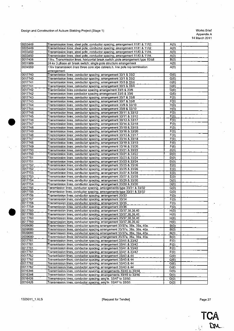
Design and Construction of Auburn Stabling Project (Stage 1)
0003449 Transmission lines; steel pole; conductor spacing; arrangement 11/t1 & 11/t2. 0003449 Transmission lines; steel pole; conductor spacing; arrangement 11/t1 & 11/t2. 0003450 Transmission lines; steel pole; conductor spacing; arrangement 11/t3 & 11!t4. 0003450 Transmission lines; steel pole; conductor spacing; arrangement 11/t3 & 11/t4. 0017406 11 kv. Transmission lines; horizontal break switch; pole arrangement type 10/s8 0001989 24-kv 3 phase air break switch; single pole structure arrangement 0004559 11 kv transmission lines three core xlpe cable/o.h. line pole top termination
arrangement 0017740 Transmission lines; conductor spacing; arrangement 33/1 & 33/2 0017740 Transmission lines; conductor spacing; arrangement 33/1 & 33/2 0017741 Transmission lines; conduCtor spacing; arrangement 33/3 & 33/4 0017741 Transmission lines; conductor spacing; arrangement 33/3 & 33/4 0017742 Transmission lines conductor spacing arrangement 33/5 & 33/6 0017742 Transmission lines conductor spacing arrangement 33/5 & 33/6 0017743 Transmission lines; conductor spacing; arrangement 33/7 & 33/8 0017743 Transmission lines; conductor spacing; arrangement 33/7 & 33/8 0017744 Transmission lines; conductor spacing; arrangement 33/9 & 33/10 0017744 Transmission lines; conductor spacing; arrangement 33/9 & 33/10 0017745 Transmission lines; conductor spacing; arrangement 33/11 & 33/12 0017745 Transmission lines; conductor spacing; arrangement 33/11 & 33/12 0017746 Transmission lines; conductor spacing; arrangement 33/13 & 33/17 0017747 Transmission lines; conductor spacing; arrangement 33/14 & 33/18 0017748 Transmission lines; conductor spacing; arrangement 33/19 & 33/15 0017749 Transmission lines; conductor spacing; arrangement 33/16 & 33/20 0017746 Transmission lines; conductor spacing; arrangement 33/13 & 33/17 0017747 Transmission lines; conductor spacing; arrangement 33/14 & 33/18 0017748 Transmission lines; conductor spacing; arrangement 33/19 & 33/15 0017749 Transmission lines; conductor spacing; arrangement 33/16 & 33/20 0017750 Transmission lines; conductor spacing; arrangement 33/21 & 33/22 0017750 Transmission lines; conductor spacing; arrangement 33/21 & 33/22 0017751 Transmission lines; conductor spacing; arrangement 33/23 & 33/24 0017751 Transmission lines; conductor spacing; arrangement 33/23 & 33/24 0017752 Transmission lines; conductor spacing; arrangement 33/25 & 33/26 0017752 Transmission lines; conductor spacing; arrangement 33/25 & 33/26 0017753 Transmission lines; conductor spacing; arrangement 33/27 & 33/28 0017753 Transmission lines; conductor spacing; arrangement 33/27 & 33/28 0017754 Transmission lines; conductor spacing; arrangement 33/29 & 33/30 0017754 Transmission lines; conductor spacing; arrangement 33/29 & 33/30 0017755 Tansmission lines; conductor spacing; arrangements type 33/31 & 33/32 0017755 Tansmission lines; conductor spacing; arrangements type 33/31 & 33/32 0017756 Transmission lines; conductor spacing; arrangement 33/33 0017757 Transmission lines; conductor spacing; arrangement 33/34 0017758 Transmission lines; conductor spacing; arrangement 33/35 0017759 Transmission lines; conductor spacing; arrangement 33/36 0017760 Transmission lines; conductor spacing; arrangement 33/37,38,39,40 0017760 Transmission lines; conductor spacing; arrangement 33/37,38,39,40 0017760 Transmission lines; conductor spacing; arrangement 33/37,38,39,40 0017760 Transmission lines; conductor spacing; arrangement 33/37,38,39,40 0009080 Transmission lines; conductor spacing arrangement 33/37a, 38a, 39a, 40a. 0009080 Transmission lines; conductor spacing arrangement 33/37a, 38a, 39a, 40a. 0009080 Transmission lines; conductor spacing arrangement 33/37a, 38a, 39a, 40a. 0009080 Transmission lines; conductor spacing arrangement 33/37a, 38a, 39a, 40a. 0017761 Transmission lines; conductor spacing; arrangement 33/41 & 33142 0017761 Transmission lines; conductor sJJ.acing; arrangement 33/41 & 33142 0017761 Transmission lines; conductor sJJ.acing; arrangement 33/41 & 33/42 0017761 Transmission lines; conductor spacing; arrangement 33/41 & 33142 0017762 Transmission lines; conductor spacing; arrangement 33/43 & 44 0017762 Transmission lines; conductor spacing; arrangement 33143 & 44 0017762 Transmission lines; conductor spacing; arrangement 33143 & 44 0017762 Transmission lines; conductor spacing; arrangement 33143 & 44 0016346 Transmission lines; conductor spacing; arrangements 33/45 to 33146 0016346 Transmission lines; conductor spacing; arrangements 33/45 to 33146 0016426 Transmission lines; conductor spacing; arrg'ts. 33/47 to 33/50. 0016426 Transmission lines; conductor spacing; arrg'ts. 33/47 to 33/50.
[Request for Tender)
AO AO AO AO BO AO A(O)
GO GO GO GO G 0) G 0) F(O F(O) H(O H(O) F(O) FO FO FO FO FO F 0) F(O) F(O) F(O) DO DO DO DO EO E(O) E(O) E(O) 0(0) 0(0) G(O) G(O) FO FO FO FO HO HO H 0) H(O) B(O) B(O) BO BO FO FO FO F(O G 0) G 0) G 0) GO) o 0) ~O)
DO DO
Works Brief Appendix A
14 March 2011
Page 27
TeA \)VL ..

Design and Construction of Auburn Stabling Project (Stage 1)
0016426 Transmission lines; conductor spacing; arrg'ts. 33/47 to 33/50. 0016426 Transmission lines; conductor spacing; arrg'ts. 33/47 to 33/50. 0016347 Transmission lines conductor spacing arrangement 33/51 & 33/55 0016348 Transmission lines; conductor spacing; arrangement33/52 0016342 Transmission lines; conductor spacings; arrangements 33/53 & 33/54. 0016342 Transmission lines; conductor spacings; arrangements 33/53 & 33/54. 0016347 Transmission lines conductor spacing arrangement 33/51 & 33/55 0005633 Transmission lines; conductor spacing; arrangement type 33/56. 0012630 Transmission lines; conductor spacing; arrangement 33/58 and 33/59. 0012630 Transmission lines; conductor spacing; arrangement 33/58 and 33/59. 0455661 General hv aerial lines - 33kv polymeric termination underground to overhead (ug/ho)
pole top arrangement 0187043 Transmission lines; conductor spacing; arrangement types 60/c/1 & 60/c/31 0187044 Transmission lines; conductor spacing; arrangement types 60/c/2 & 60/c/2a 0265890 Transmission lines; conductor spacing; arrangement type 60/c/5 0265889 Transmission lines; conductor spacing; arrangement types 60/c/6 & 60/c/33 0187047 Transmission lines; conductor sp_acing; arrangement types 60/c/7 & 60/c/37 0187048 Transmission lines; conductor spacing; arran.gement types 60/c/28 & 60/c/38 0187049 Transmission lines; conductor spacing; arrangement types 60/c/9 & 60/c/39 0187050 Transmission lines; conductor spacing; arrangement types 60/c/10 & 60/c/40 0187052 Transmission lines"; conductor spacing; arrangement types 60lcl11 & 60/c/12 0187052 Transmission lines; conductor spacing; arrangement types 60lcl11 & 60/c/12 0187051 Transmission lines; conductor spacing; arrangement types 60lcl13 0187053 Transmission lines; conductor spacing; arrangement types 60/c/14 & 60/c/15 0187053 Transmission lines; conductor spacing; arrangement types 60/c/14 & 60/c/15 0187054 Transmission lines; conductor spacing; arrangement types 60/c/16 ,
0191668 Transmission lines. Conductor spacing. Arrangement-type 60/c/17m. 0187059 Transmission lines; conductor spacing; arrangement types 60/c/17 & 60/c/18 &
60/c/84 & 60/c/85 0187059 Transmission lines; conductor spacing; arrangement types 60/c/17 & 60/c/18 &
60/c/84 & 60/c/85 0187061 Transmission lines; conductor spacing; arrangement types 60/c/19 & 60/c/86 0188569 Transmission lines; conductor spacing~ arrgt type 60/c/20 -122.-/87.-/89 0187058 Transmission lines; conductor spacing; arrangement types 60/c/21 & 60/c/88 0188569 Transmission lines; conductor spacing~ arrgt type 60/c/20 -122.-/87.-/89 0187060 Transmission lines; conductor spacing; arrangement types 60/c/23 & 60/c/24 0187060 Transmission lines; conductor spacing; arrangement types 60/c/23 & 60/c/24 0187062 Transmission lines; conductor spacing; arrangement types 60/c/27 & 60/c/28 &
60/c/90 & 60/c/91 0187062 Transmission lines; conductor spacing; arrangement types 60/c/27 & 60lcl28 &
60/c/90 & 60/c/91 0187064 Transmission lines; conductor spacing; arrangement types 60/c/29 & 60lcl30 0187064 Transmission lines; conductor spacing; arrangement types 60/c/29 & 60/c/30 0187043 Transmission lines; conductor spacing; arrangement types 60/c/1 & 60/c/31 0187063 Transmission lines; conductor spacing; arrangement types 60/c/32 0265889 Transmission lines; conductor spacing; arrangement types 60/c/6 & 60lcl33 0187054 Transmission lines; conductor spacing; arrangement types 60/c/16 0187045 Transmission lines; conductor spacing; arrangement types 60/c/35 0187046 Transmission lines; conductor spacing; arrangement types 60/c/36 0187047 Transmission lines; conductor spacing; arrangement types 60/c/7 & 60/c/37 0187048 Transmission lines; conductor spacing; arrangement types 60/c/28& 60/c/38 0187049 Transmission lines; conductor spacing; arrangement types 60/c/9 & 60/c/39 0187050 Transmission lines; conductor spacing; arrangement types 60/c/10 & 60/c/40 0187065 Transmission lines; conductor spacing; arrangement types 60/c/41 & 60/c/42 0187065 Transmission lines; conductor spacing; arrangement types 60/c/41 & 60/c/42 0187066 Transmission lines conductor spacing arrangement types 60/c/51 & 60/c/52 0187066 Transmission lines conductor spacing arrangement types 60/c/51 & 60/c/52 0251188 Transmission lines conductor spacing arrangement - types 60/c/53 & 60/c/54 0251188 Transmission lines conductor spacing arrangement - types 60/c/53 & 60/c/54 0251253 Transmission lines conductor spacing arrangement type 60lcl56 0251245 Transmission lines. Conductor spacing. Arrangements type60/c/57 & 60/c/58. 0251245 Transmission lines. Conductor spacing. Arrangements type 60lcl57 & 60/c/58. 0251222 Transmission lines conductor spacing arrangements type 60/c/59 & 60/c/60 0251222 Transmission lines conductor spacing arrangements type 60/c/59 & 60/c/60
[Request for Tender]
TCAI
" ~ . , \1'--. .
DO DO FO CO D 0) D(O) F(O) CO A(O) A(O) A(O)
N(O) C(O B(O D(O G 0) F(O) J(O) G(O) B(O) BO JO BO BO GO CO H(O)
H(O)
M 0) F Ot JiO F(O) D(O) D(O) G(O)
G(O)
D(O D(O N(O) J(O) DO GO MO MO G(O F(O) J(O GO DO DO FO FO EO EO) EO) . DO) DO) D 0) DO)
Works Brief Appendix A
14 March 2011
Page 28

Design and Construction of Auburn Stabling Project (Stage 1)
0251168 Transmission lines conductor spacing arrangement - type 60/c/61. 0251169 TransmissiOn lines conductor spacing arrangement - type 60/c/62 & 60/c/68 0251196 Transmission lines conductor spacin.g arrangement - types 60/c/63 & 60/c/64 0251196 Transmission lines conductor spacinq arranqement - types 60/c/63 & 60/c/64 0251187 Transmission lines conductor spacinq arranqement - types 60/c/65 & 60/c/66 0251187 Transmission lines conductor spacinq arranqement - types 60/c/65 & 60/c/66 0251169 Transmission lines conductor spacinq arranqement - type 60/c/62 & 60/cl68 0251253 Transmission lines conductor spacinq arranqement type 60/c/56 0251032 Transmission lines conductor spacinq. Arranqement - type 60/cl77 & 60/c/78 0251032 Transmission lines conductor spacinq. Arranqement - type 60/c/77 & 60/c/78 0190999 Transmission lines conductor spacinq arranqements types 60/c/80 & 60/cl81 0190999 Transmission lines conductor spacinq arranqements types 60/c/80 & 60/c/81 0190998 Transmission lines conductor spacinq arranqements types 60/cl82 & 60/c/83 0190998 Transmission lines conductor spacinq arranqements types 60/c/82 & 60/c/83 0187059 Transmission lines; conductor spacing; arrangement types 60/c/17 & 60/c/18 &
60/c/84 & 60/c/85 0187059 Transmission lines; conductor spacing; arrangement types 60/cl17 & 60/cl18 &
60/c/84 & 60/cl85 0187061 Transmission lines; conductor spacing; arrangement types 60/cl19 & 60/c/86 0188569 Transmission lines; conductor spacing; arrgt type 60/cl20 -/22.-/87.-/89 0187058 Transmission lines; conductor spacinq; arrqt type 60/c/21 & 60/cl88 0188569 Transmission lines; conductor spacinq; arrqt type 60/cl20 -/22.-/87.-/89 0187062 Transmission lines; conductor spacing; arrangement types 60/cl27 & 60/c/28 &
60/c/90 & 60/cl91 0187062 Transmission lines; conductor spacing; arrangement types 60/cl27 & 60/c/28 &
60/c/90 & 60/cl91 0188929 66kv transmission lines; conductor spacing; arrangement type 60/c/92 0187893 Transmission lines; conductor spacing; arrangement type 60/cl93 - /94 - /95,- /96
0187893 Transmission lines; conductor spacing; arrangement type 60/c/93 - /94 - /95 - /96
0187893 Transmission lines; conductor spacing; arrangement type 60/c/93 - /94 -/95 -/96
0187893 Transmission lines; conductor spacing; arrangement type 60/cl93 - /94 -/95 -/96
0188138 Transmission lines conductor spacing arrgt types 60/cl105 -/106-/107-/108 0188138 Transmission lines conductor spacing arrgt types 60/c/105 -/106-/107-/108 0188138 Transmission lines conductor spacing arrgt types 60/c/105 -/106-/107-/108 0188138 Transmission lines conductor spacing arrgt types 60/c/1 05 -/106-/107-/108 0162690 Transmission lines conductor spacing arrgt. Types 60/c/1 09-/11 0-/117-/118 0162690 Transmission lines conductor spacinq arrqt. Types 60/c/1 09-/11 0-/117-/118 0162691 Transmission lines conductor spacinq arrqt. Types 60/c/111-/112-/119-/120 0162691 Transmission lines conductor spacinq arrqt. Types 60/c/111-/112-/119-/120 0162692 Transmission lines conductor spacing arrgt. Types 60/c/113-/114-/121-/122 0162692 Transmission lines conductor spacing arrgt. Types 60/c/113-/114-/121-/122 0162715 Transmission lines conductor spacing arrgt. Types 60/c/115-/116-/123-/124 0162715 Transmission lines conductor spacing arrgt. Types 60/c/115-/116-/123-/124 0162690 Transmission lines conductor spacing arrgt. Types 60/c/1 09-/11 0-/117-/118 0162690 Transmission lines conductor spacing arrgt. Types 60/c/1 09-/11 0-/117-/118 0162691 Transmission lines conductor spacing. arr:gt. Types 60/c/111-/112-/119-/120 0162691 Transmission lines conductor spacinq arrqt. Types 60/c/111-/112-/119-/120 0162692 Transmission lines conductor spacinq arrqt. Types 60/c/113-/114-/121-/122 0162692 Transmission lines conductor spacing arrgt. Types 60/c/113-/114-/121-/122 0162715 Transmission lines conductor spacing arrgt. Types 60/c/115-/116-/123-/124 0162715 Transmission lines conductor spacing arrgt. Types 60/cl115-/116-/123-/124 0162764 Transmission lines conductor spacing arrangement-type 60/c/125 0162806 Transmission lines conductor spacing arrangement type 60/c/126 0159548 Transmission lines conductor spacing arrgt. Types 60/c/127 -/128-/129-/130 0159548 :rransmission lines conductor spacing arrgt. Types 60/c/127 -/128-/129-/130 0159548 Transmission lines conductor spacingarrgt. Types 60/cl127 -/128-/129-/130 0159548 Transmission lines conductor sQacing arrgt. Types 60/c/127 -/128-/129-/130 0040653 66 kv transmission lines conductor spacing arrangement type 60/c/131 0038901 66kv transmission lines conductor spacinq arran.gement type 60/c/132
[Request for Tender]
F(O) F(O C 0) C(O) E(O) E(O) F(O) E(O) B(O) B(O) A(O) A(O) A(O) A(O) H(O)
H(O)
M(O) F(O) JO F{O G(O)
G(O)
D(O) E(O)
E(O)
E(O)
E(O)
CO) CO CO CO CO C(O D(O) D(O) C(O) C(O) CO CO CO CO DO D(O) C 0) C(O) C(O) CO BO BO BO BO BO BO BO BO
Works Brief Appendix A
14 March 2011
Page 29
., , .... , , ,
TCA' ". t)l\A.

Design and Construction of Auburn Stabling Project (Stage 1)
0052208 General hv aerial lines - 66kv polymeric termination underground to overhead poletop
0003451 Transmission lines; steel pole; conductor spacing; arrangement 66/t1, 66/t2, 66/t3
0003451 Transmission lines; steel pole; conductor spacing; arrangement 66/t1, 66/t2, 66/t3
0003451 Transmission lines; steel pole; conductor spacing; arrangement 66/t1, 66/t2, 66/t3
0003452 Transmission lines; steel pole; conductor spacing; arrangement 66/t4 0003453 Transmission lines; steel pole; conductor spacing; arrangement 66/sdl & 66/sdr 0003454 Transmission lines; steel pole; conductor spacing; arrangement 66/svl & 66/svr 0008908 Transmission lines; conductor spacing; arrangement type 132/1 0008909 Transmission lines; conductor spacing; arrangement type 132/2 0008333 Transmission lines; conductor spacing; arrangement type 132/3 0008423 Transmissiom lines; conductor spacing; arrangement type 132/4 0017446 Transmission lines; conductor spacing - earth wire; ground wire arrangement 0017447 Transmission lines; conductor spacing - earth wire; ground wire arrangement 0017448 Transmission lines; conductor Spaci'lg - earth wire; ground wire arrangement 0017691 Transmission lines; conductor spacinq - earth wire; ground wire arrangement 0003455 Transmission lines; steel pole; earth wire suspension & termination arranqement 0003462 Transmission lines; steel pole; pole steps; typical arrangement & details
132501"1_1.xLS [~equest for Tender]
A(O)
A(O)
A(O)
A(O)
AO AO AO CO CO AO AO BO BO BO A 0) A(O) A(O)
Works Brief Appendix A
14 March 2011
Page 30
•

Design and Construction of Auburn Stabling Project (Stage 1)
Non-RailCorp Standards and Publications Standard Title
General Supply Authority Network Standards Draft Urban Design Guidelines with Young People in Mind, NSW Department of Urban Affairs and Planning, September 1999
BCA Building Code of Australia.2010 AR&R Australia Rainfall and Runoff (Vol 1 and Vol 2)1987
Flood Plain Development Manual NSW Rail Safety Act NSW Occupational Health & Safety Act Rail Safety (Druga& Alcohol Testing) R~ulation2003 ENA C(b)1 - 2006 Guidelines for Design and Maintenance of Overhead Distribution and Transmission Lines ESAA - SUbstation Earthing Guide Disability Discrimination Act, 1992 Disability Standards for Accessible Public Tran~ort, 2002; Health ReQulations Work Cover Guidelines Commonwealth Disability Discrimination Act 1992 and amendments to the BCA in respect of accommodation and access for disabled people Supply Authority Network Standards Local Fire Authority Standards Local Govemment Authority Standards Draft Urban Design Guidelines with Young People in Mind, NSW Department 0
Urban Affairs and PlanninQ, September 1999 NSW Code of Practice Plumbing and Drainage NSW Ministry of Transport Introduction to Graphic Standards for Public Transport Information, 2008 Department of Transport Best Practice Guidelines for Public Transport Signage and Information 2001
Australian Standards AS 622 High Voltage Switchgear and Control gear AS I ACIF S008 Requirements for Customer Cabling Products AS I ACIF S009 Installation requirements for customer cablinilJWirirlfi Rulesl AS 1049 Telecommunication Cables Insulation, Sheath and Jacket AS 1158 LiQhtinQ for Roads and Public Spaces AS 1163 Structural Steel Hollow Sections AS 1170 Structural Design Actions AS 1170.1 Loading Code - Dead and Live Loads AS 1170.2 Loading Code - Wind Loads AS 1170.4 Loading Code - Earthquake AS 1259 Methods for Testing Soils for Engineeri~ PUl"Qoses AS 1288 Glass in buildinQs-Selection and installation AS 1289 Methods of TestinQ Soil for EnQineering Purposes AS 1319 Safety Signs for the Occupational Environment AS 1337 AS 1337 Eye Protectors for Industrial Applications AS 1345 Identification of the contents of pipes, conduits and ducts AS 1428 Design for access and mobility AS 1428.1 Design for access and mobility (General requirements for access, new building work)
AS 1523 Elastomeric Bearings for Use in Structures AS 1538 Cold Formed Steel Structures Code AS 1580 Methods of Tests for Paints and Related Materials AS 1603 Automatic Fire Detection and Alarm ~stems AS 1657 Fixed platforms, walkways, stairways and ladders - Design, construction and
installation. AS 1668 The use of Ventilation and Air Conditioning in Buildings - Fire and Smoke Control in
Multi-compartment Buildings AS 1668.2 Ventilation Design for indoor air contaminant control AS 1670 Fire Detection, Warning, Control and Intercom Systems AS 1670.1 Fire Detection AS 1670.4 Emergency Warning System (EWS)
[Request for Tender]
Works Brief Appendix A
14 March 2011
Page 31
TCA bd\,\.,

Design and Construction of Auburn Stabling Project (Stage 1)
AS 1680 Interior and Workplace LiQhtinQ AS 1726 Geotechnical Site InvestiQations AS 1735 Lifts, Escalators and Moving Walks Part 12 - Facilities for Persons with Disabilities
AS 1742 Manual of uniform traffic control devices. AS 1742.3:2009 Part 3 - Spoil Control Devices for Works on Roads AS 1743 Road signs - Specifications AS 1768 Lightning Protection AS 1801 AS/NZS 1801 Occupational Protective Helmets AS 1851 Maintenance of Fire Protection Systems and Equipment AS 1882 Earth and Bonqing Clamps AS 2053 Conduits and fittings for electrical installations AS 2159 Piling - Design and Installation AS 2201.1 Intruder alarm Systems AS 2208 Safety glazing materials in buildings AS 2210 AS/NZS 2210 Occupational Protective Footwear AS 2220 EWIS Systems AS 2293 Emergency Escape Lighting and Exit Signs for Buildings AS 2293.1 Emergency Escape Lighting and Exit Signs for Buildings AS 2312 Guide to the Protection of Iron and Steel against Exterior Atmospheric Corrosion AS 2327 Composite Construction AS 2374 Power Transformers AS 2441 Fire Hose Reels AS 2444 Portable Fire Extinguishers, Selection and Location AS 24702 Telecommunications installations - Generic Cabling - Industrial Premises AS 2601 The demolition of structures AS 2603 Paints for Steel Structures AS 2673 Paints for Steel Structures - Alkyd Micaceous Iron Oxide AS 2700 Colour standards for general purposes AS 2772.2 1998 Radio Frequency Radiation Part 2 AS 2845.1 Backflow Prevention AS 2870 Residential slabs and footings - Construction AS 2885 Australian Pipeline Standard - Gas and Liquid Petroleum AS 2890 Off Street Car Parking AS 3000 Electrical Installations AS 3008 Low Voltage Installations - Selection of Cables AS 3013 Electrical Installations - Classification of the Fire and Mechanical Performance 0
WirinQ System Elements AS 3080 Telecommunications Installations - Generic CablinQ for Commercial Premises AS 3084 Telecommunications Installations - Telecommunications Pathways and Spaces for
Commercial Buildings AS 3085.1 Telecommunications Installations - Administration of Communications Cabling
Systems AS 3260 Approval and Test Specification Safety of Information Technology Equipment
IncludinQ Electrical Business Equipment AS 3439 Low VoltaQe SwitchQear and Control-Qear Assemblies AS 3500 PlumbinQ and DrainaQe Code AS 3500.1 Water Supply AS 3500.2 Sanitary Drainage AS 3500.3 Stormwater AS 3500.4 Hot Water AS 3548 Electrical Interference - Limits and Methods of Measurements of IT Equipment AS 3600 Concrete Structures Code AS 3610 Formwork for concrete AS 3678 Structural Steel Plates, Floor Plates and Slabs AS 3679.1 Hot Rolled Structural Steel Bars and Section AS 3679.2 Structural Steel - Welded Sections AS 3700 Masonry structures AS 3725 Loads on Buried Concrete Pipes AS 3750 Paints for Steel Structures AS 3799 Liquid Membrane - Forming Curing Compounds for Concrete AS 3902 Quality Systems for Production and Installation AS 3990 Steelwork for Engineering Applications AS 4020 Products for use in contact with drinking water
[Request for Tender]
.TCA , . f ....
~~
Works Brief Appendix A
14 March 2011
Page 32

Design and Construction of Auburn Stabling Project (Stage 1)
AS 4058 Precast Concrete Pipes AS 4100 Steel Structures Code AS4251.1 Electromagnetic Compatibility - Generic Emission Standard - Residential,
Commercial & Light Industry AS 4282 Control of the obtrusive effects of outdoor lighting AS 4292 Railway Safety Management AS 4308. AS/NZS 4308:2008 Procedures for Specimen Collection and the Detection and
Quantitation of Drugs of Abuse in Urine AS 4360 Risk Management AS 4419 Soils for Landscaping and Garden use AS 4431 Guidelines for Working on New Lift Installations AS 4454 Composts Soil Conditioners and Mulches AS 4536 Life Cycle Costing AS 4586 Slip resistance classification of new p_edestrian surface materials AS 4602 AS 4602 High Visibility Safety Garments AS 4678 Earth-Retaining Structure AS 4799 Installation of underground utility services and pipelines within railway boundaries AS 4806 Closed Circuit Television AS 5100 Bridqe Desiqn Code AS 60076 Power Transformers AS 60947 Low Voltage Switchgear and Control gear AS 61935-1 Testing of Balanced Communication Cabling AS 61935-2 Testing of Patch Cords and Work Area Cords AS ISO 1000 The International system of units (SI) and its application AS ISO 14001 2004 - Environmental Management Systems - Requirements with Guidance for Use
TeA CS-FO-032 TCA System Deficiency Notice (CS-FO-032) CS-FO-033 TCA System Improvement Observation (CS-FO-033) EN50126 Safety Assurance EN20128 Railway applications - Communications, Signalling and Processing Systems -
Software for Railway Control and Protection Systems EN-PR-125 TCA Operational Readiness and Commissioninq Procedure EN-PR-130 TCA Interim Asset Handover Procedure for Infrastructure EN-PR-184 TCA Buildinq Certification Procedure EN-SD-018 TCA Guide to Environmental Design Constraints Map (EN-SD-018), clauses 1, 2 and
3 EN-SD-033 TCA Operational Readiness Plan EN-SD-034 TCA Commissioning Manaqement Plan EN-ST-043 TCA Operational Readiness and Commissioning Management Standard EN-ST-084/1.0 TCA CAD Protocol Revision, Version: 1.0, Date of Issue: 11 December 2008 PE-FO-077 TCA Environmental Non-Compliance Report (PE-FO-077) . PE-FO-080 TCA Out of Hours Work Application Form (PE-FO-080) PE-FO-101 TCA Community and Environmental Incident Report (PE-FO-101) PE-PO-002 TCA Environmental Policy (PE-PO-002) PE-PR-065 TCA Out-of-Hours Assessment (PE-PR-065) PE-PR-105 TCA Environmental Incident Reporting Procedure (PE-PR-105) PE-SD-012 TCA Guide to Compliance Monitoring and Reporting Using PECOMS Procedure (PE-
SD-012) PE-SD-015 TCA Guide to Environmental Control Maps (PE-SD-015) SA-FO-002 TCA Initial Safety Occurrence Report (SA-FO-002) SA-FO-105 TCA Work Activity Advice (SA-FO-105) SA-PO-001 TCA Safety Policy (SA-PO-001) SA-ST-005 TCA Safety Inspections (SA-ST-005) I SA-ST-005 TCA Safety Traininq, Competence and Accountabilities (SA-ST-004) SA-PR-085 Sub-referenced TCA Testinq for Alcohol and Other Druqs (SA-PR-085) SP-001/2.0 Vertical Transportation Lift Specification TSRA1 Asset Management Information (RaiICorp) TSRA2 Asset Management Information (Non-RaiICorp) TSRC1 Communications and Community Liaison TSR E1 Environmental Management System TSR01 Operational Readiness and Commissioning TSRQ1 Quality Management System TSRS1 Safety Management System
1325011_1.XLS [Request for Tender]
Works Brief Appendix A
14 March 2011
Page 33
TCA ~\.

Design and Construction of Auburn Stabling Project (Stage 1)
TSRT1 Technical Manaqement TSRSIGN Siqnallinq
TCA Enqineerinq Manaqement Manual TCA CAD Manual Revision 12 TCA Corporate Identity Style Guide TCA's Construction Noise Strateqy 2007
Other Standards ISO 17123-2 Optics and optical instruments - Field procedures for testing geodetic and surveying
instruments - Part 2: Levels ISO 17123-3 Optics and optical instruments - Field procedures for testing geodetic and surveying
instruments - Part 3: Theodolites IS011801 INFORMATION TECHNOLOGY - GENERIC CABLING FOR CUSTOMER
PREMISES IS07730 Ergonomics of the thermal environment - Analytical determination and interpretation
of thermal comfort ~sing calculation of the PMV and PPD indices and local thermal comfort criteria
ISO 9001 2008 Quality Management Systems - Requirements ISO 9000 2005 Quality Management Systems - Fundamentals and Vocabulary
EMR mitigation shall use the guidelines provided in National Health and Medical Research Council: Radiation Health Series No. 30: Interim Guidelines on Limits of Exposure to 50/60 Hz Electrical and Magnetic Fields (1989) Water Supply Code of Australia, Sydney Water Edition, WSA03 2002 Sewerage Code of Australia, Sydney Water Edition, WSA02, 2002 Utility Authority regulations, policies, guidelines and requirements
NFPA130 NFPA Standard for Fixed Guideway Transit and Passenger Rail ISO 14763-3 Telecommunications Installations - Testing of Optical Fibre Communication Cabling
CPCMACA Customer Premises Cablinq Manual S 001 Safety Requirements for Customer Equipment AS/ACIF S008 Requirements for Customer Cabling Products AS/ACIF S009 Installation Requirements for Custom Cabling (Wiring Rules) ACA TCPR 2000 Communications Cabling Provider Rules 2000 ACACRCPR Competency Requirements for Cabling Provider Rules 2000 2000 SM1600 Bridge Code HB197 An introductory guide to the slip resistance of pedestrian surface materials ITU G.652/D Fibre cable
EGI Energy Supply Association (ESAA) "Substation Earthing Guide" NSW Government Aboriginal Participation in Construction Guidelines NSW Government Industrial Relations Management Guidelines NSW Government Training Management Guidelines Protection of the Environment Administration Act 1991 (NSW) Protection of the Environment Operations Act 1997 (NSW) Rail Safety (General) Regulation 2008 (NSW) Roads Act 1993 (NSW) Environmental Planning and Assessment Act 1979
AM 9995 PM Rail Infrastructure Corporation Maintenance Requirements Analysis Manual (AM 9995 PM)
TO 2003/RS03 RTA Technical Direction for Road Safety Practitioners (TO 2003/RS03) National Standard for the Health Assessments of Rail Safety Worker NSW Government Code of Practice for Procurement NSW Govemment Guidelines for Auditing· Project OHS Management Plans NSW Government Occupational Health and Safety Management System Guidelines
Occupational Health and Safety Act 2000 (NSW) Occupational Health and Safety Regulation 2001 (NSW); Rail Safety Act 2008 (NSW) State Records Act NSW Govemment Environmental Management System Guidelines Protection of the Environment Operations Act (1997) Environmental Planning and Assessment Regulation 2000 WorkCover NSW Code of Practice Tunnels under Construction "Fish note - Policy and Guidelines for Fish Friendly Waterway Crossings" NSW Fisheries, November 2003
[Request for Tender]
Works Brief Appendix A
14 March 2011
Page 34
•

• 1
Design and Construction of Auburn Stabling Project (Stage 1)
"Why do fish need to cross the road? Passage Requirements for Waterway Crossings". NSW Fisheries, January 2003 NSW Worksafe NSWDoP CPTED (Crime Prevention Through Environmental Design) RailCorp Maintenance Compendium
Austroads AGRD01/06 Part 1: Introduction to Road Design AGRD02/06 Part 2: Design Considerations AGRD03/09 Part 3: Geometric Design AGARD04/09 Part 4: Intersections and Crossings - General AGRD04A109 Part 4A: Un-signalised and Signalised Intersections AGRD04B/09 Part 4B: Roundabouts AGRD04C/09 Part 4C: Interchanges AGRD05/08 Part 5: Drainage Design AGRD06/09 Part 6: Roadside Design, Safety and Barriers AGRD06A109 Part 6A: Pedestrian and Cyclist Paths AGRD06B/09 Part 6B: Roadside Environment AGRD07108 Part 7: Geotechnical Investigation and Design AGRD08/09 Part 8: Process and Documentation British Standards BS 8002 Code of Practice for Earth Retaining Structures; BS 8004 Code of Practice for Foundations; BS 8006 Code of Practice for Strengthened Reinforced Soils and Other Fills; BS 8081 Code of Practice for Ground Anchors; and BS 8110 Structural Use of Concrete (to be used for crack width calculations only).
British Tunnelling Society and Institution of Civil Engineers - Specification for Tunnelling, 3rd Edition 2010
American Standards ASTM A.820-90 Standard Specification for Steel Fibres for Fibre Reinforced Concrete; ASTM C.309-989 Standard Specification for Liquid Membrane - Forming Compounds for Curing
Concrete AC1506R-90 Guide to Shotcrete. Eurocodes EC7 Eurocode 7 Part 1 Geotechnical Design General Rule
I External AQency Standards NSW Department of Environment and Conservation
!interim Guidelines for the Assessment of Noise from Rail Infrastructure Projects National Fire Protection Agency (NFPA)
INFPA130-2007 Department of Commerce
Information and Requirements for construction of GRN sites (GRN Enhancements)
Telstra DCRB009 DAS Design Specification In-buildinR Coverage DCRB022 Passive Intermodulation Considerations Combining CDMA and GSM on a Passive
DAS NSW Ministry of Transport
IGuidelines for the Development of Public Transport Interchange Facilities Australian Government
Disability Standards for Accessible Public Transport Disability_Standards for Accessible Public Transport Guidelines Disability Standards for Accessible Public Transport Disability Standards for Accessible Public Transport Guidelines
WorkCover ICHAIR Safety In Design Tool
1325011_1.XLS [Request for Tender]
Works Brief Appendix A
14 March 2011
Pag~ 35

Design and Construction of Auburn Stabling Project (Stage 1)
RTA Standards RTA Road Design Guide
Soils and Construction - Volume 1 - 4th Edition March 2004 RTA R2 Erosion & Sediment Control (temporary) RTA R11 Stormwater Drainage RTA R15 Kerb & Gutter RTA R23 UPVC Pipes" RTA R32 Subsurface Drainage - Materials" RTA R33 Trench Drains" RTA R44 Earthworks RTA R71 Unbound and Modified Pavement Course RTA R53 Concrete (for General Use) - Mortar & Grout" RTA R106 Sprayed Bituminous Surfacing (with Cutback Bitumen) RTA R116 Asphalt (Dense graded and Open Graded) RTA R141 Pavement Markings RTA R142 Raised Pavement Markers RTA R143 Sign posting RTA R173 General Concrete Paving RTA R3051 Unbound and modified base and sub-base materials for surfaced road pavements RTA B30 Excavation and Backfill for Bridge Foundations RTA B58 Permanently Cased Cast-in-Place Reinforced Concrete Piles RTA B59 Bored Cast-in-Place Reinforced Concrete Piles (without Permanent Casil!9l RTA B80 Concrete Work for BridQes RTA B82 Shotcrete Work RTA B204 Welding of Bridges and Other Road Structures RTA B220 Protective Treatment of Steelwork RTA B260 Erection of Structural Steelwork RTA B280 Unreinforced Elastomeric Bearing Pads and Strips RTA B281 Laminated Elastomeric Bearings RTA B282 Confirmed Elastomeric (Pot Type) Bearings RTA B344 Bituminous Waterproof Membrane for Concrete Bridge Decks
RTA Technical Direction for Road Safety Practitioners (TO 2003/RS03) RTA Road Accident Reduction Guide, Part 2: Road Safety Audits.
[Request for Tender]
TCA .: ••. J ~
f" ,t.- V'''''
Works Brief Appendix A
14 March 2011
Page 36

· "1 Transport NSW Construction GOVERNMENT Authority
Appendix B Not Used
AARLEG-#18499703-vl-Au burn_ TCA_ Works_BrieC210611. DOC
D&C Contract for Auburn Stabling Project (Stage 1) Works Brief
TCA

TCA~ , ,

.1t~~~\1.1 Transport ~Vb> Construction !!~Y,i Authority
Appendix C Interface Schedule
AARLEG-#18499703-vlAuburn3CA_Works_BrieC210611.DOC
D&C Contract for Auburn Stabling Project (Stage 1) Works Brief
TCA ".~

/TCA /. ,~~

.4
Design and Construction of Aubum Stabling Project (Stage 1)
Appendix C1- Interface Schedule (excludes Signalling)
Works Brief Appendix C
18 March 2011
The Contractor is responsible for the construction, installation, testing and commissioning of the Works except where identified as the responsibility of RailCorp in this Appendix C1. This
Appendix C1 is not an exhaustive list of the Works. The Principal and RailCorp wiil undertake those activites identified as the responsibility of the Principal and/or RailCorp. The Contractor
must undertake all activites required to complete ali other parts of the Works in accordance with the Deed including the Works Brief, whether identified in this Appendix C1 as the Contractor's
responsibility or not so identified.
Task Interface Responsibility
Number Works Description General
Design to integrate existing RailCorp communications system with the Works
COM1 RailCorp
COM2 Provide programming of telephone exchange at Clyde Exchange RailCorp
COM3 Provide programming of LAN switching RailCorp
COM4 All cable testing Contractor
PASystem Provision, installation, configuration and commissioning of OVA, DSP, PA
COM5 system including microphones with base and preamplifiers, amplifiers and Contractor speakers
COM6 EquipmenVcabling,lpathways/outlets labelling plan Contractor
COM7 Ca bl e testi ng Contractor
COM8 Preparation of design and support documentation and drawings Contractor
Installation, termination, testing and labelling of structured (UTP, MMOF) and
COM9 building (PA audio, tamper, telephone, CCTV coaxial and ELV DC) cabling Contractor
COM10 Preparation of test procedures for the commissioning of PA, Access Control and
Contractor Alarm systems
Provision of 45RU Racks in Equipment Room for Communications and SPI/PA. All Racks will be supplied with racks accessories - shelves, power boards,
COM11 equipment and services. Additional racks for CCTV equipment to be supplied as earth bars, captive power outlets and cable management. Contractor required by ADT.
CCTV
[Request for Tender]

TCA . . '\- \
. j:~

Design and Construction of Auburn Stabling Project (Stage 1) Works Brief Appendix C
18 March 2011
Appendix C1-lnterface Schedule (excludes Signalling)
The Contractor is responsible for the construction, installation, testing and commissioning of the Works except where identified as the responsibility of RailCorp in this Appendix Cl. This
Appendix Cl is not an exhaustive list of the Works. The Principal and RailCorp will undertake those activites identified as the responsibility of the Principal and/or RailCorp. The Contractor
must undertake all activites required to complete all other parts of the Works in accordance with the Deed including the Works Brief, whether !dentified in this Appendix Cl as the Contractor's
responsibility or not so identified.
Task Interface Responsibility
Number Works Description Design for the location of CCTV cameras at the Stabling yard, Staff facilities and Security system designer shall hold a 2A security licence ( 2A - Security amenities building and car park precinct (in conjunction with Design Reports, Consultant Authorises the licensee to act as a consultant by identifying and
COM12 (ASP-1333-RD-0040-SE-1313, 1314, 1315, 1316, 1425 and 1430) analysing security risks and providing solutions and strategies to minimise Contractor those risks (includes security site and risk assessments)
COM13 CCTV Rack Layout design RailCorp
COM14 Provision and installation of power circuit to CCTV rack Contractor COM15 Termination of CCTV RailCorp COM16 Testing and Commissioning of CCTV system RailCorp
Provision and installation of mounting hardware for CCTV cameras in the COM17 stabling yard, car park, staff facilities building and staff amenities building Contractor
COM18 Provision and installation of CCTV poles, cable route, installation of cables,
Contractor access pits
COM19 Provi?ion, installation and commissioning of all CCTV cameras and Rack
RailCorp mounted equipment
COM20 Provision of monitors and local equipment such as controllers RailCorp COM21 Provide network connectivity and testing to GRML RailCorp
COM22 CCTV cables for cameras, power, tamper, controller, monitors and links to PA
Contractor OVA and Intruder Alarm systems
Intruder Alarm System
COM23 Provision and installation of mounting hardware for Intruder Alarm System
Contractor
COM24 Provision of communications link cable for Intruder Alarm System to MDF
Contractor
COM25 Provision of communications link for Intruder Alarm System from RailCorp
RailCorp
COM26 Mounting Alarm System Controller on a wall in Communications Equipment
Contractor Room
Access Control System
[Request for Tender] 2

TCA

Design and Construction of Auburn Stabling Project (Stage 1) Works Brief Appendix C
18 March 2011
Appendix C1- Interface Schedule (excludes Signalling)
The Contractor is responsible for the construction, installation, testing and commissioning of the Works except where identified as the responsibility of RailCorp in this Appendix C1. This
Appendix.C1 is not an exhaustive list of the Works. The Principal and RailCorp will undertake those activites identified as the responsibility of the Principal and/or RailCorp. The Contractor
must undertake all activites required to complete all other parts of the Works in accordance with the Deed including the Works Brief, whether identified in this Appendix C1 as the Contractor's
responsibility or not so identified.
Task Interface Responsibility
Number Works Description
Design, supply and installation of Access Control system at Staff Amenities Security system designer shall hold a 2A security licence (2A - Security Building, staff facilities and vehicle pedestrian gates. Consultant Authorises the licensee to act as a consultant by identifying and
COM27 analysing security risks and providing solutions and strategies to minimise Contractor those risks (includes security site and risk assessments))
COM28 Testing of cables, configuration of system, function testing, commissioning
Contractor
COM29 Provision of communications link cable for Access Control System to MDF
Contractor
COM30 Provision of communications link for Access Control System from RailCorp
RailCorp
COM31 Testing of link to central DSX server ASP to patch the cables from MDF to Clyde Warehouse and RailCorp to
Contractor RailCorp . connect to the DSX exchange at central
COM32 Provision of network connectivity RailCorp
COM33 Mounting Access System Controller on a wall in the communications Equipment
Contractor Room
Precise Clocks and PA system
COM34 Design for the location of SPI rack and Precise Clock installation within the staff
Contractor facilities building
COM35 Provision and installation of optical fibre wall mounted enclosures for
Contractor termination of MMOF cables for Precise Clocks
COM36 Supply, testing and installation of MMOF patch cables Contractor
COM37 Testing and commissioning of SPI Precise Clocks ASP to provide the details of cable schedule to allow RailCorp to commission
RailCorp
COM38 Supply of Precise Clocks and associated SPI equipment for functionality.
RailCorp
COM39 Mounting Hardware, installation and termination of Precise clocks, SPI rack
Contractor and MMOF
COM40 Installation of cables for network connectivity for SPljLLPA to Patch Panel
Contractor
[Request for Tender] 3

,e
TCA ~

Design and Construction of Auburn Stabling Project (Stage 1) Works Brief Appendix C
18 March 2011
Appendix C1- Interface Schedule (excludes Signalling)
The Contractor is responsible for the construction, installation, testing and commissioning of the Works except where identified as the responsibility of RailCorp in this Appendix C1. This
Appendix C1 is not an exhaustive list of the Works. The Principal and RailCorp will undertake those activites identified as the responsibility of the Principal and/or RailCorp. The Contractor
must undertake all activites required to complete all other parts of the Works in accordance with the Deed including the Works Brief, whether identified in this Appendix C1 as the Contractor's
responsibility or not so identified.
Task Interface Responsibility
Number Works. Description
COM41 Provision of links for network connectivity for SPIjLLPA from RailCorp RailCorp
COM42 Design of PA system and racks layout Contractor
COM43 - Design of SPI rack layout including precise clocks RailCorp
Communications System
Supply, install and test all telephone and LAN cabling from the pat~h panel in
COM44 communications rack in Equipment Room to Telecommunications O,utlets Contractor
COM45 Communications Rack Layout Design RailCorp
COM46 Install wall mounted MDF cabinet in Equipment Room Contractor
COM47 Provision and installation of cable ducts, cable trays, and conduits from the
Equipment Room to all equipment locations Contractor
Design of Equipment Room including provision and installation of
COM48 Telecommunications Earthing System, cable ducts, cable trays and conduits Contractor
within the Equipment Room.
COM49 Provision of surge arrestors for lighting protection on RailCorp telephony circuits Lighting protection will be provided only for lead-in copper cables (RailCorp
RailCorp and Telstra)
COM50 Install tie cables between rylDF and communications rack patch panels,
Contractor terminate and test
COM51 Provision, installation and testing of all Telephone and LAN circuits RailCorp
Installation, termination, testing and labelling of RailCorp lead-in 24 core SMOF COM52 and 50pr/O.9 copper cables at Clyde Warehouse RailCorp
Supply, Install, terminate, test and label of RailCorp lead-in 24 core SMOF and
COM53 50pr/O.9 copper cables at Communications Room in Staff Facilities Building Contractor
COM54 Supply, Install and configure active Communications Equipment into Equipment
RailCorp Rack
Local Area Network
Provision of Termination Outlet for all computers in all work areas including
COM55 provision of CAT5 and MMOF cabling from Equipment Room (Includes staff Contractor amenities building and staff facilities building)
[Request for Tender] 4

:' TCA "N\.A
~, """'-" ' ."." ,i

Design and Construction of Auburn Stabling Project (Stage 1) Works Brief Appendix C
18 March 2011
Appendix C1- Interface Schedule (excludes Signalling)
The Contractor is responsible for the construction, installation, testing and commissioning of the Works except where identified as the responsibility of RailCorp in this Appendix Cl. This
Appendix Cl is not an exhaustive list of the Works. The Principal and RailCorp will undertake those activites identified as the responsibility of the Principal and/or RailCorp. The Contractor
must undertake all activites required to complete all other parts of the Works in accordance with the Deed including the Works Brief, whether identified in this Appendix Cl as the Contractor's
responsibility or not so identified.
Task Interface Responsibility
Number Works Description
COM56 Supply, install, configure, connect and test Administration Computers.
RailCorp
COM57 Supply, install, configure, connect and test LAN Computers RailCorp
COM58 Supply, install, configure, connect and test Network Switches RailCorp
COM59 Supply, install, configure, connect and test Network Printers RailCorp
Communications Backbone Systems Modification of existing (live) MDFs and communications compartments
COM60 including provision of back mounted panels, Krone Blocks, Test Modules as RailCorp
required
Backbone cable installation Contractor to coil the cables and place them to the nearest pit at the Clyde
COM61 Warehouse and CSR interface pit to CL115 as shown on Drawing ASP-1333-
Contractor RD-0040-CS-1315 . Drawings can be found in Exhibit J PrinCipal's Design.
COM62 Backbone cable termination in live locations RailCorp
COM63 All cable termination in new locations Contractor
COM64 Cable jointing/splicing in live locations Live locations are points where ASP cable is interfacing live RailCorp Network
RailCorp
COM65 Cable jointing/splicing in new locations Contractor
COM66 Testing of all installed cables Contractor
COM67 Testing after jointing/splicing with live parts of cabling RailCorp
COM68 CommiSSioning including circuits verification RailCorp
Provision, installation and commissioning of Dial in Modems in Signalling
COM69 Equipment Room for diverse connection to Clyde Warehouse and CL115 - RailCorp (ASP/LGCUP interface Pit).
Commissioning of diverse communications Links from Signalling Equipment
COM70 Room to Clyde Warehouse and CL115 (ASP/LGCUP interface pit) RailCorp
Fire Indication Panel
COM71 Supply, install and test fire indication panel and connecting cabling to PA,
Contractor Intrude'r Alarm and MDF equipment
[Request for Tender] 5

·TCA , ,

-I OQ ~ .~
Design and Construcfion of Auburn Stabling Project (Stage 1) Works Brief Appendix C
18 March 2011
Appendix C1- Interface Schedule (excludes Signalling)
The Contractor is responsible for the construction, installation, testing and commissioning of the Works except where identified as the responsibility of RailCorp in this Appendix C1. This
Appendix C1 is not an exhaustive list of the Works. The Principal and RailCorp will undertake those activites identified as the responsibility of the Principal and/or RailCorp. The Contractor
must undertake all activites required to complete all other parts of the Works in accordance with the Deed including the Works Brief, whether identified in this Appendix C1 as the Contractor's
responsibility or not so identified.
Task Interface Responsibility
Number Works Description
COM72 Design, supply, Installation and commissioning of the Fire System at Staff
Contractor Facilities and Staff Amenities Building.
COM73 Provision and installation of mounting hardware for Fire System Contractor
COM74 Mounting Fire System Panel on a wall as specified by the BCA consultant
Contractor (Reception area or security desk)
COM75 Provision of a communication link to PA system for evacuation purposes
Contractor
COM76 Provision of communications link for Fire System and Alarm condition to RMC
RailCorp
COM77 Provision of communications link for Fire System and Alarm condition to Fire
RailCorp Brigade
COM78 Provision of interconnection of c;ommunications link for Fire System and Alarm
Contractor condition to RMC
COM79 Provision of interconnection of communications link for Fire System and Alarm
Contractor condition to Fire Brigade
1 Utilities Utilities - Ch 19.800km
Runs along boundary fence to MainTrain Training Room. Needs investigation.
U1.28 Possible relocation of 20 (LV) at Ch 19.800km - 19.850km May be impacted by retaining wall. DWG Ref: UT-313, AMF DSS Sheet 11 of
Contractor 12, Sheet 13 of 34. Drawings can be found in Attachment A to this Appendix
C.
Possible relocation of 235U (DRE) Drainage Pipe and stormwater from car Needs investigation. Confirm location and depth where it crosses under
U1.32 proposed ASP track alignment. DWG Ref: UT-1313 and UT-1314. Sheets 12, Contractor turning loop at Ch 20.040km (APPROX)
14 of 34. Drawings can be found in Attachment A to this Appendix C.
Runs from Manchester Rd to Substation in MainTrain. Will require reloc'!tion
U1.33 Pole relocation and burial of OH Feeder 234 (PG33) x 2. AERIAL. (106) and (21) of two poles and burial into underground HV route through ASP. Refer to 6.1
Contractor o.n RC DSS at Ch 20.040km - 20.250km (APPROX) and 6.2 for specific impacts. DWG Ref: Sheets 11, 12, 15, 16, and 23 of 34.
UT-1313/14. Drawings can be found in Attachment A to this Appendix C.
[Request for Tender] 6

I
, e I

Design and Construction of Auburn Stabling Project (Stage 1) Works Brief Appendix C
18 March 2011
Appendix C1- Interface Schedule (excludes Signalling)
The Contractor is responsible for the construction,Instaliation, testing and commissioning of the Works except where identified as the responsibility of RailCorp in this Appendix Cl. This
Appendix Cl is not an exhaustive list of the Works. The Principal and RailCorp will undertake those activites identified as the responsibility of the Principal and/or RailCorp. The Contractor
must undertake all activites required to complete all other parts of the Works in accordance with the Deed including the Works Brief, whether identified in this Appendix Cl as the Contractor's
responsibility or not so identified.
Task Interface Responsibility
Number Works Description
Runs from MainTrain Substation. Possible relocation required. DWG Ref: U1.34 Possible relocation of 20 (LV) at Ch 20.040km - MainTrain Fence Sheets 11 and 12 of 34. Drawings can be found in Attachment A to this Contractor
Appendix C.
Possible relocation of 235 (ORE) Drainage Pipe at Ch 20.300km - 20.330km Needs investigation. Confirm location and depth. Crosses under proposed
U1.35 (APPROX)
track alignment. DWG Ref: Sheet 17,18,21,22 of 34. UT-0314.Drawings can Contractor
be found in Attachment A to this Appendix C.
Needs investigation. Confirm location and depth. Passes near proposed
Possible relocation (5) (Copper comms- direct buried) at Ch 20.300. Corner of retention pond. Possibly splits in two; according to JH As-builts. Runs to
U1.36 AMC and MainTrain.
MainTrain Substation. DWG Ref: Sheet 11,12,15,16,17 of 34.KBR-DRG-SG- Contractor CVL-2312. UT-0314. Drawings can be found in Attachment A to this Appendix
C.
Needs investigation. Confirm location and depth. Pole and earth grid in
U1.37 Possible relocation (106 to 24) (HV-Aerial to HV-Pipe), 234 on Utilities, at Ch proposed detention pond. May need relocation or re-design of detention
Contractor 20.300 Cnr of AMC and MainTrain pond. Supply feeds into items 1.33 and 1.34. DWG Ref: Sheet 16,17, 18 of
34. UT-0314. Drawings can be found in Attachment A to this Appendix C.
U1.38 Possible Relocation of 220U (Water-unknown) at Ch 20.300, corner of AMC and Needs investigation. DWG Ref: Sheet 16,17 of 34. Drawings can be found in
Contractor MainTrain. Attachment A to this Appendix C.
U1.39 Possible Relocation of 20 (LV-Pipe) at Ch20.300, corner of AMC and Potentially redundant. Needs investigation. DWG Ref: Sheet 17 of 34.
Contractor MainTrain. Drawings can be found in Attachment A to this Appendix C.
U1.40 Possible Relocation of 235U (Drainage -Pipe) at Ch 20.300, corner of AMC and Needs investigation. DWG Ref: Sheet 17,18 of 34. Drawings can be found in
Contractor MainTrain. Attachment A to this Appendix C.
Needs investigation. May have been removed now that John Holland have U1.41 Possible relocation of 20 (LV) at Ch 20.300 between AMC and JH Offices left. DWG Ref: Sheet 21 of 34. Drawings can be found in Attachment A to Contractor
this Appendix C.
NOTE: Previously supplied John Holland offices. Crosses under proposed U1.42 Possible relocation of 207 (TLS) at Ch 20.325km (APPROX) stabling area towards Manchester Rd. DWG Ref: Sheet 22,23 of 34. Contractor
/ Drawings can be found in Attachment A to this Appendix C.
[Request for Tender] 7

" I , •

Design and Construction- of Auburn Stabling Project (Stage 1) Works Brief Appendix C
18 March 2011
Appendix C1- Interface Schedule (excludes Signalling)
The Contractor is responsible for the construction, installation, testing and commissioning of the Works except where identified as the responsibility of RailCorp in this Appendix Cl. This
Appendix Cl is not an exhaustive list of the Works. The Principal and RailCorp will undertake those activites identified as the responsibility of the Principal and/or RailCorp. The Contractor
must undertake all activites required to complete all other parts of the Works in accordance with the Deed including the Works Brief, whether identified in this Appendix Cl as the Contractor's
responsibility or not so identified.
Task Interface Responsibility
Number Works Description
NOTE: Previously supplied John Holland offices. Crosses under proposed
Ul.43 Possible relocation of 220 (WT,,) at Ch 20.325km (APPROX) stabling area towards Manchester Rd. DWG Ref: Sheet 22,23 cif 34. Contractor
Drawings can qe found in Attachment A to this Appendix C.
Will require relocation of SW pits away from new track alignment. DWG Ref:
Ul.44 Possible relocation of SW pits x 3 at Ch 20.150km, 20.185km, 20.215km KBR-DRG-SG-CVL-2314. Sheet 26 of 34. Drawings can be found in Contractor
Attachment A to this Appendix C.
HV Conduits supply AMC. Should be-OK.- May need protection or be
Ul.45 Possible relocation/protection of HV Conduits. (200U) PL33 EXT on RC DSS at redundant. Needs further investigation. Potentially same service as item
Contractor New Entrance Gate. 1.94. DWG Ref: KBR-DRG-SG-CVL-2315. Sheet 22,23 of 34. TR - 1315/16.
Drawings can be found in Attachment A to this Appendix C.
Not shown in AMC As-builts. Needs further investigation. DWG Ref: KBR-DRG Ul.46 Possible Relocation of 20 (LV-Pipe) at Ch 20.200km between Pits. SG-CVL-2314. Sheet 26 of 34. UT-1316. Drawings can be found in Contractor
Attachment A to this Appendix C.
May be redundant. Needs further investigation. Refer item 1.98. DWG Ref: Ul.47 Possible Relocation of 221 (SWR-unknown) at Ch 20.440km. KBR-DRG-SG-CVL-2314. Sheet 26 of 34. UT-0316. Drawings can be found in Contractor
Attachment Ato this Appendix C. Utilities - Ch 20.460km
Ul.48 Possible relocation of FEW (FireServices) at Ch 20.475km (APPROX) NOTE: AMC utility. DWG Ref: KBR-DRG-SG-CVL-2314. UT-1315 RailCorp
Ul.49 Possible relocation of W (Water Rising Main) at Ch 20.475km (APPROX) NOTE: AMC utility. DWG Ref: KBR-DRG-SG-CVL-2314. UT-1315 RailCorp
Ul.50 Possible relocation of SRM (Sewer Rising Main) at Ch 20.4 75km (APPROX) NOTE: AMC utility. DWG Ref: KBR-DRG-SG-CVL-2314. UT-1315 RailCorp
Ul.51 Possible relocation of FH (Fire Hydrant) at Ch 20.475km (APPROX) NOTE: AMC utility. DWG Ref: KBR-DRG-SG-CVL-2314. UT-1315 RailCorp
Ul.52 Possible relocation of SGL (Sewer Gravity Line) at Ch 20.4 75km (APPROX) NOTE: AMC utility. D,WG Ref: KBR-DRG-SG-CVL-2314. UT-1315 RailCorp
Ul.53 Possible relocation of LV (Low Voltage Conduit) at Ch 20.500km (APPROX) NOTE: AMC utility. DWG Ref: KBR-DRG-SG-CVL-2314. UT-1315 RailCorp
Ul.54 Possible relocation of C (Communications) at Ch 20.500km (APPROX) NOTE: AMC utility. DWG Ref: KBR-DRG-SG-CVL-2314. UT-1315 RailCorp Ul.55 Possible relocation of D (Data cable) at Ch 20.500km (APPROX) NOTE: AMC utility. DWG Ref: KBR-DRG-SG-CVL-2314. UT-1315 RailCorp
[Request for Tender] 8

_I
. I

.-
Design and Construction of Auburn Stabling Project (Stage 1) Works Brief Appendix C
18 March 2011
Appendix C1-lnterface Schedule (excludes Signalling)
The Contractor is responsible for the construction, installation, testing and commissioning of the Works except where identified as the responsibility of RailCorp in this Appendix Cl. This
Appendix Cl is not an exhaustive list of the Works. The Principal and RailCorp will undertake those activites identified as the responsibility of the Principal and/or RailCorp. The Contractor
must undertake all activites required to complete all other parts of the Works in accordance with the Deed including the Works Brief, whether identified in this Appendix Cl as the Contractor's
responsibility or not so identified.
Task Interface Responsibility
Number Works Description
Ul.56 Possible relocation of SEC (Security Conduit) at Ch 20.500km (APPROX) NOTE: AMC utility. DWG Ref: KBR-DRG-SG-CVL-2314. UT-1315 RailCorp
Ul.57 Possible relocatiQn of HV x 2 (High Voltage Conduit) at Ch 20.490km (APPROX) NOTE: AMC utility. DWG Ref: KBR-DRG~SG-CVL-2314. UT-1315 RailCorp
Ul.58 Possible relocation of SW x 2 (Storm water) at Ch 20.510km (APPROX) NOTE: AMC utility. DWG Ref: KBR-DRG-SG~CVL-2314. UT-1315 RailCorp
NOTE: AMC utility. Possibly relocated by AMC, possibly above walkway. Needs
Ul.59 Possible relocation of 234 (PG33) at Ch 20.520km (APPROX) further investigation. Refer item 1.77 and 1.101. DWG Ref: KBR-DRG-SG-CVL RailCorp
2309/14.
Shown on RailCorp DSS, Sheet 26 of 34. Not clearly marked on Utilities or As-
Ul.60 Possible relocation of 20 (LV) at Ch 20.520km (APPROX) builts. Likely relocated or made redundant by AMC. DWG Ref: F2007/2815, RailCorp
Sheet 26 of 34.
Shown on RailCorp DSS, Sheet 26 of 34. Not clearly marked on Utilities or As-
Ul.61 Possible relocation of 32 (C, OF) at Ch 20.520km (APPROX) builts. Likely relocated or made redundant by AMC. DWG Ref: F2007/2815, RailCorp
Sheet 26 of 34.
Possibly relocated or made redundant by AMC. Needs further investigation.
Ul.62 Possible relocation of 220 (WTR) x 3 routes at Ch 20.520km (APPROX) Shown on RailCorp DSS, Sheet 26 of 34. DWG Ref: KBR-DRG-SG-CVL-2309. RailCorp
Sheet 26 of 34.
Shown on RailCorp DSS, Sheet 26 of 34. Not clearly marked on Utilities or As-
Ul.63 Possible relocation of 5 (Comms) at Ch 20.520km (APPROX) builts. Likely relocated or made redundant by AMC. DWG Ref: F2007/2815, RailCorp
Sheet 26 of 34.
Shown on RailCorp DSS, Sheet 26 of 34. Not clearly marked on Utilities or As-
Ul.64 Possible relocation of 24 (HV) x 2 routes at Ch 20.520km (APPROX) builts. Likely relocated or made redundant by AMC. DWG Ref: F2007/2815, RailCorp
Sheet 26 of 34.
Water supply pipe may be impacted on corner at Ch 20.520km. Needs
Ul.65 Possible relocation of (W) at Ch 20.520km - 20.750km along fence. further investigation. Refer item, 1.100. DWG Ref: KBR-DRG-SG-CVL-2309. RailCorp
UT-1315
Ul.66 Possible relocation or protection of SC (Signal Conduit) at Ch 20.525km NOTE: AMC utility. Crosses under ASP track alignment. DWG Ref: KBR-DRG-
RailCorp (APPROX) SG-CVL-2309. UT-1315
Ul.67 Possible relocation or protection of SEC (Security Conduit) at Ch 20.525km NOTE: AMC utility. Crosses under ASP track alignment. DWG Ref: KBR-DRG-
RailCorp (APPROX) SG-CVL-2309. UT-1315
[Request for Tender] 9

, . ,
el . 1
. 1
1

Design and Construction of Auburn Stabling Project (Stage 1) Works Brief Appendix C
18 March 2011
Appendix C1- Interface Schedule (excludes Signalling)
The Contractor is responsible for the construction, installation, testing and commissioning of the Works except where identified as the responsibility of RailCorp in this Appendix Cl. This
Appendix Cl is not an exhaustive list of the Works. The Principal and RailCorp will undertake those activites identified as the responsibility of the Principal and/or RailCorp. The Contractor
must undertake all activites required to complete all other parts of the Works in accordance with the Deed including the Works Brief, whether identified in this Appendix Cl as the Contractor's
responsibility or not so identified.
Task Interface Responsibility
Number Works Description
U1.68 Possible relocation or protection of LV (Low Voltage Conduit) at Ch 20.525km NOTE: AMC utility. Crosses under ASP track alignment. DWG Ref: KBR-DRG-
RailCorp (APPROX) SG-CVL-2309. UT-1315
Shown on RailCorp DSS, Sheet 26 of 34. Not clearly marked on Utilities.
U1.69 Possible relocation of 20 (LV) at Ch 20.530km (APPROX) Likely relocated or made redundant by AMC. DWG Ref: F2007/2815, Sheet RailCorp
26 of 34.
Possible relocation of SC (Signal Conduit) at Ch 20.525km - 20.575km NOTE: AMC utility. CSR that runs along side proposed ASP alignment. May
U1.70 (APPROX)
need to be relocated during earthworks. DWG Ref: KBR-DRG-SG-CVL-2310. RailCorp
UT-1315
NOTE: AMC utility. CSR that runs along side proposed ASP alignment. May
U1.71 Possible relocation of C (Comms) at Ch 20.525km (APPROX) need to be relocated during earthworks. DWG Ref: KBR-DRG-SG-CVL-2310. RailCorp
UT-1315
NOTE: AMC utility. CSR that runs along side proposed ASP alignment May
U1.72 Possible relocation of LV (Low Voltage Conduit) at Ch 20.525km (APPROX) need to be relocated during earthworks. DWG Ref: KBR-DRG-SG-CVL-2310. RailCorp
UT-1315
Shown on utilities. More information required. Does not cross track
U1.73 Possible relocation of 221 (SWR) at Ch 20.550km - 20.600km (APPROX) alignment. Runs through RailCorp then turn towards Clyde. Blue dashed line
RailCorp on AMC As-builts. Refer item 1.93. DWG Ref: KBR-DRG-SG-CVL-2310. UT-
1315
Shown on RailCorp DSS, Sheet 26 of 34. Not clearly marked on Utilities.
U1.74 Possible relocation of 32 (C, OF) at Ch 20.560km (APPROX) RailCorp connection into warehouse. DWG Ref: KBR-DRG-SG-CVL-2~10. UT- RailCorp
1315. Sheet 26 of 34.
Possibly relocated or made redundant by AMC. Crosses under ASP track
U1.75 Possible relocation of 20 (LV) at Ch 20.560km - 20.620km (APPROX) alignment. Needs further investigation. DWG Ref: KBR-DRG-SG-CVL-2310. UT RailCorp
1315
Possibly relocated or made redundant by AMC. Crosses under ASP track
U1.76 Possible relocation of 220 (WTR) at Ch 20.560km - 20.620km (APPROX) alignment. Needs further investigation. DWG Ref: KBR-DRG-SG-CVL-2310. UT RailCorp
1315
Possibly relocated or made redundant by AMC. Crosses under ASP track
U1.77 Possible relocation of 234 (PG33) at Ch 20.560km - 20.620km (APPROX) alignment. Needs further investigation. Refer item 1.59. DWG Ref: KBR-DRG- RailCorp
SG-CVL-2310.
[Request for Tender] 10

,rCA ~
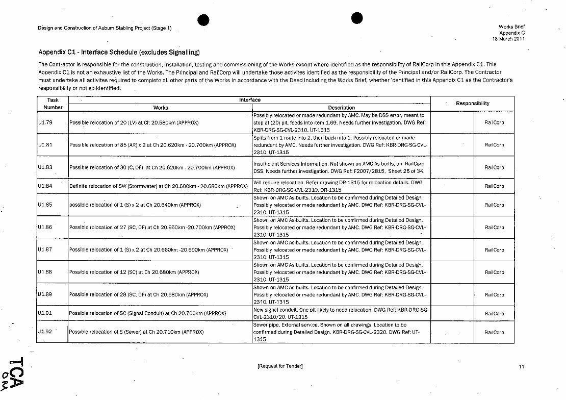
Design and Construction of Auburn Stabling Project (Stage 1) Works Brief Appendix C
18 March 2011
Appendix C1- Interface Schedule (excludes Signalling)
The Contractor is responsible for the construction, installation, testing and commissioning of the Works except where identified as the responsibility of RailCorp in this Appendix Cl. This
Appendix Cl is not an exhaustive list of the Works: The Principal and RailCorp will undertake those activites identified as the responsibility of the Principal and/or RailCorp. The Contractor
must undertake all activites required to complete all other parts of the Works in accordance with the Deed including the Works Brief, whether identified in this Appendix Cl as the Contractor's
responsibility or not so identified.
Task Interface Responsibility
Number Works Description
Possibly relocated or made redundant by AMC. May be DSS error, meant to
U1.79 Possible relocation of 20 (LV) at Ch 20.580km (APPROX) stop at (20) pit, feeds into item 1.69. Needs further investigation. DWG Ref: RailCorp
KBR·DRG-SG-CVL-2310. UT-1315
Splits from 1 route into 2, then back into 1. Possibly relocated or made U1.81 Possible relocation of 85 (AR) x 2 at Ch 20.620km - 20.700km (APPROX) redundant by AMC. Needs further investigation. DWG Ref: KBR-DRG-SG-CVL- RailCorp
2310. UT-1315
U1.83 Possible relocation of 30 (C, OF) at Ch 20.620km - 20.700km (APPROX) Insufficient Services Information. Not shown on AMC As-builts, on RailCorp
RailCorp DSS. Needs further investigation. DWG Ref: F2007/2815, Sheet 26 of 34.
U1.84 Definite relocation of SW (Stormwater) at Ch 20.600km - 20.680km (APPROX) Will require relocation. Refer drawing DR-1315 for relocation details. DWG
RailCorp Ref: KBR·DRG-SG-CVL-2310. DR-1315
Shown on AMC As-builts, Location to be confirmed during Detailed Design. U1.85 possible relocation of 1 (S) x 2 at Ch 20.640km (APPROX) Possibly relocated or made redundant by AMC. DWG Ref: KBR-DRG-SG-CVL- RailCorp
2310. UT-1315
Shown on AMC As-builts. Location to be confirmed during Detailed Design. U1.86 Possible relocation of 27 (SC, OF) at Ch 20.650km -20.700km (APPROX) Possibly relocated or made redundant by AMC. DWG Ref: KBR-DRG-SG-CVL- RailCorp
2310. UT-1315
Shown on AMC As·builts. Location to be confirmed during Detailed Design. U1.87 Possible relocation of 1 (S) x 2 at Ch 20.660km -20.690km (APPROX) Possibly relocated or made redundant by AMC. DWG Rt)f: KBR-DRG-SG-CVL- RailCorp
2310. UT-1315
Shown on AMC As-builts. Location to be confirmed during Detailed Design. U1.88 Possible relocation of 12 (SC) at Ch 20.680km (APPROX) Possibly relocated or made redundantby AMC. DWG Ref: KBR-DRG-SG-CVL- RailCorp
2310. UT-1315
Shown on AMC As-builts. Location to be confirmed during Detailed Design. U1.89 Possible relocation of 28 (SC, OF) at Ch 20.680km (APPROX) Possibly relocated or made redundant by AMC. DWG Ref: KBR-DRG-SG-CVL- RailCorp
2310. UT-1315
U1.91 Possible relocation of SC (Signal Conduit) at Ch 20.700km (APPROX) New signal conduit. One pit likely to need relocation. DWG Ref: KBR-DRG-SG-
RailCorp CVL-2310/20. UT-1315
Sewer pipe. External service. Shown on all drawings. Location to be U1.92 Possible relocation of S (Sewer) at Ch 20.710km (APPROX) confirmed during Detailed Design. KBR-DRG-SG-CVL-2320. DWG Ref: UT- RailCorp
1315
[Request for Tender] 11

JCA~ I '~ ':': , '\./ '* j'tl~ f ... ,' ..,

Design and Construction of Aubum Stabling Project (Stage 1) Works Brief Appendix C
18 March 2011
Appendix C1- Interface Schedule (excludes Signalling)
The Contractor is responsible for the construction, installation, testing and commissioning of the Works except where identified as the responsibility of RailCorp in this Appendix Cl. This
Appendix Cl is not an exhaustive list of the Works. The Principal and RailCorp will undertake those activites identified as the responsibility of the Principal and/or RailCorp. The Contractor
must undertake all activites required to complete all other parts of the Works in accordance with the Deed including the Works Brief, whether identified in this Appendix Cl as the Contractor's
responsibility or not so identified.
Task Interface Responsibility
Number Works Description
Utilities - Manchester Rd Works (HV Route)
Ul.93 Possible relocation of (S) Sewer at new ASP Entrance Gate and HV Route on Likely to be impacted by new HV Route to Warehouse. Needs further
Contractor Manchester Rd investigation. Refer item 1.73. DWG Ref: KBR-DRG-SG-CVL-2315, UT-1316.
Possible relocation of HV x 2 (High Voltage Conduit) at new ASP Entrance Gate Possibly require relocation where new gate is to be constructed. Likely to be
Ul.94 impacted by new HV Route to Warehouse. Potentially the same as item 1.45. Contractor and HV Route on Manchester Rd
DWG Ref: KBR-DRG-SG-CVL-2315, UT- 1316.
Possible relocation of C (Communications) at new ASP Entrance Gate and HV Possibly require relocation where new gate is to be constructed. Likely to be
Ul.95 Route on Manchester Rd
impacted by new HV Route to Warehouse. Service Incorrectly missing from Contractor
KBR-DRG-SG-CVL-2315. DWG Ref: KBR-DRG-SG-CVL-2315/21, UT- 1316.
Possible relocation of SRM (Sewer Rising Main) at new ASP Entrance Gate and Possibly require relocation where new gate is to be constructed. Likely to be
Ul.96 HV Route on Manchester Rd
impacted by new HV Route to Warehouse. Refer item 7.2. DWG Ref: KBR- Contractor
DRG-SG-CVL-2315/21, UT- 1316.
Ul.97 Possible relocation of SRM (Sewer Rising Main) at new HV Route on AMC New HV Route may impact SRM where it crosses at the access road and
Contractor Access Road connects into pit. DWG Ref: KBR-DRG-SG-CVL-2314, UT-1317.
Possible relocation of 221 (Sewer Rising Main) at new HV Route on AMC Access New HV Route may impact (221) where it crosses from RailCorp yard at the
Ul.98 Road
access road. May have been relocated or made redundant by AMC. Refer Contractor
item 1.47. DWG Ref: KBR-DRG-SG-CVL-2314, UT-1317.
Ul.99 Must allow for working around LV, SEC (Low Voltage and Security) at new I'IV AMC Utility: New HV Route must run adjacent to existing service. Refer item
Contractor Route on AMC Access Road 1.65. DWG Ref: KBR-DRG-SG-CVL-2314, UT-1317.
Ul.l00 Must allow for working around W (Water) at new HV Route on AMC Access Road AMC Utility: New HV Route must run adjacent to existing service. Refer item
Contractor 1.65. DWG Ref: KBR-DRG-SG-CVL-2314, UT-1317.
,
Ul.l0l Aerial 33kV (234) above new HV Route on AMC Access Road New HV Route must run be/ow existing service. Should not be an issue. Refer
Contractor item 1.59. DWG Ref: KBR-DRG-SG-CVL-2314, UT-1317.
[Request for Tender] 12

·e
,TCA ~N

Design and Construction of Auburn Stabling Project (Stage 1) Works Brief Appendix C
18 March 2011
Appendix C1- Interface Schedule (excludes Signalling)
The Contractor is responsible for the construction, installation, testing and commissioning of the Works except where identified as the responsibility of RailCorp in this Appendix C1. This
Appendix C1 is not an exhaustive list of the Works. The Principal and RailCorp will undertake those activites identified as the responsibility of the Principal and/or RailCorp. The Contractor
must undertake all activites required to complete all other parts of the Works in accordance with the Deed including the Works Brief, whether identified in this Appendix C1 as the Contractor's
responsibility or not so identified.
Task Interface Responsibility
Number Works Description
New HV Route may impact (32). Shown on As-builts as short length from
U1.102 Possible relocation of 32 (C, OF) at new HV Route near AMC level crossing RailCorp near the level crossing. May have been relocated or made Contractor
redundant by AMC. DWG Ref: KBR-DRG-SG-CVL-2314, UT-1317.
2 Track, Civil, Earthworks
Works will include: - Modification of existing level crossing to 3 tracks and relocate all
associated cabling as required by LGCUP.
Track, Civil and EarthworkS, including construction of turnout 1340. Interface - Installation of catch point and associated throw-off area by LGCUP.
TCE2.1 between ASP and LGCUP at -CH20.460km.
-Installation of turnout 1340 byLGCUP. RailCorp
- Trackwork to Down Relief Line.
-Installation of turnout 683B by LGCUP.
DWG Ref: GN-1315 & AL-1315
Drawings can be found in Exhibit J PrinCipal's Design.
TCE2.2 Track, Civil and Earthworks, not including turnout 1340. Interface between ASP Buffer stops to be installed by the D&C Contractor. DWG Ref: GN-1315 & AL-
Contractor and LGCUP at -CH20.460km 1315. Drawings can be found in Exhibit J Principal's Design.
3 Overhead Wiring
OH3.1 OHW Wires Interface between ASP and LGCUP at AS20+527 New wire for 2013 track alignment (permanent works). DWG Ref: OH-1315.
Drawings can be found in Exhibit J Principal's Design. Contractor
New wires for 2017 final track alignment and connection into 2013 ASP OH3.2 OHW Wires on Clyde end from AS20+527 to MS 20+521 OHW. DWG Ref :OH-1315. Drawings can be found in Exhibit J Principal's RailCorp
Design.
OH3.3 OHW Structures Interface between ASP and LGCUP at AS20+527 New OHW structures for 2013 track alignment (permanent works). DWG Ref
Contractor :OH-1315. Drawings can be found in Exhibit J PrinCipal's Design.
New structures for 2017 final track alignment and connection into 2013 ASP . -OH3.4 OHW Structures on Clyde end from AS20+527 to MS 20+521 OHW works.DWG Ref :OH-1315. Drawings can be found in Exhibit J RailCorp
Principal's Design.
4 Drainage
[Request for Tender) 13


Design and Construction of Auburn Stabling Project (Stage 1) Works Brief Appendix C
18 March 2011
Appendix C1-lnterface Schedule {excludes Signalling)
The Contractor is responsible for the construction, installation, testing and commissioning of the Works except where identified as the responsibility of RailCorp in this Appendix Cl. This
Appendix Cl is not an exhaustive list of the Works. The Principal and RailCorp will undertake those activites identified as the responsibility of the Principal and/or RailCorp. The Contractor
must undertake all activites required to complete all other parts of the Works in accordance with the Deed including the Works. Brief, whether identified in this Appendix Cl as the Contractor's
responsibilityor not so identified.
Task Interface Responsibility
Number Works Description
DR4.1 ASP Trunk Drainage connection into existing at -CH20.400rn Connection of ASP trunk drainage to existing AMC system at pit 18/1. DWG
Ref: DR-1314. Drawings can be found in Exhibit J Principal's Design. Contractor
DR4.2 Surface Track Drainage on Clyde End from -CH20.460km LGCUP Scope. DWG Ref: DR-1315. Drawings can be found in Exhibit J
RailCorp Principal's Design.
DR4.3 Surface Track Drainage on Auburn side of -CH20.460km D&C Contractor Scope. DWG Ref: DR-1315. Drawings can be found in
Contractor Exhibit J Principal's Design.
DR4.4 Connection to existing Culvert No.2 Extension of existing culvert No.2. DWG Ref: DR-1313. Contractor
Construction works on MainTrain side of car turning loop for Detention Basin Construction of detention Basin No.2 and connection to existing culvert No.1
DR4.5 and other existing MainTrain drainage where necessary. DWG Ref: DR-1313. Contractor No.2
Drawings can be found in Exhibit J Principal's Design.
Construction of detention Basin No.1 and connection to existing Culvert No.
DR4.6 Connection to existing Culvert No.1 and Detention Basin No.1 2 to MainTrain property. DWG Ref: DR-1314. Drawings can be found in Contractor
Exhibit J Principal's Design.
5 Retaining Wall
Small retaining wall adjacent to existing AMC boundary fence on the Clyde end New retaining wall between existing AMC level crossing and Duck River
RW5.1 of -CH20.460m.
crossing along line of modified walkway. Extent of works to be optimised by RailCorp
RailCorp - LGCUP. DWG Ref: GN-1315 & AL-1315
RW5.2 Various retaining walls ( See Items 12.5 to 12.7 below. Contractor
6 Bulk Power Supply
Modifications to feeders 721 and 695 and 722 and 623 including relocation
of poles, addition of new overhead earth wire, installation of Clyde Auxiliary substation and undergrounding of feeders. Works to take place on
P6.1 Power works adjacent to Clyde Substation at -CH19.800km to -CH19.850km MainTrain property. Outages on these feeders will have an impact on the
Contractor RailCorp electrical network. Extent of works is pole 110G to the south and
the CSR ULX under the car turning loop adjacent to the Staff Amenities building. DWG Ref: TR-1313 to TR 1316. Drawings can be found in Exhibit J Principal's Design.
[Request for Tender] 14

, .

Design and Construction of Auburn Stabling Project (Stage 1) Works Brief Appendix C
18 March 2011
Appendix C1- Interface Schedule (excludes Signalling)
The Contractor is responsible for the construction, installation, testing and commissioning of the Works except where identified as the responsibility of RailCorp in this Appendix Cl. This
Appendix Cl is not an exhaustive list of the Works. The Principal and RailCorp will undertake those activites identified as the responsibility of the Principal and/or RailCorp. The Contractor
must undertake all activites required to complete all other parts of the Works in accordance with the Deed including the Works Brief, whether identified in this Appendix Cl as the Contractor's
responsibility or not so identified.
Task Interface Responsibility
Number Works Description
Modifications to feeder 722 will affect bulk supply power to MainTrain.
P6.2 Power works adjacent to Clyde Substation at -CH19.S00krn to -CH19.S50km Works to be performed on MainTrairi Property. DWG Ref: TR-1313 to TR Contractor
1316. Drawings can be found in Exhibit J Principal's Design.
Replacement of existing pole top substation with new llkV/415 V pad
P6.3 Replacement of Clyde maintenance depot substation works at ASP site mount type substation and associated CSR across Manchester Road (see
Contractor entrance and Manchester Road item 9.4 below). DWG Ref: TR-1313 to TR 1316. Drawings can be found in
Exhibit J Principal's Design. ,
Underground feeder cable and junctions between cables from new Clyde
Underground feeder works, interface at existing pit adjacent to Clyde Central Maintenance Depot substation to existing cables int%ut of Clyde Central
P6.4 Warehouse substation
Warehouse substation and then onto pole 117G (see Item 9.4 below). DWG Contractor
Ref: TR-1313 to TR 1316. Drawings can be found in Exhibit J PrinCipal's
Design.
Installation of minimum of new SOOm of aerial earth wire from new UGOH on
P6.5 Aerial earth wire install from Pole 116G to Pole 135 feeder 721 at pole 116G in ASP site to pole 135 beyond Clyde Station. Refer
Contractor items 10.1 and 10.2. DWG Ref: TR-1313 to TR 1316. Drawings can be
found in Exhibit J Principal's Design.
Supply from Energy Australia isolation substation in ASP site. Source of feed
P6.6 ASP back-up supply power for essential loads and signalling from Manchester Road TBD. DWG Ref: TR-1313to TR 1316. Drawings can Contractor
be found in Exhibit J Principal's Design.
Installation of quad cables and associated equipment (DCCB etc) to form
fourth radial feeder from Auburn substation to feed AMC via Auburn Junction.
For the AMC entrance at Auburn junction, additional copper cross section
P6.7 Traction Power supply from Auburn substation and Auburn junction may be required to provide the required capacity (see Sectioning diagrams). RailCorp
This work will be performed by RailCorp, either via the LGCUP or using its own
in house resources. DWG Ref: OH-1322. Drawings can be found in Exhibit J
Principal's Design.
Installation of additional cable to feed power from the Down Relief to the P6.S Traction Power from Down Relief to ASP: Sections 376/1A to 376/1C . OHW for Stabling Road No.6. DWG Ref: OH-1322. Drawings can be found in RailCorp
Exhibit J Principal's Design.
[Request for Tender] 15

TCA bI.

:'.
Design and Construction of Auburn Stabling Project (Stage 1) Works Brief Appendix C
18 March 2011
Appendix C1 " Interface Schedule (excludes Signalling)
The Contractor is responsible for the construction, installation, testing and commissioning of the Works except where identified as the responsibility of RailCorp in this AppeJidix Cl. This
Appendix Cl is riot an exhaustive list of the Works. The Principal and RailCorp will undertake those activites identified as the responsibility of the Principal and/or RailCorp. The Contractor
must undertake all activites required to complete all other parts of the Works in accordance with the Deed including the Works Brief, whether identified in this Appendix Cl as the Contractor's
responsibility or not so identified.
Task Interface Responsibility
Number Works Description
7 Sewer and Water
Connection of potable cold water supply to existing Sydney Water main. D&C
Contractor to install and commission new water pipe from connection point S7.1 Potable Cold Water connection on Manchester Road along Manchester Road to connect with ASP site CW and fire water systems Contractor
in Site Access Road. DWG Ref: Pl-1316. Drawings can be found in Exhibit J
Principal's Design.
Connection of ASP site sewer system to existing Sydney Water sewer rising S7.2 Sewer connection on Manchester Road main in Manchester Road opposite the ASP site entrance. Refer item 1.96. Contractor
DWG Ref: Pl-1316. Drawings can be found in Exhibit J Principal's Design.
8 Combined Services Route ./
CSR from ASP Signal Equipment Room to pits ~t -Ch20.460km for signal
CSRB.l Construction of CSR (Sigs + Comms). Interface between ASP and lGCUP at and comms cables to Cll15. Interface pit(s) to be constructed by D&C
Contractor -CH20.460km . contractor. DWG Ref: CS-1315. Drawings can be found in Exhibit J Principal's
Design.
Construction of CSR (Sigs + Comms). Interface from -Ch20.460km to Cl115 at CSR from interface pit(s) at -Ch20.460km to CLll15 for signals and comms
CSRB.2 Clyde end.
cables to Cll15 via proposed lGCUP CSR at Clyde Junction. DWG Ref :CS- RailCorp
1315. Drawings can be found in Exhibit J Principal's Design.
CSR for Genisys Link B cable from ASP Signal Equipment Room down CSRB.3 CSR Works from Manchester Rd to Clyde Warehouse Manchester Road to Clyde Warehouse Communications Room. DWG Ref: CS Contractor
1315 & CS-1316. Drawings can be found in Exhibit J PrinCipal's Design.
CSR for comms cables from ASP Staff Facilities Building down Manchester CSRB.4 CSR Works from Manchester Rd to Clyde Warehouse Road to Clyde Warehouse Communications Room. DWG Ref: CS-1315 & CS- Contractor
1316. Drawings can be found in Exhibit J Principal's Design.
Bulk supply power CSR (feeder 623) from ASP site to pole 117G via
CSRB.5 CSR works from ASP site to pole 117G via new Clyde Maintenance Depot Manchester Road and RailCorp property (see items 6.3 and 6.4 above). DWG.
Contractor substation and the existing pit into Clyde Central Warehouse substation. Ref: CS-1315 & CS-1316. Drawings can be found in ExhibitJ Principal's
Design.
[Request for Tender] 16

.,
~TCA~

Design and Construction of Auburn Stabling Project (Stage 1) Works Brief Appendix C
-18 March 2011
Appendix C1- Interface Schedule (excludes Signalling)
The Contractor is responsible for the construction, installation, testing and commissioning of the Works except where identified as the responsibility of RailCorp in this Appendix Cl. This
Appendix Cl is not an exhaustive list of the Works: The Principal and RailCorp will undertake those activltes identified as the responsibility of the Principal and/or RailCorp. The Contractor
must undertake all activites required to complete all other parts of the Works in accordance with the Deed including the Works Brief, whether identified in this Appendix Cl as the Contractor's
responsibility or not so identified.
Task Interface Responsibility
Number Works Description
D&C Contractor to install the ducts and pits from the ASP to the LGCUP
interface point. NOTE: Depending upon the exact connection point of the
CSRB.6 Traction Power CSR construction. Interface between ASP and LGCUP at traction power cable to feeder 376/1C, all of CSR required for this cable may
Contractor -CH20.460km fall on the LGCUP side of the interface point. TBD at detailed design. DWG
Ref: CS-1315 & CS-1316. Drawings can be found in Exhibit J Principal's
Design.
LGCUP to install the ducts and pits from the LGCUP interface point to the
connection point to feeder 376/1A on the Down relief at Clyde Junction.
CSRB.7 Traction Power CSR construction. Interface between ASP and LGCUP at NOTE: Depending upon the exact connection point of the traction power
RailCorp -CH20.460km. cable to feeder 376/1C, all of CSR required for this cable may fall on the
LGCUP side of the interface point. TBD at detailed design. DWG Ref :CS-1315 & CS-1316. Drawings can be found in Exhibit J Principal's Design.
9 Signals and Comms
Conduits will be in place in CSR and fibre optic cable will be coiled in interface pit at -CH20.460km. LGCUP will complete the CSR from the ASP
S&C9.1 Installation of signals and comms cables from Signal Equipment Room to Clyde and terminate the Microlok fibre optic data cables (and other associated
RailCorp end at (CL115) signalling cables) into CL115 equipment room located on the main corridor.
DWG Ref: CS-1315, CS-1316 & CO-1336. Drawings can be found in Exhibit J
Principal's Design.
D&C Contractor to install and commission Genisys Link B cable from ASP
S&C9.2 Signal cables install from Manchester Rd to Clyde Warehouse Signal Equipment Room to Clyde Warehouse Communications Room. DWG
Contractor Ref: CS-1315, CS-1316 & CO-1336. Drawings can be found in Exhibit J
Principal's Design.
D&C Contractor to install and commission comms cables from ASP Staff
S&C9.3 Comms cables install Staff Facilities Building to Clyde Warehouse Facilities Building to Clyde Warehouse Communications Room. DWG Ref: CS-
Contractor Communications Room. 1315, CS-1316 & CO-1336. Drawings can be found in Exhit;>it J Principal's
Design.
[Request for Tender] 17

.TCA (JtJ,

Design and Construction of Auburn Stabling Project (Stage 1) Works Brief Appendix C
18 March 2011
Appendix C1- Interface Schedule (excludes Signalling)
The Contractor is responsible for the construction, installation, testing and commissioning of the Works except where identified as the responsibility of RailCorp in this Appendix C1. This
Appendix C1 is not an exhaustive list of the Works. The Principal and RailCorp will undertake those activites identified as the responsibility of the Principal and/or RailCorp. The Contractor
must undertake all activites required to complete all other parts of the Works in accordance with the Deed including the Works Brief, whether identified in this Appendix C1 as the Contractor's
responsibility or not so identified.
Task Interface Responsibility
Number Works Description
LGCUP to install and commission the traction power cable between feeder
S&C9A Traction power CSR from Down Relief to ASP: Sections 376/1A to 376/1C. Section 376/iA on the Down Relief and feeder Section 376/1C on Stabling
RailCorp Road NO.6 (see Items 8.6 and 8.7 above).DWG Ref: OH-1315 and OH-
1322. Drawings can be found in Exhibit J Principal's Design.
10 Earthing and Bonding
D&C Contractor to install and commission new aerial earth wire above feeder
EB10.l Aerial Earth Wire install on Clyde end from Pole 116G to pole 135 on feeder 721 (33kV) between pole 116G on the ASP site to Pole 135 beyond Clyde
Contractor 721 (33kV) Station. DWG Ref: TR-1313 & TR-1314. Drawings can be found in Exhibit J
Principal's Design.
D&C Contractor to install and commission new aerial earth wire above feeder
EB10.2 Aerial Earth Wire install on MainTrain property from Pole 110G to pole l11GA 721 (33kV) between pole 110G and Pole l11GA on MainTrain property.
Contractor Outages on this feeder will affect RailCorp. DWG Ref: TR-1315 & TR-1316.
Drawings can be found in Exhibit J Principal's Design.
LGCUP to reinstate any earth grid(s) supporting feeder 721 affected by
modifications to the existing walkway and security fences between the AMC EB10.3 Earthing + Bonding on walkway from AMC entrance to Clyde Station entrance and Clyde Station. Outages to Feeder 721 will impact RailCorp. RailCorp
Track work and other civil works through Clyde Throat will impact AMC. DWG
Ref: TBC
EB10A Connection of new ASP fences to existing AMC fences Where any new ASP fence connects to existing AMC fence, the connection is
Contractor to be via an isolated fence section. DWG Ref: TBC
EB10.5 Connection of new ASP fences to existing Maintrain and Janyon fences Where any new ASP fence connects to existing MainTrain fence, the
Contractor connection is to be via an isolated fence section. DWG Ref: TBC
Where any existing RailCorp/AMC fences are modified by LGCUP in the Clyde EB10.6 Earthing + Bonding on revised RailCorp/AMC fences at Clyde end Throat, the connection is to be via an isolated fence section (see also item RailCorp
10.3 above). DWG Ref: TBC
11 Compressed Air
Compressed Air Interface between ASP and LGCUP at -CH20.460km to Clyde The compressed air system will be constructed by the D&C Contractor up to a
Al1.1 end
manifold located at chainage 20A60km, LGCUP will connect into the RailCorp
location. DWG Ref: Ref: TBC
[Request for Tender] 18

e·

Design and Construction of Auburn Stabling Project (Stage 1) Works Brief Appendix C
18 March 2011
Appendix C1- Interface Schedule (excludes Signalling)
The Contractor is responsible for the construction, installation, testing and commissioning of the Works except where identified as the responsibility of RailCorp in this Appendix Cl. This
Appendix Cl is not an exhaustive list of the Works. The Principal and RailCorp will undertake those activites identified as the responsibility of the Principal and/or RailCorp. The Contractor
must undertake all activites required to complete all other parts of the Works in accordance with the Deed including the Works Brief, whether identified in this Appendix Cl as the Contractor's
responsibility or not so identified.
Task Interface Responsibility
Number Works Description
The compressed air system will be constructed by the D&C Contractor up to a
A11.2 Compressed Air Interface between ASP and LGCUP at -CH20.460km manifold located at chainage 20.460km, LGCUP will connect into the Contractor
location. DWG Ref: Ref: TBC
12 Fencing and Security
LGCUP to made necessary changes to the existing footpath and security
SEC12.1 Fencing & Security from existing AMC and RailCorp fence on either side of fences to allow for new track'installation, catch-point and associated throw
RailCorp walkway to Clyde Station.-CH20.500 km to -CH20.713 km off area (see also Items 2.1, 5.1 & 10.3 above). DWG Ref: GN/SE-1315.
Drawings can be found in Exhibit J Principal's Design.
SEC12.2 Alterations to existing fence at -Ch 20.460 D&C Contractor will be required to remove existing fence if required. DWG Ref: GN/SE-1315. Drawings can be found in Exhibit J Principal's Design.
Contractor
Fence interface with MainTrain where new high security fence connects at Ch New High Security fence connects to existing MainTrain boundary fence.
SEC12.3 19.850km
DWG Ref: GN/SE-1313. Drawings can be found in Exhibit J Principal's Contractor
Design.
Fence interface with Janyon/MainTrain along new boundary fence from Ch New property boundary fence between end of ASP Stage 1 High security
SEC12.4 19.580 to 19.850km
fence and existing Janyon/Mai~Train boundary fence. DWG Ref: GN/SE- Contractor
1313. Drawings can be found in Exhibit J Principal's Design.
Fence interface with Janyon along new boundary fence/noise wall from Ch New high security fence/noise wall and associated retaining wall along
SEC12.5 19.850km to 20.100km
Janyon property boundary. DWG Ref: GN/SE-1313, GN/SE-1316. Drawings Contractor
can be found in Exhibit J Principal's Design.
Fence interface with Janyon/Bluescope for new boundary fence/noise wall New high security fence/noise wall and associated retaining wall along
SEC12.6 -CH20.150 km to -CH20.200 km
BlueScope property boundary. DWG Ref: GN/SE-1316. Drawings can be Contractor
found in Exhibit J Princioal's Desi!1n.
Fence interface with Janyon/Bluescope for new access gate and boundary New high security fence and associated retaining wall along Bluescope
SEC12.7 fence at -CH20.150 km to -CH20.200 km
property boundary. DWG Ref :GN/SE-1316. Drawings can be found in Exhibit Contractor J Principal's Design.
[Request for Tender] 19

TCA ()o.A,

Design and Construction of Auburn Stabling Project (Stage 1) Works Brief Appendix C
18 March 2011
Appendix C1- Interface Schedule (excludes Signalling)
The Contractor is responsible for the constru'ction, installation, testing and commissioning of the Works except where identified as the responsibility of RailCorp in this Appendix Cl. This
Appendix Cl is not an exhaustive list of the Works. The Principal and RailCorp will undertake those activites identified as the responsibility of the Principal and/or. RailCorp. The Contractor
must undertake all activites required to cOmplete all other parts of the Works in accordance with the Deed including the Works Brief, whether identified in this Appendix Cl.as the Contractor's
responsibility or not so identified.
Task Interface Responsibility
Number Works Description
New high security fence around existing car turning loop from CH19.850km
SEC12.8 Fence interface with MainTrain/AMC for new high security fence around car to interface with existing AMC fence adjacent to the Bypass road 1. DWG Ref
Contractor turning loop : GN/SE-1313, GN/SE-1314. Drawings can be found in Exhibit J Principal's
Design.
Various interface points between existing AMC fence and new ASP high SEC12.9 Various fence interface with AMC due to works on high security fence. Security fences. DWG Ref: GN/SE-1316. 'Drawings can be found in Exhibit J Contractor
Principal's Design.
Relocation of existing high security fence at boundary between ASP and AMC. Relocation of existing high security fence between AMC and ASP to allow
SEC12.10 Ch 20.400km to 20.460km
room for Clyde throat to be constructed. DWG Ref: GN/SE-1314 and GN/SE- Contractor 1315. Drawings can be found in Exhibit J Principal's Design.
[Request for Tender] 20
.. '

;
. .,.

Design and Construction of Auburn Stabling Project (Stage 1)
Appendix C2 -Interface Schedule - Signalling
Works Brief Appendix C
18 March 2011
This Appendix C2 identifies activities relating to signalling work. It is not an exhaustive list of activities to be undertaken for signalling. The Principal and RailCorp will
undertake those activities identified in the column headed "PrincipaIjRaiICorp". The Contractor must undertake all activities required to complete all other parts of the Works relating to signalling in accordance with the Deed including the Works Brief.
Interface Responsibility Contractor
Task Works PrincipaljRailCorp
A B Number (included in Original Contract Price) (undertaken as Reimbursable Signalling Installation
Work) 1 Project Nil All project management activities Nil
Management 2 Design of Provision of Signalling Design. Remainder of design relating to signalling work Provision of cable schedules and mechanical and shop
Signalling System Provision of a schedule of long drawings for signalling equipment and racking lead procurement items.
3 Signals & Signal Provision of Signalling Design. Includes: Installation of signals, signal posts, SPTs, ladder and Post Telephone - design, supply and install signal bases and platform and provision of mechanical, supplier and (SPT) foundations (including ladder and SPT shop drawings for signalling equipment only.
foundation)
- procure/supply and deliver to site signals and
SPT equipment including posts and ladders
~ provide technical and site support for the signal
sighting committee. Remainder of work relating
to signals and signal post telephone
- remainder of signal and SPT work
[Request for Tender]

TCA ~M , " ,"

Design and Construction of Auburn Stabling Project (Stage 1)
Appendix C2 - Interface Schedule - Signalling
Works Brief Appendix C
18 March 2011
This Appendix C2 identifies activities relating to signalling work. It is not an exhaustive list of activities to be undertaken for signalling. The Principal and RailCorp will undertake those activities identified in the column headed "PrincipaIjRaiICorp". The Contractor must undertake all activities required to complete all other parts of the Works
relating to signalling in accordance with the Deed including the Works Brief.
Interface Responsibility Contractor
Task Works PrincipaljRailCorp
A B Number (included in Original Contract Price) (undertaken as Reimbursable Signalling Installation
Work) 4 Combined Provide support to the Contractor All remaining work associated with the combined Nil
building for to determine room dimensions, building for signalling equipment and signalling signalling equipment and compressors. equipment and compressor room layouts and compressors proposed equipment to be
accommodated.
5 Signalling Provision of Signalling Design. All remaining works including supply of signals, Installation, testing and commissioning of signalling
Equipment Procure, install, test and pOints, trainstops, EOL's, track circuit equipment, equipment in accordance with approved signalling commission Mocrolok Diagnostic SPT's, Microlok, network switches, modems, design only.
and Replay Facility patch panels, signal control equipment, surge
protection, relays and cables. Supply of sundry signalling materials such as racking, labels,
beads, crimps, wiring, fuses, terminals and earth bars.
Provision of space for Microlok Diagnostic and
Replay facility.
[Request for Tender] 2

. TCA tl~
. j
. j
j
j
j
j
j
j
j
j
j
. j
j e j
e j
j
j
j
j
j
j
j
j
j
j
j
j
j
j
j
j
j
j
j
j
j

Design and Construction of Auburn Stabling Project (Stage 1)
Appendix C2 -Interface Schedule - Signalling
Works Brief Appendix C
18 March 2011
This Appendix C2 identifies activities relating to signalling work. It is not an exhaustive list of activities to be undertaken for signalling. The Principal and RailCorp will
undertake those activities identified in the column headed "PrincipaIjRaiICorp". The Contractor must undertake all activities required to complete all other parts of the Works
relating to signalling in accordance with the Deed including the Works Brief.
Interface Responsibility Contractor
Task Works Pri nci pa IjRa i1Corp
A .B Number (included in Original Contract Price) (undertaken as Reimbursable Signalling Installation
Work) 6 Testing and Design personnel commissioning All remaining activities associated with testing Supply of accredited testing and commissioning
Commissioning support and design integrity and commissioning management including personnel including Tester-in-Charge only.
Management and te~ting support. Supply of management of overall testing and
Personnel RailCorp Commissioning Engineer commissioning process. Resource forecasts for
and RailCorp certification both Contractor and RailCorp inspection and
personnel. testing personnel.
[Request for Tender] 3

,TCA ~
ej j j
ej j j
j
. j
j j
j j
j j
j j j j j j j
j j j j
. j j j j j j
j j j j j j j
j
• j
j j j
j
j j
j
j

Design and Construction of Auburn Stabling Project (Stage 1)
Appendix C2 - Interface Schedule - Signalling
Works Brief Appendix C
18 March 2011
This Appendix C2 identifies activities relating to signalling work. It is not an exhaustive list of activities to be undertaken for signalling. Th~ Principal and RailCorp will
undertake those activities identified in the column headed "PrincipaIjRaiICorp". The Contractor must undertake all activities required to complete all other parts of the Works
relating to signalling in accordance with the Deed including the Works Brief.
Interface Responsibility Contractor
Task Works PrincipaljRailCorp
A B Number (included in Original Contract Price) (undertaken as Reimbursable Signalling Installation
Work)
7 Testing and Final Certification of Test procedures and quality assurance for Production and management of Inspection and Testing
Commissioning Commissioning Works Packages. Combined Services Route, signalling civils Plan, Interface Coordination Plan, Installation Works
Docu mentation Final certification of (buildings, signals bases) and communication Package and Commissioning Works Package.
Commissioning Offices Copies of systems. Production of engineering waivers for contractor
signalling design packages. personnel proposed for working in 'live' locations or
Production and distribution of inspection and testing activities. Certify signalling
signalling design documentation design documentation in accordance with RailCorp
updates at construction (green), standard SPG 0711.2. Set to Work and certify signalling
testing (pink), commissioning installation in accordance with ITP and IWP. (yellow) and as-built (white)
stages.
[Request for Tender] 4

· I

Design and Construction of Auburn Stabling Project (Stage 1)
Appendix C2 - Interface Schedule - Signalling
Works Brief AppendixC
181y1arch 2011
This Appendix C2 identifies activities relating to signalling work. It is not an exhaustive list of activities to be undertaken for signalling. The Principal and RailCorp will
undertake those activities identified in the column headed "PrincipaIjRaiICorp". The Contractor must undertake all activities required to complete all other parts of the Works relating to signalling in accordance with the Deed including the Works Brief.
Interface Responsibility Contractor
Task Works PrincipaljRailCorp
A B Number (included in Original Contract Price) (undertaken as Reimbursable Signalling Installation
Work) 8 Test and Operational signalling All remaining work associated with testing and Inspection and Testing of Auburn Stabling Interlocking
Commissioning commissioning of Auburn Stabling commisioning signalling equipment including:
Signalling Yard, Manchester Road LX and • Set to Work all equipment inc Microlok and field Equipment Clyde connection. Final equipment,
certification of all equipment for • Wire and Null counts
Auburn Stabling interlocking and • Insulation Testing of wires and cables
air system. Interface t~sting • Function Testing
between Auburn Stabling Yard • Set to Work of pOints,
and Clyde Interlockings. Control • Power supply commissioning System correspondence testing. • Air system and diagnostics testing and set to work.
[Request for Tender] 5

)
TCA bA· ,

Design and Construction of Aubum Stabling Project (Stage 1)
Appendix C2 -Interface Schedule - Signalling
Works Brief Appendix C
18 March 2011
This Appendix C2 identifies activities relating to signalling work. It is not an exhaustive list of activities to be undertaken for signalling. The Principal and RailCorp will
undertake those activities identified in the column he.aded "PrincipaIjRailCorp". The Contractor must undertake all activities required to complete all other parts of the Works
relating to signalling in accordance with the Deed including the Works Brief.
Interface Responsibility
Contractor Task
Works PrincipaljRailCorp A B
Number (included in Original Contract Price) (undertaken as Reimbursable Signalling Installation
Work) 9 Main and Local Provision of Signalling Design. All remaining works including design and Nil
Cable Routes Certification of cable routes. installation of CSR, ULXs, local cable route, pits,
pipes, position of trackside equipment, conduit
requirement schedule(detailing size, number,
colour of conduits) and cable conduit allocation.
CSR Design package in accordance with RailCorp
SPG 0711.2 Interim Signalling Detailed Site Survey requirements. Provide signalling technical
support in the production of the CSR design package.
10 Cables Provision of Signalling Design. All remaining work inlcuding supply of LV, Installation and termination of cables associated with
signalling, HV and communication cables. signalling systems (Microlok fibre, LV between rooms,
Installation of LV power, HV and communication local tails cable for signals, points, track circuits, signal
cables. post telephones) only 11 Permanent Way Review and approval of point All remaining work inlcuding design of point Installation of point machines (complete with fortress
inc. Turnouts configuration and layout. layout, supply, installation and assembly of locks) and set to work. Testing and bonding of IRJ's
Signalling certification of points. turnout and all points rodding (Spherolock), only.
Details of quantity and location of backdrives, spring assists and spreader bars.
IRJ's from Track Insulation Plan. Supply of point machines. Supply and install
IRJ's.
[Request for Tender] 6

TCA'twv.

Design and Construction of Auburn Stabling Project (Stage 1)
Appendix C2 -Interface Schedule - Signalling
Works Brief Appendix C
18 March 2011
This Appendix C2 identifies activities relating to signalling work. It is not an exhaustive list of activities to be undertaken for signalling. The Principal and RailCorp will
undertake those activities identified in the column headed "PrincipaIjRaiICorp". The Contractor must undertake all activities required to complete all other parts of the Works
relating to signalling in accordance with the Deed including the Works Brief.
Interface Responsibility Contractor
Task Works PrincipaljRailCorp
A B Number (included in Original Contract Price) (undertaken as Reimbursable Signalling Installation
Work) 12 Electrical Low Review and approval of electrical All remaining work including design, supply and Installation of indication cables from power room to
Voltage supply for signalling power room. installation of signalling power room and all signal equipment room only.
internal equipment, including ECO,UPS, ATS,
bypass switches, cables, distribution boards, wiring of indications and isolation transformers.
13 Traction Return Provision of Signalling Design. All remaining work including design, supply and Installation of impedance bonds including cables, all
installation of negative busbar and cable from dedicated track bonding, OHW Spark Gap bonds,
negative busbar to sub-station. Supply of electrolysis bonding and bonding cable from rail to
impedance bonds and all bond cables. negative busbar only
14 Signalling Air Provision of Signalling Design. All remaining work including design of Installation, testing and commissioning of complete
System Provision of equipment schedule compressor room including electrical supply, signalling air system only.
communication system interfaces, building
structure, building services, ventilation, cable
conduits and noise suppression systems. Supply
of internal and external pneumatic, electrical and
control equipment associated with the Signalling
Air System.
[Request for Tender) 7

.TCA a~

Design and Construction of Auburn Stabling Project (Stage 1)
Appendix C2 - Interface Schedule - Signalling
Works Brief Appendix C
18 March 2011
This Appendix C2 identifies activities relating to signalling work. It is not an exhaustive list of activities to be undertaken for signalling. The Principal and RailCorp will
undertake those activities identified in the column headed "PrincipaIjRaiICorp". The Contractor must undertake all activities required to complete all other parts of the Works
relating to signalling in accordance with the Deed including the Works Brief.
Interface Responsibility
Contractor
Task Works PrincipaljRailCorp
A B Number (included in Original Contract Price) (undertaken as Reimbursable Signalling Installation
Work) 15 Signalling Design, supply, install, test and Supply: Terminate in AS523, install, test, coil and securely cap within
Equipment at commission: 1. 656 Points operating, detection and EOL cable; nearest cable pit the following cables: 656 Contract Boundary 656 Point motor, point rodding and 2. 123AT TX, 123BT RX, 123BT TX and 123CT TX Points operating, EOL and detection cable;
EOL; track circuit cable; 123AT TX, 123BT RX, 123BT TX and 123CT TX track circuit 123AT TX, 123BT RX, 123BT TX and 3. 548 Signal, SPT and Trainstop cable. cables; 123CT TX Impedance Bond and track 548 Signal, SPT and Trainstop cable. bond cables; 548 Signal, SPT and Trainstop.
[Request for Tender] 8

T:CA 'aM

Design and Construction of Auburn Stabling Project (Stage 1)
Appendix C2 - Interface Schedule - Signalling
Works Brief Appendix C
18 March 2011
This Appendix C2 identifies activities relating to signalling work. It is not an exhaustive list of activities to be undertaken for signalling. The Principal and RailCorp will
undertake those activities identified in the column headed "PrincipaIjRaiICorp". The Contractor must undertake all activities required to complete all other parts of the Works
relating to signalling in accordance with the Deed including the Works Brief.
Interface Responsibil ity
Contractor
Task Works Pri nci pa IfRa ilCorp
A B
Number (included in Original Contract Price) (undertaken as Reimbursable Signalling Installation
Work) 16 Air System at Design of complete air system Supply of complete air system ring including ULX Install, test and commission complete air ring including
Contract Boundary ring. PVC cross pipe with pressure transmitters, ULX pressure transmitters.
Supply, install, test and cabling and 656 manifold.
commission local hoses for 656
pointsjEOL.
Design, installation, test and
commissioning of air main spur
inclusive of 548 manifold, 548
trainstop air hose, Manchester
Road URX hose with pressure
transmitters and regulator
between Auburn Stabling Yard air
system ring and Clyde Junction air
system.
[Request for Tender] 9

TCA ()tv.,

.1t~~~t1"1 Transport ~(J!t> Construction !'!~Y.i Authority
D&C Contract for Auburn Stabling Project (Stage 1)
Works Brief
Appendix 0 Earthing and Bonding Specification
AARLEG-#18499703-vl-Au bu rn_ TCA_ Works_BrieC210611. DOC
TCA ~


Auburn Stabling Project
Works Brief - Appendix D - Earthing and Bonding Specification
Contents
Section
1 EARTHING AND BONDING DESIGN BRIEF 1.1 DESIGN AUTHORITY
1.2 SUPPLY
2 DESIGN SCOPE 2.1 TEST PLANS
2.2 SOIL RESISTIVITY
e 2.3 EARTHING GRID DESIGN
2.4 SYSTEM VERIFICATION AND PHYSICAL AUDIT
2.5 INFRASTRUCTURE BONDING
2.6 EXISTING SERVICES
3 SPECIFIC DESIGN REQUIREMENTS 3.1 SITE AUDIT
3.2 SOIL RESISTIVITY MEASUREMENT
3.3 FAULT CURRENT DISTRIBUTION
3.4 GRID RESISTANCE MEASUREMENT
3.5 CURRENT INJECTION TESTS (CIT)
3.6 EARTHING ELECTRODE
3.7 SOFTWARE CALCULATIONS
3.8 ExiSTING SERVICES
4 REPORTS 4.1 GENERAL
4.2 RESISTIVITY REPORT
4.3 DESIGN REPORT ,- S REPORT DATA 5.1 SOFTWARE CALCULATED RESISTIVITY SUMMARY.
5.2 VOLTAGE liMIT TABLE
5.3 ELECTRODE RESISTANCE RESULTS
5.4 SOIL RESISTIVITY TABLE
6 DRAWING INFORMATION 6.1 'CLAMP ON METER' MEASURED ELECTRODE RESULTS
6.2 FALL OF POTENTIAL MEASURED RESULTS
6.3 CURRENT INJECTION RESULTS
7 DRAWINGS 7.1 LAYOUT DRAWINGS
7.2 CONSTRUCTION DRAWINGS
7.3 EARTH GRID DATA ARRANGEMENT DRAWING
7.4 TECHNICAL SPECIFICATION FOR CONSTRUCTION
8 ASSET MANAGEMENT DOCUMENTATION
9 EARTH GRID DESIGN STANDARDS 1325226_1.DOC
.. ltt~~n.. 'j'Transport ~bl1lb .... " ... Construction NSW A" .' h '·t' ' ''''''''""~''''. .. ut on y
2 2 2
4 4 5 5 6 7 7
7 7 8 8 9 9
10 10 10
11 11 11 12
13 13 13 13 14
14 14 15 15
16 16 16 16 16
17
17
Page
9 March 2011 Revision (01) Page 1 of 18
t.eA ~"-\

TCA
Auburn Stabling Project
Works Brief - AppendixD - Earthing and Bonding Specification
Tran$p~rt Construction Alit~ority
1 EARTHING AND BONDING DESIGN BRIEF
1.1 DESIGN AUTHORITY
The Contractor will be required to be an authorised respondent to and ensure provision of earthing design/s in accordance with the requirements of RailCorp's and Principal's Design Panel No. 32. This requires all the Designer, Checker and Design Verifier to hold the necessary qualifications to undertake the design work required in this brief, and ensures the Contractor is duly authorised by RailCorp and the Principal to do so.
Engineering Authority Applications must be submitted in line with TCA's and RailCorp Standard EM0241 - Engineering Design Competency System as listed under clause 2.5 of TSR T1.
The following is a summary of key rail corridor assets that the Contractor is required to incorporate in the design and implementation of an earthing and bonding solution to meet the requirements of both RailCorp and the Principal's Representative
Note: This is a schedule of key features and is not intended or presented as an exhaustive inventory.
1.2 SUPPLY
1.2.1 33kV Supply
Within the project boundary Feeder 721 is fed from Strathfield towards the city and Granville from the country. The works are to ensure safe systems of earthing for augmented transmission and cable termination installations.
Earthing design calculations will be based on the fault current resulting in the greater EPR applicable to each pole location.
1.2.2 11kV Supply
The 11kV Distribution substations will be supplied from either Clyde Substation or Granville Substation via RailCorp Feeder 623.
The ASP Feeder 623 11kV supply system utilises cable and overhead configurations.
Earthing system is to be developed for all new 11kV padmount substations, installed un~er this Contract, as well all new 11kV overhead configuration.
The implications of 11KV and 33KV using shared pole earths is to be investigated. The resultant current distribution for the Feeder 623 11kV earth fault current utilising the 33kV Feeder 721 aerial earth wire on shared poles is be documented and submitted for discussion and approval by RailCorp.
Earthing design calculations will be based on the fault current resulting in the greater EPR applicable to each substation.
1.2.3 Isolation Transformers
Earthing'for thE( new padmount isolation transformers must be done under the Contract. )
1.2.4 Stabling Yard Earthing and Bonding
Earthing and bonding aspects in the stabling yard must be considered due to multiple services and structures in the stabling yard area, such as: .
1325226_1.DOC 9 March 2011 Revision [01) Page 2 of 18
~

.' Auburn Stabling Project
j
Works Brief - Appendix 0 - Earthing and Bonding Specification
'I Trt;lnsp.or( , .const,ruction
fi~W' Authority
• OHW stanchions
• LV installations such as lighting, CCTV
• Communications
• Fencing/railing
• Water pipes and other metallic services and structures in the area
Earthing and bonding of the stabling yard must be undertaken in a consolidated manner and the earthing and bonding designer must review the stabling yard services designs and advise of any hazardous installations/locations and provide mitigations to those, for incorporation in the each aspect of the design.
1325226_1.DOC 9 March 2011 Revision [01) Page 3 of 18
TCA ~

Auburn Stabling Project
Works Brief - Appendix 0 - Earthing and Bonding Specification
2 DESIGN SCOPE
I Transport
NSW Co .. ·.ns.t.r~c.tion .("""'''''''Wl .• Authority
Following award of the contract, the Contractor must ensure that the Principal's Representative and RailCorp approved Designer and Design Verifier must ensure the following:
• Accept full responsibility for the design and its compliance with applicable RailCorp, Australian and/or agreed International standards, statutory requirements, regulations, guidelines and engineering practices applicable to the works.
• Develop and provide a complete set of design documentation necessary for the procurement, construction and on-going management of the new or altered RailCorp Electrical (and associated affected) Infrastructure.
• Submit designs providing a cohesive, economical, complete, system solution.
• Submit adequate design documentation supported by appropriate investigation, calculations, modelling, diagrams and analysis. The requirements expressed in the final design packages must be traceable from the investigation, design inputs, calculations and the analysis tit undertaken.
• Identify and include in the final design all works deemed,necessary to render the RailCorp Electrical Infrastructure covered by this brief fully compliant with design standards.
The design must make allowance for accredited, approved and efficient methods of construction to be deployed during installation and incorporate components and methods that permit installation at a realistic minimal cost whilst maintaining a level of reliability and quality in line with Principal's Representative and RailCorp requirements.
The complete documentation must be detailed to a level sufficient to enable the work to be completed as designed, with a minimum of supervision and without reference to the Contractor or RailCorp for qualification or ruling.
The Design Verifier, who is not directly responsible for producing the design, must verify, validate and sign off the completed design as complying with the requirements of this design/test brief.
Validation of the earthing design will be realised by processing the design outputs through staged stakeholder and specialist reviews. Final testing and commissioning, including current injection testing will be applied to ensure the design is robust, and in line with approved RailCorp processes.
2.1 TEST PLANS
The following test plans must be submitted by the Contractor and will be subject to mandatory RailCorp approval, which the Contractor will be required to ensure:
2.1.1 Soil Resistivity Test Plan
This test plan document, must demonstrate how the soil resistivity measurements are to be conducted.
2.1.2 Resistance Test Plan
This test plan document must demonstrate how the electrode/grid measurements are to b'e conducted.
2.1.3 Current Injection Test Plan
This test plan document must demonstrate how current injection tests are to be conducted.
Current injection testing of individual substations, cable terminations and selected transmission poles must be conducted during the commissioning phase. However, due to installation staging
9 March 2011 Revision [01] Page 4 of 18

Auburn Stabling Project
Works Brief - Appendix 0 - Earthing and Bonding Specification
··········IJransport ... i'Construction
. • !Authority
RailCorp must be consulted when formulating an overall system current injection staging test plan.
2.2 SOIL RESISTIVITY
The basis for any earthing design is having an accurate soil resistivity model of the applicable area. A soil model must be developed for the following locations:
• 33kV cable terminations and pole earths.
• 11kV Groundmounted Distribution Substation Locations.
• Feeder 623 11kV Aerial to Cable Terminations Locations.
The Contractor must ?llso nominate additional locations associated with existing or augmented HV pole locations etc. requiring an EPR study as determined by risk assessment for buildings and other infrastructure or in close proximity to pools.
Multiple measurement traverses must be undertaken at all sites including traverses, where possible at right angles having a common centre point.
Soil resistivity measurement traverses must be recorded on a site plan indicating both the location and direction together with relevant identifiable landmarks and GPS co-ordinates. Further, metal detection must be performed over the proposed traverse location.
Detailed Services Search should be consulted/reviewed before undertaking soil measurements or even before selecting a proposed location.
2.3 EARTHING GRID DESIGN
2.3.1 Fault Levels
The Contractor is required to specify voltage limits based on fault levels and clearing times (provided by RaiICorp). This information must be included in the Contractors design report.
2.3.2 Earth Grids
The Contractor is required to provide earthing grid designs for the following infrastructure but not limited to.
• Feeder 721 33kV transmission poles 1l0G to 112G and 116G to 135G.
• Feeder 721 33kV aerial to cable terminations at poles 112G and 116G.
• 11kV RailCorp Warehouse Groundmounted Distribution Substation.
• Auburn Stabling 11kV Groundmounted Distribution Substation.
• Clyde Auxiliary Supply 11kV Groundmounted Distribution Substation.
• 11kV Aerial to Cable Termination Locations at Feeder 623 pole 111G.
2.3.3 Pad mount Substations
The Contractor will ensure that the initial Padmount substation earthing design must be based on the RailCorp generic design. Refer to Drawings EL 0455388, EL 0480394 and EL 0455387 for details.
2.3.4 Additional Requirements
The Contractor will note that the following additional requirements will be mandated as minimum deliverables and will include:
1325226_1.DOC 9 March 2011 Revision [01] Page 5 of 18
,TCA ~

Auburn Stabling Project 't
Works Brief - Appendix 0 - Earthing and Bonding Specification
. J Transport ·lConsfruction I Authority
• Diagrams, as necessary, illustrating the model used for software inputs and current distribution and values must be provided
• Determination of EPR exclusion zone for 11kV groundmounted substations to facilitate location of utilities and common services route. Evidence of this determination will be required in agreement with the Principal's Representative,and RailCorp
• The Contractor will be required to ensure isolation of RailCorp LV earthing system and EA MEN system in line with governing RailCorp specifications and parameters.
• The Contractor will be required to establish the location of boundary fence isolation sections as dictated by compliance with EPR requirements in line with governing RailCorp specifications and parameters.
• The Contractor will be required to establish the location of cable GST isolation sections as dictated by compliance with EPR requirements in line with governing RailCorp specifications and parameters.
• The Contractor will be required to evaluate all possible EPR hazards associated with any other adjacent supply poles either forming or having an associated earth electrode in line with governing RailCorp specifications and parameters.
• The Contractor will be required to evaluate all possible stray dc hazards associated with metallic services crossing (or near) rail tracks in line with governing RailCorp specifications and parameters
• The Contractor will be required to develop an appropriate corrosion management system for identified "at risk" services in line with governing RailCorp specifications and parameters.
• The Contractor will be required to submit a system hazard assessment' report.
• The Contractor will be required to ensure the design must be optimised for the most constructible solution.
• The Contractor yvill be required to ensure earthing designs must be accompanied by a complying Technical Specification for construction plus detailed construction drawings.
2.4 SYSTEM VERIFICATION AND PHYSICAL AUDIT
This stage is required for a comparison of the "as built" configuration of the infrastructure to the design documentation.
2.4.1 11kV Pad mount Substations and HV Cable Termination and Pole Installations
The Contractor will ensure verification and acceptance of electrode/grid installations (and possible design revisions) through adoption of a mandatory and approved installation inspection and testing regime summarised, but not limited to, as follows:
1. Verify the earthing system installation is installed as specified in the Earthing Design.
2. Undertake a physical site audit. Inspect all earth grid connections and associated connections to equipment. Verify surface areas are as specified i.e. asphalt.
3. Undertake 'Ductor' continuity checks of all inter-related metallic components of the Pad mount substation.
4. Undertake new electrode/grid combination resistance measurements.
5. Compare calculated and measured electrode/grid resistance values.
6. Correlate to the software soil model accordingly.
7. Revise the design EPR software mode} based on the measured resistance values.
8. Highlight EPR and transfer potential problems associated with electrode/grid installations and recommend solutions if applicable.
9. Document the measured (corrected for measurement error) Step and Touch values.
1325226_1.DOC 9 March 2011 Revision [01] Page 6 of 18
TCA ~" ~

Auburn Stabling Project
Works Brief - Appendix D - Earthing and Bonding Specification
'·.1 transport .·;C,?nstr!Jction .,.AlJtt:Jcnlty
10. Specify requirements for fence section modifications (if applicable).
2.4.2 . Pad mount Substations- Current Injection Tests
The Contractor will ensure power current injection tests (CIT) must be undertaken to validate Pad mount substation earth grid and EPR calculated values. The Contractor will be responsible for ensuring a test regime is devised and implemented with RailCorp approval. As a minimum:
• The substation stand alone grid resistance value must be obtained with all supply cable screens disconnected.
• Combined system grid resistance values, current distribution values measured for each individual incoming and outgoing feeder cables.
2.5 INFRASTRUCTURE BONDING
The Contractor will ensure earth connection and equipotential bonding diagrams plus separate OHW structures spark gap bonding diagrams are provided for the Stabling Yard assets as a minimum.
In addition the Contractor will be required to provide explicit compliance assurance covering the following aspects of bonding:
• All separation distances between RailCorp spark gapped structures from any 'earthed' . metalwork.
• All separation distances between RailCorp structures from any external 'earthed' metalwork,' fences, MEN supplied light poles etc.
2.6 ExiSTING SERVICES
Numerous existing services affected by construction and installation of the rail track include but not limited to:
• Water pipelines.
• Telstra lines.
• Sewer lines.
The Contractor is required to conduct an evaluation of all hazards associated with both transferred EPR and stray dc currents must be and mitigating solutions nominated where necessary.
3 SPECIFIC DESIGN REQUIREMENTS
3.1 SITE AUDIT
The Contractor must undertake a site audit and determine what existing metallic objects must be included in the transferred EPR calculations for Padmount substation locations.
The location of such metallic objects, referenced in site evaluation, must be shown (including dimensions from related objects) on the general layout drawings provided by the Contractor.
The report provided by the Contractor must include photographiC evidence of such objects, together with a commentary detailing the assessment and implications of each.
1325226_1.DOC 9 March 2011 Revision [01) Page 7 of 18
TCA~

Auburn Stabling Project
Works Brief - Appendix D - Earthing and Bonding Specification
3.2 SOIL RESISTIVITY MEASUREMENT
.: ....
.. Ftf2jii§port
ICon. st.r~c.tion . Authority
The Contractor is required to ensure accuracy of soil resistivity measurements which are to be undertaken in accordance with IEEE STD 81 - 1983 to establish an equivalent model of the soil electrical performance as seen by the earthing system.
The Contractor will ensure soil resistivity modelling must be presented utilising CDEGS computer simulation software, or equivalent accepted by the Principal's Representative and RailCorp. The model must be based on a multi-layer soil methodology.
The following mandatory requirements apply:
• Soil resistivity measurements must be undertaken using the 'Wenner four point' method with a SYSCAL Auto Junior instrument, or equivalent.
• Multiple resistivity test traverses must be undertaken (including those at right angles).
• The location and direction of each traverse with GPS co-ordinates of the centre point of each traverse must be provided.
• Check instrument calibration and battery capacity before field usage.
• Measurements must be undertaken with a minimum number of electrode spacing 'a' including O.5m, 1m, 2m, 4m, 6m, 8m, 10m, 20m and, 30m where possible to the maximum available separation distance that ~nsures accurate measurement results
The spaCing required to obtain satisfactory results is in proportion to the intended earth grid dimensions. Results must be plotted when measurements are undertaken to ascertain whether additional soil traverses are required.
• Indication of soil abnormalities (as may be caused by buried pipes etc.) must require additional measurements to the minimum above. Relocate the test area (preferably at a right angle)' and review possible changes to the soil resistivity profile.
• The measUred magnitudes of soil resistivity must be used to generate a multi-layer soil resistivity profile. Uniform soil profiles are not to be used.
• A comparison of calculated and measured resistance values of existing local electrodes may be used to adjust soil parameters (if applicable).
Note: Considerable design errors can result if realistic resistivity values are not obtained due to insufficient probe spacing.
• Improved current probe contact can be obtained by adding salt water or using closely spaced and bonded multiple probes.
• Deep soil measurements may be undertaken at an 'adjacent' site should the 'near' site be limited in area
• A visual survey of the local area may indicate soil abnormalities such as land fill etc.
• Unequal test probe spacing, Schlumberger Method, between the potential probes and the current probes, may be used to overcome voltage measurement limitations within the test instrument. Refer to IEEE Std 81 for further details.
3.3 FAULT CURRENT DISTRIBUTION
The Contractor will undertake appropriate llkV and 33kV fault current distribution calculations for the entire interconnected network utilising software approved by the Principal's Representative and RailCorp. Data must be presented in both tabulated and diagram formats.
1325226_1.DOC 9 March 2011 Revision [01) Page 8 of 18
··TCA <),>-\

Auburn Stabling Project
Works Brief - Appendix 0 - Earthing and Bonding Specification
:1 Transport i Constrllction
ct,,,,,,,,,, .. ,,,, ... Authority
3.4 GRID RESISTANCE MEASUREMENT
The Contractor will ensure the resistance of earthing grids formed by single or multi electrodes (excluding substations) must be measured with an approved and calibrated portable earth tester utilising the "Fall of Potential" three probe methods in accordance with IEEE STD 81 - 1983.
The method involves injecting a current into the test grid/electrode from a remote point and measuring the ground voltage (relative to the test grid/electrode) between the test grid/electrode and current probe.
The current injection point should be installed not less than 7 times the distance of the effective area of the earthing system under test.
A full graph, resistance versus voltage probe distance, must be produced at the time of recording results when locating the voltage probe at regular intervals between the earthing system under test and the current injection point.
In general, the resistance of the test grid/electrode is determined by the potential measured at approximately 60% of the distance to the current probe. Potential probe measurement intervals between 50 and 70% current probe distance must be more frequent for measurements outside this range.
The test results must be compared with relevant design values calculated as part of this brief.
Such measurements must be used as reference for future tests and be documented on the electrode arrangement drawing.
3.5 CURRENT INJECTION TESTS (CIT)
The Contractor will ensure power current injection tests must be conducted to validate traction substation earthing designs.
The Contractor r:nust provide the following:
1) Detailed site specific test procedures for measurement of the complete earthing system based on current injection tests, from a 'remote' source, with which to validate the final design to the satisfaction of the Principal's Representative and RailCorp. Current injection tests must be performed in accordance with Section 9.3, Testing Methods of ESM EG1-2000 'Substation Earthing Guide' and must be evaluated and correlated with the RailCorp nominated CDEGS computer model.
Note 1: Utilising powerfeeder conductors and connected substations for the current injection circuit when conducting EPR tests, may require a power outage involving co-ordination from a number of relevant disciplines.
Note 2: The detail of test procedures, provided by the DeSigner, must enable future measurements be undertaken in a manner identical to the initial measurements.
2) Conduct 'remote' source current injection EPR test to measure the grid impedance and enable the model to be verified and/or to assist in correlating input parameters should a revised earth,grid design be required.
Note: Modify and correct the detailed test procedure as required.
3) Demonstrably account for possible interaction between 'remote' earth and test area ..
4) Demonstrably compare calculated and measured electrode/grid resistance values.
5) Demonstrably adjust software soil model parameters accordingly.
6) Revise the initial EPR software model based on the measured resistance values.
7) Based on multiple co-linear voltage measurements adjacent to the substation, associated fence/trough lines and electrodes provide a plot of EPR contours.
1325226_1.DOC 9 March 2011 Revision [01) Page 9 of 18
, '
TCA ~.

Auburn Stabling Project
Works Brief - Appendix D - Earthing and Bonding Specification
8) Compare CDEGS theoretical and measured voltage gradient.
I Transport 1 Construction iAuthority .
9) Provide a table of Step and Touch Voltage values measured at the substation, associated fence/trough lines and electrodes.
10) Highlight EPR and transfer potential problems associated with the padmount substations and recommend solutions if applicable.
11) Revise the Step and Touch graphs and tables.
12) Provide EPR zone of influence 1000V and 430V contours.
13) Provide requirements for fence section modifications (if applicable).
14) Verify existing service assets are safe and operation of any substation under normal or fault conditions will not harm personnel or damage plant and equipment.
15) Provide an overall site layout diagram identifying the locations of current source and remote voltage reference 'earth'.
16) Provide a localised site layout diagram indication points of voltage measurement together with a related voltage/resistance table.
17) Provide a localised site layout diagram indication points of Touch Voltage measurement together with a related voltage table.
3.6 EARTHING ELECTRODE
The Contractor will ensure all new buried HV earth conductors must be minimum 70mm2 copper and all vertical electrodes (70mm2 minimum) must be suitable for operation in areas of dc stray current.
Electrodes must be installed 'offset', with respect to the electrode inspection pit centre, and the single connectJng grid conductor shaped in a manner to provide easy operation of a clamp-on test meter. Such measurements must be used as reference for future tests.
Adequately sized electrode inspection pits 'ERITECH' Type T416D, or similar, must be used where applicable.
RailCorp drawing EL 0015189 must be referenced.
3.7 SOFTWARE CALCULATIONS
The Contractor will ensure appropriate and approved fault current distribution calculations and earth grid modelling must be designed and presented utilising CDEGS computer simulation software, or equivalent accepted by the Principal's Representative and RailCorp.
Upon design acceptance by the Principal's Representative and RailCorp a disc/s containing all relevant CDEGS (or equivalent) software input and output calculation files must be provided.
The information contained must form the basis for further evaluation should future supply modification be contemplated.
Note the order of accuracy of the calculations must be recognised and explicitly references and relevant limitations be demonstrated by software calculations using values of earth grid resistance on either side of the nominated norm value i.e. sensitivity calculations.
3.8 ExiSTING SERVICES
3.8.1 Transferred EPR
During both normal operation and fault conditions the proposed locations of the substations may impact on the safety of persons working on existing service assets. The Contractor will ensure
1325226_1.DOC 9 March 2011 Revision [01] Page 10 of 18
:'TCA . '

Auburn Stabling Project
Works Brief - Appendix D - Earthing and Bonding Specification
that the earthing design report must include an assessment of hazards associated with transferred EPR imposed on existing infrastructure together with mitigating solutions should they be required.
The solutions must nominate requirements to ensure existing services and assets within substation's zone of influence remain at safe levels for system op~rations, access, carrying out maintenance and repairs, and protection of equipment. Maintenance and repairs is not limited to appurtenances on the pipeline but may involve the excavation and installation of fittings or renewal of underground sections of pipe.
Before substations are commissioned tests must be undertaken to verify operation of substations and any overhead transmission lines under normal or fault conditions will not harm personnel or damage existing service plant or equipment.
3.8.2 Stray dc Current
Stray traction dc current, particularly in the vicinity of Padmount substations, may adversely increase the risk of corrosion to existing buried metallic infrastructure. The earthing design report must include an assessment of hazards associated with stray dc current imposed on existing infrastructure together with mitigating solutions should they be required:
• The Contractor will ensure assessment of the stray dc current profile and will consider the following as mitigation as necessary - Location of Padmount substations.
• Installation of insulating sections.
• Installation of cathodic protection equipment, if required.
Consideration and implementation of the above must be in conjunction with the asset owner's approval.
4 REPORTS
4.1 GENERAL
Technical Specifications, Design Reports and Assessment Reports must be presented by the Contractor in an A4 size hard covered folder with sections separated by numbered dividers plus one MSWord compatible copy of the completed report, including a pdf copy on removable disc.
Refer to Document EP 00 00 00 12 SP 'Electrical Power equipment - Integrated Support Requirements' for details on report configuration.
A 'stand-alone' report must be submitted by the Contractor at each stage of the design updated to the relevant design stage unless otherwise agreed to by the Principal's Representative.
4.2 RESISTIVllY REPORT
The Resistivity Report must contain the following (but not limited to) information:
• Test equipment proposed, Make and Model.
• Site audit survey and plans.
• Soil measurement and modelling.
• Details of CDEGS (or equivalent) software.
• A table of calculated results.
1325226_1.DOC 9 March 2011 Revision [01) Page 11 of 18
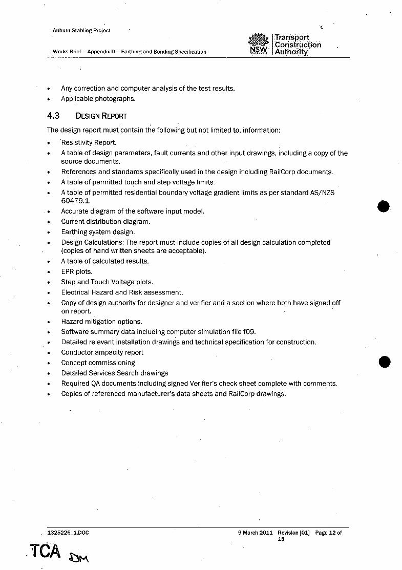
Auburn Stabling Project
Works Brief - Appendix 0 - Earthing and Bonding Specification
• Any correction and computer analysis of the test results.
• Applicable photographs.
4.3 DESIGN REPORT . .
I Transport,
, ,.Construc;t, ion Authority,
The design report must contain the following but not limited to, information:
• Resistivity Report.
• A table of design parameters, fault currents and other input drawings, including a copy of the source documents.
• References and standards specifically used in the design including RailCorp documents.
• A table of permitted to~ch and step voltage limits.
• A table of permitted residential boundary voltage gradient limits as per standard AS/NZS 60479.1.
• Accurate diagram of the software input model.
• Current distribution diagram.
• Earthing system design.
• Design Calculations: The report must include copies of all design calculation completed (copies of hand written sheets are acceptable).
• A table of calculated results.
• EPR plots.
• Step and Touch Voltage plots.
• Electrical Hazard and Risk assessment.
• Copy of design authority for designer and verifier and a section where both have signed off on report.
• Hazard mitigation options.
• Software summary data including computer simulation file f09.
• Detailed relevant installation drawings and technical specification for construction.
• Conductor ampacity report
• Concept commissioning
• Detailed Services Search drawings
• Required QA documents including signed Verifier's check sheet complete with comments.
• Copies of referenced manufacturer's data sheets and RailCorp drawings.
1325226_1.DOC
.rCA,~ 9 March 2011 Revision (01) Page 12 of
18

Auburn Stabling Project
Works Brief - Appendix D - Earthing and Bonding Specification
5 REPORT DATA
5.1 SOFTWARE CALCULATED RESISTIVITY SUMMARY.
·1 Transpqrt NSW ·0. o.ns. tru.·ction -"""""<:><r: .. ~;uthority
The Contractor will ensure that the following CDEGS calculated soil resistivity data (sample only) used for the earthing system design must be included in the body of the report.
SOIL RESISTIVITY SUMMARY
Location GPS Co-ordinates Layer Resistivity Thickness
. CO/m) (m)
Top
Middle
Bottom
5.2 VOLTAGE LIMIT TABLE
The Contractor will ensure that the following calculated voltage limit results (sample only) used for the earthing system design must be included in the body of the report.
IEEE Std 80 - 0.86s fault clearance time
Surface Properties ** 50 kg 70 kg
StepM Touch M StepM Touch M
Wet concrete 20Q.m 186 140 252 190
Normal soil 2880·m 341 179 462 243
Normal soil with shoes 20000/shoe 842 304 1139 412
100mm crushed rock with shoes 30000·m 1943 580 2630 785
50mm asphalt with shoes 100000·m 2418 698 3272 946
Hand-to-hand touch voltage [V] 125 169
**Value to be nominated
5.3 ELECTRODE RESISTANCE RESULTS
The Contractor will ensure that the following calculated electrode/grid resistance values (sample only) must be included in the body of the report:
Electrode Description
HV Single Electrode
HV Combined Electrodes
HV UGOW Electrode
HV UGOW Combined Electrodes
HV System
1325226_1.DOC
CALCULATED ELECTRODE RESISTANCE
Quantity
1
1
Resistance (ohm)
9 March 2011 Revision [01) Page 13 of 18
TCA ~

Auburn Stabling Project
Works Brief - Appendix D - Earthing and Bonding Specification
CALCULATED ELECTRODE RESISTANCE
LV Single Electrode 1.
LV Combined Electrodes
5.4 SOIL RESISTIVllY TABLE
The Contractor will ensure that the following measured soil resistivity results (sample only) used. for the earthing system design must be included in an Appendix of the report. The Appendix must also include CDEGS soil resistivity plots.
Date
Location
Local conditions
Method
GPS
Location drawing reference
Spacing(m)
0.5
1
2
4
6
··8
10
20
30 etc.
SOIL RESISTIVITY (example only)
Resistance (ohm) Resistivity (ohmjm)
6 DRAWING INFORMATION
6.1 'CLAMP ON METER' MEASURED ELECTRODE RESULTS
The Contractor will ensure that the following 'clamp on meter' measured electrode results (sample only) must be shown on the electrode layout drawing:
Electrode Description
Electrode HV1
Electrode HV2
1325226_1.DOC
CLAMP-ON METER ELECTRODE RESISTANCE
Calculated
Resistance (ohm)
Date Measured Date Measured
9 March 2011 Revision [01) Page 14 of 18

< "
Auburn Stabling Project
Works Brief - Appendix D - Earthing and Bonding Specification
~ Trarisport
!j ... C. onstruction Authority
CLAMP-ON METER ELECTRODE RESISTANCE
Electrode HV3
Electrode HV4
Electrode UGOHi
Electrode UGOH2
Electrode LVi
Electrode LV2
6.2 FALL OF POTENTIAL MEASURED RESULTS
The Contractor will ensure that the following minimum 'Fall of Potential' measured electrode/grid results (sample only) must be shown on the electrode layout drawing:
FALL OF POTENTIAL GRID RESISTANCE
Electrode Description Resistance (ohm)
Calculated Date Measured Date Measured
HV Combined Electrodes
HV UGOW Combined Electrodes
HVSystem
LV Combined Electrodes
6.3 CURRENT INJECTION RESULTS
The 9ontractor will ensure that the following minimum current injection measured electrode/grid results (sample only) must be shown on the substation layout drawing:
Substation system
1325226_1.DOC
CURRENT INJECTION GRID RESISTANCE
Measured
Voltage
Resistance (ohm)
Current Measured Calculated Injected Resistance Resistance
9 March 2011 Revision [01] Page 15 of 18

Auburn Stabling Project
Works E!rief - Appendix D - Earthing and Bonding Specification
7 DRAWINGS
lTransport !I. Construction .Authority .
The Contractor will ensure that all drawings must be completed in conformity with EP 00 00 00 15 SP 'Common Requirements for Electrical Equipment' with particular emphasis on Section 6.1.3.1 referencing 'Procedure Number: ED 0024P -CAD and Drafting Manual - Electrical'.
7.1 LAYOUT DRAWINGS
The Contractor will be required to provide layout drawings detailing the location earthing arrangement, geographical information, substation/bungalow/pole locations, fence breaks, GST breaks, pole earth wire or any other earthing solution. For fence and GST break solutions, detailed construction drawings will be required.
7.2 CONSTRUCTION DRAWINGS
The Contractor will ensure all construction drawings must contain all information necessary for construction without further clarification including tables nominating:
• Item reference.
• Component description.
• Component part number.
• Quantity per assembly (as applicable).
• All external cables and conductors (including earthing conductors) and components must be identified by an individual number code.
• Installation details for all electrodes including component part numbers, quantities etc.
• Installation layout drawings, detailing the location to all electrodes with full dimensions, interconnecting earthing connections, substations, poles, transformers, bungalows, services, fence and troughing and any other construction details necessary to complete the earthing installation.
• Padmount substation earth electrode/ earth grid (70mm2 copper minimum) specification including (as a minimum) all required conduits, conductor/cable sizes, conductor connections, conductor depths and ground cover material specification, thickness and width.
7.3 EARTH GRID DATA ARRANGEMENT DRAWING
The Contractor will ensure that the earthing electrode general arrangement drawing must include relevant data tables listing:
• Measured soil resistivity data table.
• Applicable Step and Touch Voltage limits
• Design calculated values of both individual electrodes and combined sections of the earth grid system.
• Provision for 'fall of potential' measured results of both individual and combined sections of the earth grid system.
• Provision for 'clamp on meter' measured results for individual electrodes.
Refer to RailCorp Drawing EL 0480394 for reference.
7.4 TECHNICAL SPECIFICATION FOR CONSTRUCTION
The Contractor will ensure that the technical specification for construction must include, but not limited to, the following sections:
• Document control page. (Including signatures of Designer, Verifier and Approver). 1325226_1.DOC
TeA CJ~ 9 March 2011 Revision [01] Page 16 of
18
... i ! ~

e
Auburn Stabling Project
Works Brief - Appendix 0 - Earthing and Bonding Specification
transport Construction Authority
• Introduction detailing the project scope and contributors to the project.
• Technical specifications for the components proposed for the installation including sufficient information to allow construction to be completed without further reference to the designers.
• References specifically related to the installation·phase.
• Product information.
• Electrical works specification.
• Drawings. Adequate drawings marked 'FOR CONSTRUCTION' must be supplied for:
• Installation of earth electrodes (methods etc.) and associated interconnection.
• Component details and quantities.
• Isolation details required for metallic fences, service troughing and conduits etc.
Note the specification as detailed above may be included in, and form part of, the design report.
8 ASSET MANAGEMENT DOCUMENTATION
Detailed asset mar;lagement documentation including complete works as executed drawings must be produced in accordance with TSR A1.
9 EARTH GRID DESIGN STANDARDS
The earthing and bonding designs must comply with the requirements, regulations, guidelines and engineering practices of the RailCorp, Australian, and/or agreed International, standards/drawings listed in the following table:
Ver. 2.1- 2002
EP 12 10 00 11 SP Ver. 2.1- 2002
EP 12 10 00 12 SP Ver. 2.1- 2002
EP 12 10 00 20 SP Ver. 2.1- 2002
EP 12 100021 SP Ver. 2.1- 2002
EP 12300001 SP Ver. 2.1- 2002
EP 21 00 00 01 SP Ver. 2 - 2001
ENA EG1 2006
ASjNZS 3000 2000
AS 2067 2008
ASjNZS 4853 2000
ASjNZS 3835.1 2006
IEEE Std 80 2000
IEEE Std 81 1983
1325226_1.DOC
System Substation Earthing
Distribution Substation Earthing
Transmission Line and Cable Earthing
Low Voltage Distribution Earthing
Low Voltage Installations Earthing
Electrolysis From Stray DC Current
Insulation Co-ordination & Surge Arrester Selection
Substation Earthing Guide
Electrical Installations
SWitchgear assemblies and ancillary equipment for alternating voltages above 1 kV
Electrical Hazards on Metallic.Pipelines
Earth Potential Rise - Protection of Telecommunications Network Users, Personnel and Plant - Code of Practice
Guide for Safety in AC Substation Grounding
Guide for Measuring Earth Resistivity, Ground Impedance and Surface Potentials of a Ground system
9 March 2011 Revision [01) Page 17 of 18
TCA" ~

Auburn Stabling Project
jTran$pqrt
Works Brief - Appendix D - Earthing and Bonding Specification .~ Construction I Authority
IEEE Std 81.2 1991
EL 0455388
EL 0480394
EL 0455387
CV0041344
EL0022088
ETN 11/02 2011
1325226_1.DOC
.Characteristics of Large. Extended or Interconnected Grounding Systems
11kV/415V Padmount Assembly Footprint Arrangement
11kV/415V Pad mount Assembly Earthing Arrangement
415V/415V Padmount Assembly Footprint Arrangement
Insulating Fence Panel
OHEW earth connection details
Earthing Designs for RailCorp's High Voltage AC System
9 March 2011 Revision [01) Page'18 of 18

I
Transport Construction
t!~Y.Y, Authority D&C Contract for Auburn Stabling Project (Stage 1)
Works Brief
Appendix E Signalling Functional Specification
AARLEG-#18499703-vl-Auburn_ TCA_Works_BrieC210611. DOC
'.i,\TCA~


SIGNAL DESIGN
LEVEL 13,477 Pin STREET
SYDNEY NSW 2000
TELEPHONE (02) 9782-1769
Facsimile (02) 9782-1726
NSW GOV£;;RNMIONT
Auburn Stabling Project
~Transport Construction Authority··
SIGNALLING FUNCTIONAL SPECIFICATION
27 April 2011
This report and the information contained therein have been created solely for a particular purpose and client. This is protected b'y copyright. You may not reproduce any of it in any form without permission of Rail Corporation New South Wales if you do, you may have to pay damages to Rail Corporation New South Wales or you may be prosecuted.

Quality Information
Do.cument Auburn Stabling Projecf - Signalling.Functional Specification
Ref 731769v4
Date 27 April 2011
Prepared by Richard Power (RPP) i<
Reviewed by Allen Brock (AJI:3}
Approved by David Bluck (DWB)
Document Control & Revision History . . ..
Rev No Date ""J-"'-'.. Revision D;t;"il;'"'"~~m"'""_~J---Auth;;-'"-
.0 20/07/20 ... -.... -. '"-'--I~'~;d-F~~S~;;;hbTd;c~~;;;;~t"~"·'"··- 1··'""······_··RPp
18/10/2010 Amended to Incorporate Auburn.&Clyde Junctions
2 10/01/2011 Removal of Auburn.Junction Connection RPP
3 27/04/2011 Amended to RailC()rp t,:omments RPP
j----"'f-'-----l------.-""--'-.'.'."----,,-"
, 27/04/2011
TCA , ~M.
AJB
AJB
" ..... ..;., ..... ........................
.. ;
Approver
.B;
OWB
:OWB
Page 2

AUBURN STABLING PROJECT
SIGNALLING FUNCTIONAL SPECIFICATION
REVIEWED BY:
Wayne Griffith - Team Leader, Signals
RailCorp
APPROVED BY: .
Stephen Scott - General Manager, Timetable Development
RailCorp
APPROVED BY:
Warwick Allison - Chief Engineer, Signals ,
RailCorp
27/04/2011 . Page 3
TCA ~

TABLE OF CONTENTS
1 INTRODUCTION .............................................................................................................. 5
2 OPERATIONAL OBJECTIVES .................... : ...................................................................... 5
3 TRACK LAYOUT ............................................................................................................. 5
4 LINE SPEEDS •••••••••••••••••••••••••••...•....•.......•........•.•..•.•....•.•.•.•..•......•....•..........•......•••••••••• 5
5 PROPOSED SIGNALLING WORK •.•.....•...•••••.•••.•...••..••....•.••••••••..••.•••••••••••••••••••••••••••••••..•• 6 5.1 OVERVIEW ........................................................................................................................... 6
5.2 TRAIN CONTROL SYSTEM .................................................................................................... 6
5.3 SIGNALLING INTERLOCKING CONFIGURATION ........................................................................ 6
5.4 SIGNALLING EQUIPMENT ROOMS AND CABLE ROUTE ............................................................ 7
5.5 SIGNALLING DESIGN CRITERIA ............................................................................................. 8
5.6 FIELD EQUIPMENT ............................................................................................................... 8
6 SIGNALLING INTERFACES ......•.•••••••••••••••••••••••••••••••••••••••••••••••••••••••••••••••••••••••••••••••••.•.. 14 6.1 CLYDE JUNCTION INTERFACE ............................................................................................. 14
6.? AUBURN MAINTENANCE CENTRE INTERFACE ...................................................................... 14
7 TRAIN OPERATIONS ..................................................................................................... 15 7.1 OVERViEW ........................................................................................................................ 15
.7.2 NEWCONFIGURATION ....................................................................................................... 15
7.3 CATCH POINTS ........................................................................... , ..................................... 15
7.4 GROUNDFRAMES ............................................................................................................... 15
7.5 ApPROACH LOCKING ......................................................................................................... 16
7.6 AUTOMATIC NORMALISiNG ................................................................................................. 16
7.7 AUTO-RECLEARING OF ROUTES ......................................................................................... 16
7.8 CONDITIONAL CLEARING OF SiGNALS ..................... : ........................................................... 16
8 SIGNALLING STAGEWORK .......•••••••..•••••••••••••.••••••••••••••••••••••••••••••••.•.•••••••••••••••••••••••..•• 17 8.1 ENABLING STAGEWORKS ................................................................................................... 17
8.2 SIGNALLING SUPPORT WORKS .......................................................................................... 17
8.3 SIGNALLING STAGEWORKS ................................................................................................ 17
APPENDIX A - PROPOSED DRIVERS DIAGRAMS
APPENDIX B - MICROLOK II INTERLOCKING ARCHITECTURE
APPENDIX C - AIR SUPPLY SCHEMATIC
APPENDIX D - LOW VOLTAGE LINE DIAGRAM
27/04/2011
TCA~ Page 4

1 INTRODUCTION
RailCorp is planning to expand its services to meet the forecast growth in passenger demand to 2020. The additional services require expansion in both rolling stock and stabling; as such the AuburnStabling Yard is being designed and built to provide additional stabling capacity.
The Auburn Stabling Yard is to be located adjacent to, and just to the West of, the Auburn Maintenance Centre and will be used predominantly for the over night stabling of trains.
2 OPERATIONAL OBJECTIVES
The project is to provide stabling capacity for eleven 1x8 car suburban sets; the layout will consist of 11 dead-end roads.
The Auburn Stabling Yard must be able to accommodate stabling requirements for peak and offpeak times.
The following morning peak (0330 to 0630) traffic flows are to be accommodated: • Exiting Auburn Stabling Yard at Clyde junction - Up to 11 trains accessing the Down
Suburban to support services on the South line via Granville Junction.
The following evening peak (1900 to 0130) traffic flows are to be accommodated: • Entering ~uburn Stabling Yard from Clyde junction - Up to 11 trains returning to Auburn
Stabling Yard.
3 TRACK LAYOUT
e 4
To achieve these operational objectives the following infrastructure will be provided:
• Construction of new track for the entire Auburn Stabling Yard; and
• Construction of a single track (the Transfer Road) with two way running connecting to the Down Relief to the east side of Clyde station;
LINE SPEEDS
Entry to the Transfer Road will be under the authority of a shunt aspect and therefore be limited to an entry speed of 2Skm/h. All exit movements out of the Auburn Stabling Yard will be under the authority of main line signals. The turnout speed from the .Auburn Stabling Yard to the Down Relief is 3Skm/h.
Trains will be restricted to 13km/h within the Yard, this will be enforced with the use of a speed sign placed at the entry to the Yard.
27/04/2011 Page 5
TCA ~

5 PROPOSED SIGNALLING WORK
5.1 OVERVIEW .
The Signalling works include:
• Train Control System
• . Signalling Interlocking
• Signalling Equipment Rooms and Cable Route
5.2 TRAIN CONTROL SYSTEM
Control of the Auburn Stabling Yard is to be via ATRICS at Homebush Control Centre. However, this will not become' available until the end of 2017 - after Clyde junction is commissioned into use by the Lidcombe to Granville Upgrade Program (LGCUP).
The Microlok Interlocking Simulation System (MISS) data will be used for implementation in emergency control situations, as noted in QSDP71.
5.3· SIGNALLING INTERLOCKING CONFIGURATION
5.3.1 NEW INTERLOCKING
The proposed interlocking arrangement will be a duplicated hot standby Microlok II located in interlocking room AS523. This interlocking will communicate with duplicated Microlok II 1/0 units for interfacing to trackside equipment via peer to peer utilising TCP/IP protocol.
The vital data links will be formed of 2 local rings (A & B) using fibre optic bearers. Ruggedcom servers on each ring will communicate independently with the duplicated Microlok II 1/0 units to provide redundancy.
A separate diagnostic link utilising terminal servers will also be provided. The links will be single mode fibre optic.
The minimum level of route diversity will be achieved by running one leg of the A link and one leg of the B link in one conduit within the Combined Services Route (CSR), and the other leg of each lin~ in a separate conduit within the same CSR. The conduits will then be spaced as far apart as possible within the same route. The object of this method is that if a single conduit is cut only one leg of the link will be cut, thus, maintaining system availability. .
The signalling interlocking configuration will have the following features:
• A duplicated Microlok II interlocking connecting to duplicated Microlok II 1/0 units
• Signals will be fed via 12V DC relays driven from the Microlokll vital output cards
• Interface relays will be used for point contactors,' isolating relays and trainstop controls
• Ruggedcom Ethernet servers will be connected to single-mode fibre optic links to provide TCP/IP functionality. RS400 rugged servers are to be used to communicate with Microlok Card Files.
27104/2011 Page 6
TOA \J~ . .
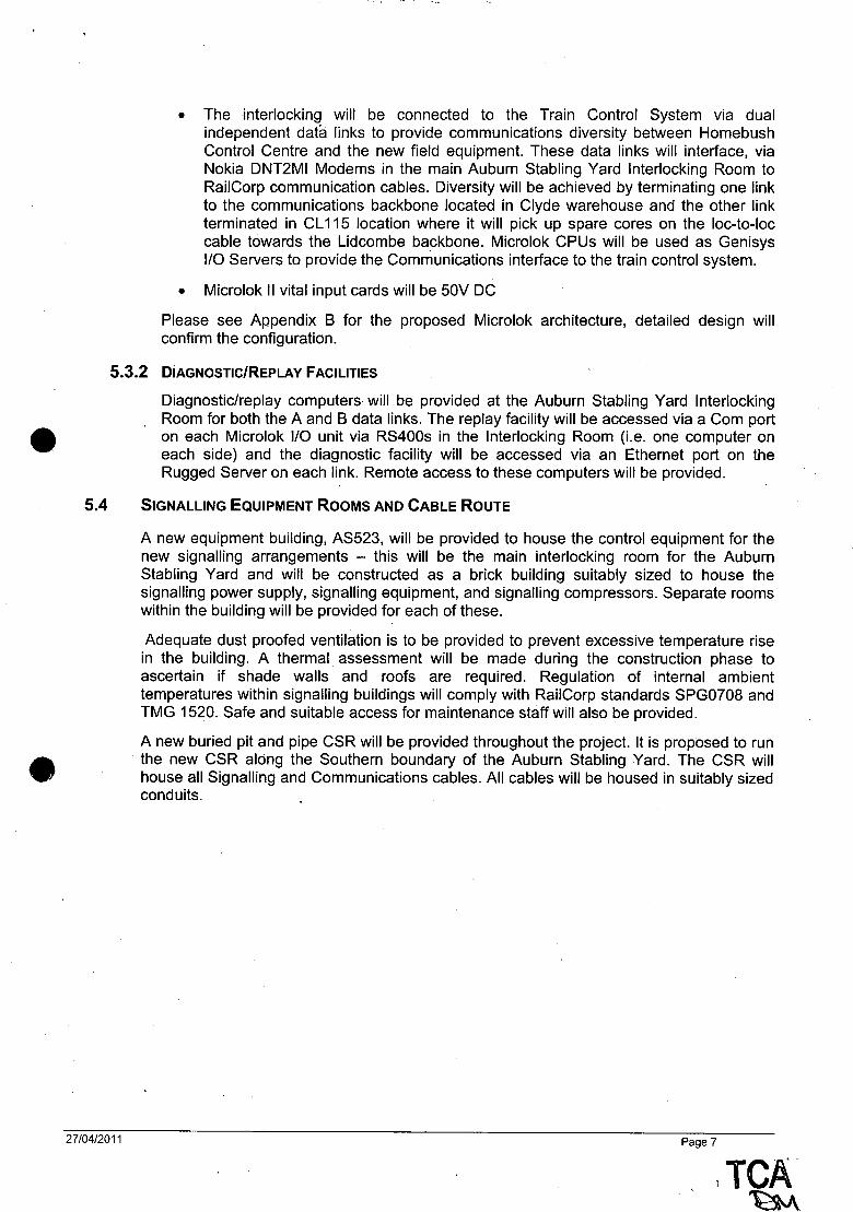
• The interlocking will be connected to the Train Control System via dual independent data links to provide communications diversity between Homebush Control Centre and the new field equipment. These data links will interface, via Nokia DNT2MI Modems in the main Auburn Stabling Yard Interlocking Room to RailCorp communication cables. Diversity will be achieved by terminating one link to the communications backbone located in Clyde warehouse and the other link terminated in CL 115 location where it will pick up spare cores on the loc-to-Ioc cable towards the Lidcombe backbone. Microlok CPUs will be used as Genisys I/O Servers to provide the Communications interface to the train control system.
• Microlok II vital input cards will be 50V DC
Please see Appendix B for the proposed Microlok architecture, detailed design will confirm the configuration.
5.3.2 DiAGNOSTiC/REPLAY FACILITIES
Diagnostic/replay computers will be provided at the Auburn Stabling Yard Interlocking Room for both the A and B data links. The replay facility will be accessed via a Com port on each Microlok I/O unit via RS400s in the Interlocking Room (Le. one computer on each side) and the diagnostic facility will be accessed via an Ethernet port on the Rugged Server on each link. Remote access to these computers will be provided.
5.4 SIGNALLING EQUIPMENT ROOMS AND CABLE ROUTE
27/04/2011
A new equipment building, AS523, will be provided to house the control equipment for the new signalling arrangements - this will be the main interlocking room for the Auburn Stabling Yard and will be constructed as a brick building suitably sized to house the signalling power supply, signalling equipment, and signalling compressors. Separate rooms within the building will be provided for each of these.
Adequate dust proofed ventilation is to be provided to prevent excessive temperature rise in the building. A thermal assessment will be made during the construction phase to ascertain if shade walls and roofs are required. Regulation of internal ambient temperatures within signalling buildings will comply with RailCorp standards SPG0708 and TMG 1520. Safe and suitable access for maintenance staff will also be provided.
A new buried pit and pipe CSR will be provided throughout the project. It is proposed to run the new CSR along the Southern boundary of the Auburn Stabling Yard. The CSR will house all Signalling and Communications cables. All cables will be housed in suitably sized conduits.
Page 7
1 TCA~

5.5 SIGNALLING DESIGN CRITERIA
The key signalling design criteria are:
Design Criteria
Overlaps GE 52A and nominal yard working overlap dist,?nce of 60m
Braking GE62
5.6 FIELD EQUIPMENT
5.6.1 EQUIPMENT TYPES
The following equipment is proposed for the installation:
Item Type
Signals All signals to be Alstom lED type - elevated type for siding exit roads and where the structure gauge permits.
. Automatic Train Protection Alstom Lineside Electronic Units (lEUs) and Balises (ATP)
Signal Miniature Multi-lamp Alstom lED type and are to be used on shunt signals with more Route Indicators (MMlRl) than 4 routes.
Train Stops Westinghouse Electro-pneumatic JA type.
Points Pneumatic in-bearer VAE Spherolock, trailable, with 'A' valve type control unit and keyless typ~ EOl's.
Track Circuits Jeumont Schneider High Voltage Impulse Track Circuits. Westinghouse 2000P Series Impedance Bonds.
Relays All relays to be of an approved type and from an approved manufacturer.
Microlok output relays are to be BR930 series 12v DC. Other vital relays are to be BR930 series 50v DC.
Interlocking Microlok II interlocking with I/O units
Server / Ethernet switch Ruggedcom RS400 servers throughout the project
5.6.2 SIGNALS
All stabling road exit signals are to be elevated type.
27104/2011
The final position and location of.the new signals are subject to the decision of the signal sighting committee.
Page 8
TCA·~

5.6.3 NEW SIGNAL ROUTES
The following new signal routes will be provided:
Signal Status Description
Route Remarks
Route Indicator
AS523(S) New Shunt, Stabling No.11 to - Elevated type
Transfer Road
AS525(S) New Shunt, Stabling No.1 0 to - Elevated type
Transfer Road
AS527(S) New Shunt, Stabling NO.9 to Transfer - Elevated type
Road
AS529(S) New Shunt, Stabling NO.8 to Transfer - Elevated type
Road
AS531(S) New Shunt, Stabling No.7 to Transfer - Elevated type
Road
AS533(S) New Shunt, Stabling NO.6 - Elevated type
AS535(S) New Shunt, Stabling NO.5 to Stabling - Elevated type
NO.6
AS537(S) New Shunt, Stabling No.4 to Stabling - Elevated type
NO.6
AS539(S) New Shunt, Stabling NO.3 to Stabling - Elevated type
Road NO.6
AS541(S) New Shunt, Stabling No.2 to Stabling - Elevated type
NO.6
AS543(S) New Shunt, Stabling No.1 to Stabling - Elevated type NO.6
AS544(S)A New Shunt, Transfer Road to Stabling
7 MMLRI provided NO.7
AS544(S)8 New Shunt, Transfer Road to Stabling
8 MMLRI provided NO.8
AS544(S)C New Shunt, Transfer Road to Stabling
9 MMLRI provided NO.9
AS544(S)D New Shunt, Transfer Road to Stabling
10 MMLRI provided No.10
AS544(S)E New Shunt, Transfer Road to Stabling
11 MMLRI provided No.11
AS546(S)A New Shunt, Stabling No.6 to Stabling
1 MMLRI provided No.1
AS546(S)8 New Shunt, Stabling NO.6 to Stabling
2 MMLRI provided No.2
AS546(S)C New Shunt, Stabling Road NO.6 to
3 MMLRI provided Stabling No.3
AS546(S)D New Shunt, Stabling NO.6 to Stabling 4 MMLRI provided No.4
AS546(S)E New Shunt, Stabling NO.6 to Stabling
5 MMLRI provided NO.5
27/04/2011 Page 9
.. TCA .. ' ~

r
Signal Status Description Route
Remarks Route Indicator
AS546(S)F New Shunt, Stabling No.6 6 MMLRI provided
Led by AS544 or AS546.
Stencil route indicator provided.
AS548(S)A New Shunt, Transfer Road to Stabling
6 The proposed route
No.6 indicator will be altered' through the detailed design process to
minimise driver confusion.
Elevated type
Led by AS544 or AS546.
Stencil route indicator provided
The proposed route
AS548(S)8 New Shunt, Transfer Road TR indicator will be altered
through the detailed design process to
minimise driver confusion.
Elevated type
CL 123(S) New Shunt, Transfer Road - Led by CL 133
,CL 125(S) New ,Shunt, Stabling No.6 to Transfer - Led by CL 133
Road
Leads CL 123 and CL125
CL 133(M) New Down Home, Transfer Road to Requirement for
Down Relief -
turnout repeater to be decided by Signal
Sighting Committee
CL 133(S) New Shunt on Down Home, Transfer Leads CL 123 and
Road to Down Relief - CL 125
CL 150(M) Existing Up Home, Down Relief - -
CL 150(S)A New Shunt on Up Home, Down Relief DR Stencil route indicator
provided
CL 150(S)8 New Shunt on Up Home, Down Relief
SR Stencil route indicator
to Standing Roads provided
27/04/2011 Page 10
TCA \lV\ , I

Signal Status Description'
Route Remarks Route Indicator
CL 150(S)C New Shunt on Up Home, Down Relief
BR Stencil route indicator
to Bypass Road provided
CL 150(5)0 New Shunt on Up Home, Down Relief
TR Stencil route indicator
to Transfer Road provided
AY994 Existing Shunt, Down Relief - Signal & associated routes removed
Note Cl 127, Cl129, Cl 131, Cl135, and Cl201 have been renumbered by lGCUP as part of their works in the area. .
The proposed route indicator for AS548(S)A and AS548(S)B will be altered through the detailed design process to minimise driver confusion.
5.6.4 NEW POINTS
Points
647
648
649
650
651
652
653
654
655
656
683A1B
The following new points will be provided:
Description
Points, Stabling NO.3 to Stabling No.2
Points, Stabling NO.6 to Stabling NO.5
Points, Stabling NO.7 to Stabling NO.8
Points, Stabling NO.9 to Stabling No.1 0
Points, Transfer Road to Stabling NO.9
Points, Stabling No.1 to Stabling NO.3
Points, Stabling NO.6 to Stabling No.4
Points, Transfer Road to Stabling NO.7
Points, Stabling NO.6 to Stabling No.1
Points, Transfer Road to Stabling No.6
Crossover, Transfer Road to Down Relief
All new EOl's will require input form a sighting committee in order to facilitate safe access. Emergency Equipment Boxes are to be provided. These will house spare flags, clips, and Xl locks for use in operationally degraded conditions. The amount and position of these boxes will require operational input in the construction phase.
5.6.5' TRACK CIRCUITS
27104/2011
The Auburn Stabling Yard will be fully track circuited. Jeumont Schneider track circuits will be used throughout the project boundaries. Single rail track circuits will be used throughout the project except for the Transfer Road, which will be double rail.
Traction bonding will be provided in accordance with heavy traction area requirements .•
Page 11
, " TCA ~

5.6.6 TRAIN STOPS
Main line signals will be fitted with trainstops. In general, shunt signals within the Auburn Stabling Yard will not be fitted with trainstops. However, shunt signal, Cl123, Cl125, and AS548 protecting Manchester Road level crossing will be fitted with trainstops. All trainstops 'will be suppressed as required by RailCorp Signal Design Principles to avoid back tripping of trains except where the approach to that signal may be occupied.
A fixed train stop will be placed 2m before each friction buffer stop on each of the 11 dead-end sidings to mitigate against collision whilst allowing the train to draw up to the buffer stop. A buffer stop light is to be placed adjacent to each fixed train stop:
5.6.7 GUARDS INDICATORS
There is no requirement for Guards Indicators.
5.6.8 WARNING LIGHTS
It is not anticipated that Warning Lights will be required however Maintenance and Operational input will assess requirements at an early stage in the design.
5.6.9 SIGNALLING POWER SUPPLY
The nprmal signalling supply will be derived from the RailCorp 11 KV network feeder 623 and the back-up emergency supply will be derived from the local Energy Australia system. The signalling supplies will be located in the main interlocking building (AS523).
A ·new Uninterruptable Power Supply (UPS) will be provided in the main interlocking building and designed such that changeover from normal' to emergency and back will not cause any disruption to the signalling. .
Please refer to Appendix D for a lV line diagram detailing the proposed arrangements.
5.6.10 TELEPHONES
New telephones will be provided at all new signals and new points EOl's.
5.6.11 BUFFER STOPS
A nominal 13km/h Friction Buffer Stop will be provided at the end of each of the 11 'dead-end sidings. The line speed in the Auburn Stabling Yard area is 13km/h therefore the fixed trainstop in conjunction with the 13km/h friction buffer stops will provide suitable mitigation for overrun of trains terminating in ~he sidings. e
5.6.12 LEVEL CROSSINGS
The Manchester Road level crossing situated along the Transfer Road is at present an active level crossing with boom gates and flashing lights. This crossing is the only
. access road to the Auburn Maintenance Centre and services freight road traffic and emergency services to and from the Auburn Maintenance Centre. There is no staff traffic across this crossing as the staff car park is on the Eastern side of the crossing and is serviced by a pedestrian footbridge. The Auburn Stabling Project introduces an additional track through the existing crossing. It is proposed that this crossing be expanded in order to accommodate the new alignment. This expansion will be implemented as part of the commissioning of Clyde junction in 2017.
level crossing warning boards to be provided for all stabling roads holding and control strike in points, the numb~r and position of the boards is to be finalised at detail design.
A separate level crossing technical interface document will be produced. This will describe in detail the control of the Manchester Road crossing and how the interfaces between each of the three interlockings controlling it will operate.
27/04/2011 Page 12
TCA CJtv\
r,-' it,: .

5.6.13 AUTOMATIC TRAIN PROTECTION
The Yard is to be fitted with ETCS level 1, using Alstom LEU's and balises. A separate conduit will be installed in the main CSR and to each anticipated controlled balise location (approximately 5m on the approach side of each signal). The position of each balise will be confirmed at the detail design phase and will ensure that standing room is provided for trains clear of the balise positions.
5.6.14 AIR SUPPLY
27104/2011
Pneumatic operation of points and trainstops is to be provided as part of this project. A new compressor room is to be constructed and located adjacent to the main interlocking room. The air compressor has been sized to accommodate the possible future expansion of the Yard including a dual connection at Auburn junction.
It is proposed to install 2 off Atlas-Copco GX7FF compressor units mounted on a 270 litre tank with inbullt refrigerator drier. This will have the following indicative operational specifications - to be finalised in detail design:
Working pressure
Output (each)
10 bar
11.6 litres/sec FAD
Plus 1 off OSC 35-2400 oil - water separator
The chosen capacity of the air supply assumes the following:
• The number of point ends with RailCorp 5% simultaneous operation plus 30% leakage allowance requirements; and
• Potential maximum number of point operations during peak usage of 16 trains per hour (assuming future Auburn connection).
The air line will be galvanised steel type and will be above ground. Crossties will be flexible hose within PVC conduit. PVC hose will be used in Under Line Crossings (ULX) or in Under Road Crossings (URX). Pressure transducers will be installed on both sides of the ULX and URX, the transducers will be individually cabled back to the compressor room to provide remote monitoring of the air pressure. Stainless steel manifolds will be provided and connections between manifolds and equipment will be flexible hose.
The pneumatic supply will have a PLCNDU based monitoring system for the maintainer with a remote diagnostic facility.
Provision will be made for indications to be sent from the new compressor room to the ATRICS system at Homebush Control Centre. Two indications are to be included: Yellow Warning if partial failure of the system has occurred and a Red Alarm if complete failure of the system has occurred.
Redundancy of the Auburn Stabling Yard air supply is to be provided via a connection to the Clyde compressor room 'located on the main corridor to the west of the Yard. This redundancy will not be reciprocal, that is, the Auburn Stabling Yard compressor room will not need to be sized to provide redundancy to the main corridor.
The propo.sed airline arrangement and calculations are shown in Appendix C.
Page 13
TeA ~

6 SIGNALLING INTERFACES
Two signalling interface points have been identified between the Auburn Stabling Yard and adjacent facilities:
• Clyde Junction, a single connection from the Auburn Stabling Yard to the Down Relief line; and
• Auburn Maintenance Centre, at the Clyde end of the Auburn Stabling Yard, which currently controls the Manchester Road Level Crossing.
6.1 CLYDE JUNCTION INTERFACE
At present, Clyde Interlocking is relay controlled; however, this control does not extend to the Suburban or Down Relief Lines. When Clyde junction is remodelled by LGCUP, this will be replaced with a new Microlok II system. .
The interface between the Auburn Stabling Yard and the mafn corridor will be between CL 115 and the Auburn Stabling Yard interlocking room AS523, To achieve this, the fibre optic data link will be extended from AS523 to CL 115. The cable will terminate in CL 115 to an RS400 server where it will become part of the main corridor master interface ring.
In order to authorise movements into and out of Auburn Stabling Yard via Clyde junction it is required that the Auburn Stabling Yard and main corridor interlockings communicate vitally. This will require interlocking functions to be passed between the Auburn Stabling Yard and Clyde Interlockings. The two interlockings will communicate vitally via a Microlokto-Microlok interface utilising RS400 servers over fibre optic cable. The configuration for this link is shown in Appendix B.
Train movements into or out of the Auburn Stabling Yard via Clyde Junction will not be able to commence until Clyde Junction is commissioned by LGCUP - anticipated to be early 2017.
6.2 AUBURN MAINTENANCE CENTRE INTERFACE
27/04/2011
TeA
Currently Auburn Maintenance Centre is the sole operator and maintainer of the Manchester Road level crossing located at the Western side of the facility. This crossing protects freight vehicular traffic required to enter Auburn Maintenance Centre.
When Clyde Junction is. commissioned into use, the Auburn Stabling Project works will have added an additional track through the croSSing. The crossing is to be expanded to accommodate a total of three tracks. The addition of the third track will require the Dew Auburn Stabling Yard approaches and extension of the existing Auburn Maintenance Centre approaches to include holding tracks. '
It is proposed that the existing Signalling Interface Coordination Plan between the Auburn Maintenance Centre and RailCorp be amended to incorporate the Auburn Stabling Yard, thus, minimising any cross boundary maintenance response problems.
Page 14

7 TRAIN OPERATIONS
7.1 OVERVIEW
The final signalling arrangements and track layout will facilitate movements to/from the Auburn Stabling Yard. All of this will be controlled by Homebush Control Centre via new Microlok II interlocking at Clyde.
The Auburn Stabling Yard will also.be controlled from Homebush Control Centre via a new Microlok II located within the Yard area.
Two-way running will be provided through the entire Yard with a speed limit of 13km/h.
7.2 NEW CONFIGURATION
7.2.1 EXITING FROM AUBURN STABLING YARD
Signals controlled from Homebush Control Centre via Clyde interlocking will authorise movements to the main corridor via the Transfer Road from the Auburn Stabling Yard and from Auburn Maintenance Centre. Signals from the Yard Stabling Roads 1 to 6 will authorise movements up to Clyde signal CL 125 and signals from Stabling Roads 7 to 11 will authorise movements up to Clyde signal CL 123. The subsequent movements to the main corridor will be completely under the control of Clyde interlocking signals.
In order to prevent trains standing over the Manchester Road level crossing, signals CL 123 and CL 125 will be led by CL 133. Catch point 683A will protect the main corridor from unauthorised movements past CL 133. Exit from Auburn Maintenance Centre will be authorised by CL 131 and CL 129. Catch points 680A and 681A will protect the main corridor from unauthorised movements past these signals.
7.2.2 ENTRY TO AUBURN STABLING YARD
Entry to the Auburn Stabling Yard from the main corridor will be via a shunt route on CL 150. Signal CL 150 will authorise movements to Auburn Stabling Yard signal AS548 which will be sited on the approach side of the Manchester Road level crossing. In order to prevent a train standing across the Manchester Road level crossing, clearance of AS548 will be led by the clearance of AS544 or AS546 signals.
It has been assumed trains will operate to timetable and that normally the signaller would route trains directly into the yard. In the event that there is no direct route into the yard, the signaller may hold the train on the approaches to the yard to avoid blocking both yards.
7.3 CATCH POINTS
The following catch point is required and will be installed and commissioned by others:
683A
7.4 GROUNDFRAMES
Nogroundframes will be provided
27104/2011 Page 15
TeA l
.~

7.5 ApPROACH LOCKING
All main line signals will be subject to a 120s approach locking time release with shunt signals having a 60s approach locking time release. '
7.6 AUTOMATIC NORMALISING
Automatic normalising will be provided on all routes.
7.7 AUTO-RECLEARING OF ROUTES
There is no requirement to provide auto-reclearing of routes.
7.8 CONDITIONAL CLEARING OF SIGNALS
Conditional Clearing of signals will not be provided.
Page 16

8 SIGNALLING STAGEWORK
A total of 2 signalling stages, including final commissioning, are proposed for the delivery of this project. All stageworks and consequent operational impacts will need to be agreed at the RailCorp Possessions Steering Group. A minimum of 20 weeks notice is required for operational impacts (this includes 6 weeks for timetable specification and 14 weeks for STNproduction).
8.1 ENABLING STAGEWORKS
8.2
8.3
27104/2011
Enabling stageworks will be required to relocate the signalling and communications cables affected by the new alignment.
Existing and new cable routes will be appropriately protected during earth works. Signal pits affected by the works will be relocated where necessary.
SIGNALLING SUPPORT WORKS
Some of the non-signalling stageworks may require signalling support, such as the bonding and/or detection of new non operational points and bonding associated with any OHW alterations. .
SIGNALLING STAGEWORKS
It is envisaged that there will be 1 non-operational signalling stage with 1 operational signalling stage. All signalling stages are detailed below. Drivers Diagrams are provided in Appendix A for each of these stages.
Stage 1 (Non-Operational Impact) - November 2013
It is proposed that the Auburn Stabling Yard area will be fully constructed by the end of 2013. At this stage, the Yard area will not be operational, as entry/exit to the Yard is dependant on the remodelling and commissioning of Clyde Junction. The commissioning of the final Microlok interlocking data that will not be undertaken at this stage. The yard will be tested as far as possible with the outputs from the interlocking simulated to the interfacing relays. Inputs to the final interlocking will also be tested. The tracks circuits will be adjusted and set to work as will the points mechanisms.
At the end of this stage, the system will be switched off and will remain inactive until Stage 2. All equipment subject to deterioration will be disconnected .and removed.
The Proposed infrastructure interface for this stage will be between interlocking rooms AS523 and CL 115. Local cabling, signals, track side equipment, and power supply will be installed up to the Yard side of the Manchester Road Level crossing. The CSR will also be run to this point, where the fibre will be coiled in a cable pit ready for the route to be completed to CL 115 interlocking room.
Stage 2 (Operational Impact) - January 2017
By the start of 2017, it is anticipated that LGCUP will have commissioned the Clyde area of the corridor. At this point, the Clyde junction and the yard interlocking and data will be commissioned into use and will allow entry and exit from the Auburn Stabling Yard via the Transfer Road. Entry and exits movements at Clyde junction will be as described in Section 7.2 above.
By the end of this stage, all Stabling Roads will be brought into use and the Yard's full operational capacity will be realised.
Page 17
TCA I "'.'.~ ." .. , . ~\.

APPENDIX A - PROPOSED DRIVERS DIAGRAMS
,.
TCA . . ,,' ~

ROUTE DESTINATION IND
(SIA STABLING No.7 7
(SIB STABLING No.8 8
544 (SIC STABLING No.9 9
(SID STABLING No.IO 10 (SIE STABLING No.11 11
ROUTE DESTINATION IND
(SIA STABLING No.1 I
(SIB STABLING No.2 2 (SIC STABLING No.3 3
546 (SID STABLING No.4 4
tJ (SIE STABLING No.5 5 (SIF STABLING No.6 6
AS523 x.cx
FOOTBRIDGE I· lQOm
• 1
~ 13 KPH -STABLING No.l1- ~523
t t ~ 651 654
EOl EDl ~123 654 ~
.--.j !FIXED ~
13 KPHA -STABLING No.10- ~525
651 574~~ :. 125
655 ~.
--.j!FIXED ~
13 KPH -STABLING No.q- ~527
--.j!FIXED ~
13 KP'j4 -STABLING No.8- ~529
546~ t
655 EOl
t --.j!FIXED
~ 13 KPH -STABLING No.7- ~531
652 EOl
--.j!FIXED ~
13 KPH -STABLING No.6- ~533
--.j!FIXED ~
13 KPH - STABLING No.5- ~535
--.j!FIXED ~
13 KPH -STABLING No.4- ~537 NOTE:
--.j!FIXED ~
13 KPH -STABLING No.3- ~53q
THE YARD WILL NOT BE IN USE AT THIS STAGE
--.j!FIXED ~
13 KPH - STABLING No.2- ~541
--.j~IXED ~
13 KPH - STABLING No.1- ~543
--.j~IXED
~
~ Rcu1Corp
AUBURN STABLING YARD STAGE 1 SIGNALLING ARRANGEMENT (2013)
SHEET 1 OF 1 VER 09032011

1J AS523 X.CX
Xh= SOm xc: 116m
I • 190m • I 14" Q 13Km/h 32" II 13Km/h
I t I ~ 651
-STABLING No.l1- ~523 1---0- EOl 1---0-13 KPH
e-j!FIXED ~
651
13KP~ -STABLING No.10- ~525
e-j!FIXEO ~
13 KPH -STABLING No.q- ~527.
e-j!FIXED ~
13 KPH,.;:::l ---:- STABLING No.8- ~52q t e-j!FIXED
652
~ EOl
13 KPH -STABLING No.7- ~531
e-jgIxEO ~
13 KPH -STABLING No.6- ~533
e-j!FIXED ~
13 KPH -STABLING No.5- ~535
e-j!FIXED ~
13 KPH -STABLING No.4- ~537
e-j!FIXED ~
13 KPH - STABLING No.3- ~53q
e-j!FIXED ~
13 KPH -STABLING No.2- ~541
e-j!FIXED ~
13 KPH - STABLING No.1- ~543
e-j!FIXED
ROUTE DESTINATION IND
(SIA STABUNG No.7 7
(SIB STABUNG No.8 8
544 (SIC STABUNG No.9 9 (sm STABUNG No.lO 10 (SIE STABUNG No.11 11
ROUTE DESTINATION IND
(SIA STABUNG No.1 1
(SIB STABUNG No.2 2
546 (SIC STABUNG No.3 3
• (sm STABUNG No.4 4
(SIE STABUNG No.5 5 (SIF STABUNG ·No.6 6
FOOTBRIDGE
t 654 ~ EOl ~123 654 ~
t1'- A 656 tu EOl UJ N
574~ 1 ~t25
Ill.. eno UJN UJ en
655 ~ A
546~ t
655 EOl
RailCorp
AUBURN STABLING YARD STAGE 2 SIGNALLING ARRANGEMENT (2017)
SHEET 1 OF 2 VER 09032011

TO AMC
f-<)-f---:-O---~969ISl
f-<)-f---:-O---~q?HS)
f-LU LUN ILL (/)0 LU~ LU (/)
MANCHESTER ROAD LEVEL CROSSING r:;;;--.,.
..... , t2V
A
A
\ \ :1. \ \ >l< I II' -30m • I • -100m
- TRANSFER ROAD-
~9731S1 ~ --.;...------....;;:.;...--...:.----.LI-LI ~131 SS
~ )) ~-.. ;::_-__ ~~/_ _ '0'(1'1'1
f-<)- f-<)-
L L J7;7'\ 9861S1 cr:r... - -__ -- ........ / ~ UJ~ 68lA
----...... ~ AY986
_ STANDING ROADS-
Xh = 50m Xc = S8m 23' C 8Km/h 30'. BKm/h
~-/.._---
ROUTE
ISlA
150 ISlB
IS1C
ISlD
Xc = 10Qm
DESTINATION
DOWN RELIEF
STANDING ROADS
BYPASS ROAD 1
TRANSFER ROAD
~ ~
1150l
IND
DR
SR
BR
TR
:
RaJ1Corp
AUBURN STABLING YARD STAGE 2 SIGNALLING ARRANGEMENT (2017)
SHEET 2 OF 2 VER 09032011

APPENDIX B - MICROLOK II INTERLOCKING ARCHITECTURE
TeA ~

CJ - RUGGED SERVER - RS400-24-R-C2C2-3R • CIIC2/C3/C4 - SERIAL DATA PORTS (RJ45)
• f1/F2 - FIBRE PORTS (SC)
• E3/E4 - ETHERNET PORTS (RJ45)
J..EG(tIll
II Fa PATCH LEADS 'SC-SC' CABLE 12 Fa PATCH PANEL CONNECTION POINT 13 DATA CAT 5 CABLE
----- DIVERSE LINK GM - GENISYS MASTER GS - GENISYS SLAVE
AUBURN STABLING PROJECT MICROLOK NET~ORK CONFIGURATION
AS523 r-----------------------------------, EXTERNAL
IN TO CONTROL SYSTEM
#3
EXTERNAL IN
#3
CLl15 <CLYDE INTERFACE) ~----------------~ 1 1
~ 1 I-":!--!...-dl AI 11 #1 AI
F2 fI I' 1 1 1 1 #1 1#21 . 1 #2 #~2 fI L ___________________ ~ ___ ~---J
#21 112 1 1 1 1 1 1 CURRENTLY UNDER
II
fI 12
1 DEVELOPMENT BY OTHERS :<INCLUDES INTERFACE TO AMC
So LEVEL CROSSING CONTROLS)I 1 1 1 1 1
eEl
'A' LINK
#1 II 1 'B' LINK
F2 #21
I 1 1 1 1 1

APPENDIX C - AIR SUPPLY SCHEMATICS
TCA .. ;" .~tM..

13 KPH STABLING No.1I
e---j !FIXEO
13 KPHA STABLING No.IO
e---j !F1XEO
13 KPH STABLING No.q
e---j !FIXEO
13 KP'k1 STABLING No.8
e---jK1XEO
J3 KPH STABLING No.7
e---j!FIXEO
13 KPH STABLING No.6
e---j!F IXEO
13 KPH STABLING No.5
e---jKIXEO
13 KPH STABLING No.4
e---j !FIXEO
13 KPH STABLING No.3
e---j!F IXEO
13 KPH STABLING No.2
e---jKIXEO
13 KPH STABLING No.1
e---jK1XEO
320M OPPROX
AS523 (SEPOROTE COMPRESSOR ROOM INSIOE'
o FLOW TRANSMITTER " " REGULATOR WITH CHECK VALVE \ \ - FLOW IN oNl.y
\ \:1 A FLOW LIMITED TO 1 LITRE/SEC MAX ~F e PRESSURE TRANSMITTER ~~~~~E~1~~s~2~D
, ,5K ~FROM CLYDE AlR 64q 650 651 653 654 ~~~ ~~ 656 548 TS RETICULATION CENTRE 9---------------------QY -- --T;r -----y -----y ---9----Y -r -----------0-8 -~ URr 8-0---Y :.-L'NE TO-M~T~H-C~Y: ~:~EM
~ t t t ~ :e tt I I ~ 651 654 '-'"' Xl 656 I I r-IDI523 ~ EOL ~ E~~4 ~ 123 5: EOL I I TRANSFER ROAD
XI -'I :;)1
I
~ r-IDI525
~ i--IDI527
~ r-IDI531
6-l Q ~533 ~
I
Xl -,I :;)1
I
~ i--IDI537
~ i--IDI54I
~ i--IDIS43 /
<;>:'7 ~ /// . /
[}----------------~/
/ /
/ /
~--------~~----~~~~~----651 - r-r.;L, 1 656 -=> 546 ~ '-'"' 548 ~
/ /
<;>:'8 /
/ /
/ /
/
/ /
/ /
/
t 652 EOL
/ /
/
/
/ /
/ /
/
/
~125 I ~ 655 ~: I
,D I /
/ / FOOTBRIOGE I 544~
t 655 EOL
/ /
/ I I /
/ ~ )) / ---- .............. /
O~5 ----/
/ /
0::2 / /
/
AUBURN STABLING YARD AIR SUPPLY ARRANGEMENTS
SHEET 1 OF1 VER 18052011

· .
TCA ,~

3750 npprox
r---------------------------------------~5700 npprox----------------------------------------~
II Sequence • Controller
I
Vehicular ( truck) access win be required to this side of building
Floor level vents in doors Net ansa 0.6 sq m
Compressor 2 Compressor 1
<1m "'~-~:~~ vent 400 n~;;:~~ ",nt \ over / \ over }
"------------ -~'.;-::::--:.·~~~I-;;dt;;;il.;y~--- --,,~:===~,.-!- -------------"
500 litre additional vertical tank
I~ 011 - water separator
CD Floor Level wall vent Net ansa 0.5 sq m. Floor Level wall vent. Net ansa 0.5 sq m.
SUGGESTED COMPRESSOR ROOM LAYOUT
Note: The above layout Is based on Atlas Copco GX7 FF compressor assemblies
with stendard 270 litre tanks
The additional tank shown is approximately 1800 high x 650 diameter
FInal size of room to be determined when component suppliers ara selected
NOTE Rotary roof vents to be placed above compressor cooling air oulets
Option 300mm powered rotary vents to operate with respective compressors

·TCA . .~

AUBURN STABLING YARD AIR RETICULATION SYSTEM
RECOMMENDED COMPRESSORS
Minimum compressor output
(From Appendix A - 5% equipment operating) 11.627 litres/sec
For normal operating conditions:
Minimum compressor size based on calculated maximum consumption of 5.0905 kg/hr (1.2
lit res/sec FAD)
For 33% duty cycle 3.6 litres/sec
For 20% duty cycle 6 litres/sec
For 10% duty cycle 12 litres/sec
The recommended compressors are:
2 off lOBar, 16 litre per second units with 270 litre receivers, Atlas Copco GX7FF or
similar.
An additional 500 litre common receiver (with by-pass pipe-work to allow for periodic
inspection) should be provided (refer to compressor room drawing).
Duty cycle will be less than 10% on calculated maximum load and one compressor has 30%
more output than required for the 5% load case.
Allowance has been made for emergency feeds from the Clyde and Auburn systems of a
maximum of 1 litre/second each but no provision has been made for this system to back-up
either Clyde or Auburn.
TCA ~

APPENDIX A
AUBURN STABLING YARD - AIR RETICULATION SYSTEM CALCULATIONS
Calculations based on:
Air Density
Air Main
Compressors
1.18 kg/cum at atmospheric pressure
6.1 kg/cu m at 430 kpa
6.8 kg/cu m at 500kpa
50 NB steel pipe with 40 NB crossties
2 off Atlas Copco GX series tank mounted
with standard 270 litre receivers
5% Load Case - Railcorp ESG 100.25 v2.5
Point ends
Train Stops
5% point ends
5% train stops
Point motor Volume
Train stop volume
Point Operating Time
Train stop operating time
Air flow required
Loss allowance 30%
Total air flow required
Free air delivery (FAD) required
from compressor
"Maximum load Case Averaged over 1 hour
Train Movements per hour
Train Stop Operations per hour
Point operations per hour
Average Air flow required
Per Train movement
Train Stop Operations per sec
Point operations per sec
Air flow required
Loss allowance
Total air flow required
FAD required
Time betweeh train movements
FAD averaged over 2 minute period
TCA ~
24
4
1.2
0.2
0.002~94719 cu m
0.0001724 cu m
2 secs minimum (4 secs maximum)
1 sec
0.001831311 cu m/sec
0.000549393 cu m/sec
0.002380705 cu m/sec
0.016188791 kg/sec
0.013719315 kg/sec
0.011626538 cu m/sec 11.62653796 litres/sec
16
32 maximum
50 maximum
2.133068888 cu m/hr
0.00059 cu m/sec
0.59252 litres/sec
2 maximum
at 500kpa
at 500kpa
includes suppression
includes leakage
1.5 maximum 6 motors over 4 second period
0.004836878 cu m/sec
0.0005494 cu m/sec
0.0053863 cu m/sec
0.031040 cu m/sec
31.03953068 litres/sec
2 min minimum
0.258662756 Iitres/sec
at 500 kpa
, .

(If no compressor input is assumed this would result in a system pressure drop of less than 10kpa)
System Recovery - To 430 kpa - NO feed from Clyde or Auburn Time required 30 min Railcorp ESG 100.25 v2.5
NO additional receiver
Total System volume
Pipewok volume
Mass of air in system
Air flow required
Add loss allowance
Total FAD required
FAD per compressor
Total
With additional 500 litre receiver
Additional mass of air
Flow
Additional FAD
Total FAD per compressor
5.399579 cu m
4.859579 cu m
32.9374319 kg
0.018298573 kg/sec
0.002380705 kg/sec
0.020679278 Kg/sec
0.020679278 kg/sec
0.017524812 cu m/sec
17.52481178 litres/sec
8.762405891 litres/sec
3.05 kg
0.001694444 kg/sec
0.00143597 cu m/sec
1.435969868 Litres/sec
9.480390825 litres/sec
5400 litres estimated
1575 litres estimated
System Maintenance 1 Hour Requirement - Railcorp ESG 100.25 v2.5 . Compressors inoperative - No feed from Clyde or Auburn
Assumed normal operating pressure 500 kpa
Minimum operating pressure 430 kpa
Total system volume 5.899579 cu m
Mass of air in Pipework 33.0451372 kg
Masss of air in receivers 9.099 Kg
Total mass of air 42.1441372 Kg
Maximum air usage 0.748597583 cu m/hour
Mass of air in system at 430 kpa
Time to drop from 500 to 430 kpa
5.090463561 kg/hour
35.9874319 kg
1.209458672 hours
incl additional 500 Itr receiver
incl additional 500 Itr receiver
includes leakage
TeA f\.i~A. . <.:~v,

· ;
APPENDIX D - LOW VOLTAGE DIAGRAM
.. TCA " .~

HV EARTH GRID
RAIL RAIL (ORP 11KV (ORP 11K V NETWORK NETWORK
FEEDER 623 FEEDER 623
.... ____________ L ______ L~~B.YE!:!~I.~l~Q.~.~._, : ~~~~g::o 1 1 .: I DISTRIBUTION RAILCORP: I TRANSFORMER STANDARD I I ASSEMBL Y RM6 RMU TO I I EP01000003SP I
I : I TRANSFORMER I I l1KV/41SV I r----------------- DYNL _________________ , I W POWER MONITOR I I I I : I I SIGNALS
~I N : SUPPLY
LV EARTH I EN GRID I E
NOTES t PROSPECTIVE SHORT CIRCUIT CURRENT AT DISTRIBUTION
SUBSTATIONS TO BE CONFIRMED FOR DETAIL DESIGN. 2. LOCATION OF RAILCORP PADMOUNTS SUBJECT TO DETAILED
EARTHING STUDIES. FAUL T LEVEL ETC TO BE CONFIRMED. 3. SWITCHBOARD LABELLING TO BE PROVIDED IN ACCORDANCE
WITH HSW SERVICE, AND INSTALLATION RULES AND AS3000. 4. RAIL CORP a. ENERGY AUSTRALIA EARTHING SYSTEHS TO BE
KEPT SEPERATE. S. WHERE REQUIRED SPACE IN SWITCHBOARD FOR FUTURE
ENERGY SUB METERING AND C1'5 TO BE PROVIDED. ~. GENERAL DISTRIBUTION BOARDS TO COMPLY WITH THE
FOLLOWING SPECIFICATIONS: FORM l,IP20,60 POL, 100A CHASSIS.
1. FIRE RATED SUPPLIES TO ALL ESSENTIAL SERVICES. 8. DISTRIBUTION ARR).NGEMENT TO BE IN ACCORDANCE WITH
APPROVED RAILCORP GENERAL DRAWING EL02820n DATED MARCH 2010.
I DSMSB I DISTRIBUTION SUPPLY MAIN
SWITCHBOARD
--~--~~~--~-----SIGNAL SUPPLY
SIGNAL COMPRESSOR SUPPLY (PRIMARY( ~ (PRIMARY)
~
I I
4(.E CABLE L _______ _
TO STAFF FACILITES
BUILDING INST ALLA TlON HSB
r;'~L--- -- -------, I COMPRESSOR
: ROOH ~;;~ i HOLE ~ J POLE
I SIGNAL COMPRESSOR I (ONTROL PANEL : 15hW L ________________ _
NOT TO SCALE ~CO=l======~S'"'' PratUIr.nllhrmu(onfnd""
". GLlreCOn .1,
~ I I ,f«lcrow /\ P
RAILCORP STANDARD ISOLATION TRANSFORMER PADMOUNT ASSEHBL Y TO OWG EL0480419
LV EARTH GRID ....
4C. ECABLE
ENERGY AUSTRALIA
r---------:~:r:~----------, I I I I
: : ~----------- ----~ I I I I I
: _______ L __
IHEN
CONSUMERS TERMINALS. SERVICE EQUIPHENT / PROTECTION DEVICE
E.4. METER PANEL PROVIDE ACCESS FOR E.4. TO READ METERS WITHOUT ENCROACHING ON RAIL CORRIDOR
: -~-~-::'--~~~==i=---'i POWER MONITOR I I I I I I I I I I I I L____ _ _____ ~
.j.-----+-4C. E CABLE
r-----------------i=::::::::. ':::. ':::.,-------;:OC;TEO;~I6N;.P;,ERR;;------' I J POLE E JPOLE I
I "1' I .... --------------j ISOlATOR l ______________________ ,
I I
I I I 415V ESSENTIAL SERVICES SWITCHBOARD No.1 I : :
: ± rPS i : I BYPASS I L___ ------- ------------------ --~~f---- -------~-~
SIGNAL ROOM 4( • E r--- -- --, FIRE
L.POB CABLE t;O~!f~~~~~'~:~:~ CABLE INTERLOCK
r----------- --------------, I I II 415V ESSENTIAL SERVICES I t SWITCHBOARD No.2 I
I I I I I I I I I I I I I I L_________________ _ _______ J
2C. 16mm' E TO EACH SIGNALS TRANSFORMER SCREEN
SIGNALLING ISOLATION TRANSFORMER SkVA.
SIZE TO BE CONFIRMED IN DEl AILED DESIGN
L ______________________________________________________ _
ARUP 'rr",nspoij Constructi.on Authority· ...
LEGEND
~ ISOLA TOR (NON AUTO)
0"""""'. CIRCUIT BREAKER
CiiiI OISTRrBuTION SOARD
C8J SWITCHBOARD/cONTROL PANEL8Y OTHER SERVICES
00 CONTACTOR'
CURRENT TRANSFORMER
~ TARIFF METERS
Iffi FUTURE PRIVATE METER (SMART ENERGY MONITORING)
.... EARTH ELECTRODE
x ATS x AUTOMATIC BREAK BEFORE \--6--\ TRANSFER SWITCH
NOT FOR CONSTRUCTION

,. , "".
lCA '.'L _ ;
,. r I"
" If)t\A·

· '" I Transport NSW Construction GOVERNMENT Authority
Appendix F Signalling Plan.
AARLEG-#18499703-vl-Auburn_ TCA_ Works_BrieC210611. DOC
D&C Contract for Auburn Stabling Project (Stage 1) Works Brief
TCA ~

TCA ~{

D c: 00 c:
en:U -Z C1 Zen D--<
• rD
~C~ ~Bz
"C1 r-< DD Z:u
o
DRAFT FOR INFORMATION ONLY
.$523 ,------------------------------------------------------------------------------, I • I I I I I I I I I I 1J I
: 'l.lI': i ill if I 'I r=-. I ~~1f;c...... FODT8RtoGE '\ \ L1V
: r I ~ r.-n:1 \~ I 11K"" -STABliNG ..... 11- ~S2l ;+-..1'----r--! UK""~E~IXIi:D ST_INO "".19-- ~5l'5 1:=::j';;t'-i:,:;;"~Dl!';-l;;--·-,OOI-' .... ~oi;;;.,I,F:;;:;;;;:;;~;;O':::::O':::o!,,----:ii I "':Anon JS S:;I!'7~ ,tlltl I I I I 1:1- T _STABLING Ho,.q_ ::t,5t1 +_L ________ J
I \:I_;~rnn ",'.TB,!-. -$TABlII«J "'0..8- ~Sl"t : o-li"~ ..~ t" I 1:1- ~ _STABliNG No.7_ ~~ll : ..,gtltlJ
i ::~~-I ..,gl~a
STABl...ING No.6
1 ,,- ,
: o-IA"~ I "-a' : "-i~~ : 0-11""
STA8LINON0.2
I IJ_ ~ -::""STABlING ..... 1-
L __ ~~I: _____________________________ ~~_~~~_: ___________________ J
•
.:" ~~"m"!:lt.' • 1<17 ... 0-( &.. 0.. .-f ... ~ 0" • . G GY OUR .-M 01 .... .-\ ~ .M .-J I'» 0.. .,. 1&0 OM .-L ms ... .-M _ olt .-D
1115523 elll5
1--"",,:: :"""'-'-'!!!!:: : : ............. ::: ::: :"'-"'--= -I
NOTES: ~#1 - NAME CHANGE ONLY ~#2 - Xh= 50m, 14" «! 13Km/h ~#3 - Xc= 116m, '32" «! 13Km/h ~TRACK CIRCUITS <BPJT, TWDT, WPCTl PROVIDED ~PLEASE CONFIRM TRACK LENGTHS .ON SITE.
\
NOTE: DOWN AND UP MAIN LINES ARE SHOWN FOR ILLUSTRATIVE PURPOSES ONLY AND ARE AS PER LGCUP PROPOSED FINAL ARRANGEMENTS. NOT ALL SIGNALLING EOUIPMENT IS SHOWN.
VERSIONI A
SCALE Ct€CIC hid-I""'"
RallCor-p
AUBURN STABLING YARD PROJECT FINAL LAYOUT
IN AMC FOR LX HOLDING DESIGNED
ORAWN J.ltt
OATE
REVIEWED
~No.
SCALE ,,-
VERIFIED ACCEPTED APPROVED
SIGNALLING PLAN
TCA ~.
o a:z <I <I >---, 0"-
~ ~~ CD :J : <I --' • >-<I enz
o za: en ::::l CD ::::l <I

TCA ,
. '.,; .. / ~~

.rr~~~11.1 Transport ~~ Construction NSW A h "t GOVERNMENT ut on y
Appendix G Not Used
AARLEG-#18499703-vl-Auburn_ TCA_ Works_BrieC210611. DOC
D&C Contract for Auburn Stabling Project (Stage 1) Works Brief

TCA ,~

I Transport Construction Authority
Appendix H Approved Waivers
AARLEG-#18499703-vlAuburn_TCA_Works_BrieC210611.DOC
D&C Contract for Auburn Stabling Project (Stage 1) Works Brief
TCA ~~

TCA b~

I
RailCorp Engineering Standards Waiver Application
Engineering: Form EN-F0-076/2.0
NSW GOVERNMENT
Transport, Construction Authority
RailCorp Engineering Standards Waiver Application -FO-076
Project Name: Auburn Stabling Project (ASP) PSC 1333 Application No: 010
CCTV Camera Spacing
Location: A) Track(s) ASP Stabling Roads 1 to 16
B) kms:
~ 0 Start Date: --Waiver Type: Permanent: Temporary:
Finish Date: --Design Stage: Reference ~ Detail: 0 Construction: 0
Engineering Track 0 Structure D Building 0
Discipline: Electrical 0 Communication ~ Other: Security
NOTE: Do not use thiS form for Signalhng Waivers. RallCorp's Standard TMG J049 must be followed for all signalling waiver applications
Background (include identification of relevant standard):
RailCorp Security Standard RSS-002 Stabling Locations & Maintenance Centres (Version 1.0, November 2008) requires CCTV camera spacing at intervals not exoeeding 30m.
To achieve an acceptable outcome for all stakeholders and to meet the proposed timeline and budget cost estima.tes, a technical waiver is requested for the spacing of CCTV cameras.
Justification for non·compllance:
The proposed design is to space cameras at 50m intervals rather than the 30m intervals as required by clause 6.3.3 in the RailCorp Security Standard RSS-002.
The 30m interval camera spacing requirement appears to be based on conservative assumptions of camera and lens performance. Based on RSS-002, the level of coverage required for perimeter fence, pathways and areas between stabled sets is 'CC' (i.e. the entire target person should represent not less than 5% of picture height). This required level of coverage can be achieved with the selection of an appropriate vari-focal lens fitted to cameras set at a 50M spacing ... Under this approach, fewer cameras will be required (therefore, more cost effective) without compromising the objective of 100% coverage of the area between stabled sets.
Camera coverage will conform to objectives and coverage levels specified within RSS-002. Please refer to risk assessment below for further details. .
Risk Assessment:
1. Hazard(s):
The following hazards have been identified:
1. 100% CCTV coverage of yard may not be achieved
@TCA201O TCA CORPORATE MANAGEMENT SYSTEM
UNCONTROLLED WHEN PRINTED Pageiof 2
TCA ~~

RailCorp Engineering Standards Waiver Application
Engineering: Form EN~FO-076/2.0
2. Poor image quality at distances above 30m
Transport Construction Authority
3. At a 5% resolution the images will be of little evidential value and the amount of data on each pixel will prevent the data being manipulated to enhance performance.
+2. Risk Profile: (refer to CS·ST -018 - Risk Management Standard for risk matrix)
The event\Jality of any of the three hazards listed above will decrease the probability of detection & identification of intruders/vandals. The risk score for this situation is C+ (Occasiona/likelihood and Minor consequence) -
3. Residue Risk (after implementation of controls - risk chart to be attached):
In order to mitigate the risks associated with the hazards identified above, the following controls are specified:
1. Appropriate va ri-foca I lenses to be selected to provide the required coverage levels in line _ with the increased camera spacing
2. CCTV installation contractor to focus cameras on site to provide the required 'image resolution and depth of field.
3. Consideration could be given to using PTZ cameras within the road an.d fixed cameras at the ends.
Upon consideration of the controls above, .the risk score becomes 0 (Improbable likelihood and Minor consequence).
Name of Signature: Designer: Jon Kelly. ________ .. ____ _
Name of Company: Halcrow._ ..... ___ .. ____ _ ----------------------~--.. -
Name of Signature: Reviewer: Richard Butlin ____________ .. __
~~;a~y: TCA ____ ..... __ . __ ...... ___ .. ___ ... __ eT~Jk_~_ .. _ .. _____ _
©TCA2010
TeA bo.A
------------------~-------------
TCA CORPORATE MANAGEMENT SYSTEM UNCONTROLLED WHEN PRINTED Page 20f2

·e
. '.1 Transport NSW Construction GOVERNMENT Authority
Appendix I Room Data Sheets
AARLEG-#18499703-vl-Aubu rn_ TCA_ Works_BrieC210611. DOC
D&C Contract for Auburn Stabling Project (Stage 1) Works Brief
·TCt~ .~

TCA ... ~
el
e. j
j j j j j j j j j
j j j j j
j j
j
j j
j j j j j j
j j j
j j
j j j
j j j j j j j j j
j j j j j
j
j j
I
j

'Appendix I Room Data Sheets Room schedule
Room No. Room Name Description / Function
Staff Facilities Building
1 Entry Sign in/Sign Off Crew sign in/sign off area
2 Office - Security Guard Office for x2 security guards
3 DELETED . Function merged within Comms Room
4 Comms & MDF Room Comms and MDF services
5a Male washroom Male urinals, wc's, washbasins and showers
5b Female washroom Female wc's, washbasins and showers
6a Male locker Room Locker provision for male staff
6b Female Locker Room Locker provision for female staff
• 7 Accessible WC . Unisex accessible toilet/shower
8 Stand By Room Shared facility for 10 people
9 Meal Room Shared facility for 30 people
10 Meeting Room Shared facility for 20 people
11 Electrical Distribution Room Electrical Services
12 Cleaner's Store Shelving for cleaning materials Equipment Storage
13 Store - Infrastructure facilities Infrastructure facilities storage area
14 Store - Presentation Services Presentation services
15 DELETED DELETED
16 Office - Network Control Area Support Operations, Yard Surveillance
17 Office - open plan Open plan office for Shift Manager, Presentation Services Supervisor & PA to Depot Manager
18 Office -Depot Manager ' Partitioned office • 19 Stationery store Compactus store within open plan office area
20 Office -Operations Standards Manager Partitioned office
21 Administration/Reception Semi - Partitioned office
22 External BBQ
23 Exterl)al Loading bay
24 External Refuse area
Staff Amenities Building
1 Foyer First Aid facilities
2 Toilet Unisex accessible toilet/shower
3 Store Presentation services
1325254_1 ,DOC Page 1

Legends
Services Legend
1. Fire Protection
FP1 Fire Protection as required by BCAlRailCorp Standards FP2 Gaseous Fire Suppression FP3 Fire detection as required by BCA RailCorp Standards
FP4 Fire Hose Reel FP5 Fire extinguisher
2. Ventilation/Air Conditioning
V1 Supply/Exhaust Air
V2 Air Conditioning V3 Supply Air/Air Conditioning
V4 Natural Ventilation
3. Electrical
E1 One GPO per 10 metres E2 One GPO ,per 5 metres • E3 Provide power for all installed equipment-with dedicated circuit breakers - Mandatory
Requirement
E4 Specific outlet provision requirements
E5 DB/MSB/MCC/ Lighting Control Gear
4. Lighting
L1 Normal and emergency lighting to RailCorp Standards
L2 Normal and emergency lighting to Australian Standards
'L3 Illuminated Signage or Specialist Lighting
5. Hydraulics
H1 Potable hot & cold water, sanitary fixtures and taps to BCA
H2 Stormwater Drainage H3 Sanitary drainage/plumbing connection
H4 Floor Waste H5 Hot and Cold filtered water drinking dispenser
6. Communications • C1 1 Data Outlet every 8 square metres connected to Krone block in Communications Room
C2 1 Data Outlet every 4 square metres connected to Krone block in Communications Room
C3 Connection of Data Cable to all communications equipment C4 PA Speaker
C5 Local Hearing Loop C6 Specific outlet provision requirements
C7 SPI / PA Head End Equipment
C8 OVA Computer C9 SPI
C10 Precise Clock
C11 TVM
C12 GAC
C13 BOM
C14 TVM / Ticket Gate Controller
C15 Equipment rack C16 ATM C17 Station LAN Workstation C18 Station Controller AFC
1325254 1.DOC
\TCA -.... ' .
Page 2

•
Legends
C19 I AV Signal Output C20 LAN Outlet
7. Telecommunications
T1 RailCorp general administration phone
T2 Electrical SCADA Phone
T3 Warden Phone
T4 Emergency Phone
T5 Public Phone
T6 Signal Phone
T7 X-ring Phone
T8 GSM Phone Antenna
T9 Telephone Outlet and Charger
T10 Local Intercom Phone
T11 Foxtel TV outlet
T12 Long distance cordless phone
8. Security
S1 Electronic door lock on each door (EACS)
S2 Doors or windows monitored
S3 CCTV to monitor room
S4 Specific Security Provisions
S5 CCTV Head End Equipment (including recording equipment and controllers)
S6 CCTV F~ont End Management Equipment
S7 Passive Infrared Detectors
S8 Intruder Alarm System
S9 EACS Front End Management Equipment S10 EACS Back End Equipment
Finishes Legend
Code Name Description
F1 Ceramic Floor Tile Type 1 200 X 200 mm fully vitrified tiles or equal (Body tiles) Colour 1
F2 Ceramic Floor Tile Type 2 200 X 200 mm fully vitrified tiles or equal (Feature tiles) Colour 2
F3 Vinyl Flooring
F4 Carpet Tile
F5 Natural Concrete
F6 Timber
G1 Glazed partition
PB1 Plasterboard PB2 Plasterboard
PB3 Villaboard
PB4 Villaboard
CT-1 Suspended ceiling system
P1 Metal Door Frame
P1A Solid Core Door
P2 Metal Door Frame
P2A Solid core Door
P2B Solid Core Door
R1.5 Wall Insulation
R3 Ceiling Insulation
1325254_ 1. DOC
Forbo Safe step - 7573 light blue or equal Flotex sheet 'montana grey' 296046 or equal
Wood float finish - sealed non-slip - see Sika or equal
12mm timber laminate flooring on acoustic layer
Aluminum glazing suite including door and door set
13mm Walls; Painted Finish - wash & wear semi gloss 13mm Ceilings; Painted Finish - wash & wear flat acrylic
9mm WR fibre cement tape & set; Painted finish - wash & wear flat acrylic. 6mm WR fibre cement tape & set; Painted finish - wash & wear semi gloss acrylic
Suspended aluminum ceiling system with 1200x600mm MF tile
Super Enamel High Gloss - 2hr FRL
Stainless steel clad all around - 2hr FRL
Super Enamel High Gloss
Stainless steel clad all around
Super Enamel High Gloss - internal
Bulk insulation with R1.5 rating or as per BCA consultant
Bulk insulation with R3 rating or as per BCA consultant
Page 3
TCA '~

.,'
Legends
Code Name Description
SK-1 Skirting type 1 100 X 100 mm vitrified ceramic cove skirting
SK-2 Skirting type 2 150 mm high vinyl skirting glue fixed
SK-3 Skirting type 3 Trunking skirting - Moduline TAL series skirting duct: TAL35150 or equal
SK-4 Skirting type 4 100mm high x13mm MDF, shadow-gap and flush with wall finish, Painted - wash & wear semi gloss
WP-1 Ceramic wall tile type 1 '200 x 200mm fully vitrified tiles or equal (Body tiles) Colour 1
WP-2 Ceramic wall tile type 2 200 x 200mm fully vitrified tiles or equal (Feature tiles) Colour 2
WP-3 Cement Render 10mm nominal cement render - wash & wear flat acrylic
WP-4 Face Masonry Painted wash & wear flat acrylic
F "t urnl ure & F"tf 1 Ing5 L egen d Code/Name Description WORKTOP 1 Finish in selected Laminex as specified WORKTOP 2 Meal table WORKTOP 3 Fabricated work / benchtop as specified STORAGE 1 • STORAGE 2 CHAIR 1 AC Ergonomic Innovations, Code: CTSS N BLACK or equal CHAIR 2 Andreu World SIT Four Leg Chair, Kezu, www.kezu.com.au or equal CHAIR 3 TABLE NOTICE BOARD Refer: RailCorp Train Crewing Division, System Procedure Notice boards
15/04/2009 LOCKER Interlock type: Timber laminate lockers. Code B: standard door, 300mm width,
standard lock, laminex 'Polar white' 205 Flint Finish
Note: Furniture Nominated or Equal
Signage Legend
Code Description D1 Standard Door Sign; Cleaner's Room, Store Room D2 Standard Door Sign for toilets; , Male & Female, Unisex Accessible Toilet. D3 Corresponding room signage; Communication & Equipment Room
Electrical DB Room. • D4 Manifestation to glazed partitions as RC lo'go - height as per AS ..
Wet Area Legend
Code Name Description
WB Wash Basin Caroma Integra 500: Vitreous china wall basin
MT Mixer Tap Caroma Nordic Mixer
TP Toilet Pan Caroma Leda 2000 Back Inlet
TS Toilet Seat Caroma Leda 2000
FC Flush & Cistern Caroma Water Wafer Mk3 : 6/3 Dual Flush Induct Cistern with Dual Flush Mk3 Remote Push Buttons Plate
HD Hand Dryer Zip Superdry SD 100
PTD Paper Towel Bobrick Stainless Steel recessed paper towel dispenser: B359 Dispenser
TPD Toilet Paper Bobrick Stainless Steel Jumbo-Roll Toilet Tissue Dispenser Dispenser
SP Soap Dispenser RBA Group Contura Surface-mounted Soap Dispenser
1325254JDOC Page 4
.TCA ~. ())J\

Legends
Code Name Description
M Mirror Size per internal elevations
SDU Sanitary Disposal Unit Alsca Pty Ltd Fresh & Clean Sanitary Disposal Unit: Slimline Option
RB Rubbish Bin RBA Group Surface-mounted Waste Receptacle 24 L' Capacity: B279
U Urinal Glenross Sanitread Urinal
DS/CH Door Stopper/Coat Hafele EVO Series Coat Hook Hook
SCT Shower Curtain Track Hand Rail Industries Altrack Shower Curtain Track - Clear Anodised Aluminium, 1100 X 11 OOmm
SS Shower Set Enware Single Lever Shower Mixer with Heavy Duty Grab Rail, Hand Held Shower and 1.5m Rose
SD Soap Dish Bobrick Surface-mounted Soap Dish B-680
HWC Hot Water Cylinder
S Sink Clark 1 004F with 1 tap hole
KB Kitchen Bench Top Corian or equal
T Tap Enware Single Lever Mixed with Blade Handle
RB-K Rubbish Bin (Kitchen) Waste bin for fixed fronts - Bins (of 8L bin - 502.90.301, 1 of 17L bin
• - Hafele 502.90.302)
- Guide for bin lid (Hafele 502.90.340)
- Runner for bin lid (Hafele 502.90.330)
- Bin lid (500X470mm -Hafele 502.90.375)
- Drawer mat (Hafele 502.90.397)
GR Disabled grab rail set Bradley 832-001 (300mm)
Bradley 832-1426or27 (700 x 700mm)
CS Cleaners Sink Caroma Cleaners Sink
CST Cleaners Sink Caroma Windsor Hospital Exposed Breech Wall Set TapwCilre
Note: Fixtures and Fitting nominated or equal.
•
1325254_1.DOC Page 5
TCA ';"""~

Staff Facilities Building
Area Function ENTRY - crew sign in/out I Reference Number I 1 Area Affinity Adjacent to main entry from car park, security office, administration office and Near OSM & Team (Location leader' office. Constraint)
Comment/Note: Drawing code - RM:01 RailCorp Corporate communications notice board -Large (1 by 1.5 m) Supported by RailCorp UPS
2000mm minimum clear corridor Room/Area Critical width
Floor Area (Minimum) 75m2 Dimensions (Minimum) 2800mm additional clearance from sign/sign off· bench
Ceiling Height 2800mm minimum (Minimum)
Capacity (Occupants) As required Capacity (Vehicles) N/A F1 to 2000mm wide corridor extent - allow inset floor mat at Wall/Skirting PB1 Ceiling Floor Finish each entrance. PB2 F4 elsewhere and as shown on Finish SK4 Finish/Cornice
drawings
Floor Load Wall Insulation R1.5 Ceiling R3 . (external) Insulation
Door Type & Finish x2 Aluminum framed glazed external double door minimum door leaf as per Accessibility Report. Each door leaf minimum 920(w). •
. Furniture & Fittinas CODE Qty I Comment/Detail JOINERY 1 Height to RailCorp standards to comply with DDA requirements DRN 1 Daily running notice board 1080mm x 1050mm SPAD 1 SPAD notice board 1080mm x 820mm
ROSTERS Rosters notice board prototype T.B.A (possibly located to entry side wall of standby room)
First Aid 1 First Aid cabinet (located adjacent entry to Meal Room) Equipment I CODE Qty I Comment/Detail
Clock 1 Rail Precise Clock 3 Monitors 3 Computers 2 Printers 1 RailCorp telephone
Signage: CODE Qty I Comment/Detail N/A I
Services: Required 1. Fire Protection
FP1 IZI Fire Exit sign FP3 IZI Smoke alarm FP4 IZI Fire. Hose Reel FP5 IZI Fire Extinauisher • 2. Ventiiation/AIC V2 IZI Air conditioning
3. Electrical E2 IZI For cleaners E4 IZI As required for equipment.
4. Lighting L1 ~
5. Hydraulics N/A 6. Communications
C4 IZI PA speaker C10 IZI Precise Clock C20 IZI LAN outlets as required for equipment
7.Telecommunications T1 IZI RailCorp general administration phone
8. Security S1 IZI EACS on both entrance doors
S2 IZI Door monitored by reed switch (as part of EACS) on both entrance doors to monitor door forced and door open too lona alarms
S7 IZI Passive Infrared Detectors on both entrance doors S8 IZI Intruder Alarm System - keypad adjacent to each double entrance door
1325254JDOC Page 6
TCA . J ..• eN

•
•
Staff Facilities Building
Area Function OFFICE - SECURITY GUARD 1 Reference Number 12 Area Affinity To be located at main entrance of the building with sightline to car park and vehicle entrance gates. (Location Constraint) Comment/Note: Drawing code - RM:02
Sliding window & shelf for guest sign in
Room/Area Critical 4000mm x 4000mm IFlo~r Area (Minimum) 1
16m2 Dimensions (Minimum) Ceiling Height (Minimum) 2700mm minimum Capacity (Occupants) 2 maximum Capacity (Vehicles) N/A Floor Finish F4 Wall/Skirting Finish PB1 Ceiling Finish CT-1
SK4 Floor Load Wall Insulation R1.S Ceiling Insulation R3 (roof)
(external) Door Type & Finish P2B,P2
Furniture & Fittings CODE Qty Comment/Detail 1 Desk with 3-d rawer module
2 Chairs 4 Yo lockers· 1 Lockable Key cabinet for SO·keys
Equipment/Access CODE QTY Comment/Detail 1 Computer 1 A4 multifunction machine 2 LonQ distance cordless telephones
5ignage: CODE Qty Comment/Detail To RailCorp Standards
Services: Required ~
1. Fire Protection n/a
2. Ventiiation/AIC V2 181 Air conditioning
3. Electrical E2 181 For cleaners E4 181 As required for equipment
4. Lighting L1 181
5. Hydraulics N/A 6. Communications
C20 181 LAN outlet
7.Telecommunications T12 181 Long distance cordless phone x2
8. Security
51 181 EACS on internal office door (based on RailCorp's comment external door is not required)
56 181 57 181 58 181 58 181 59 181
1325254_1.DOC
CCTV Front End Management Equipment Passive Infrared Detector Intruder Alarm System - keypad Intruder Alarm System - duress button on desk EACS Front End Management Equipment
Page 7
·TeA '1)M.

Staff Facilities Building
Area Function COMMS & MDF ROOM I Reference Number 14 Area Affinity Located adjacent Electrical Distribution Room (Location Constraint) Comment/Note: Drawing code - RM:04
Access requirements for equipment will dictate required door width
~~lnn/Area ~~~~i~II"'\ 15800mm tloor Area (Minimum) L CeilinQ HeiQht (Minimum) 12700mm minimum
(O,.,. lInlints) Inla Ir.,.n,.,.ih (\ .. ,Iicles) IN/A Floor Finish 1F3 IWall/"'n ..... ,~ Finish 1~~~2 ICeiling Finish CT-1
Floor Load Icheck IWall InSl)l:dinn 1~~·':II'dl) ICeiling Insulation R3 (roof)
Door Type & Finish IP1/P1A
IFurniture & FittinQs ICODE ~ ~
IEaui ICODE lQ!Y ~,-~i!
1«::1 ...... " ... ,,· ICODE ~ IC u, .... iI 103 ITo RailCorp Standards
I" Required I~"" VI""';:'
11 Fire IZI IConfirm rating.
12. Venti r V2 [81 lAir ling
13. Electrical E3 IZI E5 IZI
4. i ... h+inn . L1 IZI
5. l.I"rI,,,"lics NIA 6. Communications I
C15 IZI IEquipment rack C20 IZI ILAN outlet
7. lunications T1 [81 IRailCorp general phone
8. t",.".I ...
51 IZI I EACS on entrance door 52 IZI IDoor IIUIIIlUIIIIl:! by reed switch (as part of EACS) to monitor door forced and door open too
liang alarms 55 ICCTV Head End Equipment (including recordir1g~~ 57 IPassive Infrared Detector 58 I Intruder Alarm System back end on"inmont
510 IEACS Back End Equipment
Room Data Sheets Auburn Stabling Project - Staff Facilities and Amenities Buildings
Stage 1 Reference Design Issue - February 2011 Page 8
TCA '::'·OM

Staff Facilities Building
Area Function MALE WASHROOM 1 Reference Number 15a Area Affinity Located adjacent locker room (Location Constraint) Comment/Note: Drawing coqe - RM:05a
-2 urinals -2wc -2 hand basins -2 showers
Room/Area Critical 6000mm x 3000mm IFloor Area (Minimum) 118m2
Dimensions (Minimum) Ceiling Height (Minimum) 2400mm minimum Ca~acity (Occupants) 85% population Capacity (Vehicles) NfA
WP-1 -shower alcoves only Floor Finish F1 Wall/Skirting Finish PB4 Ceiling Finish PB-4
SK-1 Floor Load Wall Insulation n/a Ceiling Insulation n/a Door Type & Finish P2B,P2
Furniture & Fittings CODE Qty Comment/Detail
M 1 Height - from bench to u'side ceiling Width to match full length of bench - centre panel joint
WB 2 Washbasin
SP 2 Soap Dispenser
PTD 1 Paper Towel dispenser
RB 1 Rubbish bin ,
TP 2 Toilet pan
TS 2 Toilet seat
FC 2 Flush/cistern
U 2 urinal
TPD 2 Toilet paper dispenser
SS 2 Shower set
SCT 2 Shower curtain track
SD 2 Soap dish
CH 2 Coat hook Equipment/Access CODE QTY Comment/Detail
• 1 Hand dryer
Signage: CODE Qty Comment/Detail D2 1
Services: Required 1. Fire Protection
2. Ventiiation/AIC V1 181 Exhaust V4 181 Natural ventilation
3. Electrical E2 181
4. Lighting L1 181
5. Hydraulics H1 181 Potable hot & cold water, sanitary fixtures and taps to BCA H3 181 Sanitary drainage/plumbing connection H4 181 Floor Waste
6. Communications nfa 7.Telecommunications n/a 8. Security
S2 181 Window monitoring by reed switch (connected to Intruder Alarm System)
Page 9
TeA ~

Staff Facilities Building
Area Function FEMALE WASHROOM 1 Reference Number 15b Area Affinity Located adjacent locker room (Location Constraint) Comment/Note: Drawing code - RM:05b
-2wc -2 hand basins -2 showers
I Di~;:~ .. ~e: .. ~~~~~um) buuumm x 3000mm /Floor Area (Minimum) 118m2
ICeiling Height (Minimum) 2400mm minimum If'",.,,,,,,.; ... (Occupants) 15% "n""loHn" ICapacity (Vehicles) IN/A
F1 IWall/Skirting Finish WP-1 -shower alcoves only
Floor Finish ~~~1 Ceiling Finish PB-4
IFloor Load IWall Insulation ~ ~ulation :n/a 1 Door Type & Finish IP2B P2
IFurniture & Fittings ICODE JQ!y ~o./L.I.~lall
HB 2 Hand· basin
M 1 Height - from bench to u'side ceiling Width to match full length of bench - centre panel joint
SP 2 Soap Dispenser
PTD 1 Paper Towel dispenser
RB 1 Rubbish bin
TP 2 Toilet pan
TS 2 Toilet seat
FC 2 Flush/cistern
SDU 2
TPD 2 Toilet paper dispenser
SS 2 Shower set
SCT 2 Shower curtain track
SD 2 Soap dish
CH 2 Coat hook 1 Equi..,,,u,, ,~~ ... ., ICODE I<m" ~~I1lIl!t=IIULItnall
1 Hand dryer Signage: [CODE ~ ~ it
:D2
r> . Required ..... 1 VI"""'. 11 Fire
~
12. Y"IIL"c"ion/AiC V1 181 I Exhaust V4 181 INatural
13. E2 181
4. Lighting L1
15. Hydraulics H1 IPotable hot& cold~~ary fixtures an~ H3 ISanitary drairl.age/lliumbing WI II le"'"UI H4 IFloor Waste
16. Commun;,.",·;"n., n,'a 17.T lunications nla 18. Security
52 181 IWindow_ll!~h_\",,,,llle,,,,e~ S7 181 IPassive InfrCll".ed U~I~l,;lur
1325254_1.DOC Page 10
TCA ~~

Staff Facilities Building
Area Function MALE LOCKER ROOM I Reference Number iSa Area Affinity Located adjacent male and female washr9oms. (Location Constraint) CommenUNote: Drawing code - RM: Sa
Refer RFI· 9 RailCorp response: D2010/S79220Sa dated 22/10/2010
Room/Area Critical 1500mm min. circulation/clearance IFloor Area (Minimum) 1
35m2 Dimensions (Minimum) Ceiling Height (Minimum) 2400mm minimum Capacity (Occupants) Refer RFI-9 Capacity (Vehicles) N/A Floor Finish F1 Wall/Skirting Finish PB4 Ceiling Finish PB-4
SK-1 Floor Load Wall Insulation N/A Ceiling Insulation n/a Door Type & Finish P2B,P2
Furniture & Fittings CODE Qty Comment/Detail LOCKER 113 Interlock type: Timber laminate lockers. Code B: standard door, 300mm
(114 due to Yo width, standard lock, laminex 'Polar white' 205 Flint Finish locker configuration)
• 2 BENCH Equipment/Access CODE QTY IComment/Detaii
Signage: CODE Qty Comment/Detail D2 1
Services: Required 1. Fire Protection
2. Ventiiation/AIC V1 181 Ventilated/Exhaust
3. Electrical E2 ~-
4. Lighting L1 181
5. Hydraulics n/a
6. Communications n/a
7.Telecommunications n/a 8. Security • S1 181 Electronic access control system (EACS) for door
1325254_1.DOC Page 11

Staff Facilities Building
Area Function FEMALE LOCKER ROOM 1 Reference Number 16b Area Affinity Located adjacent male and female washrooms. (Location Constraint) Comment/Note: Drawing code - RM:06b
Refer RFI· 9 RailCorp response: 02010/6792206a dated 22/10/2010
DAA_/Area Critical Di-.... ~ (Mjl'llmum) 12000mm IFloor Area (Minimum)
J~~ Ceiling Height (Minimum) 12400mm minimum (',.n,.,..;t" 10,."" ,n,.nt., I Refer RFI-9 ICanacitv \ NfA Floor Finish IF1 IWall/Skirting Finish I~~~ Ceiling Finish PB-4
Floor Load IWalllnsvlatinn Infa ~~ ~ Door Type & Finish IP2B, P2
Furniture & Fittinas ICODE IQty ~ LOCKER 23 . "Hv' 'vv,:. t~pe: Timber ,u" '" ,u_'" lockers. Code B:
(24 provided due to Y:z standard door, 300mm width, standard lock, laminex locker configuration) 'Polar white' 205 Flint Finish
1 BENCH
IEqu ICODE IQTY
,
ISianaae ICODE IQty "'''L'''' ID2
Ie! :' Required ,
11. Fire
12. Ventil,.t;"n/AIf V1 JZI IV i/l=~
13 Electrical E2 181
14. Liahtina L1 181
15. 1-I",j~,."lics nfa
6. Communications nfa ,
7. lunications nfa 8. Security
S1 181 IElectronic access control system (EACS) for door I
1325254_1.DOC Page 12
TCA .' 'Cl'M

•
•
Staff Facilities Building
Area Function Unisex Accessible toilet 1 Reference Number 17 Area Affinity Located adjacent male and female washrooms. (Location Constraint) Comment/Note: Drawing code - RM:07
The facility shall contain one unisex accessible toilet and shower in accordance with AS1428.1 and AS1428.2
Room/Area Critical Dimensions (Minimum) Ceili'lg Height (Minimum) Capacity (Occupants)
Floor Finish
Floor Load Door Type & Finish
Furniture & Fittings
~quiJlment/Access
Signage:
Services: 1. Fire Protection
2. Ventiiation/AIC V1
3. Electrical E2
4. Lighting L1
5. Hydraulics H1 H3 H4
6. Communications
7.Telecommunications 8. Security
1325254_1. DOC
2000mm x 3000mm Floor Area (Minimum) 6m2
2400mm minimum 1 wheelchair Capacity (Vehicles) NfA accessible F1 Wall/Skirting WP-1 -shower alcove extent only Ceiling Finish PB-4
Finish PB4 SK-1
Wall Insulation nfa Ceiling Insulation nfa P2B,P2
CODE Qty Comment/Detail 1 WB-A, MT-A, TP-A, TS-A, FC, HD, PTD, TPD, SP-A, M, SDU, RB,
SS
CODE
HD
CODE 02
Required
181
181
181
181 181 181
nfa
nfa nfa
DSfCH, GR 1 QTY Comment/Detail
1 Hand dryer
Qty Comment/Detail 1
VentilatedfExhaust
Potable hot & cold water, sClnitary fixtures and taps to BCA Sanitary drainaqefplumbinq connection Floor Waste
Page 13
.TeA ~

Staff Facilities Buiiding
Area Function STAND BY ROOM I Reference Number 18 Area Affinity To be located at adjacent to meal room and crew sign in/sign off (Location Constraint) CommenVNote: Drawing code - RM:08
Shared facility for 10 people
Decals/motifs are required to full height glazing, located at a height of between 900mm -1100mm above floor level. Refer BeA report.
,.,,~ Critical Di;~~;o";s (Minimum) louuumm x 5000mm IFloor Area (Minimum)
125m2
Ceiling Height (Minim .. ..,) 1'<: ruumr minimum (n ............ "'"ts) 110 maximum ~
Floor Finish F4 IVVa!~;_""""l::I Finish 1~~~1 ICeiling Finish CT-1
IFloor Load IWall Insulation I~~~rnall ICeiling Insulation R3 (roof)
IDoor Type & Finish IG1
IFurniture & Fittings ICODE IQty Ir.
1 Coffee table
6 Chairs
GENERAL 1 Notice board 1080mm x 820mm
IEaui ICODE lQ!Y l~o_llln." •.• uutnall
1 RailCorp Precise Clock 1 Computer 1 Wall mounted monitor
I ~;,.n,.,."" ICODE IQty ~ 104
Required 11. Fire nfa
12. \/",ntll",t;"nI.lVC
-~ 13.
E2 ~ E4 ~
14. Lighting L1 ~
I. 5 .... "Ar", .. lics nfa 6. Communications
C20 ~ ILAN outlet C10 181 1 Precise Clock
7. mp,.",t("n" T1 ~ Icapableof~
T11 181 IFOXTEL TV outlet S. Security
S7 ~ IPassive Infrared Detector
1325254_1.DOC Page 14
TCA . ' 1::tM

•
•
Staff Facilities Building
Area Function MEAL ROOM I Reference Number 19 Area Affinity To be located at adjacent to standby room. (Location Constraint) Comment/Note: Drawing code - RM:09
Shared facility for 30 people
Flexibility for conference style layout with seating capacity for 40 people
Room/Area Critical 8000mm x 5000mm IFloor Area (Minimum)
1
40m2 Dimensions (Minimum) Ceiling Height (Minimum) 2700mm minimum Capacity (Occupants) 40 maximum C~aci!}tJVehiclesl N/A
Floor Finish F1 Wall/Skirting Finish PB-1 Ceiling Finish
PB-2 SK-4
Floor Load Wall Insulation R1.5 Ceiling R3 [iexternalJ Insulation Ilroof)
Door Type & Finish External aluminum framed glazing suite Furniture & Fittings CODE jqty lComment/Detaii
6 Tables
40 Chairs KB,S,T 1 Kitchen bench, Sink, Tap SO 1 PO 1 Paper towel dispenser GENERAL 1 General notice board 1080mm x 820mm NEWS STAND 1 Jastek Wire Wall Product code 87144375 SOCIAL & LOCAL 2 social & local notice board 1080mm x 1050mm
Eauipment/Access
Signage:
Services: 1. Fire Protection
FP5 2. Ventiiation/AIC
V1 V2
3. Electrical E2 E4
4. Lighting L1
5. Hydraulics H1 H3 H4
6. Communications C20
C10 7. Telecommunications
T1 T11
8. Security 51
52
57
1325254JDOC
SAFETY 1 Safety notice board 1080mm x 1050mm NEWS STAND 1 Corporate express Product code 86745919 UNION CODE
C10
CODE
Required
~
~~
~
~ ~
~ ~ ~ ~ ~
~ ~
~ ~
~
~
~
1 Union notice board 1080mm x 1050mm jQTYjComment/Detaii
1 Refrigerator 1 Microwave (locate below bench/counter) 1 Griller 1 Toaster 1 Chilled and boiled water uniUtap 1 Clock - precise 1 Television/screen 1 telephone
IQty IComment/Detaii I I
Fire extinguisher
In kitchenette
For cleaners / general purpose As required for equipment
Potable hot & cold water, sanitary fixtures and ta.£s to BCA Sanitary drain~ef.QIumbirlR connection Floor Waste
LAN outlet Precise Clock
Capable of external (local) call FOXTEL TV outlet
Electronic door lock on external dooriEACSl Door monitoring by reed switch (as part of EACS) to monitor door forced and door open too lon(;l alarms.
2 Passive Infrared Detectors
Page 15
TCA ~~
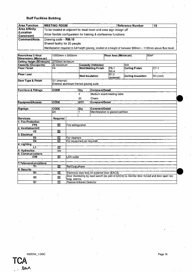
Staff Facilities Building
Area Function MEETING ROOM . ,Reference Number L10 Area Affinity To be located at adjacent to meal room and crew sign in/sign off (Location
Allow flexible configuration for training & conference functions Constraint) Comment/Note: Drawing code - RM:10
Shared facility for 20 people
Manifestation required to full height glazing, located at a height of between 900mm - 11 OOmm above floor level.
1",- ,- rA '~Critical
IDi';~~~~"';s (Minimum) 10000mm x 5000mm IFloor Area (Minimum) L
ICeiling Height (Minimum) ILruumn I minimum Ir",,,,,,,,.lh .. (Occupants) 120 maximum (' INfA IFloor Finish IF4 IWall/Skirting Finish 1~~~1 Ceiling Finish CT-1
IFloor Load IWall Insulation ~1.5 .1\ Ceiling Insulation R3 (roof)
~ Door Type & Finish IG1 (internal)
IExternal aluminum framedglazing suite
II: .. r",I ... r"! & Fittings ICODE IQty 1 Medium sized meeting table
20 Chairs
IEq IA ICODE IQTY
ICODE LQ!y ~ ID4 IMani,,,,,>LouUoI to glazed~
I~t: r Vll.it::> , ~"nI,ir .. rI
11. Fire Protection FP5 ~ IFire extinguisher
12 v IAI(
V2 IZI 13. il
E2 ~ I For cleaners E4 IZI IF()requ~
14. Lighting L1 ~
15. Hydraulics nfa 16. t"_ ............. ications
C20 IZI LAN outlet
17. I elecorn""'· ... ;,. .. ·I" ... "
11- ~ RailCorp phone 18 .... -"
51 IZI 1", ... lrnnic door lock on external door (EACS)
52 ~ ,Door monitoring by reed switch (as part of EACS) to monitor door forced and door open too :Iong alarms.
57 t:8J Passive Infrared LJeleCIOr
1325254_ 1. DOC Page 16
TeA . '
, ,~\!oA
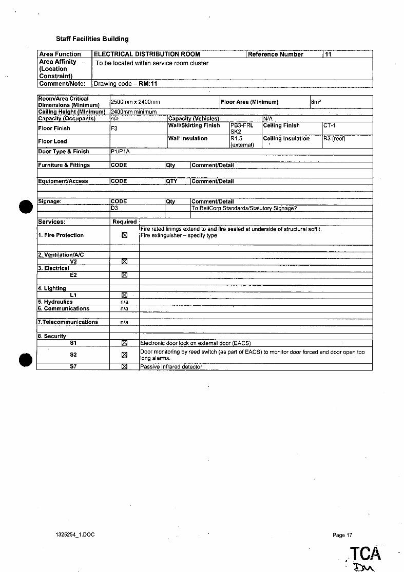
Staff Facilities Building
Area Function ELECTRICAL DISTRIBUTION ROOM 1 Reference Number 111 Area Affinity To be located within service room cluster (Location Constraint) Comment/Note: Drawing code - RM:11
Room/Area Critical 2500mm x 2400mm IFloor Area (Minimum) 18m2
Dimensions lMinimum) Ceiling Height (Minimum) 2400mm minimum Capacity (Occupants) n/a Capacity (Vehicles) N/A
Floor Finish F3 Wall/Skirting Finish PB3-FRL Ceiling Finish CT-1
SK2
Floor Load Wall Insulation R1.5 Ceiling Insulation R3 (roof)
1 (extemaO I
Door Type & Finish P1/P1A
Furniture & Fittings CODE Qty Comment/Detail
Equipment/Access ICODE QTY Comment/Detail
Signage: CODE Qty Comment/Detail 03 To RailCorp Standards/Statutory Signage? • Services: Required
Fire rated linings extend to and fire sealed at underside of structural soffit. 1. Fire Protection 181 Fire extinguisher - specify type
2. Ventiiation/AIC V2 181
3. Electrical E2 181
4. Lighting L1 181
5. Hydraulics n/a 6. Communications n/a
7.Telecommunications n/a
8. Security 51 181 Electronic door lock on external door (EACS)
• 52 181 Door monitoring by reed switch (as part of EACS) to monitor door forced and door open too long alarms.
57 181 Passive Infrared detector
1325254_ 1. DOC Page 17
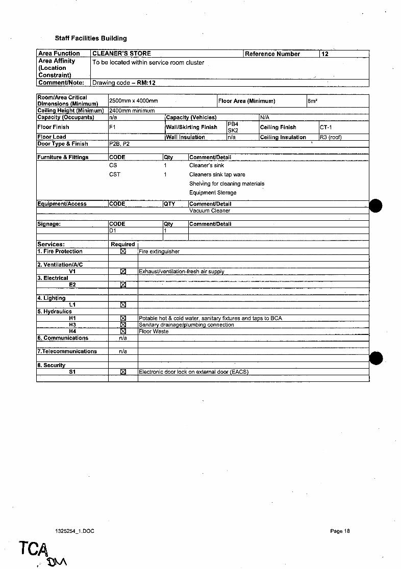
Staff Facilities Building
Area Function CLEANER'S STORE 1 Reference Number Area Affinity To be located within service room cluster (Location Constraint) Comment/Note: Drawing code - RM:12
I RoomlArea Critical 1011 -- (Minimum) ICeiling Height (Minimum) ICapacitv (OcClll')ants)
Floor Finish
IFloor Load 1000r Type & Finish
IFurniture & Fittings
I EaullJr
ISignage
IServices 11. Fire
[2. Ve lAIC V1
[3. Electrical E2
14. Lighting L1
[5. Hydraulics H1 H3 H4
6. Communications
7.
8. Security S1
1325254_1.DOC
TCA UJ\
2500mm x 4000mm I Floor Area (Minimum)
12400mm minimum [n/a Ir:",n",dtv '!~""I""J ~
F1 lIIIa!!!Sk!rting Finish l~~~ Ceiling Finish
[Wall In .. "hot;"n [n/a Ceiling Insulation IP2B, P2
[CODE [Qty IComl il
CS 1 Cleaner's sink
CST 1 Cleaners sink tap ware
Shelving for cleaning materials
Equipment Storage
ICQOE l<lli' ~ it Vacuum Cleaner
ICOOE IQty IComllltmuu., ... il [01
R .. n,,;r .. rI
~ IFire extin~
~ IExhal ~suPplY
IZI
~
1 Potable hot.& cold water, sanitary fixtures and taps to BCA ISanitary drainage/plumbing IFloor Waste
n:a
nla
~ [Electronic~~{~~t
112
/
Ism2
CT-1
IR3jrclclfL
Page 18

•
••
Staff Facilities Building
Area Function STORE - Infrastructure Facilities Store I Reference Number 113 Area Affinity To be located adjacent to Presentation Services store with roller door access to loading bay. (Location Constraint) Comment/Note: Drawing code - RM:13
Refer RF1·3 RailCorp response 02010/50213 & RailCorp comments ITEM 68, G Banks, 27/10/2010.
Room/Area Critical Dimensions (Minimum) Ceiling Height (Minimum) Capacity (Occupants)
Floor Finish
Floor Load
Door Type & Finish'
Furniture & Fittings
EquipmentlAccess
Signage:
Services:
1. Fire Protection
2. Ventiiation/AIC V1
3. Electrical, E2
4. Lighting L1
5. Hydraulics H1 H3 H4
6. Communications C20
7.Telecommunications T1
8. Security 51
52
57
1325254_ 1. DOC
3000mm minimum width IFloor Area (Minimum) 118m2
2700mm minimum nfa Capacity (Vehicles) NfA
F5 Wall/Skirting Finish PB3-FRL
Ceiling Finish CT-1 SK2
tba Wall Insulation R1.5 Ceiling Insulation R3 (roof) external) P1A, P1 check fire rating Roller door external access CODE IQty 1 CommentlDetaii
1 Work bench 4500mm x 900mm 1 Desk 1500mm x 750mm 3 350mm(w) x 4500(L) shelves positioned over bench 3 Chair
WB 1 washbasin T 1 tap ware SP 1 Soap dispenser PTD 1 Paper towel dispenser CODE jQTY lCommentlDetaii
CODE IQty ICommentlDetaii D1 11 1 Required
181 Fire extinguisher Fire rated linings extend to and fire sealed at underside of structural soffit.
181 ExhausVventilation-fresh air supply
181
181 .
181 Potable hot & cold water, sanitary fixtures and taps to BCA 181 Sanitary drainaqefplumbinq. connection 181 Floor Waste
181 LAN outlet
181 RailCorp phone
181 Electronic door lock on internal door (EACS)
181 Door monitoring by reed switch on external roller door (as part of EACS) to monitor door forced and door open too long alarms.
~ Passive Infrared detector
Page 19
TeA '~

Staff Facilities Building
Area Function STORE - Presentation Services 1 Reference Number 114 Area Affinity To be located adjacent to store room - asset maintenance/workshop with roller door access to (Location loading bay. Constraint) Comment/Note: Drawing code - RM:14
Equipment Storage
Storage racks for cleaning equipment and consumables
Room/Area Critical 3000mm minimum width IFloor Area (Minimum)
12sm2
Dimensions (Minimum) Ceiling Height (Minimum) 2700mm minimum Capacity (Occupants) n/a Capacity (Vehicles) N/A
Floor Finish FS Wall/Skirting Finish PB3-FRL Ceiling Finish CT-1 SK2
Floor Load tba Wall Insulation R1.S Ceiling Insulation R3 (roof) I(external)
Door Type & Finish P1A, P1 check fire rating Roller door external access
Furniture & Fittings CODE Qty Comment/Detail
1 Shelving for cleaning materials, equipment and consumables
1 Notice board for Material Safety Data Sheets
CS 1 Cleaner's sink • CST 1 Cleaner's sink tap ware Equipment/Access CODE QTY Comment/Detail
1 Industrial washing machine 1 Industrial dryer 1 Computer 1 Monitor 1 Printer/facsimile
Signage: CODE Qty Comment/Detail D1 1
Services: Required
1. Fire Protection 181 Fire extinguisher Fire rated linings extend to and fire sealed at underside of structural soffit.
2. Ventiiation/AIC V2 181 Air conditioning with dedicated room control
3. Electrical E2 181 For cleaner E4 181 For equipment as required
4. Lighting L1 IZI
5. Hydraulics • H1 181 Potable hot & cold water, sanitary fixtures and taps to BCA H3 181 Sanitary drainage/plumbing connection H4 181 Floor Waste
6. Communications C20 181 LAN outlets (6 outlets)
7.Telecommunications T1 181 RailCorp phone
8. Security 51 IZI Electronic door lock on internal door (EACS)
52 181 Door monitoring by reed switch on external roller door (as part of EACS) to monitor door forced and door open too long alarms.
57 181 Passive Infrared detector
1325254_1.DOC Page 20
TCA

•
•
Staff Facilities Building
Area Function OFFICE - Network Control Area 1 Reference Number 116 Area Affinity Adjacent to open plan office (Location Constraint) Comment/Note: Drawing code - RM:16
Room/Area Critical 3000mm minimum width Floor Area (Minimum) 114m2
Dimensions (Minimum) Ceiling Height 2700mm minimum (Minimum)
2 requested refer email .. Capacity (Occupants) 1 (BRS/SRS) Capacity (Vehicles) N/A
Floor Finish F4 Wall/Skirti PB-1
Ceiling Finish CT-1 ng Finish SK-4
Floor Load Wall R1.5 Ceiling Insulation R3(roof) Insulation I{external)
Door Type & Finish P2B,P2
Furniture & Fittings CODE IQty Comment/Detail
To be supplied by TCA via D&C contractor:
1 Bench desk to length of room window side sized for 2 people
1 3-d rawer under desk module
1 Chair
1 3 drawer filing cabinet
1 Whiteboard
To be supplied by RailCorp: 1 3-d rawer under desk module
1 Chair
1 Book shelf (large) size not advised
2 Notice boards Equipment/Access CODE IQTY Comment/Detail To be supplied by TCA via D&C contractor: 1 computer
1 telephone(provided by TCA) 1 RailCorp Precise Clock 1 . Monitor 21 in (provided by TCA) 1 colour A3 multifunction machine
To be supplied by RailCorp: 1 computer 1 telephone 1 Monitor 21 inch 1 Monitor 40 inch 2 Computer speakers
Signage: CODE IQty IComment/Detaii
. Services: Required
1. Fire Protection n/a 2. Ventiiation/AIC
V2 181 3. Electrical
E2 181 E4 181
4. Lighting L1 181
5. Hydraulics n/a
6. Communications
C10 IZI Precise clock C20 181 LAN outlet
7.Telecommunications T6 181 Signal phone
T12 '181 Long distance cordless phone 8. Security
S6 181 CCTV monitors to provide coverage of the yard S7 181 Passive Infrared detector
1325254JDOC Page 21
.• 1
TCA .~
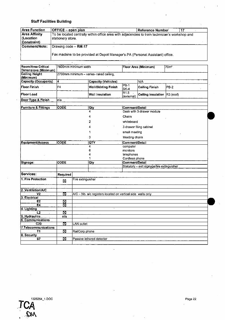
Staff Facilities Building
Area Function OFFICE - open plan I Reference Number 117 Area Affinity To be located centrally within office area with adjacencies to train technician's workshop and (Location stationery store. Constraint) Comment/Note: Drawing code - RM:17
F=ax machine to be provided at Depot Manager's PA (Personal Assistant) office.
I ~~ .. u"" ~:."d~~~~i~Um) 17800mm minimum width Floor Area (Minimum) yom2
IT~ii~~u~;9ht ILfuumm'llinimul'" varies- raked ceiling.
ICapacitv (Occupants) 14 r. ...... ",.i .. , (Vehicles) INLA
Floor Finish F4 Wall/Skirting Finish 1~~:1 Ceiling Finish PB-2
Floor Load IWalilnsulation IR1.5 .1\ Ceiling Insulation IR3 (roof) \eXlernal, IDoor Type & Finish In/a
IFurniture & Fittings ICODE IQty 4 Desk with ,,-u,a .. ~' module
4 Chairs
2 whiteboard
4 3 drawer filing cabinet
1 small meeting
3 Meeting chairs
IEQ ICODE IQTY lComllltmuut:,ail 4 computer 6 monitors 4 telephones 1 Cordless~
ICODE IQty I Statutory - exit sig ,Jr., ,extinguisher
1"'''''' YI .. ""';· I Required
11 , Fire Protection [21 /Fire extinguisher
2. Vel 'Air V2 [21 lAIC - Nb. alc ~I~,-"I()cat~d_onvertical side~
,3, electrical E2 IZI E4 ~
14. i"h.i"" L2 181
15. Hydraulics n/a i6. Comrr,UII
C20 IZI ILAN outlet 17 .• ,
T1 181 RailCorp phone 18. Security
S7 IZI P""";,,o Infrared detector
1325254 1.DOC
.TCA -Page 22
',.~ ~ '"

Staff Facilities Building
Area Function OFFICE - Depot Manager 1 Reference Number Area Affinity Depot Manager's PA to be located adjacentto office (Location Constraint) Comment/Note: Drawing code - RM:18
Depot ManaQer's PA to be located adjacent to office
Room/Area Critical 4000mm minimum width Floor Area (Minimum) 1
16m2 Dimensions (Minimum) Ceiling Height 2700mm minimum I(Minimum) Capacity (Occupants) 1 Capacity (Vehicles) NfA
Floor Finish F4 Wall/Skirting Finish PB-1
Ceiling Finish CT-1 SK-4
Floor Load Wall Insulation R1.5 Ceiling Insulation R3 (roof) l(extemi:!I)
Door Type & Finish G1
Furniture & Fittings CODE Qty Comment/Detail 1 Desk with 3-drawer module
1 Chairs
1 whiteboard • 1 3 drawer filing cabinet
1 small meeting
3 Meeting chairs
Equipment/Access CODE QTY Comment/Detail 1 Laptop computer 1 telephone
Signage: CODE Q!}t Comment/Detail 04 To Glazed partition
Services: Required
1. Fire Protection nfa
2. Ventilation/AIC V2 IZI
3. Electrical E2 181 E4 181
• 4. Lighting '.
L2 181 5. Hydraulics nfa 6. Communications
C20 181 LAN outlet 7.Telecommunications
T1 181 RailCorp phone 8. Security
S7 ~ Passive Infrared detector
1325254_ 1. DOC
118
Page 23
;,TCA '''~
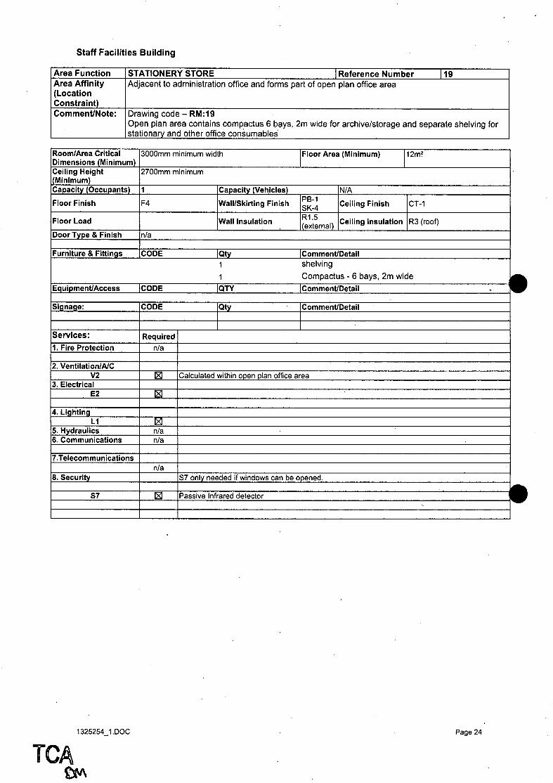
Staff Facilities Building
Area Function STATIONERY STORE 1 Reference Number 119 Area Affinity Adjacent to administration office and forms part of open plan office area (Location Constraint) Comment/Note: Drawing code - RM:19
Open plan area contains compactus 6 b~ys, 2m wide for archive/storage and separate shelving for stationary and other office consumables
D. ,~,,,,,ft~ Critical ;.:--.. ".~.-~ (Minimum) U'" """',"UII" Ceili~g H~ight (Minimum) r."n",.i+u (O,.,. ... ')ants)
Floor Finish
Floor Load
,Door Type & Finish
Furniture & Fittings
Eql .- ,,, ,"
~ignage:
Services~
11, Fire Protection
'2, VI 'A./r. V2
3, II E2
4, Lighting L1
[5,. Hydraulics 16, r."mml
17,1 IIni""ti'lns
18, Security
57
1325254_1.DOC
TCA £lV\
Juuumm minimum width Floor Area (Minimum) 112m~
'::Iuumm minimum
1 Ir."n .. ,.itv N/A
F4 WalifSkirting Finish ~~~1 Ceiling Finish CT~1
Wall Insulation ~~t~rnal) Ceiling Insulation R3 (roof)
nfa
,CODE IQty IComl Iii
1 shelving
1 Compactus - 6 bays, 2m wide
ICODE IQTY ICommem/ulmlii
CODE Qtv ICom~T1eTl" u .... liI
Required nfa
1:81 ICalculated within open plan office area
[8]
~ nfa nfa
nfa S7 only neede<! if can be opened.
1:81 P""d\lo Infrared detector v
.
Page 24

Staff Facilities Building
Area Function OFFICE - Operations Standards Manager J Reference Number 120 Area Affinity Adjacent to entry and Depot Manager's office (Location Constraint) Comment/Note: Drawing code - RM:20
Room/Area Critical 4000mm minimum width Floor Area (Minimum) 116m2
Dimensions (Minimum) Ceiling Height I(Minimum)
2700mm minimum
Capacity (Occupants) 1 Capacity (Vehicles) N/A
Floor Finish F4 Wall/Skirting Finish PB-1 Ceiling Finish CT-1 SK-4
Floor Load Wall Insulation R1.S Ceiling Insulation R3 (roof) external)
Door Type & Finish G1
Furniture & Fittings CODE Qty Comment/Detail 1 Desk with 3-drawer module
1 Chair .' 1 3 drawer filing cabinet Equipment/Access CODE QTY Comment/Detail
1 computer 1 telephone 1 RailCorp Precise Clock 2 monitor
Signage: CODE Qty Comment/Detail D4 To glazed partition
Services: Required
1. Fire Protection nla
2. Ventiiation/AIC V2 ~
3. Electrical E2 ~ E4 ~
4. Lighting L2 ~
5. Hydraulics nla 6. Communications
C10 ~ Precise clock C20 ~ LAN outlet
7.Telecommunications T1 ~ RailCorp phone
8. Security
S7 ~ Passive Infrared detector
1325254_1. DOC Page 25
TCA

Staff Facilities Building
Area Function OFFICE - Administration 1 Reference Number Area Affinity Adjacent to entry and crew sign-onl off area (Location Constraint) Comment/Note: Drawing code - RM:21
1~~':~~~:''':''~~~~i~Um) I~';ii~::;u~;ght ICapacity (Occupants)
Floor Finish
Floor Load
IDoor Type & Finish
1 J:"rnit"r .. & Fittings
lEaL IA~,~~ ..
ISignage:
I ... 1~t:lvl"'t::i;
11. Fire
12. V .. ntil~·: II\/r'
V2 13.
E4
14. Liahtina L2
15. Hydraulics 6. CommumcatlO~
C20 7. IWm;dtiu""
T1 S. Security
5S
1325254_1.DOC
TCA .~
3000mm minimum width Floor Area (Minimum)
2700mm minimum - ceiling varies refer section & reflected ceiling plan
11 ICapacity~ ~ F4 IWali/Skirting Finish
PB-1 Ceiling Finish
SK-4
iWall Insulation 1~1.5 ,1\ \tlXltlIllClI,
Ceiling Insulation
In/a - open
ICODE IQty IU~
1 Desk with 3-d rawer module
1 Chair
1 3 drawer filing cabinet
ICODE IQTY ~ 1 computer 1 telephone 1 monitor
ICODE IQty I\;U"""""U~
I Required
n/a
~ ~<lI"III<lt"tj within open plan office area
IZI
IZI n/a
IZI LAN outlet
IZI IRailCorp phone
IZI ! Intruder Alarm ~ -_d~J~~button
112m2
IPB-2
IR3 (roof)
121
I
Page 26

•
.'
Staff Facilities Building
Area Function EXTERNAL - BBQ area 1 Reference Number 122 Area Affinity Adjacent to Meals Room (Location Constraint) Comment/Note: Drawing code - RM:22
Room/Area Critical 3000mm minimum width Floor Area (Minimum) 1
12m2 Dimensions (Minimum) Ceiling Height n/a I(Minimum) Capacity (Occupants) N/A Capacity (Vehicles) N/A Floor Finish Refer landscape Wall/Skirting Finish N/A Ceiling Finish N/A
architect Floor Load N/A Wall Insulation N/A Ceiling Insulation N/A Door Type & Finish N/A
Furniture & Fittings CODE IQty IComment/Detaii 1 BBQ l( Fixed benches and planters with low maintenance plants
Equipment/Access ICODE IQTY IComment/Detaii
Signage: CODE Qty Comment/Detail To RailCorp Standards
Services: Required
1. Fire Protection ~ Fire extinguisher
2. Ventiiation/AIC N/A
3. Electrical E4 ~ Weatherproof outlet
4. Lighting L1 ~
5. Hydraulics n/a 6. Communications n/a
7. Telecommunications N/A
8. Security S3 ~ CCTV camera to monitor the boundary of the building
1325254_ 1. DOC Page 27
T,eA .... ~

Staff Facilities Building
Area Function EXTERNAL - Loading Bay I Reference Number Area Affinity Adjacent to Store Rooms and Workshop - roller door access (Location Constraint) Comment/Note: Drawing code - RM:23
.vv .... ~ • .!a Critical x IDimensions (Minimum)
If~ii~::;:':;9ht n/a
1(""n",.lt" tn,.,. .. n'lnts) IN/A ICapacity (Vehicles) [Floor Finish I:efer lar,u";il°"''' [Wall/Skirting Finish
IFloor Load IN/A IWallin .. , h.+I"n I Door Type & Finish IN/A
I Furniture & Fittings ICODE IQty N/A
= .... ICODE IQTY IN/A ISignage: ICODE IQty
I C!. I Required I·· .. ·' yl .... "'.
11, Fire N/A
12. \ .,,~., If\./("
N/A 13
N/A
14. ; .... h+;', ....
L1 I2SI 15. Hydraulics N/A 16. Com"", .. nl,."tll)ns 181
17 N/A
18. C!ftM •• , .. ,
53 181 CCTV to monitor Loading Dock
1325254_1 ,DOC
TCA '.~
IFloor Area (Minimum) y IN/A
N/A [Ceiling Finish N/A .
NIA ~ WA
~
/uetall
/u~
ITo l"ilr.nrn Standards
123
Page 28

Staff Facilities Building
Area Function EXTERNAL - Refuse Area I Reference Number 124 Area Affinity Adjacent to access road and entrance to ~tabling yard (Location Constraint) CommenUNote: Drawing code - RM:24
X2 2 tonne bins or as per rubbish removal contractors requirements Private rubbish removal contractors will not be allowed within the yard area (this is a safety requirement) An average of 4x 5kg bags of rubbish are collected per 8 car train set Possible visibility screening fence required on 3 sides.
Room/Area Critical x Floor Area (Minimum) IX Dimensions (Minimum)
Ceiling Height I(Minimum)
n/a
Capacity (Occupants) N/A Capacity (Vehicles) N/A Floor Finish Refer landscape Wall/Skirting Finish N/A Ceiling Finish N/A
architect/civil engineer Floor Load N/A Wall Insulation N/A Ceiling Insulation N/A Door Type & Finish N/A
• Furniture & Fittings CODE Qty Comment/Detail N/A
Equipment/Access CODE QTY Comment/Detail 2 2 tonne bins
Signage: CODE Qty Comment/Detail
Services: Required 1. Fire Protection N/A
2. Ventiiation/AIC N/A
3. Electrical N/A
4. Lighting L1 I8J
5. Hydraulics N/A 6. Communications I8J
7.Telecommunications N/A
8. Security • 51 I8J EACS to adjacent gate
53 I8J CCTV to monitor adjacent gate
1325254_ 1. DOC Page 29
T:&1

Staff Amenities Building
Area Function ENTRY I Reference Number 11 Area Affinity Foyer (Location Constraint) Comment/Note: Drawing code - RM:1
First aid facilities
Roon,/Are .. Critical 2000mm minimum width I Floor Area (Minimum) 1
4m2 1"\ (Minimum) Ceiling He.ight 2700mm minimum (Minimum) CaDacitv {OCCl·n"nf .. As required (""n",.if" N/A
Floor Finish FS Wall/Skirting Finish' ~~~ Ceiling Finish CT-1
Floor Load Wall Insulation R1.S I) Ceiling Insulation R3 (roof)
Door Type & Finish External door
Furniture & Fittinas CODE I QtyLCv-".~. iI 1 Eye wash 1 Washbasin 1 ~ ~
Equipment CODE I Qty I CVIIIIII<" .. /Lltnaii
5ignage CODE I Qty I C nAf"iI N/A I J
'" Required "'.," VI .... "
1 Fire In
FP1 FireExit~ FP3 Smoke alarm FP5 Fire Extinguisher
2. Ventil,,+I .... n/AJ( V2 IZI
3. Electrical E2 IZI
4. Lighting L2 IZI
5. Hydraulics Hi Potable hot & cold water, sanitary fixtures and taps to BeA H3 Sanitary nr";n",,,,/nlumbinQ H4 Floor Waste
6. Communi",,,finn ..
IZI 7.TI .- mications
~ 8. tal' ••• ; ....
51 ~ EACSol'l ",,,,o,,,,,,door
52 IZI Door IIUIIIlUIIII\:l by reed switch (as part of EACS) to monitor door forced and door open
57
58
1325254JDOC
TeA I)~
IZI 181
toolong~~ Passive Infrared Ut::,."",u,,, Intruder Alarm.Sy~tem - keypad adjacent to entrance door (alarm system linked to Staff .... -"":. Building)
Page 30
'I

Staff Amenities Building
Area Function Unisex Accessible toilet 1 Reference Number 12 Area Affinity Adjacent to entry (Location Constraint) Comment/Note: Drawing code - RM:2
unisex accessible toilet in accordance with AS1428.1 and AS1428.2
Room/Area Critical 2000mm x 3000mm minimum iFloor Area (Minimum)
16m2
Dimensions (Minimum) Ceiling Height (Minimum) 2400mm minimum
Capacity (Occupants) 1 wheelchair Capacity (Vehicles) N/A accessible
Floor Finish F1 Wall/Skirting Finish PB4
Ceiling Finish PB-4 SK-1
Floor Load Wall Insulation n/a Ceiling Insulation n/a Door Type & Finish P2B,P2
Furniture & Fittings CODE Qty Comment/Detail
1 WB-A, MT-A, TP-A, TS-A, FC, HD, PTD, TPD; SP-A, M, SDU, RB,
• Equipment/Access
Signage:
Services: 1. Fire Protection
2. Ventiiation/AIC V1
3. Electrical E2
4. Lighting L1
5. Hydraulics H1 H3 H4
, 6. Communications • 7.Telecommunications 8. Security
1325254_1.DOC
ICODE
CODE D2
Required
IZI
~
IZI
~ IZI IZI n/a
n/a nfa
DS/CH, GR
QTY Comment/Detail
Qty Comment/Detail 1 To RailCorp Standards
Ventilated/Exhaust
Potable hot & cold water, sanitary fixtures and taps to BCA Sanitary drainage/plumbing connection Floor Waste
Page 31
TCA ~.

Staff Amenities Building
Area Function STORE - Presentation Services I Reference Number 13 Area Affinity To be located adjacent to store room - asset maintenance/workshop with roller door access to (Location Constraint)
loading bay.
Comment/Note: Drawing code - RM:03 Equipment Storage
Storage racks for cleaning equipment and consumables
1~~u,"/Area ~~~~i~Um) !JOOOmm minimum width IFloor Area (Minimum) ~ ICeilinQ HeiQht (Minimum) Ir."n" ... itv In,.~ "'nts)
Floor Finish
Floor Load
IDoor Type & Finish
IFllrnif ,r"" & Fittings
IEqui
ISignage~
I~ I"'" , .... '" 1. Fire Protection
12. \/ft".II~.: '"'AlC V2
13. E4 E2
4. Lighting Li
5. 1.1"11.",, ,Iics Hi H3 H4
6. Communications C4 C20
7.T lunications Ti
18. Security S2 S7
1325254JDOC
TCA l~'
uumm minimum? n/a ICapacity (Vehicles) IN/A
F5 IWali/Skirting Finish I~~~-FRL Ceiling Finish CT-1
tba IWall Insulation I~~~rnal) Ceiling Insulation R3 (roof)
IP1A,J)1 check fire ratlQ.[ IRolier door external access ICODE IQty IC n""bil
1 Shelving for cleaning materials, equipment and consumables
1 Notice board for Material Safety Data Sheets
CS 1 Cleaner's sink
CST 1 Cleaner's sink tap ware
ICODE IQTY If IUetall 1 Industrial washing machine 1 Industrial dryer 1 Computer 1 Monitor 1 ~
ICODE lQ!y_ IC iI 101
Required
~ IFire extinguisher IFire rated-linings extend to and fire sealed at underside of structural soffit.
.. ~
~ IZI
~
IPotablehot. & cold water, sanitary fixtures and taps to BCA ISanitary ur~_9~!ll.d.ftLor I Floor Waste
~ IPA speaker ~ ILAN outlets (6 outlets are needed.)
IZI IRailCorp phone
~ IDoor IIUIIIlUIIII\! on roller door by reed switch~ ~ IPassive Infrared ut:'t:"'UI
Page 32