
ATON – Autonomous Terrain-based Optical Navigation for ...
18
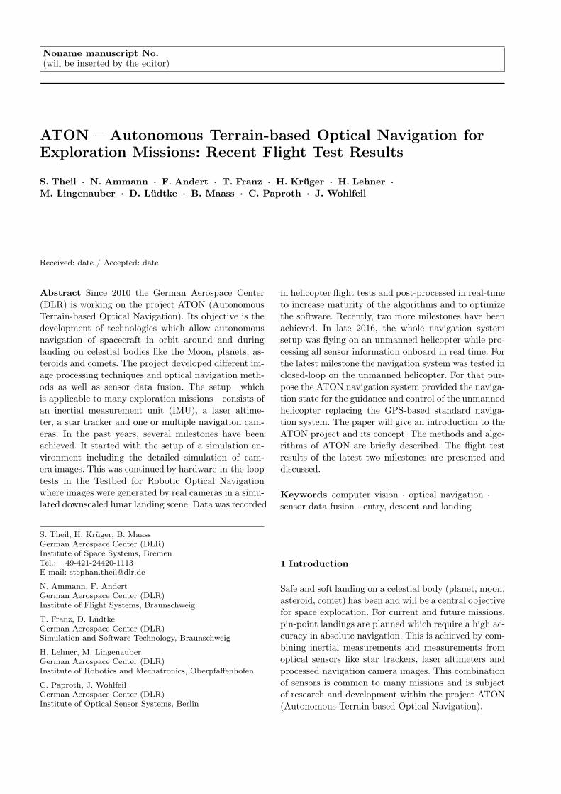
Noname manuscript No. (will be inserted by the editor) ATON – Autonomous Terrain-based Optical Navigation for Exploration Missions: Recent Flight Test Results S. Theil · N. Ammann · F. Andert · T. Franz · H. Krüger · H. Lehner · M. Lingenauber · D. Lüdtke · B. Maass · C. Paproth · J. Wohlfeil Received: date / Accepted: date Abstract Since 2010 the German Aerospace Center (DLR) is working on the project ATON (Autonomous Terrain-based Optical Navigation). Its objective is the development of technologies which allow autonomous navigation of spacecraft in orbit around and during landing on celestial bodies like the Moon, planets, as- teroids and comets. The project developed different im- age processing techniques and optical navigation meth- ods as well as sensor data fusion. The setup—which is applicable to many exploration missions—consists of an inertial measurement unit (IMU), a laser altime- ter, a star tracker and one or multiple navigation cam- eras. In the past years, several milestones have been achieved. It started with the setup of a simulation en- vironment including the detailed simulation of cam- era images. This was continued by hardware-in-the-loop tests in the Testbed for Robotic Optical Navigation where images were generated by real cameras in a simu- lated downscaled lunar landing scene. Data was recorded S. Theil, H. Krüger, B. Maass German Aerospace Center (DLR) Institute of Space Systems, Bremen Tel.: +49-421-24420-1113 E-mail: [email protected] N. Ammann, F. Andert German Aerospace Center (DLR) Institute of Flight Systems, Braunschweig T. Franz, D. Lüdtke German Aerospace Center (DLR) Simulation and Software Technology, Braunschweig H. Lehner, M. Lingenauber German Aerospace Center (DLR) Institute of Robotics and Mechatronics, Oberpfaffenhofen C. Paproth, J. Wohlfeil German Aerospace Center (DLR) Institute of Optical Sensor Systems, Berlin in helicopter flight tests and post-processed in real-time to increase maturity of the algorithms and to optimize the software. Recently, two more milestones have been achieved. In late 2016, the whole navigation system setup was flying on an unmanned helicopter while pro- cessing all sensor information onboard in real time. For the latest milestone the navigation system was tested in closed-loop on the unmanned helicopter. For that pur- pose the ATON navigation system provided the naviga- tion state for the guidance and control of the unmanned helicopter replacing the GPS-based standard naviga- tion system. The paper will give an introduction to the ATON project and its concept. The methods and algo- rithms of ATON are briefly described. The flight test results of the latest two milestones are presented and discussed. Keywords computer vision · optical navigation · sensor data fusion · entry, descent and landing 1 Introduction Safe and soft landing on a celestial body (planet, moon, asteroid, comet) has been and will be a central objective for space exploration. For current and future missions, pin-point landings are planned which require a high ac- curacy in absolute navigation. This is achieved by com- bining inertial measurements and measurements from optical sensors like star trackers, laser altimeters and processed navigation camera images. This combination of sensors is common to many missions and is subject of research and development within the project ATON (Autonomous Terrain-based Optical Navigation).
-
Upload
khangminh22 -
Category
Documents
-
view
0 -
download
0
Transcript of ATON – Autonomous Terrain-based Optical Navigation for ...
Noname manuscript No.(will be inserted by the editor)
ATON – Autonomous Terrain-based Optical Navigation forExploration Missions: Recent Flight Test Results
S. Theil · N. Ammann · F. Andert · T. Franz · H. Krüger · H. Lehner ·M. Lingenauber · D. Lüdtke · B. Maass · C. Paproth · J. Wohlfeil
Received: date / Accepted: date
Abstract Since 2010 the German Aerospace Center(DLR) is working on the project ATON (AutonomousTerrain-based Optical Navigation). Its objective is thedevelopment of technologies which allow autonomousnavigation of spacecraft in orbit around and duringlanding on celestial bodies like the Moon, planets, as-teroids and comets. The project developed different im-age processing techniques and optical navigation meth-ods as well as sensor data fusion. The setup—whichis applicable to many exploration missions—consists ofan inertial measurement unit (IMU), a laser altime-ter, a star tracker and one or multiple navigation cam-eras. In the past years, several milestones have beenachieved. It started with the setup of a simulation en-vironment including the detailed simulation of cam-era images. This was continued by hardware-in-the-looptests in the Testbed for Robotic Optical Navigationwhere images were generated by real cameras in a simu-lated downscaled lunar landing scene. Data was recorded
S. Theil, H. Krüger, B. MaassGerman Aerospace Center (DLR)Institute of Space Systems, BremenTel.: +49-421-24420-1113E-mail: [email protected]
N. Ammann, F. AndertGerman Aerospace Center (DLR)Institute of Flight Systems, Braunschweig
T. Franz, D. LüdtkeGerman Aerospace Center (DLR)Simulation and Software Technology, Braunschweig
H. Lehner, M. LingenauberGerman Aerospace Center (DLR)Institute of Robotics and Mechatronics, Oberpfaffenhofen
C. Paproth, J. WohlfeilGerman Aerospace Center (DLR)Institute of Optical Sensor Systems, Berlin
in helicopter flight tests and post-processed in real-timeto increase maturity of the algorithms and to optimizethe software. Recently, two more milestones have beenachieved. In late 2016, the whole navigation systemsetup was flying on an unmanned helicopter while pro-cessing all sensor information onboard in real time. Forthe latest milestone the navigation system was tested inclosed-loop on the unmanned helicopter. For that pur-pose the ATON navigation system provided the naviga-tion state for the guidance and control of the unmannedhelicopter replacing the GPS-based standard naviga-tion system. The paper will give an introduction to theATON project and its concept. The methods and algo-rithms of ATON are briefly described. The flight testresults of the latest two milestones are presented anddiscussed.
Keywords computer vision · optical navigation ·sensor data fusion · entry, descent and landing
1 Introduction
Safe and soft landing on a celestial body (planet, moon,asteroid, comet) has been and will be a central objectivefor space exploration. For current and future missions,pin-point landings are planned which require a high ac-curacy in absolute navigation. This is achieved by com-bining inertial measurements and measurements fromoptical sensors like star trackers, laser altimeters andprocessed navigation camera images. This combinationof sensors is common to many missions and is subjectof research and development within the project ATON(Autonomous Terrain-based Optical Navigation).

2 S. Theil et al.
1.1 Motivation and Goals
The German Aerospace Center (DLR) has been activeon planetary science for decades, and it has been in-volved in many interplanetary missions providing in-struments and technologies. Technologies for landinghave been developed for the lander Philae of the Rosettamission which was landing 12 November 2014 on thecomet 67P/Churyumov-Gerasimenko ten years and eightmonths after departing Earth [27, 31]. Similarly, theasteroid landing package MASCOT (Mobile AsteroidSurface Scout) was developed by DLR in cooperationwith the Japanese Aerospace Exploration Agency (JAXA)and the Centre National d’Études Spatiales (CNES)[13]. It is traveling onboard JAXA’s mission Hayabusa2 to its landing target the asteroid 162173 Ryugu. Thelanding is foreseen in October 2018.
As an evolution of the landing technologies whichwere applied to Philae and MASCOT technologies forprecise and safe landing, new methods are in the fo-cus of DLR’s research and development activities. Oneelement is the project ATON. The project was initi-ated in 2010 and started from several already availabletechnologies in the domain of image processing, opticalnavigation and state estimation.
The overarching goal of ATON is the developmentand demonstration of an optical navigation system forexploration missions and its technologies which are al-lowing a precise and safe landing on a celestial body.The goals of the project are:
– Development of a flexible system concept allowingtailored solutions for different missions,
– Development of image processing and optical navi-gation techniques for absolute and relative naviga-tion,
– Development of navigation filtering techniques fus-ing all available sensor data and image processingoutputs,
– Verification of all algorithms implemented as soft-ware in MiL, SiL, PiL and HiL setups including thedevelopment of software and hardware tools for re-alistic simulation,
– Verification of the navigation system performancein open-loop and closed-loop control environments,
– In-flight demonstration of the navigation system interrestrial test environments.
ATON was set up as a technology research projectwithout a concrete mission to be served. This providedmore degrees of freedom than in mission-driven devel-opments, and it allowed to explore different approachesto the same problem in parallel: to start with new ideas,and to more thoroughly investigate different solutions.
One of the main differences to many agency-driven tech-nology developments in the same area is that all ele-ments of the optical navigation system were continu-ously researched and developed by the same enterpriseand the same team. This allowed to have a broaderview and to get a deeper understanding of the opticalnavigation system and the underlying principles.
1.2 Assumptions and Decisions
ATON is targeting the navigation system developmentfor a landing on solar system bodies in general. Thenavigation system shall use the surface (respectivelythe terrain) of the target body for obtaining the naviga-tion solution (position, velocity, and attitude in a targetbody-fixed coordinate frame). Although there is a highdiversity in size and structure of solar system bodies,there is only one criterion which has a high impact onthe navigation system architecture – the atmosphere.Based on this, the class of potential targets was nar-rowed down for ATON to celestial bodies with no orvery thin atmosphere. This allows to observe featuresand landmarks on ground already from high altitudes,limits the influence of optical effects of the atmosphere,and makes topographic features more stable.
The selected class of targets includes the Moon, as-teroids, comets, and other small planetary moons likePhobos and Deimos. Out of this class the Moon wasselected as the reference target. The Moon is one of thelargest bodies without atmosphere. Since the dynamicsof a descent and landing are driven by gravity, the mostchallenging requirements can be expected for a landingon the Moon. A second aspect for choosing the Moonis that it is well known and well mapped with a lot ofdata publicly available.
When neglecting cooperative targets such as landingsites equipped with beacons, current optical navigationtechniques based on image processing can provide ab-solute and relative navigation information within thelocal reference frame of the target celestial body. Thus,the work in ATON assumes that the following sensorsuite is available for implementation in a future explo-ration mission using ATON’s technology:
– Inertial Measurement Unit (IMU) providing mea-surements of the angular rate and the non-gravita-tional acceleration,
– Star tracker (STR) providing inertial attitude infor-mation,
– Laser altimeter (ALT) delivering the distance to theground along its line of sight,
ATON – Autonomous Terrain-based Optical Navigation for Exploration Missions: Recent Flight Test Results 3
– Monocular monochrome navigation camera takingimages of the target body and terrain which are sub-ject to further image processing, and
– Flash LIDAR (light detection and ranging) provid-ing 3D-images.
This assumption is based on the review and analysisof past and currently developed missions and technolo-gies as well as on preliminary analysis at the beginningof the project.
2 Requirements and Reference Mission
In order to define a goal for the technical developmentwithin the project ATON a review of historic and plan-ned missions (at the time of the start of the projectin 2010) was done. From that the targeted navigationaccuracy was derived. Furthermore a reference missionfor the project was defined including the sensor suiteand assumed characteristic performances.
2.1 Navigation Requirements
To achieve the project goals defined above, the navi-gation system must support the guidance, navigationand control (GNC) system with sufficient state-vectordata. In case of ATON, the state-vector shall be au-tonomously determined from the beginning of the land-ing maneuver at the Descent Orbit Injection (DOI).
To help in the definition of requirements, data froma covariance analysis of a lunar landing navigation sys-tem [8] have been used as reference. The goal of theanalysis was to find the requirements for a Terrain-relative Navigation (TRN) sensor to achieve a 100m(3-σ) navigation accuracy at landing. For that purpose,the navigation data was fed into a proportional deriva-tive controller which controls position and attitude.
A major outcome of the study is the determinationof the main errors of propagation. One error is repre-sented by the accuracy of the initial state-vector. Thesecond major source for propagation error is the qualityof the gravity model.
For a better understanding of the discussion of nav-igation requirements, a short overview on dispersioncontrol is given in this paragraph. Any navigation er-ror leads to a dispersion of the lander’s position fromthe reference path. With a high probability, the disper-sion is at least in the same size as the navigation error.Nominally, the spacecraft is designed for an optimizedreference path which represents the most fuel-efficientway to land on the Moon. The earlier the dispersioncan be measured, the more efficient it can be controlled
by slight changes to the reference path. The later thedispersion is measured, the higher the modifications ofthe remaining reference path have to become. This leadsinto increased fuel consumption. The main part of land-ing dispersion is mainly in the downrange direction. Anexcellent possibility for downrange dispersion control isat the Powered Descent Initiate (PDI). By changingthe time of thruster ignition by several seconds and byslight modifications to the Powered Descent (PD) ref-erence path, the downrange dispersion can be reduceddown to the navigation error with very little fuel cost.
Based on this analysis for ATON, the following as-sumptions are made:
– The IMU and STR used in ATON are of equal qual-ity like in the study in [8],
– An initial state-vector precision comparable to [8],– Utilization of absolute position measurements in parts
of the Descent Orbit (DO),– Altimeter utilization not before PDI,– During PD, altimeter and velocitymeter function is
performed by the optical navigation system, and– The 3D imaging system is working after the landing
site becomes visible.
Based on these assumptions, the required naviga-tion performance for ATON is shown in Table 1. Atthe DOI, the navigation accuracy corresponds to thecapability of the ground station network. During thecoasting in the DO, the landmark navigation systemshall provide several measurements with an accuracy of1% of current height or 100 – 1000m for down-range andcross-range and 0.5% of current height or 50 – 500m foraltitude. This enables the propagator to determine theSC position at PDI within 100m.
During PD, the optical navigation system will per-form altimeter and velocimeter functions. Due to thelack of position measurements the navigation error willgrow during this period. The task of the navigation sys-tem is to keep the propagation stable and the errorgrowth small.
After the pitch over and as soon as the landing sitebecomes visible, the 3D imaging system will start totake measurements. The resulting data will possess aninitial resolution in the order of 50m and continuouslygrow during the descent. The 3D data will be comparedwith an onboard 3D map of the landing site, gaining anavigation knowledge in the order of 50m. The purposeof the 3D imaging system is also to deliver the necessarydata for the evaluation of the landing area. When a safelanding site is found, the GNC system must be able toplace the lander inside the safe area. The size of the safearea is assumed to be in the order of three times thediameter of the lander. Thus, the allowed landing error
4 S. Theil et al.
Table 1: Required navigation accuracy for a 200 m (3-σ) lunar landing for ATON
mission phase autonomous positiondetermination (3-σ)
autonomous velocitydetermination (3-σ)
DOI1 dr2: 1500 mcr3: 200 malt4: 50 m
dr: 0.047 m/scr: 0.2 m/salt: 1.5 m/s
pre PDI mainly dr: 100 - 1000 m 0.5 m/s
PDI mainly dr: 100 m 0.5 m/s
approach: before 3D imaging mainly dr: 500 m 0.5 m/s
approach: after 3D imaging mainly dr and cr: 50 m 0.5 m/s
landing 2 m 0.1 m/s
1accuracy of ground station tracking, 2downrange, 3crossrange, 4altitude
is in the order of half a lander diameter. The navigationrequirement for the landing is therefore set to 2m. Thisshould be possible when considering the 3D data re-quirement at the late stage of the landing. The needed3D resolution is in the order of 15cm per pixel. Thisdata will become available in an altitude of ≈ 400m.
2.2 Reference Mission
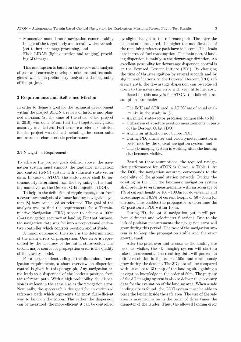
For generating simulation data a, reference mission hasto be defined. The general sequence of approach andlanding is defined as:
1. Start in an initial 100km× 100km quasi-circular or-bit around the Moon,
2. Execution of Descent Orbit Injection (DOI) maneu-ver to reach a 100km× 10km orbit,
3. Flight along the elliptic descent orbit to pericenter,4. Start of powered descent (PDI) close to the pericen-
ter of the descent orbit,5. Achieve an almost vertical descent for the last 100s,6. Final conditions: altitude ≈1m above landing site
at <1m/s velocity.
Figure 1 illustrates the sequence of events for thereference mission.
For the simulation runs, several prominent and fourarbitrary landing sites have been selected. For some ofthem, landing at different times has been simulated inorder to see the effect of different illumination condi-tions.
A powered descent trajectory with constraints foractuators and flight states as well as with the objectiveof minimal fuel consumption can only be generated as asolution of an optimal control problem. For the specificcase of a landing vehicle with non-throttable engines, asolution is provided in [24]. The paper defines an opti-mal control problem and provides a solution. Further-more, a tracking controller is designed which enables
Moon
Parking
orbit
DescentO
rbit
PoweredDescent
Lan
ding
DO
I
PDI
Earth
Fig. 1: Sketch of the lunar landing scenario with a polar orbit.
the vehicle to follow the designed reference trajectoryeven in presence of uncertainties. A more robust imple-mentation of an onboard algorithm is presented in [19]where a suboptimal trajectory is interpolated onboarddepending on the initial state. This allows very largeuncertainties at the initial conditions at PDI.
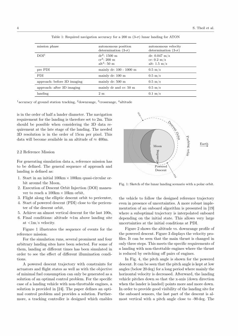
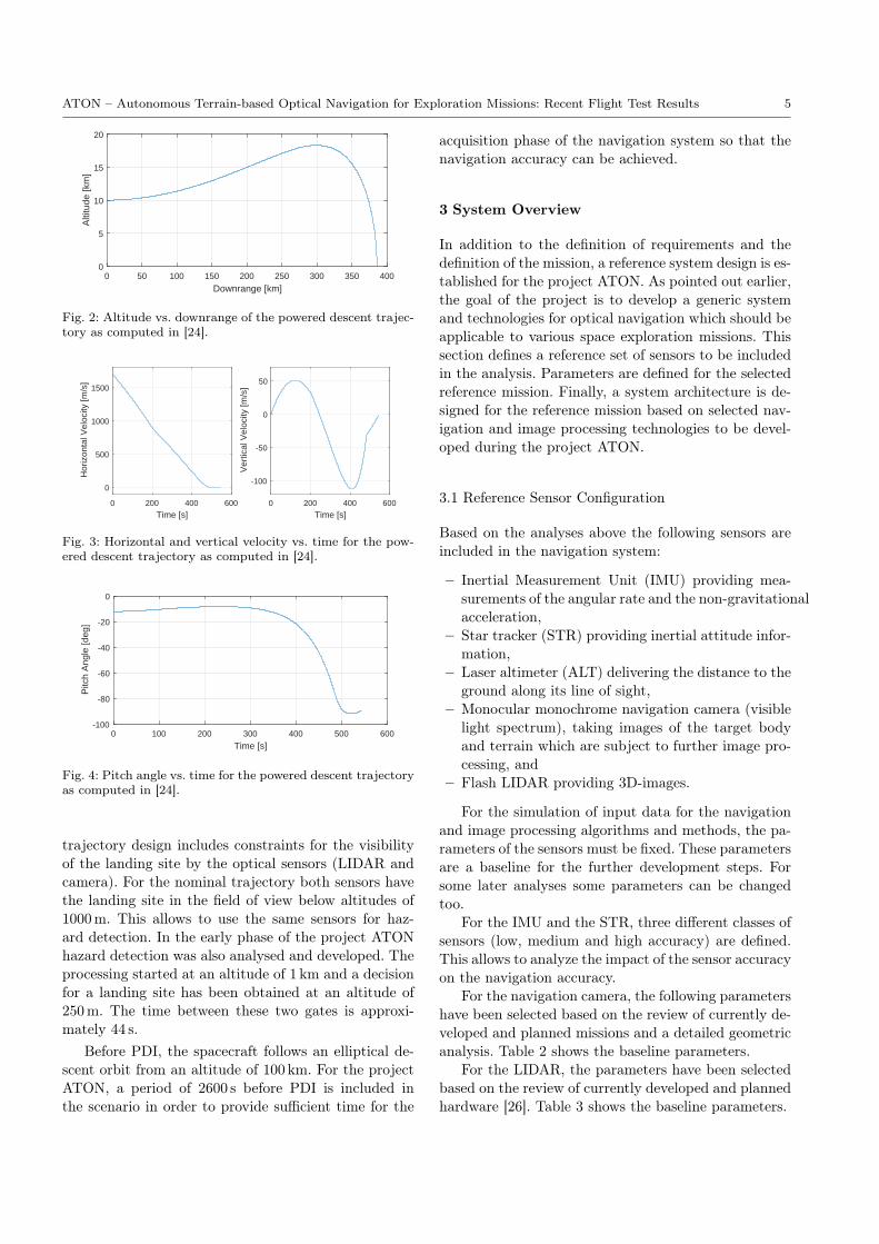
Figure 2 shows the altitude vs. downrange profile ofthe powered descent. Figure 3 displays the velocity pro-files. It can be seen that the main thrust is changed inonly three steps. This meets the specific requirements ofa landing with non-throttable engines where the thrustis reduced by switching off pairs of engines.
In Fig. 4, the pitch angle is shown for the powereddescent. It can be seen that the pitch angle is kept at lowangles (below 20 deg) for a long period where mainly thehorizontal velocity is decreased. Afterward, the landingvehicle pitches down so that the x-axis (down directionwhen the lander is landed) points more and more down.In order to provide good visibility of the landing site forthe onboard sensors, the last part of the descent is al-most vertical with a pitch angle close to -90 deg. The
ATON – Autonomous Terrain-based Optical Navigation for Exploration Missions: Recent Flight Test Results 5
0 50 100 150 200 250 300 350 400
Downrange [km]
0
5
10
15
20
Alti
tude
[km
]
Fig. 2: Altitude vs. downrange of the powered descent trajec-tory as computed in [24].
0 200 400 600
Time [s]
0
500
1000
1500
Hor
izon
tal V
eloc
ity [m
/s]
0 200 400 600
Time [s]
-100
-50
0
50
Ver
tical
Vel
ocity
[m/s
]
Fig. 3: Horizontal and vertical velocity vs. time for the pow-ered descent trajectory as computed in [24].
0 100 200 300 400 500 600
Time [s]
-100
-80
-60
-40
-20
0
Pitc
h A
ngle
[deg
]
Fig. 4: Pitch angle vs. time for the powered descent trajectoryas computed in [24].
trajectory design includes constraints for the visibilityof the landing site by the optical sensors (LIDAR andcamera). For the nominal trajectory both sensors havethe landing site in the field of view below altitudes of1000m. This allows to use the same sensors for haz-ard detection. In the early phase of the project ATONhazard detection was also analysed and developed. Theprocessing started at an altitude of 1 km and a decisionfor a landing site has been obtained at an altitude of250m. The time between these two gates is approxi-mately 44 s.
Before PDI, the spacecraft follows an elliptical de-scent orbit from an altitude of 100 km. For the projectATON, a period of 2600 s before PDI is included inthe scenario in order to provide sufficient time for the
acquisition phase of the navigation system so that thenavigation accuracy can be achieved.
3 System Overview
In addition to the definition of requirements and thedefinition of the mission, a reference system design is es-tablished for the project ATON. As pointed out earlier,the goal of the project is to develop a generic systemand technologies for optical navigation which should beapplicable to various space exploration missions. Thissection defines a reference set of sensors to be includedin the analysis. Parameters are defined for the selectedreference mission. Finally, a system architecture is de-signed for the reference mission based on selected nav-igation and image processing technologies to be devel-oped during the project ATON.
3.1 Reference Sensor Configuration
Based on the analyses above the following sensors areincluded in the navigation system:
– Inertial Measurement Unit (IMU) providing mea-surements of the angular rate and the non-gravitationalacceleration,
– Star tracker (STR) providing inertial attitude infor-mation,
– Laser altimeter (ALT) delivering the distance to theground along its line of sight,
– Monocular monochrome navigation camera (visiblelight spectrum), taking images of the target bodyand terrain which are subject to further image pro-cessing, and
– Flash LIDAR providing 3D-images.
For the simulation of input data for the navigationand image processing algorithms and methods, the pa-rameters of the sensors must be fixed. These parametersare a baseline for the further development steps. Forsome later analyses some parameters can be changedtoo.
For the IMU and the STR, three different classes ofsensors (low, medium and high accuracy) are defined.This allows to analyze the impact of the sensor accuracyon the navigation accuracy.
For the navigation camera, the following parametershave been selected based on the review of currently de-veloped and planned missions and a detailed geometricanalysis. Table 2 shows the baseline parameters.
For the LIDAR, the parameters have been selectedbased on the review of currently developed and plannedhardware [26]. Table 3 shows the baseline parameters.

6 S. Theil et al.
Table 2: Camera specifications as used in the project ATON
Resolution [px] 1024 × 1024Frame rate [1/s] 30FOV [deg] 40 × 40
Table 3: LIDAR specifications as used in the project ATON
Resolution [px] 400 × 400Frame rate [1/s] 1FOV [deg] 12 × 12Range [m] 1 - 1000Noise [m] 0.02
For the alignment of the star tracker the followingconditions are considered: it shall point away from Sunand lunar surface, thus the baffle exclusion angles forthe STR are met at all times. Furthermore, the plumeof the main engine shall not be included in the FOV ofthe sensor. During the landing, the vehicle performs apitch of about 90 deg where the baffle exclusion anglesalso have to be considered.
Since most landings on the Moon occur on a lunarmorning (in order to have about 14 days of illumina-tion), it can be assumed that the Sun elevation at thelanding site is not very high. Furthermore, it can beassumed that the low elevation of the Sun is not inflight direction or anti-flight direction since in this caseeither the navigation camera might be blinded by theSun or would not see shadows and therefore have onlyvery few characteristic features for optical navigation.Based on these assumptions the Sun elevation will bebelow 60 deg and the Sun azimuth with respect to flightdirection is between +30 deg and +150 deg, or between-30 deg and -150 deg, respectively.
With these conditions, the STR should be mountedwith its boresight close to the pitch axis. Depending onwhich side of the flight path the Sun is expected, it hasto be mounted on the left or the right side with respectto flight direction.
The camera, LIDAR and ALT are mounted outsideor on the surface of the landing vehicle. A diameterof about 4m is assumed for the vehicle. This leadsto a lever arm with respect to the IMU or body-fixedframe. The viewing direction is chosen that the edge ofthe FOV for camera and LIDAR is on one side the x-direction of the body-fixed frame (down direction whenthe lander is vertical upright, e.g. on ground, or for-ward direction when the main engine is horizontallyaligned in PD). All optical sensors are mounted on theside which faces the ground during the almost horizon-tal flight in the first phase of the PD. The setup of thesensors is illustrated in Fig. 5.
Fig. 5: Sensor reference configuration for ATON: red - camera,green - laser altimeter, blue - LIDAR; This figure is a repre-sentation for the viewing directions of the sensors. The place-ment of the sensors is not representative since the thrusterplume has not been considered.
3.2 System Architecture
In the section above, the set of sensors as well as theiralignment on the landing vehicle have been defined.Since the output of the system shall be the navigationstate vector, a mandatory element is a navigation fil-ter which combines and fuses all sensor measurementsand preprocessed data to a navigation solution. This iscomplemented with further modules for processing ofimage data. Figure 6 shows the conceptual data flowwithin the ATON navigation system with seven pro-cessing modules including the navigation filter. Figure 7provides an overview which of the modules is runningin the different phases of the landing.
The processing modules are encapsulated in taskswhich are executed in parallel. The inter-module com-munication and the scheduling of the tasks are managedby DLR’s data flow-oriented Tasking Framework [23].It ensures that a module is only executed if all neces-sary inputs are available. The integration of the ATONsoftware was conducted in a model-driven manner: anextended SysML/UML model was created to describethe processing modules with their interfaces and pa-rameters, data types, priorities and the data flow be-tween the modules [7]. Custom code generators createthe source code for data types, communication, moduleinterfaces, and serialization code for the telemetry.
The following paragraphs provide a short overviewof each processing module.
Feature TrackerThis module is used to extract and track image featuresover the camera sequence. To perform this task, theLukas Tomasi Kanade (KLT) Tracker is used over twosuccessive images at each step. The tracker is basedon two steps: the first step is image feature extraction

ATON – Autonomous Terrain-based Optical Navigation for Exploration Missions: Recent Flight Test Results 7
Navigationfilter
IMU
STR
Camera 1
LIDAR
Altimeter
Craternavigation
Feature Tracker
Epipolar geometry
Stereo matching
3D Matching
Camera 2
Navigation state
Shadow Matching
Fig. 6: Block diagram of the ATON system: blue - sensors, green - on-board processing modules
Module Phase 1 Phase 2 Phase 3Crater NavigationNavigation FilterFeature TrackingEpipolar GeometryStereo Matching3D MatchingShadow Matching
ActiveOptionally active
DO t ̴ -3200s
PDI t ̴ -550s
Touch down t = 0
Landing site visible t ̴ -430s
Fig. 7: Timeline for the different processing modules of ATON
based on high gradients in two axes [29] in the verybeginning of the sequence and later at image regionswhere no features are present (anymore). The secondstep is feature tracking which is based on image regionsimilarity [20]. This step allows sub-pixel accuracy forsharp textures. The 2D pixel coordinates of these imagefeatures in the two successive input images is output tothe Navigation Filter module.
Crater NavigationThe Crater Navigation module detects lunar surface im-pact craters in the images of the navigation camera,and it assigns each crater detection to an element froma static crater catalog referenced in Moon-fixed coordi-nates. From that correspondence, a Moon-fixed camera(and thus vehicle) position can be computed. This po-sition is supplied as a measurement to the NavigationFilter that may use it to cancel accumulated positionand velocity errors from the feature-based relative nav-igation (see above). Next to this regular drift removal
over crater fields, larger corrections after phases whereno craters were visible are of great value. The craterdetection is based on the extraction and matching ofadjacent areas of above- and below-average brightnessthat model the reflection and shadow of typical craterinteriors under illumination [21, 22].
Shadow MatchingThe Shadow Matching module provides an absolutelocalization in the planet’s reference frame with helpof the Binary Shadow Matching algorithm (BSM) de-scribed in [15]. The algorithm is based on the idea touse shadows on the lunar surface as landmarks. Given acamera image and the current pose estimate, the BSMextracts shadows from the image and creates descrip-tors for each extracted shadow. The descriptors are rep-resented as one-dimensional binary vectors for mem-ory and matching efficiency. These shadow descriptorsare matched with reference descriptors which have beencomputed previously, e.g. on ground. In a final step, thematching result is used to compute an estimate of theabsolute pose with a covariance. As an accurate orien-tation of the lander is provided by the STR, only theabsolute position along with its covariance values areprovided to the Navigation Filter.
Epipolar GeometryThe Stereo Matching, as used in the 3D processingchain, requires an accurate knowledge about the rel-ative orientation of every two images being matched. Itis required to calculate their Epipolar Geometry with
8 S. Theil et al.
less than 0.5 pixels of error to ensure the quality ofthe 3D model. The Epipolar geometry module performsthis task taking two subsequent images as input, to-gether with the rough relative orientation provided bythe Navigation Filter. It extracts and matches commonfeatures between the two images and uses them to cal-culate the precise relative orientation between the twoimages using a small bundle adjustment with RANSAC.Finally, it passes the calculated relative orientation tothe Stereo Matching module for each pair of images.
Stereo MatchingThe Stereo Matching module computes dense depthmaps from two consecutive and partly overlapping im-ages, also known as structure from motion [30]. It usesthe Semi-Global Matching algorithm (SGM) which isknown from robotics and aerial image processing to pro-vide accurate and dense depth maps [10–12]. Given twocamera images with approximately 75% to 80% overlapand the accurate relative orientation provided by theEpipolar Geometry module, the SGM can triangulatethe so-called disparity for corresponding image points.As the ATON system uses calibrated cameras, it is pos-sible to convert the disparities into metric depth values.This allows to provide metric depth maps to the 3DMatching module.
3D MatchingThe 3D Matching module provides an absolute poseestimation in the planet’s reference frame. It is basedon the Iterative Closest Point (ICP) algorithm [5, 6, 28]which can determine the offset, i.e. the relative trans-formation, between two 3D point clouds. The modulecan either use a range map from the flash LIDAR ora metric depth map from the Stereo Matching mod-ule as input. The pose estimate at the time of cre-ation of the input data is required as an initial guessof the offset between the point clouds. The in-flight-generated point cloud is matched to a reference pointcloud, which was created previously on-ground from aDEM of the fly-over area or of the landing site. First,the ICP searches corresponding points from the pointclouds, and secondly, it estimates an optimal transfor-mation that minimizes the distance between the corre-spondences. This is repeated until the optimization con-verges and a best guess of the pose estimate is achieved.Hence, the Epipolar Geometry module, the Stereo Match-ing module, and the 3D Matching represent a sequenceof consecutive modules that provide an improved ab-solute position estimate. Since the navigation systemcontains a STR providing attitude, only the positionestimate is provided as the output to the NavigationFilter.
Navigation FilterThis module uses the output of the Feature Tracker, theCrater Navigation, the Shadow Matching and the 3DMatching along with the raw IMU, Altimeter and StarTracker measurements to estimate the true navigationsolution. The Navigation Filter is based on high-ratestrap-down computation and a low-rate error-state Un-scented Kalman Filter (UKF) [1]. The strap-down al-gorithm uses the IMU measurements to propagate thetotal navigation solution forward in time for each mea-surement. The low rate UKF estimates the error of thestrap-down algorithm and corrects the propagated nav-igation solution based on the absolute position mea-surements from the other modules, the absolute atti-tude from the star tracker, and the altitude above thelunar surface measured by the altimeter. Additionally,the tracked image features are used in a visual SLAMalgorithm [2, 3] to provide further position updates tothe Navigation Filter.
4 Results
4.1 Past Development Milestones
During the project ATON, several milestones have beenachieved since its start in 2010. These can be groupedinto four phases which are:
1. Setup of simulation environment including the sim-ulation of images of the navigation camera and LI-DAR,
2. Integration and verification of software modules ina Model-in-the-Loop (MiL) environment and latera Software-in-the-Loop (SiL) environment,
3. Verification of the navigation system and elementsof the system in Hardware-in-the-Loop (HiL) andProcessor-in-the-Loop (PiL) test environments,
4. Verification of the navigation system with outdoorflight tests using an unmanned helicopter testbed.
Setup of Simulation EnvironmentIn the first step, a simulation environment was set upwhich included the dynamical model of a lunar land-ing vehicle as well as models for all sensors. In order tocreate the proper inputs for image processing methodswhich are part of the ATON system, an extensive simu-lation was set up to generate artificial images from thegiven state of the vehicle, the chosen camera param-eters and the digital elevation models (DEM) of thelunar surface. For that purpose, the DEM maps of theJapanese Selene (Kaguya) mission were acquired andpreprocessed [9, 14]. Although the Selene mission pro-vided a global mapping, the DEM resolution is limited.

ATON – Autonomous Terrain-based Optical Navigation for Exploration Missions: Recent Flight Test Results 9
Fig. 8: Example of a generated navigation camera image dur-ing a simulated lunar landing.
For the final phases of the landing (below 2 km alti-tude), the noise in the DEM is dominating. For thatreason, the DEM was enhanced with artificial struc-tures which can be expected at the landing site [18].
The preprocessed and enhanced DEMs were usedin the camera and LIDAR simulation [25]. It provideda 1024 by 1024 pixel monochrome image as well as adepth image of the same size. Figure 8 shows an exam-ple of a simulated image. From the depth image a subsetof 400 by 400 pixels was cut out to simulate the LIDARmeasurements. A single point of the depth image wasused for simulating the laser altimeter. In addition tothese time-tagged images, simulated time-tagged sen-sor outputs for IMU, STR and laser altimeter as wellas a true state were created. Based on the sets of simu-lated navigation sensor outputs, the development of thedifferent processing modules could be supported.
MiL and SiL TestsFor initial development and also for verification in laterdevelopment stages, the image processing and naviga-tion modules have been embedded in a Matlab/Simu-link-based simulation environment. Since most of themodules have been based on C/C++ - coded process-ing libraries, the same coding language has been used.To test the modules, their code was embedded in Mat-lab/Simulink s-functions. The sensor models for STRand IMU have also been created in Matlab/Simulink.As described above, the simulation of images is a veryextensive task. For that reason, the camera and LIDARmodels in Matlab/Simulink were just loading precom-puted image files into the simulation. Thus the ini-tial simulation environment was limited to open-looptests where a limited number of pre-computed trajec-tories including their pre-computed images could be
used. Nevertheless, the integration into Matlab/Simu-link proved to be the right way since this environmentallowed easy debugging of inter-module communicationand the analysis of effects that do only occur in the in-teraction of modules. It also enabled the variation ofarchitecture and configuration for the navigation sys-tem.
As a further evolution, the processing modules (seealso Fig. 6) were embedded in DLR’s Tasking Frame-work [23] which would be needed for the integration onan embedded system. The initial tests of the frameworkwere also done in the Matlab/Simulink environmentwhere the complete set of processing modules includ-ing the Tasking Framework were embedded as a singles-function.
To prove function and performance in closed-loopoperation, the simulation was extended by models forvehicle dynamics and actuators as well as by a guidanceand control function. Furthermore, the simulation wasconnected to the image simulation engine to computethe camera and LIDAR images based on the currenttrue state vector which is influenced by the control ac-tions. Since the computation of a single camera imagetook about 20s, the closed-loop simulations became alengthy exercise lasting several days for a single simu-lation of the powered descent with a length of about600s simulated time. Nevertheless, the effort to createthe closed-loop environment and to run the simulationswas returned with results indicating how the controlactions may influence the navigation function and per-formance.
HiL and PiL TestsSince the main part of the development is focusingon image processing and optical navigation, a HiL-testwith a camera in the loop was chosen as an importantdevelopment and verification step.
In order to generate a realistic scene for a camera asexperienced during a lunar landing, DLR’s Testbed forRobotic Optical Navigation (TRON) was set up (seeFig. 9). It allows test and verification of optical navi-gation technologies up to TRL 7 [16–18]. TRON offersthe possibility to perform HiL tests within scenes rep-resentative for the ones encountered by optical sensorsduring exploration missions. Typical sensor hardwarewhich can be tested in TRON are active and passiveoptical sensors like LIDAR systems and cameras. Themajor components of the lab are a robot on a rail fordynamic positioning of the sensor under testing, terrainmodels and other environmental structures, a dynamiclighting system for illumination of the targets, lasermetrology equipment for high-precision ground truth,and a dSPACE real-time system for test observation

10 S. Theil et al.
Fig. 9: Simulation of the descent orbit phase of a Moon landing trajectory in TRON. The robot positions the optical sensor(in this case a camera) with respect to the illuminated terrain model, with the sensor recording data. Simultaneously the lasertracker measures precisely the true pose of the sensor with respect to the simulated Moon.
Fig. 10: Lunar landing images created in TRON.
and control, and synchronization of ground truth andsensor data.
The lab allows to acquire highly realistic cameraimages including errors and effects of the sensor whichcannot be modeled easily, e.g., lens distortion or lensflares. An example for images generated in TRON isshown in Fig. 10.
For several reasons (see [16]) it is not feasible toreplicate all the lunar surface visible during the mis-sion. Therefore, the goal was to demonstrate a success-ful navigation during three sections of the trajectorywhich are most significant in terms of geometric shapeand in the use of optical navigation methods. Thesehave been found to be the descent orbit, the powered de-scent, and the landing phase. Furthermore, the projectdid not have access to a LIDAR sensor to be used in
Guidance + Control Dynamics
Sensor Simulation ATON S/W
Guidance + Control
IMU
STR
TRON + Camera
LA Item under Test Hardware-in-the-loop Software Models
Fig. 11: Block diagram of HiL closed-loop setup in TRON.
the lab. Therefore the tests in the lab have been limitedto the camera.
TRON was applied first for an open-loop testing andthen for closed-loop testing of the complete ATON nav-igation system. For both the software simulation wasmodified. In Fig. 11, this is shown for one step of theclosed-loop system. The software-in-the-loop test envi-ronment was changed by replacing the camera modelby the real camera in the TRON environment. Thesimulation provided TRON with the attitude and po-sition of the camera in the Moon-centered Moon-fixedframe (MCMF). This information was used to positionthe robot with respect to the lunar landscape modelin TRON. Other auxiliary information as the Sun vec-tor were also provided to TRON to position the lampin the proper way and to simulate realistic time andposition-dependent illumination of the surface.
The images acquired during the tests have then beenused in the processing chain of the ATON system to-gether with simulated sensor data for altimeter, STRand IMU. The same images have also been used to im-prove the single image processing and optical naviga-tion modules. For example, the crater navigation mod-

ATON – Autonomous Terrain-based Optical Navigation for Exploration Missions: Recent Flight Test Results 11
Fig. 12: Crater navigation during lunar landing simulationin TRON. Turquoise ellipses: detected craters, Pink crosses:craters in database. Overlapping symbols indicate match be-tween detected craters and database used for navigation.
ule was tested as a single element during the descentorbit. Figure 12 shows an example how position deter-mination by crater navigation was verified.
The three sections simulated in TRON are down-scaled by ratios of 1:125000, 1:10000, and 1:100. Es-pecially for the first two cases, the positioning errorsof the robot can translate into large errors in groundtruth. For example, a positioning error of 1 mm withrespect to the descent orbit model which is scaled by1:125000 translates to 125 m. In order to make sure thatthe ground truth error of position and attitude is in rea-sonable bounds, the camera’s position and attitude onthe robot is measured by a high-precision laser track-ing system. Further, the laser tracker measurement isused in an internal closed-loop to reduce the position-ing error of the robot down to a level of 0.3 mm and0.2 deg [17]. This allowed to prove the operation of theATON navigation system in closed-loop for parts of thepowered descent.
As a preliminary step to the following flight tests,the ATON software was implemented on an embeddedsystem. In a first step, the simulated data from theMiL simulations were fed into the navigation softwareto prove its function and performance on the embeddedsystem in an real-time environment. Later, the samesetup was used to replay recorded flight data in orderto analyze different software settings and processing pa-rameters. For both steps, a real-time capable log playerwas developed.
4.2 Unmanned Helicopter Flight Testing
Before conducting the flight tests, several other devel-opment steps had to be done. First, specific flight hard-ware had to be integrated, i.e. interfaces and softwaredrivers had to be developed, implemented, integratedand tested. Furthermore, the development included thedesign and production of targets resembling craters aswell as the design, implementation and verification ofgenerating ground truth data, together with accuratemapping of the crater targets.
As pointed out earlier in this paper, testing on-ground of GNC systems does not allow to verify theitem-under-test completely in a single test with the en-vironment or on the trajectory to be expected in opera-tion. The same applies for the flight tests. It is obviousthat the illumination conditions on the Moon cannotbe created easily on Earth. The lunar landscape cannotbe created on large areas for flight tests. And obviously,the flight dynamics of a helicopter are different to thatof a lunar landing vehicle.
The very first tests were done by mounting the wholeexperimental setup on a small carriage and driving itaround on ground. Later, flight tests were conductedusing an unmanned helicopter. The first flight test cam-paign focused on recording flight data from all availablesensors. This was followed by a second flight campaignwere the ATON navigation system was tested in open-loop. The last test campaign was concluded in March2017. In these tests, the ATON system was used as theprimary navigation system for the autonomous flightof the unmanned helicopter. The results of this mostrecent test campaign are presented in the following sec-tions.
4.2.1 Test Set-up
The objective of the flight test was to demonstrate thereal-time closed-loop operation of the ATON navigationsystem in an exploration mission scenario. The overalltest concept was to fly a navigation sensor suite along apredefined reference trajectory over a field. The groundhas been equipped with artificial crater-like targets thatwere mapped into an Earth-fixed frame. During flight,the ATON navigation system provided a navigation so-lution in the Earth-centered Earth-fixed (ECEF) framewhich was fed back into the guidance and control sys-tem of the helicopter. The navigation solution was usedto track the predefined flight trajectory.
Trajectory and Flight ApparatusThe test campaign took place near Braunschweig, Ger-many, at a test site offering a strip of land and a volume

12 S. Theil et al.
GNSS receiver
(for ground truth)
Camera
Computer
IMU
Start of trajectory at 50 m altitude
Begin of final descent
Laser
Scanner
Fig. 13: Camera, IMU, laser scanner, onboard computing andground truth hardware installed on helicopter during flight.
of restricted airspace suitable for flying unmanned ve-hicles over an area of about 300 m × 300m. The jobof transporting the navigation payload was performedby an unmanned SwissDrones (SDO 50 V2) helicopteroperated by DLR (Fig. 13). This platform is capable ofautonomous, assisted and remote-controlled flight, andit offers a payload capability of approximately 50 kg(fuel plus experiment equipment).
All sensors were integrated on a single platform. Thedevices relevant for this paper are marked in the imageof the experimental payload in Fig. 13. A tactical-gradeIMU (iMAR iTraceRT-F400-Q-E, specifications in Ta-ble 4) was used for acquiring velocity and angle incre-ments. It operated at 400 Hz.
Capturing of images was performed by two monocu-lar, monochromatic cameras (AVT Prosilica GT1380).Having been installed in a forward-looking and down-looking configuration, their resolution was set to 1024px × 1024 px at 20 Hz sampling rate. For measuringthe altitude of the platform similar to the descriptionof the lander in Fig. 5, a laser scanner (SICK LD-MRS)is used. The laser scanner has been configured to haveonly a small field of view to emulate a laser altime-ter. The STR measurements could – of course – notbe acquired during daylight. Therefore, they have beenemulated by the reference navigation system which wasalso used to provide ground truth navigation. Before theflight tests all sensors have been calibrated and alignedusing sensor measurements and images of checkerboardpatterns. Major changes caused by vibration and shockduring transport and test flight have not been observed.
Considering the experience of earlier activities withthe ATON system, a position accuracy in the order oflow one-digit percent of (camera) line-of-sight range wasassumed as a likely upper bound. Given the flight tra-jectory followed (Fig. 14), this translates to a groundtruth accuracy requirement of centimeter level. There-fore, the helicopter payload was equipped with a high-
Fig. 14: Trajectory of one test flight (red) and crater centerpositions (yellow)Image background: Google Earth
Table 4: IMU (1σ) specifications.
Gyroscope AccelerometerSensor range ±450deg/s ±5 gAxis misalignment 0.5mrad 0.5mradAngle/vel. random walk 0.1deg/
√h 50µg/
√Hz
Bias repeatability 0.75deg/h 2mgScale-factor repeatability 300ppm 1500ppm
grade GNSS receiver NovAtel Propak6. It uses bothL1 and L2 frequencies and the German precise satel-lite positioning service, SAPOS. This service relies on anetwork of reference stations with precisely known po-sitions to determine corrective data for all visible GPSsatellites. Furthermore, two GNSS antennas were usedallowing the receiver to also determine heading andpitch angles in the North-East-Down reference system.The Propak6 output has the following 1σ accuracies:about 0.03m in position, about 0.4 degrees in headingand pitch, and about 0.03m/s in velocity.
About half of the available terrain in Fig. 14 wasused for the flight operation. The remainder was re-served as safety perimeter, ground station and test crewarea. The reference flight trajectory was defined as a lin-ear path, stretching from north-east to south-west forabout 200m, and from an initial altitude of 50m downto 10m. After the slight descent on this path, the he-licopter performed an almost vertical descent down to1m above ground. Figure 14 illustrates this profile.
Obviously, craters are necessary for the crater navi-gation module to work. A pattern of planar crater tar-

ATON – Autonomous Terrain-based Optical Navigation for Exploration Missions: Recent Flight Test Results 13
Fig. 15: Craters after preparation and ready for testing
gets (Fig. 15) was thus scattered in a random mannerover four sub-fields along the flight area. Altogether,80 craters with diameters between 5m and 0.5m wereused. The bigger craters were situated near the be-ginning of the path (higher altitudes) and the smallercraters nearer to the end (lower altitudes), ensuringa near-constant coverage of the camera images duringthe linearly decreasing altitude. After placing the craterplanes, they were fixed to the ground (Fig. 15). A pic-ture of the crater scattering is shown in Fig. 16.
Crater CatalogSubsequent to field preparation, a catalog of crater po-sitions was created. The pose estimated by the CraterNavigation and processed by the Navigation Filter isrelative to this reference database. Tasks such as au-tonomous navigation for lunar landing or near-asteroidoperation require the Crater Navigation to provide apose in the reference frame of the target body. There-fore, the crater catalog was in this case expressed inthe ECEF reference frame. A two-stage process wasperformed: At first, a tachymeter (Leica TDRA-6000)was used to measure all crater centers and three auxil-iary points in a local (tachymeter) frame. Then, usingthe Propak6, the same three auxiliary points were mea-sured directly in ECEF. This allowed the determinationof a transformation from the local tachymeter referenceframe into ECEF. Applying this transformation to allmeasured craters yielded the ECEF crater catalog. Theaccuracy of this catalog is then at the level of 0.01 to0.02m.
Configuration of ATON Navigation SoftwareAs in the previous tests, the setting for the flight testsdid not allow to include all sensors. A flash LIDAR wasnot available to the project. A star tracker could not beused since the flights have been executed during day-light. Furthermore, the flight area comprised only flat
terrain. Therefore the 3D processing chain as well asthe 3D matching with LIDAR data was deactivated forthe helicopter test flights. Due to development delaysthe shadow matching was also deactivated and verifiedin post-processing. All other modules were active. Thecrater navigation was processing images of both cam-eras and was running asynchronously starting the pro-cessing of the most recent image after the previous pro-cessing step was finished. The model-based software de-velopment allowed flawless activation, deactivation andre-configuration.
Ground TruthAs mentioned above, a high-end GNSS receiver wasused as means to obtain a ground truth for the testedtrajectories. In an effort to increase the accuracy ofthis information, the output of the Propak6 receiverwas fused with IMU data in post-processing. This didnot only smooth the position and velocity solutions, italso completed the two degrees of freedom of attitudeinformation given by the receiver (i.e. pitch and head-ing). The slight observability of attitude provided bythe accelerometer measurements in combination withmeasured position and velocity further increased overallattitude accuracy. The covariance levels of kinematicsstates of the fused ground truth can be seen in Figs. 17,18, and 19.
4.2.2 Flight Results
The latest flight campaign in March 2017 conducted sixsingle flight runs in closed-loop setup. For each flight,the final altitude above ground was set individually. Afinal altitude of 0.75m has been achieved. Figures 20and 21 show the track of the helicopter (ground truthand navigation solution) in the North-East and East-Up planes. The beginning of the trajectories is in thepoint (0,0,0) where the helicopter hovers for a shorttime before the begin of the descent. It follows an al-most straight path down to an altitude of about 10mabove the landing site. From that point, the helicopterexecutes a vertical descent down to the final altitudeof about 0.75m. In both plots it can be seen that thetrue trajectory (blue) and the navigation solution of theATON system (green) differ only by a small amount.At the end of the trajectory the divergence gets largerwhen the camera loses visibility of the ground targets.The hook shaped divergence is a combination of thiseffect with the climbing motion of the helicopter afterthe end of the experiment.
Figures 22, 23, and 24 show the estimation errorsfor one of the closed-loop test flights. In Fig. 22, the es-timated position errors and the estimated correspond-ing covariances are displayed. Furthermore, the rows of

14 S. Theil et al.
Fig. 16: Helicopter over test field during flight
0 20 40 60 80 100 120 140 160 180 200 220 2401.05
1.1
1.15
1.2
1.25
1.3·10−2
Pos
itio
n,m
Position cov., ECEF
Fig. 17: Fused ground truth position quality (1σ covariance):x - red, y - green, z - blue.
0 20 40 60 80 100 120 140 160 180 200 220 2401
1.2
1.4
1.6
1.8
2·10−2
Vel
ocity,
m/s
Velocity cov., ECEF
Fig. 18: Fused ground truth velocity quality (1σ covariance):x - red, y - green, z - blue.
0 20 40 60 80 100 120 140 160 180 200 220 2400
0.1
0.2
0.3
0.4
Att
itud
e,de
g
Attitude cov., Body
Fig. 19: Fused ground truth attitude quality (1σ covariance):roll - red, pitch - green, yaw - blue.
green, blue and yellow dots at -0.5, 0 and 0.5m indicatethe state of the navigation system and the state of theclosed-loop guidance and control system. The blue andgreen dots at -0.5m and 0.5m denote an update of thenavigation filter by the sensor inputs. The blue dots at0.5 show updates by the forward camera. Green dots at-0.5 show updates of the down-looking camera. The yel-low and green dots at 0 show which navigation solutionis used for the closed-loop. Yellow dots indicate that thebuilt-in GPS-based navigation system of the helicopterhas been used. Green dots at 0 denote that the navi-gation solution of the ATON navigation system is usedin closed-loop. The switching between these states was

ATON – Autonomous Terrain-based Optical Navigation for Exploration Missions: Recent Flight Test Results 15
-80 -60 -40 -20 0East [m]
-180
-160
-140
-120
-100
-80
-60
-40
-20
0
Nor
th [m
]
Trajectory in NE plane
Fig. 20: Plot of flight trajectory in North-East plane: blue -ground truth, green - ATON navigation solution; the experi-ments starts at the point (0,0).
-80 -60 -40 -20 0East [m]
-50
-40
-30
-20
-10
0
Up
[m]
Trajectory in EU plane
Fig. 21: Plot of flight trajectory in East-Up plane: blue -ground truth, green - ATON navigation solution; the experi-ments starts at the point (0,0).
done manually by telecommand. Therefore no chatter-ing between the states was possible.
The experiment stops at time 340 s. At that point,the helicopter has reached the minimal height aboveground. After reaching this experimental goal, the he-licopter climbs up, and guidance and control switchesback to the GPS-based navigation solution.
0 50 100 150 200 250 300 350Time [s]
-20
-15
-10
-5
0
5
10
15
20
Err
or [m
]
Position Error in ECEF
Fig. 22: Position error in ECEF coordinates (x - blue, y -green, z - red); dashed lines denote the estimated error co-variance; dots at -0.5, 0 and 0.5 denote the state of the system.Yellow dots denote that the GPS based navigation system isfor controlling the helicopter.
When observing the position estimation error andthe covariances, it can be seen that at higher altitudesthe position estimation is slightly worse than at loweraltitudes. This is expected since the same angular vari-ation in the camera image corresponds at higher alti-tude to a larger variation in position. Towards the endof the flight when hovering low above the crater targetson ground, their visibility in both camera images is lost.For that reason the updates of the navigation filter stopand the error starts to grow slightly.
For the velocity errors in Fig. 23, a similar behaviorcan be seen. At high altitude, the errors are larger andbecome smaller at low altitudes. The error starts alsoto grow slightly when the observations from the imageprocessing cannot be used for the filter update. For theattitude error in Fig. 24, the deviations are independentfrom altitude as it can be expected.
5 Conclusions
This paper provided an overview of the ATON projectand its most recent results from flight testing. With thelast flight test campaign, it was demonstrated that theATON navigation system can provide a navigation solu-tion based on optical and inertial measurements in realtime. It could be proven that the provided navigationsolution is accurate and robust enough to close the loopfor the autonomous flight of an unmanned helicopter.Throughout the project duration and while achievingseveral development milestones, many valuable images,

16 S. Theil et al.
0 50 100 150 200 250 300 350Time [s]
-2
-1.5
-1
-0.5
0
0.5
1
1.5
2
Err
or [m
/s]
Velocity Error in ECEF
Fig. 23: Velocity error in ECEF coordinates (x - blue, y -green, z - red); dashed lines denote the estimated error co-variance.
0 50 100 150 200 250 300 350Time [s]
-0.6
-0.4
-0.2
0
0.2
0.4
Err
or [d
eg]
Attitude Error (Delta Angle)
Fig. 24: Attitude error in body fixed frame (x - blue, y - green,z - red); dashed lines denote the estimated error covariance.
data, information and lessons learned have been cre-ated, processed and collected. Furthermore, the ATONproject paved the way for verification of optical naviga-tion sensors and components in representative environ-ments. Hence, the creation of realistic scenes for cam-eras in TRON and the flight tests on the unmanned he-licopter have been major milestones, and they are nowavailable for further developments steps, for the verifi-cation of mission specific systems, and also for tests ofequipment and software of the space community.
5.1 Lessons Learned
Within the project many lessons have been learned. Themost important are summarized here:
– High-fidelity sensor simulation: For the proper de-velopment of image processing and navigation algo-rithms, a thorough knowledge and a complete rep-resentation of sensor signals is needed. This includesthe simulation of realistic images.
– Use and analyze real sensor data: For advancing themethods and algorithms as well as for making themmore robust, it is essential to switch to real sensorand image data at an early point in development.This triggers failure modes which are not apparentin simulations. If this is done late, the test with realdata may contain a few surprises.
– Early real-time implementation: Just from the be-ginning, implement while considering future porta-bility to embedded platforms (e.g. being indepen-dent from libraries). If not considered, the re-imple-mentation for an embedded system comes at a highcost.
– Use model-driven software development: Since thecore of a navigation fusing optical and inertial sensordata is a complex software, a model-driven softwaredevelopment is recommended [7]. It allows to controland adapt the interfaces of the single modules in aconsistent way. This way, the tedious debugging ofinter-module communication could be limited.
– Test in real-world and real-time environment: Thetransition to real sensors and real-time processingcan offer a lot of pitfalls. If this could be done forparts of the system at an early stage it reduces theeffort for bug-fixing when integrating and testingthe complete complex system.
– Accurate ground truth data: In order to assess theperformance in HiL or flight tests, care should betaken to create a ground truth measurement withsufficient accuracy. It should be at least one orderof magnitude better than the expected accuracy.
– Stereo matching can work for the reference missionbut requires the lander’s trajectory to be as muchparallel to the surface as possible. Analysis showedthat the stereo matching module can work in the al-titude range of 10 km to 2 km with an average deptherror between 0.1 to 0.5% and an inter-image inter-val of approximately 10 seconds.
– The 3D Matching could be used from time to timeas a final refinement step on pose estimates witha high confidence. It provides high accuracy whena good initialization is given, but due to the localoptimization step in the ICP algorithm it is not well-suited to correct larger deviations of the actual pose.

ATON – Autonomous Terrain-based Optical Navigation for Exploration Missions: Recent Flight Test Results 17
5.2 Outlook
Although the project ATON has achieved a major mile-stone by demonstrating the capability of the navigationsystem to provide a robust and accurate navigation so-lution to guide and control an unmanned helicopter,the development of the system and its core software iscontinuing. Currently the focus is set on optimizing thesoftware to make it more efficient and robust to runit on space-qualified hardware with limited computa-tional resources. As a reference architecture the resultsof the parallel project OBC-NG [4] are considered. Oneelement of the further development will be the inte-gration of the ATON software on the hybrid avionicsarchitecture of OBC-NG and the transfer of a part ofthe image processing to FPGAs. In parallel, the workis going on to adapt the system and its elements to dif-ferent mission scenarios. They include asteroid orbitersand landers as well as landings on larger solar systembodies.
References
1. N. Ammann and F. Andert. Visual navigation for au-tonomous, precise and safe landing on celestial bodies us-ing unscented kalman filtering. In 2017 IEEE AerospaceConference, pages 1–12, March 2017.
2. F. Andert, N. Ammann, S. Krause, S. Lorenz,D. Bratanov, and L. Mejías. Optical-aided aircraft nav-igation using decoupled visual SLAM with range sensoraugmentation. Journal of Intelligent & Robotic Systems,2017.
3. F. Andert, N. Ammann, and B. Maass. Lidar-aided cam-era feature tracking and visual SLAM for spacecraft low-orbit navigation and planetary landing. In CEAS Eu-roGNC Conference, 2015.
4. Heike Benninghoff, Kai Borchers, Anko Börner, MichaelDumke, Görschwin Fey, Andreas Gerndt, KilianHöflinger, Jörg Langwald, Daniel Lüdtke, Olaf Maibaum,Ting Peng, Kurt Schwenk, Benjamin Weps, and KarstenWesterdorff. OBC-NG Concept and Implementation.Technical report, Deutsches Zentrum für Luft- undRaumfahrt (DLR), January 2016.
5. P. J. Besl and N. D. McKay. A method for registrationof 3-d shapes. IEEE Trans. Pattern Anal. Mach. Intell.,14(2):239–256, February 1992.
6. Y. Chen and G. Medioni. Object modeling by registrationof multiple range images. In Proceedings. 1991 IEEEInternational Conference on Robotics and Automation,pages 2724–2729 vol.3, Apr 1991.
7. T. Franz, D. Lüdtke, O. Maibaum, and A. Gerndt.Model-base software engineering for an optical naviga-tion system for spacecraft. CEAS Space Journal, 2017.submitted.
8. D.K. Geller and D.P. Christensen. Linear CovarianceAnalysis for Powered Lunar Descent and Landing. Jour-nal of Spacecraft and Rockets, 46(6), 2009.
9. J. Haruyama, T. Matsunaga, M. Ohtake, T. Morota,C. Honda, Y. Yokota, M. Torii, and Y. Ogawa. Global
lunar-surface mapping experiment using the lunar im-ager/spectrometer on selene. Earth, Planets and Space,60(4):243–255, Apr 2008.
10. H. Hirschmüller. Accurate and efficient stereo process-ing by semi-global matching and mutual information. InCVPR 2005, volume 2, pages 807–814. IEEE, June 2005.
11. H. Hirschmüller. Stereo processing by semi-global match-ing and mutual information. in IEEE Transactions onPattern Analysis and Machine Intelligence, 30(2):328–341, February 2008.
12. H. Hirschmüller and T. Bucher. Evaluation of digitalsurface models by semi-global matching. In DGPF 2010,July 2010.
13. T. Ho, V. Baturkin, C. Grimm, J. Grundmann, C. Hob-bie, E. Ksenik, C. Lange, K. Sasaki, M. Schlotterer,N. Termtanasombat, M. Talapina, E. Wejmo, L. Witte,M. Wrasmann, G. Wübbels, J. Rößler, C. Ziach, R. Find-lay, J. Biele, C. Krause, S. Ulamec, M. Lange, O. Mier-heim, R. Lichtenheldt, M. Maier, J. Reill, H.-J. Sedl-mayr, P.-W. Bousquet, A. Bellion, O. Bompis, C. Cenac-Morthe, M. Deleuze, S. Fredon, E. Jurado, E. Cana-lias, R. Jaumann, J. Bibring, K.H. Glassmeier, D. Her-cik, M. Grott, L. Celotti, F. Cordero, J. Hendrikse, andT. Okada. Mascot - the mobile asteroid surface scoutonboard the hayabusa2 mission. Space Science Reviews,2016.
14. M. Kato, S. Sasaki, and Y. Takizawa. The kaguya missionoverview. Space Science Reviews, 154(1):3–19, Jul 2010.
15. H. Kaufmann, M. Lingenauber, T. Bodenmüller, andM. Suppa. Shadow-based matching for precise and ro-bust absolute self-localization during lunar landings. In2015 IEEE Aerospace Conference Proceedings, pages 1–13, Mar. 2015.
16. H. Krüger and S. Theil. Tron - hardware-in-the-loop testfacility for lunar descent and landing optical navigation.In IFAC-ACA 2010 Automatic Control in Aerospace,September 2010.
17. H. Krüger, S. Theil, M. Sagliano, and S. Hartkopf. On-ground testing optical navigation systems for explorationmissions. In 9th International ESA Conference on Guid-ance, Navigation & Control Systems, June 2014.
18. M. Lingenauber, T. Bodenmüller, J. Bartelsen, B. Maass,H. Krüger, C. Paproth, S. Kuß, and M. Suppa. Rapidmodeling of high resolution moon-like terrain models fortesting of optical localization methods. In ASTRA 2013- 12th Symposium on advanced space technologies inrobotics and automation. European Space Agency, June2013.
19. E. Lockner, T. Oehlschlägel, S. Theil, M. Knauer, J. Ti-etjen, and C. Büskens. Real-time capable trajectory syn-thesis via multivariate interpolation methods for a moonlanding manoeuvre. CEAS Space Journal, 6(2):107–118,Juni 2014.
20. B. D. Lucas and T. Kanade. An iterative image regis-tration technique with an application to stereo vision. InInternational Joint Conference on Artificial Intelligence,pages 674–679, 1981.
21. B. Maass. Robust approximation of image illuminationdirection in a segmentation-based crater detection algo-rithm for spacecraft navigation. CEAS Space Journal,2016.
22. B. Maass, H. Krüger, and S. Theil. An edge-free, scale-pose- and illumination-invariant approach to crater de-tection for spacecraft navigation. In 7th InternationalSymposium on Image and Signal Processing and Analy-sis, pages 603–608, Sept. 2011.
18 S. Theil et al.
23. O. Maibaum, D. Lüdtke, and A. Gerndt. Tasking frame-work: Parallelization of computations in onboard con-trol systems. In ITG/GI Fachgruppentreffen Betriebssys-teme, Nov. 2013.
24. T. Oehlschlägel, S. Theil, H. Krüger, M. Knauer, J. Ti-etjen, and C. Büskens. Optimal guidance and controlof lunar landers with non-throttable main engine. InF. Holzapfel and S. Theil, editors, Selected Papers ofthe 1st CEAS Specialist Conference on Guidance, Nav-igation and Control, Advances in Aerospace Guidance,Navigation and Control, pages 451–463. Springer Verlag,2011.
25. C. Paproth, E. Schlüßler, P. Scherbaum, and A. Börner.SENSOR++: Simulation of remote sensing systems fromvisible to thermal infrared. In International Archives ofthe Photogrammetry, Remote Sensing and Spatial Infor-mation Sciences, volume XXXIX-B1, pages 257–260, Jul.2012.
26. A. Pollini and H. Krüger. Fosternav: Flash optical sensorfor terrain relative navigation. Technical report, Euro-pean Commission’s Directorate-General for Industry andEnterprise, 2012.
27. R. Roll and L. Witte. Rosetta lander philae – touch-downreconstruction. Planetary and Space Science, 125:12–19,2016.
28. S. Rusinkiewicz and M. Levoy. Efficient variants of theICP algorithm. In Proceedings Third International Con-ference on 3-D Digital Imaging and Modeling, pages 145–152, 2001.
29. J. Shi and C. Tomasi. Good features to track. In IEEEConference on Computer Vision and Pattern Recogni-tion, pages 593–600, 1994.
30. R. Szeliski. Computer Vision: Algorithms and Applica-tions. Texts in Computer Science. Springer London, 1edition, 2010.
31. L. Witte, R. Roll, J. Biele, S. Ulamec, and E. Jurado.Rosetta lander philae – landing performance and touch-down safety assessment. Acta Astronautica, 2016.