Provider Perspectives on the Use of Assistive Technology for Infants and Toddlers With Disabilities
Upload
independentCategory
view
2download
0
To appear in the Wiley Encyclopaedia of Electrical and Electronics EngineeringAssistive Devices For People With Motor Disabilities - Kumar, Rahman & Krovi, 1997
Assistive Devices For PeopleWith Motor Disabilities
Vijay KumarDepartment of Mechanical Engineering
222, Towne Building220S, 33rd Street
Philadelphia, PA 19104-6315e-mail: [email protected]
Tariq RahmanApplied Science and Engineering Laboratories
Alfred I. duPont Institute and University of Delaware1600 Rockland Road, P.O. Box 269
Wilmington, DE 19899e-mail: [email protected]
Venkat KroviDepartment of Mechanical Engineering
297, Towne Building220S, 33rd Street
Philadelphia, PA 19104-6315e-mail: [email protected]
There are many examples of assistive devices for people with manipulative and locomotivedisabilities. These devices enable disabled people perform many activities of daily living thus improvingtheir quality of life. Disabled people are increasingly able to lead an independent life and play a moreproductive role in society. In the case of disabled children, such assistive devices have been shown to becritical to their cognitive, physical and social development (1).
The earliest assistive devices were prothetic limbs, dating back to 500 B. C. (2). The earlywheelchairs, in contrast, found widespread use less than 300 years ago. These simple prothestic limbs andwheelchairs have since evolved into more complex multi-degree-of-freedom mechanical and elecromechanicaldevices. In particular, robotic technology has been used to enhance the quality of life of people withdisabilities, primarily by enhancing a person's capability for independent living and vocational productivity.An assistive robot (also called a rehabilitation robot), may be viewed as being distinct from a prosthesis inthat it may not attached to the user, but may reside on a table top, or on the side of a wheelchair, or on anindependent mobile base. However, this distinction may blur in the case of electro-mechanical aids that areworn by the user.
The goal of this article to review the state of the art in the technology for assistive devices for peoplewith disabilities, with a particular focus on the technology that is loosely referred to as robotics. In theprocess, we review research that has been done by us and by other groups on assistive devices for manipulationand locomotion. We will be less interested in examples of devices that simply perform the mechanical functionof a person's limb and instead focus on assistive aids that have broader applications. Further therapeuticapplications are beyond the scope of this article. Similarly, orthoses that strengthen limbs and spines, orprevent deformities are not considered here. Instead the main goal is to provide the reader with anunderstanding of how the technology and science that underlies robotics can be used to develop assistivedevices for people with manipulative and locomotive disabilities.
P r o s t h e t i c sThe basic goal of a prothestic device is to provide a disabled person an aid that can perform the
function of one or more limbs. We will focus on upper limb prosthetics for people with manipulativedisabilities.
The body operated Bowden cable arm came into widespread use after World War II and still remainsthe prosthesis of choice for many amputees, primarily because of inherent kinesthetic feedback associatedwith cable control (3, 4). However, with the advent of new technologies such as the transistor and themicroprocessor, externally powered devices that augment human strength became more prominent. There aretwo main approaches to controlling such externally powered devices:
To appear in the Wiley Encyclopaedia of Electrical and Electronics EngineeringAssistive Devices For People With Motor Disabilities - Kumar, Rahman & Krovi, 1997
1. Activation of the prosthetic joints with the aid of myoelectric signals from intact musculature; and2. Control by displacement signals obtained from body movements.
Electromyographic Control
Electromyographic (EMG), or myoelectric, control uses the electric signal due to depolarization of thecell membrane of muscle fibers during contraction (5). The signal is sensed through electrodes, amplified,processed, and then used as input to the actuators. It was first used in prosthetics by Reiter in the early 1940s(4). Later, Bottomley (6) used EMG signals for the proportional control of prehension in the “English hand”.EMG control has been employed in many prosthetic arms with limited degrees of freedom. The main drawbackof EMG control (6, 7, 8) is its essentially open loop character due to the absence of position proprioception. Useof EMG for multi-axis prostheses or robots is deemed inferior because controlling hand position in space byindividual joint velocity control is considered mentally taxing (9). Although alternatives such as resolvedmotion rate control (10) or end-point control (8) can in principle overcome this shortcoming, it is very difficultto draw the control signals from the muscles that are directly related to the movement -- an importantrequirement for “natural” control of the arm.
A variant on this approach is to use EMG control using impedance properties of muscles, as opposed tothe more traditional velocity-controlled EMG (11). While this approach appears to have its advantages, itstill fails to provide proprioception to the user and the mode of operation is open-loop.
There have been many attempts to develop an artificial sensory system for proprioception (12).Although artificial exteroception does provide cues of position and force, it is a poor substitute forproprioception.
There is a body of research describing the application of pattern recognition techniques in the control ofmyoelectrical controlled prostheses. Because synergistic muscle groups are responsible for activating the jointsof the natural limb, any "natural" control scheme must take as input various EMG signals from the shoulderand chest. The key technical challenge is to interpret the patterns of EMG and to match these patterns tospecific movements (13). However, myoelectric signals are often inconsistent and the reliability and thebenefits of such an approach is questionable.
Body Movement Control
Visual and auditory feedback are slower, less automated, and less programmed than the normalproprioceptive feedback (9). With EMG control, the amputee relies on vision and exteroceptive feedback todetermine how well his intentions have been executed by the prosthesis. In contrast, if the movement of theprosthesis is physically linked to body movement, not only does it reduce demands on system response, but italso provides proprioceptive feedback, and hence, a closed-loop system.
Body movement control can be divided into discrete and continuous inputs. Discrete signals that areeffected by body movements include switches operated by digits in phocomelic children (14), shoulderdisplacement switches (15), feet and shoulder switches (16), and various body switches (4). The disadvantageof discrete control is that it usually relates the duration of switch closure to the distance moved. Thisrelationship does not conform to natural modes of control and coordination of multi-joint movement becomesdifficult.
A continuous signal, as opposed to a discrete signal, offers superior control. For example, a person whouses the bi-scapular movement of the shoulders to flex and extend the elbow of a conventional cable-operatedarm has a sense of being linked to the arm. The user exerts a force on the cable which moves the artificialjoint. The movement at the joint is linked to the amount of movement permitted at the shoulder. The prosthesistherefore acts as an extension of the user and provides force and position information to the user. This exchangeof information and energy signals is termed bilateral control and is an important feature of telerobotic systems(17). Bilateral control, and in particular impedance control as described by Hogan (18) share much in commonwith powered prosthesis control using body movements.
Simpson (19) attempted to realize this basic idea by developing the Edinburgh arm, a five degree offreedom pneumatic arm prosthesis for amelic and phocomelic children victimized by thalidomide. The controlof the prosthesis was performed by movements of the shoulders which were conveyed via position servo
To appear in the Wiley Encyclopaedia of Electrical and Electronics EngineeringAssistive Devices For People With Motor Disabilities - Kumar, Rahman & Krovi, 1997
systems of the joints. It was claimed that the advantage of this approach lay in the full position awareness ofnatural body movements provided by joint proprioceptors. In this case, the major responsible joint was thesternoclavicular joint. Since movements were conveyed to the hand, and the prosthesis served as an extension ofa joint, this control concept has been referred to as extended physiological proprioception (EPP). This basicidea has been pursued by (20, 21, 22) and it has been demonstrated to be more intuitive to use and superior intracking tasks (23, 24).
The main difficulty in EPP based systems is the coordinate control of mutliple joints. O'Riain andGibbons (21) investigated proprioceptive control by a microprocessor using shoulder movement. This systememployed a repertoire of input/output "linkages" (relationships). These “linkages” were designed to overcomelimitations in functionality. However, this gain is accompanied by decreased position awareness. Otherdevices of note are the Vaduz hand (6), developed in the 1950s, which used muscle bulge to operate a switch-activated position servomechanism to control an electric prehension device. This system contains concepts ofEPP in that it provides awareness of force. For a review of powered limb prosthetics see (4) and for feedbackaspects of prosthetics see (3).
Assistive Robot ManipulatorsEarly attempts at developing rehabilation robots included the Rancho “Golden” arm (25), the
Heidelberg arm (26), the VAPC arm (27), and the Johns Hopkins arm (28). Although these devices saw limiteduse by consumers, they established the foundation for further development in the field.
There are a number of rehabilation robots currently available or in development. The most well-knowndevice is the MANUS (29), which is a wheelchair-mounted seven axis (plus gripper) robot. The MANUS, aDutch project, was designed with the disabled person in mind. It was a unique collaboration between theengineering and rehabilitation worlds, which rendered a well engineered, quiet, and aesthetic device. TheMANUS folds up into an unobtrusive position at the side of the wheelchair and folds out when commanded. Itspresent inputs include a 16 button keypad, trackball and joystick. The MANUS allows task space control. Inother words, the user may directly control the motion of the end effector in Cartesian coordinates (translationsalong and rotations about Cartesian axes). This is in addition to the less sophisticated joint space control modein which each joint is controlled independently. There are currently approximately fifty users of the MANUS,mainly in the Netherlands.
Another project that has enjoyed relative success is the Handy I (30). The Handy I uses an inexpensiveindustrial robot arm (Cyber 310) to perform programmed tasks. The system is primarily used as a feedingdevice for children with cerebral palsy. The user uses a chin switch to activate the system and select the foodthrough a scanning selector, which is then automatically brought up to the mouth. The system has enabled anumber of children to feed themselves for the first time. Currently, over 40 of these systems are being used bydisabled individuals in the UK.
The RAID project (31) is a collaborative effort on the part of several European concerns. The aim of theproject is to develop and demonstrate a prototype workstation for use by the disabled or elderly in a vocationalsetting. It consists of a six degree of freedom RTX robot placed on a linear track, and a structured workcell. Auser may choose his or her preferred input device to control the robot by issuing high-level commands such as“pick up book three”. RAID is currently being evaluated in a number of rehab centers in Europe.
In North America, there are three commercial projects of note. The first is DeVAR (desktop assistantrobot for vocational support in office settings), a Palo Alto VA/Stanford University collaboration that uses aPUMA-260 robot mounted on an overhead rack that performs pre-programmed tasks in a highly structuredenvironment (32). The DeVAR system has been evaluated by a number of individuals in various VA centers,and notably by one highly motivated, disabled individual on a two year trial in his work environment. Theproject yielded much information on cost/benefit and social issues, however a high price tag has preventedcommercial success.
The second project is the Robotic Assistive Appliance (RAA) developed at the Neil Squire Foundationin Vancouver, Canada (33). The RAA, which is the result of over ten years of research in rehabilitationrobotics, offers a human size manipulator at a workstation with 6 degrees of freedom with either programmedor direct control. The device is currently undergoing testing to assess its advantages over an attendant.
The third commercial prototype is the Helping Hand (34) which was developed by Kinetic
To appear in the Wiley Encyclopaedia of Electrical and Electronics EngineeringAssistive Devices For People With Motor Disabilities - Kumar, Rahman & Krovi, 1997
Rehabilitation Instruments (KRI) of Hanover, Massachusetts. It posseses a 5 degree of freedom arm, is modularin design, and can be mounted on either side of most powered wheelchairs. The arm comes with its owncontroller comprising of switches for the joint motors. It does not include a computer which reduces cost andcomplexity. To date it has been evaluated in a number of VA centers and has been approved by the FDA.However, it remains to be seen whether the Helping Hand will meet with long term success.
Even though the field of robotics has grown considerably in the last twenty years, from robotsoperating in the space shuttle to robots used to assist in surgery, there is a disappointing lack of progress ofrehabilitation robotics. Rehabilitation robots have had limited success as commercial products because of thehigh cost, the poor interface between a complex electromechanical system and a human with limitedcapabilities, and social stigma attached with a robot. Very often, the designer has a poor understanding of theneeds of a disabled individual. The user often needs assistive devices that are customized to his or her needsand not necessarily a general purpose, complex rehabilitation robot.
W h e e l c h a i r sDespite rapid scientific and technological progress in allied disciplines, there has been very little
innovation in wheelchair design over the last 200-300 years. The folding wheelchair came in 1933, andpowered wheelchairs were developed in the early 1970s (35). New materials such as plastics, fiber-reinforcedcomposites and beryllium-aluminum alloys have found their way into the design and manufacture of lighter,stronger and more reliable wheelchairs (36). The wheelchair industry has also benefitted from thedevelopment of lighter, efficient, durable and reliable motors, better amplifiers and controllers and mostimportant of all superior batteries.
There is considerable research and development activity focussed on wheelchairs. Since the user is inintimate physical contact with the chair for extended periods of time, the contact surfaces especially the seatrequires a certain degree of customization to ensure comfort (37). Commercially available standup wheelchairsafford better seating and reaching, relief from pressure sores, and better health (38, 39, 40). They also allowusers to operate equipment designed to be operated by standing people and improve the quality of socialinteraction with non disabled standing people (38).
Conventional wheelchairs are difficult to maneuver in constrained spaces because they only have twodegrees of freedom (forward/backward movement and steering). However, the Alexis OmnidirectionalWheelchair (41), TRANSROVR (42) and the European TIDE Initiative OMNI Wheelchair (43) can move omni-directionally by adapting non-conventional wheels developed for use by robotic vehicles (44, 45) for thisapplication.
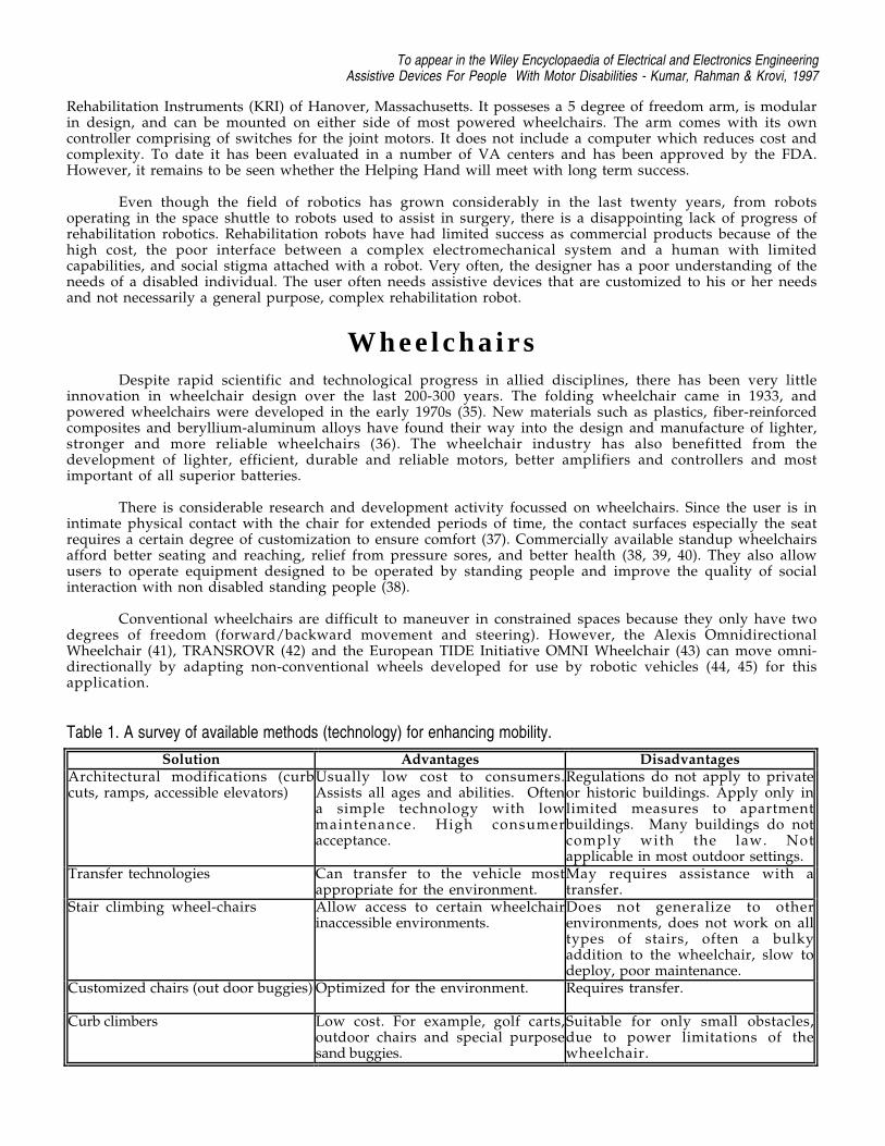
Table 1. A survey of available methods (technology) for enhancing mobility.
Solution Advantages DisadvantagesArchitectural modifications (curbcuts, ramps, accessible elevators)
Usually low cost to consumers.Assists all ages and abilities. Oftena simple technology with lowmaintenance. High consumeracceptance.
Regulations do not apply to privateor historic buildings. Apply only inlimited measures to apartmentbuildings. Many buildings do notcomply with the law. Notapplicable in most outdoor settings.
Transfer technologies Can transfer to the vehicle mostappropriate for the environment.
May requires assistance with atransfer.
Stair climbing wheel-chairs Allow access to certain wheelchairinaccessible environments.
Does not generalize to otherenvironments, does not work on alltypes of stairs, often a bulkyaddition to the wheelchair, slow todeploy, poor maintenance.
Customized chairs (out door buggies) Optimized for the environment. Requires transfer.
Curb climbers Low cost. For example, golf carts,outdoor chairs and special purposesand buggies.
Suitable for only small obstacles,due to power limitations of thewheelchair.
To appear in the Wiley Encyclopaedia of Electrical and Electronics EngineeringAssistive Devices For People With Motor Disabilities - Kumar, Rahman & Krovi, 1997
A number of computer controlled wheelchairs have been developed in recent years, including the CALLSmart Chair (46), NavChair (47), TinMan (48) and WALKY (49). Wheelchair systems with customized userinterfaces, sensors, and controllers, suitably integrated (52), can potentially make the operation of awheelchair much simpler and make it more accessible to people with disabilities. Such chairs may use a widevariety of sensors ranging from ultrasonic range sensors (51), cameras, encoders, accelerometers, and gyroscopesand any desired input device (communication aids, conventional joysticks, sip and puff switches, pressure pads,laser pointers, speech recognition systems and force reflecting joysticks (50)). Suitable control algorithms assistthe user in avoiding obstacles, following features such as walls, planning collision-free paths and travellingsafely in cluttered environments with minimal user input (53 - 56).
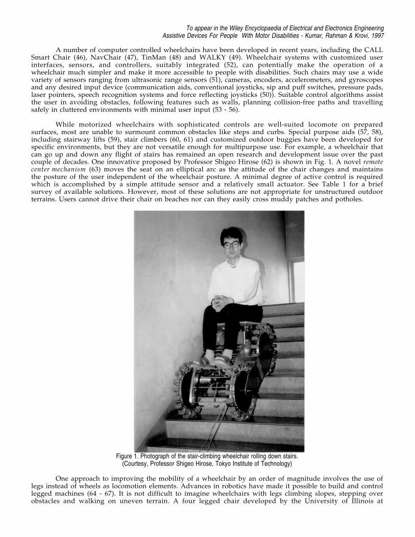
While motorized wheelchairs with sophisticated controls are well-suited locomote on preparedsurfaces, most are unable to surmount common obstacles like steps and curbs. Special purpose aids (57, 58),including stairway lifts (59), stair climbers (60, 61) and customized outdoor buggies have been developed forspecific environments, but they are not versatile enough for multipurpose use. For example, a wheelchair thatcan go up and down any flight of stairs has remained an open research and development issue over the pastcouple of decades. One innovative proposed by Professor Shigeo Hirose (62) is shown in Fig. 1. A novel remotecenter mechanism (63) moves the seat on an elliptical arc as the attitude of the chair changes and maintainsthe posture of the user independent of the wheelchair posture. A minimal degree of active control is requiredwhich is accomplished by a simple attitude sensor and a relatively small actuator. See Table 1 for a briefsurvey of available solutions. However, most of these solutions are not appropriate for unstructured outdoorterrains. Users cannot drive their chair on beaches nor can they easily cross muddy patches and potholes.
Figure 1. Photograph of the stair-climbing wheelchair rolling down stairs.(Courtesy, Professor Shigeo Hirose, Tokyo Institute of Technology)
One approach to improving the mobility of a wheelchair by an order of magnitude involves the use oflegs instead of wheels as locomotion elements. Advances in robotics have made it possible to build and controllegged machines (64 - 67). It is not difficult to imagine wheelchairs with legs climbing slopes, stepping overobstacles and walking on uneven terrain. A four legged chair developed by the University of Illinois at
To appear in the Wiley Encyclopaedia of Electrical and Electronics EngineeringAssistive Devices For People With Motor Disabilities - Kumar, Rahman & Krovi, 1997
Chicago and the Veterans Administration Hines Rehabilitation Research and Development Center based onresearch in quadruped walking (69, 70) was developed in 1987. The walking chair was designed to enable theuser to walk up and down stairs, steep slopes, cross rough terrain, with curb weight less than 113.6 kg. (250 lbs.)and capable of carrying a payload of 113.6 kg. (250 lbs.). A full scale prototype (68) design incorporatingcomputer-controlled pantographic legs walked in the laboratory in October 1988, with a simple linear gait.However, it did not carry a passenger, and it was connected by a tether to a stationary controller.
There are several inherent disadvantages in the concept of a legged chair. The legs are responsible forkeeping the rider in a stable posture. There is a natural concern of safety that arises here. In wheeled systems,the wheels passively support the chair and do not require any sophisticated actuators or control electronics. Ina legged system, stability must be maintained actively. Because of the complexity of the system, reliability isa natural concern. Further, for stability, at least three support legs must be on the ground and a vertical linethrough the center of gravity must pass within the polygon formed by the support points. This implies that atleast four legs are required to make a legged system walk −− one leg is moved forward while three otherssupport the chair. In the worst case, one leg must support half the weight of the chair and the user. Thisimplies that each leg must have a strength (payload) to weight ratio several times greater than one, with apayload of the order of hundred pounds. The leg designs and actuators scale very poorly to such highpayloads. Since the actuators must run off wheelchair batteries, and since there are severe restrictions on howlarge the chair can be (for example, the maximum width must be less than 0.762 m (30 inches)), there areserious constraints that make it difficult to design a practical legged chair.
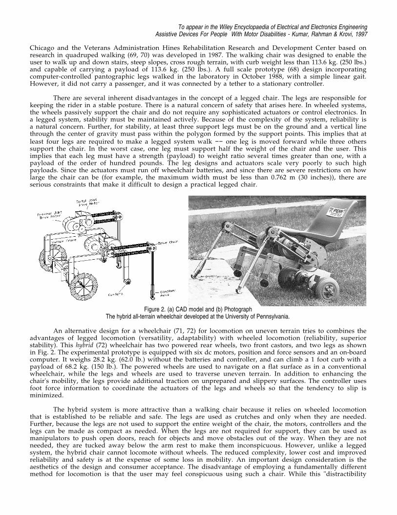
Figure 2. (a) CAD model and (b) PhotographThe hybrid all-terrain wheelchair developed at the University of Pennsylvania.
An alternative design for a wheelchair (71, 72) for locomotion on uneven terrain tries to combines theadvantages of legged locomotion (versatility, adaptability) with wheeled locomotion (reliability, superiorstability). This hybrid (72) wheelchair has two powered rear wheels, two front castors, and two legs as shownin Fig. 2. The experimental prototype is equipped with six dc motors, position and force sensors and an on-boardcomputer. It weighs 28.2 kg. (62.0 lb.) without the batteries and controller, and can climb a 1 foot curb with apayload of 68.2 kg. (150 lb.). The powered wheels are used to navigate on a flat surface as in a conventionalwheelchair, while the legs and wheels are used to traverse uneven terrain. In addition to enhancing thechair's mobility, the legs provide additional traction on unprepared and slippery surfaces. The controller usesfoot force information to coordinate the actuators of the legs and wheels so that the tendency to slip isminimized.
The hybrid system is more attractive than a walking chair because it relies on wheeled locomotionthat is established to be reliable and safe. The legs are used as crutches and only when they are needed.Further, because the legs are not used to support the entire weight of the chair, the motors, controllers and thelegs can be made as compact as needed. When the legs are not required for support, they can be used asmanipulators to push open doors, reach for objects and move obstacles out of the way. When they are notneeded, they are tucked away below the arm rest to make them inconspicuous. However, unlike a leggedsystem, the hybrid chair cannot locomote without wheels. The reduced complexity, lower cost and improvedreliability and safety is at the expense of some loss in mobility. An important design consideration is theaesthetics of the design and consumer acceptance. The disadvantage of employing a fundamentally differentmethod for locomotion is that the user may feel conspicuous using such a chair. While this "distractibility
To appear in the Wiley Encyclopaedia of Electrical and Electronics EngineeringAssistive Devices For People With Motor Disabilities - Kumar, Rahman & Krovi, 1997
factor" depends to a large extent on the environment and society, it is necessary to make any design more “un-robot-like”.
Teletheses and Human Extenders:Research Issues
The discussion on prosthetics revealed two essential features for a successful design. These are (a) threedimensional, one-to-one, map between the user’s input motion and the manipulator’s motion and (b) forcereflection from the manipulator to the user. Bilateral control provides for extended physiologicalproprioception and this allows for superior control and performance.
In the discussion that follows, we look at a class of devices that can be considered as extensions ofprosthetic limbs. Like prosthetic devices, they are intimately linked to the human user and enable EPP.Further, they are passive and powered by the human user, although they may include electromechanical,power-assist mechanisms. However, unlike prosthetic devices they may possess more than two degrees offreedom and are more reminiscent of robot manipulators. We will first look at feeding aids as examples of suchdevices and then describe research prototypes of more complex, general-purpose aids.
Feeding devices
There is a high degree of motivation for people to learn to feed themselves. A recent survey of the U.S.population indicates that the population that would benefit from well-designed feeding aids may be as highas half a million. There are commercially available feeders that are useful for people who have havecontrolled movements of the head and neck and can take food off of a feeding utensil that is brought close tothe mouth. The Winsford Feeder (Winsford Products, Pennington, NJ) and the Beeson Feeder (Maddox Inc.,Pequannock, N.J.) are two such examples. Another example is the Handy I (Rehab Robotics Ltd., Staffordshire,U.K.), a robotic arm that is programmed for feeding. Most feeders consist of an articulated, electrically-powered arm with a spoon at its end, a plate on a rotating turntable and an auxilliary arm that may be used topush food on to the spoon. The user controls, through the use of switches, the movement of the differentcomponents.
Although such feeding aids can be used effectively, there are several reasons why their use is not aswidespread as one would expect (74). The control switches may initiate a movement of a certain component, forexample, a rotation of the plate. The user may find it frustrating not to stop the motion. Visual feedback isrequired for successful feeding during most of the operation. It is acceptable if vision is required to locate themorsel of food and to target it. But requiring the user to focus on the morsel through the entire operation ofscooping it up and bringing to the mouth can be very exhausting for most users. Some devices require anelectrical outlet and this may be a nuisance factor. Finally, they are expensive and are difficult to adapt toindividual needs.
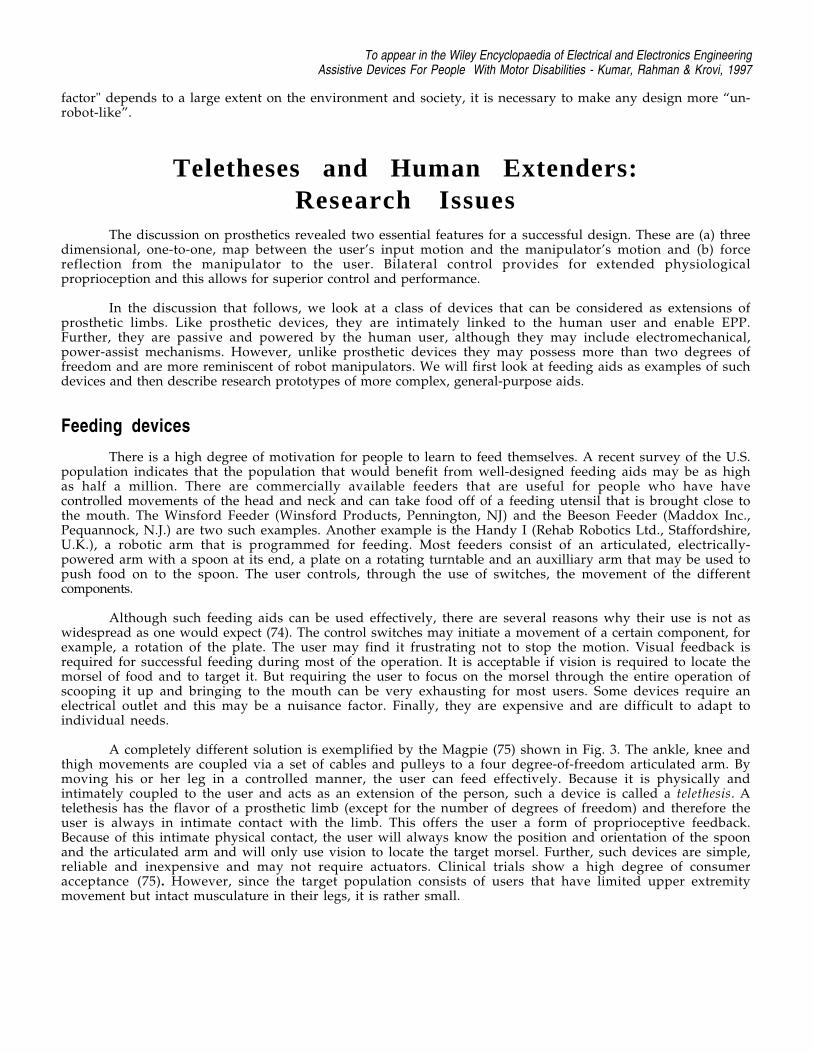
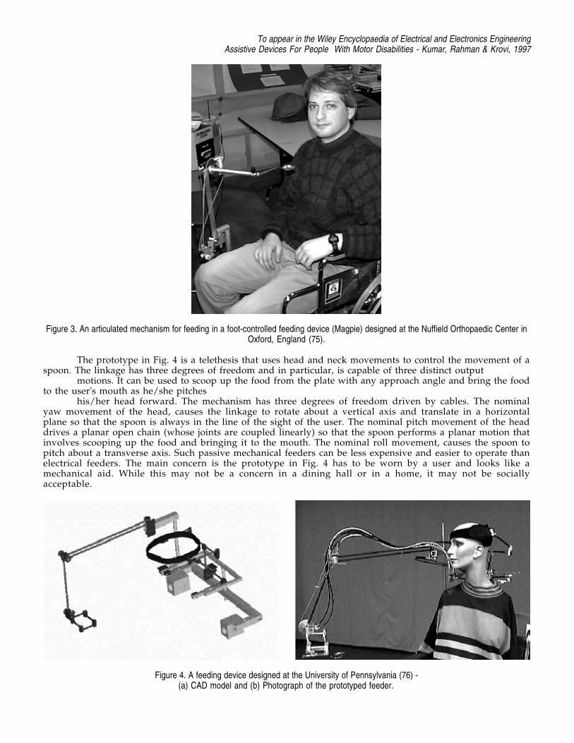
A completely different solution is exemplified by the Magpie (75) shown in Fig. 3. The ankle, knee andthigh movements are coupled via a set of cables and pulleys to a four degree-of-freedom articulated arm. Bymoving his or her leg in a controlled manner, the user can feed effectively. Because it is physically andintimately coupled to the user and acts as an extension of the person, such a device is called a telethesis. Atelethesis has the flavor of a prosthetic limb (except for the number of degrees of freedom) and therefore theuser is always in intimate contact with the limb. This offers the user a form of proprioceptive feedback.Because of this intimate physical contact, the user will always know the position and orientation of the spoonand the articulated arm and will only use vision to locate the target morsel. Further, such devices are simple,reliable and inexpensive and may not require actuators. Clinical trials show a high degree of consumeracceptance (75). However, since the target population consists of users that have limited upper extremitymovement but intact musculature in their legs, it is rather small.
To appear in the Wiley Encyclopaedia of Electrical and Electronics EngineeringAssistive Devices For People With Motor Disabilities - Kumar, Rahman & Krovi, 1997
Figure 3. An articulated mechanism for feeding in a foot-controlled feeding device (Magpie) designed at the Nuffield Orthopaedic Center inOxford, England (75).
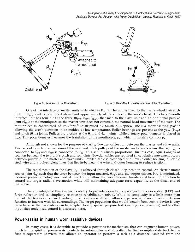
The prototype in Fig. 4 is a telethesis that uses head and neck movements to control the movement of aspoon. The linkage has three degrees of freedom and in particular, is capable of three distinct output
motions. It can be used to scoop up the food from the plate with any approach angle and bring the foodto the user's mouth as he/she pitches
his/her head forward. The mechanism has three degrees of freedom driven by cables. The nominalyaw movement of the head, causes the linkage to rotate about a vertical axis and translate in a horizontalplane so that the spoon is always in the line of the sight of the user. The nominal pitch movement of the headdrives a planar open chain (whose joints are coupled linearly) so that the spoon performs a planar motion thatinvolves scooping up the food and bringing it to the mouth. The nominal roll movement, causes the spoon topitch about a transverse axis. Such passive mechanical feeders can be less expensive and easier to operate thanelectrical feeders. The main concern is the prototype in Fig. 4 has to be worn by a user and looks like amechanical aid. While this may not be a concern in a dining hall or in a home, it may not be sociallyacceptable.
Figure 4. A feeding device designed at the University of Pennsylvania (76) -(a) CAD model and (b) Photograph of the prototyped feeder.

To appear in the Wiley Encyclopaedia of Electrical and Electronics EngineeringAssistive Devices For People With Motor Disabilities - Kumar, Rahman & Krovi, 1997
Figure 5. A feeding device designed by a team of students from Cooper Union, New Jersey Intitute of Technology, Ohio State University andthe University of Pennsylvania (77) -
(a) CAD model and (b) Photograph of the prototyped feeder.
In contrast the prototype in Fig. 5 has fewer components and is not worn by the user. Thus the user maydetach himself from the device for social interactions. However, the lack of the physical coupling at all timesmay also be a potential disadvantage because the EPP link is broken.
The spoon assembly is supported by a gravity compensated mechanical arm. The user uses his or hermouth to manipulate the spoon directly and to rotate the plate. A mechanical clutch locks the spoon while theuser rotates the spoon about a vertical axis to bring the scooped food to the mouth.
Body powered manipulators
Another example of a telethesis is the Chameleon (78), a wheelchair mounted, counter balanced,electro-mechanical arm. The arm’s end point is controlled and/or powered by a functional body part of the user,via Bowden cables and/or an electric motor.
The system consists of three main components:
1. The “slave” arm unit2. The “master” or interface unit3. The transmission and control systems
The user engages to the master unit, in this case through biting, and moves his head to control theslave arm. A transmission and control system connect the master to the slave so that the slave follows themaster in a natural and intuitive manner. Two of the degrees of freedom (d.o.f) between the units are connectedthrough pulleys and Bowden cable; the third coupled d.o.f. is through an electric motor and controller.
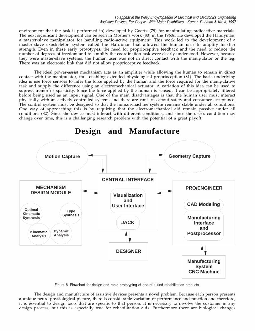
The slave arm is shown in Fig. 6. All θ values represent angular motion about a corresponding axis; allρ values represent linear motion along an axis. This unit is mounted to a wheelchair such that joint θsp is atshoulder height and the unit is to the right side of the user. The slave arm was mechanically designed withthe same d.o.f. as a spherical coordinate system: θsp (pitch), θsy (yaw), and ρs (radial). A spherical coordinatesystem was chosen because it allows any position in space to be obtained with variables (inputs) thatkinematically match a person’s input (in this case, head) and arm movements.
Pulleys are located at joints θsp and θsy which are connected, via cable, to pulleys located on themaster. A motor is present at joint θsρ; this along with the two meshing gears fixed to the ends of the two mainlinks result in radial motion, ρs. The slave arm is counter balanced so that the user does not feel its weightwhen static. Roller bearings are present in all joints. The two main links are constructed of fiberglass hollowtubing, while most other components are machined from aluminum.
To appear in the Wiley Encyclopaedia of Electrical and Electronics EngineeringAssistive Devices For People With Motor Disabilities - Kumar, Rahman & Krovi, 1997
θsρ
θs y
θsp
ρs
Distal end
Attached towheelchair
Figure 6. Slave arm of the Chameleon.
ρm
θmp
θmρ
θmy
θmr
Figure 7. Head/Mouth master interface of the Chameleon.
One of the interface or master units is detailed in Fig. 7. The unit is fixed to the user’s wheelchair suchthat the θmy joint is positioned above and approximately at the center of the user’s head. This head/mouthinterface unit has four d.o.f.; the three (θmp, θmy, θmρ,) that map to the slave unit and an additional passivejoint (θmr) at the mouthpiece so the master unit does not constrain the natural head movement of the user. The
mouthpiece is constructed of Polyform® (distributed by Smith & Nephew, Inc.); a thermosetting plasticallowing the user’s dentition to be molded at low temperature. Roller bearings are present at the yaw (θmp)and pitch (θmy) joints. Pulleys are present at the θmy and θmp joints, while a rotary potentiometer is placed atθmρ. This potentiometer measures the translation of the mouthpiece, ρm, which ultimately controls ρs.
Although not shown for the purpose of clarity, Bowden cables run between the master and slave units.Two sets of Bowden cables connect the yaw and pitch pulleys of the master and slave system; that is, θmp isconnected to θsp and θmy is connected to θsy. This set-up causes proportional (in this case, equal) angles ofrotation between the two unit’s pitch and roll joints. Bowden cables are required since relative movement occursbetween pulleys of the master and slave units. Bowden cable is comprised of a flexible outer housing, a flexiblesteel wire and a polyethylene liner that lies in-between the wire and outer housing to reduce friction..
The radial position of the slave, ρs, is achieved through closed loop position control. An electric motorrotates joint θsρ such that the error between the input (master), θmρ, and the output (slave), θsρ, is minimized.External power (a motor) was used at this d.o.f. to allow the person’s small translational head input motion tocontrol the larger radial slave motion while still maintaining adequate force capability at the distal end ofthe slave.
The advantages of this system its ability to provide extended physiological proprioception (EPP) andforce reflection and its simplicity relative to rehabilitation robots. While its complexity is a little more thanthat of the feeders discussed earlier, it is more versatile and allows a person with no or very little armfunction to interact with his surroundings. The target population that would benefit from such a device is verylarge because the basic ideas can be adapted to any special purpose task (feeding is an example) and to otherinput sites (only head control is discussed here).
Power-assist in human worn assistive devices
In many cases, it is desirable to provide a power-assist mechanism that can augment human power,much in the spirit of power-assist controls in automobiles and aircrafts. The first examples date back to thefirst teleoperators (devices that allows an operator to perform a task at a distance, isolated from the
To appear in the Wiley Encyclopaedia of Electrical and Electronics EngineeringAssistive Devices For People With Motor Disabilities - Kumar, Rahman & Krovi, 1997
environment that the task is performed in) developed by Goertz (79) for manipulating radioactive materials.The next significant development can be seen in Mosher's work (80) in the 1960s. He developed the Handyman,a master-slave manipulator for handling radio-active equipment. This work led to the development of amaster-slave exoskeleton system called the Hardiman that allowed the human user to amplify his/herstrength. Even in these early prototypes, the need for proprioceptive feedback and the need to reduce thenumber of degrees of freedom and to simplify the coordination task were clearly understood. However, becausethey were master-slave systems, the human user was not in direct contact with the manipulator or the leg.There was an electronic link that did not allow proprioceptive feedback.
The ideal power-assist mechanism acts as an amplifier while allowing the human to remain in directcontact with the manipulator, thus enabling extended physiological proprioception (81). The basic underlyingidea is use force sensors to infer the force applied by the human and the force required for the manipulativetask and supply the difference using an electromechanical actuator. A variation of this idea can be used tosupress tremor or spasticity. Since the force applied by the human is sensed, it can be appropriately filteredbefore being used as an input signal. One of the main disadvantages is that the human user must interactphysically with an actively controlled system, and there are concerns about safety and consumer acceptance.The control system must be designed so that the human-machine system remains stable under all conditions.One way of approaching this is by requiring that the electromechanical aid remain passive under allconditions (82). Since the device must interact with different conditions, and since the user's condition maychange over time, this is a challenging research problem with the potential of a great payoff.
Design and Manufacture
Motion Capture Geometry Capture
MECHANISMDESIGN MODULE
CENTRAL INTERFACE
Visualizationand
User Interface
JACK
DESIGNER
PRO/ENGINEER
CAD Modeling
ManufacturingInterface
andPostprocessor
ManufacturingSystem
CNC Machine
OptimalKinematicSynthesis
TypeSynthesis
Kinematic Analysis
Dynamic Analysis
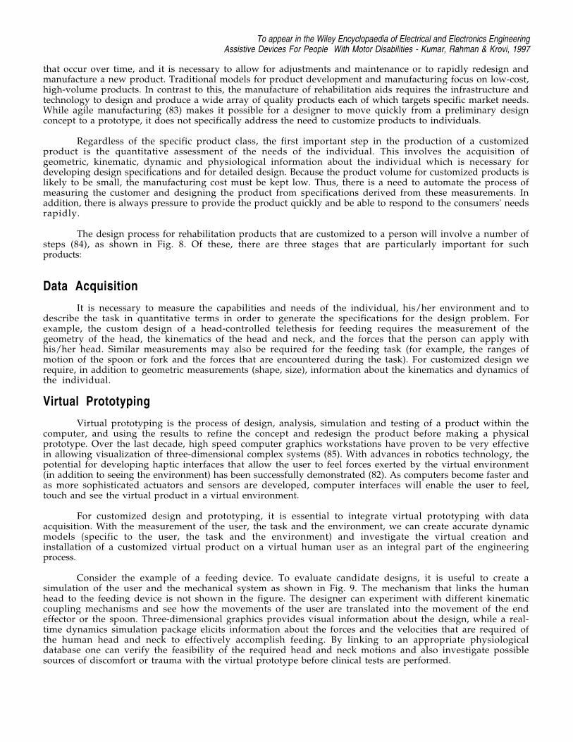
Figure 8. Flowchart for design and rapid prototyping of one-of-a-kind rehabilitation products.
The design and manufacture of assistive devices presents a novel problem. Because each person presentsa unique neuro-physiological picture, there is considerable variation of performance and function and therefore,it is essential to design tools that are specific to that person. It is necessary to involve the customer in anydesign process, but this is especially true for rehabilitation aids. Furthermore there are biological changes
To appear in the Wiley Encyclopaedia of Electrical and Electronics EngineeringAssistive Devices For People With Motor Disabilities - Kumar, Rahman & Krovi, 1997
that occur over time, and it is necessary to allow for adjustments and maintenance or to rapidly redesign andmanufacture a new product. Traditional models for product development and manufacturing focus on low-cost,high-volume products. In contrast to this, the manufacture of rehabilitation aids requires the infrastructure andtechnology to design and produce a wide array of quality products each of which targets specific market needs.While agile manufacturing (83) makes it possible for a designer to move quickly from a preliminary designconcept to a prototype, it does not specifically address the need to customize products to individuals.
Regardless of the specific product class, the first important step in the production of a customizedproduct is the quantitative assessment of the needs of the individual. This involves the acquisition ofgeometric, kinematic, dynamic and physiological information about the individual which is necessary fordeveloping design specifications and for detailed design. Because the product volume for customized products islikely to be small, the manufacturing cost must be kept low. Thus, there is a need to automate the process ofmeasuring the customer and designing the product from specifications derived from these measurements. Inaddition, there is always pressure to provide the product quickly and be able to respond to the consumers' needsrapidly.
The design process for rehabilitation products that are customized to a person will involve a number ofsteps (84), as shown in Fig. 8. Of these, there are three stages that are particularly important for suchproducts:
Data Acquisition
It is necessary to measure the capabilities and needs of the individual, his/her environment and todescribe the task in quantitative terms in order to generate the specifications for the design problem. Forexample, the custom design of a head-controlled telethesis for feeding requires the measurement of thegeometry of the head, the kinematics of the head and neck, and the forces that the person can apply withhis/her head. Similar measurements may also be required for the feeding task (for example, the ranges ofmotion of the spoon or fork and the forces that are encountered during the task). For customized design werequire, in addition to geometric measurements (shape, size), information about the kinematics and dynamics ofthe individual.
Virtual Prototyping
Virtual prototyping is the process of design, analysis, simulation and testing of a product within thecomputer, and using the results to refine the concept and redesign the product before making a physicalprototype. Over the last decade, high speed computer graphics workstations have proven to be very effectivein allowing visualization of three-dimensional complex systems (85). With advances in robotics technology, thepotential for developing haptic interfaces that allow the user to feel forces exerted by the virtual environment(in addition to seeing the environment) has been successfully demonstrated (82). As computers become faster andas more sophisticated actuators and sensors are developed, computer interfaces will enable the user to feel,touch and see the virtual product in a virtual environment.
For customized design and prototyping, it is essential to integrate virtual prototyping with dataacquisition. With the measurement of the user, the task and the environment, we can create accurate dynamicmodels (specific to the user, the task and the environment) and investigate the virtual creation andinstallation of a customized virtual product on a virtual human user as an integral part of the engineeringprocess.
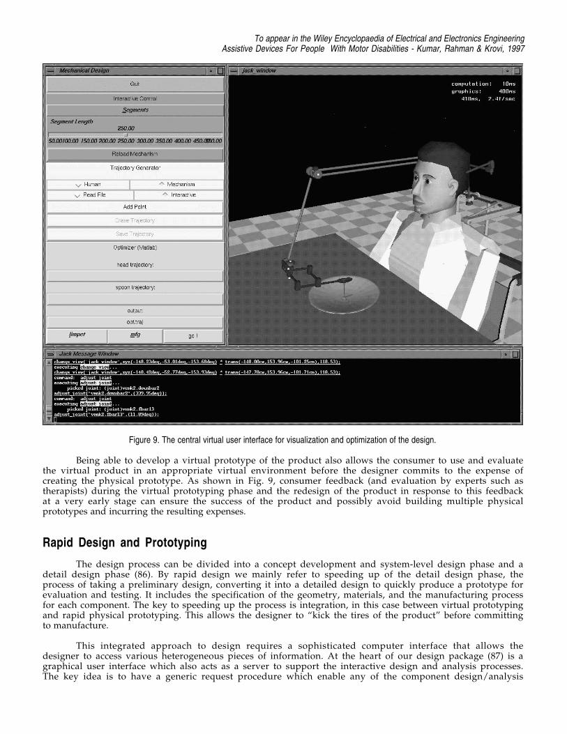
Consider the example of a feeding device. To evaluate candidate designs, it is useful to create asimulation of the user and the mechanical system as shown in Fig. 9. The mechanism that links the humanhead to the feeding device is not shown in the figure. The designer can experiment with different kinematiccoupling mechanisms and see how the movements of the user are translated into the movement of the endeffector or the spoon. Three-dimensional graphics provides visual information about the design, while a real-time dynamics simulation package elicits information about the forces and the velocities that are required ofthe human head and neck to effectively accomplish feeding. By linking to an appropriate physiologicaldatabase one can verify the feasibility of the required head and neck motions and also investigate possiblesources of discomfort or trauma with the virtual prototype before clinical tests are performed.
To appear in the Wiley Encyclopaedia of Electrical and Electronics EngineeringAssistive Devices For People With Motor Disabilities - Kumar, Rahman & Krovi, 1997
Figure 9. The central virtual user interface for visualization and optimization of the design.
Being able to develop a virtual prototype of the product also allows the consumer to use and evaluatethe virtual product in an appropriate virtual environment before the designer commits to the expense ofcreating the physical prototype. As shown in Fig. 9, consumer feedback (and evaluation by experts such astherapists) during the virtual prototyping phase and the redesign of the product in response to this feedbackat a very early stage can ensure the success of the product and possibly avoid building multiple physicalprototypes and incurring the resulting expenses.
Rapid Design and Prototyping
The design process can be divided into a concept development and system-level design phase and adetail design phase (86). By rapid design we mainly refer to speeding up of the detail design phase, theprocess of taking a preliminary design, converting it into a detailed design to quickly produce a prototype forevaluation and testing. It includes the specification of the geometry, materials, and the manufacturing processfor each component. The key to speeding up the process is integration, in this case between virtual prototypingand rapid physical prototyping. This allows the designer to “kick the tires of the product” before committingto manufacture.
This integrated approach to design requires a sophisticated computer interface that allows thedesigner to access various heterogeneous pieces of information. At the heart of our design package (87) is agraphical user interface which also acts as a server to support the interactive design and analysis processes.The key idea is to have a generic request procedure which enable any of the component design/analysis
To appear in the Wiley Encyclopaedia of Electrical and Electronics EngineeringAssistive Devices For People With Motor Disabilities - Kumar, Rahman & Krovi, 1997
packages or modules to call another package to obtain relevant information. Thus information from any dataacquisition, virtual prototyping or simulation module can be displayed on the visualization package easily.Finally, since the modules operate on different machines/architectures, efficient communication protocolsbetween separate processes (relying on Unix TCP/IP calls) are employed. Thus, this graphical server allows amodular approach to software development and enables the human designer to interact with each module atdifferent levels.
Conclus ion
We have presented a review of the technology underlying assistive devices for people withmanipulative and locomotive disabilities focusing on prosthetic limbs, robotic arms and wheelchairs. We havepointed out the important role that robotics can play in assistive devices. There is another class of assistivedevices, called teletheses, that bear a strong resemblance to the multiple degree-of-freedom robot arms and tothe body-powered prosthetic limbs. We discussed how a telethesis may be an optimal compromise that allowsfor extended physiological proprioception as well as strength enhancement. Finally, we discussed the designand manufacturing issues for such devices. The high degree of customization that is required and the one-of-a-kind flavor of these products suggest that a computer integrated, automated approach to design andprototyping is necessary for manufacturing.
Bib l iography1. C. Butler, Effect of powered mobility on self-initiated behaviours of very young children with
locomotor disability. Developmental Medicine and Child Neurology, 28:325-332, 1986.
2. A. L. Muhlenberg and M.A. LeBlanc, Body-powered upper-limb components. In D. J. Atkins and R.H. Meier (eds.), Comprehensive Management of Upper-Limb Amputee. Springer-Verlag, 1988.
3. D. S. Childress, Closed-loop control in prosthetic systems: Historical perspective. Annals ofBiomedical Engineering, 8: 293-303, 1980.
4. D. S. Childress, Historical aspects of powered limb prostheses. Clinical Prosthetics and Orthotics,9(1): 2-13, 1985.
5. R. N. Scott, R. H. Brittain, R. R. Caldwell, A. B. Cameron, and V. A. Dunfield, Sensory-feedbacksystem compatible with myoelectric control. Medical and Biological Engineering and Computing,18(1): 65-69, 1980.
6. A. H. Bottomly, Myo-electric control of powered prostheses. The Journal of Bone and Joint Surgery,47B(3):411-415, 1965.
7. N. Hogan. A review of the methods of processing ems's for use as a proportional control signal.Annals of Biomedical Engineering, 4(1), 1976.
8. D. C. Simpson and J. G. Smith, An externally powered controlled complete arm prosthesis. Journal ofMedical Engineering and Technology, pp. 275-277, September 1977.
9. M. Soede, Mental control load and acceptance of arm prosthesis. Automedica, 4: 183-191, 1982.
10. D. E. Whitney, Resolved motion rate control of manipulators and human prostheses. IEEETransactions on Man-Machine Systems, MMS-10(2): 47-53, 1969.
11. C. J. Abul-haj and N. Hogan, Functional assessment of control systems for cybernetic elbow
To appear in the Wiley Encyclopaedia of Electrical and Electronics EngineeringAssistive Devices For People With Motor Disabilities - Kumar, Rahman & Krovi, 1997
prostheses, parts i-ii. IEEE Transactions on Biomedical Engineering, 37(11): 1025-1047, 1990.
12. G. F. Shannon, Some experience in fitting a myoelectrically controlled hand which has a sense oftouch. Journal of Medical Engineering and Technology, 2(6): 312-314, 1978.
13. R. W. Witra, D. R. Taylor, and F. R. Finley, Pattern recognition arm prosthesis: A historicalperspective-a final report. Bulletin of Prosthetic Research, 10(29): 8-36, 1978.
14. D. W. Lamb, D. C. Simpson, W. H. Schutt, N. T. Speirs, G. Sunderland and G. Baker, Themanagement of upper limb deficiencies in the thalidomide-type syndrome. Journal of the Royal Collegeof Surgeons of Edinburgh, 10: 102-108, 1965.
15. C. A. McLaurin, Control of externally powered prosthetic and orthotic devices by musculo-skeletalmovement. In The Control of External Power in Upper Extremity Rehabilitation, 1966.
16. E. G. Johnsen and W. R. Corliss, Teleoperators and human augmentation. An AEC-NASATechnology Survey. National Aeronautics and Space Administration, December 1967.
17. B. Hannaford, Stability and performance tradeoffs in bi-lateral telemanipulation. In Proceedings of the1989 IEEE Conference on Robotics and Automation, pp. 1764-67, 1989.
18. N. Hogan, Impedance control: An approach to manipulation, parts i-ii. Journal of Dynamic Systems,Measurement and Control, 107: 1-16, 1985.
19. D. C. Simpson and D. W. Lamb, A system of powered prostheses for severe bilateral upper limbdeficiency. Journal of Bone and Joint Surgery, 47B(3), 1965.
20. R. E. Prior and C. M. Scott, Proportionally controlled linear power assist device for artificial arms.Bulletin of Prosthetics Research, 10(24): 43-50, 1975.
21. M. D. O'Riain and D. T. Gibbons, Position proprioception in a microcomputer-controlled prosthesis.Medical and Biological Engineering and Computing, 25: 294-298, 1987.
22. C. W. Heckathorne, J. S. Strysik, and E. C. Grahn, Design of a modular extended physiologicalpropioception controller for clinical applications in prosthesis control. In Proceedings of the RESNA12th Annual Conference, Washington DC, USA, 1989.
23. J. A. Doubler and D. S. Childress, An analysis of extended physiological proprioception as aprosthesis-control technique. Journal of Rehabilitation Research and Development, 21(1): 5-18,1984.
24. J. A. Doubler and D. S. Childress, Design and evaluation of a prosthesis control system based on theconcept of extended proprioception. Journal of Rehabilitation Research and Development, 21(1):19-31, 1984.
25. J. R. Allen, A. Karchak and V. L. Nickel, Orthotic manipulators. In Advances in External Control ofHuman Extremities, Belgrade, 1970.
26. V. Paeslack, and H. Roesler, Design and control of a manipulator for tetraplegics. Mechanism andMachine Theory, 12: 413-423, 1977.
27. C. P. Mason and E. Peiser, A seven degree of freedom telemanipulator for tetraplegics. ConferenceInternational sur les Telemanipulators pour Handicapes Physiques, pp. 309-318, 1979.
To appear in the Wiley Encyclopaedia of Electrical and Electronics EngineeringAssistive Devices For People With Motor Disabilities - Kumar, Rahman & Krovi, 1997
28. W. Seamone and G. Schmeisser, Early clinical evaluation of a robot arm/worktable system for spinal-cord-injured persons. Journal of Rehabilitation Research and Development, 22(1): 38-57, January1985.
29. G. Verburg, H. Kwee, A. Wisaksana, A. Cheetham and J. van Woerden, Manus: The evolution of anassistive technology. Technology and Disability, 5(2): 217-228, 1996.
30. M. Topping, Handy I, a robotic aid to independence for severely disabled people. Technology andDisability, 5: 233-234, 1996.
31. C. Upton, The RAID workstation. Rehabilitation Robotics Newsletter, A. I. duPont Institute, 6(1),1994.
32. H. F. M. Van der Loos, VA/Stanford rehabilitation robotics research and development program:Lessons learned in the application of robotics technology to the field of rehabilitation. IEEETransactions on Rehabilitation Engineering, 3(1): 46-55, 1995.
33. G. E. Birch, M. Fengler, R. G. Gosine, K. Schroeder, M. Schroeder and D. L. Johnson, Anassessment methodology and its application to a robotic vocational assistive device. Technology andDisability, 5(2): 151-166, 1996.
34. S. J. Sheredos, B. Taylor, C. B. Cobb and E. E. Dann, Preliminary evaluation of the helping handelectro-mechanical arm. Technology and Disability, 5(2): 229-232, 1996.
35. Teitelman, De-handicapping the handicapped. Forbes, September 24, 1984.
36. C. A. McLaurin and P. Axelson, Wheelchair standards: an overview. Journal of RehabilitationResearch and Development (Clinical Supplement). 27(2): 100-103, 1990.
37. T. K. K. Koo, A. F. T. Mak and Y. L. Lee, Evaluation of an active seating system for pressure relief.Assistive Technology, 7(2): 119-128, 1995.
38. People Weekly, Tom Houston is a real stand-up guy, thanks to the versatile vertical wheelchair hedevised. 32: 91-2, August 28, 1989.
39. IMEX Riser Wheelchair. Product Literature, Imex Medical Inc., San Jose, CA.
40. Standup Wheelchairs. Product Literature, Levo Inc., Switzerland.
41. H. F. M. Van der Loos, S. J. Michalowski and L. J. Leifer, Development of an omni-directionalmobile vocational assistant robot, In Proceedings of the 3rd International Conference of theAssociation of Advanced Rehabilitation Technology, Montreal, P. Q., Canada, June 1988.
42. R. Walli, DOE technology to develop TRANSROVR --Omnidirectional wheelchair, DOE News Brief,October 10, 1996.
43. H. Hoyer, The OMNI wheelchair. Service Robot: An International Journal, 1(1): 26-29, MCBUniversity Press Limited, Bradford, England, 1995.
44. M. West and H. Asada, A method for designing ball wheels for omni-directional vehicles. 1995 ASMEDesign Engineering Technical Conferences, DAC-29, pp. 1931-1938, Seattle, WA 1995.
45. F. G. Pin and S. M. Killough, A new family of omni-directional and holonomic wheeled platforms formobile robots. IEEE Transactions on Robotics and Automation, 10(4): 480-489, 1994.
To appear in the Wiley Encyclopaedia of Electrical and Electronics EngineeringAssistive Devices For People With Motor Disabilities - Kumar, Rahman & Krovi, 1997
46. J. D. Nisbet, I. R. Loudon and J. P. Odor, The CALL Centre smart wheelchair. In Proceedings of 1stInternational Workshop on Robotic Applications to Medical and Health Care, 9.1-9.10, Ottawa,Canada, 1988
47. D. A. Bell, J. Borenstein, S. Levine, Y. Koren and L. A. Jaros, The NavChair: An assistive navigationsystem for wheelchairs based on mobile robot obstacle avoidance. In Proceedings of the 1994 IEEEInternational Conference on Robotics and Automation, pp. 2012-2017, San Diego, CA, May 8-13,1994.
48. D. Miller and M. Slack, Design and testing of a low-cost robotic wheelchair prototype, AutonomousRobots, 2(1): 77-88, 1995.
49. O. Neveryd and Bolmsjö, WALKY, A mobile robot system for the disabled. In Proceedings of the 4thInternational Conference on Rehabilitation Robotics, Wilmington, Delaware, USA, 14-16 June,1994.
50. D. M. Brienza and J. Angelo, A force feedback joystick and control algorithm for wheelchair obstacleavoidance. Disability and Rehabilitation, 18(3): 123-129, 1996.
51. J. M.Ford and S. J. Sheredos, Ultrasonic head controller for powered wheelchairs. Journal OfRehabilitation Research and Development, 32(3): 280-284, 1995.
52. M3S: A general-purpose multiple-master multiple-slave intelligent interface for the rehabilitationenvironment, Working Draft ISO1716-17, International Standards Organisation, 1995.
53. P. F. Muir and C. P. Neuman, Kinematic modelling for feedback control of an omni-directionalwheeled mobile robot, In I.J. Cox and G.T. Wilfong (eds.) Autonomous Robot Vehicles, pp. 25-31,Springer Verlag, 1990.
54. D. A. Bell, S. P. Levine, Y. Koren, L. A. Jaros and J. Borenstein, An identification technique foradaptive shared control in human-machine systems. In Proceedings of the 15th Annual InternationalConference of the IEEE Engineering in Medicine and Biology Society, pp. 1299-1300, San Diego,CA, October 1993.
55. J. Borenstein and Y. Koren, Tele-autonomous guidance for mobile robots. IEEE Transactions onSystems, Man and Cybernetics, 17(4) : 535-539, 1991.
56. R. Borgolte, R. Hoelper, H. Hoyer, H. Heck, W. Humann, J. Nezda, I. Craig, R. Valleggi and A. M.Sabatini. Intelligent control of a semi-autonomous omni-directional wheelchair. In Proceedings of the3rd International Symposium on Intelligent Robotic Systems `95 (SIRS `95), pp. 113-120, Pisa,Italy, July 10-14, 1995
57. T. Houston and R. Metzger, Combination wheelchair and walker apparatus. U. S. Patent 5 137 102,August 1992.
58. M. W. Thring, Robots and Telechirs: Manipulators with Memory, Remote Manipulators, MachineLimbs for the Handicapped, New York: Halsted, 1983.
59. D. R. Voves, J. F. Prendergast and T. J. Green, Stairway chairlift mechanism. U. S. Patent 4 913264, April 1990.
60. B. Most, Stair-climbing wheelchair. Popular Science, 230:108, April 1987.
61. Phoenix, The Climbing universal wheelchair, Product Literature, Tunkers Industries, Rochester, MI.
To appear in the Wiley Encyclopaedia of Electrical and Electronics EngineeringAssistive Devices For People With Motor Disabilities - Kumar, Rahman & Krovi, 1997
62. S. Hirose, M. Usa, N. Ohmori, S. Aoki and K. Tsuruzawa, Terrain adaptive quadru-track vehicleHELIOS-III. 9th Annual Conf. Robotics Society of Japan, pp. 305-306 (in Japanese), 1991.
63. S. Hirose, T. Sensu and S. Aoki, The TAQT carrier: A practical terain-adaptive quadru-track carrierrobot. In Proceedings of the IEEE/RSJ International Conference on Intelligent Robots andSystems, pp. 2068-2073, 1992.
64. M. H. Raibert, Legged Robots that Balance. M.I.T. Press, Cambridge, MA, 1985.
65. S. Hirose, A study of design and control of a quadruped walking. International Journal of RoboticsResearch, 3(2): 113-133, 1984.
66. K. J. Waldron, V. J. Vohnout, A. Pery and R. B. McGhee, Configuration design of the adaptivesuspension vehicle. International Journal of Robotics Research, 3(2): 37-48, 1984.
67. V. Kumar and K. J. Waldron, Actively coordinated mobility systems. ASME Journal of Mechanisms,Transmissions and Automation in Design, 111(2): 223-231, 1989.
68. D. R. Browning, J. Trimble, S-M. Song, R. Priemer and C-D. Zhang, Legged mobility, a wheelchairalternative. http://bucky.aa.uic.edu:80/DVL/drew/leggs.html, 1988.
69. S-M. Song and K. J. Waldron, Geometric design of a walking machine for optimal mobility, ASMEJournal of Mechanisms, Transmissions and Automation in Design, 109(1), 1987.
70. C-D Zhang and S-M. Song, Gaits and geometry of a walking chair for the disabled. Journal ofTerramechanics, 26(314): 211-233, 1989.
71. P. Wellman, V. Krovi, V. Kumar and W. Harwin, Design of a wheelchair with legs for people withmotor disabilities. IEEE Transactions on Rehabilitation Engineering, 3(4): 343-353, 1995.
72. V. Krovi and V. Kumar, Modeling and control of a hybrid mobility system, Submitted to ASMEJournal of Mechanical Design, 1997.
73. V. Kumar, P. Wellman and V. Krovi, Adaptive mobility system. U. S. Patent 5 513 716, May 1996.
74. R. Mahoney and A. Phalangas, Consumer evaluation of powered feeding devices. Proceedings of theRESNA 96 Annual Conference, Salt Lake City, Utah, June 7-12,, 1996.
75. M. Evans, Magpie: It's development and evaluation. Technical Report, Nuffield Orthopeadic Center,Headington, Oxford, England OX3 7LD, 1991.
76. V. Krovi, V. Kumar, G. K. Ananthasuresh and J. -M. Vezien, Design and virtual prototyping ofrehabilitation aids. 1997 ASME Design Engineering Technical Conferences, DFM-107, Sacramento,CA, 1997.
77. G. Kinzel, V. Kumar, C-S. Wei and G. Bengu, The use of desktop teleconferencing to coordinate across-university project. Proceedings of the UPCAEDM, 1996.
78. S. Stroud, W. Sample, and T. Rahman, A body powered rehabilitation robot. In Proceedings of theRESNA ‘96 Annual Conference, pp. 363-365, Salt Lake City, Utah, June 7-12, 1996.
79. C. Goertz, Manipulators used for handling radioactive materials. In E. M. Bennet (Ed.), HumanFactors in Technology, Chapter 27, McGraw-Hill, 1963.
To appear in the Wiley Encyclopaedia of Electrical and Electronics EngineeringAssistive Devices For People With Motor Disabilities - Kumar, Rahman & Krovi, 1997
80. R. S. Mosher, Handyman to hardiman. SAE paper no. 670088, 1967.
81. H. Kazerooni and J. Guo, Human extenders. ASME Journal of Dynamic Systems, Measurement,and Control, 115(2): 281-290, June 1993.
82. J. E. Colgate and J. M. Brown, Factors affecting the z-width of a haptic display. In Proceedings of the1994 IEEE International Conference on Robotics & Automation, pp. 3205-10, San Diego, CA,May 1994.
83. J. H. Sheridan, Agile manufacturing: stepping beyond lean production. Industry Week, 242(8): 3-46,1993.
84. V. Kumar, R. Bajcsy, W. Harwin and P.Harker, Rapid design and prototyping of customizedrehabilitation aids. Communications of the ACM, 39(2): 55-61, 1996.
85. N. I. Badler, C. B. Phillips and B. L. Webber, Simulating Humans: Computer Graphics, Animation,and Control. Oxford University Press, New York, NY, 1993.
86. K.T. Ulrich and S.D. Eppinger, Product Design and Development. McGraw-Hill, New York, NY,1995.
87. V. Kumar, R. Bajcsy and W. Harwin, Design of customized rehabilitation aids. In Proceedings of theSeventh International Symposium on Robotics Research, Munich, Germany, October 1995.
Copyright © 2022 FDOKUMEN