Blowfish Privacy: Tuning Privacy-Utility Trade-offs using Policies
Upload
khangminh22Category
view
1download
0
Using an Autonomous Robot to Maintain Privacy in Assistive Environments
Christopher Armbrust, Syed Atif Mehdi, Max Reichardt, Jan Koch, and Karsten BernsRobotics Research Lab, University of Kaiserslautern,
P.O. Box 3049, D-67653 Kaiserslautern, Germany{armbrust, mehdi, reichardt, koch, berns}@cs.uni-kl.de
Abstract
In our societies, the number of senior citizens livingon their own is increasing steadily. The lack of perma-nent attention results in the late detection of emergencysituations. Labour-intensive care is already a high bur-den for the society, therefore it seems reasonable to pro-mote technology that helps to detect and react in case ofemergency situations that elderly people may encounter.
In the last decade, assistive environments havebeen established by integrating surveillance devicesinto the living environments giving remote operators ac-cess to monitor the senior inhabitant at home for detect-ing emergency situations. However, due to poor privacyin terms of intrusion into the private life of an elderlyperson, there will be an unfavourably low acceptanceof such systems.
This paper introduces a two-stage strategy and pro-poses to replace a possibly large number of human-controlled monitoring devices by a single autonomousmobile system. The first stage will be performed by theautonomous system to detect an emergency situation.The human operator will be obligatory only at the fi-nal stage when the system assumes that an emergencyhas occurred and the final evaluation of the situationis required. The self-assessment will reduce the humanfactor related to privacy issues.
Keywords Privacy, Security, Assistive Environment,Assisted Living, Autonomous Mobile Robot, El-derly Care
1. Introduction
It is a well-known fact that the demographic de-velopment in many developed countries is showing asteadily growing percentage of senior citizens. Withincreasing age, often living alone and due to immobil-ity, these people start having problems with lonelinessand missing interaction with relatives or friends. Senior
citizens are often not able to perform all activities oftheir daily life without the help of caregivers, and facea higher risk of experiencing a medical emergency inunattended situations. Inpatient care would be a solu-tion, but it would be a large financial burden for societyand also would be seen as a setback for the quality oflife of senior citizens. Therefore the approach shouldbe to support elderly people to stay within their familiarliving environment for as long as possible.
One methodology to increase the safety of elderlycitizens would be to install a dense video supervisionframework within an apartment to cover every corner ofit (see, for example, [1]). This is not only expensive interms of installation cost and monitoring cost, but alsorequires manipulation to the living environment, for in-stance installing wires and mounting cameras. Evenmore important, it gives the inhabitant the feeling of liv-ing within a ”Big Brother” environment. The results ofa study conducted by [2], unveil that elderly people re-quire that there should not by any surveillance of themat home. Moreover, the authors’ enquiries have shownthat there is in fact a small group of people who wouldaccept such conditions. It is the group of senior citi-zens who have already experienced heavy falls and havesometimes had to hold out all night, waiting for help.
1.1. Contribution
The authors introduce an electronic helper thatserves as a communication help for elderly person andprovides unobtrusive support in the normal living en-vironment. It will improve the situation of an elderlyperson, by offering attention, providing safety and stillmaintaining privacy. The authors take the definition ofprivacy from one of the oldest definitions that is stillinfluential, “Privacy is the right of the individual to beleft alone.” by Samuel Warren and Louis Brandeis pre-sented in 1890 1. For this reason, the design of the elec-tronic helper is such that it should minimise the external
1http://science.jrank.org/pages/10852/Privacy-DEFINITIONS.html

human intervention and maximise the autonomous per-formance of the robot.
The Autonomous Robot for Transport and Service(ARTOS) is a prototype for assisting senior citizens whoare living on their own. Fig. 1 shows this robot, whichis not larger than a common vacuum cleaner. It is an ex-ample of a mobile system that can serve as communica-tion platform and is able to roam around autonomously.Its size and shape are optimised for obstructed livingenvironments. Equipped with a certain amount of tech-nical infrastructure, the robot can become a mobile in-teractive agent for an assistive environment.
Figure 1. The mobile robot ARTOS
Besides the standard use for transportation andcommunication, the robot also serves as a support de-vice in emergency situations. This scenario is describedin detail in Section 2.
1.2. Recent Approaches
Many assisted living labs have been established inthe last decade, and also sophisticated mobile roboticsis evolving closer and closer to real-life products. Butnot many projects combine the two areas to become aconsistent scenario.
With the ambient assisted living hype, numerousenvironments have been equipped with such technol-ogy. The Aware Home at Georgia Tech in Atlanta [3],house n [4] as part of Placelab at MIT, the Assisted Liv-ing Lab in Kaiserslautern, Germany [5] and HomeLabfrom Philips in Eindhoven, NL, are only some to bementioned. Of course, all have the common aim of un-obtrusively keeping the human being in the centre of at-tention. The integrated systems shall maximise comfortand convenience while keeping the amount of technicalinteraction as minimal as possible. [1], is one of thesolution that may allow a remote caregiver to analysethe situation where multiple cameras have been used forfall detection. But the number of cameras to cover thecomplete home area and the expense of altering the en-vironment is quite high.
The study conducted by [2], revealed that elderlypeople require that the Ambient Assisted home shoulddo a lot of good things for them but there should not byany surveillance of inhabitants or any senor system thatwould collect any data. Moreover the question, “Arethere any hidden cameras or hidden microphones in thehome?”, always comes ahead whenever there is a refer-ence to the Ambient Assisted Living.
Monitoring of elderly persons at home can also beachieved using tele-presence services provided by a mo-bile robot. Despite mounting fixed cameras in the homeenvironment, a mobile robot with camera, controllableby the remote caregiver personnel to drive around thehome can be used to enquire the health conditions ofthe elderly person. Telepresence for assisted living ormedical scenarios using mobile robots is, for example,investigated by [6], [7] and [8]. [9] presents an approachof tele-presence, where a robot is being used to monitorthe human being at home. The movement of the robotis controlled by a remote caregiver who can monitor theelderly person using the camera mounted on the robot.The Robocup@Home initiative even proposes and runscompetitions concerning the abilities of home servicerobots [10].
Concerning safety and security, the privacy issuehas always played a major role. For example, [11] statesthat already on the infrastructure level (in this case theubiquitous middle-ware I-Living), means to ensure pri-vacy shall be provided when collecting and merging allsorts of information about activities of daily life. Theauthors of [12] invented an algorithm for perturbinguser location data in order to maintain privacy. Theyalso proposed privacy metrics to evaluate their work.
According to [13] there is a considerable lack ofsecurity and privacy in the household robots. A hackedrobot can be used to frighten the elderly person orit can even cause harm to the person by placing ordropping objects on the way. The tests conducted by[13], revealed that default accounts on the indoor robotWowWee Rovio2 are not password protected. More-over, some robots perform periodic upload of data forstorage on the external servers. Sometimes its just thelog-in information or an alive signal and sometimes itis a video stream. The video streams from web-camshave always been an issue but the difference betweena robot’s video stream and the web-cams’ is that web-cams are static and cover a very limited area and mobilerobots can move around in home and hence can causemuch harm to privacy.
As mentioned in [13], Spykee robot3 tries to regis-ter with the Spykee website by using wireless network
2http://www.wowwee.com/3http://www.spykeeworld.com/
2

and sending unencrypted information to the website.Hackers launching attacks within wireless range or justoutside the home like sniffing packets that are travellingby Internet Protocol (IP) can easily pickup such infor-mation. Once information of the robot is compromised,it is quite easy to cause harm using that robot.
In view of the above mentioned problems, theauthors have developed an autonomous mobile robot,ARTOS, to take care of transportation and service needsof an elderly person. Besides that, certain measureswith respect to privacy and security of the elderly per-son have also been taken into account in ARTOS.
1.3. Contents
This paper is structured as follows:Section 2 introduces the scenario for the primary
use case. It presents hardware and software aspects ofthe robotic platform that shall unobtrusively serve theuser in transporting objects and establishing channelsfor communication. The section also gives an overviewof the experimental setup and the lab environment. Sec-tion 3 explains how authorised personnel can use therobot as communication platform in emergency situ-ations. This section also describes the means of au-tonomous navigation, supporting the teleoperation andarriving at the site of the potential emergency as fast aspossible. Section 4 explains how to deal with obstaclesin proximity, while Section 5 depicts the systems forlocalising a human and the robot.
In order to maintain a certain level of privacy, noinformation about the user and his apartment shall bestored on any external database. Hence, the robot itselfmust be able to create a model of its environment fromthe information gathered using the installed sensor sys-tem. How this is done is described in Section 6. Therobot shall be unobtrusive and stay far away from theuser unless an emergency is detected. In such a case,however, driving to the user as fast as possible is a crit-ical requirement. An approach to meet this demand isdescribed in Section 7. Experiments conducted in thetesting apartment are presented in Section 8. Section 9explains the steps taken to secure the information ofthe inhabitant of the home that would also respect theprivacy of the elderly person. Finally, Section 10 con-cludes the work and presents an outlook on possible fu-ture work.
2. Experimental Setup
This section explains the primary use case andgives a brief overview of the robot’s hardware and soft-ware features and the assistive environment. A de-
tailed description of ARTOS’ mechatronics system canbe found in [14].
2.1. Emergency Scenario
As mentioned in Section 1.1, coping with emer-gency situations is the application scenario for illus-trating the benefit of the robotic system regarding theinhabitant’s privacy. Since the robot is not yet fullyequipped with the necessary sensors, the authors relypartially on the availability of technical infrastructureof an ambient assisted living environment (see Sec-tion 2.3). This environment provides the location ofthe human inhabitant [15] and informs the robot aboutpossible emergency situations. These events can derivefrom direct sensor information (e.g. fall sensors) or theinformation that a deviation from the expected inhabi-tant’s behaviour has occurred. Examples for Activity ofDaily Life (ADL) are given in [5]. An obvious devia-tion would be not going to the bathroom during a certainlength of time.
The robot itself features sophisticated audio andvideo teleoperation and autonomous navigation capa-bilities. When an emergency is suspected, the systembegins to move towards the human’s last known posi-tion. If the suspicion is confirmed, a human operatoris called for assistance. At any time during the robot’smovement, the operator can log-in to the robot’s tele-operation system to conveniently use camera and audioconnection to evaluate the situation. When necessary,manual control of the navigation system can be taken.The final interpretation of the situation remains with thehuman operator. This part of situation assessment, atthe current state-of-the-art, cannot be handled fully bya machine. But obviously, the possibility for a humanother than the operator to breach the privacy of the el-derly person is kept as small as possible, explained inSection 9.
Just as a side note: The system is not meant to belimited to emergency situations. It can be used for dailycommunication with relatives or friends.
2.2. Robot Hardware and Software Architec-ture
ARTOS is a small robot (59cm long, 37cm wide,and 41cm high) with a differential drive kinematics thatis equipped with a Hokuyo4 laser range finder as wellas two custom-made chains with a total of 14 ultrasonicsensors for collision avoidance, and two bumpers forcollision detection. Collision in this context is that therobot may hit any object. This can be a human being
4http://www.hokuyo-aut.jp/3

PointApproacher
Path
Behaviour-BasedDrive and
Safety System
Velocity
Map
LocalisationSystem
RobotPose
Grid MapBuilder
Visualisation
Map
Path
HardwareAbstraction
Hardware
Path PlannerElastic Band
AnalyzerElastic Band
DriverBackward
Drive Analyzer
Goal Position/Safe Point
Optimised Path
GoalPosition
Figure 2. The elements of the control system
and eventually may cause harm to the person. There-fore, to protect the human being and also the robot, itis necessary that the robot deviates from the path of anycollision.
The robot also features a Pan-Tilt-Zoom (PTZ)camera that can be used by authorised personnel to getan impression of the situation in the assisted living en-vironment and a combination of a microphone and twospeakers which can be used for establishing communi-cation between the monitored person and the medicalpersonnel.
ARTOS’ control system has been implemented us-ing MCA-KL5, a framework for the support of robotcontrol systems developed at the Robotics Research Labof the University of Kaiserslautern. It is built up in amodular way, with many components being realised asbehaviours of the behaviour-based architecture iB2C6
(see [16]).The structure of the control system is depicted in
Fig. 2. A Hardware Abstraction Layer serves as an in-terface between the real robot and the higher layers ofthe control system. It contains the basic sensor process-ing and the actuator control. A behaviour-based driveand anti-collision system realises collision-free robotmovements (see [17]). The mapping and localisationcomponents generate the basic data used by the high-level navigation components, which realise path plan-ning and path following.
2.3. Assistive Environment
A lab environment, serving as an example apart-ment, has been established recently7. It is a fullyfurnished apartment with an area of 60m2 (approx.600sq.ft.), comprising a living room, a bedroom, a bath-
5MCA-KL: Modular Controller Architecture — KaiserslauternBranch (see http://rrlib.cs.uni-kl.de/)
6iB2C: integrated Behaviour-Based Control7http://www.belami-project.org/
room and a kitchen (see Fig. 3). Equipped with a pow-erful collision avoidance and being able to create a mapof its environment, the robot can safely manoeuvre be-tween the rooms, which is very helpful for a human op-erator who is allowed, under certain conditions, to re-motely take control of the robot.
DN
A
Eld
erly
Per
son
DE
MO
CE
NT
ER
Car
eGiv
er
Rel
ativ
e P
C
MONA
2961
mm
835m
m
4444mm
1140
mm
2112mm
iCup
Set
Top
BoxC
amer
a
TV
RF
ID
Am
iCoo
ler
Figure 3. The BelAmI testing apartment
As previously mentioned, that the elderly peopledon’t want to be monitored all the time. To respect theirneed of privacy, in terms of not being observed every-where, a platform such as ARTOS should remain idle insome remote location when its services are not needed.This way, the environment is not monitored by any cam-era for most of the time. However, especially in case ofan emergency, it is crucial that the robot finds the per-son needing help as quickly and reliably as possible.This requires advanced, robust navigation mechanismsand equipment with appropriate sensors. Therefore, thecentral subsystems and ideas implemented in ARTOS toreach these goals are presented in this context.
3. Teleoperation
As introduced in Section 2.1, at a certain point ahuman operator has to remotely operate the robot. Theidea is to have a human to evaluate the situation in theliving environment and to assess the condition of its hu-man inhabitant. Based on web standards, the robot’sgraphical control interface can be accessed from anyInternet enabled computer with a web browser – an ad-vantageous solution with respect to ease of setup anddeployment. Of course, access to the robot should onlybe granted to authorised personnel, such as care-giversand relatives – a crucial requirement with respect to pri-vacy and security of the elderly person. How this isrealised is explained in Section 9. The following sec-tion describes the modular and extensible web interfaceframework the authors have created to provide a conve-nient and simple way of teleoperation.
4

3.1. The Web Interface
For the robot ARTOS, a framework for Java-basedweb interfaces and a respective editor were developed[18]. This Graphical User Interface (GUI)-layer is inde-pendent from the robot’s internal control system. It op-erates on a set of interfaces provided by MCA-KL, (seeSection 2.2). Notably, usage is not limited to ARTOSor our framework. A plug-in mechanism actually al-lows adding support for virtually any robotic platform.When a browser connects to the robot and valid cre-dentials are provided, an applet is transferred from theGUI-server to the browser. This applet shows the GUIelements previously composed by the GUI editor andmanages the network connection to the robot.
The network transport mechanism is a critical as-pect of a teleoperated system such as ARTOS. In par-ticular, the side-effects which arise with system controlover the Internet need to be taken into account. Asalready stated in [19], limited bandwidth and unpre-dictable delays, in addition to different protocol stacksfor direct remote control, can cause problems. Wire-less connections have similar issues. In the worst case,temporal connection losses occur. Therefore, a semi-autonomous control approach in terms of Goal-Point orPosition Point [9] has been chosen (see Section 3.3).
Regarding the network implementation, fault-tolerance, efficiency, low latency, data encryption, andquality-of-service are important features in this context.A suitable mechanism needs to deal with temporaryconnection losses and adapt to the available bandwidth.Having evaluated the alternatives, a slim, custom, TCP-based solution, tailored specifically to the applications’requirements, has been chosen and implemented.
For audio connections, using standard technologyappeared most feasible. Skype8 offers an out-of-the-box application which is used to enable the robot fortelephonic services. Noise-reduction and echo-filteringfeatures work fine in this context. These are important,since the elderly inhabitant is not required to wear aheadset, rather the robot itself carries a microphone.
3.2. GUI Deployment
From a technical point of view, there are three waysof deploying a Graphical User Interface. Fig. 4 illus-trates the different variants:
1. Standalone: The robot can be operated usingthe editor, a Java application, directly. This is useful asGUIs can be designed and tested simultaneously. In thiscase, however, a native connection to the robot’s controlframework is necessary, which is insecure and not op-
8http://www.skype.com/
Figure 4. Deployment of Graphical User Inter-face
timised for wireless connections in terms of bandwidthand fluctuating availability.
2. Server on Robot: In the second case, the GUIis deployed on the robot itself – publishing the GUI asan applet using an integrated web server. This exampleis shown in Fig. 5. Transferring data from the serverto a client web browser – based on the network mecha-nism tailored specifically to this problem – is typicallymore efficient than connecting the editor natively with arobotic framework, as data transfer is optimised and la-tency is controlled. In this deployment scenario, a stan-dard web browser can be used to connect.
Appropriate precautions should be taken in orderto ensure security and therewith privacy in such config-urations. When deployed behind a firewall, the robotcan be accessed by either opening a certain port, by us-ing an SSH9 tunnel or by setting up a VPN. In the caseof using a firewall, special rules can be used to allowonly a group of machines to connect to that port. Be-sides deploying the VPN connection and firewalls in thewireless network of the robot, Section 9 explains the ac-tions taken for securing communication by using securesockets.
3. Separate Web Server: If the firewall is not to belevered, a generic instance of the server can be installedseparately – possibly integrated in a central web server(see case 3 in Fig.4). In this case, the GUI data are stillstored on the robot and the generic server retrieves themvia SSH for publication.
9SSH: Secure Shell5
3.3. Control Paradigm
For respective user groups, GUIs of different ma-nipulation complexity can be provided. The server canhost different GUIs at the same time – accessible viatabs in the applet.
The implemented network mechanism for dealingwith varying connection quality has proven valuable inpractice. With latencies introduced by network connec-tions and a limited field of vision, however, driving therobot directly raises difficulties. It therefore appearsfavourable to (optionally) let the operator control therobot with high-level commands. The robot’s naviga-tion system will deal independently and autonomouslywith such navigation orders (see Sections 5 to 7). Us-ing a semi-autonomous approach, high latency and con-nection losses are far less of an issue. The operator canconveniently focus on the camera image and on the con-trol of the PTZ camera while the robot navigates by it-self. This makes teleoperation of the robot very simple.People are usually able to operate the robot without anyprior training. In the application scenario presented here(see Fig. 5), the operator has two choices:
1. He may control the robot indirectly in an au-tonomous mode by clicking on the 2D represen-tation of the living environment – thus specifyinggoal coordinates. The robot will drive indepen-dently to the specified position, even if the con-nection to the operator temporarily fails.
2. The operator may control the robot manually byusing the joystick widget arranged at the bottom ofthe GUI. If the wireless connection fails, the robotwill apply default values – in this case setting thespeed to zero and stopping. However, the robot’snavigation system also assists when using manualcontrol. The obstacle avoidance (see Section 4),for instance, ensures that the robot does not collidewith its surroundings.
The GUI, furthermore, contains a camera widgetand a geometry renderer widget. The latter visualisesa map together with the robot’s distance sensor data.Apart from that, there are LED widgets indicating themotors’ activation state, a button for toggling this state,an LCD widget indicating the robot’s control cycle pe-riod, and so on.
4. Fast Reactions in Dynamic Environ-ments
An important aspect in the life of an elderly per-son, is the security that no one is spying on him but
Figure 5. Teleoperation in an emergency sce-nario
yet he is been taken care of. A robot system withoutan autonomous behaviour is like all the other sensorsystems that are monitoring a person all the time andcontinuously transmitting the information to the health-care personnel. Therefore, one of the main aspects ofthe ARTOS project is the development of a robot thatcan move in the living environments without the helpof an operator and limit external intervention to main-tain the user’s privacy. Therefore the abilities to prop-erly detect different types of obstacles and to navigatebetween them without causing collisions are essential.Even if the robot is teleoperated by authorised person-nel (see Section 3), an anti-collision system can be usedto support the operator.
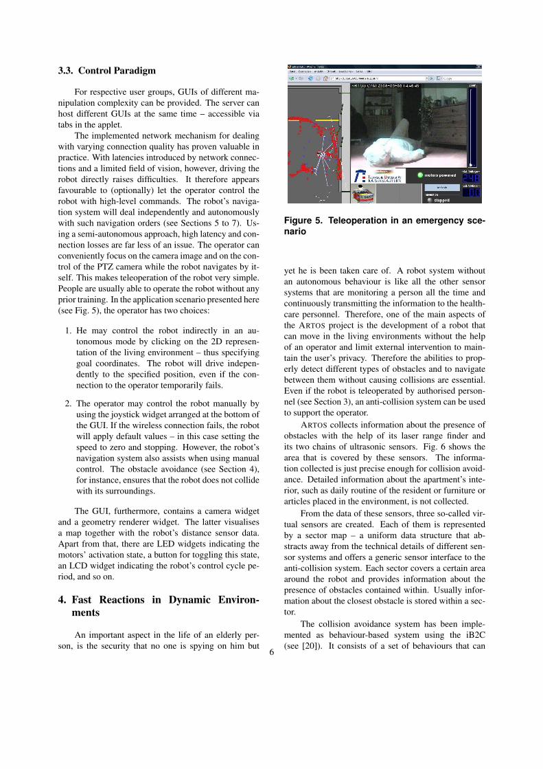
ARTOS collects information about the presence ofobstacles with the help of its laser range finder andits two chains of ultrasonic sensors. Fig. 6 shows thearea that is covered by these sensors. The informa-tion collected is just precise enough for collision avoid-ance. Detailed information about the apartment’s inte-rior, such as daily routine of the resident or furniture orarticles placed in the environment, is not collected.
From the data of these sensors, three so-called vir-tual sensors are created. Each of them is representedby a sector map – a uniform data structure that ab-stracts away from the technical details of different sen-sor systems and offers a generic sensor interface to theanti-collision system. Each sector covers a certain areaaround the robot and provides information about thepresence of obstacles contained within. Usually infor-mation about the closest obstacle is stored within a sec-tor.
The collision avoidance system has been imple-mented as behaviour-based system using the iB2C(see [20]). It consists of a set of behaviours that can
6

Bumper
Laser Range Finder
UltrasonicSensors
Figure 6. The sensors of ARTOS and the re-gions they monitor.
inhibit the motion commands coming from higher nav-igation layers, or issue different commands to keepthe robot away from obstacles. A behaviour-based ap-proach has been chosen in order to make the systemrobust against sensor failures, and easily extendable ifnew sensors are to be attached to the robot. As a last re-sort, two bumpers are attached to the robot’s front andback to stop its motion in case a collision has occurred.
Additional and more detailed information about theanti-collision system can be found in [17].
5. Localisation
As a health care and service robot, ARTOS shouldalways and precisely know its location and conse-quently the position of the human being in the environ-ment. Always tracking the human being using a cameraor a laser scanner may breach the human’s privacy in ascenario where the person wants some time alone anddoes not want to be seen or observed. Therefore, thereshould be a mechanism to track the person even withoutphysically seeing him. Such a mechanism is describedin the following.
5.1. A Discreet Human Localisation
For many assisted living applications, knowing theposition of the person is important. A typical exam-ple is the assumption that an elderly person getting upin the middle of the night and not returning to bed formore than an hour could be a sign of an emergency thatrequires further investigation.
Many approaches for localising humans in assistiveenvironments use camera-based systems to keep themunder observation at all times, but these approachescome with high costs and the loss of privacy. To en-sure maximum safety, it is necessary to know the per-son’s position at all times. But to ensure privacy, itis mandatory for an assistive system to collect only asmuch data as absolutely necessary. Therefore an ap-
proach based on RFID10 tags has been chosen here. Agrid of about 4,000 passive RFID tags with a grid sizeof 12.5cm by 12.5cm (5in by 5in) has been implantedunder the carpet (see Fig. 7) of the aforementioned testapartment (see Fig. 3). The RFID tags used are stan-dard ISO15693 tags operating at 13.56MHz, as thesetags and the corresponding readers are easily availableand have satisfying characteristics (see [21]).
At first sight, laying out so many RFID tags doesnot seem to be very cost-efficient. However, the priceof RFID tags is likely to decrease to only few cents pertag as soon as the carpet companies start selling smartcarpets as a successful product. Hence, compared to thecost of the carpet itself, the expenses for RFID tags canbe expected to be insignificant. Furthermore, a step-wise reduction in the grid density by successively hid-ing tags in experiments by the means of software is alsoplanned, with the goal of determining the number oftags needed for a sufficiently good localisation estima-tion. This would help in reducing the number of RFIDtags to be used in commercial carpets.
Fig. 8 shows an RFID reader that has been attachedto a shoe that shall be worn by a human being in theassistive environment. It is equipped with a bluetoothtransmitter which is used to connect the foot sensorto an intelligent ambient system. It should be men-tioned here that no specialised or experimental com-ponents have been used to build up the foot sensor. Ithas been assembled from components of a mobile blue-tooth RFID reader that is generally used for readingRFID tags on appliances in logistics. With a sensingrange of about 10cm (4in), the reader is able to detectat least two tags with the mentioned grid density. Thismeans that a person can be detected very reliably. Incontrast to many other human detection systems, thisapproach does not suffer from blind areas due to shield-ing, diffraction, reflexion or other field strength issues.
N = number of RFID tags in range (1)
Posx,y =1N
N
∑i=1
(xiyi
)(2)
Equations 1 and 2 show how a position estimatePos is calculated: It is simply the mean value of the 2Dpositions of all N RFID tags in range.
By sending the position estimate to an ambient sys-tem and connecting this system to the mobile robot, thelatter will know where the person is without directlymonitoring him or using a large set of firmly mountedsensors in the environment, see Fig. 9. With respect to
10RFID: radio frequency identification7

Figure 7. RFID Under the Carpet for Localisa-tion
Figure 8. Foot-attached RFID Reader
Bluetooth
Access PointLAN
WLAN
Bluetooth Gateway
Transmit currenthuman location
RFID Readeron ARTOS
Query humanlocation
RFID Reader on Shoe
ReadRFID Tag
Figure 9. Communication between ARTOS andthe shoe
privacy, the system has another advantage: As only lo-cation information about the elderly person wearing thefoot sensor is created, everyone else is invisible to thesystem.
For an even higher degree of privacy, additionaltechniques could be employed. Several approaches aredescribed in the literature. For example, a detailed anal-ysis of privacy and security in RFID systems can befound in [22]. Its author developed new concepts forproviding security and ensuring privacy and created aframework that supports their technical realisation.
It is hard to ensure that an elderly person alwayswears the RFID-enabled shoe. Therefore, a strategybased on the probability of the presence of a humanbeing at a certain place needs to be developed, whichwould help the robot to find the human even in casewhen the shoe is not being used. The methodology iscurrently being developed and beyond the scope of cur-rent paper.
5.2. Robot Localisation
Mapping and navigation of robots have alwaysbeen a challenge to researchers. Various techniqueshave been devised for precise mapping and naviga-tion. Simultaneous Localisation and Mapping (SLAM)has been developed to localise the robot while build-ing a map of the environment [23], with promising re-sults. But according to [24], different implementationsof SLAM pose certain limitations. SLAM works bet-ter in corridors and areas which are less populated andwhere there are predictable features in the environment.The dynamic nature of living environments makes itharder to track features, e.g. moving a chair may hidesome of them, and hence reliable localisation may notbe possible.
Of course, using SLAM can be an option, butsince the assistive environment is already equippedwith RFID tags under the carpet, these tags are beingused as more reliable landmarks to localise ARTOS inthe environment while moving autonomously or semi-autonomously instead of using a computationally inten-sive SLAM approach. These RFID tags are read duringthe movement of ARTOS and the information is thenused to refine the odometry-based pose estimation.
Like the foot sensor, the robot is equipped with asmall RFID reader board of 5cm by 5cm developedby FEIG Electronics11 that is attached to the bottom ofthe robot. It features an integrated antenna and is con-nected via a UART12 interface to the robot’s on-boardcomputer. While a position estimate can be computed
11http://www.feig.de/12Universal asynchronous receiver/transmitter
8

in the way described above, the orientation estimationis more difficult. It is based on detecting several land-marks while the robot is moving. A combined arith-metic and heuristic calculation is performed to estimatethe robot’s orientation. Many experiments have shownthat this approach is appropriate for indoor navigation.
The major benefit of the localisation methodologypresented here is the high robustness of the system. If anRFID tag is detected, the information is accurate with aknown maximum error. If no tag is detected, this infor-mation is also valid. Triangulating systems, in contrast,always yield a position estimate and the error that mighthave occurred is unknown.
Readers interested in more details about the RFIDlocalisation system are invited to read [15].
6. Mapping Living Environments
In order to preserve privacy and security of the el-derly person as best as possible, the approach describedin the work at hand shall work without complex mon-itoring of the environment. Hence, there shall neitherbe cameras, laser scanners, nor other similar devices at-tached to the apartment’s walls.
Regarding aspects of security, creating maps of as-sisted living apartments as a help for service robotsmight cause some concerns: Those maps would prob-ably be stored on central servers, which would createdata about people’s personal environments over whichthey would not have direct control. A solution to thisproblem would be to not provide the robots with maps,but to fully rely on their ability to create the maps ontheir own. For the sake of security, no map of the envi-ronment is required to be given to ARTOS. Therefore,it is necessary for ARTOS to generate the map of theenvironment on its own and then use that map for pathplanning, obstacle avoidance and navigation. The qual-ity of the maps generated by ARTOS is already sufficientfor assistive tasks. For more complex maps, approacheslike the one described in [25] can be employed.
In case of detection of a possible emergency, therobot has to drive to the person’s estimated locationand will probably encounter several new obstacles onits way there. It becomes mandatory that the robot isable to generate a map fast and update it continuously.
As mentioned in Section 5, the robot’s localisationis realised by the combination of odometry and usageof RFID tags (see Section 5.2), so there is no need touse SLAM here. Hence, a simpler approach can beemployed that is less computationally expensive. Asmore powerful computational hardware is more expen-sive and energy-consuming, keeping the computationalload low is important.
6.1. Single Map Creation
The main target of the mapping system is to sup-port precise navigation, and hence a grid map approachhas been chosen for map building. A grid map repre-sents the world around the robot as an array of (usu-ally uniform) grid cells. Each cell stores informationabout the area it covers, with the most important infor-mation usually being whether the area is occupied ornot. The current occupancy belief is represented by anoccupancy counter. Positive values are used for occu-pied cells, negative values for free cells and an occu-pancy counter of zero reflects an unknown occupancystate. The occupancy counters are limited so that a be-lief in an occupancy state cannot get too strong.
The laser range finder as well as the two chains ofultrasonic sensors are used as sources for the grid mapcreation process. The design of the Grid Map Builder,the component that contains the mapping functionality,allows for the addition of an arbitrary number of sensorsystems which can be used simultaneously. The sensordata can be obtained in one of the two following for-mats:
1. Polar format: The sensor values are stored as a se-ries of distance-angle-pairs. This format is usedfor the data from the laser range finder.
2. Sector map format: The polar sector maps intro-duced in Section 4 are used here to access the datagenerated by the ultrasonic sensors.
Obstacles
dj
αj
Sensor Axis
Sensor
(a) Two obstacles in the envi-ronment.
Sensor Beams
(b) Two sensor beams havebeen traced.
Figure 10. The creation of a grid map by tracingsensor beams (green/light grey: free; red/darkgrey: occupied; white: unknown).
Depending on the format, the grid map creation iscarried out in two different ways.
• When using the polar format, sensor beam trac-ing is used to alter the occupancy counters withinthe field of view of the sensor. Each sensor
9

beam is traced in small steps. Whenever it hits agrid cell, the corresponding occupancy counter isdecremented by 1. The counter of the last cell, i.e.the cell in which the obstacle lies, is incremented.The principle is illustrated by Fig. 10.
• When using polar sector maps, simply tracing sen-sor beams is not the best approach because thefact that the polar coordinates provide informationabout the closest obstacle in a sector is not used.Given a sector containing an obstacle, all grid cellsin this sector which are closer to the sensor can beregarded as free. But with sensor beam tracing,only the occupancy counters of cells which lie ona line between the sensor and the obstacle wouldbe decremented.
Algorithm 6.1 Polar Sector Map
Step 1:for all sectors s with obstacle o do
calculate cell c containing oincrement occupancy counter of c
end for
Step 2:for all cells c in rectangular area around sensor do
calculate sector s containing cif (distance(c) < distance(o)) then
decrement occupancy counter of cend if
end for
A solution is to process the sector map data in twosteps as shown in Algorithm 6.1. In the first step, thecells in which obstacles lie are marked. Each sectorcontains at most one obstacle. All sectors have to betraversed, the polar obstacle data has to be transformedinto map coordinates, and finally the cells containingobstacles have to be marked. In the second step, all cellsin a rectangular area around the sensor are traversed.For each cell, the coordinates of its centre are trans-formed into polar coordinates of the sensor coordinatesystem. The information is then processed to determinewhether the cell is closer to the sensor than the obsta-cle of this sector. If this is the case, it is regarded asfree and its occupancy counter is decremented. Fig. 11illustrates the two steps.
6.2. Map Integration
Using the above-mentioned procedure, a grid mapis created from the data of one sensor. The integration ofseveral sensors requires that the procedure is repeated
Obstacle
SectorBoundaries
(a) Initial state. (b) After step 1.
(c) After step 2.
Figure 11. The creation of a grid map using apolar sector map as data source.
for each of them. This also requires the use of differ-ent arrays of occupancy counters for different sensors,otherwise an obstacle that is only visible to sensor S1would be removed when processing the data of sensorS2, which does not see it. Therefore, in every execu-tion cycle, the data of each sensor are processed and thecorresponding array of occupancy counters is updated.Then the data of these arrays are aggregated to build onecombined grid map according to the following rules:
1. If a cell is occupied in at least one sensor’s array,then its counter in the combined grid map is set to+1.
2. If a cell is not occupied in any of the sensors’ ar-rays and is free in at least one sensor’s array, thenits counter in the combined grid map is set to −1.
3. If a cell is not occupied or free in any of the sen-sors’ arrays, then its counter in the combined gridmap is set to 0.
A grid cell stores additional information such asan occupancy counter and the information whether thecounter may be changed or not. The most relevant in-formation fields contained in one grid cell are shown inTable 1. The is fixed field is set for cells whose occu-pancy counters shall not be changed. dist to start andest length are used by the path-planning mechanism de-scribed in the next section. The combined grid map
10

Table 1. The main information fields containedin one grid cell.
Field Stored Information
occupancy counter belief about the occupancy
is near obstacle whether cell is close to an occupied cell or not
is fixed whether occupancy belief is fixed or not
dist to start distance to the start point of a path
est length estimated length of a path going through this cell
update time time of the last update of the counter
is provided to the path planning component by usinga blackboard mechanism offered by MCA.
It shall be pointed out that the mapping approachdescribed here only stores the information that is nec-essary for navigation. There is no tracking or identifi-cation of single objects, so the user can be sure that noone will collect information about the things he storesin his apartment.
7. Getting to the Place of an Emergency
The mapping system described in Section 6 is ca-pable of creating and updating a model of a dynamicassistive environment using the data of the robot’s mainsensors. Based on this model, the robot must be ableto drive to a specific location as fast as possible. Es-pecially in emergency situations, the time to reach theperson should be minimal and the robot should adoptthe shortest possible path from its current location tothe location of the person. But to respect the elderlyperson’s privacy and behave as unobtrusively as possi-ble, the robot should normally stay at a distance fromthe person.
In the following, it is explained how the robot cal-culates shortest paths, keeps a certain distance to objectswhile following those paths, and deals with the presenceof unexpected obstacles. Refer to Fig. 2 for the namesof the control system’s components.
7.1. Creating Paths
When a new path has to be created, the Path Plan-ner first reads the current grid map from the blackboard.It then executes the A*-algorithm [26] to calculate theshortest path from start point s to destination point d.This algorithm processes cell by cell, starting with s,until a path to d has been found. In each processingstep, the cell with the lowest cost is chosen as the nextcell to be processed. For a cell c, the cost f (c) is
f (c) = g(c)+h(c), (3)
where g(c) denotes the cost for the shortest knownpath going from s to c and h(c) denotes the estimatedcost of a path going from c to d. The Euclidean distanceis used as heuristic function. Before planning a path, theobstacles in the map are enlarged by marking the cellsclose to them as “neighbours”. High costs are assignedto these neighbours so that other free cells may be pre-ferred. As a result, paths do not lead the robot close toobstacles unless it is necessary.
When a path has been created as a sequence ofgrid cells, the Path Planner calculates the “relevance”of points. A point is either intermediate or relevant. Incontrast to intermediate points, the direction of the pathchanges at relevant points. In order to get an optimisedpath and a smooth robot movement, it is necessary totune some of the path points. This can be achievedby considering the fact that the direction of the pathdoes not change at intermediate points and thus theycan be altered (see Section 7.2). By contrast, relevantpath points change the direction of the robot’s move-ment and hence cannot be modified. To accommodatethe dynamically changing environment, the path is re-planned after a certain interval of time.
Finally, a path is represented as a series of triples inthe form (x-coordinate, y-coordinate, relevance). Theaforementioned blackboard mechanism is used to pro-vide a path to other components of the navigation sys-tem and to the visualisation module.
7.2. Driving along Paths
The functionality of driving forward along pathsis realised by the Elastic Band Analyzer, Elastic BandDriver, and Point Approacher modules. The pathplanned by the Path Planner is the shortest path fromthe source to the destination. Following exactly thosepoints might result in getting the robot too close to someobstacles which will cause reduction in speed and thusthe robot might take a longer time to reach its destina-tion. To overcome this problem, the elastic band ap-proach [27] has been used. The algorithm has been im-plemented in the Elastic Band Analyzer, which readsthe path from the blackboard and optimises it with re-spect to a smooth robot motion, a short driving time,and a safe distance to obstacles.
The Elastic Band Driver reads the path optimisedby the Elastic Band Analyzer from the blackboard andsends its relevant points one by one to the Point Ap-proacher. It also offers additional functionality such ascalculating a target orientation, which is important forthe use of the Elastic Band Driver on non-holonomic
11

robots.The Point Approacher receives target coordinates
and the current robot pose as input, and calculates a de-sired velocity vdes and angular velocity ωdes dependingon the distance d and absolute angle |α| to the target(see Equations 4 and 5):
vdes =
0 ; d ≤ dmin
1 ; d ≥ dmax12 + 1
2 · sin(( d−dmindmax−dmin
− 12 ) ·π) ; else
(4)
|ωdes|=
0 ; |α| ≤ αmin
1 ; |α| ≥ αmax12 + 1
2 · sin(( |α|−αminαmax−αmin
− 12 ) ·π) ; else
(5)
By comparing the robot’s orientation to α , ωdes canbe calculated from |ωdes|. dmin, dmax, αmin, αmax markthe distances and angles at which vdes and ωdes, respec-tively, take their extreme values. If dmax is reduced, forexample, the robot will drive longer at the maximumspeed when approaching a target. If it should decelerateearlier, dmax has to be increased. To make the changesof vdes and ωdes smoother, sigmoid functions are used.
7.3. Backing off
Living environments are very dynamic in nature.Despite every effort to generate a map of all the fixedand dynamic obstacles, there are many dynamic obsta-cles that obstruct the shortest path to the destination andsometimes render the destination unreachable. There-fore, a component is required to make the robot backoff after acknowledging that it cannot go any furtherand there is not even enough space to turn around. Inthis case, the only choice left is to come back to a pre-viously visited position where it was safe for the robotto move, and re-plan the path to the destination. Afterbacking off, the map will contain new information aboutthe dynamic obstacles that prevented the robot from fol-lowing the original path, and the new path will lead therobot around these obstacles.
Drive Backward shall realise this behaviour. It con-siders the robot’s velocity after a certain time period.If the velocity at some point is above a certain thresh-old, the robot is in a comfortable zone where it can eas-ily move around. The current point is recorded as safepoint so that the robot can drive back to it later if neces-sary. There can be two cases in which the velocity canbe below the threshold. First, it is possible that the robot
is moving through a tight corridor and there are lots ofobstacles around it. Second, the robot has got stuck atsome place and can neither go forward nor turn around.In the first case, after crossing the corridor the robot canregain a high velocity. Therefore, a certain time is givenas a grace period to the robot to regain a high velocity orchange the path by turning around before driving back.In the second case, there is no option other than to drivebackward to the safe point.
During the experiments, it was observed that whiledriving back, dynamic obstacles may keep ARTOS fromreaching the safe point (see Fig. 12). The robot willremain in Drive Backward mode, trying to reach thesafe point, which might no longer be possible. This isavoided by deactivating the Drive Backward after a cer-tain time. Afterwards, a path is planned from the currentpoint to the destination and the robot moves forward.
8. Experiments
In both control modes described in Section 3.3,ARTOS’ ability to manoeuvre around obstacles is es-sential. If the collision avoidance failed, the robot eas-ily could collide with a piece of furniture or the elderlyperson in the apartment, causing harm instead of com-fort to the person. For a teleoperator, controlling therobot by only clicking on a target location in a map addi-tionally requires the mapping and navigation systems tooperate properly. In the operation mode that maintainsthe highest degree of privacy – the fully autonomousmode – no operator shall be needed for the robot to beemployed. This necessitates a powerful combination ofanti-collision, mapping, and navigation systems.
Figure 13. The main obstacles in the livingroom that ARTOS encountered when drivingfrom the entrance to the kitchen.
To evaluate the performance of the overall system,numerous experiments have been conducted in the as-sistive apartment described in Section 1 (see Fig. 3).Details of such experiments can be found in [17] and[28]. Two significant examples with respect to naviga-
12

NarrowCorridor
DynamicObject
Safe Point
Destination
DynamicObject
Robot
(a)
Dynamic ObjectCovers Safe Point
(b)
New Path
(c)
Figure 12. Scenario of Backing off: (a) While approaching the destination, the robot marks the safepoint. (b) It backs off from the first obstacle and drives around another obstacle blocking the safepoint. (c) The time for backing off has expired and the robot has planned a new path.
Figure 14. ARTOS’ velocity during its tourfrom the entrance to the kitchen (scaled to[−1.0;1.0]).
tion shall be presented here. At the beginning of theexperiments, the robot was provided with an initial mapcontaining only the walls of the rooms. Furniture andother dynamic objects standing or lying on the groundwere not represented in the map and so the initially cre-ated paths led through obstacles. The challenge for thecontrol system was to detect path obstructions and tofind a way around them. In both the experiments pre-sented here, the robot had to drive from the entrance tothe kitchen. Fig. 13 shows the furniture in the livingroom through which ARTOS had to plan a path whilenavigating autonomously.
The robot’s path during the first experiment isshown in Fig. 15. The gaps in the path are caused bythe RFID-based pose corrections, which made the esti-mated pose “jump”. A diagram of its velocity is shownin Fig. 14. As can be seen, the robot did not back offwhile following the path. This is an important result
as it demonstrates that the mapping and obstacle avoid-ance components detected the obstructions so early thata way leading around them could be calculated beforethe robot got stuck.
In the second experiment, the robot took a detourbefore entering the kitchen. This was caused by thecollision avoidance system which detected the door andmade the robot turn in the wrong direction. As can beseen in Fig. 16, the navigation system adapted to thenew situation and led the robot along a curve back tothe correct course.
Finally, an emergency situation was created in theassistive apartment, where a man fell down on the floorand the assistive system detected the fall (see Fig. 17).After realising the situation, ARTOS – currently oper-ating in the autonomous mode to ensure privacy of theperson – sent an emergency call to the health care cen-tre for urgent assistance. As mentioned in Section 3, theoperator could then view the surroundings of the robotusing the web interface. He had the two options to con-trol the robot: either directly manoeuvring the robot us-ing the joystick widget in the web interface, or activat-ing the semi-autonomous mode by clicking on the 2Dmap of the apartment.
In the current scenario, the operator initially usedthe semi-autonomous mode to reach the human beingand the joystick mode to have a better view of the in-capacitated person. The remote person was able to fo-cus the PTZ camera onto the fallen person to see hiscondition. Afterwards, the medical person establishedARTOS’ audio communication link to talk to the fallenperson in order to find out how he was feeling and toassure him that medical help was on its way.
On the left side of the GUI visible in Fig. 17, thedata yielded by ARTOS’ laser scanner and ultrasonicsensors is displayed. This widget can also be used to
13

Figure 15. The path of the robot fromthe entrance to the kitchen during Ex-periment 1
Figure 16. The path of the robot fromthe entrance to the kitchen during Ex-periment 2
Figure 17. Teleoperation in an emergency sce-nario
display the grid map generated by the robot. It is impor-tant to mention here that this data, as well as the videoimage on the right, are only displayed and not stored inany way on the operator’s computer. This again is inaccordance with the approach keeping as much data aspossible on the robot and only transferring (not storing)data that are needed in special, precisely-defined situa-tions.
As visible in Fig. 17, the experiment was witnessedby a group of dignitaries. ARTOS was able to navigatebetween those persons without any collision and suc-cessfully established the communication setup after re-alising the situation.
9. Security and Privacy
Being an elderly care robot, security and privacy ofthe inhabitant of the house is one of the concerns forthe development of ARTOS. It is a system in which se-curity measures have been taken to secure the data. Asmentioned in Section 3, ARTOS is able to communicatewith the remote caregivers using wireless Internet. Toensure that only the caregivers may be able to use the in-formation from ARTOS, certain steps have been taken.It is worth mentioning that the authors are not focusingon the aspect that any government agency gets accessto the robot and hence access to the private informationabout the persons. This paper is focused on developinga secure robot for elderly people, which is secured fromconventional hacking techniques and remote agents thatmight harm the privacy of the people.
Following are some of the measures taken to pro-tect the information on the robot.
9.1. Encrypted Data
Firstly, to ensure privacy of the human being, noinformation about the daily schedule of the person iskept on the robot. Secondly, the images and videos thatare captured using the camera are sent to the caregiverperson only in case of an emergency situation and arenot stored on the system.
To ensure that data on the disk, such as maps of theenvironment etc, are encrypted, the authors use True-Crypt13. TrueCrypt creates an encrypted file which canbe mounted as a device and all the operations can beperformed as a normal drive. All the encryption and de-
13http://www.truecrypt.org14

cryption is done on-the-fly and therefore cause no delayin computation. TrueCrypt has been configured to usethree ciphers in a cascade operation in XTS14 mode forencryption and decryption. These three ciphers are Ad-vanced Encryption Standard (AES), Twofish and Ser-pent. Each block of information is first encrypted withSerpent using a 256 bit key. Then it is encrypted withTwofish using a 256 bit key and finally with AES usinga 256 bit key. Independent keys are being used for theseoperations. (More information on different configura-tions and setup could be found at TrueCrypt website).
Storing encrypted information on ARTOS ensuresthat only relevant and authorised people have access tothe stored data.
9.2. Network Security
Since ARTOS is reachable via wireless Internet, se-curing the network is the primary task that could preventany illegal access to the robot. Therefore, the followingactions have been taken.
9.2.1. Use of SSL. Secure Socket Layer (SSL) en-crypts the segments of network connections at the Ap-plication Layer to ensure secure end-to-end transit at theTransport Layer. The Transport Layer Security (TLS)protocol allows client/server applications to communi-cate across a network in a way designed to prevent tam-pering and listening. It also provides endpoint authenti-cation and communications confidentiality over the In-ternet using cryptography. TLS provides RSA securitywith 1024 and 2048 bit strengths.
In typical end-user/browser usage, TLS authentica-tion is unilateral, that means, only the server is authen-ticated (the client knows the server’s identity), but notvice versa (the client remains unauthenticated or anony-mous). TLS also supports the more secure bilateralconnection mode, in which both ends of the ”conversa-tion” can be assured with whom they are communicat-ing. This is known as mutual authentication, or 2SSL.Mutual authentication requires that the TLS client-sidealso holds a certificate.
When a TLS or SSL connection is established, theclient and server negotiate a CipherSuite, exchangingCipherSuite codes in the client hello and server hellomessages, which specifies a combination of crypto-graphic algorithms to be used for the connection. Thekey exchange and authentication algorithms are typi-cally public key algorithms.
Based on the security provided by TLS and SSL,all the network communication on ARTOS uses SSL.
14XTS: XEX-based Tweaked CodeBook mode with CipherTextStealing
The server on the PTZ camera is configured to issueself-signed digital certificates to authenticate the useraccessing the camera. The RSA algorithm (an algo-rithm for public-key cryptography) has been employedto encrypt the public-key. The transmission of the videostream is carried over a secure HTTPS channel whichprevents any kind of tampering or listening.
The web server on the computer of the robot is alsoSSL based. Over here client authentication is also re-quired. All the information for authentication of theclient is first encrypted at the client side and then trans-ferred over the Internet and finally after reaching therobot, it is decrypted and used. In this way it is assuredthat only the authorised operator is accessing the infor-mation from ARTOS.
The network security can be enhanced by establish-ing a Virtual Private Network (VPN) and installing fire-walls to limit access to the robot.
9.2.2. Use of Skype. The authors have used the thirdparty telephonic conversation tool, Skype15. The mainreason for the choice was again the security and privacyof the elderly person. The information of logging intoSkype using user-name and password is sent using Se-cure Socket Layer (SSL). Hence all the information isencrypted before it leaves the computer and can onlybe decrypted by the Skype server. Skype uses the AESalgorithm with 256 bit encryption which has a total of1.1x1077 possible keys. Skype also uses 1024 bit RSAto negotiate symmetric AES keys. User public keys arecertified by the Skype server at log-in using 1536 or2048-bit RSA certificates.
To add a level of security, automatic addition ofusers in Skype is not permissible on ARTOS. Similarly,calls and chat requests from unknown users are not al-lowed. Moreover, Skype is configured not to accept anyinvitation or files from users that are not added to theSkype list.
In case the security of Skype is compromised inany way, although the chances are low, the hacker couldget access to the Skype server effecting the privacy ofthe elderly person, but there is no way the robot can becontrolled by the illegal user to cause any harm.
10. Conclusion and Future Work
In this paper, an approach was described for im-proving safety but maintaining privacy of a person inassistive environments. The approach presented is onlya first step towards a full-featured personal robot thatshall unobtrusively monitor the user, respect the privacy,maintain a certain level of security and only call for help
15http://www.skype.com15

if it detects a possible medical emergency. The focuswas laid on the mobile system that replaces many mon-itoring devices whose deployment would tremendouslyreduce acceptance of such an environment by the inhab-itants. The assisted teleoperation for emergency evalua-tion was used as an application scenario. Technical so-lutions regarding usability, deployability, security, andprivacy were depicted. The concepts of the robot’s nav-igational subsystems and the sophisticated teleoperationhave been described in detail.
Up to now, especial tests revolving around the func-tion of the navigational components have been eval-uated. Future work will focus on real-life tests withthe target group, with care institutions and with first-responders. The results of these tests will enable to de-fine the privacy level acceptable by the elderly people.
To ensure the authentication of the client accessingthe robot, 2SSL will be implemented which not onlyrequires the server to have an SSL certificate but alsodemands that the client should also have a similar cer-tificate for mutual authentication. The Java implemen-tation allows a secure connection to the machine using2SSL. Attempts for hacking the system and decryptingthe information on the computer of the robot will alsobe launched to thoroughly test the security of the con-tents on the robotic system.
As has been mentioned, there is no guarantee thatthe elderly person wears the RFID-equipped shoe thatwould enable the robot to estimate the location of theperson in the environment. Therefore, integrating amethodology for predicting the position of the humanbeing in the environment based on a probabilistic be-lief of the presence of the human at a particular time isrequired to be developed.
Finally to enhance the state of privacy, interven-tions from the care-givers should be limited. This canbe achieved by enhancing the capabilities of the robotto assess the situation and allow any involvement of anexternal person in case of a real emergency.
Acknowledgements
The authors gratefully acknowledge the funding ofSyed Atif Mehdi by the Higher Education Commissionof Pakistan and the DAAD, Germany and the fundingof Christopher Armbrust by the PhD Programme of theUniversity of Kaiserslautern’s Department of ComputerSciences. Also, the authors want to thank FraunhoferIESE in Kaiserslautern for cultivating the Assisted Liv-ing Lab.
References
[1] R. Cucchiara, A. Prati, and R. Vezzani, “A multi-cameravision system for fall detection and alarm generation,”Expert Systems, vol. 24, no. 5, pp. 334–345, November2007.
[2] W. L. Zagler, P. Panek, and M. Rauhala, “Ambient as-sisted living systems - the conflicts between technol-ogy, acceptance, ethics and privacy,” in Assisted LivingSystems - Models, Architectures and Engineering Ap-proaches, ser. Dagstuhl Seminar Proceedings, A. Karsh-mer, J. Nehmer, H. Raffler, and G. Troster, Eds., no.07462. Dagstuhl, Germany: Schloss Dagstuhl -Leibniz-Zentrum fuer Informatik, Germany, 2008.
[3] G. Abowd, A. Bobick, I. Essa, E. Mynatt, and W. Roger,“The aware home: Developing technologies for success-ful aging,” in Procceedings of the Workshop on Automa-tion as a Care Giver at the American Association of Ar-tificial Intelligence (AAAI), Alberta, Canada, July 2002.
[4] S. Intille, K. Larson, and E. M. Tapia, “Designingand evaluating technology for independent aging in thehome,” in International Conference on Aging, Disabil-ity and Independence (ICADI), Washington DC, USA,December 2003.
[5] J. Nehmer, A. Karshmer, M. Becker, and R. Lamm,“Living assistance systems - an ambient intelligenceapproach,” in Proceedings of the 28th InternationalConference on Software Engineering (ICSE), Shanghai,China, May 20-28 2006.
[6] P. Deegan, R. Grupen, A. Hanson, E. Horrell, S. Ou,E. Riseman, S. Sen, B. Thibodeau, A. Williams, andD. Xie, “Mobile manipulators for assisted living in res-idential settings,” Autonomous Robots, Special Issue onSocially Assistive Robotics, vol. 24, no. 2, pp. 179–192,February 2008.
[7] F. Michaud, P. Boissy, H. Corriveau, A. Grant, M. Lau-ria, D. Labonte, R. Cloutier, M.-A. Roux, M.-P. Royer,and D. Iannuzzi, “Telepresence robot for home careassistance,” in AAAI Spring Symposium on Multidisci-plinary Collaboration for Socially Assistive Robotics,Palo Alto, USA, March 2007.
[8] A. Tapus, M. Mataric, and B. Scassellati, “The grandchallenges in socially assistive robotics,” Robotics andAutomation Magazin, vol. 14, no. 1, pp. 35–42, 2007.
[9] D. Labonte, F. Michaud, P. Boissy, H. Corriveau,R. Cloutier, and M. Roux, “A pilot study on teleoper-ated mobile robots in home environments,” in IEEE/RSJInternational Conference on Intelligent Robots and Sys-tems, October 9-15 2006, pp. 4466–4471.
[10] T. van der Zant and T. Wisspeintner, “Robocup@home:Creating and benchmarking tomorrows service robot ap-plications,” in Robotic Soccer, P. Lima, Ed. Vienna,Austria: Itech Education and Publication, December2007, no. ISBN: 978-3-902613-21-9, ch. 26, pp. 521–528.
[11] Q. Wang, W. Shin, X. Liu, Z. Zeng, C. Oh, B. K. Al-shebli, M. Caccamo, C. A. Gunter, E. L. Gunter, J. Hou,K. Karahalios, and L. Sha, “I-living: An open system
16

architecture for assisted living,” in IEEE InternationalConference on Systems, Man, and Cybernetics (SMC),Taipei, Taiwan, October 2006.
[12] Y. Ouyang, Y. Xu, Z. Le, G. Chen, and F. Makedon,“Providing location privacy in assisted living environ-ments,” in PETRA 08: Proceedings of the 1st interna-tional conference on PErvasive Technologies Related toAssistive Environments. New York, NY, USA: ACM,2008, pp. 1–8.
[13] T. Denning, C. Matuszek, K. Koscher, J. R. Smith, andT. Kohno, “A spotlight on security and privacy risks withfuture household robots: attacks and lessons,” in Ubi-comp ’09: Proceedings of the 11th international confer-ence on Ubiquitous computing. New York, NY, USA:ACM, September 30 - October 3 2009, pp. 105–114.
[14] J. Koch, C. Armbrust, and K. Berns, “Small servicerobots for assisted living environments,” in VDI/VDEFachtagung Robotik, Munich, Germany, June 11-122008.
[15] J. Koch, J. Wettach, E. Bloch, and K. Berns, “Indoor lo-calisation of humans, objects, and mobile robots withRFID infrastructure,” in 7th International Conferenceon Hybrid Intelligent Systems (HIS07), Kaiserslautern,Germany, September 17-19 2007, pp. 271–276.
[16] M. Proetzsch, T. Luksch, and K. Berns, “The behaviour-based control architecture iB2C for complex robotic sys-tems,” in Proceedings of the 30th Annual German Con-ference on Artificial Intelligence (KI), Osnabruck, Ger-many, September 10-13 2007, pp. 494–497.
[17] C. Armbrust, J. Koch, U. Stocker, and K. Berns,“Mobile robot navigation support in living environ-ments,” in 20. Fachgesprach Autonome Mobile Systeme(AMS). Kaiserslautern, Germany: Springer-Verlag, Oc-tober 2007, pp. 341–346.
[18] J. Koch, M. Reichardt, and K. Berns, “Universal webinterfaces for robot control frameworks,” in IEEE/RSJInternational Conference on Intelligent Robots and Sys-tems (IROS), Nice, France, September 22-26 2008.
[19] P. Fiorini and R. Oboe, “Internet-based telerobotics:Problems and approaches,” in International Conferenceon Advanced Robotics (ICAR), Monterey, USA, 1997.
[20] M. Proetzsch, T. Luksch, and K. Berns, “Developmentof complex robotic systems using the behavior-basedcontrol architecture iB2C,” Robotics and AutonomousSystems, vol. 58, no. 1, pp. 46–67, 2010.
[21] K. Finkenzeller, RFID Handbook: Radio-FrequencyIdentification Fundamentals and Applications. NewYork: Wiley, 2000.
[22] D. Henrici, RFID Security and Privacy - Concepts, Pro-tocols, and Architectures, ser. Lecture Notes in Elec-trical Engineering, Springer. Springer Berlin, 2008,ISBN: 978-3-540-79075-4.
[23] M. Montemerlo, S. Thrun, D. Koller, and B. Wegbreit,“FastSLAM: A factored solution to the simultaneous lo-calization and mapping problem,” in Proceedings of the18th National Conference on Artificial Intelligence and14th Conference on Innovative Applications of ArtificialIntelligence. Edmonton, Alberta, Canada: AAAI Press,
California, USA, August 2002, pp. 593–598.[24] R. Ouellette and K. Hirasawa, “A comparison of SLAM
implementations for indoor mobile robots,” IEEE/RSJInternational Conference on Intelligent Robots and Sys-tems, 2007 (IROS 2007), pp. 1479–1484, October 29-November 2 2007.
[25] J. Wettach and K. Berns, “3D reconstruction for ex-ploration of indoor environments,” in Autonome Mo-bile Systeme 2007, ser. Informatik aktuell, K. Berns andT. Luksch, Eds. Kaiserslautern: Springer-Verlag, Oc-tober 18-19 2007, pp. 57–63.
[26] P. E. Hart, N. J. Nilsson, and B. Raphael, “A formal basisfor the heuristic determination of minimum cost paths,”in IEEE Transactions of Systems Science and Cybernet-ics, vol. 4, no. 2, July 2 1968, pp. 100–107.
[27] S. Quinlan and O. Khatib, “Elastic bands: Connectingpath planning and control,” in Proceedings of IEEE Int.Conference on Robotics and Automation, Atlanta, 1993,pp. 802–807.
[28] S. A. Mehdi, C. Armbrust, J. Koch, and K. Berns,“Methodology for robot mapping and navigation in as-sisted living environments,” in PETRA ’09: Proceedingsof the 2nd International Conference on PErvasive Tech-nologies Related to Assistive Environments, no. ISBN:978-1-60558-409-6. Corfu, Greece: ACM, New York,NY, USA, June 9-13 2009.
17
Copyright © 2022 FDOKUMEN