assessment of'digital video recording technology f'or
138
ASSESSMENT OF'DIGITAL VIDEO RECORDING TECHNOLOGY F'OR USE IN IO\ryA STATE PATROL ENF'ORCEMENT VEHICLES Prepøred øndsabmítted by the lowti Depørtment of Publíc Søf"A pursuøntto 2007lowø Acts,Senøte Fíle 575 Statement of Context Duringthe2007 session of theIowaGeneral Assembly, questions arose relating to in-car video recording technology andassociated recording policy and practice among Iowa law enforcement agencies. [r an effort to advance awareness and understanding of issues related to in-carvideo recording technology andits use,the Iowa Department of Public Safetysupported the adoption of a study directive for theDepartment, specific to the lowa State Patrol. The study directivewas ultimately included as one element of Senate File 575, the Justice System Appropriations 8i11. Section 19, SF 575,specifi.ed the scope andcontent of the report, as follows: "The departrnent of pubtic safety shall study and makerecommendations regardirigthe benefits as well as the disadvantages of converting the recording equipment in the state pahol enforcement motorvehicles to digital carnerarecording technology for usein such vehicles. The study shallinclude an estimate of the costof converting to the technology, an assessment of issues related to data storage andtherulesof evidence, implementation concems, and if a conversion is recommended, a timefine for acquiring ancl cleploying tJre tligital carïrera recording teclurology in the motor vehicles of the state patrol.?' Though not explicitly stated in the study directive, one specific concernthat was expressed during the 2007 session relatesto the issue of the limited capactty of VHS-basedanalog recordingsystems, and the inabilify to capture video when the recording media (usuallyVHS tape) is full. The questionof whether digital recording systems offer advantages over analog systems wasraised, as mostdigital video recording systems do not use magneti c tape,but instead
-
Upload
khangminh22 -
Category
Documents
-
view
2 -
download
0
Transcript of assessment of'digital video recording technology f'or

ASSESSMENT OF'DIGITAL VIDEO RECORDING TECHNOLOGY F'ORUSE IN IO\ryA STATE PATROL ENF'ORCEMENT VEHICLES
Prepøred ønd sabmítted by the lowti Depørtment of Publíc Søf"Apursuønt to 2007 lowø Acts, Senøte Fíle 575
Statement of Context
During the 2007 session of the Iowa General Assembly, questions arose relating to in-car video
recording technology and associated recording policy and practice among Iowa law enforcement
agencies. [r an effort to advance awareness and understanding of issues related to in-car video
recording technology and its use, the Iowa Department of Public Safety supported the adoption
of a study directive for the Department, specific to the lowa State Patrol.
The study directive was ultimately included as one element of Senate File 575, the Justice
System Appropriations 8i11. Section 19, SF 575, specifi.ed the scope and content of the report, as
follows:
"The departrnent of pubtic safety shall study and make recommendations regardirig the
benefits as well as the disadvantages of converting the recording equipment in the state
pahol enforcement motor vehicles to digital carnerarecording technology for use in such
vehicles. The study shall include an estimate of the cost of converting to the technology,
an assessment of issues related to data storage and the rules of evidence, implementation
concems, and if a conversion is recommended, a timefine for acquiring ancl cleploying tJre
tligital carïrera recording teclurology in the motor vehicles of the state patrol.?'
Though not explicitly stated in the study directive, one specific concern that was expressed
during the 2007 session relates to the issue of the limited capactty of VHS-based analog
recording systems, and the inabilify to capture video when the recording media (usually VHS
tape) is full. The question of whether digital recording systems offer advantages over analog
systems was raised, as most digital video recording systems do not use magneti c tape,but instead

use solid state memory (flash memory), a hard drive; or DVD recorder. That issue, in addition to
other comparisons, will be discussed in this report.
This report is organized into seven sections, plus appendices, as follows:
I. Background and Current Practice
il. Assessment of Digital Recording Technology
ilI. Advantages, Disadvantages, Comparables, and Opportunities for Enhanced
Functionality
IV. Rules of Evidence
V. ImpiementationConcerns
VI. Cost
VII. Timeline Considerations
Appendices
I. Background and Current Practice
The first mobile video systems used by the Iowa State Patrol were installed in the early 1990s.
During the last one and a half decades of use, the in-car video technology has been demonstrated
and proven to be a critical piece of equipment for state troopers. Currently, all enforcement
vehicles assigned to ISP troopers and sergeants are equipped with in-car video systems that
record video images in color. All'systems currently installed andutílized employ analog VHS-
based recording technology. The major components of the VHS-based recording system
include:
o Singlewindshield-mounted camera.
o Contool head and monitor mounted in close proximity to the driver seat.
o Trunk-mounted vatltthat contains a video cassette recorder.
o 'Wireless microphone (worn by the trooper).
The video cassette recorder in the trunk-mounted vault uses standard VHS recording media. ISP
ui¡eè standard VHS tapes that have the capacity to record six (6) hours of video footage. Video
recor.ding is automatically initiated upon engagement of the vehicle's emergency lights.
- 2 -

Additionally, video rècording can be manually initiated without the vehicle's emergency lights in
operation. Likewise, video recordirg coÍrmenced automatically by activation of the vehicle's
emergency lights can be manually overridden to address circumstances where the ïehicles
emergency tights are erLgaged for lengfhy periods of time, but where no enforcement action,
emergency response, or public contact (such as a "motorist assist") is occwring.
The most typical example is a circumstance where an officer leaves emergency lights activated
while parked or stopped for an extended period of time to alert approaching motorists of a lane,
road, or ramp closure. During a typical eight hour shift, enforcement actions, motorist assists,
emergency response, and other actions will result in approximately two hours of video
recordings, .though any given shift can result in considerably less or more record time.
The technology used by ISP is comparable to video recording systems most commonly used by
other state and local law enforcement agencies across the nation, though there are jurisdictions
using systems that offer considerably better performance and features, just as there are
jwisdictions using systems that offer fewer features and lower performance than the systems
used by ISP. It should also be noted that there are many law enforcement agencies that do not
atilize in-car video recording technology of any sort. Generally, the smaller law enforcement
agencies with the greatest resource limitations are those most likely not to utilize in-car video
recording systems.
Though the video recording systems used by ISP all have similar fe¿tures antl pcrfururanue, thete
are cu¡rently eight different models used by ISP. Over the years, the inconsistent availability of
funding has resulted in the procurement of different models of mobile video systems. This
inconsistent life cycle costing has led to additionalftaining, inventory and maintenance burdens
and costs since the fleet has contained as many as eight different models of mobile video systems
at any given time.
'rt"" new systems were only purchased when funds were made avulable,and in quantities that
have not allowed for the outfitting of every ISP enforcement vehicle, some ISP enforcement
vehicles atre not equipped with in-car video recording systems. Given that ISP officers above the
- 3 -

rank of sergeant spend less time on the road than troopers and sergeants, a strategic deciqion was
made to install video recording systems only in vehicles assigned to troopers and sergeants. This
strategic deployment of resources has resultpd in approximately 370 state patrol vehicles being
outfitted with video recording systems.
Though it may be advantageous to install video recording systems in every state patrol
enforcement vehicle, even if resources were made available for this pu4)ose, it is not clear that
such use of additional resources would vield a favorable retum on the investment.
As VHS-based mobile video systems near obsolescence, replacement parts will beiome difficult
to obtain.
All ISP sworn personnel that have been assigned vehicles with mobile video recording systems
are required to adhere to ISP mobile video recording policy. The curreirt ISP policy is included
as Appendix A. As part of alarger department wide effort to achieve accreditation by CALEA
(Commission on Accreditation of Law Enforcement Agencies), departmental policies are being
updated and improved. A revision of the ISP mobile video recording policy is part of this effort,
is slated for adoption in early 2008. A draft of the revised policy is included as Appendix B.
Benefits of Video Recordíng þoth ønalog ønd dígìtal)
The use of mobile video systems has resulted in numerous benefits to law enforcement including
increased officer safety, documentation of haffic violatiôns, citizen behavior and other events;
redur:Ërl corlrt time and prosecutor burclen; vider-r evide;rr.:e fìrr r¡ss ilt inl:errtal investigations;
reduced frivolous lawsuits; and increased likelihood of succeqsful prosecution (Intemational
Association of Chieß of Police). Ilr-car cameras will continue to have a positive impact on
officers' perception of safety and their ability to respond to complaints regarding professionalism
and courtesy. Prosecuting attorneys and the Courts will continue to expect that video evidence
will exist in nearly all traffic cases and some criminal cases that come before them. The use of
mobile video recording systems will continue to produce effective tra;rrtrng materials for law
enforcement. The Iowa State Patuolwill continue to depend on the use of mobile video footage
for the purpose of evaluating personnel perfonnance and professionalism.
- 4 -

II. Assessment of Diqital Recor4ins Technolow
Medíø ønd Døtø Storøge
The màst current mobile video systems manufactured today utilizedigital technology and digital
recording media. Common media options include hard drives, DVD recorders, and solid state
memory (flash memory). Systems range in design from those that are fully contained in the
vehicle's dash to those systems that include a small storage compartment that fits in the vehicle's
police equipment rack. In most cases, digital systems are compact enough that no trunk
unilvault is requiied.
Research and experience has shown that storage devices that employ moving parts, such as hard
drives and disks, do not respond well to a mobile environment. The earliest generation of both
analog and now digital recording systems, that employ extensive use of moving parts, have had
high failure rates. The rapid and high failure rate of first generation analog systems was rather
quickly replaced by vastly improved, more reliable models. ISP anticipates that similar
improvements will be made in digital video recording systems.
To minimizethe risk associated with the use of the latest digital video recording systems, serious
consideration should be given to avoiding systems that write databy use of rotating media or
other media using moving parts. These concerns are especially critical for the Iowa State Patrol,
wfrictr covers a vast teritory that includes thousands of miles of gravel roads, ancl extensive
hours logged in extreme weather conditions, to include extended operation at both temperature
extremes (hlgh and low), and during major weather events, to include electrical stotttls,
snowstorms, ice events, and heavy rainstorms. Given the operating environment for the lowa
State Patrol, solid state deviees appear to be the most appropriate devices, at least until non-solid
state systems have improved and demonstrated a favorable track record.
A sixteen gigabyte (16 GB) storage device will store six to ten hours of video data recorded at
640 x 480 resolution (VGA) at 30 frameb per second (or a range of 1.6 GB per hour to 2.66 GB
per hour). Variables most greatly affecting the amount of storage required for video images are
- 5 -

the compression technology employed, and the nature of the images being captured. MoSt video
compression algorithms can achieve far gteater compression ratios with stæic images captured
by a camera in a stopped car, as compared to active images captured by a camera in a moving
car. The more active images that are captured, the lower the compression ratio willbe, and as a
result, more storage capacity is required.
By comparison, a VHS tape holds six hours of recorded video. While it is possible to select
different recording speeds to capture more or less recording time on a single tape, there are not
greatvanations in compression technologies as is the case with digital video capture technology,
and there is no difference in the amount of tape used when images are captured by a carnera in
either a stopped or a moving car.
In the case of ananalog recording system that uses VHS tape, or in the case of adiglrtal video
system that uses solid státe memory a DVD recorder, or a removable hard drive, each type of .
recording media has a set capacity. Once the capacíty of the media is reached, no further images
can be recorded without either downloading data to a seryer (sometimes done by wireless
network connection at police headquarters or a fuel filling station, which would not be viable for
ISP given the geographic deployment of troopers in all 99Iowa counties) or by changing media
(inserting a ne\ry flash memory card, hard drive, or DVD). As such, neither digital nor analog
systems are immune from the inherent limitations associated with storage capacity. I
Under the "statement of Context" at the beginning of this report, a specific question was asked
regarding any possible advantages of digital video systems with regard to the capacity o(storage
media. The previous tevir* of storage capacity for both analog and digital video recording
systems revçals that both types of systems have capacity limitations, which are inherent to the
capacity limitation ofthe recording media in use.
Pursuant to State Patrol procedures, tapes containing video evidence captured by WIS-based
systems must be stored in a secure facility. To parallel this protocol with digital video, data
would have to be stored on secure, restricted access servers at ISP district offices across the state.
Under nonnal circumstances, tapes are kept for ninety days before their contents are erased by a
- 6 -

district sergeant. If a trooper works sixty days out of a ninety day period, and given that atypical
shift results in two hours of recorded events, to achieve the 90 day retention, each trooper can be
expected to amass approximately one hundred -twenty (120) hows of video in any ninety day
period.
'trith a digital system, each trooper would require between one hundred ninety-two (192 GB)
gigabytes and three hundred nineteen gigabytes (319 GB) of storage space on a server, assuming
that aserver based storage option is selected, which clearly appears to be the most viable option
given ISP's statewide deplo¡rment of troopers. The average State Pahol district includes about
twenty-six troopers and sergeants. Therefore, at a minimum capacity of 192 GB per trooper,
each ISP district would require at least five terabytes of storage space (26 troopers x 192 GB per
trooper, minimum). By way of comparison, to retain 90 days of analog video recorded on six
hour tapes, approxim atëIy 520 tapes must be cataloged and stored at all times (120 hours per
trooper / 6 hours per tape x 26 troopers).
Neither digital nor analog appear to offer any particular benefit with respect to field of view (a
tarlge of wide angle zoom cameras are available for both systems), simplicity of use, or audio
recording qualify, though it should be noted that audio perfomrance should be a key criteria in
the evaluation of any analog or digital system.
Video revíew, cøtalogíng, storøge' ønd retríeval
Monitoring, catalogþg, storing, and retrieving images stored on analog VHS tapes is labor
intensive, particularly for district sergeants, but also for individual troopers antl ISP clerical staff.
It is anticipatedthat the same pro.cedures would apply to digital video evidence that would be
stored on a server (or DVD, if such a system were selected). However, one benefit of employing
server-based storage would be the elimination of the need for physical storage for VHS tapes or
DVDs. Recorded events can be classified by officers so that they can be quickly retieved when
necessary. Beyond basic catalogng capabilities, !t is expected that digital video recording
systems will soon be widely available with the capabilify of fully integrating the in-car recording
system with the in-car computer.
- 7 -

Retention policies could be enforced automatically through the use of data management software
that accompanies digital mobile video systems. Many of the available digital video management
software packages also include the ability to hack "chain of'custody''that is crucial for evidence
accountability. While a seryer based systern is clearly the preferred method of storing video
images, in order to meet demands, such a system would need the capaþility to generate DVD
copies of video segments for media requests, public information requests, legal proceedings,
production of haining videos, and other pu{poses.
Unìque Dìgítøl Capøbìlítíes & Enhøncement Opportuníties
The conversion to digital video recording technology presents some opportunities to enhance
capabilities, as digital technologies offer several features that are not available on typical analog
systems.
Perhaps the single most compelling and unique feature is known as 'þre-event recording" and
'þost-event recording." Most digital video recording systems available to law enforcement have
the capability to capture, at any time, a þrevious period of time (typically 30 seconds), when the
recorder was not initiated to record. Since the systêm is set to continuously receive and'retain
data in a buffer (typically 30 seconds), if a trooper's lights are not activated and the caÍÍreÍa is not
recording, but an event occurs within the field of view of the digital cameta, a trooper can
capture and save an event after the fact. Some models can even accomplish this automatically
when the impact of a crash or other extreme forces are detected. Likewise, digital systems have
'þost-event recording" capability that allows for the capture of images that occur in a periotl of
time after lights are de-activated and recording ceases.
There are certain other features that arc availabLe on both analog and digital systems, but that
would be considered pnly in the event of conversion to digital. Given the impending
obsolescence of analog systems, it would not be wise to seriously consider upgrading to obtain
new functionality on equipment that will soon become obsolete. These enhanced features
include:
o' the ability to use two or three cameras (front, rear, back-seat), with simultaneous two-
channel recording capability;
- 8 -

integration with radar systems to present taryet speed as real-time metadata along
with video images captured by the camera;
capture of certain "indicator status" items, such as the operational stafus of lights,
sirens, and officer microphone status (such as 'iout-oÊrange'); and
GPS data integration, which provides real-time.presentation of latitude, longifude,
speed, direction of travel, along with standard metadata, including date, time, officer
idehtification, and agency identification.
Dígítal Technology Standards
Given that digital video recording technology is an emerging technology, particularly its
application to a mobile environment for law enforcement-pulposes, any consideration of
conversion to digital technology must involve careful consideration of standards. For more than
two yeàrs, apanel of law enforcement officials, scientists, and equipment manufacturers have
been cooperuting in a major effort championed by the Úrternational Association of Chieß of
Police (IACP) to develop voluntary national stüurdards for in-car digital video systems. The
panel has continually refined and enhanced a draft standard. The latest draft, which is version
L2,is anear-final standard covering abroadfange of critical considerations, to include:
Offtc er I O ccup ant S afety
General Mobile Video System Specifications
Security Features
Digital Asset Recording
Data Point for Interoperability
ISP suggests that it would be unwise and inefficient to attempt to develop a set of performance
standards specifically for the Iowa State Patrol, or Iqwa generally, as the quatity, thoroughness,
and rigor of the IACP standards is almost certain to result in near universal recognition and
adoption of the IACP model as an industry standard. The IACP draft standard is included as
Appendix C to this report.
a
a
a
a
O
- 9 -

flf. Advantagqs, Disadvantages. Comparables. and Opportunities for Enhanced
FunctÍonalitv
This report was initiated based on the premise that there may be advantages for both the public
and the Iowa State Patrol if ISP begins conversion to digital in-car recording technology.
Though numerous advantages have been identified, perhaps the greatest lesson leamed in the
course of this study is that the mobile video recording industry has now been making it very
clear that manufacfure and support of analog in-car video recording systems will'cease in the
near future. Even if the advantages of conversion to digital video are not sufficiently compelling
to begin conversion, the practical and economic barriers to maintaininganalog equipment and
systems, when parts and replacement units will no longer be available, will compel the Iowa
State Patrol and alt other law enforcement agencies to begin planning for the transition to digital
video recording systems.
Though the current state of the industry may compel a hansition, it is nonetheless useful and
important to provide a review and synopsis of the major advantages and disadvantages of digital
video recording systems.
Advantøges
o Availability of equipment and support services.
. Reduced need for physical storage space for tapes.
o Reduced burden associated with review, catalogjn}, and retrieval of video segments
. (assuming integration with in-car computer system).
o Capability of enabling remote access to recordings by command staff.
o Ability to institute a second layer of protection of video evidence by restricting access to
recordings through diglital rights management (over and above the first layer security
provided by restricting physical access to tapes (in the case of VHS) or the file server (in
the case of digital).
o Ability to automatically log the date and time that a recording is created, transferred,
copied, and otherwise accessed, establishin g a clear chain of custody.
o Pre-event recording.
- 1 0 -

Dísødvøntøges
.. Requirement to have significant technology infrastructure to support collection,
storage, and use ofrecordings.
. Many digital video c¿Imera technologies have lower image quality than analog video
recording technology. To ensure comparable quality, ISP recommends that any dig;tal
recording equipment acquired must meet IACP standards.
Comparables (neither øn ødvøntage, nor ø dísødvantage)
¡ Camera "field of view" (a broad range of fixed or adjustable focal length cameras are
available for both analog and digital syqtems, include fixed focal length cameras, and
ide angle to telephoto zoomlens cameras).
o Audio recording quality.
. No major difference in complexity of system use and associated training
requirements.
Opp ortu n ítíes for En h an cem ent of Feøtures/C apøbílítìes
o Two to three cameras (front, rear, back-seat), with simultaneous two-channel
recording capability.
. . Radar integration (taryet speed presented as real-time metadata along with video
recording) (NOTE: B-oth analog and digital camera systems are available wíth radar
integration capability, however, ISP is most likely to consider enhanced functionality
only ìJ'a system conversion is undertølcen. Given indaætry plans to cease production
of analog recording systems, any system conversion wíll involve digítal technolog,t
acquisition),
o Indicator stafus metadata capture (indicators provided for operational status of lights,
sirenS, microphone) (NOTE: Both anølog and digital camera systems are available
wíth indicator status metadata capture capability, however, ISP is most likely to
consider enhanced functionalíty only if a system conversion is undertaken. Given
industry plans tÒ cease production of analog recordíng systems, any system
conversion will innolve digítat technologlt acquísítion).
' 1 1 -

o GPS data integration (latitude,
standard metadata, including
identification).
IV. Rules of Evidence
longitude, speed direction of travel, along with
date, time, officer identification, and agerLcy
The Rules of Evidence, contained in Iowa Court Rules Chapter 5, were carefully reviewed for
possible implications for the use of digital video recording technology in a law enforcement
context. While the Rules of Evidence are a critical consideration for law enforcement agency
collection, handling, use, and storage of both evidence and evidence collection equipment, most
of the Rules of Evidence address matters that apply equally to both analog and digital video
recordings, and all other forms of evidence as well. For example, Rule 5.402 establishes a
relevancy requirement that clearly establishes that relevant evidence is admissible, subject to
exceptions, while irrelevant evidence is inadmissible.
RuIe 5.402 Relevant evidence generally admÍssible;irrelevant evidence inadmissible. AIl relevant evidenceis admissible, except as otherwise provided by theConstitutions of the United States or the state of lowa, bystafute, by these rules, or by other rules of the Iowa SupremeCourt. Evidence which is not relevant is not admissible.
[Report 1983; November 9,200I, effectiveFebruary 15,20021
'Whether moving images are capfured on an analog or digital video recording system, such
images are either relevant to the prosecution of a criminal charge, or irrelevant, but the question
of relevancy is independent of the technologyused to capture the images.
As another example, Rule 5.106 provides that when a portion of art act, deblaration,
conversation, writing, or recorded statement is introduced as evidence, generall¡ the remainder
of the act, declatatton, conversation, writing, or recorded statement is generally admissible.
- 1 2 -

Rule 5.106 Remainder of related acts, declarations,conversations, writÍngs, or recorded statements.
ø. 'When
anact, declaration, conversation, writing,or recorded statement, or part thereof is inhoduced by aparty, any other part or any other act, declaration, conversation,writing, or recorded statement is admissiblewhen necessary in the interest of faimess, aclear understanding,or an adequate explanation.
b.IJponrequest by an adverse party,the court may,in its discretion, require the offering party to introducecontemporaneously with the act, declaration, conversation,
, writing, or recorded statement, orpart thereof, anyother part or any other act, declaration, conversation,writing, or recorded statement which is admissible underrute 5.106(ø). This rule, however, does not limit ttre rightof any party to develop further on crossexaminationor in the party's case in chief matters admissibleunder rule 5.106(ø). [Report 1983; November 9,200L, effective February 15,20021
Again, whether a portion of an act, declaration, conversation, or recorded statement is eaptured
on an analog or digital video recording system, the admissibility of remainler of the act,
declaration, conversation, or recorded statement is govemed by the Rule, independent of the
question of the technology used to capture the information.
The most relevant Rules to consider with respect to the question of digital video recoqding
systems are contained in Article X, which pertains to contents of writing, recordings, and
photographs. Though lowa Court Rules, Chapter 5, Articlc X, is lengfhy, the most critical and
relevant consideration appears to be the definitÍons section contained in Rule 5.1001.
Rule 5.1001 Definitions. For purposes of this article thefollorying definitions are applicable:
(1) Wrítings and recordings. "Writings" and "recordíngs"consist of letters, words, or numbers, or theirequivalent, set down by handwriting, typewriting printingphotostating, photographing, magnetic impulse, mechanicalor electronic recording, or other form of datacompilation.
(2) Photographs. " Photographs " include still photographs,X-ray films, video tapes, and motionpictures.
(3) Original. An "original" of awriting or recordirig
- 1 3 -

is the writing or recording itself or any counterpart intendedto have the same effect by a person executing orissuing it. An "orrgjnal" of a photograph includes thenegative or any print therefrom. If data are stored in acomputer or similar device, anyprintout or other ouþutreadable by sight, shown to reflect the data accurately, isan "original."
(4) Duplicate. A "duplicate" is a counterpart producedby the same impression as the original, or from thesame matrix, or by means of photography, including enlargementsand miniatures, or by mechanical or electronicte-recording, or by chemical reproduction, or by otherequivalent techniques which accurately reproduce theoriginal. fReport 1983; November 9,2001, effectiveFebruary 15,20021
The plain løngaage of Rule 5.1001, Subrule 2, which defines "þhotogtaphs," could present a
problem for the use of digital recording technology if it if it only used the words "video tapes,"
however, it also defines photographs to include "motion pictures," which appears to be
sufficientþ broad to include moving images stored on media other than video tapes. [r fact,
Subrule 3, which defines the word 'oorrgjnal," specifically references data stored in a computer.
As such, the existing definitions contained with the Rules of Evidence appêar entirely adequate
to allow for the use of digital video recording technology, and such technology is already in use
by a number of local law enforcement agencies in Iowa.
Given that Rule 5.1001, Subrule 3, provides that ouþut derived ftom datamust be "...shown to
reflect the data accurately...", oonsideration will need to be given to printing and other forms of
display to ensufe that any technology usecl tloes incleed reflect the tlata aur:ulatcly. Though this
consideration is impo rtant, ítis anticipated that meeting the threshold of accuracy will not be a
significant barrier.
\=. fmplementation Concerns
The ISP Office of Planning and Technology estimates that if sufficient resources were made
available to outfit the entire fleet of enforcement vehicles assigned to troopers and sergeants,
including associated in-frasfucture, th9 process of establishing the necessary'technological
- 1 4 -
infrastructure, soliciting bids and awarding a purchase conhact, ordering and taking delivery of
equipment, outfitting all vehicles with new equipment, and training persorutel in the use of the
equipment would take at least two years. Due to the enormity of the task of simultaneous
conversion of the all ISP enforcement vehicles assigned to troopers and sergeants, a more modest
and measured hansition appears to be the most practical and economical approach to conversion.
The use of server-based storage,. which is the most viable option for ISP, would require closer
examination of the department's wide area network due to the large amount of data that would
need to be transferred across.the network. Presently, T-1 network connectivity exists at each of
the State Patrol's district offices. Servers would need to be acquired for each of the district
offices. These servers would be responsible for distributing the video data to a central database
on a gradual basis so as not to unnecessarily burden network performance.
Ideally, central conhol of all video evidence would be assumed by General Headquarters
personnel who would be responsible for the custody of this evidence. This would require that
each district house its own server that could be remotely accessed and maintained from a central
location at General Headquarters. Working with video data files over the wide area network will
require additional bandwidth to each of the State Patrol's fourteen district offices (excludes two
specialized districts, Post 15 and Post 16). Additional bandwidth resources could be afforded to
the district offüces by installing fiber optic lines at each site.
The State Patrol has consulted with the Iowa Communications Network (ICN), and preliminary
information would indicate that bandwidth resources could be significantly inoreased by
capitaliztng on .Iowa's statewide fiber optics infrastructure. It should be notecl that the
enhancement of bandwidth resources atthe district offices would also facilitate growth for future
techiology initiatives not only for the Iowa State Patrol, but also for all other enforcement
divisions within DPS (Division of Criminal Lrvestigation, Division of Narcotics Enforcetrnent,
and State Fire Marshal Division).
- 1 5 -

VT. Cost
The assessment of digital video technology contained in the precedin$ sections of this report
established a baseline for the equipment and inÊastructure necessary for conversion to digital
technology. The following tâble contains estimates for the total costs of conversion, exiluding
any enhanced functionality that might be considered, such as radar integration and indicator
status metadata c apture.
ESTIMATED COST OF'DIGITAL MOBILE VIDEOIMPLEMENTATION IN THE IOWA STATE PATROL
Units Cost Total
' Digrtal Mobile Video System (low estimate,most basic system) 37o 4,800.00 1,776,000.00
Digital Mobile Video System (high estimate,system with many enhanced features) 370 9,000.00 3,330,000.00
Digital Mobile Video System (mid-rangeestÍmate) 370 6,900.00 2,553,ooo.oo
District Office Expenses
5 Terable Server (Temporary Storage - 1 perISP Diskict) 14 9,723.00 136,122.00
80 Terabyte Disk Array (Cenhal Storage) 1 135,103,16 135,103.16
Network .bxpenses
Network Switch/RouterFiber Optic Installation (averuge cost per
district)
14 3,731.80 52,245.20
14 62,878.57 880,299.98
Total 3,756,770.34
On Going Cost , .
DS3 Network Service per year 14 22,323.00 312,522.00
. _ 1 6 -

VII. Timeline Considerations
This report was requested by the Iowa General Assembly with the intent of providing
policymakers with the infonnation necessary to determine whether the Iowa State Pahol, and the
citizens of Iowa served by ISP, would benefit from conversion to digital video recording
technology in ISP enforcement'vehicles. While numerous benefits to conversion have been
identified, perhaps the most important conclusion that can be drawn from this report is that
conversion to digital video recording technology will have to begin in the near future given
indushy plans to cease production of analog recording systems for the mobile law enforcement
environment.
While the practical need to'convert to digital video recording teclinology is compelling, th"
implementation challenges of simultaneous fleet-wide conversion, and an environment of limited
financial resources, suggest that the most viatle approach for conversioir would involve a
gradual phase-in of new technology commencing initially with conversion of only one of 14 ISP
Districts. This project should include equipping all troopers and sergeants in the district with
digital mòbile video technology. All aspects of the mobile video procedure should be closely
monitored dwing the initiat phase to ensure that any unforeseen implementation ba¡riers are
identified and resolved. Staff in the ISP Office of Ptanning and Technology should continue to
monitor the development of model mínimum specifications for digital mobile video by the
hrtemational Association of Chieß of Police. Adhering to IACP model minimum specifications
will ensure that the State Patrol aligns itself with law enforcement best practices identified
through thc extensivn rusca,n:l¡ arnl l,esl;irrg tltat is beiug çonduÇfÇd by llru IACP.
Conclusion
Mobile video systems serve as critical evidence collectors for the Iowa State Patrol, and they will
continue to do so in the future. As agrrrg VHS-based mobile video systems apptoach
obsolescence, the industry has transitioned to systems that émploy digital technology for
capturing video footage. These digital mobile video.systems store data using DVDs, hard drives,
or solid state devices. In a mobile environment, solid state devices are more desirable because
-17 -

they lack the moving parts that comprise DVDs and hard drives. Solid state devices, like flash
cards, can be easily transported from the mobile video system to the district office where the data
can be transferred into the server. Once in the server the data is archived until it is deleted in
accordance with retention policies. When necessary, video data can be preserved for legal
proceedings. In order to achieve and maintain the highest standards of data integrity and security,
control and oversight of video evidence should be managed by personnel in General
Headquarters.
- 1 8 -

Appendix A - Current In-Car Recording Policy
fn-Car Audio Visual Equipment
The purpose of this procedure is to establish guidelines for the use of the In-Ca¡ AudioVisual Recording Equipment.
Only approved In-Ca¡ Audio/Visual Recording Equipment shall be used in lowa StatePat'ol vehicles. The equipment will consist of a camera, a conüol unit and TV monitormounted in the d¡iver's compartment, the VCR unit mounted in the trunk, the remote controlunit on the Trooper's belt and the microphone worn on the uniform.
The In-Ca¡ Video Cameras and audio equipment's primary purpose is to collect evidence foruse in prosecuting individuats whs violate the law. gther purpostis may include thefollowing:
1. Troopers may wish to review recorded t4pes prior to trial.
2. Recorded information may be subpoenaed as court testimony in civil and criminal cases.
3. Material collected on recorded tapes may be used for training purposes.
4. lïhen the showing of a portion of a tape serves the law enforcement interests of the StatePatrol.
5. Any use of taped material or recorded audio tansmissions by anyone outside of the StatePatrol shall be approved only by the Chiefor a designee.
The dfected District Commander or designated Assisønt District Commander (DADC)shall supervise the use, storage, ddplication and erasing of the material recorded byTroopers.
If a Trooper who is assigned the equipment detects any problem with any part of therecording equipment, he/she shall immediately bring this to the attention of the DistrictCommander or a D.A.D.C.
Enforcement Aqtivities s-6Revised 10/93

IowaState Patrol Procedure Manual
Recording equipment shall be used only by Troopers the Disrict Commander determinesare properly rained in the use of the equipment and storage of the tapes. Troopers shall usetapes issued only by the State Pauol Division.
l. The Trooper shall activate the audio and visual equipment on every traffic gtop, or citizencontact. The Trooper shall complete a short, audio narration of the activity to berecorded; minimally, the location and type of stop, or incident. If a Trooper discontinuestaping an incident, he/she will make an audio explanation prior to shutting off theequiprnent. If a tape ends during a taping period, an audio explanation will be made atthe beginning of the replacement tape.
2. Troopers are not required to inform the public that the recording equipment is in use, butshall disclose its use upon inQuirÍ.
3. If recording equipment is equipped for multiple speeds, the recorder shall be set to recordat ttre slowest recording speed to make the fullest use of the tape.
4. When the assigned Trooper concludes his/her work shift, he/she will indicate this with anaudio explanation.
a. If another officer who has been properly trained in the use of the equipment uses avehicle e4uipped with Audio Visual Recording Equipment and a tape is already in therecorder, he/she will make an audio explanation when the vehicle is put in service,otherwise, the equipment will not be used.
All tapes shall be stored at the Disrict Office in the proper storage fïle for a period of 90days before being erased. Only the Disnict Commander, or the D.A.D.C., shall remove orreplace tapes.that have been stored in the Disrict storage file.
1. The Trooper who uses the equipment shall notify the Distríct Commander or D.A.D.C.ofany recorded tapes and other evidence that needs to be stored for a period longer than90 days. Thosc tapç sontäiners and othu cvidence will be appropriately markcd so theyare readily identifiable in the District Office storage file.
2, No tape should be re-used for recording pu{poses without first being erased. Erasing ofrecorded tapes shall rrot be completed without the approval of the Disrict Commandet orthe D.A:D.C
3. When a tape has been fully recorded, it shall be marked to show the Trooper's badgenumber, district, and the inclusive times and dates on the tape and it will be filed in achronological order by officer and date.
o
5-7 Revised 10/93 Enforcement Actlvities
o

In-Car Audio Vlsual Equlpment
Troopers shall maintain a sufficient supply of tapes for at least 14 working shifts.
The Disricts shall maintain a stock of blank tapes to supply Trooper in their Disrict forat leastone month.
Recordings generated on State Patrol equipment are the pioperty of the Iowa State Patol.
If any portion of a recorded tape is to be used as stated ip Section B, the necessaryportion shall be duplicated. The original tape shall remain in theÐistrict storage file.
The Trooper will maintain a daily log of the irrcidents that are recorded on a tape bycounter number. This will facilitate quicker duplication
Disrict Commandeß, or the D.A.D.C., shall maintain a control log that shall indicate theflow of recorded tapes, into and out of the storage file. The log shall indicate who isresponsible for each"ransacdon, the reason, time and date.
Assistant Disrrict Commanders that supervise Troopers utilizing audio/visual recordingequipment will selecL at random, fór review, at least tno tapes per officer, per year. Thiswill help to ensure the recording equipment is being operated according to this policy.
4.
5.
1 .
2.
Enforcement Activities Revised 10/93 5€

II.
IIr.
Appendix B - Draft Revision to In-Car Recording Policy (slated for early 2008 adoption)
PT]RPOSE
The purpose of this directive is to establish the procedures and guidelines for the
op"rution ofthe in-car audio-video recording equipmenÍ in State Patrol vehicles, as well
as establish retention, storage, disposition, and duplication policies.
POLICY
It is the policy of the Iowa State Patrol that allTroopers that arc properly trained and
issued the authorized Mobile Video Recording Equipment will utilize that equipment
on every traffic stop or citizen contact. The approved Mobile Video Recording
Equipmént shail consist of a camera, a control unit and monitor mounted in the driver's
cornriartment, the recording unit mounted in the hunk, the remote control unit wom on
the Trooper's belt and the microphdne wom on the uniform'
IlefinitionsRecorded Media: Refers to audio-video signals recorded on any of several storage
devices, including analog tape(VHS, SVHS, Hi 8mm), digital tape(DV) or other
portablo digital storage devices(CD,D\¿D, hard drive, etc)
In-car camera system and Mobile Video Recorder MVR): Jhese. are synonymous
terms and refer to any system that captutes audio and video signals capable of
inst¿llation in a vehiclã, and that includes a t a minimum, a carÍrera, microphone,
recorder and monitor.
MVR Technician: Personnel trained in the installation, operational use and repair of
MVR,s. The term shall be synonymous with State Patrol Communications Technicians
and members of Fleet and Supply staffthát assist with the preparation and instaliation
of equipment.
Identifìer No.Page 1 of5
Iowa State Patrol
E] General O¡derE Division OrderI Bureau Order! Special Order
Order No.:
IDENTIT.MR: DRAFTTITLEiSIIBJECT: Mobile-Video Recording
TO: All Sworn Personnel
iøPter 22; Mobile Vítleo Checklist;
CrÍminal Interdictiou Tape Review tog l!94¡ppr,rCagI,E CALEA. STANDARD(S): 41.3.8

w. PROCEDURE
Installation
All audio-video recording equipment utilized by the Iowa State Patol shall be
installed by authorized Iowa State Patrol MVR Technicians.
Offrcers Responsibility
1. Officers issued the MVR equipment shall be responsible for all equipmentissued to them and witl ensure that the MVR recording equipment ismaintained according to manufacturer's standards and departmentalregulations. Any alteration or adjustment to this issued MVR equipment is
stictly prohibited. If any component of the unit fails to operate, the officersha[ áoiiff StatE Patrol Communications that their unit is non-functioning andhave the Communications Center Specialist log that information,Additionall¡ the officer shall notify the Assistant District Commander as to
the nature of the problem as well.
2. The officer shall also be responsible for maintainíng a supply of tapessufficient for at least 14 shifts.
c. Equipment Operation
il.
lv.
The Trooper shall activate the MVR equipment on every trafific stop, or
citizen contact. The trooper shall complete a short, audio na:ration of theactivity to be recorded. This includes the location and nature of the stop orincident, the plate number and state of origin if available, and any otherinformation relevant to the stop or incident'If the fuooper discontinues recording an incident, the officer shall make anaudio explanation prior to shutting offthe equipment. If atape ends priortothe end of tne incident/public contact, the officer shall indicate this at thebeginning of the replacement tape.Officers shall activate their wtreless microphone at all times when therecording equipmcnt is in operation.Officers shall not discontinue recording until the traffic stop/incident iscompleted.Troopers are not required to inform the public that the recording equipmentis in use, but shall disclose its use upon inquiry.If the recording equipment is equipped for multiple speeds, the recordershall be set to record at the slowest recording speed to make the firllest useofthe storage,deviceWhen tle assigned Trooper concludes their work shift, they will indicatethis with an audio explanation.
1. If another officer uses a vehicle equipped with Mobile videorecording equipment and astorage device is already in the recorder,
Identifier No.PageZ of 5
v.
vi.
vll.

the officer will make an audio explanation indicating who the
oPerator is at that time.viii. When u rtotugr device is fi:lly recorded, the officers badge number, district,
and dates recãrded on the tapes shall be reflected upon the tape prior to
stora$e. The tape will be filed in chronological order by offrcer and date.ix. It is understood that unusual circumstances may arise that prevent the stict
adherence to these procedures. However, Troopers should'make every effort
to comply with these procedures.
d. Supervísors Responsibility
1. The Assistant District Commander is responsible for reviewing a minimumof two (2) recorded media per year for each officer under their command. TheAssistant. District Commander.shall review the incidents ¿urd complete the
Mobile Video Checklist form that is located at G:winword\fonnsMobileVideo Checklist. Upon completion, the Assistant District Commander shall
review the checktisi with the offrcer and address any deficiencies noted.Additionall¡ the Assistant District Commander shall identify any potential
training needs as they review the recordings.
2.T-heAssistant Dístrict Commander shall also review all recordings from anyincidents or stops that would be of a criminal interdiction nature. The ADA
shall ensure thai the officer uses good officer safety techniques and complieswith all Deparhnental and divisional rules and regulations. Assistant DistrictCommandeis shall complete all documentation as required on the log sheet
that can be located at G:winword\forms\criminterdictlog, and shall forwædthe log sheet to the District Commander. It shall be the responsibility of theDisfict Commander to maintain the log sheet and to provide it upon requestof Command Staff.
Tape Control
1. Each district shatl designate a supervisor as the custodian ofthe tapes forthc dishict. They shall be responsible for the use, storage, duplication, anderasing of all recorded materials. OnIy the District Commander or theAssistárt Disúict Commander, ot Trooper who recorded the tape, shallrernovc or rcplacc topes that hove bcen stored in the District storago filc. Alltapes should be stored at the Disfict Office in the proper storage file for aperiod of 90 days. The exception shall be for tapes containing recordings of
narcotics arrests. These shall be retained for a period of 6 years.
2. If ttrere are any other recorded incidents that need to retained past the 90. days, the trooper shall notify the custodian of the need to retain that tape. It
shá11 be apprõpriately marked so that it is not erased or deshoyed until the
Trooper releases it.
Identifier No.Page 3 of5

3. No tape shall be re-used for recording purposes without first being erased.
Erasing óf tftr recorded tapes shall not be completed without the approval of
the District Commander or custodian of the tapes.
Tape Duplication
i. All recorded images and audio recording are the properfy of the Iowa State
Patrol and duplication and dissemination outside of the lowa State Patrol
require the authorizationof the Colonel or their designee.ii. Any requests for duplication of an incident by the county attomey shall be
complied with at no cost to the county.Other requests for duplication shall be handled as follows;
1. Should a request be made for any recording on any case pending
court, the video should generally be considered part of an
investigative file and not released pursuant to Chapter 22 of thelowaCode. Should the release for a recording come from a defendant in apending criminal casè, rules of discovery apply and the requestorihould be referred to the county attorney with jurisdiction.
2. Eor other requests, the District Commander or Assistant DistrictCommander will obtain necessary information related to the requestand forward that along with a copy of the recording afid incidentreport for the incident in question to the Department of PublicSafety's Public Information Ofücer as soon as practical
3. The Departmental PIO, in consultation with the ColoneUdesigneeand the Deparbnents Attomey General representative, shall reviewthe recording and make a determination as to wha! if anything isduplicated.
4. The PIO shall contact the District Office where the request
originated from and advise the District Commander or AssistantDiJtrict Commander as to whether the request is approved or denied.Additionally, the PIo shall advise what, if any'thing, shall be
redacted, ancl the legal authority for thc redaction, prior toduplioation and dissernination. Any questions with rcgatdto a denial,or redaction, should be directed to the Department's PIO.
5. If the recording is to be reproduced and disseminated as per therequest, the requestor shall either provide a new, recording storagedevice for duplication, or remit the sum of the current cost for adeparhnental recording storage device.
6. thi pistrict Commander/Assistant District Commander will providea receipt to the individual upon of receipt of the fees collected for the
recording. No other costs will be assessed for duplication of thetape.
7. Acopy of all receipts issued and the fees collected for each monthshailbê submitted to the Departments Finance Bureau by the tenth of
each month
IdentifierNo,Page 4 of 5
111.

Colonel Robert O. Garrison, Chieffowa State Patrol
Date
IdentifierNo.Page 5 of5

Appendix C - IACP Digital Video Recording System Standards - Version 12
In-Car Video Camera Systems Peiformancè Specifications: Dieital Video Svstems Module
International Association of Chiefs of PoliceDigital Video Systems Minimum Performance Specifications Document
Version 12 Dated January 18, 2007
:f"":lts{ } u
q-**IS:t 4 . .
"'-{*R
f x
te-|j-'T o¡. a [ 0
DRAFT
Version 12 lllS/2007

In-Car Video Camera Systems Performance Specifications: Disital Video Svstems Module
THIS PAGE INTENTIONALLY LEFT BLANK
Version 12 lll8l2007

In-Car Video Camera Svstems Performance Specifications: Digital Video Svstems Module
FOREWORD
Over a period of 18 months, a panel of law enforcement representatives, scientists, andequipment manufacturers worked together in an unprecedented èffort to develop a setof minimum performance benchmarks for digital in-car video systems. This open letterto all the participants in this project is to thank you - and commend you - for the spirit ofcooperation, collegiality, and dedication to common goals that made this a truecollaboration.
We all recognized the value of video technology for enhancing officer safety, fightingcrime, and strengthening public suppbrt of the police.
Now it is up to all of us - equipment manufacturers, scientists, and police officers - tocarry the message of this document forward to our customers and colleagues. lt is ourcollective responsibility to make sure the technology in use by law enforcement iscapable of providing high quality evidence to protect both the public and the police.
Industry representatives should use this opportunity to forge new relationships witheach other. Use your renewed commitment to high quality video technology to identifyto your eustomers the products that will best support police officers and the citizens theyserve.
Law enforcement officials must use the power of peer;-to-peer communication to informcolleagues of the critical importance of the quality of the images. ln recent years,numerous court cases have depended on video from mobile recorders to help defendofficers against charges of misconduct or, sadly, to speak for officers who are unable tospeak for themselves.
The scientific community must help us find objective methods of measuring imagequality, push the boundaries of current technology, and identiñ7 emerging technologies.Sharing this knowledge wil l benefit allstakeholders.
We want to sincerely thank allwho have participated in this project, but remind you thatthe work is not yet complete. Some formidable challenges stÍll lie ahead, and we willcontinue to count on your dedicated support of the goals of this project as we enter thenext phase.
Chief Mike Burridge, Farmington, NM Police DepartmentSteve Lisiewicz, Motorola, Inc."Digital Video Standards for Public Safety" Advisory Panel Co-Chairs
Version 12 lllS/2007

In-Car Video Camera Svstems Performance Specifications: Dieital Video Svstems Module
ACKNOWLEDGEMENTS
The lnternational Association of Chiefs of Police wishes to express its appreciation tothe following individuals that have contributed to the publication of this document.
Chief Joseph C. CarterPresidentlnternational Association of Chiefs of Police
Chief Mary Ann Viverettelmmediate Past Presidentlnternational Association of Chiefs of Police
Daniel N. RosenblattExecutive Directorlnternational Association of Chiefs of Police
James McMahonDeputy Executive Directorlnternational Association of Chiefs of Police
John FirmanResearch Center Directorlnternational Association of Chiefs of Police
David W. HagyDirectorNational lnstitute of Justice
John MorganDeputy Director for Science & TechnologyNational Institute of Justice
Chris MilesSenior Program ManagerOffice of Science & TechnologyNational lnstitute of Justice
Patricia WolfhopeTechnical Program AnalystNational lnstitute of Justice
1l Version 12 lllS/2007

The IACP Resèarch Center DirectorateDigitalVideo Systems Project Staff
Albert Arena Michael FerguðProject Manager Project Manager
Cutting Edge of Technology
William AlbrightProject Coordinator
Cutting Edge of Technology
Regional Forensic Video Laboratories
DigitalVideo Standards for Public Safety: Developing Minimum PerformanceSpecificationsl Advisory Panel Executive Committee Members
Co-Chairs
Deputy Superintendent Mark Seifert Michael BurridgeDelaware State Police L-3 Communications, Display Systems
Task Group Chairs
Lieutenant James D. Wells, Jr.Florida Highway Patrol
Officer Safety Task Group
D. Miles BrissetteTarrant County, TX Criminal .District
Attorney's OfficeTesting and Certification Task Group
Wm. Grady Baker, IACPKristy Fowler, IACPMelissa Hays, IACP
Darron Mason, IACPVictoria Kallini, IACP
Tiffany Williams, IACP
Greg DertzMotorola lnc.Chair, Data Security Task Group
Sergeant Scott GalbreathDelaware State PoliceOperational Measurements Task Group
Steve Lisiewicz, MotorolaMike Siemens, ShiftwatchBill Salveson, Panasonic
Members of the "Digital Video Standards for Public Safety: Devdloping MininrunrPerformance Specifications" Advisory Panel
(See Appendix G for full listing)
Past Contributors
lllVersion 12 Lll8l2007

In-Car Video Camera Svstems Performance Specifications: Disital Video Systems Module
THIS PAGE INTENTIONALLY LEFT BLANK
tv Version 12 l/18/2007

In-Car Video Camera Svstems Performance Specifïcations: Disital Video Svstems Module
TABLE OF CONTENTS
Foreword
Acknowledgements
Section I -General Information1 .1 Scope . . . . . . . . 11 .2 Purpose . . . . . . . . . . . . . I1 .3 Def in i t ions . . . . . . . . 11 .4 Acronyms . . . . . . . . . . . . 71.5 Uni ts o f Measure . . . . . . . . . . . I
Section 2 - Applicable Standards2.1 Industry Standards2.2 White Paper Requirement. . . . . 10
Section 3 - Officer/Occupant Safety3.1 lnstalled ltems in Passenger Compartment of Vehic1e... .......... 1 13.2 l tems Carr ied by Off icer. . . . . . . . . . . .143.3 Locat ion of Data Storage. . . . . . . . .153.4 Record lndicators. . . . . . . . .15
Section 4 - General Mobile Video System Specifications4.1 Sys tem Components . . . . . . . . . . . . . . 174.2 Front-Facing/Pr imary Camera.. . . . . . . . . . 174.3 Video Monitor. . . . . 184.4 Audio-Wireless Transmitter.. ....194.5 Camera/Mobi le Digi ta lVideo RecorderControls. . . . . . . . . . . .19
Section 5 - Security Features5.1 Restricted Access to Programming Functions., .... 215.2 Erasure Prevent ion . . . . . . .215.3 Vehic le Recording System Integr i ty. . . . . . . . . . . .215 . 4 C o n s i s t e n c y . . . . . . . . . . . . . : . . . . . . . . . . 2 15 . 5 A u t h e n t i c i t y . . . . . . . . . . . . . . 2 25.6 Transfer of DigitalAssets. ...... 235.7 Physical Secur i ty. . . .26
Section 6 - Digital Asset Recording6.1 1t ' lnstance/Pr imary lmage. . . . .296.2 Exchange of Digi ta lAssets f rom In-Car System. . . . . . . . . . . .296.3 lnter im Evaluat ion Tests. . . . . . . . . .296.4 Emergency Lights and/or Sirens InteÉace. .........326.5 Accelerometer Event Activation. .... 326.6 System Battery Backup Requirement. . . . . . . . . . . . . . . .32
Page¡
i ¡
Version 12 lllS/2007

In-Car Video Camera Svstems Performance Specifications: Dieital Videp Svstems Module
6.7 System/Metadata. . . . . . . . . . . .32
Section 7 - Data Point for Interoperability7.1 Active orArchival Storage Server. .....337,2 Types of lnteroperable Exchange. ....33
AppendicesAppendix A - Recommended Policies and Best PracticesAppendix B - Federal Motor Vehicle Safety Standards 201
, "Occupant Protection in lnterior lmpact"Appendix C - Guidance on the "Free Motion Headform Test" and its
Application to Digital Video Systems, FMVSS 201,Sections 6.1-6.2
Appendix D - Federal Motor Vehicle Safety Standards 205"Glazing Materials"
Appendix E - Federal Motor Vehicle Safety Standards 101"Controls and Displays"
Appendix F - Applicable Underwriter LaboratoriesStandards Listing
Appendix G - DigitalVideo Systems Advisory Panel Participants
VI Version 12 l/18/2007

In-Car Video Camera Svstems Performance Specifications: Dieital Video Svstems Module
Section I -General Information1.1 SCOPE
This specÍfications document is limited in scope to digital in-car video systems used bylaw enforcement agencies.
I .2 PURPOSE
The purpose of this document is to establish minimum performance specifications fordigital recording systems to enhance 1) officer safety, and 2) the effectivehess ofaudio/video evidence by identifying the scientifically measured, minimum performancelevels appropriate for use by law enforcement. To achieve this mission, the performanceof digital systems must be objectively measured and the level of performance necessaryand appropriate to meet the needs of law enforcement must be identified.
These standards apply to any mobile digital video equipment delivered to a lawenforcement agency 18 months from the date of publication of the minimumperformance specifications and must meet the minimum performance standards andshow proof of certification and compliance; as determined by the lnternationalAssociation of Chiefs of Police (IACP).
1.3 DEFINITIONS
"Reco.mmended, Should, M"y;" state preferred practices that agencies "may" deviatefrom.
"Will, Shall, Must;" "will" denote mandatory key safety items that are crucial for officersafety and "shall" not be deviated from.
1.3.1 Absolute Time Gode: Absolute time code (ATC) is generally recorded in thesubcode or control track region of any digital tape. This is the code that digital tapemachines use to locate specific points on a tape for autolocation or other functions. lnsome machines it is even used to synchronize the tape to other equipment. ATC is veryaccurate and usually conforms to the IEC standard, which is easily converted to themore commonly used SMPTE time code. Unlike SMPTE, ATC always begins at zero atthe beginning of a digitaltape. Some DAT machines hqve the ability to function withoutATC on a tape while others simply will not play a tape without it. Almost all currentmachines record it automatically so it should always be on every tape.
1.3.2 Acceptance test: This refers to any procedure used when a new product isreceived, or a product is returned from maintenance, to verify that a product or softwareis performing according to the manufacturer's specifications for a specific use.Common examples include but are not limited to: the use of diagnostic software to testa new computer before it is used to process evidence, and the processing of a set of
Version 12 l/1812007

In-Car Video Camera Svstems Performance Specif,rcations: Disital Video Svstems Module
know standards to verify that the known standards can be processed within anacceptable range of results.
1.3.3 Accuracy: 1) This can refer to the overall range of values within which theactual value obtained is considered to be within tolerance or acceptable. For examplein the early days of color printing, machine prints (amateur quality you get from the 1-hour mini lab today) were considered to be acceptable if the color balance was withint3OCCs of the ideâl color balance. However, for custom (professional lab) printing theacceptable range of variation was tSCCs of the ideal color balance. 2) This can refer tohow close the actual value obtained is to the range of acceptable values. For example,is the color balance close enough to the optimal color balance so that it can beconsidered a fair and accurate photographic reproduction. 3) This can refer to themargin of error in measuring something.
1,3.4 Active Storage: A storage location or device (i.e. Server), which videos aretransferred to from the in-vehicle recorder using any method. Active Storage shallprovide ready access to recently recorded videos which have not been moved toArchival Storage due to elapsed time from original recording creation date. Access tovideos in Active Storage may or may not require Administrator interaction based ondepartmental policy.
1.3.5 Administrative Review: A procedure used to check for consistency withagencyilaboratory policy and for edÍtorial practice.
1.3.6 Amperage: A measurement of electrical current.
1.3.7 Archival lmage: Any image placed on media that is suitable for long-termstorage.
1.3.8 Archival Storage: A storage locatíon or device which videos are moved to aftera designated amount of time. Access to videos contained within Archival Storage maybe limited and require Administrator authorization to review or move back to ActiveStorage. Media for Archival Storage may include: tapes, spinning optical media (CD, '
DVD, Blue-Ray, HD-DVD, etc.), hard drives, etc.
1.3.9 Archive: Off-line storage of video/audio intended for long-term storage andretrieval.
1.3.10 Archive Copy: A copy of data placed on media suitable for long-term storageand retrieval.
1.3.{1 Archlve lmage: 1) Any lmage placed on mëdlä that ls sultable for long-termstorage. 2) A b¡t stream duplicate of the original data placed on media that is suitablefor longterm storage and retrieval.
1.3.12 Archiving: Long-term storage of data.
1.3.13 Authentication: 1) A security measure designed to protect a communicationssystem against acceptance of a fraudulent transmission or simulation by establishingthe validity of a transmission, rnessage, or originator.2) A means of identifyingindividuals and veriffing their eligibility to receive specific ôategories of information. 3)Evidence by proper signature or seal that a document is genuine and official. 4) Inevasion and recovery operations, the process whereby the identity of an evader is
Version 12 l/1812007

In-Car Video Camera Systems Performance Specifications: Disital Video Svstems Module \
confirmed. 5) A means of proving the origin of the evidence and that it has notsubsequently been altered (or, where alteration has occurred, that such alterations areproperly identified). 6) The process of determining whether a recording or image isoriginal, continuous, and free from unexplained alterations (e.9., additions, deletions,edits, or artifacts) and is consistent with the stated operation of the recording deviceused to make it.
1.3.14 Authenticity: The quality or condition of being authentic, trustworthy, orgenuine.
1.3.15 Bundled: Accessories or software that is included in the purchase of the mainitem such as a computer or a major software application
1.3.16 Capture: The process of recording data, such as an image, video sequence, oraudio stream.
1.3.17 Gapture Device: A device used to record audio, photographic, graphic, or videodata.
1.3.18 CD/DVD (compact disc/digitalversatile disc): Optical disc formats designed to.function as digital storage media.
1.3.19 Ghamfer: To cut off the edge or corner of, bevel.
1.3.20 Ghain Of Gustody: The chronological documentation of the movement,location and possession of evidence.
1.3.21 Gonsistency: The degree of uniformity, standardization, and freedom fromcontradiction among'the Video/Data or parts of a system or component
1.3.22 Gopy: An accurate reproduction of information.
1.3.23 Corruption: A process wherein data in memory or on disk is unintentionallychanged, with its meaning thereby altered or obliterated.
1.3.24 DAT: DigitalAudío Tape.
1.3.25 Data Capture: The collection of information at the time of a transaction.
1.3.26 Data Extraction: The identification and recovery of information containedwithin a recording, which may not be immediately apparent through visual/auralInspectlon
1.3.27 Data File: A file consisting of data in the form of text, numbers, or graphics, ascompared to a program file of commands and instructions.
1.3.28 Data integrity: The accuracy of data and its conformity to its expected value,éspecially after being transmitted or processed.
1.3,29 Ðate stamping: A software feature that automatically inserts the current dateinto a document.
1.3.30 Digital Evidence:. Information of probative value that is stored or transmitted inbinary form.
1.3.31 DigitalAsset: Recorded video, audio, and associated metadata.
Version 12 lll8,/2007

In-Car Video Camera Svstems Performance Specifications: Disital Video Svstems Module
1.g.g2 Digital lmage: A photographic irnage that is represented by discrete numericalvalues organized in a two-dimensional array. Each discrete block is called a pixel.
1.3.33 Digital Recording: The storage of information in a binary-encoded (digital)format. Digital recording converts information--text,-graphics, sound, or pictures--tostrings of 1s and 0s that can be physically represented on a storage medium.t|.3.34 Download: The process of receiving data from another digital source.
1.3.35 Duplicate: An acceptably accurate and complete reproduction of all dataobjects independent of the physical media.
1.3.36 Encryption: The process of codi¡g data so that a specific code or key isrequired to restore the original data. ln broadcast, this is used to make transmissionsecure from unauthorized reception as is often found on satellite or cable systems.
1.3.37 Export: To move information from one system or program to another. Filesthat consist only of text can be exported in ASCII (plain text format). For files withgraphics, however, the receiving system or program must offer some support for theexported file's format.
1.3.38 Format Conversion: To transfer audio and/or video information fròm onemedia type to another and/or from one recording method to another.
1.3.39 Hash: A mathematicalformula that generates a numerical identif ier based oninput data. lf any bit of the input data used to calculate the numerical identifier changes,the output number changes.
1.3.40 lmage: 1) A bit stream duplicate of the original data. 2) An imitation orrepresentation of a person or thing, drawn, painted, or photographed.
1.3.41 lmage Authentication: This is the scientific examination process used to verifi7that the information content of the analyzed material is an accurate rendition of theoriginal data by some defined criteria. These criteria usually involve the interpretabilityof the data, and not simple format changes that do not alter the meaning or content ofthe data. Examples include: Determining the degradation of a transmitted image;Determining whether a video is an original recording or an edited version; Evaluatingthe degree of information loss in an image saved using lossy compression. Determiningwhether an inrage contains feature-based modifications suÇh as the addition or removalof elements in the image (e.9., adding bruises to a face).
1,3.42 lmage Gapture: The transducing of the information in a real image into thephotographic or electronic medium, Normally in motion-reproducing systems,synchronous audio information is simultaneously transduced.
1.g.4g lmage Transmission: The act of moving images from one locatioñ to another.
1.3.44 lmport: To bring information from one system or program into another. Thesystem or program receiving the data must somehow support the internalformat or
'
structure of the data.
1.g.45 Integrity: 1) The completeness of the potential evidence throughout itslifecycle. 2) The degree to which a qystem or component prevents unauthorized accessto, or modification of, digitalVideo and or data associated with such video. 3) The
Version 12 lll8l2007

In-Car Video Camera Svstems Performance Specificaticins: Disital Video Svstems Moduþ
steadfast adherence to a strict moral or ethícal code set by guidelines in the policy andprocedures process of handling in car video.
1.3.46 Intermediate Storage: Any media or device on which data is temporarilystored for transfer to permanent or archival storage.
1.3.47 Locked file: A file on which one or more of the usual types of manipulativeoperation cannot be performed-typically, one that cannot be altered by additions ordeletions.
1.3.48 Log File: A record of actions, events, and related data.
1.3.49 Logical Gopy: An accurate reproduction of information contained within alogical volume.
1.3.50 Mass Storage: Any device for the storage of large amounts of data.
1.3.51 Metadata: Data, frequently embedded within a file that describes informationabout or related to the file or directory in which it is embedded. This may include but isnot limited to the locations where the content is stored, dates and times, applicationspecific information, and permissions.
1.3.52 Multimedia Evidence: Analog or digital media, including, but not l imited to,film, tape, magnetic and optical media, and/or the information contained therein.
1.3.53 Native File Format: The original form of a file. This usually refers to a fileformat that is associated with and unique to a specific software application program.
1.3.54 Network Topology: Graphical representation of a network.
1.3.55 Physical Copy: An accurate reproduction of information contained on thephysical device.
1.3.56 Physical lmage: A bitstream duplicate of data contained on a physical device.
1.3.57 Pinch Points: Points at which it is possible to be caught between movingparts, or between moving and stationary parts of a piece of equipment.
1,3.58 Potential Evidence: ltems that have yet to be determined if it will be used inthe adjudication of civil or criminal activity. The items under consideration are: Videorecordings;Audio recordings; Metadata associated with the recorded potential evidence
1.3.59 Primary lmage: Refers to the first instance in which an image is recordedonto any media that is a separate, identifiable object. Examples include a digital imagerecorded on a flash card or a digital image downloaded from thg lnternet.
1.3.60 Processed lmage: Any image that has undergone enhancement, restorationor other operation.
1.3.61 Proxy: A Type 2 duplicate of a Primary lmage.
1.3.62 Recorded Evidence Reference Lifecycle: The stages or states in which a ' '
recording will exist from the time it is created until it is destroyed.
1.3.63 Reference Lifecycle: The stages or states that are applicable to therecommendations in this document.
Version 12 lll8l2007

In-Car Video Camera Systems Performance Specifrcations: Disital Video Svqtems Module
1.3.64 Reliability: The extent to which information can be depended upon.
1.3.65 Removable Media: Storage media that can be removed from the cameraand/or.computer.
1.3.66 Storage Media: Any object on which data is preserved.
1.3.67 Transcoding: (FV) This refers to conveñing a data stream from one format toanother, such as MPEG-1 to H.263, or an H.320 video conferencing session to H.323.
1.3.68 Type I Digital Asset: A duplicate recording that has been created that passesthe applicable lntegrity, Consistency, and Authenticity checks. The record contains allchain of custody evidence and support.
1.3.69 Type 2 Digital Asset: A duplicate recording has been created that does notcontain the chain of custody evidence and support.
1.3.70 Validation: The process of performing a set of experiments, which establishesthe efficacy and reliability of a tool, technique or procedure or modification. This is arequirement for any custom applicatlon software before it can be used for forensicapplications. This is also recommended for commercial applications. In the forensicsetting, this usually involves the processing of what the user considers to be arepresentative sample of the type or types of evidence to be processed.'
1.3.71 Validation Testing: An evaluation to determine if a tool, technique orprocedure functions correctly as intended for a specific application using arepresentative sample.
1.3.72 Validity check: The process of analyzing data to determine whether itconforms to predetermined completeness and consistency parameters.
1.g.7g Vehicle Video Evidence Gapture System Reference Lifecycle: The stagesor states in which the recording equipment in the vehicle, e.g. recorder, camera, etc.,will exist from the time it is first received by the operating agency until it is properlydisposed of.
1.3.74 Verification: 1) A scientific procedure followed by a second qualified examinerto confirm that the examínation performed by the first examiner is scientifically valid. lnmost forensic laboratory settings this also inclqdes the procedures to, be followecl in theevent that there is a disagreement over the scientific validity of the examinationperformed by the first,examiner. 2) The process of confirming the accuracy of an itemas compared to its original.
1.g.75 Video: The electronic representation of â sequence of images, depicting eitherstationary or moving scenes. lt may include audio.
1,3.76 Video Gapture: This is the process of converting analog video to digital video.
1,3.77 Video clip: A fi le that contains a short continuous video recording, usually ofone scene.
1.3.78 Video Evidence Physical Recording Media Lifecycle: The stages or statesin which the removable recording media used to capture video evidence, e.g. digital
Version 12 lll8l2007

In-Car Video Camera Svstems Performance Specifications: Digital Video Svstems Module
tape, Digital Video Disk (DVD) etc., will exist from the time it is first received by theoperating agency until it is properly disposed of.
1.3.79 Write Block/Write Protect: Hardware and/or software methods of preventingmodification of media content while the media content is being read. ln the forensicexamination of evidence these devices perform a critical function by allowing theexamíner to make an image, recover deleted files that have not been oven¡rritten,examine files, and/or copy files without altering any data on the storage media beingexamined.
1.3.8_0 Work Gopy: A copy or duplicate of a recording or data that can be used forsubsequent processing and/or analysis.
I.4 ACRONYMS
ABA American Bar AssociationAFSC United States Air Force Standard ChaÉsANSI American National Standards InstituteASR AerosolSubject RestraintASCLD-LAB American Society of Crime Lab Directors/Laboratory Accreditation
BoardCPSC Consumer Product Safety CommissionDSS Digital Spread SpectrumDVS DigitalVideo SystemEDD Electronic Disruption DevicesEIA Electronics lndustry AssociationESSID Extended Service Set ldentificationETATS Enforcement Technologies Advisory Technical SubcommitteeFCC Federal Communications CommissionFMVSS Federal Motor Vehicle Safety StandardsHF High FrequencyIACP lnternationalAssociation of Chiefs of PoliceIEC lnternational Electrotechnical CommissionIEEE Institute of Electrical and Elcctronic EngineersISO International Standards OrganizationMDT Mobile Data TerminalMDVR Mobile DigitalVideo RecorderMVS Mobile Video SystemNFPA Intl National Fire Protection Association lnternationalNHTSA National Highway Transportation Safety AdministrationNTSC NationalTelevision System CommitteeRC4 Rivest Cipher 4RFP Request for ProposalSAE Society of Automotive EngineersSIA Security Industry AssociationSMPTE Society of Motion Picture and Television EngineersSSID Service Set ldentification
Version 12 LllS/2007

SSLUHFULUL of CanadaVHFWCSWMVWORM
Secure Sockets LayerUltra High FrequencyUnderwriters LaboratoriesUndenruriters Laboratories of CanadaVery High FrequencyVehicle Video Capture SystemWindows Medía FormatWrite Once, Read Many
I.5 UNITS OF MEASURE
Reference the standards to which the measurements apply. ln all other cases, Societyof Automotive Engineers (SAE) measurement standardç will be used.
Version 12 lllS/2001

i
t l
i -I In-Car Video Camera Svsrc
Section 2 - Applicable Standards
a) American Society of Crime Lab Directors/Laboratory Accreditation Board(ASCLD-LAB)
b) Electronic lndustries Association (ElA)c) Federal Communications Commission rules and regulations (FCC)d) Institute of Electrical and Electronic Engineers (IEEE)e) International Electrotechnical Commission (lEC)f) lnternational Organization for Standardization (lSO)g) National Fire Protection lnternational (NFPA)h) National Highway Transportation Safety Admínistration (NHTSA)¡) National Televisíon System Committee (NTSC)j) Society of Automotive Engineers (SAE)k) Underwriters Laboratories lnc. (UL)l) Underwriters Laboratories of Canada (Canada UL)
2.2 Vendors must be able to provide a White Paper that establishes that it adheres tothe minimum specifications of this document, and that the technology used isgenerally accepted in the relevant field. \
- Version 12 lll8l2007

(
In-Car Video Camera Svstems Performance Specifications: Dieital Video Svstems Module
THIS PAGE INTENTIONALLY LEFT BLANK
1 0 Version 12 l/1812007
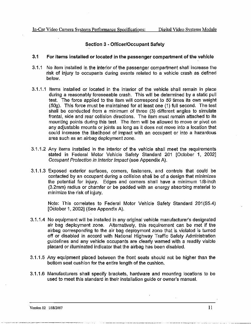
In-Car Video Camera Systems Performance Speciflrcations: Dieital Video Svstems Module
Section 3 - Officer/Occupant Safety
3.1 For items installed or located in the passenger compartment of the vehicle
3.1.1 No item installed in the interior of the passenger compartment shall increase therisk of injury to occupants during events related to a vehicle crash as definedbelow.
3.1.1.1 ltems installed or located in the interior of the vehicle shall remain in placeduring a reasonably foreseeable crash. This will be determined by a static pulltest. The force applied to the item will correspond to 50 times its own weight(509). This force must be maintained for at least one (1) full second. The testshall be conducted from a minimum of three (3) different angles to simulatefiontal, side and rear collision directions. The item must remain attached to itsmounting points during this test. The item will be allowed to move or pivot onany adjustable mounts or joints as long as it does not move into a location thatcould increase the likelihood of impact with an occupant or into a hazardousarea such as an airbag deployment zone.
3.1.1.2 Any items installed in the interior of the vehicle shall meet the requirementsstated in Federal Motor Vehicle Safety Standard 201 [October 1, 2002]Occupant Protection in Interior Impact (see Appendix A).
3.1.1.3 Exposed exterior surfaces, corners, fasteners, and controls that could becontacted by an occupant during a collision shall be of a design that minimizesthe potential for injury. Edges and corners shall have a minimum 1/8-inch(3.2mm) radius or chamfer or be padded with an energy absorbing material tominimize the risk of injury.
Note: This correlates to Federal Motor Vehicle Safety Standard 201(55.4)[Oðtober 1,20O21(See Appendix A).
3.1.1.4 No equipment wil l be installed in any original vehicle manufacturer's designatedaír bag deployment zone. Alternativefy, this requirement can þe met if theairbag corresponding to the air bag deployment zone that is violated is turnedoff or disabled in accord with National Highway Traffic Safety Administrationguidelines and any vehicle occupants are clearly warned with a readily visibleplacard or illuminated indicator that the airbag has been disabled.
3.1.1.5 Any equipment placed between the front seats should not be higher than thebottom seat cushion for the entire length of the cushion.
3.1.1.6 Manufacturers shall specif,T brackets, hardware and mounting locations to beused to meet this standard in their installation guide or owner's manual.
1 lVersion 12 l/18/2007

In-Car Video Camera Svstems Performance Specifications: Disital Video Systems Module
3.1.2 All controls and components should be located and designed to minimize driverdistraction
3.1.2.1 The control pad should be designed and organized to minimize officerworkload. The record button should be readily identifiable by size, color,location and/or other design features. The record button should be easilyaccessible by officers wearing gloves.
3.1.2.2 All controls should be easily activated by a wide range of officers/operators.Reach requirements shall correspond to guidelines set forth by the Society ofAutomotive Engineers for the placement of automotive controls. The reachrange shall correspond to the 10% female through the 90% male sizes.
3.1.2.3 All cameras should default to auto focus. The manufacturer may provide anauto focus override system if desired. The override system should beconfigurable to prevent operation while the vehicle is in motion.
3.1.2.4 System components shall be capable of being i l luminated for readyidentification during periods of darkness. Backlit controls are preferred. Theillumination level shall be capable of being controlled over a range from bright todark. The illumination level shall be set by either a discrete control within theunit itself or by linking to the vehicle dash illumination control. The viewingscreen light level shall be controlled simultaneous with the controls orindependently. The viewing screen shall be capable of being completelydimmed. The operator must have the ability to blackout the system on demand.
3.1.2.5 Only monitoring of information being or capable of being recorded should bedisplayed on the viewing screen while the vehicle is in motion. Viewing ofpreviously recorded or externally supplied digital asset should not be allowedwhile the vehicle is in motion
3.1.3 lnstalled equipment shall be located to minimize interference with the view of thedriver.
3.1.3.1 Installed equipment shall be located to minimize interference with the view ofthe front seat passenger.
3.1.3.2 No item other than the camera shall, extend below the AS-1 l ine. This l ine hasbeen determined in Federal Motor Vehicle Safety Standard 205 [October 1,20021 Glazing Materials (ANSI/SAE 2,26.1) (See Appendix B) to be theminimum vertical sight line necessary for safe vehicle operation. lt cancommonly be located on the vehicle at the bottom of the factory-installed tintband at the top of the windshield. At one or both sides of the windshield nearthe "A-pillaf is a printed designation visible from outside the vehicle marked'AS-1"., To ensure safe vehicle operation, equipment located in other locations
t2 Ve¡sion 12 1/18/2007
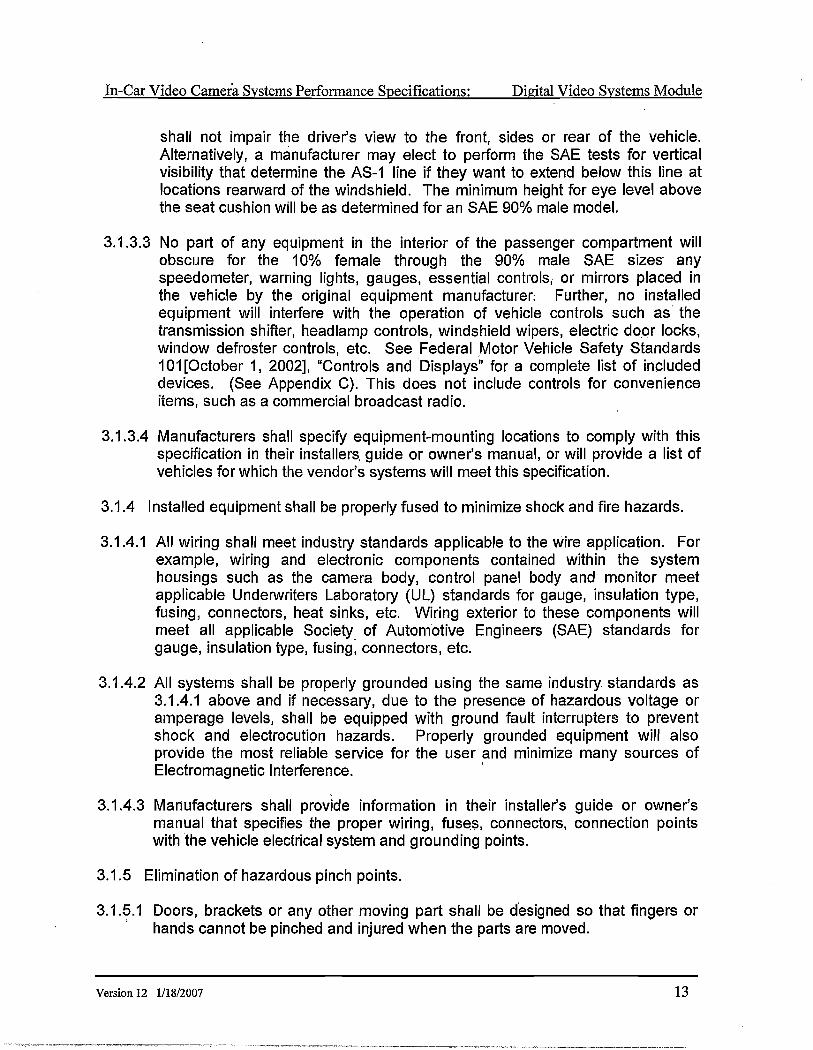
In-Car Video Camerä Systems Performance Specifications: Dieital Video Svstems Module
shall not impaÍr the driver's view to the front, sides or rear of the vehicle.Alternatively, a manufacturer may elect to perform the SAE tests for verticalvisibility that determine the AS-1 line if they want to extend below this line atlocations rearward of the windshield. The minimum height for eye level-abovethe seat cushion will be as determíned for an SAE 90% male model.
3.1.3.3 No part of any equipment in the interior of the passenger compartment wil lobscure for the 10% female through the 90% male SAE sizes anyspeedometer, warning lights, gauges, essential controlsr or mirrors placed inthe vehicle by the original equipment manufacturer, Further, no installedequipment will interfere with the operation of vehicle controls such as thetransmission shifter, headlamp controls, windshield wipers, electric door locks,window defroster controls, etc. See Federal ,Motor Vehicle Safety Standards101[October 1,2002], "Controls and Displays" for a complete l ist of includeddevíces. (See Appendix C). This does not include controls for convenienceitems, such as a commercial broadcast radio:
3.1.3.4 Manufacturers shall specify equipment-mounting locations to comply with thisspecification in their installers, guide or owner's manual, or will provide a list ofvehicles for which the vendor's systems will meet this specificatíon.
3.1.4 lnstalled equipment shall be properly fused to minimize shock and fire hazards.
3.1.4.1 All wiring shall meet industry standards applicable to the wire application. Forexample, wiring and electronic components contained within the systemhousings such as the camera body, control panel body and monitor meetapplicable Unden¡rriters Laboratory (UL) standards for gauge, insulation type,fusing, connectors, heat sinks, etc. Wiring exterior to these components willmeet all applicable Society of Automotive Engineers (SAE) standards forgauge, insulation type, fusing, connectors, etc.
3.1.4.2 All systems shall be properly grounded using the same industry standards as3.1.4.1 above and if necessary, due to the presence of hazardous voltäge oramperage levels, shall be equipped with ground fault interrupter$ to preventshock and electrocution hazards. Properly grounded equipment will alsoprovide the most reliable service for the user and minimize many sources ofElectromag netic I nterference.
3.1.4.g Mariufacturers shall provide information in their installe/s guide or owner'smanual that specifies the proper wiring, fuseg, connectors, connection pointswith the vehicle electricalsystem and grounding points.
3.1.5 Elimination of hazardous pinch points.
3.1.5.1 Doors, brackets or any other moving part shall be designed so that fingers or' hands cannot be pinched and injured when the parts are moved.
Version 12 1118/2007 1 3

In-Car Video Camera Svstems Performance Specifications: Disital Video.Svstems Module
3.1.5.2 Manufacturers shall use any recognized standard from the following sourcesthat addresses this issue: Federal Motor Vehicle Safety Standards, Society ofAutomotive Engineers, Unden¡rriters Laboratory, and Consumer Product SafetyCommission.
g.2 No parts that can come into contact with human skin shall be allowed to reach atemperature capable of causing a burn injury, Reference UL 60950 "Safety ofInformation Technology Equipment" as amended December 1, 2000. ltemscarried on the officer's person or uniform shall not pose an undue risk ofinjury.
3.2.1 Any system component carried on the officer's person shall meet all UnderwritersLaboratory Standards for shock/electrocution and burn prevention. All batteriesused in such devices shall meet Undenruriters Laboratory Standards for safety.
3.2.2 The manufacturer shall provide a warning that components and controls shall notbe placed on the officer's person so that it prohibits free access to and removal offirearm, baton, Pepper Spray, handcuffs, etc. The following proposed statementshould be prominent in the owner's manual.
"Placement of items on the duty belt can restrict ready access to importantequipment. The location of the wireless transmitter or any other devicg providedwith this system that is carried on the officer's person should be chosen with careand consideration. After a location is selected, the officer should test access toand practice drawing primary items such as service firearms and secondarydefense devices such as Aerosol Subject Restraint, Batons, Electronic DisruptionDevices, etc. Proper operation of handheld radíos and othêr signaling devicesshould also be tested as should access to handcuffs and other restrainingdevices."
3.2.3 Any body-worn cords or wires shall be of such construction that they minimizethe risk of strangulation or.cause injury from strangulation, cutting off of bloodflow or laceration during assault, slip, fall or other types of Inoldênts or during avehicle crash.
3.2.4 Any component worn or carried by the officer shall be of smooth constructionproperly rounded, or chamfered to minimize the possibility of injury. Thecomponents shall be free of sharp points or edges that could cause injury duringa fight, slip, fall or other types of incidents. ln addition all clips and retentiondevices should be designed to minimize the possibility of pinch points that couldcause injury.
l4 Version 12 lll&/2007

In-Car Video Camera Svstems Performance.Specifications: Digital Video Systems Module
3.3 Location of Data Storage
3.3.1 This specification does not require a specific location. However, if mounted inthe passenger compartment it shall meet all safety requirements in section 3.1
' above.
3.3.2 lf located in the trunk, the component shall meet all requirements for wiring andsafety above. ln addition, it shall be constructed, located and mounted in such away that the device will not become a hazard to the vehicle fuel system orpassengers fonruard of the system in a collision.
3.4 Record indicators
3.4.1 A system should have an illuminated record indicator readily visible to personsoutside the vehícle to the front and passenger side that indicates when thesystem is actively recording. This indicator does not need to be visible töoccupants inside the vehicle. This record indicator shall comply with 3.1.2.4.
3.4.2 Unmarked patrol vehicles and surveillance vehicles may be exempt from thisrequirement depending on local laws and policy requirements.
Version 12 l/1812007 1 5

In-Car Video Camera Svstems Performance Specifications: Disital Video Svstems Module
THIS PAGE INTENTIONALLY LEFT BLANK
t6 Version 12 lll8l2007

In-Car Video Camera Svstems Perform4nce Specifications: Disital Video Svstems Module
Section 4 - General Mobile Video System Specifications
4.1 The mobile video system shall consist of a camera, a recording mechanism,control center, monitor, wireless microphone/transmitter system to capture audiooutside of the vehicle for traffic stops, and a hard-wired microphone to captureaudio from inside the police vehicle.
4.1.1 Emphasis should be placed on the video system's abil ity to maintain consistentaudio/visual recording quality, while subject to interference from the followingsources (See Appendix D for applicable UL Standards Reference):
a) High-powered television stationsUi Otfiei radio frequency interference (includinf UHF, VHF and HF
transmitters.)c) Automobile alternator, ignition, and electrical systemsd) Automobile heaters / air conditioner fan motorse) Other patrolvehicle electrical systems to include radios, emergency lights,
siren, mobile data computers, and speed measuring devicesÐ High voltage power lines, traffic signals, neon signs, etc.
4.1.2 When in operation, the mobile video system must not generate electromagneticor radiation that interferes with communications or other electronic equipmentfound within a police vehicle.
4.1.3 Programming of the in-car recording system shall be restricted to authorizedpersonnel only through the system controller.
a. Electronic Conditions
The in-car recording system shall be protected from damage due toinput of voltage, reverse polarity, and electrical transients that maybe encountered.
All programmable parameters shall be contained in non-volatilememory/.
.¡¡i. Loss of power to the system shall not result in the unit requiringreprogramming. Sudden loss of power shall not cause loss of anyrecorded data.
4.2 Front-Facing/Primary Gamera
4.2.1 Dimensions should be consistent with Officer Safety Section 3.1.
4.2.2 The camera shall operate within the range of temperatures from 0 to 120degrees Fahrenheit and/or between -18 to 40 degrees Celsius.
Version 12 1118/2007I
t 7
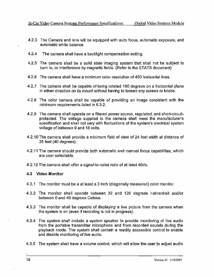
In-Car Video Camera Svstems Performance Specifications: Dieital Video Svstems Module
4..2.3 The Camera and lens will be equipped with auto focus, automatic exposure, andautomatic white balance.
4.2.4 The camera shall have a backlight compensation setting.
4.2.5 The camera shall be a solid state imaging system that shall not be subject toburn in, or interference by magnetic fields. (Refer to the ETATS document)
4.2.6 The camera shall have a minimum color resolution of 4,50 horizontal lines.
4.2.7 The caînera shall be capable of being rotated 180 degrees on a horizontal planein either direction on its mount without having to loosen any screws or knobs.
4.2.8 The color camera shall be capable of providing an image consistent with theminimum requirements l isted in 6.3.2.
4.2;9 The camera shall operate on a filtered power source, regulated, and short-circuit-. protected. The voltage supplied to the camera shall meet the manufacturer's
specification and shall not vary with fluctuations of the system's electrical systemvoltage of between I and 18 volts.
4.2.1OThe camera shall provide a minimum field of view of 24 feet width at distance of35 feet (40 degrees).
4.2.11The camera should provide both automatic and manual focus capabil it ies, whichare user selectable.
4.2.12The camera shall offer a sígnal-to-noise ratio of at least 46db.
4.3 Video Monitor
4.g.1 The monitor must be a at least a 3 inch (diagonally measured) color monitor.
4.3.2 The monitor shall operate between 32 and 120 degrees Fahrenheit and/orbetween 0 and 49 degrees Celsius.
4.3.3 The monitor shall be capable of displaying a live picture from the Çamera whenthe system is on (even if recording is not in progress).
4.3.:4 The system shall include a system speaker to provide monitoring of live audiofrom thê portable transmitter microphone and from recorded sounds during theplayback mode. The system shall contain a readily acôessible control to enableand disable monitoring of live audio.
4.3.5 The system shall have a volume control, which will allow the user to adjust audio
1 8 Version L2 lllS/2007

In-Car Video Camera Systems Performance Specifications: Dieital Video SVstems Module
level and turn off sound if desired.
4.3.6 The recording device shall operate independently of the monitor.
4.3.7 The monitor should have the capability to display: date/time, user identificationinformation, emergency light indication, siren indication, braking indicator andmicrophone activation indicator
4.3.8 The monitor shall operate on a filtered power source, regulated, and short-circuít-protected. The voltage supplied to the monitor shall meet the manufacturer'sspecification and shall not vary with fluctuations of the system's electrical systemvoltage of between 9 and 18 volts.
4.4 Audio - Wireless Transmitter:
4.4.1.1 Range of 1000 feet with l ine of síght at ideat conditions
4:4.1.2 Transmittel: internal antenna
4.4.1.3 Operator shall have the ability to deactivate audio from remote audiotransmitter, but NOT disable video recording.
4.4.1.4 Activate audio and video from remote audio transmitter
4.4.1.5 Redundant microphone built- into audio transmitter
4.4.1.6 Use of FCC-approved frequency bands
4.4.1.7 Digital transmissicin to ensure clarity of audio without distortion throughout therange of the transmitter (Use of spread spectrum technology is recommended).
4.4.1.8 Audio transmitter shall be able to be synchronized to receiver in the vehicle.
4.4.1.9 Rechargeable battery standby (15 hrs minimum) and talk time (3.5 hrsminimum).
4.5 Camera/Mobile Digital Video Recorder (MDVR) Gontrols:
4.5.1 Controlsa) Power on/offb) Playc) Record start/stopd) Fast Fonryarde) Rewind0 Stopg) Pause
Version 12 l/18/2007 T9

In-Car Video Camera Systems Performance Specif,rcations: Disital Video Svstems Module
4.5.2 Camera Controls, if not easily accessible on camera:a) Zoom in/outb) Auto Focus on/offc) Backlight Compensation
4.5.3 lndicators:a) System Power onb) Microphone onc) Media inseñed and operationalwith remaining capacity/time availabled) Recordinge) Fast ForwardD Stopg) Time Counterh) Diagnostic Indicator
4.5.4 The recording functions shall be activated by any of the following modes:a) User pushes record button.b) Activation of the emergency lights and/or sírens.c) User activates the record button on the wireless microphone transmitter.
20 Version 12 lll8l2007

In-Car Video Camera Svstems Performance Speciflrcations: . Dieital Video Svstems Module
Section 5 - Security Features
5.1 The in-car recording system shall have the capability to restrict access to theprogramming functions, including but not limited to time/date features.
5.2 The recording device must have the capability of preventing the user from erasingand recording over previously recorded information from either inside the vehicleor at the recording device controls.
5.3 Vehicle Recording System Integrity
5.3.1 Integrity of vehicle recording systems refers to the validity of the digital assetcaptured by the system, in which the system limits the potential for errors.
5.3.1.1 The Active and Archival Storage systems shall provide a mechanisrn forbacking-up digital assets.
5.3.1.2 The Active and Archival Storage systems should utilize fault tolerant storage orsimilar technology.
5.3.1.3 User interfaces should prevent the input of invalid data.
5.4 Gonsistency
5.4.1 Time Gonsistency \
5.4.1.1 Time stamping in whatever format offered or selected, shall be consistent withinallsystem components.
5.4.1.2 The Vehicle's recorder clocks should be synchronized to the Active andArchival Storage System within 0.5 seconds, when the vehicle recorders haveelectronic connectivity to the storage systems. The manufacturer shouldprovide evidence that system components are synchronized in time.
5.4.1.3 Metadata, including time stamping, shall remain accurate with respect to therecording as it was captured, despite any time sync irregularities itt a seconclaryunit, archival system, or viewer.
5.4.1"4 Time-stamping between the components of the digital asset shall be consistentand maintained. This must be verifiable by a means offered by themanufacturer.
5.4.1.5 Each component in the system maintaining an independent clock shall containa mechanism to backup the clock for a minimum of fourteen days in the case ofprimary power failure to the component.
Version 12 lll8l2007 2 l
In-Car Video Camera Svstems Performance Specifications: Dieital Video Svstems Module
5.4.2 Digital Asset ConsistencyThe inclusive subsystems within the overall system shall be able to recognizeand move data interchangeably. This is in correlation with any recommendationsincluded in the authenticity section of this document.
5.4.3 Subsystem ConsistencyThe components within the system from different manufacturers shall be incompliance with technical recommendations as indicated in this document. Toensure consistency of the digital asset, routine maintenance and repair should bedone based upon manufacturer recommendations.
5.5 Authenticity
5.5.1 Authenticity of individual access
5.5.1.1 In-Car System
5.5.1.1 .1 The recorder shall identify the vehicle in which the recorder is mounted.
5.5.2 Authenticity of equipment
5.5.2.1 Officer Assignment
5.5.2.1.1 Removable Media shall indicate the badge number of the officer assigned tothe media or the vehicle lD and the officer assigned to transfer the media, ifapplicable, and the Media lD.
5.5.2.1.2 Non-Removable Media shall indicate the badge number of the officer or thevehicle lD and the officer assigned to transfer the media, if applicable, andshall be related to a specific digital asset.
5.5.2.1.3 Optionally the officer and the officer assigned to transfer the media, ifapplicable, may log into system and validate that the equipment is operatingproperly.
5.5.2.2 Physical Security of the Rocorder
5.5.2.3 During system lnlt latlon, the system should have the capabil ity t<; visuallyindicate to the officer if the system has been tampered with.
5.5.3. Authenticity of Recorded Material
5.5.3.1 The Vehicle Video Capture System shall provide a mechanism to capture thetime and date of the recording. The time and date of the recording shallbecome part of the Chain of Custody Audit Log associated with Type 1 andType 2 recordings.
5.5.3.2 The Active Storage System shall be able to include the Media lD of anyremovable media used to transfer the digital asset from the Vehicle Video
22 Version 12 1/1812007

In-Car Video Camera Systems Performance Specifications: Digital Video Svstems Module
Capture System. 'The Media lD shall become part of thê Chain of Custody AuditLog of Type 1 recordings.
5.5.3.3 All, Type 1 digital asset recording systems using electronic transfer of therecorded material shall have an automated authentication mechanism. Digitalasset authentication shall be attached to the digital asset sequence when firstrecorded, The video recording equipment shall use a digital signature that hasbeen standardized and approved by the America Bar Association (ABA) lDigitalSignature Guidelines, lnformation Security Committee, Electronic Commerce &Infrastructure Technology Division, of the American Bar Association, 1996.1
5.5.3.4 Prior to the electronic transfer of Type I digital assets, metadata shall beattached.
5.6 Transfer of Digital AssetsThe Archive and Active Storage systems shall provide a chain of evidence report
' detailing all DigitalAssets activity listed below.
5.6.1 Physical Digital Asset Transfer Using Removable Media:
5.6.1.1The Chain of Custody Audit Log shall contain a Media ldentif ication Numberconsistent with operating agency policy.
5.6.1.2. An lntegrity check shall be used to validate that the digital asset on the ActiveStorage isan@copytoanydataontheremovab|es toragemediapr io rto the clearing of data on the removable storage media.
.5.6.1.3 The Chain of Custody Audit Log for Type 1 digital asset included on the ActiveStorage System shall contain the following items when the digital asset on aremovable media device (e.9., Spinning Optical, Flash, Digital Tape, orRemovable Magnetic) is transferred to Active Storage:
a) Name or lD (badge number or employee number) of officer or personsubmitting digital asset for transfer;
b) Media identification number (if tracked by the department);c) Number of "copies" made to other media (e.9., Tape, Spinning Optical
Media, Otlrer server storage locatiorr);d) Retention period for digital asset;e) lntegrity check performed to validate that the digital asset transferred to
the active storage is an accurate copy prior to any clearing of data on theremovable storage media.
5-6.2. Wireless Data Transfer:
5.6.2.1. An Integrity check shall be used to validate that the digital asset on the ActiveI Storage is an accurate copy to any data on the recorder prior to the information
being deleted from the recorder.
Version 12 111812007 23

In-Car Video Camera Systems Performance Specifications: Digital Video Svstems Module
5.6.2.2Wi retess Transfer Network Topology:
5.6.2.2.1 A wireless network used to transfer the digital asset from the recorder toActive Storage shall, at a minimum, use 128-bít encryption to create a secureconnection for the digital assets to be transferred. Manufacturers, at theircustomers' discretion, may provide other security technologies that surpass128-bit encryption. See Section 8.9.3 for more information on additionalforms' of digital asset protection.
5.6.2.2.2IEEE standards based wireless networking equípment shall use the followingsecurity guidelines:a) Customized network name;b) Disabled SSID/ESSID (Network Name) broadcast; andc) 128-bit RC4 link encryption.
Additional security standards which exceed those set by the standards listed above maybe applied to the wireless link as defined by the customer or manufacturer.
5.6.2.2.3 lf a non-IEEE standards based wireless networking equipment is used, itshould be configured to at least meet the equivalent minimums defined in5.6.2.2.1 and 5.6.2.2.2.
5.6.2.2.4 Audit Trail ltems on the Active Storage
The Chain of Custody Audit Log for Type I digital assets included on the Active StorageSystem shall contain the following items when wireless (automated) digital assettransfer from the recorder to Actiúe Storage is used:
Successful wireless connection with recorder made;Time/date of transfer;Number of "copies" made to other media (e.9., Tape, Spinning OpticalMedia, Other server storage location);Retention period for digital asset;Integrity check performed to validate that the digital assct transferred tothe server is an accurate copy prior to any clearing of data on the recorderstorage medium.
5.6.3. Wired Data Transfer:
5.6.3.1 An Integrity check shall be used to validate that the digital asset on theictiveStorage is an accurate copy to any digital asset on the recorder prior theinformation being deleted from the recorder.
5.6.3.2 Wired transfer network topology:
5.6.3.2.14 private network (i.e., separate from any other networks) used to transfer thedigital assets from the recorder to Active Storage shall be considered secure
a)b)c)
d)e)
24 Version 12 l/18/2007

In-Car Video Camera Svstems Performance Specifications: Digital Video Svstems Module
since it is limited in its scope and is restricted from being accessed by anydevice except for the recorder and the Active Storage server.
5.6.3.2.2 A public network (i.e., where the data must cross over another non-privatenetwork) used to transfer the digital asset from the recorder to Active Storageor between Active Storage and Archival Storage shall, at a minimum, use128-bit encryption to create a secure connection for the digital assets to betransferred. Manufacturers, at their customers' discretion, may provide othersecurity technologies that surpass 128-bit encryption. See Section 8.9.3 formore information on additional forms of digital asset protection.
5.6.3.3 Audit Trail ltems on the Active Storage
The Chain of Custody Audit Log for Type 1 digital assets included on the Active StorageSystem shall contain the following items when wÍred (automated) digital asset transferfrom the recorder to Active Storage is used:
a)b)c)
d)e)
Successful wired connection with recorder made;Time/date of transfer;Number of "copies" made to other media (e.9., Tape, Spinning OpticalMedia, Other server storage location);Retention period for digital assets;lntegrity check performed to validate that the digital assets copied to theserver is an accurate copy prior (o any clearing of data on the removablestorage medium.
5.6.4 Transfer from Active Storage to Archival StorageThe Chain of Custody Audit Log for Type 1 digital asset shall contain the following itemswhen the digitalasset is transferred form Active Storage to Archival Storage:
a) Name of System Administrator initiating the transfer (if process is notautomated);
b) Time/date of transfer;c) Retention period for digital assets;d) Integrity check performed to validate that the digital asset transferred from
Active Storage to Archival Storage is an accurate copy prior to clearing ofActive Storage.
5.6.4.1 Retrieval of Digital Assets from Archival Storage back to Active StorageThe Chain of Custody Audit Log for Type 1 digital assets shall contain the followingitems when the digital asset is transferred form Archíval Storage to Active Storage:
a) Name of System Administrator initiating the transfer (if process is notautomated);
b) Time/date of transfer;c) Retention period for digital assets;
Version 12 lll8l2007 25

In-Car Vi4eo Camera Svstems Performanqe Specifications: Dieital Video Svstems Module
d) Integrity check performed to validate that the digital assets transferredback to Active Storage is an @copy should the digitalassets storedin Archival Storage be removed.
5.6.4.2 Retrieval of Digital AssetsThe Chain of Custody Audit Log for Type I digital assets shall contain the followingitems on retrieval of data from Active or Archival Storage for replication ontodepartmentally accepted media (e.9., Spinning Optical, Flash, Digital Tape, orRemovable Magnetic) for presentation in court or other official capacity:
a) Name of System Administrator or desígnated personnel requesting digitalasset for export;
b) Time/Date of export;c) Retention period for digital assets;d) lntegrity check to validate that exported copy is an accurate copy of
original digital asset in Active or Archíval Storage.
' 5.6.5 The Chain of Custody Audit Log for Type 1 digital assets shall contain the date,
time and an identifier that indicates the digital assets removed.
5.6.6 Physical storage and archival of removable non-WORM media
5.6.6.1 lf the MVS records on removable media and the removable media is theArchival System, then the Chain of Custody Audit Log for Type 1 digital assetsshall contain an indication if the digital asset on the removable non-WORMmedia has been transferred to Active Storage (e.9., is the digital asset on theremoval non-WORM media marked as "deleted"?).
5.6.6.2 An lntegrity check shall be used to validate that the digital asset on the ActiveStorage is an rylz copy of any data on the removable storage media priorto setting the deleted indication
5.7 Physical Security
5:7.1 ln-Gar Equipment SecurityThe following items shall be included to protect the vehicle's recording media:
5.7.2 Equlpment dlagnostics
5.7.2.1 When powered, the recorder shall perform a self-test to insure completefunctionality. lf the recorder does not pass the self-test, it shall immediately
. notify the user.
5.7.2.2 The recorder shall be able to monitor itself while in operation. Should acomponent of the recorder fail while in operation, the recorder shall immediatelynotify the user.
26 Version 12 l/1812007
In-Car Video Camera Systems Performance Specifications: Dieital Video Svstems Module
5.7.2.3 The recorder shall provide the following media diagnostics:
a) lndicate amount of storage space remaining on media; andb) Send a notification to the user (audible/visual) that storage is reaching its
maximum capacity.
5.7.3 Equipment Enclosure
5.7.3.1 Recording device shall be physically mounted in the vehicle, following themanufacturer's recommendations, to prevent removal without tools and detertheft of the device.
5.7.3.2 lf removable, the recording device shall, at a minimum, be secured using aphysical lock that prevents unauthorized removal of recorder from the vehicle.A key is required to unlock the recorder for removal from the vehicle.
a) Keys to the physical loc( can include but are not limited to:i. A typical key, though one that can not be easily duplicated (cylindrical
key, etc.)ii. A "credit card" style magnetic strip that can be "swiped" to release the
lock.iii. An electronic "chip" which will release the lock when placed into
proximity of a specific sensor.
5.7.4 Removable Media Security
5.7.4.1 The recording media shall be secured using a locking mechanism that preventsunauthorized removalof the storage media from the recorder.
5.7.4.2 The recording device shall indicate when media is inserted into the recorder
5.7.4.3 A key shall be used to unlock the recording media for removal from therecorder. Examples of the type of keys that may be used to secure the
.recording media are but not l imited to:
a) A physical key, though one that can not be easily duplicated (e.g.,cylindrical key);
b) A "credit card" style magnetic strip that can be "swiped" to release the lock;c) An electronic "chip" which will release the lock when placed into proximity
of a specific sensor; ord) A password that is entered into the recorder.
5.7.4.4 Non-removable recording media shall be housed inside the recorder to preventtampering with and/or destruction of the media.
Version 12 lllS/2007 27

In;Car Video Camera Systems Performance Specifications: Disital Video Svstems Module
5.7.4.5 The manufacturer shall provide guidelines on the media life cycle of the digitalasset.
5.7.4.6 Removable media shall contain the following items and markings:
a) Tamper detection process;b) Damage protection; andc) The media must be marked on the exterior with an identifying number or
markings that identify each media and makes that media unique.
28 Version 72 l/1812007
6 . 1 . 4
In-Car Video Camera Svstems Performance Specifications: Dieital Video Svstems Module
Section 6 - Digital Asset Recording
6.1 The digital assets recorded shall accurately and reliably reproduce the viewedimaged, observed sound and associated metadata as the Type 1 DigitalAssef.
6.1.1 The in-car system shall be capable of recording events uninterrupted for aminimum of three and a half hours (3.5) hours at a minimum resolution of640x480 (VGA) and a minimum frame rate of 29.97 frames per second (fps).
6.1.2 The l"r instance / primary imageshall conform to accepted and known industrystandards. (See Appendix D for applicable UL Standards Reference).
6.1.3 1't instance / primary image shall use a HASH verification process to certify theauthenticity of the digital asset(s) consistent with Section 5 of this document.
The in-car system shall be capable of capturíng a forty degree horizontal field ofview as part of the digital asset known as l"t instance / primary image full motionvideo.
The exchange of the dígital assets from the in-car system, active system, andarchival storage system can be done in various'ways. To that end all systemsshall conform to the following:
a) All electronic transfers / exchanges between the in-car recording system, andthe active, or archival storage system along with any subsequent electronictransfers or exchanges of the Type 1 DigitalAssef betwêen the active andarchival systems shall be lossless and shall be done with a HASH verificationprocess. The HASH verification process shall be consistent with Section 5 ofthis document.
b) All digitat assets known as the Type 1 DigitalAssef and accompanying audiotracks shall be capable of being rendered to a uncompressed file in industrystandard file format. The associated metadata shall be transcoded into a filein standard file format.
c) All digital assets known as the Type 1 Digital Assef along with theiraccompanying audio tracks and associated metadata in an active storagesystem shall be capable of being rendered to ä proxy Mlcrosoft's WlndowsMedia File format (WMV).
Interim Evaluation TestsAt the time of publication of this document, the National Institute of Standards(NIST) is working on but has not yet finalized a set of standards for testing in-cardigital recording systems. The following subjective tests can be used for theevaluation of atl in-car digital recording systems.
6.2
6.3
29Version 12 l/1812007

In-Car Video Camera Svstems Performance Specifications: Disital Video Svstems Module
6.3.1 Daytime Evaluation - Optimal Lighting via Natural Sunlight'a) License plate testing. License plate is defined as a plate with either raised
or stamped lettering and a plate that has a smooth or computer appliedlettering.i) The license plate testing is established by placing one vehicle behind
another at a distance of eighteen (18) feet from the front bumper of thepatrol car to the rear bumper of the vehicle in question. This testingcould also be accomplished by placing a series of plates on a staticdisplay at the eighteen (18) foot mark from the front bumper of thepatrolvehicle.
ii) The System shall be capable of accurately and reliably recording andplaying back license plate(s) identification alphanumeric charactersused in the test.
¡¡¡) All tests shall have in addition to the digital assets collected by in-carsystem a still picture(s) taken by a stand-alone camera for verificationof the license plates identification alphanumeric characters.
b) Air Force Standard Chart Testing. The Air Force Standard Charts (AFSC)will be provided by the IACP for testing.¡) The AFSCs shall be placed at a distance of thirty-five (35) feet from the
front bumper of the patrol car vehicle.¡¡) The system shall be capable of accurately and reliably recording and
playing back AFSCs used in the test.
c) NHTSA Walk and Turn and One Leg Stand Testing. The standard fieldsobriety tests shall be conducted in accordance with the NHTSA manual.lnstructions will be provided for the conducting of these tests by IACP.¡) The Walk and Turn test shall be conducted beginníng at a location that
is 18' in front of the patrol car's front bumper. The individualperforming the test shall start walking away from the patrol car. Theperson shall conduct this test on an imaginary line that is extendedfonruard from both the left and right sides of the patrol car.
¡¡) The One Leg Stand will be conducted with the person facing thecamera standing at the 24' mark from the patrol car's front bumper.The person shall conduct this test on an imaginary fine that is extendedfon¡vard from both the left and right sides of the patrol car.
¡ii) The system shall be capable of accl¡rately ancl reliably recording andplaying back these tests.
d) Sports Ball.Tests. The balls to be used for this test shall be a collegiatefootball, a size five (5) black and white soccer ball, a softball, a baseballand a golf ball.i) The test will be conducted in the following manner and will"be repeated
with each of the balls specified above;
30 Version 12 lll8l2007
In-Car Video Camera Svstems Performance Specifications: Disital Video Svstems Module
A standard passenger carwill be parked eighteen (18) feet in front ofthe patrol car measured from the front bumper of the patrol car to therear bumper of the subject car.An average height person will sit in the driver's seat of the subject car.The "driver" wil l place a ball in their right hand. The "drivef'wil l placetheir upper arrn parallel to the ground and move the ball from anextended arm position to near their shoulder three times at a cycle timeof approximately one second per extended/shoulder/extended cycle.After completing the third cycle while the ball is near the"shoulder the"drived' will quickly throw the ball out the passenger window.
vi) This test shall be repeated three times with eáöh ball.vii) The system shall be capable of accurately and reliably recording and
playing back these tests.
6.3.2 Nighttime Evaluation wíll be conducted indoors or out in an area with noadditional lighting over that provided by the patrol car. The patrol car lights willbe as follows:
The bright headlamps shall be on.A standard Unity,A-pillar spotlight shall be on and aimed at the center ofthe back window of the subject car.
c) Two halogen takedown lights of 50 watts each mounted on the roof as in a' standard police bar light shall be activated as well.
The following tests shall be conducted:
a) Air Force Standard Chart Testing. The Air Force Standard Charts (AFSC)will be provided by the IACP for testing.i) The AFSCs shall be placed at a distance of thirty-five (35) feet from the
front bumper of the patrol car vehicleii) The system shall be capable of accurately and reliably recording and
playing back AFSCs used in the test.h) NHTSA Walk and Turn and One l.eg ,Stancl Testing. The standard field
sobriety tests shall be conducted in accoidance with the NHTSA manual.Instructions will be provided for the conducting of these tests by IACP.i) The Watk and Turn test shall be conducted beginning at a location that
is 1B' in front of the patrol car's front bumper. The individualperforming the test shall start walking away from the patrol car. Theperson shall conduct this test on an imaginary line that is extendedfon¡vard from both the left and right sides of the patrol car.
ii) The One Leg Stand will be conducted with the person facing thecamera standing at the 24' mark from the patrol car's front bumper.The person shall conduct this test on an imaginary line that is extendedfonryard from both the left and right sides of the patrol car.
¡ iDiv)
¡¡)
v)
a)b)
Version 12 lllS/2007 3 l

In-Car Video Camera Svstems Performance Specif,rcations: Disital Video Svstems Module
c) The Sports Ball Tests. The balls to be used for this test shall be acollegiate football, a size five (5) black and white soccer ball, a softball, abaseball and a golf ball.i) The test will be conducted in the following manner and will be repeated
with each of the balls specified above;ii) A standard passenger carwill be parked eighteen (18) feet in front of
the patrol car meagured from the front bumper of the patrol car to therear bumper of the subject car.
iii) An average height person will sit in the driver's seat of the subject car.iv) The "driver" will place a ball in their right hand. The "driver" will place
their upper arm parallel to the ground and move the ball from anextended arm position to near their shoulder three times at a cycle timeof approximately one second per extended/shoulder/extended cycle.
v) After completing the third cycle while the ball is near the shoulder the"driver" will quickly throw the ball out the passenger window.
vi) This test shall be repeated three times with each ball.vii) The system shall be capable of accurately and reliably recording and
playing back these tests.
6.4 The recording system shall interface with the vehicle emergency lights and/or sirencurrently installed in the vehicle, and may be activated bv all of the followingmodes: 1) User pushes the record button; 2) Activation of the emergency lightsand/or siren; and 3) User activates the record button on the wireless transmitter.
6.5 The recording system should activate during an accelerometer event (to bedesignated by depaÉmental policy).
6.6 The system's timekeeping device and the vehicle's identifier shall be protected by asystem battery backup to prevent loss of information in the event the vehicle batteryis disconnected for up to a minimum of fourteen (14) days.
6.7 System/Metadata
ö.7.1 All metadata shall be capable of belng super-imposed or absent on tlte suleellduring playback mode.
6.7.2 Recommended: ability to support enablec.l or clisablecl auclio capture by systemadministrator for pre-event and post-event buffered/recorded video, along withbackend evidence preparation/export toolé for playback in court.
32 Version 12 lll8l2007
Section 7 - DataPoint for Interoperabilify
7.1 Active orArchival Storage Serverlnteroperability shall begin after tñe transfer of the digital asset from the mobile digitalvideo recording unit located in the field. Access and availability should be granted inorder to conduct the sharing of the digital asset at this prescribed data point within thecapture, transfer and archival process. .
7.2 Types of Interoperable Exchange
7.2.1 Two levels of Interoperable ExchangeThere shall be at least two Interoperable Digital Assets obtaíned from the Active orArchival Storage Seruer.
7.2.1.1 Type I Interoperable Digital AssetThe video, audio, and associated data that meet the criteria as defined by Section 6.2.bshall serve as the evidentiary digital asset.
7.2.1.2 Type 2 Interoperable DigitalAssetThe video, audio, and associated data identified as the proxy in Section 6,2.c shallserve as the interoperable digital asset.
Version 12 Lll8l2007 33

In-Car Video Camera Systems Performance Specifications: Dieital Video Svstems Module
THIS PAGE INTENTIONALLY LEFT BLANK
74 Version 12 lllS/2007

I
j In-Car Video Camera Systems Performance Specifications: Dieital Video Svstems Module
I
l
' i
II
iI
ii ^.^tendices¡ ^PPI
Version 12 lllS/2007

In-Car Video Camera Svstems Performance Specifications: Disital Video Systems Module
THIS PAGE INTENTIONALLY LEFT BLANK
Version 12 l/1812007

In-Car Video Camera Systems Performance Specifications: Disital Video Svstems Module
Appendix A
Recommended Policiesand Best Practices
Version 12 lllS/2007

In-Car Video Camera Svstems Performance Specifications: Disital Video Svstems Module
Appendix A - Recommended Policies and Best Practices
1.1 All mobile video systems shallmodels will be considered for testing.
1.2 Requirements
1.2.1 The mobile video system (in-car camera) shall have a proven, reliable record inactual vehicular use under a variety of conditions. This record shall be evidencedby'wither manufacturers'testing results, or filed testing results by other lawenforcement agencies.
1.2.2 The vendor must have experience in manufacturing and supporting suchsystems to include provisions for parts and service as needed.
1.2.3 The vendor shall provide business and financial history upon request.
of industriallcommercial grade. No prototype
Vendors that do not manufacture the components comprising the videosystem shall be authorized by the original component manufacturer to resellsuch components. A copy of a factory-authorized dealer certificate shall beprovided.
The basic design of all equipment shall be in full production, no prototypemodels will be considered.
be
1 . 2 . 3 . 1
1.2.3.2
1.2.3.3 All components of the system must comply with Federal CommunicationsCommission (FCC) standards.
1.2.3.4 To document vendors' experience in the'manufacture, sales, and support ofmobile video systems, the vendor shall l ist agencies to which mobile videosystems were sold. Letters of reference for verification should be included.
1.2.4 Sample and Demonstration:Prior to award, the agency reserves the right to require any bidder to provide completevideo systems of the êxäöt conflguratlon offered for the purpose$ of evalttation todetermine compliance with the specification requirements.
1 .2 .4 .1 Any mobile video system may be fìeld and laboratory tested by state orindependent laboratories to verify its acceptable level of performance andconformity to specifications.
Warranty Section
All camera, recorder, environmental control components, wirelessmicrophones and transmitiers, receiver, monitor, and control circuitcomponents, shall be warranted to ensure they are fit for their intendedpurpose for a minimum of one year.
1 .31 . 3 . 1
Version L2 lll8l200'l

In-Car Video Camera Svstems Performance Specifications: Dieital Îideo Svstems Module
1.3.2 All defective equipment shall be repaired or replaced within the contracted termsof the warranty. Law enforcement agencies shbuld take into consideration thedown time of a vehicle placed out of service due to equipment failure.
1.3.3 For warranty purposes, the warranty time begins wíth initial installation of saidequipment in the vehicle.
!
1,4 Vehicle Recording System Integrity
1.4.1 The officer assigned to the vehicle shall log into the recorder prior to the use ofthe recorder. This login may be through a User ldentification and authenticationmechanism provided by the recorder or by standing in front of the camera andrecording the Officer's image and voice.
1.4.2. Before each shift, the officer shall visually verify the equipment has not beentampered with or has been damaged.
1.4.3 A Visual "check" of removable media shall be made to ensure no tampering hasoccurred, tamper seals are in place (similar to tape used to seal evidenceenvelopes); and no scratch marks are on the storage device.
1.4.4 The IACP Model Policy req.uires the user officer to conduct an operationalreadiness test of the system'prior to the beginning of their tour of duty. lf thesystem is malfunctioning, they shall notify their supervisol and communications.The supervisor shall make the determination as to when and how the system isrepaired or in some cases whether to keep the unit in service.
1.5 Active and Archival Storage Systems
1.5.1 The Active and Archival Storage system shall be located in a secured building(e.9., police station) in a room with restrÍcted access (e.9., seruer room).
1.5.2 The Active and Archival Storage system should be cloned at another location.
1.5.3 When the media is being transferred to another medium during the back-up, thefile should also be stored separately from the main server.
1.5.4 Access and authentication to the Active and Archival Storage' System shall begoverned by the agenoy's existing policies and procedures and shall includeadditional levels of user authentication prior to granting access
1.5.5 Electronic notification shall be provided for each digital asset intended to beremoved from Active or Archival Storage at a time prior to removal based onoperating agency policy according to the retention period for the digital asset(s).
Version 12 lll8l2007

In-Car Video Camera Svstems Performance Specifications: Disital Video Svstems Module
1.6 Removable Media Security .1.6.1 Physical tamper detection.
1.6.1.1 The operator of the recorder shall perform a physical "check" of removablemedia to ensure no tampering has occurred:
a) No scratch marks on storage device; andb) Physical tamper detection devices in place.
1.6.2 Key Management. Keys shall. be managed via agency policies and proceduressuch as:
a) ldentif ication of individualwith key to media;b) ldentification of individualwith a "masted' key; andc) ldentification of individual that can replicate keys.
1.7 Back Office Equipment SecurityAny space used by the agency to house the Active Storage, Archival Storage, andassociated equipment housed in the agency's back office shall include:
a) Equipment housed in secured facility with limited employee access.b) Secured system access:c) System captures standard "audit" information when user logs into system;d) System captures number of times user attempts to log into system; ande) System user accounts become inoperable if more than three unsuccessful
log-on attempts have been made.Ð System "passwords" governed by agency policy requirements:
i. Passwords to user accounts should be changed on a regular basis perdepartmental policy, though the IACP recommends that the useraccount passwords to the digital video system be changed every 30days for enhanced security.
ii. Force "character" requirements for passwords, e.g. numeric, alpha,caps, etc.
1.7 .1 Operational Policy Considerations. These are questions that should beconsidered when setting operational policy related to the use of'the recorder,recorded material, or archive. These oonsiderations are items that support therecornrnendations in these specifications but are beyond the scope of theminimum recommendations.
1.8. Operational Digital Asset Transfer Policy1.8.1 The agency should have a documented transfer policy with procedures
establishing:
b) How the transfer of the digital asset from the vehicle takes place;c) Available storage capacity remaining limit at which point the digital asset
should be transferred from the vehicle recorder;
Version 12 l/18/2007

In-Car Video Camera Svstems Performance Specifications: Disital Video Svstems Module
d) How equipment or removable media keys should be managed via policiesand procedures, such as:i. ldentification of individual with key to media;i¡. ldentification of individualwith a "mastef' key;ldentification of individuals who can replicate keys;Who is allowed to initiate the transfer or handle any removable media;How to maintain a manual audit trail;Recommended audit trail metrics for instances when the physical (manual)transfer of the digital asset from the recorder to Active Storage uses aremovable media device (e.9., Spinning Optical, Flash, Digital Tape,Removable Magnetic);A system for establishing the identification (badge number or employeenumber) of the officer or person submitting the digital asset for transfer. (lt isrecommend that when a major incident occurs, authorized personnelrespond to the scene and take custody of the digital asset.);
j) Media identification numbering system (if tracked by the department);k) The capture of time/date of the transfer;l) The capture of the size of the digital asset transferred;m) The capture of the number of "copies" made to other media (e.g., Tape,
Spinning Optical Media, Other server storage location);n) Acceptable retention periods for digital asset;o) How integrity checks are to be performed as a means to validate that the
digital asset transferred to the active storage as an accurate copy prior toany clearing of digital assets on the removable storage rnedia;Indicate successful transfer of digital asset capture; andDictate how metadata are specifically coordinated and managed, to includewhere and how a user or may not be permitted access.
1.8.2 Archival policies. How long the digital asset needs to be archivedmandated by the agency in accordance with local and state laws.operational and departmental policy that needs to be established
1.8.3 Verification of location of capture of recorded digital assets. Proof of where thedigital asset was captured through verification by officer in the stated location,
1.8.4 Electronic check of the Chain of Custody Audit Log on the media.
1.9 ManufacturerConsiderations.
Although not part of the minimum recommendations, these are additional areas thatshould be considered when specifying an Vehicle Video Capture System.
1.9.1 Storage Solution. What are the methods of digital asset retention offered by the manufacturer?. Does the manufacturer provide a storage solution that facilitates the removal
of the video from the vehicle?. Types of storage solutions:
e)f)s)h)
i)
p)q)
shall beIt is an
Version 12 lll8l2007

In'Car Video Camera Systems Performance Specif,rcations: Disital Video Systems Module
o Hard drive;o Digitalcassette;o Optical media;o Flash media.
Transfer Methods:o Automatic;o Manual;o Wireless;o Wired.
Ease of removal of the storage solution.Does the manufacturer provide a method to electronically identify when themedia is removed from the vehicle recorder and individually logged into thesystem at the time the media was removed?Does the manufacturer's solution provide a method to configure an alertÍndicating when the maximum storage capacity in the vehicle equipment isbeing approached?Does the manufacturer's Active and Archival Storage systems provideprotection against failure of the storage solution?Does the manufacturer's vehicular equipment contain mechanisms tominimize the damage to the digital assets in case of vehiçle crash, fire, and/or
3i:iü:"å:tr"åctu re r's eq u i p me nr conta i n tam pe r detectio n mech a n is ms?Does the manufacturer's equipment contaín tamper resistance mechanisms?What is the cost-effectiveness of the storage solution?
. What is the shelf life of the storage solution? For a class 1 felony, can thedigital asset be kept available for a minimum of 25 years and up to 75 years?
. Does the manufacturer's storage solution indicate when the recorder or. removable media is operated outside of the manufacturer's specified
temperature range? This indication may be used to determine when torecertiff the equipment or replace the storage solution.
. Docs the recorder include functionality to track the estimated remaininglifetime of the removable media?
. Di¡es the manufacturer provide a method to electronically identify removablemedia?
1.9.2 Chain of Gustody. Does the manufacturer proVide physical security for the vehicle equipment?o Are there mechanisms to prove that the digital asset is original?. Does the manufacturer include a CPU or Hardware lD of the vehicle recorder
in th'e audit log of the digital asset?ls there an ability to indicate where and when digital asset Was captured?Does the equipment provide electronic validation of location and timesynchronization between recorders through use of GPS equipment?ls the time and date on the recorders synchronized to the back officeequipment?
a
a
a
a
a
a
a
Version 12 lllS/2007

In-Car Video Camera Systems Performance Specifications: Dieital Video Svstems Module
. Does the manufacture provide evidence that system components aresynchronized in time?
. Can the manufacturer provide a recording stream that is not alterable?
. Does the manufacturer provide the capability of assigning individualsauthorization to access the media?
. Does the manufacturer provide the capability of protecting the digital asset onremovable media so that it cannot be accèssed by unauthorized equipment?
. Does the manufacturer provide synchronization between the record streamsand telemetry streams from one or more mobile systems for playback?
. Does the manufacturer provide a method for the user of the vehicle recorderto log in and authenticate?
1.9.3 Electronic Transfer. Does the manufacturer provide other security methods?. Cryptography methods other than 128-bit encryptioh may be used to create a
private network connection for digital asset transfer. Does the manufacturerprovide technical documentation to support admissibility hearings if anencryption method other thân 128-bit encryption is used?Other forms of high security tunnels (e.9., VPN, lKE, PKl, DES, 3DES, lPSec,AES, TKIP) are commercially available and provide security beyond what isprovided by 128-bit encryption. At their customers' discretion, manufacturersmay provide a higher level of data confidentiality for the transfer of digitalassets. Does the manufacturer provide technical documentation to supportadmissibility hearings that ensures that the link is secure and that the datatransfer across the link meets the integrity requirements laid out in thesespecifications?Manufacturers, at their customers' discretion, may also provide encryption ofthe digital asset using commercially available, or proprietary methods piior totransfer to Active Storage using one. Does the manufacturer providetechnical documentation to support admissibility hearings to ensure that thedigital asset once decrypted on the other side of the transfer is an accuratecopy of the, original and meets the integrity requirements laid in thesespecifications?
Version 12 lll8l2007

In-Car Video Camera Svstems Performance Specifications: Diqital Video Systems Module
Appendix B
Federal Motor Vehicle Safety Standards 201"Occupant Protection in Interior lmpact"
Version 12 I/1812007

ss7r.20lsmooth wheel havirg a diameter of 1.70 m +1%.
S6.3.1.2.2 Du-ri¡g the test, the amblenttemperatu-re, measu¡ecl at a dlstance of notless than 150 mm antl not more than 1 mf¡om fhe tire, shall not be less than 38'C.
S6.3.1.2.3 Conduct tbe test, without inter-ruptions, at not less than 120 kmrl test speedwith loads anti test periods not less thanthose shown in the followlng: table:
S6.3.1.2.4 Throughout the test, the i¡fl.a-tÍon presswe is not correctecl ancl the testload.s are maintaÍlled at the value cor-resBontlibg to each test perioat, as shonrn inthe table in S6.3.1.2.3.
S6.3.1.2.5 Allow the tire to cool for onehour after ru¡nÍ.nef the tire for the time spec-ified in the t¿ble i¡ 56.3.1.2.3, meâsure lts in-flation pressu-re. Irspect the ti¡e exteraallyon the test rfm for the conditions specifietiin 56.3.2(â).
56.3,2 Perîormønce requiremenfs. When theti.re is testeal i¡ âccoralaJlce with 56.3.1:
(â) îhere shall be no visual evidenco oftread, siaiev¡âU, ply, corcl, belt or beati sepa-ration, chu¡king, open splices, cracking: orbroken corcis.
(b) Tte tire Bressure, when measureai atleast ons hour after the entt of the test, shallnot be less than the i¡Ítiâl pressure specifieali¡ S6.3.1.
56.4 Lou InÍ|øtion Pressure Perloflno.nce
56.4.1 Test cond,itions cind, proceil,ures.56.4.1.1 Prepørøtion oÍ tire.S6.4.1.1.1 This tost ls conductecl followi¡g
completion of the tire endu¡aÃco test usi:rg:th¡ ¡¡r,nrr tirc ¡nd rinr n,¡¡¡nrhly to¡toct ln no.cordance with S6.3 with the tire d.eflâteal tothe following apBropriate pressu¡e:
ïre applicat¡on Test pressure(kPa)
S6.4.1.1.2 The assembly is conalitionetl atnot less than 38 'C.
S6.4.1.1.3 Before or after mounti¡g the as-sembly on a test axle, readjust the tire pres-sure to that specifietl in S6,4.1.1.1.
56.4.1.2 Test procedure.
49 CFR Ch. V (10-l-05 Edition)
S6.4.1.2.1 The test is conalucted for ninetymi¡utes at tho end of the test specifietl inS6.3, contiruous a¡tl unÍnterrupted, at aspeecl of 120 kmÆ (75 mph).
56.4.1.2.2 Press the assembly against theouter faoe of a test d-rum with a diameter of1.70 m + 1%.
56.4.1.2.3 Apply to the test axlo a loaalequal to 100% of the ti¡e's maximum loadcarrying câpâclty,
S6.4.1.2.4 Throughout the test, the infla-tion pressure is not corrected anal ths testload ís mai¡tained at the initial level.
S6.4.1.2.5 Du¡i¡g the test, the ambienttemperature, at a distance of not less than150 mm anrl not more than 1 m from the ti¡e,fs rhaintained at rot less thaD 38 "C.
S6.4.1.2.6 A]low the tire to cool for onehou¡. Méasure its lnflâtlon pressure. Then,aleflate the tÍre, remove it from the test rim,an<l i¡spect it for thê conalitions specified i¡S6.4.2(a).
56.4.2 Perlornance requirenez¿ts, W]len thstire is tested in acoordance with 56.4.1:
(a) There shall be no vÍsual evÍclence oftreacl, sidewall, ply, cord, in¡erli¡er, belt orbeatl separation, chu¡Liñ9, open slilíces,crackinei, or broken cortis, anal
(b) The tife pressure, when measured atleast one hou¡ after the end of the test, shallnot bo less thân the initial pressure specifiedin 56.4.1.
56.5 Tire strengtll,56.5.1 T¿re strength Íor P-metric tires. l'ach
tire shall comply with the requtuemeDts ofS5.A of S 571.109.
56.5.2 Tire strength Íor LT tíres. trlach tireshall comply v¡ith the requirements of S7.3 of$ 571.119.
56.6 Tubeless tire bea,¿|, unseq,ting resistance.Each tiro shall comply ìrith the require-ments of S5.2 of $571.109.
* * * * *
$571.201 Standard No. 201; Occupantprotection in interior impact.
SI. Purpose ønd scope. This standârdspecifies requirements to afford impactprgteotio[ for occupants,
S.2, ApXtlicøtiot¿. This stanalard appliesto passenger cars and to multipurposepassenger vehicles, trucks, and buseswith a GYrüi¡R, of 4,536 kilograms or less,except that the requirements of S6 alonot apply to buses with a GVWR ofmore than 3,860 kilograms.
S,3. Defini,ti.ons.A-pillør means any pillar that is en-
tirely forward of a transverse verticalplane passing thrcugh the seating ref-erence point of the d¡iver's seat.
Ambulønce means a motor vehicle de-signetl èxclusively for the purpose of
140160
200
s20
170180
Load as a percentage oftirs maximum load rating
514

Not'l Highwoy Troffic Sofety Admin., DOT
emergency medical care, as evidencectby the presence of a passenger com-partment to accommodate emergencymedical personnel, one or more pa-tÍents on litters or cots, and equiBmentand supplies for emergency care at' a'location or during transporf.
B-pillør meâns the forwardmost pillaron each side of the vehicle that is, Ínwhole or in pa,rt, rearward of a trans-verse vertical plane passing throughthe seatj¡g referenco point of the clriv-er's seat, unless:
(1) There is only one pillar rearwardof that plane and it Ís also a, rearmostpillar; or
(2) There is a door f¡ame rearward ofthe A-pillar and forward of any otherpillar or rearmost pillar.
Brøce means a. fixed diagonal struc-tural member in an open body vehiclethat is usecl to brace the roll-bar andthat connects the roll-bar to the mainbocly of tho vehicle structure.
Conaertible mea,ns a, vehicle whose A-pillars are not joined with the B-pillars(or rearmost pillars) by a fixed, rigiclstructural member.
Conuertible roof frøme means theframe of a convertible roof.
Conuertible roof hnkøge mechanismmeans any anchorage, fastener, or de-vice necessary to deploy a convertibleroof frame.
Do,glight opening means, for openingson the síde of the vehicle, other lb,an adoor opening, the locus of all pointswhere a horizontal line, perpendicularto the vehicle longitudinal centerline,is tanglent to the periphory oftho oponing. For openings on the front and rearof the vehicle, other than a door oponing, døalight opening means the locus ofall pointÈ where a horizontal line, par-allel to the vehicle longitudinal center-line, is tangent to the periphery of theopening, lf the horizontal line is tan-gent to the periphery at more than onepoint at any location, the most i¡boardpoi¡t is used to determine the daylightopening.
Door Írs,rne means tb.e rearmost pe-rimeter structu¡e, including trim butexcluding glass, of the forward cloorand the forwardmost perimeter struc-ture, including trim but exclutlingglass, of the rear door of a pair of adja-cent side doors that:
(1) Have opposing hiDges;
s 57 r.20¡(2) Latch together \ryithout engaging
or contacting an intervening pillar;(3) Are forward of any Pillar other
than the A-pillar. on the same side ofthe vehicle; and
(4) Are rearward of the A-Pillar.Door opening means, for door oPen-
ings on the sicle of the vehicle, thelocus of al1 points where a horizontalline, perpendicular to the vehicle longi-tuclinal centerlj¡e, is tangent to the pe-riphery of the side door opening' Fordoor openings on the back end of thevehicle, door opening means the locusof all points where a horizontal line,parallel to the vehÍcle longitudinalcenterline, is.tangent to the peripheryof the back door opening. Tt the hori-zontal line is tangent to the peripheryat more than one point at any location,the most i¡board point is the dooropening.
Dgnømically deploged upper interiorhead protection sAstern means a protec-tive device or devices which are inte-grabed into a vehicle and which, whenactivated by an impact, Provide,tb¡ough means requiring no actionfrom occupants, proteotion againsthead impacts with upper interior struc-tures and components of the vehicle incrashes.
Forehead imptact ¿one IJ:^eans the partof the free motion head.form sulfacearea, that is determined in accorclancewith the procedure set fbrth in 58.10.
Free motion heød,form means a test cle-vice which conforms to t'he spenifioa,-tions of na,rt, 5'12, subpä,rfr IJ 0f thtÞchapter.
Interíor reo,r quo'Tter pønel .means a ve-hicle interior component locatecl be-tween thè rear edge of the-side doorframe, the front eclge of the rearmostseat back, and the daylight opening.
Mid,sagittal pløne of ø dummE means alongitucünal vertical plane passingthrough the seating reference point ofa designated seating; position.
Other d,oor fra,rne m.eans the rearmostperimeter structüre, including trim butexcluding glass, of the forward doorand the forward.most perimeter struc-ture, including trim but excludingglass, of the rear door of a pair of adia-cent side doors that:
(1) Have opposing hinges;
515

s571.201(2) TLatcr- together without engaging
or contacting an intervening pÍllar;and
(3) Are rearward of the B-pillar.Other pillar means any pillar which is
not an A-pillar, a B-pillar, or a reaþmost pillar.
Pillør means any structure, excludingglazing and the vertical portion ofdoorwindow frames, but including accom-panying moldings, attached. compo-nents such as'safety belt anchoragesand coat hooks, which:
(1) Supports either a roof or anyother structure (such as a roll-bar)that is above the driver's head, or
(2) Is located along the side edge of awindow.
Roll-bør means a fixecl overheadstiuctural. member, inclucling itsvertical support structure, that ex-tends from the left to the right siale ofthe passenger compartment of anyopen body vehicles and convertibles. ftdoes not include a header.
Seøt belt ønchorøge means any compo-nent involved in transferring seat beltloacls to the vehicle structure. includ-i¡g, but nod Umited to, the attachmenthardware, þut excluding webbing orstraps, seat frames, seat pedestals, anclthe vehicle structule itself, whose fail-ure causes separation of the belt fromthe vehicle structure,
Seøt belt mounting structure means:(a) A vehicle body or frame compo-
nent, including trim, that incorporatesan upper seat belt anchorage con-forming to the requirements of S4:2.1and ß4.3.2 of 49 CFR 5'17.270, that is lo-cated rearwartt of the rearmost out-boarcl designated seati$g position, andthat extends above a horizontal plane660 mm above the seating reference
- point (SgRP) of that sea,ting position;and
(b) A vehicle body or frar4e compo-nent, including trim, that incorporatesan upper seat belt anchorage con-forming to the requirements of S4.2.1and 54.3.2 of 49 CX'R, 577.2L0, that is Io-catecl forwarcl of the rearmost outboarddesie¡rated seating position, antl thatextend.s above a hoqizontal plane 460mm above the SgRP of that seating po-sition located rearward of the ¿,nchor-age.
(c) The seat belt mounting structureis not a pillar, ro11 bar, brace or stiff-
49 CFR Ch. V (10-l-05 Edition)
ener, side rail, seat, interior rear quar-ter panel, or part of the roof.
Sliding d,oor trøck means a trackstructure along the upper edge ofa sidedoor opening that secures the door inthe closecl position and guides the doorwhen moving to and from the open po-sitior.
Stiffener means a fixecl overheadstructural member that connects oneroll-bar to another roll-bar or to aheacler of any open body vehicle or con-vertible.
Upper roof means the area of the ve-hicle interior that is determined in ac-cordance with the proceciure set forthin 58.15.
Windshield trim means molding of anymaterial between the w"inclshield, glaz-ing and the exterior roof surface, in-cluding material that covers a Eart ofeifher the windshield glazing or exte-rior roof surface.
S4 RequirementsS4.1 Except as provided in S4.2, each
vehicle shall comply with either:. (a) The requirements specifiedt Í¡ S5,
or,(b) The reguirements specified in S5
ancl 56.S4.2 Vehicles manufactu¡eal on or
after September 1, 1998 shall compÌywith the requirements of S5 antt 56.
SE Requirements Íor instrurnent po,n-els, sea,t bøcks, interior cornpa,rtrnentd,o)rs, sun D¿s'rs, a,nd drmrests. Each ve-hicle shall comply with the require-rnelLs speolfietl i¡r S5.1 Llu'oush 55.5.2.
S6.1 Instrument pønel* Exoept aBprovided in S5,1.1, when that area ofthe instrument pânel that is within thehead impact area is impacted in ac-cordance with 55.1.2 by a 6.8 kilogram,165 mm diameter head form at-
(a) A relative velocity of 24 kilo-meters per honr for á11 vehicles exceptthose specified in paragraph (b) of thissection,
(b) A relative velocity of 19 kilo-meters per hour for vehicles that meetthe occupant crash protection requfue-ments of S5.1 of 49 Cf'R, 5?1.208 bymeans of inflatable restraint sysùemsand .meet the requirements ofS4.1.5.1(aXB) by means of a Type 2 seatbelt assembly at the right front des-ignated seating position, the decelera-tion of the heatl form shall not exceed
516

Nol'l Highwoy Troffic Sofety Admin., DOT
B0 g continuously for more than 3 milli-seconds.
35.1.1 The requirements of S5.1 donot apply to:
(a) Console assemblies;(b) Areas less than 125 mm inboard
from the juncture of the instrumentpanel attachment to the botiy sicleinner structure;
(c) .Areas closer to the windshieldjuncture than those staticallycontactaþle by the head form with thewindshielcl in place;
(d) Areas outboard. of any point oftangency on the instrument panel of a165 mm diameter head form tangent toand inboard of a vertical longitudinalplane tangent to the inboard eclge ofthe steering wheel; or
(e) Areas below any point at which avertical line is tangent to the rearmostsurface of the panel.
5,5.7.2 Demonstration procedures.Tests shâ,ll be performed as describedin Society of .A.utomotive EngineersRecommencled Practice J921, "fnstru-ment Panel Laboratory Impact TestProcedure," June 1965, using the speoi-fied instrumentation or instrumenta-tion that meets the performance re-quirements specified in Society ofAutomotive trlngineers R,ecommendedPra,ctice J977, "Instrumentation forLaboratory Impact Tests," November1966, ercept that:
(a) The origin of the line tangent tothe instrument panel suÌface shall be apoint on a transverse horizontal linethrough a point 125 mm horizontallyforward of the seating referenoe pointof the front. outboard passenger des-ignated seating ¡rosition, displacedvertiaaJly an ainount eq!14,1 ta the riscwhich results from a 125 mm forwardadju¡tment of ühe ueaü ur 19 ¡¡¡ln; ¡rud.
(b) Dlrectlon of lmpaot shall .be ei-ther:
(1) In a vertical plane parallel to thevehicle longitucli¡al axis; or
(2) In a plane normal to the surfaceat the point of contâct,
55.2 Seat Bøcks. Except as providedin 55.2.1, when that area of the seatback that is within the head impactarea is impactecl in accortlance withS5.2.2 by a 6.8 kilogram, 165 mm diame-ter head. form at a relative velocity of24 kilometers per hour, the decelera-tion of the heacl form shall not exceed
s 57 t,201
809 continuously for more than 3 milli-seconcls.
55.2.1 The requirements of S5.2 donot apply to Seats installed in schoolbuses which comply wÍth the require-ments of Standard No. 222, School BusPa,ssenger Seating and Occupønt Protec-tion (49 C¡'R 5?1.222) or to rearmostside-facing, back-to-baok, folding aux-iliary jump, and temporary seats.
55.2.2 Dernonstrøtion proced'ures.Tests shall be performed as desoribedin Society of Automotive EngineersRe'commended Practice J921, "Instru-ment Panel Laboratory Impact TestProcedure," June 1965; usÍng the speci-fied instrumentation or instrumenta-tion that meets the performance re-quirements specifiecl in Society ofAutomotive Engineers RecommendedPractice J977, "Instrumentation forLaboratory Impact Tests," November1966, except that:
(a) The origin of the line tangenf tothe uppermost seat back frame compo-nent shall be a point on a transversehorizontal line through the seating ref-erence point of the right rear des-ignatecl seating position, with acliusf-able forward seats in their rearmost de-sign driving position and reclinableforward seat backs in their nominal de-sign d¡ivi¡g position;
(b) Direction of impact shall be ei-ther:
(1) In a vertical plane parallel to thevehicle longitudinal axis; or
(2) In ^ plane normal to the su¡faceat the point of contact.
(c) tr'or seats without head restraintsinstalled, tests shall be performecl foreach individual split or þuckef seatback at polnts within L00 mm lefü and¡'iHb! uf ilru ou¡r0orliuu, aud I'f,l' €û,ohbcnoh sbat baok betwoon points 100 mmoutboard of the centerline of each ogt-board designated seating position;
(d) For seats having head restraintsinstallecl, each test shall be conductedwith the head restraints in place at itslowest actjusted position, at a point onthe heati restraint centerline; and
(e) For a sea,t that is installecl inmore than one body style, tests con-ducted at the fore and aft extremesidentifiecl by application of subpara-graph (a) shall be deemed to have dem-.onstrated all intermediate conditions.
517
ss7r.20rS,5.3 Interior compørtment doors. IJ,ach
interior compartment door assemblylocated in an instrument panel, consoleassembly, seat back, or side pa,nel adja-cent to a designated seating positionshall remain closed when tested in ac-cordance with either S5.3.1(a) andS5.3.1(b) or S5.3,1(a) and S5.3.1(c). Addi-tionally, any interior compartmentdoor locâted in an instrumerLt panel orseat back shall remain closed. when theinstrument panel or seat back is testedin accordance with S5.1 ancl S5.2. ,tllinterior comþartment door assemblieswith a locking device must be testedwith the locking device in an u¡lockedposition.
S,5.3.L Demonstrøtion procedures.(a) Subject the interior compartment
door latch system to an i¡ertia load of10g in a horizontal transverse directionand an inertia load. of 109 in a verticaldirection in accordance w"ith the proce-dure described in section 5 of SAE B,ec-ommended Practice J839b, "PassengerCar Side Door Latch Systerns," MaY1965, or an approved equivalent.
Cb) Impact the vehicle perpendicu-larly into a fixed collision barrier at aforward longitudinal velocity of 48 kil-ometers per hour.
(c) Subject the interior compartmentdoor latch system to a horizontal iner-tia loacl of 30g in a longitudinal direc-tion in accordance with the proceduredescribed in section 5 of S,{trl Rec:ommended Practice JB39b, "PassengerCar Side Ðoor l,atch Systems," MaY1965, or a,n approved equlvalent.
S5.4 ^Su?¿ 0isors.S5.4,1 A, sun visor thâ,t is con-
structed of or covered with energy-âb-sorbing material shall be provid.etl foreach front outboard d.esignated seatingposition.
55.4.2 Each slltt visor mou:rtingshall present no rigid material edge ra-dius of less than 3.2 mm that is stati-cally contactable by a spherical 165mm diameter head form.
S,5,5 Armrests.S,5.5.7 G:enerat. Ðach instálled ârm-
rèst shall conform to at least one ofthe follor¡ing;
(a) It shall þe constructed with en-ergy-absorbing materlal and shall de-flect .or collapse laterally at least 50mm without permitting contact withany underlying rigicl material,
49 CFR Ch. V (lfFl-05 Edition)
(b) It shatl be constructecl w'ith en-ergy-absorbing material that deflectsor collapses to within 32 mm of a rigidtest panet surface without permitthgcontact with any rigid material' A¡yrigid materiàl between 13 anal 32 mmfrom the panel surface shall have aminimum vertical height of not lessthan 25 mm.
(c) Atons not less than 50 continuousm¡n of its length, the armrest shall,when measured verüically in side ele-vation, provide at least 50 mm of cov-erage within the pelvic impact area.
55.5.2 Fold,ing a'rmrests. Each armrestthat folcls into the seat back or be-tween two seat backs shall either:
(a) Meet the.requirements of 55.5.1;or
(b) Be constructed of or covered withenergy-absorbÍng material.
S6 Requirements lor WPer interiorcomponents.
S6.1 Vehicles mønufactured on or a'fturSeptember 1, 1998. Except as provided in56.3 antt 56.1,4, for vehicles manufac-'tured or1 or after September 1, 1998 andbefore September 1, 2002, ø' percentageof the manufacturer's production, asspecified Ín 56.1.1, 56.1.2, or S6.1.3 shallconform, at the manufacturer's option,to either S6.1(a) or S6.1(b). For vehiclesmanufactured by fi¡al stage manufac-turers on or after September 1, 1998 andbefore September 1, 2006, a. percentageof the manufacturer's production asspecified in S6.1.4 shall, except as pro-.vidett in 56.3, oonform, to elther S6'1(a)or S6.1(b). The manulãcturer shall se-lect the option by the timo it certifiesthe vehicle and may not thereafter se-lect â different optlon for the vehiole.
(a) ttrhen tested under the conditÍonsof S8, comply with the requirementsspecified in S? at the target locationsspecified i¡ S10 when impâcted by thefree motion heaclform specifieil in S8.9at any speed up to and inclucli¡g 24 k.rrtlh (15 mph). The requirements do notapply to any target that can¡ot be lo-cated using the procedures of SL0.
(b) When equippetl with a dynami-cally deployed upper interior head pro-tection system and tested under theconditions of S8, comply w.ith the re-quirements specifieti in ST at the targetlocations specifiecl in S10 as follows:
(1) Targets that are not located overany point inside the a¡ea measurecl
518

Nol'l Highwoy Troffic Sqfety Admin., DOT
along the contour of the vehicle sur-face within 50 mm (2.0 inch) of the pe-riphery of the stowed system projectedperpendicularly onto the vehicle inte-rior surface, including mouating andinflatÍon components but exclusive ofany cover or coiers, shall be impactedby the free motion headform specifieclin SB,9 a,t a,ny speed up to and includi:rg24 kmlh (15 mph). The requirements donot apply to any targets that can notbe located by using the proceduÌes ofs10.
(2) Targets that are over any pointinside the area measured along thecontou-r of the vehicle interior within50 mm (2.0 Ínch) of the periphery of thestowed system projected perpendicu-larly onto the vehicle interior suJface,i.ncluding mounting and inflation com-ponents but exclusive of any cover orcovers, when the dynamically cleployetlupper interior head protection systemis not cleployecl, shall be impactecl bythe free motion headform specified inS8.9 at any speed up to and including 19km/h (12 , mph) with the systerluncleployed. The requirements do notapply to a,ny ta,rget that can not be 1o-cated using the procedures of S10.
(3) Each vehicle shall, when equippeilwith a dummy test device specified inPart 572, Subpart M, and tested asspecified in 58.16 through S8.2B, complywith the requirements specified in 57when crashecl Ínto a fixed, rigitl pole of26Lmm in diametor, s,t a,ny veloaity bo-tween 24 kilometers per hour (15 mph)anti 29 kilometers per hou¡ (18 mph).
S6.l .l Plt,o,sc-itt. Sch,ed,u,Ie #lS6.1.1.1 Vel¿lules muruu[uul'wer], uv¿ ut
øfter Septernber 1, 1998 and before Sep-tember 1, .1999. Subject, to S6.1.5(a),'forvehicles manufacturecl by a manufac-turer on or after September 1, 1998 anctbefore Septernber 1, 1999, the amount ofvehicles complying with S7 shall be notless than 10 percent of:
(a) The manufacturer's average ân-nual production of vebicles manufac-tured on or after September 1, 1996 andbefore Sepüember 1, 1999, or
(b) The manufacturer's production onor after September 1, 1998 ancl beforeSeptember 1, 1999.
S6.1.1.2 Vehicles mønuføctured on orafter SeXttember 1, 1999 and, before Sep-tember 1,2000. Subject to S6.1.5(b), forvehicles manufactured by a manufac-
s 57 t.20t
turer on or after September 1, 1999 andbefore September 1, 2000, the amou¡t ofvehicleb complyÍng with S? shall be notless than 25 percent of:
(a) The manufacturer's average an-nual production öf vehicles manufac-tured on or after September 1, 1997 anctbefore September 1, 2000, or
(b) The manufacturer's production onor after September 1, 1999 ancl beforeSeptember 1, 2000.
S6.1.1.3 Vehicles mønufactured on orafter September 1, 2000 ønd' before Sep-ternber 1,200l. Subject to S6.1.5(c), forvehicles , manufacturett by a manufac-tu¡er on or after September 1, 2000 andbefore September 1, 2001, the amount ofvehicles complying with S7 shall be notless than 40 percent of:
(a) The manufacturer's average an-nual BroductÏon of vehicles manufac-tured on or after September 1, 1998 andbefore September 1, 2001, or
(b) The manu-factu.rer's production onor after September 1, 2000 and beforeSeptember 1, 2001.
S6.1.1,4 Vehicles manuføctured, on orøfter September 1, 2001 ønd before Sep-tember 1, 2002. Su]cject' to S6.1.5(d), forvehicles manufactured by a manufae-turer on or after September 1, 2001 anttbefore September 1, 2002, the amount ofvehicles compiying with SZ shall be notless than 70 percent of:
(a) The manufactu¡er's average an-lual protlucüion o.[ vehicles nranufac-tured on or after September 1, 1999 andbefore Septemlrer 1, 2002, or
(b) Ttro nrcnufcctu::or'g procluction onor after September 1, 2001 and beforeSêptember 7,2002.
S,6.L.2 Phase-in Schedule #2S6.1.2.1 Vehicles manuføctured on or
øfter Septernber 1, 1998 ønd before Sep-ternber 7,.U999. Subject to S6.1.5(a), forvehicles manufaeturect by a manufac-turer on or after September 1, 1998 anctbefore September 1, 1999, the amount ofveh.icles complying with 57 shall be notleSs than seven percent of:
(a) The manufacturer's average an-nual production of vehicles manufac-tured on or after September 1, 1996 andbefore September 1, 1999,.or
(b) The manufacüurer's production onor after September 1, 1998 and beforeSeptember 1, 1999.
519

s571.201
S6.1.2.2 Vehicles mønuføctured on ora.fter Septernber 1, 1999 o,nd. beÍore Sef)-tember 1.,2000. Subject to S6.1.5(b), forvehicles manufactured by a manufac-turer on or after September 1, 1999 andbefore September 1, 2000, the amount ofvehicles complying with S7 shall be notless than 31 percent of:
(a) The manufacturer's average an-nual production of vehicles manufac-tu¡ed on or after September 1, 1997 andbefore September 1,2000, or
(b) The manufacturer's production onor after September l-, 1999 and before
_ September 1, 2000.S6.1.2.3 Vehicles mo,nuÍa,ctured on or
ølter September 1, 2000 a,nd, belore Sep-ternber 7, 200-2. Subject to S6.1.5(c), forvehicles manufactured by a manufac-tu¡er on or after September 1, 2000 andbefore September 1, 2001, the amount ofvehicles coniplying with S7 shall be notless than 40 percent of:
(a) The manufacturer's average an-nual production of vehicles manufac-tu¡ed on or after September 1, 1998 andbefore September 1, 2001, or
(b) fhe manufacturer's production onor after September 1, 2000 and beforeSeptember 1; 2001.
S6.1.2.4 Vehi,c\es rnanulactured, on orøfter SeXtternber 1, 2001 ønd, before Sep-ternber I, 2002. S:abject to S6.1.5(d), forvehicles manufacturecl by a manufac-tu¡er on or after September 1, 2001 andbefore September 1, 2002, the amount ofvehicles complying with S7 shall be notless than 70 percent of:
(a) The rr¡ar:.uf¿oLurer's aver¿¡,ge a,n-nual production of vehÍcles manufac-tured on or after September 1, 1999 antibefore September 1, 2002, ot
(b)'Ihe manufìacturer's production onor aftêr Sêptember 1, 2001 and beforoSeptember 1,2002.
S,6.1.3 Phase-in Sched,ule #3S6.1.3.1 Vehicles manufactu¡ed on or
aftor September 1, 1998 and before Sep-tember 1, 1999 are not required to com-ply with the requirements specified ins7.
S6.1.3.2 Vehicles manufactured on orafter September 1, 1999 shall complywith the requirements specified in S7,
S,6.1.4 Phøse-i.n Schedule t*4 A. finalstage manufaotu¡er or alterer may, atits option, comply with the requúe-ments set forth in S6.1.4.1 and 56.1.4.2.
49 CFR Ch. V (10-l-05 Edition)
S6.1.4,1 Vehicles manufactureal on orafter September 1, 1998 and before Sep-tember 7, 2006 arc not required to com-ply with the requirements specified in
S6.1.4.2 Vehicles manufactured on orafter September 1, 2006 shatl complywith the requiÌements specifieal in S?.
56.L.5 Calculation oÍ complging aehi-cles.
(a) For the purposes of complyingv/ith 56.1.1.1 or 56.1,2,1, a manufacturermay count a vehicle if it is manufac-tured on or after May B, 1997, but beforeSeptember 1, 1999.
(b) For the purposes of complyingwith S6.1.1.2 or S6.1.2.2, a manufacturermay count a vehicle if it:
(1) fs manufactured on or after May8, 1997, but before September 1, 2000,and
(2) Is not counted toward compliancewith 56.1.1.1 or S6.1.2.1, as appropriate.
(c) For the. purposes of complyingwith S6.1.1.3 oi 56.1.2.3, a manufacturermay cou:rt a vehicle if it:
(1) Is manufactuÌed on or,after May8, 1997, but before September 7, 200L,and
(2) Is not couxteil toward compliancewith S6.1.1.1, . S6.1.1.2, S6.1.2.1, orS6.1.2.2, as appropriate.
(d) For the purposes of complyingwith 56.1.1.4 or S6.1.2.4, a rna,nufacturer'may
cou¡t a vehicle if it:(1) Is manufactured on or after May
B, 1997, but before September t, 2002,and
(2) ïs not counted toward compliancewÍth 56.1.1.1, S6.1.1.2, S6.1.1.3, S6.1.2.1,S6.1.2.2, or S6.1.2.3, as å,ppropriate.
56.1.6 Velti,cles prod,uced bu more thanOne mqnufø,cturer.
S6.1.6,1 For' the purpose of oalcu-latlng âverag:e anñual prodrlctlon of ve-hicles for each manufacturer and thenumber of vehicles manufactured byeach manufactu¡er u¡der S6.1.1through 56.1.4, a vehicle produced bymore than one manufacturer shall beattributecl to a single manufacturer asfollows, subject to S6.1.6.2.
(a) A vehicle. which is importect shallbe attributed to the importer.
(b) .4. vehicle manufactu¡etl in theUnited States by more tban one manu-facturer, one of which also markets thevehicle, shall be attributecl to the man-uJacturer which markets the vehicle.
520

Nol'l Highwoy Troffic Sofety Admin., DOT
S6.1,6.2 .4. vehicle produceil by morethan one manufacturer must be attrib-uted to any one of the vehicle's manu-facturers specified by an express writ-ten contract, reported to the NationalHighway Traffic Safety Administrationunder 49 Ctr'R Part 585, between ühemanufacturer so specified and the man-ufactu¡er to which the vehicle wouldotherwise be attributed uncler 56.1.6.1.
S6.2 Vehicles rna,nuføctured on or øfterSeptember 1, 2002 and oehicles built in twoor rnpre støges mønufactured øfter Sep-ternber I, 2006, trJxcepi as provided in56.1.4 and 56.3, vehicles manuJacturedon or after September 1, 2002 shall,when tested u¡.d.er the conditions of SB,conform, at the manufacturer's option,to either S6.2(a) or S6.2(b). Vehiclesmanufacturect by final stage manufac-turers on or after September 1, 2006shall, except as provided in 56.3, whentested under the conditions of S8, con-form, at the manufacturer's option, toeither S6.2(a) or S6.2(b). The manufac-turer shall select the option by thetime it certifies the vehicle and mayr.ot thereafter select a different optionfor the vehicle.
(a) When tested u¡der the conditionsof S8, comply with the requirementsspecifieal in 57 at the target locationsspecified in S10 when impacted by thefree moüion headform specifiecl in S8.9at, a:ay speed up to and including 24krnlh (15 mph). The requirements do notapply to any target that cannot be lo-catetl using the procedures of S10.
ft) ÌVhen equippcd wíth n clynami-cally deployect uÞper interjrrr hèâ'd þlîf)-tection EyËtem a,nd tested under theconditions of S8, comply. with the re-quirements spécified in S7 at the targetlocations specifieal in S10 as follows:
(1) Targets that are not locaterl overany point inside the area measuredalong the contour of the vehicle sur-face within 50 mm (2.0 inch) of the pe-riphery of the stowed system proiectedperpendicularly onto the vehÍcle inte-rior surface, incluctingl mounting andinflation components but exclusive ofany cover oi covers, shall be impactedby the free motion heaclform specifieclin SB,9 at any speed up to and inclucting24 E:m/h (15 mph). The requirements donot apply to any targets that cannot belocated by using the procedures of S10.
s 571.201
(2) Targets that are over any poÍntinside the area measured along thecontou¡ of the vehicle interior within50 mm (2.0 inch) of the periphery of thes:Ëowed system projecteci perpendicu-larly onto the vehicle interior surface,including mounting and inflation com-ponents but exclusive of any cover.orcoyers, when the dynamically deployeduppèr interior head protection systemis not deployetl, shall be impacted bythe free motion headJorm specified i¡S8.9 at any speed up to and inclucling 19km/h (I2 mph) with the systemuncleployed. The requirements do notapply to any targe|" that cannot be lo-cated using the procedures of S10.
(3) Each vehicle shall, when equippedwith a dummy test device specified inPaú 572, Subpart M, and tested asspecified in S8.16 through SB.28, complywith the requirements specified in S7when crashed into a fixecl, rigict pole of254 mm in diameter, a,t a,Ly velocity be-tvreen 24 kilometers per hour (15 mph)and 29 kilometers per hou¡ (18 mph).
S6.3 .{ vehicle need not meet the re-quirements of S6.1 th¡ough S6.2 for:
(a) A:ry target located on a convert-ible roof frame or a convertible rooflinkage mechanism.
(b) A¡y target located rearward of avertical plane 600 mm behind the seat-ing reference point of the reârmost des-ignated seating position.
(c) Any target located rearward of avertical plane 600 mm behintl tho soat-ing referenoe poilt of the driver's seat-Íng position in an ambulance or amolior home,
(d) Any barget in a walk-ln vân-typëvehioles.
(e) Ary target located on the seatbelt mounting structures, door framesand other d.oor frames befote December1, 2005.
S7 Perfonnance Criterion. The HIC(d)shall not exceecl 1000 when calculatedin accordance with the following for-mula:
ll/here the term ø is the resultant headacceleration expressed as a multiple ofg (the acceleration of gravity), and t1
*.=[#J"0,]"{,,-,,)
52r

s571.201
a,îd. tZ a,re any two points in time dur-ing the impact which are separated bynot more than a.36 milliseconti time in-terval.
(a) For the free motion headJorm;HIC(d)=0.75446 (free motion headformHIC)+166.4.
(b) For the part 572, subpart M,anthroriomorphic ' test tlummy;HIC(d)=fl19.
SB Target locøtion a,nd test conditions.The vehicle shall be tested ancl the tar-gets specified in S10 located u:rder thefollowing conditions,
S8.1 Vel¿icle test o,ttitude.(a) The vehicle is supporüed off its
suspension at an attitude determiledin accordanoe with S8.1(b).
(b) Directly above each wheel open-ing, determine the vertical distance be-tween a level surface and a standardreference point on the test vehicle'sbody under the conditions of S8.1(b)(1)throush S8.1(b)(3).
(1) The vehicle is loaded to its u¡-loacled vehicle weight, plus its ratedcargo and luggage capacity or 136 kg,whichever is less, secured in the lug-gage area. The loact placed in the cargoarea is centered over the longitudinalcenterline of the vehicle.
(2) The vehicle is fillecl to 100 percentof all fluict capacities.
(B) AU tires are inflated to the m¿nu-facturer's specifications listect on thevehicle's tire placard,
S8.2 Wind,ows ønd Sunroofs.(a) Movable vehlcle wlndows are
Placed lu the û¡llY oPen Posltlon.(b) f'or testing, any wi:rdow on the
opposite side of the longituctÍnal cen-terline of the vehicle from the targetto be impacted may be removed.
(c) For testing, movable sunroofs areplaced in the fully open position.
S,8.3 Conuertible tops. The top, if any,of convertibles and open-body iylle ve-hicles is Ín the closed passenger com-partment configuration.
S8.4 Doors.(a) Except as provided in S8.4(b) or
S8,4(c), doors, including any rearhatchback or tailgate, are fully closedand latched but not locked.
(b) Du¡ing testing, any sicle door. onthe opposite side of the longituctinalcenterline of the vehicle fiom the tar-get to be impacted may be open or re-moved,
49 CFR Ch. V (10-l{5 Edition)
(c) During testing, any rearhatchback or tailgate may be open orremoved for testing a,ny target excepttargets on the rear header, rearmostpillars, or the rearmost other side railon êither siale of the vehicle,
S8.5 ,S?¿n oisors. Each su:r visor shallbe placed in any position where oneside of the visor is in contact with thevehicle interior surface (winclshieltl,side rail, front heacler, roof, etc.).
S,8.6 Steering wheel and, seats,(a) Du¡ing targeting, the steering
wheel and seats may be placed in anyposition intended for use while the ve-hicle is in motior.
(b) During testing, the steering wheeland seats may be removecl from the ve-hicle.
S8.7 ,Seøú belt ønchorøges. lf a targetis on a seat belt anchorage, ancl if theseat belt anchorage is acljustable, testsare conducted with the anchorage ad-justett to a point midway betlüeen thetwo extreme adjustment positions. Ifthe anchorage has distinct adiustmentpositions, none of which is miclway be-tween the two extreme positions, testsare contiucted with the anchorage ad-justett to the nearest position abovethe midpoint of the'two extreme posi-tions.
S8.8 Ternperøture ønd Tturnid,àtA,(a) The ambient temperature Ís be-
tween 19 dêgrees C. and 26 degrees C.,a,t any relative humidity between 10þèrcent and ?0 percent.
(b) Tests are not conclucüed unLessi,he hea,clfÌ¡rrn çpecifiecl Ítr SB.9 is ex-posed to the conditions specified inS8.8(a) for a period not less than fourhou¡s.
SB.9 HeødÍorrn The beaclform usedfor testing conforms to the specifica-tions of part' 572, subpart L of thischapter.
SB.LO Forehead, impøct eone. The fore-head impact zone of the headform is de-termined accorcling to the procedurespecified in (a) tbrough (Ð.
(a) Position the headform so thaf thebasepì.ate of the skull is horizontal.The midsagittal plane of the headformis designated as Plane S.
(b) From the center of the tbreacleclhofe on top of the headform, draw a 69mm line forward toward the.forehead,coincident with Plane S, along the con-tour of the outer skin of the headform.
522

Nol'l Highwoy Troffic€ofety Admin., DOT
The front end of the line is designatedas Point B. From Point P, ciraw a 100mm line forward toward the forehead.,coincident with Plane S, along the con-tou¡ of the outer skin of the headform.The front end of the line is designatedas Point O.
(c) Draw a 125 mm line which is coin-cident with a horizontal plane alongthe contour of'the outer skin of theforehead from left to righü throughPoint O so tha,t the line is bisected atPoint O. The end of the line on the leftside of the headform is desÍgnated asPoint a and the end on the right asPoint b. .
(d) Draw another 125 mm line whichis coincident with a vertical planealong the contou¡ of the outer skin ofthe forehçad through Point P so thatthe line is bisected at Point P. The enclof the line on the left sitle of theheadform is designated as Point c andthe end o4 the right as Point tt.
(e) Draw a line from Point a to Pointc along the contour of the outer skin ofthe headform using a flexible steeltape. Using the same methocl, dra'w aline from Point b to Point d.
(Ð The forehead impact zone is thesu-rface area on the FMH foreheadbountled by lines a-O-b and c-P-d, anda-c and b-d.
S8.11 Tørget circle. The area of thevehicle to be impacted by the headformis marked with a solid circle 12.? mm indiameter, centered on the targets spec-ified in S10, using any trà,nsferableopaque coloring medium.
SB.l2 Loca,tion oÍ head, center of grs,!-ita.
(a) Locøtion ol |teød center of graaitglor Íront outboørd, designøted, sea'ting po-sitions (OG-L|). For dotormination ofhead ce¡rter of gravity, all directionsare l¡r lefelelue Lo Lhe se¿lL urleubaLiuu.
(L) Locøtàon of reørmost CG-F (CG-F?).For front outboard designated seatingpositions, the head oenter of gravitywith the seat in its rearmost normal
s57 r.201
design driving or riding position (CG-F2) is locatecl 160 mm rearward antl 660mm upward. from the seating referencepoint.
(2) Loco,tion of Íorwardmost CG-F (CG-Fl). tr'or front outboarcl designatedseating positions, the head center ofgravity with the seat in itsforwardmost adjustment position (CG'Fl) is located horizontally forward ofCG-I'2 by the distance equal to thefore-aft distance of the seat track.
(b) Locøti.on of \¿eød center oÍ grøoitAfor rear outboa,rd, designøted seøting poti-tions (CG-R). For. rear outboard des-ignated seati.ng positions, the head cen-ter of gravity (CG-R) is located 160 mmrearward, relative to the seat orienta-tion, and.660 mm upward from the seat-ing reference point.
S8.13 Impact configuration.S8.13,1 The headform is launchecl
from any location inside the vehiclewhich meets the eonditions of 58.13.4..4,t the time of lau:r.ch, the midsagittalplane of ùhe headform is vertical àndthe headform is upright.
58.13.2 The headJorm travels freelythrough the air, along a velocity vectorthat is perpendicular to the headform'sskull cap plate, not less than 25 mm be-fore making any contact with the vehi-cle.
S8.13.3 At the time of initial contactbetween the headform and the vehicleinterior surface, some portion of theforehead lmpact zone of the headfr¡r'¡nmust contact some portion of the tar-get circle.
58.13.4 Approøc|t, q,ngles, The headformlaunching angle is as specified in Tab1e1. tr'or comporlents for whlch Table 1spooifioc úù rfùngo of &n.Eilon, theheadform laureching angle is within theliurits rletermiued using the proceduresspecified in S8.13.4.1 ancl S8.13.4.2, anclwithin the range specified in Table 1,using the orthogonal reference systemspecifietl in S9.
Target component Vert¡cal anglê
Front Header'Rear HeaderLeft Side Ra¡l
1 80 .......................0 or 360 ...............z tu,.,..,.,.,,,.,,.,..,,..90 ............,.,..........270 ...,,.,,...............90 .........................loLtÃÃ
15uHUHO
15u(H0
Right Side RailLeft Slidìng Door Track ...Right Sliding Door TrackLeft A;Pillar
523
TABLE 1-.AppBoAcH ANGLE LtMtrs (tN DEGREES)

s 571.20I
F¡ght A-PillarLeft B-PillarRight B-P¡llarLeft Door FrameFlight Door FrameOther Left P¡llarsOther Right Pi¡lârsOther Left Door FrameOther F¡ght Door Frame .........................
-Lêft Reamost P¡llar ..............................Fl¡ght Reamost P¡llar .............................Upper RoofOverhead Rol¡barBracê or St¡ffenerLeft Seat Belt Mounting Structure ................ i ...............Right Seat Belt Mount¡iìg Structure ................CÂât trÂll Äñ^hô?âôac
49 CFR Ch. V (10-l-05 Edition)
TABLE 1-AppBoAcH ANGLE LrMrrs (rN DEcBEES)-Cont¡nued
Target component Verlical angle
- 1 H 0- I 0-50- l0-50-t0_50-10_50-'t 0-50-1o_so- 1 0-50-10_50-10_500-50
HO- 1 H 0- 1 H 0HO
S8.13.4.1 HorizontøI Approøch Anglesfor Heødform lrnpd,cts.
(a) Left A-Pillør Horizontøl Approøch,Angles.
(1) Locate a line formed by the short-est horizontal distance between CG-FIfor the left seat and the right,A.-pillar.The maximum horizontal approachangle for the left À-pillar equals 360 de-gEees minus the angle formed by thatline and the X-axis of the vehicle,measured cou¡terclockwise.
(2) T'ocate a line formed by the short-est horizontal distance between CG-F2for'the left seat and the left .A,-pillar.The minimum horizontal approachangle for the left A-pÍllar impaotequals the angle formecl by that lÍ:reancl the X-axis of the vehicle. measuredcou:rterclockwise.
@) Ri.ght A-Pillar Horizontal. ApproachAngles.
(1) Locate a line .lomrerl by the short-ost horisontal dietanoo botw€on CCr-F1for the right seat ancl the left A-pillar.The minimum horizontal approachangle for the right Â-pillar equals 360degrees minus the angle formed by thatline and the X-axis of the vehicle,measured counterclockwise.
(2) Locate a line formed by the short-est horizontal distance between CG-F2for the right seat anal the right A-piI-lar. The maximum horizontal approachangle for the rig:ht .A.-pillar impactequals the angle formecl by that li:reand the X-axis of the vehicle measuredcounterclockwise.
(c) Left B-Pittør Horizontøl ApproøchAngles.
(1) Locate a line formed by the short-est horizontal distance between CG-F2for the left seat and the left B-pillar.The maximum horizontal approachangle for the left B-pillar equals theangle formed by that line and the X-axis of the vehicle measured cou:rter-clockwise, or 270 degrees, whichever Ísgreater.
(2) Locate a line formed by the short-est horizontal distance between CG-R,for the left seat and the left B-pillar.The minimum horizontal aBllroachangle for the left B-pillar equals theangle formed by that line and the X-axis of the vehicle measurecl counter-clockwise.
(d) RigT¿t B-PiIlør Horizontøl ApproachAngles,
(1) Locate a line formed by the short-est horizontal distanee between CG-tr'2for the right seât and the right B-pil-lar'. lflre nrininrurn h.olizontal approachs,ngle for the right B-pillar oquals tbeangle formed by that line and the X-axis of the vehicle measu¡ecl counter-clockwise, or 90 degrees, whichever isless.
(2) Looate a line formed by the short-est horizontal distance bebwéen CG-R,for the right seat and the right B-pil-lar. The maximum horizontal approachangle for the right B-pillar equals theangle between that line ancl the X-axisof tþe
'vehicle measwed counter-
clockwise.(e) LeÍt d,oor frame horizonta,l øpproach
angles,(1) f,ocate a line formed by the shorf-
est horizontal distance between CG-X'2
tYæc. . , . . . . . , , . , , . .
1 5-1 65 .................tvc -ú4c . , . . . . , . . . . . . -
270 ....,..................90 .........................27 0 ..,....................90 .........................270-545 ...............tFYU . . . , . . . . . . , . , , . , , . .
Any -.-. ' .--.-.-.-.0 or 180 ...............90 or 270 .............195-345 ...............1 5-1 65 ....,............Any .--.-.--..--.-
524

Not'l Highwoy Troffic Sofely Admin., DOT
for ühe left seat and the left doorframe, The maximum horizontal ap-proach angle for the left door frameequals the angle formed þy that lineand the X-axis of the vehicle measwedcounterclockwise, or 270 degrees,whichever is greater,
(2) I¿ocale a line formed þy the short-est horizontal distance between CG-Rfor the left seat and the left doorframe. The minimum horizontal ap-proach angle for the left door frameequals the angle formed by that lineand the X-axis of the vehicle measuredcountercÌockwise.
(Ð Right d,oor lrame h,orizontøl øp-proøch angles.
(L) Locate a line formed by the short-est horizontal distance between CG-tr'2for the right seat and the right doorframe, The minimum horizontal ap-proach angle for the right door frameequals the angle formecl by that lineand the X-axis of the vehicle measuredoounterclockwise, or 90 degrees, whÍch-ever is less.
(2) Locate a line formed by the short-est horizontal distance between CG-R,for the right seat and the right doorframe. The maximum horizontal ap-proach angle for the rÍght door frameequals the angle formed by that lineand the X-axis of the vehicle measured.counterclockwise
@) Left seøt belt mounting structurehorizontøI appr o øch øng I e s.
(1) Locate a line formed.by the short-est horizontal distance between CG-tr'2for the teft seat and the left seat bettmounting structure. If the seàt beltmoulting structure is below a hori-zontal plane passing through CG-F2 forthe left sea,f, locate the poitrt 200 mmdirectly below CG-F2 ahd locate a lineformed by the shoitest horizontal tlis-tance between that point and the leftseat belt mou¡rting structu-re. The max-imum horizontal approach angle forthe left seat belt mounting structureequals the angle formed by that lineancl the X-axis of the vehicle measnredcounterclockwise, or 270 degrees,whichever is greater,
(2) Locate a line formed by the short-est horizontal distance between CG-R,for the left seat and the left seat beltmounting structure. If the seat beltmou:rtÍng structure is below a hori-zontal plane passing th¡ough CS.R for
s 571.201
the left seat; locate the point 200 mmdirectly below CG-R and locate a linoformed by the s.hortest horizontal dis-tance between that point and the leftseat belt mounting structure. The min-imum horizontal approach angle forthe left seat belt mounting structureequals the angle formecl by that lineand the X-axiB of the vehicle measuredcou¡terclockwise. If the CG-R, does notexist, or is forward of the seat beltmounting structurce, the maxÍmum hor-izontal approach àngle is 270 degrees.
(h) Right seat belt mounting structurehorizontal appr oach angles.
(1) Locate a lÍne formed by the short-est horizontal d.istance betlueen CG-X'2for the right seat and the right seatbelt mounting structure. If the seatþelt mou¡ting structure is below a hor-izontal plane passing th¡oush CG-tr'2for the right seat, locate the point 200mm directly below that CG.F2 and lo-cate a line formed by the shortest hori-zontal dista,nce between that point andthe right seat belt mou:rtÍng structure.The minimum horizontal approachangle for the right seat belt mountingstructure equals the angle formed. bythat line and the X-axis of the vehiclemeasurqd cou¡terclockwise, or 90 de-grees, whichever is less.
(2) Locate a line formed by the short-est horizontal clistance between CG-Rfor the right seat and the right seatbelt mounting structure. If the seatbelt mou¡ti¡g structure is below a hor-izontal plane passing through CG-R, lo-cate the point 200 mm directly belowOCI-Iì and locate a line formedi by theshortest horizontal distance betweenthat point and the right seat beltmounting structure. The maximumhorizontal approach angle for the rightseat belt mounting structure equalsthe angle formed by thaü line and theX-axis of the vehicle measured coun-terclockwise. If 'the CG-R, does notexist, or is forward of the seat beltmounting structure, the maximum hor-izonta,l apprqach angle is 90 degrees,
S8.13.4.2 Vertico,l Approøch Angles(a) Position the forehead impact zone
i¡ contact with the selected target, atthe þresqribed horizontal approachangle. If a range of horizontal approachangles is prescrÍbed, position the fore-head impact zone in contact witä the
525

s571.201
selected. target at any horizontal ap-proach angle within the range whichmay be used for tesüing.
(b) Keepiag the forehead. impact zonein contact with the target, rotate thetr'MH upward u¡til the Iip, chin orother parü of the FMlf contacts thecomponent or other portion of the ve-hicle interior.
(1) Except as provicletl inS8.13.4.2(bX2), keeping the forehead im-pa,ct, zone in contâct with the target,,rotate the X'MFI downwarrl by 5 degreesfor each target to deitermine the max-imum vertical angle.
(2) I'or all pillars, except A-pillâ,rs,and all door frames antl seat beltmounting structures, keeping the fore-head impact zone in contact with thetarget, rotate the FMH downward by 10degrees for each target to determinethe maximum vertical angle.
SB.L4 Multiple irnpq,cts.(a) A vehicle being tested may be im-
pacted multiple times, subject to thelimitations in S8.14(b), (c), (d) and (e).
(b) ,A,s measured as provialed inS8.14(d), impacts within 300 mm of eachother may rlot occur less than 30 min-utes apart.
(c) As measured as proviated irrS8.14(d), no impact may occur within150 mm of any other impact.
(d) r'or S8.1-4(b) and S8.14(c), the dis-tance bet\Meen impacts is the distancebetweên the center of the target circlespecifieil in 58.11 for each impacb,meâ,su.red along the vehicle interior.
(e) No impact may occur within the"exclusion øone" of any pillar targetspecifieil in 510.1 through 510.4, doorframe target specified in 510.14 andS10.15, upper roof target specified inS10.9, or seat belt mou:rting structuretargeü speclfled fn 510.16. The "exclu-sion zone" is determined accord.ing tothe procedure in S8.14(Ð tbroughs8.14(k).
(Ð I¡ocate the point, Point X, al t'h.ecenter of the target circle specified in58.11 for the testeal target.
(g) Determine two spheres centeredon Point X. B,adii of these spheres are150 mm and 200 mm, respectively,
(h) Locate a, l"orizonta,l plane passingtb¡ough Point X. Determine the inter-section points, if they exist, of thesmall sphere surface, the horizontalplane, and the vehicle interior surface.
49 CFR Ch. V (lGl-05 Edilion)
Relative to Point X, the point on theleft is Point L and the point on theright is Point R,.
(i) Locate a vertical Elane, Pla,ne Z,passing through Point X and coinci-dent (within t 5") with the horizontalapproach angle usecl or Íntended for usein testi:rg the target centered on Pointx.
(j) If either Point L or Point R doesnot exist, extend Line LX and./or LineRX, as appropriate, perpendicular toPlane Z beyond Point X by 150 mm.The end of the line is designated asPoint L or Point R, as appropriate.
(k) Locate a vertical Êtlane, PIaLe ZL,passing: through Point L and parallel toPlane Z. Locate ânother vertical plane,Plane ZÈ, passing through Point R andparallel to Plane Z. The "exclusionzone" Ís the vehicle inberior surfacearea between Plane ZT' and Plane ZR,below the upper boundary of the small-er sphere and above the lower boundaryof the larger sphere. Points on theintersection of the vehicle interior su¡-face and the large sphere þelow the tar-get, the small sphere above the targef,,Plane Zf' and Plane ZR, a,re not in-clutled in the "exclusion zone."
S8.15 Upper RooÍ, The upper roof of avehicle is determined according to theprocedure specifiecl in S8.15 (a) th¡ough(h).
(a) Locate the transverse verticalplane A at the forwardmost pointwheÍe it contacts the interior roof (in-clucting trim) at the vehicle centerline,
(b) Locate the transverse verticalplano B at the roarmost Boint where itcontacts the interior roof (includi:re;trim) at the vehicle oenterline.
(c) Measure the horizontal distance(D1) between Plane A and Plane B.
(d) ï,ocate the vertlcal longlùuttlnalplane C at tho leftmost point at whicha vertical transverse plane, locatetl 300mm rearwarct of the .q,-pilla,r referencepoint descxibed in S10.1(a), codtacts theinterior roof (including trim).
(e) Locate the vertical longituclinalplane D at the rightmost point atwhich a vertical transverse plane, lo-cated 800 mm rearward of the A-pillarreference point described i¡ S10.1(a),contacts the interior roof (includine;trim).
(Ð Measu-re the horizontal distance(D2) between Plane C ancl Plane D.
526

Not'l Highwoy Troffic Sofety Admin., DOT
(g) Locate a point (Point M) on theinterior roof surface, midway loetweenPlane ^t and Plane B along the vehiclelongitudinal cente¡line.
(h) The upper roof zone is ib.e aÍea ofthe vehicle upper irterior surfacebounded by the four planes d.escribed. i¡S8.15(hX1) and S8.15(hX2):
(1) .A, transverse vertical plane E 1o-cated at a distance of (.35 Dl) forwardof Point M and a transverse verticalplane F located at a distance of (.35 Dl)rearward of Point M, measweil hori-zontally.
(2) A longitudinal vertical plane G lo-cated at a distance of (.35 D2) to theleft of Poi:rt M and a longitudinalvertical plane H. located at a distanceof (.35 D2) to the right of Point M,measured horizontally.
S8.16 Test weight-uehicle to pole test.Each vehicle shall be loaded to its ux-loaded vehicle weight, plus 136 kilo-grams (300 pourds) or its rated cargoand luggage capacity (whichever isless), securett in the luggage or load-carrying area, plus the weight of thenecessary anthropomorphic testdummy. Any added " test equipmentshall be loca,ted away from impactareas in secure places in the vehicle.
58.17 Vel¿icle test o,tfitude-uehicle topole test. Determine the distance be'tweer. a level surface ancl a standardréference point on the test vehicle'sbody, directly above eaoh wheel open-ing, when the vehicle is in its "as deliv-ered" condition. The "as delivered"uuutliLiol is the vehicle as receÍved atthe test site, filled to 100 percent of allfluid ca,pacities and with alt tires in-flatecl to the manufacturer's speoifica-tÍons listeit on the vehicle's tireplacard. Determine the distance be-tweeri the same level su-rface ancl thesamo standard reference points in thevehicle's "fully loadeil conclition." The"fulty loadecl condition" is the test ve-hicle loadecl in accorclanoe with S8.16.Ttre load placed in the cargo area shallbe centered over the longitudinal cen-terline of the vehicle. The pretest vehi-cle attitude shall be the same as eitherthe "as delivered" or "fully loacled" at-titude or is between the "as delivered"attitucle and the "fully loadecl" a'tti-tutle. If the test configuration requiresthat the vehicle be elevatecl off the
s 571.201
ground, the pretest vehicle attitudemust be maintained.
SB.IB Ad,justøble. seøts-aehicle to poleúesf. InitÍally, acljustable seats shall beacljustecl as specified in S6.3 of Stand-ard.2L4 (49 Cx'R 577.214).
S,8.19 Adjustd,ble seøt back place-ment-uehicle to Xtole test, rnitially, posi-tion adjustable seat backs in the man-ner specified in 56.4 of Standarci 2l-4 (49cx'R 571.214).
58.20 Adjustable steering wheels-ue-l¿icle to pole test. Adiustable steeringcor.trols shall be aaljustecl so that thesteering wheel hub is at the geometriccenter of the locus it describes when itis moveil through its full range of driv-ing positions.
58.21 Windows and sunroof-uehicleto pole úesú. Movable windows anÊ ventsshall be placed. in the fully open posi-tion. Any su¡¡oof'shall be placed in thefully closed position.
58.22 Conþertible tops-uehtcle to poleúesú. The top, if any, of convertibles andopen-body type vehicles shaÌl be in theclosed passenger compartment configu-ration.
58,23 ,Doors-oehicle to pole test.Doors, including a,ny reaÍ hatchba,ck ortailgate, shall be fully closed andIatched but not locked.
58.24 Impøct reference line-uehicle topole test. On the striking side of the ve-hicle, place an impact reference line atthe intersection of the vehiolè eaterlorand a transverse vertical plane passinglihrough tJre cenfier of gravity of theheacl of the dummy scated in aooorcl-a¡rue with ß8.28, in tlre frout outboarddesignateit sea,ting posÍtion.
S,8.25 Rigid Pole-aehicle to pole test.The rigicl pole is a vertical metal struc-ture beginning: no more than 102 milli-meters (4 inches) above the lowestpoint of the tires on the striking sÍdeof the test vehicle when the vehicle isloaded as specified in 58.16 and extencl-ing above the highest point of the roofof the test vehicle, The pole is 254 mm+3 mm (10 inches) in diameter ancl setoff from any mou:rti:rg surface, such asa barrier or other structwe, so that thetest vehicle will not contact such amount or support at a,ny time within100 milliseconds of the initiation of ve-bicle to pole contact.
527

s 571.201
58.26 ImXtact conÍiguro,tion-þehicle topole test, The rigitt pole shall be sta-tionary. The test vehicle shall be pro-pelled sideways so that its line of for-ward motion forms an angle of g0 cle-grees ( t3 degrees) with the vehicle'slongitudinal center line. The impactreference line shall be aligned with thecenter line of the rigid pole so that,when the vehicle-to-pole contact oc-curs, the center line of the pole con-tacts the vehicle area bou¡ded by twotrahsverse vertical planes 38 mm (1.[inches) forward ancl aft of the impactreference line.
S8.27 Anthropornorphic test durnrnu-aehicle to pole test,
58.27.1 The anthropomorphic testdummy used for evaluation of a vehi-cle's head impact protection shall con-form to the requirements of subpart Mof part 572 of this chapter (49 CI'R, part572, subpart IVÐ. In a test in which thetest vehicle is striking its left side, thedummy, is to be coufigured and Ínstru-mented to strike on its left side, in ac-cordance with subpart M of part 572, Ina test in which the test vehicle is strik-ing its right side, the dummy is to beconfigured. and instrumented to strikeits right side, in accordance with sub-part M of.paú 572.
58.27.2 The part 572, subpart M, testdummy specified is clothed in form fit-ting cotton stretch garments withshort sleeves and midcalf length pants.Each foot of the test dummy isequipped with a size llEEE shoe, whichmeets the configuration size, sole, andheel thickness specÍtications oI IVIIL-S-13192 (1976) and weighs 0.57 10.09 kilo-grams (1.26 É0.2 pountls).
S8,,17,8 Liml¡ jointo oholl ho sot otbêt\¡reên 1 anct 2 g'Ë. Leß joints aro acl-justed with the torso in the supine po-sition.
S8.27.4 The stabilized temperature ofthe test tlummy at the time of the sideimpact test shall be at any tempera-ture between 20.6 degrees A. ar..d.22.2 de-grees C.
58.27.5 The acceleration data fromthe accelerometers installecl i¡side theskull cavity of the test dummy areprocessed according to the practicesset forth in SAE Recommencled Prac-tice JZLI, March 1995, "Instrumenta-tion for Impact Tests," Class 1000,
49 CFR Ch. V (10-l-05 Edition)
SB,2B Positioning procedure for thePart 572 Subpart M Test Durnmy-øehicleto pole úesú. The pafi 572, subpart M,test dummy shall be initially posi-tioneil in the front outboard seatingposition on the struck siale of the vehi-cle in accordance with the provisions ofS7 of Standard 214, 49 CFR, 5?1.214, andthe vehicle seat shall be positioned asspecified Ín S6.3 anct 36.4 of that stancl-ard. The position of the dummy shallthen be measu¡ed as follows, I¡ocatethe horizontal plane passing throughthe dummy head center of gravity.Identify the rearmost point on thedummy head in that plane. Construot aLine in the plane that contains therearward point of the front door day-light opening and is perpendicular tothe longitudinal vehicle centerline.Measure the longituclinal distance be-twee¡l the rearmost poÍnt on thedummy head and this li¡re, If this dis-tance is less than 50 mm (2 inches) orthe point is not forward of the line,then the seat and/or dummy positionsshaLl be adjusted as follows. tr'irst, theseat baek angle is acljustecl, a max-imum of 5 degrees, until a 50 mm (2inches) distance Is achieved, If this isnot. sufficient to produce the 50 mm (2inches) distance, the seat is moved for-ward until the 50 mm (2 inches) clis-tance is achieved or u¡til the knees ofthe dummy contact the dashboard orknee bolster, whichever comes first. Ifthe required distance cannot beaohieved th¡ough movement. of thesèa,t, the sca,li ha,ck a,ngle sÏall he a,rì-justcd çven furthçr forward until the50mm (2 inches) distance is obtainecl oru¡til the seat back is in its full uprightIocking position.
89, Orthogonul Iluference ,Sgsúuz. Thuapproocb anglcs spccificd in S8.l3.tl aredetermined using the reference systemspecified in S9.1 through S9.4.
S9.1 Alx orthogonal reference systemconsisting of a longitudinal X axis andâ tra:rsverse Y axis in the same hori-'zontal plane and a vertical Z axisthrough the intersection of X and Y isused to clefine the horizontal directionof approach of the headfotm. Th.e X-Zplane is the vertical longÍtudinal zeroplane and is parallel to the longitu-dinal centerline of the vehicle. The X-Y plane is the horizontal zero planoparallel to the grouad. The Y-Z plane is
528
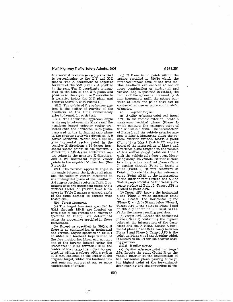
Not'l Highwoy Troffic Sofety Admin., DOT
the vertical transverse zero plane thatis perpendicular to the X-Y and, X-Zplanes. The X coordinate is negativefoxward of, th.e Y-Z plane and positiveto the rear. The Y coordinate is nega-tive to the left of tI.e X-Z plane andposÍtive to the right. The Z coordinateis negative below the X-Y plane andpositÍve above it. (See Figure 1.)
S9.2 The origi:r of the reference sys-tem is the cedter of gravity of theheadform at the time immediatelyprior to launch for each test.
S9.3 The horizontal approach angleis the angle between the X axis and theheatlform impaot velocity vector pro-jected onto the horizontal zero plane,measured in the horizontal zero planein the counter-clockwise direction. A 0degree horizontal vector and a 360 de-gree horizontal vector point Ín thepositive X direction; a 90 degree hori-zontal vector points in the positive Ydirection; a 180 degree horizontal vec-tor points in the negative X direction;a¡d a 270 horizontal degree vectorpoints in the negative Y direction. (SeeIigure 2.)
S9.4 The vertical approach angle isthe angle between the horizontal planeand the velocity vectoÌ, measured inthe midsagittal plane of the heaclform.A 0 clegree vertical vector in Table I co-incides with the horizontal plane and avertical vector of greater than 0 de-grees Ín Table I makes a upward angleof the same number of degrees wlththaü plane,
Ê10 Turget LocutiutLs.(a) The target locations speciflèd 1n
510.1 üu'oueh S10.16 are located onboth sid.es of the vehicle ancl, except asslrecified in S10(b), are determinedusing the procedures specified in thoseparagraphs.
(b) Except as specified in S10(c), ifthere is no combination of horizontaland vertical angles specified iD S8.13.4at which the forehead impact zone ofthe free motion headform can contactone of the targets located using theproced.ures ir 510.1 through 510.16, thecenter of th.at target is moved to anylocation within a sphere w.ith a radiusof 25 mm, centeled on the center of theoriginal target, which the forehead im-pact zone can contact at one or morecombination of angles,
s s7l.20l
(c) ff there is no point within thesphere specified in S10(b) which theforehead impact zone of the free mo-tion headform can contact at one ormore combination of horizontal andvertical angles specified in 58.13.4, theradius of the sphere is increasecl by 25mm increments u¡til the sphere con-tains at least one point that can becontacteal at one or more combinationof angles.
570.I A+illar tørgeis(a) A-pillør reference point and' target
AP|, On the vehicte exterior, locate atransverse vertical plane (Plane 1)which contacts the rearmost point ofthe windshield trim. -The intersecticínof Plane 1 and the vehicle exterior sur-face is Line 1. Measuring along the ve-hicle exterior surface, locate a point(Poi¡t 1) on Line 1 that is 125 mm in-board of the intersection of Line L anda vertical plane tangent to the vehicleat the outboardmost point on Line Iwith the vehÍcle sicle door open. Meas-uring along the vehicle exterior surfacein a longitudinal vertical plane (Plane2) passing through Point 1, locate apoint (Point 2) 50 mm rearward ofPoint 1. Locate the ,A.-pillar referencepoint (Point .C.PB,) at the intersectionof the interior roof swface and a lÍnethat is perpendicular to the vehicle ex-terÍor surface at Point 2. Target Á.P1 islocated at point APR,.
(b) Tørget AP2, I'ocate the horizontalplane (Plane 3) which intersects poinfAPR. Locate the horizqntal plane(Flane 4) which is BB mm below Flane 3.'L'arget ÀtsZ is the point in I'Lane 4 andon the A-plllar whlt¡b ls r¡k¡pcsL |,tt CG-tr'2 for the nearest seâting: position.
(c) Ta,rget AP3. Locate the horizontalplane (Plane 5) containing the highestpoint at the intersection of the dash-board and the ^A.-pillar. Locate a hori-zontal plane (Plane 6) half-way betweenPlane 3 and Plane 5. Target AP3 is thepoint on Plane 6 and the Â-pillar whichis closest to CG-l'l for the nearest seat-ing position.
5L0.2 B-pillør to,rgets.(a,) B-pillør reference Xtoint and target
BPI. T'ocate the point (Point 3) on thevehicle interior at the intersection ofthe horizontal plane passing throughthe highest point of the forwardmostdoor opening ancl the centerline of the
529

ss7r.20twialth of the B-pillår, as viewed lat-erally. Locate a transverse veiticatplane (Plane 7) which passes throughPoint 3. Locate the point (Point 4) atthe intersection .of the interior roofsurface, Plane 7, and the plane, de-scriþed Ín S8.15(h), tiefinÍng the nearestedge of the upper roof. The B-pillar ref-erence point (Point BPR) is the pointlocatecl at the mictcile of the ]ine fromPoint 3 to Point 4 in Plane ?, measured.along
the vehicle interior surface. Tar-get BP1 is located a,t Point BPR.
(b) To,rget BPz. If. a seat belt anchor-age is locatetl on the B-pillar, TargetBF2 is located a,t a,ny point on the an-chorage.
(c) Target BP3. Target BPB is locatedin accordance with this paragraph. I¡o-cate a horizontal plane (Plane 8) whichintersects Point BPR,. Locate a hori-zontal plane (Plane 9) which passesthrough the lowest point of the day-light opening: forwârd of the pillar, IJo-cate a horizontal plane (Plane 10) half-way between Plane B anit Plane 9. Tar-get BPB is the poi¡t located in Plane 10ancl on the interior surfâce of the B-pil-lar, which Ís closest to CG-f'(2) for thenearest seatfulg position.
(d) Tørget BP4. I'ocate a horizontalplane (Plane 11) half-way betweenPlane 9 and Plane 10. Target BP4 is thepoint locatecl in Plane 11 and on the in-terior su¡faöe of the B-pillar which isclosest to CG-F, for the neârest seâtingposition.
SL0.3 Other pillar targets.(a) Tørget OPI.(1) Except as ploviclecl in ß10.3(aX2),
target OPl is located in accordancewith this paragraph. Locate the point(Point 5), on the vehicle interior, at theintersectlon of the horizontal planethrough the highest point of the hich-est adjacent door opening or daylightopening (if no actjacent door opening)and the centerline of the width of theother pillar, as viewed laterally. Lo-cate a transverse vertical plane (Plane12) passing th¡ough Point 5. Locate thepoint (Point 6) at the intersection ofthe interior roof su¡face, Plane 12 a,¡rdthe plane, described in S8.15(h), defin-ing the nearest edge of the upper roof.The ofher pillar reference point (PointOPR) is the poi¡t located at the midclleof the line betvreen Point 5 and Point 6fn Plane 12, measured along the vehicle
49 CFR Ch. V (lfl-l-05 Edition)
i¡terior surface. Target OP1 is locatedat Point OPR.
(2) I1 a seat belt anchorage is locatedon the Billar, Target OPl is any pointon the anchorage.
(b) Target OP2. I'ocate the horizontalplane (Plane 13) intersectirg Point'OPR.
Locate a horizontal plane (Plane14) passing through the lowest point ofthe daylight opening forward of the pil-lar. IJocate a horizontal plano (Plane15) half-way between Plane 13 andPlane 14, Target OP2 is the point 1o-catecl on the interior snrface of the pil-lar at the intersection of Plane 15 andthe centerline of the width of the pil-lar, as viewed laterally.
5L0.4 Reo,rrnost pillør ta,rgets(a) Rear.nxost Xtilla,r reference point a'nd'
tørget RPI. Locate the point (Point 7)at the corner of the upper roof nearestto the pillar. The distance betweenPoint M, as described in S8.15(g), andPoint 7, as measured along the vehiclei¡terior surface, is D. Extend the linefrom Point M to Point 7 along the vehi-cle interÍor surface in the samevertical plane by (3*DÆ) beyond Point 7or u:atil the edge of a daylight opening,whichever comes first, to locate PoÍntL The reâ,rmost pillar reference point(Point RPB,) is at the midpoint of theline between Point 7 and Point B, meas-ured along the vehicle interior. TargetRPl is located at Point B,PR.
(b) To,rset RPz.(1) Exoept as provided in S10.4(b)(2),
target RP2 is locatetl in accordancewith this paragraph, Locate the hori-zontal plane (Plane lti) tlrrough FointRPR,. Locate the horizontal plane(Plane 17) 150 mm þelow Plane 16. Tar-get RPz is located in Plane 17 and onthe pillar at the location closest to CG-R, for the nearest designated seating'position,
(2) fî a, seat belt anchorage is locatedon the pillar, Target RP2 is any pointon the anchoragie.
510.5 Ftont header tørgets.(a) Tørget FHl. I'ocate the confour
line (Li¡.e 2) on the vehiole interiortrim lthich passes through the APRand is parallel to the contou.r line (Line3) at the upper edge of the winttshieldon the vehicle interior. IJocate thepoint CPoint 9) on Line 2 that is 125 mmi¡board. of the ,tPR, measured alongt}.¿t line, Locate a longitutlinal
530

Not'l Highwoy Troffic Sofely Admin., DOT
vertical plane (Plane 18) that passesthrough Point 9. Target FHl is locatedat the intersection of Plane 18 and the .upper vehicle interior, halfway be-tween a transverse vertical plane(Plane 19) through Point I and a trans-verse vertical plane (Plane 20) throughthe intersection of Plane 18 and Line 3,
(b) To.rget FHZ.(1) Except as provided in S10.5(bX2),
target tr'H2 is located in accortlancewith this paragraph. Locate a point(Point 10) 275 mm inboard of PointAPR, along Line 2. Locate a longitu-dinal vertical plane (Plane 2I) th,at'passes through Point 10. Target FHz islocated at the intersection of Plane 21and the upper vehicle interior, halfwaybetween a tratrsverse vertical plane(Plane 22) tbrough Point 10 and a trans-verse vertical plane (Plane 23) thoughthe intersection of Plane 21 and Line 3.
(2) Tf. a su¡ roof opening.is ]ocatedforward of,the front edge of the ul¡Berroof and' întersects the mid-sagittalplane of a dummy seated in eitherfront outboard seating position, targetFH2 is the nearest point that is forwardof a transverse vertical plane (Plane 24)tbrough CG-F(2) and on the intersec-tion of the mid-sagittal plane and theinterior su¡roof opening,
510,6 Tørgets on the sìd,e rail betweenthe A-piIIar o,nd the B-pillar or rea,flnostpíllar in aehicles wi,th onlE two Ttillø,rs oneøch side of the uehicle.
(a) Target SR/. Locate a tra,nsversevertical plane (Plane 25) 150 mm rear-ward of Point APR. IJocate the point(Point 11) at the intersection of Plane25 and the upper . edge of tbeforwarclmost door opening. Locate thepoint (Point 12) at Lhe intersection ofthe interior roof surface, Plane 25 andtÌro plo,nc, rlooorihod Ín S8.1õ(h). d,efin-ing the nearest eclge of the upper roof.Target SRl is located at the rniddle ofthe line between Point 11 anct Point 12i¡ Plane 25, measured along the vehioleil]'terior.
(b) Tørget Sn2, IJocate a transversevertical plane (Plane 26) 300 mm rear-ward of the APR, or 300 mm forward ofthe BPR, (or the RPR in vehicles withno B-pillar), l,ocate the point (Point 13)at the intersection of Plane 26 and theupper edge of the forwardmost dooropening. Locate the point (Point 14) atthe iútersection of tbe interior roof
s 571.201
surface, Plane 26 and. the plane, de-scribed in S8.15(h), defining the nearestedge of the upper roof. Target SB,2 islocated at the middle of the line be-tween Point 13 ancl Point 14 in Plane 26,measureal along the vehicle interior.
5L0.7 Other side rail to'rget (tq'rget^sE3).
(a) Except as provided in S10.7(b),target SRB is located in accordancewith this paragraph. Locate a trans-verse vertical plàne (Plane 27) L50 mmrearward of either Point BPR, or PointOPR. Locate the point (Point 15) asprovided in either S10.7(aX1) orS10.7(aX2), as appropriate. Locate thepoint (Point 16) at the intersection ofthe interior roof surface, Plane 27 and.the plane, desoribed i:r S8,15(h), defin-ing the.nearest edge of the upper roof.Target SRB is located at the micltlle ofthe lÍne between Point 15 antt Poi¡t 16in Piane 27, measured along the vehicleinterior surface.
(1) If P]ane 27 intersects a door ordaylight opening, the Point 15 is 10-cated at the intersection of Plane 27and the uBper edge of the door openingor tiaylight opening.
(2) If Plane 27 does not intersect adoor or daylight opening, the Point 15is located on the vehicle interior at theintersection of Plane 27 ar.d' the hori-zontal plane through the highest pointof the cloól or alaylight opening nearestPIane 27.If the attjaoent cloor(s) or day-light opening(s) are equidistânt toPla¡.e 27, Point 15 is located on the ve-hicle interior at the intersection ofPlane 27 and either horizontal planetlrlough the highest point of each dooror daylight opening.
(b) ExôëÞt âs provlde¿l ln S10.7(o), lf ä.grab handle is looated on tho side rail,ta,rßot FR3 is located at ány point onthe anchorage of the grab-handle, tr'old-ing grab-handles are in their stowedposition for testing.
(c) If a seat belt anchorage is locatedon the side rai!, target SR3 is locatedat aîy point on the anchorâge.
570.8 Rear heøder ta.rget (ta.rget RH).Locate the point (Point 17) at theinterseotion.of the surface of the uppervehicle interior, the micl-sagittal plane(Plane 28) of the outboard rearmostdummy and the plane, describecl inS8.15(h), defining the rear edge of theupper roof. Locate the point (Point 18)
531

s571.201
as provid.ed in S10.8(a) or S10.8(b), asappropriate. Except as provided inS10.8(c), Target RH is located at the*i¿:poiat of the line that is betweenPoint 17 ancl Point 18 anct is in Plane 28,as measured along the su-rface of thevehicle interior.
(a) If P1ane 28 intersects a rear dooropening or daylight opening, thenPoint 18 is located at the intersectio¡rof Plane 28 anci the upper edge of thedoor opening or the daylight opening(ifno door opening).
-
(b) If Plane 28 does not intersect ârear d.oor opening or daylÍght opening,then Poínt 18.is located on the vehicleinterior at the intersection of Plane 28and a horizontal plane thtough thehighest point of the door or alaylightopening nearest to Plane 28, If the ad-jacent door(s) or claylight opening(s)are equidistant to Plâne 28,.Point 18 Íslocated on the vehicle Ínterior at theintersection of Plane 28 and either hor-izontal plane through the highest pointof each door or daylight opening.
(c) If Target RII is more tl.:an 1L2 mmfrom Póint 18 on the line that is be-tween Point 17 ancl Point 18 ancl. is inPlane 28, as measured along the surfaceof the vehicle interior, then Target RIIis the point on that line which is 112mm from Point 18.
510.9 Upper roof tørget (target UR).Target IIR, is any point on the upperroof.
570.L0 Slid,ing d,oor track ta,rget (targetSD). I¿ocate the transverse verticalplane (Plane 29) passing through themicldle of the q/idest openi-ng of theslialing aLoor, rrieasureal horizontally
49 CFR Ch. V (10-l-05 Edilion)
and parallel to the vehicle longitudinalcenterline. Locate the point (Point 19)at the intersection of the surface of theupper vehicle interior, Plâ,ne 29 and theplane, described in 58.15@), ctefinÍngthe nea,rest edge of the upper roof. Lo-cate the point (Point 20) at the inter-section of Plane 29 and, the.upper edgeof the slicting door openi:rg, Target SDis located at the mitldle of the line be-tween Point 19 and Point 20 in Ptane 29,measurecl.along the vehicle interior.
S10.11 .RoZl-ba.r ta.rg ets.(a) Tørget RBI. Locate a longitudinal
vertical plane (Plane 30) at the mid-sagittal plane of a dummy seated inany outboarcl designated seati¡g posi-tion. Target RB1 is located on the roll-bar and. in Plane 30 at the locationclosest to either CG-tr'2 or CG-R, as ap-propriate, for the same dummy.
(b) Tørget RBz. If. a sêat belt anchor-age is located on the roll-bar, TargetRB2 is any point on the ànchorage.
510.72 Stilfener targets.(a) Tørget ST1. I'ocate a transverse
vertical plane (Plane 31) containing ei-ther CG-F2 or CG-R, as appropriate, forany outboard designated seating posi-tion. Target STI is located on the stiff-enèr and in Plane 31 at the locationclosest to either CG-tr'2 or CG-R, as ap-propriate.
(b) To,rget ST2. If. a seat belt anchor-age is located on the stiffener, Tâ,rgetST2 is any point on the anchorage.
5L0.73 Brace ts,rget (to,rget BT) Ta,réetBT is any point on the width of thebrace as viewed laterally from Ínsidethe passenger compa,rtment,
532

Nol'lHighwoy Troffic Sofety Admin., DOT s s7 l .20 l
-xf \ \ \ \
I
Y-=FIGURE I . ORTHOGOI¡AL REFERENCE EYSTEiI
533

s571.201
LEFT SIDE OF TEST VEHICLEPILLARS OîHER THAN A.PILLAR(^ssuHll{G A 270. HoRtzoI¡TALAPPROACHANGLE} Z,
SL0.L4 Door fro,rne ta,rgets,(a) Tørget DF 1, ILocate the point
(Poi¡t 21) on the vehicle interior at theintersection of the horizontal planepassing through the highest point ofthe for.ward door .opening and a trans-verse vertical plane (Plane 82 ) ta,trgentto the rearmost edge of the forwarddoor, as viewed laterally with the adja-cent door open. Locate the point (Point22) at the intersection of the interiorroof surface, Plane 32, and the plane,described in S8.15(h), ctefining the near-
f
49 CFR Ch. V (10-l-05 Edition)
est edge of the upper roof. The doorframe reference point (Point DFR) isthe poi¡t located at the middle of theline from Point 21 to Point 22 in Plane32, measured along the vehicle interiorsurface. Target Dtr'1 is located at PointDFR,,
(b) Target DFz. It a seat belt a.nchor-age is located on the door frame, Tar-get DF2 is located at any point on theanchorage.
(c) Tø,rget DF3. Locate a horizontalplane (P]ane 33) which intersects Point
X-Y PLANE
\ / E R T I C A L A N Þ H O F I I Z C I I I | T A L A Þ F R | ) A C H A N ( i I ¿ E P L A h ¡ EF I G U R E 2
RIGHT SIDE OF TEST VEIIICLEFTLLARS ôîHÈR iH^N A.PILLAR( ssrrMrHo A rq. HoRIzoNTALAPPROACH ANG|E)
VELOCITY VECTOR
FRoNT 9F TEST VEHICLT¡A.PILLAR
.534

Nol'l Highwoy Troffic Sofety Admin., DOT
Dtr'R. Locate a horizontal plane (Plane S10.16 Seøú belt rnounting structure34) t]¿.at passes through the lowest to,rgets.point of the adjacent daylight opening (a) To,rget,SB./. Target SB1 is locatedforward of the door frame. Locate a, at, àÍy point on the seat belt anchoragehorizontal plane (Plane 35) half-way be- mou¡rted on the seat belt mountingtween Plane 33 antÌ Plane 34. Target strucuure.DF3 is the point located i¡ Plane 35 (b) To,rget SB2. Locate a horizontaland on the interior surface of the door plane (plane 41), containing either CG-frame, which is closest to CG-f'2 for the F2 or CG-R, as appropriate, for anynearèst seating position. outboard designated séating position
(d) Target DF4. I'ocate a, laorizor-tal whose seating reference point, SgRP, isplane (Plane 36) half-way between forward of and closest to, the verticalPlane 34 and Plane 35. Target DF4 is center line of the width of the seat beltthe point located in Plane 36 and on mounting structure. as viewed lat-the interior surface of the door frame eralty, Target SB2 is locatecl on thethat is closest to CG-R for the nearest seat belt mo¡¡¡lting structure and inseating position, Plane 41 at the location closest to ei-
5L0.75 Other d,oor frørne tørgets. ther CG-F2 or CG-R,, as appropriate.(a)TørgetODl. @) Target ,SBJ. Locate a horizontal(L) Except âs provided in S10.15(aX2), plà¡e €lane 42), containing CG-R for
target OÐ1 is located i¡ accordance äny outboard ttesignated seating posi-with this paragraph. Locate the point tion reârwar¿ of the forwardmost des-(Point 23) on the vehicle interior, at ignated seating position or positionsthe intersection of the horizontal plale wAose seati:rg rèference point,-SgpP, isthrough the highest point of the high- rearv/ard of and closest to, the verticalest adjacent door opening or daylight center line of the wictth of the seat beltopening (if there is no adjacent door mounting structure, as viewed lat-opening) and the center line of the era¡y.
'Í,ocate a horizontal planewidth qf the other door frame, ¿,s (plane 48) 200 mm below plane 42, Tarviewed laterally with the doors in the Eet SBB is located on the seat beltclosed position. Locate a üransverse árounting structure and in Plane 43 atvertical plane (Plane 37) passing the location closest to CG-F,, as appro-th¡ough Point 23. ,I'ocate the point priate.(Point 24) at tÏ.e intèrsection of the in-terior roof surface, Plane 3? and the -[62^FR 16725' Apr' 8' 1997; 63 I¡IÈ 28' Jan. 2'prane, described in so.ib(h), FI-_Tq ffi::t3,T*rllf-Ë*är%,-"åi?irliriiáf'f*the nearest edge of the upper.roof.. The ågËii. r,"". r4, 1999; 6? 3.R,4ra54, June 18, 2002;other door frame reference point (lgitt ðiïä zgegs, Dec, 28, 2002; 68 FR 51?11, ,{us. zB,ODR) is the point located at the midttle 2003; 69 FR 922é, Feb. 27, 2004; 69 FR 54249,of the line between Point 23 ancl Point Sept. 8, 2004; 69 FIì,70914, Dec. 8, 2004; ?0 FR24 in Plane 37, measu]'ecl âlong thc ve- 61673, Âug. 31, 20061hicle intcrior surfaoe. TarEet OD1 i6 lo-cated at Point ODIì.
- $ 67I'.202 Standard No. 202; Heatl ^re'
(2) 1L a seat belt anchorase is located |q-4kilfe!t?!-l.titJ-1" manufac'
on the door rrame, T"Ë;"óirf ir;;; 9foåT" "nti"n until september 1'
point on the anchorage,(b) To,rget ODZ. I'ocate the horizontal s]-, Purpose and, scope' This standard
plane (Plane 38) intersecting Point specifies requirements for head re-ODR,. Locate a, horizontal plane (Plane straints to reduce the frequency and39) passing tbrough the lowest point of severity of neck iniury in rear-end andtne- dayliáht opðning forward of the other collisio¡is.door frame. Locate a horùontal plane S.2. Artplicøtioz. This standard applies(Plane 40) half-way between Plane 38 to passenger cars, and to multipurposeand Plane 39. Target OD2 is the point passenger vehicles, trucks and buseslocated on the interior su¡face of the with a 4,536 kS or less, manufactureddoor frame at the Íntersection of Plane before September 1, 2008. Until Sep-40 antl the center line of the width of tember 1, 2008, manufacturers maythe door frames, as viewecl laterally, comply with the standard in thiswith the doors in the closed position. 5571.202, with the trluropean regulations
s571.202
535,

In-Car Video Camera Svstems Performance Soecifications: Dieital Video Svstems Module
Appendix L
Guidance on the "Free Motion Headform Test"and its Application to Digital Video Systems,
FMVSS 201. Sections 6.1-6.2
Version 12 lllS/2007

Guidance on the "Free Motion Headform Test" and its Applicationto Digital Video Systems, FMVSS 201, Sections 6.1-6.2
The following information was put together to assist manufacturers of Digital VideoEquipment with understanding the tests requested in Federal Motor Vehicle SafetyStandard 210 "Occupant protection in interior impact" in the minimum specificationdocument. This information is taken directly from that standard. The full standard canbe located at:http:l/a257.g.akamaitech.neü7/257/2422109nov2005I500/edocket.access.gpo.gov/cfrJï05 /octqtr/pdfl49cfr57 | .201 .pdf . It is intended that manufacturers meet the requirementsof Section 6.1-6.2 generally known as the "free motion headform test?'. It is not intendedfor the purposes of this specification that manufacturers need conduct the test in Section6.3, known as the "pole tesf'.
NOTE: This summary is not intended to relieve manufacturers of anyresponsibility for any other current or future legal requirements or obligationsrequired under this or any other standard for the products they are sellÍng. It ismerely a guide for the free motion headform test specified in the minimum DigitalVideo Specification. You may be legally required to meet further and morestringent guidelines than stated herein. You should consult competent legal andengineering counsel on these issues.
As a note to manufacturers, the automakers through the Alliance of AutomobileManufacturers has entered into agreements for future crash worthiness requirements thatmay affect certain components and their locations and design in mobile Digital VideoSystems. Further, certain requirements conceming side impact testing have beenvoluntarily agreed to by this group and may affect what is considered the "industrystandard".
$ 571.201 Standard No.201; Occupantprotection in interior impact.Sl. Purpose and scope. This standard specifies requirements to afford impact protectionfor occupants.52. Application. This standard applies to passenger cars and to multipurpose passengervehicles, trucks, and buses with o GW/R of 4,536 kilograms or less, except that thereqrrirements of 56 do not ânnly to huses with a GVWR of more than 3,860 kilograms,53. Definttíons.A-pillar means any pillar that is entirely fonvard of a transverse vertical plane passingthrough the seating reference point ofthe driver's seat.Ambulance means a motor vehicle designed exclusively for the pulpose of emergencymedical care, as evidenced by the presence of a passenger compartmentto accommodate emergency medical personnel, one or more patients on litters or cots,and equipment and supplies for emergency care at a location or during transport.B-pillar means the forwardmost pillar on each side of the vehicle that is, in whole or inpart, rearward of a transverse vertical plane passing through the seating reference point ofthe driver's seat, unless: ,

(1) There is only one pillar rearward of that plane and it is also a rearmost pillar; or(2) There is a door frame rearward of the A-pillar and forward of any other pillar orrearmost pillar.Brace means a fixed diagonal structural member in an open body vehicle that is used tobrace the roll-bar and that connects the roll-bar to the main body of the vehicle structure.Convertible means a vehicle whose Apillars are not joined with the B-pillars (or rearmostpillars) by a fixed, rigid structural member.Convertible roofframe means the frame of a convertible roof.Convertible roof linkage mechanísm means any anchorage, fastener, or device necessaryto deploy a convertible roof frame.Daylight openìng means, for openings on the side of the vehicle, other than a dooropening, the locus of all points where a horizontal line, perpendicular to the vehiclelongitudinal centerline, is tangent to the periphery of the opening. For openings on thefront and rear of the vehicle, other than a door opening, daylight opening means the locusof all points where a,horizontal line, parallel to the vehicle longitudinal centerline, istangent to the periphery of the opening. If the horizontal line is tangent to the periphery atmore than one point at any location, the most inboard point is used to determine thedaylight opening.Door frame means the rearmost perimeter structure, including trim but excluding glass,of the forward door and the forwardmost perimeter structure, including trim butexcluding glass, of the rear door of apair of adjacent side doors that:(1) Have opposing hinges;(2)Latchtogether without engaging or contacting an intervening pillar;(3) Are forward of any pillar other than the A-pillar on the same side of the vehicle; and(4) Are rearward of the A-pillar.Door opening meanq for door openings on the side of the vehicle, the locus of all pointswhere ahorizontal line, perpendicular to the vehicle longitudinal centerline, is tangent tothe periphery of the side door opening. For door openings on the back end of thevehicle,door opening means the locus of all points where ahoúzontal linê, parallel to the vehiclelongitudinal centerline, is tangent to the periphery of the back door opening. If thehorizontal line is tangent to the periphery at more than one point at any location, the mostinboard point is the door opening.Dynamically deployed upper ínterior head protection system means a protective deviceor clcvices which are integrated into a vehicle and which, when activated by an impact,provide, through means requiring no action from occupants, protection against headimpacts with upper interior structures and components of the vehicle in crashes.Forehead. impact zone means the part of the free motion headform surface area that isdetermined in accordance with the procedure set forth in S8.10.Free motion headform m'eans a test device which conforms to the specifications of part572,subpartL of this chapter.Interíor rear quarter panel means a vehicle interior component located between the rearedge of the side door frame, the front edge of the rearmost seat back, and the daylightopening.Mid-sagittal plane of a dummy means a longitudinal vertical plane passing through theseating reference point of a designated seating position.

Other door frame means the rearmost perimeter structure, including trim but excludingglass, of the forward door and the forwardmost perimeter structure, including trim butexcluding glass, ofthe rear door ofapair ofadjacent side doors that:(1) Have opposing hinges;(2)Latchtogether without engaging or contacting an intervening pillar; and(3) Are rearward of the B-pillar.Other píllar means any pillar which is not an A-pillar, a B-pillar, or a rearmost pillar.Pillar means any structure, excluding glazing and the vertical portion of door windowframes, but including accompanying moldings, attached components such as safety beltanchorages and coat hooks, which:(1) Supports either a roof or any other structure (such as a roll-bar) that is above thedriver's head, or(2) Is located along the side edge of a window.Roll-bar means a fixed overhead structural member, including its vertical supportstructure, that extends from the left to the right side of the passenger compartment of anyopen body vehicles and convertibles. It does not include a header.Seat belt ønchorage means any component involved in transferring seat belt loads to thevehicle structure, including, but not limited to, the attachment hardware, but excludingwebbing or straps, seat frames, seat pedestals, and the vehicle strucfure itself, whosefailure causes separation of the belt from.the vehicle ,structure.Seat belt mounting structure.means :(a) A vehicle body or frame component, including trim, that incorporates an upper seatbelt anchorage conforming to the requirements of S4.2.1 and 54.3.2 of 49 CFR 57L.2l0,that is located rearward of the rearmost outboard designated seating position, and thatextends above a horizontal plane 660 mm above the seating reference point (SgRP) ofthat seating position; and(b) A vehicle body or frame component, including trim, that incorporates an upper seatbelt anchorage conforming to the requirements of S4.2.1 and 54.3.2 of 49 CFR 57I.210,that is located forward of.the rearmost outboard designated seating position, and thatextends above ahorizontal plane 460mm above the SgRP of that seating position locatedrearward of the anchorage.(c) The seat belt mounting structure is irot a pillar, roll bar, brace or stiffener, side rail,seat, interior rear quarter panel, or part ofthe roof.Slidirtg door tack mëâns a tack structure âlong the npper eclge of a side door openingthat seoures the door in the closed position and guides the door when moving to and fromthe open position.Stffiner means a fixecl overhead structural member that connects one roll-har to anotherroll-bar or to a header ofany open body vehicle or convertible.Upper roof means the arpa of the vehicle interior that is determined in accordance withthe procedure set forth in S8.15.Windshield trim means molding of any material between the windshield glazing and theexterior roof surface, including material that covers apart of either the windshield glazingor exterior roof surface.
36 Re quir ements for upper inter Ìor components.

36.l Vehicles manufactured on or after September I, 1998. Except as provided in 56.3and 56.1 .4, for vehicles manufactured on or after September 1, 1998 and beforeSeptember 1,2002, a percentage of the manufacturer's production, as specified in 56.1.1,56.1.2, or 56.1.3 shall conform, atthe manufacturer's option, to either 56.1(a) or 56.1(b).For vehicles manufactured by f,rnal stage manufacturers on or after September 1, 1998and before September I,2006, a percentage of the manufacturer's production as specifiedin s6.1.4 shall, except as provided in s6.3, conform, to either s6.l(a) or s6.l(b). Themanufacturer shall select the option by the time it certifies the vehicle and may notthereafter select a different option for the vehicle.(a) When tested under the conditions of S8, comply with the requirements specified in 57at the target locations specified in Sl0 when impacted by the free motion headformspecified in S8.9 atany speed up to and including 24knlh (15 mph). The requirementsdo not apply to any target that cannot be located using the procedures ofs10.(b) When equþed with a dynamically deployed upper interior head protection systemand tested under the conditions of S8, comply with the requirements specified in S7 at thetarget locations specified in S10 as follows:(1) Targets that are not located over any point inside the area measured along the contourof the vehicle surface within 50 mm (2.0 inch) of the periphery of the stowed systemprojected perpendicularly onto the vehicle interior surface, including mounting andinflation components but exclusive of any cover or covers, shall be impacted by the freemotion headform specif,red in S8.9 at any speed up to and including 24 kmlh (15 mph).The requirements do not apply to any targets that can not be located by using theprocedures ofS10.(2) Targets that are over any point inside the area measured along the contour of thevehicle interior within 50 mm (2.0 inch) of the periphery of the stowed system projectedperpendicularly onto the vehicle interior surface, including mounting and inflationcomponents but exclusive of any cover or covers, when the dynamically deployed upperinterior head protection system is not deployed, shall be impacted by the free motionheadform specified in S8.9 at any speed up to and including 19 km/h (12 mph) with thesystem undeployed. The requirements do not apply to any target that can not be locatedusing the procedures of S10.(3) Each vehicle shall, when equipped with a dummy test device specified in Part 572,Subpart M, and tested as specified in S8.16 through 58.28, comply with the requirementsspecified in 57 when crashed into a fixed, rigid pole of 254 mm in diameter, at anyvelocity between 24 kilometers per hour (15 mph) and 29 kilorneters per hour (18 mph).
37 Performancc Criterion. The HIC(d) shall not exceed 1000 when calculated inaccordance with the followine formula:
Hrc - [- t t3 1:'u
ftte - -J{--1 {*u - *'}

Where the term a is the resultant head acceleration expressed as a multiple of g (theacceleration of gravity), and tl andt? are any two points in time during the impact whichare separated by not more than a 36 millisecond time interval.(a) For the free motion headform;HIC(d):O. 7 5 44 6 (fr ee motion headform HIC)+I 6 6 .4.(b) For the part 572, subpartM, anthropomorphic test dummy;HIC(d)=g1ç.
S8 Target location and test conditions.The vehicle shall be tested and the targets speòified in S10 located under the followingconditions.
S8.l Vehicle test attitude.(a) The vehicle is supported off its suspension at an attitude determined in accordancewith S8.1(b).(b) Directly above each wheel opening, determine the vertical distance between a levelsurface and a standard reference point on the test vehicle's body under the conditions of58. I (bxl) through 58. 1 (bX3).(l) The vehicle is loaded to its unloaded vehicle weight, plus its rated cargo and luggagecapacity or 136 kg, whichever is less, secured in the luggage area. The load placed in thecargo atea is centered over the longitudinal centerline of the vehicle.(2) The vehicle is filled to 100 percent of all fluid capacities.(3) All tires are inflated to the manufacturer's specifications listed on the vehicle's tireplacard.
S8:8 Temperature and humidity.(a) The ambient temperature is between 19 degrees C. and 26 degrees C, at any relativehumidity between l0 percent and 70 percent.(b) Tests are not conducted unless the headform specified in S8.9 is exposed to theconditions specified in S8.8(a) for a period not less than four hours.58.9 Headform. The headform used for testing conforms to the specif,rcations of part 572,subpart L ofthis chapter.58.10 Forehead impact zone. The forehead impact zone of the headform is determinedaccording to the procedure specifìed in (a) through (Ð.(a) Position the headform so that the baseplate of the skull is horizontal. The midsagittalplane of the headf'orm is dcsignatcd as Planc S.(b) From the center of the threaded hole on top of the headform, draw a 69 mm lineforward toward the forehead, coincident with Plane S, along the contour of the outer skinof the headform. The front end of the line is designated as Point P. From Point P, draw a100 mm line forward toward the forehead, coincident with Plane S, along the contour ofthe outer skin of the headform. The front end of the line is designatedas Point O.(c) Draw a 125 mm line which is coincident with a horizontal plane along the contour ofthe outer skin of the forehead from left to right through Point O so that the line is bisectedat Point O. The end of the line on the left side of the headform is designated as Point aand the end on the right as Point b.

(d) Draw another 125 mm line which is coincident with a vertical plane along the contourof the outer skin of the forehead through Point P so that the line is bisected at Point P.The end of the line on the left side of the headform is designated as Point c and the endon the right as Point d.(e) Draw a line from Point a to Point c along the contour of the outer skin of theheadform using a flexible steel tape. Using the same method, draw a line from Point b toPoint d. 'r
(f) The'forehead impact zone is the surface area on the FMH forehead bounded by linesa-O-b and c-P-d, anda-c and b-d.S8.ll Target circle. The area of the vehicle to be impacted by the headform is markedwith a solid circle 12.7 mm in diameter, centered on the targets specified in S10, usingany transferable opaque coloring medium.58.12 Location of head center of gravity.(a) Location of head center of gravity þr front outboard de;ignated seating positions(CG-F). For determination of head center of gravity, all directions are in reference to theseat orientation.(l) Location of rearmost CG-F (CG-F2).For front outboard designated seating positions, the head center of gravity with the seat inits rearmost normal design driving or riding position (CGF2) is located 160 mm rearwardand 660 mm upward from the seating reference point.(2) Location ofþrwardmsst CG-F (CGFI).For front outboard designated seating positions, the head center of gravity with the seat inits forwardmost adjustment position (CGFI) is located horizontally forward ofCG-FZ by the distance equal to the fore-aft distance of the seat track.(b) Location of hqad center of grovityþr rear outboard designated seatingpositions(CG-R). For rear outboard designated seating positions, the head center of gravity (CG-R)is located 160 mm rearward, relative to the seat orientation, and 660 mm upward from theseating reference point.S8. 13 Impact configuration.58.13.1 The headform is launched from any location inside the vehicle which meets theconditions of 58.13.4. At the time of launch, the midsagiual plane of the headform isvertical and the headform is upright.58.13.2 The headform travels freely through the air, along a velocity vector that isperpendicular to the headform's skull cap plate, not less than 25 mm before making anycontáct with the vehicle.58.13.3 At the time of initial contact between the headform and the vehicle interiorsurface, some portion of the forehead impact zone of the headform must contact someportion of the target circle.58.13.4 Approach angles. The headform launching angle is as specified in Table 1. Forcomponents for which Table I specifies a range of angles, the headform launching angleis within the limits determined using the procedures specified in S8.13.4.1 and S8.13.4.2,and within the range specified in Table 1, using the orthogonal reference system speciflredin 59.
Þ,f,q@4èl¿qir¡í:ì:r.d+436!.5¡liÈ'sirt4lr4iÉr"i:É.8iw4{]@rs;!É:

TAELE 1-,{pentÅçr{ ANGTE Lmurs (lt't DBãR,EEB}
Targrit cornponent
F¡nntf|Fadsr..,..,.,,..,,,,,.;...;,,...,...,,..;,,,,.,;,.,...,..,......;.....;;.,.,,:,,,,;,,..*.;,*,...,,...,..,;,",,,*-,.**...Fesi Haaden ,.,.-. ¡,..r..i.-....--....--..tsttSldeHà¡l,.......,.,.,,,.,,...,.....,--..,...-.----.;.-,,...,:.;.,;,......,.,.i,,..:,.i,.;,...-.-..ì....,---,.--.;H(Tht SidE Hâ¡l ;;-* ¡,-..,,i,...i.-¡ i-.,. -.--LettSlídingÞooiT¡æk....¡r.--.;.-..*-.,¡i.-.-..i,...,..¡..-¡¡;,r-i¡*,..i¡¡,-,--,i¡-,,,..¡i-..¡,*¡*,F.lght 6liding DærTraak ..,.,,;.-.;;,..i..-;.-,--...,.,..,,,,.,.,.,,..,;.,,.,.,..,...,;.,..,.,.......,'....;,,..,..
f€It,tsFllhrRþht i t .F i l la r , r ¡ ¡ ! ¡ r ¡ . ¡ ! ¡ ! ¡ i r ¡ ¡ ¡ . . , ' i ¡ ¡ ¡ ¡ ¡ù ¡ ¡n . ¡ ¡ . ¡ ¡ . i l . i ¡ . r , . i ¡ ! ¡ ¡ i , . rn . ¡ i . , iN¡ ¡ ¡ ¡ . t r ¡a i ¡ ¡ i ld ¡ r .n ¡ . rNr i , . - : ,h ¡ .
Lef t RPi tbr . . - . * . , - , - - ; . , . . - . . , . . . . , ; . . . . . . . . , . . ; i . . - - , . , . , . . , , . . . i i . , i . , . . , , , . , . . , ¡ - . . . ; . . . . ; . . - i . , . , . . . , , . , , . . . . iBþLht E-FillsrLJft Oçør F, f€r.TÊ,,,- -, i, -ù..,..H.. ¡-i, i .
Uppar Hæf - . . . . .* , - , , ; . . , . . , , . , . .ßr¡ i ¡ . ¡þn.¡¡¡ ;¡ ì ¡ú;r* i . , . ¡ i . . i - . i i , , , i , - . , , . - - ,
OÍerftËqd,'Hotber ,,;.;.,;,,.;,-".-..,..r.,-,";1-;-i;,--,,.,,..,.,,,.;,..,.
V€rtinl sngle
qs09-{ûG$0â400{Bt.5Ti!-90
1ü1165 ,..,¡¡ßi¡u.!.1,Ð5-945 .,;,..,.;;,,,.1,5*'f Ê5 ;.,,,...,",,,,....lÐf945r,--..,-,¡lË:l 65 r,.;.;;,;.;;";,;2]U,.,,,:i..,..,;,....,.,,;'8ù ' , ¡ . ¡ . , - r , , - ¡ . . - ' - - ,87fl ..".,..,..,",....,.....,.Éü r,., ;,;.,,,,..:,....,,.,,..e70-g¡15 ....,,,,,,.;,i.1H0 .1. . ' . - , . - , , ' - , "Àn¡r .;..;;.,;...,,.,.;.;.r.Ð sr lât ,,,,:,,,,..,),,,;;90 orE70 ,.,,.,,.,.,".-ìfS45 .:--",;,,¡...I5-165 r ' - -^- , - , , \Äfty i . r . i - .*r . - , , . , i .
:-FSO- t0-€ù- 10-60* 1040*10+0.r 10-Ete 10-6ù* 1t40* lq$g- 104fi* 10-50t{0ô-80ffig- 10-ç0"i 10-str5û
58. 14 Multiple impacts.(a) A vehicle being tested may be impacted multiple times, subject to the limitations inS8.14(b), (c), (d) and (e).(b) As measured as provided in S8.14(d), impacts within 300 mm of each other may notoccur less than 30 minutes apart.(c) As measured as provided in S8.14(d), no impact may occur within 150 mm of anyother impact.(d) For S8.14(b) and 58.14(c), the distance between impacts is the distance between thecenter of the target circle specified in S8.11 for each impact, measured along the vehicleinterior.(e) No impact may occur within the 'oexclusion zone" of any pillar target specified inS10.1 through S10.4, door frame target specified in S10.14 and S10.15, upper roof targetspeoified in 510.9, or seal belt mounling structure target specified in 510.16. The"exchrsion zc)ne" is determined acconling to the procedl¡re in S8,14(f) through S8,14(k),(f) Locate the point, Point X, at the center of the target circle specified in S8.11 for thetosted target.(g) Determine two spheres centered on Point X. Radii of these spheres are 150 mm and200 mm, respectively.(h) Locate ahorizontal plane passing through Point X. Determine the intersection points,if they exist, of the small sphere surface, the horizontal plane, and the vehicle interiorsurface. Relative to Point X, the point on the left is Point L and the point on theright is Point R.(i) Locate a vertical plane, Plane Z, passing through Point X and coincident (within + 5o)with the horizontal approach angle used or intended for use in testing the target centeredon Point X.
+1É.¡r4!1f¿?d&¡g!¿¿igl!Àtir'!':ti;ar¿4ri!..Flt$:f:¡i*l¡,ii¡t¡*ilf;l{4i+{91Eair}r9ði¡j{9+g¡¡:y.*Jl¡¡aizì

fi) If either Point L or Point R does not exist, extend Line LX and/or Line RX, asappropriate, perpendicular to Plane Z beyond Point X by 150 mm. The end of the line isdesignated as Point L or Point R, as appropriate.(k) Locate a vertical plane, Plane ZL, passing through Point L and parallel to Plane Z.Locate another vertical plane, Plane ZR, passing through Point R and parallel to Plane Z.The "exclusion zone" is the vehicle interior surface area between Plane ZL and PlaneZR below the upper boundary of the smaller sphere and above the lower boundary of thelarger sphere. Points on the intersection of the vehicle interior surface and the largesphere below the target, the small sphere above the target, Plane ZL and Plane ZFtarc notincluded in the "exclusion zone."58.15 Upper Roof. The upper roof of a vehicle is determined according to the procedurespecified in S8.15 (a) through (h).(a) Locate the transverse vertical plane A at the forwardmost point where it contacts theinterior roof (including trim) at the vehicle centerline.(b) Locate the transverse vertical plane B at the rearmost point where it contacts theinterior roof (including trim) at the vehicle centerline.(c) Measure the horizontal distance @1) between Plane A and Plane B.(d) Locate the vertical longitudinal plane C at the leftmost point at which a verticaltransverse plane, located 300 mm rearward of the A-pillar reference point described inS10.1(a), contacts the interior roof (including trim).(e) Locate the vertical longitudinal plane D at the rightmost point at which a verticaltransverse plane, located 300 mm rearward of the A-pillar reference point described in510.1(a), centacts the interior roof (including trim).(f) Measure the horizontal distance @2) between Plane C and Plane D.(g) Locate a point @oint M) on the interior roof surface, midway between Plane A andPlane B along the vehicle longitudinal centerline.(h) The upper roofzone is the area ofthe vehicle upper interior surface bounded by thefourplanes described in S8.15(h)(1) and 58.15(h)(2):(l) A hansverse vertical plane E located at a distance of (.35 Dl) forward of Point M anda transverse vertical plane F located at a distance of (.35 Dl) rearward of Point M,measured horizontally.(2) A longitudinal vertical plane G located at a distance of (.35 D2) to the left of Point Mand a longitudinal vertical plane H located at a distanoe of (.35 D2) to the right of PointM, measured horizontally.
59. Orthogonal Reference System. The approach angles specified in 58.13.4 aredetermined using the reference system specified in S9.1 through S9.4. S9.1 Anorthogonal reference system consisting of a longitudinal X axis and a transverse Y axis inthe same horizontal plane and a vertical Z axis through the intersection of X and Y isused to define the horizontal direction of approach of the headform. TheX-Z plane is thevertical longitudinal zerc plane and is parallel to the longitudinal centerline of thevehicle. The XY plane is the horizontal zero plane parallel to the ground. The Y-Z planeis the vertical transverse zero,plane that is perpendicular to the X-Y and X-Z planes. TheX coordinate is negative forward of the Y-Z plane and positive to the rear. The Ycoordinate is negative to the left of the X-Z plane and positive to the rigtrt. The Zcoordinate is negative below the X-Y plane and positive above it. (See Figure 1.) S9.2
{*/{iì|&e¡6Ë

The origin of the reference system is the center of gravþ of the headform at the timeimmediately prior to launch for each test. S9.3 The horizontal approach angle is theangle between the X axis and the headform impact velocity vector projected onto thehorizontal zero plane, measured in the horizontal zero plane in the counter-clockwisedirection. A 0 degree horizontal vector and a 360 degree horizontal vector point in thepositive X direction; a 90 degree horizontal vector points in the positive Y direction; a180 degree horizontal vector points in the negative X direction; and a270 hor:ø,ontaldegree vector points in the negative Y direction. (See Figure 2.) 59.4 The verticalapproach angle is the angle between the horizontal plane and the velocþ vector,measured in the midsagittal plane of the headform. A 0 degree vertical vector in Table Icoincides with the horizontal plane and a vertical vector of greater than 0 degrees inTable I makes a upward angle of the same number of degtees with that plane.
510 Target Locations.(a) The target locations specified in S10.1 through S10.16 are located on both sides of thevehicle and, except as specified in S10(b), are determined using the procedures specifiedin those paragraphs.(b) Except as specified in S10(c), if there is no combination of horizontal and verticalangles specified in 58.13.4 at which the forehead impact-zone of the free motionheadform can contact one of the targets located using the procedures in 510.1 throughS10.16, the center of that target is moved to any location within a sphere with a radius of25 mm, centered on the center of the original target, which the forehead impact zone carrcontact at one or more combination of angles.(c) If there is no point within the sphere specified in S10(b) which the forehead impactzone of the free motion headform can contact at one or more combination of horizontaland vertical angles specified in 58.13.4, the radius of the sphere is increased by 25 mmincrements until the sphere contains at least one point that can be contacted at one ormore combination of angles
510.6 Targets on the sìde rail between the A-pillar and the B-pillar or rearmost pillar invehicles with only two pillars on each side of the vehícle.(a) Target,SrRl. Locate a transverse vertical plane @lane 25) 150 mm rearward of PointAPR. Locate the point (Point 11) at the intersection of Plane 25 and the upper edge of thef-orwardrnost door opening. Locate the point (Point 12) at the intersection of the interiorroof surface, Plane 25 and the plane, described in S8.15(h), defining the nearest edge ofthe upper roof. Target SRI is located at the middle of the line between Point 11 andPoint 12 in Plane 25, measured along the vehicle interior.(b) Target SR2. Loaate a transverse vertical plane (Plane 26) 300 Íìm rearward of theAPR or 300 mm forward of the BPR (or the RPR in vehicles with no B-pillar). Locate thepoint @oint 13) at the intersection of Plane 26 and the upBer edge of the forwardmostdoor opening. Locate the point @oint 14) at the intersection of the interior roof surface,Plane 26 andthe plane, described in S8.15(h), defining the nearest edge of the upper roof.Target SR2 is located at the middle of the line between Point 13 and Point 14 in.Plane 26,measured along the vehicle interior.S10.7 Other side rail target Qarget SR3).

(a) Except as provided in S10.7(b), target SR3 is located in accordance with thisparagraph. Locate a transverse vertical plane @lane 27) I50 mm rearward of either FointBPR or Point OPR. Locate the point (Point 15) as provided in either S10.7(a)(1) orS10.7(a)(2), as appropriate. Locate the point @oint 16) at the intersection of the interiorroof surface, Plane 27 and the plane, described in S8.15(h), defining the nearest edge ofthe upper roof. Target SR3 is located at the middle of the line between Point 15 andPoint 16 in Plane 27 , measured along the vehicle interior surface.(1) If Plane 27 intercects a door or daylight opening, the Point 15 is located at theintersection of Plane 27 andthe upper edge of the door opening or daylight opening.(2) If Plane 27 does not intersect a door or daylight opening, the Point 15 is located onthe vehicle interior at the intersection of Plane 27 and the horizontal plane through thehighest point of the door or daylight opening nearest Plane 27.If the adjacent door(s) ordaylight opening(s) are equidistant to Plane 27,Point 15 is located on the vehicle interiorat the intersection of Plane 27 and either horizontal plane through the highest point ofeach door or daylight opening.(b) Except as provided in S10.7(c), if a grab handle is located on the side rail, target SR3is located at any point on the anchorage of the grab-handle. Folding grab-handles are intheir stowed position for testing.(c) If a seat belt anchorage is located on the side rail, target SR3 is located at any point onthe anchorage.
I*E
-x'{**-' l + . ^ "_*_
- \ + \
\ \
T.*t{ßÈÈgr F*{¡f¡r
\Y-n¿
FIGURË t . üËTHÛÊSiliL FËÉËRËHçË ËYSTËiI
ú':lj.ìÉ.1il.g¡¡lt}jt1Jii¡,ii.q\1!;'t;:|ì'|i|i)'||i||!\!*,,n|t!n¡F]jl!l;!{+9fiJf}¿i!+ÆPj89v¿i|?.;lf|1\:..r,|JÈ||ø:#
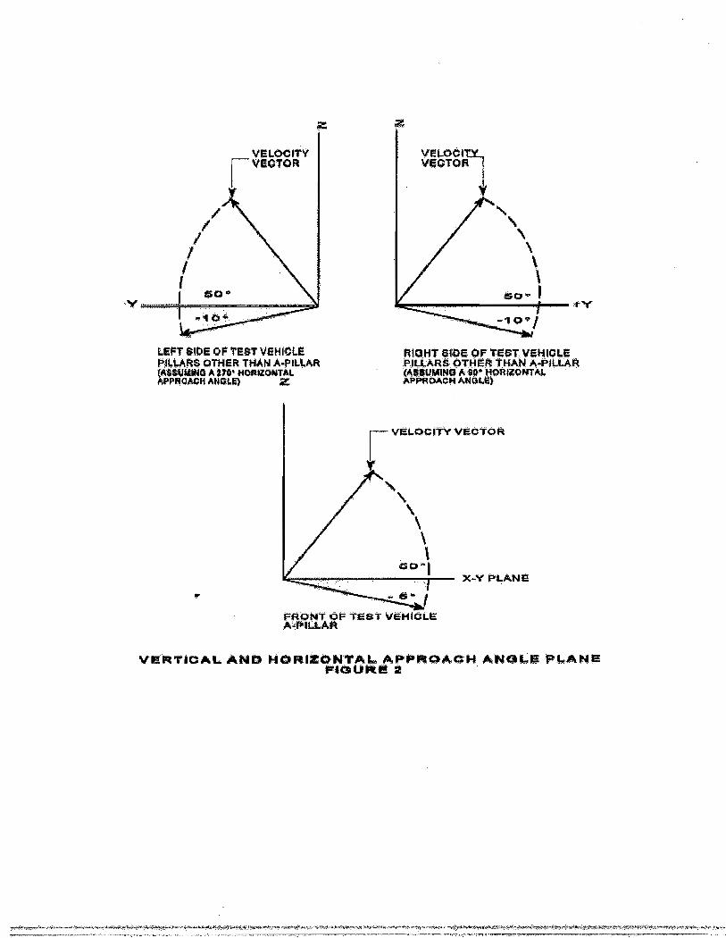
LËFT ËlDE BF TEET l¡EHIEI.ËFlL!åHÊ ÕTHER Tl{åhl Á-FlLl,rtñtúåFEJt¡¡t{Ë A Êru' fl Gñlrot*T¡Ìt,åPPHÐáCI+ ¡'t*HtFl ä
\\ìËËî l
}d-Y Pl-AltlE
vtË Ft !"¡c¡ A L åFt f* H c! F lEu tr¡T¡r. ¿* n Fts }rygdr B t{ Å f.¡É tE FLå H EF tÈuFrE t
hlËHT Ë{iÞË üF TËËî,VtHlttË,nfL!,4RË gTllER :TFÊ,\ft¡- ¡l.Fl[,[ RfÀËE:uldlË¡ç Jt Ë4. HüR|E{}|¡T,(LåFFESÀÉH A¡{ÉTE¡
ì/ËtÐEifv XIËçTÕR
FRæ+TT FF T'ã*ï VEÈIIËLE,&iFt|.t ¡tR
!+.ÈÞ€-¿È<;i.ifÞ4i:øi"¡ti1ùìtl>ttÞ4!rã.t?!fÉ4irT"r!f+ógr-f.f-4riírtrr*tftru4.41s#{ê_:l$¡iÁ?J4p
In-Car Video Camera Systems Performance Specifications: Disital Video Svstems Module
Appendix D
Federal Motor Vehicle Safety Standards 205"Glazing Materials"

WAIS Document Rehieval
lCode of Federal Regulat íons]
l t i t l e 4 9 , V o l u m e 5 ]lRev ised as o f October 1 - , 200] - l
F rom the U.S. Government Pr in t inq Of f i ce v ia GPO Access
l C r t u : 4 9 C F R 5 7 L . 2 0 5 ]
[ P a g e 4 6 2 - 4 6 7 ]
TTTLE 49 - -TRANSPORTATÏON
CHAPTER V- -NATIONAL H]GHWAY TRAFFIC
SAFETY ADMTNTSTRATTON, DEPARTMENT
OF TRANSPORTAT]ON
PART í7A_-FEDERÄL MOTOR VEHTCLE SAFETY STANDARDS--Tab]-e of CoNTCnTS
Subpart B- -Federal Motor Vehic le Safety Standards
S e c . 5 7 L . 2 0 5 S t a n d a r d N o . 2 0 5 , G l a z i n g m a t e r i a l s .
S1. Scope. This standard speci f ies requirements for g l 'azirng
mater ía ls fo r use in motor veh ic les and motor veh ic le equ ipment .52. Purpose. The purpose of th is standard is to reduce in jur ies
resul t ing f rom impact to gTazíng surfaces, to ensure a necessarydegreeof t ransparency in motor vehic le windows for dr iver vís ib i l i ty , andL ominimize the possibi l i ty of occupants beíng thrown through theveh ic lewindows in co l l - f s ions .
53. Appl icat ion. This standard appl ies to gl-azi-ng mater ia ls foru s eín passenger cars , mu l t ipurpose passenger veh ic les , t rucks , bu .ses ,motorcycles, s l ide- in carnpers, and píckup covers designed to carrypersons wh i le in mot ion .
5 4 . D e f i n i t i o n s .Bu l le t res is tan t sh ie ld means a sh ie ld o r bar r ie r tha t i s
i n s t a l l e dcompletely ínside a motor vehic le behind and separate f rom glazing
mater ia ls that ind.ependent ly comply wi th the requirements of th isstandard.
Camper means a structure designed to be mounted in the cargo area
htþ://frwebgate.access.gpo.gov/cgi-bin/get-cfr.cr..TITLE:49&PART:571&SECTION=205&YEAR:2001&TYPE:TEXT (1 of l1)6/1512006 9:38:39 AM

WAIS Document Retrieval
o fa t ruck , e r a t tached to an incomple te veh ic le w i th mot ive power , fo rthepurpose of providing shel t ,er f or persons .
Glass-p1astíc g1azing mater ia l means a laminate of one or morelayers of g lass and one or more layers of p last ic in
[ [eage 4631 ]
which a plastic surface of the g1azing faces inward when the gJ,azíngí si n s t a l l e d í n a v e h i c l e .
. Motor home means a mult ipurpose passenger vehic le that providesl iv ing accommodat ions for persons
Pickup cover means a camper having a roof and sides but without afloor, designed to be mounted on and removabl-e from the cargo area ofa
truck by the userS l ide- in camper means a camper hav ing a roo f , f1oor , and s ides ,
designed to be mounted on and removable from the cargo area of atruckby the user
S 5 . R e q u i r e m e n t s .S 5 . 1 M a t e r i a l - s .S5 . 1 . 1 G1-azing materíals for use in motor vehic les, expect as
otherwise provided ín th is standard shal1 conform to the AmericanNat iona l S tandard t *Safe ty
Code fo r Safe ty G laz ing Mater ía ls fo rGlaz ingMotor Veh ic les Opera t íng on Ï - ¡and H ighwaysr r 2 -26 .1- -L97 '7 , , -Tanuary 26 ,1977, âs supp lemented by 226 .1 -a , .Tu1y 3 | 1980 (here ina f te r re f e r redtoa s - - A N S Z 2 6 t t ) . H o w e v e r , I E e m 1 1 8 g l a z í n g a s s p e c i f i e d í n t h a tstandardmay not be used in motor vehic les at levels requisí te for dr iv ingvis ib i l i ty , and Ï tem 118 gl-azi ,ng is not required to pass Test Nos.t 7 ,3 0 , a n d 3 1 - .
S 5 . 1 - . f . f T h e c h e m i c a l s s p e c i f i e d f o r t e s t i n g c h e m i c a l r e s i s t a n c einT e s t s N o s . L 9 a n d 2 0 o f A N S 2 2 6 s h a l l b e :
(a) One percent solut ion of nonabrasive soap.(b ) Kerosene .(c ) E lnd i lu ted denatured a lcoho l , Formula SD No. 30 ( f par t 1 -00-
,*.- -hftp;/l1hrab.ealç,4lssÂs,spp,govfcgif-rdeçhe&c,*u&Ef93P4ßH7l&$EÇI9*-?*0J&EAR=?.8QrSTEE*IPXJle"o-fJÐ6l.lJJ?-qÊäi@ry'

WAIS Document Retrieval
percent methyl a l -cohol in 1¡ parts 190 -proof ethyl a lcohol by volume) .(d) Gasol ine, ASTM Reference Fuel C, whích ís composed of
fsooc tane50 volume percentage and Toluene 5O volume percentage. Isooctane mustconform Lo A2.7 ín Annex 2 o f the Motor Fue ls Sec t ion o f the 1985Annual-Book of ASTM Standards, Vol . 05 . 04, and Toluene must conform to ASTM
Spec i f íca t ion D362-84, S tandard Spec i f íca t ion fo r ïndus t r ia l - GradeTo luene. ASTM Reference Fue l C must be used as spec i f ied in :
( 1 ) P a r a g r a p h A 2 . 3 . 2 a n d 4 2 . 3 . 3 o f A n n e x 2 o f M o t o r F u e l s ,Sec t ion 1in the 1985 Annual- Book of ASTM Standards; and
( 2 ) O S H A S t a n d a r d 2 9 C F R l - 9 1 - 0 . 1 0 6 - - t t H a n d l i n g S t o r a g e a n d U s e o f
Fl-ammable Combust ib le Liquids. ' '
This íncorporat íon by reference v¡as approved by the Director of the
F e d e r a l R e g i s t e r i n a c c o r d a n c e w i t h 5 U . S . C . 5 5 2 ( a ) a n d 1 - C F R p a r t
5 1 .Copies may be inspected at the Technical Reference Library, NHTSA,
4 0 0S e v e n t h S t r e e t , S W . , R o o m 5 1 0 8 , W a s h i n g t o n , D C 2 0 5 9 0 , o r a t t h e
O f f i c eo f t h e F e d . e r a l R e g i s t e r , 8 0 0 N o r t h C a p í t o l S t r e e t , N h l . , s u i t e 7 O O ,
Wash ing ton , DC.S5 .1 - .1 - .2 The f o l low ing loca t íons are added to the l i s ts
s p e c i f í e din ANS 226 ín whích i tem 4 , i tem 5 , i tem 8 , and i tem 9 sa fe ty g laz ing
may be used:( a ) - - ( i ) [ R e s e r v e d ]( j ) V{índows and doors in motor homes, except for the wíndshield
andwindows to the ímmediate right or l-ef t of the driver
(k) lrÏ indows and doors in slide - in campers and píckup covers .( f ) Windows and doors in buses except for the windshield, wíndows
t othe immediate r íght or lef t of the dr iver, and rearmost wíndows i f
usedfor d r iv ing v ís íb í l i t y .
(m) For Ï tem 5 safety gLazíng only: Motorcycle wíndscreens below
theintersect ion of a hor izontraL plane 380 mi l l imeters vert ical ly above
thelowest seat ing pos i t ion .
http//fnvebgate:access:gpo,qov/cgi-bin/4et¡cfr,c,,,TlTlE:49&PART{71&SECTION:2.05&YEAR:2001&TYP-E=TEXT (3 of ll)6/15/2006 9:38:39 AM
lir*#ì9¡#t+ii^r{*j,tra:êj4¿|*,ÈeitIi¡+{rq4i+!4+É!fÉ.Ì +!È*Piit+r4¡Ért'.-a{+sr.i¿#{;Ìç@ffirye_rfñ.ffi-@+_w @ryw

-IilAIS Document Retrieval
S 5 . 1 - . l - . 3 T h e f o l L o w i n g l o c a t í o n s a r e a d d e d t o t h e l i s t ss p e c i f i e din Al[S 226 in whích it,em 6 and item 7 saf ety gl-azi-ng may be üsêd:
( a ) - - ( i ) [ R e s e r v e d ]( j ) lVindows and doors in motor homes, except f or the windshíeld,
forward-facíng wíndows, and windows to the immediate r ight or lef t ofthe dr iver .
(k) Windows, except f orward- f acing wj-ndows, and doors in s l ide- incampers and pickup covers.
(1) For i tem 7 safety gl-azLng only:(1 ) S tandee w indows ín buses .( 2 ) I n t e r i o r p a r t i t i o n s .( 3 ) Openings in the roof .S 5 . 1 . 1 . 4 T h e f o l l o w i n g l - o c a t i o n s a r e a d d e d t o t h e l í s t s
s p e c í f i e din ANS 226 ín which ítem 8 a.nd. item 9 saf ety gl-azíng may be ubed:
( a ) - - ( e ) [ R e s e r v e d ]( f ) Windows and doors in motor homes, except for the wíndshield
and
[ [Page 464] l
windows to the immediate r ight or lef t of the dr iver.(g) V,Iindows and doors in slide - Ín campers and pickup coversS 5 . 1 . 1 . 5 T h e p h r a s e t t r e a d i l y r e m o v a b l e ' ' w i n d o w s a s d e f i n e d i n
ANS226, for the purposes of th is standard, in buses having a GVII IR ofmorethan 4536 ki lograms, shal l ínclude pushout windows and wíndowsmountedin emergency exists that can be manual- ly pushed out of theír locat ioninthe vehic le wi thout the use of tools, regardl-ess of whether suchwindowsremain hinged at one síde to the vehic le.
S5. l - .1 .6 Mu l t ípurpose passenger veh ic les . Except as o therw isespec i f i ca l l y p rov ided by th is s tandard , g laz ing fo r use inmul t ipurposepassenger vehic les shal l conform to the requirements for gtazing foru s eín t rucks as spec i f ied in A lüS 226.
S 5 . 1 . L . 7 T e s t N o . 1 7 í s d e l e t e d f r o m t h e l i s t o f t e s t s s p e c i f i e din
=.=:!tÞ[email protected].æ{qqt-¡lr/gct:cfr.c...IITLE=19.&PART=57J&SEçTION=205&}-E-AR;Z0jl&nßE=T,EtÍ-f,(4*pJJÐ.0/fÍ2-40ó9Il$.l,39AItd-;*"..*-*ww

WAIS Document Retrieval
ANS 226 fo r I tem 5 g laz íng mater ia lthel i s t s o f t e s t s s p e c í f i e d i n A N S 2 2 6
and Tes t No. 18 is de le ted f rom
for Item 3 and Ttem 9 gl-azíngm a t e r i a l .
35 .1- .2 fn addi t ion to the gJ-azj .ng mater ia ls speci f ied in ANS2 2 6 ,m a t e r i a l s c o n f o r m i n g t o S 5 . 1 . 2 . 1 , 5 5 . I . 2 . 2 , S 5 . l - . 2 . 3 , 5 5 . t . 2 . 4 ,S 5 . 1 - . 2 . 5 , 5 5 . ! . 2 . 6 , S 5 . L . 2 . 7 , 5 5 . I . 2 . 8 a n d S 5 . 1 - . 2 . 1 1 - m a y b e u s e d i ntheloca t ions o f motor vehíc les spec í f íed in those sec t ions .
S5 . 1 .2 .L I tem 11-C- -Saf e ty GLaz i ,ng Mater ia l fo r Use in Bu l le tResistant Shiel-ds. Bul let resistant gJ-azj-ng that complíes wíth TestNos .2 , 1 7 , A 9 , 2 0 , 2 A , 2 4 , 2 7 , 2 8 , 2 9 , 3 0 a n d 3 2 o f A N S 2 2 6 a n d t h elabe l ingrequ i rements o f S5 . 1 .2 .5 may be used on ly in bu l le t res is tan t sh ie l -dsthat can be removed. f rom the motor vehic le eåsí ly for c leaning andmain tenance. A bu l le t res is tan t sh ie ld may be used ín a reas requ is i tefor drív ing v is ib i l i ty only i f the combined paral le l luminoustransmit tance with perpendicul-ar incidence through both the shieldandthe permanent vehicle gl-azLng is at l-east 6 0 percent .
S 5 . 1 . 2 . 2 I t e m l - 2 - - R i g i d P l - a s t i c s . S a f e t y p l a s t i c s m a t e r i a l s t h a tcomply w i th Tes t Nos . 10 , 13 , L6 , L9 , 20 , 2 l and 24 o f ANS 226 , w i ththeexcept ion of the test for resistance to undi lated denatured. alcoholFormula SD No. 30, and that comply wi th the label ing requirements ofs 5 . 1 . 2 . 5 , m a y b e u s e d i n a m o t o r v e h í c l e o n l y i n t h e f o l l o w i n gs p e c i f i e dloca t ions a t leve l -s no t requ is í te fo r d r iv ing v ís ib i l í t y .
(a) Window and doors in s l - ide- in campers and pick-up covers.(b) MoLorcycle wíndscreens bel-ow the intersectíon of a hor izontal
p lane 380 .mi11 ímeters ver t i ca l l y above the lowest seat ing pos i t ion .(c ) S tandee wíndows in buses .(d ) In te r io r par t i t íons(e) openings ín the roof( f ) Flexible curtains or readi ly removable windows or in
vent i l-atorsused in conjunct ion wi th readi ly removable windows.
(g) üI indows and doors in motor homes, except f or the wíndshieldandwindows to the immediate r ight or lef t of the dr iver.
(h) V,Iindows and doors in buses except for the windshield and
hff¡://frwehgare.access.gpo"gov/cgi-bin/ger-cfr.c;..TITLE+9&PART:571&SEÇTION:205&YEAR=2q01&TYPD=TEXT (5 çf 1l)6/1512006 9:38:39 AM

IVAIS Document Rehieval
windowto the ímmediate r ight and lef t of the dríver.
S 5 . L . 2 . 3 T t e m L 3 - - F l e x i b l e p l a s t i c s . S a f e t y p l a s t i c m a t e r i a l sthatc o m p l y w í t h T e s t s N o s . ! 6 , a 9 , 2 0 , 2 2 , a n d 2 3 o r 2 4 o f A N S 2 2 6 , w i t htheexcept ion of the test for resistance to und. i luted d.enatured. alcoholFormula SD No. 30, and that comply wi th the label ing requirements of5 5 . 1 - . 2 . 5 m a y b e u s e d i n t h e f o l l - o w i n g s p e c i f i c l o c a t i o n s a t l e v e l - snotrequís i te fo r d r iv ing v is ib i l i t y .
(a ) Windows, except fo rward- fac ing w indows, and doors in s l ide- incampers and pick-up covers.
(b ) Motorcyc le wíndscreens be low the ín te rsec t ion o f a hor izon ta lp lane 380 mi l l imeters ver t i ca l l y above the lowest seat ing pos i t ion .
(c ) S tandee w indows in buses .( d ) T n t e r i o r p a r t i t i o n s .(e ) Open ings in the roo f .( f ) Flexible curtaíns or readi ly removable windows or in
vent i la to rsused in conjunct ion wi th readi ly removable windows.
(g) Wíndows and doors in motor homes, except for the windshield,forward-facing windows, and windows to the immed. iate r íght or lef t ofthe dr iver .
S 5 . l - . 2 . 4 . I t e m t 4 - - G l _ a s s P l a s t i c s . G l a s s - p l a s t í c g l - a z i - n gmater ía1stha t comply w i th the labe l ing requ i rements o f 55 .1 .2 .L0 and Tes t Nos .T ,? , , 3 , 4 , 9 , 1 2 , 1 5 , L 6 , 1 7 , 1 9 , 1 - 9 , 2 4 , 2 6 , a n d 2 9 , a g t h o s e
[ [ e a g e 4 6 s ] l
t e s t s a r e m o d i f i e d i n S 5 . 1 . 2 . g , T e s l P r o c e c l u r e s f o r G 1 a s s - P l a s t i c s ,maybe used anywhere in a motor vehic le, except that i t may not be usedinwindshíel-ds of Any of the fo l lowing vehic les: convert íb les, vehíclesthat have no roof, vehic les whose roofs are completely removable.
55 . 1 - .2 . 5 . I tem L5A- -Annea led Glass - P las t íc f o r use in a l lPos i t ionsin a Vehic le Except the Windshield. Glass-p1astíc gLazi-ng mater ia lsthatc o m p l y w i t h T e s t N o s . t , 2 , 3 , 4 , , 9 , A 2 , ! 6 , 1 7 , 1 g , ! 9 , 2 4 , a n d 2 9 ,
htþ://frwebgate.acçç,ss,gpç.gov/cgi-bi¡¡/get-cfr.c...ÎïTlE=49d¿PART=571&SF.CTION:205&YEAR:?001&TYPE=TEXT 6 of fi16n5t2006 9:38:39 ÂMh"d4-Ê¿J+++-" i r . i+*^+#@| fs* {e ,+è* l4 ï ' ¡ , . {ñ '#È i } 'È"T+ 'a*4r@+a4.e t -æ+ry**+#ã. - . r * *#Fd4. là : - .+ -1 ;k .+ ; 'a , .Þ} , ' . . * ¡1 ' f f i {

WAIS Document Rehieval
A S
t h o s e t e s t s a r e m o d i f i e d i n S 5 . 1 . 2 . 9 T e s t P r o c e d u r e s f o r G l a s s -P l a s t i c s ,may be used anywhere in a motor vehícle except the windshield.
S 5 . 1 . 2 . 6 T t e m 1 5 8 - - T e m p e r e d G l a s s - P l a s t i c f o r U s e i n A l lPos i t ionsIn a Veh ic le Except the Windshíe l -d . G lass-p las t i c g l -az íng mater ía lsthatc o m p l y w i t h T e s t s N o s . L , 2 , 3 , 4 , 6 , 7 , 8 , a 6 , 1 7 , L 8 , 1 9 , 2 4 , a n d2 8 ,a s t h o s e t e s t s a r e m o d í f i e d i n S 5 . 1 . 2 . 9 T e s t P r o c e d u r e s f o r G l a s s -Plast ics, may be used anywhere in a motor vehic le except thewíndsh ie ld .
S 5 . 1 . 2 . 7 . ï t e m l - 6 4 - - A n n e a l e d G l a s s - P l a s t i c f o r U s e i n a l lPos i t ionsi n a V e h i c l e n o t R e q u i s i t e f o r D r i v í n g V i s í b i l i t y . G 1 a s s - p l a s t i cg l a z i n gm a t e r i a l s t h a t c o m p l y w i t h , T e s t N o s . 3 , 4 , 9 , 1 2 , 1 6 , 1 9 , 2 4 , a n d 2 8 ,A S
t h o s e t e s t s a r e m o d i f í e d i n S 5 . 1 . 2 . 9 T e s t P r o c e d u r e s f o r G l - a s s -P l a s t i c s ,may be used in a motor vehíc le ín a l l loca t ions no t requ is i te fo rdr ív ing v is ib i l i t y .
S 5 . 1 - . 2 . 8 . f t e m 1 6 8 - - T e m p e r e d G l a s s - P l - a s t i c f o r U s e í n a l lP o s i t í o n sin a Veh ic le no t Requ is i te fo r Dr iv ing V is ib í1 i ty . G l -ass-p las t i cgLazíngm a t e r i a l s t h a t c o m p l y w i t h T e s t N o s . 3 , 4 , 6 , 7 , ' 8 , A 6 ; A 9 , 2 4 , a n d2 8 ,a s t h o s e t e s t s a r e m o d í f í e d i n S 5 . 1 . 2 . 9 T e s t P r o c e d u r e s f o r G l - a s s -P las t ics , may be used in a motor veh ic le ín a l - l loca t ions no trequ is í tefo r d r iv íng v is ib í l i t y .
S 5 . 1 - . 2 . 9 T e s t P r o c e d u r e s f o r G l a s s - P l a s t í c s . ( a ) T e s t s N o s . 6 , 7 ,8 ,9 , 12 , L6 , and l -8 sha l l be conducted on the g lass s ide o f thespec imen,i . e . , the sur f ace wh ich wou l -d f ace the ex ter io r o f the veh ic l -e . Tes tsNos. L7 , L9 , 24 , and 26 sha l l be conducted on the p las t i c s ide o f thespecimen, i . e. , the surface which would face the inter ior of theveh ic le . Tes t No. 1 -5 shou ld be conducted w i th the g lass s ide o f theglazing facíng the i l luminated box and the screen, respect ively. ForTest No. A9 , add the fol lowing to the speci f íed l - is t : an aqueous
htp://frwêbca,1e'1cces':'c'|o.gov/cgi.birr/gêt-cfI:Ô:.TITL.E'=49&'PART=57l&SICTIoN=20J&YEAR=20!|aTYPE=TE$¡&1$r!4r{¡.'++;!t1È9rf.É¡:F,F.- l tenTr$+iïK+#i"rné4aÊ*l¡it-+*¡+.:¿#1È,4!t+. i4r¡{àgr.W1.ù:{ùf!#

ÌüAIS Document Retrieval
sol-ut ion of isopropanol and glycol ether sol-vents in concentrat ion nogreater than l-OZ or less than 5? by weight and ammon-ium hydroxíde nogreater than 5? or less than lZ by weÍght, s imulat ing tytr l ícalcommercialw indsh ie ld c leaner .
(b ) G lass-p las t íc spec ímens sha l l be exposed to an ambien t a i rtempera ture o f -40 degrees Ce ls ius (p lus o r minus 5 degrees Ce ls ius) ,for a per iod of 6 hours at the commencement of Test No. 28 , ratherthanat the in i t ia l tempera ture spec i f íed in tha t tes t . A f te r tes t ing , theg lass-p1as t íc spec imens sha11 show no ev idence o f c rack íng , c loud ing ,de laminat ing , , o r o ther ev idence o f de ter io ra t íon .
(c ) G lass-p las t i c spec ímens tes ted in accordance w i th Tes t No. 17sha l -1 be care fu l l y r ínsed w i th d ís t í1 led water fo l low ing the abras ionprocedure and wiped dry wi th l -ens paper. Af ter th is procedure, thear i thmet ic means of the percentage of l ight scattered by the threespec imens as a resu l t o f abras ion sha l l no t exceed 4 .0 percent .
(d) Data obtaíned from Test No. 1- should be used when conduct ingT e s t N o . 2 .
( e ) ( 1 ) E x c e p t a s p r o v i d e d í n 5 5 . l - . 2 . 9 ( e ) ( 2 ) , g l a s s - p l a s t í c
91 az ingspecimens tested in accofdance with Test Nos. g , L2 and 26 shal- l - beclamped ín the test f ix ture in Figure l - of th is standard in themannershown in that f igure. The clamping ,gasket shal l - be made of rubber 3mi11ímeters (mm) thick of hardness 50 TRHD (Internat ional RubberHardness Degrees) , p lus or minus f ive degrees. Movement of the testspecímen, measuied af ter the test , shal l not exceed 2 mm at any pointalong the insíde per iphery of the f ix ture. Movement of the testspecimenbeyond t ,he 2 mm l ímit shal l be considered an íncomplete test , , not af .es tfa i lu re . A spec imen used ín such an incomple te tes t sha l1 no t ber e t e s t e d .
(2 ) A t the op t ion o f the manufac turer , g lass-p las t i c g laz ingspecimens tested in accordance with Test Nos. 9 and L2 may be testedunclamped. Such specimens shal l be tested usíng the f ixture in Figure1_of the standard, including the upper f rame (unclamped) which holdsthespec ímen ín p lace .
[ [eage 466]J
http://frwehsafe,access.sno,sov/c,si-bir/sef-cfr.e...TITLE=49&PART=571&SECTION=205&YEAR:2001&TYPE=TEXT ß of 1116llS/2006 9:38;39 AMdÉr.Àù,É"¡s7iãr

WAfS Document Rehieval
S5 . 1 - .2 . lO C lean ing ins t ruc t ions . (a ) Each manuf ac tu rer o fgl-azi-ngm a t e r i a l s d e s i g n e d t o m e e t t h e r e q u i r e m e n t s o f S 5 . 1 . 2 . L , 5 5 . 1 . 2 . 2 ,s 5 . 1 . 2 . 3 , 5 5 . L . 2 . 4 , S 5 . l - . 2 . 5 , 5 5 . ! . 2 . 6 , S 5 . 1 . 2 . 7 , 5 5 . ! . 2 . 8 , o rs 5 . l _ . 2 . t tsha l - l a f f i x a labe l , removab le by hand w i thout too ls , to each i tem o fgl-azj-ng materíals. The label shal l ídent i fy the product involved,speci fy instruct ions and agents for c leaning the mater ia l - that wi l lminimize the loss of t ransparency, and instruct ions for removingf ros tand íce, and, at the opt ion of the manufacturer, refer owners to thevehíc le 's Owners Manua l fo r more spec i f Íc c lean ing and o theri n s t r u c t i o n s .
(b) Each manufacturer of g l .azi-ng mater ia ls designed to meet ther e q u i r e m e n t s o f p a r a g r a p h s S 5 . l - . 2 . 4 , 5 5 . a . 2 . 5 , S 5 . l - . 2 . 6 , 5 5 . 1 . 2 . 7 , o rS5.1 .2 .8 may permanent ly and inde l ib ly mark the lower center o f eachi t e m o f s u c h g l a z i n g m a t e r i a l , í n l - e t t e r s n o t l e s s t h a n 4 . 5m i l l i m e t e r snor more than 6 mi l l imeters high, the fo l lowing words, GLASS PLASTICMATERIAL--SEE OWNERIS MANUAL FOR CARE TNSTRUCT]ONS.
S 5 . 1 . 2 . 1 1 T e s t p r o c e d u r e s f o r Ï t e m a A - - R i g í d P l a s t í c f o r U s e i nS ide Tn l indows Rearward o f the
' tC " p i f la r . (a ) G laz ing mater ia ls tha t
c o m p l y w i t h T e s t s N o s . 2 , 1 0 , 1 3 , a 6 , I 7 , a s t h a t t e s t í s m o d i f i e d i ns 5 . 1 . 2 . 9 ( c ) ( o n t h e í n t e r í o r s í d e o n l y ) , a 7 , â s t h a t t e s t i s m o d i f i e dínparagraph (b ) o f th is sec t ion (on the ex ter io r s ide on ly ) , L9 , 20 ,2 1 ,and 24 of AXTS 226 . ! , may be used in the f o l lowing speci f ic locat ions :
(1 ) A l I a reas in whích I tem 4 sa fe ty g laz íng may be used.( 2 ) A n y s i d e w Í n d o w t h a t m e e L s L h e c r Í t e r i a i n S 5 . 1 - . 2 . 1 L ( a ) ( 2 ) ( i )
a n d ( i i ) :( i ) Ts in a veh ic le whose rearmost des ignated seat ing pos i t ion is
fo rward- fac ing and cannot be ad jus ted so tha t i t i s s ide or rear -f a c i n g ;and
( i i ) The fo rwardmost po in t on i t s v is ib le in te r io r sur face ísrearward of the vert ical t ransverse plane that passes through thes h o u l d e r r e f e r e n c e p o i n t ( a s d e s c r i b e d i n F i g u r e 1 o f S e c . 5 7 L . 2 L OSeatbel t assembly anchorages) of that rearmost seat ing posi t ion.
(b) ( 1) The init ial- maximum ]naze level shall not exceed 1- . 0percen t .
htþ://fwebqat€.a:Ts::c?o.gov/cgi.bin/get-cfr.c.'TITLE:49&PART:571&SEcTIo.N:205&YEAR:2001&T-YPE-;TExT(9of||)6/|5/20069:38.¡39ËqMf*.¡r¡tiùi!{iÉ1r-*4.,4#..ù?n#dM t.Ww+tlaú.4¡U*tt¡.f*Pyþti#@)ttltilÞS641.c,H/rtWW.fM*ld!{¡r#44rt!'t&,.4rfq:¡J

WAIS Document Retrieval
I The specimens are subjected to abrasion for l -00 cycles and thencare fu l l y w iped w i th d ry lens paper (o r í t s equ iva len t ) . The l igh tscattered by the abraded track is measured Ín accordance wíth Testt 7 .The ar i thmet ic mean of the percentages of l ight scattered by thethreespecímens sha l - l - no t exceed 4 .0 percent a f te r be ing sub jec ted toabrasionf o r 1 - 0 0 c y c l e s .
(Z) The specj-men is remounted on the specimen holder so that í tro ta tes subs tan t ia l l y in a p lane and sub jec ted to abras ion fo r anaddi t ional 4OO cycles on the same track already abraded for l -00c y c l e s .Specímens are careful ly wiped af ter abrasion with dry l -ens paper (orí t sequ iva len t ) . The l igh t sca t te red by the abraded t rack is thenmeasuredas spec í f ied ín Tes t 1 ,7 . The ar i thmet ic mean o f the percentages o f1 ightsca t te red by the th ree spec imens sha l l no t exceed 10 .0 percent a f te rbe ing sub jec ted to abras ion fo r 500 cyc les .
S5.2 Edges. In veh icLes except schoo lbuses , exposed edges sha l lbetreated ín accordance with SAE Recommended Pract ice ,J6'73a,- -Automotive
Glaz ing ' ' , August L967. In schoo lbuses , exposed edges sha l l , be banded.S6 . Cer t i f i ca t ion and mark ing .S6.1- Each pr ime gLazing mater ia l manufacturer, except as
s p e c i f i e dbeJ-ow, shall mark the gl-azíng material-s it manufactures in accordancew ì f h s e e f . i o n 6 o f A N S 2 , 2 6 . T h e m a t e r i a l - s s p e c i f i e d i n S 5 . l " . 2 . 1 ,s 5 . l _ . 2 . 2 , 5 5 . 1 - . 2 . 3 , S 5 . 1 . 2 . 4 , 5 5 . I . 2 . 5 , S 5 . 1 . 2 . 6 , 5 5 . 1 . 2 . 7 , S 5 . 1 _ . 2 . 9 ,a n r l S 5 . l - . 2 . l . 1 " s h a l l b e i d e n t i f i e d h y t h e m a r k s - ' A S l - l c r r ,
t ' A s a 2 ' , ,- - A S
1 3 r r , - ' A S ! 4 i t , t t A S
1 5 A r r , t - A S 1 5 B r r , ' r A S
1 6 A r r , r ' A S 1 6 B r f ,
and t 'AS AAt | , respect ively. A príme gLazing mater ia l manufacturer ísone which fabr icates, laminates, or tempers the glazíng mater ia l - .
56.2 Each pr ime gJ-azing mater ia l - manufacturer shal l cert i fy eachp iece o f g laz ing mater ía l to wh ich th is s tandard app l ies tha t i sdesigned as a component of any speci f ic motor vehic le or camper,pursuant to sect ion l l4 of the Nat ional Traf f ic and Motor Vehic leS a f e t yAct of 1966, by adding to the mark required by S6 .1 in l -et ters andnumerals of the síze specíf ied in sect íon 6 of ANS 226, the symbol
http://frwebs,ate:access.spo.sov/cgi:biri/set-cfr....Iï'LE=49&PART=571&SECTION:205&YEAR+001&TYPE:TEXT flO of ll\611512006 9:3E:39 AM

WAIS DocumentRehieval
t ' ùOT ' ' and a manufac turer rs code mark , wh ich wí l l be ass igned by the
NHTSA on the wr i t ten request of the manufacturer
I fPage 467] l
56 .3 Each pr ime gLazirng materíal manufacturer shal l cert i fy eachpíece of g l -azi-ng mater ia l to which th is standard appl ies that isdesigned to be cut into components for use in motor vehícles or i temso fmotor vehícle equipment, pursuant to sect ion aLA of the NatíonalTra f f i cand Motor Veh ic le Safe ty Ac t .
56 .4 Each manufac turer o r d is t r ibu tor who cu ts a sec t ion o fgl-azLngmater ia l to wh ich th is s tandard appf íes , fo r use in a motor vehíc leorcamper, shal l mark that mater ia l in accordance wíth sect ion 6 of ANS2 2 6 .
S6.5 Each manufac turer o r d ís t r ibu tor who cu ts a sec t ion o fgl-azingmater ía l to wh ich th is s tandard appf íes , fo r use ín a motor veh ic le
orcamper, shal l cert i fy that h is product compl ies wi th th is standard in
accordance with sect ion L]-A of the Nat ional Traf f ic and Motor Vehic le
S a f e t y A c t .
IGRA'PHTC] ITIFF OMTTTED] TCO lAUg L . 01 6
137 FR ]2239 , .June 21, 1 ,972, âs amended at 37 FR 1-3097 , 'Ju1y t , ] -972;
3 7
F R 2 4 Q 3 6 , N o v . l t , 1 - 9 7 2 ì 3 7 F R 2 4 8 2 6 , N o v . 2 2 , ] - 9 7 2 ¡ 4 2 F R 6 L 4 6 6 ,
D e c .
5 , 1 9 7 7 ì 4 5 F R 4 7 1 - 5 ! , r - T u l y t 4 , l - 9 8 0 ì 4 6 F R 4 3 6 9 0 , A u g . 3 1 - , L 9 8 L ì 4 8
FR
. 5 2 0 6 5 , N o v . L 6 , l - 9 8 3 ì 4 9 F R 6 7 3 4 , F e b . 2 3 , 1 9 8 4 ; 5 6 F R 1 2 6 7 4 , M a r .
2 7 , 'L g g l ; 5 6 F R l - 8 5 3 1 , A p r . 2 3 , l - 9 9 1 - ; 5 6 F R 4 9 L 4 9 , S e p t . 2 7 , 1 9 9 1 - ; 5 7 F R
1 6 5 4 , , . T a n . l - 5 , l - 9 9 2 ì 5 7 F R 1 3 6 5 6 , A p r . L 7 , L 9 9 2 ¡ 5 7 . F R 3 0 L 6 4 , . T u l y 8 ,
1 9 9 2 ì 5 7 F R 5 8 1 5 0 , D e c . 9 , L 9 9 2 ì 6 0 F R 1 3 6 4 6 , M a r . 1 4 , L 9 9 5 ì 6 L F R
4L7 43 , Aug . L2 , 19961
htp://frwebgate.access.gpo.gov/cgi-bin/get-cfr...JTLE=49&PART:571&SECTION:205&YEAR:2001&TYPE=TEXT (l I of l1)6/1512006 9:38:39 AM

In-Car Video Camera Svstems Performance Specifications: Disital Video Svstems Module
Appendix E
Federal Motor Vehicle Safety Standards 101"Controls and Displays"
Version 12 1/1812007

WAIS Document Retrieval
lCode of Federal- Regulat ionsl[T i t le 49 , Vo] -ume 5 ll R e v i s e d a s o f O c t o b e r ! , 2 0 0 1 ]
From the U.S. Government Pr in t íng Of f i ce v ia GPO Access
I C I T E : 4 9 C F R 5 7 1 . 1 0 1 ]
I P a g e 1 9 0 - 1 9 5 ]
TTTLE 4 9 - -TRÄNSPORTATÏON
CHAPTER V- -NATIONAL HTGHTVAY TR.A,FFTC
SAFETY ADMTNTSTR.A,TTON, DEPARTMENT
OF TRANSPORTATÏON
PART 571,--FEDERAL MOTOR VEHICLE SAFETY STANDARDS--Table of CONTCNIS
Subpar t B- -Federa l Motor Veh ic le Safe ty S tandards
S e c . 5 7 1 - . L 0 L S t a n d a r d N o . 1 0 1 ; C o n t r o l s a n d d i s p l a y s .
S o u r c e z 3 6 F R 2 2 g O 2 , D e c . 2 , L 9 7 1 , u n l e s s o t h e r w í s e n o t e d .
S1- . Scope. Th is s tandard spec i f ies requ i rements fo r the loca t ion ,ident i f i ca t íon , and i l lumina t íon o f motor veh ic le cont ro ls andd i s p l a y s .
S2 . Purpose. The purpose of thís standard is to ensure theaccess ib i l i t y and v is ib i l i t y o f motor veh ic le conLro ls and d isp laysandto fae í ] í ta te the í r se l -ec t íon under day l igh t and n igh t t ímecondít íons ,ín order to reduce the safety hazards caused by the diversion of thedr íver 's a t ten t ion f rom the dr iv ing task , and by mis takes ínse lec t ingcont ro l -s .
S3. App l ica t ion . Th is s tandard app l íes to passenger cars , -mu l t ipurpose passenger veh ic les , t rucks , and buses .
5 4 . D e f i n i t i o n sTe l l ta le means a d isp lay tha t ind ica tes the ac tua t ion o f a
dev ice , acorrect or defect íve funct ioning or condi t ion, or a fa i lure tofunc t ion .
http;/Ærwebgàte.access.gpo.gov/cgi-bin/get-cfr.cgi?TlTlE=49&PART=571&SEITION:I0l&YEAR:2001&TYPE:TEXT Q of 8)6115/7006 9:39:43 AM@'r+¡i;iEi+*+,rþÁrji@t+1M**f$¡¡:8f:.çi.ù.*is"lEire$Þ,+9eitç+,iìlÊiliîtf,#lili*#.¡wãP.?È4je$:.ÈÊÉdlït#ì#¡.f*t--r:Èì i

WAIS Document Retrieval
Gauge mearì .s a display that is l ísted in S5. L or in Table 2 and isn o t a t e l I t a l e .
' 55 Requ i rements . Each passenger car , mu l t ípurpose passengerv e h i c l e ,t ruck and bus manufac tured wí th any cont ro l l i s ted in S5.1 or incolumnL of Table L, and each passenger car , mul- t ipurpose passenger vehic leancit ruck or bus less than 4 ,536 kg. cVt iüR with any display l is ted in S5 . l -orin column 1 of Table 2, shal l meet the requirements of th is standardforthe loca t ion , iden t i f í ca t ion , and i l - lumínat ion o f such cont ro l o rdí spI ay
55.1- Locat ion . Under the cond i t ions o f 56 , each o f the fo l low ingcontrol-s that is furníshed shal l be operable by the dr iver and eacho fthe fol lowing displays thaL is furnished shal l be v isíbl-e to thedr iver .Under the cond i t ions o f 56 , te l l ta les a re cons idered v ís ib le whenact iva ted .
Hand-Operated Control s
( a ) S t e e r i n g w h e e l .(b ) Horn .( c ) I g n i t i o n .(d ) Head lamp.( e ) T a i l l a m p( f ) T u r n s i g n a l .(g ) T l luminat ion in tens i ty .(h ) wíndsh ie ld w iper .( i ) Windsh ie ld washer( j ) Manua l t ransmiss ion sh i f t lever , except t rans fer case.(k) Windshíeld defrost ing and defogging system(1) Rear window defrost ing and defogging system.(m) Manual choke( n ) D r i v e r ' s s u n v i s o r .(o ) Automat ic vehícLe speed sys tem.
[ [eage 1-e1 ] l
(P) H ighbeam.

WAIS Document Retriev¿l
i (q) Hazard \ÁIarning signal .( r ) C learance lamps.( s ) Hand t.hrot t le .( t ) I d e n t i f i c a t í o n l a m p s .
Foot -Opera ted Cont ro ls
( a ) S e r v i c e b r a k e .(b ) Accel-erator( c ) C l u t c h .(d) Highbeam.(e) V ' I indsh ie ld washer .( f ) Tf indshield wiper .
Displays
(a) Speedometer .(b ) Turn s ígnal .( c ) G e a r p o s i t i o n .(d) Brake fai lure warning( e ) F u e l .( f ) Engine coolant temperature.( g ) o í 1 .(h ) H ighbeam.( i ) E l e c t r i c a l c h a r g e .
S 5 . 2 I d e n t i f i c a t i o n .S 5 . 2 . 1 V e h i c l e c o n t r o l - s s h a l l b e i d e n t i f i e d a s f o l l - o w s :(a ) Except as spec i f ied ín S5 .2 . l - (b ) , any hand-opera ted cont ro l
l - i s ted in co lumn 1of Tab l -e l tha t has a symbol des ignated fo r í t íncolumn 3 of that table shal l be ident i f ied by ei ther the symboldesignated in column 3 (or symbol substant ia l ly s imi lar in form tothatshown in column 3 ) or the word or abbreviation shown in column 2 ofthattable. Any such control for which no symbol ís shown in Table l - shal lbeident i f ied by the w'ord or abbreviat ion shown in column 2. Words orsymbols in addition to the required. symbol, word or abbrevíatíon maybeused a t the manufac turer rs d isc re t ion fo r the purpose o f c la r i t y . Anysuch control f or which column 2 of Table l- and/ or column 3 of Table l-spec i f ies
* tMf r . Opt ion" sha l l be ident i f íed by the manufac turer ' s
htþ://frwebgate.access.gpglsov/cei;bideel-cfr,cgi?TlTll,:49&PART=57I&SECTION:I01&YEAR:2001&TYPE=TEXT (3 of 8)6115/2006 9:39:43 AM
lrT?È5*xïffï?Ttt'-ï' 'É***':Í-*'e1{íf.i#

i IMAIS Document Retrieval
I choice of a symbol, word or abbreviat ion, âs indicated by that.1 specíf icat ion in column 2 anð,/ or column 3 . The ident i f ícat ion shal- ll b e i
' i p laced on or ad jacent to the cont ro l . The ident i f i ca t íon sha l l , underthe cond i t íons o f s6 , be v is ib le to the dr íver and, except asprovidedi n 5 5 . 2 . 1 . 1 - , 5 5 . 2 . L . 2 , a n d S 5 . 2 . i - . 3 , a p p e a r t o t h e d r i v e rperceptual 1yupright .
(b ) 55 .2 . l - (a ) does no t app ly to a tu rn s igna l con t ro l whích isopera ted in a p lane essent ia l l y para11e1 to the face p lane o f thesteer ing wheel in i ts normal drívíng posít ion and whích is located onthe l -ef t s ide of the steeríng column so that i t is the control onthats ide o f the co lumn neares t to the s teer ing whee l face p lane.
S 5 . 2 . 1 . 1 T h e i d e n t i f i c a t i o n o f t h e f o l l o w i n g n e e d n o t a p p e a r t othedr iver perceptual ly upr ight :
(a) A master l ight ing switch or headlamp and tai l lamp controlthatadjusts control and display i l luminat ion by means of rotatron, or anyother rotat ing control that does not have an of f posi t íon.
(b ) A horn cont ro l - .
. S 5 . 2 . I . 2 T h e í d e n t i f i c a t i o n o f a r o t a t i n g c o n t r o l o t h e r t h a n o n edescr ibed by S5.2 . 1 . l - sha11 appear to the dr íver perceptua l l y upr ígh twhen the cont ro1 is Ín the o f f pos i t ion .
S 5 . 2 . 1 . 3 T h e i d e n t i f i c a t í o n o f a n a u t o m a t i c v e h i c l e s p e e dcontrollocated oá the steeríng wheel, Íncluding the steeríng wheel hub andspokes, need not appear to the dr iver perceptual ly upríght exceptwhenthe veh ie le , ã f igned Lo Lhe rnar ru fac turer ' s spec i f i ca t íons , has l t , swheels posít ioned for the vehic le to t ravel ín a straíght forwardd i r e c t i o n .
35 .2 .2 Ident i f i ca t ion sha l l be prov ided fo r each func t ion o f anyautomat ic vehícle speed system control and any heat ing and aírcondít ioníng system control , and for the extreme posít ions of anysuchcontrol that regulates a funct íon over a quant i tat ive range. Tf th isident i f í ca t ion is no t spec i f íed in Tab l -e L o r 2 , i t sha l l be in wordorsymbol form unless col-or coding is used. l f color codíng ís used toident i fy the extreme posi t ions of a temperature control , the hot
hff¡://fi'wehgafe.nccenn,g¡n,govlngi-hin/get-ofr.cgi?TlTLE:49&PART=571&SECTION-I01&YEAR-2001&TYPD=TEXT 0 of 8\6115l?006 9:39:43 ÂMWwryry-Tw

WAIS Document Retrieval
extremeshal l be ident i f ied by the col-or red and the cold extreme byc o l 0 rb l -ue .
Example 1. A s l ide l -ever controls the temperature of thethevehícle heat ing system over a cont inuous range, f rom no heatmaximumheat . S ince the cont ro l regu la tes a s ing le func t íon over aquant i tat iverange, only the extreme posi t íons require ident i f icat íon.
Example 2 . A swi tch has th ree pos í t ions , fo r heat , de f ros t , andar-rcondi t ion ing. S ince each pos i t íon regulates a d i f ferent funct ion,eac.rlpos i t ion must be ident i f ied .
S5 .2 .3 Any d isp lay loca ted w i th ínl - i s t e d í n c o l u m n 1 o f T a b l e 2 t h a t h a s4of tha t
the
a i
t o
r t-n
the passenger compartment anda symbol designated ín column
[ [ P a g e r e 2 ] J
taüfe shal l be ídent i f ied by ei ther the symbol designated in column 4(or symbol substant ia l ly s imi lar in form to that shown in column 4)
orthe word or abbreviation shown in col-umn 3 . Addítional- words or
symbol smay be used a t the manufac turer ' s d isc re t ion fo r the purpose o fc l a r i t y .Any te l l ta les used ín con juc t ion wí th a gauge need no t be ident i f ied .The ident i f i ca t ion requ i red or permi t ted by th is sec t ion sha l l bep lacedon or ad jacent to the d isp lay tha t i t iden t i f i cs . The ident i f i ca t iono fany d isp lay sha l1 , under the cond i t ions o f 56 , be v is ib le to thedr iverand appear to the dr iver perceptual ly upr ight . ì
S 5 . 3 Ï l l u m i n a t i o n .S5.3 .1 Except fo r foo t -opera ted cont ro ls o r hand-opera ted
controlsmounted upon the f loor , f loor conso le , e r s teer ing co lumn¡ o r in the
windsh ie ld header a rea , Lhe ident í f i ca t ion requ i red by S5.2 .1- o r
htþ://ti'webgate.access.gpo.gov/cgi-bi-n/get-cfr.cgi?TlTlE:49&PART:571&SECTION:I0l&YEAR=2001&TYPE=TEXT (5 of Ð611512006 9:39:43 AM

WAIS Document Retrieval
s 5 . 2 . 2of any control- l isted ín column 1- of Table 1- and accompanied by thehrord- 'y"" ' ' in the corresponding space in columTl 4 shal l be capable ofbeingí l luminated whenever the headl ights are act ivated. However, controlídent i f i ca t Íon fo r a heat ing and a i r -cond i t ion ing sys tem need no t bei l luminated i f the system does not direct aír dírect ly uponwíndsh ie ld .I f a gauge ís l is ted in column 1 of Table 2 and accompanied by theword' ty." ' ' in column 5, then the gauge and i ts identí f icat ion requiredbyS5.2 .3 shaI l be i l l umina ted whenever the ign i t ion swi tch andfor thehead lamps are ac t iva ted . Cont ro ls , gauges, and the í r iden t í f i ca t ionsneed not be i l luminated when the headlamps are being f l -ashed. At e l - 1 t a l eshal l not emít l ight except when ídent i fyíng the malfunct ion orvehic l -econdi t ion for whose índicat ion í t is designed or dur ing a bulb checkupon veh ic le s ta r t ing .
5 5 . 3 . 2 . E a c h t e l l t a l e s h a l l b e o f t h e c o l o r s h o w n i n c o l - u m n 2 o fTab le 2 . The ident i f i ca t ion o f each te l l ta le sha l l - be in a co l -o r tha tcontrasts wíth the background.
S 5 . 3 . 3 ( a ) M e a n s s h a l l b e p r o v i d e d f o r m a k i n g c o n t r o l s , g a u g e s ,andthe ident i f i ca t ion o f those i tems v is ib le to the dr iver under a l ld r i v ing cond i t ions .
(b) The means for providíng the required vis ib i l i ty- -
(1 ) Sha l l be ad jus tab le to p rov ide a t leas t two leve ls o fbr ightness, one of whích ís barely discernible to a dr iver who hasadapted Lo dark ambient roadway condi t ions.
(2) May he operable manual ly or automat, ical ly, and(3) May have levels of br íghtness at whích those i tems and
ident i f i ca t ion are no t v is ib le(c) I f the level of br ightness ís adjusted by automat ic means to
a 'po in t where those i tems or the í r iden t í f i ca t ion are no t v ís ib le tothedr iver, a means sha1l be provided to enable the dríver to restorev i s i b i l i t y .
S5.3 .4 (a ) Means sha l l - be prov ided tha t a re capab le o f mak ingte lL ta les and the í r iden t i f i ca t ion v is ib le to the dr íver under a l l
httD://frwebsate.access.soo.sovlcei-btaleet-cfr.cei?TlTlE=49&PART:571&SECTION=I01&YEAR:2001&TYPE=TEXT (6 of 8)6/1512006 9:39:43 ltNl

WAIS Document Retrieval
d r i v ing cond i t ions .(b) The means for providing the required vis ib i l i ty may be
ad jus tab le manua l ly o r au tomat ica l l y , except tha t the te l l ta les andídent i f i ca t íon fo r b rakes , h ighbeams, tu rn s igna ls , and sa fe ty be l tsmaynot be adjustable under any drívíng condi t ion to a level that isi n v í s í b l e .
S5.3 .5 Any source o f i l l umina t ion wí th in the passengercompartmentwhich is forward of a t ransverse vert ical p l -ane 110 mm rearward ofthPmanik in "H ' I po in t w i th the dr iver ' s sea t in i t s rearmost d r iv ingposi t ion, which ís not used for the control-s and displays regulatedbyth is s tandard , wh ich is no t a te l l ta le , and whích is capab le o f be ingí l luminated wh i le the vehíc le i s ín mot íon , sha l l have e i ther (1 )l ightintensi ty which ís manual ly or automatíca11y adjustable to provide atleas t two leve ls o f b r igh tness , (2 ) a s ing le ín tens i ty tha t i s bare lydiscernible to a driver who has adapted to dark ambient roadwaycond i t ions , o î (3 ) a means o f be ing tu rned o f f . Th is requ i rement doesnot apply to buses that are normal ly operated with the' passengercompartment i l lumínated.
S5.4 A common space may be used to display messages from anysources , sub jec t to the fo l lowíng requ i rements :
(a ) The te l l ta les fo r the brake, h igh beam, and tu rn s igna l , andthes a f e t y b e l t t e l l t a l e r e q u i r e d b y S 4 . 5 . 3 . 3 o f S t a n d a r d N o . 2 0 8 m a y n o tbeshown on the common space
( b ) E x c e p t a s p r o v í d e d i n S 5 . 4 ( e ) , t h e t e l l t a l e s l i s t e d i n T a b l e2shal l be displayed at the in i t iat ion of any under ly ing condi t ion.
[ [ P a g e 1 e 3 ] l
(c) l fhen the under ly ing condi t ion exists for actuat ion of two ormore messages, the messages sha1 l be e i ther -
(1 ) Repeated au tomat ica l l y in sequence, o r(2 ) Ind ica ted by v is ib le means and capab le o f be ing se lec ted by
thedrive.r f or víewing.
(d ) Messages may be cance l lab le au tomat ica l l y o r by the dr iver .
htþ://Awebgate.access.gpo.gov/cgi-binlget-cfr.cgi?TITLE=49&PART:571&SECTION:I0l&YEAR:2001&TYPE:TEXT Q of 8)6/1512006 9:39:43 AM

WAIS Document Retieval
(e ) The sa fe ty be l t te l l ta le must be d isp layed and. v is ib le dur ingt h e t í m e s p e c i f i e d í n 5 7 . 3 o f S t a n d a r d N o . 2 O B .
S6 . Condi t ions. The dríver is restrained by the crash protect ionequípment instal led in accordance with the requirements of Sec.5 7 1 , . 2 0 8of th is par t (S tandard No. 208) , ad jus ted in accordance w i th themanufacturert s instruct ions .
[ l P a g e L e L ] l
IGRAPHTC] ITTFF OM]TTED] TNZ+SEg8.032
[ [Page 1es ] l
IGRAPHTC] IT IFF oMTTTED] TR1sMYo0. 000
l Æ F R 2 7 5 4 2 , , J u n e 2 6 , 1 9 7 8 , â s a m e n d e d a t 4 4 F R 5 5 5 8 3 , S e p t . 2 7 ,L 9 7 9 ;4 5 F R 7 1 8 0 4 , O c t . 3 0 , 1 9 8 0 ; 4 7 F R 2 9 9 8 , . . T a n . 2 I , L 9 8 2 ; 4 9 F R 3 0 1 9 6 ,.Tu1y2 7 , 1 , 9 8 4 ; 5 0 F R 2 3 4 3 ] - , , J u n e 4 , 1 9 8 5 ì 5 2 F R 3 2 4 7 , F e b . 3 , 1 , 9 8 7 ; 5 2 F R7 L 5 7 , M a r . 9 , 1 , 9 8 7 ; 5 2 F R L 9 8 7 4 , M â y 2 8 , 1 9 8 7 ì 5 2 F R 3 3 4 L 7 , S e p t . 3 ,1 9 8 7 ; 5 6 F R 5 L 8 4 8 , O c t . : - . 6 , 1 , 9 9 L ì 6 0 F R 6 3 9 7 7 , D e c . 1 3 , L 9 9 5 ì 6 2 F R3 2 5 4 2 , 3 2 5 4 3 , , f u n e 1 6 , 1 9 9 7 ì 6 3 F R 2 8 9 2 6 , M a y 2 7 , 1 9 9 8 ¡ 6 3 F R 5 0 9 9 7 ,S e p t . 2 4 , 1 9 9 8 ¡ 6 5 F R 3 0 9 L 6 , M a y 1 5 , 2 0 0 0 ¡ 6 5 F R 3 0 9 1 - 6 , M â y 1 5 , 2 0 0 0 1
[ [ P a g e 1 e 6 ] l
http://frwebeate.access.spo.sov/csi-btu/eet-cfr.cei?TlTlE:49&PART=571&SECTTON:I01&YEAR:200I&TYPE:TEXT (8 of 8)6/15/2006 9:39:43 AM++?+f É:s4LJÉ¡-."9d@#€4Á++='#

In-Car Video Camera Svstems Performance Specifications: Dieital Video Svstems Module
Appendix F
Applicable U nderwriter LaboratoriesStandards Listing
Version 12 lllS/7007

Standard Numbêr UL Stándàid Title ; Apþlicable to Section
iiiiiI'iiîii|,f642+ÍÍiËlïiii:].Ë;.*;...,i,'....,..'.:..,LJthi,um.Bàttê'i.re5..l...,..':......'j]iffii$&uL,1585 Class 2 and 3 Transformers Section 3.2.1
Requirements
$iú*¡iüfiãlu-F"*+9-B*i,ìIilüiiriiiffiffiEiid-ëniiF,lçiö$.:ä¡-iÍlRë.Ë:Biä.c"1ff ffiäËÆ""itio.np"ili4;l : . ìCapacitors and Suppressors for
Radio and Television-Type
uL 60950
uL 1414
UL 796
UL 20
lnfoimation Technology Equipment- Safety - Part 1: General
Insulating Materials - General,Systems of
' Section 3.2
Sect ion 3.1.4.1
General Requi rements forPCB's (i.e. dielectric
properties, single andmultiple layer boards, etc.)
UL 507 Electric Fans General Electrical
[ir:lirig[r*,Ë_lf:Zß,e i,li:Ìffi ffil_ë"Ë.tf.ö,ä,-äi]îê-t¡ö:ïñ,têfië'iêjiçë:ËilîdË3î ffi,füi:i1re"ë-ñË"È,åiiç:íê:Ètffiäl"liiiffUL 62 Flexible Cord and Fixture Wire General Electrical
uL 1446 General Electrical
Ëfjj{nîxilUtilf.oÆ,i:i.,i.ili,,;ì.,iil: frTili*rt.t¡mBhOtaþ¡5;':¡¡¡$-o-¡-.q-q5þ rrl,:ìri,ii.:ti iiitÌtiîilgi}nëal lr*lé$iicalUL 969 Marking and Labeling Systems General Electrical
5i'=1gq ¡ag :,,,,, ,; .. j.lfî'ni"s' br+.éd: :,Equipmenl ,, illr.MitJ!iiiii¡qå_1T,13$ð1,, .'
Printed Wiring Boards
General Electrical
Appliances
Switches, General-Use, Snap
- -.*"r,.^-,-*-iHú@¡41å!:1*lì$ir¿+¡*"+4*iç¡.#aÈÈ-iÈìiå
Ve¡sion 12 lllS/2007
giir..È*¡!È.þ¡*-Ê.t!i{q.É.4.e:f; r*¡ish¿¡.üsfi 1,+i-+qqv*úú.Y+t!:;*ú

In-Car Video Camera Svstems Performance Specifications: Disital Video Systems Module
, : , ,;, : ,' r, .¡ ; ,';,,1,, J,flpe,1 Pofyviny! Chloride, : : Additionäl Insúiating .; uL 5 lo
' , : , : ' :
iriiirtr,. ii"ÌLuj.Ëj#0-gile-:*lj ffiij$#fr.ëåiii&Hilffi;trffiffiäiåffiffiffi'i,1,€iå-q"rj,ffij&${.*;ãffiëñËåällËj'--ëËffämffiiiijTrànSient Voltäge Su¡ge
SuppressorsuL 1449 Genêrâl Electriêal
ïî¡Ì!¡iÍli'ffi;iffi#itriìïiitrFÍffi,ffffi ñËifffi Ëtf'ft "#ffi-ëffi ,ffi--rutÞf ,f 8'í3Wire Gonnectors,and Soldering
Lugs for Use withCoppe¡ Cgnf,uctors
Surveillance C[osed Ci¡cuitTeleviöion Eq qipr-nênt
General Electrical
UL44
uL3044
General Electrical
General Specificafions
Version 12 l/18/2007

In-Car Video Camera Svstems Performance Specifications: Disital Video Svstems Module
Appendix G
Digital Video SystemsAdvisory Panel Participants
Version 12 1/18/2007
'+-***OO*r**o¡e$Conçø+roo-*¡**

ln-Car Video Camera Svstems Performance Specifications: Digital Video Systems Module
The IACP wishes to acknowledge the contributions from representatives of the followingagencies and companies. IACP endorsement of manufacturers listed is in no wayimplied.
A4S Security, Inc.
Applied Concepts, Inc.
cMedia SolutionsCompany
Coban Research andTechnologies, Inc.
Chicago, lL PoliceDepartment
Control Concepts, Inc.
Cruise Cam lnternational
Custody Video
Data 911
Decatur Electronics, lnc.
Delaware State Police
Digi ta lAl ly, lnc.
DriveCam Video Systems
EDO Corporation
Enforcement Technologieslnternational
Everett, WA PoliceDepartment
Farmington, NM PoliceDepartment
Federal Bureau ofInvestigation .
Fleet Safety, Inc.
Florida Highway Patrol
Forensic Video Solutions
IBM Global Services
ICOP Digital, Inc.
Integrian, Inc.
Insight Video Net
lnstitute for Forensiclmaging
lnternational PoliceTechnologies, Inc.
Kustom Signals, Inc.
L-3 Communications,Mobile-Vision
Los Angeles, CA PoliceDepartment
Los Angeles County, CASheriffs Department
McCoy's Law Line, Inc.
Mobile Police Solutions
Motorola, Inc.
MPH lndustries, Inc
National Institute ofStandards and Tech nology
National Law Enforcement& Corrections TechnologyCenter -West
National TransportationSafety Board
NL Technology
New Albany, OH PoliceDepartment
Northland SecurityProducts
New York City, NY PoliceDepartment
On PatrolVideolnternational
Panasonic GomputerSolutions Company
Prince Georges County,MD Police Department
Security lndustryAssociation
Sony Electronics, Inc.
Tarrant County, TXCriminal District Attorney'sOffice
U nderwriters Laboratorie$,lnc"
United States Park Police
Verint Video Solutions
Washington State Patrol
WatchGuard Video
Version 12 l/18/2007