
Assembly tooling - Tecniar
54
TECNI-AR Ltda www.tecni-ar.com.br Tel: (31)3362-2400 Assembly tooling
-
Upload
khangminh22 -
Category
Documents
-
view
1 -
download
0
Transcript of Assembly tooling - Tecniar

TECNI-AR Ltda www.tecni-ar.com.br Tel: (31)3362-2400
Assembly tooling
Administrador
Logo 1

TECNI-AR Ltda www.tecni-ar.com.br Tel: (31)3362-2400
Assembly tooling
H2 Catalogue 4100-8/UK
Index
Manual assembly toolsfor EO/EO2
Manualassembly devices
Assembly machines Forming machinefor EO/EO2, Triple-Lok® for EO2-FORM
Manual fl aring toolsfor Triple-Lok®
Parfl ange® Machinesfor O-Lok®/Triple-Lok®
Lubricants
VOMO KONU AKL p. H5 p. H6 p. H7
HVM-B EO-KARRYMAT p. H9 p. H11
EOMAT ECO EOMAT UNI EO2-FORM F3 p. H13 p. H15 p. H21
1004/210A Impact fl arer KarryFlare p. H25 p. H25 p. H28
1025 1050 p. H31 p. H37
NIROMONT LUBSS p. H42 p. H42

TECNI-AR Ltda www.tecni-ar.com.br Tel: (31)3362-2400
H
Assembly tooling
H3 Catalogue 4100-8/UK
Index
Cutting, bendingand deburring tools
Tube bending tools
Hand-tools
O-Ring assembly toolsfor O-Lok®
Port manufacturing tools
Thread identifi cation
Training equipment/Books
AV 6/42 BAV 6/12 IN-EX 226 p. H43 p. H44 p. H44
BV 6/18 BV 20/25 p. H45 p. H46
Par-Lok wrench WKZ – Tool box p. H47 p. H48
O-Lok® CORG O-Ring Pick p. H49 p. H49
Counterbore Thread taps p. H50 p. H50
Thread ID kit Portboard p. H52 p. H52
Training case Pocket book p. H53 p. H54

TECNI-AR Ltda www.tecni-ar.com.br Tel: (31)3362-2400
Assembly tooling
H4 Catalogue 4100-8/UK
Experienced engineers support proper operation of TFDE assembly machinery
Parker tube fabricating equipment
Equipment described in this section is designed to make strong, accurate tubing systems easier and more dependable. Every time you make up a tubing circuit, you want to be sure you get strong dependable joints, accurate kink-free bends and a neat system that will stand up to years of hard service. You want to fabricate the system with the least effort and risk of errors.Parker tube fabricating equipment is designed to help you get all these benefi ts. Parker has been leading the way in use of tubing and in fi ttings design for over 60 years. All this experience has shown Parker engineers a host of ways to make tube fabricating equipment more effi cient and trouble free. You’ll fi nd them all in the equipment featured here – from improvements that help you make accurate concentric fl ares, to bender designs that make kink-free bending easier. They’ll all help you get better tubing systems with less work and less risk of mistakes in fabrication.
Machine selectionParker offers a variety of assembly devices and machines for different products and different applications.Refer to overview in chapter E for machine recommenda-tion.
Disposal of old equipmentThe TFDE electrically driven assembly machines are large stationary industrial tools within the meaning of the Electri-cal and Electronic Equipment Act (EC Directive 2002/96/EC/“WEEE Directive”). This equipment is not usually used in private households but in industry. Within the scope of the Electrical Act, industrial users are responsible for the professional disposal of old equipment.
ServiceAssembly machines and standard tooling for TFDE con-nectors are available from stock for immediate service.Both purchasing and leasing are possible depending on machine type and volume of business. For limited projects, assembly equipment can be provided on a rental basis via our certifi ed distributor network.Special “demo”-equipment is available for sales presenta-tions and fairs.
Technical supportTFDE machine service procedures ensure that reliable machine function and fi tting performance is achieved when using genuine Parker assembly equipment. All machines come with detailed operating manuals. Parker distributors and sales representatives are trained to give advice on operation and application. Experienced applica-tion engineers at TFDE are available when it comes to spe-cial application of TFDE assembly equipment.In case of machine malfunction, spare machines can be provided on short notice so that production can continue. In the meantime, damaged machinery is checked and re-paired at the TFDE machine repair facility. Well trained and experienced engineers take personal care that the ma-chines return properly repaired and tested.
TFDE also offers a machine maintenance and calibration service. Standard spare parts like oil fi lters can be ordered from stock.
Repair procedurePlease contact your Parker Service Center for problem solving/repair. Your correspondent will organise the repair and arrange a spare machine if required. Please do not send in machines without notice to your sales correspond-ent. To assure optimum service, all machine shipments must include a documentation with information about: Ma-chine type, serial number, purchase data, problem descrip-tion, contact name, phone number and complete address for return.
Tool lifetimeAssembly tools are subject of wear and must be regularely (max. 50 assemblies) cleaned and checked (Checking in-structions see chapter E). Worn out tools can cause dan-gerous assembly failures and must be replaced in time. Average tool lifetime is approx. 5000 cycles when properly used. Maximum lifetime can be achieved by following fac-tors:
● Regular cleaning and checking● Clean and corrosion-protected storage● Proper de-burring and cleaning of tube end● Proper tool selection and operation● Use of specifi ed lubricant

TECNI-AR Ltda www.tecni-ar.com.br Tel: (31)3362-2400
H
Assembly tooling
H5 Catalogue 4100-8/UK
1) Cone gauges for tube o.d.6 to 12 mm are identical in series L and S.
Manual assembly tools for EO/EO-2
VOMO – Pre-assembly tools for EO/EO-2 tube connections
Simple but essential tool for the man-ual presetting of EO-fi ttings.
The use of a VOMO assures that the bite ring securely cuts into the tube without damage on the inner fi tting cone.
Pre-assembly using VOMO orEOMAT must be done for all connec-tions of:
– EO-2 with large tube dimensions (Tube O.D. 30 mm and above)
– EO-Progressive Stop Ring/Pro-gressive Ring with stainless steel tube or standpipe fi ttings (E.g.: “BE”-type hose fi tting).
For proper use, see EO assembly instructions. VOMO tools wear out and then may cause assembly fail-ures. VOMO’s must be checked regularly with “KONU” cone gauges (max. after 50 assemblies) and re-placed when damaged or worn out.
Specifi cations:Material: hardened tool steelSizes: 4 LL – 12 LL,
6 L – 42 L,6 S – 38 S
Pre-assembly of: EO-2 and Progres-sive Stop Ring PSR/EO progressive Ring DPR
Features, advantages and benefi ts of pre-assembly tools:1. Marking notch – A special ridge
engraves a circular mark onto the tube end to verify that it was prop-erly bottomed at assembly. Failures caused by improper tube cutting or bottoming in VOMO can be recog-nised before fi nal installation.
2. Flexible – A VOMO can be used anywhere to assure safe fi tting as-sembly – even at assembly sites where EOMAT machines are not available.
3. Safe – Hazardous blowout of incorrect assembled standpipe hose fi ttings or stainless steel tube can be avoided by VOMO-assembly.
4. Effi cient – There is no doubt that VOMO-presetting contributes to save time and effort in bite-type assembly. The small investment pays back immediately.
5. Special – VOMO tools are specifi -cally designed and manufactured to match EO-fi tting standards.
6. Tool lifetime – Assembly tools are subject of wear and must be regularely (max. 50 assemblies) cleaned and checked (Checking instructions see chapter E). Worn out tools can cause dangerous
assembly failures and must be replaced in time. Average tool life-time is approx. 5000 cycles when properly used. Maximum lifetime can be achieved by following fac-tors:
● Regular cleaning and checking● Clean and corrosion-protected
storage● Proper de-burring and cleaning of
tube end● Proper tool selection and opera-
tion● Use of specifi ed lubricant
Series Tube O.D. Pre-assembly tools Cone gauges mm Order code Order code
LL 4 VOMO04LLX KONU04+06LLX 6 VOMO06LLX 8 VOMO08LLX KONU06+08LLX 10 VOMO10LLX 12 VOMO12LLX KONU10+12LLX
L 6 VOMO06LX KONU06+08LX1) 8 VOMO08LX 10 VOMO10LX KONU10+12LX1) 12 VOMO12LX 15 VOMO15LX KONU15+18LX 18 VOMO18LX 22 VOMO22LX KONU22+28LX 28 VOMO28LX 35 VOMO35LX KONU35+42LX 42 VOMO42LX
S 6 VOMO06SX KONU06+08LX1) 8 VOMO08SX 10 VOMO10SX KONU10+12LX1) 12 VOMO12SX 14 VOMO14SX KONU14+16SX 16 VOMO16SX 20 VOMO20SX KONU20+25SX 25 VOMO25SX 30 VOMO30SX KONU30+38SX 38 VOMO38SX

TECNI-AR Ltda www.tecni-ar.com.br Tel: (31)3362-2400
Tmin
Tmax
Assembly tooling
H6 Catalogue 4100-8/UK
Series Tube o.d. Cone gauges mm Order code
LL 4 KONU04+05LLX 6 8 KONU06+08LLX 10 12 KONU10+12LLX
L 6 KONU06+08LX1) 8 10 KONU10+12LX1) 12 15 KONU15+18LX 18 22 KONU22+28LX 28 35 KONU35+42LX 42
S 6 KONU06+08LX1) 8 10 KONU10+12LX1) 12 14 KONU14+16SX 16 20 KONU20+25SX 25 30 KONU30+38SX 38
1) Cone gauges for tube o.d. 6 to 12 are identical in series L and S.
Type Tmin Tmax Type Tmin Tmax
6-L 6.95 7.05 6-S 6.95 7.05 8-L 6.95 7.05 8-S 6.95 7.05 10-L 6.95 7.05 10-S 7.45 7.55 12-L 6.95 7.05 12-S 7.45 7.55 15-L 6.95 7.05 14-S 7.95 8.05 18-L 7.45 7.55 16-S 8.45 8.55 22-L 7.45 7.55 20-S 10.45 10.55 28-L 7.45 7.55 25-S 11.95 12.05 35-L 10.45 10.55 30-S 13.45 13.55 42-L 10.95 11.05 38-S 15.95 16.05
Checklist “depth measurement” for pre-assembly tooling (MOK and VOMO)
KONU – Cone gauge for EO/EO-2 tube connections
Cone gauges are essential for moni-toring wear on pre-assembly tools like VOMO, MOK or MOS.
KONU must be regularly used to pre-vent fi tting failures caused by worn out or damaged tools (DIN 3859-2: max. each 50th assembly).
For proper use see EO assembly in-structions.
Specifi cations:Material: hardened tool steelSizes: 4 LL – 12 LL, 6 L – 42 L, 6 S – 38 S (Sizes 6 L – 12 L are identical to 6 S – 12 S)
Features, advantages and benefi ts of cone gauges:1. Special – KONU are high preci-
sion gauges specifi cally designed and manufactured to match EO standards.
2. Practical – For easy handling and less inventory, each KONU gauge is suitable for two sizes.
3. ISO 9001 – Simple but effective method to assure ISO 9001 speci-fi cation for monitoring tools.
4. Maintenance tool – A leaking fi tting can be easily checked and replaced if worn-out.

TECNI-AR Ltda www.tecni-ar.com.br Tel: (31)3362-2400
H
Assembly tooling
H7 Catalogue 4100-8/UK
Distance Gauge for Assembly AKL
Distance Gauges AKLDistance gauges AKL are suitable for check-ing the pre-assembly result of Progressive Rings PSR. They are used on pre-assembled tubes before fi nal installation. The green LED lights up, when none of the following failures is detected:
● Excessive wear of preassembly tools MOK
● Excessive assembly force / pressure set-ting
● Tube end by far not bottomed in assembly tool MOK.
Therefore, assembly check by cone gauge KONU can be void. Use of distance gauges AKL does not replace the check of the bite (visible collar in front of Progressive Ring).
Specifi cationFunction: Distance gauge with
LED indication
For checking of: Machine pre-assembly of Parker EO Progres-sive Ring PSR
Series: LL/L/S
Tube-OD: 4–38/42mm
Dimensions: Length: approx. 130–160mm
Front diameter: approx. 30–52 mm
Power: 2 x Battery AA – Mi-gnon – LR6 (included)
Scope of supply: Distance gauge with LED indication, batter-ies, master piece and instructions in a plastic case
Features, Advantages & Benefi ts of distance gauge AKL1. Clear – In contrast to the visual evalua-
tion, the simple good/bad decision is ob-vious, even for less experienced opera-tors.
2. Economical – The distance gauges AKL are fast in application. The production process is not slowed down noticeably compared with other testing methods.
3. Result-oriented – In the comparison to examining the tools with the AKL teach-ings the assembly result is examined. Thus also the failure opportunity “Tube by far not bottomed” is detected.
4. Practical – The gauges are light, handy, easy, and can be fastened with an eye. Standard batteries are used, so that a long life span is reached.
5. Safe – The measuring head consists of high-grade steel and is not adjustable or detachable.A master piece for regular functional testing is shipped with each AKL gauge.
6. Innovative – For customers of prefabricat-ed hydraulic tubes, so far it was not easy to inspect the asembly quality of incoming goods.Thus incorrect assemblies, which are caused by use of worn pre-assembly tools, remained often undiscovered. With the distance gauges AKL an effi cient and effective inspection of incoming goods can be accomplished, allowing pro-active quality management together with the tube supplier.
Limitations● Distance gauges AKL are suitable only for
the inspection of machine pre-assembly. After fi nal tightening of the connection, a failure might be indicated, even if the Pro-gressive Ring was properly assembled by the pre-assembly machine.
● Distance gauges AKL are designed for the use with Progressive Rings PSR. Parker does not take responsibility for the function with other bite type fi ttings. Distance gauges AKL are not suitable for
checking EO2 and EO2-FORM connec-tions.
● Use of distance gauges AKL does not re-place the check of the bite (visible collar in front of Progressive Ring).
FunctionDistance gauges AKL are suitable for check-ing the effect of worn tools on preassembly result of Progressive Rings PSR. They are used on pre-assembled tubes before fi nal installation. The distance gauges AKL par-ticularly detects the position of the Progres-sive Ring PSR in relation to the tube end. Shining of the green LED indicates that the assembly cone can be further used.Flicker of the green LED is quite possible, since the installed pipe in the gauge can have some clearance. If the wear of the assembly tool reaches 0,1 mm on the cone, the LEDshines no longer and indicates that the tool is worn. These defective tube assemblies must not be installed and the worn assembly tool must be replaced. The inspection has to take place regularly, at the latest after 50 assemblies. Then, assembly tool check by cone gauge KONU can be void.
Operation● Shining of the green LED indicates that
the assembly cone can be further used
● If the LED doesn‘t shine, the assembly must not be used
Applications● Mass production of hydraulic tube as-
semblies for mobile hydraulics, automo-tive and agricultural vehicles
● Commercial tube manipulators for hy-draulic tube assemblies
● Inspection of incoming tube assemblies at the fi nal installation plant
Size Order code Size Order code Size Order code
04-LL AKL04LL 10-L AKL10L 10-S AKL10S 06-LL AKL06LL 12-L AKL12L 12-S AKL12S 08-LL AKL08LL 15-L AKL15L 14-S AKL14S 10-LL AKL10LL 18-L AKL18L 16-S AKL16S 12-LL AKL12LL 22-L AKL22L 20-S AKL20S 06-L/S AKL06LS 28-L AKL28L 25-S AKL25S 08-L/S AKL08LS 25-L AKL35L 30-S AKL30S 42-L AKL42L 38-S AKL38S
Ordering

TECNI-AR Ltda www.tecni-ar.com.br Tel: (31)3362-2400
Assembly tooling
H8 Catalogue 4100-8/UK
How to select the ideal assembly device for your application:
Manual assembly devices for EO/EO-2 tube connections
Machine selection guide
Manual assembly devices are avail-able to reduce assembly time and ef-fort. High assembly quality and con-sistency assures reliable fi tting per-formance. EO assembly devices are manually operated and do not need any external power supply.
Due to the low weight, easy handling and simple but reliable design, the EO assembly devices are the ideal tool for tube preparation of small quantities.
For effi cient mass production, manu-al devices are not suitable, therefore EOMAT machines are recommend-ed.
Features, advantages and benefi ts1. Flexible – Manual assembly de-
vices are portable and do not need any power supply. Therefore they are ideal for on-site tube assembly, repair and plant maintenance.
2. Economic – Manual assembly devices close the gap in between manual fi tting pre-assembly in a vice and the Eomat technology. The devices contribute to save time and effort in bite type assem-bly. The little investment pays back immediately.
3. Controlled assembly – After pre-assembly, the tube joint can be easily inspected before fi nal in-stallation. Therefore, this manda-tory step in fi tting assembly is less likely to be forgotten.
4. Special – Each device has been especially developed for the ef-fi cient use in a certain applica-tion. The HVM-B is a handy tool for the quick pre-assembly of EO Progressive rings onto soft steel tube. The EO-KARRYMAT is a real problem solver when it comes to on-site assembly of medium to large EO-Progressive rings and EO-2 fi ttings onto steel and stain-less steel tube.
HVM-B EO-KARRYMAT
Assembly methodEO-2: not suitable Pressure controlledPSR/DPR/D: Stroke controlled Pressure controlledTriple-Lok®: not suitable not suitable
Tube specifi cationMaterial: Steel Steel, Stainless SteelOutside diameter/mm: 4–15 mm 6–42 mmWall thickness: no limitation no limitation
Tool specifi cation Special assembly cones MOSI and plates HL Standard assembly cones MOK and plates GHP
Operation drive Lever with eccentric cam Handpump
Process control Assembly stroke determined by tool geometry Pressure control according to selection chart
Preassemblyis equal toEO-2: – Gap closedPSR: 1 turn 11/2 turnD/DPR: 1 turn 11/4 turn
PerformanceOverall cycle time: 10 secs. 30–60 secs.Economic production quantity: max. 50 assemblies per day max. 50 assemblies per day
Application Simple tool for quick pre-assembly of small Most effi cient for one-site assembly dimension EO-Progressive rings onto steel tubes of medium to large DPR- and EO-2 connections onto any suitable tube material. Repair jobs and hydraulic services

TECNI-AR Ltda www.tecni-ar.com.br Tel: (31)3362-2400
H
Assembly tooling
H9 Catalogue 4100-8/UK
This pre-installation tool is a simple tool for a quick and safe pre-assem-bly of EO-Progressive Stop Ring/Pro-gressive ring. The tool is very handy and can be used at any site provided a vice is available. Suitable for LL, L and S series and tube sizes from 4 to 15 mm O.D.
Attention:� Not suitable for EO-2 assembly.� Not suitable for stainless steel
progressive ring assembly.� Final assembly of 1/2 turn in
fi tting body required.� Not suitable for tube OD larger
15 mm
Specifi cations:For pre-assembly of: EO Progressive Stop
Ring (PSR)/Progres-sive Ring (DPR)
Pre-assemblyequals: 1 turn of nut
For assembly check and fi t-ting installation see assembly instructions chapter E.
Tube O.D.: 4 to 15 mmSeries: LL, L and STube andfi tting material: SteelWeight: approx. 7.0 kg
(without tools)
Features, advantages and benefi ts of pre-assembly tool:1. Special – HVM-B is designed and
manufactured to match EO-DPR standards.
2. Vice mounted – For easy work-shop use, the HVM-B can be clamped into any vice.
3. Flexible – A HVM-B can be used anywhere to assure safe fi tting as-sembly – even at assembly sites where EOMAT technology is not available.
4. Effi cient – There is no doubt that HVM-B-presetting contributes to save time and effort in bite-type assembly. The small investment pays back immediately.
HVM-B Pre-assembly tool
Type Order code
HVM-B Pre-assembly tool device without tools HVMBKPLX
Series Tube o.d. Tube Assembly mm location plate cone Cone gauge Order code Order code Order code
LL 4 HL04X MOSI04LLX KONU04+05LLX 6 HL06X MOSI06LLX KONU06+08LLX 8 HL08X MOSI08LLX 10 HL10X MOSI10LLX KONU10+12LLX 12 HL12X MOSI12LLX
L 6 HL06X MOSI06LX KONU06+08L/X1) 8 HL08X MOSI08LX 10 HL10X MOSI10LX KONU10+12L/X1) 12 HL12X MOSI12LX 15 HL15X MOSI15LX KONU15+18L/X
S 6 HL06X MOSI06SX KONU06+08L/X1) 8 HL08X MOSI08SX 10 HL10X MOSI10SX KONU10+12L/X1) 12 HL12X MOSI12SX 14 HL14X MOSI14SX KONU14+16SX
1) Cone gauges for tube o.d. 6 to 12 are identical in series L and S.

TECNI-AR Ltda www.tecni-ar.com.br Tel: (31)3362-2400
1
2
3
4
5
Assembly tooling
H10 Catalogue 4100-8/UK
HVM-B Pre-assembly tool
● Hold tube against stop in the assembly cone.
How to use● Clamp HVM-B into vice.● Select required assembly cone (MOS-I) and insert.● The assembly cones are marked with tube O.D.
and series (e.g. 10-L).
● Slip nut “M” and Progressive Stop Ring PSR/Pro-gressive ring “DPR” (or cutting ring “D”) over tube end and insert into pre-assembly tool.
● Nut position must be in front of tube location plate– HL – !
● Insert the tube location plate– HL – of corresponding size and fasten with screw.
● The tube location plates are marked with tube O.D. (e.g. “10”).
● Pull lever to turn the eccentric cam (Pre-assembly).
Attention
� For assembly check and fi nal assembly see PSR/DPR instructions.
Attention:
� At fi nal assembly nut must be tightenedby 1/2 turn.

TECNI-AR Ltda www.tecni-ar.com.br Tel: (31)3362-2400
H
min. 60°max. 90°
~ 30°
Assembly tooling
H11 Catalogue 4100-8/UK
EO-KARRYMAT portable pre-assembly device for EO tube connections
Type Order code
EO-KARRYMAT assembly device complete device includinghandpump and carrying case, including operation manual.Tools (assembly cone MOK and backing plate GHP)must be ordered separately. EOKARRYMAT
Promotion leafl et UK/DE 4044-DE/UK
Separate operating manual UK/DE/FR/IT 4044-T
Spare parts
Handpump 82C-2HP
Pressure gauge EOKARRYMAT/MANO
Pressure chart sticker EOKARRYMAT/CHART
Cover hinge EOKARRYMAT/HINGE
Assembly head EOKARRYMAT/BLOCK
The EO-KARRYMAT is a dependable device for safe and effi cient bite-type presetting. It allows pre-assembly of even large dimension steel and stain-less steel tube at assembly sites where EOMAT technology is not available.
The EO-KARRYMAT consists of a hy-draulic drive and a handpump. The hydraulic assembly pressure can be read on a gauge. The EO-KARRYMAT comes as one unit with all components fi rmly attached to a practical carrying frame.
Specifi cations:For pre-assembly of: EO PSR/DPR and
EO-2
Pre-assembly equals:EO Progressive StopRing (PSR): 11/2 turns of nut
EO Progressivering (DPR): 11/4 turns of nut
EO-2 “Gap closed”
� For assembly check and fi tting installation see assembly instructions chapter E.
Tube O.D.: 6 to 42 mm
Series: L and S
Tube andfi tting material: Steel and stainless
steel
Weight: approx. 28 kg
Economicproductionquantity: max. 100 assemblies
per day
Oil: HLP23–1.22(fi lled before delivery)
Features, advantages and benefi ts of EO-KARRYMAT:1. Ideal – Weighing 28 kg, the EO-
KARRYMAT is portable and does not need any power supply. Therefore the EO-KARRYMAT is the ideal tool for on-site tube assembly, repair and plant maintenance.
2. Economic – The EO-KARRYMAT closes the gap in between manual fi tting pre-assembly in a vice and theEOMAT technology. EO- KARRYMAT assembly is far less hard work as manual assembly but it achieves the dependent assembly result of the EOMAT assembly machine.
3. “Must” for stainless steel – As direct assembly of stainless steel tubes in bite type fi ttings results in failure, a special pre-assembly proc-ess is mandatory according to ISO 8483 / DIN 3859 and all manufac-turers instructions. The EO-KARRY-MAT fulfi ls this requirement.
4. Dependable – The use of the EO-KARRYMAT is far less demanding than manual fi tting assembly using wrenches. It helps to prevent failures caused by insuffi ciant fi tting assem-bly which is most critical on large dimension steel and stainless steel tube.
5. Controlled assembly – After pre-assembly, the tube joint can be eas-ily inspected before fi nal assembly. Therefore, this mandatory step in fi tting assembly is less likely to be forgotten.
6. Special – The EO-KARRYMAT has been especially developed for the ef-fi cient on-site assembly of EO Pro-gressive ring and EO-2 fi ttings. The
tools are designed according to a new EO-patent which allows safe as-sembly of even large dimension steel and stainless steel tubes without ex-cessive hard work.
The applications:● Repair workshops
● Mobile repair service
● Plant maintenance in process en-gineering, paper production, power plants, offshore exploration, indus-trial production
● On-site assembly of tubing systems
Tube O.D. EO-2 PSR/DPR
∅ [mm] P [bar] P [bar]
6 45 30 8 55 40 10 65 50 12 75 60 14 95 70 15 95 70 16 110 90 18 110 90 20 160 120 22 120 110 25 210 160 28 160 140 30 300 200 35 250 180 38 350 280 42 300 230
Installation

TECNI-AR Ltda www.tecni-ar.com.br Tel: (31)3362-2400
Assembly tooling
H12 Catalogue 4100-8/UK
Assembly machines for EO/EO-2 and Triple-Lok®
Machine selection guide
EOMAT assembly is much more cost ef-fi cient than manual assembly of EO-fi t-tings. Assembly time and effort are greatly reduced. Proper and consistant pre-as-sembly support safe and leakfree fi tting performance.
EOMAT machines are specifi cally de-signed to match EO-2, EO PSR/DPR rings and Triple Lok® standards. Assembly is achieved with high precision and repeat-ability.
EOMAT machines are available in several versions to serve individual applications. All machines are designed for reliable workshop use even under severe con-struction site working conditions. Tool han-dling and machine operation are simple.
How to select the ideal EOMAT machine for your application:
Features, advantage and benefi ts:1. Universal – Assembly of EO-2, EO
PSR/DPR rings and 37° fl aring for Triple-Lok® can be done with just 1 machine.
2. Effi cient – With a cycle time of some 12 to 15 seconds the EOMAT machine greatly saves assembly time and ef-fort. The investment pays back quickly.
3. Safe – Proper pre-assembly greatly reduces the danger of leaking fi ttings or even hazardous tube blow out.
4. Strong – Even 37° fl aring of larger sized stainless steel tube is done with-in few seconds.
5. Flexible – All tube dimensions from 6 to 42 mm can be used. All common tube materials are covered, even plas-tic tube (EO-2 and PSR/DPR only).
6. Marking notch – A special ridge makes a circular mark onto the tube end to verify that it was properly bot-tomed at assembly. Failures caused by improper tube cutting or bottoming in MOK can be recog nised before fi nal installation.
7. Reliable – For more than 20 years, hundreds of EOMAT ma chines have operated under heavy duty workshop conditions.
EOMAT ECO EOMAT UNI
Assembly method:EO-2 Pressure controlled Pressure controlledD/PSR/DPR Pressure controlled Pressure controlledTriple-Lok® – Conventional 37° fl aring
Tube specifi cation:Material Steel, Stainless Steel Steel, Stainless Steel
Outside diameter 6–42 mm 6–42 mm
Wall thickness:EO-2/PSR/DPR No limitation No limitationTriple Lok® not applicable 6×1 to 38×4 or 42×3 mm (Tube O.D. × wall thickness)
Operation:Setting Manual pressure adjustment according Manual pressure adjustment according to selection chart to selection chart Depending on: Depending on: Assembly type; Tube dimension; Tube material Assembly type; Tube dimension; Tube material
Process control Pressure gauge Pressure gauge Memory function No NoOil level control No Visual controlOil temperature control No NoFoot operating switch Not available Not available
Performance 1 Phase/230 V 1 Phase/230 VOverall cycle time (sec.):
EO-2 presetting 20 12PSR/DPR presetting 25 1537° fl aring – 15
Economic productionquantity: max. 100 assemblies per day max. 300 assemblies per day
Continuous operating: 80 % 80 %Weight approx. 30 kg approx. 66 kg
Application Portable machine for repair Universal assembly machine and workshops for workshop
Selection chart EOMAT Pre assembly and Flaring machines

TECNI-AR Ltda www.tecni-ar.com.br Tel: (31)3362-2400
H
Assembly tooling
H13 Catalogue 4100-8/UK
EOMAT ECO Mobile assembly machine for EO hydraulic fi ttings
The EOMAT ECO is a portable machine for the assembly of EO-2 and EO Progressive Ring fi ttings.This electro-hydraulic unit is simple to operate; the assembly pressure is set on the digital display. The equipment is simple to use, robust and easy to move.The EOMAT ECO is an ideal piece of equipment for hydraulic service engi-neers.
Technical dataApplication: assembly of Parker
EO2 and PSRProgressive Ring fi ttingsassembly of cutting ring fi ttings to DIN EN ISO 8434-1
Process: pressure-control-led press operation through assembly tools
Drive: electro-hydraulicAssembly EO2: gap closedcorresponds PSR: 11/2 turnsto: of the nutTube steel andmaterial: stainless steel
Tubediameters: 6 to 42 mmSeries: L and SSpeed: working stroke 15 to 20
secs, total cycle time approx. 20 to 25 secs
Dimensions: 750 × 360 × 300 mmWeight: 30 kgElectrical 230V 1-phasepower rating: 50 Hz 700 W
Operation:for detailed assembly instructions, see our fi ttings technology techni-cal handbook, chapter E. For safety information, see machine operating manual.1. Install assembly cone and backing
plate
2. Set the setting pressure on the dis-play in accordance with the chart
3. Insert tube complete with nut and ring
4. Operate START button and keep pressed
5. Hold the tube fi rmly during the assembly operation and press against the stop
6. The assembly operation is com-plete when the cylinder has trav-elled back to its starting position
7. Assembly inspection and fi nal as-sembly should proceed in accord-ance with the operating manual.
Performance:Economic production quantity: max. 100 assemblies per day.
Type Order code
EOMAT ECO basic machineReady to operate, including operating manualWithout tools EOMATECO230V
Bulletin 4046 via Parker catalogue service EMDC
Operating manual UK/DE/FR/IT/ES EOMATECO/MANUAL
Pressure chart sticker EOMATECO/CHART

TECNI-AR Ltda www.tecni-ar.com.br Tel: (31)3362-2400
min. 60°max. 90°
~ 30°
Assembly tooling
H14 Catalogue 4100-8/UK
Setting pressures
The stated values are guidelines. The results of pre-assembly and tube fl aring respectively should therefore be thoroughly checked.
EOMAT ECO Tube-O.D. EO-2 PSR/DPR
∅ (mm) P (bar) P (bar)
6 25 20
8 35 25
10 40 35
12 45 40
14 60 45
15 60 45
16 70 60
18 70 60
20 105 75
22 75 70
25 135 105
28 105 90
30 190 130
35 160 115
38 210 180
42 190 145
Installation Installation

TECNI-AR Ltda www.tecni-ar.com.br Tel: (31)3362-2400
H
Assembly tooling
H15 Catalogue 4100-8/UK
EOMAT UNI assembly and fl aring machine
GeneralThe EOMAT UNI is an electro-hydraulic machine for the assembly of:
EO-2EO PSR/DPR and Triple-Lok® 37° fl ared tube fi ttings.
Compared to manual assembly it greatly reduces assembly time, effort and cost and also guarantees leakfree performance of constant high-quality fi tting assemblies.
Common tube materials such as steel (ST 37.4 NBK, ST 52.4 NBK), stainless steel (1.4571/1.4541/316Ti or similar) and copper can be pre-assembled.
The tool range covers all metric tube sizes from 4 to 42 mm outer diameter. The required operating pressure is variable and set at the LED-Display. The unit may therefore be used for a variety of different applications. The tooling for either EO-2/PSR/DPR pre-assembly or tube fl aring may be manually replaced, without the use of tools.
Technical dataTube diameters: 6–42 mm
Series: L and S
Oil: Esso Nuto H 32 or equal, 3.5L (Reference oil change, see label on unit)Operating pressure:Variable from 15 to 200 barDimensions: Width 535 mm, height 285 mm, depth 515 mm
Performance:
Overall cycletime: 12–15 sec.Economic production quantity:max. 100 assemblies per day
Hydraulic pump:1.2 kW – 3.7 l/minElectrical connection:220–240 V/ 1~ / 50 Hz / 9.5 AConnection cable:5 m – Earth plugWeight: 66 kg
We reserve the right to make modifi cations in the course of further technical development.
Features, advantagesand benefi ts:1. Universal – Assembly of EO-2,
EO-PSR/DPR and 37° fl aring for Triple-Lok® can be done with just 1 machine.
2. Effi cient – With a cycle time of some 15 seconds the EOMAT UNI greatly saves assembly time and effort. The investment pays back quickly.
3. Safe – Proper pre-assembly greatly reduces the danger of leaking fi ttings or even hazardous tube blow out.
4. Strong – Even 37° fl aring of larger sized stainless steel tube is done within few seconds.
5. Flexible – All tube dimensions from 4 to 42 mm can be pre-assembled. All com-mon tube materials are covered.
6. Workshop tool – At 66 kg, the EOMAT UNI can be brought to an assembly site.
7. Marking ridge – All MOK tools feature a special ridge in the bottom surface which is designed to make a circular groove into the tube-end at assembly. No mark indicates that the tube-end has not been properly bottomed at assembly.
8. Reliable – For more than 20 years, hun-dreds of machines are operated under heavy duty workshop conditions.
Pressure table
LED-Displayfor assembly pressure setting
Piston rod withmounting attachment
Fixture for37° tube fl aring
Rating plate(rear)
Cooler
Carry handle
On switch forassembly
Emergencyoff switch
Main switch
Fixture forPSR/DPR/EO-2 preassembly(Mounting of tube location plates)

TECNI-AR Ltda www.tecni-ar.com.br Tel: (31)3362-2400
Assembly tooling
H16 Catalogue 4100-8/UK
Basic operation for EO-2Functional nutsSee EO-2 instructions for fi tting assembly
1. Adjust EO-2 pressure according to chart (A)
2. Insert the pre-assemblyfi xture in the toolmounting weightapprox. 5.5 kg).
3. Select the assemblycone (MOK) andbacking plate(GHP) in accord-ance with the tubesize and type.
4. Place and lock theassembly cone inthe tool holder. Placethe backing plate in the slot in thefi xture.
5. Slide the EO-2 functional nut onto the tube, which has been cut off square and deburred.
6. Place the tube with the EO-2 functional nut in the pre-assembly fi xture between backing plate and assembly cone.
7. Press the tube against the stop in the assembly cone. Hold the tube in this position. Press and hold the start button until the pre-assembly process is complete.
8. Take the assembled tube connection out of the location plate. See EO-2 assembly instruction (chapter E) for assembly check and installation instructions.
9. Check assembly result before fi nal installation.
Basic operationfor EO PSR/DPR ferrulesSee PSR/DPR instructions for fi tting assembly
1. Adjust PSR/DPR pressure according to chart (A)
2. Insert the pre-assembly fi xture in the tool mounting (weight approx. 5.5 kg).
3. Select the assembly cone (MOK) and backing plate (GHP) in accord-ance with the tube size and type. Check the assembly cone using a cone gauge.
4. Place the assembly cone in the tool holder. Place the backing plate in the slot in the fi xture.
5. Oil the ring, nut and assembly cone.
6. Slide the nut and ring onto the tube, which has been cut off square and deburred.
7. Place the tube with nut and progressive ring or cutting ring in the pre-assembly fi xture between backing plate and as-sembly cone.
8. Press the tube against the stop in the assembly cone. Hold the tube in this position. Press and hold the start but-ton until the pre-assembly process is completed.
9. Take the pre-assembled tube out of the backing plate. See EO PSR/DPR assembly instruction (chapter E) for assembly check and installation instructions.
10. Check assembly result before fi nal installation.
Basic operation for 37˚ tube fl aringSee Triple-Lok® instructions for fi tting assembly
1. Adjust Triple-Lok® pressure according to chart (A)
2. Insert the tube fl aring fi xture in the toolmounting (weight approx. 19.5 kg).
3. Lubricate the fl aring pin.
4. Insert the fl aring die set corresponding to the tube size.
5. Push the nut and support sleeve onto the tube.
6. Push the tube through the fl aring die hole to the stop plate. To prevent misalignment, longer tubes are to be supported during the fl aring process.
7. Press the start button (or right-hand foot switch) and hold until the display reads “RELEASE START BUTTON”. The fl aring procedure is completed.
8. Lift the tube with the fl aring die up-wards out of the fi xture.
9. To release the tube, place the fl aring die set in the opening provided in the fi xture and tilt the tube to one side.
10. Check assembly result before fi nal installation.
EOMAT UNI assembly and fl aring machine
Important!
Only proceed with pre-assembly when a tube with nut and cutting ring has been placed in the fi xture (failure to observe this can result in damage to the tools). Longer tubes are to be suitably supported during pre-assembly.The assembly cones are to be regularly checked for correct dimensions using the cone gauge and should be replaced when necessary.
Caution: do not reach into the working area of the pre-assembly fi xture while it is operating!
Important!
Do not drive the fl aring pin into the fl aring die without a tube in position. The roughened surface of the fl aring die must be absolutely free of oil and grease to prevent the tube from slipping.
Caution: do not reach into the working area of the fl aring fi xture while it is operating!

TECNI-AR Ltda www.tecni-ar.com.br Tel: (31)3362-2400
H
min. 60°max. 90°
~ 30°min. 60°
max. 90°
Assembly tooling
H17 Catalogue 4100-8/UK
EOMAT UNI
Tube-O.D. EO-2 PSR/DPR Triple-Lok®
∅ (mm) P (bar) P (bar) P (bar)
6 30 25 20
8 35 30 25
10 45 35 35
12 50 40 35
14 60 50 45
15 60 50 60
16 70 55 60
18 70 65 70
20 100 80 95
22 80 75 95
25 130 100 105
28 100 90 125
30 180 125 135
35 150 110 155
38 200 170 165
42 180 140 185
Installation
Steel (ST 37.4 NBK, ST 52.4 NBK, …)
Stainless Steel (ST 1.4571, 1.4541, 1.4301, 316 Ti, …)
EOMAT UNI assembly and fl aring machine
Pressure setting chart A
The given values are a guide. The results of pre-assembly and/or tube fl aring are therefore always to be checked.For detailed instructions on tube preparation, tool selection, assembly check and fi nal installation see chapter E.

TECNI-AR Ltda www.tecni-ar.com.br Tel: (31)3362-2400
Assembly tooling
H18 Catalogue 4100-8/UK
EOMAT UNI assembly and fl aring machine
Ordering
Type Order code
EOMAT UNI Basic machineReady to use, including operation manualFilled with hydraulic oilWithout EO assembly fi xture/Flaring fi xtureWithout tools for EO-assembly/37˚ fl aringBasic machine 230 V, 1 Phase, 50 Hz EOMATUNI230V
Fixture for PSR/DPR/EO-2 assembly EOMATSCHNEIDRX
37° Flaring fi xture for Triple-Lok® EOMATBOERDELBX
EOMAT UNI promotion leafl et UK 4042/UK
EOMAT UNI promotion leafl et DE 4042/DE
EOMAT UNI operating manual UK/DE/FR/IT EOMATUNI/MANUAL
Assembly fi xtures, tools, cone gauges, and lubricant must be ordered separately
Assembly tools for PSR/DPR/EO2 see page H19–H20.
37° fl aring tools for Triple-Lok® see page H29.
Spare parts
Type Order code
Fixing clip for MOK EOMAT/CLIP
37° fl aring pin EOMAT/FLAREPIN
O-ring for fl aring pin EOMAT/0212500
Tube stop assembly for fl aring block EOMAT/0213800
Pressure chart sticker EOMATUNI/CHART

TECNI-AR Ltda www.tecni-ar.com.br Tel: (31)3362-2400
H
Assembly tooling
H19 Catalogue 4100-8/UK
EO PSR/DPR and EO-2 assembly tools for EOMAT/EO-KARRYMAT
Size Order code
Assembly cones for Assembly cones for EO PSR/DPR EO2 Backing plates Distance control Cone gauges Series Tube-O.D. MOK MOK GHP gauges AKL KONU
4 MOK04LLX GHP04X KONU04+05LLX 6 MOK06LLX as GHP06X LL3
8 MOK08LLX MOK for PSR/DPR GHP08X KONU06+08LLX 10 MOK10LLX GHP10X 12 MOK12LLX GHP12X KONU10+12LLX
6 MOK06LX GHP06X1 AKL06LS KONU06+08L/SX1
8 MOK08LX GHP08X1 AKL08LS 10 MOK10LX GHP10X1 AKL10L KONU10+12L/SX1
12 MOK12LX as GHP12X1 AKL12L 15 MOK15LX MOK for PSR/DPR GHP15X AKL15L KONU15+18LX L 18 MOK18LX GHP18X AKL18L 22 MOK22LX GHP22X AKL22L KONU22+28LX 28 MOK28LX MOKEO228LX GHP28X AKL28L 35 MOK35LX MOKEO235LX GHP35X2 AKL35L KONU35+42LX 42 MOK42LX MOKEO242LX GHP42X2 AKL42L
6 MOK06SX GHP06X1 AKL06LS KONU06+08L/SX1
8 MOK08SX GHP08X1 AKL08LS 10 MOK10SX as GHP10X1 AKL10S KONU10+12L/SX1
12 MOK12SX MOK for PSR/DPR GHP12X1 AKL12S 14 MOK14SX GHP14X AKL14S KONU14+16SX S 16 MOK16SX GHP16X AKL16S 20 MOK20SX MOKEO220SX GHP20X AKL20S KONU20+25SX 25 MOK25SX MOKEO225SX GHP25X AKL25S 30 MOK30SX MOKEO230SX GHP30X AKL30S KONU30+38SX 38 MOK38SX MOKEO238SX GHP38X AKL38S
Flaring tools see KARRYFLARE1. Backing plates, cone gauges and fl aring die sets for series L and S for tube outer diameter 6, 8, 10 and 12 are
the same.2. Note: For the assembly of EO-2 functional nuts FM 35L and FM42L the two-part backing plates GHP 35 and 42
must be used.3. Assembly tools for LL-series for EOMAT UNI on request.4. Special MOK for easy tube insertion.
Tool mounting rackPractical rack for storing 10 pieces each assembly cone MOK and backing plate GHP.
Assembly cone MOK Tube locating plate GHP Cone gauge KONU for MOK Assembly fi xture must be installed on EOMAT UNI II/III
Type Order code
Tool mounting rack for GHP and MOK EOMATWEKZGAUFN.X
Tool lifetime Assembly tools are subject of wear and must be regularely (max. 50 assemblies) cleaned and checked (Checking instructions see chapter E). Worn out tools can cause dangerous assembly failures and must be replaced in time. Average tool lifetime is approx. 5000 cycles when properly used. Maximum lifetime can be achieved by following factors:
● Regular cleaning and checking● Clean and corrosion-protected storage● Proper de-burring and cleaning of tube end
● Proper tool selection and operation● Use of specifi ed lubricant

TECNI-AR Ltda www.tecni-ar.com.br Tel: (31)3362-2400
Assembly tooling
H20 Catalogue 4100-8/UK
Ferulok assembly tools for EOMAT/EO-KARRYMAT
Size Order code
Dash size Tube-O.D. inch Assembly cone Back-up plate
4 1/4 975867-4 976521-4
6 3/8 975867-6 976521-6
8 1/2 975867-8 976521-8
10 5/8 975867-10 976521-10
12 3/4 975867-12 976521-12
14 7/8 975867-14 976521-14
16 1 975867-16 976521-16
20 11/4 975867-20 976521-20
24 11/2 975867-24 976521-24
32 2 975867-32 976521-32
Assembly tools for inch tube bite type FERULOK.FERULOK fi ttings see TFD US-Catalogue 4300.Machine setting according to correspondant size EO DPR.
Assembly cone Back-up plate

TECNI-AR Ltda www.tecni-ar.com.br Tel: (31)3362-2400
H
Assembly tooling
H21 Catalogue 4100-8/UK
EO2-FORM F3 WorkCenter
The EO2-FORM F3 machine is designed to cold-form hydraulic tube economically for EO2-FORM con-nections. During this process, the tube end is compressed in- between forming dies. This results in a special tube profi le which matches the genuine EO-2 fi tting components. The use of EO-2 seals provides leakfree performance and full interchangeability to the complete Ermeto Original product range according to DIN EN ISO 8434-1/DIN 2353.
EO2-FORM is an attractive solution for high pressure tube connections that combines the advantages of welding, fl aring and the proven EO-2technology. The rigidity and low tightening torques of a weld connec-tion are achieved by the unique cold forming process. Unlike other forming systems, the deformation for EO2-FORM connections is relatively small and much more a compression process than forming. This results in a high strength of the mechanical connection. During fi tting assembly, standard EO-2seals are fi ttedonto the tubeend.
The EO-2 sealachieves leak-free performanceeven undersevere workingconditions. Foreasy operationand high effi cien-cy, the EO2-FORM processis completelyautomated.Manual adjust-ment of tools orpressure settings is not required. To assure reliable function, the machine has a powerful drive and the tools are made of high-strength material. Tools are available in a
wide range and the short clamping length allows compact tube bends. Special tube treatment, heat or chemicals are not required. Zinc-plated tube can be used.
The EO2-FORM F3 machine is suitable for almost any hydraulic tube material in metric dimensions from 6 mm to 38/42 mm tube OD. Depending on tube dimension and material, the deformation is done in around 10 seconds. Total cycle time is 15 seconds on average. All machine components, including the hydraulic power pack, are integrated into the machine housing. The only external connection is the electrical power supply.
The EO2-FORM F3 machine gen-eration is perfectly designed for practical workshop use. It represents not just a machine but a complete tube forming workcenter. A practical tool compartment inside the machine housing allows orderly and clean tool storage. Additional work-benches or space to store tools are not required. Special handling devices allow quick and easy machine setup and tool change. To allow transportation, the machine is mounted on wheels and provided with special crane and forklift attachments.

TECNI-AR Ltda www.tecni-ar.com.br Tel: (31)3362-2400
Assembly tooling
H22 Catalogue 4100-8/UK
EO2-FORM F3 WorkCenter
Specifi cations● Cold-forming of hydraulic tube-ends● Elastomerically sealed high pressure tube connection using EO-2 seal element● Suitable for EO tube fi ttings according to DIN EN ISO 8434-1● Tube dimensions (tube OD × wall thickness mm)
steel tube ST37.4: 6×1 to 38x7/42x4/Stainless steel tube 1.4571: 6×1 to 38×5/42×3● Exotic tube materials, such as CuNiFe or Duplex on request● Cycle time: 15 to 20 seconds● Workshop performance (without oil-cooler): max. 100 formings per hour● Mass production performance with oil-cooler: max. 200 formings per hour● Standard power supply: 400V 50Hz● Dimensions: Width closed 650 mm, open 1200 mm, height 1200 mm, depth 750 mm● Weight: approx. 300 kg
Features, advantages and benefi ts1. Process / Product concept – The
EO2-FORM technology is not a stand-alone machine or a new fi tting system. It is a product extension of the EO-2 range which has existed since 1993. Exactly the same, proven seal ele-ments are used.
2. Workcenter concept – All tools, handling devices, lubricants and the operator manual are well organised inside the machine. Once the doors are opened, the machine turns into a stand-alone workcenter for tube preparation. On the top shelf, there are practical compartments for rules, pens, lubricant and standard EO-boxes with nuts and sealing rings. No additional workbenches or shelves for tooling are required.
3. Easy operation – One single START-button is all that needs to be operated to run a forming cycle completely. No “zero position” or “reset” activities have to be performed in-between two form-ing cycles. For effi cient mass produc-tion, a foot switch is available. A label on the machine head shows all opera-tion steps in pictograms and all impor-tant dimensions in charts.
4. Easy tool change – An ergonomic, pistol-like device allows quick and easy change of the one-piece clamping die set without opening the forming head or even touching the tools. Another handle speeds up the setup process of the forming pin in the bayonet mecha-nism.
5. Easy handling – Standard tools and one set of EO2 sealing rings are suit-able for all common hydraulic tube di-mensions. No special sleeves are re-quired for thin wall or small diameter tube.
6. Well organised – All tools and acces-sories are well organised in a practi-cal compartment inside the machine housing. Nothing gets dirty, lost or con-fused.
7. Easy transport – The machine is equipped with heavy duty wheels so that it can be moved around by one
person without hard work or addition-al equipment. Special attachments for crane and forklift truck transport are standard. A reeling serves as handle, protection and attachment for fi xing belts when transported by truck. Tools and all accessories are safely and cleanly stored inside.
8. Easy logistics – EO2-FORM uses the same components as EO2. Spe-cial sets of nuts and sealing rings can be ordered with one part number (FORM …). This reduces ordering ef-fort and contributes to achieve avail-ability with optimum inventory.
9. Stainless steel capabilities – Form-ing pins for stainless steel tubes are specially designed for optimum form-ing results and surface coated for maximum lifetime. All forming pins for stainless steel tube are marked with a blue dot. Clamping dies can be used for both, steel and stainless steel tube.
10. Approved functional system – EO2-FORM has been on market for years. It is approved for use in shipbuilding, offshore industry, hydraulic water lock systems, press and crane manu-facturing, heavy mobile equipment and general machine building. EO2-FORM is tested and approved from authorities like German Lloyd, DNV or from end-users like Daimler-Chrysler.
11. Cost saving – Compared to welding or brazing, EO2-FORM is much less time consuming. Special tube prepa-ration and fi nishing are not necessary. Cold forming uses only a fraction of the energy needed for brazing or welding.
12. Superior vibration resistance – The patented EO2-FORM process achieves a smooth structural transfor-mation of the tube wall. There are no sharp edges or notches to reduce the vibration resistance.
13. Superior mechanical strength – The working contact area of the EO2-FORM connection is the fl at front sur-face of the metal support ring which
is made of heat-treated, high-strength steel or stainless steel. This provides superior mechanical strength without settling, loosening or need for re-tight-ening.
14. Universal – The EO2-FORM ma-chine can cold-form all common steel and stainless steel tube materials for hydraulic pipework. Even exotic mate-rials such as Cu-NiFe or Duplex can be formed. EO2-FORM tools cover metric tube sizes from 6 to 42 mm OD.
15. Short tube ends – The compact clamping device and special dies are suitable for machining complex tube bends.
16. Noise/energy loss reduction – The EO2-FORM process results in a smooth inner contour of the tube. Min-imum pressure drop, heat and noise is created. No hidden corners allow the accumulation of air, dirt or other sources of trouble.
17. Clean – The EO2-FORM process is environmental clean and safe. As no heat is used, hazards from fumes or heat do not occur.
18. Zinc plated tubing – The EO2-FORM process allows the use of zinc-plated tubing. The costs of cleaning or paint-ing are saved.
19. Quality – Tube clamping and tool functions are fully automated. Proper joint geometry and seal dimensions are achieved by using standard EO-2 sealing rings. Therefore high and consistent quality is achieved without manual adjustment.
20. Proven Technology – Since 1993, millions of EO-2 fi ttings have operat-ed worldwide under heavy duty con-ditions, providing leak-free hydraulic systems.
21. No restrictions – The process al-lows to use EO-2 elastomeric seal-ing technology even for applications where bite-type connectors are not permitted by safety standards, for ex-ample hydraulic presses, cranes, lifts or ship canal systems locks.

TECNI-AR Ltda www.tecni-ar.com.br Tel: (31)3362-2400
H
Assembly tooling
H23 Catalogue 4100-8/UK
F3 Forming machine for EO2-FORM high pressure tube connections
Machine
Foot switch
Holder for forming pin
Pistol holder for forming die set
Oil cooler kit
Pin for forming pin
Type Order code
Forming machine F3, ready to use, including tool changingdevices and operation manual, without tooling Cold-formingof EO2-FORM connections In special transport containerPower supply 400V / 50Hz / 3phases EO2FORMF3400VPower supply 230V / 50Hz / 3phases EO2FORMF3230VFoot switch F3/FOOTSWITCHOil cooler kit F3/COOLERKITEO2-FORM F3 promotion leafl et UK 4032/UKEO2-FORM F3 promotion leafl et DE 4032/DEOperation manual UK/DE/FR/IT 4033
Spare parts
EO2-FORM machines are shipped in a special container which should be kept for all transports to avoid damage.
Tools Order code
Tool handling and clamping holder for forming pin F3/PINHOLDERPistol holder for forming die set F3/DIEHOLDERClamping segments for die set F3/DIECLAMPClamping segment spring ∅ 8mm F3/DIECLAMPSPRING8Clamping segment spring ∅ 12mm F3/DIECLAMPSPRING12
Machine housing Order codeTop machine cover F3/HEADCOVERTop tray F3/TOPTRAYDoor lock for tool compartment F3/DOORLOCKDoor hinge F3/DOORHINGEShock absorber for doors F3/DOORSPRINGTool tray for inner tool compartment F3/TOOLTRAYINTool tray for tool compartment in doors F3/TOOLTRAYDOORDie insert for tool tray (use screw M6) F3/TOOLTRAYDIEInsert with holder for handling devices F3/HOLDERTRAYPlastic guide for forklift (use screw M6) F3/FORKGUIDEFront wheel with lock F3/FRONTWHEELRear wheel F3/BACKWHEELOil fi lter F3/OILFILTERHigh pressure hose F3/HOSE
Sticker Order codeEO2-FORM F3 door label F3/STICKERPARKERShort instructions on side F3/STICKERINSTRUCLubrication on front F3/STICKERLUBCrane attachment (1 piece) F3/STICKERCRANEForklift on front F3/STICKERFORKBlue dot sticker for stainless steel dies F3/STICKERBLUEDOT
Operation panel Order codeFront panel counter F3/FRONTCOUNTER“Start” switch (black with symbol) F3/STARTSWITCH“Reset” switch (blue) F3/RESETSWITCH“ON” switch (green) F3/ONSWITCH“OFF” switch (red) F3/OFFSWITCHemergency stop switch (red) F3/STOPSWITCH
Tool components Order codeBayonet bolt for forming pin F3/PINBOLTFixing screw for bayonet bolt (M6×16) F3/PINSCREWScrew for clamping die segments F3/DIESCREWSpring for clamping die segments F3/DIESPRING 8,12Outer pin on die set F3/DIEPIN Pin for clamping die set

TECNI-AR Ltda www.tecni-ar.com.br Tel: (31)3362-2400
Assembly tooling
H24 Catalogue 4100-8/UK
F3 Forming machine for EO2-FORM high pressure tube connections
Tube Clamping dies for Forming pin for Forming pins for O.D. steel and stainless steel tubes steel tubes stainless steel tubes ∅ Order code ∅ × s Order code Order code1) 2)
06-L/S MF3EO206 06 × 1 BF3EO206X1S BF3EO206X1SS 06 × 1.5 BF3EO206X1.5S BF3EO206X1.5SS 06 × 2 BF3EO206X2S08-L/S MF3EO208 08 × 1 BF3EO208X1S BF3EO208X1SS 08 × 1.5 BF3EO208X1.5S BF3EO208X1.5SS 08 × 2 BF3EO208X2S 08 × 2.5 BF3EO208X2.5S10-L MF3EO210 10 × 1 BF3EO210LX1S BF3EO210LX1SS 10 × 1.5 BF3EO210LX1.5S BF3EO210LX1.5SS 10 × 2 BF3EO210LX2S BF3EO210LX2SS10-S MF3EO210 10 × 1.5 BF3EO210SX1.5S BF3EO210SX1.5SS 10 × 2 BF3EO210SX2S BF3EO210SX2SS 10 × 3 BF3EO210SX3S12-L MF3EO212 12 × 1.5 BF3EO212LX1.5S BF3EO212LX1.5SS 12 × 2 BF3EO212LX2S BF3EO212LX2SS12-S MF3EO212 12 × 1.5 BF3EO212SX1.5S BF3EO212SX1.5SS 12 × 2 BF3EO212SX2S BF3EO212SX2SS 12 × 3 BF3EO212SX3S BF3EO212SX3SS15-L MF3EO215 15 × 1 BF3EO215X1S 15 × 1.5 BF3EO215X1.5S BF3EO215X1.5SS 15 × 2 BF3EO215X2S BF3EO215X2SS16-S MF3EO216 16 × 2 BF3EO216X2S BF3EO216X2SS 16 × 2.5 BF3EO216X2.5S BF3EO216X2.5SS 16 × 3 BF3EO216X3S BF3EO216X3SS18-L MF3EO218 18 × 1.5 BF3EO218X1.5S BF3EO218X1.5SS 18 × 2 BF3EO218X2S BF3EO218X2SS20-S MF3EO220 20 × 2 BF3EO220X2S BF3EO220X2SS 20 × 2.5 BF3EO220X2.5S BF3EO220X2.5SS 20 × 3 BF3EO220X3S BF3EO220X3SS 20 × 3.5 BF3EO220X3.5S22-L MF3EO222 22 × 1.5 BF3EO222X1.5S BF3EO222X1.5SS 22 × 2 BF3EO222X2S BF3EO222X2SS25-S MF3EO225 25 × 2 BF3EO225X2S BF3EO225XSS 25 × 2.5 BF3EO225X2.5S BF3EO225X2.5SS 25 × 3 BF3EO225X3S BF3EO225X3SS 25 × 4 BF3EO225X4S28-L MF3EO228 28 × 2 BF3EO228X2S BF3EO228X2SS30-S MF3EO230 30 × 3 BF3EO230X3S BF3EO230X3SS 30 × 4 BF3EO230X4S BF3EO230X4SS 30 × 5 BF3EO230X5S35-L MF3EO235 35 × 2 BF3EO235X2S BF3EO235X2SS 35 × 3 BF3EO235X3S BF3EO235X3SS38-S MF3EO238 38 × 3 BF3EO238X3S BF3EO238X3SS 38 × 4 BF3EO238X4S BF3EO238X4SS 38 × 5 BF3EO238X5S BF3EO238X5SS 38 × 6/7 BF3EO238X6+7S42-L MF3EO242 42 × 2 BF3EO242X2S BF3EO242X2SS 42 × 3 BF3EO242X3S BF3EO242X3SS
Please select clamping die and forming pin according to tube dimension and material.1) All forming pins for stainless steel tubing are marked with a blue dot on front surface.2) Stainless steel tools are TiN coated.Clamping die sets which are only used for stainless steel tubes should be marked with the blue dot sticker to avoid use with steel tube.
Clamping die setMF3EO-2
Forming pin BF3EO-2
∅
S
Tool lifetime Assembly tools are subject of wear and must be regularely (max. 50 assemblies) cleaned and checked (Checking instructions see chapter E). Worn out tools can cause dangerous assembly failures and must be replaced in time. Average tool lifetime is approx. 5000 cycles when properly used. Maximum lifetime can be achieved by fol-lowing factors:
● Regular cleaning and checking● Clean and corrosion-protected storage● Proper de-burring and cleaning of tube end● Proper tool selection and operation● Use of specifi ed lubricant

TECNI-AR Ltda www.tecni-ar.com.br Tel: (31)3362-2400
H
Assembly tooling
H25 Catalogue 4100-8/UK
Manual fl aring tools for Triple-Lok® tubesFlaring tool selection guide
Hand fl aring tools 1004/210A Impact fl aring tool EO-KARRYFLARE
Assembly methodTriple-Lok® impact fl aring impact fl aring conventional fl aringO-Lok® not suitable not suitable not suitable
Tube specifi cationMaterial copper, steel copper, steel, stainless steel steel, stainless steelDimension metric tube 6 to 16 mm (1004) 6 to 38 mm 6 to 38 mmDimension inch tube 1/8˝ to 5/8˝ (210A) 1/4˝ to 1 1/2˝ 1/4˝ to 1 1/2˝Limitations see specifi cation see specifi cation see specifi cation EO-KARRYFLARE
ToolsClamping dies one device vice block Flaring die M15 … (same dies used EOMAT)Flaring pin integral part of device pin plus hammer integral part of device
OperationFlaring hammer impact hammer impact handpumpProcess control manual manual pressure according to chartTube clamping manual clamping manual automatic clamping
Specifi cationsDesign fl aring device for use in vice Hand tools for use in vice desktopWeight approx. 1.5 kg – approx. 29 kgDimension (W × L × H) – – 750 × 360 × 260 mm
PerformanceOverall cycle time approx. 1–3 min approx. 1–3 min approx. 30–60 sec.Economic productionquantity: 10 fl arings per week 10 fl arings per week max. 50 fl arings per dayQuality dependant on operator dependant on operator consistent result
Application on-site repair jobs only; Limited to small dimensions. Effi cient for on-site Limited to single assemblies, not for industrial production, emergency fl aring of small quantities repairs until industrial fl ared tube is available for replacement. not for mass productio
Manual fl aring devices are available for on-site assembly and fi eld repair of Triple-Lok® tube connections.Manual fl aring tools range from simple impact fl arers to handpump-operated workshop devices. Flaring re-sult and fi tting performance depends strongly on the skill and effort of operator. Hand fl aring tools are not recommended for effi cient industrial production.
Features, advantages and benefi ts of hand fl aring tools1. Flexible – Manual fl aring tools are portable and do not
need any power supply. Therefore they are ideal for on-site assembly and fi eld repair.
2. Special – Each device has been especially developed to match Parker Triple-Lok® standards. The tube con-nections will fi t properly without rework.
How to select the ideal fl aring device for your application:

TECNI-AR Ltda www.tecni-ar.com.br Tel: (31)3362-2400
Assembly tooling
H26 Catalogue 4100-8/UK
Manual fl aring tools for Triple-Lok® tubes
These 37˚ fl aring tools are for use with copper, aluminum alloy, and thin wall steel or stainless steel tubes. A vice block is clamped together with the tube end into a vicener. Flaring pin is used with a hammer. Separate tooling sets for each tube size in metric and inch dimensions are avail-able.
These hand tools are suitable for small on-site repair jobs. They are not suitable for thick-wall tubing and industrial production. A rigid vice must be available at the assembly site.
Features, advantages and benefi ts1. Light – Hand fl aring tools can be used at any assembly
site where a proper workshop is not available2. Quick – Hand fl aring tools can be used for temporary
repair until a proper spare tube has been made by ma-chine
Applications● Field repair of agricultural and construction vehicles● Small, local repair workshops● Mobile repair service
Combination impact fl arer 1004 for small dimension metric tube
Specifi cationsDesign: Hand fl aring tool for small on-site
repair jobsOperation: Flaring pin Impact37° Flaring: Triple-Lok® connection – ISO 8434-2/
SAE J514 Tube material: copper, aluminum and low carbon steelTube diameter: 6 to 16 mm metric tubeWall thickness: max 15% of tube O.D.Requirements: Rigid vice and hammerPerformance: Overall cycle time 1–3 minEconomic production quantity: 10 fl arings per week
Operation1. Clamp tube end fl ush in block halves2. Clean and lubricate tube end and fl aring pin3. Form the fl are by a few sharp hammer blows4. Use pre-fl aring pin for tube O.D. 20 mm/3/4˝ and larger5. Release vice and unclamp tube
See chapter E for detailed instructions on Triple-Lok® assembly
OrderingType Order code
Combination impact fl arer 1004-74MComplete device includingCombination dies and pinTool lubricant 0.1L can 1040LUBCAN
Combination impact fl arer 210Afor small dimension inch tube
Specifi cationsDesign: Hand fl aring tools for small on-site
repair jobsOperation: Flaring pin Impact37° Flaring: Triple-Lok® connection – ISO 8434-2/
SAE J514 Tube material: copper, aluminum and low carbon steelTube diameter: 1/8˝ to 5/8˝ inchWall thickness: max 15 % of tube-O.D.Requirements: Rigid vice and hammerPerformance: Overall cycle time 1–3 minEconomic production quantity: 10 fl arings per week
Operation1. Clamp tube end fl ush in block halves2. Clean and lubricate tube end and fl aring pin3. Form the fl are by a few sharp hammer blows4. Release vice and unclamp tube
See chapter E for detailed instructions on Triple-Lok® assembly
OrderingType Order code
Combination impact fl arer 210AComplete device includingCombination dies and pinTool lubricant 0.1L can 1040LUBCAN

TECNI-AR Ltda www.tecni-ar.com.br Tel: (31)3362-2400
H
Assembly tooling
H27 Catalogue 4100-8/UK
Impact fl aring tools for metric and inch tube
Specifi cationsDesign: Hand fl aring tools for small on-site
repair jobsOperation: Impact fl aring pin37° Flaring: Triple-Lok® connection – ISO 8434-2/
SAE J514 Tube material: copper, aluminum, steel and stainless
steel tubeTube diameter: 6 to 38 mm/1/4˝ to 1 1/2˝Wall thickness: max 15% of tube-O.D., max 10% of tube
O.D. for tubes larger 20 mm tube O.D.Requirements: Rigid vice and hammerPerformance: Overall cycle time 1–3 minEconomic production quantity: 10 fl arings per week
Operation1. Clamp tube end fl ush in block halves2. Clean and lubricate tube end and fl aring pin3. Form the fl are by a few sharp hammer blows4. Use pre-fl aring pin for tube O.D. 20 mm/3/4˝ and larger5. Release vice and unclamp tube
See chapter E for detailed instructions on Triple-Lok® assembly
Type Order code
Tool lubricant 0,1L can 1040LUBCAN
Tools for metric tube
Pre-fl aring Tube-O.D. pin Flaring Vice block mm Order code Order code Order code
06 P17408 M27406 08 P17408 M05742 10 P17408 M27410 12 P17414 M27412 14 P17414 M27414 15 P17414 M27415 16 P17414 M27416 18 P17418 M27418 20 P1E P17418 M27420 22 P1E P17422 M14742 25 P1E P17422 M27425 30 P1E P17432 M27430 32 P1E P17432 M27432 38 P1E P17438 M24742
Tools for inch tube
Pre-fl aring Tube-O.D. pin Flaring Vice block inch Order code Order code Order code
1/4˝ P17408 M04742 5/16˝ P17408 M05742 3/8˝ P17408 M06742 1/2˝ P17414 M08742 5/8˝ P17414 M10742 3/4˝ P1E P17418 M12742 7/8˝ P1E P17422 M14742 1˝ P1E P17422 M16742 P1E 1.1/4˝ P1E P17432 M20742 1.1/2˝ P1E P17438 M24742

TECNI-AR Ltda www.tecni-ar.com.br Tel: (31)3362-2400
Assembly tooling
H28 Catalogue 4100-8/UK
KarryFlare Portable fl aring device for Triple-Lok®
The KarryFlare is a portable device for easy and workmanlike 37° tube fl aring. It
allows the fl aring of even large dimen-sion steel and stainless steel hydrau-
lic tube at assembly sites where Parfl ange® technology is not
available. The KarryFlare consists of a hydraulic fl aring unit and
a hand pump. The hydrau-lic assembly pressure can be read on a gauge which is ergonomically
located. The KarryFlare is ideal for tube fl aring of
small quantities and on-site tube installation.It is practical, simple to operate, reliable and easy to trans-port. The KarryFlare comes as one unit with all compo-nents fi rmly attached to a practical carrying frame.
Technical data37° fl aring of hydraulic tubeFlare dimensions and geometry according to ISO 8434 / SAE J514For Parker Triple-Lok® hydraulic fi ttingsTube outer diameter 6 to 38 mm / ¼ to 1 ½˝Maximum capacity: 38 × 4 mm / 1 ½ × 0.120”With special fl aring pin up to 42 mm tube O.D.Tube material: steel and stainless steelWeight: approx. 29 kgDimensions: approx. L 750 mm × W 360 mm × H 260 mmHydraulic oil: H-LP32-1.2l
PerformanceCycle time: 30-60 sec.Economic production quantity: max 50 fl arings per day
Features, advantages and benefi ts 1. Flexible on-site tube fl aring
2. Simple operation
3. KarryFlare is portable and does not require any power supply
4. Flaring quality is comparable to EOMAT
5. Saves time and effort compared to manual impact fl aring
6. Safe and consistent result
7. All elements are ergonomically located
8. Robust, light metal transport box
9. Telescopic handle and wheels for convenient trolley transport
10. Uses “M15” fl aring dies (EOMAT/1015)
Applications● Assembly of 37° fl are fi ttings in small quantities
● On-site repair of agricultural vehicles and mobile con-struction equipment
● Repair workshops and plant maintenance
● Mobile repair service
Description Order code
KarryFlareManual fl aring device KarryFlare in-cluding handpump, carrying case andmanual tank fi lled with hydraulic oil,37° fl aring pin installed. Flaring dies“M15” must be ordered separately. KARRYFLAREAccessoires Tool lubricant 0,1 L can 1040LUBCANTool lubricant 1 L refi ll LUBSSPromotion leafl et LEAF/4049-D1/UK/DESpare parts Flaring bloc, complete KARRYFLARE/BLOCStandard Flaring pin 6–38 mm,with O-ring KARRYFLARE/FPINSpecial Flaring pin 42 mm,with O-ring KARRYFLARE/FPIN42Tube stop with guide KARRYFLARE/TSTOPKPLPressure chart sticker KARRYFLARE/CHARTOperating manual OM/4047-T1
KARRYFLARE
Tube-O.D. Triple-Lok, P [bar] ∅ [mm] – ∅ [Inch] 6 1/4 35 8 5/16 45 10 3/8 60 12 1/2 60 14 80 15 100 16 5/8 100 18 120 20 3/4 160 22 160 25 1 180 28 215 30 1 1/4 230 35 270 38 1 1/2 280 42 320
OrderingKarryFlare device and accessories

TECNI-AR Ltda www.tecni-ar.com.br Tel: (31)3362-2400
H
Assembly tooling
H29 Catalogue 4100-8/UK
37° fl aring tools for EO-KARRYFLARE device and EOMAT UNI, II and III machine
Flaring fi xture must be installedon EOMAT UNI II/III
Flaring die set M1574
Flaring dies for metric tube
Tube O.D. Order code
mm
6 M157406-1
8 M157408-1
10 M157410-1
12 M157412
14 M157414
15 M157415
16 M157416
18 M157418
20 M157420
22 M157422
25 M157425
28 M157428
30 M157430
32 M157432
35 M157435
38 M157438
42 M157442
Flaring diameters acc. to ISO 8434-2/SAE J514 for Triple-Lok®.The fl aring pin for the EO-KARRYFLARE is integrated in the device. For the EOMAT UNI the fl aring pins are in the EOMAT fl aring fi xture (EOMATBOERDELBX).Flaring dies are not interchangeable with Parfl ange® tools for 1025/1040/1050-machines.
Flaring dies for inch tube
Tube O.D. Order code
inch
1/4˝ M047415-1
5/16˝ M157408-1
3/8˝ M067415-1
1/2˝ M087415
5/8˝ M107415
3/4˝ M127415
1˝ M167415
1.1/4˝ M207415
1.1/2˝ M157438
Tool lifetime Assembly tools are subject of wear and must be regularely (max. 50 assemblies) cleaned and checked (Checking instructions see chapter E). Worn out tools can cause dangerous assembly failures and must be replaced in time. Average tool lifetime is approx. 5000 cycles when properly used. Maximum lifetime can be achieved by fol-lowing factors:
● Regular cleaning and checking● Clean and corrosion-protected storage● Proper de-burring and cleaning of tube end● Proper tool selection and operation● Use of specifi ed lubricant

TECNI-AR Ltda www.tecni-ar.com.br Tel: (31)3362-2400
Assembly tooling
H30 Catalogue 4100-8/UK
Assembly machines for O-Lok® and Triple-Lok®
Parfl ange® machine selection guide
Machine selection chart Parfl ange® 1025 Parfl ange® 1050
Assembly methodTriple-Lok® Orbital fl aring 37° Orbital fl aring 37°O-Lok® Orbital fl anging 180° Orbital fl anging 180°
Tube specifi cationMaterial Steel, Stainless Steel Steel, Stainless SteelDimension metric tube 6 × 1 to 25 × 4 mm/42 × 3 mm 6 × 1 to 38 × 5 mm/50 × 3 mmDimension inch tube 1/4˝ × 0.028˝ to 1˝ × 0.120˝ 1/4 × 0.028 to 1 1/2˝ × 0.188˝
Tools special Parfl ange® tools special Parfl ange® toolsClamping dies M40 … (old: M30 …) M40 …Flaring/fl anging pin B30 … B30 …
OperationSetting automatic adjustment automatic adjustmentStandard sleeve feeding manual loading manual loadingOptional sleeve feeding not available O-Lok® sleeve feederTube clamping manual clamping hydraulic clampingFlanging/Flaring automatic drive automatic driveProcess control semi automatic fully automatic
BASIC PRO
Specifi cationsDesign desktop stand-alone stand-aloneWeight approx. 85 kg approx. 380 kg approx. 410 kgDimension (W × L × H) 390 × 670 × 460 mm 700 × 840 × 1035 mm 700 × 840 × 2030 mm
PerformanceVersion 1.5 kW 1.1 kW 4.5 kW 4.5 kWVoltage 400 V 3 Phase 230 V 1 Phase 400 V 3 Phase 400 V 3 PhaseOverall cycle time approx. 50 secs. approx. 60 secs. approx. 15 secs. approx. 15 secs.Economic productionquantity max. 100 per day max. 50 per day max. 500 per day max. 1200 per day
Application Ideal for projects and on-site repair jobs Effi cient production Effi cient mass productionworkshop use and main- where 3phase power machine for low-cost machine for low-costtenance supply is not available and high-quality and high-qualityHigh quality result assembly assemblyNo mass production
How to select the ideal Parfl ange® Machine for your application:
Parfl ange® 1025 and Parfl ange® 1050 are orbital fl aring machines designed to cold-form high pressure tube connections. The unique feature of the patented Parfl ange® process is that the deformation of the tube end is achieved by rolling rather than by just pushing a tool into the tube end. The Parfl ange® machine smoothly compress-es the tube material and achieves a high strength joint with a polished surface of the tube end. O-Lok® sleeves are fi rmly fi xed onto the tube end, resulting in a very rigid high-pressure tube connection.
Features, advantages and benefi ts1. Superior sealing performance – The
patented Parfl ange® process achieves a sealing surface of unique surface quality and mechanical strength.
2. Superior vibration resistance – Unlike conventional fl aring, the Parfl ange® process results in a rigid connection of the O-Lok® sleeve on the tube-end. Parfl ange®/O-Lok® connections perform much better under reversed bending stress conditions.
3. Easy to use – No programming or ad-justments necessary. High quality re-sults are consistently achieved without manual adjustments.
4 Cost saving – Compared to brazing or welding, orbital fl anging is much less time consuming. Special tube pre-paration and fi nishing are not neces-
sary. Flanging uses only a fraction of the energy needed for brazing or weld-ing.
5. Clean – The Parfl ange® process is en-vironmental clean and safe. As no heat or chemicals are used, hazards from fumes or heat do not occur.
6. Zinc plated tubing. The Parfl ange® process allows the use of zinc-plated tubing. The cost for cleaning, post process plating or painting is saved.
7. Process/Product concept – Par-fl ange® machines are especially de-signed to match Parker O-Lok® and Triple-Lok® standards. Machine, tools and products are fi ne-tuned for reliable performance.
8. Proven technology – For more than 10 years, hundreds of Parfl ange® ma-chines have operated worldwide under heavy duty workshop conditions.

TECNI-AR Ltda www.tecni-ar.com.br Tel: (31)3362-2400
H
Assembly tooling
H31 Catalogue 4100-8/UK
Parfl ange® 1025 workshop machine for O-Lok® and Triple-Lok®
The Parfl ange® 1025 machine is designed to cold-form high pressure tube connections for O-Lok® and Triple-Lok® connec-tion. It uses the patented Parfl ange® orbital fl aring process. The Parfl ange® 1025 machine smoothly compresses the tube material and achieves a high strength joint with a polished surface of the tube end. O-Lok® and SAE fl ange sleeves are fi rmly fi xed onto the tube end, resulting in a very rigid high-pressure tube connection.
The 1025 is the smallest machine of the Parfl ange® machine programme. It is recommended for low-volume assembly jobs of small to medium tube dimensions. Maximum tube capacity is 25 × 4 mm/1˝ (steel tube) and 25 × 2.5 mm/1˝ stainless steel tube (3 Phase version). Its advantage is the quick and easy change of tooling and the simple operation without manual adjustments or programming. The machine is transportable so that it can be moved to any assembly site with electrical power supply.
The Parfl ange® 1025 comes ready to be used. Parfl ange® tools are purchased separately. For each tube dimension, special clamping dies and Parfl ange® pins are required.
Specifi cationsPurpose: 180° fl anging for O-Lok® and 37° fl aring
for Triple-Lok®
Process: Orbital fl aring and fl anging according to Parfl ange® process
Design: Desktop machine for workshop useTube material: steel and stainless steel tubeTube diameter: metric: 6 to 25 mm Inch: ¼ to 1˝Maximum capacity: Steel tube 25 × 4/1˝ × 0.120
(tube O.D. × wall thickness)Stainless steel tube 25 × 2.5/1˝ × 0.095
Tube specifi cation: fully annealed seamless cold drawn or welded precision tube
Performance:Overall cycle time 1.5 kW: 50 sec; 1.1 kW: 60 secEconomicproduction quantity 1.5 kW: max. 100; 1.1 kW: max. 50Operation: Manual clamping, automatic
fl anging/fl aringCycle time: approx. 15 to 20 secs.Tools: Flaring pin B30 … and clamping dies
M40 …Tool clamping: Manual, by eccentric leverTool lubrication: Automatic lubrication deviceLubricant: LUBSS (fi lled when delivered)Hydraulic oil: HLP 23 0.5L (fi lled when delivered)Installation: rigid workbench and electrical power
supply requiredDimensions: 390 × 670 × 460 mmWeight: 85 kg

TECNI-AR Ltda www.tecni-ar.com.br Tel: (31)3362-2400
Assembly tooling
H32 Catalogue 4100-8/UK
Features, advantages and benefi ts 1. Superior sealing performance – The patented Par-
fl ange® process achieves a sealing surface of unique surface quality and mechanical strength.
2. Superior vibration resistance – Unlike conventional fl aring, the Parfl ange® process results in a rigid connec-tion of the O-Lok® sleeve on the tube-end. Parfl ange®/O-Lok® connections perform much better under re-versed bending stress conditions.
3. Easy to use – No programming or adjustments nec-essary. High quality results are consistently achieved without manual adjustments.
4. Quality – Machine setting, tool control and even lubri-cation are fully automated so that high and consistent quality results are achieved without manual adjust-ments.
5. Small bending radii – The compact clamping device and special dies are suitable for fl anging short tube ends.
6. Cost saving – Compared to brazing or welding, orbital fl anging is much less time consuming. Special tube preparation and fi nishing are not necessary. Flanging uses only a fraction of the energy needed for brazing or welding.
7. Clean – The Parfl ange® process is environmental clean and safe. As no heat or chemicals are used, hazards from fumes or heat do not occur.
8. Zinc plated tubing – The Parfl ange® process allows the use of zinc-plated tubing. The cost for cleaning or painting can be saved.
9. High tool lifetime – The Parfl ange® 1025 machine is equipped with an automatic lubrication device. The tools will not wear rapidely if the operator does not lu-bricate regularly.
10. Process/Product concept – Parfl ange® machines are especially designed to match Parker O-Lok® and Triple-Lok® standards. Machine, tools and products are fi ne-tuned for reliable performance.
11. Proven technology – Since more than 10 years, hun-dreds of Parfl ange® machines have operated worldwide under heavy duty workshop conditions.
ApplicationsWorkshop use, project work, plant maintenance, on-site assembly.Not for effi cient mass production
OrderingType Order code
Parfl ange® 1025 Basic machineReady to use, Including operating manual,Filled with hydraulic oil and lubricantWithout Parfl ange® toolsBasic machine 400 V, 3 Phase, 50 Hz 1025-380VTRI50Basic machine 230 V, 1 Phase, 50 Hz 1025-220VMONO501025 promotion leafl et UK 4390/UK1025 promotion leafl et DE 4390/DE1025 operating manual UK/DE/FR/IT 1025/MANUAL
Parfl ange® machines are shipped in a special container which should be kept for all transports to avoid damage.
Spare partsType Order code
Tool lubricant qty: 1L LUBSSDrive belt 1025/028POLYVCame guide and with screw 1025/0281031Hydraulic tank seal kit 1025/0281042Lubrication kit 1025/0281200

TECNI-AR Ltda www.tecni-ar.com.br Tel: (31)3362-2400
H
Assembly tooling
H33 Catalogue 4100-8/UK
Parfl ange® 1050 WorkCenter
The new Parfl ange® 1050 WorkCenter is the top-of-the-range ma-chine for orbital fl aring & fl anging of O-Lok® and Triple-Lok® tube assemblies. It combines the practical EO2-FORM F3 WorkCenter concept with the proven Parfl ange® technology.Due to the robust design and the precise process control, the new Parfl ange® 1050 WorkCenter achieves consistent high quality results and high productivity. Machine housing, cycle programming and all operating elements are designed for good ergonomics, optimum work-fl ow and highest security. The compact Parfl ange unit and the compact housing allow the forming of small and complex tube bends. Maximum tool lifetime is achieved by the automatic lubrication system as well as easy visibility and accessability of the tooling area. The integrated tool compartments and designated space for bins for nuts and sleeves make it comfortable and effi cient to work with the Parfl ange® 1050.
Parfl ange® advantages over brazing or weldingFaster and lower cost – 9 to 12 times the speed of comparable in-duction brazing.Flexibility – Small batch quantities are practical due to short tool change times. Simple tube preparation – The Parfl ange® process does not require any special pre- or post-fl ange cleaning of the tube and sleeve.Safety – Unlike brazing, the Parfl ange® process does not require any fl ux, braze alloy, post braze cleaner or rust inhibitor. An environmen-tally safe lubricant applied to the fl anging pin is the only additive as-sociated with the Parfl ange®.Environment – The Parfl ange® process is environmentally clean and safe. It does not require open fl ame or any form of heating. Addition-ally, there is no emission of hazardous fumes, as is typical with weld-ing and brazing.Energy – The Parfl ange® process uses only a fraction of the energy needed for welding or brazing.Corrosion resistance – The Parfl ange® process accommodates the use of plated or unplated components (i.e. tube and sleeve). Thus, the high costs of electro-plating assemblies after fabrication is eliminated by using pre-plated tube.Excellent surface quality – The Parfl ange® process eliminates the potential leak path present at the braze or weld joint.
Features and benefi ts1. Cost saving – Compared to welding or brazing, orbital fl anging is
much less time consuming. Special tube preparation and fi nish-ing are not necessary. Flanging uses only a fraction of the energy needed for brazing or welding.
2. Zinc plated tubing – The Parfl ange® process allows the use of zinc-plated tubing. The cost for cleaning post process plating, or painting can be saved.
3. High tool lifetime – The Parfl ange® 1050 machine is equipped with an automatic lubrication device. The operator does not have to lubricate the tools ensure long pin life.
4. Use of existing tools – All existing Parfl ange® tools (M40 dies and B30/B40 pins) fi t into the new machine generation.
5. WorkCenter concept – When the doors are opened, the machine body turns into a WorkCenter for production of O-Lok® and Triple-Lok® tube assemblies. All tools are available for rapid and conven-ient machine setup and tool change.
6. Low-cost mass production – The machine can be ordered with an automated sleeve feeder. The Parfl ange® 1050 then is the per-fect solution for low-cost mass production.
7. Universal – The Parfl ange® 1050 can do 37° fl aring for Triple-Lok® connectors and fl ange tubes for O-Lok® fi ttings (ORFS). Par-fl ange® tools cover metric tube from 6 to 50 mm O.D. and inch tube from 1/4 to 2˝ O.D.
8. Flange Seal – The Parfl ange® 1050 is also capable for the innova-tive Flange Seal connection, which contributes to reduce compo-nent cost and assembly time.
9. Heavy duty – The rigid machine design allows use for mass pro-duction of even large stainless steel tube connections.
10. Process/Product concept – Parfl ange® machines are especially designed to match O-Lok®, Triple-Lok® and SAE-fl ange standards. Machine, tools and products are fi ne-tuned for reliable perform-ance.
11. Superior sealing performance – The patented Parfl ange® proc-ess achieves a sealing surface of unique surface quality and me-chanical strength.
12. Superior vibration resistance – Unlike conventional fl aring, the Parfl ange® process results in a rigid connection of the O-Lok® sleeve on the tube-end. Parfl ange®/O-Lok® connections perform much better under reversed bending stress conditions.
13. Effi cient – The short cycle time and the automatic process allow effi cient mass production.
14. Quality – Tube clamping, tool control and even lubrication is fully automated so that high and consistent quality results are achieved without manual adjustments.
15. Easy to use – The clamping and fl anging process is fully auto-mated. Manual tool manipulation is not required. The process is initiated by pushing the tube end into the tooling.
16. Bin holder – The top surface is designed to store two standard bins for fi tting nuts and Parfl ange® sleeves. Everything is easy to reach for the operator.
17. Illuminated tooling area – Insertion of Parfl ange® sleeves and condition monitoring of tools is easy.
18. Practical lubricant refi ll – The container for tool lubricant is easily accessible by a hatch on the machine side.
19. Side drawer – Chips, dirt and dropped components like Parf-lange® sleeves can be removed by a small drawer. This allows to keep the working area clear and avoid jamming of moving parts.
20. Clean – The Parfl ange® process is environmentally clean and safe. As no heat or chemicals are used, hazards from fumes or heat do not occur.
21. Perfect for project work – After fi nishing a piping project, the machine can be put aside. Tools don’t get lost and dirty. For the next project, the machine just needs to be transported to the new side and unfolded into the WorkCenter. This is particularly useful for piping projects in shipyards, paper mills, offshore platforms or steel mills.
22. Ready to go – The Parfl ange® WorkCenter is delivered including all necessary details like electrical plug, operator manual, short in-struction pictograms on machine housing and dimensional charts for tube preparation.
23. New Generation – The Parfl ange® 1050 WorkCenter replaces the Parfl ange® 1040 machine, which has been successful in the mar-ket for more than 12 years.
Bins can be stored on top platforms Easy refi ll of tool lubricant
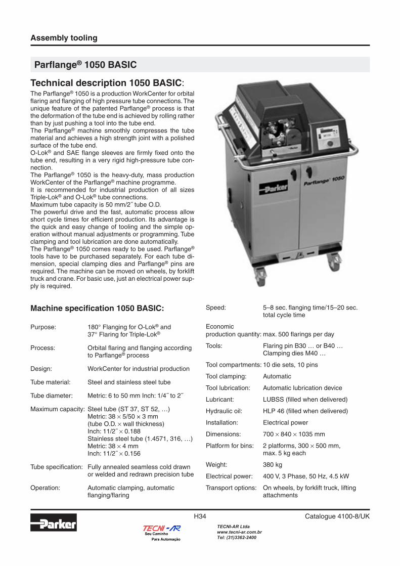
TECNI-AR Ltda www.tecni-ar.com.br Tel: (31)3362-2400
Assembly tooling
H34 Catalogue 4100-8/UK
Technical description 1050 BASIC:The Parfl ange® 1050 is a production WorkCenter for orbital fl aring and fl anging of high pressure tube connections. The unique feature of the patented Parfl ange® process is that the deformation of the tube end is achieved by rolling rather than by just pushing a tool into the tube end.The Parfl ange® machine smoothly compresses the tube material and achieves a high strength joint with a polished surface of the tube end.O-Lok® and SAE fl ange sleeves are fi rmly fi xed onto the tube end, resulting in a very rigid high-pressure tube con-nection.The Parfl ange® 1050 is the heavy-duty, mass production WorkCenter of the Parfl ange® machine programme.It is recommended for industrial production of all sizes Triple-Lok® and O-Lok® tube connections.Maximum tube capacity is 50 mm/2˝ tube O.D.The powerful drive and the fast, automatic process allow short cycle times for effi cient production. Its advantage is the quick and easy change of tooling and the simple op-eration without manual adjustments or programming. Tube clamping and tool lubrication are done automatically.The Parfl ange® 1050 comes ready to be used. Parfl ange® tools have to be purchased separately. For each tube di-mension, special clamping dies and Parfl ange® pins are required. The machine can be moved on wheels, by forklift truck and crane. For basic use, just an electrical power sup-ply is required.
Parfl ange® 1050 BASIC
Machine specifi cation 1050 BASIC:
Purpose: 180° Flanging for O-Lok® and37° Flaring for Triple-Lok®
Process: Orbital fl aring and fl anging according to Parfl ange® process
Design: WorkCenter for industrial production
Tube material: Steel and stainless steel tube
Tube diameter: Metric: 6 to 50 mm Inch: 1/4˝ to 2˝
Maximum capacity: Steel tube (ST 37, ST 52, …)Metric: 38 × 5/50 × 3 mm(tube O.D. × wall thickness)Inch: 11/2˝ × 0.188Stainless steel tube (1.4571, 316, …)Metric: 38 × 4 mmInch: 11/2˝ × 0.156
Tube specifi cation: Fully annealed seamless cold drawn or welded and redrawn precision tube
Operation: Automatic clamping, automatic fl anging/fl aring
Speed: 5–8 sec. fl anging time/15–20 sec. total cycle time
Economicproduction quantity: max. 500 fl arings per day
Tools: Flaring pin B30 … or B40 …Clamping dies M40 …
Tool compartments: 10 die sets, 10 pins
Tool clamping: Automatic
Tool lubrication: Automatic lubrication device
Lubricant: LUBSS (fi lled when delivered)
Hydraulic oil: HLP 46 (fi lled when delivered)
Installation: Electrical power
Dimensions: 700 × 840 × 1035 mm
Platform for bins: 2 platforms, 300 × 500 mm,max. 5 kg each
Weight: 380 kg
Electrical power: 400 V, 3 Phase, 50 Hz, 4.5 kW
Transport options: On wheels, by forklift truck, lifting attachments

TECNI-AR Ltda www.tecni-ar.com.br Tel: (31)3362-2400
H
Assembly tooling
H35 Catalogue 4100-8/UK
Technical description 1050 Pro:For industrial mass production of O-Lok® connections, spe-cial machines Parfl ange® 1050 PRO with O-Lok® sleeve feeder are available. This sleeve feeding device increases the productivity, particularly of high volume – single tube dimension jobs.
In “Feeder ON – mode”, O-Lok® sleeves just need to be in-serted into feeder rails. First cycle start is initiated by manu-ally closing the safety cover. Then, all following cycles are started by pushing the tube into the pre-clamped dies. All other machine activities, like tube clamping, fl anging, tube release, insertion of O-Lok® sleeves into dies, pre-clamping of dies and the operation of safety cover run fully automat-ic. The operator just is handling the tubes and refi lling the sleeve-feeder from times to times with O-Lok® sleeves.
In “Feeder OFF – mode”, the Parfl ange® 1050 PRO oper-ates like the Parfl ange® 1050 BASIC without O-Lok® sleeve feeder. This mode is useful for maximum size fl exibility and Triple-Lok® assembly. For quick changeover and safety rea-sons, the O-Lok® sleeve feeder is just switched OFF but not be removed from the Parfl ange® 1050 PRO WorkCenter.
For operation of O-Lok® PRO machines, compressed air supply is required, even when sleeve feeder is not used.
Parfl ange® 1050 PRO
Design: Parfl ange® 1050 with additionalO-Lok® sleeve feeder
Normal Operation: Same as Parfl ange® 1050 Basic when feeder is switched off
Feeder Operation: Work-cycle is initiated by inserting tube endAutomatic clamping, automatic fl anging/fl aringAutomatic insertion of O-Lok® sleeves into diesAutomatic operation of safety coverAutomatic pre-clamping of dies
Cycle time: 5–8 sec. fl anging time/approx.15 to 20 sec. total cycle time
Economicproduction quantity: max. 1200 fl arings per day
Tools: Same tools as Parfl ange®
1050 BASIC
Feeder: Feeder is delivered in separate box and must be fi rmly attached to machine.Feeder can be switched ON and OFF but must not be removed.
Feeder rails: Feeder rail kits must be ordered separately for each O-Lok® sleeve size.
Feeder setup: Installation of matching rail kit by knurled nuts and adjustment of scale wheel according to chart
Installation: Electrical power, for feeder type machines: compressed air supply(6 bar)
Dimensions: 700 × 840 × 2030 mm
Weight: 410 kg
Machine specifi cation 1050 PRO:
Specifi c differences of Parfl ange® 1050 Pro versus Parfl ange® 1050 Basic

TECNI-AR Ltda www.tecni-ar.com.br Tel: (31)3362-2400
Assembly tooling
H36 Catalogue 4100-8/UK
Parfl ange®
1050 BASIC
Parfl ange®
1050 PRO for mass production of O-Lok® assemblies
Feeder rail kits are available for each O-Lok® size
High-Performance lubricant for Parfl ange®
Parfl ange® 1050 Ordering
Type Order code
Parfl ange® 1050 Basic machineReady to use, including operation manual,fi lled with hydraulic oil and lubricantWithout Parfl ange® toolsBasis machine Europe version(not prepared for O-Lok® sleeve feeder)Purchase 1050EU400VBASICLeasing (2 year hire purchase) 1050BASICLEASEFEERent (monthly) 1050BASICRENTFEE
Type Order code
Parfl ange® 1050 PRO machineEurope versionincluding O-Lok® sleeve feederwithout feeder railsPurchase 1050EU400VPROLeasing (2 year hire purchase) 1050PROLEASEFEERent (monthly) not available
Sleeve feeder rails for Parfl ange® 1050 PRO Tube O.D. Order code
O-Lok® sleeve feeding rail 6 mm/1/4˝ 1050/RAIL04O-Lok® sleeve feeding rail 8, 10 mm/3/8˝ 1050/RAIL06O-Lok® sleeve feeding rail 12 mm/1/2˝ 1050/RAIL08O-Lok® sleeve feeding rail 14, 15, 16 mm/5/8˝ 1050/RAIL10O-Lok® sleeve feeding rail 18, 20 mm/3/4˝ 1050/RAIL12O-Lok® sleeve feeding rail 22, 25 mm/1˝ 1050/RAIL16O-Lok® sleeve feeding rail 28, 30, 32 mm/11/4˝ 1050/RAIL20O-Lok® sleeve feeding rail 35, 38 mm/11/2˝ 1050/RAIL24
1050 promotion leafl et 4391-1 via Parker catalogue service EMDC1050 operating manual UK/DE/FR/IT/ES 1050/MANUAL
Tool lubricant refi ll qty: 1L LUBSSReplacement cartridge for spindle lubrication 1050/22900001801
Parfl ange® machines and feeders are shipped in special containers which should be kept for future transports to avoid damage. Please don’t dispose the transport boxes!!!

TECNI-AR Ltda www.tecni-ar.com.br Tel: (31)3362-2400
H
Assembly tooling
H37 Catalogue 4100-8/UK
* Parfl ange® tools for stainless steel tubes have different dimensions and are specially coated. These tools are marked with suffi x “SS”.
Tooling for Parfl ange® machines
Machine and tool selection
Tube material
220 V 1,1 kW 380 V 1,5 kW
Max. tube size mm (inch)
Steel ST37 25 × 4 (1˝ × 0.120) 25 × 4 (1˝ × 0.120)
Stainless steel 25 × 4 (1˝ × 0.120) 25 × 4 (1˝ × 0.120)304L/316L*
Steel ST52 25 × 4 (1˝ × 0.120) 25 × 4 (1˝ × 0.120)
Elect. power of machine
Tube material 220 V 1.1 kW 380 V 1.5 kW Max. tube size mm (inch)
Steel ST37 25 × 3 (1˝ × 0.120) 25 × 3 (1˝ × 0.120)
Stainless steel304L/316L* 25 × 3 (1˝ × 0.120) 25 × 3 (1˝ × 0.120)Steel TU 52 B
Stainless steel Not 25 × 2.5Duplex (or PW 400) recommended (1× .095)
Parfl ange® 1025 machines fl aring capacityfor Triple-Lok®
Elect. power of machine
Tube material 220/380 V 4,5 kW Max. tube size mm (inch)
Steel TU 37 B 38 × 4/42 × 3 (11/2 × .120)
Steel TU 52 B 38 × 4/42 × 3 (11/2 × .120)
Stainless steel304L/316L* 38 × 4/42 × 3 (11/2 × .120)
Stainless steel Duplex 38 × 3.6(or PW 400)
Parfl ange® 1050 machines fl aring capacityfor Triple-Lok®
Parfl ange® 1025 machines fl anging capacityfor O-Lok®
Tube material Max tube size mm (inch)
Steel ST37 38 × 5/50 × 3 (2 × .120)
Steel ST52 38 × 4 (11/2 × .156)
Stainless steel 304L/316L* 38 × 4 (11/2 × .156)
Parfl ange® 1050 machines fl anging capacityfor O-Lok®
Parfl ange® 1050
Parfl ange® 1025

TECNI-AR Ltda www.tecni-ar.com.br Tel: (31)3362-2400
Assembly tooling
H38 Catalogue 4100-8/UK
Tooling for metric tubing
Metric die numbering system Metric pin numbering system
Die 180°-Flange Wall thickness Pin 180°-Flange Wall thickness
M 40 180 16 X 2 M B 30 180 16 X 2 M
For 1025/1030/1040/ Tube size Denotes For 1025/1030/1040/ Tube size Denotes 1050 machine metric size 1050 machine metric size
Parfl ange® tool identifi cation
Parfl ange® tools for O-Lok® Parfl ange® tools for Triple-Lok®
Parfl ange® tools for stainless steel tubes have different dimensions and are specially coated.These tools are marked with suffi x “SS”.
Tool lifetimeAssembly tools are subject of wear and must be regularely (max. 50 assemblies) cleaned and checked (Checking instructions see chapter E). Worn out tools can cause dangerous assembly failures and must be replaced in time. Average tool lifetime is approx. 5000 cycles when properly used. Maximum lifetime can be achieved by following factors:
● Regular cleaning and checking● Clean and corrosion-protected storage● Proper de-burring and cleaning of tube end● Proper tool selection and operation● Use of specifi ed lubricant
Tooling for inch tubing
Die numbering system Pin numbering system
Tube size Tube size (dash size and wall thickness in inches/1000) (dash size and wall thickness in inches/1000)
Die Pin
M 40 24 X 120 180 B 30 24 X 120 180
For 1025/1030/1040/1050 machine 180°-Flange For 1025/1030/1040/1050 machine 180°-Flange

TECNI-AR Ltda www.tecni-ar.com.br Tel: (31)3362-2400
H
Assembly tooling
H39 Catalogue 4100-8/UK
Parfl ange® tools for O-Lok®
Parfl ange® tooling – Order codes for Parfl ange® 1050/1040/1030/1025
90°-Flange-tool-selection (Metric tube)
Tube size
Steel tube Stainless steel tube
mm Flange pin Flange die Flange pin Flange die Order code Order code Order code Order code
6 × 1 B3018006X1M M4018006X1M 6 × 1.5 B3018006X1.5M M4018006X1.5M 8 × 1 B3018008X1M M4018008X1M B3018008X1MSS M4018008X1MSS 8 × 1.5 B3018008X1.5M M4018008X1.5M B3018008X1.5MSS M4018008X1.5MSS 10 × 1 B3018010X1M M4018010X1M B3018010X1MSS M4018010X1MSS 10 × 1.5 B3018010X1.5M M4018010X1.5M B3018010X1.5MSS M4018010X1.5MSS 10 × 2 B3018010X2M M4018010X2M 12 × 1 B3018012X1M M4018012X1M B3018012X1MSS M4018012X1MSS 12 × 1.5 B3018012X1.5M M4018012X1.5M B3018012X1.5MSS M4018012X1.5MSS 12 × 2 B3018012X2M M4018012X2M 15 × 1 B3018015X1MSS M4018015X1MSS 15 × 1.5 B3018015X1.5M M4018015X1.5M 15 × 2 B3018015X2M M4018015X2M 16 × 1.5 B3018016X1.5M M4018016X1.5M B3018016X1.5MSS M4018016X1.5MSS 16 × 2 B3018016X2M M4018016X2M B3018016X2MSS M4018016X2MSS 16 × 2.5 B3018016X2.5M M4018016X2.5M 18 × 1.5 B3018018X1.5M M4018018X1.5M 18 × 2 B3018018X2M M4018018X2M 20 × 2 B3018020X2M M4018020X2M B3018020X2MSS M4018020X2MSS 20 × 2.5 B3018020X2.5M M4018020X2.5M 20 × 3 B3018020X3M M4018020X3M 22 × 2 B3018022X2M M4018022X2M 22 × 2.5 B3018022X2.5M M4018022X2.5M 25 × 2.5 B3018025X2.5M M4018025X2.5M B3018025X2.5MSS M4018025X2.5MSS 25 × 3 B3018025X3M M4018025X3M 28 × 2 B3018028X2M M4018028X2M 28 × 2.5 B3018028X2.5M M4018028X2.5M 30 × 2 B3018030X2M M4018030X2M 30 × 3 B3018030X3M M4018030X3M B3018030X3MSS M4018030X3MSS 30 × 4 B3018030X4M M4018030X4M 32 × 3 B3018032X3M M4018032X3M 32 × 4 B3018032X4M M4018032X4M 35 × 3 B3018035X3M M4018035X3M 38 × 3 B3018038X3M M4018038X3M 38 × 4 B3018038X4M M4018038X4M
90°-Flange-tool-selection (Inch tube)
Tube size
Steel tube
inch Flange pin Flange die Order code Order code
1/4 × 0.035 B3004X035180 M4004X035180 1/4 × 0.049 B3004X049180 M4004X049180 3/8 × 0.035 B3006X035180 M4006X035180 3/8 × 0.049 B3006X049180 M4006X049180 3/8 × 0.065 B3006X065180 M4006X065180 1/2 × 0.035 B3008X035180 M4008X035180 1/2 × 0.049 B3008X049180 M4008X049180 1/2 × 0.065 B3008X065180 M4008X065180 5/8 × 0.065 B3010X065180 M4010X065180 5/8 × 0.083 B3010X083180 M4010X083180 3/4 × 0.065 B3012X065180 M4012X065180 3/4 × 0.083 B3012X083180 M4012X083180 3/4 × 0.095 B3012X095180 M4012X095180 3/4 × 0.120 B3012X120180 M4012X120180 1 × 0.065 B3016X065180 M4016X065180 1 × 0.095 B3016X095180 M4016X095180 1 1/4 × 0.120 B3020X120180 M4020X120180
Further tools for Inch tubing are available fromParker TFD Columbus!
Tool lifetimeAssembly tools are subject of wear and must be regularely (max. 50 assemblies) cleaned and checked (Checking instructions see chapter E). Worn out tools can cause dangerous assembly failures and must be replaced in time. Average tool lifetime is approx. 5000 cycles when properly used. Maximum lifetime can be achieved by following factors:
● Regular cleaning and checking● Clean and corrosion-protected storage● Proper de-burring and cleaning of tube end● Proper tool selection and operation● Use of specifi ed lubricant

TECNI-AR Ltda www.tecni-ar.com.br Tel: (31)3362-2400
Assembly tooling
H40 Catalogue 4100-8/UK
Parfl ange® tools for Triple-Lok®
Metric tube
Tube size
Steel tube Stainless steel tube
mm Flare pin Flare die Flare pin Flare die Order code Order code Order code Order code
6 × 1 B3007406X1M M4007406M B3007406X1MSS M4007406M 6 × 1.5 B3007406X1.5M M4007406M 8 × 1 B3007408X1M M4007408M B3007408X1MSS M4007408M 8 × 1.5 B3007408X1.5M M4007408M B3007408X1.5MSS M4007408M 10 × 1 B3007410X1M M4007410M B3007410X1MSS M4007410M 10 × 1.5 B3007410X1.5M M4007410M B3007410X1.5MSS M4007410M 12 × 1 B3007412X1M M4007412M 12 × 1.5 B3007412X1.5M M4007412M B3007412X1.5MSS M4007412M 12 × 2 B3007412X2M M4007412M 15 × 1.5 B3007415X1.5M M4007415M B3007415X1.5MSS M4007415M 15 × 2 B3007415X2M M4007415M 16 × 1.5 B3007416X1.5M M4007416M 16 × 2 B3007416X2M M4007416M B3007416X2MSS M4007416M 18 × 1.5 B3007418X1.5M M4007418M B3007418X1.5MSS M4007418M 18 × 2 B3007418X2M M4007418M 20 × 2 B3007420X2M M4007420M B3007420X2MSS M4007420M 20 × 2.5 B3007420X2.5M M4007420M B3007420X2.5MSS M4007420M 22 × 1.5 B3007422X1.5M M4007422M B3007422X1.5MSS M4007420M 22 × 2 B3007422X2M M4007422M 22 × 2.5 B3007422X2.5M M4007422M 25 × 2 B3007425X2M M4007425M B3007425X2.5MSS M4007425M 25 × 3 B3007425X3M M4007425M 28 × 2 B3007428X2M M4007428M 28 × 2.5 B3007428X2.5M M4007428M 30 × 3 B3007430X3M M4007430M B3007430X3MSS M4007430M 32 × 3 B3007432X3M M4007432M 35 × 3 B3007435X3M M4007435M 38 × 3 B3007438X3M M4007438M 38 × 4 B3007438X4M M4007438M B3007438X4MSS M4007438M 42 × 3 B3007442X3M M4007442M 42 × 4 B3007442X4M M4007442M
Tool lifetimeAssembly tools are subject of wear and must be regularely (max. 50 assemblies) cleaned and checked (Checking instruc-tions see chapter E). Worn out tools can cause dangerous assembly failures and must be replaced in time. Average tool life-time is approx. 5000 cycles when properly used. Maximum lifetime can be achieved by following factors:● Regular cleaning and checking● Clean and corrosion-protected storage● Proper de-burring and cleaning of tube
end● Proper tool selection and operation● Use of specifi ed lubricant
Inch tube
Tube size
Steel tube
inch Flange pin Flange die Order code Order code
1/4 × 0.049 B3004X049074 M4004074 3/8 × 0.049 B3006X049074 M4006074 3/8 × 0.065 B3006X065074 M4006074 1/2 × 0.065 B3008X065074 M4008074 5/8 × 0.065 B3010X065074 M4010074 5/8 × 0.095 B3010X095074 M4010074 3/4 × 0.095 B3012X095074 M4012074 1 × 0.109 B3016X109074 M4016074 1 1/4 × 0.120 B3020X120074 M4020074
Further tools for Inch tubing are available from Parker TFD Columbus!

TECNI-AR Ltda www.tecni-ar.com.br Tel: (31)3362-2400
H
Assembly tooling
H41 Catalogue 4100-8/UK
Parfl ange® tools for Flange SealFlange dies and Parfl ange® pins for machines 1050/1040/1030/1025 steel tube
Metric tube
Tube size Flange pin Flange die (O.D. × wall thickness) Order code Order code mm
6×1 B3018006X1M M4018006X1MLHP
8×1 B3018008X1M M4018008X1MLHP 8×1.5 B3018008X1.5M M4018008X1.5MLHP
10×1 B3018010X1M M4018010X1MLHP 10×1.5 B3018010X1.5M M4018010X1.5MLHP 10×2 B3018010X2M M4018010X2MLHP
12×1 B3018012X1M M4018012X1MLHP 12×1.5 B3018012X1.5M M4018012X1.5MLHP
16×2 B3018016X2M M4018016X2MLHP
20×2.5 B3018020X2.5M M4018020X2.5MLHP
25×2.5 B3018025X2.5M M4018025X2.5MLHP 25×3 B3018025X3M M4018025X3MLHP
Inch tube
Tube size Flange pin Flange die (O.D. × wall thickness) Order code Order code Inch
1/4×0.035 B4004X035180 M4004X035180LHP 1/4×0.049 B4004X049180 M4004X049180LHP
3/8×0.049 B4006X049180 M4006X049180LHP 3/8×0.065 B4006X065180 M4006X065180LHP
1/2×0.049 B4008X049180 M4008X049180LHP 1/2×0.065 B4008X065180 M4008X065180LHP 1/2×0.083 B400810X083180 M4008X083180LHP
5/8×0.065 B401010X065180 M4010X065180LHP
5/8×0.083 B401010X083180 M4010X083180LHP
3/4×0.065 B4012X065180 M4012X065180LHP 3/4×0.083 B4012X083180 M4012X08380LHP
1×0.095 B4016X095180 M4016X095180LHP
Clamping die set M … 180 Parfl ange® pin B … 180
Tool lifetimeAssembly tools are subject of wear and must be regularely (max. 50 assemblies) cleaned and checked (Checking instruc-tions see chapter E). Worn out tools can cause dangerous assembly failures and must be replaced in time. Average tool lifetime is approx. 5000 cycles when properly used. Maximum lifetime can be achieved by following factors:● Regular cleaning and checking● Clean and corrosion-protected storage● Proper de-burring and cleaning of tube end
● Proper tool selection and operation● Use of specifi ed lubricant

TECNI-AR Ltda www.tecni-ar.com.br Tel: (31)3362-2400
Assembly tooling
H42 Catalogue 4100-8/UK
LubricantsNIROMONT lubricant for fi tting assembly
LUBSS/LUBCAN lubricant for fl aring and forming tools
Ordering
Type Order code
NIROMONT Assembly lubricant paste (130 g) EONIROMONTPASTX
NIROMONT Assembly lubricant liquid (250 cc) EONIROMONTFLUESSX
Forming tool lubricant can (100 cc) 1040LUBCAN
Forming tool lubricant refi ll (1 L) LUBSS
NIROMONT is a high-performance lubricant which has been especially developed for the assembly of bite-type fi ttings.For best individual application, EO-Niromont is available in a small tin (paste) or plastic bottle (liquid).
LUBSS/LUBCAN is a special lubri-cant for fl aring dies, Parfl ange® tools and EO2-FORM tooling. It allows high-quality tube forming without ex-cessive tool wear.LUBSS is the standard Lubricant for the Parfl ange® machine automatic tool lubrication system.
Features, advantages and benefi ts of NIROMONT lubricant:1. Highly effective – Niromont dra-
matically reduces assembly effort. This helps to prevent fi tting failure resulting from insuffi cient assem-bly.
2. Cost saving – Tools in assembly machines will last much longer, re-sulting in high-quality tube forming with excellent sealing surface.
3. No cold welding – Cold welding of stainless steel threads is impossi-ble when EO-Niromont is properly applied.
4. Liquid – Penetrates even small gaps.
5. Paste – Stays in place for a while. Ideal for application on pre-assem-bly tools.
6. Compatible – NIROMONT and LUBSS/LUBCAN do not effect fi t-ting surfaces or seal materials.
LUBSS 1040LUBCAN
NIROMONT

TECNI-AR Ltda www.tecni-ar.com.br Tel: (31)3362-2400
H
Assembly tooling
H43 Catalogue 4100-8/UK
Provides a neat and quick method of cutting tube at right angles. The exact cut is achieved by hardened guides. We recommend using deeper-section sawblades that cut in both directions for best results. The AV 6/42 can be used in a vice or just be clamped onto the tube for cutting.
Specifi cations:Tube. O.D.: 6–42 mmWeight: approx. 0.7 kg
Type Order code
Tube cutting tool AV06/42KPLX
Spare hardenedguides AV06/4208X
Features, advantages and benefi ts of tube saw square:1. Square cut – Exact tube prepa-
ration greatly reduces leakage caused by assembly failures.
2. Contour clamping – Tube is not distorted by clamping.
3. No vice required – For workshop application AV 6/42 can simply be clamped onto the tube without us-ing a vice or other attachment.
4. Replaceable guides – Worn out guides can easily be replaced to maintain neat cutting result.
5. Light – At only 0.7 kg, the AV 6/42 should be carried in the toolbox of every hydraulic tube fi tter.
Cutting and bending tools
AV 6/42 – Tube saw square

TECNI-AR Ltda www.tecni-ar.com.br Tel: (31)3362-2400
Assembly tooling
H44 Catalogue 4100-8/UK
Cutting and bending tools
BAV 6/12 – Combined tube bending and cutting tool
The BAV 6/12 is a workshop device for neat tube cutting and simple but exact bending of small dimension EO-tube. Relatively small bending ra-dii can be achieved.
The exact cut is achieved with hard-ened guides and using sawblades which are notched on both sides. The BAV 6/12 can be used in a vice or just be clamped onto a workbench.
Specifi cations:Tube. OD: 6–12 mmWeight: approx. 2 kg
Type Order code
Combined tube bend-ing and cutting toolincluding 3 bendingrolls for 6 to 12 mmtube and bendinglever BAV06/12KPLX
Spare Parts
Spare hardened guide BAV06/1206X
Bending roll 6/8 mm BAV06/1209X
Bending roll 10 mm BAV06/1210X
Bending roll 12 mm BAV06/1211X
Bending pin BAV06/1207X
lever complete BAV06/1220KPLX
Bending dimensions in mm
Rolls for tube O.D. 6/8 10 12
Bending radius 19/20 25 26
In-Ex tube deburring tool 226
Material: Aluminum with hardened steel blades
Tube-O.D.: 4 to 42 mmWeight: 0.12 kg
Type Order code
Tube deburrer 226A
Replacement blades 226A Blades
Features, advantages and benefi ts of In-Ex tube deburring tool 226:1. Proper deburring – Exact tube
preparation greatly reduces leak-age caused by assembly failures.
2. Replaceable blades – Worn out blades can easily be replaced to maintain neat deburring result.
Features, advantages and benefi ts of combined tube bending and cutting tool:
1. Bending and cutting – The BAV 6/12 is a light multi-purpose tool for all small dimension tube as-semblies.
2. Square cut – Exact tube prepa-ration greatly reduces leakage caused by assembly failures.
3. No vice required – For workshop application BAV 6/12 can simply be clamped onto a workbench.
4. Small bending radii – Compact tube bends allow tight assemblies.
5. Light – At only 2 kg, the BAV 6/12 can be easily brought to the as-sembly site.
6. Optimised bending roller con-tour – Special shape of bending roller allows small bends without tube fl attening.
3. Light – At only 0.12 kg, the In-Ex tube deburring tool should be car-ried in the toolbox of every hydrau-lic tube fi tter.
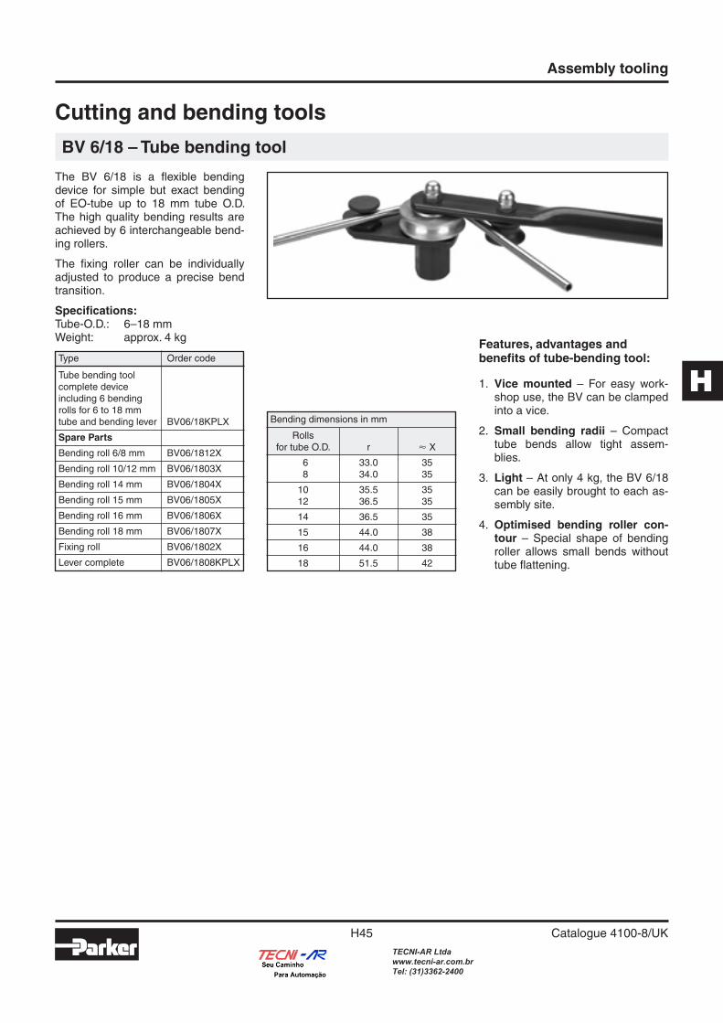
TECNI-AR Ltda www.tecni-ar.com.br Tel: (31)3362-2400
H
Assembly tooling
H45 Catalogue 4100-8/UK
Cutting and bending tools
BV 6/18 – Tube bending tool
The BV 6/18 is a fl exible bending device for simple but exact bending of EO-tube up to 18 mm tube O.D. The high quality bending results are achieved by 6 interchangeable bend-ing rollers.
The fi xing roller can be individually adjusted to produce a precise bend transition.
Specifi cations:Tube-O.D.: 6–18 mmWeight: approx. 4 kg
Type Order code
Tube bending toolcomplete deviceincluding 6 bendingrolls for 6 to 18 mmtube and bending lever BV06/18KPLX
Spare Parts
Bending roll 6/8 mm BV06/1812X
Bending roll 10/12 mm BV06/1803X
Bending roll 14 mm BV06/1804X
Bending roll 15 mm BV06/1805X
Bending roll 16 mm BV06/1806X
Bending roll 18 mm BV06/1807X
Fixing roll BV06/1802X
Lever complete BV06/1808KPLX
Bending dimensions in mm
Rolls for tube O.D. r � X
6 33.0 35 8 34.0 35
10 35.5 35 12 36.5 35
14 36.5 35
15 44.0 38
16 44.0 38
18 51.5 42
Features, advantages and benefi ts of tube-bending tool:
1. Vice mounted – For easy work-shop use, the BV can be clamped into a vice.
2. Small bending radii – Compact tube bends allow tight assem-blies.
3. Light – At only 4 kg, the BV 6/18 can be easily brought to each as-sembly site.
4. Optimised bending roller con-tour – Special shape of bending roller allows small bends without tube fl attening.

TECNI-AR Ltda www.tecni-ar.com.br Tel: (31)3362-2400
Assembly tooling
H46 Catalogue 4100-8/UK
Features, advantages and ben-efi ts of tube-bending tool:
1. Rigid design – The solid de-sign and the bar extension allow manual bending without heating the tube.
2. Optimised bending roller con-tour – Special shape of bending roller allows small bends without tube fl attening.
BV 20/25 – Tube bending tool
The BV 20/25 allows bending of medium size tube at the assembly site. The bending lever shows two universal studs. A bar extension can either be ordered or locally made.
Specifi cations:Tube-O.D.: 20–25 mm3 bendingsegments: 20, 22, 25 mmBending radius: r = 86,5 mm
x = 52 mmWeight: approx. 15 kg (with-
out bar extension)
Type Order code
BV 20/25 Tube bendingtool bending deviceincluding 3 bendingsegments for tube O.D.20 to 25 mm includingbending lever withoutbar extension tube BV20/25KPLX
Spare Parts
Bending segment 20 mm BV20/2501X
Bending segment 22 mm BV20/2502X
Bending segment 25 mm BV20/2503X
Fixing arm BV20/2505X
Lever complete BV20/2506KPLX
Bar extension tube BV20/2510X
3. Shaped clamping – Tube is not distorted by clamping.
4. Small bending radii – Compact tube bends allow for compact assemblies.
5. Vice mounted – For easy work-shop use, the BV can be clamped into a vice.

TECNI-AR Ltda www.tecni-ar.com.br Tel: (31)3362-2400
H
Assembly tooling
H47 Catalogue 4100-8/UK
Inch Sizes Metric Sizes
Hex Size Order code Hex Size Order code Hex Size Max. torque Nm Order code
3/8 860062-6 1 1/8 860062-18 10 mm 35 860063-10 7/16 860062-7 1 1/4 860062-20 11 mm 37 860063-11 1/2 860062-8 1 3/8 860062-22 12 mm 42 860063-12 9/16 860062-9 1 1/2 860062-24 13 mm 45 860063-13 5/8 860062-10 1 5/8 860062-26 14 mm 57 860063-14 11/16 860062-11 1 7/8 860062-30 16 mm 88 860063-16 3/4 860062-12 2 860062-32 17 mm 107 860063-17 13/16 860062-13 2 1/4 860062-36 19 mm 125 860063-19 7/8 860062-14 Full kit of all 860062-KIT2 21 mm 149 860063-21 15/16 860062-15 eight wrenches 22 mm 178 860063-22 1 860062-16 O-Lok® kit 860062-LKIT 24 mm 209 860063-24 Full kit 860062-KIT (six wrenches) 27 mm 100 860063-27 of all eleven sizes Triple-Lok®/Ferulok kit 860062-XUKIT 30 mm 100 860063-30 (fi ve wrenches) 32 mm 170 860063-32 36 mm 170 860063-36 41 mm 310 860063-41 Full kit 860063-KIT of all ten sizes 10 to 22 mm
Hand-tools
Par-Lok wrench
360° Snap-action ratchet wrench for hex sizes from 10 mm to 41 mm and inch sizes from 3/8˝ to 21/4˝ accross fl ats. Inch sizes meet US government specifi cations and are listed as NSN-5120-00-474-7227.
Easy fi tting assemblyEasy access ratchet wrench speeds fi ttings installation in tight loca-tions. Rugged, snap-action jaws can be opened over tube lines, locked onto fi tting hex and ratcheted within1/8 turn. Full six point contact prevents fi tting distortion common with wrench slippage. Ideal for tube line installa-tions where compact runs required multiple fi ttings make-up, disassem-bly and remakes.
Specifi cationsPar-Lok wrenches are available in-dividually or in different kit combina-tions. Par-Lok jaws are constructed from drop-forged, high carbon steel material with a black conversion coat fi nish. Par-Lok handles are made from heavy gauge steel material, heat treated and with a corrosion resist-ant black fi nish. Solid stainless steel rivets and tempered jaw springs are designed into every wrench for maxi-mum strength.
O-Lok® wrench kitSix piece wrench set for use with O-Lok® body and nut sizes -4, -6, -8. Kit contains wrenches for hex sizes 5/8˝, 11/16˝, 3/4˝, 13/16˝, 7/8˝ and 15/16˝.
Triple-Lok® & Ferulok wrench kitFive piece wrench set for use with Triple-Lok® and Ferulok body and nut sizes -4, -6, -8, -10, -12. Kit contains wrenches for hex sizes 9/16˝, 11/16˝, 7/8˝, and 1˝ and 1/4˝.
Features, advantagesand benefi tsof Par-Lok wrench:1. 360° – No slipping and hexagon
damage.
2. Snap-mechanism – Ideal for tube fi tting assembly.
3. Light – Par-Lok wrenches belong in the standard toolbox of each fi tting engineer.
Par-Lok wrench Par-Lok wrench kit O-Lok® wrench kit Triple-Lok® & Ferulok wrench kit

TECNI-AR Ltda www.tecni-ar.com.br Tel: (31)3362-2400
Assembly tooling
H48 Catalogue 4100-8/UK
Type Content Order code
Toolbox WZK1 BV6/18 tube bending tool WZK1KOMPLX Toolbox WZK2 BV6/18 tube Bending tool, AV6/42 tube saw WZK2KOMPLX square, Hacksaw, Flat fi le, Deburring tool, fi xture for assembly cones VOMO and cone gauge KONU
WZK – Tool boxes
Tools which are regularly used for tube preparation and bending are available in organized tool boxes. Two sets are avail-able:
Features, advantages and benefi ts:1. Well organised – Nothing gets dirty,
damaged, lost or forgotten.
2. Practical – In one box you take every-thing to the assembly site.
3. Rigid – The solid metal box is suitable for daily workshop use.

TECNI-AR Ltda www.tecni-ar.com.br Tel: (31)3362-2400
H
Assembly tooling
H49 Catalogue 4100-8/UK
O-ring assembly tools
CORG O-ring installation tool for O-Lok®
Ordering
Corg toolOrder code Fitting size O-ring size
CORG-4 – 4 2-011
CORG-6 – 6 2-012
CORG-8 – 8 2-014
CORG-10 –10 2-016
CORG-12 –12 2-018
CORG-16 –16 2-021
CORG-20 –20 2-025
CORG-24 –24 2-029
CORG-32 –32 2-135
Parker’s CORG Assembly Tools are designed to facilitate the installation of the O-ring into the half-dovetail groove of the O-ring face seal fi tting. They are available in sizes –4 to –32 (6 mm to 50 mm/1/4˝ to 2˝ tube).
OperationSee chapter F “Fitting assembly”for detailed instructions
The CORG assembly tool is easy to use and can be oper-ated in just a few steps:
1. Insert the O-ring into the slot located on the side of the tool.
2. Position the open end of the tool over the ORFS end of the fi tting.
3. With the fi tting end bottomed inside the tool, push the piston of the tool until the O-ring is released into the fi tting groove.
O-ring pick for O-Lok®
A plastic O-ring pick to allow easy removal of O-rings with-out causing damage to the fi tting.
Ordering
Type Order code
Plastic O-ring pick device O-RINGPICK
O-ring pick
Features, advantages and benefi tsof O-Ring installation tools
1. Special – O-ring installation tools are especially de-signed for O-Lok® fi ttings with CORG groove. O-rings are not torn or damaged at assembly.
2. Cost saving – O-ring installation tools are easy to use and save time and cost when O-rings need to be as-sembled.

TECNI-AR Ltda www.tecni-ar.com.br Tel: (31)3362-2400
Assembly tooling
H50 Catalogue 4100-8/UK
Port cutting tools
Counterbore tools and thread taps for metric ports
For manufacturing metric ports to ISO 6149 (Details see chapter D).
These tools allow correct manufacturing of metric port connections. Counterbore tools and thread taps are made of high speed tool steel.
ISO 6149 Order code
Port Large Small size Spot face1) Spot face2)
M08×1 R1449A R1449BM10×1 R1450A R1450BM12×1.5 R1451A R1451BM14×1.5 R1452A R1452BM16×1.5 R1453A R1453BM18×1.5 R1454A R1454BM22×1.5 R1455A R1455BM27×2 R1456A R1456BM33×2 R1457A R1457BM42×2 R1458A R1458BM48×2 R1459A R1459B
Part thread Order code
ISO
M10 M10×1-6H-TAP
M12 M12×1.5-6H-TAP
M14 M14×1.5-6H-TAP
M16 M16×1.5-6H-TAP
M18 M18×1.5-6H-TAP
M22 M22×1.5-6H-TAP
M27 M27×2-6H-TAP
M33 M33×2-6H-TAP
M42 M42×2-6H-TAP
M48 M48×2-6H-TAP
Ordering thread tapsOrdering counterbore tools
Counterbore tools and thread taps for straight SAE thread portsFor manufacturing UNF ports to SAE J 1926-1 (details see chapter D)
These tools allow correct manufacturing of UNF port connections. Counterbore tools and thread taps are made of high speed tool steel.
counterbore tools thread taps
Use with SAE UNF dash Order thread size size code
5/16-24 2 Y-34730 3/8-24 3 Y-34731 7/16-20 4 Y-34732 1/2-20 5 Y-34733 9/16-18 6 Y-34734 3/4-16 8 Y-34735 7/8-14 10 Y-34736 1 1/16-12 12 Y-34737 1 3/16-12 14 Y-34738 1 5/16-12 16 Y-34739 1 5/8-12 29 Y-34740 1 7/8-12 24 Y-34741 2 1/2-12 32 Y-34743
UNF SAE thread dash size size Order code
5/16-24 2 5/16X24 UNF-2B 3/8-24 3 3/8X24 UNF-2B 7/16-20 4 7/16X20 UNF-2B 1/2-20 5 1/2X20 UNF-2B 9/16-18 6 9/16X18 UNF-2B 3/4-16 8 3/4X16 UNF-2B 7/8-14 10 7/8X14 UNF-2B 1 1/16-12 12 1 1/16X12 UNF-2B 1 3/16-12 14 1 3/16X12 UNF-2B 1 5/16-12 16 1 5/16X12 UNF-2B 1 5/8-12 29 1 5/8X12 UNF-2B 1 7/8-12 24 1 7/8X12 UNF-2B 2 1/2-12 32 2 1/2X12 UNF-2B
1) with ID-groove2) without ID-groove

TECNI-AR Ltda www.tecni-ar.com.br Tel: (31)3362-2400
H
1 2 3
Assembly tooling
H51 Catalogue 4100-8/UK
Operation of port cutting tools
1. Pilot hole drilling 2. Port counterboring 3. Thread tapping
Note:All dimensions must be according to relevant standards. See chapter D for details.It is necessary to create a spotface surface which is fl at and perpendicular to the port. Smooth fi nish to prevent leakage or O-ring extrusion.
Parker counterbore tools are made from high speed tool steel (HSS). Regular HSS port tapping tools are intented for workshop use and repair.Maximum lifetime of Parker counterbores can be achieved by:● use for cutting mild steel or aluminium only● staying within recommended cutting speed for HSS / port material● suffi ciant lubrication and cooling● workshop use and repair only
For serial production of hydraulic ports, these Parker workshop tools are not suitable.For production, Parker generally recommends to use hard carbide alloy.

TECNI-AR Ltda www.tecni-ar.com.br Tel: (31)3362-2400
Assembly tooling
H52 Catalogue 4100-8/UK
Portboard
Thread identifi cation
Thread identifi cation kit
The thread identifi cation tools are benefi cial in the assist-ance of the identifi cation of international threads such as:
● European threads(Metric, BSPP, BSPT threads) and
● U.S. threads(NPT and SAE straight threads UNF)
The Thread Identifi cation Kit is equipped with thread gaug-es, a set of callipers, thread profi les, and an instruction booklet.
The components of the thread ID Kit are no high precision gauges but simple instruments for workshop use.
Portboards are suitable for thread identifi cation of male stud connectors. The two portboards are machined with female threads for quick and easy identifi cation by simply screwing the appropriate male port end.
● European(Metric, BSPP/BSPT threads)
● U.S.(NPT and SAE straight threads UNF)
Ordering
Type Order code
Thread identifi cation kit MIK-1
Ordering
Type Order code
Portboard for NPT and SAE straight threads Portboard APortboard for Metric and BSPP/BSPT threads Portboard B
Attention: The kit is only available in english!
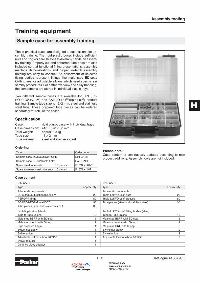
TECNI-AR Ltda www.tecni-ar.com.br Tel: (31)3362-2400
H
Assembly tooling
H53 Catalogue 4100-8/UK
Training equipment
Sample case for assembly training
These practical cases are designed to support on-site as-sembly training. The rigid plastic boxes include suffi cient nuts and rings or fl are sleeves to do many hands-on assem-bly training. Properly cut and deburred tube-ends are also included so that functional fi tting presentations, assembly machine demonstrations and proper in-depth assembly training are easy to conduct. An assortment of selected fi tting bodies represent fi ttings like male stud ED-seal/O-Ring seal or adjustable elbows which need specifi c as-sembly procedures. For better overview and easy handling, the components are stored in individual plastic trays.
Two different sample cases are available for DIN (EO/EO2/EO2-FORM) and SAE (O-Lok®/Triple-Lok®) product training. Sample tube size is 16×2 mm, steel and stainless steel tube. These prepared tube pieces can be ordered separately for refi ll of the cases.
Specifi cationCase: rigid plastic case with individual traysCase dimension: 410 × 320 × 80 mmTotal weight: approx. 10 kgTube size: 16 × 2 mmTube material: steel and stainless steel
OrderingType Order code
Sample case EO/EO2/EO2-FORM DIN-CASE
Sample case O-Lok®/Triple-Lok® SAE-CASE
Spare steel tube ends 10 pieces R16X2X140VZ
Spare stainless steel tube ends 10 pieces R16X2X14071
Please note:Case content is continuously updated according to new product additions. Assembly tools are not included.
Case content
DIN CASE SAE CASE
Type approx. qty Type approx. qty
Tube end components: Tube end components:EO nuts/EO2 functional nuts FM 20 Triple-Lok®/O-Lok® nuts 20PSR/DPR rings 50 Triple-Lok®/O-Lok® sleeves 50EO2/EO2-FORM seal DOZ 50 Tube pieces (steel and stainless steel) 30Tube pieces (steel and stainless steel) 30
EO fi tting bodies (steel): Triple-Lok®/O-Lok® fi tting bodies (steel):Tube to Tube unions 10 Tube to Tube unions 10Male stud BSPP with ED-seal 5 Male stud BSPP with ED-seal 5Male stud metric with O-ring 2 Male stud metric with O-ring 2High pressure banjo 1 Male stud UNF with O-ring 2Swivel nut elbow 1 Swivel nut elbow 2Swivel union 1 Swivel union 2Adjustable locknut elbow 90°/45° 1 Adjustable locknut elbow 90°/45° 2Swivel reducer 1Distance piece adapter 1

TECNI-AR Ltda www.tecni-ar.com.br Tel: (31)3362-2400
Assembly tooling
H54 Catalogue 4100-8/UK
Features, advantages and benefi ts1. Practical – The cases and the content have been se-
lected from experienced trainers for use with TFDE products.
2. Effi cient – The use of these case saves preparation time and effort.
3. Impressive – Customers on workshop level will be im-pressed on the simple but professional training equip-ment.
4. Give-away samples – Samples of the assemblies can stay at the customer. This will help to illustrate product function and demonstrate TFDE products.
5. Dry Technology – As both, traditional and Dry Technology products are included, this case is a powerful and con-vincing sales tool particularly on workshop level.
Training aids
The “Leak-free Hydraulic Connectors” pocket book
The 226th volume in the series “The Technology Library”, entitled “Leak-free Hydraulic Connectors”, has been pub-lished by “Verlag Moderne Industrie”. It represents the most comprehensive treatment of high pressure connec-tion technology presently available in the english language. Organised according to the fi tting system, not only the latest developments in connecting and assembly technology but also national and international standards as well as market trends are clearly described. Each chapter is rounded off with detailed advice on practical application.
Specifi cationTitle: Leak-free Hydraulic ConnectorsContents: Standards, operating principles and
assembly for tube fi ttingsAuthor: Bernd Schmehl, Parker Hannifi nPublisher: Verlag Moderne Industrie, Landsberg/Lech
2002, Germany This edition: 96 pages, 48 colour illustrations, hardbackISBN-Nr: ISBN 3-478-93267-X
OrderingThe shipment will be done by the EMDC (European Mar-keting Distribution Center). Concerning your order please ask your Certifi ed Distributor or the Parker Trading Sub-sidary.
Features, advantages and benefi ts1. Up-to-date knowledge – This pocket book is ideal for
those who are new to this fi eld and who want to fi nd their way quickly and easily into the subject. But also for users whose professional training goes back over many years, this pocket book makes for interesting reading, containing as it does information on and evaluation of the latest product solutions and assembly technology.
2. Practical – The publication is intended not only as a reference book but also as something that can be read when travelling. It is ideally suited as a gift.
3. Competitor-neutral – To a large extent the contents lean more towards international standards and less to manufacturer-specifi c products. This pocket book is therefore ideal for use in teaching and in-house training and further education.
4. Problem solver – Leakage problems occur frequently in hydraulic systems. The book helps to determine and eliminate the causes. For new projects, it can be con-sulted for the specifi cation and planning of assembly work.