Assembler course, Lecture 1
17
AVR Microcontrollers Hardware, Internals and Programming of AVR Microcontrollers in Assembler by Gerhard Schmidt Kastanienallee 20 D-64289 Darmstadt
-
Upload
khangminh22 -
Category
Documents
-
view
1 -
download
0
Transcript of Assembler course, Lecture 1
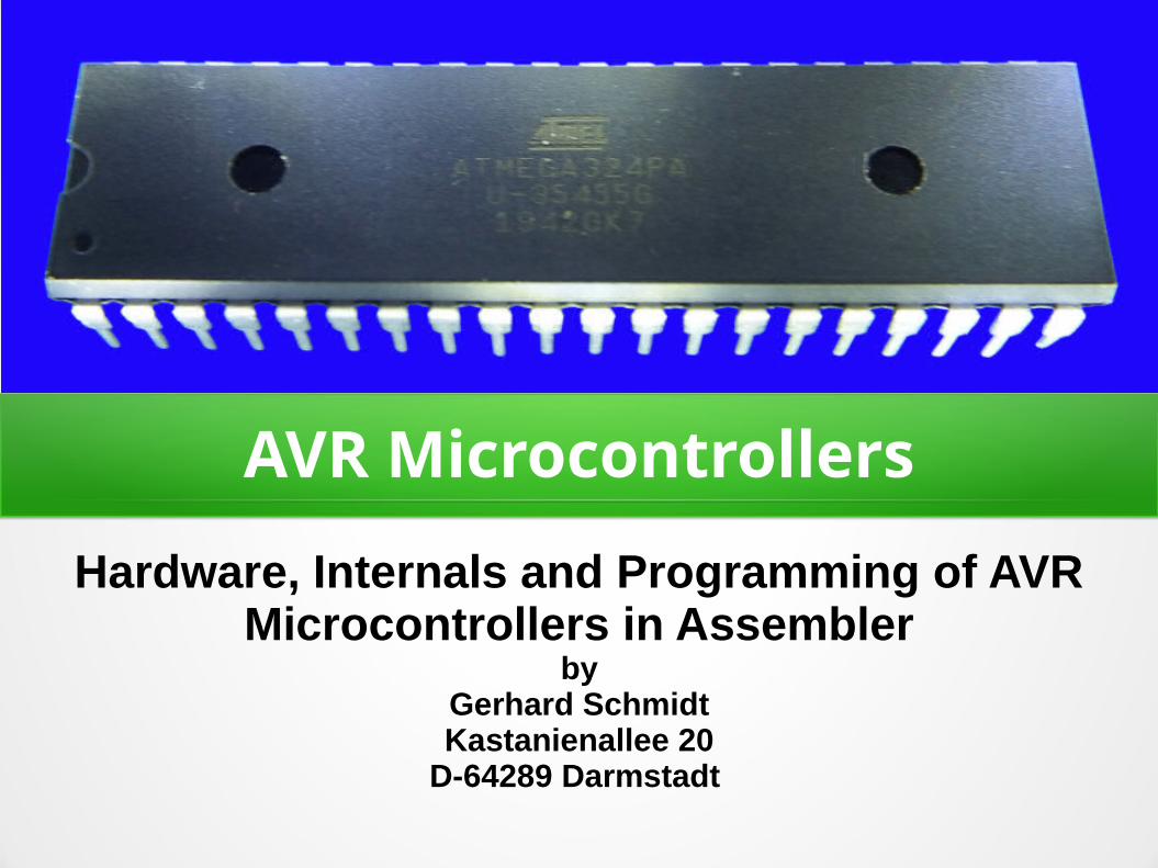
AVR MicrocontrollersHardware, Internals and Programming of AVR
Microcontrollers in Assemblerby
Gerhard SchmidtKastanienallee 20
D-64289 Darmstadt

AVR MicrocontrollersMicrocontrollers are Integrated Circuits (ICs).They can have 6, 8, 14, 20, 28, 40, 64 or 100pins.
AVRs are available in more than 460 differenttypes. So they can be tailored to verydifferent hardware needs.
They are equipped with lots of internalhardware, which can be involved whenneeded by programming them. This is whysuch controllers are extremely versatile andcan be used for thousands of purposes.
Their main features are:1)Very small power
consumption (a few mA).
2)Very fast reaction to external events (a few µs).
3)Flash memory, static RAM and durable EEPROM on board.

Program execution in AVRs● The program of the AVR is located in the flash memory as 16-bit binary
words.
Flashmemory
Programcounter
Instructiondecoder
Instructionexecution
Clockoscillator
● Driven by a clock oscillator the program counter addresses the next instruction to be executed, a decoder splits this 16-bit-word into individual steps and the instruction executor (called Central Processing Unit = CPU) executes these.
● AVRs use pre-fetch: while the CPU executes the last instruction, the decoder already decodes the next instruction word. If the last execution did not change the program counter, the next instruction can be executed immediately. Most instructions need only ONE clock oscillator cycle to be executed. This nearly doubles the execution speed (MIPS, Mega-Instructions Per Second) on the same clock frequency.

Unique: Plenty registers in AVRs● AVRs have 32 registers on board (ATtiny4/5/9/10: 16).● Each register provides 8 bit storage space (256 single bits).● Setting a register to a constant number is achieved by the following
assember source code (text on green background is assembler):
; Loading a number to a register in assembler source code formatLDI R16, 85 ; Write the decimal number 85 to register number 16LDI R16, 0B01010101 ; Write the binary number 01010101 to register 16LDI R16, 0X55 ; Write the hexadecimal number 55 to register 16
● The 32 registers can be used as source and as target of instructions. ● The following assembler source code
● loads decimal 15 to register R16,● loads decimal 55 to register R17, ● adds both numbers and writes the result to R17.
; Loading and adding two numbersLDI R16, 15 ; Write the decimal number 15 to register number 16LDI R16, 55 ; Write the decimal number 01010101 to register 17ADD R17, R16 ; Add the content of R16 to R17 and write the result to R17
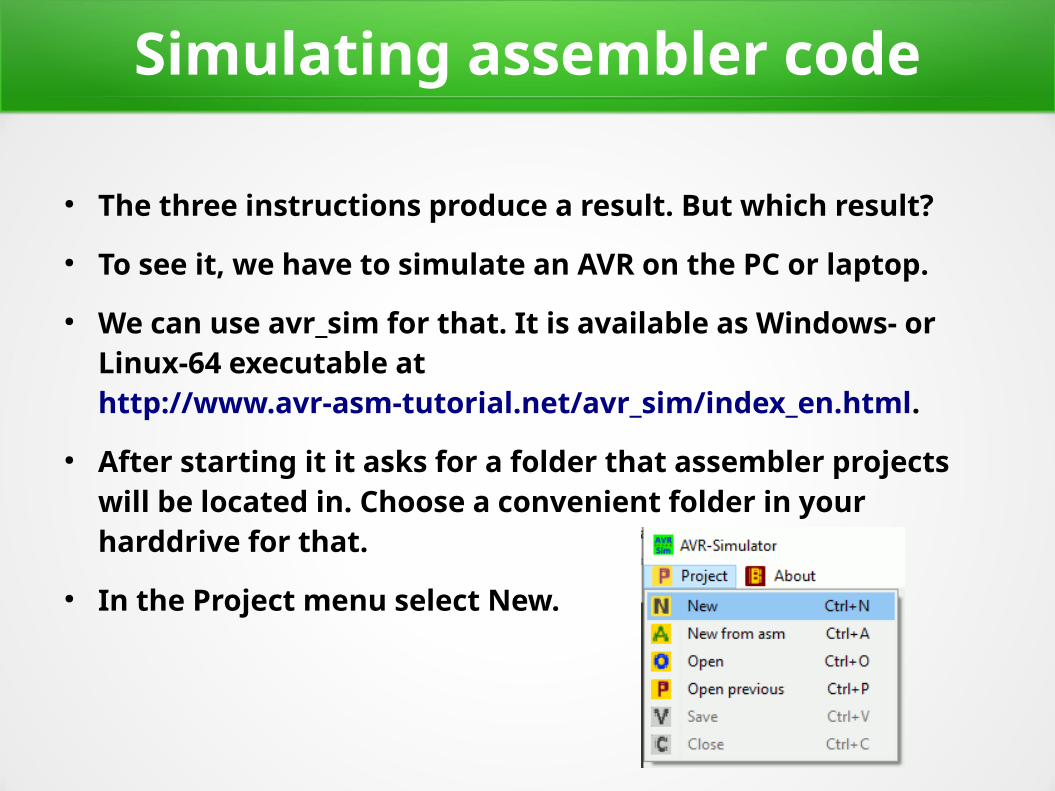
Simulating assembler code
● The three instructions produce a result. But which result?● To see it, we have to simulate an AVR on the PC or laptop.● We can use avr_sim for that. It is available as Windows- or
Linux-64 executable at http://www.avr-asm-tutorial.net/avr_sim/index_en.html.
● After starting it it asks for a folder that assembler projects will be located in. Choose a convenient folder in your harddrive for that.
● In the Project menu select New.
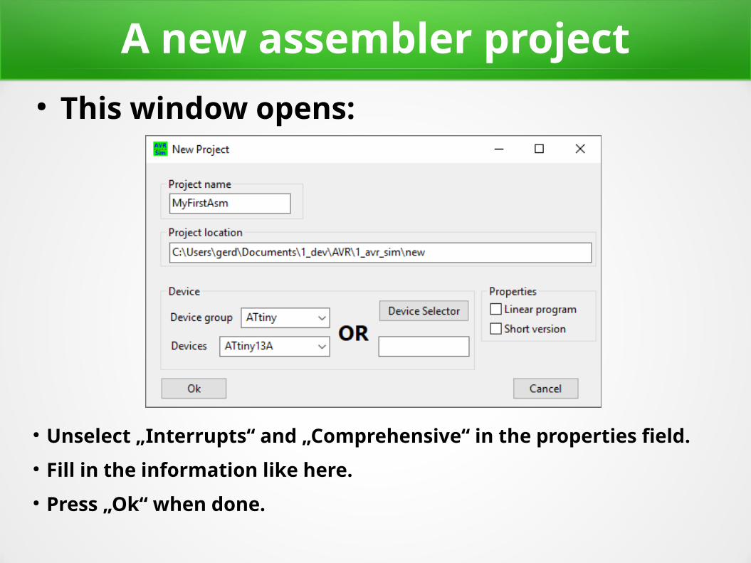
A new assembler project● This window opens:
● Unselect „Interrupts“ and „Comprehensive“ in the properties field.● Fill in the information like here.● Press „Ok“ when done.
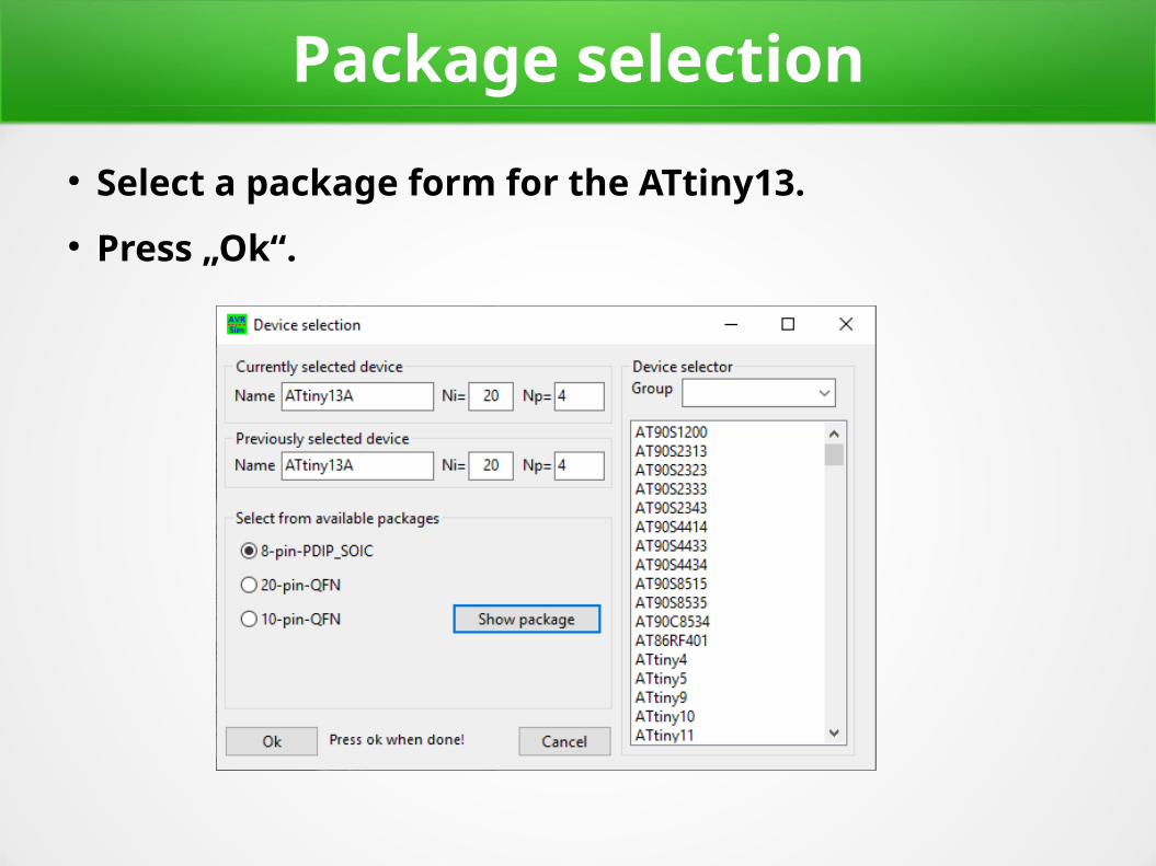
Package selection● Select a package form for the ATtiny13.● Press „Ok“.
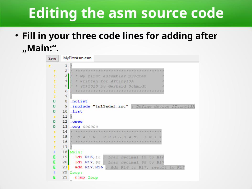
Editing the asm source code● Fill in your three code lines for adding after
„Main:“.

Assembling and simulating● Now press „Assemble“ and then „Simulate“.
● The simulation window now shows● the program counter (always starts at address zero),● the number of executed instructions (none so far), ● the clock frequency of the AVR (1.2 MHz by default),
● The blue arrow in the editor window left points to the line in the assembler listing, where the first executable instruction is located. This is the instruction that will be executed next (when STEP will be clicked).
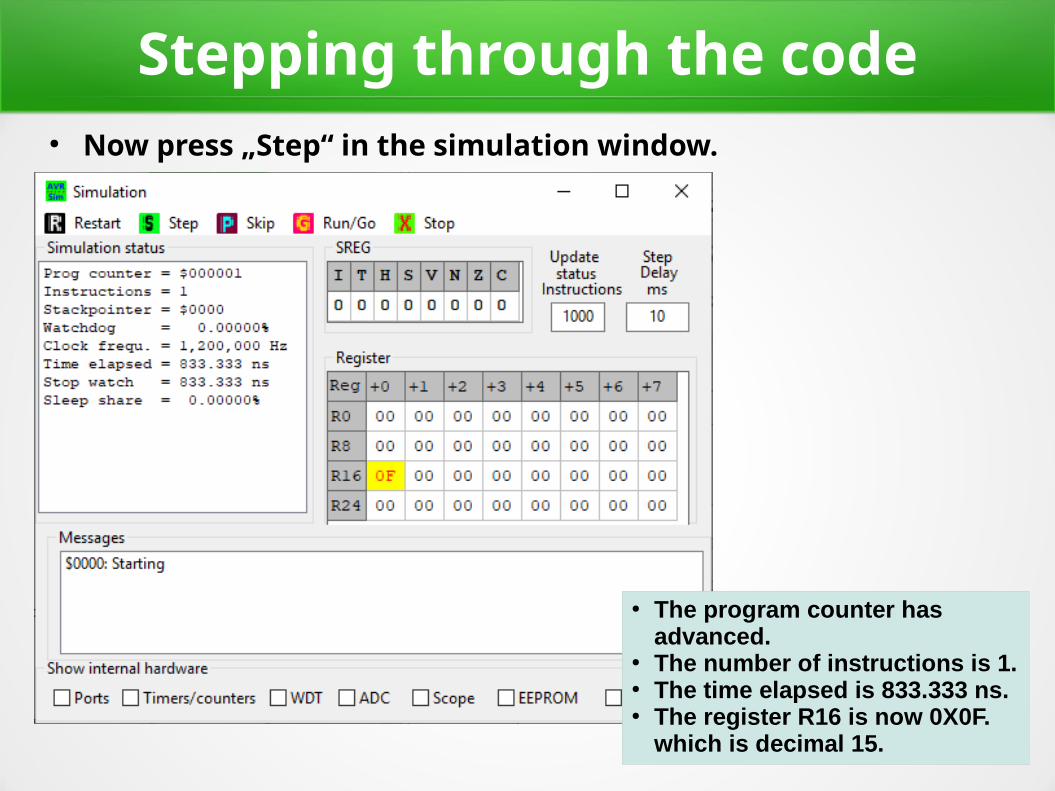
Stepping through the code● Now press „Step“ in the simulation window.
● The program counter hasadvanced.
● The number of instructions is 1.● The time elapsed is 833.333 ns.● The register R16 is now 0X0F.
which is decimal 15.
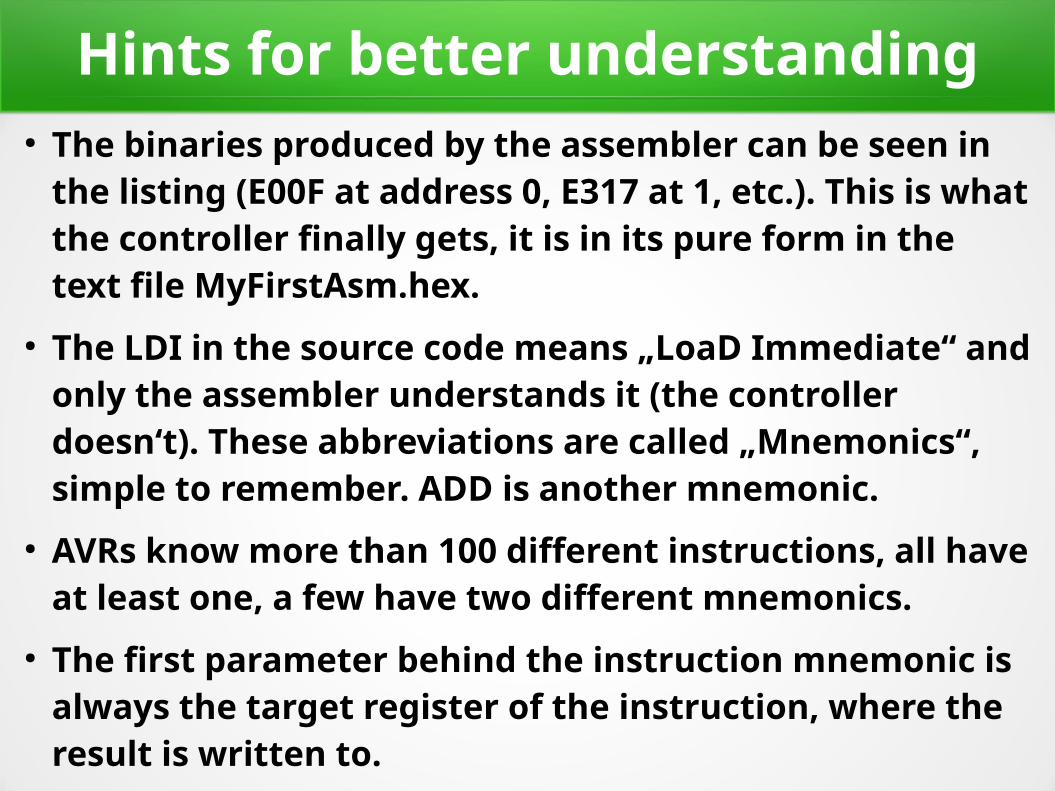
Hints for better understanding● The binaries produced by the assembler can be seen in
the listing (E00F at address 0, E317 at 1, etc.). This is what the controller finally gets, it is in its pure form in the text file MyFirstAsm.hex.
● The LDI in the source code means „LoaD Immediate“ and only the assembler understands it (the controller doesn‘t). These abbreviations are called „Mnemonics“, simple to remember. ADD is another mnemonic.
● AVRs know more than 100 different instructions, all have at least one, a few have two different mnemonics.
● The first parameter behind the instruction mnemonic is always the target register of the instruction, where the result is written to.

Simulation visualizes execution● If you press „Step“ two further times, you‘ll
see the result of adding 15 and 55 in Register R17.
● The elapsed time is still only in the microseconds range: very fast.
● Thanks to simulating we see what will be going on inside the microcontroller.
● We‘ll use this tool later on whenever we need to understand more complex instructions.
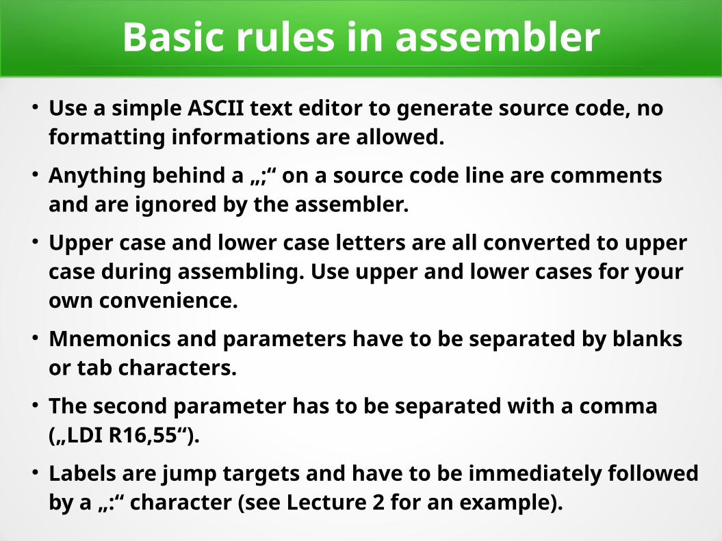
Basic rules in assembler● Use a simple ASCII text editor to generate source code, no
formatting informations are allowed.● Anything behind a „;“ on a source code line are comments
and are ignored by the assembler.● Upper case and lower case letters are all converted to upper
case during assembling. Use upper and lower cases for your own convenience.
● Mnemonics and parameters have to be separated by blanks or tab characters.
● The second parameter has to be separated with a comma („LDI R16,55“).
● Labels are jump targets and have to be immediately followed by a „:“ character (see Lecture 2 for an example).

Why assembler and not C?● Assembler translates each line of the source code directly to
its binary representation. It can be seen directly, what the controller does with it.
● C is in-transparent: no such direct connection between source code and executed instructions. One line of C source code can cause thousands of single instructions and the programmer has no chance to understand what is really going on inside.
● In assembler you‘ll learn exactly how the internal hardware works. No hidden stuff between you and the hardware.
● In C you can program without even knowing something about the controller: the compiler is between you and the controller, and you have no chance to understand.

Questions and Tasks for Lecture 1
Question 1-1: Nearly all source code examples use Register # 16. Why not Register # 0?
(Hint: Change the source code of one example to use R0 instead of R16 and try to understand the resulting error message when assembling.)
Try to find out which types of instructions can only use R16 and above (Use the Instruction Set Manual for 8-bit-AVRs provided by Microchip for that).

Questions and Tasks for Lecture 1, Continued
Question 1-2: Which range of integer numbers can be handled
a) in 8-bits,
b) in 16 bits,
c) in 24 bits, and
d) in 32 bits.
(Hint: Under Windows use the provided calculator in the „Programmer“ mode and switch to the Hexadecimal input mode.)

Questions and Tasks for Lecture 1, Continued
Task 1-3: Find out how many registers the following CPUs provided and at which maximum clock frequencies they ran:
a) ZUSE Z4
b) PIC8
c) 8086
d) Z80
e) 6502
Compare that with an ATtiny13 and ATtiny24 (use Microchips Data Books for these).