Aspirating Smoke Detection Applications Guide
88
FAAST Fire Alarm Aspiration Sensing Technology ® Aspirating Smoke Detection Applications Guide FAAST ™
-
Upload
khangminh22 -
Category
Documents
-
view
0 -
download
0
Transcript of Aspirating Smoke Detection Applications Guide

FAAST Fire Alarm Aspiration Sensing Technology®
Aspirating Smoke DetectionApplications Guide
FAAST™
2
AspiratingSmoke Detection
Installation Materials and Pipe Hangers ..........................................................14
Installing Sampling Pipe Network .....................................................................15
Commissioning ..................................................................................................16
Testing and Maintenance ..................................................................................18
Troubleshooting Guide ...................................................................................19
Data Centres /
Electronic Equipment Installations ..............................................................21
Application Overview.........................................................................................21
Benefits of Aspirating Smoke Detection ..........................................................21
Design Best Practices .......................................................................................22
More on Hot Aisle/ Cold Aisle Configurations .................................................23
Coordination and Interface with other Systems ..............................................27
Common Issues/Application Troubleshooting ................................................27
Dos......................................................................................................................28
Don’t.....................................................................................................................28
Telecommunications .......................................................................................29
Application Overview.........................................................................................29
Benefits of Aspirating Smoke Detection ..........................................................30
Design Best Practices .......................................................................................31
Common Issues/Application Troubleshooting ................................................37
Dos......................................................................................................................38
Don’ts...................................................................................................................38
Duct and Return Air Monitoring ....................................................................39
Application .........................................................................................................39
Benefits of ASD ..................................................................................................39
Best Design Practices ......................................................................................39
Common Issues/Application Troubleshooting .................................................42
Dos......................................................................................................................42
Don’ts..................................................................................................................42

3
FAAST Fire Alarm Aspiration Sensing Technology®
Clean Rooms ....................................................................................................43
Application Overview.........................................................................................43
Benefits of Aspirating Smoke Detection ..........................................................45
Design Best Practices .......................................................................................46
Common Issues/Application Troubleshooting ................................................49
Dos......................................................................................................................50
Don’ts..................................................................................................................50
Large Volume Spaces .....................................................................................51
Application Overview.........................................................................................51
Benefits of Aspirating Smoke Detection ..........................................................52
Design Best Practices .......................................................................................52
Ceiling Temp. 26º C (80° F,) 90s Timeframe ....................................................52
Ceiling Temp. 42º C (108° F), 90s Timeframe .................................................52
Common Issues/Application Troubleshooting ................................................59
Dos......................................................................................................................59
Don’ts...................................................................................................................60
References .........................................................................................................60
Prisons and Restricted Areas ........................................................................60
Application Overview.........................................................................................61
Benefits of Aspirating Smoke Detection ..........................................................61
Design Best Practices ......................................................................................62
Common Issues/Application Troubleshooting .................................................63
Dos ......................................................................................................................64
Don’ts ..................................................................................................................64
References .........................................................................................................64
Extreme Temperatures ....................................................................................65
Application .........................................................................................................65
Benefits of ASD .................................................................................................66
Aspirating Smoke Detection
An Aspirating Smoke Detection (ASD) System utilises an aspirator (fan) to actively draw air into a remote detector, through a sampling pipe network that
extends into a protected space. This method of smoke/fire detection is sometimes referred to as Air Sampling Smoke Detection.
Best Design Practices .......................................................................................66
Common Issues/Application Troubleshooting .................................................69
Hot Aisle Containment Area ..............................................................................70
Dos ......................................................................................................................70
Don’ts .................................................................................................................70
Dirty Environments ..........................................................................................71
Application Overview.........................................................................................71
Benefits of Aspirating Smoke Detection ..........................................................71
Best Design Practices .......................................................................................71
Common Issues/Application Troubleshooting ................................................75
Dos ......................................................................................................................75
Don’ts .................................................................................................................75
References .........................................................................................................75
Transportation Facilities .................................................................................76
Application Overview.........................................................................................76
Benefits of Aspirating Smoke Detection ..........................................................76
Design Best Practices .......................................................................................77
Common Issues/Application Troubleshooting ................................................79
Dos......................................................................................................................80
Don’ts ..................................................................................................................80
References .........................................................................................................80
Historic and Cultural Buildings .....................................................................81
Application Overview.........................................................................................81
Benefits of Aspirating Smoke Detection ..........................................................82
Design Best Practices .......................................................................................84
Dos.....................................................................................................................84
Don’ts..................................................................................................................85
Glossary of Terms ............................................................................................85

4
Section 1
Codes and Standards
The installation, testing, and commissioning of aspirating smoke detection
(ASD) systems is governed by several codes and standards. The following
codes and standards are required to be referenced while designing ASD
systems.
In Europe:
• Fire Detection and Fire Alarm Systems – Part 20: Aspirating Smoke
Detectors (EN54-20); the standard for the installation of ASD systems
in Europe
• In Europe, for each specific installation the local standards and codes
of practice should be adhered to. Guidance on the design of systems
is given in BS 5839, BS 6266 and/or FIA Code of Practice for the
Design, Installation, Commissioning and Maintenance of Aspirating
Smoke Detector (ASD) Systems
In the United States:
• National Fire Alarm and Signalling Code (NFPA 72)
• Standard for the protection of information Technology Equipment
(NFPA 75)
• Standard for the Fire Protection of Telecommunications Facilities
(NFPA 76)
Definitions
Sampling Hole:
Hole in a piping network that draws air by an aspiration device to an ASD.
Transport Time:
Time for the smoke particles to travel from the sampling point to the ASD.
Response Time:
Time between the smoke particles entering the sampling point and the
notification of their presence at the ASD.
Maximum Transport Time:
Maximum allowable time to transport smoke particles from the sampling
hole to response at the ASD; measured at the most remote or least sensitive
sampling hole.
Sampling Piping Network:
Vehicle in which the sampled air is transported from the protected area
to the detector.
European EN 54-20 Requirements
Within Europe, EN 54 Fire Detection and Fire Alarm Systems – Part 20:
Aspirating Smoke Detectors (EN 54-20) outlines the requirements, test
methods, and performance criteria for the use of ASD systems in fire
detection systems.
There are many similarities between the European and United States
installation and monitoring requirements. The definitions for the components
are the same in both EN 54-20 and NFPA requirements:
• A fault signal shall be initiated when the airflow is outside the operational
(manufacturer’s) specified range.
• The airflow through the ASD and sampling pipe shall be monitored to
detect a leak or obstruction in a sampling hole.
• The sampling pipes and fittings shall have mechanical strength and be
listed for the temperatures and environmental conditions where they are
being installed. See the Installation, Commissioning, and Maintenance
Section of this Application Guide (page 13), for additional information
concerning the requirements for sampling pipe installation.
The ASD system requirements outlined by NFPA are prescriptive in nature
and provide specific sampling hole spacing distances and ASD unit
sensitivities for each type of system (SFD, EWFD, and VEWFD). However,
EN 54-20 is performance-based and requires ASD systems to pass a series
of Test Fires (TF) to validate the classification of a Class A, Class B, or
Class C system.
ASD systems provide a high level of design flexibility and can be installed
in a wide range of applications; as a result, it is not possible to create
specific design criteria and to conduct specific tests for each specialised
application. With this in mind, three classes are defined to enable system
designers and installers to select the most appropriate ASD sensitivity.
Table 2 provides a summary of the various detector classes and the
corresponding fire tests used for the classification.
EN54-20 defines sensitivity Classes and the requirements for each:
Class A, Class B, and Class C:
• Class A – Very High Sensitivity – An ASD system with very high sensitivity
capable of providing very early warning of a potential fire condition.
This system would be particularly applicable for mission critical areas
where fire damage could cause significant life safety issues, extended
equipment downtime, or financial hardship. Class A is also ideal for
detecting the presence of smoke in air conditioning ducts, which may
originate from equipment within a clean room
• Class B – Enhanced Sensitivity – An ASD system with enhanced
sensitivity capable of providing an early warning of a potential of
a fire condition. This system would be particularly applicable for
high-risk areas where additional protection is required; for example,
within the proximity of valuable, vulnerable, or critical items, such as
computers or electronic equipment cabinets
• Class C – Normal Sensitivity – An ASD system designed to give the
equivalent performance of a standard point detection system
Table 2 – EN54-20 Classification table for aspirating smoke detectors*
Class Description Example application(s) Requirement
A Aspirating
smoke
detector
providing
very high
sensitivity
Very early detection: the
detection of very dilute
smoke that could emanate
from equipment in an
environmentally controlled
area and enter air
conditioning ducts
Passes test fires
TF2A, TF3A, TF4
and TF5A.

5
FAAST Fire Alarm Aspiration Sensing Technology®
B Aspirating
smoke
detector
providing
enhanced
sensitivity
Early detection: for example,
special fire detection within
or close to particularly
valuable, vulnerable, or
critical items such as
computer or electronic
equipment cabinets.
Passes test fires
TF2B, TF3B, TF4
and TF5B.
C Aspirating
smoke
detector
providing
normal
sensitivity
Standard detection: general
fire detection in normal
rooms or spaces, giving
for example, at least an
equivalent level of detection
as a point or beam type
smoke detection system.
Passes test fires
TF2, TF3, TF4 and
TF5.
*For the specific test fire performance parameters refer to the Annex of EN 54-20.
To measure the response thresholds of an ASD unit, it is essential to
generate smoke particulate in a controlled manner. This subjects the
detector to sampled air with a gradually increasing smoke particulate
concentration, and obtains a known concentration of smoke particles
compared to the overall quantity of sampled air.
EN 54-20 developed a series of test fires that allow smoke particulates to
be consistently increased and measured. Table 3 below outlines the basic
information concerning the test fires and the end-of-test conditions that
are required.
The ASD unit’s alarm signal shall be monitored so the ASD’s response time
for each test can be recorded along with the fire parameters.
Table 3 – EN 54-20 Test Fire Requirements
Test Fire EN54-20
Location
Test Fire Description End of Test Condition
(EOT)(dB m-1 = Smoke
Density -Optical)
TF2 Annex B Smouldering
(pyrolysis) wood fire
2 dB m-1
TF2A Annex C Reduced smouldering
(pyrolysis) wood fires
Class A - 0,05 dB m-1
TF2B Annex C Class B – 0,15 dB m-1
TF3 Annex D Glowing smouldering
cotton fire
2 dB m-1
TF3A Annex E Reduced g low ing
smouldering cotton fire
Class A – 0,05 dB m-1
TF3B Annex E Class B – 0,15 dB m-1
TF4 Annex F Flaming plastics
(polyurethane) fire
1,73 dB m-1
TF5 Annex G Flaming liquid
(n-heptane) fire
1,24 dB m-1
TF5A Annex H Reduced flaming liquid
(n-heptane) fire
Class A – 0,1 dB m-1
TF5B Annex H Class B – 0,3 dB m-1
The ASD shall generate an alarm signal in each test fire: before the specified
time and after the specified end of test condition is reached.
To further confirm the ASD system design, the FIA provides a system
performance test matrix outlined in Table 4 below. These tests can be
used to confirm the ASD has been designed and installed to perform in
accordance with the required codes.
Table 4 – FIA performance test to confirm system design
Type Application Response
Class Ab
Response
Class Bb
Response Class
Cb
Primary
Clean room,
Telco or
computer facility
(ceiling
<3 m)
2 m PVC wire 1 m PVC wire 7-9 g pellet
Other (in open
areas high
ceiling)
1 m PVC wire 7-9 g pellet 13-18 g pellet
Secondary
Low ceiling
(<3 m) 2 m PVC wire 1 m PVC wire
7-9 g pellet Paper
Chimney Poly’mat
Pot’Lactose
Normal ceiling
(up to 20 m
unless other
stated)
7-9 g pellets
13-18 g
pellets
Paper
Chimney –
5 m max.
2x13-18 g pellets
Paper Bin
Poly’mat
Pot’Lactose
High ceilings
(>20 m)
N/A 2x13-18 g
pellets
Paper Bin
Pot’Lactose
Localized
Ideally devise
custom test to
reflect risk -
otherwise use
2 m PVC wire 1 m PVC wire
7-9 g pellet
Poly’mat
Pot’Lactose
In-Cabinet
Vented/cooled 2x12 ohm for
80 secs..
2 m PVC wire 1 m PVC wire
Un-vented >
3 m3
12 ohms for
70 secs..
2x12 ohms for
80 secs..
2 m PVC wire
Un-vented
<3 m3
12 ohms for
80 secs..
12 ohms for
70 secs..
2x12 ohm for
80 secs..
Duct
For smoke
generated in the
Duct
2 m PVC wire 1 m PVC wire 7-9 g pellet
For smoke
generated in the
room, devised
custom test to
reflect volume
and usage of
space protected
1 m PVC wire 7-9 g pellet 13-18 g pellet
bThe information for the performance tests are outlined in Appendix B, Appendix C,
Appendix E, Appendix F, Appendix G, Appendix H of the FIA-COP

6
United States Definitions and Requirements
Within the USA, NFPA 76 “Fire Protection of Telecommunication Facilities”
provides the following definitions:
Very Early Warning Fire Detection (VEWFD) Systems:
Systems that detect low-energy fires, before the fire conditions threaten
telecommunications service.
Early Warning Fire Detection (EWFD) System:
Systems that use smoke, heat, or flame detectors to detect fires before
high heat conditions threaten human life or cause significant damage to
telecommunications service.
Standard Fire Detection (SFD) System:
Systems that use fire detection-initiating devices to achieve certain life
safety and property protection, in accordance with applicable standards.
Table 1 – NFPA code requirements
NFPA (72 and 76) Requirements
System
Alert
Sensitivity
(at each
sampling
hole)a
Alarm
Sensitivity
(at each
sampling
hole)a
Sampling Point
Coverage Area
Transport
Time
VEWFD 0.2% obs/ft.. 1.0% obs/ft.. 200 ft.. ²
(18.6 m ²)
<60
secs..
EWFD N/A 1.5% obs/ft.. 400 ft..²
(37.2 m²)
< 90
secs..
SFD N/A
No greater
than spot
smoke
detector
900 ft..²
(83.6 m²)
< 120
secs..
a The maximum sensitivity of the individual hole as noted on the design
software calculations.
Requirements of SFD systems according to NFPA 72
The requirements for the ASD System are outlined in the Initiating Devices
Section of NFPA 72, and require that each sampling hole be the equivalent
to a spot-type smoke detector for the purpose of location and spacing.
A traditional spot-type smoke detection system is spaced at 30 ft. (9.1 m).
on centers, or each detector could protect 900 ft.. ² (274.3 m²). Therefore,
the ASD sampling holes would be spaced in the same configuration.
• The maximum transport time for a SFD system, from the most remote
sampling hole to the ASD, cannot exceed 120 seconds
• The transport times and system performance are required to be
calculated by design software and confirmed during the commissioning
process
• The ASD unit shall provide a trouble signal if the airflow is outside the
manufacturer’s specified range
Requirements of EWFD systems according to NFPA 76
When standard fire protection and detector spacing won’t suffice, NFPA 76
outlines the requirements for more sensitive smoke detection systems that
provide early warning to the presence of smoke.
The code classifies two levels of smoke detection systems: Early Warning
Fire Detection (EWFD) and Very Early Warning Fire Detection (VEWFD).
The following are installation requirements for EWFD ASD systems, as
outlined in NFPA 76:
• The coverage area for a single sampling hole is limited to 400 ft..²
(37.2 m²).
• The minimum alarm sensitivity for a single sampling hole is required to
be a maximum of 1.5% obs/ft..
• The maximum transport time is 90 seconds.
Requirements of VEWFD systems according to NFPA 76
When more sensitive detection is necessary, NFPA 76 outlines the
installation requirements of these systems. The following are requirements
for VEWFD ASD systems, as outlined in NFPA 76.
• The coverage area for a single sampling hole is limited to 200 ft..²
(18.6 m²)
• The minimum alert sensitivities for a single sampling hole is required to
be a maximum of 0.2% obs/ft..
• The minimum alarm sensitivity for a single sampling hole is required to
be a maximum of 1.0% obs/ft..
• The maximum transport time is 60 seconds
• Where two levels of detection is required, high and low, sampling holes
are required in the following locations:
1. Each level of protection is required to have a maximum of 400 ft..²
(37.2 m²) per sampling hole.
2. The overall coverage between high and low sampling holes is required
to be a maximum of 200 ft..² (18.6 m²).
3. The maximum transport time is 60 seconds.
7
FAAST Fire Alarm Aspiration Sensing Technology®
Section 2
Principles of Aspirating Smoke Detection (Airflow Dynamics)
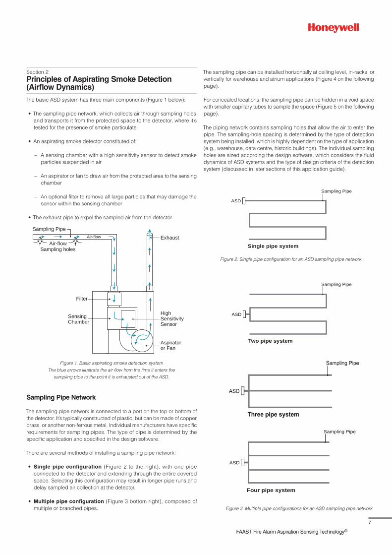
The basic ASD system has three main components (Figure 1 below):
• The sampling pipe network, which collects air through sampling holes
and transports it from the protected space to the detector, where it’s
tested for the presence of smoke particulate
• An aspirating smoke detector constituted of:
– A sensing chamber with a high sensitivity sensor to detect smoke
particles suspended in air
– An aspirator or fan to draw air from the protected area to the sensing
chamber
– An optional filter to remove all large particles that may damage the
sensor within the sensing chamber
• The exhaust pipe to expel the sampled air from the detector.
Air-flowSampling holes
Air-flow
Sampling Pipe
Filter
SensingChamber
Aspiratoror Fan
Exhaust
HighSensitivitySensor
Figure 1. Basic aspirating smoke detection system
The blue arrows illustrate the air flow from the time it enters the
sampling pipe to the point it is exhausted out of the ASD.
Sampling Pipe Network
The sampling pipe network is connected to a port on the top or bottom of
the detector. It’s typically constructed of plastic, but can be made of copper,
brass, or another non-ferrous metal. Individual manufacturers have specific
requirements for sampling pipes. The type of pipe is determined by the
specific application and specified in the design software.
There are several methods of installing a sampling pipe network:
• Single pipe configuration (Figure 2 to the right), with one pipe
connected to the detector and extending through the entire covered
space. Selecting this configuration may result in longer pipe runs and
delay sampled air collection at the detector.
• Multiple pipe configuration (Figure 3 bottom right), composed of
multiple or branched pipes.
The sampling pipe can be installed horizontally at ceiling level, in-racks, or
vertically for warehouse and atrium applications (Figure 4 on the following
page).
For concealed locations, the sampling pipe can be hidden in a void space
with smaller capillary tubes to sample the space (Figure 5 on the following
page).
The piping network contains sampling holes that allow the air to enter the
pipe. The sampling-hole spacing is determined by the type of detection
system being installed, which is highly dependent on the type of application
(e.g., warehouse, data centre, historic buildings). The individual sampling
holes are sized according the design software, which considers the fluid
dynamics of ASD systems and the type of design criteria of the detection
system (discussed in later sections of this application guide).
Sampling Pipe
Single pipe system
ASD
Figure 3. Multiple pipe configurations for an ASD sampling pipe network
Sampling Pipe
Two pipe system
ASD
Figure 2. Single pipe configuration for an ASD sampling pipe network
Sampling Pipe
Four pipe system
ASD

8
detection chamber. However, in this configuration, the air is sent directly to
the sensing chamber instead of passing through a filter. As the air passes
in front of the laser, a photo collector counts the number of particles within
the specified micron size to determine if sufficient smoke particulates are
present. The laser technology’s sophisticated electronics differentiate
between suspended dust particles and smoke particles within the sample.
Cloud Chamber – This method is the oldest and original aspirating
technology. The sensing element is a sealed chamber containing extremely
dense water vapour. When a charged smoke particle interacts with the
dense water vapour, the particle is ionized. The resulting ions act as
condensation nuclei around which a mist will form (because the original
water vapour is extremely dense and on the verge of condensation).
This process amplifies the size of the particulate from something that was
below the wavelength of light (invisible) to a size far above the wavelength
of light (visible). The particulate will then be sufficiently sized and the photo
cell inside the chamber will detect the mist/smoke particulates.
Dual Source Sensor – This method utilises a blue LED to detect extremely
low concentrations of smoke and an Infrared laser to identify nuisances like
dust that can cause false alarms. Advanced algorithms interpret signals
from both sources to determine if the sample is smoke or dust suspended
in the air. Detected particulate levels could be as low as 0.0015%/ m
(0.00046%/ ft.) obscuration.
ASD Exhaust Principles
In normal applications, it is common for the air pressure in the
Air Pressure Protected Space (APS) to be the same as the air pressure in
the space where the ASD is mounted, and the exhaust pipe is run out of the
detector Air Pressure Exhaust Space (AES). As a result, the design software
that calculates transport times and detector sensitivities assumes the air
pressures of the two spaces are equal.
The sampling hole size, pipe size, transport time, and the fan aspirator
speed are all functions of the air volume that passes through the sampling
chamber. The sensing chamber is designed to detect smoke particles
moving through the chamber at the speed of the fan. If APS is greater than
AES, the velocities of the sampled air entering the chamber may be higher
than the nominal fan speed, which could directly impact the detector’s
ability to sense smoke particles.
IMPORTANT: If AES is greater than APS, then air pressure is pushing
on the exhaust air and causing resistance and a drag on the fan. As a
result, the fan may rotate slower than designed, causing an increase
in transport times and a decrease of air into the sensing chamber.
Please note: To eliminate the pressure difference, the exhaust air needs
to be piped into the same room that is being sampled. (Figure 6 on the
following page).
A pipe can be connected to the exhaust port to divert the exhaust
away from the location of the unit; for example to exhaust back into the
area to reduce noise, reduce risk of interference/deliberate obstruction,
or to improve environmental protection etc.
Pipe of the same specification as the sample runs should be used.
Care should be taken to position the new exhaust outlet where it cannot
be accidentally or deliberately blocked.
Smoke Stratification Layer
Sampling Pipes
AspiratingDetector
Samp
ling Holes
Figure 4. Vertical configuration for an ASD sampling pipe network
Figure 5. Capillary used for an ASD sampling pipe network
Sampling P in
apillaSampling e
Sampling Pipe
S pen e eiling
Aspirating Smoke Detector
All ASD systems contain similar equipment, but the detector technology
type varies. Currently, there are several types of detection technologies:
Laser-Based Systems (Filtered) – This method utilises a laser as the light
source within the detection chamber. First, the air passes through a filter
system to remove all large particles. The filtered air sample then passes
in front of the laser, and the light scatter caused by the smoke particulates
is measured by a photo collector. The detector’s sophisticated electronics
determine the quantity of smoke particles within the chamber.
Laser-Based Systems (Non-Filtered) – This method, commonly referred
to as “Particle Counting,” also utilises a laser as a light source in the

9
FAAST Fire Alarm Aspiration Sensing Technology®
Sampling Pipe
Sampling Pipe
Sampling Pipe
ASD Sampling Methods
For the purpose of this guide, there are five acceptable sampling methods
for all potential applications.
Primary Sampling
The name of this sampling method is misleading; it is typically a
supplemental system and not the primary detection system. Primary
sampling is configured to sample the air from a specific location or where
the air is most likely to travel. For areas that have high airflow, such as
data centres or clean rooms, the primary sampling location would be at
return air grilles, air handling unit (AHUs), or air return ducts.
Secondary Sampling
This method involves configuring the sampling holes at the ceiling level, in
similar locations as traditional spot-type smoke detectors. The sampling
holes would be spaced in accordance with the appropriate code or
standard.
Localised Sampling
This method involves protecting specific equipment/areas within a larger
open space. Localised sampling may be used in a rack sampling system
in a large open warehouse.
Sampling PipeASD
P P
Figure 6. ASD Exhaust – AES vs APS
[in figure update labels in image (PE=AES and PR=APS)]
In-Cabinet Sampling
For this type of sampling method, the air sampling holes are installed to
monitor specific pieces of equipment within a larger open space. This
method is different from Localised Sampling because the protected volume
is much smaller, and the piece of equipment is typically self-contained
within a cabinet or computer rack. The ASD monitors the air used for
equipment cooling. This type of sampling is typically installed on critical
equipment that would cause devastating results if damaged by a fire.
In-Duct Sampling
This type of sampling uses an ASD, in place of traditional duct-mounted
smoke detectors, to shut down the associated HVAC unit or close dampers
to prevent the spread of smoke in the case of a fire. It can also be used
to detect smoke particles being exhausted (or supplied), when a more
sensitive detector is necessary.
Considerations for ASD Systems Based on Their
Operating Principles
The Dilution Effect
An aspirating detection system’s sensitivity is dependent on two main
factors: the number of sampling holes drilled in the piping network and
the programmable smoke detection thresholds.
The number of sampling holes can affect the dilution of the air returning
to the sensing chamber. For example, when smoke is drawn into a
single sample hole, it results in a dilution of the smoke concentration
as it is transported through the piping network past other sampling
holes that are aspirating clean air (no smoke concentration). When this
volume of clean air is mixed with the smoke laden air being transported
into the detection chamber, the quantity of smoke-laden air is diluted.
This is often referred to as the dilution effect (Figure 7 below).
In Figure 7 below, the grey represents smoke entering a single sampling
hole at the most remote location within the pipe. The smoke combines with
clear air when it is transported through the pipe, diluting the smoke density.
The dilution effect is directly linked to the sampling hole quantity within the
pipe network. The more sampling holes, the greater volume of air being
transported to the ASD, which results in an increased dilution of the smoke
suspended in the air. For example, if there is a sampling pipe measuring
50 m (164 ft.) and it has sampling holes every 5 m (16 ft.), giving 10
sampling holes including the end cap.
It can be assumed in this simplified case that the sampling holes
let in approximately the same amount of air as each other. A smoke
source of 2% obs/m is introduced at the far end of the pipe. No other
smoke is entering any of the other sampling holes. As the smoke
passes each hole, it is added to with clean air. When the sample
reaches the detector it is now at 0.2% obs/m or 1/10th of its starting
density. Therefore, if the first alarm threshold is set at 0.2% obs/m, the
smoke outside the hole must exceed 2% obs/m to sound the alarm.
It is the case, therefore, that the longer the pipe and the greater the
number of sampling holes, the more susceptible the system will be to
dilution. It is wise to work on a worst case principle in these situations.
In actuality the calculation of dilution is not as straightforward as above and
more factors are involved. Each system will have different characteristics,
meaning precise calculation is extremely complicated. Issues that will
affect the dilution rate include size and number of holes, T-joints and
bend/elbow joints in the pipe system, diameter of the pipe itself, and
outside elements such as air temperature, pressure and humidity etc.
Transport Time
The transport time is defined as the time it takes for the smoke particulates
to reach the sensing chamber. The time is measured (in seconds) from
when the particulates enter the sampling point to the time they reach the
sensing chamber. The times are calculated utilising the ASD’s design
software and field verified during the system commissioning process.
Figure 7. The Dilution Effect

10
Several parameters should be taken into account when discussing
potential transport times:
• The size and number of sampling holes
• The aspirator speed setting (rpm)
• The sensitivity setting of the detector
• The total quantity and configuration of the sampling pipe
Modern codes and standards require specific transport times for
different classes of ASD systems. The maximum required transport times
for ASD systems can range from 60 seconds for Very Early Warning
Fire Detection systems, 90 seconds for Early Warning Fire Detection
systems, or 120 seconds for Standard Fire Detection systems. Refer to
EN 54-20, NFPA 72, NFPA 76 and local codes of practice for the required
transport times.
Benefits for ASD Systems Based on Their Operating
Principles
Active Detection System
The ASD system is considered an ACTIVE form of detection because the
aspirator continuously draws air from the protected area into the sensing
chamber. This process is continuous and does not stop unless the ASD is
shut down. The active nature of the ASD provides for the earliest possible
detection of the presence of smoke, thus why ASD systems are often
referred to as Early Warning Fire Detection Systems.
The extremely sensitive ASD sensing chambers are another significant
aspect of the active smoke detection system because they can detect
smoke in a fire’s incipient stage long before incurring damage to the
protected space and equipment.
The Additive Effect
The ASD system overcomes dilution by the additive effect that is common
to ASD systems. The additive effect is a significant benefit of ASD
technology, which results in an extremely sensitive detection system,
even when multiple sampling holes are present.
During the detection process, air is drawn into all sampling holes in
the piping network, which allows each hole to contribute to the total
air sample within the sensing chamber. As explained earlier, this is
the total volume of air within the detector’s sensing chamber: the more
sampling holes, the greater the volume of air. If multiple sampling holes
are aspirating smoke-laden air, then the smoke particles are combined
as they are transported back to the sensing chamber. The ratio of clean
air to smoke laden air is decreased. It is this additive effect that makes
the overall detection system more sensitive than a traditional, spot-type
smoke detection system.
Assuming the ASD’s Fire Level 1 sensitivity is set at 0.25% obs/ft.
(0.25 %/ft.), the ASD system is protecting a room that is 1,219.2 m²
(4,000 ft.²) and the system is designed with the sampling holes spaced
at 6 m/hole (20 ft./hole) (36m² of 400 ft.² per hole), the resulting detection
system would contain 10 sampling holes. The 0.25%/ft. is the sensitivity
of the detector’s sensing chamber.
To determine the actual sensitivity of the individual sampling hole,
multiply the programmed detector obscuration rate by the total number
of sampling holes in the piping network.
For example, the detector sensitivity for Fire Level 1 set at 0.25%/ft. with
10 holes drilled in the piping network would correspond to an individual
sampling hole sensitivity of 2.5%/ft. (0.25%/ft. multiplied by 10 = 2.5%/ft.).
The benefit of the ASD system is its active nature to draw air into all
sampling holes simultaneously; the air is combined in the pipe and
transported back to the detector for sampling. When air is drawn into
all 10 sampling holes, the smoke particle concentration increases and
the clean air concentration decreases. As the smoke particles are added
together, the overall detection system sensitivity is increased.
To explain the additive effect further, take the same 1,219.2 m²
(4,000 ft.² room with an ASD piping network with 10 sampling holes and
smoke particles being drawn into two sampling holes (Figure 8 below).
To determine the new individual hole sensitivity, the obscuration rating
for Fire Level 1 (0.25%/ft.) is multiplied by the total number of sampling
holes (10), then divided by number of holes detecting smoke (2). This
results in a new effective sampling hole sensitivity of 1.25%/ft., making
the ASD system twice as sensitive as a spot smoke detector at 2.5%/ft..
The sensitivity is similar to the obscuration rate of a traditional spot-type
smoke detector. This represents the effective sensitivity of the detector if
smoke enters a single sampling hole (Figure 8 below).
Detector Sensitivity Threshold = 0.25 %/ft
Hole Sensitivity = 2.5 %/ft
Fire Alarm Control Panel
Detector Sensitivity = 2.5 %/ft
Figure 8. Comparison (ASD – point smoke detector) with smoke reaching a single
sampling hole or a spot point smoke detector
Detector Sensitivity Threshold = 0.25 %/ft
Hole Sensitivities = 1.25 %/ft
Fire Alarm Control Panel
Detector Sensitivities = 2.5 %/ft
Figure 9. Comparison (ASD – point smoke detector) with smoke
reaching two sampling holes or two spot smoke detectors
If smoke enters three sampling holes the effective sensitivity is
0.83 %/ft., and so on.
Detector Sensitivity Threshold = 0.25 %/ft
Hole Sensitivities = 0.83 %/ft
Fire Alarm Control Panel
Detector Sensitivities = 2.5 %/ft
Figure 10. Comparison (ASD – point smoke detector) with smoke
reaching three sampling holes or three spot smoke detectors

11
FAAST Fire Alarm Aspiration Sensing Technology®
To further explain the additive effect, this example can be expanded to
include smoke entering all 10 sampling holes. Each sampling hole would
have an individual sensitivity of 0.25%/ft., making the ASD system 10 times
more sensitive than spot smoke detectors at 2.5%/ft. (Figure 10 on the
previous page).
Low Sensitivity Thresholds
Another significant ASD benefit is the sophisticated electronics that detect
smoke particles at much lower obscuration rates and at multiple sensitivity
levels. These detection thresholds are programmable and allow end-users
the flexibility to create an extremely sensitive smoke detection system for
environments and occupancies that require very early smoke detection for
life safety and business continuity or less sensitive for environments that
are less critical in nature. The typical ASD system thresholds are UL-listed
for sensitivities ranging between 0.00046%/ft. (for the facilities where early
smoke detection is critical) and 6.25%/ft. (for environments that are not
as critical). An aspirating smoke detection system programmed to detect
smoke particles at the lowest possible UL listing of 0.00046%/ft. would be
over 1,000 times more sensitive than traditional spot-type smoke detection
systems.
Aspirating Smoke Detection Benefits for
Diverse Applications
When it is critical to detect smoke at the incipient stage of a fire, ASD
systems have many benefits.
Early Levels of Detection
ASD systems’ ability to detect smoke particles at much lower obscuration
levels make them ideal for areas that require the earliest possible smoke
detection (before combustion and damage can occur). Typical applications
include museums, historically significant buildings, culturally significant
hazards, and mission-critical facilities such as data centres. Also, the
programmable sensitivity ranges allow the ASD system to be customised to
the individual hazard being protected, which provides the owner a greater
level of flexibility.
Reliable Detection
The ASD system’s detection software allows the sensing chamber to
differentiate between smoke particles and dust particles that may be
suspended in the sampled air. This technology makes the ASD resistant
to nuisance alarms and eliminates unwanted alarms that could cause
unnecessary equipment shut-down, facility downtime, or premature
building evacuation.
Unaffected By High Airflows
High-airflow rooms, such as data centres, telecommunication centres, and
clean rooms, present a common hazard. The high airflow produces air
changes within the area and dilutes smoke, making it more difficult to detect.
The high air velocity carries the smoke particles away from the traditional
ceiling-mounted, spot-type smoke detectors and to the HVAC units for
conditioning. Larger particulates are filtered through the HVAC unit, but
small particulates pass through the filter and back into the room. The smoke
particles then become part of the ambient air, but they can be detected
because the ASD is actively sampling the air within the protected space.
No Degradation of Aesthetics and Actions Related to Tampering
Another benefit of ASD systems is the ability to conceal the sampling
pipe and remotely install the detector, which makes them suitable in
environments where tampering is a concern (such as correctional facilities
or schools). They’re also ideal for areas where aesthetics are a concern
(i.e., historic or culturally significant spaces).
Usage in Harsh Environments
In harsh or dirty environments, large particles can damage traditional
detectors’ electronics and small particles can initiate nuisance
alarms. The ASD system samples air from the protected space and
filters potentially damaging particles, making it ideal for installation
in such environments. Also, the detector is located outside the
protected space, which makes ASD systems suitable for areas
that have extreme temperatures (such as coolers and freezers).
Easy Maintenance
After the ASD and sampling pipe is installed, the transport times and
sampling pipe pressures need to be documented. Then, the yearly
maintenance consists of testing the most remote sampling holes and
comparing the transport time to the commissioning documents. When
sampling pipe is installed in a high ceiling or concealed in a sub-floor, a
test sampling point can be installed at floor level to make annual testing
of the system easier and reduce annual maintenance costs.
Any pipe network designed to be used with FAAST must be verified
using PipeIQ software.
System Design
When designing the actual sampling pipe network there are many factors
that need to be considered. The site must be carefully surveyed and as
much information as possible should be gathered.
Requirements
The first consideration is to precisely ascertain the requirements of the
installation. Once these have been decided, the type of situation can be
looked at.
Activities
The types of activities that take place within the space are very important. A
public area of a particular shape could have different system requirements
to a warehouse of a similar shape. Other information such as the expected
hours of operation, whether the area is manned or unmanned and whether
any pollution or dirty air is present, should also be taken into account.
Physical Characteristics
Once the general installation type has been considered, the physical
characteristics of the space should be looked at:
• Is it a room, void, cabinet or enclosure?
• Are there any floor or ceiling voids and if so, how are they divided?
• Are there any ducts and if so, what are they used for and are there
any services already present?
• What are the exact measurements of the space?
• What materials have been used and are there any areas where the
network should avoid?
• Are there any existing fire protection systems and if so, where are
they situated?
Figure 11. Additive property of the ASD system

12
Environmental Conditions
The environment within the space can have a very significant bearing on
the sampling method that should be used to protect it.
As already mentioned, smoke tests are vital in gathering this information.
This can tell you the patterns of air movement, the rate of circulation and
whether the airflow is static at any point.
Other considerations include:
• If fresh air is introduced, at what rate and in what quantity?
• Is a reference detector necessary due to pollution?
• What is the temperature and relative humidity and are these constant
or variable?
• Are there any activities that may produce smoke, dust, steam or
flames and how often do such activities occur?
Risk Assessment
With any installation it is likely that some areas require more protection than
others. This could be because of expensive equipment or a particularly
vulnerable area such as a store for flammable materials. These more
susceptible areas must be considered along with any structural hazards,
such as synthetic materials and foams or soft wood partitioning.
Potential Sites
There are also factors to consider when deciding where to position the
detector unit itself. The main aim when positioning the unit is to try to
ensure a balanced system. This means that the pipes should be kept at
similar lengths. It is also important to try and keep response times and
dilution to a minimum.
The unit requires a power supply and access will be required for
maintenance. There may also be aesthetic reasons why a particular
position is not suitable.
Exhaust Pipe
The exhaust pipe of the aspirating detector unit can have piping added,
should it be required; for example if the air passing through the detector
needs to be returned to its source. Extra piping can also be used to reduce
the noise of the fan, if needed.

13
FAAST Fire Alarm Aspiration Sensing Technology®
Section 3
Installation, Commissioning and Maintenance
Installation
This section provides the basics for ASD pipe network installation. The ASD
system is required to be installed in accordance with not only EN 54-20, but also
with BS 5839, BS 6266 and/or FIA Code of Practice for the Design, Installation,
Commissioning & Maintenance of Aspirating Smoke Detector (ASD)
Systems. Prior to starting the installation, the installer needs to remember
that each system has its own characteristics and variations to accommodate
the ASD piping and ensure proper system operation.
ASD pipes can vary from plastic to non-ferrous metal, such as copper.
The most common pipe in the industry is 25 mm OD 0.75 in.), CPVC,
PVC, ABS, or UPVC pipe. However, the internal pipe diameter can vary
between 15 mm - 21 mm (0.591 in. - 0.827 in.), depending on system
design requirements and local codes and regulations. ABS is the most
commonly installed pipe in Europe and CPVC is the most commonly
installed pipe material in the United States, The most common installation
materials, fittings, mounting brackets, hangers, and installation methods
are described in the following sections.
Pipe Requirement
For EN54-20 compliance,the pipe should be Red ABS to EN 61386
(Crush 1, Impact 1, Temp 31), with a nominal outside diameter of 25 mm
(internal diameter 21 mm). The pipe sections should be glued together
using a suitable ABS glue to avoid separation or leaks. If a section of pipe
is likely to need to be disconnected for some reason in the future, removable
unions should be used instead.
IMPORTANT
Ensure that no hole is less than 100 mm from a bend or T-joint.
Never glue pipes into the aspirating detector unit itself.
Fittings
Figure 1. Typical Plastic Coupling and Union
Figure 4. Typical Plastic T-Joint and End Cap
Fittings connect sections of pipe for longer network runs; they are
made from the same material as the pipe. There are several types
of fittings to allow for various bends, straight runs, branches, and
connections. Common fittings are described on this page.
Couplings and Unions
Couplings and unions are used to connect two sections of pipe in a straight
line. A coupling is used when the section is not intended to be taken
apart. A union offers the ability to screw the two pipe sections together for
future access, which is useful for areas of the pipe network that have to be
periodically disassembled for maintenance or cleaning. Unions can also
be used to correctly orient sample holes in a specific section of the pipe
network, such as over return air grilles. Figure 1 below shows a typical
plastic union and coupling.
Bends/Elbows
Bends/elbows are used to change the direction of the pipe network.
Both 45°and 90° bends/elbows may be used. A typical bend is shown in
Figure 2 below and typical plastic elbow fittings are shown in Figure 3 below.
Bends are either 45° or 90°. For the 90° bends it is very important
that slow radii are used and not a sharp bend, as this will introduce
unnecessary pressure losses, and increase the response times from holes
beyond the bend. Ensure that no hole is less than 100 mm from a bend.
T-Joint and End Caps
A T-joint can be used on pipes to produce multi-branches. It is important
that the branches have a balanced design - that is, they should be
approximately equal in length and number/size of holes). Ensure that no
hole is less than 100 mm from a T-joint. They are used to attach drop tubes
or sampling pipes in the network. A specialised T-joint can be used to
attach a capillary tube and a sampling point as featured in Figure 4 below.
The end of the pipe should be terminated with an end cap, having
a central hole to control air flow. If the end cap is not used, then practically
no air will be drawn through the side holes. Without a hole in the end cap the
contributions from the side holes will tend to be very unbalanced. For pipes
with only a few sampling holes, the end cap hole usually is the same size as
the sampling holes along the pipe. When there are more than five sampling
holes, the end cap hole may be larger than the remaining sampling holes
along the pipe. The end cap can be considered a sampling point if required.
The end cap may have a sampling hole: its presence and size are
determined by the system design software - PipeIQ. Please see Figure
4 below.
Figure 3. Typical Plastic 45° and 90° ElbowsFigure 2. Typical plastic bend

14
SamplingPipe
SamplingPipe
Attachedto Wall
or Ceiling
Attachedto BuildingStructure
Capillaries and Sampling Holes
Capillary Sampling
A capillary tube is a length of flexible tubing connected to the main sampling
pipe with a sampling hole at the end. The purpose of these tubes is to
extend the sampled area away from the main pipe network.
Capillary tubes are used when sampling an enclosed space, such as a
cabinet or a suspended ceiling, or when necessary or for aesthetic and
security reasons. This hides the core pipe network and allows only a small
sampling point in the space. Figure 5 below shows the capillary tube
extending down from the main sampling pipe with a sampling hole located
at the sampling location. Design software supports the addition of capillary
tubes and sampling points to the pipe network design and calculates the
appropriate air flow through the system. The typical maximum length for
capillary flexible tubing is 8 m (26 ft.), but can vary depending upon the
design software calculations. When multiple capillary tubes are used in a
network, the length of each capillary tube should be approximately equal.
This will allow for a balanced system.
Note 1: It is recommended to avoid running lengths of pipe with both
standard sampling holes and capillary sampling points, as this can
unbalance the airflow and slow the response time from the capillary points.
Figure 6. Mounting Clips
Sampling Holes
Sampling holes can be located directly in the pipe, on an end cap, or in a
sampling point at the end of a capillary tube. The most important factor is
to properly drill the holes with a diameter conformed to the design software
prescriptions.
The sampling holes should be drilled after the piping network has been
installed. To prevent sampling holes from being blocked by dust and dirt,
place the holes on the bottom side of the sampling pipes and not on the
top of the pipe. This prevents any falling debris from clogging the sampling
holes. The following guidelines should be followed when drilling the sample
holes in the pipe network.
• Holes must be drilled perpendicular (90°) to the pipe. If the drill is not
held perpendicular, then the hole is not round and may affect air flow
• Holes must be drilled exactly at the positions required by the design
software
• Holes must be drilled with the exact size determined by the design
software
• Holes must not be drilled through both sides of the pipe
• Holes should be drilled using a slow speed drill with a sharp drill bit. This
minimises the risk of burrs as well as the possibility of dust and swarf
entering the piping network
• After all holes are drilled, it is good practice to blow compressed air
through the pipe to clear any dust, dirt, or debris from the pipe. A shop
vacuum can also be used to draw the foreign material from the pipe by
removing the end cap and using the vacuum to draw the debris through
the end of the pipe near the detector connection. It is critical to remove
the sampling pipe from the detector before compressed air is blown
into the pipe or the shop vacuum is connected to the piping network,
because small particles being blown into the sensing chamber could
damage the components
Installation Materials and Pipe Hangers
Mounting Brackets/Hangers
The pipe network is mounted to the ceiling or a solid structural component
using pipe mounting brackets shown in Figure 6 to the left. It can also be
suspended from a slab ceiling with plain pipe clamps, clevis hangers,
adjustable suspension clamps, C-clamps, and threaded rods. A large
variety of brackets are also available, including clips, saddle clamps, or
tie wraps, as shown in Figure 7 above. The mounting device will depend
on the mounting material, environmental conditions, and local codes and
regulations.
Figure 7. Pipe Hangers
Figure 5. Capillary Sampling Point

15
FAAST Fire Alarm Aspiration Sensing Technology®
spacing so the pipe does not sag and create stress at the couplings,
elbows, and unions, which could cause a crack or break in the pipe.
Table 1. Spacing distance of sampling pipe hangers and supports, with
respect to temperature and pipe diameter
Pipe Diameter
Spacing distance of sampling pipe hangers
and supports, with respect to temperature
21°C (70°F) 38°C (100°F) 60°C (140°F)
15 mm (½ in.) 1.3 m (4.5 ft..) 1.2 m (4 ft.. ) 0.7 m (2.5 ft..)
20 mm (¾ in.) 1.5 m (5 ft..) 1.2 m (4 ft..) 0.7 m (2.5 ft..)
Open-style mounting clips should not be used in an inverted position with
the open section facing downward, as the pipe could accidentally drop
from the clip. In applications when the sampling pipe is installed below the
raised floor, the pipe can be mounted directly to the raised floor stanchions
using wire ties, conduit clamps, or other installation device.
Pipe Labels
NFPA 72, FIA, and other recognised codes and standards require ASD
pipes be labelled to distinguish them from other pipes and to specifically
identify them as a fire detection system component. Both the sampling pipe
network and each individual sample hole need to be identified. The pipe
and sampling holes should be labelled at the following locations:
1. At changes in direction or branches of piping
2. At each side of penetrations of walls, floors, or other barriers
3. At intervals on piping that provide visibility within the space, but no
greater than 61 m (20 ft.)
4. At each sampling hole.
The pipe shall be labelled with similar verbiage “SMOKE DETECTOR
SAMPLING TUBE: DO NOT DISTURB.” See Figure 8 below for sampling
hole and pipe labels.
Installing Sampling Pipe Network
For ceiling detection, the sampling pipe network should be mounted near
the ceiling. To minimise the threaded rod length, the pipe network should be
mounted 25 mm – 100 mm (1 in. - 4 in.) below the ceiling, subject to local
codes and regulations. See Table 2 to the right for the typical installation
steps for ASD pipe sampling systems.
Spacing distance of sampling pipe hangers and supports are defined
according to temperature and pipe diameter, as illustrated in Table 1 below.
It is critical to install the support brackets and hangers at the required
Figure 8. Sampling pipe and sampling hole labels
Mounting the Pipe Network
Pipe mounting is the most time consuming part of the system installation
process, and it can negatively impact the ASD system if it is not done
properly. Consider the following recommendations when mounting the pipe
network:
• Minimise pipe bending or sagging by bracing and supporting it at the
required intervals, and install additional support at/near couplings and
bends
• Avoid bending the pipe. Install a bend or reconfigure the sampling pipe
if a slight change of direction is required
• Allow for pipe expansion and contraction in environments with extreme
temperature changes, especially on long, straight sections of sampling
pipe.
Cutting Pipe
Use proper tools when cutting pipe. Use shears or a wheel-type plastic
tubing cutter for PVC, CPVC, or ABS pipe. Saws are not recommended
because they can produce rough edges in the pipe. Use a tube cutter for
copper or other thin-walled, non-ferrous metal piping. When cutting copper
or other thin-walled metal piping, it is important not to crimp or bend the
edges: this may cause air leaks at the couplings. Always keep the tools’
cutting edges sharp and ensure cuts are made perpendicular to the pipe
length, keeping the cuts square.
Square cuts ensure maximum bonding area and help provide a good seal
when joining the components. Remove all loose material and any burrs
from the end of the pipe after a cut – as well as debris and shavings from
cuts – in order to keep sampling holes free of obstructions.
Joining Components
The sampling pipe network must be permanently connected once the
system has been installed and tested. Establishing a permanent connection
depends on the material of the pipe and fittings. For plastic pipes, it is
important to use the proper type of glue. Never place solvent or glue on the
inside of a pipe when gluing fittings and sampling pipe together; solvent
can build up if applied to the inside of a pipe or other components. This
build-up can cause obstructions that affect the air flow within the pipe
network, and could cause abnormal behaviour within the sampling pipe.
Solvents and glue should be applied only to the outside of the pipe being
inserted into a coupling or other fitting. Make sure pipes are inserted
completely and butted against the lip of the coupling or other fitting. The
gaps can cause turbulence if this is not done, which can cause problems
with the system pressure and air flow.
Table 2. Spacing distance of sampling pipe hangers and supports with respect
to temperature and pipe diameter
Step Action
1 Verify the design documents are accurate and obtain the size and
configuration of the pipes in the sampling network
2 Mark off the area where the system is to be installed and identify the location
where the ASD detector is to be mounted
3 Select and mark the locations for all pipe clips or pipe hangers in accordance
with the design and manufacturer’s recommendations
16
4 Install the ASD detector in the permanent location
5 Mount the pipe clips or pipe hangers according to the previously marked
locations
6 Dry mount and assemble the pipe network according to the pipe network
design documents. DO NOT permanently connect the pipes at this stage
7
Measure and mark the sampling holes on the pipe network. Make sure that the
spacing of the sampling holes is in accordance with the network design and
manufacturer’s recommendations. Based upon the ASD system application,
ensure that the sampling holes are at the correct orientation to the air flow, as
recommended in the section on network pipe design
8 Verify the sampling holes’ position and orientation and drill the sampling holes
9 Drill and install end caps on all appropriate pipe ends
10 Modify the design documents to agree with the actual network, if the physical
network is significantly different from the original design documents
11
When testing is completed and the system performance is verified,
permanently bond the pipe network together. CAUTION: Never glue the pipes
to the ASD detector. The ASD detector inlet and outlet are tapered to accept
the piping without any glue and provide an air tight seal
12 Label all portions of the system according to local codes and regulations,
with available pipe and sampling point labels
13
If changes are made to the piping network during the installation process, the
installing contractor is required to update the design documents to include
new design software calculations and installation drawings. These documents
will be needed during the Commissioning Testing
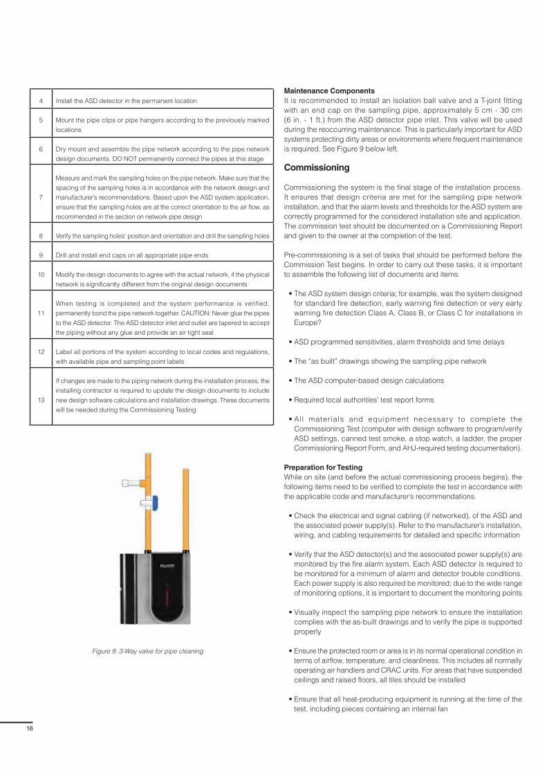
Figure 9. 3-Way valve for pipe cleaning
Maintenance Components
It is recommended to install an isolation ball valve and a T-joint fitting
with an end cap on the sampling pipe, approximately 5 cm - 30 cm
(6 in. - 1 ft.) from the ASD detector pipe inlet. This valve will be used
during the reoccurring maintenance. This is particularly important for ASD
systems protecting dirty areas or environments where frequent maintenance
is required. See Figure 9 below left.
Commissioning
Commissioning the system is the final stage of the installation process.
It ensures that design criteria are met for the sampling pipe network
installation, and that the alarm levels and thresholds for the ASD system are
correctly programmed for the considered installation site and application.
The commission test should be documented on a Commissioning Report
and given to the owner at the completion of the test.
Pre-commissioning is a set of tasks that should be performed before the
Commission Test begins. In order to carry out these tasks, it is important
to assemble the following list of documents and items:
• The ASD system design criteria; for example, was the system designed
for standard fire detection, early warning fire detection or very early
warning fire detection Class A, Class B, or Class C for installations in
Europe?
• ASD programmed sensitivities, alarm thresholds and time delays
• The “as built” drawings showing the sampling pipe network
• The ASD computer-based design calculations
• Required local authorities’ test report forms
• All materials and equipment necessary to complete the
Commissioning Test (computer with design software to program/verify
ASD settings, canned test smoke, a stop watch, a ladder, the proper
Commissioning Report Form, and AHJ-required testing documentation).
Preparation for Testing
While on site (and before the actual commissioning process begins), the
following items need to be verified to complete the test in accordance with
the applicable code and manufacturer’s recommendations.
• Check the electrical and signal cabling (if networked), of the ASD and
the associated power supply(s). Refer to the manufacturer’s installation,
wiring, and cabling requirements for detailed and specific information
• Verify that the ASD detector(s) and the associated power supply(s) are
monitored by the fire alarm system. Each ASD detector is required to
be monitored for a minimum of alarm and detector trouble conditions.
Each power supply is also required be monitored; due to the wide range
of monitoring options, it is important to document the monitoring points
• Visually inspect the sampling pipe network to ensure the installation
complies with the as-built drawings and to verify the pipe is supported
properly
• Ensure the protected room or area is in its normal operational condition in
terms of airflow, temperature, and cleanliness. This includes all normally
operating air handlers and CRAC units. For areas that have suspended
ceilings and raised floors, all tiles should be installed
• Ensure that all heat-producing equipment is running at the time of the
test, including pieces containing an internal fan

17
FAAST Fire Alarm Aspiration Sensing Technology®
Prior to the test, and in accordance with EN54-20, NFPA 72 and
FIA Code of Practice, verify the building’s fire alarm system is placed
in testing mode and that all occupants are notified. This ensures that
everyone is aware of the commissioning process so the test can
be conducted efficiently. Typically, a two-person team performs the
Commissioning Test of an ASD system, with one technician introducing
canned smoke into the sampling hole and the other remaining at the
detector location to acknowledge when smoke is detected. The results of
the travel times are documented on the Commission Form.
Relay Function Testing
ASD system commissioning should include testing and verifying that all
programmable relay outputs function as designed. However, as stated
above, most ASD systems are monitored by the building fire alarm system
or other entities: they are frequently programmed to initiate the building
occupant notification system, shut down the air distribution system, or
activate a suppression system via the relays. Before the commissioning
test starts, it is critical that the owner is consulted and the design drawings
are thoroughly reviewed, in order to disable any of these functions.
ASD Transport Time Testing
During the commissioning process, all sampling holes should be tested to
establish the baseline used during annual testing. For the annual or routine
maintenance testing, only a few holes need to be tested and compared
to the original transport times on the Commissioning Report. Typically the
sampling holes furthest from the ASD detector are tested. If the transport
times remain close to the initial results, the system is operating as designed
and no further testing is required.
If there is a difference of 5-10% between the transport times predicted by
the design software and the tested transport times, then the piping network,
hole sizes, or the detector settings should be checked to determine the
causes of this difference; for example, if wrong sized sampling holes were
drilled, if undocumented changes were made to the sampling pipe network
without performing a design calculation, or if the ASD settings were not
programmed properly. Any deviation should be immediately addressed
and corrected by the installing contractor.
Documenting Test Results
All test results must be recorded in accordance with local codes and
regulations, as well as within manufacturer’s recommendations. At a
minimum, the Commissioning Form should contain the following information:
• Customer’s information: name and address
• Date of the test
• Installing contractor’s information, including name, address, and
contact telephone number
• Identification of the rooms being protected
• Witnessing/approving authority information
• ASD information:
– Detector serial number
– Sensitivity
– % obs/m (% obs/ft.)
– Thresholds, with day, night, and weekend settings
– Time delays
• Type of detection system (SFD, EWFD, VEWFD, Class A, Class B,
or Class C)
• Number of sampling pipes and sampling holes
• Hole size
• Testing results related to:
– Transport times
• Signatures of all the persons attending the test (agents performing the
test, customer/owner’s representatives and authority representatives)
Sampling Pipe
Floor
Sampling Port
18 in.
(450 mm)
End cap with
Sample Test Port
Figure 10. 3-Test sample point for warehouse installation
Figure 11. 3-Test sample point for void space or sub-floor
Customer Acceptance
Both the team performing the testing and the customer/owner’s
representatives should be completely satisfied with all the results
from the commissioning tests. They should also agree that all testing
results meet the local codes and regulations and manufacturer’s
recommendations for the type of system being tested, and that the
testing results confirm the calculated hole and transport times calculated
with the design software. The final acceptance of the tested ASD system
should be a complete and signed copy of the Commissioning Form, a
copy of the as-built drawings, and Owner’s Manual.

18
Testing and Maintenance
ASD system testing is critical to ensure the system is operating as
originally designed. The testing requirements are outlined in
EN 54-20, BS 5839, BS 6266 and/or FIA Code of Practice for the Design,
Installation, Commissioning & Maintenance of Aspirating Smoke Detector
(ASD) Systems and the manufacturer’s recommendations. Per the test
methods documented in the manufacturer’s published maintenance
instructions, the ASD alarm response is allowed to be verified through
the end sampling hole on each pipe run and the airflow through all other
ports shall be verified as well.
For regular testing in areas that are difficult to reach, such as warehouses,
void spaces, or sub-floors, a test sample point can be installed at the
end of each sample pipe. (See Figure 1 and Figure 2 below). During
the commissioning process, the transport time from the test sampling
point should be documented; if the transport time is within 5-10% of the
documented values during annual testing, the system can be assumed to
be operating as originally designed.
Smoke Tests
IMPORTANT: It is strongly recommended that, before designing the
pipe-work system, smoke tests be undertaken in order to show the
patterns of air movement within the areas to be protected. This is
particularly important in rooms with air-handling equipment. In all cases
the aim must be to place the sampling pipes at the position the smoke is
most likely to reach.
Smoke boxes or smoke matches can be used to establish air movement
within the protected area, so the best place to locate the pipes can be
identified, as well as sampling hole locations in the pipe.
If air handling equipment is present in the environment, consideration
must be given to all the variable settings that are available; for example,
if it is switched on or off, or if an air conditioning unit has a directional
wave facility).
Sampling pipe network and holes
Sampling pipe network maintenance and sampling hole cleaning is
recommended for all ASD system installations. Depending upon the
environment in which the sampling pipes are installed, sampling holes
should be cleaned every 1-2 years. More frequent maintenance may be
Let us say that the response time for smoke thatEntered the very end of the pipe was 34 seconds
Aspirating SmokeDetector Goes
Into Alarm
SmokeEntersHere
AspiratingSmoke
DetectorGoes
Into Alarm
SmokeEntersHere
With two pipes feeding into a T-Piece at thedetector, the pipe length is approximately halved,and so is the response time to 18 seconds
needed for environments with high amounts of airborne particulate
or cold environments where condensation may freeze on the
sampling hole.
To properly clean sampling holes, a technician can either use a
pipe cleaner to clean each one or use compressed air/a vacuum
on the piping network.
Before cleaning sampling pipes’ holes, the technician should:
• Either place the connected detector in isolate or disable mode
or power down the detector
• Disconnect the involved sampling pipe network from the
detector, or at least close the valve on the T-joint fitting to ensure
no air can be forced into or out of the detector. This is extremely
important, and caution should be taken when performing this
type of maintenance. Forcing air into or out of the ASD detector
by any means other than the built-in fan may damage it and
nullify its warranty
To perform the pipe network maintenance:
• The sampling pipe can be cleaned by using compressed air.
Alternatively, a vacuum cleaner can be connected to either
the end of the sampling pipe network or the T-joint fitting at the
beginning of the pipe network
• While the vacuum is running, use a dry brush or pipe cleaner
to swab out each sampling hole in the piping network.
Leave the vacuum running for two minutes following the hole
cleaning, to ensure all dust particles are removed from the pipe
After the pipe network maintenance, the technician should:
• Reconnect the cleaned sampling pipes to the ASD detector or
open the valve on the T-joint fitting
• Replace the detector in operating mode, or re-apply power to
the ASD detector
• Observe the air flow indication on the front of the ASD detector
to ensure its fan is operating properly and the air flow has
normalised. In the event of an air flow fault condition, the
technician should perform another visual check of the sampling
pipe network, to verify all connection points are sealed. If a
pressure difference exists between the room being sampled
and the room in which the ASD is located, then the technician
should verify that the exhaust pipe is connected properly and
that the sampled room is in the “normal” condition; for example,
by verifying that all doors are closed and the HVAC units are
running
ASD Detector
The only required maintenance for the ASD detector concerns the
periodic replacement of its filter. Refer to individual manufacturer’s
instructions for filter replacement instructions.
Figure 1. Single Sampling Pipe
Figure 2. Two Sampling Pipe

19
FAAST Fire Alarm Aspiration Sensing Technology®
Section 4
Troubleshooting Guide
Though ASD units are extremely reliable, they may occasionally have
troubles that impair system operation. Most ASD units have trouble
indicators on the face of the unit that help determine the cause of the fault.
Below is a list of common trouble indicators. Consult the manufacturer’s
installation and programming guide for a more specific list.
Fault Description Cause Recommended Action
Power Failure No LEDs on the face of the ASD unit Check the power supply for the ASD unit to determine if it is functioning
properly. Verify the correct voltage is being provided at the unit
Aspirator (Fan) Failure The ASD aspirator has stopped functioning Contact the manufacturer’s representative to replace the unit
Low Voltage The ASD unit input voltage is low
• Check power supply to verify if it is operating properly and standby
batteries are not depleted
• Verify the correct voltage is being provided at the unit
Low Air Flow (Minor)
The air flow in the ASD unit has decreased
20%-50% below the programmed threshold.
This may be caused by:
• An undocumented change in the piping
• The aspirator not functioning at the required
speed
• Obstruction of sampling hole(s)
• Obstruction in the sampling pipe
1. Perform a visual inspection of the sampling pipe system to ensure
no modifications were made
2. Verify the aspirator is functioning at the required fan speed. Increase
fan speed to the next level, to improve flow performance
3. Clean sampling holes
4. Clean piping network
Refer to Maintenance Guide for pipe network cleaning
Low Air Flow (Major)
The air flow in the ASD unit has decreased more
than 50% below the programmed threshold. This
may be caused by:
• An undocumented change in the piping
• The aspirator (fan) is not functioning at its
designed speed
• Obstruction of sampling hole(s)
• Obstruction in the sampling pipe
1. Perform a visual inspection of the sampling pipe system to ensure
no modifications were made
2. Verify the aspirator is functioning at the required fan speed. Increase
fan speed to next level, to improve flow performance
3. Clean sampling holes and piping network
Refer to Maintenance Guide for pipe network cleaning
Flow Fault EN54-20
A +/- 20% change in the volumetric flow of air
through the chamber will generate a flow fault
indication at the ASD unit
1. Perform a visual inspection of the sampling pipe system to ensure
no modifications were made
2. Verify the aspirator is functioning at the required speed
3. Clean sampling holes and piping network
Refer to Maintenance Guide for pipe network cleaning
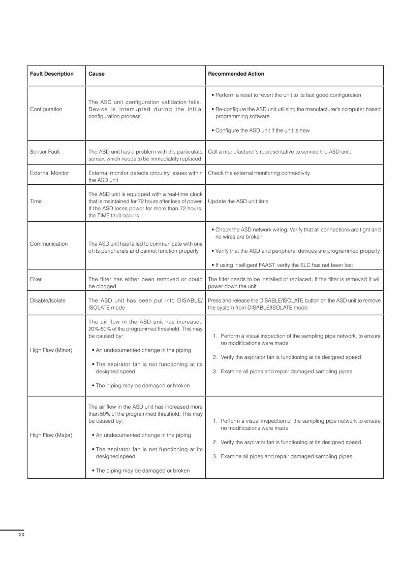
20
Fault Description Cause Recommended Action
Configuration
The ASD unit configuration validation fails..
Device is interrupted during the initial
configuration process
• Perform a reset to revert the unit to its last good configuration
• Re-configure the ASD unit utilising the manufacturer’s computer based
programming software
• Configure the ASD unit if the unit is new
Sensor Fault The ASD unit has a problem with the particulate
sensor, which needs to be immediately replaced.
Call a manufacturer’s representative to service the ASD unit.
External Monitor External monitor detects circuitry issues within
the ASD unit
Check the external monitoring connectivity
Time
The ASD unit is equipped with a real-time clock
that is maintained for 72 hours after loss of power.
If the ASD loses power for more than 72 hours,
the TIME fault occurs
Update the ASD unit time
Communication The ASD unit has failed to communicate with one
of its peripherals and cannot function properly
• Check the ASD network wiring. Verify that all connections are tight and
no wires are broken
• Verify that the ASD and peripheral devices are programmed properly
• If using intelligent FAAST, verify the SLC has not been lost
Filter The filter has either been removed or could
be clogged
The filter needs to be installed or replaced. If the filter is removed it will
power down the unit
Disable/Isolate The ASD unit has been put into DISABLE/
ISOLATE mode
Press and release the DISABLE/ISOLATE button on the ASD unit to remove
the system from DISABLE/ISOLATE mode
High Flow (Minor)
The air flow in the ASD unit has increased
20%-50% of the programmed threshold. This may
be caused by:
• An undocumented change in the piping
• The aspirator fan is not functioning at its
designed speed
• The piping may be damaged or broken
1. Perform a visual inspection of the sampling pipe network, to ensure
no modifications were made
2. Verify the aspirator fan is functioning at its designed speed
3. Examine all pipes and repair damaged sampling pipes
High Flow (Major)
The air flow in the ASD unit has increased more
than 50% of the programmed threshold. This may
be caused by:
• An undocumented change in the piping
• The aspirator fan is not functioning at its
designed speed
• The piping may be damaged or broken
1. Perform a visual inspection of the sampling pipe network to ensure
no modifications were made
2. Verify the aspirator fan is functioning at its designed speed
3. Examine all pipes and repair damaged sampling pipes
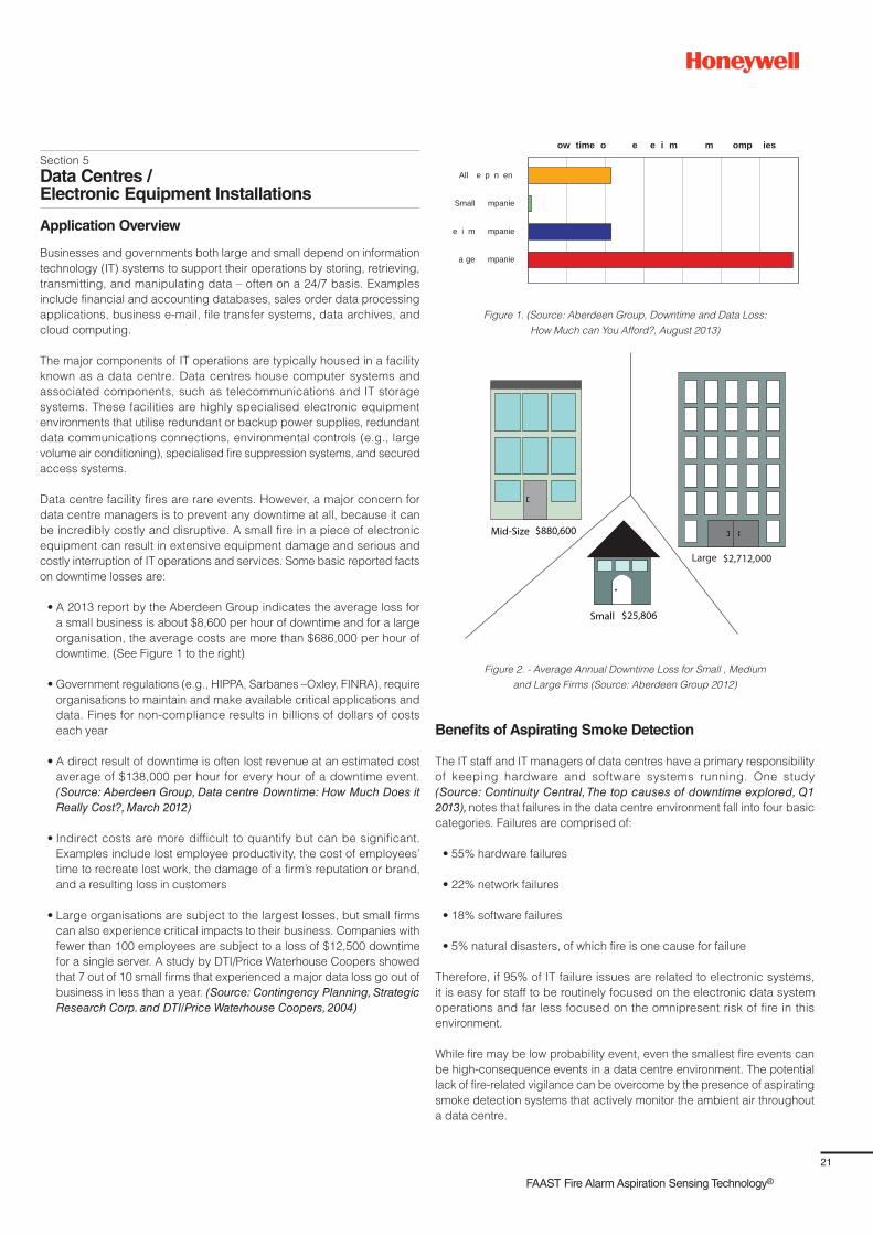
21
FAAST Fire Alarm Aspiration Sensing Technology®
Section 5
Data Centres / Electronic Equipment Installations
Application Overview
Businesses and governments both large and small depend on information
technology (IT) systems to support their operations by storing, retrieving,
transmitting, and manipulating data – often on a 24/7 basis. Examples
include financial and accounting databases, sales order data processing
applications, business e-mail, file transfer systems, data archives, and
cloud computing.
The major components of IT operations are typically housed in a facility
known as a data centre. Data centres house computer systems and
associated components, such as telecommunications and IT storage
systems. These facilities are highly specialised electronic equipment
environments that utilise redundant or backup power supplies, redundant
data communications connections, environmental controls (e.g., large
volume air conditioning), specialised fire suppression systems, and secured
access systems.
Data centre facility fires are rare events. However, a major concern for
data centre managers is to prevent any downtime at all, because it can
be incredibly costly and disruptive. A small fire in a piece of electronic
equipment can result in extensive equipment damage and serious and
costly interruption of IT operations and services. Some basic reported facts
on downtime losses are:
• A 2013 report by the Aberdeen Group indicates the average loss for
a small business is about $8,600 per hour of downtime and for a large
organisation, the average costs are more than $686,000 per hour of
downtime. (See Figure 1 to the right)
• Government regulations (e.g., HIPPA, Sarbanes –Oxley, FINRA), require
organisations to maintain and make available critical applications and
data. Fines for non-compliance results in billions of dollars of costs
each year
• A direct result of downtime is often lost revenue at an estimated cost
average of $138,000 per hour for every hour of a downtime event.
(Source: Aberdeen Group, Data centre Downtime: How Much Does it Really Cost?, March 2012)
• Indirect costs are more difficult to quantify but can be significant.
Examples include lost employee productivity, the cost of employees’
time to recreate lost work, the damage of a firm’s reputation or brand,
and a resulting loss in customers
• Large organisations are subject to the largest losses, but small firms
can also experience critical impacts to their business. Companies with
fewer than 100 employees are subject to a loss of $12,500 downtime
for a single server. A study by DTI/Price Waterhouse Coopers showed
that 7 out of 10 small firms that experienced a major data loss go out of
business in less than a year. (Source: Contingency Planning, Strategic Research Corp. and DTI/Price Waterhouse Coopers, 2004)
e i m mpanie
All e p n en
Small mpanie
a ge mpanie
ow time o e e i m m omp ies
Figure 1. (Source: Aberdeen Group, Downtime and Data Loss:
How Much can You Afford?, August 2013)
Figure 2. - Average Annual Downtime Loss for Small , Medium
and Large Firms (Source: Aberdeen Group 2012)
Benefits of Aspirating Smoke Detection
The IT staff and IT managers of data centres have a primary responsibility
of keeping hardware and software systems running. One study
(Source: Continuity Central, The top causes of downtime explored, Q1 2013), notes that failures in the data centre environment fall into four basic
categories. Failures are comprised of:
• 55% hardware failures
• 22% network failures
• 18% software failures
• 5% natural disasters, of which fire is one cause for failure
Therefore, if 95% of IT failure issues are related to electronic systems,
it is easy for staff to be routinely focused on the electronic data system
operations and far less focused on the omnipresent risk of fire in this
environment.
While fire may be low probability event, even the smallest fire events can
be high-consequence events in a data centre environment. The potential
lack of fire-related vigilance can be overcome by the presence of aspirating
smoke detection systems that actively monitor the ambient air throughout
a data centre.

22
Given the direct dollar loss and indirect losses possible due to a fire in
a data centre environment, the need for identification of the smallest fire
events – such as precursor smouldering or overheating equipment – can
be critically important. Aspirating smoke detection systems can provide the
high sensitivity and continuous sampling of low quantities of smoke that may
be distributed and easily diluted by the high-airflow environments in data
centres. Digital Equipment designed to the highest standards (UL 60950,
NEBS GR63) have components and shut down features that minimise the
production of smoke, yet an incident may only have a chance of being
detected with the use of aspirating smoke detection systems.
Due to concerns for potential damage to sensitive electronic components,
automatic fire protection systems that use water, water mist, aerosols, or
foam often may not be employed in data centre spaces. However, clean
agent or inert gas systems may be found more frequently in such spaces.
If no extinguishing system is present, the need for very early identification
of a fire or precursor event is of greater importance. This need can be
readily served by aspirating smoke detection systems. Aspirating smoke
detection provides high sensitivity to smoke with low sensitivity to airflow,
a combination of features not provided by conventional smoke detectors.
In those cases where any of the fire protection/suppression systems
noted above are installed in the data centre space, there is an equally
important need to identify and investigate an alert or alarm condition
prior to an extinguishing system operation. It has been reported that most
fixed fire extinguishing system activations in data centres are false or
nuisance-type events.
A side effect of some extinguishing system operations (gaseous agent
systems), is the need to completely or partially shut down air handling
equipment and close airflow dampers to contain suppressants. Such a
shut-down can result in significant temperature rise in the data centre and
disruption of electronics. Therefore, early staff response initiated by an
aspirating smoke detection system can result in confirmation of the need
for aborting extinguishing system operation and any associated air handling
shut-down. Conversely, an early staff response can result in manual fire
suppression intervention or de-powering a section of equipment that
appears as an ignition or fire source.
Data centres consume 25-50 times or more electrical energy as standard
office spaces. Basic design documents for data centres indicate that
planned energy usage should be 50 watts to 100 watts per m²/ft.² , and
many designs will approach or exceed 200 watts per ft². As a result, the
total and concentrated heat load of the electronic equipment needs to be
managed to keep equipment within proper operating temperature ranges.
To accomplish this, large air flows are required with the basic objective
of supplying cool air to the equipment and removing hot exhaust air.
Depending on the location within the data centre facility (under raised
floors, ceiling ducts or plenums, rack cabinets), air flow velocities can range
from 0.25 m/s - 15.2 m/s (50 - 3,000 fpm), while air temperatures range from
10° C - 60° C (50° F -140° F).
Standard smoke detectors are generally not capable of performing in
high air flows. Because of room air currents dilution and stratification
phenomenon, sufficient smoke may not be able to reach a ceiling-mounted
detector, and if smoke can penetrate to a standard ceiling-mounted
detector, there may not be a sufficient quantity of smoke to activate it.
NFPA 72 specifically requires that unless a smoke detector is recognised
for use in specific air flow environments, it should not be used in air
flow environments over 1.54 m/s (300 fpm). Both BS 6266 and NFPA 72
recognise the challenges of detecting smoke in high-airflow environments
and stipulate reductions in spacing of detection points in such high-airflow
conditions.
BS 6266 provides guidance specific to adjustments needed in electronic
equipment installations. The advantages of a using an aspirating smoke
detection system are related to providing detection at very low particle
levels and in high-airflow environments. Consider that a standard spot
smoke detector operates in the range of 1.5 to 3.0 % obs/ft.; whereas,
the aspirating detection system can be programmed to provide sensitivity
for detection as low as 0.0015% obs/m (0.00046% obs/ft.). Aspirating
detection systems are up to the challenge of the high-airflow environments
of data centres with the capability of detection in 20.3 m/s (4,000 fpm)
environments.
Design Best Practices
Identify and Understand the Airflow Management Scheme
There are numerous approaches to providing air distribution and equipment
cooling in data centres. Understanding the approach that is applied in
any given facility will allow the designer to identify the key airflow paths
as well as areas where airflow is minimal and not likely to carry smoke
particulate to a sampling port location. While other approaches (including
hybrid) are possible, distributing air in a data centre usually involves one
or more of three basic approaches. Automatic detection requirements for
data centres are based on NFPA 75 and 72 provisions. The FIA CoP for ASD
Systems provides design and installation guidance for aspirating smoke
detector systems used in data centres and other environments, and has
been coordinated with BS 6266.
A
D P
A flooded supply with a targeted air return scheme. Hot air can mix with cold air supply.
Figure 3
Figure 4
Flooded
This approach uses a supply and return air distribution system in which the
only constraints to the airflow are physical boundaries of the room or space
(walls, ceiling, floor). Due to the extent of hot and cool air mixing, sampling
points are recommended at the ceiling and at the HVAC/CRAC (computer
room air conditioning) unit air returns and supply-side outlet grills.
A
A S D
A targeted air supply with a flooded return air system. Cold supply air mixes with hot return air.
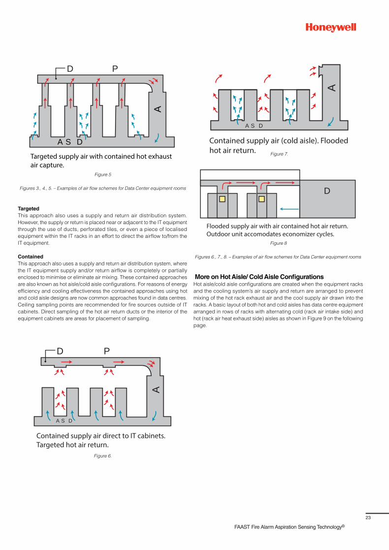
23
FAAST Fire Alarm Aspiration Sensing Technology®
A
A S D
D P
Contained supply air direct to IT cabinets. Targeted hot air return.
A
A S D
Contained supply air (cold aisle). Flooded hot air return.
D
Flooded supply air with air contained hot air return.Outdoor unit accomodates economizer cycles.
Figures 6., 7., 8. – Examples of air flow schemes for Data Center equipment rooms
Figures 3., 4., 5. – Examples of air flow schemes for Data Center equipment rooms
More on Hot Aisle/ Cold Aisle ConfigurationsHot aisle/cold aisle configurations are created when the equipment racks
and the cooling system’s air supply and return are arranged to prevent
mixing of the hot rack exhaust air and the cool supply air drawn into the
racks. A basic layout of both hot and cold aisles has data centre equipment
arranged in rows of racks with alternating cold (rack air intake side) and
hot (rack air heat exhaust side) aisles as shown in Figure 9 on the following
page.
AA S D
D P
Targeted supply air with contained hot exhaust air capture.
Targeted
This approach also uses a supply and return air distribution system.
However, the supply or return is placed near or adjacent to the IT equipment
through the use of ducts, perforated tiles, or even a piece of localised
equipment within the IT racks in an effort to direct the airflow to/from the
IT equipment.
Contained
This approach also uses a supply and return air distribution system, where
the IT equipment supply and/or return airflow is completely or partially
enclosed to minimise or eliminate air mixing. These contained approaches
are also known as hot aisle/cold aisle configurations. For reasons of energy
efficiency and cooling effectiveness the contained approaches using hot
and cold aisle designs are now common approaches found in data centres.
Ceiling sampling points are recommended for fire sources outside of IT
cabinets. Direct sampling of the hot air return ducts or the interior of the
equipment cabinets are areas for placement of sampling.
Figure 5
Figure 6.
Figure 7.
Figure 8

24
ene al n ep an l ai le ai managemen n epS n a e pi al ai ample p in l a i n
n e ai e l e in e e i emen m i le p e en Sampling p in l a e in ai l ig ai el i ie ien le n a a ing in ai l See S le pa ing a men
A e eiling e n ai plen m e in e e i emen m i le p e en See S le pa ing a men
el eiling gene al a ea p e i n p ai le ai an e g ill A ni ai e n A ange e p a ea e n m e an m e e n pening ien le
e m in ming ai l ain ain an i an e app ima el in m A ni l ai ppl le p p e en ing an el mal n i n A ange e p a ea e n m e an
m e ppl le ien le e m in ming ai l
If high air velocity, use = Sampling
Holes
The aisles are typically wide enough to allow for maintenance access to
the racks and meet any code requirements. All equipment is installed into
the racks to allow for a front-to-back airflow pattern that draws conditioned
air in from cold aisles, located in front of the equipment, and exhausts heat
out the back side of the racks into the hot aisles (or sometimes the top of
the rack into collars or exhaust duct systems). Rows of racks are placed
back-to-back, and holes through the racks (empty equipment slots), must
be blocked off on the air intake side to avoid recirculation.
With a raised floor, the same airflow is achieved with the supply coming
from tiles in the cold aisle. Using hot aisle/cold aisle configurations, proper
isolation can be achieved and the temperature of the hot aisle no longer
impacts the temperature in areas beyond the hot aisle. The hot aisle
becomes a heat exhaust. The HVAC system serves to supply cold air only
to the cold aisles and pull return air directly from the hot aisles to avoid the
losses and inefficiency that would result from mixed airflow environments.
Figure 9 above illustrates a best-case situation, where both the hot aisles
and cold aisles are contained, but some designs may rely solely on a cold
aisle containment arrangement or a hot aisle containment arrangement.
In a cold aisle containment arrangement, a physical separation is provided
between the cold air and hot air exhaust by enclosing only the cold aisle. In
this case, the spaces around the cold aisle become hot-air-flooded areas
and such areas will have higher ambient temperatures. Conversely, in a hot
aisle containment arrangement, a physical separation is provided between
the cold air and hot air exhaust by enclosing only the hot aisle. This is
intended to capture all the hot air exhaust and return it to the cooling areas.
With containment limited to the hot aisle, the remainder of space outside the
hot aisle becomes a room flooded with cold air from the HVAC/CRAC unit.
Many types and variations of hot aisle/cold aisle arrangements are possible.
A few arrangements of typical applications are illustrated in Figures 10,
11, 12. (to the right and on the following page). The containment curtains
shown are generally vinyl transparent plastic sheets. While these vinyl
sheets serve to control and contain airflow, they can cause complications in
Figure 9. – General Concept of Hot and Cold Aisle Air Management in Data Centers
terms of blocking sprinkler discharge or preventing clean agent gases from
being distributed effectively throughout the space and into the electronic
equipment.
Although spot detectors are sometimes considered for these containment
applications, their performance can actually be impaired due to high airflow
and the limitation of being able to detect smoke at a spot location subject
to high airflows. Aspirating detection can overcome these limitations and
offers advantages in capabilities over spot detectors. Outputs from the
aspirating detection systems can be useful for the automatic release of
vinyl curtains (allowing them to drop away), prior to operation of sprinkler
or clean agent systems.
Figure 10. - Hot Aisle Containment application
pi al ai le n ainmen appli a i n S n a e pi al ai ample p in l a i n n e ai e l e in e e i emen m i le p e en
Sampling p in l a e in ai l ig ai el i ie ien le n a a ing in ai l See S le pa ing a men
A e eiling e n ai plen m e in e e i emen m i le p e en See S le pa ing a men
el eiling gene al a ea p e i n p ai le ai an e g ill
a e Ai
pi al Ai le n ainmen Appli a i n
n i i ne Ai ai e l
eiling i
ipmena
ipmena
n ainmenain p
n me eiling
If high air velocity, use

25
FAAST Fire Alarm Aspiration Sensing Technology®
If high air velocity, use
o is e
ipmena
ipmena
a e Ai
p i nal
pi al l Ai le n ainmen Appli a i n
n i i ne Ai ai e l
eiling i
n ainmenain p
n me eiling
pi al l ai le n ainmen appli a i n S n a e pi al ai ample p in l a i n n e ai e l e in e e i emen m i le p e en Sampling p in l a e in ai l
ig ai el i ie ien le n a a ing in ai l See S le pa ing a men A e eiling e n ai plen m e in e e i emen m i le p e en
See S le pa ing a men el eiling gene al a ea p e i n Ai l in l ai le i n a ge e eiling n e en l eiling
e e i n in l ai le i p i nal ma e al e ing pe a i n p e i n again an ien el l a in e l ai le
p ai le ai an e g ill
Figure 11. – Cold Aisle Containment application
Figure 12. – Collar or Chimney Containment application
pen Spa e n ainmen
ain
n ainmenain p
n me eiling
ipmena
ipmena
a e Ai
pi al lla imne n ainmen Appli a i n
n i i ne Ai ai e l
eiling i
pi al lla imne n ainmen appli a i n S n a e pi al ai ample p in l a i n n e ai e l e in e e i emen m i le p e en Sampling p in l a e in ai l
ig ai el i ie ien le n a a ing in ai l See S le pa ing a men
A e eiling e n ai plen m e in e e i emen m i le p e en See S le pa ing a men
el eiling gene al a ea p e i n Ai an e g ill a p lla imne
If high air velocity, use
Raised Floors: Although data cables do not have the energy potential
to initiate fires, they do pose a significant fuel load and are subject to the
ignition sources posed by power supply cables or other potential sources.
NFPA 75 requires automatic detection systems below raised floors of IT
equipment areas when the raised floor area contains combustible cables.
Should PVC cables or other plastics ignite, a serious risk of both thermal
and non-thermal damage results. Halogen acid gases (hydrogen chloride,
hydrogen bromide, hydrogen fluoride), and carbon soot from smouldering
or flaming fires can inflict serious non-thermal damage to electronic
components. These gases can readily diffuse through the data centre
and cause serious corrosion at concentrations as low as 10 parts per
million (ppm). In addition, soot can act as either an insulator that interferes
with electrical contacts or as an electrical conductor that causes shorts
and current leakage in printed circuits and between exposed electrical
connections.
The risk of equipment damage from ignited plastic cables can be
minimised by the early detection of aspirating smoke detection technology.
Furthermore, these systems can provide alerts of a condition in the raised
floor so appropriate personnel can respond in a timely manner by removing
tiles and locating the area of issue.
Above Ceiling/Below Floor Air Handling Spaces: The ceiling plenums and
spaces below raised floors and within walls that define the IT equipment
space are often used for air circulation from other building spaces.
Consequently, there may be smoke dampers or other protective openings
for air return or supply. NFPA 75 requires detection to initiate closing such
openings and smoke dampers to eliminate smoke contamination of the
IT equipment space. NFPA 75 requires one or more of the following three
methods to be used:
• Detection throughout the above ceiling space or below floor air
circulation space
• Detection located at each smoke damper
• Detection at other locations where smoke may transported into the IT
equipment space. (E.g., door opening from a non-IT equipment space)
Smoke contamination from IT equipment space fires poses a threat that
can be easily identified with aspirating smoke detection technology.
Air sampling points can be installed at each damper location to sense
smoke and initiate the damper closing operation. If a large number of
dampers or other openings need to be controlled, then it may be beneficial
to install detection sampling points throughout the ceiling plenum or raised
floor plenum. This can be an effective installation because these concealed
spaces may have wiring and cables that warrant detection.
Ceiling Level: Airflow path locations, such as return air grills or in-duct
air sampling points, are often convenient locations for aspirating smoke
system sampling points. NFPA 75 requires early warning automatic
detection systems at the ceiling level throughout IT equipment areas.
Although various types of detection could fulfil this requirement,
NFPA 75 does note that air sampling detection devices should be
considered, due to the high air flow nature of the data centre environment.
Aspirating systems operate over a wide range of airflows from 0-20 m/s
(0 to 4,000 fpm), and can be programmed for sensitivities ranging from
Early Warning Fire Detection (EWFD) to Very Early Warning Fire Detection
(VEWFD). Aspirating detection at the ceiling fulfils basic or high sensitivity
detection throughout the space, whether the data centre is operating in full
air movement mode or during a service outage or equipment replacement
period. Data centres are subject to equipment refresh and layout changes,
during which packaging materials and combustible boxes can present a
transient fire risk anywhere in the data centre.
Locations for Air Sampling Points of IT Equipment Spaces
Large quantities of wire and cable are in data centres. Such cables are
often routed through concealed spaces that include the areas above
ceilings and below raised floors. Raised floors having cables are generally
protected with detection systems when the fire and flame propagation
characteristics do not meet appropriate standards. NFPA 75 and insurance
carriers have specific requirements for the areas above ceilings and below
raised floors containing cables.
HPR (Highly Protected Risk) insurance standards tend to prefer
Very Early Warning Fire Detection (VEWFD) technology, which is readily
provided by aspirating smoke detection system technology. The
following provides added detail about reasons for deploying aspirating
smoke detection in the areas above ceilings and below raised floors.
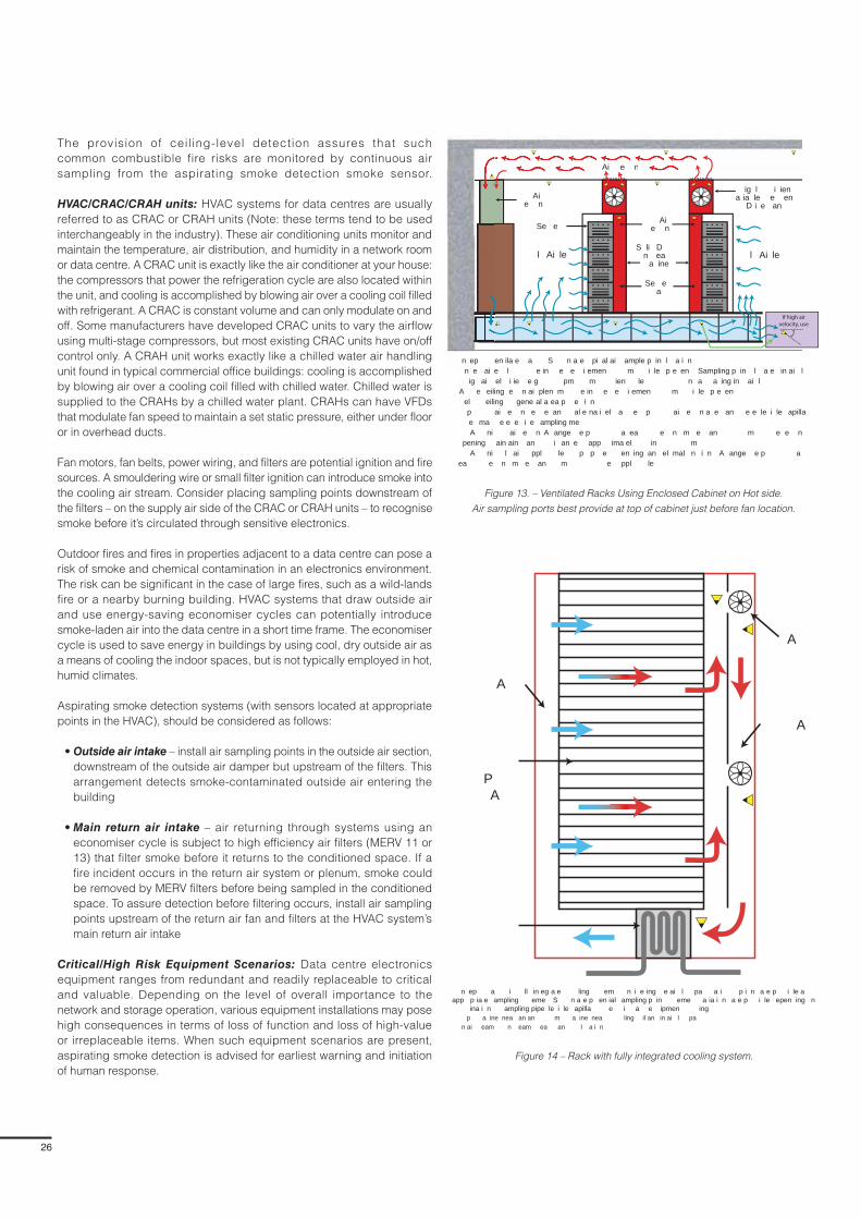
26
The provision of ceil ing-level detection assures that such
common combustible fire risks are monitored by continuous air
sampling from the aspirating smoke detection smoke sensor.
HVAC/CRAC/CRAH units: HVAC systems for data centres are usually
referred to as CRAC or CRAH units (Note: these terms tend to be used
interchangeably in the industry). These air conditioning units monitor and
maintain the temperature, air distribution, and humidity in a network room
or data centre. A CRAC unit is exactly like the air conditioner at your house:
the compressors that power the refrigeration cycle are also located within
the unit, and cooling is accomplished by blowing air over a cooling coil filled
with refrigerant. A CRAC is constant volume and can only modulate on and
off. Some manufacturers have developed CRAC units to vary the airflow
using multi-stage compressors, but most existing CRAC units have on/off
control only. A CRAH unit works exactly like a chilled water air handling
unit found in typical commercial office buildings: cooling is accomplished
by blowing air over a cooling coil filled with chilled water. Chilled water is
supplied to the CRAHs by a chilled water plant. CRAHs can have VFDs
that modulate fan speed to maintain a set static pressure, either under floor
or in overhead ducts.
Fan motors, fan belts, power wiring, and filters are potential ignition and fire
sources. A smouldering wire or small filter ignition can introduce smoke into
the cooling air stream. Consider placing sampling points downstream of
the filters – on the supply air side of the CRAC or CRAH units – to recognise
smoke before it’s circulated through sensitive electronics.
Outdoor fires and fires in properties adjacent to a data centre can pose a
risk of smoke and chemical contamination in an electronics environment.
The risk can be significant in the case of large fires, such as a wild-lands
fire or a nearby burning building. HVAC systems that draw outside air
and use energy-saving economiser cycles can potentially introduce
smoke-laden air into the data centre in a short time frame. The economiser
cycle is used to save energy in buildings by using cool, dry outside air as
a means of cooling the indoor spaces, but is not typically employed in hot,
humid climates.
Aspirating smoke detection systems (with sensors located at appropriate
points in the HVAC), should be considered as follows:
• Outside air intake – install air sampling points in the outside air section,
downstream of the outside air damper but upstream of the filters. This
arrangement detects smoke-contaminated outside air entering the
building
• Main return air intake – air returning through systems using an
economiser cycle is subject to high efficiency air filters (MERV 11 or
13) that filter smoke before it returns to the conditioned space. If a
fire incident occurs in the return air system or plenum, smoke could
be removed by MERV filters before being sampled in the conditioned
space. To assure detection before filtering occurs, install air sampling
points upstream of the return air fan and filters at the HVAC system’s
main return air intake
Critical/High Risk Equipment Scenarios: Data centre electronics
equipment ranges from redundant and readily replaceable to critical
and valuable. Depending on the level of overall importance to the
network and storage operation, various equipment installations may pose
high consequences in terms of loss of function and loss of high-value
or irreplaceable items. When such equipment scenarios are present,
aspirating smoke detection is advised for earliest warning and initiation
of human response.
S li D n ea
a inel Ai lel Ai le
Ai e n
Se e a
Ai e n
Se e
Ai e n
ig l i ien a ia le e en
D i e an
Ai e n
n ep en ila e a S n a e pi al ai ample p in l a i n n e ai e l e in e e i emen m i le p e en Sampling p in l a e in ai l
ig ai el i ie e g pm m ien le n a a ing in ai l A e eiling e n ai plen m e in e e i emen m i le p e en el eiling gene al a ea p e i n p ai e n e e an al e na i el a e p ai e n a e an e e le i le apilla
e ma e e e i e ampling me A ni ai e n A ange e p a ea e n m e an m e e n
pening ain ain an i an e app ima el in m A ni l ai ppl le p p e en ing an el mal n i n A ange e p a
ea e n m e an m e ppl le
If high air velocity, use
Figure 13. – Ventilated Racks Using Enclosed Cabinet on Hot side.
Air sampling ports best provide at top of cabinet just before fan location.
Figure 14 – Rack with fully integrated cooling system.
n ep a i ll in eg a e ling em n i e ing e ai l pa a i p i n a e p i le a app p ia e ampling eme S n a e p en ial ampling p in eme a ia i n a e p i le epen ing n
ina i n ampling pipe le i le apilla e i a e ipmen ing p a ine nea an an m a ine nea ling il an in ai l pa n ai eam n eam ea an l a i n
A
P A
A
A
27
FAAST Fire Alarm Aspiration Sensing Technology®
Ventilated IT Equipment Racks: Ideal air management and cooling
schemes for equipment racks use cooling systems integrated with plenums
contained within the rack enclosure (See Figures 13 and 14). In these highly
efficient designs, cool air is directed to the intake side of the rack and hot
air is exhausted from the opposite side. In-cabinet sample points can also
be an effective detection scheme, but the sampling points must be placed
on the hot air return side.
Coordination and Interface with other Systems
Fire Protection Systems: fire protection systems in data centres may be
implemented in a number of ways.
• Automatic sprinkler systems only
– Wet systems
– Pre-action – non-interlocked, single interlocked, double interlocked
• Automatic sprinkler systems with supplemental clean agent systems
• Water mist systems only
• Water mist systems with supplemental clean agent systems
• Clean agent systems only
Often the system choice and implementation depends on owner/operator
concerns for equipment water damage. Depending on the fire protection
system(s) used, there could be a need for a fire detection system
interface to initiate sprinkler pre-action valve operations, damper closing
operations prior to clean agent release, or shut-down of HVAC systems and
de-powering of equipment. Aspirating smoke detection plays an important
role in these operations by providing alerts and alarms at appropriately
set smoke detection levels. An aspirating smoke detection system’s alert
and action settings initiate early staff response, which can confirm the
shut-down of extinguishing system operations as well as associated air
handling. However, if there is a threatening fire in development, the typical
Fire 1 and Fire 2 alarm settings can be programmed to initiate pre-action
valve release or clean agent release. Where a sprinkler or water mist system
is supplemented by a clean agent system, there may be a desire to control
suppression/extinguishing system operations with two alarm levels of an
aspirating smoke detector (i.e., Fire Alarm 1 and Fire Alarm 2), or to use two
independent detection systems. For example, an aspirating detector may be
used for sprinkler pre-action valve control while a second detection system
is used for clean agent release after an appropriate time delay period (e.g.
30 seconds). Alternatively, a Fire Alarm 1 Level may be used for sprinkler
pre-action valve control and the Fire Alarm 2 Level used for clean agent
release. Aspirating smoke detection systems provide the early response
needed to initiate an extinguishing system in the event of a developing fire.
Quick water application and system effectiveness is typically improved by
early operations during the fire event. Aspirating smoke detection systems
provide this capability to assure prompt extinguishing system action.
HVAC Systems and De-powering operations: Electrical power supplies in
data centres serve as an ever-present ignition source. Electrical systems in
data centres allow for de-powering equipment that may be source of ignition
and re-ignition energy after extinguishing systems operate. De-powering
may be accomplished using manual power disconnect features or done
automatically. Aspirating smoke detection can be valuable to the sequence
of de-powering operations. Prematurely shutting down HVAC systems can
cause an immediate temperature spike in the facility and result in damage
to electronics equipment.
Early staff response initiated by an aspirating smoke detection system’s alert
and action settings can confirm the need for any associated air handling
shut-down. Also, should an actual fire event transpire, the typical Fire 1 and
Fire 2 alarm settings can be programmed to initiate pre-action valve release
(or clean agent release), HVAC shut-down and equipment de-powering.
The de-powering of equipment assures better clean agent suppression,
and there’s less chance of equipment damage with the electrical power
removed.
Common Issues/Application Troubleshooting
There are several considerations for the use of aspirating smoke detection
within data centres. During the design phase, the following factors should
be considered:
• The designer needs to verify the airflow and direction of air within the
space to maximise the system’s effectiveness. The sampling points
should be installed in the direction of the airflow
• For a large detection system with many sampling holes, the designer
needs to account for smoke/air dilution. The more sampling holes the
air sampling pipe contains, a greater volume of air is returning to the
aspirating detector; this can dilute the quantity of smoke within the
detection chamber and may delay the time it takes to initiate the alarm
within the detection chamber
• The location of the sampling holes within the detection network is a
concern. The further the sampling hole is located from the aspirating
smoke detector, the more air/smoke dilution occurs, which could delay
the time it takes to initiate the alarm within the detection chamber
• In normal applications, it is common for the air pressure in the protected
room (PR) to be the same as the air pressure where the air is being
exhausted from the detector (PE). The design software that is used to
calculate transport times and detector sensitivities assumes equal air
pressure in the two spaces. The sampling hole size, pipe size, transport
time, and the fan aspirator speed are all functions of the air volume
that passes through the sampling chamber. The sensing chamber is
designed to detect smoke particles moving through the chamber at the
speed of the fan. If PR is greater than PE, the velocities of the sampled air
entering the chamber could be higher than the nominal fan speed, which
could directly impact the detector’s ability to sense smoke particles.
Conversely, if PE is greater than PR, air pressure builds on the exhaust
air, causing resistance and a drag on the fan. As a result, the fan may
operate slower than designed, causing an increase in transport times
and less air going into the sensing chamber. To eliminate the pressure
difference, the exhaust air needs to be piped into the same room that
is being sampled.
During the commissioning process, the installing contractor needs to
properly program the alarm thresholds and sensitivity levels because both
could significantly impact the aspirating smoke detector’s performance. The
following programming considerations should be considered:
• Typically, aspirating smoke detectors are shipped with default settings
from the factory. These generic settings are not appropriate for all
detection systems because they may be either too sensitive or not
sensitive enough for a specific application. It is necessary for the
aspirating system designer to determine the alarm levels and program
the sensor accordingly. The sensitivity levels and alarm thresholds are
derived by a combination of the computer-based calculation program,
the hazard being protected, detection system size and engineering
judgment

28
• The programmable sensitivity levels are another significant issue
impacting the performance of aspirating smoke detection systems.
The detectors contain sophisticated electronics and software that allow
the device to be programmed to a wide range of sensitivity levels. If
these alarm levels are not programmed properly, then the quantity of
smoke necessary within the sensing chamber may exceed the desired
sensitivity and cause a delay in alarm signal initiation.
Time delays for trouble and alarm signal activation are also included at the
detector. These delays can be set for a range of times, but typically span
from 10 to 30 seconds. Consideration should be given when programming
the time delays. The greater the delay, the longer it will take for the detector
to initiate an alarm signal.
Dos
• Identify applicable codes and insurer’s requirements
• When NFPA 75 (Standard for the Fire Protection of Information
Technology Equipment) applies, the following is recommended:
– Review the documented risk assessment for the information
technology equipment areas and all recommendations for automatic
smoke detection
– Apply aspirating smoke detection when early warning smoke
detection is required for 1) the ceiling level throughout the IT
equipment areas, and 2) below the raised floor of IT equipment areas
containing cables
– Apply sampling port in the above ceiling space or below a raised
access floor of an IT equipment area, when air circulates to/from
other areas via these IT area concealed spaces. One or more of the
following installations should be used: 1) throughout the concealed air
movement space, 2) at each smoke damper, or 3) at other locations
necessary to detect smoke entering or exiting the IT equipment area
– Assure that alarm and trouble signals from aspirating smoke
detection systems are annunciated at a constantly attended location
– Confirm and implement how alert and fire alarm settings are
integrated to initiate the following if applicable: 1) power shut-down,
2) pre-action system valve operation, 3) gaseous agent release,
4) water mist system release, 5) air handling shut-down and
associated damper or door closures, 6) release of aisle air flow
containment systems (e.g. vinyl curtains), that obstruct agent delivery
from sprinkler or gaseous agent systems
• When BS 6266 (Fire protection for electronic equipment installations –
Code of practice) applies, the following is recommended
– Review the documented risk assessment for the electronic equipment
areas and understand which areas classify as medium , high, or
critical risk electronic installations
– Identify where Class C, aspirating smoke detection type smoke
detection is to be applied
– Identify where Class B, aspirating type smoke detection is to be
applied. Class B systems are used when increased sensitivity is
needed to compensate for dilution effects due to high ceilings or
moving airflows
– Identify where Class A, aspirating type smoke detection is to be
applied. Class A systems are used in areas with high air movement
and smoke dilution, or where the very earliest warning is needed to
protect critical business operations, high value data processing or
high value electronic equipment
– Install sampling holes for optimum effectiveness in accordance
with Annex A provisions of BS 6266 for air return vents, ceilings,
below floor and above ceiling void spaces, in-cabinet locations, and
proximity to air inlets and ceiling fittings
– Apply the rules of BS 6266 where aspirating type smoke detection
is applied
– Confirm and implement how alert and fire alarm settings are
integrated to initiate the following if applicable: 1) power shut-down,
2) pre-action system valve operation, 3) gaseous agent release,
4) water mist system release, 5) air handling shut-down and
associated damper or door closures, 6) release of aisle air flow
containment systems (e.g. vinyl curtains), that obstruct agent delivery
from sprinkler or gaseous agent systems.
• Understand the airflow environment and coordinate air sampling points
with key points of return and supply air movement
• Follow the spacing rules of applicable installation standards and/or
insurance carrier requirements
• Consider sampling ports both under cable trays and at the ceiling when
cable tray density and arrangement may impede smoke flowing to the
ceiling
• Provide sampling ports to monitor HVAC/ CRAC/ CRAH air returns.
Arrange the ports so that each covers no more than 0.4 m² (4 ft²) of the
return opening.
• Identify critical or high-risk equipment installations that should have
localised area or in-cabinet air sampling for earliest warning and
initiation of human response
• Consider providing sampling ports to monitor outside air intake –
install air sampling points in the outside air section, downstream of the
outside air damper but upstream of the filters. This arrangement allows
for detection of smoke-contaminated outside air entering the building
• Consider providing sampling ports to monitor Main Return air intake of
economiser systems – if a fire incident occurs in the return air system or
plenum, smoke could be removed by MERV filters before it is sampled
by detection point in the conditioned space. To assure detection before
any filtering occurs, install air sampling points at the HVAC system’s main
return air intake, upstream of the return air fan and filters
Don’ts
• Don’t exceed the recommended detector or sampling point spacing of
applicable standards or insurance carrier requirements.
• Don’t use detectors that are not listed or approved for air velocities and
temperatures that will be encountered in IT areas or equipment.
• Don’t design the aspirating smoke detection system to exceed the
transport time requirements of installation standards or insurance
company requirements.
• Don’t install ceiling sampling points too near to ceiling supply air
diffusers. Maintain a distance of 0.9 m - 3 m (3 ft. -10 ft. from ceiling
diffusers depending on the strength of the airflow. (See BS 6566 and
NFPA 72 for specific requirements)

29
FAAST Fire Alarm Aspiration Sensing Technology®
Section 6
Telecommunications
Application Overview
Telecommunication lines and systems are not only expected conveniences
of businesses and homes, but also key elements of business operations
and emergency services. Telecommunication companies spend billions
of dollars to ensure reliable voice, data, and video transmission routes
by using improved transmission-route switching technology and multiple
transmission paths in the telecommunication network, also known as the
Public Switched Telephone Network (PSTN).
Facilities that provide telecommunication services to the public are known
as “public exchanges” in Europe and “central offices” in North America but
they’re also referred to as “telephone exchanges” or “switching exchanges.”
These facilities provide services such as telephone transmissions (wireless
and land-line phones), data transmission, internet transmission, VoIP
transmission (Voice over Internet Protocol), and video signal transmissions
(e.g. cable TV). The function of a telecommunications facility is voice and
data signal transmission, making it different from the function of a data
centre (to manipulate, store, and retrieve data). If telecommunications
equipment fails or operations cease due to an unwanted event, then any
in-progress data/signal transmission is lost and not recoverable. The
transmission paths are as basic as the traditional twisted pair of copper
wires (house connected to telephone exchange), but also include:
cellular wireless networks, coaxial cable, fibre optic cable and microwave
transmission links, communications satellites, and undersea phone cables.
Important system power supplies, sophisticated circuit-switching
equipment, and circuit interfaces between local phone carriers and long
distance companies are found in thousands of telephone exchange
buildings around the world. These buildings may be high-rise structures in
major cities or small, one-story facilities in suburban or rural areas. While the
size of central offices varies widely, their relative importance to communities
they serve is always high. Many are highly automated, meaning that either
no staff or only limited staff may be present during standard working hours.
A central office/public exchange represents a highly specialised and
sensitive risk environment and typically consists of a variety of equipment
and spaces:
• Cable vaults - below-grade structures containing the telephone-cable
racks and trays entering the site
• Power areas/rooms – transformers/rectifiers convert high voltage power
company AC current to a lower voltage DC current with battery systems
that supply telecom system equipment. Batteries are final source of
power if generators fail. See Figure 1 top right
• Generator rooms - spaces housing diesel or gas-turbine generators for
long-term standby power if power company supply fails
• Distributing frames - terminal equipment that supports and positions
large numbers of telephone wires at terminal blocks for connection to
switching systems
• Switching equipment areas – modern day electronic digital switches
or electromechanical switching equipment that establishes connections
to the telephone network
• Computer rooms - spaces housing data-processing equipment that
monitors switching equipment, activity, faults, and accounting data
• Conventional offices, building systems and mechanical rooms
ele mm ni a i nipmen
e i ieD a
P e S em
ain gene aan e i
mme ialA P e ee
S anene a
S age a e ie
A P e m e mme ial e an gene a i mme ial e ail D P e ppl m e D a p e em p e e ele m e ipmen e D PS al eep e a e ie a ge en all A p e i l e ele m e ipmen i p e e i e l m e age a e ie
Figure 1. – Power supply scheme for central offices/public exchanges
Fire losses are common in telecommunication exchange buildings, given
the nature of electrical equipment systems, combustible cabling, batteries,
and associated maintenance activities. The North American fire record
in the telecommunications industry has been excellent, with only eight
notable incidents occurring from 1975 to 2000 with no occupant or first
responder loss of life. This fire record is attributable to the long-time and
widespread use of telecommunications equipment and cables with high
fire resistance characteristics, as well as high standards for telephone
exchange construction in North America. Similar standards are followed
in Europe.
Although small, slow developing fires have been the norm for
telecommunication buildings, those fires can still significantly impact the
services used by businesses and the general public. A review of seven
significant incidents in the 1980’s and 90’s showed that the fire did not
spread beyond the area of fire origin but still resulted in significant service
interruptions. For these seven incidents, the service outages were as follows
(see Figure 2 on the following page):
• 5,000 to 113,000 lines/customers interrupted
• Average of 49,900 lines/customers interrupted
• 1-16 days required for restoration of service
• Average of 4 days for restoration of lost services
• Emergency service interruptions
• Smoke damage occurred in areas beyond the room of origin
(three incidents)
Because the ramifications of a telecommunication facility fire can be severe
– including millions of dollars in lost service, related business interruption
and interruption to critical operations (emergency services) – safeguarding
against such occurrences has become a top priority for the industry.

30
Benefits of Aspirating Smoke Detection
The telecommunications equipment environment is unique because
the expected fire development has been predicated on the use of
telecommunications equipment and cables with high fire resistance
characteristics and associated low energy fire scenarios. Aspirating smoke
detection technology is an ideal solution for telecommunications equipment,
due to the nature of the fires in this environment and the nature of the
threats to the equipment from corrosive smoke, unwarranted suppression
system release, or fire department intervention (water application). The
following points describe the unique aspects of fires and operations
in telecommunications facilities and why aspirating smoke detection
technology should be used:
• Most fires are so small they seldom activate standard detection or
suppression equipment
• Non-thermal damage effects from corrosive smoke, moisture, and arcing
are chief contributors to service outages
• Fire growth rates tend to be slow in telecommunication equipment, and
experience indicates burn areas are limited (approximately 15.2 m² -
304.8 m² (50 ft.² - 1,000 ft.²)
• To keep equipment cool, airflows and air change rates are significant
and may require shut-down or a smoke mode operation to manage the
smoke and prevent contamination
• Power supplies are intended to operate equipment continuously, and
typical emergency power-off capability (as required by electrical codes),
is not provided because the use of telecommunications equipment
and the consequences of disconnecting power can be severe (loss of
voice/data/signals transmission)
• Automatic extinguishing systems, including both water-based and
gaseous agents, often have limited value due to their inability to
extinguish fires involving highly redundant reliable telecommunication
power supplies. Extinguishing-agent discharge can aggravate and
enhance non-thermal damage effects
Fire may be a low probability event in a telecommunications equipment
environment, but even the smallest fire events can have severe
consequences. The potential lack of staff presence and vigilance can be
overcome by aspirating smoke detection systems that actively monitor the
ambient air throughout telecommunications equipment areas.
Given the potential losses for telecommunication facilities, it’s critical
to identify small fire events like precursor smouldering or overheating
equipment. Aspirating smoke detection systems can provide high sensitivity
and continuous sampling of low quantities of smoke that may be distributed
and easily diluted by high airflow environments. Digital equipment designed
to the highest standards (UL 60950, NEBS GR63), has components and
construction features that minimise heat release and the production of
smoke, yet an incident may only have a chance of being detected with the
use of aspirating smoke detection systems.
Due to concerns for extensive damage to sensitive electronic components
or general effectiveness, automatic fire suppression systems that use water/
water mist/aerosols/foam are generally not employed in telecommunications
equipment spaces. However, clean agent or inert gas systems may be found
in some telecommunications facilities. The need for very early identification
of a fire or precursor event is of great importance in telecommunications
equipment areas, and the need for earliest detection can be readily served
by aspirating smoke detection systems. In cases where any of the noted
fire suppression systems are installed in the data centre space, there is an
equally important need to identify and investigate an alert or alarm condition
prior to a suppression system operation – whether needed or not. A side
effect of some suppression system operations (gaseous agent systems),
is the need to partially or completely shut-down air handling equipment
and close airflow dampers to contain suppressants. Such a shut-down
can result in significant temperature rise in the equipment spaces, as well
as the disruption of electronics. Therefore, early staff response initiated by
an aspirating smoke detection system can result in confirmation to abort
suppression system operation and any associated air handling shut-down.
Conversely, an early staff response can result in manual fire suppression
intervention or de-powering a section of equipment that appears as an
ignition or fire source.
As previously mentioned, small and slow-developing telecommunications
fires are attributable to the use of equipment and cables with high fire
resistance characteristics. However, this may not be the always be the
case: the need for suppression systems and capable smoke management
systems becomes most important when the fire risks fall outside these
controlling/limiting fire characteristics. However, fire suppression systems
and smoke management systems don’t diminish the need for an aspirating
smoke detection system in a high-risk telecommunication environment.
The early detection capabilities of aspirating smoke detection systems are
important to staff response, smoke management system operations and
potentially critically needed de-powering activities.
Figure 2. – Loss Impacts
Se i e n e p i nSm e amage
e n m igin
mpa e igni i an ele mm ni a i n i e Ame i an n i en
line in e p e A e ageA e age m e Da
Se i e e a i ne a i nA e age m e
eee age mg Se i e Se i e

31
FAAST Fire Alarm Aspiration Sensing Technology®
Design Best Practices
Two documents address the sensitive electronics environment in
telecommunications facilities: BS 6266 (Fire Protection for Electronic
Equipment Installations – Code of Practice) and the National Fire
Protection Association standard (NFPA 76, Standard for the Fire Protection
of Telecommunications Facilities). BS 6266 is intended to apply to a
wide variety of environments using electronic equipment, including
telecommunications switching/transmission systems. NFPA 76 is more
specifically focused on buildings that house telecommunication equipment
used in the transmission of voice/data/signals for the general public
(i.e., central offices, public exchanges).
In terms of best practices, the telecommunication industry in North America
has developed standards for equipment, protection, and emergency
procedures that have recently been adapted and refined into the NFPA 76
document, Standard for the Fire Protection of Telecommunications Facilities.
NFPA 76 requires that a fire protection program be established for telecom
facilities based on the risks and hazards to the occupants, facility, and
operations. It also expresses the criticality of telecommunication services,
business continuity/disaster recovery plans, and protection strategies for
minimising service disruption. A fire protection program may be established
for a telecommunication facility by using any one of three methods
(or a combination thereof):
• A performance-based analysis approach accounting for the site specific
conditions and meeting established goals, objectives, and performance
criteria
• Application of the prescriptive requirements and specifications for fire
protection in NFPA 76
• Use of redundant facilities/services or plans for rapid facility/equipment
replacement
Although the use of aspirating smoke detection technology would be
expected to play a role in any performance-based approach, guidance
on this subject is beyond the scope of this guide. However, further guidance
is available in NFPA 76 (chapter on Performance-based Approach), and
the SFPE Engineering Guide to Performance based Fire Protection.
The more common basis for fire detection and aspirating smoke detection
applications in telecommunication facilities are the prescribed requirements
of NFPA 76.
When using NFPA 76, follow the four basic steps below to determine where
fire/smoke detection is required and which type is required. Although the
NFPA 76 minimum requirements will allow for various types of detection
technologies, aspirating smoke detection can serve the needs of most
any space in a telecommunications facility. Follow the steps below to
determine the requirements for fire/smoke detection, including aspirating
smoke detection systems.
1. Step 1 – Identify the physical boundaries that define the
telecommunications facility. Typically, this will be the exterior walls of
an isolated or standalone central office or public exchange building.
In the case of a multiple tenant or multi-occupancy building, the
telecommunications facility should be that portion of the building
separated from other tenants or occupancies, as follows:
• Separated by a minimum of two-hour fire resistant construction when the
building is not under the ownership /control of the telecommunications
tenant
• Separated by a minimum of one-hour fire resistant construction when
a mixed occupancy building is under the ownership /control of the
telecommunications company
m
m
m
m
m
m
m
m
m
m
Calculated signal-processing equipment (SPE) area is 900 ft2 (84 m2)
SPE area is1500 ft2
(139 m2)SPE area is 360 ft2
(33 m2)
P e A ea
a le a l el
D A ea
i l
e i l n i e e al ne l n e ee e 2 m2 e l a e m ine SP a ea i 2 m2 A ing a e n in ea e e agg ega e SP a ea 2
m2
Se n l
a e ie
2. Step 2 – Determine the total area of signal-processing equipment
(SPE) in the telecommunication facility to determine if the SPE
occupies more than 232 m² (2,500 ft.²) or if the SPE occupies an
area equal to or less than 232 m² (2,500 ft.²). The fire protection
requirements will vary based on the total area of SPE on all floors in the
telecommunications facility, relative to the 232 m² (2,500 ft.²) threshold.
Signal-processing equipment (SPE) includes, but is not limited to, switch
and transport/access equipment, servers, routers, computers, and cable
television equipment forming one-way or two-way communications links.
When measuring to determine the total aggregate SPE floor area, keep in
mind the NFPA 76 definition. NFPA 76 defines the SPE area as that area
occupied by the SPE, including the access aisles between equipment
and a 0.6 m (2 ft.) wide access zone around the perimeter of the SPE.
Figure 3 below illustrates this calculation.
Figure 3 – Determination of SPE area
3. Step 3 – For each single enclosed room in the telecommunications
facility, identify from the following list the hazard area(s) or equipment
present and then provide fire /smoke detection as required per
Chapter 6 of NFPA 76. Table 1 on the following page, summarises
these Chapter 6 requirements. If any of the first six listed
rooms/equipment areas are located within the same enclosed room,
the most restrictive fire/smoke detection requirements are applicable
to the entire enclosed room.
1). Heating, ventilating, and air-conditioning (HVAC) equipment
installed to provide environmental control dedicated to the
telecommunications equipment or telecommunications
equipment areas
2). Signal-processing equipment areas
3). Cable entrance facility/equipment areas
4). Power areas or power equipment
(5) Main distribution frame areas or main distribution frame
equipment
6) Technical support areas
7). Standby Engine area (typically confined to room alone)

32
Table 1 - Summary of Minimum Requirements of NFPA 76 for Fire/Smoke
Detection in Telecommunication Equipment Areas
Aspirating Smoke Detection Technologies can provide VEWFD, EWFD or SFD detection capabilities to
match or exceed minimum NFPA 76 requirements
SPE aggregate area > 2500 ft²(232 m²) SPE aggregate area ≤ 2500 ft²(232 m²)
Signal-Processing Equipment (SPE)
Room/area detection
Raised floors with combustibles – No common
airflow above and below
Raised floors with combustibles - common airflow
above and below
VEWFD
EWFD below floor
VEWFD above floor (room/area detection)
EWFD
EWFD
EWFD
Cable Entrance Facility EWFD EWFD
Power Areas/Equipment EWFD EWFD
Main Distribution Frame Area (MDF)
Room/area detection
Raised floors with combustibles – No common
airflow above and below
Raised floors with combustibles - common airflow
above and below
VEWFD
EWFD below floor
VEWFD above floor (room/area detection)
EWFD
EWFD
EWFD
Standby Engine Area Heat or flame detection Heat or flame detection
Technical Support Areas (TSA)
TSA not part of telecommunications equipment area
TSA contiguous with SPE or MDF areas
TSA contiguous with power areas
TSA part of telecommunications equipment area
when SPE area ≤232 m² (2,500 ft²)
SFD per NFPA 72
VEWFD
EWFD
Not Applicable
SFD per NFPA 72
See below
See below
EWFD
HVAC Systems
If VEWFD is required for the space (see above)
then provide VEWFD as noted in next column
VEWFD ports to monitor return air; VEWFD ports
to monitor returns of stand-alone packaged
HVAC units
Not applicable

33
FAAST Fire Alarm Aspiration Sensing Technology®
4. Step 4 – When selecting aspirating smoke detection technology to
meet the requirements of NFPA 76, apply the parameters for VEWFD,
EWFD, or SFD detection capabilities to match or exceed minimum
NFPA 76 requirements as follows (also, see Figures 4, 5, 6, and 7 on
the following page):
Very Early Warning Fire Detection (VEWFD) systems – detects low energy
fires prior to the development of fire conditions that are threatening to
telecommunications service. Minimum criteria applicable to aspirating
systems are:
– Sampling port maximum coverage area: 18.6 m² (200 ft² ); where two
levels of air sampling ports are used, each level limited to a coverage
of 37.2 m² (400 ft²) as illustrated in Figure 7 below right.
– Minimum sensitivity settings (effective at each port):
– Alert condition at 0.66 %/m (0.2 %/ft.) obs
– Alarm condition at 3.3 %/m (1.0 %/ft.) obs
– Maximum transport time: 60 secs.
Early Warning Fire Detection (EWFD) systems – detection by smoke,
heat, or flame detectors before high heat conditions threaten human life or
cause significant damage to telecommunications service. Minimum criteria
applicable to aspirating systems are:
– Sampling port maximum coverage area: 37.2 m² (400 ft.²)
– Minimum sensitivity settings (effective at each port):
– Alert condition – no requirement
– Alarm condition at 4.9 %/m (1.5 %/ft.) obs
– Maximum transport time: 90 secs.
Standard Fire Detection (SFD) systems – systems that use fire
detection initiating devices to achieve life safety and property protection
in accordance with applicable standards. Automatic fire detection
devices addressed in NFPA 72 are applicable for SFD systems.
D
m m
ample a angemen ampling p l a e mee e i emen D inal a m
D
m m
ample a angemen ampling p l a e mee e i emen Dal a m
ai
n
m
anp
im
e e
n
D
inim m Sen i i i Se ing a e am ien ai ne le el an ma im m an p ime D D em appli a i n pe PA
No Requirement -User definable at
threshold less than alarm.
D
Ale
Ala m
an p imea
in
m
anp
im
e e
n
D
inim m Sen i i i Se ing a e am ien ai ne le el an ma im m an p ime D D em appli a i n pe PA
No Requirement -User definable at
threshold less than alarm.
D
Ale
Ala m
an p ime
Figure 4. - Example of VEWFD Coverage
Figure 5. - Example of EWFD Coverage
Figure 6. – NFPA 76 criteria for VEWFD and EWFD
Figure 7. – Staggered VEWFD Coverage

34
In Europe, BS 6266 (Fire Protection for Electronic Equipment Installations
– Code of Practice), is a best practice document applicable to electronic
equipment installations including telecommunications facilities (public
exchanges.
BS 6266 provides guidance on the structural fire protection measures, early
detection concepts, fire suppression concepts, and fire safety management
procedures that may be needed to minimise the potential consequences
of a fire in electronic equipment environments.
BS 6266 requires a risk assessment prior to establishing the final design
of electronic equipment installation. This involves considerations of the
building and environment in which the equipment will be sited, and the
proposed design of the fire protection systems. The criticality of the
electronic equipment is an important factor in this risk assessment process.
BS 6266 states that electronic equipment risks should be based on the
following factors and classified as medium, high, or critical risks:
• Equipment redundancy and replacement availability
• Business continuity plans
• Tolerance to system downtime
• Environmental operational requirements specific to an individual system
Telecommunication equipment spaces, such as those found in central
offices/public exchanges, would generally be expected to fall into the
classification of high or critical risk, as defined by BS 6266, when one or
more of the listed characteristics apply.
High category risk (BS 6266)
a) Equipment is non-standard and is not replaceable in the short term
b) Operations are not easily transferable without robust contingency plans
c) There is a need for files to be backed up frequently on a remote server
d) Interruption to business operations is likely to have serious consequences
Critical category risk (BS 6266)
a) Equipment is high value or purpose-built and is not easily replaceable
b) Operations are not easily transferable
c) There is a need for data to be backed up on a continual basis on a
remote server
d) Interruption to business operations is likely to have serious consequences
BS 6266 recognises all types of smoke and fire detection systems; however,
for the high and critical risk categories, BS 6266 recommends only the
highest sensitivity smoke detection technologies that can meet the test
fire requirements of EN54-20 to provide the earliest possible indication
of fire. Aspirating detection technology provides such capability, and
BS 6266 recognises EN54-20 Class A aspirating smoke detection systems
as an appropriate technology for use.
BS 6266 specifically notes that the cumulative effect associated with
aspirating smoke detection systems makes them particularly appropriated
for detecting smoke that is diluted through a space. The following factors
should be taken into consideration when designing air sampling smoke
detection systems.
a) Electronic equipment areas are continually increasing their power
handling capability, which means that the air-conditioning systems
serving the spaces require increased airflow and velocities
b) Positioning of sampling points is critical due to the very high airflows in
the room. While an even distribution of devices is often assumed to be
preferred, strategic positioning can be advantageous in many cases
c) High velocity airflow through plenum voids necessitates detectors being
placed in advantageous positions to detect any smoke
d) Hot or cold aisle containment – where physical partitioning is introduced
between the cabinet air entry (cold aisle) and the air exit (hot aisle) –
creates a further enclosure within the space, effectively an extension of
the floor (or ceiling) plenum, which needs appropriate detection
e) The detection strategy needs to be clearly defined in relation to the air
flows and cooling requirements in the area, particularly whether the air-
conditioning is to remain operational or shut down after the first alarm
signal to facilitate confirmation of the alarm by a detection system at the
ceiling and/or to prepare the area for activation of automatic suppression
f) The operational procedures, the expected number of personnel in the
area, and the time required for competent action to commence will
determine the strategy for alarm and warning signals. Generally, the
automatic fire alarm system should operate alarms within the electronic
equipment area and in other areas where action is to be taken
When applying BS 6266, the intended sensitivity of an aspirating smoke
detector should be specified by properly identifying the class required
(Class A, B, or C per EN 54-20:2006). The class of an aspirating detector
relates to the sensitivity of the sampling holes, not the detection unit
sensitivity. BS 6266 specifies EN 54-20 Class A, B, and C air sampling
detection to be implemented as follows:
• When used to detect smoke in the return airflow from the room, a
Class A system should be used to provide early warning
• When used to detect smoke within a cabinet or enclosure, a Class A
or B system should be used to provide early warning
• When used to detect smoke at the ceiling of the room or within a
floor or ceiling void, a Class A or B system should be used when the
air-conditioning is to remain operational. A Class C system can be used
when the air-conditioning can be shut down.
• The general spacing of air sampling ports for ceiling detection or void
spaces greater than 1.5 m (4.9 ft.) deep is 25 m² (269 ft.²). BS 6266,
however, stipulates that adjustments are to be made based upon
considerations for airflow, sensitivity, equipment operational factors,
etc., that are detailed in Annex 1. The total adjustments possible can
result in coverage areas as small as 5 m² (54 ft.²) and as large as
55 m² (592 ft.²).
Airflow Considerations
As a result of concentrated heat loads from electronic equipment in
telecommunications facilities, significant airflows are needed to keep
equipment within proper operating temperature ranges. To accomplish
this, large air flows are provided with the basic objective of supplying
cool supply air to the equipment and moving hot exhaust air away from
the equipment. Standard smoke detectors are generally not capable of
performing in high airflows. Because of room air currents dilution and
stratification phenomenon, sufficient smoke may not be able to reach a
ceiling-mounted detector; if smoke can penetrate to a ceiling-mounted

35
FAAST Fire Alarm Aspiration Sensing Technology®
detector, then there may not be a sufficient quantity of smoke to activate a
standard smoke detector. NFPA 72 specifies that smoke detectors should
not be used in airflow environments over 1.54 m/s ( 300 fpm ), unless the
devices are specifically recognised for such conditions.
NFPA 72’s typical spacing requirements are 84 m² (900 ft.²) for standard
smoke detectors in normal airflow environments are. However, both
BS 6266 and NFPA 72 recognise these smoke detection challenges and
stipulate spacing reductions in for detection points in such high airflow
conditions. NFPA 76 directly accounts for these airflow conditions and
requires reduced smoke detection/sampling port spacing of 18.6 m²
(200 ft.² ) or 37.2 m² (400 ft²) for various telecommunications equipment
areas.
Similarly, BS 6266 provides guidance specific to adjustments needed in
electronic equipment installations based on airflow. The BS 6266 standard
spacing of sampling ports for ceiling detection is 25 m² (269 ft.²), which
is to be reduced by 5% or 10% when airflows greater than 1m/s or 4
m/s, respectively, are present in an area greater than 25% of the space
where the detectors are located. An aspirating smoke detector can provide
detection at very low particle levels and in high airflow environments.
Consider that a standard spot smoke detector operates in the range
of 4.8 -9.7% obs/m (1.5 - 3.0% obs/ft.), and an aspirating detection
system can be programmed to provide sensitivity for detection as low as
0.0015% obscuration/m (0.00046% obs/ft.). Aspirating smoke detection
systems are up to the challenge of the high airflow environments of
telecommunication facilities, with the capability of detection in 20.3m/s
(4,000 fpm) environments.
Both BS 6266 and NFPA 76 place an emphasis on the use of highly
sensitive smoke detection for the airflow return paths in electrical equipment
environments. BS 6266 allows a Class A aspirating detection system in the
air return to a HVAC/CRAC system to be the sole means of detection, if
the air conditioning equipment has appropriate back-up power systems
and is essential for assuring 24/7 operations of the electronics equipment.
NFPA 76, Chapter 6 provisions require that SPE areas and main distribution
P i al Sepa a i n
ene al n ep ele mm ni a i n SP a ea ing an l ai le ai managemen n epS n a e pi al ai ample p in l a i n
D p a ma im m e age a ea m el eiling gene al a ea p e i n Pe PA ap e an ap e
p ai le ai an e g ill m ni ai e n p i e e m ni ing ai e n See S A ni ai e n A ange D p a ea e n m e an m e e n pening Pe PA
ap e ien le e m in ming ai l ain ain an i an e app ima el in m
If high air velocity, use
ai e l i mm n ai l pa e a e
e n Ai Plen m
frame areas use VEWFD sampling ports to monitor the return air to HVAC
systems for telecommunications environments.
Common HVAC equipment is often provided as standalone, packaged
units known as CRAC units (computer room air conditioner units). These
air conditioning units monitor and maintain the temperature, air distribution,
and humidity in telecommunications equipment rooms.
Identify and Understand the Airflow Management Scheme
There are numerous approaches to air distribution and equipment cooling
in telecommunications equipment areas. Understanding the approach
applied in any given facility will allow the designer to identify the key air
return flow paths, as well as areas where airflow is minimal and unlikely to
carry smoke particulate to a sampling port location. Figure 8 below shows
the basic placement of air sampling port locations typically encountered
in a telecommunications equipment area, using a hot and cold aisle air
management concept.
Distributing air in a telecommunications equipment area usually involves
one or more of three basic approaches:
• Flooded – the flooded approach uses a supply and return air distribution
system in which the only airflow constraints are the room’s physical
boundaries (walls, ceiling, and floor). Due to the extent of hot and cool
air mixing, sampling points are recommended at the ceiling return grills
and/or at the HVAC/CRAC unit air returns
• Targeted – the targeted approach also uses a supply and return
air distribution system; however, the supply or return is placed near
or adjacent to the electronic equipment through the use of ducts,
perforated tiles, or even a piece of localised equipment within the racks,
in an effort to direct the airflow to/from the equipment. Ceiling sampling
points are recommended for this configuration. The airflow pattern is
more predictable, and hot air returns (such as ducts or plenum spaces
Figure 8. – Example of air sampling port locations in a Signal Processing Equipment (SPE) Area

36
or the returns to a CRAC unit) are key areas for placement of sampling
points
• Contained - the contained approach also uses a supply and return
air distribution system, where the telecommunications equipment
supply and/or return airflow is completely or partially enclosed to
minimise or eliminate air mixing. These contained approaches are also
known as hot aisle/cold aisle configurations. Ceiling sampling points
are recommended for fire sources outside of IT cabinets. The hot
aisle/cold aisle containment area, the hot air return ducts, or the interior
of the equipment cabinets are areas for placement of sampling points.
Figures 9-13 below and to the right, illustrate the concepts of flooded,
targeted, and contained air flow arrangements found in telecommunications
equipment areas and the locations that should be used for air return
monitoring (when required). The flooded and target approaches have
been traditional approaches, but the contained approaches using hot and
cold aisle designs are now used often for energy efficiency and cooling
effectiveness.
Coordination and Interface with other Systems
Fire Protection Systems: fire protection systems in telecommunications
facilities may be implemented in a number of ways:
• Automatic sprinkler systems only
– Wet systems
– Pre-action – non-interlocked, single interlocked, double interlocked
• Automatic sprinkler systems with supplemental clean agent systems
• Water mist systems only
• Water mist systems with supplemental clean agent systems.
• Clean agent systems only.
A
A S D
A targeted air supply with a flooded return air system. Cold supply air mixes with hot return air. Install air sampling ports at main return into HVAC/CRAC unit.
A
A S D
Contained supply air (cold aisle). Flooded hot air return. Install air sampling ports at main return into HVAC/CRAC unit.
A
A S D
ea n ainmen
S eme g panel
pla i ain
D P
Contained supply air direct to electronic cabinets. Hot air return through heat containment system.Two options to monitor return air: 1) Provide ports at duct return grills, or2) at main return into HVAC/CRAC unit.
A
A S D
D P
Targeted supply air with contained hot exhaust air capture. Two options to monitor return air:1) Provide ports in exhaust collars, or 2) at main return into CRAC unit.
A
D P
A flooded supply with a targeted air return scheme. Hot air can mix with cold air supply.Two options to monitor return air:1) Provide ports at duct return grills, or 2) at main return into HVAC/CRAC unit.
Figure 9.– Return air monitoring for Targeted supply, flooded return
Figure 11. – Return air monitoring for contained supply, flooded return
Figure 12. – Return air monitoring with heat containment system in place
Figure 13. – Return air monitoring with hot exhaust collars
Figure 10. – Return air monitoring for flooded supply, ducted /plenum return
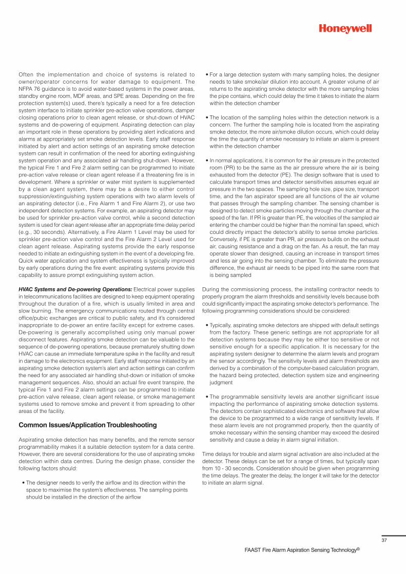
37
FAAST Fire Alarm Aspiration Sensing Technology®
Often the implementation and choice of systems is related to
owner/operator concerns for water damage to equipment. The
NFPA 76 guidance is to avoid water-based systems in the power areas,
standby engine room, MDF areas, and SPE areas. Depending on the fire
protection system(s) used, there’s typically a need for a fire detection
system interface to initiate sprinkler pre-action valve operations, damper
closing operations prior to clean agent release, or shut-down of HVAC
systems and de-powering of equipment. Aspirating detection can play
an important role in these operations by providing alert indications and
alarms at appropriately set smoke detection levels. Early staff response
initiated by alert and action settings of an aspirating smoke detection
system can result in confirmation of the need for aborting extinguishing
system operation and any associated air handling shut-down. However,
the typical Fire 1 and Fire 2 alarm setting can be programmed to initiate
pre-action valve release or clean agent release if a threatening fire is in
development. Where a sprinkler or water mist system is supplemented
by a clean agent system, there may be a desire to either control
suppression/extinguishing system operations with two alarm levels of
an aspirating detector (i.e., Fire Alarm 1 and Fire Alarm 2), or use two
independent detection systems. For example, an aspirating detector may
be used for sprinkler pre-action valve control, while a second detection
system is used for clean agent release after an appropriate time delay period
(e.g., 30 seconds). Alternatively, a Fire Alarm 1 Level may be used for
sprinkler pre-action valve control and the Fire Alarm 2 Level used for
clean agent release. Aspirating systems provide the early response
needed to initiate an extinguishing system in the event of a developing fire.
Quick water application and system effectiveness is typically improved
by early operations during the fire event: aspirating systems provide this
capability to assure prompt extinguishing system action.
HVAC Systems and De-powering Operations: Electrical power supplies
in telecommunications facilities are designed to keep equipment operating
throughout the duration of a fire, which is usually limited in area and
slow burning. The emergency communications routed through central
office/pubic exchanges are critical to public safety, and it’s considered
inappropriate to de-power an entire facility except for extreme cases.
De-powering is generally accomplished using only manual power
disconnect features. Aspirating smoke detection can be valuable to the
sequence of de-powering operations, because prematurely shutting down
HVAC can cause an immediate temperature spike in the facility and result
in damage to the electronics equipment. Early staff response initiated by an
aspirating smoke detection system’s alert and action settings can confirm
the need for any associated air handling shut-down or initiation of smoke
management sequences. Also, should an actual fire event transpire, the
typical Fire 1 and Fire 2 alarm settings can be programmed to initiate
pre-action valve release, clean agent release, or smoke management
systems used to remove smoke and prevent it from spreading to other
areas of the facility.
Common Issues/Application Troubleshooting
Aspirating smoke detection has many benefits, and the remote sensor
programmability makes it a suitable detection system for a data centre.
However, there are several considerations for the use of aspirating smoke
detection within data centres. During the design phase, consider the
following factors should:
• The designer needs to verify the airflow and its direction within the
space to maximise the system’s effectiveness. The sampling points
should be installed in the direction of the airflow
• For a large detection system with many sampling holes, the designer
needs to take smoke/air dilution into account. A greater volume of air
returns to the aspirating smoke detector with the more sampling holes
the pipe contains, which could delay the time it takes to initiate the alarm
within the detection chamber
• The location of the sampling holes within the detection network is a
concern. The further the sampling hole is located from the aspirating
smoke detector, the more air/smoke dilution occurs, which could delay
the time the quantity of smoke necessary to initiate an alarm is present
within the detection chamber
• In normal applications, it is common for the air pressure in the protected
room (PR) to be the same as the air pressure where the air is being
exhausted from the detector (PE). The design software that is used to
calculate transport times and detector sensitivities assumes equal air
pressure in the two spaces. The sampling hole size, pipe size, transport
time, and the fan aspirator speed are all functions of the air volume
that passes through the sampling chamber. The sensing chamber is
designed to detect smoke particles moving through the chamber at the
speed of the fan. If PR is greater than PE, the velocities of the sampled air
entering the chamber could be higher than the nominal fan speed, which
could directly impact the detector’s ability to sense smoke particles.
Conversely, if PE is greater than PR, air pressure builds on the exhaust
air, causing resistance and a drag on the fan. As a result, the fan may
operate slower than designed, causing an increase in transport times
and less air going into the sensing chamber. To eliminate the pressure
difference, the exhaust air needs to be piped into the same room that
is being sampled
During the commissioning process, the installing contractor needs to
properly program the alarm thresholds and sensitivity levels because both
could significantly impact the aspirating smoke detector’s performance. The
following programming considerations should be considered:
• Typically, aspirating smoke detectors are shipped with default settings
from the factory. These generic settings are not appropriate for all
detection systems because they may be either too sensitive or not
sensitive enough for a specific application. It is necessary for the
aspirating system designer to determine the alarm levels and program
the sensor accordingly. The sensitivity levels and alarm thresholds are
derived by a combination of the computer-based calculation program,
the hazard being protected, detection system size and engineering
judgment
• The programmable sensitivity levels are another significant issue
impacting the performance of aspirating smoke detection systems.
The detectors contain sophisticated electronics and software that allow
the device to be programmed to a wide range of sensitivity levels. If
these alarm levels are not programmed properly, then the quantity of
smoke necessary within the sensing chamber may exceed the desired
sensitivity and cause a delay in alarm signal initiation.
Time delays for trouble and alarm signal activation are also included at the
detector. These delays can be set for a range of times, but typically span
from 10 - 30 seconds. Consideration should be given when programming
the time delays. The greater the delay, the longer it will take for the detector
to initiate an alarm signal.

38
Dos
• Identify applicable codes and insurer’s requirements
• When NFPA 76, Standard for the Fire Protection of Telecommunications
Facilities, applies the following is recommended
– Determine which approach of NFPA 76 is being applied:
performance-based approach, prescriptive approach, or a
redundant facilities equipment approach
– Review the risk and hazards of the facility with the telecommunications
service provider and all recommendations for automatic smoke
detection
– Using a NFPA 76 prescriptive approach, apply aspirating smoke
detection when VEWFD or EWFD smoke detection is required for
1) the ceiling level throughout the telecommunications equipment
areas, and 2) below the raised floors containing combustibles when
airflow is not common with the space above and below the raised
floor
– Using a NFPA 76 prescriptive approach, apply VEWFD sampling
ports at a coverage area not exceeding 18.6 m² (200 ft.²) and EWFD
sampling ports at a coverage area not exceeding 37.2 m² (400 ft²)
– Using a NFPA 76 prescriptive approach, apply VEWFD air sampling
points to monitor return air from those spaces require VEWFD
systems. Provide sampling ports to monitor HVAC/ CRAC air returns.
Arrange the ports so that each covers no more than 0.4 m² (4 ft.²) of
the return opening
– Consider sampling ports both under cable trays and at the ceiling,
when cable tray density and arrangement are sufficient to impede
smoke flowing to the ceiling
– Assure that alarm and trouble signals from aspirating smoke
detection systems are annunciated at a constantly attended location
– Confirm and implement how alert and fire alarm settings are
to be integrated to initiate the following if applicable: 1) power
shut-down (typically a manual operation in telecommunications facilities),
2) pre-action system valve operation, 3) gaseous agent release,
4) water mist system release, 5) air handling shut-down and associated
damper or door closures, 6) initiation of smoke management/
control system, 7) release of aisle air flow containment systems
(e.g., vinyl curtains) ,that present an obstruction to agent delivery
from sprinkler or gaseous agent systems.
• When BS 6266 (Fire Protection for Electronic Equipment Installations –
Code of Practice), applies the following is recommended:
– Review the documented risk assessment for the electronic equipment
areas and understand which areas classify as medium, high, or
critical risk electronic installations
– Identify where Class C, aspirating type smoke detection is to be applied.
– Identify where Class B, aspirating type smoke detection is to be
applied. Class B systems are used when increased sensitivity is
needed to compensate for dilution effects due to high ceilings or
moving airflows
– Identify where Class A, aspirating type smoke detection is to be
applied. Class A systems are used in area having high air movement
and smoke dilution or where the very earliest warning is needed to
protect critical business operations, high value data processing or
high value electronic equipment
– Install sampling holes for optimum effectiveness in accordance
with Annex A provisions of BS 6266 for air return vents, ceilings,
below-floor and above-ceiling void spaces, in-cabinet locations, and
proximity to air inlets and ceiling fittings
– Apply the rules of BS 6266 where aspirating type smoke detection is applied.
– Confirm and implement how alert and fire alarm settings are
to be integrated to initiate the following if applicable: 1) power
shut-down (typically a manual operation in telecommunications facilities),
2) pre-action system valve operation, 3) gaseous agent release,
4) water mist system release, 5) air handling shut-down and
associated damper or door closures, 6) initiation of smoke
management/control system, 7) release of aisle air flow containment
systems (e.g., vinyl curtains), that present an obstruction to agent
delivery from sprinkler or gaseous agent systems
• Understand the airflow environment and coordinate air sampling points
with key points of return air movement
• Follow the spacing rules of applicable installation standards and/or
insurance carrier requirements
• Consider sampling ports both under cable trays and at the ceiling, when
cable tray density and arrangement are sufficient to impede smoke
flowing to the ceiling
• Provide sampling ports to monitor HVAC/CRAC air returns. Arrange
the ports so that each covers no more than 0.4 m² (4 ft²) of the return
opening
• Identify critical or high-risk equipment installations that should have
localised area or in-cabinet air sampling for earliest warning and initiation
of human response
• Consider providing sampling ports to monitor outside air intake – install
air sampling points in the outside air section downstream of the outside
air damper but upstream of the filters. This arrangement allows for
detection of smoke-contaminated outside air that is entering the building
Don’ts
• Don’t exceed the recommended detector or sampling point spacing of
applicable standards or insurance carrier requirements
• Don’t use detectors that are not listed or approved for air velocities and
temperatures that will be encountered in the IT areas or equipment
• Don’t design the aspirating smoke detection system to exceed the
transport time requirements of installation standards or insurance
company requirements
• Don’t install ceiling sampling points too near to ceiling supply air
diffusers. Maintain a distance of 0.9 m - 3 m (3 ft. -10 ft.) from ceiling
diffusers, depending on the strength of the airflow. (See BS 6566 and
NFPA 72 for specific requirements)

39
FAAST Fire Alarm Aspiration Sensing Technology®
Section 7
Duct and Return Air Monitoring
Application
The primary purpose of a duct smoke detection system is to “Detect and
Prevent” the migration and spread of smoke through a building’s HVAC
system. The installation of duct smoke detectors is not a substitute for an
area smoke detection system, but it can significantly minimise the migration
of smoke within a building.
A traditional duct smoke detection system consists of spot-type smoke
detectors mounted on the side of the duct and a sampling tube that extends
into the duct. Some applications require a greater level of sensitivity than
that provided by traditional spot-type duct smoke detectors. Typical
prerequisites of enhanced duct smoke detection system may include:
• Early warning is required to allow for evacuation of occupants
• Early warning is necessary because the smallest amount of smoke
could damage equipment within the space (in telecommunication or
data centres, for example)
• High-airflow environments may require advanced, sensitive detection
that traditional spot-type detectors couldn’t provide
Unlike traditional duct smoke detectors, ASDs offer active sampling as well
as a higher level of sensitivity and programmability to reduce nuisance
alarms, which makes them an extremely sensitive alternative.
ASDs are also effective in areas with high air exchange; such environments
typically require mechanical ventilation to maintain constant or cyclical air
flow for heating, cooling, and dust filtration. Smoke tends to travel with the
air flow, so positioning sampling pipes near the return of an air handling
unit, heating/air conditioning unit, or return air grill ensures early detection
of particulate in the area.
Benefits of ASD
The benefits of active duct sampling come with additional challenges.
ASDs are required to monitor and maintain a minimum airflow volume; when
operating inside ductwork, this can significantly test the ASD’s capabilities
because air speeds not only vary from duct to duct, but they also vary within
a duct. Use caution if ASDs are installed as duct-mounted smoke detectors.
Best Design Practices
Many ASDs are approved for in-duct applications; however, it’s necessary
to confirm the ASD is listed for duct applications prior to installation
(BS EN 54-27 and UL 268A).
Basic Design Considerations for In-Duct Sampling
Follow these guidelines to obtain the best installation results for the inlet
pipe (sampling pipe). See Figure 1 to the right for typical installation.
• Pipe should always be supported at both duct walls. Rubber grommets
can be used for support for most plastic and light weight pipes. If metal
pipes are used, more sturdy supports may be necessary
• Silicon sealer must be used to ensure an airtight seal in the duct walls
• Inlet pipes must be inserted between six and ten duct widths or
diameters (for round ducts), from any disturbances to the flow generated
by sharp bends, plenums, nozzles, and branch connections
• For European installations: the Fire Industry Association (FIA)
Code of Practice for Design, Installation, Commissioning & Maintenance
of Duct Smoke Detector (DSD) Systems, requires the sampling pipe to
be inserted a minimum of three duct widths from a bend.
• Sampling holes should be located no closer than 51 mm (2 in.) to the
duct wall
• Sampling holes on the inlet pipe should face 20° - 45° into the air flow,
with the holes concentrated at the centre of the duct (as shown in
Figure 1 below)
• For maintenance test convenience, a test sample point can be installed
externally to the duct. The test point would be installed in the sampling
pipe and remain closed during ASD normal operation
The Exhaust Pipe
Direction of
Air Flow
Air Supply to
FAAST Device
Exhaust Pipe from
FAAST Device
Figure 1. Design consideration for in-duct sampling
• The exhaust pipe must have four holes drilled (see manufacturer’s
recommendations for specific hole size); the holes should be
concentrated in the middle of the duct’s width and spaced evenly.
Holes on the exhaust pipe should be oriented so they face away from
the airflow
• The exhaust pipe should be located approximately 0.5 m (18 ft.)
downstream from the inlet pipe
• The exhaust pipe should be inserted into the duct at a height equal to
1/4 of the duct height (H/4)
• The exhaust pipe may be set up in two different configurations:
– The first option consists of a pipe with four holes and of the same
length as the sampling pipe. Traditionally, fitting the exhaust pipe with
holes has been the way to install ASDs in ducts. This configuration
promotes somewhat more stability to the air passing through the
detector with less overall sampling volume as a trade-off. When
employing this configuration, it is recommended to position the
exhaust holes directly away from the airflow.
– A second option is installing a short pipe that protrudes
51 to 76 mm (2 - 3 in.), into the duct and is not fitted with an
end cap. This is a simpler method and promotes better overall
airflow through the detector. However, this arrangement may
be more prone to faults caused by duct airflow fluctuations. It is
recommended to try this configuration first and then revert to the
traditional method if stabilising the airflow pendulum proves difficult.

40
Sampling Pipe Installation
After determining the proper number and sizes of sampling pipes and
sampling holes, all pipe should be cut to the proper length and holes
drilled. The ASD unit should be mounted to a nearby adjacent location
and additional pipe run to the duct. Duct sampling pipe should be located
at least six and ten duct widths from sharp bends or branch connections
that may disturb the duct airflow. This will allow the airflow to become
laminar before reaching the sampling pipe. Inlet and exhaust pipe holes
should be cut into the duct work, at the appropriate location. With all pieces
assembled, insert the inlet and exhaust pipes into the duct but do not
seal or cement. Using the line marked on the sampling pipe, plan the
sampling holes so they are facing into the airflow, and directed upwards
at approximately 45°. After the inlet pipe and sampling holes are properly
oriented, secure the pipes, seal the duct penetrations, and then install the
remaining pipe and connect to the ASD unit.
Figure 2. Small duct sampling locations
Figure 3. Large duct sampling locations
Figure 4. Large vertical ducts
Small Diameter Duct
Air Flow
Inlet Pipe H/2
Outlet Pipe
H
H/4
Table 1 – Small duct sampling hole quantity and size
Duct Width
Number of
Sampling
Holes Per Pipe
Hole Size
Nominal Pipe
Flow Rate
(CFM)
51 - 76 mm
(12 in.)
2 6.5 mm
(1/4 in.)
1.84 cfm
(52.0 l/min.)
500 mm
(20 in.)
3 6.5 mm
(1/4 in.)
1.83 cfm
(51.9 l/min.)
700 mm
(28 in.)
4 4.5 mm
(11/64 in.)
1.70 cfm
(48.1 l/min.)
900 mm
(36 in.)
5 4 mm
(5/32 in.)
1.81 cfm
(51.2 l/min.)
Large Horizontal Ducts
A large duct (See Table 2) is any duct that has a width of 1 m - 2 m
(3 ft. - 7 ft.). Two branch pipes are recommended for the inlets of these
ducts. The inlet pipes should enter a quarter of the way from the top and
bottom of the duct, as shown in Figure 3 below. The exhaust pipe should
be inserted approximately 0.5 m (18 in.) from the inlet pipes and halfway up
the height of the duct. To avoid dilution, sampling pipes should be located
before fresh air intakes and before exhaust air output.
Large Diameter Duct
Air Flow Inlet Pipe
Outlet Pipe3H/4
H/4
H/2
Table 2 – Large duct sampling hole quantity and size
Duct Width
Number of
Sampling Holes
Per Pipe
Hole Size
Nominal Pipe
Flow Rate
(CFM)
1 m (40 in.)
6
3.5 mm
(9/64 in )
1.77 cfm
(50.2 l/min.)
1.5 m (5 ft..) 8
3 mm
(1/8 in.)
1.80 cfm
(50.9 l/min.)
2 m (6.5 ft..) 10 3 mm (1/8 in.) 2.10 cfm
(59.6 l/min.)
The number of sampling holes and hole sizes outlined in Table 1 to the left
and Table 2 above are for a 4.6 m (15 ft.) piping network and a 3 m (10 ft.)
exhaust pipe. Before the sampling holes are drilled and the pipe is installed
in the duct, confirm the hole spacing and sizes with the design software
and manufacturer’s recommendations.
For ducts over 1 m (3 ft.), the sampling pipe will need extra support. This
can be accomplished by an external strut or a hole in the opposite wall
of the duct.
Large Vertical Ducts
A large vertical duct is any duct that exceeds 1 m (3 ft.) in height, regardless
of the width of the duct. The spacing and location of the sample pipe rows
should be 1/#P(2) (P = sampling pipe) for the sample pipes closer to the
wall of the duct, and 1/#P for the spacing of the sample rows in the middle
of the system.
Three sampling pipes are required for the inlets of large vertical ducts. The
inlet pipes should enter the duct as outlined in Figure 4 below, maintaining
the following guidelines:
• An additional row of sample ports is required when the duct height
exceeds 91.4 cm (36 in.), regardless of the width of the duct.
• When the system requires
three rows of sampling
pipes, the sampling hole
sizes are determined by
duct width in Table 1 and
Table 2. For example, if
the duct is 1,016 mm (40
in.) in height and 1,016
mm (40 in.) wide, then
the duct would require
three sampling pipes
with six equally spaced
sampl ing holes per
pipe: all sized 3.5 mm
(9/64 in.).
• Sample row spacing
and location should be
1/#P(2) for the sample
pipes closer to the wall
16
16
1
Hv
H
ExAir Flow
Large Vertical Duct > 36°
v
3
13
2

41
FAAST Fire Alarm Aspiration Sensing Technology®
of the duct, and 1/#P for the spacing of the sample rows in the middle
of the system
• For large ducts, the sampling hole sizes should be confirmed using the
manufacturer’s design software
European ASD Duct Smoke Requirements
Local regulations require duct smoke detectors to initiate an alarm
signal when the duct smoke concentration reaches approximately
13% obs/m.
EN54-20 requires ASD systems to be tested utilising four different test
fires and initiate an alarm signal at the end-of-test (EOT) conditions to its
specific Class. See Table 3 below for ASDs utilised as duct smoke detector
requirements.
Table 3 – Summary of EOT conditions for test fires
Level 1 Level 2 Level 3
EN54-20 Class C Normal Class C Enhanced Class 3 High
TF2 EOT 37% obs/m 3.4% obs/m 1.14%obs/m
TF3 EOT 37% obs/m 3.4% obs/m 1.14%obs/m
TF4 EOT 25-32% obs/m n/a n/a
TF5 EOT 19-25% obs/m 6.7% obs/m 2.3% obs/m
Return Air Monitoring
End cap
4ft. x 4ft.
Intake
Sample Ports
Figure 5. Piping installation on return air grill
Figure 6. Piping installation on return air AHU
Figure 7. Sampling hole orientation
Normal sampling methods for high air exchange areas are a combination of
return air and ceiling sampling. The return air sampling provides protection
when the air flow is present, and the ceiling network provides protection
when the air flow is off. Local codes typically require smaller sample areas
(closer spacing of sample ports), as the air flow rate increases.
Return air sampling provides an effective means of Very Early Warning
Detection (VEWD), in high air velocity environments.
Placing the pipe network sampling ports directly in the air stream at the
return air grill (see Figure 5 below left), duct, or on the air handler unit
(AHU, allows the system to monitor the air that has circulated throughout
the protected area (see Figure 6 below left). This is an extremely effective
detection strategy for data centres, telecommunication centres, and clean
rooms; as the air is conditioned, the majority will circulate or pass through
the AHUs and grills and all the air within the room will eventually be sampled.
From Table 3 to the left, it is clear that Class A and Class B ASD system
sensitivity is significantly higher than a traditional spot-type, duct-mounted
smoke detector approved by EN54-27.
The following guidelines should be reviewed and followed to ensure proper
detector system sampling:
• More than one sampling location may be required for large air grills.
NFPA 76 recommendations specify that each sampling port can cover
a maximum of 0.4 m² (4 ft.²)
• Sampling ports should be aligned at an angle of 20° - 45° to the direction
of the maximum airflow (See Figure 7 below)
• Sampling pipes should be placed in the path of the greatest airflow
• The number of bends in the pipe network should be kept to a minimum
• Pipe ends should be capped with an end cap. Depending on the pipe
design, the end caps may or may not have a sampling port
• Socket unions should be used in locations where the pipe network
requires the removal of the pipes on a regular basis for maintenance
purposes
• Use standoff fittings to keep the pipe network at least 50 mm - 200 mm
(2 - 8 in.) in front of the grill or the AHU, for high velocity airflow locations.
Installing the network any closer to the input grill or AHU locates the
sample port in an area of negative air pressure
• Always keep in mind that the monitored environment should still ensure
coverage even if the manufactured airflow gets disrupted
AB
C
20° - 45°from direction
of Air Flow
A. Airflow StreamlinesB. Low velocity (high static pressure) areaC. High velocity (low static pressure) area

42
When monitoring multiple AHUs with ASD, the AHUs should have similar
airflow at all times. The number of monitored AHUs is limited by the
maximum length of the pipe network. However, the degree of particle
dilution and air movement that occurs with multiple AHUs can adversely
affect system response times.
Port Orientation
The sampling response time can be improved by avoiding high and low
velocity airflows perpendicular to the sampling holes. Sampling holes on
the duct inlet pipes, on return air grills, or on CRAC or HVAC units should
be facing 20° - 45° from the where high velocity air will be passing over the
sampling pipe (See Figure 7 on the previous page).
Common Issues/Application Troubleshooting
Nuisance flow faults are a common concern with ASD airflow. Airflow
through the ASD is affected by two key factors: variable airflow through the
duct and also the orientation of the sampling holes and exhaust port. Duct
airflow caused by the AHU fan unit is beyond the control of the installation
practices, but sampling hole orientation could significantly impact the flow
through the ASD and reduce nuisance flow faults. To avoid nuisance flow
faults, it is recommended to “tune the system.”
Tuning the System
With the air handling units off, power up the ASD. Then, connect to it using
the computer-based software, set the desired configuration parameters,
and reconfigure the device. If the ASD unit does not automatically reset
after receiving a new configuration, power down the unit. After a brief
start-up sequence, allow 5 minutes for the ASD to adjust to the new pipe
network. Once 5 minutes have elapsed, turn on the air handling units,
preferably at the highest velocity. Observe the real-time airflow data in the
computer-based software.
If more air is needed in the ASD, carefully adjust the sampling pipe so
that the holes are facing the oncoming airflow. A few degrees of rotation
may have a significant impact. After making the adjustment, wait at least
20 - 30 seconds for the airflow to stabilise and the data to update.
If too much air is entering the ASD, carefully adjust the sampling pipe so
the holes are facing away from the airflow. After making the adjustment,
wait for the airflow to stabilise and the data to update. Continue adjusting
as necessary until the airflow data remains in the desired range.
When satisfied with the sampling tube position, shut off the air handling
units and observe the airflow data. It should remain at or near the desired
airflow. When satisfied with the airflow, mark the angle of rotation on the
duct and then complete the installation by sealing and securing the
sampling tube as appropriate. Perform smoke testing as prescribed by the
Authority Having Jurisdiction (AHJ).
Dos
• Verify the sampling holes are facing 20° - 40° to the direction of the
airflow (See Figure 7 on the previous page for installation detail)
• Verify all sampling pipes and sampling holes are unobstructed
• Verify all the penetrations into the duct(s) are sealed properly and not
leaking air
• Verify the sampling exhaust is piped back into the duct when the
sampling pipe is installed. For exhaust pipe location, see Figure 2 for
small ducts, Figure 3 for large ducts, and Figure 4 for large vertical ducts
(all featured on page 40)
• The sampling pipe is installed on stand-offs that allow 50 mm - 200 mm
(2 - 8 in.) in front of the grill
• Test the system to ensure that the detector sensitivity settings,
alarm/trouble delays, and system shut-downs are designed and installed
in accordance with the appropriate code and standard
Don’ts
• Orientate the sampling holes directly into the airflow
• For return air grill monitoring, do not mount the sampling pipe directly
to the face of the grill

43
FAAST Fire Alarm Aspiration Sensing Technology®
Section 8
Clean Rooms
Application Overview
Manufacturing industries and scientific research environments that
require highly controlled air quality environments use the concept of
clean rooms to protect against contamination. Contamination can result
from dust, pollen, bacteria, aerosol particles, combustion particles, and
chemical vapours. Humans in these work environments can introduce
contaminates in the form of skin flakes, lint, cosmetics, and emissions
due to human respiration. So from a more technical perspective, a clean
room is an airborne-particle controlled environment containing one
or more clean zones (areas that meet a specified airborne particulate
cleanliness class). The specified airborne particulate cleanliness classes
have been defined by ISO standard 14644-1 and the US federal standard
(US FED STD) 209E. The classification systems address how few particles,
measured in microns, occupy a fixed volume of air (a one-micron
particle is one-thousandth of a millimetre, or 39 millionths of an inch)..
For comparison, a human hair is approximately 100 microns.
Clean room cleanliness classifications are described in Tables 1 and 2, which
show the relationship between Class designation and extent of particles per
ft³. For example, a Class 10,000 / ISO 7 clean room will limit the concentration
of particles of ≥0.5 μm to 353,000 particles /m³ (10,000 particles/ft³ of
air). To compare to the typical workplace, 35,000,000 particles/m³ (0.5 -
1,000,000 particles/ ft³ ) 0.5 μm and larger are constantly present in the
atmosphere (per ft³) of a typical office building.
US FED
STD
209E
Class
Table 1 - US FED STD 209E
Cleanroom Classification1-
Maximum particles/ft3
ISO
Equivalent
Class
≥0.1
μm
≥0.2
μm
≥0.3
μm
≥0.5
μm
≥5
μm
1 35 7.5 3 1 0.007 ISO 3
10 350 75 30 10 0.07 ISO 4
100 3,500 750 300 100 0.7 ISO 5
1,000 35,000 7,500 3,000 1,000 7 ISO 6
10,000 350,000 75,000 30,000 10,000 70 ISO 7
100,000 3.5 x
106
750,000 300,000 100,000 700 ISO 8
1. Clean room classifications in Table 1 above was the US federal standard
(US FED STD) 209E, until it was cancelled by the US Department
of Commerce on 29th November, 2001 and superseded by the
ISO standard 14644-1. The US FED STD 209E classification for clean
room is still widely referenced.
ISO 14644-1
Class
Table 2. ISO 14644-1 Clean Room Classification
Maximum particles / m3
US FED STD 209E
Equivalent Class
≥0.1 μm ≥0.2 μm ≥0.3 μm ≥0.5 μm ≥ 1 μm ≥5 μm
ISO 1 10 2.37 1.02 0.35 0.083 0.007
ISO 2 100 23.7 10.2 3.5 0.83 0.07
ISO 3 1,000 237 102 35 8.3 1
ISO 4 10,000 2,370 1,020 350 83 10
ISO 5 100,000 23,700 10,200 3,500 832 100
ISO 6 1 x 10⁶ 237,000 102,000 35,000 8,320 0.7 1,000
ISO 7 1 x 10⁷ 237 x 106 1.02 x 10⁶ 350,000 83,200 7 10,000
ISO 8 1 x 10⁸ 2.37 x 10⁷ 1.02 x 10⁷ 3.5 x 10⁶ 832,000 70 100,000
ISO 9 1 x 10⁹ 2.37 x 10⁸ 1.02 x 10⁸ 3.5 x 10⁷ 8.32 x 10⁶ 700
A wide variety of industries use clean rooms that range from large
semiconductor facilities to hospital therapy and operating rooms. Some
key applications are as follows:
– Microelectronic clean rooms: changes in temperature, humidity,
particulate, static, and pressure levels are known to critically affect each
stage of the production of semiconductor manufactures. Since many
steps are involved in order to come to a final product, undiscovered
defects can be expensive, if left until the end of the manufacturing
process. Therefore, it is crucial that each and every clean room
(usually fabrication area or FAB area), operates properly,
within its own level of cleanliness. Semiconductor FAB facilities
can be large, complex facilities with numerous air flow paths,
plenums, and under floor areas: aspirating smoke detection
is well-suited to provide reliable, capable smoke detection.
Figure 1 on the following page illustrates the complexity
and features that can be found in semiconductor facilities.

44
– Biotechnology and Pharmaceutical Clean Rooms: contamination is
a major concern in this type of clean room, so it’s crucial to maintain a
cleanable surface condition via different sanitisation methods. Clean
room seal has to be maintained while sanitisation or filter changes
occur. This type of clean room primarily considers pressurisation
control, absence of cross-contamination, and filtration of outdoor air,
as well as indoor air. Staff working in this type of clean room (or in the
previous one), is required to wear appropriate full gowns, hair nets,
booties, and gloves, as they are a major source of contamination.
– Medical Device Clean Rooms: the main goal associated with
this clean room type is the elimination of final product surface
contamination so that the packaged medical device can be safely
utilised by the end-user. Although cleanliness levels are maintained
for the staff and the room itself, this type of room is typically designed
for the 10,000 Class and the 100,000 Class. Personnel are allowed
to work wearing smocks, hair nets, booties, and gloves.
– Defence Industry Clean Rooms: the application scope of this
type of clean room can include the three aforementioned types.
Nevertheless, due to their strategic sensitivity, defence industry clean
rooms are provided with high levels of security.
– Research and Development (R&D) Clean Rooms: incorporated in
private companies and universities, R&D clean room designs need
to adapt for flexibility of future goals, objectives, and natures of
corresponding operations. In other terms, designs of the clean room
building layout and associated air-handling systems are planned
to undergo minor modifications in order to accommodate different
levels of cleanliness required for anticipated goals and objectives.
A ea a la ge emi n a ili an e man ai l pa a e i
AxialFlowFan
Class 1 Class 1
Class 1 Class 1 Class 1 Class 1 Class 1FAB AREAFAB AREA
FAB AREA
Waffle Slab
Raised Floor
Underfloor Void
Class 1FilterFan
Units
Class 1Class 1000 (1K)
Class 1KClass 1K
Makeup Air Unit
AxialFlowFan
Makeup Air Unit
Pressurized Plenum
Air Supply Plenum
Utilities Distribution Area
Figure 1. – Semiconductor Facility
Figure 2. Large biotech clean room
Figure 3. Modular clean room
Figure 4. Semiconductor cleanroom

45
FAAST Fire Alarm Aspiration Sensing Technology®
It should be noted that some industries – such as the ones involving plastic
moulding injections for food and drug enclosures and plastic extrusions for
medical devices – have moved towards clean environments with features
called “white rooms.” Nevertheless, the design and the specifications of
“white rooms” are lower than the ones defined for clean rooms.
As illustrated by the diversity of clean room applications, the corresponding
volumes of clean rooms can range from a laboratory size to an industrial
manufacturing plant. Depending on the industry/application, the airflow
designs and filter types can vary. The required level of cleanliness is
managed through an air-handling system, which entrains undesirable
airborne particles and either collects them on HEPA or ULPA filters or sends
them to scrubbers and combustors. HEPA (High Efficiency Particulate
Air) filters are designed to remove 99.97% of passing airborne particles
measuring 0.3 μm or greater in diameter. ULPA (Ultra-Low Penetration
Air) Filters are rated as 99.999% efficient with particles 0.12 μm in
diameter. Table 3 below lists some example clean room applications and
corresponding cleanliness classifications.
US FED
STD 209E
Class
Table 3 - Clean Room Class Definition and
Examples of Clean Room in the Class
1 Sub-micron integrated circuit manufacturing
10 Semiconductor manufacturing with circuits with line width
below 0.2 μm
100
Particle-free manufacturing of aseptically produced inject-
able medicines. Steriliser unloading, sterile storage area,
filling rooms. Implant or transplant surgical operations.
Isolation of immunosuppressed patients
1,000
Manufacturing of high quality optical equipment. Rooms
containing Class 100 areas or Laminar Air Flow hoods
(LAF hoods) for filling. Assembly and testing of precision
gyroscopes. Assembly of miniaturised bearings
10,000
Assembly of precision hydraulics or pneumatic
equipment, servo-control valves, precision timing devices,
high grade gearing. Pre-culture, fermentation, buffer and
media preparation rooms
100,000
General optical work, assembly of electronic components,
hydraulic and pneumatic assembly. Prewash rooms, bulk
storage areas, equipment assembly areas
Benefits of Aspirating Smoke Detection
Clean room equipment and manufactured products are susceptible to
various forms of contamination, including smoke particles, flame and heat
from fire. Such contaminants pose major risks, such as damage to expensive
equipment, a shut-down of the manufacturing process, high decontamination
costs, direct business interruption to the facility, and indirect business
interruption to downstream users of the manufactured product. Aspirating
smoke detection systems are highly sensitive, and they continuously
sample low quantities of smoke that may be distributed and easily
diluted by the constant airflow environments encountered in clean rooms.
Aspirating smoke detection systems can play a key role in the protection of
clean room facilities. Some examples and viewpoints on the loss potential
and impacts are noted below:
• FM Global (2012 Data Sheets 1-56) indicates that clean rooms present an
intrinsic high value, while remaining important to other plant processes.
Due to the necessity of maintaining a high level of cleanliness, fire
combustion products and other contaminants generated by small
incidents can cause major shut-down time and costly decontamination
clean-up
• Mangarano (2004) reported that a class 100 clean room may approach
a value of $10,000 per m², including building equipment and stock
inside, but not including monetary loss due to business interruption.
Also, consider in semiconductor production that the silicon wafers used
in chip fabrication can contain 300 chips on a 200 mm wafer. The value
of one such wafer can exceed hundreds of thousands of dollars
• Sheffi (2007) describes one fire in detail – a 10 minute furnace fire,
extinguished with sprinklers – as well as the aftermath of the fire that
occurred in a Philips plant in the US in 2000 Ericsson (one of Phillips’
two main clients), was forced to merge with Sony to stay in the cell
phone market)
• The Hynix semiconductor fabrication plant fire that occurred
4th September, 2013, in Wuxi, China, forced its closure, making it the
biggest registered loss for this type of industry: damage was estimated
between $900 million - $1.1 billion USD [9,11]. Prices for DRAM chips
increased significantly after the fire (by 27%), reflecting Hynix’s role as
a significant producer of this type of memory (the Wuxi facility produced
10% of the world’s DRAM chips and almost 50% of the company’s own
production)
Given the direct dollar loss and possible indirect losses of clean room
fires, the need to identify even the smallest fire events (such as precursor
smouldering or overheating equipment events), can be critically important.
Electrical equipment such as high-voltage type apparatus can be prominent
in clean room facilities and pose a constant ignition risk. Aspirating smoke
detection systems provide high sensitivity by continuously sampling low
quantities of air, including smoke that could be distributed and otherwise
diluted by the filtered airflow environments encountered in clean rooms.
Clean room smoke-control systems are often required in order to prevent
smoke and aerosol exposure, which can cause non-thermal damage. The
objective of a clean room smoke-control system is to minimise the spread of
contaminants within the clean room. This is accomplished with a dedicated
smoke-control system or with the normal AHU or fume exhaust system,
in conjunction with automation controls and dampers, to initiate a smoke
control mode of operation. Aspirating smoke detection systems have the
sensitivity and response capability to quickly detect smoke contamination
in the air flow path. By using associated outputs of air aspiration detectors,
important smoke control functions can be promptly initiated.
With aspirating smoke detection technology, a number of objectives can
be achieved for the benefit of a clean room facility:
• Better response time for events
• Immediate shut-down initiation of recirculating air flows to minimize
contaminating airflows

46
• Initiation of smoke control systems to mitigate contamination and
damage.
• Better assurance of smoke detection, as compared to ceiling-mounted
smoke detectors, whose performance can be negatively affected by
clean room airflow patterns
• Low nuisance alarm rates, minimising unnecessary building evacuations
that can result in downtime and loss of production
Design Best Practices
Identify and Understand the Airflow Management Scheme
lS an a Ai l
a Ai
n aine AiP i i e
P e e
len e
Figure 5. Standard airflow within a conventional clean room
Figure 6. Semi-laminar airflow within a Class 10,000 clean room
Figure 7. Horizontal laminar airflow within a Class 1, 10 or 100 clean room
Figure 8. Vertical laminar airflow within a Class 1, 10 or 100 clean room
There are numerous approaches to air distribution in clean room
environments. Understanding the approach that is applied in any given
facility will allow the designer to identify the key airflow paths that need
to be monitored for smoke contamination. Maintaining clean air in clean
rooms usually involves one or more of four basic approaches (Figures 5, 6,
7, and 8 on this page); however, other approaches and hybrid approaches
are possible.
ln ni i e i nal emi len ai l
a Aia Ai
lg
eiling
PAil e
Ai l
n len ai l
PA il e
l e
Ai l
l e
PA il e
l a e
e i al ni i e i nal ai l
The conventional clean room (ISO Class 8, 209E Class 100,000):
Incoming air to a conventional clean room comes in via ceiling
filters/diffusers and exhausts through the wall-mounted registers as air
returns to the HVAC system (see Figure 5 to the left). This flow of air creates
a positive pressure between the clean room and its surroundings.
The semi-laminar flow clean room (ISO Class 7, 209E Class 10,000): This
type of enclosed, clean area has air that is both conditioned and filtered,
where the air comes in via a ceiling plenum. At that point, the air is diffused
throughout the room, by way of many “slots” in the flow-thru ceiling tiles.
Then the air is pushed vertically at low velocities and exhausts near or at
the level of the floor (see Figure 6 bottom left).
The horizontal unidirectional flow clean room (ISO Class 3, 4, 5;
209E Class 1, 10 or 100): Incoming treated air enters through a HEPA
filter wall, with a velocity of 0.51 ± m/s (100 ± ft./min.). An air return on
the opposite wall is by where the clean room air is exhausted, entraining
potential airborne particles produced in the work area.
The vertical unidirectional flow clean room (ISO Class 3, 4, 5; 209E
Class 1, 10 or 100): This enclosed clean room design has the conditioned
air enter by way of a HEPA filter ceiling. The filtered air moves straight
downward at 100 ± ft.... /min (0.51 ± m/s) as the design above, but the air
is then exhausted via a grate system in the floor. This design is generally
thought to be the one to use for “the optimum clean room.”
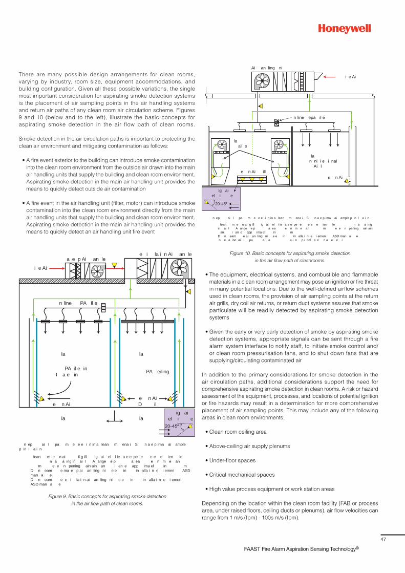
47
FAAST Fire Alarm Aspiration Sensing Technology®
There are many possible design arrangements for clean rooms,
varying by industry, room size, equipment accommodations, and
building configuration. Given all these possible variations, the single
most important consideration for aspirating smoke detection systems
is the placement of air sampling points in the air handling systems
and return air paths of any clean room air circulation scheme. Figures
9 and 10 (below and to the left), illustrate the basic concepts for
aspirating smoke detection in the air flow path of clean rooms.
Smoke detection in the air circulation paths is important to protecting the
clean air environment and mitigating contamination as follows:
• A fire event exterior to the building can introduce smoke contamination
into the clean room environment from the outside air drawn into the main
air handling units that supply the building and clean room environment.
Aspirating smoke detection in the main air handling unit provides the
means to quickly detect outside air contamination
• A fire event in the air handling unit (filter, motor) can introduce smoke
contamination into the clean room environment directly from the main
air handling units that supply the building and clean room environment.
Aspirating smoke detection in the main air handling unit provides the
means to quickly detect an air handling unit fire event
i e Aia e p Ai an le
n line PA il e
la
e n Aie n AiD il
la
la
PA il e inl a e in
la
PA eiling
e i la i n Ai an le
ig aiel i e
n ep ai l pa m e e e i n in a lean m ena i S n a e p ima ai ample p in l a i n
lean m e n ai il g ill ig ai el i ie a e e pe e e e e ien le n a a ing in ai l A ange e p a ea e n m e an m e e n pening ain ain an i an e app ima el in m
D n eam e ma e p ai an ling ni e e in in alla i n e i emen ASD man a e
D n eam e e i la i n ai an ling ni e e in in alla i n e i emen ASD man a e
Figure 9. Basic concepts for aspirating smoke detection
in the air flow path of clean rooms.
Figure 10. Basic concepts for aspirating smoke detection
in the air flow path of cleanrooms.
n line epa il e
la n ni i e i nal
Ai l
la ali e
e n Ai ill
i e Ai
Ai an ling ni
ig aiel i e
e n Ai
n ep ai l pa m e e e i n in a lean m ena i S n a e p ima ai ample p in l a i n
lean m e n ai g ill ig ai el i ie a e e pe e e e e ien le n a a ing in ai l A ange e p a ea e n m e an m e e n pening ain ain an i an e app ima el in m
D n eam e ai an ling ni e e in in alla i n e i emen ASD man a e n e a ine ai l pa e la a i n p i nal a e n a e e i
• The equipment, electrical systems, and combustible and flammable
materials in a clean room arrangement may pose an ignition or fire threat
in many potential locations. Due to the well-defined airflow schemes
used in clean rooms, the provision of air sampling points at the return
air grills, dry coil air returns, or return duct systems assures that smoke
particulate will be readily detected by aspirating smoke detection
systems
• Given the early or very early detection of smoke by aspirating smoke
detection systems, appropriate signals can be sent through a fire
alarm system interface to notify staff, to initiate smoke control and/
or clean room pressurisation fans, and to shut down fans that are
supplying/circulating contaminated air
In addition to the primary considerations for smoke detection in the
air circulation paths, additional considerations support the need for
comprehensive aspirating smoke detection in clean rooms. A risk or hazard
assessment of the equipment, processes, and locations of potential ignition
or fire hazards may result in a determination for more comprehensive
placement of air sampling points. This may include any of the following
areas in clean room environments:
• Clean room ceiling area
• Above-ceiling air supply plenums
• Under-floor spaces
• Critical mechanical spaces
• High value process equipment or work station areas
Depending on the location within the clean room facility (FAB or process
area, under raised floors, ceiling ducts or plenums), air flow velocities can
range from 1 m/s (fpm) - 100s m/s (fpm).
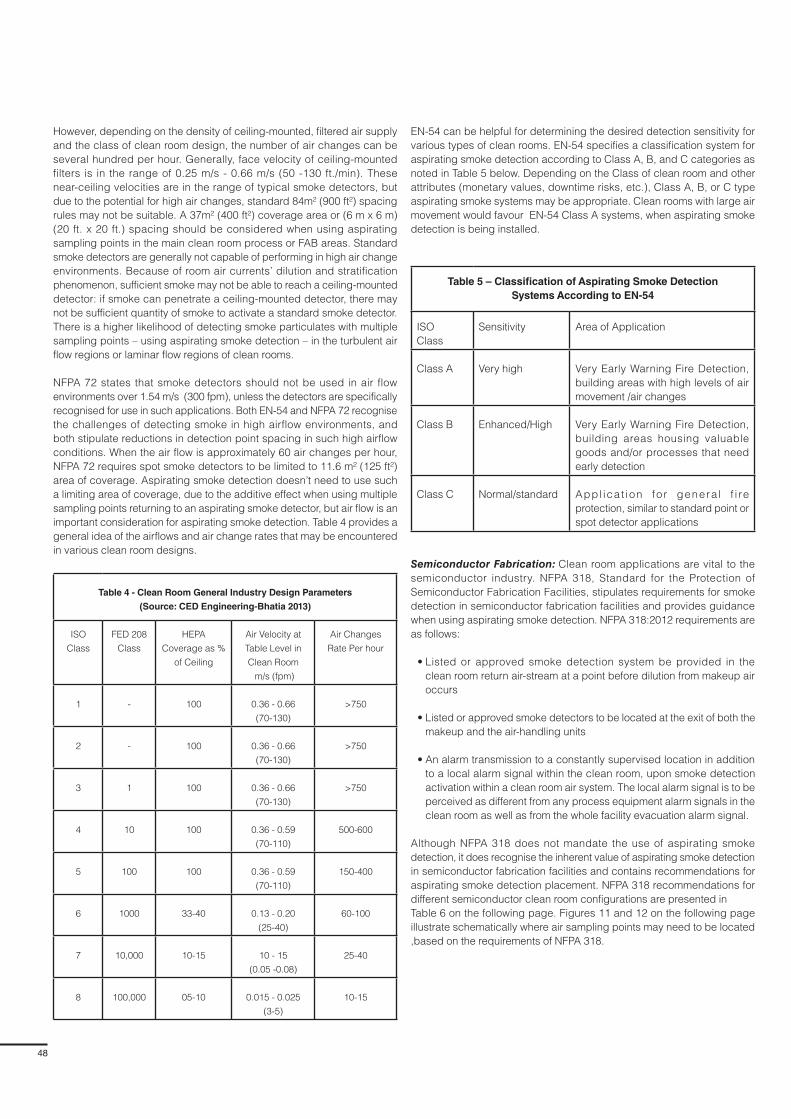
48
However, depending on the density of ceiling-mounted, filtered air supply
and the class of clean room design, the number of air changes can be
several hundred per hour. Generally, face velocity of ceiling-mounted
filters is in the range of 0.25 m/s - 0.66 m/s (50 -130 ft./min). These
near-ceiling velocities are in the range of typical smoke detectors, but
due to the potential for high air changes, standard 84m² (900 ft²) spacing
rules may not be suitable. A 37m² (400 ft²) coverage area or (6 m x 6 m)
(20 ft. x 20 ft.) spacing should be considered when using aspirating
sampling points in the main clean room process or FAB areas. Standard
smoke detectors are generally not capable of performing in high air change
environments. Because of room air currents’ dilution and stratification
phenomenon, sufficient smoke may not be able to reach a ceiling-mounted
detector: if smoke can penetrate a ceiling-mounted detector, there may
not be sufficient quantity of smoke to activate a standard smoke detector.
There is a higher likelihood of detecting smoke particulates with multiple
sampling points – using aspirating smoke detection – in the turbulent air
flow regions or laminar flow regions of clean rooms.
NFPA 72 states that smoke detectors should not be used in air flow
environments over 1.54 m/s (300 fpm), unless the detectors are specifically
recognised for use in such applications. Both EN-54 and NFPA 72 recognise
the challenges of detecting smoke in high airflow environments, and
both stipulate reductions in detection point spacing in such high airflow
conditions. When the air flow is approximately 60 air changes per hour,
NFPA 72 requires spot smoke detectors to be limited to 11.6 m² (125 ft²)
area of coverage. Aspirating smoke detection doesn’t need to use such
a limiting area of coverage, due to the additive effect when using multiple
sampling points returning to an aspirating smoke detector, but air flow is an
important consideration for aspirating smoke detection. Table 4 provides a
general idea of the airflows and air change rates that may be encountered
in various clean room designs.
Table 4 - Clean Room General Industry Design Parameters
(Source: CED Engineering-Bhatia 2013)
ISO
Class
FED 208
Class
HEPA
Coverage as %
of Ceiling
Air Velocity at
Table Level in
Clean Room
m/s (fpm)
Air Changes
Rate Per hour
1 - 100 0.36 - 0.66
(70-130)
>750
2 - 100 0.36 - 0.66
(70-130)
>750
3 1 100 0.36 - 0.66
(70-130)
>750
4 10 100 0.36 - 0.59
(70-110)
500-600
5 100 100 0.36 - 0.59
(70-110)
150-400
6 1000 33-40 0.13 - 0.20
(25-40)
60-100
7 10,000 10-15 10 - 15
(0.05 -0.08)
25-40
8 100,000 05-10 0.015 - 0.025
(3-5)
10-15
EN-54 can be helpful for determining the desired detection sensitivity for
various types of clean rooms. EN-54 specifies a classification system for
aspirating smoke detection according to Class A, B, and C categories as
noted in Table 5 below. Depending on the Class of clean room and other
attributes (monetary values, downtime risks, etc.), Class A, B, or C type
aspirating smoke systems may be appropriate. Clean rooms with large air
movement would favour EN-54 Class A systems, when aspirating smoke
detection is being installed.
Table 5 – Classification of Aspirating Smoke Detection
Systems According to EN-54
ISO
Class
Sensitivity Area of Application
Class A Very high Very Early Warning Fire Detection,
building areas with high levels of air
movement /air changes
Class B Enhanced/High Very Early Warning Fire Detection,
building areas housing valuable
goods and/or processes that need
early detection
Class C Normal/standard Appl ica t ion fo r genera l f i re
protection, similar to standard point or
spot detector applications
Semiconductor Fabrication: Clean room applications are vital to the
semiconductor industry. NFPA 318, Standard for the Protection of
Semiconductor Fabrication Facilities, stipulates requirements for smoke
detection in semiconductor fabrication facilities and provides guidance
when using aspirating smoke detection. NFPA 318:2012 requirements are
as follows:
• Listed or approved smoke detection system be provided in the
clean room return air-stream at a point before dilution from makeup air
occurs
• Listed or approved smoke detectors to be located at the exit of both the
makeup and the air-handling units
• An alarm transmission to a constantly supervised location in addition
to a local alarm signal within the clean room, upon smoke detection
activation within a clean room air system. The local alarm signal is to be
perceived as different from any process equipment alarm signals in the
clean room as well as from the whole facility evacuation alarm signal.
Although NFPA 318 does not mandate the use of aspirating smoke
detection, it does recognise the inherent value of aspirating smoke detection
in semiconductor fabrication facilities and contains recommendations for
aspirating smoke detection placement. NFPA 318 recommendations for
different semiconductor clean room configurations are presented in
Table 6 on the following page. Figures 11 and 12 on the following page
illustrate schematically where air sampling points may need to be located
,based on the requirements of NFPA 318.
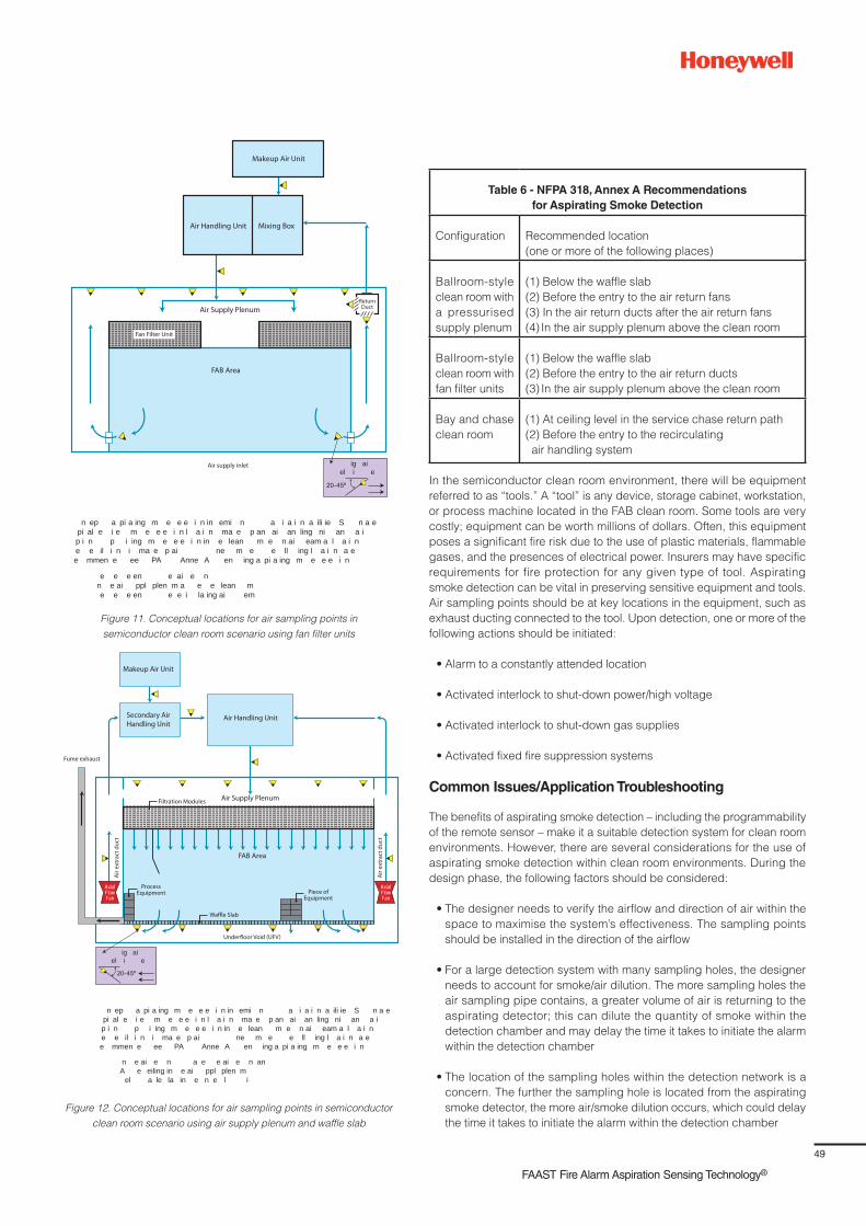
49
FAAST Fire Alarm Aspiration Sensing Technology®
Figure 11. Conceptual locations for air sampling points in
semiconductor clean room scenario using fan filter units
Figure 12. Conceptual locations for air sampling points in semiconductor
clean room scenario using air supply plenum and waffle slab
n ep a pi a ing m e e e i n in emi n a i a i n a ili ie S n a e pi al e i e m e e e i n l a i n ma e p an ai an ling ni an a i p i n p i ing m e e e i n in e lean m e n ai eam a l a i n e e il i n i ma e p ai ne m e e ll ing l a i n a e e mmen e ee PA Anne A en ing a pi a ing m e e e i n
e e e en e ai e n n e ai ppl plen m a e e lean m e e e en e e i la ing ai em
Makeup Air Unit
Air Handling Unit Mixing Box
FAB Area
Air Supply Plenum
Air supply inlet
Fan Filter Unit
ig aiel i e
Return Duct
AxialFlowFan
AxialFlowFan
ig aiel i e
Air
extr
act d
uct
Makeup Air Unit
Secondary Air Handling Unit
Air Handling Unit
Air
extr
act d
uct
FAB Area
Air Supply Plenum
Waffle Slab
Fume exhaust
Filtration Modules
Underfloor Void (UFV)
Piece ofEquipment
ProcessEquipment
n ep a pi a ing m e e e i n in emi n a i a i n a ili ie S n a e pi al e i e m e e e i n l a i n ma e p an ai an ling ni an a i p i n p i ing m e e e i n in e lean m e n ai eam a l a i n e e il i n i ma e p ai ne m e e ll ing l a i n a e e mmen e ee PA Anne A en ing a pi a ing m e e e i n
n e ai e n a e e ai e n an A e eiling in e ai ppl plen m el a le la in e n e l i
Table 6 - NFPA 318, Annex A Recommendations
for Aspirating Smoke Detection
Configuration Recommended location
(one or more of the following places)
Ballroom-style
clean room with
a pressurised
supply plenum
(1) Below the waffle slab
(2) Before the entry to the air return fans
(3) In the air return ducts after the air return fans
(4) In the air supply plenum above the clean room
Ballroom-style
clean room with
fan filter units
(1) Below the waffle slab
(2) Before the entry to the air return ducts
(3) In the air supply plenum above the clean room
Bay and chase
clean room
(1) At ceiling level in the service chase return path
(2) Before the entry to the recirculating
air handling system
In the semiconductor clean room environment, there will be equipment
referred to as “tools.” A “tool” is any device, storage cabinet, workstation,
or process machine located in the FAB clean room. Some tools are very
costly; equipment can be worth millions of dollars. Often, this equipment
poses a significant fire risk due to the use of plastic materials, flammable
gases, and the presences of electrical power. Insurers may have specific
requirements for fire protection for any given type of tool. Aspirating
smoke detection can be vital in preserving sensitive equipment and tools.
Air sampling points should be at key locations in the equipment, such as
exhaust ducting connected to the tool. Upon detection, one or more of the
following actions should be initiated:
• Alarm to a constantly attended location
• Activated interlock to shut-down power/high voltage
• Activated interlock to shut-down gas supplies
• Activated fixed fire suppression systems
Common Issues/Application Troubleshooting
The benefits of aspirating smoke detection – including the programmability
of the remote sensor – make it a suitable detection system for clean room
environments. However, there are several considerations for the use of
aspirating smoke detection within clean room environments. During the
design phase, the following factors should be considered:
• The designer needs to verify the airflow and direction of air within the
space to maximise the system’s effectiveness. The sampling points
should be installed in the direction of the airflow
• For a large detection system with many sampling holes, the designer
needs to account for smoke/air dilution. The more sampling holes the
air sampling pipe contains, a greater volume of air is returning to the
aspirating detector; this can dilute the quantity of smoke within the
detection chamber and may delay the time it takes to initiate the alarm
within the detection chamber
• The location of the sampling holes within the detection network is a
concern. The further the sampling hole is located from the aspirating
smoke detector, the more air/smoke dilution occurs, which could delay
the time it takes to initiate the alarm within the detection chamber

50
• In normal applications, it is common for the air pressure in the protected
room (PR) to be the same as the air pressure where the air is being
exhausted from the detector (PE). The design software that is used to
calculate transport times and detector sensitivities assumes equal air
pressure in the two spaces. The sampling hole size, pipe size, transport
time, and the fan aspirator speed are all functions of the air volume
that passes through the sampling chamber. The sensing chamber
is designed to detect smoke particles moving through the chamber
at the speed of the fan. If PR is greater than PE, the velocities of the
sampled air entering the chamber could be higher than the nominal fan
speed, which could directly impact the detector’s ability to sense smoke
particles. Conversely, if PE is greater than PR, air pressure builds on the
exhaust air, causing resistance and a drag on the fan. As a result, the
fan may operate slower than designed, causing an increase in transport
times and less air going into the sensing chamber. To eliminate the
pressure difference, the exhaust air needs to be piped into the same
room that is being sampled
During the commissioning process, the installing contractor needs to
properly program the alarm thresholds and sensitivity levels because both
could significantly impact the aspirating smoke detector’s performance. The
following programming considerations should be considered:
• Typically, aspirating smoke detectors are shipped with default settings
from the factory. These generic settings are not appropriate for all
detection systems because they may be either too sensitive or not
sensitive enough for a specific application. It is necessary for the
aspirating system designer to determine the alarm levels and program
the sensor accordingly. The sensitivity levels and alarm thresholds are
derived by a combination of the computer-based calculation program,
the hazard being protected, detection system size and engineering
judgment
• The programmable sensitivity levels are another significant issue
impacting the performance of aspirating smoke detection systems.
The detectors contain sophisticated electronics and software that allow
the device to be programmed to a wide range of sensitivity levels. If
these alarm levels are not programmed properly, then the quantity of
smoke necessary within the sensing chamber may exceed the desired
sensitivity and cause a delay in alarm signal initiation
• Time delays for trouble and alarm signal activation are also included at
the detector. These delays can be set for a range of times, but typically
span from 10 - 30 seconds. Consideration should be given when
programming the time delays. The greater the delay, the longer it will
take for the detector to initiate an alarm signal.
Dos
• Identify applicable codes and insurer requirements
• Identify and understand the classification of the clean room and
associated air-handling features and airflow paths. Aspirating smoke
detection systems have the sensitivity and fast response capability to
detect smoke contamination threats in the air flow path at its earliest
• Identify and understand any smoke control and/or pressurisation
schemes that need to be implemented upon smoke detection. Using
associated outputs of air aspiration detectors, important smoke control
functions can be promptly initiated
• Provide protection against smoke contaminating air flows by installing
air sampling points for makeup air units, air handling units, and key air
return points (air grills or dry coil returns to ducts or plenums). For air
returns, arrange the sampling ports so that each covers no more than
0.4 m² (4 ft.²) of the return opening
• Identify critical or high-risk equipment installations that should have
localised areas or in-cabinet air sampling for earliest warning and
initiation of human response
• Confirm the alert settings and fire alarm settings of aspirating systems
and integrate them to initiate the following, if applicable: 1) power
shut-down, 2) fixed fire suppression systems , 3) air handling shut-down
and associated damper or door closures, 4) smoke control and room
pressurisation operations, 4) gas supply shut-off
• When NFPA 318, Standard for the Protection of Semiconductor
Fabrication Facilities, applies the following is recommended:
– Install aspirating smoke detection in the clean room’s return air-stream
at a point before dilution from makeup air occurs. For implementation,
evaluate and install aspirating smoke detection in one or more select
areas of semiconductor facilities, as listed in Annex A of NFPA 318
– Install aspirating smoke detection at the exit of both the makeup units
and air-handling units
Upon smoke detection activation within a clean room air system, transmit
alarms from aspirating smoke detection to a constantly supervised location
in addition to a local alarm signal within the clean room. The local alarm signal
is to be perceived as different from any process equipment alarm signals in
the clean room, as well as from the whole facility evacuation alarm signal.
When EN 54-20 (Fire Detection and Fire Alarm Systems – Part 20: Aspirating
Smoke Detectors), applies, the following is recommended:
– Review the clean room environment to identify the nature of the air
flows and criticality of equipment or processes to be protected. This
will help identify the sensitivity class of the aspirating system that
needs to be installed in any given area
– Identify where Class C, aspirating type smoke detection is to be applied
– Identify where Class B, aspirating type smoke detection is to be
applied. Class B systems are used when increased sensitivity is
needed to compensate for moderate dilution effects due to high
ceilings or moving airflows. Also, for protection of vulnerable and
critical items.
– Identify where Class A, aspirating type smoke detection is to be
applied. Class A systems are used in areas having very high air
movement and high dilution; the very earliest warning is needed
to protect highly critical business operations
Don’ts:
• Don’t exceed the recommended detector or sampling point spacing of
applicable standards or insurance carrier requirements
• Don’t use detectors that are not listed or approved for air velocities
and temperatures that will be encountered in the airflow paths of clean
room facilities
• Don’t design the aspirating system to exceed the transport time
requirements of installation standards or insurance company
requirements

51
FAAST Fire Alarm Aspiration Sensing Technology®
Section 9
Large Volume Spaces
Application Overview
Large volume spaces include, but are not limited to:
• Spaces containing atria, such as hotel lobbies and shopping centres
• Warehouses and distribution centres
• Record/archive storage facilities and automated storage and retrieval
warehouses
• Manufacturing plants, such as automobile assembly plants
• Convention centres, theatres, auditoriums, stadiums, and indoor sports
facilities
• Cathedrals, churches, temples, and mosques
• Aircraft hangars and other large storage and maintenance areas
• Transportation terminals, such as airport terminals and train stations
Large volume spaces are spaces with ceiling or roof heights extending
tens or even hundreds of m/ft. above the floor below. Some examples
are hotels (see Figure 1 below), designed with an open atrium concept
that extends through all floors of a tall building. More modest ceiling or
roof heights may be found in public buildings such as shopping malls,
sports venues, or convention centres. Ceiling heights of 9.1 m - 15.2 m
(30 - 50 ft.), are quite common in the warehousing (see Figure 2 below), and
manufacturing sector, with trends favouring heights far above 15.2 m (50 ft)
Figure 1. – An Atrium hotel provides a common example of a large volume space
Figure 2. - A warehouse provides a common example of a large volume space Figure 3. – A historic library reading room with high ceiling condition
(Photo: Courtesy of Dan O’Connor)
and in excess of 30.4 m (100 ft.), such as in the case of highly automated
facilities (e.g., Automated Storage and Retrieval systems [ASRS]).
In public buildings, tall spaces with glazed roofing designs allow for natural
lighting and provide an appealing connection to the outdoors. However,
the solar radiation that enters through large expanses of glass can often
generate thermal gradients within the space, resulting in a hot gas layer
near the ceiling/roof. This can vary from day-to-day, depending on thermal
load and operations of the buildings’ HVAC or natural ventilation systems.
Smoke may not be buoyant or hot enough to penetrate the ceiling layer
in such stratified hot layer environments, rendering spot smoke detection
ineffective, if placed at or near the ceiling. Aspirating smoke detection
systems, however, can be designed to avoid the issues posed for
ceiling-mounted spot smoke detectors due to a solar induced hot layer.
Fire detection in tall and large volume spaces directly relates to the size
of potential fires within the space. Typically, building contents such as
furniture, large trash containers, or merchandise displays burn with enough
energy to push smoke to significant heights. However, low energy fires with
a small heat release rate can be difficult for ceiling or near-ceiling-mounted
smoke detection devices to detect. Small, low-energy fires are subject to
stratification solely due to gradual cooling of the rising smoke plume. As
the smoke rises and entrains air, the temperature of the smoke and fire
gases will decay until equilibrium is achieved with the surrounding air.
At this equilibrium temperature, the smoke ceases to rise buoyantly and
will diffuse into the surrounding atmosphere before reaching the level of
ceiling-mounted detectors. Where detection of small fire sources is
desirable – such as in heritage buildings or facilities where high-value
contents are stored in a high-ceiling environment – the use of air sampling
points at multiple locations and elevations can provide coverage that
addresses both low energy fires and larger fires that exhibit the energy to
force smoke to rise to the ceiling.
The impact of stratification can be seen in a real-world example of a
historically important library reading room, as shown in Figure 3 below. In
this case, the reading room is approximately (73 m long x 14 m wide x 15 m
high (240 ft. x 45 ft. x 50 ft.). Although the space is heated for winter months,
air conditioning is not provided in the summer. The large glass windows
around the reading room do allow for solar heat gain during hotter seasons,
which can result in air temperatures that are greater in the upper portion
of the space. Based on temperature measurements at various elevations,
it was determined that temperature differences between floor and ceiling
elevation could be in the range of 4.4º C to 9.4º C (8º F - 17º F).
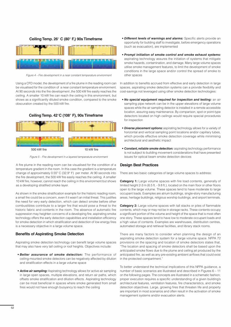
52
Figure 4 – Fire development in a near constant temperature environment
Figure 5 – Fire development in a layered temperature environment
As shown in the smoke stratification example for the historic reading room,
a small fire could be a concern, even if it wasn’t an initial threat. This justifies
the need for very early detection, which can detect smoke before other
combustibles contribute to a larger fire that would pose a threat to the
historic fabric and contents in the room. The absence of automatic fire
suppression may heighten concerns of a developing fire; aspirating smoke
technology offers the early detection capabilities and installation efficiency
for smoke detection in which stratification and detection of low energy fires
is a necessary objective in a large volume space.
Benefits of Aspirating Smoke Detection
Aspirating smoke detection technology can benefit large volume spaces
that may also have very tall ceiling or roof heights. Objectives include:
• Better assurance of smoke detection: The performance of
ceiling-mounted smoke detectors can be negatively affected by dilution
and stratification effects in a large volume space
• Active air sampling: Aspirating technology allows for active air sampling
in large open spaces, multiple elevations, and return air paths, which
offsets smoke stratification and dilution effects. Aspirating technology
can be most beneficial in spaces where smoke generated from small
fires would not have enough buoyancy to reach the ceiling
• Different levels of warnings and alarms: Specific alerts provide an
opportunity for building staff to investigate, before emergency operations
(such as evacuation), are implemented
• Prompt initiation of smoke control and smoke exhaust systems:
aspirating technology assures the initiation of systems that mitigate
smoke hazards, contamination, and damage. Many large volume spaces
utilise smoke management features, to limit the development of smoke
conditions in the large space and/or control the spread of smoke to
other spaces
In addition to benefits accrued from effective and early detection in large
spaces, aspirating smoke detection systems can a provide flexibility and
cost-savings not leveraged using other smoke detection technologies:
• No special equipment required for inspection and testing: an air
sampling pipe network can be in the upper elevations of large volume
spaces while the air sampling detector is installed in a remote accessible
location, assuring easy maintenance. By comparison, spot or point-type
detectors located on high ceilings would require special procedures
for inspection
• Diverse placement options: aspirating technology allows for a variety of
horizontal and vertical sampling point locations and/or capillary tubes,
which provide effective smoke detection coverage while minimising
architectural and aesthetic impact
• Constant, reliable smoke detection: aspirating technology performance
is not subject to building movement considerations that have presented
issues for optical beam smoke detection devices
Design Best Practices
There are two basic categories of large volume spaces to address:
Category 1: Large volume spaces with fire load contents, generally of
limited height 2-3 m (6.5 ft. - 9.8 ft.), located on the main floor or other floors
open to the large volume. These spaces tend to have moderate to large
occupant loads. Examples are atrium buildings, single-story manufacturing
areas, heritage buildings, religious worship buildings, and airport terminals.
Category 2: Large volume spaces with tall stacks or piles of flammable
contents, which may or may not be in storage racks. These contents occupy
a significant portion of the volume and height of the space that is most often
one story. These spaces tend to have low to moderate occupant loads and
a high value of contents. Examples are warehouses, distribution centres,
automated storage and retrieval facilities, and library stack rooms.
There are many factors to consider when planning the design of an
aspirating smoke detection system for a large volume space. NFPA 72
provisions on the spacing and location of smoke detectors states that,
“The location and spacing of smoke detectors shall be based upon the
anticipated smoke flows due to the plume and ceiling jet produced by the
anticipated fire, as well as any pre-existing ambient airflows that could exist
in the protected compartment.”
To better understand the technical implications of this NFPA guidance, a
number of basic scenarios are illustrated and described in Figures 6 – 11
on the following pages. The concepts are illustrated in a schematic fashion;
proper execution requires a specific understanding of a given building’s
architectural features, ventilation features, fire characteristics, and smoke
detection objectives. Large, growing fires that threaten life and property
are important in most scenarios and often result in the activation of smoke
management systems and/or evacuation alerts.
Using a CFD model, the development of a fire plume in the reading room can
be visualised for the condition of a near constant temperature environment.
At 90 seconds into the fire development ,the 500 kW fire easily reaches the
ceiling. A smaller 10 kW fire can reach the ceiling in this environment, but
shows as a significantly diluted smoke condition, compared to the smoke
obscuration created by the 500 kW fire.
Ceiling Temp. 26° C (80° F,) 90s Timeframe
A fire plume in the reading room can be visualised for the condition of a
temperature gradient in the room. In this case the gradient is a temperature
change of approximately 0.55º C (32.9° F) per meter. At 90 seconds into
the fire development, the 500 kW fire easily reaches the ceiling. A smaller
10 kW fire, however, cannot reach the ceiling in this environment but shows
as a developing stratified smoke layer.
Ceiling Temp. 42°C (108° F), 90s Timeframe
500 kW fire 10 kW fire

53
FAAST Fire Alarm Aspiration Sensing Technology®
However, it’s also important to detect small fires that may not be an
immediate threat, to alert staff and allow time for preventive or investigative
actions.
The appropriate design and implementation of smoke detection for large
volume spaces is often developed from a performance-based design
concept, which identifies high-level objectives, project-specific goals, and
performance criteria for fire and safety systems. For details and background
regarding considerations and approaches to performance-based design,
the following three documents are recognised useful references:
• Society of Fire Protection Engineers, Engineering Guide to
Performance-Based Fire Protection Analysis and Design of Buildings
• British Standards Institution, BS 7974, Application of Fire Safety
Engineering Principles to the Design of Buildings - Code of Practice.
• Australian Building Codes Board, International Fire Engineering
Guidelines.
S ena i e e e a a e e e e n e n g ing i e i ell e el pe i e pl me l a ing a pi a ing ampling p in n e ig eiling i app p ia e i a e e e ing la ge g ing i e n la ge
l me pa e e eiling ampling p in an p i e e e i n l ng e e e m e a a ill e en e pie a ea
Figure 6.
Figure 7.
Figure 9.
Figure 10
S ena i e e e a a e e e e n e n g ing i e i ell e el pe i e pl me a pill in pie le el in e ig e
ele a i n e pa e en l a ing a pi a ing ampling p in n e ig eiling an a e l le el ma e app p ia e ampling l a i n n i i a i n e e en i a n e n ea l e e i n a n e n e
a e el ping m e a a n e ppe pie pa e an ini ia i n m e n l e a ea e
S ena i e e e a a e e e e n e n g ing i e i ell e el pe i e pl me a pill in a all na pa e n i a e a i e
pl me an e e pe e n a e i e all i en e i an e a e na pa e e al app ima el e eig e i ing i e pl me e ample a i e pl me en e e in e pa e a
i e ill n a e i e all a pa e a i ee i e n i i a i n ai ampling p in l a e nl n e i e all pe ime e l
a ea e all na pa e an e i ien ap e an e e m e illing e pa e
S ena i e e e e i e i e e i e en e a e ela i el mall i limi e m e an e e empe a e ange in e pa e ma a e a i i a i n e e ampling p in a m l iple ele a i n an e an
e e i e a pi a ing e e i n l i n n man a e eiling e e i n ampling p in l al e p i e a e e e i n la ge an i e pl me a ill p m e ea il e eiling
S ena i n me la ge pa e a mall m e a e i e ma a e e an ea e eiling le el e e ai en ainmen an
a ia e ling e i ing m e e m e n i i n ma e igni i an l i e an il e ing m l iple ai ampling p in m e an e lle e a m l iple l a i n an a n a e a pi a ing e e i n ni e m la i e e e e m e eing ample m m l iple p in an e me e il i n e e an p i e e e i e e e i n a l
n e a ie e i p m e e e
Figure 8.

54
S ena i e en ila i n em e ing la ge l me pa e an e l in len ell mi e ai l n i i n Small m e a e an la ge i e pl me an e in e p e an il e e e n mal ai l A p en iall e e i e me p i e m e e e i n i p i e a pi a ing ampling p in ap e i e an il e m e a en ila i n em ai e n n i a i n e e e en ila i n i m la e ne eiling e e i n ampling p in ma al nee e p i e a e e e i n
en e en ila i n i l
Figure 11.
Figure 12. – Smoke Rise in Spaces with a Uniform Temperature Gradient
In Figure 9 on the previous page, stratification was noted as one scenario
that should be accounted for when detecting smaller fires, or when
significant temperature gradients may prevent smoke from rising to
ceiling detectors. NFPA 72 specifically notes that the effect of stratification
should be accounted for in smoke detection system design. This
requires a determination of whether or not the anticipated fires of interest
(fire heat release rate), could be subject to stratification in the temperature
environment of a large volume space. NFPA 72 provides guidance and
methods to make this determination in its Annex B-Engineering Guide for
Automatic Fire Detector Spacing.
The graphical method, shown in Figure 12 below, is also applicable in
tall spaces with a uniform temperature gradient. In Figure 12, the arrow
at the y-axis points to a temperature change (ΔT) of approximately 39º C
(70º F). Following this line across – to the intersection of the 106 kW heat
release rate fire curve (a large trash can fire) – allows for a cross reference
to the x-axis, which indicates the maximum height that smoke can rise to.
In this case, if the ambient temperature at the floor of a smoke detected
space is 20º C (68° F), then a temperature of 59º C (138.2 ° F) ( (20° + 39º C/
68° F + 70.2 ° F ), would result in stratification of smoke from a 106 kW fire at
9.5 m (31 ft.) above the floor. This is a fairly large temperature difference
over a 9.5 m elevation change and perhaps an unlikely temperature
condition in occupied buildings. However, assuming such a temperature
empe a eange in
a im m eig Sm e i e in m
empe a e ange an a im m eig Sm e i e i e i e Si e
e gi en i e i e a e pe i ie in e m al ea elea e a e n
n e i e ea elea e a e e e e e e
change is likely, this example shows that 106 kW fires or larger will reach
ceiling detectors at a ceiling height up to 9.5 m.
The methods in NFPA 72-Annex B provide a technical basis to address the
potential for stratification. Stratification, however, may not be the relevant
concern for detecting smoke in large volume, high ceiling spaces. In the
European fire detection community, much attention and full scale research
(Building Research Establishment, “Smoke Detection in High Ceiling
Spaces – Report 3”, BRE Global, 19th November, 2010), has been given
to the assessment of adequate smoke detection in high ceiling spaces
(43 m or 143 ft.), for small to moderate fires (5.8 kW to 560 kW). More
specifically, the fires considered were as follows:
Table 1
Fires Used in BRE High Ceiling Smoke Detection Research
Smoke Source Approximate Heat
Release Rate - kW
Smoke
Characteristic
Small wooden crib 220 Very limited grey
n-heptane 400 Limited black
Large wooden crib 560 Limited grey
53 sheets of paper,
loosely packed into bin
30 Grey
potassium chlorate
and lactose
45 White
Smoke pellets on top
of gas burner
5.8 White
Prior to conducting this research, European codes did not recognise the
capabilities of aspirating detection technology for ceiling heights beyond a
range of 10.5 m - 21 m (10.75 ft - 68.8 ft.); the latter value is only applicable
to property protection scenarios. The research provided insight into the
capability and values of aspirating detection technology for smaller fires
as opposed to fires with rapid growth and high heat release rates. Three
noteworthy conclusions provided the basis for revisions to the FIA code of
Practice (CoP) for ASD systems based upon using the EN54-20 Classes
of Sensitivity; Class A, B, and C. Key research conclusions from this study
are as follows:
• ASD detectors can detect smoke that rises to the ceiling from relatively
small fires, despite vertical temperature differences
• Multiple air sampling ports carry a significant advantage over cumulative
or additive effects and provide better detection, as opposed to a single
sampling port. Testing showed that 1-pipe/4-hole ASD system responses
were better than a 1-pipe/1-hole ASD system, and the 4-pipe/20-hole
ASD system responses were better than the 1-pipe/4-hole ASD system
• In the absence of cross-flows, but in the presence of a 12º C (22º F)
temperature difference, between the floor and ceiling, smoke rose to the
ceiling with no evidence of any thermal barriers to cause stratification

55
FAAST Fire Alarm Aspiration Sensing Technology®
European testing has brought about revisions to the FIA code of Practice
(CoP) for ASD systems, based upon using the EN54-20 Classes of
Sensitivity. The EN54-20 three classes of sensitivity are a measure of the
individual sampling holes’ sensitivity and not the ASD detector system.
Table 2 provides a brief description of the three EN54-20 sensitivity classes.
Table 2
EN 54-20 Sensitivity Classes vs. Typical Detection Scenarios
Class A Very High
Sensitivity
Class B Enhanced
Sensitivity
Class C Normal
Sensitivity
Smoke is not visible
due to low quantity
of smoke and/or high
dilution caused by
air movement
Smoke is visible,
but insufficient to be
detected by point* or
beam technologies*
Smoke visible and
sufficient to be
detected by point* or
beam technologies*
* According to EN-54 Part 7 or 12
Based on the BRE research efforts, the FIA Code of Practice (CoP) for ASD
has been revised to include the following recommendations for aspirating
detection systems in high ceiling applications. The FIA CoP notes that the
recommendations in Table 3 may be used as a basis for variations from
national codes on a project by project basis.
Table 3 – FIA CoP - Recommended Ceiling Height Limits for ASD
Assumes that there is no stratification and that smoke rises to the
ceiling unimpeded by thermal gradients
Detector type Generally applicable
Maximum ceiling
height
10% of ceiling height
no Greater than
General
Limits
Property
Protection
Scenarios 1
General
Limits
Property
Protection
Scenarios 1
A n y A S D s y s t e m
approved to EN 54-20
10.5 m 15 m 12.5 m 18 m
ASD system with: at
least 5 Class C holes or
at least 2 Class B holes
15 m 21 m 18 m 26 m
ASD system with: at
least 15 Class C holes
or at least 5 Class B
holes
25 m 40 m 28 m 43 m
ASD system with: at
least 15 Class B holes
40 m 40 m 43 m 43 m
Note 1.
Assumes 5 minute fire service/fire department attendance or response.
The following recommendations are also applicable to Table 3 bottom left.
a. The ASD holes should be located close to the ceiling (typically within 600
mm/1.9 ft.), and spaced in accordance with maximum areas specified
in national codes
b. An enhanced response can be achieved by using an ASD with increased
Class, e.g., a Class A detector with at least five holes will provide
enhanced detection in spaces up to 25 m (82 ft.)
c. An enhanced response can also be achieved by using a higher density
of sampling holes. For example a Class B system with 10 holes at half the
spacing (e.g., 5 m (16.3 ft.), as opposed to 10 m (32.75 ft.), will provide
enhanced detection in spaces up to 25 m (82 ft.)
d. Where possible spacing of sampling holes should be in two dimensions
(covering an area as opposed to a single line of sampling holes)
e. If multi-port ASD systems, which identify the source pipe are used,
the minimum number of holes (15 or 5), should be on each identifiable
section/pipe
f. If stratification occurs, detection may be delayed until the heat produced
by the fire is sufficient to penetrate the stratification layer. Where there
is significant stratification or a requirement to detect smaller fires the
provision of vertical sampling should be considered
g. Any air flows (e.g. as a result of air conditioning), should be considered
and taken into account by the provision of primary sampling where
necessary
Warehouse Facilities
Warehouses, distribution centres, automated storage and retrieval facilities,
and library stack rooms are a unique category of large volume spaces
that require additional considerations beyond those previously discussed.
Stacks, racks, and material handling equipment allow these facilities
to efficiently store large quantities of inventory or important documents
and items archived for legal or historic purposes. A large fire can be
catastrophic, potentially costing millions of dollars in lost contents or
major business interruptions. Warehouses serving the food industry
are very susceptible to loss from sprinkler-controlled fires due to smoke
contamination and water damage. Modern warehouses and storage
facilities often rely on automatic sprinkler systems for basic fire protection;
however, the potential loss and importance of key supply chain facilities,
extreme high value storage, and irreplaceable archived storage can warrant
the installation of early warning smoke detection for staff intervention before
sprinklers are needed. Arson and electrical/mechanical systems account
for a significant percentage of warehouse fires, and aspirating smoke
detection can provide early indications of such events and allow for manual
fire suppression or de-powering of equipment.
The following internal warehouse conditions should be assessed as part
of the air sampling system design process:
• Temperature and humidity profiles – variations on temperature throughout
the day and across the seasons may pose stratification concerns that
should be addressed
• Airborne particulate levels – consider the type of operation and how
particulate levels relate to ceiling height in order to prevent nuisance
alarms from non-fire related particulates
• Ventilation – how the area is ventilated (e.g. mechanical, air conditioning,
exhaust fans, natural ventilation, building leakages, rolling doors
opening/closing) may determine airflow patterns prior to the fire
conditions
• The presence of high storage racks

56
Large, open warehouse spaces contain great volumes of air; fire smoke,
produced in the early stage of the fire, can be easily diluted and therefore
difficult to detect. Fresh air coming from open vents (e.g., open aircraft
hangar doors), can also dilute the smoke inside the structure.
By definition [NFPA 72], stratification is the “phenomenon where the upward
movement of smoke and gases ceases due to the loss of buoyancy.”
This phenomenon can occur in the high ceiling environments of warehouses,
where the thermal buoyancy of the smoke is insufficient to reach the
detection points on the ceiling, which results in horizontal layers of air and
smoke in varied temperatures. Stratification layers will also be influenced by
ventilation and external environmental conditions. For example, the summer
sun can cause temperatures in excess of 60° C to 70° C (140° F to 158° F),
if it strikes just below a steel warehouse roof. If a small incipient fire starts at
the ground level, its smoke would not have enough energy to breach this
higher temperature air barrier and the majority of smoke particulates would
not reach the ceiling detection points. Instead, a smoke layer would form
beneath the upper hot air layer. To increase sampling point effectiveness,
it may be necessary to conduct sampling at different heights to detect the
smoke particulates.
Plastic pipes are used in most normal warehouse applications, but extreme
temperature variations would be better suited for a damage-resistant
alternative, like copper pipe. Consider this possibility during sampling pipe
network design. The thermal characteristics of commonly used plastic pipe
materials are presented in Table 4 below.
Table 4 – Thermal Characteristics of Plastic Pipe Commonly Used
Pipe material Temperature range Pipe variation within the
temperature range
ABS -40° C to 80° C
(-40° F to 176° F)
10.1 mm per 10 m per 10° C
(0.4 in. per 32.8 ft. per 18 °F)
CPVC -18° C to 94° C
(0° F to 201° F)
6.7 mm per 10 m per 10°C
0.26 in. per 32.8 ft. per 18° F)
There are four complementary design options for the configuration and
location of ASD sampling pipes and holes in warehouse and storage
buildings. Selecting a sampling pipe configuration is dependent upon
the warehouse application and internal characteristics (e.g. presence of
high-bay racking, mezzanines, and voids), as well as the
facility’s operational objectives and smoke detection objectives
(performance-related). All sampling pipe network configurations should be
verified using appropriate supporting design software.
1. Near Ceiling Detection– sampling pipes are located close to the
ceiling only
2. Below Ceiling Detection – sampling pipes above a ceiling use drop
down pipes or capillary tubes with sampling holes
3. High-Low Alternating Detection – sampling pipes are located
on the ceiling with alternating sampling holes on the ceiling and
drop-down pipes
4. Multi-Level Detection – this detection method applies to warehouses
comprising high bay storage racks and utilises more than one ASD
system for ceiling and intermediate level detection (Figure 6 on
page 53)
5. In-Rack Detection – the sampling pipes run horizontally or vertically
between back-to-back racks at various heights. Drop-down pipes
from the ceiling can also be used for in-rack detection
In addition to these generic warehouse applications of ASD systems,
additional protection should be considered in the following situations:
– Office and control area – for aesthetic reasons, sampling in these
areas is usually conducted via capillary tubes fed through the ceiling
from the main sampling pipes, which are located in the ceiling void
(Figure 13 below).
– Ceiling void – it is especially important to protect ceiling voids
containing cabling and/or any other equipment, due to an increased
risk of fire. The spacing of the ASD sampling holes is again
determined using the grid method (see Figure 13 below).
– ASD sampling pipes – should not be placed underneath or in close
proximity < 1 m (3.3 ft.), to lighting fixtures, heaters, skylights, or other
heat-emitting objects
– Loading bay – ASD sensitivity should be lowered to account for the
truck exhaust fumes, regularly present in the loading bay environment
For ceiling protection, sampling pipes can be installed directly onto the roof
trusses when drilling into the roof decking is not allowed. If there are beams
on the ceiling, the ASD pipe network can be fastened to the beams using
suitable materials. If neither method is feasible, an alternative approach is
to use catenary wire to support the pipe network.
Take local codes and standards into account when installing sampling
pipes on sloped ceilings. For warehouses containing storage rack areas,
sampling pipes can run perpendicular or parallel to the rack orientation.
For intermediate level protection, sampling pipes should be installed on the
underside of mezzanines (catwalks). Where mezzanines (catwalks) are not
present, the pipes can be fitted to the sheltered side of the racking, fixed
to the rack frame. It is important to ensure that the pipes are not in close
proximity to stored goods or installed in locations where they could be
damaged by forklifts. Wind loads and temperature fluctuations may cause
expansion or contraction of the warehouse’s structural beams and pipes,
so conduit saddles should be used to allow for small pipe length variations.
Possible expansions or contractions also make it necessary to install
airtight expansion joints to allow for pipe movement without jeopardising
the integrity of the sampling pipe network.
For warehouses containing storage rack areas, it is recommended to
place ceiling sampling holes above each aisle in a staggered layout (see
Figure 14 on the following page).
Figure 13. Example of capillary air sampling through the ceiling
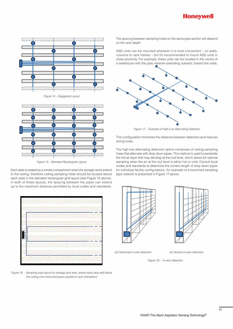
57
FAAST Fire Alarm Aspiration Sensing Technology®
Each aisle is treated as a smoke compartment when the storage racks extend
to the ceiling, therefore ceiling sampling holes should be located above
each aisle in the standard rectangular grid layout (see Figure 15 above).
In both of these layouts, the spacing between the pipes can extend
up to the maximum distance permitted by local codes and standards.
Figure 14 .- Staggered Layout
Figure 15. - Standard Rectangular Layout
Figure 16. – Sampling pipe layout for storage rack area, where racks stop well below
the ceiling (non-branched pipes parallel to rack orientation)
Figure 17. – Example of High-Low Alternating Detection
(a) Horizontal in-rack detection (b) Vertical in-rack detection
Figure 18. – In-rack detection
The spacing between sampling holes on the same pipe section will depend
on the rack depth.
ASD units can be mounted wherever it is most convenient – on walls,
columns or rack frames – but it’s recommended to mount ASD units in
close proximity. For example, these units can be located in the centre of
a warehouse with the pipe network extending outward, toward the walls.
This configuration minimises the distance between detectors and reduces
wiring costs.
The high-low alternating detection option comprises of ceiling sampling
holes that alternate with drop down pipes. This method is used to penetrate
the hot air layer that may develop at the roof level, which allows for optimal
sampling when the air at the roof level is either hot or cold. Consult local
codes and standards to determine the correct length of drop down pipes
for individual facility configurations. An example of a branched sampling
pipe network is presented in Figure 17 above.

58
Warehouse In-Rack Detection
In-rack detection may be used in warehouse facilities where the following
conditions apply:
– There is high-bay racking
– Stratification occurs
– Localised detection is required
Figure 19. Example of drop-down pipes for in-rack ASD
Figure 20. FIA recommendations for warehouse in-rack air sampling locations
Figure 21. – Example of Multi-Level Detection (Ceiling and Intermediate Level)
Figure 22. FIA recommendations for warehouse in-rack air sampling locations
The sampling pipe can have either a horizontal or vertical in-rack detection
configuration as shown in Figure 18 on the previous page. The detector
is installed at the end of the rack at an accessible level. As a safeguard
against mechanical damage from forklift trucks, sampling pipes are located
between back-to-back racks out of harm’s way.
In the case of non-high-bay racking, ceiling drop-down pipes may also be
used for in-rack detection. When installing drop-down pipes, it is important
to ensure that they will not be damaged by forklifts or be in close proximity
to the stored goods. The drop-down pipes can be fitted to the sheltered
side of the racking, fixed to the rack frame as shown (Figure 19 above).
H/4
6 19.7 �)
Ceiling
8 26.2 �)
Rac
k he
ight
(H
) >
10m
(32
.8 ft
.)
In-rack drop-down pipes normally have two or three sampling holes drilled
in them to provide sampling at different heights within the racking system.
In the UK, the Fire Industry Association (FIA) recommends protecting
warehouse high racking/shelving with air sampling points with a maximum
horizontal spacing of 6 m (19.7 ft.), in order to reduce the possibility of
smoke passing between sampling points.
In case of racks extending higher than 8 m (26.2 ft.), FIA recommends an
air sampling top level within the top 25% of the rack height and no less than
10 m (32.8 ft.), from the ceiling.
For even higher racks, additional levels of air sampling are recommended
with a maximum vertical spacing of 8 m (26.2 ft.), as presented in
Figure 20 ,bottom left. It should be noted that each level should be offset to
the one below if multiple levels of air sampling are installed, with the same
objective: to reduce the possibility of smoke passing between layers of air
sampling points.
A detailed positioning of in-rack pipework and air sampling points is
dependent on the racking configuration and stored items. FIA describes
the following options:
• Position the in-rack pipework and air sampling points within the space
between back-to-back shelving
• Or position the air sampling points at the shelving edges, adjacent to
the aisles
1st level
2nd level
3rd level
Mezzanine
Aisle-side sampling (air sampling points at the shelving edges), has
benefits when compared to sampling at the centre of the rack, including
easier installation and testing. Quicker detection is possible with
aisle-side sampling as well, because the sampling points are closer to
potential ignition sources. However, their side position makes them more
prone to mechanical damage by vehicles or other equipment.
Warehouse Multi-Level Detection
Ceiling mounted sampling holes
Rac
k he
ight
(H
) >
10M
Max
8M
Sample holes on both sidesof aisle if >3m
Max 6m
Max
10m
Max
H/4
Alternative positioning ofsampling holes in the central“chimney” of racking, if present

59
FAAST Fire Alarm Aspiration Sensing Technology®
The multi-level detection option is used in any of the following circumstances:
– There are high bay storage racking areas
– High stratification levels are expected
– Mezzanines (catwalks) consist of solid flooring that will impede/delay
the ascend of the smoke plume
This design option requires one ceiling ASD system and multiple
intermediate level ASD systems (Figure 21 on the previous page).
Important Note: ASD systems intended for intermediate level protection
should have sampling holes in every aisle.
For aisle-side sampling, FIA indicates that providing it on both sides of an
aisle should not be necessary for aisle widths under 3 m (9.8 ft.). When
multiple levels of aisle-side sampling are provided, level offsets should be
considered across the aisles, as shown in Figure 22 on the previous page.
Common Issues/Application Troubleshooting
Coordination and interfaces between an automatic fire suppression
system and emergency protocols
It is important to coordinate the smoke detection system with the building
management emergency plan. Since an ASD system handles multiple
alarm thresholds over a wide sensitivity range, its interface with notification
systems operation (e.g., horns, strobes), or could allow time for fire
investigation, while the subsequent alarms could initiate evacuation and
automated fire brigade notification.
Setting during design phase sampling locations and density, sensitivity
levels and alarm thresholds appropriate for large volume space
applications
Aspirating smoke detection has many benefits, and the remote sensor
programmability makes it a suitable detection system for large volume
spaces. However, there are several considerations for the use of aspirating
smoke detection within large volume spaces. During the design phase,
consider the following factors:
• The designer needs to verify the airflow and its direction within the space
to maximise the system’s effectiveness. The potential for stratification
should be addressed
• For large volume spaces where smaller fires are the detection objective,
smoke tends to become dilute and diffuse in the space. For better
response, consider using more sampling holes and/or a higher density
of sampling holes to enhance the cumulative effect
• Plan ASD unit locations carefully so end-of-system test points are
accessible
• Background pollution or smoke (e.g., truck exhaust fumes), can be
present in some large volume space environments. Consider and
implement false alarm prevention methods as necessary, and mitigate
the effects of background pollution or smoke. Such methods include day/
night alternative sensitivity settings, or the use of reference detectors to
offset measurements from active detectors and alarm delays to address
short term transient conditions. For example, in the case of truck exhaust
fumes from loading bay environments, sometimes it’s effective to simply
lower the ASD sensitivity.
Programming considerations of the aspirating smoke detector during
the commissioning process
During the commissioning process, the installing contractor needs to
properly program the alarm thresholds and sensitivity levels, because both
could significantly impact the aspirating smoke detector’s performance. The
following programming considerations should be considered:
• Typically, aspirating smoke detectors are shipped with default settings
from the factory. These generic settings are not appropriate for all
detection systems because they may be either too sensitive or not
sensitive enough for a specific application. It is necessary for the
aspirating system designer to determine the alarm levels and program
the sensor accordingly. The sensitivity levels and alarm thresholds are
derived by a combination of the computer-based calculation program,
the hazard being protected, detection system size and engineering
judgment
• The programmable sensitivity levels are another significant issue
impacting the performance of aspirating smoke detection systems.
The detectors contain sophisticated electronics and software that allow
the device to be programmed to a wide range of sensitivity levels. If
these alarm levels are not programmed properly, then the quantity of
smoke necessary within the sensing chamber may exceed the desired
sensitivity and cause a delay in alarm signal initiation
Time delays for initiating further actions
Time delays for trouble and alarm signal activation are also included at the
detector. These delays can be set for a range of times, but typically span
from 10 - 30 seconds. Consideration should be given when programming
the time delays. The greater the delay, the longer it will take for the detector
to initiate an alarm signal.
Dos
• Identify applicable codes and insurer’s requirements
• Verify all system designs, utilsing the manufacturer’s computer-based
flow calculations
• For systems that protect high ceilings, plan ASD unit placement carefully,
so that end-of-system test points are accessible
• Confirm how the alert and fire alarm settings of aspirating systems are
integrated to initiate the following, if applicable: 1) power shut-down,
2) fixed fire suppression systems, 3) air handling shut-down and
associated damper or door closures, 4) smoke control and room
pressurisation operations, 5) evacuation alarms
• Refer to the appropriate sections of ASD application guides for air
sampling techniques for air returns/In-duct applications (for ASD
sampling of HVAC ducts)
• When NFPA 72, National fire Alarm and Signalling Code applies, the
following is recommended:
– Determine if the aspirating smoke detection system design is a
prescriptive design or a performance-based design
– For prescriptive designs, review and understand the performance
objective (description of the purpose of the detector placement and the
intended response of the fire alarm control unit to the detector activation

60
– For performance-based designs, review and understand the
performance objectives for the fire alarm system design. This is
usually part of a larger, comprehensive fire protection strategy for
a facility or building area. The location and spacing of aspirating
detection should be based upon the anticipated smoke flows due
to the plume and ceiling jet produced by the anticipated fire, as well
as any pre-existing ambient airflows that could exist in the protected
compartment
– Refer to NFPA 72 Annex B for methods to evaluate the potential for
stratification
– Account for the effect of stratification to the performance objectives,
if relevant
• The following is recommended when EN 54-20 (Fire Detection and Fire
Alarm Systems – Part 20: Aspirating Smoke Detectors applies):
– Review the large volume space environment to identify the nature
of the airflows, the potential for stratification, and the criticality of
contents to be protected. This will help identify the sensitivity class
of aspirating system that needs to be installed in any given area
– Identify where Class C, aspirating type smoke detection is to be
applied
– Identify where Class B, aspirating type smoke detection is to be
applied. Class B systems are used when increased sensitivity is
needed to compensate for moderate dilution effects due to high
ceilings or moving airflows. Also, for protection of vulnerable and
critical items
– Identify where Class A, aspirating type smoke detection is to be
applied. Class A systems are used in areas having very high air
movement and high dilution.
Don’ts
• Don’t design the aspirating system to exceed the transport time
requirements of installation standards or insurance company
requirements
• Don’t install ceiling sampling points too near to ceiling supply air
diffusers. Maintain a distance of 0.9 m - 3 m (3 ft. -10 ft. from ceiling
diffusers, depending on the strength of the airflow). See BS 6566 and
NFPA 72 for specific requirements
• Don’t locate ASD sampling pipes underneath or in close proximity;
<1 m (3.3 ft.) to lighting fixtures, heaters, skylights, or other heat-emitting
objects
References
1. Fire Industry Association (FIA), FactFile No 0045, Smoke Detection in
High Spaces using ASD, available at:
http://www.fia.uk.com/filemanager/root/site_assets/fact_files/fiafac
files_0045_smoke_detection_for_high_ceilings_2011_fd_aproof.pdf,
April 2011 (February 2014).
2. Fire Industry Association (FIA), Design, Installation, Commissioning &
Maintenance of Aspirating Smoke Detector (ASD) Systems - Code of
Practice, Issue 3, February 2012
3. The Plastics Pipe Institute, Inc.(1999), “Suggested Temperature Limits
for the Operation and Installation of Thermoplastic Piping in Non-
Pressure Applications, TN-11/99”. www.plasticpipe.org
4. Plastic Pipe and Fittings Association (2003) “Information &
Technical Guide – ABS Plastic Pipe & Fittings. www.ppfahome.org

61
FAAST Fire Alarm Aspiration Sensing Technology®
Section 10
Prisons and Restricted Areas
Application Overview
Locked doors in buildings where occupants are intentionally restrained –
such as prisons or police stations – pose significant fire and life safety risks
for the facility, staff, first responders, and the individuals being restricted
from exits. These types of conditions can be found in facilities that provide
institutional housing of inmates on a long-term basis, as well as in small
temporary lock-up facilities (airports, sports venues, polices stations, etc.),
that may need to detain people on a short-term basis (less than 24 hours).
Long-term facilities include prisons, jails, and other types of correctional
facilities that may be known as:
• Substance abuse centres
• Community residential centres
• Local detention (lock down) facilities
• Work camps for adults or juveniles
• Correctional institutions for adults
• Training schools for juveniles
Lock-up facilities are used to provide a temporary security function for the
facility, for example:
• Security offices at retail stores, sports venues, casinos, or hotel
complexes
• Police station holding rooms
• Customs/immigration operations at airports or seaports
• Immigration facilities at border crossings
As shown in Figure 1 above right, fire-related goals [2] associated with
detention and correctional occupancy and lock-up facilities include:
– Life safety for all the occupants (inmates, staff, and visitors)
– Property protection (in addition to the inmate cells, it may be costly
to restore areas containing the control room or vocational shops,
classrooms, offices, or assembly spaces after a fire)
– Business continuity (the loss of a restricted area by fire may be a
concern if there is no easy solution to relocate the inmates before
the fire-affected area can be used again)
– Security is a primary objective (detention and correctional occupancy
facility has to maintain a secure perimeter to monitor dangerous
people and protect the public and staff. The fire protection design
for this type of occupancy should be coordinated and compatible
with the security goal)
Fire Related Goals
IgnitionControl
FuelControl
OccupantProtection
Planning andTraining Operation
1. Provide early warning detection2. Provide reliable alarm system3. Provide reliable suppression4. Provide manual suppression
Detection andSuppresion
Life safety, property protection, business continuity, security
Design Goals
Design Objectives
Figure 1. Fire goals, design goals, and objectives related to detention
and correctional occupancy and lockup facilities
The fire-related goals are achieved through a series of design goals,
as shown in Figure 1 above. For example, early warning detection is
an objective or the design goal that pertains to adequate detection and
suppression. Early warning detection can be essential when coupled
with alarm and fire suppression, because a fire can grow rapidly and
dramatically in confined areas and spread smoke to nearby spaces.
Benefits of Aspirating Smoke Detection
The “prisons and jails” category within the US National Fire Incident
Reporting System (NFIRS) includes: prison cells or cell blocks, reformatories
or juvenile detention homes, detention camps, and police stations. It should
be noted that only fires reported to public fire departments are included
in the statistics extracted from NFIRS by the NFPA [3] and presented in
this section.
During the 2003-2007 period, in the US, an estimated annual average of
590 structure fires was reported for prisons and jails:
– 380 (64%) fires in jails and prisons (not juvenile), injured 29 civilians
(79%), causing $1.2 million (57%), direct property damage
– 120 (21%), fires in reformatories and juvenile detention centres
injured 5 civilians (14%), causing $0.3 million (14%), direct property
damage
– 90 (15%), fires in police stations injured 3 civilians (7%), causing
$0.6 million (29%), direct property damage
No civilian fire deaths were reported during this period.
During the 2003-2007 period, in the US, structural fires in prisons and
jails mainly started in the four following areas (see Figure 2 on the
following page):
– Confined cooking fire (for 22% of the fires), in addition to 4% of the
fires starting in the kitchen or cooking area
– Bedroom (for 17% of the fires)
– Contained trash or rubbish (for 12% of the fires)
– Laundry room or area (for 11% of the fires)

62
80
70
60
50
40
30
20
10
00% 0%
12%
Fires
Civilian injuries
Direct propertry damage
7%
37%
19%
29%
61%
24%
5%5%
26%
Cooking Equipment Intentional Clothes dryeror washer
Contained trashor rubbish
Figure 2. – Prison/Jails Fire Cause Data(US data 2003-2007);
Source: NFPA Fire Analysis and Research
It should be noted that 1 out of every 4 reported structural fires were
intentional: these fires caused 61% of the civilian injuries and 29% of
the direct property damage. This “intentional” statistic is not surprising,
given the desire of some problematic individuals to cause disruption
or vandalise the facility. Traditional smoke detection methods, such as
spot-type detectors, pose a challenge in lock-up facilities, because many
fire incidents occur in bedrooms or cells. Aspirating smoke detection
provides effective smoke detection, while avoiding the problems associated
with using other types of detectors. Aspirating smoke detection technologies
can avoid or minimise the following concerns:
• Beam detectors or spot smoke detectors can be targets for malicious
acts by inmates. Aspirating sampling points are visually minimal,
if not fully hidden, when installed behind grills or other structural or
architectural elements at the ceiling of protected spaces
• Placing an aspirating smoke detector (ASD) unit away from inmate
housing and activity areas avoids testing and maintenance problems
related to the detection system. When the ASD unit is located outside
the inmate activity/housing zones, special security measures and
disruption does not need to be implemented in order to accommodate
maintenance and testing of the ASD unit
• Inmates aware of the presence of smoke detection systems, such as
those located in detention cells, are often subject to tampering and false
alarms. Air sampling pipe work and ASD units can be readily located to
minimise visibility and the possibility of malicious tampering by inmates
Design Best Practices
Fire and life safety is achieved within locked-door institutions through
the use of early warning smoke detection, automatic sprinklers,
compartmentalisation, established fire zones, and a relocation plan.
Building and life safety codes are cognisant of the balance needed
for providing both effective fire alarm and detection systems, while
minimising (if not eliminating), the potential for disruption, vandalism, and
a high frequency of nuisance alarms. Both the NFPA Life Safety code
and the International Building Code require detention and correctional
facilities to install automatic smoke detection systems for alerting staff.
These smoke detection system requirements generally apply to the
following areas of detention and correctional facilities:
1. Resident/inmate housing areas including day rooms, group activity
spaces, and other common spaces contiguous with sleeping spaces.
In some circumstances, detection is not required where free egress
to safe compartments is provided
2. Automatic smoke detection is required in all sleeping rooms or cells
with five or more occupants. Be aware that the local codes in some
jurisdictions or countries may require smoke detection in all cells
3. Such required smoke detection systems are required to alarm at a
constantly attended staff location but need not trigger an occupant
notification (i.e., sound general alarm), or transmit a fire alarm signal
to the fire department, as this procedure is typically relegated to staff
Fires are an anticipated problem within prisons, often taking place in
locked cells when inmates are present. Given the small cell areas and
restricted means of egress, early detection and staff response are critical
for the safety of the inmates, staff, and facility operations. Smoke detector
installations require special consideration in order to provide effective smoke
detection, while avoiding nuisance alarms and tamper resistance. Both the
NFPA Life Safety Code and the International Building Code, acknowledge
this need and permit alternative installation arrangements to prevent
tampering and damage, such as placing sampling points behind ventilation
grills or outside inmate cells. The NFPA Life Safety Code goes one step
further to require that such alternative placement or arrangement be
equivalent in speed of response to otherwise standard installation practices.
If an alternative smoke detection arrangement is necessary, then aspirating
smoke detection technology is a likely solution for maintaining performance
in speed of response. In these circumstances, aspirating smoke detection
can meet the need for fire detection and very prompt detection. Aspirating
smoke detection systems can provide high sensitivity and continuously
sample low quantities of smoke that may be slowly distributed and easily
diluted by the airflow environment as smoke travels to an alternative
sampling detection point rather than a standard location (e.g., detector on
the ceiling of an inmate cell).
To minimise, manage, or control the spread of smoke in detention/correction
facilities, codes will require one or more of the following features:
• Smoke barriers to divide floors into compartments, so that residents/
inmates in a fire-exposed compartment, can be moved to an adjacent
compartment protected against smoke spread, by structurally fire-
resistant walls, doors resistant to smoke movement, and smoke dampers
• Multi-tiered, open cell blocks may require sprinklers throughout and/
or smoke control systems to minimise the threat of smoke to cell block
occupants
• Windowless buildings or portions of buildings where windows are not
operable, not readily breakable, or not provided often require smoke
control systems for a tenable environment during a fire incident or an
evacuation to a safe compartment
The operational aspects of smoke barriers, such as automatic door closing
and smoke damper closures, will require initiating signals from smoke
detection systems. Similarly, smoke detection systems are needed to initiate
smoke control features of exhaust fans, make-up air fans, and damper
operations. Various types of smoke detectors could be used to initiate these
critical functions; however, aspirating detection is provides these initiating
functions without being subject to vandalism or tampering by the inmate

63
FAAST Fire Alarm Aspiration Sensing Technology®
population. Air sampling pipes can be run through the ceilings or other
building components, well out of the reach of inmates. Sampling points
and any portion of the protected rooms’ piping are so minimal that they
can be difficult to see.
Early detection for investigation, appropriate suppression,
and inmate relocation
It should be noted that critical security objectives can cause delays while
staff are investigating a fire and setting up manual fire suppression efforts
(as some guards may have to relocate inmates, while others get the locked
fire extinguishers). Aspiration detection can provide the time needed for
security personnel to plan or conduct a controlled response – whether it’s
to suppress the fire/smoke source, to manually initiate emergency systems,
or to evacuate a portion of the facility, which is important for protecting
lives and maintaining security in the facility. ASD systems possess very
early warning fire detection capabilities because some are designed to
respond to the incipient fire stage (i.e., before the fire growth period),
where the smoke obscuration can be as low as 0.00046% obs/ ft.. Early
stage fire detection provides guards with the opportunity to investigate the
fire situation and take appropriate actions regarding fire suppression and
possible inmate relocation. This use of aspirating technology is consistent
with the goals for security and fire safety in prisons and correctional
facilities.
Risk of vandalism
Due to the needs for very early warning fire detection, it seems essential
to install smoke detectors as close to the fire sources as possible, but this
situation may not always be practical within the inmate living facilities.
Inmates/residents may abuse building components that are within reach,
therefore generating damage and nuisance alarms. Point smoke detectors
are commonly tampered with by inmates, sometimes by spraying water and
aerosols or even lighting fires. In order to prevent such inconveniences and
sabotage, ASD pipes can be installed out of inmate reach and sampling
holes can be located in each cell return air grill, inside the HVAC system,
or even concealed inside the cell itself (for example, integrated with a light
fixture). With carefully planned concealment, the sampling pipes appear to
be passive building features that are of no interest to inmates.
Access for accessibility, maintenance and repair
When point smoke detectors located in inmates’ cells become dirty due to
a lack of maintenance, it requires entering each inmate’s cell. ASD system
maintenance and testing are centralised on the ASD detector, which can be
conveniently located outside of cells or activity areas so the whole detection
system is easily accessible, safe, and quick: this ultimately reduces testing
and maintenance costs as well. Remote and centralised access also allows
real-time monitoring and capture of all the susceptible fire events and
alarms within the detention and correctional facility, covered by one or
several detectors.
Other Use/Occupancy areas
There are many different functional spaces or building sections within
detention and correctional facilities, including workshops, laundries,
stores, classrooms, athletic facilities, religious facilities, and administrative
offices. The environment can vary significantly from that of the cell-block
areas, which limits the use of traditional types of spot detectors. Aspiration
detection can be installed in various areas of a facility and programmed
at different sensitivity ranges. Depending on the area of use, ASD range
adjustment enables aspiration systems to work just as well in machine
shops or boiler rooms within the prison as they do in individual cells or
common areas, while allowing for differences in air quality, humidity,
temperature, and other factors. The ASD detector can be programmed
so its detection thresholds vary according the inmate activities in any area
during the day-night periods. Also, frequent false alarms from point smoke
detectors are a risk due to inmate vandalism. As presented in the previous
sections, an ASD system with the locations of its sampling holes, pipes,
and detector can drastically decrease the occurrence of false alarms.
An optional filter used with some ASD units can reduce problems associated
with dirty or dusty areas (e.g., laundry rooms).
Special locations (large open spaces and ducts)
Large detention and correctional buildings may be classified as high-rise
buildings, and therefore may contain large open spaces. Phenomena such
as smoke dilution and smoke stratification may challenge a smoke detection
system organised upon point smoke detectors. The flexibility permitted
with the installation of vertical ASD pipes (combined with their very low
thresholds), overcomes the smoke dilution and stratification challenges.
Lock-ups
Lock-up facilities are associated with other types of buildings and are used
to provide a temporary security function for the facility. Examples of lock-up
facility locations include: security offices at retail stores, sports venues,
casinos, hotel complexes; police station holding rooms; and customs/
immigration operations at airports or seaports; and immigration facilities
at border crossings.
Lock-up arrangements are generally intended to detain individuals or
small populations (50 persons or less), for a period of time not exceeding
24 hours. The fire protection features provided are those associated with the
main occupancy; for example, a holding cell in a retail store would need to
meet the building or life safety code provisions for a mercantile occupancy.
In the case of NFPA 101, the mercantile occupancy requirements are
allowed provided that staff is trained, authorised, and in proximity to lock-up
so that locked doors or other restraints can be readily released (within
2 minutes), to allow for occupant evacuation in the event of a fire or other
emergency. If just one of the related staffing requirements cannot be met,
NFPA 101 then requires the lock-up to be provided with a complete smoke
detection system and fire alarm system for staff and occupant notification.
Just as in full-time prisons or jails, aspiration smoke detection can provide
the time needed for security personnel or other staff to respond to a fire
emergency in the lock-up area and unlock the doors or other restraints so
occupants can move to safety or exit the facility.
Common Issues/Application Troubleshooting
Aspirating smoke detection (ASD), has many benefits and the
programmability of a remote detector make it a suitable detection system for
a restricted assess configuration. However, there are several considerations
for the use of ASD within this type of configuration. During the design phase
the following factors should be considered:
• The sensitivity levels and alarm thresholds should be as low as possible,
in order to detect the smallest production of smoke (considered here
as a contaminant more than a fire effluent), to allow fire investigation
by the guards
• The designer needs to verify the air-flow and direction of air within the
space to maximise the systems effectiveness. The sampling points
should be installed in the direction of the air-flow, especially in the air
return ducts
• For large detection system with many sampling holes the designer
needs to take into consideration smoke/air dilution. The more sampling
holes the air sampling pipe contains, a greater volume of air is returning
to the aspirating detector; this can dilute the quantity of smoke within
the detection chamber and may delay the time the quantity of smoke
necessary to initiate an alarm, is present within the detection chamber.

64
• The location of the sampling holes within the detection network is a
concern. The further the sampling hole is located from the aspirating
smoke detector the more air/smoke dilution occurs; which could delay
the time the quantity of smoke necessary to initiate an alarm is present
within the detection chamber
• Special care will be given to the design of air sampling pipes as well
as sampling hole locations and spacing for large open space and duct
applications
Programming consideration of the aspirating smoke detector during
commissioning process
During the commissioning process the installing contractor needs to
properly program the alarm thresholds and sensitivity levels. These
programmable sensitivity levels and alarm thresholds could significantly
impact the performance of the aspirating smoke detector. The following
programming considerations should be considered:
• Typically, aspirating smoke detectors are shipped with default settings
from the factory. These settings are not appropriate for all detection
systems. These settings are to be considered generic and may not
be sensitive enough, or too sensitive for a specific application. It is
necessary for the ASD designer to determine the alarm levels and
program the sensor accordingly. The sensitivity levels and alarm
thresholds are derived by a combination of the computer based
calculation program, the hazard being protected, detection system size
and engineering judgment
• Another significant issue that will impact the performance of aspirating
smoke detection systems is the programmable sensitivity levels. The
detectors contain sophisticated electronics and software that allow
the device to be programmed to a wide range of sensitivity levels.
If these alarm levels are not programmed properly the quantity of
smoke necessary within the sensing chamber may exceed the desired
sensitivity causing a delay in the initiation of an alarm signal
Time delays for initiating further actions
Also included are time delays for the activation of the trouble and alarm
signals at the detector. These delays can be set for a range of times,
typically ranging from 10 - 30 seconds. Consideration should be given
when programming the time delays. The greater the delay the longer it will
take for the detector to initiate an alarm signal.
Dos
• Refer to the appropriate sections of ASD application guides for:
– Large and open spaces (for ASD sampling of multi-tier cell blocks
and high ceiling areas)
– In-duct (for ASD sampling of HVAC ducts)
• Identify applicable codes and related requirements and performance
criteria specified for fire detection systems. NFPA 101 or applicable
local codes
• Identify and understand the air handling features and air flow paths.
Aspirating detection systems have the sensitivity and fast response
capability to detect threatening smoke contamination in the air flow path
at the earliest opportunity
• Identify and understand any smoke control and/or pressurisation
schemes that need to be implemented upon smoke detection.
Using associated outputs of air aspiration detectors, important smoke
control functions can be promptly initiated.
• Confirm and implement how the alert settings and fire alarm settings
of aspirating systems are to be integrated to initiate the following
if applicable: 1) fixed fire suppression systems, 2) security staff
response, 3) smoke barrier associated smoke damper or door closures,
4) smoke control and room pressurisation operations.
• Transmit alarms from aspirating smoke detection to a constantly
attended location.
Don’ts
• Don’t exceed the recommended detector or sampling point spacing of
applicable standards.
• Don’t use detectors that are not listed or approved for air velocities and
temperatures that will be encounter in the airflow paths of protected
spaces
• Don’t design the aspirating system to exceed the transport time
requirements of installation standards or insurance company
requirements
References
1. NFPA 101 “Life Safety Code”, 2012 edition, National Fire
Protection Association
2. Flynn, J.D., Prisons and Jails, NFPA Fire Analysis and Research, Quincy,
MA, March 2010.

65
FAAST Fire Alarm Aspiration Sensing Technology®
Section 11
Extreme Temperatures
Application
Environments with extreme temperatures – such as cold storage facilities
or confined data centre aisles – are among the most challenging to
protect from fire and smoke damage. This presents a problem if detection
systems are required, because traditional heat and smoke detectors are
listed for a normal ambient operating temperature range of 0° C - 38° C
(32° F - 100° F); therefore, modern codes will not allow these devices to
be installed in areas that are below 0° C (32° F) or above 38° C (100° F).
Alternate detection methods are required for atmospheres that exceed
these temperature ranges.
The installation of fire detection and suppression systems is essential in
such facilities, but traditional detection methods cannot be installed due
to the extreme environment conditions.
ASD units are well-suited for extreme conditions. The ASD unit has the same
installation constraints as traditional smoke and heat detectors, except that
it’s listed for installation in areas with an ambient operating temperature
between 0 ° C (32° F) to 38° C (100° F). However, the ASD does not have
to be located inside the protected space because only the sampling pipe
is exposed to the extreme temperatures. Heating elements, pipe lagging,
or extended pipe length may be required to heat the sampled air within
ASD limits, depending on the temperature of the air being removed from
the room. A condensation trap can also be installed to trap moisture before
it enters the device.
The ASD does have limitations when protecting extreme climates.
The temperature of the air that passes through the sampling chamber
is required to be between -28° C (-4°F) to 60° C (140° F); check with
the specific manufacturer’s listing prior to installation to verify operating
temperature ranges and design methods.
Condensation may accumulate on the inside of the sampling pipe
when working in atmospheres with significant temperature and humidity
differences, particularly in hot aisle containment areas. Condensation is the
change of state of a gas (air) to a liquid (water), and is most often caused
when the gas is transported from a warmer area to a cooler area.
Cold Storage Facilities
Cold storage facilities (where refrigerated or frozen products are kept
prior to final use), are subject to extreme environmental conditions.
Ambient temperatures can range from -40° C (-40° F) for a freezer, to -5° C
(41° F) for a chiller or cooler (see Figure 1 below).
Temperature °C
-40 -30 -20 -10 0 10 20
Freezer
Chiller
Cooler
Figure 1.. Temperature ranges for freezer/chiller/cooler
High airflows and the absence of humidity further complicate fire protection
for cold storage facilities and impact the response of traditional detectors.
Heavy combustion load is another concern for cold storage facility
protection. Large quantities of highly combustible materials are stored,
including:
• Wooden pallets for stacking product
• Plastic product packaging
• Cardboard boxes for the storage of product
• Small forklifts used to move product in and out of the facility
• Polyurethane or polystyrene foam insulation used in the walls and
ceiling
Stored commodities are combustible, and generated heat could easily
transfer to them in the event of a smouldering fire. Research conducted on
stored warehouse commodities found a 2 x 2 x 2 pallet array of packaged
fruit/berry baskets produced a peak heat release rate (HRR) of 8,695 kW
within approximately 600 seconds after ignition. This is a significant amount
of heat being released from the pallet array, and could easily ignite pallets
of adjacent materials.
Cold storage ignition sources include, but are not limited to:
• Small forklifts powered by LP, LNG, or electrically
• Conveyor or other type of mechanical systems used to transport the
product
• Electrical spark or short from lighting or improperly grounded equipment
• A fire caused by the workers (such as a discharged cigarette or improper
use of a torch or welder)
Between the heavy combustion load and potential ignition sources, cold
storage fire protection is critical. The sooner a fire is detected, the better
the chances of saving stored goods.
Water-based sprinkler systems are commonly installed in cold storage
facilities to provide overall structure protection. Due to the extreme
temperatures, a traditional wet pipe sprinkler system cannot be installed.
Most cold storage facilities are protected by a double inter-lock, pre-action
sprinkler system. As the term implies, the pre-action system is interlocked
with a detection system and requires the activation of both a detection
system and an individual sprinkler to discharge water into the area.
Traditional detection systems also use heat detectors, located at the ceiling
level and within racks and flue spaces. Heat detectors typically have a
temperature rating between 57° C - 68° C (135°F and 155°F), so fire could
potentially damage the product or activate the freezer suppression system
by the time sufficient heat is present to activate a detector.
It should be noted that water-based sprinkler systems have limitations and
present challenges in the event of a system discharge. To minimise damage
and potential loss in cold storage facilities, the presence of smoke and/or
heat must be detected at the earliest possible stage.

66
Benefits of ASD in Cold Storage Facilities
ASD units provide early warning by detecting smouldering fires before
they become flaming fires. Earlier detection allows occupants more time to
respond and possibly extinguish fires prior to sprinkler system activation,
avoiding extensive clean-up and downtime.
An ASD units’ normal operating temperature is typically outside the listed
ambient operating temperature range for extreme environments. An ASD
can be mounted in a non-refrigerated space where only the sample pipe
is installed in the refrigerated area.
The device must be mounted outside of the room and the pipe network run
in to the protected space. Depending on the temperature of the air being
removed from the room, heating elements may be required to heat the
sampled air to above the listed temperature.
Refrigerated Area
NonRefrigerated
Area
NonR f i t d
Figure 2. ASD unit installed in void, non-refrigerated space
Figure 3. Typical sampling pipe ceiling mounting clips
A condensation trap is also installed to trap any condensation or moisture
before it enters the device.
ASD Unit Location
The ASD unit is located in a void or non-refrigerated space and only the
sampling pipe is installed in the cold storage, See Figure 2 above for an
example of ASD mounting in a rack installation.
Pipe Design and Material
When designing a sampling pipe system for a freezer or cooler, several
items need to be taken into account during the installation. The sampling
pipe can be attached directly to the ceiling utilising the mounting clips
(shown in Figure 3 above), but the installer needs to verify the clips
are listed for installation in atmospheres with the associated ambient
temperatures, and that the sampling pipe can be installed in storage racks
(see Figure 2 above).
The sample pipe for a cold storage application should be selected based
on local codes as well as the lowest temperature expected for the space.
CPVC and PVC are commonly used for sample pipe materials outside of
the cold storage space, but neither is capable of withstanding the extreme
subzero temperatures of freezers operating below -20°C (-4° F). ABS, PE,
copper, and stainless steel pipe (of appropriate size), can all withstand
extremely low temperatures, making them acceptable for cold applications
below -20° C (-4° F). Copper and stainless pipe have the added advantage
of enabling the installation of heat tracing cable along the pipe outside the
space (see “Heat Tracing” for more information).
All metallic pipe should be properly grounded to avoid the common static
build-up associated with continuous airflow. Plastic pipe must be used at
the ASD unit intake and exhaust ports for a proper seal with the ASD unit.
Never cement sample pipe to the ASD unit itself.
Table 1 - Pipe Temp. Ratings
Pipe Material Service Temperature
ABS -40° C - 80°C (-40° F - 176°F)
PE-80 -50° C - 60° C (-58° F - 140° F)
PE-100 -50° C - 60°C (-58° F - 140° F)
CPVC -26° C - 93° C (-15° F - 200° F)
PVC -26° C - 49° C (-15° F - 120° F)
COPPER -150° C - 110° C (-238° F - 230° F)
Best Design Practices for Cold Storage
Once temperature-appropriate pipe has been selected for the cold storage
application, several guidelines should be followed to design a sampling
pipe network.
First, the sampling pipes should be kept out of chiller units’ immediate
supply airflow; the temperature at these locations can be 20° cooler than
the room itself. The sampling pipe should also be kept away from large
overhead doors that allow warm air into the cold storage facility.
Whatever the application, pipe condensation will occur on any surface that
drops below the dew point temperature. Pipe clogs caused by condensation
or frosting on the Internal Diameter (ID), of the pipe will only occur if the
pipe experiences a drop to the dew point temperature somewhere along its
length. This dew point temperature is often a few degrees below the cold
space operating temperature, so every effort should be made to keep the
pipe away from local temperature fluctuations within the space.
Sampling Hole Spacing and Orientation
Cold storage applications have unique challenges when determining the
location and orientation of the sampling holes. Due to the extreme nature
of the space, there are more limitations because condensation and frost
conditions can impact the sampling pipe and sampling hole locations. The
following provides further guidelines for designing ASD pipe networks and
sampling holes for cold storage applications:
• Freezer thru-traffic and other conduits for added moisture can quickly
raise relative humidity levels, resulting in condensation and frost issues
within a sub-zero application. This added moisture in the air will first
and foremost show as frost around sample holes, near the doorway or
supply vent (areas to be avoided during pipe design)

67
FAAST Fire Alarm Aspiration Sensing Technology®
• Position all sample holes facing sideways in freezer applications. Sample
holes facing the floor are more prone to frost build-up and clogging if
moisture collects within the pipe
• Space sample holes appropriately to avoid the warm, moist air entering
from access doors. Sample holes nearest these locations should face
away from the access door and be no smaller than 3 mm (0.125 in)
diameter
• Sample piping and sampling holes should not be positioned in the
vicinity of the supply air stream. The supply air for cold storage can be
20° cooler than the cold space’s normal operating temperature
Exhaust pipe back to
area being monitored
From air sampling network,
run additional horizontal piping
after exiting cold area. Sample
air temperature must be above
-4°F (-20°C) before entering
the detector.
Install drip loop on tee
fitting prior to entering
detector.
Always maintain water
halfway of drip loop.
To nearest drain or
condensate collector.
Piping shall be pitched
accordingly based on
the natural flexibility the
pipe will allow.
Maintain a
minimum of 16 in.
of vertical pipe.FAAST Detector shall be
mounted 5 ft.- 0 in. AFF.
Sampling Pipe
Chiller
Insulation
InsulationX = ¾ in. (19 mm)X
Figure 4. Sampling pipe installed in the vicinity of a large chiller unit.
Figure 5. Typical pipe trap
Figure 6. Distances needed to heat air in sampling pipe
• Pipes mounted in front of the cold air supply can experience frosting at
sample hole locations. Any sample holes located within the vicinity of the
supply air should be at least 3 mm (0.125 in.) diameter and face 90° from
the floor. Wrapping the pipe in insulation at this location can help avoid
frost on the pipe’s inner diameter. If insulation is installed, leave a 20 mm
(0.75 in.) gap in the insulation at the sample hole location. The insulation
must then be fastened in place with hose clamps to prevent it from moving
and covering the sample hole. Sample holes in these locations should be
no smaller than 3 mm (0.125 in.) diameter
• Where possible, sample holes should be placed near the return air
location of the cooling unit. The cooling unit will actively pull air over
the sample hole. The sample holes should be positioned on the side of
the pipe facing into the direction of flow
• Capillary sample tubes should be avoided in cold storage due to smaller
tube diameter and the downward-facing sample holes
Pipe Locations
Sampling pipe can be installed on the ceiling and within storage racks
Pipe Traps
Pipe traps are often installed outside the space to protect against moisture
build-up. Condensation rarely occurs on the inside surface of a pipe when
it exits the cold space; however, when the cool, dry air is warmed outside
the cold space, its dry bulb temperature is warming and moving further
from the dew point temperature. The dew point temperature is based on the
moisture content in the cold space, and remains constant as the air warms
along the length of the pipe. Condensation will only occur if the sample
pipe experiences a drop in temperature below that of the cold space itself.
This drop in temperature can happen if the sample pipe is located near an
outside door in the winter months (see Figure 5 above).
Pre Heat
Sample pipes exiting cold storage must be long enough to ensure the air
temperature inside the pipe is 0° C (32° F) or higher when it reaches the
109876543210
Pipe Length (ft)
-25
-20
-15
-10
-5
0
5
10
15
20
25
Tem
pert
ure
(ºC
)
35 L/min
55 L/min
75 L/min
(¾˝ sch40 CPVC)
109876543210
Pipe Length (ft)
-25
-20
-15
-10
-5
0
5
10
15
20
25
Te
mp
ert
ure
(ºC
)
35 L/min
55 L/min
75 L/min
(¾˝ Type M Seamless Copper Tubing)

68
ASD and sampling chamber, as required. An external heater cable can
help raise the temperature if the external pipe length is too short to warm
the air prior to the entering the ASD, or if condensation on the exterior of
the pipe causes moisture-related issues.
The use of heat tracing may be required when the sampled air temperature
does not have sufficient time to warm to above -28° C (-4° F) before entering
the sampling chamber. Heat trace (or heater cable), is a low-power cable
capable of warming pipe sections, when it’s necessary to warm the air to
above the listed temperature.
ea ape a ming ai e e en e ing e ASD
ea ape
ASD
n la i na
eiling n la i n
em e P e S ppl
Figure 7. Heat trace installation
Figure 8. Ceiling insulating pipe
Figure 9. Capillary installation methods in cold storage
The typical heat trace cable is attached to the sampling pipe and
requires a supplemental power supply to provide the necessary
heat. The installation of a low-power heater cable can minimise
the required length of pipe, and provide added security against
condensation, both inside and outside the pipe external to the cold space
(see Figure 7 above for typical heat trace installation).
Wall and Ceiling Penetrations
All wall penetrations must be well-sealed against long-term air leakage.
Otherwise, moist outside air will migrate into a freezer through the smallest
of leaks and condense, causing ice formations.
Avoid vertical pipe penetrations in cold storage facilities. Cold air will carry
airborne ice particles up through the vertical pipe while leaving a freezer;
the ice particles will melt on the pipe’s inside wall when it warms outside of
the freezer space. The melted ice will then drip down the inside surface of
the pipe and back into the freezer, where it will freeze and eventually create
a pipe blockage condition.
If penetrations are made in the ceiling, then the hole should be drilled
only large enough to fit the sampling pipe. The section of the pipe that
penetrates the roof should be sealed with a urethane foam material, and
then the penetration area and insulated panels on both sides of the ceiling
need to be sealed with sealants rated for the in-unit temperatures.
Pipe Insulation
Rubber Insulation(recommended)
Urethane Foam
Pipe Insulation
Sealant listed for coldstorage temperature
Ceiling Insulation
Tray
Icing due to condensationwhen ambient temperature
is below freezing point
For ceiling penetrations, a metal tray should be installed under the ASD
sampling pipe to catch water droplets or ice that may form on the pipe.
This protects the cold storage facility’s roof from possible damage.
(see Figure 8 above, for typical penetration into ceilings and walls).
Capillary Sampling
If possible, avoid installing capillary sampling tubes in cold storage
facilities. This method requires multiple ceiling and wall penetrations
through the insulating material, and minimal penetrations should be made
to maintain the integrity of the cold storage facility. The chances of a leak
increase with more penetrations to the insulation. If warm air starts to leak
around the sampling pipe or capillary tube, condensation could result in an
ice blockage in the small diameter capillary tube. For capillary sampling,
refer to Figure 9 below.
ap ille a mm minim m
in e e e e in e apilla
l e e
ea in la i n a ing
Sl pe app ima el
Samplingle
n l a e eiling

69
FAAST Fire Alarm Aspiration Sensing Technology®
Pipe Support Spacing
Figure 10 below provides sampling pipe support spacing recommendations
based on diameter and material.
Pipe
Material
CTE 1/°C (1/°F)
Resultant Pipe
E x p a n s i o n
mm/10m x 10°C
(in/100ft. x 10°F)
Max Support
Spacing m (ft.)
ABS 9.8 x 10⁻⁵ (5.5 x 10⁻⁵) 9.8 (0.66) 1.2 (4)
PE-80 20.0 x 10⁻⁵
(11.0 x 10.5)
20.0 (0.41) 1.2 (4)
PE-100 13.0 x 10⁻⁵ (7.3 x 10⁻⁵) 13.0 (0.88) 1.2 (4)
CPVC 6.1 x 10⁻⁵ (3.4 x 10⁻⁵) 6.1 (0.41) 1.4 (4.5)
PVC 7.0 x 10⁻⁵ (4.0 x 10⁻⁵ 7.0 (0.48) 1.4 (4.5)
Copper 0.5 x 10⁻⁵ (0.9 x 10⁻⁵) 0.5 (0.11) 1.5 (5)
Figure 10. Pipe support spacing
Figure 11. Joint expansion
Figure 12. Typical hot air aisle containment configuration
Stainless 0.4 x 10⁻⁵ (0.7 x 10⁻⁵) 0.4 (0.08) 1.5 (5)
Common Issues/Application Troubleshooting
ASD can often provide a solution for cold storage spaces, but all
temperature, airflow, condensation, and pressure differential issues must
be considered and resolved prior to installation.
Frost Effects
Defrost cycle time and frequency varies for cold storage locations.
Generally, defrost cycles occur 1 or 2 times per day for a period of
20-30 minutes. The heat applied during the defrost cycle is local to the
evaporating coil of the unit and therefore has little-to-no effect on the cold
space itself, or on the performance of the ASD unit.
Pipe Thermal Expansion
Thermal expansion of the pipe network must be considered in
cold applications. Pipe hangers must allow the pipe to move freely
wherever possible. Expansion joints or flexible pipe should be
used in locations that would otherwise not allow for expansion or
contraction, including areas that require the pipe to be clamped
(refer to the expansion joint shown top right in Figure 11).
The size of an expansion joint is based on the low temperature modulus
for the chosen pipe material
Example: A 50 m (164 ft.) run of ABS pipe installed at 22° C (72° F) in a
freezer that drops in temperature to -20° C (-4° F) would contract 205 mm
(8.1 in.).
This type of contraction can easily cause a leak in a pipe network if no
provision is given for pipe movement. The final check for pipe integrity
(leaks) should be done at operating temperature.E
qu
ipm
en
t R
ack
Eq
uip
men
t R
ack
Raised FloorConditioned Air
Containment Curtians
Hot Exhausted Air Ceiling Void
Typical Hot Aisle Containment Application
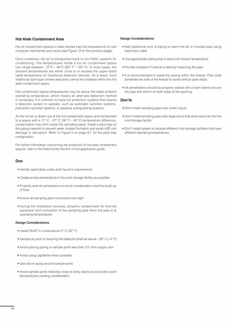
70
Hot Aisle Containment Area
Hot air containment spaces in data centres trap the exhausted air to cool
computer mainframes and racks (see Figure 12 on the previous page).
Once contained, the air is transported back to the HVAC systems for
conditioning. The temperatures inside a hot air containment space
can range between 27°C - 48°C (80° F - 120º F). In most cases, the
ambient temperatures are either close to or exceed the upper-listed
rated temperature for traditional detection devices. As a result, most
traditional spot-type smoke detectors cannot be installed within the hot
aisle containment space.
Hot containment space temperatures may be above the listed ambient
operating temperature, which means an alternate detection method
is necessary. It is common to have fire protection systems that require
a detection system to operate, such as automatic sprinkler systems,
precaution sprinkler systems, or gaseous extinguishing systems.
As the hot air is drawn out of the hot containment space and transported
to a space with a 17° C - 27° C (30° F - 40° F) temperature difference,
condensation may form inside the sampling pipes. Install a pipe trap on
the piping network to prevent water droplet formation and avoid ASD unit
damage or disruption. Refer to Figure 5 on page 67, for the pipe trap
configuration.
For further information concerning the protection of hot aisle containment
spaces, refer to the Data Centre Section of this application guide.
Dos
• Identify applicable codes and insurer’s requirements
• Create as few penetrations in the cold storage facility as possible
• Properly seal all penetrations to avoid condensation and the build-up
of frost
• Ensure all sampling pipe connections are tight
• During the installation process, properly compensate for thermal
expansion and contraction of the sampling pipe when the pipe is at
operating temperatures
Design Considerations
• Install FAAST in a area above 0° C (32° F)
• Sample air prior to reaching the detector shall be above -20° C (-4° F)
• Avoid placing piping or sample ports less than 3 ft. from supply vent
• Avoid using capillaries when possible
• Use silicon spray around sample ports
• Avoid sample ports relatively close to entry doors to avoid dew point
temperatures causing condensation
Design Considerations
• Add additional runs of piping to warm the air or insulate pipe using
heat trace cable
• Use appropriate piping that is listed with freezer temperature
• Provide insulation if cold air is directly impacting the pipe
• It is recommended to install the piping within the freezer. Pipe shall
penetrate the side of the freezer to avoid vertical pipe drops
• All penetrations should be properly sealed with a foam sleeve around
the pipe and silicon on both sides of the opening
Don’ts
• Don’t install sampling pipe near chiller inputs
• Don’t install sampling pipe near large doors that allow warm air into the
cold storage facility
• Don’t install system to sample different cold storage facilities that have
different operating temperatures

71
FAAST Fire Alarm Aspiration Sensing Technology®
Section 12
Dirty Environments
Application Overview
A wide range of environmental conditions are encountered in industrial/
manufacturing facilities: some environments may be controlled and
clean, while others may present dusty or dirty conditions during normal
operations. Often, the process and equipment that contributes to the
dusty/dirty condition requires an Early Warning Fire Detection (EWFD)
strategy. The combination of industrial or manufacturing downtime and
the replacement cost of the equipment, makes fire detection an extremely
important consideration. Aspirating smoke detection technology provides
fire detection that can not only withstand dirty or dusty environments, but
also offer effective early warning, without the false alarms and process
shut-downs. For many of these facilities, a small fire incident detected
early by aspirating smoke detection can result in the response needed to
prevent a large fire or explosion, loss of human life, and financial distress.
Dust is common in industrial or manufacturing environments, due to the
presence of coal, wood, or by-products of the process. Conventional
spot-type smoke detectors are counterproductive in these types of
environments for two main reasons. First, traditional spot detectors cannot
distinguish between dust and dirt particulates and products of combustion,
which significantly increases the occurrence of nuisance alarms. Second,
dust and dirt particulates can accumulate inside the spot-type smoke
detector and cause “dirty” detector warnings. Large dust particles can
also damage the electronic components of traditional smoke detectors,
which adds to costs, because frequent unit replacement may be required.
These factors make the installation of traditional spot-type smoke detectors
impractical in harsh environments.
The ASD system provides a practical and extremely effective alternative for
dirty environments, because the sampling pipe is located in the protected
space. The sampled air collected at the ASD unit passes through a filter
to remove particulates that would damage the sophisticated internal
components differentiating between smoke and dust.
Protected facility types include:
• Waste Handling Centres
• Zoos and Animal Stables
• Industrial/Manufacturing environments
Benefits of Aspirating Smoke Detection
ASD units provide early warning to detect products of combustion in the
early stages of fire growth. Earlier annunciation provides more time to
respond and possibly extinguish the fire before it spreads to other areas.
The ASD system has three significant advantages over the traditional
spot-type smoke detection system:
1. The electronics within some ASD units can distinguish between dust
and dirt particles and smoke particulates, which increases reliability
and decreases the potential for nuisance alarms
2. ASD units are sensitive enough to detect smoke particulates in the
fire incipient stage. ASDs can detect fires before flames are visible,
because of the active detection and the programmable sensitivity
alarm levels. This allows for greater response time for on-site personnel
3. ASD units are mounted in a “clean” environment where only the
sampling pipes are subjected to harsh conditions. In most ASD units,
the sampled air passes through a filtering system prior to entering the
sensing chamber. The filter removes the large particles that could
damage the sensing unit, making it cost effective
Use caution when installing an ASD unit in dusty environments. Dusty
environments like coal mines are often explosive in nature and may require
Intrinsically Safe (IS) devices; not all ASD units are listed or approved
for these atmospheres. Refer to manufacturer’s listings and approvals
whenever installing ASD units in these types of environments.
Best Design Practices
Certain precautions must be taken when installing an ASD system in a dirty
or dusty environment.
Additional Filters
It is sometimes necessary to install an additional filter on the sampling pipe,
before it enters the ASD unit. This can filter a larger number of particles
that would interfere with the ASD unit’s operation (See Figure 1 below).
Refer to the manufacturer’s installation guide for approved filters and their
installation.
Additional Filter Installed in
Sampling Pipe
Air Flow
Exhaust
ASD
Figure 1. Additional filter installed on the sampling pipe of the ASD system
Reference Detector
In waste handling facilities that burn solid waste to generate fuel, it is
common for particles and smoke produced by combustion to escape from
the incinerator during normal operation. If this type of smoke is injected into
the protected space and sampled, it could potentially cause a nuisance
alarm. To avoid nuisance alarms and to account for the period rise of the
ambient smoke level, a Reference Detector (RD) can be installed. The
reference detector is programmed separately from the other ASD units:
– The RD continuously samples air from outside of the protected areas
and produces a background reading of smoke and particles for this air
– For all the ASD units connected to the network, the internal
software of each ASD unit subtracts the RD background reading
from the ASD readings within their protected areas. If the resulting
reading difference is above the programmed sensitivity levels, the
corresponding ASD units activate an alarm

72
Drip Loop
Industrial environments also may have significant temperature and humidity
differences between the sampled space and the installed ASD unit space,
which means condensation could be a concern. To prevent moisture from
getting into the ASD unit and damaging the sensing chamber, it may be
necessary to install a drip loop to allow the moisture to condense, before
it enters the ASD sensing chamber. See Figure 2 below for the installation
of a drip loop in the sampling network. If there is an extreme temperature
difference, refer to the Extreme Temperatures section of this application
guide for further guidance.
Exhaust pipe back to
area being monitored
From air sampling network,
run additional horizontal piping
after exiting cold area. Sample
air temperature must be above
-4°F (-20°C) before entering
the detector.
Install drip loop on tee
fitting prior to entering
detector.
Always maintain water
halfway of drip loop.
To nearest drain or
condensate collector.
Piping shall be pitched
accordingly based on
the natural flexibility the
pipe will allow.
Maintain a
minimum of 16 in.
of vertical pipe.FAAST Detector shall be
mounted 5 ft.- 0 in. AFF.
Figure 2. Drip loop installed in sampling pipe
Figure 3. Waste on a tripper floor before recyclables are separated
Waste Handling Centre
After a product has served its purpose for the user, the remainder is
discarded as waste. The material is brought to a Waste Handling Centre
(WHC), for processing (see Figure 3 below). The Raw Municipal Waste
(RMW), is typically transported to the WHC by truck, and dumped onto a
tripper floor or waste pit; a large open space where the waste is collected
and the separation process begins.
Once on the tipper floor or in the waste pit, the RMW is separated from
the recyclable materials; plastics, metal, and glass are separated from
the wood, paper, cardboard, and ordinary trash. The recyclable materials
are then transported to the appropriate industry recycling centre and the
ordinary trash is processed in several methods, including:
• Compacted and sent to a landfill
• Sent directly to incinerators to generate steam to turn turbines or create
hot water
• Processed to create a refuse-derived fuel (RDF) (1). These processes
include a reduction in size and drying the product. In many cases the
waste is compacted to pallet or other similar form
As landfill space becomes more limited, more of the waste is being used
as an energy source and converted to RDF.
When the RMW is on the tripper floor or in the waste pit, it presents
significant fire hazards. Much of the RMW contains small amounts of
hazardous waste in the form of aerosol cans and traces of hazardous
chemicals from improperly discarded household cleaners, paint, and
similar chemicals.
Fire protection is difficult in waste handling centres due to the extremely
heavy flammable load and its distribution over a significant floor area.
Housekeeping is particularly important due to the heavy fuel load and the
numerous ignition sources. However, early warning of a potential fire is
important when there is such a significant fuel load distributed over a large
floor area. Ignition sources range from:
• Sparks from metal products during loading and while moving the RMW
on the tripper floor or in the waste pit
• Vehicles used to process the waste. In many facilities, small gas, LNG,
or propane-powered vehicles are used to move the RMW
• Welding or cutting torches used in vicinity of the RMW
• Carelessly discarding cigarettes or other smoking materials
Beam-type smoke detectors are used to detect smoke in the open areas of
many applications. However, if these types of detectors are hit or become
misaligned, they can generate nuisance alarms or troubles.
In an ASD system installation, the sampling pipe is extended into the
open tripper floor or waste pit and the ASD unit is installed in a clean
location. The large dust and dirt particles can be filtered out by either
(or both), an external or internal filter that samples the smaller dust and
smoke particulates in the sensing chamber. The following are the best
locations for the sampling pipe:
• At ceiling-level, clear of all moving equipment
• At exhaust grills to monitor the air as it is leaves the space
• Vertical sampling (similar to warehouse sampling), if the space is open
with a tall ceiling
• If an incinerator is present, a reference detector may be necessary or the
auto-learn feature utilised during commissioning to minimise nuisance
alarms.
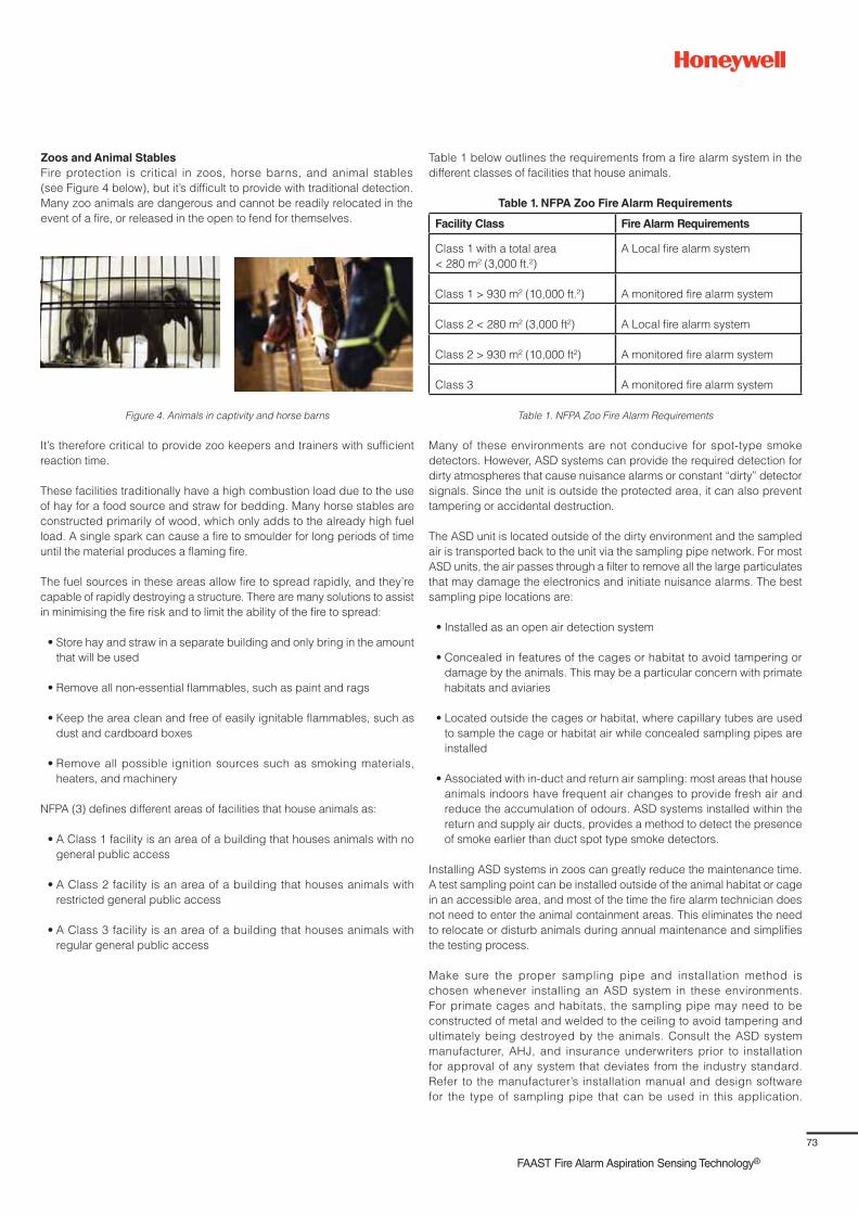
73
FAAST Fire Alarm Aspiration Sensing Technology®
Zoos and Animal Stables
Fire protection is critical in zoos, horse barns, and animal stables
(see Figure 4 below), but it’s difficult to provide with traditional detection.
Many zoo animals are dangerous and cannot be readily relocated in the
event of a fire, or released in the open to fend for themselves.
Figure 4. Animals in captivity and horse barns
It’s therefore critical to provide zoo keepers and trainers with sufficient
reaction time.
These facilities traditionally have a high combustion load due to the use
of hay for a food source and straw for bedding. Many horse stables are
constructed primarily of wood, which only adds to the already high fuel
load. A single spark can cause a fire to smoulder for long periods of time
until the material produces a flaming fire.
The fuel sources in these areas allow fire to spread rapidly, and they’re
capable of rapidly destroying a structure. There are many solutions to assist
in minimising the fire risk and to limit the ability of the fire to spread:
• Store hay and straw in a separate building and only bring in the amount
that will be used
• Remove all non-essential flammables, such as paint and rags
• Keep the area clean and free of easily ignitable flammables, such as
dust and cardboard boxes
• Remove all possible ignition sources such as smoking materials,
heaters, and machinery
NFPA (3) defines different areas of facilities that house animals as:
• A Class 1 facility is an area of a building that houses animals with no
general public access
• A Class 2 facility is an area of a building that houses animals with
restricted general public access
• A Class 3 facility is an area of a building that houses animals with
regular general public access
Table 1 below outlines the requirements from a fire alarm system in the
different classes of facilities that house animals.
Table 1. NFPA Zoo Fire Alarm Requirements
Facility Class Fire Alarm Requirements
Class 1 with a total area
< 280 m² (3,000 ft.²)
A Local fire alarm system
Class 1 > 930 m² (10,000 ft.²) A monitored fire alarm system
Class 2 < 280 m² (3,000 ft²) A Local fire alarm system
Class 2 > 930 m² (10,000 ft²) A monitored fire alarm system
Class 3 A monitored fire alarm system
Table 1. NFPA Zoo Fire Alarm Requirements
Many of these environments are not conducive for spot-type smoke
detectors. However, ASD systems can provide the required detection for
dirty atmospheres that cause nuisance alarms or constant “dirty” detector
signals. Since the unit is outside the protected area, it can also prevent
tampering or accidental destruction.
The ASD unit is located outside of the dirty environment and the sampled
air is transported back to the unit via the sampling pipe network. For most
ASD units, the air passes through a filter to remove all the large particulates
that may damage the electronics and initiate nuisance alarms. The best
sampling pipe locations are:
• Installed as an open air detection system
• Concealed in features of the cages or habitat to avoid tampering or
damage by the animals. This may be a particular concern with primate
habitats and aviaries
• Located outside the cages or habitat, where capillary tubes are used
to sample the cage or habitat air while concealed sampling pipes are
installed
• Associated with in-duct and return air sampling: most areas that house
animals indoors have frequent air changes to provide fresh air and
reduce the accumulation of odours. ASD systems installed within the
return and supply air ducts, provides a method to detect the presence
of smoke earlier than duct spot type smoke detectors.
Installing ASD systems in zoos can greatly reduce the maintenance time.
A test sampling point can be installed outside of the animal habitat or cage
in an accessible area, and most of the time the fire alarm technician does
not need to enter the animal containment areas. This eliminates the need
to relocate or disturb animals during annual maintenance and simplifies
the testing process.
Make sure the proper sampling pipe and installation method is
chosen whenever installing an ASD system in these environments.
For primate cages and habitats, the sampling pipe may need to be
constructed of metal and welded to the ceiling to avoid tampering and
ultimately being destroyed by the animals. Consult the ASD system
manufacturer, AHJ, and insurance underwriters prior to installation
for approval of any system that deviates from the industry standard.
Refer to the manufacturer’s installation manual and design software
for the type of sampling pipe that can be used in this application.

74
Animal cage areas are frequently cleaned by spraying down the entire
space with a hose; there may be high humidity levels in the atmosphere
during this time. It may be necessary to install a drip loop (See Figure 2
on page 72), to prevent moisture from entering the sampling chamber and
damaging the ASD unit.
Manufacturing/Industrial
The primary life safety feature of most manufacturing/industrial
occupancies is a properly designed, installed, and maintained automatic
sprinkler system. However, in many instances the equipment used in
the manufacturing process is critical to business operation and requires
additional fire protection systems. Fire protection challenges for these areas
include:
• Dirty atmospheres where spot-type smoke detectors are not the best option
• Access to spot-type detectors is limited due to high ceilings or
obstructions
• Early warning of the presence of smoke is critical to a specific piece
of equipment
• Smoke detection system to initiate a fire suppression or extinguishing
system when a reliable and sensitive detection system is necessary
• Chemical environments that may be corrosive to electronics
Environments Containing Combustible Dust
Traditional spot detectors may not be practical for manufacturing and
industrial plants, due to the significant amounts of dust in the atmosphere.
Please note the difference between ordinary dust that makes smoke
detection difficult and combustible dust that is hazardous. For ordinary
dust, waste recycling centres, in-filters (see Figure 1 on page 71), can
be installed to minimise nuisance alarms. However, combustible dust has
specific requirements.
NFPA (4) defines combustible dust as “finely divided solid particles that
present a dust fire or dust explosion hazard when dispersed and ignited in
air.” Examples of manufacturing and industrial facilities where combustible
dust is present include:
• Wood processing plants
• Food processing that contains floor, grain or corn
• Coal processing plants and coal fired power plants
Caution should be taken whenever installing an ASD unit in environments
that contain combustible dust. These environments are often explosive in
nature or have the potential for a dust flash fire; as a result, they may require
Intrinsically Safe (IS) devices, and not all ASD units are listed or approved
for these atmospheres. Refer to the manufacturer’s listings and approvals
whenever installing ASD units in these environments.
In the US, atmospheres that contain dust are classified by NFPA (5) as
either Class II Division 1 or Class II Division 2, and each of these classes
has specific requirements for the installation of electrical equipment. For
these atmospheres, special precautions are taken to eliminate all potential
ignition sources.
Prior to installing an ASD unit and sampling pipe in Class II Division
1 or Class II Division 2 atmospheres, refer to the manufacturer’s
recommendations and installation manual.
Environments Containing Hazardous Chemical Vapour
Many manufacturing and industrial processes utilise flammable gases,
flammable liquids that produce vapours, or combustible liquids that
produce vapours: all of these fuels present a significant challenge for fire
protection.
Caution should be taken whenever installing an ASD unit in environments
that contain or generate chemical vapours. These environments are often
explosive or corrosive in nature and could damage the electronics of the
ASD unit. Refer to the manufacturer’s listings and approvals whenever
installing ASD units in these types of environments.
The atmosphere may also contain corrosive chemical vapours that could
potentially damage either the sampling pipe or the electronic equipment.
In the US, atmospheres that contain these conditions are classified by
NFPA (5) as either Class I Division 1 or Class I Division 2; each of these
classes has specific requirements for the installation of electrical equipment.
For these atmospheres, special precautions are taken to eliminate all
potential ignition sources.
Prior to installing an ASD unit and sampling pipe in Class I Division 1 or
Class I Division 2 atmospheres, refer to the manufacturer’s recommendations
and installation manual.
Motor Control Rooms
A Motor Control Centre (MCC), the main control room that houses all
the electronic control equipment, is a common place for an ASD system
within an industrial plant. A MCC is usually a modular cabinet system for
powering and controlling motors, and an MCC room may have a
6 m (20 ft.) ceiling, with air supply and returns mounted at a lower level.
Rows of electrical cabinets are typically 2.4 m (8 ft.) tall and cable tray
tiers are mounted at 3.6 m - 5.4 m (12 ft. - 18 ft.)
Spot-type smoke detectors have difficulty sensing fires in MCC rooms
because of their airflow patterns, which can heavily dilute smoke and
prevent it from reaching the detectors. Also, because electrical cabinets
generally have gaskets on their doors with no vents, fire can potentially
develop for a long time inside the cabinet (see Figure 5 below), before
enough heat and smoke escape to trigger an alarm in a standard detector.
Heat build-up in these high-ceilinged rooms could also stop the cooler
smoke from rising to the ceiling and triggering an alarm. If these MCCs
Sampling Pipe
To FAASTDetector
Motor Control Equipment
Capillary Tube
Figure 5. Sampling motor control units utilising capillary sampling points

75
FAAST Fire Alarm Aspiration Sensing Technology®
are critical for production, then fire damage to electrical cabinets could
negatively impact.
Cabinets should have sufficient leakage when providing air sampling within
a closed cabinet, in order to allow minimal air movement for the sample
point and avoid a vacuum situation inside the cabinet.
ASD systems provide various sensitivity levels that can detect very small
quantities of smoke, mitigating the effects of dilution and enabling a
response before costly damage or loss can occur. ASD units provide fully
programmable alarm levels, so strategic responses can be customised to
specific smoke thresholds for the facility.
When installing capillary sampling points, ensure all tubing has the same
size and length. The tube length should not exceed 8 m (26 ft.) and the
sampling hole is installed near the top of the cabinet.
Common Issues/Application Troubleshooting
It’s not uncommon for the sampling holes and filters to become clogged
when installing an ASD system in dusty or dirty environments. It is critical
to regularly clean the ASD sampling holes and pipe, to keep the system
operating at the optimal level.
It may be necessary to install an additional filtration system on the sampling
pipe before the air reaches the ASD unit. Additional purging of the sampling
pipe may also be necessary to keep sampling holes clear of obstructions.
A corresponding maintenance regime should be implemented to minimise
dust accumulation in the sampling pipe and the sampling holes, as well as
to minimise clogs in the ASD unit filter.
ASD units are shipped with factory default sensitivity levels, which may
not be appropriate for applications where dirt and small traces of smoke
particulates are present in the air. If the default alarm sensitivity thresholds
are maintained, the ASD unit will not provide the optimal detection and
could potentially transmit nuisance alarms, making the system unreliable.
For these environments, it is important to utilise the auto-learn feature or a
reference detector if necessary.
Dos
• Identify applicable codes and insurer’s requirements
• Replace the filter often to avoid clogging
• Install an in-line filter if larger particles need to be removed from the
sampled air
• Purge sampling pipe network regularly to ensure sampling holes and
pipes are clear of obstructions
• Use the auto-learn feature to determine obscuration levels and alarm
threshold settings
• Clean sampling holes regularly to keep clean
• If condensation is a possibility, install a drip loop
• Ensure all sampling pipe connections are tight
Don’ts
• Install the ASD unit in a location that has the potential of being hit by
machinery or operating equipment
• Install the ASD unit in an area that is frequently washed down
• Install ASD units in Class I or Class II environments if the unit is not
UL-listed for these classes of environment
References
1. Dungan, K., Storage and Handling of Solid Fuels, NFPA Fire Protection
Handbook, Volume 1, 20th Edition, Section 7, Chapter 1, page 7-13,
National Fire Protection Association, 2008
2. NFPA 82: Standard for Incinerators and Waste and Linen
Handling Systems and Equipment, (Section 8.2), 2014 edition,
National Fire Protection Association
3. NFPA 150: Standard on Fire and Life Safety in Animal Housing
Facilities (Sections 6.2.1.1, 6.2.1.2, and 6.2.1.3), 2013 edition,
National Fire Protection Association
4. NFPA 499: Recommended Practice for the Classification of
Combustible Dusts and of Hazardous (Classified) Locations for
Electrical Installations in Chemical Process Areas, 2013 Edition,
National Fire Protection Association
5. NFPA 70: National Electrical Code (Article 500), 2014 Edition,
National Fire Protection Association

76
Section 13
Transportation Facilities
Application Overview
Transportation facilities are environments in which a lot of people, baggage,
or goods move through complex structures located both above ground and
underground. Public transportation hubs may include train stations, city
rapid transit stations (i.e., metro, buses and tramway), airport terminals, and
ferry slips and taxi stands. Modern hubs allow multiple direct connections
between the airport transportation mode and other modes, such as
car (parking lots), train, or metro. Public transport centres (also called
transit centres) have for years served to connect train stations and bus
transportation depots. For example, South Station (see Figure 1 below), in
Boston, Massachusetts constitutes a major transportation hub, with railway,
bus, and metro services. It should be noted that in Figure 1 (besides the
transportation of people), a transportation hub usually contains waiting
areas where people can eat or shop in leased areas, located in large open
spaces or concourses.
Figure 1. Boston South Station
Figure 2. Subway transportation hub
Figure 3. The metro subway control room inside the
Maryland Transit Administration (MTA) Control center (4)
(Source: http://en.wikipedia.org/wiki/File:SouthStationInterior.jpg and http://www.
south-station.net/PDF/South%20Station%20Directory%20-%20Portrait%20-%20
2013-01-23.pdf )
Public transportation hubs vary in size and importance, and parts of a
hub could be underground or above ground level. A hub can connect
several terminals with different modes of transportation, which are managed
by different entities. Within a subway transportation system, a station
connecting several lines could be considered a hub. People walk from the
station entrance to the train platforms, but the trains and tunnels pose risks
to the people in or near these locations (see Figure 2 above).
A transportation hub requires energy and power facilities to support the
equipment operations and maintain comfortable environments for the
public. Areas that house utilities, air handling systems, or emergency
systems (often called “ancillary areas”), may need to be protected against
fire threats because they can be essential to the transportation hub’s
operations.
Behind-the-scenes air traffic control operations are also critical for airports
because they continuously move planes and passengers to destinations
around the World. For example, the London Terminal Control Centre
manages air traffic for five London area airports: a small fire event in such
a facility can result in staff evacuation and the large-scale disruption of
hundreds of inbound and outbound flights. Hours or days of rescheduled
flights may then be needed to get passengers to their planned destinations.
Many rail systems are managed through Operations Control Centres (OCC)
(see Figure 3 below), using a Supervisory Control And Data Acquisition
(SCADA) system, which enables the remote control and monitoring of field
equipment located in the stations and power sub-stations. Other important
SCADA system functionality includes the “control of traction power, control
of emergency ventilation systems, and monitoring of drainage pumps
and various equipment alarms, including intrusion monitoring of remote
locations (1, 2).” The SCADA infrastructure may be integrated with a
data centre, processing real-time information reported from the entire
transportation network. Due to its extreme importance on operational
continuity, the OCC is provided with battery power supplies and/or
generator rooms in the case of network electrical power loss.
Fires can directly impact transportation facilities’ operations. In a few cases
there have been serious life safety consequences, but rail or air service
disruptions and inconvenienced passengers are far more common. A few
examples follow:
• The 1987 King’s Cross Metro station (London, UK) fire started under
a wood escalator and rapidly engulfed most of the station with smoke
that resulted in 31 fatalities and numerous injuries. The fire exposed the
paths of egress from train platforms to outside of the subway station,
leading to a rapid smoke spread via all the vertical and narrow spaces,
such as escalators and elevator shafts
• A 2009 electrical fire in the air traffic control tower at the Prague Airport
caused it to cease operations and suspend or divert flights for several
hours. No occupants were injured and no essential equipment was
damaged, but the fire created so much smoke that the tower had to be
closed. Arrivals were sent to other airports and departures were delayed,
since all flights in and out of Prague Airport were suspended
• 20th June, 2010: a fire in Chicago’s subway system left at least 12 people
with smoke-related injuries and five of them in a serious condition.
Railroad ties in a tunnel near an underground station caught fire after
apparently being ignited by sparks from passing trains (4)

77
FAAST Fire Alarm Aspiration Sensing Technology®
• June 2011: Take-offs and landings were suspended at the Dallas Love
Field after a small fire broke out on the fifth level of the FAA Air Traffic
Control Tower one afternoon. Air traffic controllers evacuated the tower
for more than a half hour, resulting in a number of diverted flights
• 14th August, 2012: an apparent tunnel cable fire in New York City (5)
affected six of the lines that connect Brooklyn to Manhattan, as the tunnel
was close to a hub station in Brooklyn
• 13th February, 2013: an engine burned out on a Philadelphia subway
train, causing it to fill with smoke. The fire was placed under control in
about 15 minutes, causing no injuries (6)
• 5th June, 2013: a power cable caught fire in a tunnel near one Moscow
metro station, forcing the evacuation of thousands of rush hour
commuters. Fifty-nine people required medical attention and eleven
were hospitalised (7)
• 28th November, 2013: heavy amounts of water may have caused
cables to short out between two subway stations in Brooklyn, New York,
disrupting the service of three subway lines for six hours but injuring
no one (8)
• 13th May, 2014: an electrical fire triggered by a bathroom exhaust fan
forced the evacuation of an air traffic control facility near Chicago, halting
all flights at the city’s two airports and shutting down one of the nation’s
busiest airspaces. The evacuation of the smoky air-traffic control facility,
combined with thunderstorms, resulted in the disruption of nearly half the
flights at O’Hare airport and nearly one-third at Midway airport.
Benefits of Aspirating Smoke Detection
The presence of escalators, elevator shafts, vertical stairs combined
with train tunnels, interconnected corridors, and constantly opening and
closing doors creates alternating local drafts and turbulent air flows within
transportation facilities. Large open spaces such as atria and concourses
also complicate smoke detection, and smoke dilution and stratification
may challenge the capabilities of point smoke detectors. The installation
flexibility of vertical ASD pipes, combined with their very low thresholds,
overcomes smoke dilution and stratification challenges.
In-duct smoke detection may be required in the numerous service ducts
of an airport or rail station, as well as in other conduits or ventilation shafts.
Point smoke detectors may be difficult to install and maintain in these
locations, especially for large open spaces, but ASD sampling pipes
provide more effective protection.
Aspirating smoke detection (ASD) has many benefits for transportation
facilities, including:
– Low threshold values, which can help detect fires during the incipient
fire stage, even if smoke levels are quite low. This early fire detection
increases the time for safe evacuation as well as for fire suppression
actions, which can reduce property loss and business interruption
– An ability to actively sample air in non-quiescent environments,
such as in air movements created by trains going through tunnels,
in elevator shafts, and in data centres
– An ability to actively sample the inside of electronic cabinets
which are essential to the control, notably the cabinets used in
transportation hub control rooms
– An ability to be used around potential fire sources like high voltage
cables, switch gear, and power supply batteries. Early detection is
essential for these valuable, substation pieces of equipment
– An ability to actively sample air in large open spaces, such as in atria
and concourses, where smoke stratification can occur (since smoke
generated from small fires would not have enough buoyancy to reach
the ceiling of such spaces)
– An ability to differentiate smoke particulates from dust, reducing false
alarms while monitoring dusty service ducts and tunnels
– An ability to detect fires in concealed spaces and any other areas
where testing and maintenance could be difficult for access
Design Best Practices
Aspirating smoke detection can play an important role in transportation
facilities’ fire protection strategies by accommodating diverse structures
both above ground and underground. Some of the main transportation
applications for aspirating smoke detection include:
Airport Terminals and Concourses: The large multi-level spaces and
concourse areas of airports provide the circulation space needed for
large populations to flow between ticketing areas and boarding gate
areas. Retail facilities, restaurants, and business lounges are commonly
provided to service passengers before and after their travels. Due to the
large populations and multi-level configurations found in airports, smoke
management systems and air handling systems are often provided
Figure 4. – Airport ticketing concourse and Escalator pedestrian circulation zone.
Figure 5. – Airport shopping concourse and high ceiling space.

78
to prevent smoke recirculation and/or exhaust smoke in the event of a
significant fire. Aspirating smoke detection is well suited to provide
effective smoke detection in the high-ceiling spaces and complex ceiling
configurations that may be encountered. The smoke movement systems
are intended to provide adequate time for a safe evacuation of occupants
through the airport atrium and concourse spaces. However, a false alarm
that initiates evacuation alarms can be highly disruptive in an airport
environment (flight delays). Aspirating smoke detection offers stability
against false alarms and can provide pre-alerts needed for airport staff
to investigate developing situations prior to the need for an evacuation.
Air Traffic Control Facilities: Efficient and uninterrupted airport operations
depend on air traffic control services that track and direct aircrafts on
the ground and in airspace. The electronic systems, radar systems,
communication links, and power supplies are critical to maintaining air and
ground safety, as well as to expediting the flow of aircraft and passengers.
Air Traffic control Towers (ATCTs), and terminal radar approach control
facilities (TRACON), require a high standard of fire protection to assure
continuous and uninterrupted operations. Automatic smoke detection and
alarm systems are very important for these facilities. Smoke detectors,
including aspirating smoke detection, should be considered for locations
near all probable sources of fire or smoke, including mechanical equipment
rooms, return air plenums, electrical/electronic rooms, facility operational
areas, etc. Aspirating smoke detection is crucial in electronic rooms to
provide the earliest warning of incipient conditions.
Train/Subway Facilities: NFPA 130, Standard for Fixed Guide-way and
Transit Systems, is recognised around the World for its guidance on station
and rail tunnel fire safety design. The train-way typically serves as the
means of egress for passengers in the event of train evacuation. In an
enclosed train way/ tunnel, enclosed exits and cross-passageways serve as
a point of safety and a means of egress. NFPA 130 requires an enclosed or
tunnel train-way 61 m (200 ft.) or more in length with emergency ventilation
to maintain a tenable environment along the path of egress from a fire
incident. Modern transit station design consists of a large space formed
by the passenger platform and contiguous train way, possible intermediate
mezzanine level(s), and several continuous connections to the street
level above. Modern stations often include extensive use of escalators
and elevators for efficient passenger movement. NFPA 130 requires the
installation of emergency ventilation in enclosed stations to maintain tenable
conditions during passenger evacuation. The basis of station platform
design is the NFPA 130 requirement: to evacuate all passengers from the
platform in four minutes, and to reach a point of safety within six minutes.
There is significant emphasis on emergency ventilation systems under the
provisions of NFPA 130, and accordingly there must be appropriate means
to detect smoke and initiate fans and equipment for emergency ventilation.
Aspirating smoke detection provides this capability and can operate in the
dirty/dusty airflow conditions found in train ways and enclosed stations.
NFPA 130 also specifies fire detection functions for key operational areas
of rail system facilities, which can be well served by aspirating detection
systems:
– Traction power sub-stations and signal bungalows require heat and
smoke detectors to be installed and connected to the operations
control centre (OCC)
– The OCC, is to “be protected by fire detection, protection, and
extinguishing equipment so that there will be early detection and
extinguishment of any fire in the OCC”. In addition, fan units serving
train control and communications rooms should be protected by fire
detection, protection, and extinguishing equipment so that there will
be early detection and extinguishment of any fire involving these
units.
Figure 6 – Train platform and train way
Figure 7. Sampling electronic/electrical cabinets utilising capillary sampling points
Critical Utility / Equipment Areas: Power systems, pumping stations (in
tunnels), air traffic control towers, SCADA control systems, and other critical
equipment and utility areas are key to the operations of transportation
facilities. Given the risk of loss of transportation facility operations due
to a fire in utility and critical equipment areas, it’s important to identify
even the smallest fire events, such as precursor smouldering or equipment
overheating. Aspirating smoke detection can provide the high sensitivity
and continuous sampling of low quantities of smoke that may be needed
to identify and avert downtime. Some aspirating smoke detectors can also
withstand dirty/dusty environments found in tunnels, some utility equipment
rooms, and baggage handling equipment areas, while providing effective
early detection without concern for false alarms and process or equipment
shut-down.
High voltage substations, data centres, and OCCs contain electric
cabinets and electronic cabinets incorporating fire loads. Sampling each
cabinet’s internal atmosphere via capillary tubes allows active and quick
smoke detection in the early fire stages (see Figure 7 below). This is
particularly important for assuring the operation and business continuity
of transportation hubs, since any malfunction of the electronic cabinets may
cause a disruption in the management of this complex system.
le ni le i a ine
Sampling Pipe
ASD
apilla e

79
FAAST Fire Alarm Aspiration Sensing Technology®
The intensive use of electric power generates heat in these areas, requiring
an air conditioning system to cool the heat-sensitive equipment and
ensure it doesn’t malfunction. Installing additional sampling pipes in the
air conditioning system’s return air vent would also allow smoke detection..
Tunnels and Ducts: Service ducts and tunnels are potential fire locations
in the underground part of a transportation hub. With an ASD system, pipe
can be positioned in the ducts and the ASD unit placed in a service room
for easy access. This configuration offers low maintenance and testing
costs, and the ASD system’s advanced electronics and filter decreases
false alarms and differentiates between fire smoke particulates and the
dust particles in service ducts and tunnels.
Common Issues/Application Troubleshooting
Coordination and interfaces with an automatic fire suppression system
and emergency protocols
It is important to coordinate the smoke detection system with the fire
suppression system. Carefully consider design practices to determine when
the system should activate the fire suppression system. It is recommended
to review the discharging of a fire suppression system with the local
Authority Having Jurisdiction (AHJ). This also applies to the fire alarm panel,
to determine when an alarm signal should be sent to a central monitoring
station and when the emergency protocols should be activated to start
emergency evacuation. Such precautions allow evacuation in the safest
conditions possible, especially for passenger cars.
Aspirating smoke detection’s (ASD) remote detector programmability
and other benefits make it suitable for a transportation and logistics hub
configuration. However, consider the following factors when using an ASD
within this type of configuration:
• The sensitivity levels and alarm thresholds should be as low as possible,
in order to detect the smallest production of smoke and to allow fire
investigation
• The designer needs to verify the airflow and direction of air within the
space to maximise the system’s effectiveness. The sampling points should
be installed in the direction of the airflow, especially in the air return ducts.
The sampling response time can be improved by avoiding high and low
velocity air flows perpendicular to the sampling holes. Sampling holes on
the inlet pipes installed in ducts, return air grills, or air conditioning unit
ducts (where high velocity air will be passing over the sampling pipe),
should be facing 20° 45° from the air flow (see Figure 8 below)
20º−45ºFrom direction
of Air Flow
A. Airflow StreamlinesB. Low velocity (high static pressure) areaC. High velocity (low static pressure) area
AB
CPort orientation
Figure 8. Sampling hole orientation for pipes installed in ducts, return air grills,
or on air conditioning unit ducts with high velocity circulating air
• For large detection systems with many sampling holes, the designer
needs to take smoke/air dilution into consideration. A greater volume
of air returns to the aspirating detector the more sampling holes the air
sampling pipe contains, and this can dilute the quantity of smoke within
the detection chamber and delay the alarm initiation time
• The location of the sampling holes within the detection network is a
concern. The further the sampling hole is located from the aspirating
smoke detector, the more air/smoke dilution occurs, which could delay
the alarm initiation time. It should be noted that the system design must
comply with the restrictions of the detector. In other terms, the ASD system
must not exceed the pipe and sample hole maximum requirements for the
lowest thresholds of smoke the system is planned to detect.
• Special care will be given to the design of air sampling pipes, sampling
hole locations, and spacing for large open space and duct applications.
Programming consideration of the aspirating smoke detector during
commissioning process
During the commissioning process, the installing contractor needs to
properly program the alarm thresholds and sensitivity levels. These
programmable sensitivity levels and alarm thresholds could significantly
impact the performance of the aspirating smoke detector. Consider the
following in regard to programming:
• Typically aspirating smoke detectors are shipped with default settings
from the factory. These settings are not appropriate for all detection
systems. These settings are to be considered generic and may be too
sensitive or not sensitive enough for a specific application. The ASD
designer must determine the alarm levels and program the sensor
accordingly. The sensitivity levels and alarm thresholds are determined
by a combination of the computer-based calculation program, the hazard
being protected, detection system size, and engineering judgment
• Programmable sensitivity levels are another significant issue impacting
the performance of aspirating smoke detection systems. The detectors
contain sophisticated electronics and software that allow the device to
be programmed to a wide range of sensitivity levels. However, if these
alarm levels are not programmed properly, then the smoke within the
sensing chamber may exceed the desired sensitivity and cause a delay
in the alarm signal initiation
• When required in Europe and the US, the ASD unit programming must
also comply with the sensitivity levels prescribed by the EN-54 and NFPA
standards, respectively
Time delays for initiating further actions
Time delays are also included for the activation of trouble and alarm signals
at the detector. These delays can be set for a range of times, typically from
10 - 30 seconds. Give careful consideration when programming the time
delays; the greater the delay, the longer it takes for the detector to initiate
an alarm signal.

80
Dos
• Identify applicable codes and insurer’s requirements
• Refer to the appropriate sections of ASD application guides for:
– Large and open spaces (for ASD sampling of atria and concourses)
– Data centres
– In-cabinets (in the “Principle” guide)
– Harsh environments (for ASD sampling of dusty tunnels)
– In-duct (for ASD sampling of HVAC ducts)
• Identify and understand any smoke control and/or pressurisation
schemes that need to be implemented upon smoke detection. Important
smoke control functions can be properly initiated, when using associated
outputs of aspiration smoke detectors
• Provide protection against smoke-contaminated air flows by installing
air sampling points for makeup air units, air handling units, and key air
return points (air grills or dry coil returns to ducts or plenums). For air
returns, arrange the sampling ports so that each covers no more than
0.4 m² (4 ft²) of the return opening
• Identify critical or high-risk equipment installations that should have
localised area or in-cabinet air sampling for earliest warning and
initiation of human response
• Confirm and implement how the alert settings and fire alarm settings
of aspirating systems are to be integrated to initiate the following if
applicable: 1) power shut-down, 2) fixed fire suppression systems,
3) air handling shut-down and associated damper or door closures,
4) smoke control and room pressurisation operations
• When NFPA 130, Standard for the Protection of Semiconductor
Fabrication Facilities, applies, the following is recommended
– Consider aspirating smoke detection for traction power sub-stations,
signal bungalows, and the OCC
– Transmit alarms from aspirating smoke detection to a constantly
supervised location
• When EN 54-20 (Fire detection and Fire Alarm Systems – Part 20:
Aspirating Smoke Detectors), applies, the following is recommended:
– Review the environment to identify the nature of the air flows and
criticality of equipment or processes to be protected. This will help
identify the sensitivity Class of the aspirating system that needs to
be installed in any given area
– Identify where Class C, aspirating type smoke detection is to be
applied
– Identify where Class B, aspirating type smoke detection is to be
applied. Class B systems are used when increased sensitivity is
needed to compensate for moderate dilution effects due to high
ceilings or moving air flows. Also, for protection of vulnerable and
critical items
– Identify where Class A, aspirating type smoke detection is to be
applied. Class A systems are used in areas having very high air
movement and high dilution and the very earliest warning is needed
to protect highly critical business operations
References
1. American Public Transportation Association (APTA), Recommend
Practice, Securing Control and Communications Systems in Transit
Environments, Part 1: Elements, Organisation and Risk Assessment/
Management (APTA SS-CCS-RP-001-10), July 2010
2. http://www.arinc.com/sectors/transportation/rail/control_systems/
scada.html
3. https://technical.ly/baltimore/2013/03/22/
reinvent-transit-hackathon-transportation/
4. http://www.cnn.com/2010/US/06/20/chicago.subway.fire/index.html
5. http://abclocal.go.com/wabc/story?section=resources/
traffic&id=8773530
6. http://philadelphia.cbslocal.com/2013/02/13/
patco-subway-train-catches-fire-in-center-city/
7. http://www.cnn.com/2013/06/05/world/europe/moscow-subway-fire/
index.html
8. http://www.nydailynews.com/new-york/brooklyn/
subway-fire-disrupts-brooklyn-bound-trains-article-1.1532340
9. NFPA 130: Fixed Guide-way Transit and passenger Rail Systems,
2014 Edition, National Fire Protection Association

81
FAAST Fire Alarm Aspiration Sensing Technology®
Section 14
Historic and Cultural Buildings
Application Overview
Historic buildings and buildings that house cultural resources require
careful approaches to fire protection, due to the unique risks and
circumstances they pose. Such buildings include historically registered
landmarks, religious buildings, museums, libraries, and art galleries, as
well as any building or structure presenting a unique or iconic design and
aesthetics. Others contain invaluable artefacts or heritage assets. Some
historical buildings were built using archaic construction techniques and
with materials that may no longer be available. Buildings can not only be
historic in nature and difficult to re-create if damaged, but their contents
can also be even more valuable and irreplaceable. Heritage and cultural
collections include priceless artwork, documents, and books that are
culturally and/or historically significant. Therefore, the fire safety measures
applied in historic and cultural facilities need to provide a satisfactory level
of fire protection and pose little or no harm to the historical fabric or valuable
contents of the building.
Minnesota History Center
State of Virginia – Capitol Rotunda
Figure 1. Examples of historical buildings
Figure 2. and Figure 3 New York State Museum Storage Room (cardboard boxes)
and Carnegie Museum of Natural History (“Big bone” collection storage room with
wood boxes)
Aspirating smoke detection offers solutions for historic/cultural environments
to achieve a proper balance. Historic and cultural buildings are often public
venues with significant crowds, and facilities like food service and child
care areas are needed to accommodate the visiting public. Life safety risks
should also be addressed in these applications.
Fires involving historical structures and cultural facilities can be very costly,
not only in terms of damage to the structure and building contents (artefacts)
but also because of the loss of business operations. Consider the Louvre
in Paris and the British Museum in London, which draw approximately 9
million and 6 million visitors each year, respectively. A major fire in either of
these two museums would generate significant revenue losses.
Back-of-house or non public areas may often present significant fire loads
or unusual fire risks, such as store rooms in museums and conservation/
preservation laboratories that use flammable liquids or other chemicals.
Museums and libraries use a large amount of plastic-based storage
containers, including film storage, magazine dividers, storage boxes
and bins, clothing bags, and various covers. Smoke produced by the
combustion of these plastic materials may be thick and acrid, which can
damage the museum and library collections in the area of fire origin and
throughout the connected facility. It should be noted that the electrostatic
characteristics of these plastic covers and bags have a tendency to attract
smoke particles to clothing and other fabrics.
From a fire protection perspective, book stacks and stored collections are
often more comparable to warehouses than typical business occupancies.
Figure 4 on the following page, presents a basic depiction of the fire
environment that may develop within a historic/cultural structure. The
fire releases heat, light, and other products of combustion. The possible
negative consequences directly attributable to the fire are as follows:
• Human injury or fatalities
• Reduced visibility or blocked passages of building spaces
• Fire and smoke damage or destruction of building contents
• Fire and smoke damage or destruction of the building structure
• Interruption of operations
• Financial Loss

82
Figure 4 .– Fire Environment in a Heritage Environment
ot mo e ye
em ti o t e i e i o me t
i ePl me
De en ing i ime
ea an e e an g e
ning e
a ia i n an e ea i i le in a e an l a
i le lig
a ia i n an e
amagea e
e mal a ia i n
Indirect consequences of a fire can also affect historic/cultural buildings
and increase the need for a prompt response. The following indirect
consequences are a special concern for the historic fabric and contents:
• Water damage
• Physical damage due to fire suppression efforts with hose streams
• Damage due to mishandling or moving of objects in emergency fire
conditions
• Damage due to a cleaning or restoration process after a fire
• Threat of theft during fire
Benefits of Aspirating Smoke Detection
Aspirating smoke detection (ASD) has many benefits for historic buildings,
including:
– Low threshold alert and alarm values, which can help detect fires
even if smoke levels are quite low during the incipient fire stage. This
early fire detection increases the time for safe evacuation, allows for
fire suppression actions to reduce potential damage, and reduces
the risk of business interruption
– Active air sampling in large open spaces such as in atria, concourses,
and high ceiling spaces where smoke stratification is possible
(smoke generated from small fires may not have enough buoyancy
to reach the ceiling of such spaces)
– Fire detection in concealed spaces and any other areas where testing
and maintenance could be difficult
– An ability to be integrated in the historic structure and fabrics with
minimal alteration, visual or otherwise
– An ability to include different levels of warnings and alarms to provide
an opportunity for building occupants to investigate and manually
use fire suppressants, before an automatic fire suppression system
starts to operate
– The possibility to sample in-duct for high airflow and atmospheres
that contain controlled HVAC configurations
Design Best Practices
The long list of fire risks associated with historic and cultural resource
buildings is addressed with several key documents, which outline
guidance and approaches for developing appropriate fire protection in
such buildings. Since the 1940’s, the US-based National fire Protection
Association has fostered an interest in historic buildings and contents. The
NFPA’s Technical Committee on Cultural Resources maintains two standards
documents specific to the fire risks and concerns for preservation in historic
and cultural buildings:
• NFPA 909 “Code for the Protection of Cultural Resource Properties –
Museums, Libraries and Places of Worship”
• NFPA 914 “Code for Fire Protection of Historic Structures”
In recent years, efforts have been made in British, European, and
ISO standards development ,for comparable NFPA documents, including:
• BS 7913: 2013 “Guide to the Conservation of Historic Buildings”
• Scotland Technical Advice Note 28 (TAN 28) – “Fire Safety Management
in Heritage Buildings”
These documents contain concepts and considerations to select and
implement automatic fire detection in historic buildings. They not only
include early fire detection goals, but also the goals to minimise/avoid
damage or irreversible changes to the historic fabric.
NFPA 909 “Code for the Protection of Cultural Resource Properties
– Museums, Libraries and Places of Worship”, adopts such goals and
objectives related to:
– Collection preservation: associated with a reasonable level of
protection for the stored collections against fire, products of
combustion, fire suppression agents and activities
– Building preservation: associated with a reasonable level of
protection for unique characteristics and fabric of these buildings
against fire, products of combustion, fire suppression agents and
activities
– Continuity of operations: associated with a reasonable level of
protection against “disruption of facility operations consistent with
the organisation’s mission and protection goals”.
Cultural buildings may also be classified as historic structures; in such
cases, additional fire protection goals and objectives may be also
considered. NFPA 914, “Fire Protection of Historic Structures”, adds to the
life safety goals and historic preservation goals as follows:
– To minimise the damage to historic structures and contents from
fire events, including the effects of the fires and the fire suppression
actions
– To maintain and preserve the original space configuration of the
historic building
– Minimising alterations, destruction, or loss of historic material or
design
In other countries such as Scotland, TAN 28 provides a philosophy and
considerations for heritage buildings similar to and consistent with those
outlined by NFPA.

83
FAAST Fire Alarm Aspiration Sensing Technology®
Integration in the historic/cultural environments
The use of conventional ceiling-mounted fire detection devices is often
considered adverse to the historic fabric or desired aesthetic design of
a cultural space. Aspirating smoke detection will minimise, if not almost
eliminate, this intrusion into a space. ASD systems use sampling holes of
limited size that draw air into the system, where they’re sampled for smoke
particulates in an ASD unit remotely located in a separate room or closet.
The sampling holes can be installed flush with ceilings or placed in ornate
or articulated ceilings where the ceiling features act as camouflage. In
addition, the sampling pipe network and capillary tubes can extend from
the pipes concealed behind ceilings, walls, or installed in void spaces.
Capillary tubes are flexible; for example, they can follow the curves of a
supporting chain of a monumental chandelier (see Figure 5 below) or be
installed in the crown moulding at the ceiling level. In many instances, the
sampling holes are small and cannot be seen from the floor level.
Airflow in large open spaces and ducts
Many culturally significant buildings contain valuable artwork, which
means temperature and humidity are regulated by systems that affect the
space’s airflow. These systems often contain high-quality filters to remove
airborne dust and particulates that may degrade valuable artwork, which
also requires regulated HVAC systems. For buildings with highly regulated
HVAC systems, it is possible to use in-duct ASD units.
Sampling point in base of the chandelier
Sampling pipesVoid Space
Capillary sampling tube attached to chandelier chain
Figure 5. Capillary sampling tube installed in the supporting
chain or the base of a chandelier
Historic buildings may contain large open spaces such as churches, atria,
museum concourses, and large open stairwells, where phenomena such as
smoke dilution and smoke stratification may be a challenge for traditional
smoke detectors. Vertical ASD pipes’ installation flexibility and their low
thresholds and sensitivities, can overcome smoke dilution and stratification
challenges.
As indicated above, ASD sampling hole locations of interest would be:
• Installed in the ceiling, since the sampling holes are small in diameter
the holes are often overlooked or cannot be seen from the floor level
• Capillary tubes and sampling holes can be installed in crown moulding
and can be incorporated into intricate and ornate ceilings
• For large ballrooms and open areas, capillary sampling tubes can be
installed along the chain of a chandelier, or a small hole can be drilled
in the base of the chandelier to conceal a sampling point
• In return and supply air distribution systems
Construction differences - historic verses modern buildings
Due to their period of construction and their historical character, it’s often
difficult to retrofit old buildings with fire protection measures required by
modern building codes. The Common construction issues include:
– A historic staircase, with all rooms opening directly to the staircase
(preventing the use of fire compartments, such as self-closing fire
doors)
– Building does not contain a suitable fire suppression system
due to the appearance of sprinklers, nozzles, hose valves, or fire
extinguisher cabinets
In such cases, automatic fire detection is important so that a fire can be
detected in its incipient stage (before it produces flames), and maintains
the historical fabric and without impacting the aesthetics of the building.
Aspirating smoke detection is also important for initiating a staff response
and/or occupant evacuation in many unique historic scenarios.
Critical detection needs for areas without automatic sprinkler
protection
Automatic fire sprinkler systems are a valuable protection feature for many
historic and cultural buildings. The piping, fittings, and space needed for
routing and concealing sprinkler systems, however, can make it difficult
to install such systems without subjecting the historic fabric to undue
damage. In cultural resource properties the curators may be averse to
allowing sprinkler systems in areas housing water-sensitive collections.
In these circumstances, the need for prompt fire detection can be met
using aspirating smoke detection. Aspirating smoke detection systems
can provide the high sensitivity and continuous sampling of low quantities
of smoke that may be slowly distributed and easily diluted by the airflow
environment.
For European-based properties, EN 54-20 can be helpful in the
decision-making process for determining the desired detection sensitivity
for various areas of historic/cultural buildings. EN 54-20 specifies a
classification system for aspirating detection according to Class A, B, and
C categories, as noted in Table 1 on the following page. Depending on the
room or space and other attributes (ceiling height, historic value of contents,
airflow environment, etc.), Class A, B, or C type aspirating systems may
be appropriate. Certainly, those facilities with high ceilings and important

84
collections would favour EN 54-20 Class A or B systems when aspirating
technology is being installed.
Table 1 - Classification of Aspirating Smoke Detection
Systems According to EN 54-20
Sensitivity Area of Application
Class A Very high Very early warning fire detection,
building areas with high levels of air
movement /air changes
Class B Enhanced/High Very early warning fire detection
, building areas housing valuable
goods and/or processes that need
early detection
Class C Normal/standard Application for general fire protec-
tion, similar to standard point or spot
detector applications
Common Issues/Application Troubleshooting
Aspirating smoke detection’s (ASD), remote detector programmability and
other benefits make it suitable for historical buildings or structures. However,
during the design phase, consider the following factors when using an ASD
within this type of configuration:
• The sensitivity levels and alarm thresholds should be as low as
possible in order to detect the smallest production of smoke, to allow
fire investigation
• The designer may need to verify the airflow and direction of air within
the space to maximise the system’s effectiveness
• For a large detection system with many sampling holes, the designer
needs to take smoke/air dilution into consideration. A greater volume
of air returns to the aspirating detector the more sampling holes the air
sampling pipe contains, which can dilute the quantity of smoke within
the detection chamber delay the alarm initiation time
• The location of the sampling holes within the detection network is a
concern. The further the sampling hole is located from the aspirating
smoke detector, the more air/smoke dilution occurs, which could delay
the alarm initiation time
• Special care will be given to the design of air sampling pipes, sampling
hole locations, and spacing for large open space and duct applications
Programming consideration of the aspirating smoke detector during
commissioning process
The installing contractor needs to properly program the alarm thresholds
and sensitivity levels during the commissioning process. These
programmable sensitivity levels and alarm thresholds could significantly
impact the performance of the aspirating smoke detector. Consider the
following in regard to programming:
• Typically aspirating smoke detectors are shipped with default settings from
the factory. These settings are not appropriate for all detection systems.
These settings are to be considered generic and may be too sensitive
or not sensitive enough for a specific application. The ASD designer
must determine the alarm levels and program the sensor accordingly
The sensitivity levels and alarm thresholds are determined by a
combination of the computer-based calculation program, the hazard
being protected, detection system size, and engineering judgment
• Programmable sensitivity levels are another significant issue impacting
the performance of aspirating smoke detection systems. The detectors
contain sophisticated electronics and software that allow the device to
be programmed to a wide range of sensitivity levels. However, if these
alarm levels are not programmed properly, then the smoke within the
sensing chamber may exceed the desired sensitivity and cause a delay
in the alarm signal initiation
Time delays for initiating further actions
Time delays are also included for the activation of trouble and alarm signals
at the detector. These delays can be set for a range of times, typically from
10 - 30 seconds. Give careful consideration when programming the time
delays; the greater the delay, the longer it takes for the detector to initiate
an alarm signal.
Dos
• Identify applicable heritage codes and guidance, including
re lated assessments, requi rements, and per formance
criteria specified for fire detection systems. BS 7913: 2013,
TAN 28 (Scotland), NFPA 909, NFPA 914 or others may be applicable.
• Refer to the appropriate sections of ASD application guides for:
Large and open spaces (for ASD sampling of atria and high ceiling areas)
• In-duct monitoring (for ASD sampling of HVAC ducts)
• Identify critical historic spaces or high-risk collections that should have
earliest warning and initiation of human response
• Confirm and implement how the alert settings and fire alarm settings
of aspirating systems are to be integrated to initiate the following if
applicable: 1) power shut-down, 2) fixed fire suppression systems ,
3) air handling shut-down and associated damper or door closures,
4)smoke contro l and room pressur isat ion operat ions,
5) evacuation alarms
When EN 54-20 (Fire Detection and Fire Alarm Systems – Part 20:
Aspirating Smoke Detectors), applies the following is recommended
- Review the heritage environment to identify the nature of the airflows and
criticality of contents to be protected. This will help identify the sensitivity
Class of air the aspirating system that needs to be installed in any given
area
- Identify where Class C, aspirating type smoke detection is to be applied
- Identify where Class B, aspirating type smoke detection is to be
applied. Class B systems are used when increased sensitivity is needed
to compensate for moderate dilution effects due to high ceilings or
moving airflows. Also, for protection of vulnerable and critical items
- Identify where Class A, aspirating type smoke detection is to be applied.
Class A systems are used in areas having very high air movement
and high dilution and the very earliest warning is needed to protect highly
valuable or sensitive collections

85
FAAST Fire Alarm Aspiration Sensing Technology®
Don’ts
• Don’t exceed the recommended detector or sampling point spacing of
applicable standards or insurance carrier requirements
• Don’t use detectors that are not listed or approved for air velocities
and temperatures that will be encounter in the airflow paths of historic
cultural facilities
• Don’t design the aspirating system to exceed the transport time
requirements of installation standards

86
Section 15
Glossary of Terms
Additive Effect – Effect occurring when smoke particulates enter multiple
sampling holes, causing the overall effective sensitivity of the air sampling
system to exceed the sensitivity from a single sampling hole on the system.
Air Traffic Control Tower – Tower facility at airports housing the equipment
and personnel that manage and direct aircraft take-offs, landings, and
ground traffic.
Aspirating Smoke Detector (ASD) System – Smoke detection system that
utilises an aspirator (fan) to actively draw air through a pipe network from a
space potentially exposed to fire or smoke back to a smoke sensing device.
Aspirating Smoke Detector (ASD) or Unit – Enclosure or physical housing
with an apparatus that consists of various components, including sensor(s)
for detection of smoke particles and an integral aspirator (fan), which
continuously draws air and aerosols through a sampling device.
Capillary Tube – Extension of the air sampling pipe network that is
significantly smaller than the main sampling pipe, typically made of plastic
or metal tubing.
Central office – A structure used by telecommunications companies
to house equipment needed to direct and process telephone calls and
data traffic. Telephone Central Offices (COs) are also known as telephone
switching centres, wire centres, or public exchanges.
Cleanroom – A room with a controlled concentration of airborne
particles that contains one or more clean zones. A clean zone is an area
that meets a specified airborne particulate cleanliness class, per the
ISO Standard 14644-1 or US Federal Standard 209E (Note: 209E cancelled in 2001).
Cold Aisle Containment Arrangement - Arrangement usually installed in
data centres, with a physical separation between the cold air supply and
hot air exhaust by enclosing the cold air supply aisle.
Collections – Prehistoric/historic objects, works of art, scientific specimens,
religious objects, archival documents, archaeological artefacts, library
media, and cultural materials that are assembled, stored, displayed, and
maintained for the purpose of preservation, research, study, exhibition,
publication, or interpretation.
Cultural Resource Properties – Culturally significant buildings, structures,
sites, or portions thereof, that house collections for museums, libraries, and
places of worship.
Cumulative Effect – See “additive effect”.
Dilution effect – Effect occurring in the case of smoke being drawn into a
single sample hole and then transported through the piping network past
other sampling holes that are aspirating clean air (no smoke concentration).
When this volume of clean air is mixed with the smoke laden air being
transported into the detection chamber the quantity of smoke latent air is
then diluted.
Duct Smoke Detector – Smoke detector designed to sense smoke in the
air flowing into or through an air duct system.
Early Warning – A signal provided by a system that detects fire in its earliest
stages of development to enhance the opportunity for appropriate fire safety
actions (e.g., evacuation, manual fire suppression).
Early Warning Fire Detection (EWFD) systems – From NFPA 76: detection
system that uses smoke, heat, or flame detectors to detect fires before
high heat conditions threaten human life or cause significant damage to
telecommunications service.
Electronic Data Processing (EDP) – Equipment that is used for processing,
receiving, transmitting, or storing electronic data.
EN 54-20 Classification – An aspirating smoke detector of
Class A, B, or C sensitivity determined per the European Standard
EN 54-20, which specifies the requirements, test methods, and performance
criteria for aspirating smoke detectors used in buildings.
Class A – From European EN 54-20 classification: very high sensitivity,
for example the detection of smoke particles in extremely diluted
concentrations, such as the detection necessary for a clean room.
Class B – From European EN 54-20 classification: enhanced or high
sensitivity. For example the detection of smoke particles at enhanced
sensitivity for protection of vulnerable or valuable items, such as areas
that contain computers or electronic equipment.
Class C – From European EN 54-20 classification: smoke detection at
normal sensitivities, where the detection system is spaced and the detector
sensitivity is similar to a traditional spot smoke detectors or beam type
smoke detection system.
Extreme Environment – Environment with extreme conditions of
temperature, airborne contamination, vapours, fumes, humidity, dust, and
dirt.
Historic Building – From NFPA 914: A building that is designated, or
deemed eligible for such designation, by a local, regional, or national
jurisdiction as having historical, architectural, or cultural significance.
Historic Fabric – From NFPA 914: original (or added) construction materials,
features, and finishes of a buildings that existed during a time period or
era that is deemed to be architecturally or historically significant, or both.
Historic Structure – From NFPA 914: A building, bridge, lighthouse,
monument, pier, vessel, or other construction that is designated or that
is deemed eligible for such designation by a local, regional, or national
jurisdiction as having historical, architectural, or cultural significance.
Hot Aisle Containment Arrangement – Arrangement usually installed in
data centres, for which a physical separation is provided between the
cold air and hot air exhaust by enclosing the cold aisle. This is intended
to capture all the hot air exhaust and return it to the cooling areas. With
containment limited to the hot aisle, the remainder of space outside the
hot aisle becomes a room flooded with cold air from the HVAC/CRAC unit.
In-Cabinet Sampling –Method involving the installation of air sampling
holes to monitor specific piece(s) of equipment located within a larger open
space. The piece of equipment is typically self-contained within a cabinet
or a computer rack.
Large Duct – Duct with a width greater than 0.9 m (3 ft.) and less than
2 m (7 ft.).

87
FAAST Fire Alarm Aspiration Sensing Technology®
Localised Sampling – Method involving the protection of specific
equipment/area within a larger open space. Localised sampling may be a
rack sampling system in a large open warehouse or monitoring the exhaust
of a row of computer cabinets.
Maintenance Test Point – Point installed at the end of a piping network
specifically used to test the ASD system.
Maximum Transport Time – Maximum allowable time it takes the smoke
particulate to travel from the most remote sampling hole to the ASD
sampling chamber.
NEBS – The Network Equipment Building Standards or NEBS (as defined
by Telcordia) are the most widely known and used set of safety, spatial, and
environmental design guidelines applied to telecommunications equipment.
The requirements address how to design and build reliable electronics for
telecommunications network use.
Primary Sampling – Sampling method relying on the airflow created by an
air conditioning or ventilation system to carry air (and smoke if present), to
the location of sampling points. For areas that have high airflow, such as
data centres or clean rooms, the primary sampling location would be at
return air grills, AHUs, or air return ducts.
Restricted Access – Areas that require special permission to enter. Such
areas include portions of buildings where people are under restraint or
security (prisons or psychiatric wards). Special pieces of equipment are
secured, as well as hazardous locations.
Return Air Grill – Grill through which, return air is extracted from a ventilated
area, usually not provided with an adjustment for volume of airflow.
Sampling Hole – Any point in the sampling pipe network that draws air
into the sampling pipe.
Sampling Pipe – The pipe that sampled air flows through, from the
protected area to the ASD unit.
Secondary Sampling – Sampling method used in conjunction with Primary
Sampling, involving the configuration of sampling holes at the ceiling level
in similar locations as traditional spot-type smoke detectors. The sampling
holes would be spaced in accordance with the appropriate code or
standard.
Signal-Processing Equipment – The electronic equipment that performs
signal-processing operations such as switching or transport for audio,
video, and data signals.
Small Duct – Duct with a width less than 1 m (3 ft.).
Standard Fire Detection (SFD) systems - From NFPA 76: systems that use
fire detection-initiating devices to achieve certain life safety and property
protection, in accordance with applicable standards.
Telecommunications Equipment – The wire, cable, and electrical/
electronic equipment, including signal-processing equipment, cable
entrance equipment, power equipment, main distribution frame equipment,
and standby engine equipment.
Telecommunications Equipment Area – The area or enclosed room of a
telecommunications facility that contains telecommunications equipment.
Terminal Radar Approach Control (TRACON) - facility housing the
equipment and personnel that manage and direct departing and
approaching aircraft for the airspace (50 miles or 80.5 km diameter zone)
of assigned airports.
Transport Time – Time it takes for the smoke particulates to travel from the
sampling hole to the ASD sampling chamber.
Very Early Warning Fire Detection (VEWFD) systems – From NFPA 76:
systems that detect low-energy fires before the fire conditions threaten
telecommunications service.

Honeywell
Tel: +44 (0) 116 246 2000
Fax: +44 (0) 116 246 2300
Email: [email protected]
140 Waterside Road
Hamilton Industrial Park
Leicester
LE5 1TN