ASME Journal paper
8
N. Nallusamy Department of Mechanical Engineering, Sri Venkateswara College of Engineering, Pennalur, Sriperumbudur, 602 105 Tamil Nadu, India e-mail: [email protected] e-mail: [email protected] R. Velraj Institute for Energy Studies, College of Engineering, Anna University, Chennai 600 025, India e-mail: [email protected] Numerical and Experimental Investigation on a Combined Sensible and Latent Heat Storage Unit Integrated With Solar Water Heating System The present work investigates, theoretically and experimentally, the thermal performance of a packed bed combined sensible and latent heat storage unit, integrated with the solar water heating system. A one-dimensional porous medium approach with the finite differ- ence technique is used to develop the numerical model to obtain the temperature profiles of both the phase change material (PCM) and heat transfer fluid (HTF), and the molten mass fraction of the PCM at any axial location of the cylindrical storage tank during the charging process. The model also incorporates the effect of the varying fluid inlet tem- perature to accommodate the actual conditions that prevails in the solar collector. Ex- perimental apparatus utilizing paraffin as PCM, which is filled in high-density polyeth- ylene spherical capsules, is constructed and integrated with a solar flat plate collector to conduct the experiments. The water used as HTF to transfer heat from the solar collector to the storage tank also acts as a sensible heat storage (SHS) material. The results of the numerical model are compared into the experimental results of the temperature profile for various porosities and HTF flow rates. It is found that the results of the numerical model are in good agreement with the experimental results. The performance parameters, such as instantaneous heat stored, cumulative heat stored, and charging rate are also studied in detail. DOI: 10.1115/1.3197600 Keywords: thermal energy storage, sensible heat storage, latent heat, PCM, packed bed, porous medium modeling 1 Introduction Renewable energy supplies are steadily gaining importance in all the countries. In particular, solar energy, being nonpolluting, clean, and inexhaustible, has received wide attention among sci- entists and engineers. Though there are many advantages, an im- portant factor is that solar energy is a time dependent energy source with an intermittent character. Hence, some form of ther- mal energy storage TES is necessary for the most effective uti- lization of this energy source. For many systems, a packed bed provides an effective means of energy storage. The earlier forms of packed bed energy storage units relied solely on the sensible heat capacity of solid bed par- ticles for storing thermal energy. This form has been satisfactorily employed for various applications. However, certain applications may impose a limitation on the size and weight of the packed bed system utilized. In such cases, utilization of only the sensible heat capacity of a certain material for energy storage may not be effi- cient. The energy density of the storage medium may be greatly enhanced if a material that undergoes a phase transition from solid to liquid latent heat of fusion is employed. The storage media used by these systems called phase change material PCM, offer advantages such as much greater heat storage per unit volume compared with SHS, and isothermal behavior during charging heat storage and discharging heat release processes. Though latent heat storage LHS systems have desirable characteristics, they are not in commercial use as much as SHS systems because of the poor heat transfer rate during heat storage and recovery process. The main reason is that during phase change, the solid- liquid interface moves away from the convective heat transfer surface during charging in the cool storage process, and discharg- ing in the heat storage process due to which the thermal resis- tance of the growing layer of solidified PCM increases, resulting in a poor heat transfer rate. The combined sensible and latent heat storage system eliminates the difficulties experienced in the SHS and LHS systems to certain extend, and posses the advantages of both systems. The present work deals with the study of combined sensible and latent heat storage system integrated with the solar water heating system. A lot of researchers conducted analytical, numerical, and ex- perimental investigation of the thermal performance of SHS sys- tems in the past. Beasley and Clark 1 provided an excellent review of such efforts in the case of packed bed SHS systems. Dincer et al. 2 presented a detailed investigation of the availabil- ity of SHS techniques for solar thermal applications, selection criteria for SHS systems, the economics, and environmental im- pacts of SHS systems. Thermal performances of solar water heat- ing systems integrated with the SHS system were investigated experimentally by many researchers, viz, Pereira et al. 3, Sodha et al. 4, and Reddy et al. 5. Thermal energy storage using the latent heat of PCMs has re- ceived considerable attention in the past 3 decades only. Several previous investigators addressed TES in PCMs in a wide variety of geometries. Zalba et al. 6 presented a detailed review on thermal energy storage using PCMs focusing on three aspects: Contributed by the Solar Energy Engineering Division of ASME for publication in the JOURNAL OF SOLAR ENERGY ENGINEERING. Manuscript received May 23, 2007; final manuscript received April 4, 2008; published online September 17, 2009. Re- view conducted by Rainer Tamme. Journal of Solar Energy Engineering NOVEMBER 2009, Vol. 131 / 041002-1 Copyright © 2009 by ASME Downloaded 09 Nov 2009 to 218.248.24.3. Redistribution subject to ASME license or copyright; see http://www.asme.org/terms/Terms_Use.cfm
Transcript of ASME Journal paper

1
acepsml
eutemsccetuac�l
ifiv
J
Downlo
N. NallusamyDepartment of Mechanical Engineering,
Sri Venkateswara College of Engineering,Pennalur,
Sriperumbudur, 602 105 Tamil Nadu, Indiae-mail: [email protected]
e-mail: [email protected]
R. VelrajInstitute for Energy Studies,
College of Engineering,Anna University,
Chennai 600 025, Indiae-mail: [email protected]
Numerical and ExperimentalInvestigation on a CombinedSensible and Latent Heat StorageUnit Integrated With Solar WaterHeating SystemThe present work investigates, theoretically and experimentally, the thermal performanceof a packed bed combined sensible and latent heat storage unit, integrated with the solarwater heating system. A one-dimensional porous medium approach with the finite differ-ence technique is used to develop the numerical model to obtain the temperature profilesof both the phase change material (PCM) and heat transfer fluid (HTF), and the moltenmass fraction of the PCM at any axial location of the cylindrical storage tank during thecharging process. The model also incorporates the effect of the varying fluid inlet tem-perature to accommodate the actual conditions that prevails in the solar collector. Ex-perimental apparatus utilizing paraffin as PCM, which is filled in high-density polyeth-ylene spherical capsules, is constructed and integrated with a solar flat plate collector toconduct the experiments. The water used as HTF to transfer heat from the solar collectorto the storage tank also acts as a sensible heat storage (SHS) material. The results of thenumerical model are compared into the experimental results of the temperature profile forvarious porosities and HTF flow rates. It is found that the results of the numerical modelare in good agreement with the experimental results. The performance parameters, suchas instantaneous heat stored, cumulative heat stored, and charging rate are also studiedin detail. �DOI: 10.1115/1.3197600�
Keywords: thermal energy storage, sensible heat storage, latent heat, PCM, packed bed,porous medium modeling
IntroductionRenewable energy supplies are steadily gaining importance in
ll the countries. In particular, solar energy, being nonpolluting,lean, and inexhaustible, has received wide attention among sci-ntists and engineers. Though there are many advantages, an im-ortant factor is that solar energy is a time dependent energyource with an intermittent character. Hence, some form of ther-al energy storage �TES� is necessary for the most effective uti-
ization of this energy source.For many systems, a packed bed provides an effective means of
nergy storage. The earlier forms of packed bed energy storagenits relied solely on the sensible heat capacity of solid bed par-icles for storing thermal energy. This form has been satisfactorilymployed for various applications. However, certain applicationsay impose a limitation on the size and weight of the packed bed
ystem utilized. In such cases, utilization of only the sensible heatapacity of a certain material for energy storage may not be effi-ient. The energy density of the storage medium may be greatlynhanced if a material that undergoes a phase transition from solido liquid �latent heat of fusion� is employed. The storage mediased by these systems called phase change material �PCM�, offerdvantages such as much greater heat storage per unit volumeompared with SHS, and isothermal behavior during chargingheat storage� and discharging �heat release� processes. Thoughatent heat storage �LHS� systems have desirable characteristics,
Contributed by the Solar Energy Engineering Division of ASME for publicationn the JOURNAL OF SOLAR ENERGY ENGINEERING. Manuscript received May 23, 2007;nal manuscript received April 4, 2008; published online September 17, 2009. Re-
iew conducted by Rainer Tamme.ournal of Solar Energy Engineering Copyright © 20
aded 09 Nov 2009 to 218.248.24.3. Redistribution subject to ASME
they are not in commercial use as much as SHS systems becauseof the poor heat transfer rate during heat storage and recoveryprocess. The main reason is that during phase change, the solid-liquid interface moves away from the convective heat transfersurface �during charging in the cool storage process, and discharg-ing in the heat storage process� due to which the thermal resis-tance of the growing layer of solidified PCM increases, resultingin a poor heat transfer rate. The combined sensible and latent heatstorage system eliminates the difficulties experienced in the SHSand LHS systems to certain extend, and posses the advantages ofboth systems. The present work deals with the study of combinedsensible and latent heat storage system integrated with the solarwater heating system.
A lot of researchers conducted analytical, numerical, and ex-perimental investigation of the thermal performance of SHS sys-tems in the past. Beasley and Clark �1� provided an excellentreview of such efforts in the case of packed bed SHS systems.Dincer et al. �2� presented a detailed investigation of the availabil-ity of SHS techniques for solar thermal applications, selectioncriteria for SHS systems, the economics, and environmental im-pacts of SHS systems. Thermal performances of solar water heat-ing systems integrated with the SHS system were investigatedexperimentally by many researchers, viz, Pereira et al. �3�, Sodhaet al. �4�, and Reddy et al. �5�.
Thermal energy storage using the latent heat of PCMs has re-ceived considerable attention in the past 3 decades only. Severalprevious investigators addressed TES in PCMs in a wide varietyof geometries. Zalba et al. �6� presented a detailed review on
thermal energy storage using PCMs focusing on three aspects:NOVEMBER 2009, Vol. 131 / 041002-109 by ASME
license or copyright; see http://www.asme.org/terms/Terms_Use.cfm

mtt
pctsavtcpacmtPso
tntfiotsBmsfmccufPottBhwtgrg
feBsamrTscmtpcepcivt
0
Downlo
aterials, heat transfers, and applications. Majority of the litera-ure research on the LHS system is performed for the shell andube configurations.
A limited number of studies have been published on the thermalerformance of the LHS systems employing PCM in sphericalapsules for cool and heat-thermal storage applications. Cool-hermal storage systems have been studied for the efficient use oftored cooling produced during off-peak hours to provide daytimeir conditioning/refrigeration applications. Chen and Yue �7� de-eloped a one-dimensional porous medium model to determinehe thermal characteristics of ice-water cool storage in packedapsules for air conditioning. Comparing this theory with the ex-erimental data of temperature profiles of PCM �water� and cool-nt �alcohol� for various porosities, flow rates and different inletoolant temperatures show good agreements. Nallusamy et al. �8�ade a case study of PCM based packed bed storage system in-
egrated in a building air conditioning system installed in Tidelark, Chennai. The modes of operation, advantages of such aystem for energy management, and suitability of this concept forther applications were highlighted in their paper.
Many researchers made theoretical and experimental investiga-ions on various types of heat-thermal storage systems. Anantha-arayanan et al. �9� developed a computer model based on thewo-phase Schumann model for the estimation of temperature pro-les of the solid and the fluid along the length of the packed bedf eutectic Al–Si PCM encapsulated spherical capsules as func-ions of distance along the bed, and time during a series of heattorage and utilization cycles. Air was used as HTF in their study.easley and Ramanarayanan �10� developed a computationalodel to study the transient thermal response of a packed bed of
pheres containing a PCM using one-dimensional separate phaseormulations with the porous medium approach. Results from theodel were compared with the experimental results of a commer-
ial size thermal storage bed, packed with polypropylene spheresontaining paraffin for both the heat storage and recovery periodssing air as HTF. Adebiyi et al. �11� developed a computer modelor the packed bed TES system formed by many independentCM capsules, and presented the results obtained in the exercisef the model. The model is used to investigate the effect of theemperature and mass flow rate of the HTF �flue gas�, porosity ofhe bed, and dimensions of the vessel on the system performance.arba and Spiga �12� analyzed the behavior of encapsulated saltydrates used as PCM in a heat transfer system of a domestic hotater tank employing three different geometrical configurations of
he PCM containers. Their study shows that spherical capsulesive the largest energy density and the most rapid charge andelease times when compared against the slab or the cylindricaleometry.
Very limited number of studies are found on the thermal per-ormance of LHS systems �employing PCM in various geom-tries� integrated with solar water heating applications. Bansal anduddhi �13� developed a mathematical model for a collector cum
torage system for quasisteady-state conditions using stearic acids PCM. Numerical calculations have been performed usingodified Hottel–Whiller–Bliss equations for a wide range of pa-
ameters to investigate the applicability of the developed model.he calculations clearly show that a PCM collector cum storageystem has definite advantages over a system that has a separateollection and a separate storage unit. Alva et al. �14� developed aathematical model using a lumped capacitance method to inves-
igate the thermal performance of the PCM integrated solar flatlate collector. The results of the lumped capacitance method areompared with the one-dimensional enthalpy based finite differ-nce method. The results of the PCM integrated collector pro-osed are very encouraging, and the authors concluded that theonventional water storage tanks may be replaced for the PCMntegrated solar collectors. Esen et al. �15� made a numerical in-estigation on the thermal performance of solar water heating sys-
ems integrated with a cylindrical LHS unit using various PCMs.41002-2 / Vol. 131, NOVEMBER 2009
aded 09 Nov 2009 to 218.248.24.3. Redistribution subject to ASME
Mehling et al. �16� presented the experimental and numericalsimulation results of the energy storage density of the solar hotwater system using different cylindrical PCM modules. Their re-sults show that adding PCM modules at the top of the water tankwould give the system higher storage density, and compensateheat loss in the top layer.
The objective of the present work is to predict, numerically andexperimentally, the thermal behavior of a packed bed combinedsensible and latent heat-thermal energy storage system integratedwith the solar water heating system. A one-dimensional porousmedium model is developed to obtain the temperature profiles ofboth the PCM and HTF. A packed bed combined storage systemcontaining PCM encapsulated spherical capsules surrounded by aSHS material is developed. Experiments are performed to exam-ine the effects of HTF flow rates and porosities on the perfor-mance of the TES unit subjected to varying HTF inlet tempera-tures. Comparison of numerical predictions with the experimentaldata of temperature profiles of both HTF and PCM during charg-ing process shows good agreement.
2 Modeling of Combined Storage SystemThe model is developed using a porous medium approach for
the estimation of temperature profiles of the PCM and the HTFalong the length of a packed bed as a function of time during aseries of heat storage cycles. The model ignores the thin encapsu-lation shell on the PCM, and considers only the PCM inside thecapsule in the calculations. The basic assumption on which porousmedium models rest is that the PCM capsules behave as a con-tinuous medium, and not as a medium comprised of independentparticles. As a result, coupled heat transfer equations may readilybe formulated for both the PCM and HTF.
Figure 1 shows the general layout of the packed bed storagesystem. The PCM in solid state is enclosed in spherical shapedcapsules, which are packed in a cylindrical storage tank. The bedis divided into a series of small height layers within which boththe PCM and HTF temperatures are assumed to be uniform withineach phase. A heat transfer fluid flows over the PCM capsulesthrough the tank. The HTF exchanges its energy to the PCM cap-sules during the charging process �heat storage�. As the analysis ofthe discharging process �heat release� is similar to that of thecharging process, only the charging process is considered in thepresent study.
The model is derived from the general energy conservationequation with the following assumptions: �1� The storage tank is
Fig. 1 General layout of the packed bed combined storagesystem
assumed to be well insulated; �2� the thermophysical properties of
Transactions of the ASME
license or copyright; see http://www.asme.org/terms/Terms_Use.cfm

Prncc
eao
cs
ervitr
ttatsdab
fdsf
c
J
Downlo
CM and HTF are constant; �3� there is no heat conduction in theadial direction; �4� free convection effects inside the capsules areeglected; and �5� the overall heat transfer coefficient between theapsules and the fluid is assumed to remain constant during theharging period.
Based on the above assumptions, a general formulation of thenergy balance is established at the respective regions of the HTFnd PCM separately, and the following governing equations werebtained.
2.1 For HTF. An energy balance equation is obtained for theontrol volume �CV� considered in the TES tank having the crossectional area Ac and height L
Qx = Qx+dx + �As�Tf − Tp� +�
�t�MfcfTf� +
�
�x�MfcfufTf� �1�
In Eq. �1� the first term on the left hand side represents thenergy entering the CV. The four terms on the right hand sideepresent the energy leaving the CV, energy transferred by con-ection from the HTF to the PCM, the rate of change in thenternal energy of the HTF, and energy change due to the flow ofhe HTF in the CV, respectively. After simplification and rear-angement, the following equation was obtained:
�AcL� fcf� �Tf
�t+ uf
�Tf
�x� = � fAcL� �2Tf
�x2 � − �As�Tf − Tp� �2�
2.2 For PCM. In the case of PCM, the energy is stored insidehe capsules as sensible heat until the PCM reaches its meltingemperature. As the charging process proceeds, energy storage ischieved by melting the PCM at a constant temperature. Finally,he PCM becomes superheated. The energy is then stored as sen-ible heat in liquid PCM. Therefore, three time domains are ad-ressed to model the complete charging phenomena in the PCM,s suggested by Chen and Yue �7�, and the equations are givenelow
�1 − ���pscpsAcL� �Tp
�t� = �PsAcL� �2Tp
�x2 �+ �As�Tf − Tp� for time domain-I
�3�
��Mpliqh��t
= �As�Tf − Tpm� for time domain-II �4�
�1 − ���plcplAcL� �Tp
�t� = �plAcL� �2Tp
�x2 �+ �As�Tf − Tp� for time domain-III
�5�By applying the finite difference method, the above equations
or three time domains of energy storage in packed capsules areiscretized by second-order central finite difference operators inpace, and forward difference approximations in time, with theollowing initial and boundary conditions.
Initial conditions are
at t = 0, Tf = Tfi, Tp = Tpi �time domain-I�
at t = tpm and Mpliq = 0, Tf = Tfm,
Tp = Tpm �time domain-II� �6�
at t = tpl and Mpliq = 1, Tf = Tfl,
Tp = Tpl �time domain-III�
Note that Tpi is the initial temperature of PCM in the spherical
apsules, Tfi is the initial HTF temperature, and Tf ,in is the HTFournal of Solar Energy Engineering
aded 09 Nov 2009 to 218.248.24.3. Redistribution subject to ASME
inlet temperature. tpm is the time when Tp=Tpm and tpl is the timewhen sensible heating of liquid PCM begins. Tfm is the tempera-ture of the HTF during the PCM melting process. Mpliq is themolten mass of the PCM, and it is noted that Mpliq=0 implies thatthe PCM in spherical capsules is completely in the solid state.
Boundary conditions applicable for all three-time domains aregiven below
at x = 0, Tf = Tf ,in,�Tp
�x= 0 �for all t�
�7�
at x = L,�Tf
�x= 0,
�Tp
�x= 0 �for all t�
The boundary conditions in Eq. �7� represent no heat losses at theinlet and outlet of the storage tank.
In order to accommodate the time varying fluid inlet tempera-ture �Tf ,in� in the model, Tf ,in is calculated continuously with re-spect to time, using Eq. �8� as given below
Tf ,in�t� = Tf ,in�0� + �Tf ,in�end� − Tf ,in�0�
TCD�t �8�
where Tf ,in�0� is the inlet temperature of the HTF when time t=0,and Tf ,in�end� is the inlet temperature of the HTF at the end ofcharging period. TCD is total charging time, and “t” is the time atwhich the temperature is estimated. Tf ,in�t� is a linearly varyingtemperature profile to simulate the actual temperature of the water�HTF� available from the solar collector.
The convective heat transfer coefficient �h� between HTF andPCM capsules is determined using the following correlation �17�:
Nu =�dp
�= 3.6�dpG
���0.365
�9�
where
G�superficial mass velocity� = �u�kg/m2 s�Thus, the model for the PCM based packed bed energy storage
system during the charging period is developed, and the resultingalgebraic equations are solved simultaneously using a computercode. Numerical calculations were performed to obtain the tem-perature profiles of the HTF �water� and PCM �paraffin�, the mol-ten mass fraction of the PCM for different values of porosity, andHTF flow rates with respect to time during the charging process.
3 Experimental Investigation
3.1 Experimental Setup. A schematic diagram of the experi-mental setup is shown in Fig. 2. This consists of an insulatedcylindrical TES tank, which contains PCM encapsulated sphericalcapsules, a solar flat plate collector, a flowmeter, and a circulating
Fig. 2 Schematic of experimental setup
pump. Figure 3 shows the photographic view of the experimental
NOVEMBER 2009, Vol. 131 / 041002-3
license or copyright; see http://www.asme.org/terms/Terms_Use.cfm

sifatsTmofpealoiwf
tcvtpmRfT2vsr
acpH
Ti
I
RDPRIC
0
Downlo
etup. The stainless steel TES tank has a capacity of 48 l �360 mmn diameter and 470 mm in height� to supply hot water for aamily of 5–6 persons. There are two plenum chambers on the topnd the bottom of the tank, and a flow distributor is provided onhe top of the tank to make a uniform flow of the HTF. Thetorage tank is insulated with a glass wool that is 50 mm thick.he outer diameter of the spherical capsule is 55 mm, and it isade of high-density polyethylene �HDPE� with a wall thickness
f 0.8 mm. The total number of capsules in the TES tank is 272or the case with porosity ��� of 0.49, and 209 for the case withorosity of 0.61. The spherical capsules are uniformly packed inight rows, and each row is supported by a wire mesh. In thenalysis, two rows of spherical capsules are considered as oneayer. When the porosity is 0.49, the PCM capsules occupy 51%f the total volume of the storage tank, and the remaining volumes occupied by the SHS material. Paraffin is used as the PCM,hich has a melting temperature of 60�1°C and latent heat of
usion of 213 kJ/kg. Water is used, both as SHS material and HTF.A flowmeter with an accuracy of �0.5 lph is used to measure
he flow rate of the HTF, and a centrifugal pump is employed toirculate the HTF through the storage tank. The TES tank is di-ided into four layers along its axial direction, and the resistanceemperature detectors �RTDs� with an accuracy of �0.1°C arelaced at the inlet, outlet, and four layers of the TES tank toeasure the temperatures of the HTF. Another four numbers ofTDs are inserted into the PCM capsules, and they are placed at
our layers of the TES tank to measure the temperatures of PCM.he position and the designation for the RTDs are shown in Fig.. The RTDs are connected to a temperature indicator, which pro-ides instantaneous digital outputs. The solar radiation is mea-ured using a pyranometer. The accuracies, uncertainties, andanges of measuring instruments/parameters are given in Table 1.
3.2 Experimental Trial. The TES tank is connected with anctive solar flat plate collector with an area of 2 m2, and the PCMapsules in the TES tank are surrounded by water. The key ex-erimental parameters are porosity, HTF inlet temperature, andTF flow rate. Several experiments are conducted with different
Fig. 3 Photographic view of experimental setup
able 1 Accuracies, uncertainties, and ranges of measuringnstruments/parameters
nstrument/parameter Accuracy RangeError�%�
esistance temperatureetector �RTD� �0.1°C 0–100°C 0.47yranometer �10 W /m2 0–1280 W /m2 2.50otameter �0.5 lph 0–600 lph 0.83
nstantaneous heat stored 0.95umulative heat stored 1.00
41002-4 / Vol. 131, NOVEMBER 2009
aded 09 Nov 2009 to 218.248.24.3. Redistribution subject to ASME
flow rates of the HTF �2 kg/min, 4 kg/min, and 6 kg/min� andporosities �0.49 and 0.61�. During the experiments, the HTF inlettemperature varies in accordance with the solar radiation, and it iscirculated through the TES tank continuously. The HTF ex-changes its energy to PCM capsules. In the beginning of thecharging process, the temperature of the PCM �Tpi� inside thepacked bed capsules is 32°C, which is lower than the meltingtemperature. Initially, the energy is stored inside the capsules assensible heat until the PCM reaches its melting temperature. Asthe charging process proceeds, energy storage is achieved by melt-ing the PCM at a constant temperature. Finally, the PCM becomessuperheated. The energy is then stored as sensible heat in liquidPCM. Temperatures of the PCM and HTF at different locations ofthe TES tank, as shown in Fig. 2, are recorded at an interval of 5min. The charging process is continued until the PCM temperaturereaches the value of 70°C.
4 Results and DiscussionThe theoretical and experimental temperature distributions of
the HTF �water in the TES tank that acts as a SHS material� andPCM for various flow rates of the HTF and porosities of thestorage tank are reported during the charging process. The perfor-mance parameters like the instantaneous heat stored, cumulativeheat stored, and charging rate during the charging process are alsostudied in detail.
4.1 Temperature Histories of HTF and PCM. Figures 4 and5 illustrate the comparison of theoretical and experimental tem-perature histories of the HTF and PCM at two layers of the TEStank �i.e., at x /L=0.25 and 1.0� for a mass flow rate of 6 kg/minand porosity of 0.49. It is observed from both figures that theexperimental values are slightly lower than the theoretical valuesduring most of the charging period. This is due to the heat loss
Fig. 4 Comparison of theoretical and experimental tempera-ture profiles of HTF
Fig. 5 Comparison of theoretical and experimental tempera-
ture profiles of PCMTransactions of the ASME
license or copyright; see http://www.asme.org/terms/Terms_Use.cfm
fnPctfiic�ftuaipttfHfitptIddPPPbs�ccpctparf1tdpf
tfl9t
J
Downlo
rom the TES tank to the surroundings in the actual case, which isot accounted in the theoretical investigation. However, after theCM changes its phase from solid to liquid, an appreciablehanges in temperature is observed in both the PCM and HTF, andhe reason is explained in this section. It is also observed from thegures that the temperature of the HTF and PCM at both layers
ncrease continuously with time in all the three time domains ex-ept in the phase change period in the theoretical investigationsecond time domain�. But the rate of temperature rise is not uni-orm in the three time domains. In the first time domain, theemperature of the HTF at all layers increases at a uniform ratentil it reaches the temperature value of 62°C, i.e., till the PCMttains its phase change temperature �i.e., 60°C�. Then an increasen temperature of HTF is observed in the first layer during thehase change period, whereas a constant temperature prevails inhe last layer. This is due to the reason that as the increase inemperature of the PCM is stopped at this temperature, as seenrom the Fig. 5, a further small increase in the temperature of theTF increases the heat flow between the HTF and the PCM in therst layer, and hence, a decreasing heat flow from the first layer to
he bottom layer. This is observed from the comparatively smalllateau in the first layer, which represents a smaller duration forhe complete melting of the PCM, compared with the last layer.mmediately after the completion of melting at each layer, a sud-en increase in HTF and PCM temperatures is observed, which isue to the high temperature difference between the HTF andCM. Once the temperature difference between the HTF andCM decreases, the increase in temperature of both HTF andCM are also reduced. In the third time domain, a differenceetween theoretical and experimental temperature values is ob-erved. This is due to the limitations of the maximum temperature70–73°C� obtainable in the experiment, due to the type of solarollector used, whereas in the theoretical analysis, a linear in-rease in heat flux is observed that increases the HTF inlet tem-erature linearly with time. From Fig. 5, it is seen that phasehange occurs at a constant temperature in the theoretical predic-ions, whereas a near constant temperature is observed in the ex-erimental investigation. The reason is that the PCMs do not havesingle melting point, and they melt normally over a temperature
ange. The theoretical temperature histories of PCM and HTF atour layers of the TES tank that is at x /L=0.25, 0.50, 0.75, and.0 are shown in Figs. 6 and 7. It is seen from the figures thathere is not much variation in the PCM temperature along the flowirection until the PCM in the corresponding layers get com-letely melted. However, the time required for complete meltingor each layer differs, and the reason is already explained.
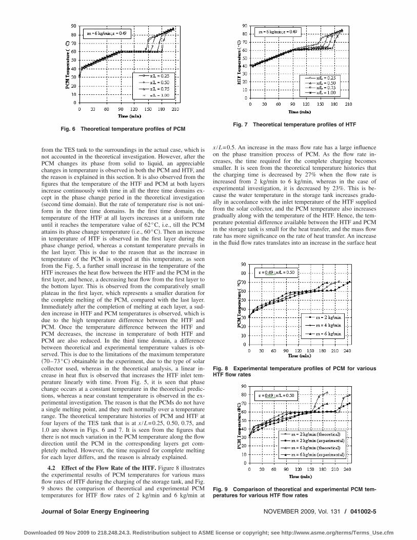
4.2 Effect of the Flow Rate of the HTF. Figure 8 illustrateshe experimental results of PCM temperatures for various massow rates of HTF during the charging of the storage tank, and Fig.shows the comparison of theoretical and experimental PCM
Fig. 6 Theoretical temperature profiles of PCM
emperatures for HTF flow rates of 2 kg/min and 6 kg/min at
ournal of Solar Energy Engineering
aded 09 Nov 2009 to 218.248.24.3. Redistribution subject to ASME
x /L=0.5. An increase in the mass flow rate has a large influenceon the phase transition process of PCM. As the flow rate in-creases, the time required for the complete charging becomessmaller. It is seen from the theoretical temperature histories thatthe charging time is decreased by 27% when the flow rate isincreased from 2 kg/min to 6 kg/min, whereas in the case ofexperimental investigation, it is decreased by 23%. This is be-cause the water temperature in the storage tank increases gradu-ally in accordance with the inlet temperature of the HTF suppliedfrom the solar collector, and the PCM temperature also increasesgradually along with the temperature of the HTF. Hence, the tem-perature potential difference available between the HTF and PCMin the storage tank is small for the heat transfer, and the mass flowrate has more significance on the rate of heat transfer. An increasein the fluid flow rates translates into an increase in the surface heat
Fig. 7 Theoretical temperature profiles of HTF
Fig. 8 Experimental temperature profiles of PCM for variousHTF flow rates
Fig. 9 Comparison of theoretical and experimental PCM tem-
peratures for various HTF flow ratesNOVEMBER 2009, Vol. 131 / 041002-5
license or copyright; see http://www.asme.org/terms/Terms_Use.cfm

ttt
taFcse=tcmiFiccfp
mw=pvstoi
Fp
FT
0
Downlo
ransfer coefficient between HTF and PCM capsules, and hence,he mass flow rate has a significant effect on the time for charginghe storage tank.
4.3 Effect of Varying the Porosity „ε… . Porosity determineshe quantity of thermal energy that can be stored, and the surfacerea of heat transfer between particle and fluid per unit volume.or a given volume of the storage tank and size of the sphericalapsules, porosity is varied by changing the number of PCM cap-ules in the storage tank. Figure 10 shows the comparison of thexperimental temperature histories of PCM for �=0.49 and �0.61. It is seen from the figures that higher porosity decreases
he charging time. A higher porosity value indicates lower heatapacity of the storage tank, and hence, less time required forelting. When porosity is increased from 0.49 to 0.61, the charg-
ng time is reduced by 18% for the mass flow rate of 6 kg/min.or a given mass flow rate of the HTF when the porosity value
ncreases, the velocity of the fluid inside the storage tank de-reases, and this will marginally decrease the heat transfer coeffi-ient between the PCM capsules and HTF. Thus, the time requiredor the completion of melting is not in exact proportion to theercentage increase in porosity.
4.4 Molten Mass Fraction of PCM. Figure 11 presents theolten mass fraction of the PCM at four layers of the storage tankith time during the phase change process. At layer 1, i.e., x /L0.25, the variation is almost steep, and the PCM melts com-letely in about 45 min, whereas in the last layer, the process isery slow, and it takes about 80 min for complete melting. As theystem receives a constant heat flux at any time and the heat beingransferred to the bottom layers are less when phase transitionccurs in the top layer, the rate of melting in the bottom layer isnitially low, and it starts increasing once the PCM in the previous
ig. 10 Experimental temperature profiles of PCM for variousorosities
ig. 11 Molten mass fraction of PCM at different heights of
ES tank41002-6 / Vol. 131, NOVEMBER 2009
aded 09 Nov 2009 to 218.248.24.3. Redistribution subject to ASME
layer is completely melted. Figure 12 shows the comparison of themolten fraction of the PCM for the flow rates of 4 kg/min and 6kg/min. It is noted from the figures that the melting time for thePCM and the charging time of the storage tank reduces with in-crease in HTF flow rate, and the reason is already explained inSec. 4.2. Figure 13 illustrates the comparison of the theoreticalmolten mass fraction of the PCM during the charging process fordifferent porosities.
4.5 Instantaneous and Cumulative Heat Stored. Figure 14illustrates the comparison of the theoretical and experimental in-stantaneous heat stored in the storage tank during the chargingprocess for a mass flow rate of 6 kg/min with �=0.49. This isestimated based on the instantaneous inlet and outlet temperatures
Fig. 12 Molten mass fraction of PCM for two different massflow rates
Fig. 13 Comparison of molten mass fraction of PCM for vari-ous porosities
Fig. 14 Comparison of theoretical and experimental instanta-
neous heat storedTransactions of the ASME
license or copyright; see http://www.asme.org/terms/Terms_Use.cfm

oiuttmctupoobwt
f1octshfl
5
csufioveeurHwHwswviembhp
J
Downlo
f the HTF. It is observed that during the initial period of charg-ng, the instantaneous heat stored is high, and then it is decreasingntil 50–60 min. This drop in heat stored is due to the decrease inemperature difference between the HTF and the temperature ofhe storage tank. As the charging process proceeds, the PCM starts
elting, and the heat stored remains almost uniform due to theonstant temperature difference between the HTF and the storageank. This is the major advantage of a combined system where aniform rate of charging and discharging is possible for a longereriod, which will be useful for many practical applications. It isbserved that there are small fluctuations in experimental valuesf heat quantities during most of the charging period. This isecause of the variation in the HTF temperature in accordanceith the intensity of solar radiation that varies continuously with
ime.Figure 15 shows the cumulative heat stored in the storage tank
or the case of �=0.49. It is seen that the time required for storing1 MJ is 240 min, 210 min, and 190 min for the mass flow ratesf 2 kg/min, 4 kg/min, and 6 kg/min, respectively, at averageharging rates of 0.764 kJ/s, 0.873 kJ/s, and 0.965 kJ/s, respec-ively. It is observed from the figure that the mass flow rate has aignificant effect on the average charging rate. This is due to theigher heat extraction rate from the solar collector as the massow rate increases.
ConclusionsA theoretical model to determine the thermal behavior of a
ombined sensible and latent heat storage unit integrated with aolar collector during the heat storage process has been developedsing the porous medium approach, and it is solved using thenite difference technique. The numerical simulation is carriedut for the case where the PCM is paraffin, and HTF is water. Theariation in temperature profiles of the PCM and HTF for differ-nt values of mass flow rates and porosities were obtained. Thexperimental investigation is carried out on a combined storagenit integrated with a solar flat plate collector to compare theesults with the theoretical model. The temperature profiles ofTF and PCM in the numerical results are in good agreementith the experimental results. The influence of the variation in theTF flow rates and porosity values on the system performanceas also reported. It was observed that the mass flow rate has a
ignificant effect on the heat extraction rate from the collector,hich in turn affects the rate of charging of the TES tank, and theariation in porosity has only less significant effect on the charg-ng time, as the time required for completion of melting is not inxact proportion to the percentage increase in porosity. Thisodel is useful to predict the energy storage behavior of a PCM
ased TES system with different phase change materials, differenteat transfer fluids, and for different HTF flow rates and various
Fig. 15 Experimental variation in the cumulative heat stored
orosity values of the storage tank.
ournal of Solar Energy Engineering
aded 09 Nov 2009 to 218.248.24.3. Redistribution subject to ASME
NomenclatureAc � cross sectional area of the storage tank �m2�As � surface area of the spherical capsules �m2�G � superficial mass velocity �kg /m2 s�L � length of the storage tank �m�
M � mass �kg�Nu � Nusselt numberQ � heat transfer rate �W�T � temperature �°C�c � specific heat capacity �J/kg K�
dp � diameter of the PCM capsule �m�h � latent heat of fusion �kJ/kg�m � mass flow rate of HTF �kg/min�t � time �s�u � velocity of HTF �m/s�x � axial coordinate �m�
Greek symbols� � heat transfer coefficient �W /m2 K�� � molten fraction of PCM� � porosity� � thermal conductivity �W/m K�� � dynamic viscosity �kg/m s�� � density �Kg /m3�
Subscriptsf � fluid �HTF�i � initial state
in � inlet conditionl, liq � liquid state PCM
m � melting statep � PCMs � solid state PCM
References�1� Beasley, D. E., and Clark, J. A., 1984, “Transient Response of a Packed Bed
for Thermal Energy Storage,” Int. J. Heat Mass Transfer, 27�9�, pp. 1659–1669.
�2� Dincer, I., Dost, S., and Li, X., 1997, “Performance Analysis of Sensible HeatStorage Systems for Thermal Applications,” Int. J. Energy Res., 21, pp. 1157–1171.
�3� Collares-Pereira, M., Gordon, J. M., Rabl, A., and Zarmi, Y., 1984, “Designand Optimization of Solar Industrial Hot Water Systems With Storage,” Sol.Energy, 32�1�, pp. 121–133.
�4� Sodha, M. S., Sharma, A. K., Sawhney, R. L., and Kumar, A., 1997, “Experi-mental Performance of Built-in-Storage Solar Water Heating Systems in Labo-ratory and Field Conditions,” Int. J. Energy Res., 21, pp. 275–287.
�5� Reddy, K. S., Avanti, P., and Kaushika, N. D., 1999, “Finite Time ThermalAnalysis of Ground Integrated-Collector-Storage Solar Water Heater WithTransparent Insulation Cover,” Int. J. Energy Res., 23, pp. 925–940.
�6� Zalba, B., Marin, J. M., Cabeza, L. F., and Mehling, H., 2003, “Review onThermal Energy Storage With Phase Change: Materials, Heat Transfer Analy-sis and Applications,” Appl. Therm. Eng., 23, pp. 251–283.
�7� Chen, S. L., and Yue, J. S., 1991, “Thermal Performance of Cool Storage inPacked Capsules for Air Conditioning,” Heat Recovery Syst. CHP, 11�6�, pp.551–561.
�8� Nallusamy, N., Sampath, S., and Velraj, R., 2003, “Energy ManagementThrough PCM Based Thermal Storage System for Building Air-Conditioning:Tidel Park, Chennai,” Proceedings of the International Symposium on Renew-able Energy, Kuala Lumpur, Malaysia, pp. 623–631.
�9� Ananthanarayanan, V., Sahai, Y., Mobley, C. E., and Rapp, R. A., 1987, “Mod-eling of Fixed Bed Heat Storage Units Utilizing Phase-Change Materials,”Metall. Trans. B, 18B, pp. 339–346.
�10� Beasley, D. E., and Ramanarayanan, C., 1989, “Thermal Response of a PackedBed of Spheres Containing a Phase Change Material,” Int. J. Energy Res., 13,pp. 253–265.
�11� Adebiyi, G. A., Hodge, B. K., Steele, W. G., Jalalzadeh-Aza, A., and Nsofor,E. C., 1996, “Computer Simulation of a High-Temperature Thermal EnergyStorage System Employing Multiple Families of Phase-Change Storage Mate-rials,” ASME J. Energy Resour. Technol., 118, pp. 102–111.
�12� Barba, A., and Spiga, M., 2003, “Discharge Mode for Encapsulated PCMs inStorage Tanks,” Sol. Energy, 74�2�, pp. 141–148.
�13� Bansal, N. K., and Buddhi, D., 1992, “Performance Equations of a CollectorCum Storage System Using Phase Change Materials,” Sol. Energy, 48�3�, pp.
185–194.NOVEMBER 2009, Vol. 131 / 041002-7
license or copyright; see http://www.asme.org/terms/Terms_Use.cfm

0
Downlo
�14� Alva S, L. H., González, J. E., and Dukhan, N., 2006, “Initial Analysis of PCMIntegrated Solar Collectors,” ASME J. Sol. Energy Eng., 128, pp. 173–177.
�15� Esen, M., Durmus, A., and Durmus, D., 1998, “Geometric Design of Solar-Aided Latent Heat Store Depending on Various Parameters and Phase ChangeMaterials,” Sol. Energy, 62�1�, pp. 19–28.
41002-8 / Vol. 131, NOVEMBER 2009
aded 09 Nov 2009 to 218.248.24.3. Redistribution subject to ASME
�16� Mehling, H., Cabeza, L. F., Hippeli, S., and Hiebler, S., 2003, “PCM-Moduleto Improve Hot Water Heat Stores With Stratification,” Renewable Energy,28�5�, pp. 699–711.
�17� Perry, R. H., and Green, D. W., 1997, Perry’s Chemical Engineers Hand Book,McGraw-Hill, New York.
Transactions of the ASME
license or copyright; see http://www.asme.org/terms/Terms_Use.cfm