Aruba 2930F / 2930M Management and Configuration Guide ...
793
Aruba 2930F / 2930M Management and Configuration Guide for ArubaOS- Switch 16.05 Part Number: 5200-4206 Published: December 2017 Edition: 1
-
Upload
khangminh22 -
Category
Documents
-
view
0 -
download
0
Transcript of Aruba 2930F / 2930M Management and Configuration Guide ...

Aruba 2930F / 2930M Management andConfiguration Guide for ArubaOS-Switch 16.05
Part Number: 5200-4206Published: December 2017Edition: 1

© Copyright 2017 Hewlett Packard Enterprise
NoticesThe information contained herein is subject to change without notice. The only warranties for Hewlett PackardEnterprise products and services are set forth in the express warranty statements accompanying such productsand services. Nothing herein should be construed as constituting an additional warranty. Hewlett PackardEnterprise shall not be liable for technical or editorial errors or omissions contained herein.
Confidential computer software. Valid license from Hewlett Packard Enterprise required for possession, use, orcopying. Consistent with FAR 12.211 and 12.212, Commercial Computer Software, Computer SoftwareDocumentation, and Technical Data for Commercial Items are licensed to the U.S. Government under vendor'sstandard commercial license.
Links to third-party websites take you outside the Hewlett Packard Enterprise website. Hewlett Packard Enterprisehas no control over and is not responsible for information outside the Hewlett Packard Enterprise website.
AcknowledgmentsIntel®, Itanium®, Pentium®, Intel Inside®, and the Intel Inside logo are trademarks of Intel Corporation in the UnitedStates and other countries.
Microsoft® and Windows® are either registered trademarks or trademarks of Microsoft Corporation in the UnitedStates and/or other countries.
Adobe® and Acrobat® are trademarks of Adobe Systems Incorporated.
Java® and Oracle® are registered trademarks of Oracle and/or its affiliates.
UNIX® is a registered trademark of The Open Group.

Chapter 1 About this guide........................................................................... 28Applicable products..................................................................................................................................28Switch prompts used in this guide........................................................................................................... 28
Chapter 2 Time Protocols..............................................................................29General steps for running a time protocol on the switch..........................................................................29
TimeP time synchronization.......................................................................................................... 29SNTP time synchronization...........................................................................................................29NTP time synchronization............................................................................................................. 30timesync Command................................................................................................................... 30
Selecting a time synchronization protocol................................................................................................30Disabling time synchronization................................................................................................................ 31TimeP: Selecting and configuring............................................................................................................ 31
Viewing, enabling, and modifying the TimeP protocol (Menu)...................................................... 32Viewing the current TimeP configuration (CLI)..............................................................................33
Configuring (enabling or disabling) the TimeP mode......................................................... 34SNTP: Selecting and configuring............................................................................................................. 38
Viewing and configuring SNTP (Menu)......................................................................................... 39Viewing and configuring SNTP (CLI).............................................................................................40
Configuring (enabling or disabling) the SNTP mode.......................................................... 42SNTP client authentication............................................................................................................47
Requirements..................................................................................................................... 47Configuring the key-identifier, authentication mode, and key-value (CLI).......................... 48Configuring a trusted key................................................................................................... 48Associating a key with an SNTP server (CLI).................................................................... 49Enabling SNTP client authentication.................................................................................. 49Configuring unicast and broadcast mode for authentication.............................................. 50Viewing SNTP authentication configuration information (CLI)............................................50Saving configuration files and the include-credentials command.......................................51
SNTP unicast time polling with multiple SNTP servers............................................................................53Displaying all SNTP server addresses configured on the switch (CLI)......................................... 53Adding and deleting SNTP server addresses............................................................................... 54
Adding addresses...............................................................................................................54Deleting addresses.............................................................................................................54
Operating with multiple SNTP server addresses configured (Menu)....................................................... 54SNTP messages in the Event Log........................................................................................................... 54Network Time Protocol (NTP).................................................................................................................. 54
Commands....................................................................................................................................55timesync ntp....................................................................................................................... 55ntp...................................................................................................................................... 55[no] ntp............................................................................................................................... 55ntp enable...........................................................................................................................56ntp authentication............................................................................................................... 57ntp authentication key-id ................................................................................................... 58ntp max-association........................................................................................................... 58ntp server........................................................................................................................... 59ntp server key-id.................................................................................................................60ntp ipv6-multicast............................................................................................................... 61debug ntp........................................................................................................................... 61
Contents
Contents 3

ntp trap............................................................................................................................... 62show ntp statistics.............................................................................................................. 63show ntp status.................................................................................................................. 63show ntp associations........................................................................................................ 64show ntp authentication......................................................................................................65Validation rules................................................................................................................... 66Event log messages........................................................................................................... 68
Precision Time Protocol (PTP).................................................................................................................69ptp................................................................................................................................................69show ptp.....................................................................................................................................70
Monitoring resources............................................................................................................................... 70Displaying current resource usage................................................................................................70Viewing information on resource usage........................................................................................ 72
Policy enforcement engine................................................................................................. 72Usage notes for show resources output.............................................................................73
When insufficient resources are available.....................................................................................73
Chapter 3 Port Status and Configuration.....................................................75Viewing port status and configuring port parameters...............................................................................75
Connecting transceivers to fixed-configuration devices................................................................ 75Viewing port configuration (Menu).................................................................................................77
Configuring ports (Menu)....................................................................................................78Viewing port status and configuration (CLI).................................................................................. 79
Dynamically updating the show interfaces command (CLI/Menu)..................................... 80Customizing the show interfaces command (CLI).........................................................................80
Error messages associated with the show interfaces command........................................82show interface smartrate...............................................................................................................82Viewing port utilization statistics (CLI)...........................................................................................82
Operating notes for viewing port utilization statistics..........................................................83Viewing transceiver status (CLI)....................................................................................................83
Operating Notes................................................................................................................. 84Enabling or disabling ports and configuring port mode (CLI)........................................................ 84Enabling or disabling flow control (CLI).........................................................................................85Port shutdown with broadcast storm............................................................................................. 87
Viewing broadcast storm.................................................................................................... 87SNMP MIB..........................................................................................................................88
Configuring auto-MDIX..................................................................................................................91Manual override..................................................................................................................91Configuring auto-MDIX (CLI)..............................................................................................92
Using friendly (optional) port names........................................................................................................ 93Configuring and operating rules for friendly port names............................................................... 93Configuring friendly port names (CLI)........................................................................................... 93
Configuring a single port name (CLI)................................................................................. 94Configuring the same name for multiple ports (CLI)...........................................................94
Displaying friendly port names with other port data (CLI)............................................................. 94Listing all ports or selected ports with their friendly port names (CLI)................................95Including friendly port names in per-port statistics listings (CLI)........................................ 96Searching the configuration for ports with friendly port names (CLI)................................. 96
Uni-directional link detection (UDLD).......................................................................................................97Configuring UDLD......................................................................................................................... 98
Configuring uni-directional link detection (UDLD) (CLI)..................................................... 98Enabling UDLD (CLI)..........................................................................................................99Changing the keepalive interval (CLI)................................................................................ 99Changing the keepalive retries (CLI)..................................................................................99Configuring UDLD for tagged ports.................................................................................... 99
4 Aruba 2930F / 2930M Management and Configuration Guide for ArubaOS-Switch 16.05

Viewing UDLD information (CLI)................................................................................................. 100Viewing summary information on all UDLD-enabled ports (CLI)......................................100Viewing detailed UDLD information for specific ports (CLI)..............................................101Clearing UDLD statistics (CLI)......................................................................................... 101
Uplink failure detection...........................................................................................................................101Configuration guidelines for UFD................................................................................................ 103UFD enable/disable.....................................................................................................................103UFD track data configuration...................................................................................................... 103UFD minimum uplink threshold configuration............................................................................. 104show uplink-failure-detection.......................................................................................................104UFD operating notes................................................................................................................... 105Error log...................................................................................................................................... 105Invalid port error messages.........................................................................................................105
Basic USB port commands.................................................................................................................... 105usb-port...................................................................................................................................106show usb-port........................................................................................................................ 106
Chapter 4 Power Over Ethernet (PoE/PoE+) Operation............................107Introduction to PoE................................................................................................................................ 107
PoE terminology..........................................................................................................................107Planning and implementing a PoE configuration................................................................................... 107
Power requirements.................................................................................................................... 107Assigning PoE ports to VLANs....................................................................................................108Applying security features to PoE configurations........................................................................108Assigning priority policies to PoE traffic...................................................................................... 108
PoE operation........................................................................................................................................ 108Configuration options.................................................................................................................. 109PD support.................................................................................................................................. 109Power priority operation...............................................................................................................110
When is power allocation prioritized?............................................................................... 110How is power allocation prioritized?................................................................................. 110
Configuring PoE operation..................................................................................................................... 110Disabling or re-enabling PoE port operation................................................................................110Enabling support for pre-standard devices..................................................................................111Configuring the PoE port priority..................................................................................................111Controlling PoE allocation............................................................................................................111Manually configuring PoE power levels.......................................................................................112Configuring PoE redundancy.......................................................................................................113Changing the threshold for generating a power notice................................................................114
PoE/PoE+ allocation using LLDP information........................................................................................115LLDP with PoE............................................................................................................................ 115
Enabling or disabling ports for allocating power using LLDP........................................... 116Enabling PoE detection via LLDP TLV advertisement......................................................116
LLDP with PoE+.......................................................................................................................... 116Overview...........................................................................................................................116PoE allocation...................................................................................................................116Viewing PoE when using LLDP information..................................................................... 117Operating note..................................................................................................................119
Viewing the global PoE power status of the switch................................................................................119Viewing PoE status on all ports...................................................................................................120Viewing the PoE status on specific ports.................................................................................... 122
PoE Event Log messages......................................................................................................................124
Chapter 5 Port Trunking.............................................................................. 125
Contents 5

Overview of port trunking....................................................................................................................... 125Port connections and configuration.............................................................................................125
Port trunk features and operation.......................................................................................................... 126Fault tolerance ........................................................................................................................... 126
Trunk configuration methods..................................................................................................................126Dynamic LACP trunk...................................................................................................................126
Using keys to control dynamic LACP trunk configuration.................................................126Static trunk.................................................................................................................................. 127
Viewing and configuring a static trunk group (Menu).............................................................................131Viewing and configuring port trunk groups (CLI)....................................................................................133
Viewing static trunk type and group for all ports or for selected ports.........................................133Viewing static LACP and dynamic LACP trunk data................................................................... 134Dynamic LACP Standby Links.................................................................................................... 134Configuring a static trunk or static LACP trunk group................................................................. 135Removing ports from a static trunk group................................................................................... 135Enabling a dynamic LACP trunk group....................................................................................... 135Removing ports from a dynamic LACP trunk group....................................................................136
Viewing existing port trunk groups (WebAgent).....................................................................................137Trunk group operation using LACP........................................................................................................137
Default port operation..................................................................................................................139LACP notes and restrictions........................................................................................................140
802.1X (Port-based access control) configured on a port................................................ 141Port security configured on a port.................................................................................... 141Changing trunking methods............................................................................................. 141Static LACP trunks........................................................................................................... 141Dynamic LACP trunks...................................................................................................... 141VLANs and dynamic LACP.............................................................................................. 141Blocked ports with older devices...................................................................................... 142Spanning Tree and IGMP.................................................................................................142Half-duplex, different port speeds, or both not allowed in LACP trunks........................... 143Dynamic/static LACP interoperation.................................................................................143
Trunk group operation using the "trunk" option......................................................................................143How the switch lists trunk data...............................................................................................................143Outbound traffic distribution across trunked links.................................................................................. 144Trunk load balancing using port layers.................................................................................................. 145
Enabling trunk load balancing..................................................................................................... 146
Chapter 6 Port Traffic Controls................................................................... 148Rate-limiting........................................................................................................................................... 148
All traffic rate-limiting...................................................................................................................148Configuring in/out rate-limiting..........................................................................................148Displaying the current rate-limit configuration.................................................................. 149Operating notes for rate-limiting....................................................................................... 151
ICMP rate-limiting.................................................................................................................................. 152Guidelines for configuring ICMP rate-limiting..............................................................................153Configuring ICMP rate-limiting.................................................................................................... 153Using both ICMP rate-limiting and all-traffic rate-limiting on the same interface.........................154Viewing the current ICMP rate-limit configuration....................................................................... 155Operating notes for ICMP rate-limiting........................................................................................155ICMP rate-limiting trap and Event Log messages.......................................................................156
Determining the switch port number used in ICMP port reset commands....................... 157Configuring inbound rate-limiting for broadcast and multicast traffic.......................................... 157
Operating Notes............................................................................................................... 159Rate-limiting Unknown Unicast Traffic................................................................................................... 159
rate-limit unknown-unicast in percent.................................................................... 160
6 Aruba 2930F / 2930M Management and Configuration Guide for ArubaOS-Switch 16.05

rate-limit unknown-unicast in kbps...........................................................................161show rate-limit unknown-unicast................................................................................. 162
Guaranteed minimum bandwidth (GMB)............................................................................................... 163Jumbo frames........................................................................................................................................ 163
Operating rules............................................................................................................................163Jumbo traffic-handling...................................................................................................... 163
Configuring jumbo frame operation.............................................................................................164Overview.......................................................................................................................... 165Viewing the current jumbo configuration.......................................................................... 165Enabling or disabling jumbo traffic on a VLAN................................................................. 166
Configuring a maximum frame size.............................................................................................167Configuring IP MTU..........................................................................................................167SNMP implementation......................................................................................................167Displaying the maximum frame size.................................................................................167Operating notes for maximum frame size........................................................................ 168
Troubleshooting...........................................................................................................................168A VLAN is configured to allow jumbo frames, but one or more ports drops all inboundjumbo frames....................................................................................................................168A non-jumbo port is generating "Excessive undersize/giant frames" messages in theEvent Log......................................................................................................................... 168
Chapter 7 Fault-Finder port-level link-flap................................................. 169Overview................................................................................................................................................ 169Fault-finder link-flap .............................................................................................................................. 169Show fault-finder link-flap.......................................................................................................................171Event Log...............................................................................................................................................172Restrictions............................................................................................................................................ 172
Chapter 8 Physical hardware removal/insertion trap generation............ 173Current default traps.............................................................................................................................. 173Event scenario matrix............................................................................................................................ 173Enabling and disabling traps..................................................................................................................174SNMP trap captures examples.............................................................................................................. 174
Chapter 9 Fans............................................................................................. 178show system ......................................................................................................................................... 178show system fans.............................................................................................................................179show system power-supply....................................................................................................................181Fan failures and SNMP traps.................................................................................................................185
Chapter 10 Configuring for Network Management Applications.............186Using SNMP tools to manage the switch...............................................................................................186
SNMP management features......................................................................................................186SNMPv1 and v2c access to the switch....................................................................................... 187SNMPv3 access to the switch.....................................................................................................187
Enabling and disabling switch for access from SNMPv3 agents......................................188Enabling or disabling restrictions to access from only SNMPv3 agents...........................188Enabling or disabling restrictions from all non-SNMPv3 agents to read-only access...... 188Viewing the operating status of SNMPv3......................................................................... 188Viewing status of message reception of non-SNMPv3 messages................................... 188Viewing status of write messages of non-SNMPv3 messages.........................................188Enabling SNMPv3............................................................................................................ 188
Contents 7

SNMPv3 users................................................................................................................. 189Group access levels......................................................................................................... 192SNMPv3 communities...................................................................................................... 193Viewing and configuring non-version-3 SNMP communities (Menu)............................... 194Listing community names and values (CLI)..................................................................... 195
SNMP notifications......................................................................................................................196Supported Notifications.................................................................................................... 197General steps for configuring SNMP notifications............................................................197SNMPv1 and SNMPv2c Traps......................................................................................... 197SNMP trap receivers........................................................................................................ 198SNMP trap when MAC address table changes................................................................ 199SNMPv2c informs.............................................................................................................200Configuring SNMPv3 notifications (CLI)...........................................................................201Network security notifications...........................................................................................204Enabling Link-Change Traps (CLI)...................................................................................206Source IP address for SNMP notifications....................................................................... 207Viewing SNMP notification configuration (CLI).................................................................209
Configuring the MAC address count option................................................................................ 209Displaying information about the mac-count-notify option................................................210
Advanced management: RMON..................................................................................................211CLI-configured sFlow with multiple instances............................................................................. 212
Configuring sFlow (CLI)....................................................................................................212Viewing sFlow Configuration and Status (CLI).................................................................212
Configuring UDLD Verify before forwarding...........................................................................................214UDLD time delay......................................................................................................................... 214
Restrictions.......................................................................................................................215UDLD configuration commands.................................................................................................. 215Show commands.........................................................................................................................216RMON generated when user changes UDLD mode................................................................... 216
LLDP...................................................................................................................................................... 216General LLDP operation............................................................................................................. 217
LLDP-MED....................................................................................................................... 217Packet boundaries in a network topology................................................................................... 217LLDP operation configuration options......................................................................................... 217
Enable or disable LLDP on the switch..............................................................................218Enable or disable LLDP-MED.......................................................................................... 218Change the frequency of LLDP packet transmission to neighbor devices....................... 218Change the Time-To-Live for LLDP packets sent to neighbors........................................218Transmit and receive mode..............................................................................................218SNMP notification.............................................................................................................218Per-port (outbound) data options..................................................................................... 218Remote management address......................................................................................... 220Debug logging.................................................................................................................. 220
Options for reading LLDP information collected by the switch....................................................220LLDP and LLDP-MED standards compatibility........................................................................... 220LLDP operating rules.................................................................................................................. 221
Port trunking..................................................................................................................... 221IP address advertisements...............................................................................................221Spanning-tree blocking.....................................................................................................221802.1X blocking................................................................................................................221
Configuring LLDP operation........................................................................................................221Displaying the global LLDP, port admin, and SNMP notification status (CLI).................. 221Configuring Global LLDP Packet Controls....................................................................... 223Configuring SNMP notification support............................................................................ 226Configuring per-port transmit and receive modes (CLI)................................................... 226Basic LLDP per-port advertisement content.....................................................................227Support for port speed and duplex advertisements..........................................................229
8 Aruba 2930F / 2930M Management and Configuration Guide for ArubaOS-Switch 16.05

Port VLAN ID TLV support on LLDP........................................................................................... 229Configuring the VLAN ID TLV...........................................................................................229Viewing the TLVs advertised............................................................................................ 230SNMP support.................................................................................................................. 231
LLDP-MED (media-endpoint-discovery)..................................................................................... 232LLDP-MED endpoint support........................................................................................... 232LLDP-MED endpoint device classes................................................................................ 233LLDP-MED operational support....................................................................................... 233LLDP-MED fast start control.............................................................................................234Advertising device capability, network policy, PoE status and location data.................... 234Location data for LLDP-MED devices.............................................................................. 237
Viewing switch information available for outbound advertisements............................................ 241Displaying the current port speed and duplex configuration on a switch port.................. 242Viewing advertisements currently in the neighbors MIB...................................................243Displaying LLDP statistics................................................................................................ 244
LLDP Operating Notes................................................................................................................ 246Neighbor maximum.......................................................................................................... 246LLDP packet forwarding................................................................................................... 246One IP address advertisement per port........................................................................... 246802.1Q VLAN Information................................................................................................ 246Effect of 802.1X Operation............................................................................................... 246Neighbor data can remain in the neighbor database after the neighbor isdisconnected.................................................................................................................... 247Mandatory TLVs............................................................................................................... 247
LLDP and CDP data management..............................................................................................247LLDP and CDP neighbor data..........................................................................................247CDP operation and commands........................................................................................ 248Viewing the current CDP configuration of the switch........................................................248Viewing the current CDP neighbors table of the switch....................................................249Enabling and Disabling CDP Operation........................................................................... 250Enabling or disabling CDP operation on individual ports................................................. 250
Configuring CDPv2 for voice transmission..................................................................................250Filtering CDP information............................................................................................................ 252
Configuring the switch to filter untagged traffic.................................................................253Displaying the configuration............................................................................................. 253
Filtering PVID mismatch log messages...................................................................................... 254DHCPv4 server...................................................................................................................................... 254
Introduction to DHCPv4.............................................................................................................. 254IP pools....................................................................................................................................... 254DHCP options............................................................................................................................. 254BootP support............................................................................................................................. 255Authoritative server and support for DHCP inform packets........................................................ 255Authoritative pools.......................................................................................................................255Authoritative dummy pools..........................................................................................................255Change in server behavior.......................................................................................................... 256DHCPv4 configuration commands.............................................................................................. 256
Enable/disable the DHCPv4 server..................................................................................256Configuring the DHCP address pool name...................................................................... 256Authoritative..................................................................................................................... 258Specify a boot file for the DHCP client ............................................................................ 258Configure a default router for a DHCP client....................................................................258Configure the DNS IP servers ......................................................................................... 258Configure a domain name................................................................................................ 259Configure lease time........................................................................................................ 259Configure the NetBIOS WINS servers............................................................................. 259Configure the NetBIOS node type....................................................................................259Configure subnet and mask ............................................................................................ 260
Contents 9

Configure DHCP server options....................................................................................... 260Configure the range of IP address................................................................................... 260Configure the static binding information........................................................................... 261Configure the TFTP server domain name........................................................................ 261Configure the TFTP server address................................................................................. 261Change the number of ping packets................................................................................ 262Change the amount of time.............................................................................................. 262Configure DHCP Server to save automatic bindings....................................................... 262Configure a DHCP server to send SNMP notifications.................................................... 263Enable conflict logging on a DHCP server....................................................................... 263Enable the DHCP server on a VLAN................................................................................263Clear commands.............................................................................................................. 263Reset all DHCP server and BOOTP counters..................................................................264Delete an automatic address binding............................................................................... 264
Show commands.........................................................................................................................264Display the DHCPv4 server address bindings................................................................. 264Display address conflicts..................................................................................................264Display DHCPv4 server database agent..........................................................................264Display DHCPv4 server statistics.....................................................................................265Display the DHCPv4 server IP pool information...............................................................265Display DHCPv4 server global configuration information.................................................265
Event log..................................................................................................................................... 265Event Log Messages........................................................................................................266
LLDP Management TLV Transmission disablement.............................................................................. 268Overview..................................................................................................................................... 268Commands..................................................................................................................................268
[no] lldp config basicTlvEnable management_addr..........................................................268lldp config......................................................................................................................... 269
Show commands.........................................................................................................................269
Chapter 11 Captive Portal for ClearPass....................................................271Requirements.........................................................................................................................................271Best Practices........................................................................................................................................ 271Limitations..............................................................................................................................................272Features.................................................................................................................................................272
High Availability...........................................................................................................................272Load balancing and redundancy................................................................................................. 272
Captive Portal when disabled................................................................................................................ 272Disabling Captive Portal..............................................................................................................273
Configuring Captive Portal on CPPM.....................................................................................................273Import the HP RADIUS dictionary............................................................................................... 273Create enforcement profiles........................................................................................................273Create a ClearPass guest self-registration................................................................................. 275Configure the login delay ........................................................................................................... 275
Configuring the switch............................................................................................................................275Configure the URL key................................................................................................................276
Configuring a certificate for Captive Portal usage..................................................................................277Display Captive Portal configuration...................................................................................................... 277Show certificate information...................................................................................................................277Troubleshooting..................................................................................................................................... 277
Event Timestamp not working.....................................................................................................277Cannot enable Captive Portal..................................................................................................... 278Unable to enable feature.............................................................................................................278Authenticated user redirected to login page ...............................................................................279Unable to configure a URL hash key.......................................................................................... 279
10 Aruba 2930F / 2930M Management and Configuration Guide for ArubaOS-Switch 16.05
authentication command............................................................................................................. 279show command........................................................................................................................... 280Debug command.........................................................................................................................280
Chapter 12 ZTP with AirWave Network Management............................... 282Requirements.........................................................................................................................................282Best Practices........................................................................................................................................ 282Limitations..............................................................................................................................................282Switch configuration...............................................................................................................................283Configure AirWave details in DHCP (preferred method)........................................................................283Configure AirWave details in DHCP (alternate method)........................................................................ 288Zero Touch Provisioning........................................................................................................................ 295
Auto-configuration using ZTP......................................................................................................295Disabling ZTP..............................................................................................................................296Image Upgrade........................................................................................................................... 296
Configure a switch using the CLI........................................................................................................... 297Troubleshooting..................................................................................................................................... 297
View AMP server messages....................................................................................................... 297Validation Rules...........................................................................................................................297
View configuration details...................................................................................................................... 298amp-server.............................................................................................................................................298debug ztp............................................................................................................................................... 299
Chapter 13 Auto configuration upon Aruba AP detection....................... 300Auto device detection and configuration................................................................................................ 300
Requirements..............................................................................................................................300Limitations................................................................................................................................... 300Feature Interactions.................................................................................................................... 300
Profile Manager and 802.1X.............................................................................................300Profile Manager and LMA/WMA/MAC-AUTH...................................................................301Profile manager and Private VLANs.................................................................................301
Procedure for creating a device identity and associating a device type......................................301device-profile name.....................................................................................................................301
Rogue AP Isolation................................................................................................................................ 303Limitations................................................................................................................................... 303Feature Interactions.................................................................................................................... 304
MAC lockout and lockdown ............................................................................................. 304LMA/WMA/802.1X/Port-Security...................................................................................... 304L3 MAC............................................................................................................................ 305
Using the Rogue AP Isolation feature......................................................................................... 305rogue-ap-isolation....................................................................................................................... 306rogue-ap-isolation action.............................................................................................................306rogue-ap-isolation whitelist..........................................................................................................307clear rogue-ap-isolation...............................................................................................................307
Troubleshooting..................................................................................................................................... 308Dynamic configuration not displayed when using “show running-config”....................................308Switch does not detect the rogue AP TLVs.................................................................................308The show run command displays non-numerical value for untagged-vlan...............................308Show commands.........................................................................................................................309Validation Rules...........................................................................................................................309
Chapter 14 LACP-MAD.................................................................................312LACP-MAD commands..........................................................................................................................312
Contents 11

Configuration command.............................................................................................................. 312show commands......................................................................................................................... 312clear command............................................................................................................................312
LACP-MAD overview............................................................................................................................. 312
Chapter 15 Scalability IP Address VLAN and Routing Maximum Values....................................................................................................................... 314
Chapter 16 File Transfers............................................................................ 316Overview................................................................................................................................................ 316Downloading switch software.................................................................................................................316
General software download rules................................................................................................316Using TFTP to download software from a server........................................................................316
Downloading from a server to primary flash using TFTP (Menu).....................................317Troubleshooting TFTP download failures.........................................................................319Downloading from a server to flash using TFTP (CLI)..................................................... 320Enabling TFTP (CLI)........................................................................................................ 321Configuring the switch to download software automatically from a TFTP server usingauto-TFTP (CLI)............................................................................................................... 321
Use USB to transfer files to and from the switch.........................................................................322Using SCP and SFTP................................................................................................................. 322Enabling SCP and SFTP.............................................................................................................323
Disabling TFTP and auto-TFTP for enhanced security.................................................... 324Enabling SSH V2 (required for SFTP)..............................................................................325Authentication...................................................................................................................326SCP/SFTP operating notes.............................................................................................. 326Troubleshooting SSH, SFTP, and SCP operations.......................................................... 327
Using Xmodem to download switch software from a PC or UNIX workstation........................... 328Downloading to primary flash using Xmodem (Menu)......................................................329Downloading to primary or secondary flash using Xmodem and a terminal emulator(CLI)................................................................................................................................. 330
Switch-to-switch download..........................................................................................................331Switch-to-switch download to primary flash (Menu)......................................................... 331Downloading the OS from another switch (CLI)............................................................... 332
Using AirWave to update switch software...................................................................................332Using IMC to update switch software..........................................................................................333
Copying software images.......................................................................................................................333TFTP: Copying a software image to a remote host (CLI)............................................................333Xmodem: Copying a software image from the switch to a serially connected PC or UNIXworkstation (CLI)......................................................................................................................... 333
Copying diagnostic data.........................................................................................................................333copy command-log......................................................................................................................334copy event-log.............................................................................................................................334
Transferring switch configurations......................................................................................................... 334TFTP: Copying a configuration file to a remote host (CLI)..........................................................335TFTP: Copying a configuration file from a remote host (CLI)......................................................335TFTP: Copying a customized command file to a switch (CLI).................................................... 335USB: Copying a configuration file to a USB device.....................................................................336USB: Copying a configuration file from a USB device................................................................ 336Xmodem: Copying a configuration file to a serially connected PC or UNIX workstation (CLI)....337Xmodem: Copying a configuration file from a serially connected PC or UNIX workstation(CLI)............................................................................................................................................ 337
Transferring ACL command files............................................................................................................338TFTP: Uploading an ACL command file from a TFTP server (CLI)............................................ 338
12 Aruba 2930F / 2930M Management and Configuration Guide for ArubaOS-Switch 16.05

Xmodem: Uploading an ACL command file from a serially connected PC or UNIXworkstation (CLI)......................................................................................................................... 340
Single copy command............................................................................................................................340Single copy command.................................................................................................................340Multiple management switches................................................................................................... 343Stacking switches........................................................................................................................344Standalone switches................................................................................................................... 344Crash file options........................................................................................................................ 344
Flight Data Recorder (FDR)................................................................................................................... 345USB........................................................................................................................................................345
usb-port...................................................................................................................................346show usb-port........................................................................................................................ 346Downloading switch software using USB....................................................................................346
Prerequisites.................................................................................................................... 346Copying using USB..................................................................................................................... 347
copy flash usb.................................................................................................................. 347copy usb command-file............................................................................................................... 347USB autorun................................................................................................................................348
Using USB autorun...........................................................................................................348Security considerations.................................................................................................... 350Troubleshooting autorun operations.................................................................................350Autorun secure mode....................................................................................................... 351
Chapter 17 Monitoring and Analyzing Switch Operation......................... 353Overview................................................................................................................................................ 353Switch and network operations.............................................................................................................. 353Status and counters data....................................................................................................................... 354
Accessing status and counters (Menu)....................................................................................... 354show system............................................................................................................................... 354
chassislocate....................................................................................................................356Chassislocate at startup................................................................................................... 357
General system information........................................................................................................ 358Accessing system information (Menu)............................................................................. 358Accessing system information (CLI).................................................................................358
Collecting processor data with the task monitor (CLI).................................................................359task-monitor cpu...............................................................................................................360
Accessing system information (Menu)........................................................................................ 361Switch management address information access.......................................................................361
show management........................................................................................................... 361Accessing switch management address information (Menu)........................................... 361
Component information views.....................................................................................................362show modules.................................................................................................................. 362Viewing port status (Menu)...............................................................................................363
Task usage reporting...................................................................................................................363Switch management address information................................................................................... 365
Accessing switch management address information (Menu)........................................... 365Accessing switch management address information (CLI).............................................. 366
Port Status.................................................................................................................................. 366Viewing port status (CLI).................................................................................................. 366Viewing port status (Menu)...............................................................................................366Viewing port and trunk group statistics (WebAgent).........................................................367
Port and trunk group statistics and flow control status................................................................367Accessing port and trunk statistics (Menu).......................................................................368Accessing port and trunk group statistics (CLI)................................................................368Displaying trunk load balancing statistics.........................................................................369
Contents 13

Clearing trunk load balancing statistics............................................................................ 369Resetting the port counters.............................................................................................. 370
Viewing the switch's MAC address tables...................................................................................370Accessing MAC address views and searches (CLI).........................................................370Accessing MAC address views and searches (Menu)..................................................... 371
Accessing MSTP Data (CLI)....................................................................................................... 373Viewing internet IGMP status (CLI).............................................................................................373Viewing VLAN information (CLI)..................................................................................................375WebAgent status information...................................................................................................... 377
Compatibility mode for v2 zl and zl modules..........................................................................................377allow-v1-modules........................................................................................................................ 377
Port status..............................................................................................................................................378show interfaces brief................................................................................................................... 378Viewing port status (menu)..........................................................................................................378
Accessing port and trunk group statistics.............................................................................................. 378Trunk bandwidth utilization..........................................................................................................379
show interfaces......................................................................................................... 379show interfaces trunk-utilization.................................................................. 381Statistic interactions of interface counters........................................................................381
Reset port counters.....................................................................................................................383clear statistics...................................................................................................................383
Accessing port and trunk statistics (Menu)................................................................................. 384MAC address tables...............................................................................................................................384
MAC address views and searches..............................................................................................384show mac-add detail................................................................................................ 385show mac-address.......................................................................................................385show mac-address <MAC-ADDRESS> detail..........................................................386Using the menu to view and search MAC addresses.......................................................387Finding the port connection for a specific device on a VLAN........................................... 387Viewing and searching port-level MAC addresses...........................................................388Determining whether a specific device is connected to the selected port........................ 388
MSTP data............................................................................................................................................. 389show spanning-tree.....................................................................................................................389
IP IGMP status.......................................................................................................................................390show ip igmp............................................................................................................................... 390
VLAN information...................................................................................................................................392show vlan.................................................................................................................................... 392
Configuring local mirroring..................................................................................................................... 393Local mirroring sessions............................................................................................................. 394Traffic-direction criteria................................................................................................................395
interface monitor all.......................................................................................................... 395Mirror policy for inbound traffic....................................................................................................395
class [ipv4|ipv6]................................................................................................................ 395policy mirror......................................................................................................................395
MAC-based criteria to select traffic............................................................................................. 395monitor mac......................................................................................................................395
Remote mirroring destination on a remote switch..................................................................................396Remote mirroring destination on a local switch..................................................................................... 396
mirror remote ip...........................................................................................................................396Local mirroring destination on the local switch...................................................................................... 396
mirror port....................................................................................................................................396Monitored traffic..................................................................................................................................... 396
interface...................................................................................................................................... 396monitor all....................................................................................................................................397service-policy.............................................................................................................................. 397
Configuring local mirroring (Menu).........................................................................................................397
14 Aruba 2930F / 2930M Management and Configuration Guide for ArubaOS-Switch 16.05

Destination mirror on a remote switch................................................................................................... 399mirror endpoint............................................................................................................................ 399
Source mirror on the local switch...........................................................................................................400mirror remote ip...........................................................................................................................400
Traffic-direction criteria...........................................................................................................................400Configure ACL criteria to select inbound............................................................................................... 400
interface monitor ip access-group............................................................................................... 400Configuring a destination switch in a remote mirroring session.............................................................400Configuring a source switch in a local mirroring session....................................................................... 401Configuring a source switch in a remote mirroring session................................................................... 402Selecting all traffic on a port interface for mirroring according to traffic direction...................................403Selecting all traffic on a VLAN interface for mirroring according to traffic direction............................... 404Configuring a MAC address to filter mirrored traffic on an interface...................................................... 405Configuring classifier-based mirroring................................................................................................... 406
Applying a mirroring policy on a port or VLAN interface............................................................. 408Viewing a classifier-based mirroring configuration.................................................................................408Viewing all mirroring sessions configured on the switch........................................................................409Viewing the remote endpoints configured on the switch........................................................................410Viewing the mirroring configuration for a specific session......................................................................411Viewing a remote mirroring session.......................................................................................................412Viewing a MAC-based mirroring session............................................................................................... 413Viewing a local mirroring session...........................................................................................................413Viewing information on a classifier-based mirroring session................................................................. 414Viewing information about a classifier-based mirroring configuration....................................................414Viewing information about a classifier-based mirroring configuration....................................................415Viewing resource usage for mirroring policies....................................................................................... 415Viewing the mirroring configurations in the running configuration file....................................................416Compatibility mode................................................................................................................................ 417Traffic mirroring overview.......................................................................................................................418
Mirroring overview.......................................................................................................................418Mirroring destinations..................................................................................................................419Mirroring sources and sessions.................................................................................................. 419Mirroring sessions....................................................................................................................... 419
Mirroring session limits.....................................................................................................420Selecting mirrored traffic...................................................................................................420
Mirrored traffic destinations.........................................................................................................421Local destinations.............................................................................................................421Remote destinations.........................................................................................................421
Monitored traffic sources.............................................................................................................421Criteria for selecting mirrored traffic............................................................................................ 422Mirroring configuration................................................................................................................ 422Remote mirroring endpoint and intermediate devices.................................................................423
Using the Menu to configure local mirroring.......................................................................................... 423Menu and WebAgent limits......................................................................................................... 423
Remote mirroring overview.................................................................................................................... 424Quick reference to remote mirroring setup..................................................................................425
High-level overview of the mirror configuration process........................................................................ 425Determine the mirroring session and destination........................................................................425
For a local mirroring session............................................................................................ 425For a remote mirroring session........................................................................................ 425
Configure a mirroring destination on a remote switch.................................................................426Configure a destination switch in a remote mirroring session.......................................... 426
Configure a mirroring session on the source switch................................................................... 426Configure a source switch in a remote mirroring session.................................................426
Configure the monitored traffic in a mirror session......................................................................427Traffic selection options....................................................................................................427Mirroring-source restrictions.............................................................................................427
Contents 15

About selecting all inbound/outbound traffic to mirror............................................................................428Untagged mirrored packets.........................................................................................................428
About using SNMP to configure no-tag-added ........................................................... 428Operating notes................................................................................................................429
About selecting inbound/outbound traffic using a MAC address.................................................429About selecting inbound traffic using advanced classifier-based mirroring.................................431
Classifier-based mirroring configuration................................................................................................ 431Classifier-based mirroring restrictions.........................................................................................433About applying multiple mirroring sessions to an interface......................................................... 434Mirroring configuration examples................................................................................................ 435
Maximum supported frame size.............................................................................................................439Enabling jumbo frames to increase the mirroring path MTU.......................................................440
Effect of downstream VLAN tagging on untagged, mirrored traffic........................................................440Operating notes for traffic mirroring.............................................................................................441
Troubleshooting traffic mirroring............................................................................................................ 443Interface monitoring features................................................................................................................. 443
Configuring port and static trunk monitoring (Menu)................................................................... 444Configuring port and static trunk monitoring (CLI)...................................................................... 444
Displaying the monitoring configuration........................................................................... 445Configuring the monitor port.............................................................................................445Selecting or removing monitoring source interfaces........................................................ 445
Chapter 18 MAC Address Management..................................................... 447Overview................................................................................................................................................ 447Determining MAC addresses................................................................................................................. 447Viewing the MAC addresses of connected devices............................................................................... 447Viewing the switch's MAC address assignments for VLANs configured on the switch..........................448
Viewing the port and VLAN MAC addresses...............................................................................449
Chapter 19 Troubleshooting........................................................................451Overview................................................................................................................................................ 451Troubleshooting approaches..................................................................................................................451Browser or Telnet access problems....................................................................................................... 452
Cannot access the WebAgent.....................................................................................................452Cannot Telnet into the switch console from a station on the network......................................... 452
Unusual network activity........................................................................................................................ 453General problems........................................................................................................................453
The network runs slow; processes fail; users cannot access servers or other devices... 453Duplicate IP addresses.................................................................................................... 453Duplicate IP addresses in a DHCP network.....................................................................454The switch has been configured for DHCP/Bootp operation, but has not received aDHCP or Bootp reply........................................................................................................454
802.1Q Prioritization problems....................................................................................................454Ports configured for non-default prioritization (level 1 to 7) are not performing thespecified action.................................................................................................................454
Addressing ACL problems.......................................................................................................... 454ACLs are properly configured and assigned to VLANs, but the switch is not using theACLs to filter IP layer 3 packets....................................................................................... 454The switch does not allow management access from a device on the same VLAN........ 455Error (Invalid input) when entering an IP address............................................................ 455Apparent failure to log all "deny" matches........................................................................456The switch does not allow any routed access from a specific host, group of hosts, orsubnet...............................................................................................................................456The switch is not performing routing functions on a VLAN...............................................456
16 Aruba 2930F / 2930M Management and Configuration Guide for ArubaOS-Switch 16.05

Routing through a gateway on the switch fails................................................................. 456IGMP-related problems............................................................................................................... 458
IP multicast (IGMP) traffic that is directed by IGMP does not reach IGMP hosts or amulticast router connected to a port................................................................................. 458IP multicast traffic floods out all ports; IGMP does not appear to filter traffic................... 458
LACP-related problems...............................................................................................................458Unable to enable LACP on a port with the interface <port-number> lacpcommand .........................................................................................................................458
Port-based access control (802.1X)-related problems................................................................458The switch does not receive a response to RADIUS authentication requests................. 459The switch does not authenticate a client even though the RADIUS server is properlyconfigured and providing a response to the authentication request.................................459During RADIUS-authenticated client sessions, access to a VLAN on the port used forthe client sessions is lost..................................................................................................459The switch appears to be properly configured as a supplicant, but cannot gain accessto the intended authenticator port on the switch to which it is connected........................ 459The supplicant statistics listing shows multiple ports with the same authenticator MACaddress.............................................................................................................................459The show port-access authenticator <port-list> command shows oneor more ports remain open after they have been configured with controlunauthorized ...............................................................................................................459RADIUS server fails to respond to a request for service, even though the server's IPaddress is correctly configured in the switch....................................................................460The authorized MAC address on a port that is configured for both 802.1X and portsecurity either changes or is re-acquired after execution of aaa port-accessauthenticator <port-list> initialize ..........................................................460A trunked port configured for 802.1X is blocked.............................................................. 460
QoS-related problems................................................................................................................. 461Loss of communication when using VLAN-tagged traffic................................................. 461
Radius-related problems............................................................................................................. 461The switch does not receive a response to RADIUS authentication requests................. 461RADIUS server fails to respond to a request for service, even though the server's IPaddress is correctly configured in the switch....................................................................461
MSTP and fast-uplink problems.................................................................................................. 462Broadcast storms appearing in the network..................................................................... 462STP blocks a link in a VLAN even though there are no redundant links in that VLAN.....462Fast-uplink troubleshooting.............................................................................................. 462
SSH-related problems.................................................................................................................462Switch access refused to a client..................................................................................... 462Executing IP SSH does not enable SSH on the switch....................................................463Switch does not detect a client's public key that does appear in the switch's publickey file (show ip client-public-key) ....................................................................463An attempt to copy a client public-key file into the switch has failed and the switchlists one of the following messages..................................................................................463Client ceases to respond ("hangs") during connection phase..........................................463
TACACS-related problems..........................................................................................................463Event Log......................................................................................................................... 463All users are locked out of access to the switch...............................................................463No communication between the switch and the TACACS+ server application................ 464Access is denied even though the username/password pair is correct............................464Unknown users allowed to login to the switch..................................................................464System allows fewer login attempts than specified in the switch configuration................465
TimeP, SNTP, or Gateway problems........................................................................................... 465The switch cannot find the time server or the configured gateway.................................. 465
VLAN-related problems...............................................................................................................465Monitor port...................................................................................................................... 465
Contents 17
None of the devices assigned to one or more VLANs on an 802.1Q-compliant switchare being recognized........................................................................................................465Link configured for multiple VLANs does not support traffic for one or more VLANs.......465Duplicate MAC addresses across VLANs........................................................................ 466Disabled overlapping subnet configuration...................................................................... 466
Fan failure................................................................................................................................... 467Mitigating flapping transceivers...................................................................................................467
Fault finder thresholds......................................................................................................469Viewing transceiver information............................................................................................................. 473
Viewing information about transceivers (CLI)..............................................................................474MIB support.................................................................................................................................474Viewing transceiver information.................................................................................................. 474
Information displayed with the detail parameter...............................................................475Viewing transceiver information for copper transceivers with VCT support...........................................479
Testing the Cable........................................................................................................................ 479Viewing transceiver information............................................................................................................. 481Using the Event Log for troubleshooting switch problems..................................................................... 483
Event Log entries........................................................................................................................ 483Using the Menu........................................................................................................................... 494Using the CLI.............................................................................................................................. 495Clearing Event Log entries..........................................................................................................496Turning event numbering on....................................................................................................... 496Using log throttling to reduce duplicate Event Log and SNMP messages.................................. 497
Log throttle periods...........................................................................................................497Example: of event counter operation................................................................................498
Reporting information about changes to the running configuration.............................................499Debug/syslog operation......................................................................................................................... 499
Debug/syslog messaging............................................................................................................ 499Hostname in syslog messages................................................................................................... 500
Logging origin-id...............................................................................................................500Viewing the identification of the syslog message sender................................................. 502SNMP MIB........................................................................................................................504
Debug/syslog destination devices...............................................................................................504Debug/syslog configuration commands...................................................................................... 505Configuring debug/syslog operation............................................................................................508
Viewing a debug/syslog configuration.............................................................................. 510Debug command.........................................................................................................................512
Debug messages............................................................................................................. 512Debug destinations...........................................................................................................514
Logging command.......................................................................................................................515Configuring a syslog server..............................................................................................516
Adding a description for a Syslog server.....................................................................................518Adding a priority description........................................................................................................519Configuring the severity level for Event Log messages sent to a syslog server......................... 519
Configuring the system module used to select the Event Log messages sent to asyslog server.................................................................................................................... 520
Enabling local command logging................................................................................................ 520Operating notes for debug and Syslog........................................................................................521
Diagnostic tools......................................................................................................................................522Port auto-negotiation...................................................................................................................522Ping and link tests....................................................................................................................... 522
Ping test........................................................................................................................... 522Link test............................................................................................................................ 522Executing ping or link tests (WebAgent)...........................................................................522Testing the path between the switch and another device on an IP network.....................523Issuing single or multiple link tests................................................................................... 525
Tracing the route from the switch to a host address................................................................... 525
18 Aruba 2930F / 2930M Management and Configuration Guide for ArubaOS-Switch 16.05

Halting an ongoing traceroute search.............................................................................. 527A low maxttl causes traceroute to halt before reaching the destination address............. 527If a network condition prevents traceroute from reaching the destination........................ 528
Viewing switch configuration and operation...........................................................................................528Viewing the startup or running configuration file......................................................................... 528Viewing the configuration file (WebAgent).................................................................................. 529Viewing a summary of switch operational data........................................................................... 529
Saving show tech command output to a text file.............................................................. 530Customizing show tech command output.........................................................................531
Viewing more information on switch operation............................................................................533Searching for text using pattern matching with show command...................................... 534
Displaying the information you need to diagnose problems........................................................536Restoring the factory-default configuration............................................................................................ 536
Resetting to the factory-default configuration..............................................................................537Using the CLI....................................................................................................................537Using Clear/Reset............................................................................................................ 537
Restoring a flash image......................................................................................................................... 537Recovering from an empty or corrupted flash state.................................................................... 537
DNS resolver..........................................................................................................................................539Basic operation........................................................................................................................... 539Configuring and using DNS resolution with DNS-compatible commands...................................540Configuring a DNS entry............................................................................................................. 541Using DNS names with ping and traceroute: Example:.............................................................. 542Viewing the current DNS configuration....................................................................................... 544Operating notes...........................................................................................................................544Event Log messages...................................................................................................................545
Locating a switch (Locator LED)............................................................................................................ 545
Chapter 20 Job Scheduler........................................................................... 546Job Scheduler........................................................................................................................................ 546Commands.............................................................................................................................................546
Job at | delay | enable | disable ...........................................................................546Show job..................................................................................................................................... 547Show job <Name>.......................................................................................................................547
Chapter 21 Configuration backup and restore without reboot................ 549Overview................................................................................................................................................ 549
Benefits of configuration restore without reboot..........................................................................549Recommended scenarios...................................................................................................................... 549Use cases.............................................................................................................................................. 549
Switching to a new configuration.................................................................................................550Rolling back to a stable configuration using job scheduler......................................................... 551
Commands used in switch configuration restore without reboot............................................................552Configuration backup............................................................................................................................. 552
cfg-backup...............................................................................................................................553show config files................................................................................................................553
Configuration restore without reboot .....................................................................................................555cfg-restore.............................................................................................................................555
Force configuration restore.............................................................................................. 557cfg-restore non-blocking......................................................................................558cfg-restore recovery-mode................................................................................... 559cfg-restore verbose................................................................................................ 561cfg-restore config_bkp..........................................................................................562
Configuration restore with force option....................................................................................... 563
Contents 19

System reboot commands................................................................................................564Configuration restore without force option.................................................................................. 565show cfg-restore status...................................................................................................565Viewing the differences between a running configuration and a backup configuration...............567
Show commands to show the SHA of a configuration........................................................................... 569show hash.................................................................................................................................569
Scenarios that block the configuration restoration process................................................................... 570Limitations..............................................................................................................................................570
Blocking of configuration from other sessions.............................................................................570Troubleshooting and support................................................................................................................. 571
debug cfg-restore................................................................................................................571
Chapter 22 Virtual Technician..................................................................... 572Cisco Discovery Protocol (CDP)............................................................................................................ 572
Show cdp traffic...........................................................................................................................572Clear cdp counters...................................................................................................................... 572
Enable/Disable debug tracing for MOCANA code................................................................................. 573Debug security ........................................................................................................................... 573
User diagnostic crash via Front Panel Security (FPS) button................................................................573Front panel security password-clear........................................................................................... 573Front-panel-security diagnostic-reset..........................................................................................574[no] front-panel-security diagnostic-reset.................................................................................... 574Front-panel-security diagnostic-reset clear-button......................................................................575[No] front-panel-security diagnostic-reset clear-button............................................................... 575Show front-panel-security........................................................................................................... 576Diagnostic table...........................................................................................................................576Validation rules............................................................................................................................577FPS Error Log............................................................................................................................. 577
User initiated diagnostic crash via the serial console............................................................................ 578Front-panel-security diagnostic-reset serial-console...................................................................578[No] front-panel-security diagnostic-reset serial-console............................................................ 579Serial console error messages....................................................................................................579
Chapter 23 IP Service Level Agreement.....................................................581Overview................................................................................................................................................ 581How IP SLA works................................................................................................................................. 583Configuration commands....................................................................................................................... 584
[no] ip-sla <ID>............................................................................................................................584ip-sla <ID> clear.......................................................................................................................... 585[no] ip-sla <ID> history-size ........................................................................................................585[no] ip-sla <ID> icmp-echo.......................................................................................................... 585[no] ip-sla <ID> udp-echo............................................................................................................585[no] ip-sla <ID> tcp-connect........................................................................................................ 586[no] ip-sla <ID> monitor threshold-config.................................................................................... 586[no] ip-sla <ID> monitor packet-loss............................................................................................586[no] ip-sla <ID> monitor test-completion..................................................................................... 587[no] ip-sla <ID> schedule............................................................................................................ 587[no] ip-sla <ID> tos...................................................................................................................... 587[no] ip-sla responder................................................................................................................... 587[no] ip-sla <ID> udp-jitter ............................................................................................................588[no] ip-sla <ID> udp-jitter-voip .................................................................................................... 588
Show commands................................................................................................................................... 588show ip-sla <ID>......................................................................................................................... 588show ip-sla <ID> history..............................................................................................................589
20 Aruba 2930F / 2930M Management and Configuration Guide for ArubaOS-Switch 16.05

show ip-sla <ID> message-statistics...........................................................................................590show ip-sla <ID> results .............................................................................................................590show ip-sla <ID> aggregated-results.......................................................................................... 591show ip-sla responder................................................................................................................. 592show ip-sla responder statistics.................................................................................................. 593show tech ip-sla.......................................................................................................................... 593
clear ip-sla responder statistics........................................................................................595Validation rules.......................................................................................................................................596Event log messages...............................................................................................................................598Interoperability....................................................................................................................................... 599IP SLA UDP Jitter and Jitter for VoIP ....................................................................................................599
Overview..................................................................................................................................... 600Significance of jitter..................................................................................................................... 600Solution components...................................................................................................................600SLA Measurements.....................................................................................................................601
Chapter 24 Aruba Central integration........................................................ 604Aruba Central Network Management Solution Overview.......................................................................604
LED Blink feature........................................................................................................................ 605Configuration commands....................................................................................................................... 605
aruba-central............................................................................................................................... 605Show commands................................................................................................................................... 606
show aruba-central......................................................................................................................606Activating ArubaOS-Switch Firmware Integration....................................................................... 606activate software-update enable................................................................................................. 607activate software-update check...................................................................................................607activate software-update update................................................................................................. 608show activate software-update....................................................................................................608
Chapter 25 Easing Wired/Wireless Deployment feature integration....... 610Overview................................................................................................................................................ 610Configuration commands....................................................................................................................... 610
allow-jumbo-frames.....................................................................................................................610Validation rules................................................................................................................. 611
Default AP Profile........................................................................................................................ 611device-profile............................................................................................................................... 611Associating a device with a profile.............................................................................................. 612device-profile type....................................................................................................................... 612Configuring the rogue-ap-isolation command............................................................................. 613rogue-ap-isolation....................................................................................................................... 613
VXLAN show commands....................................................................................................................... 614show device-profile..................................................................................................................... 614show command device-profile status.......................................................................................... 615Show rogue-ap-isolation............................................................................................................. 615
Chapter 26 IPSec for AirWave Connectivity.............................................. 617Overview................................................................................................................................................ 617
Applicable products.....................................................................................................................617AirWave details........................................................................................................................... 617IPsec for Management Traffic..................................................................................................... 617IPsec Tunnel Establishment........................................................................................................617IPSec Tunnel Failures.................................................................................................................617AirWave IP after discovery..........................................................................................................618
Contents 21

Configuring the Aruba controller................................................................................................. 618AirWave Controller IP configuration commands.................................................................................... 621
aruba-vpn type............................................................................................................................ 621Show commands................................................................................................................................... 622
show aruba-vpn...........................................................................................................................622show ip route...............................................................................................................................623show interfaces tunnel aruba-vpn............................................................................................... 623show ip counters tunnel aruba-vpn............................................................................................. 624show crypto-ipsec sa...................................................................................................................626show running-configuration......................................................................................................... 627
Chapter 27 Local user roles........................................................................ 628Overview................................................................................................................................................ 628Captive-portal commands...................................................................................................................... 630
Overview..................................................................................................................................... 630[no] aaa authentication captive-portal profile.............................................................................. 630
Validation rules................................................................................................................. 631Policy commands...................................................................................................................................632
Overview..................................................................................................................................... 632policy user................................................................................................................................... 632[no] policy user............................................................................................................................ 632policy resequence....................................................................................................................... 633Commands in the policy-user context......................................................................................... 633
(policy-user)# class.......................................................................................................... 633User role configuration...........................................................................................................................634
aaa authorization user-role......................................................................................................... 634Error log............................................................................................................................635
captive-portal-profile....................................................................................................................636policy........................................................................................................................................... 636reauth-period...............................................................................................................................636
Validation rules................................................................................................................. 637VLAN commands........................................................................................................................ 637
vlan-id...............................................................................................................................637vlan-name.........................................................................................................................637
VLAN range commands.........................................................................................................................638Applying a UDR..................................................................................................................................... 639
aaa port-access local-mac apply user-role................................................................................. 639VXLAN show commands....................................................................................................................... 639
show captive-portal profile.......................................................................................................... 639show user-role.............................................................................................................................640show port-access clients............................................................................................................. 641
Per-user tunneled node......................................................................................................................... 642tunneled-node-server-redirect......................................................................................643show user-role...................................................................................................................... 644show tunneled-node-server information .....................................................................................645show tunneled-node-users................................................................................................ 647ip source-interface tunneled-node-server..............................................................649Using Downloadable User Roles with PUTN.............................................................................. 650
Tagged VLAN for user role.....................................................................................................................651vlan-id-tagged...................................................................................................................... 652user-role vlan-id................................................................................................................652
Downloadable user-roles....................................................................................................................... 653aaa authorization user-role enable download............................................................................. 653radius-server cppm identity......................................................................................................... 654downloadable-role-delete................................................................................................ 655
22 Aruba 2930F / 2930M Management and Configuration Guide for ArubaOS-Switch 16.05

show user-role <XYZ>......................................................................................................... 655show port-access clients................................................................................................ 656debug usertn.......................................................................................................................... 657
Chapter 28 Port QoS Trust Mode................................................................ 659Overview................................................................................................................................................ 659Configuration commands....................................................................................................................... 659
qos trust...................................................................................................................................... 659qos dscp-map..............................................................................................................................660
Show commands................................................................................................................................... 660show qos trust............................................................................................................................. 660
Validation rules ......................................................................................................................................661
Chapter 29 Tunneled node...........................................................................663Overview................................................................................................................................................ 663
Operating notes...........................................................................................................................663Protocol Application Programming Interface (PAPI)....................................................................663
Configuration commands....................................................................................................................... 664tunneled-node-server.................................................................................................................. 664interface tunneled-node-server................................................................................................... 665controller-ip................................................................................................................................. 665keepalive..................................................................................................................................... 665backup-controller-ip.....................................................................................................................665fallback-local-switching............................................................................................................... 666
VLAN show commands..........................................................................................................................666show tunneled-node-server.........................................................................................................666clear statistics tunneled-node-server.......................................................................................... 667
Interaction table..................................................................................................................................... 667Restrictions............................................................................................................................................ 668PAPI security..........................................................................................................................................669
Protocol Application Programming Interface (PAPI)....................................................................669PAPI configurable secret key...................................................................................................... 670papi-security........................................................................................................................ 670
Preventing double tunneling of Aruba Access Points............................................................................ 672Preventing double tunneling using device profile parameter...................................................... 672
device-profile name................................................................................................ 672
Chapter 30 Time Domain Reflectometry.................................................... 676Virtual cable testing................................................................................................................................676Test cable-diagnostics............................................................................................................................676show cable-diagnostics..........................................................................................................................679clear cable-diagnostics.......................................................................................................................... 679Limitations..............................................................................................................................................679
Chapter 31 Link Layer Discovery Protocol bypass authentication......... 681Overview................................................................................................................................................ 681Configuration commands....................................................................................................................... 681
aaa port-access lldp-bypass....................................................................................................... 681Validation rules................................................................................................................. 682
Show commands................................................................................................................................... 683show port-access lldp-bypass clients..........................................................................................683show port-access lldp-bypass config.......................................................................................... 684
Contents 23

Error Log................................................................................................................................................ 685Debug log...............................................................................................................................................686
Chapter 32 Virtual Switching Framework (VSF)........................................ 687List of abbreviated terms........................................................................................................................687Overview of VSF.................................................................................................................................... 687Benefits of VSF...................................................................................................................................... 689VSF domain ID.......................................................................................................................................690VSF link..................................................................................................................................................690Physical VSF ports.................................................................................................................................690VSF member ID..................................................................................................................................... 690Interface naming conventions................................................................................................................ 691VSF member roles................................................................................................................................. 691Member priority...................................................................................................................................... 692Supported topologies............................................................................................................................. 692Running-configuration synchronization .................................................................................................693VSF discovery Plug-and-Play................................................................................................................ 693
Configuring VSF Plug-n-Play...................................................................................................... 693VSF split.................................................................................................................................................693VSF merge.............................................................................................................................................694VSF commands..................................................................................................................................... 694
Configuration commands ........................................................................................................... 694vsf enable......................................................................................................................... 695vsf disable........................................................................................................................ 695vsf member link ............................................................................................................... 695vsf domain........................................................................................................................ 697vsf member.......................................................................................................................697vsf member shutdown...................................................................................................... 698vsf member reboot........................................................................................................... 698vsf member remove..........................................................................................................699vsf member priority...........................................................................................................700vsf member type...............................................................................................................700snmp-server enable traps vsf........................................................................................... 701vsf port-speed...................................................................................................................702vsf vlan-mad..................................................................................................................... 702vsf lldp-mad ipv4.............................................................................................................. 702
Show commands.........................................................................................................................703show vsf........................................................................................................................... 703show vsf detail......................................................................................................... 704show vsf link..................................................................................................................... 706show vsf link detail.............................................................................................. 707show vsf member............................................................................................................. 708show vsf topology.............................................................................................................709show vsf topology detail................................................................................................... 710show vsf topology change-history.....................................................................................711show vsf lldp-mad.............................................................................................................711show vsf vlan-mad............................................................................................................712show vsf trunk-designated-forwarder............................................................................... 713show cpu.......................................................................................................................... 713show power-over-ethernet................................................................................................714show system information..................................................................................................714show system information vsf member.............................................................................. 715show system fans.............................................................................................................717show system chassislocate.............................................................................................. 718show system power-supply.............................................................................................. 719
24 Aruba 2930F / 2930M Management and Configuration Guide for ArubaOS-Switch 16.05

show uptime..................................................................................................................... 719Support commands..................................................................................................................... 719
copy core-dump................................................................................................................719copy fdr-log.......................................................................................................................720copy crash-log.................................................................................................................. 720copy crash-data................................................................................................................720show boot-history............................................................................................................. 721core-dump........................................................................................................................ 721erase fdr-log vsf................................................................................................................722copy crash-files................................................................................................................ 722
VSF configuration.................................................................................................................................. 722Manual configuration of a VSF....................................................................................................723
Manual configuration with multiple ports bundled in a VSF link....................................... 726Automatic configuration of a VSF fabric......................................................................................728
Port speed..............................................................................................................................................732VSF port LED front panel.......................................................................................................................732
VSF port LEDs............................................................................................................................ 733Diagnostic tips for stacking error.................................................................................................733
LED 1 and LED 2 display solid green color, whereas, LED 3 displays solid orange........734LED 1 displays slow flash orange, LED 2 displays solid green, whereas, LED 3displays different colors....................................................................................................734LED 1 displays slow flash orange and LED 2 displays solid green color, whereas,LED 3 displays different colors.........................................................................................735LED 1 and LED 2 display solid green, whereas, LED 3 displays different colors............ 735
Locating LED behavior in stacking system................................................................................. 736VSF restrictions......................................................................................................................................737VSF Use Cases..................................................................................................................................... 737
Use Case 1: Multiple Active Detection........................................................................................ 737Use Case 2: Replacing a switch in a stack................................................................................. 739Use Case 3: Changing VSF link speed.......................................................................................740Use Case 4: Adding a switch to a stack......................................................................................742
Chapter 33 Net-destination and Net-service..............................................744Net-service Overview.............................................................................................................................744netservice [tcp | udp | port].....................................................................................................................744Net-destination overview........................................................................................................................745net-destination host |position | network..................................................................................................746show net-destination.............................................................................................................................. 747
Chapter 34 Device Profile for custom device types..................................748Procedure for creating a device identity and associating a device type................................................ 748
Chapter 35 Dynamically detecting LLDP device profiles......................... 749device-profile.................................................................................................................................749device-profile type-device...................................................................................................................... 749device-profile device-type enable........................................................................................750Associating a profile with a device......................................................................................................... 751
device-profile device-type associate.......................................................................751show device-profile status.......................................................................................................751show device-profile config......................................................................................................................752show device-identity....................................................................................................................753
Contents 25

Chapter 36 Static IP Visibility......................................................................755Static IP Visibility....................................................................................................................................755IP client-tracker...................................................................................................................................... 755
Chapter 37 Network Out-of-Band Management (OOBM) ......................... 758OOBM concepts.....................................................................................................................................758
OOBM and switch applications................................................................................................... 759Example...................................................................................................................................... 760
OOBM Configuration..............................................................................................................................760Entering the OOBM configuration context from the general configuration context..................... 761Enabling and disabling OOBM.................................................................................................... 761Enabling and disabling the OOBM port.......................................................................................761Setting the OOBM port speed..................................................................................................... 762Configuring an OOBM IPv4 address...........................................................................................762Configuring an OOBM IPv4 default gateway.............................................................................. 763Configuring an IPv6 default gateway for OOBM devices............................................................ 763
oobm ipv6 default-gateway................................................................................... 763oobm member ipv6 default-gateway.................................................................... 764
IPv6 default router preferences...................................................................................................764ipv6 nd ra router-preference.............................................................................765
OOBM show commands .......................................................................................................................765Showing the global OOBM and OOBM port configuration.......................................................... 766Showing OOBM IP configuration................................................................................................ 766Showing OOBM ARP information............................................................................................... 766show oobm ipv6...................................................................................................................... 766show oobm ipv6 (for stacked switches)...................................................................................... 767show oobm ipv6 member (for stacked switches)........................................................................ 768show oobm ip detail (for stacked switches).................................................................................768
Application server commands................................................................................................................769Application client commands................................................................................................................. 770
Chapter 38 Websites.................................................................................... 773
Chapter 39 Support and other resources.................................................. 774Accessing Hewlett Packard Enterprise Support.................................................................................... 774Accessing updates.................................................................................................................................774Customer self repair...............................................................................................................................775Remote support..................................................................................................................................... 775Warranty information..............................................................................................................................775Regulatory information...........................................................................................................................776Documentation feedback....................................................................................................................... 776
Remote Device Deployment (TR-069).........................................................777Introduction............................................................................................................................................ 777
Advantages of TR-069................................................................................................................ 778Zero-touch configuration process................................................................................................779Zero-touch configuration setup and execution............................................................................ 782
CLI commands.......................................................................................................................................782Configuration setup..................................................................................................................... 782ACS password configuration.......................................................................................................783
26 Aruba 2930F / 2930M Management and Configuration Guide for ArubaOS-Switch 16.05

When encrypt-credentials is off........................................................................................ 783When encrypt-credentials is on........................................................................................ 784
ACS URL configuration .............................................................................................................. 784ACS username configuration...................................................................................................... 784CPE configuration....................................................................................................................... 784CPE password configuration.......................................................................................................785
When encrypt-credentials is on........................................................................................ 785When encrypt-credentials is off........................................................................................ 785
CPE username configuration...................................................................................................... 785Enable/disable CWMP................................................................................................................ 786Show commands.........................................................................................................................786
CWMP configuration and status query.............................................................................786Event logging......................................................................................................................................... 787
System logging............................................................................................................................787Status/control commands............................................................................................................788
Configuration backup and restore without reboot....................................790
Glossary........................................................................................................ 792
Contents 27

This guide provides information on how to configure, manage, and monitor basic switch operation.
Applicable productsThis guide applies to these products:
Aruba 2930F Switch Series (JL253A, JL254A, JL255A, JL256A, JL258A, JL259A, JL260A, JL261A, JL262A,JL263A, JL264A, JL557A, JL558A, JL559A)
Aruba 2930M Switch Series (JL319A, JL320A, JL321A, JL322A, JL323A, JL324A)
Switch prompts used in this guideExamples in this guide are representative and may not match your particular switch/environment. Examples usesimplified prompts as follows:
Prompt Explanation
switch# # indicates manager context (authority).
switch> > indicates operator context (authority).
switch(config)# (config) indicates the config context.
switch(vlan-x)# (vlan-x) indicates the vlan context of config, where xrepresents the VLAN ID. For example:switch(vlan-128)#.
switch(eth-x)# (eth-x) indicates the interface context of config,where x represents the interface. For example:switch(eth-48)#.
switch-Stack# Stack indicates that stacking is enabled.
switch-Stack(config)# Stack(config) indicates the config context whilestacking is enabled.
switch-Stack(stacking)# Stack(stacking) indicates the stacking context ofconfig while stacking is enabled.
switch-Stack(vlan-x)# Stack(vlan-x) indicates the vlan context of configwhile stacking is enabled, where x represents theVLAN ID. For example: switch-Stack(vlan-128)#.
switch-Stack(eth-x/y)# Stack(eth-x/y) indicates the interface context ofconfig, in the form (eth-<member-in-stack>/<interface>). For example: switch(eth-1/48)#
Chapter 1About this guide
28 Aruba 2930F / 2930M Management and Configuration Guide for ArubaOS-Switch 16.05

For successful time protocol setup and specific configuration details, you may need to contact yoursystem administrator regarding your local configuration.
General steps for running a time protocol on the switchUsing time synchronization ensures a uniform time among interoperating devices. This helps you to manage andtroubleshoot switch operation by attaching meaningful time data to event and error messages.
The switch offers TimeP, SNTP (Simple Network Time Protocol), NTP, and a timesync command for changingthe time protocol selection (or turning off time protocol operation).
Although you can create and save configurations for all time protocols without conflicts, the switchallows only one active time protocol at any time.
In the factory-default configuration, time synchronization is disabled by default.
Because the Aruba 2930F Switch does not contain an RTC (real time clock) chip, Hewlett PackardEnterprise recommends configuring one of the time synchronization protocols supported. Failure todo so could result in the switch time being reset to the factory default of 01/01/1990 00:00:00 in thecase of a switch reload, software upgrade, or power cycle.
TimeP time synchronizationYou can either manually assign the switch to use a TimeP server or use DHCP to assign the TimeP server. Ineither case, the switch can get its time synchronization updates from only one designated TimeP server. Thisoption enhances security by specifying which time server to use.
SNTP time synchronizationSNTP provides three operating modes:
• Broadcast mode
The switch acquires time updates by accepting the time value from the first SNTP time broadcast detected. (Inthis case, the SNTP server must be configured to broadcast time updates to the network broadcast address;see the documentation provided with your SNTP server application.) Once the switch detects a particularserver, it ignores time broadcasts from other SNTP servers unless the configurable Poll Interval expires threeconsecutive times without an update received from the first-detected server.
To use Broadcast mode, the switch and the SNTP server must be in the same subnet.
• DHCP mode
DHCP mode is enabled by default. In DHCP mode, the SNTP server address and the timezone are provided inthe DHCP address reply.
• Unicast mode
Chapter 2Time Protocols
Chapter 2 Time Protocols 29

The switch requests a time update from the configured SNTP server. (You can configure one server using themenu interface, or up to three servers using the CLI sntp server command.) This option provides increasedsecurity over the Broadcast mode by specifying which time server to use instead of using the first one detectedthrough a broadcast.
NTP time synchronizationThe Network Time Protocol (NTP) synchronizes the time of day among a set of distributed time servers andclients in order to correlate events when receiving system logs and other time-specific events from multiplenetwork devices. NTP uses the User Datagram Protocol (UDP) as its transport protocol.
timesync CommandThis command is used to configure the protocol used for network time synchronization.
Syntax
[no] timesync { timep | sntp | timep-or-sntp | ntp }OptionsnoDeletes all timesync configurations on the device.
timepUpdates the system clock using TIMEP.
sntpUpdates the system clock using SNTP.
timep-or-sntpUpdates the system clock using TIMEP or SNTP (default).
ntpUpdates the system clock using NTP
Exampleswitch(config)# timesyncsntp Update the system clock using SNTP.timep Update the system clock using TIMEP.timep-or-sntp Update the system clock using TIMEP or SNTP.ntp Update the system clock using NTP.
Selecting a time synchronization protocolProcedure
1. Select the time synchronization protocol: TimeP, SNTP, or NTP.
2. Enable the protocol; the choices are:
30 Aruba 2930F / 2930M Management and Configuration Guide for ArubaOS-Switch 16.05

a. TimeP: DHCP or Manualb. SNTP: Broadcast or Unicastc. NTP: Broadcast or Unicast
3. Configure the remaining parameters for the time protocol you selected.
The switch retains the parameter settings for both time protocols even if you change from one protocol to theother. Thus, if you select a time protocol, the switch uses the parameters you last configured for the selectedprotocol.
Simply selecting a time synchronization protocol does not enable that protocol on the switch unless you alsoenable the protocol itself (step 2, above). For example, in the factory-default configuration, TimeP is the selectedtime synchronization method. However, because TimeP is disabled in the factory-default configuration, no timesynchronization protocol is running.
Disabling time synchronizationYou can use either of the following methods to disable time synchronization without changing the TimeP, SNTP, orNTP configuration:
• Global config level of the CLI
Execute no timesync.
• System Information screen of the Menu interface
1. Set the Time Synch Method parameter to None.
2. Press [Enter] , then [S] (for Save ).
TimeP: Selecting and configuringThe following table shows TimeP parameters and their operations.
Table 1: TimeP parameters
TimePparameter
Operation
Time SyncMethod
Used to select either TIMEP, SNTP, NTP, or None as the time synchronization method.
TimeP Mode
Disabled TimeP does not operate, even if specified by the Menu interface Time Sync Methodparameter or the CLI timesync command.
Table Continued
Chapter 2 Time Protocols 31

TimePparameter
Operation
DHCP When TimeP is selected as the time synchronization method, the switch attempts to acquire aTimeP server IP address via DHCP. If the switch receives a server address, it polls the serverfor updates according to the TimeP poll interval. If the switch does not receive a TimeP serverIP address, it cannot perform time synchronization updates.
Manual When TimeP is selected as the time synchronization method, the switch attempts to poll thespecified server for updates according to the TimeP poll interval. If the switch fails to receiveupdates from the server, time synchronization updates do not occur.
ServerAddress
Used only when the TimeP Mode is set to Manual. Specifies the IP address of the TimePserver that the switch accesses for time synchronization updates. You can configure oneserver.
Viewing, enabling, and modifying the TimeP protocol (Menu)
Procedure
1. From the Main Menu, select:
2. Switch Configuration
1. System Information
Figure 1: System Information screen (default values)
2. Press [E] (for Edit).
The cursor moves to the System Name field.
3. Move the cursor to the Time Sync Method field.
4. If TIMEP is not already selected, use the Space bar to select TIMEP, then move to the TIMEP Mode field.
5. Do one of the following:
• Use the Space bar to select the DHCP mode.
32 Aruba 2930F / 2930M Management and Configuration Guide for ArubaOS-Switch 16.05
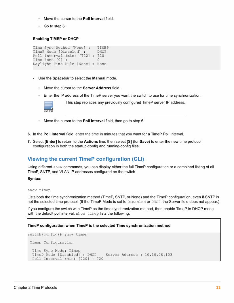
◦ Move the cursor to the Poll Interval field.
◦ Go to step 6.
Enabling TIMEP or DHCP
Time Sync Method [None] : TIMEPTimeP Mode [Disabled] : DHCPPoll Interval (min) [720] : 720Time Zone [0] : 0Daylight Time Rule [None] : None
• Use the Spacebar to select the Manual mode.
◦ Move the cursor to the Server Address field.
◦ Enter the IP address of the TimeP server you want the switch to use for time synchronization.
This step replaces any previously configured TimeP server IP address.
◦ Move the cursor to the Poll Interval field, then go to step 6.
6. In the Poll Interval field, enter the time in minutes that you want for a TimeP Poll Interval.
7. Select [Enter] to return to the Actions line, then select [S] (for Save) to enter the new time protocolconfiguration in both the startup-config and running-config files.
Viewing the current TimeP configuration (CLI)Using different show commands, you can display either the full TimeP configuration or a combined listing of allTimeP, SNTP, and VLAN IP addresses configured on the switch.
Syntax:
show timepLists both the time synchronization method (TimeP, SNTP, or None) and the TimeP configuration, even if SNTP isnot the selected time protocol. (If the TimeP Mode is set to Disabled or DHCP, the Server field does not appear.)
If you configure the switch with TimeP as the time synchronization method, then enable TimeP in DHCP modewith the default poll interval, show timep lists the following:
TimeP configuration when TimeP is the selected Time synchronization method
switch(config)# show timep
Timep Configuration
Time Sync Mode: Timep TimeP Mode [Disabled] : DHCP Server Address : 10.10.28.103 Poll Interval (min) [720] : 720
Chapter 2 Time Protocols 33

If SNTP is the selected time synchronization method, show timep still lists the TimeP configuration even thoughit is not currently in use. Even though, in this Example:, SNTP is the current time synchronization method, theswitch maintains the TimeP configuration:
TimeP configuration when TimeP is not the selected time synchronization method
switch(config)# show timep
Timep Configuration Time Sync Mode: Sntp TimeP Mode [Disabled] : Manual Server Address : 10.10.28.100 Poll Interval (min) [720] : 720Syntax:
show managementHelps you to easily examine and compare the IP addressing on the switch. It lists the IP addresses for all timeservers configured on the switch plus the IP addresses and default gateway for all VLANs configured on theswitch.
Display showing IP addressing for all configured time servers and VLANs
switch(config)# show management
Status and Counters - Management Address Information
Time Server Address : 10.10.28.100
Priority SNTP Server Address Protocol Version -------- ---------------------------------------------- ---------------- 1 10.10..28.101 3 2 10.255.5.24 3 3 fe80::123%vlan10 3
Default Gateway : 10.0.9.80 VLAN Name MAC Address | IP Address ------------ ------------------- + ------------------- DEFAULT_VLAN 001279-88a100 | 10.30.248.184 VLAN10 001279-88a100 | 10.0.10.17
Configuring (enabling or disabling) the TimeP modeEnabling the TimeP mode means to configure it for either broadcast or unicast mode. Remember to run TimeP asthe switch's time synchronization protocol, you must also select TimeP as the time synchronization method byusing the CLI timesync command (or the menu interface Time Sync Method parameter.
Syntax:
timesync timepSelects TimeP as the time synchronization method.
Syntax:
ip timep {<dhcp | manual>}
34 Aruba 2930F / 2930M Management and Configuration Guide for ArubaOS-Switch 16.05
Enables the selected TimeP mode.
Syntax:
[no] ip timepDisables the TimeP mode.
Syntax:
[no] timesyncDisables the time protocol.
Enabling TimeP in manual mode (CLI)Like DHCP mode, configuring TimeP for manual mode enables TimeP. However, for manual operation, you mustalso specify the IP address of the TimeP server. (The switch allows only one TimeP server.)
Syntax:
timesync timepSelects TimeP.
Syntax:
ip timep manual <ip-addr>Activates TimeP in manual mode with a specified TimeP server.
Syntax:
no ip timepDisables TimeP.
Enabling TimeP in DHCP ModeBecause the switch provides a TimeP polling interval (default:720 minutes), you need only these two commandsfor a minimal TimeP DHCP configuration:
Syntax:
timesync timepSelects TimeP as the time synchronization method.
Syntax:
ip timep dhcpConfigures DHCP as the TimeP mode.
For example, suppose:
• Time Synchronization is configured for SNTP.
• You want to:
Chapter 2 Time Protocols 35

◦ View the current time synchronization.
◦ Select TimeP as the synchronization mode.
◦ Enable TimeP for DHCP mode.
◦ View the TimeP configuration.
Enabling TimeP in Manual ModeLike DHCP mode, configuring TimeP for Manual Mode enables TimeP. However, for manual operation, you mustalso specify the IP address of the TimeP server. (The switch allows only one TimeP server.) To enable the TimePprotocol:
Syntax:
timesync timepSelects TimeP.
Syntax:
ip timep manual <ip-addr>Activates TimeP in manual mode with a specified TimeP server.
Syntax:
[no] ip timepDisables TimeP.
To change from one TimeP server to another, you must use the no ip timep command to disableTimeP mode, the reconfigure TimeP in manual mode with the new server IP address.
Example:
To select TimeP and configure it for manual operation using a TimeP server address of 10.28.227.141 and thedefault poll interval (720 minutes, assuming the TimeP poll interval is already set to the default):
switch(config)# timesync timeSelects TimeP.
switch(config)# ip timep manual 10.28.227.141Activates TimeP in Manual mode.
Configuring TimeP for manual operation
switch(config)# timesync timepswitch(config)# ip timep manual 10.28.227.141switch(config)# show timep Timep Configuration Time Sync Mode: Timep TimeP Mode : Manual Server Address : 10.28.227.141 Poll Interval (min) : 720
Changing from one TimeP server to another (CLI)
36 Aruba 2930F / 2930M Management and Configuration Guide for ArubaOS-Switch 16.05

Procedure
1. Use the no ip timep command to disable TimeP mode.
2. Reconfigure TimeP in Manual mode with the new server IP address.
Changing the TimeP poll interval (CLI)Syntax:
ip timep {< dhcp | manual >} interval <1-9999>Specifies how long the switch waits between time polling intervals. The default is 720 minutes and the range is 1to 9999 minutes. (This parameter is separate from the poll interval parameter used for SNTP operation.)
Example:
To change the poll interval to 60 minutes:
switch(config)# ip timep interval 60
Disabling time synchronization without changing the TimeP configuration (CLI)Syntax:
no timesyncDisables time synchronization by changing the Time Sync Mode configuration to Disabled. This halts timesynchronization without changing your TimeP configuration. The recommended method for disabling timesynchronization is to use the timesync command.
Example:
Suppose TimeP is running as the switch's time synchronization protocol, with DHCP as the TimeP mode, and thefactory-default polling interval. You would halt time synchronization with this command:
switch(config)# no timesyncIf you then viewed the TimeP configuration, you would see the following:
TimeP with time synchronization disabled
switch(config)# show timep
Timep Configuration Time Sync Mode: Disabled TimeP Mode : DHCP Poll Interval (min): 720
Disabling the TimeP modeSyntax:
no ip timepDisables TimeP by changing the TimeP mode configuration to Disabled and prevents the switch from using it asthe time synchronization protocol, even if it is the selected Time Sync Method option.
Example:
Chapter 2 Time Protocols 37

If the switch is running TimeP in DHCP mode, no ip timep changes the TimeP configuration as shown belowand disables time synchronization. Even though the TimeSync mode is set to TimeP, time synchronization isdisabled because no ip timep has disabled the TimeP mode parameter.
Disabling time synchronization by disabling the TimeP mode parameter
switch(config)# no ip timep
switch(config)# show timep
Timep Configuration Time Sync Mode: Timep TimeP Mode : Disabled
SNTP: Selecting and configuringThe following table shows the SNTP parameters and their operations.
Table 2: SNTP parameters
SNTP parameter Operation
Time Sync Method Used to select either SNTP, TIMEP, NTP, or None as the time synchronization method.
SNTP Mode
Disabled The Default. SNTP does not operate, even if specified by the Menu interface Time SyncMethod parameter or the CLI timesync command.
Unicast Directs the switch to poll a specific server for SNTP time synchronization. Requires atleast one server address.
Broadcast Directs the switch to acquire its time synchronization from data broadcast by any SNTPserver to the network broadcast address. The switch uses the first server detected andignores any others. However, if the Poll Interval expires three times without the switchdetecting a time update from the original server, the switch accepts a broadcast timeupdate from the next server it detects.
Poll Interval(seconds)
In Unicast Mode: Specifies how often the switch polls the designated SNTP server for atime update.In Broadcast Mode: Specifies how often the switch polls the networkbroadcast address for a time update.Value is between 30 to 720 seconds.
Server Address Used only when the SNTP Mode is set to Unicast. Specifies the IP address of the SNTPserver that the switch accesses for time synchronization updates. You can configure up tothree servers; one using the menu or CLI, and two more using the CLI.
Server Version Specifies the SNTP software version to use and is assigned on a per-server basis. Theversion setting is backwards-compatible. For example, using version 3 means that theswitch accepts versions 1 through 3. Default: 3; range: 1 to 7.
Priority Specifies the order in which the configured servers are polled for getting the time. Value isbetween 1 and 3.
38 Aruba 2930F / 2930M Management and Configuration Guide for ArubaOS-Switch 16.05

Viewing and configuring SNTP (Menu)
Procedure
1. From the Main Menu, select:
a. 2. Switch Configuration…
b. 1. System Information
Figure 2: System Information screen (default values)
2. Press [E] (for Edit ).
Move the cursor to the System Name field.
3. Use the Space bar to move the cursor to the Time Sync Method field.
4. Use the Space bar to select SNTP, then move to the SNTP Mode field.
5. Complete one of the following options.
Option 1
a. Use the Space bar to select the Broadcast mode.
b. Move the cursor to the Poll Interval field.
c. Go to 6. (For Broadcast mode details, see SNTP time synchronization)
Figure 3: Time configuration fields for SNTP with broadcast mode
Option 2
d. Use the Space bar to select the Unicast mode.
e. Move the cursor to the Server Address field.
f. Enter the IP address of the SNTP server you want the switch to use for time synchronization.
Chapter 2 Time Protocols 39

This step replaces any previously configured server IP address. If you will be using backupSNTP servers (requires use of the CLI), see SNTP unicast time polling with multiple SNTPservers.
g. Move the cursor to the Server Version field. Enter the value that matches the SNTP server version runningon the device you specified in the preceding step.
If you are unsure which version to use, Hewlett Packard Enterprise recommends leaving this value at thedefault setting of 3 and testing SNTP operation to determine whether any change is necessary.
Using the menu to enter the IP address for an SNTP server when the switch already has oneor more SNTP servers configured, the switch deletes the primary SNTP server from the serverlist. The switch then selects a new primary SNTP server from the IP addresses in the updatedlist. For more on this topic, see SNTP unicast time polling with multiple SNTP servers.
h. Move the cursor to the Poll Interval field, then go to step 6.
Figure 4: SNTP configuration fields for SNTP configured with unicast mode
6. In the Poll Interval field, enter the time in seconds that you want for a Poll Interval.
(For Poll Interval operation, see SNTP parameters)
7. Press Enter to return to the Actions line, then S (for Save) to enter the new time protocol configuration in boththe startup-config and running-config files.
Viewing and configuring SNTP (CLI)Syntax:
show sntpLists both the time synchronization method (TimeP, SNTP, or None) and the SNTP configuration, even if SNTP isnot the selected time protocol.
If you configure the switch with SNTP as the time synchronization method, then enable SNTP in broadcast modewith the default poll interval, show sntp lists the following:
SNTP configuration when SNTP is the selected time synchronization method
switch(config)# show sntp
SNTP Configuration
Time Sync Mode: Sntp SNTP Mode : Unicast
40 Aruba 2930F / 2930M Management and Configuration Guide for ArubaOS-Switch 16.05

Poll Interval (sec) [720] : 719
Priority SNTP Server Address Protocol Version -------- ------------------------------ ---------------- 1 2001:db8::215:60ff:fe79:8980 7 2 10.255.5.24 3 3 fe80::123%vlan10 3In the factory-default configuration (where TimeP is the selected time synchronization method), show sntp stilllists the SNTP configuration, even though it is not currently in use. In SNTP configuration when SNTP is notthe selected time synchronization method on page 41, even though TimeP is the current time synchronousmethod, the switch maintains the SNTP configuration.
SNTP configuration when SNTP is not the selected time synchronization method
switch(config)# show sntp
SNTP Configuration
Time Sync Mode: Timep SNTP Mode : Unicast Poll Interval (sec) [720] : 719
Priority SNTP Server Address Protocol Version -------- ------------------------------ ---------------- 1 2001:db8::215:60ff:fe79:8980 7 2 10.255.5.24 3 3 fe80::123%vlan10 3Syntax:
show managementThis command can help you to easily examine and compare the IP addressing on the switch. It lists the IPaddresses for all time servers configured on the switch, plus the IP addresses and default gateway for all VLANsconfigured on the switch.
Display showing IP addressing for all configured time servers and VLANs
switch(config)# show management
Status and Counters - Management Address Information
Time Server Address : fe80::215:60ff:fe7a:adc0%vlan10
Priority SNTP Server Address Protocol Version --------- ------------------------------ ---------------- 1 2001:db8::215:60ff:fe79:8980 7 2 10.255.5.24 3 3 fe80::123%vlan10 3
Default Gateway :10.0.9.80
VLAN Name MAC Address | IP address ------------ --------------- + --------------- DEFAULT_VLAN 001279-88a100 | Disabled VLAN10 001279-88a100 | 10.0.10.17
Chapter 2 Time Protocols 41
Configuring (enabling or disabling) the SNTP modeEnabling the SNTP mode means to configure it for either broadcast or unicast mode. Remember that to run SNTPas the switch's time synchronization protocol, you must also select SNTP as the time synchronization method byusing the CLI timesync command (or the menu interface Time Sync Method parameter.)
Syntax:
timesync sntpSelects SNTP as the time protocol.
sntp {<broadcast | unicast>}Enables the SNTP mode.
Syntax:
sntp server <ip-addr>Required only for unicast mode.
Syntax:
sntp server priority <1-3>Specifies the order in which the configured servers are polled for getting the time. Value is between 1 and 3.
Syntax:
sntp <30-720>Configures the amount of time between updates of the system clock via SNTP.
Default: 720 seconds
Enabling SNTP in Broadcast ModeBecause the switch provides an SNTP polling interval (default: 720 seconds), you need only these two commandsfor minimal SNTP broadcast configuration:
Syntax:
timesync sntpSelects SNTP as the time synchronization method.
Syntax:
sntp broadcastConfigures broadcast as the SNTP mode.
Example:
Suppose that time synchronization is in the factory-default configuration (TimeP is the currently selected timesynchronization method.) Complete the following:
42 Aruba 2930F / 2930M Management and Configuration Guide for ArubaOS-Switch 16.05
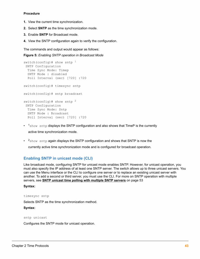
Procedure
1. View the current time synchronization.
2. Select SNTP as the time synchronization mode.
3. Enable SNTP for Broadcast mode.
4. View the SNTP configuration again to verify the configuration.
The commands and output would appear as follows:
Figure 5: Enabling SNTP operation in Broadcast Mode
switch(config)# show sntp 1 SNTP Configuration Time Sync Mode: Timep SNTP Mode : disabled Poll Interval (sec) [720] :720
switch(config)# timesync sntp
switch(config)# sntp broadcast
switch(config)# show sntp 2 SNTP Configuration Time Sync Mode: Sntp SNTP Mode : Broadcast Poll Interval (sec) [720] :720
• 1show sntp displays the SNTP configuration and also shows that TimeP is the currently
active time synchronization mode.
• 2show sntp again displays the SNTP configuration and shows that SNTP is now the
currently active time synchronization mode and is configured for broadcast operation.
Enabling SNTP in unicast mode (CLI)Like broadcast mode, configuring SNTP for unicast mode enables SNTP. However, for unicast operation, youmust also specify the IP address of at least one SNTP server. The switch allows up to three unicast servers. Youcan use the Menu interface or the CLI to configure one server or to replace an existing unicast server withanother. To add a second or third server, you must use the CLI. For more on SNTP operation with multipleservers, see SNTP unicast time polling with multiple SNTP servers on page 53
Syntax:
timesync sntpSelects SNTP as the time synchronization method.
Syntax:
sntp unicastConfigures the SNTP mode for unicast operation.
Chapter 2 Time Protocols 43

Syntax:
[no] sntp server priority < 1-3 > < ip-address > [version]Use the no version of the command to disable SNTP.
prioritySpecifies the order in which the configured SNTP servers are polled for the time.
ip-addressAn IPv4 or IPv6 address of an SNTP server.
versionThe protocol version of the SNTP server. Allowable values are 1 through 7; default is 3.
Syntax:
no sntp server priority <1-3> <ip-addr>Deletes the specified SNTP server.
priority <1-3>value must match what server is configured with. Deleting an SNTP server when only one isconfigured disables SNTP unicast operation.
Example:
To select SNTP and configure it with unicast mode and an SNTP server at 10.28.227.141 with the default serverversion (3) and default poll interval (720 seconds):
switch(config)# timesync sntpSelects SNTP.
switch(config)# sntp unicastActivates SNTP in unicast mode.
switch(config)# sntp server priority 1 10.28.227.141Specifies the SNTP server and accepts the current SNTP server version (default: 3).
Configuring SNTP for unicast operation
switch(config)# show sntp
SNTP Configuration
Time Sync Mode: Sntp SNTP Mode : Unicast Poll Interval (sec) [720] : 720
Priority SNTP Server Address Protocol Version -------- ---------------------------------------------- ---------------- 1 2001:db8::215:60ff:fe79:8980 7 2 10.255.5.24 3 3 fe80::123%vlan10 3In this Example:, the Poll Interval and the Protocol Version appear at their default settings.
44 Aruba 2930F / 2930M Management and Configuration Guide for ArubaOS-Switch 16.05

Both IPv4 and IPv6 addresses are displayed.
Note: Protocol Version appears only when there is an IP address configured for an SNTP server.
If the SNTP server you specify uses SNTP v4 or later, use the sntp server command to specify the correctversion number. For example, suppose you learned that SNTP v4 was in use on the server you specified above(IP address 10.28.227.141). You would use the following commands to delete the server IP address , re-enter itwith the correct version number for that server.
Specifying the SNTP protocol version number
switch(config)# no sntp server 10.28.227.141 1switch(config)# sntp server 10.28.227.141 4 2switch(config)# show sntp SNTP Configuration
Time Sync Mode: Sntp SNTP Mode : Broadcast Poll Interval (sec) [720] : 600
IP Address Protocol Version ------------- ----------------- 10.28.227.141 4 3
• 1Deletes unicast SNTP server entry.
• 2Re-enters the unicast server with a non-default protocol version.
• 3show sntp displays the result.
Changing the SNTP poll interval (CLI)Syntax:
sntp <30..720>Specifies the amount of time between updates of the system clock via SNTP. The default is 720 seconds and therange is 30 to 720 seconds. (This parameter is separate from the poll interval parameter used for Timepoperation.)
Example:
To change the poll interval to 300 seconds:
switch(config)# sntp 300Changing the SNTP server priority (CLI)You can choose the order in which configured servers are polled for getting the time by setting the server priority.
Syntax:
sntp server priority <1-3> <ip-address>Specifies the order in which the configured servers are polled for getting the time Value is between 1 and 3.
You can enter both IPv4 and IPv6 addresses. For more information about IPv6 addresses, see theIPv6 configuration guide for your switch.
Chapter 2 Time Protocols 45

Example:
To set one server to priority 1 and another to priority 2:
switch(config)# sntp server priority 1 10.28.22.141
switch(config)# sntp server priority 2 2001:db8::215:60ff:fe79:8980
Disabling time synchronization without changing the SNTP configuration (CLI)The recommended method for disabling time synchronization is to use the timesync command.
Syntax:
no timesyncHalts time synchronization without changing your SNTP configuration.
Example:
Suppose SNTP is running as the switch's time synchronization protocol, with broadcast as the SNTP mode andthe factory-default polling interval. You would halt time synchronization with this command:
switch(config)# no timesyncIf you then viewed the SNTP configuration, you would see the following:
SNTP with time synchronization disabled
switch(config)# show sntp SNTP Configuration Time Sync Mode: Disabled SNTP Mode : Broadcast Poll Interval (sec) [720] : 720
Disabling the SNTP ModeIf you want to prevent SNTP from being used even if it is selected by timesync (or the Menu interface's TimeSync Method parameter), configure the SNTP mode as disabled.
Syntax:
no sntpDisables SNTP by changing the SNTP mode configuration to Disabled.
Example:
If the switch is running SNTP in unicast mode with an SNTP server at 10.28.227.141 and a server version of 3(the default), no sntp changes the SNTP configuration as shown below and disables time synchronization onthe switch.
Disabling time synchronization by disabling the SNTP mode
switch(config)# no sntpswitch(config)# show sntp
SNTP Configuration
Time Sync Mode: Sntp
46 Aruba 2930F / 2930M Management and Configuration Guide for ArubaOS-Switch 16.05

SNTP Mode : disabled Poll Interval (sec) [720] : 600
IP Address Protocol Version ------------- ----------------- 10.28.227.141 3Note that even though the Time Sync Mode is set to Sntp, time synchronization is disabled because no sntphas disabled the SNTP Mode parameter.
SNTP client authenticationEnabling SNTP authentication allows network devices such as HPE switches to validate the SNTP messagesreceived from an NTP or SNTP server before updating the network time. NTP or SNTP servers and clients mustbe configured with the same set of authentication keys so that the servers can authenticate the messages theysend and clients (switches) can validate the received messages before updating the time.
This feature provides support for SNTP client authentication on switches, which addresses securityconsiderations when deploying SNTP in a network.
RequirementsYou must configure the following to enable SNTP client authentication on the switch.
SNTP client authentication support
• Timesync mode must be SNTP. Use the timesync sntp command. (SNTP is disabled by default).
• SNTP must be in unicast or broadcast mode. See Configuring unicast and broadcast mode forauthentication on page 50.
• The MD5 authentication mode must be selected.
• An SNTP authentication key-identifier (key-id) must be configured on the switch and a value (key-value)must be provided for the authentication key. A maximum of 8 sets of key-id and key-value can beconfigured on the switch.
• Among the keys that have been configured, one key or a set of keys must be configured as trusted. Onlytrusted keys are used for SNTP authentication.
• If the SNTP server requires authentication, one of the trusted keys has to be associated with the SNTP server.
• SNTP client authentication must be enabled on the HPE Switch. If client authentication is disabled, packetsare processed without authentication.
All of the above steps are necessary to enable authentication on the client.
SNTP server authentication support
SNTP server is not supported on Switch products.
You must perform the following on the SNTP server:
• The same authentication key-identifier, trusted key, authentication mode and key-value that were configuredon the SNTP client must also be configured on the SNTP server.
• SNTP server authentication must be enabled on the server.
Chapter 2 Time Protocols 47

If any of the parameters on the server are changed, the parameters have to be changed on all the SNTP clients inthe network as well. The authentication check fails on the clients otherwise, and the SNTP packets are dropped.
Configuring the key-identifier, authentication mode, and key-value (CLI)This command configures the key-id, authentication-mode, and key-value, which are required forauthentication. It is executed in the global configuration context.
Syntax:
sntp authentication key-id <key-id> authentication-mode <md5> key-value <key-string> [trusted]
no sntp authentication key-id <key-id>Configures a key-id, authentication-mode (MD5 only), and key-value, which are required for authentication.
The no version of the command deletes the authentication key.
Default: No default keys are configured on the switch.
key-idA numeric key identifier in the range of 1-4,294,967,295 (232) that identifies the unique key value. It is sent inthe SNTP packet.
key-value <key-string>The secret key that is used to generate the message digest. Up to 32 characters are allowed for key-string .
encrypted-key <<key-string>>Set the SNTP authentication key value using a base64–encoded aes-256 encrypted string.
Setting parameters for SNTP authentication
switch(config)# sntp authentication key-id 55 authentication-mode md5key-value secretkey1
Configuring a trusted keyTrusted keys are used in SNTP authentication. In unicast mode, you must associate a trusted key with aspecific NTP/SNTP server. That key is used for authenticating the SNTP packet.
In unicast mode, a specific server is configured on the switch so that the SNTP client communicates with thespecified server to get the date and time.
In broadcast mode, the SNTP client switch checks the size of the received packet to determine if it isauthenticated. If the broadcast packet is authenticated, the key-id value is checked to see if the same key-id valueis configured on the SNTP client switch. If the switch is configured with the same key-id value, and the key-idvalue is configured as "trusted," the authentication succeeds. Only trusted key-id value information is used forSNTP authentication. For information about configuring these modes, see Configuring unicast and broadcastmode for authentication on page 50.
If the packet contains key-id value information that is not configured on the SNTP client switch, or if the receivedpacket contains no authentication information, it is discarded. The SNTP client switch expects packets to beauthenticated if SNTP authentication is enabled.
When authentication succeeds, the time in the packet is used to update the time on the switch.
Configuring a key-id as trusted (CLI)Enter the following command to configure a key-id as trusted.
48 Aruba 2930F / 2930M Management and Configuration Guide for ArubaOS-Switch 16.05

Syntax:
sntp authentication key-id <key-id> trusted
no sntp authentication key-id <key-id> trustedTrusted keys are used during the authentication process. You can configure the switch with up to eight sets ofkey-id/key-value pairs. One specific set must selected for authentication; this is done by configuring the set astrusted.
The key-id itself must already be configured on the switch. To enable authentication, at least one key-id mustbe configured as trusted.
The no version of the command indicates the key is unreliable (not trusted).
Default: No key is trusted by default.
For detailed information about trusted keys, see Configuring a trusted key on page 48
Associating a key with an SNTP server (CLI)Syntax:
[no] sntp server priority <1-3> {< ip-address | ipv6-address >} <version-num> [key-id <1-4,294,967,295>]
Configures a key-id to be associated with a specific server. The key itself must already be configured on theswitch.
The no version of the command disassociates the key from the server. This does not remove the authenticationkey.
Default: No key is associated with any server by default.
prioritySpecifies the order in which the configured servers are polled for getting the time.
version-numSpecifies the SNTP software version to use and is assigned on a per-server basis. The version setting isbackwards-compatible. For example, using version 3 means that the switch accepts versions 1 through 3.Default: 3; range: 1 - 7.
key-idOptional command. The key identifier sent in the SNTP packet. This key-id is associated with the SNTPserver specified in the command.
Associating a key-id with a specific server
switch(config)# sntp server priority 1 10.10.19.5 2 key-id 55
Enabling SNTP client authenticationThe sntp authentication command enables SNTP client authentication on the switch. If SNTPauthentication is not enabled, SNTP packets are not authenticated.
Syntax:
[no] sntp authenticationEnables the SNTP client authentication.
Chapter 2 Time Protocols 49

The no version of the command disables authentication.
Default: SNTP client authentication is disabled.
Configuring unicast and broadcast mode for authenticationTo enable authentication, you must configure either unicast or broadcast mode. When authentication is enabled,changing the mode from unicast to broadcast or vice versa is not allowed; you must disable authentication andthen change the mode.
To set the SNTP mode or change from one mode to the other, enter the appropriate command.
Syntax:
sntp unicast
sntp broadcastEnables SNTP for either broadcast or unicast mode.
Default: SNTP mode is disabled by default. SNTP does not operate even if specified by the CLI timesynccommand or by the menu interface Time Sync Method parameter.
Unicast Directs the switch to poll a specific server periodically for SNTP time synchronization.Thedefault value between each polling request is 720 seconds, but can be configured.At least onemanually configured server IP address is required.
At least one key-id must be configured as trusted, and it must be associated with one of theSNTP servers. To edit or remove the associated key-id information or SNTP server information,SNTP authentication must be disabled.
Broadcast Directs the switch to acquire its time synchronization from data broadcast by any SNTP serverto the network broadcast address. The switch uses the first server detected and ignores anyothers. However, if the Poll Interval (configurable up to 720 seconds) expires three timeswithout the switch detecting a time update from the original server, the switch accepts abroadcast time update from the next server it detects.
Viewing SNTP authentication configuration information (CLI)The show sntp command displays SNTP configuration information, including any SNTP authentication keys thathave been configured on the switch.
SNTP configuration information
switch(config)# show sntp
SNTP Configuration
SNTP Authentication : Enabled Time Sync Mode: Sntp SNTP Mode : Unicast Poll Interval (sec) [720] : 720
Priority SNTP Server Address Protocol Version KeyId -------- ------------------------------------ ---------------- -----
50 Aruba 2930F / 2930M Management and Configuration Guide for ArubaOS-Switch 16.05

1 10.10.10.2 3 55 2 fe80::200:24ff:fec8:4ca8 3 55
Viewing all SNTP authentication keys that have been configured on the switch (CLI)Enter the show sntp authentication command, as shown in Show sntp authentication command outputon page 51.
Show sntp authentication command output
switch(config)# show sntp authentication
SNTP Authentication Information
SNTP Authentication : Enabled
Key-ID Auth Mode Trusted ------- ---------- -------- 55 MD5 Yes 10 MD5 No
Viewing statistical information for each SNTP server (CLI)To display the statistical information for each SNTP server, enter the show sntp statistics command.
The number of SNTP packets that have failed authentication is displayed for each SNTP server address, asshown in SNTP authentication statistical information on page 51.
SNTP authentication statistical information
switch(config)# show sntp statisticsSNTP Statistics
Received Packets : 0 Sent Packets : 3 Dropped Packets : 0
SNTP Server Address Auth Failed Pkts --------------------------------------- ---------------- 10.10.10.1 0 fe80::200:24ff:fec8:4ca8 0
Saving configuration files and the include-credentials commandYou can use the include-credentials command to store security information in the running-config file. Thisallows you to upload the file to a TFTP server and then later download the file to the HPE switches on which youwant to use the same settings. For more information about the include-credentials command, see"Configuring Username and Password Security" in the access security guide for your switch.
The authentication key values are shown in the output of the show running-config and show configcommands only if the include-credentials command was executed.
When SNTP authentication is configured and include-credentials has not been executed, the SNTPauthentication configuration is not saved.
Configuration file with SNTP authentication information
switch(config) # show configStartup configuration:.
Chapter 2 Time Protocols 51

.
.timesync sntpsntp broadcastsntp 50sntp authenticationsntp server priority 1 10.10.10.2.3 key-id 55sntp server priority 2 fe80::200:24ff:fec8:4ca8 4 key-id 55
SNTP authentication has been enabled and a key-id of 55 has been created.
In this Example:, the include-credentials command has not been executed and is not present in theconfiguration file. The configuration file is subsequently saved to a TFTP server for later use. The SNTPauthentication information is not saved and is not present in the retrieved configuration files, as shown in thefollowing Example:.
Retrieved configuration file when include credentials is not configured
switch(config) # copy tftp startup-config 10.2.3.44 config1...Switch reboots ....Startup configuration...timesync sntpsntp broadcastsntp 50 sntp server priority 1 10.10.10.2.3sntp server priority 2 fe80::200:24ff:fec8:4ca8 4...
The SNTP authentication line and the Key-ids are not displayed. You must reconfigure SNTPauthentication.
52 Aruba 2930F / 2930M Management and Configuration Guide for ArubaOS-Switch 16.05
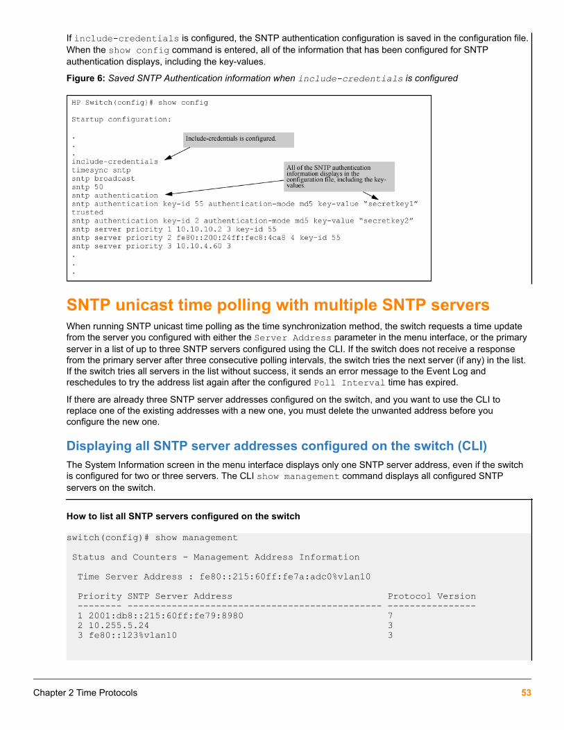
If include-credentials is configured, the SNTP authentication configuration is saved in the configuration file.When the show config command is entered, all of the information that has been configured for SNTPauthentication displays, including the key-values.
Figure 6: Saved SNTP Authentication information when include-credentials is configured
SNTP unicast time polling with multiple SNTP serversWhen running SNTP unicast time polling as the time synchronization method, the switch requests a time updatefrom the server you configured with either the Server Address parameter in the menu interface, or the primaryserver in a list of up to three SNTP servers configured using the CLI. If the switch does not receive a responsefrom the primary server after three consecutive polling intervals, the switch tries the next server (if any) in the list.If the switch tries all servers in the list without success, it sends an error message to the Event Log andreschedules to try the address list again after the configured Poll Interval time has expired.
If there are already three SNTP server addresses configured on the switch, and you want to use the CLI toreplace one of the existing addresses with a new one, you must delete the unwanted address before youconfigure the new one.
Displaying all SNTP server addresses configured on the switch (CLI)The System Information screen in the menu interface displays only one SNTP server address, even if the switchis configured for two or three servers. The CLI show management command displays all configured SNTPservers on the switch.
How to list all SNTP servers configured on the switch
switch(config)# show management Status and Counters - Management Address Information
Time Server Address : fe80::215:60ff:fe7a:adc0%vlan10
Priority SNTP Server Address Protocol Version -------- ---------------------------------------------- ---------------- 1 2001:db8::215:60ff:fe79:8980 7 2 10.255.5.24 3 3 fe80::123%vlan10 3
Chapter 2 Time Protocols 53

Default Gateway : 10.0.9.80
VLAN Name MAC Address | IP Address ------------ ------------------- + ------------------- DEFAULT_VLAN 001279-88a100 | Disabled VLAN10 001279-88a100 | 10.0.10.17
Adding and deleting SNTP server addresses
Adding addressesAs mentioned earlier, you can configure one SNTP server address using either the Menu interface or the CLI. Toconfigure a second and third address, you must use the CLI. To configure the remaining two addresses, youwould do the following:
Creating additional SNTP server addresses with the CLI
switch(config)# sntp server priority <1-3> 2001:db8::215:60ff:fe79:8980switch(config)# sntp server 10.255.5.24
If there are already three SNTP server addresses configured on the switch, and you want to use theCLI to replace one of the existing addresses with a new one, you must delete the unwanted addressbefore you configure the new one.
Deleting addressesSyntax:
no sntp server <ip-addr>Deletes a server address. If there are multiple addresses and you delete one of them, the switch re-orders theaddress priority.
Example:
To delete the primary address in the above Example: and automatically convert the secondary address to primary:
switch(config)# no sntp server 10.28.227.141
Operating with multiple SNTP server addressesconfigured (Menu)When you use the Menu interface to configure an SNTP server IP address, the new address writes over thecurrent primary address, if one is configured.
SNTP messages in the Event LogIf an SNTP time change of more than three seconds occurs, the switch's Event Log records the change. SNTPtime changes of less than three seconds do not appear in the Event Log.
Network Time Protocol (NTP)All NTP communications use Coordinated Universal Time (UTC). An NTP server usually receives its time from anauthoritative time source, such as a radio clock or an atomic clock attached to a time server, and then distributesthis time across the network. NTP is extremely efficient; no more than one packet per minute is necessary tosynchronize two machines to within a millisecond of each other.
54 Aruba 2930F / 2930M Management and Configuration Guide for ArubaOS-Switch 16.05

NTP uses a stratum to describe the distance between a network device and an authoritative time source:
• A stratum 1 time server is directly attached to an authoritative time source (such as a radio or atomic clock or aGPS time source).
• A stratum 2 NTP server receives its time through NTP from a stratum 1 time server.
Before synchronizing, NTP compares the time reported by several network devices and does not synchronizewith one that is significantly different, even if it is a stratum 1.
The security features of NTP can be used to avoid the accidental or malicious setting of incorrect time. One suchmechanism is available: an encrypted authentication mechanism.
Though similar, the NTP algorithm is more complex and accurate than the Simple Network Time Protocol (SNTP).
Enabling this feature results in synchronizing the system clock; therefore, it may affect all sub-systems that rely on system time.
CommandsThe following commands allow the user to configure NTP or show NTP configurations.
timesync ntpThis command is used to update the system clock using NTP.
Syntax
timesync ntpDescription
Update the system clock using NTP.
ntpThis command selects the operating mode of the NTP client.
Syntax
ntp [broadcast|unicast]OptionsbroadcastSets ntp client to operate in broadcast mode.
unicastSets ntp client to operate in unicast mode.
Usage
The default mode is broadcast.
[no] ntpThis command disables NTP and removes all NTP configurations on the device.
Syntax[no] ntp [authentication <key-id> | broadcast | enable | max-association
Chapter 2 Time Protocols 55

<integer> | server <IP-ADDR> | trap <trap-name> | unicast] Description
Disable NTP and removes the entire NTP configuration.
Options
authentication
Configure NTP authentication.
broadcast
Operate in broadcast mode.
enable
Enable/disable NTP.
max-association
Maximum number of Network Time Protocol (NTP) associations.
server
Configure a NTP server to poll for time synchronization.
trap
Enable/disable NTP traps.
unicast
Operate in unicast mode.
Exampleswitch(config)# no ntpThis will delete all NTP configurations on this device. Continue [y/n]?
ntp enableThis command is used to enable or disable NTP on the switch.
Syntax
ntp enableExampleswitch(config)# ntpenable Enable/disable NTP.Description
Enable or disable NTP. Use [no] to disable NTP.
Restrictions
56 Aruba 2930F / 2930M Management and Configuration Guide for ArubaOS-Switch 16.05

Validation Error/Warning/Prompt
If timeSync is in SNTP or Timep when NTP is enabled. Timesync is not configured to NTP.
When timesync is NTP and ntp is enabled and we try tochange timesync to SNTP.
Disable NTP before changing timesync toSNTP or TIMEP
ntp authenticationThis command is used for authentication of NTP server by the NTP client.
Syntaxntp authentication key-id <KEY-ID> [authentication-mode <MODE> key-value <KEY-STRING>] [trusted]Parameters/Optionskey-id <id>Sets the key-id for the authentication key.
Subcommandsauthentication-modeSets the NTP authentication mode
key-value <KEY-STRING>Sets the key-value for the authentication key.
[trusted]Sets the authentication key as trusted.ExampleSwitch(config)# ntpAuthentication Configure NTP authentication.
Switch(config)# ntp authenticationkey-id Set the key-id for this authentication key.
Switch(config)# ntp authentication key-id <1-4294967295> Set the authentication key-id.
Switch(config)# ntp authentication key-id 1authentication-mode Set the NTP authentication mode.trusted Set this authentication key as trusted.
Switch(config)# ntp authentication key-id 1 authentication-mode|trusted md5Authenticate using MD5.
Switch(config)# ntp authentication key-id 1 authentication-mode|trusted md5key-value Set the NTP authentication key.
Chapter 2 Time Protocols 57
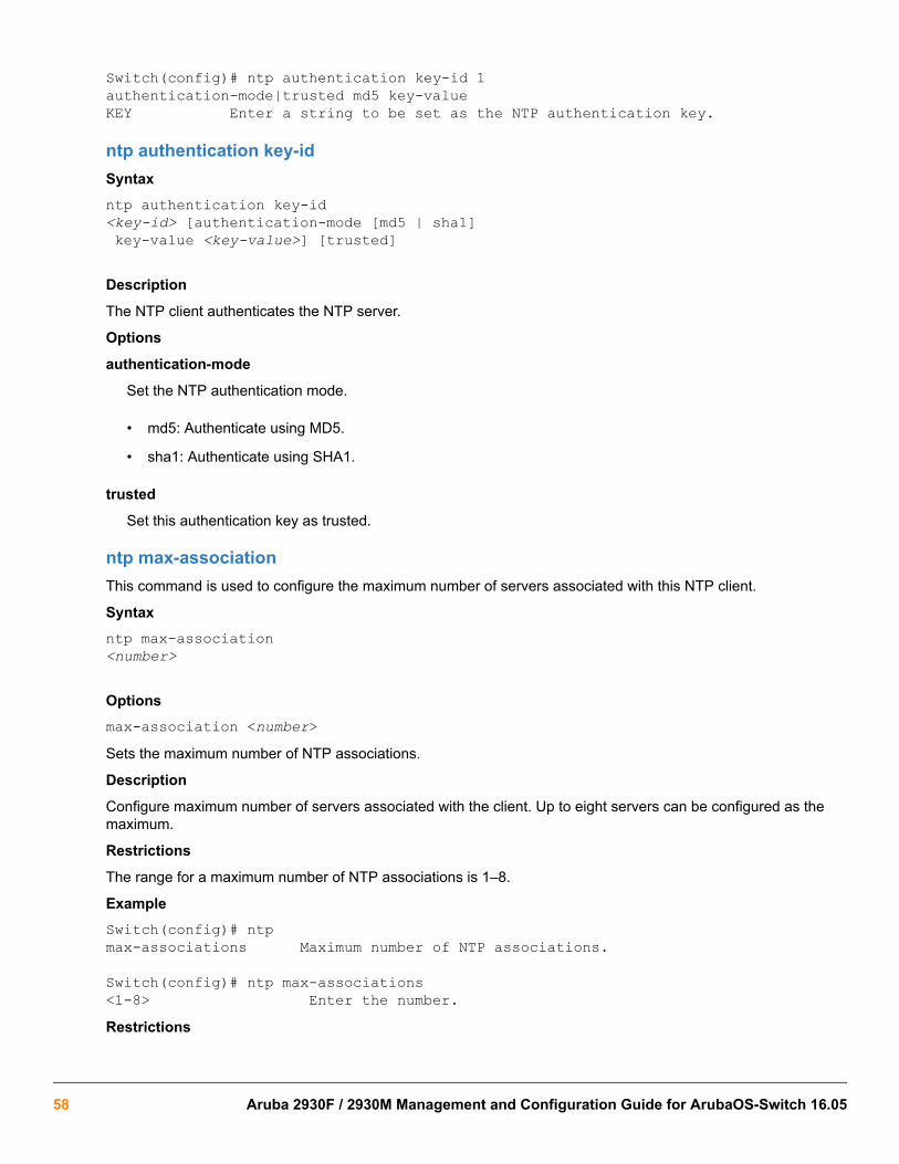
Switch(config)# ntp authentication key-id 1authentication-mode|trusted md5 key-value KEY Enter a string to be set as the NTP authentication key.
ntp authentication key-idSyntaxntp authentication key-id <key-id> [authentication-mode [md5 | sha1] key-value <key-value>] [trusted] Description
The NTP client authenticates the NTP server.
Options
authentication-mode
Set the NTP authentication mode.
• md5: Authenticate using MD5.
• sha1: Authenticate using SHA1.
trusted
Set this authentication key as trusted.
ntp max-associationThis command is used to configure the maximum number of servers associated with this NTP client.
Syntaxntp max-association <number> Optionsmax-association <number>Sets the maximum number of NTP associations.
Description
Configure maximum number of servers associated with the client. Up to eight servers can be configured as themaximum.
Restrictions
The range for a maximum number of NTP associations is 1–8.
ExampleSwitch(config)# ntpmax-associations Maximum number of NTP associations.
Switch(config)# ntp max-associations<1-8> Enter the number.Restrictions
58 Aruba 2930F / 2930M Management and Configuration Guide for ArubaOS-Switch 16.05

Validation Error/Warning/Prompt
When the number of configured NTP servers is morethan the max-associations value.
The maximum number of NTP serversallowed is <number>.
When the max-associations value is less than the (n)number of configured NTP servers.
Max-associations value cannot be lessthan the number of NTP serversconfigured.
ntp serverThis command is used to configure the NTP servers.
Syntax
[no] ntp server
ntp server <IP-ADDR|IPv6-ADDR> [key <key-id>] [oobm] [max-poll <max-poll-val>][min-poll <min-poll-val>][burst | iburst] [version <1-4>]
Parameters/Options[no]Removes the unicast NTP configurations on the device.
SubcommandsIP-ADDRSets the IPv4 address of the NTP server.
IPV6-ADDRSets the IPv6 address of the NTP server.
key <key-id>Specifies the authentication key.
max-poll <max-poll-val>Configures the maximum time intervals in power of 2 seconds. Range is 4–17 (e.g., 5 would translate to 2 raisedto 5 or 32).
min-poll <min-poll-val>Configures the minimum time intervals in seconds. Range is 4–17.
burstEnables burst mode.
iburstEnables initial burst mode.
versionSets version 1–4.
Usage
A maximum of 8 NTP servers can be configured.
Exampleswitch(config)# ntpserver Allow the software clock to be synchronized by an NTP
Chapter 2 Time Protocols 59

time server.broadcast Operate in broadcast mode.unicast Operate in unicast mode.
switch(config)# ntp serverIP-ADDR IPv4 address of the NTP server. IPV6-ADDR IPv6 address of the NTP server.
switch(config)# ntp server <IP-ADDR>Key Specify the authentication key.
switch(config)# ntp server <IP-ADDR> key key-idMax-poll Configure the maximum time intervals in seconds.
switch(config)# ntp server <IP-ADDR> key key-id max-poll<4-17> Enter an integer number.
Switch(config)# ntp server <IP-ADDR> key key-idMin-poll Configure the minimum time intervals in seconds.
switch(config)# ntp server <IP-ADDR> key key-id min-poll<4-17> Enter an integer number.
switch(config)# ntp server <IP-ADDR> key key-id prefer max-poll <max-poll-val> min-poll <min-poll-val>iburst Enable initial burst (iburst) mode.burst Enable burst mode.
Switch(config)# ntp server IP-ADDR key key-id prefer maxpoll <number>minpoll <number> iburstRestrictions
Validation Error/Warning/Prompt
If authentication key-id not configured Authentication key-id has not beenconfigured.
If Key-id is not marked as trusted Key-id is not trusted.
When min poll value is more than max poll value NTP max poll value should be more thanmin poll value.
ntp server key-idSyntaxntp server <IP-ADDR |IPV6-ADDR> key—id <key-id> [max-poll <max-poll-val>] [min-poll <min-poll-val>] [burst | iburst]
60 Aruba 2930F / 2930M Management and Configuration Guide for ArubaOS-Switch 16.05

Description
Configure the NTP server. <IP-ADDR> indicates the IPv4 address of the NTP server. <IPV6-ADDR> indicates theIPv6 address of the NTP server.
Options
burst
Enables burst mode.
iburst
Enables initial burst (iburst) mode.
key-id
Set the authentication key to use for this server.
max-poll <max-poll-val>
Configure the maximum time intervals in seconds.
min-poll <min-poll-val>
Configure the minimum time intervals in seconds.
ntp ipv6-multicastThis command is used to configure NTP multicast on a VLAN interface.
Syntaxntp ipv6-multicastDescription
Configure the interface to listen to the NTP multicast packets.
ExampleSwitch(vlan-2)# ntpipv6-multicast Configure the interface to listen to the NTP multicast packets.Restrictions
Validation Error/Warning/Prompt
If ipv6 is not enabled on vlan interface IPv6 address not configured on theVLAN.
debug ntpThis command is used to display debug messages for NTP.
Syntaxdebug ntp <event | packet> OptionseventDisplays event log messages related to NTP.
packetsDisplays NTP packet messages.
Chapter 2 Time Protocols 61

Description
Enable debug logging. Use [no] to disable debug logging.
ExampleSwitch(config)# debug ntpevent Display event log messages related to NTP.packet Display NTP packet messages.
ntp trapThis command is used to configure NTP traps.
Syntaxntp trap <trap-name> Description
Enable NTP traps. Use [no] to disable NTP traps.
Options
ntp-mode-change
Trap name resulting in send notification when the NTP entity changes mode, includingstarting and stopping (if possible).
ntp-stratum-change
Trap name resulting in send notification when stratum level of NTP changes.
ntp-peer-change
Trap name resulting in send notification when a (new) syspeer has been selected.
ntp-new-association
Trap name resulting in send notification when a new association is mobilized.
ntp-remove-association
Trap name resulting in send notification when an association is demobilized.
ntp-config-change
Trap name resulting in send notification when the NTP configuration has changed.
ntp-leapsec-announced
Trap name resulting in send notification when a leap second has been announced.
ntp-alive-heartbeat
Trap name resulting in send notification periodically (as defined byntpEntHeartbeatInterval) to indicate that the NTP entity is still alive.
all
Enable all traps.
Usage
The traps defined below are generated as the result of finding an unusual condition while parsing an NTP packetor a processing a timer event. Note that if more than one type of unusual condition is encountered while parsingthe packet or processing an event, only the first one will generate a trap. Possible trap names are:
- 'ntpEntNotifModeChange' The notification to be sent when the NTP entity changesmode, including starting and stopping (if possible).
62 Aruba 2930F / 2930M Management and Configuration Guide for ArubaOS-Switch 16.05

- 'ntpEntNotifStratumChange' The notification to be sent when stratum level of NTPchanges.- 'ntpEntNotifSyspeerChanged' The notification to be sent when a (new) syspeer hasbeen selected.- 'ntpEntNotifAddAssociation' The notification to be sent when a new association ismobilized.- 'ntpEntNotifRemoveAssociation' The notification to be sent when an association isdemobilized.- 'ntpEntNotifConfigChanged' The notification to be sent when the NTP configurationhas changed.- 'ntpEntNotifLeapSecondAnnounced' The notification to be sent when a leap secondhas been announced.- 'ntpEntNotifHeartbeat' The notification to be sent periodically (as defined byntpEntHeartbeatInterval) to indicate that the NTP entity is still alive.- 'ntpEntNotifAll' The notification to be sent when all traps have been enabled
show ntp statisticsThis command is used to show NTP statistics.
Syntaxshow ntp statisticsDescription
Show information about NTP packets.
ExamplesSwitch(config)# show ntp statistics
NTP Global statistics information
NTP In Packets : 100NTP Out Packets : 110NTP Bad Version Packets : 4NTP Protocol Error Packets : 0
switch(config)# show ntp statistics
NTP Global statistics information
NTP In Packets : 100NTP Out Packets : 110NTP Bad Version Packets : 4 NTP Protocol Error Packets : 0
show ntp statusSyntax
Description
Show the status of NTP.
show ntp status
Chapter 2 Time Protocols 63

ExampleSwitch(config)# show ntp status
NTP Status informationNTP Status : Disabled NTP Mode : BroadcastSynchronization Status : Synchronized Peer Dispersion : 8.01 secStratum Number : 2 Leap Direction : 1Reference Assoc Id : 1 Clock Offset : 0.0000 secReference : 192.0.2.1 Root Delay : 0.00 secPrecision : 2**7 Root Dispersion : 15.91 secNTP Uptime : 01d 09h 15m Time Resolution : 1Drift : 0.000000000 sec/sec
System Time : Tue Aug 25 04:59:11 2015Reference Time : Mon Jan 1 00:00:00 1990
show ntp associationsSyntaxshow ntp associations [detail <IP-ADDR>] Description
Show the status of configured NTP associations.
Options
detail
Show the detailed status of NTP associations configured for the system.
Switch(config)# show ntp associations
NTP Associations Entries
Address St T When Poll Reach Delay Offset Dispersion -------------- --- -- ---- ----- ------ ------- ------- ----------121.0.23.1 16 u - 1024 0 0.000 0.000 0.000231.45.21.4 16 u - 1024 0 0.000 0.000 0.00055.21.56.2 16 u - 1024 0 0.000 0.000 0.00023.56.13.1 3 u 209 1024 377 54.936 -6.159 12.68891.34.255.216 4 u 132 1024 377 1.391 0.978 3.860
Switch(config)# show ntp associations detail <IP ADDR>
NTP association information
IP address : 172.31.32.2 Peer Mode : Server Status : Configured, Insane, Invalid Peer Poll Intvl : 64 Stratum : 5 Root Delay : 137.77 secRef Assoc ID : 0 Root Dispersion : 142.75Association Name : NTP Association 0 Reach : 376Reference ID : 16.93.49.4 Delay : 4.23 secOur Mode : Client Offset : -8.587 sec Our Poll Intvl : 1024 Precision : 2**19
64 Aruba 2930F / 2930M Management and Configuration Guide for ArubaOS-Switch 16.05

Dispersion : 1.62 secAssociation In Packets : 60Association Out Packets : 60Association Error Packets : 0Origin Time : Fri Jul 3 11:39:40 2015Receive Time : Fri Jul 3 11:39:44 2015Transmit Time : Fri Jul 3 11:39:44 2015
-----------------------------------------------------------------------------Filter Delay = 4.23 4.14 2.41 5.95 2.37 2.33 4.26 4.33Filter Offset = -8.59 -8.82 -9.91 -8.42 -10.51 -10.77 -10.13 -10.11
show ntp authenticationSyntax
Description
Show the authentication status and other information about the authentication key.
show ntp authentication
Switch(config)# show ntp authentication
NTP Authentication Information
Key-ID Auth Mode Trusted-------- ---------- -------67 md5 yes 7 md5 no 1 sha1 yes 2 sha1 no
Chapter 2 Time Protocols 65

Validation rules
Validation Error/Warning/Prompt
If access-list name is not valid. Please enter a valid access-list name.
If the authentication method is being set totwo-factor authentication, various messagesdisplay.
If both the public key and username/password are notconfigured: Public key and username/password shouldbe configured for a successful two-factorauthentication.
If public key is configured and username is notconfigured:
Username and password should be configured for asuccessful two-factor authentication.
If the username is configured and public key is notconfigured:
Public key should be configured for a successful two-factor authentication.
If “ssh-server” certificate is not installed at the time ofenabling certificate-password authentication:
The “ssh-server” certificate should be installed for asuccessful two-factor authentication.
If the authentication method is set to two-factor while installing the public key, amessage displays.
The client public keys without username will not beconsidered for the two-factor authentication for the SSHsession.
If the username and the key installation userfor that privilege do not match, a messagedisplays and installation is not allowed.
This will also happen when theauthentication method is set for two-factor.
The username in the key being installed does notmatch the username configured on the switch.
If the maximum number of <username : TAprofile> associations is reached for a givenTA profile, a message displays.
Maximum number of username associations with a TAprofile is 10.
If secondary authentication type for two-factor authentication chosen is not "none", amessage displays.
Not legal combination of authentication methods.
If the authentication method is anything otherthan two-factor and the two-factorauthentication method options are set, amessage displays.
Not legal combination of authentication methods.
If two-factor authentication is set and usertries to SSH into another system using ssh<ip | hostname> command, a messagedisplays.
SSH client is not supported when the two-factorauthentication is enabled.
Table Continued
66 Aruba 2930F / 2930M Management and Configuration Guide for ArubaOS-Switch 16.05

Validation Error/Warning/Prompt
If timeSync is in SNTP or Timep when NTPis enabled.
Timesync is not configured to NTP.
If timesync is NTP and NTP is enabled andwe try to change timesync to SNTP.
Disable NTP before changing timesync to SNTP orTIMEP.
If we try to configure NTP servers more thanthe configured max-associations value.
The maximum number of NTP servers allowed is 2.
If we have ‘n’ NTP servers configured andwe try to configure a max-associations valueless than (n) number of NTP servers alreadyconfigured.
Max-associations value cannot be less than thenumber of NTP servers configured.
If authentication key-id is not configured. Authentication key-id %d has not been configured.
If key-id is not marked as trusted. Key-id %d is not trusted.
If min poll value is more than max poll value. NTP max poll value should be more than min pollvalue.
If ipv6 is not enabled on vlan interface. IPv6 address not configured on the VLAN.
Chapter 2 Time Protocols 67

Event log messages
Cause
Event Message
RMON_AUTH_TWO_FACTOR_AUTHEN_STATUS W 01/01/15 18:24:03 03397: auth: %s.
Examples:
W 01/01/15 18:24:03 03397: auth: Public key andusername/password should be configured for thesuccessful two-factor authentication.
W 01/01/15 18:24:03 03397: auth: Username andpassword should be configured for the successfultwo-factor authentication.
W 01/01/15 18:24:03 03397: auth: Public key shouldbe configured for the successful two-factorauthentication.
I 01/01/15 18:24:03 03397: auth: The validation ofcertificate of SSH user ‘user1’ is successful.
RMON_SSH_KEY_TWO_FACTOR_EN W 01/01/15 18:24:03 03399: ssh: %s.
Examples:
W 01/01/15 18:24:03 03399: ssh: The client publickeys without username will not be considered for thetwo-factor authentication for SSH session.
W 01/01/15 18:24:03 03399: ssh: The privilege levelfor the user with the SSH key conflicts with the userconfigured.
RMON_SSH_TWO_FACTOR_AUTH_FAIL W 01/01/15 18:24:03 03398: ssh: %s.
Examples:
W 01/01/15 18:24:03 03398: ssh: The two-factorauthentication for SSH session failed due to thefailure in public key authentication.
W 01/01/15 18:24:03 03398: ssh: The two-factorauthentication for SSH session failed due to thefailure in username/password authentication.
W 01/01/15 18:24:03 03398: ssh: The two-factorauthentication for SSH session failed due to thefailure in validating the client certificate.
W 01/01/15 18:24:03 03398: ssh: The two-factorauthentication for SSH session failed as “ssh-server”certificate is not installed.
When NTP client enabled. NTP client is enabled.
When NTP client disabled. NTP client is disabled.
Table Continued
68 Aruba 2930F / 2930M Management and Configuration Guide for ArubaOS-Switch 16.05

Event Message
When NTP found a new broadcast server. A new broadcast server at %s.
When system clock was updated with new time. The system clock time was changed by %ld sec %lunsec. The new time is %s.
When NTP stratum was updated. The NTP Stratum was changed from %d to %d.
When all NTP associations are cleared. All the NTP server associations are reset.
When server is not reachable. The NTP Server 10.1.1.2 is unreachable. (2 times in60 seconds)
When MD5/SHA1 authentication failed. The MD5 authentication on the NTP packet failed.
The SHA1 authentication on the NTP packet failed.
Precision Time Protocol (PTP)
ptpSyntaxptp {enable | disable}
no ptp {enable | disable}
Description
Enable updating of IEEE 1588 PTP packets.
• The feature is disabled by default.
• The no form of this command is the same as ptp disable.
This feature is available on the 2930M and only in standalone. It is disabled for stacks.
Command contextinterface
Parametersenable
When the ptp command is enabled, ports that support IEEE 1588 will operate in end-to-end transparentmode and will update the correction field of forwarded PTP packets.
disableWhen the ptp command is disabled, PTP packets are forwarded unchanged.
Chapter 2 Time Protocols 69
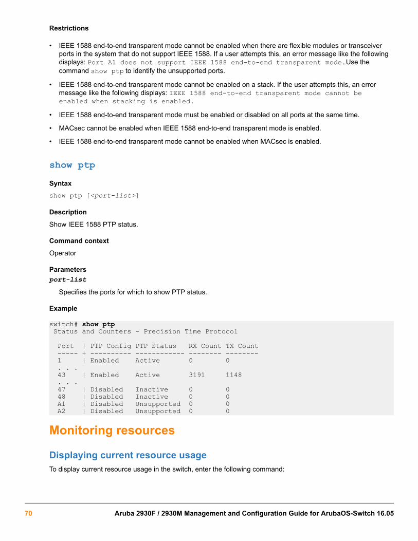
Restrictions
• IEEE 1588 end-to-end transparent mode cannot be enabled when there are flexible modules or transceiverports in the system that do not support IEEE 1588. If a user attempts this, an error message like the followingdisplays: Port A1 does not support IEEE 1588 end-to-end transparent mode.Use thecommand show ptp to identify the unsupported ports.
• IEEE 1588 end-to-end transparent mode cannot be enabled on a stack. If the user attempts this, an errormessage like the following displays: IEEE 1588 end-to-end transparent mode cannot beenabled when stacking is enabled.
• IEEE 1588 end-to-end transparent mode must be enabled or disabled on all ports at the same time.
• MACsec cannot be enabled when IEEE 1588 end-to-end transparent mode is enabled.
• IEEE 1588 end-to-end transparent mode cannot be enabled when MACsec is enabled.
show ptpSyntaxshow ptp [<port-list>]
Description
Show IEEE 1588 PTP status.
Command context
Operator
Parametersport-list
Specifies the ports for which to show PTP status.
Example
switch# show ptp Status and Counters - Precision Time Protocol
Port | PTP Config PTP Status RX Count TX Count ----- + ---------- ------------ -------- -------- 1 | Enabled Active 0 0 . . . 43 | Enabled Active 3191 1148 . . . 47 | Disabled Inactive 0 0 48 | Disabled Inactive 0 0 A1 | Disabled Unsupported 0 0 A2 | Disabled Unsupported 0 0
Monitoring resources
Displaying current resource usageTo display current resource usage in the switch, enter the following command:
70 Aruba 2930F / 2930M Management and Configuration Guide for ArubaOS-Switch 16.05
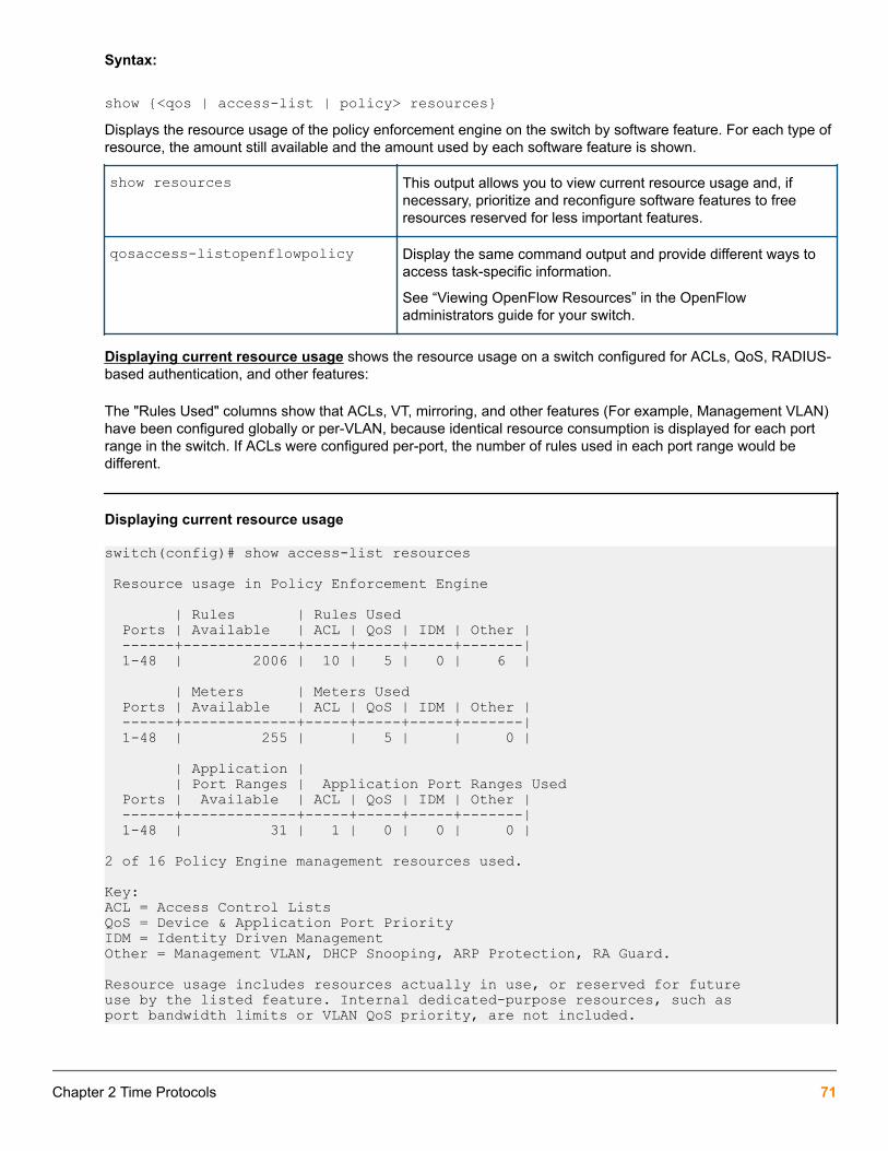
Syntax:
show {<qos | access-list | policy> resources}Displays the resource usage of the policy enforcement engine on the switch by software feature. For each type ofresource, the amount still available and the amount used by each software feature is shown.
show resources This output allows you to view current resource usage and, ifnecessary, prioritize and reconfigure software features to freeresources reserved for less important features.
qosaccess-listopenflowpolicy Display the same command output and provide different ways toaccess task-specific information.
See “Viewing OpenFlow Resources” in the OpenFlowadministrators guide for your switch.
Displaying current resource usage shows the resource usage on a switch configured for ACLs, QoS, RADIUS-based authentication, and other features:
The "Rules Used" columns show that ACLs, VT, mirroring, and other features (For example, Management VLAN)have been configured globally or per-VLAN, because identical resource consumption is displayed for each portrange in the switch. If ACLs were configured per-port, the number of rules used in each port range would bedifferent.
Displaying current resource usage
switch(config)# show access-list resources
Resource usage in Policy Enforcement Engine
| Rules | Rules Used Ports | Available | ACL | QoS | IDM | Other | ------+-------------+-----+-----+-----+-------| 1-48 | 2006 | 10 | 5 | 0 | 6 |
| Meters | Meters Used Ports | Available | ACL | QoS | IDM | Other | ------+-------------+-----+-----+-----+-------| 1-48 | 255 | | 5 | | 0 |
| Application | | Port Ranges | Application Port Ranges Used Ports | Available | ACL | QoS | IDM | Other | ------+-------------+-----+-----+-----+-------| 1-48 | 31 | 1 | 0 | 0 | 0 |
2 of 16 Policy Engine management resources used.
Key:ACL = Access Control ListsQoS = Device & Application Port PriorityIDM = Identity Driven ManagementOther = Management VLAN, DHCP Snooping, ARP Protection, RA Guard.
Resource usage includes resources actually in use, or reserved for futureuse by the listed feature. Internal dedicated-purpose resources, such asport bandwidth limits or VLAN QoS priority, are not included.
Chapter 2 Time Protocols 71

Viewing information on resource usageThe switch allows you to view information about the current usage and availability of resources in the PolicyEnforcement engine, including the following software features:
• Access control lists (ACL)
• Quality-of-service (QoS), including device and application port priority, ICMP rate-limiting, and QoS policies
• Dynamic assignment of per-port or per-user ACLs and QoS through RADIUS authentication designated as“IDM”, with or without the optional identity-driven management (IDM) application
• Virus throttling (VT) using connection-rate filtering
• Mirroring policies, including switch configuration as an endpoint for remote intelligent mirroring
• Other features, including:
◦ Management VLAN
◦ DHCP snooping
◦ Dynamic ARP protection
◦ Jumbo IP-MTU
Policy enforcement engineThe policy enforcement engine is thehardware element in the switch that manages QoS, mirroring, and ACLpolicies, as well as other software features, using the rules that you configure. Resource usage in the policyenforcement engine is based on how these features are configured on the switch:
• Resource usage by dynamic port ACLs is determined as follows:
Dynamic port ACLs configured by a RADIUS server (with or without the optional IDM application) for anauthenticated client determine the current resource consumption for this feature on a specified slot. When aclient session ends, the resources in use for that client become available for other uses.
• When the following features are configured globally or per-VLAN, resource usage is applied across all portgroups or all slots with installed modules:
◦ ACLs
◦ QoS configurations that use the following commands:
– QoS device priority (IP address) through the CLI using the qos device-priority command
– QoS application port through the CLI using qos tcp-port or qos udp-port– VLAN QoS policies through the CLI using service-policy
◦ Management VLAN configuration
◦ DHCP snooping
◦ Dynamic ARP protection
◦ Remote mirroring endpoint configuration
72 Aruba 2930F / 2930M Management and Configuration Guide for ArubaOS-Switch 16.05

◦ Mirror policies per VLAN through the CLI using monitor service◦ Jumbo IP-MTU
• When the following features are configured per-port, resource usage is applied only to the slot or port group onwhich the feature is configured:
◦ ACLs or QoS applied per-port or per-user through RADIUS authentication
◦ ACLs applied per-port through the CLI using the ip access-group or ipv6 traffic-filtercommands
◦ QoS policies applied per port through the CLI using the service-policy command
◦ Mirror policies applied per-port through the CLI using the monitor all service and service-policycommands
◦ ICMP rate-limiting through the CLI using the rate-limit icmp command
Usage notes for show resources output
• A 1:1 mapping of internal rules to configured policies in the switch does not necessarily exist. As a result,displaying current resource usage is the most reliable method for keeping track of available resources. Also,because some internal resources are used by multiple features, deleting a feature configuration may notincrease the amount of available resources.
• Resource usage includes resources actually in use or reserved for future use by the listed features.
• "Internal dedicated-purpose resources" include the following features:
◦ Per-port ingress and egress rate limiting through the CLI using rate-limit in/out◦ Per-port or per-VLAN priority or DSCP through the CLI using qos priority or qos dscp◦ Per protocol priority through the CLI using qos protocol
• The "Available" columns display the resources available for additional feature use.
• The "IDM" column shows the resources used for RADIUS-based authentication with or without the IDM option.
• "Meters" are used when applying either ICMP rate-limiting or a QoS policy with a rate-limit class action.
When insufficient resources are availableThe switch has ample resources for configuring features and supporting RADIUS-authenticated clients (with orwithout the optional IDMapplication).
If the resources supporting these features become fully subscribed:
• The current feature configuration, RADIUS-authenticated client sessions, and VT instances continue tooperate normally.
• The switch generates anevent log notice to say that current resources are fully subscribed.
• Currently engaged resources must be released before any of the following actions are supported:
◦ Modifying currently configured ACLs, IDM, VT, and other software features, such as Management VLAN,DHCP snooping, and dynamic ARP protection.You can modify currently configured classifier-base QoS and
Chapter 2 Time Protocols 73

mirroring policies if a policy has not been applied to an interface. However, sufficient resources must beavailable when you apply a configured policy to an interface.
◦ Acceptance of new RADIUS-based client authentication requests (displayed as a new resource entry forIDM).Failure to authenticate a client that presents valid credentials may indicate that insufficient resourcesare available for the features configured for the client in the RADIUS server. To troubleshoot, check theevent log.
◦ Throttling or blocking of newly detected clients with high rate-of-connection requests (as defined by thecurrent VT configuration).The switch continues to generate Event Log notifications (and SNMP trapnotification, if configured) for new instances of high-connection-rate behavior detected by the VT feature.
74 Aruba 2930F / 2930M Management and Configuration Guide for ArubaOS-Switch 16.05

Viewing port status and configuring port parameters
Connecting transceivers to fixed-configuration devicesIf the switch either fails to show a link between an installed transceiver and another device or demonstrates errorsor other unexpected behavior on the link, check the port configuration on both devices for a speed and/or duplex(mode) mismatch.
• To check the mode setting for a port on the switch, use either the Port Status screen in the menu interface orshow interfaces brief in the CLI (see Viewing port status and configuration (CLI)).
• To display information about the transceivers installed on a switch, enter the show tech receiverscommand in the CLI (The show tech transceivers command on page 83).
Table 3: Status and parameters for each port type
Status orparameter
Description
Enabled Yes (default): The port is ready for a network connection.
No: The port will not operate, even if properly connected in a network. Use this setting, Forexample, if the port needs to be shut down for diagnostic purposes or while you are makingtopology changes.
Status (read-only) Up: The port senses a link beat.
Down: The port is not enabled, has no cables connected, or is experiencing a network error.For troubleshooting information, see the installation and getting started guide you receivedwith the switch. See also to Appendix C, "Troubleshooting" (in this manual).
Table Continued
Chapter 3Port Status and Configuration
Chapter 3 Port Status and Configuration 75

Status orparameter
Description
Mode The port's speed and duplex (data transfer operation) setting.10/100/1000Base-TPorts:
• Auto-MDIX (default): Senses speed and negotiates with the port at the other end of thelink for port operation (MDI-X or MDI).To see what the switch negotiates for the autosetting, use the CLI show interfaces brief command or the 3. Port Statusoption under 1. Status and Counters in the menu interface.
• MDI: Sets the port to connect with a PC using a crossover cable (manual mode—appliesonly to copper port switches using twisted-pair copper Ethernet cables)
• MDIX: Sets the port to connect with a PC using a straight-through cable (manual mode—applies only to copper port switches using twisted-pair copper Ethernet cables)
• Auto-10: Allows the port to negotiate between half-duplex (HDx) and full-duplex (FDx)while keeping speed at 10 Mbps. Also negotiates flow control (enabled or disabled).Hewlett Packard Enterprise recommends auto-10 for links between 10/100 auto-sensingports connected with Cat 3 cabling. (Cat 5 cabling is required for 100 Mbps links.).
• 10HDx:10 Mbps, half-duplex
• 10FDx: 10 Mbps, full-duplex
• Auto-100: Uses 100 Mbps and negotiates with the port at the other end of the link forother port operation features.
• Auto-10-100: Allows the port to establish a link with the port at the other end at either10 Mbps or 100 Mbps, using the highest mutual speed and duplex mode available. Onlythese speeds are allowed with this setting.
• Auto-1000: Uses 1000 Mbps and negotiates with the port at the other end of the link forother port operation features.
• 100Hdx: Uses 100 Mbps, half-duplex.
• 100Fdx: Uses 100 Mbps, full-duplex
Gigabit Fiber-Optic Ports (Gigabit-SX, Gigabit-LX, and Gigabit-LH):
• 1000FDx: 1000 Mbps (1 Gbps), full-duplex only
• Auto (default): The port operates at 1000FDx and auto-negotiates flow control with thedevice connected to the port.
Gigabit Copper Ports:
• 1000FDx: 1000 Mbps (1 Gbps), full-duplex only
• Auto (default): The port operates at 1000FDx and auto-negotiates flow control with thedevice connected to the port.
Table Continued
76 Aruba 2930F / 2930M Management and Configuration Guide for ArubaOS-Switch 16.05

Status orparameter
Description
10-Gigabit CX4 Copper Ports: 10-Gigabit SC Fiber-Optic Ports (10-GbE SR, 10-GbELR, 10-GbE ER):
Auto: The port operates at 10 gigabits FDx and negotiates flow control. Lower speedsettings or half-duplex are not allowed.
Conditioning patch cord cables are not supported on 10-GbE.
Auto-MDIX The switch supports Auto-MDIX on 10Mb, 100Mb, and 1 Gb T/TX (copper) ports. (Fiberports and 10-gigabit ports do not use this feature.)
• Automdix: Configures the port for automatic detection of the cable type (straight-through or crossover).
• MDI: Configures the port to connect to a switch, hub, or other MDI-X device with astraight-through cable.
• MDIX: Configures the port to connect to a PC or other MDI device with a straight-throughcable.
Flow control• Disabled (default): The port does not generate flow control packets, and drops any flow
control packets it receives.
• Enabled: The port uses 802.3x link layer flow control, generates flow-control packets,and processes received flow-control packets.
With the port mode set to Auto (the default) and flow control enabled, the switch negotiatesflow control on the indicated port. If the port mode is not set to Auto, or if flow control isdisabled on the port, flow control is not used. Note that flow control must be enabled on bothends of a link.
Broadcast limit Specifies the percentage of the theoretical maximum network bandwidth that can be usedfor broadcast traffic. Any broadcast traffic exceeding that limit will be dropped. Zero (0)means the feature is disabled.
The broadcast-limit command operates at the port context level to set the broadcast limit fora port on the switch.
This feature is not appropriate for networks that require high levels of IPX orRIP broadcast traffic.
Viewing port configuration (Menu)The menu interface displays the configuration for ports and (if configured) any trunk groups.
From the Main Menu, select:
1. Status and Counters 4. Port Status
Chapter 3 Port Status and Configuration 77

A switch port status screen
==========================- CONSOLE - MANAGER MODE -========================== Status and Counters - Port Status
Intrusion MDI Flow Bcast Port Type Alert Enabled Status Mode Mode Ctrl Limit ----- --------- --------- ------- ------ ---------- ----- ----- ------ 1 100/1000T No Yes Down 100FDx Auto off 0 2 100/1000T No Yes Down 1000FDx Auto off 0 3 100/1000T No Yes Down 1000FDx Auto off 0 4 100/1000T No Yes Down 1000FDx Auto off 0 5 100/1000T No Yes Down 1000FDx Auto off 0 6 100/1000T No Yes Down 1000FDx Auto off 0 7 100/1000T No Yes Down 1000FDx Auto off 0 8 100/1000T No Yes Down 1000FDx Auto off 0 9 100/1000T No Yes Down 1000FDx Auto off 0 10 100/1000T No Yes Down 1000FDx Auto off 0 11 100/1000T No Yes Down 1000FDx Auto off 0
Actions-> Back Intrusion log Help
Return to previous screen.Use up/down arrow keys to scroll to other entries, left/right arrow keys tochange action selection, and <Enter> to execute action.
Configuring ports (Menu)The menu interface uses the same screen for configuring both individual ports and port trunk groups. Forinformation on port trunk groups, see the chapter on "Port Trunking".
Procedure
1. From the Main Menu, select:
2. Switch Configuration…
2. Port/Trunk Settings
Port/trunk settings with a trunk group configured
=====================- TELNET - MANAGER MODE -===================== Switch Configuration - Port/Trunk Settings
Port Type Enabled Mode Flow Ctrl Group Type ---- -------- + -------- ----------- --------- ----- ----- A1 1000T | Yes Auto-10-100 Disable A2 1000T | Yes Auto-10-100 Disable A3 1000T | Yes Auto Disable A3 1000T | Yes Auto Disable A4 1000T | Yes Auto Disable A5 1000T | Yes Auto Disable A6 1000T | Yes Auto Disable A7 1000T | Yes Auto Disable Trk1 Trunk A8 1000T | Yes Auto Disable Trk2 Trunk
Actions-> Cancel Edit Save Help
Cancel changes and return to previous screen.
78 Aruba 2930F / 2930M Management and Configuration Guide for ArubaOS-Switch 16.05

Use arrow keys to change action selection and <Enter> to executeaction.
2. Press [E] (for Edit).
The cursor moves to the Enabled field for the first port.
For further information on configuration options for these features, see the online help provided with thisscreen.
3. When you have finished making changes to the above parameters, press [Enter], then press [S] (forSave).
Viewing port status and configuration (CLI)Use the following commands to display port status and configuration data.
Syntax:
show interfaces [brief | config | < port-list >]brief
Lists the current operating status for all ports on the switch.
configLists a subset of configuration data for all ports on the switch; that is, for each port, the display shows whetherthe port is enabled, the operating mode, and whether it is configured for flow control.
<port-list>Shows a summary of network traffic handled by the specified ports.
The show interfaces brief command listing
switch(config)# show interfaces briefStatus and Counters - Port Status
| Intrusion MDI Flow BcastPort Type | Alert Enabled Status Mode Mode Ctrl Limit----- --------- + --------- ------- ------ ---------- ----- ----- ------B1 100/1000T | No Yes Down Auto-10-100 Auto off 0B2 100/1000T | No Yes Down 1000FDx Auto off 0B3 100/1000T | No Yes Down 1000FDx Auto off 0B4 100/1000T | No Yes Down 1000FDx Auto off 0B5 100/1000T | No Yes Down 1000FDx Auto off 0B6 100/1000T | No Yes Down 1000FDx Auto off 0
The show interfaces config command listing
switch(config)# show interfaces config
Port Settings
Port Type | Enabled Mode Flow Ctrl MDI ----- --------- + ------- ------------ --------- ---- B1 100/1000T | Yes Auto-10-100 Disable Auto B2 100/1000T | Yes Auto Disable Auto B3 100/1000T | Yes Auto Disable Auto B4 100/1000T | Yes Auto Disable Auto
Chapter 3 Port Status and Configuration 79

B5 100/1000T | Yes Auto Disable Auto B6 100/1000T | Yes Auto Disable Auto
Dynamically updating the show interfaces command (CLI/Menu)Syntax:
show interfaces displayUses the display option to initiate the dynamic update of the show interfaces command, with the outputbeing the same as the show interfaces command.
Select Back to exit the display.
Example:
switch# show interfaces displayWhen using the display option in the CLI, the information stays on the screen and is updated every 3 seconds, asoccurs with the display using the menu feature. The update is terminated with Cntl-C.
You can use the arrow keys to scroll through the screen when the output does not fit in one screen.
Figure 7: show interfaces display command with dynamically updating output
Customizing the show interfaces command (CLI)You can create show commands displaying the information that you want to see in any order you want by usingthe custom option.
Syntax:show interfaces custom [port-list] column-listSelect the information that you want to display. Supported columns are shown in the table below.
80 Aruba 2930F / 2930M Management and Configuration Guide for ArubaOS-Switch 16.05

Table 4: Supported columns, what they display, and examples:
Parameter column Displays Examples
port Port identifier A2
type Port type 100/1000T
status Port status up or down
speed Connection speed and duplex 1000FDX
mode Configured mode auto, auto-100, 100FDX
mdi MDI mode auto, MDIX
flow Flow control on or off
name Friendly port name
vlanid The vlan id this port belongs to, or "tagged" if itbelongs to more than one vlan
4tagged
enabled port is or is not enabled yes or nointrusion
intrusion Intrusion alert status no
bcast Broadcast limit 0
The custom show interfaces command
switch(config)# show int custom 1-4 port name:4 type vlan intrusion speed enabled mdi
Status and Counters - Custom Port Status
Intrusion Port Name Type VLAN Alert Speed Enabled MDI-mode ---- ---------- ---------- ----- --------- ------- ------- -------- 1 Acco 100/1000T 1 No 1000FDx Yes Auto 2 Huma 100/1000T 1 No 1000FDx Yes Auto 3 Deve 100/1000T 1 No 1000FDx Yes Auto 4 Lab1 100/1000T 1 No 1000FDx Yes AutoYou can specify the column width by entering a colon after the column name, then indicating the number ofcharacters to display. In the above example, the Name column displays only the first four characters of the name.All remaining characters are truncated.
Each field has a fixed minimum width to be displayed. If you specify a field width smaller than theminimum width, the information is displayed at the minimum width. For example, if the minimumwidth for the Name field is 4 characters and you specify Name:2, the Name field displays 4characters.
You can enter parameters in any order. There is a limit of 80 characters per line; if you exceed this limit an errordisplays.
Chapter 3 Port Status and Configuration 81

Error messages associated with the show interfaces commandThe following table provides information on error messages associated with the show interfaces customcommand.
Error Error message
Requesting too many fields (total characters exceeds80)
Total length of selected data exceeds one line
Field name is misspelled Invalid input: <input>
Mistake in specifying the port list Module not present for port or invalid port: <input>
The port list is not specified Incomplete input: custom
Note on using pattern matching with the show interfaces custom commandIf you have included a pattern matching command to search for a field in the output of the show int customcommand, and the show int custom command produces an error, the error message may not be visible andthe output is empty. For example, if you enter a command that produces an error (such as vlan is misspelled) withthe pattern matching include option, the output may be empty:
HP Switch(config)# show int custom 1-3 name vlun | include vlan1It is advisable to try the show int custom command first to ensure there is output, and then enter thecommand again with the pattern matching option.
Note that in the above command, you can substitute int for interface; that is: show int custom.
show interface smartrateSyntaxshow interface <PORT-LIST> smartrate Description
The option smartrate has been added to the show interface <PORT-LIST> command. This option is usedto display port diagnostics on a Smart Rate port only. If the command is run on a non‐Smart Rate port, amessage similar to Port A1: This command is only applicable to Smart Rate ports isdisplayed.
The show interface <PORT-LIST> smartrate command can be used to retrieve the physical layer linkdiagnostics information for the smartrate ports. As part of 802.3bz implementation, the CLI information has beenupdated with the latest BASE-T modes.
Viewing port utilization statistics (CLI)Use the show interface port-utilization command to view a real-time rate display for all ports on theswitch. The example below shows a sample output from this command.
A show interface port-utilization command listing
switch(config)# show interfaces port-utilization Status and Counters - Port Utilization
82 Aruba 2930F / 2930M Management and Configuration Guide for ArubaOS-Switch 16.05

Rx Tx Port Mode | -------------------------- | -------------------------- | Kbits/sec Pkts/sec Util | Kbits/sec Pkts/sec Util ----- -------- + ---------- --------- ----- + ---------- --------- ----- B1 1000FDx | 0 0 0 | 0 0 0 B2 1000FDx | 0 0 0 | 0 0 0 B3 1000FDx | 0 0 0 | 0 0 0 B4 1000FDx | 0 0 0 | 0 0 0 B5 1000FDx | 0 0 0 | 0 0 0 B6 1000FDx | 0 0 0 | 0 0 0 B7 100FDx | 624 86 00.62 | 496 0 00.49
Operating notes for viewing port utilization statistics
• For each port on the switch, the command provides a real-time display of the rate at which data is received(Rx) and transmitted (Tx) in terms of kilobits per second (KBits/s), number of packets per second (Pkts/s), andutilization (Util) expressed as a percentage of the total bandwidth available.
• The show interfaces <port-list> command can be used to display the current link status and the portrate average over a 5 minute period. Port rates are shown in bits per second (bps) for ports up to 1 Gigabit; for10 Gigabit ports, port rates are shown in kilobits per second (Kbps).
Viewing transceiver status (CLI)The show interfaces transceivers command allows you to:
• Remotely identify transceiver type and revision number without having to physically remove an installedtransceiver from its slot.
• Display real-timestatus information about all installed transceivers, including non-operational transceivers.
The example shows sample output from the show tech transceivers command.
Part # column below enables you to determine the manufacturer for a specified transceiver andrevision number.
The show tech transceivers command
switch# show tech transceivers
Transceiver Technical Information: Port # | Type | Prod # | Serial # | Part # -------+-----------+--------+------------------+---------- 21 | 1000SX | J4858B | CN605MP23K | 22 | 1000LX | J4859C | H11E7X | 2157-2345 23 | ?? | ?? | non operational | 25 | 10GbE-CX4 | J8440A | US509RU079 | 26 | 10GbE-CX4 | J8440A | US540RU002 | 27 | 10GbE-LR | J8437B | PPA02-2904:0017 | 2157-2345 28 | 10GbE-SR | J8436B | 01591602 | 2158-1000 29 | 10GbE-ER | J8438A | PPA03-2905:0001 |
The following transceivers may not function correctly: Port # Message -------- ------------------------ Port 23 Self test failure.
Chapter 3 Port Status and Configuration 83

Operating NotesThe following information is displayed for each installed transceiver:
• Port number on which transceiver is installed.
• Type of transceiver.
• Product number — Includes revision letter, such as A, B, or C. If no revision letter follows a product number,this means that no revision is available for the transceiver.
• Part number — Allows you to determine the manufacturer for a specified transceiver and revision number.
• For a non-HPE switches installed transceiver (see line 23 of "The show tech transceivers command"example), no transceiver type, product number, or part information is displayed. In the Serial Number field,non-operational is displayed instead of a serial number.
• The following error messages may be displayed for a non-operational transceiver:
◦ Unsupported Transceiver. (SelfTest Err#060)◦ This switch only supports revision B and above transceivers.◦ Self test failure.◦ Transceiver type not supported in this port.◦ Transceiver type not supported in this software version.◦ Not an HPE Switch Transceiver.
Enabling or disabling ports and configuring port mode (CLI)You can configure one or more of the following port parameters.
See Status and parameters for each port type.
Syntax:
[no] interface <port-list> [<disable|enable>]Disables or enables the port for network traffic. Does not use the no form of the command. (Default: enable.)
speed-duplex [<auto-10|10-full|10-half|100-full|100-half|auto|auto-100|1000-full>]Note that in the above Syntax:, you can substitute int for interface (for example, int <port-list> ).
Specifies the port's data transfer speed and mode. Does not use the no form of the command. (Default: auto.)
The 10/100 auto-negotiation feature allows a port to establish a link with a port at the other end at either 10 Mbpsor 100 Mbps, using the highest mutual speed and duplex mode available. Only these speeds are allowed with thissetting.
Examples:
To configure port C5 for auto-10-100, enter this command:
switch(config)# int c5 speed-duplex auto-10-100To configure ports C1 through C3 and port C6 for 100Mbps full-duplex, enter these commands:
switch(config)# int c1-c3,c6 speed-duplex 100-full
84 Aruba 2930F / 2930M Management and Configuration Guide for ArubaOS-Switch 16.05

Similarly, to configure a single port with the above command settings, you could either enter the same commandwith only the one port identified or go to the context level for that port and then enter the command. For example,to enter the context level for port C6 and then configure that port for 100FDx:
switch(config)# int e c6switch(eth-C6)# speed-duplex 100-fullIf port C8 was disabled, and you wanted to enable it and configure it for 100FDx with flow-control active, youcould do so with either of the following command sets:
Figure 8: Two methods for changing a port configuration
For more on flow control, see Enabling or disabling flow control (CLI) on page 85.
Enabling or disabling flow control (CLI)
You must enable flow control on both ports in a given link. Otherwise, flow control does not operateon the link and appears as Off in the show interfaces brief port listing, even if flow control isconfigured as enabled on the port in the switch. (See The show interfaces brief commandlisting example.) Also, the port (speed-duplex) mode must be set to Auto (the default).
To disable flow control on some ports, while leaving it enabled on other ports, just disable it on the individual portsyou want to exclude.
(You can find more information on flow control in the Status and parameters for each port type table.)
Syntax:
[no] interface <port-list> flow-controlEnables or disables flow control packets on the port. The no form of the command disables flow control on theindividual ports. (Default: Disabled.)
Examples:
Suppose that:
1. You want to enable flow control on ports A1-A6.
2. Later, you decide to disable flow control on ports A5 and A6.
3. As a final step, you want to disable flow control on all ports.
Chapter 3 Port Status and Configuration 85

Assuming that flow control is currently disabled on the switch, you would use these commands:
Figure 9: Configuring flow control for a series of ports
switch(config)# int a1-a6 flow-control
switch(config)# show interfaces brief
Status and Counters - Port Status
| Intrusion MDI Flow Bcast Port Type | Alert Enabled Status Mode Mode Ctrl Limit ------ --------- + --------- ------- ------ ---------- ---- ---- ----- A1 10GbE-T | No Yes Up 1000FDx NA on 0 A2 10GbE-T | No Yes Up 10GigFD NA on 0 A3 10GbE-T | No Yes Up 10GigFD NA on 0 A4 10GbE-T | No Yes Up 10GigFD NA on 0 A5 10GbE-T | No Yes Up 10GigFD NA on 0 A6 10GbE-T | No Yes Up 10GigFD NA on 0 A7 10GbE-T | No Yes Down 10GigFD NA off 0 A8 10GbE-T | No Yes Up 10GigFD NA off 0
switch(config)# no int a5-a6 flow-control
switch(config)# show interfaces brief
Status and Counters - Port Status
| Intrusion MDI Flow Bcast Port Type | Alert Enabled Status Mode Mode Ctrl Limit ------ --------- + --------- ------- ------ ---------- ---- ---- ----- A1 10GbE-T | No Yes Up 1000FDx NA on 0 A2 10GbE-T | No Yes Down 10GigFD NA on 0 A3 10GbE-T | No Yes Down 10GigFD NA on 0 A4 10GbE-T | No Yes Down 10GigFD NA on 0 A5 10GbE-T | No Yes Down 10GigFD NA off 0 A6 10GbE-T | No Yes Down 10GigFD NA off 0 A7 10GbE-T | No Yes Down 10GigFD NA off 0 A8 10GbE-T | No Yes Down 10GigFD NA off 0
switch(config)# no int a1-a4 flow-control
switch(config)# show interfaces brief
Status and Counters - Port Status
| Intrusion MDI Flow Bcast Port Type | Alert Enabled Status Mode Mode Ctrl Limit ------ --------- + --------- ------- ------ ---------- ---- ---- ----- A1 10GbE-T | No Yes Down 1000FDx NA off 0 A2 10GbE-T | No Yes Down 10GigFD NA off 0 A3 10GbE-T | No Yes Down 10GigFD NA off 0 A4 10GbE-T | No Yes Down 10GigFD NA off 0 A5 10GbE-T | No Yes Down 10GigFD NA off 0 A6 10GbE-T | No Yes Down 10GigFD NA off 0 A7 10GbE-T | No Yes Down 10GigFD NA off 0 A8 10GbE-T | No Yes Down 10GigFD NA off 0
86 Aruba 2930F / 2930M Management and Configuration Guide for ArubaOS-Switch 16.05

Port shutdown with broadcast stormA LAN broadcast storm arises when an excessively high rate of broadcast packets flood the LAN. Occurrence ofLAN broadcast storm disrupts traffic and degrades network performance. To prevent LAN traffic from beingdisrupted, an enhancement of fault-finder commands adds new options, and the corresponding MIBs, that triggera port disablement when a broadcast storm is detected on that port.
Under this enhancement, the CLI commands given only supports broadcast traffic and not multicast and unicasttypes of traffic.
The waiting period range for re-enabling ports is 0 to 604800 seconds. The default waiting period to re-enable aport is zero which prevents the port from automatic re-enabling.
Avoid port flapping when choosing the waiting period by considering the time to re-enable carefully.
Use the following commands to configure the broadcast-storm on a port.
Syntax:
[no] fault-finder broadcast-storm [ethernet] <port-list> action [warn|warn-and-disable <seconds>] [percent <percent>|pps <rate>]
To remove the current configuration of broadcast-storm on a port, use:
Syntax:
no fault-finder broadcast-storm [ethernet] <port-list>broadcast-storm
Configure broadcast storm control.
ppsRising threshold level in number of broadcast packets per second.
percentRising threshold level as a percentage of bandwidth of the port. The percentage is calculated on 64 bytepacket size.
warnLog the event only.
warn-and-disableLog the event and disable the port.
secondsRe-enable the port after waiting for the specified number of seconds. Default is not to re-enable.
Configuration examples:switch(config)# fault-finder broadcast-storm [ethernet] <A1> action [warn-and-disable <65535>]< percent 10>switch(config)# fault-finder broadcast-storm [ethernet] <A2> action [warn-and-disable <pps 100>switch(config)# fault-finder broadcast-storm [ethernet] <A22> action [warn] <pps 100>
Viewing broadcast stormUse the following command to display the broadcast-storm-control configuration.
Chapter 3 Port Status and Configuration 87

Syntax:
show fault-finder broadcast-storm [[ethernet] port-list]Examples:switch# show fault-finder broadcast-storm [A1]
Port Bcast Storm Port Status RisingThreshold
Action DisableTimer
DisableTimer Left
A1 Yes Down 10% warn-and-disable
65535 —
switch (config)# show fault-finder broadcast-storm
Port Bcast Storm Port Status RisingThreshold
Action DisableTimer
DisableTimer Left
A1 Yes Down 200 pps warn-and-disable
10 9
switch (config)# show fault-finder broadcast-storm A1
Port Bcast Storm Port Status RisingThreshold
Action DisableTimer
DisableTimer Left
A1 No Up — none — —
switch (config)# show fault-finder broadcast-storm
Port Bcast Storm Port Status RisingThreshold
Action DisableTimer
DisableTimer Left
A1 Yes Up 75% warn — —
SNMP MIBSNMP support will be provided through the following MIB objects:
hpicfFfBcastStormControlPortConfig OBJECT IDENTIFIER
:: = { hpicfFaultFinder 5 }
hpicfFfBcastStormControlPortConfigTable OBJECT-TYPE
• syntax sequence: HpicfFfBcastStormControlPortConfigEntry
• max-access: not-accessible
• status: current
• description: This table provides information about broadcast storm control configuration of all ports.::={hpicfFfBcastStormControlPortConfig 1}
hpicfFfBcastStormControlPortConfigEntry OBJECT-TYPE
88 Aruba 2930F / 2930M Management and Configuration Guide for ArubaOS-Switch 16.05

• syntax HpicfFfBcastStormControlPortConfigEntry
• max-access: not-accessible
• status: current
• description: This object provides information about broadcast storm control configuration of each port.
• index: {hpicfffbcaststormcontrolportindex}::= {hpicfFfBcastStormControlPortConfigTable 1}
hpicfFfBcastStormControlPortConfigEntry ::=
Syntax sequence:hpicfFfBcastStormControlPortIndex InterfaceIndex,
hpicfFfBcastStormControlMode Integer,
hpicfFfBcastStormControlRisingpercent Integer32,
hpicfFfBcastStormControlRisingpps Integer32,
hpicfFfBcastStormControlAction Integer,
hpicfFfBcastStormControlPortDisableTimer Unsigned32
hpicfFfBcastStormControlPortIndex OBJECT-TYPE
• Syntax: Interfaceindex
• max-access: not-accessible
• status: current
• description: The Index Value Which Uniquely Identifies A Row In The Interfaces Table.
::= {hpicfFfBcastStormControlPortConfigEntry 1}
hpicfFfBcastStormControlMode OBJECT-TYPE
• Syntax Integer: disabled(1), Bcastrisinglevelpercent(2), Bcastrisinglevelpps(3)
• max-access: read-write
• status: current
• description: The broadcast storm control mode of a port. A value of disable (1) indicates that no risingthreshold value is set for broadcast storm traffic on this port. A value of bcastrisinglevelpercent (2) indicatesthat the rising threshold rate for broadcast storm traffic is configured in percentage of port bandwidth. A valueof bcastrisinglevelpps (3) indicates that the rising threshold rate for broadcast storm traffic is configured inpackets per second.
• DEFVAL: disabled
::= {hpicfFfBcastStormControlPortConfigEntry 2}
hpicfFfBcastStormControlRisingpercent OBJECT-TYPE
• Syntax Integer32 (1..100)
• max-access: read-write
Chapter 3 Port Status and Configuration 89

• status: current
• description: This Is The Rising Threshold Level in percent of bandwidth of the port.hpicfFfBcastStormControlAction occurs when broadcast traffic reaches this level.
::= {hpicfFfBcastStormControlPortConfigEntry 3}
hpicfFfBcastStormControlRisingpps OBJECT-TYPE
• Syntax Integer32 (1..10000000)
• max-access: read-write
• status: current
• description: This object indicates the rising threshold for broadcast storm control. This value is in packets-per-second of received broadcast traffic. hpicfffbcaststormcontrolaction object takes action when broadcasttraffic reaches this level.
::= {hpicfFfBcastStormControlPortConfigEntry 4}
hpicfFfBcastStormControlAction OBJECT-TYPE
• Syntax integer: none(1), warn(2), warnanddisable(3)
• max-access: read-write
• status: current
• Description: This object defines the action taken by the switch when a broadcast storm occurs on a port. Avalue of none (1) indicates that no action is performed. A value of warn (2) indicates that an event is loggedwhen broadcast traffic crosses the threshold value set on that port. A value of warn-and-disable (3) indicatesthat the port is disabled and an event is logged as soon as the broadcast traffic reaches the threshold valueset on that port.
• DEFVAL: none
::= {hpicfFfBcastStormControlPortConfigEntry 5}
hpicfFfBcastStormControlPortDisableTimer OBJECT-TYPE
• Syntax Unsigned32 (0..604800)
• Units: seconds
• max-access: read-write
• status: current
• Description: This object specifies the time period for which the port remains in disabled state. A port is disabledwhen broadcast traffic reaches the threshold value set on that port. This time period is specified in seconds.The default value is zero which means that the port remains disabled and is not enabled again.
• DEFVAL {0}
::= {hpicfFfBcastStormControlPortConfigEntry 6}
90 Aruba 2930F / 2930M Management and Configuration Guide for ArubaOS-Switch 16.05

Configuring auto-MDIXCopper ports on the switch can automatically detect the type of cable configuration (MDI or MDI-X) on aconnected device and adjust to operate appropriately.
This means you can use a "straight-through" twisted-pair cable or a "crossover" twisted-pair cable for any of theconnections—the port makes the necessary adjustments to accommodate either one for correct operation. Thefollowing port types on your switch support the IEEE 802.3ab standard, which includes the "Auto MDI/MDI-X"feature:
• 10/100-TX xl module ports
• 100/1000-T xl module ports
• 10/100/1000-T xl module ports
Using the above ports:
• If you connect a copper port using a straight-through cable on a switch to a port on another switch or hub thatuses MDI-X ports, the switch port automatically operates as an MDI port.
• If you connect a copper port using a straight-through cable on a switch to a port on an end node—such as aserver or PC—that uses MDI ports, the switch port automatically operates as an MDI-X port.
Auto-MDIX was developed for auto-negotiating devices, and was shared with the IEEE for the development of theIEEE 802.3ab standard. Auto-MDIX and the IEEE 802.3ab Auto MDI/MID-X feature are completely compatible.Additionally, Auto-MDIX supports operation in forced speed and duplex modes.
For more information on this subject, see the IEEE 802.3ab standard reference. For more information on MDI-X,the installation and getting started guide for your switch.
Manual overrideIf you require control over the MDI/MDI-X feature, you can set the switch to either of these non-default modes:
• Manual MDI
• Manual MDI-X
The table below shows the cabling requirements for the MDI/MDI-X settings.
Table 5: Cable types for auto and manual MDI/MDI-X settings
Setting MDI/MDI-X device type
PC or other MDI device type Switch, hub, or other MDI-X device
Manual MDI Crossover cable Straight-through cable
Manual MDI-X Straight-through cable Crossover cable
Auto-MDI-X (the default) Either crossover or straight-through cable
The AutoMDIX features apply only to copper port switches using twisted-pair copper Ethernet cables.
Chapter 3 Port Status and Configuration 91

Configuring auto-MDIX (CLI)The auto-MDIX features apply only to copper port switches using twisted-pair copper Ethernet cables. Forinformation about auto-MDIX, see Configuring auto-MDIX on page 91.
Syntax:
interface <port-list> mdix-mode < {auto-mdix | mdi | mdix>}
auto-mdix The automatic,default setting. This configures the port for automatic detection of the cable(either straight-through or crossover).
mdi The manual mode setting that configures the port for connecting to either a PC or other MDIdevice with a crossover cable, or to a switch, hub, or other MDI-X device with a straight-through cable.
mdix The manual mode setting that configures the port for connecting to either a switch, hub, orother MDI-X device with a crossover cable, or to a PC or other MDI device with a straight-through cable.
Syntax:
show interfaces configLists the current per-port Auto/MDI/MDI-X configuration.
Syntax:
show interfaces brief
• Where a port is linked to another device, this command lists the MDI mode the port is currently using.
• In the case of ports configured for Auto ( auto-mdix), the MDI mode appears as either MDI or MDIX,depending upon which option the port has negotiated with the device on the other end of the link.
• In the case of ports configured for MDI or MDIX, the mode listed in this display matches the configured setting.
• If the link to another device was up, but has gone down, this command shows the last operating MDI mode theport was using.
• If a port on a given switch has not detected a link to another device since the last reboot, this command liststhe MDI mode to which the port is currently configured.
The show interfaces config displays the following data when port A1 is configured for auto-mdix, port A2is configured for mdi, and port A3 is configured for mdix:
Displaying the current MDI configuration
switch(config)# show interfaces config
Port Settings
Port Type | Enabled Mode Flow Ctrl MDI ------ --------- + ------- ------------ --------- ---- A1 10GbE-T | Yes Auto Disable Auto A2 10GbE-T | Yes Auto Disable MDI A3 10GbE-T | Yes Auto Disable MDIX A4 10GbE-T | Yes Auto Disable Auto
92 Aruba 2930F / 2930M Management and Configuration Guide for ArubaOS-Switch 16.05

A5 10GbE-T | Yes Auto Disable Auto A6 10GbE-T | Yes Auto Disable Auto A7 10GbE-T | Yes Auto Disable Auto A8 10GbE-T | Yes Auto Disable Auto
Displaying the current MDI operating mode
switch(config)# show interfaces brief
Status and Counters - Port Status
| Intrusion MDI Flow Bcast Port Type | Alert Enabled Status Mode Mode Ctrl Limit ------ --------- + --------- ------- ------ ---------- ---- ---- ----- A1 10GbE-T | No Yes Up 1000FDx MDIX off 0 A2 10GbE-T | No Yes Down 10GigFD MDI off 0 A3 10GbE-T | No Yes Down 10GigFD MDIX off 0 A4 10GbE-T | No Yes Down 10GigFD Auto off 0 A5 10GbE-T | No Yes Down 10GigFD Auto off 0 A6 10GbE-T | No Yes Down 10GigFD Auto off 0 A7 10GbE-T | No Yes Down 10GigFD Auto off 0 A8 10GbE-T | No Yes Down 10GigFD Auto off 0
Using friendly (optional) port namesThis feature enables you to assign alphanumeric port names of your choosing to augment automatically assignednumeric port names. This means you can configure meaningful port names to make it easier to identify the sourceof information listed by some show commands. (Note that this feature augments port numbering, but does notreplace it.)
Configuring and operating rules for friendly port names
• At either the global or context configuration level, you can assign a unique name to a port. You can also assignthe same name to multiple ports.
• The friendly port names you configure appear in the output of the show name [port-list], show config, andshow interface <port-number > commands. They do not appear in the output of other showcommands or in Menu interface screens. (See Displaying friendly port names with other port data (CLI) onpage 94.)
• Friendly port names are not a substitute for port numbers in CLI commands or Menu displays.
• Trunking ports together does not affect friendly naming for the individual ports. (If you want the same name forall ports in a trunk, you must individually assign the name to each port.)
• A friendly port name can have up to 64 contiguous alphanumeric characters.
• Blank spaces within friendly port names are not allowed, and if used, cause an invalid input error. (The switchinterprets a blank space as a name terminator.)
• In a port listing, not assigned indicates that the port does not have a name assignment other than its fixedport number.
• To retain friendly port names across reboots, you must save the current running-configuration to the startup-config file after entering the friendly port names. (In the CLI, use the write memory command.)
Configuring friendly port names (CLI)For detailed information about friendly port names, see Using friendly (optional) port names on page 93.
Chapter 3 Port Status and Configuration 93
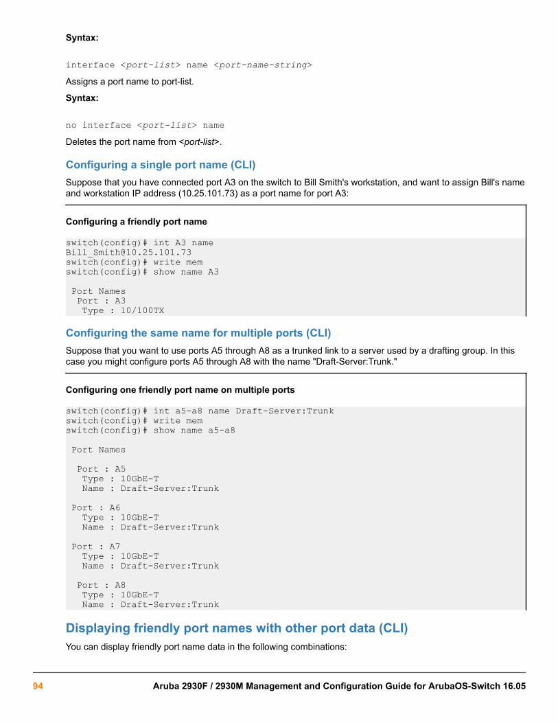
Syntax:
interface <port-list> name <port-name-string>Assigns a port name to port-list.
Syntax:
no interface <port-list> nameDeletes the port name from <port-list>.
Configuring a single port name (CLI)Suppose that you have connected port A3 on the switch to Bill Smith's workstation, and want to assign Bill's nameand workstation IP address (10.25.101.73) as a port name for port A3:
Configuring a friendly port name
switch(config)# int A3 [email protected](config)# write memswitch(config)# show name A3
Port Names Port : A3 Type : 10/100TX
Configuring the same name for multiple ports (CLI)Suppose that you want to use ports A5 through A8 as a trunked link to a server used by a drafting group. In thiscase you might configure ports A5 through A8 with the name "Draft-Server:Trunk."
Configuring one friendly port name on multiple ports
switch(config)# int a5-a8 name Draft-Server:Trunkswitch(config)# write memswitch(config)# show name a5-a8 Port Names
Port : A5 Type : 10GbE-T Name : Draft-Server:Trunk Port : A6 Type : 10GbE-T Name : Draft-Server:Trunk Port : A7 Type : 10GbE-T Name : Draft-Server:Trunk
Port : A8 Type : 10GbE-T Name : Draft-Server:Trunk
Displaying friendly port names with other port data (CLI)You can display friendly port name data in the following combinations:
94 Aruba 2930F / 2930M Management and Configuration Guide for ArubaOS-Switch 16.05

Syntax:
show nameDisplays a listing of port numbers with their corresponding friendly port names and also quickly shows you whichports do not have friendly name assignments. (show name data comes from the running-config file.)
Syntax:
show interface <port-number>Displays the friendly port name, if any, along with the traffic statistics for that port. (The friendly port name datacomes from the running-config file.)
Syntax:
show configIncludes friendly port names in the per-port data of the resulting configuration listing. (show config data comesfrom the startup-config file.)
Listing all ports or selected ports with their friendly port names (CLI)Syntax:
show name [port-list]Lists the friendly port name with its corresponding port number and port type. The show name command withouta port list shows this data for all ports on the switch.
Friendly port name data for all ports on the switch
switch(config)# show namePort Names Port Type Name ------ --------- ---------------------------- A1 10GbE-T A2 10GbE-T A3 10GbE-T [email protected] A4 10GbE-T A5 10GbE-T Draft-Server:Trunk A6 10GbE-T Draft-Server:Trunk A7 10GbE-T Draft-Server:Trunk A8 10GbE-T Draft-Server:Trunk
Friendly port name data for specific ports on the switch
switch(config)# show name A3-A5 Port Names Port : A3 Type : 10GbE-T Name : [email protected] Port : A4 Type : 10GbE-T Name : Port : A5 Type : 10GbE-T Name : Draft-Server:Trunk
Chapter 3 Port Status and Configuration 95
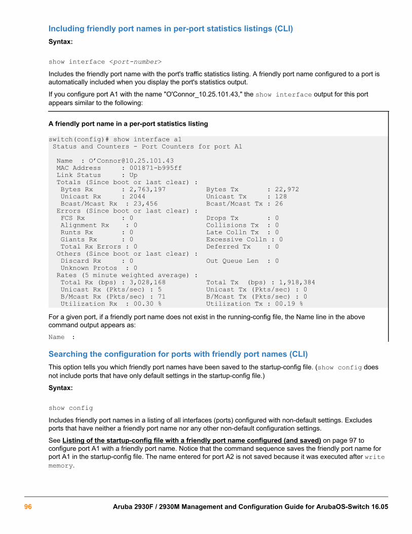
Including friendly port names in per-port statistics listings (CLI)Syntax:
show interface <port-number>Includes the friendly port name with the port's traffic statistics listing. A friendly port name configured to a port isautomatically included when you display the port's statistics output.
If you configure port A1 with the name "O'Connor_10.25.101.43," the show interface output for this portappears similar to the following:
A friendly port name in a per-port statistics listing
switch(config)# show interface a1 Status and Counters - Port Counters for port A1
Name : O’[email protected] MAC Address : 001871-b995ff Link Status : Up Totals (Since boot or last clear) : Bytes Rx : 2,763,197 Bytes Tx : 22,972 Unicast Rx : 2044 Unicast Tx : 128 Bcast/Mcast Rx : 23,456 Bcast/Mcast Tx : 26 Errors (Since boot or last clear) : FCS Rx : 0 Drops Tx : 0 Alignment Rx : 0 Collisions Tx : 0 Runts Rx : 0 Late Colln Tx : 0 Giants Rx : 0 Excessive Colln : 0 Total Rx Errors : 0 Deferred Tx : 0 Others (Since boot or last clear) : Discard Rx : 0 Out Queue Len : 0 Unknown Protos : 0 Rates (5 minute weighted average) : Total Rx (bps) : 3,028,168 Total Tx (bps) : 1,918,384 Unicast Rx (Pkts/sec) : 5 Unicast Tx (Pkts/sec) : 0 B/Mcast Rx (Pkts/sec) : 71 B/Mcast Tx (Pkts/sec) : 0 Utilization Rx : 00.30 % Utilization Tx : 00.19 %For a given port, if a friendly port name does not exist in the running-config file, the Name line in the abovecommand output appears as:
Name :
Searching the configuration for ports with friendly port names (CLI)This option tells you which friendly port names have been saved to the startup-config file. (show config doesnot include ports that have only default settings in the startup-config file.)
Syntax:
show configIncludes friendly port names in a listing of all interfaces (ports) configured with non-default settings. Excludesports that have neither a friendly port name nor any other non-default configuration settings.
See Listing of the startup-config file with a friendly port name configured (and saved) on page 97 toconfigure port A1 with a friendly port name. Notice that the command sequence saves the friendly port name forport A1 in the startup-config file. The name entered for port A2 is not saved because it was executed after writememory.
96 Aruba 2930F / 2930M Management and Configuration Guide for ArubaOS-Switch 16.05

Listing of the startup-config file with a friendly port name configured (and saved)
switch(config)# int A1 name [email protected](config)# write memswitch(config)# int A2 name Herbert's_PC
switch(config)# show config
Startup configuration:; J9091A Configuration Editor; Created on release xx.15.05.xxxxhostname "HPSwitch" interface AQ name "[email protected] exit
snmp-server community "public" Unrestricted...
Uni-directional link detection (UDLD)Uni-directional link detection (UDLD) monitors a link between two switches and blocks the ports on both ends ofthe link if the link fails at any point between the two devices. This feature is particularly useful for detecting failuresin fiber links and trunks. Figure 10: UDLD Example: on page 97 shows an Example:.
Figure 10: UDLD Example:
In this Example:, each switch load balances traffic across two ports in a trunk group. Without the UDLD feature, alink failure on a link that is not directly attached to one of the HPE switches remains undetected. As a result, eachswitch continue to send traffic on the ports connected to the failed link. When UDLD is enabled on the trunk portson each switch, the switches detect the failed link, block the ports connected to the failed link, and use theremaining ports in the trunk group to forward the traffic.
Similarly, UDLD is effective for monitoring fiber optic links that use two uni-direction fibers to transmit and receivepackets. Without UDLD, if a fiber breaks in one direction, a fiber port may assume the link is still good (becausethe other direction is operating normally) and continue to send traffic on the connected ports. UDLD-enabledports; however, will prevent traffic from being sent across a bad link by blocking the ports in the event that eitherthe individual transmitter or receiver for that connection fails.
Chapter 3 Port Status and Configuration 97

Ports enabled for UDLD exchange health-check packets once every five seconds (the link-keepalive interval). If aport does not receive a health-check packet from the port at the other end of the link within the keepalive interval,the port waits for four more intervals. If the port still does not receive a health-check packet after waiting for fiveintervals, the port concludes that the link has failed and blocks the UDLD-enabled port.
When a port is blocked by UDLD, the event is recorded in the switch log or via an SNMP trap (if configured); andother port blocking protocols, like spanning tree or meshing, will not use the bad link to load balance packets. Theport will remain blocked until the link is unplugged, disabled, or fixed. The port can also be unblocked by disablingUDLD on the port.
Configuring UDLDWhen configuring UDLD, keep the following considerations in mind:
• UDLD is configured on a per-port basis and must be enabled at both ends of the link. See the note below for alist of switches that support UDLD.
• To configure UDLD on a trunk group, you must configure the feature on each port of the group individually.Configuring UDLD on a trunk group's primary port enables the feature on that port only.
• Dynamic trunking is not supported. If you want to configure a trunk group that contains ports on which UDLD isenabled, you must remove the UDLD configuration from the ports. After you create the trunk group, you canre-add the UDLD configuration.
Configuring uni-directional link detection (UDLD) (CLI)For detailed information about UDLD, see Uni-directional link detection (UDLD) on page 97.
Syntax:
[no] interface <port-list> link-keepaliveEnables UDLD on a port or range of ports.
To disable this feature, enter the no form of the command.
Default: UDLD disabled
Syntax:
link-keepalive interval <interval>Determines the time interval to send UDLD control packets. The interval parameter specifies how often the portssend a UDLD packet. You can specify from 10 to 100, in 100-ms increments, where 10 is 1 second, 11 is 1.1seconds, and so on.
Default: 50 (5 seconds)
Syntax:
link-keepalive retries <num>Determines the maximum number of retries to send UDLD control packets. The num parameter specifies themaximum number of times the port will try the health check. You can specify a value from 3 to 10.
Default: 5
Syntax:
[no] interface <port-list> link-keepalive vlan <vid>
98 Aruba 2930F / 2930M Management and Configuration Guide for ArubaOS-Switch 16.05

Assigns a VLAN ID to a UDLD-enabled port for sending tagged UDLD control packets.Under default settings,untagged UDLD packets can still be transmitted and received on tagged only ports; however, a warning messageis logged.
The no form of the command disables UDLD on the specified ports.
Default: UDLD packets are untagged; tagged-only ports transmit and receive untagged UDLD control packets
Enabling UDLD (CLI)UDLD is enabled on a per-port basis.
Example:
To enable UDLD on port a1, enter:
switch(config)#interface al link-keepaliveTo enable the feature on a trunk group, enter the appropriate port range. For example:
switch(config)#interface al-a4 link-keepalive
When at least one port is UDLD-enabled, the switch will forward out UDLD packets that arrive onnon-UDLD-configured ports out of all other non-UDLDconfigured ports in the same vlan. That is,UDLD control packets will “pass through” a port that is not configured for UDLD. However, UDLDpackets will be dropped on any blocked ports that are not configured for UDLD.
Changing the keepalive interval (CLI)By default, ports enabled for UDLD send a link health-check packet once every 5 seconds. You can change theinterval to a value from 10 to 100 deciseconds, where 10 is 1 second, 11 is 1.1 seconds, and so on.
Example:
To change the packet interval to seven seconds, enter the following command at the global configuration level:
switch(config)# link-keepalive interval 70
Changing the keepalive retries (CLI)By default, a port waits 5 seconds to receive a health-check reply packet from the port at the other end of the link.If the port does not receive a reply, the port tries four more times by sending up to four more health-checkpackets. If the port still does not receive a reply after the maximum number of retries, the port goes down.
You can change the maximum number of keepalive attempts to a value from 3 to 10.
Example:
To change the maximum number of attempts to four, enter the following command at the global configurationlevel:
switch(config)# link-keepalive retries 4
Configuring UDLD for tagged portsThe default implementation of UDLD sends the UDLD control packets untagged, even across tagged ports. If anuntagged UDLD packet is received by a non-HPE switch, that switch may reject the packet. To avoid such anoccurrence, you can configure ports to send out UDLD control packets that are tagged with a specified VLAN.
To enable ports to receive and send UDLD control packets tagged with a specific VLAN ID, enter a commandsuch as the following at the interface configuration level:
switch(config)#interface link-keepalive vlan 22
Chapter 3 Port Status and Configuration 99

• You must configure the same VLANs that will be used for UDLD on all devices across thenetwork; otherwise, the UDLD link cannot be maintained.
• If a VLAN ID is not specified, UDLD control packets are sent out of the port as untagged packets.
• To re-assign a VLAN ID, re-enter the command with the new VLAN ID number. The newcommand overwrites the previous command setting.
• When configuring UDLD for tagged ports, you may receive a warning message if there are anyinconsistencies with the VLAN configuration of the port.
Viewing UDLD information (CLI)Syntax:
show link-keepaliveDisplays all the ports that are enabled for link-keepalive.
Syntax:
show link-keepalive statisticsDisplays detailed statistics for the UDLD-enabled ports on the switch.
Syntax:
clear link-keepalive statisticsClears UDLD statistics. This command clears the packets sent, packets received, and transitions counters in theshow link-keepalive statistics display.
Viewing summary information on all UDLD-enabled ports (CLI)Enter the show link-keepalive command.
Example:
Figure 11: Example: of show link-keepalive command
100 Aruba 2930F / 2930M Management and Configuration Guide for ArubaOS-Switch 16.05

Viewing detailed UDLD information for specific ports (CLI)Enter the show link-keepalive statistics command.
Example:
Figure 12: Example: of show link-keepalive statistics command
Clearing UDLD statistics (CLI)Enter the following command:
switch# clear link-keepalive statisticsThis command clears the packets sent, packets received, and transitions counters in the show linkkeepalive statistics display (see Figure 12: Example: of show link-keepalive statistics command onpage 101 for an Example:).
Uplink failure detectionUplink Failure Detection (UFD) is a network path redundancy feature that works in conjunction with NIC teamingfunctionality. UFD continuously monitors the link state of the ports configured as links-to-monitor (LtM), and whenthese ports lose link with their partners, UFD will disable the set of ports configured as links-to-disable (LtD.)When an uplink port goes down, UFD enables the switch to auto-disable the specific downlinks connected to theNICs. This allows the NIC teaming software to detect link failure on the primary NIC port and fail over to thesecondary NIC in the team.
NIC teams must be configured for switch redundancy when used with UFD, that is, the team spans ports on bothSwitch A and Switch B. The switch automatically enables the downlink ports when the uplink returns to service.For an example of teamed NICs in conjunction with UFD, see Figure 13: Teamed NICs in conjunction withUFD on page 102.) For an example of teamed NICs with a failed uplink, see Figure 14: Teamed NICs with afailed uplink on page 102.
Chapter 3 Port Status and Configuration 101

For UFD functionality to work as expected, the NIC teaming must be in Network Fault Tolerance(NFT) mode.
Figure 13: Teamed NICs in conjunction with UFD
Figure 14: Teamed NICs with a failed uplink
102 Aruba 2930F / 2930M Management and Configuration Guide for ArubaOS-Switch 16.05

Configuration guidelines for UFDBelow is a list of configuration guidelines to be followed for UFD. These are applicable only to blade switcheswhere there is a clear distinction between downlink and uplink ports.
1. UFD is required only when uplink-path redundancy is not available on the blade switches.
2. An LtM can be either one or more uplink ports or one or more multi-link trunk group of uplink ports.
3. Ports that are already members of a trunk group are not allowed to be assigned to an LtM or LtD.
4. A trunk group configured as an LtM can contain multiple uplink ports, but no downlink ports or ISL (Inter-Switch-Link) ports.
5. A port cannot be added to a trunk group if it already belongs to an LtM or LtD.
6. An LtD can contain one or more ports, and/or one or more trunks
7. A trunk group configured as an LtD can contain multiple downlink ports, but no uplink ports or ISL (Inter-Switch-Link) ports.
A common API will be provided for higher layers, like CLI and SNMP, which will determine if a port-list can be anLtM or LtD. The API will handle the platform specific details and ensure a uniform code flow for blade and otherswitch families.
ProCurve and TOR switches do not have a clear distinction between uplink and downlink ports sosome of the points listed above may not be applicable.
UFD enable/disableSyntax:
uplink-failure-detectionUsed to globally enable UFD. The [no] option globally disables UFD.
UFD track data configurationSyntax:
uplink-failure-detection-track <track-id> links-to-monitor <port-list> links-to-disable <port-list>
Used to configure ports given as LtM and ports given as LtD for track-id. This command will also accept trunkinterfaces.
Options
[no] ufd track-id <track-id>From within track-id context:
[no] links-to-monitor <port-list>
[no] links-to-disable <port-list>
Chapter 3 Port Status and Configuration 103

uplink-failure-detection-track
switch(config)# uplink-failure-detection-track 10 links-to-monitor 18,19,20 links-to-disable 1,2,3
The above command is used to configure ports 18,19,20 as LtM and ports 1,2,3 as LtD for track-id 10.
switch(config)# no uplink-failure-detection-track 10This command will remove any track data associated with track-id 10.
switch(config)# no uplink-failure-detection-track 10 links-to-monitor 18 links-to-disable 1This command will remove port 18 as LtM and port 1 as LtD from track-id 10. This command can be issued fromtrack-id context as well.
UFD minimum uplink threshold configurationSyntax:
uplink-failure-detection-track <track-id> minimum-uplink-threshold <treshold value>Configures the minimum uplink threshold value to a number which is the same as the number of LtM ports thatmust fail to trigger the disabling of LtD ports. This number of LtM ports must be up to enable the LtD ports if indisable state.
failure-count
Specify the number of monitored links that must fail before disabling links-to-disable ports.
all
Set the failure-count equal to the number of links-to-monitor ports configured. Default is all.
<NUMBER>
The number of ports to be set as links-to-monitor ports failure count.
Options
Inside a track-id context:
monitor-threshold treshold value | all
show uplink-failure-detectionSyntax:
show uplink-failure-detection
switch(config)# show uplink-failure-detection
Uplink Failure Detection InformationUFD Enabled : YesTrack | Monitored Links to LtM LtD LtM LtDID | Links Disable State State Lacp Key Lacp Key----- + ------------ ------------ ------ -------------- -------- --------1 | Dyn1 Dyn2 Up Up 100 2002 | Down Auto-Disabled 300 4003 | 1 D3 Up Up
104 Aruba 2930F / 2930M Management and Configuration Guide for ArubaOS-Switch 16.05

10 | 2,3 D4,D5 Down Auto-Disabled11 | Trk1 D6 Up Up
UFD operating notes
• A port cannot be added to a trunk group if it already belongs to an LtM or LtD.
• Ports that are already members of a trunk group cannot be assigned to an LtM or LtD.
• Trunks that are configured as LtM or LtD cannot be deleted.
Configuring ports as LtM and LtD for track 3
(HP_Switch_name#) uplink-failure-detection track 3 links-to-monitor 5,6,7links-to-disable 8,9,10
Removing a LtM port and an LtD port for track 3
(HP_Switch_name#) no uplink-failure-detection track 3 links-to-monitor 5links-to-disable 8
Error logUFD will log messages in the following scenarios
• Admin status change.
• When an LtM looses link to its partner and as a result number of LtM ports down becomes equal or greaterthen the LtM failure count, UFD will disable the LtD.
• When an LtM returns to service and as a result the number of LtM ports down becomes lesser than the LtMfailure count, UFD auto-enables the LtD.
Invalid port error messages
• When a user specifies an invalid LtM port, a message similar to the following is displayed.Invalid port(s)specified as links-to-monitor.
• When a user specifies an invalid LtD port, a message similar to the following is displayed.Invalid port(s)specified as links-to-disable.
• When user specifies an invalid threshold value an error message similar to the following is displayed.Invalid threshold value.
• When user tries to configure threshold value greater then number of LtM ports configured an error messagesimilar to the following is displayed. Invalid port(s) specified as links-to-disable.
• When a user specifies an invalid LtD port an error message similar to the following is displayed.Invalidport(s) specified as links-to-disable.
Basic USB port commandsThe USB port is available only on the 2930M Switch Series.
Chapter 3 Port Status and Configuration 105

usb-portSyntaxusb-port
no usb-portDescription
Enables the USB port.
The no form of the command disables the USB port and any access to the device.
Command contextConfig
show usb-portSyntaxshow usb-port
Description
Displays the status of the USB port. It can be enabled, disabled, or not present.
Command contextoperator
Usage
One of the following messages indicates the presence or absence of a USB device:
• Not able to sense device in USB port• USB device detected in port• no USB device detected in port
Example
Display USB port status.
switch# show usb-port
USB port status: enabled USB port power status: power on (USB device detected in port)
106 Aruba 2930F / 2930M Management and Configuration Guide for ArubaOS-Switch 16.05

Introduction to PoEPoE technology allows IP telephones, wireless LAN access points, and other appliances to receive power andtransfer data over existing ethernet LAN cabling. For more information about PoE technology, see the PoE/PoE+planning and implementation guide, which is available on the HPE Networking website at http://www.hpe.com/networking. Enter your Switch number.
Additionally, PoE+ provides more power-management capability, allowing the switch to have more poweravailable for more PDs. Power can be allocated exactly and automatically according to what the PD actuallyrequires at a given time.
PoE terminologyPoE and PoE+ operate similarly in most cases. Any differences between PoE and PoE+ operation are noted;otherwise, the term "PoE" is used to designate both PoE and PoE+ functionality.
Planning and implementing a PoE configurationThis section provides an overview of some considerations for planning a PoE application. For additionalinformation on this topic, refer to the HPE PoE/PoE+ planning and implementation guide which is available on theHPE Networking web site at http://www.hpe.com/networking.
Some of the elements you may want to consider for a PoE installation include:
• Port assignments to VLANs
• Use of security features
• Power requirements
This section can help you to plan your PoE installation. If you use multiple VLANs in your network, or if you haveconcerns about network security, you should read the first two topics. If your PoE installation comes close to (or islikely to exceed) the system’s ability to supply power to all devices that may request it, then you should also readthe third topic. (If it is unlikely that your installation will even approach a full utilization of the PoE power available,then you may find it unnecessary to spend much time on calculating PoE power scenarios.)
Power requirementsTo get the best PoE performance, you should provide enough PoE power to exceed the maximum amount ofpower that is needed by all the PDs that are being used.
By connecting an external power supply you can optionally provision more PoE wattage per port and or supplythe switch with redundant 12V power to operate should an internal power supply fail.
See the HPE PoE/PoE+ planning and implementation guide for detailed information about the PoE/PoE+ powerrequirements for your switch.
Chapter 4Power Over Ethernet (PoE/PoE+) Operation
Chapter 4 Power Over Ethernet (PoE/PoE+) Operation 107

Assigning PoE ports to VLANsIf your network includes VLANs, you may want to assign various PoE-configured ports to specific VLANs. Forexample, if you are using PoE telephones in your network, you may want to assign ports used for telephoneaccess to a VLAN reserved for telephone traffic.
Applying security features to PoE configurationsYou can use the port security features built into the switch to control device or user access to the network throughPoE ports in the same way as non-PoE ports. Using Port Security, you can configure each switch port with aunique list of MAC addresses for devices that are authorized to access the network through that port. For moreinformation, refer to the titled “Configuring and Monitoring Port Security” in the access security guide for yourswitch.
Assigning priority policies to PoE trafficYou can use the configurable QoS (Quality of Service) features in the switch to create prioritization policies fortraffic moving through PoE ports. The table below lists the available classifiers and their order of precedence.
Table 6: Classifiers for prioritizing outbound packets
Priority QoS classifier
1 UDP/TCP application type (port)
2 Device priority (destination or source IP address)
3 IP type of service (ToS) field (IP packets only)
4 VLAN priority
5 Incoming source-port on the switch
6 Incoming 802.1 priority (present in tagged VLAN environments)
For more on this topic, refer to the titled “Quality of Service: Managing Bandwidth More Effectively” in theadvanced traffic management guide for your switch.
PoE operationUsing the commands described in this chapter, you can:
• Enable or disable PoE operation on individual ports.
• Monitor PoE status and performance.
• Configure a non-default power threshold for SNMP and Event Log reporting of PoE consumption on either allPoE ports on the switch or on all PoE ports.
• Specify the port priority you want to use for provisioning PoE power in the event that the PoE resourcesbecome oversubscribed.
A PSE detects the power needed by a connected PD before supplying that power via a phase referred to as"searching". If the PSE cannot supply the required amount of power, it does not supply any power. For PoE usinga Type 1 device, a PSE will not supply any power to a PD unless the PSE has at least 17 watts available. For
108 Aruba 2930F / 2930M Management and Configuration Guide for ArubaOS-Switch 16.05

example, if a PSE has a maximum available power of 382 watts and is already supplying 378 watts, and is thenconnected to a PD requiring 10 watts, the PSE will not supply power to the PD.
For PoE+ using Type 2 devices, the PSE must have at least 33 watts available.
Configuration optionsIn the default configuration, all ports in a switch covered in this guide are configured to support PoE operation.You can:
• Disable or re-enable per-port PoE operation on individual ports to help control power usage and avoidoversubscribing PoE resources.
• Configure per-port priority for allocating power in case a PoE device becomes oversubscribed and must droppower for some lower-priority ports to support the demand on other, higher-priority ports.
• Manually allocate the amount of PoE power for a port by usage, value, or class.
• Allocate PoE power based on the link-partner’s capabilities via LLDP.
The ports support standard networking links and PoE links. You can connect either a non-PoE deviceor a PD to a port enabled for PoE without reconfiguring the port.
PD supportTo best utilize the allocated PoE power, spread your connected PoE devices as evenly as possible. Depending onthe amount of power the power supply device delivers to a PoE switch, there may or may not always be enoughpower available to connect and support PoE operation on all the ports. When a new PD connects to a PoE switchand the switch does not have enough power left for that port:
• If the new PD connects to a port “X” having a higher PoE priority than another port “Y” that is alreadysupporting another PD, then the power is removed from port “Y” and delivered to port “X”. In this case the PDon port “Y” loses power and the PD on port “X” receives power.
• If the new PD connects to a port “X” having a lower priority than all other PoE ports currently providing powerto PDs, then power is not supplied to port “X” until one or more PDs using higher priority ports are removed.
In the default configuration (usage), when a PD connects to a PoE port and begins operating, the port retainsonly enough PoE power to support the PD's operation. Unused power becomes available for supporting other PDconnections. However, if you configure the poe-allocate-by option to either value or class, all of the powerconfigured is allocated to the port.
For PoE (not PoE+), while 17 watts must be available for a PoE module on the switch to begin supplying power toa port with a PD connected, 17 watts per port is not continually required if the connected PD requires less power.For example, with 20 watts of PoE power remaining available on a module, you can connect one new PD withoutlosing power to any connected PDs on that module. If that PD draws only 3 watts, 17 watts remain available, andyou can connect at least one more PD to that module without interrupting power to any other PoE devicesconnected to the same module. If the next PD you connect draws 5 watts, only 12 watts remain unused. With only12 unused watts available, if you then connect yet another PD to a higher-priority PoE port, the lowest-priority porton the module loses PoE power and remains unpowered until the module once again has 17 or more wattsavailable. (For information on power priority, see Power priority operation on page 110.)
For PoE+, there must be 33 watts available for the module to begin supplying power to a port with a PDconnected.
Chapter 4 Power Over Ethernet (PoE/PoE+) Operation 109

Disconnecting a PD from a PoE port makes that power available to any other PoE ports with PDs waiting forpower. If the PD demand for power becomes greater than the PoE power available, power is transferred from thelower-priority ports to the higher-priority ports. (Ports not currently providing power to PDs are not affected.)
Power priority operation
When is power allocation prioritized?If a PSE can provide power for all connected PD demand, it does not use its power priority settings to allocatepower. However, if the PD power demand oversubscribes the available power, then the power allocation isprioritized to the ports that present a PD power demand. This causes the loss of power from one or more lower-priority ports to meet the power demand on other, higher-priority ports. This operation occurs regardless of theorder in which PDs connect to the switch’s PoE-enabled ports.
How is power allocation prioritized?There are two ways that PoE power is prioritized:
• Using a priority class method, a power priority of Low (the default), High, or Critical is assigned to eachenabled PoE port.
• Using a port-number priority method, a lower-numbered port has priority over a higher-numbered port withinthe same configured priority class, For example, port A1 has priority over port A5 if both are configured withHigh priority.
Configuring PoE operationIn the default configuration, PoE support is enabled on the ports in a PoE switch. The default priority for all portsis Low and the default power notification threshold is 80 (%).
Using the CLI, you can:
• Disable or re-enable PoE operation on individual PoE ports
• Enable support for pre-standard devices
• Change the PoE priority level on individual PoE ports
• Change the threshold for generating a power level notice
• Manually allocate the amount of PoE power for a port by usage, value, or class
• Allocate PoE power based on the link-partner’s capabilities via LLDP
Disabling or re-enabling PoE port operationSyntax:
[no] interface <port-list> power-over-ethernetRe-enables PoE operation on <port-list> and restores the priority setting in effect when PoE was disabled on<port-list>.
The no form of the command disables PoE operation on <port-list>.
Default: All PoE ports are initially enabled for PoE operation at Low priority. If you configure a higher priority, thispriority is retained until you change it.
110 Aruba 2930F / 2930M Management and Configuration Guide for ArubaOS-Switch 16.05

Enabling support for pre-standard devicesThe HPE switches covered in this guide also support some pre-802.3af devices. For a list of the supporteddevices, see the FAQ for your switch model.
Syntax:
[no] power-over-ethernet pre-std-detectDetects and powers pre-802.3af standard devices.
The default setting for the pre-std-detect PoE parameter changed. In earlier software the defaultsetting is “on”. The default setting is “off”.
Configuring the PoE port prioritySyntax:
interface <port-list> power-over-ethernet [critical | high | low]Reconfigures the PoE priority level on <port-list>. For a given level, ports are prioritized by port number inascending order. For example, if ports A1-A24 have a priority level of critical, port A1 has priority over ports A2-A24.
If there is not enough power available to provision all active PoE ports at a given priority level, the lowest-numbered port at that level is provisioned first. PoE priorities are invoked only when all active PoE ports cannotbe provisioned (supplied with PoE power)
Critical Specifies the highest-priority PoE support for <port-list>. The active PoE ports at this level areprovisioned before the PoE ports at any other level are provisioned.
High Specifies the second priority PoE support for <port-list>. The active PoE ports at this level areprovisioned before the Low priority PoE ports are provisioned.
Low (Default) Specifies the third priority PoE support for <port-list>. The active PoE ports at this levelare provisioned only if there is power available after provisioning any active PoE ports at thehigher priority levels.
Controlling PoE allocationThe default option for PoE allocation is usage, which is what a PD attached to the port is allocated. You canoverride this value by specifying the amount of power allocated to a port by using the class or value options.
Syntax:
[no] int <port-list> poe-allocate-by [usage | class | value]Allows you to manually allocate the amount of PoE power for a port by either its class or a defined value.
usage The automatic allocation by a PD
class Uses the power ramp-up signature of the PD to identify which power class the device will be in.Classes and their ranges are shown in the table below.
value A user-defined level of PoE power allocated for that port.
Chapter 4 Power Over Ethernet (PoE/PoE+) Operation 111

The allowable PD requirements are lower than those specified for PSEs to allow for power lossesalong the Cat-5 cable.
Table 7: Power classes and their values
Powerclass
Value
0 Depends on cable type and PoE architecture. Maximum power level output of 15.4 watts at thePSE.This is the default class; if there is not enough information about the load for a specificclassification, the PSE classifies the load as class 0 (zero).
1 Requires at least 4 watts at the PSE.
2 Requires at least 7 watts at the PSE.
3 15.4 watts
4 For PoE+Maximum power level output of 30 watts at the PSE.
Example:
To allocate by class for ports 6 to 8:
switch(config)# int 6-8 PoE-allocate-by class
Manually configuring PoE power levelsYou can specify a power level (in watts) allocated for a port by using the value option. This is the maximumamount of power that will be delivered.
To configure a port by value:
Procedure
1. Set the PoE allocation by entering the poe-allocate-by value command:
switch(config) # int A6 poe-allocate-by valueor in interface context:
switch(eth-A6) # poe-allocate-by value2. Select a value:
switch(config) # int A6 poe-value 15or in interface context:
switch(eth-A6) # poe-value 15
112 Aruba 2930F / 2930M Management and Configuration Guide for ArubaOS-Switch 16.05
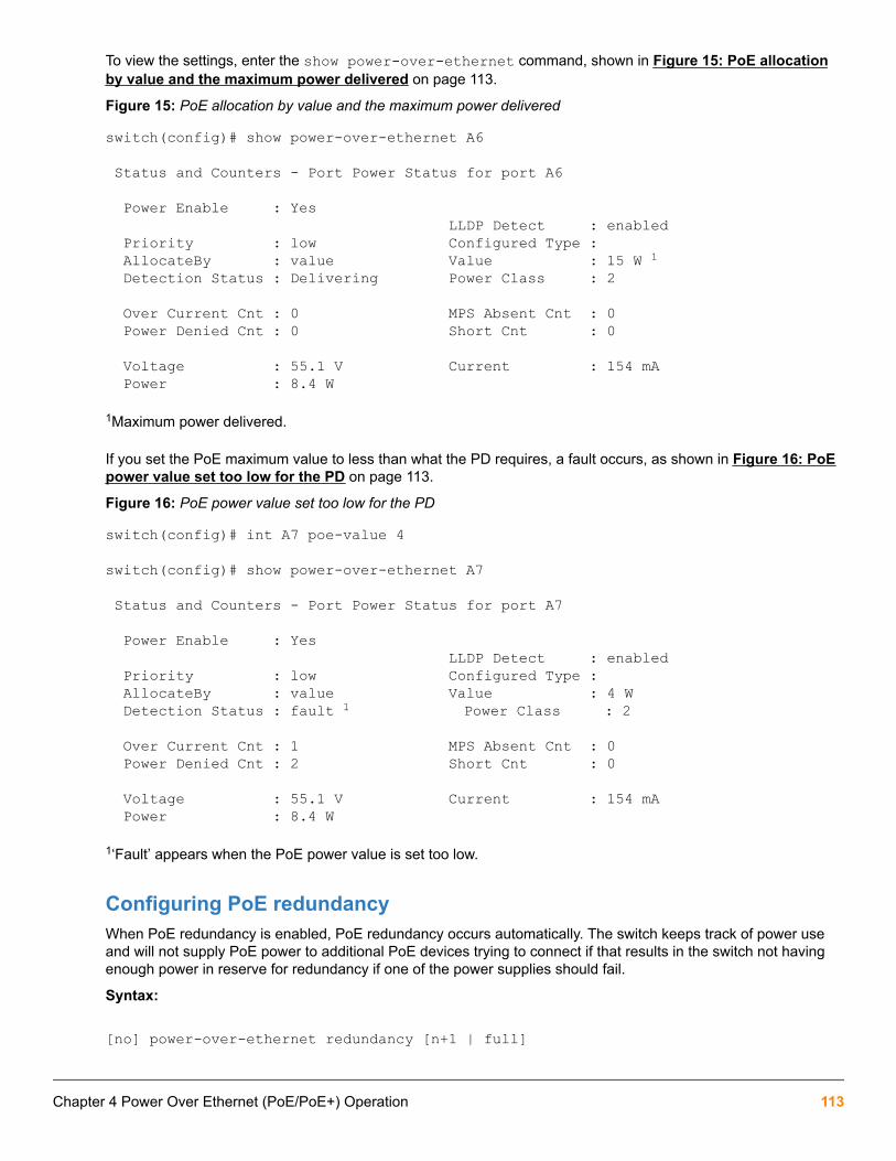
To view the settings, enter the show power-over-ethernet command, shown in Figure 15: PoE allocationby value and the maximum power delivered on page 113.
Figure 15: PoE allocation by value and the maximum power delivered
switch(config)# show power-over-ethernet A6
Status and Counters - Port Power Status for port A6
Power Enable : Yes LLDP Detect : enabled Priority : low Configured Type : AllocateBy : value Value : 15 W 1 Detection Status : Delivering Power Class : 2
Over Current Cnt : 0 MPS Absent Cnt : 0 Power Denied Cnt : 0 Short Cnt : 0
Voltage : 55.1 V Current : 154 mA Power : 8.4 W
1Maximum power delivered.
If you set the PoE maximum value to less than what the PD requires, a fault occurs, as shown in Figure 16: PoEpower value set too low for the PD on page 113.
Figure 16: PoE power value set too low for the PD
switch(config)# int A7 poe-value 4
switch(config)# show power-over-ethernet A7
Status and Counters - Port Power Status for port A7
Power Enable : Yes LLDP Detect : enabled Priority : low Configured Type : AllocateBy : value Value : 4 W Detection Status : fault 1 Power Class : 2
Over Current Cnt : 1 MPS Absent Cnt : 0 Power Denied Cnt : 2 Short Cnt : 0
Voltage : 55.1 V Current : 154 mA Power : 8.4 W
1‘Fault’ appears when the PoE power value is set too low.
Configuring PoE redundancyWhen PoE redundancy is enabled, PoE redundancy occurs automatically. The switch keeps track of power useand will not supply PoE power to additional PoE devices trying to connect if that results in the switch not havingenough power in reserve for redundancy if one of the power supplies should fail.
Syntax:
[no] power-over-ethernet redundancy [n+1 | full]
Chapter 4 Power Over Ethernet (PoE/PoE+) Operation 113

Allows you to set the amount of power held in reserve for redundancy.
no Means that all available power can be allocated to PDs.Default: No PoE redundancyenforced.
n+1 One of the power supplies is held in reserve for redundancy. If a single power supplyfails, no powered devices are shut down.If power supplies with different ratings areused, the highest-rated power supply is held in reserve to ensure full redundancy.
full Half of the available power supply is held in reserve for redundancy. If power supplieswith different ratings are used, the highest-rated power supply is held in reserve toensure full redundancy.
For more information about PoE redundancy and power supplies, see the PoE/PoE+ planning andimplementation guide, available on the HPE website at http://www.hpe.com/networking. Auto search the modelnumber for your switch, For example, “Aruba switch 2930”, then select the device from the list, and click onProduct manuals. Click on the “Setup and install — general” link under Manuals.
Changing the threshold for generating a power noticeYou can configure one of the following thresholds:
• A global power threshold that applies to all ports on the switch. This setting acts as a trigger for sending anotice when the PoE power consumption on any PoE port installed in the switch crosses the configured globalthreshold level. (Crossing the threshold level in either direction—PoE power usage either increasing ordecreasing— triggers the notice.) The default setting is 80%.
• A per-slot power threshold that applies to an individual PoE module installed in the designated slot. Thissetting acts as a trigger for sending a notice when the module in the specified slot exceeds or goes below aspecific level of PoE power consumption.
Some switches covered by this manual provide a single fixed slot.
Syntax:
power-over-ethernet [slot < slot-id-range >] threshold <1-99>This command specifies the PoE usage level (as a percentage of the PoE power available on a module) at whichthe switch generates a power usage notice. This notice appears as an SNMP trap and a corresponding Event Logmessage and occurs when a PoE module's power consumption crosses the configured threshold value. That is,the switch generates a notice whenever the power consumption on a module either exceeds or drops below thespecified percentage of the total PoE power available on the module.
This command configures the notification threshold for PoE power usage on either a global or per-module (slot)basis.
Without the [slot PoE <slot-id-range>] option, the switch applies one power threshold setting on all PoEmodules installed in the switch.
Example:
Suppose slots A, B, and C each have a PoE module installed. In this case, executing the following command setsthe global notification threshold to 70% of available PoE power:
switch(config)# power-over-ethernet threshold 70
114 Aruba 2930F / 2930M Management and Configuration Guide for ArubaOS-Switch 16.05

With this setting, if module B is allocated 100 watts of PoE power and is using 68 watts, and then another PD isconnected to the module in slot B that uses 8 watts, the 70% threshold of 70 watts is exceeded. The switch sendsan SNMP trap and generates this Event Log message:
Slot B POE usage has exceeded threshold of 70%.If the switch is configured for debug logging, it also sends the Event Log message to the configured debugdestination(s).
On any PoE module, if an increasing PoE power load (1) exceeds the configured power threshold (which triggersthe log message and SNMP trap), and then (2) later decreases and drops below the threshold again, the switchgenerates another SNMP trap, plus a message to the Event Log and any configured Debug destinations.
To continue the preceding Example:, if the PoE power usage on the PoE module in slot B drops below 70%,another SNMP trap is generated and you will see this message in the Event Log:
Slot B POE usage is below threshold of 70%.For a message listing, please see the event log message reference guide for your switch. Go to http://www.hpe.com/networking; auto search the model number for your switch, for Example: “Aruba Switch 2920”,then select the device from the list and click on Product manuals. Click on the “User guide” link under Manuals.
(Default Global PoE Power Threshold: 80). By using the [slot <slot-id-range>] option, you can specifydifferent notification thresholds for different PoE modules installed in the switch. For example, you could set thepower threshold for a PoE module in slot “A” to 75% and the threshold for the module in slot “B” to 68% byexecuting the following two commands:
switch(config)# power-over-ethernet slot a threshold 75switch(config)# power-over-ethernet slot b threshold 68
The last threshold command affecting a given slot supersedes the previous threshold commandaffecting the same slot. Thus, executing the following two commands in the order shown sets thethreshold for the PoE module in slot “D” to 75%, but leaves the thresholds for any PoE modules inthe other slots at 90%.
switch(config)# power-over-ethernet threshold 90switch(config)# power-over-ethernet slot d threshold 75If you reverse the order of the above two commands, all PoE modules in the switch will have athreshold of 90%.
PoE/PoE+ allocation using LLDP information
LLDP with PoEWhen using PoE, enabling poe-lldp-detect allows automatic power configuration if the link partner supportsPoE. When LLDP is enabled, the information about the power usage of the PD is available, and the switch canthen comply with or ignore this information. You can configure PoE on each port according to the PD (IP phone,wireless device, and so on) specified in the LLDP field. The default configuration is for PoE information to beignored if detected through LLDP.
Detecting PoE information via LLDP affects only power delivery; it does not affect normal Ethernetconnectivity.
Chapter 4 Power Over Ethernet (PoE/PoE+) Operation 115

Enabling or disabling ports for allocating power using LLDPSyntax:
int <port-list> poe-lldp-detect [enabled | disabled]Enables or disables ports for allocating PoE power based on the link-partner's capabilities via LLDP.
Default: Disabled
Example:
You can enter this command to enable LLDP detection:
switch(config) # int A7 poe-lldp-detect enabledor in interface context:
switch(eth-A7) # poe-lldp-detect enabled
Enabling PoE detection via LLDP TLV advertisementUse this command and insert the desired port or ports:
switch(config) # lldp config <port-number> medTlvenable poe
LLDP with PoE+
OverviewThe data link layer classification DLC for PoE provides more exact control over the power requirement between aPSE and PD. The DLC works in conjunction with the physical layer classification PLC and is mandatory for anyType-2 PD that requires more than 12.95 watts of input power.
DLC is defined as part of the IEEE 802.3at standard.
The power negotiation between a PSE and a PD can be implemented at the physical layer or at the data linklayer. After the link is powered at the physical layer, the PSE can use LLDP to repeatedly query the PD todiscover the power needs of the PD. Communication over the data link layer allows finer control of powerallotment, which makes it possible for the PSE to supply dynamically the power levels needed by the PD. UsingLLDP is optional for the PSE but mandatory for a Type 2 PD that requires more than 12.95 watts of power.
If the power needed by the PD is not available, that port is shut off.
PoE allocationLLDP can negotiate power with a PD by using LLDP MED TLVs (disabled by default). This can be enabled usingthe int <port-list> PoE-lldp-detect [enabled|disabled] command, as shown below. LLDP MEDTLVs sent by the PD are used to negotiate power only if the LLDP PoE+ TLV is disabled or inactive; if the LLDPPoE+ TLV is sent as well (not likely), the LLDP MED TLV is ignored.
Enabling PoE-lldp-detect allows the data link layer to be used for power negotiation. When a PD requestspower on a PoE port, LLDP interacts with PoE to see if there is enough power to fulfill the request. Power is set atthe level requested. If the PD goes into power-saving mode, the power supplied is reduced; if the need for powerincreases, the amount supplied is increased. PoE and LLDP interact to meet the current power demands.
Syntax:
int <port-list> poe-lldp-detect [enabled | disabled]
116 Aruba 2930F / 2930M Management and Configuration Guide for ArubaOS-Switch 16.05

Allows the data link layer to be used for power negotiation between a PD on a PoE port and LLDP.
Default: Disabled
Example:
You can enter this command to enable LLDP detection:
switch(config) # int 7 PoE-lldp-detect enabledor in interface context:
switch(eth-7) # PoE-lldp-detect enabled
Detecting PoE information via LLDP affects only power delivery; it does not affect normal Ethernetconnectivity.
You can view the settings by entering the show power-over-ethernet brief command, as shown in Portwith LLDP configuration information obtained from the device on page 117.
Port with LLDP configuration information obtained from the device
switch(config)# show power-over-ethernet brief
Status and Counters - Port Power Status
System Power Status : No redundancy PoE Power Status : No redundancy
Available: 300 W Used: 0 W Remaining: 300 W
Module A Power Available: 300 W Used: 5 W Remaining: 295 W
POE | Power Power Alloc Alloc Actual Configured Detection Power Port | Enable Priority By Power Power Type Status Class ----- + ------- --------- ----- ------ ------ ----------- ----------- ---- A1 | Yes low usage 17 W 0.0 W Phone1 Delivering 1 A2 | Yes low usage 17 W 0.0 W Searching 0 A3 | Yes low usage 17 W 0.0 W Searching 0 A4 | Yes low usage 17 W 0.0 W Searching 0 A5 | Yes low usage 17 W 0.0 W Searching 0 A6 | Yes low usage 17 W 0.0 W Searching 0
Viewing PoE when using LLDP informationViewing LLDP port configurationTo view information about LLDP port configuration, use the show lldp config command.
Syntax:
show lldp config <port-list>Displays the LLDP port configuration information, including the TLVs advertised.
LLDP port configuration information with PoE
switch(config)# show lldp config 4
LLCP Port Configuration Detail
Chapter 4 Power Over Ethernet (PoE/PoE+) Operation 117

Port : 4 AdminStatus [Tx_Rx] : Tx_Rx NotificationsEnabled [False] : False Med Topology Trap Enabled [False] : False
TLVS Advertised: * port_descr * system_name * system_descr * system_cap
* capabilities * network_policy * location_id * poe
* macphy_config * poeplus_config
IpAddress Advertised:Local power information on page 118 shows an Example: of the local device power information using the showlldp info local-device <port-list> command.
Local power information
switch(config)# show lldp info local-device A1
LLCP Local Port Information Detail
Port : A1 PortType : local PortId : 1 PortDesc : A1 Pvid : 1
Poe Plus Information Detail
Poe Device Type : Type2 PSE Power Source : Primary Power Priority : low PD Requested Power Value : 20 Watts PSE Actual Power Value : 20 WattsRemote power information on page 118 shows the remote device power information using the show lldpinfo remote-device <port-list> command.
Remote power information
switch(config)# show lldp info remote-device A3
LLCP Remote Device Information Detail
Local Port : A3 ChassisType : mac-address ChassisId : 00 16 35 ff 2d 40 PortType : local PortId : 23 SysName : HPSwitch System Descr : HP Switch 3500-24, revision W.14.xx
118 Aruba 2930F / 2930M Management and Configuration Guide for ArubaOS-Switch 16.05

PortDescr : 23 Pvid : 55
System Capabilities Supported : bridge, router System Capabilities Enabled : bridge
Remote Management Address Type : ipv4 Address : 10.0.102.198
Poe Plus Information Detail
Poe Device Type : Type2 PD Power Source : Only PSE Power Priority : low PD Requested Power Value : 20 Watts PSE Actual Power Value : 20 Watts
Operating noteThe advertisement of power with TLVs for LLDP PoE+ is enabled by default. If LLDP is disabled at runtime and aPD is using PoE+ power that has been negotiated through LLDP, there will be a temporary power drop. The portwill begin using PoE+ power through the PLC. This event is recorded in the event log. An Example: messagewould look like the following:
W 08/04/13 13:35:50 02768 ports: Port A1 PoE power dropped.Exceeded physical classification for a PoE Type1 device(LLDP process disabled)When LLDP is enabled again, it causes a temporary power drop. This event is also recorded in the event log. AnExample: message looks like the following:
W 08/04/13 13:36:31 02771 ports: Port A1 PoE power dropped.Exceeded physical classification due to change inclassification type (LLDP process enabled)
Viewing the global PoE power status of the switchSyntax:
show power-over-ethernet [brief | [[ethernet] <port-list>] | [slot <slot-id-range> | all>]]Displays the switch's global PoE power status, including:
• Total Available Power
Lists the maximum PoE wattage available to provision active PoE ports on the switch. This is the amount ofusable power for PDs.
• Total Failover Power
Lists the amount of PoE power available in the event of a single power supply failure. This is the amount ofpower the switch can maintain without dropping any PDs.
• Total Redundancy Power
Indicates the amount of PoE power held in reserve for redundancy in case of a power supply failure.
• Total Remaining Power
The amount of PoE power still available.
Chapter 4 Power Over Ethernet (PoE/PoE+) Operation 119

brief Displays PoE information for each port. See Viewing PoE status on all ports on page120.
<port-list> Displays PoE information for the ports in port-list. See Viewing the PoE status onspecific ports on page 122.
<slot-id-range>
Displays PoE information for the selected slots. See Showing the PoE information byslot).Enter the all option to display the PoE information for all slots.
The show power-over-ethernet displays data similar to that shown in show power-over-ethernetcommand output on page 120.
show power-over-ethernet command output
switch(config)# show power-over-ethernet
Status and Counters - System Power Status
Pre-standard Detect : On System Power Status : No redundancy PoE Power Status : No redundancy
Chassis power-over-ethernet
Total Available Power : 600 W Total Failover Power : 300 W Total Redundancy Power : 0 W Total Used Power : 9 W +/- 6W Total Remaining Power : 591 W
Internal Power 1 300W/POE /Connected. 2 300W/POE /Connected. 3 Not Connected. 4 Not Connected. External Power EPS1 /Not Connected. EPS2 /Not Connected.
Viewing PoE status on all portsSyntax:
show power-over-ethernet briefDisplays the port power status:
PoE Port Lists all PoE-capable ports on the switch.
Power Enable Shows Yes for ports enabled to support PoE (the default) and No for ports on which PoE isdisabled.
Power Priority Lists the power priority (Low, High, and Critical) configured on ports enabled for PoE. (Formore information on this topic, see Configuring PoE operation on page 110.)
Table Continued
120 Aruba 2930F / 2930M Management and Configuration Guide for ArubaOS-Switch 16.05

Alloc by Displays how PoE is allocated (usage, class, value).
Alloc Power The maximum amount of PoE power allocated for that port (expressed in watts).Default: 17watts for PoE; 33 watts for PoE+.
Actual Power The power actually being used on that port.
Configured Type If configured, shows the user-specified identifier for the port. If not configured, this field isempty.
Detection Status• Searching: The port is trying to detect a PD connection.
• Delivering: The port is delivering power to a PD.
• Disabled: On the indicated port, either PoE support is disabled or PoE power is enabledbut the PoE module does not have enough power available to supply the port's powerneeds.
• Fault: The switch detects a problem with the connected PD.
• Other Fault: The switch has detected an internal fault that prevents it from supplyingpower on that port.
Power Class Shows the 802.3af power class of the PD detected on the indicated port. Classes include:
• 0: 0.44 to 12.95 watts can be drawn by the PD. Default class.
• 1: 0.44 to 3.84 watts
• 2: 3.84 to 6.49 watts
• 3: 6.49 to 12.95 watts
• 4: For PoE+; up to 25.5 watts can be drawn by the PD
The show power-over-ethernet brief displays this output:
show power-over-ethernet brief command output
switch(config)# show power-over-ethernet brief
Status and Counters - System Power Status
System Power Status : No redundancy PoE Power Status : No redundancy
Available: 600 W Used: 9 W Remaining: 591 W
Module A Power Available: 408 W Used: 9 W Remaining: 399 W
POE | Power Power Alloc Alloc Actual Configured Detection Power Port | Enable Priority By Power Power Type Status Class ----- + ------- --------- ----- ------ ------ ----------- ---------- ---- A1 | Yes low usage 17 W 0.0 W Searching 0 A2 | Yes low usage 17 W 0.0 W Searching 0 A3 | Yes low usage 17 W 0.0 W Searching 0 A4 | Yes low usage 17 W 0.0 W Searching 0
Chapter 4 Power Over Ethernet (PoE/PoE+) Operation 121

A5 | Yes low usage 17 W 0.0 W Searching 0 A6 | Yes low usage 17 W 8.4 W Delivering 2 A7 | Yes low usage 17 W 0.0 W Searching 0 A8 | Yes low usage 17 W 0.0 W Searching 0 A9 | Yes low usage 17 W 0.0 W Searching 0You can also show the PoE information by slot:
Showing the PoE information by slot
switch(config)# show power-over-ethernet slot A
Status and Counters - System Power Status for slot A
Maximum Power : 408 W Operational Status : On Power In Use : 9 W +/- 6 W Usage Threshold (%) : 80
Viewing the PoE status on specific portsSyntax:
show power-over-ethernet <port-list>Displays the following PoE status and statistics (since the last reboot) for each port in <port-list> :
Power Enable Shows Yes for ports enabled to support PoE (the default) and No for ports on which PoE isdisabled. For ports on which power is disabled, this is the only field displayed by showpower-over-ethernet <port-list> .
Priority Lists the power priority (Low, High, and Critical) configured on ports enabled for PoE. (Formore on this topic, see Configuring PoE operation on page 110.)
Allocate by How PoE is allocated (usage, class, value).
Detection Status• Searching: The port is trying to detect a PD connection.
• Delivering: The port is delivering power to a PD.
• Disabled: On the indicated port, either PoE support is disabled or PoE power is enabledbut the PoE module does not have enough power available to supply the port's powerneeds.
• Fault: The switch detects a problem with the connected PD.
• Other Fault: The switch has detected an internal fault that prevents it from supplyingpower on that port.
Over Current Cnt Shows the number of times a connected PD has attempted to draw more than 15.4 wattsfor PoE or 24.5 watts for PoE+. Each occurrence generates an Event Log message.
Power DeniedCnt
Shows the number of times PDs requesting power on the port have been denied becauseof insufficient power available. Each occurrence generates an Event Log message.
Voltage The total voltage, in volts, being delivered to PDs.
Table Continued
122 Aruba 2930F / 2930M Management and Configuration Guide for ArubaOS-Switch 16.05

Power The total power, in watts, being delivered to PDs.
LLDP Detect Port is enabled or disabled for allocating PoE power, based on the link-partner's capabilitiesvia LLDP.
Configured Type If configured, shows the user-specified identifier for the port. If not configured, the field isempty.
Value The maximum amount of PoE power allocated for that port (expressed in watts). Default: 17watts for PoE; 33 watts for PoE+
Power Class Shows the power class of the PD detected on the indicated port. Classes include:
• 0: 0.44 to 12.95 watts
• 1: 0.44 to 3.84 watts
• 2: 3.84 to 6.49 watts
• 3: 6.49 to 12.95 watts
• 4: For PoE+; up to 25.5 watts can be drawn by the PD
MPS Absent Cnt Shows the number of times a detected PD has no longer requested power from the port.Each occurrence generates an Event Log message. ("MPS" refers to the "maintenancepower signature.")
Short Cnt Shows the number of times the switch provided insufficient current to a connected PD.
Current The total current, in mA, being delivered to PDs.
If you want to view the PoE status of ports A6 and A7, you would use show power-over-ethernet A6-A7 todisplay the data:
show power-over-ethernet <port-list> output
switch(config)# show power-over-ethernet slot A6-A7
Status and Counters - Port Power Status for port A6
Power Enable : Yes LLDP Detect : enabled Priority : low Configured Type : AllocateBy : value Value : 17 W Detection Status : Delivering Power Class : 2
Over Current Cnt :0 MPS Absent Cnt : 0 Power Denied Cnt :0 Short Cnt : 0
Voltage : 55.1 V Current : 154 mA Power : 8.4 W
Status and Counters - Port Power Status for port A7
Power Enable : Yes LLDP Detect : disabled Priority : low Configured Type : AllocateBy : value Value : 17 W
Chapter 4 Power Over Ethernet (PoE/PoE+) Operation 123

Detection Status : Searching Power Class : 0
Over Current Cnt :0 MPS Absent Cnt : 0 Power Denied Cnt :0 Short Cnt : 0
Voltage : 0 V Current : 0 mA Power : 0 W
PoE Event Log messagesPlease see the event log message reference guide for information about Event Log messages. To see thesemanuals, go to http://www.hpe.com/networking. Auto search the model number for your switch, for Example:“HPE Switch 2920”, then select the device from the list and click on Product manuals. Click on the “User guide”link under Manuals.
124 Aruba 2930F / 2930M Management and Configuration Guide for ArubaOS-Switch 16.05
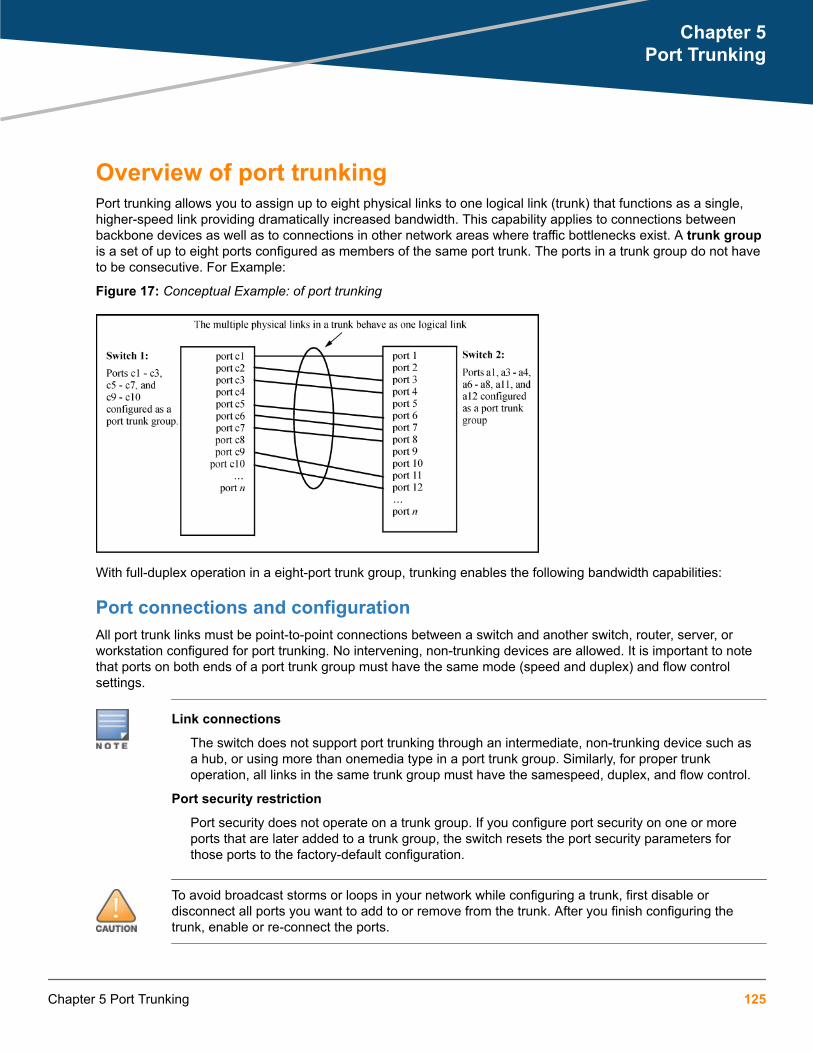
Overview of port trunkingPort trunking allows you to assign up to eight physical links to one logical link (trunk) that functions as a single,higher-speed link providing dramatically increased bandwidth. This capability applies to connections betweenbackbone devices as well as to connections in other network areas where traffic bottlenecks exist. A trunk groupis a set of up to eight ports configured as members of the same port trunk. The ports in a trunk group do not haveto be consecutive. For Example:
Figure 17: Conceptual Example: of port trunking
With full-duplex operation in a eight-port trunk group, trunking enables the following bandwidth capabilities:
Port connections and configurationAll port trunk links must be point-to-point connections between a switch and another switch, router, server, orworkstation configured for port trunking. No intervening, non-trunking devices are allowed. It is important to notethat ports on both ends of a port trunk group must have the same mode (speed and duplex) and flow controlsettings.
Link connections
The switch does not support port trunking through an intermediate, non-trunking device such asa hub, or using more than onemedia type in a port trunk group. Similarly, for proper trunkoperation, all links in the same trunk group must have the samespeed, duplex, and flow control.
Port security restriction
Port security does not operate on a trunk group. If you configure port security on one or moreports that are later added to a trunk group, the switch resets the port security parameters forthose ports to the factory-default configuration.
To avoid broadcast storms or loops in your network while configuring a trunk, first disable ordisconnect all ports you want to add to or remove from the trunk. After you finish configuring thetrunk, enable or re-connect the ports.
Chapter 5Port Trunking
Chapter 5 Port Trunking 125

Port trunk features and operationThe switches covered in this guide offer these options for port trunking:
• LACP: IEEE 802.3ad—Trunk group operation using LACP on page 137
• Trunk: Non-Protocol—Trunk group operation using the "trunk" option on page 143
Up to 60 trunk groups are supported on the switches. The actual maximum depends on the number of portsavailable on the switch and the number of links in each trunk. (Using the link aggregation control protocol—LACP—option, you can include standby trunked ports in addition to the maximum of eight actively trunking ports.) Thetrunks do not have to be the same size; For example, 100 two-port trunks and 11 eight-port trunks are supported.
LACP requires full-duplex (FDx) links of the same media type (10/100Base-T, 100FX, and so on) andthe same speed, and enforces speed and duplex conformance across a trunk group. For mostinstallations, Hewlett Packard Enterprise Switch recommends that you leave the port Mode settingsat Auto (the default). LACP also operates with Auto-10, Auto-100, and Auto-1000 (ifnegotiation selects FDx), and 10FDx, 100FDx, and 1000FDx settings. (The 10-gigabit portsavailable for some switch models allow only the Auto setting.)
Fault toleranceIf a link in a port trunk fails, the switch redistributes traffic originally destined for that link to the remaining links inthe trunk. The trunk remains operable as long as there is at least one link in operation. If a link is restored, thatlink is automatically included in the traffic distribution again. The LACP option also offers a standby link capability,which enables you to keep links in reserve for service if one or more of the original active links fails. (See Trunkgroup operation using LACP on page 137.)
Trunk configuration methods
Dynamic LACP trunkThe switch automatically negotiates trunked links between LACP-configured ports on separate devices, and offersone dynamic trunk option: LACP. To configure the switch to initiate a dynamic LACP trunk with another device,use the interface command in the CLI to set the default LACP option to active on the ports you want to usefor the trunk. For example, the following command sets ports C1 to C4 to LACP active:
switch(config) int c1-c4 lacp activeThe preceding Example: works if the ports are not already operating in a trunk. To change the LACP option onports already operating as a trunk, you must first remove them from the trunk. For example, if ports C1 to C4 areLACP-active and operating in a trunk with another device, you would do the following to change them to LACP-passive:
switch(config)# no int c1-c4 lacpRemoves the ports from the trunk.
switch(config)# int c1-c4 lacp passiveConfigures LACP passive.
Using keys to control dynamic LACP trunk configurationThe lacp key option provides the ability to control dynamic trunk configuration. Ports with the same key will beaggregated as a single trunk.
126 Aruba 2930F / 2930M Management and Configuration Guide for ArubaOS-Switch 16.05

There are two types of keys associated with each port, the Admin key and the Operational key. The Operationalkey is the key currently in use. The Admin key is used internally to modify the value of the Operational key. TheAdmin and Operational key are usually the same, but using static LACP can alter the Operational key duringruntime, in which case the keys would differ.
The lacp key command configures both the Admin and Operational keys when using dynamic LACP trunks. Itonly configures the Admin key if the trunk is a static LACP trunk. It is executed in the interface context.
Syntax:
[no] lacp [active | passive | key <0-65535>]Sets the LACP key. During dynamic link aggregation using LACP, ports with the same key are aggregated as asingle trunk.
Enabling LACP and configuring an LACP key
switch(config)# int A2-A3 lacp activeswitch(config)# int A2-A3 lacp key 500
switch(config)# show lacp
LACP LACP Trunk Port LACP Admin Oper Port Enabled Group Status Partner Status Key Key ---- ------- ------- ------- ------- ------- ------ ------ A2 Active A2 Down No Success 500 500 A3 Active A3 Down No Success 500 500
An interface configured with a different LACP key
switch(config)# int A5 lacp activeswitch(config)# int A5 lacp key 250
switch# show lacp LACP LACP Trunk Port LACP Admin Oper Port Enabled Group Status Partner Status Key Key ---- ------- ------- ------- ------- ------- ------ ------ A1 Active Dyn1 Up Yes Success 100 100 A2 Active Dyn1 Up Yes Success 100 100 A3 Active Dyn1 Up Yes Success 100 100 A4 Active Dyn1 Up Yes Success 100 100 A5 Active A5 Up No Success 250 250
Static trunkThe switch uses the links you configure with the Port/Trunk Settings screen in the menu interface or the trunkcommand in the CLI to create a static port trunk. The switch offers two types of static trunks: LACP and Trunk.
Table 8: Trunk types used in static and dynamic trunk groups
Trunking method LACP Trunk
Dynamic Yes No
Static Yes Yes
Chapter 5 Port Trunking 127

The following table describes the trunking options for LACP and Trunk protocols.
Table 9: Trunk configuration protocols
Protocol Trunking Options
LACP (802.3ad) Provides dynamic and static LACP trunking options.
• Dynamic LACP — Use the switch-negotiated dynamic LACP trunk when:
◦ The port on the other end of the trunk link is configured for Active or Passive LACP.
◦ You want fault-tolerance for high-availability applications. If you use an eight-linktrunk, you can also configure one or more additional links to operate as standbylinks that will activate only if another active link goes down.
• Static LACP — Use the manually configured static LACP trunk when:
◦ The port on the other end of the trunk link is configured for a static LACP trunk.
◦ You want to configure non-default spanning tree or IGMP parameters on an LACPtrunk group.
◦ You want an LACP trunk group to operate in a VLAN other than the default VLANand GVRP is disabled. (See VLANs and dynamic LACP on page 141.)
◦ You want to use a monitor port on the switch to monitor an LACP trunk.
For more information, see Trunk group operation using LACP on page 137.
Trunk
(non-protocol)
Provides manually configured, static-only trunking to:
• Most HPE Switch and routing switches not running the 802.3ad LACP protocol.
• Windows NT and HP-UX workstations and servers
Use the Trunk option when:
• The device to which you want to create a trunk link is using a non-802.3ad trunkingprotocol.
• You are unsure which type of trunk to use, or the device to which you want to create atrunk link is using an unknown trunking protocol.
• You want to use a monitor port on the switch to monitor traffic on a trunk.
See Trunk group operation using the "trunk" option on page 143.
128 Aruba 2930F / 2930M Management and Configuration Guide for ArubaOS-Switch 16.05

Table 10: General operating rules for port trunks
Media: For proper trunk operation, all ports on both ends of a trunk group must havethe same media type and mode (speed and duplex). (For the switches, HPESwitch recommends leaving the port Mode setting at Auto or, in networksusing Cat 3 cabling, Auto-10.)
Port Configuration: The default port configuration is Auto, which enables a port to sense speedand negotiate duplex with an auto-enabled port on another device. HPErecommends that you use the Auto setting for all ports you plan to use fortrunking. Otherwise, you must manually ensure that the mode setting for eachport in a trunk is compatible with the other ports in the trunk. See:Recommended port mode setting for LACP example
All of the following operate on a per-port basis, regardless of trunkmembership:
• Enable/Disable
• Flow control (Flow Ctrl)
LACP is a full-duplex protocol. See Trunk group operation using LACP onpage 137.
Trunk configuration: All ports in the same trunk group must be the same trunk type (LACP or trunk).All LACP ports in the same trunk group must be either all static LACP or alldynamic LACP.A trunk appears as a single port labeledDyn1(for an LACPdynamic trunk) or Trk1 (for a static trunk of type LACP, Trunk) on variousmenu and CLI screens. For a listing of which screens show which trunk types,see How the switch lists trunk data on page 143.For spanning-tree orVLAN operation, configuration for all ports in a trunk is done at the trunk level.(You cannot separately configure individual ports within a trunk for spanning-tree or VLAN operation.)
Traffic distribution: All of the switch trunk protocols use the SA/DA (source address/destinationaddress) method of distributing traffic across the trunked links. See Outboundtraffic distribution across trunked links on page 144.
Table Continued
Chapter 5 Port Trunking 129

Spanning Tree: 802.1D (STP) and 802.1w (RSTP) Spanning Tree operate as a global settingon the switch (with one instance of Spanning Tree per switch). 802.1s (MSTP)Spanning Tree operates on a per-instance basis (with multiple instancesallowed per switch). For each Spanning Tree instance, you can adjustSpanning Tree parameters on a per-port basis.A static trunk of any typeappears in the Spanning Tree configuration display, and you can configureSpanning Tree parameters for a static trunk in the same way that you wouldconfigure Spanning Tree parameters on a non-trunked port. (Note that theswitch lists the trunk by name—such as Trk1—and does not list the individualports in the trunk.) For example, if ports C1 and C2 are configured as a statictrunk named Trk1, they are listed in the Spanning Tree display as Trk1 and donot appear as individual ports in the Spanning Tree displays. See A port trunkin a Spanning Tree listing on page 131.When Spanning Tree forwards on atrunk, all ports in the trunk will be forwarding. Conversely, when Spanning Treeblocks a trunk, all ports in the trunk are blocked.
A dynamic LACP trunk operates only with the default Spanning Tree settings.Also, this type of trunk appears in the CLI show spanning-tree display, butnot in the Spanning Tree Operation display of the Menu interface.
If you remove a port from a static trunk, the port retains the same SpanningTree settings that were configured for the trunk.In the below Example:, portsC1 and C2 are members of TRK1 and do not appear as individual ports in theport configuration part of the listing.See: A port trunk in a Spanning Treelisting example
IP multicast protocol (IGMP): A static trunk of any type appears in the IGMP configuration display, and youcan configure IGMP for a static trunk in the same way that you wouldconfigure IGMP on a non-trunked port. (Note that the switch lists the trunk byname—such as Trk1—and does not list the individual ports in the trunk.) Also,creating a new trunk automatically places the trunk in IGMP Auto status ifIGMP is enabled for the default VLAN.A dynamic LACP trunk operates onlywith the default IGMP settings and does not appear in the IGMP configurationdisplay or show ip igmp listing.
VLANs: Creating a new trunk automatically places the trunk in the DEFAULT_VLAN,regardless of whether the ports in the trunk were in another VLAN. Similarly,removing a port from a trunk group automatically places the port in the defaultVLAN. You can configure a static trunk in the same way that you configure aport for membership in any VLAN.
For a dynamic LACP trunk to operate in a VLAN other than the default VLAN(DEFAULT_VLAN), GVRP must be enabled. See Trunk group operationusing LACP on page 137.
Port security: Trunk groups (and their individual ports) cannot be configured for port security,and the switch excludes trunked ports from the show port-securitylisting. If you configure non-default port security settings for a port, thensubsequently try to place the port in a trunk, you see the following messageand the command is not executed:< port-list> Command cannot operateover a logical port.
Monitor port: A trunk cannot be a monitor port. A monitor port can monitor a static trunk butcannot monitor a dynamic LACP trunk.
130 Aruba 2930F / 2930M Management and Configuration Guide for ArubaOS-Switch 16.05

Recommended port mode setting for LACP
switch(config)# show interfaces config
Port Settings
Port Type | Enabled Mode Flow Ctrl MDI ----- --------- + ------- ------------ --------- ---- 1 10/100TX | Yes Auto Enable Auto 2 10/100TX | Yes Auto Enable MDI
A port trunk in a Spanning Tree listing
Port Type Cost Priority State | Designated Bridge----- --------- ---- -------- ---------- + -----------------C3 100/1000T 5 12B Forwarding | 0020c1-b27ac0C4 100/1000T 5 12B Forwarding | 0060b0-889e00C5 100/1000T 5 12B Disabled | C6 100/1000T 5 12B Disabled | Trk1 1 64 Forwarding | 0001e7-a0ec00
Viewing and configuring a static trunk group (Menu)Configure port trunking before you connect the trunked links to another switch, routing switch, orserver. Otherwise, a broadcast storm could occur. (If you need to connect the ports beforeconfiguring them for trunking, you can temporarily disable the ports until the trunk is configured. See"Enabling or Disabling Ports and Configuring Port Mode".)
This procedure uses the Port/Trunk Settings screen to configure a static port trunk group on the switch.
Procedure
1. Follow the procedures in the preceding IMPORTANT note.
2. From the Main Menu, select:
2. Switch Configuration…
2. Port/Trunk Settings
Chapter 5 Port Trunking 131

3. Press [E] (for Edit) and then use the arrow keys to access the port trunk parameters.
Figure 18: Example: of the menu screen for configuring a port trunk group
4. In the Group column, move the cursor to the port you want to configure.
5. Use the Space bar to choose a trunk group assignment (Trk1, Trk2, and so on) for the selected port.
a. For proper trunk operation, all ports in a trunk must have the same media type and mode (such as10/100TX set to 100FDx, or 100FX set to 100FDx). The flow control settings must also be the same for allports in a given trunk. To verify these settings, see "Viewing Port Status and Configuring Port Parameters".
b. You can configure the trunk group with up to eight ports per trunk. If multiple VLANs are configured, allports within a trunk will be assigned to the same VLAN or set of VLANs. (With the 802.1Q VLAN capabilitybuilt into the switch, more than one VLAN can be assigned to a trunk. See the "Static Virtual LANs(VLANs)" in the advanced traffic management guide for your switch.)
(To return a port to a non-trunk status, keep pressing the Space bar until a blank appears in the highlightedGroup value for that port.)
Figure 19: Example: of the Configuration for a Two-Port Trunk Group
6. Move the cursor to the Type column for the selected port and use the Space bar to select the trunk type:
a. LACP
b. Trunk (the default type if you do not specify a type)
All ports in the same trunk group on the same switch must have the same Type (LACP or Trunk).
132 Aruba 2930F / 2930M Management and Configuration Guide for ArubaOS-Switch 16.05

7. When you are finished assigning ports to the trunk group, press [Enter] , then [S] (for Save) and return to theMain Menu. (It is not necessary to reboot the switch.)
During the Save process, traffic on the ports configured for trunking is delayed for several seconds. If theSpanning Tree Protocol is enabled, the delay may be up to 30 seconds.
8. Connect the trunked ports on the switch to the corresponding ports on the opposite device. If you previouslydisabled any of the trunked ports on the switch, enable them now. (See "Viewing Port Status and ConfiguringPort Parameters")
Check the Event Log ("Using the Event Log for Troubleshooting Switch Problems") to verify that the trunked portsare operating properly.
Viewing and configuring port trunk groups (CLI)You can list the trunk type and group for all ports on the switch or for selected ports. You can also list LACP-onlystatus information for LACP-configured ports.
Viewing static trunk type and group for all ports or for selected portsSyntax:
show trunks [< port-list >]Omitting the <port-list> parameter results in a static trunk data listing for all LAN ports in the switch.
Example:
In a switch where ports A4 and A5 belong to Trunk 1 and ports A7 and A8 belong to Trunk 2, you have theoptions shown in Listing specific ports belonging to static trunks on page 133 and A show trunk listingwithout specifying ports on page 133 for displaying port data for ports belonging to static trunks.
Using a port list specifies, for switch ports in a static trunk group, only the ports you want to view. In this case, thecommand specifies ports A5 through A7. However, because port A6 is not in a static trunk group, it does notappear in the resulting listing:
Listing specific ports belonging to static trunks
switch# show trunks e 5-7
Load Balancing
Port | Name Type | Group Type ---- + ----------------------- --------- + ----- ----- 5 | Print-Server-Trunk 10/100TX | Trk1 Trunk 7 | 10/100TX | Trk2 TrunkThe show trunks <port-list> command in the above Example: includes a port list, and thus shows trunkgroup information only for specific ports that have membership in a static trunk. In A show trunk listing withoutspecifying ports on page 133, the command does not include a port list, so the switch lists all ports having statictrunk membership.
A show trunk listing without specifying ports
switch# show trunks
Load Balancing
Port | Name Type | Group Type
Chapter 5 Port Trunking 133

---- + ----------------------- --------- + ----- ----- 4 | Print-Server-Trunk 10/100TX | Trk1 Trunk 5 | Print-Server-Trunk 10/100TX | Trk1 Trunk 7 | 10/100TX | Trk2 Trunk 8 | 10/100TX | Trk2 Trunk
Viewing static LACP and dynamic LACP trunk dataSyntax:
show lacpLists data for only the LACP-configured ports.
Example:
Ports A1 and A2 have been previously configured for a static LACP trunk. (For more on the Active parameter,see table "LACP port status data".)
A show LACP listing
switch# show lacp
LACP LACP Trunk Port LACP Admin OperPort Enabled Group Status Partner Status Key Key---- ------- ------- ------- ------- ------- ------ ------ Al Active Trkl Up Yes Success 0 250A2 Active Trkl Up Yes Success 0 250A3 Active A3 Down No Success 0 300A4 Passive A4 Down No Success 0 0A5 Passive A5 Down No Success 0 0A6 Passive A6 Down No Success 0 0For a description of each of the above-listed data types, see table "LACP port status data".
Dynamic LACP Standby LinksDynamic LACP trunking enables you to configure standby links for a trunk by including more than eight ports in adynamic LACP trunk configuration. When eight ports (trunk links) are up, the remaining link(s) will be held instandby status. If a trunked link that is “Up” fails, it will be replaced by a standby link, which maintains yourintended bandwidth for the trunk. (Refer to also the “Standby” entry under “Port Status” in "Table 4-5. LACP PortStatus Data".) In the next Example:, ports A1 through A9 have been configured for the same LACP trunk. Noticethat one of the links shows Standby status, while the remaining eight links are “Up”.
A Dynamic LACP trunk with one standby link
switch# show lacp LACP LACP Trunk Port LACP Admin OperPort Enabled Group Status Partner Status Key Key---- ------- ----- ------ ------- ------ ---- -----Al Active Dyn1 Up Yes Success 100 100A2 Active Dyn1 Up Yes Success 100 100A3 Active Dyn1 Up Yes Success 100 100A4 Active Dyn1 Up Yes Success 100 100A5 Active Dyn1 Up Yes Success 100 100A6 Active Dyn1 Up Yes Success 100 100A7 Active Dyn1 Up Yes Success 100 100
134 Aruba 2930F / 2930M Management and Configuration Guide for ArubaOS-Switch 16.05

A8 Active Dyn1 Up Yes Success 100 100A9 Active Dyn1 Standby Yes Success 100 100
Configuring a static trunk or static LACP trunk groupConfigure port trunking before you connect the trunked links between switches. Otherwise, abroadcast storm could occur. (If you need to connect the ports before configuring them for trunking,you can temporarily disable the ports until the trunk is configured. See "Enabling or Disabling Portsand Configuring Port Mode".)
The "Port trunk features and operation" section describes the maximum number of trunk groups you canconfigure on the switch. An individual trunk can have up to eight links, with additional standby links if you’re usingLACP. You can configure trunk group types as follows:
Trunk Type Trunk Group Membership
TrkX (Static) DynX (Dynamic)
LACP Yes Yes
Trunk Yes No
The following examples show how to create different types of trunk groups.
Syntax:
trunk < port-list > < trk1 ... trk60 > {<trunk | lacp>}Configures the specified static trunk type.
Example:
This Example: uses ports C4 to C6 to create a non-protocol static trunk group with the group name Trk2.
switch(config)# trunk c4-c6 trk2 trunk
Removing ports from a static trunk groupRemoving a port from a trunk can create a loop and cause a broadcast storm. When you remove aport from a trunk where spanning tree is not in use, HPE Switch recommends that you first disablethe port or disconnect the link on that port.
Syntax:
no trunk <port-list>Removes the specified ports from an existing trunk group.
Example:
To remove ports C4 and C5 from an existing trunk group:
switch(config)# no trunk c4-c5
Enabling a dynamic LACP trunk groupIn the default port configuration, all ports on the switch are set to disabled. To enable the switch to automaticallyform a trunk group that is dynamic on both ends of the link, the ports on one end of a set of links must be LACPActive. The ports on the other end can be either LACP Activeor LACP Passive. The active command enables
Chapter 5 Port Trunking 135

the switch to automatically establish a (dynamic) LACP trunk group when the device on the other end of the link isconfigured for LACP Passive.
Example:
Figure 20: Criteria for automatically forming a dynamic LACP trunk
Syntax:
interface <port-list> lacp activeConfigures <port-list> as LACP active. If the ports at the other end of the links on <port-list> areconfigured as LACP passive, this command enables a dynamic LACP trunk group on <port-list> .
Example:
This Example: uses ports C4 and C5 to enable a dynamic LACP trunk group.
switch(config)# interface c4-c5 lacp active
Removing ports from a dynamic LACP trunk groupTo remove a port from dynamic LACP trunk operation, you must turn off LACP on the port. (On a port in anoperating, dynamic LACP trunk, you cannot change between LACP Active and LACP passive without firstremoving LACP operation from the port.)
Unless spanning tree is running on your network, removing a port from a trunk can result in a loop.To help prevent a broadcast storm when you remove a port from a trunk where spanning tree is notin use, Hewlett Packard Enterprise recommends that you first disable the port or disconnect the linkon that port.
Syntax:
no interface <port-list> lacpRemoves <port-list> from any dynamic LACP trunk and returns the ports in <port-list> to passiveLACP.
Example:
136 Aruba 2930F / 2930M Management and Configuration Guide for ArubaOS-Switch 16.05

Port C6 belongs to an operating, dynamic LACP trunk. To remove port C6 from the dynamic trunk and return it topassive LACP, do the following:
switch(config)# no interface c6 lacpswitch(config)# interface c6 lacp passiveIn the above Example:, if the port on the other end of the link is configured for active LACP or static LACP, thetrunked link will be re-established almost immediately.
Viewing existing port trunk groups (WebAgent)While the WebAgent does not enable you to configure a port trunk group, it does provide a view of an existingtrunk group.
To view any port trunk groups:
1. In the navigation pane, click Interface.
2. Click Port Info/Config. The trunk information for the port displays in the Port Properties box.
Trunk group operation using LACPThe switch can automatically configure a dynamic LACP trunk group, or you can manually configure a staticLACP trunk group.
LACP requires full-duplex (FDx) links of the same media type (10/100Base-T, 100FX, and so on) andthe same speed and enforces speed and duplex conformance across a trunk group. For mostinstallations, HPE Switch recommends that you leave the port mode settings at Auto (the default).LACP also operates with Auto-10, Auto-100, and Auto-1000 (if negotiation selects FDx), and10FDx, 100FDx, and 1000FDx settings.
LACP trunk status commands include:
Trunk display method Static LACP trunk Dynamic LACP trunk
CLI show lacp command Included in listing. Included in listing.
CLI show trunk command Included in listing. Not included.
Port/Trunk Settings screen in menu interface Included in listing. Not included
Thus, to display a listing of dynamic LACP trunk ports, you must use the show lacp command.
In most cases, trunks configured for LACP on the switches operate as described in the following table.
Chapter 5 Port Trunking 137

Table 11: LACP trunk types
LACP port trunkconfiguration
Operation
Dynamic LACP This option automatically establishes an 802.3ad-compliant trunk group, withLACP for the port Type parameter and DynX for the port Group name, where X isan automatically assigned value from 1 to 60, depending on how many dynamicand static trunks are currently on the switch. (The switch allows a maximum of 60trunk groups in any combination of static and dynamic trunks.)
Dynamic LACP trunks operate only in the default VLAN (unless GVRP is enabledand Forbid is used to prevent the trunked ports from joining the default VLAN).Thus, if an LACP dynamic port forms using ports that are not in the default VLAN,the trunk automatically moves to the default VLAN unless GVRP operation isconfigured to prevent this from occurring. In some cases, this can create a trafficloop in your network. For more information on this topic, see VLANs anddynamic LACP on page 141 .
Under the following conditions, the switch automatically establishes a dynamicLACP port trunk group and assigns a port Group name:
• The ports on both ends of each link have compatible mode settings (speed andduplex).
• The port on one end of each link must be configured for LACP Active and theport on the other end of the same link must be configured for either LACPPassive or LACP Active. For Example:
Either of the above link configurations allows a dynamic LACP trunk link.
Backup Links: A maximum of eight operating links are allowed in the trunk, but,with dynamic LACP, you can configure one or more additional (backup) links thatthe switch automatically activates if a primary link fails. To configure a link as astandby for an existing eight-port dynamic LACP trunk, ensure that the ports in thestandby link are configured as either active-to-active or active-to-passive betweenswitches.
Displaying dynamic LACP trunk data: To list the configuration and status for adynamic LACP trunk, use the CLI show lacp command.
The dynamic trunk is automatically created by the switch and is not listed in thestatic trunk listings available in the menu interface or in the CLI show trunklisting.
Static LACP Provides a manually configured, static LACP trunk to accommodate theseconditions:
138 Aruba 2930F / 2930M Management and Configuration Guide for ArubaOS-Switch 16.05
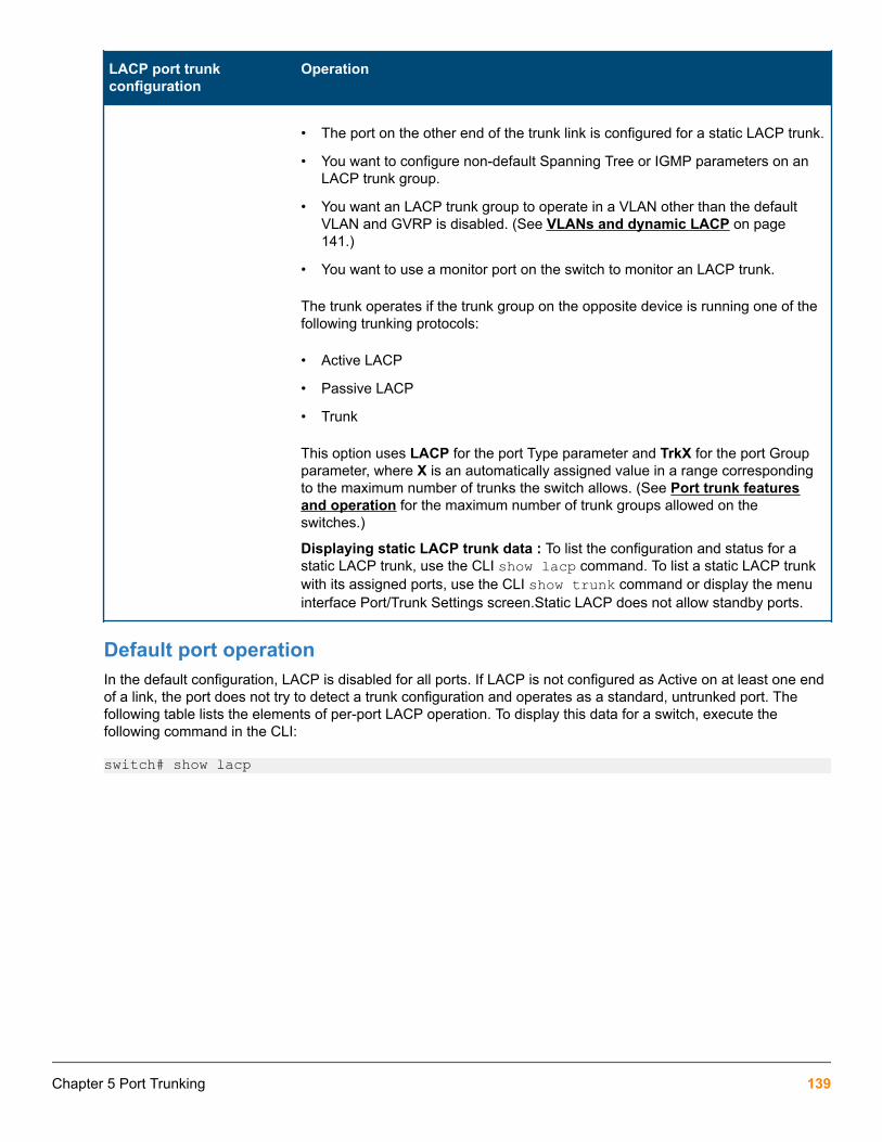
LACP port trunkconfiguration
Operation
• The port on the other end of the trunk link is configured for a static LACP trunk.
• You want to configure non-default Spanning Tree or IGMP parameters on anLACP trunk group.
• You want an LACP trunk group to operate in a VLAN other than the defaultVLAN and GVRP is disabled. (See VLANs and dynamic LACP on page141.)
• You want to use a monitor port on the switch to monitor an LACP trunk.
The trunk operates if the trunk group on the opposite device is running one of thefollowing trunking protocols:
• Active LACP
• Passive LACP
• Trunk
This option uses LACP for the port Type parameter and TrkX for the port Groupparameter, where X is an automatically assigned value in a range correspondingto the maximum number of trunks the switch allows. (See Port trunk featuresand operation for the maximum number of trunk groups allowed on theswitches.)
Displaying static LACP trunk data : To list the configuration and status for astatic LACP trunk, use the CLI show lacp command. To list a static LACP trunkwith its assigned ports, use the CLI show trunk command or display the menuinterface Port/Trunk Settings screen.Static LACP does not allow standby ports.
Default port operationIn the default configuration, LACP is disabled for all ports. If LACP is not configured as Active on at least one endof a link, the port does not try to detect a trunk configuration and operates as a standard, untrunked port. Thefollowing table lists the elements of per-port LACP operation. To display this data for a switch, execute thefollowing command in the CLI:
switch# show lacp
Chapter 5 Port Trunking 139

Table 12: LACP port status data
Statusname
Meaning
Port Numb Shows the physical port number for each port configured for LACP operation (C1, C2, C3 …).Unlisted port numbers indicate that the missing ports that are assigned to a static trunk group arenot configured for any trunking.
LACPEnabled
Active: The port automatically sends LACP protocol packets.
Passive: The port does not automatically send LACP protocol packets and responds only if itreceives LACP protocol packets from the opposite device.A link having either two active LACPports or one active port and one passive port can perform dynamic LACP trunking. A link havingtwo passive LACP ports does not perform LACP trunking because both ports are waiting for anLACP protocol packet from the opposite device.
In the default switch configuration, LACP is disabled for all ports.
TrunkGroup
TrkX: This port has been manually configured into a static LACP trunk.
Trunk group same as port number: The port is configured for LACP, but is not a member of aport trunk.
Port Status Up: The port has an active LACP link and is not blocked or in standby mode.
Down: The port is enabled, but an LACP link is not established. This can indicate, For example, aport that is not connected to the network or a speed mismatch between a pair of linked ports.
Disabled: The port cannot carry traffic.
Blocked: LACP, Spanning Tree has blocked the port. (The port is not in LACP standby mode.) Thismay be caused by a (brief) trunk negotiation or a configuration error, such as differing port speedson the same link or trying to connect the switch to more trunks than it can support. (See Trunkconfiguration protocols.)
Some older devices are limited to four ports in a trunk. When eight LACP-enabled ports areconnected to one of these older devices, four ports connect, but the other four ports are blocked.
Standby: The port is configured for dynamic LACP trunking to another device, but the maximumnumber of ports for the dynamic trunk to that device has already been reached on either the switchor the other device. This port will remain in reserve, or "standby" unless LACP detects that another,active link in the trunk has become disabled, blocked, or down. In this case, LACP automaticallyassigns a standby port, if available, to replace the failed port.
LACPPartner
Yes: LACP is enabled on both ends of the link.
No: LACP is enabled on the switch, but either LACP is not enabled or the link has not beendetected on the opposite device.
LACPStatus
Success: LACP is enabled on the port, detects and synchronizes with a device on the other end ofthe link, and can move traffic across the link.
Failure: LACP is enabled on a port and detects a device on the other end of the link, but is not ableto synchronize with this device, and therefore is not able to send LACP packets across the link.This can be caused, For example, by an intervening device on the link (such as a hub), a badhardware connection, or if the LACP operation on the opposite device does not comply with theIEEE 802.3ad standard.
LACP notes and restrictions
140 Aruba 2930F / 2930M Management and Configuration Guide for ArubaOS-Switch 16.05

802.1X (Port-based access control) configured on a portTo maintain security, LACP is not allowed on ports configured for 802.1X authenticator operation. If you configureport security on a port on which LACP (active or passive) is configured, the switch removes the LACPconfiguration, displays a notice that LACP is disabled on the port, and enables 802.1X on that port.
switch(config)# aaa port-access authenticator b1LACP has been disabled on 802.1x port(s). switch(config)#The switch does not allow you to configure LACP on a port on which port access (802.1X) is enabled. ForExample:
switch(config)# int b1 lacp passive Error configuring port < port-number > : LACP and 802.1x cannot be run together. switch(config)#To restore LACP to the port, you must first remove the 802.1X configuration of the port and then re-enable LACPactive or passive on the port.
Port security configured on a portTo maintain security, LACP is not allowed on ports configured for port security. If you configure port security on aport on which LACP (active or passive) is configured, the switch removes the LACP configuration, displays anotice that LACP is disabled on the port, and enables port security on that port. For example:
switch(config)# port-security a17 learn-mode static address-limit 2 LACP has been disabled on secured port(s).switch(config)#The switch does not allow you to configure LACP on a port on which port security is enabled. For example:
switch(config)# int a17 lacp passiveError configuring port A17: LACP and port security cannot berun together.switch(config)#To restore LACP to the port, you must remove port security and re-enable LACP active or passive.
Changing trunking methodsTo convert a trunk from static to dynamic, you must first eliminate the static trunk.
Static LACP trunksWhen a port is configured for LACP (active or passive), but does not belong to an existing trunk group, you canadd that port to a static trunk. Doing so disables dynamic LACP on that port, which means you must manuallyconfigure both ends of the trunk.
Dynamic LACP trunksYou can configure a port for LACP-active or LACP-passive, but on a dynamic LACP trunk you cannot configurethe other options that you can on static trunks. If you want to manually configure a trunk, use the trunkcommand.
VLANs and dynamic LACPA dynamic LACP trunk operates only in the default VLAN (unless you have enabled GVRP on the switch and useForbid to prevent the ports from joining the default VLAN).
Chapter 5 Port Trunking 141

If you want to use LACP for a trunk on a non-default VLAN and GVRP is disabled, configure the trunk as a statictrunk.
Blocked ports with older devicesSome older devices are limited to four ports in a trunk. When eight LACP-enabled ports are connected to one ofthese older devices, four ports connect, but the other four ports are blocked. The LACP status of the blockedports is shown as "Failure."
If one of the other ports becomes disabled, a blocked port replaces it (Port Status becomes "Up"). When the otherport becomes active again, the replacement port goes back to blocked (Port Status is "Blocked"). It can take a fewseconds for the switch to discover the current status of the ports.
Blocked ports with LACP
switch(eth-B1-B8)# show lacp
LACP
PORT LACP TRUNK PORT LACP LACP NUMB ENABLED GROUP STATUS PARTNER STATUS ---- ------- ------ ------ ------- ------ B1 Active Dyn1 Up Yes Success B2 Active Dyn1 Up Yes Success B3 Active Dyn1 Up Yes Success B4 Active Dyn1 Up Yes Success B5 Active Dyn1 Blocked Yes Failure B6 Active Dyn1 Blocked Yes Failure B7 Active B7 Down No Success B8 Active B8 Down No SuccessIf there are ports that you do not want on the default VLAN, ensure that they cannot become dynamic LACP trunkmembers. Otherwise a traffic loop can unexpectedly occur. For Example:
Figure 21: A dynamic LACP trunk forming in a VLAN can cause a traffic loop
Easy control methods include either disabling LACP on the selected ports or configuring them to operate in staticLACP trunks.
Spanning Tree and IGMPIf Spanning Tree, IGMP, or both are enabled in the switch, a dynamic LACP trunk operates only with the defaultsettings for these features and does not appear in the port listings for these features.
142 Aruba 2930F / 2930M Management and Configuration Guide for ArubaOS-Switch 16.05

Half-duplex, different port speeds, or both not allowed in LACP trunksTheports on both sides of an LACP trunk must be configured for the same speed and for full-duplex (FDx). The802.3ad LACP standard specifies a full-duplex (FDx) requirement for LACP trunking. (10-gigabit ports operateonly at FDx.)
A port configured as LACP passive and not assigned to a port trunk can be configured to half-duplex (HDx).However, in any of the following cases, a port cannot be reconfigured to an HDx setting:
• If the port is a 10-gigabit port.
• If a port is set to LACP Active, you cannot configure it to HDx.
• If a port is already a member of a static or dynamic LACP trunk, you cannot configure it to HDx.
• If a port is already set to HDx, the switch does not allow you to configure it for a static or dynamic LACP trunk.
Dynamic/static LACP interoperationA port configured for dynamic LACP can properly interoperate with a port configured for static (TrkX) LACP, butany ports configured as standby LACP links are ignored.
Trunk group operation using the "trunk" optionThis method creates a trunk group that operates independently of specific trunking protocols and does not use aprotocol exchange with the device on the other end of the trunk. With this choice, the switch simply uses theSA/DA method of distributing outbound traffic across the trunked ports without regard for how that traffic ishandled by the device at the other end of the trunked links. Similarly, the switch handles incoming traffic from thetrunked links as if it were from a trunked source.
When a trunk group is configured with the trunk option, the switch automatically sets the trunk to a priority of "4"for Spanning Tree operation (even if Spanning Tree is currently disabled). This appears in the running-config fileas spanning-tree Trkn priority 4. Executing write memory after configuring the trunk places the sameentry in the startup-config file.
Use the trunk option to establish a trunk group between a switch and another device, where the other device'strunking operation fails to operate properly with LACP trunking configured on the switches.
How the switch lists trunk dataStatic trunk group
Appears in the menu interface and the output from the CLI show trunk and show interfacescommands.
Dynamic LACP trunk group
Appears in the output from the CLI show lacp command.
Interface option Dynamic LACP trunkgroup
Static LACP trunk group Static non-protocol
Menu interface No Yes Yes
CLI show trunk No Yes Yes
CLI show interfaces No Yes Yes
Table Continued
Chapter 5 Port Trunking 143

Interface option Dynamic LACP trunkgroup
Static LACP trunk group Static non-protocol
CLI show lacp Yes Yes No
CLI show spanning-tree
No Yes Yes
CLI show igmp No Yes Yes
CLI show config No Yes Yes
Outbound traffic distribution across trunked linksThe two trunk group options (LACP and trunk) use SA/DA pairs for distributing outbound traffic over trunked links.That is, the switch sends traffic from the same source address to the same destination address through the sametrunked link, and may also send traffic from the same source address to a different destination address throughthe same link or a different link, depending on the mapping of path assignments among the links in the trunk.Likewise, the switch distributes traffic for the same destination address but from different source addressesthrough links depending on the path assignment.
The load-balancing is done on a per-communication basis. Otherwise, traffic is transmitted across the same pathas shown in the figure below. That is, if Client A attached to Switch 1 sends five packets of data to Server Aattached to Switch 2, the same link is used to send all five packets. The SA/DA address pair for the traffic is thesame. The packets are not evenly distributed across any other existing links between the two switches; they alltake the same path.
Figure 22: Example: of single path traffic through a trunk
The actual distribution of the traffic through a trunk depends on a calculation using bits from the SA/DA. When anIP address is available, the calculation includes the last five bits of the IP source address and IP destinationaddress; otherwise, the MAC addresses are used. The result of that process undergoes a mapping thatdetermines which link the traffic goes through. If you have only two ports in a trunk, it is possible that all the trafficwill be sent through one port even if the SA/DA pairs are different. The more ports you have in the trunk, the morelikely it is that the traffic will be distributed among the links.
144 Aruba 2930F / 2930M Management and Configuration Guide for ArubaOS-Switch 16.05

When a new port is added to the trunk, the switch begins sending traffic, either new traffic or existing traffic,through the new link. As links are added or deleted, the switch redistributes traffic across the trunk group. Forexample, in the figure below showing a three-port trunk, traffic could be assigned as shown in the following table.
Figure 23: Example: of port-trunked network
Table 13: Example: of link assignments in a trunk group (SA/DA distribution)
Source Destination Link
Node A Node W 1
Node B Node X 2
Node C Node Y 3
Node D Node Z 1
Node A Node Y 2
Node B Node W 3
Because the amount of traffic coming from or going to various nodes in a network can vary widely, it is possiblefor one link in a trunk group to be fully utilized while other links in the same trunk have unused bandwidth capacity,even if the assignments were evenly distributed across the links in a trunk.
Trunk load balancing using port layersTrunk load balancing using port layers allows the use of TCP/UDP source and destination port number for trunkload balancing. This is in addition to the current use of source and destination IP address and MAC addresses.Configuration of Layer 4 load balancing would apply to all trunks on the switch. Only non-fragmented packets willhave their TCP/UDP port number used by load balancing. This ensures that all frames associated with afragmented IP packet are sent through the same trunk on the same physical link.
The priority for using layer packet information when this feature is enabled is as follows:
Procedure
1. L4-based: If the packet protocol is an IP packet, use Layer 4, or Layer 3, or Layer 2 information, whichever ispresent, in that order.
2. L3-based: If the packet protocol is an IP packet, use Layer 3, or Layer 2 information, whichever is present, inthat order.
3. L2-based: If the packet protocol is an IP packet use Layer 2 information.
4. For all options, if the packet is not an IP packet, use Layer 2 information.
Chapter 5 Port Trunking 145

Enabling trunk load balancingEnter the following command to enable load balancing.
Syntax:
trunk-load-balance L3-based | [L4-based >]This option enables load balancing based on port layer information. The configuration is executed in globalconfiguration context and applies to the entire switch.
Default: L3-based load balancing
L2-based: Load balance based on Layer 2 information.
L3-based: Load balance based on Layer 3 information if present, or Layer 2 information.
L4-based: Load balance on Layer 4 port information if present, or Layer 3 if present, or Layer 2.
Enabling L4-based trunk load balancing
switch(config)# trunk-load-balance L4 based
Output when L4-based trunk load balancing is enabled
HP Switch(config)# show trunk
Load Balancing Method: L4-based
Port | Name Type | Group Type ---- + ----------------------------- --------- + ------ ------- 41 100/1000T Trk1 Trunk 42 100/1000T Trk1 TrunkNote in Running config file when L4-based trunk load balancing is enabled on page 146 that in if L4 trunkload balancing is enabled, a line appears in the running-config file. If it is not enabled, nothing appears as this isthe default and the default values are not displayed.
Running config file when L4-based trunk load balancing is enabled
switch(config)# show running-config
Running configuration
; J9091A Configuration Editor; Created on release #XX.15.02.0001x
hostname "Switch"module 1 type J8702Amodule 5 type J9051Amodule 7 type J8705Amodule 10 type J8708Amodule 12 type J8702Atrunk-load-balance L4-basedvlan 1 name "DEFAULT_VLAN" untagged A1-A24, G1-G24, J1-J4, L1-L24 ip address dhcp-bootp tagged EUP
146 Aruba 2930F / 2930M Management and Configuration Guide for ArubaOS-Switch 16.05

no untagged EDP exitsnmp-server community "public" unrestricted
Chapter 5 Port Trunking 147

Rate-limitingRate-limiting is intended for use on edge ports in a network. It is not recommended for use on links toother switches, routers, or servers within a network, or for use in the network core. Doing so caninterfere with applications the network requires to function properly.
All traffic rate-limitingRate-limiting for all traffic operates on a per-port basis to allow only the specified bandwidth to be used forinbound or outbound traffic. When traffic exceeds the configured limit, it is dropped. This effectively sets a usagelevel on a given port and is a tool for enforcing maximum service level commitments granted to network users.This feature operates on a per-port level and is not configurable on port trunks. Rate-limiting is designed to beapplied at the network edge to limit traffic from non-critical users or to enforce service agreements such as thoseoffered by Internet Service Providers (ISPs) to provide only the bandwidth for which a customer has paid.
Rate-limiting also can be applied by a RADIUS server during an authentication client session.Applying rate-limiting to desirable traffic is not recommended. For further details, see "RADIUSAuthentication and Accounting" in the access security guide for your switch.
The switches also support ICMP rate-limiting to mitigate the effects of certain ICMP-based attacks.
ICMP traffic is necessary for network routing functions. For this reason, blocking all ICMP traffic is notrecommended.
Configuring in/out rate-limitingSyntax:
[no] int <port-list> rate-limit all <in|out> percent <0-100>|kbps <0-100000000>>Configures a traffic rate limit (on non-trunked ports) on the link. The no form of the command disables rate-limitingon the specified ports.
The rate-limit all command controls the rate of traffic sent or received on a port by setting a limit on thebandwidth available. It includes options for:
• Rate-limiting on inbound or outbound traffic.
• Specifying the traffic rate as either a percentage of bandwidth, or in terms of bits per second.
(Default: Disabled.)
in or out Specifies a traffic rate limit on inbound traffic passing through that port or on outbound traffic.
percent orkbps
Specifies the rate limit as a percentage of total available bandwidth, or in kilobits per second.
Chapter 6Port Traffic Controls
148 Aruba 2930F / 2930M Management and Configuration Guide for ArubaOS-Switch 16.05

The granularity of actual limits may vary across different switch models.
For more details on configuring rate-limiting, see All traffic rate-limiting on page 148.
Notes:
• The rate-limit icmp command specifies a rate limit on inbound ICMP traffic only (see ICMP rate-limitingon page 152).
• Rate-limiting does not apply to trunked ports (including meshed ports).
• Kbps rate-limiting is done in segments of 1% of the lowest corresponding media speed. For example, if themedia speed is 1 Kbps, the value would be 1 Mbps. A 1-100 Kbps rate-limit is implemented as a limit of 100Kbps; a limit of 100-199 Kbps is also implemented as a limit of 100 Kbps, a limit of 200-299 Kbps isimplemented as a limit of 200 Kbps, and so on.
• Percentage limits are based on link speed. For example, if a 100 Mbps port negotiates a link at 100 Mbps andthe inbound rate-limit is configured at 50%, then the traffic flow through that port is limited to no more than 50Mbps. Similarly, if the same port negotiates a 10 Mbps link, then it allows no more than 5 Mbps of inboundtraffic.Configuring a rate limit of 0 (zero) on a port blocks all traffic on that port. However, if this is thedesired behavior on the port, Hewlett Packard Enterprise recommends using the <port-list> disablecommand instead of configuring a rate limit of 0.
You can configure a rate limit from either the global configuration level or from the port context level. For example,either of the following commands configures an inbound rate limit of 60% on ports 3 – 5:
switch(config)# int 3-5 rate-limit all in percent 60switch(eth-3-5)# rate-limit all in percent 60
Displaying the current rate-limit configurationThe show rate-limit all command displays the per-port rate-limit configuration in the running-config file.
Syntax:
show rate-limit all [<port-list>]Without [port-list] , this command lists the rate-limit configuration for all ports on the switch.
With [port-list] , this command lists the rate-limit configuration for the specified ports. This commandoperates the same way in any CLI context.
If you want to view the rate-limiting configuration on the first six ports:
Example:
Listing the rate-limit configuration on page 150 shows a rate-limiting configuration for the first six ports. In thisinstance:
• Ports 1–4 are configured with an outbound rate limit of 200 Kbps.
• Port 5 is configured with an inbound rate limit of 20%.
• Port 6 is not configured for rate-limiting.
Chapter 6 Port Traffic Controls 149

Listing the rate-limit configuration
switch# show rate-limit all 1-6
All-Traffic Rate Limit Maximum %
| Inbound Radius | Outbound Radius Port | Limit Mode Override | Limit Mode Override ------ + --------- -------- ----------- + --------- -------- -------- 1 | Disabled Disabled No-override | 200 kbps No-override 2 | Disabled Disabled No-override | 200 kbps No-override 3 | Disabled Disabled No-override | 200 kbps No-override 4 | Disabled Disabled No-override | 200 kbps No-override 5 | 20 % No-override | Disabled Disabled No-override 6 | Disabled Disabled No-override | Disabled Disabled No-override
To view RADIUS-assigned rate-limit information, use one of the following command options:
show port-access web-based clients <port-list> detailed mac-based clients <port-list> detailed authenticator clients <port-list> detailed For more on RADIUS-assigned rate-limits, see title "Configuring RADIUS Server Support for SwitchServices" in the latest Management and Configuration Guide for your switch.
The show running command displays the currently applied setting for any interfaces in the switch configured forall traffic rate-limiting and ICMP rate limiting.
The show config command displays this information for the configuration currently stored in the startup-config file. (Note that configuration changes performed with the CLI, but not followed by a write memcommand, do not appear in the startup-config file.)
Rate-limit settings listed in the show config output
switch# show config
Startup configuration: 3
; J9727A Configuration Editor; Created on release #WB.15.18.0000x; Ver #09:14.29.eb.8f.fc.f3.ff.37.2d:ba
hostname "HP-2920-24G-PoEP"module 1 type j9727ainterface 1 rate-limit all out kbps 200 exitinterface 2 rate-limit all out kbps 200 exitinterface 3 rate-limit all out kbps 200 exitinterface 4 rate-limit all out kbps 200 exitinterface 5
150 Aruba 2930F / 2930M Management and Configuration Guide for ArubaOS-Switch 16.05

rate-limit all in percent 20 exit
Operating notes for rate-limiting
• Rate-limiting operates on a per-port basis, regardless of traffic priority. Rate-limiting is available on alltypes of ports (other than trunked ports) and at all port speeds configurable for these switches.
• Rate-limiting on a trunk is not allowed for the all, bcast, icmp, and mcast traffic types. Rate-limiting isnot supported on ports configured in a trunk group (including mesh ports). Configuring a port for rate-limitingand then adding it to a trunk suspends rate-limiting on the port while it is in the trunk. Attempting to configurerate-limiting on a port that already belongs to a trunk generates the following message:<port-list> :Operation is not allowed for a trunked port.
• Rate-limiting and hardware. The hardware will round the actual Kbps rate down to the nearest multiple of 64Kbps.
• Rate-limiting is visible as an outbound forwarding rate. Because inbound rate-limiting is performed onpackets during packet-processing, it is not shown via the inbound drop counters. Instead, this limit is verifiableas the ratio of outbound traffic from an inbound rate-limited port versus the inbound rate. For outbound rate-limiting, the rate is visible as the percentage of available outbound bandwidth (assuming that the amount ofrequested traffic to be forwarded is larger than the rate-limit).
• Operation with other features. Configuring rate-limiting on a port where other features affect port queuebehavior (such as flow control) can result in the port not achieving its configured rate-limiting maximum. Forexample, in a situation where flow control is configured on a rate-limited port, there can be enough "backpressure" to hold high-priority inbound traffic from the upstream device or application to a rate that is lowerthan the configured rate limit. In this case, the inbound traffic flow does not reach the configured rate and lowerpriority traffic is not forwarded into the switch fabric from the rate-limited port. (This behavior is termed "head-of-line blocking" and is a well-known problem with flow-control.)In another type of situation, an outbound portcan become oversubscribed by traffic received from multiple rate-limited ports. In this case, the actual rate fortraffic on the rate-limited ports may be lower than configured because the total traffic load requested to theoutbound port exceeds the port's bandwidth, and thus some requested traffic may be held off on inbound.
• Traffic filters on rate-limited ports. Configuring a traffic filter on a port does not prevent the switch fromincluding filtered traffic in the bandwidth-use measurement for rate-limiting when it is configured on the sameport. For example, ACLs, source-port filters, protocol filters, and multicast filters are all included in bandwidthusage calculations.
• Monitoring (mirroring) rate-limited interfaces. If monitoring is configured, packets dropped by rate-limitingon a monitored interface are still forwarded to the designated monitor port. (Monitoring shows what traffic isinbound on an interface, and is not affected by "drop" or "forward" decisions.)
• Optimum rate-limiting operation. Optimum rate-limiting occurs with 64-byte packet sizes. Traffic with largerpacket sizes can result in performance somewhat below the configured bandwidth. This is to ensure thestrictest possible rate-limiting of all sizes of packets.
Chapter 6 Port Traffic Controls 151

Rate-limiting is applied to the available bandwidth on a port and not to any specific applicationsrunning through the port. If the total bandwidth requested by all applications is less than theconfigured maximum rate, then no rate-limit can be applied. This situation occurs with a number ofpopular throughput-testing applications, as well as most regular network applications. Consider thefollowing Example: that uses the minimum packet size:
The total available bandwidth on a 100 Mbps port "X" (allowing for Inter-packet Gap—IPG), with norate-limiting restrictions, is:
(((100,000,000 bits) / 8 ) / 84) × 64 = 9,523,809 bytes per secondwhere:
• The divisor (84) includes the 12-byte IPG, 8-byte preamble, and 64-bytes of data required totransfer a 64-byte packet on a 100 Mbps link.
• Calculated "bytes-per-second" includes packet headers and data. This value is the maximum"bytes-per-second" that 100 Mbps can support for minimum-sized packets.
Suppose port "X" is configured with a rate limit of 50% (4,761,904 bytes). If a throughput-testingapplication is the only application using the port and transmits 1 Mbyte of data through the port, ituses only 10.5% of the port's available bandwidth, and the rate-limit of 50% has no effect. This isbecause the maximum rate permitted (50%) exceeds the test application's bandwidth usage(126,642-164,062 bytes, depending upon packet size, which is only 1.3% to 1.7% of the availabletotal). Before rate-limiting can occur, the test application's bandwidth usage must exceed 50% of theport's total available bandwidth. That is, to test the rate-limit setting, the following must be true:
bandwidth usage (0.50 × 9,523,809)
ICMP rate-limitingIn IP networks, ICMP messages are generated in response to either inquiries or requests from routing anddiagnostic functions. These messages are directed to the applications originating the inquiries. In unusualsituations, if the messages are generated rapidly with the intent of overloading network circuits, they can threatennetwork availability. This problem is visible in denial-of-service (DoS) attacks or other malicious behaviors where aworm or virus overloads the network with ICMP messages to an extent where no other traffic can get through.(ICMP messages themselves can also be misused as virus carriers). Such malicious misuses of ICMP caninclude a high number of ping packets that mimic a valid source IP address and an invalid destination IP address(spoofed pings), and a high number of response messages (such as Destination Unreachable error messages)generated by the network.
ICMP rate-limiting provides a method for limiting the amount of bandwidth that may be used for inbound ICMPtraffic on a switch port. This feature allows users to restrict ICMP traffic to percentage levels that permit necessaryICMP functions, but throttle additional traffic that may be caused by worms or viruses (reducing their spread andeffect). In addition, ICMP rate-limiting preserves inbound port bandwidth for non-ICMP traffic.
ICMP is necessary for routing, diagnostic, and error responses in an IP network. ICMP rate-limiting isprimarily used for throttling worm or virus-like behavior and should normally be configured to allowone to five percent of available inbound bandwidth (at 10 Mbps or 100 Mbps speeds) or 100 to10,000 kbps (1Gbps or 10 Gbps speeds) to be used for ICMP traffic. This feature should not beused to remove all ICMP traffic from a network.
152 Aruba 2930F / 2930M Management and Configuration Guide for ArubaOS-Switch 16.05

ICMP rate-limiting does not throttle non-ICMP traffic. In cases where you want to throttle both ICMPtraffic and all other inbound traffic on a given interface, you can separately configure both ICMP rate-limiting and all-traffic rate-limiting.
The all-traffic rate-limiting command (rate-limit all) and the ICMP rate-limiting command(rate-limit icmp) operate differently:
• All-traffic rate-limiting applies to both inbound and outbound traffic and can be specified either interms of a percentage of total bandwidth or in terms of bits per second;
• ICMP rate-limiting applies only to inbound traffic and can be specified as only a percentage oftotal bandwidth.
Guidelines for configuring ICMP rate-limitingApply ICMP rate-limiting on all connected interfaces on the switch to effectively throttle excessive ICMPmessaging from any source. Figure 24: Example: of ICMP rate-limiting on page 153 shows an Example: ofhow to configure this for a small to mid-sized campus though similar rate-limit thresholds are applicable to othernetwork environments. On edge interfaces, where ICMP traffic should be minimal, a threshold of 1% of availablebandwidth should be sufficient for most applications. On core interfaces, such as switch-to-switch and switch-to-router, a maximum threshold of 5% should be sufficient for normal ICMP traffic. ("Normal" ICMP traffic levelsshould be the maximums that occur when the network is rebooting.)
Figure 24: Example: of ICMP rate-limiting
Configuring ICMP rate-limitingFor detailed information about ICMP rate-limiting, see ICMP rate-limiting on page 152.
The rate-limit icmp command controls inbound usage of a port by setting a limit on the bandwidth availablefor inbound ICMP traffic.
Syntax:
[no] int <port-list> rate-limit icmp {< percent < 0-100 > | kbps < 0-10000000 > | [trap-clear>]}
Configures inbound ICMP traffic rate-limiting. You can configure a rate limit from either the global configurationlevel (as shown above) or from the interface context level. The no form of the command disables ICMP rate-limiting on the specified interfaces.
(Default: Disabled.)
Chapter 6 Port Traffic Controls 153

percent <1-100> Values in this range allow ICMP traffic as a percentage of the bandwidth availableon the interface.
kbps <0-10000000> Specifies the rate at which to forward traffic in kilobits per second.
0 Causes an interface to drop all incoming ICMP traffic and is not recommended.See the caution.
trap-clear Clears existing ICMP rate limiting trap condition.
Note: ICMP rate-limiting is not supported on meshed ports. (Rate-limiting can reduce the efficiency of pathsthrough a mesh domain).
Example:
Either of the following commands configures an inbound rate limit of 1% on ports A3 to A5, which are used asnetwork edge ports:
switch(config) # int a3-a5 rate-limit icmp 1switch(eth-A3-A5) # rate-limit icmp 1
When using kbps-mode ICMP rate-limiting, the rate-limiting only operates on the IP payload part ofthe ICMP packet (as required by metering RFC 2698). This means that effective metering is at a rategreater than the configured rate, with the disparity increasing as the packet size decreases (thepacket to payload ratio is higher).
Also, in kbps mode, metering accuracy is limited at low values, For example, less than 45 Kbps. Thisis to allow metering to function well at higher media speeds such as 10 Gbps.
For information on using ICMP rate-limiting and all-traffic rate-limiting on the same interface, seeUsing bothICMP rate-limiting and all-traffic rate-limiting on the same interface on page 154.
Using both ICMP rate-limiting and all-traffic rate-limiting on the sameinterfaceICMP and all-traffic rate-limiting can be configured on the same interface. All-traffic rate-limiting applies to allinbound or outbound traffic (including ICMP traffic), while ICMP rate-limiting applies only to inbound ICMP traffic.
If the all-traffic load on an interface meets or exceeds the currently configured all-traffic inbound rate-limit while the ICMP traffic rate-limit on the same interface has not been reached, all excess traffic isdropped, including any inbound ICMP traffic above the all-traffic limit (regardless of whether theICMP rate-limit has been reached).
Example:
Suppose:
• The all-traffic inbound rate-limit on port "X" is configured at 55% of the port's bandwidth.
• The ICMP traffic rate-limit on port "X" is configured at 2% of the port's bandwidth.
If at a given moment:
• Inbound ICMP traffic on port "X" is using 1% of the port's bandwidth, and
• Inbound traffic of all types on port "X" demands 61% of the ports's bandwidth,
154 Aruba 2930F / 2930M Management and Configuration Guide for ArubaOS-Switch 16.05

all inbound traffic above 55% of the port's bandwidth, including any additional ICMP traffic, is dropped as long asall inbound traffic combined on the port demands 55% or more of the port's bandwidth.
Viewing the current ICMP rate-limit configurationThe show rate-limit icmp command displays the per-interface ICMP rate-limit configuration in the running-config file.
Syntax:
show rate-limit icmp [< port-list >]Without [port-list], this command lists the ICMP rate-limit configuration for all ports on the switch.
With [port-list], this command lists the rate-limit configuration for the specified interfaces. This command operatesthe same way in any CLI context
If you want to view the rate-limiting configuration on ports 1–6:
Listing the rate-limit configuration
switch(config)# show rate-limit icmp 1-6
Inbound ICMP Rate Limit Maximum Percentage
| Rate Port | Mode Limit ----- + -------- -------- 1 | Disabled Disabled 2 | kbps 100 3 | % 5 4 | % 1 5 | % 1 6 | Disabled DisableThe show running command displays the currently applied setting for any interfaces in the switch configured forall traffic rate-limiting and ICMP rate-limiting.
The show config command displays this information for the configuration currently stored in the startup-config file. (Note that configuration changes performed with the CLI, but not followed by a write memcommand, do not appear in the startup-config file.)
Operating notes for ICMP rate-limitingICMP rate-limiting operates on an interface (per-port) basis to allow, on average, the highest expected amount oflegitimate, inbound ICMP traffic.
• Interface support: ICMP rate-limiting is available on all types of ports (other than trunk ports or mesh ports),and at all port speeds configurable for the switch.
• Rate-limiting is not permitted on mesh ports: Either type of rate-limiting (all-traffic or ICMP) can reduce theefficiency of paths through a mesh domain.
• Rate-limiting on a trunk is not allowed for the all, bcast, icmp, and mcast traffic types. Neither all-traffic nor ICMP rate-limiting are supported on ports configured in a trunk group.
• ICMP percentage-based rate-limits are calculated as a percentage of the negotiated link speed: Forexample, if a 100 Mbps port negotiates a link to another switch at 100 Mbps and is ICMP rate-limit configuredat 5%, the inbound ICMP traffic flow through that port is limited to 5 Mbps. Similarly, if the same port negotiatesa 10 Mbps link, it allows 0.5 Mbps of inbound traffic. If an interface experiences an inbound flow of ICMP traffic
Chapter 6 Port Traffic Controls 155
in excess of its configured limit, the switch generates a log message and an SNMP trap (if an SNMP trapreceiver is configured).
• ICMP rate-limiting is port-based: ICMP rate-limiting reflects the available percentage of an interface's entireinbound bandwidth. The rate of inbound flow for traffic of a given priority and the rate of flow from an ICMPrate-limited interface to a particular queue of an outbound interface are not measures of the actual ICMP ratelimit enforced on an interface.
• Below-maximum rates: ICMP rate-limiting operates on a per-interface basis, regardless of traffic priority.Configuring ICMP rate-limiting on an interface where other features affect inbound port queue behavior (suchas flow control) can result in the interface not achieving its configured ICMP rate-limiting maximum. Forexample, in some situations with flow control configured on an ICMP rate-limited interface, there can beenough "back pressure" to hold high-priority inbound traffic from the upstream device or application to a ratethat does not allow bandwidth for lower-priority ICMP traffic. In this case, the inbound traffic flow may notpermit the forwarding of ICMP traffic into the switch fabric from the rate-limited interface. (This behavior istermed "head-of-line blocking" and is a well-known problem with flow-control.) In cases where both types ofrate-limiting (rate-limit all and rate-limit icmp) are configured on the same interface, this situationis more likely to occur.
In another type of situation, an outbound interface can become oversubscribed by traffic received from multipleICMP rate-limited interfaces. In this case, the actual rate for traffic on the rate-limited interfaces may be lowerthan configured because the total traffic load requested to the outbound interface exceeds the interface'sbandwidth, and thus some requested traffic may be held off on inbound.
• Monitoring (mirroring) ICMP rate-limited interfaces: If monitoring is configured, packets dropped by ICMPrate-limiting on a monitored interface are still forwarded to the designated monitor port. (Monitoring showswhat traffic is inbound on an interface, and is not affected by "drop" or "forward" decisions.)
• Optimum rate-limiting operation: Optimum rate-limiting occurs with 64-byte packet sizes. Traffic with largerpacket sizes can result in performance somewhat below the configured inbound bandwidth. This is to ensurethe strictest possible rate-limiting of all sizes of packets.
• Outbound traffic flow: Configuring ICMP rate-limiting on an interface does not control the rate of outboundtraffic flow on the interface.
ICMP rate-limiting trap and Event Log messagesIf the switch detects a volume of inbound ICMP traffic on a port that exceeds the ICMP rate-limit configured forthat port, it generates one SNMP trap and one informational Event Log message to notify the system operator ofthe condition. (The trap and Event Log message are sent within two minutes of when the event occurred on theport.) For Example:
I 06/30/05 11:15:42 RateLim: ICMP traffic exceeded configured limit on port A1These trap and Event Log messages provide an advisory that inbound ICMP traffic on a given interface hasexceeded the configured maximum. The additional ICMP traffic is dropped, but the excess condition may indicatean infected host (or other traffic threat or network problem) on that interface. The system operator shouldinvestigate the attached devices or network conditions further; the switch does not send more traps or Event Logmessages for excess ICMP traffic on the affected port until the system operator resets the port's ICMP trapfunction.
The switch does not send more traps or Event Log messages for excess ICMP traffic on the affected port until thesystem operator resets the port’s ICMP trap function. The reset can be done through SNMP from a networkmanagement station or through the CLI with the trap-clear command option.
Syntax:
interface <port-list> rate-limit icmp trap-clear
156 Aruba 2930F / 2930M Management and Configuration Guide for ArubaOS-Switch 16.05

On a port configured with ICMP rate-limiting, this command resets the ICMP trap function, which allows the switchto generate a new SNMP trap and an Event Log message if ICMP traffic in excess of the configured limit isdetected on the port.
Example:
An operator noticing an ICMP rate-limiting trap or Event Log message originating with port 1 on a switch woulduse the following command to reset the port to send a new message if the condition occurs again:
HP Switch(config)# interface 1 rate-limit icmp trap-clear
Determining the switch port number used in ICMP port reset commandsTo enable excess ICMP traffic notification traps and Event Log messages, use the setmib command describedon ICMP rate-limiting trap and Event Log messages on page 156. The port number included in the commandcorresponds to the internal number the switch maintains for the designated port and not the port's externalidentity.
To match the port's external slot/number to the internal port number, use the walkmib ifDescr command, asshown in the following example:
Matching internal port numbers to external port numbers
switch# walkmib ifDescrifDescr.1 = 1ifDescr.2 = 2ifDescr.3 = 3ifDescr.4 = 4ifDescr.5 = 5ifDescr.6 = 6ifDescr.7 = 7ifDescr.8 = 8ifDescr.9 = 9ifDescr.10 = 10ifDescr.11 = 11ifDescr.12 = 12ifDescr.13 = 13ifDescr.14 = 14ifDescr.15 = 15ifDescr.16 = 16ifDescr.17 = 17ifDescr.18 = 18ifDescr.19 = 19ifDescr.20 = 20ifDescr.21 = 21ifDescr.22 = 22ifDescr.23 = 23ifDescr.24 = 24ifDescr.210 = Trk1ifDescr.211 = Trk2ifDescr.330 = DEFAULT_VLANifDescr.4425 = HP Switch software loopback interfaceifDescr.4426 = HP Switch software loopback interface...
Configuring inbound rate-limiting for broadcast and multicast trafficYou can configure rate-limiting (throttling) of inbound broadcast and multicast traffic on the switch, which helpsprevent the switch from being disrupted by traffic storms if they occur on the rate-limited port. The rate-limiting isimplemented as a percentage of the total available bandwidth on the port.
Chapter 6 Port Traffic Controls 157

The rate-limit command can be executed from the global or interface context, for Example:
switch(config)# interface 3 rate-limit bcast in percent 10or
switch(config)# interface 3switch(eth-3)# rate-limit bcast in percent 10Syntax:
rate-limit {< bcast | mcast >} in percent < 0-100 >
Optionin percent <0-100>Also supports configuring limit in kbps
[no] rate-limit {<bcast | [mcast >]} inEnables rate-limiting and sets limits for the specified inbound broadcast or multicast traffic. Only the amount oftraffic specified by the percent is forwarded.
Default: Disabled
If you want to set a limit of 50% on inbound broadcast traffic for port 3, you can first enter interface context for port3 and then execute the rate-limit command, as shown in Inbound broadcast rate-limiting of 50% on port 3on page 158. Only 50% of the inbound broadcast traffic will be forwarded.
Inbound broadcast rate-limiting of 50% on port 3
switch(config)# int 3switch(eth-3)# rate-limit bcast in percent 50
switch(eth-3)# show rate-limit bcast Broadcast-Traffic Rate Limit Maximum %
Port | Inbound Limit Mode Radius Override ----- + ------------- --------- --------------- 1 | Disabled Disabled No-override 2 | Disabled Disabled No-override 3 | Disabled % No-override 4 | Disabled Disabled No-override 5 | Disabled Disabled No-overrideIf you rate-limit multicast traffic on the same port, the multicast limit is also in effect for that port, as shown in Inbound multicast rate-limiting of 20% on port 3 on page 158. Only 20% of the multicast traffic will beforwarded.
Inbound multicast rate-limiting of 20% on port 3
switch(eth-3)# rate-limit mcast in percent 20switch(eth-3)# show rate-limit mcast Multicast-Traffic Rate Limit Maximum %
Port | Inbound Limit Mode Radius Override
158 Aruba 2930F / 2930M Management and Configuration Guide for ArubaOS-Switch 16.05

----- + ------------- --------- --------------- 1 | Disabled Disabled No-override 2 | Disabled Disabled No-override 3 | 20 % No-override 4 | Disabled Disabled No-overrideTo disable rate-limiting for a port enter the no form of the command, as shown in Disabling inbound multicastrate-limiting for port 3 on page 159.
Disabling inbound multicast rate-limiting for port 3
switch(eth-3)# no rate-limit mcast in
switch(eth-3)# show rate-limit mcast Multicast-Traffic Rate Limit Maximum %
Port | Inbound Limit Mode Radius Override ----- + ------------- --------- --------------- 1 | Disabled Disabled No-override 2 | Disabled Disabled No-override 3 | Disabled Disabled No-override 4 | Disabled Disabled No-override
Operating NotesThe following information is displayed for each installed transceiver:
• Port number on which transceiver is installed.
• Type of transceiver.
• Product number — Includes revision letter, such as A, B, or C. If no revision letter follows a product number,this means that no revision is available for the transceiver.
• Part number — Allows you to determine the manufacturer for a specified transceiver and revision number.
• For a non-HPE switches installed transceiver (see line 23 of "The show tech transceivers command"example), no transceiver type, product number, or part information is displayed. In the Serial Number field,non-operational is displayed instead of a serial number.
• The following error messages may be displayed for a non-operational transceiver:
◦ Unsupported Transceiver. (SelfTest Err#060)◦ This switch only supports revision B and above transceivers.◦ Self test failure.◦ Transceiver type not supported in this port.◦ Transceiver type not supported in this software version.◦ Not an HPE Switch Transceiver.
Rate-limiting Unknown Unicast TrafficUnknown unicast traffic consists of unicast packets with unknown destination MAC addresses. The switch floodsthe unicast packets to all interfaces that are members of the VLAN. An attacker can bring down the network by
Chapter 6 Port Traffic Controls 159

sending out packets to random destination MAC addresses and hence it is important to rate limit traffic withunknown destination addresses.
You can rate limit the unknown unicast traffic per port level in either percent or kbps mode.
rate-limit unknown-unicast in percentSyntaxinterface port-list rate-limit unknown-unicast in percent 0-100
Description
Sets a rate limit for unicast flood traffic.
Command contextinterface
Parametersin
Sets a rate limit for incoming unicast flood traffic.
percentSpecifies the rate limit as a percentage of the total available bandwidth.
kbpsSpecifies the rate limit in Kb/s.
Examples
switch(config)# int 2switch(eth-2)# rate-limitall Set a rate limit for all traffic.bcast Set a rate limit for broadcast traffic.icmp Set a rate limit for ICMP traffic.mcast Set a rate limit for multicast traffic.queues Set a rate limit for each traffic queue.unknown-unicast Set a rate limit for unicast flood traffic.switch(eth-2)# rate-limit unknown-unicastin Set a rate limit for incoming unicast flood traffic.switch(eth-2)# rate-limit unknown-unicast inkbpspercentswitch(eth-2)# rate-limit unknown-unicast in percent 10switch(eth-2)# show rate-limit bcast Show broadcast traffic rate limits. icmp Show ICMP traffic rate limits. mcast Show multicast traffic rate limits. queues Show limits for outgoing queue traffic. unknown-unicast Show unicast flood traffic rate limits.switch(eth-2)# show rate-limit unknown-unicast [ethernet] PORT-LIST The ports to show information for.
switch(eth-2)# show rate-limit unknown-unicast 2
Unknown-Unicast Traffic Rate Limit Maximum %
Port | Inbound Limit Mode ----- + ------------- ---------
160 Aruba 2930F / 2930M Management and Configuration Guide for ArubaOS-Switch 16.05

2 | 10 %
rate-limit unknown-unicast in kbpsSyntaxinterface port-list rate-limit unknown-unicast in kbps rate
Description
Sets a rate limit for unicast flood traffic.
Command contextinterface
Parametersin
Sets a rate limit for incoming unicast flood traffic.
percentSpecifies the rate limit as a percentage of the total available bandwidth.
kbpsSpecifies the rate limit in Kb/s.
Examples
switch(config)# int 1switch(eth-1)# rate-limitall Set a rate limit for all traffic.bcast Set a rate limit for broadcast traffic.icmp Set a rate limit for ICMP traffic.mcast Set a rate limit for multicast traffic.queues Set a rate limit for each traffic queue.unknown-unicast Set a rate limit for unicast flood traffic.switch(eth-1)# rate-limit unknown-unicastin Set a rate limit for incoming unicast flood traffic.switch(eth-1)# rate-limit unknown-unicast inkbpspercentswitch(eth-1)# rate-limit unknown-unicast in kbps 100switch(eth-1)# show rate-limitall Show total traffic rate limits.bcast Show broadcast traffic rate limits.icmp Show ICMP traffic rate limits.mcast Show multicast traffic rate limits.queues Show limits for outgoing queue traffic.unknown-unicast Show unicast flood traffic rate limits.switch(eth-1)# show rate-limit unknown-unicast
Unknown-Unicast Traffic Rate Limit Maximum %
Port | Inbound Limit Mode ----- + ------------- --------- 1 | 100 kbps 2 | Disabled Disabled 3 | Disabled Disabled 4 | Disabled Disabled 5 | Disabled Disabled
Chapter 6 Port Traffic Controls 161

6 | Disabled Disabled 7 | Disabled Disabled 8 | Disabled Disabled 9 | Disabled Disabled 10 | Disabled Disabled 11 | Disabled Disabled 12 | Disabled Disabled 13 | Disabled Disabled 14 | Disabled Disabled 15 | Disabled Disabled 16 | Disabled Disabled
show rate-limit unknown-unicastSyntaxshow rate-limit unknown-unicast
Description
Displays the per port rate limit configuration.
Command contextinterface
Parametersethernet <port-list>
To view the rate limit configuration for the specified port.
Examples
switch(eth-2)# show rate-limit unknown-unicast
Unknown-Unicast Traffic Rate Limit Maximum %
Port | Inbound Limit Mode ----- + ------------- --------- 1 | 10 kbps 2 | 10 % 3 | Disabled Disabled 4 | Disabled Disabled 5 | Disabled Disabled 6 | Disabled Disabled 7 | Disabled Disabled 8 | Disabled Disabled 9 | Disabled Disabled 10 | Disabled Disabled 11 | Disabled Disabled 12 | Disabled Disabled 13 | Disabled Disabled 14 | Disabled Disabled 15 | Disabled Disabled 16 | Disabled Disabled 17 | Disabled Disabled 18 | Disabled Disabled
162 Aruba 2930F / 2930M Management and Configuration Guide for ArubaOS-Switch 16.05

Guaranteed minimum bandwidth (GMB)GMB provides a method for ensuring that each of a given port's outbound traffic priority queues has a specifiedminimum consideration for sending traffic out on the link to another device. This can prevent a condition whereapplications generating lower-priority traffic in the network are frequently or continually "starved" by high volumesof higher-priority traffic. You can configure GMB per-port.
Jumbo framesThe maximum transmission unit(MTU) is the maximum size IP frame the switch can receive for Layer 2 framesinbound on a port. The switch drops any inbound frames larger than the MTU allowed on the port. Ports operatingat a minimum of 1 Gbps can accept forward frames of up to 9220 bytes (including four bytes for a VLAN tag)when configured for jumbo traffic. You can enable inbound jumbo frames on a per-VLAN basis. That is, on aVLAN configured for jumbo traffic, all ports belonging to that VLAN and operating at a minimum of 1 Gbps allowinbound jumbo frames of up to 9220 bytes.
Operating rules
• Required port speed: This feature allows inbound and outbound jumbo frames on ports operating at aminimum of 1 Gbps.
• GVRP operation: A VLAN enabled for jumbo traffic cannot be used to create a dynamic VLAN. A portbelonging to a statically configured, jumbo-enabled VLAN cannot join a dynamic VLAN.
• Port adds and moves: If you add a port to a VLAN that is already configured for jumbo traffic, the switchenables that port to receive jumbo traffic. If you remove a port from a jumbo-enabled VLAN, the switchdisables jumbo traffic capability on the port only if the port is not currently a member of another jumbo-enabledVLAN. This same operation applies to port trunks.
• Jumbo traffic sources: A port belonging to a jumbo-enabled VLAN can receive inbound jumbo framesthrough any VLAN to which it belongs, including non-jumbo VLANs. For example, if VLAN 10 (without jumbosenabled) and VLAN 20 (with jumbos enabled) are both configured on a switch, and port 1 belongs to bothVLANs, port 1 can receive jumbo traffic from devices on either VLAN. For a method to allow only some ports ina VLAN to receive jumbo traffic, see Configuring a maximum frame size on page 167.
Jumbo traffic-handling
• HPE does not recommend configuring a voice VLAN to accept jumbo frames. Voice VLAN frames are typicallysmall, and allowing a voice VLAN to accept jumbo frame traffic can degrade the voice transmissionperformance.
• You can configure the default, primary, and/or (if configured) the management VLAN to accept jumbo frameson all ports belonging to the VLAN.
• When the switch applies the default MTU (1522-bytes including 4 bytes for the VLAN tag) to a VLAN, all portsin the VLAN can receive incoming frames of up to 1522 bytes. When the switch applies the jumbo MTU (9220bytes including 4 bytes for the VLAN tag) to a VLAN, all ports in that VLAN can receive incoming frames of upto 9220 bytes. A port receiving frames exceeding the applicable MTU drops such frames, causing the switch togenerate an Event Log message and increment the "Giant Rx" counter (displayed by show interfaces<port-list> ).
• The switch allows flow control and jumbo frame capability to co-exist on a port.
• The default MTU is 1522 bytes (including 4 bytes for the VLAN tag). The jumbo MTU is 9220 bytes (including 4bytes for the VLAN tag).
Chapter 6 Port Traffic Controls 163
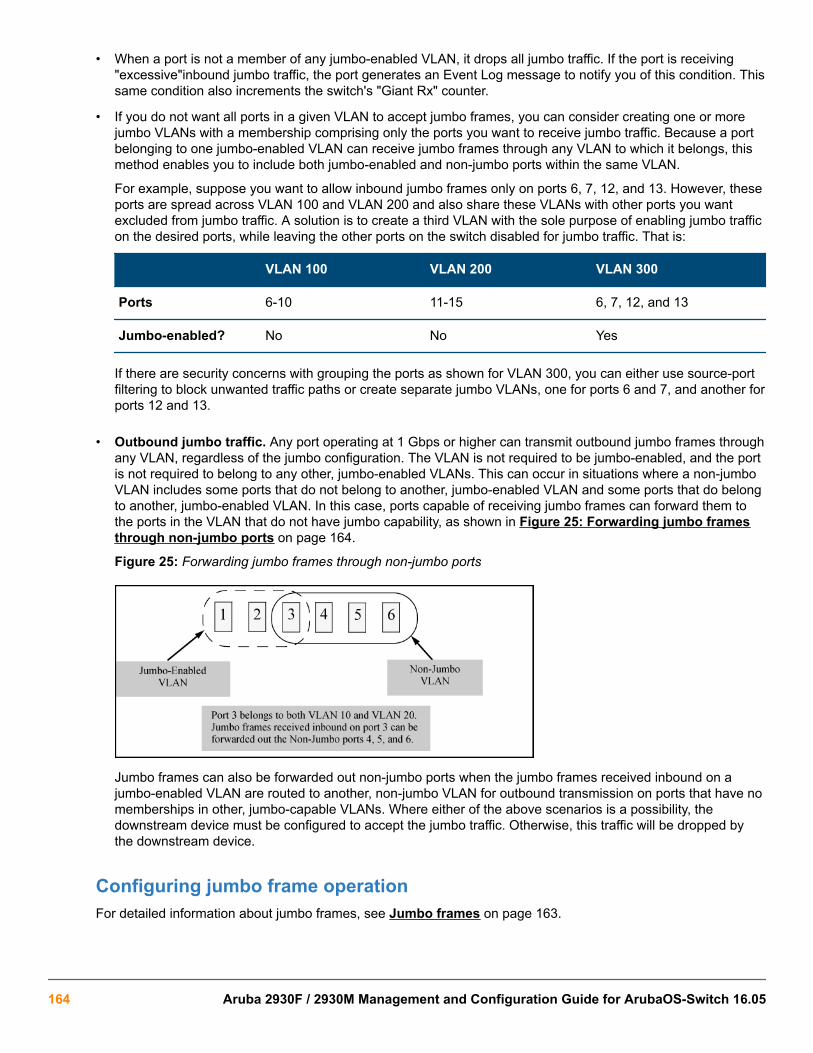
• When a port is not a member of any jumbo-enabled VLAN, it drops all jumbo traffic. If the port is receiving"excessive"inbound jumbo traffic, the port generates an Event Log message to notify you of this condition. Thissame condition also increments the switch's "Giant Rx" counter.
• If you do not want all ports in a given VLAN to accept jumbo frames, you can consider creating one or morejumbo VLANs with a membership comprising only the ports you want to receive jumbo traffic. Because a portbelonging to one jumbo-enabled VLAN can receive jumbo frames through any VLAN to which it belongs, thismethod enables you to include both jumbo-enabled and non-jumbo ports within the same VLAN.
For example, suppose you want to allow inbound jumbo frames only on ports 6, 7, 12, and 13. However, theseports are spread across VLAN 100 and VLAN 200 and also share these VLANs with other ports you wantexcluded from jumbo traffic. A solution is to create a third VLAN with the sole purpose of enabling jumbo trafficon the desired ports, while leaving the other ports on the switch disabled for jumbo traffic. That is:
VLAN 100 VLAN 200 VLAN 300
Ports 6-10 11-15 6, 7, 12, and 13
Jumbo-enabled? No No Yes
If there are security concerns with grouping the ports as shown for VLAN 300, you can either use source-portfiltering to block unwanted traffic paths or create separate jumbo VLANs, one for ports 6 and 7, and another forports 12 and 13.
• Outbound jumbo traffic. Any port operating at 1 Gbps or higher can transmit outbound jumbo frames throughany VLAN, regardless of the jumbo configuration. The VLAN is not required to be jumbo-enabled, and the portis not required to belong to any other, jumbo-enabled VLANs. This can occur in situations where a non-jumboVLAN includes some ports that do not belong to another, jumbo-enabled VLAN and some ports that do belongto another, jumbo-enabled VLAN. In this case, ports capable of receiving jumbo frames can forward them tothe ports in the VLAN that do not have jumbo capability, as shown in Figure 25: Forwarding jumbo framesthrough non-jumbo ports on page 164.
Figure 25: Forwarding jumbo frames through non-jumbo ports
Jumbo frames can also be forwarded out non-jumbo ports when the jumbo frames received inbound on ajumbo-enabled VLAN are routed to another, non-jumbo VLAN for outbound transmission on ports that have nomemberships in other, jumbo-capable VLANs. Where either of the above scenarios is a possibility, thedownstream device must be configured to accept the jumbo traffic. Otherwise, this traffic will be dropped bythe downstream device.
Configuring jumbo frame operationFor detailed information about jumbo frames, see Jumbo frames on page 163.
164 Aruba 2930F / 2930M Management and Configuration Guide for ArubaOS-Switch 16.05

Overview
1. Determine the VLAN membership of the ports or trunks through which you want the switch to accept inboundjumbo traffic. For operation with GVRP enabled, refer to the GVRP topic under “Operating Rules”, above.
2. Ensure that the ports through which you want the switch to receive jumbo frames are operating at least atgigabit speed. (Check the Mode field in the output for the show interfaces brief <port-list>command.)
3. Use the jumbo command to enable jumbo frames on one or more VLANs statically configured in the switch.(All ports belonging to a jumbo-enabled VLAN can receive jumbo frames.
4. Execute write memory to save your configuration changes to the startupconfig file.
Viewing the current jumbo configurationSyntax:
show vlansLists the static VLANs configured on the switch and includes a Jumbo column to indicate which VLANs areconfigured to support inbound jumbo traffic. All ports belonging to a jumbo-enabled VLAN can receive jumbotraffic. (For more information, see Configuring a maximum frame size on page 167.) See Figure Figure 26:Example: listing of static VLANs to show jumbo status per VLAN on page 165.
Figure 26: Example: listing of static VLANs to show jumbo status per VLAN
Syntax:
show vlans ports <port-list>Lists the static VLANs to which the specified ports belong, including the Jumbo column to indicate which VLANsare configured to support jumbo traffic.
Entering only one port in <port-list > results in a list of all VLANs to which that port belongs.
Entering multiple ports in <port-list > results in a superset list that includes the VLAN memberships of allports in the list, even though the individual ports in the list may belong to different subsets of the complete VLANlisting.
Example:
Chapter 6 Port Traffic Controls 165

If port 1 belongs to VLAN 1, port 2 belongs to VLAN 10, and port 3 belongs to VLAN 15, executing this commandwith a port-list of 1 - 3 results in a listing of all three VLANs, even though none of the ports belong to all threeVLANS. (See Figure 27: Listing the VLAN memberships for a range of ports on page 166.)
Figure 27: Listing the VLAN memberships for a range of ports
Syntax:
show vlans <vid>Shows port membership and jumbo configuration for the specified vid . (See Figure 28: Example: of listing theport membership and jumbo status for a VLAN on page 166.)
Figure 28: Example: of listing the port membership and jumbo status for a VLAN
Enabling or disabling jumbo traffic on a VLANSyntax:
vlan <vid> jumbo
[no] vlan <vid> jumboConfigures the specified VLAN to allow jumbo frames on all ports on the switch that belong to that VLAN. If theVLAN is not already configured on the switch, vlan <vid> jumbo also creates the VLAN.
A port belonging to one jumbo VLAN can receive jumbo frames through any other VLAN statically configured onthe switch, regardless of whether the other VLAN is enabled for jumbo frames.
The [no] form of the command disables inbound jumbo traffic on all ports in the specified VLAN that do not alsobelong to another VLAN that is enabled for jumbo traffic. In a VLAN context, the command forms are jumbo andno jumbo.
(Default: Jumbos disabled on the specified VLAN.)
166 Aruba 2930F / 2930M Management and Configuration Guide for ArubaOS-Switch 16.05

Configuring a maximum frame sizeYou can globally set a maximum frame size for jumbo frames that will support values from 1518 bytes to 9216bytes for untagged frames.
Syntax:
jumbo max-frame-size <size>Sets the maximum frame size for jumbo frames. The range is from 1518 bytes to 9216 bytes. (Default: 9216bytes)
The jumbo max-frame-size is set on a GLOBAL level.
Default: 9216 bytes
Configuring IP MTUThe following feature is available on the switches covered in this guide. jumbos support is requiredfor this feature. On switches that do not support this command, the IP MTU value is derived from themaximum frame size and is not configurable.
You can set the IP MTU globally by entering this command. The value of max-frame-size must be greater thanor equal to 18 bytes more than the value selected for ip-mtu. For example, if ip-mtu is set to 8964, the max-frame-size is configured as 8982.
Syntax:
jumbo ip-mtu <size>Globally sets the IP MTU size. Values range between 1500 and 9198 bytes. This value must be 18 bytes lessthan the value of max-frame-size.
(Default: 9198 bytes)
SNMP implementationJumbo maximum frame sizeThe maximum frame size for jumbos is supported with the following proprietary MIB object:
hpSwitchMaxFrameSize OBJECT-TYPEThis is the value of the global max-frame-size supported by the switch. The default value is set to 9216 bytes.
Jumbo IP MTUThe IP MTU for jumbos is supported with the following proprietary MIB object:
hpSwitchIpMTU OBJECT-TYPEThis is the value of the global jumbos IP MTU (or L3 MTU) supported by the switch. The default value is set to9198 bytes (a value that is 18 bytes less than the largest possible maximum frame size of 9216 bytes). Thisobject can be used only in switches that support max-frame-size and ip-mtu configuration.
Displaying the maximum frame sizeUse the show jumbos command to display the globally configured untagged maximum frame size for the switch,as shown in the following Example:.
switch(config)# show jumbos
Chapter 6 Port Traffic Controls 167

Jumbos Global Values
Configured : MaxFrameSize : 9216 Ip-MTU : 9198 In Use : MaxFrameSize : 9216 Ip-MTU : 9198For more information about frame size, see Jumbo frames on page 163.
Operating notes for maximum frame size
• When you set a maximum frame size for jumbo frames, it must be on a global level. You cannot use thejumbo max-frame-size command on a per-port or per-VLAN basis.
• The original way to configure jumbo frames remains the same, which is per-VLAN, but you cannot set amaximum frame size per-VLAN.
• Jumbo support must be enabled for a VLAN from the CLI or through SNMP.
• Setting the maximum frame size does not require a reboot.
• When you upgrade to a version of software that supports setting the maximum frame size from a version thatdid not, the max-frame-size value is set automatically to 9216 bytes.
• Configuring a jumbo maximum frame size on a VLAN allows frames up to max-frame-size even thoughother VLANs of which the port is a member are not enabled for jumbo support.
Troubleshooting
A VLAN is configured to allow jumbo frames, but one or more ports drops all inboundjumbo framesThe port may not be operating at a minimum of 1 Gbps on the other switches covered in this guide. Regardless ofa port's configuration, if it is actually operating at a speed lower than 1 Gbps for the other switches, it dropsinbound jumbo frames. For example, if a port is configured for Auto mode (speed-duplex auto), but hasnegotiated a 7 Mbps speed with the device at the other end of the link, the port cannot receive inbound jumboframes. To determine the actual operating speed of one or more ports, view the Mode field in the output for thefollowing command:
show interfaces brief <port-list>
A non-jumbo port is generating "Excessive undersize/giant frames" messages in theEvent LogThe switches can transmit outbound jumbo traffic on any port, regardless of whether the port belongs to a jumboVLAN. In this case, another port in the same VLAN on the switch may be jumbo-enabled through membership ina different, jumbo-enabled VLAN, and may be forwarding jumbo frames received on the jumbo VLAN to non-jumbo ports.
168 Aruba 2930F / 2930M Management and Configuration Guide for ArubaOS-Switch 16.05

OverviewDetection of link-flap and taking action on the port is done via fault-finder command at 3 different sensitivity levels(low, medium and high). The configuration in fault-finder for link-flap is a global configuration affecting all ports onthe switch. To provide further granularity to link-flap detection and action which provides different link-flapdetection and action configuration for each port rather than the same configuration for all ports on the switch. Theper-port configuration will supersede the global configuration for fault-finder link-flap.
A configurable option to re-enable ports disabled by link-flap after a waiting period is also been added. Thewaiting period time is expressed in unit of seconds in the range 0 to 604800. Maximum allowed waiting period isone week. Zero is the default value, meaning that the port will not be re-enabled automatically.
A very important point is the wording of “link-flap” itself – i.e. the word “link”. This condition should beat the link/port-level granular, allowing alerts and actions only on those certain links/ports where thefunctionality is needed.
Fault-finder link-flapSyntax
In the config context:
[no] fault-finder link-flap [ethernet] PORT-LIST action warn | warn-and-disable SECONDS sensitivity low | medium | high
Description
Configures the link-flap on a port. The default value is warn.
Options
link-flap
Configure link-flap control.
warn
Log the event only.
warn-and-disable
Log the event and disable the port.
seconds
Re-enable the port after waiting for the specified number of seconds. The default value is 0, which indicatesthat the port will not be automatically enabled.
sensitivity
Indicate the sensitivity of the link-flap control threshold within a 10-second interval.
Chapter 7Fault-Finder port-level link-flap
Chapter 7 Fault-Finder port-level link-flap 169

• Low indicates 10 link-flaps.
• Medium indicates 6 link-flaps.
• High indicates 3 link-flaps.
Parameters
action
Configure the action taken when a fault is detected.
ethernet PORT-LISTEnable link-flap control on a list of ports.
warn
Warn about faults found.
warn-and-disable
Warn and disable faulty component.
seconds
Configure the number of seconds for which the port remains disabled. A value of 0 means that the port willremain disabled until manually re-enabled.
sensitivity
Configure the fault sensitivity level.
low
Low sensitivity.
medium
Medium sensitivity
high
High sensitivity.
Subcommand Syntax
[no] fault-finder link-flap ethernet PORT-LISTDescription
To remove the current configuration of link-flap on a port
Usage
Enable a linkFault-Finder check and set parameters for it. These commands may be repeated to enable additionalchecks. The default sensitivity is medium and the default action is warn.
[no] fault-finder all | fault sensitivity low | medium | high action warn | warn-and-disable
[no] fault-finder broadcast-storm sensitivity low | medium | high action warn | warn-and-disable SECONDS
[no] fault-finder link-flap sensitivity low | medium | high action warn | warn-and-disable
[no] fault-finder link-flap PORT-LIST action warn | warn-and-disable SECONDS sensitivity low | medium | high
170 Aruba 2930F / 2930M Management and Configuration Guide for ArubaOS-Switch 16.05

Configure ports for link-flap detection with high sensitivity
Configure ports A1 to A5 for link-flap detection with sensitivity of high (3 flaps over 10s) and to log and disableport for 65535s if the link-flap threshold is exceeded.
switch(config)# fault-finder link-flap ethernet A1-A5 action warn-and-disable 65535 sensitivity high
Configure ports for link-flap detection with medium sensitivity
Configure ports A8 for link-flap detection with sensitivity of medium (6 flaps over 10s) and to log and disable port ifthe link-flap threshold is exceeded. User will need to re-enable the port if disabled.
switch(config)# fault-finder link-flap ethernet A8 action warn-and-disable 0 sensitivity medium
Configure ports for link-flap detection with low sensitivity
Configure ports A22 for link-flap detection with sensitivity of low (10 flaps over 10s) and to log if the link-flapthreshold is exceeded
switch(config)# fault-finder link-flap ethernet A22 action warn sensitivity low
Disable link-flap detection
Disable link-flap detection for port A5
switch(config)# no fault-finder link-flap ethernet A5
Show fault-finder link-flapSyntax
show fault-finder link-flap ethernet PORT-LISTDescription
Display the link-flap control configuration.
Show fault-finder link-flap
switch# show fault-finder link-flap A1
Link | Port Disable Disable Time Port Flap | Status Sensitivity Action Timer Left ------ ----- + ------ ----------- ------------------ ---------- ------------ A1 Yes Down Low warn-and-disable 65535 45303
switch# show fault-finder link-flap Link | Port Disable Disable Time Port Flap | Status Sensitivity Action Timer Left
Chapter 7 Fault-Finder port-level link-flap 171

------ ----- + ------ ----------- ------------------- ---------- ------------ A1 Yes Down Low warn-and-disable 65535 45303 A5 No Up None None - - A22 Yes Down Low warn-and-disable - - A23 Yes Down High warn-and-disable 100 -
This example displays only the list of ports configured via the above per-port config commands, doesnot include the global configuration ports.
Event LogCause
Message Cause
FFI: port <ID>- Excessive link state transitions. Link-flap is detected by fault-finder per the sensitivityconfigured.
FFI: port <ID>- Excessive link statetransitions.FFI: port <ID>-Port disabled byFault-finder.FFI: port <ID>-Administrator actionis required to re-enable.ports: Fault-finder (71)has disabled port <ID>.ports: port <ID> is nowoffline.vlan: VLAN<VLAN-ID> virtual LAN isdisabled.
Link-flap is detected and the action is to disable the port withno disable timer.
FFI: port <ID>- Excessive link statetransitions.FFI: port <ID>-Port disabled byFault-finder.ports: Fault-finder(71) has disabledport <ID> for <SECONDS> seconds.ports: port<ID> is now off-line.vlan: VLAN<VLAN-ID>virtual LAN is disabled.
Link-flap is detected and the action is to disable the port withdisable timer.
port <ID> timer (71) has expired.ports: port<ID> is now on-line.vlan: VLAN<VLAN-ID>virtual LAN is enabled.
The port is enabled when the disable timer expires.
Restrictions• Per port configuration for options – link-flap only. Global settings for other options.
• No support for menu interface.
• No support for Web UI.
• No support for trunks.
172 Aruba 2930F / 2930M Management and Configuration Guide for ArubaOS-Switch 16.05

Current default trapsThe default event scenarios for currently generated traps on ArubaOS-Switches are:
• Device cold start notifications
• Device warm start notifications
• Port down notifications
• Port up notifications
• Authentication failure notifications
• Enterprise change notifications
• Intrusion alarm notifications
Event scenario matrixDifferent event scenarios for which traps are generated:
Event Id Severity Action Message
68 Info Slot Insertion I 06/20/16 09:18:43 00068 chassis: AM1: Slot C Inserted
67 Info Slot Removal I 06/20/16 09:18:50 00067 chassis: AM1: Slot C Removed
405 Info Transceiver Insertion I 06/20/16 09:18:56 00405 ports: AM1: port A23 xcvr hot-swap insert
406 Info Transceiver Removal I 06/20/16 09:19:04 00406 ports: AM1: port A23 xcvr hot-swap remove
552 Warning Stacking moduleInsertion
W 04/20/16 09:20:43 00552 chassis: ST1-CMDR: StackingModule insertion detected: Reboot required
552 Warning Stacking moduleRemoval
W 06/20/16 09:19:43 00552 chassis: ST1-CMDR: StackingModule removal detected: Reboot required
Chapter 8Physical hardware removal/insertion trap generation
Chapter 8 Physical hardware removal/insertion trap generation 173

Enabling and disabling trapsAction Command
Disable both the log andtrap
setMib eventType.<event_Id> -i 1 – to disable both log & Trap
Enable log only setMib eventType.<event_Id> -i 2 – to allow only log
Enable both the log andtrap (Default)
setMib eventType.<event_Id> -i 4 – to allow both log & Trap
Enable trap only setMib eventType.<event_Id> -i 3 – to allow only trap
If the event is configured to disable a trap, then the trap will not be sent for that particular event. In allother scenarios, a trap is generated for the listed events.
SNMP trap captures examples
Inserting a slot module
Event Id: 68
Removing a slot module
Event Id: 67
174 Aruba 2930F / 2930M Management and Configuration Guide for ArubaOS-Switch 16.05

Inserting transceiver
Event Id: 405
Chapter 8 Physical hardware removal/insertion trap generation 175

Removing a transceiver
Inserting a stack-module
176 Aruba 2930F / 2930M Management and Configuration Guide for ArubaOS-Switch 16.05

Chapter 8 Physical hardware removal/insertion trap generation 177

There are three fan types:
• Power supply fans
• Fan-tray fans
• Stacking switch fans
show systemSyntaxshow system [chassislocate | information | temperature]
Description
Shows global system information and operational parameters for the switch.
Command contextmanager and operator
Parameterschassislocate
Shows the chassis locator LED status. Possible values are ON, Off, and Blink. When the status is On or Blink,the number of minutes that the Locator LED will continue to be on or to blink is displayed.
informationDisplays global system information and operational parameters for the switch.
temperatureShows system temperature and settings.
Usage
• To show system fans, see show system fans
• To show chassis power supply and settings, see show system power-supply
• To show system fans for VSF members, see show system fans vsf
Examples
Locating the system chassis by LED blink using the show system chassislocate command.
Chapter 9Fans
178 Aruba 2930F / 2930M Management and Configuration Guide for ArubaOS-Switch 16.05

Showing the general switch system information by using the show system command.
show system fansSyntaxshow system fans
Description
Shows the state, status, and location of system fans.
Command contextmanager and operator
Usage
Command can be executed using various command contexts. See examples for use of command context PoEPand VSF.
Examples
The state of all system fans is shown by using the command show system fans.
switch# show system fans
Fan Information
Chapter 9 Fans 179

Num | State | Failures | Location -------+-------------+----------+----------Fan-1 | Fan OK | 0 | Fan TrayFan-2 | Fan OK | 0 | Fan TrayFan-3 | Fan OK | 0 | Fan TrayFan-4 | Fan OK | 0 | Fan TrayFan-5 | Fan OK | 0 | Fan TrayFan-6 | Fan OK | 0 | Fan TrayFan-7 | Fan Removed | 0 | PS 1Fan-8 | Fan Failed | 2 | PS 2Fan-9 | Fan OK | 0 | PS 3Fan-10 | Fan OK | 0 | PS 4
1 / 10 Fans in Failure State1 / 10 Fans have been in Failure StateThe state of all system fans within the PoEP context is shown by using the command show system fans.
switch(PoEP)# show system fans
Fan Information Num | State | Failures | Location-------+-------------+---------------------Fan-1 | Fan OK | 0 | ChassisFan-2 | Fan OK | 0 | ChassisFan-3 | Fan OK | 0 | ChassisFan-4 | Fan Removed | 0 | PS 1Fan-5 | Fan Failed | 2 | PS 2
1 / 5 Fans in Failure State1 / 5 Fans have been in Failure StateThe state of all stacked switch system fans is shown by using the command show system fans within thestacked context.
Switch(stacked)# show system fans
Fan InformationMember 1
Num | State | Failures | Location-------+-------------+---------------------Sys-1 | Fan OK | 0 | ChassisSys-2 | Fan OK | 0 | ChassisSys-3 | Fan OK | 0 | ChassisSys-4 | Fan Removed | 0 | PS 1Sys-5 | Fan Failed | 2 | PS 2
0 / 5 Fans in Failure State0 / 5 Fans have been in Failure State
Member 2
Num | State | Failures | Location-------+-------------+---------------------Sys-1 | Fan OK | 0 | ChassisSys-2 | Fan OK | 0 | ChassisSys-3 | Fan OK | 0 | ChassisSys-4 | Fan OK | 0 | PS 1Sys-5 | Fan OK | 0 | PS 2
0 / 5 Fans in Failure State0 / 5 Fans have been in Failure State
180 Aruba 2930F / 2930M Management and Configuration Guide for ArubaOS-Switch 16.05

The state of all VSF switch members system fans is shown by using the command show system fans fromwithin the VSF context.
VSF-Switch# show system fans
Fan InformationVSF-Member 1
Num | State | Failures | Location-------+-------------+----------+---------Sys-1 | Fan OK | 0 | Fan TraySys-2 | Fan OK | 0 | Fan TraySys-3 | Fan OK | 0 | Fan TraySys-4 | Fan OK | 0 | Fan TraySys-5 | Fan Removed | 0 | PS 1Sys-6 | Fan Failed | 2 | PS 2
1 / 6 Fans in Failure State1 / 6 Fans have been in Failure State
VSF-Member 2
Num | State | Failures | Location-------+-------------+----------+---------Sys-1 | Fan OK | 0 | Fan TraySys-2 | Fan OK | 0 | Fan TraySys-3 | Fan OK | 0 | Fan TraySys-4 | Fan OK | 0 | Fan TraySys-5 | Fan OK | 0 | PS 1Sys-6 | Fan OK | 0 | PS 2
0 / 6 Fans in Failure State0 / 6 Fans have been in Failure StateHP-VSF-Switch#
show system power-supplySyntaxshow system power-supply [detailed | fahrenheit]
Description
Shows power supply information in either full detail or full detail in Fahrenheit only. Default temperature isdisplayed in degrees Celsius.
Command contextmanager and operator
Parametersdetailed
Shows detailed switch power supply sensor information.
fahrenheitShows detailed switch power supply sensor information with temperatures in degrees Fahrenheit.
Chapter 9 Fans 181

Usage
• The show system power-supply detailed command shows detailed information for the local powersupplies only.
• The show system power-supply detailed command shows detailed information for power supplies inthe powered state only.
Examples
Use of the command show system power-supply shows the power supply status for all active switches.
Switch# show system power-supply
Power Supply Status:
PS# Model Serial State AC/DC + V Wattage ---- --------- ------------ ----------------- -------------- --------- 1 J9828A IN30G4D009 Powered AC 120V/240V 700 2 J9828A IN30G4D00C Powered AC 120V/240V 700 3 Not Present -- --------- 0 4 J9830A IN43G4G05H Powered AC 120V/240V 2750
3 / 4 supply bays delivering power. Total power: 4150 W
Use of the command show system power-supply detailed shows the power supply status in detail for allactive switches.
Switch# show system power-supply detailed
Status and Counters - Power Supply Detailed Information
PS# Model Serial State Status --- ------- ----------- ------------ ------------------------------------- 1 J9828A IN30G4D009 Powered AC Power Consumption : 44 Watts AC MAIN Voltage : 209 Volts Power Supplied : 31 Watts Power Capacity : 700 Watts Inlet Temp (C/F) : 27.0C/80.6F Internal Temp (C/F) : 30.5C/86.0F Fan 1 Speed : 1600 RPM (47%) Fan 2 Speed : 1600 RPM (47%)
2 J9828A IN30G4D00C Powered AC Power Consumption : 46 Watts AC MAIN Voltage : 209 Volts Power Supplied : 21 Watts Power Capacity : 700 Watts Inlet Temp (C/F) : 27.7C/80.6F Internal Temp (C/F) : 32.5C/89.6F Fan 1 Speed : 1600 RPM (47%) Fan 2 Speed : 1600 RPM (47%)
3 Not Present
4 J9830A IN43G4G05H Powered AC Power Consumption : 90 Watts AC MAIN/AUX Voltage : 210/118 Volts Power Supplied : 16 Watts Power Capacity : 2750 Watts Inlet Temp (C/F) : 30.9C/86.0F
182 Aruba 2930F / 2930M Management and Configuration Guide for ArubaOS-Switch 16.05

Internal Temp (C/F) : 65.6C/149.0F Fan 1 Speed : 2000 RPM (37%) Fan 2 Speed : 1950 RPM (36%)
3 / 4 supply bays delivering power. Currently supplying 68 W / 4150 W total power.Use of the command show system power-supply fahrenheit shows the power supply status inFahrenheit for all active switches.
Switch# show system power-supply detailed fahrenheitPower Supply Status: Mem PS# Model Serial State Status --- --- ------- ----------- ------------ ----------------------------------- 1 1 J9830A IN5BGZ81KZ Powered Power Consumption : 95 Watts AC MAIN/AUX Voltage : 118/208 Volts Inlet/Internal Temp : 85.6F/87.7F Fan 1 Speed (util) : 1650RPM (20%) Fan 2 Speed (util) : 1600RPM (19%)
1 2 J9829A IN5BGZ81KX Powered Power Consumption : 51 Watts AC Input Voltage : 208 Volts Inlet/Internal Temp : 85.6F/87.7F Fan 1 Speed (util) : 1650RPM (20%) Fan 2 Speed (util) : 1600RPM (19%)
1 3 J9828A IN5BGZ81KY Powered Power Consumption : 43 Watts AC Input Voltage : 119 Volts Inlet/Internal Temp : 85.6F/87.7F Fan 1 Speed (util) : 1650RPM (20%) Fan 2 Speed (util) : 1600RPM (19%)
1 4 Not Present
2 1 J9830A IN5BGZ81KZ Powered Power Consumption : 95 Watts AC MAIN/AUX Voltage : 118/208 Volts Inlet/Internal Temp : 85.6F/87.7F Fan 1 Speed (util) : 1650RPM (20%) Fan 2 Speed (util) : 1600RPM (19%)
2 2 J9829A IN5BGZ81KX Powered Power Consumption : 51 Watts AC Input Voltage : 208 Volts Inlet/Internal Temp : 85.6F/87.7F Fan 1 Speed (util) : 1650RPM (20%) Fan 2 Speed (util) : 1600RPM (19%)
2 3 J9828A IN5BGZ81KY Powered Power Consumption : 43 Watts AC Input Voltage : 119 Volts Inlet/Internal Temp : 85.6F/87.7F Fan 1 Speed (util) : 1650RPM (20%) Fan 2 Speed (util) : 1600RPM (19%) 2 4 Not Present------------------------------------------------------------------------------ 6 / 8 supply bays delivering power. Total Input Power: 378 WattsUse of the command show system power-supply detailed shows the power supply status all activeswitches including a nonpowered J9830A PSU.
switch# show system power-supply detailed
Status and Counters - Power Supply Detailed Information
Chapter 9 Fans 183

PS# Model Serial State Status --- ------- ----------- ------------ ------------------------------------- 1 J9828A IN30G4D009 Powered AC Power Consumption : 44 Watts AC MAIN Voltage : 209 Volts Power Supplied : 31 Watts Power Capacity : 700 Watts Inlet Temp (C/F) : 27.0C/80.6F Internal Temp (C/F) : 30.5C/86.0F Fan 1 Speed : 1600 RPM Fan 2 Speed : 1600 RPM
2 J9828A IN30G4D00C Powered AC Power Consumption : 46 Watts AC MAIN Voltage : 209 Volts Power Supplied : 21 Watts Power Capacity : 700 Watts Inlet Temp (C/F) : 27.7C/80.6F Internal Temp (C/F) : 32.5C/89.6F Fan 1 Speed : 1600 RPM Fan 2 Speed : 1600 RPM
3 Not Present
4 J9830A IN43G4G05H Aux Not Powered
2 / 4 supply bays delivering power. Currently supplying 68 W / 4150 W total power.Use of the command show system power-supply shows the power supply status all active switches withpower supply #2 showing permanent failure.
switch# show system power-supply
Power Supply Status:
PS# Model Serial State AC/DC + V Wattage ---- --------- ------------ ----------------- -------------- --------- 1 Not Present -- --------- 0 2 J9829A IN30G4D00C Permanent Failure AC 120V/240V 1100 3 J9829A IN30G4D00D Powered -- --------- 1100 4 J9829A IN43G4G05H Powered AC 120V/240V 1100
3 / 4 supply bays delivering power. Total power: 3300 W
Table 14: Field key for output of show system power-supply detailed
Field Description
AC PowerConsumption
Actual power consumed from AC input
AC MAIN/AUXVoltage
Actual voltage measured on AC Input:
• Two voltages are displayed for PS#4, as the J9830A includes twoAC input IEC connectors.
• Most power-supplies contain a single AC Input IEC connector andare labeled MAIN.
Table Continued
184 Aruba 2930F / 2930M Management and Configuration Guide for ArubaOS-Switch 16.05

Field Description
Power Supplied Actual voltage being supplied from the power-supply to the switch forgeneral power and PoE.
Power Capacity The maximum power that the power-supply can provide to the switch.
Inlet Temp (C/F) The thermal sensor at the inlet of the power-supply - shown in bothCelsius and Fahrenheit
Internal Temp(C/F)
The thermal sensor internal to the power-supply (will vary dependingupon the model) - shown in both Celsius and Fahrenheit.
There is no "Output Temperature Sensor" on either the5400R or 3810M switches.
Fan Speed Shows the current fan speed in RPM and the percent of total fan speedutilization. For PSUs that contain more than one fan, a separate linewill be included for each.
CurrentlySupplying
A summary of the total power being supplied and the total capacity(same summary as seen on the command show system power-supply).
Fan failures and SNMP trapsPower supply fan-fault
Power supply events indicating an internal fan-fault are reported by SNMP traps issued up to 10 seconds after thecorresponding power supply fan fault occures.
For single event power supply fan faults, a corresponding SNMP trap is issued.
Single event and corresponding SNMP trap issued for a power supply fan-fault and recovery
Shown is a fan-fault (fan 1 of 2) and spontaneous recovery a few seconds after within power supply in baynumber 2. The event is issued as informative (I).
I 11/30/16 14:01:59 02778 chassis: AM1: Internal power supply 2: Fan 1 OK.
Fan-tray fan-fault events
For single event fan-tray fan-faults, the corresponding SNMP traps are issued only for fans within the fan-tray.
Single event and corresponding SNMP trap issued for a fan-tray fan-fault and recovery
Shown is a fan-tray fan-fault (fan number 3) and spontaneous recovery a few seconds after. The event is issuedas "Informative" (I).
I 11/30/16 14:03:08 00070 chassis: AM1: Fan OK: Fan: 3 Failures: 1Shown is a fan-tray fan-fault (fan number 3) failure. The event is issued as a "Warning" (w).
W 11/30/16 14:02:38 00070 chassis: AM1: Fan failure: Fan: 3 Failures: 1
Chapter 9 Fans 185

Using SNMP tools to manage the switchSNMP is a management protocol that allows an SNMP client application to retrieve device configuration andstatus information and to configure the device (get and set). You can manage the switch via SNMP from anetwork management station.
To implement SNMP management, the switch must have an IP address configured either manually or dynamically(using DHCP or Bootp). If multiple VLANs are configured, each VLAN interface should have its own IP address.For DHCP use with multiple VLANs, see section "The Primary VLAN" in the "Static Virtual LANs (VLANs)" of theadvanced traffic management guide for your switch.
If you use the switch's Authorized IP Managers and Management VLAN features, ensure that theSNMP management station, the choice of switch port used for SNMP access to the switch, or both,are compatible with the access controls enforced by these features. Otherwise, SNMP access to theswitch will be blocked.
For more information on Authorized IP Managers, see the access security guide for your switch. (Thelatest version of this guide is available on the HPE Networking website.) For information on theManagement VLAN feature, see the section "The Secure Management VLAN" in the "Static VirtualLANs (VLANs)" chapter of the advanced traffic management guide for your switch.
SNMP management featuresSNMP management features on the switch include:
• SNMP version 1, version 2c, or version 3 over IP
• Security via configuration of SNMP communities (SNMPv3 communities on page 193)
• Security via authentication and privacy for SNMPv3 access
• Event reporting via SNMP
◦ Version 1 traps
◦ RMON: groups 1, 2, 3, and 9
• Flow sampling using sFlow
• Standard MIBs, such as the Bridge MIB (RFC 1493), Ethernet MAU MIB (RFC 1515), and others.
The switch SNMP agent also uses certain variables that are included in an HPE proprietary MIB (managementinformation base) file.
1. Type a model number of your switch (For example, 8212) or product number in the Auto Search text box.
2. Select an appropriate product from the drop down list.
3. Click the Display selected button.
Chapter 10Configuring for Network Management Applications
186 Aruba 2930F / 2930M Management and Configuration Guide for ArubaOS-Switch 16.05

4. From the options that appear, select Software downloads.
5. MIBs are available with switch software in the Other category.
Click on software updates, then MIBs.
SNMPv1 and v2c access to the switchSNMP access requires an IP address and subnet mask configured on the switch. If you are using DHCP/Bootp toconfigure the switch, ensure that the DHCP/Bootp process provides the IP address.
Once an IP address is configured, the main steps for configuring SNMPv1 and v2c access management featuresare:
Procedure
1. Configure the appropriate SNMP communities. (See SNMPv3 communities on page 193.)
2. Configure the appropriate trap receivers.
In some networks, authorized IP manager addresses are not used. In this case, all management stations usingthe correct community name may access the switch with the View and Access levels that have been set for thatcommunity. If you want to restrict access to one or more specific nodes, you can use the switch's IP AuthorizedManager feature. (See the access security guide for your switch.)
If network management security is a concern, Hewlett Packard Enterprise recommends that youchange the write access for the "public" community to "Restricted."
SNMPv3 access to the switchSNMPv3 access requires an IP address and subnet mask configured on the switch. (See "IP Configuration" onpage 8-2.) If you are using DHCP/Bootp to configure the switch, ensure that the DHCP/Bootp process providesthe IP address. (See "DHCP/Bootp Operation".)
Once you have configured an IP address, the main steps for configuring SNMPv3 access management featuresare the following:
Procedure
1. Enable SNMPv3 for operation on the switch (see Enabling SNMPv3 on page 188).
2. Configure the appropriate SNMP users (see SNMPv3 users on page 189).
3. Configure the appropriate SNMP communities (see SNMPv3 communities on page 193).
4. Configure the appropriate trap receivers (see SNMP notifications on page 196).
In some networks, authorized IP manager addresses are not used. In this case, all management stations usingthe correct User and community name may access the switch with the View and Access levels that have been setfor that community. If you want to restrict access to one or more specific nodes, you can use the IP AuthorizedManager feature for the switch. (See the access security guide for your switch.)
SNMP version 3 (SNMPv3) adds some new commands to the CLI for configuring SNMPv3 functions. To enableSNMMPv3 operation on the switch, use the snmpv3 enable command. An initial user entry will be generatedwith MD5 authentication and DES privacy.
You may (optionally) restrict access to only SNMPv3 agents by using the snmpv3 only command. To restrictwrite-access to only SNMPv3 agents, use the snmpv3 restricted-access command.
Chapter 10 Configuring for Network Management Applications 187

Restricting access to only version 3 messages will make the community named “public” inaccessibleto network management applications (such as autodiscovery, traffic monitoring, SNMP trapgeneration, and threshold setting) from operating in the switch.
Enabling and disabling switch for access from SNMPv3 agentsThis includes the creation of the initial user record.
Syntax:
[no] snmpv3 enable
Enabling or disabling restrictions to access from only SNMPv3 agentsWhen enabled, the switch rejects all non-SNMPv3 messages.
Syntax:
[no] snmpv3 only
Enabling or disabling restrictions from all non-SNMPv3 agents to read-only accessSyntax:
[no] snmpv3 restricted-access
Viewing the operating status of SNMPv3Syntax:
show snmpv3 enable
Viewing status of message reception of non-SNMPv3 messagesSyntax:
show snmpv3 only
Viewing status of write messages of non-SNMPv3 messagesSyntax:
show snmpv3 restricted-access
Enabling SNMPv3The snmpv3 enable command allows the switch to:
• Receive SNMPv3 messages.
• Configure initial users.
• Restrict non-version 3 messages to "read only" (optional).
188 Aruba 2930F / 2930M Management and Configuration Guide for ArubaOS-Switch 16.05

Restricting access to only version 3 messages makes the community named "public" inaccessible tonetwork management applications (such as autodiscovery, traffic monitoring, SNMP trap generation,and threshold setting) from running on the switch.
Example:
SNMP version 3 enable command
SNMPv3 users
To create new users, most SNMPv3 management software requires an initial user record to clone.The initial user record can be downgraded and provided with fewer features, but not upgraded byadding new features. For this reason, Hewlett Packard Enterprise recommends that when youenable SNMPv3, you also create a second user with SHA authentication and DES privacy.
To use SNMPv3 on the switch, you must configure the users that will be assigned to different groups:
Procedure
1. Configure users in the User Table with the snmpv3 user command.
To view the list of configured users, enter the show snmpv3 user command (see Adding users on page190)
2. Assign users to Security Groups based on their security model with the snmpv3 group command (see Assigning users to groups (CLI) on page 191).
If you add an SNMPv3 user without authentication, privacy, or both, to a group that requires eitherfeature, the user will not be able to access the switch. Ensure that you add a user with theappropriate security level to an existing security group.
Chapter 10 Configuring for Network Management Applications 189

Adding usersTo configure an SNMPv3 user, you must first add the user name to the list of known users with the snmpv3 usercommand, as shown in Figure 29: Adding SNMPv3 users and displaying SNMPv3 configuration on page190.
Figure 29: Adding SNMPv3 users and displaying SNMPv3 configuration
SNMPv3 user commandsSyntax:[no] snmpv3 user <USER_NAME> [auth md5|sha] <AUTH_PASS> [priv des|aes] <PRIV_PASS> [no] snmpv3 remote-engine-id <engineid> user <username> [auth {md5| sha} <authentication password>] [priv {des|aes} <privacy password>]Parameters and options
no
Used to delete a user entry. When you delete a user, only the user name is required.
<AUTH_PASS>
With authorization, you can set either MD5 or SHA authentication. The authentication password auth_passmust be 6 to 32 characters and is mandatory when you configure authentication.
priv des|aes
With privacy, the switch supports DES (56-bit) and AES (128-bit) encryption. Defaults to DES. Only AES 128-bit and DES 56-bit encryption are supported as privacy protocols. Other non-standard encryption algorithms,such as AES-172, AES-256, and 3-DES are not supported.
<PRIV_PASS>
The privacy password priv_pass must be 6 to 32 characters and is mandatory when you configure privacy.
remote-engine-id <engineid>
Sets the SNMPv3 remote engine ID in colon-separated hexadecimal notation.
Listing UsersTo display the management stations configured to access the switch with SNMPv3 and view the authenticationand privacy protocols that each station uses, enter the show snmpv3 user command.
190 Aruba 2930F / 2930M Management and Configuration Guide for ArubaOS-Switch 16.05

Syntax:
show snmpv3 userDisplay of the management stations configured on VLAN 1 on page 191 displays information about themanagement stations configured on VLAN 1 to access the switch.
Display of the management stations configured on VLAN 1
switch# configure terminalswitch(config)# vlan 1switch(vlan-1)# show snmpv3 user
Status and Counters - SNMPv3 Global Configuration Information
User Name Auth. Protocol Privacy Protocol ----------- -------------- ----------------- initial MD5 CFB AES-128 NetworkAdmin MD5 CBC-DES
Assigning users to groups (CLI)Next you must set the group access level for the user by assigning the user to a group. This is done with thesnmpv3 group command, as shown in Figure 30: Example: of assigning users to groups on page 191. Formore details on the MIBs access for a given group, see Group access levels on page 192.
Figure 30: Example: of assigning users to groups
Syntax:
[no] snmpv3 groupAssigns or removes a user to a security group for access rights to the switch. To delete an entry, all of thefollowing three parameters must be included in the command:
Chapter 10 Configuring for Network Management Applications 191

group <group_name> Identifies the group that has the privileges that will be assigned to the user.For more details, see Group access levels on page 192.
user <user_name> Identifies the user to be added to the access group. This must match theuser name added with the snmpv3 user command.
sec-model {<ver1 | ver2c |ver3>
Defines which security model to use for the added user. An SNMPv3access group should use only the ver3 security model.
Group access levelsThe switch supports eight predefined group access levels, shown in the following table. There are four levels foruse by version 3 users and four are used for access by version 2c or version 1 management applications.
Table 15: Predefined group access levels
Group name Group access type Group read view Group write view
managerpriv Ver3 Must haveAuthentication and Privacy
ManagerReadView ManagerWriteView
managerauth Ver3 Must haveAuthentication
ManagerReadView ManagerWriteView
operatorauth Ver3 Must haveAuthentication
OperatorReadView DiscoveryView
operatornoauth Ver3 No Authentication OperatorReadView DiscoveryView
commanagerrw Ver2c or Ver1 ManagerReadView ManagerWriteView
commanagerr Ver2c or Ver1 ManagerReadView DiscoveryView
comoperatorrw Ver2c or Ver1 OperatorReadView OperatorReadView
comoperatorr Ver2c or Ver1 OperatorReadView DiscoveryView
Each view allows you to view or modify a different set of MIBs:
• Manager Read View – access to all managed objects
• Manager Write View – access to all managed objects except the following:
◦ vacmContextTable
◦ vacmAccessTable
◦ vacmViewTreeFamilyTable
• OperatorReadView – no access to the following:
◦ icfSecurityMIB
◦ hpSwitchIpTftpMode
◦ vacmContextTable
192 Aruba 2930F / 2930M Management and Configuration Guide for ArubaOS-Switch 16.05

◦ vacmAccessTable
◦ vacmViewTreeFamilyTable
◦ usmUserTable
◦ snmpCommunityTable
• Discovery View – Access limited to samplingProbe MIB.
All access groups and views are predefined on the switch. There is no method to modify or addgroups or views to those that are predefined on the switch.
SNMPv3 communitiesSNMP commuities are supported by the switch to allow management applications that use version 2c or version 1to access the switch. The communities are mapped to Group Access Levels that are used for version 2c orversion 1 support. This mapping happens automatically based on the communities access privileges, but specialmappings can be added with the snmpv3 community command (see Mapping SNMPv3 communities (CLI) onpage 193).
Mapping SNMPv3 communities (CLI)SNMP commuities are supported by the switch to allow management applications that use version 2c or version 1to access the switch. For more details, see SNMPv3 communities on page 193.
Syntax:
[no] snmpv3 communityMaps or removes a mapping of a community name to a group access level. To remove a mapping you need tospecify only the index_name parameter.
index <index_name> An index number or title for the mapping. The values of 1 to 5 are reserved and cannot be mapped.
name<community_name>
The community name that is being mapped to a group access level.
sec-name<security_name>
The group level to which the community is being mapped.
tag <tag_value> This is used to specify which target address may have access by way of this indexreference.
Example:
Chapter 10 Configuring for Network Management Applications 193

Figure 31: Assigning a community to a group access level on page 194 shows the assigning of the Operatorcommunity on MgrStation1 to the CommunityOperatorReadWrite group. Any other Operator has an access levelof CommunityOperatorReadOnly.
Figure 31: Assigning a community to a group access level
SNMP community featuresUse SNMP communities to restrict access to the switch by SNMP management stations by adding, editing, ordeleting SNMP communities. You can configure up to five SNMP communities, each with either an operator-levelor a manager-level view and either restricted or unrestricted write access.
Using SNMP requires that the switch have an IP address and subnet mask compatible with your network.
Viewing and configuring non-version-3 SNMP communities (Menu)
Procedure
1. From the Main Menu, select:
2. Switch Configuration…
6. SNMP Community Names
Figure 32: The SNMP Communities screen (default values)
2. Press [A] (for Add ).
If you need information on the options in each field, press [Enter] to move the cursor to the Actions line, thenselect the Help option. When you are finished with Help, press [E] (for Edit) to return the cursor to theparameter fields.
194 Aruba 2930F / 2930M Management and Configuration Guide for ArubaOS-Switch 16.05

3. Enter the name you want in the Community Name field, and use the Space bar to select the appropriate valuein each of the other fields. (Use the [Tab] key to move from one field to the next.)
4. Press [Enter] , then [S] (for Save ).
Listing community names and values (CLI)This command lists the data for currently configured SNMP community names (along with trap receivers and thesetting for authentication traps—see SNMP notifications on page 196).
Syntax:
show snmp-server [< community-string >]Example:
Lists the data for all communities in a switch; that is, both the default "public" community name and anothercommunity named "blue-team."
Figure 33: Example: of the SNMP community listing with two communities
To list the data for only one community, such as the "public" community, use the above command with thecommunity name included. For Example:
switch# show snmp-server public
Configuring community names and values (CLI)The snmp-server command enables you to add SNMP communities with either default or specific accessattributes, and to delete specific communities.
Syntax:
[no] snmp-server community <community-name>Configures a new community name.
• If you do not also specify operator or manager, the switch automatically assigns the community to theoperator MIB view.
• If you do not specify restricted or unrestricted, the switch automatically assigns the community torestricted (read-only) access.
The no form uses only the <community-name> variable and deletes the named community from the switch.
Chapter 10 Configuring for Network Management Applications 195

[operator | manager] Optionally assigns an access level.
• At the operator level, the community can access all MIB objectsexcept the CONFIG MIB.
• At the manager level, the community can access all MIB objects.
[restricted |unrestricted] Optionally assigns MIB access type.
• Assigning the restricted type allows the community to read MIBvariables, but not to set them.
• Assigning the unrestricted type allows the community to read andset MIB variables.
Example:
To add the following communities:
Community Access Level Type of Access
red-team manager (Access to all MIBobjects.)
unrestricted (read/write)
blue-team operator (Access to all MIBobjects except the CONFIG MIB.)
restricted (read-only)
switch(config)# snmp-server community red-team manager unrestrictedswitch(config)# snmp-server community blue-team operator restrictedTo eliminate a previously configured community named "gold-team":
switch(config) # no snmp-server community gold-team
SNMP notificationsThe switches:
• Default Traps: A switch automatically sends default traps to trap receivers using the configured communityname. You have to configure and supply the community name to use in the trap-receiver config, there is nodefault. Use the snmp-server host <IP_ADDRESS> community "<COMMUNITY_NAME>" command toconfigure a community name and the snmp-server host <IP_ADDRESS> community"<COMMUNITY_NAME>" trap-level [all | critical | not-info | debug | none] commandto set the level of traps to send to the community.
• SNMPv2c informs
• SNMP v3 notification process, including traps
This section describes how to configure a switch to send network security and link-change notifications toconfigured trap receivers.
196 Aruba 2930F / 2930M Management and Configuration Guide for ArubaOS-Switch 16.05
Supported NotificationsBy default, the following notifications are enabled on a switch:
• Manager password changes
• SNMP authentication failure
• Link-change traps: when the link on a port changes from up to down (linkDown) or down to up (linkUp)
• Port-security (web, MAC, or 802.1X) authentication failure
• Invalid password entered in a login attempt through a direct serial, Telnet, or SSH connection
• Inability to establish a connection with the RADIUS or TACACS+ authentication server
• DHCP snooping events
• ARP protection events
General steps for configuring SNMP notifications
Procedure
1. Determine the versions of SNMP notifications that you want to use in your network.
If you want to use SNMPv1 and SNMPv2c traps, you must also configure a trap receiver. See the followingsections and follow the required configuration procedures:
• SNMPv1 and SNMPv2c Traps on page 197
• Configuring an SNMP trap receiver (CLI) on page 198
• Enabling SNMPv2c informs (CLI) on page 200
If you want to use SNMPv3 notifications (including traps), you must also configure an SNMPv3 managementstation. Follow the required configuration procedure in Configuring SNMPv3 notifications (CLI) on page201.
2. To reconfigure any of the SNMP notifications that are enabled by default to be sent to a management station(trap receiver), see Enabling Link-Change Traps (CLI) on page 206.
3. (Optional) See the following sections to configure optional SNMP notification features and verify the currentconfiguration:
• Configuring the source IP address for SNMP notifications (CLI) on page 207
• Viewing SNMP notification configuration (CLI) on page 209
SNMPv1 and SNMPv2c TrapsThe switches support the following functionality from earlier SNMP versions (SNMPv1 and SNMPv2c):
• Trap receivers: A trap receiver is a management station to which the switch sends SNMP traps and(optionally) event log messages sent from the switch. From the CLI you can configure up to ten SNMP trapreceivers to receive SNMP traps from the switch.
• Default Traps: A switch automatically sends default traps to trap receivers using the configured communityname. You have to configure and supply the community name to use in the trap-receiver config, there is no
Chapter 10 Configuring for Network Management Applications 197

default. Use the snmp-server host <IP_ADDRESS> community "<COMMUNITY_NAME>" command toconfigure a community name and the snmp-server host <IP_ADDRESS> community"<COMMUNITY_NAME>" trap-level [all | critical | not-info | debug | none] commandto set the level of traps to send to the community.
• Thresholds: A switch automatically sends all messages created when a system threshold is reached to thenetwork management station that configured the threshold, regardless of the trap receiver configuration.
SNMP trap receiversUse the snmp-server host command to configure a trap receiver that can receive SNMPv1 and SNMPv2ctraps, and (optionally) Event Log messages. When you configure a trap receiver, you specify its communitymembership, management station IP address, and (optionally) the type of Event Log messages to be sent.
If you specify a community name that does not exist—that is, has not yet been configured on the switch—theswitch still accepts the trap receiver assignment. However, no traps are sent to that trap receiver until thecommunity to which it belongs has been configured on the switch.
To replace one community name with another for the same IP address, you must first enter the
no snmp-server host <community-name> {< ipv4-address | ipv6-address >}command to delete the unwanted community name. Otherwise, if you add a new community namewith an IP address that is already used with a different community name, two valid community nameentries are created for the same management station.
If you do not specify the event level ([none|all|not-info|critical|debug]), the switch doesnot send Event Log messages as traps. However, "well-known" traps and threshold traps (ifconfigured) are still sent.
Configuring an SNMP trap receiver (CLI)Syntax:
snmp-server host {< ipv4-addr | ipv6-addr >} < community name>Configures a destination network management station to receive SNMPv1/v2c traps and (optionally) Event Logmessages sent as traps from the switch, using the specified community name and destination IPv4 or IPv6address. You can specify up to ten trap receivers (network management stations). (The default community nameis public.)
198 Aruba 2930F / 2930M Management and Configuration Guide for ArubaOS-Switch 16.05

[{<none | all | not-info | critical | debug>}]
(Optional) Configures the security level of the Event Logmessages you want to send as traps to a trap receiver (seethe following table).
• The type of Event Log message that you specify appliesonly to Event Log messages, not to threshold traps.
• For each configured event level, the switch continues tosend threshold traps to all network management stationsthat have the appropriate threshold level configured.
• If you do not specify an event level, the switch uses thedefault value (none) and sends no Event Log messages astraps.
[<inform>](Optional) Configures the switch to send SNMPv2 informrequests when certain events occur. For more information, see Enabling SNMPv2c informs (CLI).
Table 16: Security levels for Event Log messages sent as traps
Security Level Action
None (default) Sends no Event Log messages.
All Sends all Event Log messages.
Not-Info Sends all Event Log messages that are not for information only.
Critical Sends only Event Log messages for critical error conditions.
Debug Sends only Event Log messages needed to troubleshoot network- and switch-level problems.
Example:
To configure a trap receiver in a community named "red-team" with an IP address of 10.28.227.130 to receiveonly "critical" event log messages, you can enter the following command:
switch(config)# snmp-server host 10.28.227.130 red-team critical
SNMP trap when MAC address table changesAn SNMP trap is generated when a laptop/PC is removed from the back of an IP phone and the laptop/PC MACaddress ages out of the MAC table for the Aruba 2930 switch.
The mac-notify trap feature globally enables the generation of SNMP trap notifications on MAC address tablechanges (learns/moves/removes/ages.)
The following command enables trap for aged MAC addresses:
Syntax:
switch(config)# [no] mac-notify traps [port-list] agedExample:
For port 1 the command is:
Chapter 10 Configuring for Network Management Applications 199

Syntax:
switch(config)# mac-notify traps 1 agedshow commandUse the following show command to display the different mac-notify traps configured on an interface:
Syntax:
HP Switch # show mac-notify trapsDisplays the following information:
Mac Notify Trap InformationMac-notify Enabled : NoMac-move Enabled : NoTrap-interval : 30Port MAC Addresses trap learned/removed/aged------ ---------------------------------------1 Learned, Removed & Aged2 Removed & Aged3 Learned & Aged4 Learned & Removed5 Aged6 Learned7 RemovedExample:
For port 1 the command would be as follows
HP Switch # show mac-notify traps 1Displays the following information:
1 Aged
SNMPv2c informsOn a switch enabled for SNMPv2c, you can use the snmp-server host inform command (EnablingSNMPv2c informs (CLI) on page 200) to send inform requests when certain events occur. When an SNMPManager receives an inform request, it can send an SNMP response back to the sending agent on the switch tolet the agent know that the inform request reached its destination.
If the sending agent on the switch does not receive an SNMP response back from the SNMP Manager within thetimeout period, the inform request may be resent, based on the retry count value.
When you enable SNMPv2c inform requests to be sent, you must specify the IP address and community name ofthe management station that will receive the inform notification.
Enabling SNMPv2c informs (CLI)For information about enabling SNMPv2c informs, see SNMPv2c informs on page 200.
Syntax:
[no] snmp-server host {< ipv4-addr | ipv6-addr >} <community name> inform [retries < count >] [timeout < interval >]
Enables (or disables) the inform option for SNMPv2c on the switch and allows you to configure options forsending SNMP inform requests.
200 Aruba 2930F / 2930M Management and Configuration Guide for ArubaOS-Switch 16.05
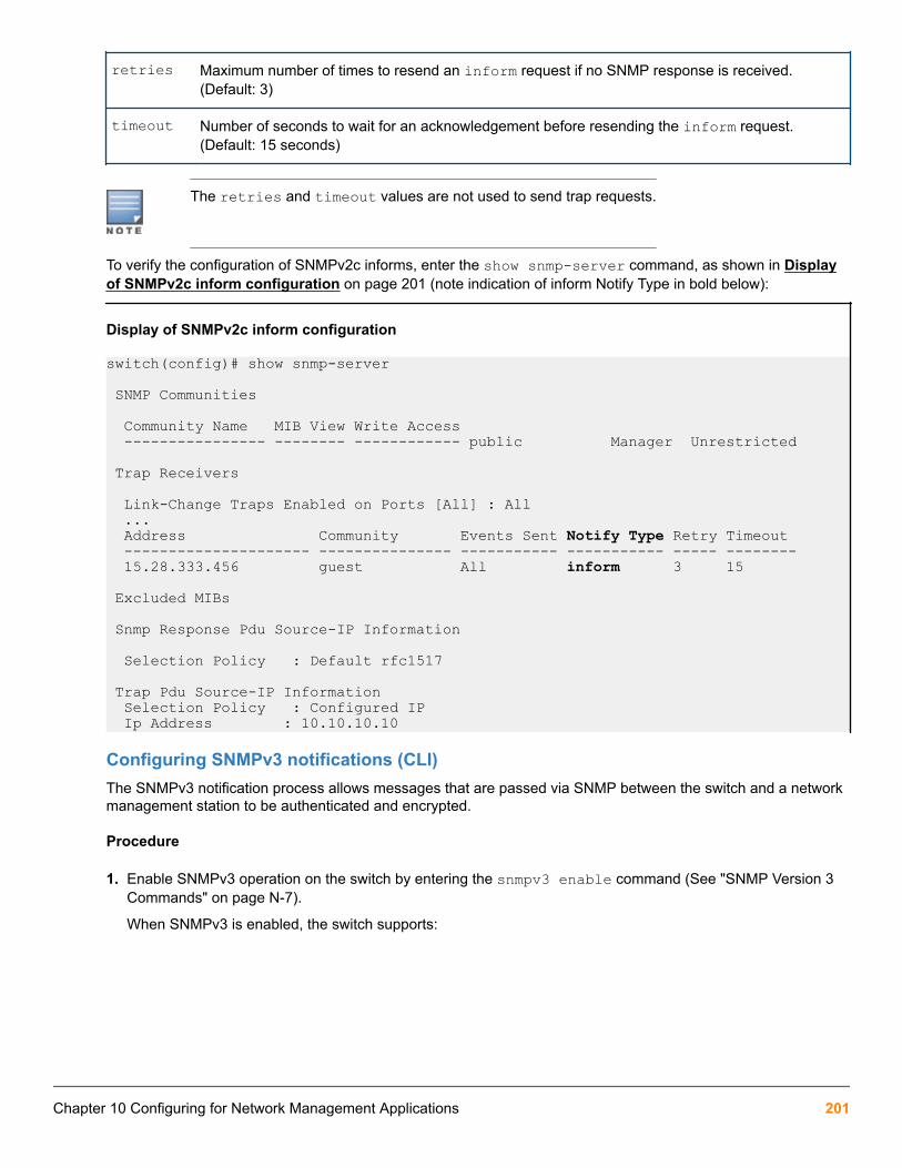
retries Maximum number of times to resend an inform request if no SNMP response is received.(Default: 3)
timeout Number of seconds to wait for an acknowledgement before resending the inform request.(Default: 15 seconds)
The retries and timeout values are not used to send trap requests.
To verify the configuration of SNMPv2c informs, enter the show snmp-server command, as shown in Displayof SNMPv2c inform configuration on page 201 (note indication of inform Notify Type in bold below):
Display of SNMPv2c inform configuration
switch(config)# show snmp-server
SNMP Communities
Community Name MIB View Write Access ---------------- -------- ------------ public Manager Unrestricted
Trap Receivers
Link-Change Traps Enabled on Ports [All] : All ... Address Community Events Sent Notify Type Retry Timeout --------------------- --------------- ----------- ----------- ----- -------- 15.28.333.456 guest All inform 3 15
Excluded MIBs
Snmp Response Pdu Source-IP Information
Selection Policy : Default rfc1517
Trap Pdu Source-IP Information Selection Policy : Configured IP Ip Address : 10.10.10.10
Configuring SNMPv3 notifications (CLI)The SNMPv3 notification process allows messages that are passed via SNMP between the switch and a networkmanagement station to be authenticated and encrypted.
Procedure
1. Enable SNMPv3 operation on the switch by entering the snmpv3 enable command (See "SNMP Version 3Commands" on page N-7).
When SNMPv3 is enabled, the switch supports:
Chapter 10 Configuring for Network Management Applications 201

• Reception of SNMPv3 notification messages (traps and informs)
• Configuration of initial users
• (Optional) Restriction of non-SNMPv3 messages to "read only"
2. Configure SNMPv3 users by entering the snmpv3 user command (see SNMPv3 users on page 189). EachSNMPv3 user configuration is entered in the User Table.
3. Assign SNMPv3 users to security groups according to their level of access privilege by entering the snmpv3group command (see Assigning users to groups (CLI) on page 191).
4. Define the name of an SNMPv3 notification configuration by entering the snmpv3 notify command.
Syntax:
[no] snmpv3 notify <notify_name> tagvalue <tag_name> type {inform|trap}
Associates the name of an SNMPv3 notification configuration with a tag name used (internally) in SNMPv3commands. To delete a notification-to-tag mapping, enter no snmpv3 notify notify_name .
notify <notify_name> Specifies the name of an SNMPv3 notification configuration.
tagvalue <tag_name> Specifies the name of a tag value used in other SNMPv3 commands, such assnmpv3 targetaddress params taglist tag_name in Step 5.
type Specifies the notification type as inform or trap. By default, the notificationtype is trap.
5. Configure the target address of the SNMPv3 management station to which SNMPv3 informs and traps aresent by entering the snmpv3 targetaddress command.
Syntax:
[no] snmpv3 targetaddress {< ipv4-addr | ipv6-addr >} <name>Configures the IPv4 or IPv6 address, name, and configuration filename of the SNMPv3 management station towhich notification messages are sent.
202 Aruba 2930F / 2930M Management and Configuration Guide for ArubaOS-Switch 16.05

params <parms_name> Name of the SNMPv3 station's parameters file.Theparameters filename configured with paramsparams_name must match the params params_namevalue entered with the snmpv3 params command inStep 6.
taglist <tag_name> [tag_name] … Specifies the SNMPv3 notifications (identified by one ormore tag_name values) to be sent to the IP address of theSNMPv3 management station.
You can enter more than one tag_name value. Eachtag_name value must be already associated with thename of an SNMPv3 notification configuration enteredwith the snmpv3 notify command in Step 4.Use ablank space to separate tag_name values.
You can enter up to 103 characters in tag_name entriesfollowing the taglist keyword.
[filter {<none | debug | all | not-info | critical>}]
(Optional) Configures the type of messages sent to amanagement station.(Default: none.)
[udp-port < port >] (Optional) Specifies the UDP port to use.(Default: 162.)
[port-mask < mask >] (Optional) Specifies a range of UDP ports. (Default: 0.)
[addr-mask < mask >] (Optional) Specifies a range of IP addresses asdestinations for notification messages.(Default: 0.)
[retries < value >] (Optional) Number of times a notification is retransmitted ifno response is received. Range: 1-255.(Default: 3.)
[timeout < value >] (Optional) Time (in millisecond increments) allowed toreceive a response from the target before notificationpackets are retransmitted. Range: 0-2147483647.[Default:1500 (15 seconds).]
[max-msg-size < size >] (Optional) Maximum number of bytes supported in anotification message to the specified target. (Default:1472)
6. Create a configuration record for the target address with the snmpv3 params command.
Syntax:
[no] snmpv3 params <params_name> user <user_name>Applies the configuration parameters and IP address of an SNMPv3 management station (from the paramsparams_name value configured with the snmpv3 targetaddress command in Step 5) to a specifiedSNMPv3 user (from the user user_name value configured with the snmpv3 user command in Step 2).
If you enter the snmpv3 params user command, you must also configure a security model ( sec-model)and message processing algorithm ( msg-processing).
Chapter 10 Configuring for Network Management Applications 203
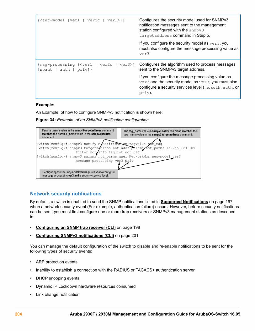
{<sec-model [ver1 | ver2c | ver3>]} Configures the security model used for SNMPv3notification messages sent to the managementstation configured with the snmpv3targetaddress command in Step 5.
If you configure the security model as ver3, youmust also configure the message processing value asver3.
{msg-processing {<ver1 | ver2c | ver3>}[noaut | auth | priv]}
Configures the algorithm used to process messagessent to the SNMPv3 target address.
If you configure the message processing value asver3 and the security model as ver3, you must alsoconfigure a security services level ( noauth, auth, orpriv).
Example:
An Example: of how to configure SNMPv3 notification is shown here:
Figure 34: Example: of an SNMPv3 notification configuration
Network security notificationsBy default, a switch is enabled to send the SNMP notifications listed in Supported Notifications on page 197when a network security event (For example, authentication failure) occurs. However, before security notificationscan be sent, you must first configure one or more trap receivers or SNMPv3 management stations as describedin:
• Configuring an SNMP trap receiver (CLI) on page 198
• Configuring SNMPv3 notifications (CLI) on page 201
You can manage the default configuration of the switch to disable and re-enable notifications to be sent for thefollowing types of security events:
• ARP protection events
• Inability to establish a connection with the RADIUS or TACACS+ authentication server
• DHCP snooping events
• Dynamic IP Lockdown hardware resources consumed
• Link change notification
204 Aruba 2930F / 2930M Management and Configuration Guide for ArubaOS-Switch 16.05

• Invalid password entered in a login attempt through a direct serial, Telnet, or SSH connection
• Manager password changes
• Port-security (web, MAC, or802.1X) authentication failure
• SNMP authentication failure
• Running configuration changes
Enabling or disabling notification/traps for network security failures and other securityevents (CLI)For more information, see Network security notifications on page 204.
Syntax:
[no] snmp-server enable traps [snmp-auth | password-change-mgr | login-failure-mgr | port-security | auth-server-fail | dhcp-snooping | arp-protect | running-config-change]Enables or disables sending one of the security notification types listed below to configured trap receivers.(Unless otherwise stated, all of the following notifications are enabled in the default configuration.)
The notification sends a trap:
arp-protect If ARP packets are received with an invalid source ordestination MAC address, an invalid IP address, or aninvalid IP-to-MAC binding.
auth-server-fail If the connection with a RADIUS or TACACS+authentication server fails.
dhcp-snooping If DHCP packets are received from an untrustedsource or if DHCP packets contain an invalid IP-to-MAC binding.
dhcpv6-snooping Set the traps for DHCPv6 snooping.
dyn-ip-lockdown If the switch is out of hardware resources needed toprogram a dynamic IP lockdown rule
dyn-ipv6-lockdown Enable traps for Dynamic IPv6 lockdown..
link-change <port-list> When the link state on a port changes from up todown, or the reverse.
login-failure-mgr For a failed login with a manager password.
password-change-mgr When a manager password is reset.
mac-notify Globally enables the generation of SNMP trapnotifications upon MAC address table changes.
nd-snooping Set the trap for nd snooping
Table Continued
Chapter 10 Configuring for Network Management Applications 205

port-security For a failed authentication attempt through a web,MAC, or 801.X authentication session.
running-config-change When changes to the running configuration file aremade.
snmp-authentication [extended |standard]
For a failed authentication attempt via SNMP.(Default:extended.)
Startup-config-change Sends a trap when changes to the startupconfiguration file are made. See “Enabling SNMPTraps on Startup Configuration Changes” on page 6–34. (Default: Disabled)
To determine the specific cause of a security event, check the Event Log in the console interface to see why atrap was sent. For more information, see "Using the Event Log for Troubleshooting Switch Problems".
Viewing the current configuration for network security notifications (CLI)Enter the show snmp-server traps command, as shown in Display of configured network securitynotifications on page 206. Note that command output is a subset of the information displayed with the showsnmp-server command in Display of SNMP notification configuration.
Display of configured network security notifications
switch(config)# show snmp-server traps
Trap Receivers
Link-Change Traps Enabled on Ports [All] : A1-A24
Traps Category Current Status ------------------------------ -------------------------- SNMP Authentication : Extended Password change : Enabled Login failures : Enabled Port-Security : Enabled Authorization Server Contact : Enabled DHCP Snooping : Enabled Dynamic ARP Protection : Enabled Dynamic IP Lockdown : Enabled
Address Community Events Sent Notify Type Retry Timeout ---------------------- ---------- ----------- ----------- ----- ------- 15.255.5.225 public All trap 3 15 2001:0db8:0000:0001 :0000:0000:0000:0121 user_1 All trap 3 15
Excluded MIBs
Enabling Link-Change Traps (CLI)By default, a switch is enabled to send a trap when the link state on a port changes from up to down (linkDown) ordown to up (linkUp). To reconfigure the switch to send link-change traps to configured trap receivers, enter thesnmp-server enable traps link-change command.
206 Aruba 2930F / 2930M Management and Configuration Guide for ArubaOS-Switch 16.05

Syntax:
[no] snmp-server enable traps link-change <port-list> [all]Enables or disables the switch to send a link-change trap to configured trap receivers when the link state on aport goes from up to down or down to up.
Enter all to enable or disable link-change traps on all ports on the switch.
Readable interface names in trapsThe SNMP trap notification messages for linkup and linkdown events on an interface includes IfDesc and IfAliasvar-bind information.
Source IP address for SNMP notificationsThe switch uses an interface IP address as the source IP address in IP headers when sending SNMPnotifications (traps and informs) or responses to SNMP requests.
For multi-netted interfaces, the source IP address is the IP address of the outbound interface of the SNMP reply,which may differ from the destination IP address in the IP header of the received request. For security reasons, itmay be desirable to send an SNMP reply with the IP address of the destination interface (or a specified IPaddress) on which the corresponding SNMP request was received.
To configure the switch to use the source IP address on which an SNMP request was received in SNMPnotification/traps and replies, enter the snmp-server response-source and snmp-server trap-sourcecommands (Configuring the source IP address for SNMP notifications (CLI)).
Configuring the source IP address for SNMP notifications (CLI)For more information, see Source IP address for SNMP notifications on page 207.
Syntax:
[no] snmp-server response-source [dst-ip-of-request | [ipv4-addr | ipv6-addr] | loopback <0-7>]Specifies the source IP address of the SNMP response PDU. The default SNMP response PDU uses the IPaddress of the active interface from which the SNMP response was sent as the source IP address.
The no form of the command resets the switch to the default behavior (compliant with rfc-1517).
(Default: Interface IP address)
dst-ip-of-request Destination IP address of the SNMP request PDU that is used as thesource IP address in an SNMP response PDU.
[ipv4-addr | ipv6-addr] User-defined interface IP address that is used as the source IP addressin an SNMP response PDU. Both IPv4 and IPv6 addresses aresupported.
loopback <0-7> IP address configured for the specified loopback interface that is used asthe source IP address in an SNMP response PDU. If multiple loopback IPaddresses are configured, the lowest alphanumeric address is used.
To use the IP address of the destination interface on which an SNMP request was received as the source IPaddress in the IP header of SNMP traps and replies, enter the following command:
switch(config)# snmp-server response-source dst-ip-of-request
Chapter 10 Configuring for Network Management Applications 207
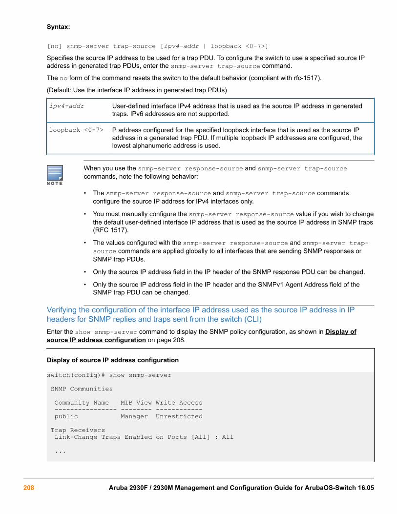
Syntax:
[no] snmp-server trap-source [ipv4-addr | loopback <0-7>]Specifies the source IP address to be used for a trap PDU. To configure the switch to use a specified source IPaddress in generated trap PDUs, enter the snmp-server trap-source command.
The no form of the command resets the switch to the default behavior (compliant with rfc-1517).
(Default: Use the interface IP address in generated trap PDUs)
ipv4-addr User-defined interface IPv4 address that is used as the source IP address in generatedtraps. IPv6 addresses are not supported.
loopback <0-7> P address configured for the specified loopback interface that is used as the source IPaddress in a generated trap PDU. If multiple loopback IP addresses are configured, thelowest alphanumeric address is used.
When you use the snmp-server response-source and snmp-server trap-sourcecommands, note the following behavior:
• The snmp-server response-source and snmp-server trap-source commandsconfigure the source IP address for IPv4 interfaces only.
• You must manually configure the snmp-server response-source value if you wish to changethe default user-defined interface IP address that is used as the source IP address in SNMP traps(RFC 1517).
• The values configured with the snmp-server response-source and snmp-server trap-source commands are applied globally to all interfaces that are sending SNMP responses orSNMP trap PDUs.
• Only the source IP address field in the IP header of the SNMP response PDU can be changed.
• Only the source IP address field in the IP header and the SNMPv1 Agent Address field of theSNMP trap PDU can be changed.
Verifying the configuration of the interface IP address used as the source IP address in IPheaders for SNMP replies and traps sent from the switch (CLI)Enter the show snmp-server command to display the SNMP policy configuration, as shown in Display ofsource IP address configuration on page 208.
Display of source IP address configuration
switch(config)# show snmp-server SNMP Communities Community Name MIB View Write Access ---------------- -------- ------------ public Manager Unrestricted
Trap Receivers Link-Change Traps Enabled on Ports [All] : All
...
208 Aruba 2930F / 2930M Management and Configuration Guide for ArubaOS-Switch 16.05
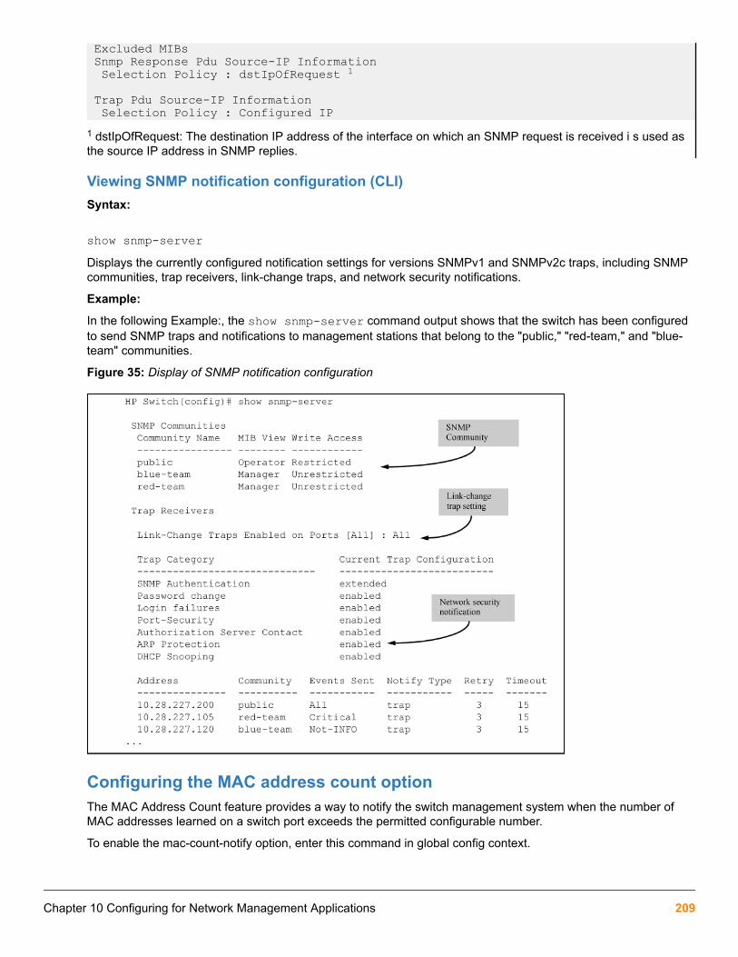
Excluded MIBs Snmp Response Pdu Source-IP Information Selection Policy : dstIpOfRequest 1
Trap Pdu Source-IP Information Selection Policy : Configured IP1 dstIpOfRequest: The destination IP address of the interface on which an SNMP request is received i s used asthe source IP address in SNMP replies.
Viewing SNMP notification configuration (CLI)Syntax:
show snmp-serverDisplays the currently configured notification settings for versions SNMPv1 and SNMPv2c traps, including SNMPcommunities, trap receivers, link-change traps, and network security notifications.
Example:
In the following Example:, the show snmp-server command output shows that the switch has been configuredto send SNMP traps and notifications to management stations that belong to the "public," "red-team," and "blue-team" communities.
Figure 35: Display of SNMP notification configuration
Configuring the MAC address count optionThe MAC Address Count feature provides a way to notify the switch management system when the number ofMAC addresses learned on a switch port exceeds the permitted configurable number.
To enable the mac-count-notify option, enter this command in global config context.
Chapter 10 Configuring for Network Management Applications 209

Syntax:
[no] snmp-server enable traps mac-count-notifySends a trap when the number of MAC addresses learned on the specified ports exceeds the configured<learned-count> value.
To configure the mac-count-notify option on a port or ports, enter this command. When the configured number ofMAC addresses is exceeded (the learned-count), a trap is sent.
Syntax:
[no] mac-count-notify traps <port-list> [<learned-count>]Configures mac-count-notify traps on the specified ports (or all) for the entire switch.
The [no] form of the command disables mac-count-notify traps.
[<learned-count>]: The number of MAC addresses learned before sending a trap. Values range between1-128.
Default: 32
Configuring mac-count notify traps on ports 5–7
switch (config)# mac-count-notify traps 5-7 50
Displaying information about the mac-count-notify optionUse the show mac-count-notify traps [<port-list>] command to display information about the configured value forsending a trap, the current count, and if a trap has been sent.
Information displayed for the show mac-count-notify traps command
switch(config)# show mac-count-notify traps
Mac-count-notify Enabled: Yes
Port Count for Count Trap Sent sending Trap------ --------------- ------- ------------12345 50 0 No6 50 2 No7 50 0 No89...The interface context can be used to configure the value for sending a trap.
Configuring mac-count-notify traps from the interface context
switch(config)# interface 5
HP Switch (eth-5)# mac-count-notify traps 35
210 Aruba 2930F / 2930M Management and Configuration Guide for ArubaOS-Switch 16.05

The show snmp-server traps command displays whether the MAC Address Count feature is enabled ordisabled.
Information about SNMP traps, including MAC address count being Enabled/Disabled
switch(config)# show snmp-server traps Trap Receivers
Link-Change Traps Enabled on Ports [All] : All Traps Category Current Status ____________________________ __________________ SNMP Authentication : Extended Password change : Enabled Login failures : Enabled Port-Security : Enabled Authorization Server Contact : Enabled DHCP-Snooping : Enabled Dynamic ARP Protection : Enabled Dynamic IP Lockdown : Enabled
MAC address table changes : Disabled MAC Address Count : Enabled 1
Address Community Events Type Retry Timeout ---------------- ----------- ------- ------ ------ ------- 15.146.194.77 public None trap 3 15 15.255.134.252 public None trap 3 15 16.181.49.167 public None trap 3 15 16.181.51.14 public None trap 3 15 Excluded MIBs
1The notify option is enabled.
Advanced management: RMONThe switch supports RMON (remote monitoring) on all connected network segments. This allows fortroubleshooting and optimizing your network.
The following RMON groups are supported:
• Ethernet Statistics (except the numbers of packets of different frame sizes)
• Alarm
• History (of the supported Ethernet statistics)
• Event
The RMON agent automatically runs in the switch. Use the RMON management station on your network toenable or disable specific RMON traps and events. Note that you can access the Ethernet statistics, Alarm andEvent groups from the HPE Switch Manager network management software.
Chapter 10 Configuring for Network Management Applications 211

CLI-configured sFlow with multiple instancessFlow can also be configured via the CLI for up to three distinct sFlow instances: once enabled, an sFlowreceiver/destination can be independently configured for full flow-sampling and counter-polling. CLI-configuredsFlow instances may be saved to the startup configuration to persist across a switch reboot.
Configuring sFlow (CLI)The following sFlow commands allow you to configure sFlow instances via the CLI. For more information, see Advanced management: RMON on page 211.
Syntax:
[no] sflow <receiver-instance> destination <ip-address> [< udp-port-num >]Enables an sFlow receiver/destination. The receiver-instance number must be a 1, 2, or 3.
By default, the udp destination port number is 6343.
To disable an sFlow receiver/destination, enter no sflow receiver-instance .
Syntax:
sflow <receiver-instance> sampling <port-list> <sampling rate>Once an sFlow receiver/destination has been enabled, this command enables flow sampling for that instance.The receiver-instance number is 1, 2, or 3, and the sampling rate is the allowable non-zero skipcount for thespecified port or ports.
To disable flow-sampling for the specified port-list, repeat the above command with a sampling rate of 0.
Syntax:
sflow <receiver-instance> polling <port-list> <polling interval>Once an sFlow receiver/destination has been enabled, this command enables counter polling for that instance.The receiver-instance number is 1, 2, or 3, and the polling interval may be set to an allowable non-zero value toenable polling on the specified port or ports.
To disable counter-polling for the specified port-list, repeat the above command with a polling interval of 0.
Under the multiple instance implementation, sFlow can be configured via the CLI or via SNMP.However, CLI-owned sFlow configurations cannot be modified via SNMP, whereas SNMP-ownedinstances can be disabled via the CLI using the no sflow <receiver-instance> command.
Viewing sFlow Configuration and Status (CLI)The following sFlow commands allow you to display sFlow configuration and status via the CLI. Viewing sFlowdestination information on page 213 is an Example: of sflow agent information.
Syntax:
show sflow agentDisplays sFlow agent information. The agent address is normally the IP address of the first VLAN configured.
The show sflow agent command displays read-only switch agent information. The version information showsthe sFlow version, MIB support, and software versions; the agent address is typically the IP address of the firstVLAN configured on the switch.
212 Aruba 2930F / 2930M Management and Configuration Guide for ArubaOS-Switch 16.05

Viewing sflow agent information
switch# show sflow agent
Version 1.3;HP;XX.11.40 Agent Address 10.0.10.228Syntax:
show sflow <receiver instance> destinationDisplays information about the management station to which the sFlow sampling-polling data is sent.
The show sflow instance destination command includes information about the management-station'sdestination address, receiver port, and owner, as shown in Viewing sFlow destination information on page213.
Viewing sFlow destination information
switch# show sflow 2 destination
Destination Instance 2 sflow Enabled Datagrams Sent 221 Destination Address 10.0.10.41 Receiver Port 6343 Owner Administrator, CLI-owned, Instance 2 Timeout (seconds) 99995530 Max Datagram Size 1400 Datagram Version Support 5Note the following details:
• Destination Address remains blank unless it has been configured.
• Datagrams Sent shows the number of datagrams sent by the switch agent to the management station sincethe switch agent was last enabled.
• Timeout displays the number of seconds remaining before the switch agent will automatically disable sFlow(this is set by the management station and decrements with time).
• Max Datagram Size shows the currently set value (typically a default value, but this can also be set by themanagement station).
Syntax:
show sflow <receiver instance> sampling-polling <port-list/range>Displays status information about sFlow sampling and polling.
Chapter 10 Configuring for Network Management Applications 213

The show sflow instance sampling-polling [port-list] command displays information aboutsFlow sampling and polling on the switch, as shown in Figure 36: Example: of viewing sFlow sampling andpolling information on page 214. You can specify a list or range of ports for which to view sampling information.
Figure 36: Example: of viewing sFlow sampling and polling information
The sampling and polling instances (noted in parentheses) coupled to a specific receiver instanceare assigned dynamically, and so the instance numbers may not always match. The key thing to noteis whether sampling or polling is enabled on a port, and the sampling rates or polling intervals for thereceiver instance configured on each port.
Configuring UDLD Verify before forwardingWhen an UDLD enabled port transitions to link-up, the port will begin with a UDLD blocking state. UDLD willprobe via protocol packet exchange to determine the bidirectional state of the link. Until UDLD has completed theprobe, all data traffic will be blocked. If the link is found to be bidirectional, UDLD will unblock the port for datatraffic to pass. Once UDLD unblocks the port, other protocols will see the port as up and data traffic can be safelyforwarded.
The default mode of a switch is “forward first then verify’’. Enabling UDLD link-up will default to “forward first thenverify”. To change the mode to “verify then forward”, you need to configure using the commands found in section6.72.
Link-UP data traffic will resumed after probing the link partner completes. All other protocols runningwill see the port as down.
UDLD time delayUDLD protocol informs the link partner simultaneously as it detects a state change from unidirectional tobidirectional traffic. Additional packet exchanges will be carried out by UDLD in addition to the existing UDLDexchanges whenever state changes from unidirectional to bidirectional.
Table 17: Peer state transition timings
Interval Time Interval 1 Interval 1 + delta Interval 2 Interval 3
5 sec 5+(<5) sec* 10 sec 15 sec
With triggeredupdates
State = blockedPeerState = blocked
Inform PeerState =unblockedPeer State= unblocked
Regular UDLD TX Regular UDLD TX
Table Continued
214 Aruba 2930F / 2930M Management and Configuration Guide for ArubaOS-Switch 16.05

Interval Time Interval 1 Interval 1 + delta Interval 2 Interval 3
Without triggeredupdates
State = blockedPeerState = blocked
State =unblockedPeer State= blocked
Inform PeerState =unblockedPeer State= unblocked
Regular UDLD TX
*delta is the time when the unblock event occurs on local side
Restrictions
• There is no support available when configuring this mode from the web and menu interface.
• There are no new packet types are introduced with UDLD.
• There are no new UDLD timers being introduced.
UDLD configuration commandsSyntax:
HP Switch(config)# link-keepalive mode [verify-then-forward | forward-then-verify]This command configures the link-keepalive mode.
Link-keepalive provides two modes of operation; verify-then-forward and forward-then-verify.
When using the verify-then-forward mode, the port is in a blocking state until the link configured for UDLDestablishes bidirectional communication. When using the forward-then-verify mode, the port forwards thedata then verifies the status of the link-in state.
When a unidirectional state is detected, the port is moved to a blocked state.
When a bidirectional state is detected, the data is forwarded without interruption.
Syntax:
HP Switch(config)# link-keepalive mode verify-then-forwardKeeps the port in a logically blocked state until the link configured for UDLD has been successfully established inbi-directional communication.
Syntax:
HP Switch(config)# link-keepalive mode forward-then-verifyForwards the data then verifies the status of the link. If a unidirectional state is detected, the port is then moved toa blocked state.
Syntax:
HP Switch(config)# link-keepalive interval <deciseconds>Configure the interval for link-keepalive. The link-keepalive interval is the time between sending twoUDLD packets. The time interval is entered in deciseconds (1/10 sec). The default keepalive interval is 50deciseconds.
Example:
A value of 10 is 1 sec., 11 is 1.1 sec.
Chapter 10 Configuring for Network Management Applications 215
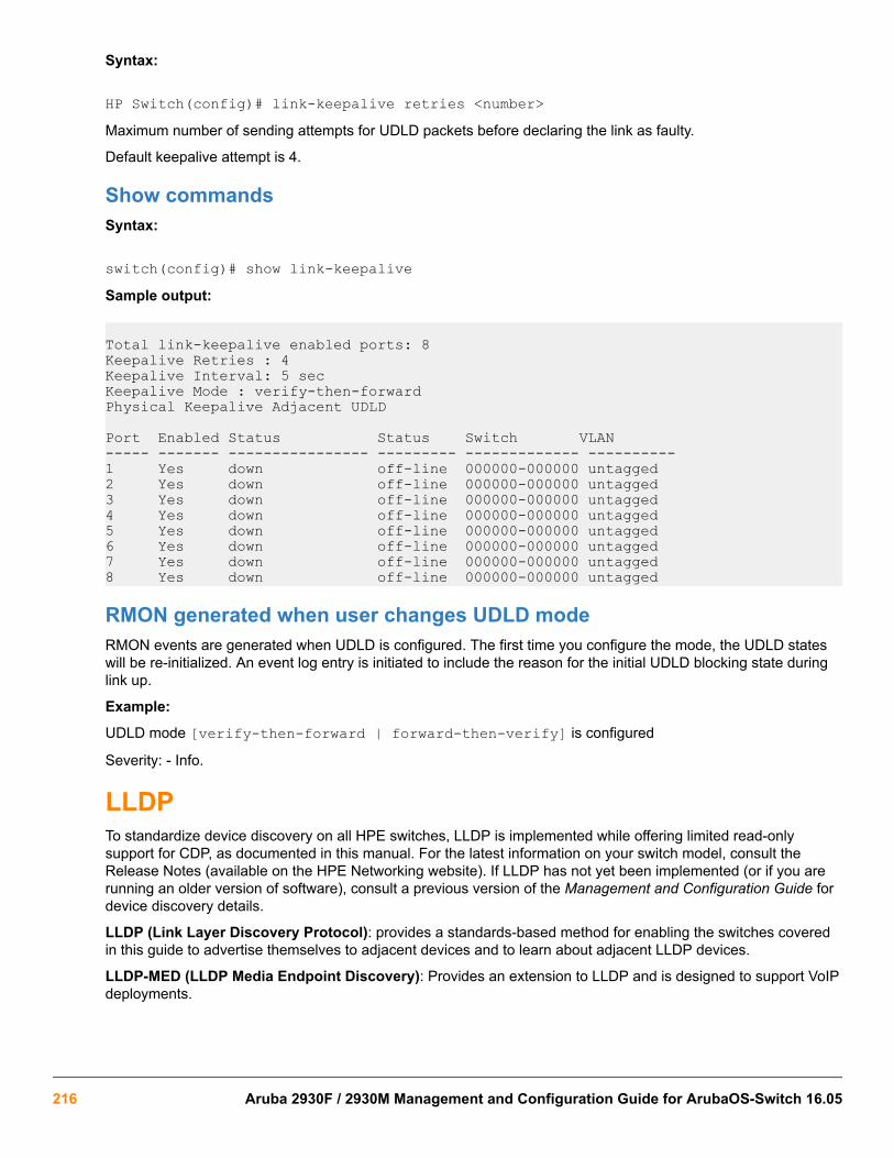
Syntax:
HP Switch(config)# link-keepalive retries <number>Maximum number of sending attempts for UDLD packets before declaring the link as faulty.
Default keepalive attempt is 4.
Show commandsSyntax:
switch(config)# show link-keepaliveSample output:
Total link-keepalive enabled ports: 8Keepalive Retries : 4Keepalive Interval: 5 secKeepalive Mode : verify-then-forwardPhysical Keepalive Adjacent UDLD
Port Enabled Status Status Switch VLAN----- ------- ---------------- --------- ------------- ----------1 Yes down off-line 000000-000000 untagged2 Yes down off-line 000000-000000 untagged3 Yes down off-line 000000-000000 untagged4 Yes down off-line 000000-000000 untagged5 Yes down off-line 000000-000000 untagged6 Yes down off-line 000000-000000 untagged7 Yes down off-line 000000-000000 untagged8 Yes down off-line 000000-000000 untagged
RMON generated when user changes UDLD modeRMON events are generated when UDLD is configured. The first time you configure the mode, the UDLD stateswill be re-initialized. An event log entry is initiated to include the reason for the initial UDLD blocking state duringlink up.
Example:
UDLD mode [verify-then-forward | forward-then-verify] is configured
Severity: - Info.
LLDPTo standardize device discovery on all HPE switches, LLDP is implemented while offering limited read-onlysupport for CDP, as documented in this manual. For the latest information on your switch model, consult theRelease Notes (available on the HPE Networking website). If LLDP has not yet been implemented (or if you arerunning an older version of software), consult a previous version of the Management and Configuration Guide fordevice discovery details.
LLDP (Link Layer Discovery Protocol): provides a standards-based method for enabling the switches coveredin this guide to advertise themselves to adjacent devices and to learn about adjacent LLDP devices.
LLDP-MED (LLDP Media Endpoint Discovery): Provides an extension to LLDP and is designed to support VoIPdeployments.
216 Aruba 2930F / 2930M Management and Configuration Guide for ArubaOS-Switch 16.05

LLDP-MED is an extension for LLDP, and the switch requires that LLDP be enabled as a prerequisiteto LLDP-MED operation.
An SNMP utility can progressively discover LLDP devices in a network by:
Procedure
1. Reading a given device's Neighbors table (in the Management Information Base, or MIB) to learn about other,neighboring LLDP devices.
2. Using the information learned in step 1 to find and read the neighbor devices' Neighbors tables to learn aboutadditional devices, and so on.
Also, by using show commands to access the switch's neighbor database for information collected by anindividual switch, system administrators can learn about other devices connected to the switch, including devicetype (capability) and some configuration information. In VoIP deployments using LLDP-MED on the switches,additional support unique to VoIP applications is also available. See LLDP-MED (media-endpoint-discovery) onpage 232.
General LLDP operationAn LLDP packet contains data about the transmitting switch and port. The switch advertises itself to adjacent(neighbor) devices by transmitting LLDP data packets out all ports on which outbound LLDP is enabled and byreading LLDP advertisements from neighbor devices on ports that are inbound LLDP-enabled. (LLDP is a one-way protocol and does not include any acknowledgement mechanism.) An LLDP-enabled port receiving LLDPpackets inbound from neighbor devices stores the packet data in a Neighbor database (MIB).
LLDP-MEDThis capability is an extension to LLDP and is available on the switches. See LLDP-MED (media-endpoint-discovery) on page 232.
Packet boundaries in a network topology
• Where multiple LLDP devices are directly connected, an outbound LLDP packet travels only to the next LLDPdevice. An LLDP-capable device does not forward LLDP packets to any other devices, regardless of whetherthey are LLDP-enabled.
• An intervening hub or repeater forwards the LLDP packets it receives in the same manner as any othermulticast packets it receives. Thus, two LLDP switches joined by a hub or repeater handle LLDP traffic in thesame way that they would if directly connected.
• Any intervening 802.1D device or Layer-3 device that is either LLDP-unaware or has disabled LLDP operationdrops the packet.
LLDP operation configuration optionsIn the default configuration, LLDP is enabled and in both transmit and receive mode on all active ports. The LLDPconfiguration includes global settings, which apply to all active ports on the switch, and per-port settings, whichaffect only the operation of the specified ports.
The commands in the LLDP sections affect both LLDP and LLDP-MED operation. For information on operationand configuration unique to LLDP-MED, see LLDP-MED (media-endpoint-discovery) on page 232.
Chapter 10 Configuring for Network Management Applications 217

Enable or disable LLDP on the switchIn the default configuration, LLDP is globally enabled on the switch. To prevent transmission or receipt of LLDPtraffic, you can disable LLDP operation.
Enable or disable LLDP-MEDIn the default configuration for the switches, LLDP-MED is enabled by default. (Requires that LLDP is alsoenabled.) For more information, see LLDP-MED (media-endpoint-discovery) on page 232.
Change the frequency of LLDP packet transmission to neighbor devicesOn a global basis, you can increase or decrease the frequency of outbound LLDP advertisements.
Change the Time-To-Live for LLDP packets sent to neighborsOn a global basis, you can increase or decrease the time that the information in an LLDP packet outbound fromthe switch will be maintained in a neighbor LLDP device.
Transmit and receive modeWith LLDP enabled, the switch periodically transmits an LLDP advertisement (packet) out each active portenabled for outbound LLDP transmissions and receives LLDP advertisements on each active port enabled toreceive LLDP traffic (Configuring per-port transmit and receive modes (CLI) on page 226). Per-portconfiguration options include four modes:
• Transmit and receive (tx_rx): This is the default setting on all ports. It enables a given port to both transmitand receive LLDP packets and to store the data from received (inbound) LLDP packets in the switch's MIB.
• Transmit only (txonly): This setting enables a port to transmit LLDP packets that can be read by LLDPneighbors. However, the port drops inbound LLDP packets from LLDP neighbors without reading them. Thisprevents the switch from learning about LLDP neighbors on that port.
• Receive only (rxonly): This setting enables a port to receive and read LLDP packets from LLDP neighborsand to store the packet data in the switch's MIB. However, the port does not transmit outbound LLDP packets.This prevents LLDP neighbors from learning about the switch through that port.
• Disable (disable): This setting disables LLDP packet transmissions and reception on a port. In this state, theswitch does not use the port for either learning about LLDP neighbors or informing LLDP neighbors of itspresence.
SNMP notificationYou can enable the switch to send a notification to any configured SNMP trap receiver(s) when the switch detectsa remote LLDP data change on an LLDP-enabled port (Configuring SNMP notification support on page 226).
Per-port (outbound) data optionsThe following table lists the information the switch can include in the per-port, outbound LLDP packets itgenerates. In the default configuration, all outbound LLDP packets include this information in the TLVs transmittedto neighbor devices. However, you can configure LLDP advertisements on a per-port basis to omit some of thisinformation (Configuring a remote management address for outbound LLDP advertisements (CLI) on page227).
218 Aruba 2930F / 2930M Management and Configuration Guide for ArubaOS-Switch 16.05

Table 18: Data available for basic LLDP advertisements
Data type Configuration options Default Description
Time-to-Live 1 120 Seconds The length of time anLLDP neighbor retains theadvertised data beforediscarding it.
Chassis Type2, N/A Always Enabled Indicates the type ofidentifier used for ChassisID.
Chassis ID33 N/A Always Enabled Uses base MAC addressof the switch.
Port Type4,33 N/A Always Enabled Uses "Local," meaningassigned locally by LLDP.
Port Id33 N/A Always Enabled Uses port number of thephysical port. This is aninternal number reflectingthe reserved slot/portposition in the chassis. Formore information on thisnumbering scheme, seethe appendix "MACAddress Management".
Remote Management Address
Type3,3 N/A Always Enabled Shows the networkaddress type.
Address55 Default or Configured Uses a default address selection method unless anoptional address is configured. See Remotemanagement address on page 220.
System Name33 Enable/Disable Enabled Uses the switch'sassigned name.
System Description33 Enable/Disable Enabled Includes switch modelname and runningsoftware version, andROM version.
Port Description33 Enable/Disable Enabled Uses the physical portidentifier.
Table Continued
Chapter 10 Configuring for Network Management Applications 219

Data type Configuration options Default Description
System capabilitiessupported3,3
Enable/Disable Enabled Identifies the switch'sprimary capabilities(bridge, router).
System capabilitiesenabled3,66 3
Enable/Disable Enabled Identifies the primaryswitch functions that areenabled, such as routing.
1 The Packet Time-to-Live value is included in LLDP data packets.2 Subelement of the Chassis ID TLV.3 Populated with data captured internally by the switch. For more on these data types, refer to the IEEE P802.1AB Standard.4 Subelement of the Port ID TLV.5 Subelement of the Remote-Management-Address TLV.6 Subelement of the System Capability TLV.
Remote management addressThe switch always includes an IP address in its LLDP advertisements. This can be either an address selected bya default process or an address configured for inclusion in advertisements. See IP address advertisements onpage 221.
Debug loggingYou can enable LLDP debug logging to a configured debug destination (Syslog server, a terminal device, or both)by executing the debug lldp command. (For more information on Debug and Syslog, see the "Troubleshooting"appendix in this guide.) Note that the switch's Event Log does not record usual LLDP update messages.
Options for reading LLDP information collected by the switchYou can extract LLDP information from the switch to identify adjacent LLDP devices. Options include:
• Using the switch's show lldp info command options to display data collected on adjacent LLDP devices—as well as the local data the switch is transmitting to adjacent LLDP devices (Displaying the global LLDP,port admin, and SNMP notification status (CLI) on page 221).
• Using an SNMP application that is designed to query the Neighbors MIB for LLDP data to use in devicediscovery and topology mapping.
• Using thewalkmib command to display a listing of the LLDP MIB objects
LLDP and LLDP-MED standards compatibilityThe operation covered by this section is compatible with these standards:
• IEEE P802.1AB
• RFC 2922 (PTOPO, or Physical Topology MIB)
• RFC 2737 (Entity MIB)
• RFC 2863 (Interfaces MIB)
• ANSI/TIA-1057/D6 (LLDP-MED; refer to LLDP-MED (media-endpoint-discovery) on page 232.)
220 Aruba 2930F / 2930M Management and Configuration Guide for ArubaOS-Switch 16.05

LLDP operating rulesFor additional information specific to LLDP-MED operation, see LLDP-MED (media-endpoint-discovery) onpage 232.
Port trunkingLLDP manages trunked ports individually. That is, trunked ports are configured individually for LLDP operation, inthe same manner as non-trunked ports. Also, LLDP sends separate advertisements on each port in a trunk, andnot on a per-trunk basis. Similarly, LLDP data received through trunked ports is stored individually, per-port.
IP address advertisementsIn the default operation, if a port belongs to only one static VLAN, the port advertises the lowest-order IP addressconfigured on that VLAN. If a port belongs to multiple VLANs, the port advertises the lowest-order IP addressconfigured on the VLAN with the lowest VID. If the qualifying VLAN does not have an IP address, the portadvertises 127.0.0.1 as its IP address. For example, if the port is a member of the default VLAN (VID=1), andthere is an IP address configured for the default VLAN, the port advertises this IP address. In the defaultoperation, the IP address that LLDP uses can be an address acquired by DHCP or Bootp.
You can override the default operation by configuring the port to advertise any IP address that is manuallyconfigured on the switch, even if the port does not belong to the VLAN configured with the selected IP address(Configuring a remote management address for outbound LLDP advertisements (CLI) on page 227). (Notethat LLDP cannot be configured through the CLI to advertise an addresses acquired through DHCP or Bootp.However, as mentioned above, in the default LLDP configuration, if the lowest-order IP address on the VLAN withthe lowest VID for a given port is a DHCP or Bootp address, the switch includes this address in its LLDPadvertisements unless another address is configured for advertisements on that port.) Also, although LLDP allowsconfiguring multiple remote management addresses on a port, only the lowest-order address configured on theport will be included in outbound advertisements. Attempting to use the CLI to configure LLDP with an IP addressthat is either not configured on a VLAN or has been acquired by DHCP or Bootp results in the following errormessage.
xxx.xxx.xxx.xxx: This IP address is not configured or is a DHCP address.
Spanning-tree blockingSpanning tree does not prevent LLDP packet transmission or receipt on STP-blocked links.
802.1X blockingPorts blocked by 802.1X operation do not allow transmission or receipt of LLDP packets.
Configuring LLDP operation
Displaying the global LLDP, port admin, and SNMP notification status (CLI)In the default configuration, LLDP is enabled and in both transmit and receive mode on all active ports. The LLDPconfiguration includes global settings that apply to all active ports on the switch, and per-port settings that affectonly the operation of the specified ports.
The commands in this section affect both LLDP and LLDP-MED operation. for information on operation andconfiguration unique to LLDP-MED, refer to “LLDP-MED (Media-Endpoint-Discovery)”.
Syntax:
show lldp config
Chapter 10 Configuring for Network Management Applications 221

Displays the LLDP global configuration, LLDP port status, and SNMP notification status. For information on portadmin status, see Configuring per-port transmit and receive modes (CLI) on page 226.
show lldp config produces the following display when the switch is in the default LLDP configuration:
Viewing the general LLDP configuration
switch(config)# show lldp config
LLDP Global Configuration
LLDP Enabled [Yes] : Yes LLDP Transmit Interval [30] : 30 LLDP Hold time Multiplier [4] : 4 LLDP Delay Interval [2] : 2 LLDP Reinit Interval [2] : 2 LLDP Notification Interval [5] : 5 LLDP Fast Start Count [5] : 5
LLDP Port Configuration
Port | AdminStatus NotificationEnabled Med Topology Trap Enabled ---- + ----------- ------------------- ------------------------- A1 | Tx_Rx False False A2 | Tx_Rx False False A3 | Tx_Rx False False A4 | Tx_Rx False False A5 | Tx_Rx False False A6 | Tx_Rx False False A7 | Tx_Rx False False A8 | Tx_Rx False False
The values displayed in the LLDP column correspond to the lldp refresh-interval command
Viewing port configuration details (CLI)Syntax:
show lldp config <port-list>Displays the LLDP port-specific configuration for all ports in <port-list>, including which optional TLVs and anynon-default IP address that are included in the port's outbound advertisements.
222 Aruba 2930F / 2930M Management and Configuration Guide for ArubaOS-Switch 16.05

For information on the notification setting, see Configuring SNMP notification support on page 226. Forinformation on the other configurable settings displayed by this command, see Configuring per-port transmitand receive modes (CLI) on page 226.
Figure 37: Per-port configuration display
Configuring Global LLDP Packet ControlsThe commands in this section configure the aspects of LLDP operation that apply the same to all ports in theswitch.
LLDP operation on the switchEnabling LLDP operation (the default) causes the switch to:
• Use active, LLDP-enabled ports to transmit LLDP packets describing itself to neighbor devices.
• Add entries to its neighbors table based on data read from incoming LLDP advertisements.
Enabling or disabling LLDP operation on the switch (CLI)For more information, see LLDP operation on the switch on page 223.
Syntax:
[no] lldp runEnables or disables LLDP operation on the switch.
The no form of the command, regardless of individual LLDP port configurations, prevents the switch fromtransmitting outbound LLDP advertisements and causes the switch to drop all LLDP advertisements receivedfrom other devices.
The switch preserves the current LLDP configuration when LLDP is disabled. After LLDP is disabled, theinformation in the LLDP neighbors database remains until it times-out.
(Default: Enabled)
Chapter 10 Configuring for Network Management Applications 223

Disabling LLDP
switch(config)# no lldp run
Changing the packet transmission interval (CLI)This interval controls how often active ports retransmit advertisements to their neighbors.
Syntax:
lldp refresh-interval <5-32768>Changes the interval between consecutive transmissions of LLDP advertisements on any given port.
(Default: 30 seconds)
The refresh-interval must be greater than or equal to (4 x delay-interval). (The defaultdelay-interval is 2). For example, with the default delay-interval, the lowest refresh-interval you can use is 8 seconds (4 x 2=8). Thus, if you want a refresh-interval of 5seconds, you must first change the delay interval to 1 (that is, 4 x 1 5). If you want to change thedelay-interval, use the setmib command.
Time-to-Live for transmitted advertisementsThe Time-to-Live value (in seconds) for all LLDP advertisements transmitted from a switch is controlled by theswitch that generates the advertisement and determines how long an LLDP neighbor retains the advertised databefore discarding it. The Time-to-Live value is the result of multiplying the refresh-interval by theholdtime-multiplier.
Changing the time-to-live for transmitted advertisements (CLI)For more information, see Time-to-Live for transmitted advertisements on page 224.
Syntax:
lldp holdtime-multiplier <2-10>Changes the multiplier an LLDP switch uses to calculate the Time-to-Live for the LLDP advertisements itgenerates and transmits to LLDP neighbors. When the Time-to-Live for a given advertisement expires, theadvertised data is deleted from the neighbor switch's MIB.
(Default: 4; Range 2–10)
Example:
If the refresh-interval on the switch is 15 seconds and the holdtime-multiplier is at the default, the Time-to-Live for advertisements transmitted from the switch is 60 seconds (4 x 15).
To reduce the Time-to-Live, you could lower the holdtime-interval to 2, which would result in a Time-to-Liveof 30 seconds.
switch(config)# lldp holdtime-multiplier 2
Delay interval between advertisements generated by value or status changes to theLLDP MIBThe switch uses a delay-interval setting to delay transmitting successive advertisements resulting from theseLLDP MIB changes. If a switch is subject to frequent changes to its LLDP MIB, lengthening this interval canreduce the frequency of successive advertisements. You can change the delay-interval by using either an SNMPnetwork management application or the CLI setmib command.
224 Aruba 2930F / 2930M Management and Configuration Guide for ArubaOS-Switch 16.05
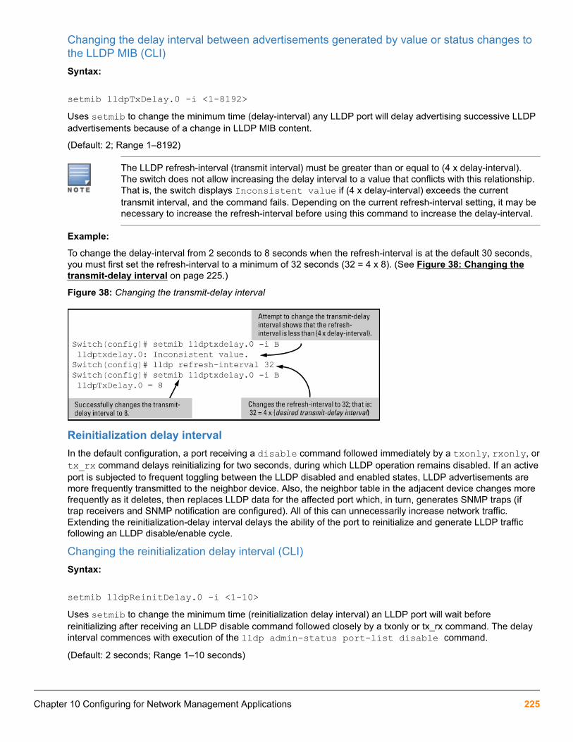
Changing the delay interval between advertisements generated by value or status changes tothe LLDP MIB (CLI)Syntax:
setmib lldpTxDelay.0 -i <1-8192>Uses setmib to change the minimum time (delay-interval) any LLDP port will delay advertising successive LLDPadvertisements because of a change in LLDP MIB content.
(Default: 2; Range 1–8192)
The LLDP refresh-interval (transmit interval) must be greater than or equal to (4 x delay-interval).The switch does not allow increasing the delay interval to a value that conflicts with this relationship.That is, the switch displays Inconsistent value if (4 x delay-interval) exceeds the currenttransmit interval, and the command fails. Depending on the current refresh-interval setting, it may benecessary to increase the refresh-interval before using this command to increase the delay-interval.
Example:
To change the delay-interval from 2 seconds to 8 seconds when the refresh-interval is at the default 30 seconds,you must first set the refresh-interval to a minimum of 32 seconds (32 = 4 x 8). (See Figure 38: Changing thetransmit-delay interval on page 225.)
Figure 38: Changing the transmit-delay interval
Reinitialization delay intervalIn the default configuration, a port receiving a disable command followed immediately by a txonly, rxonly, ortx_rx command delays reinitializing for two seconds, during which LLDP operation remains disabled. If an activeport is subjected to frequent toggling between the LLDP disabled and enabled states, LLDP advertisements aremore frequently transmitted to the neighbor device. Also, the neighbor table in the adjacent device changes morefrequently as it deletes, then replaces LLDP data for the affected port which, in turn, generates SNMP traps (iftrap receivers and SNMP notification are configured). All of this can unnecessarily increase network traffic.Extending the reinitialization-delay interval delays the ability of the port to reinitialize and generate LLDP trafficfollowing an LLDP disable/enable cycle.
Changing the reinitialization delay interval (CLI)Syntax:
setmib lldpReinitDelay.0 -i <1-10>Uses setmib to change the minimum time (reinitialization delay interval) an LLDP port will wait beforereinitializing after receiving an LLDP disable command followed closely by a txonly or tx_rx command. The delayinterval commences with execution of the lldp admin-status port-list disable command.
(Default: 2 seconds; Range 1–10 seconds)
Chapter 10 Configuring for Network Management Applications 225

Example:
The following command changes the reinitialization delay interval to five seconds:
switch(config)# setmib lldpreinitdelay.0 -i 5
Configuring SNMP notification supportYou can enable SNMP trap notification of LLDP data changes detected on advertisements received from neighbordevices, and control the interval between successive notifications of data changes on the same neighbor.
Enabling LLDP data change notification for SNMP trap receivers (CLI)Syntax:
[no] lldp enable-notification <port-list>Enables or disables each port in port-list for sending notification to configured SNMP trap receivers if an LLDPdata change is detected in an advertisement received on the port from an LLDP neighbor.
(Default: Disabled)
For information on configuring trap receivers in the switch, see SNMP notifications on page 196.
Example:
This command enables SNMP notification on ports 1 - 5:
switch(config)# lldp enable-notification 1-5
Changing the minimum interval for successive data change notifications for the sameneighborIf LLDP trap notification is enabled on a port, a rapid succession of changes in LLDP information received inadvertisements from one or more neighbors can generate a high number of traps. To reduce this effect, you canglobally change the interval between successive notifications of neighbor data change.
Syntax:
setmib lldpnotificationinterval.0 -i <1-3600>Globally changes the interval between successive traps generated by the switch. If multiple traps are generated inthe specified interval, only the first trap is sent. The remaining traps are suppressed. (A network managementapplication can periodically check the switch MIB to detect any missed change notification traps. See IEEEP802.1AB or later for more information.)
(Default: 5 seconds)
Example:
The following command limits change notification traps from a particular switch to one per minute.
switch(config)# setmib lldpnotificationinterval.0 -i 60 lldpNotificationInterval.0=60
Configuring per-port transmit and receive modes (CLI)Syntax:
lldp admin-status <port-list> {<txonly | rxonly | tx_rx | disable>}
226 Aruba 2930F / 2930M Management and Configuration Guide for ArubaOS-Switch 16.05

With LLDP enabled on the switch in the default configuration, each port is configured to transmit and receiveLLDP packets. These options enable you to control which ports participate in LLDP traffic and whether theparticipating ports allow LLDP traffic in only one direction or in both directions.
txonly Configures the specified ports to transmit LLDP packets, but block inbound LLDP packets fromneighbor devices.
rxonly Configures the specified ports to receive LLDP packets from neighbors, but block outbound packetsto neighbors.
tx_rx Configures the specified ports to both transmit and receive LLDP packets. (This is the defaultsetting.)
disable Disables LLDP packet transmit and receive on the specified ports.
Basic LLDP per-port advertisement contentIn the default LLDP configuration, outbound advertisements from each port on the switch include both mandatoryand optional data.
Mandatory DataAn active LLDP port on the switch always includes the mandatory data in its outbound advertisements. LLDPcollects the mandatory data, and, except for the Remote Management Address, you cannot use LLDP commandsto configure the actual data.
• Chassis Type (TLV subelement)
• Chassis ID (TLV)
• Port Type (TLV subelement)
• Port ID (TLV)
• Remote Management Address (TLV; actual IP address is a subelement that can be a default address or aconfigured address)
Configuring a remote management address for outbound LLDP advertisements (CLI)This is an optional command you can use to include a specific IP address in the outbound LLDP advertisementsfor specific ports. For more information, see Basic LLDP per-port advertisement content on page 227.
Syntax:
[no] lldp config <port-list> ipAddrEnable <ip-address>Replaces the default IP address for the port with an IP address you specify. This can be any IP addressconfigured in a static VLAN on the switch, even if the port does not belong to the VLAN configured with theselected IP address.
The no form of the command deletes the specified IP address.
If there are no IP addresses configured as management addresses, the IP address selection method returns tothe default operation.
Default: The port advertises the IP address of the lowest-numbered VLAN (VID) to which it belongs. If there is noIP address configured on the VLANs to which the port belongs, and if the port is not configured to advertise an IPaddress from any other (static) VLAN on the switch, the port advertises an address of 127.0.0.1.)
Chapter 10 Configuring for Network Management Applications 227

This command does not accept either IP addresses acquired through DHCP or Bootp, or IPaddresses that are not configured in a static VLAN on the switch.
Example:
If port 3 belongs to a subnetted VLAN that includes an IP address of 10.10.10.100 and you want port 3 to use thissecondary address in LLDP advertisements, you need to execute the following command:
switch(config)# lldp config 3 ipAddrEnable 10.10.10.100Syntax:
[no] lldp config <port-list> basicTlvEnable <TLV-Type>
port_descr For outbound LLDP advertisements, this TLV includes an alphanumeric string describingthe port.(Default: Enabled)
system_name For outbound LLDP advertisements, this TLV includes an alphanumeric string showing theassigned name of the system.(Default: Enabled)
system_descr For outbound LLDP advertisements, this TLV includes an alphanumeric string describingthe full name and version identification for the hardware type, software version, andnetworking application of the system.(Default: Enabled)
system_cap For outbound advertisements, this TLV includes a bitmask of supported system capabilities(device functions). Also includes information on whether the capabilities are enabled.(Default: Enabled)
Example:
If you want to exclude the system name TLV from the outbound LLDP advertisements for all ports on a switch,use this command:
switch(config)# no lldp config 1-24 basicTlvEnable system_nameIf you later decide to reinstate the system name TLV on ports 1-5, use this command:
switch(config)# lldp config 1-5 basicTlvEnable system_name
Optional DataYou can configure an individual port or group of ports to exclude one or more of the following data types fromoutbound LLDP advertisements.
• Port description (TLV)
• System name (TLV)
• System description (TLV)
• System capabilities (TLV)
◦ System capabilities Supported (TLV subelement)
◦ System capabilities Enabled (TLV subelement)
• Port speed and duplex (TLV subelement)
228 Aruba 2930F / 2930M Management and Configuration Guide for ArubaOS-Switch 16.05

Optional data types, when enabled, are populated with data internal to the switch; that is, you cannot use LLDPcommands to configure their actual content.
Support for port speed and duplex advertisementsThis feature is optional for LLDP operation, but is required for LLDP-MED operation.
Port speed and duplex advertisements are supported on the switches to inform an LLDP endpoint and the switchport of each other's port speed and duplex configuration and capabilities. Configuration mismatches between aswitch port and an LLDP endpoint can result in excessive collisions and voice quality degradation. LLDP enablesdiscovery of such mismatches by supporting SNMP access to the switch MIB for comparing the current switchport and endpoint settings. (Changing a current device configuration to eliminate a mismatch requires interventionby the system operator.)
An SNMP network management application can be used to compare the port speed and duplex data configuredin the switch and advertised by the LLDP endpoint. You can also use the CLI to display this information. For moreinformation on using the CLI to display port speed and duplex information, seeViewing the current port speedand duplex configuration on a switch port on page 243.
Configuring support for port speed and duplex advertisements (CLI)For more information, see Support for port speed and duplex advertisements on page 229.
Syntax:
[no] lldp config <port-list> dot3TlvEnable macphy_configOptionsmacphy_config
MAC Physical Config TLV
poeplus_configPower Via MDI Config TLV
eee_configEEE Config TLV
For outbound advertisements, this TLV includes the (local) switch port's current speed and duplex settings, therange of speed and duplex settings the port supports, and the method required for reconfiguring the speed andduplex settings on the device (autonegotiation during link initialization, or manual configuration).
Using SNMP to compare local and remote information can help in locating configuration mismatches.
(Default: Enabled)
For LLDP operation, this TLV is optional. For LLDP-MED operation, this TLV is mandatory.
Port VLAN ID TLV support on LLDPThe port-vlan-id option enables advertisement of the port VLAN ID TLV as part of the regularly advertisedTLVs. This allows discovery of a mismatch in the configured native VLAN ID between LLDP peers. Theinformation is visible using show commands and is logged to the Syslog server.
Configuring the VLAN ID TLVThis TLV advertisement is enabled by default. To enable or disable the TLV, use this command. For moreinformation, see Port VLAN ID TLV support on LLDP Port VLAN ID TLV support on LLDP on page 229.
Chapter 10 Configuring for Network Management Applications 229

Syntax:
[no] lldp config <port-list> dot1TlvEnable port-vlan-idEnables the VLAN ID TLV advertisement.
The no form of the command disables the TLV advertisement.
Default: Enabled.
Optionsport-vlan-id
Specifies the 802.1 TLV list to advertise.
vlan-nameSpecifies that the VLAN name TLV is to be advertised.
Enabling the VLAN ID TLV
HP Switch(config)# lldp config a1 dot1TlvEnable port-vlan-id
Viewing the TLVs advertisedThe show commands display the configuration of the TLVs. The command show lldp config lists the TLVsadvertised for each port, as shown in the following examples.
Displaying the TLVs for a port
switch(config)# show lldp config a1
LLDP Port Configuration Detail
Port : A1 AdminStatus [Tx_Rx] : Tx_Rx NotificationEnabled [False] : False Med Topology Trap Enabled [False] : False
TLVS Advertised: * port_descr * system_name * system_descr * system_cap
* capabilities * network_policy * location_id * poe
* macphy_config
* port_vlan_id 1
IpAddress Advertised:
230 Aruba 2930F / 2930M Management and Configuration Guide for ArubaOS-Switch 16.05

: :
1The VLAN ID TLV is being advertised.
Local device LLDP information
switch(config)# show lldp config info local-device a1
LLDP Port Configuration Information Detail
Port : A1 PortType : local PortId : 1 PortDesc : A1
Port VLAN ID : 1 1
1The information that LLDP used in its advertisement.
Remote device LLDP information
switch(config)# show lldp info remote-device a1
LLDP Remote Device Information Detail
Local Port : A1 ChassisType : mac-address ChassisId : 00 16 35 22 ca 40 PortType : local PortID : 1 SysName : esp-dback System Descr : HP J8693A Switch 3500yl-48G, revision XX.13.03, ROM... PortDescr : A1
System Capabilities Supported : bridge, router System Capabilities Enabled : bridge, router
Port VLAN ID : 200
Remote Management Address Type : ipv4 Address : 192.168.1.1
SNMP supportThe LLDP-EXT-DOT1-MIB has the corresponding MIB variables for the Port VLAN ID TLV. The TLVadvertisement can be enabled or disabled using the MIB object lldpXdot1ConfigPortVlanTxEnable in thelldpXdot1ConfigPortVlanTable.
The port VLAN ID TLV local information can be obtained from the MIB object lldpXdot1LocPortVlanId in thelocal information table lldpXdot1LocTable.
The port VLAN ID TLV information about all the connected peer devices can be obtained from the MIB objectlldpXdot1RemPortVlanId in the remote information table lldpXdot1RemTable.
Chapter 10 Configuring for Network Management Applications 231

LLDP-MED (media-endpoint-discovery)LLDP-MED (ANSI/TIA-1057/D6) extends the LLDP (IEEE 802.1AB) industry standard to support advancedfeatures on the network edge for Voice Over IP (VoIP) endpoint devices with specialized capabilities and LLDP-MED standards-based functionality. LLDP-MED in the switches uses the standard LLDP commands describedearlier in this section, with some extensions, and also introduces new commands unique to LLDP-MED operation.The show commands described elsewhere in this section are applicable to both LLDP and LLDP-MED operation.LLDP-MED benefits include:
• Plug-and-play provisioning for MED-capable, VoIP endpoint devices
• Simplified, vendor-independent management enabling different IP telephony systems to interoperate on onenetwork
• Automatic deployment of convergence network policies (voice VLANs, Layer 2/CoS priority, and Layer 3/QoSpriority)
• Configurable endpoint location data to support the Emergency Call Service (ECS) (such as Enhanced 911service, 999, 112)
• Detailed VoIP endpoint data inventory readable via SNMP from the switch
• Power over Ethernet (PoE) status and troubleshooting support via SNMP
• support for IP telephony network troubleshooting of call quality issues via SNMP
This section describes how to configure and use LLDP-MED features in the switches to support VoIP networkedge devices (media endpoint devices) such as:
• IP phones
• Voice/media gateways
• Media servers
• IP communications controllers
• Other VoIP devices or servers
Figure 39: Example: of LLDP-MED network elements
LLDP-MED endpoint supportLLDP-MED interoperates with directly connected IP telephony (endpoint) clients having these features andservices:
232 Aruba 2930F / 2930M Management and Configuration Guide for ArubaOS-Switch 16.05

• Autonegotiate speed and duplex configuration with the switch
• Use the following network policy elements configured on the client port
◦ Voice VLAN ID
◦ 802.1p (Layer 2) QoS
◦ Diffserv codepoint (DSCP) (Layer 3) QoS
• Discover and advertise device location data learned from the switch
• Support ECS (such as E911, 999, and 112)
• Advertise device information for the device data inventory collected by the switch, including:
◦ Hardware revision
◦ Firmware revision
◦ Software revision
◦ Serial number
◦ Manufacturer name
◦ Model name
Asset ID
• Provide information on network connectivity capabilities (For example, a multi-port VoIP phone with Layer 2switch capability)
• Support the fast-start capability
LLDP-MED is intended for use with VoIP endpoints and is not designed to support links betweennetwork infrastructure devices, such as switch-to-switch or switch-to-router links.
LLDP-MED endpoint device classesLLDP-MED endpoint devices are, by definition, located at the network edge and communicate using the LLDP-MED framework. Any LLDP-MED endpoint device belongs to one of the following three classes:
• Class 1 (generic endpoint devices): These devices offer the basic LLDP discovery services, network policyadvertisement (VLAN ID, Layer 2/802.1p priority, and Layer 3/DSCP priority), and PoE management. Thisclass includes such devices as IP call controllers and communication-related servers.
• Class 2 (media endpoint devices): These devices offer all Class 1 features plus media-streaming capability,and include such devices as voice/media gateways, conference bridges, and media servers.
• Class 3 (communication devices): These devices are typically IP phones or end-user devices that otherwisesupport IP media and offer all Class 1 and Class 2 features, plus location identification and emergency 911capability, Layer 2 switch support, and device information management.
LLDP-MED operational supportThe switches offer two configurable TLVs supporting MED-specific capabilities:
• medTlvEnable (for per-port enabling or disabling of LLDP-MED operation)
• medPortLocation (for configuring per-port location or emergency call data)
Chapter 10 Configuring for Network Management Applications 233

LLDP-MED operation also requires the port speed and duplex TLV (dot3TlvEnable), which is enabledin the default configuration.
Topology change notifications provide one method for monitoring system activity. However, becauseSNMP normally employs UDP, which does not guarantee datagram delivery, topology changenotification should not be relied upon as the sole method for monitoring critical endpoint deviceconnectivity.
LLDP-MED fast start controlSyntax:
lldp fast-start-count <1-10>An LLDP-MED device connecting to a switch port may use the data contained in the MED TLVs from the switch toconfigure itself. However, the lldp refresh-interval setting (default: 30 seconds) for transmittingadvertisements can cause an unacceptable delay in MED device configuration.
To support rapid LLDP-MED device configuration, the lldp fast-start-count command temporarilyoverrides the refresh-interval setting for the fast-start-count advertisement interval. This results in theport initially advertising LLDP-MED at a faster rate for a limited time. Thus, when the switch detects a new LLDP-MED device on a port, it transmits one LLDP-MED advertisement per second out the port for the duration of thefast-start-count interval. In most cases, the default setting should provide an adequate fast-start-count interval.
(Default: 5 seconds)
This global command applies only to ports on which a new LLDP-MED device is detected. It does notoverride the refresh-interval setting on ports where non-MED devices are detected.
Advertising device capability, network policy, PoE status and location dataThe medTlvEnable option on the switch is enabled in the default configuration and supports the following LLDP-MED TLVs:
• LLDP-MED capabilities: This TLV enables the switch to determine:
◦ Whether a connected endpoint device supports LLDP-MED
◦ Which specific LLDP-MED TLVs the endpoint supports
◦ The device class (1, 2, or 3) for the connected endpoint
This TLV also enables an LLDP-MED endpoint to discover what LLDP-MED TLVs the switch port currentlysupports.
• Network policy operating on the port to which the endpoint is connected (VLAN, Layer 2 QoS, Layer 3 QoS)
• PoE (MED Power-over-Ethernet)
• Physical location data (see Configuring location data for LLDP-MED devices on page 237)
LLDP-MED operation requires the macphy_config TLV subelement (enabled by default) that isoptional for IEEE 802.1AB LLDP operation. For more information, see the dot3TlvEnablemacphy_config command (Configuring support for port speed and duplex advertisements(CLI) on page 229).
234 Aruba 2930F / 2930M Management and Configuration Guide for ArubaOS-Switch 16.05

Network policy advertisementsNetwork policy advertisements are intended for real-time voice and video applications, and include these TLVsubelements:
• Layer 2 (802.1p) QoS
• Layer 3 DSCP (diffserv code point) QoS
• Voice VLAN ID (VID)
VLAN operating rulesThese rules affect advertisements of VLANs in network policy TLVs:
• The VLAN ID TLV subelement applies only to a VLAN configured for voice operation (vlan <vid> voice ).
• If there are multiple voice VLANs configured on a port, LLDP-MED advertises the voice VLAN having thelowest VID.
• The voice VLAN port membership configured on the switch can be tagged or untagged. However, if the LLDP-MED endpoint expects a tagged membership when the switch port is configured for untagged, or the reverse,a configuration mismatch results. (Typically, the endpoint expects the switch port to have a tagged voice VLANmembership.)
• If a given port does not belong to a voice VLAN, the switch does not advertise the VLAN ID TLV through thisport.
Policy elementsThese policy elements may be statically configured on the switch or dynamically imposed during an authenticatedsession on the switch using a RADIUS server and 802.1X or MAC authentication. (Web authentication does notapply to VoIP telephones and other telecommunications devices that are not capable of accessing the switchthrough a Web browser.) The QoS and voice VLAN policy elements can be statically configured with the followingCLI commands:
vlan <vid> voicevlan <vid> {<tagged | untagged> <port-list>}int <port-list> qos priority <0-7>vlan <vid> qos dscp <codepoint>
A codepoint must have an 802.1p priority before you can configure it for use in prioritizing packets byVLAN-ID. If a codepoint you want to use shows No Override in the Priority column of theDSCP policy table (display with show qos-dscp map, then use qos-dscp map <codepoint>priority <0-7> to configure a priority before proceeding. For more information on this topic, seethe "Quality of Service (QoS): Managing Bandwidth More Effectively" in the advanced trafficmanagement guide for your switch.
Enabling or Disabling medTlvEnableIn the default LLDP-MED configuration, the TLVs controlled by medTlvEnable are enabled. For more information,see Advertising device capability, network policy, PoE status and location data on page 234.
Syntax:
[no] lldp config <port-list> medTlvEnable <medTlv>Enables or disables advertisement of the following TLVs on the specified ports:
Chapter 10 Configuring for Network Management Applications 235
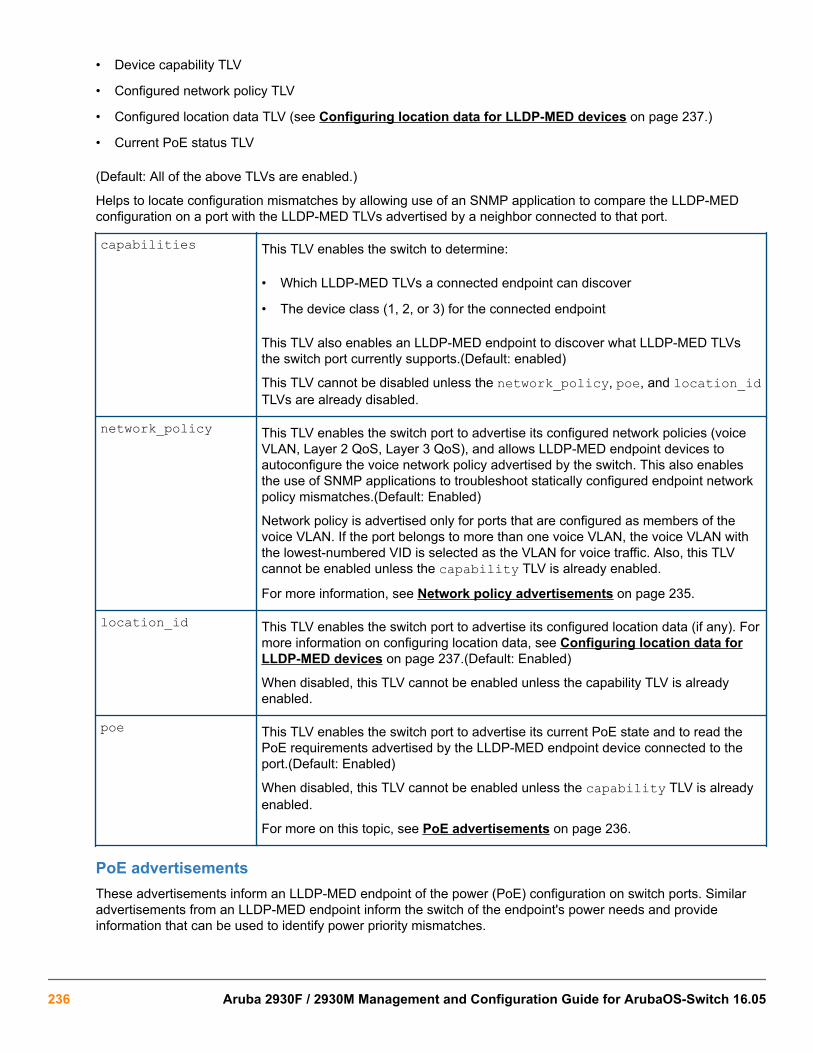
• Device capability TLV
• Configured network policy TLV
• Configured location data TLV (see Configuring location data for LLDP-MED devices on page 237.)
• Current PoE status TLV
(Default: All of the above TLVs are enabled.)
Helps to locate configuration mismatches by allowing use of an SNMP application to compare the LLDP-MEDconfiguration on a port with the LLDP-MED TLVs advertised by a neighbor connected to that port.
capabilities This TLV enables the switch to determine:
• Which LLDP-MED TLVs a connected endpoint can discover
• The device class (1, 2, or 3) for the connected endpoint
This TLV also enables an LLDP-MED endpoint to discover what LLDP-MED TLVsthe switch port currently supports.(Default: enabled)
This TLV cannot be disabled unless the network_policy, poe, and location_idTLVs are already disabled.
network_policy This TLV enables the switch port to advertise its configured network policies (voiceVLAN, Layer 2 QoS, Layer 3 QoS), and allows LLDP-MED endpoint devices toautoconfigure the voice network policy advertised by the switch. This also enablesthe use of SNMP applications to troubleshoot statically configured endpoint networkpolicy mismatches.(Default: Enabled)
Network policy is advertised only for ports that are configured as members of thevoice VLAN. If the port belongs to more than one voice VLAN, the voice VLAN withthe lowest-numbered VID is selected as the VLAN for voice traffic. Also, this TLVcannot be enabled unless the capability TLV is already enabled.
For more information, see Network policy advertisements on page 235.
location_id This TLV enables the switch port to advertise its configured location data (if any). Formore information on configuring location data, see Configuring location data forLLDP-MED devices on page 237.(Default: Enabled)
When disabled, this TLV cannot be enabled unless the capability TLV is alreadyenabled.
poe This TLV enables the switch port to advertise its current PoE state and to read thePoE requirements advertised by the LLDP-MED endpoint device connected to theport.(Default: Enabled)
When disabled, this TLV cannot be enabled unless the capability TLV is alreadyenabled.
For more on this topic, see PoE advertisements on page 236.
PoE advertisementsThese advertisements inform an LLDP-MED endpoint of the power (PoE) configuration on switch ports. Similaradvertisements from an LLDP-MED endpoint inform the switch of the endpoint's power needs and provideinformation that can be used to identify power priority mismatches.
236 Aruba 2930F / 2930M Management and Configuration Guide for ArubaOS-Switch 16.05

PoE TLVs include the following power data:
• Power type: indicates whether the device is a power-sourcing entity (PSE) or a PD. Ports on the J8702A PoEzl module are PSE devices. A MED-capable VoIP telephone is a PD.
• Power source: indicates the source of power in use by the device. Power sources for PDs include PSE, local(internal), and PSE/local. The switches advertise Unknown.
• Power priority: indicates the power priority configured on the switch (PSE) port or the power priorityconfigured on the MED-capable endpoint.
• Power value: indicates the total power in watts that a switch port (PSE) can deliver at a particular time, or thetotal power in watts that the MED endpoint (PD) requires to operate.
Viewing PoE advertisementsTo display the current power data for an LLDP-MED device connected to a port, use the following command:
show lldp info remote-device <port-list>For more information on this command, see page A-60.
To display the current PoE configuration on the switch, use the following commands:
show power brief <port-list>show power <port-list>For more information on PoE configuration and operation, see Power Over Ethernet (PoE/PoE+) Operation.
Location data for LLDP-MED devicesYou can configure a switch port to advertise location data for the switch itself, the physical wall-jack location of theendpoint (recommended), or the location of a DHCP server supporting the switch, endpoint, or both. You alsohave the option of configuring these different address types:
• Civic address: physical address data such as city, street number, and building information
• ELIN (Emergency Location Identification Number): an emergency number typically assigned to MLTS(Multiline Telephone System) Operators in North America
• Coordinate-based location: attitude, longitude, and altitude information (Requires configuration via an SNMPapplication.)
Configuring location data for LLDP-MED devicesSyntax:
[no] lldp config <port-list> medPortLocation <Address-Type>Configures location of emergency call data the switch advertises per port in the location_id TLV. This TLV isfor use by LLDP-MED endpoints employing location-based applications.
The switch allows one medPortLocation entry per port (without regard to type). Configuring a newmedPortLocation entry of any type on a port replaces any previously configured entry on that port.
civic-addr <COUNTRY-STR> <WHAT> <CA-TYPE> <CA-VALUE> … [< CA-TYPE > < CA-VALUE >] … [< CA-TYPE > < CA-VALUE >]
Enables configuration of a physical address on a switch port and allows up to 75 characters of addressinformation.
Chapter 10 Configuring for Network Management Applications 237
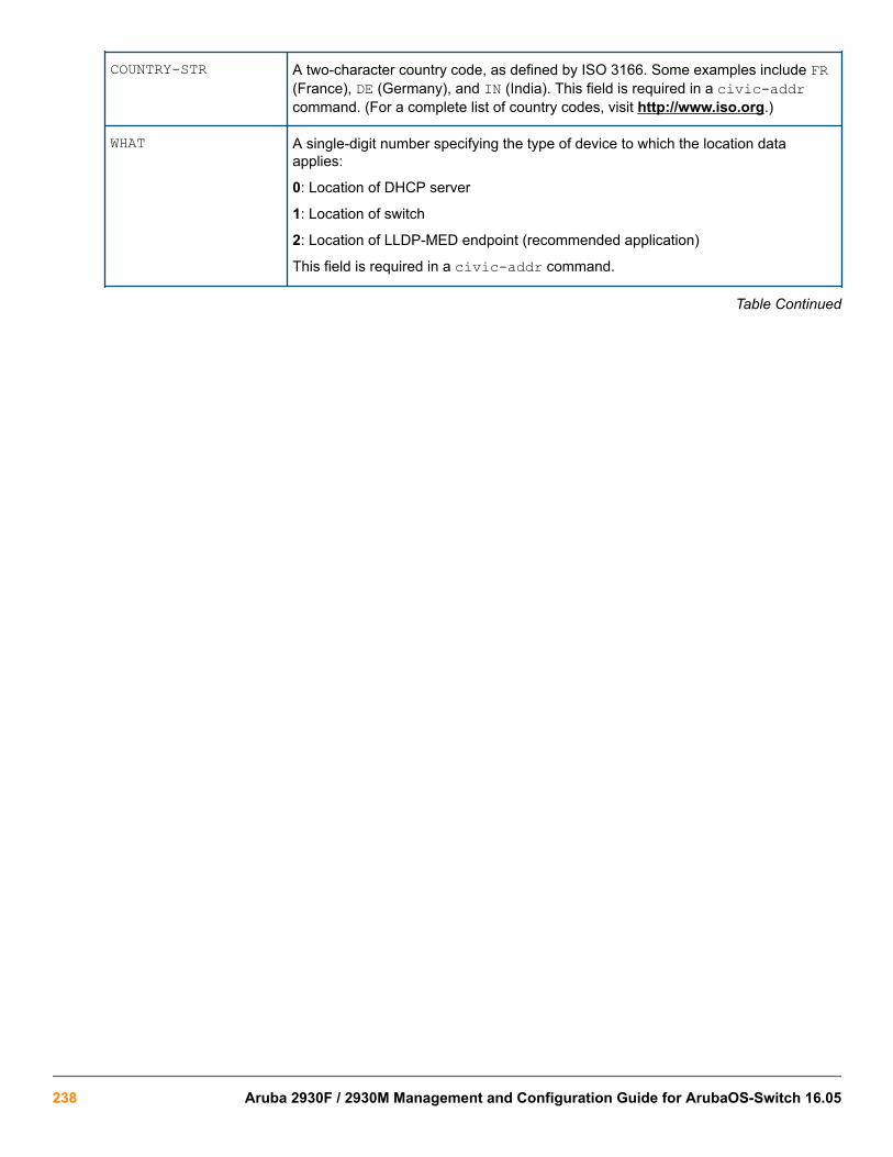
COUNTRY-STR A two-character country code, as defined by ISO 3166. Some examples include FR(France), DE (Germany), and IN (India). This field is required in a civic-addrcommand. (For a complete list of country codes, visit http://www.iso.org.)
WHAT A single-digit number specifying the type of device to which the location dataapplies:
0: Location of DHCP server
1: Location of switch
2: Location of LLDP-MED endpoint (recommended application)
This field is required in a civic-addr command.
Table Continued
238 Aruba 2930F / 2930M Management and Configuration Guide for ArubaOS-Switch 16.05

Type/Value Pairs(CA-TYPE and CA-VALUE)
A series of data pairs, each composed of a location data "type" specifier and thecorresponding location data for that type. That is, the first value in a pair is expectedto be the civic address "type" number ( CA-TYPE), and the second value in a pair isexpected to be the corresponding civic address data ( CA-VALUE).
For example, if the CA-TYPE for "city name" is "3," the type/value pair to define thecity of Paris is "3 Paris."
Multiple type/value pairs can be entered in any order, although Hewlett PackardEnterprise recommends that multiple pairs be entered in ascending order of the CA-TYPE.
When an emergency call is placed from a properly configured class 3 endpointdevice to an appropriate PSAP, the country code, device type, and type/value pairsconfigured on the switch port are included in the transmission. The "type" specifiersare used by the PSAP to identify and organize the location data components in anunderstandable format for response personnel to interpret.
A civic-addr command requires a minimum of one type/value pair, but typicallyincludes multiple type/value pairs as needed to configure a complete set of datadescribing a given location.
CA-TYPE: This is the first entry in a type/value pair and is a number defining thetype of data contained in the second entry in the type/value pair ( CA-VALUE).Some examples of CA-TYPE specifiers include:
• 3=city
• 6=street (name)
• 25=building name
(Range: 0 - 255)For a sample listing of CA-TYPE specifiers, see Some locationcodes used in CA-TYPE fields.
CA-VALUE:This is the second entry in a type/value pair and is an alphanumericstring containing the location information corresponding to the immediatelypreceding CA-TYPE entry.
Strings are delimited by either blank spaces, single quotes (' … '), or double quotes("… ").
Each string should represent a specific data type in a set of unique type/value pairscomprising the description of a location, and each string must be preceded by a CA-TYPE number identifying the type of data in the string.
A switch port allows one instance of any given CA-TYPE. For example, if a type/value pair of 6 Atlantic (to specify "Atlantic" as a street name) is configured on portA5 and later another type/value pair of 6 Pacific is configured on the same port,Pacific replaces Atlantic in the civic address location configured for port A5.
elin-addr<emergency-number>
This feature is intended for use in ECS applications to support class 3 LLDP-MEDVoIP telephones connected to a switch in an MLTS infrastructure.
An ELIN is a valid NANP format telephone number assigned to MLTS operators inNorth America by the appropriate authority. The ELIN is used to route emergency(E911) calls to a PSAP.
(Range: 1-15 numeric characters)
Chapter 10 Configuring for Network Management Applications 239

Configuring coordinate-based locationsLatitude, longitude, and altitude data can be configured per switch port using an SNMP management application.For more information, see the documentation provided with the application. A further source of information on thistopic is RFC 3825-Dynamic host configuration protocol option for coordinate-based location configurationinformation.
Endpoint use of data from a medPortLocation TLV sent by the switch is device-dependent. See thedocumentation provided with the endpoint device.
Table 19: Some location codes used in CA-TYPE fields
Location element Code1 Location element Code
national subdivision 1 street number 19
regional subdivision 2 additional location data 22
city or township 3 unit or apartment 26
city subdivision 4 floor 27
street 6 room number 28
street suffix 18
1 The code assignments in this table are examples from a work-in-progress (the internet draft titled "Dynamic Host ConfigurationProtocol (DHCPv4 and DHCPv6) Option for Civic Addresses Configuration Information draft-ietf-geopriv-dhcp-civil-06" datedMay 30, 2005.) For the actual codes to use, contact the PSAP or other authority responsible for specifying the civic addressingdata standard for your network.
Example:
Suppose a system operator wants to configure the following information as the civic address for a telephoneconnected to her company's network through port A2 of a switch at the following location:
CA-type CA-type CA-VALUE
national subdivision 1 CA
city 3 Widgitville
street 6 Main
street number 19 1433
unit 26 Suite 4-N
floor 27 4
room number 28 N4-3
The following example shows the commands for configuring and displaying the above data.
240 Aruba 2930F / 2930M Management and Configuration Guide for ArubaOS-Switch 16.05

A civic address configuration
switch(config)# lldp config 2 medportlocation civic-addr US 2 1 CA 3Widgitville 6 Main 19 1433 26 Suite_4—N 27 4 28 N4—3
switch(config)# show lldp config 2 LLDP Port Configuration Detail Port : A2 AdminStatus [Tx_Rx] : Tx_Rx NotificationEnabled [False] : False Med Topology Trap Enabled [False] : False Country Name : US What : 2 Ca-Type : 1 Ca-Length : 2 Ca-Value : CA Ca-Type : 3 Ca-Length : 11 Ca-Value : Widgitville Ca-Type : 6 Ca-Length : 4 Ca-Value : Main Ca-Type : 19 Ca-Length : 4 Ca-Value : 1433 Ca-Type : 26 Ca-Length : 9 Ca-Value : Suite_4-N Ca-Type : 27 Ca-Length : 1 Ca-Value : 4 Ca-Type : 28 Ca-Length : 4 Ca-Value : N4-3
Viewing switch information available for outbound advertisementsSyntax:
show lldp info local-device [port-list]Without the [port-list] option, displays the global switch information and the per-port information currentlyavailable for populating outbound LLDP advertisements.
With the [port-list] option, displays only the following port-specific information that is currently available foroutbound LLDP advertisements on the specified ports:
• PortType• PortId• PortDesc
This command displays the information available on the switch. Use the lldp config <port-list> command to change the selection of information that is included in actual outboundadvertisements. In the default LLDP configuration, all information displayed by this command istransmitted in outbound advertisements.
Chapter 10 Configuring for Network Management Applications 241

In the default configuration, the switch information currently available for outbound LLDP advertisements appearssimilar to the display in the following example.
Displaying the global and per-port information available for outbound advertisements
switch(config)# show lldp info local-device
LLDP Local Device Information
Chassis Type : mac-address Chassis Id : 00 23 47 4b 68 DD System Name : HP Switch1 System Description : HP J9091A Switch 3500yl, revision XX.15.06... System Capabilities Supported:bridge System Capabilities Enabled:bridge
Management Address 1 Type:ipv4 Address:
LLDP Port Information
Port | PortType PortId PortDesc ----- + --------- ------- --------- 1 | local 1 1 2 | local 2 2 3 | local 3 3 4 | local 4 4 5 | local 5 5
1
The Management Address field displays only the LLDP-configurable IP addresses on the switch. (Only manually-configured IP addresses are LLDP-configurable.) If the switch has only an IP address from a DHCP or Bootpserver, then the Management Address field is empty (because there are no LLDP-configurable IP addressesavailable.
The default per-port information content for ports 1 and 2
switch(config)# show lldp info local 1-2
LLDP Local Port Information Detail
Port : 1 PortType : local PortId : 1 PortDesc : 1
---------------------------------------- Port : 2 PortType : local PortId : 2 PortDesc : 2
Displaying the current port speed and duplex configuration on a switch portYou can compare port speed and duplex information for a switch port and a connected LLDP-MED endpoint forconfiguration mismatches by using an SNMP application. You can also use the switch CLI to display thisinformation, if necessary. The show interfaces brief <port-list> and show lldp info remote-device [port-list] commands provide methods for displaying speed and duplex information for switch
242 Aruba 2930F / 2930M Management and Configuration Guide for ArubaOS-Switch 16.05

ports. For information on displaying the currently configured port speed and duplex on an LLDP-MED endpoint,see Viewing the current port speed and duplex configuration on a switch port on page 243.
Viewing the current port speed and duplex configuration on a switch portSyntax:
show interfaces brief <port-list>Includes port speed and duplex configuration in the Mode column of the resulting display.
Viewing advertisements currently in the neighbors MIBSyntax:
show lldp info remote-device [port-list]Without the [port-list] option, provides a global list of the individual devices it has detected by reading LLDPadvertisements. Discovered devices are listed by the inbound port on which they were discovered.
Multiple devices listed for a single port indicates that such devices are connected to the switch through a hub.
Discovering the same device on multiple ports indicates that the remote device may be connected to theswitch in one of the following ways:
• Through different VLANS using separate links. (This applies to switches that use the same MAC address forall configured VLANs.)
• Through different links in the same trunk.
• Through different links using the same VLAN. (In this case, spanning-tree should be invoked to prevent anetwork topology loop. Note that LLDP packets travel on links that spanning-tree blocks for other traffic types.)
With the [port-list] option, provides a listing of the LLDP data that the switch has detected in advertisementsreceived on the specified ports.
For descriptions of the various types of information displayed by these commands, see Data available for basicLLDP advertisements.
A global listing of discovered devices
switch(config)# show lldp info remote
LLDP Remote Devices Information
LocalPort | ChassisId PortId PortDescr SysName --------- + ------------------------- ------ --------- ------------- 1 | 00 11 85 35 3b 80 6 6 HP Switch 2 | 00 11 85 cf 66 60 8 8 HP Switch
An LLLDP-MED listing of an advertisement received from an LLDP-MED (VoIP telephone) source
switch(config)# show lldp info remote-device 1
LLDP Remote Device Information Detail
Local Port : A2 ChassisType : network-address ChassisId : 0f ff 7a 5c PortType : mac-address
Chapter 10 Configuring for Network Management Applications 243

PortId : 08 00 0f 14 de f2 SysName : HP Switch System Descr : HP Switch, revision xx.15.06.0000x PortDescr : LAN Port
System Capabilities Supported : bridge, telephone System Capabilities Enabled : bridge, telephone
Remote Management Address
MED Information Detail 1 EndpointClass :Class3 Media Policy Vlan id :10 Media Policy Priority :7 Media Policy Dscp :44 Media Policy Tagged :False Poe Device Type :PD Power Requested :47 Power Source :Unknown Power Priority :High
1Indicates the policy configured on the telephone. A configuration mismatch occurs if the supporting port isconfigured differently.
Displaying LLDP statisticsLLDP statistics are available on both a global and a per-port levels. Rebooting the switch resets the LLDPstatistics counters to zero. Disabling the transmit and/or receive capability on a port "freezes" the related portcounters at their current values.
Viewing LLDP statisticsFor more information, see Displaying LLDP statistics on page 244.
Syntax:
show lldp stats [port-list]The global LLDP statistics command displays an overview of neighbor detection activity on the switch, plus dataon the number of frames sent, received, and discarded per-port.
The per-port LLDP statistics command enhances the list of per-port statistics provided by the global statisticscommand with some additional per-port LLDP statistics.
Global LLDP Counters:
Neighbor Entries List LastUpdated
The elapsed time since a neighbor was last added or deleted.
New Neighbor Entries Count The total of new LLDP neighbors detected since the last switch reboot.Disconnecting, and then reconnecting a neighbor increments thiscounter.
Table Continued
244 Aruba 2930F / 2930M Management and Configuration Guide for ArubaOS-Switch 16.05

Neighbor Entries DeletedCount
The number of neighbor deletions from the MIB for AgeOut Count andforced drops for all ports.For example, if the admin status for port on aneighbor device changes from tx_rx or txonly to disabled orrxonly, the neighbor device sends a "shutdown" packet out the portand ceases transmitting LLDP frames out that port.The device receivingthe shutdown packet deletes all information about the neighbor receivedon the applicable inbound port and increments the counter.
Neighbor Entries DroppedCount
The number of valid LLDP neighbors the switch detected, but could notadd.This can occur, For example, when a new neighbor is detected whenthe switch is already supporting the maximum number of neighbors. See Neighbor maximum on page 246.
Neighbor Entries AgeOutCount
The number of LLDP neighbors dropped on all ports because of Time-to-Live expiring.
Per-Port LLDP Counters:
NumFramesRecvd The total number of valid, inbound LLDP advertisements received fromany neighbors on port-list .Where multiple neighbors are connectedto a port through a hub, this value is the total number of LLDPadvertisements received from all sources.
NumFramesSent The total number of LLDP advertisements sent from port-list.
NumFramesDiscarded The total number of inbound LLDP advertisements discarded by port-list.This can occur, For example, when a new neighbor is detected on theport, but the switch is already supporting the maximum number ofneighbors. See Neighbor maximum on page 246. This can also be anindication of advertisement formatting problems in the neighbor device.
Frames Invalid The total number of invalid LLDP advertisements received on the port.Aninvalid advertisement can be caused by header formatting problems inthe neighbor device.
TLVs Unrecognized The total number of LLDP TLVs received on a port with a type value inthe reserved range.This can be caused by a basic management TLVfrom a later LLDP version than the one currently running on the switch.
TLVs Discarded The total number of LLDP TLVs discarded for any reason. In this case,the advertisement carrying the TLV may be accepted, but the individualTLV is not usable.
Neighbor Ageouts The number of LLDP neighbors dropped on the port because of Time-to-Live expiring.
Examples:
A global LLDP statistics display
switch(config)# show lldp stats
LLDP Device Statistics
Neighbor Entries List Last Updated : 2 hours
Chapter 10 Configuring for Network Management Applications 245

New Neighbor Entries Count : 20 Neighbor Entries Deleted Count : 20 Neighbor Entries Dropped Count : 0 Neighbor Entries AgeOut Count : 20
LLDP Port Statistics Port | NumFramesRecvd NumFramesSent NumFramesDiscarded ------ + -------------- ------------- ------------------ A1 | 97317 97843 0 A2 | 21 12 0 A3 | 0 0 0 A4 | 446 252 0 A5 | 0 0 0 A6 | 0 0 0 A7 | 0 0 0 A8 | 0 0 0
A per-port LLDP statistics display
switch(config)# show lldp stats 1
LLDP Port Statistics Detail
PortName : 1 Frames Discarded : 0 Frames Invalid : 0 Frames Received : 7309 Frames Sent : 7231 TLVs Unrecognized : 0 TLVs Discarded : 0 Neighbor Ageouts : 0
LLDP Operating Notes
Neighbor maximumThe neighbors table in the switch supports as many neighbors as there are ports on the switch. The switch cansupport multiple neighbors connected through a hub on a given port, but if the switch neighbor maximum isreached, advertisements from additional neighbors on the same or other ports will not be stored in the neighborstable unless some existing neighbors time-out or are removed.
LLDP packet forwardingAn 802.1D-compliant switch does not forward LLDP packets, regardless of whether LLDP is globally enabled ordisabled on the switch.
One IP address advertisement per portLLDP advertises only one IP address per port, even if multiple IP addresses are configured by lldp configport-list ipAddrEnable on a given port.
802.1Q VLAN InformationLLDP packets do not include 802.1Q header information and are always handled as untagged packets.
Effect of 802.1X OperationIf 802.1X port security is enabled on a port, and a connected device is not authorized, LLDP packets are nottransmitted or received on that port. Any neighbor data stored in the neighbor MIB for that port prior to the
246 Aruba 2930F / 2930M Management and Configuration Guide for ArubaOS-Switch 16.05

unauthorized device connection remains in the MIB until it ages out. If an unauthorized device later becomesauthorized, LLDP transmit and receive operation resumes.
Neighbor data can remain in the neighbor database after the neighbor is disconnectedAfter disconnecting a neighbor LLDP device from the switch, the neighbor can continue to appear in the switch'sneighbor database for an extended period if the neighbor's holdtime-multiplier is high; especially if therefresh-interval is large. See Changing the time-to-live for transmitted advertisements (CLI) on page224.
Mandatory TLVsAll mandatory TLVs required for LLDP operation are also mandatory for LLDP-MED operation.
LLDP and CDP data managementThis section describes points to note regarding LLDP and CDP (Cisco Discovery Protocol) data received by theswitch from other devices. LLDP operation includes both transmitting LLDP packets to neighbor devices andreading LLDP packets received from neighbor devices. CDP operation is limited to reading incoming CDPpackets from neighbor devices. (HPE switches do not generate CDP packets.)
Incoming CDP and LLDP packets tagged for VLAN 1 are processed even if VLAN 1 does not contain any ports.VLAN 1 must be present, but it is typically present as the default VLAN for the switch.
The switch may pick up CDP and LLDP multicast packets from VLAN 1 even when CDP- and /orLLDP-enabled ports are not members of VLAN 1.
LLDP and CDP neighbor dataWith both LLDP and (read-only) CDP enabled on a switch port, the port can read both LLDP and CDPadvertisements, and stores the data from both types of advertisements in its neighbor database. (The switchstores only CDP data that has a corresponding field in the LLDP neighbor database.) The neighbor databaseitself can be read by either LLDP or CDP methods or by using the show lldp commands. Take note of thefollowing rules and conditions:
• If the switch receives both LLDP and CDP advertisements on the same port from the same neighbor, theswitch stores this information as two separate entries if the advertisements have different chassis ID and portID information.
• If the chassis and port ID information are the same, the switch stores this information as a single entry. That is,LLDP data overwrites the corresponding CDP data in the neighbor database if the chassis and port IDinformation in the LLDP and CDP advertisements received from the same device is the same.
• Data read from a CDP packet does not support some LLDP fields, such as "System Descr,""SystemCapSupported," and "ChassisType." For such fields, LLDP assigns relevant default values. Also:
◦ The LLDP "System Descr" field maps to CDP's "Version" and "Platform" fields.
◦ The switch assigns "ChassisType" and "PortType" fields as "local" for both the LLDP and the CDPadvertisements it receives.
◦ Both LLDP and CDP support the "System Capability" TLV. However, LLDP differentiates between what adevice is capable of supporting and what it is actually supporting, and separates the two types ofinformation into subelements of the System Capability TLV. CDP has only a single field for this data. Thus,
Chapter 10 Configuring for Network Management Applications 247

when CDP System Capability data is mapped to LLDP, the same value appears in both LLDP SystemCapability fields.
◦ System Name and Port Descr are not communicated by CDP, and thus are not included in the switch'sNeighbors database.
Because HPE switches do not generate CDP packets, they are not represented in the CDP datacollected by any neighbor devices running CDP.
A switch with CDP disabled forwards the CDP packets it receives from other devices, but does notstore the CDP information from these packets in its own MIB.
LLDP data transmission/collection and CDP data collection are both enabled in the switch's default configuration.In this state, an SNMP network management application designed to discover devices running either CDP orLLDP can retrieve neighbor information from the switch regardless of whether LLDP or CDP is used to collect thedevice-specific information.
Protocol state Packet generation Inbound datamanagement
Inbound packetforwarding
CDP Enabled N/A Store inbound CDP data. No forwarding of inboundCDP packets.
CDP Disabled N/A No storage of CDP datafrom neighbor devices.
Floods inbound CDPpackets from connecteddevices to outbound ports.
LLDP Enabled1 Generates andtransmits LLDPpackets out all portson the switch.
Store inbound LLDP data. No forwarding of inboundLLDP packets.
LLDP Disabled No packetgeneration.
No storage of LLDP datafrom neighbor devices.
No forwarding of inboundLLDP packets.
CDP operation and commandsBy default the switches have CDP enabled on each port. This is a read-only capability, meaning that the switchcan receive and store information about adjacent CDP devices but does not generate CDP packets.
When a CDP-enabled switch receives a CDP packet from another CDP device, it enters that device's data in theCDP Neighbors table, along with the port number where the data was received—and does not forward the packet.The switch also periodically purges the table of any entries that have expired. (The hold time for any data entry inthe switch's CDP Neighbors table is configured in the device transmitting the CDP packet and cannot becontrolled in the switch receiving the packet.) A switch reviews the list of CDP neighbor entries every threeseconds and purges any expired entries.
For details on how to use an SNMP utility to retrieve information from the switch's CDP Neighborstable maintained in the switch's MIB, see the documentation provided with the particular SNMP utility.
Viewing the current CDP configuration of the switchCDP is shown as enabled/disabled both globally on the switch and on a per-port basis.
248 Aruba 2930F / 2930M Management and Configuration Guide for ArubaOS-Switch 16.05

Syntax:
show cdpLists the global and per-port CDP configuration of the switch.
The following example shows the default CDP configuration.
Default CDP configuration
switch(config)# show cdp
Global CDP information
Enable CDP [Yes] : Yes (Receive Only)
Port CDP ---- -------- 1 enabled 2 enabled 3 enabled . . . . . .
Viewing the current CDP neighbors table of the switchDevices are listed by the port on which they were detected.
Syntax:
show cdp neighborsLists the neighboring CDP devices the switch detects, with a subset of the information collected from the device'sCDP packet.
[[e] port-numb [detail]]Lists the CDP device connected to the specified port. (Allowsonly one port at a time.)Using detail provides a longer list ofdetails on the CDP device the switch detects on the specifiedport.
[detail [[e] port-numb]]Provides a list of the details for all of the CDP devices theswitch detects.Using port-num produces a list of details forthe selected port.
The following example displays the CDP devices that the switch has detected by receiving their CDP packets.
CDP neighbors table listing
switch(config)# show cdp neighbors
CDP neighbors information
Port Device ID | Platform Capability ---- ----------------------------- + ---------------------------- ----------- 1 Accounting (0030c1-7fcc40) | J4812A HP Switch. . . S 2 Resear¢1-1 (0060b0-889e43) | J4121A HP Switch. . . S 4 Support (0060b0_761a45) | J4121A HP Switch. . . S
Chapter 10 Configuring for Network Management Applications 249

7 Marketing (0030c5_33dc59) | J4313A HP Switch. . . S 12 Mgmt NIC(099a05-09df9b | NIC Model X666 H 12 Mgmt NIC(099a05-09df11 | NIC Model X666 H
Enabling and Disabling CDP OperationEnabling CDP operation (the default) on the switch causes the switch to add entries to its CDP Neighbors tablefor any CDP packets it receives from other neighboring CDP devices.
Disabling CDP operation clears the switch's CDP Neighbors table and causes the switch to drop inbound CDPpackets from other devices without entering the data in the CDP Neighbors table.
Syntax:
[no] cdp runEnables or disables CDP read-only operation on the switch.
(Default: Enabled)
Example:
To disable CDP read-only on the switch:
switch(config)# no cdp runWhen CDP is disabled:
• show cdp neighborsdisplays an empty CDP Neighbors table
• show cdpdisplaysGlobal CDP informationEnable CDP [Yes]: No
Enabling or disabling CDP operation on individual portsIn the factory-default configuration, the switch has all ports enabled to receive CDP packets. Disabling CDP on aport causes it to drop inbound CDP packets without recording their data in the CDP Neighbors table.
Syntax:
[no] cdp enable {< [e] port-list >}Example:
To disable CDP on port A1:
switch(config)# no cdp enable a1
Configuring CDPv2 for voice transmissionLegacy Cisco VOIP phones only support manual configuration or using CDPv2 for voice VLAN auto-configuration.LLDP-MED is not supported. CDPv2 exchanges information such as software version, device capabilities, andvoice VLAN information between directly connected devices such as a VOIP phone and a switch.
When the Cisco VOIP phone boots up (or sometimes periodically), it queries the switch and advertisesinformation about itself using CDPv2. The switch receives the VOIP VLAN Query TLV (type 0x0f) from the phoneand then immediately sends the voice VLAN ID in a reply packet to the phone using the VLAN Reply TLV (type0x0e). The phone then begins tagging all packets with the advertised voice VLAN ID.
250 Aruba 2930F / 2930M Management and Configuration Guide for ArubaOS-Switch 16.05

A voice VLAN must be configured before the voice VLAN can be advertised. For example, toconfigure VLAN 10 as a voice VLAN tagged for ports 1 through 10, enter these commands:
switch(config)# vlan 10switch(vlan-10)# tagged 1-10switch(vlan-10)# voiceswitch(vlan-10)# exit
The switch CDP packet includes these TLVs:
• CDP Version: 2
• CDP TTL: 180 seconds
• Checksum
• Capabilities (type 0x04): 0x0008 (is a switch)
• Native VLAN: The PVID of the port
• VOIP VLAN Reply (type 0xe): voice VLAN ID (same as advertised by LLDPMED)
• Trust Bitmap (type 0x12): 0x00
• Untrusted port COS (type 0x13): 0x00
CDP should be enabled and running on the interfaces to which the phones are connected. Use the cdp enableand cdp run commands.
The pre-standard-voice option for the cdp mode command allows the configuration of CDP mode so that itresponds to received CDP queries from a VoIP phone.
Syntax:
[no] cdp mode pre-standard-voice [admin-status < port-list > [tx_rx | rxonly]]Enable CDP-compatible voice VLAN discovery with pre-standard VoIP phones. In this mode, when a CDP VoIPVLAN query is received on a port from pre-standard phones, the switch replies back with a CDP packet thatcontains the VID of the voice VLAN associated with that port.
Not recommended for phones that support LLDP-MED.
pre-standard-voice Enables CDP-compatible voice VLAN discovery with pre-standard VoIP phones.
admin-status Sets the port in either transmit and receive mode, or receive mode only.Default: tx-rx.<port-list>
Sets this port in transmit and receive mode, or receive mode only.
rxonly
Enable receive-only mode of CDP processing.
tx_rx
Enable transmit and receive mode.
switch(config)# cdp mode pre-standard-voice admin-status A5 rxonly
Chapter 10 Configuring for Network Management Applications 251

The show cdp output when CDP Run is disabled
switch(config)# show cdpGlobal CDP informationEnable CDP [yes] : no
The show cdp output when cdp run and sdp mode are enabled
switch(config)# show cdp
Global CDP Information
Enable CDP [Yes] : Yes CDP mode [rxonly] : pre-standard-voice CDP Hold Time [180] : 180 CDP Transmit Interval [60] : 60
Port CDP admin-status ---- --------- ------------ A1 enabled rxonly A2 enabled tx_rx A3 enabled tx_rxWhen CDP mode is not pre-standard voice, the admin-status column is note displayed.
The show cdp output when cdp run and cdp mode rxonly are enabled
switch(config)# show cdp
Global CDP Information
Enable CDP [Yes} : Yes CDP mode [rxonly] : rxonly
Port CDP ---- -------- A1 enabled A2 enabled A3 enabled
The show running-config when admin-status is configured
switch(config)# show running-config
Running configuration:
; J9477A Configuration Editor; Created on release #XX.16.09.0000x; Ver #03:01:1f:ef:f2hostname “HPSwitch”module 1 type J9307Acdp mode pre-standard-voice admin-status A5 RxOnly
Filtering CDP informationIn some environments it is desirable to be able to configure a switch to handle CDP packets by filtering out theMAC address learns from untagged VLAN traffic from IP phones. This means that normal protocol processingoccurs for the packets, but the addresses associated with these packets is not learned or reported by the software
252 Aruba 2930F / 2930M Management and Configuration Guide for ArubaOS-Switch 16.05

address management components. This enhancement also filters out the MAC address learns from LLDP and802.1x EAPOL packets on untagged VLANs.
The feature is configured per-port.
Configuring the switch to filter untagged trafficEnter this command to configure the switch not to learn CDP, LLDP, or EAPOL traffic for a set of interfaces.
Syntax:
[no] ignore-untagged-mac <port-list>Prevents MAC addresses from being learned on the specified ports when the VLAN is untagged and thedestination MAC address is one of the following:
• 01000C-CCCCCC (CDP)
• 0180c2- 00000e (LLDP)
• 0180c2-000003 (EAPOL)
Configuring the switch to ignore packet MAC address learns for an untagged VLAN
switch(config) ignore-untagged-mac 1-2
Displaying the configurationEnter the show running-config command to display information about the configuration.
Configuration showing interfaces to ignore packet MAC address learns
switch(config) show running-config
Running configuration:
; J9627 Configuration Editor; Created on release XX.15.XX; Ver #03:03.1f.ef:f0
hostname “HP Switch”interface 1 ignore-untagged-mac exitinterface 2 ignore-untagged-mac exit...vlan 1 name “DEFAULT_VLAN” untagged 1-24 ip address dhcp-bootp exit...
Chapter 10 Configuring for Network Management Applications 253

Filtering PVID mismatch log messagesThis enhancement filters out PVID mismatch log messages on a per-port basis. PVID mismatches are loggedwhen there is a difference in the PVID advertised by a neighboring switch and the PVID of the switch port whichreceives the LLDP advertisement. Logging is an LLDP feature that allows detection of possible vlan leakagebetween adjacent switches. However, if these events are logged too frequently, they can overwhelm the log bufferand push relevant logging data out of log memory, making it difficult to troubleshoot another issue.
Logging is disabled and enabled with the support of CLI commands.
This enhancement also includes displaying the Mac-Address in the PVID mismatch log message when the port IDis Mac-Address instead of displaying garbage characters in the peer device port ID field.
Use the following command to disable the logging of the PVID mismatch log messages:
Syntax:
logging filter [filter-name][sub filter id] <regularexpression> denyRegular-expression
The regular expression should match the message which is to be filtered.
Syntax:
logging filter [filter-name] enable
DHCPv4 server
Introduction to DHCPv4The Dynamic Host Configuration Protocol (DHCP) is a network protocol that enables a server to automateassignment of IP addresses to hosts. A DHCP server can be configured to provide other network information likeIP addresses of TFTP servers, DNS server, boot file name and vendor specific options. Commonly there are twotypes of address assignments, dynamic and manual. The lease of dynamic addresses is renewed periodically;manual leases are permanently assigned to hosts. With this feature, you can configure multiple pools of IPaddresses for IP address assignment and tracking.
IP poolsA DHCP server is configured with IP pools. The server is then instructed to use IP addresses falling into thespecified range of IP while offering leases. Multiple IP pools are configured to not have duplicate or overlapping IPsubnets. You can also configure a DHCP server with multiple IP ranges within an IP subnet; this confines theallocatable IP addresses within the configured IP pool.
An IP pool will be claimed valid only if it is either:
• Dynamic pool – Has a network address, subnet mask and IP range(s)
• Static pool – Should have a static IP-to-MAC binding.
The DHCP server will discard the invalid and incomplete pools and will only operate on the valid IP pools. TheDHCP server will require at least one valid pool to start.
DHCP optionsOn a DHCP server, an IP pool is configured with various options. These options signify additional informationabout the network. Options are supported with explicit commands such as boot-file. Option codes that
254 Aruba 2930F / 2930M Management and Configuration Guide for ArubaOS-Switch 16.05

correspond to explicit commands can not be configured with a generic option command; the generic optioncommand requires an option code and TLV.
RFC 2132 defines various network information that a client may request when trying to get the lease.
BootP supportThe DHCP server also functions as BootP server. A manual binding configured in a static IP Pool may eitherservice a BootP client request or a DHCP client request.
Authoritative server and support for DHCP inform packetsThe server message DHCPinformmay be received when the server is already configured for static IPv4addresses so that the server can to get configuration parameters dynamically.
RFC 2131 states that if a client has obtained a network address through some other means (e.g.,manual configuration), it may use a DHCPinform request message to obtain other localconfiguration parameters. Servers receiving a DHCPinform message construct a DHCPACKmessage with any local configuration parameters appropriate for the client without: allocating a newaddress, checking for an existing binding, filling in yiaddr or including lease time parameters.
Authoritative poolsTo process the DHCPINFORM packets received from a client within the given IP pool, a DHCP server has to beconfigured as authoritative for that IP pool. The server is the sole authority for this IP pool so when a clientrequests an IP address lease where the server is authoritative, and the server has no record of that IP address,the server will respond with DHCPNAK message which indicates that the client should no longer use that IPaddress. Any DHCPINFORM packet received for a non-authoritative pool will be ignored by the DHCP server.
The authoritative command has no effect when configured on a static pool or an incomplete pool without anetwork statement. In such cases, the server intentionally not send an error message.
A CLI toggle is provided under the pool context that will allow the authoritative configuration.
The authoritative command requires a network statement to be configured on a pool.
Authoritative dummy poolsA dummy pool, without the range statement, can be configured and made authoritative. A dummy pool allowsstatic-bind entries which do not have matching dynamic pools with network statements to be configured. Bycreating a dummy pool on a DHCP server, the support for DHCPinform packets will not be actively serving theclient on this pool. No active leases or resource consumption will be sent to the DHCP server when this option isused.
Dummy pools help the DHCP server learn the network topology.
Example
dhcp-server pool dummy192network 192.168.10.0 255.255.255.255option 1…option 2…
Chapter 10 Configuring for Network Management Applications 255

:option n…authoritativeexit
Change in server behaviorMaking the server authoritative for an IP pool changes how the server processes DHCP REQUEST packets.
The table below exhibits the behavior on the receiving DHCP REQUEST and DHCP INFORM packets, from DHCPclients residing on either authoritative or non-authoritative pools.
Table 20: Authoritative and non-authoritative pools
Authoritative Pool Non-authoritative pool
When aDHCP clientsending..
For Own IP For IPbelonging todifferentclient
Unknown IPfalling outsidethe range
For Own IP For IP belonging todifferent client
Unknown IPfalling outsidethe range
DHCPINFORM
send ACK send ACK send ACK DROP DROP DROP
DHCPREQUEST
send ACK send NACK send NACK send ACK DROP DROP
DHCPv4 configuration commands
Enable/disable the DHCPv4 serverSyntax
[no] dhcp-server [enable | disable]To enable/disable the DHCPv4 server in a switch.
• Enable the DHCPv4 server on the device. The no form of this command will remove all DHCPv4 serverconfigurations.
• Disable the DHCPv4 server on the device. The no form of this command will remove all DHCPv4 serverconfigurations.
The default is disabled.
Configuring the DHCP address pool nameUse the following command in the global configuration mode to configure the DHCP address pool name and enterthe DHCP pool context.
A maximum of 128 pools are supported.
Syntax
[no] dhcp-server pool < pool-name>Configure the DHCPv4 server IP address pool with either a static IP or a network IP range.
256 Aruba 2930F / 2930M Management and Configuration Guide for ArubaOS-Switch 16.05
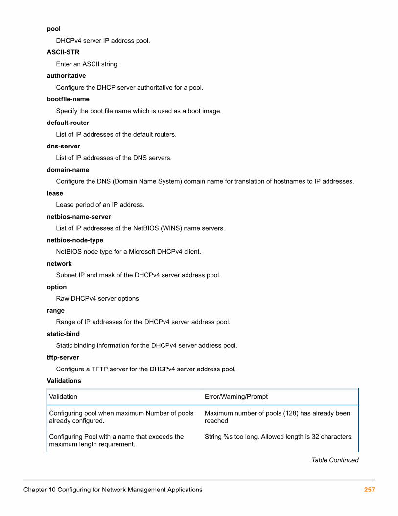
pool
DHCPv4 server IP address pool.
ASCII-STR
Enter an ASCII string.
authoritative
Configure the DHCP server authoritative for a pool.
bootfile-name
Specify the boot file name which is used as a boot image.
default-router
List of IP addresses of the default routers.
dns-server
List of IP addresses of the DNS servers.
domain-name
Configure the DNS (Domain Name System) domain name for translation of hostnames to IP addresses.
lease
Lease period of an IP address.
netbios-name-server
List of IP addresses of the NetBIOS (WINS) name servers.
netbios-node-type
NetBIOS node type for a Microsoft DHCPv4 client.
network
Subnet IP and mask of the DHCPv4 server address pool.
option
Raw DHCPv4 server options.
range
Range of IP addresses for the DHCPv4 server address pool.
static-bind
Static binding information for the DHCPv4 server address pool.
tftp-server
Configure a TFTP server for the DHCPv4 server address pool.
Validations
Validation Error/Warning/Prompt
Configuring pool when maximum Number of poolsalready configured.
Maximum number of pools (128) has already beenreached
Configuring Pool with a name that exceeds themaximum length requirement.
String %s too long. Allowed length is 32 characters.
Table Continued
Chapter 10 Configuring for Network Management Applications 257

Trying to delete non existing pool The specified address pool does not exist.
Only alphanumeric characters, numerals andunderscore is allowed in the pool name. Violatingthis would throw the following error message.
Invalid name. Only alphanumeric characters andhyphen are allowed.
Trying to delete existing pool or adding new poolwhen DHCP server enabled.
DHCP server should be disabled before changingthe configuration.
AuthoritativeSyntax
[no] authoritativeauthoritative
Configure the DHCP server authoritative for a pool.
The DHCP server is the sole authority for the network configured under this pool. When the DHCP server isconfigured as authoritative, the server will respond with DHCP ACK or NACK as appropriate for all the receivedDHCP REQUEST and DHCP INFORM packets belonging to the subnet.
Non-authoritative DHCP INFORM packets received from the clients on a non-authoritative pool will be ignored.
Specify a boot file for the DHCP clientSyntax
[no] bootfile-name<filename>Specify the boot file name to be used as the boot image.
Configure a default router for a DHCP clientSyntax
[no] default-router <IP-ADDR-STR> [IP-ADDR2 ... IP-ADDR8]Configure the DHCP pool context to the default router for a DHCP client. List all of the IP addresses of the defaultrouters.
Two IP addresses must be separated by a comma.
A maximum of eight default routers can be configured.
Configure the DNS IP serversSyntax
[no] dns-server <IP-ADDR> [IP-ADDR2 ... IP-ADDR8]Configure the DHCP pool context to the DNS IP servers that are available to a DHCP client. List of IP addressesof the DNS servers.
Two IP addresses must be separated by comma.
A maximum of eight DNS servers can be configured.
258 Aruba 2930F / 2930M Management and Configuration Guide for ArubaOS-Switch 16.05
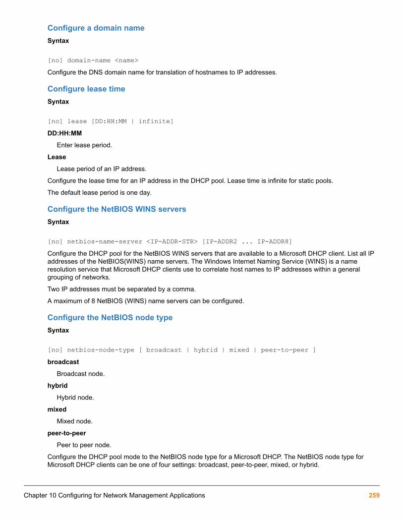
Configure a domain nameSyntax
[no] domain-name <name>Configure the DNS domain name for translation of hostnames to IP addresses.
Configure lease timeSyntax
[no] lease [DD:HH:MM | infinite]DD:HH:MM
Enter lease period.
Lease
Lease period of an IP address.
Configure the lease time for an IP address in the DHCP pool. Lease time is infinite for static pools.
The default lease period is one day.
Configure the NetBIOS WINS serversSyntax
[no] netbios-name-server <IP-ADDR-STR> [IP-ADDR2 ... IP-ADDR8]Configure the DHCP pool for the NetBIOS WINS servers that are available to a Microsoft DHCP client. List all IPaddresses of the NetBIOS(WINS) name servers. The Windows Internet Naming Service (WINS) is a nameresolution service that Microsoft DHCP clients use to correlate host names to IP addresses within a generalgrouping of networks.
Two IP addresses must be separated by a comma.
A maximum of 8 NetBIOS (WINS) name servers can be configured.
Configure the NetBIOS node typeSyntax
[no] netbios-node-type [ broadcast | hybrid | mixed | peer-to-peer ]broadcast
Broadcast node.
hybrid
Hybrid node.
mixed
Mixed node.
peer-to-peer
Peer to peer node.
Configure the DHCP pool mode to the NetBIOS node type for a Microsoft DHCP. The NetBIOS node type forMicrosoft DHCP clients can be one of four settings: broadcast, peer-to-peer, mixed, or hybrid.
Chapter 10 Configuring for Network Management Applications 259

Configure subnet and maskSyntax
[no] network <ip-addr/mask-lenght>ip-addr/mask-length
Interface IP address/mask.
Configure the DHCPv4 server pool subnet and mask for the DHCP server address pool.
Range is configured to enable pool.
Configure DHCP server optionsSyntax
[no] option <CODE> {ascii <ascii-string>|hex <hex-string>|ip <IP-ADDR-STR>[IP-ADDR2 … IP-ADDR8]}
ascii
Specify ASCII string as option code value.
hex
Specify hexadecimal string as option code value.
ip
Specify one or more IP addresses as option code value.
ip-addr-str
Specify IP address.
ascii-str
Enter an ASCII string.
hex-str
Specify Hexadecimal string.
Configure the raw DHCP server options.
Configure the range of IP addressSyntax
[no] range <IP-ADDR>[<IP-ADDR>]range
Range of IP addresses for the DHCPv4 server address pool.
ip-addr
Low IP address.
High IP address.
Configure the DHCP pool to the range of IP address for the DHCP address pool.
260 Aruba 2930F / 2930M Management and Configuration Guide for ArubaOS-Switch 16.05

Configure the static binding informationSyntax
[no] static-bind ip<IP-ADDR/MASK-LENGTH> mac <MAC-ADDR>ip
Specify client IP address.
static-bind
Static binding information for the DHCPv4 server address pool.
ip-addr / mask-length
Interface IP address or mask.
mac
Specify client MAC address.
mac-addr
Enter a MAC address.
Configure static binding information for the DHCPv4 server address pool. Manual bindings are IP addresses thathave been manually mapped to the MAC addresses of hosts that are found in the DHCP database. Manualbindings are just special address pools. There is no limit on the number of manual bindings but you can onlyconfigure one manual binding per host pool.
Configure the TFTP server domain nameSyntax
[no] tftp-server [server-name <server-name> | server-ip < ip-address >]tftp-server
Configure a TFTP server for the DHCPv4 server address pool.
server-name
TFTP server name for the DHCPv4 server address pool.
Configure the TFTP server domain name for the DHCP address pool.
Configure the TFTP server addressSyntax
[no] tftp-server server-ip <ip-address>server-ip
TFTP server IP addresses for the DHCPv4 server address pool.
ip-addr
Specify TFTP server IP address.
Configure the TFTP server address for the DHCP address pool.
Chapter 10 Configuring for Network Management Applications 261
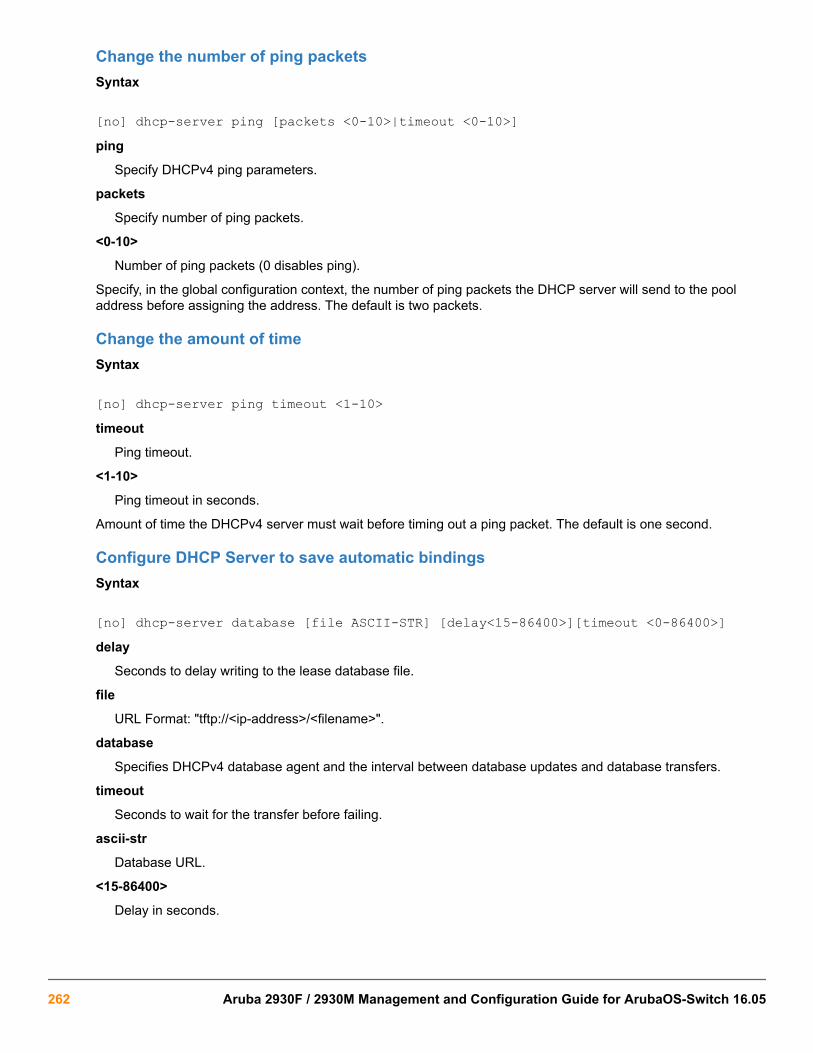
Change the number of ping packetsSyntax
[no] dhcp-server ping [packets <0-10>|timeout <0-10>]ping
Specify DHCPv4 ping parameters.
packets
Specify number of ping packets.
<0-10>
Number of ping packets (0 disables ping).
Specify, in the global configuration context, the number of ping packets the DHCP server will send to the pooladdress before assigning the address. The default is two packets.
Change the amount of timeSyntax
[no] dhcp-server ping timeout <1-10>timeout
Ping timeout.
<1-10>
Ping timeout in seconds.
Amount of time the DHCPv4 server must wait before timing out a ping packet. The default is one second.
Configure DHCP Server to save automatic bindingsSyntax
[no] dhcp-server database [file ASCII-STR] [delay<15-86400>][timeout <0-86400>]delay
Seconds to delay writing to the lease database file.
file
URL Format: "tftp://<ip-address>/<filename>".
database
Specifies DHCPv4 database agent and the interval between database updates and database transfers.
timeout
Seconds to wait for the transfer before failing.
ascii-str
Database URL.
<15-86400>
Delay in seconds.
262 Aruba 2930F / 2930M Management and Configuration Guide for ArubaOS-Switch 16.05

<0-86400>
Timeout in seconds.
Specifies DHCPv4 database agent and the interval between database updates and database transfers.
Configure a DHCP server to send SNMP notificationsSyntax
[no] snmp-server enable traps dhcp-serverdhcp-server
Traps for DHCP-Server.
Configure a DHCP server to send SNMP notifications to the SNMP entity. This command enables or disablesevent traps sent by the switch.
Enable conflict logging on a DHCP serverSyntax
[no] dhcp-server conflict-loggingconflict-logging
Enable DHCPv4 server address conflict logging.
Enable conflict logging on a DHCP server. Default is disabled.
Enable the DHCP server on a VLANSyntax
[no] dhcp-serverdhcp-server
Enable DHCPv4 server on a VLAN (VLAN context command).
Enable DHCPv4 server on a VLAN. DHCPv4 client or DHCPv4 relay cannot co-exist with DHCPv4 server on aVLAN.
Clear commandsSyntax
clear dhcp-server conflicts [ip-addr]dhcp-server
Clears theDHCPv4 server information.
ip-addr
Specify the IP address whose conflict is to be cleared.
Reset DHCPv4 server conflicts database. If IP address is specified, reset only that conflict.
Chapter 10 Configuring for Network Management Applications 263

Reset all DHCP server and BOOTP countersSyntax
clear dhcp-server statisticsstatistics
Reset DHCPv4 server and BOOTP counters.
Reset all DHCP server and BOOTP counters
Delete an automatic address bindingSyntax
clear dhcp-server binding ip-addrbinding
Reset DHCPv4 server automatic address bindings.
ip-addr
Specify IP address of the binding is to be cleared.
Delete an automatic address binding from the DHCP server database.
Show commands
Display the DHCPv4 server address bindingsSyntax
show dhcp-server bindingdhcp-server
Show DHCPv4 server global configuration information for the device.
binding
Show DHCPv4 server IP binding information for the device.
Display the DHCPv4 server address bindings on the device.
Display address conflictsSyntax
show dhcp-server conflictsconflicts
Show DHCPv4 server conflicts information for the device.
Display address conflicts found by a DHCPv4 server when addresses are offered by a client.
Display DHCPv4 server database agentSyntax
show dhcp-server database
264 Aruba 2930F / 2930M Management and Configuration Guide for ArubaOS-Switch 16.05

Database
Show DHCPv4 server database information for the device.
Display DHCPv4 server database agent information.
Display DHCPv4 server statisticsSyntax
show dhcp-server statisticsstatistics
Show DHCPv4 server statistics information for the device.
Display DHCPv4 server statistics.
Display the DHCPv4 server IP pool informationSyntax
show dhcp-server pool <pool-name>Pool
Show DHCPv4 server pool information for the device.
Display the DHCPv4 server IP pool information.
Display DHCPv4 server global configuration informationSyntax
show dhcp-serverdhcp-server
Show DHCPv4 server global configuration information for the device.
Display DHCPv4 server global configuration information.
Event log
Chapter 10 Configuring for Network Management Applications 265

Event Log Messages
Table 21: Event Log Messages
Events Debug messages
DHCP server is enabled globally. DHCP server is enabled globally.
DHCP server is enabled globally.Warnings -One or more incomplete pool configurationsare found during the server startup. Adynamic pool is considered invalid, ifnetwork IP or subnet mask is not configured.A static pool is considered incomplete, ifnetwork IP, subnet mask or MAC address isnot configured.
DHCP server is enabled globally.Warning -One ormore incomplete pool configurations are foundduring the server startup.
DHCP server failed to start. The reason forfailure is printed as the argument.
DHCP server failed to start: %s "with a manualbinding.
DHCP server is disabled globally. DHCP server is disabled globally.
The DHCP server configurations are deleted. The DHCP server configurations are deleted
Decline from client when server assigns anillegal Ipv6 address.
%s: Decline offer from %x (server) of %x becausethe address is illegal.
DHCP server is enabled on a specific VLAN. DHCP server is enabled on VLAN %d
DHCP server is disabled on a specific VLAN. DHCP server is disabled on VLAN %d
Ping check is enabled and configured withspecified retry count and timeout values
Ping-check configured with retry count = %d,timeout = %d
Ping check is disabled Ping-check is disabled
Conflict-logging is enabled Conflict-logging is enabled
Conflict-logging is disabled. Conflict-logging is disabled.
A specific IP address is removed from theconflict logging database.
IP address %s is removed from the conflict-logging database.
All IP addresses are removed from theconflict-logging database.
All IP addresses are removed from the conflict-logging database
Dynamic binding for a specific IP address isfreed.
Dynamic binding for IP address %s is freed
All the dynamic IP bindings are freed. All the dynamic IP bindings are freed
Table Continued
266 Aruba 2930F / 2930M Management and Configuration Guide for ArubaOS-Switch 16.05
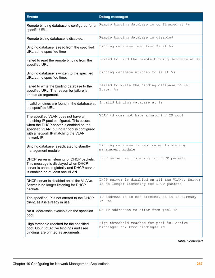
Events Debug messages
Remote binding database is configured for aspecific URL.
Remote binding database is configured at %s
Remote biding database is disabled. Remote binding database is disabled
Binding database is read from the specifiedURL at the specified time
Binding database read from %s at %s
Failed to read the remote binding from thespecified URL.
Failed to read the remote binding database at %s
Binding database is written to the specifiedURL at the specified time.
Binding database written to %s at %s
Failed to write the binding database to thespecified URL. The reason for failure isprinted as argument.
Failed to write the binding database to %s.Error: %s
Invalid bindings are found in the database atthe specified URL.
Invalid binding database at %s
The specified VLAN does not have amatching IP pool configured. This occurswhen the DHCP-server is enabled on thespecified VLAN, but no IP pool is configuredwith a network IP matching the VLANnetwork IP.
VLAN %d does not have a matching IP pool
Binding database is replicated to standbymanagement module.
Binding database is replicated to standbymanagement module
DHCP server is listening for DHCP packets.This message is displayed when DHCPserver is enabled globally and DHCP serveris enabled on at-least one VLAN.
DHCP server is listening for DHCP packets
DHCP server is disabled on all the VLANs.Server is no longer listening for DHCPpackets.
DHCP server is disabled on all the VLANs. Serveris no longer listening for DHCP packets
The specified IP is not offered to the DHCPclient, as it is already in use.
IP address %s is not offered, as it is alreadyin use
No IP addresses available on the specifiedpool.
No IP addresses to offer from pool %s
High threshold reached for the specifiedpool. Count of Active bindings and Freebindings are printed as arguments.
High threshold reached for pool %s. Activebindings: %d, Free bindings: %d
Table Continued
Chapter 10 Configuring for Network Management Applications 267

Events Debug messages
Low threshold reached for the specified pool.Count of Active bindings and Free bindingsare printed as arguments.
Low threshold reached for pool %s. Activebindings: %d, Free bindings: %d
No active VLAN with an IP address isavailable to read binding database from theconfigured URL.
No active Vlan with an IP address available toread binding database
LLDP Management TLV Transmission disablementOverviewA command has been written to suppress the IPv4 / IPv6 management address transmission in outgoing LLDPpackets.
A local LAN device transmits organization-specific information in the form of type, length, and value (TLV). Theorganization-associated values are stored in the LLDP organizationally defined local device LLDP MIBextensions. Management address TLV in IPv4 and IPv6 environments is optional from the TLV basic managementset.
TLV basic management set
• Port description TLV — Describes the port in an alpha-numeric format. The value equals the ifDescr object,if the LAN device supports RFC 2863.
• System name TLV — Assigns the system name in an alpha-numeric format. The value equals the sysNameobject, if the LAN device supports RFC 3418.
• System description TLV — Describes the network entity in an alpha-numeric format. The system descriptionTLV includes the system name, versions of hardware, operating system, and networking software supported inthe device. The value equals the sysDescr object, if the LAN device supports RFC 3418.
• System capabilities TLV — Indicates primary functions of the device and if they are enabled in the device.
• Management address TLV — Indicates the addresses of the local LLDP agent. Other remote managers canuse this address to obtain information related to the local device.
The command lldp config <all> ipAddrEnable <IP_ADDR> is used to advertise specific IP addressthrough the port.
The command [no] lldp config <PORT NO> basicTlvEnable management_addr suppresses the IPaddress to be advertised.
Commands
[no] lldp config basicTlvEnable management_addrSyntax
In the configure context:
[no] lldp config <PORT_NUM> basicTlvEnable management_addr Description
268 Aruba 2930F / 2930M Management and Configuration Guide for ArubaOS-Switch 16.05

The feature suppresses the IPv4 or IPv6 address as well as suppresses the MAC address if the [no] ipaddress is configured. By default this management address TLV is enabled in switch. No other TLV (exceptmanagement address TLV) suppression will occur when this command is used.
Parameters
Management_addr
Management TLV
Example
[no] lldp config all basicTlvEnable management_addr
lldp configSyntaxlldp config <port-number> Description
Configure the lldp for the desired port by number.
ParameterbasicTlvEnable
Enables the basic advertised TLV for each port by number.
Options
<management_addr>
Use the option <management_addr> to specify specific devices to enable TLV advertisement.
Usagelldp config <port_num> basicTlvEnable <management_addr>
Show commandsUse the command show running-config to view the lldp configuration.
Example
switch# show running-config
Running configuration:...no lldp config 1 basicTlvEnable management_addrExample
switch# show lldp config 1
LLDP Port Configuration Detail
Port : 1 AdminStatus [Tx_Rx] : Tx_Rx NotificationEnabled [False] : False Med Topology Trap Enabled [False] : False TLVS Advertised:
Chapter 10 Configuring for Network Management Applications 269

* management_addr IpAddress Advertised:
270 Aruba 2930F / 2930M Management and Configuration Guide for ArubaOS-Switch 16.05
The Captive Portal feature allows the support of the ClearPass Policy Manager (CPPM) into the ArubaOS-Switchproduct line. The switch provides configuration to allow you to enable or disable the Captive Portal feature. Bydefault, Captive Portal is disabled to avoid impacting existing installations as this feature is mutually exclusive withthe following web-based authentication mechanisms: Web Authentication, EWA, MAFR, and BYOD Redirect.
Captive Portal is user-based, rather than port or VLAN-based, therefore the configuration is on a switch globalbasis. ArubaOS-Switch supports the following authentication types on the switch with RADIUS for Captive Portal:
• Media Access Control (MAC)
• 802.1X
Once you enable Captive Portal, the redirect functionality is triggered only if a redirect URL attribute is providedas part of the RADIUS Access-Accept response from an authentication request of type 802.1X or MAC. Theredirect enables the client to self-register or directly login with valid credentials via the CPPM. Upon subsequentre-authentication, it provides access to the network per the CPPM configured policies that are communicated viathe RADIUS attributes.
The redirect feature offers:
• Client self-registration
• Client direct login with valid credentials via CPPM Captive Portal
• On-boarding
• Ability to quarantine devices to remedy their status
RequirementsHTTPS support requires a certificate to be configured on the switch with a usage type of all or captive-portal.
Best Practices• Use the Port Bounce VSA via a CoA message, instead of the Disconnect message, to cause the second
RADIUS authentication to occur during the Captive Portal exchange. This is the more reliable method forforcing a re-DHCP for the client.
• Configure Captive Portal such that the first ACCESS_ACCEPT returns a rate limit VSA to reduce the risk of DoSattacks. This configuration enables rate limiting for the HTTP/HTTPS ACL for traffic sent to CPPM.
• Do not use the keyword cpy in any other NAS-Filter-Rules. The keyword cpy in the enforcement profileattributes is specific to CPPM use. It is only supported with the deny attribute. If you configure the cpykeyword to permit, no ACL will be applied.
Chapter 11Captive Portal for ClearPass
Chapter 11 Captive Portal for ClearPass 271

Limitations• Captive Portal is supported in CPPM versions 6.5.5 and later. However, by manually modifying the RADIUS
dictionary files, any CPPM version 6.5.* can be used.
• Captive Portal does not support v1 modules, and will not work unless compatibility mode is turned off.
• Captive Portal does not support IPv6.
• Simultaneous Captive Portal client connections: maximum of 512
• Captive Portal does not support web proxy. The permit CPPM ACLs and the steal ACLs only use port 80 and443. Non-standard ports for HTTP and HTTPS are not supported.
• Captive Portal is mutually exclusive with the following web-based authentication mechanisms: WebAuthentication, EWA, MAFR, and BYOD.
• URL-string limitation of 253 characters.
Features
High AvailabilityCaptive Portal includes support for High Availability (HA). The Captive Portal configurations (such as enablement,authenticated clients, and redirect URLs) are replicated to standby or other members.
If the feature is enabled and a failover occurs, clients in the process of onboarding are still redirected to CaptivePortal, and authenticated clients continue to have the same access to the network.
Clients that are in the process of authenticating via MAC or 802.1X authentication will not be replicated to thestandby. Replication of client data is only done when MAC or 802.1X authentication has resulted in a successfulauthentication.
Load balancing and redundancyThe following options are available to create load balancing and provide redundancy for CPPM:
• Virtual IP use for a CPPM server cluster
• CPPM servers configured in the switch RADIUS server group
• External load balancer
Captive Portal when disabledBy default, Captive Portal is disabled. If the Captive Portal feature is disabled and the switch receives a redirectURL attribute from the RADIUS server as part of the Access-Accept, it will view the redirect as an error. Theauthentication success will be overridden, the session will be flushed, and the switch will send the AccountingStart and Accounting Stop messages to indicate the client is no longer authenticated.
The Captive Portal feature may be disabled while there are in flight authentication requests. These areauthentication sessions that have not finished the final authentication with the switch. The switch flushes allsessions with a redirect URL associated with them when Captive Portal is disabled.
Fully authenticated sessions are not impacted when Captive Portal is disabled. If CPPM deems these sessions tobe invalid, a RADIUS Disconnect can be sent to flush all these sessions.
272 Aruba 2930F / 2930M Management and Configuration Guide for ArubaOS-Switch 16.05

Disabling Captive PortalTo disable Captive Portal, enter one of the following:
switch(config)# aaa authentication captive-portal disable
switch(config)# no aaa authentication captive-portal enable
Configuring Captive Portal on CPPMProcedure
1. Importing the HP RADIUS dictionary
2. Creating enforcement profiles
3. Creating a ClearPass guest self-registration
4. Configuring the login delay
Import the HP RADIUS dictionaryFor CPPM versions 6.5.*, you must update the HP RADIUS dictionary. To import the dictionary in CPPM, followthese steps:
Procedure
1. Go to Administration -> Dictionaries -> RADIUS and click Import.
2. Select the XML HP RADIUS Dictionary from your Hard Drive.
3. Click Import.
Create enforcement profiles
Create the HPE Bounce Host-Port profile and the Guest Login profile only if they do not alreadyexist.
For the HPE Bounce Host-Port profile, configure Captive Portal so that the RADIUS CoA message that includesthe Port Bounce VSA is sent to force the second RADIUS re-authentication after the user registers their deviceand makes it known.
Procedure
1. In CPPM, go to Configuration -> Enforcement -> Profiles
2. Click Add.
3. Enter the Profile Name: HPE Bounce Host-Port
4. Enter the Description: Custom-defined profile to bounce host port (HPE).
5. Select the type RADIUS_CoA.
6. Select the action CoA.
Chapter 11 Captive Portal for ClearPass 273

7. Add all of the attributes required for a CoA message, and specify the port bounce duration (valid values arebetween 0 and 60). This is the amount of time in seconds the port will be held in the down state. Therecommended setting is 12 seconds.
8. Repeat Step 2 to Step 6 to configure the Guest Login profile that will be sent as part of the first RADIUSAccess-Accept and enforce the redirect to the Captive Portal on CPPM. For this profile, select RADIUS as thetype and Accept as the action.
9. Add all of the NAS-Filter-Rule attributes specified below, replacing the IP address in the first two NAS-Filter-Rule attributes with your CPPM address. Add the HPE-Captive-Portal-URL attribute to specify the redirectURL, replacing the IP address with your CPPM address. This will cause the client to be redirected to theCaptive Portal on CPPM. You can add other attributes, such as a VLAN to isolate onboarding clients, or a ratelimit to help prevent DoS attacks.
The HPE-Captive-Portal-URL value must be a URL normalized string. The scheme and hostmust be in lower case, for example http://www.example.com/.
274 Aruba 2930F / 2930M Management and Configuration Guide for ArubaOS-Switch 16.05

Create a ClearPass guest self-registration
Procedure
1. From the Customize Guest Registration window, select Server-initiated as the Login Method.
2. Optionally, under Security Hash, select the level of checking to apply to the redirect URL.
Configure the login delayEnter the Login Delay value. The value must be greater than the HPE-Port-Bounce-Host attribute. In thisexample, we set the login delay value to 20 seconds.
Configuring the switchOnce you have configured Captive Portal, you can configure the switch. To configure the switch, you must firstconfigure the switch as a RADIUS client, then configure the ports that will be used for Captive Portal, as follows:
Procedure
1. Configure the switch as a RADIUS client. In this example, the CPPM IP address is 10.73.4.136 andsecret is the secret key shared with the RADIUS server:
Chapter 11 Captive Portal for ClearPass 275

a. switch(config)# radius-server host 10.73.4.136 key "secret"b. switch(config)# radius-server host 10.73.4.136 dyn-authorizationc. switch(config)# radius-server host 10.73.4.136 time-window 0
Make sure to set your time-window to 0. See Event Timestamp not working.
2. Configure the ports that will be used for Captive Portal. In this example, the commands enable ports B3-B5 forMAC Authentication:
a. switch(config)# aaa authentication port-access chap-radiusb. switch(config)# aaa port-access mac-based B3-B5
3. If you configured the Security Hash to Deny login on validation error in Create a ClearPassguest self-registration on page 275, configure the URL key.
See Configure the URL key on page 276.
4. Configure the certificate. See Configuring a certificate for Captive Portal usage on page 277
5. Enable Captive portal:
switch(config)# aaa authentication captive-portal enable
By default, Captive Portal is disabled. Once enabled, you are redirected to the URL supplied via the HPE-Captive-Portal-URL VSA. Captive Portal is enabled on a global/switch wide basis.
Configure the URL keyYou can optionally configure a URL hash key to provide some security for the Captive Portal exchange withCPPM. The key is a shared secret between CPPM and the switch. When configured, the switch generates aHMAC-SHA1 hash of the entire redirect URL, and appends the hash to the URL to be sent to CPPM as part of theHTTP redirect. If CPPM is configured to check the hash, it will generate the hash of the URL using its version ofthe URL hash key and compare against the value provided by the switch. The action taken by CPPM upon amatch or mismatch is determined by what is configured on CPPM.
CPPM provides the following options:
• Do not check - login will always be permitted
• Deny login on validation error - login will not be permitted
The URL hash key is globally configured and will be used for all redirects to Captive Portal. This key is notconfigured on a per CPPM or RADIUS server basis. If the key is not specified, the hash is not added to the URL.The URL hash key is an ASCII string with a maximum length of 64 characters.
The URL key supports the FIPS certification feature encrypt-credentials and can optionally be encrypted for morerobust security. This option is only available when the global encrypt-credentials is enabled.
To configure a plain text captive-portal URL key:
switch(config)# aaa authentication captive-portal url-hash-key plaintext <KEY>
276 Aruba 2930F / 2930M Management and Configuration Guide for ArubaOS-Switch 16.05

To configure an encrypted captive-portal URL key when encrypt-credentials is enabled:
switch(config)# aaa authentication captive-portal url-hash-key encrypted <ENCRYPTED-KEY> To clear a captive-portal URL key:
switch(config)# no aaa authentication captive-portal url-hash-key
Configuring a certificate for Captive Portal usageHTTPS support requires the use of a certificate. If a certificate for Captive Portal does not exist, the certificatedesignated for all use is used instead.
To create a certificate signing request for Captive Portal, enter:
switch(config)# crypto pki create-csr certificate-name <cert-name> usage captive-portal To create a self-signed certificate for Captive Portal, enter:
switch(config)# crypto pki enroll-self-signed certificate-name
Display Captive Portal configurationTo display the Captive Portal configuration settings, enter the show captive-portal command:
switch(config)# show captive-portal
Captive Portal Configuration Redirection Enabled : Yes URL Hash Key Configured : No
Show certificate informationTo view the certificate information, enter:
switch(config)# show crypto pki local-certificate Name Usage Expiration Parent / Profile
-------------------- --------------- -------------- --------------------
cp Captive Portal 2016/08/14 default
TroubleshootingEvent Timestamp not working
Symptom
The client gets a credentials request on the web browser even though the valid credentials were already provided,or the client is not redirected to the Captive Portal.
Chapter 11 Captive Portal for ClearPass 277

Cause
• ClearPass 6.5.x does not support the sending of Event Timestamp in automated workflows (manual viaAccess Tracker works).
• The switch will reject CoA requests when the time on CPPM is ahead of the switch time by even a second.
Action
Set the time-window security feature in PVOS to 0:
radius-server host<CLEARPASS-IP> time-window 0
Cannot enable Captive Portal
Symptom
When running the aaa authentication captive-portal enable command, getting the following errormessage:
Captive portal cannot be enabled when BYOD redirect, MAC authentication failure redirect, or web-based authentication are enabled.
Cause
The failure is due to a mutual exclusion restriction.
Action
1. Check which one of the following are enabled: BYOD redirect, MAC authentication failure redirect, or web-based authentication.
2. Disabled the enabled authentication method found in step 1.
3. Run the aaa authentication captive-portal enable command.
Unable to enable feature
Symptom
One of the following messages is displayed:
• BYOD redirect cannot be enabled when captive portal is enabled.• MAC authentication failure redirect cannot be enabled when captive
portal is enabled.• Web-based authentication cannot be enabled when captive portal
is enabled.• V1 compatibility mode cannot be enabled when captive portal
is enabled.
Cause
You cannot enable these features when Captive Portal is already enabled. They are mutually exclusive.
278 Aruba 2930F / 2930M Management and Configuration Guide for ArubaOS-Switch 16.05

Action
You can either disable Captive Portal or avoid enabling these features.
Authenticated user redirected to login page
Symptom
User is redirected back to the login page to submit credentials even after getting fully authenticated.
Solution 1
Cause
The status is not changed to Known.
Action
After the client submits the credentials, the CPPM service must change the Endpoint Status to Known.
Solution 2
Cause
The cache value is set.
Action
Clear the CPPM Cache Timeout of the Endpoint Repository.
Unable to configure a URL hash key
Symptom
The following message is displayed:
Key exceeds the maximum length of 64 characters.
Cause
The URL hash key is not valid.
Action
Select a key that is 64 or less ASCII text. For example:
switch(config)# aaa authentication captive-portal url-hash-key plaintext“8011A89FEAE0234BCCA”
authentication commandUse the following authentication commands to configure ClearPass Captive Portal.
Chapter 11 Captive Portal for ClearPass 279

Command Description
aaa authentication captive-portal enable Enables redirection to a Captive Portal server foradditional client authentication.
aaa authentication captive-portaldisableor
no aaa authentication captive-portalenable
Disables redirection to a Captive Portal server foradditional client authentication.
aaa authentication captive-portal url-hash-key
Configures a hash key used to verify the integrity of theportal URL.
show commandUse the following show commands to view the various configurations and certificates.
Command Description
show running-config Shows the running configuration.
show config Shows the saved configuration.
show ip Shows the switch IP addresses.
show captive-portal Captive portal configuration.
show port-access clients [port][detailed]
Consolidated client view; the detailed option showsthe Access Policy that is applied. The IP address isonly displayed if dhcp-snooping is enabled.
For the summary view (without the detailed option),only the untagged VLAN is displayed.
show radius authentication Displays NAS identifier and data on the configuredRADIUS server and switch interactions with this server.
show radius dyn-authorization Statistics for Radius CoA and Disconnect.
show radius accounting Statistics for Radius accounting.
show crypto pki local-certificate[summary]
Installed certificates.
Debug commandUse the debug command to help you debug your issues.
280 Aruba 2930F / 2930M Management and Configuration Guide for ArubaOS-Switch 16.05
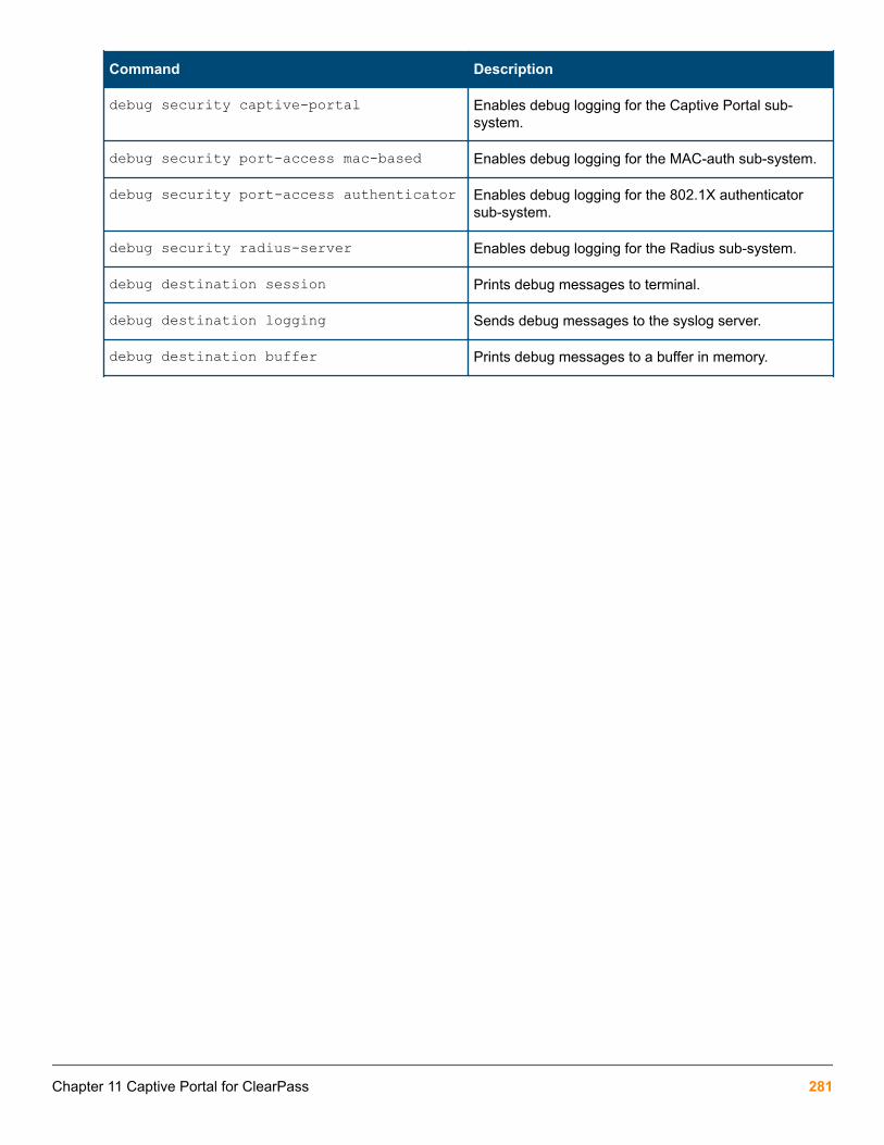
Command Description
debug security captive-portal Enables debug logging for the Captive Portal sub-system.
debug security port-access mac-based Enables debug logging for the MAC-auth sub-system.
debug security port-access authenticator Enables debug logging for the 802.1X authenticatorsub-system.
debug security radius-server Enables debug logging for the Radius sub-system.
debug destination session Prints debug messages to terminal.
debug destination logging Sends debug messages to the syslog server.
debug destination buffer Prints debug messages to a buffer in memory.
Chapter 11 Captive Portal for ClearPass 281

AirWave is a Network Management Solution (NMS) tool. Once connected to AirWave using the WebUI and CLIinterfaces, you can:
• Configure your switches using Zero Touch Provisioning (ZTP)
• Configure your switches using the CLI
• Troubleshoot your switches
• Monitor your switches
• Upgrade your firmware for your switches
Once you have configured your switch, you can monitor, manage, and upgrade your hardware using the AirWaveManagement Platform.
Requirements• DHCP server
• AirWave NMS
• HPE Aruba switches
Best Practices• Implement ZTP in a secure and private environment. Any public access may compromise the security of the
switch, as follows:
◦ ZTP is enabled only on the factory default configuration of the switch. DHCP snooping is not enabled. Youmust manage the Rogue DHCP server.
◦ The DHCP offer is in plain data without encryption. Therefore, the offer can be listened by any device onthe network and they can in turn obtain the AirWave information.
◦ The TLS certificate of the server is not validated by the switch during the HTTPs check-in to AirWave. TheAirWave server is in the private environment of the switch.
Limitations• The DNS/hostname in option 66 is not supported, only the IPv4 address.
• The switch does not validate peer certificate of the AirWave server as part of the TLS handshake.
Chapter 12ZTP with AirWave Network Management
282 Aruba 2930F / 2930M Management and Configuration Guide for ArubaOS-Switch 16.05

• The HTTPS check-in to AirWave does not support HTTPS proxy.
• For non-ZTP cases, the AirWave check-in starts by validating the following condition: Primary or ManagementVLAN must be configured with the IP address and one of the interface must be UP. By default, VLAN 1 is theprimary VLAN.
Switch configurationTo configure your switch, follow these steps:
1. Configure AirWave details in DHCP (preferred method) on page 283.
If you are using existing HPE switches and using the DHCP server for the configuration orfirmware management, you can configure the AirWave details in DHCP using this method: Configure AirWave details in DHCP (alternate method) on page 288
2. If you are configuring the switch using a CLI, see Configure a switch using the CLI on page 297.
If you are using ZTP, the configuration is automatic and does not require any user interaction, see Zero TouchProvisioning
The switch contacts the AirWave server that is configured on the switch and initiates the check-in process.
Once you have configured the DHCP server, the AirWave details received from the DHCP options are stored inthe switch configuration. This assures that the configuration is retained across reboots.
Once AirWave completes the switch check-in, it lists the first switch as New Devices. The first switch is used tocreate a new configuration template for the specific group and device type. With this new template, the requiredconfiguration is generated for the group. Subsequent switch of the specific type and joining the same group as thefirst device are added directly to the group and the configuration is pushed using the configuration template via aSSH connection.
Configure AirWave details in DHCP (preferred method)To configure a DHCP server for AirWave, from a Windows Server 2008, do the following steps:
Procedure
1. From the Start menu, select Server Manager.
Chapter 12 ZTP with AirWave Network Management 283

2. Select Roles -> DHCP -> Server -> w2k8 -> IPv4.
3. Right click on IPv4 and select Set Predefined Options...
284 Aruba 2930F / 2930M Management and Configuration Guide for ArubaOS-Switch 16.05

4. The Predefined Options and Values screen is displayed. Click Add....
5. Enter the desired Name (any), Data type (select String), Code (enter 60), and Description (any).
Chapter 12 ZTP with AirWave Network Management 285

6. Click OK.
7. From the Predefined Options and Values screen, under Value, enter the String ArubaInstantAP. The stringis case sensitive and must be ArubaInstantAP.
8. Click OK.
9. Under IPv4, expand Scope. Right click on Scope Options and select Configure Options...
286 Aruba 2930F / 2930M Management and Configuration Guide for ArubaOS-Switch 16.05

10. Under the General tab, select 043 Vendor Specific Info. The Data entry data appears. Under ASCII, enterhpeSwitch:hp2920,90.1.1.10,admin. The ASCII value has the following format:<Group>:<Topfolder>,<AMP IP>,<shared secret>If you need to add sub-folders, use the following format:
<Group>:<Topfolder>:<folder1>,<AMP IP>,<shared secret>11.
12. Under the General tab, select 060 Airwave. Click OK.
Chapter 12 ZTP with AirWave Network Management 287

No changes are required to the 060 option.
13. You can verify the AirWave details as follows:
switch# show amp-serverswitch# show run
Configure AirWave details in DHCP (alternate method)To configure a DHCP server for ZTP and AirWave, from a Windows Server 2008, do the following steps:
You must repeat these steps for every type of switch that needs to be configured for ZTP, selecting adifferent Vendor Class for each type of switch.
Procedure
1. From the Start menu, select Server Manager.
288 Aruba 2930F / 2930M Management and Configuration Guide for ArubaOS-Switch 16.05

2. Select Roles -> DHCP -> Server -> w2k8 -> IPv4.
3. Right click on IPv4 and select Define Vendor Classes...
Chapter 12 ZTP with AirWave Network Management 289

4. The DHCP Vendor Classes window is displayed. Click Add....
5. To get the vendor-specific value of a switch, go to the switch console and enter:
switch# show dhcp client vendor-specific In our example, the command returns the following value:
Vendor Class Id = HP J9729A 2920-24G-PoE+ Switch dslforum.org
290 Aruba 2930F / 2930M Management and Configuration Guide for ArubaOS-Switch 16.05

Processing of Vendor Specific Configuration is enabled
6. From the New Class window, enter the desired Display name (any) and the Description (any). For theASCII field, enter the exact value that you got by executing the show command performed in the previousstep. In this example, HP J9729A 2920-24G-PoE+ Switch dslforum.org.
7. Click OK.
8. Right click on IPv4 and select Set Predefined Options....
Chapter 12 ZTP with AirWave Network Management 291

9. From the Predefined Options and Values window, select Option class. The Option Class displayed is theone that you configured under DHCP Vendor Class. In this example, the Option Class is switch.
10. Click Add....
292 Aruba 2930F / 2930M Management and Configuration Guide for ArubaOS-Switch 16.05

11. From the Option Type window, enter the desired Class (any), the Data type (select string), the Code (enter146), and the Description (any).
12. Click OK.
13. Under the Predefined Options and Values window, enter the Value String. In this example, we enterhpeSwitch:hp2920,90.1.1.10,admin. The String has the following format: <Group>:<Topfolder>,<AMPIP>,<shared secret>If you need to add sub-folders, use the following format:<Group>:<Topfolder>:<folder1>,<AMPIP>,<shared secret>
Chapter 12 ZTP with AirWave Network Management 293

14. Click OK.
15. Under IPv4, expand Scope. Right click on Scope Options and select Configure Options...
16. From the Scope Options window:
a. Select the Advanced tab.
b. Under Vendor class, select the desired switch. In this example, switch.
c. Select the 146 hpswitch option.
d. Click OK.
294 Aruba 2930F / 2930M Management and Configuration Guide for ArubaOS-Switch 16.05

17. You can verify the AirWave details as follows:
switch# show amp-serverswitch# show run
Zero Touch ProvisioningThe Zero Touch Provisioning (ZTP) solution enables the auto-configuration of your switches on the first bootwithout requiring any administrator’s intervention at the switch. The switches use DHCP server optionconfigurations to support ZTP.
If the switch does not contain the minimal configuration set, ZTP will get disabled. See ImageUpgrade
Auto-configuration using ZTPZTP auto-configures your switches as follows:
Chapter 12 ZTP with AirWave Network Management 295

Procedure
1. The switch boots up with the factory default configuration.
2. The switch sends out a DHCP discovery from the primary VLAN interface.
a. The preferred configuration method uses DHCP option 43 value as a string to parse Airwave configuration.Switch would expect a DHCP option 60 with value ArubaInstantAP along with DHCP option 43 to parseAirwave details
b. The alternate configuration method supports both encapsulated values from option 43 and direct value fromoption 43. Encapsulated vendor-specific sub options, with sub-option code 146 is for Airwave details.
3. After the AirWave details are verified and configured, the switch initiates the check-in into the AirWave serverusing the HTTPS communication.
The AirWave configuration must be in the following format:
<Group>:<Topfolder>:<folder1>,<AMP IP >,<shared secret>
4. After a successful registration, AirWave can monitor, configure, and troubleshoot the switches. Refer to ArubaNetworks and AirWave Switch Configuration Guide.
5. Check-in failure retry is done every 60 seconds for 10 retries.
6. If the DHCP options are not configured for AirWave, the switch is left in its default state for manualconfiguration.
Disabling ZTPZero touch provisioning is disabled if you make any of the following changes to the switch’s configuration:
• Enter the switch configuration mode using the configure terminal command.
• Enter into Menu and exit without doing any configuration
• Make any successful configuration that changes the running-configuration of the switch using a CLI, SNMP,REST APIs, menu interface, or the web GUI.
• If you upgrade with non-minimal configuration set from any 15.xx version to version 16.01, see ImageUpgrade
Image UpgradeIf you upgrade from any 15.xx version to version 16.01, the following minimal set of configuration is validated toenable or disable the ZTP process:
• If the switch has any other VLAN apart from the default VLAN, ZTP gets disabled.
• In default VLAN, if the IPv4 address is not set as DHCP (default option is DHCP), ZTP gets disabled.
• In default VLAN, if IPv6 is enabled or configured, ZTP gets disabled.
If you have any other configuration during the upgrade, ZTP will be in the enabled state only.
296 Aruba 2930F / 2930M Management and Configuration Guide for ArubaOS-Switch 16.05

Configure a switch using the CLIUse the amp-server command to configure the AirWave IP address, group, folder, and shared secret. You musthave the manager role to execute this command.
For example:
HP switch(config)# amp-server ip 172.16.185.23 group 2530 folder 2530 secret secret The show amp-server command shows the configuration details:
switch# show amp-serverAirwave Configuration details AMP Server IP : 172.16.185.23 AMP Server Group : 2530 AMP Server Folder : 2530 AMP Server Secret : secret AMP Server Config status: Configured
TroubleshootingCause
You can troubleshoot switches by using the SSH connection and the device logs available in AirWave. For a list ofall RMON message, refer to ArubaOS-Switch Event Log Message Reference Guide.
You can enable the debug logging with the debug ztp command, see debug ztp
View AMP server messagesTo display the AMP server debug messages, enter:
switch# debug ztp To print the debug messages to the terminal, enter:
switch# debug destination session
Validation Rules
Validation Error/Warning
Invalid AirWave IP address Invalid input: 300.300.300.300
Group name exceeds max length String %s too long. Allowed length is 32 characters.
Folder name exceeds max length String %s too long. Allowed length is 128 characters.
Secret name exceeds max length String %s too long. Allowed length is 32 characters.
AirWave IP address or Group or folder or secret is notconfigured.
Incomplete input: amp-server
Chapter 12 ZTP with AirWave Network Management 297
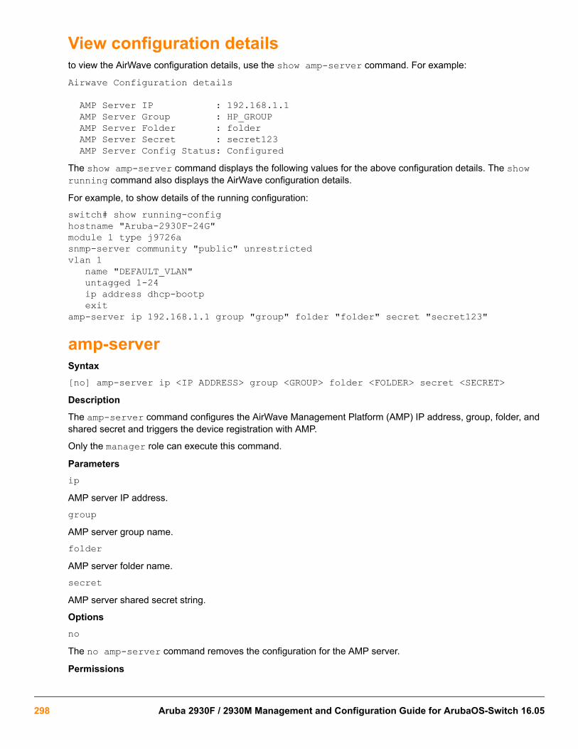
View configuration detailsto view the AirWave configuration details, use the show amp-server command. For example:
Airwave Configuration details
AMP Server IP : 192.168.1.1 AMP Server Group : HP_GROUP AMP Server Folder : folder AMP Server Secret : secret123 AMP Server Config Status: ConfiguredThe show amp-server command displays the following values for the above configuration details. The showrunning command also displays the AirWave configuration details.
For example, to show details of the running configuration:
switch# show running-confighostname "Aruba-2930F-24G"module 1 type j9726asnmp-server community "public" unrestrictedvlan 1 name "DEFAULT_VLAN" untagged 1-24 ip address dhcp-bootp exitamp-server ip 192.168.1.1 group "group" folder "folder" secret "secret123"
amp-serverSyntax[no] amp-server ip <IP ADDRESS> group <GROUP> folder <FOLDER> secret <SECRET>Description
The amp-server command configures the AirWave Management Platform (AMP) IP address, group, folder, andshared secret and triggers the device registration with AMP.
Only the manager role can execute this command.
ParametersipAMP server IP address.
groupAMP server group name.
folderAMP server folder name.
secretAMP server shared secret string.
OptionsnoThe no amp-server command removes the configuration for the AMP server.
Permissions
298 Aruba 2930F / 2930M Management and Configuration Guide for ArubaOS-Switch 16.05

Only the manager role can execute this command.
debug ztpSyntax[no] debug ztpDescription
Enables or disables ZTP debug logging.
ParametersztpZero Touch Provisioning.
OptionsnoThe no debug ztp command disables the ZTP debug logging.
Chapter 12 ZTP with AirWave Network Management 299
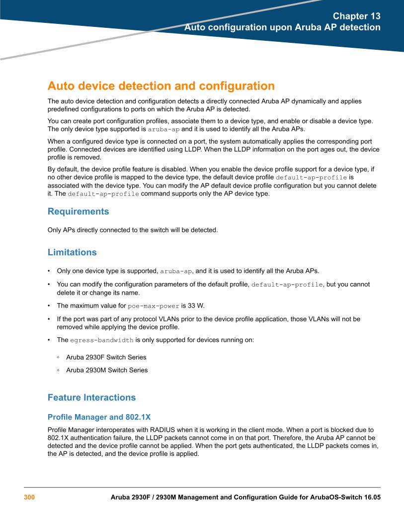
Auto device detection and configurationThe auto device detection and configuration detects a directly connected Aruba AP dynamically and appliespredefined configurations to ports on which the Aruba AP is detected.
You can create port configuration profiles, associate them to a device type, and enable or disable a device type.The only device type supported is aruba-ap and it is used to identify all the Aruba APs.
When a configured device type is connected on a port, the system automatically applies the corresponding portprofile. Connected devices are identified using LLDP. When the LLDP information on the port ages out, the deviceprofile is removed.
By default, the device profile feature is disabled. When you enable the device profile support for a device type, ifno other device profile is mapped to the device type, the default device profile default-ap-profile isassociated with the device type. You can modify the AP default device profile configuration but you cannot deleteit. The default-ap-profile command supports only the AP device type.
Requirements
Only APs directly connected to the switch will be detected.
Limitations
• Only one device type is supported, aruba-ap, and it is used to identify all the Aruba APs.
• You can modify the configuration parameters of the default profile, default-ap-profile, but you cannotdelete it or change its name.
• The maximum value for poe-max-power is 33 W.
• If the port was part of any protocol VLANs prior to the device profile application, those VLANs will not beremoved while applying the device profile.
• The egress-bandwidth is only supported for devices running on:
◦ Aruba 2930F Switch Series
◦ Aruba 2930M Switch Series
Feature Interactions
Profile Manager and 802.1XProfile Manager interoperates with RADIUS when it is working in the client mode. When a port is blocked due to802.1X authentication failure, the LLDP packets cannot come in on that port. Therefore, the Aruba AP cannot bedetected and the device profile cannot be applied. When the port gets authenticated, the LLDP packets comes in,the AP is detected, and the device profile is applied.
Chapter 13Auto configuration upon Aruba AP detection
300 Aruba 2930F / 2930M Management and Configuration Guide for ArubaOS-Switch 16.05

You must ensure that the RADIUS server will not supply additional configuration such as VLAN or CoS during the802.1X authentication as they will conflict with the configuration applied by the Profile Manager. If the RADIUSserver supplies any such configurations to a port, the device profile will not be applied on such ports.
Profile Manager and LMA/WMA/MAC-AUTHIf either LMA, WMA, or MAC-AUTH is enabled on an interface, all the MAC addresses reaching the port must beauthenticated. If LMA, WMA, or MAC-AUTH is configured on an interface, the user can have more granularcontrol and does not need the device profile configuration. Therefore, the device profile will not be applied onsuch interface.
Profile manager and Private VLANsWhen the device profile is applied, a check is performed to verify if the VLAN addition violates any PVLANrequirements. The following PVLAN related checks are done before applying the VLANs configured in the deviceprofile to an interface:
• A port can be a member of only one VLAN from a given PVLAN instance.
• A promiscuous port cannot be a member of a secondary VLAN.
Procedure for creating a device identity and associating a device type
Procedure
1. Create a device identity using the command:
switch# device-identity name <DEVICE-NAME>
2. Specify the OUI used in LLDP's organization using specific TLV, (type =127). OUI should be in XXXXXXformat. The default OUI "000000" indicates that device-identity will not use LLDP to identify device:
switch(config)# device-identity name <DEVICE-NAME> lldp oui <MAC_OUI> sub-type <SUBTYPE>
To add new device on switch:
switch(config)# device-identity name abc lldp oui a1b2c3 sub 2To remove device from switch:
switch(config)# no device-identity name abc3. Show device identity configuration:
switch(config)# show device-identity lldp
Device Identity Configuration
Index Device name Oui Subtype ------ ---------------------- ---------- ------- 1 abc a1b2c3 2
device-profile nameSyntax
Chapter 13 Auto configuration upon Aruba AP detection 301

[no] device-profile name <PROFILE-NAME> [untagged-vlan <VLAN-ID> | tagged-vlan <VLAN-LIST> | cos <COS-VALUE> | ingress-bandwidth <Percentage> | egress-bandwidth <Percentage> | {poe-priority {critical | high | low} | speed-duplex {auto | auto-10 | auto-100 | ...} | poe-max-power <Watts>]Description
This command is used to create an user-defined profile. A profile is a named collection of port settings applied asa group. You can modify the default profile, default-ap-profile, but you cannot delete it. You can create fouradditional profiles.
The default-ap-profile has the following values:
• untagged-vlan: 1
• tagged-vlan: None
• ingress-bandwidth: 100
• egress-bandwidth: 100
• cos: 0
• speed-duplex: auto
• poe-max-power: 33
• poe-priority: critical
You can modify these parameters. For example, you can execute no untagged-vlan to create a device profilewith tagged only ports.
ParametersnameSpecifies the name of the profile to be configured. The profile names can be at most 32 characters long.
cosThe Class of Service (CoS) priority for traffic from the device.
untagged-vlanThe port is an untagged member of specified VLAN.
tagged-vlanThe port is a tagged member of the specified VLANs.
ingress-bandwidthThe ingress maximum bandwidth for the device port.
egress-bandwidthThe egress maximum bandwidth for the device port.
poe-priorityThe PoE priority for the device port.
speed-duplexThe speed and duplex for the device port.
302 Aruba 2930F / 2930M Management and Configuration Guide for ArubaOS-Switch 16.05

poe-max-powerThe maximum PoE power for the device port.
OptionsnoRemoves the user-defined profiles.
Restrictions
• You can modify the configuration parameters of the default profile, default-ap-profile, but you cannotdelete it or change its name.
• For Aruba 2930F and 2930M Switch Series, the maximum value for poe-max-power is 30 W. For all otherdevices, the maximum value for poe-max-power is 33 W.
• Egress rate limiting is not supported for devices running on Aruba 2930F Switch Series.
• The profile configuration is only applicable to access points.
Rogue AP IsolationThe Rogue AP Isolation feature detects and blocks any unauthorized APs in the network. You can either log orblock the rogue device. If the action requested is to log the rogue device, the MAC address of the rogue device islogged in the system logs (RMON). If the action is to block the rogue device, the traffic to and from the MACaddress of the rogue device is blocked. The MAC is also logged in the system log.
When an Aruba AP detects a rogue AP on the network, it sends out the MAC address of the AP as well as theMAC of the clients connected to the AP to the switch using the ArubaOS-Switch proprietary LLDP TLV protocol.The switch then adds a rule in its hardware table to block all the traffic originating from the rogue AP’s MACaddress.
The rogue-ap-isolation command configures the rogue AP isolation for the switch and gives the option toenable or disable the rogue AP isolation feature. The rogue-ap-isolation action command gives you theability to block the traffic to or from the rogue device or log the MAC of the rogue device. When the action is set toblock, the rogue MAC is logged as well. By default, the action is set to block.
The rogue-ap-isolation whitelist command lets you add devices detected as possible rogue APs to thewhitelist. A maximum of 128 MAC addresses are supported for the whitelist.
The clear rogue-aps command clears the detected rogue AP device MAC address.
Limitations
• You can add a maximum of 128 MAC addresses to the whitelist.
• When a MAC is already authorized by any of the port security features such as LMA, WMA, or 802.1X, theMAC is logged but you cannot block it using the rogue-ap-isolation feature. A RMON event is logged tonotify the user.
• When a MAC is already configured as an IP received MAC of a VLAN interface, the MAC is logged but youcannot block it by using the rogue-ap-isolation feature. A RMON event is logged to notify the user.
• When a MAC is already locked out via lockout-mac or locked down using the static-mac configuration,the MAC is logged but you cannot block it using the rogue-ap-isolation feature. A RMON event is loggedto notify the user.
• The number of rogue MACs supported on a switch is a function of the value of max-vlans at boot time. Sincethe resources are shared with the lockout-mac feature, the scale is dependent on how many lockout
Chapter 13 Auto configuration upon Aruba AP detection 303

addresses have been configured on the switch using the lockout-mac feature. The following table lists thescale when there are no lockout addresses configured on the switch:
Max VLAN Supported MACs
0 < VLAN <= 8 200
8 < VLAN <= 16 100
16 < VLAN <= 256 64
256 < VLAN <= 1024 16
1024 < VLAN <= 2048 8
2048 < VLAN <= 4094 4
The switch will create an RMON log entry and the rogue MAC will be ignored when the limit is reached.
If the max-vlans value is changed to a different value, the scale of rogue MACs supported willnot change until the next reboot.
Feature Interactions
MAC lockout and lockdownThe Rogue AP isolation feature uses the MAC lockout feature to block MACs in hardware. Therefore, any MACblocked with the Rogue AP isolation feature cannot be added with the lockout-mac or static-mac commandif the action type is set to block.
For example:
switch# lockout-mac 247703-7a8950 Cannot add the entry for the MAC address 247703-7a8950 because it is already blocked by rogue-ap-isolation.
switch# static-mac 247703-7a8950 vlan 1 interface 1 Cannot add the entry for the MAC address 247703-7a8950 because it is already blocked by rogue-ap-isolation. Similarly, any MAC that was added with the lockout-mac or static-mac command and that is being detectedas rogue will be logged, but not blocked in hardware as it already is set to block. If the MAC is removed fromlockout-mac or static-mac but is still in the rogue device list, it will be blocked back in hardware if the actiontype is block.
LMA/WMA/802.1X/Port-SecurityAny configuration using LMA, WMA, 802.1X, or Port-Security will not be blocked if the Rogue AP isolation featureis enabled. All these features act only when a packet with the said MAC is received on a port.
If rogue-ap-isolation blocks a MAC before it is configured to be authorized, packets from such MACs will bedropped until one of the following happens:
304 Aruba 2930F / 2930M Management and Configuration Guide for ArubaOS-Switch 16.05

• Rogue action is changed to LOG.
• Rogue-AP isolation feature is disabled.
• The MAC is not detected as rogue anymore.
• LLDP is disabled on the port (or globally).
Once a MAC has been authorized by one of these features, it will not be blocked by Rogue AP isolation. A RMONwill be logged to indicate the failure to block.
The Rogue AP module will retry to block any such MACs periodically. In the event of the MAC no longer beingauthorized, Rogue AP isolation will block the MAC again. No RMON is logged to indicate this event.
L3 MACThe Rogue AP isolation feature will not block a MAC configured as an IP receive MAC address on a VLANinterface. This event will be logged in RMON if such MACs are detected as rogue.
Conversely, any MAC already blocked by Rogue AP isolation will not be allowed to be configured as an IP receiveMAC address of a VLAN interface.
For example:
switch# vlan 1 ip-recv-mac-address 247703-3effbb Cannot add an entry for the MAC address 247703-3effbb because it is alreadyblocked by rogue-ap-isolation.
Using the Rogue AP Isolation feature
Procedure
1. Check the feature state:
switch# show rogue-ap-isolation
Rogue AP Isolation
Rogue AP Status : Disabled Rogue AP Action : Block
Rogue MAC Address Neighbour MAC Address ----------------- ---------------------
2. Enable the feature:
switch# rogue-ap-isolation enableswitch# show rogue-ap-isolation
Rogue AP Isolation
Rogue AP Status : Enabled Rogue AP Action : Block
Rogue MAC Address Neighbour MAC Address ----------------- ---------------------
3. Change the action type from block to log:
Chapter 13 Auto configuration upon Aruba AP detection 305
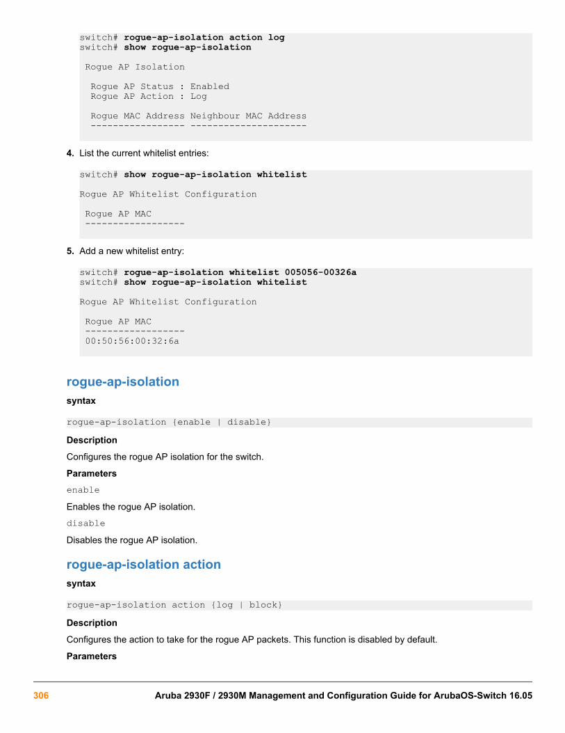
switch# rogue-ap-isolation action logswitch# show rogue-ap-isolation
Rogue AP Isolation
Rogue AP Status : Enabled Rogue AP Action : Log
Rogue MAC Address Neighbour MAC Address ----------------- ---------------------
4. List the current whitelist entries:
switch# show rogue-ap-isolation whitelist
Rogue AP Whitelist Configuration
Rogue AP MAC ------------------
5. Add a new whitelist entry:
switch# rogue-ap-isolation whitelist 005056-00326aswitch# show rogue-ap-isolation whitelist
Rogue AP Whitelist Configuration
Rogue AP MAC ------------------ 00:50:56:00:32:6a
rogue-ap-isolationsyntax
rogue-ap-isolation {enable | disable}Description
Configures the rogue AP isolation for the switch.
ParametersenableEnables the rogue AP isolation.
disableDisables the rogue AP isolation.
rogue-ap-isolation actionsyntax
rogue-ap-isolation action {log | block}Description
Configures the action to take for the rogue AP packets. This function is disabled by default.
Parameters
306 Aruba 2930F / 2930M Management and Configuration Guide for ArubaOS-Switch 16.05

actionConfigure the action to take for rogue AP packets. By default, the rogue AP packets are blocked.
OptionslogLogs traffic to or from any rogue access points.
blockBlocks and logs traffic to or from any rogue access points.
rogue-ap-isolation whitelistsyntax
[no] rogue-ap-isolation whitelist <MAC-ADDRESS>Description
Configures the rogue AP Whitelist MAC addresses for the switch. Use this command to add to the whitelist theMAC addresses of approved access points or MAC addresses of clients connected to the rogue access points.These approved access points will not be added to the rogue AP list even if they are reported as rogue devices.
ParametersMAC-ADDRESSSpecifies the MAC address of the device to be moved from the rogue AP list to the whitelist.
OptionsnoRemoves the MAC address individually by specifying the MAC.
Restrictions
You can add a maximum of 128 MAC addresses to the whitelist.
clear rogue-ap-isolationsyntax
clear rogue-ap-isolation { <MAC-ADDRESS> | all }Description
Removes the MAC addresses from the rogue AP list.
ParametersMAC-ADDRESSSpecifies the MAC address of the device to be moved from the rogue AP list.
allClears all MAC addresses from the rogue AP list.
Restrictions
The MAC addresses cleared using this option will be added back to the rogue list under the following cases:
Chapter 13 Auto configuration upon Aruba AP detection 307

1. The LLDP administrator status of the port on which the AP that reported the MAC is disabled and enabledback.
2. The data that is in the rogue AP TLV sent from the AP that informed the rogue MAC has changed.
3. To permanently ignore a MAC from being detected as rogue, add it to the whitelist.
TroubleshootingDynamic configuration not displayed when using “show running-config”
Symptom
The show running-config command does not display the dynamic configuration applied through the deviceprofile.
Cause
The show running-config command shows only the permanent user configuration and parametersconfigured through device profile.
Action
Use the specific show device-profile command to display the parameters dynamically configured throughthe device profile.
Switch does not detect the rogue AP TLVs
Symptom
The switch does not detect the rogue AP TLVs that could be sent from the neighboring device.
Cause
The LLDP administrator status of a port is moved from txOnly to tx_rx or rx_only within 120 seconds of theprevious state change to txOnly.
Action
1. Wait for 120 seconds before moving from the state txOnly to the state tx_rx or rx_only.
2. Move the administrator status to disable and then back to tx_rx or rx_only.
The show run command displays non-numerical value for untagged-vlan
Symptom
The show run command displays one of the following values for untagged-vlan:
• no untagged-vlan• untagged-vlan : None
308 Aruba 2930F / 2930M Management and Configuration Guide for ArubaOS-Switch 16.05

Cause
The no device-profile or the no rogue-ap-isolation whitelist command is executed to configureuntagged-vlan to 0.
Action
No action is required.
Show commandsUse the following show commands to view the various configurations and status.
Command Description
show device-profile Shows the device profile configuration and status.
show device-profile config Shows the device profile configuration details for asingle profile or all profiles.
show device-profile status Shows currently applied device profiles.
show rogue-ap-isolation Shows the following information:
• The status of the feature: enabled or disabled.
• The current action type for the rogue MACsdetected.
• The list of MAC addresses detected as rogue andthe MAC address of the AP that reported them.
show rogue-ap-isolation whitelist Shows the rogue AP whitelist configuration.
show run Shows the running configuration.
Validation Rules
Validation Error/Warning/Prompt
device-profile profile-name default-ap-profile
Maximum tagged VLANs that can be associated with adevice-profile is 256.
device-profile profile-name creation. String too long. Allowed length is 32 characters.
device-profile profile-name creation. Device profile <> already exists.
device-profile profile-name creation. The maximum number of device profiles allowed is 5.
device-profile profile-name deletion. Device profile <> does not exist.
Table Continued
Chapter 13 Auto configuration upon Aruba AP detection 309

Validation Error/Warning/Prompt
device-profile profile-name deletion. Cannot delete profile <> when associated with a devicetype.
device-profile profile-name deletion. Default profile cannot be deleted.
device-profile profile-name modification viaSNMP.
Default profile name cannot be changed.
device-profileprofile-name creation/modification via SNMP.
Device profile index cannot be greater than 5.
untagged-vlan Invalid VLAN.
untagged-vlan Cannot configure the VLAN <> as an untagged VLANbecause this is already used as a tagged VLAN.
tagged-vlan 1-1000 The maximum number of tagged VLANs in a profile isless than 512 or the maximum VLANs, MAX_VLANs,configurable in the system.
tagged-vlan Cannot configure the VLAN <> as a tagged VLANbecause this is already used as an untagged VLAN.
ingress-bandwidth SNMP should return WRONG_VALUE_ERROR.
egress-bandwidth SNMP should return WRONG_VALUE_ERROR.
cos SNMP should return WRONG_VALUE_ERROR.
speed-duplex SNMP should return WRONG_VALUE_ERROR.
poe-max-power SNMP should return WRONG_VALUE_ERROR.
poe-priority SNMP should return WRONG_VALUE_ERROR.
device-profile type aruba-ap profile-name
String <> too long. Allowed length is 32 characters.
device-profile type aruba-ap profile-name
Device profile <> does not exist.
device-profile type aruba-switch-router Device type is not supported.
rogue-ap-whitelist Whitelist MAC address already exists in the list.
rogue-ap-whitelist Whitelist MAC address does not exist in the list.
rogue-ap-whitelist The maximum number of whitelist MACs allowed is128.
Table Continued
310 Aruba 2930F / 2930M Management and Configuration Guide for ArubaOS-Switch 16.05

Validation Error/Warning/Prompt
rogue-ap-whitelist <MAC> Cannot add the whitelist entry because the specifiedMAC address is already configured as a lock-out MAC.
lock-out <MAC> Cannot add the lock-out entry because the specifiedMAC address is already configured as a whitelist MAC.
lockout-mac <MAC-ADDRESS>ORstatic-mac<MAC-ADDRESS> vlan <vlan-id> interface<interface>ORvlan <vlan-id> ip-recv-mac-address <MAC-ADDRESS
Cannot add an entry for the MAC address <MAC-ADDRESS> because it is already blocked by rogue-ap-isolation.
Chapter 13 Auto configuration upon Aruba AP detection 311

LACP-MAD commands
Configuration commandThe following command defines whether LACP is enabled on a port, and whether it is in active or passive modewhen enabled. When LACP is enabled and active, the port sends LACP packets and listens to them. When LACPis enabled and passive, the port sends LACP packets only if it is spoken to. When LACP is disabled, the portignores LACP packets. If the command is issued without a mode parameter, 'active' is assumed. During dynamiclink aggregation using LACP, ports with the same key are aggregated as a single trunk. MAD passthrough appliesonly to trunks and not to physical ports.
switch# [no] interface <port-list> lacp [mad-passthrough <enable|disable>|active|passive|key <key>]
show commandsLACP-MAD supports the following show commands:
• show LACP-MAD passthrough configuration on LACP trunks
switch# show lacp [counters [<port-list>] | local [<port-list>] |peer [<port-list>] | distributed | mad-passthrough [counters [<port-list>]]]
• show LACP-MAD passthough counters on ports
switch# show lacp mad-passthrough counters [<port-list>]
clear commandClear all LACP statistics including MAD passthrough counters. Resets LACP packets sent and received on allports.
switch# clear lacp statistics
LACP-MAD overviewLink Aggregation Control Protocol-Multi-Active Detection (LACP-MAD) is a detection mechanism deployed byswitches to recover from a breakup of the Virtual Switching Framework (VSF) stack due to link or other failure.
VSF is only supported on the 2930F Switch Series.
LACP-MAD is implemented by sending extended LACP data units (LACPDUs) with a type length value (TLV) thatconveys the active ID of an VSF virtual device. The active ID is identical to the member ID of the master and isthus unique to the VSF virtual device. When LACP MAD detection is enabled, the members exchange their activeIDs by sending extended LACPDUs.
Chapter 14LACP-MAD
312 Aruba 2930F / 2930M Management and Configuration Guide for ArubaOS-Switch 16.05

• When the VSF virtual device operates normally, the active IDs in the extended LACPDUs sent by all membersare the same, indicating that there is no multi-active collision.
• When there is a breakup in the VSF stack, the active IDs in the extended LACPDUs sent by the members indifferent VSF virtual devices are different, indicating that there are multi-active collisions.
LACP-MAD passthrough helps VSF-capable devices detect multi-access and take corrective action. Thesedevices do not initiate transmission of LACP-MAD frames or participate in any MAD decision making process.These devices simply forward LACP-MAD TLVs received on one interface to the other interfaces on the trunk.LACP-MAD passthrough can be enabled for 24 LACP trunks. By default LACP-MAD passthrough is disabled.
Chapter 14 LACP-MAD 313

The following table lists the switch scalability values for the areas of VLANs, ACLs, hardware, ARP, and routing.
Subject Maximum
IPv4 ACLs
total named (extended or standard) Up to 2048 (minus any IPv4 numeric standard or extended ACLassignments and any RADIUS-assigned ACLs)11
total numbered standard Up to 99
total numbered extended Up to 10011
total ACEs in all IPv4 ACLs Up to 307211
Layer-3
VLANs with at least one IP Address 512
IP addresses per system 2048 IPv4
2048 IPv6
IP addresses per VLAN 32
Static routes (IPv4 and IPv6combined)
256
IPv4 host hardware table 72 K (8K internal, 64K external)
IPv4 BMP hardware table 2 K
ARP
ARP entries 25,000
Packets held for ARP resolution 25
Dynamic Routing
Total routes supported IPv4 only: 10,000 (including ARP)
IPv4 and IPv6: 10 K (IPv4) and 3 K
(IPv6)
IPv6 only: 5 K
IPv4 Routing Protocol
RIP interfaces 128
Table Continued
Chapter 15Scalability IP Address VLAN and Routing Maximum Values
314 Aruba 2930F / 2930M Management and Configuration Guide for ArubaOS-Switch 16.05

Subject Maximum
IPv6 Routing Protocol
DHCPv6 Helper Addresses 32 unique addresses; multiple instances of same address counts as 1towards maximum
1 Actual availability depends on combined resource usage on the switch. See Monitoring resources on page 70.
Chapter 15 Scalability IP Address VLAN and Routing Maximum Values 315

OverviewThe switches support several methods for transferring files to and from a physically connected device or via thenetwork, including TFTP and Xmodem. This appendix explains how to download new switch software, upload ordownload switch configuration files and software images, and upload command files for configuring ACLs.
Downloading switch softwareHPE Switch periodically provides switch software updates through the Switch Networking website. For moreinformation, see the support and warranty booklet shipped with the switch, or visit http://www.hpe.com/networking and click on software updates.
This manual uses the terms switch software and software image to refer to the downloadablesoftware files the switch uses to operate its networking features. Other terms sometimes includeOperating System, or OS.
General software download rules
• Switch software that you download via the menu interface always goes to primary flash.
• After a software download, you must reboot the switch to implement the new software. Until a reboot occurs,the switch continues to run on the software it was using before the download.
Downloading new switch software does not change the current switch configuration. The switchconfiguration is contained in separate files that can also be transferred. See Transferring switchconfigurations on page 334.
In most cases, if a power failure or other cause interrupts a flash image download, the switch rebootswith the image previously stored in primary flash. In the unlikely event that the primary image iscorrupted (which may occur if a download is interrupted by a power failure), the switch goes into bootROM mode. In this case, use the boot ROM console to download a new image to primary flash.
Using TFTP to download software from a serverThis procedure assumes that:
• A software version for the switch has been stored on a TFTP server accessible to the switch. (The software fileis typically available from the HPE Switch Networking website at http://www.hpe.com/networking.)
• The switch is properly connected to your network and has already been configured with a compatible IPaddress and subnet mask.
• The TFTP server is accessible to the switch via IP.
Before you use the procedure, do the following:
Chapter 16File Transfers
316 Aruba 2930F / 2930M Management and Configuration Guide for ArubaOS-Switch 16.05

• Obtain the IP address of the TFTP server in which the software file has been stored.
• If VLANs are configured on the switch, determine the name of the VLAN in which the TFTP server is operating.
• Determine the name of the software file stored in the TFTP server for the switch (For example, E0820.swi).
If your TFTP server is a UNIX workstation, ensure that the case (upper or lower) that you specify forthe filename is the same case as the characters in the software filenames on the server.
Downloading from a server to primary flash using TFTP (Menu)Note that the menu interface accesses only the primary flash.
Procedure
1. In the console Main Menu, select Download OS to display the screen in Figure 40: Example: of a downloadOS (software) screen (default values) on page 317. (The term "OS" or "operating system" refers to theswitch software):
Figure 40: Example: of a download OS (software) screen (default values)
2. Press [E] (for Edit ).
3. Ensure that the Method field is set to TFTP (the default).
4. In the TFTP Server field, enter the IP address of the TFTP server in which the software file has been stored.
5. In the Remote File Name field, enter the name of the software file (if you are using a UNIX system, rememberthat the filename is case-sensitive).
6. Press [Enter], then [X] (for eXecute ) to begin the software download.
Chapter 16 File Transfers 317

The following screen appears:
Figure 41: Example: of the download OS (software) screen during a download
A "progress" bar indicates the progress of the download. When the entire software file has been received, allactivity on the switch halts and you will see Validating and writing system software to FLASH...
7. After the primary flash memory is updated with the new software, you must reboot the switch to implement thenewly downloaded software. Return to the Main Menu and press [6] (for Reboot Switch ).
You will see this prompt:
Continue reboot of system? : No
Press the space bar once to change No to Yes, then press [Enter] to begin the reboot.
When you use the menu interface to download a switch software, the new image is always storedin primary flash. Also, using the Reboot Switch command in the Main Menu always reboots theswitch from primary flash. Rebooting the switch from the CLI provides more options. See"Rebooting the Switch" in the basic operation guide.
8. After you reboot the switch, confirm that the software downloaded correctly:
a. From the Main Menu, select
2. Switch Configuration...
2. Port/Trunk Settings
b. Check the Firmware revision line.
For troubleshooting information on download failures, see Troubleshooting TFTP download failures on page319.
318 Aruba 2930F / 2930M Management and Configuration Guide for ArubaOS-Switch 16.05

Troubleshooting TFTP download failures
Cause
When using the menu interface, if a TFTP download fails, the Download OS (Operating System, or software)screen indicates the failure as seen in the following figure.
Figure 42: Example: of message for download failure
Some of the causes of download failures include:
• Incorrect or unreachable address specified for the TFTP Server parameter. This may include networkproblems.
• Incorrect VLAN.
• Incorrect name specified for the Remote File Name parameter, or the specified file cannot be found on theTFTP server. This can also occur if the TFTP server is a UNIX machine and the case (upper or lower) for thefilename on the server does not match the case for the filename entered for the Remote File Name parameterin the Download OS (Operating System, or software) screen.
• One or more of the switch's IP configuration parameters are incorrect.
• For a UNIX TFTP server, the file permissions for the software file do not allow the file to be copied.
• Another console session (through either a direct connection to a terminal device or through Telnet) wasalready running when you started the session in which the download was attempted.
To find more information on the cause of a download failure:
• Examine the messages in the switch's Event Log by executing the show log tftp command from the CLI.
• For descriptions of individual Event Log messages, see the latest version of the event log message referenceguide for your switch, available on the HPE Switch website. (See "Getting Documentation From the Web".)
If an error occurs in which normal switch operation cannot be restored, the switch automaticallyreboots itself, and an appropriate message is displayed after the reboot.
Chapter 16 File Transfers 319

Downloading from a server to flash using TFTP (CLI)Syntax:
copy tftp flash <ip-address> <remote-file> [<primary | secondary>]Automatically downloads a switch software file to primary or secondary flash. If you do not specify the flashdestination, the TFTP download defaults to primary flash.
Example:
To download a switch software file named k0800.swi from a TFTP server with the IP address of 10.28.227.103 toprimary flash:
Procedure
1. Execute copy as shown below:The command to download an OS (switch software)
switch# copy tftp flash 10.28.227.103 k0800.swiThe primary OS Image will be deleted, continue [y/n]? y 101431K 2
• 1This message means that the image you want to upload will replace the image currently in primary flash.
• 2Dynamic counter continually displays the number of bytes transferred.
When the switch finishes downloading the software file from the server, it displays this progress message:
Validating and Writing System Software to FLASH ...2. When the download finishes, you must reboot the switch to implement the newly downloaded software image.
To do so, use one of the following commands:
Syntax:
boot system flash {<primary | secondary>}Boots from the selected flash.
Syntax:
reloadBoots from the flash image and startup-config file. A switch covered in this guide (with multiple configurationfiles), also uses the current startup-config file.
For more information on these commands, see "Rebooting the Switch" in the basic operation guide for yourswitch.
3. To confirm that the software downloaded correctly, execute show system and check the Firmware revisionline.
For information on primary and secondary flash memory and the boot commands, see "Using Primary andSecondary Flash Image Options" in the basic operation guide for your switch.
If you use auto-tftp to download a new image in a redundant management system, the activemanagement module downloads the new image to both the active and standby modules. Rebootingafter the auto-tftp process completes reboots the entire system.
320 Aruba 2930F / 2930M Management and Configuration Guide for ArubaOS-Switch 16.05

Enabling TFTP (CLI)TFTP is enabled by default on the switch. If TFTP operation has been disabled, you can re-enable it by specifyingTFTP client or server functionality with the tftp [client|server] command at the global configuration level.
Syntax:
[no] tftp [client | server]Disables/re-enables TFTP for client or server functionality so that the switch can:
• Use TFTP client functionality to access TFTP servers in the network to receive downloaded files.
• Use TFTP server functionality to upload files to other devices on the network.
Usage notes
To disable all TFTP client or server operation on the switch except for the auto-TFTP feature, enterthe no tftp [client|server] command.
When IP SSH file transfer is used to enable SCP and SFTP functionality on the switch, this disablesTFTP client and server functionality. Once ip ssh file transfer is enabled, TFTP and auto-TFTPcannot be re-enabled from the CLI.
When TFTP is disabled, instances of TFTP in the CLI copy command and the Menu interface"Download OS" screen become unavailable.
The no tftp [client|server] command does not disable auto-TFTP operation. To disable anauto-TFTP command configured on the switch, use the no auto-tftp command to remove thecommand entry from the switch's configuration.
For information on how to configure TFTP file transfers on an IPv6 network, see the "IPv6Management Features" in the IPv6 configuration guide for your switch.
Configuring the switch to download software automatically from a TFTP server usingauto-TFTP (CLI)The auto-tftp command lets you configure the switch to download software automatically from a TFTP server.
At switch startup, the auto-TFTP feature automatically downloads a specified software image to the switch from aspecified TFTP server and then reboots the switch. To implement the process, you must first reboot the switchusing one of the following methods:
• Enter the boot system flash primary command in the CLI.
• With the default flash boot image set to primary flash (the default), enter the boot or the reload command, orcycle the power to the switch. (To reset the boot image to primary flash, use boot set-default flashprimary.)
Syntax:
auto-tftp <ip-addr> <filename>By default, auto-TFTP is disabled. This command configures the switch to automatically download the specifiedsoftware file from the TFTP server at the specified IP address. The file is downloaded into primary flash memoryat switch startup; the switch then automatically reboots from primary flash.
Chapter 16 File Transfers 321

To enable auto-TFTP to copy a software image to primary flash memory, the version number of thedownloaded software file (For example, XX_14_01.swi) must be different from the version numbercurrently in the primary flash image.
The current TFTP client status (enabled or disabled) does not affect auto-TFTP operation. (See Enabling TFTP (CLI) on page 321.)
Completion of the auto-TFTP process may require several minutes while the switch executes theTFTP transfer to primary flash and then reboots again.
The no form of the command disables auto-TFTP operation by deleting the auto-tftp entry from the startupconfiguration.
The no auto-tftp command does not affect the current TFTP-enabled configuration on the switch. However,entering the ip ssh filetransfer command automatically disables both auto-tftp and tftp operation.
Use USB to transfer files to and from the switchThe switch's USB port (labeled as Aux Port) allows the use of a USB flash drive for copying configuration files toand from the switch.
Operating rules and restrictions:
• Unformatted USB flash drives must first be formatted on a PC (Windows FAT format.) For devices with multiplepartitions, only the first partition is supported. Devices with secure partitions are not supported.
• If they already exist on the device, subdirectories are supported. When specifying a filename , you must entereither the individual file name (if at the root) or the full path name (for example, /subdir/filename.)
• To view the contents of a USB flash drive, use the dir command. This lists all files and directories at the root.To view the contents of a directory, you must specify the subdirectory name (that is, dir subdirectory.)
• The USB port supports a single USB device. USB hubs to add more ports are not supported.
Some USB flash drives may not be supported on your switch. Consult the latest Release Notes forinformation on supported devices.
Using SCP and SFTPFor some situations you may want to use a secure method to issue commands or copy files to the switch. Byopening a secure, encrypted SSH session and enabling ip ssh file transfer, you can then use a third-partysoftware application to take advantage of SCP and SFTP. SCP and SFTP provide a secure alternative to TFTPfor transferring information that may be sensitive (like switch configuration files) to and from the switch.Essentially, you are creating a secure SSH tunnel as a way to transfer files with SFTP and SCP channels.
Once you have configured your switch to enable secure file transfers with SCP and SFTP, files can be copied toor from the switch in a secure (encrypted) environment and TFTP is no longer necessary.
To use these commands, you must install on the administrator workstation a third-party application software clientthat supports the SFTP and/or SCP functions. Some examples of software that supports SFTP and SCP arePuTTY, Open SSH, WinSCP, and SSH Secure Shell. Most of these are freeware and may be downloaded withoutcost or licensing from the internet. There are differences in the way these clients work, so be sure you alsodownload the documentation.
As described earlier in this chapter you can use a TFTP client on the administrator workstation to update softwareimages. This is a plain-text mechanism that connects to a standalone TFTP server or another HPE switch actingas a TFTP server to obtain the software image files. Using SCP and SFTP allows you to maintain your switches
322 Aruba 2930F / 2930M Management and Configuration Guide for ArubaOS-Switch 16.05

with greater security. You can also roll out new software images with automated scripts that make it easier toupgrade multiple switches simultaneously and securely.
SFTP is unrelated to FTP, although there are some functional similarities. Once you set up an SFTP sessionthrough an SSH tunnel, some of the commands are the same as FTP commands. Certain commands are notallowed by the SFTP server on the switch, such as those that create files or folders. If you try to issue commandssuch as create or remove using SFTP, the switch server returns an error message.
You can use SFTP just as you would TFTP to transfer files to and from the switch, but with SFTP, your filetransfers are encrypted and require authentication, so they are more secure than they would be using TFTP.SFTP works only with SSH version 2 (SSH v2).
SFTP over SSH version 1 (SSH v1) is not supported. A request from either the client or the switch(or both) using SSH v1 generates an error message. The actual text of the error message differs,depending on the client software in use. Some examples are:
Protocol major versions differ: 2 vs. 1Connection closed
Protocol major versions differ: 1 vs. 2Connection closed
Received disconnect from <ip-addr> : /usr/local/libexec/sftp-server: command not supportedConnection closed
SCP is an implementation of the BSD rcp (Berkeley UNIX remote copy) command tunneled through an SSHconnection.
SCP is used to copy files to and from the switch when security is required. SCP works with both SSH v1 and SSHv2. Be aware that the most third-party software application clients that support SCP use SSHv1.
The general process for using SCP and SFTP involves three steps:
Procedure
1. Open an SSH tunnel between your computer and the switch if you have not already done so.
(This step assumes that you have already set up SSH on the switch.)
2. Execute ip ssh filetransfer to enable secure file transfer.
3. Use a third-party client application for SCP and SFTP commands.
Enabling SCP and SFTPFor more information about secure copy and SFTP, see Using SCP and SFTP on page 322.
Procedure
1. Open an SSH session as you normally would to establish a secure encrypted tunnel between your computerand the switch.
For more detailed directions on how to open an SSH session, see "Configuring secure shell (SSH)" in theaccess security guide for your switch. Please note that this is a one-time procedure for new switches orconnections. If you have already done it once you should not need to do it a second time.
2. To enable secure file transfer on the switch (once you have an SSH session established between the switchand your computer), open a terminal window and enter the following command:
Chapter 16 File Transfers 323

switch(config)# ip ssh filetransfer
For information on disabling TFTP and auto-TFTP, see Disabling TFTP and auto-TFTP for enhanced securityon page 324.
Disabling TFTP and auto-TFTP for enhanced securityUsing the ip ssh filetransfer command to enable SFTP automatically disables TFTP and auto-TFTP (ifeither or both are enabled), as shown in Switch configuration with SFTP enabled on page 324.
Switch configuration with SFTP enabled
switch(config)# ip ssh filetransferTftp and auto-tftp have been disabled. 1switch(config)# sho run
Running configuration:
; J9091A Configuration Editor; Created on release #xx.15.xx
hostname "HP Switch"module 1 type J8702Amodule 2 type J702Avlan 1 name "DEFAULT_VLAN" untagged A1-A24,B1-B24 ip address 10.28.234.176 255.255.240.0 exitip ssh filetransfer 2no tftp-enablepassword managerpassword operator1 Enabling SFTP automatically disables TFTP and auto-tftp and displays this message.2 Viewing the configuration shows that SFTP is enabled and TFTP is disabled.
If you enable SFTP and then later disable it, TFTP and auto-TFTP remain disabled unless they are explicitly re-enabled.
Operating rules are:
324 Aruba 2930F / 2930M Management and Configuration Guide for ArubaOS-Switch 16.05

• The TFTP feature is enabled by default, and can be enabled or disabled through the CLI, the Menu interface(see Figure 43: Using the Menu interface to disable TFTP on page 325), or an SNMP application. Auto-TFTP is disabled by default and must be configured through the CLI.
Figure 43: Using the Menu interface to disable TFTP
• While SFTP is enabled, TFTP and auto-TFTP cannot be enabled from the CLI. Attempting to enable eithernon-secure TFTP option while SFTP is enabled produces one of the following messages in the CLI:
SFTP must be disabled before enabling tftp.
SFTP must be disabled before enabling auto-tftp.Similarly, while SFTP is enabled, TFTP cannot be enabled using an SNMP management application.Attempting to do so generates an "inconsistent value" message. (An SNMP management application cannotbe used to enable or disable auto-TFTP.)
• To enable SFTP by using an SNMP management application, you must first disable TFTP and, if configured,auto-TFTP on the switch. You can use either an SNMP application or the CLI to disable TFTP, but you mustuse the CLI to disable auto-TFTP.
Enabling SSH V2 (required for SFTP)
switch(config)# ip ssh version 2
As a matter of policy, administrators should not enable the SSH V1-only or the SSH V1-or-V2advertisement modes. SSHv1 is supported on only some legacy switches.
Confirming that SSH is enabled
switch(config)# show ip sshOnce you have confirmed that you have enabled an SSH session (with the show ip ssh command), enter ipssh filetransfer so that SCP and/or SFTP can run. You can then open your third-party software clientapplication to begin using the SCP or SFTP commands to safely transfer files or issue commands to the switch.
Chapter 16 File Transfers 325
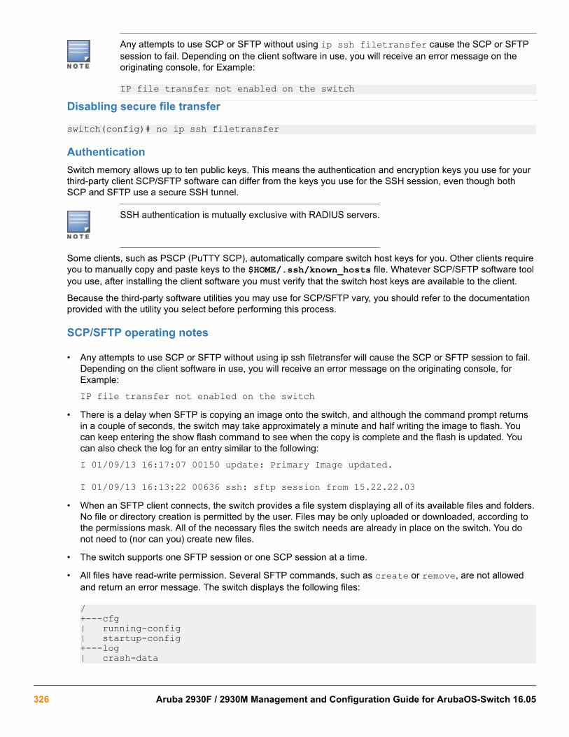
Any attempts to use SCP or SFTP without using ip ssh filetransfer cause the SCP or SFTPsession to fail. Depending on the client software in use, you will receive an error message on theoriginating console, for Example:
IP file transfer not enabled on the switchDisabling secure file transfer
switch(config)# no ip ssh filetransfer
AuthenticationSwitch memory allows up to ten public keys. This means the authentication and encryption keys you use for yourthird-party client SCP/SFTP software can differ from the keys you use for the SSH session, even though bothSCP and SFTP use a secure SSH tunnel.
SSH authentication is mutually exclusive with RADIUS servers.
Some clients, such as PSCP (PuTTY SCP), automatically compare switch host keys for you. Other clients requireyou to manually copy and paste keys to the $HOME/.ssh/known_hosts file. Whatever SCP/SFTP software toolyou use, after installing the client software you must verify that the switch host keys are available to the client.
Because the third-party software utilities you may use for SCP/SFTP vary, you should refer to the documentationprovided with the utility you select before performing this process.
SCP/SFTP operating notes
• Any attempts to use SCP or SFTP without using ip ssh filetransfer will cause the SCP or SFTP session to fail.Depending on the client software in use, you will receive an error message on the originating console, forExample:
IP file transfer not enabled on the switch• There is a delay when SFTP is copying an image onto the switch, and although the command prompt returns
in a couple of seconds, the switch may take approximately a minute and half writing the image to flash. Youcan keep entering the show flash command to see when the copy is complete and the flash is updated. Youcan also check the log for an entry similar to the following:
I 01/09/13 16:17:07 00150 update: Primary Image updated.
I 01/09/13 16:13:22 00636 ssh: sftp session from 15.22.22.03• When an SFTP client connects, the switch provides a file system displaying all of its available files and folders.
No file or directory creation is permitted by the user. Files may be only uploaded or downloaded, according tothe permissions mask. All of the necessary files the switch needs are already in place on the switch. You donot need to (nor can you) create new files.
• The switch supports one SFTP session or one SCP session at a time.
• All files have read-write permission. Several SFTP commands, such as create or remove, are not allowedand return an error message. The switch displays the following files:
/+---cfg| running-config| startup-config+---log| crash-data
326 Aruba 2930F / 2930M Management and Configuration Guide for ArubaOS-Switch 16.05

| crash-data-a| crash-data-b | crash-data-c | crash-data-d | crash-data-e " "| crash-data-f ""| crash-data-g| crash-data-h " "| crash-data-I ""| crash-data-J ""| crash-data-K ""| crash-data-L " "| crash-log| crash-log-a| crash-log-b | crash-log-c | crash-log-d| crash-log-e""| crash-log-f""| crash-log-g| crash-log-h" "| crash-log-I" "| crash-log-J" "| crash-log-K" "| crash-log-L" "| event log+---os| primary| secondary\---ssh +---mgr_keys | authorized_keys \---oper_keys | authorized_keys\---core| port_1-24.cor core-dump for ports 1-24 (stackable switches only)| port_25-48.cor core-dump for ports 25-48 (stackable switches only)
Once you have configured your switch for secure file transfers with SCP and SFTP, files can be copied to or fromthe switch in a secure (encrypted) environment and TFTP is no longer necessary.
Troubleshooting SSH, SFTP, and SCP operations
Cause
You can verify secure file transfer operations by checking the switch's event log, or by viewing the error messagessent by the switch that most SCP and SFTP clients print out on their console.
Messages that are sent by the switch to the client depend on the client software in use to displaythem on the user console.
Broken SSH connectionIf an ssh connection is broken at the wrong moment (for instance, the link goes away or spanning tree bringsdown the link), a fatal exception occurs on the switch. If this happens, the switch gracefully exits the session andproduces an Event Log message indicating the cause of failure. The following three examples show the errormessages that may appear in the log, depending on the type of session that is running (SSH, SCP, or SFTP):
ssh: read error Bad file number, session aborted I 01/01/9000:06:11 00636 ssh: sftp session from ::ffff:10.0.12.35 W01/01/90 00:06:26 00641 ssh:
Chapter 16 File Transfers 327

sftp read error Bad file number, session aborted I 01/01/9000:09:54 00637 ssh: scp session from ::ffff:10.0.12.35 W 01/01/90
ssh: scp read error Bad file number, session aborted
The Bad file number is from the system error value and may differ depending on the cause ofthe failure. In the third Example:, the device file to read was closed as the device read was about tooccur.
Attempt to start a session during a flash writeIf you attempt to start an SCP (or SFTP) session while a flash write is in progress, the switch does not allow theSCP or SFTP session to start. Depending on the client software in use, the following error message may appearon the client console:
Received disconnect from 10.0.12.31: 2: Flash access inprogress
lost connection
Failure to exit from a previous sessionThis next Example: shows the error message that may appear on the client console if a new SCP (or SFTP)session is started from a client before the previous client session has been closed (the switch requiresapproximately ten seconds to timeout the previous session):
Received disconnect from 10.0.12.31: 2: Wait for previoussession to complete
lost connection
Attempt to start a second sessionThe switch supports only one SFTP session or one SCP session at a time. If a second session is initiated (Forexample, an SFTP session is running and then an SCP session is attempted), the following error message mayappear on the client console:
Received disconnect from 10.0.12.31: 2: Other SCP/SFTPsession running
lost connection
Using Xmodem to download switch software from a PC or UNIXworkstationThis procedure assumes that:
• The switch is connected via the Console RS-232 port to a PC operating as a terminal. (For information onconnecting a PC as a terminal and running the switch console interface, see the installation and getting startedguide you received with the switch.)
• The switch software is stored on a disk drive in the PC.
• The terminal emulator you are using includes the Xmodem binary transfer feature. (For example, in theHyperTerminal application included with Windows NT, you would use the Send File option in the Transferdrop-down menu.)
328 Aruba 2930F / 2930M Management and Configuration Guide for ArubaOS-Switch 16.05

Downloading to primary flash using Xmodem (Menu)
The menu interface accesses only the primary flash.
Procedure
1. From the console Main Menu, select
7. Download OS
2. Press [E] (for Edit).
3. Use the Space bar to select XMODEM in the Method field.
4. Press [Enter], then [X] (for eXecute) to begin the software download.
The following message appears:
Press enter and then initiate Xmodem transfer from the attached computer.....
5. Press [Enter] and then execute the terminal emulator commands to begin Xmodem binary transfer.
For example, using HyperTerminal:
a. Click on Transfer, then Send File.
b. Enter the file path and name in the Filename field.
c. In the Protocol field, select Xmodem.
d. Click on the [Send] button.
The download then commences. It can take several minutes, depending on the baud rate set in the switch andin your terminal emulator.
6. After the primary flash memory has been updated with the new software, you must reboot the switch toimplement the newly downloaded software. Return to the Main Menu and press [6] (for Reboot Switch). Youthen see the following prompt:
Continue reboot of system? : No
Press the space bar once to change No to Yes, then press [Enter] to begin the reboot.
7. To confirm that the software downloaded correctly:
a. From the Main Menu, select
1. Status and Counters
1. General System Information
b. Check the Firmware revision line.
Chapter 16 File Transfers 329

Downloading to primary or secondary flash using Xmodem and a terminal emulator(CLI)Syntax:
copy xmodem flash [<primary | secondary>]Downloads a software file to primary or secondary flash. If you do not specify the flash destination, the Xmodemdownload defaults to primary flash.
Example:
To download a switch software file named E0822.swi from a PC (running a terminal emulator program such asHyperTerminal) to primary flash:
Procedure
1. Execute the following command in the CLI:
switch# copy xmodem flashPress 'Enter and start XMODEM on your host...
2. Execute the terminal emulator commands to begin the Xmodem transfer. For example, using HyperTerminal:
a. Click on Transfer, then Send File.
b. Type the file path and name in the Filename field.
c. In the Protocol field, select Xmodem.
d. Click on the [Send] button.
The download can take several minutes, depending on the baud rate used in the transfer.
3. When the download finishes, you must reboot the switch to implement the newly downloaded software. To doso, use one of the following commands:Syntax:
boot system flash {<primary | secondary>}Reboots from the selected flash
Syntax:
reloadReboots from the flash image currently in use
For more information on these commands, see “Rebooting the Switches” in the basic operation guide for yourswitch.
4. To confirm that the software downloaded correctly:
switch# show systemCheck the Firmware revision line. It should show the software version that you downloaded in the precedingsteps.
330 Aruba 2930F / 2930M Management and Configuration Guide for ArubaOS-Switch 16.05

If you need information on primary/secondary flash memory and the boot commands, see "Using Primary andSecondary Flash Image Options" in the basic operation guide for your switch.
Switch-to-switch downloadYou can use TFTP to transfer a software image between two switches of the same series. The CLI enables allcombinations of flash location options. The menu interface enables you to transfer primary-to-primary orsecondary-to-primary.
Switch-to-switch download to primary flash (Menu)Using the menu interface, you can download a switch software file from either the primary or secondary flash ofone switch to the primary flash of another switch of the same series.
Procedure
1. From the switch console Main Menu in the switch to receive the download, select 7. Download OS screen.
2. Ensure that the Method parameter is set to TFTP (the default).
3. In the TFTP Server field, enter the IP address of the remote switch containing the software file you want todownload.
4. For the Remote File Name , enter one of the following:
a. To download the software in the primary flash of the source switch, enterflashin lowercase characters.
b. To download the software in the secondary flash of the source switch, enter/os/secondary.
5. Press [Enter], and then [X] (for eXecute ) to begin the software download.
A "progress" bar indicates the progress of the download. When the entire switch software download has beenreceived, all activity on the switch halts and the following messages appear:
Validating and writing system software to FLASH...
6. After the primary flash memory has been updated with the new software, you must reboot the switch toimplement the newly downloaded software. Return to the Main Menu and press [6] (for Reboot Switch ). Youthen see this prompt:
Continue reboot of system? : No
Press the space bar once to change No to Yes, then press [Enter] to begin the reboot.
7. To confirm that the software downloaded correctly:
a. From the Main Menu, select
Status and Counters
General System Information
b. Check the Firmware revision line.
Chapter 16 File Transfers 331

Downloading the OS from another switch (CLI)Where two switches in your network belong to the same series, you can download a software image betweenthem by initiating a copy tftp command from the destination switch. The options for this CLI feature include:
• Copy from primary flash in the source to either primary or secondary in the destination.
• Copy from either primary or secondary flash in the source to either primary or secondary flash in thedestination.
Downloading from primary only (CLI)Syntax:
copy tftp flash <ip-addr> flash [primary | secondary]When executed in the destination switch, downloads the software flash in the source switch's primary flash toeither the primary or secondary flash in the destination switch.
If you do not specify either a primary or secondary flash location for the destination, the download automaticallygoes to primary flash.
To download a software file from primary flash in a switch with an IP address of 10.29.227.103 to the primary flashin the destination switch, you would execute the following command in the destination switch's CLI:
Switch-to-switch, from primary in source to either flash in destination
switch# copy tftp flash 10.29.227.13 flashDevice will be rebooted, do you want to continue [y/n]? y00107K 1
1Running Total of Bytes Downloaded
Downloading from either flash in the source switch to either flash in the destinationswitch (CLI)Syntax:
copy tftp flash <ip-addr> {</os/primary> | </os/secondary>} [primary | secondary]This command (executed in the destination switch) gives you the most options for downloading between switches.If you do not specify either a primary or secondary flash location for the destination, the download automaticallygoes to primary flash.
To download a software file from secondary flash in a switch with an IP address of 10.28.227.103 to thesecondary flash in a destination switch, you would execute the following command in the destination switch's CLI:
Switch-to-switch, from either flash in source to either flash in destination
switch# copy tftp flash 10.29.227.13 flash /os/secondary secondaryDevice will be rebooted, do you want to continue [y/n]? y00184K
Using AirWave to update switch softwareAirWave can be used to update HPE switch products. For further information, refer to the ZTP with Airwavenetwork Management chapter in this manual.
332 Aruba 2930F / 2930M Management and Configuration Guide for ArubaOS-Switch 16.05

Using IMC to update switch softwareIMC includes a software update utility for updating on HPE switch products. For further information, refer to thegetting started guide and the administrator’s guide, provided electronically with the application.
Copying software imagesFor details on how switch memory operates, including primary and secondary flash, see “SwitchMemory and Configuration” in the basic operation guide for your switch.
TFTP: Copying a software image to a remote host (CLI)Syntax:
copy flash tftp <ip-addr> <filename>Copies the primary flash image to a TFTP server.
Example:
To copy the primary flash to a TFTP server having an IP address of 10.28.227.105:
switch# copy flash tftp 10.28.227.105 k0800.swiwhere k0800.swi is the filename given to the flash image being copied.
Xmodem: Copying a software image from the switch to a serially connectedPC or UNIX workstation (CLI)To use this method, the switch must be connected via the serial port to a PC or UNIX workstation.
Syntax:
copy flash xmodem {[<pc] | unix>}Uses Xmodem to copy a designated configuration file from the switch to a PC or UNIX workstation.
Example:
To copy the primary flash image to a serially connected PC:
Procedure
1. Execute the following command:
switch# copy xmodem flashPress 'Enter' and start XMODEM on your host...
2. After you see the above prompt, press [Enter].
3. Execute the terminal emulator commands to begin the file transfer.
Copying diagnostic data
Chapter 16 File Transfers 333

copy command-logSyntaxcopy command-log {sftp | tftp | usb | xmodem}Description
This command copies the Command Log content to a remote host or to a serially-connected PC or UNIXworkstation.
• Use the sftp option to copy data to an SFTP server.
• Use the tftp option to copy data to a TFTP server.
• Use the usb option to copy data to a USB flash drive.
• Use the xmodem option to copy data to the console using XMODEM.
copy event-logSyntaxcopy event-log [tftp <IP-ADDRESS> <FILEPATH_FILENAME> [oobm]] [usb <FILENAME>] [xmodem <FILENAME>]
Description
These commands copy the Event Log content to a remote host, attached USB device, or to a serially connectedPC or UNIX workstation.
Parameters and optionsoobm
For switches that have a separate OOBM port, the oobm parameter specifies that the transfer is through theOOBM interface. If this parameter is not specified, the transfer is through the data interface. The oobmparameter is not available on switches that do not have a separate OOBM port.
Copy the event log to a PC connected to the switch
Figure 44: Sending event log content to a file on an attached PC
Transferring switch configurationsUsing the CLI commands described in the section beginning with TFTP: Copying a configuration file to aremote host (CLI) on page 335, you can copy switch configurations to and from a switch, or copy a softwareimage to configure or replace an ACL in the switch configuration.
334 Aruba 2930F / 2930M Management and Configuration Guide for ArubaOS-Switch 16.05

For greater security, you can perform all TFTP operations using SFTP, as described in the section Using SCP and SFTP on page 322.
You can also use the include-credentials command to save passwords, secret keys, and othersecurity credentials in the running config file. For more information, see the section on "SavingSecurity Credentials in a Config File" in the access security guide for your switch.
TFTP: Copying a configuration file to a remote host (CLI)Syntax:
copy {<startup-config | running-config>} tftp < ip-addr > < remote-file > [pc | unix]
copy config <filename> tftp <ip-addr> <remote-file> [pc | unix]This command can copy a designated config file in the switch to a TFTP server. For more information, see"Multiple Configuration Files" in the basic operation guide for your switch.
Example:
To upload the current startup configuration to a file named sw8200 in the configs directory on drive "d" in a TFTPserver having an IP address of 10.28.227.105:
switch# copy startup-config tftp 10.28.227.105 d:\configs\sw8200
TFTP: Copying a configuration file from a remote host (CLI)Syntax:
copy tftp {<startup-config | running-config> < ip-address > < remote-file >} [pc | unix]
copy tftp config <filename> <ip-address> <remote-file> [pc | unix]This command can copy a configuration from a remote host to a designated config file in the switch. For moreinformation, see "Multiple Configuration Files" in the basic operation guide for your switch.
For more information on flash image use, see "Using Primary and Secondary Flash Image Options" in the basicoperation guide for your switch.
Example:
To download a configuration file named sw8200 in the configs directory on drive "d" in a remote host having anIP address of 10.28.227.105:
switch# copy tftp startup-config 10.28.227.105 d:\configs\sw8200
TFTP: Copying a customized command file to a switch (CLI)Using the copy tftp command with the show-tech option provides the ability to copy a customized commandfile to the switch. When the show tech custom command is executed, the commands in the custom file areexecuted instead of the hard-coded list of commands. If no custom file is found, the current hard-coded list isexecuted. This list contains commands to display data, such as the image stamp, running configuration, boothistory, port settings, and so on.
Chapter 16 File Transfers 335

Syntax:
copy tftp show-tech <ipv4 or ipv6 address> <filename>Copies a customized command file to the switch (see Using the copy tftp show-tech command to upload acustomized command file on page 336).
Using the copy tftp show-tech command to upload a customized command file
switch(config)# copy tftp show-tech 10.10.10.3 commandfile1Syntax:
show tech customExecutes the commands found in a custom file instead of the hard-coded list.
Exit the global config mode (if needed) before executing show tech commands.
You can include show tech commands in the custom file, with the exception of show tech custom. Forexample, you can include the command show tech all.
If no custom file is found, a message displays stating "No SHOW-TECH file found." (No custom file was uploadedwith the copy tftp show-tech command.)
The show tech custom command
switch# show tech customNo SHOW-TECH file found.
USB: Copying a configuration file to a USB deviceSyntax:copy startup-config usb <FILENAME>This command can copy a designated config file in the switch to a USB device.
Example:
MyConfig is the name given to the configuration file that you copy from the switch to the USB device.
switch# copy startup-config usb MyConfig
USB: Copying a configuration file from a USB deviceSyntax:copy usb startup-config <FILENAME>Description:
Copies a configuration file from a USB device to the startup configuration file on the switch. To execute thecommand, you must know the name of the file to copy.
Example:
MyConfig is the name given to the configuration file that you copy from the switch to the USB device.
336 Aruba 2930F / 2930M Management and Configuration Guide for ArubaOS-Switch 16.05

switch# copy usb startup-config MyConfig
Xmodem: Copying a configuration file to a serially connected PC or UNIXworkstation (CLI)To use this method, the switch must be connected via the serial port to a PC or UNIX workstation. You will needto:
• Determine a filename to use
• Know the directory path you will use to store the configuration file.
Syntax:
copy {<startup-config | running-config>} xmodem {<pc | unix>}
copy config <filename> xmodem {<pc | unix>}Uses Xmodem to copy a designated configuration file from the switch to a PC or UNIX workstation. For moreinformation, see "Multiple Configuration Files" in the basic operation guide for your switch.
Example:
To copy a configuration file to a PC serially connected to the switch:
1. Determine the file name and directory location on the PC.
2. Execute the following command:
switch# copy startup-config xmodem pcPress 'Enter' and start XMODEM on your host...
3. After you see the above prompt, press [Enter].
4. Execute the terminal emulator commands to begin the file transfer.
Xmodem: Copying a configuration file from a serially connected PC orUNIX workstation (CLI)To use this method, the switch must be connected via the serial port to a PC or UNIX workstation on which isstored the configuration file you want to copy. To complete the copying, you need to know the name of the file tocopy and the drive and directory location of the file.
Syntax:
copy xmodem startup-config {<pc | unix>}
copy xmodem config <filename> < {pc | unix>}Copies a configuration file from a serially connected PC or UNIX workstation to a designated configuration file onthe switch.
For more information, see "Multiple Configuration Files" in the basic operation guide for your switch.
Example:
To copy a configuration file from a PC serially connected to the switch:
Chapter 16 File Transfers 337
Procedure
1. Execute the following command:
switch# copy xmodem startup-config pcDevice will be rebooted, do you want to continue [y/n]? yPress 'Enter' and start XMODEM on your host...
2. After you see the above prompt, press [Enter].
3. Execute the terminal emulator commands to begin the file transfer.
4. When the download finishes, you must reboot the switch to implement the newly downloaded software. To doso, use one of the following commands:
Syntax:
boot system flash [primary | secondary]
boot system flash [config < filename >]Switches boot from the designated configuration file. For more information, see "Multiple Configuration Files"in the basic operation guide for your switch.
Syntax:
reload
Reboots from the flash image currently in use.
(For more on these commands, see "Rebooting the Switch" in the basic operation guide for your switch.)
Transferring ACL command filesThis section describes how to upload and execute a command file to the switch for configuring or replacing anACL in the switch configuration. Such files should contain only access control entry (ACE) commands. For moreon this general topic, including an Example: of an ACL command file created offline, see the section "EditingACLs and Creating an ACL Offline" in the "Access Control Lists (ACLs)" of the latest access security guide foryour switch.
TFTP: Uploading an ACL command file from a TFTP server (CLI)Syntax:
copy tftp command-file <ip-addr> <filename.txt> {<unix | pc>}Copies and executes the named text file from the specified TFTP server address and executes the ACLcommands in the file.
<ip-addr> The IP address of a TFTP server available to the switch
<filename.txt> A text file containing ACL commands and stored in the TFTP directory of the serveridentified by ip-addr
{<unix | pc>} The type of workstation used for serial, Telnet, or SSH access to the switch CLI
Depending on the ACL commands used, this action does one of the following in the running-config file:
338 Aruba 2930F / 2930M Management and Configuration Guide for ArubaOS-Switch 16.05

• Creates a new ACL.
• Replaces an existing ACL. (See "Creating an ACL Offline" in the "Access Control Lists (ACLs)" in the latestaccess security guide for your switch.)
• Adds to an existing ACL
Example:
Suppose you:
• Created an ACL command file named vlan10_in.txt to update an existing ACL.
• Copied the file to a TFTP server at 18.38.124.16.
Using a PC workstation, you then execute the following from the CLI to upload the file to the switch andimplement the ACL commands it contains:
switch(config)# copy tftp command-file 18.38.124.16vlan10_in.txt pcThe switch displays this message:
Running configuration may change, do you want to continue[y/n]?To continue with the upload, press the [Y] key. To abort the upload, press the [N] key. Note that if the switchdetects an illegal (non-ACL) command in the file, it bypasses the illegal command, displays a notice (as shown in Figure 45: Using the copy command to download and configure an ACL on page 339), and continues toimplement the remaining ACL commands in the file.
Figure 45: Using the copy command to download and configure an ACL
switch(config)# copy tftp command-file 10.38.124.18 v1an10_in.txt pcRunning configuration may change, do you want to continue [y/n]? y 1. ip access-list extended "155" 2. deny tcp 0.0.0.0 255.255.255.255 10.10.10.2 0.0.0.0 eq 23 1og 3. permit ip 0.0.0.0 255.255.255.255 0.0.0.0 255.255.255.255 4. show runningCommand files are limited to access-list commands. 1 5. exitSwitch(config)# show running 2Running configuration:
; J9091A Configuration Editor; Created on release #W.15.05.0000x; Ver #01:01:00
hostname "HP Switch"cdp runip default-gateway 10.38.248.1logging 10.38.227.2snmp-server community "public" unrestrictedip access-list extended "155"deny tcp 0.0.0.0 255.255.255.255 10.10.10.2 0.0.0.0 eq 23 1ogpermit ip 0.0.0.0 255.255.255.255 0.0.0.0 255.255.255.255exit1This message indicates that the show running command just above it is not an ACL command and will beignored by the switch.
Chapter 16 File Transfers 339

2Manually executing the show running from the CLI indicates that the file was implemented, creating ACL 155in the switch’s running configuration.
Xmodem: Uploading an ACL command file from a serially connected PC orUNIX workstation (CLI)Syntax:
copy xmodem command-file {<unix | pc>}Uses Xmodem to copy and execute an ACL command from a PC or UNIX workstation. Depending on the ACLcommands used, this action does one of the following in the running-config file:
• Creates a new ACL.
• Replaces an existing ACL. (See "Creating an ACL Offline" in the "Access Control Lists (ACLs)" in the latestaccess security guide for your switch.)
• Adds to an existing ACL.
Single copy commandWhen a switch crashes, five files relating to the crash; core-dump, crash-data, crash-log, fdr-log, and event-logare created and should be copied for review. All five files (core-dump, crash-data, crash-log, fdr-log, and event-log) should be copied to a destination specified under a directory by file name.
TFTP
A destination directory and files can be created for all crash files (core-dump, crash-data, crash-log, fdr-log,and event-log) on an TFTP server (with write permissions).
SFTP
Files are auto created on the SFTP server as a secured transfer. The destination directories however can bemanually created on the server.
Specified directories can be used for the TFTP/SFTP transfers in the copy command. If the directoryis specified, all files will be copied under one directory, otherwise all files will be copied to the TFTP/SFTP server home directory. It is mandatory to specify the directory name.
Single copy commandSyntax
copy source destination optionsCopy data files to and from the switch.
Source
Specify the source of data using any of the following destinations.
340 Aruba 2930F / 2930M Management and Configuration Guide for ArubaOS-Switch 16.05
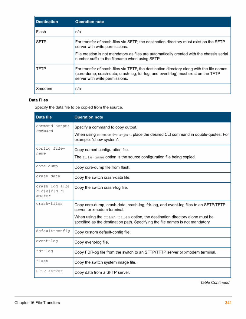
Destination Operation note
Flash n/a
SFTP For transfer of crash-files via SFTP, the destination directory must exist on the SFTPserver with write permissions.
File creation is not mandatory as files are automatically created with the chassis serialnumber suffix to the filename when using SFTP.
TFTP For transfer of crash-files via TFTP, the destination directory along with the file names(core-dump, crash-data, crash-log, fdr-log, and event-log) must exist on the TFTPserver with write permissions.
Xmodem n/a
Data Files
Specify the data file to be copied from the source.
Data file Operation note
command-outputcommand
Specify a command to copy output.
When using command-output, place the desired CLI command in double-quotes. Forexample: "show system".
config file-name
Copy named configuration file.
The file-name option is the source configuration file being copied.
core-dump Copy core-dump file from flash.
crash-data Copy the switch crash-data file.
crash-log a|b|c|d|e|f|g|h|master
Copy the switch crash-log file.
crash-files Copy core-dump, crash-data, crash-log, fdr-log, and event-log files to an SFTP/TFTPserver, or xmodem terminal.
When using the crash-files option, the destination directory alone must bespecified as the destination path. Specifying the file names is not mandatory.
default-config Copy custom default-config file.
event-log Copy event-log file.
fdr-log Copy FDR-og file from the switch to an SFTP/TFTP server or xmodem terminal.
flash Copy the switch system image file.
SFTP server Copy data from a SFTP server.
Table Continued
Chapter 16 File Transfers 341

Data file Operation note
startup-config Copy in-flash configuration file.
ssh-client-known-hosts Copy the known hosts file.
ssh-server-pub-key Copy the switch's SSH server public key.
running-config Copy running configuration file.
TFTP Copy data from a TFTP server.
xmodem Use xmodem on the terminal as the data source.
Destination
Specify the copy target.
Destination
SFTP
TFTP
USB (available only on the 2930M Switch Series)
xmodem
Destination
SFTP
TFTP
xmodem
Data Files
Specify the data file name at the target.
Data file
autorun-cert-fileautorun-key-filecommand fileconfigdefault-configflash
Table Continued
342 Aruba 2930F / 2930M Management and Configuration Guide for ArubaOS-Switch 16.05

Data file
pub-key-fileshow-techstartup-configssh-client-keyssh-client-known-hosts
Options
Option Operation note Requirement
append Add the keys for operator access. n/a
directory Directory name to upload. Required for TFTP and SFTP transfers.
filename File-name to upload/download. Required for TFTP and SFTP transfers.
hostname Hostname of the TFTP, SFTPserver.
Required for TFTP, SFTP transfers.
IPv4 address TFTP, SFTP server IPv4 address. Required for TFTP, SFTP transfers.
IPv6 address TFTP, SFTP server IPv6 address. Required for TFTP, SFTP transfers.
manager Replace the keys for manageraccess; follow with the appendoption to add the keys.
n/a
operator Replace the keys for operatoraccess (default); follow with theappend option to add the keys.
n/a
pc n/a
unix n/a
Multiple management switchesSyntax
copy crash-filesinterfaces
Copy interfaces crash files.
management
Copy management crash files.
Chapter 16 File Transfers 343

Destination
SFTP TFTP Xmodem
Slot-ID X X X
MM-active X X X
MM-standby X X X
Stacking switchesSyntax
copy crash-filesmember
Copy stack member crash files.
Options for member
Option Destination
SFTP TFTP USB xmodem
management X X X X
interfaces X X X X
Standalone switchesSyntax
copy crash-filesOptions
Option Destination
SFTP TFTP xmodem
management X X X
interfaces X X X
Crash file optionsSyntax
copy crash-files crash-file-options host-name-str | ip-addr | ipv6-addrsftp dirname-strOptions
344 Aruba 2930F / 2930M Management and Configuration Guide for ArubaOS-Switch 16.05

host-name-str
Specify hostname of the SFTP server.
ip-addr
Specify SFTP server IPv4 address.
ipv6–addr
Specify SFTP server IPv6 address.
user
Specify the username on the remote system.
username@ip-str
Specify the username along with remote system. Information (hostname, IPv4 or IPv6 address).
dirname-str
Specify the destination directory name.
Destination options
management
Copy management crash files.
Flight Data Recorder (FDR)The Flight Data Recorder (FDR) log collects information that is "interesting" when the switch is not performingcorrectly, but has not crashed. Runtime logs are written to FDR memory while the switch is running and crashtimelogs are collected and stored in the FDR buffer during a switch crash.
Syntax:
copy fdr-log [[slot < slot-list >] | [mm-active [[current] | [previous]]] | [mm-standby] | [all]] tftp [[< hostname] | [ip-addr >]] <filename>Copies fdr-log files to a user-specified file.
allCopies all the log files from both management modules and all slots.
mm-activeCopies the active management module's log.
mm-standbyCopies the standby management module's log.
slotRetrieves the crash log from the module in the identified slots.
USBThe USB port is available only on the 2930M Switch Series.
Chapter 16 File Transfers 345

usb-portSyntaxusb-port
no usb-portDescription
Enables the USB port.
The no form of the command disables the USB port and any access to the device.
Command contextConfig
show usb-portSyntaxshow usb-port
Description
Displays the status of the USB port. It can be enabled, disabled, or not present.
Command contextoperator
Usage
One of the following messages indicates the presence or absence of a USB device:
• Not able to sense device in USB port• USB device detected in port• no USB device detected in port
Example
Display USB port status.
switch# show usb-port
USB port status: enabled USB port power status: power on (USB device detected in port)
Downloading switch software using USB
Prerequisites
Procedure
1. Store a software version for the switch on a USB flash drive. (The latest software file is typically available fromthe Switch Networking website at http://www.hpe.com/networking/support.)
2. Insert the USB device into the switch's USB port.
346 Aruba 2930F / 2930M Management and Configuration Guide for ArubaOS-Switch 16.05

3. Determine the name of the software file stored on the USB flash drive (for example, K.0800.swi).
4. Decide whether the image will be installed in the primary or secondary flash.
Copying using USBTo copy the primary image to a USB flash drive:
Procedure
1. Insert a USB device into the switch's USB port.
2. Execute the command: switch# copy flash usb K.0800.swi primary/secondary where K.0800.swi is the name given to the primary flash image that is copied from the switch to the USB device.
copy flash usbSyntaxcopy flash usb <FILENAME> Description
Uses the USB port to copy the specified flash image from the switch to a USB flash memory device. The defaultsetting will use the primary image.
Copy a switch software file named K.0800.swi from a USB device to primary flash.
Procedure
1. Issue the copy usb flash command as shown below:
Figure 46: The command to copy switch software from USB
2. When the switch finishes copying the software file from the USB device, it displays this progress message:Validating and Writing System Software to the Filesystem....
3. When the save finishes, you must reboot the switch to load the newly loaded software.
4. To confirm that the software downloaded correctly, execute show system and check the Software revisionline.
copy usb command-fileSyntaxcopy usb command-file <FILENAME.TXT> [unix|pc]
Chapter 16 File Transfers 347

Description
Copies and executes the named text file from a USB flash drive and executes the ACL commands in the file.Depending on the ACL commands used, this action does one of the following in the running-config file:
• Creates a new ACL.
• Replaces an existing ACL.
• Adds to an existing ACL.
Parameters<FILENAME.TXT>
A text file containing ACL commands and stored in the USB flash drive.
unix|pcThe type of workstation used to create the text file.
Upload an ACL command file from USB
Using a PC workstation, execute the following from the CLI to upload the file to the switch and implement the ACLcommands it contains:
switch(config)# copy usb command-file vlan10_in.txt pcThe switch displays this message:
Running configuration may change, do you want to continue[y/n]?If the switch detects an illegal (non-ACL) command in the file, it bypasses the illegal command, displays a notice,and continues to implement the remaining ACL commands in the file.
USB autorunUSB autorun helps ease the configuration of Switch switches by providing a way to auto-execute CLI commandsfrom a USB flash drive. Using this solution, you can create a command file (also known as an AutoRun file), writeit to a USB storage device, and then execute the file simply by inserting the USB device into the switch's AuxiliaryPort. The AutoRun file is executed automatically when autorun is enabled on the switch and can be designed forvarious purposes, such as to configure the switch, to update software, or to retrieve diagnostic logs fortroubleshooting purposes.
The overall USB autorun solution requires the following components:
• A switch that can securely use USB autorun to load authorized configurations and write reporting information.
• A non-proprietary USB flash drive.
Using USB autorunThe general process for using USB autorun is as follows:
348 Aruba 2930F / 2930M Management and Configuration Guide for ArubaOS-Switch 16.05

Procedure
1. Create an AutoRun file.
2. See the Switch Manager documentation for details.
a. Specify the target device or devices.
b. Create the CLI script to be executed on the target devices.
c. Determine if the file will be signed and/or encrypted.
d. Determine if the file will be 'run once' (moved to a 'processed' directory on execution) or 'runmany' (kept in the root directory of the flash drive from where it can be executed again.)
3. Deploy the AutoRun file to a USB flash drive.
4. (If required) Enable the autorun feature on the switch (autorun is enabled by default unless an operator ormanager password has been set—See Autorun and configuring passwords on page 352.)
5. (If the AutoRun file has been signed or encrypted) Enable secure-mode on the switch:
a. Configure an encryption key and a valid trusted certificate
b. Enable secure-mode via the CLI.
6. Insert the USB flash drive into the switch's USB auxiliary port.
7. The switch processes the AutoRun file automatically and writes a result (.txt) file and report (.xml) file back tothe USB flash drive reporting on the command operations that were executed.
8. Remove the USB device from the USB port.
9. The switch executes any post-commands, such as rebooting the switch to apply any configuration updates.
10. See Troubleshooting autorun operations on page 350.
autorunSyntax[no] autorun [encryption-key <key-string> | secure-mode] Description
Enables or disables USB autorun on the switch.
Parameters and options
encryption-key
Configure the encryption key for Autorun. If in enhanced secure-mode, you will be prompted for the key.Encryption is regarded only when the AutoRun file is also signed by an authentic source.
secure-mode
Enable or disable secure mode for autorun. Defaults to enabled, or to disabled if a password has been set.
show autorunSyntaxshow autorun
Chapter 16 File Transfers 349

Description
Displays autorun configuration status information.
show autorun
switch(config)# show autorun
Autorun configuration status Enabled : Yes Secure-mode : Disabled Encryption-key :
Security considerationsBy default, the switch is unsecured when shipped (that is, USB autorun is enabled by default.) However, as soonas an operator or manager password is configured, autorun is disabled and must be re-enabled at theconfiguration level of the CLI before it can be used.
In terms of physical security, access to the switch's console port and USB port are equivalent. Keeping the switchin a locked wiring closet or other secure space helps to prevent unauthorized physical access. As additionalprecautions, you have the following configuration options via the CLI.
• Disable autorun by setting an operator or manager password.
• Disable or re-enable the USB autorun function via the CLI.
• Enable autorun in secure mode to verify signatures in autorun command files and to decrypt encryptedcommand files.
Troubleshooting autorun operationsUSB auxiliary port LEDsThe following table shows LED indications on the Auxiliary Port that allow you to identify the different USBoperation states.
Color State Meaning
Green Slow blinking Switch is processing USB AutoRun file.
Green Solid Switch has finished processing USB AutoRun file. This LED state indicates theAutoRun file was successfully executed and the report files were generated. You canreview the report files on a USB-enabled computer for more details. Upon removal ofthe USB device, the LED turns OFF.
Table Continued
350 Aruba 2930F / 2930M Management and Configuration Guide for ArubaOS-Switch 16.05

Color State Meaning
N/A Off Indicates one or more of the following:
• No USB device has been inserted.
• A USB device that cannot be recognized as a USB storage device has beeninserted.
• No AutoRun file can be found on the inserted USB device..
If the USB device has just been removed from the port, the switch executes any postcommands.
Amber Fast blinking Processing Error. The AutoRun file stops processing when an error is encountered (forexample, no more disk space is available on the USB device to write the result andreport files.) For more information on the error, remove the USB device and inspect itscontents on a USB-enabled computer.
AutoRun status files
Cause
The following files are generated during autorun operations and written to the USB flash drive:
• Report files (.xml files)—show which CLI commands have been run. The file name includes a serial numberand date/time stamp to indicate when and on which device the AutoRun file was executed.
• Result files (.txt files)—contain the CLI output for each command that was run on the switch, allowing you toverify whether a command was executed successfully or not.
The status files do not include any records of post commands that may have been executed after theUSB flash drive was removed from the switch.
Autorun secure mode
Cause
You can use autorun secure mode to verify the authenticity of autorun command files. Secure-mode is configuredusing the autorun secure-mode command and can be enabled under both of the following conditions:
• An encryption-key has already been configured using the autorun encryption key command.
• A trusted certificate for verifying autorun command files has been copied to the switch using the followingcommand:
copy sftp autorun-cert-file {<hostname> | <IP-Addr> | {IPv6-Adder> | <user> | <user@IP>} copy tftp autorun-cert-file {<hostname> | <IP-Addr> | <IPv6-Addr>} copy usb autorun-cert-file <filename>
Chapter 16 File Transfers 351

There is an additional security option to install a valid key-pair for signing the result files that aregenerated during autorun operations. You can generate the key-pair on the switch using the cryptokey generate autorun [rsa] command.
You can also install the key-pair from a tftp server or via the USB port using the following command:
copy sftp autorun-key-file {<hostname> | <IP-Addr> | {IPv6-Adder> | <user> | <user@IP>} copy tftp autorun-key-file {<hostname> | <IP-Addr> | <IPv6-Addr>} copy usb autorun-key-file <filename>The filename must contain the private key and the matching public key in a X509 certificate structure.Both the private key and the X509 certificate must be in PEM format.
Operating notes and restrictions
• Autorun is enabled by default, until passwords are set on the device.
• Secure-mode and encryption-key are disabled by default.
• To enable secure mode, both an encryption key and trusted certificate must be set.
• If secure-mode is enabled, the following conditions apply:
◦ The encryption-key cannot be removed or unconfigured.
◦ The key-pair cannot be removed.
• If secure mode is disabled, the key-pair can be removed using the crypto key zeorize autoruncommand.
• When installing the autorun certificate file and/or the other key files, the files must be in PEM format.
Autorun and configuring passwordsSymptom
switch# password managerNew password for manager: *****Please retype new password for manager: *****Autorun is disabled as operator/manager is configured.Cause
When an operator or manager password is configured on a switch, autorun is disabled automatically, and amessage is displayed on the screen.
Action
After passwords are set, you can re-enable autorun as needed using the autorun command.
352 Aruba 2930F / 2930M Management and Configuration Guide for ArubaOS-Switch 16.05

OverviewThe switches have several built-in tools for monitoring, analyzing, and troubleshooting switch and networkoperation:
• Status: Includes options for displaying general switch information, management address data, port status, portand trunk group statistics, MAC addresses detected on each port or VLAN, and STP, IGMP, and VLAN data.
• Counters: Display details of traffic volume on individual ports.
• Event Log: Lists switch operating events (Using the Event Log for troubleshooting switch problems onpage 483 ).
• Alert Log: Lists network occurrences detected by the switch—in the System > Logging screen of theWebAgent.
• Configurable trap receivers: Uses SNMP to enable management stations on your network to receive SNMPtraps from the switch.
• Port monitoring (mirroring): Copy all traffic from the specified ports to a designated monitoring port.
Link test and ping test—analysis tools in troubleshooting situations—are described in Troubleshooting on page 451. See Diagnostic tools on page 522.
Switch and network operationsThe switches have several built-in tools for monitoring, analyzing, and troubleshooting switch and networkoperation:
• Status
Includes options for displaying general switch information, management address data, port status, port andtrunk group statistics, MAC addresses detected on each port or VLAN, and STP, IGMP, and VLAN data.
• Counters
Display details of traffic volume on individual ports (Accessing port and trunk statistics (Menu) on page368.)
• Event Log
Lists switch operating events. See the HPE ProVision switch software troubleshooting guide fortroubleshooting information.
• Configurable trap receivers
Uses SNMP to enable management stations on your network to receive SNMP traps from the switch.
• Port monitoring (mirroring)
Chapter 17Monitoring and Analyzing Switch Operation
Chapter 17 Monitoring and Analyzing Switch Operation 353

Copy all traffic from the specified ports to a designated monitoring port .
Link test and ping test—analysis tools in troubleshooting situations—are described in the ProVisionSwitch Software Troubleshooting Guide.
Status and counters dataThis section describes the status and counters screens available through the switch console interface and/or theWebAgent.
You can access all console screens from the WebAgent via Telnet to the console. Telnet access tothe switch is available in the Device View window under the Configuration tab.
Accessing status and counters (Menu)Beginning at the Main Menu, display the Status and Counters menu by selecting:
1. Status and Counters
Figure 47: The Status and Counters menu
Each of the above menu items accesses the read-only screens described on the following pages. See the onlinehelp for a description of the entries displayed in these screens.
show systemSyntaxshow system [chassislocate|information|fans]Description
Displays global system information and operational parameters for the switch.
Parameters and optionschassislocate
Displays the chassisLocator LED status. Possible values are ON, Off, or Blink. When the status is On or Blink,the number of minutes that the Locator LED will continue to be on or to blink is displayed. (See Figure 48:Command results for show system chassislocate command on page 356.)
354 Aruba 2930F / 2930M Management and Configuration Guide for ArubaOS-Switch 16.05

informationDisplays global system information and operational parameters for the switch. (See Figure 50: Switchsystem information on page 356.)
power-supplyShows chassis power supply and settings.
temperatureShows system temperature and settings.
fansShows system fan status. (See Figure 49: System fan status on page 356.)
Chapter 17 Monitoring and Analyzing Switch Operation 355

show system chassislocate command
Figure 48: Command results for show system chassislocate command
Figure 49: System fan status
Figure 50: Switch system information
chassislocateSyntax
Description
Identifies the location of a specific switch by activating the blue locator LED on the front panel of the switch.
chassislocate [blink|on|off]Parameters and options
356 Aruba 2930F / 2930M Management and Configuration Guide for ArubaOS-Switch 16.05

blink <1–1440>Blinks the chassis locate LED for a specified number of minutes (Default: 30 min.)
on <1–1440>Turns the chassis locate LED on for a specified number of minutes (Default: 20 min.)
offTurns the chassis locate LED off.
Chassislocate at startupThe chassislocate command has an optional parameter that configures it to run in the future instead ofimmediately.
Syntaxchassislocate [on|blink] <MINUTES> at [now|startup]chassislocate offParameters and options<MINUTES>
Specify the number of minutes for the chassis locate LED to remain on or blink.
atSpecify when the command is applied (default immediately.)
nowTurn on the chassis locate LED immediately.
startupTurn on the chassis locate LED at switch startup.
offTurn off the chassis locate LED switch
chassislocate at startup
chassislocate blink 10 at startup
show system chassislocateSyntaxshow system chassislocateDescription
Displays the current status of the chassislocate settings.
Display locator LED status
Locator LED Status Current TimeMember State Remaining Configuration------ ------- --------- -------------1 blink 00:27:05 blink 30 at startup
Chapter 17 Monitoring and Analyzing Switch Operation 357

2 on 01:05:273 off
General system information
Accessing system information (Menu)From the console Main Menu, select:
1. Status and Counters
1. General System Information
Figure 51: Example: of general switch information
This screen dynamically indicates how individual switch resources are being used. See the online Help for details.
Accessing system information (CLI)Syntax:
show system [chassislocate | information | fans | power-supply | temperature]Displays global system information and operational parameters for the switch.
chassislocate Shows the chassisLocator LED status. Possible values are On,Off, or Blink.When the status is On or Blink, the number of minutesthat the Locator LED will continue to be on or to blink is displayed.(See Command results for show system chassislocatecommand on page 358)
information Shows global system information and operational parameters forthe switch. (See Switch system information on page 359.)
fans Shows system fan status. (See System fan status on page 359.)
Command results for show system chassislocate command
switch(config)# show system chassislocate
358 Aruba 2930F / 2930M Management and Configuration Guide for ArubaOS-Switch 16.05

Chassis Locator LED: ON 5 minutes 5 seconds
switch(config)# show system chassislocate
Chassis Locator LED: BLINK 10 minutes 6 seconds
switch(config)# show system chassislocate
Chassis Locator LED: OFF
System fan status
switch(config)# show system fans
Fan Information Num | State | Failures-------+-------------+---------- Sys-1 | Fan OK | 0
0 / 1 Fans in Failure State0 / 1 Fans have been in Failure State
Switch system information
switch(config)# show system
Status and Counters - General System Information
System Name : HP Switch System Contact : System Location :
MAC Age Time (sec) : 300
Time Zone : 0 Daylight Time Rule : None
Software revision : T.13.XX Base MAC Addr : 001635-b57cc0 ROM Version : XX.12.12 Serial Number : LP621KI005
Up Time : 51 secs Memory - Total : 152,455,616 CPU Util (%) : 3 Free : 100,527,264
IP Mgmt - Pkts Rx :0 Packet - Total : 6750 Pkts Tx :0 Buffers Free : 5086 Lowest : 5086 Missed : 0
Collecting processor data with the task monitor (CLI)The task monitor feature allows you to enable or disable the collection of processor utilization data. The task-monitor cpu command is equivalent to the existing debug mode command taskusage -d.
When the task-monitor command is enabled, the show cpu command summarizes the processor usage byprotocol and system functions.
Syntax:
[no] task-monitor cpuAllows the collection of processor utilization data.
Chapter 17 Monitoring and Analyzing Switch Operation 359

Only manager logins can execute this command.
The settings are not persistent, that is, there are no changes to the configuration.
(Default: Disabled)
The task-monitor cpu command and show cpu output
switch(config)# task-monitor cpuswitch(config)# show cpu
2 percent busy, from 2865 sec ago1 sec ave: 9 percent busy5 sec ave: 9 percent busy1 min ave: 1 percent busy
% CPU | Description-------+----------------- 99 | Idle
task-monitor cpuSyntax
[no] task-monitor cpuDescription
Enables or disables the collection of processor utilization data, and requires a manager log in. Settings are notpersistent; there are no changes to the configuration. Defaults to disabled.
task-monitor cpu command
Figure 52: The task-monitor cpu command and show cpu output
360 Aruba 2930F / 2930M Management and Configuration Guide for ArubaOS-Switch 16.05

Accessing system information (Menu)From the console Main Menu, select 1. Status and Counters, and then select 1. General System Information.
Figure 53: Example of general switch information
This screen dynamically indicates how individual switch resources are being used. See the online help for details.
Switch management address information access
show managementSyntaxshow managementDescription
Displays switch management address information.
Accessing switch management address information (Menu)From the Main Menu, select 1. Status and Counters ... , and then select 2. Switch Management AddressInformation.
Figure 54: Example of management address information with VLANs configured
This screen displays addresses that are important for management of the switch. If multiple VLANs are notconfigured, this screen displays a single IP address for the entire switch. See the online help for details.
Chapter 17 Monitoring and Analyzing Switch Operation 361

As shown in Figure 54: Example of management address information with VLANs configured on page 361,all VLANs on the switches use the same MAC address. (This includes both the statically configured VLANs andany dynamic VLANs existing on the switch as a result of GVRP operation.)
Also, the switches use a multiple forwarding database. When using multiple VLANs and connecting a switch to adevice that uses a single forwarding database, such as a Switch 4000M, there are cabling and tagged port VLANrequirements.
Component information viewsThe CLI show modules command displays additional component information for the following:
• SSM—identification, including serial number
• Mini-GBICS—a list of installed mini-GBICs displaying the type, "J" number, and serial number (when available)
show modulesSyntaxshow modulesDescription
Displays information about the installed modules (Figure 55: The show modules command output on page362), including:
• The slot in which the module is installed
• The module description
• The serial number
Additionally, this command displays the part number (J number) and serial number of the chassis. (See Figure56: The show modules details command for the 8212zl, showing SSM and mini-GBIC information on page363.)
show modules command
Figure 55: The show modules command output
362 Aruba 2930F / 2930M Management and Configuration Guide for ArubaOS-Switch 16.05

show modules details command
Figure 56: The show modules details command for the 8212zl, showing SSM and mini-GBIC information
Viewing port status (Menu)From the Main Menu, select 1. Status and Counters ... , and then select 3. Module Information.
Task usage reportingThe task usage reporting feature provides the ability to collect and display CPU usage data (with a refresh rate of5 seconds) of running tasks on the switch. It includes the following commands:
• process-tracking: This command is used to enable/disable the task-usage collecting capability for aspecific module on the switch.
• show cpu process: This command is used to display task-usage statistics for a specific module.
Syntax:[no] process-tracking [slot[SLOT-LIST] [<time>]] [<time>]Enables/disables module process-tracking functionality.
process-tracking <tab>
slot Enables/disables process-tracking for a module.
INTEGER Specifies time to track value between 1 second to 30 seconds.
<cr>
process-tracking slot <tab>
SLOT-ID-RANGE Enter an alphabetic device slot identifier or slot range.
process-tracking slot A
INTEGER Specifies time to track value between 1 second to 30 seconds.
<cr>
process-tracking slot A 10 <tab>
<cr>
Chapter 17 Monitoring and Analyzing Switch Operation 363

process-tracking 10 <tab>
<cr>
Syntax:show cpu [<CHASSIS_MIN_CPU_UTIL_INDEX-CHASSIS_MAX_CPU_UTIL_INDEX>][slot <SLOT-LIST>[<CHASSIS_MIN_CPU_UTIL_INDEX-CHASSIS_MODULE_MAX_CPU_UTIL_INDEX>]][process [[slot <SLOT-LIST>] [refresh <iterations>]][refresh <iterations>]Shows average CPU utilization over the last 1, 5, and 60 seconds, or the number of seconds specified.
Use the slot option to display CPU utilization for the specified modules, rather than the chassis CPU.
Use the process option to display module process usages.
Syntax:show cpu process [slot [SLOT-LIST][refresh <iterations>]][refresh <iterations>]Displays module process usage.
show cpu <tab>
process Displays process usage.
slot Displays module CPU statistics.
<1-300> Time (in seconds) over which to average CPU utilization.
<cr>
show cpu process <tab>
refresh Number of times to refresh process usage display.
slot Displays module process usage.
<cr>
show cpu process refresh <tab>
INTEGER Enter an integer number.
show cpu process refresh 10 <tab>
<cr>
show cpu process slot <tab>
SLOT-ID-RANGE Enter an alphabetic device slot identifier or slot range.
show cpu process slot A <tab>
364 Aruba 2930F / 2930M Management and Configuration Guide for ArubaOS-Switch 16.05

refresh Number of times to refresh process usage display.
<cr>
show cpu process slot A refresh <tab>
INTEGER Enter an integer number.
show cpu process slot A refresh 10 <tab>
<cr>
Output for the show cpu process command
switch# show cpu process
| Recent | % | Time Since | Times | MaxProcess Name | Priority | Time | CPU | Last Ran | Ran | Time----------------- + --------- + ------ + ---- + ---------- + ------ + -------Idle-1 | 226 | 10 s | 41 | 57 us | 380986 | 69 usIdle-3 | 1 | 5 s | 20 | 52 us | 761665 | 55 usIdle-0 | 226 | 8 s | 33 | 19 us | 380867 | 66 usSessions & I/O-24 | 171 | 926 ms | 3 | 1 ms | 150 | 335 ms
Output for the show cpu process slot <slot-list> command
switch# show cpu process slot Aslot a:
| Recent | % | Time Since | Times | MaxProcess Name | Priority | Time | CPU | Last Ran | Ran | Time----------------- + --------- + ------ + ---- + ---------- + ------ + -------System Services-2 | 156 | 253 ms | 2 | 767 ms | 12 | 35 msIdle-3 | 1 | 3 s | 28 | 13 ms | 101309 | 150 usHardware Mgmt-2 | 192 | 282 ms | 2 | 303 us | 44 | 12 msIdle-1 | 226 | 6 s | 55 | 13 ms | 50793 | 233 usIdle-0 | 226 | 1 s | 9 | 14 ms | 50633 | 106 us
Switch management address information
Accessing switch management address information (Menu)From the Main Menu, select:
1. Status and Counters ...
Chapter 17 Monitoring and Analyzing Switch Operation 365

2. Switch Management Address Information
Figure 57: Example: of management address information with VLANs configured
This screen displays addresses that are important for management of the switch. If multiple VLANs are notconfigured, this screen displays a single IP address for the entire switch. See the online Help for details.
Accessing switch management address information (CLI)Syntax:
show management
Port StatusThe WebAgent and the console interface show the same port status data.
Viewing port status (CLI)Syntax:
show interfaces brief
Viewing port status (Menu)From the Main Menu, select:
1. Status and Counters ...
366 Aruba 2930F / 2930M Management and Configuration Guide for ArubaOS-Switch 16.05
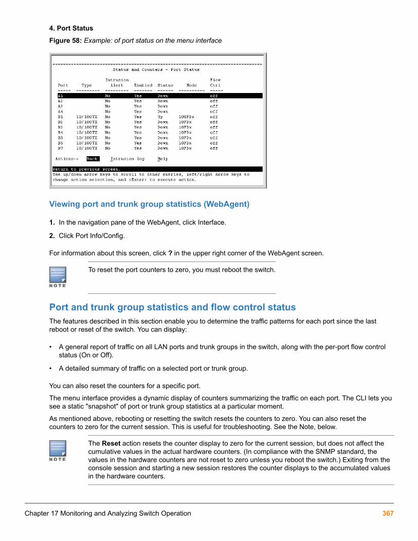
4. Port Status
Figure 58: Example: of port status on the menu interface
Viewing port and trunk group statistics (WebAgent)
1. In the navigation pane of the WebAgent, click Interface.
2. Click Port Info/Config.
For information about this screen, click ? in the upper right corner of the WebAgent screen.
To reset the port counters to zero, you must reboot the switch.
Port and trunk group statistics and flow control statusThe features described in this section enable you to determine the traffic patterns for each port since the lastreboot or reset of the switch. You can display:
• A general report of traffic on all LAN ports and trunk groups in the switch, along with the per-port flow controlstatus (On or Off).
• A detailed summary of traffic on a selected port or trunk group.
You can also reset the counters for a specific port.
The menu interface provides a dynamic display of counters summarizing the traffic on each port. The CLI lets yousee a static "snapshot" of port or trunk group statistics at a particular moment.
As mentioned above, rebooting or resetting the switch resets the counters to zero. You can also reset thecounters to zero for the current session. This is useful for troubleshooting. See the Note, below.
The Reset action resets the counter display to zero for the current session, but does not affect thecumulative values in the actual hardware counters. (In compliance with the SNMP standard, thevalues in the hardware counters are not reset to zero unless you reboot the switch.) Exiting from theconsole session and starting a new session restores the counter displays to the accumulated valuesin the hardware counters.
Chapter 17 Monitoring and Analyzing Switch Operation 367

Accessing port and trunk statistics (Menu)From the Main Menu, select:
1. Status and Counters ...
4. Port Counters
Figure 59: Example: of port counters on the menu interface
To view details about the traffic on a particular port, use the ↓ key to highlight that port number, then select ShowDetails . For example, selecting port A2 displays a screen similar to Figure 60: Example: of the display forShow Details on a selected port on page 368, below.
Figure 60: Example: of the display for Show Details on a selected port
This screen also includes the Reset action for the current session.
Once cleared, statistics cannot be reintroduced.
Accessing port and trunk group statistics (CLI)
368 Aruba 2930F / 2930M Management and Configuration Guide for ArubaOS-Switch 16.05

Viewing the port counter summary reportSyntax:
show interfacesProvides an overview of port activity for all ports on the switch.
Viewing a detailed traffic summary for specific portsSyntax:
show interfaces <port-list>Provides traffic details for the ports you specify.
Displaying trunk load balancing statisticsTo display trunk counters information since the trunk was formed with the given ports. If ports are added orremoved from the trunk-groups, statistical data is reset.
Syntax:
show trunk-statistics <trunk-group>Displays the trunk counter information since the trunk was formed.
Ouptut for the show trunk-statistics command
switch(config)# show trunk-statistics trk1
Group : Trk1 Ports : 3,4 Monitoring time : 23 hours 15 minutes
Totals
Packets Rx : 3,452,664 Bytes Rx : 14,004,243 Packets Tx : 2,121,122 Bytes Tx : 2,077,566 Packets Tx Drop :
Rates (5 minute weighted average): Trunk utilization Rx : 30.2 % Trunk utilization Tx : 78.2 %
Traffic Spread past 5 minutes
Port | %Tx | %Rx | Bytes Rx | Bytes Tx | Dropped Frame-Tx ---- + ----- + ----- + ---------- + ---------- + ---------------- 3 | 27 | 42 | 1,223,445 | 2,112,122 | 123,122 4 | 73 | 58 | 356,233 | 993,222 | 0
Clearing trunk load balancing statisticsTo display trunk counters information since the trunk was formed with the given ports. If ports are added orremoved from the trunk-groups, statistical data is reset. The data is for a specific trunk.
Syntax:
clear trunk-statistics <trunk-group>Clears statistics for all trunks if no trunks identified.
Chapter 17 Monitoring and Analyzing Switch Operation 369

trunk-group: Clears specific trunk counter information since the trunk was formed.
Resetting the port countersIt is useful to be able to clear all counters and statistics without rebooting the switch when troubleshooting networkissues. The clear statistics global command clears all counters and statistics for all interfaces exceptSNMP. You can also clear the counters and statistics for an individual port using the clear statistics<port-list> command.
Syntax:
clear statistics {<< port-list > | global>}When executed with the port-list option, clears the counters and statistics for an individual port.
When executed with the global option, clears all counters and statistics for all interfaces except SNMP.
The show interfaces [<port-list>] command displays the totals accumulated since the last boot or thelast clear statistics command was executed. The menu page also displays these totals.
SNMP displays the counter and statistics totals accumulated since the last reboot; it is not affected by the clearstatistics global command or the clear statistics <port-list> command. An SNMP trap is sentwhenever the statistics are cleared.
Viewing the switch's MAC address tables
Accessing MAC address views and searches (CLI)Syntax:
show mac-address [vlan < vlan-id>] [<port-list>] [< mac-addr >]Listing all learned MAC addresses on the switch, with the port number on which eachMAC address was learned
HP Switch# show mac-address
Listing all learned MAC addresses on one or more ports, with their corresponding portnumbersFor example, to list the learned MAC address on ports A1 through A4 and port A6:
HP Switch# show mac-address a1-a4,a6
Listing all learned MAC addresses on a VLAN, with their port numbersThis command lists the MAC addresses associated with the ports for a given VLAN. For Example:
HP Switch# show mac-address vlan 100
The switches operate with a multiple forwarding database architecture.
Finding the port on which the switch learned a specific MAC addressFor example, to find the port on which the switch learns a MAC address of 080009-21ae84:
370 Aruba 2930F / 2930M Management and Configuration Guide for ArubaOS-Switch 16.05

Accessing MAC address views and searches (Menu)Viewing and searching per-VLAN MAC-addressesThis feature lets you determine which switch port on a selected VLAN is being used to communicate with aspecific device on the network.
From the Main Menu, select:
1. Status and Counters ...
5. VLAN Address Table
Procedure
1. The switch then prompts you to select a VLAN.
2. Use the Space bar to select the VLAN you want, and then press [Enter].
The switch then displays the MAC address table for that VLAN:
Figure 61: Example: of the address table
To page through the listing, use Next page and Prev page
Finding the port connection for a specific device on a VLANThis feature uses a device's MAC address that you enter to identify the port used by that device.
Procedure
1. Proceeding from the figure above, press [S] (for Search ), to display the following prompt:
Chapter 17 Monitoring and Analyzing Switch Operation 371

Enter MAC address: _2. Enter the MAC address you want to locate and press [Enter].
The address and port number are highlighted if found (figure below). If the switch does not find the MACaddress on the currently selected VLAN, it leaves the MAC address listing empty.
Figure 62: Example: of menu indicating located MAC address
3. Press [P] (for Prev page ) to return to the full address table listing.
Viewing and searching port-level MAC addressesThis feature displays and searches for MAC addresses on the specified port instead of for all ports on the switch.
Procedure
1. From the Main Menu, select:
1. Status and Counters ...
7. Port Address Table
2. Use the Space bar to select the port you want to list or search for MAC addresses, then press [Enter] to listthe MAC addresses detected on that port.
Determining whether a specific device is connected to the selected portProceeding from Step 2, above:
Procedure
1. Press [S] (for Search), to display the following prompt:
Enter MAC address: _2. Enter the MAC address you want to locate and press [Enter].
The address is highlighted if found. If the switch does not find the address, it leaves the MAC address listingempty.
3. Press [P] (for Prev page) to return to the previous per-port listing.
372 Aruba 2930F / 2930M Management and Configuration Guide for ArubaOS-Switch 16.05

Accessing MSTP Data (CLI)Syntax:
show spanning-treeDisplays the switch's global and regional spanning-tree status, plus the per-port spanning-tree operation at theregional level.
Values for the following parameters appear only for ports connected to active devices: Designated Bridge,Hello Time, PtP, and Edge.
Example:
Figure 63: Output from show spanning-tree command
Viewing internet IGMP status (CLI)The switch uses the CLI to display the following IGMP status on a per-VLAN basis:
Chapter 17 Monitoring and Analyzing Switch Operation 373

Show command Output
show ip igmp Global command listing IGMP status for all VLANs configured in theswitch:
• VLAN ID (VID) and name
• Querier address
• Active group addresses per VLAN
• Number of report and query packets per group
• Querier access port per VLAN
show ip igmp config Displays the IGMP configuration information, including VLAN ID, VLANname, status, forwarding, and Querier information.
show ip igmp <vlan-id> Per-VLAN command listing above, IGMP status for specified VLAN (VID)
show ip igmp group <ip-addr> Lists the ports currently participating in the specified group, with port
type, Access type, Age Timer data and Leave Timer data.
show ip igmp groups Displays VLAN-ID, group address, uptime, expiration time, multicast filtertype, and the last reporter for IGMP groups.
show ip igmp statistics Displays IGMP operational information, such as VLAN IDs and names,and filtered and flooding statistics.
Output from show ip igmp config command
switch(config)# show ip igmp config
IGMP Service
IGMP Forward with Querier Querier VLAN ID VLAN Name Enabled High Priority Allowed Internal ------- ------------ ------- ------------- ------- -------- 1 DEFAULT_VLAN No No Yes 125 2 VLAN2 Yes No Yes 125 12 New_VLAN No No Yes 125
IGMP statistical information
switch(vlan-2)# show ip igmp statistics
IGMP Service Statistics
Total VLANs with IGMP enabled : 1 Current count of multicast groups joined : 1
IGMP Joined Groups Statistics
VLAN ID VLAN Name Filtered Flood
374 Aruba 2930F / 2930M Management and Configuration Guide for ArubaOS-Switch 16.05

------- -------------------------------- ------------ ------------ 2 VLAN2 2 1
Viewing VLAN information (CLI)
Show command Output
show vlan Lists:
• Maximum number of VLANs to support
• Existing VLANs
• Status (static or dynamic)
• Primary VLAN
show vlan <vlan-id> For the specified VLAN, lists:
• Name, VID, and status (static/dynamic)
• Per-port mode (tagged, untagged, forbid, no/auto)
• "Unknown VLAN" setting (Learn, Block, Disable)
• Port status (up/down)
Example:
Suppose that your switch has the following VLANs:
Ports VLAN VID
A1-A12 DEFAULT_VLAN 1
A1, A2 VLAN-33 33
A3, A4 VLAN-44 44
The next three examples show how you could list data on the above VLANs.
Listing the VLAN ID (vid) and status for specific ports
HP Switch# show vlan ports A1-A2
Status and Counters = VLAN Information - for ports A1,A2
802.1Q VLAN ID Name Status -------------- ------------ ------ 1 DEFAULT_VLAN Static 33 VLAN-33 StaticNote: Because ports A1 and A2 are not members of VLAN-44, it does not appear in this listing.
Chapter 17 Monitoring and Analyzing Switch Operation 375

VLAN listing for the entire switch
HP Switch# show vlan Status and Counters = VLAN Information
VLAN support : Yes Maximum VLANs to support : 9 Primary VLAN: DEFAULT_VLAN
802.1Q VLAN ID Name Status -------------- ------------ ------ 1 DEFAULT_VLAN Static 33 VLAN-33 Static 44 VLAN-44 Static
Port listing for an individual VLAN
switch(config)# show vlan 1 Status and Counters - VLAN Information - VLAN 1
VLAN ID : 1 Name : DEFAULT_VLAN Status : Static Voice : Yes Jumbo : No
Port Information Mode Unknown VLAN Status ---------------- -------- ------------ ------ A1 Untagged Learn Up A2 Untagged Learn Up A3 Untagged Learn Up A4 Untagged Learn Down A5 Untagged Learn Up A6 Untagged Learn Up A7 Untagged Learn Up
376 Aruba 2930F / 2930M Management and Configuration Guide for ArubaOS-Switch 16.05

WebAgent status informationThe WebAgent Status screen provides an overview of the status of the switch. Scroll down to view more details.For information about this screen, click on ? in the upper right corner of the WebAgent screen. For an Example: ofa status screen, see Figure 64: Example: of a WebAgent status screen on page 377.
Figure 64: Example: of a WebAgent status screen
Compatibility mode for v2 zl and zl modulesIn the following context, v2 zl modules are the second version of the current zl modules.
Compatibility Mode allows the inter-operation of v2 zl modules with zl modules in a chassis switch. When inCompatibility Mode, the switch accepts either v2 zl or zl modules. The default is Compatibility Mode enabled. IfCompatibility Mode is disabled by executing the no allow-v1-modules command, the switch will only powerup v2 zl modules.
allow-v1-modulesSyntax[no] allow-v1-modulesEnables Compatibility Mode for interoperation of v2 zl and zl modules in the same chassis. (See Figure 65:Enabling compatibility mode on page 378.) The no form of the command disables Compatibility Mode. Onlythe v2 zl modules are powered up. (See Figure 66: Disabling compatibility mode on page 378.) Defaults toenabled.
Chapter 17 Monitoring and Analyzing Switch Operation 377

allow-v1–modules
Figure 65: Enabling compatibility mode
no allow-v1–modules
Figure 66: Disabling compatibility mode
Port statusYou can view port status using either the CLI or the menu.
show interfaces briefSyntaxshow interfaces briefDescription
View the port status.
Viewing port status (menu)From the Main Menu, select 1. Status and Counters ... , and then select 4. Port Status.
Figure 67: Example of port status on the menu interface
Accessing port and trunk group statisticsUse the CLI to view port counter summary reports, and to view detailed traffic summary for specific ports.
378 Aruba 2930F / 2930M Management and Configuration Guide for ArubaOS-Switch 16.05

Trunk bandwidth utilization
• Trunk interface counters display the accumulated statistics over the trunk members' ports since the time theyare added into trunk.
• Bandwidth utilization for trunks is calculated by averaging the value of the sum of bandwidth utilization for eachtrunk member in the last 5 minute interval .
show interfaces
Syntaxshow interfaces [brief | config | <PORT-LIST>]
Description
Shows interface information for ports or trunk groups in brief or configuration detail.
Command contextoperator or manager
Parametersbrief
Shows the current operating status for all ports or trunk groups on the switch in brief detail.
configShows the configuration data for all ports or trunk groups on the switch.
<PORT-LIST>
Specifies the list of ports for which status information will be shown.
<TRUNK-GROUP>
Specifies the trunk group for which status information will be shown. The status information shown consists oftotal transmit and receive counters and weighted average rate for the trunk group specified. The weightedaverage rate is calculated in 5 minute intervals.
Usage
Both external and internal ports are supported on the same module. Internal ports have an “I” suffix in the outputof the show command to indicate that they are internal ports.
• “10GbE-INT” – Internal 10G data-plane ports (1i-2i, 4i-5i)
• “1GbE-INT” – Internal 1G control-plane port (3i)
• Port 3i always shows as link-down.
Examples
Show brief information and status of all interfaces.
switch# show interfaces brief
Status and Counters - Port Status | Intrusion MDI Flow BcastPort Type | Alert Enabled Status Mode Mode Ctrl Limit----- --------- + --------- ------- ------ ---------- ----- ----- ------
Chapter 17 Monitoring and Analyzing Switch Operation 379

B1 100/1000T | No Yes Down Auto-10-100 Auto off 0B2 100/1000T | No Yes Down 1000FDx Auto off 0B3 100/1000T | No Yes Down 1000FDx Auto off 0B4 100/1000T | No Yes Down 1000FDx Auto off 0B5 100/1000T | No Yes Down 1000FDx Auto off 0B6 100/1000T | No Yes Down 1000FDx Auto off 0Show the configuration of the interfaces currently available.
switch# show interfaces config
Port Settings Port Type | Enabled Mode Flow Ctrl MDI ----- --------- + ------- ------------ --------- ---- B1 100/1000T | Yes Auto-10-100 Disable Auto B2 100/1000T | Yes Auto Disable Auto B3 100/1000T | Yes Auto Disable Auto B4 100/1000T | Yes Auto Disable Auto B5 100/1000T | Yes Auto Disable Auto B6 100/1000T | Yes Auto Disable Auto Show brief information and status of interfaces for ports D1i, D2i, and D3i.
switch# show interfaces brief d1i-d3i
Status and Counters - Port Status | Intrusion MDI Flow BcastPort Type | Alert Enabled Status Mode Mode Ctrl Limit------ ---------- + --------- ------- ------ ---------- ---- ---- -----D1i 10GbE-INT | No Yes Up 10GigFD NA off 0D2i 10GbE-INT | No Yes Up 10GigFD NA off 0D3i 1GbE-INT | No Yes Down 1000FDx NA off 0Show the brief information and status of interfaces for ports B1 through internal port B3i.
switch# show interfaces brief b1-b3i
Status and Counters - Port Status | Intrusion MDI Flow Bcast Port Type | Alert Enabled Status Mode Mode Ctrl Limit ------ ---------- + --------- ------- ------ ---------- ---- ---- ----- B1 100/1000T | No Yes Down 1000FDx Auto off 0 B2 100/1000T | No Yes Down 1000FDx Auto off 0 B3 100/1000T | No Yes Down 1000FDx Auto off 0 B4 100/1000T | No Yes Down 1000FDx Auto off 0 B5 100/1000T | No Yes Down 1000FDx Auto off 0 B6 100/1000T | No Yes Down 1000FDx Auto off 0 B7 100/1000T | No Yes Down 1000FDx Auto off 0 B8 100/1000T | No Yes Down 1000FDx Auto off 0 B9 100/1000T | No Yes Down 1000FDx Auto off 0 B10 100/1000T | No Yes Down 1000FDx Auto off 0 B11 100/1000T | No Yes Down 1000FDx Auto off 0 B12 100/1000T | No Yes Down 1000FDx Auto off 0 B1i 10GbE-INT | No Yes Up 10GigFD NA off 0 B2i 10GbE-INT | No Yes Up 10GigFD NA off 0 B3i 1GbE-INT | No Yes Up 1000FDx NA off 0Show detailed interface information for port trunk 1.
switch# show interface trk1
Status and Counters - Port Counters for port Trk1 Name : Trk1 MAC Address : 3464a9-b1b8bf
380 Aruba 2930F / 2930M Management and Configuration Guide for ArubaOS-Switch 16.05

Link Status : Up Totals (Since boot or last clear) : Bytes Rx : 777,713,956 Bytes Tx : 596,853,141 Unicast Rx : 1,154,693 Unicast Tx : 0 Bcast/Mcast Rx : 48,563 Bcast/Mcast Tx : 607,474,910 Errors (Since boot or last clear) : FCS Rx : 0 Drops Tx : 0 Alignment Rx : 0 Collisions Tx : 0 Runts Rx : 0 Late Colln : 0 Giants Rx : 0 Excessive Colln : 0 Total Rx Errors : 0 Deferred Tx : 0 Others (Since boot or last clear) : Discard Rx : 0 Out Queue Len : 0 Unknown Protos : 0 Rates (5 minute weighted average) : Total Rx(Kbps) : 76,800 Total Tx(Kbps): 76,800 Unicast Rx (Pkts/sec) : 21 Unicast Tx (Pkts/sec) : 0 B/Mcast Rx (Pkts/sec) : 114,878 B/Mcast Tx (Pkts/sec) : 114,900 Utilization Rx : 00.76 % Utilization Tx : 00.76 %
show interfaces trunk-utilization
Syntaxshow interfaces trunk-utilization
Description
Shows the bandwidth utilization calculations for all trunk members.
Command context
operator or manager
Example
Show bandwidth utilization for trunks.
Switch(config)# show interfaces trunk-utilization
Status and Counters - Port Utilization
Rx Tx Port | --------------------------- | --------------------------- | Kbits/sec Pkts/sec Util | Kbits/sec Pkts/sec Util -------- ---------- ----- + ---------- ---------- --------- ----- Trk1 | 0 0 0 | 0 0 0 Trk2 | 0 0 0 | 0 0 0 Trk10 | 0 0 0 | 0 0 0
Statistic interactions of interface counters
Table 22: Statistic interactions
Interface counters are cleared using the command clear statistics. When certain actions are taken to portsand trunks, the outcome of the clear command differs.
Chapter 17 Monitoring and Analyzing Switch Operation 381

Action taken Trigger Interaction with interface counter
Adding Portinto trunk
CLI/SNMP• Interface counters for this port will be cleared across all sessions.
• Average rate counters are not cleared.
RemovingPort fromtrunk
CLI/SNMP• Interface counters for this port will be cleared across all sessions.
• Average rate counters are not cleared.
Trunk portcoming Up
CLI enable• No change in counters.
• Interface counters for this port are not cleared.
• Average rate counters are not cleared. Counters will start from 0 when thetrunk port comes up.
Trunk portcoming Up
Cable connect• No change in counters.
• Interface counters for this port are not cleared.
• Average rate counters are not cleared. Counters will start from 0 when thetrunk port comes up.
Trunk portgoing Down
CLI disable• Interface counters for this port are not cleared.
• Average rate counters are cleared.
Trunk portgoing Down
Cabledisconnect • Interface counters for this port are not cleared.
• Average rate counters are cleared.
Trunk portgoing Down
Module crash/module reload • Interface counters for this port are not cleared.
• Average rate counters are cleared.
Trunk portgoing Down
Save power - off• Interface counters for this port are not cleared.
• Average rate counters are cleared.
Trunk portgoing Down
Stackingmember reboot/crash/shutdown.
• Interface counters for this port are not cleared.
• Average rate counters of this port is not cleared.
• Utilization for the port is cleared.
• Utilization for the trunk group is updated accordingly
Table Continued
382 Aruba 2930F / 2930M Management and Configuration Guide for ArubaOS-Switch 16.05

Action taken Trigger Interaction with interface counter
Trunk portgoing Down
Module remove/member remove. • Statistics for removed trunk port can not be accessed as the port is
removed.
• Interface counters for the trunk group is updated.
• Utilization for the trunk group is updated.
Clearstatistics onphysical portwhich is partof trunk
CLI• Not allowed.
• The error message Module not present for port or invalidport: <PORT-NUM> displays when the command clear statistics isexecuted on a port which part of a trunk.
Clearstatistics ontrunk.
CLI• Interface counters for physical ports which are part of trunk will be cleared.
• Average rate counters are not cleared.
Reset port countersWhen troubleshooting network issues, you can clear all counters and statistics without rebooting the switch usingthe clear statistics global command or using the menu.
SNMP displays the counter and statistics totals accumulated since the last reboot, and it is not affected by theclear statistics global command or the clear statistics <PORT-LIST> command. Clearingstatistics initiates an SNMP trap.
Once cleared, statistics cannot be reintroduced.
clear statisticsSyntaxclear statistics [<PORT-LIST>|global] Description
This command clears all counters and statistics for all interfaces except SNMP.
Parameters and options<PORT-LIST>
Clears the counters and statistics for specific ports.
globalClears all counters and statistics for all interfaces except SNMP.
Chapter 17 Monitoring and Analyzing Switch Operation 383

Accessing port and trunk statistics (Menu)
Procedure
1. From the Main Menu, select 1. Status and Counters ... , and then select 4. Port Counters.
Figure 68: Example of port counters on the menu interface
2. To view details about the traffic on a particular port, use the ↓ key to highlight that port number, and then selectShow Details . For example, selecting port A2 displays a screen similar to the example below.
Figure 69: Example of the display for Show Details on a selected port
This screen also includes the Reset action for the current session.
MAC address tables
MAC address views and searchesYou can view and search MAC addresses using the CLI or the menu.
384 Aruba 2930F / 2930M Management and Configuration Guide for ArubaOS-Switch 16.05

show mac-add detail
Syntaxshow mac-address detail
Description
Shows the age of the learned MAC addresses in the MAC table. The age of a specific MAC-address will bedisplayed in dd:hr:min:sec.msec format.
Command contextmanager
Examplesshow mac-add detail on a specified switch.
switch# show mac-add detail
Status and Counters - Port Address Table
MAC Address Port VLAN Age (d:h:m:s.ms) ----------------- ------------------------------- ---- ---------------- 3c4a92-31c100 F23 1 0000:00:00:00.34 9cb654-ce6169 A2 1 0000:00:02:37.93 c09134-cd2740 F23 1 0000:00:00:00.28 c09134-cd277d F23 1 0000:00:00:23.62 f0921c-85b0e0 F24 1 0000:00:00:08.29 f0921c-85b0e9 F24 1 0000:00:00:09.47show mac-add detail for Vxlan Tunnel supporting and non-supporting platforms.
switch# show mac-address detail Status and Counters - Port Address Table MAC Address Port VLAN Age (d:h:m:s.ms) ----------------- ------------------------------- ---- ---------------- f0921c-b6e940 L22 1 0000:00:23:26.93 0180c2-00000f A24 50 0000:00:00:00.00 d18cc2-00000f A24 50 0001:21:43:59.92 e18dd2-00000f A24 50 0000:18:23:24.22show mac-add detail for platforms not supporting Vxlan Tunnels.
stack-Switch# show mac-address detail Status and Counters - Port Address Table MAC Address Port VLAN Age (d:h:m:s.ms) ------------- ------ ---- ---------------- 009c02-d80f28 1/2 1 0000:00:00:30.18 3464a9-abe500 1/2 1 0030:07:01:20.23
show mac-address
Syntaxshow mac-address [vlan <VLAN-ID> ] [<PORT-LIST>] [<MAC-ADDR>] [TUNNEL-ID]
Chapter 17 Monitoring and Analyzing Switch Operation 385

Description
Lists all MAC addresses on the switch and their corresponding port numbers. You can also choose to list specificaddresses and ports, or addresses and ports on a VLAN. The switches operate with a multiple forwardingdatabase architecture.
Command contextmanager
Parametersvlan <VLAN-ID>
Show MAC addresses learned on a specified VLAN.
PORT-LIST
Show MAC addresses learned on the specified ports.
<MAC-ADDR>Show the specified port for a specified MAC address.
TUNNEL-ID
Show MAC addresses learned on the specified VXLAN tunnel.
Usageshow mac-address
Lists all learned MAC addresses on the switch and their corresponding port numbers.
show mac-address a1-a4,a6Lists all learned MAC addresses on one or more ports and their corresponding port numbers.
show mac-address vlan 100Lists all learned MAC addresses on a VLAN and their corresponding port numbers.
show mac-address <MAC-ADDRESS> detail
Syntax
Syntaxshow mac-address <MAC-ADDRESS> detail
Description
Specifies the age and existing details of the specific mac address given.
manager
Parameters<MAC-ADDRESS>
Specifies the mac-address being requested in detail.
Examples
Show mac-address detail for f0921c-b6e97e.
switch# show mac-address f0921c-b6e97e detail
386 Aruba 2930F / 2930M Management and Configuration Guide for ArubaOS-Switch 16.05

Status and Counters - Port Address Table MAC Address Port VLAN Age (d:h:m:s.ms) ----------------- ------------------------------- ---- ---------------- f0921c-b6e97e L22 1 0000:00:00:30.18Show mac-address detail for a stacked switch.
switch-Stack# show mac-address 009c02-d80f28 detail Status and Counters - Port Address Table MAC Address Port VLAN Age (d:h:m:s.ms) ------------- ------ ---- ---------------- 009c02-d80f28 1/2 1 0000:00:00:30.18
Using the menu to view and search MAC addressesTo determine which switch port on a selected VLAN the switch uses to communicate with a specific device on thenetwork:
Procedure
1. From the Main Menu, select 1. Status and Counters ... , and then select 5. VLAN Address Table.
2. Use the arrow keys to scroll to the VLAN you want, and then press Enter on the keyboard to select it.
The switch then displays the MAC address table for that VLAN (Figure 70: Example of the address table onpage 387.)
Figure 70: Example of the address table
3. To page through the listing, use Next page and Prev page .
Finding the port connection for a specific device on a VLANThis feature uses a device's MAC address that you enter to identify the port used by that device.
Chapter 17 Monitoring and Analyzing Switch Operation 387

Procedure
1. Proceeding from the figure above, press [S] (for Search ), to display the following prompt:
Enter MAC address: _2. Enter the MAC address you want to locate and press [Enter].
The address and port number are highlighted if found (figure below). If the switch does not find the MACaddress on the currently selected VLAN, it leaves the MAC address listing empty.
Figure 71: Example: of menu indicating located MAC address
3. Press [P] (for Prev page ) to return to the full address table listing.
Viewing and searching port-level MAC addressesThis feature displays and searches for MAC addresses on the specified port instead of for all ports on the switch.
Procedure
1. From the Main Menu, select:
1. Status and Counters ...
7. Port Address Table
2. Use the Space bar to select the port you want to list or search for MAC addresses, then press [Enter] to listthe MAC addresses detected on that port.
Determining whether a specific device is connected to the selected portProceeding from Step 2, above:
Procedure
1. Press [S] (for Search), to display the following prompt:
Enter MAC address: _2. Enter the MAC address you want to locate and press [Enter].
388 Aruba 2930F / 2930M Management and Configuration Guide for ArubaOS-Switch 16.05

The address is highlighted if found. If the switch does not find the address, it leaves the MAC address listingempty.
3. Press [P] (for Prev page) to return to the previous per-port listing.
MSTP data
show spanning-treeSyntaxshow spanning-treeDescription
Displays the global and regional spanning-tree status for the switch, and displays the per-port spanning-treeoperation at the regional level.
Values for the following parameters appear only for ports connected to active devices: Designated Bridge,Hello Time, PtP, and Edge.
Chapter 17 Monitoring and Analyzing Switch Operation 389

show spanning-tree command output
Figure 72: show spanning-tree command output
IP IGMP status
show ip igmpSyntaxshow ip igmp <VLAN-ID> [config] [group <IP-ADDR>|groups] [statistics] Description
Global command that lists IGMP status for all VLANs configured in the switch, including:
390 Aruba 2930F / 2930M Management and Configuration Guide for ArubaOS-Switch 16.05
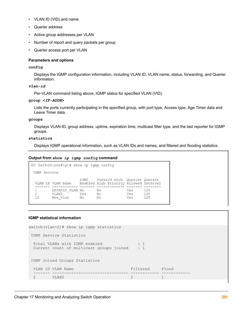
• VLAN ID (VID) and name
• Querier address
• Active group addresses per VLAN
• Number of report and query packets per group
• Querier access port per VLAN
Parameters and optionsconfig
Displays the IGMP configuration information, including VLAN ID, VLAN name, status, forwarding, and Querierinformation.
vlan-id
Per-VLAN command listing above, IGMP status for specified VLAN (VID).
group <IP-ADDR>Lists the ports currently participating in the specified group, with port type, Access type, Age Timer data andLeave Timer data.
groupsDisplays VLAN-ID, group address, uptime, expiration time, multicast filter type, and the last reporter for IGMPgroups.
statisticsDisplays IGMP operational information, such as VLAN IDs and names, and filtered and flooding statistics.
Output from show ip igmp config command
IGMP statistical information
switch(vlan-2)# show ip igmp statistics
IGMP Service Statistics
Total VLANs with IGMP enabled : 1 Current count of multicast groups joined : 1
IGMP Joined Groups Statistics
VLAN ID VLAN Name Filtered Flood ------- -------------------------------- ------------ ------------ 2 VLAN2 2 1
Chapter 17 Monitoring and Analyzing Switch Operation 391

VLAN information
show vlanSyntaxshow vlan <VLAN-ID> Description
Lists the maximum number of VLANs to support, existing VLANS, VLAN status (static or dynamic), and primaryVLAN.
Parameters and options<VLAN-ID>
Lists the following for the specified VLAN:
• Name, VID, and status (static/dynamic)
• Per-port mode (tagged, untagged, forbid, no/auto)
• "Unknown VLAN" setting (Learn, Block, Disable)
• Port status (up/down)
List data on specific VLANs
The next three figures show how you can list data for the following VLANs:
Ports VLAN VID
A1-A12 DEFAULT_VLAN 1
Table Continued
392 Aruba 2930F / 2930M Management and Configuration Guide for ArubaOS-Switch 16.05

A1, A2 VLAN-33 33
A3, A4 VLAN-44 44
Figure 73: Listing the VLAN ID (vid) and status for specific ports
Figure 74: Example of VLAN listing for the entire switch
Figure 75: Port listing for an individual VLAN
Configuring local mirroringTo configure a local mirroring session in which the mirroring source and destination are on the same switch, followthese general steps:
Chapter 17 Monitoring and Analyzing Switch Operation 393
Procedure
1. Determine the session and local destination port:
a. Session number (1-4) and (optional) alphanumeric name
b. Exit port (any port on the switch except a monitored interface used to mirror traffic)
Hewlett Packard Enterprise strongly discourages connecting a mirroring exit port to a networkbecause doing so can result in serious network performance problems. Only connect an exit portto a network analyzer, IDS, or other network edge device that has no connection to other networkresources.
2. Enter the mirror session-# [name session-name ] port port-# command to configure thesession.
3. Determine the traffic to be selected for mirroring by any of the following methods and the appropriateconfiguration level (VLAN, port, mesh, trunk, switch):
a. Direction: inbound, outbound, or both
b. Classifier-based mirroring policy: inbound only for IPv4 or IPv6 traffic
c. MAC source and/or destination address: inbound, outbound, or both
4. Enter the monitor command to assign one or more source interfaces to the session.
After you complete step 4, the switch begins mirroring traffic to the configured exit port.
The following commands configure mirroring for a local session in which the mirroring source and destination areon the same switch.
• The mirror command identifies the destination in a mirroring session.
• The interface and vlan commands identify the mirroring source, including source interface, trafficdirection, and traffic-selection criteria for a specified session.
With no allow-v2-modules specified in the configuration of a switch with V3 modules on KBfirmware, Egress VLAN ACLs do not filter mirrored traffic. You must use a port ACL to filter mirroredtraffic.
Local mirroring sessionsSyntax[no] mirror 1 - 4 port <EXIT-PORT-#> [name <NAME-STR>] Description
Configure local mirroring sessions.
Parameters and optionsno
When used with no mirror session-# port command, removes the mirroring session and anymirroring source previously assigned to that session by the following commands.
394 Aruba 2930F / 2930M Management and Configuration Guide for ArubaOS-Switch 16.05

Traffic-direction criteria
interface monitor allSyntax
Description[no] [interface <PORT> |<TRUNK> |<MESH>]|vlan <VID-#>] monitor all in|out|bothmirror <SESSION> [session ...] [no-tag-added]
Mirror policy for inbound traffic
class [ipv4|ipv6]Syntaxclass [ipv4|ipv6] <CLASSNAME> [no] [seq-number] [match|ignore] <IP-PROTOCOL><SOURCE-ADDRESS> <DESTINATION-ADDRESS>][precedence <PRECEDENCE-VALUE>][tos <TOS-VALUE>][ip-dscp <CODEPOINTS>][vlan <VLAN-ID>]Description
Configures the mirroring policy for inbound traffic on the switch.
Parameters and options
policy mirrorSyntaxpolicy mirror <POLICY-NAME> [no] <SEQ-NUMBER> [class [ipv4|ipv6] <CLASSNAME> actionmirror <SESSION>] [action mirror <SESSION>] [no] default-class action mirror<SESSION> [no] [interface <PORT/TRUNK>| vlan <VID-#>] service-policy <MIRROR-POLICY-NAME> inDescription
The [no] [interface <PORT/TRUNK>| vlan <VID-#>] service-policy <MIRROR-POLICY-NAME>in command removes the mirroring policy from a port, VLAN, trunk, or mesh interface for a specified session,but leaves the session available for other assignments.
Parameters and optionsmirror <SESSION>
Accepts either a number (1 to 4) or a name. To use a name, you must first configure the name <NAME-STR>parameter option for the specified mirroring session using the policy mirror command.
MAC-based criteria to select traffic
monitor macSyntax[no] monitor mac <MAC-ADDR> [src|dst|both] mirror session Description
Configures traffic using MAC-based criteria.
Parameters and options
Chapter 17 Monitoring and Analyzing Switch Operation 395

noUse the no form of the complete Command syntax (for example, no monitor mac 112233-445566 srcmirror 3) to remove a MAC address as mirroring criteria from an active session on the switch withoutremoving the session itself.
mirrorEnter the monitor mac mirror command at the global configuration level.
Remote mirroring destination on a remote switchSyntaxmirror endpoint ip <SRC-IP> <SRC-UDP-PORT > <DST-IP> <EXIT-PORT> [truncation] Description
Configures a remote mirroring destination on a remote switch.
Parameters and options
Remote mirroring destination on a local switch
mirror remote ipSyntaxmirror <SESSION> remote ip <SRC-IP> <SRC-UDP-PORT> <DST-IP> Description
Configures a remote mirroring destination on a local switch.
Parameters and options
Local mirroring destination on the local switch
mirror portSyntaxmirror <SESSION> port <EXIT-PORT> Description
Configures a local mirroring destination on a local switch.
Parameters and options
Monitored trafficinterfaceSyntaxinterface <PORT/TRUNK/MESH>
396 Aruba 2930F / 2930M Management and Configuration Guide for ArubaOS-Switch 16.05

Description
Parameters and options
monitor allSyntaxmonitor all [in|out|both] mirror <SESSION> [no-tag-added]monitor ip access-group ACL-NAME in mirror <SESSION>monitor mac <MAC-ADDR> [src|dest|both] mirrorshow monitor [endpoint|<SESSION-NUMBER>|name <SESSION-NAME>
service-policySyntaxservice-policy <mirror-policy-name> in
Configuring local mirroring (Menu)If mirroring has already been enabled on the switch, the Menu screens appear different from the one shown in thissection.
Procedure
1. From the Main Menu, select 1. Switch Configuration ... , and then select 3. Network Monitoring Port.
Figure 76: The default network mirroring configuration screen
2. In the Actions menu, press [E] (for Edit.)
3. If mirroring is currently disabled for session 1 (the default), enable it by pressing the Space bar (or [Y]) toselect Yes.
Chapter 17 Monitoring and Analyzing Switch Operation 397
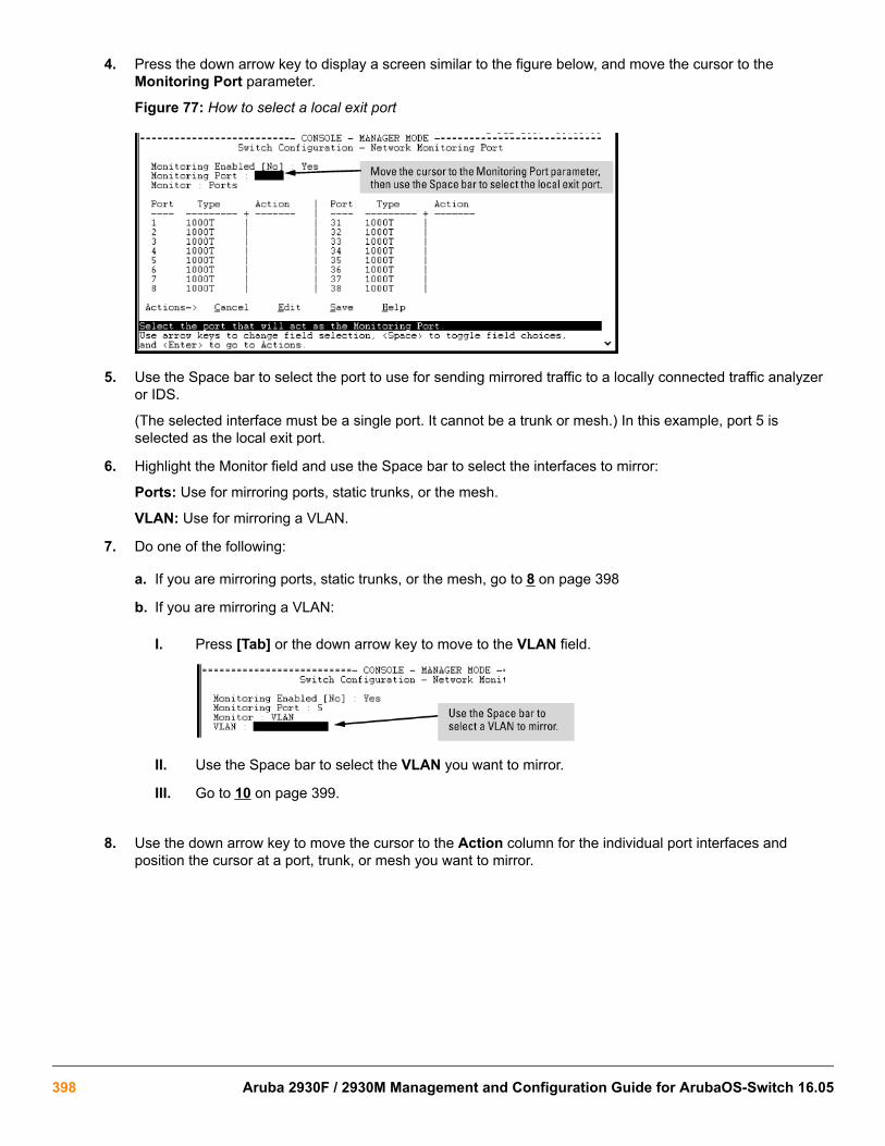
4. Press the down arrow key to display a screen similar to the figure below, and move the cursor to theMonitoring Port parameter.
Figure 77: How to select a local exit port
5. Use the Space bar to select the port to use for sending mirrored traffic to a locally connected traffic analyzeror IDS.
(The selected interface must be a single port. It cannot be a trunk or mesh.) In this example, port 5 isselected as the local exit port.
6. Highlight the Monitor field and use the Space bar to select the interfaces to mirror:
Ports: Use for mirroring ports, static trunks, or the mesh.
VLAN: Use for mirroring a VLAN.
7. Do one of the following:
a. If you are mirroring ports, static trunks, or the mesh, go to 8 on page 398
b. If you are mirroring a VLAN:
I. Press [Tab] or the down arrow key to move to the VLAN field.
II. Use the Space bar to select the VLAN you want to mirror.
III. Go to 10 on page 399.
8. Use the down arrow key to move the cursor to the Action column for the individual port interfaces andposition the cursor at a port, trunk, or mesh you want to mirror.
398 Aruba 2930F / 2930M Management and Configuration Guide for ArubaOS-Switch 16.05

9. Press the Space bar to select Monitor for the ports, trunks, mesh, or any combination of these that you wantmirrored.
Use the down arrow key to move from one interface to the next in the Action column. (If the mesh or anytrunks are configured, they appear at the end of the port listing.)
10. When you finish selecting interfaces to mirror, press [Enter], then press [S] (for Save ) to save your changesand exit from the screen.
11. Return to the Main Menu.
You can also use the CLI to configure a mirroring session for a destination device connected to an exit port oneither:
• The same switch as the source interface (local mirroring.)
• A different switch (remote mirroring.) The remote switch must be an switch offering the full mirroringcapabilities described in this chapter.
After you configure a mirroring session with traffic-selection criteria and a destination, the switch immediatelystarts to mirror traffic to each destination device connected to an exit port.
In a remote mirroring session that uses IPv4 encapsulation, if the exit switch is not already configured as thedestination for the session, its performance may be adversely affected by the stream of mirrored traffic.
For this reason, Switch strongly recommends that you configure the exit switch for a remote mirroring sessionbefore configuring the source switch for the same session.
Destination mirror on a remote switch
mirror endpointSyntaxmirror endpoint ip <SRC-IP-ADDR> <SRC-UDP-PORT> <DST-IP-ADDR> port <EXIT-PORT> Description
Enter this command on a remote switch to configure the exit port to use in a remote mirroring session. Use Source mirror on the local switch to configure the mirroring source on the local switch.
The mirror endpoint ip command configures:
Chapter 17 Monitoring and Analyzing Switch Operation 399

• The unique UDP port number to be used for the mirroring session on the source switch. The recommendedport range is from 7933 to 65535.
• The IP address of the source switch to use in the session.
• The IP address and exit-port number on the remote (endpoint) switch.
In a remote mirroring endpoint, the IP address of exit port and the remote destination switch can belong todifferent VLANs.
Source mirror on the local switch
mirror remote ipSyntax[no] mirror 1 - 4 [name <NAME-STR>] remote ip <SRC-IP> <SRC-UDP-PORT> <DST-IP>[truncation]Description
Configures the mirroring source on the local switch.
Parameters and optionsno mirror 1–4
Removes both the mirroring session and any mirroring sources previously assigned to the session by thefollowing commands.
Traffic-direction criteriaSyntax[no] [interface <PORT> <TRUNK> <MESH>|vlan <VID-#>] monitor all in|out|both mirror 1–4|<NAME-STR> [1 — 4|<NAME-STR . . .>]
Description
Configures traffic direction criteria for specific traffic
Configure ACL criteria to select inboundinterface monitor ip access-groupSyntax[no] [interface <PORT> <TRUNK> <MESH>|vlan <VID-#>] monitor ip access—group <ACL—NAME> inmirror [1–4|<NAME-STR>] [1 — 4|<NAME-STR . . .>]
Configuring a destination switch in a remote mirroringsession
When configuring a remote mirroring session, always configure the destination switch first.Configuring the source switch first can result in a large volume of mirrored, IPv4-encapsulated trafficarriving at the destination without an exit path, which can slow switch performance.
400 Aruba 2930F / 2930M Management and Configuration Guide for ArubaOS-Switch 16.05

Syntax
mirror endpoint ip src-ip src-udp-port dst-ip exit-port-# no mirror endpoint ip src-ip src-udp-port dst-ip
Used on a destination switch to configure the remote endpoint of a mirroring session. The command uniquelyassociates the mirrored traffic from the desired session on a monitored source with a remote exit port on thedestination switch. You must use the same set of source and destination parameters used when you configure thesame session on both the source and destination switches.
For a given mirroring session, the same src-ip , src-udp-port and dst-ip values must be entered withthe mirror endpoint ip command on the destination switch, and later with the mirror remote ipcommand on the source switch.
Do not remove the configuration of a remote mirroring endpoint support for a given session if thereare source switches currently configured to mirror traffic to the endpoint.
src-ip Must exactly match the src-ip address you configure on the source switch for theremote session.
src-udp-port Must exactly match the src-udp-port value you configure on the source switchfor the remote session. The recommended port range is 7933 to 65535.This settingassociates the monitored source with the desired remote endpoint in the remotesession by using the same, unique UDP port number to identify the session on thesource and remote switches.
dst-ip Must exactly match the dst-ip setting you configure on the source switch for theremote session.
exit-port-# Exit port for mirrored traffic in the remote session, to which a traffic analyzer or IDSis connected.
The no form of the command deletes the mirroring endpoint for the configured session on the remote destinationswitch.
Configuring a source switch in a local mirroring sessionEnter the mirror port command on the source switch to configure an exit port on the same switch. To createthe mirroring session, use the information gathered in High-level overview of the mirror configuration processon page 425.
Syntax
mirror 1 - 4 port exit-port-# [name name-str] no mirror 1- 4Assigns the exit port to use for the specified mirroring session and must be executed from the global configurationlevel.
1 - 4 Identifies the mirroring session created by this command. (Multiplesessions on the switch can use the same exit port.)
name name-str Optional alphanumeric name string used to identify the session( up to 15 characters)
port exit-port-#
Exit port for mirrored traffic in the remote session. This is the portto which a traffic analyzer or IDS is connected.
Chapter 17 Monitoring and Analyzing Switch Operation 401

The no form of the command removes the mirroring session and any mirroring source previously assigned to thatsession.
Configuring a source switch in a remote mirroring sessionSyntax
[no] mirror 1 - 4 [name name-str] remote ip src-ip src-udp-port dst-ip [truncation]Used on the source switch to uniquely associate the mirrored traffic in the specified session with a remotedestination switch. You must configure the same source and destination parameters when you configure the samesession on both the source and destination switches. (If multiple remote sessions use the same source anddestination IP addresses, each session must use a unique UDP port value.)
When you execute this command, the following message is displayed:
Caution: Please configure destination switch first. Do you want to continue [y/n]?
• If you have not yet configured the session on the remote destination switch, follow the configuration procedurein Configure a mirroring destination on a remote switch on page 426 before using this command.
• If you have already configured the session on the remote destination switch, enter y (for "yes") to complete thiscommand.
1 - 4 Identifies the mirroring session created by this command.
name name-str Optional alphanumeric name string used as an additional sessionidentifier (up to 15 characters.)
src-ip The IP address of the VLAN or subnet on which the traffic to bemirrored enters or leaves the switch.
src-udp-port Associates the remote session with a UDP port number. Whenmultiple sessions have the same source IP address src-ip anddestination IP address dst-ip , the UDP port number must beunique in each session. The UDP port number used for a givensession should be in the range of 7933 to 65535.
UDP port numbers below 7933 are reserved for variousIP applications. Using them for mirroring can result inthe interruption of other IP functions and in non-mirroredtraffic being received on the destination switch and sentto a device connected to the remote exit port.
The configured UDP port number is included in the frames mirroredfrom the source switch to the remote destination switch (mirrorendpoint), and enables the remote switch to match the frames tothe exit port configured for the combined UDP port number, source IPaddress, and destination IP address..
Table Continued
402 Aruba 2930F / 2930M Management and Configuration Guide for ArubaOS-Switch 16.05

dst-ip For the remote session specified in the command, this is the IPaddress of the VLAN or subnet on which the remote exit port exists.(The exit port to which a traffic analyzer or IDS is connected isconfigured on the remote switch in section.) .)
[truncation] Enables truncation of oversize frames, causing the part of the framein excess of the MTU size to be truncated. Unless truncation isenabled, oversize frames are dropped. The frame size is truncated toa multiple of 18 bytes—for example, if the MTU is 1000 bytes, theframe is truncated to 990 bytes (55 * 18 bytes.)
The no form of the command removes the mirroring session and any mirroring source previously assigned to thesession. To preserve the session while deleting a monitored source assigned to it.
Selecting all traffic on a port interface for mirroringaccording to traffic directionSyntax
[no] interface port/trunk/mesh monitor [in | out | both] [mirror 1 - 4 | name-str] [{1 - 4 | name-str} | {1 - 4 | name-str} | {1 - 4 | name-str}] [no-tag-added]Assigns a mirroring source to a previously configured mirroring session on a source switch by specifying the port,trunk, and/or mesh sources to use, the direction of traffic to mirror, and the session.
interface port/trunk/mesh Identifies the source ports, static trunks, and/or mesh on which to mirrortraffic.
Use a hyphen for a range of consecutive ports or trunks (a5-a8, Trk2-Trk4.)
Use a comma to separate non-contiguous interfaces (b11, b14, Trk4,Trk7.)
monitor all [in | out | both]
For the interface specified by port/trunk/mesh , selects traffic to mirror basedon whether the traffic is entering or leaving the switch on the interface:
• in: Mirrors entering traffic.
• out: Mirrors exiting traffic.
• both: Mirrors traffic entering and exiting.
If you enter the monitor all command without selection criteria or asession identifier, the command applies by default to session 1
Table Continued
Chapter 17 Monitoring and Analyzing Switch Operation 403

mirror [1 - 4 | name-str]Assigns the traffic specified by the interface and direction to a session bynumber or—if configured—by name. The session must have beenpreviously configured.
Depending on how many sessions are already configured on the switch, youcan use the same command to assign the specified source to up to foursessions, for example, interface a1 monitor all in mirror 1 24.
• 1 - 4: Configures the selected port traffic to be mirrored in the specifiedsession number.
• [ name name-str]: Optional; configures the selected port traffic to bemirrored in the specified session name. The string can be usedinterchangeably with the session number when using this command toassign a mirroring source to a session.
[no-tag-added] Prevents a VLAN tag from being added to the mirrored copy of an outboundpacket sent to a local or remote mirroring destination.
The no form of the command removes a mirroring source assigned to the session, but does not remove thesession itself. This enables you to repurpose a session by removing an unwanted mirroring source and addinganother in its place.
Selecting all traffic on a VLAN interface for mirroringaccording to traffic directionSyntax
vlan vid-# monitor all [in | out | both] [mirror 1 - 4 | name-str] [{1 - 4 | name-str} | {1 - 4 | name-str} | {1 - 4 | name-str}]
This command assigns a monitored VLAN source to a previously configured mirroring session on a source switchby specifying the VLAN ID, the direction of traffic to mirror, and the session.
404 Aruba 2930F / 2930M Management and Configuration Guide for ArubaOS-Switch 16.05

vlan vid-# Identifies the VLAN on which to mirror traffic.
monitor all [in | out| both] Uses the direction of traffic on the specified vid-# to select traffic to mirror. If
you enter the monitor all command without selection criteria or a sessionidentifier, the command applies by default to session 1.
mirror [1 - 4 | name-str] Assigns the VLAN traffic defined by the VLAN ID and traffic direction to a
session number or name.
Depending on how many sessions are already configured on the switch, youcan use the same command to assign the specified VLAN source to up to foursessions, for example, interface a1 monitor all in mirror 1 2 4.
• 1 - 4: Configures the selected VLAN traffic to be mirrored in the specifiedsession number.
• [name name-str]: Optional; configures the selected port traffic to bemirrored in the specified session name. The string can be usedinterchangeably with the session number when using this command toassign a mirroring source to a session. To configure an alphanumeric namefor a mirroring session, see the command description under Configuring asource switch in a remote mirroring session on page 402.
Assigning a VLAN to a mirroring session precludes assigning any other mirroring sources to the same session. Ifa VLAN is already assigned to a given mirroring session, using this command to assign another VLAN to thesame mirroring session results in the second assignment replacing the first. Also, if there are other (port, trunk, ormesh) mirroring sources already assigned to a session, the switch displays a message similar to:
Mirror source port exists on session N. Can not add mirrorsource VLAN.The no form of the command removes a mirroring source assigned to the session, but does not remove thesession itself. This allows you to repurpose a session by removing an unwanted mirroring source and addinganother in its place.
Configuring a MAC address to filter mirrored traffic on aninterfaceEnter the monitor mac mirror command at the global configuration level.
Syntax
[no] monitor mac mac-addr [src | dest | both] {mirror 1 - 4 | name-str} [1 - 4 | name-str] [1 - 4 | name-str] [1 - 4 | name-str]
Use this command to configure a source and/or destination MAC address as criteria for selecting traffic in one ormore mirroring sessions on the switch. The MAC address you enter is configured to mirror inbound (src),outbound (dest), or both inbound and outbound (both) traffic on any port or learned VLAN on the switch.
Chapter 17 Monitoring and Analyzing Switch Operation 405

monitor mac mac-addrConfigures the MAC address as selection criteria for mirroring traffic on any port or learned VLAN on the switch.
{src | dest | both}Specifies how the MAC address is used to filter and mirror packets in inboundand/or outbound traffic on the interfaces on which the mirroring session isapplied:
• src: Mirrors all packets in inbound traffic that contain the specified MACaddress as source address.
• dest: Mirrors all packets in outbound traffic that contain the specified MACaddress as destination address.
The MAC address of the switch is not supported as either thesource or destination MAC address used to select mirrored traffic.
both: Mirrors all packets in both inbound and outbound traffic that contain thespecified MAC address as either source or destination address.
mirror [1 - 4 | name-str]
Assigns the inbound and/or outbound traffic filtered by the specified MACaddress to a previously configured mirroring session. The session is identifiedby a number or (if configured) a name.
Depending on how many sessions are configured on the switch, you can usethe same command to configure a MAC address as mirroring criteria in up tofour sessions. To identify a session, you can enter either its name or number; forexample: mirror 1 2 3 traffsrc41 - 4: Specifies a mirroring session by number, for which the configured MACaddress is used to select and mirror inbound and/or outbound traffic.
Packets that are sent or received on an interface configured with a mirroring session and that contain the MACaddress as source and/or destination address are mirrored to a previously configured destination device.
To remove a MAC address as selection criteria in a mirroring session, you must enter the complete Commandsyntax, for example, no monitor mac 998877-665544 dest mirror 4.
The no form of the command removes the MAC address as a mirroring criteria from an active session, but doesnot remove the session itself. This enables you to repurpose a session by removing an unwanted mirroringcriteria and adding another in its place.
Configuring classifier-based mirroringFor more information and a list of general steps for the process beginning with this command, see the informationabout restrictions on classifier-based mirroring.
Context: Global configuration
Syntax
[no] class [ipv4 | ipv6 classname]Defines the name of a traffic class and specifies whether a policy is to be applied to IPv4 or IPv6 packets, whereclassname is a text string (64 characters maximum.)
406 Aruba 2930F / 2930M Management and Configuration Guide for ArubaOS-Switch 16.05

After you enter the class command, you enter the class configuration context to specify match criteria. A trafficclass contains a series of match and ignore commands, which specify the criteria used to classify packets.
To configure a default traffic class, use the default-class command as described below. A default classmanages the packets that do not match the match/ignore criteria in any other classes in a policy.
Context: Class configuration
Syntax
[no] seq-number [match | ignore ip-protocol source-address destination-address] [ip-dscp codepoint] [precedence precedence-value] [tos tos-value] [vlan vlan-id]For detailed information about how to enter match and ignore commands to configure a traffic class, theAdvanced Traffic Management Guide.
Context: Global configuration
Syntax
[no] policy mirror policy-nameDefines the name of a mirroring policy and enters the policy configuration context.
A traffic policy consists of one or more classes and one or more mirroring actions configured for each class oftraffic. The configured actions are executed on packets that match a match statement in a class. No policy actionis performed on packets that match an ignore statement.
Context: Policy configuration
Syntax
[no] seq-number class [ipv4 | ipv6 classname] action mirror sessionDefines the mirroring action to be applied on a pre-configured IPv4 or IPv6 traffic class when a packet matchesthe match criteria in the traffic class. You can enter multiple class action mirror statements in a policy.
[seq-number] The (optional) seq-number parameter sequentially orders the mirroring actionsthat you enter in a policy configuration. Actions are executed on matchingpackets in numerical order.
Default: Mirroring action statements are numbered in increments of 10, startingat 10.
class [ipv4 | ipv6classname] Defines the preconfigured traffic class on which the mirroring actions in the
policy are executed and specifies whether the mirroring policy is applied to IPv4or IPv6 traffic in the class. The classname is a text string (64 charactersmaximum.)
action mirror session Configures mirroring for the destination and session specified by the sessionparameter.
Chapter 17 Monitoring and Analyzing Switch Operation 407

Context: Policy configuration
Syntax
[no] default-class action mirror session [action mirror session ...]Configures a default class that allows packets that are not matched nor ignored by any of the class configurationsin a mirroring policy to be mirrored to the destination configured for the specified session.
Applying a mirroring policy on a port or VLAN interfaceEnter one of the following service-policy commands from the global configuration context.
Context: Global configuration
Syntax
interface <PORT-LIST> service-policy policy-name inConfigures the specified ports with a mirroring policy that is applied to inbound traffic on each interface.
Separate individual port numbers in a series with a comma, for example, a1,b4,d3. Enter a range of ports byusing a dash, for example, a1-a5.
The mirroring policy name you enter must be the same as the policy name you configured with the policymirror command.
Syntax
vlan vlan-id service-policy policy-name inConfigures a mirroring policy on the specified VLAN that is applied to inbound traffic on the VLAN interface.
Valid VLAN ID numbers range from 1 to 4094.
The mirroring policy name you enter must be the same as the policy name you configured with the policymirror command in the syntax policy mirror.
Viewing a classifier-based mirroring configurationTo display information about a classifier-based mirroring configuration or statistics on one or more mirroringpolicies, enter one of the following commands:
Syntax
show class [ipv4 class-name | ipv6 class-name | config]Syntax
show policy [policy-name | config]Syntax
show policy resourcesSyntax
show statistics policy [policy-name] [interface port-num | vlan vid in]
408 Aruba 2930F / 2930M Management and Configuration Guide for ArubaOS-Switch 16.05
Viewing all mirroring sessions configured on the switchSyntax
show monitorIf a monitored source for a remote session is configured on the switch, the following information is displayed.Otherwise, the output displays: Mirroring is currently disabled.
Sessions Lists the four configurable sessions on the switch.
Status Displays the current status of each session:
• active: The session is configured.
• inactive: Only the destination has been configured; the mirroring source is not configured.
• not defined: Mirroring is not configured for this session.
Type Indicates whether the mirroring session is local (port), remote (IPv4), or MAC-based (mac) forlocal or remote sessions.
Sources Indicates how many monitored source interfaces are configured for each mirroring session.
Policy Indicates whether the source is using a classifier-based mirroring policy to select inbound IPv4or IPv6 traffic for mirroring.
If a remote mirroring endpoint is configured on the switch, the following information is displayed. Otherwise, theoutput displays: There are no Remote Mirroring endpoints currently assigned.
Type Indicates whether the mirroring session is local (port), remote (IPv4), or MAC-based(mac) for local or remote sessions.
UDP Source Addr The IP address configured for the source VLAN or subnet on which the monitoredsource interface exists. In the configuration of a remote session, the same UDP sourceaddress must be configured on the source and destination switches.
UDP port The unique UDP port number that identifies a remote session. In the configuration of aremote session, the same UDP port number must be configured on the source anddestination switches.
Table Continued
Chapter 17 Monitoring and Analyzing Switch Operation 409

UDP Dest Addr The IP address configured for the destination VLAN or subnet on which the remote exitport exists. In the configuration of a remote session, the same UDP destination addressmust be configured on the source and destination switches.
Dest Port Identifies the exit port for a remote session on a remote destination switch.
Figure 78: Displaying the currently configured mirroring sessions on the switch
Viewing the remote endpoints configured on the switchSyntax
show monitor endpointDisplays the remote mirroring endpoints configured on the switch. Information on local sessions configured on theswitch is not displayed. (To view the configuration of a local session, use the show monitor [1-4 | name<name-str>] command)
Type Indicates whether the session is a port (local) or IPv4 (remote) mirroring session.
show monitorendpoint
The IP address configured for the source VLAN or subnet on which the monitored sourceinterface exists. In the configuration of a remote session, the same UDP source addressmust be configured on the source and destination switches.
UDP port The unique UDP port number that identifies a remote session. In the configuration of aremote session, the same UDP port number must be configured on the source anddestination switches.
UDP Dest Addr The IP address configured for the destination VLAN or subnet on which the remote exit portexists. In the configuration of a remote session, the same UDP destination address must beconfigured on the source and destination switches.
Dest Port fies the exit port for a remote session on a remote destination switch.
Example
410 Aruba 2930F / 2930M Management and Configuration Guide for ArubaOS-Switch 16.05

In the following figure, the show monitor endpoint output shows that the switch is configured as the remoteendpoint (destination) for two remote sessions from the same monitored source interface.
Figure 79: Displaying the configuration of remote mirroring endpoints on the switch
Viewing the mirroring configuration for a specific sessionSyntax
show monitor [1 - 4 | name name-str]Displays detailed configuration information for a specified local or remote mirroring session on a source switch.
Session Displays the number of the specified session.
Session Name Displays the name of the session, if configured.
Policy Indicates whether the source is using a classifier-based mirroring policy to selectinbound IPv4 or IPv6 traffic for mirroring.
Mirroring Destination For a local mirroring session, displays the port configured as the exit port on the sourceswitch. For a remote mirroring session, displays IPv4, which indicates mirroring to aremote (endpoint) switch.
UDP Source Addr The IP address configured for the source VLAN or subnet on which the monitoredsource interface exists. In the configuration of a remote session, the same UDP sourceaddress must be configured on the source and destination switches.
UDP port The unique UDP port number that identifies a remote session. In the configuration of aremote session, the same UDP port number must be configured on the source anddestination switches.
UDP Dest Addr The IP address configured for the destination VLAN or subnet on which the remote exitport exists. In the configuration of a remote session, the same UDP destination addressmust be configured on the source and destination switches.
Status For a remote session, displays current session activity:
• active: The session is configured and is mirroring traffic. A remote path has beendiscovered to the destination.
• inactive: The session is configured, but is not currently mirroring traffic. A remotepath has not been discovered to the destination.
• not defined: Mirroring is not configured for this session.
Table Continued
Chapter 17 Monitoring and Analyzing Switch Operation 411

Monitoring Sources For the specified local or remote session, displays the source (port, trunk, or VLAN)interface and the MAC address (if configured) used to select mirrored traffic.
Direction For the selected interface, indicates whether mirrored traffic is entering the switch (in),leaving the switch (out), or both.
Viewing a remote mirroring sessionAfter you configure session 2 for remote mirroring (Figure 80: Configuring a remote mirroring session andmonitored source on page 412), you can enter the show monitor 2 command to verify the configuration(Figure 81: Displaying the Configuration of a Remote Mirroring Session on page 412.)
Figure 80: Configuring a remote mirroring session and monitored source
Figure 81: Displaying the Configuration of a Remote Mirroring Session
412 Aruba 2930F / 2930M Management and Configuration Guide for ArubaOS-Switch 16.05
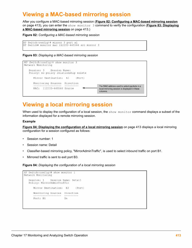
Viewing a MAC-based mirroring sessionAfter you configure a MAC-based mirroring session (Figure 82: Configuring a MAC-based mirroring sessionon page 413), you can enter the show monitor 3 command to verify the configuration (Figure 83: Displayinga MAC-based mirroring session on page 413.)
Figure 82: Configuring a MAC-based mirroring session
Figure 83: Displaying a MAC-based mirroring session
Viewing a local mirroring sessionWhen used to display the configuration of a local session, the show monitor command displays a subset of theinformation displayed for a remote mirroring session.
Example
Figure 84: Displaying the configuration of a local mirroring session on page 413 displays a local mirroringconfiguration for a session configured as follows:
• Session number: 1
• Session name: Detail
• Classifier-based mirroring policy, "MirrorAdminTraffic", is used to select inbound traffic on port B1.
• Mirrored traffic is sent to exit port B3.
Figure 84: Displaying the configuration of a local mirroring session
Chapter 17 Monitoring and Analyzing Switch Operation 413
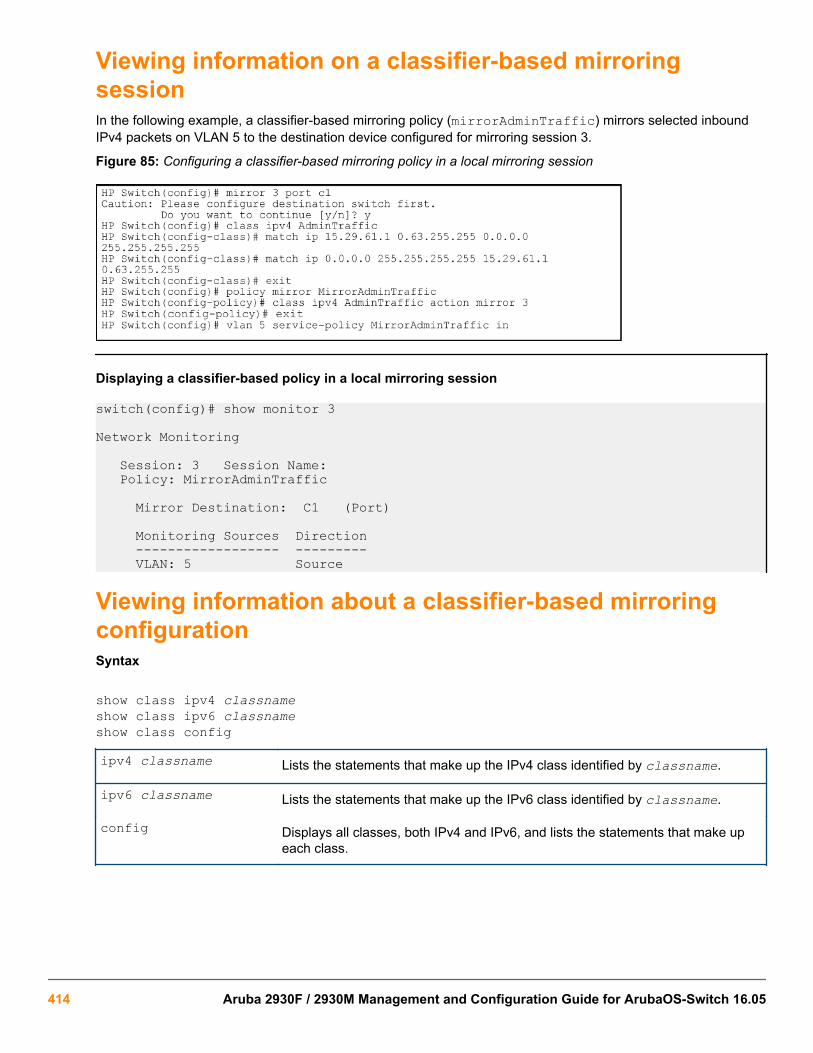
Viewing information on a classifier-based mirroringsessionIn the following example, a classifier-based mirroring policy (mirrorAdminTraffic) mirrors selected inboundIPv4 packets on VLAN 5 to the destination device configured for mirroring session 3.
Figure 85: Configuring a classifier-based mirroring policy in a local mirroring session
Displaying a classifier-based policy in a local mirroring session
switch(config)# show monitor 3
Network Monitoring
Session: 3 Session Name: Policy: MirrorAdminTraffic
Mirror Destination: C1 (Port)
Monitoring Sources Direction ------------------ --------- VLAN: 5 Source
Viewing information about a classifier-based mirroringconfigurationSyntax
show class ipv4 classnameshow class ipv6 classnameshow class config
ipv4 classname Lists the statements that make up the IPv4 class identified by classname.
ipv6 classname Lists the statements that make up the IPv6 class identified by classname.
config Displays all classes, both IPv4 and IPv6, and lists the statements that make upeach class.
414 Aruba 2930F / 2930M Management and Configuration Guide for ArubaOS-Switch 16.05

Additional variants of the show class … command provide information on classes that are members of policiesthat have been applied to ports or VLANs.
Figure 86: show class output for a mirroring policy
Viewing information about a classifier-based mirroringconfigurationSyntax
show policy policy-nameshow policy config
policy-name Lists the statements that make up the specified policy.
config Displays the names of all policies defined for the switch and lists the statements thatmake up each policy.
Additional variants of the show policy command provide information on policies that have been applied to portsor VLANs.
Figure 87: show policy output for a mirroring policy
Viewing resource usage for mirroring policiesSyntax
show policy resourcesDisplays the number of hardware resources (rules, meters, and application port ranges) used by classifier-basedmirroring policies (local and remote) that are currently applied to interfaces on the switch, as well as QoS policiesand other software features.
Chapter 17 Monitoring and Analyzing Switch Operation 415

The information displayed is the same as the output of the show qos resources and showaccess-list resources commands.
Figure 88: Displaying the hardware resources used by currently configured mirroring policies
Viewing the mirroring configurations in the runningconfiguration fileUse the show run command to view the current mirroring configurations on the switch. In the show runcommand output, information about mirroring sources in configured sessions begins with the mirror keyword;monitored source interfaces are listed per-interface.
416 Aruba 2930F / 2930M Management and Configuration Guide for ArubaOS-Switch 16.05

Example
Figure 89: Displaying mirroring sources and sessions in the running configurations
Information about remote endpoints configured for remote sessions on the switch begin with the mirrorendpoint keywords. In the following example, two remote sessions use the same exit port:
Figure 90: Displaying remote mirroring endpoints in the running configuration
Compatibility modeThe following table shows how the v2 zl and zl modules behave in various combinations and situations whenCompatibility mode is enabled and when it is disabled.
Table 23: Compatibility mode enabled/disabled comparisons
Modules Compatibility mode enabled Compatibility mode disabled
v2 zl modulesonly
Can insert zl module and the module will comeup. Any v2 zl modules are limited to the zlconfiguration capacities.
v2 zl modules are at full capacity. zl modulesare not allowed to power up.
Mixed v2 zland zlmodules
Can insert zl module and the module will comeup. Any v2 zl modules are limited to the zlconfiguration capacities. If compatibility mode isdisabled, the zl modules go down.
ZL modules are not allowed to power up.
Table Continued
Chapter 17 Monitoring and Analyzing Switch Operation 417

Modules Compatibility mode enabled Compatibility mode disabled
zl modulesonly
Same as exists already. If a v2 zl module isinserted, it operates in the same mode as the zlmodule, but with performance increases.
The Management Module is the only modulethat powers up.
In Compatibility Mode, no v2 zl features areallowed, whether the modules are all v2 zl ornot.
If Compatibility Mode is disabled and thenenabled, the startup config is erased and thechassis reboots.
Traffic mirroring overviewTraffic mirroring (Intelligent Mirroring) allows you to mirror (send a copy of) network traffic received or transmittedon a switch interface to a local or remote destination, such as a traffic analyzer or IDS.)
Traffic mirroring provides the following benefits:
• Allows you to monitor the traffic flow on specific source interfaces.
• Helps in analyzing and debugging problems in network operation resulting from a misbehaving network or anindividual client. The mirroring of selected traffic to an external device makes it easier to diagnose a networkproblem from a centralized location in a topology spread across a campus.
• Supports remote mirroring to simultaneously mirror switch traffic on one or more interfaces to multiple remotedestinations. (In remote mirroring, you must first configure the remote mirroring endpoint—remote switch andexit port—before you specify a mirroring source for a session.)
Mirroring overviewFigure 91: Local and remote sessions showing mirroring terms on page 419 shows an example of the termsused to describe the configuration of a sample local and remote mirroring session:
• In the local session, inbound traffic entering Switch A is monitored on port A2 and mirrored to a destination(host), traffic analyzer 1, through exit port A15 on the switch.A local mirroring session means that themonitored interface (A2) and exit port (A15) are on the same switch.
• In the remote session, inbound traffic entering Switch A is monitored on port A1. A mirrored copy of monitoredtraffic is routed through the network to a remote mirroring endpoint: exit port B7 on Switch B. A destinationdevice, traffic analyzer 2, is connected to the remote exit port.A remote mirroring session means that:
418 Aruba 2930F / 2930M Management and Configuration Guide for ArubaOS-Switch 16.05

◦ The monitored interface (A1) and exit port (B7) are on different switches.
◦ Mirrored traffic can be bridged or routed from a source switch to a remote switch.
Figure 91: Local and remote sessions showing mirroring terms
Mirroring destinationsTraffic mirroring supports destination devices that are connected to the local switch or to a remote switch:
• Traffic can be copied to a destination (host) device connected to the same switch as the mirroring source in alocal mirroring session. You can configure up to four exit ports to which destination devices are connected.
• Traffic can be bridged or routed to a destination device connected to a different switch in a remote mirroringsession. You can configure up to 32 remote mirroring endpoints (IP address and exit port) to which destinationdevices are connected.
Mirroring sources and sessionsTraffic mirroring supports the configuration of port and VLAN interfaces as mirroring sources in up to fourmirroring sessions on a switch. Each session can have one or more sources (ports and/or static trunks, a mesh,or a VLAN interface) that monitor traffic entering and/or leaving the switch.
Using the CLI, you can make full use of the switch's local and remote mirroring capabilities. Usingthe Menu interface, you can configure only local mirroring for either a single VLAN or a group ofports, static trunks, or both.
In remote mirroring, a 54-byte remote mirroring tunnel header is added to the front of each mirroredframe for transport from the source switch to the destination switch. This may cause some framesthat were close to the MTU size to exceed the MTU size. Mirrored frames exceeding the allowedMTU size are dropped, unless the optional [truncation] parameter is set in the mirrorcommand.
Mirroring sessionsA mirroring session consists of a mirroring source and destination (endpoint.) Although a mirroring source can beone of several interfaces, as mentioned above, for any session, the destination must be a single (exit) port. Theexit port cannot be a trunk, VLAN, or mesh interface.
Chapter 17 Monitoring and Analyzing Switch Operation 419

You can map multiple mirroring sessions to the same exit port, which provides flexibility in distributing hosts, suchas traffic analyzers or an IDS. In a remote mirroring endpoint, the IP address of the exit port and the remotedestination switch can belong to different VLANs.
Mirroring sessions can have the same or a different destination. You can configure an exit port on the local(source) switch and/or on a remote switch as the destination in a mirroring session. When configuring a mirroringdestination, consider the following options:
• Mirrored traffic belonging to different sessions can be directed to the same destination or to differentdestinations.
• You can reduce the risk of oversubscribing a single exit port by:
◦ Directing traffic from different session sources to multiple exit ports.
◦ Configuring an exit port with a higher bandwidth than the monitored source port.
• You can segregate traffic by type, direction, or source.
Mirroring session limitsA switch running software release K.12.xx or greater supports the following:
• A maximum of four mirroring (local and remote) sessions.
• A maximum of 32 remote mirroring endpoints (exit ports connected to a destination device that receivemirrored traffic originating from monitored interfaces on a different switch.)
Selecting mirrored trafficYou can use any of the following options to select the traffic to be mirrored on a port, trunk, mesh, or VLANinterface in a local or remote session:
• All traffic
Monitors all traffic entering or leaving the switch on one or more interfaces (inbound and outbound.)
• Direction-based traffic selection
Monitors traffic that is either entering or leaving the switch (inbound or outbound.) Monitoring traffic in only onedirection improves operation by reducing the amount of traffic sent to a mirroring destination.
• MAC-based traffic selection
Monitors only traffic with a matching source and/or destination MAC address in packet headers entering and/orleaving the switch on one or more interfaces (inbound and/or outbound.)
• Classifier-based service policy
Provides a finer granularity of match criteria to zoom in on a subset of a monitored port or VLAN traffic (IPv4 orIPv6) and select it for local or remote mirroring (inbound only.)
Deprecation of ACL-based traffic selection
The use of ACLs for selecting traffic in a mirroring session has been deprecated and is replaced by the use ofadvanced classifier-based service policies.
420 Aruba 2930F / 2930M Management and Configuration Guide for ArubaOS-Switch 16.05

As with ACL criteria, classifier-based match/ignore criteria allow you to limit a mirroring session to selectedinbound packets on a given port or VLAN interface (instead of mirroring all inbound traffic on the interface.)
The following commands have been deprecated:
• interface port/trunk/mesh monitor ip access-group acl-name in mirror [1 - 4 |name-str]
• vlan vid-# monitor ip access-group acl-name in mirror [1 - 4 | name-str]
After you install and boot release K.14.01 or greater, ACL-based local and remote mirroring sessions configuredon a port or VLAN interface are automatically converted to classifier-based mirroring policies.
If you are running software release K.13.XX or earlier, ACL permit/deny criteria are supported to select IP trafficentering a switch to mirror in a local or remote session, using specified source and/or destination criteria.
Mirrored traffic destinations
Local destinationsA local mirroring traffic destination is a port on the same switch as the source of the traffic being mirrored.
Remote destinationsA remote mirroring traffic destination is an switch configured to operate as the exit switch for mirrored trafficsessions originating on other switches.
After you configure a mirroring session with traffic-selection criteria and a destination, the switchimmediately starts to mirror traffic to each destination device connected to an exit port. In a remotemirroring session that uses IPv4 encapsulation, if the intended exit switch is not already configuredas the destination for the session, its performance may be adversely affected by the stream ofmirrored traffic. For this reason, Switch strongly recommends that you configure the exit switch for aremote mirroring session before configuring the source switch for the same session.
Monitored traffic sourcesYou can configure mirroring for traffic entering or leaving the switch on:
• Ports and static trunks
Provides the flexibility for mirroring on individual ports, groups of ports, static port trunks, or any combination ofthese..
• Meshed ports
Enables traffic mirroring on all ports configured for meshing on the switch.
• Static VLANs
Supports traffic mirroring on static VLANs configured on the switch. This option enables easy mirroring oftraffic from all ports on a VLAN. It automatically adjusts mirroring to include traffic from newly added ports andto exclude traffic from ports removed from the VLAN.
Chapter 17 Monitoring and Analyzing Switch Operation 421

Criteria for selecting mirrored trafficOn the monitored sources listed above, you can configure the following criteria to select the traffic you want tomirror:
• Direction of traffic movement (entering or leaving the switch, or both.)
• Type of IPv4 or IPv6 traffic entering the switch, as defined by a classifier-based service policy.
• Source and/or destination MAC addresses in packet headers.
Mirroring configurationThe table below shows the different types of mirroring that you can configure using the CLI, Menu, and SNMPinterfaces.
Table 24: Mirroring configuration options
Monitoringinterface andconfigurationlevel
Traffic selectioncriteria
Traffic direction
CLI config Menu and web i/fconfig 1
Snmp config
VLAN All traffic Inbound only
Outbound only
Both directions
All traffic (inboundand outboundcombined)
Inbound only
Outbound only
Both directions
ACL (IP traffic) See About selecting inbound traffic using advanced classifier-based mirroring
Classifier-basedpolicy (IPv4 or IPv6traffic)
Inbound only Not available Not available
Port(s) Trunk(s)Mesh
All traffic Inbound only
Outbound only
Both directions
All traffic (inboundand outboundcombined)
Inbound only
Outbound only
Both directions
ACL (IP traffic) See About selecting inbound traffic using advanced classifier-based mirroring
Classifier-basedpolicy (IPv4 or IPv6traffic)
Inbound only Not available Not available
Switch (global) MAC source/destination address
Inbound only
Outbound only
Both directions
Not available Inbound only
Outbound only
Both directions
1 Configures only session 1, and only for local mirroring.
Configuration notes
422 Aruba 2930F / 2930M Management and Configuration Guide for ArubaOS-Switch 16.05

Using the CLI, you can configure all mirroring options on a switch.
Using the Menu, you can configure only session 1 and only local mirroring in session 1 for traffic in both directionson specified interfaces. (If session 1 has been already configured in the CLI for local mirroring for inbound-only oroutbound-only traffic, and you use the Menu to modify the session 1 configuration, session 1 is automaticallyreconfigured to monitor both inbound and outbound traffic on the assigned interfaces. If session 1 has beenconfigured in the CLI with a classifier-based mirroring policy or as a remote mirroring session, an error messageis displayed if you try to use the Menu to configure the session.)
You can use the CLI can configure sessions 1 to 4 for local or remote mirroring in any combination, and override aMenu configuration of session 1.
You can also use SNMP configure sessions 1 to 4 for local or remote mirroring in any combination and override aMenu configuration of session 1, except that SNMP cannot be used to configure a classifier-based mirroringpolicy.
Remote mirroring endpoint and intermediate devicesThe remote mirroring endpoint that is used in a remote mirroring session must be an switch that supports themirroring functions described in this chapter. (A remote mirroring endpoint consists of the remote switch and exitport connected to a destination device.) Because remote mirroring on an switch uses IPv4 to encapsulatemirrored traffic sent to a remote endpoint switch, the intermediate switches and routers in a layer 2/3 domain canbe from any vendor if they support IPv4.
The following restrictions apply to remote endpoint switches and intermediate devices in a network configured fortraffic mirroring:
• The exit port for a mirroring destination must be an individual port and not a trunk, mesh, or VLAN interface.
• A switch mirrors traffic on static trunks, but not on dynamic LACP trunks.
• A switch mirrors traffic at line rate. When mirroring multiple interfaces in networks with high-traffic levels, it ispossible to copy more traffic to a mirroring destination than the link supports. However, some mirrored trafficmay not reach the destination. If you are mirroring a high-traffic volume, you can reduce the risk ofoversubscribing a single exit port by:
◦ Directing traffic from different session sources to multiple exit ports.
◦ Configuring an exit port with a higher bandwidth than the monitored source port.
Using the Menu to configure local mirroring
Menu and WebAgent limitsYou can use the Menu and WebAgent to quickly configure or reconfigure local mirroring on session 1 and allowone of the following two mirroring source options:
• Any combination of source ports, trunks, and a mesh.
• One static, source VLAN interface.
The Menu and WebAgent also has these limits:
Chapter 17 Monitoring and Analyzing Switch Operation 423
• Configure and display only session 1 and only as a local mirroring session for traffic in both directions on thespecified interface. (Selecting inbound-only or outbound-only is not an option.)
• If session 1 has been configured in the CLI for local mirroring for inbound-only or outbound-only traffic on oneor more interfaces, using the Menu to change the session 1 configuration automatically reconfigures thesession to monitor both inbound and outbound traffic on the designated interface(s.)
• If session 1 has been configured in the CLI with an ACL/classifier-based mirroring policy or as a remotemirroring session, the Menu is not available for changing the session 1 configuration.
• The CLI (and SNMP) can be used to override any Menu configuration of session 1.
Remote mirroring overviewTo configure a remote mirroring session in which the mirroring source and destination are on different switches,follow these general steps:
After you complete 5.b on page 425, the switch begins mirroring traffic to the remote destination (endpoint)configured for the session.
1. Determine the IP addressing, UDP port number, and destination (exit) port number for the remote session:
a. Source VLAN or subnet IP address on the source switch.
b. Destination VLAN or subnet IP address on the destination switch.
c. Random UDP port number for the session (7933-65535.)
d. Remote mirroring endpoint: Exit port and IP address of the remote destination switch (In a remote mirroringendpoint, the IP address of the exit port and remote switch can belong to different VLANs. Any loopback IPaddress can be used except the default loopback address 127.0.0.1.)
Requirement: For remote mirroring, the same IP addressing and UDP port number must be configured on boththe source and destination switches.
2. On the remote destination (endpoint) switch, enter the mirror endpoint command with the informationfrom 1 on page 424 to configure a mirroring session for a specific exit port.
3. Determine the session (1 to 4) and (optional) alphanumeric name to use on the source switch.
4. Determine the traffic to be filtered by any of the following selection methods and the appropriate configurationlevel (VLAN, port, mesh, trunk, global):
a. Direction: inbound, outbound, or both.
b. Classifier-based mirroring policy: inbound only for IPv4 or IPv6 traffic.
c. MAC source and/or destination address: inbound, outbound, or both.
5. On the source switch:
424 Aruba 2930F / 2930M Management and Configuration Guide for ArubaOS-Switch 16.05
a. Enter the mirror command with the session number (1 to 4) and the IP addresses and UDP port numberfrom 1 on page 424 to configure a mirroring session. If desired, enter the [truncation] parameter toallow oversize packets to be truncated rather than dropped.
b. Enter one of the following commands to configure one or more of the traffic-selection methods in 4 on page424 for the configured session:
interface port/trunk/mesh [monitor | service-policy policy-name in] vlan vid [monitor | service-policy policy-name in] monitor mac mac-addr
After you complete 5b, the switch begins mirroring traffic to the remote destination (endpoint) configured for thesession.
Quick reference to remote mirroring setupCommands to configure mirroring for a remote session in which the mirroring source and destination are ondifferent switches:
• The mirror command identifies the destination in a mirroring session.
• The interface and vlan commands identify the monitored interface, traffic direction, and traffic-selectioncriteria for a specified session.
When configuring a remote mirroring session, always configure the destination switch first.Configuring the source switch first can result in a large volume of mirrored, IPv4-encapsulated trafficarriving at the destination without an exit path, which can slow switch performance.
High-level overview of the mirror configuration process
Determine the mirroring session and destination
For a local mirroring sessionDetermine the port number for the exit port (such as A5, B10, and so forth), then go to Configure the monitoredtraffic in a mirror session.
For a remote mirroring sessionDetermine the following information and then go to.
• The IP address of the VLAN or subnet on which the exit port exists on the destination switch.
• The port number of the remote exit port on the remote destination switch. (In a remote mirroring endpoint, theIP address of the exit port and the remote destination switch can belong to different VLANs.)
• The IP address of the VLAN or subnet on which the mirrored traffic enters or leaves the source switch.
Chapter 17 Monitoring and Analyzing Switch Operation 425

Although the switch supports the use of UDP port numbers from 1 to 65535, UDP port numbersbelow 7933 are reserved for various IP applications. Using these port numbers for mirroring canresult in an interruption of other IP functions, and in non-mirrored traffic being received on thedestination (endpoint) switch and sent to the device connected to the remote exit port.
• The unique UDP port number to use for the session on the source switch. (The recommended port range isfrom 7933 to 65535.)
Configure a mirroring destination on a remote switchThis step is required only if you are configuring a remote mirroring session in which the exit port is on a differentswitch than the monitored (source) interface. If you are configuring local mirroring, go to Configure a mirroringsession on the source switch on page 426.
For remote mirroring, you must configure the destination switch to recognize each mirroring session and forwardmirrored traffic to an exit port before you configure the source switch. Configure the destination switch with thevalues you determined for remote mirroring in Determine the mirroring session and destination.
A remote destination switch can support up to 32 remote mirroring endpoints (exit ports connected toa destination device in a remote mirroring session.)
Configure a destination switch in a remote mirroring sessionEnter the mirror endpoint ip command on the remote switch to configure the switch as a remote endpointfor a mirroring session with a different source switch.
Configure a mirroring session on the source switchTo configure local mirroring, exit port number is all that is required.
If the exit port for a mirroring destination is on a remote switch instead of the local (source) switch, you must enterthe source IP address, destination IP address, and UDP port number for the remote mirroring session. You mayalso wish to enable frame truncation to allow oversize frames to be truncated rather than dropped.
Frames that exceed the maximum size (MTU) are either dropped or truncated, according to the setting of the[truncation] parameter in the mirror command.
Frames that are near the MTU size may become oversize when the 54-byte remote mirroring tunnel header isadded for transport between source switch and destination switch.
(The addition of the header is a frequent cause for frames becoming oversize, but note that all oversize frames,whatever the cause of their excess size, are dropped or truncated.) If a frame is truncated, bytes are removedfrom the end of the frame. This may cause the checksum in the original frame header to fail. Some protocolanalyzers may flag such a checksum mismatch as an alert.
Note that if you enable jumbo frames to allow large frames to be transmitted, you must enable jumboframes on all switches in the path between source and destination switches.
Configure a source switch in a remote mirroring sessionEnter the mirror remote ip command on the source switch to configure a remote destination switch for amirroring session on the source switch. The source IP address, UDP port number, and destination IP address thatyou enter must be the same values that you entered with the mirror endpoint ip command.
426 Aruba 2930F / 2930M Management and Configuration Guide for ArubaOS-Switch 16.05

After you configure a mirroring session with traffic-selection criteria and a destination, the switchimmediately starts to mirror traffic to the destination device connected to each exit port. In a remotemirroring session that uses IPv4 encapsulation, if the remote (endpoint) switch is not alreadyconfigured as the destination for the session, its performance may be adversely affected by thestream of mirrored traffic. For this reason, Hewlett Packard Enterprise strongly recommends that youconfigure the endpoint switch in a remote mirroring session, as described on the previous page in thesection titled "For a remote mirroring session", before using the mirror remote ip command inthis section to configure the mirroring source for the same session.
Configure the monitored traffic in a mirror sessionThis step configures one or more interfaces on a source switch with traffic-selection criteria to select the traffic tobe mirrored in a local or remote session configured in section.
Traffic selection optionsTo configure traffic mirroring, specify the source interface, traffic direction, and criteria to be used to select thetraffic to be mirrored by using the following options:
• Interface type
◦ Port, trunk, and/or mesh
◦ VLAN
◦ Switch (global configuration level)
• Traffic direction and selection criteria
◦ All inbound and/or outbound traffic on a port or VLAN interface
◦ Only inbound IP traffic selected with an ACL (deprecated in software release K.14.01 and greater)
◦ Only inbound IPv4 or IPv6 traffic selected with a classifier-based mirroring policy
◦ All inbound and/or outbound traffic selected by MAC source and/or destination address
The different ways to configure traffic-selection criteria on a monitored interface are described in the followingsections.
Mirroring-source restrictionsIn a mirroring session, you can configure any of the following sources of mirrored traffic:
• Multiple port and trunk, and/or mesh interfaces
• One VLAN
If you configure a VLAN as the source interface in a mirroring session and assign a second VLAN to thesession, the second VLAN overwrites the first VLAN as the source of mirrored traffic.
• One classifier-based policy
Chapter 17 Monitoring and Analyzing Switch Operation 427
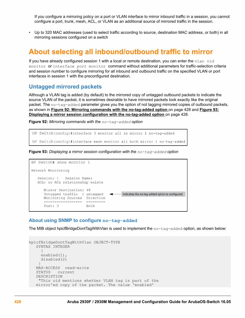
If you configure a mirroring policy on a port or VLAN interface to mirror inbound traffic in a session, you cannotconfigure a port, trunk, mesh, ACL, or VLAN as an additional source of mirrored traffic in the session.
• Up to 320 MAC addresses (used to select traffic according to source, destination MAC address, or both) in allmirroring sessions configured on a switch
About selecting all inbound/outbound traffic to mirrorIf you have already configured session 1 with a local or remote destination, you can enter the vlan vidmonitor or interface port monitor command without additional parameters for traffic-selection criteriaand session number to configure mirroring for all inbound and outbound traffic on the specified VLAN or portinterfaces in session 1 with the preconfigured destination.
Untagged mirrored packetsAlthough a VLAN tag is added (by default) to the mirrored copy of untagged outbound packets to indicate thesource VLAN of the packet, it is sometimes desirable to have mirrored packets look exactly like the originalpacket. The no-tag-added parameter gives you the option of not tagging mirrored copies of outbound packets,as shown in Figure 92: Mirroring commands with the no-tag-added option on page 428 and Figure 93:Displaying a mirror session configuration with the no-tag-added option on page 428.
Figure 92: Mirroring commands with the no-tag-added option
Figure 93: Displaying a mirror session configuration with the no-tag-added option
About using SNMP to configure no-tag-addedThe MIB object hpicfBridgeDontTagWithVlan is used to implement the no-tag-added option, as shown below:
hpicfBridgeDontTagWithVlan OBJECT-TYPE SYNTAX INTEGER { enabled(1), disabled(2) } MAX-ACCESS read-write STATUS current DESCRIPTION "This oid mentions whether VLAN tag is part of the mirror'ed copy of the packet. The value ‘enabled'
428 Aruba 2930F / 2930M Management and Configuration Guide for ArubaOS-Switch 16.05

denotes that the VLAN tag shouldn't be part of the mirror'ed copy; ‘disabled' does put the VLAN tag in the mirror'ed copy. Only one logical port is allowed. This object is persistent and when written the entity SHOULD save the change to non-volatile storage." DEFVAL { 2 } ::= { hpicfBridgeMirrorSessionEntry 2 }
Operating notesThe following conditions apply for the no-tag-added option:
• The specified port can be a physical port, trunk port, or mesh port.
• Only a single logical port (physical port or trunk) can be associated with a mirror session when the no-tag-added option is specified. No other combination of ACL mirroring, VLAN mirroring, or port mirroring can beassociated with the mirror session. If more than one logical port is specified, the following error message isdisplayed:
Cannot monitor more than one logical port with no-tag-added option
• If a port changes its VLAN membership and/or untagged status within the VLAN, the "untagged port mirroring"associated with that port is updated when the configuration change is processed.
• Only four ports or trunks can be monitored at one time when all four mirror sessions are in use (one logicalport per mirror session) without VLAN tags being added to a mirrored copy.
• The no-tag-added option can also be used when mirroring is configured with SNMP.
• A VLAN tag is still added to the copies of untagged packets obtained via VLAN-based mirroring.
About selecting inbound/outbound traffic using a MAC addressUse the monitor mac mirror command at the global configuration level to apply a source and/or destinationMAC address as the selection criteria used in a local or remote mirroring session.
While classifier-based mirroring allows you to mirror traffic using a policy to specify IP addresses as selectioncriteria, MAC-based mirroring allows you monitor switch traffic using a source and/or destination MAC address.You can apply MAC-based mirroring in one or more mirroring sessions on the switch to monitor:
• Inbound traffic
• Outbound traffic
• Both inbound and outbound traffic
MAC-based mirroring is useful in Switch Network Immunity security solutions that provide detection and responseto malicious traffic at the network edge. After isolating a malicious MAC address, a security administrator canmirror all traffic sent to and received from the suspicious address for troubleshooting and traffic analysis.
The MAC address that you enter with the monitor mac mirror command is configured to select traffic formirroring from all ports and learned VLANs on the switch. Therefore, a suspicions MAC address used in wirelessapplications can be continuously monitored as it re-appears in switch traffic on different ports or VLAN interfaces.
You can configure MAC-based mirroring from the CLI or an SNMP management station and use it to mirror:
Chapter 17 Monitoring and Analyzing Switch Operation 429

• All inbound and outbound traffic from a group of hosts to one destination device.
• Inbound and/or outbound traffic from each host to a different destination device.
• Inbound and outbound traffic from all monitored hosts separately on two destination devices: mirroring allinbound traffic to one device and all outbound traffic to another device.
Restrictions
The following restrictions apply to MAC-based mirroring:
• Up to 320 different MAC addresses are supported for traffic selection in all mirroring sessions configured onthe switch.
• A destination MAC address is not supported as mirroring criteria for routed traffic, because in routed packets,the destination MAC address is changed to the next-hop address when the packet is forwarded. Therefore, thedestination MAC address that you want to mirror will not appear in routed packet headers.
This restriction also applies to the destination MAC address of a host that is directly connected to a routingswitch. (Normally, a host is connected to an edge switch, which is directly connected to the router.)
To mirror routed traffic, we recommend that you use classifier-based policies to select IPv4 or IPv6 traffic formirroring, as described in.
• On a switch, you can use a MAC address only once as a source MAC address and only once as a destinationMAC address to filter mirrored traffic.
For example, after you enter the following commands:
monitor mac 111111-222222 src mirror 1monitor mac 111111-222222 dest mirror 2The following commands are not supported:
monitor mac 111111-222222 src mirror 3monitor mac 111111-222222 dest mirror 4In addition, if you enter the monitor mac 111111-222222 both mirror 1 command, you cannot usethe MAC address 111111-222222 in any other monitor mac mirror configuration commands on theswitch.
• To re-use a MAC address that has already been configured as a source and/or destination address for trafficselection in a mirror session, you must first remove the configuration by entering the no form of the commandand then re-enter the MAC address in a new monitor mac mirror command.
For example, if you have already configured MAC address 111111-222222 to filter inbound and outboundmirrored traffic, and you decide to use it to filter only inbound traffic in a mirror session, you could enter thefollowing commands:
monitor mac 111111-222222 both mirror 1no monitor mac 111111-222222 both mirror 1monitor mac 111111-222222 src mirror 1
• A mirroring session in which you configure MAC-based mirroring is not supported on a port, trunk, mesh, orVLAN interface on which a mirroring session with a classifier-based mirroring policy is configured.
430 Aruba 2930F / 2930M Management and Configuration Guide for ArubaOS-Switch 16.05

About selecting inbound traffic using advanced classifier-based mirroringIn addition to the traffic selection options, traffic mirroring supports the use of advanced classifier-based functionsthat provide:
• A finer granularity for selecting the inbound IP traffic that you want to mirror on an individual port or VLANinterface (instead of mirroring all inbound traffic on the interface)
• Support for mirroring both IPv4 and IPv6 traffic
• The ability to re-use the same traffic classes in different software-feature configurations; for example, you canapply both a QoS rate-limiting and mirroring policy on the same class of traffic.
Classifier-based mirroring policies provide greater precision when analyzing and debugging a network trafficproblem. Using multiple match criteria, you can finely select and define the classes of traffic that you want tomirror on a traffic analyzer or IDS device.
Classifier-based mirroring configuration1. Evaluate the types of traffic in your network and identify the traffic types that you want to mirror.
2. Create an IPv4 or IPv6 traffic class using the class command to select the packets that you want to mirror ina session on a preconfigured local or remote destination device.
A traffic class consists of match criteria, which consist of match and ignore commands.
• match commands define the values that header fields must contain for a packet to belong to the class andbe managed by policy actions.
• ignore commands define the values which, if contained in header fields, exclude a packet from the policyactions configured for the class.
Be sure to enter match/ignore statements in the precise order in which you want their criteria tobe used to check packets.
The following match criteria are supported in match/ignore statements for inbound IPv4/IPv6 traffic:
• IP source address (IPv4 and IPv6)
• IP destination address (IPv4 and IPv6)
• IP protocol (such as ICMP or SNMP)
• Layer 3 IP precedence bits
• Layer 3 DSCP codepoint
• Layer 4 TCP/UDP application port (including TCP flags)
• VLAN ID
Enter one or more match or ignore commands from the class configuration context to filter traffic anddetermine the packets on which policy actions will be performed.
3. Create a mirroring policy to configure the session and destination device to which specified classes of inboundtraffic are sent by entering the policy mirror command from the global configuration context.
Chapter 17 Monitoring and Analyzing Switch Operation 431
Be sure to enter each class and its associated mirroring actions in the precise order in which youwant packets to be checked and processed.
To configure the mirroring actions that you want to execute on packets that match the criteria in a specifiedclass, enter one or more class action mirror commands from the policy configuration context.
You can configure only one mirroring session (destination) for each class. However, you can configure thesame mirroring session for different classes.
A packet that matches the match criteria in a class is mirrored to the exit (local or remote) port that has beenpreviously configured for the session, where session is a value from 1 to 4 or a text string (if you configured thesession with a name when you entered the mirror command.)
Prerequisite: The local or remote exit port for a session must be already configured before you enter themirror session parameter in a class action statement:
• In a local mirroring session, the exit port is configured with the mirror <session-number> portcommand
• In a remote mirroring session, the remote exit port is configured with the mirror endpoint ip andmirror <session-number> remote ip commands.
Restriction: In a policy, you can configure only one mirroring session per class. However, you can configure thesame session for different classes.
Mirroring is not executed on packets that match ignore criteria in a class.
The execution of mirroring actions is performed in the order in which the classes are numerically listed in thepolicy.
The complete no form of the class action mirror command or the no <seq-number> commandremoves a class and mirroring action from the policy configuration.
To manage packets that do not match the match or ignore criteria in any class in the policy, and therefore haveno mirroring actions performed on them, you can enter an optional default class. The default class is placed atthe end of a policy configuration and specifies the mirroring actions to perform on packets that are neithermatched nor ignored.
4. (Optional) To configure a default-class in a policy, enter the default-class command at the end of a policyconfiguration and specify one or more actions to be executed on packets that are not matched and notignored.
Prerequisite: The local or remote exit port for a session must be already configured with a destination devicebefore you enter the mirror <session> parameter in a default-class action statement.
5. Apply the mirroring policy to inbound traffic on a port (interface service-policy in command) or VLAN(vlan service-policy in command) interface.
432 Aruba 2930F / 2930M Management and Configuration Guide for ArubaOS-Switch 16.05

After you apply a mirroring policy for one or more preconfigured sessions on a port or VLANinterface, the switch immediately starts to use the traffic-selection criteria and exit port to mirrortraffic to the destination device connected to each exit port.
In a remote mirroring session that uses IPv4 encapsulation, if the remote switch is not alreadyconfigured as the destination for the session, its performance may be adversely affected by thestream of mirrored traffic.
For this reason, Hewlett Packard Enterprise strongly recommends that you first configure the exitswitch in a remote mirroring session before you apply a mirroring service policy on a port or VLANinterface.
Restrictions: The following restrictions apply to a mirroring service policy:
• Only one mirroring policy is supported on a port or VLAN interface.
• If you apply a mirroring policy to a port or VLAN interface on which a mirroring policy is already configured,the new policy replaces the existing one.
• A mirroring policy is supported only on inbound traffic.
Because only one mirroring policy is supported on a port or VLAN interface, ensure that the policy you want toapply contains all the required classes and actions for your configuration.
Classifier-based mirroring restrictionsThe following restrictions apply to mirroring policies configured with the classifier-based model:
• A mirroring policy is supported only on inbound IPv4 or IPv6 traffic.
• A mirroring policy is not supported on a meshed port interface. (Classifier-based policies are supported only ona port, VLAN, or trunk interface.)
• Only one classifier-based mirroring policy is supported on a port or VLAN interface. You can, however, apply aclassifier-based policy of a different type, such as QoS.
• You can enter multiple class action mirror statements in a policy.
◦ You can configure only one mirroring session (destination) for each class.
◦ You can configure the same mirroring session for different classes.
Chapter 17 Monitoring and Analyzing Switch Operation 433

• If a mirroring session is configured with a classifier-based mirroring policy on a port or VLAN interface, noother traffic-selection criteria (MAC-based or all inbound and/or outbound traffic) can be added to the session.
Figure 94: Mirroring configuration in which only a mirroring policy is supported
• If a mirroring session is already configured with one or more traffic-selection criteria (MAC-based or all inboundand/or outbound traffic), the session does not support the addition of a classifier-based policy.
Figure 95: Mirroring configuration in which only traffic-selection criteria are supported
About applying multiple mirroring sessions to an interfaceYou can apply a mirroring policy to an interface that is already configured with another traffic-selection method(MAC-based or all inbound and/or outbound traffic) for a different mirroring session.
The classifier-based policy provides a finer level of granularity that allows you to zoom in on a subset of port orVLAN traffic and select it for local or remote mirroring.
In the following example, traffic on Port b1 is used as the mirroring source for two different, local mirroringsessions:
434 Aruba 2930F / 2930M Management and Configuration Guide for ArubaOS-Switch 16.05

• All inbound and outbound traffic on Ports b1, b2, and b3 is mirrored in session 4.
• Only selected voice traffic on Port b1 is mirrored in session 2.
Figure 96: Example of applying multiple sessions to the same interface
Mirroring configuration examples
Local mirroring using traffic-direction criteria
An administrator wants to mirror the inbound traffic from workstation "X" on port A5 and workstation "Y" on portB17 to a traffic analyzer connected to port C24 (see Figure 97: Local mirroring topology on page 435.) In thiscase, the administrator chooses "1" as the session number. (Any unused session number from 1 to 4 is valid.)Because the switch provides both the source and destination for the traffic to monitor, local mirroring can be used.In this case, the command sequence is:
• Configure the local mirroring session, including the exit port.
• Configure the monitored source interfaces for the session.
Figure 97: Local mirroring topology
Figure 98: Configuring a local mirroring session for all inbound and outbound port traffic
Chapter 17 Monitoring and Analyzing Switch Operation 435

Remote mirroring using a classifier-based policy
In the network shown in the figure below, an administrator has connected a traffic analyzer to port A15 (in VLAN30) on switch C to monitor the TCP traffic to the server at 10.10.30.153 from workstations connected to switchesA and B. Remote mirroring sessions are configured on switches A and B, and a remote mirroring endpoint onswitch C. TCP traffic is routed through the network to the server from VLANs 10 and 20 on VLAN 30.
Figure 99: Sample topology in a remote mirroring session
To configure this remote mirroring session using a classifier-based policy to select inbound TCP traffic on twoVLAN interfaces, take the following steps:
1. On remote switch C, configure a remote mirroring endpoint using port A15 as the exit port (as described in Configure a mirroring destination on a remote switch on page 426.)
Figure 100: Configuring a remote mirroring endpoint: remote switch and exit port
2. On source switch A, configure an association between the remote mirroring endpoint on switch C and amirroring session on switch A (as described in Configure a mirroring session on the source switch onpage 426.)
436 Aruba 2930F / 2930M Management and Configuration Guide for ArubaOS-Switch 16.05

3. On switch A, configure a classifier-based mirroring policy to select inbound TCP traffic destined to the server at10.10.30.153, and apply the policy to the interfaces of VLAN 10 (as described in About selecting inboundtraffic using advanced classifier-based mirroring on page 431.)
Figure 101: Configuring a classifier-based policy on source switch A
4. On source switch B, repeat steps 2 and 3:
a. Configure an association between the remote mirroring endpoint on switch C and a mirroring session onswitch B.
b. Configure a classifier-based mirroring policy to select inbound TCP traffic destined to the server at10.10.30.153, and apply the policy to a VLAN interface for VLAN 20.
Chapter 17 Monitoring and Analyzing Switch Operation 437

Because the remote session has mirroring sources on different switches, you can use the same sessionnumber (1) for both sessions.
Figure 102: Configuring a classifier-based policy on source switch B
Remote mirroring using traffic-direction criteria
In the network shown in the figure below, the administrator connects another traffic analyzer to port B10 (in VLAN40) on switch C to monitor all traffic entering switch A on port C12. For this mirroring configuration, theadministrator configures a mirroring destination (with a remote exit port of B10) on switch C, and a remotemirroring session on switch A.
If the mirroring configuration in the proceeding example is enabled, it is necessary to use a different sessionnumber (2) and UDP port number (9400.) (The IP address of the remote exit port [10.10.40.7] connected to trafficanalyzer 2 [exit port B10] can belong to a different VLAN than the destination IP address of the VLAN used toreach remote switch C [10.20.40.1]).
Figure 103: Sample topology for remote mirroring from a port interface
To configure this remote mirroring session using a directional-based traffic selection on a port interface, theoperator must take the following steps:
438 Aruba 2930F / 2930M Management and Configuration Guide for ArubaOS-Switch 16.05

1. On remote switch C, configure the remote mirroring endpoint using port B10 as the exit port for a trafficanalyzer (as described in Configure a mirroring destination on a remote switch on page 426):
Figure 104: Configuring a remote mirroring endpoint
2. On source switch A, configure session 2 to use UDP port 9400 to reach the remote mirroring endpoint onswitch C (10.10.40.1):
mirror 2 remote ip 10.10.10.119 9400 10.10.40.1
3. On source switch A, configure the local port C12 to select all inbound traffic to send to the preconfiguredmirroring destination for session 2:
interface c12 monitor all in mirror 2Figure 105: Configuring a remote mirroring session for inbound port traffic
Maximum supported frame sizeThe IPv4 encapsulation of mirrored traffic adds a 54-byte header to each mirrored frame. If a resulting frameexceeds the MTU allowed in the network, the frame is dropped or truncated.
Oversized mirroring frames are dropped or truncated, according to the setting of the [truncation]parameter in the mirror command. Also, remote mirroring does not allow downstream devices in amirroring path to fragment mirrored frames.
If jumbo frames are enabled on the mirroring source switch, the mirroring destination switch and alldownstream devices connecting the source switch to the mirroring destination must be configured tosupport jumbo frames.
Chapter 17 Monitoring and Analyzing Switch Operation 439

Enabling jumbo frames to increase the mirroring path MTUOn 1-Gbps and 10-Gbps ports in the mirroring path, you can reduce the number of dropped frames by enablingjumbo frames on all intermediate switches and routers. (The MTU on the switches covered by this manual is 9220bytes for frames having an 802.1Q VLAN tag, and 9216 bytes for untagged frames.)
Table 25: Maximum frame sizes for mirroring
Frame typeconfiguration
Maximumframe size
VLAN tag Framemirroredto localport
Frame mirrored to remoteport
Data Data IPv4 header
Untagged Non-jumbo (defaultconfig.)
1518 0 1518 1464 54
Jumbo on all VLANs 9216 0 9216 9162 54
Jumbo11 On all butsource VLAN
1518 0 n/a 1464 54
Tagged Non-jumbo 1522 4 1522 1468 54
Jumbo11 on all VLANs 9220 4 9218 9164 54
Jumbo11 On all butsource VLAN
1522 4 n/a22 1468 54
1 Jumbo frames are allowed on ports operating at or above 1 Gbps2 For local mirroring, a non-jumbo configuration on the source VLAN dictates an MTU of 1518 bytes for untagged frames, and
an MTU of 1522 for tagged frames, regardless of the jumbo configuration on any other VLANs on the switch.
Effect of downstream VLAN tagging on untagged,mirrored trafficIn a remote mirroring application, if mirrored traffic leaves the switch without 802.1Q VLAN tagging, but isforwarded through a downstream device that adds 802.1Q VLAN tags, the MTU for untagged mirrored framesleaving the source switch is reduced below the values shown in Maximum frame sizes for mirroring.
440 Aruba 2930F / 2930M Management and Configuration Guide for ArubaOS-Switch 16.05

For example, if the MTU on the path to the destination is 1522 bytes, untagged mirrored frames leaving thesource switch cannot exceed 1518 bytes. Likewise, if the MTU on the path to the destination is 9220 bytes,untagged mirrored frames leaving the source switch cannot exceed 9216 bytes.
Figure 106: Effect of downstream VLAN tagging on the MTU for mirrored traffic
Operating notes for traffic mirroring
• Mirroring dropped traffic
When an interface is configured to mirror traffic to a local or remote destination, packets are mirroredregardless of whether the traffic is dropped while on the interface. For example, if an ACL is configured on aVLAN with a deny ACE that eliminates packets from a Telnet application, the switch still mirrors the Telnetpackets that are received on the interface and subsequently dropped.
• Mirroring and spanning tree
Mirroring is performed regardless of the STP state of a port or trunk. This means, for example, that inboundtraffic on a port blocked by STP can still be monitored for STP packets during the STP setup phase.
• Tagged and untagged frames
For a frame entering or leaving the switch on a mirrored port, the mirrored copy retains the tagged or untaggedstate the original frame carried when it entered into or exited from the switch. (The tagged or untagged VLANmembership of ports in the path leading to the mirroring destination does not affect the tagged or untaggedstatus of the mirrored copy itself.)
Thus, if a tagged frame arrives on a mirrored port, the mirrored copy is also tagged, regardless of the status ofports in the destination path. If a frame exits from the switch on a mirrored port that is a tagged member of aVLAN, the mirrored copy is also tagged for the same reason.
To prevent a VLAN tag from being added to the mirrored copy of an outbound packet sent to a mirroringdestination, you must enter the no-tag-added parameter when you configure a port, trunk, or mesh interfaceto select mirrored traffic.
• Effect of IGMP on mirroring
If both inbound and outbound mirroring is operating when IGMP is enabled on a VLAN, two copies of mirroredIGMP frames may appear at the mirroring destination.
Chapter 17 Monitoring and Analyzing Switch Operation 441

• Mirrored traffic not encrypted
Mirrored traffic undergoes IPv4 encapsulation, but mirrored encapsulated traffic is not encrypted.
• IPv4 header added
The IPv4 encapsulation of mirrored traffic adds a 54-byte header to each mirrored frame. If a resulting frameexceeds the maximum MTU allowed in the network, it is dropped or truncated (according to the setting of the[truncation] parameter in the mirror command.)
To reduce the number of dropped frames, enable jumbo frames in the mirroring path, including all intermediateswitches and/or routers. (The MTU on the switch is 9220 bytes, which includes 4 bytes for the 802.1Q VLANtag.)
• Intercepted or injected traffic
The mirroring feature does not protect against either mirrored traffic being intercepted or traffic being injectedinto a mirrored stream by an intermediate host.
• Inbound mirrored IPv4-encapsulated frames are not mirrored
The switch does not mirror IPv4-encapsulated mirrored frames that it receives on an interface. This preventsduplicate mirrored frames in configurations where the port connecting the switch to the network path for amirroring destination is also a port whose inbound or outbound traffic is being mirrored.
For example, if traffic leaving the switch through ports B5, B6, and B7 is being mirrored through port B7 to anetwork analyzer, the mirrored frames from traffic on ports B5 and B6 will not be mirrored a second time asthey pass through port B7.
• Switch operation as both destination and source
A switch configured as a remote destination switch can also be configured to mirror traffic to one of its ownports (local mirroring) or to a destination on another switch (remote mirroring.)
• Monitor command note
If session 1 is already configured with a destination, you can enter the [no] vlan <VID>monitor or [no]interface <PORT> monitor command without mirroring criteria and a mirror session number. In thiscase, the switch automatically configures or removes mirroring for inbound and outbound traffic from thespecified VLAN or ports to the destination configured for session 1.
• Loss of connectivity suspends remote mirroring
When a remote mirroring session is configured on a source switch, the switch sends an ARP request to theconfigured destination approximately every 60 seconds. If the source switch fails to receive the expected ARPresponse from the destination for the session, transmission of mirrored traffic in the session halts. However,because the source switch continues to send ARP requests for each configured remote session, linkrestoration or discovery of another path to the destination enables the source switch to resume transmitting thesession's mirrored traffic after a successful ARP response cycle occurs.
Note that if a link's connectivity is repeatedly interrupted ("link toggling"), little or no mirrored traffic may beallowed for sessions using that link. To verify the status of any mirroring session configured on the sourceswitch, use the show monitor command.
442 Aruba 2930F / 2930M Management and Configuration Guide for ArubaOS-Switch 16.05

Troubleshooting traffic mirroringCause
If mirrored traffic does not reach the configured remote destination (endpoint) switch or remote exit port, check thefollowing configurations:
• In a remote mirroring session, the mirror remote ip command parameters configured on the sourceswitch for source IP address, source UDP port, and destination IP address must be identical to the sameparameters configured with the mirror endpoint ip command on the remote destination switch.
• The configured remote exit port must not be a member of a trunk or mesh.
• If the destination for mirrored traffic is on a different VLAN than the source, routing must be correctlyconfigured along the path from the source to the destination.
• On the remote destination (endpoint) switch, the IP addresses of the remote exit port and the switch canbelong to different VLANs.
• All links on the path from the source switch to the destination switch must be active.
A mirroring exit port should be connected only to a network analyzer, IDS, or other network edgedevice that has no connection to other network resources. Configuring a mirroring exit portconnection to a network can result in serious network performance problems, and is stronglydiscouraged by HPE Aruba.
Interface monitoring featuresYou can designate monitoring of inbound and outbound traffic on:
• Ports and static trunks: Allows monitoring of individual ports, groups of contiguous ports, and static porttrunks.
• Static VLANs: Allows traffic monitoring on one static VLAN.
The switch monitors network activity by copying all traffic inbound and outbound on the specified interfaces to thedesignated monitoring port, to which a network analyzer can be attached.
If a tagged packet arrives on a monitored port, the packet will remain tagged when it goes out a monitored porteven if that port is configured as untagged. If the packet is untagged, it will remain untagged going out the monitorport. The monitor port state (tagged or untagged) does not affect the tagging of the packet. However, egressmirroring does not reflect the tagged or untagged characteristic to the mirror port, instead it reflects the tagged oruntagged characteristic of the mirror port.
When both inbound and outbound monitoring is done, and IGMP is enabled on any VLAN, you mayget two copies of IGMP packets on the monitored port.
VLANs and port trunks cannot be used as a monitoring port.
The switch can monitor static LACP trunks, but not dynamic LACP trunks.
It is possible, when monitoring multiple interfaces in networks with high traffic levels, to copy moretraffic to a monitor port than the link can support. In this case, some packets may not be copied tothe monitor port.
Chapter 17 Monitoring and Analyzing Switch Operation 443

Configuring port and static trunk monitoring (Menu)This procedure describes configuring the switch for monitoring when monitoring is disabled. (If monitoring hasalready been enabled, the screens will appear differently than shown in this procedure.)
1. From the console Main Menu, select:
2. Switch Configuration...
3. Network Monitoring Port
2. In the Actions menu, press [E] (for Edit).
3. If monitoring is currently disabled (the default) then enable it by pressing the Space bar (or [Y]) to select Yes.
4. Press the down arrow key to display a screen similar to the following and move the cursor to the MonitoringPort parameter.
5. Use the Space bar to select the port to use for monitoring.
6. Highlight the Monitor field and use the Space bar to select the interfaces to monitor:
Ports: Use for monitoring ports or static trunks.
VLAN: Use for monitoring a VLAN.
7. Do one of the following:
• If you are monitoring ports or static trunks go to step 8.
• If you are monitoring a VLAN:
a. i. Press [Tab] or the down arrow key to move to the VLAN field.
b. Use the Space bar to select the VLAN you want to monitor.
c. Go to step 10.
8. Use the down arrow key to move the cursor to the Action column for the individual ports and position thecursor at a port you want to monitor.
9. Press the Space bar to select Monitor for each port and trunk that you want monitored. (Use the down arrowkey to move from one interface to the next in the Action column.)
10. When you finish selecting ports to monitor, press [Enter], then press [S] (for Save ) to save your changesand exit from the screen.
11. Return to the Main Menu.
Configuring port and static trunk monitoring (CLI)You must use the following configuration sequence to configure port and static trunk monitoring in the CLI:
1. Assign a monitoring (mirror) port.
2. Designate the port(s) and/or static trunk(s) to monitor.
444 Aruba 2930F / 2930M Management and Configuration Guide for ArubaOS-Switch 16.05

Displaying the monitoring configurationSyntax:
show monitorThis command lists the port assigned to receive monitored traffic and the ports and/or trunks being monitored.
For example, if you assign port 5 as the monitoring port and configure the switch to monitor ports 2-4, showmonitor displays the following:
Monitored port listing
switch(config)# show monitor
Network Monitoring Port
Mirror Port: 5 1
Monitoring sources 2 ------------------ 2 3 4
• 1Port receiving monitored traffic.
• 2Monitored Ports
Configuring the monitor portSyntax:
[no] mirror-port [< port-num >]This command assigns or removes a monitoring port, and must be executed from the global configuration level.Removing the monitor port disables port monitoring and resets the monitoring parameters to their factory-defaultsettings.
For example, to assign port 6 as the monitoring port:
switch(config)# mirror-port 6To turn off monitoring:
switch(config)# no mirror-port
Selecting or removing monitoring source interfacesAfter you configure a monitor port you can use either the global configuration level or the interface context level toselect ports, static trunks, or VLANs as monitoring sources. You can also use either level to remove monitoringsources.
Syntax:
[no] interface <monitor-list> monitor
<monitor-list> Includes port numbers and static trunk names such as 4, 7, 5-8, trk1.
Chapter 17 Monitoring and Analyzing Switch Operation 445

Individual ports and static trunks can be monitored at the same time. However, if you configure theswitch to monitor a VLAN, all other interfaces are removed from monitoring. Also, you can configureonly one VLAN at a time for monitoring.
Elements in the monitor list can include port numbers and static trunk names at the same time.
For example, with a port such as port 5 configured as the monitoring (mirror) port, you would use either of thefollowing commands to select these interfaces for monitoring:
• Ports 6-9, and 14
• Trunk 2
Selecting ports and static trunks as monitoring sources
switch(config)# int 6-9, 14 trk2, monitorTo monitor a VLAN:
Configuring VLAN monitoring
switch(config)# vlan 20 monitor switch(config)# show monitor
Network Monitoring Port
Mirror Port: 5
Monitoring sources ------------------ VLAN_20
Disabling monitoring at the interface context and the global config level
switch(eth-1-3, 5)# no int 5 monitor 1switch(eth-1-3, 5)# no monitor
switch(config)# no int 5 monitor 2switch(config)# no int 1-3, 5 monitor
• 1These two commands show how to disable monitoring at the interface context level for a single port or allports in an interface context level.
• 2These two commands show how to disable monitoring at the global config level for a single port or a group ofports.
446 Aruba 2930F / 2930M Management and Configuration Guide for ArubaOS-Switch 16.05

OverviewThe switch assigns MAC addresses in these areas:
• For management functions, one Base MAC address is assigned to the default VLAN (VID = 1). (All VLANs onthe switches covered in this guide use the same MAC address.)
• For internal switch operations: One MAC address per port (see Viewing the port and VLAN MAC addresseson page 449.
MAC addresses are assigned at the factory. The switch automatically implements these addresses for VLANs andports as they are added to the switch.
The switch’s base MAC address is also printed on a label affixed to the switch.
Determining MAC addressesUse the CLI to view the switch's port MAC addresses in hexadecimal format.
Use the menu interface to view the switch's base MAC address and the MAC address assigned to any VLANyou have configured on the switch. (The same MAC address is assigned to VLAN1 and all other VLANsconfigured on the switch.)
The switch's base MAC address is used for the default VLAN (VID =1) that is always available on theswitch. This is true for dynamic VLANs as well; the base MAC address is the same across all VLANs.
Viewing the MAC addresses of connected devicesSyntax:
show mac-address [port-list | mac-addr | vlan < vid>]Lists the MAC addresses of the devices the switch has detected, along with the number of the specific port onwhich each MAC address was detected.
Chapter 18MAC Address Management
Chapter 18 MAC Address Management 447

[port-list]Lists the MAC addresses of the devices the switch has detected, on the specifiedports.
[mac-addr]Lists the port on which the switch detects the specified MAC address.Returns thefollowing message if the specified MAC address is not detected on any port in theswitch:
MAC address <mac-addr> not found.
[vlan <vid>]Lists the MAC addresses of the devices the switch has detected on ports belongingto the specified VLAN, along with the number of the specific port on which each MACaddress was detected.
Viewing the switch's MAC address assignments for VLANsconfigured on the switchThe Management Address Information screen lists the MAC addresses for:
• Base switch (default VLAN; VID=1)
• Any additional VLANs configured on the switch.
Also, the Base MAC address appears on a label on the back of the switch.
The Base MAC address is used by the first (default) VLAN in the switch. This is usually the VLANnamed "DEFAULT_VLAN" unless the name has been changed (by using the VLAN Names screen).On the switches covered in this guide, the VID (VLAN identification number) for the default VLAN isalways "1," and cannot be changed.
From the Main Menu, select
1. Status and Counters
2. Switch Management Address Information
448 Aruba 2930F / 2930M Management and Configuration Guide for ArubaOS-Switch 16.05

If the switch has only the default VLAN, the following screen appears. If the switch has multiple static VLANs,each is listed with its address data.
Figure 107: Example: of the Management Address Information screen
Viewing the port and VLAN MAC addressesThe MAC address assigned to each switch port is used internally by such features as Flow Control and thespanning-tree protocol. Using the walkmib command to determine the MAC address assignments for individualports can sometimes be useful when diagnosing switch operation.
This procedure displays the MAC addresses for all ports and existing VLANs in the switch,regardless of which VLAN you select.
Procedure
1. If the switch is at the CLI Operator level, use the enable command to enter the Manager level of the CLI.
2. Enter the following command to display the MAC address for each port on the switch:
switch# walkmib ifPhysAddress(The above command is not case-sensitive.)
Example:
A switch with the following module configuration shows MAC address assignments similar to those shown in theexample below:
Chapter 18 MAC Address Management 449
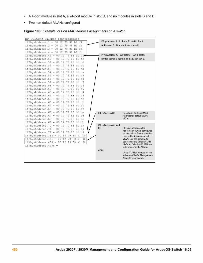
• A 4-port module in slot A, a 24-port module in slot C, and no modules in slots B and D
• Two non-default VLANs configured
Figure 108: Example: of Port MAC address assignments on a switch
450 Aruba 2930F / 2930M Management and Configuration Guide for ArubaOS-Switch 16.05

OverviewThis chapter addresses performance-related network problems that can be caused by topology, switchconfiguration, and the effects of other devices or their configurations on switch operation. (For switch-specificinformation on hardware problems indicated by LED behavior, cabling requirements, and other potentialhardware-related problems, see the installation guide you received with the switch.)
HPE periodically places switch software updates on the HPE Switch Networking website. HPErecommends that you check this website for software updates that may have fixed a problem you areexperiencing.
For information on support and warranty provisions, see the Support and Warranty booklet shipped with theswitch.
Troubleshooting approachesCause
Use these approaches to diagnose switch problems:
• Check the HPE website for software updates that may have solved your problem: http://www.hpe.com/networking
• Check the switch LEDs for indications of proper switch operation:
◦ Each switch port has a Link LED that should light whenever an active network device is connected to theport.
◦ Problems with the switch hardware and software are indicated by flashing the Fault and other switchLEDs.For a description of the LED behavior and information on using the LEDs for troubleshooting, see theinstallation guide shipped with the switch.
• Check the network topology/installation. For topology information, see the installation guide shipped with theswitch.
• Check cables for damage, correct type, and proper connections. You should also use a cable tester to checkyour cables for compliance to the relevant IEEE 802.3 specification. For correct cable types and connector pin-outs, see the installation guide shipped with the switch.
• Use the Port Utilization Graph and Alert Log in the WebAgent included in the switch to help isolate problems.These tools are available through the WebAgent:
◦ Port Utilization Graph
◦ Alert log
Chapter 19Troubleshooting
Chapter 19 Troubleshooting 451

◦ Port Status and Port Counters screens
◦ Diagnostic tools (Link test, Ping test, configuration file browser)
• For help in isolating problems, use the easy-to-access switch console built into the switch or Telnet to theswitch console. For operating information on the Menu and CLI interfaces included in the console, seechapters 3 and 4. These tools are available through the switch console:
◦ Status and Counters screens
◦ Event Log
◦ Diagnostics tools (Link test, Ping test, configuration file browser, and advanced user commands)
Browser or Telnet access problems
Cannot access the WebAgent
• Access may be disabled by the Web Agent Enabled parameter in the switch console. Check the setting on thisparameter by selecting:
2. Switch Configuration
1. System Information
• The switch may not have the correct IP address, subnet mask, or gateway. Verify by connecting a console tothe switch's Console port and selecting:
2. Switch Configuration
5. IP Configuration
Note: If DHCP/Bootp is used to configure the switch, the IP addressing can be verified by selecting:
1. Status and Counters...
2. Switch Management Address Information
Also check the DHCP/Bootp server configuration to verify correct IP addressing.
• If you are using DHCP to acquire the IP address for the switch, the IP address "lease time" may have expiredso that the IP address has changed. For more information on how to "reserve" an IP address, see thedocumentation for the DHCP application that you are using.
• If one or more IP-authorized managers are configured, the switch allows inbound telnet access only to adevice having an authorized IP address. For more information on IP Authorized managers, see the accesssecurity guide for your switch.
• Java™ applets may not be running on the web browser. They are required for the switch WebAgent to operatecorrectly. Refer to the online Help on your web browser for how to run the Java applets.
Cannot Telnet into the switch console from a station on the network
• Off-subnet management stations can lose Telnet access if you enable routing without first configuring a static(default) route. That is, the switch uses the IP default gateway only while operating as a Layer 2 device. Whilerouting is enabled on the switch, the IP default gateway is not used. You can avoid this problem by using the ip
452 Aruba 2930F / 2930M Management and Configuration Guide for ArubaOS-Switch 16.05

route command to configure a static (default) route before enabling routing. For more information, see "IPRouting Features" in the multicast and routing guide for your switch.
• Telnet access may be disabled by the Inbound Telnet Enabled parameter in the System Informationscreen of the menu interface:
2. Switch Configuration
1. System Information
• The switch may not have the correct IP address, subnet mask, or gateway. Verify by connecting a console tothe switch's Console port and selecting:
2. Switch Configuration
5. IP Configuration
• If you are using DHCP to acquire the IP address for the switch, the IP address "lease time" may have expiredso that the IP address has changed. For more information on how to "reserve" an IP address, see thedocumentation for the DHCP application that you are using.
• If one or more IP-authorized managers are configured, the switch allows inbound telnet access only to adevice having an authorized IP address. For more information on IP Authorized managers, see the accesssecurity guide for your switch.
Unusual network activityNetwork activity that fails to meet accepted norms may indicate a hardware problem with one or more of thenetwork components, possibly including the switch. Such problems can also be caused by a network loop orsimply too much traffic for the network as it is currently designed and implemented. Unusual network activity isusually indicated by the LEDs on the front of the switch or measured with the switchconsole interface or with anetwork management tool. For information on using LEDs to identify unusual network activity, see the installationguide you received with the switch.
A topology loop can also cause excessive network activity. The Event Log "FFI" messages can be indicative ofthis type of problem.
General problems
The network runs slow; processes fail; users cannot access servers or other devicesBroadcast storms may be occurring in the network. These may be caused by redundant links between nodes.
• If you are configuring a port trunk, finish configuring the ports in the trunk before connecting the related cables.Otherwise you may inadvertently create a number of redundant links (that is, topology loops) that will causebroadcast storms.
• Turn on STP to block redundant links
• Check for FFI messages in the Event Log
Duplicate IP addressesThis is indicated by this Event Log message:
ip: Invalid ARP source: IP address on IP addresswhere both instances of IP address are the same address, indicating that the switch's IP address has beenduplicated somewhere on the network.
Chapter 19 Troubleshooting 453

Duplicate IP addresses in a DHCP networkIf you use a DHCP server to assign IP addresses in your network, and you find a device with a valid IP addressthat does not appear to communicate properly with the server or other devices, a duplicate IP address may havebeen issued by the server. This can occur if a client has not released a DHCP-assigned IP address after theintended expiration time and the server "leases" the address to another device. This can also happen, Forexample, if the server is first configured to issue IP addresses with an unlimited duration, and then issubsequently configured to issue IP addresses that will expire after a limited duration. One solution is to configure"reservations" in the DHCP server for specific IP addresses to be assigned to devices having specific MACaddresses. For more information, see the documentation for the DHCP server.
One indication of a duplicate IP address in a DHCP network is this Event Log message:
ip: Invalid ARP source: <IP-address> on <IP-address>where both instances of IP-address are the same address, indicating that the IP address has been duplicatedsomewhere on the network.
The switch has been configured for DHCP/Bootp operation, but has not received aDHCP or Bootp replyWhen the switch is first configured for DHCP/Bootp operation, or if it is rebooted with this configuration, itimmediately begins sending request packets on the network. If the switch does not receive a reply to its DHCP/Bootp requests, it continues to periodically send request packets, but with decreasing frequency. Thus, if a DHCPor Bootp server is not available or accessible to the switch when DHCP/Bootp is first configured, the switch maynot immediately receive the desired configuration.
After verifying that the server has become accessible to the switch, reboot the switch to re-start the process.
802.1Q Prioritization problems
Ports configured for non-default prioritization (level 1 to 7) are not performing thespecified actionIf the ports were placed in a trunk group after being configured for non-default prioritization, the priority settingwas automatically reset to zero (the default). Ports in a trunk group operate only at the default priority setting.
Addressing ACL problems
ACLs are properly configured and assigned to VLANs, but the switch is not using theACLs to filter IP layer 3 packets
Procedure
1. The switch may be running with IP routing disabled. To ensure that IP routing is enabled, execute showrunning and look for the IP routing statement in the resulting listing. For Example:Indication that routing is enabled
switch(config)# show runningRunning configuration:; J9091A Configuration Editor; Created on release #XX.15.06hostname " HPswitch "ip default-gateway 10.33.248.1ip routing 1logging 10.28.227.2snmp-server community "public" Unrestrictedip access-list extended "Controls for VLAN 20"
454 Aruba 2930F / 2930M Management and Configuration Guide for ArubaOS-Switch 16.05

permit tcp 0.0.0.0 255.255.255.255 10.10.20.98 0.0.0.0 eq 80permit tcp 0.0.0.0 255.255.255.255 10.10.20.21 0.0.0.0 eq 80deny tcp 0.0.0.0 255.255.255.255 10.10.20.1 0.0.0.255 eq 80deny tcp 10.10.20.1? 0.0.0.0 10.10.10.100 0.0.0.0 eq 20 logdeny tcp 10.10.20.20 0.0.0.0 10.10.10.100 0.0.0.0 eq 20 logdeny tcp 10.10.20.43 0.0.0.0 10.10.10.100 0.0.0.0 eq 20 logpermit ip 10.10.20.1 0.0.0.255 10.10.10.100 0.0.0.0deny ip 10.10.30.1 0.0.0.255 10.10.10.100 0.0.0.0permit ip 10.10.30.1 0.0.0.255 10.10.10.1 0.0.0.255exit
1
Indicates that routing is enabled, a requirement for ACL operation. (There is an exception. Refer to the Note,below.)
If an ACL assigned to a VLAN includes an ACE referencing an IP address on the switch itself asa packet source or destination, the ACE screens traffic to or from this switch address regardlessof whether IP routing is enabled. This is a security measure designed to help protect the switchfrom unauthorized management access.
If you need to configure IP routing, execute the ip routing command.
2. ACL filtering on the switches applies only to routed packets and packets having a destination IP address (DA)on the switch itself.
Also, the switch applies assigned ACLs only at the point where traffic enters or leaves the switch on a VLAN.Ensure that you have correctly applied your ACLs ("in" and/or "out") to the appropriate VLANs.
The switch does not allow management access from a device on the same VLANThe implicit deny any function that the switch automatically applies as the last entry in any ACL always blockspackets having the same DA as the switch's IP address on the same VLAN. That is, bridged packets with theswitch itself as the destination are blocked as a security measure.
To preempt this action, edit the ACL to include an ACE that permits access to the switch's DA on that VLAN fromthe management device.
Error (Invalid input) when entering an IP addressWhen using the "host" option in the Command syntax, ensure that you are not including a mask in either dotteddecimal or CIDR format. Using the "host" option implies a specific host device and therefore does not permit anymask entry.
Correctly and incorrectly specifying a single host
Switch(config)# access-list 6 permit host 10.28.100.100 1
Switch(config)# access-list 6 permit host 10.28.100.100 255.255.255.2552 Invalid input: 255.255.255.255
Switch(config)# access-list 6 permit host 10.28.100.100/32 3Invalid input: 10.28.100.100/32
Chapter 19 Troubleshooting 455

• 1Correct.
• 2Incorrect. No mask needed to specify a single host.
• 3Incorrect. No mask needed to specify a single host.
Apparent failure to log all "deny" matchesWhere the log statement is included in multiple ACEs configured with a "deny" option, a large volume of "deny"matches generating logging messages in a short period of time can impact switch performance. If it appears thatthe switch is not consistently logging all "deny" matches, try reducing the number of logging actions by removingthe log statement from some ACEs configured with the "deny" action.
The switch does not allow any routed access from a specific host, group of hosts, orsubnetThe implicit deny any function that the switch automatically applies as the last entry in any ACL may be blockingall access by devices not specifically permitted by an entry in an ACL affecting those sources. If you are using theACL to block specific hosts, a group of hosts, or a subnet, but want to allow any access not specifically permitted,insert permit any as the last explicit entry in the ACL.
The switch is not performing routing functions on a VLANTwo possible causes of this problem are:
• Routing is not enabled. If show running indicates that routing is not enabled, use the ip routingcommand to enable routing.
• An ACL may be blocking access to the VLAN (on a switch covered in this guide). Ensure that the switch's IPaddress on the VLAN is not blocked by one of the ACE entries in an ACL applied to that VLAN. A commonmistake is to either not explicitly permit the switch's IP address as a DA or to use a wildcard ACL mask in adeny statement that happens to include the switch's IP address. For an Example: of this problem, see section"General ACL Operating Notes" in the "Access Control Lists (ACLs)" of the latest access security guide foryour switch.
Routing through a gateway on the switch failsConfiguring a "deny" ACE that includes a gateway address can block traffic attempting to use the gateway as anext-hop.
Remote gateway caseConfiguring ACL "101" (example below) and applying it outbound on VLAN 1 in the figure below includes therouter gateway (10.0.8.1) needed by devices on other networks. This can prevent the switch from sending ARPand other routing messages to the gateway router to support traffic from authorized remote networks.
456 Aruba 2930F / 2930M Management and Configuration Guide for ArubaOS-Switch 16.05

In Figure 109: Inadvertently blocking a gateway on page 457, this ACE (see data in bold below) deniesaccess to the 10 Net's 10.0.8.1 router gateway needed by the 20 Net (Subnet mask is 255.255.255.0).See:example
Figure 109: Inadvertently blocking a gateway
To avoid inadvertently blocking the remote gateway for authorized traffic from another network (such as the 20Net in this Example:):
Procedure
1. Configure an ACE that specifically permits authorized traffic from the remote network.
2. Configure narrowly defined ACEs to block unwanted IP traffic that would otherwise use the gateway; suchACEs might deny traffic for a particular application, particular hosts, or an entire subnet.
3. Configure a "permit any" ACE to specifically allow any IP traffic to move through the gateway.
ACE blocking an entire subnet
switch(config)# access-list config
ip access-list extended "101" deny ip 0.0.0.0 255.255.255.255 10.0.8.30 0.0.0.255 permit ip 0.0.0.0 255.255.255.255 0.0.0.00 255.255.255.255 exit
Local gateway caseIf you use the switch as a gateway for traffic you want routed between subnets, use these general steps to avoidblocking the gateway for authorized applications:
Procedure
1. Configure gateway security first for routing with specific permit and deny statements.
2. Permit authorized traffic.
3. Deny any unauthorized traffic that you have not already denied in step 1 on page 457.
Chapter 19 Troubleshooting 457

IGMP-related problems
IP multicast (IGMP) traffic that is directed by IGMP does not reach IGMP hosts or amulticast router connected to a portIGMP must be enabled on the switch and the affected port must be configured for "Auto" or "Forward" operation.
IP multicast traffic floods out all ports; IGMP does not appear to filter trafficThe IGMP feature does not operate if the switch or VLAN does not have an IP address configured manually orobtained through DHCP/Bootp. To verify whether an IP address is configured for the switch or VLAN, do one ofthe following:
• Try using the WebAgent: If you can access the WebAgent, then an IP address is configured.
• Try to telnet to the switch console: If you can Telnet to the switch, an IP address is configured.
• Use the switch console interface: From the Main Menu, check the Management Address Information screenby clicking on:
1. Status and Counters
2. Switch Management Address Information
LACP-related problems
Unable to enable LACP on a port with the interface <port-number> lacpcommandIn this case, the switch displays the following message:
Operation is not allowed for a trunked port.You cannot enable LACP on a port while it is configured as a static Trunk port. To enable LACP on a static-trunked port:
Procedure
1. Use the no trunk <port-number> command to disable the static trunk assignment.
2. Execute interface <port-number> lacp .
Removing a port from a trunk without first disabling the port can create a traffic loop that can slowdown or halt your network. Before removing a port from a trunk, Hewlett Packard Enterpriserecommends that you either disable the port or disconnect it from the LAN.
Port-based access control (802.1X)-related problemsTo list the 802.1X port-access Event Log messages stored on the switch, use show log 802.
See also Radius-related problems on page 461.
458 Aruba 2930F / 2930M Management and Configuration Guide for ArubaOS-Switch 16.05

The switch does not receive a response to RADIUS authentication requestsIn this case, the switch attempts authentication using the secondary method configured for the type of access youare using (console, Telnet, or SSH).
There can be several reasons for not receiving a response to an authentication request. Do the following:
• Use ping to ensure that the switch has access to the configured RADIUS servers.
• Verify that the switch is using the correct encryption key (RADIUS secret key) for each server.
• Verify that the switch has the correct IP address for each RADIUS server.
• Ensure that the radius-server timeout period is long enough for network conditions.
The switch does not authenticate a client even though the RADIUS server is properlyconfigured and providing a response to the authentication requestIf the RADIUS server configuration for authenticating the client includes a VLAN assignment, ensure that theVLAN exists as a static VLAN on the switch. See "How 802.1X Authentication Affects VLAN Operation" in theaccess security guide for your switch.
During RADIUS-authenticated client sessions, access to a VLAN on the port used forthe client sessions is lostIf the affected VLAN is configured as untagged on the port, it may be temporarily blocked on that port during an802.1X session. This is because the switch has temporarily assigned another VLAN as untagged on the port tosupport the client access, as specified in the response from the RADIUS server. See "How 802.1X AuthenticationAffects VLAN Operation" in the access security guide for your switch.
The switch appears to be properly configured as a supplicant, but cannot gain accessto the intended authenticator port on the switch to which it is connectedIf aaa authentication port-access is configured for Local, ensure that you have entered the local login(operator-level) username and password of the authenticator switch into the identity and secret parametersof the supplicant configuration. If instead, you enter the enable (manager-level) username and password, accesswill be denied.
The supplicant statistics listing shows multiple ports with the same authenticator MACaddressThe link to the authenticator may have been moved from one port to another without the supplicant statisticshaving been cleared from the first port. See "Note on Supplicant Statistics" in the chapter on Port-Based andUser-Based Access Control in the access security guide for your switch.
The show port-access authenticator <port-list> command shows one ormore ports remain open after they have been configured with control unauthorized802.1X is not active on the switch. After you execute aaa port-access authenticator active, all portsconfigured with control unauthorized should be listed as Closed.
Authenticator ports remain "open" until activated
switch(config)# show port-access authenticator e 9 Port Access Authenticator Status Port-access authenticator activated [No] : No Access Authenticator Authenticator Port Status Control State Backend State
Chapter 19 Troubleshooting 459

---- ------ -------- -------------- -------------- 9 Open 1 FU Force Auth Idle
Switch(config)# show port-access authenticator activeSwitch(config)# show port-access authenticator e 9 Port Access Authenticator Status Port-access authenticator activated [No] : Yes Access Authenticator Authenticator Port Status Control State Backend State ---- ------ -------- -------------- -------------- 9 Closed FU Force Unauth Idle
1Port A9 shows an “Open” status even though Access Control is set to Unauthorized (Force Auth). This isbecause the port-access authenticator has not yet been activated.
RADIUS server fails to respond to a request for service, even though the server's IPaddress is correctly configured in the switchUse show radius to verify that the encryption key (RADIUS secret key) the switch is using is correct for theserver being contacted. If the switch has only a global key configured, it either must match the server key or youmust configure a server-specific key. If the switch already has a server-specific key assigned to the server's IPaddress, it overrides the global key and must match the server key.
Displaying encryption keys
switch(config)# show radius Status and Counters - General RADIUS Information Deadtime(min) : 0 Timeout(secs) : 5 Retransmit Attempts : 3 Global Encryption Key : My-Global-Key Dynamic Authorization UDP Port : 3799
Auth Acct DM/ Time Server IP Addr Port Port CoA Window Encryption Key --------------- ---- ---- --- ------ --------------- 10.33.18.119 1812 1813 119-only-keyAlso, ensure that the switch port used to access the RADIUS server is not blocked by an 802.1X configuration onthat port. For example, show port-access authenticator <port-list> gives you the status for thespecified ports. Also, ensure that other factors, such as port security or any 802.1X configuration on the RADIUSserver are not blocking the link.
The authorized MAC address on a port that is configured for both 802.1X and portsecurity either changes or is re-acquired after execution of aaa port-accessauthenticator <port-list> initializeIf the port is force-authorized with aaa port-access authenticator <port-list> controlauthorized command and port security is enabled on the port, then executing initialize causes the port toclear the learned address and learn a new address from the first packet it receives after you executeinitialize.
A trunked port configured for 802.1X is blockedIf you are using RADIUS authentication and the RADIUS server specifies a VLAN for the port, the switch allowsauthentication, but blocks the port. To eliminate this problem, either remove the port from the trunk or reconfigurethe RADIUS server to avoid specifying a VLAN.
460 Aruba 2930F / 2930M Management and Configuration Guide for ArubaOS-Switch 16.05

QoS-related problems
Loss of communication when using VLAN-tagged trafficIf you cannot communicate with a device in a tagged VLAN environment, ensure that the device either supportsVLAN tagged traffic or is connected to a VLAN port that is configured as Untagged.
Radius-related problems
The switch does not receive a response to RADIUS authentication requestsIn this case, the switch attempts authentication using the secondary method configured for the type of access youare using (console, Telnet, or SSH).
There can be several reasons for not receiving a response to an authentication request. Do the following:
• Use ping to ensure that the switch has access to the configured RADIUS server.
• Verify that the switch is using the correct encryption key for the designated server.
• Verify that the switch has the correct IP address for the RADIUS server.
• Ensure that the radius-server timeout period is long enough for network conditions.
• Verify that the switch is using the same UDP port number as the server.
Because of an inconsistency between the Windows XP 802.1x supplicant timeout value and theswitch default timeout value, which is 5, when adding a backup RADIUS server, set the switchradius-server timeout value to 4. Otherwise, the switch may not failover properly to the backupRADIUS server.
RADIUS server fails to respond to a request for service, even though the server's IPaddress is correctly configured in the switchUse show radius to verify that the encryption key the switch is using is correct for the server being contacted. Ifthe switch has only a global key configured, it either must match the server key or you must configure a server-specific key. If the switch already has a server-specific key assigned to the server's IP address, it overrides theglobal key and must match the server key.
Global and unique encryption keys
Switch(config)# show radius Status and Counters - General RADIUS Information Deadtime(min) : 0 Timeout(secs) : 5 Retransmit Attempts : 3 Global Encryption Key : My-Global-Key 1 Dynamic Authorization UDP Port : 3799
Auth Acct DM/ Time Server IP Addr Port Port CoA Window Encryption Key --------------- ---- ---- --- ------ --------------- 10.33.18.119 1812 1813 119-only-key 2
• 1
Chapter 19 Troubleshooting 461

Global RADIUS Encryption Key
• 2
Unique RADIUS Encryption Key for the RADIUS server at 10.33.18.119
MSTP and fast-uplink problemsIf you enable MSTP, Hewlett Packard Enterprise recommends that you leave the remainder of theMSTP parameter settings at their default values until you have had an opportunity to evaluate MSTPperformance in your network. Because incorrect MSTP settings can adversely affect networkperformance, you should avoid making changes without having a strong understanding of how MSTPoperates. To learn the details of MSTP operation, see the IEEE802.1s standard.
Broadcast storms appearing in the networkThis can occur when there are physical loops (redundant links) in the topology. Where this exists, you shouldenable MSTP on all bridging devices in the topology to detect the loop.
STP blocks a link in a VLAN even though there are no redundant links in that VLANIn 802.1Q-compliant switches, MSTP blocks redundant physical links even if they are in separate VLANs. Asolution is to use only one, multiple-VLAN (tagged) link between the devices. Also, if ports are available, you canimprove the bandwidth in this situation by using a port trunk. See "Spanning Tree Operation with VLANs" in"Static Virtual LANs (VLANs)" in the advanced traffic management guide for your switch.
Fast-uplink troubleshootingSome of the problems that can result from incorrect use of fast-uplink MSTP include temporary loops andgeneration of duplicate packets.
Problem sources can include:
• Fast-uplink is configured on a switch that is the MSTP root device.
• Either the Hello Time or the Max Age setting (or both) is too long on one or more switches. Return theHello Time and Max Age settings to their default values (2 seconds and 20 seconds, respectively, on aswitch).
• A "downlink" port is connected to a switch that is further away (in hop count) from the root device than theswitch port on which fast-uplink MSTP is configured.
• Two edge switches are directly linked to each other with a fast-uplink (Mode = Uplink) connection.
• Fast uplink is configured on both ends of a link.
• A switch serving as a backup MSTP root switch has ports configured for fast-uplink MSTP and has becomethe root device because of a failure in the original root device.
SSH-related problems
Switch access refused to a clientEven though you have placed the client's public key in a text file and copied the file (using the copy tftp pub-key-file command) into the switch, the switch refuses to allow the client to have access. If the source SSHclient is an SSHv2 application, the public key may be in the PEM format, which the switch (SSHv1) does notinterpret. Check the SSH client application for a utility that can convert the PEM-formatted key into an ASCII-formatted key.
462 Aruba 2930F / 2930M Management and Configuration Guide for ArubaOS-Switch 16.05

Executing IP SSH does not enable SSH on the switchThe switch does not have a host key. Verify by executing show ip host-public-key. If you see the message
ssh cannot be enabled until a host key is configured (use 'crypto' command).you need to generate an SSH key pair for the switch. To do so, execute crypto key generate (see"Generating the switch's public and private key pair" in the SSH chapter of the access security guide for yourswitch.)
Switch does not detect a client's public key that does appear in the switch's public keyfile (show ip client-public-key)The client's public key entry in the public key file may be preceded by another entry that does not terminate with anew line (CR). In this case, the switch interprets the next sequential key entry as simply a comment attached tothe preceding key entry. Where a public key file has more than one entry, ensure that all entries terminate with anew line (CR). While this is optional for the last entry in the file, not adding a new line to the last entry creates anerror potential if you either add another key to the file at a later time or change the order of the keys in the file.
An attempt to copy a client public-key file into the switch has failed and the switch listsone of the following messagesDownload failed: overlength key in key file.Download failed: too many keys in key file.Download failed: one or more keys is not a valid RSA public key.The public key file you are trying to download has one of the following problems:
• A key in the file is too long. The maximum key length is 1024 characters, including spaces. This could alsomean that two or more keys are merged together instead of being separated by a <CR> <LF>.
• There are more than ten public keys in the key file.
• One or more keys in the file is corrupted or is not a valid rsa public key.
Client ceases to respond ("hangs") during connection phaseThe switch does not support data compression in an SSH session. Clients often have compression turned on bydefault, but then disable it during the negotiation phase. A client that does not recognize the compression-requestFAILURE response may fail when attempting to connect. Ensure that compression is turned off before attemptinga connection to prevent this problem.
TACACS-related problems
Event LogWhen troubleshooting TACACS+ operation, check the switch's Event Log for indications of problem areas.
All users are locked out of access to the switchIf the switch is functioning properly, but no username/password pairs result in console or Telnet access to theswitch, the problem may be caused by how the TACACS+ server and/or the switch are configured. Use one of thefollowing methods to recover:
Chapter 19 Troubleshooting 463

• Access the TACACS+ server application and adjust or remove the configuration parameters controlling accessto the switch.
• If the above method does not work, try eliminating configuration changes in the switch that have not beensaved to flash (boot-up configuration) by causing the switch to reboot from the boot-up configuration (whichincludes only the configuration changes made prior to the last write memory command.) If you did not usewrite memory to save the authentication configuration to flash, pressing the Reset button reboots theswitch with the boot-up configuration.
• Disconnect the switch from network access to any TACACS+ servers and then log in to the switch using eitherTelnet or direct console port access. Because the switch cannot access a TACACS+ server, it defaults to localauthentication. You can then use the switch's local Operator or Manager username/password pair to log on.
• As a last resort, use the Clear/Reset button combination to reset the switch to its factory default boot-upconfiguration. Taking this step means you will have to reconfigure the switch to return it to operation in yournetwork.
No communication between the switch and the TACACS+ server applicationIf the switch can access the server device (that is, it can ping the server), a configuration error may be theproblem. Some possibilities include:
• The server IP address configured with the switch's tacacs-serverhost command may not be correct. (Usethe switch's show tacacs-server command to list the TACACS+ server IP address.)
• The encryption key configured in the server does not match the encryption key configured in the switch (byusing the tacacs-server key command). Verify the key in the server and compare it to the key configuredin the switch. (Use show tacacs-server to list the global key. Use show config or show configrunning to list any server-specific keys.)
• The accessible TACACS+ servers are not configured to provide service to the switch.
Access is denied even though the username/password pair is correctSome reasons for denial include the following parameters controlled by your TACACS+ server application:
• The account has expired.
• The access attempt is through a port that is not allowed for the account.
• The time quota for the account has been exhausted.
• The time credit for the account has expired.
• The access attempt is outside of the time frame allowed for the account.
• The allowed number of concurrent logins for the account has been exceeded.
For more help, see the documentation provided with your TACACS+ server application.
Unknown users allowed to login to the switchYour TACACS+ application may be configured to allow access to unknown users by assigning them the privilegesincluded in a default user profile. See the documentation provided with your TACACS+ server application.
464 Aruba 2930F / 2930M Management and Configuration Guide for ArubaOS-Switch 16.05

System allows fewer login attempts than specified in the switch configurationYour TACACS+ server application may be configured to allow fewer login attempts than you have configured inthe switch with the aaa authentication num-attempts command.
TimeP, SNTP, or Gateway problems
The switch cannot find the time server or the configured gatewayTimeP, SNTP, and Gateway access are through the primary VLAN, which in the default configuration is theDEFAULT_VLAN. If the primary VLAN has been moved to another VLAN, it may be disabled or does not haveports assigned to it.
VLAN-related problems
Monitor portWhen using the monitor port in a multiple-VLAN environment, the switch handles broadcast, multicast, andunicast traffic output from the monitor port as follows:
• If the monitor port is configured for tagged VLAN operation on the same VLAN as the traffic from monitoredports, the traffic output from the monitor port carries the same VLAN tag.
• If the monitor port is configured for untagged VLAN operation on the same VLAN as the traffic from themonitored ports, the traffic output from the monitor port is untagged.
• If the monitor port is not a member of the same VLAN as the traffic from the monitored ports, traffic from themonitored ports does not go out the monitor port.
None of the devices assigned to one or more VLANs on an 802.1Q-compliant switch arebeing recognizedIf multiple VLANs are being used on ports connecting 802.1Q-compliant devices, inconsistent VLAN IDs mayhave been assigned to one or more VLANs. For a given VLAN, the same VLAN ID must be used on all connected802.1Q-compliant devices.
Link configured for multiple VLANs does not support traffic for one or more VLANsOne or more VLANs may not be properly configured as "Tagged" or "Untagged." A VLAN assigned to a portconnecting two 802.1Q-compliant devices must be configured the same on both ports. For example, VLAN_1 andVLAN_2 use the same link between switch "X" and switch "Y," as shown in Figure 110: Example: of correctVLAN port assignments on a link on page 465.
Figure 110: Example: of correct VLAN port assignments on a link
Chapter 19 Troubleshooting 465

• If VLAN_1 (VID=1) is configured as "Untagged" on port 3 on switch "X," it must also be configured as"Untagged" on port 7 on switch "Y." Make sure that the VLAN ID (VID) is the same on both switches.
• Similarly, if VLAN_2 (VID=2) is configured as "Tagged" on the link port on switch "A," it must also be configuredas "Tagged" on the link port on switch "B." Make sure that the VLAN ID (VID) is the same on both switches.
Duplicate MAC addresses across VLANsThe switches operate with multiple forwarding databases. Thus, duplicate MAC addresses occurring on differentVLANs can appear where a device having one MAC address is a member of more than one 802.1Q VLAN, andthe switch port to which the device is linked is using VLANs (instead of MSTP or trunking) to establish redundantlinks to another switch. If the other device sends traffic over multiple VLANs, its MAC address consistentlyappears in multiple VLANs on the switch port to which it is linked.
Be aware that attempting to create redundant paths through the use of VLANs causes problems with someswitches. One symptom is that a duplicate MAC address appears in the Port Address Table of one port and thenlater appears on another port. While the switches have multiple forwarding databases and thus do not have thisproblem, some switches with a single forwarding database for all VLANs may produce the impression that aconnected device is moving among ports because packets with the same MAC address but different VLANs arereceived on different ports. You can avoid this problem by creating redundant paths using port trunks or spanningtree.
Figure 111: Example: of duplicate MAC address
Disabled overlapping subnet configurationPrevious software versions allowed configuration of VLAN IP addresses in overlapping subnets which can causeincorrect routing of packets and result in IP communication failure. As of software version WB.15.09, overlappingsubnet configurations are no longer allowed. An overlapping subnet is determined by the configuration order. Thesubnet that is configured first is valid, but any subsequent IP addresses that overlap are not allowed.
When the switch is booted into software version WB.15.09 or later, and the configuration file includes overlappingsubnets, the following occurs:
• The event log provides an error message in the format:
ip: VLANx : IP initialization failed for vlan x.For a multinetted VLAN (multiple IP addresses assigned to the VLAN), only the IP addresses that areoverlapping subnets are removed. The other IP addresses on the VLAN are retained and function correctly.The error message can be somewhat misleading; the IP addresses on the VLAN that are not overlapping areinitialized correctly.
• The output of the show ip command correctly indicates that the overlapping IP address does not exist on theVLANs that have error messages in the event log.
466 Aruba 2930F / 2930M Management and Configuration Guide for ArubaOS-Switch 16.05

• The output of the show running-config command incorrectly indicates that the overlapping IP address isconfigured. In Figure 112: An IP address that is not actually configured on the VLAN on page 467, the IPaddress shown in VLAN6 is not actually configured on the VLAN; it has been removed.
Figure 112: An IP address that is not actually configured on the VLAN
switch(config)# show running-config
.
.
. vlan 5 name “VLAN5” ip address 11.22.33.1 255.0.0.0 exit vlan 6 name “VLAN6” ip address 11.23.34.1 255.255.255.0 exitThe information is retained in the config file to allow you to boot up the switch and have it function as it didwhen it was configured with earlier software that allows overlapping subnets.If you attempt to remove theoverlapping subnet from the VLAN, the switch displays an error message similar to:
The IP address <ip-address> is not configured on this VLAN This occurs because the overlapping IP address has been removed and is not visible to the switch. To resolvethis:
• Enter the show ip command to determine which addresses are visible to the switch.
• Remove the erroneous IP addresses from the config file by entering the no ip address command toremove all the IP addresses from the specific VLAN. Be sure to document the other valid IP addresses on thatVLAN so they can be restored after removing the erroneous IP addresses from the config file.
If you go back to a software version prior to WB.15.09 before removing the overlapping IP address, the priorsoftware version enables the overlapping IP subnet.
Fan failureWhenever a fan failure occurs, the Fan/Fault LEDs blink amber and a log entry is recorded. During a fan failure,all operational fans are automatically set to the maximum operating speed until the fan failure has been resolved.At that time, the fan speed is reset to the minimum operating speed.
Mitigating flapping transceiversIn traditional HPE switches, the state of a link is driven directly by the reported state of the port, which is requiredfor rapid detection of link faults. However, the consequence of this is that a marginal transceiver, optical, or wirecabling, one that "flaps" up and down several times per second, can cause STP and other protocols to reactpoorly, resulting in a network outage. The link-flap option expands the functionality of the existing fault finderfunction to include a "link-flap" event and a new action of "warn-and-disable." Together, these additions allow theerrant condition to be detected, and the port in question can be optionally disabled.
Syntax:
fault-finder <link-flap> sensitivity {<low | medium | high} > action {<warn | warn-and-disable>}
Default settings: Sensitivity = Medium; Action = Warn
Chapter 19 Troubleshooting 467

Sensitivity thresholds are static. In a 10-second window, if more than the threshold number of link state transitions(up or down) are detected, the event is triggered. The 10-second window is statically determined, that is, thecounters are reset every 10 seconds, as opposed to being a sliding window. The counters are polled twice persecond (every 500 milliseconds), and the event is triggered if the sensitivity threshold is crossed at that time.
The sensitivity thresholds are:
High 3 transitions in 10 seconds
Medium 6 transitions in 10 seconds
Low 10 transitions in 10 seconds
Configuring the link-flap event and corresponding action applies to all ports and port types (it is a global settingper FFI event type). Note that normal link transition protocols may prevent link state changes from occurring fastenough to trigger the event for some port types, configurations, and sensitivity settings.
When the link-flap threshold is met for a port configured for warn (For example, fault-finder link-flapsensitivity medium action warn), the following message is seen in the switch event log.
02672 FFI: port <number>-Excessive link state transitionsWhen the link-flap threshold is met for a port configured for warn-and-disable (For example, fault-finderlinkflap sensitivity medium action warn-and-disable), the following messages are seen in theswitch event log.
02672 FFI: port <number>-Excessive link state transitions02673 FFI: port <number>-Port disabled by Fault-finder.02674 FFI: port <number>-Administrator action required to re-enable.The warn-and-disable action is available for all fault-finder events on an individual basis. It may be used, Forexample, to disable a port when excessive broadcasts are received. Because the fault-generated disabling of aport requires operator intervention to re-enable the port, such configuration should be used with care. Forexample, link-flap-initiated disablement is not desired on ports that are at the client edge of the network, becauselink state changes there are frequent and expected.
Hewlett Packard Enterprise does not recommend automatic disabling of a port at the core or distribution layerswhen excessive broadcasts are detected, because of the potential to disable large parts of the network that maybe uninvolved and for the opportunity to create a denial-of-service attack.
Within the Web Management interface, double-clicking an event on a port that was configured with warn-and-disable and that has met the threshold to trigger the disable action brings up a dialog box with the event details,as shown in Figure 113: Link-flap on port 1 event detail dialog box on page 469. The event dialog box nowcontains a button at the bottom of the page, which can be used to re-enable the disabled port. The buttonremains, even if the port has already been brought up through a prior exercise of it, or if the port was re-enabled
468 Aruba 2930F / 2930M Management and Configuration Guide for ArubaOS-Switch 16.05

via some other interface (For example, the command line). Re-enabling an already enabled port has no effect.The button to acknowledge the event remains unchanged.
Figure 113: Link-flap on port 1 event detail dialog box
Fault finder thresholdsHPE switches feature automatic fault detection, which helps protect against network loops and defectiveequipment. The fault detection sensitivity setting determines the types of alerts reported to the Alert Log based ontheir level of severity or sensitivity. The sensitivity levels are:
• High Sensitivity.
This policy directs the switch to send all alerts to the Alert Log. This setting is most effective on networks thathave none or few problems.
• Medium Sensitivity. This policy directs the switch to send alerts related to network problems to the Alert Log.If you want to be notified of problems which cause a noticeable slowdown on the network, use this setting.
• Low Sensitivity. This policy directs the switch to send only the most severe alerts to the Alert Log. This policyis most effective on a network where there are normally a lot of problems and you want to be informed of onlythe most severe ones
• Disabled. Disables the Alert Log and transmission of alerts (traps) to the management server (in cases wherea network management tool such as ProCurve Manager is in use). Use this option when you don’t want to usethe Alert Log.
Enabling fault finder using the CLIEnter this CLI command to enable fault detection:
Syntax:
[no] fault-finder [fault][sensitivity <low|medium|high>][action <warn|warn-and-disable>]Enables or disables Fault Finder and sets sensitivity.
Chapter 19 Troubleshooting 469

When the warn-and-disable action option is configured, Fault Finder may also shut down a bad port inaddition to sending an alert to the Alert Log.
Default setting: fault-finder sensitivity medium action warn[fault]: Supported values are:
• all: All fault types
• bad-driver: Too many undersized/giant packets
• bad-transceiver: Excessive jabbering
• bad-cable: Excessive CRC/alignment errors
• too-long-cable: Excessive late collisions
• over-bandwidth: High collision or drop rate
• broadcast-storm: Excessive broadcasts
• duplex-mismatch-HDx: Duplex mismatch. Reconfigure to Full Duplex
• duplex-mismatch-FDx: Duplex mismatch. Reconfigure port to Auto
• link-flap: Rapid detection of link faults and recoveries
• loss-of-link: Link loss detected. (Sensitivity not applicable)
Examples:
To set Fault Finder with a high sensitivity to issue a warning and then disable a port on which there is a highcollision or drop rate, you could configure these options:
switch(config)# fault-finder over-bandwidth sensitivity high action warn-and-disableTo set Fault Finder with a medium sensitivity to issue a warning about excessive CRC or alignment errors on aport, you could configure these options:
switch(config)# fault-finder bad-cable sensitivity medium action warnTo set Fault Finder with a low sensitivity to issue a warning about rapid detection of link faults, you couldconfigure these options:
switch(config)# fault-finder link-flap sensitivity low action warnTo disable Fault Finder, enter this command:
switch(config)# no fault-finder all
470 Aruba 2930F / 2930M Management and Configuration Guide for ArubaOS-Switch 16.05

Table 26: Fault finder sensitivities for supported conditions
Conditiontriggeringfault finder
Sensitivities Units (inpackets)
Time period Fault finderreacts:
High Medium Low
Bad driver —Too manyunder-sizedpackets or toomany giantpackets
6 21 36 1/10,000Incoming
20 secs If (undersized/total) >=(sensitivity/10,000)OrIf(giant/total) >=(sensitivity/10,000)
Badtransceiver —Excessivejabbering -Jabbers:(Jabbers arepacketslonger thanthe MTU) -Fragments:(packetsshorter thanthey shouldbe)
65 2110 3614 1/10,000IncomingOneFragments
20 secs20secs
If (jabbers/total) >=(sensitivity/10,000)Or Iffragmentcount in thelast 20seconds >=sensitivity
Bad cable —ExcessiveCRC/alignmenterrors
6 21 36 1/10,000Incoming
20 secs If (CRC andalignmenterrors/ total)>= (sensitivity/10,000)
Too LongCable —Excessive latecollisions (alate collisionerror occursafter the first512 bit times)
6 21 36 1/10,000Outgoing
20 secs If (latecollisions/total) >=(sensitivity/10,000)
Table Continued
Chapter 19 Troubleshooting 471

Conditiontriggeringfault finder
Sensitivities Units (inpackets)
Time period Fault finderreacts:
Overbandwidth -High collisionrate -Highdrop rate
665 21257 36449 1/10,000OutgoingOnePacket
5 mins5 mins If (excessivecollisions/total) >=(sensitivity/10,000)Thecount ofdroppedpackets >=sensitivityduring the last5 minutes.
Broadcaststorm —Excessivebroadcasts
2750 9200 15600 OneBroadcastPacket
1 sec If the averageper second ofbroadcastpackets in thelast 20seconds >=sensitivity
DuplexmismatchHDx
6 21 36 1/10,000Outgoing
20 sec If (latecollisions/total) >=(sensitivity/10,000)
Duplexmismatch FDx
6 21 36 1/10,000Incoming
20 sec If (CRC andalignmenterrors/ total)>= (sensitivity/10,000)
Link flap —Excessivetransitionsbetween link-up and link-down states.
4 7 11 OneTransitions
10 secs If theTransitioncount in thelast 10s >=sensitivity.
Example: of sensitivity calculation:
If a sensitivity is set to High, and a bad cable is causing 15 CRC errors out of a total of 3500 packets transmittedin a 20 second period:
1. CRC errors/total must be >= (sensitivity/10,000) to trigger an alert.
2. CRC errors/total = 15/3500 = .00043
3. Sensitivity/10,000 = 6/10,000 = .0006
4. .00043 is not greater than or equal to .0006, so an alert is not triggered.
472 Aruba 2930F / 2930M Management and Configuration Guide for ArubaOS-Switch 16.05

Viewing transceiver informationThis features provides the ability to view diagnostic monitoring information for transceivers with Diagnostic OpticalMonitoring (DOM) support. The following table indicates the support level for specific transceivers:
Product # Description Support1
J8436A 10GbE X2–SC SROptic
V
J8437A 10GbE X2–SC LR Optic V
J8440B 10GbE X2-CX4 Xcver NA
J8440C 10GbE X2-CX4 Xcver NA
J4858A Gigabit-SX-LC Mini-GBIC
V
J4858B Gigabit-SX-LC Mini-GBIC
V
J4858C Gigabit-SX-LC Mini-GBIC
V (some)
J9054B 100-FX SFP-LCTransceiver
N
J8177C Gigabit 1000Base-TMini-GBIC
NA
J9150A 10GbE SFP+ SRTransceiver
D
J9151A 10GbE SFP+ LRTransceiver
D
J9152A 10GbE SFP+ LRMTransceiver
D
J9153A 10GbE SFP+ ERTransceiver
D
J9144A 10GbE X2-SC LRMTransceiver
D
J8438A 10Gbe X2-SC ERTransceiver
D
JH233A 40G QSFP+ MPOeSR4 Transceiver
V
Table Continued
Chapter 19 Troubleshooting 473

Product # Description Support1
JH232A 40G QSFP+ LC LR4SM Transceiver
V
JL308A 40G QSFP+BIDI V
JH231A 40G QSFP+ MPO SR4Transceiver
V
1 Support indicators:
• V - Validated to respond to DOM requests
• N - No support of DOM
• D - Documented by the component suppliers as supporting DOM
• NA - Not applicable to the transceiver (copper transceiver)
Not all transceivers support Digital Optical Monitoring. If DOM appears in the Diagnostic Support fieldof the show interfaces transceiver detail command, or the hpicfTransceiverMIBhpicfXcvrDiagnostics MIB object, DOM is supported for that transceiver.
Viewing information about transceivers (CLI)Syntax:
show interfaces transceiver [port-list] [detail]Displays information about the transceivers. If a port is specified, displays information for the transceiver in thatport.
[detail]Displays detailed transceiver information.
MIB supportThe hpicfTransceiver MIB is available for displaying transceiver information.
Viewing transceiver informationThe transceiver information displayed depends on the show command executed.
The output for show interfaces transceiver [port-list] is shown below. You can specify multipleports, separated by commas, and the information for each transceiver will display.
Output for a specified transceiver
switch(config)# show interfaces transceiver 21
Transceiver Technical information:
Product Serial Part Port Type Number Number Number
474 Aruba 2930F / 2930M Management and Configuration Guide for ArubaOS-Switch 16.05

------- ----------- ------------ ------------------ ---------- 21 1000SX J4858C MY050VM9WB 1990-3657If there is no transceiver in the port specified in the command, the output displays as shown below.
Output when no transceiver is present in specified interface
switch(config)# show interfaces transceiver 22
No Transceiver found on interface 22When no ports are specified, information for all transceivers found is displayed.
Output when no ports are specified
switch(config)# show interfaces transceiver
Transceiver Technical information:
Product Serial Part Port Type Number Number Number ------- ----------- ------------ ------------------ ---------- 21 1000SX J4858C MY050VM9WB 1990-3657 22 1000SX J4858B P834DIP2You can specify all for port-list as shown below.
Output when “all” is specified
switch(config)# show interfaces transceiver all
No Transceiver found on interface 1
No Transceiver found on interface 2... No Transceiver found on interface 24
Transceiver Technical information:
Product Serial Part Port Type Number Number Number ------- ----------- ------------ ------------------ ---------- 21 1000SX J4858C MY050VM9WB 1990-3657 22 1000SX J4858B P834DIP2
Information displayed with the detail parameterWhen the show interfaces transceiver [port-list] detail command is executed, the followinginformation displays.
Chapter 19 Troubleshooting 475

Table 27: General transceiver information
Parameter Description
InterfaceIndex
The switch interface number
Transceiver-type
Pluggable transceiver type
Transceivermodel
Pluggable transceiver model
Connector-type
Type of connector of the transceiver
Wavelength For an optical transceiver: the central wavelength of the laser sent, in nm. If the transceiversupports multiple wavelengths, the values will be separated by a comma.
TransferDistance
Link-length supported by the transceiver in meters. The corresponding transfer medium isshown in brackets following the transfer distance value, For example, 50um multimode fiber. Ifthe transceiver supports multiple transfer media, the values are separated by a comma.
DiagnosticSupport
Shows whether the transceiver supports diagnostics:None
Supported
DOM
Supported
VCT
Supported
Serial Number Serial number of the transceiver
The information in the next three tables is only displayed when the transceiver supports DOM.
Table 28: DOM information
Parameter Description
Temperature Transceiver temperature (in degrees Centigrade)
Voltage Supply voltage in transceiver (Volts)
Bias Laser bias current (mA)
RX power Rx power (mW and dBm))
TX power Tx power (mW and dBm)
The alarm information for GBIC/SFP transceivers is shown in this table.
476 Aruba 2930F / 2930M Management and Configuration Guide for ArubaOS-Switch 16.05

Table 29: Alarm and error information (GBIC/SFP transceivers only)
Alarm Description
RX loss of signal Incoming (RX) signal is lost
RX power high Incoming (RX) power level is high
RX power low Incoming (RX) power level is low
TX fault Transmit (TX) fault
TX bias high TX bias current is high
TX bias low TX bias current is low
TX power high TX power is high
TX power low TX power is low
Temp high Temperature is high
Temp low Temperature is low
Voltage High Voltage is high
Voltage Low Voltage is low
The alarm information for XENPAK transceivers is shown in this table.
Table 30: Alarm and error information (XENPAK transceivers)
Alarm Description
WIS local fault WAN Interface Sublayer local fault
Receive optical power fault Receive optical power fault
PMA/PMD receiver local fault Physical Medium Attachment/Physical Medium Dependent receiver localfault
PCS receiver local fault Physical Coding Sublayer receiver local fault
PHY XS receive local fault PHY Extended Sublayer receive local fault
RX power high RX power is high
RX power low RX power is low
Laser bias current fault Laser bias current fault
Table Continued
Chapter 19 Troubleshooting 477
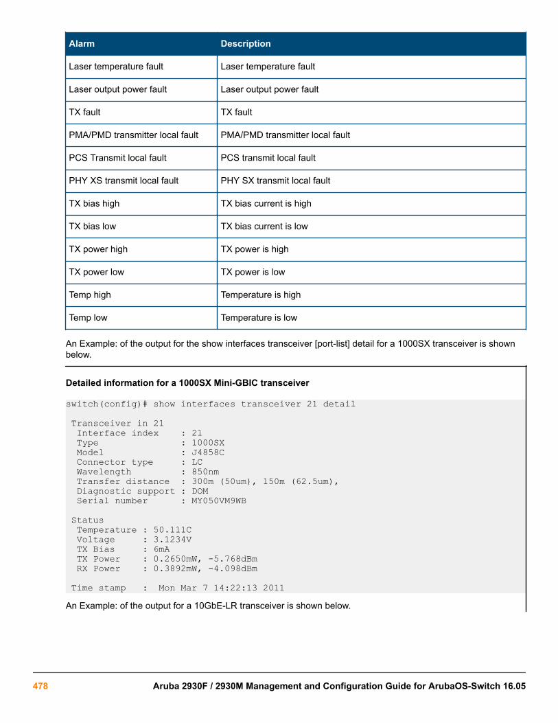
Alarm Description
Laser temperature fault Laser temperature fault
Laser output power fault Laser output power fault
TX fault TX fault
PMA/PMD transmitter local fault PMA/PMD transmitter local fault
PCS Transmit local fault PCS transmit local fault
PHY XS transmit local fault PHY SX transmit local fault
TX bias high TX bias current is high
TX bias low TX bias current is low
TX power high TX power is high
TX power low TX power is low
Temp high Temperature is high
Temp low Temperature is low
An Example: of the output for the show interfaces transceiver [port-list] detail for a 1000SX transceiver is shownbelow.
Detailed information for a 1000SX Mini-GBIC transceiver
switch(config)# show interfaces transceiver 21 detail
Transceiver in 21 Interface index : 21 Type : 1000SX Model : J4858C Connector type : LC Wavelength : 850nm Transfer distance : 300m (50um), 150m (62.5um), Diagnostic support : DOM Serial number : MY050VM9WB
Status Temperature : 50.111C Voltage : 3.1234V TX Bias : 6mA TX Power : 0.2650mW, -5.768dBm RX Power : 0.3892mW, -4.098dBm
Time stamp : Mon Mar 7 14:22:13 2011An Example: of the output for a 10GbE-LR transceiver is shown below.
478 Aruba 2930F / 2930M Management and Configuration Guide for ArubaOS-Switch 16.05

Detailed information for a 10GbE-LR transceiver
switch(config)# show interfaces transceiver 23 detail
Transceiver in 23 Interface Index : 24 Type : 10GbE-LR Model : J8437A Connector type : SC Wavelength : Channel #0: 1310nm, #1:0nm, #2:0nm, #3:0nm Transfer distance : 10000m (SM) Diagnostic support: DOM Serial number : ED456SS987
Status Temperature : 32.754C TX Bias : 42.700mA TX Power : 0.5192mW, -2.847dBm RX Power : 0.0040mW, -23.979dBm
Recent Alarms:
Rx power low alarm Rx power low warning
Recent errors: Receive optical power fault PMA/PMD receiver local fault PMA/PMD transmitter local fault PCS receive local fault PHY XS transmit local fault
Time stamp : Mon Mar 7 16:26:06 2013
Viewing transceiver information for copper transceiverswith VCT supportThis feature provides the ability to view diagnostic monitoring information for copper transceivers with VirtualCable Test (VCT) support. The cable quality of the copper cables connected between transceivers can beascertained using the transceiver cable diagnostics. Results of the diagnostics are displayed with the appropriateCLI show commands and with SNMP using the hpicfTransceiver MIB.
The J8177C 1000Base-T Mini-GBIC is supported.
Testing the CableEnter the test cable-diagnostics command in any context to begin cable diagnostics for the transceiver.The diagnostic attempts to identify cable faults. The tests may take a few seconds to complete for each interface.There is the potential of link loss during the diagnostic.
Syntax:
test cable-diagnostics [port-list]Invokes cable diagnostics and displays the results.
Chapter 19 Troubleshooting 479

Output from test cable-diagnostics command
HP Switch # test cable-diagnostics a23-a24
The ‘test cable-diagnostics’ command will cause a loss of link and will take a few seconds per interface to complete.
Continue (Y/N)? y
MDI Cable Distance Pair Pair MDI Port Pair Status to Fault Skew Polarity Mode ----- ----- ---------- --------- ----- --------- ------ A23 1-2 OK 0 m 6 ns Normal MDIX 3-6 OK 0 m 0 ns Normal 4-5 OK 0 m 6 ns Normal MDIX 7-8 OK 0 m 6 ns Normal A24 1-2 Short 2 m 3-6 Impedance 3 m 4-5 Impedance 3 m 7-8 Open 1 m
Copper cable diagnostic test results
switch# show interfaces transceiver a23 detail
Transceiver in A23 Interface Index : 23 Type : 1000T-sfp Model : J8177C Connector Type : RJ45 Wavelength : n/a Transfer Distance : 100m (copper), Diagnostic Support : VCT Serial Number : US051HF099
Link Status : Up Speed : 1000 Duplex : Full
MDI Cable Distance Pair Pair MDI Port Pair Status to Fault Skew Polarity Mode ----- ----- ---------- --------- ----- --------- ----- A23 1-2 OK 0 m 6 ns Normal MDIX 3-6 OK 0 m 0 ns Normal 4-5 OK 0 m 6 ns Normal MDIX 7-8 OK 0 m 6 ns Normal
Test Last Run : Fri Apr 22 20:33:23 2011
General transceiver information
Parameter Description
Interface Index The switch interface number
Transceiver-type Pluggable transceiver type
Transceivermodel
Pluggable transceiver model
Table Continued
480 Aruba 2930F / 2930M Management and Configuration Guide for ArubaOS-Switch 16.05

Parameter Description
Connector-type Type of connector of the transceiver
Wavelength For an optical transceiver: the central wavelength of the laser sent, in nm. If the transceiversupports multiple wavelengths, the values will be separated by a comma. An electricaltransceiver value is displayed as N/A.
TransferDistance
Link-length supported by the transceiver in meters. The corresponding transfer medium isshown in brackets following the transfer distance value, For example, 50um multimode fiber.If the transceiver supports multiple transfer media, the values are separated by a comma.
DiagnosticSupport
Shows whether the transceiver supports diagnostics:None
Supported
DOM
Supported
VCT
Supported
Serial Number Serial number of the transceiver
Link Status Link up or down
Speed Speed of transceiver in Mbps
Duplex Type of duplexing
Cable Status Values are OK, Open, Short, or Impedance
Distance to Fault The distance in meters to a cable fault (accuracy is +/- 2 meters); displays 0 (zero) if there isno fault
Pair Skew Difference in propagation between the fastest and slowest wire pairs
Pair Polarity Signals on a wire pair are polarized, with one wire carrying the positive signal and onecarrying the negative signal.
MDI Mode The MDI crossover status of the two wire pairs (1&2, 3&6, 4&5, 7&8), will be either MDI orMDIX
Viewing transceiver informationThis features provides the ability to view diagnostic monitoring information for transceivers with Diagnostic OpticalMonitoring (DOM) support. The following table indicates the support level for specific transceivers:
Chapter 19 Troubleshooting 481
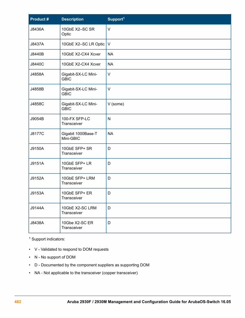
Product # Description Support1
J8436A 10GbE X2–SC SROptic
V
J8437A 10GbE X2–SC LR Optic V
J8440B 10GbE X2-CX4 Xcver NA
J8440C 10GbE X2-CX4 Xcver NA
J4858A Gigabit-SX-LC Mini-GBIC
V
J4858B Gigabit-SX-LC Mini-GBIC
V
J4858C Gigabit-SX-LC Mini-GBIC
V (some)
J9054B 100-FX SFP-LCTransceiver
N
J8177C Gigabit 1000Base-TMini-GBIC
NA
J9150A 10GbE SFP+ SRTransceiver
D
J9151A 10GbE SFP+ LRTransceiver
D
J9152A 10GbE SFP+ LRMTransceiver
D
J9153A 10GbE SFP+ ERTransceiver
D
J9144A 10GbE X2-SC LRMTransceiver
D
J8438A 10Gbe X2-SC ERTransceiver
D
1 Support indicators:
• V - Validated to respond to DOM requests
• N - No support of DOM
• D - Documented by the component suppliers as supporting DOM
• NA - Not applicable to the transceiver (copper transceiver)
482 Aruba 2930F / 2930M Management and Configuration Guide for ArubaOS-Switch 16.05

Not all transceivers support Digital Optical Monitoring. If DOM appears in the Diagnostic Support fieldof the show interfaces transceiver detail command, or the hpicfTransceiverMIBhpicfXcvrDiagnostics MIB object, DOM is supported for that transceiver.
Using the Event Log for troubleshooting switch problemsThe Event Log records operating events in single- or double-line entries and serves as a tool to isolate andtroubleshoot problems.
Once the log has received 2000 entries, it discards the oldest message each time a new message is received.The Event Log window contains 14 log entry lines. You can scroll through it to view any part of the log.
Once the log has received 2000 entries, it discards the oldest message each time a new message is received.The Event Log window contains 14 log-entry lines. You can scroll through it to view any part of the log.
The Event Log is erased if power to the switch is interruptedor if you enter the boot systemcommand. The contents of the Event Log are not erased if you:
• Reboot the switch by choosing the Reboot Switch option from the menu interface.
• Enter the reload command from the CLI.
Event Log entriesAs shown in Figure 114: Format of an event log entry on page 483, each Event Log entry is composed of sixor seven fields, depending on whether numbering is turned on or not:
Figure 114: Format of an event log entry
Item Description
Severity One of the following codes (from highest to lowest severity):
M—(major) indicates that a fatal switch error has occurred.
E—(error) indicates that an error condition occurred on the switch.
W—(warning) indicates that a switch service has behaved unexpectedly.I—(information)provides information on normal switch operation.
D—(debug) is reserved for HPE internal diagnostic information.
Date The date in the format mm/dd/yy when an entry is recorded in the log.
Time The time in the format hh:mm:ss when an entry is recorded in the log.
Event number The number assigned to an event. You can turn event numbering on and off with the [no]log-number command.
Table Continued
Chapter 19 Troubleshooting 483

System module The internal module (such as "ports:" for port manager) that generated a log entry. If VLANsare configured, a VLAN name also appears for an event that is specific to an individualVLAN.
Event message A brief description of the operating event.
Table 31: Event Log system modules
System module Description Documented in HPE Switchhardware/software guide
802.1x 802.1X authentication: Providesaccess control on a per-client orper-port basis:
• Client-level security that allowsLAN access to 802.1X clients(up to 32 per port) with valid usercredentials
• Port-level security that allowsLAN access only on ports onwhich a single 802.1X-capableclient (supplicant) has enteredvalid RADIUS user credentials
Access Security Guide
acl ACLs: Filter layer-3 IP traffic to orfrom a host to block unwanted IPtraffic and block or limit otherprotocol traffic such as TCP, UDP,IGMP, and ICMP. ACEs specify thefilter criteria and an action (permit ordeny) to take on a packet if it meetsthe criteria.
Advanced Traffic ManagementGuide
addrmgr Address Table Manager: ManagesMAC addresses that the switch haslearned and are stored in theswitch's address table.
Management and ConfigurationGuide
arp-protect Dynamic ARP Protection: Protectsthe network from ARP cachepoisoning. Only valid ARP requestsand responses are relayed or usedto update the local ARP cache. ARPpackets with invalid IP-to-MACaddress bindings advertised in thesource protocol address and sourcephysical address fields arediscarded.
Access Security Guide
Table Continued
484 Aruba 2930F / 2930M Management and Configuration Guide for ArubaOS-Switch 16.05
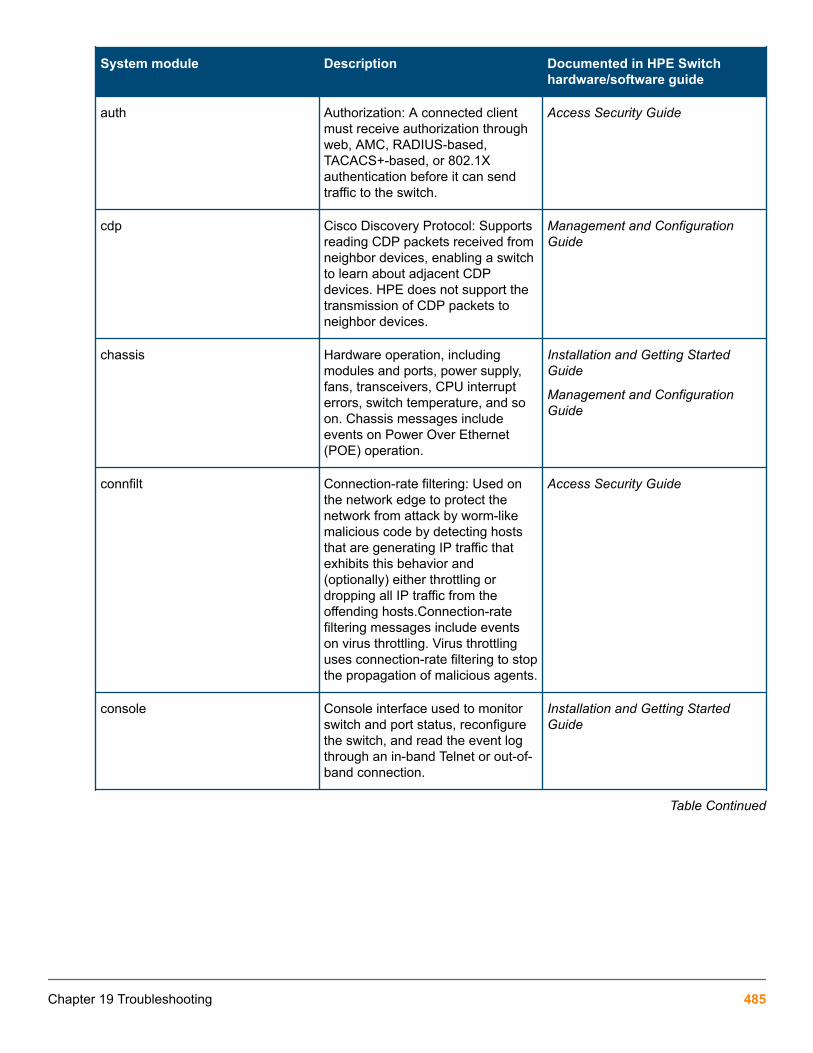
System module Description Documented in HPE Switchhardware/software guide
auth Authorization: A connected clientmust receive authorization throughweb, AMC, RADIUS-based,TACACS+-based, or 802.1Xauthentication before it can sendtraffic to the switch.
Access Security Guide
cdp Cisco Discovery Protocol: Supportsreading CDP packets received fromneighbor devices, enabling a switchto learn about adjacent CDPdevices. HPE does not support thetransmission of CDP packets toneighbor devices.
Management and ConfigurationGuide
chassis Hardware operation, includingmodules and ports, power supply,fans, transceivers, CPU interrupterrors, switch temperature, and soon. Chassis messages includeevents on Power Over Ethernet(POE) operation.
Installation and Getting StartedGuide
Management and ConfigurationGuide
connfilt Connection-rate filtering: Used onthe network edge to protect thenetwork from attack by worm-likemalicious code by detecting hoststhat are generating IP traffic thatexhibits this behavior and(optionally) either throttling ordropping all IP traffic from theoffending hosts.Connection-ratefiltering messages include eventson virus throttling. Virus throttlinguses connection-rate filtering to stopthe propagation of malicious agents.
Access Security Guide
console Console interface used to monitorswitch and port status, reconfigurethe switch, and read the event logthrough an in-band Telnet or out-of-band connection.
Installation and Getting StartedGuide
Table Continued
Chapter 19 Troubleshooting 485

System module Description Documented in HPE Switchhardware/software guide
cos Class of Service (CoS): Providespriority handling of packetstraversing the switch, based on theIEEE 802.1p priority carried by eachpacket.CoS messages also includeQoS events. The QoS featureclassifies and prioritizes trafficthroughout a network, establishingan end-to-end traffic priority policyto manage available bandwidth andimprove throughput of importantdata.
Advanced Traffic ManagementGuide
dca Dynamic Configuration Arbiter(DCA) determines the client-specificparameters that are assigned in anauthentication session.
Access Security Guide
dhcp Dynamic Host ConfigurationProtocol (DHCP) serverconfiguration: Switch isautomatically configured from aDHCP (Bootp) server, including IPaddress, subnet mask, defaultgateway, Timep Server address,and TFTP server address.
Management and ConfigurationGuide
dhcp v6c DHCP for IPv6 prefix assignment IPv6 Configuration Guide
dhcpr DHCP relay: Forwards client-originated DHCP packets to aDHCP network server.
Advanced Traffic ManagementGuide
download Download operation for copying asoftware version or files to theswitch.
Management and ConfigurationGuide
dhcp-snoop DHCP snooping: Protects yournetwork from common DHCPattacks, such as address spoofingand repeated address requests.
Access Security Guide
dma Direct Access Memory (DMA):Transmits and receives packetsbetween the CPU and the switch.
—
fault Fault Detection facility, includingresponse policy and the sensitivitylevel at which a network problemshould generate an alert.
Management and ConfigurationGuide
Table Continued
486 Aruba 2930F / 2930M Management and Configuration Guide for ArubaOS-Switch 16.05

System module Description Documented in HPE Switchhardware/software guide
fdr-log FDR collects information that is“interesting” at the time of the crash,as well as when the switch ismisbehaving, but has not crashed.Runtime logs are written to FDRmemory while the switch is running,and crashtime logs are collectedand stored in the FDR buffer duringa switch crash.
Management and ConfigurationGuide
ffi Find, Fix, and Inform: Event or alertlog messages indicating a possibletopology loop that causes excessivenetwork activity and results in thenetwork running slow. FFImessages include events ontransceiver connections with othernetwork devices.
Installation and Getting StartedGuide
Management and ConfigurationGuide
garp Generic Attribute RegistrationProtocol (GARP), defined in theIEEE 802.1D-1998 standard.
Advanced Traffic ManagementGuide
gvrp GARP VLAN Registration Protocol(GVRP): Manages dynamic 802.1QVLAN operations, in which theswitch creates temporary VLANmembership on a port to provide alink to another port in the sameVLAN on another device.
Advanced Traffic ManagementGuide
hpesp Management module that maintainscommunication between switchports.
Installation and Getting StartedGuide
idm Identity-driven Management:Optional management applicationused to monitor and control accessto switch.
Advanced Traffic ManagementGuide
igmp Internet Group ManagementProtocol: Reduces unnecessarybandwidth usage for multicast traffictransmitted from multimediaapplications on a per-port basis.
Multicast and Routing Guide
inst-mon Instrumentation Monitor: Identifiesattacks on the switch by generatingalerts for detected anomalies.
Access Security Guide
Table Continued
Chapter 19 Troubleshooting 487

System module Description Documented in HPE Switchhardware/software guide
ip IP addressing: Configures theswitch with an IP address andsubnet mask to communicate on thenetwork and support remotemanagement access; configuresmultiple IP addresses on a VLAN;enables IP routing on the switch.
Management and ConfigurationGuide
Multicast and Routing Guide
ipaddrmgr IP Address Manager: Programs IProuting information in switchhardware.
Multicast and Routing Guide
iplock IP Lockdown: Prevents IP sourceaddress spoofing on a per-port andper-VLAN basis by forwarding onlythe IP packets in VLAN traffic thatcontain a known source IP addressand MAC address binding for theport.
Access Security Guide
ipx Novell Netware protocol filtering: Onthe basis of protocol type, theswitch can forward or drop traffic toa specific set of destination ports onthe switch.
Access Security Guide
kms Key Management System:Configures and maintains securityinformation (keys) for all routingprotocols, including a timingmechanism for activating anddeactivating an individual protocol.
Access Security Guide
lacp LACP trunks: The switch can eitherautomatically establish an 802.3ad-compliant trunk group or provide amanually configured, static LACPtrunk.
Management and ConfigurationGuide
Table Continued
488 Aruba 2930F / 2930M Management and Configuration Guide for ArubaOS-Switch 16.05

System module Description Documented in HPE Switchhardware/software guide
ldbal Load balancing in LACP port trunksor 802.1s Multiple Spanning Treeprotocol (MSTP) that uses VLANs ina network to improve networkresource utilization and maintain aloop-free environment.Load-balancing messages also includeswitch meshing events. The switchmeshing feature provides redundantlinks, improved bandwidth use, andsupport for different port types andspeeds.
Management and ConfigurationGuide
Advanced Traffic ManagementGuide
lldp Link-Layer Discovery Protocol:Supports transmitting LLDP packetsto neighbor devices and readingLLDP packets received fromneighbor devices, enabling a switchto advertise itself to adjacentdevices and to learn about adjacentLLDP devices.
Management and ConfigurationGuide
loop_protect Loop protection: Detects theformation of loops when anunmanaged device on the networkdrops spanning tree packets andprovides protection by transmittingloop protocol packets out ports onwhich loop protection has beenenabled.
Advanced Traffic ManagementGuide
macauth Web and MAC authentication: Port-based security employed on thenetwork edge to protect privatenetworks and the switch itself fromunauthorized access using one ofthe following interfaces:
• Web page login to authenticateusers for access to the network
• RADIUS server that uses adevice's MAC address forauthentication
Access Security Guide
Table Continued
Chapter 19 Troubleshooting 489

System module Description Documented in HPE Switchhardware/software guide
maclock MAC lockdown and MAC lockout
• MAC lockdown prevents stationmovement and MAC address"hijacking" by requiring a MACaddress to be used only on anassigned port on the switch.MAC Lockdown also restricts theclient device to a specific VLAN.
• MAC lockout blocks a specificMAC address so that the switchdrops all traffic to or from thespecified address.
Access Security Guide
mgr Windows-based networkmanagement solutions formanaging and monitoringperformance of HPE switches.
Management and ConfigurationGuide
mld Multicast Listener Discovery (MLD):IPv6 protocol used by a router todiscover the presence of multicastlisteners. MLD can also optimizeIPv6 multicast traffic flow with thesnooping feature.
Multicast and Routing Guide
mtm Multicast Traffic Manager (MTM):Controls and coordinates L3multicast traffic for upper layerprotocols.
Multicast and Routing Guide
netinet Network Internet: Monitors thecreation of a route or an AddressResolution Protocol (ARP) entryand sends a log message in case offailure.
Advanced Traffic ManagementGuide
pagp Ports Aggregation Protocol (PAgP):Obsolete. Replaced by LACP(802.3ad).
—
Table Continued
490 Aruba 2930F / 2930M Management and Configuration Guide for ArubaOS-Switch 16.05

System module Description Documented in HPE Switchhardware/software guide
ports Port status and port configurationfeatures, including mode (speedand duplex), flow control, broadcastlimit, jumbo packets, and securitysettings.
Port messages include events onPOE operation and transceiverconnections with other networkdevices.
Installation and Getting StartedGuide
Management and ConfigurationGuide
Access Security Guide
radius RADIUS (Remote AuthenticationDial-In User Service) authenticationand accounting: A network server isused to authenticate user-connection requests on the switchand collect accounting informationto track network resource usage.
Access Security Guide
ratelim Rate-limiting: Enables a port to limitthe amount of bandwidth a user ordevice may utilize for inbound trafficon the switch.
Management and ConfigurationGuide
sflow Flow sampling: sFlow is an industrystandard sampling technology,defined by RFC 3176, used tocontinuously monitor traffic flows onall ports providing network-widevisibility into the use of the network.
Management and ConfigurationGuide
snmp Simple Network ManagementProtocol: Allows you to manage theswitch from a network managementstation, including support forsecurity features, event reporting,flow sampling, and standard MIBs.
Management and ConfigurationGuide
sntp Simple Network Time Protocol:Synchronizes and ensures auniform time among interoperatingdevices.
Management and ConfigurationGuide
Table Continued
Chapter 19 Troubleshooting 491

System module Description Documented in HPE Switchhardware/software guide
ssh Secure Shell version 2 (SSHv2):Provides remote access tomanagement functions on a switchvia encrypted paths between theswitch and management stationclients capable of SSHoperation.SSH messages alsoinclude events from the Secure FileTransfer Protocol (SFTP) feature.SFTP provides a secure alternativeto TFTP for transferring sensitiveinformation, such as switchconfiguration files, to and from theswitch in an SSH session.
Access Security Guide
ssl Secure Socket Layer Version 3(SSLv3), including Transport LayerSecurity (TLSv1) support: Providesremote web access to a switch viaencrypted paths between the switchand management station clientscapable of SSL/TLS operation.
Access Security Guide
stack Stack management: Uses a singleIP address and standard networkcabling to manage a group (up to16) of switches in the same IPsubnet (broadcast domain),resulting in a reduced number of IPaddresses and simplifiedmanagement of small workgroupsfor scaling your network to handleincreased bandwidth demand.
Advanced Traffic ManagementGuide
stp Multiple-instance spanning treeprotocol/MSTP (802.1s): Ensuresthat only one active path existsbetween any two nodes in a groupof VLANs in the network. MSTPoperation is designed to avoid loopsand broadcast storms of duplicatemessages that can bring down thenetwork.
Advanced Traffic ManagementGuide
Table Continued
492 Aruba 2930F / 2930M Management and Configuration Guide for ArubaOS-Switch 16.05
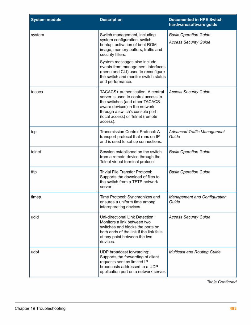
System module Description Documented in HPE Switchhardware/software guide
system Switch management, includingsystem configuration, switchbootup, activation of boot ROMimage, memory buffers, traffic andsecurity filters.
System messages also includeevents from management interfaces(menu and CLI) used to reconfigurethe switch and monitor switch statusand performance.
Basic Operation Guide
Access Security Guide
tacacs TACACS+ authentication: A centralserver is used to control access tothe switches (and other TACACS-aware devices) in the networkthrough a switch's console port(local access) or Telnet (remoteaccess).
Access Security Guide
tcp Transmission Control Protocol: Atransport protocol that runs on IPand is used to set up connections.
Advanced Traffic ManagementGuide
telnet Session established on the switchfrom a remote device through theTelnet virtual terminal protocol.
Basic Operation Guide
tftp Trivial File Transfer Protocol:Supports the download of files tothe switch from a TFTP networkserver.
Basic Operation Guide
timep Time Protocol: Synchronizes andensures a uniform time amonginteroperating devices.
Management and ConfigurationGuide
udld Uni-directional Link Detection:Monitors a link between twoswitches and blocks the ports onboth ends of the link if the link failsat any point between the twodevices.
Access Security Guide
udpf UDP broadcast forwarding:Supports the forwarding of clientrequests sent as limited IPbroadcasts addressed to a UDPapplication port on a network server.
Multicast and Routing Guide
Table Continued
Chapter 19 Troubleshooting 493

System module Description Documented in HPE Switchhardware/software guide
update Updates (TFTP or serial) to HPEswitch software and updates torunning-config and start-up configfiles
Basic Operation Guide
vlan Static 802.1Q VLAN operations,including port-and protocol-basedconfigurations that group users bylogical function instead of physicallocation
• A port-based VLAN creates alayer-2 broadcast domaincomprising member ports thatbridge IPv4 traffic amongthemselves.
• A protocol-based VLAN createsa layer-3 broadcast domain fortraffic of a particular routingprotocol, and comprises memberports that bridge traffic of thespecified protocol type amongthemselves.
VLAN messages include eventsfrom management interfaces (menuand CLI) used to reconfigure theswitch and monitor switch statusand performance.
Advanced Traffic ManagementGuide
xmodem Xmodem: Binary transfer featurethat supports the download ofsoftware files from a PC or UNIXworkstation.
Basic Operation Guide
Using the MenuTo display the Event Log from the Main Menu, select Event Log. The following example shows a sample eventlog display.
An event log display
Switch 5406zl 25-Oct-2013 18:02:52==========================-CONSOLE - MANAGER MODE -=============================M 10/25/13 16:30:02 sys: 'Operator cold reboot from CONSOLE session.'I 10/25/13 17:42:51 00061 system: -------------------------------------------I 10/25/13 17:42:51 00063 system: System went down : 10/25/13 16:30:02I 10/25/13 17:42:51 00064 system: Operator cold reboot from CONSOLE session.W 10/25/13 17:42:51 00374 chassis: WARNING: SSC is out of Date: Load 8.2 ornewer
494 Aruba 2930F / 2930M Management and Configuration Guide for ArubaOS-Switch 16.05

I 10/25/13 17:42:51 00068 chassis: Slot D InsertedI 10/25/13 17:42:51 00068 chassis: Slot E InsertedI 10/25/13 17:42:51 00068 chassis: Slot F InsertedI 10/25/13 17:42:51 00690 udpf: DHCP relay agent feature enabledI 10/25/13 17:42:51 00433 ssh: Ssh server enabledI 10/25/13 17:42:51 00400 stack: Stack Protocol disabledI 10/25/13 17:42:51 00128 tftp: Enable succeededI 10/25/13 17:42:51 00417 cdp: CDP enabled
---- Log events stored in memory 1-751. Log events on screen 690-704.
Actions-> Back Next page Prev page End Help
Return to previous screen.Use up/down arrow to scroll one line, left/right arrow keys tochange action selection, and <Enter> to execute action.The log status line below the recorded entries states the total number of events stored in the event log andwhich logged events are currently displayed.
To scroll to other entries in the Event Log, either preceding or following the currently visible portion, press the keysindicated at the bottom of the display (Back,Nextpage, Prev page, or End) or the keys described in thefollowing table.
Event Log control keys
Key Action
[N] Advances the display by one page (next page).
[P] Rolls back the display by one page (previous page).
[v] Advances display by one event (down one line).
[ˆ] Rolls back display by one event (up one line).
[E] Advances to the end of the log.
[H] Displays Help for the Event Log.
Using the CLISyntax:
show logging [-a, -b, -r, -s, -t, -m, -e, -p, -w, -i, -d, command, filter] [< option-str >]By default, the show logging command displays the log messages recorded since the last reboot inchronological order:
-a Displays all recorded log messages, including those before the last reboot.
-b Displays log events as the time since the last reboot instead of in a date/time format.
-r Displays all recorded log messages, with themost recent entries listed first (reverse order).
Table Continued
Chapter 19 Troubleshooting 495
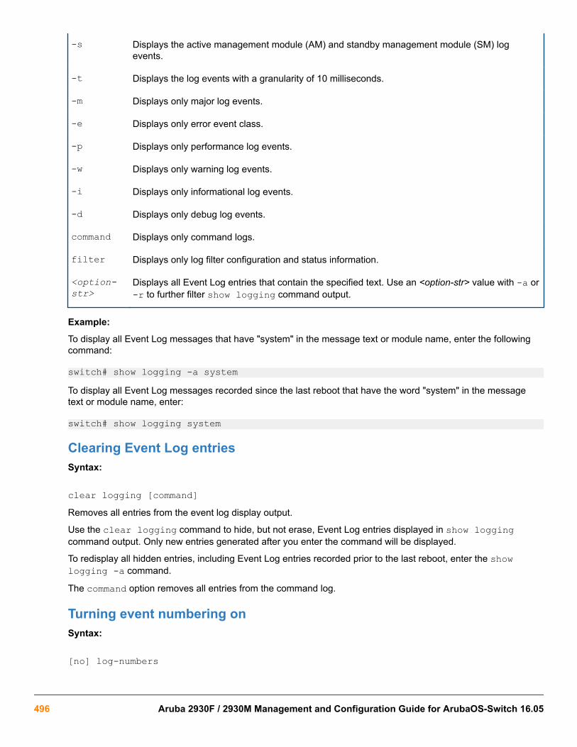
-s Displays the active management module (AM) and standby management module (SM) logevents.
-t Displays the log events with a granularity of 10 milliseconds.
-m Displays only major log events.
-e Displays only error event class.
-p Displays only performance log events.
-w Displays only warning log events.
-i Displays only informational log events.
-d Displays only debug log events.
command Displays only command logs.
filter Displays only log filter configuration and status information.
<option-str>
Displays all Event Log entries that contain the specified text. Use an <option-str> value with -a or-r to further filter show logging command output.
Example:
To display all Event Log messages that have "system" in the message text or module name, enter the followingcommand:
switch# show logging -a systemTo display all Event Log messages recorded since the last reboot that have the word "system" in the messagetext or module name, enter:
switch# show logging system
Clearing Event Log entriesSyntax:
clear logging [command]Removes all entries from the event log display output.
Use the clear logging command to hide, but not erase, Event Log entries displayed in show loggingcommand output. Only new entries generated after you enter the command will be displayed.
To redisplay all hidden entries, including Event Log entries recorded prior to the last reboot, enter the showlogging -a command.
The command option removes all entries from the command log.
Turning event numbering onSyntax:
[no] log-numbers
496 Aruba 2930F / 2930M Management and Configuration Guide for ArubaOS-Switch 16.05

Turns event numbering on and off
Using log throttling to reduce duplicate Event Log and SNMP messagesA recurring event can generate a series of duplicate Event Log messages and SNMP traps in a relatively shorttime. As a result, the Event Log and any configured SNMP trap receivers may be flooded with excessive, exactlyidentical messages. To help reduce this problem, the switch uses log throttle periods to regulate (throttle)duplicate messages for recurring events, and maintains a counter to record how many times it detects duplicatesof a particular event since the last system reboot.
When the first instance of a particular event or condition generates a message, the switch initiates a log throttleperiod that applies to all recurrences of that event. If the logged event recurs during the log throttle period, theswitch increments the counter initiated by the first instance of the event, but does not generate a new message.
If the logged event repeats again after the log throttle period expires, the switch generates a duplicate of the firstmessage, increments the counter, and starts a new log throttle period during which any additional instances of theevent are counted, but not logged. Thus, for a particular recurring event, the switch displays only one message inthe Event Log for each log throttle period in which the event reoccurs. Also, each logged instance of the eventmessage includes counter data showing how many times the event has occurred since the last reboot. The switchmanages messages to SNMP trap receivers in the same way.
Log throttle periodsThe length of the log throttle period differs according to an event's severity level:
Severity level Log throttle period
I (Information) 6000 Seconds
W (Warning) 600 Seconds
D (Debug) 60 Seconds
M (Major) 6 Seconds
Example:
Suppose that you configure VLAN 100 on the switch to support PIM operation, but do not configure an IPaddress. If PIM attempts to use VLAN 100, the switch generates the first instance of the following Event Logmessage and counter.
In The first instance of an event message and counter on page 497 the counter (1) indicates thatthis is the first instance of this event since the switch last rebooted.
The first instance of an event message and counter
W 10/01/12 09:00:33 PIM:No IP address configured on VID 100 (1)
Chapter 19 Troubleshooting 497

If PIM operation causes the same event to occur six more times during the initial log throttle period, there are nofurther entries in the Event Log. However, if the event occurs again after the log throttle period has expired, theswitch repeats the message (with an updated counter) and starts a new log throttle period.
Figure 115: Duplicate messages over multiple log throttling periods
Note that if the same type of event occurs under different circumstances, the switch handles these as unrelatedevents for the purpose of Event Log messages. For example, if PIM operation simultaneously detects that VLANs100 and 205 are configured without IP addresses, you see log messages similar to the following:
Figure 116: Example: of log messages generated by unrelated events of the same type
Example: of event counter operationSuppose the switch detects the following after a reboot:
• Three duplicate instances of the PIM "Send error" during the first log throttle period for this event
• Five more instances of the same Send error during the second log throttle period for this event
• Four instances of the same Send error during the third log throttle period for this event
In this case, the duplicate message appears three times in the Event Log (once for each log throttle period for theevent being described), and the duplicate message counter increments as shown in the following table. (Thesame operation applies for messages sent to any configured SNMP trap receivers.)
Table 32: How the duplicate message counter increments
Instances during 1st logthrottle period
Instances during 2nd logthrottle period
Instances during 3rd logthrottle period
Duplicate messagecounter1
3 1
5 4
4 9
498 Aruba 2930F / 2930M Management and Configuration Guide for ArubaOS-Switch 16.05

1 This value always comprises the first instance of the duplicate message in the current log throttle period plus all previousoccurrences of the duplicate message occurring since the switch last rebooted.
Reporting information about changes to the running configurationSyslog can be used for sending notifications to a remote syslog server about changes made to the runningconfiguration. The notifications in the syslog messages are sent in ASCII format and contain this information:
• Notice-Type: Describes the syslog notification as a “running config change”.
• Event-ID: Identifier for the running config change event that occurred on the switch.
• Config-Method: The source for the running config change.
• Device-Name: The managed device.
• User-Name: User who made the running config change.
• Remote-IP-Address: IP address of a remote host from which the user is connected.
Syntax:
[no] logging notify <running-config-change> [transmission-interval <0-4294967295>Enables sending the running configuration change notifications to the syslog server.
The no form of the command disables sending the running configuration changes to the syslog server.
Default: Disabled
<running-config-change > Mandatory option for the notify parameter. Specifies the type ofnotification to send.
transmission-interval<0-4294967295> Specifies the time interval (in seconds) between the
transmission of two consecutive notifications. Running configchanges occurring within the specified interval will not generatesyslog notifications.
A value of zero means there is no limit; a notification is sent for every running config change.
Default: Zero
Sending running config changes to the syslog server
switch(config)# logging notify running-config-changetransmission-interval 10
Debug/syslog operationWhile the Event Log records switch-level progress, status, and warning messages on the switch, the debug/system logging (syslog) feature provides a way to record Event Log and debug messages on a remote device.For example, you can send messages about routing misconfigurations and other network protocol details to anexternal device, and later use them to debug network-level problems.
Debug/syslog messagingThe debug/syslog feature allows you to specify the types of Event Log and debug messages that you want tosend to an external device. You can perform the following operations:
Chapter 19 Troubleshooting 499

• Use the debug commandto configure messaging reports for the following event types:
◦ ACL "deny" matches
◦ Dynamic ARP protection events
◦ DHCP snooping events
◦ DIPLD events
◦ Events recorded in the switch's Event Log
◦ IP routing events (IPv4 and IPv6)
◦ LACP events
◦ LLDP events
◦ SNMP events
◦ SSH events
• Use the logging commandto select a subset of Event Log messages to send to an external device fordebugging purposes according to:
◦ Severity level
◦ System module
Hostname in syslog messagesThe syslog now messages the sender identified by hostname.
The hostname field identifies the switch that originally sends the syslog message. Configurable through the CLIand SNMP, the format of the hostname field supports the following formats:
• ip-address: The IP address of the sending interface will be used as the message origin identifier. This is thedefault format for the origin identifier. The IP address of the sending interface (in dotted decimal notation) is thedefault format.
• hostname: The hostname of the sending switch will be used as the message origin identifier.
• none: No origin identifier will be embedded in the syslog message. Nilvalue is used as defined by “-“.
This configuration is system-wide, not per syslog server. There is no support for fully-qualified domain name.
Logging origin-idUse the logging origin-id command to specify the content for the hostname field.
Syntax:
logging origin-id [ip-address|hostname|none]
[no] logging origin-id [ip-address|hostname|none]To reset the hostname field content back to default (IP-address), use the no form of the command.
500 Aruba 2930F / 2930M Management and Configuration Guide for ArubaOS-Switch 16.05

filter
Creates a filter to restrict which events are logged.
IP-ADDR
Adds an IPv4 address to the list of receiving syslog servers.
IPV6-ADDR
Adds an IPv6 address to the list of receiving syslog servers.
origin-id
Sends the Syslog messages with the specified origin-id.
notify
Notifies the specified type sent to the syslog server(s).
priority-descr
A text string associated with the values of facility, severity, and system-module.
severity
Event messages of the specified severity or higher sent to the syslog server.
system-module
Event messages of the specified system module (subsystem) sent to the syslog server.
hostname
Sets the hostname of the device as the origin-id.
none
Disables origin-id in the syslog message.
Add an IP address to the list of receiving syslog servers.
Use of no without an IP address specified will remove all IP addresses from the list of syslog receivers. If an IPaddress is specified, that receiver will be removed. Both link-local with zone ID and global IPv6 addresses aresupported.
• Specify syslog server facility with the option <facility>. The command no logging <facility> setsthe facility back to defaults.
• Specify filtering rules.
• Specify severity for event messages to be filtered to the syslog server with the option <severity>. Thecommand no logging <severity> sets the severity back to default.
• Event messages of specified system module will be sent to the syslog server. Using no sends messages fromall system modules. Messages are first filtered by selected severity.
• Specify syslog server transport layer with options [udp]|[tcp]|[tls].
• Specify syslog server port number with options [udp PORT-NUM]|[tcp PORT-NUM]|[tls PORT-NUM].
• Specify notification types to be sent to the syslog server.
• Use the option transmission-interval to control the egress rate limit for transmitting notifications, 0 valuemeans there is no rate limit. The values are in seconds. Only one syslog message is allowed for transmissionwithin specified time interval.
• Specify the origin information for the syslog messages with the option origin-id.
Chapter 19 Troubleshooting 501

When the syslog server receives messages from the switch, the IPv6 address of the switch is partlydisplayed.
Example:
Configured Host Ipv6 Address: 2001::1
Expected Syslog message:
Syslog message: USER.INFO: Oct 11 02:40:02 2001::1 00025 ip:ST1CMDR: VLAN60: ip address 30.1.1.1/24 configured on vlan 60Actual Truncated syslog message:
Syslog message: USER.INFO: Oct 11 02:40:02 2001:: 00025 ip: ST1CMDR:VLAN60: ip address 30.1.1.1/24 configured on vlan 60
Use the command in the following example to set the origin-id to the hostname.
Setting the origin-id to the hostname
switch(config)# logging origin-id hostnameThe following syslog message will occur:
<14> Jan 1 00:15:35 HP-2910al-24G 00076 ports: port 2 is now on-lineUse the command in the following example to set the origin-id to none (nilvalue).
Setting the origin-id to none (nilvalue)
switch(config)# logging origin-id noneThe following syslog message will occur:
<14> Jan 1 00:15:35 - 00076 ports: port 2 is now on-lineUse any of the commands in the following example to set the origin-id to ip-address (default).
Setting the origin-id to ip-address (default)
switch(config)# logging origin-id ip-address
switch(config)# no logging origin-id hostname
switch(config)# no logging origin-id noneThe following syslog message will occur:
<14> Jan 1 00:15:35 169.254.230.236 00076 ports: port 2 is now on-line
Viewing the identification of the syslog message senderUse the commands show debug or show running-config to display the identification of the syslog messagesender. The default option for origin-id is ip-address. The command show running-config will notdisplay the configured option when origin-id is set to the default value of ip address.
When hostname or none is configured using logging origin-id, the same displays as part of the showrunning-config command.
502 Aruba 2930F / 2930M Management and Configuration Guide for ArubaOS-Switch 16.05

Syntax:
show debugDefault option is ip-address.
The following shows the output of the show debug command when configured without loggin origin-id.
Output of the show debug command when configured without login origin-id
Debug Logging Origin identifier: Outgoing Interface IP Destination: None
Enabled debug types: None are enabled.The command logging origin-id hostname will produce the syslog message shown in the followingexample.
Syslog message for logging origin-id hostname
Debug Logging Origin identifier: Hostname Destination: None
Enabled debug types: None are enabled.The command logging origin-id none will produce the syslog message shown in the following example.
Syslog message for logging origin-id none
Debug Logging Origin identifier: none Destination: None
Enabled debug types: None are enabled.Syntax:
show running-configThe following example shows the output of the show running-config command.
Output of the show running-config command
The command logging origin-id hostname will display the following:logging origin-id hostnameThe command logging origin-id none will display as the following:
logging origin-id none
Chapter 19 Troubleshooting 503

SNMP MIBSNMP support will be provided through the following MIB objects.
HpicfSyslogOriginId = textual-convention
Description
This textual convention enumerates the origin identifier of syslog message.
Syntax: integer
ip-address
hostname
none
Status
current
hpicfSyslogOriginId OBJECT-TYPE
Description
Specifies the content of a Hostname field in the header of a syslog message.
Syntax:
HpicfSyslogOriginId
Max-access
read-write
Status
current
Default
ip-address
Debug/syslog destination devicesTo use debug/syslog messaging, you must configure an external device as the logging destination by using thelogging and debug destination commands. For more information, see Debug destinations on page 514and Configuring a syslog server on page 516.
A debug/syslog destination device can be a syslog server and/or a console session. You can configure debug andlogging messages to be sent to:
• Up to six syslog servers
• A CLI session through a direct RS-232 console connection, or a Telnet or SSH session
504 Aruba 2930F / 2930M Management and Configuration Guide for ArubaOS-Switch 16.05

Debug/syslog configuration commands
Event notification logging — Automatically sends switch-levelevent messages to the switch'sEvent Log. Debug and syslog donot affect this operation, but add thecapability of directing Event Logmessaging to an external device.
logging command <syslog-ip-addr> Enables syslog messaging to besent to the specified IP address.IPv4 and IPv6 are supported.
facility (Optional) The loggingfacility command specifies thedestination (facility) subsystem usedon a syslog server for debugreports.
priority-desc A text string associated with thevalues of facility, severity, andsystem-module.
neighbor-adjacency[detail]
Enables or disables OSPFv3 (IPv6)adjacency logging. Must beexecuted in OSPFv3 context. Thedetail option displays all theadjacency state transitions andadjacency-related errors.
severity Sends Event Log messages ofequal or greater severity than thespecified value to configured debugdestinations. (The default setting isto send Event Log messages fromall severity levels.)
system-module Sends Event Log messages fromthe specified system module toconfigured debug destinations. Theseverity filter is also applied to thesystem-module messages youselect.
The default setting is to send EventLog messages from all systemmodules. To restore the defaultsetting, enter the no loggingsystem-module <system-module> or logging system-module all-pass commands.
Table Continued
Chapter 19 Troubleshooting 505

debug Command acl Sends ACL syslog logging toconfigured debug destinations.When there is a match with a "deny"statement, directs the resultingmessage to the configured debugdestinations.
all Sends debug logging to configureddebug destinations for all ACL,Event Log, IP-OSPF, and IP-RIPoptions.
cdp Displays CDP information.
destination logging: Disables or re-enablessyslog logging on one or moresyslog servers configured with thelogging syslog-ip-addrcommand.session: Assigns or re-assigns destination status to theterminal device that was mostrecently used to request debugoutput.buffer: Enables sysloglogging to send the debug messagetypes specified by the debug<debug-type> command to abuffer in switch memory.
event Sends standard Event Logmessages to configured debugdestinations. (The same messagesare also sent to the switch's EventLog, regardless of whether youenable this option.)
Table Continued
506 Aruba 2930F / 2930M Management and Configuration Guide for ArubaOS-Switch 16.05
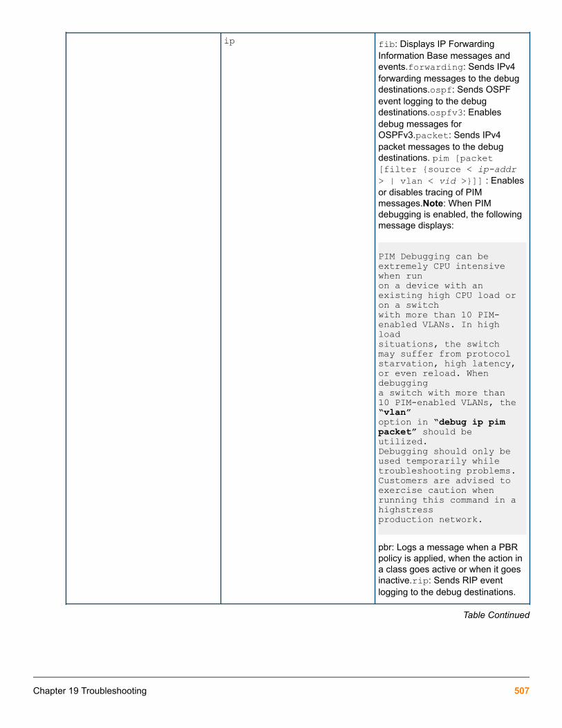
ip fib: Displays IP ForwardingInformation Base messages andevents.forwarding: Sends IPv4forwarding messages to the debugdestinations.ospf: Sends OSPFevent logging to the debugdestinations.ospfv3: Enablesdebug messages forOSPFv3.packet: Sends IPv4packet messages to the debugdestinations. pim [packet[filter {source < ip-addr> | vlan < vid >}]] : Enablesor disables tracing of PIMmessages.Note: When PIMdebugging is enabled, the followingmessage displays:
PIM Debugging can be extremely CPU intensive when runon a device with an existing high CPU load or on a switchwith more than 10 PIM-enabled VLANs. In high loadsituations, the switch may suffer from protocolstarvation, high latency, or even reload. When debugginga switch with more than 10 PIM-enabled VLANs, the “vlan”option in “debug ip pim packet” should be utilized.Debugging should only be used temporarily whiletroubleshooting problems. Customers are advised toexercise caution when running this command in a highstressproduction network. pbr: Logs a message when a PBRpolicy is applied, when the action ina class goes active or when it goesinactive.rip: Sends RIP eventlogging to the debug destinations.
Table Continued
Chapter 19 Troubleshooting 507

ipv6 dhcpv6-client: Sends DHCPv6client debug messages to theconfigured debugdestination.dhcpv6-relay: SendsDHCPv6 relay debug messages tothe configured debugdestination.forwarding: SendsIPv6 forwarding messages to thedebug destination(s)nd: Sends IPv6debug messages for IPv6 neighbordiscovery to the configured debugdestinations.
lacp event: Sends messages related tochange events.packet: Sendsmessages when BPDUs areexchanged.
lldp Sends LLDP debug messages tothe debug destinations.
security Sends security messages to thedebug destination.
services Displays debug messages on theservices module.
snmp Sends snmp messages to thedebug destination.
Using the Debug/Syslog feature, you can perform the following operations:
• Configure the switch to send Event Log messages to one or more Syslog servers. In addition, you canconfigure the messages to be sent to the User log facility (default) or to another log facility on configuredSyslog servers.
• Configure the switch to send Event Log messages to the current management- access session (serial-connectCLI, Telnet CLI, or SSH).
• Disable all Syslog debug logging while retaining the Syslog addresses from the switch configuration. Thisallows you to configure Syslog messaging and then disable and re-enable it as needed.
• Display the current debug configuration. If Syslog logging is currently active, the list f configured Syslogservers is displayed.
• Display the current Syslog server list when Syslog logging is disabled.
Configuring debug/syslog operation
Procedure
1. To use a syslog server as the destination device for debug messaging, follow these steps:
508 Aruba 2930F / 2930M Management and Configuration Guide for ArubaOS-Switch 16.05

a. Enter the logging <syslog-ip-addr> command at the global configuration level to configure thesyslog server IP address and enable syslog logging. Optionally, you may also specify the destinationsubsystem to be used on the syslog server by entering the logging facility command.If no othersyslog server IP addresses are configured, entering the logging command enables both debugmessaging to a syslog server and the event debug message type. As a result, the switch automaticallysends Event Log messages to the syslog server, regardless of other debug types that may be configured.
b. Re-enter the logging command in Step 1a to configure additional syslog servers. You can configure up toa total of six servers. (When multiple server IP addresses are configured, the switch sends the debugmessage types that you configure in Step 3 to all IP addresses.)
2. To use a CLI session on a destination device for debug messaging:
a. Set up a serial, Telnet, or SSH connection to access the switch's CLI.
b. Enter the debug destination session command at the manager level.
3. Enable the types of debug messages to be sent to configured syslog servers, the current session device, orboth by entering the debug <debug-type> command and selecting the desired options.
Repeat this step if necessary to enable multiple debug message types.
By default, Event Log messages are sent to configured debug destination devices. To block Event Logmessages from being sent, enter the no debug event command.
4. If necessary, enable a subset of Event Log messages to be sent to configured syslog servers by specifying aseverity level, a system module, or both using the following commands:
switch(config)# logging severity <debug | major | error | warning | info>switch(config)# logging system-module <system-module>
To display a list of valid values for each command, enter logging severity or logging system-modulefollowed by ? or pressing the Tab key.
The severity levels in order from the highest to lowest severity are major, error, warning, info, and debug. For alist of valid values for the logging system-module <system-module> command, see Event Logsystem modules.
5. If you configure system-module, severity-level values, or both to filter Event Log messages, when you finishtroubleshooting, you may want to reset these values to their default settings so that the switch sends all EventLog messages to configured debug destinations (syslog servers, CLI session, or both).
To remove a configured setting and restore the default values that send all Event Log messages, enter one orboth of the following commands:
switch(config)# no logging severity <debug | major | error | warning | info>switch(config)# no logging system-module <system-module>
If you configure a severity-level, system-module, logging destination, or logging facility value andsave the settings to the startup configuration (For example, by entering the write memorycommand), the debug settings are saved after a system reboot (power cycle or reboot) and re-activated on the switch. As a result, after switch startup, one of the following situations may occur:
• Only a partial set of Event Log messages may be sent to configured debug destinations.
• Messages may be sent to a previously configured syslog server used in an earlier debuggingsession.
Chapter 19 Troubleshooting 509

Viewing a debug/syslog configurationUse the show debug command to display the currently configured settings for:
• Debug message types and Event Log message filters (severity level and system module) sent to debugdestinations
• Debug destinations (syslog servers or CLI session) and syslog server facility to be used
Syntax:
show debugDisplays the currently configured debug logging destinations and message types selected for debuggingpurposes. (If no syslog server address is configured with the logging <syslog-ip-addr> command, noshow debug command output is displayed.)
Output of the show debug command
switch(config)# show debug
Debug Logging Destination: Logging -- 10.28.38.164 Facility=kern Severity=warning System module=all-pass Enabled debug types: eventExample:
In the following Example:, no syslog servers are configured on the switch (default setting). When you configure asyslog server, debug logging is enabled to send Event Log messages to the server. To limit the Event Log
510 Aruba 2930F / 2930M Management and Configuration Guide for ArubaOS-Switch 16.05
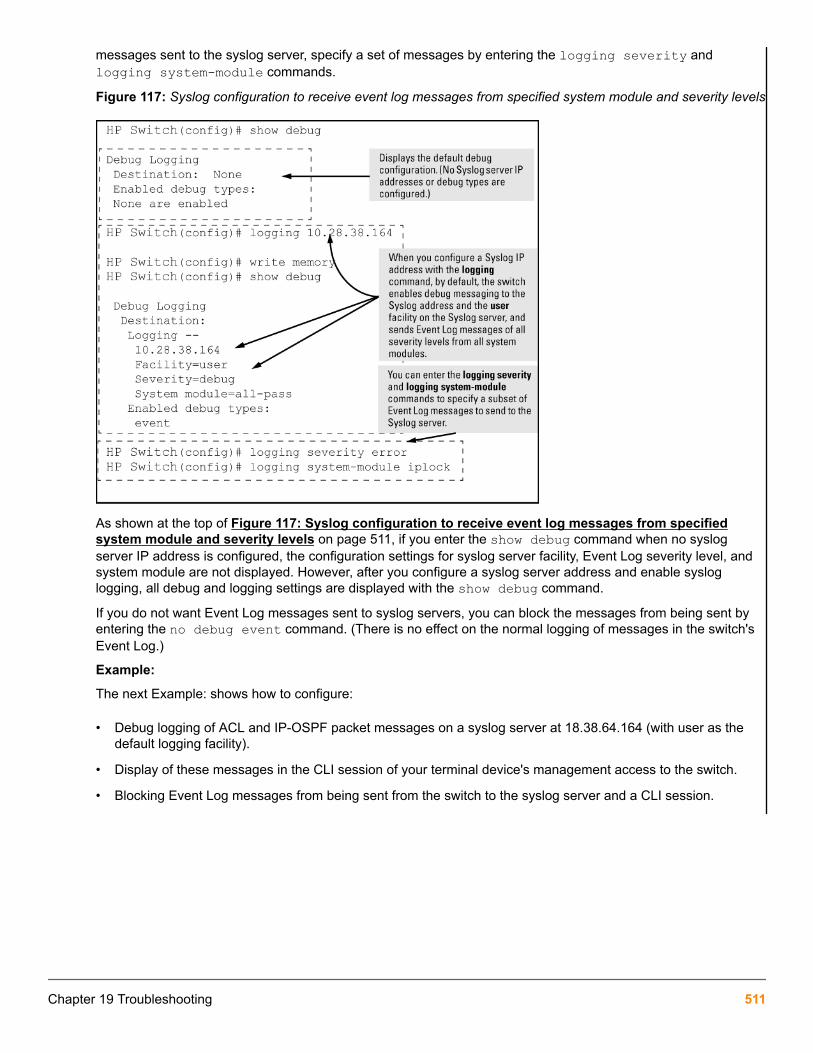
messages sent to the syslog server, specify a set of messages by entering the logging severity andlogging system-module commands.
Figure 117: Syslog configuration to receive event log messages from specified system module and severity levels
As shown at the top of Figure 117: Syslog configuration to receive event log messages from specifiedsystem module and severity levels on page 511, if you enter the show debug command when no syslogserver IP address is configured, the configuration settings for syslog server facility, Event Log severity level, andsystem module are not displayed. However, after you configure a syslog server address and enable sysloglogging, all debug and logging settings are displayed with the show debug command.
If you do not want Event Log messages sent to syslog servers, you can block the messages from being sent byentering the no debug event command. (There is no effect on the normal logging of messages in the switch'sEvent Log.)
Example:
The next Example: shows how to configure:
• Debug logging of ACL and IP-OSPF packet messages on a syslog server at 18.38.64.164 (with user as thedefault logging facility).
• Display of these messages in the CLI session of your terminal device's management access to the switch.
• Blocking Event Log messages from being sent from the switch to the syslog server and a CLI session.
Chapter 19 Troubleshooting 511

To configure syslog operation in these ways with the debug/syslog feature disabled on the switch, enter thecommands shown in Figure 118: Debug/syslog configuration for multiple debug types and multipledestinations on page 512.
Figure 118: Debug/syslog configuration for multiple debug types and multiple destinations
Debug commandAt the manager level, use the debug command to perform two main functions:
• Specify the types of event messages to be sent to an external destination.
• Specify the destinations to which selected message types are sent.
By default, no debug destination is enabled and only Event Log messages are enabled to be sent.
To configure a syslog server, use the logging <syslog-ip-addr> command. For moreinformation, see Configuring a syslog server on page 516.
Debug messagesSyntax:
[no] debug <debug-type>
512 Aruba 2930F / 2930M Management and Configuration Guide for ArubaOS-Switch 16.05

acl When a match occurs on an ACL "deny" ACE (with log configured), theswitch sends an ACL message to configured debug destinations. Forinformation on ACLs, see the "Access Control Lists (ACLs)" in the latestversion of the following guides:
• IPv4 ACLs: access security guide
• IPv6 ACLs: IPv6 configuration guide
ACE matches (hits) for permit and deny entries can be trackedusing the show statistics <aclv4|aclv6> command.
(Default: Disabled—ACL messages for traffic that matches "deny" entriesare not sent.)
all Configures the switch to send all debug message types to configured debugdestinations.(Default: Disabled—No debug messages are sent.)
cdp Sends CDP information to configured debug destinations.
destination logging—Disables or re-enables syslog logging on one or more syslogservers configured with the logging <syslog-ip-addr>command.session—Assigns or re-assigns destination status to theterminal device that was most recently used to request debugoutput.buffer—Enables syslog logging to send the debug message typesspecified by the debug <debug-type> command to a buffer in switchmemory.For more information on these options, see Debug destinations onpage 514.
event Configures the switch to send Event Log messages to configured debugdestinations.
This value does not affect the reception of event notificationmessages in the Event Log on the switch.
Event Log messages are automatically enabled to be sent to debugdestinations in these conditions:
• If no syslog server address is configured and you enter the logging<syslog-ip-addr> command to configure a destination address.
• If at least one syslog server address is configured in the startupconfiguration, and the switch is rebooted or reset.
Event log messages are the default type of debug message sent toconfigured debug destinations.
ip [fib | forwarding |packet | rip] Sends IP messages to configured destinations.
ip [fib [events]] For the configured debug destinations:events—Sends IP forwardinginformation base events.
Table Continued
Chapter 19 Troubleshooting 513

ip [packet] Enables the specified PIM message type.
ip [rip [database| event |trigger]]
rip {<database | event | trigger>} —Enables the specified RIPmessage type for the configured destination(s). database—Displaysdatabase changes. event—Displays RIP events. trigger—Displaystrigger messages.
ipv6 [dhcpv6-client | nd| packet] See the "IPv6 Diagnostic and Troubleshooting" in the IPv6
configuration guide for your switch for more detailed IPv6debug options.
When no debug options are included, displays debug messages for all IPv6debug options. dhcpv6-client [events | packet]—DisplaysDHCPv6 client event and packet data.nd—Displays debug messages forIPv6 neighbor discovery.packet—Displays IPv6 packet messages.
lldp Enables all LLDP message types for the configured destinations.
security [arp-protect |dhcp-snooping | dynamic-ip-lockdown | port-access| port-security | radius-server | ssh | tacacs-server | user-profile-mib]
arp-protect— Sends dynamic ARP protection debug messages toconfigured debug destinations.dhcp-snooping—Sends DHCP snoopingdebug messages to configured debug destinations. agent—Displays DHCPsnooping agent messages. event—Displays DHCP snooping eventmessages. packet—Displays DHCP snooping packet messages.dynamic-ip-lockdown—Sends dynamic IP lockdown debug messages tothe debug destination.port-access—Sends port-access debug messagesto the debug destination.radius-server—Sends RADIUS debugmessages to the debug destination.ssh—Sends SSH debug messages atthe specified level to the debug destination. The levels are fatal, error, info,verbose, debug, debug2, and debug3.tacacs-server—Sends TACACSdebug messages to the debug destination.user-profile-mib—Sendsuser profile MIB debug messages to the debug destination.
services <slot-id-range> Displays debug messages on the services module. Enter an alphabeticmodule ID or range of module IDs for the <slot-id-range> parameter.
snmp <pdu> Displays the SNMP debug messages.pdu—Displays SNMP pdu debugmessages.
Debug destinationsUse the debug destination command to enable (and disable)syslog messaging on a syslog server or to a CLIsession for specified types of debug and Event Log messages.
Syntax:
[no] debug destination {<logging | session | buffer>}
514 Aruba 2930F / 2930M Management and Configuration Guide for ArubaOS-Switch 16.05

logging Enables syslog logging to configured syslog servers so that the debug message typesspecified by the debug <debug-type> command (see Debug messages on page 512)are sent.(Default: Logging disabled)To configure a syslog server IP address, see Configuring a syslog server on page 516.
Debug messages from the switches covered in this guide have a debugseverity level. Because the default configuration of some syslog serversignores syslog messages with the debug severity level, ensure that thesyslog servers you want to use to receive debug messages are configured toaccept the debug level. For more information, see Operating notes fordebug and Syslog on page 521.
session Enables transmission of event notification messages to the CLI session that most recentlyexecuted this command. The session can be on any one terminal emulation device withserial, Telnet, or SSH access to the CLI at the Manager level prompt (switch#_).If morethan one terminal device has a console session with the CLI, you can redirect thedestination from the current device to another device. Do so by executing debugdestination session in the CLI on the terminal device on which you now want todisplay event messages.Event message types received on the selected CLI session areconfigured with the debug <debug-type> command.
buffer Enables syslog logging to send the debug message types specified by the debug<debug-type> command to a buffer in switch memory.To view the debug messagesstored in the switch buffer, enter the show debug buffer command.
Logging commandAt the global configuration level, the loggingcommand allows you to enable debug logging on specified syslogservers and select a subset of Event Log messages to send for debugging purposes according to:
• Severity level
• System module
By specifying both a severity level and system module, you can use both configured settings to filter the EventLog messages you want to use to troubleshoot switch or network error conditions.
After you configure a syslog server and a severity level and/or system module to filter the Event Logmessages that are sent, if you save these settings to the startup configuration file by entering thewrite memory command, these debug and logging settings are automatically re-activated after aswitch reboot or power recycle. The debug settings and destinations configured in your previoustroubleshooting session will then be applied to the current session, which may not be desirable.
After a reboot, messages remain in the Event Log and are not deleted. However, after a powerrecycle, all Event Log messages are deleted.
If you configure a severity level, system module, or both to temporarily filter Event Log messages, besure to reset the values to their default settings by entering the no form of the following commands toensure that Event Log messages of all severity levels and from all system modules are sent toconfigured syslog servers:
switch(config)# no logging severity <debug | major | error | warning | info>switch(config)# no logging system-module <system-module>
Chapter 19 Troubleshooting 515

Configuring a syslog serverSyslog is a client-server logging tool that allows a client switch to send event notification messages to anetworked device operating with syslog server software. Messages sent to a syslog server can be stored to a filefor later debugging analysis.
To use the syslog feature, you must install and configure a syslog server application on a networked hostaccessible to the switch. For instructions, see the documentation for the syslog server application.
To configure a syslog service, use the logging <syslog-ip-addr> command as shown below.
When you configure a syslog server, Event Log messages are automatically enabled to be sent to the server. Toreconfigure this setting, use the following commands:
• debugSpecifies additional debug message types (see Debug messages on page 512).
• loggingConfigures the system module or severity level used to filter the Event Log messages sent to configuredsyslog servers. (See Configuring the severity level for Event Log messages sent to a syslog server onpage 519 and Configuring the system module used to select the Event Log messages sent to asyslog server on page 520.)
To display the currently configured syslog servers as well as the types of debug messages and the severity-leveland system-module filters used to specify the Event Log messages that are sent, enter the show debugcommand (See Debug/syslog configuration commands on page 505).
Syntax:
[no] logging <syslog-ip-addr>Enables or disables syslog messaging to the specified IP address. You can configure up to six addresses. If youconfigure an address when none are already configured, this command enables destination logging (syslog) andthe Event debug type. Therefore, at a minimum, the switch begins sending Event Log messages to configuredsyslog servers. The ACL, IP-OSPF, and/or IP-RIP message types are also sent to the syslog servers if they arecurrently enabled as debug types. (See Debug messages on page 512.)
no logging Removes all currently configured syslog logging destinations from therunning configuration.Using this form of the command to delete the onlyremaining syslog server address disables debug destination logging on theswitch, but the default Event debug type does not change.
no logging <syslog-ip-address> Removes only the specified syslog logging destination from the running
configuration.Removing all configured syslog destinations with the nologging command (or a specified syslog server destination with the nologging <syslog-ip-address> command) does not delete the syslogserver IP addresses stored in the startup configuration.
Deleting syslog addresses in the startup configurationEnter a no logging command followed by the write memory command.
Verifying the deletion of a syslog server addressDisplay the startup configuration by entering the show config command.
516 Aruba 2930F / 2930M Management and Configuration Guide for ArubaOS-Switch 16.05

Blocking the messages sent to configured syslog servers from the currently configureddebug message typeEnter the no debug <debug-type> command. (See Debug messages on page 512.)
Disabling syslog logging on the switch without deleting configured server addressesEnter the no debug destination logging command. Note that, unlike the case in which no syslog serversare configured, if one or more syslog servers are already configured and syslog messaging is disabled,configuring a new server address does not re-enable syslog messaging. To re-enable syslog messaging, youmust enter the debug destination logging command.
Sending logging messages using TCPSyntax:
[no] logging <ip-addr> [udp 1024-49151 | tcp 1024-49151]Allows the configuration of the UDP or TCP transport protocol for the transmission of logging messages to asyslog server.
Specifying a destination port with UDP or TCP is optional.
Default ports: UDP port is 514
TCP port is 1470
Default Transport Protocol: UDP
Because TCP is a connection-oriented protocol, a connection must be present before the logging information issent. This helps ensure that the logging message will reach the syslog server. Each configured syslog serverneeds its own connection. You can configure the destination port that is used for the transmission of the loggingmessages.
Configuring TCP for logging message transmission using the default port
switch(config)# logging 192.123.4.5 tcp(Default TCP port 1470 is used.)
Configuring TCP for logging message transmission using a specified port
switch(config)# logging 192.123.4.5 9514(TCP port 9514 is used.)
Configuring UDP for logging message transmission using the default port
switch(config)# logging 192.123.4.5 udp(Default UDP port 514 is used.)
Configuring UDP for logging message transmission using a specified port
switch(config)# logging 192.123.4.5 9512
Chapter 19 Troubleshooting 517

(UDP port 9512 is used.)
Syntax:
[no] logging facility <facility-name>The logging facility specifies the destination subsystem used in a configured syslog server. (All configured syslogservers must use the same subsystem.) Hewlett Packard Enterprise recommends the default (user) subsystemunless your application specifically requires another subsystem. Options include:
user (default) Random user-level messages
kern Kernel messages
mail Mail system
daemon System daemons
auth Security/authorization messages
syslog Messages generated internally by syslog
lpr Line-printer subsystem
news Netnews subsystem
uucp uucp subsystem
cron cron/at subsystem
sys9 cron/at subsystem
sys10 - sys14 Reserved for system use
local10 - local17 Reserved for system use
Use the no form of the command to remove the configured facility and reconfigure the default (user) value.
Adding a description for a Syslog serverYou can associate a user-friendly description with each of the IP addresses (IPv4 only) configured for syslogusing the CLI or SNMP.
The Hewlett Packard Enterprise MIB hpicfSyslog.mib allows the configuration and monitoring ofsyslog for SNMP (RFC 3164 supported).
Entering the no logging command removes ALL the syslog server addresses without a verificationprompt.
The CLI command is:
518 Aruba 2930F / 2930M Management and Configuration Guide for ArubaOS-Switch 16.05

Syntax:
logging <ip-addr> [control-descr ZZZZTRISHZZZZ <text_string>] no logging <ip-addr> [control-descr]An optional user-friendly description that can be associated with a server IP address. If no description is entered,this is blank. If <text_string> contains white space, use quotes around the string. IPv4 addresses only.
Use the no form of the command to remove the description. Limit: 255 characters
To remove the description using SNMP, set the description to an empty string.
The logging command with a control description
switch(config)# logging 10.10.10.2 control-descr syslog_one
Adding a priority descriptionThis description can be added with the CLI or SNMP. The CLI command is:
Syntax:
logging priority-descr <text_string> no logging priority-descrProvides a user-friendly description for the combined filter values of severity and system module. If nodescription is entered, this is blank.
If text_string contains white space, use quotes around the string.
Use the no form of the command to remove the description.
Limit: 255 characters
The logging command with a priority description
switch(config)# logging priority-descr severe-pri
A notification is sent to the SNMP agent if there are any changes to the syslog parameters, eitherthrough the CLI or with SNMP.
Configuring the severity level for Event Log messages sent to a syslogserverEvent Log messages are entered with one of the following severity levels (from highest to lowest):
Major A fatal error condition has occurred on the switch.
Error An error condition has occurred on the switch.
Warning A switch service has behaved unexpectedly.
Table Continued
Chapter 19 Troubleshooting 519

Information Information on a normal switch event.
Debug Reserved for HPE switch internal diagnostic information.
Using the logging severity command, you can select a set of Event Log messages according to theirseverity level and send them to a syslog server. Messages of the selected and higher severity will be sent. Toconfigure a syslog server, see Configuring a syslog server on page 516.
Syntax:
[no] logging severity {< major | error | warning | info | debug >}Configures the switch to send all Event Log messages with a severity level equal to or higher than the specifiedvalue to all configured Syslog servers.
Default: debug (Reports messages of all severity levels.)
Use the no form of the command to remove the configured severity level and reconfigure the default value, whichsends Event Log messages of all severity levels to syslog servers.
The severity setting does not affect event notification messages that the switch normally sends to theEvent Log. All messages remain recorded in the Event Log.
Configuring the system module used to select the Event Log messages sent to a syslogserverEvent Log messages contain the name of the system module that reported the event. Using the loggingsystem-module command, you can select a set of Event Log messages according to the originating systemmodule and send them to a syslog server.
Syntax:
[no] logging system-module <system-module>Configures the switch to send all Event Log messages being logged from the specified system module toconfigured syslog servers. (To configure a syslog server, see Configuring a syslog server.)
See Event Log system modules for the correct value to enter for each system module.
Default: all-pass (Reports all Event Log messages.)
Use the no form of the command to remove the configured system module value and reconfigure the defaultvalue, which sends Event Log messages from all system modules to syslog servers.
You can select messages from only one system module to be sent to a syslog server; you cannot configuremessages from multiple system modules to be sent. If you re-enter the command with a different system modulename, the currently configured value is replaced with the new one.
This setting has no effect on event notification messages that the switch normally sends to the EventLog.
Enabling local command loggingUse this command to enable local command logging. This satisfies the NDcPP certification requirement that:
520 Aruba 2930F / 2930M Management and Configuration Guide for ArubaOS-Switch 16.05

• All administrative actions (commands) are logged locally.
• Local command log storage can be enabled and disabled.
• The identity of the user causing an event is logged.
• When the command log is exhausted by 80% and wraparound occurs, the event is logged and a trap isgenerated.
• Log messages have a maximum of 240 characters (the RMON event maximum string length) and are stored inthe command log buffer.
• Log messages greater than the maximum length are truncated and are not stored in the command log buffer.
Syntax:
[no] logging command
Operating notes for debug and Syslog
• Rebooting the switch or pressing the Reset button resets the debug configuration.
Debug option Effect of a reboot or reset
logging (debug destination) If syslog server IP addresses are stored in the startup-config file, they aresaved across a reboot and the logging destination option remains enabled.Otherwise, the logging destination is disabled.
session (debug destination) Disabled.
ACL (debug type) Disabled.
All (debug type) Disabled.
event (debug type) If a syslog server IP address is configured in the startup-config file, thesending of Event Log messages is reset to enabled, regardless of thelast active setting.
If no syslog server is configured, the sending of Event Log messages isdisabled.
IP (debug type) Disabled.
• Debug commands do not affect normal message output to the Event Log.
Using the debug event command, you can specify that Event Log messages are sent to the debugdestinations you configure (CLI session, syslog servers, or both) in addition to the Event Log.
• Ensure that your syslog servers accept debug messages.
All syslog messages resulting from a debug operation have a "debug" severity level. If you configure the switchto send debug messages to a syslog server, ensure that the server's syslog application is configured to acceptthe "debug" severity level. (The default configuration for some syslog applications ignores the "debug" severitylevel.)
• Duplicate IP addresses are not stored in the list of syslog servers.
Chapter 19 Troubleshooting 521

• If the default severity value is in effect, all messages that have severities greater than the default value arepassed to syslog. For example, if the default severity is "debug," all messages that have severities greaterthan debug are passed to syslog.
• There is a limit of six syslog servers. All syslog servers are sent the same messages using the same filterparameters. An error is generated for an attempt to add more than six syslog servers.
Diagnostic tools
Port auto-negotiationWhen a link LED does not light (indicating loss of link between two devices), the most common reason is a failureof port auto-negotiation between the connecting ports. If a link LED fails to light when you connect the switch to aport on another device, do the following:
Procedure
1. Ensure that the switch port and the port on the attached end-node are both set to Auto mode.
2. If the attached end-node does not have an Auto mode setting, you must manually configure the switch port tothe same setting as the end-node port. See Port Status and Configuration on page 75.
Ping and link testsThe ping test and the link test are point-to-point tests between your switch and another IEEE 802.3-compliantdevice on your network. These tests can tell you whether the switch is communicating properly with anotherdevice.
To respond to a ping test or a link test, the device you are trying to reach must be IEEE 802.3-compliant.
Ping testA test of the path between the switch and another device on the same or another IP network that can respond toIP packets (ICMP Echo Requests). To use the ping (or traceroute) command with host names or fullyqualified domain names, see DNS resolver on page 539.
Link testA test of the connection between the switch and a designated network device on the same LAN (or VLAN, ifconfigured). During the link test, IEEE 802.2 test packets are sent to the designated network device in the sameVLAN or broadcast domain. The remote device must be able to respond with an 802.2 Test Response Packet.
Executing ping or link tests (WebAgent)To start a ping or link test in the WebAgent:
1. In the navigation pane, click Troubleshooting.
2. Click Ping/Link Test.
3. Click Start.
4. To halt a link or ping test before it concludes, click Stop.
522 Aruba 2930F / 2930M Management and Configuration Guide for ArubaOS-Switch 16.05

For an Example: of the text screens, see Figure 119: Ping test and link test screen on the WebAgent on page523.
Figure 119: Ping test and link test screen on the WebAgent
Destination IP Address is the network address of the target, or destination, device to which you want to test aconnection with the switch. An IP address is in the X.X.X.X format where X is a decimal number between 0 and255.
Number of Packets to Send is the number of times you want the switch to attempt to test a connection.
Timeout in Seconds is the number of seconds to allow per attempt to test a connection before determining thatthe current attempt has failed.
Testing the path between the switch and another device on an IP networkThe ping test uses ICMP echo requests and ICMP echo replies to determine if another device is alive. It alsomeasures the amount of time it takes to receive a reply from the specified destination. The ping command hasseveral extended commands that allow advanced checking of destination availability.
Syntax:
ping {<ip-address | hostname>} [repetitions <1-10000>] [timeout <1-60>] [source < {ip-address | <vlan-id> | loopback <0-7>>}] [data-size <0-65471>] [data-fill <0-1024>] [ip-option {<record-route | loose-source-route | strict-source-route | include-timestamp | include-timestamp-and-address | include timestamp-from} >] [tos <0-255>]
ping6 {<ipv6-address | hostname>} [repetitions <1-10000>] [timeout <1-60>] [source < {ip-address | vlan-id | loopback <0-7>>}] [data-size <0-65471>] [data-fill <0-1024>]Sends ICMP echo requests to determine if another device is alive.
{< ip-address | hostname>}
Target IP address or hostname of the destination node being pinged
repetitions <1-10000> Number of ping packets sent to the destination address.
Default: 1
Table Continued
Chapter 19 Troubleshooting 523

timeout <1-60> Timeout interval in seconds; the ECHO REPLY must be received beforethis time interval expires for the ping to be successful.
Default: 5
source {< ip-addr | vid |loopback <0-7>>}
Source IP address, VLAN ID, or loopback address used for the ping.
The source IP address must be owned by the router.If a VLAN is specified,the IP address associated with the specified VLAN is used.
data-size <0-65471> Size of packet sent.
Default: 0 (zero)
data-fill <0-1024> The data pattern in the packet.
Default: Zero length string
ip-option Specify an IP option, such as loose or strict source routing, or an include-timestamp option:include-timestamp: Adds the timestamp option to theIP header. The timestamp displays the amount of travel time to and from ahost.
Default: 9include-timestamp-and-address: Records theintermediate router's timestamp and IP address.
Default: 4include-timestamp-from: Records the timestamp of thespecified router addresses.loose-source-route <IP-addr> : Theloose-source-route option prompts for the IP address of each sourceIP on the path. It allows you to specify the IP addresses that you want theping packet to go through; the packet may go through other IP addressesas well.record-route <1-9> : Displays the IP addresses of theinterfaces that the ping packet goes through on its way to the destinationand on the way back.
When specified without loose or strict recording, the source route is notrecorded. The source route is automatically recorded when loose or strictsource routing is enabled.
Default: 9strict-source-route <IP-addr> : Restricts the pingpacket to only those IP addresses that have been specified and no otheraddresses.
tos <0-255> Specifies the type of service to be entered in the header packet.
Default: 0 (zero)
Ping tests
switch# ping 10.10.10.1010.10.10.10 is alive, time = 15 ms
switch# ping 10.10.10.10 repetitions 310.10.10.10 is alive, iteration 1, time = 15 ms10.10.10.10 is alive, iteration 1, time = 15 ms10.10.10.10 is alive, iteration 1, time = 15 ms
switch# ping 10.10.10.10 timeout 210.10.10.10 is alive, time = 10 ms
524 Aruba 2930F / 2930M Management and Configuration Guide for ArubaOS-Switch 16.05
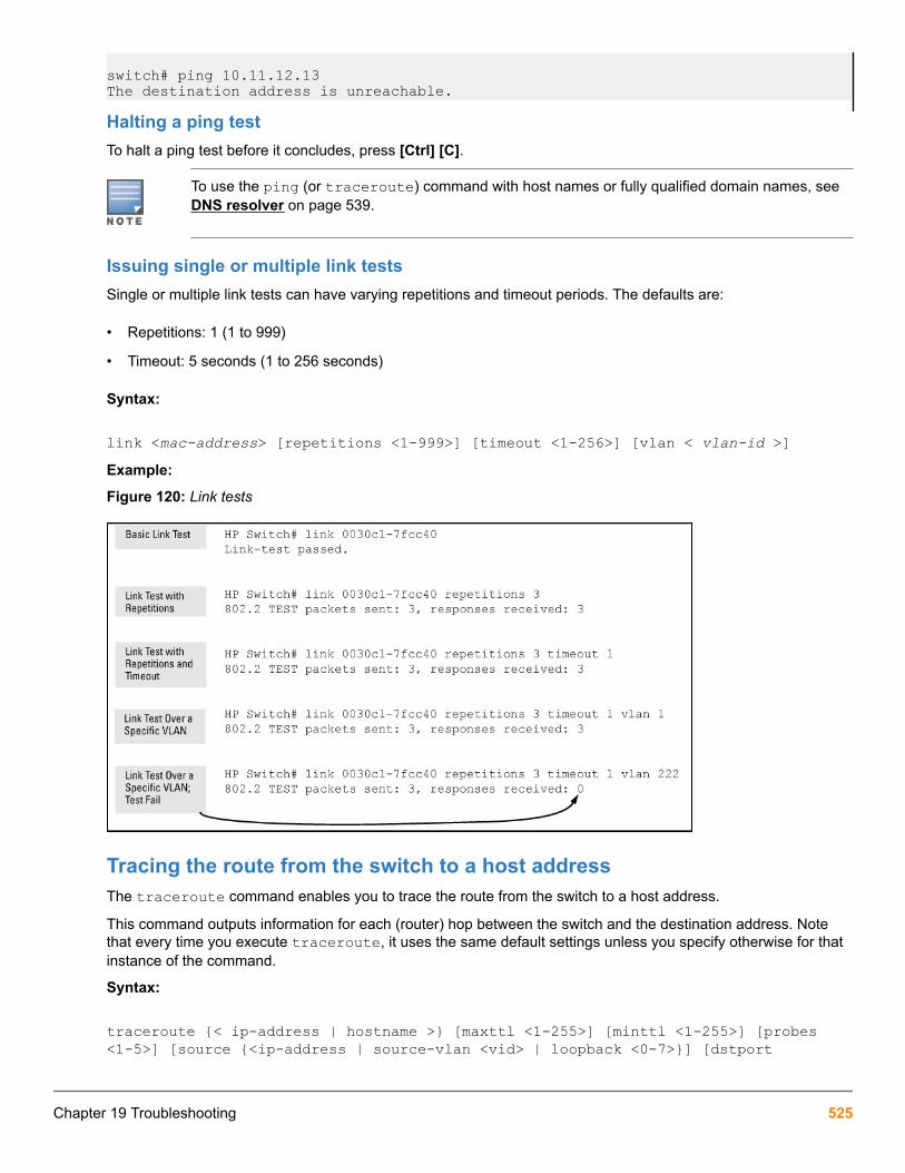
switch# ping 10.11.12.13The destination address is unreachable.
Halting a ping testTo halt a ping test before it concludes, press [Ctrl] [C].
To use the ping (or traceroute) command with host names or fully qualified domain names, see DNS resolver on page 539.
Issuing single or multiple link testsSingle or multiple link tests can have varying repetitions and timeout periods. The defaults are:
• Repetitions: 1 (1 to 999)
• Timeout: 5 seconds (1 to 256 seconds)
Syntax:
link <mac-address> [repetitions <1-999>] [timeout <1-256>] [vlan < vlan-id >]Example:
Figure 120: Link tests
Tracing the route from the switch to a host addressThe traceroute command enables you to trace the route from the switch to a host address.
This command outputs information for each (router) hop between the switch and the destination address. Notethat every time you execute traceroute, it uses the same default settings unless you specify otherwise for thatinstance of the command.
Syntax:
traceroute {< ip-address | hostname >} [maxttl <1-255>] [minttl <1-255>] [probes <1-5>] [source {<ip-address | source-vlan <vid> | loopback <0-7>}] [dstport
Chapter 19 Troubleshooting 525

<1-34000>] [srcport <1-34000>] [ip-option {<record-route | loose-source-route | strict-source-route | include-timestamp | include-timestamp-and-address | include timestamp-from>}] [< timeout 1-120 >]Lists the IP address or hostname of each hop in the route, plus the time in microseconds for the traceroutepacket reply to the switch for each hop.
{< ip-address | hostname >}
The IP address or hostname of the device to which to send the traceroute.
[minttl < 1-255 >]For the current instance of traceroute, changes the minimum number of hopsallowed for each probe packet sent along the route.
• If minttl is greater than the actual number of hops, the output includes only thehops at and above the minttl threshold. (The hops below the threshold are notlisted.)
• If minttl matches the actual number of hops, only that hop is shown in theoutput.
• If minttl is less than the actual number of hops, all hops are listed.
For any instance of traceroute, if you want a minttl value other than the default,you must specify that value.(Default: 1)
[maxttl < 1-255 >]For the current instance of traceroute, changes the maximum number of hopsallowed for each probe packet sent along the route.If the destination address isfurther from the switch than maxttl allows, traceroute lists the IP addresses forall hops it detects up to the maxttl limit.For any instance of traceroute, if youwant a maxttl value other than the default, you must specify that value.(Default: 30)
[probes < 1-5 >]For the current instance of traceroute, changes the number of queries the switchsends for each hop in the route.For any instance of traceroute, if you want aprobes value other than the default, you must specify that value.(Default: 3)
[source {< ip-addr | vid | loopback <0-7> >}]
The source IPv4 address, VLAN ID, or Loopback address.
[dstport < 1-34000 >]
Destination port.
Table Continued
526 Aruba 2930F / 2930M Management and Configuration Guide for ArubaOS-Switch 16.05

[srcport < 1-34000 >]
Source port.
[ip-option]Specify an IP option, such as loose or strict source routing, or an include-timestampoption:[include-timestamp]: Adds the timestamp option to the IP header. Thetimestamp displays the amount of travel time to and from a host.Default:9[include-timestamp-and-address]: Records the intermediate router'stimestamp and IP address.Default: 4[loose-source-route <IP-addr>] :Prompts for the IP address of each source IP on the path.It allows you to specify theIP addresses that you want the ping packet to go through; the packet may go throughother IP addresses as well.[record-route <1-9>] : Displays the IP addresses ofthe interfaces that the ping packet goes through on its way to the destination and onthe way back.When specified without loose or strict recording, the source route is notrecorded. The source route is automatically recorded when loose or strict sourcerouting is enabled.Default: 9[strict-source-route <IP-addr>] : Restricts theping packet to only those IP addresses that have been specified and no otheraddresses.[timeout <1-120>]: For the current instance of traceroute,changes the timeout period the switch waits for each probe of a hop in the route.Forany instance of traceroute, if you want a timeout value other than the default, youmust specify that value.(Default: 5 seconds)
For information about traceroute6, see the IPv6 configuration guide for your switch.
Halting an ongoing traceroute searchPress the [Ctrl] [C] keys.
A low maxttl causes traceroute to halt before reaching the destination addressExecuting traceroute with its default values for a destination IP address that is four hops away produces aresult similar to this:
Figure 121: A completed traceroute enquiry
Chapter 19 Troubleshooting 527

Continuing from the previous Example: (Figure 121: A completed traceroute enquiry on page 527), executingtraceroute with an insufficient maxttl for the actual hop count produces an output similar to this:
Figure 122: Incomplete traceroute because of low maxttl setting
If a network condition prevents traceroute from reaching the destinationCommon reasons for traceroute failing to reach a destination include:
• Timeouts (indicated by one asterisk per probe, per hop)
• Unreachable hosts
• Unreachable networks
• Interference from firewalls
• Hosts configured to avoid responding
Executing traceroute where the route becomes blocked or otherwise fails results in an output marked bytimeouts for all probes beyond the last detected hop. For example, with a maximum hop count of 7 (maxttl = 7),where the route becomes blocked or otherwise fails, the output appears similar to this:
Figure 123: Traceroute failing to reach the destination address
Viewing switch configuration and operationIn some troubleshooting scenarios, you may need to view the switch configuration to diagnose a problem. Thecomplete switch configuration is contained in a file that you can browse from the CLI using the commandsdescribed in this section.
Viewing the startup or running configuration fileSyntax:
write terminalDisplays the running configuration.
528 Aruba 2930F / 2930M Management and Configuration Guide for ArubaOS-Switch 16.05

show config Displays the startup configuration.
show running-config Displays the running-config file.
For more information and examples of how to use these commands, see “Switch Memory and Configuration” inthe basic operation guide.
Viewing the configuration file (WebAgent)To display the running configuration using the WebAgent:
1. In the navigation pane, click Troubleshooting.
2. Click Configuration Report.
3. Use the right-side scroll bar to scroll through the configuration listing.
Viewing a summary of switch operational dataSyntax:
show techBy default, the show tech command displays a single output of switch operating and running-configuration datafrom several internal switch sources, including:
• Image stamp (software version data)
• Running configuration
• Event Log listing
• Boot history
• Port settings
• Status and counters — port status
• IP routes
• Status and counters — VLAN information
• GVRP support
• Load balancing (trunk and LACP)
The show tech command on page 529 shows sample output from the show tech command.
The show tech command
switch# show tech
show system
Status and Counters - General System Information
System Name : Switch System Contact : System Location :
Chapter 19 Troubleshooting 529

MAC Age Time (sec) : 300
Time Zone : 0 Daylight Time Rule : None
Software revision : XX.14.xx Base MAC Addr : 001871-c42f00 ROM Version : XX.12.12 Serial Number : SG641SU00L
Up Time : 23 hours Memory - Total : CPU Util (%) : 10 Free :
IP Mgmt - Pkts Rx : 759 Packet - Total : 6750 Pkts Tx : 2 Buffers Free : 5086 Lowest : 4961 Missed : 0
show flashImage Size(Bytes) Date Version----- ----------- ------ --------To specify the data displayed by the show tech command, use the copy show tech command.
Saving show tech command output to a text fileWhen you enter the show tech command, a summary of switch operational data is sent to your terminalemulator. You can use your terminal emulator's text capture features to save the show tech data to a text file forviewing, printing, or sending to an associate to diagnose a problem.
For example, if your terminal emulator is the Hyperterminal application available with Microsoft® Windows®software, you can copy the show tech output to a file and then use either Microsoft Word or Notepad to displaythe data. (In this case, Microsoft Word provides the data in an easier-to-read format.)
The following example uses the Microsoft Windows terminal emulator. If you are using a different terminalemulator application, see the documentation provided with the application.
530 Aruba 2930F / 2930M Management and Configuration Guide for ArubaOS-Switch 16.05

Procedure
1. In Hyperterminal, click on Transfer|Capture Text….
Figure 124: Capture text window of the Hyperterminal application
2. In the File field, enter the path and file name in which you want to store the show tech output.
Figure 125: Entering a path and filename for saving show tech output
3. Click [Start] to create and open the text file.
4. From the global configuration context, enter the show tech command:
switch# show techThe show tech command output is copied into the text file and displayed on the terminal emulator screen.When the command output stops and displays -- MORE --, press the Space bar to display and copy moreinformation. The CLI prompt appears when the command output finishes.
5. Click on Transfer|Capture Text|Stop in HyperTerminal to stop copying data and save the text file.
If you do not stop HyperTerminal from copying command output into the text file, additional unwanted data canbe copied from the HyperTerminal screen.
6. To access the file, open it in Microsoft Word, Notepad, or a similar text editor.
Customizing show tech command outputUse the copy show tech command to customize the detailed switch information displayed with the show techcommand to suit your troubleshooting needs.
To customize the information displayed with the show tech command:
Procedure
1. Determine the information that you want to gather to troubleshoot a problem in switch operation.
2. Enter the copy show tech command to specify the data files that contain the information you want to view.
Chapter 19 Troubleshooting 531

Syntax:
copy <source> show-techSpecifies the operational and configuration data from one or more source files to be displayed by the show techcommand. Enter the command once for each data file that you want to include in the display.
Default: Displays data from all source files, where <source> can be any one of the following values:
command-output "<command>" Includes the output of a specified command in show-techcommand output.
Enter the command name between double-quotation marks,For example, copy "show system" show-tech.
crash-data [slot-id | master] Includes the crash data from all management and interfacemodules in show tech command output.
To limit the amount of crash data displayed, specify aninstalled module or management modules, where:
• slot-id: Includes the crash data from an installedmodule. Valid slot IDs are the letters a through h.
• master: Includes the crash data from both managementmodules.
crash-log [slot-id | master] Includes the crash logs from all management and interfacemodules in show tech command output.
To limit the amount of crash-log data displayed, specify aninstalled module or management modules, where:
slot-id: Includes the crash log from an installed module.Valid slot IDs are the letters a through h.
master: Includes the crash log from both managementmodules.
event-log Copies the contents of the Event Log to show techcommand output.
running-config Includes the contents of the running configuration file in showtech command output
startup-config Includes the contents of the startup configuration file in showtech command output.
Table Continued
532 Aruba 2930F / 2930M Management and Configuration Guide for ArubaOS-Switch 16.05

tftp config {<startup-config |running-config} <ip-addr> <remote-file> {<pc | unix>}
Downloads the contents of a configuration file from a remotehost to show tech command output, where:
<ip-addr> : Specifies the IP address of the remote hostdevice.
<remote-file>: Specifies the pathname on the remote hostfor the configuration file whose contents you want to include inthe command output.
pc|unix: Specifies whether the remote host is a DOS-basedPC or UNIX workstation.
For more information on using copy tftp commands, see File Transfers on page 316.
xmodem config {<startup-config |config < filename > | command-file< acl-filename.txt >} {<pc | unix>}
Copies the contents of a configuration file or ACL commandfile from a serially connected PC or UNIX workstation to showtech command output, where:
startup-config: Specifies the name of the startupconfiguration file on the connected device.
config <filename> : Specifies the pathname of aconfiguration file on the connected device.
command-file <acl-filename.txt> : Specifies thepathname of an ACL command file on the connected device.
pc|unix: Specifies whether the connected device is a DOS-based PC or UNIX workstation.
For more information on using copy xmodem commands,see File Transfers on page 316.
Viewing more information on switch operationUse the following commands to display additional information on switch operation for troubleshooting purposes.
Syntax:
show boot-historyDisplays the crash information saved for each management module on the switch.
show historyDisplays the current command history. This command output is used for reference or when you want to repeat acommand (See Displaying the information you need to diagnose problems on page 536).
show system-informationDisplays globally configured parameters and information on switch operation.
show version
Chapter 19 Troubleshooting 533

Displays the software version currently running on the switch and the flash image from which the switch booted(primary or secondary). For more information, see "Displaying Management Information" in the "Redundancy(Switch 8212zl)" .
show interfacesDisplays information on the activity on all switch ports (see "Viewing Port Status and Configuring PortParameters" in the "Port Status and Configuration" ).
show interfaces-displayDisplays the same information as the show interfaces command and dynamically updates the output everythree seconds. Press Ctrl + C to stop the dynamic updates of system information. Use the Arrow keys to viewinformation that is off the screen.
Searching for text using pattern matching with show commandSelected portions of the output are displayed, depending on the parameters chosen.
Syntax:
show {< command option > | < include | exclude | begin >} <regular expression>Uses matching pattern searches to display selected portions of the output from a show command. There is nolimit to the number of characters that can be matched. Only regular expressions are permitted; symbols such asthe asterisk cannot be substituted to perform more general matching.
include Only the lines that contain the matching pattern are displayed in the output.
exclude Only the lines that contain the matching pattern are not displayed in the output.
begin The display of the output begins with the line that contains the matching pattern.
Pattern matching is case-sensitive.
Following are examples of what portions of the running config file display depending on the option chosen.
Pattern matching with include option
switch(config)# show run | include ipv6 1 ipv6 enable ipv6 enableipv6 access-list "EH-01"switch(config)#
1Displays only lines that contain “ipv6”.
Pattern matching with exclude option
switch(config)# show run | exclude ipv6 1
Running configuration:
534 Aruba 2930F / 2930M Management and Configuration Guide for ArubaOS-Switch 16.05

; J9299A Configuration Editor; Created on release #WB.15.XX
hostname "HP Switch"snmp-server community "notpublic" Unrestrictedvlan 1 name "DEFAULT_VLAN" untagged A1-A24,B1-B20 ip address dhcp-bootp no untagged B21-B24 exitvlan 20 name "VLAN20" untagged B21-B24 no ip address exitpolicy qos "michael" exit sequence 10 deny tcp 2001:db8:255::/48 2001:db8:125::/48 exitno autorunpassword manager
1Displays all lines that do not contain “ipv6”.
Pattern matching with begin option
switch(config)# show run | begin ipv6 1 ipv6 enable no untagged 21-24 exitvlan 20 name "VLAN20" untagged 21-24 ipv6 enable no ip address exitpolicy qos "michael" exitipv6 access-list "EH-01" sequence 10 deny tcp 2001:db8:255::/48 2001:db8:125::/48 exitno autorunpassword manager
1Displays the running config beginning at the first line that contains “ipv6”.
The following is an Example: of the show arp command output, and then the output displayed when theinclude option has the IP address of 15.255.128.1 as the regular expression.
The show arp command and pattern matching with the include option
switch(config)# show arp
IP ARP table
IP Address MAC Address Type Port ------------- -------------- ------- ---- 15.255.128.1 00000c-07ac00 dynamic B1 15.255.131.19 00a0c9-b1503d dynamic
Chapter 19 Troubleshooting 535

15.255.133.150 000bcd-3cbeec dynamic B1
switch(config)# show arp | include 15.255.128.1 15.255.128.1 00000c-07ac00 dynamic B1
Displaying the information you need to diagnose problemsUse the following commands in a troubleshooting session to more accurately display the information you need todiagnose a problem.
Syntax:
aliasCreates a shortcut alias name for commonly used commands and command options.
Syntax:
killTerminates a currently running, remote troubleshooting session. Use the show ip ssh command to list thecurrent management sessions.
Syntax:
[no] pageToggles the paging mode for show commands between continuous listing and per-page listing.
Syntax:
repeatRepeatedly executes one or more commands so that you can see the results of multiple commands displayedover a period of time. To halt the command execution, press any key on the keyboard.
Syntax:
setupDisplays the Switch Setup screen from the menu interface.
Restoring the factory-default configurationAs part of your troubleshooting process, it may become necessary to return the switch configuration to the factorydefault settings. This process:
• Momentarily interrupts the switch operation
• Clears any passwords
• Clears the console Event Log
• Resets the network counters to zero
• Performs a complete self test
• Reboots the switch into its factory default configuration, including deleting an IP address
There are two methods for resetting to the factory-default configuration:
536 Aruba 2930F / 2930M Management and Configuration Guide for ArubaOS-Switch 16.05

• CLI
• Clear/Reset button combination
Hewlett Packard Enterprise recommends that you save your configuration to a TFTP server beforeresetting the switch to its factory-default configuration. You can also save your configuration viaXmodem to a directly connected PC.
Resetting to the factory-default configuration
Using the CLIThis command operates at any level except the Operator level.
Syntax:
erase startup-configurationDeletes the startup-config file in flash so that the switch will reboot with its factory-default configuration.
The erase startup-config command does not clear passwords unless include-credentials has been set, at which time this command does erase username/passwordinformation and any other credentials stored in the config file. For more information, see the sectionon "Saving Security Credentials in a Config File" in the access security guide for your switch.
Using Clear/Reset
Procedure
1. Using pointed objects, simultaneously press both the Reset and Clear buttons on the front of the switch.
2. Continue to press the Clear button while releasing the Reset button.
3. When the Self Test LED begins to flash, release the Clear button.
The switch then completes its self test and begins operating with the configuration restored to the factorydefault settings.
Restoring a flash imageThe switch can lose its operating system if either the primary or secondary flash image location is empty orcontains a corrupted OS file and an operator uses the erase flash command to erase a good OS image filefrom the opposite flash location.
Recovering from an empty or corrupted flash stateUse the switch's console serial port to connect to a workstation or laptop computer that has the following:
• A terminal emulator program with Xmodem capability, such as the HyperTerminal program included inWindows PC software.
• A copy of a good OS image file for the switch
Chapter 19 Troubleshooting 537

The following procedure requires the use of Xmodem and copies an OS image into primary flashonly.
This procedure assumes you are using HyperTerminal as your terminal emulator. If you use adifferent terminal emulator, you may need to adapt this procedure to the operation of your particularemulator.
1. Start the terminal emulator program.
Ensure that the terminal program is configured as follows:
• Baud rate: 9600
• No parity
• 8 Bits
• 1 stop bit
• No flow control
2. Use the Reset button to reset the switch.
The following prompt should then appear in the terminal emulator:
Enter h or ? for help.
=>3. Because the OS file is large, you can increase the speed of the download by changing the switch console and
terminal emulator baud rates to a high speed. For Example:
a. Change the switch baud rate to 115,200 Bps.
=> sp 115200b. Change the terminal emulator baud rate to match the switch speed:
I. In HyperTerminal, select Call|Disconnect.
II. Select File|Properties.
III. Click on Configure.
IV. Change the baud rate to 115200.
V. Click on [OK], then in the next window, click on [OK] again.
VI. Select Call|Connect.
VII. Press [Enter] one or more times to display the => prompt.
4. Start the Console Download utility by entering do at the =prompt and pressing [Enter]:
=> do5. You then see this prompt:
You have invoked the console download utility. Do you wish to continue? (Y/N)>_
6. At the above prompt:
538 Aruba 2930F / 2930M Management and Configuration Guide for ArubaOS-Switch 16.05

a. Enter y (for Yes)
b. Select Transfer|File in HyperTerminal.
c. Enter the appropriate filename and path for the OS image.
d. Select the Xmodem protocol (and not the 1k Xmodem protocol).
e. Click on [Send].
If you are using HyperTerminal, you will see a screen similar to the following to indicate that the download is inprogress:
Figure 126: Example: of Xmodem download in progress
When the download completes, the switch reboots from primary flash using the OS image you downloaded inthe preceding steps, plus the most recent startup-config file.
DNS resolverThe domain name system (DNS) resolver is designed for use in local network domains, where it enables the useof a host name or fully qualified domain name with DNS-compatible switch CLI commands.
DNS operation supports both IPv4 and IPv6 DNS resolution and multiple, prioritized DNS servers. (Forinformation on IPv6 DNS resolution, see the latest IPv6 configuration guide for your switch.)
Basic operation
• When the switch is configured with only the IP address of a DNS server available to the switch, a DNS-compatible command, executed with a fully qualified domain name, can reach a device found in any domainaccessible through the configured DNS server.
• When the switch is configured with both of the following:
◦ The IP address of a DNS server available to the switch
◦ The domain suffix of a domain available to the configured DNS serverthen:
Chapter 19 Troubleshooting 539

◦ A DNS-compatible command that includes the host name of a device in the same domain as the configureddomain suffix can reach that device.
◦ A DNS-compatible command that includes a fully qualified domain name can reach a device in any domainthat is available to the configured DNS server.
Example:
Suppose the switch is configured with the domain suffix mygroup.HP Switch.net and the IP address for anaccessible DNS server. If an operator wants to use the switch to ping a target host in this domain by using theDNS name "leader" (assigned by a DNS server to an IP address used in that domain), the operator can use eitherof the following commands:
Figure 127: Example: of using either a host name or a fully qualified domain name
In the proceeding Example:, if the DNS server's IP address is configured on the switch, but a domain suffix iseither not configured or is configured for a different domain than the target host, the fully qualified domain namemust be used.
Note that if the target host is in a domain other than the domain configured on the switch:
• The host's domain must be reachable from the switch. This requires that the DNS server for the switch mustbe able to communicate with the DNS servers in the path to the domain in which the target host operates.
• The fully qualified domain name must be used, and the domain suffix must correspond to the domain in whichthe target host operates, regardless of the domain suffix configured in the switch.
Example:
Suppose the switch is configured with the domain suffix mygroup.HP Switch.net and the IP address for anaccessible DNS server in this same domain. This time, the operator wants to use the switch to trace the route to ahost named "remote-01" in a different domain named common.group.net. Assuming this second domain isaccessible to the DNS server already configured on the switch, a traceroute command using the target's fullyqualified DNS name should succeed.
Figure 128: Example: using the fully qualified domain name for an accessible target in another domain
Configuring and using DNS resolution with DNS-compatible commandsThe DNS-compatible commands include ping and traceroute.)
540 Aruba 2930F / 2930M Management and Configuration Guide for ArubaOS-Switch 16.05

Procedure
1. Determine the following:
a. The IP address for a DNS server operating in a domain in your network.
b. The priority (1 to 3) of the selected server, relative to other DNS servers in the domain.
c. The domain name for an accessible domain in which there are hosts you want to reach with a DNS-compatible command. (This is the domain suffix in the fully qualified domain name for a given hostoperating in the selected domain. See Basic operation on page 539.) Note that if a domain suffix is notconfigured, fully qualified domain names can be used to resolve DNS-compatible commands.
d. The host names assigned to target IP addresses in the DNS server for the specified domain.
2. Use the data from the first three bullets in step1 to configure the DNS entry on the switch.
3. Use a DNS-compatible command with the host name to reach the target devices.
Configuring a DNS entryThe switch allows up to two DNS server entries (IP addresses for DNS servers). One domain suffix can also beconfigured to support resolution of DNS names in that domain by using a host name only. Including the domainsuffix enables the use of DNS-compatible commands with a target's host name instead of the target's fullyqualified domain name.
Syntax:
[no] ip dns server-address priority <1-3> <ip-addr>Configures the access priority and IP address of a DNS server accessible to the switch. These settings specify:
• The relative priority of the DNS server when multiple servers are configured
• The IP address of the DNS server
These settings must be configured before a DNS-compatible command can be executed with host name criteria.
The switch supports two prioritized DNS server entries. Configuring another IP address for a priority that hasalready been assigned to an IP address is not allowed.
To replace one IP address at a given priority level with another address having the same priority, you must firstuse the no form of the command to remove the unwanted address. Also, only one instance of a given serveraddress is allowed in the server list. Attempting to enter a duplicate of an existing entry at a different priority levelis not allowed .To change the priority of an existing server address, use the no form of the command to remove the entry, thenre-enter the address with the new priority.
The no form of the command replaces the configured IP address with the null setting. (Default: null)
Syntax:
[no] ip dns domain-name <domain-name-suffix>This optional DNS command configures the domain suffix that is automatically appended to the host nameentered with a DNS-compatible command. When the domain suffix and the IP address for a DNS server that canaccess that domain are both configured on the switch, you can execute a DNS-compatible command using onlythe host name of the desired target. (For an Example:, see Example: of using either a host name or a fully
Chapter 19 Troubleshooting 541

qualified domain name.) In either of the following two instances, you must manually provide the domainidentification by using a fully qualified DNS name with a DNS-compatible command:
• If the DNS server IP address is configured on the switch, but the domain suffix is not configured (null).
• The domain suffix configured on the switch is not the domain in which the target host exists.
The switch supports one domain suffix entry and three DNS server IP address entries. (See the precedingcommand description.)
The no form of the command replaces the configured domain suffix with the null setting. (Default: null)
Using DNS names with ping and traceroute: Example:In the network illustrated in Figure 129: Example: network domain on page 542, the switch at 10.28.192.1 isconfigured to use DNS names for DNS-compatible commands in the pubs.outdoors.com domain. The DNSserver has been configured to assign the host name docservr to the IP address used by the document server(10.28.229.219).
Figure 129: Example: network domain
Configuring switch "A" with the domain name and the IP address of a DNS server for the domain enables theswitch to use host names assigned to IP addresses in the domain to perform ping and traceroute actions onthe devices in the domain. To summarize:
Entity Identity
DNS server IP address 10.28.229.10
Domain name (and domain suffix for hosts in thedomain)
pubs.outdoors.com
Host name assigned to 10.28.229.219 by the DNSserver
docservr
Fully qualified domain name for the IP address used bythe document server (10.28.229.219)
docservr.pubs.outdoors.com
Switch IP address 10.28.192.1
Document server IP address 10.28.229.219
542 Aruba 2930F / 2930M Management and Configuration Guide for ArubaOS-Switch 16.05

With the above already configured, the following commands enable a DNS-compatible command with the hostname docserver to reach the document server at 10.28.229.219.
Configuring switch "A" in Example: network domain to support DNS resolution
switch(config)# ip dns server-address 10.28.229.10switch(config)# ip dns domain-name pbs.outdoors.com
Ping and traceroute execution for the network in Example: network domain
switch(config)# ping docservr10.28.229.219 is alive, time = 1 ms
switch# traceroute docservrtraceroute to 10.28.229.219 1 hop min, 30 hops max, 5 sec. timeout, 3 probes 1 10.28.192.2 1 1 ms 0 ms 0 ms 2 10.28.229.219 2 0 ms 0 ms 0 ms
• 1First-Hop Router (“B”)
• 2Traceroute Target
As mentioned under the following example, if the DNS entry configured in the switch does not include the domainsuffix for the desired target, you must use the target host's fully qualified domain name with DNS-compatiblecommands. For example, using the document server in Figure 129: Example: network domain on page 542 asa target:
Figure 130: Example: of ping and traceroute execution when only the DNS server IP address is configured
Chapter 19 Troubleshooting 543

Viewing the current DNS configurationThe show ip command displays the current domain suffix and the IP address of the highest priority DNS serverconfigured on the switch, along with other IP configuration information. If the switch configuration currentlyincludes a non-default (non-null) DNS entry, it will also appear in the show run command output.
Figure 131: Example: of viewing the current DNS configuration
Operating notes
• Configuring another IP address for a priority that has already been assigned to an IP address is not allowed.To replace one IP address at a given priority level with another address having the same priority, you must firstuse the no form of the command to remove the unwanted address. Also, only one instance of a given serveraddress is allowed in the server list. Attempting to enter a duplicate of an existing entry at a different prioritylevel is not allowed. To change the priority of an existing server address, use the no form of the command toremove the entry, then re-enter the address with the new priority.
• To change the position of an address already configured with priority x, you must first use no ip dnsserver-address priority x <ip-addr> to remove the address from the configuration, then use ipdns server-address priority <ip-addr> to reconfigure the address with the new priority. Also, if thepriority to which you want to move an address is already used in the configuration for another address, youmust first use the no form of the command to remove the current address from the target priority.
• The DNS servers and domain configured on the switch must be accessible to the switch, but it is notnecessary for any intermediate devices between the switch and the DNS server to be configured to supportDNS operation.
• When multiple DNS servers are configured on the switch, they can reside in the same domain or differentdomains.
• A DNS configuration must include the IP address for a DNS server that is able to resolve host names for thedesired domain. If a DNS server has limited knowledge of other domains, its ability to resolve DNS-compatiblecommand requests is also limited.
• If the DNS configuration includes a DNS server IP address but does not also include a domain suffix, then anyDNS-compatible commands should include the target host’s fully qualified domain name.
• Switch-Initiated DNS packets go out through theVLAN having the best route to the DNS server, even ifaManagement VLAN has been configured.
• The DNS server address must be manually input. It is not automatically determined viaDHCP.
544 Aruba 2930F / 2930M Management and Configuration Guide for ArubaOS-Switch 16.05

Event Log messagesPlease see the Event Log Message Reference Guide for information about Event Log messages.
Locating a switch (Locator LED)To locate where a particular switch is physically installed, use the chassislocate command to activate the blueLocator LED on the switch's front panel.
Syntax:
chassislocate [blink | on | off]Locates a switch by using the blue Locate LED on the front panel.
blink <1-1440> Blinks the chassis Locate LED for a specified number of minutes (Default: 30minutes).
on <1-1440> Turns the chassis Locate LED on for a specified number of minutes (Default: 30minutes).
off Turns the chassis Locate LED off.
Locating a switch with the chassislocate command
switch(config)# chassislocate blink <1-1440> Blink the chassis locate led (default 30 minutes). off Turn the chassis locate led off. on <1-1440> Turn the chassis locate led on (default 30 minutes).switch(config)# chassislocateFor redundant management systems, if the active management module failsover, the Locator LED does notremain lit.
Chapter 19 Troubleshooting 545

Job SchedulerThe Job Scheduler feature enables the user to schedule commands or jobs on the switch for one time or multipletimes. This is similar in concept to the UNIX ‘cron’ utility. The user can schedule any CLI command that the userwould otherwise enter interactively. This includes commands to enable or disable ports, LEDs, and Power-Over-Ethernet. Jobs can also be scheduled to be triggered by certain pre-defined events such as switch reboot. Theonly major restriction on commands scheduled is that, it should not prompt/ask for any user inputs.
Commands
Job at | delay | enable | disableSet schedule jobs using the options and set the count for the number of times the job is repeated.
Syntax
job JOB NAME at | delay | enable | disableDescription
Schedule a command to run automatically. Jobs can be scheduled to run once, multiple times on a recurringbasis, or after certain events such as reboots. All commands run with manager privilege in configuration context.
The [no] form of the command deletes a scheduled job.
By default, jobs will be repeated an infinite number of times.
Restrictions
Jobs scheduled at any event will not be counted.
Jobs that are scheduled at the event “reboot” will not work in some multi management switches.
Range
• <1-1000>: is the value range for the count option.
• ([[DD:]HH:]MM): is the format used for the specific delay.
Options
count
Specify the number of times the job should run.
delay
Specify the delay before running the job.
enable
Enable a job that is disabled or expired.
disable
Disable a job. By default, a job is enabled.
Chapter 20Job Scheduler
546 Aruba 2930F / 2930M Management and Configuration Guide for ArubaOS-Switch 16.05

Usage
job <JOB NAME> at <([DD:]HH:]MM on <WEEKDAY-LIST>)> config-save <COMMAND> count <1-1000>
job <JOB NAME> at <[HH:]MM on [MM/]DD> config-save <COMMAND> count <1-1000>
job <JOB NAME> at <EVENT> config-save <COMMAND>
job <JOB NAME> delay <([DD:]HH:]MM> config-save <COMMAND> count <1-1000>
job <JOB NAME> enable | disable
[no] job <JOB NAME>
Show jobSyntax
show jobDescription
Show the jobs scheduled.
Show job
switch# show job
Job Scheduler Status and Configuration
Scheduler Status : Waiting for the system time to be set
Event or Repeat Save Name Time Count Cfg Command ------------------ ---------------- ------- ---- ------------ Burrrrrrrrrrrr... reboot -- Yes chassislocate blink baz reboot -- No show time foo 17:00 SxTWTxS -- No savepower led a1 12:00 2 Yes sh time a2 Every 2:14:30 days 75 Yes vlan 3 a3 Every 00:00:25 days 1 No vlan 4
Caution
The scheduler does not run until the system time is set.
Show job <Name>Syntax
show job JOB NAMEDescription
Show the job by name.
Chapter 20 Job Scheduler 547

Show job <JOB NAME>
switch# show job a1
Job Information
Job Name : a1Runs At : 01:24Config Save : NoRepeat Count: --Job Status : EnabledRun Count : 1Error Count : 0Command : show timeJob Status : Enabled
Output from Last Run -------------------- Tue Dec 15 01:24:00 2015
switch# show job a2
Job Information
Job Name : a2Runs At : Every 2:14:30 daysConfig Save : YesRepeat Count: 75Run Count : 0Error Count : 0Command : vlan 3Job Status : Disabled
switch# show job foo
Job Information
Job Name : fooRuns At : 17:00 SxTWTxSConfig Save : YesRepeat Count: --Run Count : 0Error Count : 0Command : savepower ledJob Status : Enabled
548 Aruba 2930F / 2930M Management and Configuration Guide for ArubaOS-Switch 16.05

OverviewThe traditional way of restoring a configuration from a backup configuration file required a switch reboot for thenew configurations to be effective. There were network outages and a planned downtime for even minor changes.The switch configuration can now be restored from a backup configuration without reboot. It also provides hash ofthe current running configuration, which can be used for auditing.
The backup configuration can be created using the new command cfg-backup. An existing method of copying aconfiguration file from a remote location (for example, TFTP server) can also be used to backup a configuration orcopied from flash.
More information
show hash on page 569cfg-backup on page 553cfg-restore config_bkp on page 562
Benefits of configuration restore without reboot
• Restores a new or modified configuration without reboot, with minimal network outage. Any NMS can use thismethod for configuration rebase workflows. Only configurations that were exported from the switch can beimported or restored on the switch.
• Restores the configuration without reboot from a backup configuration when the running configuration hasfunctional issues, like misconfigurations from remote management stations.
Recommended scenarios• Use the configuration restore feature for incremental configuration updates.
• Use the force option with cfg-restore, for commands which require reboot.
• Use the verbose option to get detailed progress on the configuration restore process.
More information
Force configuration restore on page 557cfg-restore verbose on page 561
Use cases• A user can switch to a new configuration without rebooting the switch.
• If a user loses connectivity after applying the new configuration, a job scheduler executes the job after aspecific time frame. This restores the current configuration to the switch, without rebooting it.
More information
Switching to a new configuration on page 550
Chapter 21Configuration backup and restore without reboot
Chapter 21 Configuration backup and restore without reboot 549

Rolling back to a stable configuration using job scheduler on page 551
Switching to a new configuration
Procedure
1. Back up the configuration using cfg-backup running-config config <config_name> command. Inthe following example, the configuration name used is “stable”.cfg-backup running-config config stable
2. Check the backup configuration using show config files command.
switch(config)# show config files
Configuration files:
id | act pri sec | name---+-------------+--------1 | * * * | config2 | | stable3 | |4 | |5 | |
3. Change the running configuration as required, and backup the new configuration as “newfile”.
cfg-backup running-config config newfile
switch(config)# show config files
Configuration files:
id | act pri sec | name ---+-------------+--------- 1 | * * * | config 2 | | stable 3 | | newfile 4 | | 5 | |
4. Check the difference between the “newfile” (running configuration) and “stable” (backed up configuration)using cfg-restore flash stable diff command. Based on the difference, apply the backed-upconfiguration using cfg-restore flash stable command.
5. Check the status of the configuration restore using show cfg-restore status command.
switch(config)# show cfg-restore status
Status : Success Config File Name : stable Source : Flash Time Taken : 3 Seconds Last Run : Tue Nov 28 18:24:09 2017
Recovery Mode : Enabled Failure Reason : -
Number of Add Commands : 14 Number of Remove Commands : 0
550 Aruba 2930F / 2930M Management and Configuration Guide for ArubaOS-Switch 16.05
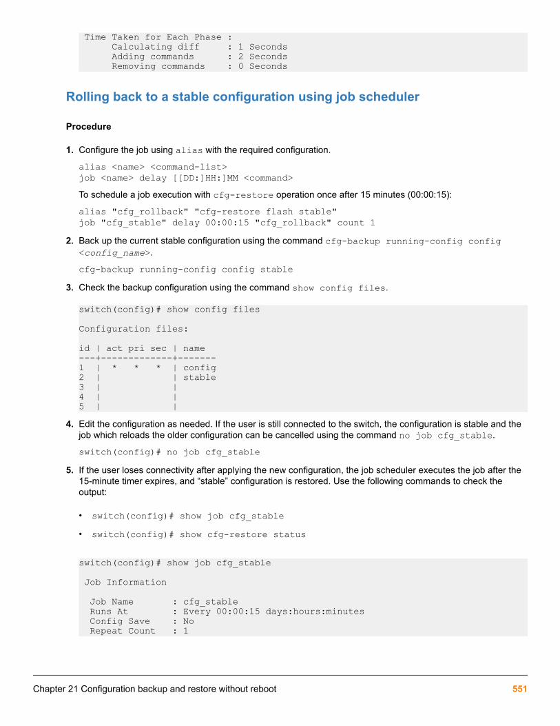
Time Taken for Each Phase : Calculating diff : 1 Seconds Adding commands : 2 Seconds Removing commands : 0 Seconds
Rolling back to a stable configuration using job scheduler
Procedure
1. Configure the job using alias with the required configuration.
alias <name> <command-list>job <name> delay [[DD:]HH:]MM <command>To schedule a job execution with cfg-restore operation once after 15 minutes (00:00:15):
alias "cfg_rollback" "cfg-restore flash stable"job "cfg_stable" delay 00:00:15 "cfg_rollback" count 1
2. Back up the current stable configuration using the command cfg-backup running-config config<config_name>.
cfg-backup running-config config stable3. Check the backup configuration using the command show config files.
switch(config)# show config files
Configuration files:
id | act pri sec | name---+-------------+-------1 | * * * | config2 | | stable3 | |4 | |5 | |
4. Edit the configuration as needed. If the user is still connected to the switch, the configuration is stable and thejob which reloads the older configuration can be cancelled using the command no job cfg_stable.
switch(config)# no job cfg_stable5. If the user loses connectivity after applying the new configuration, the job scheduler executes the job after the
15-minute timer expires, and “stable” configuration is restored. Use the following commands to check theoutput:
• switch(config)# show job cfg_stable• switch(config)# show cfg-restore status
switch(config)# show job cfg_stable
Job Information
Job Name : cfg_stable Runs At : Every 00:00:15 days:hours:minutes Config Save : No Repeat Count : 1
Chapter 21 Configuration backup and restore without reboot 551

Job Status : Enabled Running Status : Active Run Count : 0 Error Count : 0 Skip Count : 0 Command : cfg_rollback
switch(config)# show cfg-restore status Status : Success Config File Name : stable Source : Flash Time Taken : 9 Seconds Last Run : Tue Nov 28 20:50:00 2017
Recovery Mode : Enabled Failure Reason : -
Number of Add Commands : 27 Number of Remove Commands : 0
Time Taken for Each Phase : Calculating diff : 4 Seconds Adding commands : 1 Seconds Removing commands : 0 Seconds
If the configuration involves any sensitive information, backup and restore the configuration byenabling the include-credentials command.
Commands used in switch configuration restore withoutrebootcfg-backup
Backs up the selected configuration to the flash file.
show config files detailsShows a detailed list of configuration files available in the flash.
cfg-restoreRestores the given configuration as the running configuration without reboot.
show cfg-restore statusShows the status of latest restore performed.
show cfg-restore latest-diffViews the list of configuration changes that are removed, modified, or added to the running configuration.
show hashShows the SHA ID of a startup or running configuration.
Configuration backupThe configuration backup creates a backup of the running or startup configuration of ArubaOS-Switch on-demandto the flash storage on the switch.
You can now back up the configuration for ArubaOS-Switch feature on the flash storage of the switch. Themaximum number of backup files supported has increased from three to five.
552 Aruba 2930F / 2930M Management and Configuration Guide for ArubaOS-Switch 16.05

When you downgrade configuration backup files from five to three, and if the current number of filesis either a four or five, an error message Configuration file <name> stored in configindex 5 is not supported in lower image versions is displayed.
cfg-backupSyntaxcfg-backup {running-config | startup-config} config <FILE-NAME>
Description
Backs up the selected configuration to the flash file mentioned. When the firmware is downgraded to lowerversions, the details of only three configuration files appear in the show config files command.
Command contextconfig
Parametersrunning-config
Copies the running configuration to switch flash file.startup-config
Copies the startup configuration to switch flash file.
flashName of the configuration file in flash.
Usagecopy {startup-config | running-config} {sftp | tftp} <server address> <FILE-NAME>The existing copy command copies the startup and running configuration to the TFTP or SFTP server.
Examples
switch(config)# cfg-backup running-config Backup the running configuration to the flash file mentioned. startup-config Backup the startup configuration to the flash file mentioned.
switch(config)# cfg-backup {running-config | startup-config} config Backup the named configuration file.
switch(config)# cfg-backup {running-config | startup-config} config ASCII-STR Enter an ASCII string.
show config filesSyntaxshow config files
Description
Shows a list of configuration files available in the flash.
Chapter 21 Configuration backup and restore without reboot 553

Command contextconfig
Examples
switch# show config filesConfiguration files:
id | act pri sec | name ---+-------------+--------- 1 | * * * | config 2 | | add 3 | | modify 4 | | golden_config 5 | | poe2To show the details of saved configuration files:
switch(config)# show config files details Show details of saved configuration files.
switch(config)#show config files details
Backup Configuration files:
File Name : config File ID : 1 File Size : 35902 Bytes Last Modified : Mon Jan 01 1990 00:09:28 Version : WC.16.05.0000x
File Name : add File ID : 2 File Size : 35902 Bytes Last Modified : Mon Oct 23 2017 03:42:38 Version : WC.16.05.0000x
File Name : modify File ID : 3 File Size : 35902 Bytes Last Modified : Mon Oct 23 2017 03:42:38 Version : WC.16.05.0000xTo view the contents of a configuration file in the flash:
switch# show config add
; JL255A Configuration Editor; Created on release #WC.16.05.0000x; Ver #12:08.1d.9b.3f.bf.bb.ef.7c.59.fc.6b.fb.9f.fc.ff.ff.37.ef:bahostname "Aruba-2930F-24G-PoEP-4SFPP"module 1 type jl255asnmp-server community "public" unrestrictedvlan 1 name "DEFAULT_VLAN" no untagged 3-10 untagged 1-2,11-28 ip address dhcp-bootp exitvlan 100 name "VLAN100" untagged 3-5 no ip address exit
554 Aruba 2930F / 2930M Management and Configuration Guide for ArubaOS-Switch 16.05

vlan 200name "VLAN200" untagged 6-10 no ip address exit
Configuration restore without rebootThe cfg-restore without reboot command restores the configuration without reboot from a backupconfiguration to the running configuration of the switch.
The details about the difference between a running and a backup configuration can be displayed using cfg-restore {flash | tftp | sftp} <FILE-NAME> diff command.
More information
Configuration backup on page 552Viewing the differences between a running configuration and a backup configuration on page 567
cfg-restoreSyntaxcfg-restore {flash | tftp <IP-ADDRESS> | sftp <IP-ADDRESS>} <FILE-NAME> [diff |force | non-blocking | recovery-mode | verbose]
Description
Restores the given configuration as the running configuration without reboot. If the configuration is not suitable tosuccessfully restore without reboot, the command will return a failure message with details.
The restored configuration commands will be executed on a running configuration, so the name ofthe current active configuration does not change after configuration restore, except for the forceoption.
Command contextconfig
Parametersflash
Copies file from flash.tftp
Copies file from TFTP server.
sftpCopies file from SFTP server.
<IP-ADDRESS>
IP address of the TFTP server.
<FILE-NAME>
Name of the backup configuration file to restore into the running configuration.
diffProvides the list of changes that will be applied on the running configuration.
Chapter 21 Configuration backup and restore without reboot 555

forceForces a reboot if configuration in restored configuration requires a reboot. Applies the configuration withreboot if the configuration has reboot required commands or system-wide change commands. After a forcedreboot, the name of the configuration changes.
non-blockingConfiguration restoration in non-blocking mode, where actual process happens in the background.
recovery-modeEnables or disables recovery-mode. Recovery-mode is enabled by default and this retains the current runningconfiguration if configuration restoration fails.
verboseProvides the details of configuration restore status and the list of commands to be added or deleted.
Usage
• cfg-restore flash <FILE-NAME> [non-blocking | diff | force | recovery-mode{enable| disable}]] | [verbose [force | [recovery-mode{enable | disable}] | [diff |force]
• cfg-restore tftp {<IPV4-ADDR> | <IPV6-ADDR> | <HOSTNAME-STR> <FILE-NAME> [non-blocking | diff | force | recovery-mode{enable | disable}]] | [verbose [force |[recovery-mode{enable | disable}]] | [diff |force]
• cfg-restore sftp {<IPV4-ADDR> | <IPV6-ADDR> | <HOSTNAME-STR> | user <name> {<IP-ADDRESS|IPV6-ADDRESS|HOSTNAME-STR>} | <USERNAME@>{<HOST-NAME> | <IPV4-ADDR> |<IPV6-ADDR>}} [port <1-65535>] <FILE-NAME> [non-blocking | diff | force |recovery-mode{enable | disable}]] | [verbose [force | [recovery-mode{enable |disable}]] | [diff |force]
Examples
switch# cfg-restore flash Copy file from flash. sftp Copy file from SFTP Server. tftp Copy file from TFTP Server.
switch# cfg-restore flash FILE-NAME Name of the backup configuration file to restore into the running configuration.
switch# cfg-restore flash config_file diff Provide the list of changes that will be applied on the running configuration. force Apply the configuration with reboot if the configuration has reboot required commands or system-wide change commands present. non-blocking Config restoration in non-blocking mode. recovery-mode To enable/disable recovery-mode. verbose Provide the details of config restore status and the list of commands to be added or deleted.
switch# cfg-restore tftp HOSTNAME-STR Specify hostname of TFTP Server. IP-ADDR IP Address of the TFTP Server. IPV6-ADDR IPV6 Address of the TFTP Server.
switch# cfg-restore tftp 10.100.0.12 FILE-NAME Name of the backup configuration file to restore into the running configuration.
switch# cfg-restore tftp 10.100.0.12 config_file diff Provide the list of changes that will be applied on the running configuration. force Apply the configuration with reboot if the
556 Aruba 2930F / 2930M Management and Configuration Guide for ArubaOS-Switch 16.05

configuration has reboot required commands or system-wide change commands present. non-blocking Config restoration in non-blocking mode. recovery-mode To enable/disable recovery-mode. verbose Provide the details of config restore status and the list of commands to be added or deleted.
switch(config)# cfg-restore flash add non-blocking diff Provide the list of changes that will be applied on the running configuration. force Apply the configuration with reboot if the configuration has reboot required commands or system-wide change commands present. recovery-mode To enable/disable recovery-mode.
Force configuration restoreThe cfg-restore command fails if a reboot is required. The Configuration restoration is notallowed as the configuration has reboot required commands error is displayed, along with linesrequiring a reboot. The force option in the cfg-restore command allows a user to force a reboot. Thecommand is: cfg-restore {flash | tftp | sftp} <FILE-NAME> force.
Before reboot, config is the active configuration. After the device reboots, the backup file becomes the newactive configuration.
id | act pri sec | name---+-------------+--------------- 1 | * * * | config 2 | | def 3 | | golden_config 4 | | 5 | |
switch(config)# cfg-restore flash golden_configCurrent running-configuration will be replaced with 'golden_config'.Continue (y/n)? yConfiguration restore is in progress, configuration changes are temporarily disabled.Configuration restoration is not allowed as the configuration has reboot required commands.
switch(config)# show cfg-restore status Status : Failed Config File Name : golden_config Source : Flash Time Taken : 5 Seconds Last Run : Mon Oct 30 23:03:19 2017
Recovery Mode : Enabled Failure Reason : Reboot required commands present. Command : console terminal none
Number of Add Commands : 0 Number of Remove Commands : 1
Time Taken for Each Phase : Calculating diff : 3 Seconds Adding commands : 0 Seconds Removing commands : 0 Seconds
switch# cfg-restore flash golden_config forceDevice may be rebooted if the configuration file has reboot required orsystem-wide change commands. Do you want to continue (y/n)?Current running-configuration will be replaced with 'golden_config'.Continue (y/n)?Configuration restore is in progress, configuration changes are temporarilydisabled.
Successfully applied configuration 'golden_config' to running configuration.
Rebooting switch...
Chapter 21 Configuration backup and restore without reboot 557

In the preceding output, Command : console terminal none shows that cfg-restore failed because areboot is required.
After the switch reboots and comes up, the golden_config becomes the active configuration.
In case of a switch reboot, the switch comes up with the configuration associated with the primary orsecondary.
id | act pri sec | name ---+-------------+------------------------------------------------ 1 | * * | config 2 | | def 3 | * | golden_config 4 | | 5 | |
switch# show cfg-restore status Status : Success Config File Name : default Source : Flash Time Taken : 1 Seconds Last Run : Mon Oct 23 07:17:03 2017
Recovery Mode : Enabled Failure Reason : -
Number of Add Commands : 0 Number of Remove Commands : 5
Time Taken for Each Phase :
Calculating diff : 1 Seconds Adding commands : 0 Seconds Removing commands : 0 Seconds
Time taken for adding and deleting commands is zero, as the switch reboots. It is similar todownloading a startup-configuration to the device.
cfg-restore non-blocking
Syntaxcfg-restore {flash | tftp | sftp} <FILE-NAME> non-blocking
Description
Performs restore in non-blocking mode.
Command contextconfig
Example
switch(config)# cfg-restore flash add non-blockingCurrent running-configuration will be replaced with 'add'.Continue (y/n)? yConfiguration restore is in progress, configuration changes are
558 Aruba 2930F / 2930M Management and Configuration Guide for ArubaOS-Switch 16.05

temporarily disabled.switch(config)#
switch(config)# show cfg-restore status Status : Success Config File Name : add Source : Flash Time Taken : 2 Seconds Last Run : Sun Oct 22 22:09:02 2017
Recovery Mode : Enabled Failure Reason : -
Number of Add Commands : 7 Number of Remove Commands : 10
Time Taken for Each Phase : Calculating diff : 1 Seconds Adding commands : 0 Seconds Removing commands : 0 Seconds
cfg-restore recovery-mode
Syntaxcfg-restore {flash | tftp | sftp} <FILE-NAME> recovery-mode {enable | disable}
Description
Restores the current running configuration, if a restore to the backup configuration fails. By default, recovery-mode is enabled.
Command contextconfig
Usage
To disable recovery mode, use cfg-restore {flash | tftp | sftp} <FILE-NAME> recovery-modedisable.
Example
With the following running configuration, a restore to the backup file modify fails, but this configuration will beretained as recovery mode is enabled.
switch(config)# show running-config
Running configuration:
; JL255A Configuration Editor; Created on release #WC.16.05.0000x; Ver #12:08.1d.9b.3f.bf.bb.ef.7c.59.fc.6b.fb.9f.fc.ff.ff.37.ef:bahostname "Aruba-2930F-24G-PoEP-4SFPP"module 1 type jl255aip routingsnmp-server community "public" unrestrictedvlan 1 name "DEFAULT_VLAN" untagged 1-28 ip address dhcp-bootp exitvlan 10
Chapter 21 Configuration backup and restore without reboot 559

name "VLAN10" no ip address exit
switch(config)# show config modify; JL255A Configuration Editor; Created on release #WC.16.05.0000x; Ver #12:08.1d.9b.3f.bf.bb.ef.7c.59.fc.6b.fb.9f.fc.ff.ff.37.ef:bahostname "Aruba-2930F-24G-PoEP-4SFPP"module 1 type jl255aip default-gateway 172.20.0.1ip routingsnmp-server community "public" unrestrictedvlan 1 name "DEFAULT_VLAN" untagged 1-28 ip address dhcp-bootp exitvlan 100 name "VLAN100" no ip address exit
switch(config)# cfg-restore flash modifyCurrent running-configuration will be replaced with 'modify'.Continue (y/n)? yConfiguration restore is in progress, configuration changes are temporarily disabled.
Configuration restore to config 'modify' failed, restored source configuration to running configuration.
switch(config)# show running-config
Running configuration:
; JL255A Configuration Editor; Created on release #WC.16.05.0000x; Ver #12:08.1d.9b.3f.bf.bb.ef.7c.59.fc.6b.fb.9f.fc.ff.ff.37.ef:bahostname "Aruba-2930F-24G-PoEP-4SFPP"module 1 type jl255aip routingsnmp-server community "public" unrestrictedvlan 1 name "DEFAULT_VLAN" untagged 1-28 ip address dhcp-bootp exitvlan 10 name "VLAN10" no ip address exit
switch(config)# cfg-restore flash modify recovery-mode disableCurrent running-configuration will be replaced with 'modify'.Continue (y/n)? yConfiguration restore is in progress, configuration changes are temporarily disabled.
Partially applied configuration 'modify' to running configuration.Aruba-2930F-24G-PoEP-4SFPP(config)# show running-config
Running configuration:
; JL255A Configuration Editor; Created on release #WC.16.05.0000x; Ver #12:08.1d.9b.3f.bf.bb.ef.7c.59.fc.6b.fb.9f.fc.ff.ff.37.ef:ba
560 Aruba 2930F / 2930M Management and Configuration Guide for ArubaOS-Switch 16.05

hostname "Aruba-2930F-24G-PoEP-4SFPP"module 1 type jl255aip routingsnmp-server community "public" unrestrictedvlan 1 name "DEFAULT_VLAN" untagged 1-28 ip address dhcp-bootp exitvlan 100 name "VLAN100" no ip address exit
cfg-restore verbose
Syntaxcfg-restore {flash | tftp | sftp} <FILE-NAME> verbose
Description
Provides the details of configuration restore status and the list of commands to be added or deleted along withcfg-restore.
Command contextconfig
Examples
switch(config)# cfg-restore flash config verboseCurrent running-configuration will be replaced with 'config'.Continue (y/n)? y
Configuration restore is in progress, configuration changes are temporarily disabled.
Configuration Restore Information:
Status : Success Config File Name : config Source : Flash Time Taken : 6 Seconds Last Run : Tue Nov 7 03:43:07 2017
Recovery Mode : Enabled Failure Reason : -
Number of Add Commands : 0 Number of Remove Commands : 12
Time Taken for Each Phase : Calculating diff : 2 Seconds Adding commands : 0 Seconds Removing commands : 0 Seconds
Configuration delete list:
vlan 2 name "VLAN2" no ip address exitvlan 3
Chapter 21 Configuration backup and restore without reboot 561

name "VLAN3" no ip address exitvlan 4 name "VLAN4" no ip address exitvlan 5 name "VLAN5" no ip address exit
Successfully applied configuration 'config' to running configuration.
cfg-restore config_bkp
Syntaxcfg-restore {tftp <ip-address> | sftp <ip-address>} config_bkp
Description
Downloads and restores a configuration from the TFTP or SFTP server, without rebooting the switch.
The commands from the restored configuration will be executed on the running configuration. Thename of the current active configuration will not change after a configuration restore.
Command contextconfig
Example
switch(config)# cfg-restore tftp HOSTNAME-STR Specify hostname of TFTP Server. IP-ADDR IP Address of the TFTP Server. IPV6-ADDR IPV6 Address of the TFTP Server.
switch(config)# cfg-restore sftp HOSTNAME-STR Specify hostname of the SFTP server. IP-ADDR IP Address of the SFTP Server. IPV6-ADDR IPV6 Address of the SFTP Server. user Specify username on the remote system information USER@IP-STR Specify username along with remote system information
switch(config)# cfg-restore tftp 10.100.0.12 pvos/tftp_2930_config_fileCurrent running-configuration will be replaced with 'tftp_2930_config_file'.Continue (y/n)? yConfiguration restore is in progress, configuration changes are temporarily disabled.
Successfully applied configuration 'tftp_2930_config_file' to running configuration.
switch(config)# sh cfg-restore status Status : Success Config File Name : tftp_2930_config_file Source : TFTP Time Taken : 4 Seconds Last Run : Wed Nov 8 21:11:10 2017
Recovery Mode : Enabled Failure Reason : -
562 Aruba 2930F / 2930M Management and Configuration Guide for ArubaOS-Switch 16.05

Number of Add Commands : 4 Number of Remove Commands : 7
Time Taken for Each Phase : Calculating diff : 1 Seconds Adding commands : 0 Seconds Removing commands : 0 Seconds
switch(config)# show config files
Configuration files:
id | act pri sec | name ---+-------------+--------- 1 | * * * | config 2 | | 3 | | 4 | | 5 | |
Configuration restore with force option
PrerequisitesBack up the configuration using traditional copy config or cfg-backup commands.
Procedure
1. Execute the show config files command. By default, the config file provides all the associations.
switch(config)# show config files
Configuration files:
id | act pri sec | name ---+-------------+------- 1 | * * * | config 2 | | file1 3 | | file2 4 | | 5 | |
2. Use cfg-restore flash file1 force command to see the configuration of file1.
switch(config)# cfg-restore flash file1 forceAs the file1 configuration requires a reboot, a system reboot occurs. When the switch comes up, file1 is thenew active configuration.
switch(config)# sh config files
Configuration files:
id | act pri sec | name ---+-------------+--------- 1 | * * | config 2 | * | file1 3 | | file2 4 | | 5 | |
Chapter 21 Configuration backup and restore without reboot 563

During a configuration restore with reboot, the association changes. To make the configuration asa default configuration for subsequent system reboots, use startup-default [<primary|secondary>] config FILENAME command.
For startup-default config file1:
switch(config)# show config files
Configuration files:
id | act pri sec | name --+-------------+--------- 1 | | config 2 | * * * | file1 3 | | file2 4 | | 5 | |
System reboot commandsFollowing commands require a system reboot:
• secure-mode standard• secure-mode enhanced• mesh id [0-9]• mesh [a-z | A-Z | 0-9]• max-vlans <257-4094>• no allow-v2-modules• qinq (mixedvlan | svlan)• qos queue-config• terminal type (vt100 | ansi)• console (flow-control | terminal)• vsf member [0-9]• vsf remove• access-list grouping• console baud-rate (speed-sense | 1200 | 2400 | 4800 | 9600 | 19200 | 38400 |
57600 | 115200)
Systemwide change commandsFollowing commands change the system configuration:
• module [0-9 | a-z | A-Z]• module [0-9 | a-z | A-Z] type <type>• igmp lookup-mode ip
564 Aruba 2930F / 2930M Management and Configuration Guide for ArubaOS-Switch 16.05

• flexible-module [a-z | A-Z] type <type>• stacking member [0-9] flexible-module [a-z | A-Z] type <type>
Configuration restore without force optionIf the two configuration files backed up are file1 and file2:
PrerequisitesBackup the configuration using either the traditional copy config or the cfg-backup commands.
Procedure
1. Execute the show config files command. By default, the config file provides all the associations.
switch(config)# show config files
Configuration files:
id | act pri sec | name ---+-------------+------- 1 | * * * | config 2 | | file1 3 | | file2 4 | | 5 | |
2. Use cfg-restore flash file1 command to see the configuration of file1.
switch(config)# cfg-restore flash file1Even after executing the previous command, associations will remain the same, but the running configurationis replaced by file1 configuration.
In a configuration restore without reboot, the association remains the same. The default configfile is updated based on the configuration of the restored file.
show cfg-restore statusSyntaxshow cfg-restore status
Description
Shows the status of latest restore performed. The running configuration is updated based on the configuration ofthe restored file.
Command contextconfig
Usageshow cfg-restore {status | latest-diff}This command provides information on:
Chapter 21 Configuration backup and restore without reboot 565

• how a restore is performed
• whether a flash file was used from SFTP or TFTP server
• the total time taken to restore
• the time when last restore was initiated
• whether a recovery-mode was enabled
• the number of add and delete commands
• reboot commands present (if any), and
• the split time taken for each phase
Examples
switch(config)# show cfg-restore latest-diff Shows the difference between running and back-up configuration. status Show configuration restoration status.
switch(config)# show cfg-restore statusStatus : [Failed| In progress | Success | Not Started]Config File name : defSource : [-|Tftp|sftp|Flash|REST]Time taken : [-|20 Seconds.]Last Run : [-|Tue March 07 22:12:16 2017.]
Recovery Mode : EnabledFailure Reason : -
Number of Add Commands : 0Number of Remove Commands : 3
Time Taken for Each Phase : Calculating diff : 1 Seconds Adding commands : 0 Seconds Removing commands : 0 SecondsIf the configuration restoration fails, the line number and the failed commands are displayed:
switch(config)# show cfg-restore statusStatus : FailedConfig File name : defSource : FlashTime taken : 20 SecondsLast Run : Sun Oct 22 20:22:54 2017
Recovery Mode : EnabledFailure Reason : Add commands have been failed
Number of Add Commands : 0Number of Remove Commands : 3
Time Taken for Each Phase : Calculating diff : 1 Seconds Adding commands : 0 Seconds Removing commands : 0 Seconds
Failed to remove commands: Line: 12 vlan 10
566 Aruba 2930F / 2930M Management and Configuration Guide for ArubaOS-Switch 16.05

Line: 15 no ipv6 nd snooping mac-checkFailed to add commands: Line: 10 icmp 10.100.0.12 source-inter vlan 1 Line: 20 udp-echo 10.100.0.12 source vlan 1
The number of add and delete commands is calculated excluding the exit commands in theconfiguration file.
Viewing the differences between a running configuration and a backupconfiguration
PrerequisitesUse the cfg-restore {flash | tftp | sftp} <FILE-NAME> diff command to view the list ofconfiguration changes that are removed, modified, or added to the running configuration.
Procedure
1. Execute the show running-config command to show the running configuration of the switch.
switch(config)# show running-config
Running configuration:
; JL255A Configuration Editor; Created on release #WC.16.05.0000x; Ver #12:08.1d.9b.3f.bf.bb.ef.7c.59.fc.6b.fb.9f.fc.ff.ff.37.ef:bahostname "Aruba-2930F-24G-PoEP-4SFPP"module 1 type jl255asnmp-server community "public" unrestrictedvlan 1 name "DEFAULT_VLAN" no untagged 11-13,15-18 untagged 1-10,14,19-28 ip address dhcp-bootp exitvlan 100 name "VLAN100" untagged 11-13 no ip address exitvlan 300 name "VLAN300" untagged 15-18 no ip address exit
2. Execute the show config golden_config command to show the backup configuration of the switch.
switch(config)# show config golden_config; JL255A Configuration Editor; Created on release #WC.16.05.0000x; Ver #12:08.1d.9b.3f.bf.bb.ef.7c.59.fc.6b.fb.9f.fc.ff.ff.37.ef:bahostname "Aruba-2930F-24G-PoEP-4SFPP"module 1 type jl255a; JL255A Configuration Editor; Created on release #WC.16.05.0000x; Ver #12:08.1d.9b.3f.bf.bb.ef.7c.59.fc.6b.fb.9f.fc.ff.ff.37.ef:bahostname "Aruba-2930F-24G-PoEP-4SFPP"module 1 type jl255a
3. Execute the cfg-restore flash golden_config diff command to view the differences that will beapplied.
Chapter 21 Configuration backup and restore without reboot 567

switch# cfg-restore flash golden_config diff
Configuration delete list:
vlan 1 no untagged 11-13,15-18 untagged 3-10 exitvlan 100 untagged 11-13 exitvlan 300 name "VLAN300"
untagged 15-18 no ip address exit
Configuration add list:
vlan 1 no untagged 3-10 untagged 11-13,15-18 exitvlan 100 untagged 3-5 exitvlan 200 name "VLAN200" untagged 6-10 no ip address exit
If the running and the backup configuration is the same, no difference will be displayed.
switch(config)# cfg-restore flash modify diff
Current config and backup config is identical.
4. Execute the show cfg restore latest-diff command to display the difference between the runningand the backup configuration.
switch(config)# show cfg-restore latest-diff Shows the difference between running and back-up configuration. status Show configuration restoration status.
switch(config)# show cfg-restore latest-diff
Configuration delete list:
ip default-gateway 172.20.0.1vlan 100 name "VLAN100" no ip address exit
Configuration add list:
vlan 10
568 Aruba 2930F / 2930M Management and Configuration Guide for ArubaOS-Switch 16.05

name "VLAN10" no ip address exit
switch(config)#
Show commands to show the SHA of a configurationThe show commands provide SHA details of the running and startup configurations.
show hashSyntaxshow {config | running-config} hash {recalculate}
Description
Shows SHA ID of startup or running configuration.
Command contextconfig
Examples
switch# show config config files List saved configuration files. hash Display the hash calculated for the startup configuration. interface Show the startup configuration for interfaces. oobm Show the startup configuration for OOBM. To display the hash calculated for the startup configuration:
switch(config)# show config hashThe hash must be calculated. This may take several minutes.
Continue (y/n)? y
Calculating hash...Startup Configuration hash:
4f66 8b77 6b66 e5fb 0c12 f7fb 8ea6 b548 af2e 2e03
This hash is only valid for comparison to a baseline hash ifthe configuration has not been explicitly changed (such aswith a CLI command) or implicitly changed (such as by theremoval of a hardware module).
switch(config)# show config hashrecalculate Calculate hash (if needed) without prompting.
switch(config)# show config hash recalculateStartup Configuration hash:
4f66 8b77 6b66 e5fb 0c12 f7fb 8ea6 b548 af2e 2e03
This hash is only valid for comparison to a baseline hash if
Chapter 21 Configuration backup and restore without reboot 569

the configuration has not been explicitly changed (such aswith a CLI command) or implicitly changed (such as by theremoval of a hardware module).To display the hash calculated for the running configuration:
switch(config)# show running-config hashThe hash must be calculated. This may take several minutes.
Continue (y/n)? y
Calculating hash...Running configuration hash:
6d88 0880 98af e8a8 b564 15cd 368e 4269 9d61 4bfa
This hash is only valid for comparison to a baseline hash ifthe configuration has not been explicitly changed (such aswith a CLI command) or implicitly changed (such as by theremoval of a hardware module).
Scenarios that block the configuration restoration processThe configuration restoration process is blocked in the following scenarios:
• If the restored configuration file requires a reboot.
• If the restored configuration changes the entire configuration (for example, module add or remove).
More information
cfg-restore on page 555
LimitationsSwitch configuration restore without reboot feature does not support the following scenarios:
• Removing a physically present member through cfg-restore command
• Flex-module provisioning or removal on standalone or a stack
• Module provisioning or removal on standalone or a stack
• Adding a VLAN when the VLAN limit is already reached by having dynamic VLANs. Due to timing issues, portsor dynamic VLANs take some time to become offline or be removed, even after applying a removal command.In such a case, restore commands fail as normal CLI commands.
• The maximum number of backup configuration files has been increased from three to five. When the firmwareis downgraded to lower versions, the show config files command displays the details to only threeconfiguration files.
• Restore is allowed based on the available system resource factors.
Blocking of configuration from other sessionsAll write operations are not allowed from other sessions (CLI/WebUI/SNMP/REST, and so on) during aconfiguration restoration process. Only read operation is allowed. Attempts to use write operation results in theConfiguration restore is in progress, configuration changes are temporarilydisabled error. The following show commands are blocked during a configuration restoration process:
570 Aruba 2930F / 2930M Management and Configuration Guide for ArubaOS-Switch 16.05

• show-tech• show config• show running-config• show startup-config
Troubleshooting and supportSwitch configuration restore without reboot feature provides CLI support to:
• display the number of commands with line number that failed to restore.
• display the delta between running configuration and the configuration to be restored.
More information
Viewing the differences between a running configuration and a backup configuration on page 567show cfg-restore status on page 565
debug cfg-restoreSyntaxdebug cfg-restore
Description
Debug logs display the commands executed by cfg-restore.
Command context
config and manager
Example
switch(config)# debug cfg-restoreswitch(config)# debug destination bufferswitch(config)# show debug buffer0000:01:39:51.58 CFG mCfgRestoreMgr:cfg-restore to config file "backup_conif" started.0000:01:39:56.45 CFG mCfgRestoreMgr:cfg-restore diff calculated, number of commands to add =0 number of commands to delete = 3.0000:01:39:56.45 CFG mCfgRestoreMgr:cfg-restore iteration count = 1.0000:01:39:56.51 CFG mCfgRestoreMgr:Command executed = no vlan 2 tagged 9, Status = Success.0000:01:39:56.51 CFG mCfgRestoreMgr:Command deleted = vlan 2 tagged 9.0000:01:39:56.58 CFG mCfgRestoreMgr:Command executed = no vlan 3 tagged 9, Status = Success.0000:01:39:56.58 CFG mCfgRestoreMgr:Command deleted = vlan 3 tagged 9.0000:01:39:56.64 CFG mCfgRestoreMgr:Command executed = no vlan 4 tagged 9, Status = Success.0000:01:39:56.65 CFG mCfgRestoreMgr:Command deleted = vlan 4 tagged 9.0000:01:39:56.65 CFG mCfgRestoreMgr:cfg-restore iteration count = 2.0000:01:39:59.38 CFG mCfgRestoreMgr:Successfully applied configuration 'backup_conif' to running configuration.** Total debug messages = 22
Chapter 21 Configuration backup and restore without reboot 571

HPE’s Virtual Technician is a set of tools aimed at aiding network switch administrators in diagnosing and caringfor their networks. VT provides tools for switch diagnoses when faced with unforeseen issues.
To improve the Virtual Technician features of our devices, HPE has added the following tools:
• Cisco Discovery Protocol
• Enabling Debug tracing for MOCANA code
• User diagnostic crash via front panel security button
• User diagnostic crash via the serial console
Cisco Discovery Protocol (CDP)
Show cdp trafficSyntax
show cdp trafficDescription
Displays the number of Cisco Discovery Protocol (CDP) packets transmitted, received and dropped.
CDP frame Statistics
Port No|Transmitted Frames|Received Frames|Discarded Frames|Error Frames------- ----------------- -------------- --------------- ---------A1 46 26 6 7A2 30 35 7 9A3 120 420 670 670
Clear cdp countersSyntax
clear cdp countersDescription
Allows a user to clear CDP statistics.
Clear cdp counters
Port No|Transmitted Frames|Received Frames|Discarded Frames|Error Frames------- ----------------- -------------- --------------- ---------A1 46 26 6 7
Chapter 22Virtual Technician
572 Aruba 2930F / 2930M Management and Configuration Guide for ArubaOS-Switch 16.05

A2 30 35 7 9A3 120 420 670 670
Enable/Disable debug tracing for MOCANA code
Debug securitySyntax
debug security sslDescription
Enables the debug tracing for MOCANA code.
Use the [no] parameter to disable debug tracing.
ssl
Display all SSL messages.
User diagnostic crash via Front Panel Security (FPS)buttonAllows the switch’s front panel Clear button to manually initiate a diagnostic reset. In the case of an applicationhang, this feature allows you to perform reliable diagnostics by debugging via the front panel Clear button.Diagnostic reset is controlled via Front Panel Security (FPS) options.
Front panel security password-clearFrom the configure context:
Syntax
[no] front-panel-security password-clear <RESET-ON-CLEAR> | factory-reset | password-recovery | diagnostic-reset <CLEAR-BUTTON | SERIAL-CONSOLE>Description
Enable the ability to clear the password(s) and/or configuration via the front panel buttons.
[no] disables the password clear option.
Parameters
• If password-clear is disabled, the password(s) cannot be reset using the clear button on the front panel ofthe device.
• If factory-reset is disabled, the configuration/password(s) can not be reset using the clear and resetbutton combination at boot time.
• When password-recovery is enabled (and the front panel buttons disabled), a lost password can berecovered by contacting HPE customer support.
• When password-recovery is disabled, there is no way to access a device after losing a password with thefront panel buttons disabled.
Chapter 22 Virtual Technician 573

• If diagnostic-reset is disabled, the user cannot perform a diagnostic switch reset on those rare eventswhere the switch becomes unresponsive to user input because of unknown reason(s).
• If diagnostic-reset is enabled, the user can perform a diagnostic hard reset which will capture valuablediagnostic data and reset the switch.
Options
factory-reset
Enable/Disable factory-reset ability.
password-clear
Enable/Disable password clear.
password-recovery
Enable/Disable password recovery.
diagnostic-reset
Enable/Disable diagnostic reset.
Front-panel-security diagnostic-resetFrom the configure context:
Syntax
front-panel-security diagnostic-reset <CLEAR-BUTTON | SERIAL-CONSOLE>Description
Enables the diagnostic reset so that the switch can capture diagnostic data.
• To initiate diagnostic reset via the clear button, press the clear button for at least 30 seconds but not more than40 seconds.
• To initiate diagnostic switch reset via the serial console, enter the diagnostic reset sequence on the serialconsole.
Options
Clear button
Enables the diagnostics by choosing the clear button option.
Serial console
Enables the diagnostics by choosing the serial console option.
[no] front-panel-security diagnostic-resetFrom the configure context:
Syntax
[no] front-panel-security diagnostic-resetDescription
Disables the diagnostic reset feature so that the user is prevented from capturing diagnostic data and performinga diagnostic reset on the switch. Both the sub-options reset-via-serial-console and reset-via-clear-button will be disabled. This is necessary if the switch becomes unresponsive (hangs) for unknown reasons.
574 Aruba 2930F / 2930M Management and Configuration Guide for ArubaOS-Switch 16.05

No front-panel-security diagnostic-reset
no front-panel-security diagnostic-reset
Clear Password - EnabledReset-on-clear - DisabledFactory Reset - EnabledPassword Recovery - EnabledDiagnostic Reset - Disabled
Disabling the diagnostic reset prevents the switch from capturing diagnostic data on those rareevents where the switch becomes unresponsive to user input because of unknown reasons. Ensurethat you are familiar with the front panel security options before proceeding.
Front-panel-security diagnostic-reset clear-buttonFrom the configure context:
Syntax
front-panel-security diagnostic-reset clear-buttonDescription
This command will enable diagnostic-reset via clear button. The user will be allowed to perform diagnostic resetby depressing the clear button for 30 seconds and not more than 40 seconds.
Front-panel-security diagnostic-rest clear-button
front-panel-security diagnostic-rest clear-button
Diagnostic Reset - Enabledclear-button - Enabledserial-console -Disabled
Disabling the diagnostic reset prevents the switch from capturing diagnostic data on those rareevents where the switch becomes unresponsive to user input because of unknown reasons. Ensurethat you are familiar with the front panel security options before proceeding.
[No] front-panel-security diagnostic-reset clear-buttonFrom the configure context:
Syntax
[no] front-panel-security diagnostic-reset clear-buttonDescription
Disables the diagnostic-reset via clear button.
Disabling the diagnostic reset prevents the switch from capturing diagnostic data on those rareevents where the switch becomes unresponsive to user input because of unknown reasons. Ensurethat you are familiar with the front panel security options before proceeding.
Chapter 22 Virtual Technician 575

Show front-panel-securitySyntax
show front-panel-securityOptions
Show front-panel-security
Clear Password - EnabledReset –on-clear - DisabledFactory Reset - EnabledPassword Recovery - EnabledDiagnostic Reset - Enabled
By default, user initiated diagnostic reset is enabled.
Diagnostic table
To accomplish this Do this Result
Soft Reset (Standaloneswitch)
Press and release the Reset button The switch operating system is clearedgracefully (such as data transfercompletion, temporary error conditions arecleared), then reboots and runs self tests.
Hard Reset (Standaloneswitch)
Press and hold the Reset button formore than 5 seconds (until all LEDsturn on), then release.
The switch reboots, similar to a powercycle. A hard reset is used, for example,when the switch CPU is in an unknownstate or not responding.
Delete console andmanagement accesspasswords
Press Clear for at least one second,but not longer than 5 seconds.
The switch deletes all access password.
Restore the factory defaultconfiguration 1. Press Clear and Reset
simultaneously.
2. While continuing to press Clear,release Reset.
3. When the Test LED begins blinking(after approximately 25 seconds),release Clear.
The switch removes all configurationchanges, restores the factory defaultconfiguration, and runs self test.
Table Continued
576 Aruba 2930F / 2930M Management and Configuration Guide for ArubaOS-Switch 16.05

To accomplish this Do this Result
Diagnostic reset1. Press Clear to 30–40 seconds.
2. When the test LED begins blinking(approximately after 30 seconds),release Clear.
Releasing the Clearbutton when TEST LEDis not blinking(approximately after 40seconds ) will not honorthe diagnostic resetrequest.
This initiates diagnostic reset, collectsdiagnostic information, and reboots theswitch.
These buttons are provided for the user’s convenience. If switch security is a concern, ensure thatthe switch is installed in a secure location, such as a locked writing closet. To disable the buttons,use the front-panel-security command.
Validation rules
Validation Error
Extra ‘token’ passed after diagnostic-reset. Invalid input: <token>.
FPS Error Log
Event Message
RMON_BOOT_CRASH_RECORD1 Diagnostic reset sequence detected on serialconsole; user has initiated diagnostic reset.
On detection on local serial
RMON_BOOT_CRASH_RECORD1 SMM: Diagnostic reset sequence detectedon serial console; user has initiateddiagnostic reset.
On detection on SMM serial console andsignaled to AMM
RMON_BOOT_CRASH_RECORD1 STKM: Diagnostic reset sequence detectedon serial console; user has initiateddiagnostic reset.
On detection on non-commander serialconsole and signaled to commander
Table Continued
Chapter 22 Virtual Technician 577

Event Message
RMON_BOOT_CRASH_RECORD1 User has initiated diagnostic reset via theserial console.
Sw_panic() message
RMON_BOOT_CRASH_RECORD1 SMM: User has initiated diagnostic reset viathe serial console.
Sw_panic() message when triggered viaSMM
RMON_BOOT_CRASH_RECORD1 STKM: User has initiated diagnostic reset viathe serial console.
Sw_panic() message when triggered via non-commander
Console print STKM: HA Sync in progress; user initiateddiagnostic request via the serial consolerejected. Retry after sometime.
Printed on the device console. When standbyis in sync state, we don’t want to crash thecommander. So we report to the user to retrylater
Console print STKM: Member is booting; user initiateddiagnostic request via the serial consolerejected. Retry after sometime.
Printed on the device console. When themember is till booting, it doesn’t have thecommander member number, thus we can’tissue UIDC on the commander. So we reportto the user to retry later.
User initiated diagnostic crash via the serial consoleRemotely triggers a diagnostic reset of the switch via a serial console. This reset reboots the switch and collectsdiagnostic data for debugging an application hang, a system hang or any other rare occurrence. Diagnostic resetis controlled via FPS options.
The serial sequence to initiate the User Initiated Diagnostic Reset via Serial console is Ctrl+S, Ctrl+T, Ctrl+Q, Ctrl+T, Ctrl+S.
Front-panel-security diagnostic-reset serial-consoleIn the configure context:
Syntax
front-panel-security diagnostic-reset serial-consoleEnables the diagnostic-reset via serial console. Allows the user to perform diagnostic reset by keying-indiagnostic reset sequence.
578 Aruba 2930F / 2930M Management and Configuration Guide for ArubaOS-Switch 16.05

Front-panel-security diagnostic-reset serial-console
front-panel-security diagnostic-reset serial-console
Diagnostic Reset - Enabledclear-button - Disabledserial-console - Enabled
[No] front-panel-security diagnostic-reset serial-consoleIn the configure context:
Syntax
[no] front-panel-security diagnostic-reset serial-consoleDescription
Disables the diagnostic-reset via serial console.
No front-panel-security diagnostic-reset serial-console
no front-panel-security diagnostic-reset serial-console
Diagnostic Reset - Disabled
Disabling the diagnostic reset prevents the switch from capturing diagnostic data on those rareevents where the switch becomes unresponsive to user input because of unknown reasons. Ensurethat you are familiar with the front panel security options before proceeding.
Serial console error messages
Error Message
RMON_BOOT_CRASH_RECORD1 Diagnostic reset sequence detected on serial console;user has initiated diagnostic reset.
RMON_BOOT_CRASH_RECORD1 SMM: Diagnostic reset sequence detected on serialconsole; user has initiated diagnostic reset.
RMON_BOOT_CRASH_RECORD1 STKM: Diagnostic reset sequence detected on serialconsole; user has initiated diagnostic reset.
RMON_BOOT_CRASH_RECORD1 User has initiated diagnostic reset via the serialconsole.
RMON_BOOT_CRASH_RECORD1 SMM: User has initiated diagnostic reset via the serialconsole.
RMON_BOOT_CRASH_RECORD1 STKM: User has initiated diagnostic reset via the serialconsole.
Table Continued
Chapter 22 Virtual Technician 579

Error Message
Console print STKM: HA Sync in progress; user initiated diagnosticrequest via the serial console rejected. Retry aftersometime.
Console print STKM: Member is booting; user initiated diagnosticrequest via the serial console rejected. Retry aftersometime.
580 Aruba 2930F / 2930M Management and Configuration Guide for ArubaOS-Switch 16.05

OverviewIP Service Level Agreement (IP SLA) is a feature that helps administrators collect information about networkperformance in real time. With increasing pressure on maintaining agreed-upon Service Level Agreements onEnterprises and ISPs alike, IP SLA serves as a useful tool.
Any IP SLA test involves a source node and a destination node. For all discussions in this document, the sourceis always an ArubaOS-switch with IP SLA support. As shown in the diagram above, a destination can, in mostcases, be any IP-enabled device. For some SLA types that expect a nonstandard response to a test packet, an“SLA responder” must be configured. An “SLA responder” is nothing but an ArubaOS-switch with IP SLAconfigurations on it that enable it to respond to the test packet.
The IP SLA feature provides:
• Application-aware monitoring that simulates actual protocol packets.
• Predictable measures that aid in ease of deployment and help with assessment of existing networkperformance.
• Accurate measures of delay and packet loss for time-sensitive applications.
• End-to-end measurements to represent actual user experience.
We support the following SLA types:
• UDP Echo, including connectivity testing of transport layer (UDP) services, Round-Trip-Time (RTT)measurement, one-way delay, and packet loss details.
• ICMP Echo, including connectivity testing, RTT measurement, and packet loss details.
• TCP Connect, including connectivity testing of transport layer (TCP) services, and handshake timemeasurement.
Chapter 23IP Service Level Agreement
Chapter 23 IP Service Level Agreement 581

• DHCP, which measures the round-trip time taken to discover a DHCP Server and obtain a leased IP addressfrom it.
• DNS, which measures the time taken for a DNS resolution. This measures the difference between the timetaken to send a request to the DNS server and the time the IP SLA source receives a reply.
• User Datagram Protocol (UDP) Jitter, which measures RTT, one way jitter and one way delays.
• UDP Jitter for VoIP, which measures RTT, one way jitter, one way delays, ICPIF (Impairment CalculatedPlanning Impairment Factor) and MOS (Mean Opinion Score).
Limitations for IPSLA support on HPE Aruba switches:
• IP SLA is not enabled for IPv6.
• DHCP SLA supports DHCPv4 only.
• IP SLA tests cannot be initiated over OOBM interfaces.
• History results for the configured IP SLAs will not be available after a switchover or a reboot.
• Maximum number of IP SLAs that can be configured varies based on the type of SLA test.
• When there are multiple IP SLAs configured with destination as hostname, the DNS resolution happensserially. There can be a delay in sending the test probe (which will be sent only after successful DNSresolution).
• For TCP Connect SLA type, the four-tuple (source IP/port, destination IP/port) must be unique.
• System clocks between the source and the responder must be synchronized with NTP if One Way Delayparameters have to be calculated for UDP Echo tests.
• Timeout for probes is 3 seconds for all SLA types and is not configurable.
• Transient spikes in RTT occur during the tests (in the source and the responder) if processor usage is high.Consider average result values over a period of time rather than point-in-time results. This is not applicable forUDP Jitter nor Jitter for VoIP.
Entity Limit
Maximum number of SLAs enabled. 50
Maximum history bucket size per SLA.1 50
Number of responders that can be configured. 10
1 Not applicable for UDP Jitter and Jitter for VoIP.
The following are operational restrictions with respect to IP SLA jitter implementation:
• Feature is not supported on 2540.
• Feature is supported only on v3-based platforms (5400R, 3810, 2930F).
• No history results are stored.
• IPSLA Jitter and Jitter for VoIP initiator and responder is only supported on 5400R with v3 modules(noncompatibility mode), 3810, and 2930F switches.
• The maximum number of Jitter responder sessions (UDP Jitter + Jitter For VoIP) supported is 10. Themaximum number of Jitter initiator sessions (UDP Jitter + Jitter For VoIP) supported is 5.
582 Aruba 2930F / 2930M Management and Configuration Guide for ArubaOS-Switch 16.05

• IMC (Intelligent Management Center) supports below IP SLAs:
5400R requires V3 modules
◦ UDP Jitter
◦ UDP Jitter Voip
◦ UDP Echo
◦ TCP connect
◦ ICMP echo
◦ DHCP
• Measurement of RTT and jitter values is in milliseconds.
• IPv6 SLA for UDP jitter and VoIP is not supported.
• UDP jitter and UDP jitter for VoIP tests are not supported over Tunnel, Trunk, and OOBM interfaces.
• UDP jitter and UDP jitter for VoIP results are not carried forward across failover or a device reboot.
• History bucket size cannot be configured for UDP jitter and VoIP tests. Results are aggregated for the last 25probes.
• System clocks between the source and the responder must be synchronized with NTP if One Way Delayparameters have to be calculated for UDP Jitter & UDP Jitter for VoIP tests.
• The UDP jitter and UDP jitter for VoIP feature on ArubaOS-Switches has the following limited interoperabilitywith Comware 7 SLA v2 version:
◦ One Way packet drops (SD packet loss and DS packet loss) on the Comware Jitter initiator is not reportedwhen interoperating with HPE Aruba Jitter Responder.
• IP SLA responder or initiator implementation is not interoperable with Cisco's IP SLA feature.
How IP SLA works1. The source originates a test packet to the destination.
2. The destination responds to the test packet, at times embedding the needed information in the responsepacket.
3. Upon receiving the response, the source calculates the test results based on the timestamp, other packetparameters, and so on.
4. The source stores the results and updates the history records for the SLA.
5. The source reschedules the SLA for the next run.
For one-way delay calculations, the IP SLA sender and IP SLA responder must be NTP TimeSynchronized.
Chapter 23 IP Service Level Agreement 583

Configuration commands
[no] ip-sla <ID>Syntax[no] ip-sla <ID>Description
Configure the IP Service Level Agreement (SLA) parameters. The value of ID can range from 1-255.
Options
clear
Clear history records, message statistics, and threshold counters of particular SLA entry.
dhcp
Configure DHCP as the IP SLA test mechanism.
disable
Disable the IP SLA.
dns
Configure DNS as the IP SLA test mechanism.
enable
Enable the IP SLA.
history-size
Configure the number of history records to be stored for the IP SLA.
icmp-echo
Configure ICMP echo as the IP SLA test mechanism.
monitor
Configure monitoring parameters and respective threshold-action values.
schedule
Configure the start time, stop time, lifetime, and frequency of run for the IP SLA.
tcp-connect
Configure TCP connect as the IP SLA test mechanism.
tos
Configure the Type of Service value to be set in the test packet for the IP SLA.
udp-echo
Configure UDP echo as the IP SLA test mechanism.
On platforms that support Jitter and VOIP, the following options are also provided:
udp-jitter
Configure UDP jitter as the IP SLA test mechanism.
udp-jitter-voip
Configure UDP jitter for VoIP as the IP SLA test mechanism.
584 Aruba 2930F / 2930M Management and Configuration Guide for ArubaOS-Switch 16.05

ip-sla <ID> clearSyntaxip-sla <ID> clearDescription
Clear history records, message statistics, and threshold counters of a particular SLA entry.
Options
records
Clear history records, message statistics, and threshold counters of particular SLA entry.
[no] ip-sla <ID> history-sizeSyntax[no] ip-sla <ID> history-sizeDescription
Configure the number of history records to be stored for the IP SLA. The maximum supported size is 50 and thedefault value for history-size is 25.
[no] ip-sla <ID> icmp-echoSyntax[no] ip-sla <ID> icmp-echo [<IP-ADDR> | <HOST-NAME>] [source <IP-ADDR> | source-interface vlan <VLAN-ID>] [payload-size <SIZE>]Description
Configure ICMP echo as the IP SLA test mechanism. Requires destination address/hostname and sourceaddress/vlan id for the IP SLA of ICMP-Echo SLA type.
payload-size
: Value can range from 1-1440. By default, payload-size is not set.
[no] ip-sla <ID> udp-echoSyntax[no] ip-sla <ID> udp-echo [destination [<IP-ADDR> | <HOST-NAME>] <PORT-NUM>] [source <IP-ADDR> | <VLAN-ID>] [payload-size <SIZE>]Description
Configure UDP echo as the IP SLA test mechanism. Requires destination address/hostname and source address/VLAN ID for the IP SLA of UDP-Echo SLA type.
• PORT-NUM: Value can range from 1024–65535.
• payload-size: Value can range from 1-1440. By default, payload-size is not set.
Chapter 23 IP Service Level Agreement 585

[no] ip-sla <ID> tcp-connectSyntax[no] ip-sla <ID> tcp-connect [destination [<IP-ADDR> | <HOST-NAME>] <PORT-NUM>] [source [<IP-ADDR> | <VLAN-ID>] <PORT-NUM>]Description
Configure TCP connect as the IP SLA test mechanism. Requires destination address/hostname and sourceaddress/VLAN ID for the IP SLA of TCP connect SLA type. The value of PORT-NUM can range from 1024-65535.
[no] ip-sla <ID> monitor threshold-configSyntax[no] ip-sla <ID> monitor threshold-config [rtt | srcTodstTime | dstToSrcTime] threshold-type [immediate | consecutive <COUNT>] threshold-value <UPPER-LIMIT> <LOWER-LIMIT> action-type [trap | log | trap-log | none]Description
Set upper and lower threshold parameters.
• threshold-type immediate: Take action immediately when the monitored parameters cross the thresholdupper limit (subsequent notifications for upper thresholds are not generated until the parameter values golower than the configured lower threshold value).
• threshold-type consecutive: Take action after threshold is hit consecutively for number of times.
• action-type: Describes action to be taken when the upper threshold is crossed.
• trap: Send snmp-trap when configured threshold is hit.
• log: Only log the event when configured threshold is hit.
• trap-log: Send snmp-trap and log the event when configured threshold is hit.
• none: Take no action.
The command option threshold-config can be individually set for rtt, srcTodstTime, anddstToSrcTime.
[no] ip-sla <ID> monitor packet-lossSyntax[no] ip-sla <ID> monitor packet-loss threshold-type [immediate | consecutive <COUNT>] action-type [trap | log | trap-log | none]Description
Configure threshold-action values when packet loss happens.
• threshold-type immediate: Take action immediately when the monitored parameters cross the thresholdupper limit (subsequent notifications for upper thresholds are not generated until the parameter values golower than the configured lower threshold value).
• threshold-type consecutive: Take action after threshold is hit consecutively for number of times.
• action-type: Describes action to be taken when the upper threshold is crossed.
586 Aruba 2930F / 2930M Management and Configuration Guide for ArubaOS-Switch 16.05

• trap: Send snmp-trap when configured threshold is hit.
• log: Only log the event when configured threshold is hit.
• trap-log: Send snmp-trap and log the event when configured threshold is hit.
• none: Take no action.
[no] ip-sla <ID> monitor test-completionSyntax[no] ip-sla <ID> monitor test-completion action-type [trap | log | trap-log | none]Description
Configure action to be taken when test gets completed.
• trap: Send snmp-trap when configured threshold is hit.
• log: Only log the event when configured threshold is hit.
• trap-log: Send snmp-trap and log the event when configured threshold is hit.
• none: Take no action.
[no] ip-sla <ID> scheduleSyntax[no] ip-sla <ID> schedule [[now | startTime <START-TIME>] [forever | stopTime <STOP-TIME> | repetitions <NUM>] [frequency <FREQUENCY>Description
Configure the start time, stop time, lifetime, and frequency of run for the IP SLA. The default value for thefrequency of operation is 60 seconds.
[no] ip-sla <ID> tosSyntax[no] ip-sla <ID> tos <VALUE>Description
Configure the Type of Service value to be set in the test packet for the IP SLA.
Valid values: 0–255
[no] ip-sla responderSyntax[no] ip-sla responderDescription
Configure SLA responder to respond to probe packets.
Chapter 23 IP Service Level Agreement 587

• IP address: local interface IP address
• port: takes L4 port numbers.
• SLA types supported: udp-echo, tcp-connect, UDP Jitter & Jitter For VoIP.
[no] ip-sla <ID> udp-jitterSyntax[no] ip-sla <ID> udp-jitter destination [<IP-ADDR> | <HOST-NAME>] <PORT-NUM> source [<IP-ADDR> | <VLAN-ID>] [payload-size <SIZE> num-of-packets <NUM> packet-interval <PKT-INTERVAL>]Description
Configures the UDP Jitter test.
• Payload-size: Payload size of the test packet. Value can range from 68-8100. Default value is 68.
• Num-of-packets: Number of packets sent in one probe. Default is 10. Allowed range: 10-1000.
• Packet-interval: Inter packet gap in milliseconds.Time between consecutive packets within a probe. Default is20ms. Allowed range: 10-60000
[no] ip-sla <ID> udp-jitter-voipSyntax[no] ip-sla <ID> udp-jitter-voip destination [<IP-ADDR> | <HOST-NAME>] <PORT-NUM> source [<IP-ADDR> | <VLAN-ID>] [codec-type <CODEC-TYPE> advantage-factor <ADV-FACTOR>]Description
Configures the UDP Jitter for VoIP test.
• Codec-type: Codec to be used to encode the test VoIP packets. Available codecs: g711a, g711u, g729a.Default is g711a.
• Advantage-factor: Advantage factor to be configured for the test. Default is 0. Allowed range: 0-20.
Show commands
show ip-sla <ID>Syntaxshow ip-sla <ID>Description
Show IP SLA configurations.
Options
history
Show the IP SLA results history.
588 Aruba 2930F / 2930M Management and Configuration Guide for ArubaOS-Switch 16.05

message-statistics
Show the IP SLA message statistics.
results
Show the IP SLA results for UDP Jitter and UDP Jitter VoIP.
aggregated-results
Show the IP SLA aggregated results for UDP Jitter and UDP Jitter VOIP.
show ip-sla <ID>
SLA ID: 1Status: [Enabled | Admin-disabled | Scheduled | Expired | Running]
SLA Type: [ICMP-echo | tcp-connect | UDP-echo | DHCP | DNS | udp-jitter | voip]
Destination Hostname: www.hp.comDestination Address : 20.0.0.2Source Address : 20.0.0.1History Bucket Size : 5TOS: 32Schedule: Frequency (seconds) : 60 Life : [Forever | 144 seconds] Start Time : Tue Oct 27 22:12:16 2015 Next Scheduled Run Time : Tue Oct 27 22:43:16 2015
Threshold-Monitor is : Enabled Threshold Config: RTT Threshold Type : immediate Upper Threshold : 500 ms Lower Threshold : 100 ms Action Type : Trap and Log
Threshold Config: packet-loss Threshold Type : consecutive (5) Action Type : Trap
Threshold Config: test-completion Action Type: None
show ip-sla <ID> historySyntaxshow ip-sla <ID> historyDescription
Show the IP SLA results history.
show ip-sla <ID> history
SLA ID : 1
SLA Type : UDP-Echo
Minimum RTT (ms) : 1
Chapter 23 IP Service Level Agreement 589

Maximum RTT (ms) : 4294967282Average RTT (ms) : 3Total RTT (ms) : 315RTT2 (sum of RTT squared): 63681
Start Time Status RTT Description------------------------ -------- ---- ------------Mon Jan 1 00:51:28 1990 Failed - DMA tail drop detected.Mon Jan 1 00:51:30 1990 Failed - SLA disabled before probe response arrived.
show ip-sla <ID> message-statisticsSyntaxshow ip-sla <ID> message-statisticsDescription
Show the IP SLA message statistics.
show ip-sla <ID> message-statistics
SLA ID : 1 Status : Running SLA Type : UDP-Echo Destination Address : 10.0.0.2Source Address : 10.0.0.1 Destination Port : 2000 History Bucket Size : 25 Payload Size : 500 TOS : 0 Messages: Destination Address Unreachable : 0 Probes Skipped Awaiting DNS Resolution : 0DNS Resolution Failed : 0 No Route to Target : 0 Internal Error : 0 Local Interface is Down : 0 No Response from Target : 0 Successful Probes Sent : 3 Probe Response received : 3 Possibly Tail Dropped : 0
show ip-sla <ID> resultsSyntaxshow ip-sla <ID> resultsDescription
Shows the results for the last IPSLA UDP Jitter or UDP Jitter for VoIP test. Note this command is not valid for anyother SLA type.
HP-5406Rzl2(config)# sh ip-sla 1 results
Test Results for SLA ID: 1Probe Id : 10SLA Type : UDP-Jitter
590 Aruba 2930F / 2930M Management and Configuration Guide for ArubaOS-Switch 16.05

Destination IP Address : 10.2.2.2 Destination Port : 4444 Source IP Address : 10.2.2.2 Source Port : 5555
Number of Packets Sent : 10Number of Packets Received : 10Minimum Round Trip Time : 15Maximum Round Trip Time : 32Average Round Trip Time : 17Square-Sum of Round Trip Time : 3235Last Succeeded Probe Time : 2008-05-29 13:56:17.6
Extended Results: Packet Loss in Test : 0%
UDP-Jitter Results: RTT Number : 10 Min Positive SD : 4 Min Positive DS : 1 Max Positive SD : 21 Max Positive DS : 28 Positive SD Number : 5 Positive DS Number : 4 Positive SD Sum : 52 Positive DS Sum : 38 Positive SD Average : 10 Positive DS Average : 10 Positive SD Square Sum : 754 Positive DS Square Sum : 460 Min Negative SD : 1 Min Negative DS : 6 Max Negative SD : 13 Max Negative DS : 22 Negative SD Number : 4 Negative DS Number : 5 Negative SD Sum : 38 Negative DS Sum : 52 Negative SD Average : 10 Negative DS Average : 10 Negative SD Square Sum : 460 Negative DS Square Sum : 754
One-way Results: Max SD Delay : 15 Max DS Delay : 16 Min SD Delay : 7 Min DS Delay : 7 Number of SD Delays : 10 Number of DS Delay s : 10 Sum of SD Delays : 78 Sum of DS Delays : 85 Square Sum of SD Delays: 666 Square Sum of DS Delays : 787
For UDP Jitter for VoIP SLA, the following parameters are additionally shown:
Voice Scores: ICPIF : 4 MOS : 4.38
show ip-sla <ID> aggregated-resultsSyntaxshow ip-sla <ID> aggregated-resultsDescription
Shows the aggregated results for the last 25 probes conducted for an IPSLA UDP Jitter or UDP Jitter For VoIPSLA test. Note this command is not valid for any other SLA type.
HP-5400-48G(config)# show ip-sla 1 aggregated-results
Test results for SLA ID: 1SLA Type : UDP-JitterDestination IP Address : 10.2.2.2 Destination Port : 4444
Chapter 23 IP Service Level Agreement 591

Source IP Address : 10.2.2.2 Source Port : 5555First Probe Start Time : 2008-05-29 13:56:17.6
Number of Packets Sent : 10Number of Packets Received : 10Minimum Round Trip Time : 15Maximum Round Trip Time : 32Average Round Trip Time : 17Square-Sum of Round Trip Time : 3235
Aggregated Results for the Last 25 Probes
Extended Results: Packet Loss in Test : 0% Probe Failure Reason :
UDP-Jitter Results: RTT Number : 10 Min Positive SD : 4 Min Positive DS : 1 Max Positive SD : 21 Max Positive DS : 28 Positive SD Number : 5 Positive DS Number : 4 Positive SD Sum : 52 Positive DS Sum : 38 Positive SD Average : 10 Positive DS Average : 10 Positive SD Square Sum : 754 Positive DS Square Sum : 460 Min Negative SD : 1 Min Negative DS : 6 Max Negative SD : 13 Max Negative DS : 22 Negative SD Number : 4 Negative DS Number : 5 Negative SD Sum : 38 Negative DS Sum : 52 Negative SD Average : 10 Negative DS Average : 10 Negative SD Square Sum : 460 Negative DS Square Sum : 754
One-way Results: Max SD Delay : 15 Max DS Delay : 16 Min SD Delay : 7 Min DS Delay : 7 Number of SD Delays : 10 Number of DS Delay s : 10 Sum of SD Delays : 78 Sum of DS Delays : 85 Square Sum of SD Delays: 666 Square Sum of DS Delays : 787
For UDP Jitter for VoIP SLA, the following parameters are additionally shown:
Voice Scores: Max MOS Value : 4.38 Min MOS Value : 4.38 Max ICPIF Value : 0 Min ICPIF Value : 0
show ip-sla responderSyntaxshow ip-sla responderDescription
Show the IP SLA responder details.
show ip-sla responder
SLA type : UDP-echoListening Address: 1.1.1.1Listening Port : 5555
592 Aruba 2930F / 2930M Management and Configuration Guide for ArubaOS-Switch 16.05

show ip-sla responder statisticsSyntaxshow ip-sla responder statisticsDescription
Show the IP SLA responder statistics details.
Options
udp-jitter
Show the IP SLA responder statistics for UDP Jitter SLA type.
udp-jitter-voip
Show the IP SLA responder statistics for UDP Jitter VoIP SLA type.
show ip-sla responder statistics
IP SLA Responder : ActiveNumber of packets received : 31Number of error packets received : 0Number of packets sent : 0
Recent Sources : 10.12.80.100 [07:23:49.085 UTC Sun Oct 25 2015] UDP 10.12.80.100 [07:22:49.003 UTC Sun Oct 25 2015] TCP 10.12.80.100 [07:20:48.717 UTC Sun Oct 25 2015] TCP 10.12.80.100 [07:18:48.787 UTC Sun Oct 25 2015] TCP 10.12.80.100 [07:17:48.871 UTC Sun Oct 25 2015] TCP
show tech ip-slaSyntaxshow tech ip-slaDescription
Display output of a predefined command sequence used by technical support.
show tech ip-sla
switch# sh tech ip-sla
ipslaShowTech
======== IP SLA show tech BEGIN ============
GLOBALS: Hash Handle: 1e7bab20 Struct Mem Handle for hash: 1e7ba2a8 Struct Mem Handle for SLA ID LL: 1e7c9430 Struct Mem Handle for FD List: 1e7bd690 FastLog Handle: dfabf5c IPSLACtrl task ID: 1068091456 IPSLA Sender ID: 1068092544 IPSLA Listener ID: 1068091840
Chapter 23 IP Service Level Agreement 593

Number of enabled SLA's: 1 SLA ID List Handle: 1ec1ffd4 FD ID List Handle: 0 Ring Full Counter: 0
Details for SLA ID: 1
SLA ID: 1Status: Running
SLA mechanism: ICMP-Echo
Destination address: 192.168.1.2Source address: 192.168.1.1History bucket size: 25Payload size: 0TOS: 0Schedule: Frequency (seconds) : 60 Life : Forever Start Time : Mon Jun 13 10:42:52 2016 Next Scheduled Run Time : Mon Jun 13 10:46:52 2016
Threshold-Monitor is : Enabled Threshold Config : RTT Threshold Type : Immediate Upper Threshold : 10 Lower Threshold : 2 Action Type : Log
SLA ID: 1Status: Running
SLA mechanism: ICMP-Echo
Destination address: 192.168.1.2Source address: 192.168.1.1History bucket size: 25Payload size: 0TOS: 0Messages: Destination address unreachable : 0 Probes skipped awaiting DNS resolution : 0 DNS resolution failed : 0 No route to target : 0 Internal error : 0 Local interface is down : 0 No response from target : 0 Successful probes sent : 9 Probe response received : 9 Possibly tail dropped : 0
Count of Threshold hits: RTT : 0 packetLoss : 0
SLA ID: 1
Minimum RTT (ms) : 1
594 Aruba 2930F / 2930M Management and Configuration Guide for ArubaOS-Switch 16.05
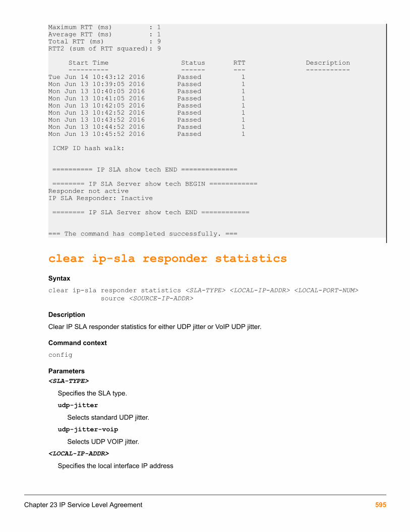
Maximum RTT (ms) : 1Average RTT (ms) : 1Total RTT (ms) : 9RTT2 (sum of RTT squared): 9
Start Time Status RTT Description ---------- ------ --- -----------Tue Jun 14 10:43:12 2016 Passed 1Mon Jun 13 10:39:05 2016 Passed 1Mon Jun 13 10:40:05 2016 Passed 1Mon Jun 13 10:41:05 2016 Passed 1Mon Jun 13 10:42:05 2016 Passed 1Mon Jun 13 10:42:52 2016 Passed 1Mon Jun 13 10:43:52 2016 Passed 1Mon Jun 13 10:44:52 2016 Passed 1Mon Jun 13 10:45:52 2016 Passed 1
ICMP ID hash walk:
========== IP SLA show tech END ==============
======== IP SLA Server show tech BEGIN ============ Responder not activeIP SLA Responder: Inactive
======== IP SLA Server show tech END ============
=== The command has completed successfully. ===
clear ip-sla responder statisticsSyntaxclear ip-sla responder statistics <SLA-TYPE> <LOCAL-IP-ADDR> <LOCAL-PORT-NUM> source <SOURCE-IP-ADDR>
Description
Clear IP SLA responder statistics for either UDP jitter or VoIP UDP jitter.
Command contextconfig
Parameters<SLA-TYPE>
Specifies the SLA type.
udp-jitterSelects standard UDP jitter.
udp-jitter-voipSelects UDP VOIP jitter.
<LOCAL-IP-ADDR>
Specifies the local interface IP address
Chapter 23 IP Service Level Agreement 595

<LOCAL-PORT-NUM>
Specifies the local interface port number. Range: 1024 to 65535.
<SOURCE-IP-ADDR>
Specifies the Source IP address.
Examples
Clear IP SLA responder statistics for UDP jitter:
switch(config)# clear ip-sla responder statistics udp-jitter 1.1.1.1 1100 source 1.1.1.2
Validation rulesValidation Error/Warning/Prompt
Enabling SLA without configuring SLA type. Cannot enable IP SLA, no valid source/destination configured.
IP address given for source or destination ismulticast or broadcast.
Invalid IP address.
Configure the SLA type with a source IP whichis configured in the same switch.
Destination IP cannot be configured as the same as one of thelocal interface IP addresses.
Configure threshold with invalid value. Invalid threshold count value. For threshold type 'Immediate',count must be 1 and for 'Consecutive', count must be greaterthan or equals to 2.
Configure threshold value for 'PacketLoss' or'TestCompletion'
Configuration is not applicable when threshold is configuredfor 'PacketLoss' or 'TestCompletion'.
Configure threshold type for TestCompletion. Configuration is not applicable when threshold is configuredfor 'TestCompletion'.
Configure schedule with proper end time with afrequency which is out of end time.
Invalid endtime. Endtime is not enough to run the tests forconfigured frequency and repetitions.
Configuring ‘srcTodstTime’ or ‘dstTosrcTime’threshold configuration for ‘icmp-echo’ or ‘tcp-connect’.
Invalid threshold configuration for configured SLA type.
Enabling the IP SLA which is already in enabledstate.
IP SLA is already enabled.
Disabling the IP SLA which is already indisabled state.
IP SLA is already disabled.
Show IP SLA history of un-configured SLA. IP SLA is not configured for this ID.
Enable more number (currently decided 50 aslimit) of IP SLA.
Maximum number of enabled IP SLAs at a time is limited to50.
Table Continued
596 Aruba 2930F / 2930M Management and Configuration Guide for ArubaOS-Switch 16.05

Validation Error/Warning/Prompt
Removing IP SLA type/tos/history size/schedule/ threshold configuration with un-configured value.
IP SLA configuration does not exist.
Configuring scheduler with a frequency valuewhich is not satisfying the condition frequency >number of packets per probe * packet interval.
Frequency value is insufficient to configure the scheduler.
Scheduler already configured and try toconfigure SLA type with a value of ‘number ofpackets per probe’ and ‘packet interval’ which isnot satisfying the condition frequency > numberof packets per probe * packet interval.
Number of packets/packet interval is insufficient to configureIP SLA type.
Configuring IP SLA with invalid values. Invalid configuration for IP SLA.
Change the IP SLA configuration when the SLAis enabled.
Configuration changes not allowed when IP SLA is enabled.
When IP address vs port number configured foran SLA is already in use
Error: Socket for configured address, port is already in use,choose different port number
When Source IP address given in SLAconfiguration is not configured in the switch
Error: Source IP address is not configured in switch
Invalid SLA ID given in show command Error: Invalid IP SLA ID
Configure SLA more than allowed limit Warning: The maximum number of IP SLAs allowed is 50.
Configure Responder more than allowed limit Error: IP SLA Responder configurations reached max limit. Nomore configurations accepted.
Configure inter-packet interval when number ofpackets to be sent out is one.
Error Not applicable as Number of packets to be sent out is 1.
Upper threshold value is less than lowerthreshold value.
Error: Upper threshold value X is less than lower thresholdvalue Y.
Configure schedule with start time greater thanstop time.
Error: Stop time must be greater than start time.
Configure schedule with past stop time. Error: Stop time must be greater than current time.
Configure schedule with invalid frequencyvalue.
Error: Schedule frequency is out of range. Valid range is 5 to604800.
Configuring history size with invalid value. Error: IP SLA History size is out of range. Valid range is 1–50.
Configuring SLA type with invalid payload value. IP SLA Payload value is out of range. Valid range is 1–1440.
Configuring SLA type with invalid port number. Invalid port number. Valid range is 1024 to 65535.
Table Continued
Chapter 23 IP Service Level Agreement 597

Validation Error/Warning/Prompt
Configure the IPSLA parameters withoutconfiguring SLA type.
No valid IP SLA type configuration found.
Configuring the responder with existing details. IP SLA Responder with same configuration exist.
Configure management VLAN as source VLAN. Error: Not allowed to configure management VLAN as sourceinterface.
Enabling IP SLA without required configurationparameters.
Configuration is incomplete to enable the entry.
Configure IPSLA UDP Jitter/VoIP session whenan OpenFlow custom match mode instance isalready enabled.
Cannot enable IP SLA: Initiator cannot co-exist with OpenFlowcustom Cannot enable IP SLA: Initiator cannot co-exist withOpenFlow custom
Configure UDP Jitter/VoIP IPSLA Initiatorsession with a source IP same as tunnel overlayVLAN
Cannot enable IP SLA: The source VLAN cannot be a tunneloverlay VLAN.
Configure UDP Jitter/VoIP IPSLA Initiatorsession with a source IP same as a servicetunnel endpoint.
Cannot enable IP SLA: The source VLAN cannot be a servicetunnel endpoint.
Event log messagesCause
Event Message
User adds IP SLA endpoint configuration. I 10/28/15 02:47:12 05020 ipsla: The IP SLA 1 ofSLA Type: UDP-Echo, Source IPv4 Address:10.0.0.1, Destination IPv4 Address: 10.0.0.5,Destination Port: 54563 added.
User removes the endpoint configuration. I 10/28/15 02:47:12 05021 ipsla: The IP SLA 1 ofSLA Type: UDP-Echo, Source IPv4 Address:10.0.0.1, Destination IPv4 Address: 10.0.0.5,Destination Port: 54563 removed.
When the SLA state changes (can be either systeminitiated or done by the user)
I 10/28/15 01:42:22 05027 ipsla: IP SLA 1 statechanged to Expired.I 10/28/15 01:42:22 05021 ipsla:IP SLA 1 state changed to Enabled.I 10/28/1501:42:22 05021 ipsla: IP SLA 1 state changed toScheduled.I 10/28/15 01:42:22 05021 ipsla: IP SLA1 state changed to Admin-disabled.
User configures a responder I 10/28/15 01:42:22 05025 ipsla: IP SLA responderconfigured for SLA Type: TCP-Connect, ListenAddress: 10.0.0.7, Listen Port: 38425
Table Continued
598 Aruba 2930F / 2930M Management and Configuration Guide for ArubaOS-Switch 16.05

Event Message
User removes a responder I 10/28/15 01:42:22 05026 ipsla: IP SLA responderremoved for SLA Type: TCP-Connect, ListenAddress: 10.0.0.7, Listen Port: 38425
SLA test results cross configured threshold I 10/28/15 01:42:22 05022 ipsla: IP SLA 1, thresholdis crossed. Monitored Param: RTT, Threshold Type:immediate, Upper threshold: 500, Lower threshold:100, Action Type: Trap and Log. Actual Threshold:600
User adds DNS IP-SLA configuration I 08/09/16 02:47:12 05029 ipsla: The IP SLA 1 ofSLA Type: DNS, Name server IPv4 Address:10.0.0.1, Target Hostname: a.hp.com added
User removes DNS IP-SLA configuration I 08/09/16 02:47:12 05030 ipsla: The IP SLA 1 ofSLA Type: DNS, Name server IPv4 Address:10.0.0.1, Target Hostname: a.hp.com removed.
The packet loss threshold for the SLA has reached I 08/09/16 02:47:12 05023 ipsla: The IP SLA 1 ofSLA Type: DNS, Packet loss is observed. Thresholdtype: immediate, Action type: Trap and Log
The SLA test has completed and the thresholdconfig for test completion is present
I 08/09/16 02:47:12 05024 ipsla: The IP SLA 1,Probe for SLA Type: UDP-Echo, Source IPv4Address:1.1.1.2, Destination IPv4 Address:1.1.1.3,Destination Port:3000 Completed
TCP-Connect Duplicate configuration is present W 08/09/16 02:47:12 05028 ipsla: Duplicateconfiguration detected; the IP SLA 10 configurationis the same as the IP SLA 1. For TCP, 4-tuplecombination has to be unique.
User adds DHCP SLA configuration I 08/09/16 02:47:12 05031 ipsla: The IP SLA 1 ofSLA Type: DHCP, Vlan: 1 added.
User removes DHCP SLA configuration I 08/09/16 02:47:12 05032 ipsla: The IP SLA 1 ofSLA Type: DHCP, Vlan: 1 removed.
DHCP SLA test has completed and the thresholdconfig for test completion is present
I 08/09/16 02:47:12 05033 ipsla: The IP SLA 1,Probe for SLA Type: DHCP, Source Vlan : 1Completed
InteroperabilityPacket loss is expected when H3C TCP-CONNECT source, with a frequency less than or equal to10 ms, interoperates with HPE TCP-CONNECT responder.
IP SLA UDP Jitter and Jitter for VoIP
Chapter 23 IP Service Level Agreement 599

OverviewThe UDP Jitter and Jitter for VoIP SLA types enable the user to assess the suitability of the network for voice &video related traffic. These SLA's basically calculate parameters like RTT, one way delay, one way positive andnegative Jitter etc.
The above diagram shows a typical deployment, where voice & video traffic are exchanged between branchoffices of an enterprise over the backbone network. Assessment of the network readiness is always helpful forhosting such services. Parameters like RTT, Jitter and one way delay are a good indicator of network health whichassist a network administrator to diagnose latency related issues in the network. VoIP traffic is generally sensitiveto delays in the network.
Jitter stands for inter-packet delay variance. If the inter-packet delay increases between successive probepackets, jitter is said to be positive. If the inter-packet delay decreases, jitter is said to be negative. Positive jittervalues are undesirable for a network as they indicate increased latencies. A value of 0 jitter is desirable.
Significance of jitterConsider a media player which plays video streams from a server. Assume that packets take 1 second in flight toreach the media player. This means the moment a user requests a video from the server, the very first packet willarrive after one second and successive packets will be sent immediately (ideally). In real world scenarios,intermediate node latencies, different return paths for different packets and network congestion can contribute tovarying delays. To counter such effects, packets are buffered at the media player. The amount of packet bufferingneeded can be derived from the jitter values.
The above analogy is applicable for other voice & video services and can be a good measure toassess the possibility for hosting a service on a network.
Solution components
IP SLA responder
This device receives IP SLA probe packets from a configured initiator, timestamps the frame at a pre-definedlocation in the packet upon receipt and sends the same frame back to the initiator.
IP SLA initiator
This device initiates IP SLA probe packets to multiple destinations each with a certain user configurable packetcontent and periodicity.
600 Aruba 2930F / 2930M Management and Configuration Guide for ArubaOS-Switch 16.05

The initiator timestamps the frame at a pre-defined location before sending the frame out to the configureddestinations and re-timestamps the frame at a different location once it receives the same back from theresponder.
IP SLA measurement engine
This is an application running on the initiator. It processes response frames received from the IP SLA responderand computes one-way delay, jitter and RTT based on the timestamps present in the packet.
This application aggregates this computed information across multiple probe samples and stores this forconsumption by an NMS via SNMP or via the device CLI.
It also supports asynchronous user configurable threshold breach notification to an NMS (via SNMP Traps).
SLA MeasurementsThe following metrics are measured as part of this IP SLA jitter functionality.
One way jitter
One way jitter is defined as the time difference between inter-packets transmit time and inter-packets arrival timein a given direction. This is measured in both the Initiator to Responder direction (referred to as SD jitter) as wellas the Responder to initiator direction (referred to as DS jitter).
Ideally, the jitter in both directions should be 0. A positive value of jitter is bad for VOIP and higher values of jitterwill mean poor conversation quality. This is explained in the illustration below:
Chapter 23 IP Service Level Agreement 601

One way delay
One way delay is defined as the time difference between the Initiator transmitting the frame and the Responderreceiving the frame. This requires the Initiator and the Responder to be time synchronized with the same clockserver. This is explained in the illustration below:
Round trip time
RTT is measured at the initiator on a per packet basis and is as illustrated below:
602 Aruba 2930F / 2930M Management and Configuration Guide for ArubaOS-Switch 16.05
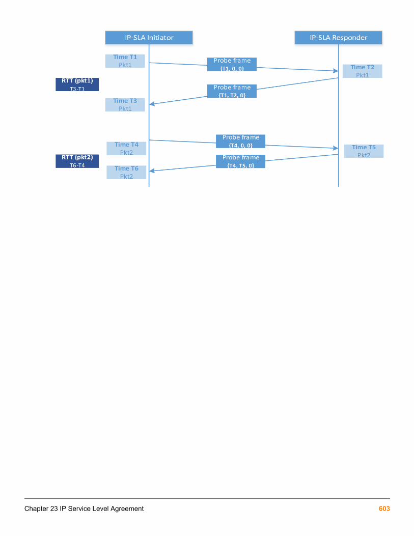
Chapter 23 IP Service Level Agreement 603

Aruba Central Network Management Solution OverviewThe Aruba Central network management solution, a software-as-a-service subscription in the cloud, providesstreamlined management of multiple network devices. Aruba switches are able to talk to Aruba Central and utilizecloud-based management functionality. Cloud-based management functionality allows for the deployment ofnetwork devices at sites with no IT personnel (branch offices, retail stores, and so forth). The communicationchannel used to connect the devices with the cloud portal is outside the control of end users. It adheres tocorporate standards like the use of firewalls.
This feature provides:
• Zero-touch provisioning
• Network Management/Remote monitoring
• Events/alerts notification
• Configuration
• Firmware management
Table 33: Features supported by Aruba Central
Configuration
VLANS Create VLANs
IP address assignment
Tag/Untag
Ports Admin status [Up/Down]
PoE [ Enable/Disable for an interface]
UserManagement
Create/delete Operator User
Create Manager user
IP address assignment to Uplink Vlan [ Static to DHCP and vice versa ]
Name server configuration
RCD
Establish a remote console session to Switch
Monitoring
Events
Statistics
Chapter 24Aruba Central integration
604 Aruba 2930F / 2930M Management and Configuration Guide for ArubaOS-Switch 16.05

Firmware Management
Update the switch firmware
Troubleshooting
Execute troubleshooting commands from central
Restricted commands in switch when connected to Central
bootrecopyerasereloadstartup-defaultupgrade-softwaresetupdeleterebootrestoremenuwrite memoryamp-server
Limited Management Interface on switch
WebUIRESTSNMPTR-69Menu
You can provision the switch in Aruba Activate. For more information about provisioning, See Aruba Networks andAirWave Switch Configuration Guide.
LED Blink featureCentral connectivity loss is indicated by LEDs. If connectivity is broken and Aruba-Central is enabled, theUSR/FDX and Locator LEDs will blink. The LEDs will stop blinking once the switch is connected back to Central.
Configuration commands
aruba-centralSyntaxaruba-central {enable | disable | support-mode {enable | disable}}Description
Configure Aruba Central server support. When enabled, and when a server web address has been obtained usingAruba Activate, the system will connect to an Aruba Central server. The system will obtain configuration updatesand most local configuration commands will be disabled. This mode is enabled by default.
Enter support mode to enable all configuration commands. Normally, when the system is connected to an ArubaCentral server, the configuration is updated from that server and most local configuration commands are disabled.
Chapter 24 Aruba Central integration 605

Support mode enables those commands for use in troubleshooting problems. Support mode is disabled bydefault. When the system is not connected to Aruba Central server, the full command set is enabled for localconfiguration.
Restrictions
• Switch communication to Aruba Central is not supported via OOBM.
• Aruba-central is not supported in FIPS switches and it will be disabled by default.
• Aruba-central is not supported in Stack switches and it will be disabled by default.
To avoid broadcast storm or loops in your network while configuring ZTP, do not have redundant linksafter you complete ZTP and Airwave registration. Authorize the new switch and then push theGolden Configuration template from Airwave.
Example
Enable Aruba Central server support
switch(config)# aruba-central enableDisable Aruba Central server support
switch(config)# aruba-central disableEnter support mode to enable all CLI configuration commands
switch(config)# aruba-central support-mode enable
This mode will enable all CLI configuration commands, including those normally reserved by the Aruba Centralservice. Use of this mode may invalidate the configuration provisioned through Aruba Central server.Continue (y/n)?
Show commands
show aruba-centralSyntaxshow aruba-centralDescription
Show Aruba Central server information.
show aruba-central
switch# show aruba-central
Configuration and Status - Aruba Central Server URL : https://hpsw-jenkins-soa-qa-build-1404-250.test.pdt1.arubathena.com/ws Connected : Yes Mode : Managed Last Disconnect Time : Tue Jun 14 16:01:15 2016
Activating ArubaOS-Switch Firmware IntegrationCLIs are available for Activate firmware updates which enables, update, checks and shows firmware upgrades.
606 Aruba 2930F / 2930M Management and Configuration Guide for ArubaOS-Switch 16.05

Operating Notes
Switch will periodically check with Activate every seven days for the latest image version.
Download the image from the URL provided by Activate and upgrade the switch with the new image.
Restrictions
When a switch is managed by either AirWave or Central, the automatic firmware check is disabled. The manualfirmware check is available.
Activate upgrade from the non-supported build is disabled upon upgrading to version 16.03.
Upon upgrade from version 16.02 to version 16.03 with activate provision enabled, activate software update willbe enabled.
activate software-update enable
Syntaxactivate software-update [enable | disable]
Description
Enables or disables the Activate software update.
Activate software-update is enabled by default.
Optionsdisable
Disables the Activate software update.enable
Enables the Activate software update.
Example
Switch will check with activate for every seven days for latest image available and RMON logs will be generated:
I 10/25/16 14:04:27 05219 activate: A system software update is available to version WB.16.02.0012.
activate software-update check
Syntaxactivate software-update check
Description
Check the Activate software update manually.
Chapter 24 Aruba Central integration 607

Example
switch(config)$# activate software-update check
Configuration and Status - Activate Software Update
Activate Server Address : device.arubanetworks.com Activate Server Polling : Enabled Installed Software Version : WB.16.04.0000x Server Software Version : Not available - server communication error. Server Software Image URL : Not available - server communication error.switch(config)$
This switch is not connected to Activate, hence communication error is shown in “Server SoftwareVersion” and “Server Software Image URL” field.
activate software-update updateSyntaxswitch#(config) activate software-update updateDescription
Updates the software for Activate.
Optionsprimary
Update primary software image using the Aruba Activate server.
secondary
Update secondary software image using the Aruba Activate server.
Example
switch# activate software-update update
This command will save the current configuration,update the selected software image, and reboot thesystem to the selected partition.
Continue (y/n)? y
000M
show activate software-update
Syntaxshow activate software-update
Description
Show the configuration and status of the Activate software update.
Example output
switch(config)$ show activate software-update
Configuration and Status - Activate Software Update
608 Aruba 2930F / 2930M Management and Configuration Guide for ArubaOS-Switch 16.05

Activate Server Address : device.arubanetworks.com Activate Server Polling : Enabled Installed Software Version : WB.16.04.0000x Server Software Version : Not available - server communication error. Server Software Image URL : Not available - server communication error.switch(config)$
Chapter 24 Aruba Central integration 609

OverviewAuto device detection
The command device-profile enables the user to define profiles and configure the associations of profiles toeach device type. By creating a device profile, parameters will be defined for a connection interface by devicetype. To configure each parameter under a profile name, a context level is provided.
The command device-profile name <PROFILE NAME> configures for the default values. The default valueis permissible when no user-defined profile is created.
To associate each device type with a device profile, a context level is created which authorizes the user to enableor disable the profile by device-type. Only the device type aruba-ap is supported.
Rogue AP isolation
The command rogue-ap-isolation configures each device and blocks, logs, or allows a rogue AP whendetected. The command enables or disables rogue AP isolation.
The command clear rogue-ap-isolation is provided to clear the detected rogue AP device MAC address.
Show commands are provided to display the configuration and status of the profiles. Another show command willdisplay the list of rogue APs detected.
Jumbo frames on a device port
Configure jumbo frame support for the device port. Jumbo frames are not permissible by default.
Enabling jumbo frame support in a profile might affect other ports with different profiles. When a profile has jumboframe enabled and is applied to any port, all other ports that are members of any VLAN listed in the profile willalso have jumbo frame support.
Configuration commands
allow-jumbo-framesSyntaxallow-jumbo-framesDescription
Configure jumbo frame support for the device port. Jumbo frames are not enabled by default.
Enabling jumbo frame support in a profile affects other ports with different profiles. When a profile has jumboframes enabled and is applied to any port, all other ports that are members of any VLAN listed in the profile willalso have jumbo frame support.
Chapter 25Easing Wired/Wireless Deployment feature integration
610 Aruba 2930F / 2930M Management and Configuration Guide for ArubaOS-Switch 16.05

Validation rules
Validation Error/Warning/Prompt
Invalid jumbo command. Invalid input.
If jumbo frame support is configured on a VLAN forwhich the device profile had overridden theconfiguration, display the existing warning.
This configuration change will be delayed because adevice profile that enables jumbo frame support isapplied to a port in this VLAN.
Default AP ProfileCreates a user-defined profile.
The profile name is a valid character string with the maximum permissible length of 32. The default profile isnamed default-ap-profile and cannot be modified.
The default configuration parameters may be modified using the command device-<PROFILE NAME>default-ap-profile . Up to four different profiles may be configured.
The [no] command removes the user-defined profiles.
device-profileFrom within the configure context:
Syntaxdevice-profile <PROFILE-NAME> <DEVICE-TYPE> Description
Create port configuration profiles and associate them with devices. When a configured device type is connectedon a port, the system will automatically apply the corresponding port profile. When the device is disconnected, theprofile is removed after a 2 minute delay. Connected devices are identified using LLDP.
Options
<PROFILE-NAME>
Specify the name of the profile to be configured.
<DEVICE-TYPE>
Specify an approved device-type to configure and attach a profile to.
Parameters
allow-jumbo-frames
Configure jumbo frame support for the device port.
untagged-vlan <VLAN-ID>
Configure this port as an untagged member of specified VLAN.
tagged-vlan <VLAN-LIST>
Configure this port as a tagged member of the specified VLANs.
cos <COS-VALUE>
Configure the Class of Service (CoS) priority for traffic from the device.
Chapter 25 Easing Wired/Wireless Deployment feature integration 611
ingress-bandwidth <PERCENTAGE>
Configure ingress maximum bandwidth for the device port.
egress-bandwidth <PERCENTAGE>
Configure egress maximum bandwidth for the device port.
poe-max-power <WATTS>
Configure the maximum PoE power for the device port (in watts).
poe-priority
Configure the PoE priority for the device port.
Usage[no] device-profile name <PROFILE-NAME> [no] device-profile type <DEVICE>
Associating a device with a profileTo associate an Aruba access point (AP) device-type to a user-defined profile, use the context HPESwitch(device-aruba-ap)#. All Aruba access points use the identifier aruba-ap.
The [no] form of the command removes the device type association and disables the feature for the device type.
The feature is disabled by default.
device-profile typeFrom within the configure context:
Syntax
device-profile type <DEVICE> [associate <PROFILE-NAME> | enable | disable ]Description
This command specifies an approved device type in order to configure and attach a profile to it. The profile’sconfiguration is applied to any port where a device of this type is connected.
Approved device types
aruba-ap
Aruba access point device.
Options
From within the device-aruba-ap context
associate <PROFILE-NAME>
Associated the specified device type by profile name.
enable
Enables the automatic profile association.
disable
Disables the automatic profile association.
612 Aruba 2930F / 2930M Management and Configuration Guide for ArubaOS-Switch 16.05
Usage[no] device-profile type <DEVICE> [associate <PROFILE-NAME> |enable | disable] Restrictions
Only one device type is supported, aruba-ap, and it is used to identify all the Aruba access points.
Configuring the rogue-ap-isolation commandUsed to configure the rogue-ap-isolation command. A block/log option may be configured for when a rogueAP is identified by the switch. The block/log option may be enabled or disabled. The default action is to block arogue AP.
The whitelist command is used to configure any specific MAC addresses excluded from the rogue AP list. Thewhitelist configuration is saved in the configuration. The whitelist supports 128 MACs.
The [no] form the command is used to remove the MAC address individually by specifying the MAC.
rogue-ap-isolationWithin the configure context:
Syntaxrogue-ap-isolationDescription
Configure rogue AP isolation and rogue AP Whitelist MAC addresses for the switch. When enabled, the systemdetects the MAC address of rogue access points and takes the specified action for traffic or from that address.The whitelist is used to add MAC addresses of approved access points to the whitelist.
Options
action
Configure the action to take for rogue AP packets. Actions available are enable, disable, block, log, andwhitelist.
block
Block and logs traffic to or from any rogue access points.
log
Log traffic to or from any rogue access points.
enable
Enable the rogue AP Isolation.
disable
Disable the rogue AP Isolation.
whitelist <MAC-ADDRESS>
Configures rogue AP Whitelist MAC addresses for the switch. This option is used to add MAC addresses ofapproved access points to the whitelist.
<MAC-ADDR>
Specify the MAC address of the device to be moved from the Rogue AP list to the whitelist.
Chapter 25 Easing Wired/Wireless Deployment feature integration 613

Usagerogue-ap-isolation [enable | disable]rogue-ap-isolation action [log | block][no] rogue-ap-isolation whitelist <MAC-ADDRESS>
VXLAN show commandsVXLAN show commands include commands to display the status of a VXLAN feature, tunnels, and tunnelstatistics.
show device-profileSyntax
Within the configure context:
show device-profileDescription
Show device profile configuration and status.
config
Show the device profile configuration details for a single, or all, profiles.
status
Show currently applied device profiles.
Usageshow device-profile config <PROFILE-NAME> show device-profile status
show device-profile config
Switch# Show device-profile config Device Profile Configuration Configuration for device profile : default-ap-profile untagged-vlan : 1 tagged-vlan : None ingress-bandwith : 100% egress-bandwith : 100% cos : 0 speed-duplex : auto poe-max-power : 33W poe-priority : High allow-jumbo-frames: Enabled
Configuration for device profile : profile1 untagged-vlan : 10 tagged-vlan : 40,50,60 ingress-bandwith : 10% egress-bandwith : 95% cos : 4 speed-duplex : auto-10
614 Aruba 2930F / 2930M Management and Configuration Guide for ArubaOS-Switch 16.05
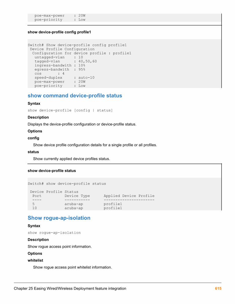
poe-max-power : 20W poe-priority : Low
show device-profile config profile1
Switch# Show device-profile config profile1 Device Profile Configuration Configuration for device profile : profile1 untagged-vlan : 10 tagged-vlan : 40,50,60 ingress-bandwith : 10% egress-bandwith : 95% cos : 4 speed-duplex : auto-10 poe-max-power : 20W poe-priority : Low
show command device-profile statusSyntaxshow device-profile [config | status]Description
Displays the device-profile configuration or device-profile status.
Options
config
Show device profile configuration details for a single profile or all profiles.
status
Show currently applied device profiles status.
show device-profile status
Switch# show device-profile status
Device Profile Status Port Device Type Applied Device Profile ---- ----------- ---------------------- 5 aruba-ap profile1 10 aruba-ap profile1
Show rogue-ap-isolationSyntaxshow rogue-ap-isolationDescription
Show rogue access point information.
Options
whitelist
Show rogue access point whitelist information.
Chapter 25 Easing Wired/Wireless Deployment feature integration 615

Usageshow rogue-ap-isolation whitelist
show rogue-ap-isolation
Switch# show rogue-ap-isolation
Rogue AP Isolation Rogue AP Status : Enable Rogue AP Action : Block Rogue AP MAC Neighbor Device ----------------- ----------------- 11:22:33:44:55:66 00:12:34:56:67:89 aa:bb:cc:dd:ee:ff 00:98:45:56:67:89
show rogue-ap-isolation whitelist
Switch# show rogue-ap-isolation whitelist
Rogue AP Whitelist Configuration Rogue AP MAC ----------------- 11:22:33:44:55:66 aa:bb:cc:dd:ee:ff
616 Aruba 2930F / 2930M Management and Configuration Guide for ArubaOS-Switch 16.05

OverviewThis feature supports secure communication between ArubaOS-Switches and the Aruba mobility controller (VPNconcentrator) for Network Management Server (AirWave) traffic. The switch also provides the necessary supportfor Zero Touch Provisioning (ZTP) by establishing a secure tunnel between an ArubaOS-Switch and the NetworkManagement Server (AirWave) which are provided for by a DHCP Server or Activate.
IPsec ensures that communication between ArubaOS-Switch-based switches and AirWave Server (managementtraffic) is protected by establishing a secure channel between the switches and the Aruba VPN Controller(connected to AirWave server).
Applicable productsAruba 2930F Switch Series (JL253A, JL254A, JL255A, JL256A, JL259A, JL260A, JL261A, JL262A, JL263A,JL264A, JL258A)Aruba 2930M Switch Series ( JL319A, JL320A, JL321A, JL322A)
AirWave detailsZTP discovers switches in their respective management stations (AirWave) during initial boot up which enablesthe automatic configuration and management of the switches.
• ZTP checks if AirWave details are provided along with IP via DHCP.
If AirWave details are missing from DHCP, ZTP will try to connect to Activate to receive AirWave details.
IPsec for Management TrafficIPsec provides support for Zero Touch Provisioning in deployment scenarios less restrictive than private LANs.This enables switches to be configured and managed automatically without administrator intervention. In adeployment scenario where a switch and AirWave are located in different branches connected via an untrustedpublic network (the Internet), communication between the switch and the AirWave server is now protected.
IPsec Tunnel Establishment
• IPsec tunnel for AirWave is auto-configured. The switch decides to create IPSec tunnel only when an Arubacontroller IP is present in the device before establishing the connection to AirWave.
• If the controller IP is not provided, the switch will try to establish a direct connection to AirWave.
• If the controller IP is present, the ArubaOS-Switch auto configures and initiates an IPsec tunnel interface.Once the tunnel is established, the Aurba controller provides an inner IP which the switch will then use assource IP to send any AirWave bound traffic. The switch then creates a static route to AirWave with the IPsectunnel interface as the gateway.
IPSec Tunnel FailuresThe following behaviors can cause an IPSec tunnel creation failure:
Chapter 26IPSec for AirWave Connectivity
Chapter 26 IPSec for AirWave Connectivity 617

• Time
The time in the switch has to be valid and correct. Time issues have been observed on the Aruba 2930FSwitches.
• Authentication
The switch MAC addresses for both members must be added to the Aruba controller whitelist.
• Controller IP
The controller IP must be reachable from the switch.
• Static Route
There must not be any conflicting static route in the system for the AirWave IP configured.
AirWave IP after discoveryAirwave IP and Aruba Controller IP (either from the Activate Server or from a DHCP server) are established andauto configured in an IPSEC-IPv4 Tunnel. Once received, the IPsec tunnel is auto configured and established tosend Airwave traffic securely. The Aruba Controller provides an inner-ip to the switch which then cancommunicate with Airwave.
Configuring the Aruba controllerOn the Aruba Controller, configure via CLI:
Procedure
1. Disable control-plane-security (CPSEC).
control-plane-securityno cpsec-enable
2. Add the switch MAC address to whitelist and for authentication.
whitelist-db rap add mac-address <Switch Mac add> ap-group default [remote-ip <ipaddress for Switch>]local-userdb add username <Switch Mac Add> password <switch mac add>
3. Add an IP address pool that can be assigned to switch after tunnel creation. IP range must be in the samesubnet through which AirWave is reachable from Controller.
ip local pool "ipsec" 2.0.0.100 2.0.0.2554. Create access lists that permit AirWave traffic and assign them to ap-roles.
ip access-list session hpe-aclany any tcp 22 permitany any tcp 443 permit !user-role ap-roleaccess-list session hpe-acl !
5. View the whitelist.show whitelist-db cpsec
618 Aruba 2930F / 2930M Management and Configuration Guide for ArubaOS-Switch 16.05

(host) #show whitelist-db cpsec ap-group <ap_group> ap-name <ap_name> cert-type {factory-cert|switch-cert} mac-address <name> page <num> start <offset> state {approved-ready-for-cert|certified-factory-cert| unapproved-factory-cert|unapproved-no-cert}show whitelist-db cpsec-status
(host) #show whitelist-db cpsec-status(host) #show whitelist-db rap apgroup <rap-group> apname <rap-name> fullname <rap-fullname> long mac-address <mac-address> page <page-number> start <offset>show whitelist-db rap-status
(host) #show whitelist-db rap-statusshow ip interface brief
(Aruba7210) #show ip interface brief
Interface IP Address / IP Netmask Admin Protocol VRRP-IP (VRRP-Id)vlan 1 172.16.0.254 / 255.255.255.0 up up none (none)vlan 30 30.30.30.2 / 255.255.255.0 up up none (none)vlan 17 17.0.0.5 / 255.255.255.0 up up none (none)loopback unassigned / unassigned up upshow vlan
(Aruba7210) #show vlan
VLAN CONFIGURATION------------------VLAN Description Ports AAA Profile---- ----------- ----- -----------1 Default GE0/0/2-0/5 Pc0-7 N/A17 VLAN0017 GE0/0/1 N/A30 VLAN0030 GE0/0/0 N/Aamp ip is : 30.30.30.1show running-config | begin "0/0/0"
#show running-config | begin "0/0/0"(Aruba7210) #show running-config | begin "0/0/0"interface gigabitethernet 0/0/0 description "GE0/0/0" trusted trusted vlan 1-4094 switchport access vlan 30
Chapter 26 IPSec for AirWave Connectivity 619
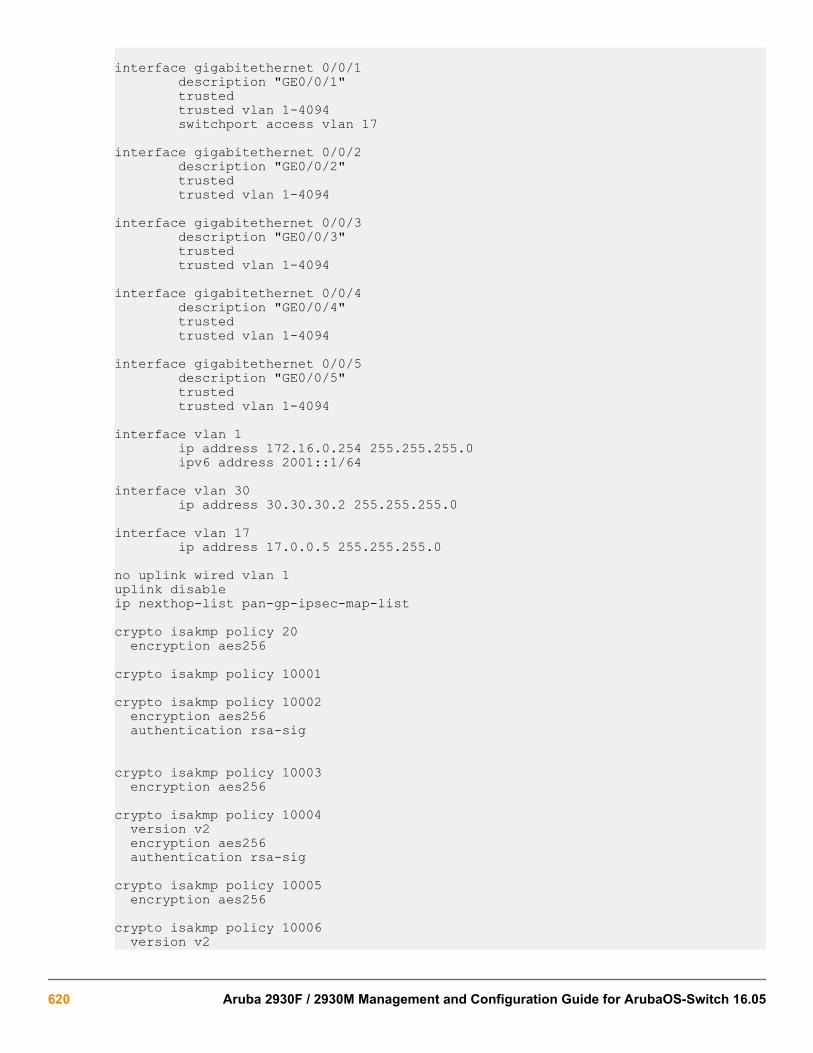
interface gigabitethernet 0/0/1 description "GE0/0/1" trusted trusted vlan 1-4094 switchport access vlan 17
interface gigabitethernet 0/0/2 description "GE0/0/2" trusted trusted vlan 1-4094
interface gigabitethernet 0/0/3 description "GE0/0/3" trusted trusted vlan 1-4094
interface gigabitethernet 0/0/4 description "GE0/0/4" trusted trusted vlan 1-4094
interface gigabitethernet 0/0/5 description "GE0/0/5" trusted trusted vlan 1-4094
interface vlan 1 ip address 172.16.0.254 255.255.255.0 ipv6 address 2001::1/64
interface vlan 30 ip address 30.30.30.2 255.255.255.0
interface vlan 17 ip address 17.0.0.5 255.255.255.0
no uplink wired vlan 1uplink disableip nexthop-list pan-gp-ipsec-map-list
crypto isakmp policy 20 encryption aes256
crypto isakmp policy 10001
crypto isakmp policy 10002 encryption aes256 authentication rsa-sig
crypto isakmp policy 10003 encryption aes256
crypto isakmp policy 10004 version v2 encryption aes256 authentication rsa-sig
crypto isakmp policy 10005 encryption aes256
crypto isakmp policy 10006 version v2
620 Aruba 2930F / 2930M Management and Configuration Guide for ArubaOS-Switch 16.05

encryption aes128 authentication rsa-sig
crypto isakmp policy 10007 version v2 encryption aes128
crypto isakmp policy 10008 version v2 encryption aes128 hash sha2-256-128 group 19 authentication ecdsa-256 prf prf-hmac-sha256
crypto isakmp policy 10009 version v2 encryption aes256 hash sha2-384-192 group 20 authentication ecdsa-384 prf prf-hmac-sha384
crypto isakmp policy 10012 version v2 encryption aes256 authentication rsa-sig
crypto isakmp policy 10013 encryption aes256
crypto ipsec transform-set default-ha-transform esp-3des esp-sha-hmaccrypto ipsec transform-set default-boc-bm-transform esp-aes256 esp-sha-hmaccrypto ipsec transform-set default-1st-ikev2-transform esp-aes256 esp-sha-hmaccrypto ipsec transform-set default-3rd-ikev2-transform esp-aes128 esp-sha-hmaccrypto ipsec transform-set default-rap-transform esp-aes256 esp-sha-hmaccrypto ipsec transform-set default-aes esp-aes256 esp-sha-hmaccrypto dynamic-map default-rap-ipsecmap 10001
version v2 set transform-set "default-gcm256" "default-gcm128" "default-rap-transform"
crypto dynamic-map default-dynamicmap 10000 set transform-set "default-transform" "default-aes"
crypto map GLOBAL-IKEV2-MAP 10000 ipsec-isakmp dynamic default-rap-ipsecmapcrypto map GLOBAL-MAP 10000 ipsec-isakmp dynamic default-dynamicmapcrypto isakmp eap-passthrough eap-tlscrypto isakmp eap-passthrough eap-peapcrypto isakmp eap-passthrough eap-mschapv2
ip local pool "ipsec" 30.30.30.100
AirWave Controller IP configuration commands
aruba-vpn typeFrom within the configure context:
Chapter 26 IPSec for AirWave Connectivity 621

Syntaxaruba-vpn type amp peer-ip <ip-addr> no aruba-vpn type amp peer-ip <ip-addr>Description
Configure the Aruba VPN type, peer IP address.
The no form of the command removes the aruba-vpn type statement from the configuration.
Optionsamp
Configure the AirWave Management Platform (AMP) server.
typeConfigure the controller IP.
<ip-addr>
IP address of the VPN.
Usageswitch(config)# aruba-vpn typeswitch(config)# aruba-vpn type ampswitch(config)# aruba-vpn type amp peer-ip
Show commands
show aruba-vpnSyntaxshow aruba-vpn type <VPN-TYPE> Description
Show Aruba-VPN configuration information.
Switch(config)# show aruba-vpn
show aruba-vpn Aruba VPN details Aruba VPN Type : amp Aruba VPN Peer IP : 171.0.0.3 Aruba VPN Config Status : Configured Aruba VPN tos : Value from IPv4 header Aruba VPN ttl : 64
show aruba-vpn type amp
show aruba-vpn type amp
622 Aruba 2930F / 2930M Management and Configuration Guide for ArubaOS-Switch 16.05

Aruba VPN details Aruba VPN Type : amp Aruba VPN Peer IP : 2.2.2.2 Aruba VPN Config Status : Configured Aruba VPN tos : 32 Aruba VPN ttl : 54
show ip routeSyntaxshow ip routeDescription
Show the IP route.
show ip route
IP Route Entries Destination Gateway VLAN Type Sub-Type Metric Dist. ------------------ --------------- ---- --------- ---------- ---------- ----- 0.0.0.0/0 192.168.20.31 1 static 250 1 2.0.0.25/32* aruba-vpn connected 1 0 2.0.0.199/32** aruba-vpn static 1 1 127.0.0.0/8 reject static 0 0 127.0.0.1/32 lo0 connected 1 0 192.168.20.0/24 DEFAULT_VLAN 1 connected 1 0*The inner IP received from the Aruba Controller.
**Static Route for Airwave IP. Added automatically by the switch after tunnel establishment.
show interfaces tunnel aruba-vpnSyntaxshow interfaces tunnel aruba-vpnDescription
Auto-configured tunnel interface before creating IPSec. The tunnel ID is auto generated and to avoid conflict withuser generated tunnel interface, the tunnel id is always the max tunnel supported by the switch + 1.
aruba-vpn
Display the configuration and status details of aruba-vpn tunnel.
brief
Display brief configuration and status for all tunnels.
Usageshow interfaces tunnel aruba-vpnshow interfaces tunnel briefshow interfaces [tunnel] [<TUNNEL-LIST> | <TUNNEL-NAME> | brief | type]
Chapter 26 IPSec for AirWave Connectivity 623

show interfaces tunnel aruba-vpn
Aruba-3810M-24G-PoEP-1-slot(config)# show interfaces tunnel aruba-vpn Tunnel Configuration : Tunnel : tunnel-129 Tunnel Name : aruba-vpn-tunnel Tunnel Status : Enabled Source Address : 17.0.0.30 Destination Address : 17.0.0.5 Mode : IPsec IPv4 TOS : Value from IPv4 header TTL : 64 IPv6 : Disabled MTU : 1280
Current Tunnel Status : Tunnel State : Up Destination Address Route : 17.0.0.0/24 Next Hop IP : 17.0.0.5 Next Hop Interface : vlan-1 Next Hop IP Link Status : Up Source Address : Configured on vlan-1 IP Datagrams Received : 9732 IP Datagrams Transmitted : 13129
show interfaces tunnel brief
Aruba-3810M-24G-PoEP-1-slot(config)# show interfaces tunnel brief Status - Tunnel Information Brief Tunnel : tunnel-129 Mode : IPsec IPv4 Source Address : 17.0.0.30 Destination Address : 17.0.0.5 Configured Tunnel Status : Enabled Current Tunnel State : Up
show ip counters tunnel aruba-vpnSyntaxshow ip counters tunnel aruba-vpnDescription
Show IP counters for a tunnel.
Options
aruba-vpn
Show counters for aruba-vpn tunnel.
ipv4
Show IPv4 only.
ipv6
Show IPv6 only.
624 Aruba 2930F / 2930M Management and Configuration Guide for ArubaOS-Switch 16.05

<TUNNEL-ID>
Show specified tunnel only.
Usageshow ip counters tunnel ipv4show ip counters tunnel ipv6show ip counters tunnel <TUNNEL-ID>
show ip counters tunnel aruba-vpn
sh ip counters tunnel Address Family : IPv4Interface : Tunnel 129 IP In Datagrams Received : 2439 IP In Octets Received : 362736 IP In Datagrams Broadcast Received : 0 IP In Octets Broadcast Received : 0 IP In Datagrams Multicast Received : 0 IP In Octets Multicast Received : 0 IP In Datagrams Discarded Datagram Header Error : 0 IP In Datagrams Discarded No Route : 0 IP In Datagrams Discarded Invalid Address : 0 IP In Datagrams Discarded Unknown Protocol : 0 IP In Datagrams Discarded Truncation : 0 IP In Datagrams Discarded Processing Error : 0 IP In Datagrams Forwarding Required : 0 IP In Datagrams Delivery to Protocols Successful : 2439 IP Datagrams Reassembly Required : 0 IP Datagrams Reassembly Successful : 0 IP Datagrams Reassembly Failed : 0 IP Out Datagrams Transmitted : 2514 IP Out Octets Transmitted : 1197348 IP Out Datagrams Broadcast Transmitted : 0 IP Out Octets Broadcast Transmitted : 0 IP Out Datagrams Multicast Transmitted : 0 IP Out Octets Multicast Transmitted : 0 IP Out Datagrams Discarded Processing Error : 0 IP Out Datagrams Forwarded : 0 IP Out Datagrams Transmit Requests from Protocols : 2509 IP Out Datagrams Fragmentation Required : 0 IP Out Datagrams Fragmentation Successful : 5 IP Out Datagrams Fragmentation Failed : 0 IP Out Datagrams Fragments Created : 0
Address Family : IPv6Interface : Tunnel 129 IP In Datagrams Received : 0 IP In Octets Received : 0 IP In Datagrams Broadcast Received : 0 IP In Octets Broadcast Received : 0 IP In Datagrams Multicast Received : 0 IP In Octets Multicast Received : 0 IP In Datagrams Discarded Datagram Header Error : 0 IP In Datagrams Discarded No Route : 0 IP In Datagrams Discarded Invalid Address : 0 IP In Datagrams Discarded Unknown Protocol : 0 IP In Datagrams Discarded Truncation : 0 IP In Datagrams Discarded Processing Error : 0
Chapter 26 IPSec for AirWave Connectivity 625
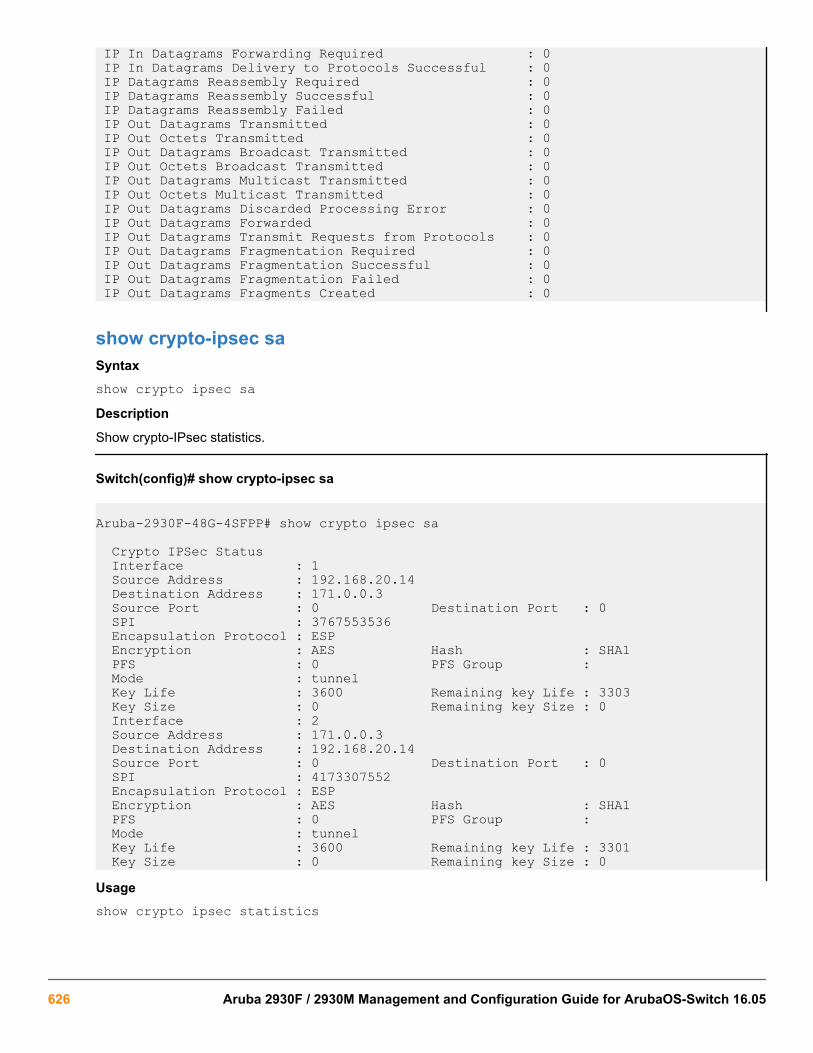
IP In Datagrams Forwarding Required : 0 IP In Datagrams Delivery to Protocols Successful : 0 IP Datagrams Reassembly Required : 0 IP Datagrams Reassembly Successful : 0 IP Datagrams Reassembly Failed : 0 IP Out Datagrams Transmitted : 0 IP Out Octets Transmitted : 0 IP Out Datagrams Broadcast Transmitted : 0 IP Out Octets Broadcast Transmitted : 0 IP Out Datagrams Multicast Transmitted : 0 IP Out Octets Multicast Transmitted : 0 IP Out Datagrams Discarded Processing Error : 0 IP Out Datagrams Forwarded : 0 IP Out Datagrams Transmit Requests from Protocols : 0 IP Out Datagrams Fragmentation Required : 0 IP Out Datagrams Fragmentation Successful : 0 IP Out Datagrams Fragmentation Failed : 0 IP Out Datagrams Fragments Created : 0
show crypto-ipsec saSyntaxshow crypto ipsec saDescription
Show crypto-IPsec statistics.
Switch(config)# show crypto-ipsec sa
Aruba-2930F-48G-4SFPP# show crypto ipsec sa
Crypto IPSec Status Interface : 1 Source Address : 192.168.20.14 Destination Address : 171.0.0.3 Source Port : 0 Destination Port : 0 SPI : 3767553536 Encapsulation Protocol : ESP Encryption : AES Hash : SHA1 PFS : 0 PFS Group : Mode : tunnel Key Life : 3600 Remaining key Life : 3303 Key Size : 0 Remaining key Size : 0 Interface : 2 Source Address : 171.0.0.3 Destination Address : 192.168.20.14 Source Port : 0 Destination Port : 0 SPI : 4173307552 Encapsulation Protocol : ESP Encryption : AES Hash : SHA1 PFS : 0 PFS Group : Mode : tunnel Key Life : 3600 Remaining key Life : 3301 Key Size : 0 Remaining key Size : 0Usageshow crypto ipsec statistics
626 Aruba 2930F / 2930M Management and Configuration Guide for ArubaOS-Switch 16.05

show running-configurationSyntaxshow running-configuration
IP route or tunnel interface will not be displayed in show run as they are auto created.
show running-configuration
show running-configuration
; JL254A Configuration Editor; Created on release #WC.16.02.0000x; Ver #0e:01.b3.ef.7c.5f.fc.6b.fb.9f.fc.f3.ff.37.ef:ab
hostname "Aruba-2930F-48G-4SFPP"module 1 type jl254asnmp-server community "public" unrestricted
vlan 1 name "DEFAULT_VLAN" untagged 1-52 ip address dhcp-bootp exit
amp-server ip 2.0.0.199 group "aw_group" folder "fold" secret "secr"aruba-vpn type amp peer-ip 171.0.0.3
Chapter 26 IPSec for AirWave Connectivity 627

OverviewEvery client is associated with a user role. User roles associate a set of attributes for authenticated clients (clientswith authentication configuration) and unauthenticated clients, applied to each user session. User roles must beenabled globally.
Examples of user roles are:
• Employee = All access
• Contractor = Limited access to resources
• Guest = Browse Internet
Each user role determines the client network privileges, frequency of reauthentication, applicable bandwidthcontracts, and other permissions. There are a maximum of 32 administratively configurable user roles availablewith one predefined and read-only user role called denyall.
A user role consists of optional parameters such as:
• Captive portal profileSpecifies the URL via:
◦ captive-portal profile
or
◦ Vendor Specific Attribute (VSA). RADIUS: HP HP-Captive-Portal-URL = <http://...>
• Ingress user policy
L3 (IPv4 and/or IPv6) ordered list of Classes with actions, with an implicit deny all for IPv4 and IPv6.
• Reauthentication period
The time that the session is valid for. The default is 0 unless the user role is overridden. The default meansthat the reauthentication is disabled.
Reauthentication period is required to override the default of 0.
• Untagged VLAN (either VLAN ID or VLAN-name)
VLAN precedence order behavior:
◦ If configured, untagged VLAN specified in the user role (VSA Derived Role, UDR, or Initial Role).
◦ Statically configured untagged and/or tagged VLANs of the port the user is on.
Operational notes
Chapter 27Local user roles
628 Aruba 2930F / 2930M Management and Configuration Guide for ArubaOS-Switch 16.05

• When user roles are enabled, all users that are connecting on ports where authentication is configured willhave a user role applied. User role application happens even if the user fails to authenticate. If the user cannotbe authenticated, the “Initial Role” will be applied to that user.
• The user role may be applied in one of two ways:
◦ Vendor Specific Attribute (VSA)
Type: RADIUS: Hewlett-Packard-Enterprise
Name: HPE-User-Role
ID: 25
Value: <myUserRole>
The RADIUS server (ClearPass Policy Manager) determines application of the VSA Derived Role. The roleis sent to the switch via a RADIUS VSA. The VSA Derived Role will have the same precedence order asthe authentication type (802.1x, WMA).
◦ User Derived Role (UDR
)The User Derived Role is part of Local MAC authentication (LMA) and is applied when user roles areenabled and LMA is configured.
UDR will have the same precedence as LMA. Precedence behavior of the authentication types will bemaintained, (802.1x -> LMA -> WMA (highest to lowest)).
Restrictions
• User roles cannot be enabled when BYOD redirect, MAC authentication failure redirect, or enhanced web-based authentication are enabled.
• Web-based authentication is not supported on the same port with other authentication methods when userroles are enabled.
• show port-access <AUTH-TYPE> commands are not supported when user-roles are enabled. Thecommand show port-access clients [detail] is the only way to see authenticated clients with theirassociated roles.
• aaa port-access auth <port> control commands are not supported when user roles are enabled.
• unauth-vid commands are not supported when user roles are enabled.
• auth-vid commands are not supported when user roles are enabled.
Limitations for web-based authentication
Cannot be combined with other authentication types on same port.
Limitations for LMA
Reauthentication period and captive portal profile are not supported.
Error messages
Chapter 27 Local user roles 629

Action Error message
Attempting to enable BYOD Redirect when user rolesare enabled.
BYOD redirect cannot be enabled when user roles areenabled.
Attempting to enable MAFR when user roles areenabled.
MAC authentication failure redirect cannot be enabledwhen user roles are enabled.
Attempting to enable enhanced web-basedauthentication when user roles are enabled.
Enhanced web-based authentication cannot beenabled when user roles are enabled.
Attempting to enable web-based authentication whenother authentication types are enabled for the sameport, and user roles are enabled.
Web-based authentication cannot be enabled withother authentication types on this port when user rolesare enabled.
switch (config)# show port-access mac-based clients User roles are enabled. Use show port-access
clients to view client information.
switch (config)# aaa port-accessauthenticator e8 control autho 802.1x control mode, Force Authorized/
Unauthorized, cannot be set when user roles areenabled.
Attempting to enable local user rolewhen MAFR, BYOD, or EWA are enabled. User roles cannot be enabled when BYOD redirect,
MAC authentication failure redirect, or enhanced web-based authentication are enabled.
Captive-portal commands
OverviewThe Captive Portal profile defines the web address that a user is redirected to for Captive Portal authentication. Ifthe url is blank, a RADIUS VSA will be used.
There is a predefined profile called use-radius-vsa that is already configured to use the RADIUSVSA.
Two captive portal profiles are supported:
• Predefined and read-only
Predefined and read-only profile name is use-radius-vsa.
• Customized
[no] aaa authentication captive-portal profileSyntax[no] aaa authentication captive-portal profile <PROFILE-STR> [url <URL-STR>] Description
630 Aruba 2930F / 2930M Management and Configuration Guide for ArubaOS-Switch 16.05

Create a captive-portal profile. Profiles are used in user roles to direct the user to a designated captive portalserver. When the profile includes a web address, that web address is always used to contact the server. When noweb address is specified, it is obtained from the RADIUS VSA.
A profile does not have to be pre-existing in the switch for it to be configured to a user role.
Options
profile
Configure a captive portal profile.
<PROFILE-STR>
Configure a captive portal profile string 64 characters long.
url
Configure the captive portal server web address.
<URL-STR>
Configure the captive portal server web address string.
UsageSwitch# aaa authentication captive-portal profile <NAME> Switch# aaa authentication captive-portal profile <NAME> url <URL>
Validation rules
Validation Error/Message/Prompt
Attempts made to remove a nonexisting profile willreturn an error:
switch# no aaa authentication captive-portal profile NON_EXISTING_PROFILE
Captive portal profileNON_EXISTING_PROFILE not found.
When including the configured web address after theweb address parameter:
[no] aaa authentication captive-portalprofile myCaptivePortalProfile urlhttp://myCPPM.local/guest/captive_portal_login.php
Invalid input: http://blablabla.com
A profile name with invalid syntax produces an error:
Switch# aaa authentication captive-portal-profile “this is an invalid name”
#aaa authentication captive-portal-profile “this is an invalid name”Invalid character ' ' in name.
When trying to modify a profile that is predefined,switch# aaa authentication captive-portal-profile name use-radius-vsa
Captive portal profile use-radius-vsa is read onlyand cannot be modified
Table Continued
Chapter 27 Local user roles 631

Validation Error/Message/Prompt
A profile name that is too long produces an error:
switch# aaa authentication captive-portal-profiletest342...;ldklsdjflkdsjflk
The name must be fewer than 64 characters.
When attempting to configure more than the number ofadmin configured profiles,switch# aaaauthentication captive-portal-profileprofileNumber2
No more captive portal profiles may be created.
Policy commands
OverviewThese commands create a context that may be used to classify the policy. From the existing policy command, anew policy type called user was added. The new actions are specific to policy user:
• redirect
• permit
• deny
Only L3 classes (IPv4 and IPv6) are currently supported.
The user policy includes “implicit deny all rules” for both IPv4 and IPv6 traffic.
policy userSyntaxpolicy user <POLICY-NAME> Description
Create and enter newly created user policy context.
UsageSwitch (config)# policy user employee
[no] policy userSyntax[no] policy user <POLICYNAME> Description
Delete and remove specified user policy from switch configuration.
Operating notes
632 Aruba 2930F / 2930M Management and Configuration Guide for ArubaOS-Switch 16.05

• The user policy will include implicit “deny all” rules for both IPv4 and IPv6 traffic.
• ipv4 or ipv6 classes must specify source address as any. Specifying host addresses or subnets will result inthe following error message:
Switch (policy-user)# class ipv4 class25 action priority 0 User policies cannot use classes that have a source IP address specified.
• permit and deny are mutually exclusive.
• ip-precedence and dscp are mutually exclusive.
Usageswitch (config)# no policy user employee
policy resequenceSyntaxpolicy resequence <POLICYNAME> <START><INCREMENT> Description
Resequence classes and remarks configured within specified user policy. The usage shows resequencing classesand remarks within user policy “employee” starting at 200 and incrementing by 2.
UsageSwitch (config)# policy user employee 200 2
Commands in the policy-user contextCreate classes inside of the policy context before you apply actions to them.
(policy-user)# classWithin the policy-user context:
Syntax(policy-user)# [no] [<SEQUENCE-NUMBER>] class ipv4 | ipv6 <CLASS-NAME> [action permit | deny | redirect captive portal] | [action dscp | ip—precedence <CODEPOINT | PRECEDENCE>] [action priority <PRIORITY>] | [action rate-limit kbps <RATE>] Description
Associate a class with ACL or QoS actions for this policy.
Options
Options
deny
Deny all traffic.
DSCP
Specify an IP DSCP.
IP-precedence
Specify the IP precedence.
Chapter 27 Local user roles 633

permit
Permit all traffic.
priority
Specify the priority.
rate-limit
Configure rate limiting for all traffic.
redirect
Specify a redirect destination.
UsageSwitch(policy-user)# class ipv6 employeeIpv6Http action denySwitch(policy-user)# class ipv4 http action redirect captive-portalSwitch(policy-user)# class ipv4 dnsDhcp action permit
User role configuration
aaa authorization user-roleSyntaxaaa authorization user-role [enable | disable| [initial-role <ROLE-STR>] |[name <ROLE>]] Description
Configure user roles. A user role determines the client network privileges, the frequency of reauthentication,applicable bandwidth contracts, along with other permissions. Every client is associated with a user role or theclient is blocked from access to the network.
Options
enable
Enable authorization using user roles.
disable
Disable authorization using user roles.
initial-role
The default initial role “denyall” is used when no other role applies. If a client connects to the switch and doesnot have a user role associated, then the initial role is used. Any role can be configured as initial role usingthis option. Can be configured at per port level. The per port initial role takes priority over global initial role.
The initial role may be assigned if:
• captive-portal profile is configured with a web address, but the Captive Portal VSA is sent from RADIUS
• captive-portal profile is configured to use the RADIUS VSA but no Captive Portal VSA is sent.
• captive-portal feature is disabled when the captive-portal profile is referenced in the applied user role to theclient.
• The user role feature is enabled with RADIUS authentication, but no user role VSA is returned.
• User role does not exist.
634 Aruba 2930F / 2930M Management and Configuration Guide for ArubaOS-Switch 16.05
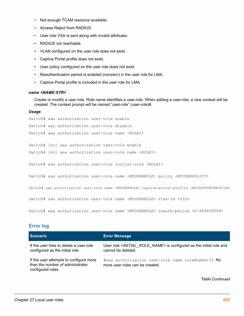
• Not enough TCAM resource available.
• Access-Reject from RADIUS.
• User role VSA is sent along with invalid attributes.
• RADIUS not reachable.
• VLAN configured on the user role does not exist.
• Captive Portal profile does not exist.
• User policy configured on the user role does not exist.
• Reauthentication period is enabled (nonzero) in the user role for LMA.
• Captive Portal profile is included in the user role for LMA.
name <NAME-STR>
Create or modify a user-role. Role name identifies a user-role. When adding a user-role, a new context will becreated. The context prompt will be named “user-role” (user-role)#.
UsageSwitch# aaa authorization user-role enableSwitch# aaa authorization user-role disableSwitch# aaa authorization user-role name <ROLE1> Switch# [no] aaa authorization user-role enableSwitch# [no] aaa authorization user-role name <ROLE1> Switch# aaa authorization user-role initial-role <ROLE1> Switch# aaa authorization user-role name <MYUSERROLE> policy <MYUSERPOLICY> Switch# aaa authorization user-role name <MYUSERROLE> captive-portal-profile <MYCAPTPORTPROFILE> Switch# aaa authorization user-role name <MYUSERROLE> vlan-id <VID> Switch# aaa authorization user-role name <MYUSERROLE> reauth-period <0-999999999>
Error log
Scenario Error Message
If the user tries to delete a user-roleconfigured as the initial role
User role <INITIAL_ROLE_NAME> is configured as the initial role andcannot be deleted.
If the user attempts to configure morethan the number of administratorconfigured roles
#aaa authorization user-role name roleNumber33. Nomore user roles can be created.
Table Continued
Chapter 27 Local user roles 635
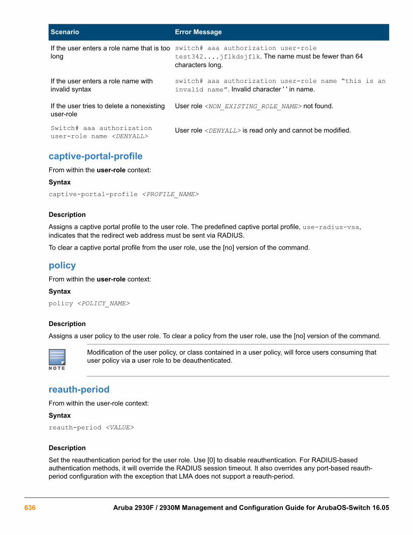
Scenario Error Message
If the user enters a role name that is toolong
switch# aaa authorization user-roletest342....jflkdsjflk. The name must be fewer than 64characters long.
If the user enters a role name withinvalid syntax
switch# aaa authorization user-role name “this is aninvalid name”. Invalid character ' ' in name.
If the user tries to delete a nonexistinguser-role
User role <NON_EXISTING_ROLE_NAME> not found.
Switch# aaa authorizationuser-role name <DENYALL> User role <DENYALL> is read only and cannot be modified.
captive-portal-profileFrom within the user-role context:
Syntaxcaptive-portal-profile <PROFILE_NAME> Description
Assigns a captive portal profile to the user role. The predefined captive portal profile, use-radius-vsa,indicates that the redirect web address must be sent via RADIUS.
To clear a captive portal profile from the user role, use the [no] version of the command.
policyFrom within the user-role context:
Syntaxpolicy <POLICY_NAME> Description
Assigns a user policy to the user role. To clear a policy from the user role, use the [no] version of the command.
Modification of the user policy, or class contained in a user policy, will force users consuming thatuser policy via a user role to be deauthenticated.
reauth-periodFrom within the user-role context:
Syntaxreauth-period <VALUE> Description
Set the reauthentication period for the user role. Use [0] to disable reauthentication. For RADIUS-basedauthentication methods, it will override the RADIUS session timeout. It also overrides any port-based reauth-period configuration with the exception that LMA does not support a reauth-period.
636 Aruba 2930F / 2930M Management and Configuration Guide for ArubaOS-Switch 16.05

Options
<VALUE>
Valid values are 0 – 999,999,999; a required configuration in user roles and it defaults to 0.
(user-role)# reauth-period 100
Set the reauthentication value for the current user role:
(user-role)# reauth-period 100
(user-role)# reauth-period 0
0 is used to disable reauthentication, and it is the default value.
(user-role)# reauth-period 0
Validation rules
Validation Error/Warning/Prompt
(user-role)# reauth-period 10000000 Invalid input: 100000000000000000
VLAN commandsThe VLAN must be configured on the switch at the time the user role is applied. Only one of VLAN-name or VLAN-ID is allowed for any user role.
Modification of the VLAN will force users assigned to that VLAN via a user role to bedeauthenticated.
vlan-idFrom within the user-role context:
Subcommand syntaxvlan-id <VLAN-ID> Description
Create a VLAN with id VLAN-ID.
Use the [no] version of the command when clearing the VLAN-ID from the user role:
Usage(user-role)# no vlan-id
vlan-nameFrom within the user-role context:
Subcommand syntaxvlan-name <VLAN-NAME> Description
Create a VLAN with the name VLAN-NAME. Only one of VLAN-NAME or VLAN-ID is allowed for any user role.
Chapter 27 Local user roles 637

Use the [no] version of the command when clearing the VLAN from the user role, by name:
Usage(user-role)# no vlan-name
vlan-id 100
(user-role)# vlan-id 100
vlan-name vlan100
(user-role)#vlan-name VLAN100
VLAN range commandsThis command is executed from a global configuration context.
VLANs specified by VLAN-ID-LIST
Syntax[no] vlan <VLAN-ID-LIST>
Description
Creates VLANs specified by the VLAN-ID-LIST and returns to the global configuration context. Use the [no]version of the command to delete the VLANs specified by the VLAN-ID-LIST.
Examplesconfig# vlan 2-15config# vlan 5,10,13-20,25config# no vlan 2-10config# no vlan 2,5,15-18,25
VLANs specified by VLAN-ID-LIST and tag specified ports specified by PORT-LIST
Syntax[no] vlan <VLAN-ID-LIST> tagged <PORT-LIST>
Description
Creates VLANs specified by the VLAN-ID-LIST and tags the ports specified by the PORT-LIST to the VLAN-ID-LIST. If VLANs already exist, the tagging of ports specified by the PORT-LIST is performed.
Use the [no] version of the command to remove the tagged PORT-LIST from a range of VLANs specified by theVLAN-ID-LIST. After command execution, CLI returns to the global configuration context.
Examplesconfig# vlan 2-15 tagged A1-A20config# vlan 5,10,13-20,25 tagged A1-A5,L2,L5-L10config# vlan 2-20 tagged allconfig# no vlan 2-15 tagged A1-A5config# no vlan 5,10,13-20 tagged A1-A5,L6
638 Aruba 2930F / 2930M Management and Configuration Guide for ArubaOS-Switch 16.05

Applying a UDRUDR can be used to assign user roles locally (that is, without RADIUS). LMA has been extended to allow applyinga user role to a MAC address, MAC group, MAC mask, or MAC OUI.
aaa port-access local-mac apply user-roleSyntax[no] aaa port-access local-mac apply user-role <Role-Name> [ mac-oui <MAC-OUI> | mac-mask <MAC-MASK> |mac-addr <MAC-ADDR> | mac-group <MAC-GROUP-NAME>]Description
Apply user roles.
Options
mac-addr
To apply user role with MAC address.
mac-group
To apply user role with MAC group.
mac-mask
To apply user role with MAC Mask.
mac-oui
To apply user role with MAC OUI.
Usage[no] aaa port-access local-mac apply user-role <MYUSERROLE> [mac-oui <MAC-OUI>] [no] aaa port-access local-mac apply user-role <MYUSERROLE> [mac-mask <MAC-MASK>] [no] aaa port-access local-mac apply user-role <MYUSERROLE> [mac-addr <MAC-ADDR>] [no] aaa port-access local-mac apply user-role <MYUSERROLE> [mac-group <MAC-GROUP-NAME>]
VXLAN show commandsVXLAN show commands include commands to display the status of a VXLAN feature, tunnels, and tunnelstatistics.
show captive-portal profileSyntaxshow captive-portal profileDescription
Show Captive Portal profile configuration.
Chapter 27 Local user roles 639

show captive-portal profile
(config)# show captive-portal profile
Captive Portal Profile Configuration Name : use-radius-vsa Type : predefined URL : Name : myCaptivePortalProfile Type : custom URL : http://mycppm.local/guest/captive_portal_login.php
show user-roleSyntaxshow user-role [<ROLE-NAME>] [detailed] Description
Show users role configuration.
Options
<ROLE-NAME>
Show user roles by role-name.
<ROLE-NAME> detailed
Show user roles in detail by role-name.
show user-role
Switch# show user-role
User Roles
Enabled : <Yes/No> Initial Role : denyall
Type Name ---------- ------------ local Employee local Guest predefined denyall
show user-role <ROLE-NAME>
Switch# show user-role captivePortalwithVSA
User Role Information
Name : captivePortalwithVSA Type : local Reauthentication Period (seconds) : 0 Untagged VLAN : 610
640 Aruba 2930F / 2930M Management and Configuration Guide for ArubaOS-Switch 16.05

Captive Portal Profile : use-radius-vsa Policy : cppolicy
show user-role detailed
The example shows how to configure user roles to use Clearpass as a Captive Portal. The Captive Portal URL isspecified in a RADIUS VSA.
Switch# show user-role captivePortalwithVSA detailed
User Role Information Name : captivePortalwithVSA Type : local Reauthentication Period (seconds) : 0 VLAN : 610 Captive Portal Profile : use-radius-vsa URL : (use RADIUS VSA) Policy : cppolicy
Statements for policy "cppolicy"policy user "cppolicy" 10 class ipv4 "cppm" action permit 20 class ipv4 "steal" action redirect captive-portal 30 class ipv4 "other" action permit exit
Statements for class IPv4 "cppm"class ipv4 "cppm" 10 match tcp 0.0.0.0 255.255.255.255 1.0.9.15 0.0.0.0 eq 80 20 match tcp 0.0.0.0 255.255.255.255 1.0.9.15 0.0.0.0 eq 443 exit
Statements for class IPv4 "steal"class ipv4 "steal" 10 match tcp 0.0.0.0 255.255.255.255 0.0.0.0 255.255.255.255 eq 80 20 match tcp 0.0.0.0 255.255.255.255 0.0.0.0 255.255.255.255 eq 443 exit
Statements for class IPv4 "other"class ipv4 "other" 10 match udp 0.0.0.0 255.255.255.255 0.0.0.0 255.255.255.255 eq 53 20 match udp 0.0.0.0 255.255.255.255 0.0.0.0 255.255.255.255 eq 67 30 match icmp 0.0.0.0 255.255.255.255 0.0.0.0 255.255.255.255 exit
show port-access clientsSyntaxshow port-access clients [detailed]Description
Use this command to display the status of active authentication sessions.
show port-access clients
Port Access Client Status
Port Client Name MAC Address IP Address User Role Type VLAN
Chapter 27 Local user roles 641

----- ------------- ------------- --------------- -------------------- ------1/A18 001517581ec4 001517-581ec4 10.108.1.201 ixia1 MAC 108A7 000c29-5121fc n/a denyall LOCALA8 000c29-d12996 n/a myrole LOCAL 42
show port-access clients detailed
Switch (config)# show port-access clients detailed
Port Access Client Status Detail Client Base Details : Port : 1/A18 Authentication Type : mac-based Client Status : authenticated Session Time : 11 seconds Client Name : 001517581ec4 Session Timeout : 60 seconds MAC Address : 001517-581ec4 IP : 10.108.1.201
User Role Information Name : ixia1 Type : local Reauthentication Period (seconds) : 60 Untagged VLAN : 108 Tagged VLANs : Captive Portal Profile : Policy : policyIxia1
Statements for policy "policyIxia1"policy user "policyIxia1" 10 class ipv4 "classIxia1" action rate-limit kbps 11000 exit
Statements for class IPv4 "classIxia1"class ipv4 "classIxia1" 10 match ip 0.0.0.0 255.255.255.255 0.0.0.0 255.255.255.255 exit
Per-user tunneled nodeAruba per-user tunneled node (PUTN) is similar to the MAS equivalent per-port tunneled node where all ingresstraffic is tunneled through a specified switch port to a controller. Aruba PUTN gives ArubaOS-Switch the ability totunnel traffic per client through Generic Routing Encapsulation (GRE) from an interface on a switch (tunneled-node-port) to an Aruba controller (tunneled-node-server).
Once PUTN is enabled, the Aruba controller provides a centralized security policy, authentication, and access-control. The decision to tunnel client traffic is based on the user-role. User-role authorizations are givenpermission to redirect traffic to an Aruba controller when the PUTN status is UP. A secondary role, provided by theauthentication subsystem (DCA), when present in the user-role authorizations, notifies the PUTN and provides asecondary role.
PUTN, combined with CPPM/LMA policies, can be used to indicate per client whether that clients traffic is to betunneled to a controller or forwarded locally.
For example when a PC Phone is deployed to a network, the administrator can use PUTN to route the PC trafficthrough additional security and allow the VoIP traffic to move freely through the wired network.
Flow
• Authenticate user.
• Apply user role to authenticated user.
642 Aruba 2930F / 2930M Management and Configuration Guide for ArubaOS-Switch 16.05

• Redirect user traffic to controller
• Apply secondary user-role to user traffic on controller.
Limitations
• 1024 users with redirect policy per switch (or stack).
• 32 users supported per port.
• Tunneled and nontunneled users are not allowed to belong to same VLAN.
• Tunneled node is not supported on port-channel.
Tunneled node server prerequisitesCommands necessary to configure a tunneled node server for a tunneled node ArubaOS-switch:
• switch(config)#tunneled-node-server• switch(tunneled-node-server)# controller-ip <IP-ADDR>• Optional: switch(tunneled-node-server)# backup-controller-ip <IP-ADDR>• Optional: switch(tunneled-node-server)# keepalive interval <Integer>• switch(tunneled-node-server)# mode role-based• switch(tunneled-node-server)# enable
These commands are available in detail in the ArubaOS-Switch Configuration Guide at http://support.arubanetworks.com/.
Per-port tunneled-node encapsulates incoming packets from end-hosts in GRE packets and forwardsthem to an Aruba Mobility Controller to be processed further. The Aruba Mobility Controller, uponreceiving the GRE packets, strips the GRE header and further processes the packet for additionalpurposes such as authentication, stateful firewall, and others.
Cluster mode
If the controller is in a cluster mode, see the Mobility Master Configuration managed controller information in theArubaOS-Switch User Guide at %3C?xm-replace_text%20http://support.arubanetworks.com/?%3E
Note
PUTN works for Standalone Controller or with the Aruba 8.x controller cluster.
tunneled-node-server-redirectSyntaxtunneled-node-server-redirect [secondary-role <ROLE-NAME>]
no tunneled-node-server-redirect [secondary-role <ROLE-NAME>]
Description
This command is used to instruct the switch to redirect traffic for a particular user to the user-based tunnel.
Chapter 27 Local user roles 643

The no form of this command configures traffic redirect to the user-based tunnel. Secondary role is the new userrole that will be applied to the tunneled traffic by the controller.
Command contextuser-role
Parameterssecondary-role <ROLE-NAME>
Specifies the secondary role applied on the user traffic by the controller.
Example
User role configuration example on TN switch. The tunneled-node-server-redirect attribute instructs the switch toredirect all traffic with user-role “testrole” to the controller. The secondary-role “authenticated” specified with theredirect attribute should be configured and present on the controller. The switch sent VLAN (client VLAN) has tobe present on the controller.
class ipv4 "testclass" 10 match ip 0.0.0.0 255.255.255.255 0.0.0.0 255.255.255.255 20 match tcp 0.0.0.0 255.255.255.255 0.0.0.0 255.255.255.255 exitpolicy user "testpolicy" 10 class ipv4 "testclass" action permit exitaaa authorization user-role name "testrole" policy "testpolicy" vlan-id 100 tunneled-node-server-redirect secondary-role "authenticated" exitShow the tunneled-node-server status for all users.
switch-PoEP# show tunneled-node-users all
PORT MAC-ADDRESS TUNNEL-STATUS SECONDARY-USERROLE FAILURE-REASON1 000ffe-c8ce92 UP authenticated5 082e5f-263518 UP authenticated
show user-roleSyntaxshow user-role <role-name>
Description
Displays the user-role information for the specified user-role name.
Command contextmanager or operator
Parameters<role-name>
Specifies the user-role name.
644 Aruba 2930F / 2930M Management and Configuration Guide for ArubaOS-Switch 16.05

Examples
Shows the user-role by specific name.
switch# show user-role XYZ
User Role Information
Name : XYZ Type : local Reauthentication Period (seconds) : 0 Untagged VLAN : Tagged VLAN : Captive Portal Profile : Policy : Tunnelednode Server Redirect : Enabled Secondary Role Name : ROLE NAME
show tunneled-node-server information
Syntaxshow tunneled-node-server [information | statistics <controller> | state <controller>]
Description
Shows the tunneled-node-server information, statistics, or state.
Information for SAC and SSAC Switch Anchor Controller (SAC), Standby Anchor Controller (SSAC)and User Anchor Controller (UAC) is available in the ArubaOS-Switch Controller Guide at https://support.arubanetworks.com/.
Command contextmanager or operator
Parametersinformation
Specifies tunneled-node-server information, node-list, and the bucket map information.
statistics <controller>Specifies the data plane statistics with respect to a controller for each port.
state <controller>Specifies the data plane state with respect to a controller.
Example
Show the cluster, node-list, and the bucket map information.
Switch# show tunneled-node-server information
SAC Information
SAC : 121.34.211.90 Standby-SAC : 192.168.34.111
Node List Information
Chapter 27 Local user roles 645

Cluster Name: abcd Cluster Status: Enabled Node List 10.1.1.1 10.1.1.2 10.1.1.3
Bucket Map Information
Bucket name: xyz Bucket ID A-UAC S-UAC Connectivity 0 10.1.1.1 10.1.1.2 L2 1 10.1.1.2 10.1.1.1 L2 2 10.1.1.3 10.1.1.4 L2
Example
Show the tunneled-node-server state. If the PUTN is active, the output of this command will change.
Switch# show tunneled-node-server state
Local Master Server (LMS) State LMS Type IP Address State Capability Role Primary : 120.121.111.221 Complete Per User Operational Primary Secondary : 120.121.111.222 In Progress Per User Operational Secondary Switch Anchor Controller (SAC) State IP Address MAC Address State SAC : 120.121.111.222 68b599-1e6200 Registered Standby-SAC : 120.121.111.221 68b599-1e6201 Registered
User Anchor Controller (UAC): 123.222.212.90 User Port VLAN State Bucket ID 68b599-1e6100 5 1000 Registering 2 68b599-1e6200 7 2000 Registered 7
User Anchor Controller (UAC): 123.222.212.70 User Port VLAN State Bucket ID 68b599-1e6300 15 800 Unregistering 3 68b599-1e6400 17 3000 Registered 9
Example
Show the users information with respect to a UAC. The output is displayed when per user tunneled node featureis active.
Switch# show tunneled-node-server state <UAC-IP>
User Port VLAN State Bucket ID 68b599-1e6300 15 800 Unregistering 3 68b599-1e6400 17 3000 Registered 9
Example
Show the tunneled-node-server statistics. The output of this command will not change if the PUTN is active.
Switch# show tunneled-node-server statistics
Tunneled Node Statistics
646 Aruba 2930F / 2930M Management and Configuration Guide for ArubaOS-Switch 16.05
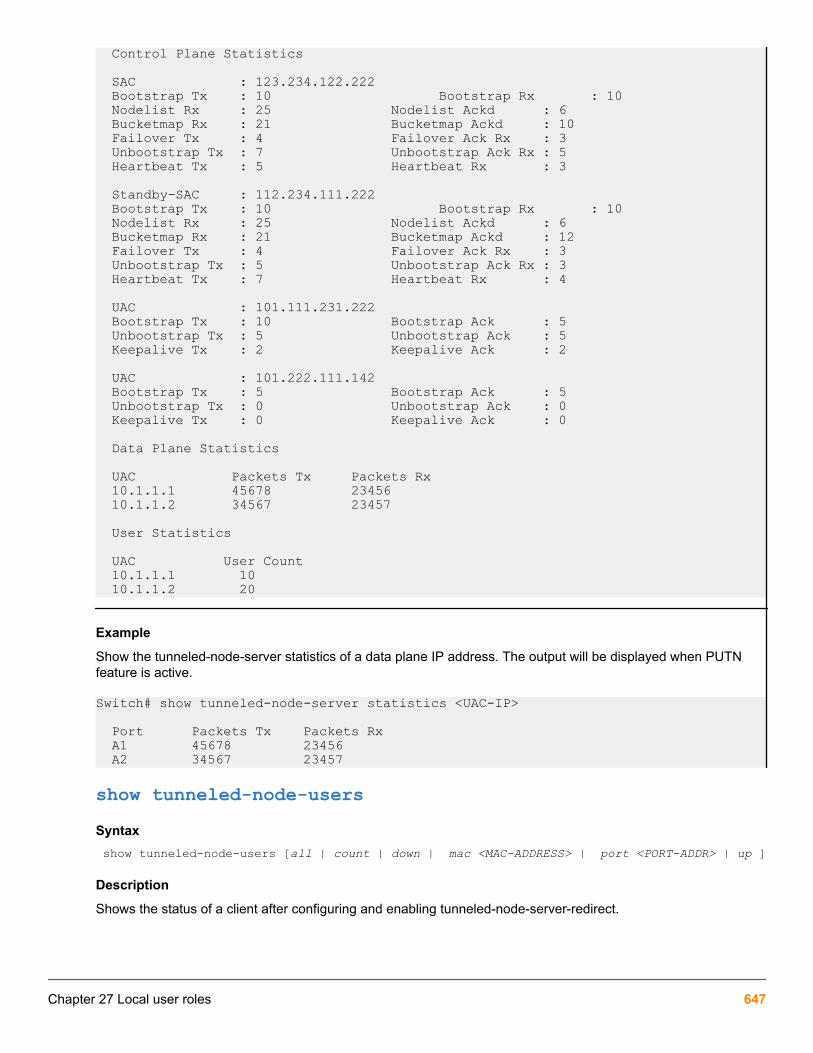
Control Plane Statistics SAC : 123.234.122.222 Bootstrap Tx : 10 Bootstrap Rx : 10 Nodelist Rx : 25 Nodelist Ackd : 6 Bucketmap Rx : 21 Bucketmap Ackd : 10 Failover Tx : 4 Failover Ack Rx : 3 Unbootstrap Tx : 7 Unbootstrap Ack Rx : 5 Heartbeat Tx : 5 Heartbeat Rx : 3
Standby-SAC : 112.234.111.222 Bootstrap Tx : 10 Bootstrap Rx : 10 Nodelist Rx : 25 Nodelist Ackd : 6 Bucketmap Rx : 21 Bucketmap Ackd : 12 Failover Tx : 4 Failover Ack Rx : 3 Unbootstrap Tx : 5 Unbootstrap Ack Rx : 3 Heartbeat Tx : 7 Heartbeat Rx : 4
UAC : 101.111.231.222 Bootstrap Tx : 10 Bootstrap Ack : 5 Unbootstrap Tx : 5 Unbootstrap Ack : 5 Keepalive Tx : 2 Keepalive Ack : 2 UAC : 101.222.111.142 Bootstrap Tx : 5 Bootstrap Ack : 5 Unbootstrap Tx : 0 Unbootstrap Ack : 0 Keepalive Tx : 0 Keepalive Ack : 0
Data Plane Statistics
UAC Packets Tx Packets Rx 10.1.1.1 45678 23456 10.1.1.2 34567 23457 User Statistics
UAC User Count 10.1.1.1 10 10.1.1.2 20
Example
Show the tunneled-node-server statistics of a data plane IP address. The output will be displayed when PUTNfeature is active.
Switch# show tunneled-node-server statistics <UAC-IP>
Port Packets Tx Packets Rx A1 45678 23456 A2 34567 23457
show tunneled-node-usersSyntax show tunneled-node-users [all | count | down | mac <MAC-ADDRESS> | port <PORT-ADDR> | up ]
Description
Shows the status of a client after configuring and enabling tunneled-node-server-redirect.
Chapter 27 Local user roles 647

Command contextmanager or operator
Parameters<ALL>
Specifies all clients and their status.
<COUNT>
Specifies the total number of clients configured to tunnel their traffic to the controller.
<DOWN>
Specifies the clients which are not able to tunnel their traffic.
PORT <PORT-ADDR>
Specifies the port client status.
MAC <MAC-ADDRESS>
Specifies the client status based on the MAC address desired by the user.
<UP>
Specifies the status of clients with tunnels up.
Example
Show tunneled-node-users information for all clients.
switch(user-role)# show tunneled-node-users all
PORT MAC-ADDRESS TUNNEL-STATUS SECONDARY-USERROLE FAILURE-REASON 123 XYZ123 UP ROLE NAME1 234 XYZ1234 DOWN ROLE NAME2 UAC_DOWN
Example
Show the total number of clients configured with the user-based tunneled-node.
switch(user-role)# show tunneled-node-users count
Total number of clients configured with user-based tunneled node: <NUMBER>
Example
Show the port access client status in detail.
switch(user-role)# show tunneled-node-users port 1/7
PORT MAC-ADDRESS TUNNEL-STATUS SECONDARY-USERROLE FAILURE-REASON1/7 d48564-940c46 UP authenticated
Example
Show the port access clients in detail.
switch# show port-access clients
Downloaded user roles are preceded by *
648 Aruba 2930F / 2930M Management and Configuration Guide for ArubaOS-Switch 16.05

Port Access Client Status
Port Client Name MAC Address IP Address User Role Type VLAN ----- ------------- ----------------- --------------- ----------------- ----- ---- 1/7 2c41387f35b9 2c4138-7f35b9 n/a Voice_HP MAC 171 1/7 d48564940c46 d48564-940c46 n/a *DUR_prof2_PUT... MAC 100 1/16 dur1 001517-857121 n/a *DUR_prof2_PUT... 8021X 100 1/17 dur1 d48564-a8afa0 n/a *DUR_prof2_PUT... 8021X 100 3/7 2c41387fe7f8 2c4138-7fe7f8 n/a Voice_HP MAC 171 3/7 e8393537b4a5 e83935-37b4a5 n/a *DUR_prof2_PUT... MAC 100
Example
Show the detailed port-access clients for port 1/7.
switch# show port-access clients detailed 1/7
Port Access Client Status Detail
Client Base Details : Port : 1/7 Authentication Type : mac-based Client Status : authenticated Session Time : 18972 seconds Client Name : 2c41387f35b9 Session Timeout : 0 seconds MAC Address : 2c4138-7f35b9 IP : n/a
Downloaded user roles are preceded by * User Role Information
Name : Voice_HP Type : Reauthentication Period (seconds) : 0 Untagged VLAN : 171 Tagged VLANs : Captive Portal Profile : Policy : Tunnelednode Server Redirect : Disabled Secondary Role Name :
Client Base Details : Port : 1/7 Authentication Type : mac-based Client Status : authenticated Session Time : 18947 seconds Client Name : d48564940c46 Session Timeout : 0 seconds MAC Address : d48564-940c46 IP : n/a
Downloaded user roles are preceded by * User Role Information
Name : *DUR_prof2_PUTN-3037-12 Type : downloaded Reauthentication Period (seconds) : 0 Untagged VLAN : 100 Tagged VLANs : Captive Portal Profile : Policy : upol2_DUR_prof2_PUTN-3037-12
Statements for policy "upol2_DUR_prof2_PUTN-3037-12"policy user "upol2_DUR_prof2_PUTN-3037-12" 10 class ipv4 "remark2_DUR_prof2_PUTN-3037-12" action rate-limit kbps 1000000 action priority 2 action permit exitStatements for class IPv4 "remark2_DUR_prof2_PUTN-3037-12"class ipv4 "remark2_DUR_prof2_PUTN-3037-12" 10 match ip 0.0.0.0 255.255.255.255 0.0.0.0 255.255.255.255 exit
Tunnelednode Server Redirect : Enabled Secondary Role Name : authenticated
ip source-interface tunneled-node-serverSyntaxswitch(config)# ip source-interface tunneled-node-server [<IP_ADDRESS> | loopback <LOOPBACK_INTERFACE> | vlan <VLAN_ID>]
Chapter 27 Local user roles 649

Description
Defines source IP address or interface for specified protocol.
• If interface has multiple addresses, lowest address is used.
• Protocols not configured with a specific address will use the IP address of outbound interface assource.
Command contextip source-interface
Parameters<IP_ADDRESS>
Specifies IP address.
<LOOPBACK_INTERFACE>
Specifies a loopback interface.
<VLAN_ID>
Specifies VLAN ID.
Example
Running configuration:
Requires (config)#show run context:
; J9850A Configuration Editor; Created on release #KB.16.05.0000x; Ver #12:08.1f.fb.7f.bf.bb.ff.7c.59.fc.7b.ff.ff.fc.ff.ff.3f.ef:f4hostname "Anay5400R"module A type j9989amodule B type j9986amodule C type j9989amodule D type j9986amodule E type j9986amodule F type j9986aclass ipv4 "testclass" 10 match ip 0.0.0.0 255.255.255.255 0.0.0.0 255.255.255.255 20 match tcp 0.0.0.0 255.255.255.255 0.0.0.0 255.255.255.255 exitpolicy user "testpolicy" 10 class ipv4 "testclass" action permit exitradius-server host 90.90.90.1ip routingip source-interface tunneled-node-server loopback 1tunneled-node-server controller-ip 21.1.1.2 mode role-based exit
Using Downloadable User Roles with PUTNThis feature extends download ability of user roles to controller. Supported platforms: 3810, 5400R, 2930F and2930M.
650 Aruba 2930F / 2930M Management and Configuration Guide for ArubaOS-Switch 16.05

• There are two roles required when using Downloadable User Roles with PUTN:
Primary user role: Configured on switch
Secondary user role: Configured on controller
• Aruba network switches support Downloadable User Roles for primary roles present in the switch. Secondaryroles present in the controller are manually configured on the controller.
This feature is only available for:
• CPPM Version 6.7.0 onward
• Aruba Controller Version 8.3.0 onward
◦ To support Downloadable User Roles on controller, a new VSA (HP-CPPM-Seconday-Role)is introduced in CPPM 6.7.0, which contains the secondary user role name:
CPPM Sample Configurationaaa authorization user-role name "<role-name>" vlan-id <vlan id> tunneled-node-server-redirect VSA
Tagged VLAN for user roleTagged VLAN for user-role supports the flow of tagged traffic. Once the client is authenticated and a user-roleapplied, tagged traffic is allowed to flow through a user-based tunnel.
Chapter 27 Local user roles 651

vlan-id-taggedSyntaxvlan-id-tagged [<VLAN-ID> | < VLAN-STR>]
no vlan-id-tagged [<VLAN-ID> | < VLAN-STR>]
Description
Supports tagged client traffic by directing the user-role. When the user-role is applied, tagged traffic is allowed topass.
The no form of this command removes the [<VLAN-ID> | < VLAN-STR>] from the tagged VLAN ID.
Command contextuser-role
Parameters<VLAN-ID>
Specifies the tagged VLAN ID assigned to users.
<VLAN-STR>
Specifies the tagged VLAN name assigned to users.
Example
Show the user-role information for PUTN-emp.
switch-PoEP# show user-role PUTN-emp
User Role Information
Name : PUTN-emp Type : local Reauthentication Period (seconds) : 0 Untagged VLAN : Tagged VLAN : 11 Captive Portal Profile : Policy : Tunnelednode Server Redirect : Enabled Secondary Role Name : authenticated
user-role vlan-idSyntaxvlan-id <VLAN-ID>
no vlan-id <VLAN-ID>
Description
Creates the VLAN within the user-role context.
The no form of this command removes the VLAN from the user-role context.
Command contextuser-role
652 Aruba 2930F / 2930M Management and Configuration Guide for ArubaOS-Switch 16.05

Parameters<VLAN-ID>
Specifies the ID assigned to the VLAN for when the client is authenticated and the user-role applied.
Example
Show the detailed status of the clients port-access.
switch-PoEP# show port-access clients detailed
Port Access Client Status Detail
Client Base Details : Port : 1 Authentication Type : 802.1x Client Status : authenticated Session Time : 58081 seconds Client name : emp4 Session Timeout : 0 seconds MAC Address : 000ffe-c8ce92 IP : n/a
User Role Information
Name : PUTN-emp Type : local Reauthentication Period (seconds) : 0 Untagged VLAN : Tagged VLANs : 11 Captive Portal Profile : Policy : Tunnelednode Server Redirect : Enabled Secondary Role Name : authenticated
Downloadable user-rolesDownloadable user-role enables ArubaOS-Switches to download user-roles, policy, and class from the Clear PassPolicy Manager (CPPM) server. The download facilitates the setup of policies and attributes for a specific user-role which can then be stored on the switch. New users can be configured and assigned the same stored versionof the user-role in ClearPass, saving the administrator time reconfiguring each user individually.
• The command radius-server cppm identity <IDENTITY> key <KEY> can only be used if the userrole is going to be downloaded from the CPPM server.
• See commands radius-server host <server-ip> and radius-server key <key-string>.
aaa authorization user-role enable download
Syntaxaaa authorization user-role enable download
no aaa authorization user-role enable download
Description
Enables the downloadable user-role.
The no form of this command disables the downloadable user-role in ArubaOS-Switches.
Chapter 27 Local user roles 653

Command context
config
Parametersdownload
Enables the switch to download the user role from a CPPM server.
Warning
The command no aaa authorization user-role enable disables both the user-role and thedownloadable user-role.
Usage
A CPPM user name and password must be configured for download user-role to work.
Example
Download the user role from a CPPM server.
switch(config)# aaa authorization user-role enable downloadSome legacy secure client access functionality is not supported when user roles are enabled.Please refer to the end user documentation for details.
CPPM user name and password must be configured for downloading the user role.CPPM HTTPS root certificate must be installed for downloading the user role.
radius-server cppm identity
Syntaxradius-server cppm identity <IDENTITY> key <KEY>
no radius-server cppm identity <IDENTITY>
Description
User name and logon password combination of the CPPM allows access to the download user-roles.
The no form of the command removes the user name and password combination from CPPM.
Command contextuser-role
Parameters<IDENTITY>
Specifies the user name of the CPPM.
<KEY>
Specifies the password of the CPPM user.
Example
Set the password key for the CPPM user.
654 Aruba 2930F / 2930M Management and Configuration Guide for ArubaOS-Switch 16.05

switch(config)# radius-server cppm identity admin key xxxxxxxx
downloadable-role-deleteSyntaxdownloadable-role-delete <USER-ROLE-NAME>
Description
Deletes the downloaded user-role, the associated class, and policy information from the user-role.
Command contextmanager
Parameters<USER-ROLE-NAME>
Specifies the user-role name to be deleted.
Example
Delete the user-role for the user DUR_prof2_PUTN-3037-12.
switch(config)# downloadable-role-delete DUR_prof2_PUTN-3037-12
show user-role <XYZ>Syntaxshow user-role <XYZ> [detailed | downloaded]
Description
Shows the named user-role in either detail or downloaded information.
Command contextoperator or manager
Parameters<detailed>
Specifies the downloaded user-role in detail.
<downloaded>
Specifies the downloaded user-role.
Example
Show the download information for user-role XYZ.
Switch(config)# show user-role XYZ downloaded
User Role Information
Name : XYZ Type : Downloaded Reauthentication Period (seconds) : 0 Untagged VLAN : Tagged VLAN :
Chapter 27 Local user roles 655

Captive Portal Profile : Policy : Tunnelednode Server Redirect : Enabled Secondary Role Name : ROLE NAME
show port-access clientsSyntaxshow port-access clients [ethernet <PORT-LIST> |<PORT>| detailed] [ethernet] PORT-LIST Show information for specified ports only. detailed Show detailed client authentication status.
Description
Shows the general port-access status information for clients by detailed status information for a specified port, listof ports or ethernet.
Command contextoperator or config
Parametersethernet <PORT-LIST>
Specifies the detailed port-access information by a list of ethernet ports.
detailedSpecifies the detailed port-access information for all.
<PORT>
Specifies the detailed port-access information for a client by port name.
Example
Show the port access status of a client.
switch# show port-access clients Downloaded user roles are preceded by * Port Access Client Status
Port Client Name MAC Address IP Address User Role Type VLAN ----- ------------- ----------------- --------------- ----------------- ----- ---- 1/7 2c41387f35b9 2c4138-7f35b9 n/a Voice_HP MAC 171 1/7 d48564940c46 d48564-940c46 n/a *DUR_prof2_PUT... MAC 100 1/16 dur1 001517-857121 n/a *DUR_prof2_PUT... 8021X 100 1/17 dur1 d48564-a8afa0 n/a *DUR_prof2_PUT... 8021X 100 3/7 2c41387fe7f8 2c4138-7fe7f8 n/a Voice_HP MAC 171 3/7 e8393537b4a5 e83935-37b4a5 n/a *DUR_prof2_PUT... MAC 100
Example
Show the detailed port-access for clients.
switch# show port-access clients detailed 1/7 Port Access Client Status Detail
Client Base Details : Port : 1/7 Authentication Type : mac-based
656 Aruba 2930F / 2930M Management and Configuration Guide for ArubaOS-Switch 16.05

Client Status : authenticated Session Time : 22203 seconds Client Name : 2c41387f35b9 Session Timeout : 0 seconds MAC Address : 2c4138-7f35b9 IP : n/a
Downloaded user roles are preceded by * User Role Information
Name : Voice_HP Type : Reauthentication Period (seconds) : 0 Untagged VLAN : 171 Tagged VLANs : Captive Portal Profile : Policy : Tunnelednode Server Redirect : Disabled Secondary Role Name :
Client Base Details : Port : 1/7 Authentication Type : mac-based Client Status : authenticated Session Time : 1259 seconds Client Name : d48564940c46 Session Timeout : 0 seconds MAC Address : d48564-940c46 IP : n/a
Downloaded user roles are preceded by * User Role Information
Name : *DUR_prof2_PUTN-3037-12 Type : downloaded Reauthentication Period (seconds) : 0 Untagged VLAN : 100 Tagged VLANs : Captive Portal Profile : Policy : upol2_DUR_prof2_PUTN-3037-12
Statements for policy "upol2_DUR_prof2_PUTN-3037-12"policy user "upol2_DUR_prof2_PUTN-3037-12" 10 class ipv4 "remark2_DUR_prof2_PUTN-3037-12" action rate-limit kbps 1000000 action priority 2 action permit exitStatements for class IPv4 "remark2_DUR_prof2_PUTN-3037-12"class ipv4 "remark2_DUR_prof2_PUTN-3037-12" 10 match ip 0.0.0.0 255.255.255.255 0.0.0.0 255.255.255.255 exit
Tunnelednode Server Redirect : Enabled Secondary Role Name : authenticated
debug usertnSyntaxdebug usertn
Description
Enables the debug for the user tunneled node.
Command contextmanager
Example
Debug session for the user tunneled node.
0007:23:11:47.44 TNT mtnodeUserCtrl:userTNodeProcAddUserReq User Add for num clients: 10007:23:11:47.54 TNT mtnodeUserCtrl:AMM: Sync user add0007:23:11:47.60 TNT mtnodeUserCtrl:Bucket 148 initialized0007:23:11:47.68 TNT mtnodeUserCtrl:userTNodeDecapReserveResource: reservetgTcam 0 reserve 1 port's uitgReserveCnt: 0 uac->uitgReserve:0
0007:23:11:47.83 TNT mtnodeUserCtrl:1664a8c0 uac->uitgReserve ZERO reserve 1
0007:23:11:47.92 TNT mtnodeUserCtrl:Entering userTNodeTCAMDecapReserveResources
Chapter 27 Local user roles 657

0007:23:11:48.07 TNT mtnodeUserCtrl:userTNodeDecapReserveResource: reservetgTcam 0 reserve 1 port's uitgReserveCnt: 0 uac->uitgReserve:0
0007:23:11:48.22 TNT mtnodeUserCtrl:1564a8c0 uac->uitgReserve ZERO reserve 1
0007:23:11:48.30 TNT mtnodeUserCtrl:Entering userTNodeTCAMDecapReserveResources
0007:23:11:48.45 TNT mtnodeUserCtrl:User 000ffe-c8ce92 added to tree0007:23:11:48.52 TNT mtnodeUserCtrl:UAC Bootstrap to node: 192.168.100.220007:23:11:48.60 TNT mtnodeUserCtrl:userTNodeSendUACBStrapReq: Packet Sent Successfully0007:23:11:48.70 TNT mtnodeUserCtrl:User 000ffe-c8ce92 bootstrapping0007:23:11:48.82 TNT mtnodeUserCtrl:create tunnel: 1 port 1664a8c0 uac 0 ifindex 0 count0007:23:11:48.91 TNT mtnodeUserCtrl:AMM: Active Sync State uac ifindex: 318767788 port: 1 cluster: 0 uac: 10007:23:11:49.03 TNT mtnodeUserCtrl:create tunnel: 1 port 1564a8c0 uac 0 ifindex 0 count0007:23:11:49.17 TNT mtnodeUserCtrl:AMM: Active Sync State uac ifindex: 318767789 port: 1 cluster: 0 uac: 00007:23:11:49.29 TNT mtnodeUserCtrl:User 000ffe-c8ce92 tunneling to 3187677880007:23:11:49.37 TNT mtnodeUserCtrl:AMM: Sync papi payload from the controller event
658 Aruba 2930F / 2930M Management and Configuration Guide for ArubaOS-Switch 16.05

OverviewThe Port QoS Trust feature restricts which packet QoS information may be used to determine inbound queueservicing and any priority information to be permitted into the local hop.
Port QoS Trust Mode configuration allows preservation or removal of the inbound QoS priorities carried in Layer 2(the VLAN cos or Priority CodePoint (PCP) value, known as the 802.1p priority tag) and/or in Layer 3 (the IP-ToSbyte, in IP-Precedence or IP-Diffserv mode). The different modes let the customer trust all, some, or no packetpriority fields.
The per-port configuration enables the customer to trust some sources or devices and not others. This feature ismutually exclusive with any active port-priority configuration.
Configuration commandsqos trustSyntaxqos trust [default|dot1p|dscp|ip-prec|none|device [none|<DEVICE-TYPE>]] Description
Set the QoS Trust Mode configuration for the port.
Options
default
Trust 802.1p priority and preserve DSCP or IP-ToS.
device <DEVICE-TYPE>
On approved devices, trust IP-ToS Differentiated-Services in IP packets, and use the DSCP-MAP to remarkthe 802.1p priority. If the DSCP codepoint does not have an associated priority, the priority will be remarked to0. On unapproved devices, trust 802.1p priority and preserve any IP- ToS values.
dot1p
Trust 802.1p priority and preserve DSCP or IP-ToS.
dscp
Trust IP-ToS Differentiated-Services in IP packets, and use the DSCP-MAP to remark the 802.1p priority. Ifthe DSCP codepoint does not have an associated 802.1p priority, the priority will be remarked to 0.
ip-precedence
Trust IP-ToS IP-Precedence mode in IP packets and remark the 802.1p priority.
none
Do not trust either the 802.1p priority or the IP-ToS values.
QoS trust devices
Chapter 28Port QoS Trust Mode
Chapter 28 Port QoS Trust Mode 659

aruba-ap
Aruba Access point device.
none
Clear all trusted devices from port.
Both SNMP and the CLI will verify that the current QoS Port Priority and desired QoS Trust Modeconfiguration are not mutually exclusive (and conversely).
qos dscp-mapSyntaxqos dscp-map <CODEPOINT> priority <PRIORITY> [name <NAME> | default | legacy] Description
Modifies DSCP mapping.
Options
default
Returns switch to the fully mapped factory-default configuration.
legacy
Restore the legacy default behavior (partial mapping) used in earlier code releases.
Show commands
show qos trustSyntaxshow qos trust [device] <PORT> Description
Shows port-based QoS trust configuration
Options
device
Show list of trusted devices per-port.
<port>
Show trusted devices on a single port.
Usageshow qos trust [device | [ethernet <PORT-LIST> ]
show qos trust
switch# show qos trust
660 Aruba 2930F / 2930M Management and Configuration Guide for ArubaOS-Switch 16.05

Port-based qos Trust Configuration
Port Trust Mode | Device Trust State ---- --- ---- A1 Default | A2 Default | A3 Device** | Trusted A4 IP-Prec | A5 Dot1p | A5 None | A5 DSCP | A5 Device** | A5 Dot1p |
** For a list of trusted devices per-port, use the command show qos trust device.To show trusted devices on a single port, use the command show qos trust device <PORT>.
show qos trust device
switch# show qos trust device
Port-Based QoS Trust Configuration
Port Trusted Devices ------- --------------- A1 aruba-ap A2 aruba-ap A4 aruba-ap
show qos trust device <PORT>
switch# show qos trust device <PORT>
Port A4 QoS Trust Configuration Current state: Trusted
Trusted Devices: aruba-ap
Validation rulesValidation Error/Warning/Prompt
qos trust <UNSUPPORTEDDEVICETYPE>
Invalid input: %s
no qos trust <ANYVALUE>
Invalid command. To disable trust for a port, useqos trust none. To return to the defaultconfiguration and leave priority informationunchanged, use qos trust default.
QoS priority when trust mode isanything other than <NONE> or<DEFAULT>.
The port QoS trust mode must be <DEFAULT>or <NONE> to configure the QoS port priorityfeature.
Table Continued
Chapter 28 Port QoS Trust Mode 661

Validation Error/Warning/Prompt
QoS DSCP when trust mode isanything other than <NONE> or<DEFAULT>.
The port QoS trust mode must be <DEFAULT>or <NONE> to configure the QoS port priorityfeature.
QoS trust dot1.p when any portQoS priority is enabled.
The port QoS priority feature must be disabledbefore configuring this port QoS trust mode.
QoS trust ip-prec when any port QoSpriority is enabled.
The port QoS priority feature must be disabledbefore configuring this port QoS trust mode.
QoS trust DSCP when any port QoSpriority is enabled.
The port QoS priority feature must be disabledbefore configuring this port QoS trust mode.
QoS trust device when any port QoSpriority is enabled.
The port QoS priority feature must be disabledbefore configuring this port QoS trust mode.
662 Aruba 2930F / 2930M Management and Configuration Guide for ArubaOS-Switch 16.05

OverviewThe tunneled node feature encapsulates incoming packets from end-hosts in Generic Routing Encapsulation(GRE) and forwards them to a Mobility Controller for additional processing. The Mobility Controller strips the GREheader and processes the packet for authentication and stateful firewall, which enables centralized security policy,authentication, and access control.
The tunneled node feature is enabled on a per-port basis. Any traffic coming from nontunneled node interfaces isforwarded without being tunneled to a Mobility Controller.
Operating notes
• Tunneled node profile may be created using CLI and SNMP.
• The tunneled node profile supports configuring of:
◦ Primary controller (IPv4 only).
◦ Backup controller (IPv4 only).
◦ Heartbeat keepalive timeout – range 1-8 seconds.
• Only one tunneled node profile may be created.
• The tunneled-node profile may be applied to a physical port only via CLI and SNMP.
• The configuration related to the tunneled node profile will be stored in the flash and restored after a boot.
• High availability (HA) will be supported for the tunneled-node related configuration.
• A tunnel, associated with a port, is “up” when both conditions are met. A tunnel is “down” when either of theconditions are not met.
◦ Either the primary or backup controller is reachable.
◦ A boot strap message response is received from the controller.
• Heartbeat between the switch and controller has failed when the controller does not respond after fiveattempts. All tunnels are brought down with a heartbeat failure.
• A tunnel “up or down” status will be logged for each tunnel node port in the event log.
• The show tech command dumps all user-mode and test-mode command outputs.
• To reach the Aruba controller, the VLAN must have a manual IP configured.
• With the exception of the 802.1x BPDU, the switch consumes all other BPDUs.
Protocol Application Programming Interface (PAPI)The PAPI Enhanced Security configuration provides protection to Aruba devices, AirWave, and ALE againstmalicious users sending fake messages that results in security challenges.
Chapter 29Tunneled node
Chapter 29 Tunneled node 663

Starting from ArubaOS-Switch version 16.02, a minor security enhancement has been made to ProtocolApplication Programming Interface (PAPI) messages. Protocol Application Programming Interface endpointauthenticates the sender by performing a check of the incoming messages using MD5 (hash). All PAPI endpoints— APs, Controllers, Mobility Access Switches, Airwave, and ALE — must use the same secret key. The switchsoftware currently uses a fixed key to calculate the MD5 digest and cooperate with the controller for PAPIenhanced security.
To use this functionality, the PAPI security profile must be configured on the controller. For moreinformation on the Aruba controller, see the Aruba Networks Controller Configuration Manual.
Configuration commands
tunneled-node-serverSyntaxtunneled-node-server [controller-ip <IP-ADDR> | backup-controller-ip <IP-ADDR> | [keepalive <TIMEOUT>] | enable | fallback-local-switching]
no tunneled-node-server [controller-ip <IP-ADDR> | backup-controller-ip <IP-ADDR> | [keepalive <TIMEOUT>] | enable | fallback-local-switching]Description
Configure tunneled node server information.
The no form of the command removes the tunneled node server configuration.
Options
controller-IP
Configure the controller IP address for the tunneled node.
backup-controller-IP
Configure the backup controller IP address for the tunneled node.
keepalive
Configure the keepalive timeout for the tunneled node in seconds [1-40]. The default is 8 seconds.
enable
Enter the manager command context.
fallback-local-switching
Apply fallback option when communication with the controller fails. When the tunneled node is applied to aport and the tunnel cannot be established with the controller, the fallback-local-switching option allows porttraffic to be switched locally. When the option fallback-local-switching is not specified, the port traffic isdropped when the tunnel reestablishment fails.
Usageswitch(config)# tunneled-node-server controller-ip 15.255.133.148switch(config)# tunneled-node-server backup-controller-ip 15.255.133.148switch(config)# tunneled-node-server keepalive 40switch(config)# tunneled-node-server fallback-local-switching
664 Aruba 2930F / 2930M Management and Configuration Guide for ArubaOS-Switch 16.05

interface tunneled-node-serverSyntaxinterface <PORT> tunneled-node-server
no interface <PORT> tunneled-node-server Description
Enable tunneled node on a port.
The no command disables the tunneled node on the port.
controller-ipFrom within the tunneled-node-profile context:
Syntax[no] controller-ip <IP-ADDR> Description
Configure the Controller IP address for the tunneled node.
Usage[no] controller-ip <IP-ADDR> controller-ip
Configure the Controller IP address for the tunneled node.
keepaliveFrom within the tunneled-node context:
Syntax[no] keepalive <TIMEOUT> Description
Configure the keepalive timeout for the tunneled node in seconds.
Keepalive timeout seconds [1-40].
Default: 8 seconds.
Options
keepalive
Configure the keepalive timeout for the tunneled node in seconds.
backup-controller-ipFrom within the tunneled-node-profile context:
Syntax[no] backup-controller-ip <IP-ADDR>
Chapter 29 Tunneled node 665

Description
Configure the backup controller IP address for the tunneled node.
Options
backup-controller-ip
Configure the backup controller IP address for the tunneled node.
Usage[no] backup-controller-ip <IP-ADDR>
fallback-local-switchingFrom within the interface context:
Syntaxfallback-local-switchingDescription
To switch traffic locally upon losing connectivity to the controller, you must configure the fallback option beforeconnectivity fails. When the tunneled node is applied to a port and the tunnel cannot be established with thecontroller, the fallback-local-switching option allows port traffic to be switched locally. When the option fallback-local-switching is not specified, the port traffic is dropped when the tunnel reestablishment fails.
VLAN show commandsVLAN show commands display information about configured VLANs.
show tunneled-node-serverSyntaxshow tunneled-node-server [state | statistics]Description
Display switch operation information.
Options
state
Display the tunneled node port state.
statistics
Display the tunneled node statistics.
show tunneled-node-server state
Tunneled node Port State Active Controller IP Address : Port State ------ ------------------------- 2 Port down
666 Aruba 2930F / 2930M Management and Configuration Guide for ArubaOS-Switch 16.05

show tunneled-node-server statistics
Tunneled node Statistics
Port : 2
Control Plane Statistics Bootstrap packets sent : 0 Bootstrap packets received : 0 Bootstrap packets invalid : 0
Tunnel Statistics Rx Packets : 0 Tx Packets : 0 Rx 5 Minute Weighted Average Rate (Pkts/sec) : 0 Tx 5 Minute Weighted Average Rate (Pkts/sec) : 0
Aggregate Statistics Heartbeat packets sent : 0 Heartbeat packets received : 0 Heartbeat packets invalid : 0 Fragmented Packets Dropped (Rx) : 0 Packets to Non-Existent Tunnel : 0 MTU Violation Drop : 0
clear statistics tunneled-node-serverSyntaxclear statistics tunneled-node-serverDescription
Clear statistics from the tunneled node server.
Interaction tableFeatures enabled with tunneled node:
Feature
Mirrors (MAC, VLAN, port)
PVST/RPVST/STP
DLDP
UDLD
LLDP/CDP
GVRP/MVRP
LACP
UFD
Table Continued
Chapter 29 Tunneled node 667

Feature
Sflow
Loop protect
Smartlink
Global QoS (VLAN, port, rate limit)
Mac lockout/lockdown
ACL/Classifiers (ingress/egress)
IGMP/MLD
GMB
Broadcast-limit
energy-efficient-Ethernet
flow-control
power-over-ethernet
• poe-allocate-by
• poe-lldp-detect
Rogue Mac detection
LLDP auto-provisioning
Restrictions• Once a tunneled-node profile is applied to a port, the controller IP (primary and backup) cannot be changed.
• IP address cannot be assigned to VLANs that the tunnel-node port belongs to.
• No support for fragmentation and reassembly for encapsulated frames that result in an MTU violation. Suchframes will be dropped. HPE recommends configuring the switch-controller path for Jumbo MTU. No supportfor PMTU detection for tunnel traffic.
• The packets from nontunneled node ports (in the same VLAN as tunnel-node port) will not be bridged to thetunneled-node ports and conversely.
Features not allowed on a tunneled node port/VLAN with tunneled node ports/globally:
668 Aruba 2930F / 2930M Management and Configuration Guide for ArubaOS-Switch 16.05

Feature Blocked globally/per port/ VLAN with tunneled-node-ports
IP multicast routing Global
Openflow Global
Q-in-Q Global
Distributed Trunking Global
Mesh Global
VXLAN Global
IP address: manual and dhcp VLAN
802.1x, mac auth, webauth, LMA, portsecurity
port
DIPLD (IPv4/IPv6) port
DSNOOP (IPv4/IPv6) VLAN
ARP protect VLAN
RA guard port
Virus throttling port
BYOD VLAN
Trunk Profile cannot be applied to a trunk
PBR policies VLAN
Tunneled-node port port
Src port/Mcast filters port
DHCP client/Server/Relay VLAN
PAPI security
Protocol Application Programming Interface (PAPI)The PAPI Enhanced Security configuration provides protection to Aruba devices, AirWave, and ALE againstmalicious users sending fake messages that results in security challenges.
Starting from ArubaOS-Switch version 16.02, a minor security enhancement has been made to ProtocolApplication Programming Interface (PAPI) messages. Protocol Application Programming Interface endpointauthenticates the sender by performing a check of the incoming messages using MD5 (hash). All PAPI endpoints— APs, Controllers, Mobility Access Switches, AirWave, and ALE — must use the same secret key. The switchsoftware currently uses a fixed key to calculate the MD5 digest and cooperate with the controller for PAPIenhanced security.
Chapter 29 Tunneled node 669

To use this functionality, the PAPI security profile must be configured on the controller. For moreinformation on the Aruba controller, see the Aruba Networks Controller Configuration Manual.
PAPI configurable secret keyTo support enhanced PAPI security, a command is available to configure a MD5 secret key.
papi-securitySyntaxswitch# (config) papi-security
Description
Configure MD5 key for enhanced PAPI security.
Parametersenhanced-security
The enhanced-security CLI must be enabled in Aruba controller for the connection to be truly secured.
<KEY-STR>
Configure MD5 key for enhanced PAPI security using a key-string parameter.
<KEY-VALUE>
Configure MD5 key for enhanced papi security using a key-value parameter.
Restrictions
• To view the status of the PAPI security, using the show run command with the option includecredentials enabled, the PAPI security key will show in the output as an encrypted form.
• Key length has to be between 10-64.
• By default the enhanced-security is disabled.
• When enhanced-security mode is disabled, any AP can obtain the current shared secret key.
• When enhanced-security mode is enabled, an AP is not updated with the new shared secret key unless the APknows the previous key and the AP is updated with the new key within one hour of the key creation.
• Key length has to be between 10-64 or the following message will appear:
Minimum key-value length allowed is 10 characters and maximum allowed is 64 characters.
UsageSwitch(config)# papi-security key-value <KEY-VALUE>Switch(config)# [no] papi-security <KEY-VALUE>
papi-security key-value
HP-2920-24G(config)# papi-security key-value TestKey12345678HP-2920-24G(config)# no papi-security key-value
670 Aruba 2930F / 2930M Management and Configuration Guide for ArubaOS-Switch 16.05

HP-2920-24G(config)# papi-security key-value TestMinimum key-value length allowed is 10 characters and maximum allowed is 64 characters.
show run with encrypted key
Switch(config)# sh runRunning configuration:;J9576A Configuration Editor;Created on release #KA.16.02.0000x;Ver #0e:01.f0.92.34.5f.3c.6b.fb.ff.fd.ff.ff.3f.ef:78;encrypt-cred +NXT3w7ky2IXNXadlJblS/1ZRi/o73Qq28XXcLkSCZq9PU30Kl+KMLMva8rQri5g
hostname "HP-3810-48G-4SFPP" module 1 type j9576y module 2 type j9576x encrypt-credentials papi-security encrypted-key <"encrypted-key"> snmp-server community "public" unrestricted snmpv3 engineid "00:00:00:0b:00:00:50:65:f3:b4:a6:c0" oobm ip address dhcp-bootp exit
vlan 1 name "DEFAULT_VLAN" untagged 1-52 ip address dhcp-bootp exit
activate provision disable
show run with include key
show runRunning configuration:; J9576A Configuration Editor; Created on release #KA.16.02.0000x; Ver#0e:01.f0.92.34.5f.3c.6b.fb.ff.fd.ff.ff.3f.ef:78
hostname "HP-3810-48G-4SFPP" module 1 type j9576y module 2 type j9576x include-credentials papi-security key-value <"key"> snmp-server community "public" unrestricted snmpv3 engineid "00:00:00:0b:00:00:50:65:f3:b4:a6:c0" oobm ip address dhcp-bootp exit vlan 1 name "DEFAULT_VLAN" untagged 1-52 ip address dhcp-bootp exit activate provision disable
Chapter 29 Tunneled node 671

Preventing double tunneling of Aruba Access PointsWhen an Aruba Access Point (AP) is connected to a port on which per-port tunneled node is configured, there aretwo tunnels from that port to the Controller - one for the AP and another for the tunneled node. To improveperformance of APs connected to tunneled node ports, the following configuration parameter under the deviceprofile feature prevents double tunneling.
The parameter decides whether to allow or not, a tunneled node to be configured on the port on which the device-profile is applied. Use the command switch(config)# device-profile name <device-profile-name>[no] allow-tunneled-node.
The default setting of device-profile allows tunneled node. Device profile is applied on the portonly by reading Organizational Specific TLV in LLDP packets.
Preventing double tunneling using device profile parameter
device-profile name
Syntaxdevice-profile name <device-profile-name> [no] allow-tunneled-node
Description
Allows or disallows tunneled node when device profile is applied on that port.
Command contextconfig
Parameter<device-profile-name>
Specifies the name of the device profile to be configured.
Usage
To create a device-profile named “test”, execute the following command:
switch(config)# device-profile name testTo allow tunneled-node by the configured device profile parameter, execute the following command:
switch(device-profile)# allow-tunneled-node
Examples
switch(config)# device-profile name <device-profile-name> switch(device-profile)# allow-jumbo-frames Configure jumbo frame support for the device port. allow-tunneled-node Configure Tunneled Node support for the device port. cos Configure the Class of Service (CoS) priority for traffic from the device. egress-bandwidth Configure egress maximum bandwidth for the device port. ingress-bandwidth Configure ingress maximum bandwidth for the device port. poe-max-power Configure the maximum PoE power for the device port. poe-priority Configure the PoE priority for the device port. speed-duplex Configure the speed and duplex for the device port. tagged-vlan Configure this port as a tagged member of the specified
672 Aruba 2930F / 2930M Management and Configuration Guide for ArubaOS-Switch 16.05

VLANs. untagged-vlan Configure this port as an untagged member of specified VLAN.Execute show run command to display the tunneled mode configuration in an enabled or disabled state:
switch(config)# show run; J9625A Configuration Editor; Created on release #KB.16.05.0000x; Ver #0f:02.43.18.82.34.61.1c.28.f3.84.9c.63.ff.37.2f:dahostname "switch"snmp-server community "public" unrestricteddevice-identity name "cpe" lldp oui 33bbccdevice-identity name "cpe" lldp sub-type 1device-identity name "phone" lldp oui 112233 vlan 1 name "DEFAULT_VLAN" untagged 1-28 ip address dhcp-bootp exitdevice-profile name "ram" exitdevice-profile name "test" exitdevice-profile type “scs-wan-cpe” associate "ram" enable exitdevice-profile type-device "cpe" associate "ram" enable exitdevice-profile type-device "phone" associate "default-device-profile" exit When allow-tunneled-node is disabled:
switch(config)# show run; J9625A Configuration Editor; Created on release #KB.16.05.0000x; Ver #0f:02.43.18.82.34.61.1c.28.f3.84.9c.63.ff.37.2f:dahostname "switch"snmp-server community "public" unrestricteddevice-identity name "cpe" lldp oui 33bbccdevice-identity name "cpe" lldp sub-type 1device-identity name "phone" lldp oui 112233 vlan 1 name "DEFAULT_VLAN" untagged 1-28 ip address dhcp-bootp exitdevice-profile name "ram" exitdevice-profile name "test" no allow-tunneled-node exitdevice-profile type “scs-wan-cpe” associate "ram" enable exitdevice-profile type-device "cpe" associate "ram" enable
Chapter 29 Tunneled node 673

exitdevice-profile type-device "phone" associate "default-device-profile" exit
show device-profile config
Syntaxshow device-profile config
Description
Displays device profile configuration.
Command contextconfig
Usage
To verify whether tunneled-node is allowed (when “test” is device-profile name):
switch(device-profile)# show device-profile config testTo verify the output when tunneled-node is disabled:
switch(device-profile)# no allow-tunneled-nodeswitch(device-profile)# show device-profile config test
Example
switch(config)# show device-profile config Device Profile Configuration
Configuration for device-profile : default-ap-profile untagged-vlan : 1 tagged-vlan : None ingress-bandwidth : 100% egress-bandwidth : 100% cos : 0 speed-duplex : auto poe-max-power : Class/LLDP poe-priority : critical allow-jumbo-frames : Disabled allow-tunneled-node: Enabled
Device Profile Configuration
Configuration for device-profile : test untagged-vlan : 1 tagged-vlan : None ingress-bandwidth : 100% egress-bandwidth : 100% cos : None speed-duplex : auto poe-max-power : Class/LLDP poe-priority : critical allow-jumbo-frames : Disabled allow-tunneled-node: EnabledWhen tunneled-node is disabled:
674 Aruba 2930F / 2930M Management and Configuration Guide for ArubaOS-Switch 16.05

switch(config)# show device-profile config Device Profile Configuration
Configuration for device-profile : default-ap-profile untagged-vlan : 1 tagged-vlan : None ingress-bandwidth : 100% egress-bandwidth : 100% cos : 0 speed-duplex : auto poe-max-power : Class/LLDP poe-priority : critical allow-jumbo-frames : Disabled allow-tunneled-node: Disabled
Device Profile Configuration
Configuration for device-profile : test untagged-vlan : 1 tagged-vlan : None ingress-bandwidth : 100% egress-bandwidth : 100% cos : None speed-duplex : auto poe-max-power : Class/LLDP poe-priority : critical allow-jumbo-frames : Disabled allow-tunneled-node: Disabled
Chapter 29 Tunneled node 675

The Time Domain Reflectometry (TDR) is a port feature supported on some switches running ArubaOS-Switchsoftware. TDR is used to detect cable faults on 100BASE-TX and 1000BASE-T ports.
Virtual cable testingThe Virtual Cable Test (VCT) uses the same command as TDR. It is applicable only for GigT transceivers likecopper transceiver (J8177C–ProCurve Gigabit 1000Base-T Mini-GBIC). The VCT test results include distance tothe fault, but not the cable length.
Test cable-diagnosticsSyntax
test cable-diagnostics <PORT-LIST>Description
Use the command to test for cable faults.
OptionPORT-LIST
Specify copper port as a input port number.
Test cable-diagnostics C21
test cable-diagnostics C21
The 'test cable-diagnostics' command will cause a loss of link and will take a few seconds per interface to complete.Continue [Y/N]? y
MDI Cable Distance Pair Pair MDIPort Pair Status to Fault Skew Polarity Mode--------- ------ -------- ----- ------ ------C21 1-2 Open 0 m 0 ns 3-6 Open 0 m 0 ns 4-5 Open 0 m 0 ns 7-8 Open 1 m 0 ns
Test cable-diagnostics 1/1-1/10
switch# test cable-diagnostics 1/1-1/10
This command will cause a loss of link on all tested ports and will takeseveral seconds per port to complete. Use the ‘show cable-diagnostics’ command to view the results.
Continue (y/n)? Y
switch# show cable-diagnostics 1/1-1/10
Cable Diagnostic Status - Copper Ports
MDI Cable Cable Length or
Chapter 30Time Domain Reflectometry
676 Aruba 2930F / 2930M Management and Configuration Guide for ArubaOS-Switch 16.05

Port Pair Status Distance to Fault ---- ------ ----------- --------------------- 1/1 1-2 OK 5m 3-6 OK 5m 4-5 OK 7m 7-8 OK 7m 1/2 1-2 OK 7m 3-6 OK 7m 4-5 OK 7m 7-8 OK 7m 1/3 1-2 OK 5m 3-6 OK 7m 4-5 OK 5m 7-8 OK 7m 1/4 1-2 OK 7m 3-6 OK 7m 4-5 OK 7m 7-8 OK 5m 1/5 1-2 OK 4m 3-6 OK 5m 4-5 OK 5m 7-8 OK 4m 1/6 1-2 OK 4m 3-6 OK 4m 4-5 OK 4m 7-8 OK 4m 1/7 1-2 OK 5m 3-6 OK 4m 4-5 OK 5m 7-8 OK 4m 1/8 1-2 OK 4m 3-6 OK 5m 4-5 OK 4m 7-8 OK 4m 1/9 1-2 OK 5m 3-6 OK 5m 4-5 OK 5m 7-8 OK 5m 1/10 1-2 OK 7m 3-6 OK 5m 4-5 OK 5m 7-8 OK 5m
Good cable tests
switch# test cable-diagnostics 51
This command will cause a loss of link on all tested ports and will takeseveral seconds per port to complete. Use the 'show cable-diagnostics'command to view the results.
Continue (y/n)? Y
switch# show cable-diagnostics 51
Cable Diagnostic Status - Transceiver Ports
MDI Cable Distance Pair Pair MDI Port Pair Status to Fault Skew Polarity Mode ---- ------ --------- -------- ----- ------- ----- 51 1-2 OK 0 m 8 ns Normal MDI 3-6 OK 0 m 8 ns Normal 4-5 OK 0 m 8 ns Normal MDIX
Chapter 30 Time Domain Reflectometry 677

7-8 OK 0 m 0 ns Normal
switch# test cable-diagnostics 52
This command will cause a loss of link on all tested ports and will takeseveral seconds per port to complete. Use the 'show cable-diagnostics'command to view the results.
Continue (y/n)? Y
switch# show cable-diagnostics 52
Cable Diagnostic Status - Transceiver Ports
MDI Cable Distance Pair Pair MDI Port Pair Status to Fault Skew Polarity Mode ---- ------ --------- -------- ----- ------- ----- 52 1-2 OK 0 m 0 ns Normal MDI 3-6 OK 0 m 0 ns Normal 4-5 OK 0 m 0 ns Normal MDIX 7-8 OK 0 m 0 ns Normal
Faulty cable test
switch# test cable-diagnostics 51This command will cause a loss of link on all tested ports and will takeseveral seconds per port to complete. Use the 'show cable-diagnostics'command to view the results.
Continue (y/n)? yswitch# show cable-diagnostics 51
Cable Diagnostic Status - Transceiver Ports
MDI Cable Distance Pair Pair MDI Port Pair Status to Fault Skew Polarity Mode ---- ------ ----------- ---------- ------ ---------- ------ 51 1-2 OK 0 m 0 ns 3-6 Short 1 m 0 ns 4-5 Short 1 m 0 ns 7-8 OK 0 m 0 ns
switch# test cable-diagnostics 52
This command will cause a loss of link on all tested ports and will takeseveral seconds per port to complete. Use the 'show cable-diagnostics'command to view the results.
Continue (y/n)? Y
switch# show cable-diagnostics 52
Cable Diagnostic Status - Transceiver Ports
MDI Cable Distance Pair Pair MDI Port Pair Status to Fault Skew Polarity Mode ---- ------ ----------- ---------- ------ ---------- ------ 52 1-2 Open 0 m 0 ns 3-6 Open 0 m 0 ns
678 Aruba 2930F / 2930M Management and Configuration Guide for ArubaOS-Switch 16.05

4-5 Open 1 m 0 ns 7-8 Open 0 m 0 nsError message
Error Message Cause
The transceiver on port 1/A1does not support cablediagnostics.
• usage of invalid(fiber-SFP+) port
• The selected range includes an entry for an invalid port.
show cable-diagnosticsSyntaxshow cable-diagnostics <PORT-LIST>Description
Use the command to generate results of completed tests on single or multiple ports. For incomplete tests, awarning is displayed.
OptionPORTSpecify one copper port as an input port number.
clear cable-diagnosticsSyntaxclear cable-diagnosticsDescription
Use the command to clear the result buffer.
Example
switch(config)# clear cable-diagnostics
LimitationsTDR has the following limitations:
• TDR length accuracy is ± 5 m
• Does not work on Smart Rate Interfaces with 10GBASE-T and NGBASE-T (2.5G, 5G copper) ports availableon:
◦ v3 blades
Chapter 30 Time Domain Reflectometry 679

– J9991A — Aruba 20-port 10/100/1000BASE-T PoE+ / 4-port 1/2.5/5/10GBASE-T PoE+ MACsec v3 zl2Module
– J9995A — Aruba 8-port 1/2.5/5/10GBASE-T PoE+ MACsec v3 zl2 Module
◦ 3810M (JL076A — Aruba 3810M 40G 8 HPE Smart Rate PoE+ 1-slot Switch)
• Not supported on v2 zl modules
• Valid only on 100BASE-TX and 1000BASE-T ports
680 Aruba 2930F / 2930M Management and Configuration Guide for ArubaOS-Switch 16.05

OverviewThe Link Layer Discovery Protocol (LLDP) is a vendor-neutral link layer protocol in the Internet Protocol Suiteused by Aruba network devices for advertising their identity, capabilities, and neighbors on an IEEE 802 local areanetwork, principally wired ethernet. The LLDP-bypass authentication feature provides zero touch provisioning ofAruba 802.11ac wireless access points (APs).
In an LLDP module, the packet is parsed and inspected for the presence of an Aruba Organizational UnitIdentifier (OUI) Type-Lenght-Value (TLV). The Aruba OUI TLV, once detected, will bypass the authentication andpermit traffic to pass on the port. If the Aruba OUI TLV is absent, the packet will be dropped and processing of thepacket or LLDP transmission for that device will not pass.
In ZTP environments, when an Aruba AP is plugged into the switch port, the device profiles will be applied on theAP without any user intervention. After discovery of an Aruba AP, the switch will dynamically provision the APconnected port without initiating any authentication needs. This feature is enabled at the port-level or on a rangeof ports.
Features not supported
Authorization parameters configured in RADIUS and the switch are not supported by the LLDP-bypassauthentication feature.
Configuration commands
aaa port-access lldp-bypassFrom within the configure context:
Syntax[no] aaa port-access lldp-bypassDescription
The command configures lldp-bypass authentication on the switch ports.
Configure lldp-bypass on the switch ports to bypass authentication for Aruba-APs which sends special LLDPTLVs. When LLDP-BYPASS is enabled on a port, it will behave as all other devices and bypass LLDP PDU for alldevice-profile enabled device.
By default, lldp-bypass is disabled on the switch ports.
Usage[no] aaa port-access lldp-bypass <PORT-LIST> Description
Chapter 31Link Layer Discovery Protocol bypass authentication
Chapter 31 Link Layer Discovery Protocol bypass authentication 681

Validation rules
Validation Error/Warning/Prompt
When the lldp-bypass is enabled on theport, different error messages aredisplayed.
If MAC lockdown is enabled on the port:
Error configuring port A1: lldp-bypass cannot be enabled on a port with MAC lock-enabled.If learn-mode is configured on the port:
A1: lldp-bypass cannot be enabled on the port with learn-mode configured.If MACsec is configured on the port:
Error configuring port A1: lldp-bypass cannot be enabled on the port with MACsec-enabled.If trunk is configured on the port:
Error configuring port A1: lldp-bypass cannot be enabled on the port with mesh or manual trunks configured.
If mesh is configured on the port:
lldp-bypass cannot be enabled on the port with mesh or manual trunks configured.If Distributed Trunking is configured on the port:
lldp-bypass cannot be enabled on the port with mesh or manual trunks configured.
When MACsec is enabled on the port: If lldp-bypass is enabled on the port:
Cannot apply MACsec on the port A1 when lldp-bypass is enabled on that port.
When learn-mode is configured on theport:
If lldp-bypass is enabled on the port:
A1: Cannot apply learn-mode on the port A1 when lldp-bypass is enabled on that port.
When trunk, distributed trunk or meshis configured on the port:
If lldp-bypass is enabled on the port:
Cannot apply mesh or manual trunks on the port A1 when lldp-bypass is enabled on that port.
Table Continued
682 Aruba 2930F / 2930M Management and Configuration Guide for ArubaOS-Switch 16.05

Validation Error/Warning/Prompt
When MAC-lockdown is enabled on theport:
If lldp-bypass is enabled on the port:
Cannot apply MAC lock-enable on the port A1 when lldp-bypass is enabled on that port.
Security Warning when enabling lldp-bypass on the port. Enabling lldp-bypass on the port may
give access to any Aruba-AP that sends a special LLDP TLV without undergoing any authentication. This configuration may allow network access to the rogue devices that are capable of sending the special LLDP TLV Do you want to continue? [y/n]:
Show commandsshow port-access lldp-bypass clientsSyntaxshow port-access lldp-bypass clientsDescription
Displays the clients which bypassed the authentication.
Options
<PORT-LIST>
Show information for specified ports only.
Usageshow port-access lldp-bypass clients [<PORT-LIST>]
show port-access lldp-bypass clients
switch#show port-access lldp-bypass clients
Port Access lldp-bypass Client StatusPort MAC Address ------- ----------------A1 000005-010203A2 010203-040506
Stackable switch: show port-access lldp-bypass clients
switch(config)# show port-access lldp-bypass clients
Port Access lldp-bypass Client Status
Chapter 31 Link Layer Discovery Protocol bypass authentication 683

Port MAC Address ------- ----------------1/1 000005-0102031/2 005056-bd7039
show port-access lldp-bypass clients A1
switch#show port-access lldp-bypass clients A1
Port Access lldp-bypass Client StatusPort MAC Address ------- ----------------A1 000005-010203
Stackable switch: show port-access lldp-bypass clients 1/1
switch(config)# show port-access lldp-bypass clients 1/1
Port Access lldp-bypass Client StatusPort MAC Address ------- ----------------1/1 000005-010203
show port-access lldp-bypass configSyntaxshow port-access lldp-bypass configDescription
Displays the lldp-bypass configuration applied on all switch ports.
show port-access lldp-bypass config
switch#show port-access lldp-bypass config
Port Access lldp-bypass ConfigurationPort Enabled ------ ----------A1 Yes A2 Yes A3 No A4 No ...A24 No F1 No F2 No F3 No F24 No
684 Aruba 2930F / 2930M Management and Configuration Guide for ArubaOS-Switch 16.05

Stackable switch: show port-access lldp-bypass config
switch(config)#show port-access lldp-bypass config
Port Access lldp-bypass ConfigurationPort Enabled ------ ----------1/1 Yes 1/2 Yes 1/3 No ...1/52 No 2/1 No 2/26 No 3/1 No 3/26 No
Error LogEvent Message
CLIERR_CANNOT_ENABLE_LLDP_BYPASS_MAC_LOCKDOWN_ENABLED
lldp-bypass is not allowed on the port where MAC-lockdown is enabled.
lldp-bypass cannot be enabled on a port with MAC lock-enabled.
CLIERR_MACLOCK_AND_LLDP_BYPASS MAC-lockdown is not permitted on the port where isenabled lldp-bypass.
Cannot configure MAC lock-enable on the port A1 when lldp-bypass is enabled on that port.
CLIERR_CANNOT_ENABLE_LLDP_BYPASS_MACSEC_ENABLED
lldp-bypass is not allowed on the port MACsec isconfigured.
lldp-bypass cannot be enabled on a port when MACsec is enabled.
CLIERR_CANNOT_ENABLE_MACSEC_AS_LLDP_BYPASS_CONFIGURED
MACsec is not permitted on the port where is enabledlldp-bypass.
Cannot apply MACsec on the port A1 when lldp-bypass is enabled on that port.
Table Continued
Chapter 31 Link Layer Discovery Protocol bypass authentication 685

Event Message
CLIERR_CANNOT_ENABLE_LEARN_MODE_CONFIGURED_LLDP_BYPASS
Port-security learn-mode configured is not permittedwhen lldp-bypass is enabled on the port.
A1: Cannot apply learn-mode on the port A1 when lldp-bypass is enabled on that port.
CLIERR_LLDP_BYPASS_AND_LEARN_MODE_CONFIGURED
lldp-bypass is not permitted when port-security learn-mode is configured.
lldp-bypass cannot be enabled on a port when learn-mode is enabled.
CLIERR_LLDP_BYPASS_AND_MESH_OR_MANUAL_TRUNK
Trunk/ mesh/Distributed Trunk is not permitted on thelldp-bypass enabled port.
Cannot apply mesh or manual trunks on the port A1 when lldp-bypass is enabled on that port.
ExistingLog:CLIERR_MESH_OR_MANUAL_TRUNK
lldp-bypass cannot be enabled for trunk/mesh/Distributed Trunk ports.
lldp-bypass cannot be enabled on a port when mesh or manual trunks is enabled.
Debug logComment Message
Security warning to be displayed when lldp-bypass configuration is enabled on the port.
Enabling lldp-bypass on the port may give access to any Aruba-AP that sends a special LLDP TLV without undergoing any authentication. This configuration may allow network access to the rogue devices that are capable of sending the special LLDP TLV Do you want to continue? [y/n]:
When adding the Aruba-AP into the authorizedclient list.
Will use the existing debug log:0000:00:24:25.07 PSEC mPORTSECMCtrl:added new SA 000005-000000 to authorized addr list of port A1 for vlan 1.
When removing the Aruba-AP from theauthorized client list.
Will use the existing debug log:0000:00:01:47.07 PSEC mPORTSECMCtrl:removed 000006-000000 from authorized addr list of port A1 for vlan 1 due to delete.
When Aruba-AP is detected on lldp-bypassenabled port:
0000:00:13:57.64 PSEC mPORTSECMCtrl: Received PROFMGR_DEVICE_CONNECTED event for 40e3d6-c6d492 on port A1.
When already connected Aruba-AP isdisconnected/removed on lldp-bypass enabledport.
0000:00:13:07.96 PSEC mPORTSECMCtrl: Received PROFMGR_DEVICE_DISCONNECTED event for 40e3d6-c6d492 on port A1.
686 Aruba 2930F / 2930M Management and Configuration Guide for ArubaOS-Switch 16.05

List of abbreviated termsTerm Definition
VSF Virtual Switch Framework (front plane stacking)
FPS Front Plane Stacking
BPS Back Plane Stacking
MM Management Module
IM Interface Module
GVRP GARP VLAN Registration Protocol
GARP Generic Attribute Registration Protocol
MVRP Multiple VLAN Registration Protocol
Overview of VSFHPE-Aruba Virtual Switching Framework (VSF) technology virtualizes up to four physical devices in the samelayer into one virtual fabric which provides high availability and scalability. A virtual fabric is therefore multiplephysical devices in the same layer that utilize VSF technology.
VSF allows supported switches connected to each other through normal ethernet connections (copper or fiber) tobehave like a single switch.
Chapter 32Virtual Switching Framework (VSF)
Chapter 32 Virtual Switching Framework (VSF) 687

VSF is supported only on the Aruba 2930F Switch Series.
Figure 132: Two devices using VSF technology appearing as a single node to the upper-layer and lower-layerdevices
VSF previously supported 2–member stack for a pair of 5400R switches with V3 blades, interconnected throughstandard Ethernet connections with front-plane stacking capability. Interswitch connectivity was restricted to 10Gand 40G links. In VSF 4–member stack, the same front-plane stacking capability has been extended to 2930Fswitches. Variants have:
• 1G (copper and SFP) ports and 10G (SFP+) ports.
• PoE+ and non-PoE+ ports.
• None of the variants have an OOBM port.
The VSF feature allows the user to form a stack of up to four devices of any SKU, including mixing the SKUs in asingle stack. The switches in these stacks are interconnected using standard Ethernet connections. Theseinterconnections between member switches are called VSF links. Each VSF link can comprise up to eightindividual VSF ports, and traffic between two members will be load-balanced automatically across all the
688 Aruba 2930F / 2930M Management and Configuration Guide for ArubaOS-Switch 16.05

connected ports. Each switch can have two VSF links. The switches behave as a single virtual switch. 2930Fsupports a maximum of four 10G ports.
Figure 133: A 4–member VSF stack
Benefits of VSFSimplified topology and easy management
A VSF fabric appears and behaves as one logical switch and is accessible by the network through a single IPaddress.
Spanning tree features are not necessary among VSF members.
1:1 redundancy
One member acts as the commander to manage and control the entire VSF fabric. One of the switches actsas a standby and backs up the commander, and takes over in case of commander failure.
VSF port aggregation
A VSF link can aggregate upto eight VSF ports with the immediate neighboring member. This providesredundancy till failure of seven VSF ports.
Distributed trunking
The Ethernet link aggregation feature can be used to aggregate physical links between the VSF and itsupstream or downstream devices across the VSF members. This eliminates the need for spanning tree andalso provides load balancing across all ports of the link aggregate.
Network scalability
The processing power is equal to the Commander, the forwarding capacity is equal to all the stack memberscombined.
Chapter 32 Virtual Switching Framework (VSF) 689
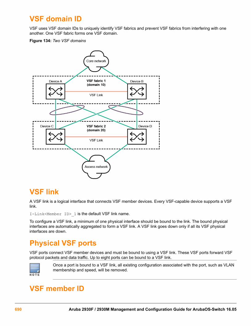
VSF domain IDVSF uses VSF domain IDs to uniquely identify VSF fabrics and prevent VSF fabrics from interfering with oneanother. One VSF fabric forms one VSF domain.
Figure 134: Two VSF domains
VSF linkA VSF link is a logical interface that connects VSF member devices. Every VSF-capable device supports a VSFlink.
I-Link<Member ID>_1 is the default VSF link name.
To configure a VSF link, a minimum of one physical interface should be bound to the link. The bound physicalinterfaces are automatically aggregated to form a VSF link. A VSF link goes down only if all its VSF physicalinterfaces are down.
Physical VSF portsVSF ports connect VSF member devices and must be bound to using a VSF link. These VSF ports forward VSFprotocol packets and data traffic. Up to eight ports can be bound to a VSF link.
Once a port is bound to a VSF link, all existing configuration associated with the port, such as VLANmembership and speed, will be removed.
VSF member ID
690 Aruba 2930F / 2930M Management and Configuration Guide for ArubaOS-Switch 16.05
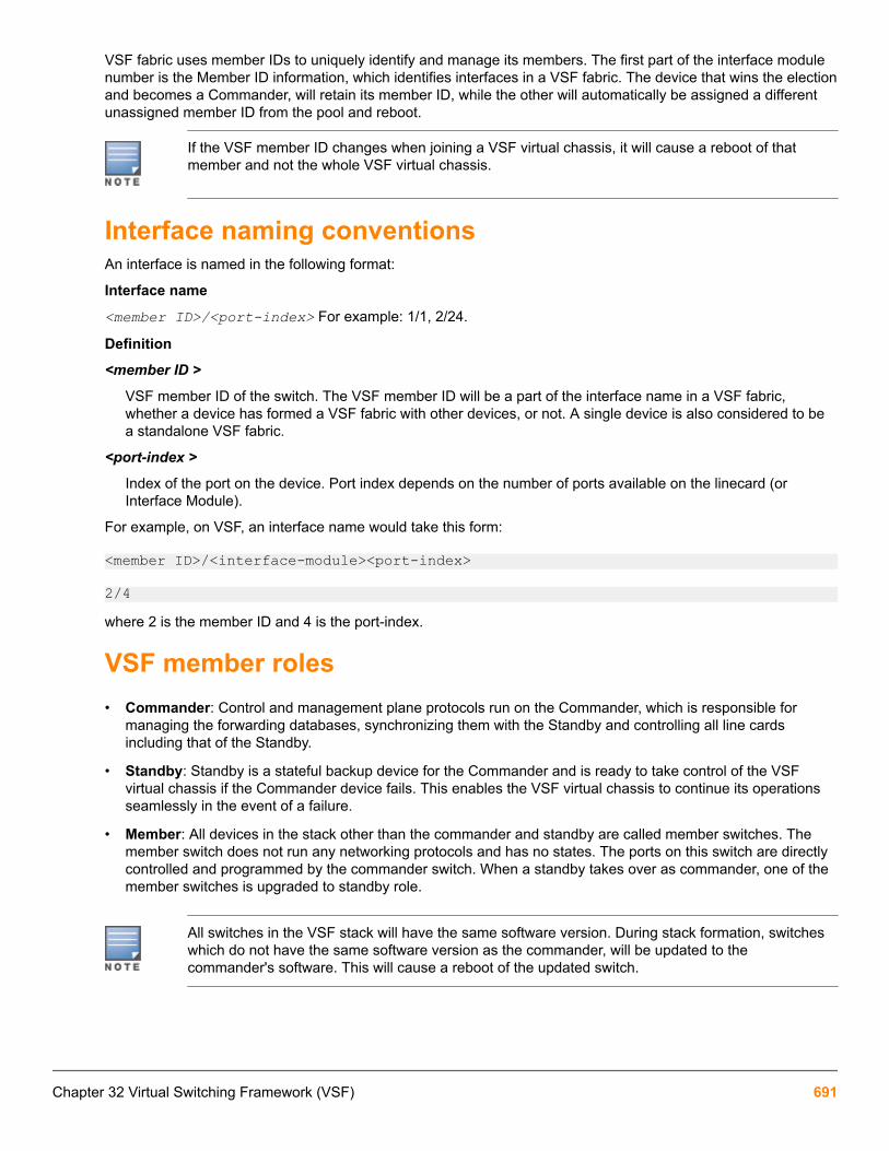
VSF fabric uses member IDs to uniquely identify and manage its members. The first part of the interface modulenumber is the Member ID information, which identifies interfaces in a VSF fabric. The device that wins the electionand becomes a Commander, will retain its member ID, while the other will automatically be assigned a differentunassigned member ID from the pool and reboot.
If the VSF member ID changes when joining a VSF virtual chassis, it will cause a reboot of thatmember and not the whole VSF virtual chassis.
Interface naming conventionsAn interface is named in the following format:
Interface name
<member ID>/<port-index> For example: 1/1, 2/24.
Definition
<member ID >
VSF member ID of the switch. The VSF member ID will be a part of the interface name in a VSF fabric,whether a device has formed a VSF fabric with other devices, or not. A single device is also considered to bea standalone VSF fabric.
<port-index >
Index of the port on the device. Port index depends on the number of ports available on the linecard (orInterface Module).
For example, on VSF, an interface name would take this form:
<member ID>/<interface-module><port-index>
2/4where 2 is the member ID and 4 is the port-index.
VSF member roles• Commander: Control and management plane protocols run on the Commander, which is responsible for
managing the forwarding databases, synchronizing them with the Standby and controlling all line cardsincluding that of the Standby.
• Standby: Standby is a stateful backup device for the Commander and is ready to take control of the VSFvirtual chassis if the Commander device fails. This enables the VSF virtual chassis to continue its operationsseamlessly in the event of a failure.
• Member: All devices in the stack other than the commander and standby are called member switches. Themember switch does not run any networking protocols and has no states. The ports on this switch are directlycontrolled and programmed by the commander switch. When a standby takes over as commander, one of themember switches is upgraded to standby role.
All switches in the VSF stack will have the same software version. During stack formation, switcheswhich do not have the same software version as the commander, will be updated to thecommander's software. This will cause a reboot of the updated switch.
Chapter 32 Virtual Switching Framework (VSF) 691

Member priorityMember priority determines the possibility of a member device being elected as the Commander. A member withhigher priority is more likely to be elected as the Commander. The default priority is 128, but can be between 1and 255.
Changing the priority does not affect the commander immediately. It will take effect from the nextstack reboot, during the commander election.
Supported topologies• A VSF fabric can have up to four members.
• A VSF member can have up to two VSF links.
• A VSF fabric with ring topology is recommended. Loss or failure of one link in this topology will degrade thetopology to chain, without losing any VSF members from the stack. Traffic will still continue with minimal loss ofin-flight traffic.
Table 34: Supported chain topologies
Members Chain topology
1–member(standalone)
2–member
3–member
4–member
692 Aruba 2930F / 2930M Management and Configuration Guide for ArubaOS-Switch 16.05

Table 35: Supported ring topologies
Members Ring topology
3–member
4–member
Running-configuration synchronizationVSF uses a strict running-configuration synchronization mechanism. In a VSF fabric, the Commander managesand retains the configuration of all the devices. All other devices obtain and use the running configuration from theCommander.
VSF discovery Plug-and-PlayIn the 2920 or 38XX devices, switches can be directly connected and automatically formed into a stack. But inVSF devices, since the interconnect is over Ethernet ports, it is difficult to distinguish between a regularinterswitch link and a VSF link. To overcome this, the plug-and-play (auto-join) mechanism requires the user topre-configure the commander in a VSF fabric. The other connected switches then automatically join into a VSFfabric.
Configuring VSF Plug-n-PlayVSF Plug-n-Play can be configured using two methods:
• provisioning
◦ Chassis type, called loose provisioning
◦ Chassis type and MAC-address, called strict provisioning
• without provisioning
For more information, see Automatic configuration of a VSF fabric.
VSF splitA VSF split can occur due to a VSF link failure where all ports in the VSF link go down or any member is power-cycled or crashes in the chain topology. This failure results in independent VSF fabric fragment each having itsown Commander role. HPE Aruba recommends configuring a Multiple Active Detection (MAD) mechanism to
Chapter 32 Virtual Switching Framework (VSF) 693

avoid duplicate IP addresses, routing issues and traffic forwarding problems when a VSF split occurs. For MAD,see Multi-Active Detection .
Figure 135: VSF split
In the preceding figure, after the split, Member 1 will be elected as the new Standby in the previous Commanderfragment. Previous Standby will failover and become Commander. Member 2 will be elected as a new standby tothat fragment. Once the fragment become inactive, all front plane ports except VSF links will be brought down. Alimited set of CLI commands will be available on the inactive fragment.
VSF mergeVSF merge occurs on connecting two different VSF fragments having the same domain-ID via VSF links. One ofthe VSF fragments reboots to merge with the other fragment and forms one VSF fabric. Devices merge only ifthey have the same domain ID.
Figure 136: VSF Merge
VSF commands
Configuration commands
694 Aruba 2930F / 2930M Management and Configuration Guide for ArubaOS-Switch 16.05

vsf enableSyntaxvsf enable domain <DOMAIN-ID>Description
Enable VSF on the switch. Allows for switches to be stacked using Ethernet ports.
Parameters
<DOMAIN-ID>
The domain ID can be from 1 to 4294967296.
The command vsf enable causes the switch to reboot once and form the fabric. Upon reboot, theswitch comes up in the "VSF enabled" mode. Port numbers are prefixed with member numbers, suchas "1/1". The configuration on the switch becoming Commander will be retained, but any pre-existingconfiguration on other switches will be over-written. The switch will inherit the same switch softwareas the member becoming Commander. If the software image of a switch needs to be updated, theswitch will reboot twice.
vsf disableSyntaxvsf disableDescription
Disable VSF on the virtual chassis.
Restriction
This command will not be available until VSF is enabled.
Validation rules for enabling or disabling VSF
Validation Error/Warning/Prompt
When vsf enable is executed on a VSFdisabled switch following warning message will bedisplayed.
This will save the current configuration and rebootthe switch. Continue [y/n]?
Run vsf disable when VSF links is UP. VSF cannot be disabled when the VSF virtualchassis is active.
vsf member linkSyntax[no] vsf member <MEMBER-ID> link <LINK-ID> [[ethernet] <PORT-LIST> | name <LINK-NAME> [start-disabled]]Description
Create the VSF links. A set of physical ports between any two members, carrying VSF traffic, is collectivelyreferred to as a VSF link.
Parameters
Chapter 32 Virtual Switching Framework (VSF) 695

<MEMBER-ID>
The VSF member-ID for the member command or parameter. Member ID value can be in the range from 1 to4.
<LINK-ID>
VSF link ID value.
<PORT-LIST>
The port number or a list of ports. Upto 8 ports can be assigned into a VSF link.
<LINK-NAME>
The VSF link name. Upto 10 characters are allowed for link name.
Operating Notes
• A VSF link is a logical port dedicated to the internal connection of a VSF virtual device.
• A VSF link is effective only after it is bound to a physical port.
• When an Ethernet port is bound to a VSF link, it carries VSF data traffic and VSF protocol packets.
Validation rules for VSF link
Validation Error/Warning/Prompt
When trunk is static/manual and mesh is gettingconfigured as VSF port
Cannot configure VSF on port “1” because thatport is an LACP trunk.
Cannot configure VSF on port “1” because thatport is a Mesh.
Cannot configure VSF on port “1” because thatport is a Distributed LACP trunk.
Cannot configure VSF on port “1” because thatport is a Distributed trunk.
Cannot configure VSF on port “1” because thatport is a Dynamic trunk.
Cannot configure VSF on port “1” because thatport is an InterSwitch Connect (ISC) port.
Error configuring VSF on port “1”: An unsupportedtrunking mode is already configured on this port.
Adding 10G ports to a VSF link configured on 1G. Warning: Port 10 does not support the currentVSF port speed of 1G and may not be activated.Use compatible transceiver or reconfigure portspeed to utilize this port.
Max eight ports per link. Cannot configure more than eight physical portsas a VSF link.
For other than physical ports. VSF capabilities are not supported on port “1”.
Table Continued
696 Aruba 2930F / 2930M Management and Configuration Guide for ArubaOS-Switch 16.05
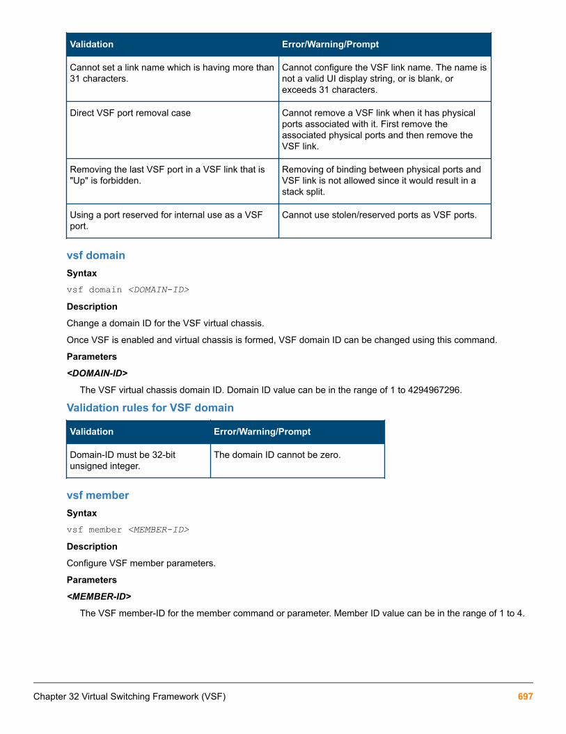
Validation Error/Warning/Prompt
Cannot set a link name which is having more than31 characters.
Cannot configure the VSF link name. The name isnot a valid UI display string, or is blank, orexceeds 31 characters.
Direct VSF port removal case Cannot remove a VSF link when it has physicalports associated with it. First remove theassociated physical ports and then remove theVSF link.
Removing the last VSF port in a VSF link that is"Up" is forbidden.
Removing of binding between physical ports andVSF link is not allowed since it would result in astack split.
Using a port reserved for internal use as a VSFport.
Cannot use stolen/reserved ports as VSF ports.
vsf domainSyntaxvsf domain <DOMAIN-ID>Description
Change a domain ID for the VSF virtual chassis.
Once VSF is enabled and virtual chassis is formed, VSF domain ID can be changed using this command.
Parameters
<DOMAIN-ID>
The VSF virtual chassis domain ID. Domain ID value can be in the range of 1 to 4294967296.
Validation rules for VSF domain
Validation Error/Warning/Prompt
Domain-ID must be 32-bitunsigned integer.
The domain ID cannot be zero.
vsf memberSyntaxvsf member <MEMBER-ID>Description
Configure VSF member parameters.
Parameters
<MEMBER-ID>
The VSF member-ID for the member command or parameter. Member ID value can be in the range of 1 to 4.
Chapter 32 Virtual Switching Framework (VSF) 697

vsf member shutdownFor a switch that physically exists, this command will cause the switch to shut down. shutdown is used inpreparation to remove the switch from the virtual chassis. The switch will not become a voting member of thevirtual chassis again until it is rejoined.
The shutdown command cannot be used on the Commander. The shutdown command will succeed only if theswitch physically exists and is an active member of the virtual chassis.
Syntaxvsf member <MEMBER-ID> shutdownDescription
Shut down the VSF virtual chassis member.
Parameters
<MEMBER-ID>
The VSF member-ID for the member command or parameter. Member ID value can be in the range of 1 to 4.
Restriction
Shutdown will not be available until VSF is enabled.
Validation rules for VSF member shutdown
Validation Error/Warning/Prompt
If member switch physically exists The specified VSF virtual chassis member will beshut down. Continue [y/n]?
If member switch physically exists and is thecommander
The VSF virtual chassis commander cannot beshut down. Please fail over to the standby first.
If member switch does not physically exist The specified VSF virtual chassis member doesnot exist.
If shutting down a member will cause a VC –split Shutting down this VSF virtual chassis member isnot allowed since it would result in a VSF virtualchassis split.
If VSF not enabled, this command is not allowed. VSF is not enabled.
vsf member rebootSyntaxboot vsf member <MEMBER-ID>Description
Reboot the VSF member and have it rejoin the virtual chassis with the current configuration. If the reboot optionis specified, the switch will come back up with a new member-ID and rejoin the virtual chassis with the currentconfiguration.
Parameters
<MEMBER-ID>
The VSF member-ID for the member command or parameter. Member ID value can be in the range of 1 to 4.
Restriction
698 Aruba 2930F / 2930M Management and Configuration Guide for ArubaOS-Switch 16.05

Reboot will not be available until VSF is enabled.
Validation rules for VSF member reboot
Validation Error/Warning/Prompt
Reboot a nonexistent or missing VSF member. The specified VSF virtual chassis member does notexist.
Reboot a standalone VSF commander. Standby does not exist and this command will notcause a switch over. System will reboot from theprimary image. Continue [y/n]?
Reboot of the member will cause VSF stack split. Rebooting this member is not allowed since it wouldresult in a stack split.
vsf member removeThis command removes the entire configuration for a specified member. After issuing the command, the specifiedmember-ID is available for reuse and may be provisioned or assigned to another device.
If the member physically exists, its configuration will be erased. It will then be powered down by default.
Syntaxvsf member <MEMBER-ID> removeDescription
Erase the VSF virtual chassis member configuration.
Parameters
<MEMBER-ID>
The VSF member-ID for the member command/ or parameter. Member ID value can be in the range of 1 to 4.
Restriction
Remove will not be available until VSF is enabled.
Validation rules for removing a VSF member
Validation Error/Warning/Prompt
If VSF not enabled, this command is not allowed. VSF is not enabled.
VSF member neither exists nor provisioned The specified VSF virtual chassis member eitherdoes not exist or is not provisioned.
VSF standby syncing add remove memberblocked
VSF virtual chassis members cannot be added orremoved while the standby is booting.
VSF member remove causes VSF virtual chassissplit
Removing this member is not allowed since itwould result in a VSF virtual chassis split.
Table Continued
Chapter 32 Virtual Switching Framework (VSF) 699

Validation Error/Warning/Prompt
VSF missing member remove The specified VSF virtual chassis member will beremoved and its configuration will be erased. Theresulting configuration will be saved. Continue[y/n]?
VSF provision member remove The specified VSF virtual chassis memberconfiguration will be erased. The resultingconfiguration will be saved. Continue [y/n]?
VSF remove commander The VSF virtual chassis commander cannot beremoved. Please fail over to standby before tryingto remove the commander.
VSF member remove The specified VSF virtual chassis member will beremoved and its configuration will be erased. Theresulting configuration will be saved. The VSFmember will be shut down. Continue [y/n]?
VSF standby remove The specified VSF virtual chassis member will beremoved and its configuration will be erased. Theresulting configuration will be saved. The VSFmember will be shut down. Continue [y/n]?
vsf member prioritySyntaxvsf member <MEMBER-ID> priority <PRIORITY>Description
Assign a priority to the specified VSF virtual chassis member. The higher the priority, the more likely that thevirtual chassis member will become the commander at the next virtual chassis reboot. The default priority value is128.
Parameters
<MEMBER-ID>
The VSF member-ID for the member command or parameter. Member ID value can be in the range of 1 to 4.
<PRIORITY>
The priority value for VSF member. Priority value can be in the range of 1 to 255.
vsf member typeThis CLI command provisions a switch with the member ID and the type defined by the specified J-number for thedevice. After provisioning the member, the user may perform any configuration on the device’s ports.
A “strict” provisioning specifies a MAC address and allows for only one device with the matching J-number andMAC to be configured.
A “loose” provisioning allows the device with the specified J-number to be configured without a MAC addressbeing specified. This allows any device which matches the J-number to adopt this configuration.
If a provisioned configuration exists with the member ID, the following command is used to change theprovisioning from “strict” and “loose” and vice versa.
Syntax
700 Aruba 2930F / 2930M Management and Configuration Guide for ArubaOS-Switch 16.05

vsf member <MEMBER-ID> type <TYPE> [mac <MAC-ADDR>]Description
Configure the family of the VSF member-switch being provisioned. After provisioning, the VSF member-switchcan be configured as if it were physically present. When a VSF member-switch matching the provisioned detailsjoins the VSF, it is provided this configuration. A new or missing VSF member can be configured as a provisioneddevice by using this command.
Parameters
<MEMBER-ID>
The VSF member-ID for the member command/parameter. Member ID value can be in the range of 1 to 4.
<TYPE>
Configure the family of the VSF member-switch being provisioned.
<MAC-ADDR>
Configure the MAC address of the VSF member switch being provisioned.
Restrictions
• If switch “N” physically exists, the command will fail.
• If switch “N” is provisioned, the command can be used to change the MAC or type.
• If the J-Number is known to not support stacking, or the J-Number is unknown, the command will fail.
• If the same MAC address is already provisioned or exists on another member ID, the command will fail.
Usage
vsf member <2> type <J9850A> mac <001122-334455>Updates the strict provisioning for VSF VC member 2, and changes the MAC address to 001122-334455.
vsf member <2> type <J9850A>Changes the “strict” provisioning for VSF VC member 2 to “loose” provisioning. The configured MAC address isthen removed.
vsf member <2> type <J9850A> mac <00aabb-cceedd>Changes “loose” provisioning for VSF VC member 2 to “strict” provisioning with MAC address 00aabb-cceedd.
Validation rules for VSF member type
Validation Error/Warning/Prompt
When a VSF member is provisioned, the link and portsalso need to be provisioned for new member to joinVSF.
Warning: The link and port should be provisioned formember 3 to join the VSF stack.
snmp-server enable traps vsfSyntax[no] snmp-server enable traps vsfDescription
Chapter 32 Virtual Switching Framework (VSF) 701

Enable traps for the VSF functionality.
Validation rules for VSF SNMP server enable traps
Validation Error/Warning/Prompt
This command cannot be executed if VSF is notenabled.
VSF is not enabled.
vsf port-speedSyntaxvsf port speed <SPEED>Description
Configure the port speed for all VSF ports. Ports that do not support the configured speed can be part of the VSF,but will not be operational. By default, the speed for the VSF is automatically set to the maximum speed of thefirst link port added. The port speed cannot be set to default if there are ports in the link. Changing the link speedof the VSF ports will trigger a reboot.
Parameters<SPEED>
The allowed values for port speeds are 1g and 10g.
Usage[no] vsf port speed <SPEED>The no form of the command cannot be executed if there are ports configured on the link. All the ports in the linkhave to be unconfigured before setting the speed to default.
Example input
Switch(config)# vsf port-speed 1g Specify the VSF ports to auto-negotiate at 1 Gbps. 10g Specify the VSF ports to auto-negotiate at 10 Gbps.
vsf vlan-madSyntaxvsf vlan-mad <VLAN-ID>Description
Configure the VSF Multi-Active Detection (MAD) VLAN. The MAD VLAN is used for stack fragment discoverywhen there is a stack split. Only one MAD VLAN can be configured.
Parameters
<VLAN-ID>
VLAN identifier or the VLAN name if configured. Vlan ID value can be in the range of 1 to 4096.
Usage[no] vsf vlan-mad <VLAN-ID>
vsf lldp-mad ipv4Syntax[no] vsf lldp-mad ipv4 <IPV4_ADDR> v2c <COMMUNITY-STR>
702 Aruba 2930F / 2930M Management and Configuration Guide for ArubaOS-Switch 16.05
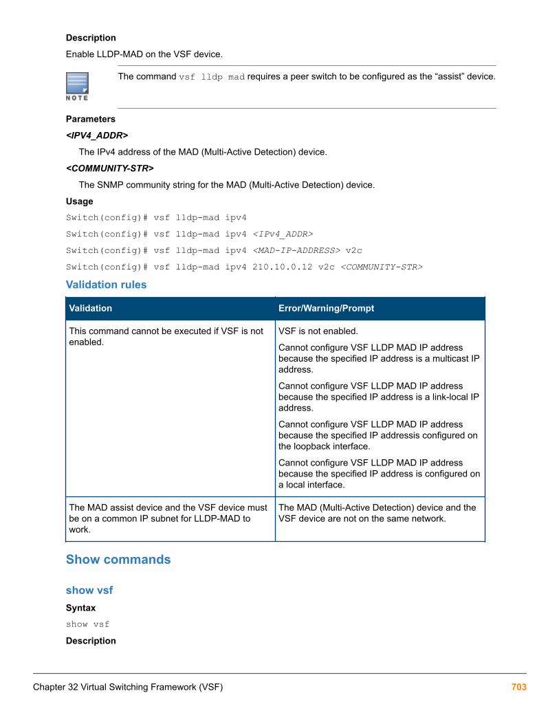
Description
Enable LLDP-MAD on the VSF device.
The command vsf lldp mad requires a peer switch to be configured as the “assist” device.
Parameters
<IPV4_ADDR>
The IPv4 address of the MAD (Multi-Active Detection) device.
<COMMUNITY-STR>
The SNMP community string for the MAD (Multi-Active Detection) device.
UsageSwitch(config)# vsf lldp-mad ipv4Switch(config)# vsf lldp-mad ipv4 <IPv4_ADDR>Switch(config)# vsf lldp-mad ipv4 <MAD-IP-ADDRESS> v2cSwitch(config)# vsf lldp-mad ipv4 210.10.0.12 v2c <COMMUNITY-STR>Validation rules
Validation Error/Warning/Prompt
This command cannot be executed if VSF is notenabled.
VSF is not enabled.
Cannot configure VSF LLDP MAD IP addressbecause the specified IP address is a multicast IPaddress.
Cannot configure VSF LLDP MAD IP addressbecause the specified IP address is a link-local IPaddress.
Cannot configure VSF LLDP MAD IP addressbecause the specified IP addressis configured onthe loopback interface.
Cannot configure VSF LLDP MAD IP addressbecause the specified IP address is configured ona local interface.
The MAD assist device and the VSF device mustbe on a common IP subnet for LLDP-MAD towork.
The MAD (Multi-Active Detection) device and theVSF device are not on the same network.
Show commands
show vsfSyntaxshow vsfDescription
Chapter 32 Virtual Switching Framework (VSF) 703

Shows the list of VSF virtual chassis members that are provisioned.
Restrictions
show vsf can be run only after VSF is enabled.
Example output
Switch# show vsf VSF Domain ID : 1234 MAC Address : b05ada-9611e3 VSF Topology : Ring VSF Status : Active Uptime : 3d 20h 59m VSF MAD : None VSF Port Speed : 1G Software Version : WC.16.03.0000x
Mbr ID MAC Address Model Pri Status --- ------------- -------------------------------------- --- --------------- 1 b05ada-9611e0 Aruba JL253A 2930F-24G-4SFP+ Switch 128 Commander *2 b05ada-971180 Aruba JL254A 2930F-48G-4SFP+ Switch 128 Standby 3 b05ada-9761c0 Aruba JL256A 2930F-48G-PoE+-4SFP+ S... 128 Member 4 b05ada-9611c0 Aruba JL253A 2930F-24G-4SFP+ Switch 128 Member The above example shows:
• Topology is ring.
• Member 1 is Commander.
• Member 2 is Standby
• Member 3 and 4 are Members.
Validation rules
Validation Error/Warning/Prompt
If VSF not enabled, this command isnot allowed.
VSF is not enabled.
show vsf detail
Syntaxshow vsf detail
Description
This commands shows detailed information related to the current state of the VSF virtual chassis.
Example output
Switch# show vsf detailVSF Domain ID : 1234MAC Address : b05ada-9611e3VSF Topology : Chain VSF Status : Active Uptime : 3d 21h 18m
704 Aruba 2930F / 2930M Management and Configuration Guide for ArubaOS-Switch 16.05

VSF MAD : None VSF Port Speed : 1G Software Version : WC.16.03.0000x
Name : Aruba-VSF-2930FContact : Location :
Member ID : 1 MAC Address : b05ada-9611e0Type : JL253AModel : Aruba JL253A 2930F-24G-4SFP+ Switch Priority : 128Status : Commander ROM Version : WC.16.01.0003 Serial Number : TW5ZHKT065 Uptime : 3d 21h 18m CPU Utilization : 0% Memory - Total : 335,503,872 bytes Free : 219,944,392 bytes VSF Links - #1 : Inactive #2 : Active, Peer member 2
Member ID : 2 MAC Address : b05ada-971180Type : JL254AModel : Aruba JL254A 2930F-48G-4SFP+ Switch Priority : 128Status : Standby ROM Version : WC.16.01.0003 Serial Number : TW5ZHKV038 Uptime : 3d 21h 15m CPU Utilization : 0% Memory - Total : 335,503,872 bytes Free : 234,746,152 bytes VSF Links - #1 : Active, Peer member 3 #2 : Active, Peer member 1
Member ID : 3 MAC Address : b05ada-9761c0Type : JL256AModel : Aruba JL256A 2930F-48G-PoE+-4SFP+ Switch Priority : 128Status : Member ROM Version : WC.16.01.0003 Serial Number : TW5ZHKX057 Uptime : 3d 21h 13m CPU Utilization : 0% Memory - Total : 335,503,872 bytes Free : 247,270,504 bytes VSF Links - #1 : Active, Peer member 2 #2 : Active, Peer member 4
Member ID : 4 MAC Address : b05ada-9611c0Type : JL253AModel : Aruba JL253A 2930F-24G-4SFP+ Switch
Chapter 32 Virtual Switching Framework (VSF) 705

Priority : 128Status : Member ROM Version : WC.16.01.0003 Serial Number : TW5ZHKT067 Uptime : 3d 21h 13m CPU Utilization : 0% Memory - Total : 335,503,872 bytes Free : 247,131,388 bytes VSF Links - #1 : Inactive #2 : Active, Peer member 3
Switch# The above example shows:
• Member 1 Link 2 is connected to Member 2 Link 2.
• Member 2 Link 1 is connected to Member 2 Link 1.
• Member 3 Link 2 is connected to Member 4 Link 2.
• Member 4 Link 1 is connected to Member 1 Link 1.
Validation rules
Validation Error/Warning/Prompt
If VSF not enabled, this command isnot allowed.
VSF is not enabled.
show vsf linkSyntaxshow vsf linkDescription
Shows the VSF port state of the VSF links for each VSF member.
Example output
Switch# show vsf link
VSF Member 1
Link Peer Peer Link Link-Name State Member Link ---- ---------- -------- ------ ---- 1 I-Link1_1 Down 0 0 2 I-Link1_2 Up 2 2
VSF Member 2
Link Peer Peer Link Link-Name State Member Link ---- ---------- -------- ------ ---- 1 I-Link2_1 Up 3 1 2 I-Link2_2 Up 1 2
706 Aruba 2930F / 2930M Management and Configuration Guide for ArubaOS-Switch 16.05
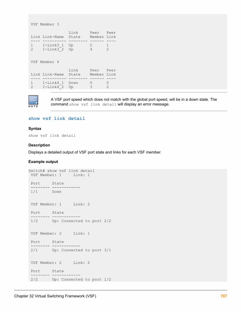
VSF Member 3
Link Peer Peer Link Link-Name State Member Link ---- ---------- -------- ------ ---- 1 I-Link3_1 Up 2 1 2 I-Link3_2 Up 4 2
VSF Member 4
Link Peer Peer Link Link-Name State Member Link ---- ---------- -------- ------ ---- 1 I-Link4_1 Down 0 0 2 I-Link4_2 Up 3 2
A VSF port speed which does not match with the global port speed, will be in a down state. Thecommand show vsf link detail will display an error message.
show vsf link detail
Syntaxshow vsf link detail
Description
Displays a detailed output of VSF port state and links for each VSF member.
Example output
Switch# show vsf link detail VSF Member: 1 Link: 1
Port State -------- ------------ 1/1 Down
VSF Member: 1 Link: 2
Port State -------- ------------ 1/2 Up: Connected to port 2/2
VSF Member: 2 Link: 1
Port State -------- ------------ 2/1 Up: Connected to port 3/1
VSF Member: 2 Link: 2
Port State -------- ------------ 2/2 Up: Connected to port 1/2
Chapter 32 Virtual Switching Framework (VSF) 707

VSF Member: 3 Link: 1
Port State -------- ------------ 3/1 Up: Connected to port 2/1
VSF Member: 3 Link: 2
Port State -------- ------------ 3/2 Up: Connected to port 4/2
VSF Member: 4 Link: 1
Port State -------- ------------ 4/1 Down
VSF Member: 4 Link: 2
Port State -------- ------------ 4/2 Up: Connected to port 3/2
show vsf memberSyntax
show vsf member <MEMBER ID>Parameters
<MEMBER ID>
The VSF member-ID for the member command or parameter. Member ID value can be in the range of 1 to 4.
Example output
Example output for Member 1:
Switch# show vsf member 1Member ID : 1 MAC Address : b05ada-9611e0Type : JL253AModel : Aruba JL253A 2930F-24G-4SFP+ SwitchPriority : 128Status : Commander ROM Version : WC.16.01.0003Serial Number : TW5ZHKT065Uptime : 3d 21h 19m CPU Utilization : 5% Memory - Total : 335,503,872 bytes Free : 219,808,496 bytes VSF Links - #1 : Inactive#2 : Active, Peer member 2Example output for Member 2:
708 Aruba 2930F / 2930M Management and Configuration Guide for ArubaOS-Switch 16.05

Switch# show vsf member 2Member ID : 2 MAC Address : b05ada-971180Type : JL254AModel : Aruba JL254A 2930F-48G-4SFP+ SwitchPriority : 128Status : Standby ROM Version : WC.16.01.0003Serial Number : TW5ZHKV038Uptime : 3d 21h 16m CPU Utilization : 0% Memory - Total : 335,503,872 bytes Free : 234,746,152 bytes VSF Links - #1 : Active, Peer member 3#2 : Active, Peer member 1Example command output for Member 3:
Switch# show vsf member 3Member ID : 3 MAC Address : b05ada-9761c0Type : JL256AModel : Aruba JL256A 2930F-48G-PoE+-4SFP+ SwitchPriority : 128Status : Member ROM Version : WC.16.01.0003Serial Number : TW5ZHKX057Uptime : 3d 21h 14m CPU Utilization : 0% Memory - Total : 335,503,872 bytes Free : 247,270,504 bytes VSF Links - #1 : Active, Peer member 2#2 : Active, Peer member 4Example command output for Member 4:
Switch# show vsf member 4Member ID : 4 MAC Address : b05ada-9611c0Type : JL253AModel : Aruba JL253A 2930F-24G-4SFP+ SwitchPriority : 128Status : MemberROM Version : WC.16.01.0003Serial Number : TW5ZHKT067Uptime : 3d 21h 14m CPU Utilization : 0% Memory - Total : 335,503,872 bytes Free : 247,131,388 bytes VSF Links - #1 : Inactive#2 : Active, Peer member 3
show vsf topologySyntaxshow vsf topologyDescription
This command shows information about VSF virtual chassis member connections.
Chapter 32 Virtual Switching Framework (VSF) 709

Example output
Switch# show vsf topology
VSF member’s interconnection with links:
Stby Cmdr +---+ +---+ +---+ +---+ | 4 |2==2| 3 |1==1| 2 |2==2| 1 | +---+ +---+ +---+ +---+ The above example shows:
• Member ID 4 Link 2 is connected to Member ID 3 Link 2.
• Member ID 3 Link 1 is connected to Member ID 2 Link 1.
• Member ID 2 Link 2 is connected to Member ID 1 Link 2.
• Member ID 1 is current VSF commander.
• Member ID 2 is current VSF standby.
show vsf topology detailSyntaxshow vsf topology detailDescription
This command displays forwarding path information (unidestination and multidestination flood path information).The unidestination forwarding takes the shortest path in terms of hop counts to reach destination member. Thecommand output provides the egress VSF link used to send traffic along the shortest path computed. The multidestination path provides the complete flood path taken along the VSF stack for the multidestination trafficingressing VSF stack or sourced at any VSF member.
Example output
Unicast Link Path:
VSF Member ID 1 2 3 4 ------------- ---- ---- ---- ---- 1 - 1 1 1 2 2 - 1 1 3 1 1 - 2 4 1 1 1 -In the above example, the unidestination traffic from Member Id 1 to Member Id 4 egresses through VSF link 1.Member Id 2 to Member Id 4 egresses through VSF link 1. Member Id 3 to Member Id 4 egresses through VSFlink 2, and so on.
Multicast Path:
VSF Member ID Path ------------- ---- 1 2-3-4 2 3-4, 1 3 2-1, 4 4 3-2-1In the above example, the multidestination traffic:
710 Aruba 2930F / 2930M Management and Configuration Guide for ArubaOS-Switch 16.05

• ingressing at Member Id 1 will be relayed to Member Id 2, Member Id 2 will further relay to Member Id 3,Member Id 3 will further relay to Member Id 4 which will not relay further. All the receiving Members willconsume multi-destination traffic before relaying further.
• ingressing or sourced at Member 2 will take two forwarding paths:
◦ Relay to Member Id 3 which will further relay to Member Id 4. Member Id 4 will consume and not relayfurther.
◦ Relay to Member Id 1. Member Id 1 will consume and not relay further.
show vsf topology change-historySyntaxshow vsf topology <change-history>Description
This command is used to display last 16 topology changes which occurred in the VSF stack and all topologytransitions which occurred in recent history, along with details on which specific VSF member or link pairwitnessed the state transitions.
Parameters<change-history>
Show VSF stack topology changes.
Example output
Switch# show vsf topology change-history Thu Apr 21 00:06:10 2017 : The link between Member 4, Link 2 and Member 3, Link 2 went UP
Thu Apr 21 00:06:10 2017 : The link between Member 3, Link 2 and Member 4, Link 2 went UP
Thu Apr 21 00:06:09 2017 : The link between Member 3, Link 1 and Member 2, Link 1 went UP
Thu Apr 21 00:06:09 2017 : The link between Member 2, Link 1 and Member 3, Link 1 went UP
Thu Apr 21 00:04:07 2017 : The link between Member 2, Link 2 and Member 1, Link 2 went UP
Thu Apr 21 00:04:07 2017 : The link between Member 1, Link 2 and Member 2, Link 2 went UP
show vsf lldp-madSyntaxshow vsf lldp-mad {parameters|status}Description
Display the VSF LLDP MAD (Multi-Active Detection) information.
Parameters
Chapter 32 Virtual Switching Framework (VSF) 711

parameters
Displays the MAD-assist configuration as well as the readiness state.
status
Displays the current state of the MAD probe.
Example output
Switch# show vsf lldp-mad parameters
MAD device IP : 134.1.5.29 MAD readiness status : Success | Failure [21:49:45, 9/Jan/2015] MAD device MAC : 08:12:2b:40:44:3a Reachable via Vlan : 10 Local LAG interface : TRK5 MAD-probe portset : 1, 7, 23 LAG connectivity : Full | Partial
Switch# show vsf lldp-mad statusMAD device IP : 134.1.5.29 MAD probe portset : 1, 7, 23
VSF split : Yes | No MAD probe originator : Yes | No Number of probe requests sent : 3 Number of probe responses received : 0 MAD Active Fragment : Yes | No
show vsf vlan-madSyntaxshow vsf vlan-madDescription
Shows information for the VSF Multi-Active Detection (MAD) VLAN.
VLAN MAD Connectivity status:
full
All member VLAN MAD ports are connected to the MAD interconnect device.
partial
Atleast one member VLAN MAD port is connected to the MAD interconnect device.
none
None of the member VLAN MAD ports are connected to the MAD interconnect device.
Example output
Switch# show vsf vlan-mad Multi-Active Detection VLAN status :
VLAN ID : 30 VLAN NAME : VLAN30 VLAN MAD Connectivity Status : Full
Port Status Member State ----- ------- --------------- 1/17 Up Commander 2/21 Up Standby
712 Aruba 2930F / 2930M Management and Configuration Guide for ArubaOS-Switch 16.05

3/21 Up Member 4/17 Up Member If a MAD VLAN is not configured:
Switch(config)# show vsf vlan-madMAD VLAN is not configuredSwitch(config)#
show vsf trunk-designated-forwarderSyntaxshow vsf trunk-designated-forwarder member <MEMBER-ID>Description
Show the designated forwarders for each trunk.
Parameters
<MEMBER-ID>
The VSF member-ID for the member command or parameter. Member ID value can be in the range of 1 to 4.
Example
Switch# show vsf trunk-designated-forwarder member 1
Trunk Designated Forwarders
NAME TYPE Forwarding Member (Flood) Forwarding Member (Unicast) ----- ----- ------------------------- --------------------------- Trk1 TRK 2 1, 2 Trk2 TRK 3 3, 4
show cpuSyntaxshow cpu <SECONDS>Description
Show average CPU utilization.
Usageshow cpu slot <SLOT-LIST> [<SECONDS>]show cpu process [slot <SLOT-LIST>] [refresh <COUNT>]Example output
Switch# show cpu slot all
VSF slot 1/a: ------------- 12 percent busy, from 18 sec ago
1 sec ave: 14 percent busy 5 sec ave: 12 percent busy 1 min ave: 12 percent busy VSF slot 1/f: ------------- 16 percent busy, from 17 sec ago 1 sec ave: 27 percent busy 5 sec ave: 16 percent busy
Chapter 32 Virtual Switching Framework (VSF) 713

1 min ave: 15 percent busy
VSF slot 2/a: ------------- 12 percent busy, from 18 sec ago 1 sec ave: 14 percent busy 5 sec ave: 12 percent busy 1 min ave: 12 percent busy
VSF slot 2/f: ------------- 16 percent busy, from 17 sec ago 1 sec ave: 27 percent busy 5 sec ave: 16 percent busy 1 min ave: 15 percent busy
=====================================
Switch# show cpu slot 1/A
VSF slot 1/a: ------------- 12 percent busy, from 18 sec ago 1 sec ave: 14 percent busy 5 sec ave: 12 percent busy 1 min ave: 12 percent busy
show power-over-ethernetSyntaxshow power-over-ethernet vsf member <MEMBER-ID>Description
Show PoE information of specified VSF member.
Parameters
<MEMBER-ID>
The VSF member-ID for the member command or parameter. Member ID value can be in the range of 1 to 4.
Example
For show power-over-ethernet vsf member 4:
Switch# show power-over-ethernet vsf member 4
Status and Counters - System Power Status for member 4
Maximum Power : 370 W Operational Status : On Power In Use : 0 W +/- 6 W Usage Threshold (%) : 80
show system informationSyntaxshow system information [vsf member <MEMBER-ID>]Description
Show global configured and operational system parameters. If VSF is enabled, this shows the system informationfor all VSF members.
Parameters
714 Aruba 2930F / 2930M Management and Configuration Guide for ArubaOS-Switch 16.05

<MEMBER-ID>
The VSF member-ID for the member command or parameter. Member ID value can be in the range from 1 to4.
Example
Switch# show system information
Status and Counters - General System Information
System Name : Switch System Contact : System Location : MAC Age Time (sec) : 300 Time Zone : 0 Daylight Time Rule : None
Software revision : WC.16.03.0005A Base MAC Addr : b05ada-968423
VSF-Member :1
ROM Version : WC.16.01.0003 Up Time : 4 mins CPU Util (%) : 0 MAC Addr : b05ada-96a080 Serial Number : TW5ZHKW029 Memory - Total : 350,290,432 Free : 262,604,456
VSF-Member :2
ROM Version : WC.16.01.0003 Up Time : 4 mins CPU Util (%) : 0 MAC Addr : b05ada-968420 Serial Number : CN65HKT02B Memory - Total : 350,290,432 Free : 235,467,044
Memory - Total : 350,290,432 Free : 250,085,732
VSF-Member :4
ROM Version : WC.16.01.0003 Up Time : 3 mins CPU Util (%) : 0 MAC Addr : b05ada-964640 Serial Number : CN65HKW018 Memory - Total : 350,290,432 Free : 262,729,172
show system information vsf memberSyntax
Chapter 32 Virtual Switching Framework (VSF) 715

show system information vsf member <MEMBER-ID>Description
Show global configured and operational system parameters of the specified VSF members.
Parameters
<MEMBER-ID>
The VSF member-ID for the member command or parameter. Member ID value can be in the range of 1 to 4.
Example output
Switch# show system information vsf member 1
Status and Counters - General System Information Daylight Time Rule : None
Software revision : WC.16.03.0005A Base MAC Addr : b05ada-968423
VSF-Member :1
ROM Version : WC.16.01.0003 Up Time : 4 mins CPU Util (%) : 0 MAC Addr : b05ada-96a080 Serial Number : TW5ZHKW029 Memory - Total : 350,290,432 Free : 262,604,456
======================================================Switch# show system information vsf member 2
Status and Counters - General System Information Daylight Time Rule : None
Software revision : WC.16.03.0005A Base MAC Addr : b05ada-968423
VSF-Member :2
ROM Version : WC.16.01.0003 Up Time : 5 mins CPU Util (%) : 0 MAC Addr : b05ada-968420 Serial Number : CN65HKT02B Memory - Total : 350,290,432 Free : 235,369,964
======================================================Switch# show system information vsf member 3
Status and Counters - General System Information Daylight Time Rule : None
Software revision : WC.16.03.0005A Base MAC Addr : b05ada-968423
716 Aruba 2930F / 2930M Management and Configuration Guide for ArubaOS-Switch 16.05

VSF-Member :3
ROM Version : WC.16.01.0003 Up Time : 5 mins CPU Util (%) : 2 MAC Addr : b05ada-9694e0 Serial Number : CN65HKT017 Memory - Total : 350,290,432 Free : 249,987,056
======================================================Switch# show system information vsf member 4
Status and Counters - General System Information Time Zone : 0 Daylight Time Rule : None
Software revision : WC.16.03.0005A Base MAC Addr : b05ada-968423
VSF-Member :4
ROM Version : WC.16.01.0003 Up Time : 4 mins CPU Util (%) : 0 MAC Addr : b05ada-964640 Serial Number : CN65HKW018 Memory - Total : 350,290,432 Free : 262,729,172
show system fansSyntaxshow system fans [vsf member <MEMBER-ID>]Description
Show system fan status. If VSF is enabled, this shows the system fan status for all VSF members.
Parameters
<MEMBER-ID>
The VSF member-ID for the member command parameter. Member ID value can be in the range of 1 to 4.
Example output
Switch# show system fans Fan Information
VSF-Member 1
Num | State | Failures -------+-------------+---------- Sys-1 | Fan OK | 0 Sys-2 | Fan OK | 0 Sys-3 | Fan OK | 0 Sys-4 | Fan OK | 0
0 / 4 Fans in Failure state 0 / 4 Fans have been in Failure state
VSF-Member 2
Chapter 32 Virtual Switching Framework (VSF) 717

Num | State | Failures -------+-------------+---------- Sys-1 | Fan OK | 0 Sys-2 | Fan OK | 0 Sys-3 | Fan OK | 0 Sys-4 | Fan OK | 0
0 / 4 Fans in Failure state 0 / 4 Fans have been in Failure state
VSF-Member 3
Num | State | Failures -------+-------------+---------- Sys-1 | Fan OK | 0 Sys-2 | Fan OK | 0 Sys-3 | Fan OK | 0 Sys-4 | Fan OK | 0
0 / 4 Fans in Failure state 0 / 4 Fans have been in Failure state
=============================================
Switch# show system fans vsf member 1 Fan Information
VSF-Member 1
Num | State | Failures -------+-------------+---------- Sys-1 | Fan OK | 0 Sys-2 | Fan OK | 0 Sys-3 | Fan OK | 0 Sys-4 | Fan OK | 0
0 / 4 Fans in Failure state 0 / 4 Fans have been in Failure state
show system chassislocateSyntaxshow system chassislocate [vsf member <MEMBER-ID>]Description
Show locator LED information. If VSF is enabled, this shows locator LED information for all the VSF members.
Parameters
<MEMBER-ID>
The VSF member-ID for the member command or parameter. Member ID value can be in the range of 1 to 4.
Example output
Switch# show system chassislocate
Locator LED Status
Current Time Member State Remaining Configuration ------ ------- --------- ------------- 1 off
718 Aruba 2930F / 2930M Management and Configuration Guide for ArubaOS-Switch 16.05

2 off 3 off 4 off==============================================
show system chassislocate vsf member 3
Locator LED Status
Current Time Member State Remaining Configuration ------ ------- --------- ------------- 3 off
show system power-supply
Description
Show chassis power supply information. If VSF is enabled, this shows power supply information for all the VSFmembers.
Example output
Switch(config)# show system power-supply
Power Supply Status:
VSF Member PS# Model Serial State AC/DC + V Wattage
------- ----- --------- ----------- --------------- ----------------- -------- 4 1 Not Avail Not Avail Powered AC 120V/240V 500
Switch(config)# show system power-supply
show uptimeSyntaxshow uptime [vsf member <MEMBER-ID>]Description
Display the elapsed time since the last boot of the specified member.
Parameters
<MEMBER-ID>
The VSF member-ID for the member command or parameter. Member ID value can be in the range of 1 to 4.
Example output
Switch(config)# show uptime vsf member 4 VSF Member 4 0d 4h 5m
Support commands
copy core-dumpCopy core-dump from the specified VSF member. User can copy available core-dump file from interface moduleor management module.
Chapter 32 Virtual Switching Framework (VSF) 719

Syntax
copy core-dump vsf member <MEMBER-ID> <SLOT-ID> | mm-active sftp | tftp | usb | xmodem <HOST-NAME-STR> | <IP-ADDR> | <IPV6-ADDR> <FILENAME-STR>Description
The VSF member-ID for the member command or parameter. Member ID value can be in the range from 1 to 4.
Parameters
<MEMBER-ID>
Specify the VSF member.
<SLOT-ID>
Copy interface module core-dump file.
copy fdr-logCopy FDR (Flight data recorder) logs. User can either copy from management module or interface module orboth.
Syntax
copy fdr-log vsf member <MEMBER-ID> all | mm-active sftp | tftp | usb | xmodem <HOST-NAME-STR> | <IP-ADDR> | <IPV6-ADDR> <FILENAME-STR>
Description
Copy FDR logs from the switch to an SFTP/TFTP server, USB or xmodem terminal.
Parameters
<MEMBER-ID>
The VSF member-ID for the member command or parameter. Member ID value can be in the range from 1 to4.
copy crash-logSyntax
copy crash-log vsf member <MEMBER-ID> | <SLOT-ID-RANGE> | mm | sftp | tftp | usb | xmodem sftp | tftp | usb | xmodem <HOST-NAME-STR> | <IP-ADDR> | <IPV6-ADDR> <FILENAME-STR>
Description
Copy the switch log file.
Parameters
<MEMBER-ID>
The VSF member-ID for the member command or parameter. Member ID value can be in the range from 1 to4.
<SLOT-ID-RANGE>
Enter the single slot identifier.
copy crash-dataCopy the crash data file of the switch.
720 Aruba 2930F / 2930M Management and Configuration Guide for ArubaOS-Switch 16.05

Syntaxcopy crash-data vsf member <MEMBER-ID> <SLOT-ID-RANGE> | mm | sftp | tftp | usb | xmodem sftp | tftp | usb | xmodem <HOST-NAME-STR> | <IP-ADDR> | <IPV6-ADDR> <FILENAME-STR>
Description
Copy the switch crash data file.
Parameters
<MEMBER-ID>
The VSF member-ID for the member command or parameter. Member ID value can be in the range from 1 to4.
<SLOT-ID-RANGE>
Enter the single slot identifier.
show boot-historySyntaxshow boot-history [vsf member <MEMBER-ID>]Description
Display the system boot log for VSF.
Parameters
<MEMBER-ID>
The VSF member-ID for the member command or parameter. Member ID value can be in the range from 1 to4.
core-dumpEnable/disable core-dump for the specified member. User can enable/disable core-dump for interface modules ormanagement module.
Syntax
core-dump interfaces | management-module | vsf | tftp-server member <MEMBER-ID> interfaces | management-module
Description
Enable/disable core-dump on the management module or the interface module.
Parameters
interfaces
Enable/disable core dump on all the interfaces.
management-module
Enable/disable core-dump on the management module.
tftp-server
Address of the auto TFTP server to which the files will be uploaded.
<MEMBER-ID>
The VSF member-ID for the member command or parameter. Member ID value can be in the range from 1 to4.
Chapter 32 Virtual Switching Framework (VSF) 721

erase fdr-log vsfErase FDR log from the specified member.
Syntaxerase fdr-log [vsf member <MEMBER-ID>] [slot | mm-active]Description
Erase the FDR log files.
Parameters
<MEMBER-ID>
The VSF member-ID for the member command or parameter. Member ID value can be in the range from 1 to4.
copy crash-filesSyntaxcopy crash-files vsf member <MEMBER-ID> [<SLOT-ID-RANGE> | mm-active sftp | tftp |usb | xmodem] <HOST-NAME-STR> | <IP-ADDR> | <IPV6-ADDR> <FILENAME-STR>Description
Copy the switch crash files from the specific VSF member
Parameters
mm-active
Copy active management module crash files.
<MEMBER-ID>
The VSF member-ID for the member command or parameter. Member ID value can be in the range from 1 to4.
<SLOT-ID-RANGE>
Enter single slot identifier.
UsageSwitch(config)# copy crash-files vsf memberSwitch(config)# copy crash-files vsf member 1
VSF configurationThere are two methods to configure VSF for a switch:
• Manual configuration. See Manual configuration of a VSF.
• Automatic configuration. See Automatic configuration of a VSF.
722 Aruba 2930F / 2930M Management and Configuration Guide for ArubaOS-Switch 16.05
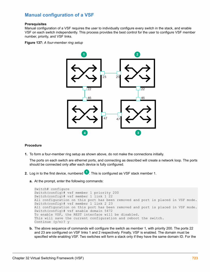
Manual configuration of a VSF
PrerequisitesManual configuration of a VSF requires the user to individually configure every switch in the stack, and enableVSF on each switch independently. This process provides the best control for the user to configure VSF membernumber, priority, and VSF links.
Figure 137: A four-member ring setup
Procedure
1. To form a four-member ring setup as shown above, do not make the connections initially.
The ports on each switch are ethernet ports, and connecting as described will create a network loop. The portsshould be connected only after each device is fully configured.
2. Log in to the first device, numbered . This is configured as VSF stack member 1.
a. At the prompt, enter the following commands:
Switch# configureSwitch(config)# vsf member 1 priority 200Switch(config)# vsf member 1 link 1 22All configuration on this port has been removed and port is placed in VSF mode.Switch(config)# vsf member 1 link 2 23All configuration on this port has been removed and port is placed in VSF mode.Switch(config)# vsf enable domain 5472To enable VSF, the REST interface will be disabled.This will save the current configuration and reboot the switch.Continue (y/n)? y
b. The above sequence of commands will configure the switch as member 1, with priority 200. The ports 22and 23 are configured on VSF links 1 and 2 respectively. Finally, VSF is enabled. The domain must bespecified while enabling VSF. Two switches will form a stack only if they have the same domain ID. For the
Chapter 32 Virtual Switching Framework (VSF) 723

MAD protocols to work effectively, it is recommended for each VSF stack in a network to have uniquedomain IDs.
3. Log in to the second device, numbered . This is configured as VSF member 2.
a. At the prompt, enter the following commands:
Switch# configureSwitch(config)# vsf member 2 priority 150Switch(config)# vsf member 2 link 1 22All configuration on this port has been removed and port is placed in VSF mode.Switch(config)# vsf member 2 link 2 23All configuration on this port has been removed and port is placed in VSF mode.Switch(config)# vsf enable domain 5472To enable VSF, the REST interface will be disabled.This will save the current configuration and reboot the switch.Continue (y/n)? y
b. The above sequence of commands will configure the switch as member 2, with priority 150. A switch withhigher priority has a higher chance of becoming commander on the next boot.
4. Log in to the third and fourth devices (configured as members and respectively).
a. Enter the following commands on device 3:
Switch# configureSwitch(config)# vsf member 3 priority 100Switch(config)# vsf member 3 link 1 46All configuration on this port has been removed and port is placed in VSF mode.Switch(config)# vsf member 3 link 2 47All configuration on this port has been removed and port is placed in VSF mode.Switch(config)# vsf enable domain 5472To enable VSF, the REST interface will be disabled.This will save the current configuration and reboot the switch.Continue (y/n)? y
b. Enter the following commands on device 4:
Switch# configureSwitch(config)# vsf member 4 priority 100Switch(config)# vsf member 4 link 1 46All configuration on this port has been removed and port is placed in VSF mode.Switch(config)# vsf member 4 link 2 47All configuration on this port has been removed and port is placed in VSF mode.Switch(config)# vsf enable domain 5472To enable VSF, the REST interface will be disabled.This will save the current configuration and reboot the switch.Continue (y/n)? yBoth the switches have priority set to 100, and have ports 46 and 47 on VSF links 1 & 2 respectively. Allfour switches have been configured to use the same domain ID: 5472.
5. Connect the switches together as shown, upon configuration completion. The stack forms once the cables areconnected. Multiple reboots of the switch may occur since the switch roles change when connected together.To prevent this, the user can power off all switches, connect the cables, and power on together. The stack willform directly.
6. The final VSF stack configuration after the stack formation is:
724 Aruba 2930F / 2930M Management and Configuration Guide for ArubaOS-Switch 16.05
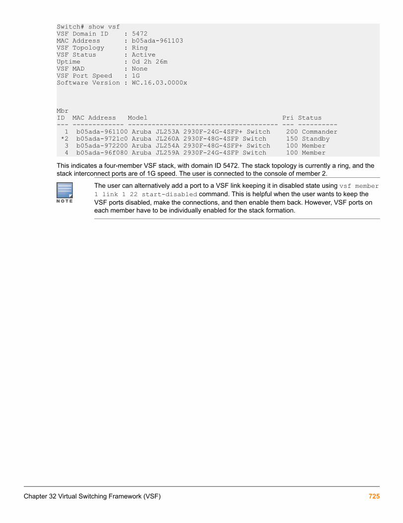
Switch# show vsfVSF Domain ID : 5472MAC Address : b05ada-961103VSF Topology : RingVSF Status : ActiveUptime : 0d 2h 26mVSF MAD : NoneVSF Port Speed : 1GSoftware Version : WC.16.03.0000x
MbrID MAC Address Model Pri Status--- ------------- -------------------------------------- --- ---------- 1 b05ada-961100 Aruba JL253A 2930F-24G-4SFP+ Switch 200 Commander *2 b05ada-9721c0 Aruba JL260A 2930F-48G-4SFP Switch 150 Standby 3 b05ada-972200 Aruba JL254A 2930F-48G-4SFP+ Switch 100 Member 4 b05ada-96f080 Aruba JL259A 2930F-24G-4SFP Switch 100 MemberThis indicates a four-member VSF stack, with domain ID 5472. The stack topology is currently a ring, and thestack interconnect ports are of 1G speed. The user is connected to the console of member 2.
The user can alternatively add a port to a VSF link keeping it in disabled state using vsf member1 link 1 22 start-disabled command. This is helpful when the user wants to keep theVSF ports disabled, make the connections, and then enable them back. However, VSF ports oneach member have to be individually enabled for the stack formation.
Chapter 32 Virtual Switching Framework (VSF) 725

Manual configuration with multiple ports bundled in a VSF linkIn manual configuration of a switch with multiple ports bundled in a VSF link, up to eight VSF ports can beaggregated in a single VSF link. This creates a load-balanced aggregate VSF connection with redundancy.
Figure 138: Manual configuration with multiple ports bundled in a VSF link
Procedure
1. Log in to the second device. This will be configured as VSF member . At the prompt, enter the followingcommands:
Switch# configureSwitch(config)# vsf member 2 priority 150Switch(config)# vsf member 2 link 1 25-28 start-disabledAll configuration on this port has been removed and port is placed in VSF mode.Switch(config)# vsf member 2 link 2 49-52 start-disabledAll configuration on this port has been removed and port is placed in VSF mode.Switch(config)# vsf enable domain 5472To enable VSF, the REST interface will be disabled.This will save the current configuration and reboot the switch.Continue (y/n)? y
2. Log in to the third device and fourth devices. These will be configured as members and respectively.Enter the following commands on device 3:
Switch# configureSwitch(config)# vsf member 3 priority 100Switch(config)# vsf member 3 link 1 25-28 start-disabledAll configuration on this port has been removed and port is placed in VSF mode.Switch(config)# vsf member 3 link 2 49-52 start-disabled
726 Aruba 2930F / 2930M Management and Configuration Guide for ArubaOS-Switch 16.05

All configuration on this port has been removed and port is placed in VSF mode.Switch(config)# vsf enable domain 5472To enable VSF, the REST interface will be disabled.This will save the current configuration and reboot the switch.Continue (y/n)? yEnter the following commands on device 4:
Switch# configureSwitch(config)# vsf member 4 priority 100Switch(config)# vsf member 4 link 1 25-28 start-disabledAll configuration on this port has been removed and port is placed in VSF mode.Switch(config)# vsf member 4 link 2 49-52 start-disabledAll configuration on this port has been removed and port is placed in VSF mode.Switch(config)# vsf enable domain 5472To enable VSF, the REST interface will be disabled.This will save the current configuration and reboot the switch.Continue (y/n)? y
3. By now, each switch is booted as an individual commander. Enable VSF ports for each VSF link on allswitches separately for the stack formation:
Switch(config)# show vsfVSF Domain ID : 5472MAC Address : b05ada-961103VSF Topology : No Stack FormedVSF Status : ActiveUptime : 0d 2h 26mVSF MAD : NoneVSF Port Speed : 1GSoftware Version : WC.16.03.0000x
MbrID MAC Address Model Pri Status--- ------------- -------------------------------------- --- ---------*1 b05ada-961100 Aruba JL253A 2930F-24G-4SFP+ Switch 200 Commander
Switch(config)# interface 1/25-1/28,1/49-1/52 enable
Switch(config)# show vsfVSF Domain ID : 5472MAC Address : b05ada-9721c0VSF Topology : No Stack FormedVSF Status : ActiveUptime : 0d 2h 26mVSF MAD : NoneVSF Port Speed : 1GSoftware Version : WC.16.03.0000x
MbrID MAC Address Model Pri Status--- ------------- -------------------------------------- --- ---------*2 b05ada-9721c0 Aruba JL260A 2930F-48G-4SFP Switch 150 Commander
Switch(config)# interface 2/25-2/28,2/49-2/52 enable
Switch(config)# show vsfVSF Domain ID : 5472MAC Address : b05ada-972200VSF Topology : No Stack FormedVSF Status : ActiveUptime : 0d 2h 26mVSF MAD : NoneVSF Port Speed : 1G
Chapter 32 Virtual Switching Framework (VSF) 727

Software Version : WC.16.03.0000x
MbrID MAC Address Model Pri Status--- ------------- -------------------------------------- --- ---------*3 b05ada-972200 Aruba JL254A 2930F-48G-4SFP+ Switch 100 Commander
Switch(config)# interface 3/25-3/28,3/49-3/52 enable Switch(config)# show vsfVSF Domain ID : 5472MAC Address : b05ada-96f080VSF Topology : No Stack FormedVSF Status : ActiveUptime : 0d 2h 26mVSF MAD : NoneVSF Port Speed : 1GSoftware Version : WC.16.03.0000x
MbrID MAC Address Model Pri Status--- ------------- -------------------------------------- --- ---------*4 b05ada-96f080 Aruba JL259A 2930F-24G-4SFP Switch 100 Commander
Switch(config)# interface 4/25-4/28,4/49-4/52 enable4. Once the interfaces are enabled, the stack is formed. This may result in multiple reboots of switches, since
their roles will change when connected together.
Automatic configuration of a VSF fabricAutomatic configuration of a VSF is simpler than the manual configuration, as it only requires the user to log inand configure one switch. The other switches automatically get their configurations from the first switch, but only ifthe switches are in factory default state. Automatic configuration is not supported on switches that have beenpreviously deployed, or have had any configuration change made to them, over either CLI, web, or SNMP. Aswitch may be restored to factory default state by using the CLI command erase startup-configurationcommand.
1. Do not connect the ports initially. Since the ports are ethernet ports, connecting them in a ring topology cancause loops. Note down the J-number & MAC address of each switch. The J-number is available on the frontpanel of the switch while the MAC address is available on the back panel of the switch.
2. Connect to the console of the member intended to be the commander (member 1 in this example). Executethe following commands to enable VSF on the member:
Switch# configureSwitch(config)# vsf member 1 priority 200Switch(config)# vsf member 1 link 1 22All configuration on this port has been removed and port is placed in VSF mode.Switch(config)# vsf member 1 link 2 23All configuration on this port has been removed and port is placed in VSF mode.Switch(config)# vsf enable domain 3144To enable VSF, the REST interface will be disabled.This will save the current configuration and reboot the switch.Continue (y/n)? yThe above sequence of commands will configure the switch as member 1, with priority 200. The ports 22 and23 are configured on VSF links 1 and 2 respectively. VSF is now enabled. The domain must be specified whileenabling VSF. It is recommended for each VSF stack in a network to have unique domain IDs, for the MADprotocols to work effectively.
728 Aruba 2930F / 2930M Management and Configuration Guide for ArubaOS-Switch 16.05

3. Upon reboot, the switch is a one-member stack. Execute the show vsf command:
Switch# show vsf
VSF Domain ID : 3144MAC Address : b05ada-961103VSF Topology : No Stack FormedVSF Status : ActiveUptime : 0d 3h 22mVSF MAD : NoneVSF Port Speed : 1GSoftware Version : WC.16.03.0000x
MbrID MAC Address Model Pri Status--- ------------- -------------------------------------- --- ---------------*1 b05ada-961100 Aruba JL253A 2930F-24G-4SFP+ Switch 200 Commander
4. Provision the configuration for each of the other switches. Provisioning allows the user to specify the type ofeach switch in the stack. Once provisioned, the user can make configuration changes on ports of the switch.When the switch joins the stack, it will automatically get any configuration made. Provision member 2:
Switch# configureSwitch(config)# vsf member 2 type JL260A mac-address b05ada-9721c0This will save the current configuration. Continue (y/n)? y
Warning - The link and port should be provisioned for member 2 tojoin the VSF stack.
Switch(config)# vsf member 2 priority 150Switch(config)# vsf member 2 link 1 2/22All configuration on this port has been removed and port is placed in VSF mode.Switch(config)# vsf member 2 link 2 2/23All configuration on this port has been removed and port is placed in VSF mode.Switch(config)#The member number, switch type, and mac address are specified first. Once this command is executed, theports of the switch are now available to be configured, as 2/1, 2/2 etc. The links of member 2 are alsoprovisioned, using ports 2/22 and 2/23 on links 1 & 2 respectively. The provisioned switch also shows up in thestack configuration:
Switch# show vsf
VSF Domain ID : 3144MAC Address : b05ada-961103VSF Topology : No Stack FormedVSF Status : ActiveUptime : 0d 3h 22mVSF MAD : NoneVSF Port Speed : 1GSoftware Version : WC.16.03.0000x
MbrID MAC Address Model Pri Status--- ------------- -------------------------------------- --- ---------------*1 b05ada-961100 Aruba JL253A 2930F-24G-4SFP+ Switch 200 Commander 2 b05ada-9721c0 Aruba JL260A 2930F-48G-4SFP Switch 150 Provisioned
5. The same procedure is repeated to provision switches 3 & 4 too. Enter the following commands on the consoleto continue configuring and provisioning switches 3 & 4:
Switch(config)# vsf member 3 type JL254A mac-address b05ada-972200This will save the current configuration. Continue (y/n)? y
Chapter 32 Virtual Switching Framework (VSF) 729

Warning - The link and port should be provisioned for member 3 tojoin the VSF stack.
Switch(config)# vsf member 3 link 1 3/46All configuration on this port has been removed and port is placed in VSF mode.Switch(config)# vsf member 3 link 2 3/47All configuration on this port has been removed and port is placed in VSF mode.Switch(config)# vsf member 4 type JL259A mac-address b05ada-96f080This will save the current configuration. Continue (y/n)? y
Warning - The link and port should be provisioned for member 4 tojoin the VSF stack.
Switch(config)# vsf member 4 link 1 4/46All configuration on this port has been removed and port is placed in VSF mode.Switch(config)# vsf member 4 link 2 4/47All configuration on this port has been removed and port is placed in VSF mode.The provisioned switch also shows up in the stack configuration:
Switch# show vsf
VSF Domain ID : 3144MAC Address : b05ada-961103VSF Topology : No Stack FormedVSF Status : ActiveUptime : 0d 3h 22mVSF MAD : NoneVSF Port Speed : 1GSoftware Version : WC.16.03.0000x
MbrID MAC Address Model Pri Status--- ------------- -------------------------------------- --- ---------------*1 b05ada-961100 Aruba JL253A 2930F-24G-4SFP+ Switch 200 Commander 2 b05ada-9721c0 Aruba JL260A 2930F-48G-4SFP Switch 150 Provisioned
730 Aruba 2930F / 2930M Management and Configuration Guide for ArubaOS-Switch 16.05

3 b05ada-972200 Aruba JL254A 2930F-48G-4SFP+ Switch 128 Provisioned 4 b05ada-96f080 Aruba JL259A 2930F-24G-4SFP Switch 128 Provisioned
6. All switches can be now interconnected and powered on. Connect all the switches as shown:
Procedure
• Power on the switches after the connections have been made.
• Each of the three switches in factory-default configuration will boot up normally, as a standalone switch.
• The VSF enabled switch will push down the VSF configuration information to the other switches over the VSFlink ports.
• Since switches 2 and 4 are the directly connected switches, they will receive their configuration first, andreboot.
• This procedure takes between 30 seconds to 1 minute after booting up.
• Once switches 2 & 4 have joined the stack, they push the VSF configuration on to switch 3.
• Switch 3 will reboot last, and join the stack.
• The final stack configuration will now include all switches.
Switch# show vsf
VSF Domain ID : 3144MAC Address : b05ada-961103VSF Topology : RingVSF Status : ActiveUptime : 0d 3h 22mVSF MAD : NoneVSF Port Speed : 1GSoftware Version : WC.16.03.0000x
MbrID MAC Address Model Pri Status--- ------------- -------------------------------------- --- ---------------
Chapter 32 Virtual Switching Framework (VSF) 731

*1 b05ada-961100 Aruba JL253A 2930F-24G-4SFP+ Switch 200 Commander 2 b05ada-9721c0 Aruba JL260A 2930F-48G-4SFP Switch 150 Standby 3 b05ada-972200 Aruba JL254A 2930F-48G-4SFP+ Switch 128 Member 4 b05ada-96f080 Aruba JL259A 2930F-24G-4SFP Switch 128 Member
In this scenario, specifying the MAC address of each provisioned switch is optional. If the MACaddress is not specified, the switch is termed a loose-provisioned switch. When the commanderconfigures a switch connected on a VSF link port, it will find the first provisioned switch whichmatches the J-number, and push the configuration to the connected switch.
Port speedThe 2930 switches support only one port speed across all VSF ports in the stack. This port speed is configurable,and is initially set automatically to the highest speed capable by the first VSF port that is configured.
Users can add ports of any speed to a VSF link. Only ports which match the configured VSF port speed will linkup in the VSF stack. Ports which do not match the VSF port speed will be in an error state, stating port speedmismatch. This new feature allows users to migrate a stack based on 1G interconnects to a stack based on 10Ginterconnects, and vice-versa, without having to reform the VSF stack from the beginning. The migrationprocedure from 1G interconnects to 10G interconnects is:
In a stack with 1G interconnects, the user simply adds the 10G ports to each link. These ports should also bephysically interconnected, but they will not link up. Once all the configuration is complete and the interconnectionsare made, the user changes the port speed using the command vsf port-speed 10g. This triggers a reboot ofthe stack, and once the stack is reformed, it uses the configured 10G ports while the 1G ports will be in errorstate. The 1G ports can now be disconnected and unconfigured.
In the case of transceiver ports, the speed is determined by the bay type. An SFP+ bay, if configured,will set port speed to 10G. If an SFP transceiver is inserted into the bay, it will not link up and be inerror state.
VSF port LED front panelOn enabling the VSF link ports, the LED flashes solid orange state in the front panel. The user can recognize andconnect the VSF link ports. Solid orange LED state indicates:
• Port is reserved.
• Port is reserved but disabled.
• Post is reserved and not linked up. The port LED starts showing activity by flashing green when it links up tothe partner port, and successfully forms the VSF stack.
Selecting Usr in the front panel displays stack member information. For example:
• Port1 LED indicates status of Stack Member 1.
• Port2 LED indicates status of Stack Member 2.
732 Aruba 2930F / 2930M Management and Configuration Guide for ArubaOS-Switch 16.05

Table 36: Mode LED states and indication
LED States Indication
Slow flash green Stack member number of the displaying chassis
Fast flash green Stack member number of the commander chassis.
On orange Stack member is faulty or in a booting condition.
Off Stack member does not exist in the stack.
VSF port LEDsTable 37: VSF port LEDs
Global Status LED Mode LED Usr Port LED Diagnostic tips
Solid green Solid green Solid orange See LED 1 and LED 2display solid greencolor, whereas, LED 3displays solid orange onpage 734
Slow flash orange Solid green Slow flash green-MemberFast flash green-CommanderSolid green-Member with goodstacking connectionSlowflash orange-Member withpoor stacking connection
See LED 1 displays slowflash orange, LED 2displays solid green,whereas, LED 3 displaysdifferent colors on page734
Slow flash orange Solid green Slow flash green-MemberFast flash green-CommanderSlow flashorange-Member in anotherfragment
See LED 1 displays slowflash orange and LED 2displays solid greencolor, whereas, LED 3displays different colorson page 735
Solid green Solid green Slow flash green-MemberFast flash green-Commander
See LED 1 and LED 2display solid green,whereas, LED 3 displaysdifferent colors on page735
Solid green Solid green Slow flash green-MemberFast flash green-Commander
See LED 1 and LED 2display solid green,whereas, LED 3 displaysdifferent colors on page735
Diagnostic tips for stacking error
Chapter 32 Virtual Switching Framework (VSF) 733

LED 1 and LED 2 display solid green color, whereas, LED 3 displays solid orange
Symptom
LED 1 and LED 2 display solid green color, whereas, LED 3 is off. 1
1 LED 1 is Global Status LED, LED 2 is Mode LED Usr, and LED 3 is Port LED.
Cause
Stacking is disabled on the switch. The member is unreachable or booting.
Action
1. Connect a console cable to the switch and establish a console session.
2. Enter vsf enable domain <ID> from the CLI config context.
3. Recheck the switch LEDs:
Stacking port LED is back to solid green. Port LED in user mode is green.
LED 1 displays slow flash orange, LED 2 displays solid green, whereas, LED 3 displaysdifferent colors
Symptom
LED 1 displays slow flash orange and LED 2 displays solid green. LED 3 displays slow flash green, fast flashgreen, slow flash orange, or solid green.1
1 LED 1 is Global Status LED, LED 2 is Mode LED Usr, and LED 3 is Port LED.
Solution 1
Cause
The interface cable is connected to the VSF port on which the link LED is blinking.
Action
1. Make sure that the stacking cable is fully connected at both ends of the link.
2. If an equipment failure has occurred, see the LEDs on the device at the other end of the connection.
Solution 2
Cause
A stacking link failure has occurred on a link that was functioning:
• The switch at the other end of the VSF port cable has been powered off.
• The stacking feature is disabled on the switch at the other end of the VSF port cable.
• The cable is faulty.
734 Aruba 2930F / 2930M Management and Configuration Guide for ArubaOS-Switch 16.05

Action
1. If this error occurred on an operational stack, it could result in changes to the stack configuration. This caninclude election of a new stack commander and possibly a new standby. Ensure that the correct set ofsupported cabling is used for installed transceivers or RJ45 fixed port.
2. See the Stack Management chapter in the 2930F Advance Traffic Management Guide for more information.Contact your Hewlett Packard Enterprise authorized network reseller, or use the electronic support servicesfrom Hewlett Packard Enterprise to get assistance. See www.hpe.com/support/hpesc.
LED 1 displays slow flash orange and LED 2 displays solid green color, whereas, LED 3displays different colors
Symptom
LED 1 displays slow flash orange and LED 2 displays solid green color. LED 3 displays slow flash green, fastflash green, or slow flash orange.1
1 LED 1 is Global Status LED, LED 2 is Mode LED Usr, and LED 3 is Port LED.
Cause
A stack link failure has occurred in a chain topology and multiple stack fragments have been created. Eachfragment will elect a Commander, so there will be multiple switches with the Cmd LED on.
Action
1. Repair the cause of the stack link failure.
2. Reconnect the switches in their original topology so that the switches can reform the original stack.
LED 1 and LED 2 display solid green, whereas, LED 3 displays different colors
Symptom
LED 1 and LED 2 display solid green, whereas, LED 3 displays slow flash green and fast flash green.1
1 LED 1 is Global Status LED, LED 2 is Mode LED Usr, and LED 3 is Port LED.
Cause
Merging two stacks that have different stack IDs which were not previously part of the same stack.
Action
1. Select one of the stacks as the one to retain.
2. Erase the stacking configuration for each switch in the other stack by issuing stacking factory-reset atthe config level. The startup configuration for each switch is erased, including the stacking configuration.
3. Add the switches to the stack as described in the Stack Management chapter of the ArubaOS-SwitchAdvanced Traffic Management Guide K/KA/KB.16.01.
Chapter 32 Virtual Switching Framework (VSF) 735

Locating LED behavior in stacking systemTable 38: Locating LED behavior in stacking system
Switch LED State Meaning
Locator(blue) Standalonecommander ChassisLocate On | Off| Blink
On-Blinking-Off The Locator LED is used to identifya specific switch in the networkequipment installation. The LED canbe set to Solid or Blink, and for aspecified number of minutes(1-1440). Default: 30 minutes. Usechassislocate command tocontrol this LED.
Locator in 4 member stack Locatingspecific stacking Member ChassisLocate Member <No> On | Off |Blink
On-Blinking-Off Locator LED is used to locatespecific stacking member instacking.
Locator in 4 member stack Globalcommand to locate all the membersin stack. ChassisLocate On | Off |Blink
On-Blinking-Off Locator LED is used to locatespecific stacking member instacking.
Locator behavior in various memberstates
Standby rebooting in the middle oflocate LED duration.
After bootup, standby indicatesLocator, if it was indicating beforereboot.
Member rebooting in the middle oflocate LED duration.
After bootup, member indicatesLocator, if it was indicating beforereboot.
Member removed in the middle oflocate LED duration.
After member is removed, it bootsup as standalone member and doesnot indicate Locator LED.
Stack split and merge Locate LED indication is restoredonce merged back into stack.
Unsupported XCVR behavior
When unsupported transceiver is installed or hotswapped on the VSF reserved port, it flashesslow orange, indicating that the transceiver has failed validation
Port or Link LED behavior
When VSF is reserved, it flashes solid orange, indicating port state as reserved, but moves on toflash green, showing activity when linked up successfully.
Mode LED set to PoE on VSF enabled Port
PoE is disabled by default on VSF port, hence it indicates slow flash orange on VSF port whenPOE mode LED is selected.
736 Aruba 2930F / 2930M Management and Configuration Guide for ArubaOS-Switch 16.05

VSF restrictions• VSF is mutually exclusive with distributed trunking, mesh, and Q-in-Q.
• VSF port restrictions:
◦ Must be 10Gbps/1Gbps.
◦ A VSF link can only comprise ports with the same speed; either all 10G or all 1G. A VSF port’s speed whichdoes not match with the global port speed, will be in a down state. The command show vsf linkdetail will display an error message.
◦ Maximum eight ports can be configured on one VSF link.
◦ VSF ports must be directly connected and there should be no transit devices between members.
• In a VSF virtual chassis, flow-control is not supported between ports on different chassis across VSF links.
• A VSF stack downgrade is not allowed if we try to downgrade a 2930 VSF stack to a 16.02 image.
VSF Use CasesUse Case 1: Multiple Active DetectionWhat is MAD?
Multiple Active Detection (MAD) is a protection mechanism against the fallout of a VSF stack split. A stack splitoccurs when there is a connectivity failure between the two stack switches. The simplest protection againstconnectivity failure is to have multiple redundant ports in the VSF link.
The two switches operate in a “split-brain” scenario. Both split fragments cannot talk to each other and areforwarding traffic, but:
• they have the same MAC address,
• they have the same IP addresses on all VLANs, and
• depending on the deployment, they are likely to be connected to same uplink/downlink switches though a link-aggregation.
A MAD protocol must be enabled to prevent network-wide issues that a stack split can cause. MAD protocolsattempt to detect the presence of the other stack fragment. If detected, the goal of MAD is to keep only one stack
Chapter 32 Virtual Switching Framework (VSF) 737

fragment up. The other stack fragment is brought down (all switch ports are disabled). This prevents issuescaused by duplicate IP addresses and/or duplicate MAC address.
Figure 139: MAD interconnect device
Once a MAD decision has been accepted and the active member is determined, the memberremains in the current state until the VSF fabric has been repaired.
LLDP MAD
LLDP-MAD is used to detect multiple-active VSF fragments. This protocol is not supported for more than 2–member stacking switches. When a VSF fabric existing between an active and a standby member fails, LLDP-MAD determines whether multiple active topology is in place. If LLDP-MAD is configured and a VSF split occurs,one of the VSF members will become inactive, which disables the non-VSF frontplane ports. This ensures thatonly one of the members will be actively forwarding traffic.
Figure 140: LLDP-MAD
MAD readiness check
The MAD assist device must be connected over a LACP trunk interface to the VSF device. Once you configurethe IP address of a MAD assist device, the VSF switch will perform a MAD readiness check to determine:
• If the MAD assist device is reachable.
• If a trunk interface is used to reach the device.
• If the trunk state is up.
738 Aruba 2930F / 2930M Management and Configuration Guide for ArubaOS-Switch 16.05
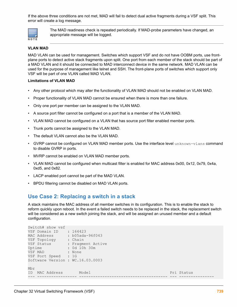
If the above three conditions are not met, MAD will fail to detect dual active fragments during a VSF split. Thiserror will create a log message.
The MAD readiness check is repeated periodically. If MAD-probe parameters have changed, anappropriate message will be logged.
VLAN MAD
MAD VLAN can be used for management. Switches which support VSF and do not have OOBM ports, use front-plane ports to detect active stack fragments upon split. One port from each member of the stack should be part ofa MAD VLAN and it should be connected to MAD interconnect device in the same network. MAD VLAN can beused for the purpose of management like telnet and SSH. The front-plane ports of switches which support onlyVSF will be part of one VLAN called MAD VLAN.
Limitations of VLAN MAD
• Any other protocol which may alter the functionality of VLAN MAD should not be enabled on VLAN MAD.
• Proper functionality of VLAN MAD cannot be ensured when there is more than one failure.
• Only one port per member can be assigned to the VLAN MAD.
• A source port filter cannot be configured on a port that is a member of the VLAN MAD.
• VLAN MAD cannot be configured on a VLAN that has source port filter enabled member ports.
• Trunk ports cannot be assigned to the VLAN MAD.
• The default VLAN cannot also be the VLAN MAD.
• GVRP cannot be configured on VLAN MAD member ports. Use the interface level unknown-vlans commandto disable GVRP in ports.
• MVRP cannot be enabled on VLAN MAD member ports.
• VLAN MAD cannot be configured when multicast filter is enabled for MAC address 0x00, 0x12, 0x79, 0x4a,0xd5, and 0x82.
• LACP enabled port cannot be part of the MAD VLAN.
• BPDU filtering cannot be disabled on MAD VLAN ports.
Use Case 2: Replacing a switch in a stackA stack maintains the MAC address of all member switches in its configuration. This is to enable the stack toreform quickly upon reboot. In the event a failed switch needs to be replaced in the stack, the replacement switchwill be considered as a new switch joining the stack, and will be assigned an unused member and a defaultconfiguration.
Switch# show vsfVSF Domain ID : 164423MAC Address : b05ada-96f043VSF Topology : ChainVSF Status : Fragment ActiveUptime : 0d 10h 30mVSF MAD : NoneVSF Port Speed : 1GSoftware Version : WC.16.03.0003
MbrID MAC Address Model Pri Status--- ----------------- -------------------------------------- --- ---------------
Chapter 32 Virtual Switching Framework (VSF) 739

1 b05ada-962160 Aruba JL253A 2930F-24G-4SFP+ Switch 128 Missing *2 b05ada-96f040 Aruba JL253A 2930F-24G-4SFP+ Switch 250 Commander 3 b05ada-973680 Aruba JL262A 2930F-48G-PoE+-4SFP Sw... 250 Standby 4 b05ada-963860 Aruba JL261A 2930F-24G-PoE+-4SFP Sw... 128 MemberIn the above stack, member 1 has failed, and needs to be replaced. A replacement switch with the same modelnumber (JL253A) will not take on the role of the switch it replaced, because the MAC address of the replacementswitch will be different from the switch that it replaces.
To enable the configuration to assimilate the replacement switch as member 1 in the stack, the MAC addressneeds to be cleared. Use the CLI command vsf member 1 type JL253A. This will retain all configurationmade on member 1 and remove only the MAC address. After the command is executed, the output of show vsfwill be as follows:
VSF Domain ID : 164423MAC Address : b05ada-96f043VSF Topology : ChainVSF Status : Fragment ActiveUptime : 0d 10h 34mVSF MAD : NoneVSF Port Speed : 1GSoftware Version : WC.16.03.0003
MbrID MAC Address Model Pri Status--- ----------------- -------------------------------------- --- --------------- 1 Aruba JL253A 2930F-24G-4SFP+ Switch 128 Provisioned *2 b05ada-96f040 Aruba JL253A 2930F-24G-4SFP+ Switch 250 Commander 3 b05ada-973680 Aruba JL262A 2930F-48G-PoE+-4SFP Sw... 250 Standby 4 b05ada-963860 Aruba JL261A 2930F-24G-PoE+-4SFP Sw... 128 MemberSubsequently, any switch model under JL253A, which is connected to the stack, will be assigned member 1configuration and role.
Use Case 3: Changing VSF link speedThe sequence to change the VSF link speed is as follows:
PrerequisitesVSF requires that all ports in all VSF links in the VSF stack must be of the same speed. VSF supports two portspeeds, 1G and 10G, and up to 8 ports can be added to a VSF link. There is no default port speed defined. Whena VSF link is first configured, the global port speed is automatically set to the interface speed of the port on thelink.
• There is no restriction on the ports which can be added to a VSF link. Ports which do not match the global portspeed can be added to a VSF link, but only ports matching the configured global port speed will be up.
• On a running VSF stack, the current applicable port speed is shown as part of the show vsf commandoutput.
Switch(config)# show vsfVSF Domain ID : 164423MAC Address : b05ada-9694e3VSF Topology : ChainVSF Status : ActiveUptime : 0d 5h 37mVSF MAD : NoneVSF Port Speed : 1GSoftware Version : WC.16.03.0003
740 Aruba 2930F / 2930M Management and Configuration Guide for ArubaOS-Switch 16.05

Procedure
1. Add ports of the desired link speed to each link of the stack.
Once this is done, the show vsf link detail output would be similar to:
VSF Member: 1 Link: 1
Port State-------- ----------------------------1/1 Up : Connected to port 4/11/25 Error: Port speed mismatch
VSF Member: 1 Link: 2
Port State-------- ---------------------------1/2 Up : Connected to port 2/21/26 Error: Port speed mismatch
VSF Member: 2 Link: 1
Port State-------- ----------------------------2/1 Up : Connected to port 3/12/25 Error: Port speed mismatch
2. Connect the ports of the new speed (1/25, 1/26, etc.). Since the ports are kept disabled, it is safe to make theconnections at this point. The link will not come up. All links must have ports of both speeds, otherwise the linkwill fail to come up when the port speed is changed.
3. Execute the command indicating the target speed: vsf port speed <1G/10G>. This will trigger a reboot ofthe whole stack. On reboot, the stack will form using the ports which match the new VSF port speed. Portswhich do not match will be kept disabled. The output of show vsf link detail after the reboot would beas follows:
VSF Member: 1 Link: 1
Port State-------- --------------------------1/1 Error: Port speed mismatch 1/25 Up : Connected to 4/25
VSF Member: 1 Link: 2
Port State-------- --------------------------1/2 Error: Port speed mismatch 1/26 Up : Connected to 2/26
VSF Member: 2 Link: 1
Port State-------- --------------------------2/1 Error: Port speed mismatch 2/25 Up : Connected to 3/25
Chapter 32 Virtual Switching Framework (VSF) 741

4. Disconnect the unused ports (1/1, 1/2 etc.). This is a safety measure to avoid accidentally creating a networkloop when executing the next step.
5. Unconfigure the unused ports from the VSF link, using the command no vsf member 1 link 1 1/1 etc.Once this step is completed, the output of show vsf link detail would be as follows:
VSF Member: 1 Link: 1
Port State-------- ---------------------1/25 Up: Connected to 4/25
VSF Member: 1 Link: 2
Port State-------- --------------------1/26 Up: Connected to 2/26
VSF Member: 2 Link: 1
Port State-------- ---------------------2/25 Up: Connected to 3/25The ports which have been removed from VSF links can now be used as regular Ethernet ports.
Use Case 4: Adding a switch to a stackThe automatic configuration mode only works with a newly unboxed switch, or a switch which has been reset tofactory default configuration using the CLI command erase startup-configuration. Now, connecting theswitch in between the two end switches of the chain will trigger an automatic configuration download to the switch,after which it will join the stack.
In manual configuration mode, the switch to be added has to be configured to join the stack. This involves thefollowing steps:
PrerequisitesA functional running stack can be scaled up by adding a switch to increase capacity. There will be minimaldisruption of switching function during this operation. This process is similar to the VSF deployment, and can bedone in either Manual or Automatic configuration mode.
The maximum number of members in a VSF stack is 4.
• The first step is to convert running stack to chain, if it is in ring topology.
• This involves disconnecting a VSF link between two stack members. Switching functions will continue, withpossible loss of some in-flight traffic.
Procedure
1. Configure new switch links, which will be connected to the two end switches of the chain.
2. Enable VSF on new switch with the same Domain ID as the stack. This will cause the switch to reboot.
3. Connect the cables to the end switches of the stack, and the stack will be formed.
742 Aruba 2930F / 2930M Management and Configuration Guide for ArubaOS-Switch 16.05

There could again be some possible loss of some in-flight traffic as a ring topology forms from the chaintopology.
Chapter 32 Virtual Switching Framework (VSF) 743

Net-service OverviewNet-service names are used as alias in defining ACL rules for defined lists. An alias of net-service will configure alist of hosts, networks, or subnets.
Extended ACL can have both source IP, destination IP and port number along with protocol in its ACE. An alias-based ACE for an extended ACL therefore allows the use of an alias of net-service protocol and destination port.
Limitations
• Alias-based ACE will not support access-control based on source port which is a limitation of the net-servicecommand. The use of net-service will also restrict operators specified for port number to equals and range.
◦ Operators lt, gt, equal,negative, and range for the source port in the ACL rule are not specified usingthe options available in net-service.
◦ Operators lt, gt, negative are not specified for destination port using the options available in net-service.
◦ Only the ACL will be affected when changes are made to an existing net-service. Either the rule must bereapplied to the ACL or the switch must be rebooted to affect the service.
netservice [tcp | udp | port]Syntax[no] netservice <NAME-STR> [tcp | udp | <PROTOCOL>] port <PORT-LIST>Description
Configures net-service.
Parameters
protocol
IP protocol number.
Range: 0-255
TCP
Configure an alias for a TCP protocol.
UDP
Configure an alias for a UDP protocol.
port
Specify a single port or a list of noncontiguous port numbers, by entering up to six port numbers, separated bycommas or range of ports.
Range: 0-65535
Chapter 33Net-destination and Net-service
744 Aruba 2930F / 2930M Management and Configuration Guide for ArubaOS-Switch 16.05

Example net-service tcp-service tcp 100
net-destination src-ip host 10.120.0.1 host 10.91.1.1 host 10.0.100.12
net-destination destn-ip host 16.90.51.12 host 10.93.24.1
net-service tcp-service tcp 100 ip access-list extended “acl1” permit alias src-ip alias destn-ip alias tcp-service
Net-destination overviewThe use of net-destination and net-service helps reduce effort required to configure ACL rules.
Net-destination is a list of hosts, networks, or subnets that are used to configure an ACL rules.
There are two types of ACLs supported and configured on the switch:
• Standard
• Extended
Standard
The standard ACL can have an IP source or network in the ACE. Defining the alias-based ACE for standard ACL,only use an alias of net-destination for the source.
Example - standard
net-destination src-ip host 10.120.0.1 host 10.91.1.1 host 10.0.100.12
net-destination destn-ip host 16.90.51.12 host 10.93.24.1
net-service tcp-service tcp 100 ip access-list extended “acl1” permit alias src-ip alias destn-ip alias tcp-serviceExtended
The extended ACL can have both source IP, destination IP and port number along with protocol in its ACE.Defining an alias-based ACE for an extended ACL can use an alias of net-destination for the source anddestination and an alias of net-service for the protocol and destination port. Alias-based ACE will not supportaccess-control based on source port which is a limitation of the net-service command. The use of net-service willalso restrict the operators that can be specified for port number to equalsand range.
Example - extended
HP-Switch-5406Rzl2(config)# ip access-list extended aext1HP-Switch-5406Rzl2(config-ext-nacl)#
Chapter 33 Net-destination and Net-service 745

permit tcp host 10.100.12.1 gt 23 16.90.0.0 /16 range 200 400HP-Switch-5406Rzl2(config-ext-nacl)# exit Limitations
• Limited to IPv4 addresses per syntax.
• Any changes made to an existing net-destination that is used by an ACL, will be applied on the ACL only whenthe rule is reapplied to it or when switch is rebooted.
• The number of entries for a single net-destination is limited. The number of net-destinations configurable on aswitch is also limited.
• A considerable amount of memory (for global structures) will be allocated when alias-based ACEs areconfigured which may cause issues on a switch with low memory.
• The Host or Domain name cannot be specified as an entry in a net-destination.
• Application level gateway will not be supported as the existing ACL infra does not support ALG.
• SNMP support to configure and delete net-destination, net-service, and the alias-based rules will not beprovided.
• The ‘invert’ and ‘range’ option have been deprecated as per ArubaOS-Switch 7.4 CLI Reference Guide andhence will not be supported. However, the functionality of ‘invert’ option can be achieved through the ‘deny’rule.
• RADIUS server-based ACL application to interface/VLAN will not be supported for ACLs with alias-basedrules.
net-destination host |position | networkSyntax[no] netdestination <NAME-STR> [host <IP-ADDR> [position <NUM>] network <IP-ADDR/MASK-LENGTH> [position <NUM>]]Description
Net-destination is a list of hosts, networks, or subnets that are used to configure an ACL rule.
Parameters
host
Configures a single IPv4 host.
network
An IPv4 subnet consisting of an IP address and netmask.
no
Removes any configured item in list or an entire net-destination.
position
Specifies the position of a host, network, or range in the net-destination. This optional parameter is specific toa net-destination and may only be used to sort entries in a list.
746 Aruba 2930F / 2930M Management and Configuration Guide for ArubaOS-Switch 16.05

show net-destinationSyntaxshow net-destination <NAME-STR>Description
Show a host-specific net-destination.
Chapter 33 Net-destination and Net-service 747
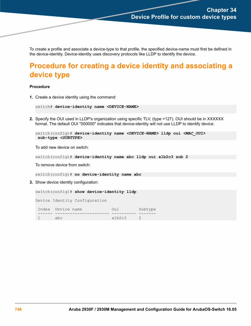
To create a profile and associate a device-type to that profile, the specified device-name must first be defined inthe device-identity. Device-identity uses discovery protocols like LLDP to identify the device.
Procedure for creating a device identity and associating adevice typeProcedure
1. Create a device identity using the command:
switch# device-identity name <DEVICE-NAME>
2. Specify the OUI used in LLDP's organization using specific TLV, (type =127). OUI should be in XXXXXXformat. The default OUI "000000" indicates that device-identity will not use LLDP to identify device:
switch(config)# device-identity name <DEVICE-NAME> lldp oui <MAC_OUI> sub-type <SUBTYPE>
To add new device on switch:
switch(config)# device-identity name abc lldp oui a1b2c3 sub 2To remove device from switch:
switch(config)# no device-identity name abc3. Show device identity configuration:
switch(config)# show device-identity lldp
Device Identity Configuration
Index Device name Oui Subtype ------ ---------------------- ---------- ------- 1 abc a1b2c3 2
Chapter 34Device Profile for custom device types
748 Aruba 2930F / 2930M Management and Configuration Guide for ArubaOS-Switch 16.05

LLDP device profile detection dynamically uses organization-specific TLV to detect and apply profiles to devices.Organizational Unique Identifiers (OUI) and subtypes are detected based on the configuration of the switch. Amaximum of 16 devices can be detected and defined using LLDP.
Requirements
The device-identity must be configured with a name.
device-profileSyntaxdevice-profile <PROFILE-NAME>
no device-profile <PROFILE-NAME>
Description
Create and name a new device profile.
Command contextconfig
Parameters<PROFILE-NAME>
Specifies the name assigned to the profile.
Example
When adding a new device-identify name to a device, the new identity will show in the command context.
switch-Stack# configswitch-Stack(config)# device-identity name test switch-stack(identity-test)#
device-profile type-deviceSyntaxdevice-profile type [aruba-ap | aruba-switch | scs-wan-cpe | device-name <DEVICE-NAME> associate <PROFILE-NAME> | enable | disable]
no device-profile type [aruba-ap | aruba-switch | scs-wan-cpe | device-name <DEVICE-NAME> associate <PROFILE-NAME> | enable | disable]
Description
Associates the device profile with the type of device by identity.
The no form of this command removes the device profile from the device type.
Chapter 35Dynamically detecting LLDP device profiles
Chapter 35 Dynamically detecting LLDP device profiles 749

Command contextconfig
Parametersassociate <PROFILE-NAME>
Selects the profile name associated with the device-type.
enableSelects the profile of the device being enabled.
disableSelects the profile of the device being disabled.
Usage
• The command device-profile type aruba-ap enable enables an Aruba-AP within the device profile.
• Device Name is defined the same as Device Identity.
device-profile device-type enableSyntaxdevice-profile device-type <DEVICE-NAME> enable
device-profile device-type <DEVICE-NAME> disable
Description
Enables the newly created device profile and associates it with the device-type and device-name.
The disable form of this command removes the association.
Command contextconfig
Parameters<DEVICE-NAME>
Specifies the device name.
The device identification may be used in other subsystems (like device profile).
Examples
Enable the device d1 using the command device-profile device-type <d1> enable.
switch(config)# device-profile device-type d1 enableDisable the device d1 using the command device-profile device-type d1 disable.
switch (config)# device-profile device-type d1 disable
750 Aruba 2930F / 2930M Management and Configuration Guide for ArubaOS-Switch 16.05

Associating a profile with a deviceAssociate a profile with a device by using the command device-profile device-type <DEVICE-NAME>associate <PROFILE-NAME>. Associated devices can be Aruba Access Points, ArubaOS-Switch Switches,scs-wan-cpe, or association can be by the device profile.
The feature is disabled by default.
device-profile device-type associateSyntaxdevice-profile device-type <DEVICE-NAME> associate <PROFILE-NAME>
no device-profile device-type <DEVICE-NAME> associate <PROFILE-NAME>
Description
Associate the profile to newly added device .
The no form of this command removes the profile association.
Usage
The device identification may be use in other subsystems like device profile.
Command contextconfig
Parameters<DEVICE-NAME>
Specifies the name of the device.
<PROFILE-NAME>Specifies the name given to the profile.
Examples
Use the command to associate the device d1 with the profile abc.
switch(config)# device-profile device-type d1 associate abc
show device-profile statusSyntaxshow device-profile status
Description
Shows the profile status of the device.
Command contextconfig
Chapter 35 Dynamically detecting LLDP device profiles 751

Example
Use the show decive-profile status command to view status.
switch(confg)# show device-profile statusPort Device-type Applied device profile -------- -------------------- ---------------------- A1 <device-name> abc
show device-profile configSyntaxshow device-profile config
Description
Shows the device profile configuration.
Command contextconfig
Examples
Use the command show device-profile config to display the device profile configuration.
switch(config)# show device-profile config
Device Profile Configuration Configuration for device-profile : default-ap-profile untagged-vlan : 1 tagged-vlan : None ingress-bandwidth : 100% egress-bandwidth : 100% cos : 0 speed-duplex : auto poe-max-power : Class/LLDP poe-priority : critical allow-jumbo-frames: Disabled Configuration for device-profile : abc untagged-vlan : 1 tagged-vlan : None ingress-bandwidth : 100% egress-bandwidth : 100% cos : None speed-duplex : auto poe-max-power : Class/LLDP poe-priority : critical allow-jumbo-frames: Disabled Configuration for device-profile : default-aos-profile untagged-vlan : 1 tagged-vlan : None ingress-bandwidth : 100% egress-bandwidth : 100% cos : 0 speed-duplex : auto poe-max-power : Class/LLDP poe-priority : critical allow-jumbo-frames: Disabled Configuration for device-profile : default-scs-profile untagged-vlan : 1 tagged-vlan : None
752 Aruba 2930F / 2930M Management and Configuration Guide for ArubaOS-Switch 16.05

ingress-bandwidth : 100% egress-bandwidth : 100% cos : 0 speed-duplex : auto poe-max-power : Class/LLDP poe-priority : critical allow-jumbo-frames: Disabled allow-jumbo-frames: Disabled Configuration for device-profile : default-device-profile untagged-vlan : 1 tagged-vlan : None ingress-bandwidth : 100% egress-bandwidth : 100% cos : 0 speed-duplex : auto poe-max-power : Class/LLDP poe-priority : critical allow-jumbo-frames: Disabled Device Profile Association
Device Type : aruba-ap Profile Name : default-ap-profile
Device Status : Disabled Device Type : aruba-switch Profile Name : default-aos-profile Device Status : Disabled
Device Type : scs-wan-cpe Profile Name : abc Device Status : Disabled Device Type : <lldp-device-name> Profile Name : default-device-profile Device Status : Disabled
show device-identitySyntaxshow device-identity <LLDP>
Description
Show the device-identity configuration.
Command contextconfig
Parameters<LLDP>
Shows the configuration of the LLDP device.
Examples
Shows the device identity configuration.
switch(config)# show device-identity lldp
Chapter 35 Dynamically detecting LLDP device profiles 753

Device Identity Configuration Index Device name Oui Subtype ------ --------------------- ---------- ------- 1 cpe 33 bb cc 0 2 phone 11 22 33 2
switch(config)# show running configuration
Running configuration: ; J9625A Configuration Editor; Created on release #RA.16.04.0000x; Ver #0f:02.43.18.82.34.61.1c.28.f3.84.9c.63.ff.37.2f:dahostname "HP-3810-24-PoEP"snmp-server community "public" unrestricteddevice-identity name "cpe" lldp oui 33bbccdevice-identity name "cpe" lldp sub-type 1device-identity name "phone" lldp oui 112233 vlan 1 name "DEFAULT_VLAN" untagged 1-28 ip address dhcp-bootp exitdevice-profile name "ram" exitdevice-profile type “scs-wan-cpe” associate "ram" enable exitdevice-profile type-device "cpe" associate "ram" enable exitdevice-profile type-device "phone" associate "default-device-profile" exit
754 Aruba 2930F / 2930M Management and Configuration Guide for ArubaOS-Switch 16.05

Static IP VisibilityOnly IP addresses assigned by the DHCP server are visible in RADIUS accounting on an ArubaOS-Switch.Visibility of statically assigned IP addresses in RADIUS accounting is available with a command that enables anddisables static IP visibility for an authenticated client.
IP client-trackerSyntaxip client-tracker [trusted | untrusted]
no ip client-tracker [trusted | untrusted]
Description
Enables the visibility of statically and dynamically assigned IPv4 and IPv6 addresses for both authenticated andunauthenticated client.
The no form of this command disables the visibility of statically and dynamically assigned IPv4 and IPv6addresses for both authenticated and unauthenticated client.
Command contextconfig
Parameterstrusted
Enables or disables the visibility of statically and dynamically assigned IPv4 and IPv6 addresses forauthenticated clients.
untrustedEnables or disables the visibility of statically and dynamically assigned IPv4 and IPv6 addresses forunauthenticated client.
Usage
• Enabling this feature will send ARP probes to the client at regular intervals. This interval is determined bysetting arp-age timeout. By default arp-age timeout is 20 minutes however the default timeout can bechanged by using the command ip arp-age <timeout value in minutes>.
◦ The periodic ARP probe aids in detecting any change of IP addresses on end clients.
◦ The periodic probe aids silent clients to stay connected to the switch. Silent clients do not send any traffic tothe switch after authentication which causes de-authenticated after a logoff period of 5 minutes (defaultvalue) due to inactivity. The periodic ARP probe triggers the end client to send response packets and aids
Chapter 36Static IP Visibility
Chapter 36 Static IP Visibility 755

the client in staying connected. The customer must manually configure the IP arp-age value to 1 minutewith the command ip arp-age 1 to avoid being de-authenticated.
• When the ip client-tracker command is executed more than once, it takes the last commands' behavior.For example when the command ip client-tracker trusted is run after the command ip client-tracker, the behavior will follow the last command, ip client-tracker trusted.
◦ When the administrator tries to execute the no command that has not been configured (does not exist inrunning configuration), an error will appear.
Example
Show port-access client with multiple addresses.
switch# show port-access clients
Port Access Client Status
Port Client Name MAC Address IP Address User Role Type VLAN---- -------------- -------------- ---------------------- ---------- ----- ----1 005056bd3ff7 005056-bd3ff7 3ffe:501:ffff:100::5e MAC 1
Example
Show the port-access IPv4 client.
Switch-Stack(config)# show port-access clients
Port Access Client Status
Port Client Name MAC Address IP Address User Role Type VLAN ----- ------------- ------------- --------------- ----------------- ----- ---- 1/3 000002b85001 000002-b85001 10.1.1.30 MAC 10
Example
Show the port-access IPv6 client.
switch(config)# show port-access clients 22
Port Access Client Status
Port Client Name MAC Address IP Address User Role Type VLAN ----- ------------- ------------- --------------- ----------------- ----- ---- 22 0000005daa34 000000-5daa34 n/a MAC 20
Example
Show the port-access client detail.
switch(config)# show port-access clients 22 detailed
Port Access Client Status Detail
Client Base Details : Port : 22 Authentication Type : mac-based Client Status : authenticated Session Time : 64 seconds Client Name : 0000005daa34 Session Timeout : 0 seconds MAC Address : 000000-5daa34 IP : n/a
756 Aruba 2930F / 2930M Management and Configuration Guide for ArubaOS-Switch 16.05

Access Policy Details : COS Map : Not Defined In Limit Kbps : Not Set Untagged VLAN : 20 Out Limit Kbps : Not Set Tagged VLANs : No Tagged VLANs Port Mode : 1000FDx RADIUS ACL List : No Radius ACL List IPV6 Address : 2000::10
Chapter 36 Static IP Visibility 757

The OOBM port is available only on the 2930M Switch Series.
OOBM conceptsManagement communications with a managed switch can be:
• In band—through the networked data ports of the switch
• Out of band—through a dedicated management port (or ports) separate from the data ports
Out-of-band ports have typically been serial console ports using DB-9 or specially wired 8-pin modular (RJ-style)connectors. Some recent switches have added networked OOBM ports.
Figure 141: Switch management port identification
OOBM operates on a "management plane" that is separate from the "data plane" used by data traffic on theswitch and by in-band management traffic. That separation means that OOBM can continue to function evenduring periods of traffic congestion, equipment malfunction, or attacks on the network. In addition, it can provideimproved switch security: a properly configured switch can limit management access to the management portonly, preventing malicious attempts to gain access via the data ports.
Network OOBM typically occurs on a management network that connects multiple switches. It has the addedadvantage that it can be done from a central location and does not require an individual physical cable from themanagement station to each switch's console port.
Chapter 37Network Out-of-Band Management (OOBM)
758 Aruba 2930F / 2930M Management and Configuration Guide for ArubaOS-Switch 16.05

Table 39: Switch management ports
In band Out of band
Networked Directly connected Networked
Management interface Command line (CLI),menu, Web
Command line (CLI),menu
Command line (CLI),menu
Communication plane Data plane Management plane Management plane
Connection port Any data port Dedicated serial or USBconsole port
Dedicated networkedmanagement port
Connector type Usually RJ-45; also CX4,SFP, SFP+, and XFP
DB9 serial, serial-wired 8-pin RJ
RJ-45
Advantages Allows centralizedmanagement
Not affected by events ondata network, shows bootsequence
Not affected by events ondata network, allowscentralized management,allows improved security
Disadvantages Can be affected by eventson data network; does notshow boot sequence
Requires direct connectionto console port (can bedone via networkedterminal server)
Does not show bootsequence
OOBM and switch applicationsThe table below shows the switch applications that are supported on the OOBM interface as well as on the datainterfaces. In this list, some applications are client-only, some are server-only, and some are both.
Application Inbound OOBM(server)
Outbound OOBM(client)
Inbound data plane(server)
Outbound dataplane (client)
Telnet yes yes yes yes
SSH yes yes 1
SNMP yes yes yes yes
TFTP yes yes yes yes
HTTP yes 1 yes 1
SNTP 1 yes 1 yes
TIMEP 1 yes 1 yes
RADIUS 1 yes 1 yes
TACACS 1 yes 1 yes
Table Continued
Chapter 37 Network Out-of-Band Management (OOBM) 759

Application Inbound OOBM(server)
Outbound OOBM(client)
Inbound data plane(server)
Outbound dataplane (client)
DNS 1 yes 1 yes
Syslog 1 yes 1 yes
Ping yes yes yes4 yes
Traceroute yes4 yes yes4 yes
1 N/A = not applicable2 ***=Ping and Traceroute do not have explicit servers. Ping and Traceroute responses are sent by the host stack.
For applications that have servers, oobm/data/both options have been added to listen mode. There is now alisten keyword in the CLI commands to allow selection of those options. Default value is both for all servers.
ExampleIn a typical data center installation, top-of-rack switches connect servers to the data network, while themanagement ports of those switches connect to a physically and logically separate management network. Thisallows network administrators to manage the switches even if operation on the data network is disrupted.
In Figure 142: Network OOBM in a data center on page 760, the switches face the hot aisle of the datacenter, allowing easy connection to the network ports on the backs of the servers.
Figure 142: Network OOBM in a data center
For even more control, the serial console ports of the switches can be connected to the management networkthrough a serial console server (essentially, a networked serial switch), allowing the network administrators toview the CLI activity of each switch at boot time and to control the switches through the console ports (as well asthrough the management ports.)
OOBM ConfigurationOOBM configuration commands can be issued from the global configuration context (config) or from a specificOOBM configuration context (oobm.)
760 Aruba 2930F / 2930M Management and Configuration Guide for ArubaOS-Switch 16.05

Entering the OOBM configuration context from the general configurationcontextSyntax
oobmEnters the OOBM context from the general configuration context.
Example
switch(config)# oobmHP Switch (oobm)#
Enabling and disabling OOBMFrom the OOBM context:
Syntax
enable disableFrom the general configuration context:
Syntax
oobm enable oobm disableEnables or disables networked OOBM on the switch.
OOBM is not compatible with either a management VLAN or stacking. If you attempt to enable OOBM when amanagement VLAN is enabled or when stacking is enabled, the command will be rejected and you will receive anerror message.
If an OOBM IP address exists and you disable OOBM, the OOBM IP address configuration is maintained. If youenable OOBM and there is a pre-existing OOBM IP address, it will be reinstated.
Network OOBM is enabled by default.
Examples
HP Switch (oobm)# enableHP Switch (oobm)# disableswitch(config)# oobm enableswitch(config)# oobm disable
Enabling and disabling the OOBM portThe OOBM interface command enables or disables the OOBM interface (that is, the OOBM port, as opposedto the OOBM function.)
From the OOBM context:
Syntax
interface [enable | disable]From the general configuration context:
Chapter 37 Network Out-of-Band Management (OOBM) 761

Syntax
oobm interface [enable | disable]Enables or disables the networked OOBM interface (port.)
Examples
HP Switch (oobm)# interface enableswitch(config)# oobm interface disable
Setting the OOBM port speedThe OOBM port operates at 10 Mbps or 100 Mbps, half or full duplex. These can be set explicitly or they can beautomatically negotiated using the auto setting.
From the OOBM context:
Syntax
interface speed-duplex [10-half | 10-full | 100-half | 100-full | auto]From the general configuration context:
Syntax
oobm interface speed-duplex [10-half | 10-full | 100-half | 100-full | auto]Enables or disables the networked OOBM interface (port.) Available settings are:
10-half 10 Mbps, half-duplex
10-full 10-Mbps, full-duplex
100-half 100-Mbps, half-duplex
100-full 100-Mbps, full-duplex
auto auto negotiate for speed and duplex
Example
HP Switch (oobm)# interface speed-duplex auto
Configuring an OOBM IPv4 addressConfiguring an IPv4 address for the OOBM interface is similar to VLAN IP address configuration, but it isaccomplished within the OOBM context.
From the OOBM context:
Syntax
[no] ip address [dhcp-bootp | ip-address/mask-length]From the general configuration context:
762 Aruba 2930F / 2930M Management and Configuration Guide for ArubaOS-Switch 16.05

Syntax
[no] oobm ip address [dhcp-bootp | ip-address/mask-length]Configures an IPv4 address for the switch's OOBM interface.
You can configure an IPv4 address even when global OOBM is disabled; that address will become effective whenOOBM is enabled.
Example
HP Switch (oobm)# ip address 10.1.1.17/24
Configuring an OOBM IPv4 default gatewayConfiguring an IPv4 default gateway for the OOBM interface is similar to VLAN default gateway configuration, butit is accomplished within the OOBM context.
From the OOBM context:
Syntax
[no] ip default-gateway ip-addressFrom the general configuration context:
Syntax
[no] oobm ip default-gateway ip-addressConfigures an IPv4 default gateway for the switch's OOBM interface.
Example
HP Switch (oobm)# ip default-gateway 10.1.1.1
Configuring an IPv6 default gateway for OOBM devicesAn OOBM interface is used for managing devices from remote sites. OOBM devices must be given a defaultgateway responsible to maintain a network connection when these devices are placed in an IPv6 network enabledwith RA suppression.
To configure and enable an IPv6 default gateway for OOBM interfaces, use the oobm ipv6 default-gatewaycommand.
oobm ipv6 default-gateway
Syntaxoobm ipv6 default-gateway <IPV6-ADDR>
no oobm ipv6 default-gateway
Description
Configures the IPv6 default gateway address for OOBM interfaces.
The no form of the command deletes the default gateway. It is imparative that an IPv6 address is specified whenthe no form of the command is used.
Chapter 37 Network Out-of-Band Management (OOBM) 763

Command contextconfig
Parameters<IPV6-ADDR>
Specifies the IPv6 address when configuring the OOBM for a specific gateway.
Example
switch(config)# oobm ipv6 default-gateway 1001::1/64
oobm member ipv6 default-gateway
Syntaxoobm member <MEMBER-ID> ipv6 default-gateway <IPV6-ADDR>
no oobm member <MEMBER-ID> ipv6 default-gateway
Description
Configures the IPv6 default gateway address for an OOBM member using their unique identifier and the IPv6address of the default gateway.
When no proceeds the command, the default gateway address is deleted.
Command contextconfig
Parameters<MEMBER-ID>
Specifies the unique member-id which allows the OOBM device access to the IPv6 default-gateway.<IPV6-ADDR>
Specifies the IPv6 address of the default gateway for a member OOBM interface.
Example
Configuring and deleting the OOBM member from a specific IPv6 gateway.
switch(config)# oobm member 1 ipv6 default-gateway 1001::1
switch(config)# no oobm member 1 ipv6 default-gateway
IPv6 default router preferencesThe command ipv6 nd ra router-preference {high | medium | low} provides an extension to theNeighbor Discovery Router Advertisement messages for communicating default router preferences from routersto hosts. The extension improves the ability of hosts to pick the appropriate router for an off-link destination. Innetwork topologies, where the host has multiple routers on its Default Router list, the choice of router for an off-link destination is critical for making the communication more efficient. For example, one router may provide muchbetter performance than another for a destination while choosing a wrong router may result in failure tocommunicate.
764 Aruba 2930F / 2930M Management and Configuration Guide for ArubaOS-Switch 16.05

ipv6 nd ra router-preference
Syntaxipv6 nd ra router-preference {low | medium | high}
no ipv6 nd ra router-preference
Description
Sets the router-preference configuration for communicating default router preferences from routers to hosts.Improves the ability of hosts to pick the appropriate router for an off-link destination by providing options at theoperator level which set the router preference value as low, medium, or high. Depending on the router preferencevalue set, the host receives the value as part of the IPv6 neighbor discovery router advertisement and choosesthe best router for communication.
The no form of this command removes the router-preference configuration.
Command contextvlan
Parameterslow
Specifies the router-preference value to low.
mediumSpecifies the router-preference value to medium. Medium is the default router-preference value.
highSpecifies the router-preference value to high.
Usage
• When VRRP is configured, RA messages for Virtual IP are sent with configured router-preference values.
• This command complies with RFC 4191.
Example
Default router-preferences.
switch(vlan-1)# ipv6 nd ra router-preference low Set the Default Router Preference to low. medium Set the Default Router Preference to medium (default). high Set the Default Router Preference to high.
switch(vlan-1)# ipv6 nd ra router-preference high
OOBM show commandsThe show commands for OOBM are similar to the analogous commands for the data plane. Note that you mustalways include the oobm parameter to see the information for the OOBM interface, regardless of the context. Forinstance, even from the OOBM context, the show ip command displays the IP configuration for the data plane;to see the IP configuration of the OOBM interface, you need to use show oobm ip.
Chapter 37 Network Out-of-Band Management (OOBM) 765

Showing the global OOBM and OOBM port configurationSyntax
show oobmSummarizes OOBM configuration information. This command displays the global OOBM configuration (enabledor disabled), the OOBM interface status (up or down), and the port status (enabled/disabled, duplex, and speed.)
You can issue this command from any context
Example
HP Switch# show oobm
Global Configuration OOBM Enabled : Yes OOBM Port Type : 10/100TX OOBM Interface Status : Up OOBM Port : Enabled OOBM Port Speed : Auto
Showing OOBM IP configurationSyntax
show oobm ipSummarizes the IP configuration of the OOBM interface. This command displays the status of IPv4 (enabled/disabled), the IPv4 default gateway, and the IPv4 address configured for the interface.
You can issue this command from any context.
Example
HP Switch# show oobm ip
Showing OOBM ARP informationSyntax
show oobm arpSummarizes the ARP table entries for the OOBM interface.
You can issue this command from any context.
Example
HP Switch# show oobm arp
show oobm ipv6Syntaxshow oobm ipv6
Description
Shows the IPv6 service status for OOBM interfaces.
766 Aruba 2930F / 2930M Management and Configuration Guide for ArubaOS-Switch 16.05

Command contextoperator
Example
Shows the IPv6 service status for OOBM interfaces.
switch# show oobm ipv6
Internet (IPv6) Service for OOBM Interface
IPv6 Status : Enabled IPv6 Default Gateway : 1000::2
Address Intf Member IP Config IP Address/Prefix Length Status Status ------ ---------- ------------------------------------------- --------- ------ Global manual 1000::1/64 Up Global autoconfig fe80::42a8:f0ff:fe9e:901/64 Up
show oobm ipv6 (for stacked switches)
Syntaxshow oobm ipv6
Description
Shows the OOBM IPv6 interface for a stacked switch.
Command contextoperator
Example
Shows the OOBM IPv6 interface for a stacked switch.
stack-switch# show oobm ipv6
Internet (IPv6) Service for OOBM Interface
IPv6 Status : Enabled IPv6 Default Gateway : 3000::2
Address Intf Member IP Config IP Address/Prefix Length Status Status ------ ---------- ------------------------------------------- --------- ------ Global manual 3000::1/64 Active Down Global autoconfig fe80::42a8:f0ff:fe9b:a581/64 Active Down 1 manual 1000::1/64 Active Down 2 manual 2000::1/64 Active Up
Chapter 37 Network Out-of-Band Management (OOBM) 767

show oobm ipv6 member (for stacked switches)
Syntax
show oobm ipv6 member <MEMBER-ID>
Description
Shows the OOBM IPv6 service detail for a specific member.
Command contextoperator
Example
Shows the OOBM IPv6 service detail for a specific member.
stack-switch# show oobm ipv6 member 2
Internet (IPv6) Service for OOBM Interface
IPv6 Status : Enabled IPv6 Default Gateway : 1000::1
Address Intf Member IP Config IP Address/Prefix Length Status Status ------ ---------- ------------------------------------------- --------- ------ 2 manual 1000::2/64 Active Up
show oobm ip detail (for stacked switches)
Syntaxshow oobm ip detail
Description
Shows the OOBM IP detail for a stacked switch.
Command contextoperator
Example
Show the OOBM IP detail for a stacked switch.
stack-switch# show oobm ip detail
Internet (IP) Service for OOBM Interface
Global Configuration
IPv4 Status : Enabled IPv6 Status : Enabled
IPv4 Default Gateway : 3.3.3.1 IPv6 Default Gateway : 3000::1
768 Aruba 2930F / 2930M Management and Configuration Guide for ArubaOS-Switch 16.05
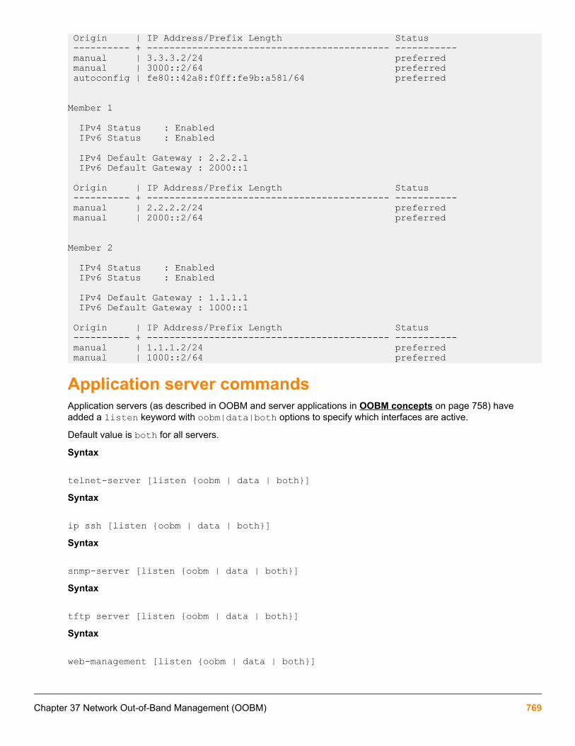
Origin | IP Address/Prefix Length Status ---------- + ------------------------------------------- ----------- manual | 3.3.3.2/24 preferred manual | 3000::2/64 preferred autoconfig | fe80::42a8:f0ff:fe9b:a581/64 preferred
Member 1
IPv4 Status : Enabled IPv6 Status : Enabled
IPv4 Default Gateway : 2.2.2.1 IPv6 Default Gateway : 2000::1
Origin | IP Address/Prefix Length Status ---------- + ------------------------------------------- ----------- manual | 2.2.2.2/24 preferred manual | 2000::2/64 preferred
Member 2
IPv4 Status : Enabled IPv6 Status : Enabled
IPv4 Default Gateway : 1.1.1.1 IPv6 Default Gateway : 1000::1
Origin | IP Address/Prefix Length Status ---------- + ------------------------------------------- ----------- manual | 1.1.1.2/24 preferred manual | 1000::2/64 preferred
Application server commandsApplication servers (as described in OOBM and server applications in OOBM concepts on page 758) haveadded a listen keyword with oobm|data|both options to specify which interfaces are active.
Default value is both for all servers.
Syntax
telnet-server [listen {oobm | data | both}]Syntax
ip ssh [listen {oobm | data | both}]Syntax
snmp-server [listen {oobm | data | both}]Syntax
tftp server [listen {oobm | data | both}]Syntax
web-management [listen {oobm | data | both}]
Chapter 37 Network Out-of-Band Management (OOBM) 769
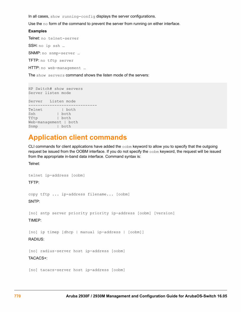
In all cases, show running-config displays the server configurations.
Use the no form of the command to prevent the server from running on either interface.
Examples
Telnet: no telnet-serverSSH: no ip ssh …SNMP: no snmp-server …TFTP: no tftp serverHTTP: no web-management …The show servers command shows the listen mode of the servers:
HP Switch# show serversServer listen mode
Server Listen mode-----------------------------Telnet | bothSsh | bothTftp | bothWeb-management | bothSnmp | both
Application client commandsCLI commands for client applications have added the oobm keyword to allow you to specify that the outgoingrequest be issued from the OOBM interface. If you do not specify the oobm keyword, the request will be issuedfrom the appropriate in-band data interface. Command syntax is:
Telnet:
telnet ip-address [oobm]TFTP:
copy tftp ... ip-address filename... [oobm]SNTP:
[no] sntp server priority priority ip-address [oobm] [version]TIMEP:
[no] ip timep [dhcp | manual ip-address | [oobm]]RADIUS:
[no] radius-server host ip-address [oobm]TACACS+:
[no] tacacs-server host ip-address [oobm]
770 Aruba 2930F / 2930M Management and Configuration Guide for ArubaOS-Switch 16.05

DNS:
[no] ip dns server-address priority priority ip-address [oobm]Syslog:
[no] logging ip-address [[control-descr] | [oobm]]Ping:
ping [...] [source [ip-address | vlan-id | oobm]]Traceroute:
traceroute [...][source [ip-address|vlan-id|oobm]] Management and Configuration Guide
Example
Figure 143: Example data center on page 771 shows setup and use of network OOBM using the commandsdescribed above.
Assume that the figure below describes how you want to set up your data center.
Figure 143: Example data center
Assume that you are configuring the switch in the left-hand rack to communicate on both the data andmanagement networks. You might do the following:
• Configure an IP address on the data network.
• Verify that out-of-band management is enabled. (It is enabled by default.)
• Configure an IP address on the management network.
• Verify that the switch can communicate on both networks.
The CLI commands that follow would accomplish those tasks. (The first time through the process you might easilymake the omission shown near the end of the example.)
Switch 41# configSwitch 41(config)# vlan 1Switch 41(vlan-1)# ip address 10.1.129.7/20 Set up IP address on data network.Switch 41(vlan-1)# end Exit back to manager context.
Chapter 37 Network Out-of-Band Management (OOBM) 771

Switch 41# show oobm Look at default OOBM configuration.
Global Configuration OOBM Enabled : Yes OOBM Port Type : 10/100TX OOBM Interface Status : Up Defaults look appropriate. OOBM Port : Enabled OOBM Port Speed : Auto
Switch 41# configSwitch 41(config)# oobm Go to OOBM context andSwitch 41(oobm)# ip address 10.255.255.41/24 add IP address andSwitch 41(oobm)# ip default-gateway 10.255.255.1 default gateway.Switch 41(oobm)# end Exit back to manager context.Switch 41# ping 10.1.131.44 Ping server in this rack (on data network.)10.1.131.44 is alive, time = 19 msSwitch 41# ping 10.1.131.51 Ping server in adjacent rack.10.1.131.51 is alive, time = 15 msSwitch 41# ping 10.255.255.42 Ping switch in adjacent rack.The destination address is unreachable. Oops! It’s on the management network.Switch 41# ping source oobm 10.255.255.42 Go through the management port10.255.255.42 is alive, time = 2 ms and it works fine.Switch 41#
772 Aruba 2930F / 2930M Management and Configuration Guide for ArubaOS-Switch 16.05

Networking WebsitesHewlett Packard Enterprise Networking Information Library
www.hpe.com/networking/resourcefinder
Hewlett Packard Enterprise Networking Software
www.hpe.com/networking/software
Hewlett Packard Enterprise Networking website
www.hpe.com/info/networking
Hewlett Packard Enterprise My Networking website
www.hpe.com/networking/support
Hewlett Packard Enterprise My Networking Portal
www.hpe.com/networking/mynetworking
Hewlett Packard Enterprise Networking Warranty
www.hpe.com/networking/warranty
General websitesHewlett Packard Enterprise Information Library
www.hpe.com/info/EIL
For additional websites, see Support and other resources.
Chapter 38Websites
Chapter 38 Websites 773

Accessing Hewlett Packard Enterprise Support• For live assistance, go to the Contact Hewlett Packard Enterprise Worldwide website:
http://www.hpe.com/assistance
• To access documentation and support services, go to the Hewlett Packard Enterprise Support Center website:
http://www.hpe.com/support/hpesc
Information to collect
• Technical support registration number (if applicable)
• Product name, model or version, and serial number
• Operating system name and version
• Firmware version
• Error messages
• Product-specific reports and logs
• Add-on products or components
• Third-party products or components
Accessing updates• Some software products provide a mechanism for accessing software updates through the product interface.
Review your product documentation to identify the recommended software update method.
• To download product updates:
Hewlett Packard Enterprise Support Centerwww.hpe.com/support/hpesc
Hewlett Packard Enterprise Support Center: Software downloadswww.hpe.com/support/downloads
Software Depotwww.hpe.com/support/softwaredepot
• To subscribe to eNewsletters and alerts:
www.hpe.com/support/e-updates
• To view and update your entitlements, and to link your contracts and warranties with your profile, go to theHewlett Packard Enterprise Support Center More Information on Access to Support Materials page:
Chapter 39Support and other resources
774 Aruba 2930F / 2930M Management and Configuration Guide for ArubaOS-Switch 16.05
www.hpe.com/support/AccessToSupportMaterials
Access to some updates might require product entitlement when accessed through the HewlettPackard Enterprise Support Center. You must have an HPE Passport set up with relevantentitlements.
Customer self repairHewlett Packard Enterprise customer self repair (CSR) programs allow you to repair your product. If a CSR partneeds to be replaced, it will be shipped directly to you so that you can install it at your convenience. Some partsdo not qualify for CSR. Your Hewlett Packard Enterprise authorized service provider will determine whether arepair can be accomplished by CSR.
For more information about CSR, contact your local service provider or go to the CSR website:
http://www.hpe.com/support/selfrepair
Remote supportRemote support is available with supported devices as part of your warranty or contractual support agreement. Itprovides intelligent event diagnosis, and automatic, secure submission of hardware event notifications to HewlettPackard Enterprise, which will initiate a fast and accurate resolution based on your product's service level.Hewlett Packard Enterprise strongly recommends that you register your device for remote support.
If your product includes additional remote support details, use search to locate that information.
Remote support and Proactive Care informationHPE Get Connected
www.hpe.com/services/getconnectedHPE Proactive Care services
www.hpe.com/services/proactivecareHPE Proactive Care service: Supported products list
www.hpe.com/services/proactivecaresupportedproductsHPE Proactive Care advanced service: Supported products list
www.hpe.com/services/proactivecareadvancedsupportedproducts
Proactive Care customer informationProactive Care central
www.hpe.com/services/proactivecarecentralProactive Care service activation
www.hpe.com/services/proactivecarecentralgetstarted
Warranty informationTo view the warranty for your product or to view the Safety and Compliance Information for Server, Storage,Power, Networking, and Rack Products reference document, go to the Enterprise Safety and Compliance website:
www.hpe.com/support/Safety-Compliance-EnterpriseProducts
Additional warranty informationHPE ProLiant and x86 Servers and Options
www.hpe.com/support/ProLiantServers-Warranties
Chapter 39 Support and other resources 775

HPE Enterprise Serverswww.hpe.com/support/EnterpriseServers-Warranties
HPE Storage Productswww.hpe.com/support/Storage-Warranties
HPE Networking Productswww.hpe.com/support/Networking-Warranties
Regulatory informationTo view the regulatory information for your product, view the Safety and Compliance Information for Server,Storage, Power, Networking, and Rack Products, available at the Hewlett Packard Enterprise Support Center:
www.hpe.com/support/Safety-Compliance-EnterpriseProducts
Additional regulatory information
Hewlett Packard Enterprise is committed to providing our customers with information about the chemicalsubstances in our products as needed to comply with legal requirements such as REACH (Regulation EC No1907/2006 of the European Parliament and the Council). A chemical information report for this product can befound at:
www.hpe.com/info/reach
For Hewlett Packard Enterprise product environmental and safety information and compliance data, includingRoHS and REACH, see:
www.hpe.com/info/ecodata
For Hewlett Packard Enterprise environmental information, including company programs, product recycling, andenergy efficiency, see:
www.hpe.com/info/environment
Documentation feedbackHewlett Packard Enterprise is committed to providing documentation that meets your needs. To help us improvethe documentation, send any errors, suggestions, or comments to Documentation Feedback([email protected]). When submitting your feedback, include the document title, part number, edition,and publication date located on the front cover of the document. For online help content, include the productname, product version, help edition, and publication date located on the legal notices page.
776 Aruba 2930F / 2930M Management and Configuration Guide for ArubaOS-Switch 16.05

Remote Device Deployment (TR-069)
IntroductionTR-069 is a technical specification created by the Broadband Forum. The TR-069 protocol specifies client andserver requirements to manage devices across the Internet by using a client server architecture to providecommunication between the CPE (Customer Premises Equipment) and the ACS (Auto Configuration Server). Aprotocol helps to manage complex networks where many devices such as modems, routers, gateways, VoIPphones and mobile tablets compete for resources. TR-069 defines the CPE WAN Management Protocol (CWMP)protocol necessary to remotely manage end-user devices. ACS provides automatic configuration for thesedevices.
CWMP is automatically enabled. To conserve resources, reconfigure this setting using the cwmpdisable command.
TR-069 defines an auto-configuration architecture which provides the following primary capabilities:
• Auto-configuration and dynamic service provisioning
• Software/firmware image management
• Status and performance monitoring
• Diagnostics
• Bidirectional SOAP/HTTP based protocol
Appendix ARemote Device Deployment (TR-069)
Appendix A Remote Device Deployment (TR-069) 777

Advantages of TR-069
• TR-069 can manage devices with dynamic IP addresses.
TR-069 use Organization Unique ID (OUI) and serial number rather than IP to identify a device.
• TR-069 can manage devices in a private network.
The HPE ACS BIMS (an iMC module) uses HTTP to communicate with the device, and the session is initiatedby the device, so BIMS can pass through NAT to manage the device.
• TR-069 is secure.
TR-069 can use HTTPS to communicate with or transfer files to/from the device; it is more secure than TFTP,FTP or Telnet.
• TR-069 is suitable for WAN management across internet.
• TR-069 is suitable for zero-touch configuration.
The zero-configuration mechanism is defined in the TR-069 specification.
• TR-069 is suitable for large-scale device management.
TR-069 support distributed architecture. The ACS can be distributed to multiple servers, each ACS canmanage part of devices.
778 Aruba 2930F / 2930M Management and Configuration Guide for ArubaOS-Switch 16.05

Zero-touch configuration processAuto configuration or “zero-touch” deployment is a recurring customer requirement, especially for remote-officedeployments. New devices introduced inside a private network require management tools be co-located toconfigure them or update firmware, or require manual intervention to do configuration. TR-069 allows managingdevices that reside in a private network via HTTP(S), enabling a new set of deployment and management modelstoday, not possible using SNMP.
The client side, when configured, will contact the server at a predefined URL, using HTTP or HTTPS as protocol.After authentication, the ACS is able to perform the following basic operations:
• Update CPE Configuration.
• Update CPE TR-069 parameters.
• Update CPE firmware.
• Reboot CPE (backup, startup, and running configurations)
• Run CPE ping diagnostics.
• Reset CPE to factory default.
• Get periodic Status (several parameters can be retrieved depending on what is supported).
Since TR-069 uses HTTP, it can be used across a WAN. If the CPE can reach the URL, it can be managed.TR-069 is mostly a push protocol where the client periodically sends information without server requests. Thisallows for greater scalability over traditional SNMP based tools, which are also bounded to work within the LAN,while TR-069 can offer management to remote offices.
Appendix A Remote Device Deployment (TR-069) 779
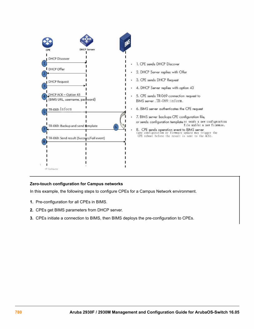
Zero-touch configuration for Campus networks
In this example, the following steps to configure CPEs for a Campus Network environment.
1. Pre-configuration for all CPEs in BIMS.
2. CPEs get BIMS parameters from DHCP server.
3. CPEs initiate a connection to BIMS, then BIMS deploys the pre-configuration to CPEs.
780 Aruba 2930F / 2930M Management and Configuration Guide for ArubaOS-Switch 16.05

Zero-touch configuration for Branch networks
In this example, the following steps to configure CPEs for a Branch network environment.
1. Create the basic configuration for your spoke device manually, using the username/password from ISP andBIMS URL.
2. The IPSec VPN configuration is generated by IVM and deployed by BIMS.
3. The IPSec VPN tunnel is automatically created.
4. The device in the branch private network can DHCP relay to HQ to continue the zero touch configuration.
Appendix A Remote Device Deployment (TR-069) 781

Zero-touch configuration setup and execution1. DHCP configuration
2. BIMS configuration
3. Execution
CLI commands
Configuration setupWithin the configure mode:
Syntax:
cwmp
782 Aruba 2930F / 2930M Management and Configuration Guide for ArubaOS-Switch 16.05

acs
Configure Auto Configuration Server (ACS) access.
cpe
Configure Customer Premises Equipment (CPE) access.
disable
Disable the CPE WAN Management Protocol.
CWMP is automatically enabled. To conserve resources, reconfigure this setting using the cwmpdisable command.
enable
Enable the CPE WAN Management Protocol.
Syntax:
[no] cwmpacs
Configure Auto Configuration Server (ACS) access.
cpe
Configure Customer Premises Equipment (CPE) access.
enable
Enable the CPE WAN Management Protocol.
ACS password configurationSyntax:
cwmp acspassword
Configure the password used for authentication when the switch connects to the ACS.
url
Configure the URL of the ACS.
username
Configure the username used for authentication when the switch connects to the ACS.
When encrypt-credentials is offSyntax:
cwmp acs passwordplaintext
Configure the password used for authentication when the switch connects to the ACS.
Appendix A Remote Device Deployment (TR-069) 783
When encrypt-credentials is onSyntax:
cwmp acs passwordencrypted-key
An encrypted password generated with the encrypt-credentials command.
plaintext
Configure the password used for authentication when the switch connects to the ACS.
Encrypt-credential on
cwmp acs password encrypted-keyASCII-STR
Enter an ASCII string (maximum length: 384 characters).
Plaintext password
cwmp acs password plaintextPASSWORD-STR
A plaintext password used for ACS authentication (maximum length: 256 characters).
ACS URL configurationSyntax:
cwmp acs urlURL-STR
The URL of the ACS (maximum length: 256 characters).
ACS username configurationSyntax:
cwmp acs usernameUSERNAME-STR
A username for ACS authentication (maximum length: 256 characters).
CPE configurationSyntax:
cwmp cpepassword
Configure the password used for authentication when the ACS connects to the switch.
784 Aruba 2930F / 2930M Management and Configuration Guide for ArubaOS-Switch 16.05

username
Configure the username used for authentication when the ACS connects to the switch.
CPE password configuration
When encrypt-credentials is onSyntax:
cwmp cpe passwordencrypted-key
An encrypted password generated with the 'encrypt-credentials' command.
plaintext
Configure the password used for authentication when the ACS connects to the switch.
Syntax:
cwmp cpe password encrypted-keyASCII-STR
Enter an ASCII string (maximum length: 384 characters).
When encrypt-credentials is offSyntax:
cwmp cpe [password]plaintext
Configure the password used for authentication when the ACS connects to the switch
Syntax:
cwmp cpePASSWORD-STR
A plaintext password used for ACS authentication (maximum length: 256 characters).
CPE username configurationSyntax:
cwmp cpe [username]USERNAME-STR
A username for ACS authentication (maximum length: 256 characters).
Appendix A Remote Device Deployment (TR-069) 785

Enable/disable CWMPSyntax:
cwmp [enable|disable]
Show commands
CWMP configuration and status querySyntax:
show cwmpconfiguration
Show current CWMP configuration.
status
Show current CWMP status.
When CWMP is enabledSyntax:
show cwmp configuration
CWMP configuration
CWMP ConfigurationCWMP Status : EnabledACS URL : http://16.93.62.32:9090ACS Username : bimsInform Enable Status : EnabledInform Interval : 60Inform Time : 2014-04-08T06:00:00Reconnection Timeout : 30
CWMP status
CWMP StatusCWMP Status : EnabledACS URL : http://16.93.62.32:9090ACS URL Origin : ConfigACS Username : bimsConnection Status : DisconnectedData Transfer Status : NoneLast ACS Connection Time : Wed Apr 9 16:56:00 2014Time to Next Connection : 00:00:36
When CWMP is disabledSyntax:
show cwmp status
786 Aruba 2930F / 2930M Management and Configuration Guide for ArubaOS-Switch 16.05

CWMP status
CWMP StatusCWMP Status : Disabled
CWMP configuration
show cwmp configurationCWMP ConfigurationCWMP Status : Disabled
Event loggingThe TR-069 client offers some tools to diagnose problems:
• System logging
• Status/control commands
System loggingThe CPE implements the following system log notification codes and sample messages:
• RMON_TR69_INFORM_COMPLETE
◦ INFORM to http://15.29.20.50:9090/ from (IP address not set yet) completed with error.
◦ INFORM to http://15.29.20.50:9090/ from 10.0.10.212 completed with error.
◦ INFORM to http://15.29.20.50:9090/ from 10.0.10.212 completed successfully.
• RMON_TR69_AUTH_FAILED
◦ Authentication on ACS http://15.29.20.50:9090/ failed.
• RMON_TR69_CONN_FAILED
◦ Connection attempts with ACS http://15.29.20.50:9090/ from 10.0.10.212 failed.
To avoid flooding the system log on frequent attempts to connect with the ACS, the following criteria are used withboth successful and failed attempts:
1. The very first event is always logged.
2. Any change from success to failure or vice versa is always logged.
3. Repeat success or failure events are logged only once every five minutes.
The HTTP file transfer component supports these system log notification codes and sample messages:
• RMON_HTTP_XFER_COMPLETE
Appendix A Remote Device Deployment (TR-069) 787

◦ I 11/19/13 08:06:13 04185 http: Download of http://10.0.11.240:9876/path to DestinationFile completedsuccessfully.
◦ I 11/19/13 08:06:13 04185 http: Upload of SourceFile to http://10.0.11.240:9876/path completedsuccessfully.
• RMON_HTTP_CONN_FAILED
◦ W 11/19/13 08:06:13 04186 http: Connection to http://10.0.11.240:9876/path failed.
• RMON_HTTP_TIMED_OUT
◦ W 11/19/13 08:06:13 04192 http: Download of http://10.0.11.240:9876/path to DestinationFile timed out.
◦ W 02/20/14 00:32:17 04192 http: Upload of SourceFile to http://10.0.11.240:9876/path timed out.
• RMON_HTTP_NO_SPACE
◦ W 11/19/13 08:06:13 04189 http: Upload of SourceFile to http://10.0.11.240:9876/path canceled because ofinsufficient memory.
• RMON_HTTP_REQ_FAILED
◦ W 11/19/13 08:06:13 04190 http: Upload of SourceFile to http://10.0.11.240:9876/path failed (errno 13).
◦ W 11/19/13 08:06:13 04190 http: Upload of SourceFile to http://10.0.11.240:9876/path failed (errno 1).
◦ W 11/19/13 08:06:13 04190 http: Download of http://10.0.11.240:9876/path to DestinationFile failed (errno13).
◦ W 11/19/13 08:06:13 04190 http: Download of http://10.0.11.240:9876/path to DestinationFile failed (errno1).
◦ W 11/19/13 08:06:13 04190 http: Download of http://10.0.11.240:9876/path to DestinationFile failed (errno17).
• RMON_HTTP_WRONG_FILE
◦ W 11/19/13 08:06:13 04191 http: Download canceled because file http://10.0.11.240:9876/path ismalformed or incompatible.
◦ W 11/19/13 08:06:13 04191 http: Download canceled because file http://10.0.11.240:9876/path ismalformed or incompatible.
• RMON_HTTP_FILE_NOT_FOUND
◦ W 11/19/13 08:06:13 04200 http: Upload of SourceFile to http://10.0.11.240:9876/path canceled because ofinexistent file.
Status/control commandsThe following commands help assess the general state of TR–069 and control the source of the ACSconfiguration record:
788 Aruba 2930F / 2930M Management and Configuration Guide for ArubaOS-Switch 16.05

Table 40: Status/control commands
Command Result
show cwmp statusCWMP is Enabled ACS URL : https://16.93.62.32:9443ACS URL is set by : ConfigACS Username : bimsConnection status : DisconnectedData transfer status : NoneTime of last successful connection : Thu Feb 20 01:16:59 2014Interval upon to next connection : Null
show cwmpconfiguration CWMP is Enabled ACS URL : https://16.93.62.32:9443
ACS Username : bims Inform Enable Status : DisabledInform Interval : 3559 Inform Time : Reconnection times : 30
[no] dhcp tr69-acs-url Prevents using any ACS information from DHCP
Appendix A Remote Device Deployment (TR-069) 789

Configuration backup and restore withoutreboot
Beginning with switch software release 16.05, the configuration backup and restore without reboot supports thefollowing features:
Interface Access (Telnet, Console/Serial, web) Port Shutdown with Broadcast Storm
Access Control Lists (ACLs) Source-Port Filters
AAA Authentication TACACS+ Authentication
CoS (Class of Service) Time Protocols (TimeP, SNTP)
Network Management Applications (SNMP) Uni-directional Link Detection (UDLD)
Port Configuration Virus Throttling (Connection-Rate Filtering)
Port Security Web-based Authentication
Port-Based Access Control (802.1X) Backplane stacking
Quality of Service (QoS) Job Scheduler
Spanning Tree (STP, RSTP, MSTP, RPVST+) Authorized IP Managers
VLANs Authorized Manager List (Web, SSH, TFTP)
802.1Q VLAN Tagging Auto MDIX Configuration
802.1X Port-Based Priority DHCP Configuration
802.1X Multiple Authenticated Clients Per Port Flow Control (802.3x)
IGMP Friendly Port Names
LACP/Trunk Guaranteed Minimum Bandwidth (GMB)
MAC Lockdown IP Addressing
MAC-based Authentication IP Routing
MAC Lockout Jumbo Packets
LMA LLDP
Multicast Filtering LLDP-MED
Power over Ethernet (PoE and PoE+) Loop Protection
Protocol Filters MAC Address Management
RADIUS Authentication and Accounting Management VLAN
RADIUS-Based Configuration Passwords and Password Clear Protection/include-credentials
Table Continued
Appendix BConfiguration backup and restore without reboot
790 Aruba 2930F / 2930M Management and Configuration Guide for ArubaOS-Switch 16.05

Encrypted-password QoS: Strict-Priority Queuing
Port Monitoring QoS: Turn on/off VLAN Precedence
Port Status QoS: Egress Queue Rate-limiting
Rate-Limiting CDP
Syslog System Parameters (hostname, Banner)
System Information Front-panel-security
Telnet Access DLDP
Traffic/Security Filters OOBM
VLAN Mirroring (1 static VLAN)/Port mirroring Switch interconnect
Voice VLAN Airwave Controller IP configuration
Web Authentication RADIUS Support Aruba Central integration
Web UI Captive portal commands
Log IP address of an ACL match Consolidated Client View
access-list logtimer IPsec for Zero Touch Provisioning
UFD: Uplink Failure Detection Local User roles
Wake-on-LAN for a Specific VLAN Port QoS Trust Mode
WebUI Inactivity Timer Per-port Tunneled node
Control Plane Protection Zero-touch provisioning - DHCP, Activate
Egress ACLs CPPM support
Device profile - switch auto configuration HTTP redirection/Captive portal
Device profile: Auto configuration with Aruba APdetection
Device profile: LLDP Authentication Bypass with AP
Tunneled Node enhancement: fallback to switching RADIUS Port Speed VSA
Rogue AP isolation Dynamic ARP Protection
DHCP Option 82 Dynamic IP Lockdown
DHCP snooping Eavesdrop Protection
Distributed Trunking GVRP
RMON 1,2,3,9 Private VLANs
SavePower Features IP SLA
sFlow sys-debug acl
VxLAN MAC Based VLANs (MBV)
Smartlink RBAC: Role Based Access Control
Fault Finder extended to cover Flapping TransceiverMitigation
RADIUS Service Tracking
Fault Finder (Per Port Enable) sys-debug destination
SNMP Trap Throttling Protocol VLANS
Appendix B Configuration backup and restore without reboot 791

GlossaryAcronym Definition
ACL Access Control List
AMP AirWave Management Platform
AP Access Point
BYOD Bring Your Own Device
CoA Change of Authorization
CLI Command Line Interface
CPPM ClearPass Policy Manager
DHCP Dynamic Host Configuration Protocol
DoS Denial-of-Service
EWA Enhanced Web Authentication
IP Internet Protocol
HA High Availability
HMAC-SHA1 Hash-based Message Authentication Code used withthe SHA-1 cryptographic hash function.
HTTP Hypertext Transfer Protocol
HTTPS Secure Hypertext Transfer Protocol
ID Identifier
IP Internet Protocol
L3 The third, or routing, layer of the open systemsinterconnection (OSI) model. The network layer routesdata to different LANs and Wide Area Networks(WANs) based on network addresses.
Table Continued
Appendix CGlossary
792 Aruba 2930F / 2930M Management and Configuration Guide for ArubaOS-Switch 16.05

Acronym Definition
LAN Local Area Network
MAC Media Access Control
MAFR MAC Authentication Failure Redirect
MAS Management Interface Specification
NMS Network Management System
PVOS ArubaOS-Switch Operating System
RADIUS Remote Authentication Dial In User Service
SNMP Simple Network Management Protocol
VLAN Virtual Local Area Network
VSA Vendor Specific Attribute
ZTP Zero Touch Provisioning
Appendix C Glossary 793