
ARRL VHF Digital Handbook
173
Transcript of ARRL VHF Digital Handbook


./
Copyright © 2008 by
The American Radio Relay League
Copyright secured under the Pan-American Convention
I I1~ternational Copyright secured
This work is publication No. 332 of the Radio Amateur'sLibrary, published by the League. All rights reserved. Nopart of this work may be reproduced in any form exceptwith written permission of the publisher. All rights oftranslation are reserved .
Printed in USA
-Quedan reservados todos los derechos
ISBN: 0-87259-122-0
First EditionSecond Printing

Foreword
Acknowledgements
Chapter 1 • Packet Radio Fundamentals
Chapter 2 • The Automatic Position Reporting System
Chapter 3 • Packet and Public Service
Chapter 4 • D-STAR
Chapter 5 • Digital Meteor Scatter and Moonbounce with WSJT
. .Chapter 6 • APCO-25
Chapter 7 • High Speed Multimedia (HSMM) Radio
Appe ndix A • AX .25 Link Access Protocol for Amateur Packet Radio
Appendix B • D-STAR System (Technical Description)
Appendix C • APCO-25: Anatomy Of The Common Air Interface
Index

When the Internet became part of everyday life, the amateur packet radio networks thathad flourished in the 1980s and early '90s declined sharply. To some, the collapse of packetspelled the end of digital Amateur Radio above 50 MHz. How wrong they were!
Although packet networks see less activity than they did decades ago, packet radio itselfis far from dead. Packet radio has been "repurposed" to create the popular Automatic PositionReporting System, and traditional packet networks still exist to support public service activities. New software applications have greatly enhanced their function.
Thanks to pioneering work by Joe Taylor, KUT, hams can now enjoy digital meteor scattercontacts and even moonbounce on VHF and UHF frequencies with modest stations. His WSJTsoftware is available free of charge and requires little more than an ordinary computer sounddevice.
The Japan Amateur Radio League developed the D-STAR digital voice and data standard,and it has seen significant growth in the United States as hams establish D-STAR repeaternetworks on VHF, UHF and microwave bands .
Amateurs are even experimenting with the APCO-25 standard used by public serviceagencies. They're reprogramming commercial APCO-25 transceivers for use on 2 meters and70cm.
All of these topics, and more, are discussed in this edition of the ARRL VHF DigitalHandbook. My hope is that you'll use this book not only as a helpful reference, but also as aninspiration to try your own VHF+ digital experimentation.
David Sumner, KIZZExecutive Vice PresidentNewington, ConnecticutJanuary 2008

The author wishes to thank the following individuals and organizations, whosecontributions helped make this book a reference that many readers will enjoy.
• Allan Crosswell, N2YGK and Bill Covey, WIGTT, for their contributions toChapter 2.
• Rick Muething, KN6KB, Alan Isaachsen, KB2WF and Jim Oberhofer, KN6PE,for materials used in Chapter 3.
• Ray Novak, N9JA, of ICOM America and Ward Silver, N0AX, for theircontributions to Chapter 4.
• Joe Taylor, KIJT, for his WSJT Users Guide and Reference Manual, portions ofwhich appear in Chapter 5.
• Pete Lunness, AScT, Training and Special Projects, Daniels Electronics Ltd, forthe use of Chapter 4: Anatomy OfThe Common Air Interface from the DanielsElectronics APCO-25 training manual, which has been reprinted in Appendix C.
• T.J. Molenkamp, KC8LTS, for his contributions to Chapter 6.
• John Champa, K80CL, for authoring Chapter 7.


l' acket radio is not a new phenomenon. Nor is it
, - confined to Amateur Radio, or to VHF, for thatmatter.
In the beginning, there was X.25, a protocol for widearea digital networks that typically communicated overtelephone lines. Without going into gory detail, X.25 worksby chopping data into strictly defined packets, or framesof information. This is accomplished by a device knownas a Packet Assembler/Dissembler or PAD. Each packetis sent to the destination device where another PAD checksit for errors. If errors are discovered, the packet must besent again . This ensures that the data the user receives is100% error free .
In the early 1980s, amateurs began adapting X.25 forover-the-air digital communications. The result wasAX.25.The new AX.25 protocol worked in much the same way,although it identified each message by sender and destination station call signs and added a Secondary Station IDnumber (SSID) in a range from 0 through 15. The entireAX.25 protocol description is included as an appendix tothis book.
As with X.25, each AX.25 frame has a defined structure as shown in Figure 1-1. The frame is logically brokenup into the following fields:
Flag - The flag is a delimiter between frames. The01111110 pattern is unique due to bit-stuffing (any timefive Is are seen, a zero is stuffed and vice-versa fordecoding). Extra flags are permitted between frames. This givesreceiver time to sync up to the received signal and alsoallows the transmitter to run continuously if it has to.
Address list - The address list is between 14 and 70
-,
octets (2 and 10 call signs) and consists of a destination,source and up to 8 intermediate repeating stations. Theaddress is 7 octets consisting of the call sign followed bythe 4-bit (SSID) and 4 flag bits. Flag bits of note includethe repeated and end of list (last repeating station) markers.
Control- This is used mostly for AX,25 connectionoriented protocol.
PID - The protocol ID identifies what higher-levelprotocol the frame carries data for. Examples include:
• AX.25 layer 3 (virtual circuits - connections).Internet Protocol (IP frames inside UI frames).Address Resolution Protocol (call sign-to-IP address).No layer 3 (UI frames)
Information - This is the "text" of the message.FCS - A checksum used to detect garbled
packets so they can be ignored.Instead of a PAD to create and decode these AX.25
packets, hams invented the Terminal Node Controller; orTNC. Unlike PADs, TNCs do much more than assembleand disassemble data. A TNC is programmed to workwithin a radio network where there may be other competingsignals. For example, to maximize the throughput foreveryone on the same frequency, a TNC is designed todetect the presence of other data signals. If it has a packetto send, but detects a signal on the frequency, it will waituntil the frequency is clear. TNCs also have a variety of useradjustments and other features, such as mailbox functionsthat allow them to store messages when the operators areaway.
Packet Radio Fundamentals • I-I

FlagFlagFlagFGSInformationGtrl PIDAddressFlagFlagFlag
ARRL 0150
r----.--------,---,--------,---.----,--------.------r~:_:_:_:_::T:":~::T~:_::::I
Figure 1-1-The AX.25 packet frame structure (see text).
The TAPRTNC-2.
The First TNCs and thePacket Revolution
In March 1980 the Federal Communications Commission approved the use of the American Standard Codefo rInformation Interchange, or ASCII, for Amateur Radio .Prior to 1980, hams had been restr icted to the limitedBaudot code familiar to radioteletype enthusiasts. Baudotcan communicate the English alph abet, the number 0to 9 and some punctuation. ASCII, in contrast, contains128 letters, numerals, symbols and special codes, each ofwhich is repre sented by a unique binary number. Everykeyboard character is repre sented in this set. With ASCII,hams finally had access to what was then the standardlanguage for computer-to-computer communication.
The FCC approval came 18 months after Canadianhams had been authorized to transmit ASCII and they hadalready been working on a protocol for doing so. To thatend, Doug Lockhart, VE7APU, of Vancouver, BritishColumbia , developed the first TNC. It worked with a modem to convert ASCII to modulated tones and convert thedemodulated tones back to ASCII. Doug had also formedthe Vancouver Amateur Digital Communications Group(VADCG) and named his TNC the "VADCG board".
Hams in the US started experimenting with theVADCG board, but in December 1980 Hank Magnuski,KA6M , put a digital repeater on 2 meters using a TNC ofhis own design. A group of hams interested in Hank's TNCstarted working together on further developments inpacket radio and formed the Pacific Packet Radio Society(PPRS). At the same time , AMRAD, the Amateur RadioResearch and Development Corporation, in Washington,DC became the center for packet work on the east coast.In 1981 a group of hams in Tucson, Arizona, foundedthe Tucson Amateur Packet Radio Corporation .(TAPR). With three centers of amateur packet research in the US, it wasn't long before one groupwould take the lead : TAPR.
TAPR pioneered the TNC-1 , first commerJcially successful packet TNC in the UnitedStates. By 1984 they introduced its succes sor, the TNC-2. The TNC-2 design wasmuch more compact, easy to use andhighly reliable . The TNC-2 was enthu siastically received by the mushroomingamateur packet community, so much sothat TAPR had difficulty keep ing pace
1-2 • Chapter I
with the demand. Soon after, several US manufacturersbegan producing their own TNCs based on ,the TAPRTNC-2 standard. In fact , the TNC-2 became the standardfor packet radio world wide.
The packet fever spread quickly. For the first time,hams discovered that they could use ordinary VHF FMtransceivers to create over-the-air data networks. Thesenetworks began springing up around the country, mostcentered on collections of stations that functioned asPacket Bulletin Board Systems, or PBBSs. Hams couldconnect to PBBSs directly, or through relaying stations,and read or send Amateur Radio e-mail. Some PBBSsoffered small fi le downloads, too. It was even possible toconfigure your TNC mailbox function to automaticallyrespond to queries from the PBBS and transfer e-mailwithout you ever lifting a finger. "-
Most user activity was conducted at a signaling rateof 1200 baud, although there were PBBSs that accepted9600 baud connections. On the HF bands, hams are limited to 300 baud, but that didn't stop amateurs from settingup HF links to relay information 'between scattered packet networks throughout the nation and, eventually, theworld. (Beware of confusing baud with bits per second.See the sidebar "Baud vs BPS vs Throughput.")
If.• '7

Then Came the InternetThe Internet had existed for years and was well known
in government, military and academic circles. Its exposureto the general public in the late 1980s coincided with theincreasing popularity of personal computers. Ordinarycitizens began tapping the Internet through connectionsprovided by their employers, or by colleges and universities.The revolutionary potential of the Internet was obvious,but unless you knew your way around the cryptic TCP/IPlanguage, using the Internet could be a challenge. Something more was needed before the Internet could spread toan even larger audience.
"Something more" arrived in 1991.That was the yearthe Conseil Europeen pour la Recherche Nucleaire (CERN)established their new World Wide Web project with Web"pages" created in Hypertext Markup Language, or HTML.In 1993 the National Center for Supercomputing Applications at the University of Illinois released Mosaic, the firstWeb browser. Finally, the public had an extremely "friendly" tool for navigating in cyberspace. The Web, as we knowit today, was born .
The rest, as they say, is history. The Web exploded inpopularity and within 5 years became mainstream technology, as familiar as a household telephone. Internet e-mail
quickly became the standard for text communication withmillions (and eventually billions) of people exchangingmessages every day. What was once esoteric was nowcommonplace.
The effect of the Internet on packet radio was devastating. Unlike amateur packet radio, the Internet was extremely fast, reliable over long distances and capable ofeasily handling large file transfers. The allure of "instant"global e-mail was too great for most packet users to resist.They abandoned traditional packet radio in droves, whichresulted in the shrinkage or collapse of amateur networksthroughout the world. The effect was similar to the impactcellular telephones had on amateur repeater autopatchsystems. Once everyone had an affordable and privatewireles s telephone , the practice of making a call throughan autopatch was rendered obsolete.
This is not to by that amateur packet radio is dead.There are many packet networks still in place. What hashappened instead is that packet radio has become specialized through applications designed to meet specific needs.We'll discuss these applications later in the book. The mostpopul ar application of Ax'25 packet radio today is theAutomatic Position Reporting System, or APRS , and thatsubject has a chapter all its own. v.,
creates a 1200 baud output signal. Thanks to clevercoding, the modem is capable of encod ing two bits forevery signal change, so it is operating at 2400 bps(1200 baud x 2). So far so good, but let's say the radiois sending the 2400 bps data on a path that is prone tointerference. The receiving s@ ion .often de!ects errorsG.lr1dframes hG.lY'Elto be re-V . 'ttedmthough the sen(jingstation'i .. ing dbps, the throughput, based 0 . he amou . ...... <> asuccessfully decoded at the receiving statton ; is muchlower. - --
Be wary when you read manufacturer claims aboutequipment that can transfer data at spec ific rates overradio channels. Do they mean the encoded bits perseco nd at the transmitter, or the effective throughput?In most instances, they mean.the data ratea.tJhetransmitter. When you take theirhardwareintc,the real.World,your tive throu ' b . .
> dIfferent.
Baud vs BPSvs ThroughputThese three terms are often confused and many
hams use them interchangeably. By definition , however,they are quite different.
The baud rate is a measure of how many times persecqnd a signal changes states (from "mark" to "space"in G.l ra.dioteletype t~ansmission, for example) in one
' . he term aud" comes from Emile Baudot,orof t nchronoustelegraph printer.
BRS-"-Bits pe econd-is afneasure of how manybits p er second are transmitted. W ith some digitalcoding schemes, it is possible to encode mult iple bitsper baud resultinq in bit rates that exceed the baud rate.
Throughput is a measure of the amount of datatransferred in a specific amount of time, usuallyexpressed in bits per seco nd (bps). This is a criticaldistinction because throughput can be independent ofbaudr ate or encoded bits per second.
AILthree termsqan come together in some, i ntElr~$ting ways. Imagine you have a.radlo modem that
-Packet Radio Fundamentals • 1-)

THETNC: STILL AT THE HEART OF PACKET RADIO
Figure 1-2-A functional block diagram of a typical packet radio TNC.
Regardless .of the changes in packet radio, the TNC isstill a vital component. In essence, a TNC functions as a"radio modem." It acts the middleman between your radioand your computer. The TNC takes data from your computer, creates AX.25 packets and then transforms theAX.25 formatted data into audio signals for transmissionby the radio. Working in reverse, the TNC demodulatesthe received audio, changes it back into data, disassemblesthe AX.25 packets and sends the result to the computer.
For 300 and 1200-baud applications, TNCs createsignals for transmission using audio frequency shift keying(AFSK). Twelvehundred baud packet is most common andis used primarily at VHF. When creating a 1200-baudsignal, a mark or 1 bit is represented by a frequency of1200 Hz. A space or 0 bit is represented by a frequency of2200 Hz. The transition between each successive mark orspace waveform happens at a rate of 1200 baud. The frequencies of 1200 and 2200 Hz fit within the standardnarrowband FM audio passband used for voice, so AFSKis accomplished by simply generating 1200 and 2200 Hztones and feeding them into the microphone input of astandard FM voice transmitter.
Pure frequency shift keying is used for 9600 baudpacket and this signal must be applied to dedicated 9600baud ports on the transceiver.
A block diagram of a typical TNC is shown inFigure 1-2. You'll note that it has a serial interface connecting to a "terminal." The terminal can be a so-called"dumb terminal," which is little more than a keyboard andmonitor screen. More commonly, the terminal is a fullfledged computer. Data flows to the computer and viceversa via this interface. At the heart of the TNC is themicroprocessor and the attendant High level Data LinkController, or HDLC. The microprocessor is the brain ofthe unit, but the HDLC is responsible for assembling anddisassembling the packets. The modem is simply that-amodulator (changing data to audio tones) and demodulator (changing audio tones back to data).
You can still find TNCs for sale from manufacturerssuch as Timewave (www.timewave.com), MFJ (www,mfjenterprises.com) and Kantronics(www.kantronics.com). There are alsoseveral transceivers that have packetTNCs built in.
Talking to a TNCThe first step is to furnish the cable
that connects the TNC to your computer at the COM port. In most casesthis is an RS-232 serial cable. Most hamTNCs have yet to migrate to USB at thetime of this writing.
1-4 • Chapter I
Many TNC manufacturers supply software to communicate with the TNC, but any terminal program willwork (Microsoft Windows includes such a program). You'llneed to start that software and specify the COM port you'llbe using, and set the baud and data parameters for thatport. Refer to the manual for the specific program you'vechosen. The baud rate of your computer must match thebaud rate of your TNC. Some TNCs will automatically settheir baud rate to match the computer. Other TNCs havesoftware commands or switches for setting the baud rate.Again, you'll need to refer to your manual for specificinstructions. When setting the data parameters, 8-N-1 isnormally used: 8 data bits, no parity, and 1 stop bit. Butlike the baud rate, the computer and TNC parameters mustmatch. \
Once you have your communications program orpacket software up and running, you need to set up yourTNC. When you switch on the TNC, you should see somesort of "greeting" text on your screen. That's the first signthat all is well. If you see a bunch of gibberish, it meansthat the parameters ofthe TNC and computer don't agreeand you'll have to make adjustments.
Now try sending a CONTROL-C to put the TNC intothe command mode (the mode it needs to be in to acceptcommands from you). Press the CNTRL key and hold itdown while tapping the C key. The TNC should respondwith...
cmd:
This means that it is in the command mode and awaiting input from you. The first thing to do is put your callsign in the TNC's memory. Type MYCALL, your call signand hit the ENTER key. Like this...
cmd: MYCALL WB8IMY
Ifyou type MYCALL again and hit ENTER, the TNCshould respond with your call sign. If so, the computer-toTNC link is working fine. If you do not see anything onthe screen when you type, enter the following:
cmd:ECHOON

The Timewave PK-96 is a packet TNC capable of 1200 and 9600-baudoperation.
When you are setting up your TNC, becareful about pumping too much transmitaudio into the radio. This will create dis torted signals that won't be decodable at thereceiving station.
An easy way to check your transmittedsignal is to use the TNC calibrate function.Get to the command mode (CONTROL-C)and enter. . .
cmd:MONITOR ON <ENTER>
cmd: MRPT ON <ENTER>
TNC TimingTiming can use as critical as audio-both for the radio
and the network.The TNC's TXDELAYparameter specifies the delay
interval between the time the TNC keys your radio and themoment when it starts sending data. Normally 300-400milliseconds is adequate, but some 2-meter rigs take a bitlonger for the phase-locked loop to set after the keying lineis triggered. If you seem to be having a problem beingheard and your audio seems normal, go to the commandmode and try increasing TXDELAY to 400-600 milliseconds.
When you're part of a busy network, packets andpacket acknowledgements are flying back and forth at afurious rate. One way to keep interference to a minimumis to manipulate the RESP (Response Time) and DWAITparameters in conjunction with PERSIST and SLOTTIMEto allow staggered transmissions. See your TNC manualfor a list of all of these commands.
RESP is the time delay between reception of a packetand transmission of an acknowledgement. DWAIT sets thedelay between the time when activity is last heard on thechannel and the moment your radio transmits. You shouldset values of RESP and DWAIT to the values recommended in your area (the person managing the local network or PBBS should be able to tell you) . Your TNCprobably accepts a value in "counts" rather than in milli-
Packet Radio Fundamentals • 1-5
cmd: CALIBRATE
Listen to your transmitted signal withanother rig and raise the audio level from the TNC untilthe received volume seems to stop increasing. Now reducethe audio from the TNC until you can just hear a volumedecrease in the receiver. Reduce it a bit more and you'redone. \
Some TNCs have an audio output adjustment pot onthe board, some have an adjustment accessible through ahole in the side of the unit and some have two fixed outputlevels selectable with a jumper. If one of these does notwork, you may have to open up the transceiver and findthe mic gain control. If this is necessary, be sure you adjustthe mic gain control and not the (leviation control. The micgain control is before the limiters and the deviation controlis after the limiters. '
FM Transceiver
If you see two of everything that you type, such asMMYYCCAALLLL, enter:
cmd: ECHO OFF
The next step is to open your TNC to communicationswith the world. Enter the following commands:
Figure 1-3-An outboard TNC connects to the computerthrough an RS-232serial cable, although some recent modelsuse a USB connection. The connections to the transceiver arefor transmit audio, receive audio and push-to-talk (PTI) keying.
ARRL0151
TNCs and RadiosTwelve hundred baud packet tones can be fed directly
into the microphone input of any VHF FM voice transceiver. To connect the radio and TNC, you will need toeither purchase a custom-made cable, or build your own.
If you opt to craft your own cable, check your transceiver manual for the wiring diagram of the microphonejack. In most cases, there are separate connections for theaudio input and the push-to-talk (PTT) line. (The TNCgrounds the PTT line to key your transceiver.) Some transceivers also make receive audio available at the microphonejack for use with speaker/microphone combos. You canuse this line to feed audio to the TNC. If it isn't available,you will have to make a separate connection to the transceiver's external speaker jack. See Figure 1-3.

If youmonitor 144.39 MHzwithyourradio andTNC,youmayseeAutomatic PositionReporting System (APRS) traffic.
- _._-- - ---_.__.----- - --------~
"Connected" vs "Unconnected"
Packetclusters, which we'll discuss later in this chapter,you'll see DX call signs and frequencies.
When discussing TNCs and networks, it is importantto understand the difference between connected and unconnected communication.
If you are simply monitoring local packet transmissions, your TNC is in an unconnected state. What you seeis what you get. If a signal is garbled by noise or interference, you'll see nothing on your screen (unless you'veenabled the PASSALL function, in which case you'll seegibberish). If you transmit an unconnected packet, thesignal simply leaves your antenna destined for nowhere inparticular. Some stations may decode it, some may not.
When your TNC is operating in a connected state,everything changes. When you are connected, your stationis linked to another station in a "virtual" sense. In a connected state, every packet you send is intended specifically for the receiving station (even though others cansee it).
When your TNC transmits a packet, it starts a countdown clock. If the clock reaches zero before your TNCreceives an acknowledgement (known as an ACK) that thepacket arrived without errors, it will send the same packetagain. When the packet is finally acknowledged, the TNCwill send the next packet. And so .itgoes, one packet afteranother. The operator at the other station may also besending packets to you since this communication processcan flow in both directions simultaneously.
The big advantage of the connected state is that itensures that data is delivered error-free. One packet station
I ~:
N1RHN-1S>APN382 ,N10FZ-1S,WA1LOU .WIDE2- <UI>: !4ll9.S8NS07303.3SWHPHGS220/W3,CTn siouth Central CT - Ansonia i
N1URA-9>T4PV4Y ,KQ1L-S ,WIDEl ,W1GTT-1S,WA1LOU ,WIDE3- ,GATE <UI R>:'bl'l ->/> IKX1EOC-1S>APN383 ,KB1AEV-1S ,WA1LOU ,WIDE2- <UI>: !4l2l.4SNN07328 .S4WHPHGS660/KX1EOci-15 DANBURY EOC
W1LH-12>APR846 ,W1LH-9 ,N1YHR-1S,WA1LOU ,WIDE2- <UI> :@0808S0z4444 .l0N/06730 .llW_17S/000g000t0S3r000p000 . . . .h00b1020ldU2k
KB1JID>APTW0l,KA1QFE-1S,KB1AEV-1S-,WIDE2 <UI> :_0S08l939clS6s003g000t066r000p000P000h . .b10l9StU2kN1GAU-1S>APU2SN,KB1AEV-1S*,CT2-2 <UI C>:=4l47 .41NI07236 .78WHPHG63S0C/IGATE/Fillin Digi {UIV32N}
N1GAU-1S>APU2SN ,WA1LOU-,CT2-l <UI C>:=4l47.41NI07236.78WHPHG63S0C/IGATE/Fill-in IDigi {UIV32NJ
N1GAU-1S>APU2SN,KB1AEV-1S-,CT2 <UI C> :=4l47.41NI07236.78WHPHG63S0C/IGATE/Fill-in iDigi {UIV32NJ i
--_._------_._---_._-- - - - - - - -
Monitoring
seconds, so don't forget to convert by the proper value inorder to arrive at the correct timing value in milliseconds.For example, if you have been asked to set DWAIT to 600milliseconds and the units of DWAIT for your TNC are10 milliseconds per count, then you would commandDWAIT=60.
Most TNCs contain commands called PERSIST andSLOTTIME, which help enormously in avoiding interference. PERSIST sets the probability that a packet will betransmitted during a given time interval called a SLOTTIME. The parameter SLOTTIME governs the intervalbetween transmission timing "slots." Initially, PERSISTshould be set to approximately 64 and SLOTTIME to avalue of about 10,which is equivalent to 100 milliseconds.PERSIST is the probability that when your TNC needs totransmit, it will transmit in the next time slot - if it doesn'ttransmit on this one, then, one slottime later, the sameprobability is applied. Eventually, the packet is transmitted,but the delay varies. This gives everyone a reasonablechance to get their data through.
FRACK (frame acknowledgement) should be set to 6and RETRY to 10. FRACK sets the number of secondsbetween retries and RETRY sets the number of times yourTNC will try to send a packet and gain acknowledgementof it before it gives up and disconnects
A little packet eavesdropping is the best way to get thescoop on what is going on in your area. With the radiocable connected, turn on your radio and increase the receiver volume to about the 10o'clock position. Some TNCsinclude an LED indicator that shows that the TNC is receiving audio. Turn up the squelchcontrol on the radio until the LED isextinguished. Tune the rig to any oddnumbered frequency between 144.91and 145.09, or between 145.61 and145.79 MHz, and set the rig for simplex operation. With the decline inpacket messaging networks, your bestbet may be to search for a DX Packetcluster, or try monitoring Automatic Position Reporting Systemactivity on 144.39 MHz. When youhear the buzzing packet signals andsee text on your screen, you'll knowyou've hit the jackpot.
Depending on the type of activity you are monitoring, you may seewhat appears to be nonsense. If youare monitoring APRS, you 'll seestrings of numbers. These are latitude/longitude position reports. On
1-6 • Chapter I

can connect to another directly, or through a series of relaying stations. Making a connection is easy. Just put the TNCin the command mode (remember CNTRL-C?) and enterthe following.. .
cmd: Connect WB8IMY
(let's assume I have a packet station). . .or if you are using a relay station (N6ATQ in this
example) . . .
cmd: Connect WB8IMY VIA N6ATQ
Your TNC will instantly begin sending a connect request. When my station receives your request, it confirmsback to your TNC and a connected link is established.Depending on how you have your TNC software configured, you may hear a chime and see .. .
***CONNECTED TO WB8IMY
Now we're in the conversation or CONVERSE mode.Everything you type will be sent to me and vice versa.When we're finished with our error-free connected chat,do a CONTROL-C to get back into command mode onyour TNC, or hit the ESC key if using the packet software,
then enter D to disconnect. You'll see "DISCONNECTED"on the screen.
While a connected state ensures error-free communication, its disadvantage is that it ensures error-free communication! At the risk of sounding very Zen about it, whatbenefits one situation can be a liability in another. Specifically, a connected state works best when signals arestrong and interference is minimal. Remember that if toomany packets are lost-by either not arriving at all, or arriving with errors-the link will fail. That's why AX.25packet radio tends not to work well on the HF bands.Withall the noise, fading and interference, packets are oftenobliterated enroute.
Despite the advantages of being connected, there issomething to be said for operating unconnected as well.Unconnected packets are ideal for applications where youare transmitting essentially the same information over andover. Since unconnected packets can be decoded by anystation, they are an excellent means of disseminating noncritical data (data that doesn't need guaranteed error-freedelivery) throughout a given area. If a station fails to decodeone packet, it merely waits for the next one. The AutomaticPosition Reporting System uses exactly this approach.
-,
Packet Radio Fundamentals • 1-7

Transmit!ReceiveKeying
Transmit Audio
Receive Audio
Sound Card I----~
Interface
Figure 1A-A typical sound card interfaceconnects between the computer soundcard and the transceiver. " hfdig2-05
Transmit Audio
@ I~---------------~OC 8il
PACKET NETWORKSThe first packet networks were built on digipeaters.
Digipeaters are simple digital relaying stations, somewhatlike FM voice repeaters. If you make a connect requestlike this . ..
cmd: C WB8IMY VIA WRIB
...you are asking the WRlB digipeater to retransmityour packets to WB8IMY. The digipeater will obedientlycomply because it "sees" its call sign (WR lB) in the digipeater field of the packet frame.
This scheme works well when only a few people areon the radio channel. On crowded channels, however, adigipeater will quickly become overwhelmed and causewidespread interference. Worse yet, if the packet doesn' treach its destination through the digipeater, the originationstation has to retransmit the entire packet again, causingeven more congestion. See Figure 1-4.
NET/ROM and TheNetNET/ROM and TheNet networking was introduced
as a solution for the digipeater problem. Stations functioning in this configuration are more than simple relays, theyare "intelligent" network nodes with the ability to routepackets automatically without the user shouldering the
1-8 _ Chapter I
burden of specifying and maintaining the circuit.A user connects to a NET/ROM or TheNet node as if
connecting to any other packet station. From there, he canissue commands to instruct the node to connect to anotheruser locally, or connect to yet another node. As far as yourTNC is concerned, it's only connected to the first node.Once a packet is successfully received by the first node,your TNC effectively "forgets" about it. It is now the responsibility of the node to pass the packet to the receivingstation, or to another node. This reduces channel congestionand greatly increases reliability. See Figure 1-5.
NET/ROM and TheNet nodes don't use all of theAX.25 protocol. Instead, they use special AX.25 packetscalled Unnumbered Information (UI) packets, and then 'they place their own special protocol on top ofAX.25.NET/ROM and TheNet nodes, at regular intervals, trans mit to other nodes their current list of known nodes. In thisway, each node is "aware" of the state of the network (whichnodes are available and which ones are not). As new nodescome on-line, they are automatically integrated in thenetwork, but there is a weakness in this approach. If thereis a band opening, ordinarily unreachable nodes can suddenly find their way into the node lists. The same is trueif a nearby node comes on the air briefly, but then leavesfor whatever reason. The routing software doesn't know

/
WJ1B
WB81MY
Figure 1-4-ln this example, station WB81MY sends each packet to WJ1B through the W1AW digipeater.The digipeater isfunctioning only as a relay. If the packet does not arrive intact at WJ1B, WB8IMY's TNC must send the entire packet again.
ARRL0153
WJ1B
WB81MY
Figure 1-5-Packet nodes are intelligent relays. WB81MY has to only get its packets to the W1AW node. The node is thenresponsible for getting the packets to WJ1B. If a packet is received with errors at WJ1B, the node re-sends the packet, notWB8IMY.
that these nodes are no longer reachable, but it tries anyway.The result is delayed or lost data .
ROSEROSE is another networking protocol derived from
AX.25. Each ROSE node has a static (unchanging) list ofthe nodes it can reach. For a user to use a ROSE switch,he issues a connect with the destination station and in thedigipeater field places the call of the local ROSE switchand the distant ROSE switch the destination station canhear. Other than that, the network is completely transparent to the user.
ROSE's use of static routing tables ensures that ROSEnodes don't attempt to route packets through links that aren'treliably reachable, as NET/ROM and TheNet nodes oftendo. However, ROSE suffers from the inability to automatically update its routing tables as new nodes come on-line.
The operators must manually update the routing tables,which is why ROSE networks require more maintenance.
TexNetTexNet is a 3-port switch designed to create a 9600
baud backbone with 2 local access channels. The TexNetnetwork provides transparent network access to the user.The user simply accesses his/her local TexNet node andthen either connects to a user at another node or accessesvarious system services. TexNet provides the stability offixed routing, while allowing new nodes to be automati cally brought into the network.
FlexNetOriginally developed in Germany, FlexNet is one of
the most advanced AX.25 packet network systems in use
Packet Radio Fundamentals • 1-9

today. On a FlexNet network, each FlexNet node usesregul ar polling of its linked neighbors to verify that theselinks are currently available for network routing. An autorouter at each FlexNet node exchanges network-widerouting data with its FlexNet node neighbors. Wheneverlink conditions change anywhere with in the network, routing data is updated network wide very quickly.
FlexNet features include:. Hop-to-hop recovery of lost/damaged frames• Simple route specification• Automatic adaptive routing. Improved adaptive channel access• Support for Demand Ass igned Multiple Access
(DAMA)Connecting to a station through a FlexNet nodes is
extremely simple , which is part of its attractiveness. Forexample, assuming that N6ATQ and I can both hear theKIZZ node , I only need to send the command...
cmd: CONNECT N6ATQ VIA KIZZ
In a different example, let 's say that N6ATQ is muchfarther away and can only hear the N6BV node. The KIZZFlexNet node automatically takes care of the packet routing to N6ATQ. All you have to do is specify that the N6BVnode is the final node.
cmd: CONNECT N6ATQ VIA KI ZZ N6BV
The KIZZ node will pick up your request and , as itdissects the packet, will see your request for packet routingto N6ATQ through the N6BV node. Once again, the FlexNet network will take care of routing the packets to andfrom the N6BV node. All this will be completely tran sparent to you.
But what if you don't know which node N6ATQ ismonitoring? FlexNet has a solution. Connect to any FlexNet node and send the "find" command . . .
FN6ATQ
If a node has logged activity from N6ATQ, it willreport back to you.
OX Packetcluste rsDX Packetcluster networks are a modern version of an
old concept: the DX spotting network.Hams who chase contacts for DX Century Club award
credits don't always have time to sit in front .of radios,waiting for long-sought DX stations to suddenly appear onthe air. Instead, they often rely on their fellow amateurs tosound the alarm. Before the advent of computer networks,ham s called each other on the telephone to announce thata "rare" DX station was accepting contacts at a particularfrequency. When FM repeaters appeared on the scene, itwasn't uncommon to 'set up a system solely for DX alerts.Hams could simply monitor the repeater frequency whilethey busied themselves with other tasks. If someone discovered a desired DX station on the air, they would announce the fact on the repeater for everyone to hear.
Packet radio offered a completely new approach to thisold idea, one that became popular almost overnight. Itbegan in the late 1980s when Dick 'Newell, AKIA, created
"the PacketCluster software. At the time of this writing, itis still the most popular software for this application, although there are newer contenders such as AR-Cluster, CCCluster, CLX, DX Spider and others,
Packetcluster software acts as an aggregator of information , accepting input from various sources , then makingthat data available to any user who is connected to thenetwork. Most Packetcluster networks are built aroundgroups ("clusters") of node stations, all of which are running Packetcluster software. These nodes share informationwith each other, so what is "known" to one node is knownto all . This node sharing can take place via RF links, or
1-10 • Chapter I

by the Internet. Node networks can link to each other,creating large Packetcluster systems that cover whole statesand regions.
Joining a Packetcluster is easy. You simply connect toyour nearest node using a standard packet TNC and a2-meter FM transceiver. No special software is requiredother than what is necessary for your computer to "talk"to yourTNC.
When you connect to a Packetcluster node for the first .time, you'll probably be asked to register with the network.Usually this involves sending your name and location.
To enter your name, type SET/NAME <name>
SET/NAME Steve
To enter your location, type SET/QTH <qth>:
SET/QTH Wallingford, CT
To use the features which give the DX station headingand sunrise-sunset times, you need to enter your latitudeand longitude using SET/LOC[ation]:
SET/LOC[ation] 3723 N 12115 W
To verify the information entered, type in SHOW/STA[tion] -cyourcalb-:
SHOW/STA[tion] WB8IMY
Once you are registered, you'll begin receiving DXannouncements, known as spots, from other hams who areconnected to the network (Figure 1-6). To see the mostrecent spots, type SHOWIDX. to list the last five. Ifyou'reinterested in one band, say 15 meters, type SHOWIDX 15.To list spots for a particular call, type SHOW/DX<call>:
SHOW/DX BS7H
If you're the lucky person who stumbles across a DXstation, you can post a spot of your own. The format is:DX <freq> <call> [optional comment]:
DX 14223.4 PZ5RV
or...
DX 28012.0 9X5AA up 3 QSL via W4FRU
Spot FilteringOne of the nice features about Packetclusters is that
you can configure your local node to only send the spotsyou want to see.
DX filtering is done by band, mode and DXCC entity.The general syntax of the filter command is:
SETIFILTERlmode/band=(x,x,x) DXCC-prefix(es)
Let's say that you don't want to see spots for stationsin the United Kingdom, Spain, France and Germany on10, 15 and 20 meters.
SET/FILTER/BAND=(10,15,20) G,EA,F,DL or,alternatively,
SET/FILTER/CW/SSB/BAND=(10,15,20)G,EA,F,DL
Ifthe mode is not specified in the command, it defaultsto both CW and SSB.
Filter out all announcements for spots on the 6 and2 meter bands:
SET/FILTER/BAND=(6,2) ALL
Filter out spots for British stations on all bands:
SET/FILTERIBANDS=(ALL) G
Remember that the prefix field is prefix, and not country, sensitive, so if you want no Japanese spots, you willhave to specify JR, JR, n, JK, JL, JM, IN, JO, JP etc.
If you look at'the list of common Packetcluster commands shown in Table 1-1,you'll quickly realize that thereare many more features you can use. For instance, you canexchange e-mail with anyone on the network, or even chatin real time (not unlike instant messaging on the Internet).Youcan view propagation bulletins from National Instituteof Standards and Technology radio station WWV. Youcaneven ask the Packetcluster to estimate the maximum usablefrequency from your location to any part of the world.,
You find a directory of Packetcluster nodes throughoutthe country on the Web at www.dxcluster.info/dxnodes.htm,
Networks and TransparencyIn our discussion of packet networks, it is important
to point out that most of the interaction between the network and the user (that's you) is transparent. In otherwords, you can use any of these networks with a simplepacket radio TNC and an FM transceiver. The commands
lwe 1 c om.e t o t h e Kl TTT AP.- Cluster n ode Te l n e t p ort !Pleas e liInellil r y ou r cal l ::ae l lo St ev en (Wa I HY) ,!we l c ome t o t h e YCCC RlTTT AR- Cl uster Node in Peru Ha .iJ,.vailab llliil i n Wa y - liMA on 1 45.690 o r via telnet t o kle t t . n e tFor more into see htt p : / /uww.klttt .nee or em.ail k ltt t lla rr1 _n etWV: SFI=83 A= 4 K=2: NO SrOPHS ; NO STORMS 5 / 4 / 2:007 1 8: aDZ:Your last log in was 4 / 17 / 20 07 01:35 : 57rIP : SHj Il'ZONR.. . = SH/ZONE 'Wi t h s p ots formatted i n the real-time formatNelJ Hai l : Personal'" a Bul l e tin - IS119 nodes, 96 local / 1197 t otal u sers Uptime 1 2 0 : 51WB8IHY de KITTT 04-Hay 1 8532 a rc >
X de IZeFtIJN : 10140.0 OZl IID you call cq on my freq!!! ! ! ! I I 1 8532 IDX d e PA?WB: 14180 .6 OX/ MAl SA 5 7 dOlJn 3 OX 18542 PA
14180 .6 OX/NA1SA 04-Hay-200? 1 8 5 42 5 7 d OlJn 3 OX -<PA? UTB>706 8 .0 A0 5KB 04-Hay-ZOO? 1 8 54 Z XA -<EC4DIP>
1014 0 . 0 OZlllD 04 - Day-ZOO? 1 8 5 3 2 you cal l cq on my f req ! !!! I ! I I-<I 2 8 PW>Z8 S0 0 . 0 JAT EST 0 4-Bay-200? 18S2 Z Test ! ! I I J A <lJI)9 ID V>1 81 5 0 . 0 tI8II 04 -Ray -ZOO? 1852Z TI <WSTF1]>1 40 00. 0 G6I OL 04-lI ay-2 0 0 ? 1 852 Z S POON FED ALVAYS EASY! G <G4W1 Q>
144 3 20 . a LA2PHA 0 4 - lI ay - 200? 1 8SZ2 5Z j o 3 8 jo42 LA <DK4U>14 1 90 . a xtr7TZG 0 4- Hay-ZOO? 1 8S 1 Z 5-1 0 up VER.Y Qasy! xu <G6 I OL>1 0140 . 9 DKOOl 04 - May-ZOO? 1 8 512 CO RTTT DL <9A3C.S>1 41 9 5 . 0 BS? H 04 -May -ZOO? l S5 1 2 li a s 'G' on ly-E a sy/1' s t ca11 l <G6I OL>
:uasntY d e Kl TTT Of-Hay 1 8 5 3 Z a r c >pX de IW6BN: 1 0105 . 5 J A? ARH CO_ _ _ JA I S5 42 EU
Figure 1-6-Connecting to the K1TTT Packetcluster node andobtaining a list of the latest OXspots.
Packet Radio Fundamentals • I-I I

1-12 • Chapter I

you'll use to access the network may vary, but everythingelse remains the same. You do not have topurchase specialhardware or software to use any of the AX.25 networksdiscussed in this chapter.
As I stated earlier, the best approach at first is to sim-
ply monitor local packet activity. By doing so you'll pickup clues about which types of networks are active in yourarea. Also try a Web search for more information aboutlocal packet activity. You may be able to find lists of networks and network maps.
PACKET BEYOND 1200 BAUDNearly all of the activity we've discussed so far in
volves 1200-baud packet. This is the defacto standard forAX.25 packet networks in the United States. Compared toeven the slowest Internet dial-up access rates, 1200 baudis slow indeed!
There have been efforts to move the amateur packetcommunity to 9600 baud and higher, but they've met withlimited success . Ninety-six hundred baud activity occursmost often among network backbones where the additional speed is particularly helpful.
The reason that most users remain stuck at 1200 baudis because few FM transceivers can adequately handle9600 baud signals. As I stated earlier, 1200-baud signalingtones can be easily applied to the microphone jack of anyFM transceiver. This is not true for 9600-baud tones. Theymust be applied after the microphone amplifier stage toavoid distortion. This requires a separate, dedicated audioinput. Manufacturers of FM base and mobile transceiversbegan offering 9600-baud inputs a number of years ago,
but the performance of many of these transceivers at 9600baud is uneven at best. /
Every transceiver that offers a 9600-baud input istested when it is evaluated in QST magazine's "ProductReview" column. Look for the BER (bit error rate) testresults. Some transceivers can handle 9600 baud signalswell, but others fall short.
Another issue is that there has not been a groundswellof user demand for 9600-baud-and-above access in amateurpacket networks. Since most users are exchanging onlytext messages, they've found 1200 baud to be adequate. Ifyou're satisfied with packet performance at 1200 baud, itis difficult to justify the expense of a 9600-baud-capabletransceiver and a 9600-baud T~C. (Yes, your TNC mustbe capable of 9600 baud, too.)
Hams have been exploring other digital options -forbreaking through the 1200 baud ceiling. One of them isknown as D-STAR and this book devotes an entire chapterto the topic.
Packet Radio Fundamentals • 1-13


t he Automatic Position/Packet Reporting System,better known as APRS, was the brainchild of BobBruninga, WB4APR. In fact, APRS® is a trademark
registered by WB4APR. The original application of APRSwas to track moving objects, and that's still its primary usetoday. Even so, APRS can do much more such as short textmessaging, telemetry and so on.
APRS stations transmit position informationthat is
decoded at the receiving stations. Station positions are rep-'.
resented by symbols (called icons) on computer-generatedmaps. When a station moves and transmits a new position,the icon moves as well. When you click on the icon withyour mouse cursor, you see information such as speed,direction of travel and more.
Any discussion of APRS must begin with the technology that lies at its heart: the Global Positioning System.
THE EVOLUTION OF GPSThe Global Positioning System (GPS) is a satellite
based radionavigation system that uses 24 orbiting satellites to provide a highly accurate position finding capability anywhere on the face of the Earth anytime, day ornight. Although GPS has become the best known electronicnavigation system today, it was not the first. GPS was preceded by other well known electronic navigational aidsincluding radio direction finders (RDF), hyperbolic systems(OMEGA, DECCA. Loran-A, and Loran-C), and the veryfirst satellite based navigational aid, TRANSIT.
The Global Positioning System is owned and managedby the US Department of Defense. The official name of thesystem is NAVSTAR, which is an acronym for NAVigationSatellite Timing and Ranging. To meet US requirementsfor a highly accurate electronic navigational system formilitary and intelligence communities, the Department ofDefense began research and development of GPS in 1973.The United States Air Force was named as the lead agencyfor this multiservice program. The first GPS satellite waslaunched on February 22, 1978.
GPS was originally developed strictly for militaryuse. This changed in 1983 after the downing of Korean AirFlight 007 by the Soviet Union. This tragedy occurred inpart because the crew of the Korean 747 aircraft made anerror in navigation which brought the aircraft over Sovietair space. It was argued that if GPS had been available thistragedy would not have occurred. As a result, PresidentRonald Reagan issued an Executive Decree that certainportions of the GPS system be made available free ofcharge "to the entire world. The US military insisted, however, that those portions of the GPS made available forcivilian use be degraded in accuracy so that the systemcould not be used by the enemies of the US for clandestinepurposes. When the Standard Positioning Service portionof the GPS was opened up to everyone, it came with something called Selective Availability (SA) which degradedthe normal accuracy of 50 feet to 300 feet.
Even with portions of GPS now open to civilian use,there were very few GPS receivers available, and any tobe found were very expensive. In 1991, during Operation
Automatic Position Reporting System - APRS • 2-1

When this bookwaswritten, theGPS network was supported by24 satellites orbiting the Earth.
Desert Storm, the use of GPS was so widespread that themilitary found they did not have enough GPS receivers tosupply the troops. A large multi-sourced procurement bythe military for GPS receivers resulted in a tremendousspin-off of the technology into the civilian sector. This ,in turn, resulted in the availability of highly capable GPSreceiver equipment to the global market. Although GPSreceivers were expensive at first, widespread acceptanceof the technology and a flood of receiver equipment hasresulted today in a basic unit that can give position location accuracy to within 10 feet and can be purchased forless than $100.
After many studies and considerable lobbying in
2-2 • Chapter 2
A portableGPS receiver.

Congress, President Clinton ordered that SA be permanently turned off on May 2, 2000. The improvement inGPS accuracy for the civilian world since then has beenconsiderable, and the military has found a way of locallydegrading GPS accuracy for selected areas without affecting the rest of the system.
GPS and APRSWith the sudden availability of affordable GPS re
ceivers, it wasn't long before WB4APR and others beganexperimenting with them. They discovered that it waspossible to tap the GPS receiver's data stream and extract
position information that could then be sent via amateurpacket radio. At the receiving end, special software wasused to decode the position information and create symbolson computer-generated maps. Whenever the GPS receivermoved, a new position report was transmitted. When thereceiving station decoded the signal, it "moved" the mapicon to the new position. APRS as we know it today wasborn!
Virtually all APRS activity takes place today on144.39 MHz using 1200-baud packet TNCs and ordinaryFM voice transceivers. In areas where the APRS network isparticularly active, you may hear traffic on 445.925 MHz,and there is some activity on HF at 10.151 MHz (LSB) .
SETTING UP AN APRS STATION
Figure 2-1-A typical mobile APRS station equipped with a packetTNC and aGPS receiver.
U/-Viewfor Windows is available at www.ui.view.org/.This view shows aU/-Viewstation setup screen. Note the unproto path statement and the fieldsfor latitude and longitude.
2- MeterFM Mobile Transceiver
ARRL0154
If you own a 2-meter FM voice transceiver, you already have the primary component of your APRS station. Tune yourradio to 144.39 MHz and listen for packettransmissions. If you hear them, it meansyou have APRS activity in your area.
To decode APRS packets, you'll needa TNC-either an outboard hardwareTNC, a radio with a built-in TNC or you canuse a sound-card TNC with one of manysoundcard interfaces that are available.See Chapter 1 for tips on buying and installing TNCs. The TNC doesn't necessarily have to be "APRS compatible." APRScompatibility is only a factor if you wish toconnect the TNC to a GPS receiver, weatherstation or other data source.
Using the TNC MYCALL command,you can enter your call sign followed byyour SSID, or Secondary Station Identifier, if you wish. (We discussed SSIDs inChapter 1.) A typical SSID might beWI AW-lO. An SSID is not requiredfor APRS, although many APRSoperators use them to distinguish between their home and mobile stations.For instance, WB8IMY is my homestation, but WB8IMY-5 is my APRSmobile station.
But do you really need a GPSreceiver? Well.. .it depends. If all youwant to do is monitor APRS activity,you do not need a GPS receiver. Ifyouwant to participate in the local APRSnetwork from a fixed (non-moving)
Automatic Position Reporting System - APRS • 2-3

In this view, the UI-View map is centered on an area south of Dayton, Ohio. Youcan see several mob ile stations and a fixed (home) station.
station such as your home, you still do not need a GPSreceiver. Just determine your home latitude/longitude coordinates and you can use them to establish the locationof your home station on the network. There are numeroussites on the Internet that will convert your home addressto a correct latitude and longitude .
The only APRS station that requires a GPS receiver isa moving station. The good news is that almost any GPSreceiver will do the job. It does not have to be elaborate orexpensive. The only requirement of an APRS-compatibleGPS receiver is that it provide data output in NMEA(National Marine Electronics) format. Beware, however.Many GPS receivers advertise the fact that they providedata output, but some do it in a proprietary format, notNMEA. Check carefully and make sure the data is available in standard NMEA format. See Figure 2-1 for adiagram of a typical mobile APRS station with a GPSreceiver.
The reason NMEA is important is that APRS-compatible TNCs and tracking devices have standardized onthe NMEA protocol (speci fically, NMEA 0183). They"expect" data from the GPS receiver to be in NMEA format so that they can extract the necessary information andmassage it into packets for transmission. If the data fromthe GPS receiver is in a non-NMEA format, the TNC ortracker won't be able to make sense of it.
The critical component of a fixed APRS station issoftware. You'll need software to display the positions of
.0====(001====
+Maps and APRS
No matter which APRS software youchoose, one highly important aspect is themapping function itself. To get the mostfrom APRS, your software maps must beas comprehensive as possible, preferablywith the abilit y to show detail down tostreet level.
Downloadable APRS software applications generally do not come with detailedmaps. The reason is that detailed map files
lCCE
Woodla n.. Hi lls
Be lJbfo ok +
APRS stations, along with other information containedin their transmissions. APRS software is also essential ifyou want to communicate over the APRS network. Note,however, that APRS software is not necessary for mobilestations that wish to merely transmit APRS beacons fortracking purposes. That function is carried out automatically using the GPS receiver and ARPS-compatible TNCor tracking device.
Since most amateurs use Microsoft Windows on theirstation computers, the most widely used APRS softwareis written for Windows. The most popular APRS Windowsprogram by far is UI-View. UI-View was created by the lateRoger Barker, G4IDE. You'll find it on the Web at www.ui-view.org/. The 16-bitversion is free for downloading. Touse the 32-bit registered version, hams are asked to donateto their local cancer charities. Details are available on theUI-View Web site. i
Mac users aren't left out, though. Many use MacAPRSat www.winaprs.org/MacAPRS.htm.
For Linux there is Xastir, which is the most widely usedLinux application for APRS. It is free for downloading atwww.xastir.org/.
APRS software, regardless of the operating system,is designed to "talk" to the packet TNC, processing theincoming APRS data and creating icons on your computerscreen. The application also uses the TNC to tran smitAPRS data. As we discussed in Chapter 1, this means thatthe software and the TNC must be communicating with
each other at the same baud rate. EveryAPRS application has a setup menu that allows you to program the correct parametersto communicate with the TNC.
Depending on the software, there maybe other features such as logging, messaging and more. Software changes rapidly, soit isn't practical to document the functionsof every program in this book. Fortunately,most APRS applications come with "help"files that describe how to use the software.Others include full-featured manual s thatare downloadable online.
o W.Charleston
- ~..".:..:-.;' .-..-: i
Po"Town 0
Trobioood +
DAY ~JAMESM 7cox DAY TON INTL~-=van.d.a l i 'a.
==~~= ..~~~arg~ nPla ce
Li be~.
~1447DAYTON
- NEW-LE BANON
. Ga lla nd
17PHILLIP SBURG
2-4 • Chapter 2

The latitude and longi de are expressed in degrees, inutes a decima tions of minutes. ~ is the standard NMEA formatorlat/long output by GPS receivers, and is also the default format for APRS.Thus, the examp le above says, "36 degrees 12.34 minutesnorth latitude" and "115 degrees 18.95 minutes west longitude". The character afte r the longitude, at the end of the str ing, spec ifiesthe symbol that will appea r on monitor screen at the receiving stations . In this example, it would be a car.
Description "WinLinKPBBS (MailboxWeatH@~$tationAmbulanceBicycleFire DepartmentHorseFire TruckGlider, Hang Glide rHospitalIslanJeep
;TruckMIC-Encoder RepeaterNodeEmergency Operations CenterRover, DogGrid Square (4 Digit)AntennaPowerBoatTrUG,k;StopTruck,:18WheelerVan ~
Water Stat ionX-APRS (UNIX APRS )House ,OTH with Yagi Antenn a
bdefghijkmnopqrs
"tuvwxy
Symbol , DescriptionCarFileSHurric ropicaLStormAid Stat ion;CanoeEyeballGrid Square (6-Digit)Hotel (Blue Dot)TCPSchool'acAPTS Sta
BalloonPolice CarRecreat iona l VehicleSpace ShuttleSSTVBus
>TVationa]
Hel icopYacht, SailboatWinAPRSRunner, JoggerTriangle (Direction Finding)
oPRSTUV
xYZ[\
DescriptionPolice or Sheriff
igipeatGreen Ho
Telepho neGatewayCloudySnowmob ileRed CrossBoy Scouts ,House, OTHwith ve ical
,antennaCircle (Numbered)Circle (Numbered)Circle (Numbered)Circle (Num bered)Circle NumberedCircle (Numbered)Circle (Numbered)
ircle (Numbered)ircle (Numbered)
Circle (Numbered)FireCampground , Tent, PortableMotorcycleRailroad Engine
<
SymbolI
, ,
are numerous and large-it would not bepractical to bundle these files with everyAPRS program. Instead, most applications are designed to impor t user-createdcustom maps, or to work with existingcommercial mapping programs that arecommonly available for sale on CDsor DVDs. Examples include MicrosoftStreets, Delorme Street Atlas and UnderTow's Precision Mapping.
UI-View, for example, has the abilityto automatically load and display mapsfrom Precis ion Mapping. You must purchase and install Precision Mapping onyour PC, then download and install a smallPrecision Mapping "server" applicationinto UI-View.
Each APRS transmission includescharacters that define the type of mapicon that will be displayed at the receiving end. A list is shown in Table 2-1. If
A 39.2 2 9ONy 84.101·.76\11
'~K!f1~q;C'~0 $. If (! ~.· 9,;~·PM .
If you double click on an APRS icon in U/-View, a small window opens todisplay more detail about the station.
Automatic Position Reporting System - APRS _ 2-5

you are operating a fixed station, your APRS softwarewill allow you to choose your icon (mine is a symbol inthe shape of a house) . If you are a mobile station using atraditional TNC, you'll need to define your chosen iconin your beacon statement. APRS-compatible TNCs giveyou the ability to do this. APRS trackers (which we'lldiscuss in a moment) also allow you to choose your iconwhen you program the unit. Your mobile icon might be acar, boat, airplane, etc.
APRS and "Real Time"When you are viewing local APRS activity on your
computer, keep in mind that the icons may not represent thetrue positions of stations in "real time." Obviously,buildingsdo not move, so you can be confident that those icons rep-
resent station positions that are essentially unchanging.Mobile icons are another matter. Every icon you see
on your screen represents the last reported position of thatparticular station-or at least the position defined by thelast packet transmission you decoded. If your computerdisplays an icon of a mobile station that's moving at 60MPH down 1-95 at exit 27, in reality that vehicle is probably some distance from where the icon shows it to be.There are several reasons for this. The vehicle only sendsbeacons at certain intervals, so a few minutes may haveelapsed since the last transmission. It is also possible thatthe vehicle moved into a location where no digipeaterscould receive and relay its transmissions, which meansyou didn't receive subsequent position reports. Finally,interference on the frequency may have blocked the vehiclepackets from reaching your station.
\
APRS TRACKERSYou can create a mobile APRS station with a
VHF FM transceiver, a TNC and a GPS receiver. Wireeverything together, connect an antenna, supply depower and you're set. For hams on the go, however,it's common to replace the full -fledged TNC with anAPRS tracker. An APRS tracker is a compact devicedesigned for one purpose: to receive data from the GPSreceiver, assemble APRS packets from the data and create modulated signals for use by the transmitter. SomeAPRS trackers include GPS receivers in their designs.You'll even find trackers that are complete packagesincorporating tiny GPS receivers and low power FMtransmitters.
To use a tracker you must program it the sameway that you initially program a TNC. Like TNCs, trackers connect to computer serial ports for programmingand most come with their own programming software. You must enter your call sign and other information such as your beacon interval (how often you wantthe tracker to transmit your position) . Most trackers allow you to set the beacon interval to a certain amountof time (say, every two minutes) . Some trackers canbeconfigured to transmit position beacons after a certaindistance (every mile), or whenever the vehicle turns acorner.
Calsign §iMYD Ente< the calsign 01 yo<r mobile station
st ation Icon [~~_. .__~_.__.__~~ Selectyourmobile statiorl Icon
BeaconEvery Seconds ~J It willIXpositionBeaconevery n 5ecorx:ls
BeaconEveryAngle [~90-'- '-"-"- "'I It wiD TXpositio~ Beacon~henyour vehiclediredionc~anges n o09le,
Beacon EveryDistance L----=:J It will TXpositionBeacon~~n your vehicleCoversn Distance.in.Km,
Status Text(20chars) L~~~~@arr~~__.__. . ._==-="H'__'_'-'-' -'~~ - H"__'M".'H'_!
o SendGPS NIoEA SenteocesOver USBTo Hostc_<ter.
o DoNOT 5erd to GPSReceivedStation Posits as lHa~oints
oSendTo GPS usi1Q NMEA (Garmin)
O SendToMagel lan GPS"'its.
Press the rcceee Buttonsto UpIoad(save) or Download(P.ead) settings.
A typical tracker software setup screen.
The popularTinyTrak3 takesthe output froma GPS receiverand assemblespacket signalsfor transmission.It is available atbyonics.comJtinytrak/.
APRS NETWORKING
One of the key features of APRS is that while it usesAX.25 to transport its messages, it essentially ignoresall the AX.25 connection-oriented baggage. This meansunlike the packet operations described in the previouschapter, APRS stations do not establish "connections"with each other. Instead, APRS packets are sent to no onein particular, meaning to everyone.
2-6 • Chapter 2
Every APRS station has the ability to function as adigital repeater, or digipeater. So, if it receives a packet,it will retransmit the packet to others. As other digipeaters decode the same packet, they will also retransmit andspread it further. This is known as flooding and is illustrated in Figure 2-2.
As an APRS user, you can set up your station to address

ARRL0155
Figure 2-2-ln this example, an APRS packet is transmitted by a mobile station and is retransmitted by a nearby digipeater.Depending on how the mobile operator configured his TNC or tracker's path statement , the packet will be picked up andrepeated by several other digipeaters.This is known as floo ding.
its packets through speci fic digipeaters according to theircall signs. But when you're traveling, how do you determinewhich digipeaters you should use? This may sound like adifficult problem, but APRS has a built-in solution.
Paths and AliasesIf I was a criminal mastermind, news reporters might
identify me like this:Steve "The Cat" FordMy true name is Steve Ford, but my alias in the crime
world might be "The Cat." (Yes, I have a fondness for cats.)Steve Ford and "The Cat" are interchangeable; they bothfuncti on as labels for the same person.
In the packet world, nodes and digipeaters can havealiases, too. My digipeater call sign may be WB8IMY-l,but I can also assign an alias, using the MYALIAS command in my digipeater TNC. Perhaps my digipeater aliaswould be WLFD (meaning my home town of Wallingford).You can route packets through my digipeater by addre ssing them to WB8IMY-I, or simply by addre ssing them toWLFD. Any station that is set up to respond to an aliasis capable of handling your packets automatically, even ifyou don' t know its call sign.
Unlike typical packet use of aliases, in which a givensingle station has a specific alias, APRS specifies standarddigipeater aliases that nearly all stations use. This meansthat you can travel anywhere in the country and still participate in the APRS network without knowing digipeatercall signs. (Otherwise, you'd have to reconfigure your TNC
whenever you moved from one area to another. ) The mostcommon APRS digipeater alias is WIDEn -no
Toaddress the increasing congestionon APRS networks,the WIDEn-n system was introduced in 1994 and by 2004was in widespread use. The letter "n" represents a number.The first (left-most) "n" designates the type of WIDE digipeater that will relay your packets. A WIDEl digipeater isa limited coverage "fill in" relay.A WIDE2 digipeateris forwide coverage. The second "n" is the Secondary StationIdentifier (SSID) that we discussed earlier, as well as inChapter 1.The digipeater's SSID is used in APRS networksas a means oflimiting how often (and how far) a packet canbe repeated.
Here 's how it works . Each time your packet traversesa WIDEn-n digipeater, the digipeater subtracts 1 from theSSID as it retransmits. The next digipeater deducts 1 andso on until the SSID reaches zero, at which time thepacket will not be repeated again. This has the effect oflimiting the flood radius. See Figure 2-3 .
When you configure a TNC or tracker for use withAPRS, you can use these aliases to set up the paths for thebeacon packets you' ll be transmitting. In most devices thisis accomplished with the UNPROTO parameter, sometimessimply referred to as the "Path." If you are a fixed station(a station at home , for instance), set your path as. . .
WIDE2-2(or with a traditional TNC UNPROTO statement, set it toAPRS VIA WIDE2-2) .
This designates that your reports will be relayed by two
Automatic Position Reporting System - APRS • 2-7

Figure 2-3-By using the WIDEn-nsystem, we can limit packetflooding in a local network andgreatly reduce congestion. Themobile station in this example hashis path set as WIDE1-1,WIDE2-2.Notice how his packet propagatesthrough the network and howthe SSID number is reducedby one each time the packet isrepeated through a digipeater with a corresponding alias.When itleaves the WIDE1 digipeater, theWIDE1 SSID is set to zero. WIDE1digipeaters will not relay thispacket , but the WIDE2 digipeaters 'will. When it reaches the thirdWIDE2 digipeater, the counters allreach zero and digipeating stops.
WIDE2Broad
Coverage
WIDE2Broad Cove rage
WIDE1Local
ARRL0 156
WIDEn-n digipeaters (remember that a WIDE2 digipeateris a broad-coverage relay) and limit s the spread beyondthose repeaters to just two retransmissions. Set your TNCto beacon once every 30 minutes. That's sufficient for afixed station.
If you are running APRS from a car, try. . .
WIDEl-l,WIDE2-1(or APRS VIA WIDEI-I ,WIDE2-1).
WIDEl-1 ensures that your packet will be pickedup by at least one local (WIDEl) digipeater or a homestation acting as a fill-in digipeater and relayed at leastonce. WIDE2-1 gets your packet to another, presumablywider-coverage digipeater, but limits the retransmissionsbeyond this point. It's wasteful of the network to set up widecoverage for a station that is rapidly changing its positionanyway. (A guy 200 miles away isn't all that interested to
MyCan IWB6IMY iUnp,oto call ~-::===t
f'wilii'~-i:'wID'E2-'i -~~-" --" _." '~"" "-'~"='~~==~==~~==_~'.~.=][:~~~ , _. ,nj specifies 10 msIntervals.
TXTaii ~, scecnes m ms eaeve s.
Perslstenceunex 255) [61--'----]BeaconText Lj==="--~-------------'
Beacm Every (WI) ~ A value d 0 disablesBeacon
ModulationVolume p-oo_n ] 0 is the lowestand255 the maximum
PresstheToolBar Butt~ to Upload(Save) or Download(Read) settings.
Setting up an APRS-compatible packet TNC for APRS. Noticethe UNPROTO(path) statement.
know which route you're taking to the grocery!) Mobilestations that are in motion should also limit their beaconrate to once every 60 seconds, or once per mile, whichevercomes first. -, "-
Never invoke extremely wide coverage, such as .aWIDE2-5 path , unless you are way out in the hinterlandsand need every relaying station available to get your packetsinto the network.
It is worth noting that you can use aliases to limit thespread of your packets to specific areas. Tokeep my packetswithin the State of Connecticut, I can use the CTn-n aliasin my path statement, like this: CTl-I, CT2-2
This path assures that local Connecticut stations(CTl-l) will repeat my packets, and that broad-coveragestations (CT2-2) will relay them throughout a large portion of the state. APRS digipeaters outside Connecticut,however, will not respond to these packets because theywon't recognize the CT2-2 alias. My packets will still beheard across state boarders but will not be digipeated oradd to the packet activity in a neighboring state.
Duplicate packet suppressionNow. that APRS has finished flooding your data way
too much, it also adds a means of suppressing too muchflooding. Some APRS digipeaters keep a history of recently received packets (for the last 90 seconds, for example)and throwaway any duplicates (based on the Informationfield remaining the same). Besides helping to solve a lotof looping, this technique also dampens the noise levelcoming from hams who set their APRS beacon intervalsto unreasonable short times (e.g. one a second)!
2-8 _ Chapter 2

APRS MESSAGESWe've now finished introducing the APRS digipeating
infrastructure. What about the data that we've worked sohard to flood (and suppress)? APRS sends a variety of messages, including telemetry, short two-way text messages,bulletins, queries and replies.
APRS messages: TelemetryAPRS sends out a variety of status messages which
include the time, latitude, longitude, altitude, heading andspeed. Other data can include transmitter power, height,and gain, DF bearings, weather conditions and a varietyof other objects. In fact , electronic home weather stationscan be interfaced to GPS-compatible TNCs and their data
UI-Viewdisplays a weather bulletin in its message list.
transmitted over the APRS network. (Double click yourmouse cursor on a weather station icon and you'll see a listof interesting weather stats such as wind speed, h~midity levels and more.) Every TNC telemetry connection isdifferent, so be sure to consult your TNC manual. In mostcases, the same port is used to communicate with GPSreceivers and weather stations-or any other data sourcesuch as a moisture sensor in your boat to let you know thatit sprung a leak while you were away.
Since APRS is trying to cram a lot of information intoa fairly low bandwidth channel , a number of compressiontechniques have been developed. These include reusingthe destination call sign (you may have noticed that it's notreally used for anything of importance) and compressing
position data to take up less space. An example of this isthe APRS Mic-Encoder (Mic-E) compression shown in thefollowing:
N2NWZ-4>TOTW4X,WIDE2-2: 'eUOl")v!]"4e
The destination call sign in the above humanly-unreadable example contains an encoded version of the position,as does the remaining message text. Mic-E encoding alsosupports the concept of SSID-encoding the digipeater path(which must be supported by the digipeater receiving thepacket). By SSID-encoding, the packet can be shortenedfurther, completely eliminating the digipeat path resultingin, for example:
N2NWZ-4>TOTW4X-3: 'eUOl")v!]"4e}
\ The ~se of SSID 3 above isequivalent to using WIDE3-3. Fourbits of data already being sent resultsin 21 bytes of data not clogging theairwaves - saving 140 ms for eachrepetition of the packet.
Also of note is that SSIDs 8-15allows the ,APRS digipeater administrator to determine the bestnext-hop digis in the indicateddirections. For example, WB2ZIImight use N2MH-15 (in West Orange, NJ) as the next hop for theWest path.
APRS messages:Two-way text
So far, the APRS messagesshown have been one-way announcements of a station's location,etc. APRS also supports two-wayreliable mes saging . One can send
a short text message to a specific station and that station,upon rece ipt of the message, will send back an acknowledgement:
N2YGK>APXI04,WIDE2-2::N2NWZ-2 :I'm trackingthe trail now!{4
N2NWZ-2>APW246,WIDE2-2:: N2YGK :ack4
Ifno ACK is received, the sending station periodicallyretransmits the message. One problem for APRS messagingis the appropriate selection of the correct digipeater path toget the message there. "Smart" implementations of APRSuse the last received packet from the recipient to derive areasonably good path .
Automatic Position Reporting System - APRS _ 2-9

APRS messages: BulletinsAPRS Bulletins are one-way short messages. Rather
than being addressed to a specific station, they are sent tothe special call sign BLNn. BLNI is shown on line I ofthe bulletins display, BLN2 on line 2 and so on. Bulletinsshould be used sparingly or not at all:
KC2GMM>APR851,WIDE2-2: :BLNI :WelcomeHAMS NYC marathon.{ll}
KC2GMM>APR851,WIDE2-2::BLN2 :Anyone knowfreqs for race?{16}
When you double click on weatherstation icons in U/-View, windowsopen to display the latest reportedweather data such as temperature,wind direction, wind speed andmore. Other APRS applicationsfunction in a similar manner.
The N10FZ IGate stationappears on an APRS map.IGates act as gateways toand from the Internet.
2-1 0 • Chapter 2
APRS messages: Queries/RepliesAPRS supports a variety of general and directed
(addressed to a single recipient) queries and their replies .Some of these include:.?APRS Query for what other APRS stations are on
frequency. Is typically used when a new stations comesup and wants to get an up to date status . The querycan be constrained to a circle around a given latitudeand longitude in which case only stations within thatcircle reply.
• ?APRSD Asks for a list of stations heard direct. Usefulfor mapping out propagation giventhat the reporting stations typicallyhave announced their location, altitude, and approximate EIRP.• ?APRSH Asks if you've heard a
particular station.• ?WX Solicits weather telemetry
from APRS stations equippedwith automated weather measurement equipment. A numberof home weather stations suchas those manufactured by Davisand Peet Brothers will interfacedirectly with packet TNCs forAPRS applications. Their beacon information contains informative data on wind speed, winddirection, temperature, humidityand much more.

IGATES AND THE INTERNET
By entering a call sign in the query box, you can see thelast reported position of any APRS station whose packetshave managed to reach an Kiate portal. Try it yourself. Goto the Wulfden site and enter WI/).W, the call sign of theARRL Headquarters station. You'll see the WIAW position displayed on a map along with the actual "raw" dataof the last packet received.
This ability can come in handy when you are traveling and you want your friends and family to be able tomonitor your progress . Anyone can use these lookup sites(ham license not required), so all you have to do is givethem the Web URL and tell them to enter your call signin the query field.
Support find U!
Position of'WB 8IMY -- 52 miles southeast of Meriden, CT - - Report received 24 seco nds agoStatus: 242301zUI-View32 Vl,03
Raw packet: WB8IMY >\\1DE I-I ,WA ILOU'.WIDE2-1.qAR.N IOFZ-15:=4128.09Ni072462 7W-Email: wb8imy@arr!.net--.itJ1V32N}
! finllTT linltll: fn1"
Thanks to IGates, you can see position reports from APRS stations throughoutthe country by simply opening a Web browser and doing a query of the FINDU andAPRSWorld databases. Several Web sites provide the ability to do this, such as"Wulfden " at www.wulfden.orglAPRSQuery.shtml.
The APRS network is not a continuous VHF or UHF system stretching from coast to coast and border toborder. There are gaps in coveragewhere one subset of the network isisolated from the rest. Fortunately,APRS uses the Internet to act as abridge between these areas, unifyingthe network nationwide.
It does this fascinating trickthrough the use of specialized stationsknown as Internet Gateways, or simply [Gates. IGate stations run dedicated software that takes all receivedpackets and transfers them to APRSInternet servers . Depending on howthe IGate owner has configured hisstation, this can be a two-way processwith packets also entering local networks from distant locations through the IGate. If you see an icon from a stationon the opposite side of the continent, chances are the datareached you through a nearby IGate (or the mother of allVHF bands openings is taking place!) . To keep congestionto a minimum, however, most IGates limit the amount of"DX" they relay to the local network.
Thanks to IGates and the APRS Internet servers, itis possible to see position reports from APRS stationsthroughout the country by simply opening a Web browserand doing a query of the FINDU and APRSWorld databases. Several Web sites provide the ability to do this, suchas "Wulfden" at www.wulfden.org/APRSQuery.shtml.
Automatic Position Reporting System - APRS • 2-1 1

/

One of the more innovative uses of packet radio technology in recent years has been in public service operations."Public Service" can mean emergency support, but it can
also mean support in non-emergency situations, such asproviding communications for a parade or other activity.
AUTOMATIC POSITION REPORTING SYSTEM (APRS)With its ability to track moving objects, APRS is a
"natural" for public service work. An APRS station at acentral location, such as an Emergency Operations Center(EOC), can display the movements of amateurs throughouta wide area. If the EOC is blessed with an LCD projector,you could even project the APRS screen on a large walldisplay for all to see.
For this type of application to work properly, eachtracked amateur must have a 2-meter FM transceiver, aGPS receiver and a packet radio TNC or tracker as described in Chapter 2. There are some potential pitfalls thatyou may need to address:.The tracked amateurs may be forced to use low power
and compromise antennas. A typical example is a hamwith a 5-W handheld transceiver and a "rubberduck"antenna. Such a station may have only a marginal signalback to the EOC, insufficient to decode and display.
• Tracked amateurs with higher output and better antennaswill require"mobile" stations that lack easy portability. They may consist of hams driving their ownvehicles, or higher-powered mobile installations inagency vehicles.
• Rugged terrain can create difficult signal paths, as can aforest of tall buildings in urban settings. This can resultin poor coverage and unreliable tracking. One solutionis to build and deploy portable digipeaters powered
A handheld radio can be turned into an APRS tracker byadding- a GPS receiver and a tracking TNC.
by batteries or other sources. See Figure 3-1. Theseportable digis can be scattered at advantageous pointsthroughout the area to help fill coverage gaps (Figure3-2). Everyone in the network would have to configuretheir TNC UNPROTO path statements to include thedigipeater call signs or aliases.It is also possible to attach low-power APRS tracking
Packet and Public Service • 3-1

Figure 3-2-Strategically placed digipeaters can extend APRS coverage.
ARRL0158
units to vehicles and other moving objects without the needfor an amateur onboard. A string of parade floats could betracked in this fashion, for example. The same power andantenna considerations apply, though. Cost is a factor aswell. A typical APRS tracking package could cost $300 ormore, and clubs could find it difficult to afford a collectionof such devices.
The technical issues notwithstanding, many amateurshave made good use of APRS in public service applications. Storm spotters have used APRS to quickly relay theirlocations back to operators at weather centers. Automated
APRS weather stations (see Chapter2) have been valuable resources indetermining the strength and movement of severe weather systems. Inthe western US, hams have attachedsmall APRS trackers to search andrescue dogs to track their movements! APRS trackers have alsobeen used to monitor the positionsof boats in a community riverrace. And last but not least, somepublic-service networks use APRSexchanging short text messages during emergency operations.
Figure 3-1-Aportable APRSdigipeater canbe assembledand deployedquickly, Thedc powersource mightbe a deepcycle batteryrecharged by asolar panel.
PortableDigipeater
FM MobileTransceiver
OmnidirectionalAntenna
ARRL0151
Coverage Zones ----
APRS in action during an emergency communication exercisein New London, CT.
This Beeline GPS tracker combines theGPS receiver,TNC and FM transmitter into at iny package weighing only two ounces. On theWeb at h~p:llbigredbee.com/.
3-2 • Chapter 3

WINLINK 2000
Figure 3-3-Winlink 2000 on VHF functions as a "last mile" solution when agenciesneed Internet e-mail access. In this example, a VHF link out of the disaster zone allowse-mail to be sent via the nearestTelPac station. .
Installing and ConfiguringAirMail
When you open AirMail, youwill see a screen similar to theone shown in Figure 3-4. Clickyour mouse cursor on Tools, thenOptions then the Modules tab.Click the VHF Packet Setup box
Packet and Public Service • 3-3
Winlink Access
ARRL0159
To access Win link 2000 on VHF, you must have acomputer, a packet radio TNC and an FM voice transceiver-the same basic packet station described in Chapter1. Most Winlink 2000 VHF operations use 1200 baudpacket and this works well if the e-mails are strictly textmessages. To handle e-mails with file attachments, it isbest to use 9600 baud.
Your ultimate goal is to establish a connection to aWinlink 2000 TelPac station . A TelPac station has reliableaccess to the Internet, usually through a broadband connection . It will function as your gateway to the outside world.You can link to the TelPac station directly, or through nodesor digipeaters. There are many TelPac stations in continuous operation throughout the country. You'll find a list atwww.winlink.org/status/TeIPacStatus.aspx.
To send and .receive e-mail through Winlink 2000,you'll also need a piece of Windows software known asAirMail. It is downloadable free on the Web at www.siriuscyber.net/haml. AirMail functions much like a traditional e-mail application. In fact, it is designed to lookvery much like Microsoft Outlook, and to be just as easyto use. Every ham in the field who intends to access theWinlink 2000 network must have AirMail installed on his
computer. There is an AirMail alternative known as Paclink, whichwe'll discuss later.
disaster site to a point where the Internet is still available.See Figure 3-3. It is also possible to create HF links tospan greater distances.
With an RF link to the Internet, hams and other volunteers can quickly communicate with the outside world.Once an e-mail message reaches the Winlink 2000 systemvia the Internet, it becomes available to any authorized individual with Internet access . For example, AmateurRadiovolunteers might use the Winlink 2000 system to send ane-mail request for medical supplies to a Red Cross facilityoutside the disaster area. Workers at the distant Red Crosscenter can also send e-mail replies to the amateurs in thefield. As far as the Red Cross workers are concerned, theexchange looks as though it is taking place entirely viathe Internet.
&-,---,8Winlink
TelPac Station
VHF/UHF LinkZ
Disaster Zone - No Internet Access
Winlink 2000 EvolutionThe Winlink network evolved in the mid 1990s from
the original AMTOR based APLink system, authoredby Victor D. Poor, W5SMM. APLink was a network ofstations that relayed messages to and from each other andthe VHF packet network. As PCs became more powerful,and as the PACTOR protocols superseded AMTOR, a newsoftware system was needed. That need brought about thedebut ofWin link Classic, authored by Poor, with additionsfrom Peter Schultz, TYIPS.
Winlink itself evolved with substantial enhancementscourtesy of Hans Kessler, N8PGR. To bring the Internetinto the picture Winlink stations needed an e-mail agentto interface with cyberspace. To meet that requirementSteve Waterman, K4CJX, enlisted the help of Jim Jennings,W5EUT and Rick Muething, KN6K.B, to add Netlink toWinlink Classic.
Early in 2000, the system took a major technologicaland evolutionary leap, becoming a full-featured Internetto-RF "star network" gateway system known as Winlink2000 or "WL2K." Today Winlink 2000 is an internationalnetwork of participating stations .The network is comprisedof PACTOR mailbox operations (PMBOs) on the HF bandsand TelPac packet stations on VHF and UHF, all connectedvia the Internet to a central server (CMBO) hub.
When disaster strikes, it usually causes power andInternet disruption over a confined area. This area mightbe the size of a small town, or it could cover an entire state .Outside the disaster area, however, power and Internet access are still available. By using VHF packet links Winlink2000 can provide "last mile" connectivity beyond the
If you've heard of Winlink 2000 at all, you probablythink of it as an HF application. In truth, there is considerable Winlink 2000 activity on VHF as a network of packetstations linked through Internet gateways. The major attraction of Winlink 2000 is that it gives hams and servedagencies the ability to reach the Internet via RF pathwaysto exchange vital e-mails, some of which may include fileattachments such as supply lists and even small images.

Composing a Message in AirMailIn the main AirMail screen, click the third icon from
the left (you should see "Format a New Message" as yourmouse cursor hovers over the icon). This will bring up the
window where you will enter the destination e-mailaddress and compose your message. See Figure3-6. If the destination address is on the Internet,you simply enter it as you would any other Internetaddress in ordinary e-mail. Composing your message works the same way. You can attach files atthis point, but.make sure they are relatively small.If you are operating at 1200 baud, limit the attachment size to about 15 Kbytes.
Note the POST VIA field in this window. If youare connecting to a Winlink 2000 TelPac station,it should read WL2K. When you are ready, clickon the little mailbox button and your e-mail will bemoved to the "Outbox" for transmission.
and click the SETUP button to choose your packetTNC and configure the other settings. Also clickAuto Start and Show in Tool Bar. Auto Start willstart the packet client as soon as you start AirMail.Make sure your TNC is connected and on or AutoStart will fail. Put a checkmark in the box to theleft of "VHF Packet Client" then click the SETUPbutton.
Clicking on SETUP should open a windowsimilar to the one in Figure 3-5. In this window youneed to "tell" AirMail what type of TNC you areusing, the computer COM port you have the TNCattached to and the baud rate the TNC is using tocommunicate with the computer. At the time of this
writing, AirMail supported only the following TNCs :
AEA/Timewave PK232 and PK900\
Kantronics KPC3 and KPC3+, KPC9612 and KPC9612+,KAM and KAM+, KAM98 and KAMXL
SCS PTC-H, PTC-He, PTC-Hex, PTC-Hpro
You can use the default port settings, although you willneed to change the "Radio Baud Rate" if you are using9600 baud packet. Click the OK b;ttton and you're done.
Airmail 3.2.034Re INQUIRY: 3'INQUIRY: LIST
INQUIRY: LISTPMBO'sFebrual
}!:'J!?9.r.~...Telnet.W .Telnet.W .TeInet .W .PKT.r-I5D .
Figure 3-5-ln thiswindow you "tell"AirMail what typeofTNC you areusing.
[email protected]@airmaiI2000.comkk5ca
TxDeIoy.~lmslPersistance:roo- (1-255)
SIoI T ime;~lmsJ
Ma:-: frames:r--"
FreckIframeack'~ lnislMaKAellies~
Responsedelay:~ (ms)
Check time:Po-- (sec's)
PacketLengUl:~- lby!esJ
TlCAudio levet~ millWolUJ
Ra60Baudra<e:ll 200 :::J
If£J66008~wiocljI£]CSOHE490UMKO
~M0113JC0640J
'!£ISY0 26HM6QOLS
dougIC213JimIke6rk)kk5ca
Figure 3-S-Composing a message in AirMail.
Figure 3-4-The AirMail main screen.
Figure 3-7-Connecting and sending your AirMail message.
o ~ ~~ Connectlo lmmJ
2006102/0422:28:09 Pocket initialized OK
3 ConneetAs: lKB2WF.
Connect ing to a TelPac StationLet's assume that you want to connect to TelPac sta
tion KN5A-1O. On the mail AirMail screen (Figure 3-4) ,click on Modules, then Packet Client. You should see thewindow shown in Figure 3-7.
In the Connect to box, insert the call sign of theTelPac station you are contacting (KN5A-1O in this example) . In the Connect As box, check that your call signis correct. If you need to connect through a digipeater,thi s is where you enter the dig ipeater call sign afteryour own, separated by a single space. Do not add a V,
3-4 • Chapter 3

VIA or any other characters.Click on the automatic handshake icon. This is the
easiest way to connect. This enables AirMail to handleall the connections and instructions to start, send postedmessages, pick up waiting messages and disconnect whenfinished. This is much quicker than the keyboard mode,which is only used for special purposes.
As your station connects and begins exchanging email, you should see the red transmit light on your TNCblink. Then you should see your receive light blink if areply is received. Both lights will alternate on and off. Ifthe other station cannot be contacted, the TNC will timeout after a fixed number of tries
As the transfer progresses, you will see codes beingsent and also the file transfer rate, either transmit or receive, if an attachment is being sent. Finally, you will seean "FQ" and then a disconnect message. Your list of postedmessages should now have a check mark to indicate thatthey have been successfully sent.
Your message is now in the hands of the TelPac station, which will automatically forward it to the Internet.Within seconds your e-mail will be sitting in the recipient'sInternet e-mail box. Your address will appear to them as<Your Call Sign>@winlink.org. If they respond to youre-mail, it will automatically route back to the Winlink2000 central server and will be available the next time youaccess a TelPac station-any TelPac station.
The Paclink AlternativePaclink is a Winlink application that does much
of what we've already described, but it uses MicrosoftOutlook as the e-mail client. Paclink supports more TNCmodels than AirMail, including a sound card TNC, and italso allows you to use tactical call signs such as "EOCl"rather than W6XYZ. There are significant issues to consider, however:_You must download theAGW Packet Engine (AGWPE)
software (www.elcom.gr/sv2agw/inst.htm)._You must download Paclink AGW and Paclink Post
Office from www.winlink.org/Client.htm (scroll tothe bottom of the page). .
_ Your computer must be running Windows XP or2000.
_Your computer must have Microsoft .Net Frameworkinstalled. This is freely downloadable from Microsoft.Setting up a Paclink station is substantially more com
plicated than configuring a station for use with AirMail.That's why a number of amateurs choose AirMail for VHFWinlink access. As this book was being written, the Winlink development group was working on a new version ofPaclink that will be much easier to install.
But until that day arrives, you need to download thesoftware noted above and follow these simplified steps to
create your Paclink station.(1) If your computer doesn't have Microsoft .Net
Framework installed, get on the Web and go to www.microsoft.com. In the SEARCH box, enter NET Framework and you will find the download page. Download thefile and install.
(2) Run AGWPE. Once it is running, it will place twoicons in your lower right-hand desktop tray. Right click theicon that resembles two radio towers. Click PROPERTIES,
then New Port. Configure a port according to the TNCyou are using. Exit AGWPE.
(3) Run Paclink Post Office and configure it by entering your call sign and password. Accept defaults foreverything else. You have to connect to a Winlink TelPacstation and use it before you're actually registered in theWinlink system and receive a password, but go ahead andput password in the field anyway. During the initial setup,Paclink Post Office will automatically create an Outlooke-mail account using your call sign. Check your Outlookaccounts after the setup and you will see it listed. It will beset as the default account, but you can easily change this.Check the account to make sure your Winlink passwordis there.
(4) Now run Paclink AGl¥, click FILE and make sureyou have entered correct path to the AGWPE software onyour hard drive. Next you'll need to set up a "channel"in Paclink AGW. Click FILE then CHANNEL. Set up thechannel accordingly. Note the field for the call sign of the"remote station." This is the call sign of the TelPac stationyou will be connecting to on this channel. Ifyou have several TelPac stations that you may be using, you can createseparate channels for each.
(5) With everything finally configured, you canstart the system by running AGWPE, then Paclink AGW(Paclink AGW will start Paclink Postoffice automatically). Alternatively, you can have AGWPE start PaclinkAGW when it starts. (Right click AGWPE icon, then clickSTARTUP PROGRAMS.)
Open Outlook and compose a message. When you arefinished, click SEND just as you would for normal Internete-mail. If the Winlink account is the default, it should starttrying to connect to the designated TelPac station throughthe Paclink AGW. When connected, it will send the message and download waiting e-mail.
FOra more detailed description of this process, download the excellent tutorial in PDF format at www.winlink.org/Presentations/Paclink%20AGW%20Install.pdf.
Establishing a Winlink 2000TelPac Station
Winlink 2000 TelPac stands for TELnet PACket gateway. It functions as the gateway between packet users inthe field and the Internet Winlink 2000 network.
Packet and Public Service • 3-5

To set up a TelPac station you must have the following:_ A connection to the Internet, preferably DSL or broad-
band cable• A computer running Windows XP or Vista_ An FM transceiver and antenna_A packet radio TNC
TelPac stations can be permanent or portable as theneed requires. Since the TelPac station is the key link in thechain back to the Internet , it is best to use good antennasand higher output power to ensure reliable coverage.
TelPac installation itself is straightforward. See Figure 3-8.
First download the TelPac.exe self-extracting zip filewhich contains the install program and documentation(about 2.5 Meg). Go to www.winlink.org/Client.htm,scroll down to the section on TelPac and download thefile. Run the file and put the zipped files into a temporaryfolder. You should see the Setup. exe, SETUP.LST andTelPac.CAB files. Double click on the Setup.exe to begininstallation.
RegistrationYou don't have to register your TelPac gateway, but it
is a good idea. With your TelPac registered in the system,users will be about to look it up online easily and determine when it is operational. TelPacs now can automatically"check in" periodically to WL2K, which keeps statisticson gateway activity. You can see real-time TelPac status ona map display at www.Winlink.org/positions/telpacpos.aspx.
When you run the TelPac software for the first time,it will ask you to register the product. You can run theprogram without registration, but you will get the "nag"pop up each time it is started. Registration is free and
P EnableLogg;,g
MaxStreems 11°_r iP / LoconInlc,7'-'- -'- -' - ' C;:~_ _ ,", .!T I Teln.~t HOsls se;v~;t;;p.; IWL2~ :::::r .-- ' j
r=::O:= = """ : !. IPConnection Host P;;rt Pa~s\NOfd 1!l default 3Ikn6kb~no-ip.comI12OO1 IW12 KTELNETCLIENT I
L. ~: :.·.•..:·-·-::.: :.: : -_ ....: .::.: dJ l l~;~ .__~~;;~~~:~:~~::~. J
r.;;- p EnableAutoCheck;' to Host,10 P APRSReporting
Figure 3-8-The TelPac configurat ion screen.
3-6 _ Chapter 3
easy. Just go to www.winlink.org/status/TeIPacEx.aspx, enter your station gateway call sign including any-SSID desired. Most TelPac gateways select an SSID of-10. When you have completed the entry you will see theregistration number in bold letters at the top of the page.This number can be entered at the nag prompt when youstart TelPac again.
AGWPacket Engine (AGWPE) SetupYour first decision on setup is whether you will use
theAGW Packet Engine to interface the TNC(s) to TelPac,or just use the TNC directly. The advantage of AGWPEis that it supports more TNC types and it allows reliableuse of multiple streams. The later can be important in anemergency application where you may have several fieldstations connecting at the same time.
AGWPE is available in two formats. Packet EnginePro has a 30 day evaluation period and costs $49 afterthat. The AGW Packet Engine is free for amateur use,but is more difficult to set up. Both can be downloaded atwww.elcom.gr/sv2agw.
Let's take a look at the steps necessary to run a TelPacsetup with AGWPE first. Before doing anything else, youmust install and testAGWPE (or Pro) and make sure it isworking properly.Don't proceed with'the TelPac setup untilyou know you have a working AGW installation. '
When you register your TelPac station, or decline registration, the next menu you will see is the TelPac setup.This is where you must decide whether you are going to useAGWPE or just a TNC by itself. Look for the "TNC Types"selection box. For now, let's assume that you haveAGWPEinstalled. We'll cover TNC-only installations later.
Enter the gateway call sign you wish to use for thisTelPac "instance," as it is called. This should be the samecall sign you registered. The field Max Outstanding Framesis used to meter the outbound flow to avoid channel hogging. Normally values of 1-3 are fine for busy-to-averagechannels. Higher numbers (6-10) can increase channelthroughput at the expense of increased channel "hogging".
If AGWPE is running on the same computer as TelPacyou can leave the ID and PW fields blank. An IP addressof "localhost" will normally resolve to your local computerbut try 127.0.0.1 if localhost does not work. AGWPE is,usually set up with a default port of 8000 but if yours wasnot enter the IP Port number in the IP port field.
The Connection Timeout is a mechanism that willautomatically disconnect a connected station if there hasbeen no response after the preset time. Usually 5 minutesis good for AGWPE install ations.
The Max Streams parameter determines how manysimultaneous connections (from all ports) will be supported. This can be set from 0-10. A value of 0 will disableall inbound connections.
Checking the Enable Logging checkbox will enable

the TelPac log that will log all connects by call letter andtime, so you'll be able to see who has been accessing yourstation. Logging will not include the Stream Monitorwindow of the main menu unless the Save Monitor to Logbutton is manually clicked.
Your TelPac station must be able to reach a WinlinkTelnet server on the Internet and it does this through a Telnet connection. The TelPac software has a built-in serverlist and in most cases this will be adequate. You can selecta first and second backup Telnet host. If a connection cannot be made to the primary, the backup Telnet servers willbe tried automatically.
It is recommended you also check Enable AutoCheck-in and set a period (nominally 15-30 minutes forfull time connections). When this option is checked TelPacwill periodically log in briefly as the gateway call sign.This allows WL2K to capture stats and be able to showwhich TelPac gateways are active on the status Web page.Recommended check-in intervals are 15-30 minutes fora full time connection and 60-180 minutes for a dial-upconnection. Each auto check-in session is logged and thelast check-in is shown on the main TelPac menu. If thesysop menu is being used and the sysop is logged in autocheck-in will be disabled.
Once all the appropriate fields are set up, click Initial
ize on the setup menu (upper left corner). This will savethe settings and attempt the connection to the AGWPE.AGWPE will , in turn, communicate with your TNC, placing it in the KISS mode.
As TelPac attempts to initialize, you may see an errormessage to the effect that banner Ltxt can't be found. Ifso, use Windows Notepad to open Examplebanner Ltxt inthe TelPac directory and edit it to include your TelPac callsign and any other message you wish connecting stationsto see. Save this file as Banner_l.txt.
TNC (No AGW) SetupYou'll need to begin by creating custom initialization
file for your TNC. In the TelPac directory on your harddrive you will find several TNC files with names likeExampleKPC3_l.aps, ExampleKAM_l.aps etc . Theseare example files and can be used as templates. You willhave to edit the one of these that applies to the TNC youwill use and save it as KPC3_l.aps or KAM_l.aps etc(without the preface "Example"). Use a simple text editor(like Windows Notepad) arid save the files as text files withthe exact names shown. The call sign you will enter in theTelPac software Setup menu will override any MYCallsettings in the TNC or in the .aps file .
Now start the TelPac program and follow the regis tration and setup instructions as for the AGWPE setupexcept for the Serial port setup data. If you select a TNCtype other than '~GWPE" on the setup page you will seea menu similar to the one shown in Figure 3-9. In Figure
wEnableAuto Checkinto HostP APRSReporting
Figure 3-9-Setting up the TelPacCOM port parameters.
3-9 the AGWPE setup frame is replaced by the COM Portsetup frame. Set the serial port parameters here. Parameterson the left are used to select the COM port parameters,flow control mechanism and TNC Type. You should usehardware flow control RTS/CTS: Once all parameters areselected you can test the communications to the TNC using the Check TNC COM menu item. If the baud rate andCOM port parameters are OK you should get a positivecheck. The check will work if the TNC is in any interfacemode. .
The other setup fields are similar to what was described in the AGWPE setup . The differences are:_You have a check box option to restore the TNC to its
initial settings. Check this if you need to leave the TNCunaltered on exit.
_The AGWPEPorts menu is disabled and the Check TNCCOM menu is enabled. This allows easy verificationof serial port settings and communications with theTNC.
_ You should use a larger Connection Timeout value whensending large files. This is because the TNC does notprovide explicit information on what packets have actually been sent. A value of 10-20 minutes should covermost practical file sizes.In the IP Connection Type frame you must select
whether you are using a full time (cable, DSL or LANtype) connection or a dial up connection for connectingto the WL2K Telnet Server via the Internet. The full timeconnection is recommended for minimal latency, but adial-on-demand mechanism is also available for dial uponly connections.
You can initialize the TNC by clicking the Initialize
menu item. This will take several seconds depending onthe TNC and baud rate . An initialization form will showthe progress and should close automatically if successful.
Packet and Public Service _ 3-7

2005108121 04:45:47:AG'w'PEVersion: 2004.7032005/08121 04:45:47: TelpecVersion 1.2.2 .~GWPE Call~gn KN6KB·l 0 registered2005108121 04:58:49: AutoCheckin wilh Server localho'l
.net
Figure 3-1o-When you see this screen, your Winlink 2000TelPac station is up and running.
Disconnect SlreamA
TeJnet Server
lccelhost
Copy_~ tream Monit~rto Log I
ID
Stream/Porl Callsign
lA/ l KN6KB-1IBIeI~
the stream (A-J) ) and will be capitalized for data origi-'c-,
natin g from the TelPac gateway and lower case for dataoriginating from the remote connected station. The secondnumber is the port number (1-20) . The right hand columnidentifies the active Telnet server being used for each con- :nection. Normally this would be the primary server un lessthe primary were not available or has reached its maximumnumber of connections.
With the TelPac software up and runn ing, your TelPacstation is on the air and ready to receive e-mail from theInternet or via packet radio . Check the activity in yourarea before choosing the frequency for your TelPac station.Most TelPac stations in the United States are operating on2 meters between 145.00 and 145.70 MHz.
Log saved to C:\Program Files\TELPAC\KN 6KB-10 1 08.log}
A/1:2005/08/21 05:03:42; NewVirus attacks!Do notopen .exe or.zo files . A :
Al1:2005/08/21 05:03:42; Telpac packet node registration at:http://winlink.orglstatuslTelpacE l<..'asp~ .,-,.,Al1'2005108I21 05-03-42'l.'j.lil;mlkWllmiitil@'j~9;I"rjS§I§a:allliJja§l#a:
If initialization fails try other communication parametersand make sure the TNC and computer are connected bya proper cable (Including RTS and CTS signals) and theTNC is set for the matching comm. parameters.
As with the AGWPE setup previously, you may see anerror message to the effect that bannerLtxt can't be found.If so, use Windows Notepad to open Examplebanner Ltxtand edit it to include your TelPac call sign and any othermessage you wish connecting stations to see. Save this fileas Banner Ltxt.
After a successful initialization the next time you startTelPac the TNC should initia lize automatically.
Starting Your Te/Pac StationYou can start the TelPac program by using the Win
dows Start, Programs, TelPac or by double clicking theTelPac icon in the installation directory. You can of courseput short cuts to start the program on your desktop orstartup directories. If you are using AGWPacket Engine therecommend way is to have the Packet Engine start TelPacautomatically after the Packet Engine has initialized.
See the operating menu in Figur e 3 -10. It shows theTNC Status and COM port and all active connections to theTelPac gateway. The right side shows all the connections(Up to 10 depending on your settings for Max Streams) .When a connection is active it 's Stream (A-J), Port number (1-20) and call sign ofthe connecting station is shownand the background becomes yellow. The traffic ind icatorshows the direction by arrow and color of the last packetsent to or received by the connected station. For each streamthere is a "radio style" selector button for monitoring.When selected, new traffic for that stream will be show nin the monitor window. If the monitor radio style buttonis selected on an active link the manu al disconnect buttonwill be enabled. This allows a sysop to force a disconnectafter answering YES to the confirmation request.
The left most character in the mon itor window shows
AD HOC PACKET NETWORKS W ITH OUTPOSTAd Hoc is Latin for "to this" or "to thi s purpose:" In
this chapter we use it to refer to packet networks that arededicated to one purpose-public service. The networkmay be available continuously, or it may be set up "on thefly" to provide communications at an event or disastersite.
Amateur Rad io Emergency Service (ARES) groupshave been putting 1200 and 9600-baud packet radio to workin this application for a number of years . Since there are somany TNCs avail able, and since almos t any modern FMtransceiver can instantly become a data radio, packet networks are relatively easy to establish as the need arises.
Public service packet can be made even more efficient
3-8 • Chapter 3
through the use of software designed for the application.One such program that has gained a great deal of attention in recent years is Outpost for Windows, created byJim Oberhofer, KN6PE. Outpost is available at no chargeand can be downloaded on the Web at www.outpostpm.orgl.
Outpost is a PC-based messaging application that simplifies the process of passing emergency packet traffic . Byhiding the complexity of the TNC and BBS command-setand simplifying the mechanics for managing messages, thethinking was that Outpos t could be used in a similar manner as other contemporary e-mail clients (like Microsoft'sWindows Mail and Outlook). There are plenty of people

who use e-mail that do not know how a me ssage gets fromhere to there. Outpost attempts to do something similarwith packet messaging.
Outpost is not a complete packet environment. Instead,it is a messaging client that plugs into the existing AX.25packet infrastructure. Outp ost uses any existing BBS orPBBS (there are probably a couple in your area tod ay) asmail drops where Outp ost can send messages for pickup byother users or to be forwarded to another BBS. With onlyyour existing TNC, a radio, and a Windows-based PC, youtell Outpost about who you are (your call sign), the TNC,and the BBS. Outpost then manages all message-handlingbetween your PC and the BBS.
How Outpost worksIfyou are a current AX.25 packet user, you will recog
nize the steps: boot up your PC , run your favorite term inalemu lator, power up your TNC and radio, and check theTNC (or interface) settings. Connect to your local BBS,check for and retrieve any personal me ssages , bulletins ofinterest, or NTS mes sages, send any outgoing messages,and then exit from the BBS. Ifyou are operating dur ing anemergency, you may be waiting for information and haveto repeat these steps several times.
Outpost takes care of most of the above steps. Whatever a user would normally type at the keyboard, Outpostdoes automatically in an automated terminal emu lationmode. Because you have previously told Outpost all aboutthe TNC and BBS prompts and commands, Outpost essentially read s and interp rets the messages sent back by theTNC or BBS to determine when they are ready to acceptanother command (just like you would do), then sends andprocesses all TNC and BBS commands and replies duringa "Send/Receive Sess ion."
Once you initiate a Send/Receive session (just a pushof a button), Outpost sets up the TNC or selected interface,connects to the BBS, .sends all mes sages from its out-traydestined for this BBS, requests the list of messages basedon the message types you selected, reads each message,stores it in the in-t ray, deletes the retrieved message off ofthe BBS (if allowed) , then exits. Outpost can be configuredto periodically repeat this process automatically, essentiallyoperating in an unattended mode.
FeaturesAll of Outpost's features align with its mis sion to sup
port emergency packet communications. W hile there areplenty of things it can do, the top 10 features are:. Supports all th ree packet message types: Private, NTS
and Bulletins.• Messages can be created from scratch, imported from
an ASCII file , cut and pasted in from other applica-
tions, or by Replying to or Forwarding a previouslyreceived message.
• Create messages with the built-in NTS Message Maker,a forms-based menu that prompts the user for all required fields, then creates a correctly formatted andaddressed NTS packet message. ARL Messages canalso be selected and automatically formatted.
.Use the online report interpreter that helps get a predefined report templates filled out, formatted, and_sentquickly.
. Supports serial TNCs, AGWPE, and Telnet interfacing.
.Outpost can use several popular PBBS and BBSs asmail drops including Winlink via TelPac.
• You can reach these BBSs by configuring for eitherdirect access, going through one or more digipeaterstations, or through a series of nodes.
.When multiple Outpost stations are in use, the originator can flag a mes sage as Urgent (shows up in REDat the recipient's station), or request delivery and readreceipts .
• Outpost can automatically initiate packet sessions with aBBS either at some predefined interval, or by definingup to 4 absolute times over the course of an hour (i.e.: 5minutes after the hour, 20 after;J5 after, 50 after).
. Tactical Calls can makes a field assignment "operatorneutral ," thereby allowing the operators to changewithout having the assignment name change. Outpostimplements Tactical Calls ' by taking advantage ofspecific BBS behaviors while still operating withinthe FCC rules.
Getting The Most Out Of YourPacket Ope rations
We've seen what Outpost can do and how it has beendeployed. In the examples described above, and duringmost packet emergency deployments, somebody, sooneror later, makes some decisions on how to use it so thatthe mes sages keep flowing. Idea lly, these deci sions werecon sidered up front, and essentially manifest themselvesin an organization' s Packet Policy. A policy is defined asa course of action, guiding principle, or procedure that isconsidered expedient, prudent or advantageous. •
During an emergency, we operate within a certainprotocol to manage nets and exchange messages. Thi s alsoapplie s to packet. With the above definition in mind and ina community of packet user s, packet policies should be defined to help support order, consistency, and efficiency withhow packet is deployed and used. Packet Policies also needto be designed speci fically with the needs of the emergencyresponse team and served agencies in mind. While there isno single answer or official set of packet policies , the following is a good starting list of packet policy statements that
Packet and Public Service • 3-9

an emergency communications team might consider adopting or adapting for their local packet operations. Other policystatements may be developed as necessary._All stations will identify with a tactical call sign_All messages exchanged between 2 stations are sent as
private messages_All messages are uniquely identified_All messages are as short as possible_All stations will poll the BBS for messages no less than
every 15 minutes_All stations will poll for Private and Bulletin message
types_All packet message traffic becomes part of the official
event documentation packageOutpost's evolution has been based on the input from
packet users, many of whom needed a capability added toOutpost that implied a policy need. Several changes wereimplemented to satisfy these needs, and in almost all cases,these needs addressed an implicitly stated policy that wasaimed to improve overall packet operations. Here's howOutpost implements these policies :
Policy #1: Identify with a Tactical Call SignAmateur Radio voice nets have used tactical call signs
for years. However, the flexibility of Tactical Calls hasbeen elusive in the packet radio world due to a variety oflimitations and constraints. Ideally, Tactical Call supportshould be implemented at the BBS. However, it appearsthat all out-of-the-box BBSs do not explicitly support theuse of Tactical Calls. Outpost implements Tactical Callson the Outpost (client) side.
Given the current BBS designs, the approach for usingTactical Calls is essentially to find and adopt a call signstructure that satisfies the BBS' call sign checking logicwhile still making sense in your organization. For instance,through lim ited experimentation with the F6FBB BBSand KPC-3 PBBS, one valid BBS call sign format thatcould be used as a tactical call is as follows:
#xxxxx, where:#is a number.xxxxx is any combinations of 5 letters.
The best way to understand Tactical Calls is to look atan example. In Santa Clara County, the County Hospitalsystem implemented a packet network for its 11 regionalhospitals using the F6FBB BBS as its packet mail drop.These hospitals were assigned a tactical call with thestructure described above. For instance:
lMVECH - Mountain View EI Camino HospitallPASMC - Palo Alto Stanford Medical CenterlSJVMC - San Jose Valley Medical CenterlSJGSH - San Jose Good Samaritan HospitalFor the Hospital system, the basic tactical call format
that is used is:
3-10 • Chapter 3
lCCHHH
-- the number "I"; arbitrary, satisfies the BBS needto see a digit
--2 letters for the city in which the hospital is located
--3 letter abbreviation for the hospital name
What does your BBS support? The first step is to determine a tactical call structure. Whereas F6FBB and KPC3PBBSs support the example above, not all BBSs behave thesame. From the Outpost, select Tools> Interactive Packetor some other packet program, and set the TNC "mycall"to your test "tactical call".
Connect to the BBS. At this point, you are connectingwith your tactical call and not your legal call sign. Verifythat the BBS accepts the call sign. If the connect is successful, register the 'Tactical Call with the BBS if you areprompted. Try sending yourself a message (round trip) . Ifsuccessful, you have a valid tactical call format.
Now we're ready to configure Outpost. From the mainmenu, select Setup > Identification. Check the "Use Tactical Call..," box, enter your Tactical Call in the "Tactical .Call" field, and fill in the "ID Text String" (will be partof the transmitted legal identification string at the end ofan Outpost Session) .
At this point, when you start a new message, it willopen with lSJVMC set as the FROM address. Whenconnecting to the BBS, Outpost will look for messagesaddressed to lSJVMC
To turn offTactical Calls , go to Setup > Identification,
and uncheck the "Use Tactical Call..." box. All subsequent message and BBS processing will occur with yourlegal call sign. See Figure 3-11.
Figure 3-11-To turn off Tactical Calls, go to Setup>Identification, and uncheck the "Use Tactical Call... " box.

Policy #2: Messages Sent. Between StationsAre Sent As Private
While this policy may seem obvious, it is not uncommon to find new packet users sending messages as bulletins. Inappropriate bulletin message traffic is one of thebig contributors to channel congestion since every stationchecking for a valid bulletin gets to read your private message to your intended recipient.
Outpost helps control this by defaulting bulletins toPrivate (Tools > Message Settings, New Messages Tab).In general, do not send bulletins unless they really are(i) intended for a broad audience and (ii) the message iscritical in nature .
Policy #3: All Messages Are UniquelyIdentified
In voice nets, we number or serialize our message sothat we can keep track of what was sent and received aswell as allowing us to reply to a specific message moreefficiently. The same applies should apply to packet messaging. The trick is finding a significantly unique identifierscheme that allows many stations operate within a packetnetwork to pass uniquely identified messages without therisk of duplicating a message identifier. One way of deriving a message identifier is to create a message numberingscheme that embeds information about the originator witha number.
Outpost supports this by creating a concatenatedunique message identifier based on the 3 character TacticalID and the Next Message Number, both defined fromthe Tools> Reports Settings Menu, then turning it on fromthe Tools> Message Settings Menu, New Message Tab,and clicking the "Add Message number to SUbject Line"option. See Figure 3-12.
Once defined, the next time a new message is created,Outpost automatically places a message identifier in thesubject line, and the user can enter additional subject linetext following the identifier. The message number automatically increments to the next number ensuring uniquemessages from this station.
Figure 3-12Outpost can createa concatenatedunique messageidentifier basedon the 3 characterTactical JDand
_ ..................."""'""1 the Next MessageNumber, bothdefined from theTools> ReportsSettings Menu.
Policy #4: Keep Messages As Short AsPossible
Thi s is another common sense policy that should beobvious. This is even more critical if there are a large number of stations competing for bandwidth at 1200 baud.
Implementing this packet policy is may a matter ofwhat you won't do instead of what you could do. Forinstance:
Outpost supports placing a signature on a messageform. These signatures should be for key-stroke convenience, and not to state titles, addresses, phone numbers,and other information that may be irrelevant during adisaster.
When replying to or forwarding a message , Outpostputs a copy of the original message in the new message.While this is a nice feature during non-emergency timesand with tradition~l high-speed e-mail, it could burden amessage with text that does not add any value. It is recommended that if you do reply to or forward a message, reviewit for relevance, and trim the text as necessary.
Lastly, how long should a message be? It should belong enough to convey the intent of the sender, and not acharacter longer. In short , avoi~ general wordines s.
Policy #5: Frequency Of Polling The BBS ,Creating efficient messages, as described above, is
one way to manage the frequency. The other means is tomanage how often you poll the BBS for incoming messages. It needs to be unders tood that there is overheadwith checking for a message on the BBS. You issue theconnect request , receive the BBS header, execute the ListMine (LM) command, execute the List Bulletins (LB)command, receive the list of bulletins (hoping that thereis a new one you didn't already retrieve) , then disconnect.With no other traffic this could be less than 1 minute ofconnect time. However, if everyone is constantly pollingthe BBS, it is likely that only the station with the loudestsignal will get all the attention .
Outpost offers two methods for automatically polling the BBS to send and receive messages (Tools> Send!Receive Settings). See Figure 3-13. The user can selectsthe number of minutes that they want Outpost to initiate aSend/Receive Session. The range of interval times is from1 to 999 minutes (about 16 and a half hours).
Figure 3-13Outpost offerstwo methods forautomaticallypolling theBBS to sendand receivemessages (Tools> Send/ReceiveSettings).
Packet and Public Service • 3- 11

The user can also select up to 4 absolute times duringthe 60 minutes of an hour when Outpost will run. Thisapproach essentially allows "slots" of BBS access to beassigned to a number of Outpost users within a packetnetwork. It is best used when a group of Outpost usersoperating on the same frequency need access to the sameBBS and they work together to pick their individual slottimes. If designed correctly, Slot Timing should significantly reduce the amount of collisions between competingpacket stations.
Policy #6: Polling For Message TypesAnother way of reducing unnecessary traffic is to care
fully poll for only the types of message that are relevant tothe disaster. In most cases, packet message traffic is madeup on private messages sent from one station intendedfor another. However, there are times when bulletins aregood, and the need to send a broadcast message to packetinstallations is critical.
Minimally, you should plan to retrieve messages addressed to you (Private Messages, Tools> Send/Receive
Settings). Ifpacket NTS messages are also passed, checkthis box as well.
However, retrieving bulletins depends on the BBSthat you are using. If the BBS is dedicated to your ARES/RACES operations and not connected to the global packetnetwork and your organization plans to send bulletins,then check the option Retrieve New Bulletins. All newbulletins not previously downloaded will be retrieved.(Figure 3-14.)
If your BBS is open to the public AND is connectedto the global packet network, then check the option Re
trieve Selected Bulletins. However, to use this approach,the Emergency Communications Team needs to agree onan addressing scheme that allows Outpost users to pollfor only those bulletins of interest among the hundreds ofthousands that are up on the BBS.
For instance, suppose your ARES/RACES organizationplans to send bulletins to all County sites, all fire base camps,all staging areas, and provide general weather updates. Theymay define addresses as ALLCTY, ALFIRE, ALSTA9,
and WX. In Outpost, check the option Retrieve SelectedBulletins, and enter these addresses in the Filter fields.
Policy #7: Packet Messages Are Part Of TheOfficial Record
As the saying goes, the job is not done until the paperwork is complete. Regardless of the disaster, two things aretrue : an affected municipality wants to speed the recoveryregardless of what is required, and they want to recovertheir costs. For instance, California uses the StandardizedEmergency Management System (SEMS) for managingemergencies that involve multiple jurisdictions or agencies.SEMS requires emergency response agencies to use theIncident Command System (ICS) as the basis emergencymanagement system.
One of the ICS functions is Finance/Administration.They have the job to track all financial and cost aspects ofthe incident with, among other things , an eye on submittingexpenses for reimbursement. To back up reimbursementrequests, all event documentation - logs, forms, receipts,check-lists, and message forms - is collected as part ofthe official record and the appropriate documentation issubmitted as support for a reimbursement request. Packetmessages become part of this record. ..
Packet messages managed in Outpost can be submitteda couple of different ways:.Print a message. Outpost lets you print a message to a
printer one at a time. This approach is recommendedif your municipality or agency requires specific papercopies of messages to be submitted at the close of theevent.
.Save-All File. Outpost allows you to save all messagesassociated with a folder to a file. The contents of thisfile are printer-ready and include page breaks betweenmessages. This approach is recommended if your municipality or agency requires all messages printed at theclose of the event, or will accept an electronic versionof the messages with the intent of printing them at alater date if needed.
• Outpost Archive File. This file is created by exportingmessages from one or all Outpost folders to a file thatcould be imported again at a later time. This approachis recommended only to recreate an actual trail of mes- <
sages generated within Outpost.
Figure 3-14-Retrieving bulletins depends on the BBS that you are using. If theBBS is dedicated to your ARES/RACES operations and not connected to theglobal packet network and your organization plans to send bulletins, then checkthe option Retrieve New Bulletins. All new bulletins not previously downloadedwill be retrieved.
3-12 • Chapter 3

Passing Effective MessagesEmergency communications response teams use
packet radio primarily for moving messages that do notlend themselves very well to being passed as voice traffic.Typical information that is ideal for packet includes (butdefinitely not limited to):.A request list of shelter supplies.Descriptions of medicines, pharmaceuticals, chemi
cals , or anything complex where the exact spelling iscritical
.Detailed instructions, directions, or process steps
.Structured data that needs to be rolled up at the receiving end
.Common formatted status reports, or other types ofagency reportsBecause users can send (and BBSs can store) messages
consisting of ASCII characters, it is possible for an Outpostuser to send information from a wide range of applicationsthat store their data in ASCII. While packet is ideal forsharing lists of materials, requests , or resources is perfectfor packet, spreadsheets are perfect for managing the lists.Togive you a sense on how to integrate these two programs,the following shows how Outpost can easily work withMicrosoft's Excel spreadsheet program (note that otherspreadsheet programs essentially behave the same) .
A spreadsheet allows you to store either data in individual cells. Sometimes, formulas are used to calculate adata value from one or more cells. Regardless on how thedata is derived, it can be extracted from a spreadsheet andcopied into an Outpost message. The easiest method is tocopy the cells you want to send, then paste them into anOutpost message form.
For this example, let's assume you are operating out ofa shelter and it needs a list of material to be delivered fromthe regional Red Cross Material Replenishment Center.
The shelter manager has directed his logistics lead to usea spreadsheet to track what supplies the shelter has and theitems that they need . A sample spreadsheet could look likethe one shown in Figure 3-15.
The logistics lead passes off a copy of the spreadsheet to you and asks that the first 16 rows be sent to thereplenishment center. After opening the spreadsheet, youhighlight the data to be sent, select Edit- e-Copy from thespreadsheet menu (or press CNTL-C) to copy the messageto the Windows clipboard. ..
Back at Outpost, you open an Outpost message form,position the cursor in the message area , and select Edit->Paste (or press CNTL-V) . The text Add whatever additionalmessage text as required. (Figure 3-16.)
As you look at the message form, you will see that thedata is not always aligned to the column as it was displayedin the spreadsheet. This is because when Windows takesthe copy from the spreadsheet, it separates the data. in arow using a TAB character. These TAB characters nicelykeep the data separate as it is sent over packet.
If the information is to be imported into a spreadsheetat the receiving station, do not change the spacing betweenthe data items. This will misalign the data during the recovery process at the receiving-station (this process relieson one TAB character between each column data entry).
If the information is to be only viewed or printed atthe receiving station, you can "clean up" the look of themessage by entering additional tabs to re-align the data tocolumns. Press CNTL-TAB to enter tabs into the messagewindow. When done, press Send to move the message inthe Out Tray, then Send/Receive to send the message onits way.
At the receiving station, let's assume the above received
Qt y needed h1len Re eded16-AuQ'-0115 16-Au g-07bottles 150 18 -Aug- 0712 16-Aug- 0'1250 1 6- Au-a--Q750 16 -Auq-0755 16 -Aug -0725 16-Aug- Q716- Auq-07300 16 -Auq-<l7eervrnae
On Hand UIE25}.
200kitsroll"eoeee.25
Sh~lter: QuinlanCit y : Cupe r tino, CAReque~n;: ll.a t er1al ReplenishmentDat e : • 8/ 15/2007
910
. I tem liD Description1 Cots 302 Blanke t s 453 water , 12 0 2 bot t l e 3
,. 4 First Aid kit~ 35 ccire c paper 506" tooth b rus hes 10
t ooth paste 5n ot e pads 0pencfLe 0l!RE: 10
Figure 3-16-Sending the shelter spreadsheet via Outpost.
Packet and Public Service • 3-13
manager.
'~L~z;; ~dit '-leW [nsert ~R).rmat I oois !l.at<l ~mdow Help
cie:rj;?j CO ;@J~ L\l : "!7 ~ l ~Hi;'::" i\" ,' , U ~ ! J!IDtl',;;:t' " ," ~~. -=- "'!W~ roLs % , . ~;g .:.'g : i.;: ~i!l:
G20_ ,,n ,, ec -, U- ! ,_ E ' , , E" '
ina. CA,I
Dateo!
Item No Descrintion On Hand WE Qty needed When Needed1 Cots 30 ea 25 16-Atlft072 Blankets 45 ea 15 16-AuQ-07
9 3 water, 12 oz bottles 200 bottles 150 18-Auq-()710 4 First Aid kits 3 kits 12 16-AuQ-071111 5 toilet oaoer 50 rolls 250 16-Au -07i t ! 6 tooth brushes 10 ea 50 16-Au -07 ..-13 i 7 tooth cast e 5 ea 55 16·Au -07 ..-141 8 note Dads 0 ea 25 16-Au!r07 ..
115 91pencils 0 ea 25 16-Au -07 . .h1E 10MRE 10 seNings 300 16-Aug-07I f
... ..- ..':J'

data is to be imported into a new spreadsheet. Once theOutpost message arrives, open the message, highlight thedata that was sent, and either press CNTL-C or Edit->Copy
from the message menu.Open the spreadsheet; position the cursor in the upper
right cell where the data will be inserted, and press CNTL-V,
or Edit-> Paste. Save the spreadsheet, and deliver the fileto the intended user.
Of course , at the receiving end the formatting is notpreserved when compared to the source spreadsheet. Inthis
3- 14 • Chapter 3
kind of ASCII spreadsheet data transfer, formatting thatwill be lost includes the bold cells, column width spacing,line drawing , position alignment within the cell (left, right ,or centered), and any cell formulas . Keep in mind that wedidn't send a formatted spreadsheet , just the data .
One decision that Operational Area Responders shouldmake is how data should be passed and in what format.Resolving this question up front whether the data will beprinted or imported into another application will reducethe amount of data reformatting later on.

The D-STARdigital protocol wasborn in 2001 as a project funded by the Japanese Ministry of Posts and Telecommunications to investigate digital technologies for AmateurRadio. The research committee included representatives ofJapanese Amateur Radio manufacturers, including ICOM,and the Japan Amateur Radio League (JARL). The JARL isthe publisher of the D-STAR protocol (a technical description is included in the appendix of this book)
All radio manufacturers are free to develop D-STARequipment, but at the time of this writing ICOM is the onlycompany that has done so for the US amateur market. Because of this fact, amateurs tend to associate the D-STARdigital protocol with the ICOM -Corporation, AlthoughICOM may develop D-STAR protocol enhancementspeculiar to the function of its hardware, ICOM does not"own" the original D-STAR protocol.
WHAT IS D-STAR?
Figure 4-1-A D-STARnetwork can take several forms. D-STARcompatibletransceivers can communicate directly (simplex) or through a D-STAR repeater forwide coverage.
D-STAR Repeater
LocalRepeater
User
Internet Link
D-STAR Backbone
Direct Connection
D-STAR Signals
Local -rrt->Repeater -----. '.---User - ~
D-STAR Repeater
<r-----__>
Another misconception aboutD-STAR is that it is strictly a digitalvoice protocol. The primary application of D-STAR is indeed voice,but it is a system capable of handling any sort of data-text, voice,images, etc.
As shown in Figure 4-1, aD-STAR network can take severalforms. D-STAR compatible trans ceivers can communicate directly(simplex), or through aD-STARrepeater for wide coverage. It is important to note that D-STAR signalscannot be repeated through trad itional analog repeaters.
D-STARrepeaters, in tum, canlink together to form a backbone.This linking can take place withRF (microwave) or by way of theInternet.
The D-STAR system carries
D-STAR • 4-1

Figure 4-2- Radios that support DV voice and data present an RS-232 or USB 1.1interface to the user.
D-STAR BackboneAs we discussed earlier, D-STAR backbones are used
to link individual D-STAR repeaters.Backbone connections can be madeby any combination of Internet (a .broadband connection is required atthe repeater site) or radio links. Userscannot access a D-STAR backbonedirectly; it is used only by the DSTAR repeater gateways.
Gateways communicate over theD-STAR backbone using the Asynchronous Transfer Mode (ATM) protocol. The backbone operates at datarates of up to 10Mbps , depending onthe connection available. If the radio
data and then start again when ready again. This processis called flow control. D-STAR requires the sender andreceiver to perform flow control by using special datacharacters. This is called software flow contro l.
High-Spe ed Dat a (DO)D-STAR's high-speed data mode is called D-STAR
DD. Unlike DV, this mode does transmit voice data simultaneously. The data-only packets sent over the RF link at araw data rate of 128k bps, but since that includes the packetheader and the delay between packets, the net data rate issomewhat lower. As with the DV mode, data is transmittedwithout modification so flow control is left to the users oneach end. Radios supporting DD mode communicationsmay also support DV mode.
Users connect tohradio supporting DD mode with anEthernet interface via the usual RJ-45 modular jack foundon computer networking equipment. The DD mode interface looks to computer equipment just like a customarynetwork connection. Specifically, the DD mode interfaceis an Ethernet "bridge" between a pair of fixed networkaddresses. This allows Web browsers and other Internet
<,
software to run normally, as if they. were connected tostandard computer network.
The net data rate ofDD mode is comparable to or better than a high-speed dial-up Internet connection. Voicetransmission using DD mode connections can be accomplished digitizing the voice separately and transmitting it asa stream of data via D-STAR (Since DD mode just treatsthe digitized voice as data , any codec may be used.) Anystream ing media mode that will run over dial-up Internetwill likely perform well over D-STAR, too.
With its high signaling rate at 130-kHz bandwidth,FCC regulations restrict D-STAR DD operating to the 902MHz and higher bands.
High-Speed Applications- File Transfer- Web pages- Email- Streaming Audio
D- STAR Data RS-232 or USB IJ Slow-Speed Applications
r - -Short Message, g g g - Keyboard to Keyboard
Compute r running ~~~~~) I~' , :1L 12~::PSTerm inal Emulator,Web Browser or
FTP Software
10 0 0 0 0 1
Ethernet '-- --'
128 bpsARRL016 1
digitized voice and digital data, but does the job in twodifferent ways, There is a combined voice-and-data mode(DV) and a high-speed data-only stream (DD), From theperspective of the D-STAR user, data and voice are carriedat different rates and managed in different ways, but overthe air, they are transported in packets,
Digital Voice andLow-Speed Data (DV)
D-STAR digitizes analog voice by using the AMBE2020 codec. AMBE stands for Advanced Multiple BandEncoding and 2020 designates the particular variationused by D-STAR (Detailed technical informat ion aboutAM BE 2020 is available at www.dvsinc.com/products /a2020.htm),
AMBE can digitize voice at several different rates, TheD-STAR system uses a 2Ak bits per second (bps) rate thatoffers a good compromise between intelligibility and thespeed at which data must be transmitted via the radio linkIn addition , AMBE adds information to the voice data thatallows the receiving codec to correct errors introduced during transmission. The net result is that the digitized voicestream carries data at a rate of 3.6 kbps.
Low-Speed DataAlong with the digitized voice information, D-STAR's
DV mode can also carry 8-bit digital data at 1200 bps.Radios that support DV voice and data present an
RS-232 or USB 1.1 interface to the user as shown inFigure 4-2. (The RS-232 interface is restricted to RxD,TxD, and ground--"three-wire" connection.) Any computer terminal or program that can exchange data overthose types of interfaces can use D-STAR's DV modecapabilities as a "radio cable."
Because D-STAR's DV mode handles the data streamin an unmodified "raw" format, it is up to the equipmentor programs that are exchanging data to manage its flow.For example, if one system is busy and can't accept data , itmust be able to signal the sending system to stop sending
4-2 • Chapter 4

link backbone is used, signal bandwidth can be as highat 10.5 MHz, so these links are restricted to the amateurmicrowave bands . (ICOM currently provides a 10.7 GHzmicrowave point-to-point radio link.)
It is worth noting that while D-STAR is an openprotocol, ICOM's implementation of Internet gatewayfunctionality is accomplished through proprietary ICOMsoftware.
WHAT D-STAR IS NOTIt is important to understand what D-STAR systems
can not or may not do, due to both technical and regulatory restrictions.
D-STAR uses many techniques that are derived fromor seem similar to those of the mobile phone systems andthe Internet. Nevertheless, D-STAR does not create a"Ham Radio Cell Phone" or an ''Amateur Internet." Mostimportantly, D-STAR communications are public and canbe monitored by anyone with a D-STAR radio or a receivercapable of decoding D-STAR signals.
Streaming media are also quite constrained by DSTAR's limited data rate. Anyone expecting to watch videoor download music via aD-STAR DD mode connectionwill likely be disappointed. D-STAR supports reasonable
amateur requirements, but is not a replacement for broadband Internet connections.
The intent of D-STAR is to provide amateurs withstate-of-the-art digital communications to supporttraditional amateur communications and foster thedevelopment of new applications suitable for amateurradio.
Hams using D-STAR's DD mode can certainly connect to the Internet, send and receive e-mail, use FTPservers, and so forth. Nevertheless, the FCC's prohibitionagainst using Amateur Radio for commercial purposesstill applies. This means that D-STAR users and systemowners must be vigilant in keeping the many commercialaspects of the Internet off of the D-STAR system.
<,
D-STAR PROTOCOL-THE NITTY GRITTY
Figure 4-3-The basicstructure of eachtype of O-STAR packet.
o EControl ID ::lc: III Ethernet Packet>- Flags Data -'"(f) .I::
o
The header and other information added to the originalset of data creates a small amount of packet overhead.The additional information in the header is transmitted atthe same rate as the data, reducing the net data rate. It is
The D-STAR backbonehas its own protocol that carriesthe gateway-to-gateway information - the AsynchronousTransfer Mode (ATM) protocol. Because the method bywhich the gateways communicate is not public, the ATMprotocol is not discussed in this course.
"I~
EVoice ::l
III
Frame Cl -'"is .I::
o
Data
Data
Overhead
o E~ ]jControl ID ::l Voice Voicec: III "6>>- Flags Data -'" Frame Cl Frame(f) .I:: is iso
r-- Header ---:-I E
I Header IE
ARRL0162
DOHigh-Speed
Data
DVDigital Voice
and Data
D-STAR is a packet-based protocol, which means thedata is assembled into packages containing the data itselfplus other information about the data and how the communications system should handle it. Packets are transmittedin their entirety and the receiving system processes thepackets as a group.
There are two types of packets in the D-STAR radiolink protocol; DV (data and voice) and DD (high-speeddata). Figure 4-3 shows the basic structure of each typeof packet. Before examining the details, observe thesimilarities between the two packets. The packets consistof a header segment and a data segment. (Data segmentsare sometimes referred to as pay - 'loads.)
The header segment containsinformation about the packet;control flags, identification ofthe sender and destination, andD-STAR network routing directions. The header contains theinformation the receiving deviceneeds to process the data, whetherthat means reading and acting onthe data or just forwarding it onto another receiver elsewhere inthe system.
D-STAR • 4-3

/
(J)oLL
In,
Error
roN0=1:1::c: c:~ .2'a(J)
roT""0=1:1::c: c:~ .2'a(J)
t::ell c:0.0>... .-$(J)c:=~ ell00o
Identification
8 Bytes Each
...g. .§,C:::(J)-0=c: ellQ)O(J)
l:; c:0.0>Q) .-c:::(J)>() ell
c::: O
C"')
0>ell
u:::
N0>ell
u:::
Control
Header: The header segment is the same for both theDV and DO packets. Figure 4-4 shows the structure ofthe D-STAR packet header.
Sync Frames: Because a packet can start at any time,it takes the receiver some time to detect and synchronizewith the incoming packet data. Sync frames are .uniquepatterns of bits that the receiver can use to unambiguouslydetermine that a packet is beginning. The receiver is thenready to process the data elements that follow. D-STARuses two sync frames . Bit Sync is a standard pattern for theGMSK 1010 modulation used by D-STAR. Frame Syncis '111011001010000' - a unique 'bit pattern in D-STARpackets. '
Control Flags: The bits in the control flag bytes areused to direct the processing of the packet. For a detaileddescription of the function of each bit, refer to the D-STARprotocol technical description document.
Flag 1: Flag 1bits indicate whether the data is controldata or user data, whether communications is simplex orrepeater, set priority, etc.
Flag 2: Flag 2 is reserved for future use as identification data.
Flag 3: Flag 3 is reserved to indicate the version ofthe D-STAR protocol being used so that if new functions are added in the future, the receiver can apply themproperly;
Identification Data: There are four fields of identification data. These carry information about the origin and
0>ell
u:::
Sync
o() c:c: >. T"">. (J)
(J) Q)E~
LL
ARRL0163
Figure 4-4-The structure of the D-STARpacket header.
Encapsulation
D-STAR PacketStructure
Protocol Overhead DifferencesAn important difference between packet radio and
D-STAR is that packet radio (AX.25) requires an acknowledgement and the receiver can request retransmission ifthe packet is received with errors . The time it takes for thepacket's receiver to process and acknowledge the packetadds to the overall time to transfer data. This waitingtime is called protocol overhead. D-STAR is a one-wayprotocol--no response is required from the receiver toacknowledge that a packet was received. D-STAR doesnot require acknowledgement because error detection andcorrection are built-in to the data.
a challenge for protocol designers to min imize overhead,while still providing enough information to make theprotocol useful.
Table 4-1 shows the amount of overhead for the DVand DO packets. The DV packets are always the same sizewith 11 pairs of voice and data frames.
Each D-STAR packet consists ofspecific components, not unlike AX.25packets. Let's take a quick look at eachone.
D-STAR also employs a common technique of usingone protocol to send data formatted according to anotherprotocol. In the DV packet, voice data is contained inshort segments (called frames) formatted according to theAMBE protocol. In the DO packet, the data segment is formatted according to the Ethernet protocol. This process ofputting data from one protocol "inside"another protocol is called encapsulation.The encapsulating protocol (D-STAR inthis case) acts as a wrapper or envelopefor the packets from the encapsulatedprotocol, just asa paper envelope carriesdocuments or letters.
4-4 • Chapter 4

destination of the packet.Receive Repeater Call Sign: The call sign of the
repeater that is to receive the packetSend Repeater Call Sign: The call sign of the re
peater that is sending the packetCounterpart Call Sign: The call sign of the station
that is to receive the data.Own Call Sign #1 and Own Call Sign #2: The first
field contains the call sign of the station that originated thedata. The second field contains suffix information.
P-FCS Checksum: A checksum is used to detecterrors as described below. The P-FCS checksum is computed from the Flag and ID data bytes. Any transmissionerrors in those bytes can be detected as a discrepancy inthe P-FCS value.
D-STAR Error Detect io n andCorrection
Transmission errors can occur in any digital datatransmission, even those over wired networks. Somewherealong the way, a noise burst or a loose connection changeswhatever represents a 0 bit to a 1bit or vice versa. Depend-
ing on the bit's importance, the result can be insignificantor catastrophic.
To combat transmission errors, D-STAR uses twotechniques:
Error detection codes are used to detect transmissionerrors. These only tell the receiver that the data is damaged,but not how. D-STAR checksums follow the CRC-CCITTstandard.
Error correcting codes contain information about thepayload data. Because the codes are sent with the data toenable correction at the receiver, they are called ForwardError Correcting or FEC codes. FEC codes contain enoughextra information for the receiver to repair most damage.
Both the DV and DD data packets use the P_FCSchecksum to protect the information in the header. TheDD data packet also contains the Ethernet data packet
\checksum at the very end of the packet. It protects theEthernet data payload.
In the DV packet data segment, each AMBE 2020 digitized voice frame contains its own FEC code to allow thereceiver to repair errors in that 20 msec of speech. DV digital data frames are not protected, relying on the transmittingand receiving applications to detect and correct errors.
O-STAR NETWORKING
Figure 4-5-The header potion of each D·STAR packet can carry up to fourdifferent call signs. Own Call Sign #2 isn't counted because it only containssuffix information.
-jjjoc:>.
Cf)
Cf)oU-
ri..
ErrorIdentification
8 Bytes Each1 ByteEach
Control
Sender Repeater Call Sign - the repeater andspecific module (A-D) through which the user intends tocommunicate, referred to as "repeater 1."
Receiver Repeater Call Sign - the repeater andspecific module (A-D) through which the station identified by Counterpart Call Sign will communicate, referredto as "repeater 2."
Sync
ARRL0164
D-STAR packets contain call signsidentifying the origin and destination ofeach transmission, as well as repeaterstations through which the transmission is routed. Call signs are stored inthe memories of each D-STAR transmitter, just as alphanumeric labels canbe stored in many modern VHF/UHFtransmitters.
As you may recall from the previousdiscussion, each D-STAR header packetcan carry up to four different call signs.The following list begins with the nameof the field in the D-STAR packet (seeFigure 4-5) for each of the four callsigns:
Own Call Sign - the call sign of the user makingthe transmission, referred to as "my call sign". AlthoughOwn Call Sign #2 is a separate field, it carries only suffixinformation, not a whole call sign.
Counterpart Call Sign - the call sign of the stationthe user is in contact with, referred to as "your call sign"or "UR."
D-STAR _ 4-5

Own Call Sign
SenderRepeater Call Sign
Counterpart "Call Sign
Figure 4-6-The callsignsprovide the identity of the packet's origin, destination and repeaters used.The D-STAR network needsthis information to make surethat the packets from onestation to another takethe right path.
The call signs provide the identity of the packet's origin, destination, and repeaters used. The D-STAR networkneeds this information to make sure that the packets fromone station to another take the right path as illustrated inFigure 4-6. The repeaters can be located anywhere thereis Internet access, so the users can be across town or ondifferent continents.
Each D-STAR repeater can have up to four modulesthat handle voice or data, each identified by a letter; A, B,CorD. Each module acts as a separate repeater sharing acommon controller with the other modules. By adding themodule identifier letter in a repeater call sign, the information is routed only to that module.
It is important to remember that even though a transmission may be directed to a specific station, all D-STARtransmissions not over an Internet link are public andcan be monitored by anyone, just as on analog repeaters.There are no "private conversations" on the D-STARnetwork.
D-STAR recognizes government-assigned call signsof users or repeaters up to 8 characters long, which is'sufficient for a 6-character call, plus a slash and one numericportable indicator digit. Extra information can be addedas a suffix to the originating station's call sign in the OwnCall Sign #2 field.
Note that any routing suffix letters must be in the 8thavailable space in the call sign. For example, if the repeaterhas a 4-character call sign, three spaces must be addedbefore the routing suffix letter.
If the character string "CQCQCQ" is present in theCounterpart Call Sign field, it indicates that the callingstation wishes to talk to any station. This is the same assaying "N9JA monitoring" or "W7JRL for a contact" onan analog repeater.
4-6 • Chapter 4
Prefixes and SuffixesPrefixes and suffixes added to the call sign do not have
the same meaning or format as in' all analog transmission.These prefixes and suffixes are routing information for theD-STAR repeater controllers to tell them how to handlethe packet. D-STAR suffix characters are separated fromthe call by spaces.
Point -t o-Point SimplexThe simplest D-STAR contact is a simplex, user-to
user contact without any repeaters involved. To make asimplex contact, the calling station programs their call signin the Own Call Sign field and "CQCQCQ" or the desiredstation's call sign in the Counterpoint Call Sign field. Operation is then conducted just as it is on analog FM.
Repeater OperationUsing a local D-STAR repeater is very much like
simplex communications except that the repeater's callsign must be programmed into the Sender Repeater CallSign field. For a repeater to relay a D-STAR signal, it mustrecognize its own call sign in the packets from the transmitting station. The transmitting station must also includethe letter identifying the repeater module being used in therepeater call sign.
D-STAR ZonesJust as analog repeaters can be linked together to
extend the range of communications, D-STAR repeatermodules can be linked into zones. A D-STAR Zoneconsists of all of the repeater modules that share a

D-STAR repeaters around theworld. Using a gateway is howusers in different zones cancommunicate. The user is required to know the call sign ofthe zone's repeater that providesthe gateway.
Adding a "G" to a repeatercall tells the D-STAR repeatersto send the transmission via the
7gateway. Note that the "G" mustbe in the 8th available space inthe call sign, so if the repeaterhas a 4-character call sign, threespaces must be added beforethe "G."
Call Routing
ARRL0166
D-STARBackbone
What if the user does notknow the call sign of the repeater on which the desired station is.operating? The D-STARnetwork provides that information automatica lly through theD-STAR registry.
The registry is a database ofuser call signs registered on theD-STAR network by repeatersystem operators.Each D-STARgateway has a copy of that database, which is maintained byseveral D-STAR trusted serverslocated around the world. EachD-STAR repeater gateway data
base is updated a number of times each day.For a user to make use of the D-STAR network, his or
her call sign must be added to the registry by a D-STARrepeater operator, just as you are assigned a passwordfor a computer system. (Note that you can make simplexcontacts without registering.) Once added to the list, eachtime the user transmits via a D-STAR repeater, the user'slocation is updated in the master registry where it will beprovided to all D-STAR gateways.
To contact a registered station, the calling station enters that call sign into the UR call sign field and instructsthe repeater to use the gateway by adding "G" after the Rlor R2 call sign as described above. The D-STAR controllerwill then look up the station's call in its database and routethe call to the repeater on which the call last registered.
Figure 4-7- A C-STAR Zone con sists of all of the repeater modules that share a commongateway, the Internet connection for a C-STAR repeater. A C-STAR backbone can also bean RF-only'connection.
common gateway, the RF backbone or Internet connection for a D-STAR repeater. Figure 4-7 shows how thisworks.
Within the group of repeaters, modules identifiedwith the same letter, such as "B", form a D-STAR Zone.The zone may be a single repeater with a single moduleassigned the letter B or there may be several repeaters withB modules. The important thing to remember is that all ofthe repeaters must share a single, common gateway.
D-STAR Internet GatewayA D-STAR Internet gateway is a broadband Internet
connection from a D-STAR repeater controller to other
D-STAR.4-7

D-STAR RADIOSRemember that D-STAR is an open protocol and
available to any manufacturer. At the time this bookwent to press, however, ICOM is the only manufactur-er offering D-STAR compatible radios and repeat-ers. So, by default, the focus of any discussion ofD-STAR hardware has to center on ICOM gear.
To determine which is the best radio for anapplication, the first step is to understand what therequirements are:_Is DD mode operation required (high-speed
data)? If so, the only radio supporting DD modeis the ICOM ID-l.
_Is dual-band operation required?_Is high-power required?_Ifdata is to be transmitted, what data interface
does the computer have?When adding up the costs, don't forget to include the ICOM
UT-118 D-STAR module if the radio requires one fordigital operation.
Key items to remember when choosing the right D-STARtechnology :
_High-speed data (DD mode) can only be sent on thebands above 70 ern.
_Error correction for low-speed data (DV mode) is theresponsibility of the data communications programsused to exchange data.
_RS-232 interfaces for D-STAR data do not provide dataflow control hardware signals, such as RTS or CTS, butXON/XOFF software flow control is provided.
_ Higher power radios will result in stronger signalstrengths and fewer data transmission errors.
_ If data is to be transmitted while in motion, higherfrequencies will result in fewer transmission errors,improving the net data exchange rate.
MY CALL~ M0 1
MYCALLIIC81
! ..... : SET
<IIlI : BACK
SIGN
...... :SEL
~ : EDITCLR:CLR
An ICOM 10·1tra nsceiver.
' Figure 4-8-The resultof programming"MYCALUlC91" intothe first (M01) memoryfor MY CALL SIGN.
YOUR CALL SIGN~ U0 1
STATION1
Configuring an ICOMD-STAR Radio
D-STAR radios may all have slightly different labels,keys, and sequences of operation, but under the surfacethey all use the same sets of D-STAR information; Bystudying the ICOM IC-91AD configuration process , you'llbe able to quickly learn to configure other D-STAR radios.(The IC-91AD manual can be downloaded from ICOM aticomamerica.com/downloads/manuals.asp.) The sametechniques also apply to the newer IC-92AD.
Call SignsThe most important D-STAR information is your own
call sign. The IC-91AD stores this information labeled asMY CALL SIGN.\_ Select MENU_Select CALL SIGN
4-8 • Chapter 4
Figure 4-9"STATION1"programmed intomemory U01.
..... : SET<lIlI : BACK
.... :SEL~ : E D IT
CLR :CLR

Figure 4-10"RPT1AAG"programmed intomemory R01.
• Select MY.Select which of the MY CALL SIGN memories (MOl
M06) is to be programmed (the IC-9lAD can store upto six different call signs)
.Enter up to 8 characters
.If a suffix is desired, select the "I" character and thenfollow it with up to 4 characters.
• Exit the MENU systemFigure 4-8 shows the result of programming "MY
CALL/IC9l" into the first (MOl) memory for MY CALLSIGN. You might want multiple selections for MY CALLSIGN if the radio is shared by more than one operator orif you frequently operate away from home or with a clubcall sign.
Along with your own call, D-STAR's ability to callother system users directly by call sign means you'll wantto set up a list of commonly contacted call signs. TheIC-9lAD labels these calls "YOUR CALL SIGN" andcan store up to 60 8-character call signs in memories Ul-U60. The process of accessing and entering thedata is similar to that for "MY CALL SIGN",selecting "UR" instead of "MY." Figure4-9 shows "STATIONl" programmed intomemory UOL
The D-STAR repeater call signs arepart of establishing a D-STAR connec-tion, so the IC-9lAD can also store 608-character call signs for repeaters inmemories ROl-R60. These are labeled"RPTl/2 CALL SIGN". Figure 4-10shows "RPTlAA G" programmedinto memory ROL You can store sev-eral variations of repeater call signsto make local calls ("RPTlAA") orzone calls ("/RPTlAA") through the same
repeater without having to manually edit the call signeach time.
Useful FunctionsD-STAR radios can also take advantage of the infor
mation contained in each packet to provide handy functions, such as automatically loading received call signsand repeater routing. Each of these IC-9lAD functions canbe enabled or disabled as part of the radio configuration.Other radios may provide a different set of configurationoptions. /
AUTO REPLY - a method of replying with a prerecorded voice message
BREAK IN - allows you to enter a conversation if .the stations are using CALL SIGN SQUELCH (see nextitem)
CALL SIGNISQUELCH - mutes the receiver outputaudio unless packets addressed to MY CALL SIGN arereceived
.EMR - enables full audio output whenever an EMRcall is received
RX CALL SIGN AUTO WRITE - temporarily acquires and stores the call sign Ofthe calling station
RPT CALL SIGN AUTO ,WRITE - temporarilyacquires and stores the call sign of the repeaters used bythe calling station
Operating "an ICO MD-STAR Radio
As you have seen, configuring your radio to take advantage of the information stored in the D-STAR packetscan make operating much simpler. Assuming that it'sconfigured to use these "smart call" features, here's howto use the IC-9lAD for common tasks.
The ICOM 10-1·transceiver shown without its removablecontrol head.
D-STAR • 4-9

. Select which of the message memories (CHOl-CH06)is to be programmed or edited -,
. A stored message may be edited at this point
. To store the message, press the "5" key to store the.message.The message will then be included in the header of the
D-STAR packet on all transmissions under text messagingis turned OFF.
Figure 4-11 shows the IC-91AD ready for an operatorto input text characters for text message memory CHOl.
Data TransmissionThere are two ways to send data in the DV mode; PTT
and AUTO. (The transmissio n mode is a configurable itemthat is selected via the menu system.)
PTT mode does not transmit until the PTT switch isclosed on the radio or at the microphone jack (either by amicrophone or an external circuit). While PTT is closed ,the radio transmits whatever data it receives.
AUTO mode transmits data as it is sent to the datainterface. The communications software used to generateand receive data should be set to:. Specified by the radio - this is the speed of the data
between the software host and the radio, not across theD-STAR link!
8 data bits1 stop bitNo parit y bit. Software flow control - XON/XOFF between the
radio and computer
Frequency SelectionThere is nothing special about frequency selection on
D-STAR radios-In VFO mode , just turn the VFO knob!You can store frequencies (including repeater offsets) inmemory channels for later recall just on an analog radio.
M onitoringThe squelch function of digital radios does not func
tion the same way as for an analog radio. DV mode offersthe option of CSS (Call Sign Squelch) in which the radioremains silent until D-STAR packets are received containing the specified call sign. Selecting "no squelch" meansthat you will hear every signal that can be decoded fromD-STAR packets. You can then monitor all conversationson the channel - there are no private contacts!
Calling CQFirst , select your simplex or repeater frequency as de
scribed above. Then select either of these two methods:• Store "CQCQCQ" in one of the memories from UOl to
U60 and retrieve it.• Press and hold the "0 CQ" key to load "CQCQCQ" into
YOUR CALL SIGN.By setting YOUR CALL SIGN to "CQCQCQ" you
can make transmissions that are not intended for a specificstation, such as announcements, test transmissions, orsoliciting a contact.
Getting an AnswerWhen you get an answer, the display of the radio will
show you the call sign of the station calling and you canalso view the repeater or repeaters used in the D-STARnetwork.
Store the caller's call sign in YOUR CALL SIGN bypressing the CALLlRX>CS key. This also stores the Rland R2 (if present) call signs. Talk to the calling stationas you would normally.
Your radio will also have functions to transfer thetemporarily saved station and repeater call signs to longterm memory channels .
Text M essagingD-STAR also supports the exchange of short text
messages, similar to Internet Messaging (IM) or a mobilephone's Short Messaging Service (SMS) . The IC-91ADallows the operator to make up messages or store and retrieve them from message memories . (The IC-91AD has 6message channels, CHOl-CH06, of 20 characters each.)• Select MENU• Select MESSAGE I POSITION. Select TX MESSAGE
4-10 • Chapter 4
..... : SET .......~ : BACK
ARRL0170
Figure 4-11Now the IC-91ADis ready for anoperator to inputtext charactersfor text messagememory CH01.

LOCAL O-STAR OPERATION
Figure 4-12-This string can be stored in a call sign memory, just like regularcall signs. Some radios will even have a "ca" key to set YOURCALL SIGN to"cacaca" automatically.
The vast majority of time "on channel" is spent just listening or monitoring.Monitoring works just the same on DSTAR as it does for analog FM. You donot have to enter any call signs for theradio to receive D-STAR packets. Onceyour radio is tuned to an active channelfrequency, you'll hear every conversation. The only difference is the squelchfunction.
The squelch function of digital radiosdoes not function the same way as for ananalog radio . Instead of "opening" thesquelch to hear unmodulated white noise,your radio is silent until D-STAR packetsare received, then the decoded digitalvoice will be heard over the speaker aslong as the signal is strong enough toreceive the packets properly.
If D-STAR's DV mode is in use ,the CSS (Call Sign Squelch) is available. When CSS is turned ON and acall sign entered, the radio will remainsilent until D-STAR packets contain-ing the specified call sign are received.Since the transmitting station's call signis contained in every D-STAR packet,CSS does away with having to agree ona special code as with analog DigitallyCoded Squelch where tone sequences are transmitted.
Along with speech, D-STAR data and digital mes sages can also be received and displayed by a listener. Alldigita l information is carried by the D-STAR packet as"plain text."
Making a Call & RespondingWhat if your transmissions are not directed spe
cifically at another station? There are many instances inwhich you might want to simply have everyone listeninghea r your voice. Of course, the most common exampleis announcing that you are listening yourself and areavailable for a contact - "This is N9JA, monitoring." Atother times, you might want to make an announcementabout traffic conditions or as a net control station, makefrequent transmissions to manage net functions.
In cases like this , you would not enter another station's call sign as YOUR CALL SIGN, nor would youleave it empty. D-STAR's solution is to use the special textstring "CQCQCQ" as seen in Figure 4-12. This stringcan be stored in a call sign memory, just like regular callsigns. Some radios will even have a "CQ" key to set YOURCALL SIGN to "CQCQCQ" automatically.
UR -CQCQCQR1 - blank
R2 - blank
MY - W7JRL
N9JA
It's worth noting that if MY CALL SIGN is set toyour call sign, any transmission that you make will beidentified in the D-STAR packet header. However, itis good amateur practice to announce your call sign byvoice as well . .
Here's how to enter the call signs in a D-STAR radiofor a simplex contact using the IC-91AD call sign entrylabels; UR, Rl, R2, and MY:
Calling CQ (Calling Station)UR:CQCQCQRl: BlankR2: BlankMY: [calling station 's call sign]
Responding to a CQ and during the QSO (Respond-ing Station)
UR: [calling station 's call sign]Rl : BlankR2 : BlankMY: [listening station 's call sign]
During the Contact (Calling Station)UR: [listening station's call sign]R l : BlankR2 : BlankMY: [calling station's call sign]
D-STAR • 4-11

D-STAR Packet HeaderEMR function, the key is pressed andheld agai n.
Figure 4-13- Bit 3 of the Flag byte 1 is used to indi cate the emergency condition.
Although this seems like a lot of call sign programming, the presence of the call signs in D-STAR packetslets the radio acquire them automatically. D-STAR radioshave special keys to set up the radio to call CQ, respondto a caller, or use a repeater.
Bit 3 = 1 indicates urgent priority
Calling a SpecificStation
(/)oLL
Io,
Error
1
roC'\!o:t:t:C Cs .QlO(/)
There are two ways to call a specificstation using a D-STAR radio. The firstis to operate as if using analog FM.Set Counterpart Call Sign to "CQCQCQ" and call the station by voice.For example, "N9JA, N9JA, are you onfrequency? This is W7JRL." IfN9JA islistening and does not have the specialsquelch functions DCS or CCS enabled,W7JRL's call will be heard.
The second is to\make a call directed specifically toN9JA by setting Counterpart Call Sign to N9JA as shownin Figure 4-14. That way, if N9JA has set his radio to usethe Call Sign Squelch (CSS), the receiver will detect N9JAin the packets and output your voice.
roT"""o:t:t:C C:s: .QlO(/)
tCO C0.0).....-(1)(/).....c =:::::l CO0 0o
Identification
1
....~.§,o::(/)"'C =C CO(1)0
(/)
l:; C0.0)(1) .o::(/)>t) CO0:: 0
('I')
0)COu::
Control
1
0)COu::
i
Sync
1
.....05
ot) CC >- T""">- (/)
(/) (1)E~
LL
ARRL0172
Figure 4-14-The alternative way to call a specific station is shown in thi s examplewhere a call is di rected specif ically to N9JA by setting Counterpart Call Sign to N9JA
EmergenciesD-STAR also provides an
"all-call" function to alert all sta.tions within range that an urgentor emergency situation exists.Figure 4-13 shows the D-S TARheader once again. There arethree bytes that make up the control flags . Each bit of these threebytes has a separate meaning.
Bit 3 of the Flag byte 1 is usedto indicate the emergency condi-
o tion. Under normal conditions,bit 3 is clear (equal to 0). The bitcan be set (equal to 1) to indicatethat an emergency situation exists .Whenever a packet is receivedwith this bit set to a 1 instead of a0, the receiving radio ignores itscurrent squelch settings and opensthe speaker so that the receivedaudio is heard.
The IC-91AD uses the "(decimal point)/EMR/DTMF" key tocontrol the EMR function. If thekey is pressed and held, a seriesof three short and one long beepsare heard, the "EMR" indicatoris shown on the display, and allfurther packets will carry theemergency flag. To turn off the
KE7DIQCSSON
Does NOT hearW7JRL's call to N9JA
N5MIJCSS OFF
DOES hear W7JRL's call to N9JA
ARRL0173
UR - N9JA
R1 - blank
R2 - blank
MY - W7JRL
N9JA
4-12 • Chapter 4

U sing a RepeaterIn the analog FM world, sub-audible CTCSS tones
are often used to control access to a repeater. You mustknow the correct tone or the repeater receiver will not relayyour voice to the transmitter. The D-STAR equivalentis the call sign stored in Rl. If Rl is left blank orthe call sign does not match the D-STAR repeater onthe selected frequency, the repeater will not relay yoursignal.
The following sets of call signs assume that both usersare using the same repeater - the most common type ofrepeater operation.
Calling CQ (Calling Station)DR: CQCQCQRl: [Repeater's call sign]R2: BlankMY: [calling station's call sign]
Responding to a CQ and during the QSO (Respond-ing Station)
DR: [calling station's call sign]RI: [Repeater's call sign]R2: BlankMY: [listening station's call sign]
During the Contact (Calling Station)DR: [listening station's call sign]Rl: [Repeater's call sign]R2: BlankMY: [calling station's call sign]
Making a Contact w ithin aD-STARZone
In an analog system of linked repeaters, to make a callon the entire system the user might have to enter a specialDTMF tone or sequence of tones to send the signal to allof the repeaters. In a D-STAR zone, the same functionis performed by adding a slash character "I" before therepeater's call sign as follows:
Calling CQ (Calling Station)DR: CQCQCQRl: I[Repeater's call sign] - note the slash in front
of the call signR2: BlankMY: [calling station's call sign]
Responding to a CQ and during the QSO (Respond-ing Station) .
DR: [calling station's call sign]Rl : [Responding station repeater's call sign]
note, no slashR2: [Calling station repeater's call sign]MY: [responding station's call sign]
During the Contact (Calling Station)DR: [responding station's call sign]Rl: [Calling station repeater's call sign]
' .R2: [Responding station repeater's call sign] ,MY: [calling station's call sign]
As before, the D-STAR radio will automatically acquire the necessary call signs from the packets, allowingthe user to set up the radio in a'few key presses.
D-STAR INTERNET GATEWAY DETAILSThe D -STAR gateway
is not a "thing", but rather a"connection." The gatewayis software that runs on a PCconnected to the controller ofa D-STAR repeater as shownin Figure 4-15. The PC has tobe supplied with a broadbandInternet connection, throughwhich it can exchange data withany other gateway or D-STARserver worldwide.
Automatic andManual Functions
Some functions of the gateway are automatic . For example, the call sign registry isaccessed automatically to locate
Ethernet
Ethernet
Gateway Software
Figure 4-15- The gateway is software that runs on a PC connected to the controller of aC-STAR repeater.
D-STAR • 4-1 3

W40ZK
KE4ROC (left) and KE4RNB proudly display their ICOM O-STARrepeater inHuntsville, Alabama.
The Directed GatewayThere are no "link control" signals re
quired to connect and disconnect the repeaters. In a sense, all D-STAR repeaters areconnected all the time and it is up to the usersto decide when and where their signals shouldbe heard! Unlike analog repeaters wherelinked systems share every signal they canhear, the D-STAR gateway only sends digitized signals to other repeaters when directedto do so by the information in a received D-STAR packet. . /
This also means that you can't "listen in"on a remote D-STAR repeater by switchingon alink. The only time you will hear a signal froma remote D-STAR system is when the stationthat generates the signal directs the gateway tosend it to your repeater or repeater zone.
the current repeater on which a specific call sign is registered. Another automatic function is the regular updateof the database of the Internet Protocol (IP) addresses forother D-STAR gateways. That update occurs several timesevery day.
To the repeater user, though, most D-STAR functionsthat use the gateway require some kind of manual directionto be activated or initiated. For example, to call a friendusing a different D-STAR repeater, you must direct yourlocal D-STAR repeaterto use its gateway to locate them.When making a CQ call outside the local D-STAR zone,you must direct your local repeater to the appropriaterepeater system through the gateway.
Gateway Call Sign ConventionsThe Receiver Repeater Call Sign field contains the
necessary information to route.signals through the DSTAR network by using a gateway;.D-STAR packets notbeing relayed to other repeaters aren't handled by thegateway and so aren't heard elsewhere.
Adding a "G" to a repeater call in the Receiver Repeater Call Sign field tells the D-STAR repeater to sendthe transmission via the gateway. The "G" must be in the8th available space in the call sign, so if the repeater has a4-character call sign, three spaces must be added beforethe "G." Figure 4-16 shows the necessary call sign set upto make a call on a remote repeater by using a gateway.
Repeater W1AWRepeater N71H
R1 - N71H •__ ,~ Instructs the N71Hrepeater to use its registry to
R2 - N7IH "'~.J find the repeater on which N9JA last operated
MY - W7JRL and route the packets there via the gateway
'", , , , , , , , , , , , , , , , ,.... N9JA
UR - W7JRL
R1 -W1AW
R2-W1AW G
MY - N9JA
Figure 4-16- The necessary call sign set up to make a call on a remote repeater by using a gateway.
4-14 • Chapter 4

Repeater W1AW
ARRL0175
Repeater N71H
UR - N9JA,__,~W7JRL is using moduleAon the N71H repeaterR1 - N7IH" A,
R2 -W1AW(~)-- N9JA is using module B on the W1AW repeaterMY -W7JRL
"""""""""""""""""" '"
UR - W7JRL
R1-W1AW B
R2 - N71H A
MY - N9JA
t{9JA
Figure 4·17-This example illustrates how two stations, W7JRL and N9JA, can have a contact even if they are operating ondifferent repeaters on different bands.
In the figure, W7JRL is calling N9JA. W7JRL (MyCall Sign, or MY) is sending D-STAR packets to theN7IH repeater. That requires W7JRL to have programmedSender Repeater Call Sign (Rl) with N7IH. Similarly,N9JA's Rl call sign is set to WlAW. N7IH and WlAW canbe anywhere there is an Internet connection.
For W7JRL to call N9JA without knowing what repeater N9JAis using, W7JRL uses the automatic registry lookupof the N7IH gateway. This is accomplished by adding the"G" at the end of the Rl call sign. That tells the N7IHgateway software to look in its copy of the call sign registry(updated several times each day) for the repeater throughwhich N9JA last made a transmission. When W7JRL callsN9JA, the N7IH repeater then knows .to where to route thedigitized audio signals. IfN9JA is listening to the WIAWrepeater, the call from W7JRL will be heard .
When W7JRL's ~all is heard, N9JA'sradio should automatically save W7JRL's call along with W7JRL's repeatercall sign - the Sender's Repeater Call Sign. This allowsN9JA to reply immediately, without having to enter anycall signs. The resulting set of call signs for W7JRi andN9JA to have a contact is shown in the figure.
What ifW7JRL just wants to make a general call for a .contact on the WIAW repeater? In that case, "CQCQCQ"is sent in the Your Call Sign (UR) field and the call isheard by everyone listening to the output of the WIAWrepeater.
Cross-band OperationD-STAR repeaters can support up to four radio mod
ules as shown in Figure 4-15. The modules can be on anycombination of bands. Currently, ICOM supplies modulesfor 144 and 440 MHz and 1.2 GHz . More than one module
can be on the same band, assuming that adequate filteringis available to prevent desense. Each module is assigned aunique letter identifier; A, B, C~ or D.
Usually, your signal and those of the stations youcontact will be on the same band. In this case, no module identification letter needs to be added to the SenderRepeater Call Sign field . The controller will cause yourrepeated signal to be transmitted on the same band onwhich it was received.
You may also choose to specify the output moduleexplicitly and if the module chosen operates on a different band, you are then operating cross-band! This workssimilarly to an analog repeater system; the signal from onestation is received and demodulated on one band and thenrouted to a transmitter whose output is on a different band.The other station's signal takes the opposite path .
In D-STAR systems, the modules (up to four) are selected by adding the module identification letter after therepeater call sign. The controller uses the letter to routethe information between modules.
The D-STAR gateway allows cross-band operationacross the D-STAR network just as if the modules were all
~in the same equipment cabinet. Figure 4-17 illustrates howtwo stations, W7JRL and N9JA, can have a contact even ifthey are operating on different repeaters on different bands.As with single-band gateway operation, the D-STAR radiosshould acquire the necessary call sign information from thereceived packets to make replying automatic.
Just as with analog repeater systems, however, if youchoose to specify the module the station you are callingmust be listening on that band. Otherwise, they will nothear your call . Unlike analog systems, you can allow the.D-STAR gateway to determine the proper module by usingthe call sign registry.
D-STAR • 4-15

THE ICOM O-STAR REPEATERLike most repeaters, the actual equipment consists
of several specialized pieces of hardware. Figure 4-18shows a repeater that has four modules (the actual RFtransceivers), a controller, an RF link, and a gateway PCwith Internet link. This is a complete ICOM D-STARrepeater. (Antennas and other accessory equipment arenot shown.)
At a minimum, a D-STAR repeater must have a controller and at least one module. The functionality of thisisolated repeater would be quite limited because it wouldnot have access to the D-STAR network for the call signregistry or any kind of zone communications with otherD-STAR repeaters.
By adding the ICOM ID-RP2L RF link, the repeatercan be linked to other D-STAR repeaters. If one of thelinked repeaters has an Internet gateway,a D-STAR zone isformed. So this simple repeater - controller, module, andlink--can provide all of the D-STAR network services.
Repeater Call SignYou will need a unique call sign for the repeater, such
a club call sign. The same call sign can not be used in twodifferent "roles" in the D-STAR network. (eg, the repeatercall sign can not also be your individual call sign.) Thecall sign may not be used anywhere else in the D-STARnetwork. It is OK to reuse the call sign outside the D-STARnetwork, such as on HF or for an analog repeater.
ICOM O-STAR RepeaterComponents
One ID-RP2C repeater controller is required for eachD-STAR repeater. Modules can not function without a controller. The controller is a microprocessor-baser computersystem that supervises the modules, routes digital voice anddata signals amongst them, and provides the interface tothe gateway or RF link that connects the repeater to othersin the D-STAR network.
D-STAR repeater modules perform the same functions as do transmitters and receivers in an analog repeatersystem. Modules do not include the duplexers necessaryfor the receiver and transmitter to share the antenna. Aseparate antenna connection is required for each module.
' .
ID-RP2V (1.2 GHz Digital Voice Repeater)
ID-RP2D (1.2 GHz Digital Data Repeater)
ID-RP2000V (2 m Digital Voice Repeater)
ID-RP4000V (70 cm Digital Voice Repeater)
To OtherD-STAR
Repeaters
Gateway Server
ARRL0177
- Figure 4-18-The repeater shown here has four modules: (the actual RF transceivers), acontroller, an RF link, and a gateway PC with Internet link.
4-16 • Chapter 4

The modules process only D-STAR digital signals. Ananalog signal on a D-STAR module's input frequency isnot demodulated or retransmitted.
The currently available ICOM D-STAR repeatermodules are:
Each module is connected to the controller at a separate port. There are four module ports on the controllerand each can be connected to a DD or DV module. Therecommended configuration for a full re-peater system is:
RP2DRP2VRP4000VRP2000V
1.2 GHz, 128k Digital Data (DD)1.2 GHz Digital Voice (DV)440 MHz Digital Voice (DV)144 MHz Digital Voice (DV)
software window as shown in Figure 4-19.Step One - Enter the repeater's call sign. Remember
that this must be a unique call sign within the entire DSTAR network. This is the repeater's D-STAR networkidentity to all D-STAR users.
Step Two - Select a "module configuration" from thedrop down menu. The example shown is for a single DDmodule and three DV modules. Select the configurationthat matches your repeater.
Step Three - Enable the active modules by clicking in the check box. If your repeater has fewer than fourmodules, the lower checkboxes and labels will be blank orgrayed-out. The modules must be physically connected to
Note that the interfaces between the controller and other ICOM modules or equipment are proprietary to ICOM equipment.
Configuring an ICO MD-STAR Repeater
To program the repeater controller andfrequencies you will need:. A Windows-based PC with at least 1 Eth
ernet and 1 USB port (Ll or 2.0).USB A to B cable• Ethernet cable (not a crossover cable)
RP2C Configuration Software
Figure 4-19-The ID-RP2C configuration software window.
GatewayEnableo
...r ile Qption
IC~ga.dJ~ 0(COM
Utility for ID-RP2C ""';'ion'.•
I Fll'J'TIWare JReviSiOtl1,08 ~ Use Oaleway
ign - ~callsign !N1IH IPAddress 1171J 6.D.2D
!I Repet t&rlO 11 Po~ 120000
! I- lo cal RPT-- ---- - -- - ----------..,
ion.~ Cot>f", lo:w.v ::J ij p;;a:- jA
, IPAddren 117 ~".•ti (1) w j203i.,
(2)'"~fB, PonI SUbnelMilsk }255.255.255.0
T(3)'"~jc i(4' '''~jA ! 0.'0_ ~nne
II i r UseAssist2r AIwa)'SlX
r UselotalSe ,
Module 17\Identification \.V
Letters
(2)Repeater Call S
Module Configurat
0)Active
Modules
0)
RP2DRP4000VRP2000VRP2V
Port 1Port 2Port 3Port 4
Configuring a D-STAR RepeaterController
Connect the Ethernet cable to the 10BASE-Tjack (an RJ-45 modular connector)on the controller's front panel. Configure thePC's Internet TCP/IP protocol to manuallyenter an IP address for the connection. (Thisis done via the Windows Network Connections window.)
Start the IC-RP2C configura tion software and enter the controller's IP address inthe "Network Setup" screen. The default IPaddresses for the controller as shipped fromICOM are either 172.16.0.1 or 172.16.0.10.Click "OK". The ID-RP2C configurationsoftware window will appear.
Click the "Read" button. In the subsequent "Network Password" window enterthe password, which is "PASSWORD". Youwill now see the ID-RP2C configuration
Repeater Module Frequency Selection
(2)Confirm the module
is correct
0)Enter the desiredfrequency
Figure 4-20-The frequency programming window is part of the repeatermodules software. .'
D-STAR • 4-17

Port 1 to 4 on the controller in exactly the same order asshown on this screen.
Step Four --.:...- Assign each active module a different identification letter. These are the letters by whichusers will identify the modules on which they wantto operate. IflD-RP2V or ID-RP2D modules are includedin the system, they must both be assigned the letter "1\.'.This is due to the controller's internal software requirements.
Step Five - If the repeater will use an Internet gateway, click "Enable Gateway" to tell the controller that thegateway interface will be active.
Configuring an ICOM D-STAR RepeaterModule
The D-STAR repeater module's control and programming is done using a USB interface on the module. There aretwo USB ports on each repeater module; one for the transmit(TX) frequency and the other for the receive (RX) frequency.Plug the USB A-B cable into the module and computer.
The Windows ''Add New Hardware" wizard will belaunched by your PC and the appropriate USB drivers willbe installed. Launch the repeater modules software, whichwill then interrogate the module and display the frequencyprogramming window shown in Figure 4-20. Enter thedesired frequency for the module and click OK.
ICOM D-STAR GATEWAY CONFIGURATION AND OPERATION
Figure 4-21-The port forwarding configuration screen for the LinksysWRV54G router.
GatewayPorts
The D-STAR Internet gateway must beassigned a fixed or static IP address and beprovided with a broadband Internet connection, such as those provided by a DSLor cable connection. Whether your Internetconnection router is a standalone device orincluded in a broadband gateway modemrouter, it will need to provide or implementthe following:• Class ''N.' internal subnet (LAN) 10.0.0.1
/255.0.0.0.Port forwarding• Setting a fixed IP address, such as for
PPoEforWANNote also that ICOM's gateway soft
ware is a proprietary, licensed vendorproduct, and can not be copied, shared orre-distributed. It is not part of the openD-STAR protocol.
If you are unfamiliar with the Linuxoperating system or with basic computer networking, it isstrongly recommended that you obtain assistance before attempting to install or configure D-STAR gateway systems.For all of the following instructions and when editirig orentering data , pay particularly close attention to detail.Thesyntax of the information is very important--errors willlikely cause the software to fail or operate improperly.
Gateway RouterThe gateway router--the interface between the gateway
server and the Internet--must be configured to support theserver software as follows:.Make sure the router's "local IP" settings are set as
follows:.Local IP address: 10.0.0.1• Subnet mask: 255.0.0.0
4-18 _ Chapter 4
~ , ~ '''':!;'' _ ~ _ _ ~ ._ ..:~ __ *_~ "" '""'_..~ ;}~.~:: =_"'_M' - __ ~_
: ~ ;.pPI~~~~S~&Setup V'lirel es s Security Restncti on s ; ' _ Ga~ng . .
" Port Range Forw<;r~ - 1"POllT~ 'J ti'i.Pf~;"~g·::T·; -. DMz
Port Range
AppIioatlon start ' End Prolo<:ol lP .Address: Enabled
1!l? .!5~!:. : 12000?]to I ~QQ.Q.? l'f"" @ 10.0.0.f[J po
IGll vClic. 1400 00jto l ~o Q.Qo. IlJPP @ 10.0.0.f[J po
1~1!.'p_,,~a] 1~Q.~!J to 1 ~.Q_o. o.!' I T~'@ 10.0.0.f[J po
I5.5.L . . 1222 _.110 12.~2 _ _ 1r.<:I'.@ 10.0.0.12:] po
tROUT _..: 13,~Z-_l to 1337__ Illoth @ 10.0.0.~ p;
1~1'1IR.."'; 1 ~~.Q(',J to 1~10_6. .j l~h.@ 10.0.0.f[J p-
Set the router to forward the following ports:.Data sync: 20005, Protocol - TCP, IP Address
10.0.0.2.Voice RX: 40000, Protocol - UDP, IP Address
10.0.0.2.Data RX: 40001 , Protocol - TCP, IP Address -,
10.0.0.2.SSH: 222, Protocol - TCP, IP Address - 10.0.0.2• Monitor: 3306, Protocol - TCP & UDP, IP Address
10.0.0.2Figure 4-21 shows the port forwarding configuration
screen for the Linksys WRV54G router as an example. Therouter is then ready to support the gateway.
Gateway Server ConfigurationThe gateway software is hosted by a Linux-based PC.

All of the following instructions are based on the FedoraCore 3 or Fedora Core 4 version of Linux.The PC on whichthe gateway server and gateway software will run mustmeet the following minimum requirements:.Linux OS (recommend Fedora Core 3 or 4).Pentium-grade 2.4 GHz or faster CPU.At least 512MB RAM.2 LAN cards (NIC from Intel recommended).At least 10 GBytes hard drive free space
Ethernet Port ConfigurationThe host PC must have two Ethernet ports , ethOand
ethl. EthO is configured as a LAN port and will be connected to the router. Ethl is configured to connect to theID-RP2C controller. Both ports will have static IP addresses. In the "Ethernet Port" configuration screen setup EthOand Ethl as follows:
EthOSelect "Statically Set IP Address"Address: 10.0.0.2Subnet Mask: 255.0.0.0Default Gateway Address: 10.0.0.1Select "static IP" for ethl as well and enter the proper
settings.EthlSelect "Statically Set IP Address"Address: 172.16.0.20Subnet Mask: 255.0.0.0Default Gateway Address: noneThe gateway server must be physically located at the
repeater. The segment of the LAN that connects the controller to the gateway (Ethl - 172.16.0.20) is very sensitiveto latency!
Network ConfigurationIn the "Network Configuration" configuration screen,
the DNS server 's address should be set to 127.0.0.1.
D-STAR Gateway Database'You will need to create the local database used to
maintain connections with other repeaters and services onthe D-STAR network. This requires the following steps:.Add the information shown in the configuration guide
to the named.conf file as shown in the gateway software manual.
.Create a folder named "dsipsvd" in the Ivar/namedlchroot/var directory.
• Create the local database, named dstar.loeal.db in theIvar/named/chroot/var/namedl directory. The database file should contain the information shown in theconfiguration guide-vsyntax is critical. Errors in the
"named" service configuration are a common causefor the gateway to not operate properly.
.Re-start the Linux "named" service.
.From the Edit Runlevel menu, select Runlevel3• Click "named" and then Restart.From the Edit Runlevel menu, select Runlevel 5.Click "named" and then Restart
Use a terminal window to test the router and verifythat the correct IP address has been entered by entering"dig router.dstar.local" In the ''ANSWER SECTION" youshould see the router 's IP address - 10.0.0.1.
Trust ServersA trust server, USRoot, is provided as a service to the
D-STAR community by K5TIT in Dallas, TX. You canuse your own private trust server to create your own DSTAR network or you can link to the USRoot trust serverin Dallas, if desired. Any PC running the D-STAR gatewaysoftware can be configured to be a trust server to createyour own private network.
Gateway SoftwareThe D-STAR gateway software is supplied as a self
extracting file. Be sure to extract the program to the "dstar"folder in the "root" directory.
Once the software has been installed, open the filedsipsvd.conf to set up the foliowing pieces of information:.TRUST_SERVER - the IP address of the trust server
you have chosen.ZR_CALLSIGN - the call sign of the zone repeater (the
repeater with the D-STAR gateway for your zone).IPSV_ADDR - the IP address of the gateway server.DNS_ZONE_FILE_PATH - the location of the dstar,
locaI.db file.NAMED_PID_FILE - the location of the named.pid
fileNext, acquire the MAC address of the EthOport by typing
the command "arp" in a terminal window. Look forthe line that shows EthOconnected to an IP address of10.0.0.1. Record the MAC address on that line. That isthe MAC address of the NIC card of the EthOport.
Open the dsgwd.conf file and set up the following piecesof information:
. ZR_ADDR - the address of the zone repeater server,set to 172.16.0.10
. ZR_CALLSIGN - the call sign of the zone repeater
.DNS_MAC - the MAC address of the Ethernet deviceused to connect to the DNS server.In the blank file, add the following lines to set up
the D-STAR log files (the first line, beginning with #, isa comment):
D-STAR • 4- 19

Figure 4-22- If the gateway has been synchronized, you will see a list ofother D-STAR gateway servers and their IP addresses.
Adding Users to the D-STARNetwork
Any user can operate locally on a D-STAR repeater,with or without their call sign inth~ registry. Only usersthat have been added to the gateway registry are allowed tocross the D-STAR gateway and access the global D-STARnetwork. Once a user is added to the D-STAR gateway,they have gateway rights via any;D-STAR gateway that isconfigured to use the same trust server.
Each user call sign is assigned a fixed IP address. Theavailable IP addresses are assigned in blocks of 32 and canbe viewed by entering the command
cat Itmp/dsipsvd-cmdoutRecord the range of IP addresses for use in registering
new calls.The exact syntax of the "add user"
command is shown in the gateway softwaremanual. Along with the range of IP addresses ,the following information is required:• User ID - the users call sign, it must be 8characters long, add spaces to pad• Area Repeater Call Sign - the system callsign with the letter [A]in the 8th position, usespaces between the call sign and the [A].Zone Repeater Call Sign - the zone repeater call sign, it must be 8 characters long,add spaces to pad• GW IP Address - the public fixed IPaddress of the gateway server.Users Assigned IP Address - the addressassigned to the user by the local address coordinator (one of the IP addresses recordedearlier).Alias Name for DNS - the user's call
easiest way to see if it synchronized is to look at the dstar,local.db file.
Open the file:Ivar/named/chrootlvar/named/dstar.local.dbIf the gateway has been synchronized, you will see
a list of other D-STAR gateway servers and their IP addresses as shown in Figure 4-22.
The gateway software uses 3 tables:RIP - Reserved IP addressesGIP - Gateway IP addressesMNG - Call sign manage tableThe backup tables are stored in the Ivar/dsipsvd
folder. The files being used by the gateway are resident inmemory after being downloaded from the trust server. Youcan "write" the tables to a text file to view, if desired. Youcan not edit them directly. All files are updated I mergedautomatically with the trust server and all the other gateways on the network at least once a day.
10.141).194.55A 10 . 140 . 19 4.4210.18'1.194.16010. 18'7. 194. 16110 . 146 . 146 . 10210. 60. 140 .9610. 60. 140'. 1051 0 . 60.i40 . 99
IN A , 10. 0. 0.1IN A 10 . 0 . 0. 2
AINAAAAAA
L 8s400tORIGDf ~tu.l<»:al.
9 ID I II SOA ds t u .loeal. l OOt (42: : sertl11 ( d. adala3)9 ; r et r ettb-15ft ; r e t t yIV : exp i rylD ) ; flIinillUlt
I D IN US ds t4r . l oeal.
adSk: INseSpl- -ig41ea I Rg4tkr INk Obog I Nk1de INk l do9 mk a i lr1
D-STARGateways "M."
\ ~
#forD-STAR10caIO.* Ivar/log/dsgwd.loglocaI2.* Ivar/log/dsipsvd.logMake sure to type "local" immediately before the
number with no spaces.Next, modify the startup script letc/rc.d/rc.local to
automatically run the D-STAR gateway software by adding this line anywhere in the file:
Idstar/exec-mgsvSet the software 's default runlevel to "3" by opening
the file letc/inittab and changing the lineid:#:initdefault:so that the pound sign (#) is replaced by "3".This completes the configuration of the D-STAR
gateway software. Restart the Linux system.
Test ing the GatewayAfter the system starts , from the SSH Shell, type:ps -ef Igrep dstarand you should see at least the following pair of pro-
grams running:Idstar/dsipsvddsipsvd - this is the gateway serverIdstar/dsgwd/dsgwd - this is the gateway itselfWithout both programs running, the gateway will not
be functional! If the programs are not running, check thelog file at:
Ivar/logThe log files from both programs should be being
saved as:dsipsvd.logdsgwd.logOnce your gateway is up and running, it will syn
chronize itself with the rest of the D-STAR network. The
4-20 • Chapter 4

sign, in lower case, padded with spaces at the end ifnecessary.The following is an example of a "add user" command
to add W7JRL to the N7IH registry. * represents a spacein this example:
add W7JRL71*IN7IH9**AIN7IH9***165.102.167.14611O.140.194.xxxlw7jrl71" > Itmp/dsipsvd-cmdin
Going Live!Before attempting to go "live" on the D-STAR net
work you must verify that you are 100% functional onthe ICOM test system. Ifyou have any questions, contactICOM. This will avoid corrupting the network databasesthat would inconvenience many D-STAR users.
Once operational on the "test" network, you need to"kill & clean" your gateway, change the TRUST_SERVER IP address, and re-boot the gateway Pc. Simply restarting the gateway software will not do the job!
To "clean" your system and start fresh (on the livenetwork), begin by killing all active D-STAR services:.Execute a 'ps -ef I grep dstar' command. This will
provide the process numbers for the dsgwd & dsipsvdprocesses.
.Execute a 'kill xxx' command, where 'xxx' is the process number revealed in step one, for each of the twoprocesses.
. Execute a 'rm /var/dsipsvd/*.*' command. This shouldcompletely clear the /var/dsipsvd directory.
.Edit the file Ivar/named/chroot/var/named/dstar.local.db with a text editor and delete any call sign entriesafter "#DSTAR A RECORD".E
. Execute a 'cat letc/dsipsvd.conf' command, and ensurethat your TRUST_SERVER points to the proper serverIP for the desired network. Use a text editor to changethe TRUST_SERVER IP, if needed.If you are creating or cleaning your own D-STAR
network, you can execute the cleanup on the TRl!ST_SERVER, and have it ready. (Do not perform this step ifyou are joining an existing D-STAR network.). Execute a 'reboot' command on your gateway.
The gateway will run and download new databasefiles from the TRUST_SERVER, then re-sync with eachof the other gateways.
All gateways pointed to the same trust server sharethe same GIP, RIP and MNG tables. These tables can notbe changed or "cleaned-up" independently. Going liverequires that all connected gateways to be "killed" and"cleaned" first.
Once all connected gateways are "killed", the trustserver files can be edited, but 'only before any gatewayis re-booted. When the gateways are "cleaned" and rebooted, they will download the new GIP, RIP and MNGtables from the TRUST_SERVER.
D-STAR • 4-21


Meteors are plunging into theEarth's atmosphere constantly-even as you read this book.
Although it sounds like sciencefiction , hams routinely use meteorsand the Moon as radio reflectors.They've been doing it for decades.In the ham world, these activitiesare known as meteor scatter andmoonbounce (or EME-EarthMoon-Earth) respectively. Both relyon the principle that radio commu-
The Moon isn't just a pretty face. It'salso a handy radio reflector.
nication can span greatdistances when signalsare reflected from high-
" altitude objects.Take meteors a~ an
example. These spacerocks plunge into Earth'satmosphere constantly.As you read these words,there are meteors streaking across the sky a fewhundred miles above yourhead. It is estimated thatthe Earth sweeps up morethan 100,000 tons of meteor debris each year.Most are the size of sandgrains and even smaller.Of course, there are alsomuch larger meteors thatcreate spectacular dis-
plays in the night sky, particularly during events such asmeteor showers.
Ajneteor is screaming along at tens of thousands ofmiles per hour when it enters our atmosphere. At suchspeeds the air molecules cannot easily slide by. Instead,they accumulate immediately in front of the meteor and arecompressed under fantastic pressure. Ifyou've ever studiedhow a diesel engine works, you know that when air in theengine cylinder is placed under high pressure by the piston,it heats up very quickly. The same thing happens to the airin front of the meteor. The molecules can't get out of theway fast enough and become squeezed until they createsuperheated plasma. It is this white-hot plasma that burns
Digital Meteor Scatter and Moonbounce with WSJT • 5-1

Ionized GasARRL0178
1500 miles
Figure 5-1- By bouncing signals off their ionized trails, hams can use meteors to commun icate over distances of hundreds ofmiles, and potentially as far as 1500 miles.
ARRL0180
Figure 5-2- By using the Moon as a reflector, it is possibleto communicate over thousands of miles here on Earth. TheMoon need only be above your horizon and the horizon of thestation you wish to contact at the same time.
and destroys the meteor, not simple friction. This plasmaalso creates a stream of ionized gas that trails behind themeteor. The ionization may only last a few seconds, butwhile it exists it acts as a mirror for radio waves. By bouncing signals off their ionized trails, hams can use meteorsto communicate over distances of hundreds of miles, andpotentially as far as 1500 miles. See Figure 5-1 .
The Moon is a somewhat different matter. Having beenour nighttime companion for a few billion years, the Moon,
5-2 • Chapter 5
unlike evanescent meteor trails, is constant and highly reliable. Its surface also reflects radio waves, although not asefficiently as ionized gas. Using the Moon as a radio reflector, hams thousands of miles apart can communicate. Therule is simple: the Moon must be simultaneiously aboveyour horizon and the horizon of the station you want totalk to. See Figure 5-2.
The only problem with communicating by way of theMoon is distance and the resulting path loss. A round-trip tothe Moon is a journey of nearly 500,000 miles. Any signalyou send to another ham via the Moon is going to lose alot of its energy along the way thanks to the inverse squarerule :The decrease in strength of a radio signal is inverselyproportional to the square of the change in distance from theantenna. Worse still, the signal returning from the Moon isagain attenuated by the inverse square rule, thereby producing an overall inverse fourth-power effect. To compensatefor the huge loss, you need serious RF (1000 W or more) ,high-gain antennas and sensitive receive systems.
The old-school approach to meteor scatter and moonbounce was to invest in large antennas and high-powerRF amplifiers. CW was the mode of choice since a concentrated, narrow-bandwidth signal had the best chance tosurvive the journey and still be intelligible at the receivingstation (this was especially true for moonbounce).
Then along came Joe Taylor, KIJT, and everythingchanged.

THE DEBUT OF WSJTscheme more efficient than standard Morse code.
A similar approach could also apply DSP techniquesto squeeze information from extremely weak signalsthe kind that travel to the Moon and back. With the rightsoftware, it would be possible to do digital moonbouncewith less elaborate antennas and much less output power(on the order of a couple of hundred watts).
In 2001 Joe Taylorfinally unveiled his software masterpiece-a suite of applications known simply as WSJT.
WSJT is available for both Windows and Linux. Itis a software suite that supports five different operatingmodes:
\_FSK441 for meteor scatter_JT65 for moonbounce_JT6M, optimized for meteor scatter on 6 meters_EME Echo formeasuring the echoes of yourown signal
from the Moon_ CW for moonbounce communication using 15 WPM
Morse code "-The software is available for free downloading from
Joe Taylor's Web page at physics.princeton.edu/pulsar/KUT/.
/
The WS]T Suite
Joe Taylor, KIJT, has been a ham and a scientistthroughout most of his life, but he attracted the mediaspotlight in 1993 when he won a Nobel Prize in Physicsfor the discovery of a new type of pulsar, a discovery thatcreated new possibilities for the study of gravitation.
Joe was keenly aware of the many interesting thingsthat were happening in the field of personal computertechnology in the 1990s.In particular, the computer soundcard was rapidly evolving from a simple entertainmentdevice to a sophisticated digital signal processor. Likeother pioneering radio amateurs, Joe was attracted tothe idea that an inexpensive sound card could become asensitive two-way analog/digital converter. A sound cardcan convert analog signals from a radio to digital data forprocessing within a computer. The same sound card canbe instructed to create analog audio signals with variousmodulation schemes for transmission. With the increasingpower of personal computers, it became apparent that asound-card-equipped PC could function as a stand-alonedigital communicator. All you needed was a radio.
In 1999, Peter Martinez, G3PLX, used this approachtocreate a new Amateur Radio digital communication modeknown as PSK31. His Windows-based program used thecomputer sound card to digitize received signals. Once theanalog signal had been converted to data, Peter's softwareapplied digital signal processing (DSP) techniques todecode an encoded pattern of phase changes, thereby ex- WSJTTechnical Descriptiontracting text informationfor displayon a computermonitor. FSK441 uses four-tone frequency shift keying (FSK)Thanks to the power of DSP, even weak signals could be at 41 baud. The frequencies of the audio tones are 882,decoded with ease. When it was time to transmit, Peter's 1323, 1764, and 2205 Hz. The FSK441 alphabet consistssoftware accepted text from the keyboard and instructed of 43 characters and each encoded character uses threethe sound card to create a narrow, phase-shift-encoded tone intervals and therefore requires 3/441 seconds (ap-output signal for the radio. With so many hams owning proximately 2.3 ms) for transmission.sound-card-equipped PCs, PSK31 caught on quickly and The four possible single-tone character codes, namelybecame the mostpopular HF digital communicationsmode 000, 111, 222, and 333, are reserved for special use asused by amateurs today. shorthand messages.When sent repeatedly, these reserved
Joe Taylor also set out to devise a means to put the characters generate pure single-frequency carriers . Thesound card to work in a practical ham application, but as shorthand messages are defined to mean "R26", "R27",a radio astronomer his focus was on the heavens. He was "RRR", and "73", respectively. These messages are fre-aware that some hams were already using high-speed quently used in meteor scatter QSOs after call signs haveMorse code communication as a means to exploit short- been exchanged.duration meteor burns. They sent brief messages at 200 JT6M uses44-toneFSK with a synchronizingtoneandwords per minute or faster. The receiving stations then had 43 possible data tones, one for each character in the sameto slow the pulse streams to more reasonable speeds for set used for FSK441. The sync tone is at 1102500/1024manual decoding.This was a tediousprocess, however, and =1076.66Hz and the 43 other possible tones are spacedit was limited to amateurs who had the ability to decipher at intervals of 11025/512 =21.53 Hz up to 2002.59 Hz.Morse code accurately. Transmitted symbols are keyed at a rate of 21.53 baud, so
Joe believed that a more efficient alternative would each one lasts for 1/21.53 = 0.04644 seconds. Every thirdbe to develop a method of digital text communication that symbol is the sync tone, and each sync symbol is followedcould also work with very short meteor burns. If such an by two data symbols. The transmission rate of user data isapplicationexisted, hams could operate meteor scatter any therefore (2/3) x 21.53 =14.4characters per second.time of the day or night without having to master Morse JT65 60-second transmit/receive sequences andcode. As a bonus, the system could use a modulation carefully structured messages. Standard messages are
Digital Meteor Scatter and Moonbounce with WSJT • 5-3

compressed so that two call signs and a grid locator can betransmitted with just 71 bits. A 72nd bit serves as a flag toindicate that the message consists of arbitrary text (up to 13characters) instead of call signs and a grid locator. Specialformats allow other information such as call sign prefixesor numerical signal reports (in dB) to be substituted for thegrid locator. The aim of source encoding is to compress thecommon messages used for EME QSOs into a minimumfixed number of bits. After compression, a Reed Solomon(63,12)error-correcting code converts 72-bit user messagesinto sequences of 63 six-bit channel symbols.
Unlike the meteor scatter WSJT modes, JT65 requirestight synchronization of time and frequency between thetransmitter and receiver. Each transmission is divided into126 contiguous time intervals or symbols, each of length4096/11025 =0.372 s. Within each interval the waveformis a constant-amplitude sinusoid at one of 65 pre-definedfrequencies. Frequency changes between intervals areaccomplished in a phase -continuous manner. Half of thechannel symbols are devoted to a pseudo-random synchronizing vector interleaved with the encoded informationsymbols. The sync vector allows calibration of relative time
and frequency offsets between transmitter and receiver.A transmission nominally begins at t = 1 s after the
start of a UTC minute and finishes at t =47.8 s. The synchronizing tone is at 11025 x 472/4096 =1270.5 Hz, and isnormally sent in each interval having a "I" in the followingpseudo-random sequence:
100110001111110101000101100100011100111101101111000110101011001
101010100100000011000000011010010110101010011001001000011111111
Encoded user information is transmitted during the 63intervals not used for the sync tone. Each channel symbolgenerates a tone at frequency 1275.8 + 2.6917 Nm Hz,where N is the value of the six-bit symbol, 0 ::; N::; 63, andm is 1, 2, or 4 for JT65 sub-modes A, B, or C. The signalreport "000" is conveyed by reversing sync and data positions in the transmitted sequence. Shorthand messagesdispense with the sync vector and use intervals of 1.486 s(16,384 samples) for the alternating tones . The lower frequency is always 1270.5 Hz, the same as that of the synctone, and the frequency separation is 26.92 nm Hz with n=2, 3, 4 for the messages RO, RRR, and 73.
YOUR WS]T STATIONThe type of station you create for WSJT depends on the
activities you wish to pursue. The one common element isthe computer: a 1 GHz or faster PC running either Windowsor Linux. You will also need a sound card (or pre-installedmotherboard sound chipset) .
To connect the computer and sound card to your transceiver, you will need a sound card interface. See Figure5-3. This device allows your computer to switch yourradio automatically between transmit and receive. Manyinterfaces also provide audio isolation for cleaner transmitand receive signals. You don't need an elaborate interface;just a simple model will do nicely. Check the advertising
pages of QST magazine and you'll find interfaces frommanufacturers such as West Mountain Radio (www.westmountainradio.com), MFJ (www.mfjenterprises.com),TigerTronics (www.tigertronics.com) and others.
As you approach the RF portion ofyour WSJT station,you have several options to consider..MeteorScatter on 6 Meters: This is the simplest station
configuration. All you need is an SSB transceiver with6 meter coverage and a basic antenna system. You willwork more stations with a directional antenna such asa Yagi or Moxon design , but this isn't strictly necessary. Six meters is the easiest band for meteor scatter
ARRL0179
Transm iUReceiveSwitching
Transmit Audio Input
Receive Audio Output
VHF Multimode Transceiver
Sound CardInterface
Sound CardLine or Mic In
Serial COM Portor USB
Sound CardLine or Speaker Out
Computer withSound Card
D'········ ••.~~.0.1+------
Figure 5·3-The sound card interface acts as the bridge between your radio and your computer. Its primary job is to handletransmit/receive switching. Some sound card interfaces also provide audio signal isolation and other features.
5-4 • Chapter 5

and many hams have enjoyed success with simple wireantennas and even ground-mounted verticals. In termsof RF output, 100 W is adequate.
.MeteorScatteron 2 Meters:Twometers is more popularthan 6 meters for meteor scatter, but it is also more challenging. To ensure success on this band you'll definitely
Rene Hasper, PE1L (left) and Peter de Graaf, PJ4/PA3CNX,set up this portable 2-meter moon bounce station on theCaribbean island of Bonaire and made more than 200 digitalcontacts using WSJT.They used four 2-meterVagi antennasin a phased array. According to Peter, they contacted severalstations who were using only single Vagi antennas and about500 W output.
need directional antennas . The antennas will also needto be elevated on towers or roof tops to clear trees andother obstacles that attenuate the 2-meter signal. AnSSB transceiver with 2-meter coverage at 100 W outputshould suffice, although some hams prefer to add amplifiers to boost the RF output to several hundred watts.
• Moonbounce: Even with the advantage of WSJT, yourodds of success at moonbounce are directly relatedto your hardware investment. Yes, it is possible tocomplete WSJT moonbounce contacts with 100 Won 2 meters and a single long Yagi antenna. However,conditions have to be just right and the station at theother end of the path must be running high power withhigh-gain antennas. In other words, he has to do mostofthe work to make the contact!To enjoy WSJT moonbounce 'contacts on a consistent
basis, a better bet is an SSB transceiver feeding an RFpower amplifier (500 W output or more) and an antennasystem consisting of two or more Yagis connected in phase.The antennas should be turned with an azimuth/elevationrotator that will allow them to move up and down as well asside to side. This will permit the antenna system to track theMoon as it moves across the sky. The station will also needa receive preamplifier mounted at the antenna to give theweak signals a boost before they enter the feed line. Lookfor an RF switched preamp. This device incorporates anRF-sensitive relay that protects the preamplifier circuits byautomatically switching them out of the line whenever youtransmit. For more detailed information about assemblinga moonbounce station, see the ARRL Handbook.
W~TSOFTVVARESETUP
Once you've downloaded and installed WSJT, you'll I if you will use COMI). This is the port you're usingneed to perform the initial configuration. for your sound card interface. Enter 0 if you will use
Select Options from the Setup menu and enter your VOX control (not recommended if you are running highcall sign and grid locator. If you don't know your grid power). Ifyou are running WSJTunder Linux, enter thelocator, or how to find it, get on the Web and go to www. actual device name, for example / dev/ t t yS O.arrl.org/locate/gridinfo.html. You'll find complete Close the Options window and tap the F7 key toinstructions there. choose the FSK441A mode. Select Open from the File
In the box labeled PTT Port enter the number of menu. Navigate to the RxWav\Samples folder in yourthe serial port you will use for T/R control (for example WSJT home directory on your hard drive and open the
Digital Meteor Scatter and Moonbounce with WSJT • 5-5

WSJTsetupscreen.
file recorded from W8WN. Click DECODE to processit. When this file has been decoded, click with the rightmouse button around the location of the signal (known asa ping) at t = 18 s on the graphical display, and observethe decoded text that appears. If you click on the staticcrashes around t = 1 s or elsewhere on the green line,you will see garbage text. Click ERASE to clear the textand graphical areas. You can click DECODE to decodethe full file again.
Take note of two numbers in the first panel of thestatus bar at lower left of the main screen. After WSJThas been running for a minute or so they should stabilizeat values close to 1.0000. If both numbers are between0.9995 and 1.0005, the input and output sampling rates ofyour soundcard are close to the nominal 11025 Hz. If either number is outside this range, enter it as Rate in (firstnumber) or Rate out (second number) on the Optionsscreen. WSJT will then make necessary adjustments for
the incorrect hardware sampling rate or rates.You will need a method of setting your computer
clock to an accuracy ofone second or better, and keepingit set. Many operators use an Internet-based clock-settingprogram, while others use a broadcast service such asGPS or WWVB. Ifyou are using Windows XP or Vista ,the clock setting application is built in. You'll find inunder DATE and TIME in the CONTROL PANEL.
Adjusting Signal LevelsIfyour computer has more than one sound card, se
lect the desired device numbers for Audio In and AudioOut. The Console Window offers a menu of choices.
Once you've selected your sound device, turn onyour radio and tune it to a clear frequency so that onlybackground noise is 'sent to the sound card. On 6 meters,for example, try 50.260 MHz. That's the calling frequency for WSJT meteor scatter activity on that band.
Click MONITOR to start audio sampling and selectOptions IRx volume control on the SpecJT screen tobring up the sound card input mixer.
Adjust a slider on the audio .mixer and/or your receiver gain control(s) to bring the -signal level close towhat WSJT considers "0 dB" as indicated on the bargraph .at lower right of the SpecJT screen. The signallevel is also displayed on the status bar at bottom of themain WSJT window.
Now press F7 to enter FSK441A mode. Select Options ITx volume control to bring up the sound cardoutput mixer. Click the Tx1 button to be sure that T/Rswitching works and that audio tones are being sent fromthe computer to your radio. If everything is working asit should, your sound card interface should switch yourtransceiver into the transmit mode.
Adjust the slider on the audio output mixer to getthe proper audio signal level for your transmitter. Watchyour transceiver ALC meter. If you see any ALC activity,reduce the audio output level until it stops . Overdrivingyour radio will result in a distorted signal.
5-6 • Chapter 5

ON THE AIR WITH WS]T
Meteor Scatter with FSK441 andJT6M
The FSK441 and JT6M operating modes use 30second for transmission and reception . When a reception interval has finished, the program looks for signalenhancements produced by short-lived reflections from
display spectral information and synchronization results,depending on the mode.
Decoded text appears in the large box below thegraphical area and is also written to a cumulative outputfile, ALL.TXT. The program's best estimate of DF, adetected signal's frequency offset, is included on eachtext line. The accuracy of these estimates is about ±25Hz for FSK441 signals, ±10 Hz for JT6M, and ±3 Hz forJT65. Within these tolerances (and subject to the stabilityof oscillators and the propagation path) you should seeconsistent numbers in the DF column during any QSOthat produces usable signals. '
Double-clicking on a call sign in either one of thedecoded text windows will cause that call sign to becopied into the To radio box. The corresponding gridlocator will be looked up in the database and the call signinserted appropriately into the message boxes Txt andTx2. If the decoded text line includes "CQ" before theselected call sign, message Txt will be selected for yournext transmission. Otherwise, Tx2 will be selected. Thestatus of Tx First may be changed if the time-stamp onthe decoded message indicates this should be done andif "Double-click on call sign sets TxFirst" has beenchecked on the Setup menu.
Digital meteor scatter and moonbounce contactsare usually just that-contacts, not true conversations.Given the weak signals and tenuous conditions, the ideais to simply send enough information to constitute a validcontact:• An exchange of call signs.An exchange of signal reports.An exchange of acknowledgements
WSJT is designed to facilitate making such minimalQSOs under difficult conditions, and the process can bemade easier if you follow standard operating practices.The recommended procedure is as follows:
1.Ifyou have received less than both calls from theother station, send both calls.
2. If you have received both calls, send both callsand a signal report.
3. Ifyou have received both calls and a report, sendR plus your signal report.
4. If you have received R plus signal report, sendRRR.
5. If you have received RRR - that is, a definiteacknowledgment of all of your information - the QSOis "officially" complete. However, the other station maynot know this, so it is conventional to send 73s (or someother conversational information) to signify that youare done.
Slightly different procedures may be used in different parts of the world, or in the different operating modes.Typing the FS key will cause WSJT to pop up a screenthat reminds you of the recommended procedures.
To prepare for making a QSO, enter the other station's call sign in the To radio box and click LOOKUP
and GENSTDMSGS to generate a sequence of the commonly used messages . IfLookup does not find the callsign in the database file CALL3.TXT, you may enterthe grid locator manually. Decide whether you or theother station will transmit first, and check or uncheckTx First appropriately. Select the message for your nexttransmission by clicking in the small circle to the rightof the message text. Click AUTO to start an automaticsequence of transmission and reception intervals . Youcan switch messages while a transmission is in progressby clicking on one of the Tx buttons to the right of thecircles.
Real-time spectral information is displayed graphi cally on the SpecJT screen. Spectrograms scroll horizontally in FSK441 and JT6M, and vertically in JT65.You can select one of several scrolling speeds at the topright of the SpecJT window.
At the end of each receiving period, WSJT displaysvarious properties of a received signal on the mainscreen . A green line in the main graphical area illus- A meteor scatter signal is detected and decoded in the WSJTtrates signal strength vs. time, and other lines or images FSK441 mode.
Digital Meteor Scatter and Moonbounce with WSJT • 5-7

meteor trails. You can often hear such pings when theyoccur, and you will see them as spikes on the green lineand brighter colors in the waterfall spectrum. One ormore lines of decoded text may result from each ping.By clicking in the graphical area you can force a decoding attempt at a particular spot in a record. You can alsomake the program decode in real time, just after hearinga ping, by clicking on the ping in the SpecJT display.
WSJT attempts to compensate for relative mistuningbetween transmitting and receiving stations. By defaultthe frequency search range is ±400 Hz in FSK441 andJT6M modes. You can reduce the range by setting thevalue of Tol (for "tolerance") to a smaller value. Adjustments to the decoding parameters can be made at any timeby right- or left-clicking on the parameter labels. S sets theminimum strength (in dB) for acceptable pings. Clip setsa parameter that establishes the program's immunity tobroadband noise pulses. Set Clip to a value greater than 0if static crashes are producing too many garbage decodes.All parameters can be reset to their default values for themode in use by clicking the Defaultsbutton.
In the FSK441 and JT6M modes, if DF lies outsidethe range ±100 Hz it will help to retune your receiver tocompensate. Do this with your transceiver's RIT control,or by using split Rx/Tx VFOs. In JT6M mode you canaccomplish the same thing by checking Freeze and using the keyboard right/left arrows to move Freeze DF(as displayed in the bottom-of-screen status bar) to thedesired value. In general you should not change yourtransmitting frequency during a QSO, since your partnerwill be trying to tune you in at the same time.
In addition to the green line for overall signalstrength, JT6M produces a yellow line showing thedetected strength of a JT6M synchronizing tone. JT6Mattempts to decode both individual pings and an "averagemessage" based on the entire transmission, or selectedportions thereof. An average message is flagged with anasterisk at the right end of the decoded text line. Clickingwith the left mouse button decodes a 4 s block of datanear the mouse pointer, while the right button decodesa 10 s segment. As in FSK441, with marginal signalsyou should experiment as necessary for best decoding.JT6M can work with signals many dB weaker thanthose required for FSK441. You will sometimes find thatclicking on a smooth green line , even where nothing washeard and nothing can be seen, causes call signs or otherinformation to pop up out of the noise.
Standard messages in FSK441 and JT6M are generated with the aid of templates defined on the Setup IOptions screen. Default templates are provided conformingto standard operating practices in North America andEurope, and you can edit the templates to suit your ownrequirements. Your edits will be saved on program termination and restored when you restart WSJT. Normal
5-8 • Chapter 5
FSK441 and JT6M messages can contain any arbitrarytext up to 28 characters. The supported character set is 01234567 89AB CDEFG HIJKLMNOPQRSTU V W X Y Z . , / # ? $ plus the space character.
FSK441 also provides a special shorthand formatto transmit a few simple messages in a highly efficientway. Check Sh Msg to enable shorthand messages.The supported shorthands are R26, R27, RRR, and73, and FSK441 sends pure tones at 882, 1323, 1764,or 2205 Hz to convey these messages. If activity levelsare high enough that there could be some doubt aboutwho has transmitted a shorthand message, it is better touse normal messages tagged with call signs or portionsthereof.
A typical minimal QSO in FSK441 or JT6M modesmight look something like the following:
\
1. CQ KUT
2. KU T W8WN
3. W8WN KUT 27
4. J T R26
5. WN RRR
6. 73 W8WN
Don't move to the next message in your sequenceuntil you have received your QSO partner's informationfrom his sequence.
Moonbounce with JT65JT65 has three sub-modes known as JT65A, B, and
C. They are identical except for the spacing betweentransmitted tone intervals. At the present time JT65A isgenerally used on 50 MHz, JT65B on 144 and 432 MHz,and JT65C on 1.2 and 2.3 GHz. The Band C modes areslightly less sensitive than mode A, but progressivelymore tolerant of frequency drifts and rapid fading .
JT65 uses 60-second transmit/receive intervals. Anincoming signal is analyzed only when the receivingsequence is complete. The resulting graphical displayincludes red and blue lines along with the green line. Theadditional curves summarize the program's attempts to 'synchronize with the received signal in frequency (red)and time (blue), both of which are necessary steps indecoding the message. You can set the minimum synchronizing threshold with the Sync parameter (defaultvalue =1). Proper synchronization is indicated by a sharpupward spike in the red curve and a broader peak on theblue curve.Locations ofthe peaks correspond to the timeand frequency offsets , DT and DF, between transmitter and receiver. EME signals have propagation delaysof about 2.5 s and can have significant Doppler shifts.Along with clock and frequency errors, these effects

Moonbounce with WSJT.
contribute to the measured values of DT and DEJT65 is tolerant of frequency offsets up to ±600 Hz.
Unless the "red spike" is close to the left or right edgeof the plot area (see picture on page 14), retuning withRIT is optional. However, on bands above 432 MHz,where EME Doppler shifts can amount to several kHzor more , you may need to use RIT or split VFOs in order to acquire the desired signal. Once the program hassynchronized on a JT65 signal , it's best to click on thered spike or on the sync tone in the SpecJT waterfall,check Freeze, and reduce Tol to 100 Hz or less. Then,in subsequent decoding attempts, WSJT will search arange of frequencies only ±Tol Hz around the selectedFreezeDF.
In JT65 mode, double-clicking on the SpecJTwaterfall or on the red curve in the main window setsFreeze DF to the selected frequency, turns Freeze on,sets Tol to 50 Hz.jmd invokes the decoder. Using thishandy feature, you can quickly decode a transmissionat several different values of DE Colored vertical tickmarks on the SpecJT frequency scale indicate the currentsetting of Freeze DF and the corresponding upper edgeof the JT65 bandwidth (green ticks), and the frequenciesof the shorthand message tones (red ticks). A horizontalgreen bar indicates the search range specified by Tol andcentered on Freeze DF. .
The JT65 decoder uses a multi-layered procedure.A full description of how it works is available at http://pulsar.princeton.edu/-joe/KUT/JT65.pdf. Ifthe softdecision Reed Solomon decoder fails, a deeper searchis made using a matched-filter approach. The decoderconstructs a list of hypothetical messages by pairing eachentry in the call sign database with "CQ" and with thehome call sign of the user. Each trial message is encoded
as it would be done at the transmitter, including all ofthe forward error-control (FEe) symbols. The resultingpatterns are then tested for good match with the receivedwave file. Even a single-character mismatch will preventa decoding from being achieved. You can define the listof likely call signs in any way you choose. A defaultcall sign database named CALL3.TXT is provided withWSJT, containing the calls of over 4800 stations knownto have been active in weak-signal work on the VHF/UHF bands. It is strongly advised that you keep your listup to date and adapt it to your own requirements.
In addition to DT and DF, decoded text lines provideinformation on the relative strength of synchronization, the average signal-to-noise ratio in dB (relativeto the noise power in 2500 Hz bandwidth), and W, themeasured frequency width of the sync signal , in Hz. Asymbol following .W indicates that an adequate level ofsynchronization has been achieved: * will be displayedfor a normal message, and # for a message including the000 signal report. Two numbers appear at the end ofeach line.The first number tells whether the soft-decisionReed Solomon decoder failed (0) or succeeded (1). Thesecond number gives a relative confidence level on a 0 to10scale for results produced bythe Deep Search decoder.Shorthand messages do not produce these numbers.
If a JT65 transmission synchronizes correctly, itsspectral information is added into an accumulating array. Subsequent transmissions added into this array canmake it possible to decode the'average, even if individualtransmissions were not decodable. Results of such decoding attempts appear in the Average Text window.
The JT65 Deep Search decoder necessarily has a"grey area" in which it finds a solution but may haveonly moderate confidence in it. In such cases the decoderappends a "?" to the decoded text, and the operator mustmake the final decision as to whether the decoding isbelievable. Be aware that because of the mathematicalmessage structure, incorrect decodings will not differfrom the correct one in only a few characters; morelikely, they will contain wholly incorrect call signs andgrid locators. As you gain experience in recognizing thegraphical and numerical indications of proper messagesynchronization (Sync, dB, DT, DF, W, and the green,red, and blue curves), as well as the effects of birdiesand other interference, you will become adept at recognizing and rejecting the occasional false decodes. If itappears that an unexpected (and perhaps exotic) stationis calling you, wait until you decode the message againin a subsequent transmission. Random decoding errorswill seldom repeat themselves.
Several options are available for adjusting the JT65decoding procedure to your liking. Ifyou check DecodeIJT65 IOnly EME calls, only a subset of call signs inthe database that include an "EME" flag will be used
Digital Meteor Scatter and Moonbounce with WSJT • 5-9

in the Deep Search procedure. Check "No Shor thandsif Tx I" if you wish to suppress shorthand decodingswhen you are still tran smitting the first Tx message.The Decode I J T65 sub-menu offers four options forthe Deep Search decoder. The first , No Deep Search,disables it entirely. Normal Deep Search turns it on butsuppresses output with confidence levels less than 3, andAggressive Deep Search allows output down to level 1.The last option , "Include Average in Aggressive DeepSearch," applies the Deep Search procedure to the accumulating average as well as the most recently receiveddata. You can check the Sked box if you are running aschedule with a known station and do not wish to seeany results from the Deep Search decoder that are notrelevant to your QSO.
JT65 messages can have one of three basic formats:
1. Two to four alphanumeric fields with specificcontents, as described below
2. Any other arbitrary text, up to 13 characters3. Special shorthand messages RO, RRR, and 73The four fields of a type 1 message usually consist
of two legal call signs , an optional grid locator, andthe optional signal report 000. CQ or QRZ can besubstituted for the first call sign. An add-on countryprefix followed by "I", a suffix preceded by"/", a signalreport of the form "-NN" or "R-NN", or the messagefragments "RO", "RRR" or "73" can be substituted forthe grid locator. The minus sign in the numerical reportis required, and the two-digit number NN must lie between 01 and 30. In circumstances where there could beany confusion about who is sending a report or who itis intended for, these messages including call signs arethe preferred method of sending signal reports. A list ofthe supported add-on country prefixes can be displayedfrom the Help menu .
Messages used in a minimal JT65 QSO are typicallysomething like the fo~lowing:
1. CQ KUT FN20
2. KUT VK7MO QE37
3. VK7MO KUT FN20 0 00
4. RO
5. RRR
6. 73
5-10 • Chapter 5
In a pile-up situation, messages 3, 4, and 5 mightalternatively be sent as:
3. VK7MO KUT -24
4. KUT VK7MO R-26
5. VK7MO KUT RRR
Some other examples of properly formatted JT65messages include the following:
CQ ZA/PA2CHR
CQRWIAY/l
ZA/PA2CHR KUT
KUT ZA/PA2CHR 000\
QRZ KUT FN20
The JT65 shorthand messages are powerful becausethey can be decoded at signal levels some 5 dB belowthose required for standard messages. (In fact, theycan often be decoded by ear, or by eye directly fromthe SpecJT waterfall display.) If a message starts withRO, RRR, or 73, the shorthandf ormat will be sent. Ifthe message text satisfies the requirements for a typeI message, the specified call signs, CQ, QRZ, prefix,locator, and/or report will be encoded and sent as entered. With any other entry, 13.characters of arbitrarytext will be encoded and sent. The actual message beingtransmitted is displayed in the bottom right corner of themain screen. Yellow highlighting indicates a standardmessage, blue a shorthand message, and red a JT65plain text message.
cwThe WSJT CW mode is provided as a convenience
for operators attempting EME contacts using timedtransmissions of 1, 2, or 2.5 minutes duration. The program sends EME-style messages at 15 WPM by keyingan 800 Hz audio tone, and it takes care of the timing andT/R switching. Receiving is left up to you, the operator.Select the desired period by right- or left-clicking on the.label at bottom center of the main window. Present conventions typically use 1 minute sequences on 50 MHz,either 1 or 2 minutes on 144 MHz, and 2.5 minutes on432 MHz and above.

Unlike D-STAR, which is a digital standard devisedby and for Amateur Radio, APCO-25 was developedspecifically for local, state and federal public safety communications. ''APCO'' is the Association of Public-SafetyCommunications Officials, originally an association ofpolice communication technicians, but now a privateorganization. APCO has a technical standards group responsible for planning the future needs of police (and morerecently public-safety) users . It was through this group thata standard for advanced narrow-band digital communications (voiceor data) was developed. This standard is knownas APCO Project 25, APCO-25, or simply P25.
The overall purpose of the APCO-25 standard is tomake it possible for governments to shift from analog todigital communications with the least difficulty possible.This means placing a great deal of emphasis on backwardcompatibility (P25 radios include analog operation andnewer P25 technology doesn't render older technologyinstantly obsolete) and interoperability (the ability for allP25 radios to communicate with each other). .
In the public safety world, interoperability is a key selling point. The chaotic communications experience in NewYork City during the September 11, 2001 terrorist attackand in 2005 during Hurricane Katrina demonstrated thecritical importance of interoperability. During both disasters there were numerous instances where radio communication between various groups was impossible becauseeach group was using mutually incompatible equipment.
APCO-25 is comprised of a "Suite of Standards" thatspecifies eight open interfaces between the various components of a land mobile radio system.• Common Air Interface (CAl) standard specifies the
type and content of signalstransmitted by compliantradios. One radio using CAl should be able to communicate with any other CAl radio , regardless of manufacturer. There is a detailed explanation of the CommonAir Interface in Appendix C of this book.
• Subscriber Data Peripheral Interface standard specifies the port through which mobiles and portables canconnect to laptops or data networks
.Fixed Station Interface standard specifies a setof mandatory messages supporting digital voice, data , encryptionand telephone interconnect necessary for communicationbetween a Fixed Station and P25 RF Subsystem
• Console Subsystem Interface standard specifies thebasic messaging to interface a console subsystem to aP25 RF Subsystem
.Network Management Interface standard specifiesa single network management scheme which will allow all network elements of the RF subsystem to bemanaged
.Data Network Interface standard specifies the RFSubsystem's connections to computers, data networks,or .external data sources
.Telephone Interconnect Interface standard specifiesthe interface to Public Switched Telephone Network(PSTN) supporting both analog and ISDN telephoneinterfaces.
• Inter RF Subsystem Interface (ISSI) standard specifies the interface between RF subsystems which willallow them to be connected into wide area networks.You'll find more details about the APCO-25 standard
on the Web at www.apcointl.org/frequency/project25/index.html.
APCO-25 • 6-1

APCO-25 "PHASES"The APCO-25 rollout was planned in "phases." Phase 1
radio systems operate in 12.5 kHz analog, digital or mixedmode. Phase 1 radios use continuous 4-level FM (C4FM)modulation for digital transmissions at 4800 baud and 2bits per symbol, which yields 9600 bits per second totalthroughput. It is interesting to note that receivers designedfor the C4FM standard can also demodulate the compatible quadrature phase shift keying (CQPSK) standard. Theparameters of the CQPSK signal were chosen to yield thesame signal deviation at symbol time as C4FM while usingonly 6.25 kHz of bandwidth. This is to pave the way forPhase 2, which we'll discuss in a moment.
In a typical Phase 1 radio , the analog signal fromthe microphone is compressed and digitized by an Improved Multi-Band Excitation, or IMBE, vocoder. Thisis a proprietary device licensed by Digital Voice SystemsCorporation. The IMBE vocoder converts the voice signalfrom the microphone into digital data at a rate of 4400 bps.An additional 2400 bps worth of signaling information is
added, along with 2800 bps of forward error correction toprotect the bits during transmission. The combined channelrate for IMBE in P25 radios is 9600 bps. Figure 6-1 showsa block diagram of a typical P25 transceiver.
P25 radios are able to operate in analog mode with olderanalog radios and in digital mode with other P25 radios. If anagency wants to mix old analog radios with P25 radios, thesystem must use a control channel that both types of radioscan understand. That means a trunked radio system.
Phase 1 is the current phase in use at the time thiscourse was written and is likely to be in force for a number of years to come. Phase 2 is still under development.Phase 2 will use the AMBE vocoder, the same one usedin D-STAR equipment (this does not mean that Phase 2APCO-25 and D-STAR will be interoperable, however).
\
Phase 2 also involves console interfacing between repeat-ers and other subsystems, and man-machine interfaces forconsole operators that would facilitate centralized training,equipment transitions and personnel movement.
Speaker
BasebandFilters
Filters andEqualizer
Modulator
Demodulator
TXAmplifier
JW
RXAmplifier
Duplexer
Figure 6-1-Block diagram of a typical P25 transceiver.
JWARRL0181
OPERATING APCO-25APCO-25 transceivers vary substantially from one
manufacturer to another, but there are some common elements . For example, there are 3 methods to send a voicemessage, with several options and variations of eachcase.• Routine Group Call: This is the most common type
of call and is intended for a group of users within thesystem. This type of call is typically initiated by pressing the Push-To-Talk switch.
. Emergency Group Call : This type of call is similar to
6-2 • Chapter 6
a Routine Group Call, but is used during an emergencycondition. An emergency condition is defined by theradio system users. This type of call is typically initiated by pressing the EMERGENCY switch, which isprominent on every APCO-25 compliant radio.
.Individual Call: This type of call is addressed to aspecific individual. The caller enters the subscribersUnit ID and this is used as the Destination ID by theradio making the call. This type of call is made afterthe Destination ID is entered into the radio. For ham

A Motorola handheld P25transceiver.
application, the Unit andDestination IDs can be callsigns.
In addition to data capability, APCO-25 radios andrepeater systems also supportvarious control messages.These control messages usepacket data to transfer discrete information. For example ...• Emergency Alarm: Activated by a user to informthe dispatcher that an emergency is taking place.• Call Alert: Sends a datapacket to another user identifying the source of theCall Alert and requesting
the destination station to contact the source. Call Alertis typically used if the destination user did not respondto a voice message from the source .
• Radio Check: Used to determine if a specific user iscurrently available on the radio system. A response tothe Radio Check is required, or the system will assumethe user is not available.
. Radio Inhibit (Radio Uninhibit) : Used to deny allcalls between the inhibited user. Uninhibit cancels theinhibit status of the user.
. Status Update and Status Request: Status Updateis used by a user to indicate his or her current status.Status Request is used by a user to request the currentstatus of a another user.
. Message: A Message may be sent by a user to the systemor to a specific user.
• Telephone Interconnect Dialing: Ifa telephone connection is available through the system, the user can place acall, or someone outside the system can call the user.
. Radio Unit Monitor: A form of remote control thatwill key a user's radio upon request from a centraldispatcher so that he or she can listen to activity at theuser location.
APCO·2S AND AMATEUR RADIO
Mobile P25 rigs are often suppliedwith sophisticated microphone unitsthat display user 10,GPS locatio ndata and short text messages.
At the time this book was written, no one was makingAPCO-25 transceivers specifically for the Amateur Radiomarket, but that hasn't stopped some hams from exploringthis mode. Because APCO-25 is an open, publishedstandard, it is legal for Amateur Radio, but the trickis finding the means to adapt commercial APCO-25gear to ham purposes.
The present-day Amateur Radio APCO-25world looks a lot like the analog FM community in the early 1970s. Back then, noneof the Amateur Radio manufacturers weremaking FM transceivers or repeaters.Hams were forced to modify existingcommercial FM gear, which typicallyconsisted of transceivers that had seenduty in police cruisers, taxi cabs andso on. Many of the FM "gurus" inthose days were individuals who wereemployed by two-way radio serviceshops. These hams had easy access notonly to test equipment, but also to theknowledge of how to modify commercial transceivers for ham applications .They built the first Amateur Radio FMrepeaters by repurposing commercial
two-way radio transmitters and receivers.Amateur Radio APCO-25 enthusiasts today are tread
ing the same path taken by analog FM pioneers more than30 years ago. They are modifying.commer
cial APCO-25 equipment for AmateurRadio and setting up APCO-25 repeater
systems. Thanks to online sites suchas eBay, it is relatively easy to trackdown surplus APCO-25 transceivers.Manufactured in both handheld and
mobile configurations, these rigs areavailable for either VHF or UHF.
Modifying commercial APCO25 radios has become a softwarehacking game. Since most functionsof these radios are software defined,you can change their operating
characteristics (including frequencies) with a computer and a compatible
interface.The first step is to obtain the pro-
gramming software, which can be different for every brand. Some manufacturersprovide programming software if youpurchase the radio as new equipment.
APCO -25 • 6-3

A MAlCOM APCO·25mobile transceiver.
Others are highly restrictive and will not provide theirsoftware under any conditions. Motorola, a popular brandamong amateur P25 users, uses different programs forevery transceiver model. The programming software mustbe purchased from them at a cost of $250 to $300. To reprogram the Motorola transceivers (as well as many otherbrands), you may need a hardware device that is sometimesreferred to as a Radio Interface Box, or RIB.
The downside of using surplus commercial equipment
is that it can be expensive. At the time of this writing,used handheld APCO -25 transceivers were selling for asmuch as $700 at eBay and other sites. Modified APCO-25repeaters can cost several thousand dollars.
The cost hurdle hasn't deterred hams from setting upAPCO -25 networks. There are more than a dozen amateurAPCO-25 repeater system in operation throughout theUnited States. Many of these repeaters operate in mixedmode-analog and digital. Others are digital only. Theability to operated in mixed modes is one of the strengthsof Amateur Radio APCO-25. An APCO-25 repeater, forinstance, can support digital voice and data with APCO-25transceivers, but can still relay analog FM traffic.
More ham-related programming information is available at the following Web sites, although it applies specifically to Motorola transceivers:
.www.batlabs.com/newbie.html
.www.batlabs.comlflash.html
AMATEUR APCO·25 IN EMERGENCY APPLICATIONSAPCO-25 transceivers can operate in either analog or
digital voice modes. APCO-25 rigs also support selectivecalling and are capable of sending data within a networkedenvironment.
APCO-25 has potential for use in Amateur Radioemergency communications, although that potential hasyet to be tested. Some manufacturers are marketing rapiddeployment APCO-25 repeaters, which can be used toset up networks at a moment's notice. Many of these aredesigned to use solar power.
With a network of portable repeaters in the disasterzone, and possibly long-distance VHF/UHF data links
6-4 • Chapter 6
Two Vertex(Yaesu)APCO·25radios.
\lX·7200
to the near~st Internet access point, an Amateur Radioimplementation of APCO-25 may provide excellentservice.

ByJohn Champa, KBDCLAny discussion of High Speed Multimedia radio must start
with a special communication mode known as spread spectrum.
Its origins are unusual, to say the least. Rather than springingfrom the mind of a career scientist or engineer, spread spectrumwas the 1940s brainchild of Hollywood movie actress Hedy Lamarr and composer George Antheil. In fact, they were granteda patent for spread spectrum.
In its most basic form, the idea behind spread spectrum isingenious, yet simple. Instead of a signal appearing on a singlefrequency, the signal is spread throughout a range of frequencies.In the original frequency hopping spread spectrum design, thesignal rapidly switched from one frequency to the other. Spreadspectrum turned out to be ideal for military communications (thekind Hedy Lamarr and George Antheil had in mind) because thewide bandwidth signals are difficult to detect using conventionalAM/SSB and FM receiving gear. With wide signal bandwidthand low power densities, if anyth ing at all is heard, it is simplyperceived as an increase in the background noise level.
Although HSMM has spread spectrum at its heart, HSMMis not a specific mode per se. In Amateur Radio it means anyVHF/UHF/SHF/EMF digital mode with a raw data rate above
.1
56 kilobits per second (kbps). Accordingly, the D-STAR system
discussed earlier in this book is one form of HSMM radio. Withexisting technology the HSMM data rate provides enough signalcapacity to operate more than one mode at the same time. Usuallyit uses an IP-based transport infrastructure that makes it completely compatible with personal computer (PC) technology.
Despite the fact that John Costas, W2CRR, published apaper on nonmilitary applications of spread spectrum communications in 1959, spread spectrum was used almost solelyfor military purposes until the late 1970s. In 1981,the FederalCommunications Commission (FCC) granted the AmateurRadio Research and Development Corporation (AMRAD) aSpecial Temporary Authorization (STA) to conduct AmateurRadio spread spectrum experiments.
In June 1986, the FCC authorized all US amateurs to usespread spectrum above 420 MHz. These FCC grants wereintended to encourage the development of spread spectrum,which is an important element in commercial wireless systems.An example of such commercial wireless products are wirelesslocal area networks (WLAN) using the Institute of Electricaland Electronics Engineers (IEEE, pronounced "I triple E") radiostandards 802.11. In their traditional fashion, radio amateurshave been quick to adapt these commercial products to theirneeds in radio experimenting.
SPREAD-SPECTRUM TRANSMISSIONS
A transmission can be called "spread spectrum" if the RFbandwidth used is (l) much larger than that needed for traditionalmodulation schemes and (2) independent of the modulationcontent. Although numerous spread spectrum schemes are inexistence, amateurs can use any of them as long as the modulation scheme has been published, for example, on the ARRLWeb.By far, direct-sequence spread spectrum (DSSS) and orthogonalfrequency domain modulation (OFDM) are the most popular
forms within the Amateur Radio community. The older frequency hopping spread spectrum (FHSS) has fallen into disuseas cheap used commercial gear becomes less available.
The Global Positioning System (GPS) is an excellentexample of the use of DSSS. The average signal at the GPSreceiver's antenna terminals is approximately -160 dBw. Sincemost sources of interference are relatively narrowband, spreadspectrum users will also benefit, as narrowband interfering
HSMM _ 7-1

signals are rejected automatically during the despreading process. These benefits are obtained at the cost of fairly intricatecircuitry: The transmitter must spread its signal over a widebandwidth in accordance with a certain prearranged code,while the receiver must somehow synchronize on this code andrecombine the signal.
This technical complexity is offset by several importantadvantages:_Interference rejection.If the interference is not synchronized
with the original spread spectrum signal, it will not appearafter despreading at the receiver.
_ Security.The length and sophistication of the pseudo-randomcodes used can be such as to make unauthorized recoverydifficult, if not impossible.
_Power density. Low power density makes for easy hidingof the RF signal and a resulting lower probability of detection.
For the Amateur Radio community particular benefit isderived from the interference rejection, since it offers bothrobustness and reliability of transmissions, as well as a lowprobability of interference to other users.
Additionally, spread spectrum has the potential to allowbetter utilization of the RF spectrum allocated to amateurs.
There is a limit as to how many conventional signals can beplaced in a given band before serious transmission degradationtakes place. Additional spread spectrum signals will not causesevere interference, but may instead only raise the backgroundnoise level.This becomes particularly important in bands sharedwith other users and in our VHF and UHF bands increasinglytargeted by commercial users. The utilization of a channel bymany transmitters is essentially the concept behind CDMA(Code Division Multiple Access), a system in which severalDSSS transmissions can share the same RF bandwidth, providedthey utilize orthogonal pseudo-random sequences.
Amateur Radio Spread SpectrumIn 1989, in a paper titled License-Free Spread Spectrum
Packet Radio, Al Broscius, N3FCT, suggested the use of Part ISspread spectrum wireless local area network (WLAN) devicesbe put to use in Amateur Radio.
Then in late 1999, the FCC considerably relaxed the Amateur Radio service rules regarding the use of spread spectrum.These changes allowed amateurs to use commercial off-the-shelf(COTS) Part 15 spread spectrum devices used under § 97.311 ofthe FCC rules. The stage was now s~t for amateur HSMM.
HSMM AND THE EMERGENCE OF COMMERCIALPART 15 EQUIPMENT
Just as military surplus radio equipment fueled AmateurRadio in the 1950s, and commercial FM radios and repeaterssnowballed the popularity ofVHFfUHF amateur repeaters in the1960s and 1970s, the availability of commercial wireless LAN(WLAN) equipment is driving the direction and popularity ofAmateur Radio use of spread spectrum in the 2000s.
FCC Part 15documents the technical rules for commercialspread-spectrum equipment. The IEEE has provided the standards under which manufacturers have developed equipmentfor sale commercially for unlicensed use. You'll recognize.thisequipment in the form of wireless routers, access points andmore. IEEE 802.11 standardized DSSS (802.1lb) and OFDM(802.1lg) for the 2.4 GHz band provide data rates of 11 to 54Megabits per second (Mbit/s), half-duplex. 802.11g,which doesnot use spread spectrum but uses OFDM for data rates of 6, 9,12, 18, 24, 36, 48 and 54 Mbit/s, is backward compatible with802.1lb. 802.1la addresses the use ofOFDM in certain parts ofthe 5 GHz band, but unfortunately most of the equipment pres-
7-2 • Chapter 7
ently made in the US operates outside the Part 15shared portionof 5 GHz Amateur Band. 802.1la provides the same data ratesas 802.11g.The currently unreleased 802.11nstandard promisesdata rates in excess of 108 Mbitls.
The Wireless Fidelity (WiFi) organization certifies compliance of manufactures equipment with these FCC Part 15requirements. Recently, radio amateurs have started to investigate the use of ZigBee (802.15.4) devices for mesh networkingcapabilities. By trading bandwidth for power output, the rangesof these devices are surprising good. Increasing the power outputbeyond the Part 15restrictions may lead to some significant opportunities for radio experimenting under Part 97 of the regulations. That is the reason radio amateurs refer to our use of thisequipment under Part 97 as HSMM radio rather than "WiFi","WiMax" etc. because we, as a licensed radio service, are notbound by such restrictions. However, we have other restrictionswhich will be mentioned later.

MULTIMEDIA MODESIn HSMM radio we have the opportunity to operate several
different modes at the same time, and usually do. Being generally IP-based, and given enough bandwidth, radio amateurs havethe capability to do the same things with HSMM radio that aredone on the Internet. ..
AUDIO : Although technically digital voice, since it istwo-way voice over an IP (VoIP) network similar to EchoLinkand IRLP networks used to link many Amateur Radio repeatersover the Internet.
VIDEO: Motion and color video modes are called amateurdigital video (ADV).This is to distinguish it from Digital AmateurTelevision(DATV). DATV uses hardware digital coder-decoders(CODEC) to achieve relatively high-definition video similar toentertainment quality TV. The usual practice in HSMM radio isto use a far less expensive (often free) PC-based software videoCODEC such as Microsoft Netmeeting to achieve video communications quality signals in much smaller bandwidths.
TEXT: Text exchanges via a keyboard are often used inHSMM radio, but they are similarly called by their Internet orpacket radio name: Chat mode. If a server is available on thenetwork, e-mail can also be exchanged.
IMAGE : File transfers using file transfer protocol (FTP)e.g., JPEG, can also be done, just as on the Internet.
MOTION VIDEO: FTP of MPEG files can provide one-
way video streaming of short video clips. Alternatively, if yourHinternet has an I-Gateway or server, you can simply send alink (URL).
REMOTE CONTROL (RC): Individual devices or evencomplete stations can be remotely controlled.
WARNING: Do not use two computers in ad hoc mode forremote station operation. This method is completely insecure,You must use an AP/wireless router for the host and a wirelessclient adaptor in the far end PC as a client. This will allowfor implementation of various network infrastructure securitymeasures to protect the link. More on this later.
MESH NETWORKS: A main emphasis in HSMM radiois a dramatic shift in emphasis within Amateur Radio fromtraditional analog point-to-point radio connections and towardnetworked digital radios. This has resulted in many amateursnick naming HSMM radio The Hinternet. Although the namemay imply an under-dog status, the intent is to provide a radioamateur based network completely independent of the Internet.Is this really possible? Won't it always be necessary to use theInternet for at least part of any high-speed radio amateur networking infrastructure? Not necessarily. Already we are seeingtrends in Automatic Position Reporting Systems (APRS), Automatic Link Establishment (ALE), etc. in which all the radiosare networked together most of the time.
HSMM RADIO APPLICATIONSBy far the most intense application of HSMM radio technol
ogy has been in Field Day activities. Field Day presents a specialchallenge since the event is intended to simulate emergencyoperating. Field Day stations are usually outdoors and operatewith limited resources.
Field Day HSMM applications generally fall into two easyand economical areas, but there undoubtedly are many others:_ Providing a radiolocal area network (RLAN) covering
several acres of radio stations._ Providing a high-speed (HS) data link back to another ama
teur's house where there is a DSL line or cable modem for,an HSMM Internet Gateway.
In the more sophisticated Field Day operations, we see bothapplications being served. Why? With the RLAN logging canbe instantaneous and, for ex~mple, duplicate contacts can beimmediately identified and eliminated. With access to an RLANserver, ongoing scoring can be accomplished. This allows theleadership to frequently analyze the group's performance. Theycan then quickly re-direct resources and activities on the run tobetter achieve the club's objectives .
Having an HS data link to the outside world from a remoteField Day location allows sending e-mail, photos, and other material to other club members joining the Field day after the startup or wanting to watch and learn. Also, supporting individualsand family members can be kept informed of needed supplies
and situational changes complete with images, etc.
Shared High-Speed InternetAccess
Sharing high-speed Internet access (cable, DSL, etc) withanother radio amateur is not a frequent application for HSMMradio, but there is an occasional call for it, usually not for routineuse, but for special events. Remember that halfof the US population is restricted to slow dial-up Internet connections (usuallyaround 20 to 40 kbit/s) overregular analog telephone lines. Getting a high-speed Internet connection, even a shared one, can .dramatically change the surfing experience! Just remember thatif you use an HSMM radio to share HS access to the Internet,Amateur Radio has content restrictions. For example, you cannotuse the link to run your business, transmit music, etc.
What about pop-up ads? These can be effectively blocked,but if one slips through it is analogous to an amateur televisionstation CATV) transmitting an outdoor scene (e.g., MemorialDay parade) and inadvertently picking-up a billboard in the station camera. Such background sources are merely incidental toyour transmission and can be ignored. They are not the primarypurpose of your communications, plus they are not intendedfor rebroadcast to the public, making them totally unrelated toyour transmissions.
HSMM .7-3

Remember when sharing Internet access that some cableand DSL companies do not permit such sharing of their services.Other companies seem not to care. It is better to check out thecustomer agreement situation first. Different ISPs (InternetService Providers) have different agreements. The control operator of the host HSMM radio node or I-Gate (Internet gateway),is responsible is responsible for ensuring compliance with theuser agreement.
Security for all HSMM radios and their associated computerneeds to be emphasized here:_ All PCs must have an individual or personal firewall , either
software or hardware._ All PCs must have an active and updated anti-spyware/anti
virus software program(s)._ Always be a safe computer user whether you are on the
Internet or the Hinternet. Protect your system!_ This topic is covered in additional detail in the section on
Information Security that follows.
Figure 7-1-The MFJ-1800 is an inexpensive Vagi antennadesigned for HSMM on 2.4 GHz.
Gaming Over HSMM Radio data network can be more than emergency organizations andcommunities can collectively afford. The volunteers and HSMMradio operators can be a stop gap measure to provide such community assistance until a commercially available solution canbe provided.
4. EmComm managers also know that they need to continuously exercise any emergency communications systemand have trained operators for the system in order for it to bedependable.
Being able to communicate what is taking place at a disastersite to everybody on the HSMM radio network can be invaluablein estimating the severity of the situation, planning appropriate responding resources and other reactions. The EmergencyOperations Center (EOC) can actually see what is happening
Figure 7-2--N500M and the North Texas Microwave Society have usedRooTenna-based systems for public service activi ties. The RooTenna is thesquare housing atop the support mast.
HSMM Radioin EmergencyCommunications
Just as on the Internet, it is possible to do such things asplaying interactive games using HSMM radio. Currently individuals play chess via CW (continuous wave telegraphy) on theHF (high frequency/shortwave) ham bands. The big differenceis, with HSMM radio the game can come complete with soundeffects and full-motion animation. This can be lots of fun fornew and old hams alike. Further, it can attract others in the"Internet Generation" to become interested in Amateur Radioand perhaps become new radio club members. In the future itis easy to imagine entire radio amateur clubs based on gaming technology much as clubs presently are often focused oncontesting. In the commercial gaming world these activities arecalled "WLAN Parties." Such e-games are also anexcellent method for testing the true speed of yourstation's Hinternet link capability.
There are a number of significant reasons andexcitingnew examples why HSMM radio might bethe way of the future for many Emergency Communications (EmComm) situations.
These mayor may not be under ARES,RACES, or MARS auspices.
1. The amount of digital radio traffic on2.4 GHz is increasing and operating under lowpowered, unlicensed Part 15 limitations cannotovercome this noise.
2. EmComm organizations increasingly needhigh-speed radio networks that can simultaneouslyhandle voice, video, data and text traffic.
3. The cost of a commercially installed HS
7-4 • Chapter 7

while it is happening. Submitting a written report while simultaneously talking to the EOC using Voice over IP (VoIP) wouldprovide additional details.
Prior to connecting any HSMM radio device to any EOCinternal data network, however, the control operator must coordinate with and get approval from the appropriate EOC officials.All EOCs and other governmental facilities (National Guard,etc.) have strict security policies regarding the connection ofany wireless devices to their wired data network.
With HSMM radio, often all that is needed to accomplish
such immediacy in the field is a laptop computer equipped witha wireless local area network card (PCMCIA) with an externalantenna jack, a small directive 2.4 GHz antenna such as theMFJ-1800 (see Figure 7-1), an antenna stand, and an inexpensivewebcam or even the video output from a digital camera. Othercreative approaches are possible, such as the Pacific WirelessRooTenna (www.pacwireless.com). a small radio housing with abuilt in 19dB antenna. N5MOO and the North Texas MicrowaveSociety have used RooTenna-based systems for public serviceactivities (see Figure 7-2.)
!
HSMM RADIO RELAYSThere are a number of ways to extend an HSMM radio
link. The most obvious means would be to run higher power(at both ends of the link) and to place the antennas as high aspossible (Figure 7-3), as is the case with VHF/UHF FM repeaters. Even in densely populated urban areas of the country thisapproach with 802.11, at least in the 2.4 GHz band, may causesome interference with non-licensed other users. Although thelaw states that such uses must tolerate interference from licensedusers of the band, it is best to avoid it. Radio amateurs shouldalways strive to be good neighbors.
There are several simple means of accomplishingnon-interference with Part 15ers. First, is by doing an RF sitesurvey of the area and the route you wish to cover. NetStumbler(www.netstumbler.com) is an excellent a free radio tool that
Figure 7-3-Height is important for any HSMM installatio n. Inthi s photo, Daryl , KG4PRR, is installi ng an HSMM parabolicdish antenna at the home of K4RBZ.
can be used for this purpose. You will also need some qualitytopographical maps of the route. Secondly, avoid channels already in use as much as possible, remembering that only channels1 through 6 are within the amateur band. Thirdly, use highlydirective antennas at both ends of the link. Follow good radioamateur operating practices and use the minimum power necessary to complete the link. When running high power (anythingover a few hundred milliwatts) use adequate filtering to avoidsplattering by suppressing the signal sidebands of the channelyou are using, etc.
There is a quick short cut to conducting the ranging portion of an RF site survey. You want to see beforehand see if thepath you have in mind might be suitable. Try using two 1.2 GHzhandheld transceivers. If possible, get at the same height as thedirective antennas you are going to use, and see if any contactwhatsoever is possible.Chances are fair that if the 1 or more Wattsof 1.2 GHz FM signal does not get through, then neither will the2.4 GHz link signal without some special attention to design.
Other means of getting greater distances using 802.11 on2.4 GHz or other amateur bands should also be considered. Oneapproach we have already mentioned: Use highly directive, highgain antennas, or what is called the directive link approach.
Another approach used by some HSMM radio networks iswhat is called a low-profile radio network design. They dependon several low power sources and radio relays of various types.For example, two HSMM radio repeaters (known commerciallyas access points (AP) or wireless routers) may be placed back-toback in what is known as bridge mode. In this configuration theywill simply act as an automatic radio relay for the high-speeddata. Using a series of such radio relays on a series of amat~urtowers between the end-points of the link, it is possible to covergreater distances with relatively low power. Although the datathroughput will suffer to some extent using this approach, thelink will still move lots of multimedia data.
HSMM .7-5

A BASIC HSMM RADIO STATIONHow do you set up an HSMM radio base station? It is re
ally very easy. HSMM radio amateurs can go to any electronicsoutlet or office supply store and buy commercial off the shelf(COTS) Wireless LAN gear, either IEEE 802.llb (now moreor less obsolete and usually sold for very low prices) or IEEE802.11g.
The favorite location for radio amateurs to shop is Freeman,Anderson , and Bird (FAB Corp) where most ofthe personnel areradio amateurs and if you identify yourself as an HSMM radiobuff you can get a 10% discount (www.fab-corp.com). Moreimportantly, being radio amateurs, they can give you technicaladvice on how to most economically and effectively accomplishyour HSMM radio experimenting objectives.
The most popular model in use in Amateur Radio by faris the Linksys WRT54GL wireless router (Figure 7-4). It is acombination unit consisting of a wireless access point (AP) orhub coupled with a router. As with other routers, your host PCor laptop connects directly to it using a standard Ethernet cable.If the PC is also connected to the Internet, then it may alsoperform the function of a gateway. If further, this PC is loadedwith appropriate server software, it may also perform a networkserver function such a se-mail management.
This HSMM radio popular wireless router is a Linux basedmodel that supports firmware upgrades to distros such as DDWRT and Tomato (see this URL for more details: www.youtube.com/watch?v=No_NyW2Ug90).
The WRT54GL Router
Linksys released the WRT54GL in 2005 to support thirdparty firmware based on Linux, after the original WRT54G linewas switched from Linux to VxWorks. See Table 7-1.
The first step in configuring your router for HSMM is to
Figure 7-4--The Linksys WRT54GLwireless router.
7-6 • Chapter 7
disconnect both rubber duck antennas that came with the unitand put them in your parts box or nearest trash container! Toconnect any outside antenna or a small field antenna such asthe MFJ-1800 mentioned earlier, you are going to be becomefamiliar with RP (reverse polarity) connectors. These are connectors that may appear to be male connectors on the outside.However, a close examination of the interior of the connectorwill reveal that there is no pin. Instead it will be equipped witha socket. Confusing? Not really. These RP connectors are usedby the manufacturers to discourage Part 15 owners from usingthe equipment in ways for which it was not WiFi certified. Beinglicensed radio amateurs; we are not bound by such certificationand can modify the system to accomplish our specific requirements.
\
How do you get around this situation so you can connectyour coaxial cable for the long run out to the tower, mast pipe,roof, etc? There are two common approaches. (1)use a TNC RPto female N-series adaptor, or (2) construct or purchase a pigtail adaptor with a TNC RP connector on one end and a femaleN-series connector on the other end .
There are often two antenna Rorts on wireless devices.These are used for receive space diversity. The wireless devicewill normally automatically select whichever antenna is receiving the best signal at any specific moment. Which do youconnect to?
The transmitted signal from the.wireless router always goesout the same antenna port. It does not switch. In other words,except for some Cisco models, most wireless devices haveonly receive space diversity. They do not have transmit spacediversity. Some access points/wireless routers will allow you tomanually (via software) select the antenna port that is used fortransmission. When it does not allow such a choice, you will needto find some means of detecting which antenna is the transmitantenna port with RF output power present. That is the port tobe used for the pig tailor feed line connection to your exteriorantenna. Space diversity is discussed in more detail later.
Now you are ready to connect your wireless router tothe length of low-loss coaxial cable (often Times LMR-400,equivalent or better) running to the tower, mast pipe, or roofmounted directive antenna outside. You now have the host endof the link.
Softwa're ConfigurationLinksys is the most popular 802.11 modulation AP/wireless
router presently used in HSMM radio; the comments here applygenerally to that brand and similar units from other manufacturers. If you use another brand of AP/wireless router, followthe instructions from that manufacturer. The usual practice isto use the supplied Linksys CD as a nice Frisbee to play withyour puppy. Most people just use the wireless network configuration tool that comes with their PC's OS (operating system),especially if it is Microsoft XP, which works particularly well.

Version1.0
1.1
However, I recently installed a Linksys Wireless Print Server onmy network so that all the other stations could share my printerwithout anyone, including me, being physically connected to thedevice (with the price of ink cartridges you'd better exercise carehere!) . In that case, the Linksys CD worked perfectly, so youmust be your own judge. The point is, be prepared to use otherdrivers when needed and available , just as you might with anyother electronic device in your PC network, wired or wireless.Some of these have the newest drivers and some have the originalthat came with the unit years ago. They all probably still workto a certain extent.
SSID: The AP/wireless router host software is providedwith an SSID (Service Set Identifier) that many Part 15 stationsturned off for somewhat higher security. But radio amateursshould leave it ON. Enter your call sign as the SSID and use it forthe station identification. It constantly broadcasts your call , thusproviding automatic and constant station identification. Thereare 32 characters available for use in this field so more information such as your group's name can be entered too, includingspaces and punctuation. If the router asks if you want to enablethe broadcast, click YES. (Note that ssmin the HSMM worldhas a somewhat different meaning than SSID in the packet radiocommunity. Among packet users, SSID is defined as SecondaryStation Identifier.)
ESSID: Some manufacturers use this term in place of SSIDto put emphasis on the fact that the SSID is the name for your
NotesNew rna released after the version 5 'WRT54G,which return s to a Linux-based OS as opposed to the 'VxWorks firmware. SpeedBooster is not enabled in stockfirmware; However, third-party firmware will enable thefeature. The hardware is essentially the same as theWRT54Gversion 4.0. One alteration is that the internal .numbering scheme of the 4-port switch chal1gedXn thismodel , from l' 2 3 4, to 321 O. ' -
i
DITION. ses
ogy,iL.inux'ODD-WRT.lt reqto it as its stock c
t-mobil . . .' rmware images. Build the cie,f6Sm ~' .scratcli witli"yourrouter's MAC address using ~'skYl1etrepa rkit." after flashing the cfe to it you can downlO<ldtheLinksysstock firmware for a "Yrt54gl 1.0and then use theLinksys Web page update tool to flash the 3rd party"firmware onto it. the IP address will go from 192.168.0.1(t-mobile firmware) to 192.168.1.1(wrt54gI1.0-'1.1 firmware) ;other third-party firmware unknown
-------_.__.,=~
network, not for a specific wireless AP/router.
ACCESS POINT NAME : When this field is made available (by default it is blank) it is for you to enter a description.Th is may be handy if you have deployed more than one AP inyour network all with your call sign as the SSID. It would allowyou to tell them apart. Otherwise, just leave it blank.
CHANNEL: To be as non-interfering with other servicesas possible, we need to also look at channel selection. The channels provided under Part 15 are only 5 MHz wide. However, the802.l1b/g bandwidth is approximately 20 MHz wide resultingin considerable frequency overlap. Consequently, there are onlythree totally non-overlapping channels: 1,6 and 11.Channel 7and above are outside the Amateur Radio band , so we will focusour discussion only on channels 1 through 6.
After you have completed a site survey of 802.11 activitiesin your ~rea, you will be in a much better position to select anappropriate channel for your HSMM radio link. In the interim,here are some general guidelines: Avoid channel 6. It is themost common manufacturer default channel setting and 80%or more of your neighbors will be using it for their householdwireless LAN. Channell is used by most of the remainingmanufactures as their default channel , so that should probably beavoided also. The result is most radio amateurs use channels 3 or4 depending whether there is a WISP (wireless Internet serviceprovider) operating in their area. Often a WISP will use one ofthese intermediate channels with a highly directive antenna for
HSMM _ 7-7

7-8 • Chapter 7

back-haul or other purposes. If so, you may wish to coordinatewith the WISP and arrange to use some other channel ratherthan the one specifically used by the WISP. It is not a perfectsolution because of all the overlap, but it is a good faith effort tokeep most of your stronger signal out of anyone's home, businessor governmental WLAN traffic. Yes, we are licensed and theyare not, but the political reality is we must learn how to share theband. Radio amateurs have done it successfully on other bandssuch as 60 meters. We can learn to do it here, too.
WEP: This stands for Wired Equivalent Privacy. In spiteof all the horror stories you may have read in the press, this encryption method is more than adequate means to economicallyachieve authentication and thus keep the vast majority of freeloaders off your network. If you live in the country you may notneed to enable this capability. However,in an urban environment,it is probably a good thing to do so that you need not constantlymonitor every bit of traffic coming over the network to ensurethat it originates from an Amateur Radio station. Mixing trafficwith another service that shares the same frequency band is not agenerally accepted practice except in times of emergency. There fore it is often necessary for HSMM radio stations to encrypttheir transmissions. This is not to obscure the meaning of thetransmission because the encryption algorithm is standardizedand published, and the encryption key is available at any timefrom the transmitting station. The purpose ofthe encryption isfor authentication and protection of the Part 97 network, notobscuring the meaning. Other forms ofauthentication often involvea level ofcomplexity that is alien to HSMM radio networks.Most ofthese networks at this time do not have servers on them.In addition other methods ofauthentication involve an actualexchange (pass word, user id, etc.) with the Part 15 in orderto operate. As mentioned earlier, under normal circumstances(non-emergencies) different services are not intended by theFCC to communicate with one another.
Why use encryption when the primary purpose is authentication, these are two separate network protection issues?HSMM radio networks, at this stage in the development of theHinternet (the radio amateur version of the Internet) are very
,"simple networks.
Using the onboard encryption to also provide authenticationis a readily available, economic and easy way for radio amateursto protect their HSMM radio network, much as in the niannerof FM repeater codes used to protect that type of system. Oftenclubs handle the WEP/WPA keys in the same manner as PL(Private Line, a Motorola term for limiting access to a repeaterby requiring a sub-audio tone code on the incoming transmissions in order to activate the repeater's receiver). See the sidebar''Authentication and HSMM Networks" by Nate Duehr, WY0X,for a fuller explanation as to why radio amateurs often needto use encryption to achieve the one function that is actuallyneeded, i.e., authentication.
However, because we are operating licensed HSMM radio,not unlicensed WiFi, and we have much greater communicationscapability in terms of antenna design, output power (up to 100W for spread spectrum modulation), we must follow certain
HSMM • 7-9

practices before using any encryp tion:• Use only frequencies above 50 MHz
• Permit no international traffic• Station identification must be at required times and always
in the clear (not encrypted). The encryption algorithm used (WEP, WPA, etc.) must be
a published algorithm• Specific keyts) used by the HSMM radio station must be
recorded in the station logbook• All other restrictions regarding the nature of the Amateur
Radio traffic apply (no music, etc.)Most wireless routers will allow for the use of multiple
7-10 • Chapter 7
WEP keys, typically up to four. This will allow you to configurethe device so that different client stations have different accessauthority. For example, club members may have one level ofaccess , while visiting radio amateurs may be given a lesseraccess. Most HSMM radio groups have just one WEP key andeverybody gets that one. It is treated in the same fashion, andfor much the same purpose, as a repeater's PL tone.
Remember that when it comes to the length of the WEP orother key used, our main purpose is to provide a simple and economical means of authenticationalready available on the wirelessdevices. In other words, it is to ensure that only Part 97 stationsand not Part 15 stations auto-associate or auto-connect with our

Figure 7·5-This is a simplified diagram of a typical HSMM link between two stations.Note that high gain parabolic dish antennas are being used in this example.
2.4 GHz
--- -SSa- ---
is to simply call them laptop PC cards.(2) Another type of transceiver/adaptor comes with a USB
interface. This is often considered a superior interface for mostHSMM stations. The reason for this has nothing to do with thequality of the transceiver, but rather the fragile nature of the tinyconnectors (MMCX, etc.) that are !ound on the PC cards. Theyare not really designed for frequent plugging and unplugging.Without extreme care, they can be easily torn out. An exampleof a wireless USB adapter is shown in Figure 7-6.
(3) Linksys and other manufactures also produce similarcards for the expansion slot on the rear of your desktop PC too.For example, the Linksys Wireless-G PCI Adapter WMP54Gshown in Figure 7-7.
Just make certain that regardless of which model clientcard or type of USB or expansion port interface you purchasehas an antenna that is removable or has an external antennaport ofsome type!
(4) If you are not afraid to modify your laptop, you canaccess the wireless adaptor built into many new laptops andadd a small SMA connector. See http://repair4Iaptop.org/wireless_lan_antenna.html.
Figure 7-6-This 802.11 big Wireless LAN USB Adapterfeatures an external RP-SMA female connector if you wantedto extend its range with an optional antenna. Transmit poweris a standard 15dBm It is perfect to travel with and it is thesize of a removable USB Thumb Drive, so you can keep it inyour pocket! .
ARRL0192
The Far End of the Link
HSMM radio node. The shorter theWEP key, the better! This makes iteasy to use and remember. During earlyHSMM radio experimenting at the turnof the century the shortest possible key(5 characters) was used: HSMM-
AUTHENTICATION TYPE:Some routers will ask for the type ofauthentication you want to use suchas shared key, open system, and both.Click on shared key because you willbe sharing the WEP/WPA key withany and all radio amateurs who wish toaccess your HSMM radio node.
DHCP: Some routers will ask ifyou want Dynamic Host ConfigurationProtocol enabled. This is the functionthat assigns IP addresses. Unless you have another source of theDHCP function on your network, you will want to ENABLEthis function.
ANTENNA SELECTION: A few wireless routers withdual antennas will ask you select an antenna. The default is normally receive space diversity.Because we are going to connect anoutside gain antenna, you want to make a selection. Otherwise,you will need to identify which antenna is the actual transmitantenna and connect the feed line to that port.
MAC ADDRESS FILTER: Some wireless routers willallow for this security measure, but it is troublesome to administer it, so it is recommended that you not bother enabling thisfunction. Use WEP or some other method of encryption usingthe guidelines discussed previously.
OUTPUT POWER: Some wireless routers will allow youto set this power level, often up to 100 mW. As with all otherradio amateur operations use only the minimum power neededto accomplish your mission.
If you have selected the Linksys WRT54GL as your hostcomputer's device, this link will help talk you through the set-up:www.youtube.com/.Yatch?v=No_NyW2Ug90.
Next we will address the client end of the link. SeeFigure 7-5. The core of the other end of the HSMM radio linkis a computer-operated HSMM 2.4 GHz radio transceiver orsimply a PC client adapter. It will probably cost well under $80,especially if you are able to find some older 802.11b cards. Afriend of mine, Randy Dunning, KC5QHH, recently purchasedone of these PC card transceivers at a flea market for only $5,yet it runs a mighty 200 mW of RF transmitter output powerand has a reasonably good quality receiver.
These transceivers/wireless adapter cards usually come inthree forms:
(l) One form is called a PC cards as described above.Earlierthese were called PCMCIA cards, but more recent terminology
HSMM • 7- 11

To connect to the AP/wireless router in an HSMM radionetwork the wireless computer user(s) at the far end must exitad-hoc mode and enter what is called the infrastructure mode,in their operating software. Infrastructure mode requires thatyou specify the radio network your computer station is intendedto connect to (the host station call sign), so set your computerstation to recognize the SSID you assigned to the AP/wirelessrouter to which you wish to connect.
You may need to use either an adaptor or a short pigtail toconnect the card's MMCX antenna port or the interface's RPantenna connector to the N-series connector on the coaxial cablerun to the antenna. Fortunately at the other end, most 2.4 GHzantennas come with a female N-series connector.
Team up with a nearby radio amateur to test. Do your initial testing in the same room together making sure the link-upis working. Then as you increase distances going toward yourseparate station locations, you can coordinate using a suitablelocal FM simplex frequency. You will increasingly need thiscommunication to assist with directional antenna orientationas you get further apart.
Figure 7-7-The LinksysWireless-G PCIAdapter WMP54G.
MOBILE HSMM OPERATINGWhen hams use the term "mobile HSMM station" what they
are talking about is a wireless computer set-up in their vehicleto operate in a stationary portable fashion. Nobody is suggesting that you try to drive a vehicle and look at a computer screenat the same time! That would be very dangerous and possiblymake you immediately eligible for the Silent Keys list in QSTmagazine! So unless you have someone else driving the vehicle,keep your eyes on the road and not on the computer screen!
What sort of equipment is needed to operate an HSMMmobile station? .'_ A portable computer, such as laptop or mini-computer. A
PDA might be made to work but software for such devicesmay be problematic. The operating system can be MicrosoftWindows, Linux, or Mac OS, although Microsoft XP offerssome better WLAN functionality.
_ PC Card wireless client adaptor card with at least one externalantenna port.
_ Pig tail assembly as described earlier, with a short length oflow-loss coaxial cable.
_ Topographic maps or mapping software of the area._ A small power inverter (-200W) to convert your vehicle's
13.8Vdc to 115Vac to keep the laptop battery charged. Running the laptop plus a small transceiver drains the onboardbattery fairly quickly.
7-12 • Chapter 7
_ Two antennas. One omnidirectional magnet mount on the
roof of the vehicle, and another directional antenna that canbe clip mounted on a window edge or placed outside thevehicle on a small tripod or portable mast.
Some type of radio software hams call an automatic monitor, and computer buffs would call a sniffer utility. The mostcommon type being used by hams is Marius Milner's Network
Stumbler for Windows or NetStumbler. All operating systemshave monitoring programs that are available. Linux has Kismet;MAC OS has MacStumbler. Marius Milner has a version for thePocketPC, which he calls MiniStumbler. Whichever monitoringutility you use, make certain it supports the specific PC cardyou are using too.
While operating your HSMM mobile station, if you monitoran unlicensed Part 15 station (non-ham), most types of WiFiequipment will automatically associate or link to such stations. Although Part 15 stations share the 2.4-GHz band on anon-interfering basis with hams, they are operating in anotherservice. In another part of this section we will provide varioussteps you can take to prevent Part 15 stations from automaticallylinking with HSMM stations. So in like manner, except in thecase of a communications emergency, we recommend that youdo not use a Part 15 station's Internet connection for any radioamateur purpose.

HSMM AREA SURVEYSArea or site surveys were mentioned earlier. Exactly how
should these be conducted?Both licensed amateurs (FCC Part 97 Regulations) and
unlicensed (FCC Part 15 Regulations) stations use the 2.4-GHzband. Tobe a good neighbor,find out what others are doing in yourarea before designing your community HSMM radio network orlong range link. This is easy to do using IEEE 802.11 modulation.Unless it has been disabled, an access point/router is constantlysending out an identification beacon known as its ssm. In HSMMpractice this is simply the radio amateur station call sign (andperhaps the local radio club name) entered into the software configuration supplied on the CD that comes with the device.
An area or site survey using appropriate monitoring software, for example the free NetStumbler software downloadedand running on your PC (www.netstumbler.com/index.php).is recommended prior to starting up any HSMM operations.Slew your station's directional antenna through a 360-degreearc, and drive your HSMM mobile station (described earlier)around your local area. This HSMM area survey will identifyand automatically log most other 802.11 station activity in yourarea. There are many different ways to avoid interference withother users of the band when planning your HSMM operations.Moving your operating frequency 2-3 channels awayfrom theother stations is often sufficient.
RUNNING HIGH POWERIt is tempting for some radio amateurs to think that if they
run higher power they will get better range out of their HSMMradio station. This is not always the case. There are many factorsinvolved in range determination when operating UHF or microwave frequencies. The first and most significant of these is thelay ofland (topology) and path obstructions. Running additionalpower is unlikely to correct for either of these impediments.
Second, running higher power to improve signal link margins often requires that this be done at both ends of the link toobtain meaningful results .
Third, most RF amplifiers for use with 802.11 modulationsare of the BDA (bi-directional amplifier) type . They amplifyboth the incoming signal and the outgoing signal using a HSswitch, with perhaps some AGC (automatic gain control) function in more sophisticated models. That means to get maximumeffectiveness out of such devices they must be mounted as closeas possible to the antenna.
Fourth, 802.11 signals from such inexpensive broadbanddevices often come with significant sidebands. This is notprime RF suitable for amplification! A tuned RF channel filtershould be added to the system to reduce these sidebands andto avoid splatter.
Also, if your HSMM radio station is next door to an OSCARsatellite ground station or other licensed user of the barta, youmay need to take extra steps in order to avoid interfering withthem, such as moving to channel 4 or even channel 5: In thiscase a tuned output filter may be necessary to avoid not onlycausing QRM, but also to prevent some of your now amplifiedsidebands from going outside the amateur band, which stopsat 2450 MHz.
Nonetheless, achieving the network design objectives, especially in the case of EMCOM, may require the use of high-powerto overcome the noise and Part 15 interference on the band.Higher power output may be needed to improve the reliabilityof the link. Generally when speaking of "high-power" HSMMradio amateurs mean 1-3 W of RF output power. Beyond thatlevel becomes very expensive and the additional signal strength
can be more economically and appropriately obtained with theuse of higher gain, more directive antennas arrays.
Only after an HSMM radio link analysis (see Iogidac.com/gfk/80211Iink/pathAnalysis.htmI) clearly indicates that additional RF output power is required to achieve the desired pathdistance and a thorough RF area survey has been conducted,should more RF power output be considered. Even then, do notuse higher power as a substitute for higher antenna gain at Dothends of the link. Only after all reasonable efforts have been takento get the highest possible antenna system gain and directivity,and the link is still not meeting 'requirements, should higherpower be employed. At that point in the analysis showing thathigher power is required, what is needed is called a bi-directional
amplifier. It is usually mounted at the end of the antenna pig-tailnear the top of the tower or mast for maximum efficiency. SeeFigure 7-8.
The importance of the RF area survey cannot be over emphasized. The control operator needs to be continually aware ofthe Part 15 surrounding activities and sources, especially alongthe directional path of the RF beamed signal from their station.
Figure 7-8-A typical bi-directional amplifier for HSMMapplications. This unit delivers 1W output.
HSMM • 7-13

To date radio amateurs have never been attributed to being thesource of a library, school, police station's etc. WLAN beingground to a halt by being in the path of a strong Part 97 stationsignal running 1-3 Woutput. That may not sound like a lot ofpower, but it is much higher than normal Part 15 power. Youdon't want to be the first! Run higher power with care and onlyas a last resort. As radio amateurs we have the right, and theFCC has always supported that right against Part 15objections,but the political reality is that Part 15 stations out number us by100,000 to 1, if not more. Be careful, please!
Automatic Power ControlIt should be noted that the existing FCC Amateur Radio
regulations covering spread spectrum at the time this is be-
ing written were implemented prior to 802.11 being available.The provision in the existing regulations calling for automaticpower control (APC) for RF power outputs in excess of 1 W isnot considered technologically feasible in the case of 802.11modulations for various reasons. As a result the FCC has communicated to the ARRL that the APC provision of the existingspread spectrum regulations are therefore not applicable to802.11 emissions under Part 97.
However, using higher than normal output power in HSMMradio, in the shared 2.4 GHz band, is also something that shouldbe done with considerable care, and only after careful analysisof link path conditions and the existing 802.11 activity in yourarea. Using the minimum power necessary for the communications is the law and has always been a good operating practicefor hams.
HSMM ANTENNA SYSTEMS
OS0507-Ford04
Relay Station802.11Router
r2.4 GHz Link
17 Miles
L~ 2.4 GHz Link ----II 4 Miles I
<,<,
r----..l...t """<,
<,<, -,
<,<, -,
<,<,
<,<, -,
<,<,
1 802.11 NI5---------~~=~:;-/"-+Relay Station
-> 802.11/"/"/" Router
/"/"/" .
/"/"
/"/"
1802.11 Nib
unique antenna system designs can be used to simply help avoidinterference, or to extend the range of the station. For example,much more experimenting needs to be done with the use ofcircularly polarized (CP) antennasinstead of liner polarized
"
Field Day Computers
Cable Internet Connection
Figure 7-9-The Valley ARA and the Massanutten ARA set up th is complexHSMM network for their Field Day operations. Note the long links supported byparabolic dish antennas, as well as the final link to the Internet.
There are a number of factors that determine the bestantenna design for a specific HSMM radio application. Mostcommonly, HSMM stations use horizontal instead of verticalpolarization. It seems to work better than vertical polarization.In addition, most Part 15 stations are verti-cally polarized, so this is sometimes thoughtto provide another small barrier between thetwo different services sharing the band. Withmultipath propagation is it doubtful howmuch real isolation this polarization changeactually provides.
More importantly, most HSMM radiostations use highly directional antennasinstead of omnidirectional antennas. Directional antennas provide significantly moregain and thus better signal-to-noise ratios,which in the case of 802.11 modulationsmeans higher rate data throughput. Higherdata throughput, in turn, translates intomore multimedia radio capability. Look atFigure 7-9. The Valley ARA and the Massanutten ARA set up an elaborate HSMMnetwork on Field Day, using high-gain directional antennas on mountaintops to spanas much as 17miles!
Highly directional antennas also havemany other advantages. Such antennas canallow two radio amateurs to shoot theirnarrow beam width signals over, or shootaround, or evenshoot between, other wirelessstations on the band. However, the nature of802.11modulations coupled with the variousconfigurations of many COTS devices allows hams to economically experiment withmany other fascinating antenna designs.Such
7-14 • Chapter 7

antennas. What about the isolation provided between left-handedCP and right-handed CP? Would using two antennas of different handiness for receive space diversity produce significantlybetter reception? These are questions for which we don't haveanswers at this time.
Space DiversitySome AP/wireless routers have space diversity capability
built-into their design. However, as mentioned previously, it isnot always operated in the same fashion, so check the literatureor the Web site of your particular device manufacturer to becertain how the dual antenna ports are used. Many APs comeequipped with two rubber ducky antennas and two antennaports. One antenna port may be the primary and the other portthe secondary input to the transceiver. Which signal input isused may depends on which antenna is providing the best SINratio at that specific instant.
The antenna spacing on the back panel of the AP providesa very minimum antenna separation to achieve space diversity.Try experimenting with two outside high-gain antennas spaced10 or more wavelengths apart (that is only about one meter onthe 2.4-GHz band). It may be very worthwhile in improving thequality of the link and the resulting speed of data throughput,especially on long links. Such extended radio paths tend to experience more multipath signal distortion. This multipath effectis caused by multiple signal reflect ions off various objectsin the path of the linking signal. The use of space diversitytechniques helps reduce this effect and thus improve thedata rate throughput on the link. The higher the date ratemeans that more multimedia (MM) capability is builtinto radio link.
Circular PolarizationAnother technique that warrants further
investigation is the use of circula r polarization. Radio amateurs haveused such antennas for year insatellite communications. Theyare easily home-made devices .See Figure 7-10.
The use of circular polarization (CP) using helicalantennas, patch feedpoints on dish an-
Figure 7-1O-An exampleofa circularly polarizedantenna used forsatellitecommunications.
tennas or other means, warrants further study by radio amateurs.Remember this is HS digital radio. The use of CP antennasmay help avoid symbol errors. Circularly polarized antennasshould be used at both ends of the link. Also, be certain that theantennas are of the same handedness, for example, right-handcircular polarization (RHCP). The ability of circular polarization to enhance propagation of long-path HSMM radio signalsshould not be overlooked.
Circularly Polarized Space DiversityA combination or hybrid antenna design combining both
circularly polarized antennas and space diversity could 'yieldsome extraordinary signal propagation results. For e~ample,
it has been suggested that using an RHCP for one antenna andLHCP for the other antenna, plus using antenna spacing greaterthan 10 wavelengths, could provide a nearly "bullet-proof ' design. Only actual field testing of such designs under differentterrain feature s would reveal such potential.
Mixed Antenna Design IssueIn conventional wide-bandwidth analog radio antennas
systems, so long as both antennas at both ends of a radio linkhave broad bandwidths and the same polarization, all is fine.
While this may be true for wide bandwidth analog signals,such as amateur television VSB (vestigial sideband)
signals or FM ATV signals, it may not be true forbroad bandwidth high-speed digital signals.
802.11 signals produce very broadband signals,typically 20-22 MHz. There is evidence to date that
indicates the use of a same polarized antenna with onetype of feed point at one end of the link and the use of a samepolarized antenna with a different type of feed point at the
other end of the link, may introduce a problem with HS digitalsignals. A common example of this potential mixed-antenna
issue would be if one HSMM radio station uses a horizontallypolarized linear Yagi, while the other HSMM radio station atthe opposite end of the link uses a horizontally polarized loopYagi.
Here is another typical situation. Let us say the ham at oneend of the radio path uses a dish antenna with a horizonta l dipolefeed point. The other ham at the opposite end of the path uses ahorizontally polarized loop Yagi. Both antennas have gain, bothantennas are broad bandwidth designs, and both antennas' arehorizontally polarized. Nonetheless , the radio amateur experimenters may experience higher BER (bit error rate) because ofsymbol errors caused by the different manner in which the twoantennas manipulate the digital radio signal wave front.
Further radio amateur experimentation with HSMM radiosignals is warranted to determine the full impact on the radiolink of using mixed antenna types .
HSMM . 7- 15

INFORMATION SECURITYAn HSMM radio station can be considered a form of
software defined radio (SDR) . Your computer running theappropriate software combined with the wireless adaptor orrouter creates a single unit, which is now your station's HSMMradio transceiver. Unlike other radios, your HSMM radio isnow a networked radio device. It could be connected directlyto other computers (ad hoc mode) and to other radio networks(infrastructure mode) and even to the Internet. So each HSMMradio station needs to be protected.
There are at least two basic steps that should be taken withregards to all HSMM radios:
(1) The PC should be provided with a current antivirus/antispyware program(s). This software must be regularly updatedto remain effective. Such programs may have come with the PC
when it was purchased. If that is not the case, reasonably pricedand even free anti-virus programs are readily available from anumber of sources, e.g. AVG (http://free.grisoft.com/).
(2) It is important to use a firewall software programor hardware on your HSMM radio. The firewall should beconfigured to allow all outgoing traffic, but to restrict allincoming traffic without specific authorization. Commercialpersonal computer firewall products are available from Symantee, ZoneLabs and McAfee Network Associates. Check thisURL for a list of freeware firewalls for your personal computer:www.webattack.com/freeware/secnrity/fwfirewall.shtml.Check this URL for a list of shareware firewalls for your personal computer: www.webattack.com/Shareware/secnrity/swfirewall.shtml.
HSMM ON OTHER BANDSUp to this point all the discussion has been regarding
HSMM radio operations on the 2.4-GHz amateur band. However, 802.11 signals can be used on any amateur band above902 MHz.
FM repeaters may not have a problem with sharing thefrequency with 802.11 operations, since they would likely justhear an 802.11 modulated signal as weak background noise, andthe 802.11 modulation, especially the OFDM channels used by802.1lg, would simply work around the FM interference withlittle negative impact.
There is some older 802.11 gear (FHSS) available on thesurplus market for amateur experimentation. Alternatively, someform of frequency transverter may be used to take 2.4 GHz tothe 902-MHz band.
The l.2-GHz band has some potential for 802.11 experimenting. Some areas have several FM voice repeaters and evenATV FM repeaters on the band. But again these relativelynarrowbandwidth signals would likely hear any 802.11 modulations assimply background noise,
Looking at the potential interference from the HSMM radioperspective, even in the case of the FM ATV, it is unlikely thesignal would significantly disrupt the 802.11 modulation unlessthe two signals were on exactly the same center frequency or atleast with complete overlap in bandwidth. Keep in mind that theFM ATV signal is only several megahertz wide, but the 802.11modulation is 20 - 22 MHz wide, For the analog signal to wipeout the spread spectrum signal, it would need to overpower orcompletely swamp the 802.11 receiver's front end.
The 3.5-GHz band offers some real possibilities for 802.11developments. Frequency transverters are available to get to theband from 2.4 GHz and there is little other activity on the bandat this time. Developments in Europe of 802.16 with 108 Mbit/sdata throughput may make 3.5-GHz gear available for amateur
7-16 • Chapter 7
experimentation in the US. Radio amateurs are investigating thefeasibility of using such gear when it becomes available in theUS for providing a RMAN or radio metropolitan area networks.
The RMAN would be used to link the individual HSMM radiorepeaters (AP/wireless routers) or RLANs together in order toprovide county-wide or regional HSMM radio coverage, depending on the Amateur Radio population density.
The 5-GHz band is also being investigated. Some USmanufactured COTS 802.1la modulation gear has OFDMchannels that operate in this Amateur Radio band . The 802.11amodulation could be used in a HSMM RLAN operating muchas 802.1lg is in the 2.4-GHz band. It is also being considered bysome HSMM groups as a means of providing MAN links. Thisband is also being considered by AMSAT for what is knownas an ADX (Advanced Digital Transponder). This would be anHSMM radio transponder onboard a Phase-3 high orbit satellite (HaS), or even a high-altitude or a Phase-a geostationaryOSCAR. Another form of modulation such as TDMA (timedivision multiple access) would likely have to be used becauseof signal timing issues and other factors, but the concept is atleast being seriously discussed.
RMAN link alternatives are also being tested by radio amateurs. One of these is the use of virtual private networks (VPN)similar to the method currently used to provide worldwide FMvoice repeater links via the Internet.
AcknowledgementsThe author would like to express his appreciation to the
following individuals for their intellectual contributions to thischapter: Nathan Duehr, WY0X;Tim Gorman, AB0WR, DouglasKilgore, KD50UG and Les Rayburn , NILE

AX.25 Link Access Protocolfor Amateur Packet Radio
Version 2.2Revision: July 1998
Copyright (c) 1997 by Tucson Amateur Packet Radio COlPortions Copyright (c) 1984, 1993 by The American Rad
Authors:William A. Beech, NJ7PDouglas E. Nielsen, N7LEMJack Taylor, N700
Edited by:Lee Knoper, [email protected]
Production Editors:Greg Jones , WD5IVD, [email protected]
AppendixA • I

1. AbstractThis document details AX.25 version 2.2 digital communication standard. The objective of this standard is to
ensure link-layer compatibility between stations. This document is intended to assist the designers and users ofamateur packet radio equipment by providing a high-level common reference publication. However, the existenceof this protocol is not intended to disparage anyone from designing, marketing or using products, processes orprocedures not conforming to the protocol.
As with any evolving technical standard, this protocol is subject to periodic review. Interested parties areencouraged to use the latest edition.
1.1. GeneralThe amateur radio community has expressed the need and desire to defme a protocol that can accept and
reliably deliver data over a variety of communications links between two signaling terminals. The AX.25\
version 2.2 Link-Layer Protocol provides this service, independent of the existence of any upper layer.
This protocol conforms to International Standards Organization (ISO) Information Standards (IS) 3309, 4335and 7809 High-level Data Link Control (HDLC) and uses terminology found in these documents. It also followsthe principles of Consultative Committee in International Telegraph and Telephone (CCITT) RecommendationQ.920 and Q.921 (LAP-D) in the use of multiple links, distinguished by the address field , on a single sharedchannel. Parameter negotiation was extracted from ISO IS 8885. The data-link service definitions were extractedfrom ISO IS 8886 .
As defined, this protocol works equally well in either half- or full-duplex amateur radio environments, andhas been improved for operation over partially impaired HF circuits .
It works equally well for direct connections between two individual amateur packet radio stations, or betweenan individual station and a multi-port controller.
It permits the establishment of more than one link-layer connection per device, if the device is so capable.
It also permits self-connections. A self-connection occurs when a device establishes a link to itself using itsown address for both the source and destination of the frame .
Most link-layer protocols assume that one primary (or master) device (generally called a Data CircuitTerminating Equipment, or DCE), is connected to one or more secondary (or slave) device(s) (usually called aData Terminating Equipment, or DTE). This type of unbalanced operation is not practical in a shared RFamateur radio environment. Instead, AX.25 assumes that both ends of the link are of the same class, thereby.eliminating the two different classes of devices.
In this protocol specification, the phrase Terminal Node Controller (TNC) refers to the balanced type ofdevice found in amateur packet radio. Other standards refer to these peer entities as DXEs.
2 • Appendix A

2. Concepts and Terminology
2.1. Basic ConceptsISO has developed a reference model for Open Systems Interconnection (OSI) to better facilitate the
interconnection of differenttypesof computingsystems. The basic structuringtechniquein this referencemodelis known as layering. According to this technique, communicationamong applicationprocesses is viewed asbeing logicallypartitionedinto an orderedset of layers representedin a vertical sequenceas shownin Figure 2.1.Each layer provides a ServiceAccessPoint (SAP)for interfaceto the next higher layer. Note that any layer maybe a null, where no function or code is provided. Such is the case with the current TAPR TNC-2 equipment,whereonlyLayers1,2 and7 areprovided; thesecomprisetheminimumconfiguration forreliable communications.
Layer Function
7 Applicationi
6 Presentation
5 Session
4 Transport
3 Network
2 Data Link
I Physical
Figure 2.1. Seven layer OSl reference model.
2.2. AX.25 ModelThe twolowerlayers, datalink andphysical,canbe furthersubdivided intoseveraldistinctfinitestate machines
as shown in Figure 2.2. This example shows a single link to the radio port.
Layer Function(s)(DLSAP)
./ Segmenter Management
Data Link (2) Data Link Data Link
Link Multiplexer
Physical (l)Physical
SiliconlRadio
Figure 2.2. AX.25 finite state machine model (single link).
Appendix A • 3

Figure 2.3 shows an example of multiple links to the radio port. The link multiplexer described in thisstandard multiplexes multiple data-link connections into one physical connection. A separate data-link machinemust be provided for each connection allowed by the implementation.
Layer Function(s)(DLSAP) (DLSAP)
Segmenter Segmenter · . . .Management Management · .. .
Data Data Link Data Link · . . .Data Link Data Link
Link (2) · . . .
Link Multiplexer
\
Physical
Physical (1)
SiliconlRadio
Figure 2.3. AX.25finite state machine model (multiple stream) .
2.3. Data-Link Service Access PointFigures 2.2 and 2.3 indicate a Data-Link Service Access Point (DLSAP) at the upper boundary of Layer 2.
This DLSAP is the point at which the data-link layer provides services to Layer 3. Associated with each DLSAPis one or more data-link connection endpoint(s).
Entities exist in each layer. Entities may be the Link Multiplexer, Data Link, Management Data Link orSegmenter. Entities in the same layer, but in different systems that must exchange information to achieve acommon objective, are called "peer entities." Entities in adjacent layers interact through their common boundary.The services provided by the data-link layer are the combination of the services andfunctions provided by boththe data-link layer and the physical layer.
Cooperation between data-link layer entities is governed by a peer-to-peer protocol specific to the layer. Forexample, when information is to be exchanged between two Layer 3 entities , an association must be establishedbetween the entities through the data-link layer using the AX.25 protocol. This association is called a data-linkconnection. Data-link connections are provided by the data-link layer between two or more DLSAPs.
Layer 3 requests services from the data-link layer via command/response interactions known as service"primitives." (Similarly, the interaction between the data-link layer and the physical layer also occurs via serviceprimitives.) Primitives are discussed in greater detail in Section 5.
4 • AppendixA

The primitives that are exchanged between the data-link layer and adjacent layers are of the following fourtypes:
a) REQUEST primitive type: used by a higher layer to request a service from the next lower layer;
b) INDICATION primitive type: used by a layer to provide a service to notify the next higher layer of anyspecificactivity that is service related. The INDICATION primitive may be the result of an activity of thelower layer related to the primitive type REQUEST at the peer entity;
c) RESPONSE primitive type: used by a layer to acknowledgereceipt from a lower layer of the primitivetype INDICATION. AX.25 does not use the RESPONSE primitive;and
d) CONFIRM primitivetype:usedby a layer to provide the requestedserviceto confirmthat the activityhasbeen completed.
Figure 2.4 illustratesthe use of the four primitive types in conjunctionwith the connect primitive.
Station A DLSAP DLSAP
I IStation B
DL-CONNECT Request - >-I - >- DL-CONNECT Indication«- DL-CONNECT Response
DL-CONNECT Confirm «~
Figure 2.4. Example use ofprimitive types.
2.4. SegmenterThe SegmenterState Machine accepts input from the higher layer through the DLSAP. If the unit of data to
be sent exceeds the limitsof aAX.25 Information(I) frame (seeSection4.3.1) or UnnumberedInformation (UI)frame(seeSection4.3.3.6),the segmenterbreaksthe unitdownintosmallersegmentsfor transmission. Incomingsegmentsare reassembledfor deliveryto the higher layerandpassed throughthe DLSAP. The segmenterpassesall other signals unchanged.
One segmenter exists per data link. Because a single piece of equipment may have multiple data links inoperationsimultaneously (e.g., to supportmultiplehigher-layer applications), therecanbe multiple, independentlyoperating segmenters within the equipment.
2.5. Data LinkThe Data-link State Machine is the heart of the AX.25 protocol. The Data-link State Machine provides all
logic necessary to establish and release connections between two stations and to exchange information in aconnectionless (i.e.,via ill frames)and connection-oriented (i.e., via I frameswithrecoveryprocedures)manner.
One Data-link State Machine exists per data link. Because a single piece of equipment may have multipledata links in operationsimultaneously (e.g.,to supportmultiplehigher layerapplications), therecan be multiple,independentlyoperatingdata-link machineswithin the equipment.
Appendix A • 5

2.6. Management Data LinkThe Management Data-link State Machine provides for the parameter negotiation of the AX.25 protocoL
The Management Data-link State Machine provides all logic necessary to negotiate operating parameters betweentwo stations.
One Management Data-link State Machine exists per data link. Because a single piece of equipment mayhave multiple data links in operation simultaneously (e.g., to support multiple higher layer applications), t~erecan be multiple, independently operating management data-link machines within the equipment.
2.7. Link MultiplexerThe Link Multiplexer State Machine allows one or more data links to share the same physical (radio) channeL
The Link Multiplexer State Machine provides the logic necessary to give each data link an opportunity to use thechannel, according to the rotation algorithm embedded within the link multiplexer.
One Link Multiplexer State Machine exists per physical channeL Ifa single piece of equipment has multiplephysical channels operating simultaneously, then an independently operating Link Multiplexer State Machineexists for each channeL
2.8. PhysicalThe Physical State Machine manipulates the radio transmitter and receiver. One Physical State Machine
exists per physical channeL
Because different types of radio channel operations are used, the Physical State Machine exists in differentforms. Each form hides the peculiar characteristics of each radio channel from the higher layer state machines.Two Physical State Machines have been defmed in this standard: simplex and full duplex Physical State Machines.
6 • Appendix A

3. Frame StructureLink layer packet radio transmissions are sent in small blocks of data, called frames .
There are three general types ofAX.25 frames:a) Information frame (I frame);b) Supervisory frame (S frame); andc) Unnumbered frame (U frame) .
Each frame is made up of several smaller groups, called fields. Figures 3.1a and 3.1b illustrate the three basictypes of frames. Note that the first bit to be transmitted is on the left side.
Flag Address Control Info FCS Flag
01111110 112/224 Bits 8/16 Bits N*8 Bits 16 Bits 01111110\
Figure 3.la. U and Sframe construction.
Flag Address Control PID Info FCS Flag
01111110 112/224 Bits 8/16 Bits 8 Bits N*8 Bits 16 Bits 01111110<,
Figure 3.lb. Informationframe construction. '
Notes:• The Info field exists only in certain frames (Section 4.4.3)• FCS is the Frame Check Sequence field (Section 4.4.6)• PID is the Protocol Identifier field (Section 3.4)
Each field is made up of an integral number of octets (8-bit byte of binary data) and serves the specificfunction outlined below.
All fields except the Frame Check Sequence (FCS) are transmitted low-order bit first. FCS is transmitted bit15 first.
3.1. Flag FieldThe flag field is one octet long. Because the flag delimits frames, it occurs at both the beginning and end of
each frame. Two frames may share one flag, which would denote the end of the first frame and the start of thenext frame. A flag consists of a zero followedby six ones followed by another zero, or 01111110 (7E hex), Asa result of bit stuffing (see Section 3.6), this sequence is not allowed to occur anywhere else inside a completeframe.
3.2. Address FieldThe address field identifies both the source of the frame and its destination. In addition, the address field
contains the command/response information and facilities for Layer 2 repeater operation.
The encoding of the address field is described in Section 3.12.
Appendix A • 7

3.3. Control FieldThe control field identifies the type of frame being passed and controls several attributes of the Layer 2
connection. It is one or two octets in length; its encoding is discussed in Section 4.2.
3.4. PID FieldThe Protocol Identifier (Pill) field appears in information frames (I and VI) only. It identifies which kind of
Layer 3 protocol, if any, is in use.
The Pill itself is not included as part of the octet count of the information field. The encoding of the Pill is asfollows:
M L
HEX s s TranslationB B \
** yyOlyyyy AX.25 layer 3 implemented.
** yylOyyyy AX.25 layer 3 implemented.
OxOI 00000001 ISO 8208/CCITI X.25 PLP
Ox06 00000110Compressed TCP/IP packet.Van Jacobson (RFC 1144)
<,
Ox07 00000111Uncompressed TCP/IP packet. -c.,
Van Jacobson (RFC 1144)
Ox08 00001000 Segmentation fragment
OxC3 11000011 TEXNET datagram protocol,
OxC4 11000100 Link Quality Protocol
OxCA 11001010 Appletalk
OxCB 11001011 Appletalk ARP
OxCC 11001100 ARPA Internet Protocol
OxCD 11001101 ARPA Address resolution
OxCE 11001110 FlexNet
OxCF 11001111 NETIROM
. OxFO 11110000 No layer 3 protocol implemented.
Escape character. Next octetOxFF 11111111 contains more Level 3 protocol
information.
Escape character. Next octetcontains more Level 3 00001000protocol information.
Figure3.2. PID definitions.Where:
An "Y" indicates all combinations used.
Note: All forms ofYYllYYYY and YYOOYYYY other than those listed above are reserved at this time forfuture Layer 3 protocols. The assignment of these formats is subject to mutual agreement among amateur radiooperators. It is recommended that the creators of Layer 3 protocols contact the ARRL for suggested encodings.
8 • Appendix A
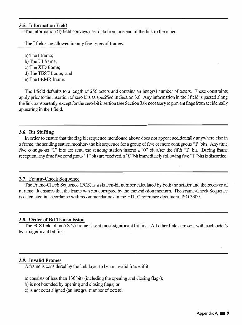
3.5. Information FieldThe information (I) field conveys user data from one end of the link to the other.
The I fields are allowed in only five types of frames:
a) The I frame;b) The ill frame;c) The XID frame;d) The TEST frame; ande) The FRMR frame.
The I field defaults to a length of 256 octets and contains an integral number of octets. These constraintsapply prior to the insertion of zero bits as specified in Section 3.6. Any information in the I field is passed alongthe link transparently, except for the zero-bit insertion (see Section 3.6) necessary to prevent flags from accidentallyappearing in the I field.
3.6. Bit StuffingIn order to ensure that the flag bit sequence mentioned above does not appear accidentally anywhere else in
<,
a frame, the sending station monitors the bit sequence for a group of five or more contiguous"I" bits, Any timefive contiguous "1" bits are sent, the sending station inserts a "0" bit after the fifth "1" bit. During framereception, any time five contiguous "1" bits are received, a "0" bit immediately following five "1" bits is discarded.
3.7. Frame-Check SequenceThe Frame-Check Sequence (PCS) is a sixteen-bit number calculated by both the sender and the receiver of
a frame. It ensures that the frame was not corrupted by the transmission medium. The Frame-Check Sequenceis calculated in accordance with recommendations in the HDLC reference document, ISO 3309.
3.8. Order of Bit TransmissionThe FCS field of an AX.25 frame is sent most-significant bit first. All other fields are sent with each octet's
least-significant bit first.
3.9. Invalid FramesA frame is considered by the link layer to be an invalid frame if it:
a) consists of less than 136 bits (including the opening and closing flags);b) is not bounded by opening and closing flags; orc) is not octet aligned (an integral number of octets).
AppendixA • 9

3.10. Frame AbortIf a frame must be prematurelyaborted,at least fifteen contiguous "l"s are sent without bit stuffingadded.
3.11. Inter-Frame Time FillWhenever it is necessary for a TNC to keep its transmitter on while not actually sending frames, the time
between frames should be filled with contiguousflags.
3.12. Address-Field EncodingThe addressfieldofall framesconsistsof a destination, sourceand (optionally) twoLayer 2 repeatersubfields.
Each subfieldconsistsof an amateurcallsignand a SecondaryStationIdentifier(SSID). The callsignis made upof upper-case alpha and numericASCn charactersonly. The SSID is a four-bit integer that uniquelyidentifiesmultiple stationsusing the same amateur callsign.
The HDLC addressfield is extendedbeyond one octetby assigningthe least-significant bit of each octet to bean "extension bit." The extensionbit of each octet is set to "0" to indicate the next octet containsmore addressinformation, or to "I", to indicate that this is the last octet of the HDLC address field. 'Io make room for thisextensionbit, the amateur radio call- sign informationis shifted one bit left. < .
3.12.1. Non-repeater Address-Field EncodingIfLayer 2 repeaters are not being used, the addressfield is encoded as shown in Figure 3.3. The destination
addressis the callsignand SSID of the amateurradio stationto which the frame is addressed. The sourceaddresscontainsthe amateurcallsignand SSID of the stationthat sent the frame. These callsignsare the callsignsof thetwo ends of a Layer 2 AX.25 link only.
FirstOctetSent
. Address Field of Frame
Destination Address Subfield Source Address Subfield
Al A2 A3 A4 A5 A6 A7 A8 A9 AlO All A12 A13 A14
Figure 3.3. Non-repeater address-field encoding.
Al through A14, above; are the fourteen octets that make up the two address subfieldsof the address field.The destinationsubfieldis seven octets long (AI throughA7), and is sent first. This address sequenceprovidesthe receivers of frames time to check the destination address subfield to see if the frame is addressed to themwhile the rest of the frame is being received. The source address subfield is then sent in octetsA8 throughA14.Both of these subfields are encoded in the same manner, except that the last octet of the address field has theHDLC address extensionbit set.
10 • Appendix A

The SSID octet at the end of each address subfield (A7 and A14) contains the SSID and the "C" bit. The Cbits identify command and response frames (see Section 6.1.2). The SSID octet at the end of each optionalLayer 2 repeater address subfield (A21 and A28) contains the SSID and the "H" bit ("[H]as-been-repeated").The H bits indicate that the Layer 2 repeater station has repeated the frame (see Section 3.12.3). Each SSID octetcontains two bits that are reserved for future use.
Figure 3.4 shows a typical AX.25 frame in the non-repeater mode of operation.
Octet ASCII Bin Data Hex Data
Flag 01111110 7E
Al N 10011000 98
A2 J 10010100 94
7 01101110\
6EA3
A4 P 10100000 AO
A5 space 01000000 40
A6 space 01000000 40
A7 SSID 11100000 EO,
A8 N 10011000 98< .
A9 7 01101110 6E
AlO L 10011000 98
All E 10001010 8A
A12 M 10011010 9A
A13 space 01000000 40
A14 SSID 01100001 61
Control I 00111110 3E
PID none 11110000 FO
FCS part1 XXXXXXXX HH
FCS part2 XXXXXXXX HH
Flag 01111110 7E
Bit position 76543210
Figure 3.4. Non-repeater AX.25frame.
The frame shown is an I frame, not going through a Layer 2 repeater, from N7LEM (SSID=O) to NJ7P(SSID=O), without a Layer 3 protocol. The PIP bit is set; the receive sequence number [N(R)] is 1; the sendsequence number [N(S)] is 7.
Appendix A • I I

3.12.2. Destination Subfield EncodingFigure 3.5 shows how an amateur callsign is placed in the destination address subfield, occupying octets Al
throughA7.
Octet ASCII Bin Data Hex Data
Al N 10011000 98
A2 J 10010100 94
A3 7 01101110 6E
A4 P 10100000 AO
A5 space 01000000 40
A6 space 01000000 i 40
A7 SSID 11100000 EO
A7 SSID CRRSSIDO
Bit position 76543210
Figure 3.5. Destination field encoding.
Where:
a) The top octet (AI) is the first octet sent, with bit aof each octet being the first bit sent, and bit 7 being thelast bit sent.
b) The first (low-order or bit 0) bit of each octet is the HDLC address extension bit, set to zero on all but thelast octet in the address field , where it is set to one.
c) The bits marked "R" are reserved bits. They may be used in an agreed-upon manner in individualnetworks. When not implemented, they are set to one.
d) The bit marked "C" is the command/response bit of an AX.25 frame, as outlined in Section 6.1.2.
e) The characters of the callsign are standard seven-bitASCII (upper case only) placed in the left-most sevenbits of the octet to make room for the address extension bit. If the callsign contains fewer than six characters,it is padded with ASCII spaces between the last call sign character and the ssmoctet.
f) The 0000 ssmis reserved for the first personal AX.25 station. This provision establishes one standardssmfor "normal" stations to use for the first station.
12 • Appendix A

3.12.3. Source Subfield EncodingFigure 3.6 shows how an amateur callsign is placed in the destinationaddress subfield,occupyingoctetsAl
throughA7.
Octet ASCII Bin Data Hex Data
A8 N 10011000 98
A9 7 01101110 6E
AlO L 10011000 98
All E 10001010 8A
A12 M 10011010 9A
A13 space 01000000 40\
A14 SSID CRRSSIDO
/
Bit position 76543210
Where:
Figure 3.6. Source field encoding.
a) The top octet (A8) is the first octet sent, with bit aof each octet being the first bit sent, and bit 7 being'thelast bit sent.
b) The first (low-order or bit 0) bit of each octet is the HDLC addressextensionbit, set to zero on all but thelast octet in the address field, where it is set to one.
c) The bits marked "R" are reserved bits. They may be used in an agreed-upon manner in individualnetworks. When not implemented, they are set to one.
d) The bit marked "C" is the command/responsebit of an LA PAframe, as outlined in Section 6.1.2.
e) The charactersof the callsignare standardseven-bitASCn (uppercase only)placed in the leftmost sevenbits of the octet to make room for the addressextensionbit. Ifthe callsigncontainsfewer thansix characters,it is padded withASCn spaces between the last callsign character and the ssmoctet.
f) The 0000 ssmis reserved for the first personalAX.25 station. This provision establishesone standardssmfor "normal" stations to use for the first station.
AppendixA • 13

3.12.4. Layer 2 Repeater Address EncodingEvolving consensus opinion is that repeater chaining belongs to a higher protocol layer. Consequently, it is
being phased out ofLayer 2, although backward compatibility is being maintained with a limit of two repeaters.
If a frame is to go through Layer 2 amateur packet repeater(s), an additional address subfield is appended tothe end of the address field. This additional subfield contains the callsign(s) of the repeater(s) to be used. Thisallows more than one repeater to share the same RF channeL If this subfield exists, the last octet of the sourcesubfield has its address extension bit set to "0", indicating that more address-field data follows. The repeateraddress subfield is encoded in the same manner as the destination and source address subfields, except for themost-significant bit in the last octet, called the H bit. As discussed in Section 3.12.1, the H bit indicates whethera frame has been repeated or not.
The H bit is set to "0" on frames going to a repeater. The repeater changes the H bit to "1" before it retransmitsthe frame. Stations monitor and repeat frames that meet the following conditions:
a) the frame is addressed to this station in a repeater address subfield;b) the H bit in its repeater address subfield is 0; orc) all previous H bits are set to one .
Figure 3.7 shows how the repeater address subfield is encoded. Figure 3.8 is an example of a complete frameafter being repeated.
Octet ASCII Bin Data Hex Data
A15 N 10011000 98
A16 J 10010100 94
A17 7 01101110 6E
A18 P 10100000 AO
A19 space 01000000 40
A20 space 01000000 40
A21 SSID HRRSSID1
Bit position 76543210
Figure 3.7. Repeater address encoding.
Where:
a) The top octet is the first octet sent, with bit 0 being sent first and bit 7 sent last of each octet.
b) As with the source and destination address subfields discussed above, bit 0 of each octet is the HOLCaddress extension bit, is set to "0" on all but the last address octet, where it is set to "1".
c) The "R" bits are reserved in the same manner as in the source and destination subfields.
d) The "H" bit is the has-been-repeated bit. It is set to "0" when a frame has not been repeated, and set to "1"by the repeating station when repeated.
14 • Appendix A

Octet ASCII Bin Data Hex Data
Flag 01111110 7E
Al N 10011000 98
A2 J 10010100 94
A3 7 01101110 6E
A4 P 10100000 AO
A5 space 01000000 40
A6 space 01000000 40
A7 SSID 11100000 EO
A8 N 10011000 98
A9 7 01101110 \ 6E
AlO L 10011000 98
All E 10001010 8A
A12 M 10011010 9A
A13 space 01000000 40
A14 ssm 01100000 60 -,' .
A15 N 10011000 98
A16 7 01101110 6E
A17 0 10011110 9E ·
A18 0 10011110 9E
A19 space 01000000 40
A20 space 01000000 40
A21 SSID 11100011 E3
Control I 00111110 3E
PID none 11110000 FO
FCS part 1 xxxxxxxx HH
FCS part 2 XXXXXXXX HH
Flag.,
01111110 7E
Bit position 76543210
Figure 3.8. AX.25 frame in repeater mode.
The above frame is the same as shown in Figure 3.3, except for the addition of a repeater address subfield(N700, SSID=l). The H bit is set, indicating this frame is from the output of the repeater.
Appendix A • 15

3.12.5. Multiple Repeater OperationThe link-layer AX.25 protocol allows operation through more than one repeater. Up to two repeaters may be
used by extending the repeater address subfield. When there is more than one repeater address, the repeateraddress immediately following the source address subfield will be considered the address of the first repeater ofa multiple-repeater chain. As a frame progresses through a chain of repeaters, each successive repeater will setthe H bit in its SSID octet, indicating that the frame has been successfully repeated through it. No other changesto the frame are made (except for the necessary recalculation of the FCS). The destination station can determinethe route the frame took to reach it by examining the address field and use this path to return frames.
The number of repeater addresses is variable. The last repeater address will have the address extension bit ofthe SSID octet set to "I" indicating the end of the address field. All other address octets will have their addressextension bit set to "0".
Note that various timers (see Section 6.6.1) may require adjustment to accommodate the additional delaysencountered when a frame must pass through a multiple-repeater chain. \
16 • Appendix A

4. Elements of Procedure and Formats of Fields
4.1. GeneralThe elements of procedure define the command and response frames used on the AX.25 link.
Procedures are built from these elements and are described in Section 6.
4.2. Control FieldsThe control field identifies the type of frame being sent. The control fields in AX.25 are modeled after the
ISO HDLC balanced operation control fields.
4.2.1. Control-Field FormatsThe three formats of control fields used in AX.25 are the:
a) Information frame (I frame);
b) Supervisory frame (S frame); and
c) Unnumbered frame (U frame).
Figures 4.1a and 4.1b illustrate the basic format of the control field associated with each of these three typesof frames .
The control field can be one or two octets long and may use sequence numbers to maintain link integrity.These sequence numbers may be three-bit (modulo 8) or seven-bit (modulo 128) integers.
Control-Field BitsControl Field Type
6 5 4 3 2 1 07
I Frame N(R) P N(S) I 0
S Frame N(R) PIP S S o 1J
U Frame MMM PIP M M 1 1
Figure 4.1a. Control-fieldformats (modulo 8).
Appendix A • 17

Control-Field BitsControl Field Type
15 14 13 12 11 10 9 6 5 4 38 7 2 1 0
I Frame N(R) P N(S)1
0
S Frame N(R) PIP o 000 S SOl
Figure 4.1b. Control-fieldformats (modulo 128).
I
Where:
a) Bit 0 is the first bit sent and bit 7 (or bit 15 for modulo 128) is the last bit sent of the control field.
b) N(S) is the send sequence number (bit 1 is the LSB).
c) N(R) is the receive sequence number [bit 5 (or bit 9 for modulo 128) is the LSB].
d) The "S" bits are the supervisory function bits; their encoding is discussed in Section 4.2.1.2.
e) The "M" bits are the unnumbered frame modifier bits; their encoding is discussed in Section 4.2.1.3."
"f) The PIP bit is the PolllFinal bit. The PIP bit is used in all types of frames . The PIP bit is also used in a
command (poll) mode to request an immediate reply to a frame. The reply to this poll is indicated by settingthe response (final) bit in the appropriate frame. Only one outstanding poll condition per direction is allowedat a time. The procedure for PIP bit operation is described in Section 6.2.
4.2.1.1. Information-Transfer FormatAll I frames have bit 0 of the control field set to "0". N(S) is the sender's send sequence number (the send
sequence number of this frame). N(R) is the sender's receive sequence number (the sequence number of thenext expected receive frame). These numbers are described in Section 4.2.4.
4.2.1.2. Supervisory FormatSupervisory frames have bit 0 of the control field set to "1", and bit 1 of the control field set to "0". S frames
provide supervisory link control such as acknowledging or requesting retransmission of I frames, and link-layerwindow control. Because S frames do not have an information field, the sender's send variable and the receiver'sreceive variable are not incremented for S frame~.
4.2.1.3. Unnumbered FormatUnnumbered frames have both bits 0 and 1 of the control field set to "I". U frames are responsible for
maintaining additional control over the linkbeyond what is accomplished with S frames. U frames are responsiblefor establishing and terminating link connections. U frames also allow for the transmission and reception ofinformation outside of the normal flow control. Some U frames may contain both information and PID fields,
18 • Appendix A

4.2.2. Control-Field Parameters
4.2.3. Sequence NumbersIfmodulo 8 operation is in effect (the default) , an I frame is assigned a sequential number from 0 to 7. This
step allows up to seven outstanding I frames per Layer 2 connection at one time.
Ifmodulo 128 operation is in effect, an I frame is assigned a sequential number between 0 and 127. This stepallows up to 127 outstanding I frames per Layer 2 connection at one time. -
4.2.4. Frame Variables and Sequence Numbers
4.2.4.1. Send State Variable VCS)The send state variable exists within the TNC and is never sent. It contains the next sequential number to be
\
assigned to the next transmitted I frame. This variable is updated with the transmission of each I frame .
4.2.4.2. Send Sequence Number NCS)The send sequence number is found in the control field of all I frames. It contains the sequence number of the
I frame being sent. Just prior to the transmission of the I frame, N(S) is updated to equal the send state variable.
4.2.4.3. Receive State Variable VCR)'.
The receive state variable exists within the TNC. It contains the sequence number of the next expectedreceived I frame. This variable is updated upon the reception of an error-free I frame whose send sequencenumber equals the present received state variable value.
4.2.4.4. Received Sequence Number NCR)The received sequence number exists in both I and S frames. Prior to sending an I or S frame, this variable is
updated to equal that of the received state variable, thus implicitly acknowledging the proper reception of allframes up to and including N(R)-l.
4.2.4.5. Acknowledge State Variable VCA)The acknowledge state variable exists within the TNC and is never sent. It contains the sequence number of
the last frame acknowledged by its peer [V(A)-1 equals the N(S) of the last acknowledged I frame].
Appendix A • 19

4.3. Control-Field Coding for Commands and Responses
4.3.1. Information Command Frame Control FieldThe information (I) command transfers sequentially-numbered frames containing an information field across
a data link.
The information-frame control field is encoded as shown inFigures 4.2a and 4.2b. These frames are sequentiallynumbered by the N(S) subfield to maintain control of their passage over the link-layer connection.
Control-Field BitsControl Field Type
7 6 5 4 3 2 1 0,
I Information N(R) P N(S) o I
Figure 4.2a. Iframe controlfield (modulo 8).
Control-Field Bits
Control Field Type Second Octet First Octet
15 14 13 12 11 10 9 8 7 6 5 4 3 2 1 0
I I Frame N(R) P N(S) 0
Figure 4.2b. Iframe controlfield (modulo 128).
20 • Appendix A

4.3.2. Supervisory Frame Control FieldThe supervisory frame control fields are encoded as shown in Figures 4.3a and 4.3b.
Control Field Control-Field Bits
Type 7 6 5 4 3 2 1 0
Receive Ready RR NCR) PIP o 0 0 1
Receive Not Ready RNR NCR) PIP o 1 0 1
Reject REJ NCR) PIP 1 0 0 1
Selective Reject SREJ NCR) PIP 1 1 0 1
Figure 4.3a. S frame control fields (modulo 8).
Control-Field Bits<,
Control Field Type Second Octet First Octet
15 14 13 12 11 10 9 8 7 6 5 4 3 2 1 0
RR NCR) PIP o 0 0 0 .0 0 0 1
RNR NCR) PIP o 0 0 0 0 1 0 1
REJ NCR) PIP o 0 0 0 1 o 0 1
SREJ NCR) PIP o 0 0 0 1 1 0 1
Figure 4.3b. Sframe controlfields (modulo 128).
Where:
Acronym
RRRNRREJSREJ
Description of Frame Identifiers
Receive Ready - System Ready To Receive.Receive Not Ready - TNC Buffer Full.Reject Frame - Out of Sequence or Duplicate.Selective Reject - Request single frame repeat.
Appendix A • 21

4.3.2.1. Receive Ready (RR) Command and ResponseReceive Ready accomplishes the following:
a) indicates that the sender of the RR is now able to receive more I frames;b) acknowledges properly received I frames up to, and including N(R)-I;andc) clears a previously-set busy condition created by an RNR command having been sent.
The status of the TNC at the other end ofthe link can be requested by sending an RR command frame witl: theP-bit set to one.
4.3.2.2. Receive Not Ready (RNR) Command and Response .Receive Not Ready indicates to the sender of! frames that the receiving TNC is temporarily busy and cannot
accept any more I frames. Frames up to N(R)-I are acknowledged. Frames N(R) and above that may have beentransmitted are discarded and must be retransmitted when the busy condition clears.
The RNR condition is cleared by the sending of a VA, RR, REJ or SABM(E) frame.
The status of the TNC at the other end of the link is requested by sending an RNR command frame with theP bit set to one.
4.3.2.3. Reject (RE,n Command and ResponseThe reject frame requests retransmission of I frames starting with N(R). Any frames sent with a sequence
number of N(R)-I or less are acknowledged. Additional I frames which may exist may.be appended to theretransmission of the N(R) frame.
Only one reject frame condition is allowed in each direction at a time. The reject condition is cleared by theproper reception of I frames up to the I frame that caused the reject condition to be initiated.
The status of the TNC at the other end ofthe link is requested by sending a REJ command frame with the P bitset to one.
4.3.2.4. Selective Reject (SRE,n Command and ResponseThe selective reject, SREJ, frame is used by the receiving TNC to request retransmission of the single I frame
numbered N(R). If the PIF bit in the SREJ frame is setto "1", then I frames numbered up to N(R)-I inclusive areconsidered as acknowledged. However, if the PlFbitin the SREJ frame is set to "0", then the N(R) of the SREJframe does not indicate acknowledgement of I frames.
Each SREJ exception condition is cleared (reset) upon receipt of the I frame with an N(S) equal to the N(R)of the SREJ frame.
A receiving TNC may transmit one or more SREJ frames, each containing a different N(R) with the Pbit setto "0", before one or more earlier SREJ exception conditions have been cleared. However, a SREJ is nottransmitted if an earlier REJ exception condition.has not been cleared as indicated in Section 4.5.4. (To do sowould request retransmission of an I frame that would be retransmitted by the REJ operation.) Likewise, a REJframe is not transmitted if one or more earlier SREJ exception conditions have not been cleared as indicated inSection 4.5.4.
I frames transmitted following the I frame indicated by the SREJ frame are not retransmitted as the result ofreceiving a SREJ frame. Additional I frames awaiting initial transmission may be transmitted following theretransmission of the specific I frame requested by the SREJ frame.
22 _ Appendix A

4.3.3. Unnumbered Frame Control FieldsUnnumbered frame control fields are either commands or responses.
Figure 4.4 shows the layout of U frames implemented within this protocoL
Control-Field BitsControl Field Type Type
6 5 4 37 2 1 0
Set Async Balanced Mode SABME Cmd 0 1 1 P 1 1 1 1
Set Async Balanced Mode SABM Cmd o 0 1 P 1 1 1 1
Disconnect DISC Cmd 010 P o 0 1 1
Disconnect Mode DM Res o 0 0 \ F 1 1 1 1
Unnumbered Acknowledge UA Res o 1 1 F o 0 1 1
Frame Reject FRMR Res 100 F 0 1 1 1
Unnumbered Information UI Either 000 P/F o 0 1 1
Exchange Identification XID Either 1 0 1 P/F 1; 1 1 1
Test TEST Either 1 1 1 P/F o 0 1 1
Figure 4.4. Uframe control fields.
Where:
/
Acronym
SABMSABMEDISCFRMRUIDMXIDUATEST
Description of Frame Identifiers
Connect RequestConnect Request Extended (modulo 128)Disconnect requestFrame RejectUnnumbered Information FrameDisconnect Mode - System Busy or Disconnected.Exchange Identifications - Negotiate features.Unnumbered AcknowledgeTest
Appendix A • 23

4.3.3.1. Set Asynchronous Balanced Mode (SABM) CommandThe SABM command places two Terminal Node Comtrollers (TNC) in the asynchronous balanced mode
(modulo 8). This a balanced mode of operation in which both devices are treated as equals or peers.
Information fields are not allowed in SABM commands. Any outstanding I frames left when the SABMcommand is issued remain unacknowledged.
The TNC confirms reception and acceptance of a SABM command by sending a UA response frame at theearliest opportunity. If the TNC is not capable of accepting a SABM command, it responds with a DM frame ifpossible.
4.3.3.2. Set Asynchronous Balanced Mode Extended (SABME) CommandThe SABME command places two TNCs in the asynchronous balanced mode extended (modulo 128). This
is a balanced mode of operation in which both devices are treated as equals or peers.\
Information fields are not allowed in SABME commands. Any outstanding I frames left when the SABMEcommand is issued remains unacknowledged.
The TNC confirms reception and acceptance of a SABME command by sending a UAresponse frame at theearliest opportunity. If the TNC is not capable of accepting a SABME command, it responds with a DM frame.A TNC that uses a version ofAX.25 prior to v2.2 responds with a FRMR.
4.3.3.3. Disconnect (DISC) CommandThe DISC command terminates a link session between two stations. An information field is not permitted in
a DISC command frame.
Prior to acting on the DISC frame, the receiving TNC confmns acceptance of the DISC by issuing a UAresponse frame at its earliest opportunity. The TNC sending the DISC enters the disconnected state when itreceives the UA response .
Any unacknowledged I frames left when this command is acted upon remain unacknowledged.
4.3.3.4. Unnumbered Acknowledge (UA) ResponseThe UA response frame acknowledges the reception and acceptance of a SABM(E) or DISC command
frame. A received'command is not actually processed until the UAresponse frame is sent. Information fields arenot permitted in a UA frame.
4.3.3.5. Disconnected Mode (DM) ResponseThe disconnected mode response is sent whenever a TNC receives a frame other than a SABM(E) or UI
frame while in a disconnected mode. The disconnected mode response also indicates that the TNC cannotaccept a connection at the moment. The DM response does not have an information field.
Whenever a SABM(E) frame is received and it is determined that a connection is not possible, a DM frame issent. This indicates that the called station cannot accept a connection at that time.
While a TNC is in the disconnected mode, it responds to any command other than a SABM(E) or UI framewith a DM response with the PIF bit set to " I" .
24 • AppendixA

4.3.3.6. Unnumbered Information (UI) FrameThe Unnumbered Information frame contains Pill and information fields and passes information along the
link outside the normal information controls. This allows information fields to be exchanged on the link, bypassingflow control.
Because these frames cannot be acknowledged, if one such frame is obliterated, it cannot be recovered.
A received VI frame with the P bit set causes a response to be transmitted. This response is a DM frame whenin the disconnected state, or an RR (or RNR, if appropriate) frame in the information transfer state.
4.3.3.7. Exchange Identification (XID) FrameThe Exchange Identification frame causes the addressed station to identify itself, and to provide its characteristics
to the sending station. An information field is optional within the XID frame. A station receiving an XIDcommand returns an XID response unless a VA response to a mode setting command is awaiting transmission,or a FRMR condition exists.
The XID frame complies with ISO 8885. Only those fields applicable to AX.25 are described. All otherfields are set to an appropriate value. This implementation is compatible with any implementation which followsISO 8885. Only the general-purpose XID information field identifier is required in this version ofAX.25.
The information field consists of zero or more information elements. The information elements start with aFormat Identifier (PI) octet. The second octet is the Group Identifier (GI). The third and forth octets form theGroup Length (GL). The rest of the information field contains parameter fields. ~
The PI takes the value 82 hex for the general-purpose XID information. The GI takes the value 80 hex for theparameter-negotiation identifier. The GL indicates the length of the associated parameter field. This length isexpressed as a two-octet binary number representing the length of the associated parameter field in octets. Thehigh-order bits of length value are in the first of the two octets. A group length of zero indicates the lack of anassociated parameter field and that all parameters assume their default values. The GL does not include its ownlength or the length of the GI.
The parameter field contains a series of Parameter Identifier (PI), Parameter Length (PL), and ParameterValue (PV) set structures, in that order. Each PI identifies a parameter and is one octet in length. Each PLindicates the length of the associated PV in octets, and is one octet in length. Each PV contains the parametervalue and is PL octets in length. The PL does not include its own length or the length of its associated PI. A PLvalue of zero indicates that the associated PV is absent; the parameter assumes the default value. A PIIPLIPV setmay be omitted if it is not required to convey information, or if present values for the parameter are to be used.The PIIPLIPV fields are placed into the information field of the XID frame in ascending order. There is only oneentry for each PIIPLIPV field used. A parameter field containing an unrecognized PI is ignored. An omittedparameter field assumes the currently negotiated value.
The parameter fields described below represent the minimum implementation and do not preclude thenegotiation of other parameters between consenting stations.
The encoding of each PIIPLIPV applicable to AX.25 is detailed in Figure 4.5. Some of the fields are defmedin this standard. Only the fields discussed below are required in an implementation that complies with thisversion ofAX.25.
AppendixA • 25

Name PI PL Parameter Field Element Type Bit Value
Balanced-ABM E I 1Classes of 2 2
Unbalanced-NRM-Pri * E 2 0Procedures
Unbalanced-NRM-Sec * E 3 0
Unbalanced-ARM-Pri * E 4 0
Unbalanced-ARM-Sec * E 5 0
Half Duplex E 6 0/1
Full Duplex E 7 OIl
Reserved * 8-16 0
1 Reserved * E 1 0HDLC 3 3 2 REJ cmd/resp E 2 0/1OptionalFunctions 3A SREJ cmd/resp E 3 0/1
4 UI cmd/resp * E 4 0
5 SIM cmd/RIM resp * E 5 0
6 UP cmd * E 6 0
7A Basic address * E 7 0
7B Extended address E 8 1
8 Delete I resp * E 9 0
9 Delete I cmd * E 10 0
lOA Modulo 8 E 11 0/1
lOB Modulo 128 E l 2 0/1
11 RSETcmd * E 13 <. 0
12 TEST cmd/resp E 14 I
13 RD resp * E 15 0
14A 16-bit FCS E 16 1
14B 32-bit FCS * E 17 0
15A Synchronous Tx E 18 1
15B Start/stop Tx * E 19 0
15C Start/Stop Basic Flow Ctl * E 20 0
15D Start/stop Octet Transparent * E 21 0
3B SREJ Mu1tiframe * E 22 0
Reserved * E 23-24 0
I Field5 N
Max I field length* B NA B
Length Tx. Tx (bits) N1*8
I Field6 N
Max I field lengthB NA B
Length Rx Rx (bits) N1*8
Window7 I
Window Size k (frames)*
B 1-7 0-127Size Tx TX B 8 0
Window8 I
Window Size k (frames) B 1-7 0-127Size Rx RX B 8 0
Ack Timer 9 N Wait for Ack T1 (Msec) B NA B
Retrys 10 N Retry Count N2 B NA B
Figure 4.5. Parameter negotiation - parameterfield elements.
• Note that Type E is a bit field and Type B is a numeric field of N octets.• Parameter field elements marked * are defined in ISO 8885. They are shown for compatibility
purposes only and are not needed to negotiate the features of this version ofAX.25.
26 • App endix A

The Classes of Procedures parameter field (PI=2) serves to negotiate half- or full-duplex:
• Bit 1 is always a 1.• Bits 2 through 5 and 8 through 16 are always zero.• Either Bit 6 (half-duplex) or bit 7 (full-duplex), but not both, must be set. If this parameter field is not
present, the current values are retained. The default is half-duplex.
The HDLC Optional Functions parameter field (pI=3) allows the negotiation ofimplicit reject (REJ), selectivereject (SREJ), or selective reject-reject (SREJIREJ) and modulo 8 or 128:
• Bits 1,4-7,9,10,13, 15, 17 and 19-24 are always zero .• Bits 8, 14, 16 and 18 are always a one.• Implicit reject is selected by setting bit 1 and resetting bit 2.• Selective reject is selected by resetting bit 1 and setting bit 2.• Selective reject-reject is selected by setting bit 1 and bit 2.• Clearing both bit 1 and 2 is not allowed.• Modulo 8 operation is selected by setting bit 11 and resetting bit 12.• Modulo 128 operation is selected by setting bit 12 and resetting bit 11. If this parameter field is not
present, the current values are retained. The default is selective reject-reject and modulo 8.
The I Field Length Receive parameter field (pI=6) allows the sending TNC to notify the receiving TNC ofthemaximum size of an Information field (Nl) it will handle without error. A transmitting TNC may not exceed thissize, but may send smaller frames. If this field is not present, the current values are retained. The default is 256octets (2048 bits).
The Window Size Receive parameter field (pI=8) allows the sending TNC to notify the receiving TNC of themaximum size of the window (k) it will handle without error. If the TNCs are using modulo 128, this allows thenegotiation of a window size less than 127 to conserve memory. If the TNCs are using selective reject orselective reject-reject, the receiving TNC is required to buffer k frames at any time. A transmitting TNC may notexceed this size, but may send fewer frames. If this field is not present, the .current values are retained. Thedefault is 4 for modulo 8 and 32 for modulo 128.
The Acknowledge Timer parameter field (PI=9) allows the negotiation of the wait for acknowledgementtimer (Tl). If this.field is not present, the current values are retained. The default is 3000 MSec.
The Retries parameter field (pI=IO) allows the negotiation of the retry count (NI). If this field is not present,the current values are retained. The default is 10 retries.
A FRMR condition may be established ifthe received XID command information field exceeds the maximumdefmed storage capability of the station, or if the receiving station is using AX.25 version 2.0 or earlier versions .
A typical XID frame is shown in Figure 4.6.
AppendixA • 27

28 • Appendix A
Rag 7E Start Rag
Al 98
A2 94
A3 6E
A4 AO From Address (Example Call -SSID : NJ7P-O)
AS 40
A6 40
A7 EO
A8 98
A9 6E
A IO 98
All 8A To Address (Example Call-SSID: N7LEM-0)
AI2 9A
A13 40
AI4 61 \
Ctl AF Control Field (XID)
FI 82 Format indicator
or 80 Group Identifier - parameter negotiation
GL 00 Group length - all of the PIIPLlPV fields
17 (2 bytes)
PI 02 Parameter Indicator - classes of procedures
PL 02 Parameter Length
PV 00 Parameter Variable - Half Duplex, Async
20 Balan ced Mode
PI 03 Parameter Indicator - optional funct ions
PL 03 Parameter Length
PV 86Parameter Vari able - SREJIREJ, extended addr
A8 16-bit FCS, TEST cmdJresp, Modulo 128
02 synchronous transmit
PI 06 Parameter Indicator - Rx I field length (bits)
PL 02 Parameter Length
PV 04Parameter Variable - 1024 bits (128 octets)
00
PI 08 Parameter Indicator - Rx window size
PL 01 Parameter length
PV 02 Parameter Variable - 2 frames
PI 09 Parameter Indicator - Timer TI
PL 02 Parameter Length
PV 10Parameter Variable - 4096 MSec
00
PI OA Parameter Indic ator - Retrie s (NI)
PL 01 Parameter Length
PV 03 Parameter Variable - 3 retrie s
FCS XX
FCS XX
R ag 7E
Figure 4.6. Typical XID frame.

4.3.3.8. Test (TEST) FrameThe Test command causes the addressed station to respond with the TEST response at the first respond
opportunity; this performs a basic test of the data-linkcontrol. An informationfield is optional with the TESTcommand. Ifpresent, the received informationfield is returned, if possible, by the addressed station, with theTEST response. TheTEST commandhas no effecton themode or sequencevariablesmaintainedby the station.
AFRMR conditionmaybeestablished ifthereceivedTESTcommandinformation fieldexceedsthemaximumdefinedstoragecapabilityof the station. Ifa FRMR responseis not returnedfor this condition,a TEST responsewithout an informationfield is returned.
The stationconsiders the data-link layer test terminatedon receipt of theTEST response,or when a tin:e-outperiod has expired. The results of the TEST command/responseexchange are made availablefor interrogationby a higher layer.
4.3.3.9. FRMR Response FrameThe FRMR response is removed from the standard for the followingreasons:
a) ill frame transmissionwas not allowed during FRMR recovery;b) During FRMR recovery, the link could not be reestablished by the station that sent the FRMR;c) The above functions are better handled by simply resetting the link with a SABM(E) + UAexchange;d) An implementation that receivesand processFRMRs but does not transmit themis compatiblewith older
versions of the standard; "and e) SDL is simplifiedand removes the need for one state.
This version ofAX.25 operates with previous versions of AX.25. It does not generate a FRMR Responseframe, but handles error conditionsby resetting the link.
4.4. Link Error Reporting and RecoverySeveral link-layer errors can be recovered without terminating the connection. These error situations may
occur as a result of transmissionerrors or malfunctions within the TNC. .
4.4.1. TNC Busy ConditionWhen a TNC is temporarilyunable to receiveI frames (e.g.,whenreceivebuffersare full), it sends a Receive
Not Ready (RNR) frame. This informs the sending TNC that the receiving TNC cannot handle any more Iframes at the moment. This receivingTNC clears this condition by the sending a UA, RR, REI or SABM(E)command frame.
AppendixA • 29

4.4.2. Send Sequence Number ErrorIf the send sequence number, N(S), of an otherwise error-free received frame does not match the receive state
variable, VCR), a send sequence error has occurred. If SREJ has been negotiated and the N(s) is in the range"greater-than V(r)" and "less-than V(r)+k," the information field is saved; otherwise it is discarded. The receiverwill not acknowledge this frame or any other I frames until N(S) matches VCR).
The control field of the erroneous I frame(s) is accepted so that link supervisory functions such as checkingthe P/F bit can be performed. Because of this update, the retransmitted I frame may have an updated P bit andN(R).
4.4.3. Reject (REJ) Recovery ,The REJ frame requests a retransmission of! frames following the detection of a N(S) sequence error. Only
one outstanding "sent REJ" condition is allowed at a time. This condition is cleared when the requested I framehas been received.
A TNC receiving the REJ command clears the condition by resending all outstanding I frames (up to thewindow size), starting with the frame indicated in N(R) of the REJ frame.
4.4.4. Selective Reject (SREJ) RecoveryThe SREJ command/response initiates more-efficient error recovery by requesting the retransmission of a
single I frame following the detection of a sequence error. This is an advancement over the earlier versions inwhich the requested I frame was retransmitted togther with all additional I frames subsequently transmitted anasuccessfully received.
When a TNC sends one or more SREJ commands, each with the Pbit set to "0" or "1", or one or more SREJresponses, each with the F bit set to "0", and the "sent SREJ" conditions are not cleared when the TNC is readyto issue the next response frame with the F bit set to "1", the TNC sends a SREJ response with the F bit set to "1",with the same N(R) as the oldest unresolved SREJ frame.
Because an I or S format frame with the F bit set to "1" can cause checkpoint retransmission, a TNC does notsend SREJ frames until it receives at least one in-sequence I frame, or it perceives by timeout that the checkpointretransmission will not be initiated at the remote TNC.
With respect to each direction of transmission on the data link, one or more "sent SREJ" exception conditionsfrom a TNC to another TNC may be established at a time . A "sent SREJ" exception condition is cleared whenthe requested I frame is received.
The SREJ frame may be repeated when a TNC perceives by timeout that a requested I frame will not bereceived, because either the requested I frame or the SREJ frame was in error or lost.
When appropriate, a TNC receiving one or more SREJ frames initiates retransmission of the individual Iframes indicated by the N(R) contained in each SREJ frame. After having retransmitted the above frames, newI frames are transmitted later if they become available.
30 • AppendixA

When a TNC receives and acts on one or more SREJ commands, each with the P bit set to "0", or an SREJcommand with the P bit set to "I", or one or more SREJ responses each with the F bit set to "0", it disables anyaction on the next SREJ response frame if that SREJ frame has the F bit set to " I" and has the same N(R) (i.e.,the same value and the same numbering cycle) as a previously actioned SREJ frame, and if the resultantretransmission was made following the transmission of the P bit set to a "1".
When the SREJ mechanism is used, the receiving station retains correctly-received I frames and deliversthem to the higher layer in sequence number order.
4.4.5. Timeout Error Recovery
4.4.5.1. Tl Timer RecoveryIf a transmission error causes a TNC to fail to receive (or to receive and discard) a single I frame, or the last I
frame in a sequence of I frames, then the TNC does not detect a send-sequence-number error and consequentlydoes not transmit a REJ/SREJ. The TNC that transmitted the unacknowledged I frame(s) following the completionof timeout period Tl, takes appropriate recovery action to determine when I frame retransmission as describedin Section 6.4.10 should begin. This condition is cleared by the reception of an acknowledgement for the sentframe(s) , or by the link being reset.
4.4.5.2. Timer T3 RecoveryTimer T3 ensures that the link is still functional during periods of low information transfer. When Tl is not
running (no outstanding I frames), T3 periodically causes the TNC to poll the other TNC of a link. When T3times out, an RR or RNR frame is transmitted as a command with the P bit set, and then Tl is started. When aresponse to this command is received, Tl is stopped and T3 is started. If Tl expires before a response isreceived, then the waiting acknowledgement procedure (Section 6.4.11) is executed. .
4.4.6. Invalid Frame or FCS ErrorIfan invalid frame is received, or a frame is received with an FCS error, that frame is discarded with no further
action taken.
Appendix A • 31

5. Elements for Layer-to-Layer CommunicationCommunication between layers is accomplished with primitives. In an abstract way, primitives represent the
logical exchange of information and control between the data link and adjacent layers; they do not specify orconstrain implementations.
Primitives consist of commands and their respective responses associated with the services requested from alower layer. The general syntax of a primitive is:
xxx -Generic name - Type: Parameters
Where "XXX" designates the interface across which the primitive flows.
For this Standard, "XXX" is:
a) DL for communications between Layer 3 and the data-link layer;b) LM for communications between the data-link layer and the link multiplexer;c) PH for communications between the link multiplexer and the physical layer; andd) MDL for communications between Layer 3 and the layer management.
5.1. Layer 3 Entity <-> Management Data-link State MachineCommunication between the Layer 3 Entity and the Management Data-link State Machine is characterized
by three primitives:
• MDL-NEGOTIATE Request. The Layer 3 entity uses this primitive to request the Data-link StateMachine to notify/negotiate.
• MDL-NEGOTIATE Confirm. The Management Data-link State Machine uses this primitive tonotify the Layer 3 entity that notification/negotiation is complete.
• MDL-ERROR Indicate. The Management Data-link State Machine uses this primitive to notify theLayer 3 entity that notification/negotiation has failed.
5.2. Management Data-Link State Machine <-> Link Multiplexer State MachineCommunication between the Management Data-link State Machine and the Link Multiplexer State Machine
is characterized by two primitives: •
• LM-DATARequest. The Management Data-link State Machine uses this primitive to pass frames ofany type (XID , ill, etc.) to the Link Multiplexer State Machine.
• LM-DATAIndication. The Link Multiplexer State Machine uses this primitive to pass frames of anytype (XID, DI, etc.)to the Management Data-link State Machine.
32 • AppendixA

5.3. Layer 3 Entity <-> Data-Link State MachineCommunication between the Layer 3 Entity and the Data-link State Machine is characterized by thirteen
primitives:
• DL-CONNECT Request. The Layer 3 entity uses this primitive to request the establishment of aAX.25 connection.
• DL-CONNECT Indication. The Data-link State Machine uses this primitive to indicate that a AX.25connection has been requested.
• DL-CONNECT Confirm. The Data-link State Machine uses this primitive to indicate that a AX.25connection has been made.
• DL-DISCONNECT Request. The Layer 3 entity uses this primitive\to request the release of a AX.25connection.
• DL-DISCONNECT Indication. The Data-link State Machine uses this primitive to indicate that aAX.25 connection has been released.
• DL-DISCONNECT Confirm. The Data-link State Machine uses this primitiveto indicate that aAX.25 connection has been released and confirmed. -;
• DL-DATA Request. The Layer 3 entity uses this primitive to request the transmission of data usingconnection-oriented protocol. If necessary, this frame is examined and acted upon by the segmenter.
• DL-DATA Indication. The reassembler uses this primitive to indicate reception of Layer 3 data usingconnection oriented protocol.
• DL-UNIT-DATA Request. The Layer 3 entity uses this primitive to request the transmission of datausing connectionless protocol. If necessary, this frame is examined and acted upon by the segmenter.
• DL-UNIT-DATA Indication. The reassembler uses this primitive to indicate reception of Layer 3 datausing connectionless protocol.
• DL-ERROR Indication. The Data-link State Machine uses this primitive to indicate when framesinconsistent with this protocol definition have been received. This includes short frames , frames withinconsistent parameter values, etc. The error indications are discussed in the SDL appendices.
• DL-FLOW-OFF Request. The Layer 3 entity uses this primitive to temporarily suspend the flow ofincoming information.
• DL-FLOW-ON Request. The Layer 3 entity uses this primitive to resume the flow of incominginformation.
AppendixA • 33

--- - -- - - - - - ----_..._-
5.4. Data-Link State Machine <-> Link Multiplexer State MachineCommunicationbetween the Data-linkState Machine and the Link MultiplexerStateMachine is characterized
by six primitives:
• LM-SEIZE Request. The Data-link State Machine uses this primitive to request the Link MultiplexerState Machine to arrange for transmission at the next available opportunity. The Data-link StateMachine uses this primitive when an acknowledgement must be made; the exact frame in which theacknowledgement is sent will be chosen when the actual time for transmission arrives. -
• LM-SEIZE Confirm. This primitive indicates to the Data-link State Machine that the transmissionopportunity has arrived.
• LM-RELEASE Request. The Link Multiplexer State Machine uses this primitive to stoptransmission.
• LM-EXPEDITED-DATA Request. The data-link machine uses this primitive to pass expedited datato the link multiplexer.
• LM-DATARequest. The Data-link State Machine uses this primitive to pass frames of any type(SABM, RR, VI, etc.) to the Link Multiplexer State Machine.
• LM-DATAIndication. The Link Multiplexer State Machine uses this primitive to pass frames of anytype (SABM, RR, VI, etc.) to the Data-link State Machine. <,
34 • Appendix A

5.5. Link Multiplexer State Machine <-> Physical State MachineCommunication between the Link: MultiplexerState Machine and the Physical State Machine is characterized
by eight primitives:
• PH-SEIZE Request. The Link Multiplexer State Machine uses this primitive before eachtransmission to request access to the radio channel.
• PH-SEIZE Confirm. The Physical State Machine uses this primitive to confirm that the channel hasbeen seized.
• PH-RELEASE Request. The Link Multiplexer State Machine uses this primitive to release the radiochannel.
• PH-QUIET Indication. The Physical State Machine uses this primitive to indicate that the channel isnot busy.
• PH-BUSY Indication. The Physical State Machine uses this primitive to indicate that the channel isbusy.
• PH-EXPEDITED-DATA Request. The Link Multiplexer State Machine uses this primitive to requesttransmission of each digipeat or expedite data frame.
• PH-DATA Request. The Link Multiplexer State Machine uses this primitive to request transmissionof each normal frame.
• PH-DATA Indication. The Physical State Machine uses this primitive to provide incoming frames tothe link multiplexer.
5.6. Physical State Machine <-> HardwareCommunication between the Physical State Machine and the Hardware is characterized by five primitives:
• Acquisition of Signal. The hardware uses this primitive to notify the Physical State Machine thatmodem synchronization, flag fill or frame structure have been detected.
• Loss of Signal. The hardware uses this primitive to notify the Physical State Machine that modemsynchronization, flag fill or frame structure have been lost.
• Frame. The hardware uses this primitive and the Physical.State Machine to pass frames to send or thathave been received.
• Turn On Transmitter. The Physical State Machine uses this primitive to tell the hardware to key thetransmitter.
• Turn Off Transmitter. The Physical State Machine uses this primitive to tell the hardware to unkeythe transmitter.
Appendix A • 35

6. Description ofAX.25 ProceduresThe following paragraphs describe the procedures involved in setting up, using and disconnecting a balanced
link: between two TNC stations.
6.1. Address Field Operation
6.1.1. Address InformationAll transmitted frames have address fields conforming to Section 3.12. All frames have both the destination
device and the source device addresses in the address field, with the destination address coming first. ' Thisallows many links to share the same RF channel. The destination address is always the address of the station(s)for which the frame is intended; the source address contains the address of the device that sent the frame.
i
If point-to-multipoint operation is desired, the destination address can be a group name or club callsign.Operation with destination addresses other than actual amateur callsigns is a subject for further study.
6.1.2. CommandlResponse ProcedureAX.25 implements the command/response information in the address field. ~e command/response
information is conveyed using two bits to maintain compatibility with previous versions ofAX.25.
An upward-compatible AX.25 TNC communicating with a distant TNC determines if the latter is using anolder version of this protocol by testing the command/response bit information located in bit 7 ofthe ssmoctetsof both the destination and source address subfields. Ifboth C bits are set to "0", then the distant device is usingthe older protocol. The newer version of the protocol always has one of these two bits set to" I" and the other bitset to "0", depending on whether the frame is a command or a response.
The command/response information is encoded into the address field as shown in Figure 6.1. ImplementationsofAX.25 prior to version 2.0 defined these bits to be either both "0" or both "I".
Frame TypeDest.. Previous versions
Command (V2'x)Response (V2,X)Previous versions
ssm C-Bito1o1
Source ssm C-BitooI1
Figure 6.1. 'Command/Response encoding.
Because all frames are considered to be either commands or responses, a device always has one of the bits setto "1" and the other bit set to "0".
The use of the command/response information in AX.25 allows S frames to be either commands or responses.This arrangement helps maintain proper control over the link:during the information transfer state.
36 _ AppendixA

6.2. PolVFinal (p/F) Bit ProceduresThe response frame returned by a TNC depends on the previous command received, as described in the
following paragraphs.
The next response frame returned by the TNC to a SABM(E) or DISC command with the P bit set to "1" is aVA or DM response with the F bit set to " I".
The next response frame returned to an I frame with the P bit set to "I", received during the informationtransfer state, is an RR, RNR or REJ response with the F bit set to "1" .
The next response frame returned to a supervisory command frame with the P bit set to "1", received duringthe information transfer state, is an RR, RNR or REJ response frame with the F bit set to "I".
The next response frame returned to a S or I command frame with the P bit set to "I", received in thedisconnected state, is a DM response frame with the F bit set to "I".
The P bit is used in conjunction with the timeout recovery condition discussed in Section 4.5.5.
When not used, the PIF bit is set to "0".
6.3. Procedures For Link Set-Up and Disconnection
6.3.1. AX.25 Link Connection EstablishmentTo connect to a distant TNC, the originating TNC sends a SABM command frame to the distant TNC and
starts its Tl timer. If the distant TNC exists and accepts the connect request, it responds with a VA responseframe and resets all of its internal state variables (V(S), V(A) and VCR)). Reception of the VA response frame bythe originating TNC causes it to cancel the Tl timer and set its internal state variables to "0".
If the distant TNC doesn't respond before Tl times out, the originating TNC resends the SABM frame andstarts Tl running again. The originating TNC tries to establish a connection until it has tried unsuccessfully N2times. N2 is defuied in Section 6.7.2.3.
If the distant TNC receives a SABM command and cannot enter the indicated state, it sends a DM frame.~ ,
When the originating TNC receives a DM response to its SABM(E) frame, it cancels its T l timer and doesnot enter the information-transfer state.
The originating TNC sending a SABM(E) command ignores and discards any frames except SABM, DISC,VA and DM frames from the distant TNC.
In response to a received SABM(E), frames other than VA and DMare sent only after the link is set up and ifno outstanding SABM(E) exists.
Appendix A _ 37

6.3.2. Parameter Negotiation PhaseParameter negotiation occurs at any time. It is accomplished by sending the XID command frame and
receiving the XID response frame. Implementations ofAX.25 prior to version 2.2 respond to an XID commandframe with a FRMR response frame. The TNC receiving the FRMR uses a default set ofparameters compatiblewith previous versions ofAX.25.
The receipt of an XID response from the other station establishes that both stations are using AX.25 version2.2 or higher and enables the use of the segmenter/reassembler and selective reject.
This version ofAX.25 implements the negotiation or notification of six AX.25 parameters. Notificationsimply tells the distant TNC some limit that cannot be exceeded. The distant TNC can choose to use the limit orsome other value that is within the limits. Notification is used with the Wmdow Size Receive (k) and InformationField Length Receive (N1) parameters. Negotiation involves both TNCs choosing a value that is mutuallyacceptable. The XID command frame contains a set of values acceptable to the originating TNC. The distantTNC chooses to accept the values offered, or other acceptable values, and places these values in the XID response.Both TNCs set themselves up based on the values used in the XID response. Negotiation is used by Classes ofProcedures, HDLC Optional Functions, Acknowledge Timer and Retries.
The Classes of Procedure parameter field (pI=2) negotiates half- or full-duplex operation. This reverts tohalf-duplex if either TNC cannot support full-duplex (i.e., if the XID command requests full-duplex and thereceiving TNC can only support half-duplex, it sets the value to half-duplex in the XID response. Ifthis parameterfield is not present, the default half-duplex operation is selected. < ,
The HDLC Optional Functions parameter field (PI=3) allows the negotiation ofimplicit reject (REJ), selectivereject (SREJ), or selective reject-reject (SREJIREJ), and modulo 8 or 128. Function reverts to the lesser of theselection offered in the XID command and XID response frames. Ordering is (highest to lowest): selectivereject-reject, selective reject and implicit reject: Modulo 128 and modulo 8. If this parameter field is absent, thedefault function selective reject and modulo 8 are selected.
The I Field Length Receive parameter field (PI=6) allows the sending TNC to notify the receiving TNC ofthemaximum size of an Information field (N1) it will handle without error. A transmitting TNC may not exceed thissize, but may send smaller frames. .
The Window Size Receive parameter field (PI=8) allows the sending TNC to notify the receiving TNC of themaximum size of the window (k) it will handle without error. If the TNCs are using modulo 128, this allows thenegotiation of a window size less than 127 to conserve memory. If the TNCs are using selective reject orselective reject-reject, the receiving TNC is required to buffer k frames at any time.
The Acknowledge Timer parameter field (PI=9) allows the negotiation of the "Wait for Acknowledgement"timer (T1) . Function reverts to the greater of the values offered ill" the XID command and XID response frames.
The Retries parameter field (PI=lO) allows the negotiation of the retry count (N1). Function reverts to thegreater of the values offered in the XID command and XID response frames.
38 • AppendixA

Defaults for the negotiated parameters for use with a previous version ofAX.25 are:
Set Half DuplexSet Implicit RejectModulo =8I Field Length Receive =2048 bitsWindow Size Receive =4Acknowledge Timer =3000 MSecRetries =10
Defaults for the negotiated parameters for use with this version ofAX.25 are:
Set Half DuplexSet Selective RejectModulo =8I Field Length Receive =2048 bitsWindow Size Receive =7Acknowledge Timer =3000 MSecRetries =10
6.3.3. Information-Transfer Phase ' .After establishing a link connection, the TNC enters the information-transfer state. In this state, the TNC
accepts and transmits I and S frames according to the procedure outlined in Section 6.4.If the TNC receives a SABM(E) command while in the information-transfer state, it follows the resetting
procedure outlined in Section 6.5.
6.3.4. Link DisconnectionWhile in the information-transfer state, eitherTNC may indicate a request to disconnect the link by transmitting
a DISC command frame and starting timer Tl.
After receiving a valid DISC command, the TNC sends a VA response frame and enters the disconnectedstate. After receiving a VA or DM response to a sent DISC command, the TNC cancels timer Tl and enters thedisconnected state.
Ifa VA or DM response is not correctly received before Tl times out, the DISC frame is sent again and Tl isrestarted. If this happens N2 times, the TNC enters the disconnected state.
6.3.5. Disconnected StateIn the disconnected state, a TNC monitors received commands, reacts to the receipt ofa SABM(E) as described
in Section 6.3.1, and transmits a DM frame in response to a DISC command.
In the disconnected state, a TNC may initiate a link set up as outlined in connection establishment (Section6.3.1). It may also respond to the receipt of a SABM(E) command and establish a connection, or it may refusethe SABM(E) and send a DM instead.
AppendixA • 39

Any TNC receiving a command frame other than a SABM(E) or ill frame with the P bit set to "I" respondswith a DM frame with the F bit set to "I". The offending frame is ignored.
When the TNC enters the disconnected state after an error condition, or if an internal error has resulted in theTNC being in the disconnected state, the TNC indicates this by sending a DM response rather than a DISC frameand follows the link disconnection procedure outlined in Section 6.3.4. The TNC may then try to reestablish thelink using the link set up procedure outlined in Section 6.3.1.
6.3.6. Collision Recovery
6.3.6.1. Collisions in a Half-Duplex EnvironmentCollisions of frames in a half-duplex environment are taken care of by the retry nature of the Tl timer and
retransmission count variable. No other special action is required.
6.3.6.2. Collisions of Unnumbered Commands.If sent and received SABM(E) or DISC command frames are the same, both TNCs send a UAresponse at the
earliest opportunity, and both devices enter the indicated state.
If sent and received SABM(E) or DISC commands are different, both TNCs enter the disconnected state andtransmit a DM frame at the earliest opportunity.
6.3.6.3. Collision of a DM with a SABM(E) or DISCWhen an unsolicited DM response frame is sent, a collision between it and a SABM(E) or DISC may occur.
In order to prevent this DM from being misinterpreted, all unsolicited DM frames are transmitted with the F bitset to "0". All SABM(E) and DISC frames are sent with the Pbit set to "1". This prevents confusion when a DMframe is received.
6.3.7. Connectionless OperationAn additional type of operation exists in amateur radio that is not feasible using Layer 2 connections. This is
the "round-table" operation, in which several amateurs may be engaged ill one conversation. This type ofoperation cannot be accommodated by currentAX.25link-layer connections.
The way round-table activity is implemented is technically outside the AX.25 connection, although it stilluses the AX.25 frame structure.
AX.25 uses a special frame for this operation, the Unnumbered Information (ill) frame. In this type ofoperation, the destination address has a code word installed in it that prevents users of that specific round-tablefrom seeing all frames going through the shared RF medium. For example, if a group of amateurs are engagedin a round-table discussion about packet radio, they could put "PACKET" in the destination address; they willreceive frames only from others in the same discussion. An added advantage of the use ofAX.25 in this manneris that the source of each frame is in the source address subfield; software could be written to automaticallydisplay who is making what comments.
Since this mode is connectiohless, there are no requests for retransmissions of bad frames. Without thehandshaking activity of a point-to-point connection, collisions may also occur, with the potential of losing theframes that collided.
40 • Appendix A

6.4. Procedures for Information TransferOnce a connection has been established as outlined above, both TNCs can accept I, S and U frames.
6.4.1. Sending I Frames .Whenever a TNC has an I frame to transmit, it sends the I frame with the N(S) of the control field equal to its
current send state variable YeS). After the I frame is sent, the send state variable is incremented by one. IftimerT1 is not running, it is started. If timer T1 is running, it is restarted.
The TNC does not transmit any more I frames if its send state variable equals the last received N(R)from theother side of the link plus k. If the TNC sent more I frames, the flow control window would be exceeded anderrors could result.
If a TNC is in a busy condition, it may still send I frames as long as the distant TNC is not also busy.
6.4.2. Receiving I FramesThe reception of! frames that contain zero-length information fields is reported to the next layer; no information
field will be transferred.
6.4.2.1. Not Busy -,If a TNC receives a valid I frame (one with a correct F;CS and whose send sequence number equals -the
receiver's receive state variable) and is not in the busy condition, it accepts the received I frame, increments itsreceive state variable, and acts in one of the following manner~:.
a) If it has an I frame to send, that I frame may be sent with the transmitted N(R) equal to its receive statevariable V(R) (thus acknowledging the received frame). Alternately, the TNC may send an RR frame with N(R)equal to VCR), and then send the I frame.
or b) If there are no outstanding I frames, the receiving TNC ~ends an RR frame with N(R) equal to V(R). Thereceiving TNC may wait a small period of time before sending the RR frame to be sure additional I frames arenot being transmitted.
6.4.2.2: BusyIf the TNC is in a busy condition, it ignores any received I frames without reporting this condition, other than
repeating the indication of the busy condition. ,
Ifa busy condition exists, the TNC receiving'the busy condition indication polls the sending TNC periodicallyuntil the busy condition disappears.
A TNC may poll the busy TNC periodically with RR or RNR frames with the P bit set to "1".
6.4.3. Priority AcknowledgeThis version ofAX.25 implements the priority acknowledgement procedure. This feature precludes a non
priority frame from being transmitted during slot 0, the time when the TNC receiving the previous frame wouldbe expected to send an acknowledgement.
Appendix A • 41

6.4.4. Reception of Out-of-Sequence Frames
6.4.4.1. Implicit Reject (RE.DWhen an I frame is received with a correct FCS but its send sequence number N(S)does not match the current
receiver's receive state variable, the frame is discarded. A REJ frame is sent with a receive sequence numberequal to one higher than the last correctly received I frame if an uncleared N(S) sequence error condition has notbeen previously established. The received state variable and poll bit of the discarded frame is checked and actedupon, if necessary.
This mode requires no frame queueing and frame resequencing at the receiver. However, because the moderequires transmission of frames that may not be in error, its throughput is not as high as selective reject- Thismode is ineffective on systems with long round-trip delays and high data rates. '
6.4.4.2. Selective Reject (SRE.DWhen an I frame is received with a correct FCS but its send sequence number N(S) does not match the current
receiver's receive state variable, the frame is retained. SREJ frames are sent with a receive sequence numberequal to the value N(R) of the missing frame, and P=l if an uncleared SREJ condition has not been previouslyestablished. Ifan SREJ condition is already pending, an SREJ will be sent with P=O. The received state variableand poll bit of the received frame are checked and acted upon, if necessary.
This mode requires frame queueing and frame resequencing at the receiver. The holding of frames canconsume precious buffer space, especially if the user device has limited memory available and several activelinks are operational. '
6.4.4.3. Selective Reject-Reject (SRE.IIRE.I)When an I frame is received with a correct FCS but its send sequence number N(S) does not match the current
receiver's receive state variable, and ifN(S) indicates 2 or more frames are missing, a REJ frame is transmitted.All subsequently received frames are discarded until the lost frame is correctly received. If only one frame ismissing, a SREJ frame is sent with a receive sequence number equal to the value N(R) of the missing frame. Thereceived state variable and poll bit of the received frame are checked and acted upon. If another frame erroroccurs prior to recovery of the SREJ condition, the receiver saves all frames received after the first errored frameand discards frames received after the second errored frame until the first eirored frame is recovered. Then, aREJ is issued to recover the second errored frame and all subsequent discarded frames.
6.4.5. Reception of Incorrect FramesWhen a TNC receives a frame with an incorrect FCS, an invalid frame, or a frame with an improper address,
that frame is discarded.
6.4.6. ReceivingAcknowledgementWhenever an I or S frame is correctly received, even in a busy condition, the N(R) of the received frame is
checked to see if it includes an acknowledgement of outstanding sent I frames. The T1 timer is canceled if thereceived frame actually acknowledges previously unacknowledged frames. Ifthe T1 timer is canceled and thereare still some frames that have been sent that are not acknowledged, T1 is started again. If the T1 timer expiresbefore an acknowledgement is received, the TNC proceeds with the retransmission procedure outlined in Section6.4.11.
42 • Appendix A

6.4.7. Receiving REJAfter receiving a REI frame, the transmitting TNC sets its send state variable to the same value as the REJ
frame's received sequence number in the control field. The TNC then retransmits any I frame(s) outstanding atthe next available opportunity in accordance with the following:
a) If the TNC is not transmitting at the time and the channel is open, the TNC may begin retransmission oftheI frame(s) immediately.
b) Ifthe TNC is operating on a full-duplex channel transmitting a ill or S frame when it receives a REI frame,it may finish sending the ill or S frame and then retransmit the I frame(s). /
c) If the TNC is operating in a full-duplex channel transmitting another I frame when it receives a REI frame,it may abort the I frame it was sending and start retransmission of the requested I frames immediately.
d) The TNC may send just the one I frame outstanding, or it may send inore than the one indicated if more Iframes followed the first unacknowledged frame, provided that the total to be sent does not exceed the flowcontrol window (k frames).
If the TNC receives a REI frame with the poll bit set, it responds with either an RR or RNR frame with thefinal bit set before retransmitting the outstanding I frame(s).
6.4.8. Receiving an SREJAfter receiving a SREJ frame, the transmitting TNC retransmits the individual I frame indicated by the N(R)
contained in the SREI at the next available opportunity. After retransmitting the frame,above, new I frames maybe retransmitted subsequently if they become available. If the P bit was set, then all frames up to N(R)-1 areacknowledged.
6.4.9. Receiving an RNR FrameWhenever a TNC receives an RNR frame, it stops transmitting I frames until the busy condition is cleared. If
timerT3 expires after the RNR was received, an RR or RNR command with the P bit set is sent to poll the distantTNC of its status; then timer T1 is started. Ifan RNR frame is received in response to this poll, T 1 is stopped andT3 is started again. Ifno response is received before T1 expires, the waiting acknowledgment procedure (Section6.4.11) is performed. If an RR frame is received in response to the poll, then T1 is stopped and the busycondition cleared.
6.4.10. Sending a Busy IndicationWhenever a TNC enters a busy condition, it indicates this by sending an RNR response at the next opportunity.
While the TNC is in the' busy condition, it may receive and process S frames. Ifa received S frame has the P bitset to " 1", the TNC sends an RNR frame with the F bit set to "1" at the next possible opportunity. To clear thebusy condition, the TNC sends either an RR or REI frame with the received sequence number equal to thecurrent receive state variable, depending on whether the last received I frame was properly received or not.
Appe ndix A • 43

6.4.11. Waiting AcknowledgementIf the originatingTNC's timerTl expires while awaiting the distantTNC's acknowledgementof an I frame
transmitted, the originatingTNC restarts timer Tl and transmits an appropriate supervisory command frame(RR or RNR) with the P bit set. .'
If the TNC correctly receives a supervisory response frame with the F bit set and with an N(R) within therange from the last N(R) received to the last N(S) sent plus one, theTNC restarts timerTl and sets its send statevariable V(S)to thereceivedN(R). It maythenresumewithI frametransmission or retransmission, as appropriate.
If, on the other hand, the TNC correctlyre~eives a supervisoryresponseframe with the F bit not set, or an Iframe or supervisorycommandframe, and with an N(R) within the range from the last N(R) received to the lastN(S) sent plus one, the TNC does not restart timer Tl ; it uses the received N(R) as an indication ofacknowledgementof transmittedI frames up to and including I frame numbered N(R)-l .
If timerTl expiresbefore a supervisoryresponseframe with the F bit set is received, the TNC retransmitsanappropriatesupervisorycommandframe (RR or RNR) with the P bit set. AfterN2 attemptsto get a supervisoryresponse frame with the F bit set from the distantTNC, the originatingTNC initiates a link resettingprocedureas describedin Section 6.5.
6.5. Resetting ProcedureThe link resettingprocedure initializes both directionsof data flow after a unrecoverableerror has occurred.
This resetting procedure is used only in the information-transfer state of anAX.25 link.
ATNC initiatesa reset procedurewhenever it receivesan unexpectedUAresponse frame, or after receipt ofa FRMR frame from a TNC using an older version of the protocol.
A TNC resets the link by sending a SABM(E) frame and starting timer Tl. After receiving a SABM(E)frame from the TNC to which it was previouslyconnected,the receiverof a SABM(E) frame sends a UAframeback at the earliestopportunity, sets its send andreceivestatevariablesV(S) andVCR) to "0" andstopsTl, unlessit has sent a SABM(E)or DISC itself. If the UAframeis correctlyreceivedby the firstTNC, it resetsits sendandreceive state variablesV(S) and VCR), and stops timer Tl. Any busy condition that previously existed is alsocleared. -
If a DM response is received, the TNC enters the disconnectedstate and stops timer Tl. If timer Tl expiresbefore a UAor DM responseframe is received,the SABM(E)is retransmittedand timerTl restarted. IftimerTlexpires N2 times, the TNC enters the disconnectedstate. Any previously existing link conditions are cleared. •
Other commands or responses received by the TNC before completionof the reset procedure are discarded.
One TNC may request that the other TNC reset the link by sending a DM response frame. After the DMframe is sent, the sendingTNC then enters the disconnectedstate.
44 • Appendix A

6.6. Disassembler/ReassemblerThe segmenter/reassembler procedure is only enabled ifboth stations on the link: are using AX.25 version 2.2
or higher. The use of the segmenter/reassembler allows the transmission of packets longer than NI in a simpleand clean manner. This adds less than one percent overhead for the standard NI of 256 bytes. It also adds theability to send large Level 3 data entities such as IP datagrams as single entities over AX.25.
The segmenter is a simple process that divides long data units into smaller segments for transmission, attachinga two-octet header to each segment. At the receiving end, segments are reassembled into the original data unit.Overhead is kept to a minimum throughout; steps are taken to prevent deadlock situations from arising in thebuffer management of both stations on the link. The header is illustrated in Figure 6.2.
7 6 5 4 3 2 1 0
0 0 0 0 1 0 0 0
\
<- Segmentation PID
<- Number of segments which remain to be sent
A
First Segment Flag
Figure 6.2 Segment headerformat.
The reassembler can tell when a segmented frame is received by the PID. If the first segment flag is set, thenthe amount of buffer space required for the entire frame can be calculated and allocated. Ifusing the segmenterover connectionless service and a segment is lost, error recovery is not done by the reassembler. An error ispassed to Layer 3; it is up to Layer 3 to recover.
6.7. List of System Defined Parameters
6.7.1. Timers 'Thirteen timers maintain the integrity of the AX.25 Layer 2 connection and are discussed in the following
subsections. 1
6.7.1.1. Acknowledgment Timer TlTI, the Acknowledgement Timer, ensures that a TNC does not wait indefinitely for a response to a frame it
sends. This timer cannot be expressed in absolute time; the time required to send frames varies greatly with thesignaling rate used at Layer I . TI should take at least twice the amount of time it would take to send maximumlength frame to the distant TNC and get the proper response frame back from the distant TNC. This allows timefor the distant TNC to do some processing before responding.
IfLayer 2 repeaters are used, the value ofTI should be adjusted according to the number ofrepeaters throughwhich the frame is being transferred.
Appendix A • 45

6.7.1.2. Response Delay Timer T2T2, the Response Delay Timer, may optionally be implemented by the TNC to specify a maximum amount of
delay to be introduced between the time an I frame is received and the time the resulting response frame is sent.This delay is introduced to allow a receiving TNC to wait a short period of time to determine if more than oneframe is being sent to it. If more frames are received, the TNC can acknowledge them at once (up to seven),rather than acknowledging each individual frame. The use oftimerT2 is not required; it is simply recommendedto improve channel efficiency. Note that to achieve maximum throughput on full-duplex channels,acknowledgments should not be delayed beyond k/2 frames. The k parameter is defined in Section 6.8.2.3.-
6.7.1.3. Inactive Link Timer T3 /T3, the Inactive Link Timer, maintains link integrity whenever TI is not running. It is recommended that
whenever there are no outstanding unacknowledged I frames or P-bit frames (during the information-transferstate), an RR or RNR frame with the P bit set to "1" be sent every T3 time units to query the status of the otherTNC. The period ofT3 is locally defined, and depends greatly on Layer 1 operation. T3 should be greater thanTI; it may be very large on channels of high integrity.
6.7.1.4. Repeater Hang Timer TI00 (AXHANG)TIOO, the Repeater Hang Timer, tracks the amount of time an audio repeater will keep its transmitter keyed
after it stops receiving. This timer can increase channel efficiency when an audio repeater is used. If therepeater's transmitter remains keyed, it is not necessary to add AXDELAY to the transmitter key-up time.
6.7.1.5. Priority Window Timer TI0l (PRIACK)TlOI, the Priority Window Timer, prevents stations from transmitting non-priority frames during the first
available transmission time slot. The first transmission time slot is reserved for priority frames (acknowledgmentsand digipeat frames).
6.7.1.6. Slot Time Timer TI02 (p-persistence)T102, the Slot Time Timer, randomly delays stations before they begin transmitting immediately after the
channel becomes clear. This helps prevent several stations from beginning to transmit at the same time andcausing collisions.
6.7.1.7. Transmitter Startup Timer TI03 (TXDELAY)T103, the Transmitter Startup Timer, allows time to be reasonably certain that the transmitter has properly
ramped up and is ready to transmit after being keyed, before any frames are sent.
6.7.1.8. Repeater Startup Timer TI04 (AXDELAY)TI04, the Repeater Startup Timer, allows time to be reasonably certain that audio repeaters have had time to
start their transmitters before frames are sent.
6.7.1.9. Remote Receiver Sync Timer TI05T105, the Remote Receiver Sync Timer, introduces additional delay time after TXDELAY; if needed, to
allow a remote receiver to sync up before transmitting frames.
6.7.1.10. Ten Minute Transmission Limit Timer TI06TI06, the Ten Minute Transmission Limit Timer, ensures that the transmitter is not keyed for more than ten
minutes.
46 • Appendix A

6.7.1.11. Anti-Hogging Limit Timer TI07T107, the Anti-Hogging Limit Timer, prevents a station from monopolizing the channel.
6.7.1.12. Receiver Startup Timer TI08T108, the Receiver Startup Timer, allows sufficient time to be reasonably certain that the receiver is monitoring
the status of the channel (busy or not) after unkeying the transmitter, before attempting to start transmittingagain.
6.7.1.13. Next Segment Timer TR210T21O, the Next Segment Timer, ensures that the reassembler doesn't wait forever for the next segmentof a
segmented frame.
6.7.2. Parameters
6.7.2.1. Maximum Number of Octets in an I Field (Nl)The default maximum number of octets allowed in the I field is 256. This variable is negotiable between end
stations. The I field is an integral number of octets .
6.7.2.2. Maximum Number of Retries (N2)The maximum number of retries is used in conjunction with the T1 timer.
6.7.2.3. Maximum Number of I Frames Outstanding (k)The maximum number of I frames outstanding at a time is seven (modulo 8) or 127 (modulo 128).
AppendixA • 47


D-STAR System
Technical Requirements for the Wireless System
1.1 Voice Communication
1.1.1 General Terms
(l) Communication Method
Half-duplex, digitized voice transmissions.
(2) Communication Contents
Digitized voice/audio signals and short data messages are supported. Voice and audio streams
are transmitted synchronously to support communications quality reproduction. Data and
voice/audio transmissions are interleaved.
1.1.2 Transmitting Equipment
(1) Modulation methods
GMSK
QPSK
4FSK
(2) Data rate
Maximum of 4.8 Kbps
(3) Voice encoding method
AMBE (2020) converting at 2.4 Kbps
FEC at 3.6 Kbps
(4) Occupied bandwidth
Maximum of 6 KHz
1.1.3 Tx / R.x Switching time
Less than lOOms.
1.2 Data Communication
1.2.1 General Terms
(1) Communication Method
Simplex
(2) Communication Contents
Digital data stream is supported.
Appendix B • 8-1

1.2.2 Transmitting Equipment
(1) Modulation method
GMSK
QPSK
4FSK
(2) Data rate
Maximum of 128 Kbps
(3) Occupied bandwidth
Maximum of 150 KHz
1.1.3 Switching time (Tx-Rx)
Less than 50ms.
1.3 Backbonecommunication
1.3.1 General Terms
(1) Transmission Method
Full duplex.
(2) Transmission Contents
Backbone communication between repeaters contammg multiplexed digitized
voice/audio, user data, and link control data signals.
1.3.2 Transmitting Setup
(1) Output power
Complies with FCC regulations.
(2) Modulation method
GMSK
(3) Data rate
Maximu~ of 10Mbps
(5) Occupied bandwidth
Maximum of 1O.5MHz
1.3.3 Multiplexing Method
The multiplexing method for backbone links is an ATM . The details of the specifications
comply with the ATM protocol. Digitized voice/audio signals should be given the highest
transmission priority.
If more data is required, refer to ATM standards.
ATM Cell (53byte) 1-I I I
Header I 0000000 Header I 0000000 Header I 0000000I I II I II I I
5byte 48byte
B-2 • Appendix B

2. System Interconnection Requirements
2.1 Wireless Communication Packet
The frame structure of the wireless packet is below;
2.1.1 Frame structure of a data packet
Radio Header Data FCS
10 MAC HeaderBit Frame Flag Flag Flag DataSyn Syn. I 2 3 Destina- Depart- Compa- Own Own P_FCS E_Len frame CRC
tion ure nion Callsign Callsign SA DA Type
Repea ter Repeater Callsign 1 2Callsign Callsign
64bi t 15bi t 1 1 1 8byte 8byte 8byte 8byte 4byte 2byta:byte.byte6byte:bytllb-1500bytllbytebyte
1+------ error correction 660bit
The explanation of the data frame structure the Radio Header follows.
(1) Bit Syn. (Bit synchronization) : Repeated standard 64-bit synchronization pattern (for
GMSK 1010, for QPSK 1001). Transmission direction is from left to right. <,
(2) Frame Syn. (Frame synchronization) : 15bit pattern (111011001010000). Transmission
direction is from left to right.
(3) Flag 1 (8 bit): Flag 1 uses upper 5 bits and lower 3 bits separately.
A detailed explanation follows.
bit
7(MSB)
bit 6 I Identifies if the signal goes through a repeater or is a direct
communication between terminals.(1for repeater, 0 for terminal)
~ Recognizes if communication interruption exists. 1 indicates
~ interruption, 0 indicates no interruption.
bit 4 IIdentifies .control signal/data signa1.1 represents control signal
and 0 represents regular data signal.(Voice signal included)
bit 3 11 represents an urgent priority signal,O represents a normal
priority signal.
Fo r signals with a " 1" in this position, the receive r will open
squelch etc.
Note, Urgent signal in this document does not mean "U rgency
signal" as defined in International Radio Law; It means an
urgent priority signal for use in emergency communications.
Append ix B • B-3

I bit 2,1,0 1111 =repeater station control flag, while the repeater is controlled,
the flag is "Ill" and the data frame contains control data.
110=Auto reply
101=Unused(spare)
100=Resend flag, requests resending previous frame
Oll =ACK flag,Treated as ACK flag
OlO=No reply flag, Indicates no rep ly is available
001=Relay unavailable flag, Indicates unsuitable relaying
conditions.
OOO=NULL, No information.
Upper bit
Bit 7 6 5 4 3
1 Data Relay Interruption Control Urgent
0 Voice Direct No interruption Contro l Urgent
Lower bit
2 I 0 Function Note
I I I Repeater Repeater Control Mode
Control -,
I I 0 Auto Reply Used for Auto Reply
I 0 I (Unused) (UnusedO
I 0 0 Resend Requests Resend
0 I 1 ACK ACKflag
0 1 0 No Response Indicates No Response
Available
0 0 1 Relay Indicates Relay
Unavailable Unavailable
0 0 0 NULL NULL
(4) Flag 2
Flag 2 is.for future expandability and is defined below:
. I :~g ~UD:;;m_]a. flag is used as an format descriptor. This is available not only for the increase and
decrease of a figure of callsign but also for ID, which is not used as callsign rather than
numeric .
b. flag is used only a creator or a manufacturer of the equipment.
(5) Flag 3
Flag 3 is used to match control functions to protocol versions, which may be upgraded in
future software versions.
Bit Meaning Function
00000000 No Default
8-4 • Appendix B

Function
00000001
to Undefmed Use for future expansion
11111111
(6) "Destination repeater Callsign" can have a maximum of 8 ASCII letters and numbers.
Blanks should be filled with a space character. In the case of direct communication, it
inserts " " and fills the blanks with a space character. The use of this field is
described in section 2.2.
(7) "Departure repeater Callsign" can have a maximum of 8 ASCII letters and numbers.
Blanks should be filled with a space character. In the case of direct communication, it
inserts " " and fills the blanks with a space character. The use of this field is
described in section 2.2.
(8) "Companion Callsign" can have a maximum of 8 ASCII letters and numbers. Blanks
should be filled with a space character. The use of this field is described in section 2.2.
(9)"Own Callsign 1" can have a maximum of 8 ASCII letters and numbers. Blanks should be
filled with a space character. This field same as voice frames.
(10) "Own Callsign 2" is used when to add suffixes to a callsign or an additional destination
address information. "Own Callsign 2" can have a maximum of 4 ASCII letters and
numbers. Blanks should be filled with a space character.
(11) P_FCS is the Radio Header CRC-CCITT checksum, computed by the following
expression.
G(x) =X16 + X
12 + Y!+ 1
(12) The data frame of the packet is constructed as an Ethernet packet.
(13) FCS is the checksum of the Ethernet data payload. It is a CRC-32 checksum as defined
in IS03309 and is computed by the following expression.
G (x) = X32+ X
26+ X23+ X
22+ X16+ X
12+ xll+ xlO+ x8+ x7+ x5+ x4+ x2+ x+ 1
2.1.2 Frame structure of voice packet
Radio Header Data
10Bit Frame
Syn Syn. Flag Flag Flag Destina- Depart- Own Own P_FCS Voice Data Voice Data Voice Data1 2 3 tion ure Compa- Callsign Callsig Frame Frame Frame Frame Frame Frame
Repeater Repeater nion 1 2Callsign Callsign Callsign
64bi t15b i t 1 1 1 8byte 8byte 8byte 8byte 4byt e 2byt e 72byt24 byte72byte 2 4byte
I+-----ey.t;.e--- e r ro r correction 66Dbi t ---~
72byte 24 byt
Appendix B • 8-5

The explanation of the voice packet including the voice and data frames follows:
(1) The Radio Header has the same frame structure as for the data packet.
(2) Data part includes 72-bit voice signal frames with a length of 20ms in order of their output
from the CODEC according to the AMBE (w/FEC) specification. Data frames contain
24-bits of data.
(3) The first data frame and then every Zl" data frame in a repeating cycle, are used only for
synchronizing data for each modulation type. Synchronization corrects for the lag between
transmission and reception, including the transit time of communications. This synchronized
signal contains a lO-bit synchronized signals and two 7-bit Maximal-length sequences
"1101000" patterns. (24 bits total). Transmission direction is from left to right.
\
(4) The data in a data frame is transmitted without modification from the input data. If the
data is required as error correction or synchronization, these frames are processed before
processing the data input.
(5) If the data signal length is greater than the length of the voice communication the
transmitting switch is turned on until the completion of the data signal manually. The
processing can be allowed automatically. -c.,
(6) The last data frame, which requires a means of terminating the transmission, is a unique
synchronizing signal (32 bit + 15bit "000100110101111" + "0", making 48 bits) as
defined by the modulation type. Transmission direction is from left to right.
2.2 Communication protocol
Note: In the following descriptions,_ (under-bar) indicates a space character, ASCII
$20. If the callsign field has blanks between the callsign's last letter and last
character in the field, the blanks should be filled with a space character.
2.2.1 Callsign
The Callsign field of the radio header of data and voice packets is used for packet routing .
Except for the callsign in the "Own 'station" fields, callsigns generally have less than 6
letters (or 7 letters). The following paragraphs show how to interpret callsign fields:.
(1) "Destination repeaterCallsign"In zone communication, this field must be set to the callsign of the repeater utilized by
the companion station.
If there are multiple repeaters in a repeater site, they are distinguished by last character,
of "Pl', "B" , "C", or "D". (Ex. W$lAAA_A , W$lAAA_D, etc.) The default character is
(Explained callsign is not to exist as W$lAAA but only for examples)
8-6 • Appendix B-

When communicating outside the local zone, which is called zone to zone
communication, this field must be set to the callsign of the zone repeater connected to a
gateway and last character set to "G" to indicate communications via the gateway. (Ex.
W$IAAA_G)
(2) "D eparture repeater Callsign"
This field must be set to the repeater callsign of the originating station.
If there are multiple repeaters in a repeater site, they are distinguished by last
character of "N.', "B", "C" , or "D". (Ex. W$IAAA_A ,W$IAAA_D etc.) The
default character is "N.'.
(3) "Companion Callsign"
The field must be set the callsign of the companion i station with which
communication is desired. If the station has multiple radios" they are distinguished
by last character of "N.', "B", "C", "D" , "E" , or "F". (Ex. W$IAAA_A ,
W$lAAA_F etc.)
When originating a non-directed call" the field should contain "CQCQCQ".
When calling CQ to a non-local zone, which is called zone to zone communication,
prepend "/ " to the destination repeater callsign. If there are multiple repeaters in a
repeater site, they are distinguished by last character of "N.', "B", "C", or "D" . (Ex.
W$lAAA_A, W$lAAA_D etc.) The default character is "N.'.
To access a repeater with a local server, in "Companion Callsign" , the field should
contain the repeater callsign and set last character to "S". (Ex. W$lBBB_S)
(4) "Own Callsign 1"
The "Own Callsign" field contains the own station's callsign. If the station has
multiple radios, they are distinguished by last character of "N.', "B", "C", "D", "E",
or "F". (Ex. W$lAAA_A , W$lAAA_F etc.)
(5) "Own Callsign 2"
This field contains information to display as in after a "/ (slash)". (Ex. W$lAAA_F
/ JDl etc. Note: "I" is not displayed). The purpose of "Own Callsign 2" is to
allow "Own Callsign 1" to contain as complete a callsign as possible. "Own Callsign
2" is not evaluated by the system's identification functions.
Appendix B • B-7

Appendix
APt ScramblerScrambling is implemented as follows to eliminate errors when the same bit patterns are receivedcontinuously.
AP1.1 Scramble codes
S(x) =x7 +x4 +1Initialization defines . Initialization begins the scrambling process .
D t . ut
+aamp
shift~
shift~
shift shift+-
shift~
shift+-
shift +L....-~
register register register register register register register
Data output
AP 1.2 Data packet scrambling
Radio Header,
Data FCS
10 MAC HeaderBit Frame Flag Flag Flag DataSyn Syn. 1 2 3 Destina- Depart- Compa- Own Own P]CS E_Len frame CRC
rion ure nion Callsign Callsign SA DA TypeRepeater Repeater Callsign 1 2Ca11sign Ca11sign
64bi t 15b i t 1 1 1 8b yt e 8 by t e 8by te 8 byt e 4byt e 2by tei' by t e.by te6b y t ei' byU6-1 500by t llby tebyt e
Initialization point
If- error correction 660bit - - ------+Scramble range ~I
AP1.3 Voice packet scramblingVoice packet scrambling includes the radio header and data frames except for synchronizing frames.Synchronized signals and the last frame are not scrambled.
Radio Header : Data
10Bit Frame
Syn Syn. Flag Flag Flag Destina- Depart- Own Own P]CS Voice Data Voice Data Voice Data1 2 3 tion ure Compa- Callsign Callsig F~e Frame Frame Frame Frame Frame
Repeater Repeater nion I 2Callsign Callsign Callsign
6 4b i t 15bi t 1 1 1 8b yt e 8byte 8byt e 8byt e 4b yt e 2byte 72byt24byt e72 byt e 2 4byt e 72 byte 24 byt
I f-- - - - - error correction 660bit~ scramble
t Initialization Pointt Initialization point
AP2 Error Correction
Error correction for data voice packets is performed as follows.
8-8 • Appendix B

The error correction range is from Flag 1 to P-FCS.
The error correction signal is interleaved with the packet data with a convolutional rate of
1/2, a constraint length of 3, and a depth of interleave of 24.
The structure of encoder
Convolution code
Convolutional code rate /
Constraint length
Handover bit
Generator polynomial
G1(D) =1 + D + DZ
Gz(D) = 1 + DZ
Odd output
~Output
Even output
Composing process
(1) Xl , X2 registers must be set to zero before encoding.
(2) Feed header data into the encoder beginning with the LSB.
(3) Following the header data, including P_FCS, input two zero bits.
AP3 Interleave process
To reduce continuous burst errors during the radio header, the interleaving process specified by
the following interleave matrix is used . The interleave process operates independently of the
error correction process.
To interleave transmit error correction, input the packet data stream from left top to the
bottom. Read the interleaved data stream from left top to right.
To separate the error correction data and original data stream, input from the received data
stream from the left top to right. Read the output data stream from the left top to the bottom.
Appendix B • 8-9

irte1eetestru::tlse Ml.TRX
(no) 02 0.4 0.6 0.8 12 1.5 1.7 1.9 21 23 25 27 29 3.1 3.3 3.5 3.7 4 42 4.4 4.6 4.8 5 52 5.4 5.6 5.8
o 2 3 4 5 6 7 8 9 10 11 12 13 14 15 16 17 18 19 a:> 21 22 Z3 24 25 28 27
021 0
6.00 1
121 2
1&1 3
24.1 4
:D2 5
:n2 6422 7
4&3 8
54.3 9
003 10
63.4 11
72.4 12
75.7 13
81.5 14
87.4 15
ffi2 16
9:l 17
105 18
111 19
116 a:>122 21
128 22
134 Z3
I
B-IO _ Appendix B

Lexicon
Gate way (GW)
Equipment of to connect between a zone repeater and the Internet. Usally it is normal PC including
D-STAR GW softwares.
Zone
A region of connected multi repeaters by backbone repeaters.
Zone repeater
Connected a repeater to the Internet in a zone.
Repeater area
A region of available to access a repeater to the terminals.
Repeater site
A place of setting some repeaters and/or backbone repeaters.
Appendix B • B-1 I

Zo
ne
\',
'"
\,
'\
'....
....\
Rep
eate
rA
1:i!l
t'4\',
........
........
"',
,I-c
-a'::ll
-si-gn-
I.
\,
\1Cal
lsig
nI
',,4c
\40
[Caf
uignI
lO.n{90
.1~
.110
.12.
34.5
6.
/.
r ,
?\'<
~~~-f
-----I~-
ll.~I"'1
~peatef
Are
a1./
1f,
_a_s
-:;lgc-n
II
"'l",
3d,----'-
'-I
II
,ICa
llsig
nI
~I
IIC
alls
igriI
3aI
II
3c
ICall~
ignI
II
3bI
II
I
1B
ackb
one
lOM
bps
-
\D
esti
nati
on1
Dep
artu
reIC
ompa
~ion
lO
wn
Des
tina
tion
1D
epar
ture
ICom
pani
onFl
ag
1100
0000
1 VV
$IV
VV
GI
VV
$ISS
SIV
V$
10
00
1100
0000
IV
V$I
SSS
Man
agem
ent
Serv
er
Sys
tem
cons
titu
tion
"~
')I
I\
; !
........
.........
....
Ow
nlP
Ow
nlP
Fig
ure
of
Co
mp
.IP
Com
p.I
P
10.1
2.34
.56
110.
78.9
0.13
//D
epar
ture
Des
tinat
ion
1D
epar
ture
..........
..
Flag
1100
0000
1V
V$I
YY
YIV
V$
ITT
TG
(/
IJJ I - ~ • » "'C2
"'C (1)
::J C. X· (Xl

Reprinted with permission from Daniels Electronics fromP25 Radio Systems Training Guide
ANATOMY OF THECOMMONAIR INTERFACE
VO ICE
The P25 standard requires the use of the IMBETM Vocoder to encode speech (tone and audio level) intoa digital bit stream. The IMBETMdigital bit stream is broken ino voice frames where each voice frame is88 bits in length (representing 20 ms of speech). The voice frames are protected with error correctioncodes which add 56 parity check bits resulting in an overall voice frame size of 144 bits. The voiceframes are grouped into Logical Link Data Units (LDU1 and LDU2) thatcontain 9 voice frames each.Each Logical Link Data Unit is 180 ms in length and can be consecutively grouped into Superframesof 360 ms. The superframes are repeated continuously throughout the voice message after a HeaderData Unit has been sent. Add itional information (encryption, Link Control information and Low SpeedData) is interleaved throughout the voice message.
The voice message structure for a P25 CAl voice transmission is shown in Figure 4- 1. The voicemessage begins with a Header Data Unit (to properly initialize any encryption and link control functionsfor the message), and then continues with Logical Link Data Units or LDUs. The LDUs alternate untilthe end of the voice message. The end of the message is marked with a Terminator Data Unit. TheTerminator Data Unit can follow any of the other voice data units.
!--- - - - - --Superframe 360 ms 3456 bits- - - - - - - -->-
Header Data Unit
: II- •!-82.5 ms 792 bits-.+. I-- - --180 ms 1728 bits- - - -+t--- - -180 ms 1728 bits- - ----oo·1 115 or45msI'r--- - H--D-U- - +-- - - - - L-D-U-1-----+------LD"""U-2- - - - - -; •••• TDUL..- ..L- --L ---'
Logical Link Data Unit 1 Logical Link Data Unit 2 Terminator Data Unit
Figure 4-1: P25 Voice Message Structure
Appendix C • C-I

DATA
Data messages are transmitted over the P25 CAl using a packet technique. The data information isbroken into fragments, packets and blocks are then error coded and sent as a single packet called aPacket Data Unit. The Packet Data Unit can be of varying lengths and includes a header block thatcontains the length of the data message.
~_..Packet length is variable ----II PDU I
Packet Data Unit
Figure 4-2: P25 Data Message Structure
FRAME SYNCHRONIZAT ION AND NETWORK IDENTIFIER\
Each data unit (Header Data Unit, Logical Link Data Unit 1, Logical Link Data Unit 2, Packet Data Unitand Terminator Data Unit) begins with a Frame Synchronization (FS) and Network Identifier (NID).
Header Data Unit, Logical Link Data Unit 1 or 2; Packet Data Unit or TerminatorData Unit
I
I--- - - - --- - - - - - - - --- Total Number of Bits----- - - - - - ----- - ---1
Status Symbol Each 2 bits for Every 70 Bits~--...,
II II
I--- - - ----- --- Total Number of Bits Minus Status Symbol Bits--- - ---- - - - -.
\,
\1- 12 bits +-4bitS-1/
IA11 1Alo iA9 1As iA7 1MlAS IA4 IAJ IA2 IAl jAOI53152151I50 I, CNAC ' CDa~a Unit 10
Data Unit 10 P Data Unit Usage0000 00011 00101 11010 11100 01111 0
Header Data UnitTerminator without subsequent Link ControlLogical Link Data Unit 1Logical Link Data Unit 2Packet Data Unit
. Terminator with subsequent Link Control
The codes for the 6 different data units are shown.The other 10 data units not shown are reserved for use in trunking or other systems.
The P bit is the last (64-th) parity bit in the code word.
Figure 4-3: Frame Synchronization and Network Identifier
C-2 • Appendix C

STATUS SYMBOLS
Throughout all of the data units (Header Data Unit, Logical Link Data Unit 1, Logical Link Data Unit 2,Packet Data Unit and Terminator Data Unit) the 2 bit status symbols are interleaved so that there is onestatus symbol for every 70 bits of information.
Status Symbol Meaning Usage01001011
Inbound Channel is BusyUnknown, use for talk-aroundUnknown, use for inbound oroutboundInbound Channel is Idle
RepeaterSubscriberRepeater orSubscriberRepeater
HEADER DATA UNIT
A diagram of the header data unit is given in Figure 4-4. The Header Data Unit is composed of the FS(48 bits) , NID (64 bits) , and the header code word (648 bits). Ten null bits are added to the end ofthe header code word resulting in 770 bits. Eleven status symbols are also interleaved throughout theHeader Data Unit yielding 792 bits total. The Header Data Unit takes 82.5 ms to transmit at 9.6 kbps(the standard bit rate of the P25 CAl).
Header DataUnit -l1+-- --- - - - - - - - - - - - 792 bits-- - - --- - --- - ----
Status Symbol Each 2 bits for Every 70 Bits 11 X 2 = 22 Bits __( -----,
TGID 16 bitsKID 16 bits
ALGID 8 bitsMFID 8 bits
'L ,i
~~~~~~~~~~~~~~~~~~~~IIIIIIIIIIIIII
\ form into 20 hex bits / <
r----~I · -IInit ialization vector forencry ption algorithm
770 bits 'I[~I~t~3 bits+1Parity bit ;mmgmPlwmf:' rng I
<. /~1 ~~!ts~I' 648 bits -1/
[] [] [] •••• Each encode with (18,6,8) shortened Golay. . . . [] []
,t l 36X6=216 [(36,20,17) RS code adds 16 hex bits
Figure 4-4: Header Data Unit
The Header Code Word field includes a Message Indicato r (MI) , and A lgorithm 10 (ALGID) for theencrypt ion algorithm, and the Key 10 (KID) for the encryption key as well as the Manufacturer's 10(MF ID) and Talk-group 10 (TGID). These information fields total 120 bits .
The information fields are separated into 20 symbols of 6 bits each (these are called hex bits). Thesymbols or hex bits are encoded with a (36,20 ,17) Reed-Solomon code to yield 36 hex bits. The 36 hexbits are then encoded with a (18,6,8) shortened Golay code to yield 648 bits total.
Appendix C • C-3

VO ICE CODE WORDS
The IMBETM vocoder converts speech into a digital bit stream where the bit stream is broken intovoice frames of 88 bits in length for every 20 ms of speech. This corresponds to a continuous averagevocoder bit rate of 4.4 kbps. Voice frames consist of 8 information vectors, labelled u_O, u_1, ... u_7.
Voice frames are encoded into a 144 bit voice code word as follows:
The voice frame bits are rated according to their effect on audio quality and are then protected usingGolay and Hamming codes. The 48 most important bits (u_O through u_3) are error protected with four(23,12,7) Golay code words . The next 33 most significant bits (u_4 through u_6) are error protectedwith three (15,11,3) Hamming code words . The last 7 least significant bits (u_7) are not error protected ..Construction of the IMBE™digital bit stream into voice code words is given in Figure 4-5.
- - - - ---- - ----- - -1728 btts----- - - - - - - - - - - --
I
~S VOiceD~.i>: ~56'bits parity;;;~ . ~
Low Speed . \r Data 32 bi ts
• VC3 • VC4 • - VC5 I VC6 I Vci l VC8 !LSDI VC9 IVC2eNID 64 bits
____- - - - --- - - - - - 1680 bitss--- - --- - - --- - - --I· FS 48 bitsrS + Vc1 ~ 1
7 bits
·111 bits
se uence
11 bits
. ~
".--,-~~~... ~+-------....,
12 bits12 bits 12 bits 12 bits 11 bits
--- - -------- -Voice Data 20 ms 88 bits------------~
/...------+c=-
Figure 4-5: Voice Code Word
After the voice data has been error protected using the Golay and Hamming codes , a 114 bit pseudorandom sequence (PN sequence) is generated from the 12 bits of u_O. The error protected voice datain u_1 through u_6 is then bit-wise exclusive-ored with the PN sequence . This information is theninterleaved throughout the voice frame to resist fades.
C-4 • Appendix C

LOGICAL LI NK DATA UNIT 1
A diagram of Logical Link Data Unit 1 (LDU 1) is given in Figure 4-6. LDU 1 is the first half of a superframe.LDU1 is composed of the FS (48 bits), NID (64 bits), nine voice code words, numbered VC1 throughVC9 (1296 bits), Link Control Word (240 bits) and Low Speed Data (32 bits). Twenty-Four StatusSymbols are also interleaved throughout LDU 1 yielding 1728 bits total. LDU 1 takes 180 ms to transmitat 9.6 kbps (the standard bit rate of the P25 CAl).
Low Speed 'IData 32 bits
.r Each Block 70 bits
•••Destination ID 24 bits
Hammln:1~~?tS10,6,31 ',p1-r----=_ _ ~:-=--R:_-24-1_2,;~ctets (56 bits) / .
TGID 16 bits
VC1 - VC9 each 144 bits(88 Digital Voice IMBE + 56 bits Pari ty)
,, (.DU1 with Embedded Link Conlrol(LC 72 oits + 168 bits parity =240oilS) ' .Y
------ - - - - - --- - - 1728 blts-- - - - - ---- - - - - - ----.
r---,-~-"T"""-r s::;us S,mbolt bits, Eac~ for Eiery ~o ~iti (24 ~ 2 =;8bit;)
--------- - - ---1680 bits-- - - - - - - - - - ---:----:--
LC 1-4
Link Control Format (LCF) to specify the word's informationcontent (this shows two examplesonly)
Figure 4-6: Logical Data Unit 1
The Link Control Word fie ld may include a Talk-group 10 (TGID), a Source 10 , a Destination 10 , anEmergency indicator, a Manufacturer's 10 (MFID) and any other necessary call ID information. TheLink Control Word uses a variable format since there is too much information for a fixed fie ld format.The type of format is identified by the Link Control Format (LCF). The LCF specifies the the contentof the Link Control Word's information. Two format examples are diagrammed in Figure 4-6. All of theinformation fields (including the LCF) total 72 bits.
The Link Control Word is cons tructed by serializing the information into 12 hex bits and then encodingthem with a (24,12 ,13) R~ code to yield 24 hex bits. The 24 hex' bits are then encoded with a (10,6,3)shortened Hamming code to yield 240 bits total. The 240 bits of Link Control (LC) information is theninserted in between the voice code words (VC2 to VC8) in blocks of 40 bits (LC 1-4 is a block of 40bits, etc .).
Appendix C • C-S

LOGICAL LINK DATA UN IT 2
A diagram of Logical Link Data Unit 2 (LDU2) is given in Figure 4-7. LDU2 is the second half of asuperframe. LDU2 is composed of the FS (48 bits), NID (64 bits), nine voice code words, numberedVC10 through VC18 (1296 bits), Encryption Sync Word (240 bits) and Low Speed Data (32 bits).Twenty-Four Status Symbols are also interleaved throughout LDU1 yielding 1728 bits total. LDU2takes 180 ms to transmit at 9.6 kbps (the standard bit rate of the P25 CAl) .
.I
'ILow SpeedData 32 bits
! I I !r Each Block 70 bits
. ' LSD
VC1D- VC18 each 144 bits(88 DigitalVoice IMBE+ 56 bits Parity)
. s ~ L[)U2L\Nitli Embedded Encryption Sync'(ES 96 bits + 144 bits parity =.240:Dits)~:.~T':
----- ----- - - - - --1728 bits---- - - - - - - - - - - - ----
r---r---r_-r-.....,LSt~;~.sslmbo't bitS!EaCh!for Elery ~o biti(24~ 2.=;8 bitj)
f--- ----- --- - --1680 bits-- - - - - ----- - - -
ES1-4
~I __' H_a_mm_'";,:::11O,6,31 ,1/
I RS Code (24. 16.9) I~I ' 72 bits -r8bitST-16bits----l /
Figure 4-7: Logical Data Unit 2
The Encryption Sync Word field includes the Message Indicator (MI), Algo rithm 10 (ALGID) for theencryption algorithm, and the Key 10 (KID) for the encryption key. This information may be used tosupport a multi-key encryption system, but is also used for single key and clear messages.
The Encryption Sync Word is constructed by serializing the information into 16 hex bits and thenencoding them with a (24,16,9) RS code to yield 24 hex bits. The 24 hex bits are then encoded witha (10,6,3) shortened Hamming code to yield 240 bits total. The 240 bits of Encryption Sync (ES)information is then inserted in between the voice code words (VC11 to VC17) in blocks of 40 bits (ES1-4 is a block of 40 bits, etc.).
C-6 • Appendix C

LOW SPEED DATA
Low Speed Data is a serial stream of information. This information is provided for custom applicationsthat are not defined in the CAl. Low Speed Data is comprised of 32 bits of data, 16 bits of which areinserted between VC8 and VC9 in LDU1 and 16 bits are inserted between VC17 and VC18 in LDU2.Each group of 16 bits is encoded with a (16,8,5) shortened cyclic code, creating 32 bits total in eachLDU. Low Speed Data has a total capacity of 88.89 bps.
TERMINATOR DATA UNIT
Voice messages may use one of two different Terminator Data Units.. The simple Terminator DataUnit is composed of the FS (48 bits), NID (64 bits), and Null bits (28 bits). A diagram of the simpleTerminator Data Unit is given in Figure 4-8. '
_--- - - - -144 bitss----- --- --+
Status Symbol Each 2 bits
Ifor Every 70 bits (2 X 2 =4 bits) =-0------==--,~J--I ' - -
Figure 4-8: Terminator Data Unit without Link Control Info
Appendix C • C-7

The Terminator Data Unit can also be sent with the Link Control Word embedded in it. A diagram of theexpanded Terminator Data Unit is given in Figure 4-9. The Link Control Word is the same as the LinkControl Word used in LDU1 , except that it is error protected with a Golay code instead of the Hammingcode .
- - ------ - - --- ---432 bits- - - ---- - - - --- - - - .....
\ 1..--' - ----420bits- - - - --·11
--=~=:.---------------288 bits-----------------~::_+
TGID 16 bits
•••Destination 10 24 bits
Link Control Format (LCF) to specify the word's informationcontent (this shows two examples only)
Figure 4-9: Terminator Data Unit with Link Control Info
When the voice message is finished , the transmitter continues the transmission, by encoding silence forthe voice, until the Logical Link Data Unit is completed. Once the Logical Link Data Unit is completed,the transmitter then sends the Terminator Data Unit to sign ify the end of the message. The terminatingdata unit may follow either LOU1 or LDU2. .
C-8 • Appendix C

PACKET DATA UNI T
A diagram of the Packet Data Unit is given in Figure 4-10. Data Packets use two different types of datawith two different structures . Confirmed or uncomfirmed delivery may be used to send data. Confirmeddelivery is used when the recipient of the packet is required to send an acknowledgment of receipt.Unconfirmed delivery does not require an acknowledgment of receipt. Confirmed or unconfirmeddelivery is defined in the header block.
PDU (arbitrary length)
••••••••
••••••••••••••••
Rate 1/2 Trellis Encoderif Unconfirmed
Rate 314Trellis Encoderif Confirmed
Fragment
M =12 octetsforunconfirmedM =16 octets forconfirmed
expand with status symbols
70 bits II
Break into Fragments/
'.--- - -.,-.,- - - - -.,-.,- - - -.,-.,-.,-.,- - -.,-.,....,-- - -.,-.,-.,- ---.,.- -.,-.,.."..,
Figure 4-10: Data Packet Unit
Data is sent in variable length packets and the length of the data packet is defined in the header block.When a data packet ends, nulls are added until the next status symbol.
The data message is split into fragments , then formed into packets, and the packets are then split intoa sequence of information blocks that are error protected by a Trellis code. These blocks are thentransmitted as a single data packet.
Appendix C • C-9


A
AGWPE 3-5
AirMail 3-3Aliases 2- 7AMBE 4-2Amplifiers
WiFi (HSMM) : 7- 13Antennas
WiFi (HSMM) 7- 14APCO-25 6-1
Amateur Radio 6-3Common Air Interface Appendix CEmergency Communications 6-4Interfaces , 6-1Operation 6-2Phases 6-2
APRS 2-1Aliases 2-7Bulletins 2-10Digipeaters 2-6Frequencies 2-3IGates 2-11Internet 2-11Maps 2-4Messages 2-9NEMA 2-4Path 2- 7Public Service 3-1Software 2-4SSID 2- 3Symbols ~ 2-5TNC 2-3Trackers 2-6, 3-1Weather Stations 2-10
AX.25 ~ 1-1Protocol Description.... .......................... Appendix A
B
Baud 1-3BPS (Bits Per Second) 1-3
C
Connected Mode (Packet) 1-6
D
D-STAR 4-11 4 2AMBE -
DD Mode 4-2DV Mode : 4-2Gateway 4-7,4-13Networking 4-5Operating 4-9,4-11
Calling CQ 4-10Data Transmission 4-10
. 4-12Emergencies ..Making a Call 4-11, 4-12Repeaters 4-13Text Messaging 4-10Zones 4-13
Protocol '.· 4-3, Appendix BPacket Structure 4-4
Repeaters 4-6, 4-13, 4-16Call Routing 4-7Cross-Band Operation : 4-15Zones 4-6, 4-13
Transceivers 4-8Configuration 4-8
DAMA 1-10Digipeaters 1-8, 2-6
E
Emergency CommunicationsAPCO-25 6-4D-STAR 4-12HSMM 7-4Packet 3-1, 3-8Winlink2000 3-3
F
Flexblet 1-9
G
GPS 2-1NEMA 2-4
H
Hinternet (see HSMM)
Index _ I

Host Mode 1- 7HSMM (High Speed Multimedia) 7- 1
Amp1ifers 7-13Antennas ~ 7- 14Applications 7- 3Authentication 7-9Emcomm 7-4Glossary 7-8Mobile Operating 7-12Relays 7-5Routers 7-6WEP 7-9Wireless Adapters 7-11
I
IGates 2-11Internet 1-3
APRS 2-11D-STAR 4-7,4-13
K
KISS Mode , 1- 7
M
MacA PRS 2-4Meteor Scatter 5-1Moonbounce 5-1Multimedia 7-3
N
NEMA 2-4NET/ROM 1-8Networks
D-STAR 4-5DAMA 1-10Digipeaters 1-8Outpost : 3-8Packet
FlexNet 1-9NET/ROM ,1-8PacketClusters 1-10ROSE ·1- 9TexNet 1-9
Winlink 2000 3-3Nodes
Packet 1-8
oOutpost 3-8
2 • Index
P
P25. See APCO-25Packet Radio 1-1
AX.25 1-1Protocol Description Appendix A
Bits and Baud 1-3Connected and Unconnected 1-6Digipeaters 1-8Networks -1- 8
DAMA 1-10FlexNet. 1-9NET/ROM 1-8Nodes : 1-8ROSE 1-9TexNet 1-9
PacketClusters............. ....................................... 1-10\
PBBS 1-2Public Service 3-1
Outpost 3-8TAPR 1-2Throughput. 1-3TNC 1-2, 1-4
Setup <. 1-5Transceiver Interfacing 1-5
PacketClusters 1-10Commands ; 1-12
Paclink 3-5Part 15 Equipment.. , 7-2Path, APRS 2-7PBBS 1-2
R
ROSE 1-9Router 7-6
DHCP : 7- 11LinkSys 7-7
S
SoftwareAGWPE 3-5AirMail 3-3APRS , 2-4Paclink 3-'5WSJT 5-1
Sound CardTNC 1-8
Spread Spectrum 7- 1SSID 1-1 ,2-3

T
TablesCommon PacketC1uster Commands 1-12LinkSys WRT54GL Routers Supporting
Third-Party Firmware 7- 7TAPR · 1-2Te1Pac 3-4TexNet 1-9TheNET 1-8Throughput. 1-3TNC 1-2, 1-4, 2-3
Command Mode 1-4Host Mode 1- 7KISS Mode....... ................ .... 1-7Parameters ...................................... ................ 1-5Sound Card........................................................... 1-8Transceiver Interfacing 1-5
U
UI-View 2-4
W
WEP 7-9WIDEn-n 2- 7WiFi (see HSMM)Win1ink 2000 3-3
AGWPE 3-5Setup 3-6
AirMail 3-3TNCs :.. 3-4
Paclink 3-5Te1Pac .. 3-4
Setup 3-5WSJT : 5-1
Configuration 5-5Meteor Scatter 5-7Moonbounce 5-8Setup 5-4Signal Levels 5-6
X
Xastir 2-4
Index.3