DESIGNER'S HANDBOOK
144
Designer's handbook Document no.: 4189341223A Digital Voltage Controller DVC 550 DEIF A/S · Frisenborgvej 33 · DK-7800 Skive · Tel.: +45 9614 9614 · Fax: +45 9614 9615 · [email protected] · www.deif.com
-
Upload
khangminh22 -
Category
Documents
-
view
1 -
download
0
Transcript of DESIGNER'S HANDBOOK

Designer's handbook Document no.: 4189341223A
Digital Voltage Controller
DVC 550DEIF A/S · Frisenborgvej 33 · DK-7800 Skive · Tel.: +45 9614 9614 · Fax: +45 9614 9615 · [email protected] · www.deif.com

1. About the Designer's handbook1.1 Document information............................................................................................................................................................................................................ 7
1.1.1 Intended users of the Designer's handbook........................................................................................................................................................... 71.1.2 List of technical documentation for DVC 550.........................................................................................................................................................71.1.3 Notation and symbols.......................................................................................................................................................................................................7
1.2 Warnings and safety.................................................................................................................................................................................................................81.3 Support information................................................................................................................................................................................................................. 9
1.3.1 Software and hardware versions.................................................................................................................................................................................91.3.2 Technical support ..............................................................................................................................................................................................................9
1.4 Legal information.................................................................................................................................................................................................................... 10
2. About the DVC 5502.1 Product overview.....................................................................................................................................................................................................................11
2.1.1 Product description......................................................................................................................................................................................................... 112.1.2 Applications........................................................................................................................................................................................................................122.1.3 Extended features through AGC...............................................................................................................................................................................132.1.4 Terminal description........................................................................................................................................................................................................142.1.5 Regulation modes........................................................................................................................................................................................................... 142.1.6 Operating values..............................................................................................................................................................................................................15
2.2 Communication and connections..................................................................................................................................................................................162.2.1 Communication and LED overview..........................................................................................................................................................................162.2.2 LED indication...................................................................................................................................................................................................................16
2.3 Running modes........................................................................................................................................................................................................................ 182.3.1 Regulation modes........................................................................................................................................................................................................... 182.3.2 Regulation mode priority...............................................................................................................................................................................................202.3.3 AVR regulation mode priority......................................................................................................................................................................................202.3.4 Control of modes and information............................................................................................................................................................................ 21
2.4 Protections..................................................................................................................................................................................................................................212.4.1 Under-voltage (ANSI 27)..............................................................................................................................................................................................212.4.2 Over-voltage (ANSI 59).................................................................................................................................................................................................212.4.3 Under-frequency (ANSI 81L)......................................................................................................................................................................................222.4.4 Over-frequency (ANSI 81H)........................................................................................................................................................................................222.4.5 Diode faults........................................................................................................................................................................................................................ 232.4.6 Open diode fault...............................................................................................................................................................................................................232.4.7 Shorted diode fault..........................................................................................................................................................................................................232.4.8 Motor start fault.................................................................................................................................................................................................................242.4.9 Reverse active power (ANSI 32P)............................................................................................................................................................................242.4.10 Reverse reactive power (ANSI 32Q).................................................................................................................................................................... 252.4.11 Loss of sensing.............................................................................................................................................................................................................. 252.4.12 Short circuit......................................................................................................................................................................................................................252.4.13 Unbalanced voltage..................................................................................................................................................................................................... 262.4.14 Unbalanced current......................................................................................................................................................................................................262.4.15 Battery under voltage (power supply fault).........................................................................................................................................................272.4.16 IGBT fault......................................................................................................................................................................................................................... 272.4.17 Power bridge overload................................................................................................................................................................................................282.4.18 PT100 # Temperature fault....................................................................................................................................................................................... 282.4.19 PTC # Temperature fault............................................................................................................................................................................................292.4.20 Wire break : Analogue input AIN #........................................................................................................................................................................ 292.4.21 Wire break : Analogue output AOUT #................................................................................................................................................................ 30
DESIGNER'S HANDBOOK 4189341223A UK Page 2 of 144

2.4.22 Wire break : Digital output.........................................................................................................................................................................................30
2.5 Related functions.................................................................................................................................................................................................................... 31
3. Get started with DEIF EasyReg Advanced3.1 About the utility software....................................................................................................................................................................................................323.2 Set up.............................................................................................................................................................................................................................................32
3.2.1 Download............................................................................................................................................................................................................................323.2.2 Install.....................................................................................................................................................................................................................................323.2.3 Connect................................................................................................................................................................................................................................333.2.4 Launch..................................................................................................................................................................................................................................33
3.3 Software access levels.........................................................................................................................................................................................................34
4. DEIF EasyReg Advanced4.1 General layout...........................................................................................................................................................................................................................354.2 Configuration window...........................................................................................................................................................................................................37
4.2.1 Generator description.................................................................................................................................................................................................... 374.2.2 Wiring....................................................................................................................................................................................................................................374.2.3 Limitations...........................................................................................................................................................................................................................384.2.4 Protections..........................................................................................................................................................................................................................394.2.5 Regulation mode..............................................................................................................................................................................................................414.2.6 PID settings........................................................................................................................................................................................................................414.2.7 Inputs/outputs....................................................................................................................................................................................................................424.2.8 Curves functions.............................................................................................................................................................................................................. 424.2.9 User PID gain....................................................................................................................................................................................................................424.2.10 Logic/analogic gates....................................................................................................................................................................................................434.2.11 Synchronization..............................................................................................................................................................................................................454.2.12 Grid code..........................................................................................................................................................................................................................45
4.3 Oscilloscope.............................................................................................................................................................................................................................. 464.3.1 Oscilloscope window......................................................................................................................................................................................................464.3.2 Curves..................................................................................................................................................................................................................................464.3.3 Trigger.................................................................................................................................................................................................................................. 474.3.4 Cursors.................................................................................................................................................................................................................................484.3.5 Transient test.....................................................................................................................................................................................................................484.3.6 Open a curve or an oscilloscope configuration...................................................................................................................................................494.3.7 Save a curve or an oscilloscope configuration....................................................................................................................................................504.3.8 Change the plotting area background.....................................................................................................................................................................504.3.9 Zoom feature..................................................................................................................................................................................................................... 50
4.4 Monitor..........................................................................................................................................................................................................................................514.4.1 Monitor window.................................................................................................................................................................................................................514.4.2 Add a display.....................................................................................................................................................................................................................514.4.3 Add a curve........................................................................................................................................................................................................................524.4.4 Add a gauge.......................................................................................................................................................................................................................524.4.5 Add a capability curve................................................................................................................................................................................................... 534.4.6 Add inputs/outputs.......................................................................................................................................................................................................... 534.4.7 Add temperatures............................................................................................................................................................................................................534.4.8 Add synchronisation.......................................................................................................................................................................................................544.4.9 Add AVR status and faults...........................................................................................................................................................................................544.4.10 Edit mode : Resize or delete panels.....................................................................................................................................................................544.4.11 Start or stop monitor.....................................................................................................................................................................................................554.4.12 Save a monitor configuration................................................................................................................................................................................... 55
DESIGNER'S HANDBOOK 4189341223A UK Page 3 of 144

4.4.13 Open a monitor configuration...................................................................................................................................................................................56
4.5 Comparison window..............................................................................................................................................................................................................564.6 Create a PDF report................................................................................................................................................................................................................574.7 Excel Export...............................................................................................................................................................................................................................57
5. Configure the DVC 5505.1 Generator description...........................................................................................................................................................................................................595.2 Wiring.............................................................................................................................................................................................................................................605.3 Limitations.................................................................................................................................................................................................................................. 61
5.3.1 Capability curve limitations : Under excitation limitation.................................................................................................................................615.3.2 Over excitation limitation.............................................................................................................................................................................................. 625.3.3 Stator current limitation.................................................................................................................................................................................................635.3.4 Generator current limitation.........................................................................................................................................................................................63
5.4 Protections..................................................................................................................................................................................................................................645.4.1 Protections..........................................................................................................................................................................................................................645.4.2 Faults group.......................................................................................................................................................................................................................65
5.5 Regulation mode......................................................................................................................................................................................................................655.5.1 Determination of the regulation mode.....................................................................................................................................................................655.5.2 Start-up - Set the ramp..................................................................................................................................................................................................665.5.3 Voltage regulation............................................................................................................................................................................................................665.5.4 Volt matching.....................................................................................................................................................................................................................725.5.5 Generator power factor.................................................................................................................................................................................................725.5.6 Generator kVAr.................................................................................................................................................................................................................745.5.7 Grid power factor............................................................................................................................................................................................................. 765.5.8 Field current (manual mode).......................................................................................................................................................................................79
5.6 PID settings................................................................................................................................................................................................................................ 815.7 Inputs/outputs...........................................................................................................................................................................................................................825.8 Curve functions........................................................................................................................................................................................................................835.9 User PID gain.............................................................................................................................................................................................................................845.10 Logic/analogic gates...........................................................................................................................................................................................................845.11 Synchronization.....................................................................................................................................................................................................................875.12 Grid code...................................................................................................................................................................................................................................88
5.12.1 Grid code..........................................................................................................................................................................................................................885.12.2 Profile monitoring..........................................................................................................................................................................................................895.12.3 I stator Max (stator current monitoring)............................................................................................................................................................... 895.12.4 Voltage monitoring in PF mode...............................................................................................................................................................................90
5.13 Log event...................................................................................................................................................................................................................................915.14 Second Configuration........................................................................................................................................................................................................ 91
6. Configure the DVC 550 with AGC6.1 About the DVC 550 with the AGC-4...............................................................................................................................................................................93
6.1.1 Software and hardware versions.............................................................................................................................................................................. 936.1.2 Introduction.........................................................................................................................................................................................................................936.1.3 Factory settings................................................................................................................................................................................................................946.1.4 Communication options................................................................................................................................................................................................ 94
6.2 Wiring the AGC-4 to the DVC 550...................................................................................................................................................................................956.3 Configure the DVC 550.........................................................................................................................................................................................................97
6.3.1 Connect and launch DEIF EasyReg Advanced..................................................................................................................................................976.3.2 Generator description.................................................................................................................................................................................................... 986.3.3 Wiring....................................................................................................................................................................................................................................99
DESIGNER'S HANDBOOK 4189341223A UK Page 4 of 144

6.3.4 Start up and tuning in DVC 550..............................................................................................................................................................................1006.3.5 Configure AGC-4 to DVC 550 communication.................................................................................................................................................1026.3.6 Voltage transformer settings.....................................................................................................................................................................................1036.3.7 Analogue bias connection from AGC-4............................................................................................................................................................... 104
6.4 Generator start up................................................................................................................................................................................................................ 1046.4.1 Start modes..................................................................................................................................................................................................................... 1046.4.2 Normal start.....................................................................................................................................................................................................................1046.4.3 Close before excitation (CBE)................................................................................................................................................................................. 1056.4.4 Excitation ramp.............................................................................................................................................................................................................. 1096.4.5 Start-on threshold......................................................................................................................................................................................................... 1096.4.6 Soft-start............................................................................................................................................................................................................................1106.4.7 Excitation during CBE..................................................................................................................................................................................................112
6.5 Magnetisation or inductive motor starting..............................................................................................................................................................1136.5.1 Stator current limitation...............................................................................................................................................................................................1136.5.2 Magnetisation..................................................................................................................................................................................................................1136.5.3 Inductive motor starting.............................................................................................................................................................................................. 114
6.6 Operation modes...................................................................................................................................................................................................................1156.6.1 U/f variable slope (knee function)...........................................................................................................................................................................1156.6.2 Load acceptance module (LAM).............................................................................................................................................................................1176.6.3 Soft voltage recovery (SVR).....................................................................................................................................................................................1196.6.4 Droop compensation................................................................................................................................................................................................... 120
6.7 Genset modes.........................................................................................................................................................................................................................1216.7.1 Genset modes................................................................................................................................................................................................................1216.7.2 Genset mode : Dry alternator...................................................................................................................................................................................1216.7.3 Genset mode : Ventilation......................................................................................................................................................................................... 123
6.8 Protections...............................................................................................................................................................................................................................1236.8.1 Introduction......................................................................................................................................................................................................................1236.8.2 Alarm logging from DVC 550 to AGC-4...............................................................................................................................................................123
6.9 DVC 550 options....................................................................................................................................................................................................................1256.9.1 IN, IN/2, IN/3 or IN/4 sensing...................................................................................................................................................................................1256.9.2 Negative forcing.............................................................................................................................................................................................................1266.9.3 VBus compensation.....................................................................................................................................................................................................127
6.10 Regulation of DVC 550.................................................................................................................................................................................................... 1276.10.1 PID settings...................................................................................................................................................................................................................1276.10.2 Bias and control.......................................................................................................................................................................................................... 128
6.11 AGC-4 and DVC 550 cooperation...............................................................................................................................................................................1296.11.1 Nominal settings..........................................................................................................................................................................................................1296.11.2 Auto-view........................................................................................................................................................................................................................1296.11.3 Communication error.................................................................................................................................................................................................1296.11.4 DVC 550 alarms on AGC-4....................................................................................................................................................................................1306.11.5 DAVR info menu (jump 9090)................................................................................................................................................................................130
6.12 M-Logic related to DVC 550..........................................................................................................................................................................................1316.12.1 M-Logic events, outputs and commands..........................................................................................................................................................131
6.13 Common DVC 550 settings...........................................................................................................................................................................................1336.13.1 Mixed applications......................................................................................................................................................................................................1336.13.2 Shared parameters....................................................................................................................................................................................................134
6.14 Modbus communication.................................................................................................................................................................................................1356.14.1 Modbus communication...........................................................................................................................................................................................135
DESIGNER'S HANDBOOK 4189341223A UK Page 5 of 144

6.14.2 Modbus table................................................................................................................................................................................................................136
7. Troubleshooting7.1 Preventive maintenance instructions........................................................................................................................................................................1397.2 Troubleshooting.................................................................................................................................................................................................................... 1397.3 Replace a faulty DVC 550................................................................................................................................................................................................. 140
8. End-of-life8.1 Disposal of waste electrical and electronic equipment...................................................................................................................................142
9. Glossary9.1 Terms and abbreviations..................................................................................................................................................................................................1439.2 Vector permutations............................................................................................................................................................................................................144
DESIGNER'S HANDBOOK 4189341223A UK Page 6 of 144

1. About the Designer's handbook
1.1 Document information
1.1.1 Intended users of the Designer's handbook
The manual is primarily for the person who designs the control system and electrical system where the DVC 550 is installed.
1.1.2 List of technical documentation for DVC 550
Document Contents
Data sheet • System description• Technical specifications• Ordering information
Product sheet • Product features• Technical specifications
Installation instructions • Mounting• Default wiring
Designer's handbook • Hardware characteristics and configuration• System principles
More informationVisit https://www.deif.com/products/dvc-550#documentation for free access all the DVC 550 documentation and softwareupdates.
1.1.3 Notation and symbols
Warnings and safety symbols
DANGER!
This highlights a dangerous situation.
If these guidelines are not followed, the situation will result in death, serious personal injury, and equipment damage ordestruction.
WARNING
This highlights a potentially dangerous situation.
If these guidelines are not followed, the situation could result in death, serious personal injury, and equipment damageor destruction.
CAUTION
This highlights a low level risk situation.
If these guidelines are not followed, the situation could result in minor or moderate injury.
DESIGNER'S HANDBOOK 4189341223A UK Page 7 of 144

Notation symbols
NOTICE
This highlights general information.
More informationThis highlights where to find more information.
NOTE * This highlights a referenced note.
Example heading
This highlights an example.
Symbols for LED indicationLEDs in this document are noted by the following symbols:
Symbol Colour State Notes
Grey Off Static • The LED is not active.• The feature or indication is not active.
Any On Static The feature or indication is active.
Any On Flashing The feature or indication is active.
1.2 Warnings and safety
General safety guidelines
The DVC 550 may contain unprotected live parts, as well as hot surfaces, during operation.
Unjustified removal of protection devices, incorrect use, faulty installation or inappropriate operation could represent a serious risk topersonnel and equipment.
All work relating to transportation, installation, commissioning and maintenance must be performed by experienced, qualifiedpersonnel (see IEC 364, CENELEC HD 384 or DIN VDE 0100, as well as national specifications for installation and accidentprevention).
In these basic safety instructions, qualified personnel means persons competent to install, mount, commission and operate theproduct and possessing the relevant qualifications.
Safety guidelines during installation
The installation and cooling of equipment must comply with the specifications in the documentation supplied with the product.
The DVC 550 must be protected against excessive stress. In particular, there must be no damage to parts and/or modification of theclearance between components during transportation and handling.
Avoid touching the electronic components and any live parts.
The DVC 550 contains parts which are sensitive to electrostatic stress and may be easily damaged if handled incorrectly. Electricalcomponents must not be exposed to mechanical damage or destruction.
DESIGNER'S HANDBOOK 4189341223A UK Page 8 of 144

Safety guidelines during electrical connection
When work is performed on DVC 550s which are powered up, national accident prevention specifications must be respected.
The electrical installation must comply with the relevant specifications (for example conductor cross-sections, protection via fusedcircuit-breaker, or/and connection of protective conductor).
Instructions for an installation which meets the requirements for electromagnetic compatibility, such as screening, earthing, presenceof filters and correct insertion of cables and conductors, are also given in this manual. These instructions must be followed in allcases, even if the AVR carries the CE mark. Adherence to the limits given in the EMC legislation is the responsibility of themanufacturer of the installation or the machine.
For EU application: Instrument transformers shall provide basic insulation according to the requirements of IEC 61869-1, "Instrument transformers – Part 1: General requirements " and IEC 61869-2, " Additional requirements for current transformers"
For US application: Instrument transformers shall provide basic insulation according to the requirements of IEEE C57.13,"Requirements for Instrument Transformers," and IEEE C57.13.2, "Conformance Test Procedure for Instrument Transformers."
Protective earth
For the user’s own safety, the DVC 550 must be connected to an approved earth using the earth terminal. All 0 V terminals on theDVC 550 are connected to the earth terminal.
Protection of components
The auxiliary power supply, which sources the product's internal power supplies, is essential for AVR operation. It should beconnected permanently and be protected by 1 A slow-blow fuses.
Similarly, both the AC and DC AVR power supplies, which are used to create the field current, should be protected by fast-blowfuses or circuit-breakers.
1.3 Support information
1.3.1 Software and hardware versions
The information in this document corresponds to the following software and hardware versions.
Table 1.1 Supported versions
Item Details Version
AGC-4 Supported product 4.75.x or later
DVC 550 Hardware: Rev. AFirmware: 1.1
DEIF EasyReg Advanced Utility software 1.0.6.x or later
1.3.2 Technical support
Technical documentationDownload free without registration any of the DVC 550 technical documentation from the DEIF website.
https://www.deif.com/products/dvc-550#documentation
DESIGNER'S HANDBOOK 4189341223A UK Page 9 of 144

Service and supportDEIF is committed to being available to our customers and partners 24 hours a day, seven days a week, to guarantee the highestlevels of service and support.
https://www.deif.com/support
TrainingDEIF arranges training courses at DEIF offices worldwide.
https://www.deif.com/training
Additional serviceDEIF offers service with design, commissioning, operating and optimisation.
https://www.deif.com/support/local-office
1.4 Legal information
Disclaimer
DEIF A/S reserves the right to change any of the contents of this document without prior notice.
The English version of this document always contains the most recent and up-to-date information about the product. DEIF does nottake responsibility for the accuracy of translations, and translations might not be updated at the same time as the English document.If there is a discrepancy, the English version prevails.
Third party equipment
DEIF takes no responsibility for the installation or operation of any third party equipment, including the genset. Contact the gensetcompany if you have any doubt about how to install or operate the genset.
Trademarks
DEIF is a trademark of DEIF A/S.
Windows® and Excel® are a registered trademarks of Microsoft Corporation in the United States and other countries.
All trademarks are the properties of their respective owners.
Copyright
© Copyright DEIF A/S 2019. All rights reserved.
DESIGNER'S HANDBOOK 4189341223A UK Page 10 of 144

2. About the DVC 550
2.1 Product overview
2.1.1 Product description
The DVC 550 is a digital automatic voltage regulator (AVR) in a compact unit with a set of connectors and a USB port on the front.
DVC
550
X2
WV
U
+10V
X1Z1 Z2 F+ F- L1 L2 U V W
CAN BUS AIO
1A
IO2 0V
AIO
3A
IO4 0V RL1 RL2
S1S1
S1S2
S2S2
RTD
5R
TD4
RTD
3R
TD2
RTD
1
Faul
t
Exc.
VoltHz
I Exc
.
PF kVA
R
U =
U
Pow
erO
N
USB
DIO
1D
IO2
0V DIO
3D
IO4
0V DIO
5D
IO6
0V DIO
7D
IO8
The DVC 550 monitors and regulates the alternator output with rated field current up to 7 A in continuous operation. Up to amaximum 15 A in the event of short-circuit for 10 seconds. These values are given for a temperature of 70 °C.
More informationSee the DVC 550 Data sheet specification for more information about the full range of values.
It is designed for alternators with SHUNT, AREP (auxiliary winding) or PMG (permanent magnet) excitation types. The DVC adjuststhe excitation current in the exciter field according to the desired alternator output. The DVC 550 includes several protections andfunctions to keep the alternator running in full safe operation.
The utility software, DEIF EasyReg Advanced, provides a visual interface to configure values and parameters. It can also beconfigured directly with the USB port without external power supply.
The DVC 550 is designed for mounting in a generator terminal box or a control cabinet.
NOTICE
Installation
It must be installed in compliance with local protection and safety standards, especially those specific to electrical installations witha maximum voltage of 300 V AC phase/neutral.
The DVC 550 has several function blocks:
• A power bridge (that supplies a field current)• A measuring circuit for the various signals such as voltage or current• A set of digital and analogue I/O: for control of regulation modes, operating information, correcting references• A set of connectors• A set of communication modes for dialogue and remote parameter setting
DESIGNER'S HANDBOOK 4189341223A UK Page 11 of 144

The DVC 550 also features:
• 5 Pt100 or PTC temperature sensors• 1 CAN BUS connector• 1 USB connector
2.1.2 Applications
The DVC 550 can be used in applications either with an AGC-4 controller or as a standalone AVR.
When used with an AGC-4 controller, the AGC-4 can control all of the features and receive fault information directly with the CANbus communication in a similar way to an Engine Control Unit (ECU).
Example applications with AGC-4
Figure 2.1 AGC-4 with DVC 550
LOAD
DVC 550
AGC-4 DG
G
CAN bus
Figure 2.2 Multiple AGC-4s with DVC 550s
LOAD
DVC 550
AGC-4 DG
G1
CAN bus
DVC 550
AGC-4 DG
G2
Example standalone application
LOAD
DVC 550G
DESIGNER'S HANDBOOK 4189341223A UK Page 12 of 144

2.1.3 Extended features through AGC
CAN busA dedicated J1939 CAN bus connection provides efficient and exclusive communication between the DVC and the controller. Thismakes it possible to, for example, quickly and easily swap between nominal voltage or frequency settings for a generator.
Start managementUse magnetisation boosting or inductive motor starting to limit the stator current during start-up. This reduces the need to startmultiple gensets when connecting a heavy load, and reduces genset over-sizing requirements to a minimum.
Genset ventilation
Use the genset ventilation mode to prevent condensation forming on the windings by removing built-up humid air using thealternator fan. Power generation is postponed until the humidity levels are safe.
Genset dryingCondensation on the windings can be removed using the genset drying mode. During drying mode heat generated from a controlledshort circuit is used to evaporate condensation on the windings. The genset cannot be connected to the busbar until it is safe to doso.
Run-up synchronisation for critical power applicationsUse run-up synchronisation to start multiple gensets at the same time while the gensets are connected to the busbar.
Gridcode complianceThe DVC 550 fast reaction speed complies with European gridcodes. By combining the fast reaction speed with the AGC controller,it is easy to comply with advanced gridcodes (for example, low voltage ride through).
DESIGNER'S HANDBOOK 4189341223A UK Page 13 of 144

2.1.4 Terminal description
1. LED indication2. CAN J1939 port3. Analogue inputs / outputs4. Relay outputs5. Digital inputs / outputs6. USB port7. Temperature sensors
• PTC• Pt100
8. Current transformer• U: Used for paralleling and
measurement• V and W: Used for
measurement only.9. Voltage sensing
• Alternator:• 1-phase = V and W• 3-phase = U, V, and W
10. Voltage sensing• Mains: L1 and L2
11. DC supply• DC + and DC -
12. Excitation output:• F + = E + field winding• F - = E - fielding winding
13. Field excitation supply• AREP: X1, Z1, X2, Z2• PMG: X2, X1, Z2• SHUNT: X1, X2
2.1.5 Regulation modes
The DVC 550 is a digital voltage regulator used to control the alternator field current using separate control loops. The regulationmode is managed either by parameter-setting, digital inputs, or via the communication mode.
These regulation modes are:
• Voltage regulation◦ With or without quadrature droop to allow parallel machine operation (1F).◦ With or without cross-current compensation.◦ With or without load compensation. *
• Matching of the machine voltage and grid voltage prior to connection to a grid (called 3F or U=U)• Power factor regulation, only when the alternator is connected to a grid (2F).• Reactive power (kVAr) regulation, only when the alternator is connected to a grid.• Regulation of cos phi at the installation delivery point within the drive system capacity, from an analog input (remote
measurement mode by a converter supplied by the customer) or by directly calculating the power factor at the delivery point. **
DESIGNER'S HANDBOOK 4189341223A UK Page 14 of 144

• Regulation of the field current, or manual mode, which allows direct control of the field current value.
NOTE * Quadrature droop, cross-current and load compensation cannot be enabled at the same time and require the use of anoptional current transformer.
** Obligation to have the Grid code VTs and Grid code current measurement CT placed at the delivery point and wired onthe DVC 550.
The DVC 550 can also be used to:
• Adjust the reference for the regulation mode in progress, using:◦ up/down dry contacts◦ an analogue input (4-20 mA, 0-10 V, ±10 V, Potentiometer)
• Monitor 5 temperature sensors (Pt100 or PTC)• Limit the minimum field current delivered to the exciter field• Limit the maximum stator current• Detect loss of phase• Withstand a sudden short-circuit for 10 seconds maximum in AREP, PMG or Shunt• Protect the alternator in the event of a rotating diode failure• Monitor (trips) and support electrical networks (Grid Code)• Monitor signals (event logger)• Record signals (scope meter feature with the utility SW)
The various faults regulation mode and measurement data items can be delivered to the 8 digital configurable outputs or inputs and4 analog configurable outputs or inputs (4-20 mA, 0-10 V, ±10 V).
2.1.6 Operating values
• Alternator voltage sensing:◦ 3 phases, 2 phases◦ Two-phase range 0-230 V AC or 0-530 V AC (120 % max. 2 minutes)◦ Consumption < 2 VA
• Grid code voltage sensing:◦ 2 phases◦ Two-phase range 0-230 V AC or 0-530 V AC (120 % max. 2 minutes)◦ Consumption < 2 VA
• Stator current measurement by CT:◦ 1 or 3 phases◦ Range 0-1 A or 0-5 A (300% max. 30s)◦ Consumption < 2 VA
• Power supply:◦ AC:
◦ 4 terminals for PMG, AREP, SHUNT◦ 2 independent circuits◦ Range 50-277 V AC (115% max. 2 minutes)◦ Max Consumption < 3000 VA
• Field excitation◦ Rated 0-7 A◦ Short-circuit 15 A max. at 70°C for 10 seconds◦ Field winding resistance > 4 ohms
• Auxiliary supply:◦ Range 8-35 V DC
DESIGNER'S HANDBOOK 4189341223A UK Page 15 of 144

◦ Consumption < 1 A• Frequency measurement
◦ Range 30-400 Hz• Regulation accuracy: +/-0.25 % of the average of the three phases on a linear load, with harmonic distortion less than 5%• Voltage adjustment range: 0 to 150 % of the rated voltage by means of volt-free contacts or an analog input• Quadrature droop adjustment range: -20 % to 20 %• Under frequency protection: integrated, adjustable threshold, slope adjustable from k x V/Hz with 0.5<k<5 in steps of 0.1 V/Hz• Excitation ceiling: adjustable by a time dependent curve 3 points• Environment: ambient temperature from -40°C to +70°C, relative humidity of less than 95%, non-condensing, mounted in a
cabinet or in a terminal box without excessive vibration
• AVR parameters set using software EasyReg Advance supplied with the product or via communication interfaces
2.2 Communication and connections
2.2.1 Communication and LED overview
Figure 2.3 DVC 550 communication ports and LED indication
DVC
550
X2W
VU
+10V
X1Z1 Z2 F+ F- L1 L2 U V W
CAN BUS AIO
1A
IO2 0V
AIO
3A
IO4 0V RL1 RL2
S1S1
S1S2
S2S2
RTD
5R
TD4
RTD
3R
TD2
RTD
1
Faul
t
Exc.
VoltHz
I Exc
.
PF kVA
R
U =
U
Pow
erO
N
USB
DIO
1D
IO2
0V DIO
3D
IO4
0V DIO
5D
IO6
0V DIO
7D
IO8
3
21
No. Item Notes
1 LED indication Shows operation indication by the different LEDs.
2 CAN bus CAN bus connection port.
3 USB USB connection port (Type B).
2.2.2 LED indication
The DVC 550 features LED indication directly on the board.
DESIGNER'S HANDBOOK 4189341223A UK Page 16 of 144

Faul
t
Exc.
VoltHz
I Exc
.
PF kVA
R
U =
U
Pow
erO
N
USB
1 2 3 4 5 6 7 98
No. Symbol LED Notes
1 Hz Frequency fault Underspeed operation.
2 Volt Voltage Fault • Under voltage.• Over voltage.
3 Exc. Excitation Fault
Rotor overheating.
• Rotor Overload.• Under Excitation.• Minimum excitation.
4 Fault Diode Fault • Diode Open.• Diode in short circuit.
5 I Exc. I excitation regulation Manual excitation mode
6 PFkVAR PF or kVAR Regulation
• PF regulation mode• kVAR regulation mode
7 U = U Voltage equalization Voltage equalization mode
8 PowerON Power ON
Regulation in operation
24 V DC connected but genset stopped.
9 USB USB USB connected
DESIGNER'S HANDBOOK 4189341223A UK Page 17 of 144

2.3 Running modes
2.3.1 Regulation modes
The regulation mode to be configured depends on the alternator operation (standalone, parallel between machines, parallel with thegrid). Based on these different operating modes, certain regulation modes need to be enabled (some of which are stronglyrecommended, or even mandatory, and others are only optional).
The following schematics are given for information only, they do not take into account any step-up transformers or voltage sensingtransformers. The presence of a transformer for measuring the alternator current is however indicated depending on the regulationmode.
Example 1: Alternator only connected to a load
G
LOAD
DVC 550
The AVR is operating in voltage regulation mode only.• There is no need to measure the alternator current.• No power rating can be indicated.• Stator current limit, load compensation, or quadrature droop cannot be enabled.Field current regulation is optional.• The reference must be permanently set so that it matches the existing load and will not risk any damage to the load or
the machine (risk of over-voltage or under-voltage and risk of over excitation).
Example 2: Alternator connected to other alternators and a load
G
LOAD
DVC 550G G
DVC 550 DVC 550
The AVR is operating in voltage regulation mode only.• To divide the load reactive power equally between all of the running the machines, select one of the following modes:
1. Quadrature droop:◦ Voltage drop according to the percentage of rated reactive load applied to the machine. In this case, alternator
current measurement is mandatory on the alternator current measurement input.
DESIGNER'S HANDBOOK 4189341223A UK Page 18 of 144

2. Cross current:◦ Reactive load sharing from a current loop. In this case, a dedicated CT needs to be connected and a current
loop needs to be created on the Cross current input.Field current regulation is optional.• In this case, the reference must be permanently set so that it matches the existing load and will not risk damaging the
load or the machine (risk of over-voltage or under-voltage and over excitation).NOTE Load compensation cannot be enabled if quadrature droop or cross current is active.
Example 3: The alternator is in parallel with the grid
GDVC 550
GRIDCouplingcircuit breaker
The AVR is operating in voltage regulation mode when the alternator starts.• Quadrature droop or cross-current correction is not needed, but only if the alternator is connected to the grid.
The voltage match circuit is used to adjust the alternator voltage to the grid voltage prior to connection.• This can be done automatically by directly measuring the voltage after the coupling circuit breaker, or by changing the
alternator reference.
Regulation of the alternator power factor (kVAr), or power factor (PF) at one point of the grid must be enabledonce the coupling circuit breaker is closed• Alternator current measurement is essential in all these regulation scenarios.• Regulation of the power factor at one point of the grid also requires alternator voltage and current measurements:
◦ Measurement of the grid voltage and current at the required point (in this case, the power factor is calculated by theDVC 550).
◦ Remote measurement of this power factor through a DVC 550 analogue input or by CAN bus, provided that thedelay introduced into the measuring circuit loop is not too long (need to match the delay and the speed of the PID).
Field current regulation is optional.• In this case, the reference must be permanently set so that it matches the existing load and will not risk damaging the
load or the machine.
More informationSee Glossary, Vector permutations for more information about AVR regulation.
NOTICE
Switching regulation mode
Switching from one regulation mode to another is bumpless.
DESIGNER'S HANDBOOK 4189341223A UK Page 19 of 144

2.3.2 Regulation mode priority
The different regulation modes have a priority order. The order is as follows (highest priority down to lowest priority):
1. Field current2. If the grid code connection contactor is closed:
• Grid power factor• Alternator kVAr• Alternator power factor
3. Voltage matching circuit4. Voltage
2.3.3 AVR regulation mode priority
Field excitationswitched on?
END
Yes
No Field currentregulation active?
Yes
No
No
Yes
Yes
Mainsbreaker closed?
No
Grid PFregulation active?
Field currentregulation
Yes
Grid PFregulation
kvarregulation
Machine PFregulation
Voltagematch circuit
kvarregulation active?
No
Yes
No
Voltage matchcircuit active?
YesVoltageregulation active?
No
Voltageregulation
Field currentregulation
DESIGNER'S HANDBOOK 4189341223A UK Page 20 of 144

2.3.4 Control of modes and information
Switching from one regulation mode to another, transferring operating modes, and monitoring of alarms or trips can be done byseveral means: inputs and outputs or communication.
Also, see the schematic for the alternator on which your AVR is installed.
2.4 Protections
2.4.1 Under-voltage (ANSI 27)
Protections / Machine fault
Under-voltage protection is activated if the generator voltage is less than the set pointpercentage after the time delay ends.
This fault is active only if the regulation is enabled and the soft start ramp achieved.
Setpoint
Value
time
Delay
NOTE The set point is a percentage of the actual set point value.
Table 2.1 Default settings
Parameter Range Default
Set point 0.00 to 100.00 % 85.00 %
Delay 0.00 s to 3600.00 s 1.00 s
Action No action, Stop regulation, Shutdown current, Field current before fault No action
Auto-reset Not enabled, Enabled Not enabled
Activation Not enabled, Enabled Not enabled
2.4.2 Over-voltage (ANSI 59)
Protections / Machine fault
The Over-voltage protection is activated if the generator voltage is higher than the set pointpercentage after the time delay ends.
Setpoint
Value
time
Delay
Table 2.2 Default settings
Parameter Range Default
Set point 50.00 to 200.00 % 115.00 %
Delay 0.00 s to 3600.00 s 1.00 s
DESIGNER'S HANDBOOK 4189341223A UK Page 21 of 144

Parameter Range Default
Action No action, Stop regulation, Shutdown current, Field current before fault No action
Auto-reset Not enabled, Enabled Not enabled
Activation Not enabled, Enabled Not enabled
2.4.3 Under-frequency (ANSI 81L)
Protections / Machine fault
Under-frequency protection is activated if the generator frequency is less than the set pointafter the time delay ends.
This protection is also inhibited if the genset is not running.
Setpoint
Value
time
Delay
Table 2.3 Default settings
Parameter Range Default
Set point 0.00 to 400.00 Hz 47.00 Hz
Delay 0.00 s to 3600.00 s 1.00 s
Action No action, Stop regulation, Shutdown current, Field current before fault No action
Auto-reset Not enabled, Enabled Not enabled
Activation Not enabled, Enabled Not enabled
2.4.4 Over-frequency (ANSI 81H)
Protections / Machine fault
Over-frequency protection is activated if the generator frequency is higher than the set pointafter the time delay ends.
Setpoint
Value
time
Delay
Table 2.4 Default settings
Parameter Range Default
Set point 45.00 to 450.00 Hz 53.00 Hz
Delay 0.00 s to 3600.00 s 1.00 s
Action No action, Stop regulation, Shutdown current, Field current before fault No action
Auto-reset Not enabled, Enabled Not enabled
Activation Not enabled, Enabled Not enabled
DESIGNER'S HANDBOOK 4189341223A UK Page 22 of 144

2.4.5 Diode faults
If the pole ratio (number of exciter poles divided by the number of poles of the generator) is known, the percentage of harmonicssupervised by the AVR is the sum of the two harmonics closer of the ratio. For example, for an exciter of 16 poles, and a generatorof 6 poles, pole ratio is 2.66, so the percentage of harmonics 2 and 3 are summed.
If the pole ratio is unknown, the percentage of harmonics supervised by the AVR is the sum of all of harmonics.
2.4.6 Open diode fault
Protections / Machine fault
Open diode fault protection is activated if the percentage of field current harmonics is higherthan the set point after the time delay ends.
This protection is only active if the regulation is enabled.
Setpoint
Value
time
Delay
Table 2.5 Default settings
Parameter Range Default
Set point 1.00 to 50.00 % 5.00 %
Delay 0.00 s to 3600.00 s 1.00 s
Action No action, Stop regulation, Shutdown current, Field current before fault No action
Auto-reset Not enabled, Enabled Not enabled
Activation Not enabled, Enabled Not enabled
2.4.7 Shorted diode fault
Protections / Machine fault
Shorted diode fault protection is activated if the percentage of the field current harmonics ishigher than the set point percentage after the time delay ends.
Setpoint
Value
time
Delay
Table 2.6 Default settings
Parameter Range Default
Set point 1.00 to 100.00 % 10.00 %
Delay 0.00 s to 3600.00 s 1.00 s
Action No action, Stop regulation, Shutdown current, Field current before fault No action
DESIGNER'S HANDBOOK 4189341223A UK Page 23 of 144

Parameter Range Default
Auto-reset Not enabled, Enabled Not enabled
Activation Not enabled, Enabled Not enabled
2.4.8 Motor start fault
Protections / Machine fault
The Motor start fault protection is activated if the generator voltage is less than the ratedvoltage after the time delay ends.
The timer starts when excitation begins.
Setpoint
Value
time
Delay
Table 2.7 Default settings
Parameter Range Default
Delay Not configurable 30.00 s
Action No action, Stop regulation, Shutdown current, Field current before fault No action
Auto-reset Not enabled, Enabled Not enabled
Activation Not enabled, Enabled Not enabled
2.4.9 Reverse active power (ANSI 32P)
Protections / Machine fault
The Reverse active power protection is activated if the active power threshold as apercentage of the rated active power is less than the set point after the time delay ends.
In this situation the active power is negative and the alternator is in motor mode.
Setpoint
Value
time
Delay
Table 2.8 Default settings
Parameter Range Default
Set point - 100.00 to 0.00 % -10.00 %
Delay 0.00 s to 3600.00 s 1.00 s
Action No action, Stop regulation, Shutdown current, Field current before fault No action
Auto-reset Not enabled, Enabled Not enabled
Activation Not enabled, Enabled Not enabled
DESIGNER'S HANDBOOK 4189341223A UK Page 24 of 144

2.4.10 Reverse reactive power (ANSI 32Q)
Protections / Machine fault
The Reverse reactive power protection is activated if the reactive power threshold (as apercentage of the rated reactive power) is less than the set point after the time delay ends.
In this situation the reactive power is negative.
Setpoint
Value
time
Delay
Table 2.9 Default settings
Parameter Range Default
Set point - 100.00 to 0.00 % -10.00 %
Delay 0.00 s to 3600.00 s 1.00 s
Action No action, Stop regulation, Shutdown current, Field current before fault No action
Auto-reset Not enabled, Enabled Not enabled
Activation Not enabled, Enabled Not enabled
2.4.11 Loss of sensing
Protections / Regulator fault
The Loss of sensing protection is activated if the generator voltage is less than the set pointpercentage after the time delay ends.
This function is deactivated during the short circuit, the soft start and when the voltage isregulated according to the U/f slope.
Setpoint
Value
time
Delay
Table 2.10 Default settings
Parameter Range Default
Set point 0.00 to 100.00 % 20.00 %
Delay 0.00 s to 3600.00 s 1.00 s
Action No action, Stop regulation, Shutdown current, Field current before fault No action
Auto-reset Not enabled, Enabled Not enabled
Activation Not enabled, Enabled Not enabled
2.4.12 Short circuit
Protections / Regulator fault
DESIGNER'S HANDBOOK 4189341223A UK Page 25 of 144

The Short circuit protection is activated if the generator current measurement is higher thanthe set point of the rated stator current after the time delay ends.
Setpoint
Value
time
Delay
Table 2.11 Default settings
Parameter Range Default
Set point 0.00 to 500.00 % 200.00 %
Delay 0.00 s to 3600.00 s 10.00 s
Action No action, Stop regulation, Shutdown current, Field current before fault No action
Auto-reset Not enabled, Enabled Not enabled
Activation Not enabled, Enabled Not enabled
2.4.13 Unbalanced voltage
Protections / Regulator fault
The Unbalanced voltage protection is activated if the percentage of unbalance is at least theset point percentage after the time delay ends.
This function is deactivated during the soft start.
Setpoint
Value
time
Delay
CalculationCalculation of the voltage unbalance is according to the NEMA standard.
= xUnbalance percentageAverage of generator voltage
Maximum generator voltage100
Table 2.12 Default settings
Parameter Range Default
Set point 0.00 to 200.00 % 20.00 %
Delay 0.00 s to 3600.00 s 1.00 s
Action No action, Stop regulation, Shutdown current, Field current before fault No action
Auto-reset Not enabled, Enabled Not enabled
Activation Not enabled, Enabled Not enabled
2.4.14 Unbalanced current
Protections / Regulator fault
DESIGNER'S HANDBOOK 4189341223A UK Page 26 of 144

The Unbalanced current protection is activated if the percentage of unbalance is at least theset point percentage after the time delay ends.
This function is deactivated during the soft start.
Setpoint
Value
time
Delay
CalculationCalculation of the voltage unbalance is according to the NEMA standard.
= xUnbalance percentageAverage of generator current
Maximum generator current100
Table 2.13 Default settings
Parameter Range Default
Set point 0.00 to 200.00 % 20.00 %
Delay 0.00 s to 3600.00 s 1.00 s
Action No action, Stop regulation, Shutdown current, Field current before fault No action
Auto-reset Not enabled, Enabled Not enabled
Activation Not enabled, Enabled Not enabled
2.4.15 Battery under voltage (power supply fault)
Protections / Regulator fault
Battery under voltage protection is activated if the power supply voltage is less than the setpoint voltage after the time delay ends.
Setpoint
Value
time
Delay
Table 2.14 Default settings
Parameter Range Default
Set point 0.00 to 10,000.00 V 10.00 V
Delay 0.00 s to 3600.00 s 10.00 s
Action No action, Stop regulation, Shutdown current, Field current before fault No action
Auto-reset Not enabled, Enabled Not enabled
Activation Not enabled, Enabled Not enabled
2.4.16 IGBT fault
Protections / Regulator fault
DESIGNER'S HANDBOOK 4189341223A UK Page 27 of 144

The IGBT fault protection is activated if there is a coordination fault between the command and action of the power transistors.
NOTICE
Possible degradation of accuracy
If no action is set on this protection then the AVR continues to regulate the set point but with a degradation in accuracy. It isnecessary to change the DVC 550 in this situation.
Table 2.15 Default settings
Parameter Range Default
Action No action, Stop regulation, Shutdown current, Field current before fault No action
Activation Not enabled, Enabled Not enabled
2.4.17 Power bridge overload
Protections / Power bridge fault
The Power bridge overload protection is activated if the field current is higher than the setpoint after the time delay ends.
Setpoint
Value
time
Delay
Table 2.16 Default settings
Parameter Range Default
Set point 0.00 to 10,000.00 A 15.00 A
Delay 0.00 s to 3600.00 s 10.00 s
Action No action, Stop regulation, Shutdown current, Field current before fault Shutdown current
Auto-reset Not enabled, Enabled Not enabled
Activation Not enabled, Enabled Enabled
2.4.18 PT100 # Temperature fault
Protections / Temperature protections
NOTE There is a PT100 temperature protection for each RTD1, RTD2, RTD3, RTD4, RTD5, and RTD 6. The configuration ofeach of these protections are the same.
DESIGNER'S HANDBOOK 4189341223A UK Page 28 of 144

The Temperature alarm is activated if the temperature is higher than the alarm set pointtemperature.
The Temperature fault protection is activated if the temperature is higher than the fault setpoint temperature.
AlarmFault
Setpoint
Value
time
Table 2.17 Default settings
Parameter Range Default
Alarm set point -50.00 to 250.00 °C 155.00 °C
Fault set point -50.00 to 250.00 °C 165.00 °C
Action No action, Stop regulation, Shutdown current, Field current before fault No action
Auto-reset Not enabled, Enabled Not enabled
Activation Not enabled, Enabled Not enabled
2.4.19 PTC # Temperature fault
Protections / Temperature protections
NOTE There is a PTC temperature protection for each RTD1, RTD2, RTD3, RTD4, RTD5, and RTD 6. The configuration of eachof these protections are the same.
The Temperature fault protection is activated if the resistance value is higher than the alarm setpoint.
Setpoint
Value
time
Table 2.18 Default settings
Parameter Range Default
1 PTC set point Not configurable 1.330 Ω
3 PTC (serial) set point Not configurable 3.990 Ω
Custom set point 0 to 10,000 Ω -
Action No action, Stop regulation, Shutdown current, Field current before fault No action
Auto-reset Not enabled, Enabled Not enabled
Activation Not enabled, Enabled Not enabled
2.4.20 Wire break : Analogue input AIN #
Protections / Inputs/outputs protections
NOTE This fault can only be activated if the input type is either 4-20 mA or POT (Potentiometer).
DESIGNER'S HANDBOOK 4189341223A UK Page 29 of 144

The wire break detection is activated if the analogue input is no longer detected.
time
AIN#
Signal
Where # is the number of the input.
You can configure under Inputs/outputs if the analogue input value should be maintained during a wire break or not.
More informationSee Inputs/outputs in Custom configuration for more information about how to configure the analogue input to maintainthe value during a wire break.
Table 2.19 Default settings
Parameter Range Default
Activation Not enabled, Enabled Not enabled
Action No action, Stop regulation, Shutdown current, Field current before fault No action
Auto-reset Not enabled, Enabled Not enabled
2.4.21 Wire break : Analogue output AOUT #
Protections / Inputs/outputs protections
The wire break detection is activated if the analogue output is either:• No longer detected.• Overload.
time
AIN#
Signal
Where # is the number of the output.
Table 2.20 Default settings
Parameter Range Default
Activation Not enabled, Enabled Not enabled
Action No action, Stop regulation, Shutdown current, Field current before fault No action
Auto-reset Not enabled, Enabled Not enabled
2.4.22 Wire break : Digital output
Protections / Inputs/outputs protections
DESIGNER'S HANDBOOK 4189341223A UK Page 30 of 144

The wire break detection is activated if the digital output is in overload after the time delay *ends.
time
Delay *
Signal
DOUT
Overload
NOTE * The default time delay is 0 seconds which means the fault is activated immediately. You can also specify a time delay inseconds before the protection is activated.
Table 2.21 Default settings
Parameter Range Default
Activation Not enabled, Enabled Not enabled
Delay 0.00 s to 3,600.00 s 0.00 s
Action No action, Stop regulation, Shutdown current, Field current before fault No action
Auto-reset Not enabled, Enabled Not enabled
2.5 Related functions
Other DVC 550 functions can be used to record events, supervise the phase synchronizing the alternator with the grid, or createsimple control systems or functions for monitoring references.
DESIGNER'S HANDBOOK 4189341223A UK Page 31 of 144

3. Get started with DEIF EasyReg Advanced
3.1 About the utility software
DEIF EasyReg Advanced is the utility software for the DVC 550.
Easily configure the parameter settings for the alternator, regulation, limits, and protection devices. Access log information andtrending data through the utility software.
3.2 Set up
3.2.1 Download
You can download DEIF EasyReg Advanced from the DEIF homepage.
1. Visit: https://www.deif.com/products/dvc-550#software2. Open the section + General software.3. Select the download link.
• This page shows you the current software version and changelog.• You can also access the previous version(s) changelog(s) and license agreement.
4. Submit your email address and then follow the instructions to download the software.
3.2.2 Install
NOTICE
Compatibility
DEIF EasyReg Advanced is compatible with computers running Windows 7 or Windows 10 operating systems.
To install the utility software on your computer:
1. Run the installer as Administrator for your computer.
•• The software must be installed with Administrator rights.
2. Select the installation language.3. Select the installation type:
• Quick installation◦ All files and folders are automatically created in the default locations.
• Custom installation◦ You can choose the installation directory.
DESIGNER'S HANDBOOK 4189341223A UK Page 32 of 144

◦4. A summary is shown when the installation is complete.
• You can manage the shortcuts created and start the software directly.
3.2.3 Connect
To connect the DVC 550 to your computer you will need a USB Type A to Type B cable.
Type APC
Type BDVC 550
To use the utility software with your DVC 550:
1. Connect the USB cable (shown above) to the DVC 550 and to your computer.2. Start the DEIF EasyReg Advanced utility software.3. The utility software attempts to communication with the DVC 550.4. When communication has been made, this is shown in the bottom left of the software.
• DVC 550 CONNECTED
3.2.4 Launch
Launch DEIF EasyReg Advanced from the installed location.
Example desktop shortcut:
DESIGNER'S HANDBOOK 4189341223A UK Page 33 of 144

3.3 Software access levels
DEIF EasyReg Advanced has two access levels. When you start the utility software you are prompted to select one of the accesslevels.
User (standard mode)For read only access to the parameters and monitoring.
ExpertFor full access to the different functions of the regulator and for creating a configuration.
DESIGNER'S HANDBOOK 4189341223A UK Page 34 of 144

4. DEIF EasyReg Advanced
4.1 General layout
12
3
4 5
No. Item Notes
1 Areas (Tabs) Shows the different areas available.
2 Options Shows the options under the area selected.
3 Window Window for option selected.
4 Connection status Shows if the DVC 550 is connected to the utility software.
5 Access level (mode) Shows which access level was selected.
Navigate the different configuration pagesThe configuration settings are configured on a number of different pages.
You can use either the Selection list or Navigation options to move between the different configuration pages.
Figure 4.1 Selection list
Figure 4.2 Navigation options
DESIGNER'S HANDBOOK 4189341223A UK Page 35 of 144

Additional optionsThere are additional options that can be used for certain settings.
Help Opens help for the setting.
Calculator Calculator for setting.
Direct upload Uploads the setting to the DVC 550.
NOTE Not all settings have these options available.
About information
Select the Information area and then the option Information to display the about information window:
This window features:• Software version• Running hours counter in hours and minutes *• Firmware upgrade
NOTE * This counter is updated every 10 minutes and only when the voltage regulation set point is reached.
To upgrade firmware, select the Firmware option and select a firmware file.
DESIGNER'S HANDBOOK 4189341223A UK Page 36 of 144

4.2 Configuration window
4.2.1 Generator description
This page configures the alternator and thefield excitation settings.
4.2.2 Wiring
This page configures the wiring for themeasurement inputs (alternator voltage andcurrent).
The preview for the wiring configurationautomatically updates when settings arechanged.
When the CT only measures part of thegenerator total current, use the help buttonto access the advanced CT settings.
DESIGNER'S HANDBOOK 4189341223A UK Page 37 of 144

4.2.3 Limitations
These pages configure the parameter settings for the various machinelimits (maximum and minimum field current, stator current limit).
Capability curve limitations
Over excitation limitation
Stator current limitation
DESIGNER'S HANDBOOK 4189341223A UK Page 38 of 144

4.2.4 Protections
This page configures the protectionsprovided by the DVC 550.
There are 3 types of protections:1. Machine faults (generator)2. Regulator faults3. Temperature protections
All protections have the same settings:• An activation of the protection• A threshold• A delay• An action when the delay is over.
Available actions after fault• 0: No action
◦ The regulation will continue.• 1: Stop regulation
◦ The excitation is then stopped.• 2: Shutdown current
◦ Regulation in field current mode at shutdown value.• 3: Field current before fault
◦ No bump in the regulation.
Auto-reset optionEach protection has an auto-reset option:
• If selected and the fault disappears then regulation will return to the automatic mode (voltage mode, or PF mode, etc.)• If not selected then the fault action is maintained.
DESIGNER'S HANDBOOK 4189341223A UK Page 39 of 144

You can group faults in to a fault group:• Group 1• Group 2• Group 3• Group 4
If any fault is activated in the group, theoutput for that group is also activated.
You can use the group output state with adigital output or as input on a logical gate.
Example Under-voltage protection
Activate protections are shown in light green.
In this example, the Under-voltage protection is activated if the percentage of under voltage is 85 % or less for at least 1second.
DESIGNER'S HANDBOOK 4189341223A UK Page 40 of 144

4.2.5 Regulation mode
This page configures the regulationparameter settings. This includes activeregulations, references, and theiradjustments.
4.2.6 PID settings
This page configures the PID settings.
DESIGNER'S HANDBOOK 4189341223A UK Page 41 of 144

4.2.7 Inputs/outputs
This page configures the digital andanalogue input and output parametersettings.
4.2.8 Curves functions
This page configures the control functionsof a parameter as a function of another byplotting 5 points.
4.2.9 User PID gain
This page configures an independent PIDwhich can be used to regulate anothercomponent.
DESIGNER'S HANDBOOK 4189341223A UK Page 42 of 144

4.2.10 Logic/analogic gates
Create logical functions for simple control withone or two inputs and one configurableoutput.
A maximum of 20 function gates with 2 inputseach can be used.
Link the functions in sequence and use anoutput from a previous function as an inputcondition.
Use your own value variables as gate inputconditions in the comparator mode.
Available logic gate functions
Gate type Symbol Parameter type Truth table
AND Binary
E1 E2 S
0 0 0
0 1 0
1 0 0
1 1 1
OR Binary
E1 E2 S
0 0 0
0 1 1
1 0 1
1 1 1
Exclusive OR (XOR) Binary
E1 E2 S
0 0 0
0 1 1
1 0 1
1 1 0
DESIGNER'S HANDBOOK 4189341223A UK Page 43 of 144

Gate type Symbol Parameter type Truth table
COMPARATOR Decimal E1 and E2Binary O
O
E1<E2 0
E1=E2 0
E1>E2 1
SET-RESET Binary
E1 E2 S
0 0 S
0 1 0
1 0 1
1 1 O
SWITCHING Binary On the rising edge of I1, Schanges state
COPY E1 BinaryE2 and S Decimal
E1 E2 S
0 0 0
0 E2 0
1 E2 E2
ADDITION Decimal E1 and E2S Decimal S = E1 + E2
SUBSTRACTION Decimal E1 and E2S Decimal S = E1 - E2
MULTIPLICATION Decimal E1 and E2S Decimal S = E1 x E2
DIVISION Decimal E1 and E2S Decimal
S = E1 / E2S value is not changed if E2is null
DESIGNER'S HANDBOOK 4189341223A UK Page 44 of 144

Gate type Symbol Parameter type Truth table
PERCENTAGE Decimal E1 and E2S Decimal S = (E1/E2)*100
TEMPORIZATIONE1 BinaryE2 decimal (in seconds)S Binary
S=1 if (E1=1 and t≥E2)S=0 if E1=0 or t<E2
4.2.11 Synchronization
This page configures the parameters for thesynchronization between the alternator andthe grid.
4.2.12 Grid code
The grid code function provides one ormore protection faults to be detected couldcome from the grid. For example, LVRTevents (Low Voltage Ride Through) or FRTevents (Fault Ride Through), which candamage the generator.
The DVC 550 has the functions:• Voltage measurement monitoring for
grid code fault• Grid code profile monitoring• Maximum stator current monitoring
You can also save parameter values, for example generator voltage measurement, generator current measurement or internalangles.
DESIGNER'S HANDBOOK 4189341223A UK Page 45 of 144

4.3 Oscilloscope
4.3.1 Oscilloscope window
This window is used to trace the evolution ifthe measured values of up to 8 parameterssimultaneously.
4.3.2 Curves
Each curve is set by:• Parameter name• Minimum value• Maximum value• Colour
It has its own axis, which is the same colour as the curve.
Select the coloured circle to change the colour.
Select a predefined colour or create your own colour under Other colors.
Select Parameter name to add or change a parameter.
Select the parameter from the drop-down list.
This parameter can be an analogue or digital value (regulation mode forexample).
Select OK to use the parameter.
DESIGNER'S HANDBOOK 4189341223A UK Page 46 of 144

You can refine the minimum and maximum values if necessary.
Changes to these values are applied automatically to the curve shown.
When the monitor is on, the current value appears in square brackets.
4.3.3 Trigger
The trigger is used to launch oscilloscope operation once the chosen parameter value exceeds the value entered either upwards(arrow facing up) or downwards (arrow facing down).
1 2 3
No. Notes
1 Trigger value.
2 Rising edge.
3 Falling edge.
Select Trigger and select the curve.• Enter the threshold value to be exceeded.• Choose the overshoot direction (up or down).• To launch the trigger, select GO.• To cancel the trigger, deselect the curve.
DESIGNER'S HANDBOOK 4189341223A UK Page 47 of 144

4.3.4 Cursors
Two cursors are available for browsing the curves.
The difference between the two values of Y (curve value) is displayed inDelta Y for each curve and Delta X (time in seconds) for the timebetween the two cursors.
4.3.5 Transient test
The transient test is used to check the PID response when changing the reference of current regulation mode.
It has 5 steps, each one can take a different reference value.
The PID parameters can be changed directly when the command is sent.
Select Start a transient test to configure the options:
• Select between 1 and 5 steps by selecting on the corresponding tickbox.
• For each selected step, define the reference value.• Define the step time between each step.
The PID values can be changed in order to adjust the gains.
Select Run to start the test.
DESIGNER'S HANDBOOK 4189341223A UK Page 48 of 144

Steps in progress are shown by the reference turning green.
This test can be stopped at any time by selecting Stop the transient test. The display then reverts to the original reference.
Transient tests cannot be performed if the control reference input is controlled by an analogue input, as this control mode haspriority.
During this transient test, the defined minimum and maximum upper and lower limits are not exceeded.
Example
4.3.6 Open a curve or an oscilloscope configuration
Only files created with DEIF EasyReg Advanced can be opened.
DESIGNER'S HANDBOOK 4189341223A UK Page 49 of 144

Select the Open down arrow at the bottom right to open either aconfiguration or a curves file.
When a curve file is opened, the curve configuration in progress isreplaced by the saved curve configuration.
4.3.7 Save a curve or an oscilloscope configuration
Select the Savedown arrow at the bottom right to:• Save the curves file• Save the configuration• Print screensave either a configuration or a curves file.
Print screen allows you to save an image of the oscilloscope.
4.3.8 Change the plotting area background
You can change the oscilloscope background colour.
Select Light for a white background.
Select Dark for a black background.
4.3.9 Zoom feature
You can zoom in (or out) on the oscilloscope plotting area.
First select in the oscilloscope plotting area.
• Hold the Ctrl key and use the mouse wheel:◦ Both the X and Y axes are then modified.
• Hold the Alt key and scroll the mouse wheel:◦ Only the X axis is modified, the scales on the Y axis remain the same.
• Hold the Shift key and scroll the mouse wheel:◦ Only the Y axis is modified, the scales on the X axis remain the same.
DESIGNER'S HANDBOOK 4189341223A UK Page 50 of 144

4.4 Monitor
4.4.1 Monitor window
This window is used to configure theparameter display in different forms(gauges, graphs, display units), as well ascertain AVR specific components: PQdiagram, I/O, temperatures.
It is fully configurable and the variousobjects can be added, moved, modifiedand/or deleted.
4.4.2 Add a display
You can add a new display for a parameter value.
Select the New Display icon.
Select the parameter you wish to display from the drop-down list.
This parameter can be an analogue or a digital value.
Select OK to use the selected parameter.
The display is added to the monitor in the next free slot.
DESIGNER'S HANDBOOK 4189341223A UK Page 51 of 144

4.4.3 Add a curve
You can add a new curve for a parameter value.
Select the New curve icon.
Select the parameter you wish to display from the drop-down list.
This parameter can be an analogue or a digital value.
Select OK to use the selected parameter.
The curve is added to the monitor in the next free slot.
4.4.4 Add a gauge
You can add a new gauge for a parameter value.
Select the New gauge icon.
Select the parameter you wish to display from the drop-down list.
This parameter can be an analogue or a digital value.
Select OK to use the selected parameter.
The gauge is added to the monitor in the next free slot.
DESIGNER'S HANDBOOK 4189341223A UK Page 52 of 144

4.4.5 Add a capability curve
You can add a capability curve. *
Select the New capability diagram icon.
The curve is added to the monitor in the next free slot.
NOTE * Only one PQ diagram can be added to the monitor.
4.4.6 Add inputs/outputs
You can add an inputs/outputs panel. *
Select the Inputs/outputs Analogs/Digitals icon.
The inputs/outputs panel is added to the monitor in the next free slot.
NOTE * Only one inputs/outputs panel can be added to the monitor.
4.4.7 Add temperatures
You can add the temperature panel. *
Select the RTD icon.
The panel is added to the monitor in the next free slot.
NOTE * Only one temperature panel can be added to the monitor.
DESIGNER'S HANDBOOK 4189341223A UK Page 53 of 144

4.4.8 Add synchronisation
You can add the synchronisation panel. *
Select the Synchronizer icon.
The panel is added to the monitor in the next free slot.
The left side of the panel shows the angle difference between the grid and the alternator voltage.
The right side of the panel shows with a red dot whether the difference in frequency and voltage is between the alternator and thegrid voltage is in the configured range.
NOTE * Only one synchronisation panel can be added to the monitor.
4.4.9 Add AVR status and faults
You can add the AVR status and faults panel.
Select the AVR status icon.
The panel is added to the monitor in the next free slot.
This panel shows the DVC 550 operating information, the regulation mode in progress, and a list of active faults.
4.4.10 Edit mode : Resize or delete panels
To change to Edit mode:
Right click in the monitor area and select Edit mode.
A grid then appears on the monitor area.
DESIGNER'S HANDBOOK 4189341223A UK Page 54 of 144

To resize a panel:• Move over a side or the bottom right corner of the panel.• Select and drag to resize the panel.
Right click on a panel and select Delete to remove that panel.
To leave Edit mode either:• Right click in the monitor area and select Edit mode again to stop editing.• Press Esc on your keyboard to stop editing.
4.4.11 Start or stop monitor
To start the monitor select the start icon.
To stop the monitor select the stop icon.
You can change how often the monitor window is refreshed.
Use the drop-down list to select a new refresh.
4.4.12 Save a monitor configuration
Select Save to save the monitor configuration.
DESIGNER'S HANDBOOK 4189341223A UK Page 55 of 144

4.4.13 Open a monitor configuration
Select Open to open a monitorconfiguration.
4.5 Comparison window
This window is used to compareconfiguration settings.
You can compare the DVC 550configuration with a file, or you cancompare two configuration files together.
Compare the DVC 550 with a configuration file
Select … under File 1 and select aconfiguration file.
Select Run the comparison between theAVR and the file.
Differences between the configuration fileand the DVC 550 are displayed in a list.
DESIGNER'S HANDBOOK 4189341223A UK Page 56 of 144

Compare two configuration files
Select … under File 1 for the firstconfiguration file.
Select … under File 2 for the secondconfiguration file.
Select Compare.
Differences between the two files aredisplayed in a list.
4.6 Create a PDF report
You can create a PDF report of theconfiguration settings. *
Select Print from under the Homeoption.
4.7 Excel Export
You can export the configuration settings as an Excel spreadsheet.
Select Save from under the Home option.
Select Export to Excel .
DESIGNER'S HANDBOOK 4189341223A UK Page 57 of 144

The file created contains each parameterwith:• Identifier (ID)• Parameter name• Minimum value• Maximum value• Value measured• Default value• Unit
DESIGNER'S HANDBOOK 4189341223A UK Page 58 of 144

5. Configure the DVC 550
5.1 Generator description
Generator data
Describe all the alternator characteristics: voltage (in Volts),apparent power (in kVA), frequency (in Hz), and powerfactor.
Fields: rated current, reactive power and active power arecalculated automatically.
Pole ratio for diode fault (exciter poles number divided bygenerator poles number).
Excitation data
Describe all the field excitation characteristics: exciter fieldresistance (in ohms), shutdown field current (in Amps), andrated field current (in Amps).
DESIGNER'S HANDBOOK 4189341223A UK Page 59 of 144

5.2 Wiring
Configure the wiring connections betweenthe DVC 550 and the alternator.
The wiring preview changes according to thesettings.
Alternator voltage measurement PTs• State the primary and secondary winding
voltages (in Volts).• State the type of measurement: phase-
neutral, phase-phase, 3 phases or 3phases and neutral using the drop-downmenu.
Alternator current measurement CTs• State the primary and secondary winding
currents (in Amps).• Indicate the IT configuration using the
drop-down menu.
NOTE The phase shift value should beset during tests andcommissioning. It is used tocompensate for the phasedifference caused by the CTs andVTs.
If an isolation CT is present, thesecondary parameter valueshould correspond to the isolationCT secondary.
Bus voltage measurement VTs• State the primary and secondary winding
voltages (in Volts).
DESIGNER'S HANDBOOK 4189341223A UK Page 60 of 144

Bus current measurement CT: Placed inthe V phase• If this is present, choose the 4 mode.• State the primary and secondary winding
currents in Amps).• This input is also used for Grid code over
current detection.
Step-up VT
This VT corresponds to a power transformerwhich can be found between the alternatorand the grid. It makes it easier to calculatethe voltage when matching the grid voltage,especially if the ratios between the primaryand secondary on the various measurementVTs are not identical.
The “primary” corresponds to the machine(on the production side) and the secondaryon the grid side.
GDVC 550
Voltage reference
Alternator measurement VT Grid measurement VT
Step-up VT Grid voltage measurement
Indicate the primary and secondary windingvoltages (in Volts).
PT100 and PTC• Select PT100 or PTC inputs.
5.3 Limitations
5.3.1 Capability curve limitations : Under excitation limitation
This limit corresponds to the absorption limit defined in the capability curve. It is defined with five points.
We recommend using kVAr values slightly higher than the curve point so that the alternator can operate in complete safety. Thesepoints can be defined as an actual value (kVAr and kW) or as a percentage of kVA.
DESIGNER'S HANDBOOK 4189341223A UK Page 61 of 144

Example of a capability curve:
Configure the five points for the capabilitycurve.
This limitation is activated as soon as the operating point reaches this limit. The field current is then controlled so that the alternatorstays in the area defined by the capability curve.
If needed, select Enable under excitation limitation on voltage regulation mode and configure the settings.
5.3.2 Over excitation limitation
Over excitation limitation is defined in 3different parts using 3 points which definethe areas. These points are determinedaccording to the machine capability.
The common adjustment values are:• 2.5 time of the rated field current for 10
seconds for the stator short-circuit.• 1.5 times the rated field current for 10
seconds up to 120 seconds.• 1.1 times the rated field current for 10
seconds up to 3600 seconds.
When the field current exceeds the value ofthe rated current, a counter is triggered.
S1S2
The S1 “field current measurement x time” area (shown in red) is then compared with the “maximum field current x time” area(shown in blue).
DESIGNER'S HANDBOOK 4189341223A UK Page 62 of 144

If S1 equals S2, the limit is active and the DVC 550 limits the field current to 99% of the rated current (which in this case results inthe interruption of the regulation mode in progress).
NOTE If the limit is active, in order to protect the machine, it is only possible to have a current higher than 99% of the rated currentafter 24 hrs.
5.3.3 Stator current limitation
Stator current limitation is defined in 3different parts using 3 points which definethe areas. These points are determinedaccording to the machine capability.
The common adjustment values are:• 3 times the rated stator current for 10
seconds for the stator short-circuit.• 1.5 times the rated stator current for 10
seconds up to 120 seconds.• 1.1 times the rated stator current for 10
seconds up to 3600 seconds.
When the stator current exceeds the valueof the rated current, a counter is triggered.
S1S2
The S1 "stator current measurement x time" area (shown in red) is then compared with the “maximum stator current x time” area(shown in blue).
If S1 equals S2, the limit is active and the DVC 550 limits the stator current to 99% of the rated current (which in this case results inthe voltage reference not being tracked).
5.3.4 Generator current limitation
You can also enable Generator currentlimitation.
This is a permanent limitation percentage (%)of IStator rated (A).
In this example, shown as the purple line it is50 % (43.3 A).
The current limitation gain must be adjustedto improve the regulation stability during theprime mover starting sequence.
DESIGNER'S HANDBOOK 4189341223A UK Page 63 of 144

5.4 Protections
5.4.1 Protections
Configure the protections provided by theDVC 550.
Examples:• Rotating diode failure• Over-voltage• Under-voltage
To enabled a protection, select Activationand then configure the settings as needed.
Activate protections are shown in lightgreen.
More informationSee Protections in About the DVC 550 for more information about each of the protections, their setting ranges, and theirdefault settings.
DESIGNER'S HANDBOOK 4189341223A UK Page 64 of 144

5.4.2 Faults group
You can group faults in to a fault group:• Group 1• Group 2• Group 3• Group 4
If any fault is activated in the group, theoutput for that group is also activated.
You can use the group output state with adigital output or as input on a logical gate.
Example with a digital output
The output from Group 1 fault status is used as the output on DO1:
Example with a logic gate
The output from Group 1 fault status is used as input E1 on an OR logic gate:
5.5 Regulation mode
5.5.1 Determination of the regulation mode
The regulation mode to be configured depends on the alternator operation:• Standalone.• Parallel between machines.
DESIGNER'S HANDBOOK 4189341223A UK Page 65 of 144

• Parallel with the grid.
More informationIf the alternator is not connected to the grid, continue configuration from Regulation mode : Field current (manualmode).
5.5.2 Start-up - Set the ramp
The start-up ramp time is the time taken toreach the machine's voltage reference (orfield current reference).
For an immediate start, put 0 s in the ramptime.
Select the field excitation starting mode from the drop-down list:• Control with a digital input (DI1 to DI8).• Always active by selecting Always enabled.
◦ The field excitation is always energised as soon as the product is powered up.• Control with the result of a logic gate.
Time
Ramp time
Reference
Voltage reference or field current
Field excitation start time
5.5.3 Voltage regulation
This regulation must always be active.
Select Always enabled in the drop-down list.
The reference point is configured by either:• An Internal set point fixed reference.• An Analogue input set with a range.
If a value is configured this value can be changed with the CAN bus.
DESIGNER'S HANDBOOK 4189341223A UK Page 66 of 144

The limits of the reference should be fixed, depending onthe machine capability.
In this example, the minimum voltage reference is 0 % of400 V, and the maximum voltage reference is 110 % of 400V).
For Internal set point reference:
Configure the reference set point value.
Set point adjustment: *
The set point can be adjusted with a Step +/- U (V) value toeither increase or decrease the reference.
Digital inputs are used to trigger the increase or decrease.
A Repeat delay, in milliseconds (ms), gives a delaybetween the next increase or decrease applying.
NOTE * Set point adjustment is only available to configure when used with the Internal set point reference. This option is notavailable when using an analogue input for the set point.
To use the set point adjustment, select Active and configure the values:• Step +/- U (V)
◦ Value used for either increase (Input +) or decrease (Input -)• Input -
◦ The digital input for the decrease trigger.• Input +
◦ The digital input for the increase trigger.• Repeat delay
◦ The repeat delay in milliseconds (ms) between steps.
NOTE The Input + and Input - digital inputs are the same for all regulation modes, but only affect the regulation modes in whichthey were enabled.
For Analogue input set point reference:
Select the analogue input to use:• AIN1• AIN2• AIN3• AIN4
DESIGNER'S HANDBOOK 4189341223A UK Page 67 of 144

Select the analogue input configuration:• 0/10 V• +/-10 V• 4-20 mA• POT (Potentiometer)
Configure the voltage reference for 0 % and 100 % values.
NOTE The voltage terminals could be swapped if needed. For example, the minimum voltage for 100% of the analogue input, andthe maximum voltage for 0% of the analogue input.
Use the Simulation selection to see the values obtained on the voltage and under frequency curves displayed at the right.
For under frequency there are two under speed settings.
These values are used to set the voltage drop as a functionof the alternator speed.
Knee (Hz)• The typical values are:
◦ 48 Hz for an alternator with 50 Hz rated frequency.◦ 57 Hz for an alternator with 60 Hz rated frequency.◦ 380 Hz for an alternator with 400 Hz rated frequency.
Slope (V/Hz)• Adjustable from 0.5 to 3 V/Hz• The higher the slope value, the greater the voltage drop will be if the prime mover speed drops.
The curve drawing for Typical underspeed curve ischanged as a function of these two values:
Quadrature droop
Select to enable this function.
The default value is 3 %.
Configure the voltage drop percentage between -20 % and +20 %.
NOTE A negative value corresponds to an increase in voltage.
This function is mainly used with alternators operating in parallel with one another.
DESIGNER'S HANDBOOK 4189341223A UK Page 68 of 144

The curve drawing for Reactive droop curve is changedas a function of this value:
NOTE If quadrature droop has been enabled, it is no longer possible to have load compensation or cross current function.
Load compensation
Select to enable this function.
The default value is 3 %.
Configure the voltage reference change percentage between -20 % and +20 %.
This function is mainly used, depending on the kVA delivered by the machine, to:• Increase the voltage reference (with a percentage between 1 % and 20 %) in the case of particularly long distribution lines.• Decrease the voltage reference (with a percentage between -20 % and -1 %) to balance the loads for machines connected to a
rectifier (DC bus).
The curve drawing for Voltage curve is changed as afunction of this value:
NOTE If load compensation has been enabled, it is no longer possible to have quadrature droop or the cross current function.
Cross current
Select to enable this function.
This function requires special wiring.
Configure the voltage correction percentage as a function of the measured residual kVAr.
The system automatically corrects the voltage (temporarily) to permanently cancel the kVAr difference between machines, yetwithout lowering the regulation point.
DESIGNER'S HANDBOOK 4189341223A UK Page 69 of 144

NOTE If the cross current function has been enabled, it is no longer possible to have quadrature droop or load compensation.
Motor start
Select to enable this function.
Configure the percentage of rated stator current.
NOTE This function is active only in voltage regulation mode and allows limiting the stator current at a defined value.
When the breaker is closed between the motor and the generator, the DVC 550 continues regulating the voltage until the statorcurrent measured reaches the limitation value. In this case, the DVC 550 regulates the stator current. When the motor reaches itsrated speed, the current will decrease naturally and the voltage will increase. The DVC 550 will then return to voltage regulationmode.
To detect and prevent a possible bad motor starting event, a delay can be set between 1 s to 60 s on the protections page. If thevoltage is not at the voltage set point when the delay has ended, the regulator will then respond based on the chosen action:• No action• Stop the regulation• Field current regulation mode at shutdown value• Field current regulation mode at value before the fault
If the motor breaker is closed before energising, this limitation has the priority and ramp time is not respected.
LAM: Load Acceptance Module.
This function improves the generator response reducing thevoltage set point during a load impact.
When the measured generator frequency is below the under-speed knee defined in the configuration (for example 48Hz or 57Hz),the voltage set point is decreased to a defined value (in the example above, 10 % under the rated voltage.
If frequency continues to fall, the voltage is regulated according to the U/f law.
The Soft voltage recovery helps the speed recovery of the generator. It is configured in seconds per percent of the rated voltage(s/%).
Example
If the frequency decreases by 10 % then the progressive rise time will be 1 second.
1 s = 0.10 s/% * 10
NOTE If the slope of the progressive rise is greater than the U/f law, then the latter will be used to raise the voltage
DESIGNER'S HANDBOOK 4189341223A UK Page 70 of 144

The frequency stabilisation delay corresponds to thewaiting time before the voltage set point is raised gradually(according to the increase of the frequency).
Frequency
Soft voltage recovery
VoltageTime
TimeFrequency stabilisation delay
Ur
FnKnee
LAM duration
Smart LAM: Self-adaptive Load Acceptance Module.This function improves the generator response reducing thevoltage set point during a load impact, but has an adaptivelevel.
The controller measures the operating frequency and calculates its derivative permanently. From this derivative value, anattenuation coefficient (K) of the voltage is calculated according to the parameters configured by the user.
Example
For a frequency variation of 10 Hz/s, the applied voltage drop will be 10 % of the nominal voltage.
For each load impact, the voltage attenuation is determined by the formula:
∆U = K × Ur
Where Ur is the rated voltage of the alternator.
The frequency stabilisation delay corresponds to the waiting time before the voltage set point is raised gradually (according to theincrease of the frequency).
NOTE During the motor starting, all the other limitations, faults, and protections (under voltage, over voltage, stator limitation,under speed, under excitation, over excitation) have to be inactivate.
DESIGNER'S HANDBOOK 4189341223A UK Page 71 of 144

5.5.4 Volt matching
To connect an alternator to the grid, the grid voltage and the alternator voltage must be very close in value (less than 5% differencebetween the two measurements). The voltage matching circuit function is used to measure the instantaneous grid voltage as analternator voltage reference.
NOTE This function requires one or two grid voltage measurement transformer(s).
Enable the voltage match circuit by selecting an activation type from the drop-down list.• Controlled by a digital input (DI1 to DI8)• Always enabled
◦ The voltage matching circuit is always switched on, depending on the order of priority ofthe regulations.
NOTE If None is selected, the voltage matching circuit is never enabled or is enabled by a logic gate.
5.5.5 Generator power factor
This regulation must be enabled when the machine connects to the grid (grid contactor closing) and disabled as soon as themachine is disconnected from the grid.
Configure the source of the grid connection contactor under Grid breakerinput.
It can be chosen with kVAr regulation and regulation of the power factor at one point of the grid for machines connected to the grid.
This function is used to regulate the power factor at the machine terminals. It requires that the alternator current measurement mustbe connected (1 or 3 current transformers).
This regulation is activated by default as soon as the grid breaker is closed. The other regulation modes kVAr or power factor at agrid point, have priority over this regulation.
The reference point is configured by either:• An Internal set point fixed reference.• An Analogue input set with a range.
If a value is configured this value can be changed with the CAN bus.
The limits of the reference should be fixed, depending on the machinecapability.
In this example, the power factor reference is fixed between 1 and 0.8(supplying reactive power as seen by the generator).
These reference limits define the light green area on the capabilitydiagram in which the reference can vary.
DESIGNER'S HANDBOOK 4189341223A UK Page 72 of 144

For Internal set point reference:
Configure the reference set point value.
Set point adjustment: *
The set point can be adjusted with a Step +/- PF value to either increaseor decrease the reference.
Digital inputs are used to trigger the increase or decrease.
A Repeat delay, in milliseconds (ms), gives a delay between the nextincrease or decrease applying.
NOTE * Set point adjustment is only available to configure when used with the Internal set point reference. This option is notavailable when using an analogue input for the set point.
To use the set point adjustment, select Active and configure the values:• Step +/- PF
◦ Value used for either increase (Input +) or decrease (Input -)• Input -
◦ The digital input for the decrease trigger.• Input +
◦ The digital input for the increase trigger.• Repeat delay
◦ The repeat delay in milliseconds (ms) between steps.
NOTE The Input + and Input - digital inputs are the same for all regulation modes, but only affect the regulation modes in whichthey were enabled.
For Analogue input set point reference:
Select the analogue input to use:• AIN1• AIN2• AIN3• AIN4
Select the analogue input configuration:• 0/10 V• +/-10 V• 4-20 mA• POT (Potentiometer) *
NOTE * Potentiometer is a 10k ohm.
Configure the voltage reference for 0 % and 100 % values.
DESIGNER'S HANDBOOK 4189341223A UK Page 73 of 144

NOTE The power factor reference could be swapped if needed. For example, the minimum power factor for 100% of the analogueinput, and the maximum power factor for 0% of the analogue input.
Use the Simulation selection to see thepower factor reference (blue line) on thecapability diagram displayed at the right.
5.5.6 Generator kVAr
This regulation must be enabled when the machine connects to the grid (grid contactor closing) and disabled as soon as themachine is disconnected from the grid.
Configure the source of the grid connection contactor under Grid breakerinput.
The other options are regulation of the generator power factor or regulation of the power factor at one point of the grid for machinesconnected to the grid.
This function is used to regulate the kVAr value at the machine terminals. It requires that the alternator current measurement mustbe connected (1 or 3 current transformers).
Enable the regulation by selecting an activation type from the drop-downlist.• Controlled by a digital input (DI1 to DI8)• Always enabled
◦ The kVAr regulation is always switched on, depending on the orderof priority of the regulations.
NOTE If None is selected, the kVAr regulation is never enabled or is enabled by a logic gate.
The reference point is configured by either:• An Internal set point fixed reference.• An Analogue input set with a range.
If a value is configured this value can be changed with the CAN bus.
DESIGNER'S HANDBOOK 4189341223A UK Page 74 of 144

The limits of the reference should be fixed, depending on the machinecapability.
In this example, the kVAr regulation is fixed between - 10 % of thealternator rated kVA power (drawing reactive power as seen by thegenerator) and 62 % of the alternator rated kVA power (supplying reactivepower as seen by the generator).
These reference limits define the light green area on the capabilitydiagram in which the reference can vary.
For Internal set point reference:
Configure the reference set point value.
Set point adjustment: *
The set point can be adjusted with a Step +/- kVAr value to eitherincrease or decrease the reference.
Digital inputs are used to trigger the increase or decrease.
A Repeat delay, in milliseconds (ms), gives a delay between the nextincrease or decrease applying.
NOTE * Set point adjustment is only available to configure when used with the Internal set point reference. This option is notavailable when using an analogue input for the set point.
To use the set point adjustment, select Active and configure the values:• Step +/- kVAr
◦ Value used for either increase (Input +) or decrease (Input -)• Input -
◦ The digital input for the decrease trigger.• Input +
◦ The digital input for the increase trigger.• Repeat delay
◦ The repeat delay in milliseconds (ms) between steps.
NOTE The Input + and Input - digital inputs are the same for all regulation modes, but only affect the regulation modes in whichthey were enabled.
DESIGNER'S HANDBOOK 4189341223A UK Page 75 of 144

For Analogue input set point reference:
Select the analogue input to use:• AIN1• AIN2• AIN3• AIN4
Select the analogue input configuration:• 0/10 V• +/-10 V• 4-20 mA• POT (Potentiometer)
Configure the voltage reference for 0 % and 100 % values.
NOTE The kVAr regulation terminals could be swapped if needed. For example, the minimum value for 100% of the analogueinput, and the maximum value for 0% of the analogue input.
Use the Simulation selection to see the kVArregulation (blue line) on the capabilitydiagram displayed at the right.
5.5.7 Grid power factor
This regulation must be enabled when the machine connects to the grid (grid contactor closing) and disabled as soon as themachine is disconnected from the grid.
Configure the source of the grid connection contactor under Grid breakerinput.
This regulation is used to regulate the power factor at one point of the grid. The alternator current measurement must be connected.
Enable the regulation by selecting anactivation type from the drop-down list.• Controlled by a digital input (DI1 to DI8)
DESIGNER'S HANDBOOK 4189341223A UK Page 76 of 144

• Always enabled◦ The regulation of the power factor at
one point of the grid is alwaysenabled, depending on the order ofpriority of the regulations.
NOTE If None is selected, the regulation of the power factor at one point of the grid is never enabled or is enabled by a logic gate.
The reference point is configured by either:• An Internal set point fixed reference.• An Analogue input set with a range.
If a value is configured this value can be changed with the CAN bus.
The limits of the reference should be fixed, depending on the machinecapability.
In this example, the power factor reference is fixed between 1 and 0.8(supplying reactive power as seen by the generator).
The active limits must be those of the alternator to keep the machine in itscapability diagram, but also those fixed in this page.
In certain conditions, there can be a grid power factor reference limit without actually being at the limit of this reference because themachine power factor reference is active.
These reference limits define the light green area on the capability diagram in which the reference can vary.
For Internal set point reference:
Configure the reference set point value.
Set point adjustment: *
The set point can be adjusted with a Step +/- PF value to either increaseor decrease the reference.
Digital inputs are used to trigger the increase or decrease.
A Repeat delay, in milliseconds (ms), gives a delay between the nextincrease or decrease applying.
NOTE * Set point adjustment is only available to configure when used with the Internal set point reference. This option is notavailable when using an analogue input for the set point.
To use the set point adjustment, select Active and configure the values:• Step +/- PF
◦ Value used for either increase (Input +) or decrease (Input -)• Input -
DESIGNER'S HANDBOOK 4189341223A UK Page 77 of 144

◦ The digital input for the decrease trigger.• Input +
◦ The digital input for the increase trigger.• Repeat delay
◦ The repeat delay in milliseconds (ms) between steps.
NOTE The Input + and Input - digital inputs are the same for all regulation modes, but only affect the regulation modes in whichthey were enabled.
For Analogue input set point reference:
Select the analogue input to use:• AIN1• AIN2• AIN3• AIN4
Select the analogue input configuration:• 0/10 V• +/-10 V• 4-20 mA• POT (Potentiometer)
NOTE The power factor reference terminals could be swapped if needed. For example, the minimum power factor for 100% of theanalogue input, and the maximum power factor for 0% of the analogue input.
Use the Simulation selection to see thepower factor reference (blue line) on thecapability diagram displayed at the right.
NOTE This capability diagram is fictitious because it describes evolution of the power factor at one point of the grid, not at thealternator terminals.
DESIGNER'S HANDBOOK 4189341223A UK Page 78 of 144

5.5.8 Field current (manual mode)
This regulation is used to control the value of the fieldcurrent directly.
It is mainly used during commissioning or as fallbackmode if a measurement is incorrect on the AVR (alternatorvoltage measurement or alternator current measurement).
It takes priority over all the other regulation modes that might be active.
The reference point is configured by either:• An Internal set point fixed reference.• An Analogue input set with a range.
If a value is configured this value can be changed with the CAN bus.
Enable field current regulation by selecting the activation type from the drop-down list:• Controlled by a digital input (DI1 to DI8)• Always enabled
NOTE If None is selected, field current regulation is never enabled or is enabled by a logic gate.
For Internal set point (home preference) :
Configure the reference set point value.
You can enable Follower mode (tracking function), when switching from a regulation mode to manual mode. This allows the fieldcurrent measurement to be used as a reference and prevents any visible jumps in the operating point of the machine.
NOTE Follower mode can only be used if the Internal set point (home reference) is fixed.
The Internal set point (home reference) can be changed by configuring the Set point adjustment.
Set point adjustment: *
The set point can be adjusted with a Step +/- IF (A) valueto either increase or decrease the reference.
Digital inputs are used to trigger the increase or decrease.
A Repeat delay, in milliseconds (ms), gives a delaybetween the next increase or decrease applying.
DESIGNER'S HANDBOOK 4189341223A UK Page 79 of 144

NOTE * Set point adjustment is only available to configure when used with the Internal set point reference. This option is notavailable when using an analogue input for the set point.
To use the set point adjustment, select Active and configure the values:• Step +/- IF (A)
◦ Value used for either increase (Input +) or decrease (Input -)• Input -
◦ The digital input for the decrease trigger.• Input +
◦ The digital input for the increase trigger.• Repeat delay
◦ The repeat delay in milliseconds (ms) between steps.
NOTE The Input + and Input - digital inputs are the same for all regulation modes, but only affect the regulation modes in whichthey were enabled.
For Analogue input set point reference:
Select the analogue input to use:• AIN1• AIN2• AIN3• AIN4
Select the analogue input configuration:• 0/10 V• +/-10 V• 4-20 mA• POT (Potentiometer)
Configure the current reference for 0 % and 100 % values.
NOTE The current terminals could be swapped if needed. For example, the minimum field current for 100% of the analogue input,and the maximum field current for 0% of the analogue input.
DESIGNER'S HANDBOOK 4189341223A UK Page 80 of 144

Use the Simulation selection to see the correspondingvalue of the field current reference (blue line) displayed atthe right.
5.6 PID settings
Configure the PID gains.
The settings for the PID in the DVC 550 must be used afterthe nominal settings have been made.
The PID settings shown are not final settings, but can beused as a starting point for the DVC 550 voltage regulation.Further tuning will be needed for the type of alternatorpresent.
Regulation loop speed can be modified according to theresponse time of the generator, between 2.5 ms and 20 msin 2.5 ms steps. If this value is modified, it will be necessaryto adjust PID gains.
Select Negative forcing if the alternator operation requiresvarious load steps.Whether adding and/or shedding (standalone operation orparallel machine operation).
This function briefly inverts the voltage at the exciter fieldterminals to minimise the time to recover the rated voltageto the rated voltage.
DESIGNER'S HANDBOOK 4189341223A UK Page 81 of 144

If a shunt or AREP type supply is being used, the powersupply voltage depends directly on the voltage at thealternator terminals.
This can fluctuate with the load and therefore influence thePID's behaviour.Select DC Bus voltage compensation (VBus) tocompensate these fluctuations.
5.7 Inputs/outputs
You can configure additional inputs or outputs to those already configured for use in the regulation configuration.
Already configured inputs or outputs are shown greyed out.
Digital inputs (DI) or digital outputs (DO):
The configured type is display to the right ofthe screen (relay or transistor).
Digital input (DI)Active setting:• Active low
◦ Closed if the condition is fulfilled.• Active high
◦ Open if the condition is fulfilled
Destination setting:• The input is used to activate or deactivate the feature selected.
Digital output (DO)Active setting:• Active low
◦ Closed if the condition is fulfilled.• Active high
◦ Open if the condition is fulfilled
Source setting:• The output is driven by the state of the feature selected.
Analogue inputs (AI) or analogue outputs(AO):The analog inputs/outputs can beconfigured by defining the source, theconfiguration and the 0% and 100% values.
DESIGNER'S HANDBOOK 4189341223A UK Page 82 of 144

Analogue input (AI)Select the input type:• 0-10 V• +/-10V• 4-20mA• POT (Potentiometer)
Destination setting:• The input is used to activate or deactivate the feature selected.
Configure the 0 % and 100 % values.
You can also configure if the analogue input should maintain the valueduring a wire break.
Analogue output (AO)Select the output type:• 0-10 V• +/-10V• 4-20mA• POT (Potentiometer)
Source setting:• The output is driven by the state of the feature selected.
Configure the 0 % and 100 % values.
5.8 Curve functions
Curve functions are used to control aparameter as a function of anotherparameter.
Example use for curve functions:• The kVAr reference as a function of the voltage during kVAr regulation.• The maximum stator current as a function of the stator temperature.• The maximum field current as a function of the temperature or an analogue input.• The voltage reference as a function of the speed.• The field current as a function of the active power.• Specific scaling.
For a curve function to work, the X axis and Y axis parameters must be configured, and the set of 5 points plotted.
NOTE These functions are active as soon as the curve is created.
DESIGNER'S HANDBOOK 4189341223A UK Page 83 of 144

Select Reset to clear the curve settings.
Example 1
Reactive power reference as a function of the grid voltage for a 400 V machine.
A voltage value lower than the one defined at point 1, the reactive power reference is held at the value defined at point 1.
A voltage value higher than the one defined at point 5, the reactive power reference is held at the value defined at point 5.
Example 2
Field current reference as a function of the temperature measured at the stator (in this example temperature 1).
For a low temperature, increase in the field current is then allowed.
5.9 User PID gain
This page configures an independent PIDwhich can be used to regulate anothercomponent.
5.10 Logic/analogic gates
Change type of logic gateChange the type of gate by selecting the gate symbol:
DESIGNER'S HANDBOOK 4189341223A UK Page 84 of 144

Enlarge parameter list selectionTo make the parameter list larger, select and drag from the bottom right of the list:
To quickly select a parameter, enter the first few letters in the drop-down list.
Link logical gate functionsLink the functions in sequence and use an output from a previous function as an input condition.
Select the input Function # state, where # is the number of the logic function to use for input.
Reverse input or output values
The input values E1 or E2 and the output value S can be reversed. Not all types of logic gate can be reversed.
A white circle is shown on the logic gate symbol for reversed inputs or output.
Example AND gate with E1 reversed
DESIGNER'S HANDBOOK 4189341223A UK Page 85 of 144

To reverse E1, E2 or S, select the logic gate and use the REVERSE option. *
Logic gate truth help Use the help option next to the logic gate to display the truth table for that type of gate. The truth tables does take into account if anyreversals have been applied to either input or output.
Reset logic gateTo reset a logic gate, select the symbol and use RESET.
Examples
Start the AVR on power supply voltage threshold
When the power is switched on, the power supply voltage increases. A threshold should therefore be set above which theramp will be able to be executed. A user-defined variable is used.
Use the COMPARATOR gate with the following variables:• E1 : Internal power supply Volts• E2 : User variable 1 *, set at 10 (DC bus 10 V)• S : Starting
NOTE * The value of User variable 1 depends on the voltage your field excitation system can be provided by theresidua magnetization. In this example we used 10 V.
DESIGNER'S HANDBOOK 4189341223A UK Page 86 of 144

kVAr regulation for a load less than 10% of the rated power (connected to the grid)
When the machine is connected to the grid, without a load being present, instabilities can appear due to the stator currentmeasurement interference. We therefore recommend kVAr regulation if the active power is less than 10% of the alternatorrated power.
Use the COMPARATOR gate with the following variables:• E1 : User variable 2, set at 10 (10% reactive power)• E2 : Real power percentage• S : VAR regulation
Pulse Start and Stop
The regulation function is switched on by a maintained input. As soon as this input changes state, field excitation isstopped. Pulsed starting and stopping can be configured using a SET-RESET gate:
Use the SET-RESET gate with the following variables:• E1 : DI1, which sends the start pulse• E2 : DI2, which sends the stop pulse• S : Starting
5.11 Synchronization
With the grid code voltage measurementwired, the DVC 550 is capable of runningthe grid synchronization sequence.
Check that the phase order is correct as theDVC 550 does not automatically do this.
Check that the grid and the generator havethe same measurement type (single-phase,or three-phase).
The frequency, voltage and phase angle ranges must be configured. These must be complied with so that connection can take placewithout damaging the machine.
DESIGNER'S HANDBOOK 4189341223A UK Page 87 of 144

The closing time of the circuit breaker between thealternator and the grid must also be configured.
This ensures that synchronization can be performedand completed before leaving of the configuredconnection zone.
Voltage difference (V)
Frequency difference (Hz)
Voltage maximum difference
Voltage minimum difference
Frequency minimum difference Frequency maximum difference
Acceptable connection zone
The synchronization sequence is controlled by a parameter which is kept active (controllable from an input, communication, or alogic gate).
The possible synchronization pulse remains active as long as the frequency difference and voltage difference are in the rangedefined by the upper and lower limits. A signal should therefore be provided for closing the grid connection contractor.
The frequency difference can be used to control an analogue output to inform the genset controller (or any other control device) thatthe driving system frequency needs to be increased or decreased. The parameters are configured on the Input/outputs page.
Example
An example for a frequency difference between - 0.5 Hz and + 0.5 Hz:
This corresponds to the following diagram:
AIO1 analogue output (V)
Frequency maximum difference
10 V
- 10 V
Frequency minimum differenceFrequency difference (Hz)
Alternator slower than the grid Alternator faster than the grid
5.12 Grid code
5.12.1 Grid code
The grid code function provides one or more protection faults to be detected could come from the grid. For example, LVRT events(Low Voltage Ride Through) or FRT events (Fault Ride Through), which can damage the generator.
The DVC 550 has 3 functions:• Grid code profile monitoring• Maximum stator current monitoring
DESIGNER'S HANDBOOK 4189341223A UK Page 88 of 144

• Voltage measurement monitoring for grid code fault
You can also save parameter values, for example generator voltage measurement, generator current measurement or internalangles.
5.12.2 Profile monitoring
Select Enable grid code profile monitoringto activate this mode.
Configure the values of the profile, imposedby the grid code standard applied in thelocation where the DVC 550 is implemented.
It monitors that the generator voltage isalways at least greater or equal to the valuegiven in the profile, as soon as the grid codeevent is started.
If the voltage is lower than the valuedetermined by the profile, the fault flag isactivated.
The state of this monitoring can be output as a digital output and alsoused in logical functions.
In this example the fault is addressed on output DO2 in Inputs/Outputspage.
5.12.3 I stator Max (stator current monitoring)
Select Enable I stator Max to activate thismode.
Configure the value for maximum current thatthe generator can withstand (in times of ratedstator current).
Such an over current can occur when the grid recovers after a grid code fault, if the difference between angular position of the rotorand electric angle is too high.
The measure of over-current is realized with a dedicated CT connected on Grid code CT input. Values for the primary and thesecondary have to be set on the Wiring page.NOTE As the over-current is very fast, the fault status will not be an auto reset fault.
The over-current state can be output as a digital output and also used inlogical functions.
In this example the fault is addressed on output DO2 in Inputs/Outputspage.
DESIGNER'S HANDBOOK 4189341223A UK Page 89 of 144

Grid code current measurement
Over-current status flag
Maximum measure8 times rated
5.12.4 Voltage monitoring in PF mode
Select Enable voltage monitoring in PFmode to activate this mode.
Configure:• A delay (ms) before switching to voltage
mode.• Voltage difference (%) of rated grid
voltage.• Grid rated voltage (V)
When the measured voltage is outside the predefined range, the voltageregulation mode is activated and enables to sustain the grid by absorbingor producing reactive power, for example, with a difference of 10%:
Generator voltage measurement
+ 10 %
Rated voltage
Voltage regulation (forced)
Voltage regulation (forced)- 10 %
Generator PF or VARor grid PF regulation
The state of this monitoring can be output as a digital output and alsoused in logical functions.
In this example the fault is addressed on output DO2 in Inputs/Outputspage.
DESIGNER'S HANDBOOK 4189341223A UK Page 90 of 144

5.13 Log event
Select Enable for a log event to count theamount of events that are detected.
For an enabled event, the excitation currentis recorded.
5.14 Second Configuration
This function is usually known as the50/60Hz switch function, but it offers manymore features and flexibilities.
To activate this feature, select Secondconfiguration enable.
Select the digital input to activate the secondconfiguration. *
DESIGNER'S HANDBOOK 4189341223A UK Page 91 of 144

NOTE * The activation of the digital input leads the switching to the second configuration and its deactivation brings the regulationback to the base configuration.
The switch is only taken into account at the start of regulation. Any activation or deactivation when the regulator is in operation willbe ignored.
Select the parameters which will be affected when switching to the second configuration.
In the example above, we define a new:• Knee frequency at 50 Hz.• Voltage set point at 400 V.• V/Hz slope set to 1.5.
DESIGNER'S HANDBOOK 4189341223A UK Page 92 of 144

6. Configure the DVC 550 with AGC
6.1 About the DVC 550 with the AGC-4
6.1.1 Software and hardware versions
The information in this document corresponds to the following software and hardware versions.
Table 6.1 Supported versions
Item Details Version
AGC-4 Supported product 4.75.x or later
DVC 550 Hardware: Rev. AFirmware: 1.1
DEIF EasyReg Advanced Utility software 1.0.6.x or later
6.1.2 Introduction
CAN busThe AGC-4 uses CAN bus to communicate with the DVC 550, additional DEIF controllers, and other equipment.
Always use twisted pairs, shielded cables (120 ohm impedance) of good quality for the CAN bus communication, such as Belden3105A or Unitronic Bus CAN.
Parameter settingsMany settings for the DVC 550 can be directly configured from the AGC-4.
Some other settings can only be configured by using the DEIF EasyReg Advanced utility software.
Parameters controlled by the AGC-4 are greyed out in the DEIF EasyReg Advanced utility software. These parameters must beconfigured with the AGC-4 utility software.
Shared AGC-4 parameters on mixed DVC 310 and DVC 550 applicationsIn applications with both AGC-4s and DVC 550s together with AGC-4s and DVC 310s, some of the parameters are no longer sharedbetween the AGC-4s. These parameters must be configured in each group of controllers.
More informationSee Mixed applications in the section Common DVC 550 settings for information on a mixed application and the sharedparameters.
The first time you set up a DVC 550, the DEIF EasyReg Advanced software must be used, and the CAN bus communicationbetween the AGC-4 and the DVC 550 should not be connected.
More informationSee Get started with DEIF EasyReg Advanced in this document for information on downloading and installing the utilitysoftware.
DESIGNER'S HANDBOOK 4189341223A UK Page 93 of 144

NOTICE
GENSET start
The genset should not be started before this manual states that it is allowed to start. This is to make sure that the protections andsettings have been correctly configured.
More informationSee About the DVC 550 in this document for an overview of the DVC 550, the CAN bus port, LED indication, and otherconnections.
6.1.3 Factory settings
The AGC-4 is delivered from the factory with certain factory settings. These are based on typical values and are not necessarily thecorrect settings for matching the engine/generator set in question. Precautions must be taken to check the settings before runningthe engine/generator set.
6.1.4 Communication options
The AGC-4 can use several CAN bus ports to communicate with a number of other components. A system application could alsoinclude additional CIO modules.
The CAN bus communication is based on a J1939 protocol. Many Engine Control Units (ECUs) also communicate with the J1939protocol, which means that the AGC-4 can communicate to the ECU and DVC 550 on the same CAN bus port.
If the AGC-4 is used in an application with a DVC 550 and a CANopen based ECU, the communication must be split into twodifferent CAN bus ports on the unit. This can be done with the H12 dual CAN bus. The AGC-4 supports the CANopen engineinterfaces: MTU-MDEC and MTU-ADEC.
The following examples can be helpful:
Description of application: Settings:
Analogue GOVDVC 550(Option H5.2)*
• 2781 (Regulator output GOV): Analogue• 2783 (Regulator output AVR): EIC• 7565 (Digital AVR Interface): DEIF DVC 550• 7843 (CAN bus port C protocol): EIC
J1939-based ECUDVC 550(Option H5.2)*
• 2781 (Regulator output GOV): EIC• 2783 (Regulator output AVR): EIC• 7561 (Engine Interface): “Relevant J1939 protocol”• 7565 (Digital AVR Interface): DEIF DVC 550• 7843 (CAN bus port C protocol): EIC
J1939-based ECUDVC 550DEIF CIO modules(Option H5.2)*
• 2781 (Regulator output GOV): EIC• 2783 (Regulator output AVR): EIC• 7561 (Engine Interface): “Relevant J1939 protocol”• 7565 (Digital AVR Interface): DEIF DVC 550• 7843 (CAN bus port C protocol): EIC• 7891 (CIO Enable): ON
Analogue GOVDVC 550DEIF CIO modules(Option H5.2)*
• 2781 (Regulator output GOV): Analogue• 2783 (Regulator output AVR): EIC• 7565 (Digital AVR Interface): DEIF DVC 550• 7843 (CAN bus port C protocol): External modules DEIF• 7891 (CIO Enable): ON
DESIGNER'S HANDBOOK 4189341223A UK Page 94 of 144

Description of application: Settings:
CANopen-based ECUDVC 550(Option H12.2)*(DVC 550 mounted on CAN port D)
• 2781 (Regulator output GOV): EIC• 2783 (Regulator output AVR): EIC• 7561 (Engine Interface): “Relevant CAN Open protocol”• 7565 (Digital AVR Interface): DEIF DVC 550• 7843 (CAN bus port C protocol): EIC• 7844 (CAN bus port D protocol): External modules DEIF
CANopen-based ECUDVC 550DEIF CIO modules(Option H12.2)*(DVC 550 mounted on CAN port D)
• 2781 (Regulator output GOV): EIC• 2783 (Regulator output AVR): EIC• 7561 (Engine Interface): “Relevant CANOpen protocol”• 7565 (Digital AVR Interface): DEIF DVC 550• 7843 (CAN bus port C protocol): EIC• 7844 (CAN bus port D protocol): External modules DEIF• 7891 (CIO Enable): ON
NOTE * The above examples use either option H5 or H12 mounted in slot number 2 (H5.2 or H12.2). The different setups will alsowork if H5 or H12 are mounted in slot number 8 instead (H5.8 or H12.8). If using slot number 8, then the parameters for theCAN port setup must be changed for the application.
NOTICE
Initial set up
During the initial setup of the DVC 550 with the DEIF EasyReg Advanced software, it is recommended to not have the CAN busconnected to the DVC 550.
6.2 Wiring the AGC-4 to the DVC 550
The AGC-4 uses CAN bus communication to the DVC 550 with the engine communication port via J1939.
CAN bus connector wiring
DVC 550 AGC-4
12345
6789
Terminal: 2 CAN LowTerminal: 3 CAN ShieldTerminal: 7 CAN High
Terminal: 1C+ CAN-HTerminal: 1C- CAN-LTerminal: GND CAN-Shield
Check the setting of theterminal resistor when thewiring is done. It can be set toON or OFF with the switchnext to the terminals.
DESIGNER'S HANDBOOK 4189341223A UK Page 95 of 144

Figure 6.1 Recommended wiring to AGC-4
AGC-4
CAN port C CAN port D CAN port E CAN port F
H H H HSh.Sh.Sh.Sh. L L L L
29 30 31 32 33 34 128 129 130 131 132 133
Pin numbers on DVC 550 Terminal numbers on connector2: CAN LOW 1C+: CAN HIGH3: CAN SHIELD 1C-: CAN LOW7: CAN HIGH GND: CAN SHIELD
Power supply to
excitation circuit
L1 L2 L3
Constant 24 V DCpower supply
To excitation circuit
GB
GENERATOR
S2
S1
P2
P1S2
S1
P2
P1S2
S1
P2
P1
Mandatory
Optional
NOTE The CT inputs on the DVC 550 can be coupled serially with the AGC-4's CT input. In this case, only one set of CTs areneeded.
DESIGNER'S HANDBOOK 4189341223A UK Page 96 of 144

Power supply to
excitation circuit
U
Mandatory
Optional
X2
X1
Z2
PMG
Shunt feed
AREP feedV W
T4 T5 T6
X2 X1
U V W
T4 T5 T6
6.3 Configure the DVC 550
6.3.1 Connect and launch DEIF EasyReg Advanced
The DVC 550 is configured by using the DEIF EasyReg Advanced utility software.
More informationSee Get started with DEIF EasyReg Advanced for more information about downloading, installing, connecting, andlaunching the utility software.
1. Connect the USB cable from your PC to the DVC 550.
DESIGNER'S HANDBOOK 4189341223A UK Page 97 of 144

2. Launch DEIF EasyReg Advanced from your PC.
• The DVC 550 indicates connection on the USB cable with a blue LED USB .• The DVC 550 connection status is also shown in the bottom left of the DEIF EasyReg Advanced utility software.
3. Select Expert mode .4. Select New customized configuration to create a new configuration.
• You can also reload a previously saved configuration by using Open a file.5. The Generator description settings are now displayed.
6.3.2 Generator description
You can enter an application name for the project.
The serial number of the DVC 550 is also shown.
Generator data
Describe all the alternator characteristics: voltage (in Volts),apparent power (in kVA), frequency (in Hz), and powerfactor.
Fields: rated current, reactive power and active power arecalculated automatically.
Pole ratio for diode fault (exciter poles number divided bygenerator poles number).
Excitation data
Describe all the field excitation characteristics:
• Field inductor resistance (in Ohms) *• Shutdown field current (in Amps)• Rated field current (in Amps)
NOTE * This can be measured with a multimeter. Take the F+ and F- wires of the terminals and measure the resistance throughthe excitation circuit on the alternator.
DESIGNER'S HANDBOOK 4189341223A UK Page 98 of 144

6.3.3 Wiring
Configure the wiring connections betweenthe DVC 550 and the alternator.
The wiring preview changes according to thesettings.
Alternator voltage measurement PTs• State the primary and secondary winding
voltages (in Volts).• State the type of measurement: phase-
neutral, phase-phase, 3 phases or 3phases and neutral using the drop-downmenu.
Alternator current measurement CTs• State the primary and secondary winding
currents (in Amps).• Indicate the CT configuration using the
drop-down menu.
NOTE The phase shift value should beset during tests andcommissioning. It is used tocompensate for the phasedifference caused by the CTs andVTs.
If an isolation CT is present, thesecondary parameter valueshould correspond to the isolationCT secondary.
Bus voltage measurement VTs• State the primary and secondary winding
voltages (in Volts).
DESIGNER'S HANDBOOK 4189341223A UK Page 99 of 144

NOTE Main CT and Cross current CT are not for use with AGC-4.
Bus current measurement CT: Placed inthe V phase• If this is present, choose the 4 mode.• State the primary and secondary winding
currents in Amps).• This input is also used for Grid code over
current detection.
Pt100 and PTC• Select Pt100 or PTC inputs.
6.3.4 Start up and tuning in DVC 550
To protect against over-voltage and over-current, make a shutdown alarm in the AGC-4 before tuning in the regulators.
NOTE The CAN bus communication between the AGC-4 and the DVC 550 should not be connected yet. It will be stated later inthis document when this should be connected.
Before the first start of the genset with the DVC 550, make sure that the PWM for start-on threshold is set to 0 % and the Activationthreshold set point is high, for example 90 % of nominal voltage. It is also a good idea to remove the excitation circuit supply (X1-X2-Z1-Z2) terminal connector.
Additionally, the Soft-start ramp should be set slow, for example 10 seconds, to ensure that a slow PID regulation is able to followthe ramp.
When the alarms, start-on threshold, and soft-start settings have been made, the genset is ready for the first start.
NOTE When the genset is started for the first time, it is presumed that all other equipment is tested, verified and tuned as desired.This manual is only relevant for when the DVC 550 is ready for the first start.
At the first start, only remanence voltage will be present, since the PWM is set to 0 %. This remanence voltage can be used to verifythat the DVC 550 is able to measure alternator voltage correctly. This measurement should be compared to the genset controller'smeasured voltage and/or a multimeter reading.
The genset can then be stopped, and the PWM settings can be raised to, for example, 2 % (small steps), and the Activationthreshold can be set to, for example, 15 % of nominal voltage. The user must verify that voltage is not shooting upwards, and thePWM can be raised until the alternator reaches Activation threshold voltage.
When the DVC 550 reaches this Activation threshold, the Soft-start ramp will now be used, up to the voltage set point.
DESIGNER'S HANDBOOK 4189341223A UK Page 100 of 144

When the voltage has reached the set point for the alternator, a transient test can be performed from the Oscilloscope window.
More informationSee Transient test in DEIF EasyReg Advanced, Oscilloscope for more information about configuring a transient test.
For the first transient test, the voltage steps should only deviate about 2 % from the voltage set point.
With the result of the transient test, the regulation of the DVC 550 can now be verified, to see the regulation response.
It is now possible with the transient test to tune the DVC 550 regulation. When the sufficient response is acquired, the deviations forthe transient test can be raised to +/- 5 % of the voltage set point.
Shown below is a transient test, which is considered reasonably tuned.
When the regulation has been tuned sufficiently, the Soft-start ramp can be tuned down until the user finds the start-up ramp fastenough.
The PWM percentage can be raised, until the first part of the ramp is fast enough for the user. The DVC 550's regulation is notactive during start-on threshold. The PWM is a constant percentage of voltage that is led directly through the excitation circuit.
When the regulators and functions have been tuned in, the CAN bus cable between the AGC-4 and the DVC 550 can be connected.
It is recommended to go to parameter 7805 and set this to ON. Then the AGC-4 will be in control of the DVC 550, which makes itpossible, for example, to switch regulation modes.
DESIGNER'S HANDBOOK 4189341223A UK Page 101 of 144

More informationWhen the CAN bus cable is connected between the AGC-4 and the DVC 550, see Overview of shared parameters andconfigure the settings for Soft-start ramp, Start-on threshold, PWM and other settings made during commissioning of theDVC 550. Make sure that the gain factor in DEIF EasyReg Advanced and the gain factor parameter 7801 are the same.
6.3.5 Configure AGC-4 to DVC 550 communication
For the AGC-4 to communicate with a DVC 550, these parameters must be configured by using DEIF Utility software 3.
DAVR controls (7805)
The DAVR control is enabled by default.
Reg. output AVR (2783)
Select the regulation output AVR to be EIC on parameter 2783:
Digital AVR (7565)
Select DEIF DVC 550 for the digital AVR type on parameter 7565:
DESIGNER'S HANDBOOK 4189341223A UK Page 102 of 144

Engine I/F (7561)
The engine interface must be configured on parameter 7561:
• If using other external DEIF modules, set this to OFF.• For other applications set this to anything other than OFF.
This parameter must be configured even though relay or analogue regulation is used for governor control.
NOTE When performing initial setup of the DVC 550 with the DEIF EasyReg Advanced software, it is recommended not to havethe CAN bus connected to the DVC 550.
6.3.6 Voltage transformer settings
The DVC 550 has the possibility to use voltage transformers (VT or PT) for alternator as well as busbar measurements.
The VT ratio is configured in the general settings in the AGC-4 (parameters 6041-6042 and 6051-6052). The DVC 550 provides theopportunity to have different VTs than those used in the AGC-4 (meaning that the range of the DVC 550 VTs is different from therange of the AGC-4 VTs). If this is the case, parameter 7745 must be enabled, and then the parameters 7741 to 7744 are used andmust be configured for DVC 550 VT ratio.
NOTE When the communication between the AGC-4 and the DVC 550 is running, multiple settings are sent to the DVC 550. Thisis, for example, knee set point, soft-start timers, VT settings.
More informationSee Overview of shared parameters for a list of these settings.
Parameter Item Range Default Note
7741 DVC 550 VT’s primary setting (side that isin contact with generator voltage).
400 V32000 V 400 V Only in genset.
7742 DVC 550 VT’s secondary setting (side thatis in contact with the DVC 550 voltageinput).
50 V600 V 400 V Only in genset.
7743 DVC 550 busbar VT’s primary setting(side that is in contact with busbarvoltage).
400 V32000 V 400 V Only in genset.
7744 DVC 550 busbar VT’s secondary setting(side that is in contact with the DVC 550voltage input).
50 V600 V 400 V Only in genset.
7745 Activation of VT settings in the DVC 550(when set to ON, the settings above willbe sent).
OFFON OFF Only in genset.
DESIGNER'S HANDBOOK 4189341223A UK Page 103 of 144

6.3.7 Analogue bias connection from AGC-4
It is possible to connect the DVC 550 to the AGC-4 or any other controller, and to have the voltage regulation made using analoguelines.
Control in this way to the DVC 550, means that digital features will not be available. Only voltage regulation will be effective whenusing the analogue lines.
To use analogue lines, the DVC 550 must be configured for an analogue input.
Configure this under Regulation mode and voltage analogue set point.
It is also possible to configure analogue regulation from the AGC-4 by switching parameter 2783 to analogue instead of EIC.Remember to set the transducer output also at parameter 5991. At parameter 7796, the input type on the DVC 550 is set, and it willexpect it to have an analogue. To enable sending of all these commands, parameter 7805 must be enabled. By this, it is possible tosend all commands via CAN bus and to control the DVC 550 via analogue bias using parameter 7796.
6.4 Generator start up
6.4.1 Start modes
The DVC 550 is able to handle two start modes:
• Normal start• Close before excitation (CBE)
6.4.2 Normal start
Excitation is activated at start-up. Normal start is obtained when close before excitation is disabled at parameter 2254. During anormal start, both the start-on threshold and soft-start function are used.
There two ways to control the excitation ramp for a normal start:1. With the start-on threshold and soft-start ramp.2. Where the start-up ramp is controlled by the U/f slope.
1. Control the excitation ramp with the start-on threshold and soft-start ramp.In this method the excitation ramp is controlled during start-up.
2. Control the excitation ramp with the U/f slope.In this method the start-up ramp is controlled by the U/f slope.
The DVC 550 will regulate towards this on start-up, as the RPMs are ramping up during a start sequence.
Not using the soft-start functionality is only recommended on engines that slowly ramp up the RPM, since the U/f law ramp-up cangive an overshoot.
DESIGNER'S HANDBOOK 4189341223A UK Page 104 of 144

For this method, configure:• Start-on threshold to 100 % (7751).• Upper limit for the start-on threshold to 0 % (7752).• Soft-start ramp to 0.1 s (7753).
6.4.3 Close before excitation (CBE)
Excitation is applied after the genset is started and the breaker is closed.
Close before excitation is enabled at parameter 2254.
Normally with an analogue AVR, switching on/off the excitation is controlled by a relay output from the AGC to the AVR.
When excitation is switched on, the rate of voltage build-up is controlled solely by the AVR. Using the DVC 550 provides thepossibility of switching the excitation on/off without the use of a relay output. The rate of voltage build-up is automatically configuredvia parameter 2262 as part of the existing setup of close before excitation.
More informationSee AGC-4 Designer’s handbook for more information about the settings for close before excitation.
Example of how the different settings are working
DESIGNER'S HANDBOOK 4189341223A UK Page 105 of 144

DVC 550
DVC 550
RPM
VoltageNominal RPM
Nominal Voltage
Exc. Start RPM (2263)
CBE Close RPM (2251)
Remove Starter (6174)Activation threshold
(7752)
Hz and V O
K
Time [s]
Starter/Crank
CBE Break. Lim. (2252)
GB close
Excitation activation
PWM Threshold (7751)
CBE Soft-start (2262)
AGC-4 Regulation ON
CBE Fail (2271)
Timer
Timer
If the timer expires and RPM in 2263 is not reached,the AGC-4 breaks out of the CBE sequence.
This point will not be activated immediately in Power Management systems.All DGs will need to have 2252 expired and 2263 reached.
When Hz/V OK is present, the timer resets.Otherwise the AGC-4 activates the CBE fail alarm (2270).
Note that the soft-start ramp time is started when the excitation is started. The soft-start timer should be considered as an angle ofslope instead of a specific time.
During a CBE sequence, the start-on threshold function will be used and the soft-start function will also be used. The soft-start timeris not the same for the CBE sequence and a normal start. These are two separate timers/angles which can be adjusted individually.
If the application has been configured to use Close Before Excitation (CBE) during start, the AGC-4 can action additional features tohandle the sequence correctly.
DESIGNER'S HANDBOOK 4189341223A UK Page 106 of 144

If, for example, the application is made for backup power (AMF), it can be chosen what the AGC-4 should do during cooldown. TheAGC-4 is able to make a rerun, which means that if a new start request comes during cooldown, the genset(s) can perfom the CBEsequence again without stopping the genset(s). To handle the functionality for the rerun and cooldown, some parameters must beconfigured.
Excitation control during cooldownParameter 2266 configures how the AGC-4 should react during cooldown.
It is possible to select between three settings:
• Excitation follow busbar (default)• Excitation constant OFF• Excitation constant ON
Excitation follow busbar
If there is voltage on the busbar during cooldown of the specific genset, the excitation is ON. If the voltage on the busbardisappears, the excitation is shut OFF.
Excitation constant OFF
The excitation will be switched OFF, as soon as the GB is open during cooldown. This feature can be handy if the genset fans arepulled mechanically by the genset. Then the genset will be able to make a rerun faster.
Excitation constant ON
The excitation will be ON until the genset stops or a new start request comes. This feature can be handy if the genset fans aredriven by the voltage from the genset.
Parameter Item Range Default Note
2266 Excitation control duringcooldown
Excitation follow busbarExcitation constant ON Excitation follow busbar Parameter is not shared
between gensets.
Voltage rerun levelParameter 2265, configures how low the voltage must be, before it is allowed to close the breaker during the rerun. If the voltage isnot below the Voltage rerun level before the Voltage discharge timer has expired, the specific genset will be excluded from theCBE rerun sequence.
Parameter Item Range Default Note
2265 Voltage rerun level 30 %100 % 30 % Parameter is not shared
between gensets.
Voltage discharge timer
Parameter 2264 configures how long time it takes from the excitation is removed until the voltage is below Voltage rerun level. Thevoltage discharge timer can be started either from a new start request or from when the generator breaker opens. The differentreactions are dependent on the selection of Excitation control during cooldown.
The two rerun sequences:
DESIGNER'S HANDBOOK 4189341223A UK Page 107 of 144

Time0
% of nominal voltage
100
GB open
Voltage rerun level (2265)
Voltage discharge
(2264)
New start request
GB closeCBE Break Lim (2252) expired
In the diagram above, the excitation is shut off as soon as the breaker is opened. Shortly after the breaker is opened, a new startrequest appears. The AGC-4 waits closing the GB until the Voltage discharge timer has expired.
Time0
% of nominal voltage
100
GB open
Voltage rerun level (2265)
Voltage discharge
(2264)
New start request GB close
CBE Break Lim (2252) expired
In the diagram above, the excitation is ON during cooldown. Then a new start request is made, which means that the excitation willbe shut off. When the excitation is shut off, the voltage discharge timer starts.
Comparing the two situations shows that the first example is the fastest. This is because the excitation is already off when the nextstart request appears. If the new start request had appeared a little later, the voltage discharge timer could already have expired.This means that the generator breaker could have closed very shortly after the new start request.
Parameter Item Range Default Note
2264 Voltage discharge timer 1.0 s20.0 s 5.0 s Parameter is not shared
between gensets.
DESIGNER'S HANDBOOK 4189341223A UK Page 108 of 144

6.4.4 Excitation ramp
During start-up of a generator, the curve can have different characteristics. During each start, the start-on threshold function and thesoft-start function will make a part of the characteristic for the excitation.
If the generator uses Close Before Excitation (CBE), the characteristics will be different from a normal start.
In both a normal start or a CBE start, the start-on threshold and soft-start are used. There are different soft-start timers for normalstart and for CBE start.
NOTE The voltage can never exceed the U/f law, which is described later in this document. This also applies during start-upramps and soft-starts.
6.4.5 Start-on threshold
The first part of the excitation ramp is called the start-on threshold.
The parameters for start-on threshold are located at parameters 7751 and 7752:
Parameter Item Range Default Note
7751
PWM signal for start-onthreshold ramppercentage of nominalvoltage
0.00 %100.00 % 10.00 % Only in genset
7752 Start-on threshold setpoint percentage ofnominal voltage
0.0 %100.0 % 35.0 % Only in genset
Here it is possible to set the upper limit and a PWM output. The upper limit determines when the soft-start function takes over. As adefault, this value is set to 35 %, which means 140 V AC for a 400 V alternator. This means that the start-on threshold is theexcitation ramp from 0 V AC to default 140 V AC. The PWM output decides how steep the slope for the excitation is. When settingthe PWM higher, the excitation slope will be steeper/more aggressive. In the graph below, only the PWM is changed:
DESIGNER'S HANDBOOK 4189341223A UK Page 109 of 144

0
Voltage
Time
Start-on threshold limit
Engi
ne s
tart
Too low PWM setting
Low PWM setting
Medium PWM setting
High PWM setting
When the upper limit for the start-on threshold is changed, the start point for the soft-start is also changed. The upper limit for start-on threshold is always the start point for soft-start.
6.4.6 Soft-start
When the upper limit of the start-on threshold function has been reached, the soft-start function will be initiated. The soft-start isused from the point of the upper limit of start-on threshold until the nominal voltage has been reached.
In the soft-start function only a timer is available; this the parameter located at 7753:
Parameter Item Range Default Note
7753 Soft-start ramp timer/angle
0.1 s120.0 s 2.0 s Only in genset
The timer defines how long time it should take for the soft-start to increase the voltage from 0 to nominal voltage.
Example
If the timer is set to 5 seconds, with the start-on threshold set to 120 V AC and the nominal voltage is 400 V AC, the soft-start will be active for 3.5 seconds.
The calculation is:
= xDuration of Soft-startNominal voltage
(Nominal voltage) - (Start-on theshold voltage)timer for Soft-start
The graph below shows how the different things are placed:
DESIGNER'S HANDBOOK 4189341223A UK Page 110 of 144

0 Time
100
% of nominal voltage
Start-on threshold voltage
Engi
ne s
tart
Soft-start timer
Duration of Soft-start
Soft-
star
t act
iveSt
art-o
n th
resh
old
activ
e
The graph below shows three different settings in the soft-start. The first one has a low timer, the second a medium and the last ahigh timer. If the DVC 550 has been configured with start-on threshold, the soft-start should not be considered as a timer, but insteadas an angle.
0 Time
100
Engi
ne s
tart
High soft-start value
Medium soft-start value
Low soft-start value
% of nominal voltage
Start-on threshold limit
Since the soft-start timer represents how much time it should take to ramp up the voltage from 0 V to nominal, the full timer will notbe used if the start-on threshold function is also used.
DESIGNER'S HANDBOOK 4189341223A UK Page 111 of 144

Example
If the wanted duration of the soft-start is known, the timer to set in the parameter can be calculated:
= xTimer for Soft-start Duration of Soft-startNominal voltage
(Nominal voltage) - (Start-on theshold voltage)
NOTE If the soft-start ramp is set to 0.1 seconds, the soft-start function is disabled. The DVC 550 will then use the U/f slope whenramping up the excitation.
6.4.7 Excitation during CBE
During a CBE sequence, the excitation ramp will look different from the curves in the normal start. The start-on threshold will beinhibited until the timer in parameter 2252 has run out.
Parameter Item Range Default Note
2252 Timer for initiation of thestart-on threshold
0.1 s999.0 s 5.0 s Only in genset
2262 Soft-start timer duringCBE sequence
0.0 s999.0 s 5.0 s Only in genset
The timer at parameter 2252 decides how long it should take before the excitation from the DVC 550 begins. The generator is ableto build up some voltage because of the remanence in the rotor of the alternator.
The CBE excitation curve will have a characteristic as shown below:
0 Time
100
Engi
ne s
tart
Soft-start
Start-on threshold
Remanence voltage
% of nominal voltage
Start-on threshold limit
Syst
em re
ady
to e
xcite
The soft-start timer in CBE is not the same as the soft-start timer in normal start, but the start-on threshold parameters are the sameas in the normal start. Having different settings for the soft-start gives the possibility to have, for example, a more aggressiveexcitation ramp for CBE sequences. The timer for the soft-start in CBE is located in parameter 2262. Note that this timer is differentfrom the one in normal start.
DESIGNER'S HANDBOOK 4189341223A UK Page 112 of 144

6.5 Magnetisation or inductive motor starting
6.5.1 Stator current limitation
DVC 550 provides the possibility of limiting the stator current. This can be used when applying inductive loads drawing large in-rushcurrents such as transformers and inductive motors. The function can be controlled through the AGC-4.
During normal operation, the DVC 550 will have the voltage as set point. When stator current limitation is active, the DVC 550 willinstead keep the current as reference and let the voltage drop until the voltage reaches nominal level again.
Activate current limitation in the AGC-4 at parameter 7795:
• Off• Magnetisation• Inductive motor
The selection of stator current limitation type is also available through M-Logic. The M-Logic commands related to the DVC 550 canbe found later in this manual.
6.5.2 Magnetisation
Use the magnetisation function when a load must be magnetised up to nominal voltage. When the function is enabled, the currentwill only rise to a point defined in parameter 7793.
The AGC-4 raises the voltage until nominal voltage has been reached and then closes the generator breaker. Before the breaker isclosed, the AGC-4 activates the stator current limitation function in the DVC 550. When the current decreases, the stator currentlimitation function disables again.
The DVC 550 regulates with the current as the set point. This parameter indicates a percentage of the nominal current for thegenset. The DVC 550 lets the voltage drop and keeps the current at a constant level. The voltage will then start to rise, and when itreaches its nominal voltage, the DVC 550 will instead regulate with the voltage as set point again. The current will then decreaseagain. When the current has decreased to a level of 5 % below the current limitation, the transformer magnetisation function is notactive any more. The transformer magnetisation will not be activated again until the generator breaker has been opened. If thegenset is closing the breaker towards a busbar with live voltage, the transformer magnetisation function will be deactivated as soonas the breaker is closed, because then the transformer will already be magnetised.
Example with the transformer magnetisation function:
DESIGNER'S HANDBOOK 4189341223A UK Page 113 of 144

Time0
% of nominal
100
GB closeNom. voltage
reached
Genset current
Genset voltage
Magnitisation set point
The first dotted line shows when the generator breaker (GB) closes.
The second dotted line shows when the transformer magnetisation function will be deactivated (5 % below the currentlimitation set point configured at parameter 7793).
Parameter Item Range Default Note
7793 Current limitation formagnetisation
0.0 %300.0 % 100.0 % Only in genset
7795 Enabling of currentlimitation function
OFFInductive motor OFF Only in genset
NOTE Settings at parameters 7793 and 7795 are treated as shared set points among the AGC DG units in power managementapplications.
6.5.3 Inductive motor starting
NOTE The inductive motor function is not active when the generator is parallel to the mains.
The inductive motor function is very similar to the magnetisation function.
The main difference is that the magnetisation function is only active when the generator breaker has just been closed, whereas theinductive motor starting function is active all the time the genset is running and the generator breaker is closed, and the function isenabled.
If a heavy inductive load is turned on, the current from the generator will rise, which gives a risk of tripping an over-currentprotection. To avoid tripping the over-current protection, the DVC 550 is capable of limiting the current by dropping the voltageinstead. By lowering the voltage, the power produced from the genset is also reduced, which means a lower risk of tripping from anover-power protection.
If the inductive motor function is active all the time, the genset will drop the reactive power, and the short circuit level will not bemaintained during a short circuit. The inductive motor function can be enabled/disabled with M-Logic, so that it can be controlled byeither a digital input or with some custom-made logic.
DESIGNER'S HANDBOOK 4189341223A UK Page 114 of 144

Example with the inductive motor function:
Time0
% of nominal
100
Inductive load start
Nom. voltage reached
Genset current
Genset voltage
Inductive motor set point
When the inductive load is turned on, the current will rise. The inductive motor function will limit the current to the pre-defined level set in parameter 7794. The DVC 550 will change to have the current as set point and let the voltage drop.When the voltage reaches the nominal value again, the DVC 550 will change to regulate with the voltage as set pointagain.
Parameter Item Range Default Note
7794 Current limitation forinductive motor
0.0 %300.0 % 100.0 % Only in genset
7795 Enabling of currentlimitation function
OFFON OFF Only in genset
NOTE Settings at parameters 7794 and 7795 are treated as common set points among the AGC DG units in power managementapplications.
6.6 Operation modes
6.6.1 U/f variable slope (knee function)
NOTE This function is automatically disabled by the AGC-4 when operating parallel to mains.
The U/f variable slope (U/f law) determines the voltage reference/set point used by the DVC 550, depending on the frequency.
The U/f law is used to ensure that the genset does not reach its cutout limit. Some gensets are restricted to cut out when reaching40 Hz, for example. This limit can be reached at heavy loads. If the dive in frequency is below the genset's cutout limit, the gensetwill be forced to stop. The U/f law allows the voltage to droop and by this reduce the torque on the engine, so the frequency can bekept above the cutout limit. This function will not work with load that determines constant power, such as frequency converters andUPS installations. But it will work with, for example, electrical motors and electrical heaters where the voltage can be reduced.
The U/f law determines how much the DVC 550 should droop the voltage compared to the frequency drop at big loads. It is possibleto configure at which frequency the knee set point should be, and this is set in parameter 7771. Below the knee set point, the DVC550 will let the voltage droop. The slope of how much the voltage should droop compared to the frequency can be set in parameter7772.
DESIGNER'S HANDBOOK 4189341223A UK Page 115 of 144

The changes on the U/f law are shown in the graph below. The knee point is held constant in all of them. The graph shows howmuch the DVC 550 will regulate down in nominal voltage:
Freq.0
% of nom. volt
100
U/f value set to 1.5
U/f value set to 1
Nom
. freq.
50454035302520151050
Knee set point
U/f value set to 3
U/f value set to 2
The knee set point determines when the U/f law becomes active. When the frequency goes below the knee set point, the U/f lawdefines a temporary voltage set point for the DVC 550.
The U/f setting can also be calculated:
=- x
U/f100
Knee set point - Cutout limit
Minimal voltage( )Nominal voltage100
Example
A genset has the nominal voltage of 400 V AC, the knee set point is set to 48 Hz.
The genset will cut out at 40 Hz, and the breaker will open at 350 V AC.
=- x
=U/f100
48 - 40
350( )400100
1.56
So the U/f slope can now be set to either 1.5 or 1.6.
The U/f law (knee function) is set up in the parameters shown below:
Parameter Item Range Default Note
7771 Knee set point 70.0 % 96.0 % Only in genset
DESIGNER'S HANDBOOK 4189341223A UK Page 116 of 144

Parameter Item Range Default Note
100.0 %
7772 U/f variable slope 0.55.0 1.0 Only in genset
The voltage regulator of the AGC-4 is inhibited in case the frequency drops below knee set point.
Voltage reference is limited by U/f law at any time.
6.6.2 Load acceptance module (LAM)
NOTE This function is automatically disabled by the AGC-4 when operating parallel to mains.
The DVC 550 supports LAM, which is a functionality to optimise transient performance of frequency when high load steps areapplied.
The LAM function is only used together with the Soft voltage recovery (SVR), see parameter 7774.
This is achieved by dropping the voltage reference momentarily when the frequency drops below the knee point. In this way, thetorque demand on the engine is reduced momentarily. Afterwards, the voltage is raised slowly (according to the soft voltagerecovery setting) towards the voltage reference defined by the U/f law. The LAM function can be used to gain more stability in theregulation when a big load impact has been experienced. The percentage set in the LAM function defines how many percent thevoltage is allowed to drop, as soon as the knee point is reached.
A comparison of U/f and LAM system performance is shown below:
Time0
% of nominal voltage
100
Load impact
With LAM
Without LAM (U/f)
80
90
Transient voltage drop
In the graph above, a comparison is made with and without the LAM function. Without the LAM function, the voltage may getunstable at load impacts. Here it is only the U/f law from the knee set point function that determines the voltage set point. With theLAM function, it is allowed to drop the voltage for a short time. The LAM function will start to ramp up the voltage when thefrequency is starting to ramp up again. The slope of the ramp-up of the voltage is controlled by the soft voltage recovery function,which will be described later.
DESIGNER'S HANDBOOK 4189341223A UK Page 117 of 144

Time0
% of nominal frequency
100
Load impact
With LAM
Without LAM (U/f)
80
90
The graph above shows that with the LAM function, the frequency will rise and stabilise faster after a big load impact. This isbecause the LAM function will drop the voltage and by this lower the torque on the engine.
Time
Load on shaft
Load impact
With LAM
Without LAM (U/f)
Load shedding due to LAM
The graph above shows a comparison of the load on the shaft of the engine, with the LAM function enabled and disabled. When theLAM function drops the voltage, the torque on the shaft is lightened, which makes it possible for the engine to rise faster in RPMafter a load impact. This also gives the possibility to steadily reach nominal values faster after the load impact, since the LAMfunction will increase system stability.
DESIGNER'S HANDBOOK 4189341223A UK Page 118 of 144

Frequency0
% of nominal voltage
100
70
Nominal frequencyKnee set point
U/f variable slope
The graph above is very similar to the U/f law graph. The difference is that a triangle is marked here. When the LAM function isenabled, the genset is allowed to be inside the marked area. When having the U/f law, the DVC 550 will never cross the U/f law linein the graph, but will always seek to be near it. When the genset is above the knee set point, the DVC 550 will regulate up to thenominal voltage instead. But as long as it is in the marked area (triangle), the DVC 550 will have the U/f law to determine the voltageset point.
The LAM set point in the DVC 550 is set in percentage of how much it should drop the voltage compared to nominal. So if a setpoint of 10 % is made, the voltage will drop to 90 % of nominal when the LAM function is active. In the AGC-4, the LAM function isset on how much it should drop to when LAM is active. So, if the LAM function in the AGC-4 is set to 90 %, the DVC 550 will dropthe voltage to 90 % of the nominal voltage when LAM is active.
Parameter Item Range Default Note
7774 Activation of LAMfunction
OFFSVR + LAM OFF
Only in genset.Set to SVR + LAM toenable.
7775 LAM set point 70 %100 % 90 %
Only in genset.Defines the voltage levelto which the voltage isdropped when the kneeset point is reached.
7776 LAM duration 0.0 ms10000.0 ms 1000.0 ms Only in genset.
NOTE Settings at parameters 7774, 7775 and 7776 are treated as shared set points among the AGC DG units in powermanagement applications.
6.6.3 Soft voltage recovery (SVR)
NOTE This function is automatically disabled by the AGC-4 when operating parallel to mains.
Soft voltage recovery (SVR) helps the genset return to its rated speed after experiencing a voltage drop due to a load impact. This isdone by gradually increasing the voltage towards the voltage defined by the U/f law. The SVR is activated when the frequency dropsbelow the knee point and an increase in frequency is detected. The setting for the SVR function defines the slope for the voltagerecovery after a load impact. The SVR setting in parameter 7773 defines how many seconds the voltage should take to recover tonominal voltage from a percentage drop of voltage due to load impact.
DESIGNER'S HANDBOOK 4189341223A UK Page 119 of 144

Example
Different SVR settings are shown at 5 % voltage drop due to a load impact:
% of nominalvoltage
Time s
100
0 2.5 5 7.5 10
5% load im
pact
U/f law
Kneefunction
SVR setting 0.5 s/%SVR setting 1.0 s/%SVR setting 1.5 s/%SVR setting 2.0 s/%
The dotted line at time point 0 represents where the frequency is starting to recover again. When the frequency starts torecover, the SVR function will be activated. When the genset is exposed to a 5 % voltage drop due to a load impact andthe SVR setting is 1.0 s/%, the voltage will be recovered in 5 seconds. But the U/f law can still not be passed, which canmake the SVR longer than for example 5 seconds. This can happen if the engine is not fast to recover in RPM from a loadimpact.
The voltage regulator of the AGC-4 is inhibited in case the SVR functionality is active. Regulation is activated again when the SVRtimer runs out.
Parameter Item Range Default Note
7773 Soft voltage recoverytimer
0.0 s/%10.0 s/% 0.2 s/% Only in genset
7774 Activation of soft voltagerecovery function
OFFSVR + LAM OFF Only in genset
NOTE Parameter 7774 is treated as a shared set point among the AGC DG units in power management applications.
6.6.4 Droop compensation
NOTE This function is automatically disabled by the AGC-4 when operating parallel to mains.
Two types of droop compensation are supported by the DVC 550:• Reactive droop.• Voltage line droop.
They can be controlled with the AGC-4.
DESIGNER'S HANDBOOK 4189341223A UK Page 120 of 144

Q (kvar)0
% of nominal voltage
110
90
100%
100
75%50%25%
Q droop compensation
Q droop = 4%
Q droop = 10%
S (kVA)0
% of nominal voltage
110
90
100%
100
75%50%25%
U droop compensation
U droop = 4%
U droop = 10%
The droop compensation decides how much the voltage is allowed to droop if the regulation is turned off in the AGC-4. Theregulation can be turned off by setting the AGC-4 to MANUAL. The regulation can also be off if the CAN bus cables should break.With the droop, it is possible to give the DVC 550 a set point for the voltage if an error in the CAN bus lines should occur. Thismakes it possible for the genset to share the reactive load when no interfacing is available.
It is recommended that the U droop compensation is not turned on when interfacing the DVC 550 with a AGC-4. These functions willtry to work in opposite directions, which may cause instability.
All settings for droop are found in menu 7780 - Droop compensation.
Parameter Item Range Default Note
7781 Q droop compensationset point
0.0 %10.0 % 2.0 % Only in genset
7782 U droop compensationset point
0.0 %10.0 % 2.0 % Only in genset
7783 Activate droopcompensation type
Q droop compensationOFF Q droop compensation Only in genset
NOTE All settings at menu 7780 are treated as common set points among the AGC DG units in power management applications.NOTE Only one of the droop functions can be active.
6.7 Genset modes
6.7.1 Genset modes
The AGC-4 with the DVC 550 give two new genset modes.
These are available at parameter 6070 - Genset mode:
• Dry alternator• Ventilation
6.7.2 Genset mode : Dry alternator
The purpose of the dry alternator mode is to dry the windings in the generator before use. If the genset has been standing outsidethere could be moisture on the windings. The reason for drying the windings is to prevent the winding insulation from beingdegraded due to moisture in the generator and to prevent arc-over in the windings. External heat sources can be used to vaporisethe moisture, but the DVC 550 provides the possibility of using the alternator to dry the windings instead.
DESIGNER'S HANDBOOK 4189341223A UK Page 121 of 144

We need to create a short circuit of the busbar, so when the GB closes, the generator will supply an intentional short circuit:
F+
F-
Busbar
AGC-4
GB
GENERATORTO EXCITATIONCIRCUIT
CAN
bus
Short circuit
1. Configure parameter 7791 to a set point of 0.1 A.• If the set point is set to 0.1 A, the DVC 550 will supply 0.1 A excitation current.• This will result in much higher current in the stator, and the heating from the stator current will dry the windings.
2. Configure parameter 6070 (Genset mode) to Dry alternator.3. Start the genset in semi-auto mode and close the GB.4. When the windings are dried out, open the GB and stop the genset.5. Configure parameter 6070 (Genset mode) back to your original genset mode.6. Start the generator again and close the GB.7. The DVC 550 will slowly raise the excitation current.8. If the voltage is not raised, the AGC-4 will make a shutdown, because it means that the short circuit is not removed.
Parameter Item Range Default Note
7791 Excitation reference fordry alternator
0.0 A20.0 A 1.5 A Only in genset
NOTICE
Excitation supply
If the excitation supply for the DVC 550 comes from AREP or shunt, an external supply is needed when running dry alternatormode. Only a PMG does not require external supply.
DESIGNER'S HANDBOOK 4189341223A UK Page 122 of 144

6.7.3 Genset mode : Ventilation
The purpose of ventilation is to remove humidity before use.
1. Configure parameter 6070 (Genset mode) to Ventilation.2. Start the genset in semi-auto mode with open GB.
• The generator will be ventilated by fan air.• The excitation current will be 0 A.
3. Configure parameter 6070 (Genset mode) back to your original genset mode.
6.8 Protections
6.8.1 Introduction
The DVC 550 provides many configurable protection functions. These must be configured with the DEIF EasyReg Advancedsoftware.
More informationSee Protections in the chapter About the DVC 550 for more information about all of the available protections.
The AGC-4 can be configured to display and log alarms created from the DVC 550.
The alarms logged can then be viewed:• On an AGC-4 display by using the jump menu 9090.• In the event log for the AGC-4.
6.8.2 Alarm logging from DVC 550 to AGC-4
Two additional parameters need to be enabled, that will activate when alarms are created by the DVC 550.
Parameter Description
7761 DAVR WarningActivates if a protection is activated by the DVC 550 where Action after fault:• 0 : No action
7763 DAVR Trip
Activates if a protection is activated by the DVC 550 where Action after fault is either:• 1 : Stop regulation• 2 : Shutdown current• 3 : Field current before fault
The log entry for either parameter includes a fault value, which provides information on which fault was created.
Example AGC-4 event log
In this example, the DAVR Trip and DAVR Warning have these values:
DESIGNER'S HANDBOOK 4189341223A UK Page 123 of 144

• DAVR Trip - value 38• DAVR Warning - value 39
DAVR Trip shows that AIN1 Wirebreak fault was detected.DAVR Warning shows that AIN2 Wirebreak fault was detected.
Table 6.2 List of AGC-4 alarm values from DVC 550
Alarm value Description
1 Over-voltage
2 Under-voltage
3 Over-frequency
4 Under-frequency
5 Open diode
6 Shorted diode
7 Reverse active power
8 Reverse reactive power
9 Pt100 1 alarm
10 Pt100 1 fault
11 Pt100 2 alarm
12 Pt100 2 fault
13 Pt100 3 alarm
14 Pt100 3 fault
15 Pt100 4 alarm
16 Pt100 4 fault
17 Pt100 5 alarm
18 Pt100 5 fault
19 PTC 1 fault
20 PTC 2 fault
21 PTC 3 fault
22 PTC 4 fault
23 PTC 5 fault
24 Loss of AC voltage sensing
25 Unbalanced voltage
26 Unbalanced current
27 Short circuit
28 Excitation chain fault
29 Motor start
30 Power bridge overload
DESIGNER'S HANDBOOK 4189341223A UK Page 124 of 144
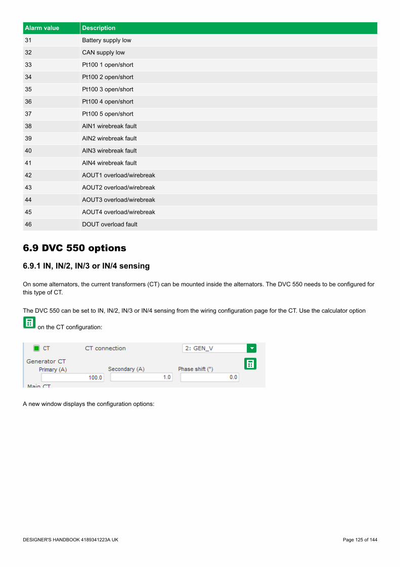
Alarm value Description
31 Battery supply low
32 CAN supply low
33 Pt100 1 open/short
34 Pt100 2 open/short
35 Pt100 3 open/short
36 Pt100 4 open/short
37 Pt100 5 open/short
38 AIN1 wirebreak fault
39 AIN2 wirebreak fault
40 AIN3 wirebreak fault
41 AIN4 wirebreak fault
42 AOUT1 overload/wirebreak
43 AOUT2 overload/wirebreak
44 AOUT3 overload/wirebreak
45 AOUT4 overload/wirebreak
46 DOUT overload fault
6.9 DVC 550 options
6.9.1 IN, IN/2, IN/3 or IN/4 sensing
On some alternators, the current transformers (CT) can be mounted inside the alternators. The DVC 550 needs to be configured forthis type of CT.
The DVC 550 can be set to IN, IN/2, IN/3 or IN/4 sensing from the wiring configuration page for the CT. Use the calculator option
on the CT configuration:
A new window displays the configuration options:
DESIGNER'S HANDBOOK 4189341223A UK Page 125 of 144

Under Sensing, then select:
• Sensing IN◦ This is the default setting.◦ When IN is selected, it means that the CT measures the full current.
• Sensing IN/2◦ When IN/2 is selected, it means that the CT measures half of the full current.
• Sensing IN/3◦ When IN/3 is selected, it means that the CT measures one third of the full current.
• Sensing IN/4◦ When IN/4 is selected, it means that the CT measures one fourth of the full current.
6.9.2 Negative forcing
The negative forcing function enables the DVC 550 to reverse the excitation voltage because of the principle with two transistorsinstead of one.
It allows to have reversed voltage at the output (field excitation), because the two transistors are in parallel and upside down. Thisfunction can be useful if the DVC 550 is placed in an application where big loads are turning off. When shutting off a big load, thevoltage may increase.
By reversing the excitation for a moment, the nominal voltage will be recovered faster.
In the graph below, it is shown with the negative forcing function enabled and disabled.
DESIGNER'S HANDBOOK 4189341223A UK Page 126 of 144

Time0
% of nominal voltage
100
Load rejection
Negative forcing enabled
Negative forcing disabled
More informationSee PID settings in the Configure the DVC 550 for more information about Negative forcing.
6.9.3 VBus compensation
This function is used to compensate for the deviations in voltage, to which the excitation circuit can be exposed.
If the excitation circuit's supply voltage is lower for a moment, the excitation current will also be lower at this time. The PID controllermust then be slightly more aggressive to raise the excitation current again.
Alternatively, if the excitation circuit's supply voltage is higher than normal, the PID controller must be less aggressive to make surethat the excitation will match the nominal voltage.
More informationSee PID settings in the Configure the DVC 550 for more information about DC Bus voltage compensation (VBus).
6.10 Regulation of DVC 550
6.10.1 PID settings
Configure the PID settings for the AGC-4 under menu 7800.
Parameter Description Comment
7801 PID Gain This is a gain for the PID regulator in the DVC 550
7803 Wr All settings This parameter sends all settings to the DVC 550.• This is a pulse command.• By default the parameter returns to OFF state after use.
The PID regulators can only be changed with DEIF EasyReg Advanced software.
DESIGNER'S HANDBOOK 4189341223A UK Page 127 of 144

More informationSee PID settings in the Configure the DVC 550 for more information about PID configuration.
When the AGC-4 has the control (parameter 7805 is enabled) only the voltage regulators are used. The gain for voltage regulator isset from the AGC-4 at parameter 7801.
More informationSee DAVR control in Bias and control for more information about the AGC-4 control settings.
With parameter 7803, the AGC-4 writes the settings as the settings are made. The user can apply this parameter to ensure that allthe settings regarding the DVC 550 in the AGC-4 are written once more.
The ranges and defaults for the parameters are shown below:
Parameter Item Range Default Note
7801 PID gain in DVC 550 1100 20 Only in genset
7803 Write all settings to DVC550
OFFON OFF
Only in genset. Whenset to ON, it willautomatically reset toOFF.
6.10.2 Bias and control
Bias rangeParameter 7804, the AGC-4 can control how wide the bias range should allow the AGC-4 to control the voltage in the DVC 550.
By default, it is set to +/- 10 %, which means that the AGC-4 is allowed to regulate the voltage on a 400 V genset from 360 V to 440V. The bias range should be wide enough to ensure that the gensets can load-share the reactive power in both capacitive andinductive situations. By making the bias range wider, the resolution for load sharing between the AGC-4s will be harder, since asmall step gives a bigger response. By experience, the +/- 10 % bias range covers most applications.
The bias range is for CAN bus based bias signal or for analogue bias and CAN bus based bias signal.
Bias for analogue regulationParameter 7796 can be set with the type of input the DVC 550 should expect to receive if parameter 2783 is set to analogue.
To ensure that the DVC 550 is regulated from the AGC-4, parameter 5990 must be set to the correct transducer output that mustgive the bias to the DVC 550.
DAVR controlParameter 7805 controls whether the AGC-4 should send commands and information in the CAN bus. This could, for example, becontrolling the DVC 550 in switching regulation mode, and sets the knee set point and other settings/commands to the DVC 550.
It does not matter if DAVR control is set to ON or OFF as regards the bias signal. The AGC-4 is still able to regulate on the CANbus based bias to the DVC 550. Parameter 2783 must then still be set to EIC, and the engine interface 7561 must be set to a J1939-based protocol.
If the AGC-4 has the control and the communication is up and running, it can be seen in the DEIF EasyReg Advanced software.
Settings controlled by the AGC-4 are shown greyed out, so these settings can only be changed from the AGC-4.
More informationSee Common DVC 550 settings in this chapter for more information about the common settings for DVC 550.
DESIGNER'S HANDBOOK 4189341223A UK Page 128 of 144

The table below shows the parameters that are described above:
Parameter Item Range Default Note
7804 DVC 550 bias range forCAN bus-basedregulation
0.1 %30.0 % 10.0 % Only in genset.
7805 Allow the AGC-4 tocontrol DVC 550
OFFON ON Only in genset.
7796 DVC 550 analogue biasinput type
4 to 20 mA0 to 10 V DC 0 to 10 V DC Only in genset.
6.11 AGC-4 and DVC 550 cooperation
6.11.1 Nominal settings
When the CAN bus communication is established and the parameter 7805 for DAVR control is enabled, the AGC-4 controls thenominal settings in the DVC 550.
For rental customers, this can be helpful in cases where the gensets are exposed to different scenarios where different nominalsettings can be required. By shifting the nominal settings in the DVC 550, it makes sure that the bias range is still the same eventhough the nominal voltage is either higher or lower.
The nominal settings that are sent automatically from the AGC-4 are active nominal voltage and frequency. So if the nominal settingis shifted between the four possible nominal settings, the active nominal settings will be sent automatically to the DVC 550.
6.11.2 Auto-view
If the CAN bus communication between the AGC-4 and the DVC 550 is established, the AGC-4 is able to display some values that itreceives via the CAN bus. These values will be added to the 20 views that are already present in the AGC-4, so the total number ofviews will be expanded. It will still only be possible to configure the first 20 views.
The extra lines will be displayed if parameter 7564 is enabled and the CAN bus is active. Parameter 7564 will automatically switch toOFF again.
NOTE If the DVC 550 is mounted on a genset that also has an ECU, and the ECU also gives information via the CAN bus, thenthe ECU data might not be required to start the genset before toggling the auto-view to ON, because some ECUs only giveinformation when the engine is running.
The parameter for auto-view:
Parameter Item Range Default Note
7564 Auto-view - enable OFFON OFF
Only in genset. Note thatit automatically switchesto OFF again.
6.11.3 Communication error
When the settings regarding communication to the DVC 550 have been set, the AGC-4 has an alarm for checking thecommunication lines. If the communication between the AGC-4 and the DVC 550 suddenly stops, the AGC-4 creates the alarmDAVR Comm. Err.
The alarm is configured on parameter 7830, where it is also possible to set a fail class to activate if the DAVR Comm. Err alarmoccurs.
DESIGNER'S HANDBOOK 4189341223A UK Page 129 of 144

The parameters used for the communication alarm error:
Parameter Item Range Default Note
7831 Digital AVRcommunication error -delay
0.0 s100.0 s 0.0 s Only in genset.
7832 Digital AVRcommunication error -output A
Not usedOption-dependent Not used Only in genset.
7833 Digital AVRcommunication error -output B
Not usedOption-dependent Not used Only in genset.
7834 Digital AVRcommunication error -enable
OFFON OFF Only in genset.
7835 Digital AVRcommunication error -fail class
BlockTrip MB/GB Warning Only in genset.
6.11.4 DVC 550 alarms on AGC-4
The DVC 550 can give two different levels of alarms:• DAVR Warning• DAVR Trip
This is enabled in menu 7760, in which it is also possible to set a fail class.
Parameter Item Range Default Note
7761 DAVR Warning
BlockTrip GBWarningTrip+stopShutdownTrip MBSafety stop
Warning Only in genset.
7763 DAVR Trip
BlockTrip GBWarningTrip+stopShutdownTrip MBSafety stop
Warning Only in genset.
6.11.5 DAVR info menu (jump 9090)
Jump menu 9090 shows information about DAVR software version and see any active alarms in the DAVR.
Parameter 9093 acknowledges any current active alarms and clears any alarms if they are no longer active.
DESIGNER'S HANDBOOK 4189341223A UK Page 130 of 144

Parameter Item Note
9091 DAVR SW version Display of DAVR software version
9092 DAVR alarms Display of all active alarms
9093 DAVR trip alarms Display of active trip alarms (select to acknowledge alarms from theDAVR)
6.12 M-Logic related to DVC 550
6.12.1 M-Logic events, outputs and commands
M-Logic has many DVC 550 related events, outputs, and commands available for use.
EventsThese are grouped under DVC 550 events:
DESIGNER'S HANDBOOK 4189341223A UK Page 131 of 144

Outputs
DESIGNER'S HANDBOOK 4189341223A UK Page 132 of 144

CommandsTwo additional commands in M-Logic: Dry alternator and Ventilation.
6.13 Common DVC 550 settings
6.13.1 Mixed applications
What is a mixed application?A mixed application includes both AGC-4s and DVC 550s together with AGC-4s and DVC 310s in the same complete application.This could, for example, be a rental application.
Example mixed application
X2 Z1 X1 Z2 F+ F- L1 L2 U V W
S1S2
S1S2
S1S2
UV
W
CANbus
DV
C31
0
X2 Z1 X1 Z2 F+ F- L1 L2 U V W
S1S2
S1S2
S1S2
UV
W
CANbus
DV
C31
0
DVC 550
AGC-4 DG
CAN bus
DVC 550
AGC-4 DG
DVC 310
AGC-4 DG
DVC 310
AGC-4 DG
Shared DVC 500 Shared DVC 310
Shared all AGC-4s
These parameters are only shared between AGC-4s and DVC550s.
These parameters are only shared between AGC-4s and DVC310s.
These parameters are shared between all AGC-4s.
Shared parameters mean that if you change a parameter setting on one AGC-4 this setting is sent to all other AGC-4s in the system.The AGC-4s have the same setting when it is a shared parameter.
In mixed applications some parameters (shown in orange and green) are no longer shared between all the AGC-4s (shown in grey).
DESIGNER'S HANDBOOK 4189341223A UK Page 133 of 144

Table 6.3 Parameters not shared between DVC 550 and DVC 310 applications
Parameter Parameter no.
U/f law slope 7772
Soft voltage recovery timer 7773
LAM + SVR Conf 7774
LAM set point 7775
These parameters must be configured for each group of controllers (shown in orange and green). That is to say, the parameters forAGC-4s with DVC 550s must be configured separately to the parameters for AGC-4s with DVC 310s. These parameters are nolonger shared (shown in grey) between all AGC-4 DG units.
6.13.2 Shared parameters
The following parameters are shared between the AGC-4 controllers and between an AGC-4 and a DVC 550.
More informationFor applications that include both AGC-4s with DVC 550s and AGC-4s with DVC 310s, see Mixed applications for moreinformation about parameters that are not shared.
Parameter Parameter no. AGC DG toAGC DG
AGC-4 toDVC 550
CBE set point 2251 X
CBE delay 2252 X
CBE enable 2254 X
CBE breaker sequence 2261 X
CBE soft-start timer 2262 X X
CBE RPM excite 2263 X
Generator nominal voltage - nominal set 1 6004 X
Generator nominal voltage - nominal set 2 6014 X
Generator nominal voltage - nominal set 3 6024 X
Generator nominal voltage - nominal set 4 6034 X
Generator voltage transformer primary side 6041 X
Generator voltage transformer secondary side 6042 X
Busbar voltage transformer primary side -busbar nominal set 1 6051 X
Busbar voltage transformer secondary side -busbar nominal set 1 6052 X
Busbar voltage transformer primary side -busbar nominal set 2 6061 X
Busbar voltage transformer secondary side -busbar nominal set 2 6062 X
DVC 550 generator primary voltage 7741 X
DVC 550 generator secondary voltage 7742 X
DVC 550 busbar primary voltage 7743 X
DVC 550 busbar secondary voltage 7744 X
DESIGNER'S HANDBOOK 4189341223A UK Page 134 of 144

Parameter Parameter no. AGC DG toAGC DG
AGC-4 toDVC 550
DVC 550 voltage transformer enable 7745 X
Start-on threshold PWM 7751 X
Start-on threshold voltage limit 7752 X
Soft-start timer (Normal start) 7753 X
Minimum frequency threshold 7754 X
Minimum Vbus threshold 7755 X
Knee set point 7771 X X
U/f law slope 7772 X
Soft voltage recovery timer 7773 X
SVR + LAM conf 7774 X
LAM set point 7775 X
LAM duration 7776 X
Q droop compensation set point 7781 X X
U droop compensation set point 7782 X X
Droop compensation type 7783 X X
Excitation current for dry alternator mode 7791 X
Transformer excitation set point for current 7793 X
Inductive motor starting set point for current 7794 X
Stator current limitations enable 7795 X
Bias analogue 7796 X
PID Gain 7801 X
Write all settings to DVC 550 7803 X
DVC 550 bias range 7804 X
DVC 550 controls 7805 X
6.14 Modbus communication
6.14.1 Modbus communication
This chapter is additional information for option H2/N (Modbus RS-485 RTU).
If option H2/N is installed, the data can be transmitted to a PLC, a computer, the alarm-and-monitoring system or a Scada system.
More informationPlease refer to the technical documentation for Option H2 and H9 Modbus communication and Option N Modbus TCPIP available on the DEIF homepage : https://www.deif.com/products/agc-4#documentation
The data readable by the Modbus communication are converted into the chosen unit in menu 10970.
DESIGNER'S HANDBOOK 4189341223A UK Page 135 of 144

6.14.2 Modbus table
Function code 4
Address Bit Content Note
916 AVR generator AC Voltage [V]
917 AVR generator frequency [Hz] 1/10
918 AVR generator AC current [A]
919 AVR field excitation current [A] 1/10
920 Not used
921 AVR generator reactive power
922 AVR generator Power Factor [ ] 1/100
923 AVR generator Power Factor lagging 00= lagging
01= leading
924 Not used
925 Total Power
926 Not used
927 AVR generator apparent power
928 AVR Pt100 1 temperature [deg C/F]
929 AVR Pt100 2 temperature [deg C/F]
930 AVR Pt100 3 temperature [deg C/F]
1056
0 AVR comm. error
1 AVR Warning
2 AVR Trip
3-15 Not used
1365
0 USB LED
1 POWER LED Function code 4
2 U = U
3 PF kVAR
4 I Exc.
5 Diode fault
6 Exc. fault
7 Voltage fault
8 Frequency fault
9-15 Not used
DESIGNER'S HANDBOOK 4189341223A UK Page 136 of 144

Function code 4
Address Bit Content Note
1366
0 Over voltage
1 Under voltage
2 Over frequency
3 Under frequency
4 Open diode
5 Shorted diode
6 Reverse P
7 Reverse Q
8 PT100 1 alarm
9 PT100 1 fault
10 PT100 2 alarm
11 PT100 2 fault
12 PT100 3 alarm
13 PT100 3 fault
14 PT100 4 alarm
15 PT100 4 fault
1367
0 PT100 5 alarm
1 PT100 4 fault
2 PTC 1 fault
3 PTC 2 fault
4 PTC 3 fault
5 PTC 4 fault
6 PTC 5 fault
7 Sensing lost
8 Unbalanced U
9 Unbalanced I
10 Short circuit
11 Excitat. chain
12 Motor start
13 Pwr bridge
14 Batt supply lo
15 CAN supply low
DESIGNER'S HANDBOOK 4189341223A UK Page 137 of 144

Function code 4
Address Bit Content Note
1368
0 PT100 1 op/sho
1 PT100 2 op/sho
2 PT100 3 op/sho
3 PT100 4 op/sho
4 PT100 5 op/sho
5 AIN1 wirebreak
6 AIN2 wirebreak
7 AIN3 wirebreak
8 AIN4 wirebreak
9 AOUT1 ol/wb
10 AOUT2 ol/wb
11 AOUT3 ol/wb
12 AOUT4 ol/wb
13 DOUT overload
14-15 Not used
DESIGNER'S HANDBOOK 4189341223A UK Page 138 of 144

7. Troubleshooting
7.1 Preventive maintenance instructions
During a downtime period for the alternator, it is recommended to:• Check the wires are tight in the connectors.
◦ Torque setting between 0.6 Nm and 0.8 Nm.• Blow dry air through to get rid of any dust that may have settled on or around the DVC 550.• Check there is free circulation of air around the aluminum heatsink at the front of the device.• Check the running time counter.
◦ If this exceeds 40,000 hours, consider changing the AVR.
7.2 Troubleshooting
Issues can occur on the AVR which may lead to its replacement.
The main faults are listed below:
Fault Cause(s) Solution Restart action(s)
Voltage sensing fault.
Alternator sensing VTbroken. Replace faulty VT.
1. Stop the alternator.2. Replace faulty VT.3. Restart the alternator.
Internal measurementbroken. Replace the AVR.
More informationSee Replace AVR forhow to replace.
Excitation fault.
• Faulty component.• Opening of the field
excitation circuit whichcaused a voltage surgeon the transistor.
Replace the AVR. More informationSee Replace AVR forhow to replace.
24 V DC auxiliary supply fault.
External supply fault. Replace the 24 V DC powersupply.
1. Stop the alternator.2. Replace faulty power supply.3. Restart the alternator.
Voltage converter fault. Replace the AVR. More informationSee Replace AVR forhow to replace.
The AVR is not responding(display frozen, nocommunication).
Microcontroller fault. Replace the AVR. More informationSee Replace AVR forhow to replace.
The regulation mode controlledby an input is not active.
Faulty input.
Switch control of the regulationmode to another input
1. Stop the alternator.2. Configure new settings.3. Restart the alternator.
Replace the AVR. More informationSee Replace AVR forhow to replace.
The wiring is faulty
Check that the input has beenenabled by shunting the 0 V andthe local input and checking theinput state on the HMI.
Restart the alternator.
DESIGNER'S HANDBOOK 4189341223A UK Page 139 of 144

Fault Cause(s) Solution Restart action(s)
The field excitation does notstart.
Faulty starting input Switch control of starting toanother input
1. Stop the alternator.2. Configure new settings.3. Restart the alternator.
The AVR power is notswitched on.
Check the VBus voltage on theHMI. Restart the alternator.
The 24 V DC power supplyis faulty
Check that the AVR is poweredup by looking at the HMI LEDs.PowerON
Restart the alternator.
Regulation of the power factor isunstable.
The active power is too lowto have a correct powerfactor measurement.
Use kVAr mode for low loadregulation (less than 10% ofrated load)
1. Stop the alternator.2. Configure new settings.3. Restart the alternator.
The stator currentmeasurement is incorrect.
Check the CT wiring on thecurrent measurement input andthe CT.
Restart the alternator.
Replace the AVR if the wiring iscorrect.
More informationSee Replace AVR forhow to replace.
7.3 Replace a faulty DVC 550
DANGER!
Hazardous live currents and voltages
Risk of electrical shock and/or damage
While the AVR is in operation, do not unplug any connectors or make any wiring modifications. This may lead to electricshock and/or destruction of the AVR and/or damage to the alternator.
NOTICE
Configuration changes during operation
Possible damage to equipment
Modifications to the main alternator settings, such as: machine data, voltage and current measurement transformer wiring, upperor lower reference limits, or starting control, must be made when the alternator stopped.
NOTICE
Operating range
Possible damage to equipment
The operating ranges must always be adhered to. Changing the settings to inappropriate voltages or currents may cause partial ortotal destruction of the AVR and/or alternator.
DESIGNER'S HANDBOOK 4189341223A UK Page 140 of 144

NOTICE
Power input protection
Possible damage to equipment
The power input must be protected by a circuit-breaker or fuses in order to avoid irreparable damage to the AVR in the event ofshort-circuit or voltage surge.
NOTICE
Installation/Replacement
The installation/replacement must only be carried out by authorised personnel who understand the risks involved in working withelectrical equipment.
To replace a faulty DVC 550 AVR:
1. Stop the alternator (if not already done).2. Switch off and electrically isolate the auxiliary supply and power supply.3. Check that no voltage is present.4. Carefully remove all the AVR connectors, noting their positions.5. Undo all the AVR mounting brackets so it can be removed from the installed location.6. Using DEIF EasyReg Advanced upload your configuration project to the new DVC 550 AVR.7. Disconnect the DVC 550 USB cable.8. Fix the new DVC 550 in place of the faulty AVR.9. Reconnect all the connectors on the new AVR.10. Power up the auxiliary supply and check that the AVR is energized.11. Start up the alternator drive system.12. Power up the power supply without exciting the machine.13. Before exciting the alternator, check the alternator voltage measurement and power supply voltage (VBus).14. Switch on the alternator excitation.15. Check all the AVR measurements and regulation modes, and any controlled outputs.
DESIGNER'S HANDBOOK 4189341223A UK Page 141 of 144

8. End-of-life
8.1 Disposal of waste electrical and electronic equipment
WEEE symbol
All products that are marked with the crossed-out wheeled bin (the WEEE symbol) are electrical andelectronic equipment (EEE). EEE contains materials, components and substances that can be dangerousand harmful to people's health and to the environment. Waste electrical and electronic equipment (WEEE)must therefore be disposed of properly. In Europe, the disposal of WEEE is governed by the WEEEdirective issued by the European Parliament. DEIF complies with this directive.
You must not dispose of WEEE as unsorted municipal waste. Instead, WEEE must be collected separately,to minimise the load on the environment, and to improve the opportunities to recycle, reuse and/or recoverthe WEEE. In Europe, local governments are responsible for facilities to receive WEEE. If you need moreinformation on how to dispose of DEIF WEEE, please contact DEIF.
DESIGNER'S HANDBOOK 4189341223A UK Page 142 of 144

9. Glossary
9.1 Terms and abbreviations
Term Abbreviation Explanation
Alternating current AC
Analogue input AI
Terminals on a controller hardware module that the controller uses to measure ananalogue input. The analogue input type and range are typically selected duringcommissioning from a list of pre-configured voltage, current, and resistancemeasurement input ranges. A pre-configured analogue input function or alarm canalso be assigned to the input.
Analogue input oroutput AIO
Analogue output AO
Terminals on a controller hardware module that the controller uses to send ananalogue output. The analogue output type and range are typically selected duringcommissioning from a list of pre-configured voltage and current output ranges. A pre-configured analogue output function can also be assigned to the output.
Auxiliary windingregulation excitationprinciple
AREP Auxiliary windings installed in the machine which are used to supply the AVR withpower. They often consist of 2 windings: the first “H1” which is affected by voltagevariations, the second “H3” which is affected by current variations.
Configuration Assigning input and output functions to terminals, and setting parameters, so that thecontroller is suitable for the application where it is installed.
Current transformer CT A transformer for the current measurements.
Insulated gate bi-polartransistor IGBT A three terminal power semiconductor device, primarily used as an electronic switch
for high efficiency and fast switching.
Digital input DI Terminals on a controller hardware module that the controller uses to measure a digitalinput. A pre-configured digital input function or alarm can be assigned to the input.
Digital input or output DIO
Direct current DC
Digital output DO
Earth A connection between the equipment and earth. For marine applications, a earth is aconnection to the ship's frame.
Neutral N The neutral line in a three-phase electrical system.
Parameter A value, or set point, used to determine the controller's operation. Parameters includenominal values, the configuration options for the configurable inputs and outputs, andalarm settings. The same set of parameters can be uploaded to several controllers.
Phase U U
The power line for one phase of a three-phase electrical system. Corresponds to R inGermany, Red in the UK and Pacific, Red in New Zealand, Black in the USA, and U onelectrical machine terminals. The above colour codes are for guidance only. Ifuncertain perform a phase measurement.
Phase V V
The power line for one phase of a three-phase electrical system. Corresponds to S inGermany, Yellow in the UK and Pacific, White in New Zealand, Red in the USA, and Von electrical machine terminals. The above colour codes are for guidance only. Ifuncertain perform a phase measurement.
Phase W W
The power line for one phase of a three-phase electrical system. Corresponds to T inGermany, Blue in the UK and Pacific, Blue in New Zealand, Blue in the USA, and Won electrical machine terminals. The above colour codes are for guidance only. Ifuncertain perform a phase measurement.
DESIGNER'S HANDBOOK 4189341223A UK Page 143 of 144

Term Abbreviation Explanation
Permanent magnetgenerator PMG
Pt100 Platinum temperature sensor
Pulse width modulation PWM Terminals with an output that uses variable pulse widths, and behaves as an analogueoutput.
Single-phase A system where the load is connected between one of the phases and the neutral.Note: Single-phase does NOT mean a 3-wire single-phase distribution system, wherethe waveforms are offset by a half-cycle (180 degrees) from the neutral wire.
Voltage V Electrical potential difference. U is used as an abbreviation for voltage in most ofEurope, Russia and China.
Voltage transformer VT A transformer for the voltage measurements, so that the voltage at the controller iswithin the controller's specifications.
9.2 Vector permutations
If only one stator current measurement CT is wired up, the vector permutations can compensate for voltage measurement andcurrent measurement transformer layouts which generate incorrect power and power factor (cos phi) calculations.
The DVC 550 must be wired according to the position of the stator current measurement if only one stator current measurement CTis used. The table below gives the possible permutations according to the phase used for the stator current measurement CT.
Table 9.1 Single CT wiring guidelines for DVC 550
Position of stator currentmeasurement CT
Alternator direction ofrotation (a/c IEC 60034-1)
Alternator voltage measurement
AVR terminals U V W
Phase V (standard)
Clockwise Alternator phases (three-phase measurement) U V W
Alternator phases (phase/phase single-phasemeasurement) U - W
Anti-clockwise Alternator phases (three-phase measurement) W V U
Alternator phases (phase/phase single-phasemeasurement) W - U
Phase U
Clockwise Alternator phases (three-phase measurement) W U V
Alternator phases (phase/phase single-phasemeasurement) W - V
Anti-clockwise Alternator phases (three-phase measurement) V U W
Alternator phases (phase/phase single-phasemeasurement) V - W
Phase W
Clockwise Alternator phases (three-phase measurement) V W U
Alternator phases (phase/phase single-phasemeasurement) V - U
Anti-clockwise Alternator phases (three-phase measurement) U W V
Alternator phases (phase/phase single-phasemeasurement) U - V
DESIGNER'S HANDBOOK 4189341223A UK Page 144 of 144