Archived: GPIB-CT IBCL Reference Manual - Apex Waves
195
GPIB-CT IBCL Reference Manual December 1993 Edition Part Number 320132-01
-
Upload
khangminh22 -
Category
Documents
-
view
3 -
download
0
Transcript of Archived: GPIB-CT IBCL Reference Manual - Apex Waves
' Copyright 1989, 1993 National Instruments
Corporation.
All Rights Reserved.
GPIB-CT IBCLReference Manual
December 1993 Edition
Part Number 320132-01

National Instruments Corporate Headquarters6504 Bridge Point ParkwayAustin, TX 78730-5039(512) 794-0100Technical support fax: (512) 794-5678
Branch Offices:Australia 03 879 9422, Austria 0662 435986, Belgium 02 757 00 20,Canada (Ontario) 519 622 9310, Canada (Québec) 514 694 8521,Denmark 45 76 26 00, Finland 90 527 2321, France 1 48 65 33 70,Germany 089 714 50 93, Italy 02 48301892, Japan 03 3788 1921,Netherlands 01720 45761, Norway 03 846866, Spain 91 640 0085,Sweden 08 730 49 70, Switzerland 056 27 00 20, U.K. 0635 523545

Limited Warranty
The GPIB-232CT, GPIB-422CT, and the GPIB-232CT-A are warrantedagainst defects in materials and workmanship for a period of two years fromthe date of shipment, as evidenced by receipts or other documentation.National Instruments will, at its option, repair or replace equipment thatproves to be defective during the warranty period. This warranty includesparts and labor.
A Return Material Authorization (RMA) number must be obtained from thefactory and clearly marked on the outside of the package before anyequipment will be accepted for warranty work. National Instruments willpay the shipping costs of returning to the owner parts which are covered bywarranty.
National Instruments believes that the information in this manual isaccurate. The document has been carefully reviewed for technical accuracy.In the event that technical or typographical errors exist, NationalInstruments reserves the right to make changes to subsequent editions ofthis document without prior notice to holders of this edition. The readershould consult National Instruments if errors are suspected. In no eventshall National Instruments be liable for any damages arising out of orrelated to this document or the information contained in it.
EXCEPT AS SPECIFIED HEREIN, NATIONAL INSTRUMENTS MAKES NOWARRANTIES, EXPRESS OR IMPLIED, AND SPECIFICALLY DISCLAIMSANY WARRANTY OF MERCHANTABILITY OR FITNESS FOR APARTICULAR PURPOSE. CUSTOMER'S RIGHT TO RECOVER DAMAGESCAUSED BY FAULT OR NEGLIGENCE ON THE PART OF NATIONALINSTRUMENTS SHALL BE LIMITED TO THE AMOUNT THERETOFOREPAID BY THE CUSTOMER. NATIONAL INSTRUMENTS WILL NOT BELIABLE FOR DAMAGES RESULTING FROM LOSS OF DATA, PROFITS,USE OF PRODUCTS, OR INCIDENTAL OR CONSEQUENTIAL DAMAGES,EVEN IF ADVISED OF THE POSSIBILITY THEREOF. This limitation of theliability of National Instruments will apply regardless of the form of action,whether in contract or tort, including negligence. Any action againstNational Instruments must be brought within one year after the cause ofaction accrues. National Instruments shall not be liable for any delay inperformance due to causes beyond its reasonable control. The warrantyprovided herein does not cover damages, defects, malfunctions, or servicefailures caused by owner's failure to follow the National Instrumentsinstallation, operation, or maintenance instructions; owner's modification ofthe product; owner's abuse, misuse, or negligent acts; and power failure orsurges, fire, flood, accident, actions of third parties, or other events outsidereasonable control.

Important Notice
The material in this manual is subject to change without notice. NationalInstruments assumes no responsibility for errors which may appear in thismanual. National Instruments makes no commitment to update, nor to keepcurrent, the information contained in this document.
Copyright
Under the copyright laws, this publication may not be reproduced ortransmitted in any form, electronic or mechanical, including photocopying,recording, storing in an information retrieval system, or translating, inwhole or in part, without the prior written consent of National InstrumentsCorporation.
Trademarks
MicroGPIB™ is a trademark of National Instruments Corporation.
Product and company names listed are trademarks or trade names of theirrespective companies.
Warning Regarding Medical and Clinical Useof National Instruments Products
National Instruments products are not designed with components and testingintended to ensure a level of reliability suitable for use in treatment anddiagnosis of humans. Applications of National Instruments productsinvolving medical or clinical treatment can create a potential for accidentalinjury caused by product failure, or by errors on the part of the user orapplication designer. Any use or application of National Instrumentsproducts for or involving medical or clinical treatment must be performed byproperly trained and qualified medical personnel, and all traditional medicalsafeguards, equipment, and procedures that are appropriate in the particularsituation to prevent serious injury or death should always continue to beused when National Instruments products are being used. NationalInstruments products are NOT intended to be a substitute for any form ofestablished process, procedure, or equipment used to monitor or safeguardhuman health and safety in medical or clinical treatment.

© National Instruments Corp. v GPIB-CT IBCL Reference Manual
Contents
About This Manual ........................................................................xvAssumption of Previous Knowledge ........................................xvOrganization of the Manual ......................................................xvConventions Used in This Manual ........................................... xviRelated Documentation ............................................................xviiCustomer Communication ........................................................ xvii
Chapter 1Getting Started with IBCL ......................................................... 1-1
Using IBCL............................................................................... 1-1Starting IBCL ............................................................. 1-1Pushing and Popping Numbers from the Stack ......... 1-2Adding Numbers on the Stack ................................... 1-2Defining New Words ................................................. 1-3Using Loops and Conditionals ................................... 1-4Using Conditionals ..................................................... 1-5Manipulating the Stack............................................... 1-6Looping ......................................................................1-6Forgetting ................................................................... 1-7Using GPIB Functions ............................................... 1-8Exiting IBCL ..............................................................1-8
Chapter 2IBCL Reference ............................................................................... 2-1
Language Structure................................................................... 2-1Stacks ......................................................................... 2-3
Numeric Operations..................................................................2-6Unary Operators ......................................................... 2-7Binary and Ternary Operators ....................................2-8
Memory Access ........................................................................2-10Load and Store ........................................................... 2-10Fill ..............................................................................2-11Move........................................................................... 2-12Constants, Variables and Arrays ................................2-12
Input/Output ............................................................................. 2-16IBCL Input ................................................................. 2-16
ASCII-Type Input ........................................2-16Binary-Type Input ....................................... 2-17
Contents
GPIB-CT IBCL Reference Manual vi © National Instruments Corp.
IBCL Output............................................................... 2-17ASCII-Type Output Words..........................2-17
Character-Based Words................. 2-18Numeric-Based Words ..................2-18
Binary-Type Output ..................................... 2-21BASIC Program Example............................2-22
Defining New Words................................................................ 2-22Colon Definitions ....................................................... 2-23Dictionary................................................................... 2-27Vocabularies ............................................................... 2-28
Control ......................................................................................2-30Conditional Execution................................................2-30Loops ..........................................................................2-31
Chapter 3GPIB Extensions ............................................................................. 3-1
brd............................................................................................. 3-2bwrt ........................................................................................... 3-4cac............................................................................................. 3-6caddr ......................................................................................... 3-7clr ..............................................................................................3-8cmd ........................................................................................... 3-9eos............................................................................................. 3-11eot ............................................................................................. 3-13gts ............................................................................................. 3-14ist............................................................................................... 3-15loc ............................................................................................. 3-16onl ............................................................................................. 3-17pct ............................................................................................. 3-18ppc............................................................................................. 3-19r d ..............................................................................................3-21rpp............................................................................................. 3-23rsc ............................................................................................. 3-24rsp ............................................................................................. 3-25rsv ............................................................................................. 3-27sic ..............................................................................................3-28sre ............................................................................................. 3-29stat ............................................................................................. 3-30tmo ............................................................................................3-32trg..............................................................................................3-34wait ........................................................................................... 3-35wrt ............................................................................................. 3-37

Contents
© National Instruments Corp. vii GPIB-CT IBCL Reference Manual
Chapter 4Programming Examples ............................................................... 4-1
Microsoft BASIC IBCL Compiler Programming Example ..... 4-1Example 1................................................................... 4-1
Modem Programming Examples ..............................................4-2Example 2................................................................... 4-2Example 3................................................................... 4-3
Macro Programming Example ................................................. 4-6Example 4................................................................... 4-7
Timed Applications Examples ................................................. 4-8Example 5................................................................... 4-8Example 6................................................................... 4-9Example 7................................................................... 4-9Example 8................................................................... 4-10
Chapter 5Technical Information ..................................................................5-1
Loading Programs..................................................................... 5-1The IBCL Interpreters............................................................... 5-1
Inner Interpreter Sequence ......................................... 5-2Outer Interpreter Sequence......................................... 5-3
Errors ........................................................................................5-4Advanced Defining Techniques ............................................... 5-5
Machine Code Primitives........................................... 5-6Vectored Execution ....................................................5-8
Memory Organization............................................................... 5-9General Port I/O ....................................................................... 5-11
Appendix AMultiline Interface Messages ..................................................... A-1
Appendix BIBCL Status and Error Messages ............................................B-1
Appendix CCreating Permanent IBCL Words in EPROM ..................C-1
Appendix DUsing Extended Memory ............................................................. D-1
About Extended Memory ......................................................... D-1

Contents
GPIB-CT IBCL Reference Manual viii © National Instruments Corp.
Appendix EOther Useful IBCL Words ..........................................................E-1
dump ......................................................................................... E-1ud. ............................................................................................. E-3depth ......................................................................................... E-3not ............................................................................................. E-40> ..............................................................................................E-4binary ........................................................................................E-5octal........................................................................................... E-5msa............................................................................................E-5.s ................................................................................................E-6pick ........................................................................................... E-7roll ............................................................................................. E-8decom ....................................................................................... E-9cls ..............................................................................................E-11Redefining the Basic IBCL Mathematical Operatorsto Use Infix Notation ................................................................E-12
Programming Examples ............................................. E-12Redefining = ................................................E-12Redefining + ................................................E-12Redefining - ................................................. E-12Redefining *................................................. E-13Redefining / ................................................. E-13
Appendix FGlossary of IBCL Functions ....................................................... F-1
Glossary Conventions............................................................... F-1GPIB Glossary ..........................................................................F-1Standard Glossary..................................................................... F-2
!................................................................................... F-2!csp ............................................................................. F-3" ..................................................................................F-3#..................................................................................F-3#> ............................................................................... F-3#s ................................................................................F-3' ................................................................................... F-4(................................................................................... F-4(.")............................................................................... F-4(+loop) ........................................................................F-4(abort) ......................................................................... F-4(do) ............................................................................. F-4(dq) ............................................................................. F-5(find) ........................................................................... F-5

Contents
© National Instruments Corp. ix GPIB-CT IBCL Reference Manual
(loop) ..........................................................................F-5(number) ..................................................................... F-5*..................................................................................F-5*/ ................................................................................. F-5*/mod ......................................................................... F-6+ ................................................................................. F-6+! ................................................................................F-6+- ................................................................................F-6+loop........................................................................... F-6+origin ........................................................................F-7,................................................................................... F-7-................................................................................... F-7-dup............................................................................. F-7-find ............................................................................F-7-trailing....................................................................... F-7.................................................................................... F-8." ................................................................................. F-8.r ................................................................................. F-8/................................................................................... F-8/mod ........................................................................... F-80 1 2 3......................................................................... F-80< ............................................................................... F-80= ............................................................................... F-90branch....................................................................... F-91+ ............................................................................... F-92!................................................................................. F-92+ ............................................................................... F-92@ ..............................................................................F-92dup............................................................................F-9:................................................................................... F-10;................................................................................... F-10;s ................................................................................. F-10< ................................................................................. F-10<# ............................................................................... F-10<builds ........................................................................F-11= ................................................................................. F-11> ................................................................................. F-11>r ................................................................................F-11? ..................................................................................F-11?comp ......................................................................... F-12?csp............................................................................. F-12?error .......................................................................... F-12?exec........................................................................... F-12?pairs .......................................................................... F-12

Contents
GPIB-CT IBCL Reference Manual x © National Instruments Corp.
?stack .......................................................................... F-12?terminal ..................................................................... F-12@ ................................................................................ F-12abort ........................................................................... F-12abs............................................................................... F-12again ........................................................................... F-13allot ............................................................................. F-13and .............................................................................. F-13back ............................................................................ F-13base............................................................................. F-13begin........................................................................... F-14bl ................................................................................. F-14blanks ......................................................................... F-14branch......................................................................... F-14bye .............................................................................. F-14c! ................................................................................. F-14c, ................................................................................. F-15c/l ................................................................................ F-15c@ .............................................................................. F-15cfa............................................................................... F-15cmove ......................................................................... F-15cold............................................................................. F-15compile ....................................................................... F-15constant....................................................................... F-16context ........................................................................ F-16count ........................................................................... F-16cr ................................................................................. F-16create .......................................................................... F-16csp............................................................................... F-16current......................................................................... F-17d+ ............................................................................... F-17d+- .............................................................................. F-17d. ................................................................................. F-17d.r ............................................................................... F-17dabs............................................................................. F-17decimal ....................................................................... F-17definitions................................................................... F-18digit............................................................................. F-18dliteral......................................................................... F-18dlm ............................................................................. F-18dminus ........................................................................ F-18do................................................................................ F-19does> .......................................................................... F-19dp................................................................................ F-19
Contents
© National Instruments Corp. xi GPIB-CT IBCL Reference Manual
dpl ............................................................................... F-20drop............................................................................. F-20dup.............................................................................. F-20else ............................................................................. F-20emit ............................................................................. F-20enclose ........................................................................ F-21end .............................................................................. F-21endif ........................................................................... F-21erase ........................................................................... F-21error ............................................................................ F-21execute ....................................................................... F-22expect ......................................................................... F-22fence ........................................................................... F-22fill ............................................................................... F-22forget .......................................................................... F-22here............................................................................. F-22hex .............................................................................. F-22hld............................................................................... F-23hold............................................................................. F-23i................................................................................... F-23ibcl .............................................................................. F-23id. ................................................................................ F-23if ................................................................................. F-24immediate ................................................................... F-24in................................................................................. F-24interpret ...................................................................... F-25key .............................................................................. F-25l! ................................................................................. F-25l@ ............................................................................... F-25latest ........................................................................... F-25lc! ............................................................................... F-25lc@ ............................................................................. F-25leave ........................................................................... F-26lfa ............................................................................... F-26limit ............................................................................ F-26lit................................................................................. F-26literal........................................................................... F-26loop............................................................................. F-27m*............................................................................... F-27m/ ............................................................................... F-27m/mod......................................................................... F-27max............................................................................. F-27message ...................................................................... F-28min ............................................................................. F-28

Contents
GPIB-CT IBCL Reference Manual xii © National Instruments Corp.
minus .......................................................................... F-28mod............................................................................. F-28nfa............................................................................... F-28number ....................................................................... F-28or................................................................................. F-28out ............................................................................... F-29over ............................................................................. F-29p!................................................................................. F-29p@ .............................................................................. F-29pad .............................................................................. F-29pfa............................................................................... F-29query........................................................................... F-29quit ............................................................................. F-29r................................................................................... F-29r> ................................................................................ F-30r0................................................................................. F-30repeat .......................................................................... F-30rot ............................................................................... F-30rp! ............................................................................... F-30rp@............................................................................. F-30s->d............................................................................. F-30s0 ................................................................................ F-31sign ............................................................................. F-31smudge ....................................................................... F-31sp! ............................................................................... F-31sp@............................................................................. F-31space........................................................................... F-31spaces ......................................................................... F-31state............................................................................. F-31swap ........................................................................... F-31task ............................................................................. F-32then............................................................................. F-32tib ............................................................................... F-32toggle .......................................................................... F-32traverse ....................................................................... F-32type............................................................................. F-32u.................................................................................. F-32u*................................................................................ F-32u< ............................................................................... F-33u/ ................................................................................. F-33ulm ............................................................................. F-33until............................................................................. F-33user ............................................................................. F-34variable ....................................................................... F-34
Contents
© National Instruments Corp. xiii GPIB-CT IBCL Reference Manual
voc-link....................................................................... F-34vocabulary .................................................................. F-35vlist ............................................................................. F-35warm........................................................................... F-35warning....................................................................... F-35while ........................................................................... F-36width........................................................................... F-36word ........................................................................... F-36xor............................................................................... F-36[................................................................................... F-37[compile] .................................................................... F-37]................................................................................... F-37
Appendix GCustomer Communication ..........................................................G-1
Glossary...................................................................................... Glossary-1
© National Instruments Corp. xiv GPIB-CT IBCL Reference Manual
Illustrations
List of Figures
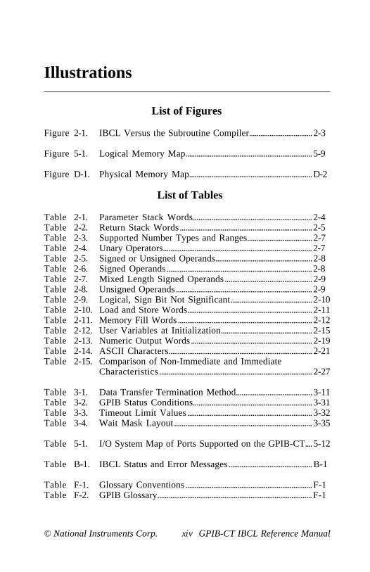
Figure 2-1. IBCL Versus the Subroutine Compiler..................................2-3
Figure 5-1. Logical Memory Map....................................................................5-9
Figure D-1. Physical Memory Map..................................................................D-2
List of Tables
Table 2-1. Parameter Stack Words................................................................2-4Table 2-2. Return Stack Words.......................................................................2-5Table 2-3. Supported Number Types and Ranges...................................2-7Table 2-4. Unary Operators................................................................................2-7Table 2-5. Signed or Unsigned Operands....................................................2-8Table 2-6. Signed Operands..............................................................................2-8Table 2-7. Mixed Length Signed Operands...............................................2-9Table 2-8. Unsigned Operands.........................................................................2-9Table 2-9. Logical, Sign Bit Not Significant............................................2-10Table 2-10. Load and Store Words................................................................... 2-11Table 2-11. Memory Fill Words ........................................................................ 2-12Table 2-12. User Variables at Initialization.................................................2-15Table 2-13. Numeric Output Words................................................................. 2-19Table 2-14. ASCII Characters............................................................................. 2-21Table 2-15. Comparison of Non-Immediate and Immediate
Characteristics.................................................................................. 2-27
Table 3-1. Data Transfer Termination Method.........................................3-11Table 3-2. GPIB Status Conditions................................................................ 3-31Table 3-3. Timeout Limit Values................................................................... 3-32Table 3-4. Wait Mask Layout.......................................................................... 3-35
Table 5-1. I/O System Map of Ports Supported on the GPIB-CT....5-12
Table B-1. IBCL Status and Error Messages.............................................B-1
Table F-1. Glossary Conventions ....................................................................F-1Table F-2. GPIB Glossary...................................................................................F-1

© National Instruments Corp. xv GPIB-CT IBCL Reference Manual
About This Manual
This manual describes the National Instruments IBCL (Interface BusControl Language) operating system for the GPIB-232CT, GPIB-422CT,and GPIB-232CT-A interface products. This manual describes the built-inIBCL commands and outlines techniques for adding new ones to thesystem.
This manual applies to the GPIB-232CT, GPIB-422CT, andGPIB-232CT-A interface products. Rather than mentioning all threeproducts when a reference is made, this manual will use the notationGPIB-CT to indicate all products.
Assumption of Previous Knowledge
IBCL users include OEMs who have custom applications for the GPIB-CTand experienced users who wish to access the full power of the on-boardprocessor.
To use this manual effectively, you should be somewhat familiar withmicrocomputers, computer devices, and the GPIB-CT default operatingsystem. You should also have an understanding of the IEEE 488functionality.
Organization of the Manual
The following discussion contains a description of each section of theGPIB-CT IBCL Reference Manual .
• Chapter 1, Getting Started with IBCL, contains a brief tutorial whichdemonstrates the operation of the IBCL language.
• Chapter 2, IBCL Reference, contains a formal description of the IBCLlanguage.
• Chapter 3, GPIB Extensions , describes the IBCL extensions you canuse to directly operate and control the GPIB.
• Chapter 4, Programming Examples, contains sample applicationswritten in IBCL.
About This Manual
GPIB-CT IBCL Reference Manual xvi © National Instruments Corp.
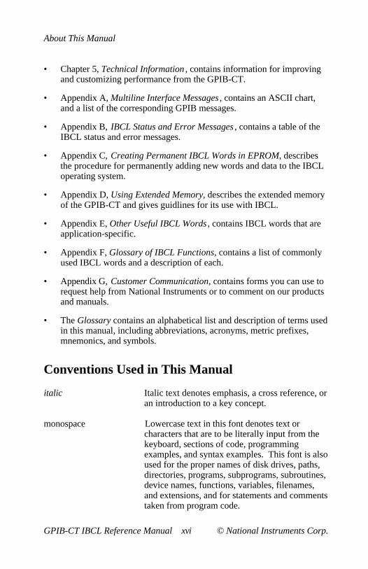
• Chapter 5, Technical Information , contains information for improvingand customizing performance from the GPIB-CT.
• Appendix A, Multiline Interface Messages , contains an ASCII chart,and a list of the corresponding GPIB messages.
• Appendix B, IBCL Status and Error Messages , contains a table of theIBCL status and error messages.
• Appendix C, Creating Permanent IBCL Words in EPROM, describesthe procedure for permanently adding new words and data to the IBCLoperating system.
• Appendix D, Using Extended Memory, describes the extended memoryof the GPIB-CT and gives guidlines for its use with IBCL.
• Appendix E, Other Useful IBCL Words , contains IBCL words that areapplication-specific.
• Appendix F, Glossary of IBCL Functions, contains a list of commonlyused IBCL words and a description of each.
• Appendix G, Customer Communication, contains forms you can use torequest help from National Instruments or to comment on our productsand manuals.
• The Glossary contains an alphabetical list and description of terms usedin this manual, including abbreviations, acronyms, metric prefixes,mnemonics, and symbols.
Conventions Used in This Manual
italic Italic text denotes emphasis, a cross reference, oran introduction to a key concept.
monospace Lowercase text in this font denotes text orcharacters that are to be literally input from thekeyboard, sections of code, programmingexamples, and syntax examples. This font is alsoused for the proper names of disk drives, paths,directories, programs, subprograms, subroutines,device names, functions, variables, filenames,and extensions, and for statements and commentstaken from program code.

About This Manual
© National Instruments Corp. xvii GPIB-CT IBCL Reference Manual
bold monospace Bold lowercase text in this font denotes themessages and responses that the computerautomatically prints to the screen.
italic monospace Italic lowercase text in this font denotes that youmust supply the appropriate words or values inthe place of these items.
<CR> carriage return
<LF> line feed
The period character (.) is referred to as the IBCL word "dot" in theprogramming examples.
A space ( ) appears in the examples wherever you should press the spacebar.It is very important that you notice where spaces are used in the examples,because a space is the separator operation for IBCL. In the programmingexamples of this manual, characters separated by spaces look like this:
0 1 2 3 4
The same string of characters that are not separated by spaces look like this:
01234
Abbreviations, acronyms, metric prefixes, mnemonics, symbols, and termsare listed in the Glossary.
Related Documentation
For more information on the internal workings of IBCL or for more tutorial-style information, consult one of the Forth language books listed here:
Forth Fundamentals Vol. 1 by C. Kevin McCabe, dilithium Press.Starting Forth by Leo Brodie, Prentice Hall (Advanced Techniques).Forth, An Application Approach by David L. Toppen, McGraw-Hill.Forth Programming by Leo J. Scanlon, Howard W. Sams Publication.
For more information about the IEEE 488, refer to the IEEE StandardDigital Interface for Programmable Instrumentation , published by theInstitute of Electrical and Electronics Engineers, Incorporated.

About This Manual
GPIB-CT IBCL Reference Manual xviii © National Instruments Corp.
For more information about what each bit represents in each I/O register ofthe HD64180 microprocessor, refer to the HD64180 8-Bit High IntegrationCMOS Microprocessor User Manual, available from Hitachi America, Ltd.,Semiconductor and IC Division.
For more information about what each bit represents in each I/O register ofthe GPIB Controller chip used in the GPIB-CT, refer to the description ofthe µPD7210 GPIB controller chip in NEC Microcomputer Products ,available from NEC Electronics, Inc. This description is used for interfaceproducts that contain the NAT4882 controller chip as well as interfaceproducts that contain the µPD7210 controller chip.
For information about your GPIB-CT hardware, refer to the GPIB-232CTUser Manual (part number 320114-01) the GPIB-422CT User Manual (partnumber 320115-01), or the GPIB-232CT-A User Manual (part number320504-01).
Customer Communication
National Instruments wants to receive your comments on our products andmanuals. We are interested in the applications you develop with ourproducts, and we want to help if you have problems with them. To make iteasy for you to contact us, this manual contains comment and configurationforms for you to complete. These forms are in Appendix G, CustomerCommunication , at the end of this manual.
© National Instruments Corp. 1-1 GPIB-CT IBCL Reference Manual
Chapter 1Getting Started with IBCL
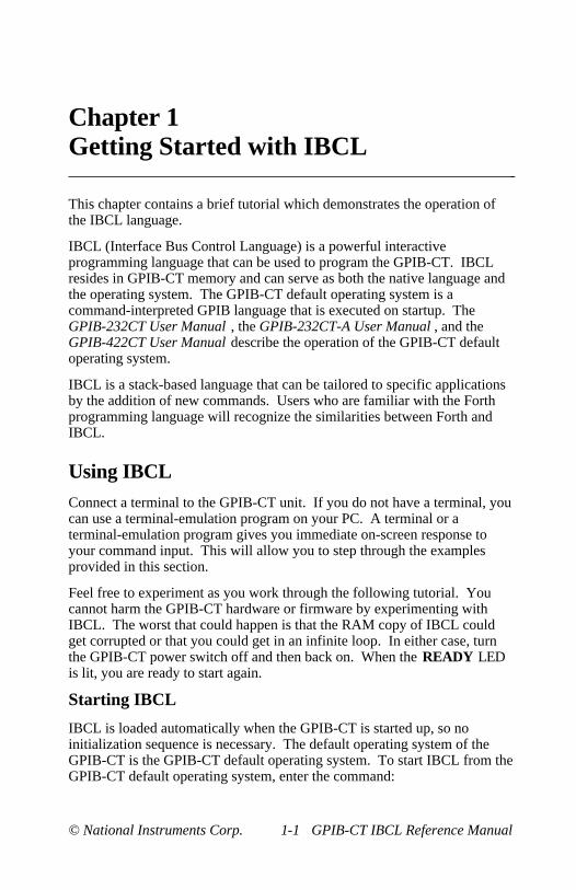
This chapter contains a brief tutorial which demonstrates the operation ofthe IBCL language.
IBCL (Interface Bus Control Language) is a powerful interactiveprogramming language that can be used to program the GPIB-CT. IBCLresides in GPIB-CT memory and can serve as both the native language andthe operating system. The GPIB-CT default operating system is acommand-interpreted GPIB language that is executed on startup. TheGPIB-232CT User Manual , the GPIB-232CT-A User Manual , and theGPIB-422CT User Manual describe the operation of the GPIB-CT defaultoperating system.
IBCL is a stack-based language that can be tailored to specific applicationsby the addition of new commands. Users who are familiar with the Forthprogramming language will recognize the similarities between Forth andIBCL.
Using IBCLConnect a terminal to the GPIB-CT unit. If you do not have a terminal, youcan use a terminal-emulation program on your PC. A terminal or aterminal-emulation program gives you immediate on-screen response toyour command input. This will allow you to step through the examplesprovided in this section.
Feel free to experiment as you work through the following tutorial. Youcannot harm the GPIB-CT hardware or firmware by experimenting withIBCL. The worst that could happen is that the RAM copy of IBCL couldget corrupted or that you could get in an infinite loop. In either case, turnthe GPIB-CT power switch off and then back on. When the READY LEDis lit, you are ready to start again.
Starting IBCL
IBCL is loaded automatically when the GPIB-CT is started up, so noinitialization sequence is necessary. The default operating system of theGPIB-CT is the GPIB-CT default operating system. To start IBCL from theGPIB-CT default operating system, enter the command:

Getting Started with IBCL Chapter 1
GPIB-CT IBCL Reference Manual 1-2 © National Instruments Corp.
IBCL<CR>
You should immediately see an ok prompt on your screen signifying thatIBCL is ready for input. The IBCL operating system responds with ok aftera successful operation. Press <CR> a few times to verify that IBCL isresponding to input properly. You should see the following lines:
<CR>ok<CR>ok<CR>ok
Pushing and Popping Numbers from the Stack
IBCL uses a push-down stack to store the numbers you enter. Enter thefollowing line:
1 2 3 4 . . . .<CR>
Be sure to put a space after every character including the dots (.).
After you enter a <CR>, the line should look like this:
1 2 3 4 . . . . 4 3 2 1ok
The period character ( .), called a dot in this context, is an IBCL operatorthat returns, or pops , the top number from the stack and prints its value.Four dots print the top four numbers on the stack. Numbers are pushed ontothe stack in the order in which they are entered and are retrieved in thereverse order.
IBCL reports the status information (either the ok message or an error code)from the previous command on a new line for easy program processing.
Adding Numbers on the Stack
To add two numbers, first enter the numbers you want to add followed bythe operator:
For example, to add the numbers 9 and 5, enter this line:

Chapter 1 Getting Started with IBCL
© National Instruments Corp. 1-3 GPIB-CT IBCL Reference Manual
9 5 + .<CR>
The answer E is displayed. E is the hexadecimal equivalent of the decimalvalue 14. Hexadecimal is the default base of IBCL.
To change the base to decimal, enter this line:
decimal<CR>
Enter the following line with no space between the number 5 and the plusoperator (+):
9 5+ .<CR>
IBCL responds with this message:
5+? MSG # 0
MSG # 0 is the unrecognized word error. IBCL operates in terms of words,where a word is an unbroken string of any sequence of characters separatedby a space ( ), a carriage return (<CR>), or a linefeed (<LF>). Becausethere is no space entered between the number 5 and the plus sign (+), IBCLinterprets 5+ as one word. Notice that because there was an error, IBCL didnot return the message ok .
If you type dot (.), IBCL responds with the following message:
. 46
.? MSG # 1
MSG # 1 is the empty stack error. Empty stack means that there are nonumbers on the stack. There is nothing on the stack because IBCL clearsthe stack after an error occurs. Notice that 46 was printed before the errormessage. This is because IBCL does not detect errors until after executionof a command. In this case, IBCL popped a number off the stack andprinted it before it determined that the stack was empty.
Defining New Words
You can easily add new words to the IBCL dictionary. The dictionary isthe list of IBCL functions.
To define a new word called 3add, which will add the top three numbers onthe stack, enter this line:

Getting Started with IBCL Chapter 1
GPIB-CT IBCL Reference Manual 1-4 © National Instruments Corp.
: 3add + + ;<CR>
Now, to execute your new word, enter this line:
5 6 7 3add .<CR> 18ok
IBCL returns the answer 18 (decimal).
A new word is defined with a sequence starting with a colon (:). The firstword after the colon is the name of the new word. The remaining words, upto the semicolon (;) comprise the definition of the new word.
Now define a new word, 3addshow, which adds the top three numbers onthe stack and prints out the result. Enter this line:
: 3addshow ." The answer is " 3add . ;<CR>
To execute 3addshow, enter this line:
3 4 5 3addshow<CR> The answer is 12ok
Notice that 3addshow uses 3add, which is now part of the dictionary. Theword ." prints out the characters to the next " exactly as they are entered.
Using Loops and Conditionals
Define a new word, doline, which loops five times and prints out themessage line i, where i is the loop count. Enter this line:
: doline 5 0 do cr ." line " i . loop ;<CR>
To execute doline, enter this line:
doline<CR>line 0line 1line 2line 3line 4ok

Chapter 1 Getting Started with IBCL
© National Instruments Corp. 1-5 GPIB-CT IBCL Reference Manual
do requires two arguments, a terminal count and an initial count. The wordloop increments the index and loops back to do if the index is less than theterminal count. The word i pushes the current value of the index onto thestack. The word cr performs a carriage return (<CR>).
Looping and conditional constructs only work within a word definition.
Using Conditionals
In IBCL, a TRUE value is any non-zero value; a FALSE value is a zerovalue.
The word if checks the top number on the stack and conditionally executeswords based on the TRUE/FALSE value of the top number.
Define a new word called tf which will determine whether a number isTRUE or FALSE. Enter this line:
: tf if ." TRUE " else ." FALSE " endif ;<CR>
To execute tf a few times, enter the following lines:
1 tf<CR> TRUEok0 tf<CR> FALSEok-1 tf<CR> TRUEok9 9 + tf<CR> TRUEok9 9 - tf<CR> FALSEok7 4 = tf<CR> FALSEok7 4 > tf<CR> TRUEok
In the second to the last command line, the equal sign (=) tests the equalityof the top two numbers on the stack. In the last example, the greater-thansign (>), tests whether the second number on the stack is greater than thetop number on the stack.

Getting Started with IBCL Chapter 1
GPIB-CT IBCL Reference Manual 1-6 © National Instruments Corp.
Manipulating the Stack
There are times when the numbers on the stack are not in the order that youwant, or when you need to verify a value on the stack without changing itsposition. There are several stack words that you can use in these cases, suchas swap, dup and drop.
Enter this line:
1 2 3 4 swap . . . .<CR>
The result is 3 4 2 1 because swap reverses the order of the top two numberson the stack.
Enter this line:
2 dup . .<CR>
The result is 2 2 , because dup duplicates the top number on the stack.
Another stack word, drop, drops, or pops, the top number from the stack.
Looping
Using the IBCL words you have already learned, you can explore morecomplicated looping structures.
Enter the following three lines:
: eq4 dup 4 = ;<CR>: ndec ." going " 1 - eq4 ;<CR>: beg1 7 begin ndec until ." gone " drop ;<CR>
To execute your program, enter this line:
beg1<CR> going going going goneok
The word begin marks the start of a non-iterated loop. until checks the firstnumber on the stack, which is the result from ndec, and if it is FALSE loopsback to the begin statement–that is, it loops until ndec returns TRUE.

Chapter 1 Getting Started with IBCL
© National Instruments Corp. 1-7 GPIB-CT IBCL Reference Manual
ndec prints out the string going, then subtracts one from the top number onthe stack. It then calls eq4, which returns a TRUE/FALSE value indicatingwhether the top number on the stack is equal to four. eq4 duplicates the topnumber on the stack and compares it to four. The number must beduplicated, because the top two numbers are popped off the stack when thecomparison to four is made. After the begin ... until, the number 4 was stillon the stack; the drop removes it.
Forgetting
If you have tried to redefine an existing word definition, you have seen theIBCL warning message:
xxxx MSG # 4ok
IBCL does not replace a previously defined word with a new one. Itremembers both, but uses the most recently defined word. To revert to theprevious definition of a word, use forget. forget removes the requestedword and all words that were defined since that word. Enter the followingsequence:
: ver ." version 1 " ;<CR>ok: ver ." version 2 " ;<CR> ver MSG # 4okver<CR> version 2okforget ver<CR>okver<CR> version 1okforget ver<CR>okver<CR>ver? MSG # 0
In the previous example, the first line of input defines the new word, ver, toprint version 1 . The second line of input redefines ver to print version 2 .MSG # 4 is a warning message stating that a dictionary word has beenredefined. The original definition is unchanged, but IBCL uses the mostrecent definition of a word.
Getting Started with IBCL Chapter 1
GPIB-CT IBCL Reference Manual 1-8 © National Instruments Corp.
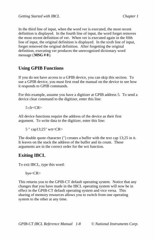
In the third line of input, when the word ver is executed, the most recentdefinition is displayed. In the fourth line of input, the word forget removesthe most recent definition of ver. When ver is executed again in the fifthline of input, the original definition is displayed. In the sixth line of input,forget removed the original definition. After forgetting the originaldefinition, executing ver produces the unrecognized dictionary wordmessage (MSG # 0 ).
Using GPIB Functions
If you do not have access to a GPIB device, you can skip this section. Touse a GPIB device, you must first read the manual on the device to see howit responds to GPIB commands.
For this example, assume you have a digitizer at GPIB address 5. To send adevice clear command to the digitizer, enter this line:
5 clr<CR>
All device functions require the address of the device as their firstargument. To write data to the digitizer, enter this line:
5 " cap13;25" wrt<CR>
The double quote character (") creates a buffer with the text cap 13;25 in it.It leaves on the stack the address of the buffer and its count. Thesearguments are in the correct order for the wrt function.
Exiting IBCL
To exit IBCL, type this word:
bye<CR>
This returns you to the GPIB-CT default operating system. Notice that anychanges that you have made in the IBCL operating system will now be ineffect in the GPIB-CT default operating system and vice versa. Thissharing of memory resources allows you to switch from one operatingsystem to the other at any time.

© National Instruments Corp. 2-1 GPIB-CT IBCL Reference Manual
Chapter 2IBCL Reference
This chapter contains a formal description of the IBCL language.
Language Structure
An IBCL program is a list of numbers or one-word commands receivedover the GPIB-CT serial port. A word is an unbroken string composed ofup to 31 characters. The IBCL standard word set includes the followingcharacters:
!"#$%&'()*+,-./0123456789:;<=>?@abcdefghijklmnopqrstuvwxyz[\]
IBCL defines and recognizes words composed of any sequence of 8-bitbytes. Space ( ), carriage return (<CR>), and linefeed (<LF>) charactersserve as word delimiters. The backspace character, ASCII 8, causes IBCLto back over the last byte entered.
IBCL may use both upper and lower case characters; however, IBCL iscase-sensitive. Thus, the input sequence SAMPLE, sample and Sample willbe interpreted as three distinct words. Notice that all of the standard IBCLwords use lower case characters and must be typed in lower case in order tobe recognized.
Learning IBCL is similar to adding a few hundred words to yourvocabulary. The names of the words will often relate to English words thatyou already know. The definitions of the IBCL words are detailed andspecific; they are neither ambiguous nor dependent on context.
IBCL uses postfix notation syntax. In postfix notation, you write the stacknumbers and then the operators. Numbers are pushed onto a stack andtaken from it. For example, examine this line:
7 2 12 3 / * -

IBCL Reference Chapter 2
GPIB-CT IBCL Reference Manual 2-2 © National Instruments Corp.
First 7, and then 2, 12, and 3 are pushed onto the stack. The next character,the slash (/), is an operator which divides 12 by 3. The result, 4, is placedon the top of the stack. Now 7, 2 and 4 comprise the stack. The nextoperator is *, which multiplies 2 by 4. The result, 8, is placed on the top ofthe stack, leaving 7 and 8 on the stack. The next operator is -, whichsubtracts 8 from 7, which leaves -1 on the stack.
The definition of a new IBCL word is composed of a list of previouslydefined IBCL words or machine code primitives. A machine code primitiveis the lowest-level routine, which is written in assembly language. Amachine code primitive does not call any other IBCL words.
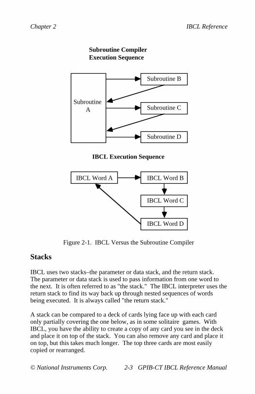
An IBCL program is executed by executing a sequence of words. If a wordin the sequence is defined by a code primitive, that code is executed. Whena word is defined by a list of other IBCL words, execution of the originallist is suspended until the list from the definition is executed. When you runan IBCL program, each word in the sequence composing the programexecutes in turn.
This execution sequence is different from subroutine-oriented languages. Ina subroutine-oriented language, you may still define a higher-levelsubroutine as a list of lower-level ones, but time is always wasted byreturning to the high-level routine before proceeding to the next routine inthe definition.
Chapter 2 IBCL Reference
© National Instruments Corp. 2-3 GPIB-CT IBCL Reference Manual
Subroutine CompilerExecution Sequence
Subroutine A
Subroutine B
Subroutine C
Subroutine D
IBCL Execution Sequence
IBCL Word B
IBCL Word C
IBCL Word D
IBCL Word A
Figure 2-1. IBCL Versus the Subroutine Compiler
Stacks
IBCL uses two stacks–the parameter or data stack, and the return stack.The parameter or data stack is used to pass information from one word tothe next. It is often referred to as "the stack." The IBCL interpreter uses thereturn stack to find its way back up through nested sequences of wordsbeing executed. It is always called "the return stack."
A stack can be compared to a deck of cards lying face up with each cardonly partially covering the one below, as in some solitaire games. WithIBCL, you have the ability to create a copy of any card you see in the deckand place it on top of the stack. You can also remove any card and place iton top, but this takes much longer. The top three cards are most easilycopied or rearranged.
IBCL Reference Chapter 2
GPIB-CT IBCL Reference Manual 2-4 © National Instruments Corp.
Using the card scenario, consider the following examples. A mathematicalor logical operator like max (maximum value) would take the top two cardsfrom the stack, place the higher valued one back, and discard the other.Addition is defined as removing the top two cards, writing the sum of theirnumbers on a blank card, and placing the new card on the stack.
IBCL keeps the data it is using on the parameter stack. IBCL wordsgenerally take their input parameters from this stack and leave their resultson it. The most fundamental IBCL words are defined in machine code andperform the following functions:
• Place an address on the stack
• Replace an address on the stack with the contents of that address
• Replace the top element(s) on the stack with the result of somemathematical or logical operation using them
• Place a copy of some stack element on top of the stack
• Rearrange the top few elements of the stack
• Delete element(s) from the top of the stack
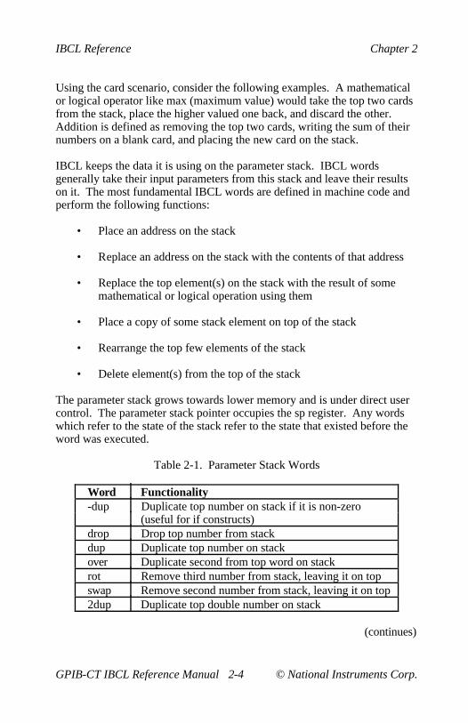
The parameter stack grows towards lower memory and is under direct usercontrol. The parameter stack pointer occupies the sp register. Any wordswhich refer to the state of the stack refer to the state that existed before theword was executed.
Table 2-1. Parameter Stack Words
Word Functionality-dup Duplicate top number on stack if it is non-zero
(useful for if constructs)drop Drop top number from stackdup Duplicate top number on stackover Duplicate second from top word on stackrot Remove third number from stack, leaving it on topswap Remove second number from stack, leaving it on top2dup Duplicate top double number on stack
(continues)
Chapter 2 IBCL Reference
© National Instruments Corp. 2-5 GPIB-CT IBCL Reference Manual
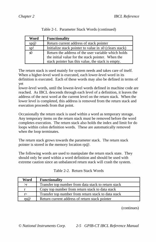
Table 2-1. Parameter Stack Words (continued)
Word Functionalitysp@ Return current address of stack pointersp! Initialize stack pointer to value in s0 (clears stack)s0 Return the address of the user variable which holds
the initial value for the stack pointer. When thestack pointer has this value, the stack is empty.
The return stack is used mainly for system needs and takes care of itself.When a higher-level word is executed, each lower-level word in itsdefinition is executed. Each of these words may also be defined in terms ofyetlower-level words, until the lowest-level words defined in machine code arereached. As IBCL descends through each level of a definition, it leaves theaddress of the next word at the current level on the return stack. When thelower level is completed, this address is removed from the return stack andexecution proceeds from that point.
Occasionally the return stack is used within a word as temporary storage.Any temporary items on the return stack must be removed before the wordcompletes execution. The return stack also holds the index and limit for doloops within colon definition words. These are automatically removedwhen the loop terminates.
The return stack grows towards the parameter stack. The return stackpointer is stored in the memory location rp@.
The following words are used to manipulate the return stack state. Theyshould only be used within a word definition and should be used withextreme caution since an unbalanced return stack will crash the system.
Table 2-2. Return Stack Words
Word Functionality>r Transfer top number from data stack to return stackr Copy top number from return stack to data stackr> Transfer top number from return stack to data stackrp@ Return current address of return stack pointer
(continues)

IBCL Reference Chapter 2
GPIB-CT IBCL Reference Manual 2-6 © National Instruments Corp.
Table 2-2. Return Stack Words (continued)
Word Functionalityrp! Initialize return stack pointer to value in r0 (clears return
stack)r0 Return the address of the user variable which holds the initial
value for the return stack pointer. When the return stackpointer has this value, the return stack is empty.
Numeric Operations
IBCL stores numeric information in consecutive 8-bit byte memorylocations and can represent character (8-bit), single precision (16-bit), ordouble precision (32-bit) data. It is the responsibility of the programmer toinsure that the correct numeric operations are used with the proper datatypes, as IBCL does not differentiate between the different data formats.
Both signed and unsigned single and double precision numbers can berepresented, but again, the programmer is responsible for insuring thecorrect representation of data types. All signed numbers are stored in two'scomplement form so that arithmetic operations can be handled withoutspecial consideration.
A number is interpreted as a double number with the inclusion of a decimalpoint anywhere within the number. A number is interpreted in its two'scomplement form if a negative sign directly precedes the number.
All IBCL arithmetic operations deal with integer quantities. Integerarithmetic is fast, requires very little memory and is not subject to round-offerror. Although floating point routines can be written in IBCL, the easiestway to represent quantities that contain fractional parts is to scale thenumber. For example, to represent a value given in dollars and cents as aninteger value, multiply the number by 100. This gives a value representinga number of cents. This integer value can then be used by any arithmeticfunction and the result can be reported back in the normalized format or canbe scaled back to represent a fractional value. In a sense, IBCLautomatically scales numbers which include decimal points since it convertsthem to double length integers and reports the position of the decimal place.
The arithmetic and logic words find and remove all of their inputs on thedata stack and return their results on the data stack.
The ranges for the supported number types are given in Table 2-3.
Chapter 2 IBCL Reference
© National Instruments Corp. 2-7 GPIB-CT IBCL Reference Manual
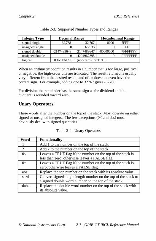
Table 2-3. Supported Number Types and Ranges
Integer Type Decimal Range Hexadecimal Rangesigned single -32,768 32,767 -8000 7FFFunsigned single 0 65,535 0 FFFFsigned double -2147483648 2147483647 -80000000 7FFFFFFFunsigned double 0 4294967295 0 FFFFFFFFlogical 0 for FALSE; 1 (non-zero) for TRUE
When an arithmetic operation results in a number that is too large, positiveor negative, the high-order bits are truncated. The result returned is usuallyvery different from the desired result, and often does not even have thecorrect sign. For example, adding one to 32767 gives -32768.
For division the remainder has the same sign as the dividend and thequotient is rounded toward zero.
Unary Operators
These words alter the number on the top of the stack. Most operate on eithersigned or unsigned integers. The few exceptions (0< and abs) mustobviously deal with signed quantities.
Table 2-4. Unary Operators
Word Functionality1+ Add 1 to the number on the top of the stack.2+ Add 2 to the number on the top of the stack.0< Leaves a TRUE flag if the number on the top of the stack is
less than zero; otherwise leaves a FALSE flag.0= Leaves a TRUE flag if the number on the top of the stack is
zero; otherwise leaves a FALSE flag.abs Replace the top number on the stack with its absolute value.s->d Convert signed single length number on the top of the stack to
a signed double word number on the top of the stack.dabs Replace the double word number on the top of the stack with
its absolute value.
IBCL Reference Chapter 2
GPIB-CT IBCL Reference Manual 2-8 © National Instruments Corp.
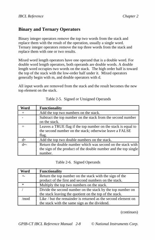
Binary and Ternary Operators
Binary integer operators remove the top two words from the stack andreplace them with the result of the operation, usually a single word.Ternary integer operators remove the top three words from the stack andreplace them with one or two results.
Mixed word length operators have one operand that is a double word. Fordouble word length operators, both operands are double words. A doublelength word occupies two words on the stack. The high order half is towardthe top of the stack with the low-order half under it. Mixed operatorsgenerally begin with m, and double operators with d.
All input words are removed from the stack and the result becomes the newtop element on the stack.
Table 2-5. Signed or Unsigned Operands
Word Functionality+ Add the top two numbers on the stack.- Subtract the top number on the stack from the second number
on the stack.= Leaves a TRUE flag if the top number on the stack is equal to
the second number on the stack; otherwise leave a FALSEflag.
d+ Add the top two double numbers on the stack.d+- Return the double number which was second on the stack with
the sign of the product of the double number and the top singlenumber.
Table 2-6. Signed Operands
Word Functionality+- Return the top number on the stack with the sign of the
product of the first and second numbers on the stack.* Multiply the top two numbers on the stack./ Divide the second number on the stack by the top number on
the stack leaving the quotient on the top of the stack./mod Like / but the remainder is returned as the second element on
the stack with the same sign as the dividend.
(continues)

Chapter 2 IBCL Reference
© National Instruments Corp. 2-9 GPIB-CT IBCL Reference Manual
Table 2-6. Signed Operands (continued)
Word Functionalitymod Return the remainder of / with the same sign as the dividend.*/ Multiplies the first and second number, divides the result by
the third number, and leaves the quotient on the stack. Thequotient is rounded toward zero. The intermediary result(after n1 * n2) is a double number, resulting in greaterprecision than n1 n2 * n3 /.
*/mod Like */ but the remainder is returned as the second element onthe stack. The remainder has the same sign as the product ofn1 * n2.
< Leaves a TRUE flag if the first number is greater than thesecond; otherwise leaves a FALSE flag.
> Leaves a TRUE flag if the second number is greater than thefirst; otherwise leaves a FALSE flag.
max Return the greater of the top two numbers on the stack.min Return the lesser of the top two numbers on the stack.
Table 2-7. Mixed Length Signed Operands
Word Functionalitym* Multiply the two numbers on the top of the stack and return
the signed double integer product.m/ Divide the double integer by the number on the top of the
stack leaving the signed quotient on the top of the stack andthe remainder as the second element on the stack. Theremainder takes its sign from the dividend.
m/mod Like m/ but returns a double word unsigned quotient and anunsigned remainder from an unsigned double dividend and anunsigned single divisor.
Table 2-8. Unsigned Operands
Word Functionalityu* Multiplies two unsigned numbers and leaves the result as an
unsigned double number on the stack.u< Leaves a TRUE flag if the first unsigned number is greater
than the second unsigned number; otherwise leaves a FALSEflag.

IBCL Reference Chapter 2
GPIB-CT IBCL Reference Manual 2-10 © National Instruments Corp.
Table 2-9. Logical, Sign Bit Not Significant
Word Functionalityand Leaves the bitwise AND of the top two numbers on the stack.or Leaves the bitwise inclusive-OR of the top two numbers on
the stack.xor Leaves the bitwise exclusive-OR of the top two numbers on
the stack.
Memory Access
These words allow a single byte, word, or double word to be stored orreturned from memory. An entire block of bytes may be cleared or filledwith any value or a contiguous block may be moved from one location toanother.
Constants, variables and arrays are structures used to reserve memorylocations in the IBCL system. They also provide user defined labelidentification for easy recall.
Load and Store
These words store values into memory or retrieve them from memory usingan address on the top of the stack.
The root of these words is an at character (@) for load, and an exclamationpoint (!) for store. A word with the root @ requires an address on the top ofthe stack. A word with the root ! takes two parameters from the stack, anaddress from the top of the stack and a number under the address. Doubleword numbers store the most significant portion toward the top, just belowthe address word or words.
A word with the root @ replaces the address on the stack with the valuestored at that address.
A word with the root ! stores the number from the stack under the addressinto the location at that address.
Chapter 2 IBCL Reference
© National Instruments Corp. 2-11 GPIB-CT IBCL Reference Manual
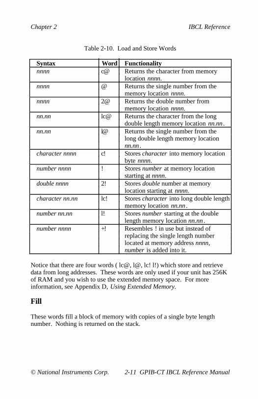
Table 2-10. Load and Store Words
Syntax Word Functionalitynnnn c@ Returns the character from memory
location nnnn.nnnn @ Returns the single number from the
memory location nnnn.nnnn 2@ Returns the double number from
memory location nnnn.nn.nn lc@ Returns the character from the long
double length memory location nn.nn .nn.nn l@ Returns the single number from the
long double length memory locationnn.nn .
character nnnn c! Stores character into memory locationbyte nnnn.
number nnnn ! Stores number at memory locationstarting at nnnn.
double nnnn 2! Stores double number at memorylocation starting at nnnn.
character nn.nn lc! Stores character into long double lengthmemory location nn.nn .
number nn.nn l! Stores number starting at the doublelength memory location nn.nn .
number nnnn +! Resembles ! in use but instead ofreplacing the single length numberlocated at memory address nnnn,number is added into it.
Notice that there are four words ( lc@, l@, lc! l!) which store and retrievedata from long addresses. These words are only used if your unit has 256Kof RAM and you wish to use the extended memory space. For moreinformation, see Appendix D, Using Extended Memory.
Fill
These words fill a block of memory with copies of a single byte lengthnumber. Nothing is returned on the stack.
IBCL Reference Chapter 2
GPIB-CT IBCL Reference Manual 2-12 © National Instruments Corp.
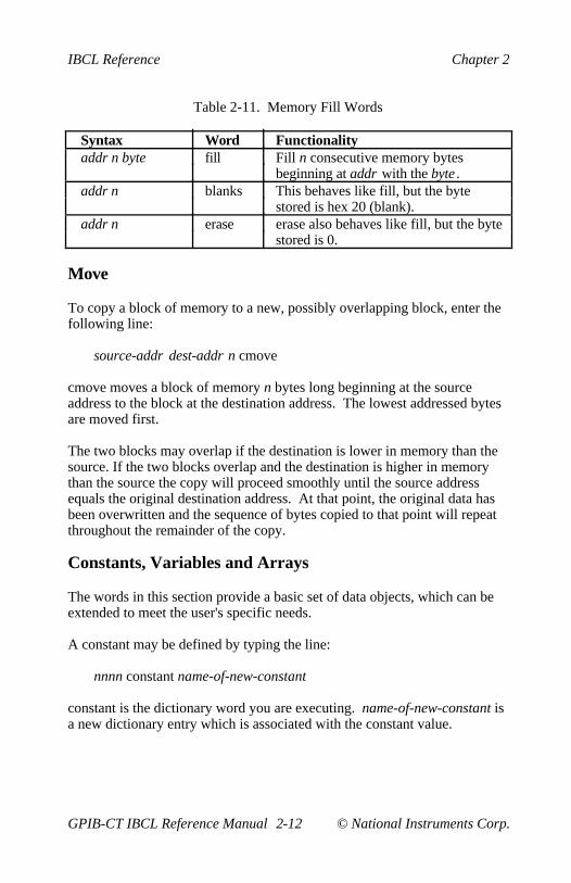
Table 2-11. Memory Fill Words
Syntax Word Functionalityaddr n byte fill Fill n consecutive memory bytes
beginning at addr with the byte .addr n blanks This behaves like fill, but the byte
stored is hex 20 (blank).addr n erase erase also behaves like fill, but the byte
stored is 0.
Move
To copy a block of memory to a new, possibly overlapping block, enter thefollowing line:
source-addr dest-addr n cmove
cmove moves a block of memory n bytes long beginning at the sourceaddress to the block at the destination address. The lowest addressed bytesare moved first.
The two blocks may overlap if the destination is lower in memory than thesource. If the two blocks overlap and the destination is higher in memorythan the source the copy will proceed smoothly until the source addressequals the original destination address. At that point, the original data hasbeen overwritten and the sequence of bytes copied to that point will repeatthroughout the remainder of the copy.
Constants, Variables and Arrays
The words in this section provide a basic set of data objects, which can beextended to meet the user's specific needs.
A constant may be defined by typing the line:
nnnn constant name-of-new-constant
constant is the dictionary word you are executing. name-of-new-constant isa new dictionary entry which is associated with the constant value.

Chapter 2 IBCL Reference
© National Instruments Corp. 2-13 GPIB-CT IBCL Reference Manual
The top word on the stack provides the value for the new constant.Whenever the new constant is executed, the number nnnn will be pushedonto the top of the stack. The constant can be executed by entering its nameoutside of a colon definition or executed immediately within a colondefinition by using the square bracket pair. It can also be executed whenany definition into which the constant has been compiled is executed.
A signed constant may range from -32768 through 32767 decimal. Anunsigned constant may range from 0 through 65535 decimal.
For example, examine the following lines:
5 constant five<CR>okfive . <CR>5ok
A few small integers are used so frequently that they have beenimplemented as IBCL constants. When the interpreter encounters them,they are located in the dictionary rather than being parsed by number. Moreimportantly, when used in definitions, they result in compilation of a singleword rather than the lit and value pair of words produced by other integers.The predefined IBCL constants are 0, 1, 2, and 3.
A variable is defined like a constant, except that whenever the new variableis executed, its parameter field address is pushed onto the stack. Valuesmay then be stored and retrieved from this location.
A value may be defined by entering the following line:
nnnn variable name-of-new-variable
variable is the dictionary word you are executing. name-of-new-variable isa new dictionary entry which will place the value nnnn on the top of thestack.
A signed variable may range from -32768 through 32767 decimal. Anunsigned variable may range from 0 through 65535 decimal.

IBCL Reference Chapter 2
GPIB-CT IBCL Reference Manual 2-14 © National Instruments Corp.
For example, examine the following lines:
1 variable jellybeans<CR>okjellybeans @ . <CR>1ok3 jellybeans +!<CR>okjellybeans @ . <CR>4ok
User variables are a special type of variable that permit multi-tasking andmulti-user applications. They are generally system variables that can varyfor different tasks and users. They are assigned sequentially beginning ataddress 22a hex. If multiple copies of this array are needed, the user mustcreate another array, copy the old user array to it, and place the appropriateaddress in user-base for each task.
The user-base is stored at memory location 226 hex. To use your new arrayof user variables, you must put the address of the new array into the user-base by entering the following line:
address-of-array 226 !
After you enter this line, IBCL uses your array of user variables. If youwant to restore the use of the system array, you must enter 22a hex foraddress-of-array , or turn off the GPIB-CT. No IBCL word resets the arrayfor you.
The user variables at system initialization are listed in Table 2-12.

Chapter 2 IBCL Reference
© National Instruments Corp. 2-15 GPIB-CT IBCL Reference Manual
Table 2-12. User Variables at Initialization
Location Variable Location Variable22a reserved 24a context22c reserved 24c current22e reserved 24e state230 S0 250 base232 R0 252 dpl234 tib 254 reserved236 width 256 csp238 warning 258 reserved23a fence 25a hld23c dp 25c unused23e voc-link 25e unused240 unused 260 unused242 in 262 unused244 out 264 unused246 reserved 266 unused248 reserved 268 unused
If more user variables are required, you can create a new user variable bytyping this line:
hex 52 user my-var
When executed, my-var would push the sum of the address contained inuser-base and the offset 52 onto the stack. The original user variable arraystarts at address 22a hex and is 40 hex bytes long.
Arrays can be created by first defining an array name by using variable,then reserving extra storage space by adjusting the dictionary pointer byusing allot. allot takes a number off the top of the stack and reserves thatnumber of bytes in the dictionary space. For example, to create an arraymany_items with 1000 bytes of storage, enter the following line:
0 variable many_items FFE allot
FFE is used during the allot since two bytes were already reserved byvariable. The first element in the array will be 0. Any array element can bedesignated by its relative location within the array structure.
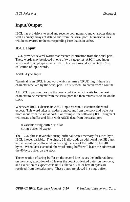
IBCL Reference Chapter 2
GPIB-CT IBCL Reference Manual 2-16 © National Instruments Corp.
Input/Output
IBCL has provisions to send and receive both numeric and character data aswell as binary arrays of data to and from the serial port. Numeric valueswill be converted to the corresponding base that is in effect.
IBCL Input
IBCL provides several words that receive information from the serial port.These words may be placed in one of two categories–ASCII-type inputwords and binary-type input words. This discussion documents IBCL'scollection of input words.
ASCII-Type Input
?terminal is an IBCL input word which returns a TRUE flag if there is acharacter received by the serial port. This is useful to break from a routine.
All IBCL input routines use the core word key which waits for the nextcharacter to be received from the serial port and then returns its value on thestack.
Whenever IBCL exhausts its ASCII input stream, it executes the wordexpect. This word takes an address and count from the stack and waits formore input from the serial port. For example, the following IBCL fragmentwill create a buffer and fill it with ASCII data from the serial port:
0 variable string-buffer 3E allotstring-buffer 40 expect
The IBCL phrase 0 variable string-buffer allocates memory for a two-byteIBCL integer variable. The phrase 3E allot adds an additional hex 3E bytesto the two already allocated, increasing the size of the buffer to hex 40bytes. When later executed, the word string-buffer will leave the address ofthe 40 byte buffer on the stack.
The execution of string-buffer on the second line leaves the buffer addresson the stack, execution of 40 leaves the count of desired bytes on the stack,and execution of expect waits until either a <CR> or hex 40 bytes arereceived from the serial port. These bytes are placed in string-buffer.

Chapter 2 IBCL Reference
© National Instruments Corp. 2-17 GPIB-CT IBCL Reference Manual
IBCL executes expect not only when the user explicitly uses it interactivelyor in a program, but also when the IBCL interpreter itself needs more ASCIIinput.
Binary-Type Input
The IBCL word dlm, for down load memory, allows the host serial deviceto transmit large arrays of binary data directly to GPIB-CT memory. Thisword expects a count on top of the stack and a buffer address under that.The IBCL word dlm causes the GPIB-CT to wait for the serial device tosend the specified number of bytes over the serial bus and places the data atthe specified address. Unlike the other IBCL input words, dlm does notecho the received characters back to the serial port. The following BASICexample illustrates operation of this word:
OPEN "COM1:9600,N,8,1" AS #1OPEN "SENDFILE" FOR INPUT AS #2PRINT #1,"0 variable buffer FFE allot"PRINT #1, "buffer 1000 dlm"FOR COUNT = 1 + 0 &H1000BYTE$ = INPUT$ (1, #2);PRINT #1, BYTE$;NEXT
IBCL Output
IBCL provides several words that send information out the serial port.These words may be placed in one of two categories–ASCII-type outputwords and binary-type output words. This section documents IBCL'scollection of output words.
ASCII-Type Output Words
Many different ASCII output words exist, but all of them work by callingthe IBCL word emit one or more times. This word outputs a single ASCIIcharacter to the serial port. emit also increments the value stored in the uservariable out which is used as on offset pointer to the last character output.
The system constant c/1, an abbreviation for characters/line, determines themaximum number of ASCII characters per display line (default 64decimal).
The remainder of this section describes the ASCII-type output words.
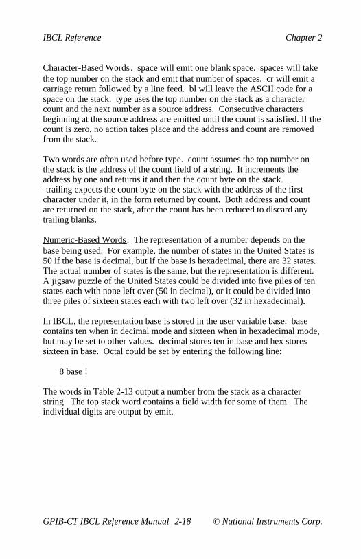
IBCL Reference Chapter 2
GPIB-CT IBCL Reference Manual 2-18 © National Instruments Corp.
Character-Based Words . space will emit one blank space. spaces will takethe top number on the stack and emit that number of spaces. cr will emit acarriage return followed by a line feed. bl will leave the ASCII code for aspace on the stack. type uses the top number on the stack as a charactercount and the next number as a source address. Consecutive charactersbeginning at the source address are emitted until the count is satisfied. If thecount is zero, no action takes place and the address and count are removedfrom the stack.
Two words are often used before type. count assumes the top number onthe stack is the address of the count field of a string. It increments theaddress by one and returns it and then the count byte on the stack.-trailing expects the count byte on the stack with the address of the firstcharacter under it, in the form returned by count. Both address and countare returned on the stack, after the count has been reduced to discard anytrailing blanks.
Numeric-Based Words . The representation of a number depends on thebase being used. For example, the number of states in the United States is50 if the base is decimal, but if the base is hexadecimal, there are 32 states.The actual number of states is the same, but the representation is different.A jigsaw puzzle of the United States could be divided into five piles of tenstates each with none left over (50 in decimal), or it could be divided intothree piles of sixteen states each with two left over (32 in hexadecimal).
In IBCL, the representation base is stored in the user variable base. basecontains ten when in decimal mode and sixteen when in hexadecimal mode,but may be set to other values. decimal stores ten in base and hex storessixteen in base. Octal could be set by entering the following line:
8 base !
The words in Table 2-13 output a number from the stack as a characterstring. The top stack word contains a field width for some of them. Theindividual digits are output by emit.

Chapter 2 IBCL Reference
© National Instruments Corp. 2-19 GPIB-CT IBCL Reference Manual
Table 2-13. Numeric Output Words
Syntax Word Functionalitynumber . Display number with a single trailing
blank and, if required, a leadingnegative sign.
double d. Like . except for double word lengthnumber, double. The high-order wordis on top of the stack with the low-orderword under it.
number u. Like . but number is unsigned and themagnitude may therefore range from 0through 65535 (decimal) or 0 throughFFFF (hexadecimal)
number #char .r Display number right aligned in field#char characters wide. The sign isincluded only if it is negative. If #charis too small, no leading blank appearsbut the field is expanded to include alldigits and sign.
double #char d.r Like .r but for double word lengthnumber, double.
source-address ? Print the number stored at source-address. (@ . )
The only punctuation included in the above numbers is the leading minussign. If more specific formatting is required, words are available to convertnumbers one digit at a time.
The following example will output the negative decimal single wordnumber -12345 and insert a decimal point between the 3 and 4:
decimal -12345 dup s->d dabs<# # # 46 hold #s rot sign #> type
In the previous example, decimal changes the base to decimal and-12345 places -12345 on the stack. dup places two copies of -12345 on thestack. s->d sign extends the top copy to double length. dabs takes theabsolute value of the double number. <# initializes for output conversion.The next # places the lowest order digit (5) in the buffer. The next # placesthe second lowest order digit in the buffer. 46 is the ASCII code for adecimal point.
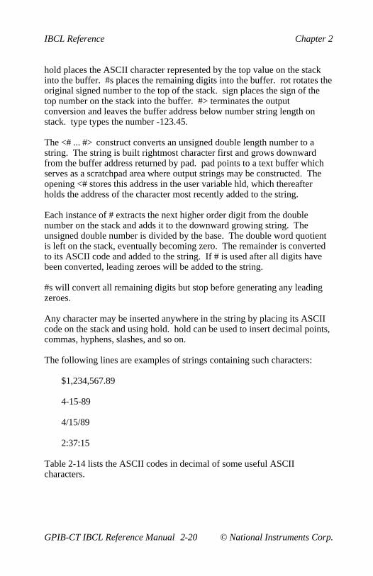
IBCL Reference Chapter 2
GPIB-CT IBCL Reference Manual 2-20 © National Instruments Corp.
hold places the ASCII character represented by the top value on the stackinto the buffer. #s places the remaining digits into the buffer. rot rotates theoriginal signed number to the top of the stack. sign places the sign of thetop number on the stack into the buffer. #> terminates the outputconversion and leaves the buffer address below number string length onstack. type types the number -123.45.
The <# ... #> construct converts an unsigned double length number to astring. The string is built rightmost character first and grows downwardfrom the buffer address returned by pad. pad points to a text buffer whichserves as a scratchpad area where output strings may be constructed. Theopening <# stores this address in the user variable hld, which thereafterholds the address of the character most recently added to the string.
Each instance of # extracts the next higher order digit from the doublenumber on the stack and adds it to the downward growing string. Theunsigned double number is divided by the base. The double word quotientis left on the stack, eventually becoming zero. The remainder is convertedto its ASCII code and added to the string. If # is used after all digits havebeen converted, leading zeroes will be added to the string.
#s will convert all remaining digits but stop before generating any leadingzeroes.
Any character may be inserted anywhere in the string by placing its ASCIIcode on the stack and using hold. hold can be used to insert decimal points,commas, hyphens, slashes, and so on.
The following lines are examples of strings containing such characters:
$1,234,567.89
4-15-89
4/15/89
2:37:15
Table 2-14 lists the ASCII codes in decimal of some useful ASCIIcharacters.
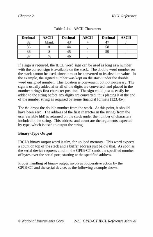
Chapter 2 IBCL Reference
© National Instruments Corp. 2-21 GPIB-CT IBCL Reference Manual
Table 2-14. ASCII Characters
Decimal ASCII Decimal ASCII Decimal ASCII32 blank 43 + 47 /35 # 44 , 58 :36 $ 45 - 59 ;37 % 46 .
If a sign is required, the IBCL word sign can be used as long as a numberwith the correct sign is available on the stack. The double word number onthe stack cannot be used, since it must be converted to its absolute value. Inthe example, the signed number was kept on the stack under the doubleword unsigned number. This location is convenient but not necessary. Thesign is usually added after all of the digits are converted, and placed in thenumber string's first character position. The sign could just as easily beadded to the string before any digits are converted, thus placing it at the endof the number string as required by some financial formats (123.45-).
The #> drops the double number from the stack. At this point, it shouldhave been zero. The address of the first character in the string (from theuser variable hld) is returned on the stack under the number of charactersincluded in the string. This address and count are the arguments expectedby type, which is used to output the string.
Binary-Type Output
IBCL's binary output word is ulm, for up load memory. This word expectsa count on top of the stack and a buffer address just below that. As soon asthe serial device requests an ulm, the GPIB-CT sends the specified numberof bytes over the serial port, starting at the specified address.
Proper handling of binary output involves cooperative action by theGPIB-CT and the serial device, as the following example shows.
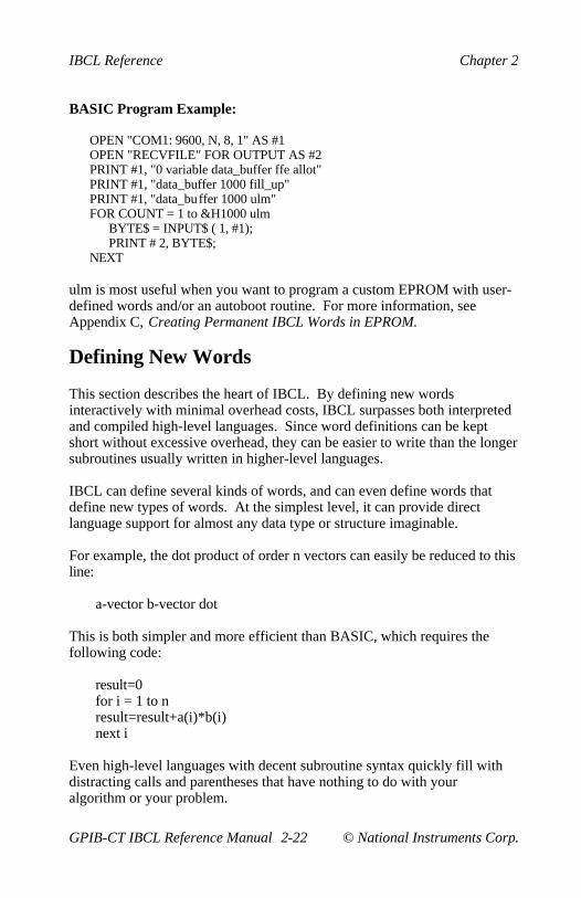
IBCL Reference Chapter 2
GPIB-CT IBCL Reference Manual 2-22 © National Instruments Corp.
BASIC Program Example:
OPEN "COM1: 9600, N, 8, 1" AS #1OPEN "RECVFILE" FOR OUTPUT AS #2PRINT #1, "0 variable data_buffer ffe allot"PRINT #1, "data_buffer 1000 fill_up"PRINT #1, "data_buffer 1000 ulm"FOR COUNT = 1 to &H1000 ulm
BYTE$ = INPUT$ ( 1, #1);PRINT # 2, BYTE$;
NEXT
ulm is most useful when you want to program a custom EPROM with user-defined words and/or an autoboot routine. For more information, seeAppendix C, Creating Permanent IBCL Words in EPROM.
Defining New Words
This section describes the heart of IBCL. By defining new wordsinteractively with minimal overhead costs, IBCL surpasses both interpretedand compiled high-level languages. Since word definitions can be keptshort without excessive overhead, they can be easier to write than the longersubroutines usually written in higher-level languages.
IBCL can define several kinds of words, and can even define words thatdefine new types of words. At the simplest level, it can provide directlanguage support for almost any data type or structure imaginable.
For example, the dot product of order n vectors can easily be reduced to thisline:
a-vector b-vector dot
This is both simpler and more efficient than BASIC, which requires thefollowing code:
result=0for i = 1 to nresult=result+a(i)*b(i)next i
Even high-level languages with decent subroutine syntax quickly fill withdistracting calls and parentheses that have nothing to do with youralgorithm or your problem.
Chapter 2 IBCL Reference
© National Instruments Corp. 2-23 GPIB-CT IBCL Reference Manual
The primary word used to define all new words is create, as in:
create new-name
This enters new-name in the context vocabulary with a memory wordinitialized to point to the next available dictionary location. You can thenplace machine language opcodes directly into this and later dictionary spaceby using c,. This allows you to write your own machine languageprimitives for speed-sensitive applications. create is used by all system-defining words.
create will truncate names longer than the value contained in the uservariable width. The initial value, also the maximum value, is decimal 31characters. If truncation occurs, the system remembers only the shortenedlength.
Colon Definitions
These are the most pervasive definitions in IBCL. They resemble thesubroutines or functions of other high-level languages such as Pascal orFortran, but have some important differences.
The syntax is not cluttered with parentheses and parameter lists. Thisenables IBCL words to be used more nearly like the words in a humanlanguage. IBCL syntax is admittedly more like German than English, sincethe action is specified after any values or addresses required.
Values and addresses are passed either on the data stack or throughlocations specified within the definition. Use of the data stack aids in thecreation of more generally useful words.
The other crucial difference is that the definition is compiled when it isentered. No distracting or time consuming compile and link sequence isrequired.
In a very small way, BASIC shares this convenient lack of extra steps.IBCL may be used calculator style like BASIC, or it may be used to definethe equivalent of a single IBCL word with the name RUN. In IBCL, youcould type this line:
: run IBCL equivalent of BASIC program ;
IBCL Reference Chapter 2
GPIB-CT IBCL Reference Manual 2-24 © National Instruments Corp.
In IBCL, of course, run could be named anything and you could havehundreds of programs at your fingertips simultaneously. No need forBASIC's incomprehensible tangle, single program limits, or incomparableslowness.
The basic format of the colon definition is:
: name-of-new-word words-comprising-definition ;
The colon and name must be on the first line, but the remainder of thedefinition may occupy as many lines as required. Each word or numbermust be complete on a single line.
After : has initialized the definition and set compilation mode, the followingwords are compiled into the definition for execution when the defined wordis executed. When a word is compiled, the address of its code field isappended to the list being created for the word being defined. If a numberis encountered, the word lit is compiled into the definition followed by thenumber. Later execution of lit will cause the number to be placed on thestack and the interpreter will skip the location that held the number. The ;terminates the definition by compiling a ;s at its end and setting executionmode. ;s will unwind the interpreter nesting one level, returning control tothe word after the instance of the one that finished execution.
The following example will print the number followed by a % sign whenthe word's name is entered: (37 is ASCII code for %)
decimal<CR>ok: fifteen-percent 15 . 37 emit ;<CR>okfifteen-percent <CR>15%okhex<CR>okfifteen-percent <CR>F%ok
Numbers are interpreted using the current base. In the example, theprevious base was discarded in favor of hexadecimal. Changing the base tohex changes the output representation of the number, but not the ASCIIcharacter. The output of an ASCII character requires no numericconversion.

Chapter 2 IBCL Reference
© National Instruments Corp. 2-25 GPIB-CT IBCL Reference Manual
Notice that the following definition would not have changed the base untilthe definition executed:
: fifteen-percent decimal 15 . 37 emit ;
The 15 and 37 would be interpreted according to the previous base, andtyping fifteen-percent would always change the base to decimal.
The words . and emit perform no action when used in a definition. Instead,their code field addresses are stored in the definition and will be executedonly when the defined word is executed. All non-immediate words followthis pattern.
Another type of word is immediate. Immediate words execute even whenused within a colon definition. The word may, but need not, alter or add tothe definition. Primary examples include the flow control words, definitionterminator words, and embedded string words.
To create an immediate word, use immediate after defining the new word:
: name definition ; immediate
Every definition needs at least one immediate word–the word that signals itsend. ; provides this service in the previous example and for all simple high-level colon definitions.
Another immediate word often used in definitions is the apostrophecharacter ('), which is often called a "tick" in this context. This word placesthe parameter field address of the next word in the input stream on thestack. Assuming that we have a code field address on the stack, we coulddetermine whether it was a variable with the following word:
: ?var @ [ ' memory cfa @ ] literal =if ." variable" else ." not variable" then ;
Note: memory is an IBCL variable.
The ." immediate word is used to include a message in a definition. If ." isin an active path, the message prints when the word is executed.
Sometimes it is necessary to cause compilation of an immediate word as ifit were a non-immediate one. This is accomplished by preceding theimmediate word with [compile].

IBCL Reference Chapter 2
GPIB-CT IBCL Reference Manual 2-26 © National Instruments Corp.
A word to print the parameter field address of another word could bedefined as follows:
: .address [compile] ' cr ." address is " . ;.address some-wordaddress is nnnn
This is basically a means for reusing the function of an immediate wordwithin another word which is itself often immediate.
Occasionally it is necessary to cause execution of non-immediate wordswhile creating a colon definition. This is accomplished by a pair of words,the opening square bracket ([) which switches the user variable state fromcompile to execute mode, and the closing square bracket (]), which switchesstate from execute to compile mode. The [ word leaves the definition open.The most common use for this pair would be the calculation of some offset,address, or constant. This pair is frequently used with the literal word,which takes the top value on the stack and enters it into the currentdefinition. Refer to the example on the previous page that begins with :?var for an example of the correct usage of [ and ]. A similar word, dliteral,is available for compiling double length values from the stack into thedefinition.
The following lines are examples of equivalent ways to define a wordreturning the address of the fifth line of a block given its base address on thestack. Notice that the first is inefficient, since the operations are performedevery time the word is executed:
: line-5 64 4 * + ;
64 4 * : line-5 literal + ;
: line-5 [ 64 4 * ] literal + ;
The second format could lead to ambiguity in a real program, and might notbe usable if the stack was busy with control parameters for loops.
Sometimes the word we are defining will be used to build part of thedefinition of other words. In this case, our definition may contain wordsthat we do not want to execute even when the word executes. Instead wewant the word to be copied to the definition being created.

Chapter 2 IBCL Reference
© National Instruments Corp. 2-27 GPIB-CT IBCL Reference Manual
compile is used within immediate words to allow the word followingcompile to be compiled into the dictionary entries of other words thatcontain the immediate word. Because compile takes the next word from thedefinition list, the word following compile should never be immediate.
Table 2-15 compares the behavior of an example word, called a-word,defined as non-immediate or immediate.
Table 2-15. Comparison of Non-Immediate andImmediate Characteristics
Non-Immediate Immediatea-word executed executed: q [ a-word ] ; executed executed *: q a-word ; compiled executed: q [compile] a-word ; compiled * compiled: q compile a-word ; immediate compiled ** error
* These forms are not really used since they are redundant.** This q must be used in a definition and a-word will be compiled into
that definition.
Comments may be inserted within the definition by enclosing them inparentheses. The opening parenthesis (() must be preceded and followed bya space to be interpreted as an IBCL word. The terminating parenthesis ())is a delimiter and needs no preceding space. For example:
: name some words ( comments) more words ;
Dictionary
IBCL recalls word definitions using a data structure called the dictionary.When you define a new word, IBCL adds a dictionary entry for that word.The only words IBCL understands which are not in the dictionary arenumbers.
The actual definition of an IBCL word consists of four parts–the name field,the link field, the code field, and the parameter field. The name fieldcontains the ASCII codes of characters making up the word's name,preceded by a length byte which specifies the number of characters in thename and certain attributes of the definition.

IBCL Reference Chapter 2
GPIB-CT IBCL Reference Manual 2-28 © National Instruments Corp.
The link field immediately follows the name field. The link field holds apointer to the name field of the next most recent word in the samevocabulary. These two fields allow for an easy comparison of input wordsto dictionary entries by using a linked list technique.
The code field contains an address pointer to the word's executionprocedure, which is executable machine code. The parameter fieldimmediately follows the code field. The purpose of the parameter fieldvaries from word to word. For example, the code field of a constant holds apointer to an execution procedure that causes a single precision constantvalue to be copied from the constant's parameter field to the stack wheneverthe name of that constant is entered. Likewise, the code field of a variablecontains a pointer to an execution procedure which causes the address of avariable's parameter field (rather than the single precision value storedthere) to be placed on the stack when the variable name is executed.
The parameter field of a colon-defined word contains one or more addresspointers designating the code field of a component word.
Vocabularies
IBCL allows separate vocabularies that separate definitions into well-organized groups, much like you would place related C functions in a singlefile. IBCL can find words faster when it only has to search a couple ofvocabularies instead of the entire dictionary.
The two vocabularies, context and current, are always singled out forspecial treatment. The context vocabulary is searched first for wordsencountered in the input stream. If the word is not found, the rootvocabulary, named ibcl, is searched. The current vocabulary is thevocabulary to which new definitions are added. The variables context andcurrent contain pointers to these two vocabularies.
An IBCL system initially contains a single vocabulary named ibcl. Newwords are added to this vocabulary as they are defined. It is possible tocreate additional vocabularies and to limit the scope of word searches to oneof the additional vocabularies followed by the IBCL vocabulary.

Chapter 2 IBCL Reference
© National Instruments Corp. 2-29 GPIB-CT IBCL Reference Manual
A new vocabulary may be created by typing this command:
vocabulary new-vocabulary-name immediate
where the term new-vocabulary-name would be replaced by the name youwant to give the new vocabulary. For example:
vocabulary assembler immediate
will create a new vocabulary titled assembler.
To cause the assembler vocabulary to be searched before the IBCLvocabulary, type the vocabulary name:
assembler
At this point, no words will be found in the assembler vocabulary, but theuser variable context will contain a pointer to the assembler vocabularyrather than to the IBCL vocabulary. New definitions would still be assignedto the IBCL vocabulary.
To cause new definitions to be assigned to the context vocabulary, type thisline:
definitions
Now the user variable current points to the assembler vocabulary instead ofthe IBCL vocabulary. current governs which vocabulary receives newdefinitions. If you want to enter new definitions in the vocabulary my-words, but limit interpreter searches to the IBCL vocabulary, type this line:
vocabulary my-words immediate my-words definitionsassembler
This would have reset context to point to assembler.
Note: Entering a colon definition sets context to current.
In the course of defining new words, you may discover that you have madea mistake. Words can be forgotten and dictionary space can be recoveredby typing this line:
forget word-to-forget-through
IBCL Reference Chapter 2
GPIB-CT IBCL Reference Manual 2-30 © National Instruments Corp.
This type of forget may only be used in the newest vocabulary. If thatvocabulary is still the IBCL vocabulary, the user variable fence contains apointer to a word below which forgetting is disabled, to protect you fromforgetting the system.
You can move fence by entering this line:
new-fence-limit fence !
This raises the fence beyond which forgetting is not allowed, and preventsaccidental forgetting of newly-defined function words.
Control
IBCL contains high-level control structures similar to those found inBASIC and Pascal. These perform conditional execution and repeatedexecution of word blocks. They also eliminate the need for any programposition labels such as BASIC's line numbers.
Words that control the flow of program execution are used only withincolon definitions. They are immediate words which execute when the colondefinition is first compiled. Most cause branches or conditional branches tobe compiled into the definition list of the word being compiled, but a fewmerely save an address and identifier on the stack for use by a later controlword.
The branch compiled into the definition list may be a conditional 0branch oran unconditional branch. The 0branch is ignored if the top word on thestack is nonzero. In either case, the branch fills two words in the definitionlist. The first, as with any compiled word, is a pointer to the code fieldaddress of the word, in this case branch or 0branch. The second word is thebyte offset of the destination relative to the second word. The conditionalbranch always uses and drops the top stack word.
Conditional Execution
The if true-phrase else false-phrase then construct is used within colondefinitions to enable a number on the stack to control whether or not groupsof words within the definition are executed. A phrase is any list of wordsnormally allowed in a colon definition. If conditional or loop constructs areincluded, they must be completed within the phrase. Nesting is limited onlyby stack size; overlapping is forbidden.
Chapter 2 IBCL Reference
© National Instruments Corp. 2-31 GPIB-CT IBCL Reference Manual
The following example will display a game score along with one of twomessages (the new score is on the stack):
0 variable high-score: .score dup high-score @ >
if dup high-score ! ." new high score!!!" .else ." your score is " .." high score is " high-score @ . then ;
When .score is executed, your latest score should be at the top of the stack.It is duplicated and compared with the old high score. The comparison setsthe top number on the stack to 0 (FALSE) if your score is not greater thanthe old high score. It sets the top number to a nonzero (TRUE) valueotherwise. If the number is 0, execution will branch to the words after theelse. If it is nonzero, execution will continue after the if, then skip thewords between else and then. The true part sets the new high score, thendisplays new high score!!! and the new score. The false part displays yourscore is nnnn high score is nnnnn .
else and the words between it and then may be omitted, in which case noaction is taken if the condition is false.
The if compiles a 0branch and puts the address of its destination field on thestack. It then places an identifier on the stack to signal its presence to elseor then. The else checks for an if identifier and issues an error message if itisn't found. else next compiles an unconditional branch . It calculates theoffset from the address on the stack to the word after the branch and storesthat offset into the original 0branch. The address of the destination field ofthe branch is placed on the stack, followed by another copy of the identifier.The then aborts with an error message if the identifier isn't found, but doesnot need to know whether it follows an if or an else . It calculates the offsetfrom the address on the stack to the next free word and stores it into theprevious branch.
Loops
Loop constructing words are similar to the conditional execution words inthat they compile branches and leave addresses on the stack. As describedin the previous discussion, a phrase may be any list of words normallyallowed in a colon definition. If conditional or loop constructs are included,they must be completed within the phrase. Nesting is limited only by stacksize; overlapping is forbidden.

IBCL Reference Chapter 2
GPIB-CT IBCL Reference Manual 2-32 © National Instruments Corp.
There are three types of conditional loops–begin-again, begin-until, andbegin-while-repeat.
The loop begin phrase again, is really an unconditional infinite loop since ithas no exit. The only legal exit would be an abort within the phrase orwithin a word in the phrase.
In the conditional loop, begin phrase until, until functions like if except thatit compiles a backward branch to the beginning of the phrase. The phraseexecutes repeatedly until the top word on the stack is TRUE (nonzero). Thephrase always executes at least once.
In begin test-phrase while phrase repeat, after the test phrase is executed,the top word on the stack is examined. If it is TRUE (nonzero), the phraseis executed and control branches back to the test-phrase. If it is FALSE(zero), the loop is exited and execution continues after the repeat. Thesecond phrase will not execute even once if the initial test-phrase is false.
There are two types of do loops–do-loop and do-+loop.
In the loop limit start do phrase loop, the do loop starts execution with anindex set to start and increments that index by one for every encounter ofloop. The phrase is executed repeatedly until the index equals or exceedsthe limit using a signed comparison. The limit and start values are takenfrom the data stack at execution time. While executing the loop, the indexis on top of the return stack with the limit under it. You may use the returnstack within the phrase, but its condition at the end of the phrase should bethe same as at the beginning. The data stack is not used other than on entry.
The limit start do phrase number +loop is similar to the first do loop, butthe +loop takes a signed number from the data stack and adds this to theindex instead of incrementing the index by one. If the increment is positive,termination is the same as for loop. If the increment is negative, executionrepeats until the index is less than the limit.

Chapter 2 IBCL Reference
© National Instruments Corp. 2-33 GPIB-CT IBCL Reference Manual
In addition to the loop control words just mentioned, there are a few wordsthat are designed to help loop processing:
• i is used within a loop to place the current loop index onto the topof the stack. For example, the following definition:
: display 10 0 do i c@ u. loop ;
outputs to the serial port the bytes in memory locations 0 to 9.
• leave is used within a loop to set the index equal to the limit, thuscausing an exit of the loop after the current loop finishes. This isuseful if a certain condition became TRUE during execution of aloop.
© National Instruments Corp. 3-1 GPIB-CT IBCL Reference Manual
Chapter 3GPIB Extensions
This chapter describes the IBCL extensions you can use to directly operateand control the GPIB. These functions are in alphabetical order and areformatted so that you can easily reference them.
The following discussion of the GPIB-related extensions containsreferences to the constants ibcnt , iberr , and ibsta . These constantsrefer to memory locations within the IBCL operating system which containinformation pertaining to GPIB actions.
ibcnt stores the number of bytes transferred from or received by theGPIB-CT during brd , rd , bwrt , wrt , or cmd . iberr stores flags toindicate certain error conditions that may have occurred. ibsta storesinformation about the current state of the GPIB system to which the GPIB-CT is attached. For more information about what each bit represents inibsta and what each value represents in iberr , refer to the statfunction description later in this section.
To aid in the use of these variables, you can define IBCL constants in yourdictionary by typing the following lines:
4 constant ibcnt2 constant iberr0 constant ibsta
When you need to use the information in these locations, type the followinglines:
ibcnt @iberr c@ibsta @
This puts the information stored at these locations onto the stack. Noticethat iberr is an 8-bit value, and ibcnt and ibsta are 16-bit values.
Another way to obtain the information stored in ibsta and ibcnt is touse the IBCL command stat , which puts these two values on the stack foryou.

GPIB Extensions Chapter 3
GPIB-CT IBCL Reference Manual 3-2 © National Instruments Corp.
brd
brd: Read Data from GPIB
Syntax: buf cnt brd
Remarks: buf is the address of the buffer to use.
cnt specifies the number of bytes to read from the GPIB.
brd attempts to read cnt bytes of data from a GPIB devicethat is assumed to already be properly initialized andaddressed.
If the GPIB-CT GPIB port is CIC, cmd must be called prior tobrd to address a device to talk and the GPIB-CT GPIB port tolisten. If the GPIB-CT GPIB port is not CIC, the device onthe GPIB that is the CIC must perform the addressing.
If the GPIB-CT GPIB port is Active Controller, the GPIB-CTGPIB port is first placed in Standby Controller state with ATNoff and remains there after the read operation is completed.
An EADR error results if the GPIB-CT GPIB port is CIC buthas not been addressed to listen with cmd . An EABO errorresults if the GPIB-CT GPIB port is not CIC and is notaddressed to listen within the time limit. An EABO error alsoresults if the device that is to talk is not addressed and/or theoperation does not complete for whatever reason within thetime limit.
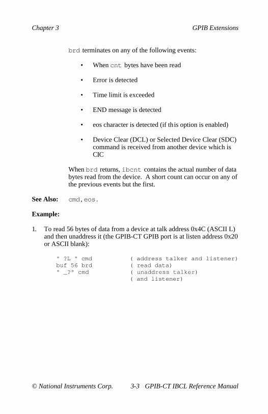
Chapter 3 GPIB Extensions
© National Instruments Corp. 3-3 GPIB-CT IBCL Reference Manual
brd terminates on any of the following events:
• When cnt bytes have been read
• Error is detected
• Time limit is exceeded
• END message is detected
• eos character is detected (if this option is enabled)
• Device Clear (DCL) or Selected Device Clear (SDC)command is received from another device which isCIC
When brd returns, ibcnt contains the actual number of databytes read from the device. A short count can occur on any ofthe previous events but the first.
See Also: cmd , eos .
Example:
1. To read 56 bytes of data from a device at talk address 0x4C (ASCII L)and then unaddress it (the GPIB-CT GPIB port is at listen address 0x20or ASCII blank):
" ?L " cmd ( address talker and listener)buf 56 brd ( read data)" _?" cmd ( unaddress talker)
( and listener)
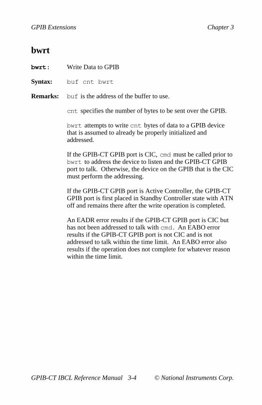
GPIB Extensions Chapter 3
GPIB-CT IBCL Reference Manual 3-4 © National Instruments Corp.
bwrt
bwrt: Write Data to GPIB
Syntax: buf cnt bwrt
Remarks: buf is the address of the buffer to use.
cnt specifies the number of bytes to be sent over the GPIB.
bwrt attempts to write cnt bytes of data to a GPIB devicethat is assumed to already be properly initialized andaddressed.
If the GPIB-CT GPIB port is CIC, cmd must be called prior tobwrt to address the device to listen and the GPIB-CT GPIBport to talk. Otherwise, the device on the GPIB that is the CICmust perform the addressing.
If the GPIB-CT GPIB port is Active Controller, the GPIB-CTGPIB port is first placed in Standby Controller state with ATNoff and remains there after the write operation is completed.
An EADR error results if the GPIB-CT GPIB port is CIC buthas not been addressed to talk with cmd . An EABO errorresults if the GPIB-CT GPIB port is not CIC and is notaddressed to talk within the time limit. An EABO error alsoresults if the operation does not complete for whatever reasonwithin the time limit.
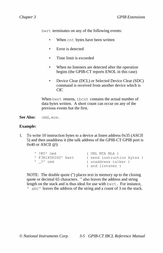
Chapter 3 GPIB Extensions
© National Instruments Corp. 3-5 GPIB-CT IBCL Reference Manual
bwrt terminates on any of the following events:
• When cnt bytes have been written
• Error is detected
• Time limit is exceeded
• When no listeners are detected after the operationbegins (the GPIB-CT reports ENOL in this case)
• Device Clear (DCL) or Selected Device Clear (SDC)command is received from another device which isCIC
When bwrt returns, ibcnt contains the actual number ofdata bytes written. A short count can occur on any of theprevious events but the first.
See Also: cmd , eos .
Example:
1. To write 10 instruction bytes to a device at listen address 0x35 (ASCII5) and then unaddress it (the talk address of the GPIB-CT GPIB port is0x40 or ASCII @):
" ?@5" cmd ( UNL MTA MLA )" F3R1X5P2G0" bwrt ( send instruction bytes )" _?" cmd ( unaddress talker )
( and listener )
NOTE: The double quote (") places text in memory up to the closingquote or decimal 65 characters. " also leaves the address and stringlength on the stack and is thus ideal for use with bwrt . For instance," abc" leaves the address of the string and a count of 3 on the stack.

GPIB Extensions Chapter 3
GPIB-CT IBCL Reference Manual 3-6 © National Instruments Corp.
cac
cac: Become Active Controller
Syntax: v cac
Remarks: If v is non-zero, the GPIB-CT takes control synchronouslywith respect to data transfer operations; otherwise, the GPIB-CT takes control immediately (and possibly asynchronously).
It is generally not necessary to use the cac word. Words suchas cmd and rpp , which require that the GPIB-CT takecontrol, do so automatically.
To take control synchronously, the GPIB-CT waits beforeasserting the ATN signal so that data being transferred on theGPIB will not be corrupted. If a data handshake is inprogress, the take control action is postponed until thehandshake is complete; if a handshake is not in progress, thetake control action is done immediately. Synchronous takecontrol is not guaranteed if a rd or wrt operation completedwith a timeout or error.
Asynchronous take control should be used in situations whereit appears to be impossible to gain control synchronously (e.g.,after a timeout error).
The ECIC error results if the GPIB-CT is not CIC.
See Also: gts , sic .
Examples:
1. To take control immediately without regard to any data handshake inprogress:
0 cac
2. To take control synchronously and assert ATN:
1 cac
Chapter 3 GPIB Extensions
© National Instruments Corp. 3-7 GPIB-CT IBCL Reference Manual
caddr
caddr: Change GPIB Address of GPIB-CT
Syntax: addr caddr
Remarks: addr is a valid GPIB address.
caddr is used to change the GPIB address of the GPIB-CT.The new address will remain in effect until caddr is calledagain or the GPIB-CT is turned off.
The power-on default is zero with secondary addressingdisabled.
Examples:
1. To change the GPIB address of the GPIB-CT to 5 with secondaryaddressing disabled:
5 caddr
2. To change the GPIB address of the GPIB-CT to 7 with a secondaryaddress of 8:
7 8 hex 100 * + 8000 + caddr

GPIB Extensions Chapter 3
GPIB-CT IBCL Reference Manual 3-8 © National Instruments Corp.
clr
clr: Send Selected Device Clear (SDC)
Syntax: addr clr
Remarks: addr is a valid GPIB address.
clr sends the selected device clear (SDC) message. SDCreinitializes all device functions. clr sends the followingcommands:
• Unlisten (UNL)
• Listen address of the device
• Secondary address of the device if applicable
• Selected Device Clear (SDC)
• Unlisten (UNL)
If this is the first function you call that requires GPIBcontroller capability, and you have not disabled SystemController capability with rsc , the GPIB-CT sends InterfaceClear (IFC) to make itself CIC. It also asserts Remote Enable.
If you passed control to some other GPIB device, control mustbe passed back to you or you must send IFC to make yourselfCIC before making this call. Otherwise, the ECIC error willbe posted.
Example:
1. To clear the device at GPIB address 5:
5 clr
Chapter 3 GPIB Extensions
© National Instruments Corp. 3-9 GPIB-CT IBCL Reference Manual
cmd
cmd: Send Command Message to GPIB
Syntax: buf cnt cmd
Remarks: buf is the address of a buffer containing the commands to besent over the GPIB.
cnt specifies the number of bytes to be sent over the GPIB.
cmd is used to transmit interface messages (commands) overthe GPIB. These commands include device talk and listenaddresses, secondary addresses, serial and parallel pollconfiguration messages, and device clear and triggerinstructions.
cmd is not used to transmit programming instructions todevices; programming instructions and other device dependentinformation are transmitted with brd , bwrt , rd , and wrt .
cmd terminates on any of the following events:
• All commands are successfully transferred
• Error is detected
• Time limit is exceeded
• Take Control (TCT) command is sent
• Interface Clear (IFC) message is received from theSystem Controller (not GPIB-CT)
When cmd returns, ibcnt contains the actual number ofcommand bytes sent.
An ECIC error results if the GPIB-CT GPIB port is not CIC.If the GPIB-CT GPIB port is not Active Controller, it assertsATN prior to sending the command bytes. The GPIB-CTGPIB port remains Active Controller afterward.

GPIB Extensions Chapter 3
GPIB-CT IBCL Reference Manual 3-10 © National Instruments Corp.
Examples:
In the following examples, GPIB commands and addresses are coded asprintable ASCII characters. When the hex values to be sent over the GPIBcorrespond to printable ASCII characters, this is the simplest means ofspecifying the values. Appendix A contains conversions of hex values toASCII characters.
1. To unaddress all Listeners with the Unlisten command (ASCII ?) andaddress a Talker at 0x46 (ASCII F) and a Listener at 0x31 (ASCII 1):
" ?F1" cmd
NOTE: The double quote (") places text in memory up to the closingquote or decimal 65 characters. " also leaves the address and stringlength on the stack and is thus ideal for use with cmd . For instance," abc" leaves the address of the string and a count of 3 on the stack.
2. Same as Example 1 except the Listener has a secondary address of0x6E (ASCII n):
" ?F1n" cmd

Chapter 3 GPIB Extensions
© National Instruments Corp. 3-11 GPIB-CT IBCL Reference Manual
eos
eos: Change/Disable GPIB EOS Termination Mode
Syntax: val eos
Remarks: val specifies the eos character and the data transfertermination method according to Table 3-1.
The assignment made by this function remains in effect untileos is called again or the GPIB-CT is turned off. By default,no eos modes are enabled.
Table 3-1. Data Transfer Termination Method
Method Value of val *Byte 1 Byte 0
A. Terminate read when eos is detected REOS eos(brd and rd ) 04 hex
B. Send END when eos is written XEOS eos(bwrt and wrt ) 08 hex
C. Compare all 8 bits of eos byte rather BIN eosthan low 7 bits (all reads and writes) 10 hex
* Byte 0 is the least significant byte.
Methods A and C determine how read operations terminate. IfMethod A alone is chosen, reads terminate when the low 7 bitsof the byte that is read match the low 7 bits of the eoscharacter. If Methods A and C are chosen, a full 8-bitcomparison is used.
Methods B and C together determine when write operationssend the END message. If Method B alone is chosen, theEND message is sent automatically when the low 7 bits of anybyte match the low 7 bits of the eos character. If Methods Band C are chosen, a full 8-bit comparison is used. The eoscharacter should always be the last byte sent.
See Also: eot .
GPIB Extensions Chapter 3
GPIB-CT IBCL Reference Manual 3-12 © National Instruments Corp.
Examples:
1. To send END when the linefeed character is written for operationsinvolving device dvm :
80A eos31 buf c! ( data bytes to be written )32 buf 1+ c! ( are placed in buffer with )33 buf 2+ c! ( EOS character as last byte )0A buf 3 + c!dvm buf 4 wrt
2. To program device dev1 to terminate a read on detection of thelinefeed character that is expected to be received within 512 bytes:
40A eosdev1 buf 512 rd( The END bit in status word is set if the )( read terminated on the eos character with )( the actual number of bytes received )( contained in ibcnt.)
3. To disable EOS termination:
0 eos

Chapter 3 GPIB Extensions
© National Instruments Corp. 3-13 GPIB-CT IBCL Reference Manual
eot
eot: End of Transfer Mode
Syntax: v eot
Remarks: If v is non-zero, the GPIB-CT automatically sends the ENDmessage with the last byte of each wrt . If v is zero, END isnot sent. The power-on default is 1.
eot is used to change how the GPIB-CT terminates GPIBwrites. Using eot , you tell the GPIB-CT to automaticallysend or not send the GPIB END message with the last bytewritten to the GPIB.
The assignment made by eot remains in effect until eot iscalled again or the GPIB-CT is turned off.
The GPIB-CT sends the END message by asserting the GPIBEOI signal during the last byte of a data transfer.
Examples:
1. To disable END termination:
0 eot
2. To enable END termination:
1 eot

GPIB Extensions Chapter 3
GPIB-CT IBCL Reference Manual 3-14 © National Instruments Corp.
gts
gts: Go from Active Controller to Standby
Syntax: v gts
Remarks: v is the type of go-to-standby.
gts causes the GPIB-CT to go to the Controller Standby stateand to unassert the ATN signal if it is the Active Controller.gts permits GPIB devices to transfer data without theGPIB-CT being a party to the transfer.
It is generally not necessary to use gts . Functions such as rdand wrt , which require that the GPIB-CT go to standby, do soautomatically.
If v is non-zero, GPIB-CT shadows data transfer handshakesas an Acceptor and when the END message is detected,GPIB-CT enters a Not Ready For Data (NRFD) handshakeholdoff state on the GPIB. If v is zero, no shadow handshakeor holdoff is done.
If the shadow handshake option is activated, the GPIB-CTparticipates in data handshake as an Acceptor without actuallyreading the data. It monitors the transfers for the ENDmessage and holds off subsequent transfers. This mechanismallows the GPIB-CT to take control synchronously on asubsequent operation such as cmd or rpp .
The ECIC error results if the GPIB-CT is not CIC.
See Also: cac , cmd , wait .
Example:
1. To turn the ATN line off:
0 gts
Chapter 3 GPIB Extensions
© National Instruments Corp. 3-15 GPIB-CT IBCL Reference Manual
ist
ist: Set or Clear Individual STatus Bit (IST)
Syntax: v ist
Remarks: v is the sense of the IST bit. If v is non-zero, the individualstatus bit is set. If v is zero, the bit is cleared. The power-ondefault is that the individual status bit is cleared.
ist is used when the GPIB-CT participates in a parallel pollthat is conducted by another device that is the ActiveController. The Active Controller conducts a parallel poll byasserting the EOI and ATN signals which send the Identify(IDY) message. While this message is active, each device thathas been configured to participate in the poll responds byasserting a predetermined GPIB data line either true or false,depending on the value of its local IST bit. The GPIB-CT, forexample, can be assigned to drive the DIO3 data line true ifIST=1 and false if IST=0; conversely, it can be assigned todrive DIO3 true if IST=0 and false if IST=1.
The relationship between the value of IST, the line that isdriven, and the sense at which the line is driven is determinedby the Parallel Poll Enable (PPE) message in effect for eachdevice. The GPIB-CT receives this message via a commandfrom the Active Controller. Once the PPE message isexecuted, ist changes the sense at which the line is drivenduring the parallel poll, and in this fashion the GPIB-CT canconvey a 1-bit, device dependent message to the Controller.
See Also: ppc , rpp .
Examples:
1. To set the individual status bit:
1 ist
2. To clear the individual status bit:
0 ist

GPIB Extensions Chapter 3
GPIB-CT IBCL Reference Manual 3-16 © National Instruments Corp.
loc
loc: Go to Local Mode
Syntax: addr loc
Remarks: addr is a valid GPIB address.
loc is used to move devices temporarily from a remoteprogram mode to a local mode. A device enters remote modewhen the REN line is asserted and the device detects its listenaddress.
loc places the indicated device in local mode by sending thecommand sequence:
• Unlisten (UNL)
• Listen address of the device
• Secondary address of the device if applicable
• Go To Local (GTL)
• Unlisten (UNL)
If this is the first function you call that requires GPIBcontroller capability, and you have not disabled SystemController capability with rsc , the GPIB-CT sends InterfaceClear (IFC) to make itself CIC. It also asserts Remote Enable.
If you passed control to some other GPIB device, control mustbe passed back to you or you must send IFC to make yourselfCIC before making this call. Otherwise, the ECIC error willbe posted.
Examples:
1. To return device plotter to local state:
plotter loc

Chapter 3 GPIB Extensions
© National Instruments Corp. 3-17 GPIB-CT IBCL Reference Manual
onl
onl: Place Device Online or Offline
Syntax: v onl
Remarks: v is a true/false value indicating online/offline.
onl is used to disable communications between the GPIB-CTand the GPIB.
NOTE: Unlike the onl in the GPIB-CT default operatingsystem, IBCL onl does not restore the GPIB-CT operatingparameters. To reset your GPIB-CT to its defaultcharacteristics, you must exit to the GPIB-CT defaultoperating system and call the onl function. Refer to yourGPIB-CT User Manual for a description of the GPIB-CT onlfunction and the default characteristics.
If v is non-zero, the GPIB-CT places itself online; if zero, theGPIB-CT places itself offline. By default, the GPIB-CT startsup online, is in the Idle Controller state, and configures itselfto be the System Controller.
Placing the GPIB-CT offline may be thought of asdisconnecting its GPIB cable from the other GPIB devices.
Placing the GPIB-CT online allows the GPIB-CT tocommunicate over the GPIB.
Examples:
1. To put the GPIB-CT online:
1 onl
2. To put the GPIB-CT offline to prevent it from communicating on theGPIB:
0 onl

GPIB Extensions Chapter 3
GPIB-CT IBCL Reference Manual 3-18 © National Instruments Corp.
pct
pct: Pass Control
Syntax: addr pct
Remarks: addr is a valid GPIB address.
pct passes CIC authority to the specified device. TheGPIB-CT GPIB port automatically goes to an idle state. Thefunction assumes that the device has Controller capability.
pct sends the following commands:
• Talk address of the device
• Secondary address of the device, if applicable
• Take Control (TCT)
If pct is called and the GPIB-CT is not CIC, the ECIC erroris posted.
Example:
1. To pass control to the device at GPIB address 3:
3 pct

Chapter 3 GPIB Extensions
© National Instruments Corp. 3-19 GPIB-CT IBCL Reference Manual
ppc
ppc: Parallel Poll Configure
Syntax: addr v ppc
Remarks: addr is a valid GPIB address.
v is a valid parallel poll enable/disable command.
ppc enables or disables the device from responding to parallelpolls.
ppc sends the following commands:
• Unlisten (UNL)
• Listen address of the device
• Secondary address of the device, if applicable
• Parallel Poll Configure (PPC)
• Parallel Poll Enable (PPE) or Disable (PPD)
• Unlisten (UNL)
Each of the 16 PPE messages specifies the GPIB data line(DIO1 through DIO8) and sense (one or zero) that the devicemust use when responding to the Identify (IDY) messageduring a parallel poll. The assigned message is interpreted bythe device along with the current value of the individual status(IST) bit to determine if the selected line is driven true orfalse. For example, if PPE=0x64, DIO5 is driven true if IST=0and false if IST=1. And if PPE=0x68, DIO1 is driven true ifIST=1 and false if IST=0. Any PPD message cancels the PPEmessage in effect.
If this is the first function you call that requires GPIBcontroller capability, and you have not disabled SystemController capability with rsc , the GPIB-CT sends InterfaceClear (IFC) to make itself CIC. It also asserts Remote Enable.

GPIB Extensions Chapter 3
GPIB-CT IBCL Reference Manual 3-20 © National Instruments Corp.
If you passed control to some other GPIB device, control mustbe passed back to you or you must send IFC to make yourselfCIC before making this call. Otherwise, the ECIC error willbe posted.
Which PPE and PPD messages are sent and the meaning of aparticular parallel poll response are all system dependentprotocol matters to be determined by the user.
The 16 valid PPE messages and the 16 valid PPD messagesare listed in Appendix A.
See Also: rpp , ist .
Example:
1. To configure device dvm to respond to a parallel poll by sending dataline DIO3 true if IST=0:
dvm 62 ppc
2. To configure device dvm to respond to a parallel poll by sending dataline DIO1 true if IST=1:
dvm 68 ppc
3. To cancel the parallel poll configuration of device dvm :
dvm 70 ppc

Chapter 3 GPIB Extensions
© National Instruments Corp. 3-21 GPIB-CT IBCL Reference Manual
rd
rd: Read Data from GPIB
Syntax: addr buf cnt rd
Remarks: addr is a valid GPIB address.
buf is the address of the buffer to use (buf might have beencreated using allot ).
cnt specifies the number of bytes to read from the GPIB.
rd attempts to read cnt bytes of data from a GPIB device.The following steps are performed:
1. UNL is sent.
2. The device is addressed to talk and the GPIB-CTGPIB port to listen, if not already addressed to do so.
3. The GPIB-CT reads the data from the device.
An EABO error results if the operation does not complete forwhatever reason within the time limits.
rd operation terminates on any of the following events:
• When cnt bytes have been read
• Error is detected
• Time limit is exceeded
• END message is detected
• eos character is detected (if this option is enabled)
• Device Clear (DCL) or Selected Device Clear (SDC)command is received from another device which isCIC

GPIB Extensions Chapter 3
GPIB-CT IBCL Reference Manual 3-22 © National Instruments Corp.
When rd returns, ibcnt contains the actual number of databytes read from the device. A short count can occur on any ofthe previous events but the first.
If this is the first function you call that requires GPIBcontroller capability, and you have not disabled SystemController capability with rsc , the GPIB-CT sends InterfaceClear (IFC) to make itself CIC. It also asserts Remote Enable.
If you passed control to some other GPIB device, control mustbe passed back to you or you must send IFC to make yourselfCIC before making this call. Otherwise, the ECIC error willbe posted.
Example:
1. To read hex 56 bytes of data from device tape:
tape buf 56 rd

Chapter 3 GPIB Extensions
© National Instruments Corp. 3-23 GPIB-CT IBCL Reference Manual
rpp
rpp: Conduct a Parallel Poll
Syntax: rpp
Remarks: rpp conducts a parallel poll of previously configured devicesby sending the IDY message (ATN and EOI both asserted).
When done, the parallel poll response byte is passed back asthe top element on the stack. The program should also checkiberr to determine if the response byte is valid.
If this is the first function you call that requires GPIBcontroller capability, and you have not disabled SystemController capability with rsc , the GPIB-CT sends InterfaceClear (IFC) to make itself CIC. It also asserts Remote Enable.
If you passed control to some other GPIB device, control mustbe passed back to you or you must send IFC to make yourselfCIC before making this call. Otherwise, the ECIC error willbe posted.
See Also: ist , ppc , ppu .
Example:
1. To remotely configure a device at listen address 0x23 to respondpositively on DIO3 if its individual status bit is 1, and then parallel pollall configured devices:
3 6a ppc ( configure device at )( listen address 3)
rpp ( parallel poll all )( configured devices )( response passed back on )( stack )
GPIB Extensions Chapter 3
GPIB-CT IBCL Reference Manual 3-24 © National Instruments Corp.
rsc
rsc: Request or Release System Control (SC)
Syntax: v rsc
Remarks: v specifies request or release system control.
If v is non-zero, functions requiring System Controllercapability are subsequently allowed. If v is zero, functionsrequiring System Controller capability are disallowed.
rsc is used to enable or disable the capability of the GPIB-CT to send the Interface Clear (IFC) and Remote Enable(REN) messages to GPIB devices using the sic and srefunctions. The GPIB-CT GPIB port must not be SystemController to respond to Interface Clear sent by anotherController.
In most applications, the GPIB-CT will always be the SystemController. In other applications, the GPIB-CT will never bethe System Controller. In either case, rsc is used only if theGPIB-CT is not going to be System Controller for theduration of the program execution. While the IEEE 488standard does not specifically allow schemes in which SystemControl can be passed dynamically from one device toanother, rsc would be used in such a scheme.
Example:
1. To request to be System Controller if the GPIB-CT GPIB port is notcurrently so designated:
1 rsc

Chapter 3 GPIB Extensions
© National Instruments Corp. 3-25 GPIB-CT IBCL Reference Manual
rsp
rsp: Conduct a Serial Poll
Syntax: addr rsp
Remarks: addr is a valid GPIB address.
rsp is used to serially poll one device and obtain its statusbyte. If the 0x40 bit of the response is set, the status responseis positive, i.e., the device is requesting service. Before rspcompletes, all devices are unaddressed.
Upon completion, the serial poll response is returned in thelow-order 8 bits of the word on the top of the stack. If thedevice did not respond within the allotted time a -1 will bereturned on the top of the stack.
The interpretation of the response, other than the RQS bit, isdevice-specific. For example, the polled device might set aparticular bit in the response byte to indicate that it has data totransfer, and another bit to indicate a need for reprogramming.Consult the manufacturer's documentation for the device forinterpretation of the response byte.
If this is the first function you call that requires GPIBcontroller capability, and you have not disabled SystemController capability with rsc , the GPIB-CT sends InterfaceClear (IFC) to make itself CIC. It also asserts Remote Enable.
If you passed control to some other GPIB device, control mustbe passed back to you or you must send IFC to make yourselfCIC before making this call. Otherwise, the ECIC error willbe posted.

GPIB Extensions Chapter 3
GPIB-CT IBCL Reference Manual 3-26 © National Instruments Corp.
rsp sends the following commands:
• UNL (Unlisten)
• SPE (Serial Poll Enable)
• GPIB-CT listen address
• Talk address of the device
• Read in response byte
• SPD (Serial Poll Disable)
• UNL (Unlisten)
• UNT (Untalk)
ATN and REN remain asserted after the function call.
Example:
1. To obtain the Serial Poll response byte from device tape:
tape rsp

Chapter 3 GPIB Extensions
© National Instruments Corp. 3-27 GPIB-CT IBCL Reference Manual
rsv
rsv: Request Service and/or Set Serial Poll Status Byte
Syntax: val rsv
Remarks: val specifies the serial poll response byte.
If the 0x40 bit is set in val , the GPIB-CT additionallyrequests service from the Controller by asserting the GPIBSRQ line.
rsv is used to request service from the Controller using theService Request (SRQ) signal and to provide a systemdependent status byte when the Controller serially polls theGPIB-CT.
It is not an error to call rsv when the GPIB-CT is CIC,although this usage makes sense only if control will be passedlater to another device. In this case, the call updates the statusbyte, but the SRQ signal is asserted only if the 0x40 bit is setand only when control is passed.
See Also: rsp .
Examples:
1. To set the Serial Poll status byte to 0x41, which simultaneouslyrequests service from an external CIC:
41 rsv
2. To stop requesting service (unassert SRQ):
0 rsv
3. To change the status byte to 1 without requesting service:
1 rsv

GPIB Extensions Chapter 3
GPIB-CT IBCL Reference Manual 3-28 © National Instruments Corp.
sic
sic: Send Interface Clear (IFC)
Syntax: sic
Remarks: sic causes the GPIB-CT to assert the IFC signal for at least100 µsec, provided the GPIB-CT has System Controllerauthority. This action initializes the GPIB and makes theGPIB-CT GPIB port CIC. sic is generally used when youwant to become CIC or clear a bus fault condition.
The IFC signal resets only the GPIB interface functions of busdevices and is not intended to reset internal device functions.Device functions are reset with the Device Clear (DCL) andSelected Device Clear (SDC) commands. To determine theeffect of these messages, consult the device documentation.
The GPIB-CT records the ESAC error if you have disabled itsSystem Controller capability with the rsc function.
See Also: rsc .
Example:
1. To initialize the GPIB and become CIC at the beginning of a program:
sic

Chapter 3 GPIB Extensions
© National Instruments Corp. 3-29 GPIB-CT IBCL Reference Manual
sre
sre: Set or Clear Remote Enable (REN)
Syntax: v sre
Remarks: v specifies set or clear.
sre turns the REN signal on and off. If v is non-zero, theRemote Enable (REN) signal is asserted. If v is zero, thesignal is unasserted. REN is used by devices to select betweenlocal and remote modes of operation. REN enables the remotemode. A device does not actually enter remote mode until itreceives its listen address.
The ESAC error occurs if the GPIB-CT is not SystemController.
See Also: cmd , loc , rsc , sic .
Examples:
1. To place a device at listen address 0x23 (ASCII #) into remote mode:
1 sre ( set REN to true )" #" cmd ( MLA )
2. To exclude the local ability of the device, send the Local Lockoutcommand (0x11), or include it in the command string in Example 1:
11 buf c! ( send LLO )buf 1 cmd
or
1 sre ( REN true )23 buf c! ( MLA LLO )11 buf 1+ c!buf 2 cmd
3. To return all devices to local mode:
0 sre ( set REN to false )

GPIB Extensions Chapter 3
GPIB-CT IBCL Reference Manual 3-30 © National Instruments Corp.
stat
stat: Return GPIB-CT status
Syntax: stat
Remarks: stat is used to obtain the status of the GPIB-CT to see ifcertain conditions are currently present. Use stat most oftento verify if the previous operation resulted in an error.
Use stat frequently in the early stages of program developmentwhen your device's responses are likely to be unpredictable.
Status represents a combination of GPIB-CT conditions.Internally in the GPIB-CT, status is stored as a 16-bit integer.Each bit in the integer represents a single condition. A bitvalue of 1 indicates that the corresponding condition is ineffect; a bit value of zero indicates that the condition is not ineffect. Since more than one GPIB-CT condition may exist atone time, more than one bit may be set in status. The highestorder bit of status, also called the sign bit, is set when theGPIB-CT detects a GPIB error. Consequently, when status isnegative, an error condition exists, and when status is positive,no error condition exists. Table 3-2 lists the indication of eachbit in the status.
The status is returned on the stack as two words. The topnumber represents the 16-bit status of the GPIB-CT. Thesecond number is the count of bytes last transferred usingbrd , bwrt , rd and wrt .

Chapter 3 GPIB Extensions
© National Instruments Corp. 3-31 GPIB-CT IBCL Reference Manual
Table 3-2. GPIB Status Conditions
Numeric SymbolicValue (n) Value (s) Description Bit-32768 ERR Error detected 1516384 TIMO Timeout 148192 END EOI or EOS detected 134096 SRQI SRQ detected while CIC 122048 - Reserved 111024 - Reserved 10512 - Reserved 9256 CMPL Operation completed 8128 LOK Lockout state 764 REM Remote state 632 CIC Controller-In-Charge 516 ATN Attention asserted 48 TACS Talker active 34 LACS Listener active 22 DTAS Device trigger state 11 DCAS Device clear state 0
See Also: Appendix B in your GPIB-CT User Manual for a detaileddescription of the conditions under which each bit in status is set or cleared.
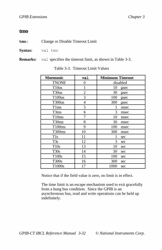
GPIB Extensions Chapter 3
GPIB-CT IBCL Reference Manual 3-32 © National Instruments Corp.
tmo
tmo: Change or Disable Timeout Limit
Syntax: val tmo
Remarks: val specifies the timeout limit, as shown in Table 3-3.
Table 3-3. Timeout Limit Values
Mnemonic val Minimum TimeoutTNONE 0 disabledT10us 1 10 µsecT30us 2 30 µsecT100us 3 100 µsecT300us 4 300 µsecT1ms 5 1 msecT3ms 6 3 msecT10ms 7 10 msecT30ms 8 30 msecT100ms 9 100 msecT300ms 10 300 msecT1s 11 1 secT3s 12 3 secT10s 13 10 secT30s 14 30 secT100s 15 100 secT300s 16 300 secT1000s 17 1000 sec
Notice that if the field value is zero, no limit is in effect.
The time limit is an escape mechanism used to exit gracefullyfrom a hung bus condition. Since the GPIB is anasynchronous bus, read and write operations can be held upindefinitely.
Chapter 3 GPIB Extensions
© National Instruments Corp. 3-33 GPIB-CT IBCL Reference Manual
Examples:
1. To change the time limit for device level I/O operations to 300 µsec:
4 tmo
2. To perform I/O operations with no timeout in effect:
0 tmo
GPIB Extensions Chapter 3
GPIB-CT IBCL Reference Manual 3-34 © National Instruments Corp.
trg
trg: Send Device Trigger
Syntax: addr trg
Remarks: addr is a valid GPIB address.
trg addresses and triggers the specified device, thenunaddresses all devices on the GPIB.
trg sends the following commands:
• Unlisten (UNL)
• Listen address of the device
• Secondary address of the device, if applicable
• Group Execute Trigger (GET)
• Unlisten (UNL)
If this is the first function you call that requires GPIBcontroller capability, and you have not disabled SystemController capability with rsc , the GPIB-CT sends InterfaceClear (IFC) to make itself CIC. It also asserts Remote Enable.
If you passed control to some other GPIB device, control mustbe passed back to you or you must send IFC to make yourselfCIC before making this call. Otherwise, the ECIC error willbe posted.
The response to a trigger is device dependent.
Example:
1. To trigger device analyzer :
analyzer trg

Chapter 3 GPIB Extensions
© National Instruments Corp. 3-35 GPIB-CT IBCL Reference Manual
wait
wait: Wait for Selected Events
Syntax: mask wait
Remarks: The mask bit is set to wait for the corresponding event tooccur.
wait is used to monitor the events selected in mask and todelay processing until any of them occur. These events andbit assignments are shown in Table 3-4.
Table 3-4. Wait Mask Layout
Decimal Mnemonic Description Hex BitValue Value
- - Reserved - 1516384 TIMO Timeout 4000 148192 END EOI or EDS detected 2000 134096 SRQI SRQ detected while CIC 1000 12- - Reserved - 11- - Reserved - 10- - Reserved - 9- - Reserved - 8128 LOK Lockout state 80 764 REM Remote state 40 632 CIC Controller-In-Charge 20 516 ATN Attention asserted 10 48 TACS Talker active 8 34 LACS Listener active 4 22 DTAS Device trigger state 2 11 DCAS Device clear state 1 0
If mask = 0 , the function returns immediately. This is usedto report the current device or GPIB-CT GPIB port state.
If the TIMO bit is 0 or the time limit is set to 0, timeouts aredisabled. Disabling timeouts should be done only when it iscertain the selected event will occur; otherwise the GPIB-CTwaits indefinitely for the event to occur.

GPIB Extensions Chapter 3
GPIB-CT IBCL Reference Manual 3-36 © National Instruments Corp.
All activity on the GPIB-CT GPIB port is suspended until theevent occurs.
See Also: stat , tmo .
Examples:
1. To wait for a service request or a timeout:
5000 wait
2. To update the status:
0 wait
3. To wait indefinitely until control is passed from another CIC:
20 wait
4. To wait indefinitely until addressed to talk or listen by another CIC:
C wait

Chapter 3 GPIB Extensions
© National Instruments Corp. 3-37 GPIB-CT IBCL Reference Manual
wrt
wrt: Write Data to GPIB
Syntax: addr buf cnt wrt
Remarks: addr is a valid GPIB address.
buf is the address of the buffer that contains the data to besent over the GPIB.
cnt specifies the number of bytes to be sent over the GPIB.
wrt attempts to write cnt bytes of data to the specified GPIBdevice. The following steps are performed:
1. UNL is sent.
2. The device is addressed to listen and the GPIB-CTGPIB port to talk, if not already addressed to do so.
3. The GPIB-CT writes the data to the device.
An EABO error results if the operation does not completewithin the time limit.
wrt terminates on any of the following events:
• When cnt bytes have been written
• Error is detected
• Time limit is exceeded
• When no listeners are detected after the operationbegins (the GPIB-CT reports ENOL in this case)
• Device Clear (DCL) or Selected Device Clear (SDC)command is received from another device which isCIC
GPIB Extensions Chapter 3
GPIB-CT IBCL Reference Manual 3-38 © National Instruments Corp.
When wrt returns, ibcnt contains the actual number of databytes written. A short count can occur on any of the previousevents but the first.
If this is the first function you call that requires GPIBController capability, and you have not disabled SystemController capability with rsc , the GPIB-CT sends InterfaceClear (IFC) to make itself CIC. It also asserts Remote Enable.
If you passed control to some other GPIB device, control mustbe passed back to you or you must send IFC to make yourselfCIC before making this call. Otherwise, the ECIC error willbe posted.
Example:
1. To write 10 bytes of instructions to device dvm :
dvm " F3R1X5P2G0" wrt
NOTE: The double quote (") places text in memory up to the closingquote or decimal 65 characters. " also leaves the address and stringlength on the stack and is thus ideal for use with wrt . For instance, "abc" leaves the address of the string and a count of 3 on the stack.

© National Instruments Corp. 4-1 GPIB-CT IBCL Reference Manual
Chapter 4Programming Examples
This contains sample applications written in IBCL Some examples arestandalone; others have software that communicates with ongoing IBCLcode from an external computer. These examples are simplified so that youcan enhance them to meet your own programming needs.
Microsoft BASIC IBCL Compiler ProgrammingExample
Example 1 demonstrates how you can use a high-level language that hasaccess to the system's serial port to download a file of IBCL source code,macros, or data to IBCL.
Example 1
10 CLS20 INPUT "Enter the filename of the source code using a
correct pathname: ";file$30 OPEN file$ FOR INPUT AS #1
' Opens the disk file for' input
40 OPEN "COM1:9600,N,8,1" AS #2' Opens the RS-232 com-' munications port
50 LINENUM = 1 : Locate 2,1 : PRINT "Compiling line # ";LINENUM ' Initialize a line count
' variable60 CMDSTR$ = "ibcl"+CHR$(13) ' Command to enter IBCL from
' the GPIB-CT default' operating system.
70 PRINT #2,CMDSTR$ ' Send the string to RS-232' port
80 LINE INPUT #2,STAT$ ' Ensure ok message given90 STAT$ = RIGHT$ (STAT$,2)100 IF STAT$ <> "ok" THEN 500
' Check if successfully' entered IBCL
110 while (not EOF(1)) ' Keep reading until disk' file is depleted of words,' macros, and commands.

Programming Examples Chapter 4
GPIB-CT IBCL Reference Manual 4-2 © National Instruments Corp.
120 LINE INPUT #1,CMDSTR$ ' Get command from disk file130 PRINT #2,CMDSTR$ ' Send command to IBCL140 LINE INPUT #2,COPY$ ' Read in echo of CMDSTR$
' from IBCL150 LINE INPUT #2,STAT$ ' Get status of last command160 STAT$ = RIGHT$ (STAT$,2)170 IF STAT$<> "ok" THEN 500 ' Some error occurred. Stop!180 LINECNT = LINECNT + 1 ' Increment count of lines
' sent190 WEND ' Repeat the loop200 PRINT : PRINT LINECNT;" lines were successfully
transmitted."210 END
500 REM ' This error routine could be any action you510 REM ' take when an error occurs in a transfer.520 PRINT : PRINT "Transmission interrupted due to an
error."530 PRINT "Value of CMDSTR$ which created an error is
";CMDSTR$540 PRINT "Value of STAT$ after the error is ";STAT$550 END
Modem Programming Examples
Example 2 is an IBCL program that loops twenty decimal times reading thesettings from an oscilloscope located at GPIB address 1. When all thereadings are obtained, IBCL will use a modem and dial the number of amodem attached to another computer executing Example 3.
Example 3 is a Microsoft BASIC program that dials a modem connected toa distant GPIB-CT, downloads a file (the program from Example 2), andthen waits for IBCL to call back with the results of its operation.
Example 2
0 variable buff ( Create a buffer named "buff")1000 allot ( Allocate 1000 hex bytes for)
( the buffer): analyze ( Define a word "analyze")
buff ( Or iginal buffer address onto)( the stack)
14 0 do ( Loop 20 decimal times)dup dup ( Duplicate the moving buffer)
( address twice)c tmo ( Set up a 3 sec timeout)

Chapter 4 Programming Examples
© National Instruments Corp. 4-3 GPIB-CT IBCL Reference Manual
4000 wait ( Wait 3 sec between data)( acquisitions)
d tmo ( Reset default 10 sec timeout)1 " set?" wrt ( Request the instrument state)
( of the Tektronix 2230)( oscilloscope located at GPIB)( address 1)
1 swap 1000 rd ( Read data from instrument at)( GPIB address 1 into the)( buffer whose address is on)( the stack)
d swap ( Put a <CR> on the stack and)( swap its value with the)( remaining buffer address)
stat drop + ( Get actual count of chars.)( read and add this value to)( the buffer address)
c! ( Store the <CR> into the)( buffer)
stat drop 1+ + ( Get new buffer address by)( adding count of chars. read)( plus 1 for <CR>)
loop ( Loop and do again)." ATDT9,3358570" ( Send command to modem serial)
( port to dial)cr ( Send a <CR><LF>--." does not)
( automatically)4000 wait ( Wait 10 sec to insure)
( Carrier Detect)buff - buff swap ( Get starting address of)
( buffer and count of chars.)( to send to the host)
ulm ( Upload the data to the)( serial port)
;
Example 310 CLS : KEY OFF20 DIM RESULT$(20) ' Create an array for results30 ON COM(1) GOSUB 520 ' Trap routine for incoming
' serial data40 INPUT "filename"; FILE$ ' Disk file of IBCL data,
' program, etc.50 OPEN FILE$ FOR INPUT AS #1 ' Ope n IBCL command file60 OPEN "com1:1200,n,8,1" AS #270 PRINT #2,"ATs2=42" ' Local modem escape character
' is the asterisk (*)80 LFCR$=INPUT$(2,2) ' Get leading CR and LF

Programming Examples Chapter 4
GPIB-CT IBCL Reference Manual 4-4 © National Instruments Corp.
90 LINE INPUT #2,ESCSTAT$ ' Status from modem100 LF$=INPUT$(1,2) ' Get trailing LF110 PRINT #2,"ATDT9,335857O" ' Dial IBCL modem120 LFCR$=INPUT$(2,2) ' Get leading CR and LF130 LINE INPUT #2,DLSTAT$ ' Status from modem140 LF$ = INPUT$(1,2) ' Get trailing LF150 IF INSTR(DLSTAT$,"CONNECT") = 0 THEN PRINT "No carrier detected" : END
' Check if CONNECT message' received
160 FOR PAUSE = 1 TO 3000 : NEXT PAUSE' Wait to ensure Carrier' Detect
170 PRINT #2,"task" ' An IBCL do-nothing word -' insures that IBCL' is ready for commands
180 LINE INPUT #2,COPY$ ' Echo of IBCL command190 LINE INPUT #2,STAT$ ' Status after IBCL processes
' command200 LF$=INPUT$(1,2) ' Get trailing LF210 PRINT #2,"cold" ' OPTIONAL--IBCL will be in a
' known state after execution' of this command
220 LINE INPUT #2,COPY$ ' Echo of IBCL command230 LINE INPUT #2,STAT$ ' Status after IBCL processes
' command240 LF$=INPUT$(1,2) ' Get trailing LF250 IF INSTR(STAT$,"ok") = 0 THEN PRINT "IBCL is not responding. Program terminated" : END
' Check if status was an ok' message
260 LINENUM = 1 : LOCATE 2,1 : PRINT "Compiling line # ";LINENUM270 IF EOF(1) THEN PRINT "downloaded file" : GOTO 400280 LINE INPUT #1,CMDSTR$ ' Get next IBCL command from
' file290 PRINT #2,CMDSTR$ ' Send IBCL command to GPIB-CT
' to be compiled300 LINE INPUT #2,COPY$ ' Receive echoed command line -
' disregard310 LF$ = INPUT$(1,2) ' Get trailing LF320 LINE INPUT #2,STAT$ ' receive status line (ok or
' error message)330 LF$ = INPUT$(1,2) ' Disregard line feed character340 IF STAT$ <> "ok" THEN GOTO 380
' if not ok then go to error' routine
350 LINENUM = LINENUM + 1 ' increment line number

Chapter 4 Programming Examples
© National Instruments Corp. 4-5 GPIB-CT IBCL Reference Manual
360 LOCATE 2,18 : PRINT LINENUM370 GOTO 270380 PRINT : PRINT "Compile error on line number " ; LINENUM ' error routine390 PRINT CMDSTR$ : PRINT STAT$ : END400 PRINT #2, "analyze" ' Name of the program just
' downloaded--'analyze' in our' example
410 FOR PAUSE = 1 TO 5000 : NEXT PAUSE' Modem guard time for esc.' sequence
420 PRINT #2,"***"; ' Enter modem escape mode430 FOR PAUSE = 1 TO 5000 : NEXT PAUSE
' Modem guard time for esc.' sequence
440 RESP$=INPUT$(LOC(2),2) ' Get any characters in comm.' buffer-disregard these
450 PRINT #2,"ATH0" ' Modem command to hang up' phone
460 LFCR$=INPUT$(2,2) ' Get CR and LF470 LINE INPUT #2,STATUS$ ' Get hang-up status string480 LF$=INPUT$(1,2) ' Get trailing LF490 REM The following section of code is the trap routine for incoming serial data.500 COM(1) ON ' Enable communications
' trapping510 GOTO 510 ' No meaningful work to be
' done, so wait for results520 COM(1) OFF ' Stop communications trapping530 CLS:PRINT "Now getting ring and connect status"540 CRLF$=INPUT$(2,2) ' Get leading CR and LF550 LINE INPUT #2,RING$ ' Get ring status string (RING)560 LF$=INPUT$(1,2) ' Get trai ling LF570 WHILE RING$="RING" ' Keep getting ring status
' string until not = to RING580 CRLF$=INPUT$(2,2)590 LINE INPUT #2,RING$600 LF$=INPUT$(1,2)610 WEND620 FOR PAUSE = 1 TO 3000 : NEXT PAUSE
' Wait to insure Carrier Detect630 IF INSTR(RING$,"CONNECT") = 0 THEN PRINT "No carrier detected" : END ' Stop program if no Carrier
' Detected640 ON COM(1) GOSUB 670 ' New trap address650 COM(1) ON ' Enable communications
' trapping660 GOTO 660 ' No meaningful work, so wait670 COM(1) OFF ' Disable communications

Programming Examples Chapter 4
GPIB-CT IBCL Reference Manual 4-6 © National Instruments Corp.
' trapping680 CLS:PRINT "Now waiting for the results"690 FOR RESULT = 1 TO 20700 LINE INPUT #2,RESULT$(RESULT)
' Get a result string' from the communications' buffer
710 PRINT : PRINT RESULT$(RESULT)720 NEXT RESULT730 FOR PAUSE = 1 TO 5000 : NEXT PAUSE
' Modem escape guard time740 PRINT #2,"***"; ' Local modem escape sequence750 FOR PAUSE = 1 TO 5000 : NEXT PAUSE
' Modem escape guard time760 IF LOC(2) <> 0 THEN RESP$=INPUT$(LOC(2),2)
' Insure comm. buffer empty770 PRINT #2,"ATH0" ' Command for modem to hang-up780 CRLF$=INPUT$(2,2) ' Get leading CR and LF790 LINE INPUT #2,STAT$ ' Get modem status800 CLOSE #2 ' Close the communications port810 CLOSE #1 ' Close the disk file820 END
Macro Programming Example
Example 4 is an IBCL macro that will set your GPIB-CT to default valuesdifferent from those of the GPIB-CT default operating system. For this example,assume you want the following default values for the GPIB-CT default operatingsystem that differ from those at startup or at ONL 1:
• Do not send EOI on the last byte of a GPIB write
• Send EOI with the carriage return (ASCII 13)
• Terminate GPIB reads upon receiving a carriage return
• Configure an IBM 7372 color plotter to participate in a parallel poll byreturning a positive response when its pen is down
• Set timeout limit at 3 sec
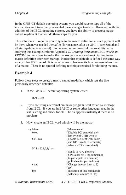
Chapter 4 Programming Examples
© National Instruments Corp. 4-7 GPIB-CT IBCL Reference Manual
In the GPIB-CT default operating system, you would have to type all of theinstructions each time that you wanted these changes to occur. However, with theaddition of the IBCL operating system, you have the ability to create a macrocalled mydefault that will do these steps for you.
This solution still requires you to type in the macro definition at startup, but it willbe there whenever needed thereafter (for instance, after an ONL 1 is executed andall startup defaults are reset). For an even more powerful macro ability, afterstudying this example, refer to Appendix C, Creating Permanent IBCL Words inEPROM , to learn how to make the macros permanent and avoid typing in eachmacro definition after each startup. Notice that mydefault is defined the same wayas any other IBCL word. It is called a macro because its function resembles thatof a macro. There is no special defining technique required for defining macros.
Example 4
Follow these steps to create a macro named mydefault which sets the fivepreviously described defaults:
1. In the GPIB-CT default operating system, enter:
ibcl<CR>
2. If you are using a terminal emulator program, wait for an ok messagefrom IBCL. If you are in BASIC or some other language, read in thestatus string and check for ok. The ok appears instantly if there is noproblem.
3. Now, create an IBCL word which will be the macro:
: mydefault ( Macro name)0 eot ( Disable EOI sent with the)
( last byte of GPIB writes)C0D eos ( Enable EOI sent with <CR>)
( and GPIB reads to terminate)( when a <CR> is received)
5 " im 223,0,1;" wrt( Sends to 7372 plotter at)( GPIB address 5 the command)( to participate in a parallel)( poll when it's pen is down)
c tmo ( Change timeout limit to 3)( sec)
bye ( Inclusion of this command)( will cause a return to the)

Programming Examples Chapter 4
GPIB-CT IBCL Reference Manual 4-8 © National Instruments Corp.
( GPIB-CT default operating)( system)( immediately upon completion)( of the macro. Leaving this)( statement out allows you to)( remain in IBCL after)( execution of the macro.)
; ( End the macro definition)
This example demonstrates only a fraction of the power available to you withIBCL and macros. After you have completed this example, you can typemydefault if you are operating in IBCL, or ibcl<CR> mydefault<CR> if you arein the GPIB-CT default operating system, to set these defaults.
Timed Applications Examples
Example 5
Within IBCL, you can access the on-board system timer to time activities.To do this, you must convert the required time limit into a 4-byte value thatthe timer can use and load those values into four specified memorylocations within IBCL.
To program any value, you may derive the values required for IBCL in thefollowing manner:
• The first number is the actual number of timer interrupts that willoccur before the routine completes. Valid values for this numberlie in the range of 1 to 65535.
• The second number is the length of time before a timer interruptwill occur. Valid values for this number lie in the range of 3 to65535. Each increment in the second number represents a time of3.26 µsec (0.0000326 sec). Therefore, the minimum value of timewhich can be generated is roughly 10 µsec (3, the minimum valueof the second number, times 3.26 µsec is roughly equal to 10 µsec).Incrementing the second number by 1 produces a timer value ofroughly 13 µsec (4, the minimum value of the second number, + 1* 3.26 µsec is roughly equal to 13 µsec).
A useful general formula is given here:
(VAL2 * 3.26 µsec) * VAL1 ≈ desired time value

Chapter 4 Programming Examples
© National Instruments Corp. 4-9 GPIB-CT IBCL Reference Manual
Example 6
Assume you have an application which requires servicing approximatelyevery 24 µsec Using the previous formula, VAL2 = 8 and VAL1 = 1produce the proper values for this application ((8 * 3 µsec) * 1 ≈ 24 µsec).
Example 7
Assume you have an application requiring service at approximately 48 µsecintervals. One way to produce this value is to let VAL1 = 2 ((8 * 3 µsec) *2 ≈ 48 µsec). However, this is not the most efficient solution because thetimer interrupt has to be serviced more often than necessary. A moreefficient method of achieving the same time limit is to change VAL2instead of VAL1 ((16 * 3 µsec) * 1 ≈ 48 µsec). Of course, when VAL2becomes larger than 65535, VAL1 will have to be adjusted to accommodatelonger times.
After you have these numbers (VAL1 and VAL2 comprise the necessary 4bytes for the timer), they have to be loaded into the memory locationsstarting at 1C hex using the IBCL command ! (pronounced store). In thisexample, the values used are from the 24 µsec given in Example 6.
First, store VAL1, the actual number of timer interrupts at memory location1C hex by typing:
1 1c !
Next, store VAL2, the time interval between interrupts, at memory location1E hex by typing:
8 1e !
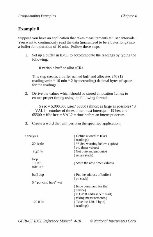
Programming Examples Chapter 4
GPIB-CT IBCL Reference Manual 4-10 © National Instruments Corp.
Example 8
Suppose you have an application that takes measurements at 5 sec intervals.You want to continuously read the data (guaranteed to be 2 bytes long) intoa buffer for a duration of 10 min. Follow these steps:
1. Set up a buffer in IBCL to accommodate the readings by typing thefollowing:
0 variable buff ee allot<CR>
This step creates a buffer named buff and allocates 240 (12readings/min * 10 min * 2 bytes/reading) decimal bytes of spacefor the readings.
2. Derive the values which should be stored at location 1c hex toensure proper timing using the following formula:
5 sec = 5,000,000 µsec/ 65500 (almost as large as possible) / 3= VAL1 = number of times timer must interrupt = 19 hex and65500 = ffdc hex = VAL2 = time before an interrupt occurs.
3. Create a word that will perform the specified application:
: analysis ( Define a word to take)( readings)
20 1c do ( ** See warning below-copies)( old timer values)
i c@ >r ( Get byte and put onto)( return stack)
loop19 1c ! ( Store the new timer values)ffdc 1e !
buff dup ( Put the address of buffer)( on stack)
5 " put cmd here" wrt( Issue command for the)( device)( at GPIB address 5 to start)( taking measurements.)
120 0 do ( Take the 120, 2 byte)( readings)

Chapter 4 Programming Examples
© National Instruments Corp. 4-11 GPIB-CT IBCL Reference Manual
dup 2+ swap ( Get next buffer location)( and leave old buffer)( location on top of stack)
5 swap 2 ( Put the GPIB address of)( device on the stack, swap)( with old buffer location,)( and put the number of)( characters to read {2} on)( top. This leaves the)( parameters required for a)( GPIB read on the stack--)( addr{5} buffer{old buffer})( and count {2})
4000 wait ( Wait the required 5 sec)rd ( Execute a GPIB read of 2)
( chars into the buffer)loop ( Start the loop again)4 0 do ( Get old timer values from)
( return stack and put them)r> ( on the computation )
loop ( stack)20 1c do ( Store the old values)
i c!loop
;
6. Type the following to execute the program:
analysis<CR>
Warning: Using this method of setting timeout limits will work and willremain in effect until changed again by this method or by thetmo command. However, if the >r and r> blocks of code areomitted from the previous example, the reporting of timeoutlimits in the GPIB-CT default operating system will beincorrect because the string holding the TMO value will not bechanged. So, although the string contains one value, the actualvalue in the timer routine will be your last value stored. Byusing the >r and r> blocks in the previous example, the stringreports the correct value as the values before you make anychanges will have been reset at the end of execution of thecode.

© National Instruments Corp. 5-1 GPIB-CT IBCL Reference Manual
Chapter 5Technical Information
This chapter contains information for improving and customizingperformance from the GPIB-CT.
Loading Programs
There are several ways in which you can load IBCL source code. SinceIBCL treats incoming source code as normal text, any method you have ofsending data over the serial port is an effective way to download sourcecode into IBCL.
The easiest way to communicate with the GPIB-CT is through a terminalemulation program. Using a terminal emulator is a preferred way ofcreating and debugging an application as you can see everything sent andreceived over the serial port at one time. If you are using a terminalemulation program, downloading source code is as easy as sending a textfile of the code over the serial port.
Another way you could download source code is through a programminglanguage which has access to the system's serial port. An example usingthis method is provided in Section Four, Programming Examples, MicrosoftBASIC IBCL Compiler Programming Example.
If you wish to make your code permanent in IBCL after downloading, seeAppendix C, Creating Permanent IBCL Words in EPROM, for instructions.
The IBCL Interpreters
IBCL has two interpreters–the inner interpreter, and the outer interpreter.The inner interpreter does nothing except branch from one machine coderoutine to the next. The nesting and unnesting routines supporting high-level IBCL definitions are among the code routines through whichexecution passes.
The outer interpreter accepts text from the host. It then attempts to parsethe text string as a sequence of IBCL words and numbers. In execute mode,words are executed and numbers are placed on the stack. In compile mode,words and numbers are entered into the definition of a new word.

Technical Information Chapter 5
GPIB-CT IBCL Reference Manual 5-2 © National Instruments Corp.
Inner Interpreter Sequence
If the definition list which the inner interpreter is interpreting consists of alist of pointers to simple machine code primitive instructions, such as stackand math words, execution proceeds from one word to the next in the list.A few special machine code primitives alter this orderly flow.
One of these diverting primitives, :, is compiled by (docol) which is anIBCL word to which users have no access. This primitive nests control to alower-level definition.
;s is the last pointer in a definition list. Its machine code primitive pops thetop element from the return stack and continues list interpretation at thataddress. This is the word from which control was originally diverted.
There are several other words which alter the sequential interpretation of adefinition list. (.") and (abort) are compiled by the immediate words, ." andabort. (.") controls display of the subsequent in-line string and causesinterpretation to skip to the word subsequent to that string, while (abort)could cause execution of a user-supplied routine in the event of an error. litcauses the next word value to be pushed onto the stack; interpretationcontinues after that value.
execute causes a branch to the word pointed to by the top value on the stack,just as if the pointer to that word's code field address had been in the listinstead of execute.
The remaining control-flow altering words handle the high-level flowcontrol within a single definition list. branch causes control to skip forwardor backward the number of words contained in the subsequent location.Obranch does so only if the top word on the data stack is zero. Otherwisecontrol continues with the word following the unneeded relative offset.
The do loop terminating words are similar in function and appearance toObranch. First, these words perform the additional task of updating anindex and comparing it to a limit. If the limit has exceeded bounds, controlis transferred as with branch. If the bound has not been exceeded,interpretation continues after the relative offset.

Chapter 5 Technical Information
© National Instruments Corp. 5-3 GPIB-CT IBCL Reference Manual
Outer Interpreter Sequence
Text is accepted one line at a time from the host. A line can be up to 80bytes long. The interpreter further breaks each line or block into individualwords and processes them sequentially. A word is a string of characterspreceded and followed by blank spaces or by a <CR>. A few words requiretext strings as following arguments and use a special delimiter such as quoteto end the string. Within these strings, blanks are not interpreted as wordseparators. These strings are processed by the preceding word rather thanby the interpreter.
One such special string is the comment which opens with an openingparenthesis ((). The interpreter ignores input after the ( word until the nextclosing parenthesis ()) or until the end of the current line. The initial ( is atrue IBCL word, but the closing ) is only a delimiter and need not bepreceded by a blank.
Once a word is extracted, an attempt is made to locate it in the dictionary.If it is found, its code field address is returned. In execution mode, thedefinition beginning at this address is executed, but when compiling ahigher-level word, the address is appended to the definition being createdunless it is an immediate word. These execute immediately–even within acolon definition.
If the word was not located, the interpreter assumes that it is a number andattempts to convert it to binary form. The value stored in base identifies thecurrent numerical base. The number may begin with a minus sign. If itcontains a decimal point, it is converted as a double length number.Otherwise, it must fit in a single byte-pair. When a single byte-pair numberis too large, high-order bits are lost. Double byte-pair numbers cannotoverflow, but the correct decimal point location must be determined fromthe user variable dpl.
The decimal point in the double numbers identifies them as double numbersbut does not affect the binary value generated. The two numbers 123. and1.23 produce the same binary value. The location of the decimal point isavailable in the user variable dpl, which is 0 and 2 for the previous numbers.dpl can be used by the application to scale numbers according to thelocation of the decimal point.

Technical Information Chapter 5
GPIB-CT IBCL Reference Manual 5-4 © National Instruments Corp.
In execution mode, the binary value is placed on the stack. For single byte-pair numbers in compilation mode, the code field address of lit (literal) isappended to the definition followed by the binary value. For double byte-pair numbers in compilation mode, the behavior is similar except that eachbyte-pair will be compiled separately, along with pointers to lit.
If the string cannot be converted, the interpreter aborts with an errormessage. The stacks are cleared and the rest of the line being interpreted isignored.
The interpreter uses -find to locate the potential word in the dictionary.Since the source string for -find is the next word in the input stream, thisalso advances the interpreter over the input text.
If the string is not a word, number is used to convert it to binary form.number compiles (number) which does the conversion. (number) expectsthe address of the source string's count byte on the stack. It replaces theaddress with the double word binary value converted using the current base.If conversion is not possible, (number) aborts with a ? MSG #0 error. Theuser variable dpl will contain -1 if no decimal point was present in thenumeric string. In this case, the number was of single word length and thetop word on the stack may be dropped. The interpreter ignores dpl exceptas a flag to drop the top word of single word entries.
When all words in the input stream have been executed, query is used toobtain more input and the entire cycle repeats.
Errors
When an error is encountered during interpretation, an error message isusually generated using abort. Execution of the run-time portion of thisword, (abort), clears the stacks and prints an error message. Control is thenreturned to the terminal to await the next line of input. See the discussionsDefining New Words , Colon Definitions, and IBCL Input, in Chapter 2,IBCL Function Reference .

Chapter 5 Technical Information
© National Instruments Corp. 5-5 GPIB-CT IBCL Reference Manual
Error-checking is performed by the following words:
• ?comp Error if not compiling
• ?csp Error if stack position is not that in csp
• ?pairs Error if top two stack elements unequal
• ?stack Error if stack out of bounds
Defining a new word increases the memory allocated in the dictionary. Ifan error causes the definition to abort before completion, memory allocatedin the dictionary is reclaimed.
Advanced Defining Techniques
Two actions must be specified when defining words. The first is done whenthe defining word is executed. The next is done when the word definedusing the defining word is executed. As an example, assume that thesystem does not provide the word defining constants. One way to definethis defining word is given here:
: constant <builds , does> @ ;
does> is an immediate word. It executes when the definition is entered.The @ is compiled as usual.
To define the constant five using this defining word, type this line:
5 constant five<CR>
The 5 is placed on the stack and momentarily ignored. Referring to thedefinition of constant, the <builds requires a word from the input stream. Ittakes the string five and adds it to the current vocabulary with a pointer tothe next free word in the definition list. This word is initialized with apointer to the code for constants, and the working end of the definition listis incremented by two to point to the parameter field of the word beingdefined, five. Next the comma (,) takes the top value on the stack, 5, andstores it at the working end of the definition list, the parameter field of five,and increments the end pointer by two.

Technical Information Chapter 5
GPIB-CT IBCL Reference Manual 5-6 © National Instruments Corp.
Next, the does> replaces the contents of the code field with a pointer to afew bytes of code created by does> each time it is used. This code has twofunctions. It nests the interpreter one level deeper, transferring control tothe word after does>, and it places the parameter field address of the wordbeing defined, five, on the stack. The code is executed only when five isexecuted. Finally, the @ is compiled and the ; causes a routine to becompiled that unnests the interpreter one level, and then terminates thedefinition.
When five is executed, the code created by does> is executed. The addressof the parameter field of five is placed on the stack and the interpreter nestsdown to the @ in the definition of constant. A 5 is waiting at the parameterfield address and is returned on the stack. The exit compiled by ; returns theinterpreter to the next higher level, with the 5 remaining on the stack. Or,stated simply, executing five causes 5 to be left on the stack.
For a slightly more complex case, consider a double length constant:
: dconstant <builds swap , ,does> dup @ swap 2+ @ ;
hex 1234.5678 dconstant longfellow
dconstant creates a double length constant named longfellow. Whenlongfellow executes, it leaves a double length number on the stack. First5678 is pushed onto the stack, then 1234.
The complexity and utility of words that define words is unlimited.
Machine Code Primitives
This discussion provides a simple means of entering machine codedefinitions for words which must execute rapidly or which require machineresources not immediately available in high-level IBCL.
The GPIB-CT contains a Hitachi HD64180 microprocessor which has aninstruction set that is a superset of the Z-80 instruction set. You should befamiliar with the Z-80 instruction set before attempting machine codeprimitives.

Chapter 5 Technical Information
© National Instruments Corp. 5-7 GPIB-CT IBCL Reference Manual
Three addresses very important to creating your own machine codeprimitives are dpush, hpush, and next. There are no given system constantsfor these addresses, although the fixed offsets from the origin are 6A hex fordpush, 6B hex for hpush, and 6C hex for next. To get the true address ofthese words, you can enter this line:
offset +origin u.
The 64180 has six general-purpose registers–B, C, D, E, F, G, H, and L.You can combine these six into three general-purpose 16-bit registers (BC,DE, and HL), an 8-bit accumulator, an 8-bit flag register (F), and two indexregisters (IX and IY). Along with these registers, the 64180 has an alternateregister set (HL', BC', DE', and AF').
dpush is used to push onto the stack the value stored in the DE register pair,and then push onto the stack the value stored in the HL register pair. hpushis used when you wish to push onto the stack only the value stored in theHL register pair. next is a routine which returns control to the IBCLoperating system after execution of the primitive. dpush and hpushautomatically execute next, but in all primitives which do not put anythingonto the stack with dpush or hpush, you will specifically need to jump tonext at the end of your primitive.
Warning: IBCL uses the value in register pair BC as its addresspointer; therefore, register pair BC should be used withextreme caution to prevent a system crash.
The following example, fastadd, demonstrates these topics. Notice that thisis how the + word is defined, so this example will not execute faster thanthe existing + operation.
Enter this sequence:
create fastadd ( Makes a dictionary )(entry for fastadd)
e1 c, ( pop hl)d1 c, ( pop de)19 c, ( add hl, de)c3 c, 6B c, 2 c, ( jp hpush)( see note about hpush following example)smudge ( Toggle the definition's)
( smudge kit to allow)( fastadd to be found in)( dictionary searches)

Technical Information Chapter 5
GPIB-CT IBCL Reference Manual 5-8 © National Instruments Corp.
Note : In the current version of the IBCL software, the code for hpush isat 026Bhex. This code is not guaranteed to remain in that locationin future software revisions. Before doing this step, you shouldfind out the address of hpush as detailed earlier in this section inthe discussion of +origin.
In the previous example, create makes a dictionary entry for fastadd andleaves the dictionary pointer at the code field of fastadd. c, then puts thebyte on the stack into the memory location pointed to by the dictionarypointer and increments the dictionary pointer. This process places themachine language sequence into the dictionary.
Vectored Execution
You cannot include a word in a definition if that word has not already beendefined. If the function you wish to perform cannot be defined before theword in which it is used, you must first define a variable that will eventuallycontain the code field address, or vector, of the word to be defined.
Consider the following example:
nnnn variable vector-name( creates a variable called vector-name, initialized to)( nnnn , although this value does not matter)
: some-word words vector-name @ execute words ;( defines some-word, which needs to use a currently)( undefined word)
: future-word words ;( define the future word)
future-word cfa vector-name !( put the code field of future-word into the vector)
some-word ( execute the complete word)
The vector name used in some-word compiles like any variable. Whenexecuted, it leaves its parameter field address on the stack and @ replacesthat address with the variable's contents. This variable was initialized onthe last line to contain the code field address of future-word. ' returns theparameter field address of the next word in the input stream and cfaconverts the parameter field address to the code field address. executeexecutes the word whose code field address is on the stack as if it had beencompiled into the definition.
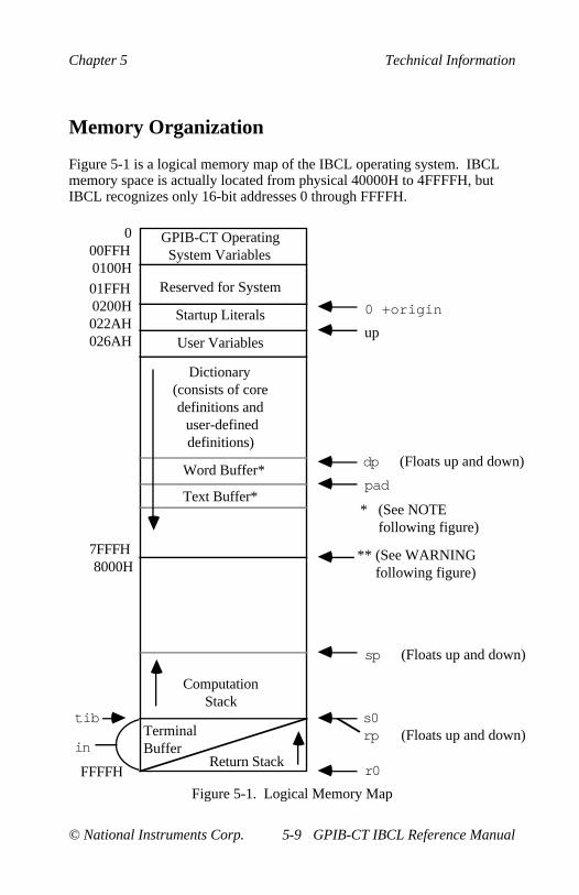
Chapter 5 Technical Information
© National Instruments Corp. 5-9 GPIB-CT IBCL Reference Manual
Memory Organization
Figure 5-1 is a logical memory map of the IBCL operating system. IBCLmemory space is actually located from physical 40000H to 4FFFFH, butIBCL recognizes only 16-bit addresses 0 through FFFFH.
GPIB-CT OperatingSystem Variables
000FFH0100H
Reserved for System01FFH0200H022AH026AH
Startup Literals
User Variables
Dictionary(consists of coredefinitions and
user-defined definitions)
Word Buffer*
Text Buffer*
Computation Stack
Terminal Buffer
Return Stackin
FFFFH
7FFFH8000H
0 +origin
up
dp
pad
sp
s0rp
r0
tib
**(See WARNINGfollowing figure)
*(See NOTEfollowing figure)
(Floats up and down)
(Floats up and down)
(Floats up and down)
Figure 5-1. Logical Memory Map

Technical Information Chapter 5
GPIB-CT IBCL Reference Manual 5-10 © National Instruments Corp.
Note: These buffers float immediately above the dictionary at a fixedoffset from the dictionary pointer.
Warning: After expanding the IBCL dictionary past logical address7FFFH, any definitions made are not guaranteed toremain if you leave IBCL to the GPIB-CT defaultoperating system, because the GPIB-CT default operatingsystem uses addresses starting at 8000H as a serial portinput buffer.
The operating system variables at the top of IBCL space are shared betweenthe GPIB-CT default and IBCL operating systems. This sharing ofresources ensures that any changes made to the characteristics of the GPIB-CT in either operating system are present in the other operating system aswell.
Logical space from 100H to lFFH is reserved for the system and shouldnever be changed.
Startup literals begin at the origin of IBCL, 200H. These values arenecessary for system initialization. Some literals specify values which arecopied to the user area of memory during initialization. Other literalsspecify the starting address of the user area, the ASCII code of theGPIB-CT's backspace character, and pointers to the top definition and theend of the core dictionary.
The user variables section contains the user variables dp, fence, r0, s0, tib,voc-link, warning, width, base, context, current, in, out, dpl, csp, hld, andstate. For more information on the user variables, refer to the discussionConstants, Variables, and Arrays , in Chapter 2, IBCL Function Reference .
The dictionary is the largest and most essential element of IBCL. This areacontains the definitions of all core and user-created words. The dictionaryarea expands in memory as new words are defined, and contracts whenword definitions are deleted. The user variable dp always contains theaddress of the next available dictionary location and floats as the dictionarygrows and shrinks.
The word buffer floats immediately above the top of the dictionary,beginning at the location stored in dp. The fixed length of the buffer is 68characters. As the dictionary expands and contracts, the limits of the wordbuffer move the same distance up or down in memory without retaining itscontents.

Chapter 5 Technical Information
© National Instruments Corp. 5-11 GPIB-CT IBCL Reference Manual
The text interpreter parses the input stream by obtaining individual wordsfrom the terminal input buffer and placing them into the word buffer.
The text buffer lies immediately above the word buffer a fixed distanceabove the dictionary. Like the word buffer, this area goes up or down inmemory in response to dictionary movements, without saving its contentsduring relocation. This buffer serves as a scratchpad area where output textstrings may be constructed character by character, or the IBCL word quote(") constructs the buffer for bwrt, wrt, or cmd. This buffer is the samelength as an output line that is stored in the system constant c/l and defaultsto 64 decimal bytes.
The terminal buffer and return stack share memory from address FFFFH toFF60H. As IBCL calls other words in a definition, the return stack growstowards low memory. As IBCL returns from each level of execution, thereturn stack shrinks towards high memory.
The terminal buffer begins at the value stored in tib and grows toward highmemory. This buffer holds each line of input data from the serial port. Assoon as a line is entered and processed, the buffer is reset for the next line.
The computation stack is the stack where parameters are stored. It is basedin s0, and grows towards low memory and the dictionary. sp contains thestack pointer at all times. The value in sp can be viewed and altered usingsp@ and sp!.
General Port I/O
IBCL provides two port input/output words, p! and p@, which change orrecall the internal parameters of the GPIB-CT. These words transfer databetween the top of the stack and any of the on-board GPIB-CT I/O ports. Innormal applications, these words should be used only in the followingcircumstances:
• To read the states of the user defined switch (U20)
• To set up the DMA controller for GPIB reads and writes toextended memory
All other port accesses should be done with extreme caution. Improper usecan cause the system to crash.

Technical Information Chapter 5
GPIB-CT IBCL Reference Manual 5-12 © National Instruments Corp.
p! outputs a byte to the I/O port address represented by the word on top ofthe stack. The byte to be output is in the low-order position of the secondword on the stack. The high-order byte of the second word is ignored.
p@ inputs a byte from the I/O port address represented by the word on thetop of the stack. The byte input replaces the I/O address on the top of thestack and the high-order bytes of the word is zero-filled.
Table 5-1 is an I/O system map of the ports supported on the GPIB-CT.Only the port addresses noted should be used. Any access to any otheraddresses could produce unexpected results.
Table 5-1. I/O System Map of Ports Supported on the GPIB-CT
Name AddressAsynchronous Serial Communication Interface (ASCI):
ASCI Control Register A, Channel 0 00HASCI Control Register A, Channel 1 01HASCI Control Register B, Channel 0 02HASCI Control Register B, Channel 1 03HASCI Status Register, Channel 0 04HASCI Status Register, Channel 1 05HASCI Transmit Data Register, Channel 0 06HASCI Transmit Data Register, Channel 1 07HASCI Receive Data Register, Channel 0 08HASCI Receive Data Register, Channel 1 09H
Programmable Reload Timer (PRT):PRT Data Register, Channel 0L 0CHPRT Data Register, Channel 0H 0DHReload Register, Channel 0L 0EHReload Register, Channel 0H 0FHTimer Control Register 10HPRT Data Register, Channel 1L 14HPRT Data Register, Channel 1H 15HReload Register, Channel 1L 16HReload Register, Channel 1H 17H
(continues)

Chapter 5 Technical Information
© National Instruments Corp. 5-13 GPIB-CT IBCL Reference Manual
Table 5-1. I/O System Map of Ports Supported on the GPIB-CT(continued)
Name AddressDirect Memory Access (DMA):
DMA Source Address Register, Channel 0L 20HDMA Source Address Register, Channel 0H 21HDMA Source Address Register, Channel 0B 22HDMA Destination Address Register, Chan. 0L 23HDMA Destination Address Register, Chan. 0H 24HDMA Destination Address Register, Chan. 0B 25HDMA Byte Count Register, Channel 0L 26HDMA Byte Count Register, Channel 0H 27HDMA Memory Address Register, Channel 1L 28HDMA Memory Address Register, Channel 1H 29HDMA Memory Address Register, Channel 1B 2AHDMA I/O Address Register, Channel 1L 2BHDMA I/O Address Register, Channel 1H 2CHDMA Byte Count Register, Channel 1L 2EHDMA Byte Count Register, Channel 1H 2FHDMA Status Register 30HDMA Mode Register 31HDMA/WAIT Control Register 32H
Interrupts:IL Register (Interrupt Vector Low Register) 33HINT/TRAP Control Register 34H
Dynamic RAM Refresh:Refresh Control Register 36H
Memory Management Unit (MMU):MMU Common Base Register 38HMMU Bank Base Register 39HMMU Common/Bank Area Register 3AHI/O Control Register 3FH
* See NOTE following table.GPIB Controller Read Only I/O Address Registers:
Data In Register 40HInterrupt Status Register 1 41HInterrupt Status Register 2 42HSerial Poll Status Register 43HAddress Status Register 44H
(continues)

Technical Information Chapter 5
GPIB-CT IBCL Reference Manual 5-14 © National Instruments Corp.
Table 5-1. I/O System Map of Ports Supported on the GPIB-CT(continued)
Name AddressGPIB Controller Read Only I/O Address Registers (continued):
Command Pass Through Register 45HAddress Register 0 46HAddress Register 1 47H
GPIB Controller Write Only I/O Address Registers:Command/Data Out Register 40HInterrupt Mask Register 1 41HInterrupt Mask Register 2 42HSerial Poll Mode Register 43HAddress Mode Register 44HAuxiliary Mode Register 45HAddress Register 0/1 46HEnd of String Register 47H
* See NOTE following table.GPIB Controller DMA Acknowledge Register:
DMA Acknowledge Register 48HBoard Registers:
Board Control Register (write only, 50Hcontrols front panel LEDs)
Switch 1 Register (read only, settings of 68HDIP Switch U20; use this registerto set your own switch configurations)
Switch 2 Register (read only, settings of 70HDIP Switch U22; this is used by theGPIB-CT operating system)
Note: I/O addresses in the range of 00H to 3FH are internal to themicroprocessor (HD64180). For specific information about whateach bit represents in each I/O register, refer to the HD64180 8-BitHigh Integration CMOS Microprocessor User Manual, availablefrom Hitachi America, Ltd.

Chapter 5 Technical Information
© National Instruments Corp. 5-15 GPIB-CT IBCL Reference Manual
I/O addresses in the range of 40H-47H are internal to the GPIB Controllerchip used in the GPIB-CT. For specific information about what each bitrepresents in each I/O register, refer to the section describing the µPD7210intelligent GPIB controller chip in NEC Microcomputer Products , availablefrom NEC Electronics, Inc. This description is used for interface productsthat contain the NAT4882 controller chip as well as interface products thatcontain the µPD7210 controller chip.
© National Instruments Corp. A-1 GPIB-CT IBCL Reference Manual
Appendix AMultiline Interface Messages
The following tables are multiline interface messages (sent and receivedwith ATN TRUE).
The subsequent pages contain an interface message reference list, whichdescribes the mnemonics and messages which correspond to the interfacefunctions.
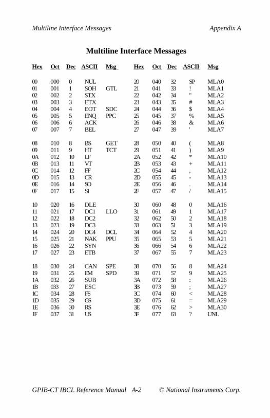
Multiline Interface Messages Appendix A
GPIB-CT IBCL Reference Manual A-2 © National Instruments Corp.
Multiline Interface Messages
Hex Oct Dec ASCII Msg Hex Oct Dec ASCII Msg
00 000 0 NUL 20 040 32 SP MLA001 001 1 SOH GTL 21 041 33 ! MLA102 002 2 STX 22 042 34 " MLA203 003 3 ETX 23 043 35 # MLA304 004 4 EOT SDC 24 044 36 $ MLA405 005 5 ENQ PPC 25 045 37 % MLA506 006 6 ACK 26 046 38 & MLA607 007 7 BEL 27 047 39 ' MLA7
08 010 8 BS GET 28 050 40 ( MLA809 011 9 HT TCT 29 051 41 ) MLA90A 012 10 LF 2A 052 42 * MLA100B 013 11 VT 2B 053 43 + MLA110C 014 12 FF 2C 054 44 , MLA120D 015 13 CR 2D 055 45 - MLA130E 016 14 SO 2E 056 46 . MLA140F 017 15 SI 2F 057 47 / MLA15
10 020 16 DLE 30 060 48 0 MLA1611 021 17 DC1 LLO 31 061 49 1 MLA1712 022 18 DC2 32 062 50 2 MLA1813 023 19 DC3 33 063 51 3 MLA1914 024 20 DC4 DCL 34 064 52 4 MLA2015 025 21 NAK PPU 35 065 53 5 MLA2116 026 22 SYN 36 066 54 6 MLA2217 027 23 ETB 37 067 55 7 MLA23
18 030 24 CAN SPE 38 070 56 8 MLA2419 031 25 EM SPD 39 071 57 9 MLA251A 032 26 SUB 3A 072 58 : MLA261B 033 27 ESC 3B 073 59 ; MLA271C 034 28 FS 3C 074 60 < MLA281D 035 29 GS 3D 075 61 = MLA291E 036 30 RS 3E 076 62 > MLA301F 037 31 US 3F 077 63 ? UNL

Appendix A Multiline Interface Messages
© National Instruments Corp. A-3 GPIB-CT IBCL Reference Manual
Multiline Interface Messages
Hex Oct Dec ASCII Msg Hex Oct Dec ASCII Msg
40 100 64 @ MTA0 60 140 96 ` MSA0,PPE41 101 65 A MTA1 61 141 97 a MSA1,PPE42 102 66 B MTA2 62 142 98 b MSA2,PPE43 103 67 C MTA3 63 143 99 c MSA3,PPE44 104 68 D MTA4 64 144 100 d MSA4,PPE45 105 69 E MTA5 65 145 101 e MSA5,PPE46 106 70 F MTA6 66 146 102 f MSA6,PPE47 107 71 G MTA7 67 147 103 g MSA7,PPE
48 110 72 H MTA8 68 150 104 h MSA8,PPE49 111 73 I MTA9 69 151 105 i MSA9,PPE4A 112 74 J MTA10 6A 152 106 j MSA10,PPE4B 113 75 K MTA11 6B 153 107 k MSA11,PPE4C 114 76 L MTA12 6C 154 108 l MSA12,PPE4D 115 77 M MTA13 6D 155 109 m MSA13,PPE4E 116 78 N MTA14 6E 156 110 n MSA14,PPE4F 117 79 O MTA15 6F 157 111 o MSA15,PPE
50 120 80 P MTA16 70 160 112 p MSA16,PPD51 121 81 Q MTA17 71 161 113 q MSA17,PPD52 122 82 R MTA18 72 162 114 r MSA18,PPD53 123 83 S MTA19 73 163 115 s MSA19,PPD54 124 84 T MTA20 74 164 116 t MSA20,PPD55 125 85 U MTA21 75 165 117 u MSA21,PPD56 126 86 V MTA22 76 166 118 v MSA22,PPD57 127 87 W MTA23 77 167 119 w MSA23,PPD
58 130 88 X MTA24 78 170 120 x MSA24,PPD59 131 89 Y MTA25 79 171 121 y MSA25,PPD5A 132 90 Z MTA26 7A 172 122 z MSA26,PPD5B 133 91 [ MTA27 7B 173 123 { MSA27,PPD5C 134 92 \ MTA28 7C 174 124 | MSA28,PPD5D 135 93 ] MTA29 7D 175 125 } MSA29,PPD5E 136 94 ^ MTA30 7E 176 126 ~ MSA30,PPD5F 137 95 _ UNT 7F 177 127 DEL

Multiline Interface Messages Appendix A
GPIB-CT IBCL Reference Manual A-4 © National Instruments Corp.
Interface Message Reference List
Mnemonic Message Interface Function(s)
LOCAL MESSAGES RECEIVED (by interface functions)
gts go to standby Cist individual status qualifier PPlon listen only L, LE[lpe] local poll enable PPltn listen L, LElun local unlisten L, LEnba new byte available SHpon power on SH, AH, T, TE, L, LE,
SR, RL, PP, Crdy ready AHrpp request parallel poll Crsc request system control Crsv request service SRrtl return to local RLsic send interface clear Csre send remote enable Ctca take control asynchronously Ctcs take control synchronously AH, Cton talk only T, TE
REMOTE MESSAGES RECEIVED
ATN attention SH, AH, T, TE, L, LE,PP, C
DAB data byte (via L, LE)DAC data accepted SHDAV data valid AHDCL device clear DCEND end (via L, LE)GET group execute trigger DTGTL go to local RLIDY identify L, LE, PPIFC interface clear T, TE, L, LE, CLLO local lockout RLMLA my listen address L, LE, RL[MLA] my listen address TMSA or [MSA] my secondary address TE, LEMTA my talk address T, TE[MTA] my talk address LOSA other secondary address TEOTA other talk address T, TEPCG primary command group TE, LE, PP
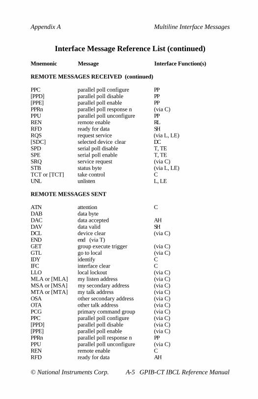
Appendix A Multiline Interface Messages
© National Instruments Corp. A-5 GPIB-CT IBCL Reference Manual
Interface Message Reference List (continued)
Mnemonic Message Interface Function(s)
REMOTE MESSAGES RECEIVED (continued)
PPC parallel poll configure PP[PPD] parallel poll disable PP[PPE] parallel poll enable PPPPRn parallel poll response n (via C)PPU parallel poll unconfigure PPREN remote enable RLRFD ready for data SHRQS request service (via L, LE)[SDC] selected device clear DCSPD serial poll disable T, TESPE serial poll enable T, TESRQ service request (via C)STB status byte (via L, LE)TCT or [TCT] take control CUNL unlisten L, LE
REMOTE MESSAGES SENT
ATN attention CDAB data byteDAC data accepted AHDAV data valid SHDCL device clear (via C)END end (via T)GET group execute trigger (via C)GTL go to local (via C)IDY identify CIFC interface clear CLLO local lockout (via C)MLA or [MLA] my listen address (via C)MSA or [MSA] my secondary address (via C)MTA or [MTA] my talk address (via C)OSA other secondary address (via C)OTA other talk address (via C)PCG primary command group (via C)PPC parallel poll configure (via C)[PPD] parallel poll disable (via C)[PPE] parallel poll enable (via C)PPRn parallel poll response n PPPPU parallel poll unconfigure (via C)REN remote enable CRFD ready for data AH

Multiline Interface Messages Appendix A
GPIB-CT IBCL Reference Manual A-6 © National Instruments Corp.
Interface Message Reference List (continued)
Mnemonic Message Interface Function(s)
REMOTE MESSAGES SENT (continued)
RQS request service T, TE[SDC] selec ted device clear (via C)SPD serial poll disable (via C)SPE serial poll enable (via C)SRQ service request SRSTB status byte (via T, TE)TCT take control (via C)UNL unlisten (via C)UNT untalk (via C)
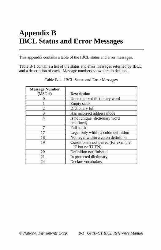
© National Instruments Corp. B-1 GPIB-CT IBCL Reference Manual
Appendix BIBCL Status and Error Messages
This appendix contains a table of the IBCL status and error messages.
Table B-1 contains a list of the status and error messages returned by IBCLand a description of each. Message numbers shown are in decimal.
Table B-1. IBCL Status and Error Messages
Message Number(MSG #) Description
0 Unrecognized dictionary word1 Empty stack2 Dictionary full3 Has incorrect address mode4 Is not unique (dictionary word
redefined)7 Full stack
17 Legal only within a colon definition18 Not legal within a colon definition19 Conditionals not paired (for example,
IF but no THEN)20 Definition not finished21 In protected dictionary24 Declare vocabulary

© National Instruments Corp. C-1 GPIB-CT IBCL Reference Manual
Appendix CCreating Permanent IBCL Words inEPROM
This appendix describes the procedure for permanently adding new wordsand data to the IBCL operating system. It will also explain how toautomatically run a permanently-saved application when the GPIB-CT ispowered-on.
All newly defined IBCL words are compiled and stored into the dictionarywhich is stored in the system's dynamic RAM. Since dynamic RAM isvolatile, its contents will be lost if power to the unit is removed.
Compiled words and data can be permanently added to the IBCL system byincluding them in an unused section of the system's EPROM. Then, eachtime the unit is powered on, the new IBCL system stored in the EPROMwill be copied to and run out of RAM.
To add additional code to the EPROM of the GPIB-CT you will need anEPROM programmer and software as well as a blank 27256 or 27C256EPROM with a maximum access time of 150 nsec. Do not reprogram theEPROM provided with the system. The system EPROM is like a masterdiskette–once it is copied it should be put aside for safekeeping. You mayonly copy the GPIB-CT system EPROM to add code to its dictionary,because the operating system within the EPROM is copyrighted.
Follow these steps to permanently save a new custom IBCL dictionary inEPROM:
1. Enter IBCL and create your extended dictionary. This can be doneseveral ways. The most common method uses colon definitions tocompile new words into the dictionary, and uses constant ,variable and allot to add data to the dictionary.
Make sure that your words are fully tested and debugged beforeattempting to put them in EPROM. It is much easier to make changeswhile you are running in RAM than to program another EPROM.

Creating Permanent IBCL Words in EPROM Appendix C
GPIB-CT IBCL Reference Manual C-2 © National Instruments Corp.
2. After you have compiled and debugged your code, you need to verifythat the extended dictionary will fit into the available EPROM space.A 27256 EPROM has 32K (8000 hex) bytes of storage.Approximately 11,520 (2D00 hex) bytes are taken up by the GPIB-CToperating system. This leaves 21,248 (5300 hex) bytes available forthe IBCL system and your extended words.
The IBCL operating system starts at 200 hex. Thus, if you enter thehex here 200 - u. command string and the value that isreturned is less than 5300, then the added code will fit into the 27256EPROM. If the value returned is greater than 5300, then the extendeddictionary exceeds the capacity of the EPROM. This probably meansthat you have allocated extremely large amounts of buffer space,because compiled IBCL code is very compact.
Here are some tips for reducing the amount of storage space requiredfor the dictionary due to buffer space:
• Be realistic when allocating space for buffers. Do not allocate1000 bytes of space if you only expect to use 100 bytes of thebuffer.
• If the buffer is uninitialized (there is no valid data in it prior toyour application being run), buffer space can be allocated withinRAM when your application is run rather than creating and storingthe buffer space in the EPROM. For instance, you could include aword in your application that would allocate space for a buffer justbefore the space was needed. In this way you would not beincreasing the dictionary size until your application has beencopied out of the EPROM and executed.
• If the buffer is uninitialized prior to your application, considerdefining the buffer space to be in extended RAM (see AppendixD). This can be done by defining a constant which is a pointer to abuffer area in extended RAM. Be careful not to allow buffers tooverwrite one another in extended space, as this space is free to beused, and no protection mechanism is implemented.

Appendix C Creating Permanent IBCL Words in EPROM
© National Instruments Corp. C-3 GPIB-CT IBCL Reference Manual
3. It is now necessary to change the boot-up literals which IBCL uses onstart-up to determine the size and placement of the dictionary. Thesenew values of the literals can be determined and stored in the start-uparea by the following code:
here 1e +origin !here 1c +origin !latest c +origin !
The first line is used to store the location of the end of the dictionary.Notice that only code and data added to the system through memorylocation here will be saved. Any code or data stored outside thedictionary will not be recognized and stored.
The second line is used to determine where the fence will be placed.This is not absolutely necessary, but is highly recommended so thatwords defined in the newly expanded dictionary will not beinadvertently forgotten.
The third line stores the name field address of the last word defined inyour extended dictionary. This tells IBCL where to begin itsdictionary searches.
If you want to auto-boot, that is, to start an application on power-up,you will also need to store the code field address of the word you wantto boot with in the boot-up area. This can be done by the followingcode:
hex ' name-of-power-on-word cfa 258 !
When the GPIB-CT is power-on, it will look at location 258 hex. If itfinds the code field address of a word, it will execute that word. Thisword will most likely consist of an infinite loop that will continuouslyrun an application, but it could consist of a word that will terminate.
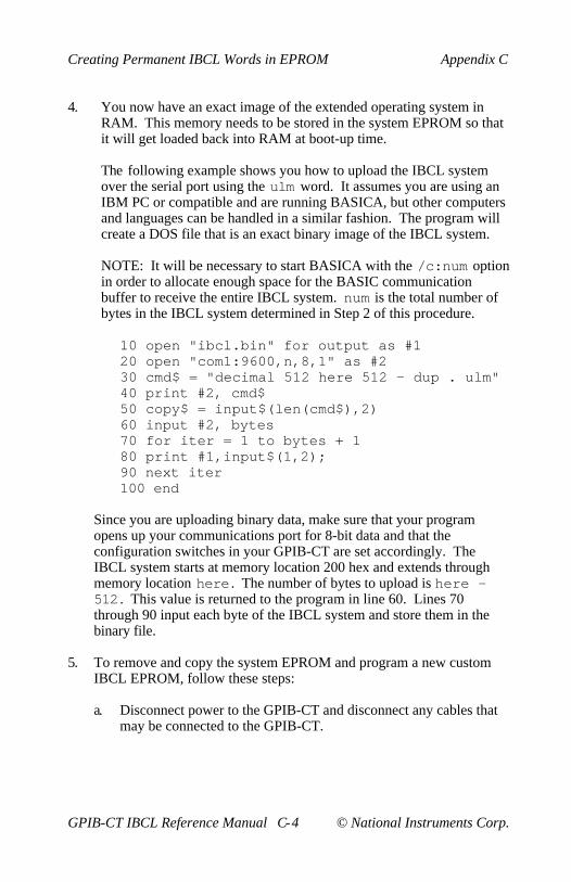
Creating Permanent IBCL Words in EPROM Appendix C
GPIB-CT IBCL Reference Manual C-4 © National Instruments Corp.
4. You now have an exact image of the extended operating system inRAM. This memory needs to be stored in the system EPROM so thatit will get loaded back into RAM at boot-up time.
The following example shows you how to upload the IBCL systemover the serial port using the ulm word. It assumes you are using anIBM PC or compatible and are running BASICA, but other computersand languages can be handled in a similar fashion. The program willcreate a DOS file that is an exact binary image of the IBCL system.
NOTE: It will be necessary to start BASICA with the /c:num optionin order to allocate enough space for the BASIC communicationbuffer to receive the entire IBCL system. num is the total number ofbytes in the IBCL system determined in Step 2 of this procedure.
10 open "ibcl.bin" for output as #120 open "com1:9600,n,8,1" as #230 cmd$ = "decimal 512 here 512 - dup . ulm"40 print #2, cmd$50 copy$ = input$(len(cmd$),2)60 input #2, bytes70 for iter = 1 to bytes + 180 print #1,input$(1,2);90 next iter100 end
Since you are uploading binary data, make sure that your programopens up your communications port for 8-bit data and that theconfiguration switches in your GPIB-CT are set accordingly. TheIBCL system starts at memory location 200 hex and extends throughmemory location here . The number of bytes to upload is here -512 . This value is returned to the program in line 60. Lines 70through 90 input each byte of the IBCL system and store them in thebinary file.
5. To remove and copy the system EPROM and program a new customIBCL EPROM, follow these steps:
a. Disconnect power to the GPIB-CT and disconnect any cables thatmay be connected to the GPIB-CT.

Appendix C Creating Permanent IBCL Words in EPROM
© National Instruments Corp. C-5 GPIB-CT IBCL Reference Manual
b. Unscrew the two screws on the opposite sides of the rear panel.
NOTE: Before attempting to change the system EPROM,remember that the system's EPROM, as well as most of thesystem's circuitry, uses CMOS technology and can be damaged bystatic electricity. Avoid touching the legs of components, and takeany necessary CMOS handling precautions before opening theunit.
c. Remove the rear panel bezel by pulling it straight away from therest of the unit. The board should slide out the back of theenclosure.
d. Locate and remove the system EPROM (U19). This can be donewith an IC extractor tool, or by carefully prying up on each end ofthe EPROM with a flat head screwdriver until it pops out of thesocket. Be careful not to bend any of the EPROM's legs whileremoving it.
e. Place the EPROM into your EPROM programmer and read itscontents into a buffer file. You must read at least from 0 to 2CFFhex, but you may read all of the contents.
f. Load the binary file ibcl.bin (created in Step 4 of thisprocedure) into the EPROM programmer's buffer starting ataddress 2D00 hex.
g. Place the blank EPROM in the programmer and program theEPROM from address 0 to 7FFF hex.
6. Carefully insert the newly programmed EPROM back into theGPIB-CT EPROM socket, insuring that pin 1 of the EPROM is alignedwith pin 1 of the socket. Also, make sure that all the EPROM legs arefirmly inserted into the socket and that none are bent underneath theEPROM.
7. Close the unit and reinsert the rear panel screws removed in Part b. ofStep 5.
8. Reconnect the power cord and power on the unit. Your new extendeddictionary has now become a permanent part of IBCL.
© National Instruments Corp. D-1 GPIB-CT IBCL Reference Manual
Appendix DUsing Extended Memory
This appendix describes the extended memory of the GPIB-CT, and givesguidelines for its use with IBCL.
About Extended Memory
The baseline GPIB-CT comes with 64K bytes of dynamic RAM. 32K bytesare used to store the IBCL system. The remaining 32K bytes are used bythe GPIB-CT default operating system as a serial input buffer, and by theIBCL operating system as stack space and free dictionary area.
If the GPIB-CT was ordered with 256K bytes of RAM, an additional 192Kbytes of memory is available for use by the IBCL system. This memory isreferred to as extended memory, and can be used to store data and compiledIBCL code. Extended memory is for storage purposes only–IBCL cannotrun outside of its 64K bytes logical address range.
Extended memory lies hidden from IBCL and is only accessible byreprogramming the onboard Memory Management Unit (MMU). Theactual programming of the MMU is rather complex, and is taken care ofautomatically by the extended access words. The MMU is used to form theupper address lines to map the logical 64K bytes address range of the GPIB-CT into the 512K bytes physical address space. The physical memory mapof the GPIB-CT is shown in Figure D-1.
Notice that although the IBCL operating system appears to be operating inmemory ranging from location 0 to FFFFH, it is actually operating fromphysical memory location 40000H to 4FFFFH. The MMU is loaded atpower-on with the values needed to form this offset. Extended RAM spacelies from physical locations 50000H to 7FFFFH.
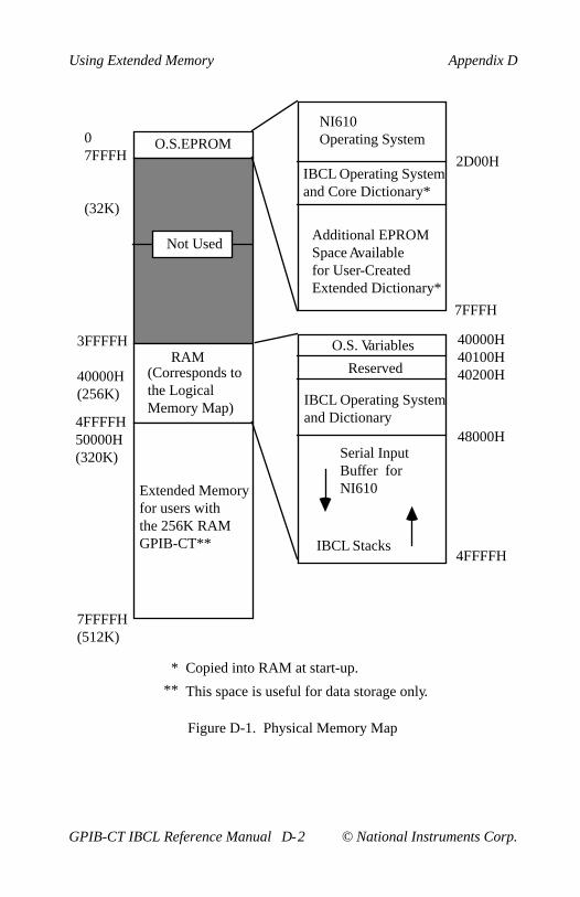
Using Extended Memory Appendix D
GPIB-CT IBCL Reference Manual D-2 © National Instruments Corp.
Not Used
O.S.EPROM
RAM(Corresponds to the Logical Memory Map)
Extended Memoryfor users withthe 256K RAMGPIB-CT**
This space is useful for data storage only.
NI610Operating System
IBCL Operating System and Core Dictionary*
Additional EPROMSpace Availablefor User-CreatedExtended Dictionary*
Copied into RAM at start-up.
O.S. Variables
Reserved
IBCL Operating Systemand Dictionary
Serial InputBuffer for NI610
IBCL Stacks
**
*
07FFFH
(32K)
3FFFFH
40000H(256K)
4FFFFH50000H(320K)
7FFFFH(512K)
2D00H
7FFFH
40000H40100H40200H
48000H
4FFFFH
Figure D-1. Physical Memory Map
Appendix D Using Extended Memory
© National Instruments Corp. D-3 GPIB-CT IBCL Reference Manual
There are four IBCL words that are used to move data between extendedmemory and the data stack. These words are l@ (long at), lc@ (longcharacter at), l! (long store), and lc! (long character store). These wordsprogram the MMU to allow access to any physical address space within thesystem. They also restore the MMU to its default condition after thememory access is complete, so that normal operation may continue.
All extended access words use a double number on the top of the stack torepresent the physical address of the memory address to be accessed. Forexample, to print the byte at physical memory location 65848H, you wouldenter this line:
hex 6.5848 lc@ .<CR>
The period between the 6 and the 5 forms a double number of the addresson the stack. Notice that only addresses through location 7FFFFH aresupported. If a larger double number is supplied the unused upper bits ofthe specified address will be truncated.
Although you could write to and retrieve any physical memory locationusing these long words, it is suggested that you use @, c@, !, and c! toaccess memory in the physical range of the IBCL system (40000H to4FFFFH). These words are slightly faster, as they do not require thereprogramming of the MMU.
You can also use extended memory as a buffer area for GPIB read and writeoperations. Both of these operations use the on-board DMA controller,which bypasses the MMU. This allows you to directly specify a startingaddress for a DMA transfer anywhere in physical memory.
The upper address register of the DMA controller supplies the upper fouraddress lines during a DMA transfer. This is why it is only necessary tospecify a 16-bit buffer address during GPIB read and write operations.Normally this register is programmed at power-on by the operating systemto always DMA data within the IBCL address range (40000H to 4FFFFH).
The DMA upper address register can be changed at any time to allow DMAtransfers to take place within the extended memory space. This register canbe changed by writing the new value of the upper 4 address bits to I/O portaddress 2AH.

Using Extended Memory Appendix D
GPIB-CT IBCL Reference Manual D-4 © National Instruments Corp.
For example, to read 8 bytes from GPIB device 3 to an extended memorybuffer starting at physical address 58000H, enter these lines:
5 2a p! ( change DMA address range to 50000H thru 5FFFFH )3 8000 8 rd ( read 8 bytes from device 3 into offset 8000 )4 2a p! ( restore DMA address range to IBCL space )
Notice that the last line restores the DMA controller upper address registerto its original default condition. This insures that any future DMAoperations will be performed in IBCL space. This step can be omitted ifyour next DMA operation is scheduled to use the same page in extendedmemory. The DMA upper address register as well as all data stored inextended memory remain the same until the unit is powered-down or thesevalues are overwritten, even if you return to the GPIB-CT default operatingsystem and later come back to IBCL.
To print the 8 bytes received from GPIB device 3 in the previous example,you can use the lc@ word as shown here:
: read_extended 8 0 do 5.8000 i s->d d+ lc@ . loop ;

© National Instruments Corp. E-1 GPIB-CT IBCL Reference Manual
Appendix EOther Useful IBCL Words
This appendix contains descriptions of IBCL words that are application-specific. The word description includes the purpose of the word, the kind ofparameters required for execution, and where the code expects anyincoming parameters. The fully commented programming examples thatfollow the descriptions create dictionary words. Use these programmingexamples to add these words to the IBCL dictionary.
dump
dump takes an address followed by a byte count as its arguments from thestack and displays the bytes in memory locations beginning with thememory address on the stack. Values are generated in hex and printableASCII characters are also generated. Characters that are not printable (0 to19 hex and 7F to FF hex) are displayed as a period. The byte count that isthe second argument is rounded up to an even 10 hex.
Programming Example
: dump ( Memory dump)base @ rot rot ( Store the current base)
( at bottom of stack)0 do ( Loop from 0 to the count)
( specified)cr dup hex ( Duplicate the address)
( and change output base)( to hex)
0 ( Zero fill upper 16 bits)( of double word)
<# # # # # # > type( Convert address and)( display it)
." .." ( Separate address from)( contents with this)( string.)
10 0 do ( Go from address through)( 10 addresses)

Other Useful IBCL Words Appendix E
GPIB-CT IBCL Reference Manual E-2 © National Instruments Corp.
dup c@ dup ( Get the byte at the)( address)
0 ( Zero fill upper 16 bits)( of double word)
<# 20 hold # # #> type( Display ASCII code)( of byte)
r> r> rot >r >r >r( Put copy of byte onto)( return stack)
1+ ( Increment address)loop10 0 do
r> r> r> rot rot >r >r( Bring the bytes from the)( return stack.)
loop5 spaces ( Insert 5 spaces into)
( output string)10 0 do
dup ( Duplicate byte)20 < ( Check if less than 20)
( hex-unprintable)if
drop 2e ( If unprintable, replace)( with a period)
thendup ( Duplicate byte)7e > ( Check if greater than 7e)
( hex-unprintable)if
drop 2e ( If unprintable, replace)( with a period)
thenemit ( Display the byte)
loop10 ( Increment address by 10)
( hex)+loopdrop cr ( Drop what would have)
( been the address of the)( next row of the dump)
base ! ( Restore base);

Appendix E Other Useful IBCL Words
© National Instruments Corp. E-3 GPIB-CT IBCL Reference Manual
ud.
ud. removes the top double length number from the stack and displays it asunsigned in the current base.
Programming Example
: ud. ( Unsigned double print)<# #s #> type ( Convert to a string and)
( type it out)space ( Insert a space in output)
( string);
depth
depth counts the number of words on the stack (prior to execution of theword) and leaves the count as the top value on the stack.
Programming Example
: depth ( Count the depth of the)( data stack)
s0 @ ( Put stack's origin)( address on stack)
sp@ ( Put current stack)( address on stack)
- ( Get {depth + 2}*2)2 - ( Compensate for length)
( being on stack)2 / ( Depth is distance)
( between address / 2);

Other Useful IBCL Words Appendix E
GPIB-CT IBCL Reference Manual E-4 © National Instruments Corp.
not
not performs the logical NOT of the value on the stack. This is an exampleof redefining an existing IBCL word with a more meaningful name (theIBCL word 0= performs the logical NOT).
Programming Example
: not ( Logical NOT function)0= ( 0= provides the)
( logical NOT operation in)( IBCL)
;
0>
0> checks if the word on the top of the stack has a value greater than zero.If it does, a TRUE flag is left on the stack. If it is not, a FALSE is left onthe stack.
Programming Example
: 0> ( Zero greater)-dup 0= ( Duplicate if not zero)
( the number to be checked)( then compare it to zero)
if ( If number tested was)( zero, put false flag on)( the stack)
0else
0< ( Determine whether number)( is < 0)
not ( Get the logical NOT of)( the flag)
then;

Appendix E Other Useful IBCL Words
© National Instruments Corp. E-5 GPIB-CT IBCL Reference Manual
binary
binary sets the I/O base to binary, in the same way that decimal and hex setthe I/O base to decimal and hexadecimal respectively.
Programming Example
: binary ( Set I/O base to 2)[ decimal ] 2 base !
( Store a 2 in the)( base user variable)
;
octal
octal sets the I/O base to binary, in the same way that decimal and hex setthe I/O base to decimal and hexadecimal respectively.
Programming Example
: octal ( Set I/O base to 8)[ decimal ] 8 base !
( Store an 8 in the base)( user variable)
;
msa
msa takes its arguments on the stack a primary address with a secondaryaddress on top. It formulates the single word necessary to use with anyGPIB word requiring a device address as a parameter. Use the word likethis:
23 ( primary) 67 ( secondary) msa caddr
or like this:
23 ( primary) 67 ( secondary) msa clr
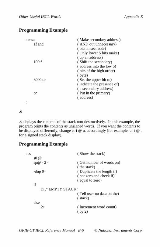
Other Useful IBCL Words Appendix E
GPIB-CT IBCL Reference Manual E-6 © National Instruments Corp.
Programming Example
: msa ( Make secondary address)1f and ( AND out unnecessary)
( bits in sec. addr)( Only lower 5 bits make)( up an address)
100 * ( Shift the secondary)( address into the low 5)( bits of the high order)( byte)
8000 or ( Set the upper bit to)( indicate the presence of)( a secondary address)
or ( Put in the primary)( address)
;
.s
.s displays the contents of the stack non-destructively. In this example, theprogram prints the contents as unsigned words. If you want the contents tobe displayed differently, change cr i @ u. accordingly (for example, cr i @ .for a signed stack display).
Programming Example
: .s ( Show the stack)s0 @sp@ - 2 - ( Get number of words on)
( the stack)-dup 0= ( Duplicate the length if)
( not zero and check if)( equal to zero)
ifcr ." EMPTY STACK"
( Tell user no data on the)( stack)
else2+ ( Increment word count)
( by 2)

Appendix E Other Useful IBCL Words
© National Instruments Corp. E-7 GPIB-CT IBCL Reference Manual
sp@ + ( Get do loop limit-this)( is the highest stack)( address plus 2)
sp@ 2+ do ( Get beginning address)cri ( Get current address)@ ( Get what's at that)
( address)u. ( Display the value)2
+loop ( Loop again-loop index)( now at next stack word)
then;
pick
pick takes as its parameter the top word on the stack. This word is treatedas an index into the stack. pick copies the value at that index onto the top ofthe stack. If the stack is not deep enough to have a corresponding value onit, no error message is printed, nothing is put on the stack, and the wordaborts, causing the stack to be reset.
Programming Example
: pick ( Pick the number from the)( stack and duplicate it)( on the top of the stack)
dup ( Duplicate top number -)( index into stack)
depth 2 - ( Get depth of stack - 2)( because of the extra)( count on top)
> ( Check if the requested)( element exists on the)( stack)
ifdrop ( Remove duplicate index)
( into stack)abort ( Stop executing)
else2 * ( Convert byte index to)
( word index)

Other Useful IBCL Words Appendix E
GPIB-CT IBCL Reference Manual E-8 © National Instruments Corp.
sp@ ( Get current stack)( location)
+ ( Get address of desired)( stack location)
@ ( Get value stored there)then
;
roll
roll takes as its parameter the top word on the stack. This word is treated asan index into the stack. roll puts the value at that index onto the top of thestack, removing it from its present location in the stack. If the stack is notdeep enough to have a corresponding value on it, no error message isprinted, nothing is put on the stack, and the word aborts, causing the stackto be reset.
Programming Example
: roll ( Put a value from the)( stack on top of stack)
dup ( Duplicate stack index)( of element wanted)
depth 1 - ( Get true depth-disregard)( the extra index)
> ( Check if stack is deep)( enough)
ifdrop ( Remove the extra index)abort ( Stop executing the word)
elsedup dup >r >r ( Duplicate index and)
( store on return stack)( twice)
pick ( Get a copy of the)( desired value)
r> ( Get one of the indexes)( from the return stack)( do loop limit)
0 dor> r> ( Bring the do loop cnt)
( and limit from the)( return stack)

Appendix E Other Useful IBCL Words
© National Instruments Corp. E-9 GPIB-CT IBCL Reference Manual
rot ( Put the value that was)( top value on stack)( before r> r> onto top)
r> ( Bring over last index)( from return stack)
swap ( Swap it with the value)( that was rotated up from)( the data stack)
>r >r >r >r ( Put all values on return)( stack-value from stack,)( index, do limit, do)( count)
loop ( Do this until we get to)( where the value is on)( the stack that we rolled)( up)
drop ( Remove that value)r> 0 do ( Get the index-do loop)
( limit)r> r> r> ( Bring over do limit, do)
( count and stack value)rot ( Put the do limit on top)rot ( Put the do count on top)>r >r ( Put these two back on)
( the return stack-leaving)( the data value on the)( data stack)
loopthen
;
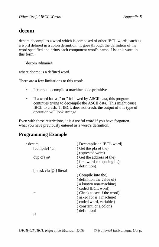
Other Useful IBCL Words Appendix E
GPIB-CT IBCL Reference Manual E-10 © National Instruments Corp.
decom
decom decompiles a word which is composed of other IBCL words, such asa word defined in a colon definition. It goes through the definition of theword specified and prints each component word's name. Use this word inthis form:
decom <dname>
where dname is a defined word.
There are a few limitations to this word:
• It cannot decompile a machine code primitive
• If a word has a ." or " followed by ASCII data, this programcontinues trying to decompile the ASCII data. This might causeIBCL to crash. If IBCL does not crash, the output of this type ofoperation will look strange.
Even with these restrictions, it is a useful word if you have forgottenwhat you have previously entered as a word's definition.
Programming Example
: decom ( Decompile an IBCL word)[compile] ' cr ( Get the pfa of the)
( requested word)dup cfa @ ( Get the address of the)
( first word composing its)( definition)
[ ' task cfa @ ] literal( Compile into the)( definition the value of)( a known non-machine)( coded IBCL word)
= ( Check to see if the word)( asked for is a machine)( coded word, variable,)( constant, or a colon)( definition)
if

Appendix E Other Useful IBCL Words
© National Instruments Corp. E-11 GPIB-CT IBCL Reference Manual
begin ( The word is composed of)( other IBCL words-NOT)( machine coded)
dup 2+ swap ( Get address of next)( component word and store)( at bottom of the stack)
@ ( Get the cfa of component)( word)
dup 2+ ( Convert to pfa of)( component word)
nfa ( Convert to nfa of)( component word)
id. cr ( Display the name of the)( word whose nfa is on the)( stack)
' ;s cfa ( Get the cfa of the word)( that has to complete a)( colon definition)
= until ( Keep decompiling until)( this word is reached)
drop ( Remove the address which)( was the next component)( word)( in the requested word's)( pfa list)
elsecr. "Machine Code Primitive"
( Display message)then
;
cls
cls clears the screen on many terminals by emitting an ASCII 1A hex(decimal 26), or <CTRL-z>, which clears many terminal screens.

Other Useful IBCL Words Appendix E
GPIB-CT IBCL Reference Manual E-12 © National Instruments Corp.
Programming Example
: cls ( Clear the terminal)( screen)
1a emit ( Ctrl-z character);
Redefining the Basic IBCL MathematicalOperators to Use Infix Notation
These five examples show how you can redefine the basic IBCLmathematical operators to use infix notation. These examples are verysimple. They work on only 2 operands, must have an = entered after eachexpression (for example, 3 + 4 = + 5 = . instead of 3 + 4 + 5 = . ), andexecute from left to right. Precedence rules are obeyed only if you enter theexpression in the correct order.
Programming Examples
Redefining =
: = ( Redefinition of IBCL =)rot execute ( Leaves on the stack the)
( result from the)( operation whose cfa is)( under the 2 operands)
;
Redefining +
: + ( Redefinition of IBCL +)[ ' + cfa ] literal swap
( Puts the cfa of the IBCL)( + on the stack and swaps)( it with the first)( operand)
;
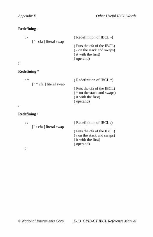
Appendix E Other Useful IBCL Words
© National Instruments Corp. E-13 GPIB-CT IBCL Reference Manual
Redefining -
: - ( Redefinition of IBCL -)[ ' - cfa ] literal swap
( Puts the cfa of the IBCL)( - on the stack and swaps)( it with the first)( operand)
;
Redefining *
: * ( Redefinition of IBCL *)[ ' * cfa ] literal swap
( Puts the cfa of the IBCL)( * on the stack and swaps)( it with the first)( operand)
;
Redefining /
: / ( Redefinition of IBCL /)[ ' / cfa ] literal swap
( Puts the cfa of the IBCL)( / on the stack and swaps)( it with the first)( operand)
;
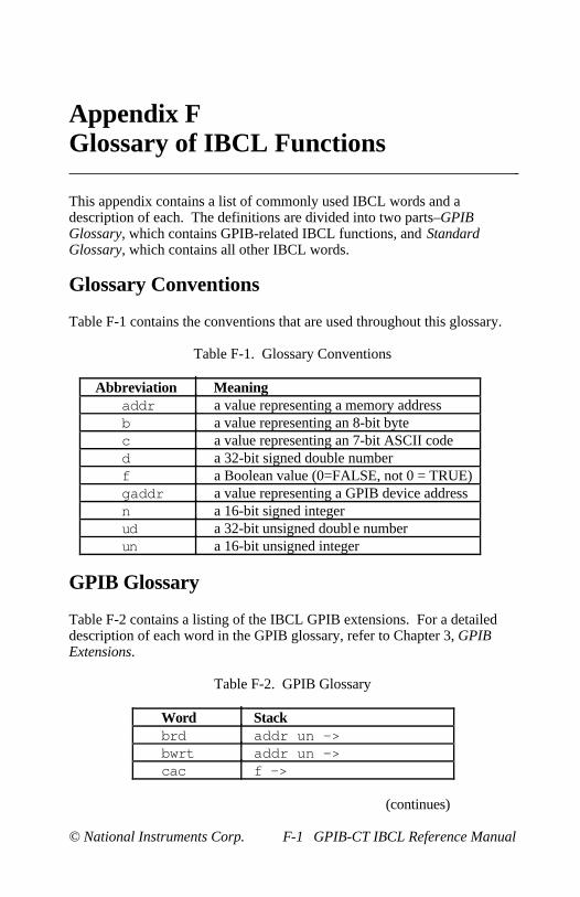
© National Instruments Corp. F-1 GPIB-CT IBCL Reference Manual
Appendix FGlossary of IBCL Functions
This appendix contains a list of commonly used IBCL words and adescription of each. The definitions are divided into two parts–GPIBGlossary, which contains GPIB-related IBCL functions, and StandardGlossary, which contains all other IBCL words.
Glossary Conventions
Table F-1 contains the conventions that are used throughout this glossary.
Table F-1. Glossary Conventions
Abbreviation Meaningaddr a value representing a memory addressb a value representing an 8-bit bytec a value representing an 7-bit ASCII coded a 32-bit signed double numberf a Boolean value (0=FALSE, not 0 = TRUE)gaddr a value representing a GPIB device addressn a 16-bit signed integerud a 32-bit unsigned double numberun a 16-bit unsigned integer
GPIB Glossary
Table F-2 contains a listing of the IBCL GPIB extensions. For a detaileddescription of each word in the GPIB glossary, refer to Chapter 3, GPIBExtensions.
Table F-2. GPIB Glossary
Word Stackbrd addr un —>bwrt addr un —>cac f —>
(continues)

Glossary of IBCL Words Appendix F
GPIB-CT IBCL Reference Manual F-2 © National Instruments Corp.
Table F-2. GPIB Glossary (continued)
Word Stackcaddr gaddr —>clr gaddr —>cmd addr un —>eos un —>eot f —>gts f —>ist f —>loc gaddronl f —>pct gaddr —>ppc gaddr b —>rd gaddr addr un —>rpp —> brsc f —>rsp gaddr —> nrsv b —>sicsre f —>stat —> un ntmo b —>trg gaddr —>wait un —>wrt gaddr addr un —>
Standard Glossary
All IBCL words other than the IBCL GPIB extensions are listed here.Because IBCL words can contain non-alphanumeric characters, the wordsin this glossary are arranged in the order that the characters appear in theASCII chart of Appendix A, Multiline Interface Messages :
!"#$%&'()*+,-./0123456789:;<=>?@abcdefghijklmnopqrstuvwxyz[\]
Word: !Stack: n addr —>Description: Store value n at address addr . Called "store."
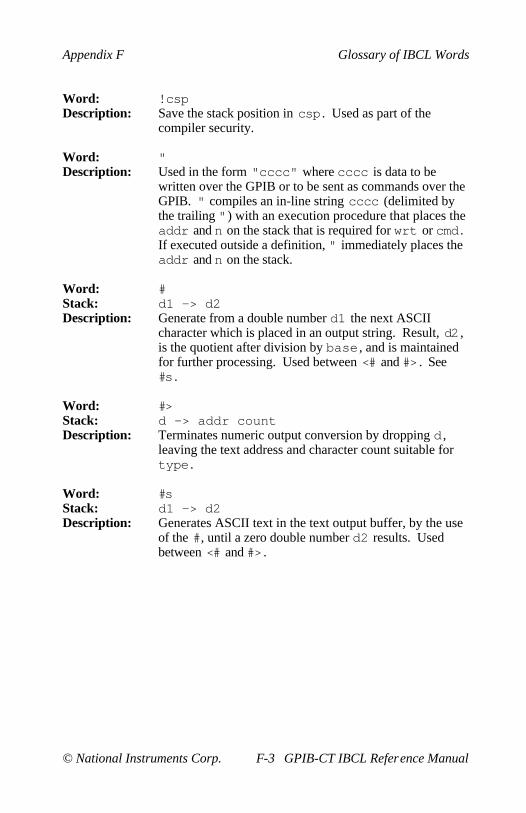
Appendix F Glossary of IBCL Words
© National Instruments Corp. F-3 GPIB-CT IBCL Reference Manual
Word: !cspDescription: Save the stack position in csp . Used as part of the
compiler security.
Word: "Description: Used in the form "cccc" where cccc is data to be
written over the GPIB or to be sent as commands over theGPIB. " compiles an in-line string cccc (delimited bythe trailing ") with an execution procedure that places theaddr and n on the stack that is required for wrt or cmd .If executed outside a definition, " immediately places theaddr and n on the stack.
Word: #Stack: d1 —> d2Description: Generate from a double number d1 the next ASCII
character which is placed in an output string. Result, d2 ,is the quotient after division by base , and is maintainedfor further processing. Used between <# and #> . See#s .
Word: #>Stack: d —> addr countDescription: Terminates numeric output conversion by dropping d ,
leaving the text address and character count suitable fortype .
Word: #sStack: d1 —> d2Description: Generates ASCII text in the text output buffer, by the use
of the #, until a zero double number d2 results. Usedbetween <# and #> .

Glossary of IBCL Words Appendix F
GPIB-CT IBCL Reference Manual F-4 © National Instruments Corp.
Word: 'Stack: —>Description: Used in the form:
' nnnn
Leaves the parameter field address of dictionary wordnnnn . As a compiler directive, executes in a colon-definition to compile the address as a literal. If the wordis not found after a search of context and current ,an appropriate error message is given. Called "tick."
Word: (Description: Used in the form:
( cccc )
Ignore a comment that will be delimited by a closeparenthesis on the same line. May occur during executionor in a colon-definition. A blank after the leadingparenthesis is required.
Word: (.")Description: The run-time procedure, compiled by ." , which transmits
the subsequent in-line text to the serial port. See ." .
Word: (+loop)Stack: n —>Description: The run-time procedure compiled by +loop , which
increments the loop index by n and tests for loopcompletion. See +loop .
Word: (abort)Description: Executes after an error when warning is -1. This word
normally executes abort , but may be changed (withcare) to a user's alternative procedure.
Word: (do)Description: The run-time procedure compiled by do which moves the
loop control parameters to the return stack. See do .
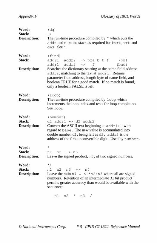
Appendix F Glossary of IBCL Words
© National Instruments Corp. F-5 GPIB-CT IBCL Reference Manual
Word: (dq)Stack: —>Description: The run-time procedure compiled by " which puts the
addr and n on the stack as required for bwrt , wrt andcmd . See ".
Word: (find)Stack: addr1 addr2 —> pfa b t f (ok)
addr1 addr2 —> f (bad)Description: Searches the dictionary starting at the name field address
addr2 , matching to the text at addr1 . Returnsparameter field address, length byte of name field, andboolean TRUE for a good match. If no match is found,only a boolean FALSE is left.
Word: (loop)Description: The run-time procedure compiled by loop which
increments the loop index and tests for loop completion.See loop .
Word: (number)Stack: d1 addr1 —> d2 addr2Description: Convert the ASCII text beginning at addr1+1 with
regard to base . The new value is accumulated intodouble number d1 , being left as d2 . addr2 is theaddress of the first unconvertible digit. Used by number .
Word: *Stack: n1 n2 —> n3Description: Leave the signed product, n3 , of two signed numbers.
Word: */Stack: n1 n2 n3 —> n4Description: Leave the ratio n4 = n1*n2/n3 where all are signed
numbers. Retention of an intermediate 31 bit productpermits greater accuracy than would be available with thesequence:
n1 n2 * n3 /

Glossary of IBCL Words Appendix F
GPIB-CT IBCL Reference Manual F-6 © National Instruments Corp.
Word: */modStack: n1 n2 n3 —> n4 n5Description: Leave the quotient n5 and remainder n4 of the operation
n1*n2/n3 . A 31 bit intermediate is used as for */ .
Word: +Stack: n1 n2 —> n3Description: Leave the sum n3 of n1+n2.
Word: +!Stack: n addr —>Description: Add n to the value at the address. Called "plus-store."
Word: +-Stack: n1 n2 —> n3Description: Leave n3 , with magnitude of n1 and sign of n1*n2 .
Word: +loopStack: n1 —> ( run )
addr n2 —> (compile)Description: Used in a colon-definition in the form:
do ... n1 +loop
At run-time, +loop selectively controls branching backto the corresponding do based on n1 , the loop index andthe loop limit. The signed increment n1 is added to theindex and the total compared to the limit. The branchback to do occurs until the new index is equal to orgreater than the limit (n1>0), or until the new index isequal to or less than the limit (n1<0). Upon exiting theloop, the parameters are discarded and executioncontinues ahead.
At compile time, +loop compiles the run-time word(+loop) and the branch offset computed from here tothe address left on the stack by do . n2 is used forcompile time error-checking.
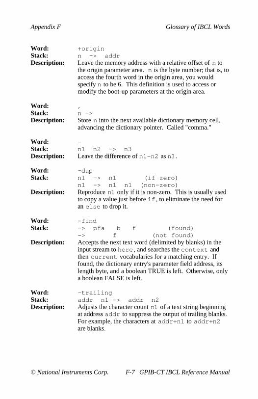
Appendix F Glossary of IBCL Words
© National Instruments Corp. F-7 GPIB-CT IBCL Reference Manual
Word: +originStack: n —> addrDescription: Leave the memory address with a relative offset of n to
the origin parameter area. n is the byte number; that is, toaccess the fourth word in the origin area, you wouldspecify n to be 6. This definition is used to access ormodify the boot-up parameters at the origin area.
Word: ,Stack: n —>Description: Store n into the next available dictionary memory cell,
advancing the dictionary pointer. Called "comma."
Word: -Stack: n1 n2 —> n3Description: Leave the difference of n1-n2 as n3 .
Word: -dupStack: n1 —> n1 (if zero)
n1 —> n1 n1 (non-zero)Description: Reproduce n1 only if it is non-zero. This is usually used
to copy a value just before if , to eliminate the need foran else to drop it.
Word: -findStack: —> pfa b f (found)
—> f (not found)Description: Accepts the next text word (delimited by blanks) in the
input stream to here , and searches the context andthen current vocabularies for a matching entry. Iffound, the dictionary entry's parameter field address, itslength byte, and a boolean TRUE is left. Otherwise, onlya boolean FALSE is left.
Word: -trailingStack: addr n1 —> addr n2Description: Adjusts the character count n1 of a text string beginning
at address addr to suppress the output of trailing blanks.For example, the characters at addr+n1 to addr+n2are blanks.
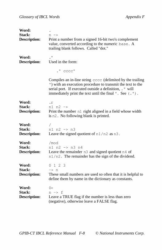
Glossary of IBCL Words Appendix F
GPIB-CT IBCL Reference Manual F-8 © National Instruments Corp.
Word: .Stack: n —>Description: Print a number from a signed 16-bit two's complement
value, converted according to the numeric base . Atrailing blank follows. Called "dot."
Word: ."Description: Used in the form:
." cccc"
Compiles an in-line string cccc (delimited by the trailing") with an execution procedure to transmit the text to theserial port. If executed outside a definition, ." willimmediately print the text until the final " . See (.") .
Word: .rStack: n1 n2 —>Description: Print the number n1 right aligned in a field whose width
is n2 . No following blank is printed.
Word: /Stack: n1 n2 —> n3Description: Leave the signed quotient of n1/n2 as n3 .
Word: /modStack: n1 n2 —> n3 n4Description: Leave the remainder n3 and signed quotient n4 of
n1/n2 . The remainder has the sign of the dividend.
Word: 0 1 2 3Stack: —> nDescription: These small numbers are used so often that it is helpful to
define them by name in the dictionary as constants.
Word: 0<Stack: n —> fDescription: Leave a TRUE flag if the number is less than zero
(negative), otherwise leave a FALSE flag.
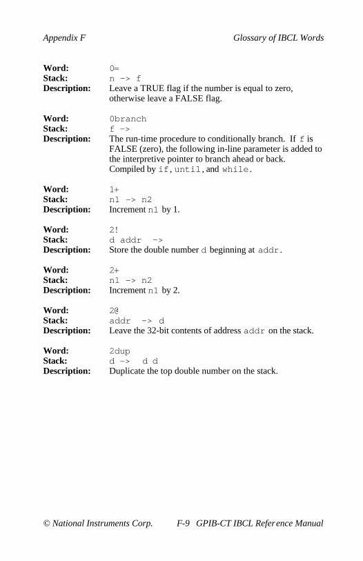
Appendix F Glossary of IBCL Words
© National Instruments Corp. F-9 GPIB-CT IBCL Reference Manual
Word: 0=Stack: n —> fDescription: Leave a TRUE flag if the number is equal to zero,
otherwise leave a FALSE flag.
Word: 0branchStack: f —>Description: The run-time procedure to conditionally branch. If f is
FALSE (zero), the following in-line parameter is added tothe interpretive pointer to branch ahead or back.Compiled by if , until , and while .
Word: 1+Stack: n1 —> n2Description: Increment n1 by 1.
Word: 2!Stack: d addr —>Description: Store the double number d beginning at addr .
Word: 2+Stack: n1 —> n2Description: Increment n1 by 2.
Word: 2@Stack: addr —> dDescription: Leave the 32-bit contents of address addr on the stack.
Word: 2dupStack: d —> d dDescription: Duplicate the top double number on the stack.

Glossary of IBCL Words Appendix F
GPIB-CT IBCL Reference Manual F-10 © National Instruments Corp.
Word: :Description: Used in the form called a colon-definition:
: cccc ... ;
Creates a dictionary entry defining cccc as equivalent tothe following sequence of IBCL word definitions '...'until the next ';' .
The compiling process is done by the text interpreter aslong as state is non-zero. Other details are that thecontext vocabulary is set to the current vocabularyand that words with the precedence bit set (seeimmediate) are executed rather than being compiled.
Word: ;Description: Terminate a colon-definition and stop further compilation.
Compiles the run-time word ;s .
Word: ;sDescription: ;s is the run-time word compiled at the end of a colon-
definition which returns execution to the callingprocedure.
Word: <Stack: n1 n2 —> fDescription: Leave a TRUE flag if n1 is less than n2 ; otherwise leave
a FALSE flag.
Word: <#Description: Setup for pictured numeric output formatting using the
words:
<# # #s sign #>
The conversion is done on a double number producingtext at pad .
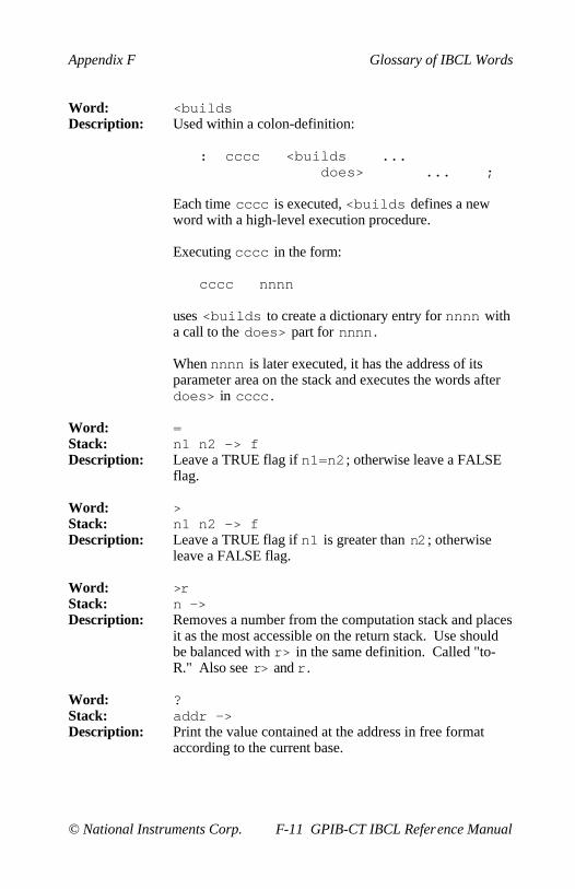
Appendix F Glossary of IBCL Words
© National Instruments Corp. F-11 GPIB-CT IBCL Reference Manual
Word: <buildsDescription: Used within a colon-definition:
: cccc <builds ... does> ... ;
Each time cccc is executed, <builds defines a newword with a high-level execution procedure.
Executing cccc in the form:
cccc nnnn
uses <builds to create a dictionary entry for nnnn witha call to the does> part for nnnn .
When nnnn is later executed, it has the address of itsparameter area on the stack and executes the words afterdoes> in cccc .
Word: =Stack: n1 n2 —> fDescription: Leave a TRUE flag if n1=n2 ; otherwise leave a FALSE
flag.
Word: >Stack: n1 n2 —> fDescription: Leave a TRUE flag if n1 is greater than n2 ; otherwise
leave a FALSE flag.
Word: >rStack: n —>Description: Removes a number from the computation stack and places
it as the most accessible on the return stack. Use shouldbe balanced with r> in the same definition. Called "to-R." Also see r> and r.
Word: ?Stack: addr —>Description: Print the value contained at the address in free format
according to the current base.

Glossary of IBCL Words Appendix F
GPIB-CT IBCL Reference Manual F-12 © National Instruments Corp.
Word: ?compDescription: Issue error message if not compiling.
Word: ?cspDescription: Issue error message if stack position differs from value
saved in csp .
Word: ?errorStack: f n —>Description: Issue an error message number n , if the boolean flag is
TRUE.
Word: ?execDescription: Issue an error message if not executing.
Word: ?pairsStack: n1 n2 —>Description: Issue an error message if n1 does not equal n2 . The
message indicates that compiled conditionals do notmatch.
Word: ?stackDescription: Issue an error message if the stack is out of bounds.
Word: ?terminalStack: —> fDescription: Perform a test of the serial port to see if a character has
been sent. A TRUE flag indicates that a character hasbeen sent.
Word: @Stack: addr —> nDescription: Leave the 16-bit contents of address addr on the stack.
Word: abortDescription: Clear both the computation stack and the return stack.
Return control to the operators terminal.
Word: absStack: n —> uDescription: Leave the absolute value of n as u.
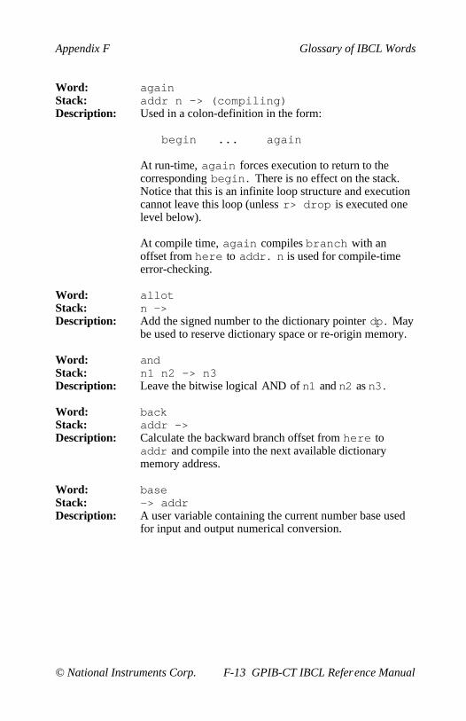
Appendix F Glossary of IBCL Words
© National Instruments Corp. F-13 GPIB-CT IBCL Reference Manual
Word: againStack: addr n —> (compiling)Description: Used in a colon-definition in the form:
begin ... again
At run-time, again forces execution to return to thecorresponding begin . There is no effect on the stack.Notice that this is an infinite loop structure and executioncannot leave this loop (unless r> drop is executed onelevel below).
At compile time, again compiles branch with anoffset from here to addr . n is used for compile-timeerror-checking.
Word: allotStack: n —>Description: Add the signed number to the dictionary pointer dp . May
be used to reserve dictionary space or re-origin memory.
Word: andStack: n1 n2 —> n3Description: Leave the bitwise logical AND of n1 and n2 as n3 .
Word: backStack: addr —>Description: Calculate the backward branch offset from here to
addr and compile into the next available dictionarymemory address.
Word: baseStack: —> addrDescription: A user variable containing the current number base used
for input and output numerical conversion.

Glossary of IBCL Words Appendix F
GPIB-CT IBCL Reference Manual F-14 © National Instruments Corp.
Word: beginStack: —> addr n (compiling)Description: Occurs in a colon-definition in the form:
begin ... untilbegin ... againbegin ... while ... repeat
At run-time, begin marks the start of a sequence thatmay be repetitively executed. It serves as a return pointfrom the corresponding until , again , or repeat .When executing until , a return to begin will occur ifthe top of the stack is FALSE. For again and repeat ,a return to begin always occurs.
At compile time begin leaves its return address and nfor compiler error-checking.
Word: blStack: —> cDescription: A constant that leaves the ASCII value for "blank."
Word: blanksStack: addr n —>Description: Fill an area of memory beginning at addr with blanks for
n bytes.
Word: branchDescription: The run-time procedure to unconditionally branch. An in-
line offset is added to the interpretive pointer to branchahead or back. branch is compiled by else , again ,repeat .
Word: byeDescription: Exit IBCL to the GPIB-CT default operating system.
Word: c!Stack: b addr —>Description: Store 8 bits at addr .

Appendix F Glossary of IBCL Words
© National Instruments Corp. F-15 GPIB-CT IBCL Reference Manual
Word: c,Stack: b —>Description: Store 8 bits of b into the next available dictionary byte,
advancing the dictionary pointer.
Word: c/lStack: —> nDescription: A constant leaving the number of characters per source
code screen line.
Word: c@Stack: addr —> bDescription: Leave the 8-bit contents of addr .
Word: cfaStack: addr1 —> addr2Description: Convert the parameter field address addr1 of a word to
its code field address addr2 .
Word: cmoveStack: addr1 addr2 n —>Description: Move n bytes beginning at address addr1 to address
addr2 . The contents of addr1 is moved first andproceeds toward high memory.
Word: coldDescription: The cold start procedure to adjust the dictionary pointer to
the minimum standard and restart via abort . May becalled to remove application programs and restart.
Word: compileDescription: When the word containing compile executes, the
execution address of the word following compile iscopied (compiled) into the dictionary. This allowsspecific compilation situations to be handled in additionto simply compiling an execution address (which theinterpreter already does).

Glossary of IBCL Words Appendix F
GPIB-CT IBCL Reference Manual F-16 © National Instruments Corp.
Word: constantStack: n —>Description: A defining word used in the form:
n constant cccc
to create word cccc , with its parameter field containingn. When cccc is later executed, it will push the value ofn onto the stack.
Word: contextStack: —> addrDescription: A user variable containing a pointer to the vocabulary
within which dictionary searches will first begin.
Word: countStack: addr1 —> addr2 nDescription: Leave the address addr2 and byte count n of text
beginning at address addr1 . It is presumed that the firstbyte at addr1 contains the text byte count and the actualtext starts with the second byte. Typically count isfollowed by type .
Word: crDescription: Transmit a carriage return and linefeed to the serial port.
Word: createDescription: A defining word used in the form:
create cccc
to create a dictionary header for an IBCL definition. Thecode field contains the address of the word's parameterfield. The new word is created in the currentvocabulary.
Word: cspStack: —> addrDescription: A user variable temporarily storing the stack pointer
position, for compilation error-checking.
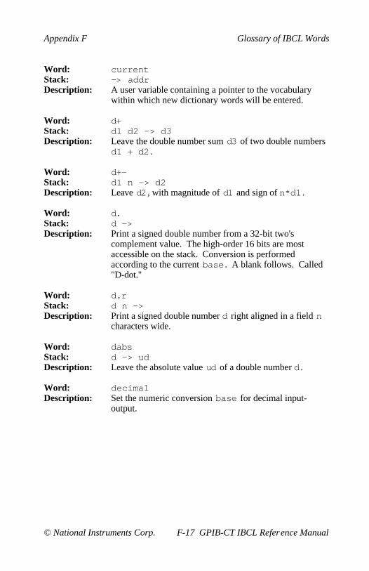
Appendix F Glossary of IBCL Words
© National Instruments Corp. F-17 GPIB-CT IBCL Reference Manual
Word: currentStack: —> addrDescription: A user variable containing a pointer to the vocabulary
within which new dictionary words will be entered.
Word: d+Stack: d1 d2 —> d3Description: Leave the double number sum d3 of two double numbers
d1 + d2 .
Word: d+-Stack: d1 n —> d2Description: Leave d2 , with magnitude of d1 and sign of n*d1 .
Word: d.Stack: d —>Description: Print a signed double number from a 32-bit two's
complement value. The high-order 16 bits are mostaccessible on the stack. Conversion is performedaccording to the current base . A blank follows. Called"D-dot."
Word: d.rStack: d n —>Description: Print a signed double number d right aligned in a field n
characters wide.
Word: dabsStack: d —> udDescription: Leave the absolute value ud of a double number d .
Word: decimalDescription: Set the numeric conversion base for decimal input-
output.

Glossary of IBCL Words Appendix F
GPIB-CT IBCL Reference Manual F-18 © National Instruments Corp.
Word: definitionsDescription: Used in the form:
cccc definitions
Set the current vocabulary to the contextvocabulary. In the example, executing vocabulary namecccc made it the context vocabulary and executingdefinitions made both specify vocabulary cccc .
Word: digitStack: c n1 —> n2 f (ok)
c n1 —> f (bad)Description: Converts the ASCII character c (using base n1) to its
binary equivalent n2 , accompanied by a TRUE flag. Ifthe conversion is invalid, leaves only a FALSE flag.
Word: dliteralStack: d —> d (executing)
d —> (compiling)Description: If compiling, compile a stack double number into a literal.
Later execution of the definition containing the literal willpush it to the stack. If executing, the number will remainon the stack.
Word: dlmStack: addr un —>Description: dlm is a binary input word. dlm downloads from the
host directly to the GPIB-CT memory un bytes starting ataddr .
Word: dminusStack: d1 —> d2Description: Convert d1 to its double number two's complement.
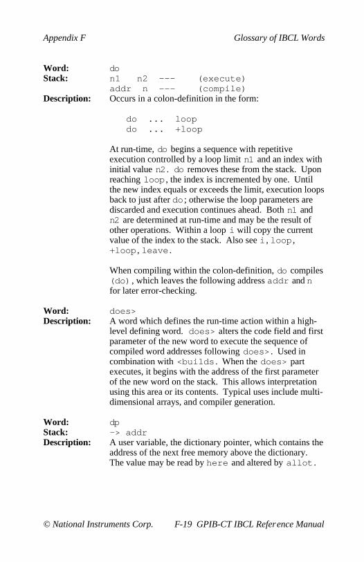
Appendix F Glossary of IBCL Words
© National Instruments Corp. F-19 GPIB-CT IBCL Reference Manual
Word: doStack: n1 n2 --- (execute)
addr n --- (compile)Description: Occurs in a colon-definition in the form:
do ... loopdo ... +loop
At run-time, do begins a sequence with repetitiveexecution controlled by a loop limit n1 and an index withinitial value n2 . do removes these from the stack. Uponreaching loop , the index is incremented by one. Untilthe new index equals or exceeds the limit, execution loopsback to just after do ; otherwise the loop parameters arediscarded and execution continues ahead. Both n1 andn2 are determined at run-time and may be the result ofother operations. Within a loop i will copy the currentvalue of the index to the stack. Also see i , loop ,+loop , leave .
When compiling within the colon-definition, do compiles(do) , which leaves the following address addr and nfor later error-checking.
Word: does>Description: A word which defines the run-time action within a high-
level defining word. does> alters the code field and firstparameter of the new word to execute the sequence ofcompiled word addresses following does> . Used incombination with <builds . When the does> partexecutes, it begins with the address of the first parameterof the new word on the stack. This allows interpretationusing this area or its contents. Typical uses include multi-dimensional arrays, and compiler generation.
Word: dpStack: —> addrDescription: A user variable, the dictionary pointer, which contains the
address of the next free memory above the dictionary.The value may be read by here and altered by allot .
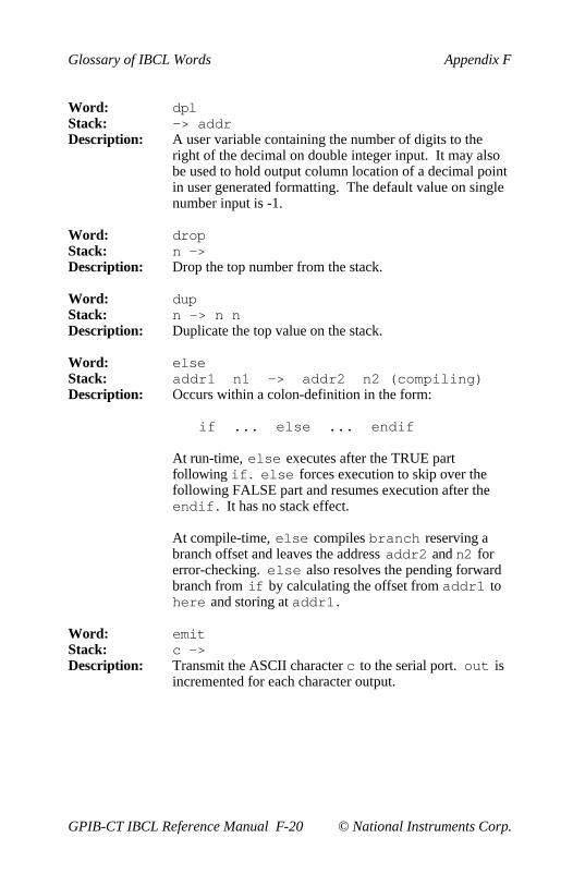
Glossary of IBCL Words Appendix F
GPIB-CT IBCL Reference Manual F-20 © National Instruments Corp.
Word: dplStack: —> addrDescription: A user variable containing the number of digits to the
right of the decimal on double integer input. It may alsobe used to hold output column location of a decimal pointin user generated formatting. The default value on singlenumber input is -1.
Word: dropStack: n —>Description: Drop the top number from the stack.
Word: dupStack: n —> n nDescription: Duplicate the top value on the stack.
Word: elseStack: addr1 n1 —> addr2 n2 (compiling)Description: Occurs within a colon-definition in the form:
if ... else ... endif
At run-time, else executes after the TRUE partfollowing if . else forces execution to skip over thefollowing FALSE part and resumes execution after theendif . It has no stack effect.
At compile-time, else compiles branch reserving abranch offset and leaves the address addr2 and n2 forerror-checking. else also resolves the pending forwardbranch from if by calculating the offset from addr1 tohere and storing at addr1 .
Word: emitStack: c —>Description: Transmit the ASCII character c to the serial port. out is
incremented for each character output.
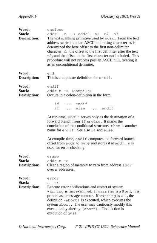
Appendix F Glossary of IBCL Words
© National Instruments Corp. F-21 GPIB-CT IBCL Reference Manual
Word: encloseStack: addr1 c —> addr1 n1 n2 n3Description: The text scanning primitive used by word . From the text
address addr1 and an ASCII delimiting character c, isdetermined the byte offset to the first non-delimitercharacter n1 , the offset to the first delimiter after the textn2 , and the offset to the first character not included. Thisprocedure will not process past an ASCII null, treating itas an unconditional delimiter.
Word: endDescription: This is a duplicate definition for until .
Word: endifStack: addr n —> (compile)Description: Occurs in a colon-definition in the form:
if ... endifif ... else ... endif
At run-time, endif serves only as the destination of aforward branch from if or else . It marks theconclusion of the conditional structure. then is anothername for endif . See also if and else .
At compile-time, endif computes the forward branchoffset from addr to here and stores it at addr . n isused for error-checking.
Word: eraseStack: addr n —>Description: Clear a region of memory to zero from address addr
over n addresses.
Word: errorStack: n —>Description: Execute error notifications and restart of system.
warning is first examined. If warning is a 0 or 1, n isprinted as a message number. If warning is a -1, thedefinition (abort) is executed, which executes thesystem abort . The user may cautiously modify thisexecution by altering (abort) . Final action isexecution of quit .
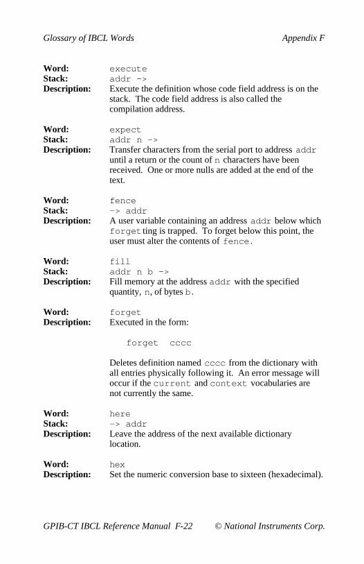
Glossary of IBCL Words Appendix F
GPIB-CT IBCL Reference Manual F-22 © National Instruments Corp.
Word: executeStack: addr —>Description: Execute the definition whose code field address is on the
stack. The code field address is also called thecompilation address.
Word: expectStack: addr n —>Description: Transfer characters from the serial port to address addr
until a return or the count of n characters have beenreceived. One or more nulls are added at the end of thetext.
Word: fenceStack: —> addrDescription: A user variable containing an address addr below which
forget ting is trapped. To forget below this point, theuser must alter the contents of fence .
Word: fillStack: addr n b —>Description: Fill memory at the address addr with the specified
quantity, n, of bytes b .
Word: forgetDescription: Executed in the form:
forget cccc
Deletes definition named cccc from the dictionary withall entries physically following it. An error message willoccur if the current and context vocabularies arenot currently the same.
Word: hereStack: —> addrDescription: Leave the address of the next available dictionary
location.
Word: hexDescription: Set the numeric conversion base to sixteen (hexadecimal).

Appendix F Glossary of IBCL Words
© National Instruments Corp. F-23 GPIB-CT IBCL Reference Manual
Word: hldStack: —> addrDescription: A user variable that holds the address of the latest
character of text during numeric output conversion.
Word: holdStack: c —>Description: Used between <# and #> to insert an ASCII character
into a pictured numeric output string. For example, 2Ehold will place a decimal point.
Word: iStack: —> nDescription: Used within a do-loop to copy the loop index to the
stack. Also see r.
Word: ibclDescription: The name of the primary vocabulary. Execution makes
ibcl the context vocabulary. Until additional uservocabularies are defined, new user definitions become apart of ibcl . ibcl is immediate, so it will executeduring the creation of a colon-definition to select thisvocabulary at compile time.
Word: id.Stack: addr —>Description: Print a definition's name from its name field address.
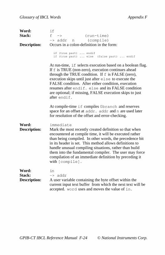
Glossary of IBCL Words Appendix F
GPIB-CT IBCL Reference Manual F-24 © National Instruments Corp.
Word: ifStack: f —> (run-time)
—> addr n (compile)Description: Occurs in a colon-definition in the form:
if (true part) ... endifif (true part) ... else (false part) ... endif
At run-time, if selects execution based on a boolean flag.If f is TRUE (non-zero), execution continues aheadthrough the TRUE condition. If f is FALSE (zero),execution skips until just after else to execute theFALSE condition. After either condition, executionresumes after endif . else and its FALSE conditionare optional; if missing, FALSE execution skips to justafter endif .
At compile-time if compiles 0branch and reservesspace for an offset at addr . addr and n are used laterfor resolution of the offset and error-checking.
Word: immediateDescription: Mark the most recently created definition so that when
encountered at compile time, it will be executed ratherthan being compiled. In other words, the precedence bitin its header is set. This method allows definitions tohandle unusual compiling situations, rather than buildthem into the fundamental compiler. The user may forcecompilation of an immediate definition by preceding itwith [compile] .
Word: inStack: —> addrDescription: A user variable containing the byte offset within the
current input text buffer from which the next text will beaccepted. word uses and moves the value of in .

Appendix F Glossary of IBCL Words
© National Instruments Corp. F-25 GPIB-CT IBCL Reference Manual
Word: interpretDescription: The outer text interpreter which sequentially executes or
compiles text from the serial port depending on state .If the word name cannot be found after a search of thecontext and then the current vocabulary, it isconverted to a number according to the current base. Thatalso failing, an error message echoing the name with a" ?" will be given. Text input will be taken according tothe convention for word . If a decimal point is found aspart of a number, a double number value will be left. Thedecimal point has no other purpose than to force thisaction. Also see number .
Word: keyStack: —> cDescription: Leave the ASCII value of the next serial character
received.
Word: l!Stack: n d —>Description: Stores value n at address specified by the double d .
Word: l@Stack: d —> nDescription: Leave the 16-bit contents of the memory addressed by d
on the stack.
Word: latestStack: —> addrDescription: Leave the name field address of the topmost word in the
current vocabulary.
Word: lc!Stack: b d —>Description: Store 8 bits of b at address specified by the double d .
Word: lc@Stack: d —> bDescription: Leave the 8-bit contents of the memory addressed by d on
the stack.
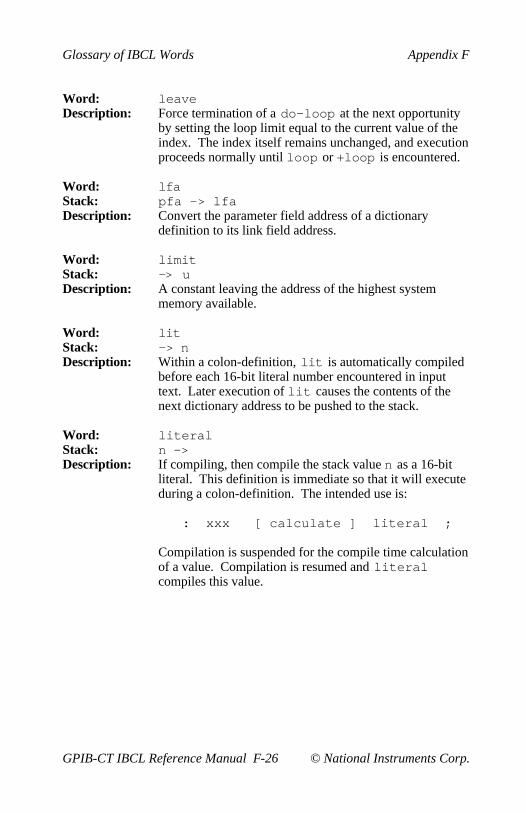
Glossary of IBCL Words Appendix F
GPIB-CT IBCL Reference Manual F-26 © National Instruments Corp.
Word: leaveDescription: Force termination of a do-loop at the next opportunity
by setting the loop limit equal to the current value of theindex. The index itself remains unchanged, and executionproceeds normally until loop or +loop is encountered.
Word: lfaStack: pfa —> lfaDescription: Convert the parameter field address of a dictionary
definition to its link field address.
Word: limitStack: —> uDescription: A constant leaving the address of the highest system
memory available.
Word: litStack: —> nDescription: Within a colon-definition, lit is automatically compiled
before each 16-bit literal number encountered in inputtext. Later execution of lit causes the contents of thenext dictionary address to be pushed to the stack.
Word: literalStack: n —>Description: If compiling, then compile the stack value n as a 16-bit
literal. This definition is immediate so that it will executeduring a colon-definition. The intended use is:
: xxx [ calculate ] literal ;
Compilation is suspended for the compile time calculationof a value. Compilation is resumed and literalcompiles this value.

Appendix F Glossary of IBCL Words
© National Instruments Corp. F-27 GPIB-CT IBCL Reference Manual
Word: loopStack: addr n —> (compiling)Description: Occurs in a colon-definition in the form:
do ... loop
At run-time, loop selectively controls branching back tothe corresponding do based on the loop index and limit.The loop index is incremented by one and compared tothe limit. The branch back to do occurs until the indexequals or exceeds the limit; at that time, the parametersare discarded and execution continues ahead.
At compile-time, loop compiles (loop) and usesaddr to calculate an offset to do . n is used for error-checking.
Word: m*Stack: n1 n2 —> dDescription: A mixed magnitude math operation which leaves the
signed double number product of two numbers.
Word: m/Stack: d n1 —> n2 n3Description: A mixed magnitude math operator which leaves the
signed remainder n2 and signed quotient n3 from adouble number dividend d and divisor n1 . Theremainder takes its sign from the dividend.
Word: m/modStack: ud1 u2 —> u3 ud4Description: An unsigned mixed magnitude math operation which
leaves a double quotient ud4 and remainder u3 from adouble dividend ud1 and single divisor u2 .
Word: maxStack: n1 n2 —> n3Description: Leave the greater of two numbers.

Glossary of IBCL Words Appendix F
GPIB-CT IBCL Reference Manual F-28 © National Instruments Corp.
Word: messageStack: n —>Description: Prints MSG# n . n may be positive or negative.
message could be used to alert a user of a condition,provided the user knows what each message numberrepresents.
Word: minStack: n1 n2 —> n3Description: Leave the smaller of two numbers.
Word: minusStack: n1 —> n2Description: Leave the two's complement of a number.
Word: modStack: n1 n2 —> n3Description: Leave the remainder of n1/n2 , with the same sign as n1 .
Word: nfaStack: pfa —> nfaDescription: Convert the parameter field address of a word to its name
field address.
Word: numberStack: addr —> dDescription: Convert a character string left at addr to a signed double
number using the current numeric base. The stringconsists of the characters for conversions preceded by a 1-byte count of characters to convert followed by a blank(hex 20). If a decimal point is encountered in the text, itsposition will be given in dp1 , with no other effect. If anumeric conversion is not possible, error message 0 willbe given.
Word: orStack: n1 n2 —> n3Description: Leave the bit-wise logical inclusive-OR of two 16-bit
values.
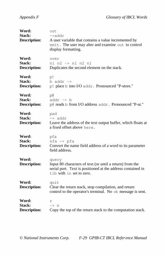
Appendix F Glossary of IBCL Words
© National Instruments Corp. F-29 GPIB-CT IBCL Reference Manual
Word: outStack: —>addrDescription: A user variable that contains a value incremented by
emit . The user may alter and examine out to controldisplay formatting.
Word: overStack: n1 n2 —> n1 n2 n1Description: Duplicates the second element on the stack.
Word: p!Stack: b addr —>Description: p! place b into I/O addr . Pronounced "P-store."
Word: p@Stack: addr —> bDescription: p@ reads b from I/O address addr . Pronounced "P-at."
Word: padStack: —> addrDescription: Leave the address of the text output buffer, which floats at
a fixed offset above here .
Word: pfaStack: nfa —> pfaDescription: Convert the name field address of a word to its parameter
field address.
Word: queryDescription: Input 80 characters of text (or until a return) from the
serial port. Text is positioned at the address contained intib with in set to zero.
Word: quitDescription: Clear the return stack, stop compilation, and return
control to the operator's terminal. No ok message is sent.
Word: rStack: —> nDescription: Copy the top of the return stack to the computation stack.

Glossary of IBCL Words Appendix F
GPIB-CT IBCL Reference Manual F-30 © National Instruments Corp.
Word: r>Stack: —> nDescription: Pops the top value from the return stack and pushes it
onto the computation stack. Called "R-from." Also see>r and r.
Word: r0Stack: —> addrDescription: A user variable containing the initial location of the return
stack. Called "R-zero." Also see rp!
Word: repeatStack: addr n —> (compiling)Description: Used within a colon-definition in the form:
begin ... while ... repeat
At run-time, repeat forces an unconditional branchback to just after the corresponding begin .
At compile-time, repeat compiles branch and theoffset from here to addr . n is used for error-checking.
Word: rotStack: n1 n2 n3 —> n2 n3 n1Description: Rotate the top three values on the stack, bringing the third
to the top.
Word: rp!Description: A procedure to initialize the return stack pointer from user
variable r0 . Extreme caution should be used with thisword.
Word: rp@Stack: —> addrDescription: A procedure that places the return stack pointer address
onto the stack.
Word: s->dStack: n —> dDescription: Sign extend a single number to form a double number.

Appendix F Glossary of IBCL Words
© National Instruments Corp. F-31 GPIB-CT IBCL Reference Manual
Word: s0Stack: —> addrDescription: A user variable that contains the initial value for the stack
pointer. Called "S-zero." Also see sp!
Word: signStack: n d —> dDescription: Stores an ASCII hyphen (-) just before a converted
numeric output string in the text output buffer when n isnegative. n is discarded, but double number d ismaintained. Must be used between <# and #> .
Word: smudgeDescription: Used during word definition to toggle the "smudge bit" in
a word's name field. This prevents an uncompleteddefinition from being found during dictionary searchesuntil compiling is completed without error.
Word: sp!Description: A procedure to initialize the stack pointer from s0 .
Word: sp@Stack: —> addrDescription: A procedure to return the address of the stack position to
the top of the stack, as it was before sp@ was executed.For example, the line 1 2 sp@ @ . . .would type 2 2 1).
Word: spaceDescription: Transmit an ASCII blank to the serial port.
Word: spacesStack: n —>Description: Transmit n ASCII blanks to the serial port.
Word: stateStack: —> addrDescription: A user variable containing the compilation state. A non-
zero value indicates compilation state. A zero valueindicates execution state.
Word: swapStack: n1 n2 —> n2 n1Description: Exchange the top two values on the stack.
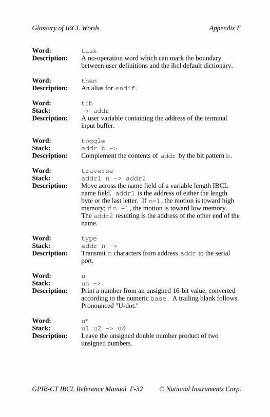
Glossary of IBCL Words Appendix F
GPIB-CT IBCL Reference Manual F-32 © National Instruments Corp.
Word: taskDescription: A no-operation word which can mark the boundary
between user definitions and the ibcl default dictionary.
Word: thenDescription: An alias for endif .
Word: tibStack: —> addrDescription: A user variable containing the address of the terminal
input buffer.
Word: toggleStack: addr b —>Description: Complement the contents of addr by the bit pattern b .
Word: traverseStack: addr1 n —> addr2Description: Move across the name field of a variable length IBCL
name field. addr1 is the address of either the lengthbyte or the last letter. If n=1 , the motion is toward highmemory; if n=-1 , the motion is toward low memory.The addr2 resulting is the address of the other end of thename.
Word: typeStack: addr n —>Description: Transmit n characters from address addr to the serial
port.
Word: uStack: un —>Description: Print a number from an unsigned 16-bit value, converted
according to the numeric base . A trailing blank follows.Pronounced "U-dot."
Word: u*Stack: u1 u2 —> udDescription: Leave the unsigned double number product of two
unsigned numbers.
Appendix F Glossary of IBCL Words
© National Instruments Corp. F-33 GPIB-CT IBCL Reference Manual
Word: u<Stack: u1 u2 —> fDescription: Leave a TRUE flag if u1 is less than u2 ; otherwise leave
a FALSE flag.
Word: u/Stack: ud u1 —> u2 u3Description: Leave the unsigned remainder u2 and unsigned quotient
u3 from the unsigned double dividend ud and unsigneddivisor u1 .
Word: ulmStack: addr un —>Description: ulm is a binary output word. ulm uploads from the
GPIB-CT to the host un bytes starting at addr .
Word: untilStack: f —> (run-time)
addr n —> (compile)Description: Occurs within a colon-definition in the form:
begin ... until
At run-time, until controls the conditional branch backto the corresponding begin . If f is FALSE, executionreturns to just after begin ; if TRUE, execution continuesahead.
At compile-time, until compiles (0branch) and anoffset from here to addr . n is used for error-checking.

Glossary of IBCL Words Appendix F
GPIB-CT IBCL Reference Manual F-34 © National Instruments Corp.
Word: userStack: n —>Description: A defining word used in the form:
n user cccc
which creates a user variable cccc . The parameter fieldof cccc contains n as a fixed offset relative to the userpointer register user-base for this user variable. Whencccc is later executed, it places the sum of its offset andthe user area base address on the stack as the storageaddress of that particular variable.
Word: variableDescription: A defining word used in the form:
n variable cccc
When variable is executed, it creates the definitioncccc with its parameter field initialized to n. Whencccc is later executed, the address of its parameter field(containing n) is left on the stack, so that a fetch or storemay access this location.
Word: voc-linkStack: —> addrDescription: A user variable containing the address of a field in the
definition of the most recently created vocabulary. Allvocabulary names are linked by these fields to allowcontrol for forget ting through multiple vocabularies.

Appendix F Glossary of IBCL Words
© National Instruments Corp. F-35 GPIB-CT IBCL Reference Manual
Word: vocabularyStack: —>Description: A defining word used in the form:
vocabulary cccc immediate
to create a vocabulary definition cccc . Subsequent useof cccc will make it the context vocabulary which issearched first by interpret . The sequence ccccdefinitions will also make cccc the currentvocabulary into which new definitions are placed.
cccc will be so chained as to include all definitions ofthe vocabulary in which cccc is itself defined. Allvocabularies ultimately chain to ibcl . By conventionvocabulary names are to be declared immediate . Alsosee voc-link .
Word: vlistStack: ->Description: List the names of the definitions in the context
vocabulary. Any serial character received will terminatethe listing.
Word: warmDescription: Similar to cold , except that the dictionary is not cleared.
Word: warningStack: —> addrDescription: A user variable containing a value controlling messages.
If warning is 0 or 1, messages are displayed by number.If warning is -1, execute (abort) for a user-specifiedprocedure. See message , error .

Glossary of IBCL Words Appendix F
GPIB-CT IBCL Reference Manual F-36 © National Instruments Corp.
Word: whileStack: f --- (run-time)
addr1 n1 --- addr1 n1 addr2 n2Description: Occurs in a colon-definition in the form:
begin ... while (true part) ... repeat
At run-time, while selects conditional execution basedon boolean flag f. If f is TRUE (non-zero), whilecontinues execution of the TRUE part through torepeat , which then branches back to begin . If f isFALSE (zero), execution skips to just after repeat ,exiting the structure.
At compile-time, while emplaces (0branch) andleaves addr2 of the reserved offset. The stack valueswill be resolved by repeat .
Word: widthStack: —> addrDescription: A user variable containing the maximum number of
characters saved in the compilation of a definition's name.It must be 1 through 31, with a default value of 31. Thename character count and its natural characters are saved,up to the value in width . The value may be changed atany time within the above limits.
Word: wordStack: c —>Description: Read the next text characters from the input stream being
interpreted until a delimiter c is found, storing the packedcharacter string beginning at the dictionary buffer here .word leaves the character count in the first byte, thecharacters, and ends with two or more blanks. Leadingoccurrences of c are ignored.
Word: xorStack: n1 n2 —> n3Description: Leave the bitwise logical exclusive-OR of two values.

Appendix F Glossary of IBCL Words
© National Instruments Corp. F-37 GPIB-CT IBCL Reference Manual
Word: [Description: Used in a colon-definition in the form:
: xxx [ words ] more words ;
Suspend compilation. The words after [ are executed, notcompiled. This allows calculation or compilationexceptions before resuming compilation with ]. Also seeliteral and ].
Word: [compile]Description: Used in a colon-definition in the form:
: xxx [compile] cccc ;
[compile] will force the compilation of the immediateword cccc that would otherwise execute duringcompilation.
Word: ]Description: Resume compilation, to the completion of a colon-
definition. Also see [ .

© National Instruments Corp. G-1 GPIB-CT IBCL Reference Manual
Appendix GCustomer Communication
For your convenience, this appendix contains forms to help you gather theinformation necessary to help us solve technical problems you might haveas well as a form you can use to comment on the product documentation.Filling out a copy of the Technical Support Form before contactingNational Instruments helps us help you better and faster.
National Instruments provides comprehensive technical assistance aroundthe world. In the U.S. and Canada, applications engineers are availableMonday through Friday from 8:00 a.m. to 6:00 p.m. (central time). In othercountries, contact the nearest branch office. You may fax questions to us atany time.
Corporate Headquarters(512) 795-8248Technical Support fax: (512) 794-5678
Branch Offices Phone Number Fax NumberAustralia 03 879 9422 03 879 9179Austria 0662 435986 0662 437010 19Belgium 02 757 00 20 02 757 03 11Denmark 45 76 26 00 45 76 71 11Finland 90 527 2321 90 502 2930France 1 48 65 33 00 1 48 65 19 07Germany 089 7 14 50 93 089 7 14 60 35Italy 02 48301892 02 48301915Japan 03 3788 1921 03 3788 1923Netherlands 01720 45761 01720 42140Norway 03 846866 03 846860Spain 91 640 0085 91 640 0533Sweden 08 730 49 70 08 730 43 70Switzerland 056 27 00 20 056 27 00 25U.K. 0635 523545 0635 523154
or 0800 289877 (in U.K. only)

Technical Support Form
Photocopy this form and update it each time you make changes to yoursoftware or hardware, and use the completed copy of this form as areference for your current configuration. Completing this form accuratelybefore contacting National Instruments for technical support helps ourapplications engineers answer your questions more efficiently.
If you are using any National Instruments hardware or software productsrelated to this problem, include the configuration forms from their usermanuals. Include additional pages if necessary.
Name
Company
Address
Fax ( ) Phone ( )
Computer brand
Model Processor
Operating system
Speed MHz RAM M
Display adapter
Mouse yes no
Other adapters installed
Hard disk capacity M Brand
Instruments used
National Instruments hardware product model
Revision
Configuration
(continues)

National Instruments software product
Version
Configuration
The problem is
List any error messages
The following steps will reproduce the problem

Documentation Comment Form
National Instruments encourages you to comment on the documentationsupplied with our products. This information helps us provide qualityproducts to meet your needs.
Title: GPIB-CT IBCL Reference Manual
Edition Date: December 1993
Part Number: 320132-01
Please comment on the completeness, clarity, and organization of themanual.
(continues)

If you find errors in the manual, please record the page numbers anddescribe the errors.
Thank you for your help.
Name
Title
Company
Address
Phone ( )
Mail to: Technical PublicationsNational Instruments Corporation6504 Bridge Point Parkway, MS 53-02Austin, TX 78730-5039
Fax to: Technical PublicationsNational Instruments CorporationMS 53-02(512) 794-5678

© National Instruments Corp. Glossary-1 GPIB-CT IBCL Reference Manual
Glossary
Prefix Meaning Value
m-µ-n-
milli-micro-nano-
10-3
10-6
10-9
EPROM erasable programmable read-only memory
hex hexadecimal
in. inches
K 1,024 bytes (of memory)
M megabytes of memory
sec seconds