Archaeological Investigations of the Japanese Light Wreck, Saipan, CNMI
63
Archaeological Investigations of the Japanese Channel Light Wreck Jennifer F. McKinnon, Sarah Nahabedian, and Jason T. Raupp 2011 Flinders University Program in Maritime Archaeology Report Series Number 2
Transcript of Archaeological Investigations of the Japanese Light Wreck, Saipan, CNMI

Archaeological Investigations of the
Japanese Channel Light Wreck
Jennifer F. McKinnon, Sarah Nahabedian, and Jason T. Raupp
2011
Flinders University Program in Maritime Archaeology
Report Series Number 2

ii
Contents Figures................................................................................................................................ iv
Tables .................................................................................................................................. v Acknowledgements ............................................................................................................. 1 Technical Data .................................................................................................................... 2 Project Background ............................................................................................................. 3 Saipan Maritime Historical Context ................................................................................... 4
Previous Investigations of Saipan’s Submerged Sites ........................................................ 6 Fieldwork ............................................................................................................................ 7
Site Conditions on Assessment ....................................................................................... 7 General Description of Site ............................................................................................. 7 Survey, Recording and Samples ................................................................................... 11
Baseline Offset, Trilateration and Triangulation Survey .......................................... 11 Hand Fanning ............................................................................................................ 12
Photography .............................................................................................................. 13 Timber Sample .......................................................................................................... 13
Site Components and Artifacts ......................................................................................... 13 Ship’s Rigging .............................................................................................................. 14
Wire Rigging ............................................................................................................. 14 Deadeye..................................................................................................................... 17 Mast band .................................................................................................................. 18
UID Iron Object ........................................................................................................ 20 UID Iron Ring ........................................................................................................... 21
UID Copper-alloy Band ............................................................................................ 21
Ballast ........................................................................................................................... 22
Ship’s fittings ................................................................................................................ 24 Copper-alloy Tacks ................................................................................................... 24
Iron Pins or Bolts ...................................................................................................... 25 Copper-alloy Fastener ............................................................................................... 26 Copper-alloy fastener with Rove .............................................................................. 27
Copper-alloy Sheathing ............................................................................................ 27 Glass and Ceramics ....................................................................................................... 29
Bottles ....................................................................................................................... 29 Stoneware .................................................................................................................. 33 Porcelain ................................................................................................................... 33
Timber ........................................................................................................................... 34 Conglomerate ............................................................................................................ 34
Miscellaneous ............................................................................................................... 36 Possible Draught Number ......................................................................................... 36
Oarlock ...................................................................................................................... 38 UID Iron Object ........................................................................................................ 39
Site Interpretation.............................................................................................................. 39 Possible Historic Identification ......................................................................................... 40
William T. Sayward ...................................................................................................... 41 Lizzie Jarvis .................................................................................................................. 41 Unknown Barque .......................................................................................................... 41

iii
Iolanthe ......................................................................................................................... 41
Research and Management Considerations ...................................................................... 42 Conclusion ........................................................................................................................ 43 References ......................................................................................................................... 44
Appendices ........................................................................................................................ 49 Appendix A ................................................................................................................... 50 Appendix B ................................................................................................................... 53 Appendix C ................................................................................................................... 56

iv
Figures Figure 1. Ballast stone and fasteners found on the site during the 2010 investigations. .... 4
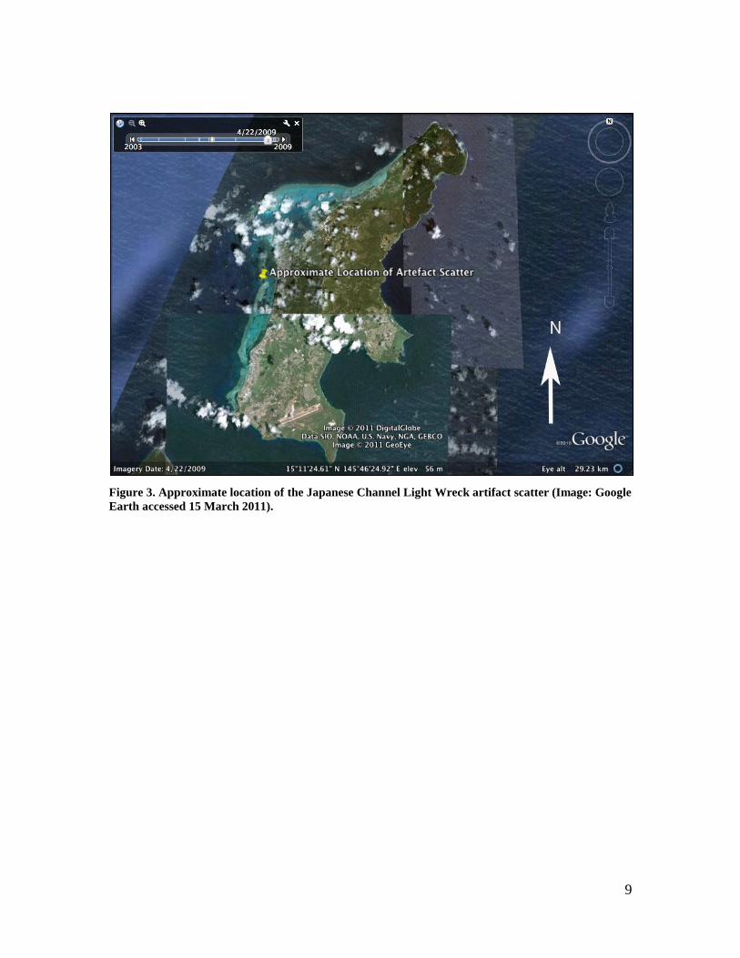
Figure 2. Site plan of Japanese Channel Light Wreck (Flinders University, April 2011). . 8 Figure 3. Approximate location of the Japanese Channel Light Wreck artifact scatter
(Image: Google Earth accessed 15 March 2011). ............................................................... 9 Figure 4. Japanese Channel Light Wreck artifact scatter site circled; abandoned light is
shown as a star and the location the Fishing Base Dock is noted (USGS 1983). ............. 10
Figure 5. Underwater baseline on site (looking east). ...................................................... 11 Figure 6. Julie Mushynsky and Peter Harvey taking baseline offset measurements. ....... 12 Figure 7. Deadeyes and chainplate used in rigging (Stone 1993:72). .............................. 15 Figure 8. Concreted iron wire, broken exposing wire core............................................... 16
Figure 9. Concreted iron eye with 25cm scale. ................................................................. 16 Figure 10. Wood deadeye conglomeration with wood visible and 8cm scale. ................. 18
Figure 11. Steel or iron object, possibly half of a mast band with 8cm scale. .................. 19 Figure 12. Mast band (Underhill 1946:48). ...................................................................... 19 Figure 13. Concreted iron object; possible chainplate with 25cm scale. .......................... 20
Figure 14. Iron ring with 8cm scale. ................................................................................. 21 Figure 15. Unidentified copper-alloy band and small object with 8cm scale. .................. 22
Figure 16. Ballast pile and iron fastener with 25cm scale. ............................................... 23 Figure 17. Recovered ballast stones with 8cm scale. ........................................................ 23 Figure 18. Two copper sheathing tacks and a folded piece of copper sheathing with 8cm
scale................................................................................................................................... 25 Figure 19. Iron fastener with 25cm scale. ......................................................................... 25
Figure 20. Large copper bolt with 8cm scale. ................................................................... 26 Figure 21. Copper-alloy fastener with 8cm scale. ............................................................ 27
Figure 22. Copper sheathing fragments with 8cm scale. .................................................. 28 Figure 23. Basal and side view with 8cm scale. ............................................................... 29
Figure 24. Close-up of base exhibiting small cut and three separate lips. ........................ 30 Figure 25. Green glass 3-piece mould bottle exhibiting horizontal seam around shoulder.
........................................................................................................................................... 31
Figure 26. Green glass bottle with broken lip and 8cm scale. .......................................... 32 Figure 27. Amber-coloured bottle exhibiting Japanese writing embossed into shoulder
with 8cm scale................................................................................................................... 32 Figure 28. Exterior of ceramic fragment with 8cm scale. ................................................. 33 Figure 29. Porcelain fragment with 8cm scale.................................................................. 34 Figure 30. Porcelain fragment interior view. .................................................................... 34
Figure 31. Unidentified wood conglomeration, timber sample was taken from this
fragment with 8cm scale. .................................................................................................. 35 Figure 32. Timer sample image. (Photo: courtesy of Jugo Ilic from Know Your Wood). 36
Figure 33. Folded piece of lead in initial state found with 8cm scale. ............................. 37 Figure 34. Lead artifact unrolled to lie flat, appearing as the number “4” with three small
holes and 8cm scale. ......................................................................................................... 37 Figure 35. Oarlock exhibiting heavy concretion with 8cm scale. ..................................... 38 Figure 36. Unidentified iron square with 25cm scale. ...................................................... 39

v
Tables
Table 1. Artifact date ranges. ............................................................................................ 40

1
Acknowledgements This project was supported by a number of individuals and agencies. We would first like
to thank the staff at the CNMI Historic Preservation Office for their continuing support
and for providing Flinders University’s staff and students with the opportunity to conduct
research in the CNMI. Particular thanks go to Ronnie Rogers and Herman Tudela for
organizing the opportunity to undertake this project and for providing logistical support
on island. Thank you to John Starmer for first mentioning the site and subsequently
showing us where it was located. Thank you to John D. San Nicolas for your continuing
support on the island, for finding all the significant artifacts, and for taking the time out
of your busy schedule to support and take care of the team. Thank you also to
Department of Environmental Quality for providing the team with a working platform
and in particular to John Iguel for providing exceptional captaining skills and logistical
support. Finally, thank you to volunteers Della Scott-Ireton, Peter Harvey, Julie
Mushynsky and Ania Legra for all of your hard work and support.
Funds for this project were made available through a National Park Service Preservation
Funds Grant.
Please reference this report as:
McKinnon, Jennifer F., Sarah Nahabedian, and Jason T. Raupp. 2011. Archaeological
Investigations of the Japanese Channel Light Wreck. Flinders University, Program in
Maritime Archaeology Report Series, No. 2.

2
Technical Data
Site Name
The Japanese Channel Light Wreck
Dates of Inspection
18 and 20 April 2011
Personnel
Jennifer McKinnon- Flinders University (Principal Investigator)
Sarah Nahabedian- Flinders University (Archaeological Assistant)
Jason Raupp- Flinders University (Archaeological Assistant)
Ania Legra- Flinders University (Volunteer)
Julie Mushynsky- Flinders University (Volunteer)
Della Scott-Ireton- Florida Public Archaeology Network (Volunteer)
Peter Harvey- Heritage Victoria (Volunteer)
Herman Tudela- Historic Preservation Office, Saipan
Ronnie Rogers- Historic Preservation Office, Saipan
John D. San Nicolas- Costal Resource Management, Saipan
John Iguel - Department of Environmental Quality, Saipan
Location
The site is located approximately 1 kilometer (km) southwest of the Fishing Base Dock in
2-3 meters (m) of water nearby the Japanese channel light marker. The site is scattered
over approximately 90 meters (m) of the coral reef and sandy areas adjacent to the
channel in the reef.

3
Project Background Since the time of first colonization around 3500 years ago (Rainbird 2004:81), several
cultural groups have utilized the island of Saipan in the Commonwealth of the Northern
Mariana Islands (CNMI) for settlement, trade, provisioning and as a strategic position for
wartime activities. While archaeological investigations on the island have revealed many
sites of ancient coastal settlements and World War II (WWII) ship and aircraft wrecks,
there exists a gap in the archaeological record. Until recently a nearly four hundred year
gap in the submerged heritage record of Saipan’s colonial period had existed. The finding
of an artifact scatter associated with a possible late nineteenth to early twentieth century
wooden wreck presented an opportunity to begin filling that gap. Historical and
archaeological investigations of this site have produced a list of possible candidates for
the identification of this wreck and provided the groundwork for a future colonial
shipwreck survey in the CNMI.
In July 2010, John Starmer, a marine biologist from the Coastal Resources Management
Office (CRM) in Saipan, notified maritime archaeologists from Flinders University of a
possible wooden shipwreck site in Tanapag Lagoon. Upon inspection, several shards of
green bottle glass, iron and copper-alloy fasteners, ballast and burnt timbers were found
in the sand and encrusted in coral (Figure 1). Archaeologists initially assessed these
remains as late nineteenth century artifacts associated with a possible shipwreck or
anchorage debris field and the site was reported to the CNMI Historic Preservation Office
(HPO). As there is little archaeological documentation of pre-WWII maritime-related
sites in Saipan’s waters, the uniqueness of the site justified further investigations and
HPO developed a project for the site to be documented. A research outline for this project
was supplied to HPO by Flinders University archaeologists and a contract for the
investigation of the artifact scatter was awarded to Flinders University (Appendix A).

4
Figure 1. Ballast stone and fasteners found on the site during the 2010 investigations.
Saipan Maritime Historical Context Since the late fifteenth century the Pacific Ocean has served as a trading highway for
European nations by aiding in the movement of people and the colonization of new areas.
Ferdinand Magellan became the first European to visit the Mariana Islands on 6 March
1521 and named the archipelago Islas de los Ladrones (Islands of the Thieves) due to a
misunderstanding in trade practices (Russell 1998). Over a century later in 1667 Spain
officially claimed the island chain and named it Las Marianas in honour of Queen
Mariana of Austria (Coomans 2000). Spanish occupation of the islands began in 1668, a
point at which the lives of both the colonizing Spaniards and the Indigenous Chamorro
peoples who had inhabited the islands for thousands of years were forever altered (Hezel
2000). The Marianas served as a strategic provisioning location for Spanish trading ships
voyaging between Manila and Acapulco for 250 years and were vital to the success of
Spain’s commerce system (Cushner 1971).
By the late seventeenth century Spanish efforts to Christianize the Chamorro people
resulted in large groups being forcibly removed from the northern islands and resettled
into church-centered villages on Guam (Hezel 1983; Carrell 1991). Missions were also
set up in Saipan and Rota but until the end of the nineteenth century, the islands to the

5
north of Guam served mainly as ranches or infirmaries. In the early 1800s, Spanish
authorities granted a request from a group of voyagers from the central Caroline Islands
to establish a settlement on Saipan which ushered in a new population to the archipelago
(Russell 1984:2). By the middle of the nineteenth century, whale ships and trading
vessels commonly visited the island to resupply and rest.
Subsequent to Spain’s loss in the Spanish-American War in 1898 all Spanish
Micronesian possessions except Guam were sold to Germany, thus beginning what is
known as the German Colonial Period (Spennemann 2007:7). The settlement of Garapan
on the west coast of Saipan served as the administrative seat of the Marianas District.
Between 1898 and 1907 German colonists constructed an administration building that
was visible to approaching ships, a landing pier and shelters along the waterfront, and
roads linking villages on the island (Fritz 1901:34-46). An important aspect contributing
to the growth of Garapan was its proximity to Tanapag Harbor, considered by most
captains as the second best anchorage in the Marianas (Russell 1984:46).
Though Germany held claim to the Northern Mariana Islands throughout this period, the
Japanese controlled trade and economic life, primarily through large-scale sugar cane
production (Peattie 1988:22). Shortly after Japan declared war on Germany in World War
I (WWI), German officials in Saipan abandoned their post and Japan quickly seized
several Pacific islands including the Northern Marianas. This occupation was sanction by
the United Nations provided the Japanese government did not engage in military-related
building. The Japanese government and private industry began increasing maritime
works, including the building of a lighthouse and channel markers to guide ships coming
into and going out of Saipan. But they also clandestinely began fortifying the islands in
preparation for defense of their holdings.
Upon the entry of the United States (US) into WWII, the islands and islanders of the
Pacific basin were subjected to events beyond their control and eventually Saipan would
play a pivotal role in the war. “Operation Forager” was the codename for the Allied plan
to seize control of the Northern Mariana Islands from Japan. The 1944 invasion and

6
capture of the islands by US forces caused devastation on both sides and left military
vehicles and debris scattered on land and in the water surrounding the island. From 1945
to 1947 the islands continued under US military occupation (Carrell 2009:348). In 1947
the Northern Mariana Islands came under US Trust Territory status and in 1978 the
constitutional government of the Commonwealth of the Northern Mariana Islands took
office.
Previous Investigations of Saipan’s Submerged Sites The submerged cultural resources of Saipan have been the subject of both public and
private archaeological surveys, as well as commercial treasure hunting over the past
thirty years. Beginning in 1979, the first literature search and diver visual surveys were
conducted which resulted in the location of objects from the Japanese, WWII and
American periods (Thomas and Price 1980). In the 1980s the US National Park Service
(NPS) and private archaeological consulting firms assessed the submerged WWII
remains in Saipan (Miculka & Manibusan 1983; Miculka, et al. 1984; Pacific Basin
Environmental Consultants 1985). In 1986 and 1987, a treasure hunting company, Pacific
Sea Resources, commercially salvaged the 1638 wreck of Nuestra Señora de la
Concepción off the south coast of Saipan (Mathers, et al. 1990). Upon completion of the
the project the artifacts were divided between the treasure hunting company and the
CNMI government.
In 1990 the NPS again documented the WWII sites in the lagoons on Saipan (Miculka, et
al. 1990), and in 1991 published a comprehensive submerged cultural resources summary
for all of Micronesia which included details of more than 50 shipwrecks and abandoned
vessels on Saipan (Carrell 1991). From that point, little research or fieldwork was
conducted on Saipan until 2001, when the National Oceanic and Atmospheric
Administration (NOAA) initiated an abandoned vessel inventory for the CNMI (Lord &
Plank 2003). This survey identified 28 historic resources, most of which were WWII-era
pontoons/barges and freighters (Lord & Plank 2003).
Beginning in 2008, interest in Saipan’s underwater cultural heritage was reignited. That
year Southeastern Archaeological Research, Inc. conducted, at the bequest and funding of
7
the HPO, extensive remote sensing and diver identification surveys of Saipan’s western
lagoons, which identified over 1500 magnetic targets. Of these only 142 were identified
through diver investigation, side scan sonar or were previously known (Burns 2008a;
Burns 2008b). Using this survey data, a research project to document the submerged
remains of the WWII Battle of Saipan was initiated in 2009 by researchers from Ships of
Exploration and Discovery Research, Inc. and Flinders University. This project has
resulted in the creation of an underwater heritage trial (McKinnon and Carrell 2011).
Fieldwork
Site Conditions on Assessment The site was visited in April 2011 during the island’s dry season which allowed for
exceptional visibility in the lagoon. The average water temperature was 82 degrees
Fahrenheit. Swell and surge were nearly non-existent on site and every opportunity was
taken to dive during high tide so that shallower areas could be surveyed. A total of 31
dives were conducted for a total of 2,790 minutes (46.5 hours) on site.
General Description of Site The wreck site is located in Tanapag Lagoon on the western side of Saipan and lies in 2-
3m of water, southwest of the Fishing Base Dock (Figure 2). Approximately 1km from
shore, the wreck is located north of the channel and a nearby abandoned Japanese
Channel Light marker (Figure 3 and Figure 4). The wreck debris field measures
approximately 90m long by 30m wide and major features include a large, dispersed
ballast pile and a scatter of ship construction and shipboard related artifacts.
The wreck site is located directly on top of the coral reef and limestone substrate in
shallow water and appears to be scattered in a westerly direction down the reef slope into
smaller sandy channels that lead into the larger, deeper channel. The site is colonized by
a variety of hard and soft corals, as well as other marine flora and fauna. Red and brown
algae can be found with regularity.
8
Figure 2. Site plan of Japanese Channel Light Wreck (Flinders University, April 2011).
9
Figure 3. Approximate location of the Japanese Channel Light Wreck artifact scatter (Image: Google
Earth accessed 15 March 2011).

10
Figure 4. Japanese Channel Light Wreck artifact scatter site circled; abandoned light is shown as a
star and the location the Fishing Base Dock is noted (USGS 1983).
Fishing Base Dock

11
Survey, Recording and Samples
Baseline Offset, Trilateration and Triangulation Survey
Due to the scattered nature of the site, baseline offset, trilateration and triangulation
methods were used for recording the wreck. A baseline was set along the centre of a
small sand channel that contained artifacts initially recorded in 2010. The zero end of the
baseline was secured to a coral/limestone head to the west and was laid to 30m to the east
and secured on another coral/limestone head (Figure 5). The baseline was later extended
to 92m. This allowed for the inclusion of the largest concentration of ballast and other
scattered features. The baseline was oriented approximately 90 degrees from 0-30m, 60
degrees from 31-62m and 70 degrees from 62-92m, splitting the site roughly on a
north/south orientation. Polypropylene rope was used for the baseline and secured using
zip ties so that it could be removed with minimal impact to the natural environment.
Figure 5. Underwater baseline on site (looking east).
Once the polypropylene baseline was set, a fiberglass measuring tape was attached using
clothespins. The measuring tape was emplaced at the start of each day and removed at the

12
end of the day. The site was split into manageable sections for measurements (0-30m, 30-
60m, and 60-90m along the baseline) and teams mapped the north and south portions of
each section. The baseline was used to take 90 degree offset measurements to structures
on both its north and south sides (Figure 6). Due to the topography of the site some
features and artifacts were triangulated or trilaterated to account for major obstacles.
Features mapped included cultural features such as ballast concentrations and identifiable
artifacts, as well as the natural bathymetry of the seabed.
Figure 6. Julie Mushynsky and Peter Harvey taking baseline offset measurements.
Hand Fanning
A small amount of hand fanning was conducted on the site to remove the top 1-2cm of
sand and identify any ship or artifact features. When an artifact was located a small metal
hexagon nut, tied with fluorescent tape, was placed where the artifact was located. This
allowed the object to be easily relocated and recorded on the site plan, photographed in
situ, recovered for topside photographs and returned to its original location. All markers
were recovered at the end of field work. The hand fanning identified some positive

13
returns; however, many of the located objects were heavily concreted into the limestone
substrate and were unable to be recovered for surface photography.
Photography
Since the visibility in Tanapag Lagoon is exceptional year-round, every attempt was
made to photograph artifacts and features in situ. Photographic surveys of the site using
digital still cameras in underwater housings were completed in order to document the
current state of the site and artifacts prior to disturbance. These photographic surveys
aided in the completion of a site plan, and can also be used to evaluate the condition of
the site during future studies or monitoring visits.
A limited number of artifacts were recovered for detailed recording and photography on
the surface. These artifacts were chosen based on context, significance or uniqueness and
their ability to provide diagnostic data. Once on the surface, all artifacts were measured
and sketches were made. Any diagnostic features were recorded in a notebook and scaled
photographs of the artefact were taken from all angles. The artifacts were then replaced
on site in their exact locations and recovered with sediment via hand fanning.
Timber Sample
Timber samples provide useful information concerning the possible origin of
construction. Very little timber existed on the site likely due to the tropical waters and the
ability for marine borers to flourish. Only one useable sample was obtained from a
conglomeration of wood and metal of unknown function. The roughly 3cm² sample was
collected using a handsaw. Although it was in very poor condition with extensive wood
borer damage, enough of the sample survived to conduct timber identification. The
sample was sent to a wood identification lab in Victoria, Australia and the results are
reported below.
Site Components and Artifacts A total of 114 artifacts were recorded in situ; however this number does not account for
the large amount of ballast stones on site (Appendix B). Overall the assemblage indicates
an association with a wooden sailing vessel. Artifacts noted during this investigation
included ship construction and rigging materials, as well as shipboard items and some

14
intrusive artifacts unassociated with the wreck. The following is a discussion of those
objects that were identified either by type or possible function. They are grouped into
categories including ship’s rigging, ballast, ship’s fittings, glass and ceramics, timber, and
miscellaneous.
Ship’s Rigging Rigging is the name given to all wires or ropes on a vessel used to support the masts, and
raise, lower or fasten the sails (Desmond 1919: 129; Stone 1993: 69). Rigging servs two
functions: it supports the masts and it helps position the spars and sails to catch the wind
(Stone 1993: 69). The rigging of a vessel is divided into two classes, one class
comprising standing rigging, and the other class comprising running rigging (Desmond
1996: 129). Standing rigging is usually composed of organic rope such as hemp, or iron
or steel wire rope consisting of metal strands of wire laid around a hemp core. Standing
rigging also includes deadeyes usually of wood that are held within iron or steel strops.
Wire rope and deadeyes work together to adjust the tension on mast-supporting shrouds
and stays (Crisman 1985: 376). Vertical metal bars called chainplates are fastened to the
side of the vessel to support deadeyes (Figure 7). Running rigging is comprised of all the
various ropes and tackles used to handle the sails (Desmond 1996: 132). As the name
suggests, these lines moved to perform their functions and usually were composed of
manila or hemp (Desmond 1996: 132; Stone 1993: 70). Elements of rigging found on the
Japanese Channel Light Wreck included portions of wire rigging, a wooden deadeye
contained within an iron strop, a mast band and other unidentified (UID) objects
potentially associated with rigging.
Wire Rigging
Approximately four sections of concreted steel or iron wire were positively identified on
the site, but it is possible that other artifacts identified as iron fasteners are in fact wire
rigging. Due to heavy concretion it was difficult to determine if a long iron object was
wire rope or a fastener. Nevertheless it was determined that wire rigging artifacts had a
curved shape and iron bolts were straight with a head on one end. Some of the wire
rigging artifacts found were concreted into the limestone substrate, however a small
number were found unattached on the seafloor. Those concreted to the seabed were

15
photographed and recorded in situ. The sections that were not concreted were removed
for photography and recording on the surface.
Figure 7. Deadeyes and chainplate used in rigging (Stone 1993:72).
During handling of one of these samples, the concretion broke exposing the fibrous hemp
core (Figure 8). Details of the rope construction were recorded and it was determined
that the rope had a right-hand lay. Seen from the side, the strands lay from upper right to
lower left, indicating a right-handed laid rope (Bathe 1978: 5.06). The direction of lay
and the amount of torsion put into the rope varies according to the purpose for which is
required (Bathe 1978: 5.08).
Four concreted wire eyes were also found scattered in the shallow coral reef (Figure 9).
These wire eyes are made by splicing a length of wire back on itself to create an eye that
was then filled with a thimble through which another rope or wire would be passed
(Bathe 1978: 5.03). Most of the iron eyes found appeared to be severed at the base.
Interestingly, these eyes were found in close proximity to concreted wire rope and may
have been severed during the wrecking or sometime thereafter. The eye photographed
below measures 28cm in length with an eye diameter (lengthwise) of 19cm.

16
Figure 8. Concreted iron wire, broken exposing wire core.
Figure 9. Concreted iron eye with 25cm scale.
Wire rope made from strands of steel or soft iron wrapped around hemp, jute or manila,
were used in England as early as the 1830s and 1840s (Wallace 1856: 194; Macgregor

17
1984: 150-151; Murphy 1993: 265; Stone 1993: 69; Meide 2000: 221; Burns 2003: 48-
49). Andrew Smith first patented wire rope in 1835 (Macgregor 1984: 151). Dating from
the early 1850s, most large British ships had wire standing rigging (Macgregor 1984:
151) and by the 1860s wire rigging was being used by US shipbuilders (Stone 1993: 69).
Wire rope became commonplace on most vessels by the 1870s and reduced top-hammer
weight, allowing the use of taller masts and larger sails (Murphy 1993: 265). By the
1900s it was used almost exclusively for standing rigging (Stone 1993: 69).
Wire rope diameter can be useful for estimating vessel size if the number of strands or
wires per strand are known (Murphy 1993: 284). The wire rope sections measured
approximately 1 cm in diameter (0.4 inches), but unfortunately they were too heavily
concreted to determine the number of strands or wires per strand.
The use of hemp-core wire rope like that found on the Japanese Channel Light Wreck site
indicates a date likely no earlier than the 1850s if a British vessel, but more likely the
mid-1870s, or if US built a possible later date of post 1860s (Murphy 1993: 284).
Deadeye
A single wood deadeye was found on the site and recovered for topside recording. This
artifact measured 15cm in diameter (Figure 10) and was identified as a deadeye from the
three noticeable holes in the same configuration as well-known deadeyes. Each hole is
approximately 4cm wide but this may not be an accurate original measurement due to
extreme deterioration of the wood. As well as the deadeye, an iron strop is fixed around
the wood and ballast stones are concreted to it. The overall dimension of the concreted
deadeye is 28cm tall by 37cm wide. Few timber fragments were found on the site, most
likely due to the warm, shallow water and the proliferation of marine boring organisms. It
is likely that the deadeye survived nearly intact due to the associated iron stop which
formed a protective concretion around the deadeye, but also the fact that deadeyes are
typically made out of strong woods resistant to rot and insects (i.e. lignum vitae). One
side of the deadeye was more protected from marine growth and deterioration because it
was buried in the sand which aided in the identification of the artifact.

18
Figure 10. Wood deadeye conglomeration with wood visible and 8cm scale.
Deadeyes are easily identifiable by their round, flattish block nature pierced with three
holes and grooved around the edge to hold an iron or rope strop (Bathe 1978: 5.01;
Crisman 1985: 376; Stone 1993: 71). Deadeyes are components of a vessel’s standing
rigging and are used in vertical pairs; one dangled on a rope from above, the other
supported from below (Stone 1993: 71; Burns 2003: 64). A lanyard was threaded
between them and pulled tight, and used to adjust the tension on mast-supporting shrouds
and stays (Crisman 1985: 376). A ship typically had four to six different sizes of
deadeyes for various uses (Burns 2003: 64). Based its size, the deadeye recorded on the
Japanese Channel Light Wreck may have been used on the mizzenmast topgallant or
royal backstays (Underhill 1946: 267; Stone 1993: 73).
Mast band
One steel or iron object in the shape of a half circle with flanges at each end was located
on the site (Figure 11). The object has been identified as a portion of a mast band. The
radius of the half circle is 15cm; the overall length of the object including the two flanges
is 43cm; and the diameter of the inner half circle is 25cm. Red and brown algae were
present growing on the exposed side of the object.

19
Figure 11. Steel or iron object, possibly half of a mast band with 8cm scale.
Mast bands are metal bands that round a mast, fitted with lugs to take blocks (Bathe
1978: 4.02) (Figure 12). These iron collars provide additional strengthening for the mast
(Burns 2003: 46-47). External mast bands are generally distinguishable by eyes or
swivels for various attachments (Stone 1993: 64). A vessel’s rig can sometimes be
identified by the fittings on the mast bands or on their kin around the bowsprit (Stone
1993: 64). Unfortunately mast bands were manufactured for such a long period of time
that they provide little evidence as temporal markers.
Figure 12. Mast band (Underhill 1946:48).

20
UID Iron Object
An iron object likely to be a chainplate assembly was located concreted to the seabed.
Approximately 60cm in length, 4cm wide at the top, and 15cm wide at the base it was
found 21m north of the baseline in a large sand pocket (Figure 13). The top of the object
is circular and has a hole in its centre, although algae growth and concretion have nearly
enclosed the circle. Roughly 25cm from the top, the object curves and appears
fragmented, although it is uncertain if the object is comprised of multiple pieces.
Figure 13. Concreted iron object; possible chainplate with 25cm scale.
Chainplates are iron or bronze strips or bars solidly bolted to the ship’s hull to which the
shrouds are secured by a system of deadeyes and screws (Bathe 1978: 4.08; Stone 1993:
72). Round, iron bar-stock chainplates appeared earlier than flat-bar chainplates, which
appeared in the latter part of the nineteenth century (Murphy 1993: 285). Unfortunately
due to the concretion it was impossible to determine if it was bar-stock or flat-bar.
21
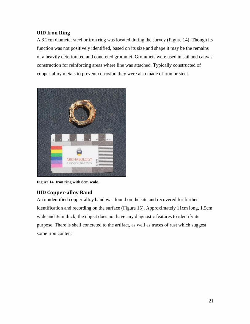
UID Iron Ring
A 3.2cm diameter steel or iron ring was located during the survey (Figure 14). Though its
function was not positively identified, based on its size and shape it may be the remains
of a heavily deteriorated and concreted grommet. Grommets were used in sail and canvas
construction for reinforcing areas where line was attached. Typically constructed of
copper-alloy metals to prevent corrosion they were also made of iron or steel.
Figure 14. Iron ring with 8cm scale.
UID Copper-alloy Band
An unidentified copper-alloy band was found on the site and recovered for further
identification and recording on the surface (Figure 15). Approximately 11cm long, 1.5cm
wide and 3cm thick, the object does not have any diagnostic features to identify its
purpose. There is shell concreted to the artifact, as well as traces of rust which suggest
some iron content

22
Figure 15. Unidentified copper-alloy band and small object with 8cm scale.
Ballast Ballast stones were found in large quantities in both concentrated areas and scattered
around the site. The stones are dark black and grey, with some red algal growth on
exposed surfaces (Figure 16 and Figure 17). Stones range from 3cm² to 15cm² in size and
were generally oval in shape, typical of water smoothed cobble. A total of four stones
were brought to the surface to photograph.
The concentrated ballast area occurred from approximately 45m to 90m along the
baseline and extended out as much as 20m in the broadest area. The concentrated area of
ballast stones lies on top of the reef adjacent to the channel, and spans southwest towards
the channel. Small pockets of ballast were in reef crevices and sand pockets to the east as
the reef slopes into the channel. No further investigations were conducted under the
ballast pile to determine if there was wooden structure; however it is highly unlikely that
there is wooden ship structure given the tropical waters and that the ballast pile does not
extend much deeper than the surface.

23
Figure 16. Ballast pile and iron fastener with 25cm scale.
Figure 17. Recovered ballast stones with 8cm scale.

24
Ship’s fittings Hull fittings encountered on shipwreck sites consist mainly of wooden, iron and copper-
alloy fasteners used to articulate wooden components of the vessel (Meide 2000:186).
Classification of ships’ fasteners can be quite complex, as there is much variation in
form, materials and function, as well as change in nomenclature over time (Meide
2000:186). McCarthy (1983) studied eighteenth, nineteenth and twentieth century
shipbuilding literature and encountered 50 different types of fasteners with 80 different
names from those periods. Generally speaking, nails are less than three inches long (7.6
cm), spikes are large nails up to a foot (30.5 cm) or more in length, and bolts are rods of
metal, with heads and tips shaped by hammering, that are driven into pre-augured holes
(Stone 1993: 33-34). All three types of metal fasteners were encountered on the site and
are grouped by material and types below.
Copper-alloy Tacks
Approximately 31 copper-alloy tacks were found distributed across sand pockets in the
reef (Figure 18. Two copper sheathing tacks and a folded piece of copper sheathing with
8cm scale.). These fasteners are most likely sheathing tacks due to their size and
association with nearby sheathing. Of the samples recovered, the tacks were square in
cross-section (approximately 0.5cm wide) with a shank width of 0.3 to 0.4cm. The tacks
ranged in length from 2.2cm to 3cm.
Hull sheathing is attached with sheathing nails or tacks. Tacks are essentially nails that
are up to 3.8cm in length (Stone 1993: 34; McCarthy 1996: 186). Steffy (1994: 279)
defines sheathing nails as a small nail or tack used to attach sheathing to a hull. Ronnberg
(1980: 128, 137, 141) used the terms 'sheathing nails' and 'coppering nails' to describe the
fastenings used for wooden and metallic sheathing on nineteenth century American
merchant ships. By the 1830s most sheathing tacks were cut by machine (Stone 1993:
34).

25
Figure 18. Two copper sheathing tacks and a folded piece of copper sheathing with 8cm scale.
Iron Pins or Bolts
Forty-three possible iron pins or bolts were recorded affixed to the limestone substrate
(Figure 19. Iron fastener with 25cm scale.). Due to the heavy iron concretion, the positive
identification of these artifacts was difficult; however the general shape, straight body
and presence of a head, indicated either a pin or bolt. Most of these fasteners ranged from
30-40cm long with an approximately 3.5cm diameter.
Figure 19. Iron fastener with 25cm scale.

26
Bolts are essentially round rods of various diameters, lengths and materials, and were
used in conjunction with a cling ring (Crothers 1997: 61). Iron or copper bolts were used
in shipbuilding either to fasten several members of a ship’s frame solidly together, or to
fix any moveable object for a particular purpose (Bathe 1978: 3.02). Due to the corrosive
environment of seawater, iron bolts were generally installed in drier places above the
waterline (Burns 2003: 56).
Copper-alloy Fastener
One copper-alloy fastener was found in a sand pocket and recovered for photography on
the surface (Figure 20. Large copper bolt with 8cm scale.). The fastener measured 16cm
long, 1.6cm wide and had a head width of 2.3cm. The fastener was tapered at one end
and is bowed or curved in the middle, indicating stress at some point in its use. The exact
material composition of the copper-alloy fastener is unidentifiable but is most likely
bronze due to the color of corrosion materials on its surface.
Figure 20. Large copper bolt with 8cm scale.
Dump bolts or short bolts are essentially round spikes that are used to fasten planking to
frames (Crothers 1997: 70; Stone 1993: 34). Normally made from bronze or other
copper-alloy metals, dump bolts have a round head and a round shaft that tapers in a
chiseled end (Burns 2003: 56).

27
Copper-alloy fastener with Rove
A copper-alloy fastener and rove was located on the site in a sand pocket and retrieved to
be recorded on the surface (Figure 21. Copper-alloy fastener with 8cm scale.).
Approximately 10.5cm long with a shank width of 1.8cm, it has a head that measures
1.8cm in diameter. A square copper-alloy rove, approximately 3cm in diameter is
noticeable just below the head.
Figure 21. Copper-alloy fastener with 8cm scale.
The term “bolt” is used to refer to a fastener cut to length from a rod of iron, steel, copper
or bronze (Stone 1993: 34). The head and top were shaped by hammer; often hammered
down over washers called clench rings or roves (Stone 1993: 34). Bathe (1978: 3.02) uses
the term “rove” to describe a small copper washer over which the nail end is flattened to
make a firm fastening. Due to corrosion, bolts installed below the waterline were made of
copper-alloy metals (Burns 2003: 56). This bolt, composed of copper-alloy, was likely
used below the waterline.
Copper-alloy Sheathing
Four copper-alloy sheathing pieces were recorded both concreted into the limestone
substrate and loose in sand pockets southwest of the ballast area. These pieces measured
no larger than 5cm square and were in close proximity to copper tacks or fasteners.
Many smaller pieces were also located concreted into the rocky limestone substrate but
were unable to be recorded due to their proliferation (Figure 22). The copper was easily

28
identified due to the green color corrosion product that develops over time when copper
is submerged in saltwater.
Figure 22. Copper sheathing fragments with 8cm scale.
To protect vessels from marine organisms such as the shipworm (Teredo navalis) and
gribble (Limnoria), a layer of protective sheathing was placed over the outer hull of a
vessel (Bathe 1978: 3.10; Burns 2003: 61-62; McCarthy 2005: 101-102). Sheathing
typically covered the entire hull below the waterline of a vessel. Lead or copper were the
most commonly used metals for sheathing wooden ships. Copper sheathing plates,
introduced into the Royal Navy in 1761, were the first effective barriers against fouling
(Stone 1993: 23). British merchantmen began to be coppered in the 1770s, French in the
1790s and US vessels after 1800 (Stone 1993: 23). In 1832 George Frederick Muntz
patented Muntz metal, a tougher, longer wearing and less expensive metal than copper
for sheathing (Stone 1993: 23; Crothers 1997: 330; McCarthy 2005: 115-121). By the
1850s, Muntz metal had become the most widely used metal for sheathing; however
copper sheathing was still used (Burns 2003: 63). Though some sheathing manufacturers
are known to have stamped maker’s marks into the sheet, no such marks were identified
on any of the four samples recovered for photographs on the Japanese Channel Light
Wreck.

29
Glass and Ceramics
Bottles
Fifteen intact bottles and bottle fragments were located scattered over the site and in the
channel. A total of nine whole bottles or fragments were retrieved for surface recording
and are discussed below.
A dark green glass bottle base was found on the site (Figure 23 and Figure 24) that
measured 10.5cm diameter at the base and had a wall thickness of 0.7cm. The bottom of
the bottle exhibits a “kick-up,” concave or dome form (Jones and Sullivan 1989; 113),
and a small cut in the base edge. The kick-up suggests the bottle was used in the
transportation and storage of wine or alcoholic beverages.
Figure 23. Basal and side view with 8cm scale.

30
Figure 24. Close-up of base exhibiting small cut and three separate lips.
A second green glass bottle base was found, however the artifact was too heavily
concreted to determine any diagnostic features. This base also exhibits a kick-up or
concave form.
Two heavily concreted bottlenecks were found in different locations on the site. Both
appear to have applied lips that are 2.5cm in diameter. Tibbitts (1964: 3) uses the term
“applied lip” as any lip or mouth that was hand worked after the bottle was broken off
from the blowpipe. Adams (1969: 114) defines applied lip as any bottle made before
1900 where the mouth was formed after being separated from the blowpipe. One of the
bottle necks was a dark green color but the second was unidentifiable due to the amount
of concretion.
Another dark green bottle exhibiting an applied lip was recovered for topside
photographs (Figure 25). The bottle measures 30cm tall and 9cm in diameter and displays
a seam running along the circumference of the shoulder approximately 4cm below the
neck, as well as two seams running along the body. The lines indicate the bottle was
constructed in a three-piece mould.

31
Figure 25. Green glass 3-piece mould bottle exhibiting horizontal seam around shoulder.
A three-piece mould, or Ricketts mould, consists of a dip mould for shaping the body and
two matching shoulder or shoulder-neck shaping halves (Jones and Sullivan 1989: 29).
Used generally between the1820s to 1920s, three-piece bottles of dark green glass were
used exclusively for liquor between ca. 1821 and ca. 1840. In the 1840s, the mould began
to be used for other kinds of bottles (Jones and Sullivan 1989: 30). By the late nineteenth
century, the use of moulds for liquor bottles had ended, but they continued to be used for
pharmaceuticals, toiletries, inks, etc. (Jones and Sullivan 1989: 29-30;
http://www.sha.org/bottle/body.htm).
Another green glass bottle was recovered from the site for surface photography (Figure
26). The bottle is intact except for the lip and is made of a lighter green glass. A faint
horizontal seam around the shoulder is visible, possibly indicating a two-piece mould
construction.

32
Figure 26. Green glass bottle with broken lip and 8cm scale.
This bottle appears to be a turn-mould due to a faint horizontal line, most likely caused
by contact with grit on the lining of the mould (Jones and Sullivan 1989: 31). This bottle
mould was most common from 1870s through WWI, and during the 1870s and 1880s
several patents were acquired for production in the US (Toulouse 1969: 532).
Three amber-colored glass bottles were found on the site in different locations (Figure
27). Two of these are Japanese bottles with embossed lettering “DNB” and a crown cap.
One of these bottles exhibits a two-piece horizontal mould and the other was covered
with algae on the exposed side which prevented the detection of the mould seam. The
artifacts are assessed as twentieth century Japanese bottles.
Figure 27. Amber-coloured bottle exhibiting Japanese writing embossed into shoulder with 8cm
scale.

33
The third brown bottle exhibited similar features to the two Japanese bottles. A crown
cap is visible, as is the word “DIANIPPON” which is embossed around the base of the
bottle. This bottle is also assessed as a twentieth century Japanese bottle.
Stoneware
A stoneware body and rim fragment was located on the site. The fragment is of compact
light grey paste and is approximately 13cm by 10cm in size (Figure 28), with a 2.9cm
thick rim, a 1.5cm thick neck and an approximately 0.8cm thick body. No diagnostic
features were visible on the artifact, but its function iss most likely utilitarian. When
compared to a rim chart the fragment appears to belong to a 6 to 6.5cm diameter jug or
jar.
Porcelain
One piece of blue on white porcelain was found on the site and recovered for surface
photography. The fragment is decorated on both sides with geometric and floral patterns
and is 3cm thick (Figure 29 and Figure 30). This sherd could possibly belong to either a
shallow bowl or saucer, as the reconstructed diameter of the fragment is 4cm.
Figure 28. Exterior of ceramic fragment with 8cm scale.

34
Figure 29. Porcelain fragment with 8cm scale.
Figure 30. Porcelain fragment interior view.
Timber
Conglomerate
An unidentified conglomeration of wood, iron and copper-alloy metal was located and
brought to the surface for recording (Figure 31). The conglomeration was covered in red
and brown algae and exhibits rust and corrosion the around metal remnants. No part of
the object was identifiable; however a timber sample was obtained for possible species
identification.

35
Figure 31. Unidentified wood conglomeration, timber sample was taken from this fragment with 8cm
scale.
The sample was sent to Jugo Ilic of Know Your Wood in Victoria and the results were
reported as Birch (Betula sp.), most likely Yellow Birch (Betula alleghaniensis) (J. Ilic,
email, May 2011) (Figure 32) (Appendix C). Birch is wide spread throughout the
northern hemisphere but Yellow Birch is native to eastern North America, from
Newfoundland to Nova Scotia, New Brunswick, southern Quebec and Ontario, and the
southeast corner of Manitoba, west to Minnesota, and south to northern Georgia within
the Appalachian Mountains.
Birch is a hard durable wood, described as “strong, stiff and tough” (Forest Products
Laboratory Manual 1973: 1). In the mid- to late nineteenth and early twentieth centuries,
yellow birch, beech, and maple, three tough woods possessing very little rot resistance
when exposed to moisture and air, were commonly used in Bath, Maine shipyards for
keels and floor timbers (B. Bunting on MARHST-L, personal communication, May
2011). Birch was also used extensively for shipbuilding in Canada’s Maritime Provinces
during the “great shipbuilding days of the mid-nineteenth century” (Greenhill 1988: 205)
and was considered superior to oak because it did not contain acid that corroded iron drift
pins.

36
Figure 32. Timer sample image. (Photo: courtesy of Jugo Ilic from Know Your Wood).
Miscellaneous Most of the miscellaneous finds are considered part of the ship’s hardware. Hardware
items include a possible lead draught mark; an oarlock; and three unidentified objects.
Possible Draught Number
A peculiar lead object was identified in a sand pocket and recovered for recording on the
surface. Initially folded, the artifact was carefully unfolded to reveal the shape of an
Arabic number “4” with the base missing (Figure 33 and Figure 34). The lead artifact was
not manipulated in any other way except to fold it flat for recording purposes. The object
is roughly 9cm tall, 0.2cm thick and is perforated by three small holes. The holes do not
appear in any particular pattern and are fastener holes through which small tacks would
have attached it probably to wood. If the lead object is in fact a number, it might have
been a vessel’s draught number or cabin number.

37
Figure 33. Folded piece of lead in initial state found with 8cm scale.
Figure 34. Lead artifact unrolled to lie flat, appearing as the number “4” with three small holes and
8cm scale.
Draught marks typically appear on the stem and sternpost and indicate depth which is
used to determine a vessel's draught and adjust its trim (Steffy 1994: 270; Bathe 1978:
301). On US merchant sailing ships in the nineteenth century draft marks, or load lines,
were made of lead (Ronnberg 1980).
Lead draught marks have been found on other historic shipwreck sites as well. Colin
Martin (1978) has identified cut lead draught marks found on Dartmouth, a British frigate
wrecked off Mull (England) in 1690. The English slave ship Henrietta Marie, sunk off
the Florida Keys in 1700 also had cut sheet lead draught numbers (in Roman numerals

38
“VII”, “VIII” and “VIIII”) approximately 6 inches (15.2 cm) tall (Moore & Malcom
2008).
Oarlock
A heavily concreted metal oarlock was found in a large sand pocket and recovered for
surface recording (Figure 35). Also known as a rowlock, these were u-shaped metal
swivels that mounted on ships’ boat’s gunwales to accommodate an oar (Bathe 1978:
9.02). This object was easily distinguished by its general form and exhibits a ribbed horn-
style opening 10cm wide, a straight shank 5cm in width and its overall length is 25.5cm
(all measurements include concretion). This oarlock is most likely associated with a gig
or lifeboat, would have been propelled by oars (Bathe 1978: 9.01).
Figure 35. Oarlock exhibiting heavy concretion with 8cm scale.

39
UID Iron Object
An unidentified metal box-like artifact was also located embedded in the coral reef.
Square in shape and with rounded edges, it measures 30cm² and 6cm deep and does not
appear to have a bottom (Figure 36). Though the object has no diagnostic features to
identify its function, possible uses associated with nineteenth century sailing vessels
include an anchor stock band or spar band.
Figure 36. Unidentified iron square with 25cm scale.
Site Interpretation Archaeological and historical data suggests this site is the remains of a ship dating to the
mid-nineteenth to early twentieth century (Table 1). The presence of ballast stones,
copper sheathing and tacks, as well as iron drift pins and bolts, indicate that it was a
wooden vessel, and the hemp core wire rope, wooden deadeye and possible chainplate
specify that it was a sailing vessel. The small collection of glass and ceramic fragments
further signify a mid-nineteenth to early twentieth century use. Timber identification
provides yellow birch, a species found in North-eastern North America and commonly
used in shipbuilding. While this does provide some evidence to suggest a North
American built vessel, one sample is not conclusive.

40
Table 1. Artifact date ranges.
Artifact Time Period
Wire Rope 1830-1900
Hemp Wire Rope 1850-1870
Copper Sheathing 1770-1900
Three-piece mould bottle 1820-1920
Two-piece mould bottle 1870-1880
The close proximity of the ballast area to the channel suggests that the vessel hit the reef
and wrecked while entering or exiting the lagoon. Another scenario which may be more
likely is that the vessel parted lines at the nearby dock or moorings and blew onto the
reef. Saipan is recorded as having predominantly east winds throughout the year with the
exception of monsoons which may bring short periods of southwesterly winds (Lander
2004: 5). If a vessel was docked at what is now know as the fishing base dock or in the
boat basin just to the south of the dock, a heavy easterly wind could have pushed it
directly onto the reef.
The shallow nature of the site, the length of the scatter and the fact that no major features
of the ship were found is a possible indication of post-depositional salvage. Often
wrecked wooden vessels were burned to their waterline so that cargo stored below the
deck could be salvaged or metal fasteners could be easily removed for recycling. The
identification of burnt wood during the February 2010 fieldwork and the overall lack of
timber on the site could support the theory of post-depositional salvage. However it is
important to note that the abundance of marine wood-boring organisms in the tropical
water would have aided in the degradation of any wood left on the site whether the vessel
was salvaged or not.
Possible Historic Identification Forty-one documented ship losses occurred in and around Saipan between 1552 and 1941
(Carrell 1991:280). Though data pertaining to the island during this period is sparse,
historical documents suggest that seven wooden sailing vessels are known to have
wrecked in Saipan’s water between the mid-nineteenth and early twentieth century.
Though little historical information pertaining to these vessels was located, comparison

41
between them and the archaeological evidence recovered indicates four of them as
possible candidates for the identity of the Japanese Channel Light Wreck.
William T. Sayward The barque William T. Sayward was built in Rockland, Maine in 1853 (Fairburn
1946:3421). Accounts state that the barque was sailing from San Francisco to Shanghai
with a cargo of flour and $164,000 in specie, when it sprang a leak off the “Ladrone
Islands” and was abandoned on December 21, 1854 (Daily National Intelligencer 1854,
Plain Dealer 1854, Salem Register 1854). Unfortunately details about the exact location
where William T. Sayward came to rest are vague.
Lizzie Jarvis The next sailing vessel reported to have wrecked around Saipan is the US ship Lizzie
Jarvis. Historical sources present some discrepancies about the fate and identity of this
vessel. One source reports that the whaler Lizzie Jarvis was lost in the “Ladrone Islands”
while travelling from Hong Kong to San Francisco in 1855. The ship was previously
known as Lady Pierce and was owned by Mr. Silas E. Burrows, who at one time intended
to present the vessel to the Emperor of Japan (Ward 1967(4):187). A later report states
that the ship was actually John N. Gossler, another vessel of the same owner which
traded between the US and China and which wrecked in 1855, 150 miles Northeast of
Saipan (Ward 1967(4):187-188; Lévesque 2002(20):73). Though the loss location of
John N. Gossler would exclude it, the confusion surrounding the loss of Lizzie Jarvis
make it a possible candidate for the identity of the wreck in Tanapag Lagoon.
Unknown Barque An unknown barque was lost in 1876 in Saipan (Carrell 1991:280). Current historical
research was unable to ascertain further information about this wreck. Until further
information pertaining to this vessel and its loss are obtained, it is impossible to
determine an association between it and the wreck in Tanapag Lagoon.
Iolanthe The 103-ton American schooner Iolanthe was wrecked at Saipan in 1896. All hands
survived and were transported to Guam on the Japanese schooner Chomey-Maru

42
(Lévesque 2002 (20):512). Little information was found about this vessel aside from the
fact that it was built in Essex, Massachusetts in 1883 (Record of American and Foreign
Shipping 1896). Again the limited data relating to this vessel or the circumstances make
it impossible to determine an association between it and the wreck in Tanapag Lagoon.
Research and Management Considerations Almost no wooden structure remains on the site suggesting that the conditions are poor
for wood preservation. Unfortunately, it is not uncommon for wooden vessels to be
consumed by marine organisms in tropic environments where there is little sand or
substrate to create an anaerobic environment. Although little wood was identified during
the project, there is potential for more wood to be present in the small pockets of sand
between reef heads and in the deeper channel. If any wood exists it would be buried in
the sand and would require excavation.
Much of the metal artifacts associated with wooden shipwrecks and shipboard culture are
still present on the site and there are likely more buried in the sand. Though the seawater
is corrosive for most metals, the environment also preserves metal objects through
calcium carbonate concretions. Provided the artifacts are not disturbed through cultural or
natural processes, they are like to be preserved into the future.
The fact that multiple portable artifacts such as wire rigging fragments, iron fasteners,
glass bottles and other shipboard items still exist, indicates that the site has not been
regularly dived or looted. This is likely due to the location of the site in close proximity
to the channel and the lack of information about the shipwreck’s position. The site should
remain protected by its depositional environment as long as the location of the site is not
promoted.
More research into vessels lost around Saipan during this period may lead to a greater
understanding of the maritime activities and future site identification. Nineteenth century
wooden sailing vessels exhibit distinctive structural and artifactual components. It is
possible that other underwater sites in Saipan exhibit analogous artifact assemblages as
the Japanese Channel Light Wreck site. More so, another underwater survey of the area

43
might lead to more artifacts and timbers being recorded; such new information may
reveal the identity of the site.
It is important that all shipwrecks and submerged sites be better understood and related to
their wider terrestrial contexts. More information regarding the importance of Tanapag
Lagoon can be gained by studying the historic waterfront in Garapan to investigate its use
and history. This project has added to the increasing amount of literature related to
nineteenth century sailing ships and should act as a jumping off point for additional
research and expansion for other pre-World War II shipwrecks and submerged sites in the
Northern Mariana Islands.
Conclusion Though the identity of the shipwreck recently located in Tanapag Lagoon was not
absolutely determined, this investigation is considered significant for its contribution to
increasing knowledge of a little explored period in Saipan’s history. As stated previously,
until the Japanese Channel Light Wreck was identified, a nearly 400-year gap existed in
the archaeological record pertaining to shipwrecks that had occurred around the island.
The detailed study of the remains of this nineteenth or early twentieth century sailing
vessel has produced not only archaeological data that will be added to the growing
database of sites in the waters surrounding Saipan, but it has also provided the impetus
for building a more comprehensive database of archival information relating to colonial
ship losses. Thus the compilation and analysis of this data has begun to fill the gaps, and
in doing so provides insight into colonial interaction and trade in the Pacific region
around the turn of the century.
The investigation of the Japanese Channel Light Wreck also represents the first multi-
agency archaeological investigation of an underwater pre-WWII shipwreck in Saipan.
This approach allowed multiple local government agencies (HPO, CRM and DEQ) to
collaborate with archaeologists from Australia and the US to assess and record this
important piece of CNMI heritage. Due to the site’s location along the fringing reef, it
has also allowed agencies concerned with reef health and environmental quality an
opportunity to monitor and protect the reef that has grown around this site. Ultimately

44
this kind of collaboration offers all groups involved the opportunity to better
understand and appreciate each other's work and can be seen as best practice for the
protection and management of Saipan’s marine resources.
References Adams, J.P., 1969. Bottle collecting in New England: A guide to digging, identification,
and pricing. New Hampshire Publishing Co, Somersworth.
Bathe, B.W. 1978. The visual encyclopaedia of nautical terms under sail, Crown
Publishers Inc., New York.
Burns, J.M., 2003. The life and times of a merchant sailor: the archaeology and history
of the Norwegian ship Catharine. Kluwer Academic/ Plenum Publishers, New York.
Burns, J.M., 2008a. Archaeological survey of lagoons on the West Coast of Saipan,
Commonwealth of the Northern Mariana Islands. Southeastern Archaeological Research,
Inc.
____ 2008b. Archaeological survey of Tanapag Lagoon Saipan, Commonwealth of the
Northern Mariana Islands. Southeastern Archaeological Research, Inc.
Carrell, T. ed., 1991. Micronesia Submerged Cultural Resources Assessment. Southwest
Cultural Resource Centre Professional Papers No. 16. Submerged Cultural Resources
Unit, National Park Service, Santa Fe, New Mexico.
Carrell, T., 2009. Maritime history and archaeology of the Commonwealth of the
Northern Mariana Islands. Prepared for the Division of Historic Preservation,
Commonwealth of the Northern Mariana Islands, Saipan.
Crisman, K., 1985. The construction of the Boscawan. The Bulletin of the Fort
Ticonderoga Museum 14: 357-370.
Coomans, P. 2000. History of the Mission in the Mariana Islands, 1667-1673, Translated
by Rodrique Lévesque, Occasional Historical Papers Series, No. 4. Division of Historic
Preservation, Commonwealth of the Northern Mariana Islands, Saipan.
Crothers, W.L., 1997. The American built clipper ship, 1850-1856: characteristics,
construction, and details. International Marine, Camden.
Cushner, N.P. 1971. Spain in the Philippines from Conquest to Revolution, Ateneo de
Manila University, Quezon City, Philippines.
Daily National Intelligencer. 1854. Telegraphic Correspondence Rumored Insurrection in
Australia-Disastrous Shipwreck and Loss of Seven Hundred Lives. Available at:
<http://www.genealogybank.com/gbnk/newspapers/?sort=_rank_%3AD&lname=&fnam

45
e=&minit=&kwinc=Ladrone+Island&kwexc=&formDate=March+1855&processingtime
=> [Accessed on 14 July 2011].
Desmond, C., 1919. Wooden ship-building. Vestal Press Ltd, Vestal.
Fairburn, W.A., 1945. Merchant Sail, Vol. 1. Center. Fairburn Marine Educational
Foundation, Inc., Lovell.
_____ 1945. Merchant Sail, Vol 6. Center. Fairburn Marine Educational
Foundation, Inc, Lovell.
Forest Products Laboratory Manual, 1973. U.S. Department of Agriculture, Madison.
Fritz, G., 1901. Yearly report 1901. Submitted to Imperial Governor of German New
Guinea. Translation on file with Trust Territory Headquarters, Saipan.
Gould, R. and D. Conlin.1999. Archaeology of the Barrel Wreck, Loggerhead Reef, Dry
Tortugas National Park, Florida. International Journal of Nautical Archaeology 28(3):
207-228.
Greenhill, B., 1988. Evolution of the wooden ship. Facts on File, New York.
Hezel, F.X., 1983. The first taint of civilization: A history of the Caroline and Marshall
Islands in Pre-Colonial days, 1521-1885. Pacific Islands Monograph Series No. 1.
University of Hawaii Press, Honolulu.
_____ 2000. From Conquest to Colonization: Spain in the Mariana Islands 1690 to 1740,
Occasional Historical Papers Series No. 2, Division of Historic Preservation,
Commonwealth of the Northern Mariana Islands, Saipan.
Jones, O.R. and Sullivan, C., 1978. The Parks Canada glass glossary for the description
of containers, tableware, flat glass and closures. National Historic Parks
and Sites, Canadian Parks Service, Environment Canada, Ottawa.
Lander, M., 2004. A Rainfall Climatology for Saipan: distribution, return-periods, El
Nino, tropical cyclones, and long-term variations. University of Guam, Water and
Environmental Research Institute of the Western Pacific, Technical Report 3, Guam.
Lévesque, R., 2002. History of Micronesia, Bibliography of Micronesia, Ships Through
Micronesia Cumulative Index. Vol. 20, Lévesque Publications, Quebec.
Lord, C. and Plank, C., 2003. Surveys of Abandoned Vessels: Guam and the
Commonwealth of the Northern Mariana Islands. A Report Prepared for National
Oceanic and Atmospheric Administration, National Ocean Service, Office of Response
and Restoration by Research Planning, Inc. Columbia, South Carolina.

46
Plain Dealer. 1854. No headline. Available at:
<http://www.genealogybank.com/gbnk/newspapers/?sort=_rank_%3AD&lname=&fnam
e=&minit=&kwinc=Wm++Sayward&kwexc=&formDate=March+1855&processingtime
=> [Accessed on 14 July 2011].
Macgregor, D.R., 1984. Merchant sailing ships 1815~1850: Supremacy of sail. Conway
Maritime Press Ltd, London.
Marche, A.A. 1889. The Mariana Islands. Translated from French by S.R. Cheng, 1982.
In R.D. Craig (ed) MARC Publication Series No. 8. Guam: University of Guam.
Martin, C.J., 1978. The Dartmouth, a British frigate wrecked off Mull, 1690 5. The ship.
The International Journal of Nautical Archaeology and Underwater Exploration
7(1): 29-58.
Mathers, W.M., Parker, H.S. and Copus K.A., 1990. Archaeological Report: The
recovery of the Manila Galleon Nuestra Señora de la Concepción. Pacific Seas
Resources, Sutton, Vermont.
McCarthy, M., 2005. Ships’ fastenings: From sewn boats to steamship. College Station:
Texas A&M University Press.
McKinnon, J. F. and Carrell, T. L., 2011. Saipan WWII Invasion Beaches Underwater
Heritage Trail. Ships of Exploration and Discovery Research, Corpus Christi, Texas.
Meide, C.T., 2000. An archaeological investigation of the San Marcos shipwreck
(8WA501) and a submerged cultural resources survey of the St. Marks River, 29
June to 07 August 1998. Underwater Archaeological Research Report No. 2.
Tallahassee: Florida State University Program in Underwater Archaeology.
Miculka, J.E. and Manibusan, R.S., 1983. Submerged cultural resources assessment
American memorial park. War in the Pacific National Historic Park, Guam.
Miculka J.E., Carter, K.J. and Ichihara H., 1984. Submerged cultural resources
assessment Saipan lagoon 03-05 December 1984. War in the Pacific National Historical
Park, Guam.
Moore, D.D. and Malcom, C., 2008. Seventeenth-Century vehicle of the middle passage:
Archaeological and historical investigations on the Henrietta Marie shipwreck site.
International Journal of Historical Archaeology 12(1): 20-38.
Murphy, L.E. (ed.), 1993. Dry Tortugas National Park: submerged cultural resources
assessment. Southwest Cultural Resource Centre Professional Papers No. 45. Santa
Fe: Submerged Cultural Resources Unit, National Park Service.

47
Olive y García, F., 2006. The Mariana Islands Random Notes Concerning Them, Second
Edition. Translated from Spanish by M.G. Driver. University of Guam, Guam.
Pacific Basin Environmental Consultants (PBEC), 1985. Underwater survey of Tanapag
Lagoon for historic properties. A report prepared for community and cultural affairs,
Historic Preservation Office by Pacific Basin Environmental Consultants, Guam.
Peattie, M. R., 1988. Nanyo: The rise and fall of the Japanese in Micronesia, 1885-1945.
University of Hawaii Press, Honolulu.
Rainbird, P. 2004. The archaeology of Micronesia. Cambridge University Press,
Cambridge.
Record of American and Foreign Shipping, 1896. [online] Available at:
<http://library.mysticseaport.org/initiative/SPSearch.cfm?ID=556672> [Accessed 3 June
2011]
Ronnberg, E.A.R., 1980. The coppering of 19th century American merchant sailing
ships; some historical background with notes for modelmakers. Nautical Research
Journal 26(3): 125-148.
Russell, S., 1984. From Arabwal to ashes: A brief history of Garapan village 1818 to
1945. Micronesian Archaeological Survey Report Series vol. 19, Saipan.
Salem Register. 1854. Loss of Specie at Sea.
<http://www.genealogybank.com/gbnk/newspapers/?sort=_rank_%3AD&lname=&fnam
e=&minit=&kwinc=Ladrone+Island&kwexc=&formDate=March+1855&processingtime
=> [Accessed on 14 July 2011].
Spennemann, D.R., 2007. Edge of Empire. The German Colonial Period in the Northern
Mariana Islands 1899-1914. Retrospect, Albury.
Steffy, R.J., 1994. Wooden ship building and the interpretation of shipwrecks. Texas
A&M University Press, College Station.
Stone, D.L., 1993. The wreck diver’s guide to sailing ship artifacts of the 19th
Century.
Underwater Archaeological Society of British Columbia, Vancouver.
Tibbitts, J.C., 1964. 1200 bottle priced: A bottle price guide, catalogue and classification
system. The Little Glass Shack, Sacramento.
Thomas, M. and Price, S., 1980. Cultural resources reconnaissance report for the Saipan
small boat harbor study area. A report prepared for US Army Corps of Engineers Pacific
Ocean Division by Pacific Studies Institute, Guam.
Toulouse, J. H., 1969. A primer on mold seams. The Western Collector, 7(11): 526-535.

48
Underhill, H.A., 1946. Masting and rigging the clipper ship and ocean carrier. Brown,
Son and Ferguson, Ltd., Nautical Publishers, Glasgow.
Wallace, W.H., 1855. Wire rope. The U.S. Nautical Magazine, and Naval Journal 4: 192-
197.
Ward, R.G. (ed.) 1966. American activities in the central Pacific, 1790-1870: A history,
geography and ethnography pertaining to American involvement and Americans in the
Pacific taken from contemporary newspapers etc. Vol. 4, pp. 186-189, The Greg Press,
Ridgewood, New Jersey.

49
Appendices
Appendix A – Project Notification, CNMI HPO
Appendix B – Artifact Database
Appendix C – Timber Identification Report, Know Your Wood

50
Appendix A
PROJECT NOTIFICATION
TITLE: Underwater Archaeology Training: GRANT NUMBER:
Documentation of a 19th
Century Shipwreck
AREA AFFECTED BY PROJECT: TOTAL PROJECT COST: $2500
Less than 1000 m2 of submerged land FEDERAL SHARE: $2500
NONFEDERAL SHARE: 0
PROGRAM AREA: Survey and Inventory TYPE: NEW [x] REVISION [ ]
1. PROJECT PERSONNEL/CONTRACTOR:
Dr. Jennifer McKinnon
2. ITEMIZED BUDGET:
Car 5 days $350 Boat fuel (assuming use of CRM boat) $200 Per diem (2) $1650 Air fills and misc. supplies $ 300 Total $2500
3. SCOPE OF WORK:
While conducting underwater investigations to develop an interpretive trail featuring
WWII resources, archaeologists discovered a previously unknown wooden shipwreck.
The wreck consists of a ballast pile, debris field containing mid-19th
century glass, copper
sheathing, and an admiralty anchor and unknown amount of stud link chain connected to
the anchor by a shackle. The anchor shank is ca. 2.5 meters and stock is ca. 2 meters.
Based on objects in the debris field, the wreck appears to date to the mid-19th
century,
which is within the Spanish period in the Marianas. Documented archaeological
resources dating to the Spanish period are uncommon in the Northern Marianas. This
project will document the wreck, conduct archival research and attempt to identify the
vessel and its history and account for its presence in the Marianas.
Dr. McKinnon has been actively assisting HPO in developing our underwater capabilities
for the past three years. She has provided training for our staff and has assisted us in
development of a group of trained site stewards to help us protect and manage our
underwater resources. This project presents an opportunity to apply the knowledge and
skills learned in classroom and controlled environment situations to a real-world project.

51
Dr. McKinnon will supervise HPO staff during documentation of the shipwreck.
Documentation will include establishing reference points and/or a baseline for mapping.
Dr. McKinnon will supervise mapping the wreck using appropriate methods. The crew
will prepare scaled drawings of the wreck site. If possible, the documentation will
include underwater photography. The crew will attempt to interpret the wreck based on
archaeological evidence and archival research. While this project is not a formal class,
informal discussions between professional archaeologists and HPO staff will include the
following topics: determining the date of construction through knowledge of
construction/propulsion chronology, determining the type of vessel, type of cargo,
location of activity areas (passenger and crew quarters, cargo areas, etc.) interpreting
clues to where it came from and learning the names of structural components of a sailing
vessel. There will be discussions regarding conducting archival research on shipwrecks
including potential sources of information. If possible, the research will lead to
identification of the vessel and cause of the sinking.
4. PURPOSE:
In addition to obtaining information about an underwater resource from a time period
other than WWII (thereby satisfying our goal of identifying and interpreting sites from all
time periods of CNMI, the training will provide participants with an opportunity to
practice the skills learned in a previous workshop and also to learn how to extract
information from an unknown wreck The hands-on training and interaction with
professional underwater archaeologists and discussions regarding conducting archival
research on shipwrecks will enhance HPO's ability to identify and manage submerged
resources.
Since 2006, HPO has been attempting to develop our capabilities to manage underwater
resources in a four part plan: develop in-house skills and knowledge, produce a Maritime
Context report, develop a group of responsible site stewards through training and
education, and conduct inventory surveys for submerged cultural resources. We are now
entering the next phase in staff development: identification and documentation of newly
discovered resources. The training and hands-on experience gained from this project will
facilitate additional investigations of potential targets identified in our recent remote
sensing surveys and our investigation of other discoveries at other locations.
In addition to enhancing staff capabilities, the project has the potential to provide another
interpreted site for divers to visit. The tourism/dive industry is an important contributor
to CNMI economy. Many dive operators have requested information about the location
of interesting sites that they can show their clients. HPO currently contributes to the
economy by providing interpretive signs at several of our terrestrial sites. An American
Battlefield Protection Program grant is in the process of providing interpreted submerged
American and Japanese resources dating to the 1944 invasion of Saipan. Documentation
of underwater sites from other time periods can enhance the visitor experience while
adding to our understanding of history of the Northern Marianas.
Partnership with other CNMI Agencies is likely for this project.

52
5. PRODUCTS:
Site map and report
Enhanced staff knowledge and skills for documenting and identifying submerged
resources.
6. BEGINNING/ENDING DATES:
Project will begin in October or November 2010 and will be completed by September 30, 2011.
NO PROGRAM INCOME WILL BE GENERATED.
GRANT NUMBER:
7. CERTIFICATION: As the duly authorized representative, I certify that this contract will be
administered and work will be performed under the supervision of a professional meeting
appropriate 36 CFR 61 requirements, in accordance with the Historic Preservation Fund Grants
Manual, and the Secretary of the Interior's "Standards and Guidelines for Archeology and
Historic Preservation." All documentation required by the Historic Preservation Fund Grants
Manual will be maintained on file for audit and State Program Review purposes. All proposed
costs for personal compensation charged to the Federal or nonfederal share of this contract are
within the maximum limit imposed by Chapter 13, Section B.34.e. of Historic Preservation Fund
Grants manual. These costs have been assessed by knowledgeable SHPO staff and found to be
within the normal and customary range of charges for similar work in the local labor market, and
appear to be appropriate charges for the product to be achieved with grant assistance.
________________________________ _____________________
Historic Preservation Officer Signature Date
National Park Service, Department of Interior Approval
________________________________ _______________________
Paula Falk Creech Date
American Samoa and Micronesia Program Manager
Project Notification Version 2006

53
Appendix B
Category
Artefact
number Description Composition Dimensions/Comments
BALLAST 1
Ballast x4; Dark black and grey; Material
composition UID. Stone 5 cmx 4 cm, 5.5 cm x 3.5 cm, 3 cm x 3 cm, 12 cm x 9 cm
SHIP'S FITTINGS
Sheathing 2 Sheathing; folded piece of lead? sheathing Copper-alloy 4.5 cm x 1.5 cm
3 Sheathing x2 Copper-alloy 5 cm x 4 cm, 6 cm x 5 cm, 2.5 cm diameter
Fasteners 4 Nail; square, possible sheathing tack Copper-alloy 3 cm long, .5 cm nail head width, .3 cm wide shaft
5 Nail; square, possible sheathing tack Copper-alloy 2.2 cm long, .5 cm nail head width, .4 cm width shaft
6 Fastener with Rove; bolt? Copper-alloy
10.5 cm long, 1.8 cm head diameter, 3 cm rove diameter,
1.8 cm width shank
7
Fastener; dump bolt; likely bronze,
tapered and bent Copper-alloy; bronze? 16 cm long, 2.3 cm nailhead with 1.6 cm wide sheet
8 Fastener; pin; with heavy concretion Iron 33 cm long, 3.5 cm diameter head concreted
GLASS 9
Bottle base; green; 3 piece mould, small
cut in base? Glass 10.5 cm diameter of base, .7 thick wall.
10
Bottle whole; green; 3 piece mould,
applied lip Glass
8 cm base diameter, 9 cm body diameter, 4 cm neck base
diameter, 3 cm lip diameter, 2.5 cm lip diameter top, 30
cm tall, 16.3 cm bottom mould tall
11 Bottle neck; green; applied lip Glass
2.5 cm diameter lip, .5 cm thickness lip, 8 cm long, 3 cm
width neck
12 Bottle rim; applied lip Glass
13 Bottle base; green; kick up Glass 6.5 cm diameter
14
Bottle; whole except lip; light green;
blown, possible 2-piece mould (Faint
horizontal seam around shoulder) Glass
8 cm base diameter, 8 cm body diameter, 4 cm neck base
diameter
15
Bottle; whole; amber 1940's era, 2 piece
horizontal mould, crown cap, Japanese
bottle with embossed lettering 'DNB' Glass
16
Bottle; whole; amber; 2 piece horizontal
mould, crown cap, Japanese bottle with
embossed lettering 'DNB' Glass

54
17
Bottle; whole; amber; DIANIPPON
embossed around base, crown cap Glass
CERAMIC 18
Ceramic body and rim; earthenware
container, light sandy gray Ceramic
19 Porcelain B/W; likely Japanese period Ceramic
White. Bowl?, around rim blue geometric/ floral design,
interior/ exterior, 3 cm thick.
WOOD 20
Conglomeration UID; wood, iron, copper
allow, not able to ID function Conglomerate
Timber sample taken. Timber sample yielded Birch sp.
Most likely Yellow Birch. Sample thought to be from
1850s to 1900s.
SHIP'S RIGGING
Wire Rope 21
Wire rope; heavily concreted, right hand
lay Iron
40 cm long, 1 cm diameter. Wire rope found scattered
over site.
Dead Eye 22
Wood dead eye with concretion; 15 cm
diameter, 3 holes, concreted with ballast
stones and iron band around dead eye Wood Hole approximately 4 cm wide, 28 cm x 37 cm overall
UID 23 Possible grommet Iron 3.2 cm diameter
24 Band UID Copper-alloy 11 cm long, 1.5 cm wide, 3 cm thick
Mast band 25 Mast band Iron
6.5 cm thick, 2.8 cm thick; 43 cm from end to end, 25 cm
diameter lengthwise, 15 cm diameter width.
Chainplate 26 Chainplate Iron
60cm length, 4cm width near eye, 15cm base. Eye is 5cm
x 5cm. Slight curve in middle
Iron Eyes 27 Concreted wire eyes Iron 15cm wide, 26cm long, 4cm wire width. Eye 8cm x 15cm
MISCELLANEOUS
28
Lead object; possibly a number "4" with
base missing, might be a lead # indicator,
draught marker Lead 2 cm thick.
29 Iron oarlock; heaving concreted Iron 25.5 cm long.
30 Box-like object, UID Iron 30cm x 30cm x 6cm deep
31 UID concretion Iron
32 UID, possible wire rope Iron
Total Artifacts Recorded
Ship's Fittings 78
fasteners 31

55
sheathing 4
iron bolts 43
Glass 15
Ceramics 2
Wood 1
Ship's Rigging 13
wire rope 4
deadeye 1
UID 3
chain plate 1
iron eyes 4
Miscellaneous 5
Total 114

56
Appendix C KNOW YOUR WOOD
19 Benambra Street, South Oakleigh,
Victoria 3167, AUSTRALIA Phone: 03 95127523
Mobile: 0412786482
Email:[email protected]
Provider of wood identification services.
2nd
May, 2011
WOOD IDENTIFICATION RESULTS
Jennifer McKinnon, PhD Lecturer in Maritime Archaeology Department of Archaeology Flinders University GPO Box 2100 Adelaide, South Australia 5001
Dear Jen,
Re: Assessment of one wood sample from a shipwreck at Saipan; Your request –
2nd
May, 2011.
Following microscopic examination, in my opinion the structure of the wood
specimens is consistent with:
Sample Scientific
name
Commercial name/group
Sample thought to be from
1850-1900
Betula sp. Birch
I hope the information will help with your evaluation process.
Best regards,
Jugo Ilic
Jugo Ilic MSc, Dr(Forest)Sc, FIAWSc

57
KNOW YOUR WOOD Invoice
ABN 57 099 103 446
19 Benambra Street, South
Oakleigh, Victoria 3167,
AUSTRALIA Phone: 03 95127523
Mobile: 0412786482
Email: [email protected] Provider of wood identification services.
INVOICE NO: 267_ McKinnon
Invoice Date: 2nd
May, 2011 Jennifer McKinnon, PhD Lecturer in Maritime Archaeology Department of Archaeology Flinders University GPO Box 2100 Adelaide, South Australia 5001
Ph +61 8 8201 5875 Fx +61 8 8201
2784
For:
Assessment of one wood sample from a shipwreck at Saipan; Your request –
2nd
May, 2011.
TOTAL PRICE
........................................................................$ 150.001
Please forward e-transfer or cheque within 14 days to: Know Your Wood
19 Benambra
St., South
Oakleigh,
Victoria,
3167
payment by direct e-transfer:
Account name: Know Your Wood

58
Account No. 23168499
BSB No: 803140
Bank/Credit Society name: MECU (Members & Education Credit Union)
1 Please do not add GST [I declare that I do not pay GST]