ARB F/INST TEMPLATE
16
Last Rev Date: 08/04/2016 Page 1 of 16 Fitting instructions# 3789522 Copyright © 2005 by ARB Corporation Limited. All rights reserved, this document must not be reproduced without the express authority of ARB Corporation Ltd Part Number: 2814020 (LH ASSEMBLY), 2814030 (RH ASSEMBLY) Product Description: RECOVERY POINT 8000kg rated Suited to vehicle/s: TOYOTA HILUX & FORTUNER ‘15 on (Fitted with OEM bumper or ARB bull bar) WARNING REGARDING VEHICLES EQUIPPED WITH SRS AIRBAG; When installed in accordance with these instructions, recovery point does not affect operation of the SRS airbag. ALSO, NOTE THE FOLLOWING: This product must be installed exactly as per these instructions using only the hardware supplied. Do not use this product for any vehicle make or model, other than those specified by ARB. Do not remove labels included in recovery point kit. This product or its fixing must not be modified in any way. The installation of this product may require the use of specialized tools and/or techniques It is recommended that this product is only installed by trained personnel These instructions are correct as at the publication date. ARB Corporation Ltd. cannot be held responsible for the impact of any changes subsequently made by the vehicle manufacturer During installation, it is the duty of the installer to check correct operation/clearances of all components Work safely at all times Unless otherwise instructed, tighten fasteners to specified torque ARB 4x4 ACCESSORIES Corporate Head Office 42-44 Garden St Tel: +61 (3) 9761 6622 Kilsyth, Victoria Fax: +61 (3) 9761 6807 AUSTRALIA 3137 Australian enquiries [email protected] North & South American enquiries [email protected] Other international enquiries [email protected] www.arb.com.au
-
Upload
khangminh22 -
Category
Documents
-
view
1 -
download
0
Transcript of ARB F/INST TEMPLATE
Last Rev Date: 08/04/2016 Page 1 of 16 Fitting instructions# 3789522 Copyright © 2005 by ARB Corporation Limited. All rights reserved, this document must not be reproduced without the express authority of ARB Corporation Ltd
Part Number: 2814020 (LH ASSEMBLY), 2814030 (RH ASSEMBLY)
Product Description:
RECOVERY POINT 8000kg rated
Suited to vehicle/s:
TOYOTA HILUX & FORTUNER ‘15 on
(Fitted with OEM bumper or ARB bull bar)
WARNING REGARDING VEHICLES EQUIPPED WITH SRS AIRBAG;
When installed in accordance with these instructions, recovery point does not affect operation of the SRS airbag.
ALSO, NOTE THE FOLLOWING:
This product must be installed exactly as per these instructions using only the hardware supplied.
Do not use this product for any vehicle make or model, other than those specified by ARB.
Do not remove labels included in recovery point kit.
This product or its fixing must not be modified in any way.
The installation of this product may require the use of specialized tools and/or techniques
It is recommended that this product is only installed by trained personnel
These instructions are correct as at the publication date. ARB Corporation Ltd. cannot be held responsible for the impact of any changes subsequently made by the vehicle manufacturer
During installation, it is the duty of the installer to check correct operation/clearances of all components
Work safely at all times
Unless otherwise instructed, tighten fasteners to specified torque
ARB 4x4 ACCESSORIES
Corporate Head Office
42-44 Garden St Tel: +61 (3) 9761 6622 Kilsyth, Victoria Fax: +61 (3) 9761 6807 AUSTRALIA 3137
Australian enquiries [email protected] North & South American enquiries [email protected] Other international enquiries [email protected]
www.arb.com.au
Last Rev Date: 08/04/2016 Page 2 of 16 Fitting instructions# 3789522 Copyright © 2005 by ARB Corporation Limited. All rights reserved, this document must not be reproduced without the express authority of ARB Corporation Ltd
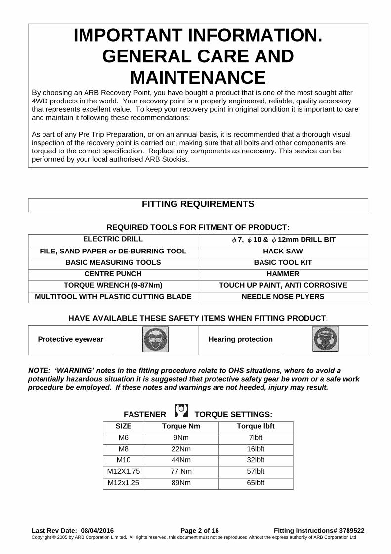
IMPORTANT INFORMATION. GENERAL CARE AND
MAINTENANCE By choosing an ARB Recovery Point, you have bought a product that is one of the most sought after
4WD products in the world. Your recovery point is a properly engineered, reliable, quality accessory that represents excellent value. To keep your recovery point in original condition it is important to care and maintain it following these recommendations: As part of any Pre Trip Preparation, or on an annual basis, it is recommended that a thorough visual inspection of the recovery point is carried out, making sure that all bolts and other components are torqued to the correct specification. Replace any components as necessary. This service can be performed by your local authorised ARB Stockist.
FITTING REQUIREMENTS
REQUIRED TOOLS FOR FITMENT OF PRODUCT:
ELECTRIC DRILL φ7, φ10 & φ12mm DRILL BIT
FILE, SAND PAPER or DE-BURRING TOOL HACK SAW
BASIC MEASURING TOOLS BASIC TOOL KIT
CENTRE PUNCH HAMMER
TORQUE WRENCH (9-87Nm) TOUCH UP PAINT, ANTI CORROSIVE
MULTITOOL WITH PLASTIC CUTTING BLADE NEEDLE NOSE PLYERS
HAVE AVAILABLE THESE SAFETY ITEMS WHEN FITTING PRODUCT:
Protective eyewear
Hearing protection
NOTE: ‘WARNING’ notes in the fitting procedure relate to OHS situations, where to avoid a potentially hazardous situation it is suggested that protective safety gear be worn or a safe work procedure be employed. If these notes and warnings are not heeded, injury may result.
FASTENER TORQUE SETTINGS:
SIZE Torque Nm Torque lbft
M6 9Nm 7lbft
M8 22Nm 16lbft
M10 44Nm 32lbft
M12X1.75 77 Nm 57lbft
M12x1.25 89Nm 65lbft
Last Rev Date: 08/04/2016 Page 3 of 16 Fitting instructions# 3789522 Copyright © 2005 by ARB Corporation Limited. All rights reserved, this document must not be reproduced without the express authority of ARB Corporation Ltd
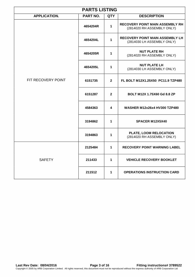
PARTS LISTING
APPLICATION. PART NO. QTY DESCRIPTION
FIT RECOVERY POINT
4654204R 1 RECOVERY POINT MAIN ASSEMBLY RH
(2814020 RH ASSEMBLY ONLY)
4654204L 1 RECOVERY POINT MAIN ASSEMBLY LH
(2814030 LH ASSEMBLY ONLY)
4654205R 1 NUT PLATE RH
(2814020 RH ASSEMBLY ONLY)
4654205L 1 NUT PLATE LH
(2814030 LH ASSEMBLY ONLY)
6151735 2 FL BOLT M12X1.25X50 PC11.9 TZP480
6151287 2 BOLT M12X 1.75X60 Gd 8.8 ZP
4584363 4 WASHER M12x26x4 HV300 TZP480
3194862 1 SPACER M12X5X40
3194863 1 PLATE, LOOM RELOCATION
(2814020 RH ASSEMBLY ONLY)
SAFETY
2125484 1 RECOVERY POINT WARNING LABEL
211433 1 VEHICLE RECOVERY BOOKLET
211512 1 OPERATIONS INSTRUCTION CARD

Last Rev Date: 08/04/2016 Page 4 of 16 Fitting instructions# 3789522 Copyright © 2005 by ARB Corporation Limited. All rights reserved, this document must not be reproduced without the express authority of ARB Corporation Ltd
FITTING PROCEDURE
(Fitted with an ARB bull bar)
Note: HILUX images shown, FORTUNA fasteners are the same unless otherwise specified. 1. Remove wing under panel, ARB stone guards
and stone shield from bull bar. (Refer to ARB bull bar fitting instructions that came with the bull bar).
2. Disconnect all components fitted to bull bar. (Indicators, Fog lights, Winch, Arial, Driving lights, Side rails etc.)
3. On both sides of the vehicle mark the position of bull bar mounts on braces. This is to aid in re-installed in the same location.
4. Loosen and remove bull bar 4 X M12 bolts and nut on lower sides of bull bar mounts. (2 x LH SIDE, 2 X RH SIDE)
5. Loosen and remove 8 X M10 Sems bolts and nut. (4 x LH SIDE, 4 X RH SIDE)
6. With the aide of another person remove 4 X M10 OEM bolts (2 x LH SIDE, 2 X RH SIDE) and remove bull bar from vehicle.
WARNING: Due to the weight of the bar and winch if fitted, it is advised that you use some form of mechanical assistance when lifting the bar onto the vehicle such as an elevating trolley.
7. On the side the recovery point is to be installed, remove 2XM12 bolts holding inner bull bar mount bracket to chassis rail.
8. Remove nut plate from inside chassis rail.
SUMMIT BAR
RH SIDE
RH SIDE
RH SIDE
RHS OUTER
RHS INNER
Last Rev Date: 08/04/2016 Page 5 of 16 Fitting instructions# 3789522 Copyright © 2005 by ARB Corporation Limited. All rights reserved, this document must not be reproduced without the express authority of ARB Corporation Ltd
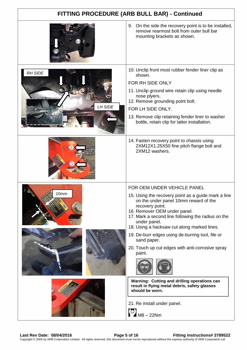
FITTING PROCEDURE (ARB BULL BAR) - Continued
9. On the side the recovery point is to be installed,
remove rearmost bolt from outer bull bar mounting brackets as shown.
10. Unclip front most rubber fender liner clip as shown.
FOR RH SIDE ONLY
11. Unclip ground wire retain clip using needle nose plyers.
12. Remove grounding point bolt.
FOR LH SIDE ONLY.
13. Remove clip retaining fender liner to washer bottle, retain clip for latter installation.
14. Fasten recovery point to chassis using
2XM12X1.25X50 fine pitch flange bolt and 2XM12 washers.
FOR OEM UNDER VEHICLE PANEL
15. Using the recovery point as a guide mark a line on the under panel 10mm reward of the recovery point.
16. Remover OEM under panel. 17. Mark a second line following the radius on the
under panel. 18. Using a hacksaw cut along marked lines.
19. De-burr edges using de-burring tool, file or sand paper.
20. Touch up cut edges with anti-corrosive spray paint.
21. Re install under panel.
M8 – 22Nm
RH SIDE
10mm
Warning: Cutting and drilling operations can result in flying metal debris, safety glasses should be worn.
LH SIDE
Last Rev Date: 08/04/2016 Page 6 of 16 Fitting instructions# 3789522 Copyright © 2005 by ARB Corporation Limited. All rights reserved, this document must not be reproduced without the express authority of ARB Corporation Ltd
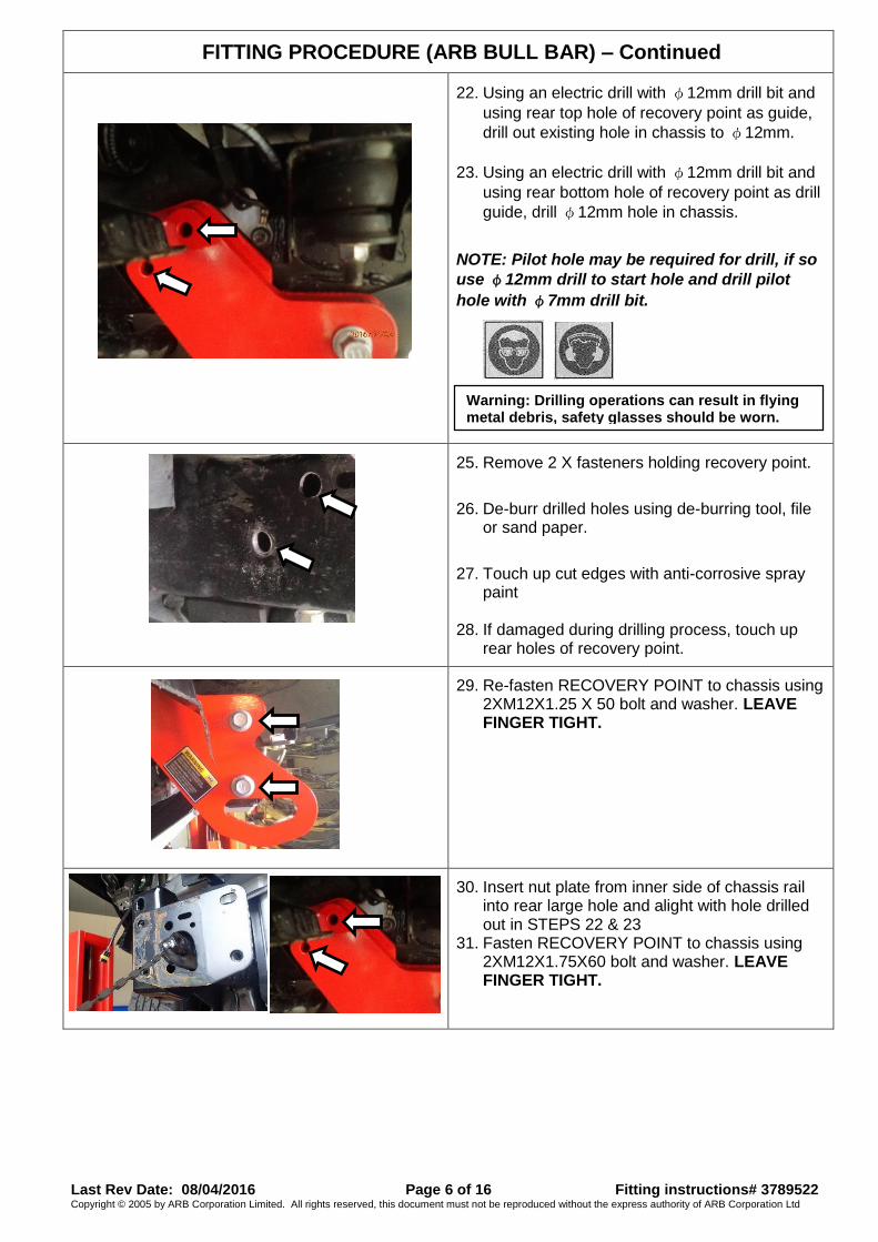
FITTING PROCEDURE (ARB BULL BAR) – Continued
22. Using an electric drill with φ12mm drill bit and
using rear top hole of recovery point as guide,
drill out existing hole in chassis to φ12mm.
23. Using an electric drill with φ12mm drill bit and
using rear bottom hole of recovery point as drill
guide, drill φ12mm hole in chassis.
NOTE: Pilot hole may be required for drill, if so
use φ12mm drill to start hole and drill pilot
hole with φ7mm drill bit.
24.
25. Remove 2 X fasteners holding recovery point.
26. De-burr drilled holes using de-burring tool, file or sand paper.
27. Touch up cut edges with anti-corrosive spray
paint
28. If damaged during drilling process, touch up rear holes of recovery point.
29. Re-fasten RECOVERY POINT to chassis using
2XM12X1.25 X 50 bolt and washer. LEAVE FINGER TIGHT.
30. Insert nut plate from inner side of chassis rail
into rear large hole and alight with hole drilled out in STEPS 22 & 23
31. Fasten RECOVERY POINT to chassis using 2XM12X1.75X60 bolt and washer. LEAVE FINGER TIGHT.
Warning: Drilling operations can result in flying metal debris, safety glasses should be worn.
Last Rev Date: 08/04/2016 Page 7 of 16 Fitting instructions# 3789522 Copyright © 2005 by ARB Corporation Limited. All rights reserved, this document must not be reproduced without the express authority of ARB Corporation Ltd
FITTING PROCEDURE (ARB BULL BAR) – Continued
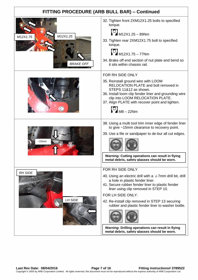
32. Tighten front 2XM12X1.25 bolts to specified
torque.
M12X1.25 – 89Nm
33. Tighten rear 2XM12X1.75 bolt to specified torque.
M12X1.75 – 77Nm
34. Brake off end section of nut plate and bend so it sits within chassis rail.
FOR RH SIDE ONLY
35. Reinstall ground wire with LOOM RELOCATION PLATE and bolt removed in STEPS 11&12 as shown.
36. Install loom clip fender liner and grounding wire clip into LOOM RELOCATION PLATE.
37. Align PLATE with recover point and tighten.
M8 – 22Nm
38. Using a multi tool trim inner edge of fender liner
to give ~15mm clearance to recovery point.
39. Use a file or sandpaper to de-bur all cut edges.
FOR RH SIDE ONLY
40. Using an electric drill with a φ7mm drill bit, drill
a hole in plastic fender liner. 41. Secure rubber fender liner to plastic fender
liner using clip removed in STEP 10.
FOR LH SIDE ONLY.
42. Re-install clip removed in STEP 13 securing rubber and plastic fender liner to washer bottle.
BRAKE OFF
M12X1.25
M12X1.75
Warning: Cutting operations can result in flying metal debris, safety glasses should be worn.
~15mm
Warning: Drilling operations can result in flying metal debris, safety glasses should be worn.
RH SIDE
LH SIDE
Last Rev Date: 08/04/2016 Page 8 of 16 Fitting instructions# 3789522 Copyright © 2005 by ARB Corporation Limited. All rights reserved, this document must not be reproduced without the express authority of ARB Corporation Ltd
FITTING PROCEDURE (ARB BULL BAR) – Continued
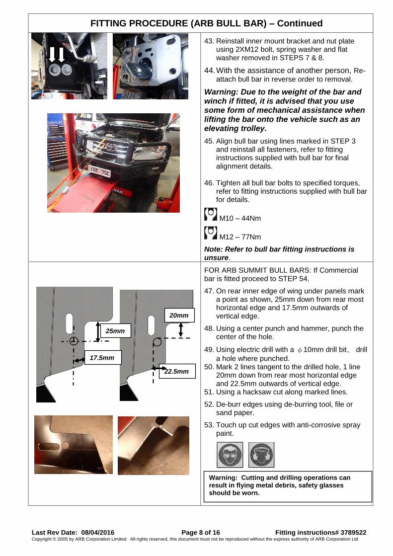
43. Reinstall inner mount bracket and nut plate
using 2XM12 bolt, spring washer and flat washer removed in STEPS 7 & 8.
44. With the assistance of another person, Re-
attach bull bar in reverse order to removal.
Warning: Due to the weight of the bar and winch if fitted, it is advised that you use some form of mechanical assistance when lifting the bar onto the vehicle such as an elevating trolley.
45. Align bull bar using lines marked in STEP 3 and reinstall all fasteners, refer to fitting instructions supplied with bull bar for final alignment details.
46. Tighten all bull bar bolts to specified torques, refer to fitting instructions supplied with bull bar for details.
M10 – 44Nm
M12 – 77Nm
Note: Refer to bull bar fitting instructions is unsure.
FOR ARB SUMMIT BULL BARS: If Commercial bar is fitted proceed to STEP 54.
47. On rear inner edge of wing under panels mark a point as shown, 25mm down from rear most horizontal edge and 17.5mm outwards of vertical edge.
48. Using a center punch and hammer, punch the center of the hole.
49. Using electric drill with a φ10mm drill bit、 drill
a hole where punched. 50. Mark 2 lines tangent to the drilled hole, 1 line
20mm down from rear most horizontal edge and 22.5mm outwards of vertical edge.
51. Using a hacksaw cut along marked lines.
52. De-burr edges using de-burring tool, file or sand paper.
53. Touch up cut edges with anti-corrosive spray paint.
54.
Warning: Cutting and drilling operations can result in flying metal debris, safety glasses should be worn.
20mm
22.5mm
25mm
17.5mm

Last Rev Date: 08/04/2016 Page 9 of 16 Fitting instructions# 3789522 Copyright © 2005 by ARB Corporation Limited. All rights reserved, this document must not be reproduced without the express authority of ARB Corporation Ltd
FITTING PROCEDURE (ARB BULL BAR) – Continued
55. Re-install wing under panel, stone guards and
stone shield to bull bar. 56. Tighten all fasteners to specified torques.
M6 – 9Nm
M8 – 22Nm
57. Add recovery point warning label onto wing under panel as shown.
FITTED PRODUCT – Recovery Point (LH & RH)
RH SUMMIT WING PANEL SHOWN
WARNING LABEL
Last Rev Date: 08/04/2016 Page 10 of 16 Fitting instructions# 3789522 Copyright © 2005 by ARB Corporation Limited. All rights reserved, this document must not be reproduced without the express authority of ARB Corporation Ltd
FITTING PROCEDURE
(Fitted with an OEM BUMPER)
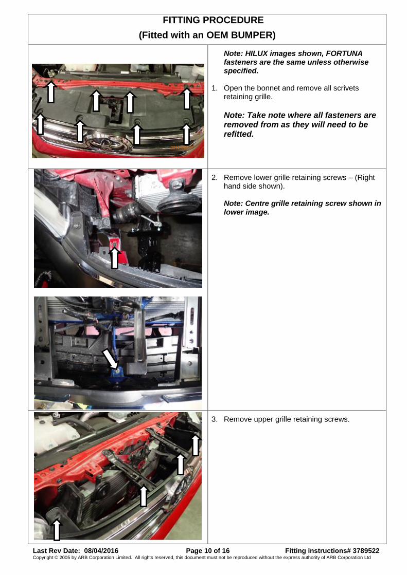
Note: HILUX images shown, FORTUNA fasteners are the same unless otherwise specified.
1. Open the bonnet and remove all scrivets retaining grille.
Note: Take note where all fasteners are removed from as they will need to be refitted.
2. Remove lower grille retaining screws – (Right hand side shown). Note: Centre grille retaining screw shown in lower image.
3. Remove upper grille retaining screws.
Last Rev Date: 08/04/2016 Page 11 of 16 Fitting instructions# 3789522 Copyright © 2005 by ARB Corporation Limited. All rights reserved, this document must not be reproduced without the express authority of ARB Corporation Ltd
FITTING PROCEDURE (OEM BUMPER) – Continued
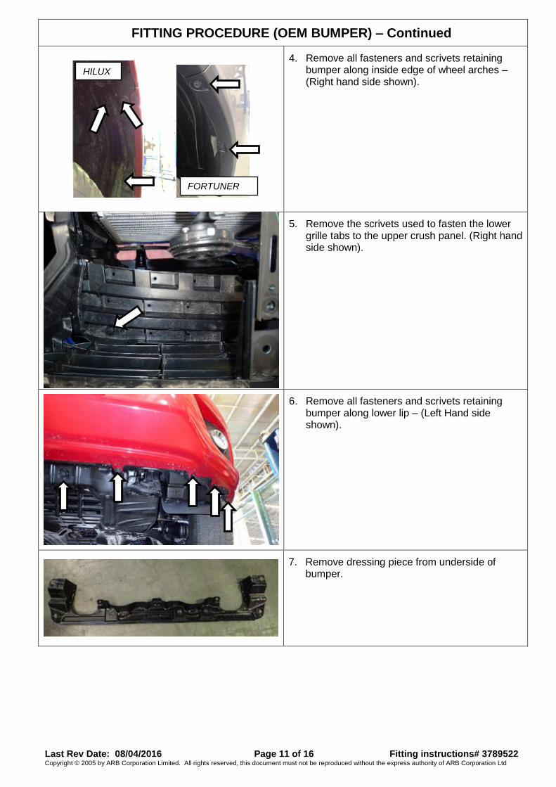
4. Remove all fasteners and scrivets retaining bumper along inside edge of wheel arches – (Right hand side shown).
5. Remove the scrivets used to fasten the lower grille tabs to the upper crush panel. (Right hand side shown).
6. Remove all fasteners and scrivets retaining bumper along lower lip – (Left Hand side shown).
7. Remove dressing piece from underside of bumper.
HILUX
FORTUNER
Last Rev Date: 08/04/2016 Page 12 of 16 Fitting instructions# 3789522 Copyright © 2005 by ARB Corporation Limited. All rights reserved, this document must not be reproduced without the express authority of ARB Corporation Ltd
FITTING PROCEDURE (OEM BUMPER) – Continued
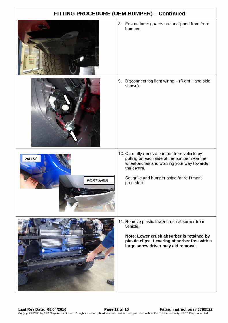
8. Ensure inner guards are unclipped from front bumper.
9. Disconnect fog light wiring – (Right Hand side shown).
10. Carefully remove bumper from vehicle by
pulling on each side of the bumper near the wheel arches and working your way towards the centre. Set grille and bumper aside for re-fitment procedure.
11. Remove plastic lower crush absorber from vehicle. Note: Lower crush absorber is retained by plastic clips. Levering absorber free with a large screw driver may aid removal.
HILUX
FORTUNER
Last Rev Date: 08/04/2016 Page 13 of 16 Fitting instructions# 3789522 Copyright © 2005 by ARB Corporation Limited. All rights reserved, this document must not be reproduced without the express authority of ARB Corporation Ltd
FITTING PROCEDURE (OEM BUMPER) – Continued
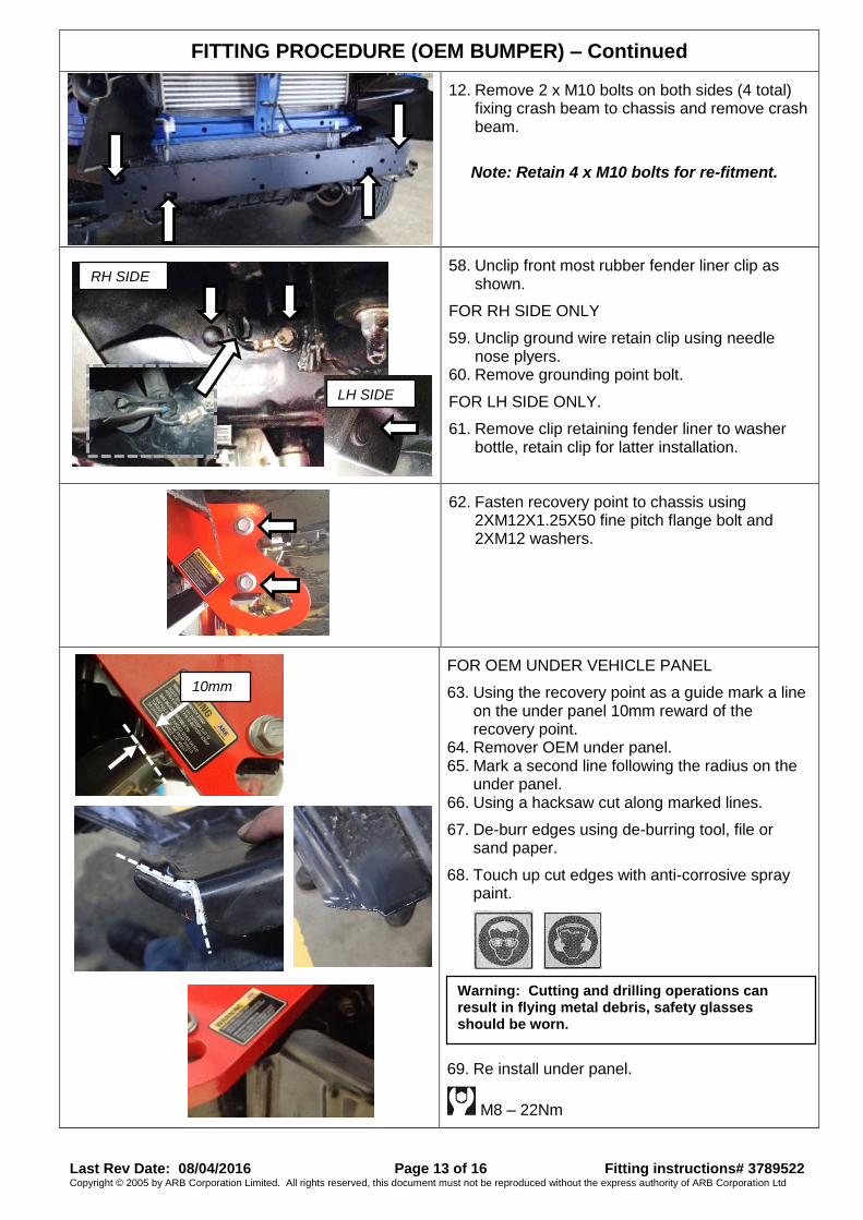
12. Remove 2 x M10 bolts on both sides (4 total) fixing crash beam to chassis and remove crash beam.
Note: Retain 4 x M10 bolts for re-fitment.
58. Unclip front most rubber fender liner clip as shown.
FOR RH SIDE ONLY
59. Unclip ground wire retain clip using needle nose plyers.
60. Remove grounding point bolt.
FOR LH SIDE ONLY.
61. Remove clip retaining fender liner to washer bottle, retain clip for latter installation.
62. Fasten recovery point to chassis using
2XM12X1.25X50 fine pitch flange bolt and 2XM12 washers.
FOR OEM UNDER VEHICLE PANEL
63. Using the recovery point as a guide mark a line on the under panel 10mm reward of the recovery point.
64. Remover OEM under panel. 65. Mark a second line following the radius on the
under panel. 66. Using a hacksaw cut along marked lines.
67. De-burr edges using de-burring tool, file or sand paper.
68. Touch up cut edges with anti-corrosive spray paint.
69. Re install under panel.
M8 – 22Nm
10mm
Warning: Cutting and drilling operations can result in flying metal debris, safety glasses should be worn.
RH SIDE
LH SIDE

Last Rev Date: 08/04/2016 Page 14 of 16 Fitting instructions# 3789522 Copyright © 2005 by ARB Corporation Limited. All rights reserved, this document must not be reproduced without the express authority of ARB Corporation Ltd
FITTING PROCEDURE (OEM BUMPER) – Continued
70. Using an electric drill with φ12mm drill bit and
using rear top hole of recovery point as guide,
drill out existing hole in chassis to φ12mm.
71. Using an electric drill with φ12mm drill bit and
using rear bottom hole of recovery point as drill
guide, drill φ12mm hole in chassis.
NOTE: Pilot hole may be required for drill, if so
use φ12mm drill to start hole and drill pilot
hole with φ7mm drill bit.
72.
73. Remove 2 X fasteners holding recovery point.
74. De-burr drilled holes using de-burring tool, file or sand paper.
75. Touch up cut edges with anti-corrosive spray
paint
76. If damaged during drilling process, touch up rear holes of recovery point.
77. Re-fasten RECOVERY POINT to chassis using
2XM12X1.25 X 50 bolt and washer. LEAVE FINGER TIGHT.
78. Insert nut plate from inner side of chassis rail
into rear large hole and alight with hole drilled out in STEPS 69 & 70
79. Fasten RECOVERY POINT to chassis using 2XM12X1.75X60 bolt and washer. LEAVE FINGER TIGHT.
Warning: Drilling operations can result in flying metal debris, safety glasses should be worn.
Last Rev Date: 08/04/2016 Page 15 of 16 Fitting instructions# 3789522 Copyright © 2005 by ARB Corporation Limited. All rights reserved, this document must not be reproduced without the express authority of ARB Corporation Ltd
FITTING PROCEDURE (OEM BUMPER) – Continued
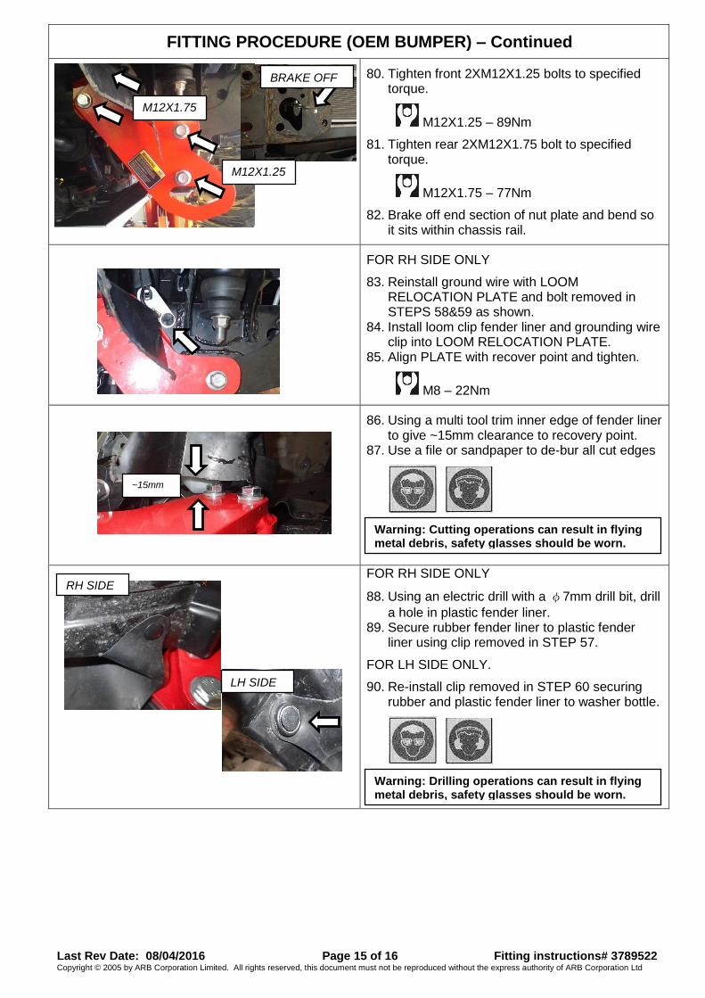
80. Tighten front 2XM12X1.25 bolts to specified
torque.
M12X1.25 – 89Nm
81. Tighten rear 2XM12X1.75 bolt to specified torque.
M12X1.75 – 77Nm
82. Brake off end section of nut plate and bend so it sits within chassis rail.
FOR RH SIDE ONLY
83. Reinstall ground wire with LOOM RELOCATION PLATE and bolt removed in STEPS 58&59 as shown.
84. Install loom clip fender liner and grounding wire clip into LOOM RELOCATION PLATE.
85. Align PLATE with recover point and tighten.
M8 – 22Nm
86. Using a multi tool trim inner edge of fender liner
to give ~15mm clearance to recovery point. 87. Use a file or sandpaper to de-bur all cut edges
FOR RH SIDE ONLY
88. Using an electric drill with a φ7mm drill bit, drill
a hole in plastic fender liner. 89. Secure rubber fender liner to plastic fender
liner using clip removed in STEP 57.
FOR LH SIDE ONLY.
90. Re-install clip removed in STEP 60 securing rubber and plastic fender liner to washer bottle.
BRAKE OFF
M12X1.25
M12X1.75
Warning: Cutting operations can result in flying metal debris, safety glasses should be worn.
~15mm
Warning: Drilling operations can result in flying metal debris, safety glasses should be worn.
RH SIDE
LH SIDE
Last Rev Date: 08/04/2016 Page 16 of 16 Fitting instructions# 3789522 Copyright © 2005 by ARB Corporation Limited. All rights reserved, this document must not be reproduced without the express authority of ARB Corporation Ltd
FITTING PROCEDURE (OEM BUMPER) – Continued
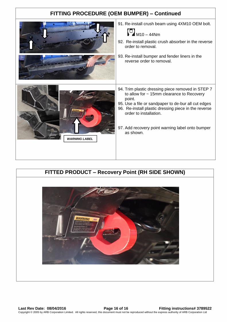
91. Re-install crush beam using 4XM10 OEM bolt.
M10 – 44Nm
92. Re-install plastic crush absorber in the reverse order to removal.
93. Re-install bumper and fender liners in the reverse order to removal.
94. Trim plastic dressing piece removed in STEP 7
to allow for ~ 15mm clearance to Recovery point.
95. Use a file or sandpaper to de-bur all cut edges 96. Re-install plastic dressing piece in the reverse
order to installation.
97. Add recovery point warning label onto bumper as shown.
FITTED PRODUCT – Recovery Point (RH SIDE SHOWN)
WARNING LABEL