Acura/Honda 1990-1998 INST-7800 - Yahoo
40
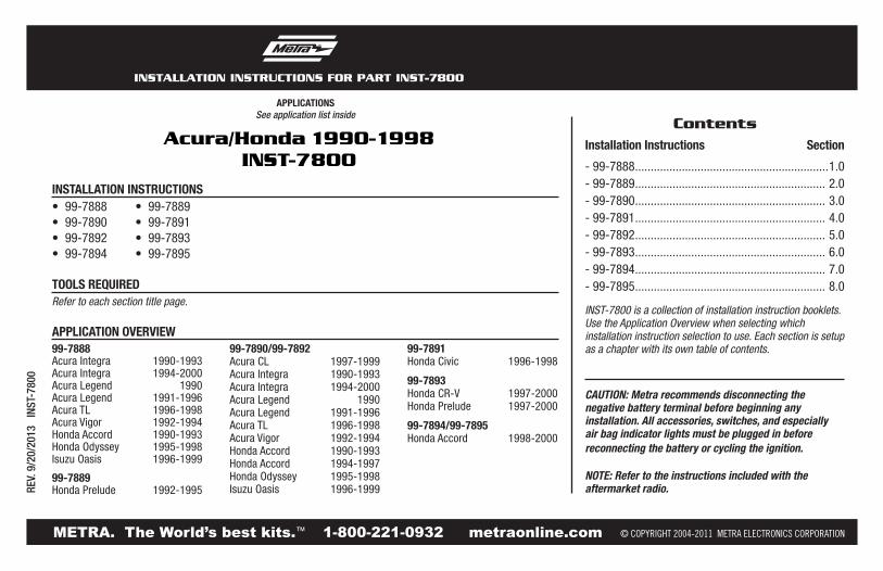
INSTALLATION INSTRUCTIONS FOR PART INST-7800 APPLICATIONS METRA. The World’s best kits. ™ metraonline.com 1-800-221-0932 © COPYRIGHT 2004-2011 METRA ELECTRONICS CORPORATION REV. 9/20/2013 INST-7800 CAUTION: Metra recommends disconnecting the negative battery terminal before beginning any installation. All accessories, switches, and especially air bag indicator lights must be plugged in before reconnecting the battery or cycling the ignition. NOTE: Refer to the instructions included with the aftermarket radio. • 99-7888 • 99-7889 • 99-7890 • 99-7891 • 99-7892 • 99-7893 • 99-7894 • 99-7895 Refer to each section title page. INSTALLATION INSTRUCTIONS TOOLS REQUIRED Acura/Honda 1990-1998 INST-7800 See application list inside Installation Instructions Section - 99-7888.............................................................. 1.0 - 99-7889............................................................. 2.0 - 99-7890............................................................. 3.0 - 99-7891............................................................. 4.0 - 99-7892............................................................. 5.0 - 99-7893............................................................. 6.0 - 99-7894............................................................. 7.0 - 99-7895............................................................. 8.0 Contents 99-7888 Acura Integra 1990-1993 Acura Integra 1994-2000 Acura Legend 1990 Acura Legend 1991-1996 Acura TL 1996-1998 Acura Vigor 1992-1994 Honda Accord 1990-1993 Honda Odyssey 1995-1998 Isuzu Oasis 1996-1999 99-7889 Honda Prelude 1992-1995 99-7890/99-7892 Acura CL 1997-1999 Acura Integra 1990-1993 Acura Integra 1994-2000 Acura Legend 1990 Acura Legend 1991-1996 Acura TL 1996-1998 Acura Vigor 1992-1994 Honda Accord 1990-1993 Honda Accord 1994-1997 Honda Odyssey 1995-1998 Isuzu Oasis 1996-1999 99-7891 Honda Civic 1996-1998 99-7893 Honda CR-V 1997-2000 Honda Prelude 1997-2000 99-7894/99-7895 Honda Accord 1998-2000 APPLICATION OVERVIEW INST-7800 is a collection of installation instruction booklets. Use the Application Overview when selecting which installation instruction selection to use. Each section is setup as a chapter with its own table of contents.
-
Upload
khangminh22 -
Category
Documents
-
view
0 -
download
0
Transcript of Acura/Honda 1990-1998 INST-7800 - Yahoo
INSTALLATION INSTRUCTIONS FOR PART INST-7800
APPLICATIONS
METRA. The World’s best kits.™ metraonline.com1-800-221-0932 © COPYRIGHT 2004-2011 METRA ELECTRONICS CORPORATION
REV.
9/2
0/20
13
INST
-780
0
CAUTION: Metra recommends disconnecting the negative battery terminal before beginning any installation. All accessories, switches, and especially air bag indicator lights must be plugged in before reconnecting the battery or cycling the ignition.
NOTE: Refer to the instructions included with the aftermarket radio.
• 99-7888 • 99-7889• 99-7890 • 99-7891• 99-7892 • 99-7893• 99-7894 • 99-7895
Refer to each section title page.
INSTALLATION INSTruCTIONS
TOOLS requIred
Acura/Honda 1990-1998INST-7800
See application list inside
Installation Instructions Section
-99-7888..............................................................1.0-99-7889.............................................................2.0-99-7890.............................................................3.0-99-7891.............................................................4.0-99-7892.............................................................5.0-99-7893.............................................................6.0-99-7894.............................................................7.0-99-7895.............................................................8.0
Contents
99-7888AcuraIntegra 1990-1993AcuraIntegra 1994-2000AcuraLegend 1990AcuraLegend 1991-1996AcuraTL 1996-1998AcuraVigor 1992-1994HondaAccord 1990-1993HondaOdyssey 1995-1998IsuzuOasis 1996-1999
99-7889HondaPrelude 1992-1995
99-7890/99-7892AcuraCL 1997-1999AcuraIntegra 1990-1993AcuraIntegra 1994-2000AcuraLegend 1990AcuraLegend 1991-1996AcuraTL 1996-1998AcuraVigor 1992-1994HondaAccord 1990-1993HondaAccord 1994-1997HondaOdyssey 1995-1998IsuzuOasis 1996-1999
99-7891HondaCivic 1996-1998
99-7893HondaCR-V 1997-2000HondaPrelude 1997-2000
99-7894/99-7895HondaAccord 1998-2000
APPLICATION OvervIew
INST-7800 is a collection of installation instruction booklets. Use the Application Overview when selecting which installation instruction selection to use. Each section is setup as a chapter with its own table of contents.
1.0
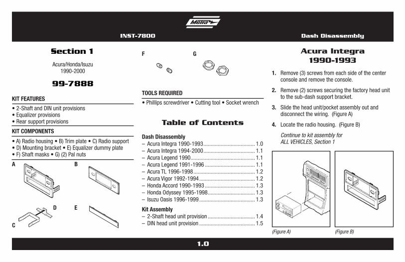
1. Remove(3)screwsfromeachsideofthecenterconsoleandremovetheconsole.
2. Remove(2)screwssecuringthefactoryheadunittothesub-dashsupportbracket.
3. Slidetheheadunit/pocketassemblyoutanddisconnectthewiring.(FigureA)
4. Locatetheradiohousing.(FigureB)
Continue to kit assembly for ALL VEHICLES, Section 1
Acura Integra1990-1993
(Figure A)
Section 1
Acura/Honda/Isuzu1990-2000
99-7888
•A)Radiohousing•B)Trimplate•C)Radiosupport•D)Mountingbracket•E)Equalizerdummyplate•F)Shaftmasks•G)(2)Palnuts
KIT FeATureS
KIT COMPONeNTS
•2-ShaftandDINunitprovisions•Equalizerprovisions•Rearsupportprovisions
•Phillipsscrewdriver•Cuttingtool•Socketwrench
TOOLS requIred
BA
Table of Contents
Dash Disassembly – AcuraIntegra1990-1993.................................... 1.0– AcuraIntegra1994-2000.................................... 1.1– AcuraLegend1990............................................. 1.1– AcuraLegend1991-1996................................... 1.1– AcuraTL1996-1998........................................... 1.2– AcuraVigor1992-1994....................................... 1.2– HondaAccord1990-1993................................... 1.3– HondaOdyssey1995-1998................................. 1.3– IsuzuOasis1996-1999....................................... 1.3
Kit Assembly– 2-Shaftheadunitprovision................................. 1.4– DINheadunitprovision....................................... 1.5
D E
C
GF
(Figure B)
Dash DisassemblyINST-7800

1.1
1. Removethecovercaplocatedundertheemergencybrakeandremove(2)screwsexposed.
2. Remove(2)screwsfromtherearcornersofthelowerdashtrimbezelandremove.(FigureA)
3. Removetheashtrayand(2)screwsexposed.(FigureA)
4. Unsnaptheashtrayhousinganddisconnectthecigarettelighterharness.
5. Removethegearshifterknobandunsnaptheshiftertrim.
6. Remove(2)screwsbelowtheradioopeningandremovetheupperdashtrimbezel.
7. Remove(2)8mmscrewssecuringthefactoryheadunitanddisconnectthewiring.
8. Locatetheradiohousing.(FigureB)
Continue to kit assembly for ALL VEHICLES, Section 1
Acura Integra 1994-2000
1. Remove(2)screwsbelowtheashtray.(FigureA)
2. Unclipthedashtrimbezelthendisconnectthecigarettelighterwiringandremovethebezel.
3. Remove(2)boltssecuringtherearofthefactoryheadunitanddisconnectthewiring.
4. Modifythefactoryradiohousingbycuttingand
removingtheshadedportionsofthehousinglip.(FigureB)
Continue to kit assembly for ALL VEHICLES, Section 1
Acura Ledgend 1990
(Figure A) (Figure B)
1. Remove(2)screwsbelowtheashtray.(FigureA)
2. Unclipthedashtrimbezelanddisconnectthecigarettelighterwiringandremovethebezel.
3. Remove(2)boltssecuringthe rearofthefactoryheadunitanddisconnectthewiring.
4. Locatetheradiohousing.(FigureB)
Continue to kit assembly for ALL VEHICLES, Section 1
Acura Ledgend1991-1996
(Figure A) (Figure B)(Figure B)
(Figure A)
Factoryradiohousingopening
¼” ¼”
1¼” 1¼”
1” 1”
¾” ¾”
Dash Disassembly INST-7800
1.2
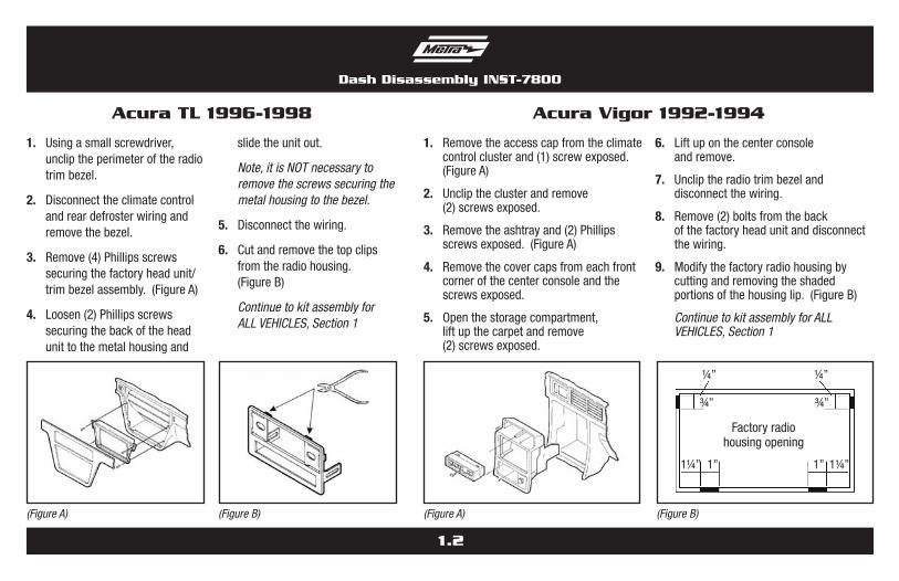
1. Usingasmallscrewdriver,uncliptheperimeteroftheradiotrimbezel.
2. Disconnecttheclimatecontrolandreardefrosterwiringandremovethebezel.
3. Remove(4)Phillipsscrewssecuringthefactoryheadunit/trimbezelassembly.(FigureA)
4. Loosen(2)Phillipsscrewssecuringthebackoftheheadunittothemetalhousingand
slidetheunitout.
Note, it is NOT necessary to remove the screws securing the metal housing to the bezel.
5. Disconnectthewiring.
6. Cutandremovethetopclipsfromtheradiohousing.(FigureB)
Continue to kit assembly for ALL VEHICLES, Section 1
Acura TL 1996-1998
1. Removetheaccesscapfromtheclimatecontrolclusterand(1)screwexposed.(FigureA)
2. Uncliptheclusterandremove(2)screwsexposed.
3. Removetheashtrayand(2)Phillipsscrewsexposed.(FigureA)
4. Removethecovercapsfromeachfrontcornerofthecenterconsoleandthescrewsexposed.
5. Openthestoragecompartment,liftupthecarpetandremove(2)screwsexposed.
6. Liftuponthecenterconsoleandremove.
7. Uncliptheradiotrimbezelanddisconnectthewiring.
8. Remove(2)boltsfromthebackofthefactoryheadunitanddisconnectthewiring.
9. Modifythefactoryradiohousingbycuttingandremovingtheshadedportionsofthehousinglip.(FigureB)
Continue to kit assembly for ALL VEHICLES, Section 1
Acura Vigor 1992-1994
(Figure A) (Figure A) (Figure B)(Figure B)
Factoryradiohousingopening
¼” ¼”
1¼” 1¼”1” 1”
¾” ¾”
Dash Disassembly INST-7800

1.3
1. Remove(4)screwsfromthelowerportionofthecenterconsole.(FigureA)
2. Removethegearshifterknobandlifttheconsoleout.
3. Removetheashtrayandashtraybracket.
4. Remove(2)screwsfromthebottomoftheheadunitsupport,slidetheunitoutanddisconnectthewiring.
5. Locatetheradiohousing.(FigureB)
Continue to kit assembly for ALL VEHICLES, Section 1
Honda Accord 1990-1993
1. Remove(2)8mmscrewsundertheglovebox.
2. Remove(1)Phillipsscrewonthegloveboxarmandremovethebox.
3. Remove(2)Phillipsscrewsexposedinthegloveboxcavitythenremove(2)Phillipsscrewsbelowthestorageboxdoor(undertheashtray).(FigureA)
4. Remove(2)screwsfromtheleftsideofthedashconsole.
5. Remove(1)Phillipsscrewfromthecointray
andthenremove(1)Phillipsscrewundertheignition.
6. Remove(4)Phillipsscrewssecuringthefactorycupholder.
7. Remove(2)8mmhex-headscrewsfromtherearsupportbracketanddisconnectthewiring.
8. Locatetheradiohousing.(FigureB)
Continue to kit assembly for ALL VEHICLES, Section 1
Honda Odyssey 1995-1998Isuzu Oasis 1996-1999
(Figure A) (Figure B) (Figure A) (Figure B)
Dash Disassembly INST-7800

1.4
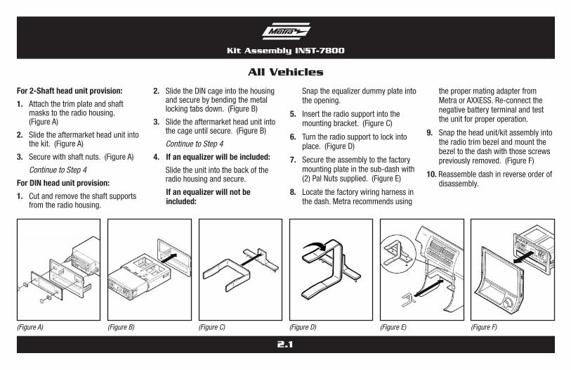
For 2-Shaft head unit provision:
1. Attachthetrimplateandshaftmaskstotheradiohousing.(FigureA1)
2. Slidetheaftermarketheadunitintothekitandsecurewithshaftnuts.(FigureA1)
Continue to Step 4
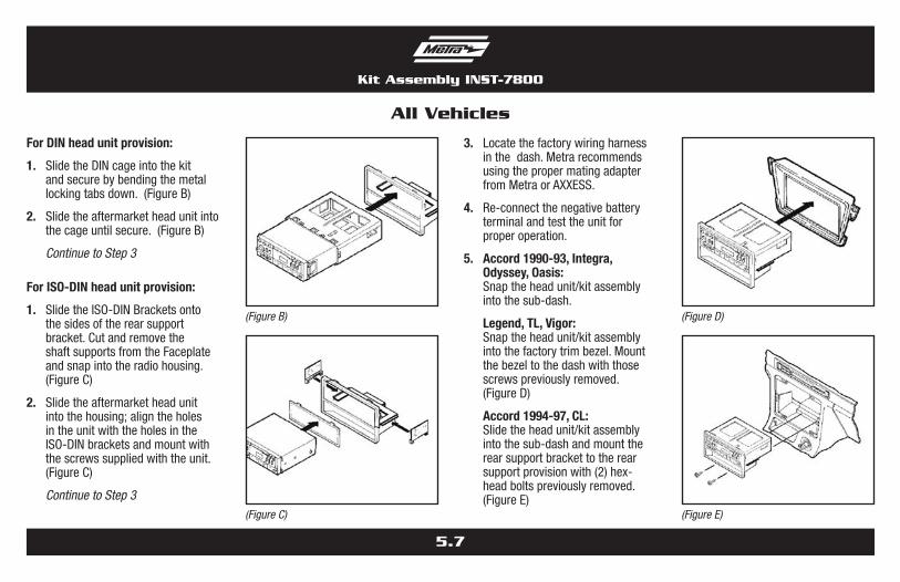
For DIN head unit provision:
1. Cutandremovetheshaftsupportsfromtheradiohousing.
2. SlidetheDINcageintothekitandsecurebybendingthemetal lockingtabsdown.
3. Slidetheaftermarketheadunitintothecageuntilsecure.(FigureA2)
Continue to Step 4
All Vehicles
(Figure A1) (Figure A2)
4. If an equalizer will be included: Slidetheaftermarketequalizerintothebackoftheradiohousing.Usingthe
hardwareincludedwiththeequalizer,mounttheunittothekit.(FigureB)
If an equalizer will Not be included: SnaptheEqualizerDummyPlateintotheradiohousing.(FigureC)
5. InserttheRadioSupportintotheMountingBracket.(FigureD)
6. TurntheRadioSupporttolockintoplace.(FigureE)
7. Mounttheassemblytothefactorymountingplateinthesub-dashwith(2)PalNutssupplied.(FigureF)
Continue on next page
(Figure B) (Figure C)
Kit Assembly INST-7800

1.5
8. Locatethefactorywiringharnessinthedash.MetrarecommendsusingthepropermatingadapterfromMetraorAXXESS.Re-connectthenegativebatteryterminalandtesttheunitforproperoperation.
9. Integra, Accord, odyssey, oasis: Snaptheheadunit/kitassemblyintothesub-dash.(FigureG)
Legend, tL, Vigor: Snaptheheadunit/kitassemblyintothefactorytrimbezel.Mountthebezeltothedashwiththosescrews
previouslyremoved.(FigureH)
10.Reassembledashinreverseorderofdisassembly.
All Vehicles
(Figure G) (Figure H)(Figure F)
(Figure D) (Figure E)
Kit Assembly INST-7800

2.0
3. Pullupontheconsoletrimbezelandremove.
4. Usinganangledscrewdriver,remove(2)screwssecuringthegearshifterbrackettothebezel.(FigureA)
5. Remove(4)screwsfromtheradiotrimbezel,removethefactoryheadunitassemblyanddisconnectthewiring. (FigureB)
Continue to kit assembly for ALL VEHICLES, Section 2
Honda Prelude 1992-1995
(Figure A)
Section 2
HondaPrelude1992-1995
99-7889
•A)Radiohousing•B)Trimplate•C)Shaftmasks•D)Equalizerdummyplate•E)Radiosupport•F)Mountingbracket
KIT FeATureS
KIT COMPONeNTS
•2-ShaftandDINunitprovisions•Equalizerprovisions•Rearsupportprovisions
•Phillipsscrewdriver•Cuttingtool•Socketwrench
TOOLS requIred
BA
Table of Contents
Dash Disassembly – HondaPrelude1992-1995.................................. 2.0
Kit Assembly– 2-Shaftheadunitprovision................................. 2.1– DINheadunitprovision....................................... 2.1
D
F
E
(Figure B)
C1. Remove(2)screwsfromthetopoftheconsoletrim
bezel.(FigureA)
2. Slidethefrontseatsbackandremove(4)Phillipsscrewsfromeachsideofthebezel.(FigureA)
Honda Prelude 1992-1995
INST-7800 Dash Disassembly
For 2-Shaft head unit provision:
1. Attachthetrimplateandshaftmaskstotheradiohousing.(FigureA)
2. Slidetheaftermarketheadunitintothekit.(FigureA)
3. Securewithshaftnuts.(FigureA)
Continue to Step 4
For DIN head unit provision:
1. Cutandremovetheshaftsupportsfromtheradiohousing.
2. SlidetheDINcageintothehousingandsecurebybendingthemetallockingtabsdown.(FigureB)
3. Slidetheaftermarketheadunitintothecageuntilsecure.(FigureB)
Continue to Step 4
4. If an equalizer will be included:
Slidetheunitintothebackoftheradiohousingandsecure.
If an equalizer will not be included:
Snaptheequalizerdummyplateintotheopening.
5. Inserttheradiosupportintothemountingbracket.(FigureC)
6. Turntheradiosupporttolockintoplace.(FigureD)
7. Securetheassemblytothefactorymountingplateinthesub-dashwith(2)PalNutssupplied.(FigureE)
8. Locatethefactorywiringharnessinthedash.Metrarecommendsusing
thepropermatingadapterfromMetraorAXXESS.Re-connectthenegativebatteryterminalandtesttheunitforproperoperation.
9. Snaptheheadunit/kitassemblyintotheradiotrimbezelandmountthebezeltothedashwiththosescrewspreviouslyremoved.(FigureF)
10. Reassembledashinreverseorderofdisassembly.
All Vehicles
(Figure A) (Figure B) (Figure C) (Figure D) (Figure E) (Figure F)
2.1
Kit Assembly INST-7800

3.0
1. Uncliptheradiotrimbezelanddisconnecttheclockandclimatecontrolwiring.(FigureA)
2. Remove(2)8mmhex-headscrewssecuringthefactoryheadunitanddisconnectthewiring.
3. Locatetheradiohousingandthencutandremovethesideclipsfromtheradiohousing. (FigureBandC)
4. Mounttherearsupportbrackettothebottomtabontheradiohousingwith(2)carriageboltsand(2)nuts.(FigureD)
Continue to kit assembly for ALL VEHICLES, Section 3
Acura CL 1997-1999
Section 3
Acura/Honda/Isuzu1990-2000
99-7890
•A)Radiohousing•B)Rearsupportbracket•C)Shaftsupports•D)(2)Nuts•E)Radiosupport•F)Mountingbracket•G)Equalizerdummyplate•H)(2)Carriagebolts•I)(2)Palnuts
KIT FeATureS
KIT COMPONeNTS
•2-ShaftandDINunitprovisions•Equalizerprovisions•Rearsupportprovisions
•Phillipsscrewdriver•Cuttingtool•Socketwrench
TOOLS requIred
BA
Table of Contents
Dash Disassembly – AcuraCL1997-1999....................................3.0-3.1
– AcuraIntegra1990-1993.................................... 3.1
– AcuraIntegra1994-2000.................................... 3.2
– AcuraLegend1990.......................................3.2-3.3
– AcuraLegend1991-1996................................... 3.3
– AcuraTL1996-1998........................................... 3.4
– AcuraVigor1992-1994.................................3.4-3.5
D
F
E
C
INST-7800
G
H I
– HondaAccord1990-1993................................... 3.5
– HondaAccord1994-1997................................... 3.6
– HondaOdyssey1995-1998...........................3.6-3.7
– IsuzuOasis1996-1999.................................3.6-3.7
Kit Assembly– 2-Shaftheadunitprovision...........................3.7-3.8
– DINheadunitprovision.................................3.7-3.8
Dash Disassembly
3.1
Acura CL 1997-1999
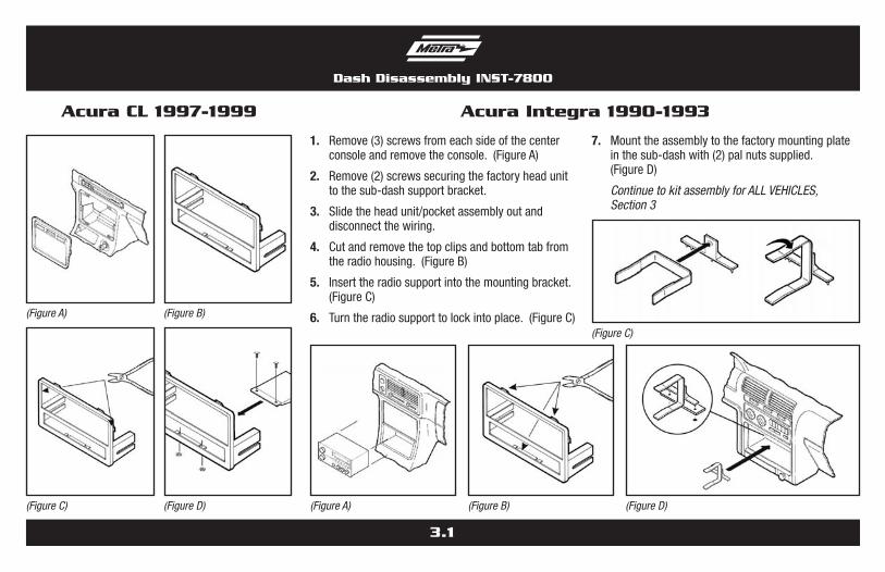
1. Remove(3)screwsfromeachsideofthecenterconsoleandremovetheconsole.(FigureA)
2. Remove(2)screwssecuringthefactoryheadunittothesub-dashsupportbracket.
3. Slidetheheadunit/pocketassemblyoutanddisconnectthewiring.
4. Cutandremovethetopclipsandbottomtabfromtheradiohousing.(FigureB)
5. Inserttheradiosupportintothemountingbracket.(FigureC)
6. Turntheradiosupporttolockintoplace.(FigureC)
7. Mounttheassemblytothefactorymountingplateinthesub-dashwith(2)palnutssupplied.(FigureD)
Continue to kit assembly for ALL VEHICLES, Section 3
Acura Integra 1990-1993
(Figure C) (Figure D) (Figure A) (Figure B) (Figure D)
(Figure A) (Figure B)
(Figure C)
Dash Disassembly INST-7800
3.2
Acura Legend 1990
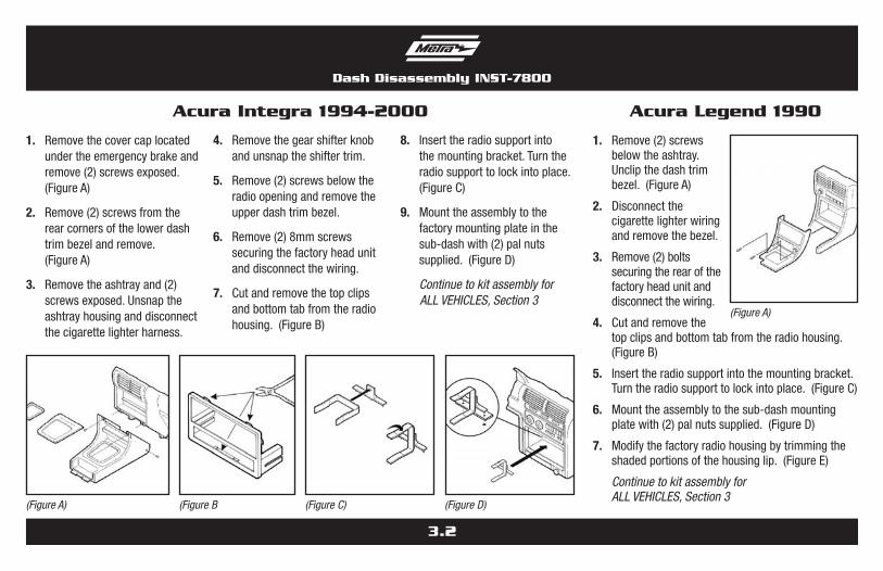
1. Removethecovercaplocatedundertheemergencybrakeandremove(2)screwsexposed.(FigureA)
2. Remove(2)screwsfromtherearcornersofthelowerdashtrimbezelandremove.(FigureA)
3. Removetheashtrayand(2)screwsexposed.Unsnaptheashtrayhousinganddisconnectthecigarettelighterharness.
4. Removethegearshifterknobandunsnaptheshiftertrim.
5. Remove(2)screwsbelowtheradioopeningandremovetheupperdashtrimbezel.
6. Remove(2)8mmscrewssecuringthefactoryheadunitanddisconnectthewiring.
7. Cutandremovethetopclipsandbottomtabfromtheradiohousing.(FigureB)
8. Inserttheradiosupportintothemountingbracket.Turntheradiosupporttolockintoplace.(FigureC)
9. Mounttheassemblytothefactorymountingplateinthesub-dashwith(2)palnutssupplied.(FigureD)
Continue to kit assembly for ALL VEHICLES, Section 3
Acura Integra 1994-2000
(Figure A) (Figure B (Figure C) (Figure D)
1. Remove(2)screwsbelowtheashtray.Unclipthedashtrimbezel.(FigureA)
2. Disconnectthecigarettelighterwiringandremovethebezel.
3. Remove(2)boltssecuringtherearofthefactoryheadunitanddisconnectthewiring.
4. Cutandremovethetopclipsandbottomtabfromtheradiohousing.(FigureB)
5. Inserttheradiosupportintothemountingbracket.Turntheradiosupporttolockintoplace.(FigureC)
6. Mounttheassemblytothesub-dashmountingplatewith(2)palnutssupplied.(FigureD)
7. Modifythefactoryradiohousingbytrimmingtheshadedportionsofthehousinglip.(FigureE)
Continue to kit assembly for ALL VEHICLES, Section 3
(Figure A)
Dash Disassembly INST-7800

3.3
1. Remove(2)screwsbelowtheashtray.Unclipthedashtrimbezel.(FigureA)
2. Disconnectthecigarettelighterwiringandremovethebezel.
3. Remove(2)boltssecuringtherearofthefactoryheadunitanddisconnectthewiring.
4. Cutandremovethetopclipsandbottomtabfromtheradiohousing.(FigureB)
5. Inserttheradiosupportintothemountingbracket.Turntheradiosupporttolockintoplace.(FigureC)
6. Mounttheassemblytothefactorymountingplateinthesub-dashwith(2)palnutssupplied.(FigureD)
Continue to kit assembly for ALL VEHICLES, Section 3
Acura Legend 1991-1996
(Figure C)
Acura Legend 1990
(Figure D) (Figure E)
(Figure B) (Figure C)
Factoryradiohousingopening
¼” ¼”
1¼”
1”
¾”
1”
(Figure A)
(Figure D)
(Figure B)
Dash Disassembly INST-7800
3.4
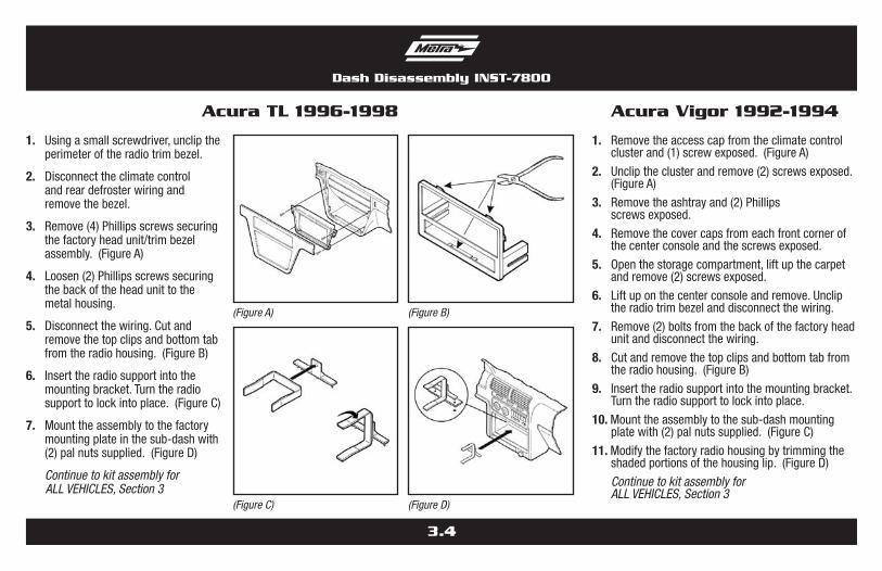
1. Usingasmallscrewdriver,uncliptheperimeteroftheradiotrimbezel.
2. Disconnecttheclimatecontrolandreardefrosterwiringandremovethebezel.
3. Remove(4)Phillipsscrewssecuringthefactoryheadunit/trimbezelassembly.(FigureA)
4. Loosen(2)Phillipsscrewssecuringthebackoftheheadunittothemetalhousing.
5. Disconnectthewiring.Cutandremovethetopclipsandbottomtabfromtheradiohousing.(FigureB)
6. Inserttheradiosupportintothemountingbracket.Turntheradiosupporttolockintoplace.(FigureC)
7. Mounttheassemblytothefactorymountingplateinthesub-dashwith(2)palnutssupplied.(FigureD)
Continue to kit assembly for ALL VEHICLES, Section 3
Acura TL 1996-1998
(Figure C)
(Figure A)
(Figure D)
(Figure B)
Acura Vigor 1992-1994
1. Removetheaccesscapfromtheclimatecontrolclusterand(1)screwexposed.(FigureA)
2. Uncliptheclusterandremove(2)screwsexposed.(FigureA)
3. Removetheashtrayand(2)Phillips screwsexposed.
4. Removethecovercapsfromeachfrontcornerofthecenterconsoleandthescrewsexposed.
5. Openthestoragecompartment,liftupthecarpetandremove(2)screwsexposed.
6. Liftuponthecenterconsoleandremove.Uncliptheradiotrimbezelanddisconnectthewiring.
7. Remove(2)boltsfromthebackofthefactoryheadunitanddisconnectthewiring.
8. Cutandremovethetopclipsandbottomtabfromtheradiohousing.(FigureB)
9. Inserttheradiosupportintothemountingbracket.Turntheradiosupporttolockintoplace.
10. Mounttheassemblytothesub-dashmountingplatewith(2)palnutssupplied.(FigureC)
11. Modifythefactoryradiohousingbytrimmingtheshadedportionsofthehousinglip.(FigureD)
Continue to kit assembly for ALL VEHICLES, Section 3
Dash Disassembly INST-7800

3.5
Acura Vigor 1992-1994
(Figure C) (Figure D)
(Figure A) (Figure B)
Factoryradiohousingopening
¼” ¼”
1¼”
1”
¾”
1”
1. Remove(4)screwsfromthelowerportionofthecenterconsole.(FIgureA)
2. Removethegearshifterknobandlifttheconsoleout.Removetheashtrayandashtraybracket.
3. Remove(2)screwsfromthebottomoftheheadunitsupport,slidetheunitoutanddisconnectthewiring.
4. Cutandremovethetopclipsandbottomtabfromtheradiohousing.(FigureB)
5. Inserttheradiosupportintothemountingbracket.Turntheradiosupporttolockintoplace.(FigureC)
6. Mounttheassemblytothefactorymountingplateinthesub-dashwith(2)palnutssupplied.(FIgureD)
Continue to kit assembly for ALL VEHICLES, Section 3
Honda Accord 1990-1993
(Figure C)
(Figure A)
(Figure D)
(Figure B)
Dash Disassembly INST-7800

3.6
Dash Disassembly INST-7800
1. Removetheashtrayand(1)3/4”#8Phillipsscrewexposed.
2. Openthestoragecompartmentandremove(2)#8Phillips screwsexposed.
3. Removethecupholdertrayand(3)#8Phillipsscrewsinside.(FigureA)
4. Liftthecenterconsoleoutandremove(2)Phillipsscrewsexposedatthebaseofthedashtrimbezel.Unclipthebezelandremove.(FigureA)
5. Remove(2)hex-headscrewssecuringthefactoryheadunitanddisconnectthewiring.
6. Locatetheradiohousingandthencutandremovethesideclipsfromtheradiohousing.(FigureBandC)
7. Mounttherearsupportbrackettothebottomtabontheradiohousingwith(2)carriageboltsand(2)kepsnuts.(FigureD)
Continue to kit assembly for ALL VEHICLES, Section 3
Honda Accord 1994-1997
(Figure C)
(Figure A)
(Figure D)
(Figure B)
Honda Odyssey 1995-1998Isuzu Oasis 1996-1999
1. Remove(2)8mmscrewsunderthegloveboxandthenremove(1)Phillipsscrewonthegloveboxarmandremovethebox.
2. Remove(2)Phillipsscrewsexposedinthegloveboxcavity.
3. Remove(2)Phillipsscrewsbelowthestorageboxdoor(undertheashtray).
4. Remove(2)screwsfromtheleftsideofthedashconsoleandthenremove(1)Phillipsscrewfromthecointray.
5. Remove(1)Phillipsscrewundertheignitionandthenremove(4)Phillipsscrewssecuringthefactorycupholder.
6. Remove(2)8mmhex-headscrewsfromtherearsupportbracketanddisconnectthewiring.
7. Cutandremovethetopclipsandbottomtabfromtheradiohousing.(FigureB)
8. Inserttheradiosupportintothemountingbracket.Turntheradiosupporttolockintoplace.(FigureC)
9. Mounttheassemblytothefactorymountingplateinthesub-dashwith(2)palnutssupplied.(FigureD)
Continue to kit assembly for ALL VEHICLES, Section 3
3.7
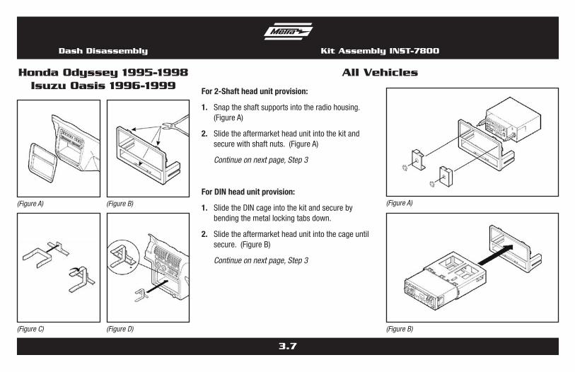
For 2-Shaft head unit provision:
1. Snaptheshaftsupportsintotheradiohousing.(FigureA)
2. Slidetheaftermarketheadunitintothekitandsecurewithshaftnuts.(FigureA)
Continue on next page, Step 3
For DIN head unit provision:
1. SlidetheDINcageintothekitandsecurebybendingthemetallockingtabsdown.
2. Slidetheaftermarketheadunitintothecageuntilsecure.(FigureB)
Continue on next page, Step 3
All Vehicles
Dash Disassembly
Honda Odyssey 1995-1998Isuzu Oasis 1996-1999
(Figure C) (Figure D)
(Figure A) (Figure B)
Kit Assembly INST-7800
(Figure A)
(Figure B)
3.8
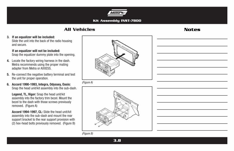
3. If an equalizer will be included: Slidetheunitintothebackoftheradiohousing
andsecure.
If an equalizer will not be included: Snaptheequalizerdummyplateintotheopening.
4. Locatethefactorywiringharnessinthedash.MetrarecommendsusingthepropermatingadapterfromMetraorAXXESS.
5. Re-connectthenegativebatteryterminalandtesttheunitforproperoperation.
6. Accord 1990-1993, Integra, odyssey, oasis: Snaptheheadunit/kitassemblyintothesub-dash.
Legend, tL, Vigor: Snaptheheadunit/kitassemblyintothefactorytrimbezel.Mountthebezeltothedashwiththosescrewspreviouslyremoved.(FigureA)
Accord 1994-1997, CL: Slidetheheadunit/kitassemblyintothesub-dashandmounttherearsupportbrackettotherearsupportprovisionwith(2)hex-headboltspreviouslyremoved.(FigureB)
All Vehicles
Kit Assembly INST-7800
(Figure A)
(Figure B)
Notes

4.0
Dash DisassemblyINST-7800
3. Pullstraightdownonthelowersteeringcolumnpanelandremovethepanel.
4. Remove(2)Phillipsscrewsundertheclimatecontrolpanel.
5. Remove(4)Phillipsscrewsfromthelowerdashlocation.
6. Remove(2)8mmhex-headscrewssecuringthebottom-rearofthefactoryheadunitanddisconnectthewiring.
Continue to installation instructions for ALL VEHICLES, Section 4
Honda Civic 1996-1998
•Phillipsscrewdriver•Cuttingtool•Socketwrench
TOOLS requIred
Table of Contents
Dash Disassembly
– HondaCivic1996-1998...................................... 4.0
Kit Assembly
– 2-Shaftheadunitprovision................................. 4.1
– DINheadunitprovision....................................... 4.1
D
C
Section 4
HondaCivic1996-1998
99-7891
•A)Radiohousing•B)Faceplate •C)Radiosupport•D)Mountingbracket •E)(2)Palnuts•F)Shaftsupports
KIT FeATureS
KIT COMPONeNTS
•2-ShaftandDINunitprovisions•Rearsupportprovisions
BA
F
E1. Remove(2)Phillipsscrewsfromthebottomedge
ofthegloveboxdoorandremovethedoor.
2. Remove(3)Phillipsscrewsfromthelowersteeringcolumnpanel.
Honda Civic 1996-1998
4.1
Kit Assembly INST-7800
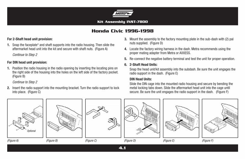
For 2-Shaft head unit provision:
1. Snapthefaceplate*andshaftsupportsintotheradiohousing.Thenslidetheaftermarketheadunitintothekitandsecurewithshaftnuts.(FigureA)
Continue to Step 2
For DIN head unit provision:
1. Positiontheradiohousingintheradioopeningbyinsertingthelocatingpinsontherightsideofthehousingintotheholesontheleftsideofthefactorypocket.(FigureB)
Continue to Step 2
2. Inserttheradiosupportintothemountingbracket.Turntheradiosupporttolockintoplace.(FigureC)
3. Mounttheassemblytothefactorymountingplateinthesub-dashwith(2)palnutssupplied.(FigureD)
4. Locatethefactorywiringharnessinthedash.MetrarecommendsusingthepropermatingadapterfromMetraorAXXESS.
5. Re-connectthenegativebatteryterminalandtesttheunitforproperoperation.
6. 2-Shaft Head Units: Snaptheheadunit/kitassemblyintothesubdash.Besuretheunitengagesthe
radiosupportinthedash.(FigureE)
DIN Head Units: SlidetheDINcageintothemountedradiohousingandsecurebybendingthe
metallockingtabsdown.Slidetheaftermarketheadunitintothecageuntilsecure.Besuretheunitengagestheradiosupportinthedash.(FigureF)
Honda Civic 1996-1998
(Figure A) (Figure B) (Figure C) (Figure D) (Figure E) (Figure F)
Optional

5.0
INST-7800
1. Uncliptheradiotrimbezelanddisconnecttheclockandclimatecontrolwiring.(FigureA)
2. Remove(2)8mmhex-headscrewssecuringthefactoryheadunitanddisconnectthewiring.
Continue on next page
Acura CL 1997-1999
•Phillipsscrewdriver•Cuttingtool•Socketwrench
TOOLS requIred
Table of Contents
Dash Disassembly – AcuraCL1997-1999...........................................5.x– AcuraIntegra1990-1993.....................................5.x– AcuraIntegra1994-2000.....................................5.x– AcuraLegend1990..............................................5.x– AcuraLegend1991-1996....................................5.x– AcuraTL1996-1998............................................5.x– AcuraVigor1992-1994........................................5.x– HondaAccord1990-1993..................................5.xx– HondaAccord1994-1997..................................5.xx– HondaOdyssey1995-1998................................5.xx– IsuzuOasis1996-1999......................................5.xx
Kit Assembly– 2-Shaftheadunitprovision..................................5.x– DINheadunitprovision........................................5.x– ISO-DINheadunitprovision.................................5.x
Section 5
Acura/Honda/Isuzu1997-2000
99-7892
•A)Radiohousing•B)Faceplate•C)ISO-DINbrackets•D)Rearsupportbracket•E)(2)Phillipsscrews
KIT FeATureS
KIT COMPONeNTS
•2-ShaftandDINunitprovisions•Rearsupportprovisions
BA
C D
E
(Figure A)

5.1
Dash Disassembly INST-7800
1. Remove(3)screwsfromeachsideofthecenterconsoleandremovetheconsole.(FigureA)
2. Remove(2)screwssecuringthefactoryheadunittothesub-dashsupportbracket.(FigureA)
3. Slidetheheadunit/pocketassemblyoutanddisconnectthewiring.
4. Cutandremovethetopclipsfromtheradiohousing.(FigureB)
For ISO-DIN head units: Mount the rear support bracket to the back of the pocket with (2) Phillips screws supplied.(FigureC)
Continue to kit assembly for ALL VEHICLES, Section 5
Acura Integra 1990-1993
3. Cutandremovethesideclipsfromtheradiohousing.(FigureB)
4. Mounttherearsupportbrackettothebackofthepocketwith(2)Phillipsscrewssupplied.(FigureC)
Continue to kit assembly for ALL VEHICLES, Section 5
Acura CL 1997-1999
(Figure C)
(Figure B)
(Figure B) (Figure C)
(Figure A)

5.2
Dash Disassembly INST-7800
1. Removethecovercaplocatedundertheemergencybrakeandremove(2)screwsexposed.(FigureA)
2. Remove(2)screwsfromtherearcornersofthelowerdashtrimbezelandremove.(FigureA)
3. Removetheashtrayand(2)screwsexposed.Unsnaptheashtrayhousinganddisconnectthecigarettelighterharness.
4. Removethegearshifterknobandunsnaptheshiftertrim.
5. Remove(2)screwsbelowtheradioopeningandremovetheupperdashtrimbezel.
6. Remove(2)8mmscrewssecuringthefactoryheadunitanddisconnectthewiring.
7. Cutandremovethetopclipsfromtheradiohousing.(FigureB)
For ISO-DIN head units: Mount the rear support bracket to the back of the pocket with (2) Phillips screws supplied.(FigureC)
Continue to kit assembly for ALL VEHICLES, Section 5
Acura Integra 1994-2000
(Figure C)
(Figure A)
(Figure B)
1. Remove(2)screwsbelowtheashtray.(FigureA)
2. Unclipthedashtrimbezel.
3. Disconnectthecigarettelighterwiringandremovethebezel.
4. Remove(2)boltssecuringtherearofthefactoryheadunitanddisconnectthewiring.
Continue on next page
Acura Legend 1990
(Figure A)
5.3
Dash Disassembly INST-7800
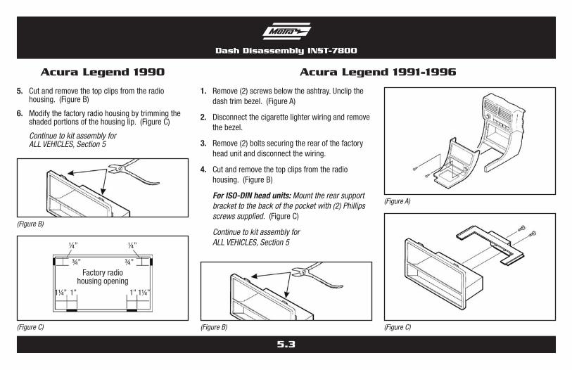
5. Cutandremovethetopclipsfromtheradiohousing.(FigureB)
6. Modifythefactoryradiohousingbytrimmingtheshadedportionsofthehousinglip.(FigureC)
Continue to kit assembly for ALL VEHICLES, Section 5
Acura Legend 1990
(Figure C)
(Figure B)
Factoryradiohousingopening
¼” ¼”
1¼” 1”
¾” ¾”
1¼”1”
1. Remove(2)screwsbelowtheashtray.Unclipthedashtrimbezel.(FigureA)
2. Disconnectthecigarettelighterwiringandremovethebezel.
3. Remove(2)boltssecuringtherearofthefactoryheadunitanddisconnectthewiring.
4. Cutandremovethetopclipsfromtheradiohousing.(FigureB)
For ISO-DIN head units: Mount the rear support bracket to the back of the pocket with (2) Phillips screws supplied.(FigureC)
Continue to kit assembly for ALL VEHICLES, Section 5
Acura Legend 1991-1996
(Figure C)
(Figure A)
(Figure B)
5.4
Dash Disassembly INST-7800
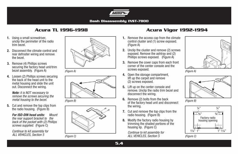
1. Usingasmallscrewdriver, uncliptheperimeteroftheradiotrimbezel.
2. Disconnecttheclimatecontrolandreardefrosterwiringandremovethebezel.
3. Remove(4)Phillipsscrewssecuringthefactoryheadunit/trimbezelassembly.(FigureA)
4. Loosen(2)Phillipsscrewssecuringthebackoftheheadunittothemetalhousingandslidetheunitout.Disconnectthewiring.
Note: it is NOT necessary to remove the screws securing the metal housing to the bezel.
5. Cutandremovethetopclipsfromtheradiohousing.(FigureB)
For ISO-DIN head units: Mount the rear support bracket to the back of the pocket with (2) Phillips screws supplied.(FigureC)
Continue to kit assembly for ALL VEHICLES, Section 5
Acura TL 1996-1998
(Figure C)
(Figure A)
(Figure B)
1. Removetheaccesscapfromtheclimatecontrolclusterand(1)screwexposed.(FigureA)
2. Uncliptheclusterandremove(2)screwsexposed.Removetheashtrayand(2)Phillipsscrewsexposed.(FigureA)
3. Removethecovercapsfromeachfrontcornerofthecenterconsoleandthescrewsexposed.
4. Openthestoragecompartment,liftupthecarpetandremove(2)screwsexposed.
5. Liftuponthecenterconsoleandremove.Uncliptheradiotrimbezelanddisconnectthewiring.
6. Remove(2)boltsfromthebackofthefactoryheadunitanddisconnectthewiring.
7. Cutandremovethetopclipsfromtheradiohousing.(FigureB)
8. Modifythefactoryradiohousingbytrimmingtheshadedportionsofthehousinglip.(FigureC)
Continue to kit assembly for ALL VEHICLES, Section 5
Acura Vigor 1992-1994
(Figure C)
(Figure A)
(Figure B)
Factoryradiohousingopening
¼” ¼”
1¼” 1”
¾” ¾”
1¼”1”

5.5
Dash Disassembly INST-7800
1. Remove(4)screwsfromthelowerportionofthecenterconsole.(FigureA)
2. Removethegearshifterknobandlifttheconsoleout.Removetheashtrayandashtraybracket.
3. Remove(2)screwsfromthebottomoftheheadunitsupport,slidetheunitoutanddisconnectthewiring.
4. Cutandremovethetopclipsfromtheradiohousing.(FigureB)
For ISO-DIN head units: Mount the rear support bracket to the back of the pocket with (2) Phillips screws supplied.(FigureC)
Continue to kit assembly for ALL VEHICLES, Section 5
Honda Accord 1990-1993
1. Removetheashtrayand(1)3/4”#8Phillipsscrewexposed.
2. Openthestoragecompartmentandremove (2)#8Phillipsscrewsexposed.
3. Removethecupholdertrayand(3)#8Phillipsscrewsinside.(FigureA)
4. Liftthecenterconsoleoutandremove(2)Phillipsscrewsexposedatthebaseofthedashtrimbezel.(FigureB)
5. Unclipthebezelandremove.Remove(2)hex-headscrewsecuringthefactoryheadunitanddisconnectthewiring.
6. Cutandremovethesideclipsfromtheradiohousing.(FigureC)
7. Mounttherearsupportbrackettothebackofthepocketwith(2)Phillipsscrewssupplied.(FigureD)
Continue to kit assembly for ALL VEHICLES, Section 5
Honda Accord 1994-1997
(Figure C)
(Figure A)
(Figure B)
(Figure D)
(Figure B)
(Figure C)
(Figure A)
5.6
Dash Disassembly INST-7800
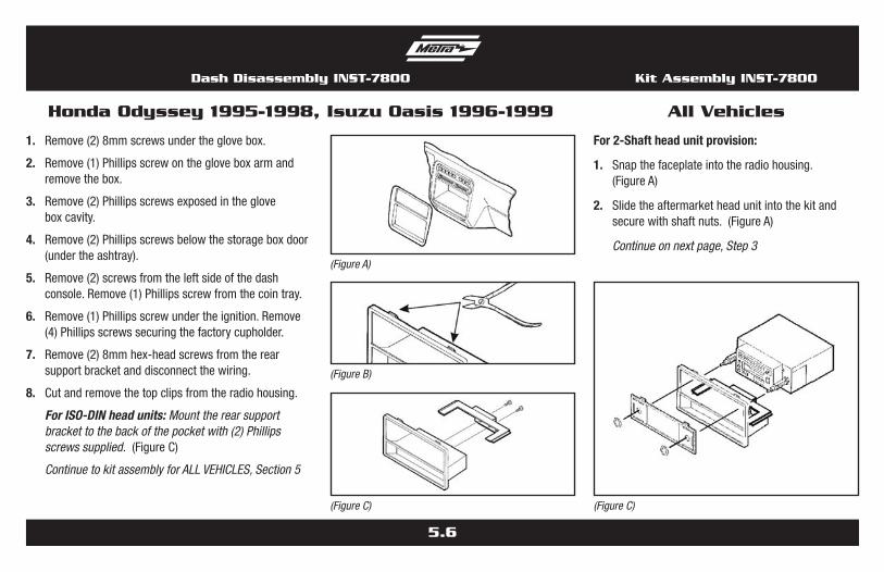
1. Remove(2)8mmscrewsundertheglovebox.
2. Remove(1)Phillipsscrewonthegloveboxarmandremovethebox.
3. Remove(2)Phillipsscrewsexposedintheglove boxcavity.
4. Remove(2)Phillipsscrewsbelowthestorageboxdoor(undertheashtray).
5. Remove(2)screwsfromtheleftsideofthedashconsole.Remove(1)Phillipsscrewfromthecointray.
6. Remove(1)Phillipsscrewundertheignition.Remove(4)Phillipsscrewssecuringthefactorycupholder.
7. Remove(2)8mmhex-headscrewsfromtherearsupportbracketanddisconnectthewiring.
8. Cutandremovethetopclipsfromtheradiohousing.
For ISO-DIN head units: Mount the rear support bracket to the back of the pocket with (2) Phillips screws supplied.(FigureC)
Continue to kit assembly for ALL VEHICLES, Section 5
Honda Odyssey 1995-1998, Isuzu Oasis 1996-1999 All Vehicles
For 2-Shaft head unit provision:
1. Snapthefaceplateintotheradiohousing.(FigureA)
2. Slidetheaftermarketheadunitintothekitandsecurewithshaftnuts.(FigureA)
Continue on next page, Step 3
(Figure C)
Kit Assembly INST-7800
(Figure C)
(Figure A)
(Figure B)
5.7
Kit Assembly INST-7800
For DIN head unit provision:
1. SlidetheDINcageintothekitandsecurebybendingthemetallockingtabsdown.(FigureB)
2. Slidetheaftermarketheadunitintothecageuntilsecure.(FigureB)
Continue to Step 3
For ISo-DIN head unit provision:
1. SlidetheISO-DINBracketsontothesidesoftherearsupportbracket.CutandremovetheshaftsupportsfromtheFaceplateandsnapintotheradiohousing.(FigureC)
2. Slidetheaftermarketheadunitintothehousing;aligntheholesintheunitwiththeholesintheISO-DINbracketsandmountwiththescrewssuppliedwiththeunit.(FigureC)
Continue to Step 3
All Vehicles
3. Locatethefactorywiringharnessinthedash.MetrarecommendsusingthepropermatingadapterfromMetraorAXXESS.
4. Re-connectthenegativebatteryterminalandtesttheunitforproperoperation.
5. Accord 1990-93, Integra, odyssey, oasis: Snaptheheadunit/kitassemblyintothesub-dash.
Legend, tL, Vigor: Snaptheheadunit/kitassemblyintothefactorytrimbezel.Mountthebezeltothedashwiththosescrewspreviouslyremoved.(FigureD)
Accord 1994-97, CL: Slidetheheadunit/kitassembly
intothesub-dashandmounttherearsupportbrackettotherearsupportprovisionwith(2)hex-headboltspreviouslyremoved.(FigureE)
(Figure C)
(Figure B)
(Figure E)
(Figure D)
6.0
INST-7800
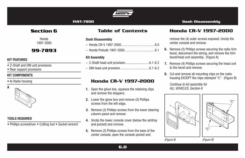
removethe(4)outerscrewsexposed.Unclipthecenterconsoleandremove.
6. Remove(2)Phillipsscrewssecuringtheradiotrimbezel,disconnectthewiring,andremovethetrimbezel/headunitassembly.(FigureA)
7. Remove(4)Phillipsscrewssecuringtheheadunittothebezelandremove.
8. CutandremoveallmountingclipsontheradiohousingEXCEPTtheclipsstamped“C”.(FigureB)
Continue to kit assembly for ALL VEHICLES, Section 6
Honda CR-V 1997-2000
•Phillipsscrewdriver•Cuttingtool•Socketwrench
TOOLS requIred
Table of Contents
Dash Disassembly
– HondaCR-V1997-2000...................................... 6.0
– HondaPrelude1997-2000.................................. 6.1
Kit Assembly
– 2-Shaftheadunitprovision...........................6.1-6.2
– DINheadunitprovision.................................6.1-6.2
Section 6
Honda1997-2000
99-7893
•A)Radiohousing
KIT FeATureS
KIT COMPONeNTS
•2-ShaftandDINunitprovisions•Rearsupportprovisions
A
(Figure A)
1. Opentheglovebox,squeezetheretainingclipsandremovethestoppers.
2. Lowerthegloveboxandremove(2)Phillipsscrewsfromtheleftedge.
3. Remove(2)Phillipsscrewsfromthelowersteeringcolumnpanelandremove.
4. Unclipthelowerconsolecover(belowtheashtrayandpocket)andremove.
5. Remove(2)Phillipsscrewsfromthebaseofthecenterconsole,opentheconsolepocketand
Honda CR-V 1997-2000
(Figure B)
“C”
“C”
Dash Disassembly

6.1
Dash Disassembly INST-7800
1. Usingapanelremovaltool,uncliptheradiotrimbezelandremove(someforcemayberequired).(FigureA)
2. Remove(4)Phillipsscrewssecuringthefactoryheadunit/brackethousingassemblyanddisconnectthewiring.
3. Remove(4)Phillipsscrewssecuringthefactoryheadunittothebrackethousingandremove.
4. CutandremoveallmountingclipsontheradiohousingEXCEPTtheclipsstamped“P”.(FigureB)
Continue to kit assembly for ALL VEHICLES, Section 6
Honda Prelude 1997-2000
For 2-Shaft head unit provision:
1. Slidetheaftermarketheadunitintotheradiohousing.(FigureA)
2. Secureunitwithshaftnuts.(FigureA)
Continue to Step 3
For DIN head unit provision:
1. CutandremovetheshaftsupportsfromtheradiohousingandthenslidetheDINcageintothekit(securebybendingthemetallockingtabsdown).
2. Slidetheaftermarketheadunitintothecageuntilsecure.(FigureB)
Continue to Step 3
3. Locatethefactorywiringharnessinthedash.MetrarecommendsusingthepropermatingadapterfromMetraorAXXESS.
4. Re-connectthenegativebatteryterminalandtesttheunitforproperoperation.
All Vehicles
(Figure A) (Figure B)
Kit Assembly INST-7800
(Figure B)
(Figure A)
“P”
“P”
6.2
Kit Assembly INST-7800
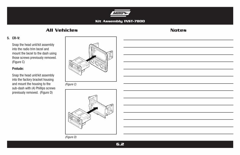
5. CR-V:
Snaptheheadunit/kitassemblyintotheradiotrimbezelandmountthebezeltothedashusingthosescrewspreviouslyremoved.(FigureC)
Prelude:
Snaptheheadunit/kitassemblyintothefactorybrackethousingandmountthehousingtothesub-dashwith(4)Phillipsscrewspreviouslyremoved.(FigureD)
All Vehicles Notes
(Figure D)
(Figure C)
A B
7.0
Honda Accord 1998-2000
•Phillipsscrewdriver•Cuttingtool•Socketwrench
TOOLS requIred
Table of Contents
Dash Disassembly – HondaAccord1998-2000.............................7.0-7.1
Kit Assembly– 2-Shaftheadunitprovision...........................7.1-7.2– DINheadunitprovision.................................7.1-7.2
Section 7
Honda1998-2000
99-7894
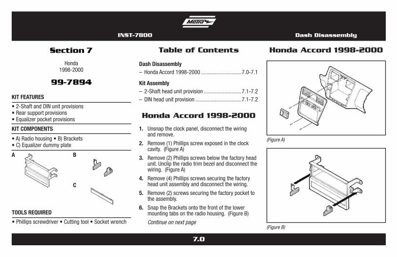
•A)Radiohousing•B)Brackets•C)Equalizerdummyplate
KIT FeATureS
KIT COMPONeNTS
•2-ShaftandDINunitprovisions•Rearsupportprovisions•Equalizerpocketprovisions
1. Unsnaptheclockpanel,disconnectthewiringandremove.
2. Remove(1)Phillipsscrewexposedintheclockcavity.(FigureA)
3. Remove(2)Phillipsscrewsbelowthefactoryheadunit.Uncliptheradiotrimbezelanddisconnectthewiring.(FigureA)
4. Remove(4)Phillipsscrewssecuringthefactoryheadunitassemblyanddisconnectthewiring.
5. Remove(2)screwssecuringthefactorypockettotheassembly.
6. SnaptheBracketsontothefrontofthelowermountingtabsontheradiohousing.(FigureB)
Continue on next page
Honda Accord 1998-2000
C
(Figure B)
(Figure A)
INST-7800 Dash Disassembly
7.1
Dash Disassembly INST-7800
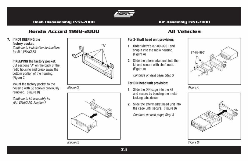
7. If Not KEEPING the factory pocket:
Continue to installation instructions for ALL VEHICLES
If KEEPING the factory pocket: Cutsections“A”onthebackofthe
radiohousingandbreakawaythebottomportionofthehousing.(FigureC)
Mountthefactorypockettothehousingwith(2)screwspreviouslyremoved.(FigureD)
Continue to kit assembly for ALL VEHICLES, Section 7
Honda Accord 1998-2000
For 2-Shaft head unit provision:
1. OrderMetra’s87-09-9901andsnapitintotheradiohousing.(FigureA)
2. Slidetheaftermarketunitintothekitandsecurewithshaftnuts.(FigureA)
Continue on next page, Step 3
For DIN head unit provision:
1. SlidetheDINcageintothekitandsecurebybendingthemetallockingtabsdown.
2. Slidetheaftermarketheadunitintothecageuntilsecure.(FigureB)
Continue on next page, Step 3
All Vehicles
(Figure D)
(Figure C)
“A”
Kit Assembly INST-7800
(Figure B)
(Figure A)
87-09-9901

7.2
Kit Assembly INST-7800
3. If an equalizer will be included: Slidetheunitintothebackofthe
radiohousingandsecure.
If an equalizer will Not be included:Snaptheequalizerdummyplateintotheopening.
4. Locatethefactorywiringharnessinthedash.MetrarecommendsusingthepropermatingadapterfromMetraorAXXESS.
5. Re-connectthenegativebatteryterminalandtesttheunitforproperoperation.
6. Mounttheheadunit/kitassemblytothesub-dashwith(4)Phillipsscrewspreviouslyremoved.(FigureC)
7. Re-attachtheradiotrimbezel.Besuretheclipsonthebackofthebezelengageslots“A”onthekit.(FigureC)
All Vehicles Notes
(Figure C)
“A”

8.0
A
Honda Accord 1998-2000
•Phillipsscrewdriver
TOOLS requIred
Table of Contents
Dash Disassembly – HondaAccord1998-2000................................... 8.0
Kit Assembly
– 2-Shaftheadunitprovision................................. 8.1– DINheadunitprovision....................................... 8.1
Section 8
Honda1998-2000
99-7895
•A)Radiohousing
KIT FeATureS
KIT COMPONeNTS
•2-ShaftandDINunitprovisions•CDjewelcasepocket
1. Unsnaptheclockpanel,disconnectthewiringandremove.
2. Remove(1)Phillipsscrewexposedintheclockcavity.(FigureA)
3. Remove(2)Phillipsscrewsbelowthefactoryheadunit.(FigureA)
4. Uncliptheradiotrimbezelanddisconnectthewiring.
5. Remove(4)Phillipsscrewssecuringthefactoryheadunitassemblyanddisconnectthewiring.
Honda Accord 1998-2000
INST-7800 Dash Disassembly
6. Remove(2)screwssecuringthefactorypockettotheassembly.
Continue to kit assembly for ALL VEHICLES, Section 8
(Figure A)

8.1
Kit Assembly INST-7800
For 2-Shaft head unit provision:
1. OrderMetra’s87-09-9901andsnapitintotheradiohousing.(FigureA)
2. Slidetheaftermarketunitintothekitandsecurewithshaftnuts.(FigureA)
Continue on next page, Step 3
For DIN head unit provision:
1. SlidetheDINcageintothekitandsecurebybendingthemetallockingtabsdown.
2. Slidetheaftermarketheadunitintothecageuntilsecure.(FigureB)
Continue on next page, Step 3
All Vehicles
3. Locatethefactorywiringharness inthedash.Metrarecommends
usingthepropermatingadapterfromMetraorAXXESS.
4. Re-connectthenegativebatteryterminalandtesttheunitforproperoperation.
5. Mounttheheadunit/kitassemblytothesub-dashwith(4)Phillipsscrewspreviouslyremoved.(FigureC)
6. Re-attachtheradiotrimbezel.(FigureD)
Note: Make sure the clips on the back of the bezel engage the slots on the kit.
(Figure B)
(Figure A)
87-09-9901
(Figure D)
(Figure C)
INST-7800
Notes

INST-7800
Notes

INST-7800
Notes

INSTALLATION INSTRUCTIONS FOR PART INST-7800
METRA. The World’s best kits.™ metraonline.com1-800-221-0932 © COPYRIGHT 2004-2011 METRA ELECTRONICS CORPORATION
REV.
9/2
0/20
13
INST
-780
0
KNOWLEDGE IS POWEREnhance your installation and fabrication skills by enrolling in the most recognized and respected mobile electronics school in our industry.Log onto www.installerinstitute.com or call 800-354-6782 for more information and take steps toward a better tomorrow.
Metra recommends MECP certified technicians