Aquifer disposal of acid gases: modelling of water–rock reactions for trapping of acid wastes
11
Aquifer disposal of acid gases: modelling of water–rock reactions for trapping of acid wastes W.D. Gunter a, *, E.H. Perkins a , Ian Hutcheon b a Alberta Research Council, Edmonton, Alberta, T6N 1E4, Canada b Geology and Geophysics Department, University of Calgary, Calgary, Alberta, T2N 1N4, Canada Received 9 July 1998; accepted 19 November 1999 Editorial handling by Y.K. Kharaka Abstract The pore space of deep saline aquifers in the Alberta (sedimentary) Basin oers a significant volume for waste storage by ‘‘hydrodynamic trapping’’. Furthermore, given the slow regional fluid flow in these deep saline aquifers, ample time exists for waste-water/rock chemical reactions to take place. A geochemical computer model (PATHARC) was used to compute the interaction of industrial waste streams comprising CO 2 ,H 2 SO 4 and H 2 S with the minerals in typical carbonate and sandstone aquifers from the Alberta Basin. The results support the idea that these acids can be neutralized by such reactions and that new mineral products are formed, such as calcite, siderite, anhydrite/gypsum and pyrrhotite, thereby trapping the CO 3 , SO 4 and S ions that are formed when the acid gases dissolve in the formation water. Siliciclastic aquifers appear to be a better host for ‘‘mineral trapping’’ than carbonate aquifers, especially with regard to CO 2 . Carbonate aquifers may be more prone to leakage due to high CO 2 pressures generated by reaction with H 2 SO 4 and H 2 S. Even though permeability decreases are expected due to this ‘‘mineral trapping’’, they can be partially controlled so that plugging of the aquifer does not occur. 7 2000 Elsevier Science Ltd. All rights reserved. 1. Introduction In the past, most studies of deep waste disposal of fluids into the subsurface have been evaluated in terms of ‘‘flow through porous media’’ without regard to the reactivity of the host rock. Three examples involving CO 2 , H 2 SO 4 and H 2 S injection waste streams are reviewed here. Geological storage of CO 2 is being considered as one technology among others to be pursued in order to meet greenhouse gas emission reductions called for in the Kyoto protocol drafted at COP3 in December of 1997. It oers an alternative option to CO 2 storage in biomass (Gunter et al., 1998). StatOil (Baklid et al., 1996) already has an ongoing project injecting one million tonnes of waste CO 2 /year into the Utsira aqui- fer in the North Sea, in order to avoid a Norwegian tax of approximately $50 US per tonne of CO 2 emitted oshore. On a similar scale, PanCanadian will start commercial production operation in 2000 of a CO 2 miscible flood at Weyburn, Saskatchewan in a planned 25 year enhanced oil recovery project (Bamhart and Coulthard, 1995). Although not specifically planned as a CO 2 storage project, approximately 30% of the injected CO 2 will be trapped in the reservoir at the end of the project. In both cases, no consideration has Applied Geochemistry 15 (2000) 1085–1095 0883-2927/00/$ - see front matter 7 2000 Elsevier Science Ltd. All rights reserved. PII: S0883-2927(99)00111-0 www.elsevier.com/locate/apgeochem * Corresponding author. Fax: +1-780-450-5083. E-mail address: [email protected] (W.D. Gunter).
-
Upload
albertatechfutures -
Category
Documents
-
view
2 -
download
0
Transcript of Aquifer disposal of acid gases: modelling of water–rock reactions for trapping of acid wastes
Aquifer disposal of acid gases: modelling of water±rockreactions for trapping of acid wastes
W.D. Guntera,*, E.H. Perkinsa, Ian Hutcheonb
aAlberta Research Council, Edmonton, Alberta, T6N 1E4, CanadabGeology and Geophysics Department, University of Calgary, Calgary, Alberta, T2N 1N4, Canada
Received 9 July 1998; accepted 19 November 1999
Editorial handling by Y.K. Kharaka
Abstract
The pore space of deep saline aquifers in the Alberta (sedimentary) Basin o�ers a signi®cant volume for wastestorage by ``hydrodynamic trapping''. Furthermore, given the slow regional ¯uid ¯ow in these deep saline aquifers,ample time exists for waste-water/rock chemical reactions to take place. A geochemical computer model(PATHARC) was used to compute the interaction of industrial waste streams comprising CO2, H2SO4 and H2S
with the minerals in typical carbonate and sandstone aquifers from the Alberta Basin. The results support the ideathat these acids can be neutralized by such reactions and that new mineral products are formed, such as calcite,siderite, anhydrite/gypsum and pyrrhotite, thereby trapping the CO3, SO4 and S ions that are formed when the acid
gases dissolve in the formation water. Siliciclastic aquifers appear to be a better host for ``mineral trapping'' thancarbonate aquifers, especially with regard to CO2. Carbonate aquifers may be more prone to leakage due to highCO2 pressures generated by reaction with H2SO4 and H2S. Even though permeability decreases are expected due to
this ``mineral trapping'', they can be partially controlled so that plugging of the aquifer does not occur. 7 2000Elsevier Science Ltd. All rights reserved.
1. Introduction
In the past, most studies of deep waste disposal of
¯uids into the subsurface have been evaluated in termsof ``¯ow through porous media'' without regard to thereactivity of the host rock. Three examples involvingCO2, H2SO4 and H2S injection waste streams are
reviewed here.Geological storage of CO2 is being considered as
one technology among others to be pursued in order
to meet greenhouse gas emission reductions called for
in the Kyoto protocol drafted at COP3 in December
of 1997. It o�ers an alternative option to CO2 storage
in biomass (Gunter et al., 1998). StatOil (Baklid et al.,
1996) already has an ongoing project injecting one
million tonnes of waste CO2/year into the Utsira aqui-
fer in the North Sea, in order to avoid a Norwegian
tax of approximately $50 US per tonne of CO2 emitted
o�shore. On a similar scale, PanCanadian will start
commercial production operation in 2000 of a CO2
miscible ¯ood at Weyburn, Saskatchewan in a planned
25 year enhanced oil recovery project (Bamhart and
Coulthard, 1995). Although not speci®cally planned as
a CO2 storage project, approximately 30% of the
injected CO2 will be trapped in the reservoir at the end
of the project. In both cases, no consideration has
Applied Geochemistry 15 (2000) 1085±1095
0883-2927/00/$ - see front matter 7 2000 Elsevier Science Ltd. All rights reserved.
PII: S0883-2927(99 )00111-0
www.elsevier.com/locate/apgeochem
* Corresponding author. Fax: +1-780-450-5083.
E-mail address: [email protected] (W.D. Gunter).
been given to potential water±rock reactions and their
role in the process.Schuiling and van Gaans (1997) document an
example of waste H2SO4 being discharged into a shal-
low lake at Armyansk, Crimea, Ukraine. The resultingpH of 0.85 has caused the formation of a layer of jaro-
site, gypsum and Fe oxides/hydroxides from reactionwith the lake sediments. It is not desirable to continuethis method of surface disposal due to the potential en-
vironmental liabilities. Schuiling and van Gaanssuggest that either the acids could be neutralized byreaction with olivine at the industrial plant or injected
into the subsurface into a carbonate aquifer.In order to meet sti�er emission regulations in
Alberta, Canada, natural gas processing plants havefound alternative solutions to ¯aring of sour gas wastecomponents (Longworth et al., 1995). Sulfur recovery
from H2S is uneconomic and consequently a numberof companies compress the waste gas and dispose of itin a suitable underground zone (Chakma, 1997). There
are over 19 such projects in western Canada in whichmaximum injection rates vary from 2000 to 60,000
tonnes/a of mixtures of H2S and CO2 in ratios varyingfrom 3:1 to 1:20 (Wichert and Royan, 1997). Again noconcern has been expressed about the water±rock reac-
tions occurring as a result of injection of these acid gasmixtures.
On a geological time scale, Deming (1994) suggestedthat: ``The old concept of a continental crust as anunchanging body of solid rock should be replaced by a
paradigm that recognizes the continental crust as atwo-component system: a solid framework which con-tinuously evolves through thermal, chemical and mech-
anical interaction with crustal ¯uids''. This is not anew concept. Fyfe et al. (1978) in their book, ``Fluids
in the Earth's Crust'', looked at release of ¯uids duringmetamorphism. More recently, Nesbitt (1990) orga-nized a Mineralogical Society of Canada short course,
``Fluids in Tectonically Active Regimes of the Continen-tal Crust'', that followed on the same theme. Presently,interest is becoming more focused on less active en-
vironments such as are present in some sedimentarybasins (see for example the book ``Geo¯uids: Origin,
Migration and Evolution of Fluids in SedimentaryBasins'', edited by J. Parnell (1994)). Consequently, theassumption of ``non-reactive minerals'' is not valid
when considering extended periods of time.Saline aquifers in sedimentary basins are particularly
attractive for waste disposal. Sedimentary basins o�er
the potential of long term-storage and capture of cer-tain man-made wastes. Industry, the prime emitter of
waste ¯uids, is often located in sedimentary basinsbecause the basins are the source of fossil fuels thatindustry needs (Hitchon et al., 1999). Saline aquifers
are ubiquitous to sedimentary basins; in fact, salineaquifers form the pathways for the migration of oil
and gas. Consequently, sedimentary basins have boththe industrial point sources of emissions, for easy cap-
ture, and have the appropriate geological sinks in theform of saline aquifers near industrial sources.
2. The Alberta Basin: a potentially huge waste disposal
site
The Alberta Basin, in Western Canada, consists of awedge of sedimentary rocks that thickens westwardfrom zero at the western edge of the Canadian Shieldto more than 6 km at the foreland fold and thrust belt,
a lateral distance of 500 km. The Alberta Basin has avolume of approximately 2 million km3 covering anarea of about 0.8 million km2. It is the major producer
of oil and gas in Canada, and is an important produ-cer of coal.The geological history of the basin can be divided
into two distinct phases: the passive margin and theforeland basin. From Cambrian to Middle Jurassictime, during the passive margin phase, there was directconnection to the proto Paci®c Ocean. The sediments
deposited during this time consisted predominantly ofcarbonates, with periods of clastic and evaporite depo-sition. Starting in Middle Jurassic time, the western
margin of the North American craton changed to asite of active compressional tectonism, that resulted inuplifted areas in what is now eastern British Columbia
and western Alberta. Thus connection to the Paci®cOcean was severed. The Jurassic-to-Tertiary forelandbasin consists mainly of clastic rocks (sandstones and
shales) that were shed from the developing mountainbelt to the west. Detailed overviews of the regional ge-ology in the Alberta Basin are given by Porter et al.(1982) and Mossop and Shetsen (1994).
Bachu et al. (1994) estimated the storage capacity ofthe Alberta Basin based on 20% of the sedimentarysuccession being saline aquifers with an average poros-
ity of 7% at depths greater than 800 m. Assuming a5% sweep e�ciency of the pore space (i.e. only 5% ofthe available pore space is contacted) in any aquifer by
the injected waste ¯uids, the theoretical e�ective porevolume available for injection and storage in theAlberta Basin is 1250 km3. This represents a huge dis-posal capacity compared to the province of Alberta's
annual emissions. Obviously, this volume can not beused in its entirety because of economic, technical andpolicy reasons.
Formation water and other ¯uids in sedimentarybasins are in constant motion, although the rate ofmovement is generally slow; in the Alberta Basin, it is
of the order of 1±10 cm/a in deep saline aquiferswhich are part of the regional ¯ow regime (Bachu etal., 1994). Adjacent to the Canadian Shield, the re-
W.D. Gunter et al. / Applied Geochemistry 15 (2000) 1085±10951086
gional dip of Paleozoic strata is approximately 4 m/km, while that of the overlying Mesozoic strata is only
about 1.4 m/km. Approaching the foreland front andthrust belt, the regional dip of the Phanerzoic strataincreases to 10 m/km. The regional ¯ow is generally
updip to the east. Waste disposal of ¯uids into deepsaline aquifers in the basin will locally perturb this¯ow regime. However, once outside the radius of in¯u-
ence of the injection well, the ¯ow of the waste ¯uidswill become part of the regional ¯ow system. Simplecalculations show that times of the order of millions of
years will still ®nd the waste ¯uid within tens of kilo-meters of the injection site. The geological time-scaletrapping of waste ¯uids in deep regional saline aquifersas a result of very slow velocity of the regional ¯ow
system is called hydrodynamic trapping because itdepends on the hydrodynamic regime in the aquifers(Bachu et al., 1994). A further feature is that the waste
¯uid will gradually mix with the formation water anddepending on its composition, may dissolve in the for-mation water resulting in a gradual approach to a one-
phase system. The geological time-scale for ¯ow allowsample time for kinetically-slow waste-water-mineralreactions to take place during movement through the
aquifer. Depending on the mineralogy of the aquifer,these reactions can permanently trap the wastes. Inthis paper, the focus is on disposal of waste acid gases,although the same approach can be used for some
other wastes. The acid gases were chosen because,when they dissolve in water, they form very reactiveaqueous solutions. Mineral trapping reactions with
these acid wastes will likely reach equilibrium given thelong time-scale present in saline aquifer ¯ow.
3. A speci®c potential disposal site in the Alberta Basin
A 3 a-study of CO2 aquifer disposal in the AlbertaBasin near Lake Wabamun in the vicinity of several
major coal-®red power plants is summarized in somedetail both by Gunter et al. (1996) and by Hitchon(1996). Two deep disposal saline aquifers were ident-
i®ed: the Lower Cretaceous Glauconitic Sandstoneaquifer and the Upper Devonian Nisku carbonateaquifer. The Glauconitic Sandstone aquifer was ident-i®ed as having a more appropriate mineralogy for min-
eral trapping whereas in the higher capacity Niskuaquifer, hydrodynamic trapping is the most importantmechanism. The strategy would be to drill one disposal
well to penetrate both saline aquifers in a zone oflocally-enhanced permeability which could accept thedaily CO2 emissions (i.e. approximately 12,000 tonnes
of CO2/day) from a 500 MW coal-®red power plant.The Glauconitic Sandstone aquifer was chosen as
representing a typical sandstone aquifer from the
Alberta Basin. The Glauconitic Sandstone aquifer is amedium- to ®ne-grained litharenite located at average
depth of approximately 1480 m and has an averagetemperature of 548C and pore pressure of 13 MPa inthe area of the coal-®red power plants. Framework
grain-size ranges in diameter from 0.125 to 0.5 mm,while the clays and carbonates average about 0.008 mmin diameter. The average mineralogy is: 87% quartz,
2% K-feldspar, 1% plagioclase (represented by albitein the modelling), 5% glauconite (represented byannite in the modelling), 2% kaolinite, 1% calcite, 1%
dolomite and 1% siderite. The average porosity is12%. The highest allowable injection pressure of CO2
is 26 MPa or 80% of the fracture pressure. The for-mation water chemistry (mg/l) is Na: 28,800; K: 690;
Ca: 2970; Mg: 578; HCO3: 198; Cl: 51,600; SO4: 366and pH: 7.2. These data were used to evaluate the con-sequences of acid gas disposal in a siliciclastic aquifer.
The mineralogy of the Nisku carbonate aquifer isrelatively simple, consisting predominantly of dolomiteand/or calcite with or without accessory anhydrite,
quartz, pyrite and illite (normally under 1%). Nahny-bida et al. (1982), in their study of the Nisku, foundthat both the dolomite (1.15 wt.% FeO) and calcite
(0.15 wt.% FeO) contained Fe in solid solution; corre-sponding to a stoichiometry of CaMg0.97Fe0.03(CO3)2for dolomite and to Ca0.998Fe0.002CO3 for calcite.
4. Modelling considerations
Application of absolute time-rate geochemical mod-
elling over periods of hundreds and thousands of yearsis in its infancy, but is extremely important in evaluat-ing potential environmental problems in the far futureas a result of actions taken today. The uncertainties in
such model predictions are high. Consequently, thephysical and chemical representation of the systemmodelled is de®ned below.
Speci®c rate data were gathered for dissolution ofsingle minerals (Table 1) to allow the mineral reactionsin the Glauconitic Sandstone and Nisku aquifers to be
modelled. As stated above, the mineralogy of theGlauconitic Sandstone aquifer is dominated by quartz.Dissolution rate data for quartz were examined fromthree sources. Rimstidt and Barnes (1980) data were
chosen because they were in close agreement to thoseof Knauss and Wollery (1988). The value for the rateconstant from Sverdrup (1990) seems too large to be
credible. K-feldspar rate data were also examined fromthree sources, and were in fair agreement. The data ofHelgeson et al. (1984) were chosen because they cov-
ered a larger temperature range. Plagioclase comprisesa solid solution of albite and anorthite. Albite ratedata were examined from ®ve sources and were in gen-
W.D. Gunter et al. / Applied Geochemistry 15 (2000) 1085±1095 1087
eral agreement with each other; the Sverdrup (1990)data were used because they were more complete.
Glauconite is a member of the mica family, andbecause data were poor, an Fe-rich biotite was chosento proxy for glauconite, using the 258C data from
Acker and Bricker (1992) and an activation energy of58.6 kj/mole from Fleer and Johnston (1986). Kaoli-nite data were taken from Sverdrup (1990), in agree-
ment with the experiments of Carroll-Webb andWalther (1988) and Carroll and Walther (1990). Dataon the carbonates, calcite and dolomite were taken
from Plummer et al. (1978) and Busenberg and Plum-mer (1982) because the data covered an appropriatetemperature range and were in general agreement withthat of Chou et al. (1989) at 258C. No rate data was
found for siderite, so it was assumed to have the samerate constants as dolomite. The rate data chosen forthe carbonates are not as critical as for the silicates
because the carbonate minerals react orders of magni-tude faster and thus are nearly always very close toequilibrium when longer time scales are considered.
A reaction path computer model, PATHARC.94(Perkins et al., 1997), was used to simulate the acid gasreactions occurring in the aquifer. The rate equation
used in this model for neutral to acid aqueous sol-utions, is of the same form for each mineral and isbased on the work of a number of people (Chou et al.,1989; Knaus and Wollery, 1989; Lasaga, 1981; 1984;
Lasaga et al., 1994; Plummer et al., 1978; Sverdrupand Warfvinge, 1988, 1993; Wood and Walther, 1983)and is described in detail elsewhere (Gunter et al.,
1997). It has the general form
R � Rn � Ra � RCD
� A��kn� � ka��H��x � kCD��PCO2�z��1ÿ On�m
where R=rate, n=neutral, a=acid, O=the saturationquotient and CD=CO2. RCD was set to zero for all
the minerals and the powers, x, z, n and m were set
equal to one. No data were found for the e�ect ofPH2S or PS02 on the rates of mineral dissolution, andso were ignored. Data for the e�ect of PCO2
on the
rates of calcite and dolomite dissolution were availablebut not for the other minerals, and were also not used
in the modelling. Consequently the only uncertaintiesleft are found in the rate constants for dissolution(i.e.the k+-values), and the reactive surface areas (i.e. the
A�-values). The uncertainties in the ``k''s have beendiscussed above and are set at approximately one log
unit. The reactive surface area, ``A�'', was set equal tothe geometrical surface area, ``A''. The geometry of theindividual mineral grains was considered as constant
volume spheres, and was set to an average grain diam-eter of 100 mm (see Gunter et al., 1997 for additional
justi®cation); the uncertainty due to this assumption isdi�cult to estimate. Di�erences between geometricalsurface area and BET are commonly an order-of-mag-
nitude (Sverdrup, 1990) with the additional area foundby the BET method being attributed to surface rough-
ness. However the correlation of these two natural sur-face areas to reactive surface area is not simple, and is
a complicated function of grain size (Anbeek, 1993).White and Peterson (1990) suggested that reactive sur-face areas are 1±3 orders-of-magnitude lower than
physical surface areas. Consequently, using geometricalsurface areas yields a conservative estimate of ``A�'';with an uncertainty set at one order-of-magnitude formost cases. Therefore, if these arguments are correct,the total uncertainty in the calculations would be sev-
eral orders-of-magnitude in absolute time.The initial conditions necessary to run
PATHARC.94 include the formation water chemistry;the mass of each of the formation minerals in equili-brium (i.e. equilibrium phase) with the formation
water; and the mass, grain size, and kinetic parametersfor each reactant phase. In this simulation, phases in
equilibrium with the formation water in the aquifer
Table 1
Rate constants at 548C used in modelling calculations
Mineral Rate constants (mol/m2 s) Reference
548C4 Log(kn+) Log(ka+) Log(kCD+)
Quartz ÿ12.20 ± ± Rimstidt and Barnes, 1980
K-feldspar ÿ10.93 ÿ7.38 ± Helgeson et al., 1984
Albite ÿ11.01 ÿ8.50 ÿ10.51a Sverdrup, 1990
Annite ÿ10.49 ± ± Acker and Bricker, 1992
Kaolinite ÿ11.42 ÿ7.85 ÿ Sverdrup, 1990
Calcite ÿ5.83 ÿ0.16 ÿ2.82a Plummer et al., 1978
Dolomite ÿ6.73 ÿ2.63 ÿ4.57a Busenberg and Plummer, 1982
Siderite ÿ6.73 ÿ2.63 ÿ Assumed dolomite rates
a Not used in modelling calculations.
W.D. Gunter et al. / Applied Geochemistry 15 (2000) 1085±10951088
before injection of an acid gas, move out of equili-brium with the formation water when the injected acid
gas dissolves in the formation water. These mineralsbecome the reactant phases. Consequently, all mineralspresent in the aquifer were treated as reactant phases.
As time progresses, the reactants dissolve into the for-mation water, thus modifying the formation watercomposition leading to precipitation of product phases.
Product phases, once formed, are assumed by themodel to remain in equilibrium with the solution byprecipitation/dissolution in response to the aqueous
phase compositional changes. Often a product phase isformed but later completely reacts out, with none leftin the system. PATHARC.94 terminates a run whenequilibrium has been achieved with all of the reactant
phase(s) and/or when all of the reactant phase(s) havereacted out.The waste acid gases are very soluble in water. In
the case of SO2, the common waste form is H2SO4.Solution of SO2 in water forms the acid H2SO3 whichreadily oxidizes to H2SO4 if O2 is present. The waste
forms for CO2 and H2S are normally the gaseousform. When these gases are dissolved in water, theanions formed are susceptible to being captured in a
mineral (e.g. a carbonate mineral for CO2, a sulfatemineral for SO4 and a sul®de mineral for H2S). In thediscussion which follows, one mole of acid was dis-solved in 1000 g of formation water and allowed to
react in situ in the aquifer under no-¯ow conditions bymodelling the mineral reaction kinetics using the reac-tion path computer code PATHARC.94. All mineral
quantities are normalized to 1000 g of water. The min-eral trapping reactions investigated are of two types.Type 1 capture is de®ned as occurring when a mineral
is precipitated incorporating the anion formed by thedissolved gas. Type 2 capture is where the acid gas isneutralized in solution forming a non-volatile solublesalt leading to brine formation. Below, three reactions
illustrate this process of acid gas. capture.
Type 1:
Anorthite� 2H2O� CO2 �) Calcite� Kaolinite
Type 2:
Olivine� H2SO4 �) 6SO�4 �Mg�� � Quartz� H2O
Types 1 and 2:
3Annite� 10H2S�) 9Pyrrhotite� S� � 2K�
�Muscovite� 6Quartz� 12H2O
For these reactions to occur, the aquifer mineralogy
must contain basic minerals such as the olivines, feld-spars, clays, zeolites or some of the micas. In theAlberta Basin, Type 2 reactions would involve other
minerals (probably pyroxenes) rather than olivine due
to its rarity. However, the use of olivines for neutraliz-ing H2SO4 is of interest in industrial processes. Innature, olivines may be found in a concentrated form
in peridotites.In the modelling, the partial pressures of the waste
gases were monitored as a function of reaction pro-gress by assuming to be those in equilibrium with theformation water at all times, in the absence of a free
vapor phase. Obviously, if the dissolved gas reactswith the aquifer in the manner described above, thepressure of the waste gas will decrease. This is desir-
able since continued high pressures of the waste gasexisting in the aquifer are an environmental liability
(e.g. leakage may occur). The presence of carbonateminerals in the aquifer complicate this conclusionwhen the waste gas is H2S or SO2; because CO2 may
be released by the breakdown of the carbonate min-erals and bu�er the total gas pressure.In the modelling described next, both a sandstone
and a carbonate aquifer, were examined with thephysical properties of the Glauconitic Sandstone and
Nisku aquifers. The mineralogy of the GlauconiticSandstone aquifer was used for the sandstone aquifer.At a porosity of 12%, 1000 g of water will occupy a
space containing over 18,000 g of minerals in the Glau-conitic Sandstone aquifer (i.e. 15,950 g quartz, 367 gK-feldspar, 183 g albite, 917 g annite, 367 g kaolinite,
183 g calcite, 183 g dolomite and 183 g siderite). Twocases are compared for the Glauconitic Sandstone
aquifer: ``reactive'' vs ``non-reactive'' silicate minerals.In the non-reactive case, only the calcite, dolomite andsiderite of the Glauconitic Sandstone were allowed to
react. That is, the silicates are assumed to have in®-nitely slow kinetics and do not participate in any reac-tions. It was chosen here in order to directly compare
the e�ects of the presence and absence of silicate min-erals on the reactions taking place.
For the carbonate aquifer, the mineralogy previouslydescribed for the Nisku aquifer was considered, assum-ing the absence of silicate and sul®de minerals. Only
the dolomite and calcite components were consideredfor a case where extensive dolomitization has occurred
(i.e. 14,000 g dolomite and 1100 g of calcite per 1000 gof water). However, it is to be noted that both aquiferscontain very similar amounts of Fe carbonate com-
ponent if the solid solution of FeO in dolomite andcalcite is accounted for in the Nisku aquifer. Thisshould not be ignored in the modelling. In the absence
of comprehensive data for solid solutions of Fe-poorcarbonates, the e�ect of the Fe solid solution in the
dolomite and calcite in the Nisku aquifer was modelledas a separate siderite phase (equivalent to 262 g ofsiderite per 1000 g of water based on the total FeO
component measured in the calcite and dolomite). Thisis a gross simpli®cation and will overestimate the
W.D. Gunter et al. / Applied Geochemistry 15 (2000) 1085±1095 1089
amount of Fe minerals formed; as probably only asmall amount of the total Fe will be released from the
calcite and dolomite through reaction. It is importantto incorporate the Fe in the modelling in order toevaluate the formation of Fe minerals due to water
mineral reactions in these acid environments.In order to compare mineral±¯uid reactions between
the Nisku and the Glauconitic sandstone aquifers, the
formation water chemistry, grain size and porosityused were identical for both aquifers, and was thatdescribed for the Glauconitic Sandstone aquifer.
5. Modelling results
Two types of plots are used to describe the model-
ling results for CO2,, H2SO4 and H2S disposal into theNisku and Glauconitic Sandstone aquifers:
1. Log molality of aqueous species vs time (years);
2. Moles or change in moles of silicate and carbonatemineral vs time (years).
5.1. Disposal of greenhouse gases: CO2
The geochemistry of CO2 disposal has been dis-cussed in some detail for a hypothetical case in theAlberta Basin by Gunter et al. (1993) Ð where CO2
was injected into a saline aquifer, ®rst displacing andthen dissolving in the formation water, maintainingequilibrium with the aquifer minerals, until the desired
injection pressure of CO2 was reached, by Perkins andGunter (1995) Ð where the pressure of CO2 was buf-fered at the injection pressure and the aquifer minerals,now reactants, were allowed to come to equilibrium
with the imposed conditions, and by Gunter et al.(1997) Ð to extend the time scale of experiments at a®xed CO2 pressure. In the case of Perkins and Gunter
(1995) and Gunter et al. (1997), the CO2 pressure wasmaintained constant and as CO2 was trapped by min-eral reactions, more CO2 was added to maintain the
equilibrium with the gas phase. The di�erence for thescenario examined in this paper is that the CO2 is notbu�ered; the amount of dissolved CO2 is ®nite (i.e. in-itially 1 molal); and the concentration of CO2
decreases with reaction progress resulting in a corre-sponding drop in the pressure of CO2. This scenariowould represent the conditions prevailing after injec-
tion of CO2 had ceased.The starting pH of the formation water for these
conditions was calculated to be 2.88 after the addition
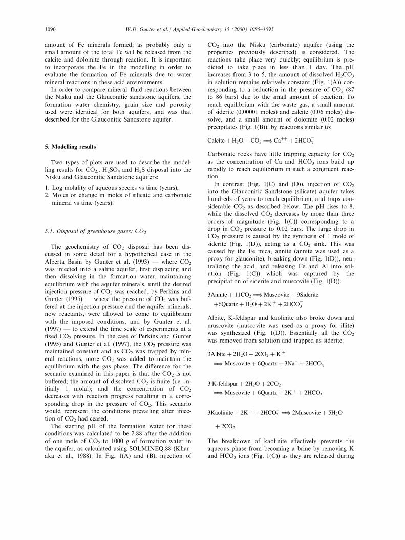
of one mole of CO2 to 1000 g of formation water inthe aquifer, as calculated using SOLMINEQ.88 (Khar-aka et al., 1988). In Fig. 1(A) and (B), injection of
CO2 into the Nisku (carbonate) aquifer (using theproperties previously described) is considered. The
reactions take place very quickly; equilibrium is pre-dicted to take place in less than 1 day. The pHincreases from 3 to 5, the amount of dissolved H2CO3
in solution remains relatively constant (Fig. 1(A)) cor-responding to a reduction in the pressure of CO2 (87to 86 bars) due to the small amount of reaction. To
reach equilibrium with the waste gas, a small amountof siderite (0.00001 moles) and calcite (0.06 moles) dis-solve, and a small amount of dolomite (0.02 moles)
precipitates (Fig. 1(B)); by reactions similar to:
Calcite� H2O� CO2 �) Ca�� � 2HCOÿ3
Carbonate rocks have little trapping capacity for CO2
as the concentration of Ca and HCO3 ions build up
rapidly to reach equilibrium in such a congruent reac-tion.In contrast (Fig. 1(C) and (D)), injection of CO2
into the Glauconitic Sandstone (silicate) aquifer takeshundreds of years to reach equilibrium, and traps con-siderable CO2 as described below. The pH rises to 8,while the dissolved CO2 decreases by more than three
orders of magnitude (Fig. 1(C)) corresponding to adrop in CO2 pressure to 0.02 bars. The large drop inCO2 pressure is caused by the synthesis of 1 mole of
siderite (Fig. 1(D)), acting as a CO2 sink. This wascaused by the Fe mica, annite (annite was used as aproxy for glauconite), breaking down (Fig. 1(D)), neu-
tralizing the acid, and releasing Fe and Al into sol-ution (Fig. 1(C)) which was captured by theprecipitation of siderite and muscovite (Fig. 1(D)).
3Annite� 11CO2 �)Muscovite� 9Siderite
�6Quartz� H2O� 2K � � 2HCOÿ3
Albite, K-feldspar and kaolinite also broke down andmuscovite (muscovite was used as a proxy for illite)was synthesized (Fig. 1(D)). Essentially all the CO2
was removed from solution and trapped as siderite.
3Albite� 2H2O� 2CO2 � K �
�)Muscovite� 6Quartz� 3Na� � 2HCOÿ3
3 K-feldspar � 2H2O� 2CO2
�)Muscovite� 6Quartz� 2K � � 2HCOÿ3
3Kaolinite� 2K � � 2HCOÿ3 �) 2Muscovite� 5H2O
� 2CO2
The breakdown of kaolinite e�ectively prevents theaqueous phase from becoming a brine by removing Kand HCO3 ions (Fig. 1(C)) as they are released during
W.D. Gunter et al. / Applied Geochemistry 15 (2000) 1085±10951090
the breakdown of annite, K-feldspar and albite. If Caor Mg silicates had been present in the aquifer, they
would have had the same e�ect reacting to form calciteand dolomite or Mg calcites and consuming the CO2.Since they were not present, there is only synthesis of
0.02 moles of dolomite and 0.05 moles of calcite. Forthe ``non-reactive'' case of the Glauconitic Sandstoneaquifer, the results are very similar to those previously
described for the Nisku aquifer.
5.2. Disposal of industrial acids: H2SO4
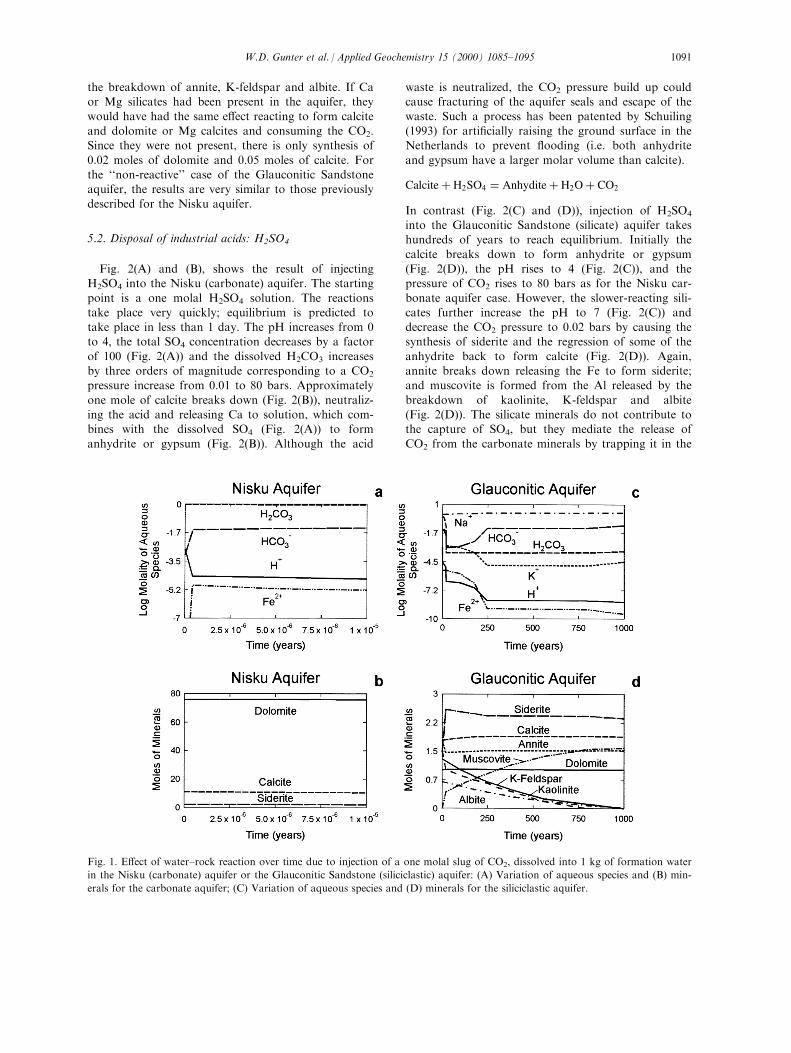
Fig. 2(A) and (B), shows the result of injectingH2SO4 into the Nisku (carbonate) aquifer. The starting
point is a one molal H2SO4 solution. The reactionstake place very quickly; equilibrium is predicted totake place in less than 1 day. The pH increases from 0to 4, the total SO4 concentration decreases by a factor
of 100 (Fig. 2(A)) and the dissolved H2CO3 increasesby three orders of magnitude corresponding to a CO2
pressure increase from 0.01 to 80 bars. Approximately
one mole of calcite breaks down (Fig. 2(B)), neutraliz-ing the acid and releasing Ca to solution, which com-bines with the dissolved SO4 (Fig. 2(A)) to form
anhydrite or gypsum (Fig. 2(B)). Although the acid
waste is neutralized, the CO2 pressure build up couldcause fracturing of the aquifer seals and escape of the
waste. Such a process has been patented by Schuiling(1993) for arti®cially raising the ground surface in theNetherlands to prevent ¯ooding (i.e. both anhydrite
and gypsum have a larger molar volume than calcite).
Calcite� H2SO4 � Anhydite� H2O� CO2
In contrast (Fig. 2(C) and (D)), injection of H2SO4
into the Glauconitic Sandstone (silicate) aquifer takeshundreds of years to reach equilibrium. Initially the
calcite breaks down to form anhydrite or gypsum(Fig. 2(D)), the pH rises to 4 (Fig. 2(C)), and thepressure of CO2 rises to 80 bars as for the Nisku car-
bonate aquifer case. However, the slower-reacting sili-cates further increase the pH to 7 (Fig. 2(C)) anddecrease the CO2 pressure to 0.02 bars by causing thesynthesis of siderite and the regression of some of the
anhydrite back to form calcite (Fig. 2(D)). Again,annite breaks down releasing the Fe to form siderite;and muscovite is formed from the Al released by the
breakdown of kaolinite, K-feldspar and albite(Fig. 2(D)). The silicate minerals do not contribute tothe capture of SO4, but they mediate the release of
CO2 from the carbonate minerals by trapping it in the
Fig. 1. E�ect of water±rock reaction over time due to injection of a one molal slug of CO2, dissolved into 1 kg of formation water
in the Nisku (carbonate) aquifer or the Glauconitic Sandstone (siliciclastic) aquifer: (A) Variation of aqueous species and (B) min-
erals for the carbonate aquifer; (C) Variation of aqueous species and (D) minerals for the siliciclastic aquifer.
W.D. Gunter et al. / Applied Geochemistry 15 (2000) 1085±1095 1091
form of siderite, exactly as discussed previously for theCO2 disposal case. If no carbonate minerals are pre-
sent, little trapping would occur, unless a Ca silicatemineral, such as anorthite, is present. In this case, theanorthite would break down to supply the Ca to make
the synthesis of anhydrite or gypsum possible. For the``non-reactive'' case of the Glauconitic Sandstone aqui-fer, the results are very similar to those previously
described for the Nisku aquifer.
5.3. Disposal of sour gases: H2S
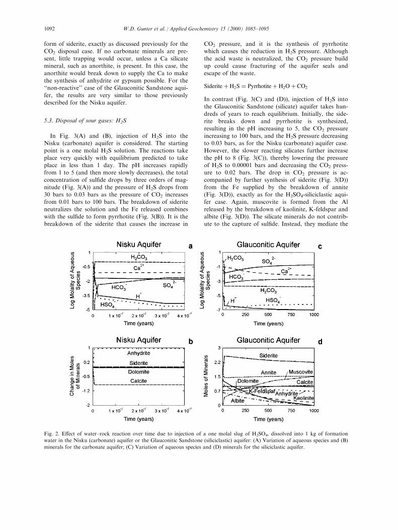
In Fig. 3(A) and (B), injection of H2S into theNisku (carbonate) aquifer is considered. The startingpoint is a one molal H2S solution. The reactions take
place very quickly with equilibrium predicted to takeplace in less than 1 day. The pH increases rapidlyfrom 1 to 5 (and then more slowly decreases), the totalconcentration of sul®de drops by three orders of mag-
nitude (Fig. 3(A)) and the pressure of H2S drops from30 bars to 0.03 bars as the pressure of CO2 increasesfrom 0.01 bars to 100 bars. The breakdown of siderite
neutralizes the solution and the Fe released combineswith the sul®de to form pyrrhotite (Fig. 3(B)). It is thebreakdown of the siderite that causes the increase in
CO2 pressure, and it is the synthesis of pyrrhotitewhich causes the reduction in H2S pressure. Although
the acid waste is neutralized, the CO2 pressure buildup could cause fracturing of the aquifer seals andescape of the waste.
Siderite� H2S � Pyrrhotite� H2O� CO2
In contrast (Fig. 3(C) and (D)), injection of H2S intothe Glauconitic Sandstone (silicate) aquifer takes hun-
dreds of years to reach equilibrium. Initially, the side-rite breaks down and pyrrhotite is synthesized,resulting in the pH increasing to 5, the CO2 pressure
increasing to 100 bars, and the H2S pressure decreasingto 0.03 bars, as for the Nisku (carbonate) aquifer case.However, the slower reacting silicates further increase
the pH to 8 (Fig. 3(C)), thereby lowering the pressureof H2S to 0.00001 bars and decreasing the CO2 press-ure to 0.02 bars. The drop in CO2 pressure is ac-companied by further synthesis of siderite (Fig. 3(D))
from the Fe supplied by the breakdown of annite(Fig. 3(D)), exactly as for the H2SO4-siliciclastic aqui-fer case. Again, muscovite is formed from the Al
released by the breakdown of kaolinite, K-feldspar andalbite (Fig. 3(D)). The silicate minerals do not contrib-ute to the capture of sul®de. Instead, they mediate the
Fig. 2. E�ect of water±rock reaction over time due to injection of a one molal slug of H2SO4, dissolved into 1 kg of formation
water in the Nisku (carbonate) aquifer or the Glauconitic Sandstone (siliciclastic) aquifer: (A) Variation of aqueous species and (B)
minerals for the carbonate aquifer; (C) Variation of aqueous species and (D) minerals for the siliciclastic aquifer.
W.D. Gunter et al. / Applied Geochemistry 15 (2000) 1085±10951092
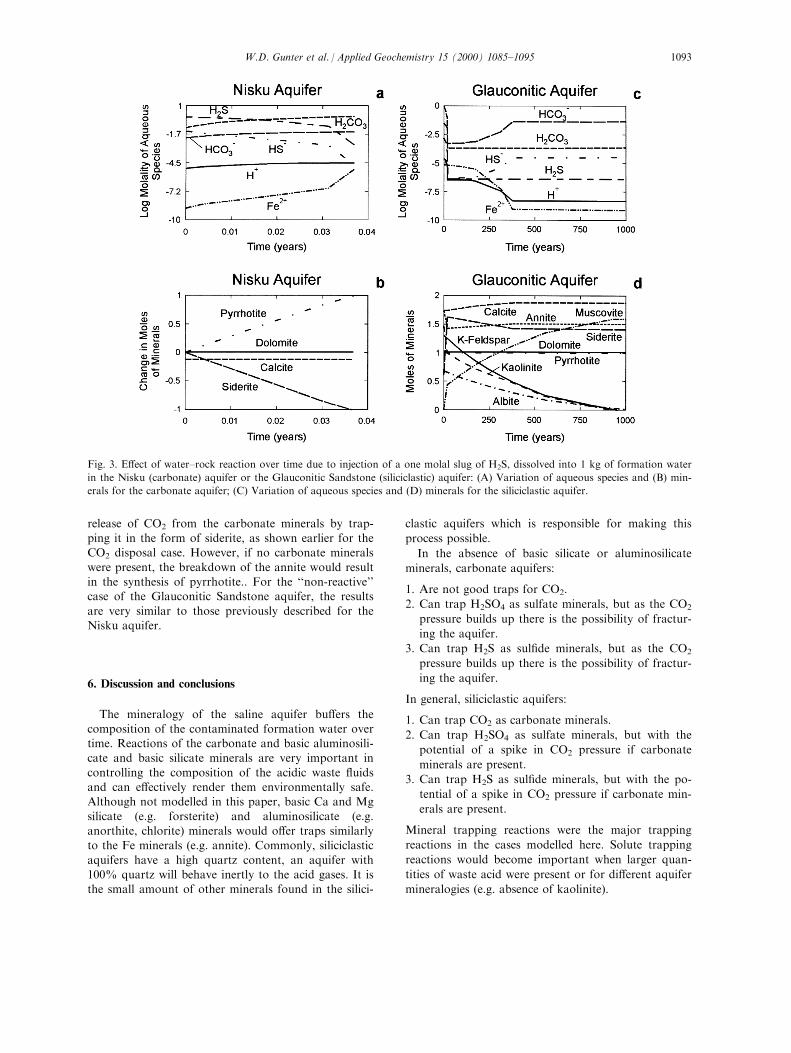
release of CO2 from the carbonate minerals by trap-ping it in the form of siderite, as shown earlier for theCO2 disposal case. However, if no carbonate minerals
were present, the breakdown of the annite would resultin the synthesis of pyrrhotite.. For the ``non-reactive''case of the Glauconitic Sandstone aquifer, the results
are very similar to those previously described for theNisku aquifer.
6. Discussion and conclusions
The mineralogy of the saline aquifer bu�ers thecomposition of the contaminated formation water overtime. Reactions of the carbonate and basic aluminosili-cate and basic silicate minerals are very important in
controlling the composition of the acidic waste ¯uidsand can e�ectively render them environmentally safe.Although not modelled in this paper, basic Ca and Mg
silicate (e.g. forsterite) and aluminosilicate (e.g.anorthite, chlorite) minerals would o�er traps similarlyto the Fe minerals (e.g. annite). Commonly, siliciclastic
aquifers have a high quartz content, an aquifer with100% quartz will behave inertly to the acid gases. It isthe small amount of other minerals found in the silici-
clastic aquifers which is responsible for making this
process possible.
In the absence of basic silicate or aluminosilicate
minerals, carbonate aquifers:
1. Are not good traps for CO2.
2. Can trap H2SO4 as sulfate minerals, but as the CO2
pressure builds up there is the possibility of fractur-
ing the aquifer.
3. Can trap H2S as sul®de minerals, but as the CO2
pressure builds up there is the possibility of fractur-
ing the aquifer.
In general, siliciclastic aquifers:
1. Can trap CO2 as carbonate minerals.
2. Can trap H2SO4 as sulfate minerals, but with the
potential of a spike in CO2 pressure if carbonate
minerals are present.
3. Can trap H2S as sul®de minerals, but with the po-
tential of a spike in CO2 pressure if carbonate min-
erals are present.
Mineral trapping reactions were the major trapping
reactions in the cases modelled here. Solute trapping
reactions would become important when larger quan-
tities of waste acid were present or for di�erent aquifer
mineralogies (e.g. absence of kaolinite).
Fig. 3. E�ect of water±rock reaction over time due to injection of a one molal slug of H2S, dissolved into 1 kg of formation water
in the Nisku (carbonate) aquifer or the Glauconitic Sandstone (siliciclastic) aquifer: (A) Variation of aqueous species and (B) min-
erals for the carbonate aquifer; (C) Variation of aqueous species and (D) minerals for the siliciclastic aquifer.
W.D. Gunter et al. / Applied Geochemistry 15 (2000) 1085±1095 1093
Carbonate reactions will tend to rapidly approxi-mate local equilibrium conditions while silicate reac-
tions occur, because of the two-to-four higher ordersof magnitude rate constants of the carbonate minerals.Consequently, in the examples considered here, the
reaction sequence found for carbonate aquifers isalways duplicated early in the reaction path for thecase of the siliciclastic aquifers before signi®cant sili-
cate reaction takes place.The times inferred for the carbonate reactions to
take place (based on the modelling) are probably faster
than would occur in the natural system, although therelative rates compared to silicates are correct. Onereason for this, as discussed previously, is the use of a100% reactive surface in the model and the assump-
tion that the surface of each mineral is in intimate con-tact with the aqueous phase. If the surfaces arepartially coated by another solid, covered by gas
bubbles due to reaction or are poisoned by the pre-sence of foreign ions, the rates would decrease substan-tially. However, given the extremely slow regional ¯ow
rates in saline aquifers in the Alberta Basin, uncertain-ties in excess of two orders of magnitude in the reac-tive surface areas can be tolerated without a�ecting the
viability of mineral traps.The destruction of old minerals and synthesis of new
minerals may lead to permeability changes in the aqui-fer. Overall, there will be a volume increase approxi-
mately equivalent to 5% of the pore volume for thecase of the Glauconitic Sandstone aquifer. Providingthe precipitation does not take place in pore throats,
this should not cause plugging of the aquifer. Thesaline aquifer will probably be least a�ected near thewellbore, because the gas bubble formed by injection
of the waste gas will both displace and dehydrate theformation, essentially blocking the formation of newphases. DeGraa� et al. (1995) reached a similar con-clusion for disposal of H2SO4 into limestone, namely,
that close to the well dissolution dominates while pre-cipitation dominates away from the wellbore. This dis-tance can be controlled by the rate of injection of the
waste.Although only speci®c aquifer conditions with a
speci®c mineralogy approximating the Glauconitic
Sandstone aquifer in the Alberta Basin were modelled,the approach and the conclusions may be extrapolatedto other saline aquifers and other sedimentary basins.
Acknowledgements
One of us (WDG) spent a winter semester in Graz,
Austria where he was introduced to Austrian schnappsand had the time to compose some of his thoughts ondisposal of waste acids. The contents of this paper
were partly formulated there and he is grateful to boththe Austrian government and Professor G. Hoinkes,
head of the Institut fur Mineralogie, Kristallographieund Petrographie of the Karl-Franzens-UniversitatGraz who made the visit possible and enjoyable.
Also thanks are extended to Brian Hitchon for hiscaustic (as opposed to acidic) editorial comments onan earlier version of the manuscript; to Steve Talman
for his continuous improvement of PATHARC; and toY. Kharaka and J. Bischo� for their suggestions forimprovement of this manuscript.
References
Anbeek, C., 1993. The e�ect of natural weathering on dissol-
ution rates. Geochim. Cosmochim. Acta 57, 4963±4975.
Acker, J.G., Bricker, O.P., 1992. The in¯uence of pH on bio-
tite dissolution and alteration kinetics at low temperature.
Geochim. Cosmochim. Acta 56, 3073±3092.
Bachu, S., Gunter, W.D., Perkins, E.H., 1994. Aquifer dispo-
sal of CO2: hydrodynamic and mineral trapping. Energy
Convers. Mgmt 35, 269±279.
Baklid, A., Ragnhild, K., Geir, O., 1996. Sleipner Vest CO2
Disposal, CO2 Injection into a Shallow Underground
Aquifer. Society Petroleum Engineers Paper No. 36600.
Bamhart, W.D., Coulthard, C. 1995. Weyburn CO2 Miscible
Flood Conceptual Design and Risk Assessment, Paper
No. 95-120. In: Sixth Petroleum Conference of the South
Saskatchewan Section, Petroleum Society of CIM, Regina,
16±18 October.
Busenberg, E., Plummer, L.N., 1982. The kinetics of dissol-
ution of dolomite in CO2-H2O systems at 1.5±658C and 0±
1 atm PCO2. Am. J. Sci. 282, 45±78.
Carroll, S.A., Walther, J.V., 1990. Kaolinite dissolution at 25,
60 and 808C. Am. J. Sci. 290, 797±810.
Carroll-Webb, S.A., Walther, J.V., 1988. A surface complex
model for the pH-dependence of corundum and kaolinite
dissolution rates. Geochim. Cosmochim. Acta 52, 2609±
2623.
Chakma, A., 1997. Acid gas re-injection Ð a practical way to
eliminate CO2 emissions from gas processing plants.
Energy Convers. Mgmt 38, S205±S209.
Chou, L., Garrels, R.M., Wollast, R., 1989. A comparative
study of the kinetics and mechanisms of dissolution of car-
bonate minerals. Chem. Geol. 78, 269±282.
DeGraa�, J.W.M., Speck, P.J.H.R., Schuiling, R.D.,
Shmulovich, K.I. 1995. Neutralization of sulphuric acid by
percolation through limestone. In: Kharaka, Y.K.,
Chudaev, O.V. (Eds.), Proc. 8th International Symposium
on Water±Rock Interaction. A. A. Balkema, Rotterdam,
pp. 411±414.
Deming, D., 1994. Fluid ¯ow and heat transport in the upper
continental crust. In: Parnell, J. (Ed.), Geo¯uids: Origin,
Migration and Evolution of Fluids in Sedimentary Basins,
Geol. Soc. Spec. Pub. No. 78, pp. 27±42.
Fleer, V.N., Johnston, R.M., 1986. A Compilation of
Solubility and Dissolution Kinetics Data on Minerals in
W.D. Gunter et al. / Applied Geochemistry 15 (2000) 1085±10951094
Granitic and Gabbroic Systems. Atomic Energy of
Canada Limited Technical Report TR-328-2.
Fyfe, W.S., Price, N.J., Thompson, A.B., 1978. Fluids in the
Earth's Crust. Developments in Geochemistry, vol. 1.
Elsevier, Amsterdam.
Gunter, W.D., Marwaha, V., McDonald, M.M., Macdonald,
D.E., 1996. Technical and economic feasibility of CO2 dis-
posal in aquifers within the Alberta Sedimentary Basin,
Canada. Energy Convers. Mgmt 37, 1135±1142.
Gunter, W.D., Perkins, E.H., McCann, T.J., 1993. Aquifer
disposal of CO2-rich gases: Reaction design for added ca-
pacity. Energy Convers. Mgmt 34, 941±948.
Gunter, W.D., Wiwchar, B., Perkins, E.H., 1997. Aquifer dis-
posal of CO2-rich greenhouse gases: Extension of the time
scale of experiment for CO2-sequestering reactions by geo-
chemical modelling. Mineral. Petrol. 59, 121±140.
Gunter, W.D., Wong, S., Cheel, D.B., Sjostrom, G., 1998.
Large CO2 sinks: their role in the mitigation of greenhouse
gases from an international, national (Canada) and pro-
vincial (Alberta) perspective. Appl. Energy 61, 209±227.
Helgeson, H.C., Murphy, W.M., Aagaard, P., 1984.
Thermodynamic and kinetic constraints on reaction rates
among minerals and aqueous solutions. II. Rate constants,
e�ective surface area, and the hydrolysis of feldspar.
Geochim. Cosmochim. Acta 48, 2405±2432.
Hitchon, B. (Ed.), 1996. Aquifer Disposal of Carbon Dioxide:
Hydrodynamic and Mineral Trapping Ð Proof of
Concept. Geoscience Publishing Ltd, Sherwood Park.
Hitchon, B., Gunter, W.D., Gentzis, T., Bailey, R.T., 1999.
Sedimentary basins and greenhouse gases: A serendipitous
association. Energy Conv. Mgmt 40, 825±843.
Kharaka, Y.K., Gunter, W.D., Aggarwal, P.K., Perkins,
E.H., DeBraal, J.D., 1988. SOLMINEQ.88: A Computer
Program for Geochemical Modelling of Water±Rock
Interactions. US Geological Survey, Water Resource
Investigations Report 88-4227.
Knauss, K.G., Wollery, T.J., 1988. The dissolution kinetics of
quartz as a function of pH and time at 708C. Geochim.
Cosmochim. Acta 52, 43±53.
Knauss, K.G., Wollery, T.J., 1989. Muscovite dissolution kin-
etics as a function of pH and time at 708C. Geochim.
Cosmochim. Acta 53, 1493±1501.
Lasaga, A.C., 1981. Rate laws of chemical reactions. In:
Lasaga, A.C., Kirkpatrick R.J. (Eds.), Kinetics of
Geochemical Processes. Mineralogical Society of
America's Reviews in Mineralogy, 8(1), 1±68.
Lasaga, A.C., 1984. Chemical kinetics of water±rock inter-
action. J. Geophys. Res. 89, 4009±4025.
Lasaga, A.C., Soler, J.M., Ganor, J., Burch, T.E., Nagy,
K.L., 1994. Chemical weathering rate laws and global geo-
chemical cycles. Geochim. Cosmochim. Acta 58, 2361±
2386.
Longworth, H.L., Dunn, G.C., Semchuck, M., 1995.
Underground Disposal of Acid Gas in Alberta, Canada:
Regulatory Concerns and Case Histories. Society of
Petroleum Engineers Paper No. 35584.
Mossop, G., Shetsen, I., 1994. Geological Atlas of the
Western Canada Sedimentary Basin. Cdn. Soc. Petrol.
Geol. and Alberta Research Council.
Nahnybida, C., Hutcheon, I., Kirker, J., 1982. Diagenesis of
the Nisku formation and the origin of late stage cements.
Cdn. Miner. 20, 129±140.
Nesbitt, B.E., 1990. Fluids in Tectonically Active Regimes of
the Continental Crust. Min. Soc. Canada short course,
vol. 18.
Parnell, J., 1994. Geo¯uids: Origin, Migration and Evolution
of Fluids in Sedimentary Basins. Geol. Soc. London Spec.
Pub. No. 78.
Perkins, E.H., Gunter, W.D., Nesbitt, H.W., St-Arnaud, L.C.
1997. Critical review of classes of geochemical models
adaptable for prediction of acidic drainage from mine
waste rock. In: 4th Int. Conf. on Acid Rock Drainage
Proc., Vancouver, Canada, 2, pp. 587±601.
Perkins, E.H., Gunter, W.D. 1995. Aquifer disposal of CO2-
rich greenhouse gases: Modelling of water±rock reaction
paths in a siliciclastic aquifer. In: Kharaka, Y.K.,
Chudaev, O.V. (Eds.), Proc. 8th Internat. Symp. on
Water±Rock Interaction, A.A. Balkema, Rotterdam, pp.
895±898.
Plummer, L.N., Parkhurst, D.L., Wigley, T.M.L., 1978. The
kinetics of calcite dissolution in CO2-water systems at 5±
608C and 0.0±1.0 atm CO2. Amer. J. Sci. 278, 179±216.
Porter, I.E., Price, R.A., McGrossan, R.G., 1982. The western
Canada sedimentary basin. Phil. Trans. Royal. Soc.
London Series A, 169±192.
Rimstidt, J.D., Barnes, H.L., 1980. The kinetics of silica±
water reactions. Geochim. Cosmochim. Acta 44, 1683±
1699.
Schuiling, R.D., 1993. Procedure for Locally Raising the
Ground Arti®cially. European Patent PCT/NL89/00014.
(proprietor-Delft Geotechnics).
Schuiling, R.D., van Gaans, P.F.M., 1997. The waste sulfuric
acid lake of the TiO2-plant at Armyansk, Crimea,
Ukraine. Part I. Self-sealing as an environmental protec-
tion mechanism. Appl. Geochem. 12, 181±186.
Sverdrup, H.U., 1990. The Kinetics of Base Cation Release
due to Chemical Weathering. Lund University Press,
Lund.
Sverdrup, H.U., Warfvinge, P., 1988. Weathering of primary
silicate minerals in the natural soil environment in relation
to a chemical weathering model. Water, Air, Soil Poll. 38,
387±408.
Sverdrup, H.U., Warfvinge, P., 1993. Calculating ®eld weath-
ering rates using a mechanistic geochemical model
PROFILE. App. Geochem. 8, 273±284.
White, A.F., Peterson, M.L., 1990. Role of reactive-surface-
area characterization in geochemical models. In: Melchor
DC, Bassett RL (Eds.), Chemical Modelling of Aqueous
Systems II. ACS Symp. Ser. 416, 35, 461±475.
Wichert, E., Royan, T., 1997. Acid gas injection eliminates
sulfur recovery expense. Oil and Gas Journal, April 28,
67±72.
Wood, B.J., Walther, J.V., 1983. Rates of hydrothermal reac-
tions. Science 222, 413±415.
W.D. Gunter et al. / Applied Geochemistry 15 (2000) 1085±1095 1095