
AquaDisk® - DN Higgins 2021
370
AquaDisk ® RE-SUBMITTAL MANUAL COLLIER COUNTY NESA ADFSP-54X6E NAPLES, FL PROJECT I.D. 116275 © 2020 Aqua-Aerobic Systems, Inc. All rights reserved. This manual may not be copied all or in part without the express written permission of Aqua-Aerobic Systems, Inc.
-
Upload
khangminh22 -
Category
Documents
-
view
2 -
download
0
Transcript of AquaDisk® - DN Higgins 2021

AquaDisk®
RE-SUBMITTAL MANUAL
COLLIER COUNTY NESA
ADFSP-54X6E
NAPLES, FL
PROJECT I.D. 116275
© 2020 Aqua-Aerobic Systems, Inc. All rights reserved. This manual may not be copied all or in part without the express written permission of Aqua-Aerobic Systems, Inc.

Submittal Review Stamp For: COLLIER COUNTY NESA Project ID #116275 / SO #92236
2020-05-21 116275 Approval Stamp.doc 1 of 1
© 2020 Aqua-Aerobic Systems, Inc.
Contractor's Review Stamp Engineer's Review Stamp

EP-10042 Introduction Letter.doc 1 of 1
Copyright © 2008 Aqua-Aerobic Systems, Inc. 2020-05-28
INTRODUCTION
The purpose of this submittal manual is to communicate the equipment manufacturer’s scope of supply, material of construction, and level of responsibility.
As the equipment manufacturer, Aqua-Aerobic Systems’ intent is to interface equipment into your wastewater/water system such that our equipment either meets or exceeds all customer specifications. Please review all information within this submittal package to determine accurate civil basin work and/or foundation dimensions, verify the surrounding site components do not interfere with equipment proposed, and that the manufacturer has complied with all materials and specifications. In the event that the manufacturer has not met the customer’s specifications for a given item, please mark in red and flag the page in the submittal. This will facilitate a fast response and insure that said items are responded to by the equipment manufacturer.
If there are any questions regarding this submittal, please feel free to contact the equipment manufacturer and /or representative.
Please remember that Aqua-Aerobic Systems, Inc. is there for you in the long run, starting with process / system design through post installation field support. This kind of philosophy insures a working relationship with Aqua- Aerobic Systems, Inc. We hope this submittal meets your needs. Please return one (1) copy stamped and signed “approved”. Thank you.

Project Associates
OWNER CONTRACTOR
Collier County Mitchell & Stark Construction Company
3301 Tamiami Trail East 6001 Shirley Street
Naples, FL 34112 Naples, FL 34109
Phone: 239-732-2667 Phone: 239-332-1632
ENGINEER AQUA-AEROBIC SALES REPRESENTATIVE
Source, Inc. EnviroSales of Florida, Inc. - Chuck Hlavach
1334 Lafayette Streat 4125 Bee Ridge Road
Cape Coral, FL 33904 Sarasota, FL 34233-2555
Phone: 239-549-2345 Phone: 941-343-9244
AQUA-AEROBIC PROJECT MANAGER
Dave Cornford
6306 North Alpine Road
Loves Park, IL 61111-7655
Phone: 815/639-4439
Fax: 815/654-8258
Email: [email protected]
Project Name: Collier County NESA, FL
Project Location: Naples, FL
AASI Project ID: 116275

AquaDisk® Re-Submittal Table of Contents
2020-09-24 116275-Re-SUB AquaDisk TOC.doc 1 of 7
© 2020 Aqua-Aerobic Systems, Inc.
AquaDisk® Re-Submittal Manual Book Cover Sheet Approval Stamp Sheet Introduction Sheet EP-10042 Associates Sheet
Table of Contents SECTION 1 GENERAL INFORMATION
A. Technical Support Contact Sheet EP-10033 B. Product Manuals Special Messages EP-10050 C. Equipment Safety Documents and Precautions
1. Electrical Safety Precautions EP-10015 2. Electrical Lockout-Tag Out Procedures EP-10095 3. Filter General Safety Precautions EP-10043 4. In Basin Maintenance EP-10530 5. Gearbox Safety Precautions EP-10035 6. Pump Safety Precautions EP-10036 7. Control Panel Safety Precautions EP-10005
D. Outline for Manufacturers Training EP-10029 E. Training Session Sign-In Sheet EP-10284 F. Warranty Documents G. Receiving and Handling EP-10031
1. Loss & Damage Claim Form EP-10032 H. Protective Coatings
1. Paint – Technical data Sheets a. Stainless Steel Tank ES-1059
i. PPG PSX 805 EP-50453 I. Storage Procedures
1. Storage Introduction EP-10034 2. Cloth Media EP-10025 3. Control Panel EP-10028 4. External Centrifugal Pumps EP-10022 5. Float Switch EP-10027 6. Gearbox EP-10023 7. General Instrumentation EP-10252 8. Valve & Actuators EP-10024
J. List of Spare Parts K. Video Recording Notice EP-10437

AquaDisk® Re-Submittal Table of Contents
2020-09-24 116275-Re-SUB AquaDisk TOC.doc 2 of 7
© 2020 Aqua-Aerobic Systems, Inc.
SECTION 2 INSTALLATION and START-UP
A. Anchor Installation Instructions 1. Wedge Anchor
i. Red Head Trubolt EP-50329 B. Loctite Installation Instructions ES-1018 C. Double Nut Procedure EP-10080
1. Bolt Torque Specification ES-1057 D. General Start-up Procedures EP-10017 E. Start-up Papers
1. Equipment Inspection, Mechanical Start-Up and Process Training Report EP-10091
2. Disk Filter Equipment Mechanical Checkout EP-10086 F. Shutdown Procedures EP-10018 G. Emergency Shutdown Procedures EP-10212
SECTION 3 PROCESS and CONTROL
A. Process Design B. Control & Operation Description
SECTION 4 MECHANICAL and FIELD INSTRUMENT COMPONENT INFORMATION
A. Anchor 1. Wedge See Drawing Section 7 for Details
B. Bearing 1. Pillow Block 2608932
C. Shaft Collar 1. Locking 2 Piece 2614245
D. Chain 1. Drive 2606032
E. Filter Cloth 1. OptiFiber PES-14® 2966912
F. Coupling, Victaulic 1. 2.00 in Painted 2962966
G. Frame 1. Assembly 2962035
H. Gauge 1. Pressure 2.5 in 0-15 psi 2607690 2. Vacuum 3.5 in 30-0 in Hg 2607833

AquaDisk® Re-Submittal Table of Contents
2020-09-24 116275-Re-SUB AquaDisk TOC.doc 3 of 7
© 2020 Aqua-Aerobic Systems, Inc.
I. Helical Gear Drive 1. Nord 2965892 See Drawing Section 7 for Detail
a. SK33N 2615163-1 b. SK33N 2615163-2 c. .5 HP Nord 2615164-1 d. .5 HP Nord 2615164-2
J. Hose 1. PVC
a. 1.50 in 2612035 2. Nitrile
a. 2.00 in 2606512 K. Instrumentation
1. Level a. IFM Flush Mount 2614969 b. IFM Connector Cable 2614968 c. Float Switch, Non-Mercury 2611183
2. Vacuum a. IFM Flush Mount 2614990 b. IFM Connector Cable 2614968
L. Pump, Centrifugal 1. Gorman-Rupp 2965308 See Dwg Sec. 7 for Detail
a. 12B20-B 2614428 b. 2 HP PE F1 2615707-1 c. 2 HP PE F2 2615707-2 d. Coupling 2614432
i. Spider 2612223 M. Seal
1. Effluent 2607719 N. Sprocket
1. Drive a. .5 HP 2607227
2. Centertube a. Single Segment 48T 2509003
O. Valve Schedule 1. Electric Ball
a. 2 in Valve Assy Grooved See Dwg 2964965 Sec. 7 for Detail i. RCIA Act. Assy 2964966
ii. Valve 2614032 iii. Cable 2614395
2. Manual Gate a. 3 in 2610351

AquaDisk® Re-Submittal Table of Contents
2020-09-24 116275-Re-SUB AquaDisk TOC.doc 4 of 7
© 2020 Aqua-Aerobic Systems, Inc.
3. Manual Lever Ball a. 3 in 2609798 b. 2 in 3-Way 2606833 c. .5 in 2612176
4. Manual Butterfly a. 12 in 2610925
SECTION 5 ELECTRICAL CONTROL PANEL COMPONENT INFORMATION
A. Control Panel Safety Precautions Elec EP-10005 B. Electrical Lock-out Procedures Elec EP-10095 C. Cable, Conduit and Wire
1. Ethernet Patch 3 ft 2752496 2. Ethernet Patch 10 ft 2752497 3. PVC Rigid EP-10100 4. PVC Flex EP-10260
D. Circuit Breaker 1. 3 Amp 2753912 2. 4 Amp 2753915 3. 5 Amp 2753916 4. 10 Amp 2753922
E. Enclosure 1. Wall Mount 48x36x12 SS304 2751224
F. Enclosure Accessories 1. Isolation Ground Bar 2751091 2. Sub Panel 48x36 2750055 3. Ground Bar 2750028 4. GFCI Receptacle 2751627 5. Ground Lug 2750031
G. Enclosure Environment Control 1. Corrosion Inhibitor 2607334 2. Air Conditioner 1600 BTU 2750558
H. Fuse 1. Midget 1 Amp Branch 2608762 2. Class CC 10 Amp Primary 2kVA Transformer 2751427 3. Class CC 20 Amp Secondary 2kVA Transformer 2751479 4. Electronic .050 Amp Analog 2751144
I. Fuse Blocks 1. Midget 30 Amp 1-Pole Branch 2751333 2. Electronic 15 Amp 1-Pole Analog 2750034
J. Fuse Covers 1. Fuse Puller 2702219
K. HMI – Human Machine Interface 1. PanelView Plus 7 700 2754080
AquaDisk® Re-Submittal Table of Contents
2020-09-24 116275-Re-SUB AquaDisk TOC.doc 5 of 7
© 2020 Aqua-Aerobic Systems, Inc.
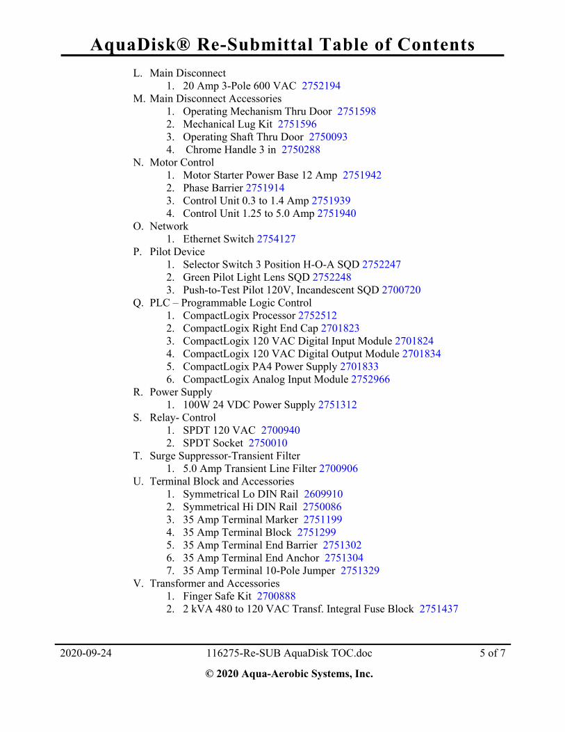
L. Main Disconnect 1. 20 Amp 3-Pole 600 VAC 2752194
M. Main Disconnect Accessories 1. Operating Mechanism Thru Door 2751598 2. Mechanical Lug Kit 2751596 3. Operating Shaft Thru Door 2750093 4. Chrome Handle 3 in 2750288
N. Motor Control 1. Motor Starter Power Base 12 Amp 2751942 2. Phase Barrier 2751914 3. Control Unit 0.3 to 1.4 Amp 2751939 4. Control Unit 1.25 to 5.0 Amp 2751940
O. Network 1. Ethernet Switch 2754127
P. Pilot Device 1. Selector Switch 3 Position H-O-A SQD 2752247 2. Green Pilot Light Lens SQD 2752248 3. Push-to-Test Pilot 120V, Incandescent SQD 2700720
Q. PLC – Programmable Logic Control 1. CompactLogix Processor 2752512 2. CompactLogix Right End Cap 2701823 3. CompactLogix 120 VAC Digital Input Module 2701824 4. CompactLogix 120 VAC Digital Output Module 2701834 5. CompactLogix PA4 Power Supply 2701833 6. CompactLogix Analog Input Module 2752966
R. Power Supply 1. 100W 24 VDC Power Supply 2751312
S. Relay- Control 1. SPDT 120 VAC 2700940 2. SPDT Socket 2750010
T. Surge Suppressor-Transient Filter 1. 5.0 Amp Transient Line Filter 2700906
U. Terminal Block and Accessories 1. Symmetrical Lo DIN Rail 2609910 2. Symmetrical Hi DIN Rail 2750086 3. 35 Amp Terminal Marker 2751199 4. 35 Amp Terminal Block 2751299 5. 35 Amp Terminal End Barrier 2751302 6. 35 Amp Terminal End Anchor 2751304 7. 35 Amp Terminal 10-Pole Jumper 2751329
V. Transformer and Accessories 1. Finger Safe Kit 2700888 2. 2 kVA 480 to 120 VAC Transf. Integral Fuse Block 2751437
file://///aqua40/adeptvault1/Standards/2752247%20-%20Square%20D%203-Position%20Selector%20Switch.doc

AquaDisk® Re-Submittal Table of Contents
2020-09-24 116275-Re-SUB AquaDisk TOC.doc 6 of 7
© 2020 Aqua-Aerobic Systems, Inc.
SECTION 6 MAINTENANCE and TROUBLESHOOTING
THIS SECTION IS LEFT BLANK AND WILL BE INCLUDED IN THE OPERATION & MAINTENANCE MANUAL.
SECTION 7 MECHANICAL DRAWINGS Disk 6 Tank Material 304 SS Cloth Material OptiFiber PES-14
Material Schedule
A. 911627560000 Sh. 1 – Plan View & General List B. 911627560000 Sh. 2 – Plan View & General List C. 911627560000 Sh. 3 – Plan View & General List D. 911627560001 Sh. 1 – Tank Assembly, 6 Disk, RH E. 911627560001 Sh. 2 – Tank Assembly, 6 Disk, RH F. 911627560002 Sh. 1 – Tank Assembly, 6 Disk, LH G. 911627560002 Sh. 2 – Tank Assembly, 6 Disk, LH H. 911627560003 Sh. 1 – Conduit System Assembly, 6 Disk, RH I. 911627560003 Sh. 2 – Conduit System Assembly, 6 Disk, RH J. 911627560004 Sh. 1 – Conduit System Assembly, 6 Disk, LH K. 911627560004 Sh. 2 – Conduit System Assembly, 6 Disk, LH L. 911627560005 – Control Panel-Junction Box Mtg Assy M. 2962622 – 0.50 in Wedge Anchor Detail 4.25 in N. 2964965 – 2 in Grooved Backwash Ball Valve Assy O. 2964966 – Actuator, RCI RCEL-005L with Receptacle P. 2965274 – Actuator, RCI RCEL-005L with Wallnut Q. 2965308 Sh. 1 – Pump Assy R. 2965308 Sh. 2 – Pump Assy S. 2965527 – Wheel Assy-Dual T. 2965560 – Backwash Nozzle Assy, RH U. 2965561 – Backwash Nozzle Assy, LH V. 2965563 – Valve and Hose Assy W. 2965614 – Centertube Bearing Kit X. 2965616 – Pressure Transmitter Installation Y. 2965623 – Float Switch Instl Z. 2965763 – Threaded Rod Drive Assembly AA. 2965886 – Centertube Assembly, 6 Disk BB. 2965887 – Drive System Instl, 0.5HP, RH CC. 2965892 – Gearmotor, Nord SK33N, 0.5HP DD. 2965957 – Centertube Installation, 6 Disk EE. 2965958 Sh. 1 – Backwash System Instl, 6 Disk, RH FF. 2965958 Sh. 2 – Backwash System Instl, 6 Disk, RH GG. 2965961 – BW Waste Pump Instl, 6 Disk, RH HH. 2965991 – Vacuum Transmitter Instl II. 2966009 Sh. 1 – Backwash System Instl, 6 Disk, LH

AquaDisk® Re-Submittal Table of Contents
2020-09-24 116275-Re-SUB AquaDisk TOC.doc 7 of 7
© 2020 Aqua-Aerobic Systems, Inc.
SECTION 8 ELECTRICAL DRAWINGS
JJ. 2966009 Sh. 2 – Backwash System Instl, 6 Disk, LH KK. 2966011 – BW Waste Pump Instl, 6 Disk, LH LL. 2966016 – Drive System Instl, 0.5HP, LH MM. 2967169 – Cloth and Frame Assy, ADF-54, PES-14 NN. 2967192 – Disk Segment Instl, PES-14 OO. 2967218 – Wheel Assy-Single
A. 911627560600 – Installation Notes B. 911627560700 Sh. 1 – Control Panel Assembly C. 911627560700 Sh. 2 – Control Panel Assembly D. 911627560700 Sh. 3 – Control Panel Assembly E. 911627560700 Sh. 4 – Control Panel Assembly F. 911627560800 Sh. 1 – Electrical Schematic G. 911627560800 Sh. 2 – Electrical Schematic H. 911627560800 Sh. 3 – Electrical Schematic I. 911627560800 Sh. 4 – Electrical Schematic J. 911627560910 – Network Communication Drawing

GENERAL INFORMATION
TECHNICAL SUPPORT
2020-05-28 EP-10033 Tech Support.doc 1 of 1
© 2012 Aqua-Aerobic Systems, Inc.
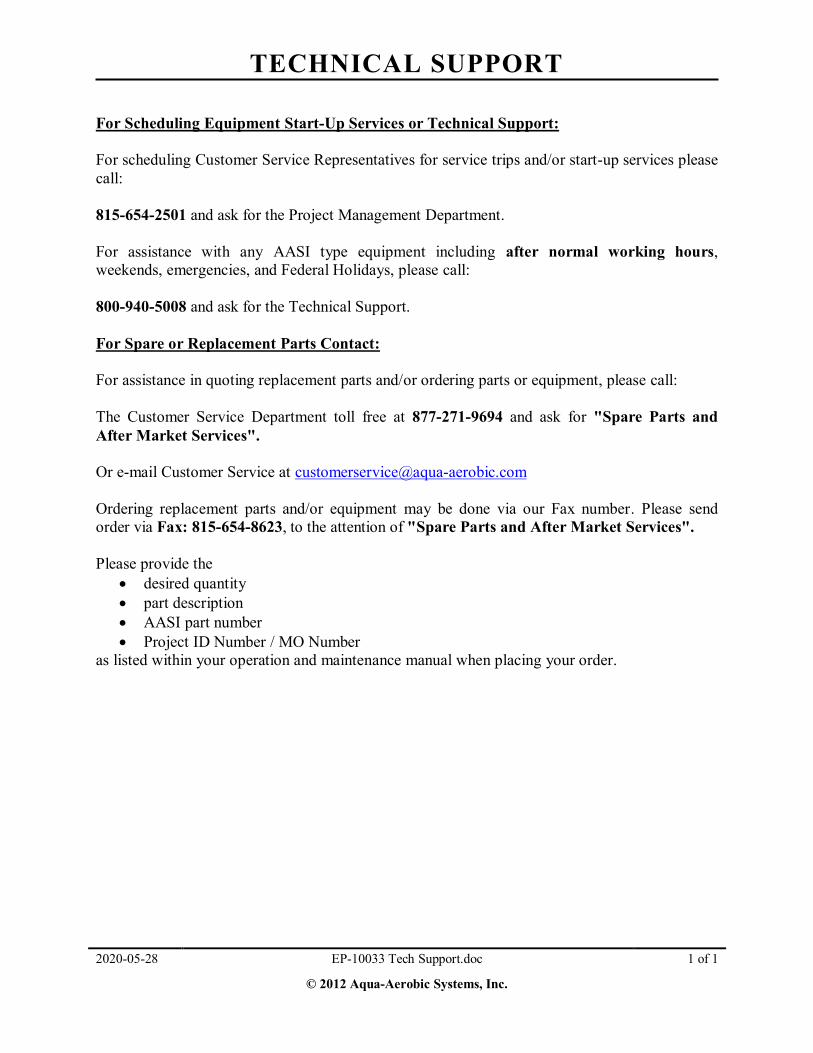
For Scheduling Equipment Start-Up Services or Technical Support: For scheduling Customer Service Representatives for service trips and/or start-up services please call: 815-654-2501 and ask for the Project Management Department. For assistance with any AASI type equipment including after normal working hours, weekends, emergencies, and Federal Holidays, please call: 800-940-5008 and ask for the Technical Support. For Spare or Replacement Parts Contact: For assistance in quoting replacement parts and/or ordering parts or equipment, please call: The Customer Service Department toll free at 877-271-9694 and ask for "Spare Parts and After Market Services". Or e-mail Customer Service at [email protected] Ordering replacement parts and/or equipment may be done via our Fax number. Please send order via Fax: 815-654-8623, to the attention of "Spare Parts and After Market Services". Please provide the
desired quantity part description AASI part number Project ID Number / MO Number
as listed within your operation and maintenance manual when placing your order.

PRODUCT MANUALS SPECIAL MESSAGES
EP-10050 Product Manuals Special Messages.doc 1 of 1
Copyright © 2008 Aqua-Aerobic Systems, Inc. 2020-05-28
Your manual contains special messages to bring attention to potential safety concerns, equipment damage as well as helpful operating and servicing information. Please read all the information carefully to avoid injury and equipment damage.
DANGER
Indicate an immediately hazardous situation which, if not avoided, will result in death or serious injury. Danger is limited to the most extreme situations.
WARNING Indicate a potentially hazardous situation which, if not avoided, could result in death or serious injury.
CAUTION Indicate a potentially hazardous situation which, if not avoided, may result in minor or moderate injury. Caution may also be used to alert against unsafe practices. NOTICE Indicate a statement of company policy as the message relates directly or indirectly to the safety of personnel or protection of property. GENERAL SAFETY Indicate general instructions relative to safe work practices, reminders of proper safety procedures, and the location of safety equipment.

EQUIPMENT SAFETY DOCUMENTS and PRECAUTIONS

Electrical Safety Precautions
EP-10015 Electrical Safety Precautions.doc 1 of 1
Copyright © 2017 Aqua-Aerobic Systems, Inc. 2020-05-28
CAUTION
Be aware of electrical hazards: o Electric shock and burns – An electric shock occurs when electric current passes
through the body. This can happen when touching an energized part.
o Arc-flash burns – An electric arc flash can occur if a conductive object gets too close to a high-amp current source or by equipment failure. The arc flash can cause severe burns by direct heat exposure and by igniting clothing.
o Arc-blast impacts – The heating of air and vaporization of metal during an arc,
creates a pressure wave that can damage hearing and cause concussions among other injuries.
o Falls – Electric shocks and arc blasts can cause falls.
Equipment is automated and operates cyclically. Never reach into equipment to actuate a device. Unexpected operation could occur. Installation and service of electrical machinery and controls must be completed by
qualified personnel only. Before proceeding with servicing any electrical equipment, all sources of power to the
equipment must be disconnected and securely locked out and tagged out. Refer to the Electrical Lockout / Tag Out Procedures for details.
Refer to NFPA 70E, Standard for Electrical Safety in the Workplace, for additional
guidance. Minimize the hazards. Discuss potential hazards and procedures with supervisors and other workers before starting any electrical wiring or service repairs. De-energize and lockout / tag out all electrical equipment, and insulate, or isolate exposed live parts so contact cannot be made. If this is impossible, obtain and wear proper Personal Protective Equipment (PPE) and tools. Refer to the Lockout / Tag Out Procedures before attempting to service any electrical equipment.

Electrical Lockout / Tag Out Procedures
EP-10095 Electrical Lockout Procedures.doc 1 of 5
Copyright © 2020 Aqua-Aerobic Systems, Inc. 2017-2-03
Consult your facility procedure. Each facility should have a written lockout/tag out program and train employees in this program. The typical program should cover planning for locating and labeling energy sources, identifying employees at risk, how and by whom the equipment is de-energized, releasing of stored energy, verifying that the circuit is de-energized and can't be restarted, voltage testing, grounding requirements, shift changes, coordination with other jobs in progress, a procedure for keeping track of all involved personnel, applying and removing lockout/tag out devices, return to service, and temporary re-energizing for testing/positioning. Lockout/tag out procedures should be developed for each machine or piece of equipment that will require servicing. Lockout / Tag Out Application Each person who could be exposed to electric energy must be involved in the lockout/tag out process. A typical process is described below.
After de-energizing, each employee at risk should apply an individual lockout/tag out device to each source of electric energy. Pushbuttons or selector switches cannot be used as the only way to de-energize.
Lockout Device: A lockout device is a key or combination lock with a tag that can be attached to a disconnecting device to prevent the re-energizing of the equipment being worked on without removal of the lock. The lockout device should have a way of identifying the individual who tagged it and the reason why it was tagged. Individual lockout devices with worker’s name and picture on them are preferred. That worker must be the only person who has the key or combination for the lockout device they install, and that worker should be the only person to remove the lock after all work has been completed.
Tag Out Device: A tag out device is a tag or means that can be attached to the actual lockout device to notify all workers that this equipment has been locked out. The tag out device must include a way to attach to the lockout device that can withstand at least 50 pounds of force. Tag out devices on electrical power should be used alone only when it is not possible to install a lockout device.
Lockout Tag: The tag used in conjunction with a lockout or tag out device must have a warning label prohibiting unauthorized disconnecting or removal of the lockout/tag out device.
Before beginning work, each involved worker must verify through testing that all energy sources have been de-energized.
Electric lockout/tag out procedures should be coordinated with all other site procedures for controlling exposure to electric energy and other types of energy sources.
Complex lockout/tag out procedures are special procedures that are needed when there is more than one energy source, crew, craft, location, employer, way to disconnect, or lockout/tag out procedure or for work that lasts beyond one shift. In any of these cases, one qualified person should be in charge of the lockout/tag out procedure with full responsibility for ensuring all energy sources are under lockout/tag out and to account for all people on the job.

Electrical Lockout / Tag Out Procedures
EP-10095 Electrical Lockout Procedures.doc 2 of 5
Copyright © 2020 Aqua-Aerobic Systems, Inc. 2017-2-03
Removal of Lockout/Tag Out devices: Lockout and tag out devices should be removed only by the person installing them. If work is not completed when the shift changes, workers arriving on shift should apply their locks before departing workers remove their locks.
Return to service: When electrical work has been completed tests and visual inspections must be made to confirm that all tools, mechanical restraints, electric jumpers, shorts, and grounds have been removed. Once work is completed and lockout/tag out devices are removed, tests and visual inspection must confirm that all tools, mechanical restraints, electric jumpers, shorts, and grounds have been removed. Only then is it safe to re-energize and return to service.
Temporary release: If the job requiring lockout/tag out is interrupted for any reason, the steps outlined in Return to Service (above) should be followed before removing the lockout/tag out devices, and placing the equipment back into operation.
WARNING
Electrical Hazards Electric shock and burns: An electric shock occurs when electric current passes
through the body. This can happen when touching an energized part. If the electric current passes across the chest or head, death can result. At high voltages, severe burns can result.
Arc-flash burns: An electric arc flash can occur if a conductive object gets too close to a high-amp current source or by equipment failure (for instance, while opening or closing disconnects). The arc can heat the air to temperatures as high as 35,000º F, and vaporize metal in the equipment. The arc flash can cause severe skin burns by direct heat exposure and by igniting clothing.
Arc-blast impacts: The heating of air and vaporization of metal creates a pressure wave that can damage hearing and cause memory loss (from concussion) and other injuries. Flying metal parts are also a hazard.
Falls: Electric shocks and arc blasts can cause falls, especially from ladders or unguarded scaffolding.
Electric Safety Principles - Energized Condition
De-energize whenever possible. Plan every job. The approach and step-by-step procedures to complete the work at hand
must be discussed and agreed upon between all involved employees before beginning. Write down first-time procedures. Discuss hazards and procedures in a job briefing with supervisors and other workers before starting any job. It is the employer’s responsibility to have or develop a checklist system for working on live circuits, if such a scenario arises.
Identify the hazards. Conduct a job hazard analysis. Identify steps that could create electric shock or arc-flash hazards.

Electrical Lockout / Tag Out Procedures
EP-10095 Electrical Lockout Procedures.doc 3 of 5
Copyright © 2020 Aqua-Aerobic Systems, Inc. 2017-2-03
Minimize the hazards. De-energize any equipment, and insulate, or isolate exposed live parts so contact cannot be made. If this is impossible, obtain and wear proper Personal Protective Equipment (PPE) and tools.
Anticipate problems. If it can go wrong, it might. Make sure the proper PPE and tools are immediately available for the worst-case scenario.
Obtain training. Make sure all involved employees are qualified electrical workers with appropriate training for the job.
Working on De-Energized Equipment Electrically Safe Condition The most important principle of electrical safety is to assume all electric circuits are energized unless each involved worker ensures they are not. Every circuit and conductor must be tested every time work is done on them. Proper PPE must be worn until the equipment is proven to be de-energized.
The National Fire Protection Association (NFPA) lists six steps to ensure conditions for electrically safe work.
1. Identify all sources of power to the equipment. Check applicable up-to-date drawings, diagrams, and identification tags.
2. Remove the load current, and then open the disconnecting devices for each power source. 3. Where possible, visually verify that blades of disconnecting devices are fully open or that
drawout-type circuit breakers are fully withdrawn. 4. Apply lockout/tag out devices in accordance with your facilities formal, written policy. 5. Test each phase conductor or circuit part with an adequately rated voltage detector to
verify that the equipment is de-energized. Test each phase conductor or circuit part both phase-to-phase and phase-to-ground. Check the voltage detector before and after each test to be sure it is working.
6. Properly ground all possible sources of induced voltage and stored electric energy (such as, capacitors) before touching. If conductors or circuit parts that are being de-energized could contact other exposed conductors or circuit parts, apply ground-connecting devices rated for the available fault current.
The process of de-energizing is "live" work and can result in an arc flash due to equipment failure. When de-energizing, follow the procedures below described in "Working on / or Near Energized Equipment."
Working on / or Near Energized Equipment Working on live circuits means actually touching energized parts. Working near live circuits means working close enough to energized parts to pose a risk even though work is on de-energized parts. Common tasks where there may be a need to work on or near live circuits include:
Taking voltage measurements Opening and closing disconnects and breakers

Electrical Lockout / Tag Out Procedures
EP-10095 Electrical Lockout Procedures.doc 4 of 5
Copyright © 2020 Aqua-Aerobic Systems, Inc. 2017-2-03
Racking breakers on and off the bus Removing panels and dead fronts Opening electric equipment doors for inspection
Facilities should adopt standard written procedures and training for these common tasks. For instance, when opening and closing disconnects, use the left-hand rule when possible (stand to the right side of the equipment and operate the disconnect switch with the left hand). Approach Distances to Exposed Live Parts The National Fire Protection Association (NFPA) defines three approach boundaries for shock
hazards and one for arc flash. Shock Hazards
The Limited Approach Boundary is the distance from an exposed live part within which a shock hazard exists.
The Restricted Approach Boundary is the closest distance to exposed live parts a qualified person can approach with or without proper PPE and tools. Inside this boundary, accidental movement can put a part of the body or conductive tools in contact with live parts or inside the prohibited approach boundary. To cross the restricted approach boundary, the qualified person must review and understand Annex C, Limits of Approach, of NFPA 70-E
The Prohibited Approach Boundary is the minimum approach distance to exposed live parts to prevent flashover or arcing. Approaching any closer is comparable to making direct contact with a live part.
Arc Flash Hazard
The Flash Protection Boundary is the approach limit at a distance from exposed live parts within which a person could receive a second degree burn if an electrical arc flash were to occur. For systems of 600 volts and less, the flash protection boundary is 4 feet (1.2m), based on an available bolted fault current of 50 kA and a clearing time of 6 cycles for the circuit breaker to act, or any combination of fault currents and clearing times not exceeding 300 kA cycles.
Approach Boundaries to Live Parts for Shock Protection (All dimensions are distance from live part to worker) Limited approach boundary
Nominal system voltage range, phase
to phase
Exposed movable conductor
Exposed fixed- circuit part
Restricted approach boundary (allowing for accidental movement)
Prohibited approach boundary
0 to 50 volts Not specified Not specified Not specified Not specified 51 to 300 volts 10 ft. 0 in. (3.0m) 3 ft. 6 in. (1.1m) Avoid contact Avoid contact
301 to 750 volts 10 ft. 0 in. (3.0m) 3 ft. 6 in. (1.1m) 1 ft. 0 in. (0.3m) 0 ft. 1 in. (25.4mm) 751 to 15 KV KV 10 ft. 0 in. (3.0m) 5 ft. 0 in. 1.5m) 2 ft. 2 in. (0.7m) 0 ft. 7 in. (177.8mm)
Source: Excerpted from table 130.2(C), “Approach Boundaries to Live Parts for Shock

Electrical Lockout / Tag Out Procedures
EP-10095 Electrical Lockout Procedures.doc 5 of 5
Copyright © 2020 Aqua-Aerobic Systems, Inc. 2017-2-03
Protection” (NFPA 70-E Standard for Electrical Safety Requirements for Employee Workplaces,
2004 edition). Wet or Damp Locations Work in wet or damp work locations (i.e., areas surrounded or near water or other liquids) should not be performed unless it is absolutely critical. Electrical work should be postponed until the liquid can be cleaned up. The following special precautions must be incorporated while performing work in wet or damp locations:
Only use electrical cords that have Ground Fault Circuit Interrupters (GFCIs); Place a dry barrier over any wet or damp work surface; Remove standing water before beginning work. Work is prohibited in areas where there
is standing water; Do not use electrical extension cords in wet or damp locations; and Keep electrical cords away from standing water.
Other Precautions When working on de-energized parts, but still inside the flash protection boundary for nearby live exposed parts:
If the parts cannot be de-energized, barriers such as insulated blankets must be used to protect against accidental contact or PPE must be worn.
Do not reach blindly into areas that might contain exposed live parts. Do not enter spaces containing live parts unless illumination is provided that allows the
work to be performed safely. Conductive articles of jewelry and clothing shall not be worn where they present an
electrical contact hazard with exposed live parts. Conductive materials, tools, and equipment that are in contact with any part of the body
shall be handled in a manner that prevents accidental contact with live parts. References
NFPA 70-E, “Standard for Electrical Safety Requirements for Employee Workplaces”, 2004 edition.

Filter GENERAL SAFETY PRECAUTIONS
EP-10043 Filter General Safety Precautions.doc 1 of 1
Copyright © 2008 Aqua-Aerobic Systems, Inc. 2020-05-28
WARNING
Disconnect and lock out all power sources to equipment before performing maintenance. GENERAL SAFETY
Read the installation, operation and maintenance instructions in the owner’s manual before work begins.
Read and obey all warnings and other safety information within this manual and those
attached to equipment.
Keep all warning and safety labels attached and legible.
Do not work on equipment alone. Always wear eye protection when using power tools or when working around rotating
equipment. Exercise all necessary precautions with regard to personal hygiene and sanitation.
Observe all necessary precautions for ventilation and identification of dangerous gases
whenever working in confined spaces.
Do not lift or transport a load until all personnel are clear. Use lifting lugs where provided on equipment. Use approved rigging only.
Do not enter basin / tank while equipment is operating.
Do not begin equipment operation that has just been installed or serviced without notifying
personnel near equipment.
Do not manually operate equipment without knowing its result.

In Basin Maintenance CMF Effluent End Drive
2020-05-28 EP-10530 Safe Filter Maintenance Eff.doc 1 of 2
© 2017 Aqua-Aerobic Systems, Inc.
In the event of maintenance or a mechanical failure inside the basin, caution, safe practices, and common sense must be used. Local regulations and site specific guidelines will supersede the instructions presented below. Several locations that could require maintenance are outlined below. In addition, an access path is recommended for each. Depending on custom options and specific site layout an alternative route may have to be found.
WARNING Review General Safety Procedures EP-10043 and any other specific precaution documentation located in section 1 of the O&M prior to commencing maintenance.
Follow Lock-out Tag-out Procedures EP-10095 Do not perform maintenance if you are not comfortable with entering the basin. Do not enter a basin if it is not drained. Do not work alone in a basin.
Many sites have found that half of an extension ladder fastened securely to handrail or another rigid mounting point is sufficient if the basin is not equipped with a permanent ladder, platform, or stairway.
CAUTION If this method is used, be sure that the ladder rests on both feet and is fastened such that the legs cannot kick out and it cannot tip backwards.
CAUTION To safely access some components disk segments may have to be removed. Always remove disks completely, do not remove 1 segment from each disk along the length of the centertube. Doing so will cause the centertube to become unstable and rotate on its own unexpectedly. Drive, drive sprocket, float switch, and chain These components are located at the top of the wall. Maintenance such as chain tensioning, oil changes, drive motor replacement, drive sprocket changes, and float switch adjustment can be performed from outside the basin, either standing on a secured ladder or on a platform if available. If the item in this area must be accessed from inside the basin and the influent weir is present below, then it is safe to stand in the influent weir. If there is no weir, then a ladder may be placed on either side of the drive as required. If lifting heavy equipment such as a replacement drive into place, an appropriate crane or hoist must be used. Do not attempt to install a drive without lifting equipment.

In Basin Maintenance CMF Effluent End Drive
2020-05-28 EP-10530 Safe Filter Maintenance Eff.doc 2 of 2
© 2017 Aqua-Aerobic Systems, Inc.
Effluent seal, driven sprocket, rider wheels, and chain These components are located low along the effluent wall of the filter. The corner opposite the drive and next to the effluent end should have enough room to place a ladder in it such that these components can be accessed. Access on both sides of the centertube may be required. In that case, use care when placing the ladder so that there is clearance with the chain. NOTICE Avoid standing on the PVC piping on the floor of the tank. The piping is not designed to support a person and may be damaged. Centertube bearing The centertube bearing is located low in the influent end of the basin. A ladder on either side wall or the influent wall will allow access to this area. The area around the bearing may be tight and removal of one disk may be required. Disk segments The disk segments are at a mid elevation in the filter. They are easiest to remove vertically up. The most common ways that disk segments are removed is with the technician standing on the flats of the centertube (not the plastic disk assemblies) or the backwash shoe support arms. A ladder may be placed in the influent weir or in any corner with enough clearance to allow access to stand on the flats of the centertube or the main pipe of the backwash shoe support arms. The specific procedure for removing disk segments varies by filter model and can be found in section 6 of the O&M.
CAUTION Always remove disks completely, do not remove 1 segment from each disk along the length of the centertube. Doing so will cause the centertube to become unstable and rotate on its own unexpectedly. The centertube flat should be as level as possible. The flat may be slippery and caution must be used. The backwash shoe support arms are round, wet, and slippery, caution must be used. The drive control must be in the off position for this work. Backwash shoes and hoses The backwash shoes and hoses are low in the tank. Disks must be removed to access these components. Once the disks are removed, a ladder may be secured along any wall in the area where work is to be performed.

GEARBOX SAFETY PRECAUTIONS
EP-10035 Gearbox Safety.doc 1 of 1
Copyright © 2008 Aqua-Aerobic Systems, Inc. 2020-05-28
WARNING
Do not operate gearbox without all guards and shields in place
Hot oil and reducers can cause severe burns. Use extreme care when removing lubrication plugs and vents. Make certain that the power supply is disconnected before attempting to service or remove any components. Lock out the power supply and tag it to prevent unexpected application of power. Lifting supports including eyebolts are to be used for vertically lifting the gearbox only and no other associated attachments or motors.
GENERAL SAFETY Maintain lubricants at the proper levels. Mounting bolts should be routinely checked to ensure that the unit is firmly anchored for
proper operation.

Gorman-Rupp External Pump SAFETY PRECAUTIONS
EP-10036 G. R. External Pump Safety.doc 1 of 2
Copyright © 2008 Aqua-Aerobic Systems, Inc. 2020-05-28
WARNING Overheated pumps can cause severe burns and injury. If overheating of pump casing occurs:
Stop pump immediately. Allow pump to cool to air temperature. Slowly and cautiously vent pump at drain plug. Refer to O&M before restarting.
Electrocution may occur whenever electricity is present Before working on pumps with electric motors and panels, LOCK control panel in the OFF position:
If control panel cannot be locked, pull main fuse or circuit breaker. Remove all v-belts. Disengage drive coupling.
Never use gas piping as an electrical ground.
CAUTION Allow only qualified personnel to install, wire and operate pumps and motors. Always ground electrical units. Be sure to connect motor to correct phase and voltage. Do not operate pump if voltage is not within limits. If circuit breaker or fuse is tripped, locate and fix the problem before restarting pump. Make sure all electrical installations are in accordance with National Electrical Code and
local codes. Do not work in underground pump systems alone or without adequate ventilation. Never wear loose clothing around machinery. Never operate pumps in explosive or volatile atmospheres unless they are designed to be
operated in these environments. Do not operate pump without all guards and shields in place. Do not remove the cover plate, fill port cap, gauge port plug, or drain plug from any
overheated pump. Allow pump to cool to air temperature. Check pump temperature before removing cover plate, fill port cap, gauge port plug, or drain plug.

Gorman-Rupp External Pump SAFETY PRECAUTIONS
EP-10036 G. R. External Pump Safety.doc 2 of 2
Copyright © 2008 Aqua-Aerobic Systems, Inc. 2020-05-28
GENERAL SAFETY
Read the installation, Operation and Maintenance Manual for your pump before installing, operating or performing maintenance on the pump or its related equipment. Cautiously approach any pump that has been in operation. Pump only liquids for which the pump was designed. Do not pump flammable or corrosive liquids unless pump and piping are designed for such. Operating pump with suction and/or discharge closed is one cause of severe overheating. Note direction of rotation-operating pump in wrong direction may cause impeller to unscrew and damage pump casing or other pump parts. Locate the pump in an accessible location, as close as safely possible to the liquid being pumped. Secure the pump so that it cannot move after it is in its operating position. Check all lubricants before installation and operation in accordance with maintenance programs. When lifting pumps, use only lifting equipment in good repair with adequate capacity. Never operate a self-priming pump unless the pump casing is filled with liquid. Doing so may damage the pump. The pump will not prime unless the pump casing is filled with liquid. Do not operate pump against a closed valve. Check the suction strainer regularly to be sure that it is not clogged. Check the pump thoroughly upon delivery for any shipping damage. Always read and keep the Installation, operation and Maintenance Manual for your pump. When overhauling pumps, never remove or cover warning tags and labels. Be sure that only experienced personnel operate machinery. Drain pump completely of water before freezing weather. Follow motor manufacturer’s recommended operation and maintenance instructions.

CONTROL PANEL SAFETY PRECAUTIONS
EP-10005 Control Panel Safety.doc 1 of 1
Copyright © 2008 Aqua-Aerobic Systems, Inc. 2020-05-28
CAUTION Be aware of electrical hazards:
o Electric shock and burns – An electric shock occurs when electric current passes through the body. This can happen when touching an energized part.
o Arc-flash burns – An electric arc flash can occur if a conductive object gets too close to a high-amp current source or by equipment failure. The arc flash can cause severe burns by direct heat exposure and by igniting clothing.
o Arc-blast impacts – The heating of air and vaporization of metal during an arc, creates a pressure wave that can damage hearing and cause concussions among other injuries.
o Falls – Electric shocks and arc blasts can cause falls.
All electrical service should be performed by qualified personnel.
Treat all electrical equipment and conductors as though they are energized until they are placed in an electrically safe work condition.
Create an electrically safe work condition by performing the following lockout/tag out
procedures. o Notify others prior to beginning a lockout/tag out procedure. o Lockout/Tagout out all energy sources following sheet EP-10095 and / or
documented site procedures. o Confirm that equipment is de-energized by checking voltages. o Clean, service, inspect or clear equipment. o Make sure others are safe; machine guards are in place; tools, locks, and tags are
removed before restoring energy.
See NFPA 70E for additional guidelines on safety related work practices. GENERAL SAFETY
Protect panel components from contamination (metal chips, loose bolts, liquids, etc.). Do not use control panels for storage. Do not leave an open panel unattended. Exercise all necessary precautions with regard to personal hygiene and sanitation.

Operation and Maintenance Training Outline Cloth Media Filter
EP-10029 CMF Training Outline.doc 1 of 2
Copyright © 2008 Aqua-Aerobic Systems, Inc. 2020-05-28
1. INTRODUCTION AND GENERAL INFORMATION a) Sign in sheets b) Review assembly drawings c) View filter assemblies on site, identify major components/assemblies of units
2. GENERAL INFORMATION
a) Discuss general safety precautions b) Discuss theory of operation of filter c) Review use of Operation and Maintenance manual
3. INSTALLATION, START-UP, PREVENTATIVE MAINTENANCE
a) Receiving and handling documents b) Review storage procedures c) Pre start-up requirements d) Start-up procedures e) Shut-down procedures f) Review lubrication and maintenance schedules g) Review troubleshooting procedures h) Review mechanical check-out list
4. CENTERTUBE COMPONENTS
a) Review centertube / seal plate tolerances b) Review pillow block / locking collar assembly c) Review upper rider wheel clearance d) Discuss theory of operation
5. FILTER CLOTH
a) Review cloth assembly b) Discuss installation orientation c) Discuss fouling and cleaning of cloths d) Refer to Operation and Maintenance manual for detailed cleaning instructions
6. BACKWASH SYSTEM OVERVIEW
a) Identify backwash system components on assembly drawings b) Discuss theory of operation c) Pump troubleshooting procedures
7. BACKWASH SHOES
a) Review backwash shoe contact area b) Discuss backwash shoe alignment with centertube c) Review shoe subcomponent and assembly

Operation and Maintenance Training Outline Cloth Media Filter
EP-10029 CMF Training Outline.doc 2 of 2
Copyright © 2008 Aqua-Aerobic Systems, Inc. 2020-05-28
8. VALVES a) Identify valves on assembly drawings b) Discuss general maintenance c) Stainless ball valves d) Brass gate valves e) Butterfly valves f) Plug valves
9. ELECTRIC ACTUATORS
a) Discuss wiring b) Review limit switch setup
10. BACKWASH PUMPS
a) Review impeller rotation and position with shaft b) Review motor coupling alignment c) Pump troubleshooting procedures d) Review draw down test procedure
11. SOLIDS REMOVAL SYSTEM
a) Review flushing technique b) Discuss theory of operation for each type
12. DRIVE ASSEMBLY
a) Identify drive assembly components b) Review drive placement and orientation c) Discuss chain tension and sprocket alignment d) Discuss theory of operation
13. TRANSDUCERS AND GAUGES
a) Review sensor types and locations b) Discuss sensor maintenance c) Discuss theory of operation
14. CONTROL PANELS
a) Discuss theory of operation b) Safety procedures c) Alarms d) Modes of operation e) User adjustable settings f) Junction boxes g) PLC review (inputs, outputs, troubleshooting) h) Review electrical drawings

Training Session Sign-in sheet
EP-10284 Training Session Sign-in sheet.doc 1 of 1
Copyright © 2018 Aqua-Aerobic Systems, Inc. 2018-10-16
Attendee’s Name:
1.
2.
3.
4.
5.
6.
7.
8.
9.
10.
11.
12.
13.
14.
15.
16.
17.
Date Training was completed:
Hours spent for classroom Training:
Hours spent for On-Site Training:
Instructors Name:
Firm Represented:

WARRANTY; LIMITATION OF LIABILITY; AND DISCLAIMER
In return for purchase and full payment for Aqua-Aerobic Systems, Inc. goods, we warrant new goods provided by us to be free from defects in materials and workmanship under normal conditions and use for a period of one year from the date the goods are put into service, or eighteen months from date of shipment (whichever first occurs). If the goods include an Endura Series® motor, the complete Endura Series unit shall be warranted by Aqua to be free from defects in materials and workmanship under normal conditions and use for three years from the date the product is put into service or 42 months from the date of shipment (whichever occurs first). OUR OBLIGATION UNDER THIS WARRANTY IS EXPRESSLY AND EXCLUSIVELY LIMITED to replacing or repairing (at our factory at Loves Park, Illinois) any part or parts returned to our factory with transportation charges prepaid, and which our examination shall show to have been defective. Prior to return of any goods or its parts to our factory, Buyer shall notify Aqua-Aerobic Systems, Inc. of claimed defect, and Aqua-Aerobic Systems, Inc. shall have the privilege of examining the goods at Buyer's place of business at or where the goods have otherwise been placed in service. In the event this examination discloses no defect, Buyer shall have no authority to return the goods or parts to our factory for the further examination or repair. All goods or parts shall be returned to Buyer, F.O.B. Loves Park, Illinois. This warranty shall not apply to any goods or part which has been repaired or altered outside our factory, or applied, operated or installed contrary to our instruction, or subjected to misuse, chemical attack/degradation, negligence or accident. This warranty and any warranty and guaranty of process or performance shall no longer be applicable or valid if any product, including any software program, supplied by Aqua-Aerobic Systems, Inc., is modified or altered without the written approval of Aqua-Aerobic Systems, Inc. Our warranty on accessories and component parts not manufactured by us is expressly limited to that of the manufacturer thereof. THE FOREGOING WARRANTY IS MADE IN LIEU OF ALL OTHER WARRANTIES, EXPRESS OR IMPLIED, AND OF ALL OTHER LIABILITIES AND OBLIGATIONS ON OUR PART, INCLUDING ANY LIABILITY FOR NEGLIGENCE, STRICT LIABILITY, OR OTHERWISE; AND ANY IMPLIED WARRANTY OF MERCHANTABILITY OR FITNESS FOR A PARTICULAR PURPOSE IS EXPRESSLY DISCLAIMED; AND WE EXPRESSLY DENY THE RIGHT OF ANY OTHER PERSON TO INCUR OR ASSUME FOR US ANY OTHER LIABILITY IN CONNECTION WITH THE SALE OF ANY GOODS PROVIDED BY US. THERE ARE NO WARRANTIES OR GUARANTEES OF PERFORMANCE UNLESS SPECIFICALLY STATED OTHERWISE.
UNDER NO CIRCUMSTANCES, INCLUDING ANY CLAIM OF NEGLIGENCE, STRICT LIABILITY, OR OTHERWISE, SHALL AQUA-AEROBIC SYSTEMS, INC. BE LIABLE FOR ANY INCIDENTAL OR CONSEQUENTIAL DAMAGES, COSTS OF CONNECTING, DISCONNECTING, OR ANY LOSS OR DAMAGE RESULTING FROM A DEFECT IN THE GOODS. LIMIT OF LIABILITY: AQUA-AEROBIC SYSTEMS, INC.’S TOTAL LIABILITY UNDER THE ABOVE WARRANTY IS LIMITED TO THE REPAIR OR REPLACEMENT OF ANY DEFECTIVE PART. THE REMEDIES SET FORTH HEREIN ARE EXCLUSIVE, AND OUR LIABILITY WITH RESPECT TO ANY CONTRACT OR SALE, OR ANYTHING DONE IN CONNECTION THEREWITH, WHETHER IN CONTRACT, IN TORT, UNDER ANY WARRANTY, OR OTHERWISE, SHALL NOT, IN ANY CASE, EXCEED THE PRICE OF THE GOODS UPON WHICH SUCH LIABILITY IS BASED.

RECEIVING & HANDLING
2020-05-28 EP-10031 Receiving-Handling.doc 1 of 2
© 2008 Aqua-Aerobic Systems, Inc.
Receiving When receiving equipment and crates, the shipment should be completely checked to verify that no transit damage has occurred. All equipment and accessories (if any) must be verified against the packing list and bill of lading to assure proper contents. If any damage or shortage exists please notify Aqua-Aerobic Systems, Inc. immediately with complete details. NOTICE
Do not sign any receiving tickets or acceptance papers unless the shipment is in proper condition and receipt of all accessories is verified.
Aqua-Aerobic Systems, Inc. purchases certain completed components from third party original equipment manufacturers (OEMs). Examples include actuators, blowers, instrumentation, and pumps. Aqua-Aerobic Systems, Inc. includes the entire OEM documentation within this O&M manual. In addition to the receiving, handling, storage, maintenance, and troubleshooting information provided by Aqua-Aerobic Systems, Inc., please refer to sections 4 and 6 for the OEM documentation pertinent to each of these components.
If there are shortages on any shipment, the packing slip will indicate that the item is back ordered, or shipping direct from original supplier. All items back ordered will be shipped as soon as possible to complete entire order. If you have any questions regarding your shipments, or back ordered items, please call Aqua-Aerobic Systems, Inc. at (877) 271-9694 and ask for assistance on your project. If receiving personnel finds discrepancies, shortages, or damage within any shipment, it must be reported in writing within seven (7) days to Aqua-Aerobic Systems, Inc. to obtain credit from the trucking company. Only the trucking company can supply appropriate credit for loss or damaged goods. A standard form has been provided in this manual for presentation of loss and damage claims. Also the original bill of lading and shipping list must be submitted. If at any time shortages or damage has occurred, please notify Aqua-Aerobic Systems, Inc. immediately after filing report with trucking company. Aqua-Aerobic Systems, Inc. will not be responsible for any items found damaged or lost due to circumstances beyond our control. Aqua-Aerobic Systems, Inc. will repair or replace these items after receipt of a purchase order from the responsible party.
RECEIVING & HANDLING
2020-05-28 EP-10031 Receiving-Handling.doc 2 of 2
© 2008 Aqua-Aerobic Systems, Inc.
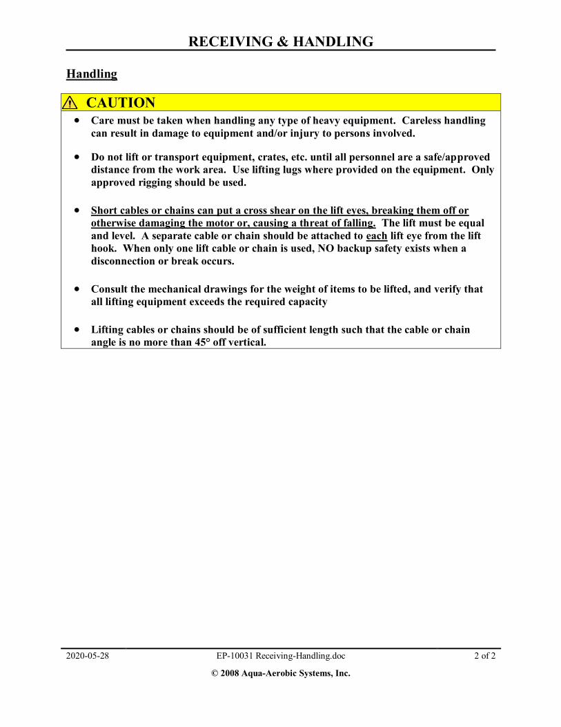
Handling
CAUTION
Care must be taken when handling any type of heavy equipment. Careless handling can result in damage to equipment and/or injury to persons involved.
Do not lift or transport equipment, crates, etc. until all personnel are a safe/approved distance from the work area. Use lifting lugs where provided on the equipment. Only approved rigging should be used.
Short cables or chains can put a cross shear on the lift eyes, breaking them off or
otherwise damaging the motor or, causing a threat of falling. The lift must be equal and level. A separate cable or chain should be attached to each lift eye from the lift hook. When only one lift cable or chain is used, NO backup safety exists when a disconnection or break occurs.
Consult the mechanical drawings for the weight of items to be lifted, and verify that
all lifting equipment exceeds the required capacity Lifting cables or chains should be of sufficient length such that the cable or chain
angle is no more than 45° off vertical.

EP-10032 Claim Form.DOC 1 of 1
Copyright © 2008 Aqua-Aerobic Systems, Inc. 2020-05-28
STANDARD FORM FOR PRESENTATION OF LOSS AND DAMAGE CLAIMS
(Claimant's Number)*
(Name of person to whom claim is presented) (Address of claimant)
(Name of Carrier) (Date) (Carrier's Number)
(Address)
This claim for $ is made against the carrier named above by
(Amount of claim) (Name of claimant)
for in connection with the following described shipment(s):
(Loss or damage)
Description of shipment
Name & address of consignor (shipper)
Shipped from To
(City, Town or Station) (City, Town or Station)
Final Destination Routed via
(City, Town or Station)
Bill of Lading issued by Co.,Date of Bill of Lading
Paid Freight Bill (Pro) Number Original Car Number & Initial
Truck or Trailer Number Connecting Line Reference
Name & Address of Consignee (Whom shipped to)
If shipment reconsigned enroute, state particulars:
DETAILED STATEMENT SHOWING HOW AMOUNT CLAIMED IS DETERMINED
(Number & description of articles, nature & extent of loss or damage, invoice price of articles, amount of claim, etc.)
_________________________________________________________________________________________________________________
Total Amount Claimed $
IN ADDITION TO THE INFORMATION GIVEN ABOVE, THE FOLLOWING DOCUMENTS ARE SUBMITTED IN SUPPORT OF THIS CLAIM**
( ) 1. Original bill of lading, if not previously surrendered to carrier.
( ) 2. Original paid freight ("Expense") bill.
( ) 3. Original invoice or certified copy.
( ) 4. Other particulars obtainable in proof of loss or damage claimed.
Remarks:
The foregoing statement of facts is hereby certified to as correct.
(Signature of claimant) * Claimant should assign to each claim a number, inserting same in the space provided at the upper hand corner of this form. Reference should be made thereat in all correspondence pertaining to this claim.
**Claimant will please place check (x) before such of the documents mentioned as have been attached, and explain under "Remarks" the absence of any of the documents called for in connection with this claim. When for any reason it is impossible for claimant to produce original bill of lading, or paid freight bill, claimant should indemnify carrier(s) against duplicate claim supported by original document .

PROTECTIVE COATINGS

PAINT-TECHNICAL DATA SHEETS

Paint Specification – SS Filter Tanks PPG PSX 805 Satin Engineered Siloxane
ES-1059 Paint Spec SS Filter Tank.doc 1 of 1
© 2018 Aqua-Aerobic Systems, Inc. 2020-05-28
Metal Preparation: All weld slag, splatter, and fluxes must be removed from welded
areas. All parts are to be de-burred and all rough or sharp edges must be removed and smoothed out. Remove all marking paint used for identification. Protect all pipe threads, bolt threads, hose barbs, and Victaulic couplings.
Surface Preparation: External: Commercial blast clean per SSPC-SP6 Internal: Near white blast clean per SSPC-SP10 Coating Specification: External: Two coats PPG PSX 805T3/01, Satin Engineered Siloxane
Base coat: 1-2 mils DFT Top Coat: 2-3 mils DFT
Total: 3-5 mils DFT
Internal: (Top of tank down a distance of 2 feet) Two coats PPG PSX 805T3/01, Satin Engineered Siloxane
Base coat: 1-2 mils DFT Top Coat: 2-3 mils DFT
Total: 3-5 mils DFT The remaining interior section of the tank is to remain uncoated.
Application: Apply coating in accordance with the latest publication of PPG
PSX® 805, Satin Engineered Siloxane Product Bulletin. Product: PX805T3/01 (Satin Clear-Tinted) Color Name: Aquapanel Color #: 829402000001038 Version: 0 Formula: BLX-1Y+34 ROX-10 WTX-5Y+24 YOX-1Y+12
DFT = Dried Film Thickness


STORAGE PROCEDURES

Introduction to Storage
2020-05-28 EP-10034 Introduction to Storage.doc 1 of 1
© 2012 Aqua-Aerobic Systems, Inc.
The following documents summarize the short-term and special long-term storage procedures required for each piece of equipment and/or instrumentation device. The phrase “short-term storage” is recognized herein as storage of equipment for three months or less, prior to installation.
The phrase “long-term storage” is recognized herein as storage of equipment after the initial start-
up period and/or for periods greater then three (3) months. These procedures are recommended along with the listed precautions, which are necessary for the protection of products due to exposure to the elements after being initially installed. When the equipment has been removed from service for any reason and/or taken out of service and stored in place for any length of time, all equipment, hoses, piping, or manifold openings must be sealed off to prevent water and/or rodents from entering equipment or piping system that may cause damage. All finished surfaces of exposed flanges, valves, etc. must be sealed off with cap plugs or wooden blank flanges securely bolted or fastened in place over the flange face to prevent entry of contaminants.
NOTICE The following storage documents list the appropriate procedures required during short-term or long-term storage periods. Failure to comply with these recommended storage procedures will void the warranty and possibly reduce the life of your equipment. Aqua-Aerobic Systems, Inc. purchases certain completed components from third party original equipment manufacturers (OEMs). Examples include actuators, blowers, instrumentation, and pumps. Aqua-Aerobic Systems, Inc. includes the entire OEM documentation within this O&M manual. In addition to the receiving, handling, storage, maintenance, and troubleshooting information provided by Aqua-Aerobic Systems, Inc., please refer to sections 4 and 6 for the OEM documentation pertinent to each of these components.

CLOTH MEDIA SHORT & LONG TERM STORAGE PROCEDURES
EP-10025 Cloth Storage.doc 1 of 1
© 2012 Aqua-Aerobic Systems, Inc. 2020-05-28
The cloth media must not be exposed to direct sunlight for prolonged periods of time. Sunlight can degrade the cloth materials leading to premature failure. The cloths should be protected from direct sunlight if the exposure is expected to last more than five (5) days. This may be accomplished by one of the following two alternatives for all cloth media filters.
The cloths can be protected by submerging the disks with clean water. The water level must completely cover the cloths. Periodically check the water level and add water as required to make up for evaporative losses.
The cloths can also be protected by covering with a loose fitting opaque cover that is vented
to prevent heat build-up. Spare cloths should be stored indoors away from sunlight and moisture. Maximum storage temperature must not exceed 140°F (60°C).
NOTICE Do not add chlorine or any other chemical to the water in the filter tank without checking the cloth data sheet found in this manual for compatibility.

CONTROL PANEL SHORT & LONG TERM STORAGE PROCEDURES
EP-10028 Control Panel Storage.doc 1 of 2
© 2012 Aqua-Aerobic Systems, Inc. 2020-05-28
Short Term Storage An installed control panel should have all openings sealed and the door properly latched in the closed position. If power is left applied to the panel, internal devices will protect against normal variations in outside temperature and humidity. If power is disconnected, the panel should be stocked with desiccant material or an incandescent lamp to guard against condensation within the panel. If the control panel cannot be installed and powered without delay, proper precautions must be taken to prevent damage due to corrosive atmospheres, water, humidity, dirt, dust, and physical damage. The control panel should be stored in a climate controlled building. If a climate controlled building is not available, desiccant bags or an incandescent lamp should be placed in the panel to guard against condensation. Protect the panel by covering with a good canvas or heavy gauge plastic tarp or similar covering material if stored outdoors. Always disconnect and lockout all power sources to panel before working on or preparing for storage.
WARNING A warning tag must be attached to the face of the panel or secured to the locking device indicating power is supplied to the panel during storage. Control panels are top-heavy. Once upright, control panels must be secured to prevent tipping (restated from warning label on inner door panel) Long Term Storage If the control panel is to be stored upon arrival at site, it should remain sealed within the crated box or skid and stored in a climate controlled building that is maintained at or above ambient temperature for the entire storage period. The control panel is shipped with corrosion inhibitors installed inside and they have a life expectancy of 2 years provided temperatures do not exceed 104 degrees F (40 degrees C). Life expectancy is reduced by 25% above this temperature limit, which would still give 1 ½ years of protection. Corrosion inhibitors are installed for protection against salt and high humidity. They eliminate pre-coatings, special wraps, and drying agents. If the control panel has been installed outside and was operational and must be taken out of service, it must contain some type of desiccant bags, drying agent, and/or corrosion inhibitors. The control panel must also be covered with a good canvas or heavy gauge plastic tarp or similar covering material to keep out dust, dirt, water, and foreign substances. If internal heaters are available inside the panel, they are to be connected and energized for the complete storage period. If heaters are not available, an incandescent lamp mounted inside the cabinet with an adequate power supply must be installed. At all times during the storage period, the panel door must be kept closed, sealed securely, and latched.

CONTROL PANEL SHORT & LONG TERM STORAGE PROCEDURES
EP-10028 Control Panel Storage.doc 2 of 2
© 2012 Aqua-Aerobic Systems, Inc. 2020-05-28
When determining the proper corrosion inhibitor for your application, assume the enclosure volume to be protected is greater than calculated if (1) the enclosure doors are opened frequently, (2) the enclosure is located in an extremely corrosive area, and/or (3) the enclosure length divided by depth is greater than four (4).

EXTERNAL CENTRIFUGAL PUMP SHORT & LONG TERM STORAGE PROCEDURES
EP-10022 EP-10022 External Pump Storage.doc 1 of 2
© 2012 Aqua-Aerobic Systems, Inc. 2020-05-28
Short Term Storage: Inside storage is recommended for all pumps. If this is not possible, a good canvas or heavy gauge plastic sheathing or tarp should be securely fastened around each pump and motor. This type of protective covering must allow good ventilation to prevent condensation under the covering material. Long Term Storage: For inside storage, the pumps must be temporarily disconnected from the discharge piping and the casing drain plug must be removed allowing all remaining water to be removed. The ambient temperatures of the inside storage area should not drop below freezing. For long periods of storage, the pump and motor must be protected against moisture and heat, as the pump impeller may freeze at low temperatures. The inside casing area should be allowed to thoroughly dry and the entire internal casing must be protected with a rust inhibitor. The pump impeller must be rotated by hand and protected with the rust inhibitor to prevent the seals from sticking together and to ensure that all parts are operable and lubricated. Condensation, gas vapors, or seal water can close up internal clearances and cause the impeller to bind or seize. Injection of oil or other rust retardant lubricants within the oil reservoirs, as described within the operation and maintenance section will help to prevent rusting of the internal parts or bearings. Improper storage of electric motors will also result in seriously reduced reliability. For example, a motor exposed to the elements such as normal humidity or extreme temperature changes is likely to encounter rust within the bearings. NOTICE Any standard motor being returned to service following 90 days or more shutdown or storage period should have the insulation resistance of the stator windings checked with a megohmeter before placing it back into service or applying power. An acceptable test to insure there are no shorts and open legs of the motor would be to check between all three phases to each other and the ground lead with a meger test of one (1) megohm. If the megohmeter test for each lead result in greater than 1.0 MEG the motor may be placed back into service. All standard motors must also be re-greased (if applicable) by thoroughly flushing the old grease from both motor bearings until bright new grease appears at the open relief port.
Coat internal pump cavity and impeller with a rust inhibitor such as Sprayon® # S00100 white
lithium lube. Then immediately close off all openings tightly. The Sprayon® lubricant is a high solid white grease in an aerosol form with NSF registration number 115074; H2 rated which inhibits corrosion and works from 20º F to 275º F and is non-melting. An alternative lubricant would be; Nox-Rust® VCI-10. Repeat storage protection once a year or as conditions may require by storage area. Motorstor® is another good oil soluble lubricant.

EXTERNAL CENTRIFUGAL PUMP SHORT & LONG TERM STORAGE PROCEDURES
EP-10022 EP-10022 External Pump Storage.doc 2 of 2
© 2012 Aqua-Aerobic Systems, Inc. 2020-05-28
Reinstall the drain plug after applying a rust inhibitor and complete piping connection to seal off the pump from any possible moisture that could cause rusting and/or long term corrosion. This procedure must be continued once a year or as storage conditions may require during the entire storage period. The pump and/or motor shafts and all other exposed surfaces should be painted or coated with Nox-Rust® X-110 or equivalent. Refer to the specific pump and/or motor O&M Manuals for recommendations and instructions for storage and procedures to follow when placing any pump back into operation.
Sprayon® is a product of Krylon Products Group, 101 W. Prospect Ave. Cleveland, OH 44115, Call
Toll Free: (800) 251-2486.
Nox-Rust® and Motorstor® are products of Daubert Chemical Co. Inc., 4700 TS. Central Ave.
Chicago, IL 60638-1590 Phone # (708) 496-7350 or Suit 1000, Westchester, IL 60154-5716 Phone #
(708) 409-5100.

FLOAT SWITCH SHORT & LONG TERM STORAGE PROCEDURES
EP-10027 Float Switch Storage.doc 1 of 1
Copyright © 2008 Aqua-Aerobic Systems, Inc. 2020-05-28
Short Term Storage Inside storage is preferable. If this is not possible, any float switch installed in potentially freezing environments must be raised up above the water level within the basin. The sensor cable must be tethered in place to prevent impact or damage from wind or the elements during the entire storage period. Long Term Storage Although the float switch is designed for tough duty, care must be taken to prevent any possible damage to these devices. When removing the system from operation and during the storage period, it is recommended that all instrumentation type equipment be stored indoors out of the elements in its original carton with the packing material. The instrumentation devices should be stored in a clean, dry, protected area free from excessive vibration and rapid temperature changes. All cables must be protected from damage and individually ty-wrapped in a coil and kept from being kinked in any way.

GEAR DRIVE SHORT & LONG TERM STORAGE PROCEDURES
EP-10023 Gear Drive Storage.doc 1 of 1
© 2012 Aqua-Aerobic Systems, Inc. 2020-05-28
Short Term Storage: For short term storage periods (< 9 months) indoor, climate controlled storage is preferable for the gearmotor assembly. If this is not possible, a good canvas or heavy gauge plastic sheathing or tarp should be securely fastened around each unit. This type of protective covering must allow good ventilation to prevent condensation under the covering material. Gearmotor units are supplied with an oil fill and breather installed according to the mounting position specified and should be stored in that position. Long Term Storage: For extended storage periods (2 years or more) the following storage conditions must be satisfied:
Store under roof, enclosed at a constant temperature between 41°F < 140°F. Store in a controlled environment with < 50% relative humidity. Store in a controlled environment with no sudden temperature fluctuations. Store in a controlled environment with filtered ventilation (free from dust & dirt). Store in a controlled environment, free from aggressive vapors and shocks.
If gearmotor units are to be stored for an extended period (> 9 months), AASI recommends ordering them prepared with an “extended storage” option. In this case, a VCI (volatile corrosion inhibitor) is added to the lubricant in these units. Additionally, it is recommended to rotate the motor shaft 2-3 revolutions every 3 months. This can be accomplished by removing the fan guard and rotating the fan. A log should be kept with each gearmotor to document the quarterly rotations. For units placed into long term storage after shipment from AASI:
The gearbox oil must be drained and replaced with one (1) can of Nox-Rust® VCI-10 rust inhibitor and the remainder filled with oil as specified on the gearbox datasheet.
The gearbox and/or motor shafts and all other exposed surfaces should be painted or coated with Nox-Rust® X-110 or equivalent.
Nox-Rust® is a product of Daubert Chemical Co. Inc. (www.daubertchemical.com) 4700 S. Central Ave. Chicago, IL 60638 Inside US: (800) 688-0459 / Outside US: (708) 496-7350 NOTICE Any standard motor being returned to service following 90 days or more shutdown or storage period should have the insulation resistance of the stator windings checked with a megohmmeter before placing it back into service or applying power. An acceptable test to ensure there are no shorts and open legs of the motor is to check between all three phases and the ground lead with a meger test of one (1) mega ohm. If the megohmmeter test for each lead results in greater than 1.0 MEG the motor may be placed back into service. All standard motors must also be re-greased (if applicable) by thoroughly flushing the old grease from both motor bearings until bright new grease appears at the open relief port.

GENERAL INSTRUMENTATION STORAGE PROCEDURES
EP-10252 General Instrumentation Storage Procedures.doc 1 of 1
Copyright © 2009 Aqua-Aerobic Systems, Inc. 2020-05-28
Unless otherwise specified, all instrumentation must be stored in a climate controlled environment away from the elements with temperatures that range from 4 to 40 ºC (40 to 104 ºF). All electrical cables must be protected from damage and individually tie-wrapped in a coil and kept from being kinked in any way. The instrumentation must be protected from sharp impact at all times during the storage period.
For more detailed storage procedures, go to individual storage procedures and/or operation and maintenance manuals for each specific component.

VALVES & ELECTRIC ACTUATORS SHORT & LONG TERM STORAGE PROCEDURES
EP-10024 Valves & Electric Actuators Storage.doc 1 of 1
© 2012 Aqua-Aerobic Systems, Inc. 2020-05-28
NOTICE Wide variations in the temperature of the actuator body for electrical valve assemblies will cause moisture to accumulate within the actuator. This accumulated moisture will damage the electrical components and void the actuator warranty. Once power is applied to the actuator, an internal heater will protect the actuator from moisture accumulations.
While the actuator is in storage in an un-powered condition, the actuator must be protected in a climate-controlled room. Installed actuators must remain powered for the internal heater to prevent damage from condensation. In regions with low relative humidity where condensation is unlikely to form, the actuator should be protected from sunlight and stored in a well ventilated, dry environment or covered with a loose fitting waterproof canvas or tarp with bottom open, to prevent heat buildup.
Failure to follow these instructions may void warranty.
Do not wrap with plastic.
Valves with assembled electric actuators, including valves with long stem extensions, should be stored in a climate-controlled building. Normal temperature and humidity variations outdoors or in unheated buildings may result in condensation, which could accumulate inside un-powered actuators. If a climate-controlled building is not available, then the actuators should be powered during storage. Each actuator has an internal compartment heater to prevent condensate accumulation. All hand-operated valves should be in the open position unless otherwise indicated herein, and metallic valves should be coated with an exterior film of oil. All valves regardless of storage location must be opened and closed at least two times, twice a month during the storage period. This will help prevent seizing and possible damage to inside seats. Long Term Storage Valves with assembled electric actuators, including valves with long stem extensions, should remain powered. If actuated valves are removed from the piping system for storage the internal compartment heaters must be re-connected to the power source during the entire storage period. If conditions allow, all valves should be cycled two times monthly. All valves removed from the system must be stored in the vertical position making sure they cannot roll or fall over. All spare actuators should be stored vertically inside, in a climate-controlled building. All conduit openings or plastic protection caps or plugs need to be replaced with threaded pipe plugs to ensure all openings are sealed.

Spare Parts List AquaDisk®
2020-05-28 116275 Spare Parts.doc 1 of 3
© 2020 Aqua-Aerobic Systems, Inc.
Project Name: COLLIER COUNTY NESA Project Location: NAPLES, FL
Project I.D.: 116275
Manufacturer Contacts 24/7 Technical Support & Customer Service: 800-940-5008
After Market Services, M-F 8:00AM-5:00PM CDT: 877-271-9694 Visit us online at http://www.aqua-aerobic.com
MECHANICAL COMPONENTS
Aqua-Aerobic Systems’ Part No. Description Manufacturer’s
Catalog No. Manufacturer Recommended Quantity
Purchased Quantity
2967169 Filter Cloth & Frame Assembly
OptiFiber PES-14™
Aqua-Aerobic Systems, Inc. 2 2
2607719 Effluent Lip Seal VRS1-Viton Chicago
Rawhide / National
1 1
2964965 2" Ball Valve & Actuator Assembly (Victaulic)
TC-3000 / RCEL-005L TCI / RCIA 1 1

Spare Parts List AquaDisk®
2020-05-28 116275 Spare Parts.doc 2 of 3
© 2020 Aqua-Aerobic Systems, Inc.
ELECTRICAL COMPONENTS
Aqua-Aerobic Systems’ Part No. Description Manufacturer’s
Catalog No. Manufacturer Recommended Quantity
Purchased Quantity
2751144 Fast Acting Electronic Fuse .050 A, 250 V
217.050 Littelfuse 6 6
2608762 Time Delay Midget Fuse 1 A, 250 V
FLM1 Littelfuse 3 3
2751427 Time Delay Class CC Fuse 10 A, 600 V
KLDR10 Littelfuse 1 1
2751479 Time Delay Class CC Fuse 20 A, 600 V
KLDR20 Littelfuse 1 1
2752272
Incandescent Bulb (6 VAC) Full Voltage Transformer Pilot Light
2550101020 Square D 5 5
2700940 Control Relay 700-HK36A1-4 Allen Bradley 2 2

Spare Parts List AquaDisk®
2020-05-28 116275 Spare Parts.doc 3 of 3
© 2020 Aqua-Aerobic Systems, Inc.
NOTES:
Aqua-Aerobic Systems is proud to offer its SpareCare® Parts Replacement Program. SpareCare® program eliminates the hassle of finding spare parts elsewhere for Aqua-Aerobic Systems equipment because your order comes directly from our factory in Rockford, IL. We are your partner for life and will do our best to uphold this promise by offering exceptional service that only a leader in the wastewater treatment industry can provide.
Confidentiality Notice: This spare parts document page and any accompanying pages containing information which is confidential and privileged and is for the sole use of the intended recipient. If you are not the intended recipient, be aware that any disclosure, copying, distribution or use of the contents is prohibited.
It is very difficult to determine an estimated reliability or cycle life of equipment, as every application is different. The equipment selected and provided was designed for years of trouble free maintenance when applied and maintained in accordance to Aqua-Aerobic Systems and/or the Manufacturers operation and maintenance recommendations listed herein.
Availability is quoted on an In-Stock basis and may vary at time of order. Prices and delivery schedules for all other parts and/or recommended spare parts beyond that date will be available upon request. * State and/or local taxes will be added unless we receive a valid resale / exemption certificate at time of order.
The spare parts and quantities shown above within this document are estimated replacement parts for a 5-7 year routine maintenance plan.
To order spare replacement parts, contact the AASI After-Market Services, P.O. Box 2026, Rockford, IL 61131-0026, Phone (800) 940-5008, Fax (815) 654-8247. To contact the Customer Service Department, please call (815) 654-2501, or (800) 940-5008, Fax (815) 654-8623.
For qualifying Next Day shipments via UPS or Fed-EX, the order must be received before 2:00 pm. Prices and/or special part numbers not listed above will be available upon request. With regard to pressure gauges if applicable, consideration should be given to discard rather than repair them. Refer to the operation & maintenance manual for gauge replacement categories. Stocking of gauges is not recommended unless ten (10) or more instruments have been supplied.

Customer Video Recording Notice
2020-05-28 EP-10437 Customer Video Recording Notice.doc 1 of 1
NOTICE If applicable, in consideration for allowing video recording (“Video Recording”) of Aqua-
Aerobic Systems, Inc. (AASI) personnel performing maintenance service or the service of giving instruction or training, the Customer acknowledges that AASI has advised the Customer as follows:
Customer acknowledges that AASI advises against making the Video Recording based on
AASI’s opinion that the subject matter of the Video Recording is best conveyed in person and in an interactive manner. Customer further acknowledges that AASI has no control over the content or quality of the Video Recording, and, therefore, cannot endorse or approve of the Video Recording or the use of the Video Recording for any purpose. The Video Recording is used at Customer’s own risk and is not intended as a substitute for personal training, safety or operating instruction, scheduled maintenance and/or recommended service, or the operating service and maintenance manuals.
AASI ASSUMES NO LIABILITY IN RESPECT OF THE VIDEO RECORDING,
INCLUDING WITHOUT LIMITATION FOR ITS COMPLETENESS OR ACCURACY, ANY CLAIM THAT ARISES OUT OF THE PREPARATION, USE OR RELIANCE UPON THE VIDEO RECORDING IS CUSTOMER’S SOLE RESPONSIBILITY, AND CUSTOMER DOES HEREBY RELEASE, INDEMNIFY, DEFEND AND HOLD AASI HARMLESS FROM ANY CLAIM, CAUSE OF ACTION, LOSS, EXPENSE, DAMAGE OR LIABILITY THAT ARISES THEREFROM.
Upon request Customer shall give AASI a copy of the Video Recording.
The Video Recording shall be made at a mutually agreed upon date. The Customer’s Video
Recording operator and equipment shall not hinder or distract AASI personnel during their work.
Customer agrees not to prepare any derivative works from the Video Recording.
The training, service, maintenance and/or demonstration actually depicted on the Video
Recording are AASI’s proprietary information (the “Information”). AASI’s permission for Customer to use the Video Recording does not grant Customer any right or license, express or implied, under any patent or other intellectual property rights of AASI, except for Customer to use the Video Recording for Customer’s own operations and use. Customer’s obligations of limited use and nondisclosure with respect to the Video Recording shall continue in perpetuity.

ASSEMBLY, INSTALLATION AND START-UP

ANCHOR INSTALLATION


WEDGE ANCHORS INSTALLATION

TRUBOLT WEDGEANCHOR•
ANCLA DE CUÑATRUBOLT
•ANCRAGE À BOULON
TRUBOLT
Installation Instructions
Instrucciones de Instalación
Mode D’Installation
F833P–Rev. 08/09
1 432
1. Select a carbide drill bit with a diameter equal to the anchor diameter. Drill hole to any depth excceedingthe desired embedment. See chart for minimum recommended embedment.
2. Clean hole or continue drilling additional depth to accommodate drill fines.
3. Assemble washer and nut, leaving nut flush with end of anchor to protect threads. Drive anchor throughmaterial to be fastened until washer is flush to surface of material.
4. Expand anchor by tightening nut 3-5 turns past the hand tight position, or to the specified torque requirement.
NOTE: Read Caution on back page before installation.
PASOS DE INSTALACION1. Seleccione una broca de carburo con diámetro igual al diámetro del ancla. Perfore el agujero a cualquier
profundidad que exceda el empotramiento deseado. Vea la tabla que señala el empotramiento minimorecomendado.
2. Limpie la perforación o siga dando más profundidad para eliminar las particulas de la perforación.
3. Arme la arandela y la tuerca de manera que esta ultima quede al ras con la extremidad del ancla para protegerlas roscas. Clave el ancla hasta quedar al ras con la superficie de concreto.
4. Expanda el ancla apretando la tuerca de 3 a 5 vueltas más que la posición al apretar a mano, o según eltorque especificado.
NOTA: Lea la sección Atención al reverso antes de instalar.
INSTALLATION1. Choisissez un foret en carbure métallique ayant un diamètre égal à celui de l’ancrage. Perforez le trou à
une profondeur excédant l’encastrement souhaité. Consultez le tableau pour connaître l’encastrementminimum recommandé.
2. Nettoyez le trou ou perforez un peu plus profondément pour les particules de perforation.
3. Assemblez la rondelle et l’écrou de façon à ce que le bord de l’écrou soit à égalité avec l’extrémité duboulon pour protéger les filets. Enfoncez l’ancrage dans la pièce à fixer jusqu’à ce que la rondelle soit àégalité avec la surface de la pièce.
4. Elargissez l’ancrage en serrant l’écrou sur 3-5 tours au-delà du serrage à main, ou serrez-le jusqu’auserrage spécifié.
REMARQUE: Avant l’installation, lisez les avertissements de la dernière page.
INSTALLATION STEPS WARNING!Use in concrete ONLY. Not recommended foruse in lightweight masonry such as block or brick.
Always wear safety glasses and other necessaryprotective devices or apparel when installing orworking with anchors.
CAUTION:Use of core drills is not recommended to drill holes for usewith this anchor.
Not recommended for use in new concrete which has nothad sufficient time to cure.
The use of carbide drill bits manufactured within ANSIB212.15 drill bit diameter requirements is recommendedfor installation of this anchor.
Anchor spacing and edge distance requirements (anchorinstallation locations) are the responsibility of the engineerof record.
¡ADVERTENCIA!Utilize solo en concreto. No se recomienda paramateriales ligeros de mampostería tales comobloques de concreto o ladrillos.
Use siempre gafas y otros dispositivos o equipode seguridad necesario al instalar o trabajar conanclas.
ATENCION:No se recomiendan los taladros tubulares para taladrarlos agujeros a utilizar con esta ancla.
No se recomienda para concreto nuevo que no hacurado lo suficiente.
Para la instalación de esta ancla, se recomienda utilizarbrocas de carburo fabricadas según los requisitos deldiámetro de las brocas de la norma ANSI B212.15 .
Los requerimientos de espaciamiento de las anclas yla distancia entre los bordes (ubicación de las anclaspara la instalación) son responsabilidad del ingenieroa cargo.
AVERTISSEMENT!Utiliser dans du ciment SEULEMENT. Nonrecommandé pour l’utilisation dans lesmatériaux de maçonnerie légère, commela brique ou les blocs de ciment.Lorsque vous installez ou manipulez desancrages, portez toujours des lunettes desécurité, ainsi qu’un vêtement ou appareilprotecteur approprié.
ATTENTION:L’utilisation d’un foret-aléseur n’est pas recommandéepour percer le trou de cet ancrage.
Non recommandé pour l’utilisation dans du cimentneuf n’ayant pas eu le temps de sécher complètement.
Pour l’installation de cet ancrage, il est recommandéd’utiliser des forets en carbure métallique fabriquésdont le diamètre est conforme à la norme ANSIB212.15 .
Les normes concernant la distance entre les clavetteset l’espacement des ancrages relèvent de l’ingénieuren charge des travaux.
� 1-800-899-7890www.itwredhead.com2171 Executive DriveSuite 100Addison, IL 60101
Note for INSTALLATION of TIE WIRE Wedge: Drill 1⁄4" hole 1-1⁄2" deep. Tap anchor hole and set bypulling anchor head with claw of hammer.
Nota para la instalación de Cuña de ALAMBRE DE UNION: Perfore un agujero de 1⁄4" a 1-1⁄2" deprofundidad. Golpee el agujero y asiente tirando de la cabeza del ancla con el sacaclavos del martillo.
Remarque concernant l’installation d’une clavette TIE WIRE: Perforez un trou de 1⁄4" po (0,64 cm)jusqu’à une profondeur de 1-1⁄2" po (3,81 cm). Enfoncez la clavette puis réglez la profondeur en tirant latête de l’ancrage avec la panne à pied-de-biche d’un marteau.
Trubolt_Installation_Instr.qxd:Layout 1 8/17/09 9:44 AM Page 1

23Call our toll free number 800-899-7890 or visit our web site for the most current product and technical information at www.itwredhead.com 101Call our toll free number 800-899-7890 or visit our web site for the most current product and technical information at www.itwredhead.com
APPENDIX B: Strength Design Performance values in accordance to 2006 IBC
ITW RED HEAD TRUBOLT WEDGE ANCHOR DESIGN INFORMATION TESTED TO ICC-ES AC193 AND ACI 355.2, IN ACCORDANCE WITH 2006 IBC
TRUBOLT WEDGE ANCHOR DESIGN INFORMATION1,2,3
DESIGN INFORMATION Symbol UnitsNominal Anchor Diameter
1/4 3/8 1/2 5/8 3/4
Anchor O.D. do in 0.250 0.375 0.500 0.625 0.750
Effective embedment hef in 1-1/2 2 1-3/4 2-5/8 1-7/8 3-3/8 2-1/2 4 3-1/2 4-3/4
Minimum member thickness hmin in 4 4 4 5 5 6 5 8 6 8
Critical edge distance cac in 2-5/8 3 2-5/8 5-1/4 3-3/4 6-3/4 5 8 7 9
Minimum edge distance cmin in 1-3/4 1-1/2 2-1/4 2 3-3/4 3-3/4 4-1/4 3-1/4 3-3/4 3-1/2
Minimum anchor spacing smin in 1-3/4 1-1/2 2-1/4 2 3-3/4 3-3/4 4-1/4 3-1/4 3-3/4 3-1/2
Min. Specified Yield Strength fy lb/in2 55,000
Min. Specified Ultimate Strength futa lb/in2 75,000
Effective tensile stress area Ase in2 0.032 0.078 0.142 0.226 0.334
Steel strength in tension Ns lb 2,385 5,815 10,645 16,950 25,050
Steel strength in shear Vs lb 1,430 2,975 3,490 4,450 6,385 6,045 10,170 10,990 15,030
Pullout strength, uncracked concrete Np,uncr lb 1,392 1,706 2,198 3,469 2,400 4,168 4,155 6,638 8,031 10,561
Anchor Category (All anchors are ductile) 1
Effectiveness factor kuncr uncracked concrete 24
Axial stiffness in service load range b lb/in 14,651 9,385 17,515 26,424 32,483 26,136 42,899 21,749 43,576 28,697
Coefficient for variation for axial stiffness in service load range 34 47 28 45 17 33 55 22 63 28
Strength reduction factor f for tension, steel failure modes 0.75
Strength reduction factor f for shear, steel failure modes 0.65
Strength reduction factor f for tension, concrete failure modes, Condition B 0.65
Strength reduction factor f for shear, concrete failure modes, Condition B 0.70
1 Trubolt+ Anchor Design Strengths must be determined in accordance with ACI 318-05 Appendix D and this table2 The Trubolt+ Wedge Anchor is a ductile steel element as defined by ACI 318 D.13 1/4", 3/8", & 1/2" diameter data is listed in ICC-ES ESR-2251.
TRUBOLT WEDGE ANCHOR (INSTALLED) TRUBOLT WEDGE INSTALLATION INFORMATION
Symbol UnitsNominal Anchor Diameter (in.)
1/4 3/8 1/2 5/8 3/4Anchor outer
diameter do in 0.25 0.375 0.5 0.625 0.750
Nominal carbide bit diameter dbit in 1/4 3/8 1/2 5/8 3/4
Effective embedment depth hef in 1-1/2 2 1-3/4 2-5/8 1-7/8 3-3/8 2-1/2 4 3-1/2 4-3/4
Min hole depth ho in 2 2-1/2 2-1/2 3-3/8 2-3/4 4-1/4 3-3/4 5-1/4 4-3/4 6
Min slab thickness hmin in 4 4 5 5 6 5 8 6 8
Installation torque Tinst ft-lb 4 25 55 90 110Min hole diameter
in fixture dh in 5/16 7/16 9/16 11/16 13/16

Loctite® 243TM Installation Instructions
2010-08-26 ES-1018 Loctite 243.doc 1 of 1
These directions describe the assembly, disassembly and cleanup of Loctite® 243 when used for the bonding of threaded assemblies. Loctite® 243TM is a general purpose threadlocker of medium bond strength. This threadlocker secures and seals bolts, nuts, and studs to prevent loosening due to vibration. The product works on all metals, including passive substrates such as stainless steel, aluminum and plated surfaces. It is proven to be tolerant of minor contamination due to industrial oils, e.g. motor oils, corrosion prevention oils and cutting fluid. Assembly
1. For best results, clean all surfaces (external and internal) with solvent and allow surfaces to dry. Surfaces should be free of grease.
2. Shake Loctite® 243TM thoroughly before use. 3. Apply several drops of the product onto the bolt at the nut engagement area. 4. When Loctite® 243TM is applied and components fitted, allow 10 minutes for initial
handling strength to be achieved. Curing speed is based on a combination of substrate, bond gap and temperature.
Disassembly 1. For Standard Applications: Loctite® 243TM adhesive is designed to be disassembled by
hand. In rare instances where hand tools do not work because of excessive engagement length, heat nut or bolt to approximately 480°F (250°C). Disassemble while hot.
Cleanup
1. Cured product can be removed with a combination of soaking in a solvent and mechanical abrasion such as a wire brush.
For More Information
1. Refer to Loctite® 243TM technical data sheets for material properties and storage instructions.
2. For safe handling information on this product, consult the Material Safety Data Sheet (MSDS) for Loctite® 243TM

DOUBLE NUT TIGHTENING PROCEDURE
EP-10080 Double Nut Tightening Procedure.doc 1 of 1
Copyright © 2008 Aqua-Aerobic Systems, Inc. 2020-05-28
1. Hand tighten full nut onto bolt.
2. Tighten the bolt or nut, with the torque wrench, within the given torque range for the size bolt being used per Bolt Torque Specification Sheet ES-1057.
3. Hand tighten jam nut down to full nut.
4. While holding the full nut in place, tighten the jam nut, with the torque wrench, within
the given torque range for the size bolt being used per Bolt Torque Specification Sheet ES-1057.

Bolt Torque Specification Sheet
2020-05-28 ES-1057 Bolt Torque Spec.doc 1 of 1
© 2020 Aqua-Aerobic Systems, Inc.
Notes: 1. Torque values listed are based on actual lab testing on dry or near dry fasteners wiped clean. 2. Lubricated values are 85% of dry values. 3. Torque specification applies only if fastening identical materials. Consult Engineering if materials differ or
length of engagement is shorter than specified in note 4. Pre-load stress not to exceed 75% of the softest material's proof stress.
4. Bolt, screw, or stud fastened with regular height nuts. Nuts to be made of either same material or grade as fastener or stronger.
Thread SizeDry Lubricated Dry Lubricated Dry Lubricated Dry Lubricated
in-lbsN-m
in-lbsN-m
in-lbsN-m
in-lbsN-m
in-lbsN-m
in-lbsN-m
in-lbsN-m
in-lbsN-m
1/4-20 UNC 79 67 72 61 120 102 168 1438.9 7.6 8.1 6.9 13.6 11.5 19.0 16.2
1/4-28 UNF 99 84 90 77 150 128 211 17911.2 9.5 10.2 8.7 16.9 14.5 23.8 20.2
5/16-18 UNC 138 117 144 157 228 316 348 29615.6 13.2 16.3 17.7 25.8 35.7 39.3 33.4
5/16-24 UNF 147 125 153 173 243 346 371 31516.6 14.1 17.3 19.5 27.5 39.1 41.9 35.6
3/8-16 UNC 247 210 240 204 396 337 564 47927.9 23.7 27.1 23.0 44.7 38.1 63.7 54.1
3/8-24 UNF 271 230 263 224 434 369 619 52630.6 26.0 29.7 25.3 49.0 41.7 69.9 59.4
7/16-14 UNC 393 334 384 326 648 551 936 79644.4 37.7 43.4 36.8 73.2 62.3 106 89.9
7/16-20 UNF 418 355 408 347 689 586 996 84747.2 40.1 46.1 39.2 77.8 66.2 113 95.7
ft-lbsN-m
ft-lbsN-m
ft-lbsN-m
ft-lbsN-m
ft-lbsN-m
ft-lbsN-m
ft-lbsN-m
ft-lbsN-m
1/2-13 UNC 45 38 47 40 78 66 119 10161 52 64 54 106 89 161 137
1/2-20 UNF 47 40 49 42 81 69 124 10564 54 66 57 110 94 168 142
5/8-11 UNC 96 82 96 82 154 131 230 196130 111 130 111 209 178 312 266
5/8-18 UNF 108 92 108 92 173 147 259 220146 125 146 125 235 199 351 298
3/4-10 UNC 131 111 155 132 257 218 380 323178 150 210 179 348 296 515 438
3/4-16 UNF 129 110 153 130 253 215 374 318175 149 207 176 343 292 507 431
7/8-9 UNC 202 172 206 175 382 325 600 510274 233 279 237 518 441 813 691
7/8-14 UNF 201 171 205 174 380 323 597 507273 232 278 236 515 438 809 687
1-8 UNC 299 254 310 264 587 499 700 595405 344 420 358 796 677 949 807
1-12 UNF 270 230 275 234 510 434 802 682366 312 373 317 691 588 1087 925
SAE J995 Grade 8304 & 316 Stainless Steel SAE J995 Grade 2 SAE J995 Grade 5

Start Up Procedure Cloth Media Filter
EP-10017 CMF Start Up.doc 1 of 1
© 2008 Aqua-Aerobic Systems, Inc. 2020-05-28
This document covers the process of bringing a Disk filter online at any point after an Aqua-Aerobic Systems field service representative has performed a mechanical and controls check-out of the filter. If any maintenance has been performed during the filter shut-down, the mechanical and/or controls check-out documents pertaining to the item should be reviewed prior to restarting the filter.
1. Inspect filter interior and exterior to verify that all equipment is in order and no maintenance materials are left in or around the filter.
2. Verify that all motor controls are “Off”, and that all valve controls are set to “Close”. 3. Restore power to the filter by closing the disconnect on the face of the control panel. 4. Priming the pump.
a. Confirm pump volute is full of water by removing the pump casing fill plug on the top of the pump casing. If the pump has not been primed, you must fill the volute until the casing has been filled to the top.
b. Replace the fill plug before operating pump. Note: no leakage should be visible
at pump mating surfaces, or at the pump connections or fittings. 5. Priming the suction lines and manifold.
a. Fill basin with clean water to the top crest of effluent weir. b. Start centertube drive by setting the motor control to “Hand”. c. Open the first backwash valve by setting the control to “Open”. d. After the valve is fully open, turn on the associated pump by setting the motor
control to “Hand”. Run pump until it establishes full flow. e. If the filter is equipped with more than one valve, cycle through them by opening
the next valve and when it is fully open closing the previous valve. 6. Return pump and all valve controls to “Auto” position. Some controls may be on the
front of the panel, with others on the HMI. 7. Verify set point values are those that were last used or the factory defaults, which can be
found in the Control Strategy. 8. Set the filter mode to “Online”. 9. Open the influent valve to the filter. 10. As the filter fills, monitor the level feedback at the operator interface. Verify that the
level indication is tracking actual water level. 11. Acknowledge any alarms that appear on the HMI. It is normal for some alarms to
activate when restoring power. Some alarms may remain active until the liquid level in the filter reaches a normal operating level.
12. When the water level reaches the effluent weir, initiate a manual backwash. Note that a backwash cycle may automatically initiate once the water level is sufficient due to the backwash interval timer expiring. Verify that the backwash cycle completes properly.

START-UP-PAPERS

FILTER EQUIPMENT INSPECTION MECHANICAL START-UP AND PROCESS
TRAINING REPORT
2020-05-28 EP-10091 Filter Elec.-Mech. Startup Papers.doc 1 of 4
© 2008 Aqua-Aerobic Systems, Inc.
Project I.D. # ______________ Date:__________ By:___________________________ Equip. Ship Date:______________
Job Location: __________________________ Contractor:____________________________ ___________________ _____________________ ___________________ _____________________ ___________________ _____________________ ___________________ _____________________ ___________________ _____________________ Engineer:_____________________________ Owner:________________________________

FILTER EQUIPMENT INSPECTION MECHANICAL START-UP AND PROCESS
TRAINING REPORT
2020-05-28 EP-10091 Filter Elec.-Mech. Startup Papers.doc 2 of 4
© 2008 Aqua-Aerobic Systems, Inc.
A. Describe general condition of jobsite and equipment installation for proper handling, appearance and operation. B. List any potential hazards observed that could impair operational success of equipment, such as ice damage in cold weather, low water levels, voltage or amperage problem, debris in water, exposure to vandalism, etc.
C. Name people present at inspection and start-up. Name Company Plant Operator ____ Phone # ______ Mailing Address for the Plant: E-Mail _________________

FILTER EQUIPMENT INSPECTION MECHANICAL START-UP AND PROCESS
TRAINING REPORT
2020-05-28 EP-10091 Filter Elec.-Mech. Startup Papers.doc 3 of 4
© 2008 Aqua-Aerobic Systems, Inc.
D. Explain the inspection and start-up work performed. E. How long were you at the jobsite? Did you take any pictures? ________________________ F. How long were owner’s representatives at the jobsite? G. Is this the final inspection and start-up? ____Yes ____No If no, explain: H. Did you leave the O & M manuals, or were they already at the jobsite? Explain: I. Did you explain the safe use of all Aqua equipment and explain the safety instructions contained in the O & M manuals? Yes______(initial) J. Did you perform operator training on all Aqua-Aerobic Systems’ equipment? Yes______(initial)

FILTER EQUIPMENT INSPECTION MECHANICAL START-UP AND PROCESS
TRAINING REPORT
2020-05-28 EP-10091 Filter Elec.-Mech. Startup Papers.doc 4 of 4
© 2008 Aqua-Aerobic Systems, Inc.
K. Did you explain the meaning and importance of the “warnings” contained in the O & M manuals? Yes______(initial) L. Did you advise the customer of factory contacts for mechanical problems/process questions: 1-800-940-5008 Yes______(initial) NOTE: The above two items must be explained and initialed by the person performing start-up
before start-up can be considered complete.
SPECIAL COMMENTS: Start-up Technician (Please print clearly) Signature Title Date *Owner’s acknowledgment that the contents of the above inspection and report are correct and that the explanations and advice in I) and J) were given to the owner. Owner (Please print clearly) Signature Title Date Owner’s comments: ______

Field Check-Out Cloth Media Filter
2020-05-28 EP-10086 Disk Filter Field Check-Out.doc 1 of 9
© 2008 Aqua-Aerobic Systems, Inc.
Job Location:
Project ID #:
Filter Model:
Items with a superscript number have explanatory text at the end of the document. Follow the instructions at the end of this document.
1. Centertube Assembly a. Centertube Alignment
i. Effluent seal plate opening is centered (1/4” gap on all sides) in the effluent chamber opening.
ii. Use a carpenters square to check verify the lower roller wheels are perpendicular to effluent seal plate.
iii. Effluent seal plate is installed plumb and is perpendicular to the centertube axis.
iv. Shim under pillow block bearing as required to level centertube. v. Lower support wheel axles are parallel to the centertube axis.[1]
vi. Clearance between the top rider wheel and the machined centertube flange is no more than 1/32” (0.03”).
vii. All support wheels turn freely as the centertube is rotated manually.
viii. The gap between the machined centertube flange and the effluent seal plate should measure as follows: ADFSP: 1/16” (+1/16” / -0)
All other filters: 1/8” (+1/16” / -1/16”) The gap must hold stable for 5 minutes of drive operation. After the 5 minutes, check the rolling surface of the lower rider wheels. There should be an even dark pattern, with no indication of side loading.
ix. Concrete units: sealant applied between seal plate and wall. b. Pillow Block Bearing
i. Securely fastened to the support beam using the mounting plate to ensure the bolts do not slip out of the slots in the bearing. (Plate is used for ADFS-54 and ADFS-11 only).
ii. Bearing is level, and housing is inline with centertube axis.[2]
iii. Locking collars are installed on both sides of bearing, and the set screws are locked in place with Loctite 243 (blue).

Field Check-Out Cloth Media Filter
2020-05-28 EP-10086 Disk Filter Field Check-Out.doc 2 of 9
© 2008 Aqua-Aerobic Systems, Inc.
c. Lip Seal i. Secured in place and provides complete seal to effluent chamber.
ii. Manually rotate the centertube to ensure that the lip seal does not work out of position.
iii. Verify seal plate is lubricated with water resistant grease where the lip seal contacts it.
d. Torque Check i. Verify upper rider wheel bolt torque at 38 lb-ft, secured with a
jam nut. ii. Verify centertube support beam wall bolt torque at 38 lb-ft,
secured with a jam nut (ADFC-54 only). 2. Disk Assembly
a. Disk segments are installed such that the retaining bar’s tab end passes through the backwash shoes before the slot end. (ADF-54, ADFS-108)
b. Each disk segment cloth retaining bar slot is fully engaged with the adjoining segment’s slot.
c. All disk segments are retained by a washer or plate, full nut and jam nut at each stud.
3. Drive Assembly a. Gear Reducer
i. Filled with oil. Check print for type if additional oil is needed. ii. Gearbox vent not located in a cavity that can collect water.
iii. Motor condensation hole(s) facing downwards. b. Sprockets / Chain
i. Centertube sprocket segments align to produce a smooth, continuous, and concentric sprocket.
ii. Adjust drive assembly placement so that sprocket faces are aligned with each other. Chain does not rub on one side of the tooth.
iii. Chain enters and exits the sprockets smoothly. iv. Chain should deflect 2” when the following loads are applied:
1/2 HP: 20 lb ¾ to 5 HP: 30 lb c. Direction of rotation is down through the backwash shoes. d. Set VFD parameters to disable the forward-reverse button. e. For ADFS-54: Snap idler installed on 12+ disk units or basins more than
11-1/2’ deep. (Except 12 disk package).
4. Backwash System[3] a. Visually inspect all piping connections to ensure proper fit. b. Backwash shoe hoses are zip tied together between disks and do not
contact the cloth at any time. ADFS hoses fastened to floor. c. Backwash shoes swing freely on pivot arms. d. Shoe does not travel within 1/4” of outer perimeter of the disk.

Field Check-Out Cloth Media Filter
2020-05-28 EP-10086 Disk Filter Field Check-Out.doc 3 of 9
© 2008 Aqua-Aerobic Systems, Inc.
e. Shoe does not travel closer than 3/16” to the centertube. f. Shoe firmly and evenly engages the disk surface. g. Backwash support hangers centered between disks. h. Any temporary zip ties on the backwash shoes have been removed.
5. Backwash / Waste Pump a. Review valves in suction and discharge lines until the line reaches a free
discharge point. Confirm valves are in the correct state for operation.[4] b. Verify that backwash pumps may be serviced without requiring
modification to the piping system. c. Verify impeller rotation. Impeller will spin off the drive shaft rotation is
reversed from that specified. Pumps ship with couplings disassembled. Couplings must remain disassembled until rotation checks are complete. After all motor rotation tests are complete, verify that impeller is securely fastened to the drive shaft.
d. Pump assemblies are factory aligned, however through handling the alignment can be compromised. Check alignment using the procedure found in the pump O&M (see section 6) and then assemble couplings.
e. Check that seal oiler(s) are full and that bearing sight gauge(s) shows oil at the middle of the gauge.
f. For filters without VFD driven pumps, perform the drawdown test using the following procedures: ADF-54: EP-10097 ADFS-54: EP-10097-001 ADFS-11: EP-10097-002
g. For filters with VFD driven pumps, perform the drawdown test using the following procedures: ADF-54: EP-10104 ADFS-54: EP-10104-001 ADFS-11: EP-10104-002 ADFS-108: EP-10104-003 Set the minimum VFD frequency as determined in the drawdown test. Set the VFD parameters to disable the forward-reverse button.
6. Controls a. Control Panel
i. Tighten all terminal screws. b. Automatic Valves
i. Valves can be cycled from the control panel. ii. Valve position matches indication on control panel.
iii. Verify valve/actuator limit switch operation. Important: Follow manufacturer’s guidelines when adjusting mechanical stops and/or limit switches.
iv. Watch PLC input to check switch and wiring. v. All valve labels are installed.

Field Check-Out Cloth Media Filter
2020-05-28 EP-10086 Disk Filter Field Check-Out.doc 4 of 9
© 2008 Aqua-Aerobic Systems, Inc.
c. Float Switch(es)
i. Contact closes when float switch(es) are in elevated position. d. Level Transducers
i. Verify dimension from sensor face to floor of tank. ii. Confirm level transducer is reading liquid levels.
iii. On concrete units, confirm wiring through J-Box to panel. iv. Confirm cable is not damaged and is protected from kinking,
cutting, and abrasion. v. Confirm level reading matches actual water level with water at
effluent weir elevation and zero flow through tank. e. All devices
i. Ensure all cords have a drip loop to prevent water ingress at connections.
f. Complete Equipment Electrical Test Record for 3 phase motors. g. If applicable, ensure after final edits / setting of defaults, program is
written to EEPROM for all PLC’s. 7. Preparation for Operation
a. Clean all surfaces, remove all debris, and touch up paint as needed. b. Check all fasteners torque per ES-1057.

Field Check-Out Cloth Media Filter
2020-05-28 EP-10086 Disk Filter Field Check-Out.doc 5 of 9
© 2008 Aqua-Aerobic Systems, Inc.
[1] The entire surface of each wheel on the lower roller wheel assembly should contact the machined flange at the effluent end of the centertube. If the wheel axes are not parallel with the centertube then a non-uniform load is placed on the wheels and a thrust load is placed on the centertube, possibly causing it to shift over time. The bolts mounting the lower roller wheel assembly may be loosened and the centertube rotated for a couple of revolutions. This should self-align the wheels to the centertube axis. [2] The pillow block bearing supporting the influent end of the centertube relies upon the centertube support channel to set its orientation. The mounting surface of the bearing must be horizontal to place the bearing axis inline with the centertube axis. If the bearing is out of level, check the top surface of the centertube support channel. If this surface is not level, it may be necessary to shim or rework the support channel. [3] Location and free rotation of the backwash shoes are both critical. The shoes must not interfere with the centertube during rotation. The shoes must not extend outside the outer edge of the disks. The shoes must freely pivot about their mounts to accommodate slight variations in position from one disk segment to the next. Minor adjustments in shoe position may be made by lengthening or shortening the rod eyes that support the backwash support weldments. This will move the shoes closer or farther from the centertube, but will also change the angle of the shoes off horizontal. No adjustment beyond ~1° (roughly 1/2” vertically over shoe length) should be made. If additional movement is needed then shims should be placed between the wall angle and backwash support weldment. [4] Standard filter installations have three manual valves in the pump discharge piping (or 2 valves, one 3 way, for 2-6 Disk units). Immediately following the pump is a throttling gate valve. This valve should normally be wide open, with its final position determined during the basin draw-down test. There should also be two isolation valves, which are typically ball valves. One is for recirculation of the pump discharge back to the tank. This valve is normally closed and would be opened only when chemical cleaning of the media is required. The second should be in the normal waste discharge line and would be normally open. It would only close during chemical cleaning when pump discharge is routed back to the tank. The discharge line and its final termination point should be located. The standard waste pump provides 23.2 feet of TDH at 130 gpm and 1765 RPM. Of this, a substantial portion is consumed on the suction side of the pump. This leaves around 5 psig for the pump discharge. Discharge lines that are undersized, route too many pumps through a single line, travel too far, or lift too high may reduce flow to an unacceptable level. AASI engineering reviews each installation and provides a VFD and higher horsepower pump when discharge piping requires it. Any discharge piping that would create undue discharge pressure in the absence of sufficient pump TDH should be reported to AASI for action.

Field Check-Out Cloth Media Filter
2020-05-28 EP-10086 Disk Filter Field Check-Out.doc 6 of 9
© 2008 Aqua-Aerobic Systems, Inc.
Instructions: This document will be included in your weekly packet.
Provide drawing numbers and revision levels of assembly and schematics used to
complete panel checkout.
All items on list must be checked. If a certain item does not apply, check it and write
N/A in the comments. Do not leave blank.
Use the check stamp to check off each applicable box. To locate this stamp, go to
Tools, then Comment & Mark-up, then Stamps, and then AquaSpecReview. To keep
your checkmark stamp tool selected for repeat use, right click on the stamp button ,
select Show/Hide Toolbars, and then select Properties Bar (Ctrl+E). Selecting the stamp
button will open the Stamp Tool Properties in the Properties Bar. Check “Keep tool
selected” to repeatedly use the check stamp.
To add a comment for a stamp, right click in the Navigation panel on the left side and
select Comments to bring up the panel. Then select the check mark you wish to comment
on, which will automatically select the corresponding comment field in the panel, and
then click in the field next to your username to type in the comment. Comments can also
be accessed by double-clicking on a check mark. Clicking on the double speech bubble
icon in the Navigation Panel will bring up the Comments Panel.
You can also view the Attachments panel, which contains the Equipment Voltage-
Amperage Test Record sheet. To access the sheet, simply double-click the attachment in
the Attachments panel (accessed by clicking on the paper clip icon in the
Navigation Panel) and Excel will open it. You can also bring up your Navigation panels
by clicking View, then Navigation Panels, and clicking the applicable panels. Once you
have made your changes to the spreadsheet you can simply click save in Excel and it will
save over the attachment in your PDF.
The file name should be in the following format: project I.D. number followed by the
document title and a filter designation (if required). For example:
“107658 AquaDisk Filter Field Checkout, Filter #1.pdf”

Field Check-Out Cloth Media Filter
2020-05-28 EP-10086 Disk Filter Field Check-Out.doc 7 of 9
© 2008 Aqua-Aerobic Systems, Inc.
Pump Pump Model No. Pump Serial No. Condition Product Comments 1. 2. 3. 4. 5. 6. 7. 8. 9. 10. 11. 12. 13. 14. 15. 16. 17. 18. 19. 20.
Comments:

Field Check-Out Cloth Media Filter
2020-05-28 EP-10086 Disk Filter Field Check-Out.doc 8 of 9
© 2008 Aqua-Aerobic Systems, Inc.
Pump calibration condition: during backwash cycle with clean filter cloths. Discharge pressure:
Gorman-Rupp 12B20-B: 6-8 PSIG Gorman-Rupp T2: 9-11 PSIG Gorman-Rupp 13A20-B: 14-16 PSIG
Suction pressure: 6-10 inHg
1 2 3 4 5 6 7 8 9 10
Discharge Suction
11 12 13 14 15 16 17 18 19 20
Discharge Suction
Comments:
Pump Pressure
Pump Pressure

AquaDisk® / MiniDisk® Cloth Media Filter Field Check-Out
Equipment Voltage / Amperage Test Record
Equipment MFR Serial Number
Running Voltage
Running Amperage
Running Frequency
Nameplate Data
Start Size &
Type
Over Load Size
Fuse Size Initial Date
L1-L2 L1-L3 L2-L3 L1 L2 L3 HZ HP FLA
Comments:

Shutdown Procedures Cloth Media Filter
EP-10018 CMF Shutdown.doc 1 of 3
© 2012 Aqua-Aerobic Systems, Inc. 2020-05-28
This document covers the process of taking a Disk filter offline. Depending on the purpose and duration of the shutdown, the procedures vary. A short term shutdown is for any period up to three days. A long term shutdown is for any period longer than three days. Typical shutdown purposes include the following:
A. Short term shutdown to perform external maintenance that does not require draining the filter. This may include items such as an actuator replacement, control component replacement, etc.
B. Short term shutdown to perform maintenance that requires draining of the filter. This may include a valve replacement, media replacement, etc.
C. Short term shutdown to rotate equipment out of service. This may be done to increase flow rate to remaining units for performance testing, etc. This does not require draining the filter.
D. Long term shutdown for any reason. Any filter shutdown should begin with the following steps:
1. Perform a manual backwash. 2. Upon completion of the manual backwash, perform a manual solids wasting cycle. 3. Upon completion of the solids wasting cycle, close the filter influent valve.
If the shutdown is short term and the filter does not require draining or service, complete the shutdown by setting the drive motor and backwash / waste pump controls to “Off”. Power should remain applied to the panel as this prevents the formation of condensation in the panel and valve actuators. If the shutdown is short term for maintenance but the filter does not require draining, complete the shutdown by rotating the panel disconnect to the “Off” position at the filter control panel and lock-out power until the filter maintenance is complete.

Shutdown Procedures Cloth Media Filter
EP-10018 CMF Shutdown.doc 2 of 3
© 2012 Aqua-Aerobic Systems, Inc. 2020-05-28
If the shutdown is short term and the filter requires draining for service, perform the following steps:
1. Set the control for the solids waste valve to “Open”. 2. Once the valve is fully open, set the associated backwash / waste pump control to “Hand”. 3. Monitor the liquid level in the filter and set the backwash / waste pump control to “Off” once
the liquid level reaches the solids collection manifold at the bottom of the tank.
NOTICE Do not run pump(s) dry.
4. If service must be performed inside the filter, use a hose to wash down the filter interior walls
and equipment. With the solids waste valve still open, continue to manually pump down the filter contents by setting the backwash / waste pump control to “Hand” as required.
5. Rotate the panel disconnect to the “Off” position at the filter control panel and lock-out power until the filter maintenance is complete.
NOTICE Do not direct a hose spray in excess of 15 psig directly at the filter media. Typical plant pressure discharged through a garden hose (5/8” diameter or less) is permissible. Larger diameter hose or nozzles that concentrate flow must be avoided as this may result in damage to the filter media.
If the shutdown is long term, perform the following steps:
1. Set the solids waste valve control to “Open”. 2. Once the valve is fully open, set the backwash / waste pump control to “Hand”. 3. Monitor the liquid level in the filter and set the backwash / waste pump control to “Off” once
the liquid level reaches the solids collection manifold at the bottom of the tank. 4. Set the drive motor control to “Off”. 5. Set all valve controls to “Open”. 6. Use a hose to wash down the filter interior walls and equipment. 7. Open the filter drain and continue washing solids out the filter drain. 8. Prepare backwash / waste pumps for long term shutdown:
a. Drain pumps b. Remove inspection cover c. Liberally coat pump interior with a water-displacing material or spray-on grease d. Replace the inspection cover
9. Keep main power supplied to the panel and leave the disconnect in the “On” position. This will prevent the formation of condensate in the panel and valve actuators and maintain power to any motor or pump heaters that may be present.
10. Follow the long term storage procedure for the individual items as noted in the Receiving and Storage section of the O&M manual.

Shutdown Procedures Cloth Media Filter
EP-10018 CMF Shutdown.doc 3 of 3
© 2012 Aqua-Aerobic Systems, Inc. 2020-05-28
NOTICE Cloth media requires protection from extended exposure to sunlight. If required, the media should be protected from direct sunlight using a loose-fitting, opaque cover that is vented to prevent heat build-up. Media submerged in water does not require covering.
If a filter is to be shutdown or stored for any duration in a location where freezing is a concern, precautions must be taken to avoid damage to equipment.
1. Follow the steps as described in the long term shutdown procedure above. 2. Remove any ¼” NPT pipe plug(s) from the backwash collection manifold(s). If equipped,
remove the 1 1/2” cap from the solids manifold. Be prepared, as liquid and/or solids may be present. See Figure 1.
3. Store the plug(s) and caps in a secure location. Aqua-Aerobic Systems, Inc. recommends tagging out the filter so that it will not be inadvertently started with out these plugs in place.
1/4" NPT PLUG(S)1 1/2" CAP Figure 1

Emergency Shutdown Procedure Cloth Media Filter
2020-05-28 EP-10212 CMF Emergency Shutdown.doc 1 of 1
© 2013 Aqua-Aerobic Systems, Inc.
Should any type of emergency exist, immediately cut power to the filter system and notify the appropriate personnel with complete details. The following steps should be followed as a minimum precaution to any type emergency. 1. Immediately turn the control panel’s main power disconnect handle to the “Off” position to remove power from the equipment. Lock out and secure disconnect handle in the “Off” position until emergency condition has passed.
CAUTION
Notify appropriate personnel of emergency condition. 2. The filter control system contains controls and devices for high voltage equipment. All
electrical service should be performed by an experienced and certified electrician. Before proceeding with any repair work, all power must be removed from the equipment and tagged or locked out.
3. The PLC monitors a number of filter components and will issue an alarm when an abnormal
condition occurs, and the operator interface will display the alarm until it has been acknowledged.
4. Wear personal protective equipment; especially Coast Guard approved personal flotation
devices in or near liquid filled basins. 5. Follow all warning and safety labels attached to equipment and refer to the Troubleshooting
guide in the operation & maintenance manual for suggested trouble shooting procedures for problems encountered. If you are unable to determine the actual problem or cause, please call Aqua-Aerobic Systems for assistance.
Notes: For troubleshooting and work repairs required inside the filter system, you will need to
shutdown the filter by closing the influent valve to stop all influent flow or bypass all influent flow. Please refer to the standard document titled “Shutdown Procedure” for properly shutting down the filter system for repair work.
If the filter system is to be shutdown for any length of time after an emergency, you must refer to and follow the instructions from the document titled “Cloth Media Storage”. This document will list all storage procedures and precautions necessary for the protection of the equipment when shutting down or removing the filter system for service or placing the equipment in storage.

PROCESS AND CONTROL

6306 N. Alpine Rd Loves Park, IL 61111(815) 654-2501 www.aqua-aerobic.com
Design# 159304
AquaDisk®
Cloth Media Filter
Process Design Report
© 2020 Aqua-Aerobic Systems, Inc
COLLIER COUNTY NESA FL
August 06, 2019
Option: BID Design
Designed By: Paula Dorn

Design Notes
Filtration
- The cloth media filter recommendation and anticipated effluent quality are based upon influent water quality conditions asshown under "Design Parameters" of this Process Design Report
- The filter influent should be free of algae and other solids that are not filterable through a nominal 5 micron pore size media.Provisions to treat algae and condition the solids to be filterable are the responsibility of others.
- For this application, pile filter cloth is recommended.
- The cloth media filter recommendation is based upon Florida's Class I Reliability Requirement: With one unit out of service, theremaining filter(s) must be capable of handling 75% of the maximum design flow.
Equipment
- Equipment selection is not based on a specific specification. Scope of supply is based on matching a previous project's scopeof supply.
02/14/2020 9:58:09AM Aqua-Aerobic Systems, Inc CONFIDENTIAL
COLLIER COUNTY NESA FL / Design#: 159304
Page 2 of 3

AquaDISK Tertiary Filtration - Design Summary
DESIGN INFLUENT CONDITIONS
Avg. Design Flow
Max Design Flow
= 1.50 MGD = 5678.12 m³/day= 4.13 MGD = 15614.82 m³/day
Pre-Filter Treatment: Secondary
= 1041.67 gpm= 2864.58 gpm
DESIGN PARAMETERS Influent mg/l Required <= mg/l Anticipated <= mg/l
Effluent
Avg. Total Suspended Solids: 10TSSa 5 5TSSa TSSa
Max. Total Suspended Solids: TSSm 20 -- -- -- --
AquaDISK FILTER RECOMMENDATION
Qty Of Filter Units Recommended
Number Of Disks Per Unit
AquaDISK FILTER CALCULATIONS
Filter Type:
Total Number Of Disks Recommended
Total Filter Area Provided
Filter Model Recommended
= 2
= 6
= 12
= 645.6 ft² = (59.98 m²)
= AquaDisk Package: Model ADFSP-54 x 6E-PC
Filter Media Cloth Type = OptiFiber PES-14
Vertically Mounted Cloth Media Disks featuring automatically operated vacuum backwash . Tank shall include a rounded bottom and solids removal system.
Average Flow Conditions:
Average Hydraulic Loading
Maximum Flow Conditions:
Maximum Hydraulic Loading
= Avg. Design Flow (gpm) / Recommended Filter Area (ft²)= 1041.7 / 645.6 ft²= 1.61 gpm/ft² (3.94 m/hr) at Avg. Flow
= Max. Design Flow (gpm) / Recommended Filter Area (ft²)= 2864.6 / 645.6 ft²= 4.44 gpm/ft² (10.85 m/hr) at Max. Flow
Solids Loading:
Solids Loading Rate = (lbs TSS/day at max flow and max TSS loading) / Recommended Filter Area (ft²)= 688.1 lbs/day / 645.6 ft²= 1.07 lbs. TSS /day/ft² (5.20 kg. TSS/day/m²)
The above recommendation is based upon the provision to maintain a satisfactory hydraulic surface loading at 75% of the Maximum Design Flow with (1) unit out of service. The resultant hydraulic loading rate at 75% of the Maximum Design Flow is: 6.7 gpm / ft² = (16.3 m/hr )
02/14/2020 9:58:09AM Aqua-Aerobic Systems, Inc CONFIDENTIAL
COLLIER COUNTY NESA FL / Design#: 159304
Page 3 of 3

AquaDisk® Filter Control Strategy
116275 AquaDisk Control Strategy.docx 1 of 20
© 2020 Aqua-Aerobic Systems, Inc. 2020-05-28
AquaDisk® Cloth Media Filter
ADFSP-54X6E-PC
Collier County NESA, FL Naples, FL ID # 116275
Revision Date By Comments
2020-04-21 JTN Submittal Issue

AquaDisk® Filter Control Strategy
116275 AquaDisk Control Strategy.docx 2 of 20
© 2020 Aqua-Aerobic Systems, Inc. 2020-05-28
Table of Contents 1.0 INTRODUCTION ............................................................................................................3
1.1 OVERVIEW ......................................................................................................................................... 3 1.2 PRIMARY COMPONENTS .................................................................................................................. 3
2.0 PLC / HMI EQUIPMENT ................................................................................................5
2.1 DESCRIPTION ..................................................................................................................................... 5 2.2 MAIN COMPONENTS ......................................................................................................................... 5 2.3 SCADA INTERFACE ........................................................................................................................... 5
3.0 AUTOMATIC OPERATION ...........................................................................................6
3.1 SYSTEM STARTUP ............................................................................................................................. 6 3.2 SYSTEM SHUTDOWN ........................................................................................................................ 6
4.0 MANUAL OVERRIDE....................................................................................................7
5.0 HUMAN-MACHINE INTERFACE (HMI) ......................................................................7
5.1 HMI SCREEN LIST .............................................................................................................................. 8 5.2 HMI SCREEN TREE ............................................................................................................................ 9 5.3 HMI SECURITY LEVELS .................................................................................................................. 10 5.4 HMI CONTROL AND DATA ENTRY ............................................................................................... 10 5.5 HMI ALARM STATUS ...................................................................................................................... 10
6.0 ALARM HANDLING .................................................................................................... 11
6.1 ALARM RESET ................................................................................................................................. 11 6.2 ALARM MESSAGES ......................................................................................................................... 11 6.3 ALARM HELP.................................................................................................................................... 12
7.0 OPERATION SUMMARY ............................................................................................ 13
7.1 FILTRATION ..................................................................................................................................... 13 7.2 BACKWASH ...................................................................................................................................... 14 7.3 SOLIDS WASTING ............................................................................................................................ 15
8.0 FILTER MODE DESCRIPTIONS ................................................................................. 16
8.1 OFFLINE MODE ................................................................................................................................ 16 8.2 ONLINE-IDLE MODE........................................................................................................................ 16 8.3 FILTERING MODE ............................................................................................................................ 16 8.4 BACKWASH MODE .......................................................................................................................... 16 8.5 EXTENDED BACKWASH MODE ..................................................................................................... 17 8.6 SOLIDS WASTE MODE .................................................................................................................... 17 8.7 CLEANING MODE ............................................................................................................................ 18 8.8 SHUTDOWN & DRAIN ..................................................................................................................... 18 8.9 CLEANING MODE ............................................................................................................................ 18
APPENDIX - SYSTEM SETPOINTS ....................................................................................... 19

AquaDisk® Filter Control Strategy
116275 AquaDisk Control Strategy.docx 3 of 20
© 2020 Aqua-Aerobic Systems, Inc. 2020-05-28
1.0 INTRODUCTION 1.1 OVERVIEW
The AquaDisk® Cloth Media Filter is a complete system for continuously removing particulates from a flow stream. The system’s operational strategy consists of three modes: Filtration, Backwash, and Solids Waste. A programmable logic controller (PLC) based control system provides for automatic operation of all process modes. 1.2 PRIMARY COMPONENTS The primary components and their respective functions are as follows: Influent Valve The influent valve allows isolation of the filter for maintenance. Filter Basin The filter basin allows influent to distribute to each individual pile cloth media/filter frame section and allows heavy particulates to settle to the bottom of the tank for discharge by the solids waste system. Pile Cloth Media Pile cloth media covers the filter frames and removes particulates from the water. Filter Frame Supports the pile cloth media and channels filtrate to the centertube. Centertube The centertube collects filtrate from each individual pile cloth media/filter frame section and routes it to the effluent chamber. Drive Motor The drive motor rotates the centertube during the backwash mode through the stationary backwash shoes such that the entire pile cloth media area is cleaned by the backwash system. Level Sensor The level sensor measures the liquid level in the filter tank. Verifies sufficient level for backwash/waste pump(s) and triggers specific modes based on water level. An alarm will be shown on the HMI when water level is outside normal operating ranges.

AquaDisk® Filter Control Strategy
116275 AquaDisk Control Strategy.docx 4 of 20
© 2020 Aqua-Aerobic Systems, Inc. 2020-05-28
Backwash System The backwash assembly consists of backwash shoes, associated plumbing, and backwash/waste pump(s). The stationary backwash shoes draw water at high velocity from the clean water side of the pile cloth media. The drive motor rotates the centertube such that the entire pile cloth media area passes under the backwash shoes. The backwash/waste pump(s) provides the necessary suction and discharges the flow to the designated location. Solids Waste System The solids wasting system uses a backwash/waste pump to remove settled solids via a connection to a perforated manifold. Control Panel The control panel contains the programmable logic controller and associated electronics to control the filter. Human-Machine Interface The human-machine interface (AKA operator interface) displays information about the status of the filter, alarm information, and allows user input to control filter operation.

AquaDisk® Filter Control Strategy
116275 AquaDisk Control Strategy.docx 5 of 20
© 2020 Aqua-Aerobic Systems, Inc. 2020-05-28
2.0 PLC / HMI EQUIPMENT 2.1 DESCRIPTION The filter has one main control panel. The Programmable Logic Controller (PLC) is located in this control panel. The PLC interfaces with the real world using the following I/O (Input/Output) module types:
Discrete input module: 120VAC Discrete output module: 120VAC Analog input module: 4-20mA and 0-10VDC Analog output module: 4-20mA and 0-10VDC
If the filter was online when a power loss occurred, it will index back into filtration mode once power is restored. If the filter was in the middle of a cleaning mode (e.g., backwash or solids waste) when the power loss occurred, that cleaning mode will be aborted and the filter will index into filtration mode. The filter has a touch screen Human-Machine Interface (HMI) which communicates directly with the PLC. The HMI is the user interface which displays the filter status, alarm information, and short term historical trending. The HMI unit also provides the operator with the ability to change filter setpoints and other parameters. 2.2 MAIN COMPONENTS
PLC Allen-Bradley MicroLogix 1400
HMI Allen-Bradley PanelView Plus 700
2.3 SCADA INTERFACE The filter PLC can interface with the SCADA system (or another PLC) over a communication network. The default communication network is Ethernet.

AquaDisk® Filter Control Strategy
116275 AquaDisk Control Strategy.docx 6 of 20
© 2020 Aqua-Aerobic Systems, Inc. 2020-05-28
3.0 AUTOMATIC OPERATION 3.1 SYSTEM STARTUP
Verify the disconnect switch on the control panel is in the “ON” position. Verify all motor controls are set to “AUTO”. Verify all valve controls are set to “AUTO”. Verify the PLC is in the “RUN” mode by checking the status on the PLC Main Menu
screen. Note: This is not the HMI, but is a small LCD screen on the PLC itself. If the PLC is not in the “RUN” mode, follow these steps:
1. On the Main Menu screen, select “Mode Switch” by using the arrow keys on the LCD keypad. Then press the “OK” key.
2. The Mode Switch screen is displayed, as shown below. The arrow indicates current Mode Switch position (not the current mode).
3. When the Up or Down key is pressed, the mode indicated by the arrow starts to blink if the mode is different from the current mode of controller. Press OK key to set the controller to the Run mode indicated by the arrow.
4. If you have finished changing mode switch position, press the ESC key to
return to the Main Menu screen, as shown in step 1. Acknowledge any new alarms displaying on the HMI. Review the Filter Setup screens to make sure the setpoints are at the desired values. Open the manual influent valve (if applicable). Press the “Go ONLINE” button (located on the “Filter Control” screen) to begin
filtration. Acknowledge any new alarms that may occur. Go to the Alarm Summary screen and
check for any active alarms. If there are active alarms indicated, reset the alarms. 3.2 SYSTEM SHUTDOWN
Press the “Go OFFLINE” button (located on the “Filter Control” screen) to stop filtration.

AquaDisk® Filter Control Strategy
116275 AquaDisk Control Strategy.docx 7 of 20
© 2020 Aqua-Aerobic Systems, Inc. 2020-05-28
Close the manual influent valve (if applicable). If required, set all motor controls to “OFF”. If required, set the valve controls to “CLOSE”. If required, turn off the disconnect switch on the control panel.
4.0 MANUAL OVERRIDE Setting the respective Hand-Off-Auto controls (for motors) or Open-Close-Auto controls (for valves) in any position other than “Auto” will operate the respective components independent from PLC interlocks.
WARNING Manually controlling the equipment bypasses safety interlocks. Caution must be used when operating equipment manually. Manually operated equipment should never be left unattended.
5.0 HUMAN-MACHINE INTERFACE (HMI)
The HMI screens are organized by different levels. There are screens which provide the operator with system status and alarm information. There are also screens which allow the user to modify system setpoints and parameters. All screens include touch cells to navigate to additional screens.

AquaDisk® Filter Control Strategy
116275 AquaDisk Control Strategy.docx 8 of 20
© 2020 Aqua-Aerobic Systems, Inc. 2020-05-28
5.1 HMI SCREEN LIST
Screen Name Screen Description Main Menu This screen contains the name and project number. There is access to security
login/logout. Filter Status This screen contains operating data about the filter including the current mode,
time since the most recent backwash and solids wasting cycles, and the tank level.
Filter Control This screen contains pushbutton controls for the filter modes, including online or offline.
Level Setup This screen contains the tank level setpoints applicable to all modes. The differential level setpoints are also on this screen.
Backwash Setup These screens contain setpoints applicable to all of the backwash modes, such as time interval and flow.
Solids Waste Setup This screen contains the setpoints applicable to the Solids Waste and Draw Down modes.
Backwash History These screens display a history of the past forty backwash cycles. The frequency of backwash provides an indication of filter loading and filter performance. The operator can reset this history.
Run Times This screen contains process meters for the backwash, solids wasting, and scum removal cycles. Total minutes as well as cycle counts are listed. The screen also contains hour meters for each motor.
Alarm Summary This screen displays the current active alarms for the filter. Active alarms must be reset after the alarm condition has been corrected.
Alarm History This screen displays a recent history of alarms for the filter. Alarms remain on this list until bumped from the list by a newer alarm.
Operator Setup This screen allows the user to set the real time clock in the PLC. There is access for the restore defaults and system setup screens.
System Setup These screens contain setup information about the filter. This includes which valves and instruments exist, as well as the analog scaling parameters are for all instrumentation.

AquaDisk® Filter Control Strategy
116275 AquaDisk Control Strategy.docx 9 of 20
© 2020 Aqua-Aerobic Systems, Inc. 2020-05-28
5.2 HMI SCREEN TREE
Main Menu
Filter Status
Filter Control
Filter Setup
Level
Backwash
Solids WasteOperator
Setup
System Setup
Restore DefaultsBackwash
History
Alarm Summary
Alarm Reset & History

AquaDisk® Filter Control Strategy
116275 AquaDisk Control Strategy.docx 10 of 20
© 2020 Aqua-Aerobic Systems, Inc. 2020-05-28
5.3 HMI SECURITY LEVELS The HMI has security levels built in to protect the system operation, setpoint parameters, and the system configuration. There are five security accounts, or user levels: “Guest” (or Default), “Operator”, “Supervisor”, “Engineer”, and “AASI”. The “Guest” account has view access only. The “Operator” account provides protection to parameters that may need to be adjusted as part of normal operation. The “Supervisor” account includes operator functionality plus additional setpoint access. The “Engineer” account has full access to the system. The “AASI” account also has full access to the system, but this account is intended for use by Aqua-Aerobic Systems personnel only. For further security reasons, the system will automatically logout after a preset time period. The system default values are identified in the Appendix. This appendix also identifies the security level required to modify a specific parameter. The current security login (account name) is displayed on the Main Menu screen. There is also a button on that screen to access the login/logout functions. To login as a different account on the HMI, perform the following:
1. Press the “Login” button to bring up the Login window. 2. Press the “User” button to bring up the software keyboard. Type the desired account
name, then press the enter button. 3. Press the “Password” button to bring up the software keyboard. Type the password, then
press the enter button. 4. Press the enter button on the Login window.
5.4 HMI CONTROL AND DATA ENTRY The user has the ability to modify system setpoints and other parameters via the HMI. The user selects the desired parameter to modify by pressing the respective point on the HMI touch screen. A numeric keypad will appear which allows the user to enter a new value. This new value is tied to the parameter that was selected. After entering the new value via the numeric keypad, the user then presses the Enter key to store the new value. Software buttons and discrete (digital) parameters do not use the numeric keypad. These are activated directly by the user pressing the respective location on the touch screen. 5.5 HMI ALARM STATUS When a new alarm is detected, the HMI will automatically change to the alarm summary screen. The alarm summary will indicate the description of the alarm condition, and the time and date at which the alarm occurred. There will also be a button for the user to acknowledge the current alarm shown. Note: On the HMI, the alarm message will be prefixed with an alarm number. This is a reference number assigned by Aqua-Aerobic Systems and is not related to an equipment tag number.

AquaDisk® Filter Control Strategy
116275 AquaDisk Control Strategy.docx 11 of 20
© 2020 Aqua-Aerobic Systems, Inc. 2020-05-28
6.0 ALARM HANDLING 6.1 ALARM RESET If a new (unacknowledged) alarm is present, the alarm will be indicated on the HMI alarm banner. If an alarm is present but is acknowledged, the alarm banner will not be displayed, but the alarm will be listed on the Alarm Summary screen. The alarms may be reset by pressing the alarm reset pushbutton on the HMI. Once all alarms have been reset, the Alarm Summary screen will be empty. 6.2 ALARM MESSAGES The alarm messages for this system are indicated on the following pages.
Alarm #501 PLC Battery LOW Alarm #502 PLC Output Power FAIL Alarm #503 PLC Detected POWER LOSS Alarm #504 PLC Input Power FAIL Alarm #506 PLC-SCADA Communication LOSS
Alarm #101 Basin Level HIGH Alarm #102 Basin Level too LOW for Backwash Alarm #103 Basin Level too LOW for Solids Waste Alarm #104 Basin Level Tank Level Transmitter vs. High Level Switch Mismatch Alarm #105 Basin Level OUT-OF-RANGE Alarm #110 Backwash/Waste Pump Vacuum HIGH Alarm #111 Backwash/Waste Pump Vacuum OUT-OF-RANGE
Alarm #133 Drive Motor #1 FAILED TO RUN Alarm #136 Backwash/Waste Pump #1 FAILED TO RUN Alarm #141 H-O-A Controls NOT IN AUTO for Backwash Alarm #143 Influent Valve FAILED TO OPEN Alarm #144 Influent Valve FAILED TO CLOSE Alarm #145 Backwash Valve #1 FAILED TO OPEN Alarm #146 Backwash Valve #1 FAILED TO CLOSE Alarm #147 Backwash Valve #2 FAILED TO OPEN Alarm #148 Backwash Valve #2 FAILED TO CLOSE Alarm #149 Backwash Valve #3 FAILED TO OPEN Alarm #150 Backwash Valve #3 FAILED TO CLOSE Alarm #157 Solids Waste Valve #1 FAILED TO OPEN Alarm #158 Solids Waste Valve #1 FAILED TO CLOSE

AquaDisk® Filter Control Strategy
116275 AquaDisk Control Strategy.docx 12 of 20
© 2020 Aqua-Aerobic Systems, Inc. 2020-05-28
6.3 ALARM HELP This section explains the purpose of some of the alarm messages which may not be intuitive. Input Power FAIL and Output Power FAIL alarms
These alarms indicate power was lost for the respective PLC I/O. This typically means one of the circuit breakers supplying power to the I/O has tripped.
PLC Detected POWER LOSS alarm
This alarm indicates power was lost to the main control panel. The alarm can be reset once power is restored.
Level Transmitter vs. High Level Switch MISMATCH alarm
This alarm indicates a mismatch between the level transmitter (transducer) and the high level switch. The high level should be triggered from the level transmitter first. If the high level is triggered by the level switch first, this alarm is annunciated. To correct this issue, raise the mounting of the high level switch.
MCP TRIP alarm
These alarms indicate the Motor Circuit Protector (i.e., circuit breaker) has tripped for the respective motor. This indicates a high current or short circuit event was detected by the MCP, and it tripped to protect the motor. This alarm may indicate a locked rotor condition (jam) or a loose wire.
Flow DEVIATION from Setpoint alarms
These alarms are used where the PLC is controlling the flow rate by adjusting the pump speed. Typically, a flow PID loop is used for this purpose. If the actual flow deviates from the setpoint (i.e., goes too far below or too far above the setpoint), this alarm is annunciated. This alarm may indicate the pump is having trouble sustaining flow; from an air gap in the line or from dirty cloth media causing a high suction vacuum.

AquaDisk® Filter Control Strategy
116275 AquaDisk Control Strategy.docx 13 of 20
© 2020 Aqua-Aerobic Systems, Inc. 2020-05-28
7.0 OPERATION SUMMARY The AquaDisk® Cloth Media Filter is a complete system for continuously removing particulates from a flow stream. The system’s operational strategy consists of three modes: Filtration, Backwash, and Solids Wasting. A programmable logic controller (PLC) based control system provides for automatic operation of all process modes. 7.1 FILTRATION The influent pipe (1) routes flow to the filter basin (2), where filtration occurs. The filter basin contains a series of circular disks covered with a unique pile cloth media. As water passes through the media via an outside-in flow path, some particulates are removed and stored within the pile cloth media while others are deposited on the pile cloth media surface. Filtered water, or filtrate, is collected in a centertube (3) and flows, via gravity, over the effluent weir and into the effluent chamber (4) prior to discharge. It is important to note that during filtration, the disks do not rotate.
Normal Operation
As more particulates are deposited on and within the pile cloth media, the pressure required to drive water through the pile cloth media (headloss) increases. This results in a rise in the water level within the filter basin and increased differential pressure on the pile cloth media. Upon reaching a specific basin water level set point, the PLC automatically initiates the backwash mode to clean the pile cloth media.

AquaDisk® Filter Control Strategy
116275 AquaDisk Control Strategy.docx 14 of 20
© 2020 Aqua-Aerobic Systems, Inc. 2020-05-28
7.2 BACKWASH As the amount of particulates on and within the pile cloth media increases, the static pressure required to pass water through the pile cloth media increases. This results in an increased water level within the filter basin and increased differential pressure on the pile cloth media. Upon reaching a specific basin level or elapsed time period, the backwash mode will be automatically initiated to clean the pile cloth media. Solids are backwashed from the pile cloth media surface by liquid suction through backwash shoes (5) positioned on both sides of each disk. These spring loaded backwash shoes contact the pile cloth media to provide the necessary suction for optimum cleaning efficiency. During backwash, disks are cleaned in multiples of two, unless the filter has only one disk. The disks rotate slowly while a backwash/waste pump (not shown) draws filtered water from the centertube through the pile cloth media on an inside-to-outside, or reversed, flow path. This provides effective cleaning of the pile cloth media over the entire disk. By the end of the backwash cycle, the basin water level returns to its normal operating level. Backwash water is typically directed to the headworks. Filtration continues while the filter is in backwash mode. This feature allows continuous filtration while maintaining efficient filter performance.
Backwash Shoes Clean Media

AquaDisk® Filter Control Strategy
116275 AquaDisk Control Strategy.docx 15 of 20
© 2020 Aqua-Aerobic Systems, Inc. 2020-05-28
7.3 SOLIDS WASTING A quiescent environment during filtration, combined with the outside-in filtration flow path, allows heavier particulates to settle to the bottom of the filter basin. Upon reaching a specific number of backwash cycles performed, or an elapsed time, the solids waste mode will be automatically initiated. The solids waste mode utilizes the backwash/waste pump to provide suction of the settled solids through a perforated solids collection manifold (6). Since solids wasting occurs immediately after a backwash cycle is completed, the backwash/waste pump remains on during the backwash-to-solids waste mode transition. The solids are pumped on an intermittent basis, typically to the headworks. Filtration continues while the filter is in solids waste mode. This feature allows continuous filtration while maintaining efficient filter performance.
Settled Solids Removal

AquaDisk® Filter Control Strategy
116275 AquaDisk Control Strategy.docx 16 of 20
© 2020 Aqua-Aerobic Systems, Inc. 2020-05-28
8.0 FILTER MODE DESCRIPTIONS There are two main cleaning modes the filter may activate during typical operation. These cleaning modes are backwash mode and solids waste mode. 8.1 OFFLINE MODE The filter is out of service and not filtering any influent. If there are automated influent valves, these are closed by the PLC. The filter is not allowed to enter backwash or solids waste modes. 8.2 ONLINE-IDLE MODE The filter was placed online, but the influent valve is not open, so there is no flow through the unit. This may indicate the influent valve is still set to local control (not automatic), so the PLC is not able to open it. 8.3 FILTERING MODE The filter is in service and water is flowing through the unit. The disks are stationary, so no pile cloth media cleaning (backwash) is currently taking place. This is the typical mode of operation for the filter. 8.4 BACKWASH MODE The backwash mode draws water from the filtered-side of the pile cloth media. This reverse flow dislodges particulates embedded in the pile cloth media and restores it to a clean condition. Each filter disk has two backwash shoes in contact with its disk faces. The backwash shoes connect via flexible hose to a collection manifold. For each pair of disks, there is one automatic backwash valve which isolates the collection manifold from the backwash/waste pump. At the start of the cycle, there is a delay to allow the first automatic backwash valve to open fully before starting the backwash/waste pump. Once the automatic backwash valve is open, the drive motor turns and the backwash/waste pump runs for the operator specified duration. When the specified duration has elapsed, the first automatic backwash valve closes and the next one opens (if applicable). This sequence continues until each automatic backwash valve has been open for the specified duration. The (normal) Backwash mode may be triggered by one of the following events:
1. The basin level is above the Backwash Start setpoint. 2. The length of time between backwashes has exceeded the setpoint. 3. A request occurs via user command. 4. High level float switch is triggered.
For installations with multiple backwash/waste pumps, the system can operate: 1) with all pumps operating simultaneously, or 2) with the pumps operating sequentially so that only one pump can be running at a time.

AquaDisk® Filter Control Strategy
116275 AquaDisk Control Strategy.docx 17 of 20
© 2020 Aqua-Aerobic Systems, Inc. 2020-05-28
The minimum permissible backwash duration per collection manifold is ten seconds. In approximately 53 seconds the drive motor rotates the disks through one complete revolution. The default cycle duration is 55 seconds. This allows the disks to stop at a position slightly different than where they started so that the backwash shoes aren’t always parked on the same section of pile cloth media. A level sensor in the filter tank will prevent the backwash mode from initiating if the water level is too low. If the basin level drops to the minimum backwash level in the midst of a backwash cycle, the backwash/waste pump and drive motor will stop, all automatic backwash valves will close, and an alarm will display. Once the water exceeds the minimum backwash level, the backwash mode will initiate based on the conditions outlined above even if the alarm has not been reset. freezing. 8.5 EXTENDED BACKWASH MODE An Extended Backwash is used to provide extra backwash cycles to further clean the pile cloth media on regular intervals. This mode uses the same backwash cycle setpoints as a normal backwash, but the trigger interval is different and the operator has the option to set the time of day when this extended backwash will occur. 8.6 SOLIDS WASTE MODE During normal filter operation, some particulates will settle to the bottom of the filter tank. On a periodic basis, they must be removed. A perforated manifold at the bottom of the basin is connected to the backwash/waste pump. An automatic solids waste valve on the suction side of the backwash/waste pump prevents free flow when the solids waste mode is inactive. When the solids waste mode activates, the automatic solids waste valve opens, connecting the perforated manifold to the backwash/waste pump. After a short delay to allow the automatic solids waste valve to open fully, the backwash/waste pump runs for an operator selected duration. When the selected duration completes, the backwash/waste pump shuts off and the automatic solids waste valve closes. Backwash frequency correlates to the solids loading rate. The number of backwashes provides an indication of how quickly solids accumulate within the filter basin. Scheduling the solids waste mode based on backwash frequency automatically ties the solids waste cycle frequency to the solids loading rate. The time-based solids waste cycle interval ensures that periodic solids removal occurs regardless of solids loading rate. When the specified number of backwash cycles have completed, the solids waste cycle will begin immediately following the backwash. This reduces stop/start cycles on the backwash/waste pump. The Solids Waste mode may be initiated by one of the following events:
1. The number of backwashes since the last solids waste cycle has exceeded the setpoint. 2. The length of time between solids waste cycles has exceeded the setpoint. 3. A request occurs via user command.

AquaDisk® Filter Control Strategy
116275 AquaDisk Control Strategy.docx 18 of 20
© 2020 Aqua-Aerobic Systems, Inc. 2020-05-28
A level sensor in the filter tank will prevent the solids waste mode from initiating if the water level is too low. If the basin level drops to the minimum solids waste level in the midst of a solids waste cycle, the backwash/waste pump will stop, the automatic solids waste valve will close, and an alarm will display. Once the water exceeds the minimum solids waste level, the solids waste mode will initiate based on the conditions outlined above even if the alarm has not been reset. 8.7 CLEANING MODE A Cleaning Mode is used to provide extra backwash and cloth soaking cycles to further clean the pile cloth media if needed. The cleaning mode must be requested by the operator as it will not automatically start. The filter will perform the # of backwashes requested, then stop the backwashing and soak. When the soaking time is done, the cycle repeats with the filter backwashing again. This mode uses the same backwash cycle setpoints as a normal backwash. The flow will automatically recirculate back into the filter tank if an automatic recirculation valve exists. Otherwise, the manual valves must be set accordingly to provide the recirculation path. 8.8 SHUTDOWN & DRAIN The filter must be Offline before the Shutdown & Drain mode can be requested. When a Shutdown & Drain is requested, the filter will first perform a Scum Removal (if applicable). Then the filter will Backwash until the level reaches the backwash minimum. Finally, the filter will perform a Solids Waste until the level reaches the solids waste minimum. At that point, the operator has the option to continue the Solids Waste for an additional preset time after the minimum level was reached. Once solids waste is complete, the filter goes back to the Offline mode. The HMI will indicate whether the Shutdown & Drain mode completed successfully or failed. The operator has the option to have all valves open at the end of this sequence. Pressing the Offline pushbutton will close these valves again (if option was enabled). 8.9 CLEANING MODE A Cleaning Mode is used to provide extra backwash and cloth soaking cycles to further clean the pile cloth media if needed. The cleaning mode must be requested by the operator as it will not automatically start. The filter will perform the # of backwashes requested, then stop the backwashing and soak. When the soaking time is done, the cycle repeats with the filter backwashing again. This mode uses the same backwash cycle setpoints as a normal backwash. The flow will automatically recirculate back into the filter tank if an automatic recirculation valve exists. Otherwise, the manual valves must be set accordingly to provide the recirculation path.

AquaDisk® Filter Control Strategy
116275 AquaDisk Control Strategy.docx 19 of 20
© 2020 Aqua-Aerobic Systems, Inc. 2020-05-28
APPENDIX - SYSTEM SETPOINTS
Description Default Units Min Max Security Level Setup High Basin Level 9.17 Feet 4.00 13.00 Supervisor Start Backwash Level 8.70 Feet 3.50 12.50 Supervisor Minimum Level for Backwash 5 Feet 1.50 7.00 Supervisor Minimum Level for Solids Waste 2.67 Feet 0.25 3.00 Supervisor Backwash Setup Backwash Time Interval 60 Minutes 10 360 Operator Backwash Duration (per valve) 55 Seconds 15 135 Operator Backwash Flow 65 195 - Valve #1 130 gpm 15.0 1200.0 Operator - Valve #2 130 gpm 15.0 1200.0 Operator - Valve #3 130 gpm 15.0 1200.0 Operator Backwash Setup (continued) Backwash/Waste Pump High Vacuum 20.0 Inches Hg 10.0 30.0 Operator Solids Waste Setup Solids Waste Time Interval 180 Minutes 30 1440 Operator Solids Waste Duration 15 Seconds 5 180 Operator Solids Waste Flow 130.0 gpm 15.0 500.0 Supervisor # of Backwashes Between Solids Waste 5 - - 1 50 Operator Cleaning Mode Setup Cleaning Mode Duration 4.0 Hours 0.5 24.0 Engineer # of Backwashes per Cycle 5 - - 1 250 Engineer Soak Time per Cycle 1.0 Hours 0.1 24.0 Engineer Shutdown & Drain Setup Time to Extend the Solids Waste 1.0 Minutes 0.1 15.0 Operator System Setup – Valves & Pumps Waste Pump Operation Simultaneous - - - - - - Engineer Influent Valve (Discrete) Feedback? Yes - - - - - - Engineer
Valve Stroke Time 120 Seconds 5 300 Engineer Backwash Valve #1 Feedback? Yes - - - - - - Engineer
Valve Stroke Time 15 Seconds 2 100 Engineer Backwash Valve #2 Feedback? Yes - - - - - - Engineer Backwash Valve #3 Feedback? Yes - - - - - - Engineer Solids Waste Valve #1 Feedback? Yes - - - - - - Engineer
Valve Stroke Time 15 Seconds 2 100 Engineer Similar valves have the same stroke time.

AquaDisk® Filter Control Strategy
116275 AquaDisk Control Strategy.docx 20 of 20
© 2020 Aqua-Aerobic Systems, Inc. 2020-05-28
Description Default Units Min Max Security System Setup - Analog Scaling Influent Flow Enabled? No - - - - - - Engineer
Offset 0.0 gpm -10.0 10.0 Engineer Span 2500.0 gpm 50.0 15000.0 Engineer
Influent Turbidity Enabled? No - - - - - - Engineer Offset 0.0 ntu 0.0 10.0 Engineer Span 25.0 ntu 2.0 5000.0 Engineer
Basin Level Enabled? Yes - - - - - - Engineer Offset 2.00 Feet 0.00 5.00 Engineer Span 8.33 Feet 2.00 24.00 Engineer
Waste Flow Enabled? No - - - - - - Engineer Offset 0.0 gpm -5.0 5.0 Engineer Span 358.0 gpm 10.0 1500.0 Engineer
Backwash/Waste Pump Vacuum Enabled? Yes - - - - - - Engineer Offset 0.0 Inches Hg -5.0 5.0 Engineer Span 30.5 Inches Hg 1.0 40.0 Engineer
Effluent Turbidity Enabled? No - - - - - - Engineer Offset 0.0 ntu 0.0 10.0 Engineer Span 25.0 ntu 2.0 5000.0 Engineer
Ambient Temperature Enabled? No - - - - - - Engineer Offset 0 Deg F -100 100 Engineer Span 300 Deg F 10 400 Engineer
Dedicated Solids Waste Flow Enabled? No - - - - - - Engineer Offset 0.0 gpm -5.0 5.0 Engineer Span 300.0 gpm 10.0 1500.0 Engineer

MECHANICAL AND FIELD INSTRUMENT
COMPONENT INFORMATION

ANCHORS

WEDGE ANCHOR See Drawing Section 7 for Details

BEARING

Bearing, Pillow Block Part # 2608932
2020-05-28 2608932 Pillow Block Bearing.doc 1 of 1
Rexnord Series 1AF Specifications:
Diameter: 2" (50mm) Insert: Duralon Lining: Woven Teflon fabric Housing Material: 316 SS Weight: 4.2 Lbs. (1.9 Kg.)
Manufacturer Model No. 899-02032-028 Drawing No. 705-39904-20

SHAFT COLLAR

Shaft Collar Part # 2614245
Locking Shaft Collar, 2 piece
2020-05-28 2614245 Shaft Collar.doc 1 of 1
Specifications:
Does not mar the shaft Single point faced 316 Stainless Steel Width Tolerance: + 0.003” / - 0.010” Bore Tolerance: + 0.002” / + 0.0005” Temperature Range (F°): -40° to 350° Temperature Range (C°): -40° to 177°
Dimensions:
B C OD R W Hardware Inches 2.000 3.273 3.00 1.25 0.688 5/16-24 MM 50.8 83.1 76.2 31.75 17.5

CHAIN

Chain Part # 2606032
Drive, NH-78
2020-05-28 2606032 Chain.doc 1 of 1
Specifications: Weight of Chain: 1.41 Lbs/Ft. [2.10 Kg/m] Material: High Molecular Weight Acetal,
Black color for UV stabilization Working Load: 1800 Lbs [8000 N]
Direction of Travel: For Drive Chain:
Dimensions:
Part Suffix Table Part Number Pin Material 2606032 304 SS 2606032-6X0 316 SS
A B C E P V W (in/mm) .875/22.2 1.65/41.9 1.10/27.9 .43/11.0 2.61/66.3 1.13/28.6 2.97/75.4

FILTER CLOTH

AquaDisk® Filter Cloth Part # 2966912
Polyester OptiFiber PES-14® Pile Cloth Media
2020-05-28 2966912 AquaDisk Filter Cloth PES-14.doc 1 of 1
Effective Surface Area: 8.97 ft² (0.83 m²) per segment Segments per Disk: 6 Total Disk Area: 53.8 ft² (5.0 m²) Specification:
Polyester fiber blend pile construction on a polyester support backing Color: blue fibers Active Filter Depth: 3 to 5 mm Stitching: white polyester thread Polyester Velcro® closure strips to retain cloth during retainer bar compression Nominal cloth rating: 5 micron
Physical Properties: The user shall expose the media to influent temperatures between 50-100°F (10-35°C). The user shall protect the media from prolonged, intense direct sunlight using a loose-
fitting opaque cover that is vented to prevent heat build-up. Media submerged in water does not require covering.
The user shall ensure that the media is properly installed and aligned to prevent contact with hardware that will cause damage.
Chemical Resistance:
The cloth media shall be exposed only to influent streams that are essentially free of aggressive chemicals that may damage or blind the media. The user shall contact AAS technical staff anytime their influent contains such chemicals; AAS will respond with appropriate recommendations. Examples of potentially-destructive/blinding chemicals include but are not limited to: mineral acids, organic acids, organic solvents, strong bases, strong oxidizing agents, organic polymers, and fats/oils/greases.
The user shall expose the media to no more than 3.0 mg/L free chlorine residual on a continuous basis, however ~0.5 mg/L levels are considered far more typical for routine maintenance purposes and are therefore preferred, if site conditions require. The user shall also expose the media to no more than 10 mg/L free chlorine residual during brief intermittent cleaning events, if site conditions require. Concentrations of 5.0 mg/L are adequate for most cleaning procedures and are therefore preferred.
The user shall expose the media only to pH values between 6.5 and 8.5. The user shall not employ any of the listed chemicals or out-of-spec pH and temperature
values while cleaning the filter media; they shall employ only those chemicals and procedures approved by AAS and outlined in the O&M manual.
The user shall select any required filter aid chemicals (precipitants, coagulants, and flocculants) through systematic screening tests conducted by experienced technicians. The user shall ensure that the selected chemicals are consistently dosed in proper concentrations, dispersed rapidly and completely, and allowed adequate flocculation times prior to filtration to form settleable/filterable solids. The user shall also ensure that any chemical conditioning protocol may be adjusted to accommodate changing influent conditions.

VICTAULIC COUPLING

Coupling Part # 2962966 Victaulic Style 107H Rigid, 2” (50mm)
2010-05-03 2962966 GROOVED COUPLING ASSY 2 IN.doc 1 of 1
Material:
Housing : Ductile Iron Coating: Black Powder Coat
Coupling Gasket : Grade “E” EPDM
Bolts: Carriage, 304 SS 3/8”-16 x 2 1/2” lg.
Nuts : Full Hex , 316 SS 3/8”-16
Specifications: Approximate Wt: 2.1 lbs (0.95kg) Schedule 40 Wall Thickness: 0.154” (3.91mm) Maximum Joint Work Pressure: 750 psi (5170 kPa) Maximum Permissible End Load: 3323 lbs (14780N)
WARNING
Depressurize and drain the piping system before attempting to install, remove, or adjust coupling.
Size X Y Z Nominal Actual 2 2.375” 3.87” 5.75” 1.97”
50mm 60.3mm 98.3mm 145.9mm 50.0mm

FRAME

AquaDisk® Frame Assembly Part # 2962035
Filter Cloth Frame Assembly
2020-05-28 2962035 AquaDisk Frame Assembly.doc 1 of 1
Specifications:
• Construction Grade: Scolefin 53G 13-9 PPH (polypropylene).
• Inserts: 5/16-18 UNC square nuts (316 SS)
Frame Assembly Consisting of:
• Two (2) frame halves sealed and bolted together with Dow Corning #732 silicone sealant
including two (2) internal PVC mounting tubes for protection of assembly studs during
disk assembly.
• Assembly Hardware: 5/16" (7.94mm) bolts and fasteners of 316 stainless steel material.

GAUGE

Gauge Part # 2607690
Ashcroft Pressure Gauge, 2-1/2" (64mm) Dial
2020-05-28 2607690 Pressure Gauge Ashcroft.doc 1 of 1
Specifications: Pressure range 0-15 psi (103 kPa) Case material is black-painted steel Heat resistant polycarbonate window. Patented PowerFlex™ movement with
polyester segment. TrueZero™ indication 1/4" NPT lower connection Bourdon tube : "C" shaped bronze Socket material: Brass

Vacuum Gauge Part # 2607833 Ashcroft, 3-1/2″ Dial
2020-05-28 2607833 Vacuum Gauge.doc 1 of 1
3-1/2″ dial gauge has all stainless, all
welded construction for long life. Vacuum range 30″/ 0 Hg. ASME Grade 1A, 1% accuracy full
scale. Liquid filled, weatherproof. 1/4″ NPT back connection. Bourdon Tube and Tip material: 316
stainless steel Socket material: Bronze.

HELICAL GEAR DRIVE

NORD See Drawing 2965892 in
Section 7 for Details

Gearbox Part # 2615163-1
Nord SK33N
2020-05-28 2615163-1 Gearbox Nord SK33N.doc 1 of 1
Specifications: Nord Part Number SPA1508-125-GO Power 0.5 HP (0.37 KW) Output Speed 5.1 RPM Output Torque 6166 lb-in (696.66 Nm) Service Factor 0.9 Gear Ratio 339.15 Bearing Rating, Overhung Load
1292 lb (586 Kg)
Bearing Rating, Thrust 2025 lb (919 Kg) Weight 86 lb (39 Kg) Mounting Position M5 Motor Frame NEMA 56C Type Mineral Oil Viscosity VG220 Quantity 2.3L (2.43 Qt)
Nord final coat stainless steel paint is single package 2.0 mil thick, water reducible, acrylic emulsion pigment with 316SS flakes. It is non-flammable, low VOC and offers high corrosion resistance and long term durability. It has superior adhesion and good abrasion resistance.
Dimension AJ1 AK1 BB1 BD1 BF1 U1 V1 UY1 Y1 C CC
Inch 5.88 4.5 0.18 6.54 0.43 0.625 2.06 0.71 0.188 18.68 4.45 Metric 149.4 114.3 4.6 166.1 10.9 15.9 52.3 18.0 4.8 474.5 113

Gearbox Part # 2615163-2
Nord SK33N
2020-05-28 2615163-2 Gearbox Nord SK33N.doc 1 of 1
Specifications: Nord Part Number SPA1508-124-GO Power 0.5 HP (0.37 KW) Output Speed 5.1 RPM Output Torque 6166 lb-in (696.66 Nm) Service Factor 0.9 Gear Ratio 339.15 Bearing Rating, Overhung Load 1292 lb (586 Kg) Bearing Rating, Thrust 2025 lb (919 Kg) Weight 86 lb (39 Kg) Mounting Position M6 Motor Frame NEMA 56C Type Mineral Oil Viscosity VG220 Quantity 2.3L (2.43 Qt)
Nord final coat stainless steel paint is single package 2.0 mil thick, water reducible, acrylic emulsion pigment with 316SS flakes. It is non-flammable, low VOC and offers high corrosion resistance and long term durability. It has superior adhesion and good abrasion resistance.
Dimension AJ1 AK1 BB1 BD1 BF1 U1 V1 UY1 Y1 C CC
Inch 5.88 4.5 0.18 6.54 0.43 0.625 2.06 0.71 0.188 18.68 4.45 Metric 149.4 114.3 4.6 166.1 10.9 15.9 52.3 18.0 4.8 474.5 113

Motor Part # 2615164-1
Nord, 1/2 HP (0.37 KW)
2020-05-28 2615164-1 Motor Nord .5HP.doc 1 of 1
Features:
Ball Bearings Moisture resistant motor windings Squirrel cage rotor / Aluminum die cast
Specifications: Nord Part Number SPA1508-125-MO Model Number 71 L/4 Output Power 0.50 HP (0.37KW) Speed 1800 RPM Service Factor 1.15 Voltage 208-230/460 Power Phase 3 Phase Operational Frequency 60 Hz Power Factor 0.69 Full Load Efficiency 71 Ambient Temperature Rating 104°F (40°C) Full Load Amperage 2.1-1.9 / 0.95 Enclosure TEFC Frame 56C Shipping Weight 14 lb (6.4 Kg) Mounting F1
Paint Specification: Nord standard efficient motors have a final coat of gray polyurethane stainless steel paint.

Motor Part # 2615164-2
Nord, 1/2 HP (0.37 KW)
2020-05-28 2615164-2 Motor Nord .5HP.doc 1 of 1
Features:
Ball Bearings Moisture resistant motor windings Squirrel cage rotor / Aluminum die cast
Specifications: Nord Part Number SPA1508-124-MO Model Number 71 L/4 Output Power 0.50 HP (0.37KW) Speed 1800 RPM Service Factor 1.15 Voltage 208-230/460 Power Phase 3 Phase Operational Frequency 60 Hz Power Factor 0.69 Full Load Efficiency 71 Ambient Temperature Rating 104°F (40°C) Full Load Amperage 2.1-1.9 / 0.95 Enclosure TEFC Frame 56C Shipping Weight 14 lb (6.4 Kg) Mounting F2
Paint Specification: Nord standard efficient motors have a final coat of gray polyurethane stainless steel paint.

HOSE

PVC HOSE

Hose Part # 2612035
Flexible PVC Hose
2020-05-28 2612035 Flexible PVC Hose.doc 1 of 1
Tigerflex Series CF
Features: Size: 1-1/2″ Temp Range: -40 to 150ºF (-40 to 65ºC) Working PSI @68ºF: 100PSI (20ºC: 689 kPa) Working PSI @104ºF: 65PSI (40ºC: 448 kPa) Vacuum rating @68ºF: FULL (20ºC: FULL) Vacuum rating @104ºF: 28 In-Hg (40ºC: 710 mm-Hg) Outside Dia: 1.84″ (47 mm) Bend Radius @68ºF: 3” ″ (20ºC: 75 mm) Smooth Bore HMW PVC Convoluted Construction Color: Black

NITRILE HOSE

Hose Part # 2606512 Flexible Nitrile Hose
2020-05-28 2606512 Hose.doc 1 of 1
Specifications: Size: 2″ (50.8 mm) Temperature Range: -40 to 180º F (-40 to 82.2 ºC) Working Pressure: 250 PSI (1724 kPa) Outside Diameter: 2 9/16″ (65.1 mm) Tube: Seamless high grade Nitrile Reinforcement: Multiple plies of polyester yarn
with wire helix Cover: Corrugated Nitrile Bend Radius: 2″ (50.8 mm) Color: Black

INSTRUMENTATION

LEVEL

Pressure Transmitter Part # 2614969
IFM Effector PX3228
2020-05-28 2614969 Pressure Transmitter.doc 1 of 1
Specifications: Process Connection ¼” NPT Measuring Range 0…100 inH2O (0…2.54 mH2O) Analog Output 4…20 mA Operating Voltage 9.6…32 VDC Reverse Polarity Protection Yes Overload Protection Yes Min. Burst Pressure 12043 inH2O (305.9 mH2O) Electrical Connection Four pin M12 Repeatability (FS) < 0.15% Long Term Stability (FS) < ± 0.05% Characteristic Deviation (FS) < ± 0.75% Ambient Temperature Range -13…176°F (-25…80°C) Storage Temperature Range -40…212°F (-40…100°C) Protection IP 65, III Housing Materials 316L SS; Viton; EPDM/X Wetted Materials 303 SS; Viton Weight 0.47 lb (0.211 Kg)

Connector Cable Part # 2614968
IFM Efector EVC531
2020-05-28 2614968 Connector Cable.doc 1 of 1
Specifications: Electrical Design AC/DC Operating Voltage 50 VAC / 60 VDC Current Rating 4 A Ambient Temperature -13 to 194°F (-25 to 90°C) Protection IP 65/67/68/69K Body Material TPU (Urethane, Orange) Sealing FKM (Viton) Nut Material Nickel plated Brass Sheath Material PUR (Polyurethane, Black) Wires 4 x AWG 22 w/ screen (drain) wire Connection M12 Length 32.8 ft (10 m) Tightening Torque 5.3 to 13.3 in-lb (0.6 to 1.5 Nm) Drawing:
Pin Color 1 Brown (BN) 2 White (WH) 3 Blue (BU) 4 Black (BK) 5 No Connection

Float Switch Part # 2611183
Anchor Scientific, Inc. ECO-FLOAT Model G
2017-10-19 2611183 Float Switch-Anchor Scientifics-Non-Mercury.doc 1 of 1
Features: Mercury Free Variety of Mounting Styles Variety of Circuit Configurations Installation Easy Differential in One Float Replaces Diaphragm and Mercury Switches
Description: The Eco-Float is a mercury-free float switch for controlling liquid levels in a variety of applications. A snap-action switch is activated by a steel ball rolling back and forth within a switching tube in a plastic float housing. There is a minimum differential between “on” and “off” of approximately 3.5 inches (90mm). Greater differentials can be achieved when the pipe mounted or externally weighted mounting styles are used. Various lengths of cable and circuit configurations are available and in stock. Applications: The Eco-Float can be used in a variety of liquid level monitoring applications including sumps, sewage ejectors, septic tanks, vaults, lift stations and tanks. Eco-Floats are ruggedly constructed of corrosion resistant materials, enabling them to be used in a variety of different liquids. Some applications are subject to additional requirements described in the National Electric Code. Specifications:
Cable: 18-3 STO, Polyvinylchloride (PVC) jacket, -40 to 140°F (-40 to 60ºC), 600 Volts, 16/30 conductor stranding, .365 (9.3mm) nominal outside diameter Float Housing: Polypropylene, 3" O.D. X 4.25" long (76.2mm X 108mm ) Electrical Ratings: 7A @ 115 VAC, 3.5A @ 230 VAC Temperature Limit: 140ºF (60ºC) Wiring Information: White - Common
Red - Normally Open Black - Normally Closed
Information: Part Number: GSI 40NONC Model: G Mounting Style: SI (internal weight) Cable Length: 40 ft. (12m) Circuit Configuration: NONC (normally open / normally closed)

VACUUM
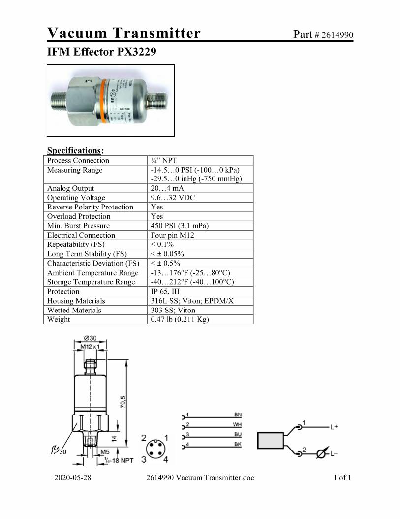
Vacuum Transmitter Part # 2614990
IFM Effector PX3229
2020-05-28 2614990 Vacuum Transmitter.doc 1 of 1
Specifications: Process Connection ¼” NPT Measuring Range -14.5…0 PSI (-100…0 kPa)
-29.5…0 inHg (-750 mmHg) Analog Output 20…4 mA Operating Voltage 9.6…32 VDC Reverse Polarity Protection Yes Overload Protection Yes Min. Burst Pressure 450 PSI (3.1 mPa) Electrical Connection Four pin M12 Repeatability (FS) < 0.1% Long Term Stability (FS) < ± 0.05% Characteristic Deviation (FS) < ± 0.5% Ambient Temperature Range -13…176°F (-25…80°C) Storage Temperature Range -40…212°F (-40…100°C) Protection IP 65, III Housing Materials 316L SS; Viton; EPDM/X Wetted Materials 303 SS; Viton Weight 0.47 lb (0.211 Kg)

Connector Cable Part # 2614968
IFM Efector EVC531
2020-05-28 2614968 Connector Cable.doc 1 of 1
Specifications: Electrical Design AC/DC Operating Voltage 50 VAC / 60 VDC Current Rating 4 A Ambient Temperature -13 to 194°F (-25 to 90°C) Protection IP 65/67/68/69K Body Material TPU (Urethane, Orange) Sealing FKM (Viton) Nut Material Nickel plated Brass Sheath Material PUR (Polyurethane, Black) Wires 4 x AWG 22 w/ screen (drain) wire Connection M12 Length 32.8 ft (10 m) Tightening Torque 5.3 to 13.3 in-lb (0.6 to 1.5 Nm) Drawing:
Pin Color 1 Brown (BN) 2 White (WH) 3 Blue (BU) 4 Black (BK) 5 No Connection

CENTRIFUGAL PUMP

GORMAN-RUPP See Drawing 2965308 in
Section 7 for Details

Pump Part # 2614428 Centrifugal, G-R 12B20-B
2010-05-20 2614428 Pump, Centrifugal, G-R 12B20-B.doc 1 of 4
Basic Pedestal Pump Specifications: Size: 2" x 2" NPT (51mm x 51mm) - Female Casting: Gray Iron N.30. Maximum Operating Pressure 54 psi (3.7 bar) Open Type, Two Vane Impeller:
Ductile Iron No. 65-45-12. Handles 1-1/4" (31.8 mm) Diameter Spherical Solids
Impeller Shaft: Carbon Steel No. 1215 Replaceable Wear Plate: Carbon Steel No. 1026 Removable Cover Plate: Gray Iron No.30; 10 lbs (5 kg) Pedestal: Gray Iron No. 30 Seal Plate: Gray Iron No. 30 Flap Valve: Buna-N; Gray Iron No. 30 Shaft Sleeve: Alloy Steel 4130 Radial/Thrust Bearing: Open Single Row Ball Bearing Lubrication: SAE No. 30 Non-Detergent Oil Flange: Gray Iron No. 30 Gaskets: Vegetable Fiber and Rubber O-Rings: Buna-N Hardware Standard Plated Steel

Pump Part # 2614428 Centrifugal, G-R 12B20-B
2010-05-20 2614428 Pump, Centrifugal, G-R 12B20-B.doc 2 of 4
12B20-B Seal Detail The mechanical seal on the model 12B20-B pumps are Oil-Lubricated, Double Floating, and Self-Aligning with Tungsten Titanium Carbide Rotating and Stationary Faces. Stainless Steel No. 316 Stationary Seat. Fluorocarbon Elastomers (DuPont Viton® or Equivalent). Stainless Steel No. 303/304 Cage and Spring. Maximum Temperature of Liquid Pumped, 160°F (71°C). Oil for the seal is administered by a small bottle oiler part number S1933 (#50, on the parts list within the Maintenance & Repair Manual). All of the seal oiler components are available as parts as detailed within the parts list within the Gorman-Rupp Maintenance & Repair Manual. Pump Paint Specification Gorman-Rupp final coat paint is a high quality, 1.0-1.25 mil, water reducible, alkyd enamel. The standard color is blue. This paint specification also applies to the pump base and the guard.

Pump Part # 2614428 Centrifugal, G-R 12B20-B
2010-05-20 2614428 Pump, Centrifugal, G-R 12B20-B.doc 3 of 4

Pump Part # 2614428 Centrifugal, G-R 12B20-B
2010-05-20 2614428 Pump, Centrifugal, G-R 12B20-B.doc 4 of 4

Motor Part # 2615707-1 2 HP TECO PE, F1
2020-05-28 2615707-1 Motor, 2hp TECO PE F1.doc 1 of 1
Product Overview: Description: 2 HP / 1740 RPM 3PH / TEFC / 145T NEMA Features:
Ball Bearings Suitable for mounting any position Heavy gauge steel and cast iron frames Oversized Conduit Box Stainless Steel Nameplate Speed ranges: 20:1 variable torque; 10:1 constant
torque Inverter duty magnet wire capable of withstanding
voltage spikes of up to 2200 volts Certifications:
CE Mark on nameplate U.L. Recognized CSA Approved Meets or exceeds NEMA Premium Efficiency Levels Department of Energy Efficiency Certificate #CC002A VFD Rated per NEMA MG1, Part 30.1.4.4.2
Specifications:
Catalog Number NP0024 Rating 40C AMB-CONT Drawing Number 31057NP0024 Locked Rotor Code L Horsepower / Kilowatt 2/1.49 NEMA Design Code B Voltage 230 / 460 Insulation Class F (2 DIP&BAKE) Hertz 60 Full Load Efficiency 86.5 Phase 3 Power Factor 78 Full Load Amps 5.56 / 2.78 Enclosure TEFC (IP44) DE Bearing 6205ZZ RPM 1740 ODE Bearing 6205ZZ Frame Size 145T Weight 53 lbs Service Factor 1.15 Mounting F1
Motor Paint Specification: TECO premium efficient motors have a phenolic rust proof base plus polyurethane top coat. The standard color is blue grey.

Motor Part # 2615707-2 2 HP TECO PE, F2
2020-05-28 2615707-2 Motor, 2hp TECO PE F2.doc 1 of 1
Product Overview: Description: 2 HP / 1740 RPM 3PH / TEFC / 145T NEMA Features:
Ball Bearings Suitable for mounting any position Heavy gauge steel and cast iron frames Oversized Conduit Box Stainless Steel Nameplate Speed ranges: 20:1 variable torque; 10:1 constant
torque Inverter duty magnet wire capable of withstanding
voltage spikes of up to 2200 volts Certifications:
CE Mark on nameplate U.L. Recognized CSA Approved Meets or exceeds NEMA Premium Efficiency Levels Department of Energy Efficiency Certificate #CC002A VFD Rated per NEMA MG1, Part 30.1.4.4.2
Specifications:
Catalog Number NP0024 Rating 40C AMB-CONT Drawing Number 31057NP0024 Locked Rotor Code L Horsepower / Kilowatt 2/1.49 NEMA Design Code B Voltage 230 / 460 Insulation Class F (2 DIP&BAKE) Hertz 60 Full Load Efficiency 86.5 Phase 3 Power Factor 78 Full Load Amps 5.56 / 2.78 Enclosure TEFC (IP44) DE Bearing 6205ZZ RPM 1740 ODE Bearing 6205ZZ Frame Size 145T Weight 53 lbs Service Factor 1.15 Mounting F2
Motor Paint Specification: TECO premium efficient motors have a phenolic rust proof base plus polyurethane top coat. The standard color is blue grey.

Coupling Part # 2614432 Jaw Type, L095, 0.88-1.00 Bore
2020-05-28 2614432 Coupling, Jaw Type, L095, 0.88-1.00.doc 1 of 1
The Jaw Type couplings require no lubrication and provide highly reliable service for light, medium, and heavy duty electrical motor and internal combustion power transmission applications. Applications include power transmission to industrial equipment such as pumps, gear boxes, compressors, blowers, mixers.
Coupling Features
Fail-safe – will still perform if elastomer fails. No metal to metal contact. Resistant to oil, dirt, sand, moisture and grease. Standard bore program covers AGMA, SAE, and DIN bore/keyway combinations. Coupling offers standard shaft-to-shaft connection for general industrial duty applications. Coupling hub material is sintered iron. Spider material is NBR Rubber
Assembly Dimensions
STYLE 1
LoveJoy Part Numbers Coupling 1 = 685144-11089 Coupling 2 = 685144-11091 Spider = 685144-11070
For replacement spider only, order Aqua-Aerobic Systems part 2612223
Size OAL LTB G SL OD ID 1 K.W. 1 ID 2 K.W. 2 T Inch 2.51 1.00 0.52 0.44 2.11 .875 3/16 x 3/32 1.00 1/4 x 1/8 5/16-18 mm 63.75 25.40 13.21 11.18 53.59 22.23 4.76 x 2.38 25.40 6.36 x 3.18

Coupling Part # 2612223 Spider, Lovejoy 685144-11070
2020-05-28 2612223 Spider for Coupling.doc 1 of 1
Replacement spider for Lovejoy flexible coupling
Spider type: SOX
Style: A (Solid)
Material: NBR (Nitrile Butadiene Rubber)
Coupling Type: L
Coupling Size: L090/095 Spider Performance Data:
Characteristics
Temperature Range
Misalignment Shore Hardness
Dampening Capacity
Chemical Resistance
Color Angular
Degree Parallel Inch
NBR Rubber – Nitrile Butadiene (Buna N) Rubber is a flexible elastomeric material that is oil resistant, resembles natural rubber in resilience and elasticity.
-40° to 212° F -40° to 100° C
1°
.015
80A
High
Good
Black
Spider Dimensions:
Size A B DC H W Inch 2.12 .36 .18 0.88 .44 mm 53.85 9.14 4.57 22.35 11.18

SEAL

Effluent Seal Part # 2607719
V-Ring Seal
2020-05-28 2607719 Effluent Seal V-Ring.doc 1 of 1
COMPOUND Viton® (Fluoro-Elastomer) CODE V ADVANTAGES Excellent high temperature capabilities.
Compatible with wide range of fluids. Very long life
RANGE -40°F to 400°F -40°C to 204°C
Style VRS1
Inches mm
Shaft Size Metric (d1) 23.62 600
Shaft Size Minimum (d1) 22.83 580
Shaft Size Maximum (d1) 24.80 630
Width on Shaft (A) 0.560 14.2
Overall Width (B) 0.980 24.9
Height (C) 0.590 15.0
Fitted Width (B1) 0.790 20.0
Width Tolerance (+/-) 0.160 4.1

SPROCKET

DRIVE SPROCKET

Sprocket Part # 2607227
2020-05-28 2607227 Sprocket.doc 1 of 1
Drive Sprocket NH-78 Chain
Material UV Resistant Cast Nylon (Black)
Number of Teeth 11 Pitch 2.609″ (66.27 mm) Pitch Dia. 9.26″ (235.2 mm) Overall Dia. 10.05″ (255.27 mm) Hub Dia. 6.00″ (152.4 mm) Hub Width 3.00″ (76.2 mm) Bore Dia. 1.625-1.630″ (41.28-41.4 mm)

CENTERTUBE SPROCKET

Sprocket Part # 2509003
Centertube Sprocket Segment (120º) NH-78 Chain
2020-05-28 2509003 Sprocket Segment.doc 1 of 1
.
Material UHMW Polyethylene (Black)
Segments Required 3 Number of Teeth 48 (360º)
16 (per Segment) Pitch 2.609″ (66.3 mm) Pitch Dia. 39.89″ (1013.21 mm) Overall Dia. 41.024″ (1042 mm)

Valve Schedule Cloth Media Filter
2020-05-29 116275 Valve Schedule.doc 1 of 1
© 2020 Aqua-Aerobic Systems, Inc.
QTY. EQUIPMENT MANUFACTURER DESCRIPTION / LOCATION PART NUMBER
_8_ TCI / RCEL 2" Electric ball valve (Grooved) / 2964965 (_6_) Backwash (_2_) Solids Wasting
QTY. EQUIPMENT MANUFACTURER DESCRIPTION / LOCATION PART NUMBER
_2_ NIBCO 3" Manual Gate Valve (Threaded) 2610351 Backwash Throttle
QTY. EQUIPMENT MANUFACTURER DESCRIPTION / LOCATION PART NUMBER
_2_ NIBCO 3" Manual lever ball valve (Threaded) 2609798 Tank drain
QTY. EQUIPMENT MANUFACTURER DESCRIPTION / LOCATION PART NUMBER
_2_ NIBCO 12” Manual butterfly valve / Influent
2610925
QTY. EQUIPMENT MANUFACTURER DESCRIPTION / LOCATION PART NUMBER
_2_ APOLLO 2” Manual 3-Way Ball Valve (Threaded) 2606833 Recirculation
QTY. EQUIPMENT MANUFACTURER DESCRIPTION / LOCATION PART NUMBER
_2_ APOLLO 1/2” Manual lever ball valve / 2612176 Gage isolation

ELECTRIC BALL VALVE

2 INCH VALVE ASSEMBLY GROOVED See Drawing 2964965 in
Section 7 for Details

Actuator Assembly Part # 2964966 RCI RCEL-005L, 115V, with Receptacle
2020-05-28 2964966 Actuator Assembly.doc 1 of 4
RCEL-005L series electric actuators are designed to provide reliable and efficient operation of quarter turn valves.
WARNING Use caution when working in, with or around valves and actuators. High pressures, forces, voltages and flammable media can be present. Failure to follow instructions for proper electrical wiring, storage, set-up and maintenance may cause serious injury, damage equipment, or void warranty. RCEL-005L Standard Specifications: Enclosure Rated IP67, Nema 4, 4X and 6 Materials Steel, Aluminum Alloy, Bronze Power Supply 120 VAC, 1 PH, 50/60Hz Motor Reversible Motor Limit Switches 4 x open/close SPDT, 250VAC 3A rating Stall Protection Built-in Thermal Protection Indicator Continuous Position Indicator w/ Illumination Manual Override Allen Key, 6mm Space Heater 2W Anti-condensation Conduit Entries (2) x 1/2” NPT Lubrication Grease Moly EP Ambient Temperature -20° C to +70° C (-4° F to 158° F) External Coating Dry Powder, Epoxy Polyester Color Red Weight 3.5 Kg (7.7 lb)

Actuator Assembly Part # 2964966 RCI RCEL-005L, 115V, with Receptacle
2020-05-28 2964966 Actuator Assembly.doc 2 of 4
Travel Limit Switch Setting Instructions:
Maintenance and Storage: At least once a year a check should be made of the actuator:
1. Disconnect all power to actuator. 2. Open electrical enclosure. Inspect and tighten all electrical connections. 3. Visually inspect for any electrical or mechanical damage. Replace worn or damaged
components. Actuators must be stored in a clean, cool and dry area. The unit shall be stored with the cover installed and the conduit openings plugged. Storage must be off the floor, covered with a sealed dust protector.

Actuator Assembly Part # 2964966 RCI RCEL-005L, 115V, with Receptacle
2020-05-28 2964966 Actuator Assembly.doc 3 of 4
#16 AWG Yellow STOOW cable – U.S. color code Oil-resistant PVC jacket Low-resistance contact design with gold/palladium nickel plating Brad Harrison Part: 2R7006A20A120 (A.A.S.I. # 2612782) For use with mating cord set, A.A.S.I. #2614395

Actuator Assembly Part # 2964966 RCI RCEL-005L, 115V, with Receptacle
2020-05-28 2964966 Actuator Assembly.doc 4 of 4
CABLE ENTRY2-1/2" PF
MA
NU
AL O
PERA
TION
ISO 5211 F05(
50 M6TA
P DP10)
ISO 5211 F07(
70 M8TA
P DP13)
ISO 5211 F03(
36 M5TA
P DP8)
BA
SE B.C
.D
14 D
P2515
9 11
20
11
DR
IVE IN
SERT
14
208 132
168
72
44
140

Ball Valve Part # 2614032 TCI 2” Ball Valve, Less Operator
2020-05-28 2614032 TCI Ball Valve 2 in.doc 1 of 2
Design Features:
Full port for high flow Grooved end connections Three-piece design for easy inline maintenance Investment cast 316SS body and caps ME-PTFE seal has low deformation under load and low permeation Temperature rating: -45.5°C (-50°F) to 246°C (475°F) Long cycle life Blow-out-proof stem Anti-static device Adjustable stem packing ISO-5211 (F05/F07) for direct mounting of actuators ANSI B16.34 Full Compliance Test Standard: API 598 Vacuum service to 29” Hg Opening Torque: 31.8 Nm (282 in-lb) Cv Factor: 500 Weight: 4.71 Kg (10.37 lb)

Ball Valve Part # 2614032 TCI 2” Ball Valve, Less Operator
2020-05-28 2614032 TCI Ball Valve 2 in.doc 2 of 2
Dimension in (mm) Pipe Size 2 (50)
A 1.44 (36.6) B 2.38 (60.5) C 2.68 (68) D 2.41 (61.1) d 2 (50.8) L 7.01(178.1)
H1 3.42 (86.9) H 0.63 (16) S 0.55 (14) T 0.51 (13)
Material List: Item Part Material Qty
1 Body ASTM A351 Gr.CF8M (316) 1 2 Cap ASTM A351 Gr.CF8M (316) 2 3 Ball ASTM A351 Gr.CF8M (316) 1 4 Seat ME-PTFE* 2 5 Bolt ASTM A193 Gr.B8 (304) 4 6 Gasket ME-PTFE* 2 7 Thrust Washer ME-PTFE* 1 8 Stem ASTM A276 Gr.316 (316) 1 9 O-Ring Viton 1 10 Packing ME-PTFE* 1 11 Ring 304 SS 1 12 Belleville Washer 410 SS 2 13 Handle Nut 304 SS 1 18 Bolt Washer 304 SS 4 19 Bolt Nut ASTM A194 Gr.8 (304) 4
* ME-PTFE is Molecularly Enhanced PTFE

Cordset Part # 2614395 7P Double Female-Male, 3’ Cord
2020-05-28 2614395 Cordset, 7P Double Female-Male, 3' Cord.doc 1 of 1
#16 AWG Yellow STOOW cable – U.S. color code Oil-resistant PVC jacket Low-resistance contact design with gold/palladium nickel plating Brad Harrison Part: 227020A01F030

MANUAL GATE VALVE

Valve, Gate Part # 2610351
NIBCO T-113, 80 mm (3″)
2010-10-13 2610351 Gate Valve 80mm - 3 inch.doc 1 of 2
Features: Class 125 Bronze Gate Valve Screw-in Bonnet Non-Rising Stem Solid Wedge
Material List - Conforms to MSS SP-80
Part Specification 1 Handwheel Nut Zinc Plated Steel with Clear Chromate 2 Identification Plate Aluminum 3 Handwheel a. Malleable Iron ASTM A-47 (T-113)
b. Bronze (T-113-BHW) c. Bronze Cross (T-113-K)
4 Stem Silicon Bronze ASTM B-371 Alloy C6940 or ASTM B99 Alloy C65100
5 Packing Nut Bronze ASTM B-62 or ASTM B-584 Alloy C84400 or Brass ASTM B-16
6 Packing Gland Bronze ASTM B-62 or ASTM B-584 Alloy C84400 or Brass ASTM B-16
7 Packing Aramid Fibers with Graphite 8 Stuffing Box Bronze ASTM B-62 9 Bonnet Bronze ASTM B-62 10 Body Bronze ASTM B-62 11 Wedge Bronze ASTM B-62

Valve, Gate Part # 2610351
NIBCO T-113, 80 mm (3″)
2010-10-13 2610351 Gate Valve 80mm - 3 inch.doc 2 of 2
Dimensions - Weights – Quantities
Size (In.) 3 Size (mm.) 80 A - In. 4.50 A - mm. 114 B - In. 10 B - mm. 254 C - In. 1.94 C - mm. 49 T-113 (Lbs.) 14.40 T-113 (Kg.) 6.53 S-113 (Lbs.) 12.84 S-113 (Kg.) 5.82 Master Carton Quantity 4

MANUAL LEVER BALL VALVE

Valve Part # 2609798
Nibco, T-FP-600A, 3", Ball
2020-05-28 2609798 Valve.doc 1 of 1
Part Suffix Table
Features:
Two-Piece Body Full Port Blowout-Proof Stem PTFE Seats 400 PSI/2758 kPa Non-Shock Cold
Working Pressure CSA Certified to ASME B16.44 and CR
91-002 UL Listed IAPMO, Listed to NSF/ANSI61-8 Weight: 9.36 lbs. (4.24kg)
Note: CSA is now the approving agency for AGA and CGA standards. Dimensions:
Part Number Material Comments 2609798 Brass None
2609798-DX2 Brass ARRA Certified
Inches mm 3 75 A 6.04 153 B 5.08 129 C 8.66 220 D Port 2.95 75

Valve, 3-Way Bronze Ball Part # 2606833
2010-09-07 2606833 3-Way Bronze Ball Valve.doc 1 of 2
Apollo 70-600 Series, 2″ (50.8mm) Threaded, 400 psig WOG, Cold Non-Stock
Features Chrome plated ball RPTFE seats and stuffing box ring Blow-out-proof stem design Adjustable packing gland Weight: 6.20 lbs / 2.81 kg
3-WAY DIVERSION BRONZE BALL VALVE
Number 70-600-01 Inches mm Size 2" 50.8 A 1.50 38.1 B 2.34 59.4 C 4.69 119.1 D 3.00 76.2 E 5.50 139.7 F 2.50 63.5 G 0.94 23.9 H 1.50 38.1 I 1/4-20 ---

Valve, 3-Way Bronze Ball Part # 2606833
2010-09-07 2606833 3-Way Bronze Ball Valve.doc 2 of 2
Apollo 70-600 Series Threaded, 400 psig WOG, Cold Non-Stock
Standard Material List
1. Lever and Grip Steel zinc plated w/vinyl 2. Stem packing RPTFE 3. Stem bearing RPTFE 4. Ball B16, chrome plated 5. Seat (2) RPTFE 6. Retainer B584-C84400 7. Gland nut B16 8. Stem B16 9. Lever nut Steel, zinc plated 10. Body seal (1-1/2" to 2") PTFE 11. Body B284-C84400

Valve, Ball - Stainless Steel Part # 2612176
1/2" NPT Apollo Two-Piece 76-100 Series, 76-103-01
2017-11-29 2612176 Ball Valve.doc 1 of 1
Threaded 2000 psig WOG, Cold Non-stock. 150 psig Saturated Steam
FEATURES: • Investment cast components • RPTFE seats and stuffing box ring • Mounting pad for easy actuator mounting • Blow-out proof stem design • Adjustable packing gland • Meets NACE MR-01-75 • SS lever and nut • MSS SP-110; Ball Valves Threaded
STANDARD MATERIAL LIST:
1. Lever and grip 304SS w/vinyl 7. Gland nut A276-316 2. Stem packing RPTFE 8. Stem A276-316 3. Stem bearing RPTFE 9. Lever nut 18-8 SS 4. Ball A276-316 10. Body seal (1-1/4" to 3') PTFE 5. Seat (2) RPTFE 11. Body A351-CF8M 6. Retainer A276-316
SS BALL VALVE PART PIPE SIZE A B C D E WEIGHT
NUMBER IN (NOM) MM IN MM IN MM IN MM IN MM IN MM LBS KG 76-103-01 1/2" 12.7 0.50 12.7 1.12 28.4 2.25 57.15 1.81 46.0 3.87 98.3 0.63 0.3

MANUAL BUTTERFLY VALVE

Valve Part # 2610925
NIBCO, Butterfly, 12", LD-2000-5, Lugged, Gear Operated
2020-05-28 2610925 Nibco Butterfly Valve 12in-300mm-Lug.doc 1 of 3
Specifications:
Size: 12” (300 mm) Pressure Rating: 200 PSI Service: 225°F (107°C) continuous, 250°F (121°C)
intermittent Weight: 113 lbs (51 kg) (this includes the gear operator) Install between standard ASME Class 125/150 Flanges
200 PSI bi-directional dead end service rating without a downstream flange.
Designed to meet MSS SP-67 Standard U.S. Coast Guard “Category A” Certified Lead-Free* by TRUESDAIL to NSF/ANSI
61-8 Commercial hot 180°F (Includes Annex F and G) and NSF/ANSI-372
Valve Materials:
1. Stem – Stainless Steel ASTM A582 Type 416
8. Disc – Aluminum Bronze ASTMB148 Alloy 955
2. Collar Bushing – Brass ASTM B16 9. Lower Bushing – Copper CDA 122 3. Stem Seal – EPDM Rubber 10. Body – Ductile Iron ASTM A536 4. Body Seal – EPDM Rubber 5. Nameplate – Aluminum 6. Upper Bushing – Copper CDA 122 7. Liner – EPDM Rubber
* Lead Free refers to the wetted surface of pipe, fittings, and fixtures in potable water systems that have a weighted average lead content ≤ 0.25% per the Safe Drinking Water Act (Sec. 1417) amended 1-4-2011 and other equivalent state regulations.

Valve Part # 2610925
NIBCO, Butterfly, 12", LD-2000-5, Lugged, Gear Operated
2020-05-28 2610925 Nibco Butterfly Valve 12in-300mm-Lug.doc 2 of 3
Dimensions:
Inch mm A 12.13 308 B 15.00 381 C 1.25 32 D 12.00 305 E 9.25 235 F 0.50 13
G (Flat) 0.748 19 H (Metal) 3.000 76 I (Rubber) 3.125 79 J (Square) 4.75 121 N (Dia.) 1.250 32
O (Bolt Circle) 5.00 127
P (Dia.) 0.562 14 R (Dia.) 1.062 27 K (No.) 12 L (Dia.) 7/8”-9 UNC
M (Bolt Circle) 17.00 432

Valve Part # 2610925
NIBCO, Butterfly, 12", LD-2000-5, Lugged, Gear Operated
2020-05-28 2610925 Nibco Butterfly Valve 12in-300mm-Lug.doc 3 of 3
Cast Iron Gear Operator: The NIBCO butterfly valve will be provided with heavy-duty operator, indicator and hand wheel, for trouble-free operation in all moisture and weather conditions (not submersible). Operator is a self-locking worm gear type. Equipped with adjustable stops at open and shut positions.
GEAR OPERATOR DETAILS BUTTERFLY VALVE OPTION AND ACCESSORIES - HANDWHEEL
VALVE SIZE GEAR
OPERATOR NUMBER
GEAR OPERATOR
HANDWHEEL
SPROCKET RIM MODEL RATIO
12” T117121PP T117124PP #2 1/2 30:1
GEAR OPERATOR DETAILS DIMENSIONS
A B C D E F WEIGHT in mm in mm in mm in mm in mm in mm lbs Kg
11.54 293 2.48 63 6.93 176 6.06 154 9.84 250 3.26 83 23 10

ELECTRICAL CONTROL PANEL
COMPONENT INFORMATION

CONTROL PANEL SAFETY PRECAUTIONS
EP-10005 Control Panel Safety.doc 1 of 1
Copyright © 2008 Aqua-Aerobic Systems, Inc. 2020-05-28
CAUTION Be aware of electrical hazards:
o Electric shock and burns – An electric shock occurs when electric current passes through the body. This can happen when touching an energized part.
o Arc-flash burns – An electric arc flash can occur if a conductive object gets too close to a high-amp current source or by equipment failure. The arc flash can cause severe burns by direct heat exposure and by igniting clothing.
o Arc-blast impacts – The heating of air and vaporization of metal during an arc, creates a pressure wave that can damage hearing and cause concussions among other injuries.
o Falls – Electric shocks and arc blasts can cause falls.
All electrical service should be performed by qualified personnel.
Treat all electrical equipment and conductors as though they are energized until they are placed in an electrically safe work condition.
Create an electrically safe work condition by performing the following lockout/tag out
procedures. o Notify others prior to beginning a lockout/tag out procedure. o Lockout/Tagout out all energy sources following sheet EP-10095 and / or
documented site procedures. o Confirm that equipment is de-energized by checking voltages. o Clean, service, inspect or clear equipment. o Make sure others are safe; machine guards are in place; tools, locks, and tags are
removed before restoring energy.
See NFPA 70E for additional guidelines on safety related work practices. GENERAL SAFETY
Protect panel components from contamination (metal chips, loose bolts, liquids, etc.). Do not use control panels for storage. Do not leave an open panel unattended. Exercise all necessary precautions with regard to personal hygiene and sanitation.

Electrical Lockout / Tag Out Procedures
EP-10095 Electrical Lockout Procedures.doc 1 of 5
Copyright © 2020 Aqua-Aerobic Systems, Inc. 2017-2-03
Consult your facility procedure. Each facility should have a written lockout/tag out program and train employees in this program. The typical program should cover planning for locating and labeling energy sources, identifying employees at risk, how and by whom the equipment is de-energized, releasing of stored energy, verifying that the circuit is de-energized and can't be restarted, voltage testing, grounding requirements, shift changes, coordination with other jobs in progress, a procedure for keeping track of all involved personnel, applying and removing lockout/tag out devices, return to service, and temporary re-energizing for testing/positioning. Lockout/tag out procedures should be developed for each machine or piece of equipment that will require servicing. Lockout / Tag Out Application Each person who could be exposed to electric energy must be involved in the lockout/tag out process. A typical process is described below.
After de-energizing, each employee at risk should apply an individual lockout/tag out device to each source of electric energy. Pushbuttons or selector switches cannot be used as the only way to de-energize.
Lockout Device: A lockout device is a key or combination lock with a tag that can be attached to a disconnecting device to prevent the re-energizing of the equipment being worked on without removal of the lock. The lockout device should have a way of identifying the individual who tagged it and the reason why it was tagged. Individual lockout devices with worker’s name and picture on them are preferred. That worker must be the only person who has the key or combination for the lockout device they install, and that worker should be the only person to remove the lock after all work has been completed.
Tag Out Device: A tag out device is a tag or means that can be attached to the actual lockout device to notify all workers that this equipment has been locked out. The tag out device must include a way to attach to the lockout device that can withstand at least 50 pounds of force. Tag out devices on electrical power should be used alone only when it is not possible to install a lockout device.
Lockout Tag: The tag used in conjunction with a lockout or tag out device must have a warning label prohibiting unauthorized disconnecting or removal of the lockout/tag out device.
Before beginning work, each involved worker must verify through testing that all energy sources have been de-energized.
Electric lockout/tag out procedures should be coordinated with all other site procedures for controlling exposure to electric energy and other types of energy sources.
Complex lockout/tag out procedures are special procedures that are needed when there is more than one energy source, crew, craft, location, employer, way to disconnect, or lockout/tag out procedure or for work that lasts beyond one shift. In any of these cases, one qualified person should be in charge of the lockout/tag out procedure with full responsibility for ensuring all energy sources are under lockout/tag out and to account for all people on the job.

Electrical Lockout / Tag Out Procedures
EP-10095 Electrical Lockout Procedures.doc 2 of 5
Copyright © 2020 Aqua-Aerobic Systems, Inc. 2017-2-03
Removal of Lockout/Tag Out devices: Lockout and tag out devices should be removed only by the person installing them. If work is not completed when the shift changes, workers arriving on shift should apply their locks before departing workers remove their locks.
Return to service: When electrical work has been completed tests and visual inspections must be made to confirm that all tools, mechanical restraints, electric jumpers, shorts, and grounds have been removed. Once work is completed and lockout/tag out devices are removed, tests and visual inspection must confirm that all tools, mechanical restraints, electric jumpers, shorts, and grounds have been removed. Only then is it safe to re-energize and return to service.
Temporary release: If the job requiring lockout/tag out is interrupted for any reason, the steps outlined in Return to Service (above) should be followed before removing the lockout/tag out devices, and placing the equipment back into operation.
WARNING
Electrical Hazards Electric shock and burns: An electric shock occurs when electric current passes
through the body. This can happen when touching an energized part. If the electric current passes across the chest or head, death can result. At high voltages, severe burns can result.
Arc-flash burns: An electric arc flash can occur if a conductive object gets too close to a high-amp current source or by equipment failure (for instance, while opening or closing disconnects). The arc can heat the air to temperatures as high as 35,000º F, and vaporize metal in the equipment. The arc flash can cause severe skin burns by direct heat exposure and by igniting clothing.
Arc-blast impacts: The heating of air and vaporization of metal creates a pressure wave that can damage hearing and cause memory loss (from concussion) and other injuries. Flying metal parts are also a hazard.
Falls: Electric shocks and arc blasts can cause falls, especially from ladders or unguarded scaffolding.
Electric Safety Principles - Energized Condition
De-energize whenever possible. Plan every job. The approach and step-by-step procedures to complete the work at hand
must be discussed and agreed upon between all involved employees before beginning. Write down first-time procedures. Discuss hazards and procedures in a job briefing with supervisors and other workers before starting any job. It is the employer’s responsibility to have or develop a checklist system for working on live circuits, if such a scenario arises.
Identify the hazards. Conduct a job hazard analysis. Identify steps that could create electric shock or arc-flash hazards.
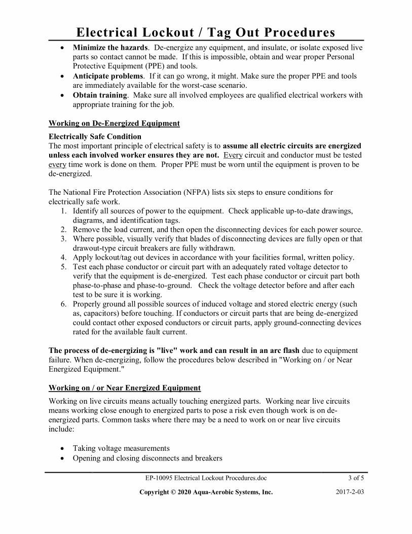
Electrical Lockout / Tag Out Procedures
EP-10095 Electrical Lockout Procedures.doc 3 of 5
Copyright © 2020 Aqua-Aerobic Systems, Inc. 2017-2-03
Minimize the hazards. De-energize any equipment, and insulate, or isolate exposed live parts so contact cannot be made. If this is impossible, obtain and wear proper Personal Protective Equipment (PPE) and tools.
Anticipate problems. If it can go wrong, it might. Make sure the proper PPE and tools are immediately available for the worst-case scenario.
Obtain training. Make sure all involved employees are qualified electrical workers with appropriate training for the job.
Working on De-Energized Equipment Electrically Safe Condition The most important principle of electrical safety is to assume all electric circuits are energized unless each involved worker ensures they are not. Every circuit and conductor must be tested every time work is done on them. Proper PPE must be worn until the equipment is proven to be de-energized.
The National Fire Protection Association (NFPA) lists six steps to ensure conditions for electrically safe work.
1. Identify all sources of power to the equipment. Check applicable up-to-date drawings, diagrams, and identification tags.
2. Remove the load current, and then open the disconnecting devices for each power source. 3. Where possible, visually verify that blades of disconnecting devices are fully open or that
drawout-type circuit breakers are fully withdrawn. 4. Apply lockout/tag out devices in accordance with your facilities formal, written policy. 5. Test each phase conductor or circuit part with an adequately rated voltage detector to
verify that the equipment is de-energized. Test each phase conductor or circuit part both phase-to-phase and phase-to-ground. Check the voltage detector before and after each test to be sure it is working.
6. Properly ground all possible sources of induced voltage and stored electric energy (such as, capacitors) before touching. If conductors or circuit parts that are being de-energized could contact other exposed conductors or circuit parts, apply ground-connecting devices rated for the available fault current.
The process of de-energizing is "live" work and can result in an arc flash due to equipment failure. When de-energizing, follow the procedures below described in "Working on / or Near Energized Equipment."
Working on / or Near Energized Equipment Working on live circuits means actually touching energized parts. Working near live circuits means working close enough to energized parts to pose a risk even though work is on de-energized parts. Common tasks where there may be a need to work on or near live circuits include:
Taking voltage measurements Opening and closing disconnects and breakers

Electrical Lockout / Tag Out Procedures
EP-10095 Electrical Lockout Procedures.doc 4 of 5
Copyright © 2020 Aqua-Aerobic Systems, Inc. 2017-2-03
Racking breakers on and off the bus Removing panels and dead fronts Opening electric equipment doors for inspection
Facilities should adopt standard written procedures and training for these common tasks. For instance, when opening and closing disconnects, use the left-hand rule when possible (stand to the right side of the equipment and operate the disconnect switch with the left hand). Approach Distances to Exposed Live Parts The National Fire Protection Association (NFPA) defines three approach boundaries for shock
hazards and one for arc flash. Shock Hazards
The Limited Approach Boundary is the distance from an exposed live part within which a shock hazard exists.
The Restricted Approach Boundary is the closest distance to exposed live parts a qualified person can approach with or without proper PPE and tools. Inside this boundary, accidental movement can put a part of the body or conductive tools in contact with live parts or inside the prohibited approach boundary. To cross the restricted approach boundary, the qualified person must review and understand Annex C, Limits of Approach, of NFPA 70-E
The Prohibited Approach Boundary is the minimum approach distance to exposed live parts to prevent flashover or arcing. Approaching any closer is comparable to making direct contact with a live part.
Arc Flash Hazard
The Flash Protection Boundary is the approach limit at a distance from exposed live parts within which a person could receive a second degree burn if an electrical arc flash were to occur. For systems of 600 volts and less, the flash protection boundary is 4 feet (1.2m), based on an available bolted fault current of 50 kA and a clearing time of 6 cycles for the circuit breaker to act, or any combination of fault currents and clearing times not exceeding 300 kA cycles.
Approach Boundaries to Live Parts for Shock Protection (All dimensions are distance from live part to worker) Limited approach boundary
Nominal system voltage range, phase
to phase
Exposed movable conductor
Exposed fixed- circuit part
Restricted approach boundary (allowing for accidental movement)
Prohibited approach boundary
0 to 50 volts Not specified Not specified Not specified Not specified 51 to 300 volts 10 ft. 0 in. (3.0m) 3 ft. 6 in. (1.1m) Avoid contact Avoid contact
301 to 750 volts 10 ft. 0 in. (3.0m) 3 ft. 6 in. (1.1m) 1 ft. 0 in. (0.3m) 0 ft. 1 in. (25.4mm) 751 to 15 KV KV 10 ft. 0 in. (3.0m) 5 ft. 0 in. 1.5m) 2 ft. 2 in. (0.7m) 0 ft. 7 in. (177.8mm)
Source: Excerpted from table 130.2(C), “Approach Boundaries to Live Parts for Shock

Electrical Lockout / Tag Out Procedures
EP-10095 Electrical Lockout Procedures.doc 5 of 5
Copyright © 2020 Aqua-Aerobic Systems, Inc. 2017-2-03
Protection” (NFPA 70-E Standard for Electrical Safety Requirements for Employee Workplaces,
2004 edition). Wet or Damp Locations Work in wet or damp work locations (i.e., areas surrounded or near water or other liquids) should not be performed unless it is absolutely critical. Electrical work should be postponed until the liquid can be cleaned up. The following special precautions must be incorporated while performing work in wet or damp locations:
Only use electrical cords that have Ground Fault Circuit Interrupters (GFCIs); Place a dry barrier over any wet or damp work surface; Remove standing water before beginning work. Work is prohibited in areas where there
is standing water; Do not use electrical extension cords in wet or damp locations; and Keep electrical cords away from standing water.
Other Precautions When working on de-energized parts, but still inside the flash protection boundary for nearby live exposed parts:
If the parts cannot be de-energized, barriers such as insulated blankets must be used to protect against accidental contact or PPE must be worn.
Do not reach blindly into areas that might contain exposed live parts. Do not enter spaces containing live parts unless illumination is provided that allows the
work to be performed safely. Conductive articles of jewelry and clothing shall not be worn where they present an
electrical contact hazard with exposed live parts. Conductive materials, tools, and equipment that are in contact with any part of the body
shall be handled in a manner that prevents accidental contact with live parts. References
NFPA 70-E, “Standard for Electrical Safety Requirements for Employee Workplaces”, 2004 edition.

CABLE, CONDUIT & WIRE

Patch Cord Part # 2752496
Quiktron 530-135-003SDTBOD
2020-05-28 2752496 - Patch Cord, Ethernet Cat5e.doc 1 of 1
The Ethernet Cat5e patch cord provides signal routing from one device to another. Certifications:
UL Listed Specifications:
Conductors Wire Size Jacket Material
Jacket Color
First Connector
Second Connector Length
8 24 AWG Shielded 600V, PVC Black Male RJ45 Male RJ45 3 Feet
Operating Temperature
-40 to +75° C (-40 to +167° F) Pin Out Chart:
RJ45 Position RJ45
White/Orange 1 White/Orange Orange 2 Orange
White/Green 3 White/Green Blue 4 Blue
White/Blue 5 White/Blue Green 6 Green
White/Brown 7 White/Brown Brown 8 Brown

Patch Cord Part # 2752497
Quiktron 530-135-010SDTBOD
2020-05-28 2752497 - Patch Cord, Ethernet Cat5e.doc 1 of 1
The Ethernet Cat5e patch cord provides signal routing from one device to another. Certifications:
UL Listed Specifications:
Conductors Wire Size Jacket Material
Jacket Color
First Connector
Second Connector Length
8 24 AWG Shielded 600V, PVC Black Male RJ45 Male RJ45 10 Feet
Operating Temperature
-40 to +75° C (-40 to +167° F) Pin Out Chart:
RJ45 Position RJ45
White/Orange 1 White/Orange Orange 2 Orange
White/Green 3 White/Green Blue 4 Blue
White/Blue 5 White/Blue Green 6 Green
White/Brown 7 White/Brown Brown 8 Brown

PVC Conduit System Specification
EP-10100 PVC Conduit Specification.doc 1 of 3
© 2020 Aqua-Aerobic Systems, Inc. 2020-05-28
The PVC conduit is manufactured in accordance with UL651, ANSI/NEMA TC-2, Federal Military Specification WC-1094A and Article 352 of the National Electrical Code. Nonmetallic conduits are 1/4 to 1/5 the weight of metallic systems. They are listed for exposed or outdoor usage. They will not rust or corrode and are rated for use with 90º C conductors. The maximum ambient temperature is 122ºF (50ºC). Rigid conduit, conduit bodies, and support straps are light gray in color. Schedule 40 Schedule 80
The complete conduit system uses 304SS support straps designed especially for the installation of conduit. The clamp allows conduit to expand and contract freely, eliminating bowing caused by varying temperature changes
A.A.S.I.# Description 2612968 1” x 10’-0” LG 2612969 1 ¼” x 10'-0" LG
A.A.S.I.# Description 2605745 ½” x 10’-0” LG 2615006 ¾” x 10’-0” LG 2608436 1” x 10’-0” LG 2607840 1 ¼” x 10’-0” LG 2611966 1 ½” x 10’-0” LG 2617419 2” x 10’-0” LG 2607791 2” x 20’-0” LG
A.A.S.I # Conduit Size 2613588 0.38”-0.5” 2612246 0.75” 2611921 1.00” 2611922 1.25” 2614736 1.50” 2613922 2.00”

PVC Conduit System Specification
EP-10100 PVC Conduit Specification.doc 2 of 3
© 2020 Aqua-Aerobic Systems, Inc. 2020-05-28
The conduit body hubs are not threaded. Their lids are textured, and have foam-in-place gaskets to assure a weather resistant seal. The rigid conduit is cemented into the conduit body hubs using quick set cement.
C E LB
LL LR T
1/2" Components A.A.S.I.# Description 2605747 UNION 2607127 ELBOW 2607128 BODY TYPE LR 2607236 BODY TYPE LL
3/4" Components A.A.S.I.# Description 2611713 BODY TYPE T 2611714 BODY TYPE LR 2611715 BODY TYPE LL 2611717 MALE ADAPTER 2611899 BODY TYPE LB 2615007 BODY TYPE C
1” Components A.A.S.I.# Description 2608440 BODY TYPE T 2608439 BODY TYPE LR 2608442 BODY TYPE LB 2608438 BODY TYPE LL 2608437 BODY TYPE C 2609438 UNION 2608444 NUT 2608441 BODY TYPE E
1 1/4" Components A.A.S.I.# Description 2607741 BODY TYPE T 2607742 BODY TYPE LL 2607743 BODY TYPE LR 2607738 BODY TYPE C 2607739 BODY TYPE E 2607740 BODY TYPE LB 2608314 COUPLING 2610141 NUT
1 1/2" Components A.A.S.I.# Description 2611967 BODY TYPE LL 2611968 BODY TYPE LR 2615000 BODY TYPE LB 2615001 BODY TYPE T 2615003 BODY TYPE C
2" Components A.A.S.I.# Description 2607789 BODY TYPE LL 2617416 BODY TYPE LR 2609207 BODY TYPE LB 2617417 BODY TYPE T 2617418 BODY TYPE C

PVC Conduit System Specification
EP-10100 PVC Conduit Specification.doc 3 of 3
© 2020 Aqua-Aerobic Systems, Inc. 2020-05-28
Seal Rings, Locknuts, and Conduit Adapters
1/2" Components A.A.S.I.# Description 2616628 SEAL RING
2613034 LOCKNUT (316SS)
N/A CONDUIT ADAPTER (SOC X MNPT)
3/4" Components A.A.S.I.# Description 2600644 SEAL RING
2617079 LOCKNUT (316SS)
2611717 CONDUIT ADAPTER (SOC X MNPT)
1” Components A.A.S.I.# Description 2600809 SEAL RING 2617080 LOCKNUT (316SS)
2608446 CONDUIT ADAPTER (SOC X MNPT)
1 1/4" Components A.A.S.I.# Description 2608013 SEAL RING
2617081 LOCKNUT (316SS)
2607762 CONDUIT ADAPTER (SOC X MNPT)
1 1/2" Components A.A.S.I.# Description 2616629 SEAL RING
2617082 LOCKNUT (316SS)
2611964 CONDUIT ADAPTER (SOC X MNPT)
2" Components A.A.S.I.# Description 2616220 SEAL RING
2617083 LOCKNUT (316SS)
2617420 CONDUIT ADAPTER (SOC X MNPT)

PVC Flex Conduit System Specification
EP-10260 PVC Flex Specification.doc 1 of 1
Copyright 2020 Aqua-Aerobic Systems, Inc. 2020-05-28
The PVC flex conduit is manufactured in black. All flex conduits are glued using traditional PVC pipe cement and primer. We recommend medium to heavy bodied glue and any standard primer.
A.A.S.I.# Description Minimum Bend Radius 2607761 1/2” FLEX 2” 2607750 3/4” FLEX 3” 2612061 1” FLEX 4” 2611118 1-1/4” FLEX 5” 2614897 1-1/2” FLEX 6”

CIRCUIT BREAKER

Circuit Breaker Part # 2753912
Schneider Electric M9F42103
2020-05-28 2753912 - Square D C60 Circuit Breaker.doc 1 of 2
C60BP are multi-standard miniature circuit breakers and branch circuit protection as defined by UL 489. It combines following functions:
circuit protection against short-circuit currents circuit protection against overload currents tripping and fault indication by the addition of auxiliaries..
Standards: UL 489 CSA C22.2 No 5 RoHS Compliant EN/IEC 60947-2 GB 14048-2
Specifications: Product name Multi 9 C60 Product or component type Miniature circuit-breaker Device short name C60BP Device application Distribution Poles description 1P Number of protected poles 1 [In] rated current 3 A at 77 °F (25 °C) conforming to EN/IEC 60947-2 Network type DC
AC Trip unit technology Thermal-magnetic Curve code C Breaking capacity Icu 3 kA at 415 V AC conforming to EN/IEC 60947-2
Icu 10 kA at 240 V AC conforming to EN/IEC 60947-2 Icu 20 kA at 60 V DC conforming to EN/IEC 60947-2 Icu 3 kA at 415 V AC conforming to GB 14048.2 Icu 10 kA at 240 V AC conforming to GB 14048.2 Icu 20 kA at 60 V DC conforming to GB 14048.2 AIR 10 kA at 277 V AC conforming to UL 489 AIR 14 kA at 240 V AC conforming to UL 489 AIR 14 kA at 120 V AC conforming to UL 489 AIR 10 kA at 60 V DC conforming to UL 489 AIR 10 kA at 277 V AC conforming to CSA C22.2 No 5 AIR 14 kA at 240 V AC conforming to CSA C22.2 No 5 AIR 14 kA at 120 V AC conforming to CSA C22.2 No 5 AIR 10 kA at 60 V DC conforming to CSA C22.2 No 5
Suitability for isolation Yes conforming to EN/IEC 60947-2 System Voltage 240 V AC 50/60 Hz
415 V AC 50/60 Hz 60 V DC
Magnetic tripping limit 8.5 x In +/- 20% AC 12 x In +/- 20% DC

Circuit Breaker Part # 2753912
Schneider Electric M9F42103
2020-05-28 2753912 - Square D C60 Circuit Breaker.doc 2 of 2
[Ics] rated service breaking capacity 2.25 kA 75 % x Icu at 415 V AC conforming to EN/IEC 60947-2
7.5 kA 75 % x Icu at 240 V AC conforming to EN/IEC 60947-2 2.25 kA 75 % x Icu at 415 V AC conforming to GB 14048.2 7.5 kA 75 % x Icu at 240 V AC conforming to GB 14048.2 15 kA 75 % x Icu at 60 V DC conforming to GB 14048.2 15 kA 75 % x Icu at 60 V DC conforming to EN/IEC 60947-2 [Ui] rated insulation voltage 500 V AC conforming to EN/IEC 60947-2 [Uimp] rated impulse withstand voltage 6 kV conforming to EN/IEC 947-2
Contact position indicator Yes Control type Toggle Local signalling ON/OFF indication Mounting mode Clip-on Mounting support DIN rail Colour Grey Mechanical durability 20000 cycles Electrical durability 10000 cycles Provision for padlocking Padlockable Environment: IP degree of protection IP40 modular enclosure conforming to IEC 60529
IP20 conforming to IEC 60529 Pollution degree 3 conforming to EN/IEC 60947-2 Tropicalisation 2 conforming to IEC 60068-1 Relative humidity 95 % 131 °F (55 °C) Operating altitude 0...6561.68 ft (0...2000 m) Ambient air temperature for operation -22...158 °F (-30...70 °C) Ambient air temperature for storage -40...176 °F (-40...80 °C)
Dimensions:

Circuit Breaker Part # 2753915
Schneider Electric M9F42104
2020-05-28 2753915 - Square D C60 Circuit Breaker.doc 1 of 2
C60BP are multi-standard miniature circuit breakers and branch circuit protection as defined by UL 489. It combines following functions:
circuit protection against short-circuit currents circuit protection against overload currents tripping and fault indication by the addition of auxiliaries..
Standards: UL 489 CSA C22.2 No 5 RoHS Compliant EN/IEC 60947-2 GB 14048-2
Specifications: Product name Multi 9 C60 Product or component type Miniature circuit-breaker Device short name C60BP Device application Distribution Poles description 1P Number of protected poles 1 [In] rated current 4 A at 25 °C conforming to EN/IEC 60947-2 Network type DC
AC Trip unit technology Thermal-magnetic Curve code C Breaking capacity Icu 3 kA at 415 V AC conforming to EN/IEC 60947-2
Icu 10 kA at 240 V AC conforming to EN/IEC 60947-2 Icu 20 kA at 60 V DC conforming to EN/IEC 60947-2 Icu 3 kA at 415 V AC conforming to GB 14048.2 Icu 10 kA at 240 V AC conforming to GB 14048.2 Icu 20 kA at 60 V DC conforming to GB 14048.2 AIR 10 kA at 277 V AC conforming to UL 489 AIR 14 kA at 240 V AC conforming to UL 489 AIR 14 kA at 120 V AC conforming to UL 489 AIR 10 kA at 60 V DC conforming to UL 489 AIR 10 kA at 277 V AC conforming to CSA C22.2 No 5 AIR 14 kA at 240 V AC conforming to CSA C22.2 No 5 AIR 14 kA at 120 V AC conforming to CSA C22.2 No 5 AIR 10 kA at 60 V DC conforming to CSA C22.2 No 5
Suitability for isolation Yes conforming to EN/IEC 60947-2 [Ue] rated operational voltage 240 V AC 50/60 Hz
415 V AC 50/60 Hz 60 V DC
Magnetic tripping limit 8.5 x In +/- 20% AC 12 x In +/- 20% DC

Circuit Breaker Part # 2753915
Schneider Electric M9F42104
2020-05-28 2753915 - Square D C60 Circuit Breaker.doc 2 of 2
[Ics] rated service breaking capacity 2.25 kA 75 % x Icu at 415 V AC conforming to EN/IEC 60947-2
7.5 kA 75 % x Icu at 240 V AC conforming to EN/IEC 60947-2 2.25 kA 75 % x Icu at 415 V AC conforming to GB 14048.2 7.5 kA 75 % x Icu at 240 V AC conforming to GB 14048.2 15 kA 75 % x Icu at 60 V DC conforming to GB 14048.2 15 kA 75 % x Icu at 60 V DC conforming to EN/IEC 60947-2
[Ui] rated insulation voltage 500 V AC conforming to EN/IEC 60947-2 [Uimp] rated impulse withstand voltage 6 kV conforming to EN/IEC 60947-2 Contact position indicator Yes Control type Toggle Local signalling ON/OFF indication Mounting mode Clip-on Mounting support DIN rail Colour Grey Mechanical durability 20000 cycles Electrical durability 10000 cycles Provision for padlocking Padlockable Environment: IP degree of protection IP40 modular enclosure conforming to IEC 60529
IP20 conforming to IEC 60529 Pollution degree 3 conforming to EN/IEC 60947-2 Tropicalisation 2 conforming to IEC 60068-1 Relative humidity 95 % 131 °F (55 °C) Operating altitude 0...6561.68 ft (0...2000 m) Ambient air temperature for operation -22...158 °F (-30...70 °C) Ambient air temperature for storage -40...176 °F (-40...80 °C) Dimensions:

Circuit Breaker Part # 2753916
Schneider Electric M9F42105
2020-05-28 2753916 - Square D C60 Circuit Breaker.doc 1 of 2
C60BP are multi-standard miniature circuit breakers and branch circuit protection as defined by UL 489. It combines following functions:
circuit protection against short-circuit currents circuit protection against overload currents tripping and fault indication by the addition of auxiliaries..
Standards: UL 489 CSA C22.2 No 5 RoHS Compliant EN/IEC 60947-2 GB 14048-2
Specifications: Product name Multi 9 C60 Product or component type Miniature circuit-breaker Device short name C60BP Device application Distribution Poles description 1P Number of protected poles 1 [In] rated current 5 A at 77 °F (25 °C) conforming to EN/IEC 60947-2 Network type DC
AC Trip unit technology Thermal-magnetic Curve code C Breaking capacity Icu 3 kA at 415 V AC conforming to EN/IEC 60947-2
Icu 10 kA at 240 V AC conforming to EN/IEC 60947-2 Icu 20 kA at 60 V DC conforming to EN/IEC 60947-2 Icu 3 kA at 415 V AC conforming to GB 14048.2 Icu 10 kA at 240 V AC conforming to GB 14048.2 Icu 20 kA at 60 V DC conforming to GB 14048.2 AIR 10 kA at 277 V AC conforming to UL 489 AIR 14 kA at 240 V AC conforming to UL 489 AIR 14 kA at 120 V AC conforming to UL 489 AIR 10 kA at 60 V DC conforming to UL 489 AIR 10 kA at 277 V AC conforming to CSA C22.2 No 5 AIR 14 kA at 240 V AC conforming to CSA C22.2 No 5 AIR 14 kA at 120 V AC conforming to CSA C22.2 No 5 AIR 10 kA at 60 V DC conforming to CSA C22.2 No 5
Suitability for isolation Yes conforming to EN/IEC 60947-2 System Voltage 240 V AC 50/60 Hz
415 V AC 50/60 Hz 60 V DC
Magnetic tripping limit 8.5 x In +/- 20% AC 12 x In +/- 20% DC

Circuit Breaker Part # 2753916
Schneider Electric M9F42105
2020-05-28 2753916 - Square D C60 Circuit Breaker.doc 2 of 2
[Ics] rated service breaking capacity 2.25 kA 75 % x Icu at 415 V AC conforming to EN/IEC 60947-2
7.5 kA 75 % x Icu at 240 V AC conforming to EN/IEC 60947-2 2.25 kA 75 % x Icu at 415 V AC conforming to GB 14048.2 7.5 kA 75 % x Icu at 240 V AC conforming to GB 14048.2 15 kA 75 % x Icu at 60 V DC conforming to GB 14048.2 15 kA 75 % x Icu at 60 V DC conforming to EN/IEC 60947-2
[Ui] rated insulation voltage 500 V AC conforming to EN/IEC 60947-2 [Uimp] rated impulse withstand voltage 6 kV conforming to EN/IEC 60947-2 Contact position indicator Yes Control type Toggle Local signalling ON/OFF indication Mounting mode Clip-on Mounting support DIN rail Colour Grey Mechanical durability 20000 cycles Electrical durability 10000 cycles Provision for padlocking Padlockable Environment: IP degree of protection IP40 modular enclosure conforming to IEC 60529
IP20 conforming to IEC 60529 Pollution degree 3 conforming to EN/IEC 60947-2 Tropicalisation 2 conforming to IEC 60068-1 Relative humidity 95 % 131 °F (55 °C) Operating altitude 0...6561.68 ft (0...2000 m) Ambient air temperature for operation -22...158 °F (-30...70 °C) Ambient air temperature for storage -40...176 °F (-40...80 °C) Dimensions:

Circuit Breaker Part # 2753922
Schneider Electric M9F42110
2020-05-28 2753922 - Square D C60 Circuit Breaker.doc 1 of 2
C60BP are multi-standard miniature circuit breakers and branch circuit protection as defined by UL 489. It combines following functions:
circuit protection against short-circuit currents circuit protection against overload currents tripping and fault indication by the addition of auxiliaries..
Standards:
UL 489 CSA C22.2 No 5 RoHS Compliant EN/IEC 60947-2 GB 14048-2
Specifications: Product name Multi 9 C60 Product or component type Miniature circuit-breaker Device short name C60BP Device application Distribution Poles description 1P Number of protected poles 1 [In] rated current 10 A at 25 °C conforming to EN/IEC 60947-2 Network type AC
DC Trip unit technology Thermal-magnetic Curve code C Breaking capacity Icu 3 kA at 415 V AC conforming to EN/IEC 60947-2
Icu 10 kA at 240 V AC conforming to EN/IEC 60947-2 Icu 20 kA at 60 V DC conforming to EN/IEC 60947-2 Icu 3 kA at 415 V AC conforming to GB 14048.2 Icu 10 kA at 240 V AC conforming to GB 14048.2 Icu 20 kA at 60 V DC conforming to GB 14048.2 AIR 10 kA at 277 V AC conforming to UL 489 AIR 14 kA at 240 V AC conforming to UL 489 AIR 14 kA at 120 V AC conforming to UL 489 AIR 10 kA at 60 V DC conforming to UL 489 AIR 10 kA at 277 V AC conforming to CSA C22.2 No 5 AIR 14 kA at 240 V AC conforming to CSA C22.2 No 5 AIR 14 kA at 120 V AC conforming to CSA C22.2 No 5 AIR 10 kA at 60 V DC conforming to CSA C22.2 No 5
Suitability for isolation Yes conforming to EN/IEC 60947-2 [Ue] rated operational voltage 240 V AC 50/60 Hz
415 V AC 50/60 Hz 60 V DC
Magnetic tripping limit 8.5 x In +/- 20% AC 12 x In +/- 20% DC

Circuit Breaker Part # 2753922
Schneider Electric M9F42110
2020-05-28 2753922 - Square D C60 Circuit Breaker.doc 2 of 2
[Ics] rated service breaking capacity 2.25 kA 75 % x Icu at 415 V AC conforming to EN/IEC 60947-2
7.5 kA 75 % x Icu at 240 V AC conforming to EN/IEC 60947-2 2.25 kA 75 % x Icu at 415 V AC conforming to GB 14048.2 7.5 kA 75 % x Icu at 240 V AC conforming to GB 14048.2 15 kA 75 % x Icu at 60 V DC conforming to GB 14048.2 15 kA 75 % x Icu at 60 V DC conforming to EN/IEC 60947-2
[Ui] rated insulation voltage 500 V AC conforming to EN/IEC 60947-2 [Uimp] rated impulse withstand voltage 6 kV conforming to EN/IEC 60947-2 Contact position indicator Yes Control type Toggle Local signalling ON/OFF indication Mounting mode Clip-on Mounting support DIN rail Colour Grey Mechanical durability 20000 cycles Electrical durability 10000 cycles Provision for padlocking Padlockable Environment: IP degree of protection IP40 modular enclosure conforming to IEC 60529
IP20 conforming to IEC 60529 Pollution degree 3 conforming to EN/IEC 60947-2 Tropicalisation 2 conforming to IEC 60068-1 Relative humidity 95 % 131 °F (55 °C) Operating altitude 0...6561.68 ft (0...2000 m) Ambient air temperature for operation -22...158 °F (-30...70 °C) Ambient air temperature for storage -40...176 °F (-40...80 °C) Dimensions:

ENCLOSURE


4X Wall-Mount Enclosure Part # 2751224 Hoffman, With 3-Point Latch
2007-07-09 2751224 - Hoffman 4X Wall-Mount Enclosure.doc 1 of 2
Cat. No. A48H3612SSLP3PT
The Hoffman Stainless Steel Type 4X Wall-Mount Enclosures with 3-Point Latch provide housing for electrical components and controls in washdown or corrosive environments. These enclosures are well-suited for indoor and outdoor applications that are frequently wet or exposed to other corrosive agents.
Standards:
UL 508A, 508, File No E61997: Type 3R, Type 4, Type 4X, and Type 12 NEMA/EEMAC Type 3R, Type 4, Type 4X, Type 12, and Type 13 JIC standard EGP-1-1967 cUL CSA-C22.2 No 94: Type 4, Type 4X, and Type 12 IEC 60529, IP66 Meets Type 3RX requirements
Enclosure Size (A x B x C x F)
Steel Panel Catalog Number
Panel Size (D x E) Data Pocket
48.00 x 36.00 x 12.00 x 3.00 (1219 x 914 x 305 x 76) A48P36 45.00 x 33.00
(1143 x 838) Large
Type 304 Stainless Steel

4X Wall-Mount Enclosure Part # 2751224 Hoffman, With 3-Point Latch
2007-07-09 2751224 - Hoffman 4X Wall-Mount Enclosure.doc 2 of 2

ENCLOSURE ACCESSORIES

Ground Bar Part # 2751091 ABB
2008-09-09 2751091 - ABB Ground Bar.doc 1 of 1
Cat. No. RAU0356 101.02
The ABB ground bar provides a convenient DIN rail mounted means for ground wiring.
7 position Green color DIN rail mount Max wire size 10mm² per IEC Torque on screws 1.5Nm per IEC, 13.3 lb.in.
per UL and CSA
Dimension information:

Steel Panel Part # 2750055 Hoffman
2007-10-03 2750055 - Hoffman Panel.doc 1 of 1
Cat. No. A48P36
The Hoffman Steel Panel for Type 3R, 4, 4X, 12, and 13 Enclosures
Panel Thickness (“T”) Panel Size (D x E) Number of Holes Edge Flanges
0.75 (19) 45.00 x 33.00 (1143 x 838) 8 4
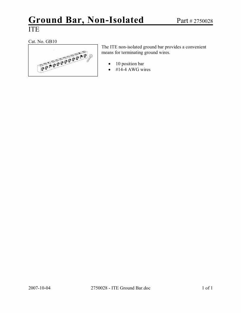
Ground Bar, Non-Isolated Part # 2750028 ITE
2007-10-04 2750028 - ITE Ground Bar.doc 1 of 1
Cat. No. GB10
The ITE non-isolated ground bar provides a convenient means for terminating ground wires.
10 position bar #14-4 AWG wires

Duplex GFCI Receptacle Part # 2751627
Hubbell DRUBGFI20
2020-05-28 2751627 - Hubbell Duplex GFCI Receptacle.doc 1 of 1
The Hubbell DRUBGFI20 is a DIN rail mountable utility box with GFCI duplex receptacle. Certifications:
UL Listed CSA Certified
Standards: UL498 UL514 UL943
Specifications:
Material: Composite Color: Gray Amperage: 20A Voltage Range: 120V AC +10% / -15% NEMA Configuration: 5-20R Frequency: 60Hz Operating temperature range: -13º F to 158º F (-25º C to 70º C)
Dimensions: Inches [ mm]

Type PNL Bronze Penn-Lug Part # 2750031 Penn-Union, 1-Hole tongue
2007-07-09 2750031 - Penn Union Bronze Penn-Lug.doc 1 of 1
Cat. No. PNL-1-0
The Penn-Union Type PNL Bronze Penn-Lug tightens directly on the conductor forcing the conductor into intimate contact with the body for maximum conductivity. Flat bottom allows mounting either on tongue only or with full contact surface.
Conductor Range Wire Diameter Range (inch) Wrench Size
8 Solid-1/0 Str. 0.128-0.375 0.25
C K H L T W J (threads) 0.375 (10)
0.328 (8)
0.781 (20)
1.594 (40)
0.141 (3.57)
0.734 (16) 1/2-20

ENVIRONMENTAL CONTROL ENCLOSURE

Industrial Corrosion Inhibitor Part # 2607334 Hoffman
2007-07-09 2607334 - Hoffman Industrial Corrosion Inhibitor.doc 1 of 1
Cat. No. AHCI5E
The Hoffman corrosion inhibitors contain a special chemical combination that vaporizes and condenses on all surfaces in an enclosed area. Vapors will redeposit as needed in the event of condensation of moisture on surfaces. These vapors reach every part of an enclosure, protecting all interior components. Spraying, wiping, or greasing or not required. This eliminates precoating, special wraps, and drying agents. Protection is effective even in salt water atmospheres. There are additional red metal inhibitors for further protection.
These inhibitors protect:
Interior components of electrical enclosures, boxes, consoles, and wireways Interior components of electronic enclosures Electrical and electronic equipment and controls Parts and components that are packaged in crates during shipping and storage Switch gear and relay cabinets Interiors of pipes, conduits, and fuse boxes Process control computers, instruments, and recording devices Tool chest interiors and contents Equipment stored at construction sites
AHCI5E Emitter protects five cubic feet (141.6 liter) of enclosure volume for approximately one year. Emitters contain additional red metal (non-ferrous) inhibitors. Size: 2.50” (diameter) x 1.50” (high) (63mm x 51mm)

Air Conditioner Part # 2750558 Hoffman, Compact A/C
2007-07-09 2750558 - Hoffman Air Conditioner.doc 1 of 2
Cat. No. CR230216G015
The Hoffman CR Compact Air Conditioner features closed loop cooling involving the clean air within the air conditioner being recirculated and kept separate from the ambient airflow system. This protects the electronic controls and prevents shutdowns caused by heat, humidity, dust, and other contaminants. It maintains UL/cUL type 4X, Type 4, Type 12 rating when properly installed on a UL/cUL Type 4X, Type 4, Type 12 rated enclosure.
For use where air conditioner must operate in ambient temperatures below 50°F (10°C)
Lowest operating temp = 40°F (4.4°C) Constructed of Type 304 stainless steel for increased protection in corrosive and
outdoor applications For protection from corrosive environments, thermostat is tin-plated and a special
coating is applied to coils and copper lines exposed to the ambient air Protective shield protects unit in outdoor and hose-down applications and provided
4X rating. Shield protrudes about 2 inches (51mm) from the air conditioner
Voltage Hz Phase BTU/Hr @ 131°F/131°F
Amps @ 131°F/131°F
115 50/60 1 1400/1600 4.1/4.5
BTU/Hr @ 95°F/95°F
Amps @ 95°F/95°F
Max Amb. Temp °F/°C
Shipping Weight Lbs./Kgs.
1500/1700 3.8/3.6 131/55 57/26

Air Conditioner Part # 2750558 Hoffman, Compact A/C
2007-07-09 2750558 - Hoffman Air Conditioner.doc 2 of 2

FUSE

Axial Lead and Cartridge Fuse Part # 2608762 Littelfuse, 250 Volt Slo-Blo FLM Series
2007-07-09 2608762 - Littelfuse - FLM 1.doc 1 of 2
Cat. No. FLM 1
Littelfuse 250 Volt Slo-Blo Type Fuse FLM Series. Agency approvals listed by Underwriters Laboratories and Certified by CSA.
Voltage Ratings Ampere Ratings Interrupting Ratings
250 VAC 1.0 A 10,000 amperes at 250 VAC

Axial Lead and Cartridge Fuse Part # 2608762 Littelfuse, 250 Volt Slo-Blo FLM Series
2007-07-09 2608762 - Littelfuse - FLM 1.doc 2 of 2

Fuse Part # 2751427
Littelfuse KLDR010
2020-05-28 2751427 - Littelfuse - KLDR 10.0.doc 1 of 1
KLDR fuses are a time-delay Class CC type fuse specifically designed to withstand the momentary high magnetizing currents of control transformers, solenoids, and similar inductive loads.
Approvals:
UL Listed per UL 248, UL File E81895 CSA Certified per File LR 29862 RoHS Compliant
Specifications:
Voltage Ratings Ampere Ratings Interrupting Ratings
AC: 600 Volts DC: 300 Volts 10 A
AC: 200,000 A RMS symmetrical
DC: 20,000 A Dimensions:

Fuse Part # 2751479
Littelfuse KLDR020
2020-05-28 2751479 - Littelfuse - KLDR 20.0.doc 1 of 1
KLDR fuses are a time-delay Class CC type fuse specifically designed to withstand the momentary high magnetizing currents of control transformers, solenoids, and similar inductive loads.
Approvals:
UL Listed per UL 248, UL File E81895 CSA Certified per File LR 29862 RoHS Compliant
Specifications:
Voltage Ratings Ampere Ratings Interrupting Ratings
AC: 600 Volts DC: 300 Volts 20 A
AC: 200,000 A RMS symmetrical
DC: 20,000 A Dimensions:

Axial Lead and Cartridge Fuse Part # 2751144 Littelfuse, 250Volt Fast Acting 217 Series
2007-08-20 2751144 - Littelfuse - 217-050.doc 1 of 3
Cat. No. 217.050
Littelfuse 250 Volt Fast Acting Type 217 Series fuses are designed to IEC standards.
Voltage Ratings Ampere Ratings Interrupting Ratings
250 VAC 0.050 A 35 Amps @250VAC, unity power factor

Axial Lead and Cartridge Fuse Part # 2751144 Littelfuse, 250Volt Fast Acting 217 Series
2007-08-20 2751144 - Littelfuse - 217-050.doc 2 of 3

Axial Lead and Cartridge Fuse Part # 2751144 Littelfuse, 250Volt Fast Acting 217 Series
2007-08-20 2751144 - Littelfuse - 217-050.doc 3 of 3

FUSE BLOCK

Fuse Block Part # 2751333 Allen Bradley
2007-07-09 2751333 - AB Fuse Block.doc 1 of 1
Cat. No. 1492-FB1M30
Allen Bradley fuse holder provides a safe and convenient means for installation of 1-1/2” x 13/32” Midget Fuses. The 1492-FB fuse holder family is designed for use in many OEM applications such as power supplies, equipment protection, primary and secondary control transformers, solenoids, lighting and heater loads, and drives. Standards:
UL512 CSA C22.2 No. 39 EN/IEC 60947-3 EN/IEC 60269-2-1 CE marked
Poles Fuse Class Wire Range Tightening Torque
1 M – Midget Fuses (1-1/2” x 13/32”) #16-#4 AWG Cu. 22 lb – in
(2.5 Nm)
Temperature Range
Withstand Rating
Maximum Current Rating
Maximum Voltage Rating
Dimensions
Height Depth Width
-4-130 F -20 C to 55 C 50kA 30 A 600V AC/DC 3.19 in
(81 mm) 2.51 in
(64 mm) 0.71 in
(18 mm)

Terminal Block Part # 2750034 Allen Bradley, Screw Connection
2007-07-09 2750034 - AB Screw Connection Terminal Block.doc 1 of 1
Cat. No. 1492-WFB4
Allen Bradley Fuse Block, 50 Pcs. / Pkg.

FUSE COVERS

Fuse Puller Part # 2702219 Square D
2009-06-26 2702219 - Square D Fuse Puller.doc 1 of 1
Cat. No. 9070-FP1
Square D fuse puller.

HMI-HUMAN MACHINE INTERFACE

Operator Interface Part # 2754080
Allen Bradley 2711P-T7C22D9P
2020-05-28 2754080 Operator Interface PanelView Plus 7 700 1 of 4
The Allen Bradley PanelView Plus 7 700 Enhanced color graphic terminal has a 6.5” flat-panel display and supports operator input via a touch screen.
Certifications:
Certification c-UL-us cULus Listed Industrial Control Equipment, for use in Hazardous Locations
(File E10314) per standards ANSI/ISA 12.12.01 and CSA C22.2 No. 213 rated:
Class I, Div 2, Group A, B, C, D Enclosure type ratings per UL50 and CSA 22.2 No. 94.2-07. Enclosure ingress protection classified by UL per IEC 60529.
CE (EMC) European Union 2004/108/EC EMC Directive, compliant with: EN 61000-6-2; Industrial Immunity EN 61000-6-4; Industrial Emissions EN 61131-2; Programmable Controllers
CE (LVD) European Union 2006/95/EC Low Voltage Directive, compliant with: EN 61131-2; Programmable Controllers

Operator Interface Part # 2754080
Allen Bradley 2711P-T7C22D9P
2020-05-28 2754080 Operator Interface PanelView Plus 7 700 2 of 4
Specifications: Display:
Type Display Area (W x H) Resolution Backlight
Color Thin Film Transistor (TFT)
LCD
5.2” x 3.9” (132mm x 99mm)
640 x 480 VGA, 18-bit color
graphics
50,000 hour life, minimum, non-replaceable
Type Display Size Diagonal Luminance Touch screen
Touch 6.5” 300 cd/m² Nits Analog resistive
Actuation: 1 million presses Operating force: 100 grams
Environmental:
Temperature Humidity Enclosure Ratings Operating Storage
0 to 55 °C (32 to 131 °F)
-25 to 70 °C (-13 to 158 °F) 5 to 95%, non-condensing NEMA and UL Type 12,
13, 4X (indoor only), IP66 Heat
Dissipation Altitude
Operating Shock Vibration Operating Storage
51 BTU/Hr 2000 m (6561 ft) 15g at 11ms 30g at 11ms
10..57 Hz, 0.012 pc-pc displacement
57…500 Hz, 2g pc acceleration

Operator Interface Part # 2754080
Allen Bradley 2711P-T7C22D9P
2020-05-28 2754080 Operator Interface PanelView Plus 7 700 3 of 4
Electrical:
Input Voltage Power Consumption
18-30V DC (24V DC Nominal)
50 W maximum (2.1 A @ 24V DC)
Memory Communication Ports
512MB RAM and 512 MB storage. 80MB nonvolatile storage for applications.
(2) Ethernet (10/100Base-T, Auto MDI/MDI-X Ethernet ports that
support Device Level Ring (DLR), linear, or star network topologies.
(2) USB 2.0 high speed host port (Type A) support removable flash drives for
storage and (1) high-speed 2.0 device port (Type B) that will be functional in a
future release.

Operator Interface Part # 2754080
Allen Bradley 2711P-T7C22D9P
2020-05-28 2754080 Operator Interface PanelView Plus 7 700 4 of 4
Dimensions:
Height a
Width b
Overall Depth c Weight
6.69” (170 mm)
8.35” (212 mm)
2.74” (69.6 mm)
2.75 lb 1.2 kg

MAIN DISCONNECT

Circuit Breaker Part # 2752194
Square D HDL36020
2020-05-28 2752194 - Square D MCB 600V 20A.doc 1 of 2
The H-frame molded case circuit breaker protects electrical systems from damage caused by overloads and short circuits. The circuit breaker opens and closes a circuit by non-automatic means and opens the circuit automatically on a predetermined overcurrent.
Codes and Standards:
UL 489 File No. E10027 IEC Standard 60947-2 CSA 22.2 No. 5-02 Federal Specification W-C-375B/GEN NEMA AB1 NMX J-266 CCC CE Mark
Specifications:
No. of Poles
Current Rating @ 40° C
Voltage Fixed AC Magnetic Trip
UL/CSA/NOM
(kA rating)
AC DC Hold Trip
240
VAC
480 VAC
600 VAC
3 20 Amps 600 250 350 A 750 A 25 18 14

Circuit Breaker Part # 2752194
Square D HDL36020
2020-05-28 2752194 - Square D MCB 600V 20A.doc 2 of 2
Dimensions:
Inches (millimeters)

MAIN DISCONNECT ACCESSORIES

Operating Mechanism Part # 2751598 Square D, Type L
2009-05-13 2751598 - Square D Operating Mechanism.doc 1 of 1
Cat. No. 9421LJ7
The Square D door mounted, operating mechanisms feature heavy duty, all metal construction. Circuit breaker can be padlocked in the “OFF” position.
Use With No. of Poles
Use With Frame Size (Amps) Finish/Color Use With Circuit
Breaker Type
3 150 Steel Type H, J

Molded Case Lug Part # 2751596 Square D, Class 0611
2009-05-13 2751596 - Square D Molded Case Lug.doc 1 of 1
Cat. No. PDC6HD6
The power distribution connectors (PDC) can be used for multiple load wire connections on one circuit breaker. Use in place of standard distribution blocks to save space and time. Field installable kit includes tin-plated aluminum lug, connectors, and required mounting hardware.
Connectors are UL Listed:
For use on load end of circuit breaker only. For use in UL508 industrial control applications only. For use in UL 1995/CSA C22.2 No. 236 heating and cooling equipment For copper wire only.
Use With Circuit Breaker
Circuit Breaker Ampere Rating
Number of Wires Per Terminal &
Wire Range
Lug Quantity Per Kit
Dimension b (In.)
H-Frame 15-150 6-#14-#2 AWG Cu 3 2.24

Long Shaft Part # 2750093 Square D, Type L
2007-07-10 2750093 - Square D Long Shaft.doc 1 of 1
Cat. No. 9421LS10
The Square D door mounted, variable depth operating mechanisms feature heavy duty, all metal construction with trip indication. All can be padlocked in the “OFF” position when the enclosure door is open. Further, the handle assemblies can be locked “OFF” with up to three padlocks, which also locks the door closed. (The 3” handle accepts one padlock.)
Use With No. of Poles
Use With Frame Size (Amps) Finish/Color Use With Circuit
Breaker Type
2-3 400-MAL Steel LAL, MAL

Disconnect Handle Part # 2750288 Square D, Type L
2007-07-10 2750288 - Square D Disconnect Handle.doc 1 of 1
Cat. No. 9421LC43
The Square D door mounted, variable depth operating mechanisms feature heavy duty, all metal construction with trip indication. All can be padlocked in the “OFF” position when the enclosure door is open. Further, the handle assemblies can be locked “OFF” with up to three padlocks, which also locks the door closed. (The 3” handle accepts one padlock.)
Use With No. of Poles
Use With Frame Size (Amps) Finish/Color Use with Circuit
Breaker Type
Degree of Protection (NEMA)
2-3 100-250 Chrome Plated FAL, KAL 3, 4, 4X

MOTOR CONTROL

TESYS U Starter-Controller Part # 2751942
Schneider Electric, Power Base
2020-05-28 2751942 - Schneider Electric Power Base.doc 1 of 3
Cat. No. LUB12
Each Tesys U Motor Starter Controller consists of a Power Base and a Control Unit as a minimum. The Power Base incorporates the breaking function with a breaking capacity of 50 kA @ 400V total coordination and the switching function. Each Power Base includes 1 N.O. and 1 N.C. aux contact to indicate the open or closed position of the power contact.
Ampere Rating Control Connection Power Connection Action
12
Screw Clamp Terminals
Screw Clamp Terminals Non-Reversing
Horse Power Rating
Single Phase Three Phase
115V AC 230V AC 200/230V AC 460V AC 575/600V AC
0.5 2.0 3.0 7.5 10

TESYS U Starter-Controller Part # 2751942
Schneider Electric, Power Base
2020-05-28 2751942 - Schneider Electric Power Base.doc 2 of 3

TESYS U Starter-Controller Part # 2751942
Schneider Electric, Power Base
2020-05-28 2751942 - Schneider Electric Power Base.doc 3 of 3

TESYS U Starter-Controller Part # 2751914 Schneider Electric, Phase Barrier
2010-01-27 2751914 - Schneider Electric Phase Barrier.doc 1 of 1
Cat. No. LU9SP0
Phase barrier must be used to build a UL508 type E certified starter.
For Use On Mounting
LUB12 Direct to terminals L1,L2,L3

TESYS U Starter-Controller Part # 2751939 Schneider Electric, Advanced Control Unit
2010-01-26 2751939 - Schneider Electric Control Unit.doc 1 of 1
Cat. No. LUCB1XFU
Each Tesys U Motor Starter Controller consists of a Power Base and a Control Unit as a minimum. The Advanced Motor Starter Control Unit provides solid state overload relay and control power source for the Tesys Motor Controller.
Magnetic Trip Setting Operating Voltage Thermal Trip Setting (Amps) Overload Type
14.2 times the FLA setting
110/240V AC/DC
0.3 to 1.4 Solid State (Class 10)

TESYS U Starter-Controller Part # 2751940
DS 2751940 - Schneider Electric Control Unit.doc 1 of 1
Copyright © 2010 Aqua-Aerobic Systems, Inc. 2020-05-28
Schneider Electric, Advanced Control Unit Cat. No. LUCB05FU
Each Tesys U Motor Starter Controller consists of a Power Base and a Control Unit as a minimum. The Advanced Motor Starter Control Unit provides solid state overload relay and control power source for the Tesys Motor Controller.
Magnetic Trip Setting Operating Voltage Thermal Trip Setting (Amps) Overload Type
14.2 times the FLA setting
110/240V AC/DC
1.25 to 5.0 Solid State (Class 10)

NETWORK

Stratix 5700
Industrial Managed Ethernet Switch
The wide deployment of EtherNet/IP™ in industrial automation means that there is a growing demand to manage the network properly. Integtrating new machine-level networks into an existing plant network requires convergence.
With more devices connected on the same Ethernet network than ever before, an industrial managed switch can help you simplify your network infrastructure. Adding a managed switch to your network architecture can also help make the process of adding new machines easier.
The Allen-Bradley® Stratix 5700™ is a compact, scalable Layer 2 managed switch with embedded Cisco technology for use in applications with small isolated, to complex networks. With integration into Studio 5000 Automation Engineering and Design Environment™, you can leverage FactoryTalk® View faceplates and Add-on Profiles for simplified configuration and monitoring.
By choosing a switch co-developed by Rockwell Automation and Cisco, your Operations Technology (OT) and Information Technology (IT) professionals leverage tools and technology that are familiar to them. This collaboration can also help to reduce configuration time and cost.
Features and Benefits:
Advanced Networking Features
• Integrated Device Level Ring (DLR) connectivity helps optimize the network architecture and provide consolidated network diagnostics
• Integrated Network Address Translation (NAT) provides 1:1 IP address mapping helping to reduce commissioning time
• Power over Ethernet (PoE) versions provide power to devices over Ethernet minimizing cabling
• Security features, including access control lists, help ensure that only authorized devices, users and traffic can access the network
• Secure Digital (SD) card provides simplified device replacement
Optimized integration:
• Studio 5000® Add-on Profiles (AOPs) enable premier integration into the Rockwell Automation Integrated Architecture® system
• Predefined Logix tags for monitoring and port control
• FactoryTalk® View faceplates enable status monitoring and alarming
• Built-in Cisco® Internet Operating System (IOS) helps provide secure integration with enterprise network

Network Address Translation
Machine integration onto a plant network architecture can be difficult as machine builder IP-address assignments rarely match the addresses of the end-user network. Also, network IP addresses are often unknown until the machine is being installed.
The Stratix 5700 with Network Address Translation (NAT) is a Layer 2 implementation that provides “wire speed” 1:1 translations ideal for automation applications where performance is critical.
NAT allows for:
• Simplified integration of IP-address mapping from a set of local, machine-level IP addresses to the end user’s broader plant network
• OEMs to deliver standard machines to end users without programming unique IP addresses
• End users to more simply integrate the machines into the larger network
Designed and Developed for EtherNet/IP Automation Applications
MACHINE 1
1:1 NAT Mapping
Private Public
MACHINE 2
192.168.1.2192.168.1.3192.168.1.4
10.10.10.210.10.10.310.10.10.4
1:1 NAT Mapping
Private Public
192.168.1.2192.168.1.3192.168.1.4
10.10.11.210.10.11.310.10.11.4Public Network
10.10.10.xPublic Network
10.10.11.x
192.168.1.2
192.168.1.4 192.168.1.3
Private Network192.168.1.x
Private Network192.168.1.x
Industrial Zone
00:00:BC:66:0F:C7
0 1 2 3 4 5 6 7
8 9 10 11 12 13 14 15
0 1 2 3 4 5 6 7
8 9 10
A0 B0 Z0
A1 B1 Z1
0 2 FUSE
1 3 OK11 12 13 14 15
HIG
H S
PE
ED
CO
UN
TE
R INO
UT
DC
INP
UT
24V
DC
SIN
K\
SO
UR
CE
24V
DC
SO
UR
CE
OU
TP
UT
DC
DANGER
00 0801 0902 1003 1104 1205 1306 1407 15
00 0801 0902 1003 1104 1205 1306 1407 15
NC
COM0
COM1
COM0
COM1
NC
+V +V
A0+ Ao-B0+
+V -V
COM
COM
COM
COM
B0-Z0+ Z0-A1+ A1-B1+ B1-Z1+ Z1-
COM
OUT0
OUT2
IOUT0+
IOUT0+
VOUT0+
VOUT0+
VOUT0+
VOUT0+
VOUT0+
VOUT0+
VOUT0+
VOUT0+
VOUT0+
VOUT0+
VOUT0+
VOUT0+
VOUT0+
VOUT0+
OUT1
OUT3
COM
D+D-
MBRK
SHLD
IN1
1
2
IN2COM
W
V
U
+
-
ModNet
5500S2
D+D-
MBRK
SHLD
IN1
1
2
IN2COM
W
V
U
+
-
ModNet
5500S2
D+D-
MBRK
SHLD
IN1
1
2
IN2COM
W
V
U
+
-
ModNet
5500S2
D+D-
MBRK
SHLD
IN1
1
2
IN2COM
W
V
U
+
-
ModNet
5500S2
192.168.1.2
192.168.1.4 192.168.1.3
00:00:BC:66:0F:C7
0 1 2 3 4 5 6 7
8 9 10 11 12 13 14 15
0 1 2 3 4 5 6 7
8 9 10
A0 B0 Z0
A1 B1 Z1
0 2 FUSE
1 3 OK11 12 13 14 15
HIG
H S
PE
ED
CO
UN
TE
R INO
UT
DC
INP
UT
24V
DC
SIN
K\
SO
UR
CE
24V
DC
SO
UR
CE
OU
TP
UT
DC
DANGER
00 0801 0902 1003 1104 1205 1306 1407 15
00 0801 0902 1003 1104 1205 1306 1407 15
NC
COM0
COM1
COM0
COM1
NC
+V +V
A0+ Ao-B0+
+V -V
COM
COM
COM
COM
B0-Z0+ Z0-A1+ A1-B1+ B1-Z1+ Z1-
COM
OUT0
OUT2
IOUT0+
IOUT0+
VOUT0+
VOUT0+
VOUT0+
VOUT0+
VOUT0+
VOUT0+
VOUT0+
VOUT0+
VOUT0+
VOUT0+
VOUT0+
VOUT0+
VOUT0+
VOUT0+
OUT1
OUT3
COM
D+D-
MBRK
SHLD
IN1
1
2
IN2COM
W
V
U
+
-
ModNet
5500S2
D+D-
MBRK
SHLD
IN1
1
2
IN2COM
W
V
U
+
-
ModNet
5500S2
D+D-
MBRK
SHLD
IN1
1
2
IN2COM
W
V
U
+
-
ModNet
5500S2
D+D-
MBRK
SHLD
IN1
1
2
IN2COM
W
V
U
+
-
ModNet
5500S2
Stratix 5700with NAT
Stratix 5700with NAT
Device Level Ring Technology
The Device Level Ring (DLR) protocol is used for high-speed, high-performance applications where resiliency is required. DLR is a layer 2 protocol that allows multi-port EtherNet/IP devices to form a ring topology. When the supervisor in the ring detects a break in the ring, it provides an alternate data route to help recover the network quickly.
The Stratix 5700 includes integrated DLR connectivity, which allows the switch to act as a node or a supervisor on the ring. When acting as a supervisor, the Stratix 5700 can consolidate information from the ring, and be the single place to manage machine-level network diagnostics and DLR status. With redundant gateway capabilities, the Stratix 5700 can support two switches on a single ring while being directly connected to the rest of the network helping to provide increased resiliency. The switch also offers DHCP IP address assignment to end devices on the DLR network for simplified device replacement.
RELAY115 VAC
AC/D
C OU
TI/O
CHO
OK
DCHO
I/O
CHO
OK
DCHO
FAULT
FWDHERTZ
Enet LINK
SelEsc
PORTMODNET ANET B525
D+D-
MBRK
SHLD
IN1
1
2
IN2COM
W
V
U
+
-
ModNet
5500S2
D+D-
MBRK
SHLD
IN1
1
2
IN2COM
W
V
U
+
-
ModNet
5500S2
D+D-
MBRK
SHLD
IN1
1
2
IN2COM
W
V
U
+
-
ModNet
5500S2
D+D-
MBRK
SHLD
IN1
1
2
IN2COM
W
V
U
+
-
ModNet
5500S2
Com
IN2
IN1Ref
Com
IN2
IN1Ref
Network
Powerflex192.168.1.102
Stratix 5700 Active
Supervisor/Gateway
(REP OR STP OR FLEXLINK)
Stratix 5700 Backup
Supervisor/Gateway
PORT 7PORT 8
Point I/O192.168.1.105
Kinetix192.168.1.103
CompactLogixStatic IP Address
DLR DHCP Configuration Table
Index
235
IP Address
192.168.1.102192.168.1.103192.168.1.105

CATALOG NUMBER
TOTAL PORTS
COPPER PORTS
COMBO PORTS
SFP SLOTS
PoEPORTS
SW TYPE
CIP Sync (IEEE 1588)
NAT CONFORMAL COATING DLR
1783-BMS4S2SGL 6 4 FE +2GE Lite
1783-BMS4S2SGA 6 4 FE +2GE Full
1783-BMS06SL 6 4 FE 2 FE Lite
1783-BMS06SA 6 4 FE 2 FE Full
1783-BMS06TL 6 6 FE Lite
1783-BMS06TA 6 6 FE Full
1783-BMS06SGL 6 4 FE 2 GE Lite
1783-BMS06SGA 6 4 FE 2 GE Full
1783-BMS06TGL 6 4 FE + 2 GE Lite
1783-BMS06TGA 6 4 FE + 2 GE Full
1783-BMS10CL 10 8 FE 2 FE Lite
1783-BMS10CA 10 8 FE 2 FE Full
1783-BMS10CGL 10 8 FE 2 GE Lite
1783-BMS10CGA 10 8 FE 2 GE Full
1783-BMS10CGP 10 8 FE 2 GE Full • •1783-BMS10CGN 10 8 FE 2 GE Full • • •1783-BMS12T4E2CGL 18 12 FE 2 GE 4 FE Lite •1783-BMS12T4E2CGP 18 12 FE 2 GE 4 FE Full • •1783-BMS12T4E2CGNK 18 12 FE 2 GE 4 FE Full • • • •1783-BMS20CL 20 16 FE 2 FE 2 FE Lite •1783-BMS20CA 20 16 FE 2 FE 2 FE Full •1783-BMS20CGL 20 16 FE 2 GE 2 FE Lite •1783-BMS20CGP 20 16 FE 2 GE 2 FE Full • •1783-BMS20CGN 20 16 FE 2 GE 2 FE Full • • •1783-BMS20CGPK 20 16 FE 2 GE 2 FE Full • • •
FE - Fast Ethernet GE - Gigabit Ethernet
Switch Reference Chart
Allen-Bradley Stratix 5700 Industrial Ethernet Switch
Switch Selection Table

Publication ENET-PP005F-EN-E – April 2016 Copyright ©2016 Rockwell Automation, Inc. All Rights Reserved. Printed in USA.Supersedes Publication ENET-PP005E-EN-E – March 2015
EtherNet/IP is a trademark of the ODVA.
Cisco is a trademark of Cisco Systems, Inc.
Allen-Bradley, CompactLogix, Factory Talk, Integrated Architecture, Kinetix, LISTEN. THINK. SOLVE., Powerflex, Rockwell Automation, Rockwell Software, Stratix 5700, Studio 5000, Studio 5000 Automation Engineering
and Design Environment are trademarks of Rockwell Automation, Inc.
Glossary of TermsAccess Control Lists allow you to filter network traffic. This can be used to selectively block types of traffic to provide traffic flow control or provide a basic level of security for accessing your network.
CIP port control and fault detection allows for port access based on Logix controller program or controller mode (idle/fault). Allows secure access to the network based on machine conditions.
CIP SYNC (IEEE1588) is the ODVA implementation of the IEEE 1588 precision time protocol. This protocol allows very high precision clock synchronization across automation devices. CIP SYNC is an enabling technology for time-critical automation tasks such as accurate alarming for post-event diagnostics, precision motion and high precision first fault detection or sequence of events.
Device Level Ring (DLR) allows direct connectivity to a resilient ring network at the device level.
DHCP per port allows you to assign a specific IP address to each port, confirming that the device attached to a given port will get the same IP address. This feature allows for device replacement without having to manually configure IP addresses.
Encryption provides network security by encrypting administrator traffic during Telnet and SNMP sessions.
EtherChannel is a port trunking technology. EtherChannel allows grouping several physical Ethernet ports to create one logical Ethernet port. Should a link fail, the EtherChannel technology will automatically redistribute traffic across the remaining links.
Ethernet/IP (CIP) interface enables premier integration to the Integrated Architecture with Studio 5000 AOP, Logix tags and View Faceplates.
FlexLinks provides resiliency with a quick recovery time and load balancing on a redundant star network.
IGMP Snooping (Internet Group Management Protocol) constrains the flooding of multicast traffic by dynamically configuring switch ports so that multicast traffic is forwarded only to ports associated with a particular IP multicast group.
* Separate SW IOS required
Key Software Features
FEATURE HIGHLIGHTS LITE FULL
Switching
CIP Sync (IEEE 1588) Separate Option
REP (Resilient Ring Protocol) • •
FlexLinks •
QoS •
STP/RSTP/MST (instances) 64 128
IGMP snooping with querier • •
VLANs with trunking 64 255
EtherChannel (link aggregation) •
Port Threshold (Storm Control & Traffic Shaping) •
IPv6 support •
Access control lists (ACLs) •
Static and InterVLAN routing •
Device Level Ring (DLR) Select Versions Select Versions
Security
CIP port control & fault detection • •
MAC ID Port Security •
IEEE 802.1x security •
TACACS+, RADIUS authentication • •
Encryption (SSH, SNMPv3, HTTPS) Separate Option* Separate Option*
Diagnostics
Port mirroring • •
Syslog • •
Broken wire detection • •
Duplicate IP detection • •
Management
SNMP • •
Smartports • •
DHCP per port • •
Network Address Translation (NAT) Separate Option
Command Line Interface (CLI) • •
Compatible with Cisco tools: CNA, CiscoWorks • •
Application interface
EtherNet/IP (CIP) interface • •
MAC ID Port Security checks the MAC ID of devices connected to the switch to determine if it is authorized. If not the device is blocked and the controller receives a warning message. This provides a method to block unauthorized access to the network.
Network Address Translation (NAT) provides 1:1 translations of IP addresses from one subnet to another. Can be used to integrate machines into an existing network architecture.
Port Thresholds (Storm control & Traffic Shaping) allows you to set both incoming and outgoing traffic limits. If a threshold is exceeded alarms can be set in the Logix controller to alert an operator.
Power over Ethernet (PoE) provides electrical power along with data on a single Ethernet cable to end devices.
QoS – Quality of Service (QoS) is the ability to provide different priority to different applications, users, or data flows, to help provide a higher level of determinism on your network.
REP (Resilient Ethernet Protocol) – A ring protocol that allows switches to be connected in a ring, ring segment or nested ring segments. REP provides network resiliency across switches with a rapid recovery time ideal for industrial automation applications.
Smartports provide a set of configurations to optimize port settings for common devices like automation devices, switches, routers, PCs and wireless devices. Smartports can also be customized for specific needs.
SNMP Simple Network Management Protocol (SNMP) is a management protocol typically used by IT to help monitor and configure network-attached devices.
Static and InterVLAN Routing bridges the gap between layer 2 and layer 3 routing providing limited static and connected routes across VLANs.
STP/RSTP/MST Spanning Tree Protocol, is a feature that provides a resilient path between switches. Used for applications that requires a fault tolerant network.
VLANs with Trunking is a feature that allows you to group devices with a common set of requirements into network segments. VLANs can be used to provide scalability, security and management to your network.
802.1x Security is an IEEE standard for access control and authentication. It can be used to track access to network resources and helps secure the
network infrastructure.

PILOT DEVICE

Selector Switch Part # 2752247
Square D 9001SKS43FBH2
2020-05-28 2752247 - Square D 3-Position Selector Switch.doc 1 of 2
The Square D 9001SKS43FBH2 is an 30mm 3-position maintained selector switch with a NEMA Type 4/4X/13 corrosion-resistant/watertight/oiltight rating for industrial environments.
Certifications:
UL Listed (File No. E42259 CCN NKCR) CSA Certified (File No. LR24590 Class 3211-03)
Specifications: General
Maximum Voltage Rating 600VAC
Operator Type Non-Illuminated
Operator Action Maintained
Bezel Material Black Plastic
Knob Type Gloved-Hand Knob
Knob Color Black
Cam Type Cam C
Head Type Round
Size 30mm
Contact Configuration
XOO OOX XOO OOX

Selector Switch Part # 2752247
Square D 9001SKS43FBH2
2020-05-28 2752247 - Square D 3-Position Selector Switch.doc 2 of 2
Environmental
Ambient Air Temperature (around the device)
Storage °F (°C) -40 to +158 (-40 to +70)
Operation °F (°C) -13 to +158 (-25 to +70)
Vibration Resistance Conforming to IEC 60068-2-6 Frequency: 2 to 500 Hz: 7gn
Ford Standard EA-1
Shock Resistance Conforming to IEC 60068-2-27 Half sine wave: 50 gn
Electric Shock Protection Conforming to IEC 61140 Class II
Degree of Protection
Conforming to EN/IEC 60529 IP 66
Conforming to NEMA Types 1,2,3,3R,4,4X,12 and 13
Mechanical Life (in millions of operating cycles) 0.5
Dimensions:

Lens Part # 2752248
Square D 9001G7
2020-05-29 2752248 - Square D Green Lens.doc 1 of 1
The Square D 9001G7 is a green pilot light lens for 30mm operator device.
Specifications: General
Color Green
Size 30mm

Pilot Light Part # 2700720
Square D 9001SKT1
2020-05-29 2700720 - Square D Pilot Light.doc 1 of 2
The Square D 9001SKT1 pilot lights are an 30mm push-to-test operator device with a NEMA Type 4/4X/13 corrosion-resistant/watertight/oiltight rating for industrial environments.
Certifications:
UL Listed (File No. E42259 CCN NKCR) CSA Certified (File No. LR24590 Class 3211-03)
Specifications: General
Light Module Supply Voltage 110/120VAC @ 50/60Hz
Light Module Type Transformer
Operator Type Push-To-Test
Bezel Material Black Plastic
Head Type Round
Lens Type No Lens
Lens Color No Lens
Size 30mm
Terminal Type Screw Clamp
Environmental
Ambient Air Temperature (around the device)
Storage °F (°C) -40 to +158 (-40 to +70)
Operation °F (°C) -13 to +158 (-25 to +70)
Vibration Resistance Conforming to IEC 60068-2-6 Frequency: 2 to 500 Hz: 7gn
Ford Standard EA-1
Shock Resistance Conforming to IEC 60068-2-27 Half sine wave: 50 gn
Electric Shock Protection Conforming to IEC 61140 Class II

Pilot Light Part # 2700720
Square D 9001SKT1
2020-05-29 2700720 - Square D Pilot Light.doc 2 of 2
Degree of Protection
Conforming to EN/IEC 60529 IP 66
Conforming to NEMA Types 1,2,3,3R,4,4X,12 and 13
Dimensions:

PLC-PROGRAMMABLE LOGIC CONTROL

PLC Processor Part # 2752512
Allen Bradley 1769-L33ER, CompactLogix 5370 L3
2014-01-31 2752512 PLC Processor.doc 1 of 1
Specifications:
User Memory: 2 MB Secure Digital Memory Card: 1 GB (standard); 2 GB
(optional) Communication Ports: Dual-port Ethernet DLR, USB Communication Options: DeviceNet with 1769-SDN Module Expansion Capacity: Up to 16 Compact I/O modules
and 32 Ethernet nodes Power Supply Distance Rating: 4 modules Operating Temperature: 32…140°F (0…60°C) Storage Temperature: -40…185°F (-40…85°C) Surrounding Air Temperature (max.): 140°F (60°C) Relative Humidity: 5…95% non-condensing Vibration: 5g @10...500 Hz Operating Shock: 20 g (DIN rail); 30 g (Panel) Non-operating Shock: 30 g (DIN rail); 40 g (Panel) Weight: 10.93 oz (0.31 kg)
Certifications: UL Listed Industrial Control Equipment for US & Canada, File E65584 UL Listed for Class I, Div II Group A,B,C,D Hazardous Locations US & Canada, File
E194810 European Union 2004/108/EC EMC Directive compliant with EN 61326-1, EN61000-6-
2, EN 61000-6-4, EN 61131-2 Australian Radiocommunications Act compliant with AS/NZS CISPR 11 European Union 94/9/EC ATEX Directive compliant with EN 60079-15, EN 60079-0, II
3 G Ex nA IIC T5 X

End Cap, Right Part # 2701823 Allen Bradley, CompactLogix
2008-01-30 2701823 - AB Compact Logix End Cap.doc 1 of 1
Cat. No. 1769-ECR
The final module of each Compact I/O system must be an end cap. It provides termination for the system. There are left end caps for terminating the left-most slot, if applicable.
Vibration, Operating
Temperature Range Humidity, Operating Operating Storage
10…500Hz, 5G, 0.030” max peak-to-peak
0 to 60 °C (32 to 140 °F)
-40 to 85 °C (-40 to 185 °F)
5…95% without condensation
Bus Current Draw Shock
Operating (Non-Relay)
Operating (Relay contact) Non-Operating
5mA at 5VDC 30G panel mounted 20G DIN rail mounted
7.5G panel mounted 5G DIN rail mounted
40G panel mounted 30G DIN rail mounted

Digital I/O Module Part # 2701824 Allen Bradley, CompactLogix, 100/120V AC
2008-01-30 2701824 - AB Digital IO CompactLogix.doc 1 of 2
Cat. No. 1769-IA16
Allen Bradley CompactLogix Programmable Logic Controllers feature input filtering, optical isolation, and build-in surge protection to enhance the reliability of operation in noisy industrial environments. Certified to C-UL (under CSA C22.2 No. 142), UL 508, CE. Features include:
Terminal identification diagrams on each module LEDs indicate the status of each I/O point Digital and field circuits are isolated Class 1 Div2, Groups A, B, C, D (UL 1604, C-UL under CSA
C22.2 No 213)
Voltage Category Operating Voltage Number of
Inputs Points per Common
Bus Current Draw
5V 24V
100/120V AC 79…132V AC at 47…63Hz 16 16 115mA 0mA
Voltage, Off-State input,
max Input Current Min. Current, Off-State Input, Max Signal Off Delay, Max
20V AC 5mA at 79V AC 2.5mA 20ms
Shock
Operating (Non-Relay) Relay Operation Non-Operating
30G panel mounted (20G DIN rail mounted)
7.5G panel mounted (5G DIN rail mounted)
40G panel mounted (30G DIN rail mounted)
Vibration Temperature range
Operating Relay Operation Operating Storage Humidity
10 to 500Hz, 5G, 0.030 in. max. peak-to-peak 2G 0 to +60 °C
(32 to 140 °F) -40 to +85 °C (-40 to 185 °F)
5 to 95% without condensation

Digital I/O Module Part # 2701824 Allen Bradley, CompactLogix, 100/120V AC
2008-01-30 2701824 - AB Digital IO CompactLogix.doc 2 of 2
Wiring Diagram

Digital I/O Module Part # 2701834 Allen Bradley, CompactLogix, Relay Output
2008-01-17 2701834 - AB Digital IO CompactLogix.doc 1 of 2
Cat. No. 1769-OW16
Allen Bradley CompactLogix Programmable Logic Controllers feature input filtering, optical isolation, and build-in surge protection to enhance the reliability of operation in noisy industrial environments. Certified to C-UL (under CSA C22.2 No. 142), UL 508, CE. Features include:
Terminal identification diagrams on each module LEDs indicate the status of each I/O point Digital and field circuits are isolated Class 1 Div2, Groups A, B, C, D (UL 1604, C-UL under CSA
C22.2 No 213)
Voltage Category
Operating Voltage Ranges
Number of Outputs
Points per Common
Bus Current Draw
5V 24V AC/DC normally
open relay 5 to 265 VAC 5 to 125 VDC 16 8 205mA 180mA
Off-State Leakage, max On-State Current Min. Power Supply Distance, max.
0 mA 10mA at 5 VDC 8
Continuous Current per
Point (max) Continuous Current per
Common (max) Continuous Current per
Module (max) Signal Delay, Max
2.5A 10A 20A turn on = 10ms turn off = 10ms
Shock
Operating Relay Operation Non-Operating
30G panel mounted (20G DIN rail mounted)
10G panel mounted (5G DIN rail mounted)
40G panel mounted (30G DIN rail mounted)
Vibration Temperature range
Operating Relay Operation Operating Storage Humidity
10 to 500Hz, 5G, 0.030 in. max. peak-to-peak 2G 0 to +60 °C
(32 to 140 °F) -40 to +85 °C (-40 to 185 °F)
5 to 95% without condensation

Digital I/O Module Part # 2701834 Allen Bradley, CompactLogix, Relay Output
2008-01-17 2701834 - AB Digital IO CompactLogix.doc 2 of 2
Wiring Diagram

Power Supply Part # 2701833 Allen Bradley, CompactLogix
2008-01-11 2701833 - AB Power Supply CompactLogix.doc 1 of 2
Cat. No. 1769-PA4
Allen Bradley CompactLogix Programmable Logic Controllers feature input filtering, optical isolation, and build-in surge protection to enhance the reliability of operation in noisy industrial environments. Certified to C-UL (under CSA C22.2 No. 142), UL 508, CE. Features include:
Short circuit protection Class 1 Div2, Groups A, B, C, D (UL 1604, C-UL under
CSA C22.2 No 213)
Line Voltage Bus Current
Capacity at 5V (0 to+55 °C)
Bus Current Capacity at 24V
(0 to+55 °C)
User Current Capacity
Inrush Current, Max
85…132/170…250V AC, 47…63Hz 4A at 5 VDC 2A at 24 VDC N/A 25A at 132 VAC
40A at 265 VAC
Shock
Operating (Non-Relay) Relay Operation Non-Operating
30G panel mounted (20G DIN rail mounted)
7.5G panel mounted (5G DIN rail mounted)
40G panel mounted (30G DIN rail mounted)
Vibration Temperature range Operating
Humidity Operating Relay Operation Operating Storage
10 to 500Hz, 5G, 0.030 in. max. peak-to-peak 2G 0 to +60 °C
(32 to 140 °F) -40 to +85 °C (-40 to 185 °F)
5 to 95% without condensation

Power Supply Part # 2701833 Allen Bradley, CompactLogix
2008-01-11 2701833 - AB Power Supply CompactLogix.doc 2 of 2

Analog Input Module Part # 2752966
Allen Bradley 1769-IF4I
2015-06-11 2752966 Analog Input Module.doc 1 of 5
The Allen Bradley 1769-IF4I is a four channel analog current/voltage isolated input module.
Certifications: c-UL-us UL Listed for Class 1, Division 2 Group A,B,C,D
Hazardous Locations, certified for U.S. and Canada. See UL File E10314 CE European Union 2004/108/EC EMC Directive, compliant with:
EN 61000-6-2; Industrial Immunity EN 61000-6-4; Industrial Emissions EN 61131-2; Programmable Controllers (Clause 8, Zone A & B)
C-Tick Australian Radio communications Act, compliant with: AS/NZS CISPR 11; Industrial Emissions
Specifications:

Analog Input Module Part # 2752966
Allen Bradley 1769-IF4I
2015-06-11 2752966 Analog Input Module.doc 2 of 5

Analog Input Module Part # 2752966
Allen Bradley 1769-IF4I
2015-06-11 2752966 Analog Input Module.doc 3 of 5
Input Specifications:

Analog Input Module Part # 2752966
Allen Bradley 1769-IF4I
2015-06-11 2752966 Analog Input Module.doc 4 of 5
Wiring Diagrams:

Analog Input Module Part # 2752966
Allen Bradley 1769-IF4I
2015-06-11 2752966 Analog Input Module.doc 5 of 5

POWER SUPPLY

Power Supply Part # 2751312 Allen Bradley
2008-02-28 2751312 - AB Power Supply.doc 1 of 5
Cat. No. 1606-XLP100E
Allen-Bradley Power Supply units provide a large amount of highly reliable power flow for a very small unit size. Features include:
Quick mounting and connecting World-wide industry approvals Very compact design (WxHxD = 73x75x103mm) Output voltage adjustable to DC 28V 100…240V Auto Select Input (AC 85…264V permitted) 1.9 times nominal current

Power Supply Part # 2751312 Allen Bradley
2008-02-28 2751312 - AB Power Supply.doc 2 of 5

Power Supply Part # 2751312 Allen Bradley
2008-02-28 2751312 - AB Power Supply.doc 3 of 5

Power Supply Part # 2751312 Allen Bradley
2008-02-28 2751312 - AB Power Supply.doc 4 of 5

Power Supply Part # 2751312 Allen Bradley
2008-02-28 2751312 - AB Power Supply.doc 5 of 5

RELAY CONTROL

Relay Part # 2700940 Allen Bradley 700-HK36A1-4, 120VAC Coil, SPDT w/Indicating LED
2020-05-28 2700940 - AB Relay with Indicator.doc 1 of 2
Cat. No. 700-HK36A1-4
Allen Bradley Interposing/Isolation Relays feature small size as well as a reduction in time, resulting an extremely efficient overall electrical circuit.

Relay Part # 2700940 Allen Bradley 700-HK36A1-4, 120VAC Coil, SPDT w/Indicating LED
2020-05-28 2700940 - AB Relay with Indicator.doc 2 of 2

Relay Socket Part # 2750010 Allen Bradley, General Purpose
2007-07-13 2750010 - AB Relay Socket.doc 1 of 1
Cat. No. 700-HN121
Screw terminal Socket – Panel or DIN Rail Mounting 5-blade miniature socket with 10A rating for use with 1-pole, Bulletin 700-HK relays. Accepts forked lug conductors. Socket includes retainer clip. Certifications:
CSA Certified, File LR75088 UL Recognized, File E3125
Guide NLDX 2, UL Listed, with Allen-Bradley Sockets CE-Marked (per EU Low Voltage Directive 73/23 EEC 93/68
EEC)

SURGE SUPPRESSOR- TRANSIENT FILTER

Active Tracking Filter Part # 2700906 SolaHD STFV050-10N
2020-05-28 2700906 Active Tracking Filter.doc 1 of 2
The SolaHD STFV Plus Series combines Active Tracking filtration for low energy noise and surge protection for high energy transients. It continuously tracts the input AC power line responding instantly into action upon detecting extraneous high frequency noise and high voltage transients caused by everyday events such as turning on machinery, motors, or equipment. Certifications and Compliances:
Features:
Non degrading, series filter / TVSS technology UL surge current capacity – 25,000 amps High impact plastic case, epoxy encapsulated enclosure Transient protection in all modes (L-N, L-G, and N-G) Single phase applications up to 30 amps Operating temperature from -40°C to +60°C Hardwire connection LED power indication
Dimensions:

Active Tracking Filter Part # 2700906 SolaHD STFV050-10N
2020-05-28 2700906 Active Tracking Filter.doc 2 of 2
Specifications:

TERMINAL BLOCK & ACCESSORIES

Terminal Block Accessory Part # 2609910 Allen Bradley 1492-DR5
2020-05-28 2609910 - AB Terminal Block Accessory.doc 1 of 1
Cat. No. 1492-DR5

Terminal Block Accessory Part # 2750086 Allen Bradley
2007-07-09 2750086 - AB Terminal Block Accessory.doc 1 of 1
Cat. No. 1492-DR6

IEC Terminal Block Accessory Part # 2751199 Allen Bradley, Snap-In Marker
2007-07-09 2751199 - AB Terminal Block Accessory.doc 1 of 1
Cat. No. 1492-M6X12
Allen Bradley Terminal Block Snap-In Marker:
5 Pcs / Pkg Used with 1492-J, L 120 Markers per Card White

Terminal Block Part # 2751299 Allen Bradley, Screw Connection
2020-05-28 2751299 - AB Screw Terminal Block.doc 1 of 1
Cat. No. 1492-J4
Allen Bradley Screw Connection Terminal Block: 100 Pcs. / Pkg.

IEC Terminal Block Accessory Part # 2751302 Allen Bradley, End Barrier
2020-05-28 2751302 - Terminal Block Accessory.doc 1 of 1
Cat. No. 1492-EBJ3
Allen Bradley Terminal Block End Barrier:
50 Pcs / Pkg Gray Used with 1492-J3, J4, J6, J10, J2Q, J3TW, J4M,
J3F, JG2Q, JG3, JG3TW, JKD3, JKD3TP, J3P, J3PTP, JTC3…
Dimensions Width x Length x Height: 0.06 x 1.31 x 2.36in. (1.5 x 33.35 x 60 mm)

IEC Terminal Block Accessory Part # 2751304 Allen Bradley, End Anchor
2020-05-28 2751304 - AB Terminal Block Accessory.doc 1 of 1
Copyright © 2007 Aqua-Aerobic Systems, Inc.
Cat. No. 1492-EAJ35
Allen Bradley Terminal Block End Anchor:
100 Pcs / Pkg Gray

IEC Terminal Block Accessory Part # 2751329 Allen Bradley, Screwless Center Jumper
2013-01-14 2751329 - AB Terminal Block Accessory.doc 1 of 1
Cat. No. 1492-CJLJ6-10
Allen Bradley Terminal Block Screwless Center Jumper:
20 Pcs. / Pkg. Used on 1492-J4, J4M 10 Pole

TRANSFORMER & ACCESSORIES

Fingersafe Kit Part # 2700888 Square D 9070FSC2
2020-05-28 2700888 - Square D Fingersafe Kit.doc 1 of 1
Cat. No. 9070FSC2
The Square D finger safe kit provides cover for transformer terminals that typically have energized wires on them.
For 9070 series transformers

Industrial Control Transformer Part # 2751437 Square D, Type T
2007-12-10 2751437 - Square D Type T Transformer .doc 1 of 1
Cat. No. 9070TF2000D1
The Square D Type T unit is designed for the global market and is the best choice when size and cost are of concern. It features 50/60 Hz rated, customer installed accessories (Finger-Safe covers, fuse blocks, fuse clips), as well as various temperature classes.
Standards: UL E61239, Guide XPTQ2 cUL E61239 EN 9579078 EN 61 558/01.89 (TUV ref: 00941-RAG/sg E9471921.02E01)
VA A B UL CE
2000 1500 7.17 (182)
7.06 (179)
C E F Slots 6.17 (157)
4.56 (116)
5.81 (148)
0.28 x 0.56 (7 x 14)
Voltages Connections Primary Secondary Primary Secondary
220 X 440 230 X 460 240 X 480
110 115 120
220/230/240 V: Connect to H1 and H4 Jumper H1 with H3 Jumper H2 with H4
440/460/480 V: Connect H1 and H4
Jumper H2 with H3
Connect to X1 and X2

MAINTENANCE AND TROUBLESHOOTING

THIS SECTION IS LEFT BLANK AND WILL BE INCLUDED IN THE
OPERATION & MAINTENANCE MANUAL.

MECHANICAL DRAWINGS

Material Schedule (Expanded BOM Report 4) for 911627560000 Rev B
Part Number Part Description (First 40 Characters Only) Material
9.11628E+11 PLAN VIEW & GENERAL LIST -. 911627560001 TANK ASSEMBLY, 6 DISK, RH -.. 911627560200 TANK ACCESSORY WELDMENT, 6 DISK, RH 304 SS.. 2965957-SX0 CENTERTUBE INSTALLATION, 6 DISK - S = 3 304 SS... 2965886-SX0 CENTERTUBE ASSEMBLY, 6 DISK - S = 30 304 SS.... 2915101-SX0 CENTERTUBE WELDMENT, 6 DISK 304 SS 304 SS.... 2509003 CENTERTUBE SPROCKET SEGMENT, 16T - BL POLYETHYLENE.... 2600410 HHCS, 1/2-13 X 2.5" - 316 SS 316 SS.... 2600517 NUT, HEX, FULL, 1/2-13 - 316 SS 316 SS.... 2600234 NUT, HEX, JAM, 1/2-13 - 316 SS 316 SS.... 2600426 WASHER, FLAT, 1/2" X 1 1/4" - 316 SS 316 SS... 2965527-SX0 DUAL WHEEL ASSEMBLY - S = 30 304 SS.... 2914946-SX0 DUAL WHEEL WELDMENT - S = 30 304 SS.... 2519481 WHEEL, 6", WIDE NYLON.... 2519483 BUSHING, WIDE ROLLER 17-4 SS.... 2613537 HHCS, 1/2-13 X 5" - 316 SS 316 SS.... 2600517 NUT, HEX, FULL, 1/2-13 - 316 SS 316 SS.... 2600234 NUT, HEX, JAM, 1/2-13 - 316 SS 316 SS.... 2600426 WASHER, FLAT, 1/2" X 1 1/4" - 316 SS 316 SS... 2967218-SX0 RIDER WHEEL ASSEMBLY - S = 30 304 SS.... 2915932-SX0 RIDER WHEEL WELDMENT - S = 30 304 SS.... 2519480 WHEEL, 6", NARROW NYLON.... 2519482 BUSHING, NARROW ROLLER 17-4 SS.... 2600915 HHCS, 1/2-13 X 3.5" - 316 SS 316 SS.... 2600517 NUT, HEX, FULL, 1/2-13 - 316 SS 316 SS.... 2600234 NUT, HEX, JAM, 1/2-13 - 316 SS 316 SS.... 2600426 WASHER, FLAT, 1/2" X 1 1/4" - 316 SS 316 SS... 2965614-SX0 CENTERTUBE BEARING KIT - S = 30 304 SS.... 2608932 PILLOW BLOCK BEARING W/INSERT SEE NOTE.... 2608944 V-RING SEAL 2.880"x.270 NITRIL NITRILE.... 2510776 SHAFT SLEEVE BEARING DELRIN DELRIN.... 2614245 COLLAR, LOCKING SHAFT 2PC 2" ID 316 SS.... 2518703-SX0 SHIM, PILLOW BLOCK, 1/8" THK. - S = 30 304 SS.... 2518704-SX0 SHIM, PILLOW BLOCK, 1/4" THK. 304 SS 304 SS.... 2518705-SX0 SHIM, PILLOW BLOCK, 1/16" THK. 304 SS 304 SS... 2914994-SX0 SEAL PLATE WELDMENT - S = 30 304 SS... 2914997-SX0 BEARING PLATE WELDMENT - S = 30 304 SS... 2607719 V-RING SEAL, 21.26" X .98" - VITON VITON... 2512340 GASKET, SEAL PLATE - EPDM EPDM... 2610502 HHCS, 3/8-16 X 1.5", FULL THREAD - 316 316 SS... 2600411 HHCS, 3/8-16 X 2" - 316 SS 316 SS... 2600348 HHCS, 1/2-13 X 2" - 316 SS 316 SS... 2618873 HHCS, 1/2-13 X 2.75", FULL THREAD - 316 316 SS... 2600403 NUT, HEX, JAM, 3/8-16 - 316 SS 316 SS... 2600381 WASHER, FLAT, 3/8" X 1" X .042" 316 SS... 2608899 NUT, HEX, NYLOCK, 3/8-16 - 316 316 SS... 2600517 NUT, HEX, FULL, 1/2-13 - 316 SS 316 SS... 2600234 NUT, HEX, JAM, 1/2-13 - 316 SS 316 SS... 2600426 WASHER, FLAT, 1/2" X 1 1/4" - 316 SS 316 SS... 2520753-SX0 SHIM, PILLOW BLOCK, 22 GA - S = 304 SS... 2518705-SX0 SHIM, PILLOW BLOCK, 1/16" THK. 304 SS 304 SS... 2518703-SX0 SHIM, PILLOW BLOCK, 1/8" THK. - S = 30 304 SS... 2518704-SX0 SHIM, PILLOW BLOCK, 1/4" THK. 304 SS 304 SS
Generated on 2020-05-22 10:25:58 AM 1 of 10

Material Schedule (Expanded BOM Report 4) for 911627560000 Rev B
.. 2965958-SX0 BACKWASH SYSTEM INSTL, 6 DISK, RH - S = 304 SS
... 2965561-SX0 BACKWASH NOZZLE ASSEMBLY LH - S = 30 304 SS
.... 2914975-SX0 BACKWASH SHOE WELDMENT LH - S = 30 304 SS
.... 2520594 BACKWASH SHOE, ADFS-54, 8MM - UHMW, UHMWPE
.... 2610700 BHMS, 1/4-20 X 0.75" - 316 S 316 SS
.... 2600224 WASHER, FLAT, 1/4" X 5/8" X .044" 316 SS
.... 2610701 NUT, HEX, NYLOCK, 1/4-20 - 316 316 SS
.... 2606859 SILICONE SEALANT, DOW CORNING 732 - NO SILICONE
... 2965560-SX0 BACKWASH NOZZLE ASSEMBLY RH - S = 30 304 SS
.... 2914974-SX0 BACKWASH SHOE WELDMENT RH - S = 30 304 SS
.... 2520594 BACKWASH SHOE, ADFS-54, 8MM - UHMW, UHMWPE
.... 2610700 BHMS, 1/4-20 X 0.75" - 316 S 316 SS
.... 2600224 WASHER, FLAT, 1/4" X 5/8" X .044" 316 SS
.... 2610701 NUT, HEX, NYLOCK, 1/4-20 - 316 316 SS
.... 2606859 SILICONE SEALANT, DOW CORNING 732 - NO SILICONE
... 2914963-SX0 BACKWASH SUPPORT WELDMENT, 3 HANGER - S 304 SS
... 2914962-SX0 BACKWASH SUPPORT WELDMENT, 4 HANGER - S 304 SS
... 2914995-SX0 BACKWASH BRACE WELDMENT - S = 30 304 SS
... 2612035-81 HOSE, 1.5" ID X 81" LG, CF150 - KURIYA PVC
... 2518581-SX0 BACKWASH SHOE SPACER - S = 30 304 SS
... 2518579-SX0 BACKWASH END STOP - S = 30 304 SS
... 2518578 TORSION SPRING 316 SS 316 SS
... 2616298 CLAMP, HOSE, WORM DRIVE, 1.00-2.00" - 3 316 SS
... 2607266 U-BOLT, 3/8-16, 2" - 316 SS 316 SS
... 2615444 EYEBOLT, 3/8-16 x 3" LG, WELDED - MC 316 SS
... 2600421 HHCS, 3/8-16 X 1.5" - 316 SS 316 SS
... 2602257 HHCS, 3/8-16 X 1.25" - 316 SS 316 SS
... 2609812 HHCS, 1/4-20 X 2" - 316 SS 316 SS
... 2600481 NUT, HEX, FULL, 3/8-16 - 316 SS 316 SS
... 2610701 NUT, HEX, NYLOCK, 1/4-20 - 316 316 SS
... 2611519 WASHER, FLAT, 1/2" X 1 1/4" X 1/16" - P PVC
... 2610705 WASHER, FLAT, 1/4" X 1 1/4" - 316 316 SS
... 2608900 WASHER, FLAT, 3/8" X 1 1/2" - 316 316 SS
... 2600381 WASHER, FLAT, 3/8" X 1" X .042" 316 SS
... 2600224 WASHER, FLAT, 1/4" X 5/8" X .044" 316 SS
... 2600286 TY-WRAP/CABLE TIE 4" MAX DIA - NYLON NYLON
.. 2965887-SX0 DRIVE SYSTEM INSTL., 1/2 HP, RH 304 SS 304 SS
... 2965892-1 GEARMOTOR, NORD SK33N, 1/2HP, RH PURCHAS -
.... 2615163-1 GEARBOX, NORD SK33N 56C - NORD P -
.... 2615164-1 MOTOR, NORD, 1/2 HP NORD PART -
... 2607227 SPROCKET, DRIVE, 11T, 1.63" BORE - UV NYLON
... 2606032 CHAIN, DRIVE, NH-78, 100 LINKS - 304 ACETAL
... 2915033-SX0 STATIONARY MOTOR BRACKET WELDMENT 304 SS 304 SS
... 2915034-SX0 ADJUSTABLE MOTOR BRACKET WELDMENT, RH - 304 SS
... 2915035-SX0 CHAIN GUARD WELDMENT, RH - S = 30 304 SS
... 2965763-SX0 THREADED ROD DRIVE ASSEMBLY - S = 30 304 SS
.... 2615057-WX0 THREADED ROD, 3/4"-6 ACME x 12" LG. 18-8 SS
.... 2610533 NUT, HEX, ACME, 3/4-6 - 18-8 S 18-8 SS
.... 2610360 PIN, GROOVED 5/16" DIA X 1-1/4" - ZINC STEEL
... 2512205 KEY, 1" X 3/4" X 13 3/4" - B BRONZE
... 2610359 NUT, SQUARE, ACME, 3/4-6 - BRASS BRASS
... 2603242 HHCS, 1/2-13 X 1.75" - 316 SS 316 SS
... 2600278 HHCS, 1/2-13 X 1.5" - 316 SS 316 SS
... 2606640 HHCS, 1/2-13 X 0.75" - 316 SS 316 SS
Generated on 2020-05-22 10:25:58 AM 2 of 10

Material Schedule (Expanded BOM Report 4) for 911627560000 Rev B
... 2612859 HHCS, #10-24 X 0.5" - 316 SS 316 SS
... 2609730 SHCS, #10-24 X 0.75" - 316 S 316 SS
... 2607229 SET SCREW, 3/8-16 X 1", SOC - S 316 SS
... 2610369 NUT, HEX, NYLOCK, 1/2-13 - 316 SS 316 SS
... 2600426 WASHER, FLAT, 1/2" X 1 1/4" - 316 SS 316 SS
... 2609843 WASHER, LOCK, #10 - 316 S 316 SS
... 2610532 WASHER, FLAT, THRUST, 3/4" X 1 3/4" X 1/ BRONZE
... 2610375 DECAL "NO STEP" - 5" X -
... 2608355 LABEL, WARNING, CHAIN GUARD -
... 2507993 KEY, DRIVE, STEPPED, 2.5" LG, PLTD - STEEL
... 2619859 STICKER, ARROW, 2" X 2" BLACK - SETON, VINYL
.. 911627560003 CONDUIT SYSTEM ASSEMBLY, 6 DISK, RH PVC
... 911627560005 CONTROL PANEL / JUNCTION BOX MTG ASSY 304 SS
.... 2615177-SX0 UNISTRUT, 1 5/8", SQ X 10' LG 304 SS 304 SS
.... 2518881-SX0 STOP PLATE 304 SS 304 SS
.... 2610648 NUT, SPRING, CHANNEL, 3/8-16 - 316 SS 316 SS
.... 2602257 HHCS, 3/8-16 X 1.25" - 316 SS 316 SS
.... 2600481 NUT, HEX, FULL, 3/8-16 - 316 SS 316 SS
.... 2600403 NUT, HEX, JAM, 3/8-16 - 316 SS 316 SS
.... 2600381 WASHER, FLAT, 3/8" X 1" X .042" 316 SS
... 2611966 CONDUIT, 1-1/2" x 10 FT - PVC S4 PVC
... 2615006 CONDUIT, 3/4" X 10 FT - PVC S4 PVC
... 2611968 CONDUIT BODY, TYPE LR, 1-1/2" - PVC PVC
... 2611967 CONDUIT BODY, TYPE LL, 1-1/2" - PVC PVC
... 2615000 CONDUIT BODY, TYPE LB, 1-1/2" PVC
... 2615001 CONDUIT BODY, TYPE T, 1-1/2" PVC
... 2615003 CONDUIT BODY, TYPE C, 1-1/2" PVC
... 2611714 CONDUIT BODY, TYPE LR, 3/4" - PVC PVC
... 2611713 CONDUIT BODY TYPE T 3/4" PVC PVC
... 2614736 HANGER, CONDUIT, 1 1/2" - MCMAST 304 SS
... 2612246 HANGER, CONDUIT, 3/4" - 304 SS 304 SS
... 2607761 FLEX CONDUIT, 1/2", BLACK - NON-ME PVC
... 2600222 BHMS, 1/4-20 X 1" - 316 SS 316 SS
... 2615071 GROMMET, 1 1/2" ID - MID RUBBER
... 2615070 GROMMET, 2 1/2" ID - MID RUBBER
... 2610701 NUT, HEX, NYLOCK, 1/4-20 - 316 316 SS
... 2600224 WASHER, FLAT, 1/4" X 5/8" X .044" 316 SS
... 2607535 CORDGRIP, 0.169-0.449, 0.50" NPT, STRT NYLON
... 2611720 RED BUSH, 3/4" X 1/2", SOC X NPT, S80 PVC
... 2615639 RED BUSH, 1 1/2" X 1/2", SOC X NPT, S80 PVC
... 2607383 CONNECTOR, LIQUIDTIGHT, 0-90, 1/2" - NYLON
... 2612779 RECEPTACLE, 7P FEMALE 8 METER LEAD, 14 A -
... 2607352 NUT, SPRING, CHANNEL, 1/4-20 - 316 SS 316 SS
... 2611717 CONDUIT, ADAPTER, 3/4" MNPT X SOC - PVC
... 2611964 CONDUIT, ADAPTER, 1 1/2", MNPT X SOC - PVC
... 2600644 SEAL RING, CONDUIT, 0.75" - APPLET NEOPRENE
... 2616629 SEAL RING, CONDUIT, 1.50" - APPLET NEOPRENE
... 2617079 LOCKNUT, 3/4" NPT - 316SS 316 SS
... 2617082 LOCKNUT, 1 1/2" NPT - 316SS 316 SS
... 2966429 FLOAT SWITCH JUNCTION BOX ASSY POLYCARBONATE
.... 2603833 NUT, HEX, FULL, #8-32 - 304 SS
.... 2609689 WASHER, FLAT, #8 X 3/8" - 316 316 SS
.... 2607535 CORDGRIP, 0.169-0.449, 0.50" NPT, STRT NYLON
.... 2606312 LOCKNUT, NPT, 1/2", PLTD - APPLET STEEL
Generated on 2020-05-22 10:25:58 AM 3 of 10

Material Schedule (Expanded BOM Report 4) for 911627560000 Rev B
.... 2607383 CONNECTOR, LIQUIDTIGHT, 0-90, 1/2" - NYLON
.... 2605676 RING, SEAL, CONDUIT, 1/2" - THOMA 316 SS
.... 2615426 PHMS, #8-32 X 0.75" - 304 SS 304 SS
... 2611899 CONDUIT BODY, TYPE LB, 3/4" PVC
... 911627560600 CONTROL PANEL ASSEMBLY -
... 2913571 CP SUN SHIELD WELDMENT B 304 SS
.. 2965616 PRESSURE TRANSMITTER INSTL -
... 2614969 PRESSURE TRANSMITTER, IFM PX3228 - PROC 316L SS
... 2614968 CONNECTOR CABLE, IFM EVC531 - CONNEC -
... 2615179-6X0 RED BUSH, NPT, 1/2" X 1/4" - MCMAST 316 SS
... 2612176 VALVE, BALL, NPT, 1/2" - APOLLO STAINLESS STEEL
... 2615401-000-6X0 NIPPLE, 1/2", S40, CLOSE - 6 = 31 316 SS
.. 2965991 VACUUM TRANSMITTER INSTL. -
... 2614990 VACUUM TRANSMITTER, IFM PX3229 - PROCES 316L SS
... 2614968 CONNECTOR CABLE, IFM EVC531 - CONNEC -
.. 2967192-SX0 DISK SEGMENT INSTL, PES-14 - S = 30 304 SS
... 2967169 CLOTH & FRAME ASSY, ADF-54, PES-14 -
.... 2962035 FRAME ASSY, ADF-54 POLYPROPYLENE
..... 2521694 DISK FRAME HALF - PURCHA POLYPROPYLENE
..... 2506985 TUBE, MOUNTING, CLOTH FRAME, 3/4" S80 - PVC
..... 2606686 SHCS, 5/16-18 X 1.75" - 316 SS 316 SS
..... 2600516 NUT, HEX, FULL, 5/16-18 - 316 SS 316 SS
..... 2600951 WASHER, FLAT, 5/16" X 3/4" X 1/16" - 316 SS
..... 2606859 SILICONE SEALANT, DOW CORNING 732 - NO SILICONE
..... 2618142 NUT, SQUARE, 5/16-18, MOLYKOTE - 316 316 SS
.... 2966912 CLOTH SOCK, ADF-54, PES-14, GLOBAL - FI POLYESTER
..... 2616581 RAW CLOTH, PES-14 (T2) - BLUE M -
.... 2506166 RETAINER BAR-TAB NORYL
.... 2506165 RETAINER BAR-NOTCH NORYL
.... 2519224 RETAINER BAR - SIDE NORYL
.... 2612413 HHCS, 5/16-18 X 1.5" - 316 SS 316 SS
.... 2600951 WASHER, FLAT, 5/16" X 3/4" X 1/16" - 316 SS
... 2518580-SX0 ROD, DISK SEGMENT RETAINER - S = 30 304 SS
... 2506752 GASKET, CENTERTUBE PORT POLYETHYLENE
... 2600301 NUT, HEX, FULL, 5/8-11 - 316 SS 316 SS
... 2600302 NUT, HEX, JAM, 5/8-11 - 316 SS 316 SS
... 2610704 WASHER, FLAT, 16MM X 30MM X 3MM - 31 316 SS
.. 2965563 VALVE & HOSE ASSY, 2" ELECTRIC BALL - R -
... 2964965 VALVE, 2" ELECTRIC BALL, GROOVED - RCEL -
.... 2614032 VALVE, BALL, 2", TCI TC-3000, LO - GROO 316 SS
.... 2964966 ACTUATOR ASSY, RCI RCEL-005L, 115V, RECE -
..... 2965274 ACTUATOR ASSY, RCI RCEL-005L, 115V, W/ W -
...... 2614298 ACTUATOR, RCI RCEL-005L, 120V - REMOTE -
...... 2610162 WALL NUT #12-#16 X 4 - WAG -
..... 2612782 RECEPTACLE, 7P MALE 12" LEAD -
.... 2613990 WASHER, FLAT, 8MM - 316 316 SS
.... 2614016 HHCS, M8 X 1.25 X 25MM - 316S 316 SS
... 2606512 HOSE, 2"ID, 250PSI, TITAN SWC609 NITRILE
... 2609481 COMBO NIPPLE, 2" HOSE X VIC - 316 SS 316 SS
... 2617813 CLAMP, T-BOLT, 2.396"-2.692" - DIXON STAINLESS STEEL
... 2962966 GROOVED COUPLING ASSY, 2" VIC - VICTAU CAST IRON
.... 2609480 GROOVED COUPLING, 2" VICTAULIC - STYLE CAST IRON
.... 2617598 BOLT, CARRIAGE, 7/16-14 X 3" LG - 18-8 18-8 SS
.... 2606682 NUT, HEX, FULL, 7/16-14 - 316 SS 316 SS
Generated on 2020-05-22 10:25:58 AM 4 of 10

Material Schedule (Expanded BOM Report 4) for 911627560000 Rev B
... 2614395 CORDSET, 7P DOUBLE MALE-FEMALE, 3' CORD -
.. 2965623 FLOAT SWITCH INSTL, NON-MERCURY -
... 2611183 FLOAT SWITCH, ANCHOR GSI 40NONC-STO - A -
... 2613034 LOCKNUT, 1/2" NPT - 316SS 316 SS
... 2607535 CORDGRIP, 0.169-0.449, 0.50" NPT, STRT NYLON
.. 2518895-1 VALVE LABEL, BACKWASH VALVE #1 PLASTIC PLASTIC
.. 2518895-2 VALVE LABEL, BACKWASH VALVE #2 PLASTIC PLASTIC
.. 2518895-3 VALVE LABEL, BACKWASH VALVE #3 PLASTIC PLASTIC
.. 2518895-7 VALVE LABEL, SOLIDS WASTE VALVE #1 - PL PLASTIC
.. 2615178-015-SX0 PLUG, SQ HD, NPT, 1 1/2" 304 SS 304 SS
.. 2615178-005-SX0 PLUG, SQ HD, NPT, 1/2" 304 SS 304 SS
.. 2615178-002-SX0 PLUG, SQ HD, NPT, 1/4" 304 SS 304 SS
.. 2609065 NAMEPLATE, AQUADISK - SINTRA SINTRA
.. 2606360 SAFETY WIRE, .050 DIA - 316 S 316 SS
.. 2615533-020-SX0 CAP, NPT, 150#, 2" - 304 SS 304 SS
.. 2610925 VALVE, BFLY, 12", NIBCO, LUG, GO - NIBC DUCTILE IRON
.. 2613482 HHCS, 7/8-9 X 2.5" - 316 SS 316 SS
.. 2607554 WASHER, FLAT, 7/8" X 2" - 316 SS 316 SS
. 911627560002 TANK ASSEMBLY, 6 DISK, LH -
.. 911627560201 TANK ACCESSORY WELDMENT, 6 DISK, LH 304 SS
.. 2965957-SX0 CENTERTUBE INSTALLATION, 6 DISK - S = 3 304 SS
... 2965886-SX0 CENTERTUBE ASSEMBLY, 6 DISK - S = 30 304 SS
.... 2915101-SX0 CENTERTUBE WELDMENT, 6 DISK 304 SS 304 SS
.... 2509003 CENTERTUBE SPROCKET SEGMENT, 16T - BL POLYETHYLENE
.... 2600410 HHCS, 1/2-13 X 2.5" - 316 SS 316 SS
.... 2600517 NUT, HEX, FULL, 1/2-13 - 316 SS 316 SS
.... 2600234 NUT, HEX, JAM, 1/2-13 - 316 SS 316 SS
.... 2600426 WASHER, FLAT, 1/2" X 1 1/4" - 316 SS 316 SS
... 2965527-SX0 DUAL WHEEL ASSEMBLY - S = 30 304 SS
.... 2914946-SX0 DUAL WHEEL WELDMENT - S = 30 304 SS
.... 2519481 WHEEL, 6", WIDE NYLON
.... 2519483 BUSHING, WIDE ROLLER 17-4 SS
.... 2613537 HHCS, 1/2-13 X 5" - 316 SS 316 SS
.... 2600517 NUT, HEX, FULL, 1/2-13 - 316 SS 316 SS
.... 2600234 NUT, HEX, JAM, 1/2-13 - 316 SS 316 SS
.... 2600426 WASHER, FLAT, 1/2" X 1 1/4" - 316 SS 316 SS
... 2967218-SX0 RIDER WHEEL ASSEMBLY - S = 30 304 SS
.... 2915932-SX0 RIDER WHEEL WELDMENT - S = 30 304 SS
.... 2519480 WHEEL, 6", NARROW NYLON
.... 2519482 BUSHING, NARROW ROLLER 17-4 SS
.... 2600915 HHCS, 1/2-13 X 3.5" - 316 SS 316 SS
.... 2600517 NUT, HEX, FULL, 1/2-13 - 316 SS 316 SS
.... 2600234 NUT, HEX, JAM, 1/2-13 - 316 SS 316 SS
.... 2600426 WASHER, FLAT, 1/2" X 1 1/4" - 316 SS 316 SS
... 2965614-SX0 CENTERTUBE BEARING KIT - S = 30 304 SS
.... 2608932 PILLOW BLOCK BEARING W/INSERT SEE NOTE
.... 2608944 V-RING SEAL 2.880"x.270 NITRIL NITRILE
.... 2510776 SHAFT SLEEVE BEARING DELRIN DELRIN
.... 2614245 COLLAR, LOCKING SHAFT 2PC 2" ID 316 SS
.... 2518703-SX0 SHIM, PILLOW BLOCK, 1/8" THK. - S = 30 304 SS
.... 2518704-SX0 SHIM, PILLOW BLOCK, 1/4" THK. 304 SS 304 SS
.... 2518705-SX0 SHIM, PILLOW BLOCK, 1/16" THK. 304 SS 304 SS
... 2914994-SX0 SEAL PLATE WELDMENT - S = 30 304 SS
... 2914997-SX0 BEARING PLATE WELDMENT - S = 30 304 SS
Generated on 2020-05-22 10:25:58 AM 5 of 10

Material Schedule (Expanded BOM Report 4) for 911627560000 Rev B
... 2607719 V-RING SEAL, 21.26" X .98" - VITON VITON
... 2512340 GASKET, SEAL PLATE - EPDM EPDM
... 2610502 HHCS, 3/8-16 X 1.5", FULL THREAD - 316 316 SS
... 2600411 HHCS, 3/8-16 X 2" - 316 SS 316 SS
... 2600348 HHCS, 1/2-13 X 2" - 316 SS 316 SS
... 2618873 HHCS, 1/2-13 X 2.75", FULL THREAD - 316 316 SS
... 2600403 NUT, HEX, JAM, 3/8-16 - 316 SS 316 SS
... 2600381 WASHER, FLAT, 3/8" X 1" X .042" 316 SS
... 2608899 NUT, HEX, NYLOCK, 3/8-16 - 316 316 SS
... 2600517 NUT, HEX, FULL, 1/2-13 - 316 SS 316 SS
... 2600234 NUT, HEX, JAM, 1/2-13 - 316 SS 316 SS
... 2600426 WASHER, FLAT, 1/2" X 1 1/4" - 316 SS 316 SS
... 2520753-SX0 SHIM, PILLOW BLOCK, 22 GA - S = 304 SS
... 2518705-SX0 SHIM, PILLOW BLOCK, 1/16" THK. 304 SS 304 SS
... 2518703-SX0 SHIM, PILLOW BLOCK, 1/8" THK. - S = 30 304 SS
... 2518704-SX0 SHIM, PILLOW BLOCK, 1/4" THK. 304 SS 304 SS
.. 2966009-SX0 BACKWASH SYSTEM INSTL, 6 DISK, LH - S = 304 SS
... 2965561-SX0 BACKWASH NOZZLE ASSEMBLY LH - S = 30 304 SS
.... 2914975-SX0 BACKWASH SHOE WELDMENT LH - S = 30 304 SS
.... 2520594 BACKWASH SHOE, ADFS-54, 8MM - UHMW, UHMWPE
.... 2610700 BHMS, 1/4-20 X 0.75" - 316 S 316 SS
.... 2600224 WASHER, FLAT, 1/4" X 5/8" X .044" 316 SS
.... 2610701 NUT, HEX, NYLOCK, 1/4-20 - 316 316 SS
.... 2606859 SILICONE SEALANT, DOW CORNING 732 - NO SILICONE
... 2965560-SX0 BACKWASH NOZZLE ASSEMBLY RH - S = 30 304 SS
.... 2914974-SX0 BACKWASH SHOE WELDMENT RH - S = 30 304 SS
.... 2520594 BACKWASH SHOE, ADFS-54, 8MM - UHMW, UHMWPE
.... 2610700 BHMS, 1/4-20 X 0.75" - 316 S 316 SS
.... 2600224 WASHER, FLAT, 1/4" X 5/8" X .044" 316 SS
.... 2610701 NUT, HEX, NYLOCK, 1/4-20 - 316 316 SS
.... 2606859 SILICONE SEALANT, DOW CORNING 732 - NO SILICONE
... 2914963-SX0 BACKWASH SUPPORT WELDMENT, 3 HANGER - S 304 SS
... 2914962-SX0 BACKWASH SUPPORT WELDMENT, 4 HANGER - S 304 SS
... 2914995-SX0 BACKWASH BRACE WELDMENT - S = 30 304 SS
... 2612035-81 HOSE, 1.5" ID X 81" LG, CF150 - KURIYA PVC
... 2518581-SX0 BACKWASH SHOE SPACER - S = 30 304 SS
... 2518579-SX0 BACKWASH END STOP - S = 30 304 SS
... 2518578 TORSION SPRING 316 SS 316 SS
... 2616298 CLAMP, HOSE, WORM DRIVE, 1.00-2.00" - 3 316 SS
... 2607266 U-BOLT, 3/8-16, 2" - 316 SS 316 SS
... 2615444 EYEBOLT, 3/8-16 x 3" LG, WELDED - MC 316 SS
... 2600421 HHCS, 3/8-16 X 1.5" - 316 SS 316 SS
... 2602257 HHCS, 3/8-16 X 1.25" - 316 SS 316 SS
... 2609812 HHCS, 1/4-20 X 2" - 316 SS 316 SS
... 2600481 NUT, HEX, FULL, 3/8-16 - 316 SS 316 SS
... 2610701 NUT, HEX, NYLOCK, 1/4-20 - 316 316 SS
... 2611519 WASHER, FLAT, 1/2" X 1 1/4" X 1/16" - P PVC
... 2610705 WASHER, FLAT, 1/4" X 1 1/4" - 316 316 SS
... 2608900 WASHER, FLAT, 3/8" X 1 1/2" - 316 316 SS
... 2600381 WASHER, FLAT, 3/8" X 1" X .042" 316 SS
... 2600224 WASHER, FLAT, 1/4" X 5/8" X .044" 316 SS
... 2600286 TY-WRAP/CABLE TIE 4" MAX DIA - NYLON NYLON
.. 2966016-SX0 DRIVE SYSTEM INSTL., 1/2 HP, LH - 304 S 304 SS
... 2965892-2 GEARMOTOR, NORD SK33N, 1/2HP, LH PURCHAS -
Generated on 2020-05-22 10:25:58 AM 6 of 10
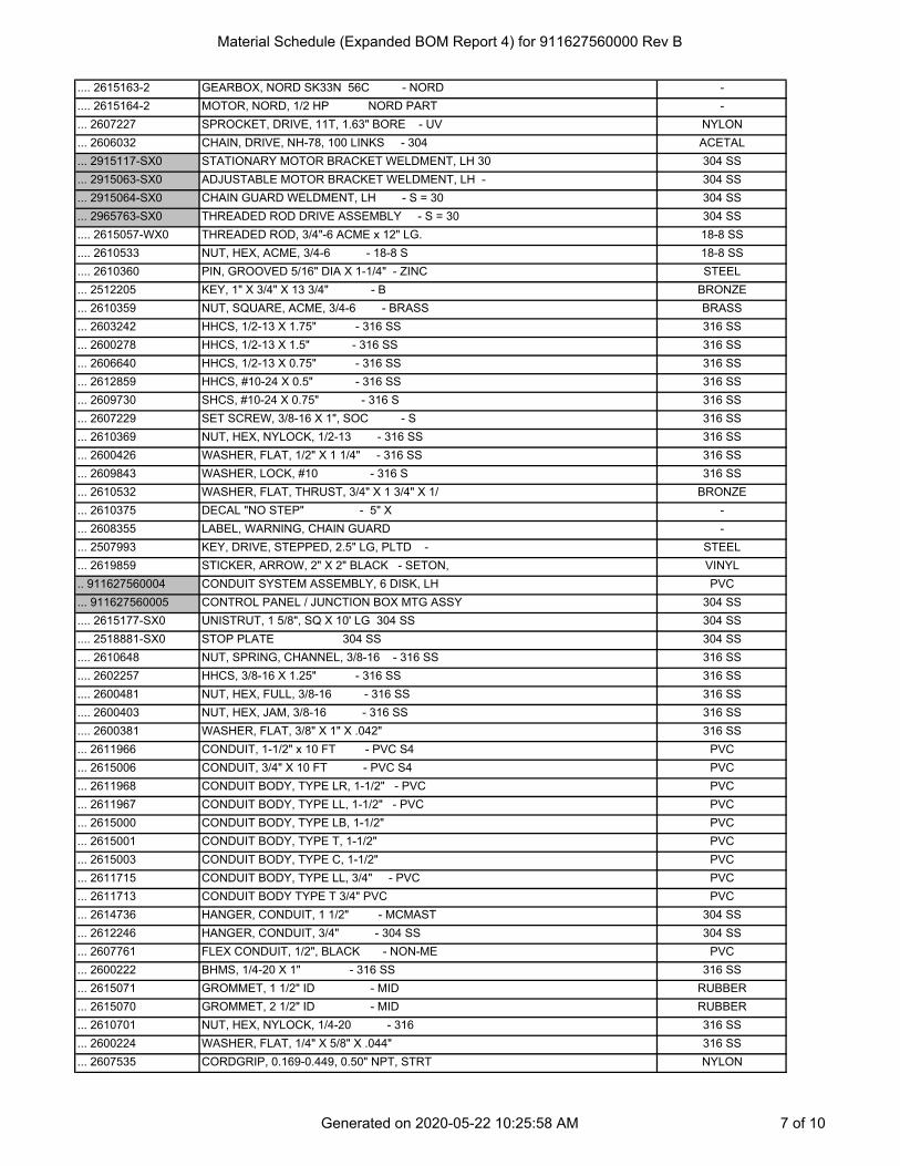
Material Schedule (Expanded BOM Report 4) for 911627560000 Rev B
.... 2615163-2 GEARBOX, NORD SK33N 56C - NORD -
.... 2615164-2 MOTOR, NORD, 1/2 HP NORD PART -
... 2607227 SPROCKET, DRIVE, 11T, 1.63" BORE - UV NYLON
... 2606032 CHAIN, DRIVE, NH-78, 100 LINKS - 304 ACETAL
... 2915117-SX0 STATIONARY MOTOR BRACKET WELDMENT, LH 30 304 SS
... 2915063-SX0 ADJUSTABLE MOTOR BRACKET WELDMENT, LH - 304 SS
... 2915064-SX0 CHAIN GUARD WELDMENT, LH - S = 30 304 SS
... 2965763-SX0 THREADED ROD DRIVE ASSEMBLY - S = 30 304 SS
.... 2615057-WX0 THREADED ROD, 3/4"-6 ACME x 12" LG. 18-8 SS
.... 2610533 NUT, HEX, ACME, 3/4-6 - 18-8 S 18-8 SS
.... 2610360 PIN, GROOVED 5/16" DIA X 1-1/4" - ZINC STEEL
... 2512205 KEY, 1" X 3/4" X 13 3/4" - B BRONZE
... 2610359 NUT, SQUARE, ACME, 3/4-6 - BRASS BRASS
... 2603242 HHCS, 1/2-13 X 1.75" - 316 SS 316 SS
... 2600278 HHCS, 1/2-13 X 1.5" - 316 SS 316 SS
... 2606640 HHCS, 1/2-13 X 0.75" - 316 SS 316 SS
... 2612859 HHCS, #10-24 X 0.5" - 316 SS 316 SS
... 2609730 SHCS, #10-24 X 0.75" - 316 S 316 SS
... 2607229 SET SCREW, 3/8-16 X 1", SOC - S 316 SS
... 2610369 NUT, HEX, NYLOCK, 1/2-13 - 316 SS 316 SS
... 2600426 WASHER, FLAT, 1/2" X 1 1/4" - 316 SS 316 SS
... 2609843 WASHER, LOCK, #10 - 316 S 316 SS
... 2610532 WASHER, FLAT, THRUST, 3/4" X 1 3/4" X 1/ BRONZE
... 2610375 DECAL "NO STEP" - 5" X -
... 2608355 LABEL, WARNING, CHAIN GUARD -
... 2507993 KEY, DRIVE, STEPPED, 2.5" LG, PLTD - STEEL
... 2619859 STICKER, ARROW, 2" X 2" BLACK - SETON, VINYL
.. 911627560004 CONDUIT SYSTEM ASSEMBLY, 6 DISK, LH PVC
... 911627560005 CONTROL PANEL / JUNCTION BOX MTG ASSY 304 SS
.... 2615177-SX0 UNISTRUT, 1 5/8", SQ X 10' LG 304 SS 304 SS
.... 2518881-SX0 STOP PLATE 304 SS 304 SS
.... 2610648 NUT, SPRING, CHANNEL, 3/8-16 - 316 SS 316 SS
.... 2602257 HHCS, 3/8-16 X 1.25" - 316 SS 316 SS
.... 2600481 NUT, HEX, FULL, 3/8-16 - 316 SS 316 SS
.... 2600403 NUT, HEX, JAM, 3/8-16 - 316 SS 316 SS
.... 2600381 WASHER, FLAT, 3/8" X 1" X .042" 316 SS
... 2611966 CONDUIT, 1-1/2" x 10 FT - PVC S4 PVC
... 2615006 CONDUIT, 3/4" X 10 FT - PVC S4 PVC
... 2611968 CONDUIT BODY, TYPE LR, 1-1/2" - PVC PVC
... 2611967 CONDUIT BODY, TYPE LL, 1-1/2" - PVC PVC
... 2615000 CONDUIT BODY, TYPE LB, 1-1/2" PVC
... 2615001 CONDUIT BODY, TYPE T, 1-1/2" PVC
... 2615003 CONDUIT BODY, TYPE C, 1-1/2" PVC
... 2611715 CONDUIT BODY, TYPE LL, 3/4" - PVC PVC
... 2611713 CONDUIT BODY TYPE T 3/4" PVC PVC
... 2614736 HANGER, CONDUIT, 1 1/2" - MCMAST 304 SS
... 2612246 HANGER, CONDUIT, 3/4" - 304 SS 304 SS
... 2607761 FLEX CONDUIT, 1/2", BLACK - NON-ME PVC
... 2600222 BHMS, 1/4-20 X 1" - 316 SS 316 SS
... 2615071 GROMMET, 1 1/2" ID - MID RUBBER
... 2615070 GROMMET, 2 1/2" ID - MID RUBBER
... 2610701 NUT, HEX, NYLOCK, 1/4-20 - 316 316 SS
... 2600224 WASHER, FLAT, 1/4" X 5/8" X .044" 316 SS
... 2607535 CORDGRIP, 0.169-0.449, 0.50" NPT, STRT NYLON
Generated on 2020-05-22 10:25:58 AM 7 of 10

Material Schedule (Expanded BOM Report 4) for 911627560000 Rev B
... 2611720 RED BUSH, 3/4" X 1/2", SOC X NPT, S80 PVC
... 2615639 RED BUSH, 1 1/2" X 1/2", SOC X NPT, S80 PVC
... 2607383 CONNECTOR, LIQUIDTIGHT, 0-90, 1/2" - NYLON
... 2612779 RECEPTACLE, 7P FEMALE 8 METER LEAD, 14 A -
... 2607352 NUT, SPRING, CHANNEL, 1/4-20 - 316 SS 316 SS
... 2611717 CONDUIT, ADAPTER, 3/4" MNPT X SOC - PVC
... 2611964 CONDUIT, ADAPTER, 1 1/2", MNPT X SOC - PVC
... 2600644 SEAL RING, CONDUIT, 0.75" - APPLET NEOPRENE
... 2616629 SEAL RING, CONDUIT, 1.50" - APPLET NEOPRENE
... 2617079 LOCKNUT, 3/4" NPT - 316SS 316 SS
... 2617082 LOCKNUT, 1 1/2" NPT - 316SS 316 SS
... 2966429 FLOAT SWITCH JUNCTION BOX ASSY POLYCARBONATE
.... 2603833 NUT, HEX, FULL, #8-32 - 304 SS
.... 2609689 WASHER, FLAT, #8 X 3/8" - 316 316 SS
.... 2607535 CORDGRIP, 0.169-0.449, 0.50" NPT, STRT NYLON
.... 2606312 LOCKNUT, NPT, 1/2", PLTD - APPLET STEEL
.... 2607383 CONNECTOR, LIQUIDTIGHT, 0-90, 1/2" - NYLON
.... 2605676 RING, SEAL, CONDUIT, 1/2" - THOMA 316 SS
.... 2615426 PHMS, #8-32 X 0.75" - 304 SS 304 SS
... 2611899 CONDUIT BODY, TYPE LB, 3/4" PVC
... 911627560600 CONTROL PANEL ASSEMBLY -
... 2913571 CP SUN SHIELD WELDMENT B 304 SS
.. 2965616 PRESSURE TRANSMITTER INSTL -
... 2614969 PRESSURE TRANSMITTER, IFM PX3228 - PROC 316L SS
... 2614968 CONNECTOR CABLE, IFM EVC531 - CONNEC -
... 2615179-6X0 RED BUSH, NPT, 1/2" X 1/4" - MCMAST 316 SS
... 2612176 VALVE, BALL, NPT, 1/2" - APOLLO STAINLESS STEEL
... 2615401-000-6X0 NIPPLE, 1/2", S40, CLOSE - 6 = 31 316 SS
.. 2965991 VACUUM TRANSMITTER INSTL. -
... 2614990 VACUUM TRANSMITTER, IFM PX3229 - PROCES 316L SS
... 2614968 CONNECTOR CABLE, IFM EVC531 - CONNEC -
.. 2967190-SX0 DISK SEGMENT INSTL, PA2-13 - S = 30 -
... 2967167 CLOTH & FRAME ASSY, ADF-54, PA2-13 -
.... 2962035 FRAME ASSY, ADF-54 POLYPROPYLENE
..... 2521694 DISK FRAME HALF - PURCHA POLYPROPYLENE
..... 2506985 TUBE, MOUNTING, CLOTH FRAME, 3/4" S80 - PVC
..... 2606686 SHCS, 5/16-18 X 1.75" - 316 SS 316 SS
..... 2600516 NUT, HEX, FULL, 5/16-18 - 316 SS 316 SS
..... 2600951 WASHER, FLAT, 5/16" X 3/4" X 1/16" - 316 SS
..... 2606859 SILICONE SEALANT, DOW CORNING 732 - NO SILICONE
..... 2618142 NUT, SQUARE, 5/16-18, MOLYKOTE - 316 316 SS
.... 2966910 CLOTH SOCK, ADF-54, PA2-13, GLOBAL - FI NYLON
..... 2616579 RAW CLOTH, PA2-13 (T2) - WH NYLON
.... 2506166 RETAINER BAR-TAB NORYL
.... 2506165 RETAINER BAR-NOTCH NORYL
.... 2519224 RETAINER BAR - SIDE NORYL
.... 2612413 HHCS, 5/16-18 X 1.5" - 316 SS 316 SS
.... 2600951 WASHER, FLAT, 5/16" X 3/4" X 1/16" - 316 SS
... 2518580-SX0 ROD, DISK SEGMENT RETAINER - S = 30 304 SS
... 2506752 GASKET, CENTERTUBE PORT POLYETHYLENE
... 2600301 NUT, HEX, FULL, 5/8-11 - 316 SS 316 SS
... 2600302 NUT, HEX, JAM, 5/8-11 - 316 SS 316 SS
... 2610704 WASHER, FLAT, 16MM X 30MM X 3MM - 31 316 SS
.. 2965563 VALVE & HOSE ASSY, 2" ELECTRIC BALL - R -
Generated on 2020-05-22 10:25:58 AM 8 of 10

Material Schedule (Expanded BOM Report 4) for 911627560000 Rev B
... 2964965 VALVE, 2" ELECTRIC BALL, GROOVED - RCEL -
.... 2614032 VALVE, BALL, 2", TCI TC-3000, LO - GROO 316 SS
.... 2964966 ACTUATOR ASSY, RCI RCEL-005L, 115V, RECE -
..... 2965274 ACTUATOR ASSY, RCI RCEL-005L, 115V, W/ W -
...... 2614298 ACTUATOR, RCI RCEL-005L, 120V - REMOTE -
...... 2610162 WALL NUT #12-#16 X 4 - WAG -
..... 2612782 RECEPTACLE, 7P MALE 12" LEAD -
.... 2613990 WASHER, FLAT, 8MM - 316 316 SS
.... 2614016 HHCS, M8 X 1.25 X 25MM - 316S 316 SS
... 2606512 HOSE, 2"ID, 250PSI, TITAN SWC609 NITRILE
... 2609481 COMBO NIPPLE, 2" HOSE X VIC - 316 SS 316 SS
... 2617813 CLAMP, T-BOLT, 2.396"-2.692" - DIXON STAINLESS STEEL
... 2962966 GROOVED COUPLING ASSY, 2" VIC - VICTAU CAST IRON
.... 2609480 GROOVED COUPLING, 2" VICTAULIC - STYLE CAST IRON
.... 2617598 BOLT, CARRIAGE, 7/16-14 X 3" LG - 18-8 18-8 SS
.... 2606682 NUT, HEX, FULL, 7/16-14 - 316 SS 316 SS
... 2614395 CORDSET, 7P DOUBLE MALE-FEMALE, 3' CORD -
.. 2965623 FLOAT SWITCH INSTL, NON-MERCURY -
... 2611183 FLOAT SWITCH, ANCHOR GSI 40NONC-STO - A -
... 2613034 LOCKNUT, 1/2" NPT - 316SS 316 SS
... 2607535 CORDGRIP, 0.169-0.449, 0.50" NPT, STRT NYLON
.. 2518895-1 VALVE LABEL, BACKWASH VALVE #1 PLASTIC PLASTIC
.. 2518895-2 VALVE LABEL, BACKWASH VALVE #2 PLASTIC PLASTIC
.. 2518895-3 VALVE LABEL, BACKWASH VALVE #3 PLASTIC PLASTIC
.. 2518895-7 VALVE LABEL, SOLIDS WASTE VALVE #1 - PL PLASTIC
.. 2615178-015-SX0 PLUG, SQ HD, NPT, 1 1/2" 304 SS 304 SS
.. 2615178-005-SX0 PLUG, SQ HD, NPT, 1/2" 304 SS 304 SS
.. 2615178-002-SX0 PLUG, SQ HD, NPT, 1/4" 304 SS 304 SS
.. 2609065 NAMEPLATE, AQUADISK - SINTRA SINTRA
.. 2606360 SAFETY WIRE, .050 DIA - 316 S 316 SS
.. 2615533-020-SX0 CAP, NPT, 150#, 2" - 304 SS 304 SS
.. 2610925 VALVE, BFLY, 12", NIBCO, LUG, GO - NIBC DUCTILE IRON
.. 2613482 HHCS, 7/8-9 X 2.5" - 316 SS 316 SS
.. 2607554 WASHER, FLAT, 7/8" X 2" - 316 SS 316 SS
. 2966011-SX0 BW / WASTE PUMP INSTL., 6 DISK, LH - 30 -
.. 2965308-16 PUMP, G-R 12B20B, 2HP TECO MTR PE F2 - -
... 2614428 PUMP, CENTRIFUGAL, G-R 12B20-B/S1 - GOR -
... 2615707-2 MOTOR, 2HP TECO 460V 1800RPM PE, F2 - # -
... 2614430 BASE, PUMP 12781-B - PAINTE -
... 2614431 GUARD, COUPLING ASSEMBLY - GORMAN -
... 2614432 COUPLING ASSY, JAW TYPE, L095, .875 & 1. -
.. 2962622 KIT, WEDGE ANCHOR, 1/2", RED HEAD SWW 316 SS
... 2605272 WEDGE ANCHOR, 1/2 -13 X 4.25", RED HE 316 SS
... 2600234 NUT, HEX, JAM, 1/2-13 - 316 SS 316 SS
.. 2607690 PRESSURE GUAGE, 2.5", 0-15 PSI STEEL
.. 2610351 VALVE, 3", GATE, THREADED - BRONZE BRONZE
.. 2606833 VALVE, 2", BALL, 3-WAY, THREADED - BRON BRONZE
.. 2615247-SX0 RED BUSH, NPT, 2" X 3" 304 SS 304 SS
. 2965961-SX0 BW / WASTE PUMP INSTL., 6 DISK, RH - S: 304 SS
.. 2965308-15 PUMP, G-R 12B20B, 2HP TECO MTR PE F1 - -
... 2614428 PUMP, CENTRIFUGAL, G-R 12B20-B/S1 - GOR -
... 2615707-1 MOTOR, 2HP TECO 460V 1800RPM PE, F1 - # -
... 2614430 BASE, PUMP 12781-B - PAINTE -
... 2614431 GUARD, COUPLING ASSEMBLY - GORMAN -
Generated on 2020-05-22 10:25:58 AM 9 of 10

Material Schedule (Expanded BOM Report 4) for 911627560000 Rev B
... 2614432 COUPLING ASSY, JAW TYPE, L095, .875 & 1. -
.. 2962622 KIT, WEDGE ANCHOR, 1/2", RED HEAD SWW 316 SS
... 2605272 WEDGE ANCHOR, 1/2 -13 X 4.25", RED HE 316 SS
... 2600234 NUT, HEX, JAM, 1/2-13 - 316 SS 316 SS
.. 2607690 PRESSURE GUAGE, 2.5", 0-15 PSI STEEL
.. 2610351 VALVE, 3", GATE, THREADED - BRONZE BRONZE
.. 2606833 VALVE, 2", BALL, 3-WAY, THREADED - BRON BRONZE
.. 2615247-SX0 RED BUSH, NPT, 2" X 3" 304 SS 304 SS
. 2607833 VACUUM GAUGE, 3.5", 30"/0HG - ASHCRO STAINLESS STEEL
. 2609798 VALVE, 3", BALL, MANUAL, THREADED - BRA BRASS
. 911627560006 SPARE PARTS - 116275 -
. 911627560007 JOB SITE O&M MANUAL - 116275 JOBSITE -
The report lists components in order through the entirety of the BOM. Periods in front of a part number indicate how many levels deep that part is with respect to the top level BOM. To indicate that a part has a BOM, the part number is highlighted.
Generated on 2020-05-22 10:25:58 AM 10 of 10

--JOB SITE O&M MANUAL - 11627591162756000718--SPARE PARTS - 11627591162756000617-BRASSVALVE, 3", BALL, MANUAL, THREADED260979826--VACUUM GAUGE, 3 1/2", 0-30" HG260783325Y-BW / WASTE PUMP INSTL., 6 DISK, RH2965961-SX014Y-BW / WASTE PUMP INSTL, 6 DISK, LH2966011-SX013Y-TANK ASSEMBLY, 6 DISK, LH91162756000212Y-TANK ASSEMBLY, 6 DISK, RH91162756000111
DWGMATERIALDESCRIPTIONPART NUMBERQTYITEM
A
A
B
B
1
1
2
2
3
3
4
4
5
5
6
6
7
7
8
8
A A
B B
C C
D D
PLAN VIEW & GENERAL LIST
COPYRIGHT 2020 AQUA-AEROBIC SYSTEMS, INC. ALL RIGHTS RESERVED. THIS DRAWING MAY NOT BE COPIED ALL OR IN PART WITHOUT THE EXPRESS WRITTEN PERMISSION OF AQUA-AEROBIC SYSTEMS, INC.
ANSI
D
JOB NAME:
JOB LOCATION:
DRAWING NAME: DRAWING NUMBER:
WEIGHT:
TYPE:
SIMILAR TO:
MATERIAL:
SHEET: OF
SIZE:SCALE:
911627560000
ADFSP-54X6E
1/16
COLLIER COUNTY NESANAPLES, FL
DRAWN BY: DATE:TWA 2020-05-22
UNLESS OTHERWISE SPECIFIEDALL DIMENSIONS ARE IN INCHESDO NOT
SCALEDRAWING
AQUA-AEROBIC SYSTEMS, INC.
+/- 1/16+/- 0.010+/- 0.005+/- 1/2°
FRACTIONAL DIMENSIONSALL TWO PLACE DECIMALSALL THREE PLACE DECIMALSALL ANGLES
3
®
1
A Metawater Company
THE O&M MANUAL CONTAINS INSTALLATION DRAWINGSAND FIELD INSTALLATION INSTRUCTIONS
A - 2020-05-22 TWA SUBMITTALREV ERN/ECO DATE BY REVISION DESCRIPTION
GENERAL INSTALLATION NOTES: 1. PLEASE REVIEW ALL INDIVIDUAL INSTALLATION DRAWINGS FOR ACTUAL DETAILS. REFER TO ASSEMBLY INSTRUCTIONS IN THE OPERATION AND MAINTENANCE MANUAL PRIOR TO INSTALLING THE EQUIPMENT.
1
4 3
2
14" EFFLUENT PIPINGBY OTHERS
14" EFFLUENT PIPINGBY OTHERS
12" INFLUENT PIPINGBY OTHERS
12" INFLUENT PIPINGBY OTHERS
SUBMITTAL
NOT FOR CONSTRUCTIO
N

SECTION B-BSCALE 1/16
SECTION A-ASCALE 1/16
1
1
2
2
3
3
4
4
5
5
6
6
7
7
8
8
A A
B B
C C
D D
PLAN VIEW & GENERAL LIST
COPYRIGHT 2020 AQUA-AEROBIC SYSTEMS, INC. ALL RIGHTS RESERVED. THIS DRAWING MAY NOT BE COPIED ALL OR IN PART WITHOUT THE EXPRESS WRITTEN PERMISSION OF AQUA-AEROBIC SYSTEMS, INC.
ANSI
D
JOB NAME:
JOB LOCATION:
DRAWING NAME: DRAWING NUMBER:
WEIGHT:
TYPE:
SIMILAR TO:
MATERIAL:
SHEET: OF
SIZE:SCALE:
911627560000
ADFSP-54X6E
1/16
COLLIER COUNTY NESANAPLES, FL
DRAWN BY: DATE:TWA 2020-05-22
UNLESS OTHERWISE SPECIFIEDALL DIMENSIONS ARE IN INCHESDO NOT
SCALEDRAWING
AQUA-AEROBIC SYSTEMS, INC.
+/- 1/16+/- 0.010+/- 0.005+/- 1/2°
FRACTIONAL DIMENSIONSALL TWO PLACE DECIMALSALL THREE PLACE DECIMALSALL ANGLES
3
®
2
A Metawater Company
A - 2020-05-22 TWA SUBMITTALREV ERN/ECO DATE BY REVISION DESCRIPTION
1
6
3 MIN
3 MIN
4
5
12" INFLUENT PIPINGBY OTHERS
3" DRAIN PIPINGBY OTHERS
14" EFFLUENT PIPINGBY OTHERS
14" EFFLUENT PIPINGBY OTHERS
3" DRAIN PIPINGBY OTHERS
6
3 MIN3 MIN
3 MIN
3
5
2
FILTER PADFILTER PAD
SUBMITTAL
NOT FOR CONSTRUCTIO
N

1
1
2
2
3
3
4
4
5
5
6
6
7
7
8
8
A A
B B
C C
D D
PLAN VIEW & GENERAL LIST
COPYRIGHT 2020 AQUA-AEROBIC SYSTEMS, INC. ALL RIGHTS RESERVED. THIS DRAWING MAY NOT BE COPIED ALL OR IN PART WITHOUT THE EXPRESS WRITTEN PERMISSION OF AQUA-AEROBIC SYSTEMS, INC.
ANSI
D
JOB NAME:
JOB LOCATION:
DRAWING NAME: DRAWING NUMBER:
WEIGHT:
TYPE:
SIMILAR TO:
MATERIAL:
SHEET: OF
SIZE:SCALE:
911627560000
ADFSP-54X6E
1/16
COLLIER COUNTY NESANAPLES, FL
DRAWN BY: DATE:TWA 2020-05-22
UNLESS OTHERWISE SPECIFIEDALL DIMENSIONS ARE IN INCHESDO NOT
SCALEDRAWING
AQUA-AEROBIC SYSTEMS, INC.
+/- 1/16+/- 0.010+/- 0.005+/- 1/2°
FRACTIONAL DIMENSIONSALL TWO PLACE DECIMALSALL THREE PLACE DECIMALSALL ANGLES
3
®
3
A Metawater Company
GENERAL PROJECT NOTES A. VERIFICATION OF ALL DIMENSIONS GIVEN AND WATER LEVELS DETAILED ON THESE DRAWINGS TO ENSURE ACCURATE FABRICATION OF EQUIPMENT IS BY OTHERS. B. UNLESS IDENTIFIED ON A DRAWING BILL OF MATERIAL, ALL PIPING, SUPPORTS, GASKETS, HARDWARE, ELECTRICAL WIRING AND SUPPLY POWER BEYOND AQUA-AEROBIC SYSTEMS, INC. EQUIPMENT TERMINATIONS ILLUSTRATED ON THESE DRAWINGS IS SHOWN FOR REFERENCE ONLY. SIZING, LOCATION AND SUPPLY ARE TO BE DETERMINED BY OTHERS. C. SOME GASKETS SUPPLIED WITH THIS EQUIPMENT MAY BE MADE OF STYRENE BUTADIENE / "RED RUBBER", URETHANE, OR EPDM. VERIFICATION THAT THESE MATERIALS ARE COMPATIBLE WITH THE CHEMICALS THAT WILL BE PRESENT IN THIS APPLICATION ARE BY OTHERS. D. MOUNTING HARDWARE FOR THE CONTROL PANEL WILL BE PROVIDED BY OTHERS. FIELD INSTALLATION OF FLOOR AND/OR WALL MOUNTED CONTROL PANELS IS THE RESPONSIBILITY OF OTHERS. E. DIMENSIONS ON THESE DRAWINGS ARE FINAL UNLESS CHANGED IN WRITING BY OTHERS. SPECIFIC NOTATION MUST BE SHOWN IN RED INK TO CHANGE ANY DIMENSIONS, COMPONENT PARTS, OR EQUIPMENT DETAILS. UNLESS CHANGES ARE SHOWNHEREON, AQUA-AEROBIC SYSTEMS, INC. SHALL NOT BE RESPONSIBLE FOR COSTS REQUIRED TO MODIFY OR CHANGE ITEMS AS A RESULT OF UNMARKED CHANGES OR CHANGES AFTER REVIEW. MANUFACTURED PRODUCTS WILL BE SHIPPED AS DIMENSIONED AND DESCRIBED WITHIN THIS MANUAL. F. AQUA-AEROBIC SYSTEMS, INC. DOES NOT ASSUME THE RESPONSIBILITY OF COORDINATING THE CIVIL, MECHANICAL, OR DESIGN ENGINEERING THAT MAY BE REQUIRED. G. IF FREEZING IS A CONCERN, ANY NECESSARY PROTECTION, INCLUDING BUT NOT LIMITED TO HEAT TRACING AND INSULATIONOF PUMPS, VALVES, AND PIPING AS WELL AS PROTECTION AGAINST INTERNAL TANK EQUIPMENT FREEZING SHALL BE SUPPLIED AND INSTALLED BY OTHERS. H. REFER TO SECTION 1 OF THE OPERATION & MAINTENANCE MANUAL FOR A COMPLETE LIST OF RECOMMENDED SPARE PARTS OR THOSE PROVIDED FOR THIS PROJECT. I. NO SPECIAL TOOLS ARE REQUIRED FOR NORMAL INSTALLATION OR ROUTINE MAINTENANCE OF EQUIPMENT TO BE FURNISHED. J. COMPLETE FACTORY ASSEMBLY AND INSTALLATION DRAWINGS WITH PARTS LIST WILL BE PROVIDED WITHIN EACH OPERATION & MAINTENANCE MANUAL. OPERATION & MAINTENANCE MANUALS WILL BE MAILED PRIOR TO SHIPMENT OF EQUIPMENT. REVIEW ALL FACTORY ASSEMBLY AND INSTALLATION DRAWINGS PRIOR TO COMMENCING FINAL ASSEMBLY. K. WHEN RECEIVING EQUIPMENT AND CRATES, THE SHIPMENT SHOULD BE COMPLETELY CHECKED TO VERIFY THAT NO TRANSITDAMAGE HAS OCCURRED. ALL EQUIPMENT AND ACCESSORIES (IF ANY) MUST BE VERIFIED AGAINST THE PACKING LIST AND BILL OF LADING TO ASSURE PROPER CONTENTS. L. UNLESS OTHERWISE SPECIFIED, ALL WALKWAYS, PLATFORMS, STAIRWAYS, HANDRAILING, ETC. HAVE BEEN SHOWN FOR REFERENCE ONLY AND ARE TO BE SUPPLIED AND INSTALLED BY OTHERS. AQUA-AEROBIC SYSTEMS, INC. IS NOT RESPONSIBLE FOR VERIFYING CLEARANCE WITH EQUIPMENT SUPPLIED BY OTHERS. M. ADHESIVE AND/OR WEDGE ANCHORS ARE PROVIDED FOR ANCHORING EQUIPMENT TO THE BASIN FLOOR AND/OR WALLS. ANCHOR INSTALLATION AND FIELD ATTACHMENT OF EQUIPMENT TO THE BASIN IS THE RESPONSIBILITY OF OTHERS. N. ANTI-SEIZE LUBRICANT IS REQUIRED ON ALL STAINLESS STEEL FASTENERS.
PACKAGE DISK FILTER PROJECT NOTES A. DISCHARGE / DRAIN PIPING AND VALVE SIZES ARE TO BE VERIFIED BY OTHERS BASED ON ACTUAL LINE LOSSES. B. AQUA-AEROBIC SYSTEMS, INC. RECOMMENDS A MINIMUM 3" THICK CONCRETE FILTER PAD. THE FINISHED FLOOR OR PAD MUST BE FLAT TO WITHIN +/- 1/4" FOR PROPER OPERATION OF PACKAGE FILTER ASSEMBLIES. C. 3" BALL VALVE IS PROVIDED LOOSE. VALVE TO BE ATTACHED TO TANK DRAIN, INSTALLING CONTRACTOR TO PROVIDE FITTINGS AND PIPING. INSTALLING CONTRACTOR TO ENSURE DRAIN PIPE HAS NO LINE PRESSURE AND ALLOW FOR GRAVITY DRAINING.
A - 2020-05-22 TWA SUBMITTALREV ERN/ECO DATE BY REVISION DESCRIPTION
SUBMITTAL
NOT FOR CONSTRUCTIO
N

DETAIL B
VIEW A-A
B
A
A
C
C
-316 SSWASHER, FLAT, 7/8" X 2"26075541223-316 SSHHCS, 7/8-9 X 2.5"26134821222-DUCTILE IRONVALVE, 12", B/FLY, MANUAL, NIBCO2610925121-304 SSCAP, NPT, 150#, 2"2615533-020-SX0120-316 SSSAFETY WIRE, .050 DIA.26063608 FT19YSINTRANAMEPLATE, AQUADISK2609065118-304 SSPLUG, SQ HD, NPT, 1/4"2615178-002-SX0417-304 SSPLUG, SQ HD, NPT, 1/2"2615178-005-SX0316-304 SSPLUG, SQ HD, NPT, 1 1/2"2615178-015-SX0115YPLASTICVALVE LABEL, SOLIDS WASTE VALVE #12518895-7114YPLASTICVALVE LABEL, BACKWASH VALVE #32518895-3113YPLASTICVALVE LABEL, BACKWASH VALVE #22518895-2112YPLASTICVALVE LABEL, BACKWASH VALVE #12518895-1111Y-FLOAT SWITCH INSTL, NON-MERCURY2965623110Y-VALVE & HOSE ASSY, 2" BALL, RCEL-005L, TC-RC296556349Y304 SSDISK SEGMENT INSTL, PES-142967192-SX0368Y-VACUUM TRANSMITTER INSTL296599117Y-PRESSURE TRANSMITTER INSTL296561616YPVCCONDUIT SYSTEM ASSEMBLY, 6 DISK, RH91162756000315Y304 SSDRIVE SYSTEM INSTL, 1/2 HP, RH2965887-SX014Y304 SSBACKWASH SYSTEM INSTL, 6 DISK, RH2965958-SX013Y304 SSCENTERTUBE INSTALLATION, 6 DISK2965957-SX012Y304 SSTANK ACCESSORY WELDMENT, 6 DISK, RH91162756020011
DWGMATERIALDESCRIPTIONPART NUMBERQTYITEM
1
1
2
2
3
3
4
4
5
5
6
6
7
7
8
8
A A
B B
C C
D D
TANK ASSEMBLY, 6 DISK, RH
COPYRIGHT 2020 AQUA-AEROBIC SYSTEMS, INC. ALL RIGHTS RESERVED. THIS DRAWING MAY NOT BE COPIED ALL OR IN PART WITHOUT THE EXPRESS WRITTEN PERMISSION OF AQUA-AEROBIC SYSTEMS, INC.
ANSI
D
JOB NAME:
JOB LOCATION:
DRAWING NAME: DRAWING NUMBER:
WEIGHT:
TYPE:
SIMILAR TO:
MATERIAL:
SHEET: OF
SIZE:SCALE:
911627560001
M-ADFSP-4
ADFSP
9500
1/20
COLLIER COUNTY NESANAPLES, FL
DRAWN BY: DATE:TWA 2020-05-21LBS
UNLESS OTHERWISE SPECIFIEDALL DIMENSIONS ARE IN INCHESDO NOT
SCALEDRAWING
AQUA-AEROBIC SYSTEMS, INC.
+/- 1/16+/- 0.010+/- 0.005+/- 1/2°
FRACTIONAL DIMENSIONSALL TWO PLACE DECIMALSALL THREE PLACE DECIMALSALL ANGLES
2
®
1
A Metawater Company
3CORNER LIFT POINT
TYP (4)
49 3/8( )
141 9/16( )
66( )TO CENTEROF DISPLAY
12
12INFLUENT
(12" FLANGE)
101 1/2( )
135( )
18
14 1/4( )
89( )
9( ) TYP
NOTE 2
1163 1/4 OVERALL LENGTH
9
14
9
11
9
12
16
9
13
EFFLUENT(14" FLANGE)
48 MINIMUM CLEARANCE FORREMOVAL OF DISK SEGMENTS
137 3/8OVERALLHEIGHT
16
16
17
40 3/16( )
28 9/16( )
NOTES: 1. INSTALL ONLY THE PIPE PLUGS CALLED OUT ON THE BILL OF MATERIAL. ANY OTHER PLUGS AND CAPS MUST BE REMOVED PRIOR TO SHIPPING. 2. USE SAFETY WIRE (ITEM 19) TO ATTACH VALVE LABEL TO EACH VALVE / ACTUATOR IN A VISIBLE LOCATION. 3. REFER TO EXPANDED BILL OF MATERIAL FOR MATERIAL, FINISH, AND CERTIFICATION. 4. REFER TO EP-10031 FOR LIFTING INSTRUCTIONS. MAX LIFTING WEIGHT: 9500 LB OPERATIONAL WEIGHT: 40500 LB 5. DURING ASSEMBLY, COMPLETE THE PACKAGE FILTER SHOP CHECK-OUT EP-10176. 6. USE THREAD PASTE ON ALL PIPE THREADS.
CONTROL PANEL SHOWN FORREFERENCE ONLY. SEE CONDUITASSEMBLY (ITEM 5) FOR DETAILS.
5 6 7
4 10
3
8
2
171717
20
15
A - 2020-05-21 TWA SUBMITTALREV ERN/ECO DATE BY REVISION DESCRIPTION
21
22
23
SUBMITTAL
NOT FOR CONSTRUCTIO
N

FLOW CONDITION AVG. DESIGN MAX. DESIGN MAX. CAPACITY
QTY FILTERS ONLINE 2 2 1PLANT FLOW (MGD) 1.50 4.13 -
FLOW / FILTER (MGD) .75 2.07 3.02FLUX RATE (GPM/FTĮ) 1.61 4.44 6.50
LENGTH (FT) ELEVATION (FT) NAPPE EL (FT) NAPPE EL (FT) NAPPE EL (FT)
A INFLUENT WEIR 4.42 8.74 / 8.74 8.92 / 8.92 9.10 / 9.10 9.20 / 9.20B EFFLUENT WEIR 5.08 7.32 / 7.32 7.49 / 7.49 7.65 / 7.65 7.75 / 7.75C OVERFLOW WEIR 2.67 9.42 / 9.42 9.67 / 9.67 9.92 / 9.92 10.07 / 10.07D BACKWASH INITIATE - 8.70 / 8.70 - - -E MAX. DOWNSTREAM EL - 6.82 / 6.82 - - -
LOCATION
SECTION C-C
C
D A
EB
1
1
2
2
3
3
4
4
5
5
6
6
7
7
8
8
A A
B B
C C
D D
TANK ASSEMBLY, 6 DISK, RH
COPYRIGHT 2020 AQUA-AEROBIC SYSTEMS, INC. ALL RIGHTS RESERVED. THIS DRAWING MAY NOT BE COPIED ALL OR IN PART WITHOUT THE EXPRESS WRITTEN PERMISSION OF AQUA-AEROBIC SYSTEMS, INC.
ANSI
D
JOB NAME:
JOB LOCATION:
DRAWING NAME: DRAWING NUMBER:
WEIGHT:
TYPE:
SIMILAR TO:
MATERIAL:
SHEET: OF
SIZE:SCALE:
911627560001
M-ADFSP-4
ADFSP
9500
1/14
COLLIER COUNTY NESANAPLES, FL
DRAWN BY: DATE:TWA 2020-05-21LBS
UNLESS OTHERWISE SPECIFIEDALL DIMENSIONS ARE IN INCHESDO NOT
SCALEDRAWING
AQUA-AEROBIC SYSTEMS, INC.
+/- 1/16+/- 0.010+/- 0.005+/- 1/2°
FRACTIONAL DIMENSIONSALL TWO PLACE DECIMALSALL THREE PLACE DECIMALSALL ANGLES
2
®
2
A Metawater Company
EL. 0.00'
CENTERTUBE C.L.EL. 3.92'
EL. 11.25'
A - 2020-05-21 TWA SUBMITTALREV ERN/ECO DATE BY REVISION DESCRIPTION
SUBMITTAL
NOT FOR CONSTRUCTIO
N

DETAIL A
VIEW B-B
A
B
B
C
C
-316 SSWASHER, FLAT, 7/8" X 2"26075541223-316 SSHHCS, 7/8-9 X 2.5"26134821222-DUCTILE IRONVALVE, 12", B/FLY, MANUAL, NIBCO2610925121-304 SSCAP, NPT, 150#, 2"2615533-020-SX0120-316 SSSAFETY WIRE, .050 DIA.26063608 FT19YSINTRANAMEPLATE, AQUADISK2609065118-304 SSPLUG, SQ HD, NPT, 1/4"2615178-002-SX0417-304 SSPLUG, SQ HD, NPT, 1/2"2615178-005-SX0316-304 SSPLUG, SQ HD, NPT, 1 1/2"2615178-015-SX0115YPLASTICVALVE LABEL, SOLIDS WASTE VALVE #12518895-7114YPLASTICVALVE LABEL, BACKWASH VALVE #32518895-3113YPLASTICVALVE LABEL, BACKWASH VALVE #22518895-2112YPLASTICVALVE LABEL, BACKWASH VALVE #12518895-1111Y-FLOAT SWITCH INSTL, NON-MERCURY2965623110Y-VALVE & HOSE ASSY, 2" BALL, RCEL-005L, TC-RC296556349Y304 SSDISK SEGMENT INSTL, PES-142967192-SX0368Y-VACUUM TRANSMITTER INSTL296599117Y-PRESSURE TRANSMITTER INSTL296561616YPVCCONDUIT SYSTEM ASSEMBLY, 6 DISK, LH91162756000415Y304 SSDRIVE SYSTEM INSTL, 1/2 HP, LH2966016-SX014Y304 SSBACKWASH SYSTEM INSTL, 6 DISK, LH2966009-SX013Y304 SSCENTERTUBE INSTALLATION, 6 DISK2965957-SX012Y304 SSTANK ACCESSORY WELDMENT, 6 DISK, LH91162756020111
DWGMATERIALDESCRIPTIONPART NUMBERQTYITEM
1
1
2
2
3
3
4
4
5
5
6
6
7
7
8
8
A A
B B
C C
D D
TANK ASSEMBLY, 6 DISK, LH
COPYRIGHT 2020 AQUA-AEROBIC SYSTEMS, INC. ALL RIGHTS RESERVED. THIS DRAWING MAY NOT BE COPIED ALL OR IN PART WITHOUT THE EXPRESS WRITTEN PERMISSION OF AQUA-AEROBIC SYSTEMS, INC.
ANSI
D
JOB NAME:
JOB LOCATION:
DRAWING NAME: DRAWING NUMBER:
WEIGHT:
TYPE:
SIMILAR TO:
MATERIAL:
SHEET: OF
SIZE:SCALE:
M-ADFSP-52
M-ADFSP-52
ADFSP
9500
1/20
COLLIER COUNTY NESANAPLES, FL
DRAWN BY: DATE:CJC 2012-05-02LBS
UNLESS OTHERWISE SPECIFIEDALL DIMENSIONS ARE IN INCHESDO NOT
SCALEDRAWING
AQUA-AEROBIC SYSTEMS, INC.
+/- 1/16+/- 0.010+/- 0.005+/- 1/2°
FRACTIONAL DIMENSIONSALL TWO PLACE DECIMALSALL THREE PLACE DECIMALSALL ANGLES
2
®
1
A Metawater Company
141 9/16( )
49 3/8( )
9
13
1
9
14
9
11
9
12
9( ) TYP
163 1/4 OVERALL LENGTH
NOTE 2
16
3CORNER LIFT POINTTYP (4)
INFLUENT(12" FLANGE)
101 1/2( )
135( )
12
12
66( )TO CENTEROF DISPLAY
18
14 1/4( )
89( )
EFFLUENT(14" FLANGE)
137 5/8OVERALLHEIGHT
48 MINIMUM CLEARANCE FORREMOVAL OF DISK SEGMENTS
16
1716
28 9/16( )
40 3/16( )
NOTES: 1. INSTALL ONLY THE PIPE PLUGS CALLED OUT ON THE BILL OF MATERIAL. ANY OTHER PLUGS AND CAPS MUST BE REMOVED PRIOR TO SHIPPING. 2. USE SAFETY WIRE (ITEM 19) TO ATTACH VALVE LABEL TO EACH VALVE / ACTUATOR IN A VISIBLE LOCATION. 3. REFER TO EXPANDED BILL OF MATERIAL, FOR MATERIAL, FINISH, AND CERTIFICATION. 4. REFER TO EP-10031 FOR LIFTING INSTRUCTIONS. MAX LIFTING WEIGHT: 9500 LB OPERATIONAL WEIGHT: 40500 LB 5. DURING ASSEMBLY, COMPLETE THE PACKAGE FILTER SHOP CHECK-OUT EP-10176. 6. USE THREAD PASTE ON ALL PIPE THREADS.
56
7
410
3
CONTROL PANEL IS SHOWN FORREFERENCE ONLY. SEE CONDUITASSEMBLY (ITEM 5) FOR DETAILS.
8
2
17
17 17
20
A - 2020-05-21 TWA SUBMITTALREV ERN/ECO DATE BY REVISION DESCRIPTION
21
22
23
SUBMITTAL
NOT FOR CONSTRUCTIO
N

FLOW CONDITION AVG. DESIGN MAX. DESIGN MAX. CAPACITY
QTY FILTERS ONLINE 2 2 1PLANT FLOW (MGD) 1.50 4.13 -
FLOW / FILTER (MGD) .75 2.07 3.02FLUX RATE (GPM/FTĮ) 1.61 4.44 6.50
LENGTH (FT) ELEVATION (FT) NAPPE EL (FT) NAPPE EL (FT) NAPPE EL (FT)
A INFLUENT WEIR 4.42 8.74 / 8.74 8.92 / 8.92 9.10 / 9.10 9.20 / 9.20B EFFLUENT WEIR 5.08 7.32 / 7.32 7.49 / 7.49 7.65 / 7.65 7.75 / 7.75C OVERFLOW WEIR 2.67 9.42 / 9.42 9.67 / 9.67 9.92 / 9.92 10.07 / 10.07D BACKWASH INITIATE - 8.70 / 8.70 - - -E MAX. DOWNSTREAM EL - 6.82 / 6.82 - - -
LOCATION
SECTION C-C
1
1
2
2
3
3
4
4
5
5
6
6
7
7
8
8
A A
B B
C C
D D
TANK ASSEMBLY, 6 DISK, LH
COPYRIGHT 2020 AQUA-AEROBIC SYSTEMS, INC. ALL RIGHTS RESERVED. THIS DRAWING MAY NOT BE COPIED ALL OR IN PART WITHOUT THE EXPRESS WRITTEN PERMISSION OF AQUA-AEROBIC SYSTEMS, INC.
ANSI
D
JOB NAME:
JOB LOCATION:
DRAWING NAME: DRAWING NUMBER:
WEIGHT:
TYPE:
SIMILAR TO:
MATERIAL:
SHEET: OF
SIZE:SCALE:
M-ADFSP-52
M-ADFSP-52
ADFSP
9500
1/14
COLLIER COUNTY NESANAPLES, FL
DRAWN BY: DATE:CJC 2012-05-02LBS
UNLESS OTHERWISE SPECIFIEDALL DIMENSIONS ARE IN INCHESDO NOT
SCALEDRAWING
AQUA-AEROBIC SYSTEMS, INC.
+/- 1/16+/- 0.010+/- 0.005+/- 1/2°
FRACTIONAL DIMENSIONSALL TWO PLACE DECIMALSALL THREE PLACE DECIMALSALL ANGLES
2
®
2
A Metawater Company
EL. 0.00'
EB
C
DA
CENTERTUBE C.L.EL. 3.92'
EL. 11.25'
A - 2020-05-21 TWA SUBMITTALREV ERN/ECO DATE BY REVISION DESCRIPTION
SUBMITTAL
NOT FOR CONSTRUCTIO
N

SECTION A-A
DETAIL B
B
A A
Y304 SSCONTROL PANEL SUN SHIELD WELDMENT2913571134Y-CONTROL PANEL INSTALLATION911627560600133-PVCCONDUIT BODY, TYPE LB, 3/4"2611899132Y-FLOAT SWITCH JUNCTION BOX ASSEMBLY2966429131-316 SSLOCKNUT, 1 1/2" NPT2617082130-316 SSLOCKNUT, 3/4" NPT2617079129-NEOPRENESEAL RING, CONDUIT, 1 1/2"2616629128-NEOPRENESEAL RING, CONDUIT, 3/4"2600644127-PVCCONDUIT MALE ADAPTER, 1 1/2" NPT2611964126-PVCCONDUIT MALE ADAPTER, 3/4" NPT2611717125-316 SSNUT, SPRING, CHANNEL, 1/4-202607352124--RECEPTACLE, 7P FEMALE, 25 FT. LEAD, 14 AWG THHN2612779423-NYLONCONNECTOR, LIQTITE 0-90, 1/2" 2607383322-PVCRED BUSH, 1 1/2" SOC x 1/2" FNPT, S802615639621-PVCRED BUSH, 3/4" SOC x 1/2" FNPT, S802611720220-NYLONCORD GRIP, 0.169-0.449", 1/2" NPT STRAIGHT2607535219-316 SSWASHER, FLAT, 1/4" X 5/8" X .044"26002242318-316 SSNUT, HEX, NYLOCK, 1/4-20 26107011117-RUBBERGROMMET, 2 1/2" ID2615070416-RUBBERGROMMET, 1 1/2" ID2615071215-316 SSBHMS, 1/4-20 X 1"26002221214-PVCFLEX CONDUIT, 1/2" BLACK26077615 FT13-304 SSHANGER, CONDUIT, 3/4"2612246212-304 SSHANGER, CONDUIT, 1 1/2"26147361011-PVCCONDUIT BODY, TYPE T, 3/4"2611713110-PVCCONDUIT BODY, TYPE LR, 3/4"261171419-PVCCONDUIT BODY, TYPE C, 1 1/2"261500318-PVCCONDUIT BODY, TYPE T, 1 1/2"261500167-PVCCONDUIT BODY, TYPE LB, 1 1/2"261500036-PVCCONDUIT BODY, TYPE LL, 1 1/2"261196715-PVCCONDUIT BODY, TYPE LR, 1 1/2"261196824-PVCCONDUIT PIPE, 3/4", S40 x 10 FT. LG261500613-PVCCONDUIT PIPE, 1 1/2", S40 x 10 FT. LG261196622Y304 SSCONTROL PANEL / JUNCTION BOX MTG ASSY91162756000511
DWGMATERIALDESCRIPTIONPART NUMBERQTYITEM
1
1
2
2
3
3
4
4
5
5
6
6
7
7
8
8
A A
B B
C C
D D
CONDUIT SYSTEM ASSEMBLY, 6 DISK, RH
COPYRIGHT 2020 AQUA-AEROBIC SYSTEMS, INC. ALL RIGHTS RESERVED. THIS DRAWING MAY NOT BE COPIED ALL OR IN PART WITHOUT THE EXPRESS WRITTEN PERMISSION OF AQUA-AEROBIC SYSTEMS, INC.
ANSI
D
JOB NAME:
JOB LOCATION:
DRAWING NAME: DRAWING NUMBER:
WEIGHT:
TYPE:
SIMILAR TO:
MATERIAL:
SHEET: OF
SIZE:SCALE:
911627560003
M-ADFSP-85
ADFSP
700
1/20
COLLIER COUNTY NESANAPLES, FL
DRAWN BY: DATE:TWA 2020-05-21LBS
UNLESS OTHERWISE SPECIFIEDALL DIMENSIONS ARE IN INCHESDO NOT
SCALEDRAWING
AQUA-AEROBIC SYSTEMS, INC.
+/- 1/16+/- 0.010+/- 0.005+/- 1/2°
FRACTIONAL DIMENSIONSALL TWO PLACE DECIMALSALL THREE PLACE DECIMALSALL ANGLES
2
®
1
A Metawater Company
ASSEMBLY NOTES: 1. ALL RIGID CONDUIT AND FITTINGS UTILIZED ON TANK ASSEMBLY MUST BE PVC. ALL WIRE MUST BE 14GA, 600V, 19 STR, THHN. 2. USE TEFLON TAPE OR PASTE ON ALL THREADED CONNECTIONS WITH THE EXCEPTION OF TUBE FITTING NUTS. 3. SOLVENT BOND FITTINGS TOGETHER AS SHOWN UTILIZING THE LATEST INSTRUCTIONS FOR PRIMING AND SOLVENT CEMENTING PVC PIPING. 4. LABEL ALL WIRES AS SHOWN ON WIRING DIAGRAM WITH MARKERS FOUND IN CONTROL PANEL. 5. A MINIMUM OF TEN (10) FOOT LEADS OF ELECTRICAL WIRES (4) 14 GA. MUST BE PROVIDED BEYOND THE TERMINATION MANIFOLD FLANGES THAT ARE LISTED ON DRAWING AND ARE NOT FACTORY ASSEMBLED TO TANK. EACH SET OF LEADS MUST BE COILED, AND WRAPPED IN WEATHERPROOF PLASTIC BAG AND TEATHERED OFF TO TANK PRIOR TO SHIPMENT, FOR FIELD WIRING BY THE INSTALLING CONTRACTOR. 6. ALL FIELD WIRING AND MATERIALS REQUIRED TO COMPLETE INSTALLATION BETWEEN THE FACTORY MOUNTED CONTROL PANEL / JUNCTION BOX, AND THE SITE MAIN CONTROL PANEL, WILL BE SUPPLIED AND INSTALLED BY THE INSTALLING CONTRACTOR. 7. CUT CABLE FOR FLOAT SWITCH TO ALLOW FOR A 12 in. COIL OF EXTRA CABLE FOR FUTURE ADJUSTMENTS. TY-WRAP TO SUPPORT. 8. CUT CABLE FOR TRANSMITTERS, ALLOWING FOR A 36" SERVICE COIL INSIDE THE PANEL FOR FUTURE ADJUSTMENTS. 9. WHEN RUNNING CONNECTOR CABLES TO DEVICES, LEAVE A DRIP LOOP SO THAT WATER WILL NOT COLLECT AT THE CONNECTIONS. 10. EXTRA CONNECTORS ARE INCLUDED FOR THE MATING CONNECTION.
262830
25 27 29
10
11244
CONDUIT BODYFOR BACKWASH
PUMP
7
51
13
616
65
15
124
31 13
16
7 21 22
21
23
2CONDUIT BODYFOR BACKWASHVALVES TYP11
1515
CONDUIT BODYFOR DRIVE MOTOR
11
5
8132122
2
7 1/2
25 1/2
43 1/2
61 1/2
8
15 TYP
110
11 1/4
36 1/4
4
16
16
6
11141718
6
10 15/16
9 12
37 5/16
19 20
19 20
CONDUIT BODYFOR PRESSURE
AND VACUUMTRANSMITTERS
NOTES 8 & 9
12141718
10
NOTE 10
1
32
37 5/8
14 1/2
5 1/2
34
33
A - 2020-05-21 TWA SUBMITTALREV ERN/ECO DATE BY REVISION DESCRIPTION
SUBMITTAL
NOT FOR CONSTRUCTIO
N
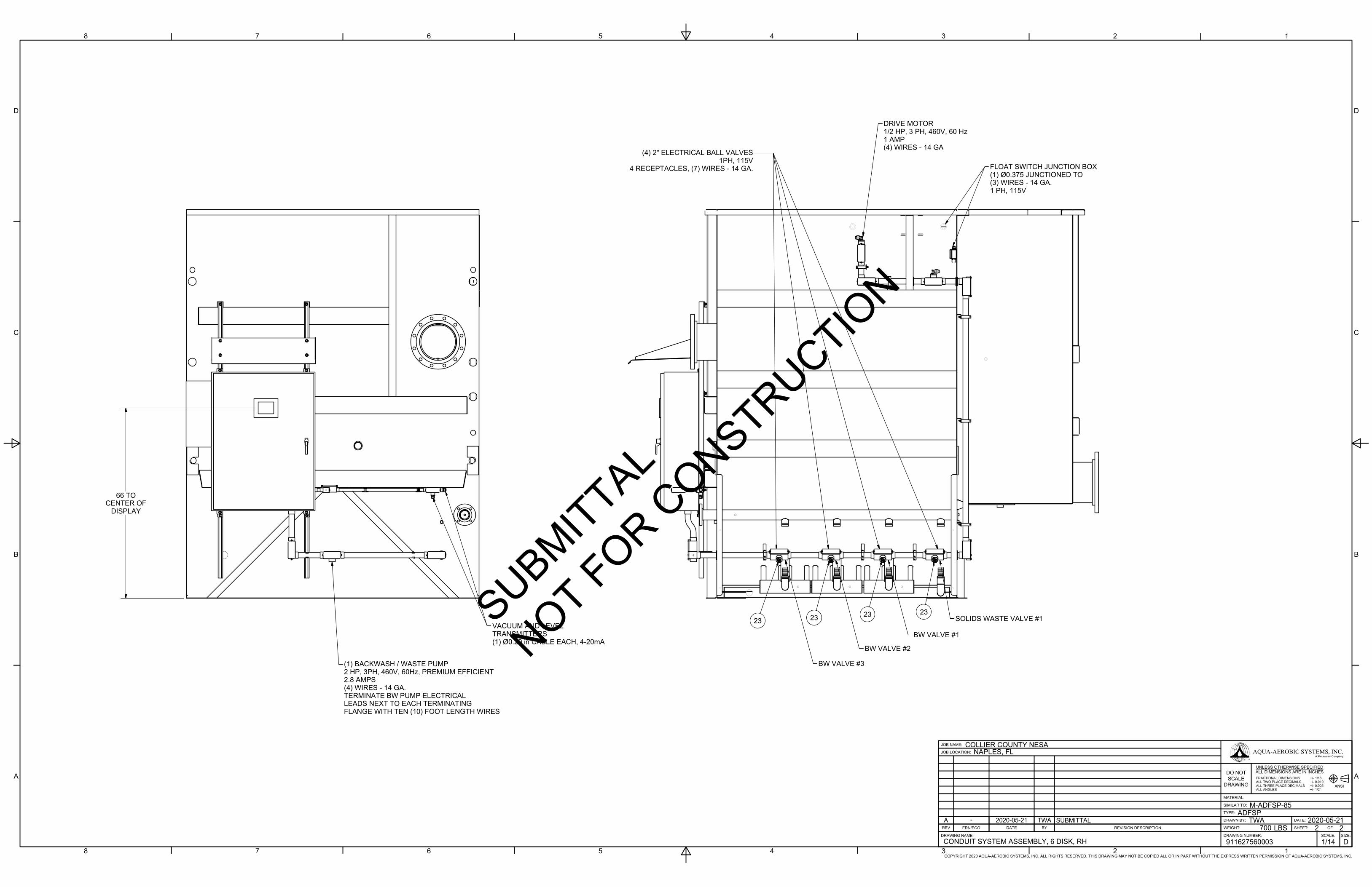
1
1
2
2
3
3
4
4
5
5
6
6
7
7
8
8
A A
B B
C C
D D
CONDUIT SYSTEM ASSEMBLY, 6 DISK, RH
COPYRIGHT 2020 AQUA-AEROBIC SYSTEMS, INC. ALL RIGHTS RESERVED. THIS DRAWING MAY NOT BE COPIED ALL OR IN PART WITHOUT THE EXPRESS WRITTEN PERMISSION OF AQUA-AEROBIC SYSTEMS, INC.
ANSI
D
JOB NAME:
JOB LOCATION:
DRAWING NAME: DRAWING NUMBER:
WEIGHT:
TYPE:
SIMILAR TO:
MATERIAL:
SHEET: OF
SIZE:SCALE:
911627560003
M-ADFSP-85
ADFSP
700
1/14
COLLIER COUNTY NESANAPLES, FL
DRAWN BY: DATE:TWA 2020-05-21LBS
UNLESS OTHERWISE SPECIFIEDALL DIMENSIONS ARE IN INCHESDO NOT
SCALEDRAWING
AQUA-AEROBIC SYSTEMS, INC.
+/- 1/16+/- 0.010+/- 0.005+/- 1/2°
FRACTIONAL DIMENSIONSALL TWO PLACE DECIMALSALL THREE PLACE DECIMALSALL ANGLES
2
®
2
A Metawater Company
(1) BACKWASH / WASTE PUMP2 HP, 3PH, 460V, 60Hz, PREMIUM EFFICIENT2.8 AMPS(4) WIRES - 14 GA.TERMINATE BW PUMP ELECTRICALLEADS NEXT TO EACH TERMINATINGFLANGE WITH TEN (10) FOOT LENGTH WIRES
66 TOCENTER OF
DISPLAY
VACUUM AND LEVELTRANSMITTERS(1) Ø0.20 in CABLE EACH, 4-20mA
DRIVE MOTOR1/2 HP, 3 PH, 460V, 60 Hz1 AMP(4) WIRES - 14 GA
FLOAT SWITCH JUNCTION BOX(1) Ø0.375 JUNCTIONED TO(3) WIRES - 14 GA.1 PH, 115V
23232323
BW VALVE #3
BW VALVE #2
BW VALVE #1
SOLIDS WASTE VALVE #1
(4) 2" ELECTRICAL BALL VALVES1PH, 115V
4 RECEPTACLES, (7) WIRES - 14 GA.
A - 2020-05-21 TWA SUBMITTALREV ERN/ECO DATE BY REVISION DESCRIPTION
SUBMITTAL
NOT FOR CONSTRUCTIO
N

SECTION A-A
DETAIL B
A A
B
Y304 SSCONTROL PANEL SUN SHIELD WELDMENT2913571134Y-CONTROL PANEL INSTALLATION911627560600133-PVCCONDUIT BODY, TYPE LB, 3/4"2611899132Y-FLOAT SWITCH JUNCTION BOX ASSEMBLY2966429131-316 SSLOCKNUT, 1 1/2" NPT2617082130-316 SSLOCKNUT, 3/4" NPT2617079129-NEOPRENESEAL RING, CONDUIT, 1 1/2"2616629128-NEOPRENESEAL RING, CONDUIT, 3/4"2600644127-PVCCONDUIT MALE ADAPTER, 1 1/2" NPT2611964126-PVCCONDUIT MALE ADAPTER, 3/4" NPT2611717125-316 SSNUT, SPRING, CHANNEL, 1/4-202607352124--RECEPTACLE, 7P FEMALE, 25 FT. LEAD, 14 AWG THHN2612779423-NYLONCONNECTOR, LIQTITE 0-90, 1/2" 2607383322-PVCRED BUSH, 1 1/2" SOC x 1/2" FNPT, S802615639621-PVCRED BUSH, 3/4" SOC x 1/2" FNPT, S802611720220-NYLONCORD GRIP, 0.169-0.449", 1/2" NPT STRAIGHT2607535219-316 SSWASHER, FLAT, 1/4" X 5/8" X .044"26002242318-316 SSNUT, HEX, NYLOCK, 1/4-20 26107011117-RUBBERGROMMET, 2 1/2" ID2615070416-RUBBERGROMMET, 1 1/2" ID2615071215-316 SSBHMS, 1/4-20 X 1"26002221214-PVCFLEX CONDUIT, 1/2" BLACK26077615 FT13-304 SSHANGER, CONDUIT, 3/4"2612246212-304 SSHANGER, CONDUIT, 1 1/2"26147361011-PVCCONDUIT BODY, TYPE T, 3/4"2611713110-PVCCONDUIT BODY, TYPE LL, 3/4"261171519-PVCCONDUIT BODY, TYPE C, 1 1/2"261500318-PVCCONDUIT BODY, TYPE T, 1 1/2"261500167-PVCCONDUIT BODY, TYPE LB, 1 1/2"261500036-PVCCONDUIT BODY, TYPE LL, 1 1/2"261196725-PVCCONDUIT BODY, TYPE LR, 1 1/2"261196814-PVCCONDUIT PIPE, 3/4", S40 x 10 FT. LG261500613-PVCCONDUIT PIPE, 1 1/2", S40 x 10 FT. LG261196622Y304 SSCONTROL PANEL / JUNCTION BOX MTG ASSY91162756000511
DWGMATERIALDESCRIPTIONPART NUMBERQTYITEM
CONDUIT SYSTEM ASSEMBLY, 6 DISK, LH
COPYRIGHT 2020 AQUA-AEROBIC SYSTEMS, INC. ALL RIGHTS RESERVED. THIS DRAWING MAY NOT BE COPIED ALL OR IN PART WITHOUT THE EXPRESS WRITTEN PERMISSION OF AQUA-AEROBIC SYSTEMS, INC.
ANSI
D
JOB NAME:
JOB LOCATION:
DRAWING NAME: DRAWING NUMBER:
WEIGHT:
TYPE:
SIMILAR TO:
MATERIAL:
SHEET: OF
SIZE:SCALE:
911627560004
M-ADFSP-86
ADFSP
700
1/20
COLLIER COUNTY NESANAPLES, FL
DRAWN BY: DATE:TWA 2020-05-21LBS
UNLESS OTHERWISE SPECIFIEDALL DIMENSIONS ARE IN INCHESDO NOT
SCALEDRAWING
AQUA-AEROBIC SYSTEMS, INC.
+/- 1/16+/- 0.010+/- 0.005+/- 1/2°
FRACTIONAL DIMENSIONSALL TWO PLACE DECIMALSALL THREE PLACE DECIMALSALL ANGLES
2
®
1
A Metawater Company
1
1
2
2
3
3
4
4
5
5
6
6
7
7
8
8
A A
B B
C C
D D
ASSEMBLY NOTES: 1. ALL RIGID CONDUIT AND FITTINGS UTILIZED ON TANK ASSEMBLY MUST BE PVC. ALL WIRE MUST BE 14GA, 600V, 19 STR, THHN. 2. USE TEFLON TAPE OR PASTE ON ALL THREADED CONNECTIONS WITH THE EXCEPTION OF TUBE FITTING NUTS. 3. SOLVENT BOND FITTINGS TOGETHER AS SHOWN UTILIZING THE LATEST INSTRUCTIONS FOR PRIMING AND SOLVENT CEMENTING PVC PIPING. 4. LABEL ALL WIRES AS SHOWN ON WIRING DIAGRAM WITH MARKERS FOUND IN CONTROL PANEL. 5. A MINIMUM OF TEN (10) FOOT LEADS OF ELECTRICAL WIRES (4) 14 GA. MUST BE PROVIDED BEYOND THE TERMINATION MANIFOLD FLANGES THAT ARE LISTED ON DRAWING AND ARE NOT FACTORY ASSEMBLED TO TANK. EACH SET OF LEADS MUST BE COILED, AND WRAPPED IN WEATHERPROOFPLASTIC BAG AND TEATHERED OFF TO TANK PRIOR TO SHIPMENT, FOR FIELD WIRING BY THE INSTALLING CONTRACTOR. 6. ALL FIELD WIRING AND MATERIALS REQUIRED TO COMPLETE INSTALLATION BETWEEN THE FACTORY MOUNTED CONTROL PANEL / JUNCTION BOX, AND THE SITE MAIN CONTROL PANEL, WILL BE SUPPLIED AND INSTALLED BY THE INSTALLING CONTRACTOR. 7. CUT CABLE FOR FLOAT SWITCH TO ALLOW FOR A 12 in. COIL OF EXTRA CABLE FOR FUTURE ADJUSTMENTS. TY-WRAP TO SUPPORT. 8. CUT CABLE FOR TRANSMITTERS, ALLOWING FOR A 36" SERVICE COIL INSIDE THE PANEL FOR FUTURE ADJUSTMENTS. 9. WHEN RUNNING CONNECTOR CABLES TO DEVICES, LEAVE A DRIP LOOP SO THAT WATER WILL NOT COLLECT AT THE CONNECTIONS. 10. EXTRA CONNECTORS ARE INCLUDED FOR THE MATING CONNECTION.
3113
72122
16
21
23
124
2CONDUIT BODYFOR BACKWASHVALVES TYP
1161 1/2
43 1/2
25 1/2
7 1/2
2
CONDUIT BODYFOR DRIVE MOTOR
8 13 21 2215
15
4
11
8
110
11 1/4
36 1/4
15 TYP
5
16
6
11 14 17 18
6
16
10 15/16
26 28 30
252729
51
11 24 14 18
CONDUIT BODYFOR BACKWASHPUMP
7
5
6
16
13
103
65
15
9
13 1/25 5/8
36 1/8
12
1920
CONDUIT BODYFOR PRESSURE
AND VACUUMTRANSMITTER
NOTES 8 & 9
10
12 14 17 18
19 20
NOTE 10
1
37 5/8
32
11 14 17 18
33
34
A - 2020-05-21 TWA SUBMITTALREV ERN/ECO DATE BY REVISION DESCRIPTION
SUBMITTAL
NOT FOR CONSTRUCTIO
N

CONDUIT SYSTEM ASSEMBLY, 6 DISK, LH
COPYRIGHT 2020 AQUA-AEROBIC SYSTEMS, INC. ALL RIGHTS RESERVED. THIS DRAWING MAY NOT BE COPIED ALL OR IN PART WITHOUT THE EXPRESS WRITTEN PERMISSION OF AQUA-AEROBIC SYSTEMS, INC.
ANSI
D
JOB NAME:
JOB LOCATION:
DRAWING NAME: DRAWING NUMBER:
WEIGHT:
TYPE:
SIMILAR TO:
MATERIAL:
SHEET: OF
SIZE:SCALE:
911627560004
M-ADFSP-86
ADFSP
700
1/14
COLLIER COUNTY NESANAPLES, FL
DRAWN BY: DATE:TWA 2020-05-21LBS
UNLESS OTHERWISE SPECIFIEDALL DIMENSIONS ARE IN INCHESDO NOT
SCALEDRAWING
AQUA-AEROBIC SYSTEMS, INC.
+/- 1/16+/- 0.010+/- 0.005+/- 1/2°
FRACTIONAL DIMENSIONSALL TWO PLACE DECIMALSALL THREE PLACE DECIMALSALL ANGLES
2
®
2
A Metawater Company
1
1
2
2
3
3
4
4
5
5
6
6
7
7
8
8
A A
B B
C C
D D
66 TOCENTER OF
DISPLAY
(1) BACKWASH / WASTE PUMP2 HP, 3PH, 460V, 60Hz, PREMIUM EFFICIENT
2.8 AMPS(4) WIRES - 14 GA.
TERMINATE BW PUMP ELECTRICALLEADS NEXT TO EACH TERMINATING
FLANGE WITH TEN (10) FOOT LENGTH WIRES
VACUUM AND LEVELTRANSMITTERS
(1) Ø0.20 in CABLE EACH, 4-20mA
DRIVE MOTOR1/2 HP, 3 PH, 460V, 60 Hz
1 AMP(4) WIRES - 14 GA
FLOAT SWITCH JUNCTION BOX(1) Ø0.375 JUNCTIONED TO
(3) WIRES - 14 GA.1 PH, 115V
23 23 2323
SOLIDS WASTE VALVE #1
BW VALVE #1
BW VALVE #2
BW VALVE #3
(4) 2" ELECTRICAL BALL VALVES1PH, 115V4 RECEPTACLES, (7) WIRES - 14 GA.
A - 2020-05-21 TWA SUBMITTALREV ERN/ECO DATE BY REVISION DESCRIPTION
SUBMITTAL
NOT FOR CONSTRUCTIO
N

SECTION A-ASCALE 1 / 16
DETAIL A(TYP. 6 PLACES)
DETAIL B(TYP. 4 PLACES)
DETAIL C(TYP. 2 PLACES)
DETAIL DSCALE 1/4
A
A
-316 SSWASHER, FLAT, 3/8" X 1" X .042"2600381227-316 SSNUT, HEX, JAM, 3/8-16260040366-316 SSNUT, HEX, FULL, 3/8-16260048165-316 SSHHCS, 3/8-16 X 1.25"2602257164-316 SSNUT, SPRING, CHANNEL, 3/8-162610648103Y304 SSSTOP PLATE2518881-SX022-304 SSUNISTRUT, 1 5/8", SQ X 10' LG2615177-SX021
DWGMATERIALDESCRIPTIONPART NUMBERQTYITEM
A
B
C
D
1
1
2
2
3
3
4
4
A A
B B
C C
D D
CONTROL PANEL / JUNCTION BOX MTG ASSY
COPYRIGHT 2020 AQUA-AEROBIC SYSTEMS, INC. ALL RIGHTS RESERVED. THIS DRAWING MAY NOT BE COPIED ALL OR IN PART WITHOUT THE EXPRESS WRITTEN PERMISSION OF AQUA-AEROBIC SYSTEMS, INC.
ANSI
C
JOB NAME:
JOB LOCATION:
DRAWING NAME: DRAWING NUMBER:
WEIGHT:
TYPE:
SIMILAR TO:
MATERIAL:
SHEET: OF
SIZE:SCALE:
911627560005
2965691
ADFSP
34
1/16
COLLIER COUNTY NESANAPLES, FL
DRAWN BY: DATE:TWA 2020-05-21LB
UNLESS OTHERWISE SPECIFIEDALL DIMENSIONS ARE IN INCHESDO NOT
SCALEDRAWING
AQUA-AEROBIC SYSTEMS, INC.
+/- 1/16+/- 0.010+/- 0.005+/- 1/2°
FRACTIONAL DIMENSIONSALL TWO PLACE DECIMALSALL THREE PLACE DECIMALSALL ANGLES
1
®
1
A Metawater Company
11
CONTROL PANEL / JUNCTION BOXIS FOR REFERENCE ONLY. REFER
TO CONDUIT ASSEMBLY FORLOCATION DETAILS.
4567
437
2347
437
437
(66)
(3)
A - 2020-05-21 TWA SUBMITTALREV ERN/ECO DATE BY REVISION DESCRIPTION
SUBMITTAL
NOT FOR CONSTRUCTIO
N

B
B
4 3 2 1
4 3 2 1
B B
A A
Copyright 2014 Aqua-Aerobic Systems, Inc. All Rights Reserved. This Drawing May Not Be Copied All Or In Part Without The Express Written Permission Of Aqua-Aerobic Systems, Inc.
JOB NAME:
JOB LOCATION:
B
REV ERN / ECO BY
DRAWING NAME:
REVISION DESCRIPTION
DRAWING NUMBER:
WEIGHT:
DRAWN BY:
TYPE:
SIMILAR TO:
MATERIAL:
DATE:
SHEET: OF
SIZE:SCALE:
DATE
AQUA-AEROBIC SYSTEMS, INC.®
ANSI
FRACTIONAL DIMENSIONSALL TWO PLACE DECIMALSALL THREE PLACE DECIMALSALL ANGLES
DO NOTSCALE
DRAWING+/- 1/16+/- 0.010+/- 0.005+/- 1/2°
UNLESS OTHERWISE SPECIFIEDALL DIMENSIONS ARE IN INCHES
KIT, WEDGE ANCHOR, 1/2", RED HEAD SWW 2962622 1:2
316 SS2962164
KMV 2002-11-141 1
D C16382 2014-07-10 CJC REV'D NOTE 4C C16309 2014-05-28 CJC REV'D NOTESB C15375 2012-12-20 JFF REV'D EMBEDMENT, INSTALLATION NOTES
R6415 2002-11-14 KMV NEW
INSTALLATION NOTES:
1. REVIEW ANCHOR INSTALLATION INSTRUCTIONS (EP-50329)LOCATED IN THE INSTALLATION SECTION OF THE O&M.
2. SELECT A CARBIDE HAMMER DRILL BIT WITH A DIAMETEREQUAL TO THE DIAMETER OF THE ANCHOR. LOCATE ANDHAMMER DRILL A STRAIGHT HOLE TO THE EMBEDMENT DEPTHSHOWN. CLEAN HOLE WITH COMPRESSED AIR TO REMOVEDUST AND DEBRIS.
3. ANTI-SEIZE LUBRICANT IS REQUIRED ON ALL STAINLESSSTEEL FASTENERS.
4. PLACE EQUIPMENT IN POSITION AND INSERT ASSEMBLEDANCHOR. INSTALL FULL NUT AND JAM NUT FLUSH WITH TOP OFANCHOR. HAMMER ANCHOR INTO HOLE UNTIL WASHER ANDFULL NUT ARE TIGHT AGAINST THE EQUIPMENT.
5. EXPAND WEDGE BY TIGHTENING FULL NUT, DO NOT USE ANIMPACT WRENCH TO SET OR TIGHTEN. USE AN INSTALLATIONTORQUE OF 41 LB-FT. WHILE HOLDING THE FULL NUT IN PLACE,TIGHTEN JAM NUT TO THE SAME TORQUE.
C
"F"
"A"
1
2
1/2" NUT(INCLUDED)
1/2" WASHER(INCLUDED)
"B" "C"
"D"
"E"
D
EFFECTIVEEMBEDMENT
"A"
NOMINALEMBEDMENT
"B"
MINIMUMHOLE DEPTH
"C"
ANCHOR LENGTH"D"
MAXIMUMPLATE THICKNESS
"E"
DRILL BITDIAMETER
"F"1 7/8" 2 1/8" 2 3/4" 4 1/4" 1 1/2" Ø1/2"
SUBMITTAL
NOT FOR CONSTRUCTIO
N

A
COPYRIGHT 2009 AQUA-AEROBIC SYSTEMS, INC. ALL RIGHTS RESERVED. THIS DRAWING MAY NOT BE COPIED ALL OR IN PART WITHOUT THE EXPRESS WRITTEN PERMISSION OF AQUA-AEROBIC SYSTEMS, INC.1234
1234
A
BB
B
JOB NAME:
JOB LOCATION:
REV ERN / ECO BY
DRAWING NAME:
REVISION DESCRIPTION
DRAWING NUMBER:
WEIGHT:
CHECKED BY:
DRAWN BY:
TYPE:
SIMILAR TO:
MATERIAL:
DATE:
DATE:
SHEET: OF
SIZE:SCALE:
DATE
DO NOTSCALE
DRAWING
AQUA-AEROBICSYSTEMS, INC.
MANUFACTURERS OF WASTEWATERTREATMENT EQUIPMENT
UNLESS OTHERWISE SPECIFIED
ANSIFRACTIONAL DIMENSIONS +/- 1/16ALL TWO PLACE DECIMALS +/- 0.010ALL THREE PLACE DECIMALS +/- 0.005ALL ANGLES +/- 1/2°
2" TCI SS GROOVED BALL VALVE W/RCEL-005L 2964965 1:4
DISKJFF 6/4/2009
1 1A R10749 6/4/2009 JFF NEW PARTB C12692 1/26/2010 JFF ADDED GROOVES TO VALVE
2"
3 7/16"
7.28"NOTES:
1. TO PREVENT NUISANCE TRIPPING AT THE END OF EACH STROKE,INDICATOR LAMP LIMIT SWITCHES MUST BE SET TO "LEAD" THE MOTORSTOP LIMIT SWITCH ON EACH END OF THE STROKE.
2. VALVE AND ACTUATOR MUST BE FULLY ASSEMBLED WITH 316STAINLESS STEEL HARDWARE WITH ACTUATOR BODY MOUNTEDPARALLEL WITH VALVE BODY. VALVE MUST BE SHIPPED IN THE FULLOPEN POSITION.
3. ONE COPY OF THE TEST REPORT / QUALITY CONTROL SHEET ANDONE COPY OF THE OPERATION AND MAINTENANCE MANUAL MUSTBE PROVIDED FOR EACH VALVE SUPPLIED. SEE ES-1135.
11 5/8"
2
34
1
ITEM QTY PART NUMBER DESCRIPTION MATERIAL DWG1 1 2614032 VALVE, 2" BALL GROOVED END, TCI TC-3000 316SS -2 1 2964966 ACTUATOR, RCI RCEL-005L W/ RECEPTACLE - Y3 4 2613990 FLAT WASHER, 8MM 316SS -4 4 2614016 HHCS, M8 X 1.25 x 25MM LG. 316SS -
3 1/2"
B
SUBMITTAL
NOT FOR CONSTRUCTIO
N
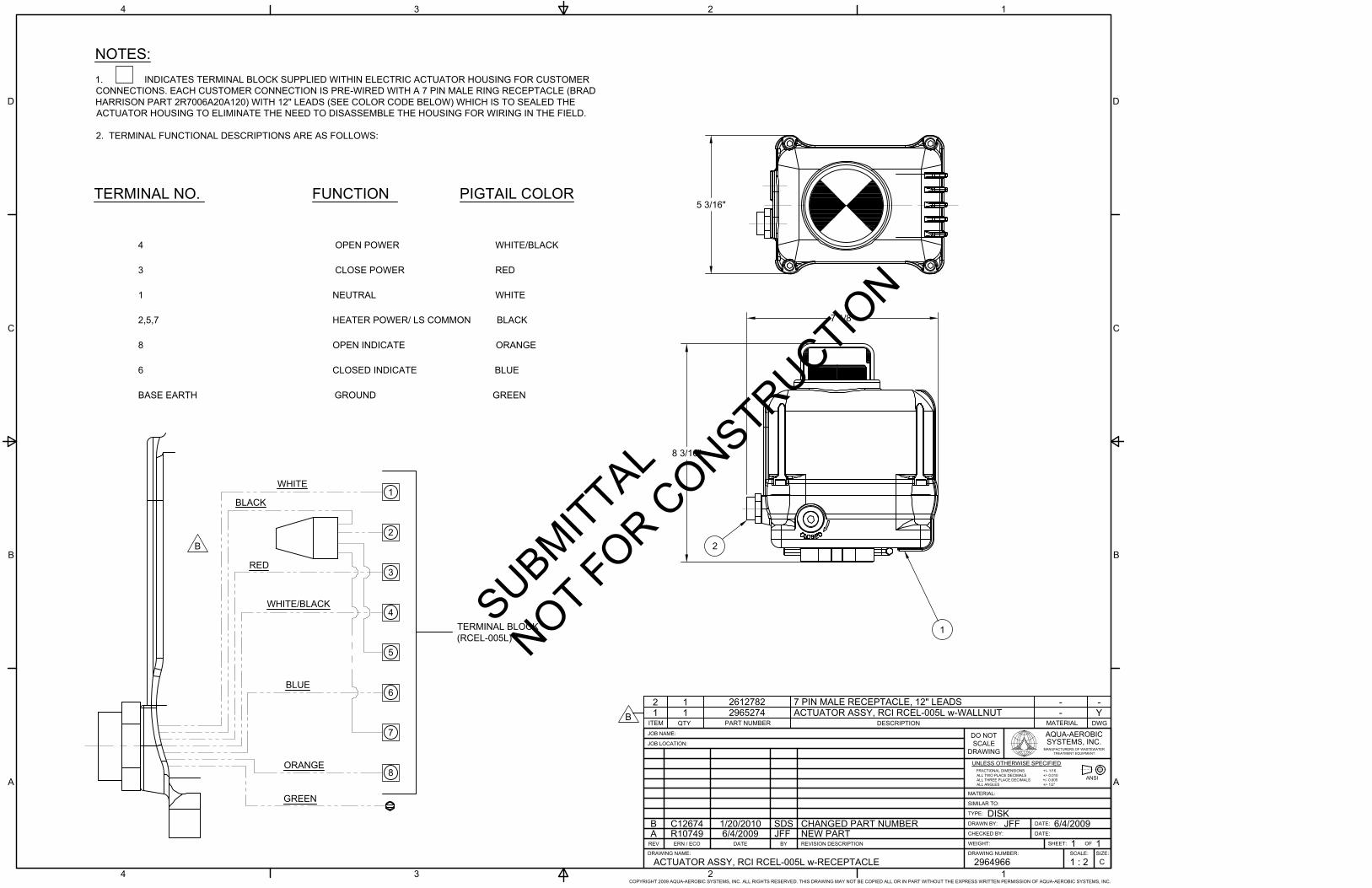
TERMINAL NO. FUNCTION PIGTAIL COLOR
4 OPEN POWER WHITE/BLACK
3 CLOSE POWER RED
1 NEUTRAL WHITE
2,5,7 HEATER POWER/ LS COMMON BLACK
8 OPEN INDICATE ORANGE
6 CLOSED INDICATE BLUE
BASE EARTH GROUND GREEN
1
2
3
4
5
6
7
8
WHITE
BLACK
RED
WHITE/BLACK
BLUE
ORANGE
TERMINAL BLOCK(RCEL-005L)
GREEN
A
2
COPYRIGHT 2009 AQUA-AEROBIC SYSTEMS, INC. ALL RIGHTS RESERVED. THIS DRAWING MAY NOT BE COPIED ALL OR IN PART WITHOUT THE EXPRESS WRITTEN PERMISSION OF AQUA-AEROBIC SYSTEMS, INC.1234
B
C
D
134
A
B
C
D
C
JOB NAME:
JOB LOCATION:
REV ERN / ECO BY
DRAWING NAME:
REVISION DESCRIPTION
DRAWING NUMBER:
WEIGHT:
CHECKED BY:
DRAWN BY:
TYPE:
SIMILAR TO:
MATERIAL:
DATE:
DATE:
SHEET: OF
SIZE:SCALE:
DATE
DO NOTSCALE
DRAWING
AQUA-AEROBICSYSTEMS, INC.
MANUFACTURERS OF WASTEWATERTREATMENT EQUIPMENT
UNLESS OTHERWISE SPECIFIED
ANSIFRACTIONAL DIMENSIONS +/- 1/16ALL TWO PLACE DECIMALS +/- 0.010ALL THREE PLACE DECIMALS +/- 0.005ALL ANGLES +/- 1/2°
ACTUATOR ASSY, RCI RCEL-005L w-RECEPTACLE 2964966 1 : 2
DISKJFF 6/4/2009
1 1A R10749 6/4/2009 JFF NEW PARTB C12674 1/20/2010 SDS CHANGED PART NUMBER
2
1
ITEM QTY PART NUMBER DESCRIPTION MATERIAL DWG1 1 2965274 ACTUATOR ASSY, RCI RCEL-005L w-WALLNUT - Y2 1 2612782 7 PIN MALE RECEPTACLE, 12" LEADS - -
NOTES:1. INDICATES TERMINAL BLOCK SUPPLIED WITHIN ELECTRIC ACTUATOR HOUSING FOR CUSTOMERCONNECTIONS. EACH CUSTOMER CONNECTION IS PRE-WIRED WITH A 7 PIN MALE RING RECEPTACLE (BRADHARRISON PART 2R7006A20A120) WITH 12" LEADS (SEE COLOR CODE BELOW) WHICH IS TO SEALED THEACTUATOR HOUSING TO ELIMINATE THE NEED TO DISASSEMBLE THE HOUSING FOR WIRING IN THE FIELD.
2. TERMINAL FUNCTIONAL DESCRIPTIONS ARE AS FOLLOWS:
B
B
5 3/16"
8 3/16"
7 1/8"
SUBMITTAL
NOT FOR CONSTRUCTIO
N

2
5
7
TERMINAL BLOCK(RCEL-005L)
A
2
COPYRIGHT 2009 AQUA-AEROBIC SYSTEMS, INC. ALL RIGHTS RESERVED. THIS DRAWING MAY NOT BE COPIED ALL OR IN PART WITHOUT THE EXPRESS WRITTEN PERMISSION OF AQUA-AEROBIC SYSTEMS, INC.1234
B
C
D
134
A
B
C
D
C
JOB NAME:
JOB LOCATION:
REV ERN / ECO BY
DRAWING NAME:
REVISION DESCRIPTION
DRAWING NUMBER:
WEIGHT:
CHECKED BY:
DRAWN BY:
TYPE:
SIMILAR TO:
MATERIAL:
DATE:
DATE:
SHEET: OF
SIZE:SCALE:
DATE
DO NOTSCALE
DRAWING
AQUA-AEROBICSYSTEMS, INC.
MANUFACTURERS OF WASTEWATERTREATMENT EQUIPMENT
UNLESS OTHERWISE SPECIFIED
ANSIFRACTIONAL DIMENSIONS +/- 1/16ALL TWO PLACE DECIMALS +/- 0.010ALL THREE PLACE DECIMALS +/- 0.005ALL ANGLES +/- 1/2°
ACTUATOR ASSY, RCI RCEL-005L w-WALLNUT 2965274 1 : 2
DISKSDS 1/20/2010
1 1A R11237 1/20/2010 SDS NEW PART
2
1
ITEM QTY PART NUMBER DESCRIPTION MATERIAL DWG1 1 2614298 ACTUATOR, RCI RCEL-005L - -2 1 2610162 WALL NUT #12-#16 X 4 - -
EXTERNAL2614298
8 3/16"
6 5/8"
5 3/16"
SUBMITTAL
NOT FOR CONSTRUCTIO
N

A A
12348 7 6 5Copyright 2013 Aqua-Aerobic Systems, Inc. All Rights Reserved. This Drawing May Not Be Copied All Or In Part Without The Express Written Permission Of Aqua-Aerobic Systems, Inc.
JOB NAME:
JOB LOCATION:
D
REV ERN / ECO BY
DRAWING NAME:
REVISION DESCRIPTION
DRAWING NUMBER:
WEIGHT:
DRAWN BY:
TYPE:
SIMILAR TO:
MATERIAL:
DATE:
SHEET: OF
SIZE:SCALE:
DATE
AQUA-AEROBIC SYSTEMS, INC.®
ANSI
FRACTIONAL DIMENSIONSALL TWO PLACE DECIMALSALL THREE PLACE DECIMALSALL ANGLES
DO NOTSCALE
DRAWING+/- 1/16+/- 0.010+/- 0.005+/- 1/2°
UNLESS OTHERWISE SPECIFIEDALL DIMENSIONS ARE IN INCHES
D
C
B
D
C
B
8 7 6 5 1234
PUMP ASSY, 12B20-B, 143T/145T MTR FRAME 2965308 1:8
PUMPSDS 2010-02-08
1 2AB C19883 2019-11-22 CJC ADDED TAB -31, -32 & SHT 2AA C19678 2019-08-14 GBM ADDED TABS -29 & -30Z C18655 2018-01-19 MOM REMOVED 208V RATINGS ON TECO MOTORSY C18384 2017-09-11 GBM ADDED TABS -27 & -28X C17805 2016-09-27 GBM UPDATED VOLTAGE, BALDOR MOTORSW C17012 2015-06-26 CJC ADDED ALIGNMENT NOTEV C16178 2014-03-19 AMG ADDED NOTEU C16155 2014-03-07 TWA ADDED TABS -25 & -26T C15841 2013-09-13 CJC ADDED TABS -23 & -24
TAB MOTOR
-1 2614678W-1
MTG MFG
OBSOLETE
HP FRAME RPM "A" "B"
-2 2614678W-2 OBSOLETE
-3 2614745-1 F1 BALDOR 2 145T 1800 37.0 [ 939.8 ] 6.38 [ 162.1 ] 214 LBS [ 97 kg ] ST, INVD
-4 2614745-2 F2 BALDOR 2 145T 1800 37.0 [ 939.8 ] 6.38 [ 162.1 ] 214 LBS [ 97 kg ]
-5 2614429W-1 F1 WEG 2 145T 1800 37.9 [ 962.6 ] 6.18 [ 157.0 ] 209 LBS [ 95 kg ]
-6 2614429W-2 F2 WEG 2 145T 1800 37.9 [ 962.6 ] 6.18 [ 157.0 ] 209 LBS [ 95 kg ]
-7 2614979W-1
-8 2614979W-2
-9 2614678W-1
-10 2614678W-2
-11 2614745-3 F1 BALDOR 2 145T 1800 37.0 [ 939.8 ] 6.38 [ 162.1 ] 214 LBS [ 97 kg ]
-12 2614745-4 F2 BALDOR 2 145T 1800 37.0 [ 939.8 ] 6.38 [ 162.1 ] 214 LBS [ 97 kg ]
-13 2614745-5 F1 BALDOR 2 145T 1800 37.4 [ 950.0 ] 6.51 [ 165.4 ] 222 LBS [ 101 kg ]
-14 2614745-6 F2 BALDOR 2 145T 1800 37.4 [ 950.0 ] 6.51 [ 165.4 ] 222 LBS [ 101 kg ]
-15 2615707-1 F1 TECO 2 145T 1800 38.0 [ 965.2 ] 6.18 [ 157.0 ] 211 LBS [ 96 kg ]
-16 2615707-2 F2 TECO 2 145T 1800 38.0 [ 965.2 ] 6.18 [ 157.0 ] 211 LBS [ 96 kg ]
-17 2615707-3 F1 TECO 2 145T 1800 38.0 [ 965.2 ] 6.18 [ 157.0 ] 211 LBS [ 96 kg ]
-18 2615707-4 F2 TECO 2 145T 1800 38.0 [ 965.2 ] 6.18 [ 157.0 ] 211 LBS [ 96 kg ]
-19 2614914-3 F1 BALDOR 2 145T 1800 37.4 [ 950.0 ] 6.51 [ 165.4 ] 222 LBS [ 101 kg ]
-20 2614914-4 F2 BALDOR 2 145T 1800 37.4 [ 950.0 ] 6.51 [ 165.4 ] 222 LBS [ 101 kg ]
-21
-22
-23
-24
-25
-26
-27
-28
NOTES:1. F1 MOUNTING SHOWN. THE F2 MOUNTING WILL HAVE THE MOTOR ELECTRICAL BOX ON THE OPPOSITE SIDE.
2. PUMP AND MOTOR ARE REQUIRED TO BE FACTORY ALIGNED DURING THE ASSEMBLY PROCESS.
3. AFTER PROPER ALIGNMENT IS COMPLETE, DISCONNECT COUPLING FOR SHIPMENT. COUPLING HALVES TO BESEPARATED AND SET SCREWED IN PLACE ON THE SHAFT RETAINING KEY WITH COUPLING HALF. PLACE COUPLINGSPIDER IN BAG AND WIRE TIE BAG TO PUMP. ATTACH TAG TO PUMP INDICATING "COUPLING HAS BEENDISCONNECTED".
4. 5.00 [ 127 ] MINIMUM / 18.00 [ 457.2 ] MAXIMUM DISTANCE FOR REMOVAL OF BACK COVER PLATE.
5. MOTOR WEIGHT (ITEM 2) = TOTAL WEIGHT FROM COLUMN MINUS TOTAL COMPONENT WEIGHT BELOW;PUMP (ITEM 1) = 111 lbs [ 51 kg ]BASE (ITEM 3) = 40 lbs [ 18 kg ]GUARD (ITEM 4) = 5 lbs [ 2 kg ]COUPLING (ITEM 5) = 2 lbs [ 1 kg ]
TOTAL COMPONENT WEIGHT = 158 lbs [ 72 kg ]
6. ALL MOTORS IN THIS ASSEMBLY MUST BE PREMIUM EFFICIENT PER EISA 2007 MOTOR REGULATIONS.
15.25 [387.4]
18.44 [468.3]
1.81[46.0]
5.88[149.2]
11.75 [298.5]
3.00[76.2]
12.88[327.2]
19.44[493.8]
(4) Ø.56 [14.3] HOLES
6.53[165.9]
7.75[196.9]
1.94 [49.2]
20.25[514.4]
5.00[127.0]
NOTE 4
SUCTION CONNECTION2.00 NPT
1.87 [47.6]
3.47[88.1]
30.25[768.4]
6.44[163.6]
"A" OVERALL LENGTH
23.22[589.7]
DISCHARGE CONNECTION2.00 NPT
SIGHT GAUGEBOTH SIDES
PEDESTAL AIR VENT
AUTOMATIC BOTTLE OILER FORSHAFT AND SLEEVE ASSEMBLY
1.28[32.6]2
541
3
NOTE 1
NOTE 2, 3
WEG
WEG
OBSOLETE
OBSOLETE
NOTE 3
2.63 [66.7]
DISCHARGE GAUGE PORT CONNECTION.25 NPT
3.31 [84.1]
SUCTION GAUGE PORT CONNECTION.25 NPT
"B"TO MOTOR
JUNCTION BOX
2616357-1 F1 BALDOR 2 145T 1800 37.4 [ 950.0 ] 6.51 [ 165.4 ] 222 LBS [ 101 kg ]
2616357-2 F2 BALDOR 2 145T 1800 37.4 [ 950.0 ] 6.51 [ 165.4 ] 222 LBS [ 101 kg ]
2 145T 1800 36.6 [ 929.7 ] 6.11 [ 155.2 ] 206 LBS [ 94 kg ]
2 145T 1800 36.6 [ 929.7 ] 6.11 [ 155.2 ] 206 LBS [ 94 kg ]
F1
F2
T2615707-5 F1 TECO 2 145T 1500 38.0 [ 965.2 ] 6.18 [ 157.0 ] 211 LBS [ 96 kg ]
2615707-6 F2 TECO 2 145T 1500 38.0 [ 965.2 ] 6.18 [ 157.0 ] 211 LBS [ 96 kg ]
ST, INVD
ST
ST
HTR, INVD
HTR, INVD
INVD
INVD
2614745-9 F1 BALDOR 2 145T 1800
2614745-10 F2 BALDOR 2 145T 1800
HTR, TSTAT, INVD
HTR, TSTAT, INVDU
EFF
PE
PE
PE
PE
PE
PE
PE
PE
PE
PE
PE
PE
PE
PE
PE
PE
PE
PE
PE
PE
PE
PE
V / PH / HZ
230-460 / 3 / 60
230-460 / 3 / 60
208-230-460 / 3 / 60
208-230-460 / 3 / 60
230-460 / 3 / 60
230-460 / 3 / 60
230-460 / 3 / 60
230-460 / 3 / 60
230-460 / 3 / 60
230-460 / 3 / 60
230-460 / 3 / 60
230-460 / 3 / 60
230-460 / 3 / 60
230-460 / 3 / 60
575 / 3 / 60
575 / 3 / 60
575 / 3 / 60
575 / 3 / 60
415 / 3 / 50
415 / 3 / 50
230-460 / 3 / 60
230-460 / 3 / 60
SF
1.15
1.15
1.25
1.25
1.15
1.15
1.15
1.15
1.15
1.15
1.15
1.15
1.15
1.15
1.15
1.15
1.0
1.0
1.15
1.15
F
F
F
F
F
F
F
F
F
F
F
F
F
F
F
F
F
F
F
F
F
F
40° C
40° C
40° C
40° C
40° C
40° C
40° C
40° C
40° C
40° C
40° C
40° C
50° C
50° C
40° C
40° C
40° C
40° C
40° C
40° C
50° C
50° C
MOTORSPECIAL
TOTALWEIGHT
AMB.TEMP
INS.CLASS
1.25
1.25
37.0 [ 939.8 ] 6.38 [ 162.1 ] 214 LBS [ 97 kg ]
37.0 [ 939.8 ] 6.38 [ 162.1 ] 214 LBS [ 97 kg ]
INVD
INVD
INVD
INVD V
CHART NOTES:1. "RPM" IS SHOWN AS NOMINALMOTOR RPM.
2. SEE ES-1268 FOR EXPLANATIONOF "MOTOR SPECIAL".
W
W
X
X
X
X
2614914-1 F1 BALDOR 2 145T 1800 37.4 [ 950.0 ] 6.51 [ 165.4 ] 222 LBS [ 101 kg ]
2614914-2 F2 BALDOR 2 145T 1800 37.4 [ 950.0 ] 6.51 [ 165.4 ] 222 LBS [ 101 kg ]
PE
PE
230-460 / 3 / 60
230-460 / 3 / 60
1.15
1.15
F
F
50° C
50° CY
HTR
HTR
Z
-29
-30
2616357-3 F1 BALDOR 2 145T 1800 37.4 [ 950.0 ] 6.51 [ 165.4 ] 222 LBS [ 101 kg ]
2616357-4 F2 BALDOR 2 145T 1800 37.4 [ 950.0 ] 6.51 [ 165.4 ] 222 LBS [ 101 kg ]
PE
PE
575 / 3 / 60
575 / 3 / 60
1.15
1.15
F
F
40° C
40° CAA
HTR, TMSTR
HTR, TMSTR
SUBMITTAL
NOT FOR CONSTRUCTIO
N
AutoCAD SHX Text
GORMAN-RUPP
AutoCAD SHX Text
R

A A
12348 7 6 5Copyright 2013 Aqua-Aerobic Systems, Inc. All Rights Reserved. This Drawing May Not Be Copied All Or In Part Without The Express Written Permission Of Aqua-Aerobic Systems, Inc.
JOB NAME:
JOB LOCATION:
D
REV ERN / ECO BY
DRAWING NAME:
REVISION DESCRIPTION
DRAWING NUMBER:
WEIGHT:
DRAWN BY:
TYPE:
SIMILAR TO:
MATERIAL:
DATE:
SHEET: OF
SIZE:SCALE:
DATE
AQUA-AEROBIC SYSTEMS, INC.®
ANSI
FRACTIONAL DIMENSIONSALL TWO PLACE DECIMALSALL THREE PLACE DECIMALSALL ANGLES
DO NOTSCALE
DRAWING+/- 1/16+/- 0.010+/- 0.005+/- 1/2°
UNLESS OTHERWISE SPECIFIEDALL DIMENSIONS ARE IN INCHES
D
C
B
D
C
B
8 7 6 5 1234
PUMP ASSY, 12B20-B, 143T/145T MTR FRAME 2965308 1:8
PUMPSDS 2010-02-08
2 2AB C19883 2019-11-22 CJC ADDED TAB -31, -32 & SHT 2AA C19678 2019-08-14 GBM ADDED TABS -29 & -30Z C18655 2018-01-19 MOM REMOVED 208V RATINGS ON TECO MOTORSY C18384 2017-09-11 GBM ADDED TABS -27 & -28X C17805 2016-09-27 GBM UPDATED VOLTAGE, BALDOR MOTORSW C17012 2015-06-26 CJC ADDED ALIGNMENT NOTEV C16178 2014-03-19 AMG ADDED NOTEU C16155 2014-03-07 TWA ADDED TABS -25 & -26T C15841 2013-09-13 CJC ADDED TABS -23 & -24
TAB MOTOR
-31
MTG MFG HP FRAME RPM "A" "B"
-32
NOTES:1. F1 MOUNTING SHOWN. THE F2 MOUNTING WILL HAVE THE MOTOR ELECTRICAL BOX ON THE OPPOSITE SIDE.
2. PUMP AND MOTOR ARE REQUIRED TO BE FACTORY ALIGNED DURING THE ASSEMBLY PROCESS.
3. AFTER PROPER ALIGNMENT IS COMPLETE, DISCONNECT COUPLING FOR SHIPMENT. COUPLING HALVES TO BESEPARATED AND SET SCREWED IN PLACE ON THE SHAFT RETAINING KEY WITH COUPLING HALF. PLACE COUPLINGSPIDER IN BAG AND WIRE TIE BAG TO PUMP. ATTACH TAG TO PUMP INDICATING "COUPLING HAS BEENDISCONNECTED".
4. 5.00 [ 127 ] MINIMUM / 18.00 [ 457.2 ] MAXIMUM DISTANCE FOR REMOVAL OF BACK COVER PLATE.
5. MOTOR WEIGHT (ITEM 2) = TOTAL WEIGHT FROM COLUMN MINUS TOTAL COMPONENT WEIGHT BELOW;PUMP (ITEM 1) = 111 lbs [ 51 kg ]BASE (ITEM 3) = 40 lbs [ 18 kg ]GUARD (ITEM 4) = 5 lbs [ 2 kg ]COUPLING (ITEM 5) = 2 lbs [ 1 kg ]
TOTAL COMPONENT WEIGHT = 158 lbs [ 72 kg ]
6. ALL MOTORS IN THIS ASSEMBLY MUST BE PREMIUM EFFICIENT PER EISA 2007 MOTOR REGULATIONS.
15.25 [387.4]
18.44 [468.3]
1.81[46.0]
5.88[149.2]
11.75 [298.5]
3.00[76.2]
12.88[327.2]
19.44[493.8]
(4) Ø.56 [14.3] HOLES
6.53[165.9]
7.75[196.9]
1.94 [49.2]
20.25[514.4]
5.00[127.0]
NOTE 4
SUCTION CONNECTION2.00 NPT
1.87 [47.6]
3.47[88.1]
30.25[768.4]
6.44[163.6]
"A" OVERALL LENGTH
23.22[589.7]
DISCHARGE CONNECTION2.00 NPT
SIGHT GAUGEBOTH SIDES
PEDESTAL AIR VENT
AUTOMATIC BOTTLE OILER FORSHAFT AND SLEEVE ASSEMBLY
1.28[32.6]2
541
3
NOTE 1
NOTE 2, 3
NOTE 3
2.63 [66.7]
DISCHARGE GAUGE PORT CONNECTION.25 NPT
3.31 [84.1]
SUCTION GAUGE PORT CONNECTION.25 NPT
"B"TO MOTOR
JUNCTION BOX
2616357-5 F1 BALDOR 2 145T 1800 37.4 [ 950.0 ] 6.51 [ 165.4 ] 222 LBS [ 101 kg ]
2616357-6 F2 BALDOR 2 145T 1800 37.4 [ 950.0 ] 6.51 [ 165.4 ] 222 LBS [ 101 kg ]
EFF
PE
PE
V / PH / HZ
575 / 3 / 60
575 / 3 / 60
SF
1.15
1.15
F
F
40° C
40° C
MOTORSPECIAL
TOTALWEIGHT
AMB.TEMP
INS.CLASS
CHART NOTES:1. "RPM" IS SHOWN AS NOMINALMOTOR RPM.
2. SEE ES-1268 FOR EXPLANATIONOF "MOTOR SPECIAL".TSTAT
TSTATAB
SUBMITTAL
NOT FOR CONSTRUCTIO
N
AutoCAD SHX Text
GORMAN-RUPP
AutoCAD SHX Text
R

A
A
10-FLAT WASHER - 1/2 - Std - 316SS260042649-HEX JAM NUT - 1/2-13 UNC260023428-HEX FULL NUT - 1/2-13 UNC - 316SS260051727-HHCS, 1/2-13 UNC X 5.00" LG 261353726 5YBUSHING, WIDE ROLLER251948324 3YWHEEL, 6", WIDE251948122YDUAL WHEEL WELDMENT291494611
DWGDESCRIPTIONPART NUMBERQTYITEM
1
1
2
2
3
3
4
4
A A
B B
DUAL WHEEL ASSEMBLY
CJC 2010-07-19
COPYRIGHT 2010 AQUA-AEROBIC SYSTEMS, INC. ALL RIGHTS RESERVED. THIS DRAWING MAY NOT BE COPIED ALL OR IN PART WITHOUT THE EXPRESS WRITTEN PERMISSION OF AQUA-AEROBIC SYSTEMS, INC.
ANSI
B
DO NOTSCALE
DRAWING
AQUA-AEROBICSYSTEMS, INC.MANUFACTURERS OF WASTEWATER
TREATMENT EQUIPMENT
UNLESS OTHERWISE SPECIFIEDFRACTIONAL DIMENSIONS +/- 1/16ALL TWO PLACE DECIMALS +/- 0.010ALL THREE PLACE DECIMALS +/- 0.005ALL ANGLES +/- 1/2°
JOB NAME:JOB LOCATION:
REV ERN / ECO BYDRAWING NAME:
REVISION DESCRIPTIONDRAWING NUMBER:WEIGHT:
CHECKED BY:
DRAWN BY:
TYPE:
SIMILAR TO:
MATERIAL:
DATE:
DATE:
SHEET: OFSIZE:SCALE:
DATE 1 1
2965527
2962377
ADFS
41 LB
1:4
A R11646 2010-08-24 CJC RELEASE TO PRODUCTIONB C13721 2011-02-03 CJC REV'D ITEM #3C C14574 2011-11-23 CJC REV'D BOMD C15081 2012-08-08 CJC REV'D BOM
NOTES: 1. APPLY A LIBERAL AMOUNT OF WATER-RESISTANT GREASETO BOLT SHANK AND BUSHING PRIOR TO ASSEMBLY. 2. TORQUE BOLT AND FULL NUT TO 30 ft-lb AND LOCK WITH JAM NUT. (TYP 2 PLACES) 3. ANTI-SEIZE LUBRICANT IS REQUIRED ON ALL FASTENERS. 4. REFER TO AASI PURCHASE ORDER, ROUTING, OR MATERIAL SCHEDULE FOR MATERIAL TYPE, FINISH, AND CERTIFICATION INFORMATION.
2
69 7 8 9
4
32 in REF
1
B
C
C
3 3/8 inREF
CD
SUBMITTAL
NOT FOR CONSTRUCTIO
N

-SILICONE SEALANT, RTV2606859.126-NUT, HEX, NYLOCK, 1/4-20 261070185-WASHER, FLAT, 1/4" X 5/8" X .044"260022484-BHMS, 1/4-20 X 0.75"261070083YBACKWASH SHOE, ADFS-54, 8MM252059412YBACKWASH SHOE WELDMENT RH291497411
DWGDESCRIPTIONPART NUMBERQTYITEM
1
1
2
2
3
3
4
4
A A
B B
C C
D D
BACKWASH NOZZLE ASSEMBLY RH
CJC 2010-07-06
COPYRIGHT 2010 AQUA-AEROBIC SYSTEMS, INC. ALL RIGHTS RESERVED. THIS DRAWING MAY NOT BE COPIED ALL OR IN PART WITHOUT THE EXPRESS WRITTEN PERMISSION OF AQUA-AEROBIC SYSTEMS, INC.
ANSI
C
DO NOTSCALE
DRAWING
AQUA-AEROBICSYSTEMS, INC.MANUFACTURERS OF WASTEWATER
TREATMENT EQUIPMENT
UNLESS OTHERWISE SPECIFIEDFRACTIONAL DIMENSIONS +/- 1/16ALL TWO PLACE DECIMALS +/- 0.010ALL THREE PLACE DECIMALS +/- 0.005ALL ANGLES +/- 1/2°
JOB NAME:JOB LOCATION:
REV ERN / ECO BYDRAWING NAME:
REVISION DESCRIPTIONDRAWING NUMBER:WEIGHT:
CHECKED BY:
DRAWN BY:
TYPE:
SIMILAR TO:
MATERIAL:
DATE:
DATE:
SHEET: OFSIZE:SCALE:
DATE 1 1
2965560
2962574
ADFS
8 LB
1:2
A R11677 2010-08-24 CJC RELEASE TO PRODUCTIONB C16344 2014-06-17 CJC REV'D ITEM 2
24 in REF.9/32 in REF.
10 1/8 inREF.
4 11/16 inREF.
83°REF.
NOTES: 1. SEAL BACKWASH SHOE NOZZLE PLATE (ITEM #2) TO BACKWASH SHOE WELDMENT (ITEM #1) USING RTV SILICONE SEALANT (ITEM #6), DO NOT SUBSTITUTE THE RTV SILICONE SEALANT. SEAL ENTIRE PERIMETER OF HOUSING ESPECIALLY THE 1/4" THK. END CAPS TO ELIMINATE LEAKS. 2. DO NOT USE ANTI-SEIZE ON BOLTS FASTENED WITH NYLOK NUTS. 3. REFER TO EXPANDED BILL OF MATERIAL FOR MATERIAL FINISH AND CERTIFICATION.
2 6
1
345
SEE NOTE #1
B
SUBMITTAL
NOT FOR CONSTRUCTIO
N

-SILICONE SEALANT, RTV2606859.126-NUT, HEX, NYLOCK, 1/4-20 261070185-WASHER, FLAT, 1/4" X 5/8" X .044"260022484-BHMS, 1/4-20 X 0.75"261070083YBACKWASH SHOE, ADFS-54, 8MM252059412YBACKWASH SHOE WELDMENT LH291497511
DWGDESCRIPTIONPART NUMBERQTYITEM
1
1
2
2
3
3
4
4
A A
B B
C C
D D
BACKWASH NOZZLE ASSEMBLY LH
CJC 2010-07-06
COPYRIGHT 2010 AQUA-AEROBIC SYSTEMS, INC. ALL RIGHTS RESERVED. THIS DRAWING MAY NOT BE COPIED ALL OR IN PART WITHOUT THE EXPRESS WRITTEN PERMISSION OF AQUA-AEROBIC SYSTEMS, INC.
ANSI
C
DO NOTSCALE
DRAWING
AQUA-AEROBICSYSTEMS, INC.MANUFACTURERS OF WASTEWATER
TREATMENT EQUIPMENT
UNLESS OTHERWISE SPECIFIEDFRACTIONAL DIMENSIONS +/- 1/16ALL TWO PLACE DECIMALS +/- 0.010ALL THREE PLACE DECIMALS +/- 0.005ALL ANGLES +/- 1/2°
JOB NAME:JOB LOCATION:
REV ERN / ECO BYDRAWING NAME:
REVISION DESCRIPTIONDRAWING NUMBER:WEIGHT:
CHECKED BY:
DRAWN BY:
TYPE:
SIMILAR TO:
MATERIAL:
DATE:
DATE:
SHEET: OFSIZE:SCALE:
DATE 1 1
2965561
2962574
ADFS
8 LB
1:2
A R11677 2010-08-24 CJC RELEASE TO PRODUCTIONB C16344 2014-06-17 CJC REV'D ITEM 2
24 in REF.9/32 in REF.
10 1/8 inREF.
4 11/16 inREF.
83°REF.
1
2 6
345
NOTES: 1. SEAL BACKWASH SHOE NOZZLE PLATE (ITEM #2) TO BACKWASH SHOE WELDMENT (ITEM #1) USING RTV SILICONE SEALANT (ITEM #6), DO NOT SUBSTITUTE THE RTV SILICONE SEALANT. SEAL ENTIRE PERIMETER OF HOUSING, ESPECIALLY THE 1/4" THK. END CAPS TO ELIMINATE LEAKS. 2. DO NOT USE ANTI-SEIZE ON BOLTS FASTENED WITH NYLOK NUTS. 3. REFER TO EXPANDED BILL OF MATERIAL FOR MATERIAL FINISH AND CERTIFICATION.
SEE NOTE #1
B
SUBMITTAL
NOT FOR CONSTRUCTIO
N

SECTION A-A
A
A
--CORD, 7P MALE/FEMALE, 3 FT. LG.261439516-STEELGROOVED COUPLING ASSEMBLY296296625-STAINLESS STEELCLAMP, T-BOLT, STBC263261781324-316 SSCOMBO NIPPLE, 2" HOSE X VICTAULIC260948113-NITRILEHOSE, 2" ID26065120.6 FT2Y316 SS2" TCI SS GROOVED BALL VALVE W/RCEL-005L296496511
DWGMATERIALDESCRIPTIONPART NUMBERQTYITEM
1
1
2
2
3
3
4
4
A A
B B
VALVE & HOSE ASSY, 2" BALL, RCEL-005L, TC-RC
COPYRIGHT 2016 AQUA-AEROBIC SYSTEMS, INC. ALL RIGHTS RESERVED. THIS DRAWING MAY NOT BE COPIED ALL OR IN PART WITHOUT THE EXPRESS WRITTEN PERMISSION OF AQUA-AEROBIC SYSTEMS, INC.
ANSI
B
JOB NAME:
JOB LOCATION:
DRAWING NAME: DRAWING NUMBER:
WEIGHT:
TYPE:
SIMILAR TO:
MATERIAL:
SHEET: OF
SIZE:SCALE:
2965563
-2964967
ADFSP
0
1/8
DRAWN BY: DATE:CJC 2010-07-07LB
UNLESS OTHERWISE SPECIFIEDALL DIMENSIONS ARE IN INCHESDO NOT
SCALEDRAWING
AQUA-AEROBIC SYSTEMS, INC.
+/- 1/16+/- 0.010+/- 0.005+/- 1/2°
FRACTIONAL DIMENSIONSALL TWO PLACE DECIMALSALL THREE PLACE DECIMALSALL ANGLES
1
®
1
A Metawater Company
A R11828 2010-08-25 CJC RELEASE TO PRODUCTIONB C13603 2010-12-09 CJC REV'D HOSE LENGTHC C14235 2011-08-03 CJC REV'D BOM & NOTESD C16941 2015-05-20 CJC REV'D HOSE CLAMPSE C17515 2016-05-16 GBM REV'D HOSE CLAMPS
REV ERN/ECO DATE BY REVISION DESCRIPTION
1
6
4
4
5
5
7REF.
2
3
INSTALLATION NOTES:
1. BE SURE TO REMOVE ANY DEBRIS FROM THE MATING COMPONENT TO ENSURE A LEAK-TIGHT SEAL. 2. APPLY A THIN LAYER OF SILICONE LUBRICANT ONLY TO THE SEALING LIPS OF THE GASKET INTERIOR. 3. TIGHTEN THE NUTS EVENLY BY ALTERNATING SIDES UNTIL METAL-TO-METAL CONTACT OCCURS AT THE ANGLE BOLT PADS. 4. REFER TO EP-50195 FOR MORE DETAILED INSTALLATION INSTRUCTIONS.
ED
B
C
C
SUBMITTAL
NOT FOR CONSTRUCTIO
N

SECTION A-A
YSHIM, PILLOW BLOCK, 1/16" THK.251870517YSHIM, PILLOW BLOCK, 1/4" THK.251870426YSHIM, PILLOW BLOCK, 1/8" THK.251870325-SHAFT COLLAR, 2" ID261424524YSHAFT SLEAVE BEARING251077623-V-RING SEAL - 2.88" I.D.260894422-BEARING - PILLOW BLOCK 2" DIA. 260893211
DWGDESCRIPTIONPART NUMBERQTYITEM
A A
1
1
2
2
3
3
4
4
A A
B B
CENTERTUBE BEARING KIT
CJC 2010-07-21
COPYRIGHT 2010 AQUA-AEROBIC SYSTEMS, INC. ALL RIGHTS RESERVED. THIS DRAWING MAY NOT BE COPIED ALL OR IN PART WITHOUT THE EXPRESS WRITTEN PERMISSION OF AQUA-AEROBIC SYSTEMS, INC.
ANSI
B
DO NOTSCALE
DRAWING
AQUA-AEROBICSYSTEMS, INC.MANUFACTURERS OF WASTEWATER
TREATMENT EQUIPMENT
UNLESS OTHERWISE SPECIFIEDFRACTIONAL DIMENSIONS +/- 1/16ALL TWO PLACE DECIMALS +/- 0.010ALL THREE PLACE DECIMALS +/- 0.005ALL ANGLES +/- 1/2°
JOB NAME:JOB LOCATION:
REV ERN / ECO BYDRAWING NAME:
REVISION DESCRIPTIONDRAWING NUMBER:WEIGHT:
CHECKED BY:
DRAWN BY:
TYPE:
SIMILAR TO:
MATERIAL:
DATE:
DATE:
SHEET: OFSIZE:SCALE:
DATE 1 1
2965614
2961821
ADFS
1:2
A R11646 2010-08-24 CJC RELEASE TO PRODUCTIONB C14568 2011-11-22 CJC ADDED NOTEC C14633 2012-01-09 CJC REV'D NOTE
1
NOTES:
1. ITEMS #5 THRU #7 ARE USED TO ADJUST THE HEIGHT OF THE BEARING TO MATCH THE CENTERLINE OF THE CENTERTUBE. 2. SECURE SHAFT COLLAR SCREWS WITH LOCTITE 243 (BLUE). 3. REFER TO AASI PURCHASE ORDER, ROUTING, OR MATERIAL SCHEDULE FOR MATERIAL TYPE, FINISH, AND CERTIFICATION INFORMATION.
232 3
4 4
B
SEE NOTE 2
C
SUBMITTAL
NOT FOR CONSTRUCTIO
N

SECTION A-ASCALE 1/4
A
A
-316 SSNIPPLE, 1/2", S40, CLOSE2615401-000-6X015-316 SSBALL VALVE, NPT, 1/2", APOLLO 76-103-01A261217614-316 SSRED BUSH, NPT, 1/2" X 1/4" 2615179-6X013--CONNECTOR CABLE, IFM EVC531261496812--PRESSURE TRANSMITTER, IFM PX3228, 0-100 IN H2O261496911
DWGMATERIALDESCRIPTIONPART NUMBERQTYITEM
1
1
2
2
3
3
4
4
A A
B B
PRESSURE TRANSMITTER INSTL
COPYRIGHT 2017 AQUA-AEROBIC SYSTEMS, INC. ALL RIGHTS RESERVED. THIS DRAWING MAY NOT BE COPIED ALL OR IN PART WITHOUT THE EXPRESS WRITTEN PERMISSION OF AQUA-AEROBIC SYSTEMS, INC.
ANSI
B
JOB NAME:
JOB LOCATION:
DRAWING NAME: DRAWING NUMBER:
WEIGHT:
TYPE:
SIMILAR TO:
MATERIAL:
SHEET: OF
SIZE:SCALE:
2965616
ADFSP
1/8
DRAWN BY: DATE:CJC 2010-07-26
UNLESS OTHERWISE SPECIFIEDALL DIMENSIONS ARE IN INCHESDO NOT
SCALEDRAWING
AQUA-AEROBIC SYSTEMS, INC.
+/- 1/16+/- 0.010+/- 0.005+/- 1/2°
FRACTIONAL DIMENSIONSALL TWO PLACE DECIMALSALL THREE PLACE DECIMALSALL ANGLES
1
®
1
A Metawater Company
(26 1/2)
1
2
(13)
NOTES:
1. USE PIPE TAPE OR PASTE. 2. LOCATE TRANSMITTER AS CLOSE AS POSSIBLE TO AN EXISTING SIGNAL CONDUIT RUN. 3. RH TANK WITH PANEL ON INFLUENT END SHOWN FOR REFERENCE ONLY.
3
BC
E
45
A R11828 2010-08-25 CJC RELEASE TO PRODUCTIONB C13423 2010-09-21 CJC REV'D ITEM #2 DESCRIPTIONC C13522 2010-10-28 CJC REV'D ITEM #3D C13721 2011-02-03 CJC VANTAGE REV.E C14235 2011-08-03 CJC REV'D BOMF C18436 2017-09-28 CJC ADDED ISOLATION VALVE
REV ERN/ECO DATE BY REVISION DESCRIPTION
F
(24)FROMTANK
FLOORF
SUBMITTAL
NOT FOR CONSTRUCTIO
N

RH TANK SHOWN FOR REFERENCE ONLY
SECTION A-ASCALE 1/6
-NYLONCORD GRIP, 0.169-0.449", 1/2" NPT STRAIGHT260753513-316 SSLOCKNUT, 1/2" NPT261303412--FLOAT SWITCH, MODEL #GSI 40NONC-STO261118311
DWGMATERIALDESCRIPTIONPART NUMBERQTYITEM
A
A
1
1
2
2
3
3
4
4
A A
B B
C C
D D
FLOAT SWITCH INSTL, NON-MERCURY
CJC 2010-08-12
COPYRIGHT 2010 AQUA-AEROBIC SYSTEMS, INC. ALL RIGHTS RESERVED. THIS DRAWING MAY NOT BE COPIED ALL OR IN PART WITHOUT THE EXPRESS WRITTEN PERMISSION OF AQUA-AEROBIC SYSTEMS, INC.
ANSI
C
DO NOTSCALE
DRAWING
AQUA-AEROBICSYSTEMS, INC.MANUFACTURERS OF WASTEWATER
TREATMENT EQUIPMENT
UNLESS OTHERWISE SPECIFIEDFRACTIONAL DIMENSIONS +/- 1/16ALL TWO PLACE DECIMALS +/- 0.010ALL THREE PLACE DECIMALS +/- 0.005ALL ANGLES +/- 1/2°
JOB NAME:JOB LOCATION:
REV ERN / ECO BYDRAWING NAME:
REVISION DESCRIPTIONDRAWING NUMBER:WEIGHT:
CHECKED BY:
DRAWN BY:
TYPE:
SIMILAR TO:
MATERIAL:
DATE:
DATE:
SHEET: OFSIZE:SCALE:
DATE 1 1
2965623
2963873
ADFSP
1/16
A R11828 2010-08-25 CJC RELEASE TO PRODUCTIONB C16635 2014-11-06 CJC REV'D MOUNTING
1 in TO OVERFLOW
WEIR
1
TOP OF TANK
NOTES: 1. SEE CONTROL PANEL WIRING SCHEMATIC DRAWINGS FOR WIRING INFORMATION.
11 1/8 inREF
1 inDE-ACTUATE
(FALLING LEVEL)
3
2
RUN CABLETHROUGH EYELETTO NEARESTCONDUIT BODY
3 inACTUATE
(RISING LEVEL)
TRIP POINT
B
B
B
SUBMITTAL
NOT FOR CONSTRUCTIO
N

-PIN, GROOVED, 5/16' DIA. x 1 1/4" LG.261036013-NUT, HEX, 3/4"-6 ACME261053312-THREADED ROD, 3/4"-6 ACME x 12" LG.261505711
DWGDESCRIPTIONPART NUMBERQTYITEM
1
1
2
2
3
3
4
4
A A
B B
THREADED ROD DRIVE ASSEMBLY
CJC 2010-08-31
COPYRIGHT 2010 AQUA-AEROBIC SYSTEMS, INC. ALL RIGHTS RESERVED. THIS DRAWING MAY NOT BE COPIED ALL OR IN PART WITHOUT THE EXPRESS WRITTEN PERMISSION OF AQUA-AEROBIC SYSTEMS, INC.
ANSI
B
DO NOTSCALE
DRAWING
AQUA-AEROBICSYSTEMS, INC.MANUFACTURERS OF WASTEWATER
TREATMENT EQUIPMENT
UNLESS OTHERWISE SPECIFIEDFRACTIONAL DIMENSIONS +/- 1/16ALL TWO PLACE DECIMALS +/- 0.010ALL THREE PLACE DECIMALS +/- 0.005ALL ANGLES +/- 1/2°
JOB NAME:JOB LOCATION:
REV ERN / ECO BYDRAWING NAME:
REVISION DESCRIPTIONDRAWING NUMBER:WEIGHT:
CHECKED BY:
DRAWN BY:
TYPE:
SIMILAR TO:
MATERIAL:
DATE:
DATE:
SHEET: OFSIZE:SCALE:
DATE 1 1
2965763
2962680
ADFSP
2 LB
1:1
A R11828 8/31/2010 CJC RELEASE TO PRODUCTION
12.00 in
0.64 in
1.00 in
NOTES:
1. ASSEMBLE HEX NUT AS SHOWN. DRILL Ø.312 / .316 HOLE THRU NUT AND THREADED ROD. THEN INSERT Ø5/16 in. GROOVED PIN. 2. REFER TO EXPANDED BILL OF MATERIAL FOR MATERIAL FINISH AND CERTIFICATION.
1
23
SEE NOTE 1
SUBMITTAL
NOT FOR CONSTRUCTIO
N

DETAIL A
FLAT WASHER - 1/2 - Std - 316SS2600426186 HEX JAM NUT - 1/2-13 UNC - 316SS260023495 HEX FULL NUT - 1/2-13 UNC - 316SS260051794 HHCS - 1/2-13 UNC X 2.5 - 316SS260041093YCENTERTUBE SPROCKET SEGMENT250900332YCENTERTUBE WELDMENT, 6 DISK291510111
DWGDESCRIPTIONPART NUMBERQTYITEM
A
1
1
2
2
3
3
4
4
A A
B B
C C
D D
CENTERTUBE ASSEMBLY, 6 DISK
CJC 10/13/2010
COPYRIGHT 2010 AQUA-AEROBIC SYSTEMS, INC. ALL RIGHTS RESERVED. THIS DRAWING MAY NOT BE COPIED ALL OR IN PART WITHOUT THE EXPRESS WRITTEN PERMISSION OF AQUA-AEROBIC SYSTEMS, INC.
ANSI
C
DO NOTSCALE
DRAWING
AQUA-AEROBICSYSTEMS, INC.MANUFACTURERS OF WASTEWATER
TREATMENT EQUIPMENT
UNLESS OTHERWISE SPECIFIEDFRACTIONAL DIMENSIONS +/- 1/16ALL TWO PLACE DECIMALS +/- 0.010ALL THREE PLACE DECIMALS +/- 0.005ALL ANGLES +/- 1/2°
JOB NAME:JOB LOCATION:
REV ERN / ECO BYDRAWING NAME:
REVISION DESCRIPTIONDRAWING NUMBER:WEIGHT:
CHECKED BY:
DRAWN BY:
TYPE:
SIMILAR TO:
MATERIAL:
DATE:
DATE:
SHEET: OFSIZE:SCALE:
DATE 1 1
2965886
2965586
ADFS
573 LB
1:8
A R11962 10/13/2010 CJC RELEASE TO PRODUCTION
2
1
3 4 5 6
ASSEMBLE BOLTS ASSHOWN (TYP. 9 PLACES)
ASSEMBLY NOTES: 1. VERIFY THAT THE SPROCKET SEGMENTS ALIGN TO PRODUCE A SMOOTH, CONTINUOUS, AND CONCENTRIC SPROCKET. 2. USE ANTI-SEIZE ON ALL STAINLESS STEEL HARDWARE. 3. REFER TO EXPANDED BILL OF MATERIAL FOR MATERIAL FINISH AND CERTIFICATION.
79 in REF.
SUBMITTAL
NOT FOR CONSTRUCTIO
N

6 DISK TANK SHOWN FOR REFERENCE ONLY
SECTION A-A
DETAIL BDETAIL C
A
A
B
-STICKER, ARROW, 2" X 2" BLACK2619859123YDRIVE STEP KEY2507993122-DECAL, WARNING - CHAIN GUARD2608355121-DECAL, "NO STEP", 3 1/2" x 5" LG. 2610375120-WASHER, FLAT, THRUST, 3/4" X 1 3/4" X 1/8"2610532119-WASHER, LOCK, #102609843318-WASHER, FLAT, 1/2" X 1 1/4"26004261617-NUT, HEX, NYLOCK, 1/2-132610369416-SET SCREW, 3/8-16 X 1", SOC2607229415-SHCS, #10-24 X 0.75"2609730214-HHCS, #10-24 X 0.5"2612859313-HHCS, 1/2-13 X 0.75" 2606640412-HHCS, 1/2-13 X 1.5"2600278411-HHCS, 1/2-13 X 1.75"2603242410-NUT, SQUARE, ACME, 3/4-6261035919YKEY, 3/4" x 1" x 13 3/4" LG. 251220518YTHREADED ROD DRIVE ASSEMBLY296576317YCHAIN GUARD WELDMENT, RH291503516YADJUSTABLE MOTOR BRACKET WELDMENT, RH291503415YSTATIONARY MOTOR BRACKET WELDMENT, RH291503314-CHAIN, #NH78260603221.75 FT.3YSPROCKET, 11T, 1 5/8" BORE260722712YGEARMOTOR, NORD SK33N, 1/2 HP, RH2965892-111
DWGDESCRIPTIONPART NUMBERQTYITEM
C
1
1
2
2
3
3
4
4
5
5
6
6
7
7
8
8
A A
B B
C C
D D
DRIVE SYSTEM INSTL, 1/2 HP, RH
CJC 2010-11-09
COPYRIGHT 2010 AQUA-AEROBIC SYSTEMS, INC. ALL RIGHTS RESERVED. THIS DRAWING MAY NOT BE COPIED ALL OR IN PART WITHOUT THE EXPRESS WRITTEN PERMISSION OF AQUA-AEROBIC SYSTEMS, INC.
ANSI
D
DO NOTSCALE
DRAWING
AQUA-AEROBICSYSTEMS, INC.MANUFACTURERS OF WASTEWATER
TREATMENT EQUIPMENT
UNLESS OTHERWISE SPECIFIEDFRACTIONAL DIMENSIONS +/- 1/16ALL TWO PLACE DECIMALS +/- 0.010ALL THREE PLACE DECIMALS +/- 0.005ALL ANGLES +/- 1/2°
JOB NAME:JOB LOCATION:
REV ERN / ECO BYDRAWING NAME:
REVISION DESCRIPTIONDRAWING NUMBER:WEIGHT:
CHECKED BY:
DRAWN BY:
TYPE:
SIMILAR TO:
MATERIAL:
DATE:
DATE:
SHEET: OFSIZE:SCALE:
DATE 1 1
2965887
2965617
ADFSP
251 LB
1:18
A R12056 2010-11-09 CJC RELEASE TO PRODUCTIONB C13883 2011-03-30 CJC REV'D NOTE #5C C14304 2011-08-30 CJC ADDED ITEM #22D C19629 2019-07-15 DJB ADDED ITEM 23
4
5
814
11
17
1217
13 18
20
6
2719
10
16
17
15
15
9
ASSEMBLY NOTES:
1. CLEAN GEARBOX OUTPUT SHAFT WITH SPRAY SOLVENT. APPLY DRY FILM LUBRICANT PER INSTRUCTIONS ON CONTAINER. DO NOT INSTALL SPROCKET UNTIL DRY FILM LUBRICANT HAS CURED. 2. APPLY GREASE TO FULL LENGTH OF ACME THREADED ROD (ITEM #7) PRIOR TO ASSEMBLY. 3. AFTER INSTALLING THE DRIVE SPROCKET, ALIGN WITH DRIVEN SPROCKET ON CENTERTUBE BEFORE TIGHTENING SET SCREWS (ITEM #15). DRIVE SPROCKET AND CENTERTUBE SPROCKET ARE TO BE IN LINE WITHIN ± 1/8 in. 4. CHAIN IS DIRECTIONAL AND SHOULD BE INSTALLED AS SHOWN. LOOSEN BOLTS (ITEM #11), LOWER DRIVE, AND INSTALL MINIMUM NUMBER OF LINKS. 5. AFTER INSTALLING CHAIN, TENSION IT PROPERLY BY APPLYING 15 ft-lb OF TORQUE TO THE THREADED ROD DRIVE ASSEMBLY (ITEM #7). LOCK DRIVE BASE INTO PLACE USING BOLTS (ITEM #11). 6. OIL LEVEL TO BE CHECKED AFTER INSTALLATION. FILL WITH MIN-EP VG220 OIL IF NECESSARY. REFER TO GEARMOTOR INSTALLATION MANUAL. 7. REFER TO AASI PURCHASE ORDER, ROUTING, OR MATERIAL SCHEDULE FOR MATERIAL TYPE, FINISH, AND CERTIFICATION INFORMATION.
21
DIRECTION OFROTATION
SEE NOTE 4
8 3/4 in REF
3
1 B
22
C
C
D
D23
SUBMITTAL
NOT FOR CONSTRUCTIO
N

RH PLAN VIEW
LH PLAN VIEW
--MOTOR, 1/2 HPSEE TABLE12--GEARBOX, NORD SK33NSEE TABLE11
DWGMATERIALDESCRIPTIONPART NUMBERQTYITEM
1
1
2
2
3
3
4
4
5
5
6
6
7
7
8
8
A A
B B
C C
D D
GEARMOTOR, NORD SK33N, 1/2 HP
COPYRIGHT 2016 AQUA-AEROBIC SYSTEMS, INC. ALL RIGHTS RESERVED. THIS DRAWING MAY NOT BE COPIED ALL OR IN PART WITHOUT THE EXPRESS WRITTEN PERMISSION OF AQUA-AEROBIC SYSTEMS, INC.
ANSI
D
JOB NAME:
JOB LOCATION:
DRAWING NAME: DRAWING NUMBER:
WEIGHT:
TYPE:
SIMILAR TO:
MATERIAL:
SHEET: OF
SIZE:SCALE:
2965892
2607539
ADFS
100
1:4
DRAWN BY: DATE:CJC 2010-12-06LBS
UNLESS OTHERWISE SPECIFIEDALL DIMENSIONS ARE IN INCHESDO NOT
SCALEDRAWING
AQUA-AEROBIC SYSTEMS, INC.
+/- 1/16+/- 0.010+/- 0.005+/- 1/2°
FRACTIONAL DIMENSIONSALL TWO PLACE DECIMALSALL THREE PLACE DECIMALSALL ANGLES
1
®
1
A Metawater Company
GEARBOX VENT PLUGTHIS LOCATION ONLY TERMINAL BOX ENTRY
(CE II)
2
1
1
2
GEARBOX VENT PLUGTHIS LOCATION ONLYTERMINAL BOX ENTRY
(CE II)
MOTOR DRAINTHIS SIDE
GEARBOX VENT PLUGTHIS SIDE
TERMINAL BOX ENTRY(CE II)
MOTOR DRAINTHIS SIDE
GEARBOX VENT PLUGTHIS SIDE
TERMINAL BOX ENTRY(CE II)
TAB "A" ITEM #1 ITEM #2 LH/RH GEARBOX RATIO
GEARBOX MTG
MOTOR FLANGE
MOTOR MANUF.
MOTOR EFF. MOTOR SPECIAL TERMINAL
BOX LOC.MOTOR
VOLTAGE FREQ.-1 2615163-1 2615164-1 RH 339.15 M5 56C NORD STD - TB3 208-230/460 60 Hz-2 2615163-2 2615164-2 LH 339.15 M6 56C NORD STD - TB1 208-230/460 60 Hz-3 2615163-1 2615313-1 RH 339.15 M5 56C BALDOR STD - TB3 230/460 60 Hz-4 2615163-2 2615313-2 LH 339.15 M6 56C BALDOR STD - TB1 230/460 60 Hz-5 2615163-5 2615313-3 RH 339.15 M5 56C BALDOR STD HTR, 60C, TSTOR TB3 220/415/440 50 Hz-6 2615163-6 2615313-4 LH 339.15 M6 56C BALDOR STD HTR, 60C, TSTOR TB1 220/415/440 50 Hz-7 2615163-1 2615465-1 RH 339.15 M5 56C BALDOR PE DRATE TB3 380 60 Hz-8 2615163-2 2615465-2 LH 339.15 M6 56C BALDOR PE DRATE TB1 380 60 Hz-9 2615163-5 2615313-5 RH 339.15 M5 56C BALDOR STD 50C TB3 230/460 60 Hz-10 2615163-6 2615313-6 LH 339.15 M6 56C BALDOR STD 50C TB1 230/460 60 Hz-11 2615163-1 2615313-7 RH 339.15 M5 56C BALDOR STD - TB3 230/400/415 50 Hz-12 2615163-2 2615313-8 LH 339.15 M6 56C BALDOR STD - TB1 230/400/415 50 Hz-13 2615163-1 2615313-9 RH 339.15 M5 56C BALDOR PE INVD, C1D2 TB3 230/460 60 Hz-14 2615163-2 2615313-10 LH 339.15 M6 56C BALDOR PE INVD, C1D2 TB1 230/460 60 Hz-15 2615163-1 2615313-11 RH 339.15 M5 56C BALDOR PE SEVERE, INVD, C1D2 TB3 460 60 Hz-16 2615163-2 2615313-12 LH 339.15 M6 56C BALDOR PE SEVERE, INVD, C1D2 TB1 460 60 Hz-17 -18 -19 2615163-1 2618276-1 RH 339.15 M5 56C BALDOR STD TSTAT TB3 575 60 Hz-20 2615163-2 2618276-2 LH 339.15 M6 56C BALDOR STD TSTAT TB1 575 60 Hz-21 2615163-1 2618276-3 RH 339.15 M5 56C BALDOR STD - TB3 575 60 Hz-22 2615163-2 2618276-4 LH 339.15 M6 56C BALDOR STD - TB1 575 60 Hz-23 2615163-1 2615313-13 RH 339.15 M5 56C BALDOR STD INVD TB3 208 50 Hz-24 2615163-2 2615313-14 LH 339.15 M6 56C BALDOR STD INVD TB1 208 50 Hz-25 2615163-5 2615313-15 RH 339.15 M5 56C BALDOR STD INVD, 50C TB3 400 50Hz-26 2615163-6 2615313-16 LH 339.15 M6 56C BALDOR STD INVD, 50C TB1 400 50Hz
NOTES: 1. LOCATE MOTOR DRAIN HOLES, GEARBOX VENT PLUG, AND TERMINAL BOX AS INDICATED. TERMINAL BOX WILL ALWAYS BE ON TOP OF THE MOTOR, WITH CONDUIT ENTRY AWAY FROM THE GEARBOX OUTPUT SHAFT.
THIS VIEW: RH CONFIGURATION (M5 MOUNTING)OPERATING ORIENTATION
THIS VIEW: LH CONFIGURATION (M6 MOUNTING)OPERATING ORIENTATION
C
B
D
E
FG
H
G
G
G
G G
F
H
J
K
L
L
M
J C15841 2013-09-13 CJC ADDED TABS -11 & -12K C16778 2015-02-04 CJC ADDED TABS -13 & -14L C17796 2016-09-22 GBM UPDATED TABS -1 & -2, ADDED 208V & MOREM C17877 2016-11-04 LJB ADDED TABS -15 & -16N C17971 2017-01-09 GBM ADDED TABS -17, -18, -19, -20P C18153 2017-05-04 GBM ADDED TABS -21 & -22R C18324 2017-08-07 CJC ADDED TABS -23 & -24T C18999 2018-07-12 GBM ADDED TABS -25 & -26U C19011 2018-07-24 GBM CHG TABS 5, 6, 9, 10, 25 & 26 (ITEM 1)
REV ERN/ECO DATE BY REVISION DESCRIPTION
N
P
R
T
U
U
U
SUBMITTAL
NOT FOR CONSTRUCTIO
N

NOTE
RIGHT HAND TANK SHOWN FOR REFERENCE ONLY
SECTION A-ASCALE 1/16
SECTION B-BSCALE 1/8
DETAIL DSCALE 1 / 4
SECTION C-CSCALE 1/8
DETAIL ESCALE 1 / 2
Y-SHIM, 1/4" THK2518704122Y-SHIM, 1/8" THK2518703121Y-SHIM, 1/16" THK2518705120Y-SHIM, 22 GA2520753119-316 SSWASHER, FLAT, 1/2" X 1 1/4"26004261218-316 SSNUT, HEX, JAM, 1/2-132600234717-316 SSNUT, HEX, FULL, 1/2-132600517516-316 SSNUT, HEX, NYLOCK, 3/8-162608899815-316 SSWASHER, FLAT, 3/8" X 1" X .042"26003811614-316 SSNUT, HEX, JAM, 3/8-162600403413-316 SSHHCS, 1/2-13 X 2.75", FULL THREAD2618873212-316 SSHHCS, 1/2-13 X 2"2600348511-316 SSHHCS, 3/8-16 X 2"2600411810-316 SSHHCS, 3/8-16 X 1.5", FULL THREAD261050249YEPDMGASKET - SEAL PLATE251234018-VITONSEAL, V-RING 600MM260771917Y-BEARING PLATE WELDMENT291499716Y-SEAL PLATE WELDMENT291499415Y-CENTERTUBE BEARING KIT296561414Y-RIDER WHEEL ASSEMBLY296721813Y-DUAL WHEEL ASSEMBLY296552712Y-CENTERTUBE ASSEMBLY, 6 DISK296588611
DWGMATERIALDESCRIPTIONPART NUMBERQTYITEM
A A
B
B
D
C
C
E
1
1
2
2
3
3
4
4
5
5
6
6
7
7
8
8
A A
B B
C C
D D
CENTERTUBE INSTALLATION, 6 DISK
COPYRIGHT 2017 AQUA-AEROBIC SYSTEMS, INC. ALL RIGHTS RESERVED. THIS DRAWING MAY NOT BE COPIED ALL OR IN PART WITHOUT THE EXPRESS WRITTEN PERMISSION OF AQUA-AEROBIC SYSTEMS, INC.
ANSI
D
JOB NAME:
JOB LOCATION:
DRAWING NAME: DRAWING NUMBER:
WEIGHT:
TYPE:
SIMILAR TO:
MATERIAL:
SHEET: OF
SIZE:SCALE:
2965957
2965881
ADFSP
692
1/16
DRAWN BY: DATE:CJC 2010-11-09LB
UNLESS OTHERWISE SPECIFIEDALL DIMENSIONS ARE IN INCHESDO NOT
SCALEDRAWING
AQUA-AEROBIC SYSTEMS, INC.
+/- 1/16+/- 0.010+/- 0.005+/- 1/2°
FRACTIONAL DIMENSIONSALL TWO PLACE DECIMALSALL THREE PLACE DECIMALSALL ANGLES
1
®
1
A Metawater Company
77 1/8
11 16 17 18
11 16 17 18
8
7
913
101514
8
6 12 18 17
1
3/8TO
COMPRESSGASKET
NOTE 3
1/16 - 01/16+
(GAP BETWEEN SEALPLATE AND CENTERTUBE)
(13/16)
(2 1/2)
4
5
B
B
INSTALLATION NOTES:
1. RH TANK SHOWN FOR REFERENCE ONLY. 2. USE CARE IN PROTECTING THE PORTION OF THE EFFLUENT SEAL PLATE THAT CONTACTS THE V-RING SEAL. NO NICKS OR SCRATCHES ARE ALLOWED IN THE SEAL CONTACT AREA. 3. CAREFULLY APPLY SEAL PLATE GASKET TO BACK OF SEAL PLATE, MAKING SURE TO ALIGN ALL HOLES. COMPRESSGASKET TO 3/8" MAX. THICKNESS AND SQUARE SEAL PLATE WITH CENTERTUBE BY ADJUSTING JACK SCREWS ON SEAL PLATE. 4. INSTALLATION OF THE EFFLUENT SEAL PLATE MUST BE PLUMB AND SQUARE TO THE SIDE WALL OF THE BACKWASH SUPPORTS. 5. PLACE THE DUAL WHEEL ASSEMBLY ONTO THE DUAL WHEEL SUPPORT WELDMENT. INSTALL, BUT DO NOT TIGHTEN THE FASTENERS FOR THE BRACKET. USE A TAPE MEASURE TO ROUGHLY SET THE DUAL WHEEL ASSEMBLY PARALLEL TO THE EFFLUENT SEAL PLATE. 6. INSTALL BEARING KIT ONTO THE CENTERTUBE SHAFT. INSTALL THE CENTERTUBE INTO THE BASIN. USE EXTREME CARE TO AVOID CONTACT BETWEEN THE EFFLUENT SEAL PLATE AND THE END OF THE CENTERTUBE. 7. LOOSEN THE SHAFT COLLARS ON BOTH SIDES OF THE BEARING. SET THE AVERAGE GAP BETWEEN THE CENTERTUBE AND SEAL PLATE PER DETAIL "E". DO NOT PUSH AGAINST THE CENTERTUBE SUPPORT BEAM AS IT WILL DEFLECT AND WILL SPRING BACK, CHANGING THE GAP. TO OPEN THE GAP, PUSH OFF OF THE EFFLUENT SEAL PLATE.TO CLOSE THE GAP, PUSH OFF OF THE WALL OPPOSITE OF THE EFFLUENT SEAL PLATE. 8. THE AXIS OF THE CENTERTUBE MUST BE PERPENDICULAR TO THE EFFLUENT SEAL PLATE AND CENTERED ON THE HOLE IN THE EFFLUENT SEAL PLATE. USE THE SHIM KIT TO ADJUST THE ELEVATION OF THE DUAL WHEEL ASSEMBLY. USE SHIMS INCLUDED WITH THE BEARING KIT TO ADJUST THE ELEVATION OF THE BEARING SUCH THAT THE CENTERTUBE FLANGE / EFFLUENT SEAL PLATE GAP IS UNIFORM FROM TOP TO BOTTOM. IF THE SIDE TO SIDE GAP IS NOT UNIFORM, LOOSEN THE BEARING AND ADJUST ITS POSITION ACCORDINGLY. RE-TIGHTEN THE FASTENERS WHENCOMPLETE. VERIFY THAT THE GAP AT ALL LOCATIONS MATCHES THE DRAWING DIMENSIONAL TOLERANCE. 9. WHEN THE CENTERTUBE IS CENTERED ON THE EFFLUENT SEAL PLATE OPENING AND THE GAP IS UNIFORM AND WITHIN THE DRAWING TOLERANCES, TIGHTEN BOTH SHAFT COLLARS. ROTATE THE CENTERTUBE FIVE (5) TIMES WHILE MONITORING THE SEAL PLATE GAP. THESE ROTATIONS ALIGN THE DUAL WHEEL ASSEMBLY TO THE CENTERTUBE AXIS. IF THE GAP REMAINS UNCHANGED AFTER FIVE (5) ROTATIONS, TIGHTEN THE FASTENERS ON THE DUAL WHEEL ASSEMBLY. IF THE GAP SHIFTS, RESET THE GAP AND REPEAT NOTES 7 THROUGH 9. 10. LOOSEN THE INBOARD SHAFT COLLAR AND SLIDE THE CENTERTUBE APPROXIMATELY ONE (1) INCH AWAY FROM THE EFFLUENT SEAL PLATE. INSTALL THE V-RING EFFLUENT SEAL ONTO THE END OF THE CENTERTUBE. DO NOT LUBRICATE THE LAND ON THE CENTERTUBE. COAT THE SEAL CONTACT REGION OF THE EFFLUENT SEAL PLATE WITH A GENEROUS AMOUNT OF WATER-RESISTANT GREASE (AASI# 2615464). SLIDE THE CENTERTUBE TOWARD THE SEAL PLATE UNTIL THE OUTBOARD SHAFT COLLAR CONTACTS THE BEARING. SLIDE THE INBOARD SHAFT COLLAR UNTIL IT CONTACTS THE BEARING AND LOCK IT INTO PLACE, USING BLUE LOCTITE 243 (AASI# 2615791). MAKE A FINAL VERIFICATION OF THE PROPER GAP BETWEEN THE CENTERTUBE AND THE EFFLUENT SEAL PLATE. 11. INSTALL AND SHIM THE RIDER WHEEL ASSEMBLY TO OBTAIN A GAP OF 0.030" BETWEEN THE RIDER WHEEL AND CENTERTUBE FLANGE. 12. CHECK THAT ALL FASTENERS HAVE BEEN TIGHTENED PER ES-1057. 13. REFER TO AASI PURCHASE ORDER, ROUTING, OR MATERIAL SCHEDULE FOR MATERIAL TYPE, FINISH, AND CERTIFICATION INFORMATION. 14. ANTI-SEIZE LUBRICANT IS REQUIRED ON ALL STAINLESS STEEL FASTENERS, UNLESS OTHERWISE SPECIFIED.
C
NOTE 9
CENTERTUBESHAFT
OUTBOARDSHAFT COLLAR
NOTE 10
INBOARDSHAFT COLLAR
2
NOTE 5, 8
NOTE 9
NOTES 2, 5, 8
NOTE 890°0.25°
90°0.25°
NOTE 11
C
C
C
3 19 20 21 22
A R12056 2010-11-09 CJC RELEASE TO PRODUCTIONB C13724 2011-02-04 CJC REV'D ITEM #5C C16565 2014-07-01 CJC REV'D NOTES, ADD SHIMSD C18505 2017-10-25 CJC ITEM 12 WAS 2603850
REV ERN/ECO DATE BY REVISION DESCRIPTION
D
D
SUBMITTAL
NOT FOR CONSTRUCTIO
N

SECTION A-ASCALE 1/16
SECTION B-BSCALE 1/16 SECTION C-C
SCALE 1/16
SECTION K-KSCALE 1/4
DETAIL LSCALE 1 / 4
A
A
-TY-WRAP / CABLE TIE, 4" MAX. DIA. 26002861623-FLAT WASHER - 1/4 - Std - 316SS26002241422-FLAT WASHER - 3/8 - Std - 316SS26003812021-WASHER, FLAT 3/8" x 1 1/2" DIA.2608900420-WASHER, FLAT, 1/4" X 1 1/4" - 316SS26107051419-WASHER, FLAT, 1/2" X 1 1/4" - PVC26115191418-NUT, HEX, FULL, NYLOK, 1/4-20 26107011417-HEX FULL NUT - 3/8-16 UNC - 316SS26004813216-HHCS - 1/4-20 UNC X 2 - 316SS26098121415-HHCS - 3/8-16 UNC X 1.25 - 316SS2602257414-HHCS - 3/8-16 UNC X 1.5 - 316SS2600421413-EYEBOLT, 3/8"-16 x 3" LG2615444412YU-BOLT, 3/8-16, 2" 2607266411-CLAMP, HOSE, WORM DRIVE, 1.00-2.00"26162982410YTORSION SPRING2518578149YBACKWASH END STOP251857948YBACKWASH SHOE SPACER2518581147-HOSE, 1.5" ID X 81" LG #CF1502612035-81126YBACKWASH BRACE WELDMENT291499545YBACKWASH SUPPORT WELDMENT, 4 HANGER291496214YBACKWASH SUPPORT WELDMENT, 3 HANGER291496313YBACKWASH NOZZLE ASSEMBLY RH296556062YBACKWASH NOZZLE ASSEMBLY LH296556161
DWGDESCRIPTIONPART NUMBERQTYITEM
B
B
D E
C
C
F
K K
L
1
1
2
2
3
3
4
4
5
5
6
6
7
7
8
8
A A
B B
C C
D D
BACKWASH SYSTEM INSTL, 6 DISK, RH
CJC 2010-11-09
COPYRIGHT 2010 AQUA-AEROBIC SYSTEMS, INC. ALL RIGHTS RESERVED. THIS DRAWING MAY NOT BE COPIED ALL OR IN PART WITHOUT THE EXPRESS WRITTEN PERMISSION OF AQUA-AEROBIC SYSTEMS, INC.
ANSI
D
DO NOTSCALE
DRAWING
AQUA-AEROBICSYSTEMS, INC.MANUFACTURERS OF WASTEWATER
TREATMENT EQUIPMENT
UNLESS OTHERWISE SPECIFIEDFRACTIONAL DIMENSIONS +/- 1/16ALL TWO PLACE DECIMALS +/- 0.010ALL THREE PLACE DECIMALS +/- 0.005ALL ANGLES +/- 1/2°
JOB NAME:JOB LOCATION:
REV ERN / ECO BYDRAWING NAME:
REVISION DESCRIPTIONDRAWING NUMBER:WEIGHT:
CHECKED BY:
DRAWN BY:
TYPE:
SIMILAR TO:
MATERIAL:
DATE:
DATE:
SHEET: OFSIZE:SCALE:
DATE 2 1
2965958
2965882
ADFSP
174 LB
1:16
A R12056 2010-11-09 CJC RELEASE TO PRODUCTIONB C13623 2010-12-17 CJC REV'D HOSE LENGTHC C13698 2011-01-21 CJC REV'D HOSE & NOTED C13804 2011-03-03 CJC REV'D ITEM #12E C13852 2011-05-10 CJC ADDED NOTEF C15286 2012-11-12 CJC REV'D ITEM 10G C15558 2013-04-04 CJC REV'D NOTES, ADD NUTS
3
610
USE TY-WRAPS TO SECURE BOTH HOSESTO FLOOR
4
CONNECT THIS END TOSUCTION MANIFOLD (TYP.)
B
B
SEE NOTE 3
C
C
D
E
6
F
23
G
NOTES: 1. HOSE LENGTH APPROXIMATELY: 6'-9" (81"). 2. MAXIMUM LIFTING WEIGHT OF EACH BACKWASH ASSEMBLY: 90 lbs. 3. ALIGN HOSE CLAMPS SO THAT THEY WILL NOT INTERFERE WITH THE DISK SEGMENTS. 4. USE VASELINE (AASI #2603424) AND A HEAT GUN AS REQUIRED TO INSTALL HOSES. AVOID OVER HEATING THE HOSE, IT CAN MELT. 5. BACKWASH SHOES MUST SWING FREELY ON PIVOT ARMS. 6. BACKWASH SUPPORT WELDMENTS ARE TO BE CENTERED BETWEEN THE DISKFACES. 7. BACKWASH SHOE ASSEMBLIES MUST BE NO CLOSER THAN 3/16" TO THE CENTERTUBE AND MUST HAVE AT LEAST A 1/4" GAP ON THE OUTSIDE PERIMETEROF THE DISK. 8. REFER TO AASI PURCHASE ORDER, ROUTING OR MATERIAL SCHEDULE FOR MATERIAL TYPE, FINISH AND CERTIFICATION INFORMATION.
G
SUBMITTAL
NOT FOR CONSTRUCTIO
N

DETAIL ESCALE 1 / 6
DETAIL GSCALE 1 / 1
DETAIL DSCALE 1 / 6
DETAIL FSCALE 1 / 6
DETAIL HSCALE 1 / 1
DETAIL JSCALE 1 / 1
GH J
1
1
2
2
3
3
4
4
5
5
6
6
7
7
8
8
A A
B B
C C
D D
BACKWASH SYSTEM INSTL, 6 DISK, RH
CJC 2010-11-09
COPYRIGHT 2010 AQUA-AEROBIC SYSTEMS, INC. ALL RIGHTS RESERVED. THIS DRAWING MAY NOT BE COPIED ALL OR IN PART WITHOUT THE EXPRESS WRITTEN PERMISSION OF AQUA-AEROBIC SYSTEMS, INC.
ANSI
D
DO NOTSCALE
DRAWING
AQUA-AEROBICSYSTEMS, INC.MANUFACTURERS OF WASTEWATER
TREATMENT EQUIPMENT
UNLESS OTHERWISE SPECIFIEDFRACTIONAL DIMENSIONS +/- 1/16ALL TWO PLACE DECIMALS +/- 0.010ALL THREE PLACE DECIMALS +/- 0.005ALL ANGLES +/- 1/2°
JOB NAME:JOB LOCATION:
REV ERN / ECO BYDRAWING NAME:
REVISION DESCRIPTIONDRAWING NUMBER:WEIGHT:
CHECKED BY:
DRAWN BY:
TYPE:
SIMILAR TO:
MATERIAL:
DATE:
DATE:
SHEET: OFSIZE:SCALE:
DATE 2 2
2965958
2965882
ADFSP
174 LB
1:6
A R12056 2010-11-09 CJC RELEASE TO PRODUCTIONB C13623 2010-12-17 CJC REV'D HOSE LENGTHC C13698 2011-01-21 CJC REV'D HOSE & NOTED C13804 2011-03-03 CJC REV'D ITEM #12E C13852 2011-05-10 CJC ADDED NOTEF C15286 2012-11-12 CJC REV'D ITEM 10G C15558 2013-04-04 CJC REV'D NOTES, ADD NUTS
8
7
15
19
18
22
17
2
9
14161621
10
2
11 16 16 21
5
8
6
1
121316162021
4
19
18
22
17
15
19
7
3
17
22
1829
1
19
15
7
4
1
G
G3/16 in
MIN
G
G
SUBMITTAL
NOT FOR CONSTRUCTIO
N

(BACKWASH VALVES NOT SHOWN FOR CLARITY)
DETAIL A
SECTION C-C
DETAIL B
B
C C
A
-BUSHING, RED, NPT, 2" X 3"261524716-VALVE, 2", BALL, 3-WAY, THREADED260683315-VALVE, 3", GATE, THREADED261035114-PRESSURE GAUGE, 2.5", 0-15 PSI260769013YKIT, WEDGE ANCHOR, 1/2"296262242YPUMP, G-R 12B20B, 2HP TECO MTR PE F12965308-1511
DWGDESCRIPTIONPART NUMBERQTYITEM
1
1
2
2
3
3
4
4
5
5
6
6
7
7
8
8
A A
B B
C C
D D
BW / WASTE PUMP INSTL., 6 DISK, RH
COPYRIGHT 2012 AQUA-AEROBIC SYSTEMS, INC. ALL RIGHTS RESERVED. THIS DRAWING MAY NOT BE COPIED ALL OR IN PART WITHOUT THE EXPRESS WRITTEN PERMISSION OF AQUA-AEROBIC SYSTEMS, INC.
ANSI
D
DO NOTSCALE
DRAWING
AQUA-AEROBIC
UNLESS OTHERWISE SPECIFIEDFRACTIONAL DIMENSIONS +/- 1/16ALL TWO PLACE DECIMALS +/- 0.010ALL THREE PLACE DECIMALS +/- 0.005ALL ANGLES +/- 1/2°
JOB NAME:
JOB LOCATION:
DRAWING NAME: DRAWING NUMBER:WEIGHT:
TYPE:
SIMILAR TO:
MATERIAL:
SHEET: OF
SIZE:SCALE:1 1
2965961
2965885
ADFSP-54X6E
1:24
CHECKED BY:
DRAWN BY:
DATE:
DATE:
SYSTEMS, INC.
CJC 2010-11-10
A R12056 2010-11-10 CJC RELEASE TO PRODUCTIONB C14148 2011-06-27 CJC ADDED TOP VIEWC C14650 2012-01-17 AMG UPDATED PUMP PART NUMBERD C15831 2013-09-10 CJC REV'D ITEM 1 DESCRIPTIONE C18048 2017-03-06 GBM UPDATED NOTE 3
REV ERN/ECO DATE BY REVISION DESCRIPTION
7 3/4 in MIN.CLEARANCE
CONCRETE PAD (REF.)
14 3/16 in MIN.RECOMMENDED
LOCATION TOCENTERLINE OFPUMP SUCTION
SEE NOTE 2
SEE NOTE 5
1
SEE NOTE 3 AND 4 BACKWASH / WASTE PUMP #1
SEE NOTE 8
3
PRESSURE GAUGE TO BEINSTALLED INTO DISCHARGEGAUGE PORT LOCATEDON PUMP HOUSING (1/4" NPT)
SEE NOTE 1
45
62" NPT TANK
TERMINATION COUPLING
2" UNION AND 90° ELBOW(SEE NOTE 5)
12 7/8 in REF.
REFER TO ANCHOR KIT FORINSTALLATION INSTRUCTIONS.USE PUMP BASE AS A TEMPLATETO LOCATE ALL ANCHORS.
2
SEE NOTE 3 AND 4
11 3/4 in
NOTES: 1. THIS VALVE IS NORMALLY USED DURING BACKWASH BUT CAN ALSO BE USED TO DIRECT FLOW BACK INTO THE TANK DURING CHEMICAL CLEANING. 2. THE PURPOSE OF THESE VALVES IS TO ALLOW ADJUSTMENT OF DISCHARGE PRESSURE IN RELATIONSHIP TO VACUUM FROM THE SUCTION MANIFOLD TO OBTAIN THE CORRECT BACKWASH NOZZLE SUCTION AND PUMP DISCHARGE FLOW. 3. THE BACKWASH / WASTE PUMP CAPABILITIES ARE AS FOLLOWS. PIPING FROM EACH BACKWASH/ WASTE PUMP TO THE FINAL DISCHARGE LOCATION MUST ALLOW FOR OPERATION OF ALL PUMPS SIMULTANEOUSLY WITHOUT EXCEEDING THIS ALLOWABLE DISCHARGE HEAD. - CONNECTION: 2"- MOTOR: 2 HP- FLOW: 130 GPM- TOTAL DISCHARGE HEAD: 23.2 FT- ALLOWABLE DISCHARGE HEAD AFTER FILTER LOSSES: 12.2 FT 4. AFTER ELECTRICAL HOOKUP, THE FOLLOWING IS A PROCEDURE FOR THE PUMP SPIDER COUPLING INSTALLATION: A. REMOVE COUPLING GUARD. B. CONFIRM COUPLING HAS BEEN SEPARATED. C. CHECK THE MOTOR FOR PROPER ROTATION. D. INSTALL THE SPIDER AND CONNECT THE COUPLING. E. REINSTALL THE COUPLING GUARD. F. REMOVE TAG. 5. PIPING, GASKETS, AND FASTENERS ARE SUPPLIED BY OTHERS. PIPING IS SHOWN FOR REFERENCE ONLY. DESIGN, MATERIAL, AND ASSEMBLY ARE THE RESPONSIBILITY OF THE INSTALLING CONTRACTOR. ONLY PARTS LABELED AND LISTED IN THE BILL OF MATERIAL ARE SUPPLIED BY AQUA-AEROBIC SYSTEMS, INC. 6. PUMP SUCTION AND DISCHARGE PIPING MUST HAVE A FLANGED OR UNION CONNECTION (BY OTHERS) TO FACILITATE PUMP REMOVAL FOR SERVICE. 7. THE BACKWASH / WASTE PUMP ASSEMBLY WEIGHS: 200 lbs (90.7 kg). 8. CONDUIT FITTING WITH 10 FT. LEAD WIRES FOR PUMP. WIRE IS COILED AND PROTECTED FOR SHIPMENT. CONTRACTOR MUST LOCATE PUMPS WITHIN DISTANCE OF THE FACTORY WIRING. 9. REFER TO EXPANDED BILL OF MATERIAL FOR MATERIAL, FINISH, AND CERTIFICATION.
B
CD
E
SUBMITTAL
NOT FOR CONSTRUCTIO
N

SECTION A-ASCALE 1/4
-CONNECTOR CABLE, IFM EVC531261496812-VACUUM TRANSMITTER, IFM #PX3229, 30-0 IN Hg261499011
DWGDESCRIPTIONPART NUMBERQTYITEM
A A
1
1
2
2
3
3
4
4
A A
B B
VACUUM TRANSMITTER INSTL.
CJC 2010-11-11
COPYRIGHT 2010 AQUA-AEROBIC SYSTEMS, INC. ALL RIGHTS RESERVED. THIS DRAWING MAY NOT BE COPIED ALL OR IN PART WITHOUT THE EXPRESS WRITTEN PERMISSION OF AQUA-AEROBIC SYSTEMS, INC.
ANSI
B
DO NOTSCALE
DRAWING
AQUA-AEROBICSYSTEMS, INC.MANUFACTURERS OF WASTEWATER
TREATMENT EQUIPMENT
UNLESS OTHERWISE SPECIFIEDFRACTIONAL DIMENSIONS +/- 1/16ALL TWO PLACE DECIMALS +/- 0.010ALL THREE PLACE DECIMALS +/- 0.005ALL ANGLES +/- 1/2°
JOB NAME:JOB LOCATION:
REV ERN / ECO BYDRAWING NAME:
REVISION DESCRIPTIONDRAWING NUMBER:WEIGHT:
CHECKED BY:
DRAWN BY:
TYPE:
SIMILAR TO:
MATERIAL:
DATE:
DATE:
SHEET: OFSIZE:SCALE:
DATE 1 1
2965991
2965619
ADFSP
1:8
A R12056 11/11/2010 CJC RELEASE TO PRODUCTION
NOTES:
1. USE PIPE TAPE OR PASTE. 2. LOCATE THE TRANSMITTER AS CLOSE AS POSSIBLE TO AN EXISTING SIGNAL CONDUIT RUN. 3. RH TANK WITH PANEL ON INFLUENT SHOWN FOR REFERENCE ONLY.
29 inREF.
2 1
1/4" NPT (REF.)
SUBMITTAL
NOT FOR CONSTRUCTIO
N

SECTION A-ASCALE 1/16
SECTION B-BSCALE 1/16 SECTION C-C
SCALE 1/16
SECTION K-KSCALE 1/4
DETAIL LSCALE 1 / 4
A
A
-TY-WRAP / CABLE TIE, 4" MAX. DIA. 26002861623-FLAT WASHER - 1/4 - Std - 316SS26002241422-FLAT WASHER - 3/8 - Std - 316SS26003812021-WASHER, FLAT 3/8" x 1 1/2" DIA.2608900420-WASHER, FLAT, 1/4" X 1 1/4" - 316SS26107051419-WASHER, FLAT, 1/2" X 1 1/4" - PVC26115191418-NUT, HEX, FULL, NYLOK, 1/4-20 26107011417-HEX FULL NUT - 3/8-16 UNC - 316SS26004813216-HHCS - 1/4-20 UNC X 2 - 316SS26098121415-HHCS - 3/8-16 UNC X 1.25 - 316SS2602257414-HHCS - 3/8-16 UNC X 1.5 - 316SS2600421413-EYEBOLT, 3/8"-16 x 3" LG2615444412YU-BOLT, 3/8-16, 2" 2607266411-CLAMP, HOSE, WORM DRIVE, 1.00-2.00"26162982410YTORSION SPRING2518578149YBACKWASH END STOP251857948YBACKWASH SHOE SPACER2518581147-HOSE, 1.5" ID X 81" LG #CF1502612035-81126YBACKWASH BRACE WELDMENT291499545YBACKWASH SUPPORT WELDMENT, 4 HANGER291496214YBACKWASH SUPPORT WELDMENT, 3 HANGER291496313YBACKWASH NOZZLE ASSEMBLY RH296556062YBACKWASH NOZZLE ASSEMBLY LH296556161
DWGDESCRIPTIONPART NUMBERQTYITEM
B
B
DE
C
C
F
KK
L
1
1
2
2
3
3
4
4
5
5
6
6
7
7
8
8
A A
B B
C C
D D
BACKWASH SYSTEM INSTL, 6 DISK, LH
CJC 2010-11-23
COPYRIGHT 2010 AQUA-AEROBIC SYSTEMS, INC. ALL RIGHTS RESERVED. THIS DRAWING MAY NOT BE COPIED ALL OR IN PART WITHOUT THE EXPRESS WRITTEN PERMISSION OF AQUA-AEROBIC SYSTEMS, INC.
ANSI
D
DO NOTSCALE
DRAWING
AQUA-AEROBICSYSTEMS, INC.MANUFACTURERS OF WASTEWATER
TREATMENT EQUIPMENT
UNLESS OTHERWISE SPECIFIEDFRACTIONAL DIMENSIONS +/- 1/16ALL TWO PLACE DECIMALS +/- 0.010ALL THREE PLACE DECIMALS +/- 0.005ALL ANGLES +/- 1/2°
JOB NAME:JOB LOCATION:
REV ERN / ECO BYDRAWING NAME:
REVISION DESCRIPTIONDRAWING NUMBER:WEIGHT:
CHECKED BY:
DRAWN BY:
TYPE:
SIMILAR TO:
MATERIAL:
DATE:
DATE:
SHEET: OFSIZE:SCALE:
DATE 2 1
2966009
2965997
ADFSP
174 LB
1:16
A R12089 2010-11-23 CJC RELEASE TO PRODUCTIONB C13623 2010-12-20 CJC REV'D HOSE LENGTHC C13698 2011-01-21 CJC REV'D HOSE & NOTED C13804 2011-03-03 CJC REV'D ITEM #12E C13981 2011-05-06 CJC ADDED NOTEF C15286 2012-11-12 CJC REV'D ITEM 10G C15558 2013-04-05 CJC REV'D NOTES, ADD NUTS
3
6 10
USE TY-WRAPSTO SECURE BOTH HOSES TO FLOOR
CONNECT THIS END TOSUCTION MANIFOLD (TYP.)
4
6
B
B
SEE NOTE 3
C
C
D
E
F
23
NOTES: 1. HOSE LENGTH APPROXIMATELY: 6'-9" (81"). 2. MAXIMUM LIFTING WEIGHT OF EACH BACKWASH ASSEMBLY: 90 lbs. 3. ALIGN HOSE CLAMPS SO THAT THEY WILL NOT INTERFERE WITH THE DISK SEGMENTS. 4. USE VASELINE (AASI #2603424) AND A HEAT GUN AS REQUIRED TO INSTALL HOSES. AVOID OVER HEATING THE HOSE, IT CAN MELT. 5. BACKWASH SHOES MUST SWING FREELY ON PIVOT ARMS. 6. BACKWASH SUPPORT WELDMENTS ARE TO BE CENTERED BETWEEN THE DISKFACES. 7. BACKWASH SHOE ASSEMBLIES MUST BE NO CLOSER THAN 3/16" TO THE CENTERTUBE AND MUST HAVE AT LEAST A 1/4" GAP ON THE OUTSIDE PERIMETEROF THE DISK. 8. REFER TO AASI PURCHASE ORDER, ROUTING OR MATERIAL SCHEDULE FOR MATERIAL TYPE, FINISH AND CERTIFICATION INFORMATION.
G
GSUBMITTAL
NOT FOR CONSTRUCTIO
N

DETAIL ESCALE 1 / 6
DETAIL GSCALE 1 / 1
DETAIL DSCALE 1 / 6 DETAIL F
SCALE 1 / 6
DETAIL HSCALE 1 / 1
DETAIL JSCALE 1 / 1
G H J
1
1
2
2
3
3
4
4
5
5
6
6
7
7
8
8
A A
B B
C C
D D
BACKWASH SYSTEM INSTL, 6 DISK, LH
CJC 2010-11-23
COPYRIGHT 2010 AQUA-AEROBIC SYSTEMS, INC. ALL RIGHTS RESERVED. THIS DRAWING MAY NOT BE COPIED ALL OR IN PART WITHOUT THE EXPRESS WRITTEN PERMISSION OF AQUA-AEROBIC SYSTEMS, INC.
ANSI
D
DO NOTSCALE
DRAWING
AQUA-AEROBICSYSTEMS, INC.MANUFACTURERS OF WASTEWATER
TREATMENT EQUIPMENT
UNLESS OTHERWISE SPECIFIEDFRACTIONAL DIMENSIONS +/- 1/16ALL TWO PLACE DECIMALS +/- 0.010ALL THREE PLACE DECIMALS +/- 0.005ALL ANGLES +/- 1/2°
JOB NAME:JOB LOCATION:
REV ERN / ECO BYDRAWING NAME:
REVISION DESCRIPTIONDRAWING NUMBER:WEIGHT:
CHECKED BY:
DRAWN BY:
TYPE:
SIMILAR TO:
MATERIAL:
DATE:
DATE:
SHEET: OFSIZE:SCALE:
DATE 2 2
2966009
2965997
ADFSP
174 LB
1:6
A R12089 2010-11-23 CJC RELEASE TO PRODUCTIONB C13623 2010-12-20 CJC REV'D HOSE LENGTHC C13698 2011-01-21 CJC REV'D HOSE & NOTED C13804 2011-03-03 CJC REV'D ITEM #12E C13981 2011-05-06 CJC ADDED NOTEF C15286 2012-11-12 CJC REV'D ITEM 10G C15558 2013-04-05 CJC REV'D NOTES, ADD NUTS
12 13 16 16 20 21
1
7
15
19
18
22
17
3
9
11161621
10
14 16 16 21
5
1517
22
18
9
2
19
7
6
1
2
88
2
15
19
921
18
22
17
7
4
4
G
G3/16 in
MIN
G
G
SUBMITTAL
NOT FOR CONSTRUCTIO
N

(BACKWASH VALVES NOT SHOWN FOR CLARITY)
DETAIL ADETAIL B
SECTION C-C
C C
A
B
-BUSHING, RED, NPT, 2" X 3"261524716-VALVE, 2", BALL, 3-WAY, THREADED260683315-VALVE, 3", GATE, THREADED261035114-PRESSURE GAUGE, 2.5", 0-15 PSI260769013YKIT, WEDGE ANCHOR, 1/2"296262242YPUMP, G-R 12B20B, 2HP TECO MTR PE F22965308-1611
DWGDESCRIPTIONPART NUMBERQTYITEM
1
1
2
2
3
3
4
4
5
5
6
6
7
7
8
8
A A
B B
C C
D D
BW / WASTE PUMP INSTL., 6 DISK, LH
COPYRIGHT 2012 AQUA-AEROBIC SYSTEMS, INC. ALL RIGHTS RESERVED. THIS DRAWING MAY NOT BE COPIED ALL OR IN PART WITHOUT THE EXPRESS WRITTEN PERMISSION OF AQUA-AEROBIC SYSTEMS, INC.
ANSI
D
DO NOTSCALE
DRAWING
AQUA-AEROBIC
UNLESS OTHERWISE SPECIFIEDFRACTIONAL DIMENSIONS +/- 1/16ALL TWO PLACE DECIMALS +/- 0.010ALL THREE PLACE DECIMALS +/- 0.005ALL ANGLES +/- 1/2°
JOB NAME:
JOB LOCATION:
DRAWING NAME: DRAWING NUMBER:WEIGHT:
TYPE:
SIMILAR TO:
MATERIAL:
SHEET: OF
SIZE:SCALE:1 1
2966011
2965885
ADFSP-54X6E
1:24
CHECKED BY:
DRAWN BY:
DATE:
DATE:
SYSTEMS, INC.
CJC 2010-11-24
NOTES: 1. THIS VALVE IS NORMALLY USED DURING BACKWASH BUT CAN ALSO BE USED TO DIRECT FLOW BACK INTO THE TANK DURING CHEMICAL CLEANING. 2. THE PURPOSE OF THESE VALVES IS TO ALLOW ADJUSTMENT OF DISCHARGE PRESSURE IN RELATIONSHIP TO VACUUM FROM THE SUCTION MANIFOLD TO OBTAIN THE CORRECT BACKWASH NOZZLE SUCTION AND PUMP DISCHARGE FLOW. 3. THE BACKWASH / WASTE PUMP CAPABILITIES ARE AS FOLLOWS. PIPING FROM EACH BACKWASH /WASTE PUMP TO THE FINAL DISCHARGE LOCATION MUST ALLOW FOR OPERATION OF ALL PUMPS SIMULTANEOUSLY WITHOUT EXCEEDING THIS ALLOWABLE DISCHARGE HEAD. - CONNECTION: 2"- MOTOR: 2 HP- FLOW: 130 GPM- TOTAL DISCHARGE HEAD: 23.2 FT- ALLOWABLE DISCHARGE HEAD AFTER FILTER LOSSES: 12.2 FT 4. AFTER ELECTRICAL HOOKUP, THE FOLLOWING IS A PROCEDURE FOR THE PUMP SPIDER COUPLING INSTALLATION: A. REMOVE COUPLING GUARD. B. CONFIRM COUPLING HAS BEEN SEPARATED. C. CHECK THE MOTOR FOR PROPER ROTATION. D. INSTALL THE SPIDER AND CONNECT THE COUPLING. E. REINSTALL THE COUPLING GUARD. F. REMOVE TAG. 5. PIPING, GASKETS, AND FASTENERS ARE SUPPLIED BY OTHERS. PIPING IS SHOWN FOR REFERENCE ONLY. DESIGN, MATERIAL, AND ASSEMBLY ARE THE RESPONSIBILITY OF THE INSTALLING CONTRACTOR. ONLY PARTS LABELED AND LISTED IN THE BILL OF MATERIAL ARE SUPPLIED BY AQUA-AEROBIC SYSTEMS, INC. 6. PUMP SUCTION AND DISCHARGE PIPING MUST HAVE A FLANGED OR UNION CONNECTION (BY OTHERS) TO FACILITATE PUMP REMOVAL FOR SERVICE. 7. THE BACKWASH / WASTE PUMP ASSEMBLY WEIGHS: 200 lbs (90.7 kg). 8. CONDUIT FITTING WITH 10 FT. LEAD WIRES FOR PUMP. WIRE IS COILED AND PROTECTED FOR SHIPMENT. CONTRACTOR MUST LOCATE PUMPS WITHIN DISTANCE OF THE FACTORY WIRING. 9. REFER TO EXPANDED BILL OF MATERIAL FOR MATERIAL, FINISH, AND CERTIFICATION.
A R12089 2010-11-24 CJC RELEASE TO PRODUCTIONB C14148 2011-06-27 CJC ADDED TOP VIEWC C14650 2012-01-17 AMG UPDATED PUMP PART NUMBERD C15831 2013-09-10 CJC REV'D ITEM 1 DESCRIPTIONE C18048 2017-03-07 GBM UPDATED NOTE 3
REV ERN/ECO DATE BY REVISION DESCRIPTION
7 3/4 in MIN.CLEARANCE
CONCRETE PAD (REF.)
14 3/16 in MIN.RECOMMENDED
LOCATION TOCENTERLINE OFPUMP SUCTION
SEE NOTE 8
1
SEE NOTE 5
SEE NOTE 15
SEE NOTE 2
4
PRESSURE GAUGE TO BEINSTALLED INTO DISCHARGE
GAUGE PORT LOCATEDON PUMP HOUSING (1/4" NPT)
3
SEE NOTE 3 AND 4BACKWASH / WASTE PUMP #1
6
SEE NOTE 3 AND 4
REFER TO ANCHOR KIT FORINSTALLATION INSTRUCTIONS.USE PUMP BASE A TEMPLATETO LOCATE ALL ANCHORS.
2
12 7/8 in REF.
11 3/4 in
2" NPT TANKTERMINATION COUPLING
2" UNION AND 90° ELBOW(SEE NOTE 5)
B
CD
E
SUBMITTAL
NOT FOR CONSTRUCTIO
N

6 DISK TANK SHOWN FOR REFERENCE ONLY
SECTION A-A
DETAIL B
DETAIL C
A
A
B
-STICKER, ARROW, 2" X 2" BLACK2619859123YDRIVE STEP KEY2507993122-DECAL, WARNING - CHAIN GUARD2608355121-DECAL, "NO STEP", 3 1/2" x 5" LG. 2610375120-WASHER, FLAT, THRUST, 3/4" X 1 3/4" X 1/8"2610532119-WASHER, LOCK, #102609843318-WASHER, FLAT, 1/2" X 1 1/4"26004261617-NUT, HEX, NYLOCK, 1/2-132610369416-SET SCREW, 3/8-16 X 1", SOC2607229415-SHCS, #10-24 X 0.75"2609730214-HHCS, #10-24 X 0.5"2612859313-HHCS, 1/2-13 X 0.75" 2606640412-HHCS, 1/2-13 X 1.5"2600278411-HHCS, 1/2-13 X 1.75"2603242410-NUT, SQUARE, ACME, 3/4-6261035919YKEY, 3/4" x 1" x 13 3/4" LG. 251220518YTHREADED ROD DRIVE ASSEMBLY296576317YCHAIN GUARD WELDMENT, LH291506416YADJUSTABLE MOTOR BRACKET WELDMENT, LH291506315YSTATIONARY MOTOR BRACKET WELDMENT, LH291511714-CHAIN, #NH78260603221.75 FT3YSPROCKET, 11T, 1 5/8" BORE260722712YGEARMOTOR, NORD SK33N, 1/2 HP, LH2965892-211
DWGDESCRIPTIONPART NUMBERQTYITEM
C
1
1
2
2
3
3
4
4
5
5
6
6
7
7
8
8
A A
B B
C C
D D
DRIVE SYSTEM INSTL, 1/2 HP, LH
CJC 2010-11-24
COPYRIGHT 2010 AQUA-AEROBIC SYSTEMS, INC. ALL RIGHTS RESERVED. THIS DRAWING MAY NOT BE COPIED ALL OR IN PART WITHOUT THE EXPRESS WRITTEN PERMISSION OF AQUA-AEROBIC SYSTEMS, INC.
ANSI
D
DO NOTSCALE
DRAWING
AQUA-AEROBICSYSTEMS, INC.MANUFACTURERS OF WASTEWATER
TREATMENT EQUIPMENT
UNLESS OTHERWISE SPECIFIEDFRACTIONAL DIMENSIONS +/- 1/16ALL TWO PLACE DECIMALS +/- 0.010ALL THREE PLACE DECIMALS +/- 0.005ALL ANGLES +/- 1/2°
JOB NAME:JOB LOCATION:
REV ERN / ECO BYDRAWING NAME:
REVISION DESCRIPTIONDRAWING NUMBER:WEIGHT:
CHECKED BY:
DRAWN BY:
TYPE:
SIMILAR TO:
MATERIAL:
DATE:
DATE:
SHEET: OFSIZE:SCALE:
DATE 1 1
2966016
2965964
ADFSP
251 LB
1:18
A R12089 2010-11-24 CJC RELEASE TO PRODUCTIONB C13883 2011-03-30 CJC REV'D NOTE #5C C14304 2011-08-30 CJC ADDED ITEM #22D C19629 2019-07-15 DJB ADDED ITEM 23
45
8 14
11
17
12 17
13 18
20
6
2
7 19
10
16
17
15
15
9
ASSEMBLY NOTES:
1. CLEAN GEARBOX OUTPUT SHAFT WITH SPRAY SOLVENT. APPLY DRY FILM LUBRICANT PER INSTRUCTIONS ON CONTAINER. DO NOT INSTALL SPROCKET UNTIL DRY FILM LUBRICANT HAS CURED. 2. APPLY GREASE TO FULL LENGTH OF ACME THREADED ROD (ITEM #7) PRIOR TO ASSEMBLY. 3. AFTER INSTALLING THE DRIVE SPROCKET, ALIGN WITH DRIVEN SPROCKET ON CENTERTUBE BEFORE TIGHTENING SET SCREWS (ITEM #15). DRIVE SPROCKET AND CENTERTUBE SPROCKET ARE TO BE IN LINE WITHIN ± 1/8 in. 4. CHAIN IS DIRECTIONAL AND SHOULD BE INSTALLED AS SHOWN. LOOSEN BOLTS (ITEM #11), LOWER DRIVE, AND INSTALL MINIMUM NUMBER OF LINKS. 5. AFTER INSTALLING CHAIN, TENSION IT PROPERLY BY APPLYING 15 ft-lb OF TORQUE TO THE THREADED ROD DRIVE ASSEMBLY (ITEM #7). LOCK DRIVE BASE INTO PLACE USING BOLTS (ITEM #11). 6. OIL LEVEL TO BE CHECKED AFTER INSTALLATION. FILL WITH MIN-EP VG220 OIL IF NECESSARY. REFER TO GEARMOTOR INSTALLATION MANUAL. 7. REFER TO AASI PURCHASE ORDER, ROUTING, OR MATERIAL SCHEDULE FOR MATERIAL TYPE, FINISH, AND CERTIFICATION INFORMATION.
21
DIRECTION OFROTATION
3
SEE NOTE 4
1
B
22
C
C8 3/4 in REF
D
D23
SUBMITTAL
NOT FOR CONSTRUCTIO
N

D
C
B
A
D
C
B
A
8 7 6 5 1234
12348 7 6 5Copyright 2014 Aqua-Aerobic Systems, Inc. All Rights Reserved. This Drawing May Not Be Copied All Or In Part Without The Express Written Permission Of Aqua-Aerobic Systems, Inc.
JOB NAME:
JOB LOCATION:
D
REV ERN / ECO BY
DRAWING NAME:
REVISION DESCRIPTION
DRAWING NUMBER:
WEIGHT:
DRAWN BY:
TYPE:
SIMILAR TO:
MATERIAL:
DATE:
SHEET: OF
SIZE:SCALE:
DATE
AQUA-AEROBIC SYSTEMS, INC.®
ANSI
FRACTIONAL DIMENSIONSALL TWO PLACE DECIMALSALL THREE PLACE DECIMALSALL ANGLES
DO NOTSCALE
DRAWING+/- 1/16+/- 0.010+/- 0.005+/- 1/2°
UNLESS OTHERWISE SPECIFIEDALL DIMENSIONS ARE IN INCHES
CLOTH & FRAME ASSY, ADF-54, PES-14 2967169 1/2
POLYESTER2966070
ADF-54CJC 2014-08-26
1 1B C18181 2017-05-18 GBM CHG ITEM 6 P/N, WAS 2609821A R14927 2014-08-26 CJC RELEASE TO PRODUCTION
4
6
7
2
6
7
6
7
6
7
3
1
5
6
7
6
7
6
7
DIRECTION OF ROTATION(SEE NOTE 7)
ASSEMBLY INSTRUCTIONS:1. FIT THE CLOTH SOCK (ITEM 2) ONTO THE FRAME ASSEMBLY (ITEM 1).
NOTE: APPLY 'ANTI-SEIZE' COMPOUND TO ALL BOLT THREADS.
2. ATTACH THE SIDE RETAINER BAR (ITEM 5) TO FRAME. INSTALL CENTER BOLTLOCATION FIRST, FOLLOWED BY THE UPPER AND LOWER BOLT LOCATIONS. ATTHIS POINT, THESE FASTENERS SHOULD ONLY BE THREADED IN PARTIALLY,ALLOWING FOR ADDITIONAL CLOTH STRETCH/FIT ADJUSTMENTS, IF NECESSARY.
3. ATTACH THE TOP-TAB RETAINER BAR (ITEM 3) TO FRAME. PULL OR STRETCHCLOTH AS NECESSARY TO PREVENT EDGE BINDING FROM BEING EXPOSED.INSTALL CENTER BOLT LOCATION FIRST, FOLLOWED BY THE LEFT, THEN RIGHTBOLT LOCATIONS. FASTEN/TORQUE BOLTS TO 70 IN-LBS (7.9 N-M) PERSEQUENCE DESCRIBED ABOVE.
4. ATTACH THE TOP-NOTCH RETAINER BAR (ITEM 4) TO FRAME. PULL ORSTRETCH CLOTH AS NECESSARY TO PREVENT EDGE BINDING FROM BEINGEXPOSED. INSTALL CENTER BOLT LOCATION FIRST, FOLLOWED BY THE LEFT,THEN RIGHT BOLT LOCATIONS. FASTEN/TORQUE BOLTS TO 70 IN-LBS (7.9 N-M)PER SEQUENCE DESCRIBED ABOVE.
5. WITH THE INITIAL INSTALLATION OF THE TOP RETAINER BARS COMPLETE,RETURN TO THE SIDE RETAINER BAR (ITEM 5). STARTING WITH THE CENTERBOLT LOCATION FIRST, FOLLOWED BY THE UPPER, THEN LOWER BOLTLOCATIONS, FASTEN/TORQUE BOLTS TO 70 IN-LBS (7.9 N-M) PER SEQUENCEDESCRIBED ABOVE.
6. WITH THE INITIAL INSTALLATION COMPLETE, RETURN TO EACH RETAINER BAR,PER SEQUENCE 3 THRU 5 ABOVE, AND FASTEN/TORQUE ALL BOLTS TO 90 IN-LBS(10.2 N-M) TO FINISH.
7. FOR PROPER INSTALLATION OF EACH CLOTH AND FRAME ASSEMBLY TO THECENTERTUBE, THE TOP-TAB RETAINER BAR AND SIDE RETAINER BAR SHOULDBE ORIENTED SO THEY ARE LOCATED ON THE LEADING EDGE OF ROTATION ORON THE FORWARD SIDE ENTERING THE BACKWASH SHOE ASSEMBLY.
8. FOR DISASSEMBLY OF THE CLOTH FRAMES, REVERSE THE ASSEMBLYPROCEDURE SEQUENCE OUTLINED ABOVE.
MAX (WET) LIFTING WEIGHT: 35 LB (15.9 KG)DRY LIFTING WEIGHT: 18 LB (8.2 KG)
B
SUBMITTAL
NOT FOR CONSTRUCTIO
N

VIEW A-ASCALE 1/2
A
A
-316 SSWASHER, FLAT, 16MM X 30MM X 3MM261070426-316 SSNUT, HEX, JAM, 5/8-11260030225-316 SSNUT, HEX, FULL, 5/8-11260030124YPEGASKET, CENTERTUBE PORT250675213Y-ROD, DISK SEGMENT RETAINER251858022Y-CLOTH & FRAME ASSY, ADF-54, PES-14296716911
DWGMATERIALDESCRIPTIONPART NUMBERQTYITEM
1
1
2
2
3
3
4
4
A A
B B
C C
D D
DISK SEGMENT INSTL, PES-14
COPYRIGHT 2014 AQUA-AEROBIC SYSTEMS, INC. ALL RIGHTS RESERVED. THIS DRAWING MAY NOT BE COPIED ALL OR IN PART WITHOUT THE EXPRESS WRITTEN PERMISSION OF AQUA-AEROBIC SYSTEMS, INC.
ANSI
C
JOB NAME:
JOB LOCATION:
DRAWING NAME: DRAWING NUMBER:
WEIGHT:
TYPE:
SIMILAR TO:
MATERIAL:
SHEET: OF
SIZE:SCALE:
2967192
2966427
ADFS
25
1/6
DRAWN BY: DATE:CJC 2014-09-15LB
UNLESS OTHERWISE SPECIFIEDALL DIMENSIONS ARE IN INCHESDO NOT
SCALEDRAWING
AQUA-AEROBIC SYSTEMS, INC.
+/- 1/16+/- 0.010+/- 0.005+/- 1/2°
FRACTIONAL DIMENSIONSALL TWO PLACE DECIMALSALL THREE PLACE DECIMALSALL ANGLES
1
®
1
A R14977 2014-09-15 CJC RELEASE TO PRODUCTIONB C19878 2019-11-21 SGY WAS LOCTITE 249, NOW 243
REV ERN/ECO DATE BY REVISION DESCRIPTION
THE RETAINER BAR SHOULDBE FACING THE SAME
DIRECTION AS THE ROTATION.
4 5 6
3
2
1
DIRECTION OF ROTATION
DOWN THROUGHBACKWASH SHOES
ASSEMBLY NOTES:
1. INSTALL THE CENTERTUBE PORT GASKETS (ITEM #3) (6 GASKETS PER DISK LOCATION.) PORT GASKETS ARE SELF-ADHESIVE, NO OTHER ADHESIVE IS REQUIRED. CLEAN THE SURFACE OF THE CENTERTUBE WITH A SOLVENT CLEANER TO REMOVE ANY DIRT AND OIL. REMOVE THE BACKING ANDCENTER THE GASKET OVER THE SLOT MAKING CERTAIN THAT THE 5/8"-11 TAPPED HOLES ARE EXPOSED. PRESS FIRMLY AND EVENLY FOR PROPER ADHESION. DO NOT ALLOW GASKET TO WRINKLE. 2. THE DISK SEGMENTS (ITEM #1) AND RODS (ITEM #2) ARE MOUNTED ON THE CENTERTUBE AFTER THE BACKWASH SYSTEM IS INSTALLED. 3. CLEAN BOTH ENDS OF STUDS AND TAPPED HOLES IN CENTERTUBE. USE LOCTITE 243 ON THE 13/16in. LG THREADS TO SECURE STUD INTO CENTERTUBE. APPLY DRY FILM LUBRICANT ON 2" LG. THREADS. TORQUE FULL NUT TO 20 ft-lbs AND LOCK WITH JAM NUTS. 4. REFER TO AASI PURCHASE ORDER, ROUTING, OR MATERIAL SCHEDULE FOR MATERIAL TYPE, FINISH, AND CERTIFICATION INFORMATION.
B
SUBMITTAL
NOT FOR CONSTRUCTIO
N

SECTION A-ASCALE 1:1
A
A
-316 SSWASHER, FLAT, 1/2" X 1 1/4"260042627-316 SSNUT, HEX, JAM, 1/2-13260023416-316 SSNUT, HEX, FULL, 1/2-13260051715-316 SSHHCS, 1/2-13 X 3.5"260091514Y17-4 SSBUSHING, NARROW ROLLER251948213YNYLONWHEEL, 6", NARROW251948012Y-RIDER WHEEL WELDMENT291593211
DWGMATERIALDESCRIPTIONPART NUMBERQTYITEM
1
1
2
2
3
3
4
4
A A
B B
C C
D D
RIDER WHEEL ASSEMBLY
COPYRIGHT 2014 AQUA-AEROBIC SYSTEMS, INC. ALL RIGHTS RESERVED. THIS DRAWING MAY NOT BE COPIED ALL OR IN PART WITHOUT THE EXPRESS WRITTEN PERMISSION OF AQUA-AEROBIC SYSTEMS, INC.
ANSI
C
JOB NAME:
JOB LOCATION:
DRAWING NAME: DRAWING NUMBER:
WEIGHT:
TYPE:
SIMILAR TO:
MATERIAL:
SHEET: OF
SIZE:SCALE:
2967218
2965791
ADFS-54
8
1:1
DRAWN BY: DATE:CJC 2014-10-15LB
UNLESS OTHERWISE SPECIFIEDALL DIMENSIONS ARE IN INCHESDO NOT
SCALEDRAWING
AQUA-AEROBIC SYSTEMS, INC.
+/- 1/16+/- 0.010+/- 0.005+/- 1/2°
FRACTIONAL DIMENSIONSALL TWO PLACE DECIMALSALL THREE PLACE DECIMALSALL ANGLES
1
®
1 A R15048 2014-10-15 CJC RELEASE TO PRODUCTION
REV ERN/ECO DATE BY REVISION DESCRIPTION
1
2
4 7
3
(1 7/8)
(4)
567
2
NOTES: 1. APPLY A LIBERAL AMOUNT OF WATER-RESISTANT GREASE TO BOLT SHANK AND BUSHING PRIOR TO ASSEMBLY. 2. TORQUE BOLT AND FULL NUT TO 30 ft-lb AND LOCK WITH JAM NUT. 3. ANTI-SEIZE LUBRICANT IS REQUIRED ON ALL STAINLESS STEEL FASTENERS, UNLESS OTHERWISE SPECIFIED. 4. REFER TO AASI PURCHASE ORDER, ROUTING, OR MATERIAL SCHEDULE FOR MATERIAL TYPE, FINISH, AND CERTIFICATION INFORMATION.
SUBMITTAL
NOT FOR CONSTRUCTIO
N

ELECTRICAL DRAWINGS

SUB-PANEL MOUNTED COMPONENTS = RECTANGULAR NAMEPLATE (WHITE WITH BLACK LETTERS)DOOR MOUNTED OPERATOR DEVICES = STANDARD 30.5 mm RING TYPE NAMEPLATE (WHITE WITH BLACK LETTERS)
ENGRAVED IDENTIFICATION NAMEPLATE TYPES ARE AS FOLLOWS:
CONTROL PANEL TO BE UL 508A CERTIFIED.
WH OR W = WHITE (INFORMATION)GN OR G = GREEN (MOTOR ON,VALVE OPEN)RE OR R = RED (VALVE CLOSED)AM OR A = AMBER (ALARM)
GROUND SYMBOL ( ) INDICATES ISOLATED GROUND BAR.GROUND SYMBOL ( ) INDICATES COMMON GROUND BAR TO CHASSIS.
WIRE LABEL IDENTIFICATION IS TYPICALLY FOUR OR FIVE DIGITS LONG UTILIZING THE DRAWING AND
ORANGE
WHITE w/BLUE STRIPEBLUE
18 AWG SHIELDED TWISTED PAIR CABLE = ANALOG CONTROL CIRCUITS
DIAMONDS " " INDICATE COMPONENTS EXTERNAL TO THE CONTROL PANEL.
SOLID WIRING ( ) INDICATES WIRING INSTALLED BY AASI (AQUA-AEROBIC SYSTEMS, INC).
UNFILLED CIRCLES " " INDICATE TERMINAL STRIP TERMINATIONS SUPPLIED BY AASI.
FROM INDEX POSITION TO INDEX POSITION AS INDICATED.REPRESENTS CONTINUATION OF WIRING AND/OR COMPONENTS.
AT THE LEFT EDGE OF EACH COLUMN OF SCHEMATIC.
DASHED WIRING ( - - - - ) INDICATES WIRING INSTALLED BY OTHERS IN FIELD.
UNFILLED SQUARES " " INDICATE TERMINAL STRIP TERMINATIONS IN JUNCTION BOX SUPPLIED BY AASI.
GROUND BAR. THE ISOLATED GROUND BAR SHOULD BE TIED WITH ONE WIRE TO THE MAIN GROUND BAR INGROUNDS FROM LOW VOLTAGE COMPONENTS AND ANALOG CABLE SHIELDS SHOULD BE TERMINATED ON AN ISOLATEDWHENEVER POSSIBLE LOW VOLTAGE DC WIRING SHOULD CROSS PERPENDICULAR TO HIGHER VOLTAGE AC WIRING.
REFERENCE NUMBER 215
REPRESENTS SHEET NUMBER OF ELECT SCHEMATICTHE FIRST DIGIT OF THE LINE NUMBER ALSO
WIRE NUMBER 1 ON THAT LINE NUMBER
WHITE
EXAMPLE: 2 1 5 1LINE NUMBER OF THE POINT TO POINT WIRING DIAGRAM.
PILOT LIGHT COLOR KEY
F
GREEN
MINIMUM SINGLE CONDUCTOR (COPPER) WIRE GAUGE SIZE
RED
16 AWG STRANDED MTW = DIGITAL CONTROL CIRCUITS AND DC POWER14 AWG STRANDED MTW = MOTOR POWER
BLACK
THE ENCLOSURE.
WIRE COLOR CODE
SCHEMATIC SYMBOL LEGEND
TO #AND
FROM #
STANDARD NOTES:
ALL NAMEPLATES TO BE ATTACHED WITH 1/2" 3M SCOTCH ATG ADHESIVE TRANSFER TAPE 926 CLEAR UNLESS OTHERWISE SPECIFIED.
WHITE w/YELLOW STRIPE
SHORT CIRCUIT CURRENT RATING NAMEPLATE: 5kA RMS SYMMETRICAL @ 460VAC MAXIMUM.
PROJECT SPECIFIC NOTES:
ISO
FOR CONTROL PANEL ASSEMBLY AND WIRING GUIDELINES SEE CONTROL PANEL WIRING SPECIFICATION ES-7014.
WIRE LABELS ARE WHITE VINYL SELF-LAMINATING THERMAL TRANSFER PRINTABLE TYPE.LINE NUMBER OF THE POINT TO POINT WIRING DIAGRAM.
ORANGEWHITE w/ORANGE
= 230V OR GREATER 3 PHASE= 115V 1PH= 115V NEUTRAL= (+) 24VDC, INDICATED ON WIRING BY "BLU" ON THE WIRE= (-) 24VDC, INDICATED ON WIRING BY "W/B" ON THE WIRE= GROUND, INDICATED ON WIRING BY "G" ON THE WIRE= POWER FROM REMOTE SOURCE, INDICATED BY "ORG" ON THE WIRE= NEUTRAL FROM REMOTE SOURCE, INDICATED BY "W/Y" ON THE WIRE= DC POWER FROM REMOTE SOURCE, INDICATED BY "ORG" ON THE WIRE= DC NEUTRAL FROM REMOTE SOURCE, INDICATED BY "W/O" ON THE WIRE
E
D
C
B
A
G
H
J
1
WHEN ROUTING CONDUIT TO THE CONTROL PANEL, AVOID TOP ENTRY INTO THE ENCLOSURE. TOP CONDUIT ENTRY PROVIDES AAA
CRITICAL FIELD INSTALLATION NOTES:
POTENTIAL MOISTURE PATH TO ELECTRICAL DEVICES WITHIN THE PANEL. BOTTOM CONDUIT ENTRY IS RECOMMENDED. IF TOP ENTRY CANNOT BE AVOIDED, KEEP AWAY FROM THE AREA DIRECTLY OVER THE PLC OR OTHER ELECTRICAL DEVICES.
FOR OUTDOOR INSTALLATIONS,AVOID MOUNTING THE ENCLOSURE WITH DOOR FACING A SOUTHERLY DIRECTION WHEN POSSIBLE.BBJOB NAME: DO NOT
SCALEDRAWING
DRAWN BY: DATE:
DRAWING NAME:
TYPE:
SHEET:REV ERN / ECO DATE BY REVISION DESCRIPTION OF
JOB LOCATION:
UNLESS OTHERWISE SPECIFIED DIMENSIONS ARE IN INCHES
ANSI
FRACTIONAL DIMENSIONS +/- 1/16ALL TWO PLACE DECIMALS +/- 0.010ALL THREE PLACE DECIMALS +/- 0.005ALL ANGLES +/- 1/2°
WEIGHT:
DRAWING NUMBER: SIZE:SCALE:
D
C
B
A
D
C
B
A
8 7 6 5 1234
12348 7 6 5
®
Copyright 2019 Aqua-Aerobic Systems, Inc. All Rights Reserved. This Drawing May Not Be Copied All Or In Part Without The Express Written Permission Of Aqua-Aerobic Systems, Inc.
D
AQUA-AEROBICSYSTEMS, INC.
A Metawater Company
DISK FILTER INSTALLATION NOTES 911627560600 NONE
ADFSP-54X6E-PCWCD 2020-05-06
- 1 1
COLLIER COUNTY NESANAPLES, FL
B R19542 2020-09-02 BLP PRODUCTION RELEASEA - 2020-05-28 WCD SUBMITTAL RELEASE
1
SUBMITTAL
NOT FOR CONSTRUCTIO
N
AutoCAD SHX Text
REMOTE CONTROL SERIES RCEL-005L ACTUATOR
AutoCAD SHX Text
TYPICAL WIRING DIAGRAM
AutoCAD SHX Text
4
AutoCAD SHX Text
WHITE/BLACK
AutoCAD SHX Text
3
AutoCAD SHX Text
RED
AutoCAD SHX Text
7
AutoCAD SHX Text
BLACK
AutoCAD SHX Text
8
AutoCAD SHX Text
ORANGE
AutoCAD SHX Text
OLS-OPEN
AutoCAD SHX Text
CLS-CLOSE
AutoCAD SHX Text
CAPACITOR
AutoCAD SHX Text
MOTOR
AutoCAD SHX Text
VALVE
AutoCAD SHX Text
AOLS-OPEN
AutoCAD SHX Text
5
AutoCAD SHX Text
6
AutoCAD SHX Text
BLUE
AutoCAD SHX Text
ACLS-CLOSED
AutoCAD SHX Text
2
AutoCAD SHX Text
1
AutoCAD SHX Text
WHITE
AutoCAD SHX Text
HEATER
AutoCAD SHX Text
GREEN
AutoCAD SHX Text
3
AutoCAD SHX Text
1
AutoCAD SHX Text
911627560910
AutoCAD SHX Text
DISK FILTER NETWORK COMMUNICATION DIAGRAM
AutoCAD SHX Text
D
AutoCAD SHX Text
2
AutoCAD SHX Text
1
AutoCAD SHX Text
911627560800
AutoCAD SHX Text
DISK FILTER CONTROL PANEL ELEMENTARY
AutoCAD SHX Text
D
AutoCAD SHX Text
1
AutoCAD SHX Text
1
AutoCAD SHX Text
911627560700
AutoCAD SHX Text
DISK FILTER CONTROL PANEL ASSEMBLY
AutoCAD SHX Text
D
AutoCAD SHX Text
TOTAL FLA: 8.13
AutoCAD SHX Text
460 VAC 3 PHASE 60 HZ
AutoCAD SHX Text
ENCLOSURE RATED NEMA TYPE 4X
AutoCAD SHX Text
ROCKFORD, IL (815)654-2501
AutoCAD SHX Text
AQUA AEROBIC SYSTEMS, INC.
AutoCAD SHX Text
LARGEST MOTOR: 2 HP 2.78 FLA
AutoCAD SHX Text
DRAWING #: 911627560700
AutoCAD SHX Text
SHORT CIRCUIT CURRENT RATING:
AutoCAD SHX Text
5 kA rms symmetrical 460v max.
AutoCAD SHX Text
UL DATA NAMEPLATE TO BE 3x4 GRAVOPLY,WHITE WITH BLACK CORE, ENGRAVED AS INDICATED ABOVE. TAG TO AFFIXED TO INTERIOR OF ENCLOSURE WITH DOUBLE SIDED TAPE.

2607488
SERIAL NO.
R
Cloth Media Filter SystemAquaDisk
911627560800
BEFORE PROCEEDING WITHREPAIR WORK, ALL SOURCES OF
POWER TO THE MACHINE MUST BETAGGED-OUT AND/OR SECURED
WITH A LOCKING DEVICE
CAUTION
DANGER!Arc Flash and Shock HazardAppropriate PPE Required
Do not operate controls or open coverswithout appropriate personal protection equipment.Failure to comply may result in injury ordeath!
Refer to NFPA 70E for minimum PPE requirements
SERIAL NO. 911627560700
2607488
R
Cloth Media Filter SystemAquaDiskJOB NAME: DO NOT
SCALEDRAWING
DRAWN BY: DATE:
DRAWING NAME:
TYPE:
SHEET:REV ERN / ECO DATE BY REVISION DESCRIPTION OF
JOB LOCATION:
UNLESS OTHERWISE SPECIFIED DIMENSIONS ARE IN INCHES
ANSI
FRACTIONAL DIMENSIONS +/- 1/16ALL TWO PLACE DECIMALS +/- 0.010ALL THREE PLACE DECIMALS +/- 0.005ALL ANGLES +/- 1/2°
WEIGHT:
DRAWING NUMBER: SIZE:SCALE:
D
C
B
A
D
C
B
A
8 7 6 5 1234
12348 7 6 5
®
Copyright 2019 Aqua-Aerobic Systems, Inc. All Rights Reserved. This Drawing May Not Be Copied All Or In Part Without The Express Written Permission Of Aqua-Aerobic Systems, Inc.
D
AQUA-AEROBICSYSTEMS, INC.
A Metawater Company
DISK FILTER CONTROL PANEL ASSEMBLY 911627560700 NONE
ADFSP-54x6E-PCWCD 2020-05-04
- 1 4
COLLIER COUNTY NESANAPLES, FL
B R19542 2020-09-02 BLP PRODUCTION RELEASEA - 2020-05-28 WCD SUBMITTAL RELEASE
30.3
25
33
45
5
48
36
SUBMITTAL
NOT FOR CONSTRUCTIO
N
AutoCAD SHX Text
5A
AutoCAD SHX Text
SU131
AutoCAD SHX Text
%%UDOOR LAYOUT
AutoCAD SHX Text
HOFFMAN MODEL A-48H3612SSLP3PT
AutoCAD SHX Text
ENCLOSURE: NEMA 4X 304 STAINLESS STEEL
AutoCAD SHX Text
ES147
AutoCAD SHX Text
100mA
AutoCAD SHX Text
2KVA
AutoCAD SHX Text
T120
AutoCAD SHX Text
FU119A
AutoCAD SHX Text
FU119B
AutoCAD SHX Text
FU119C
AutoCAD SHX Text
DC ok
AutoCAD SHX Text
-
AutoCAD SHX Text
+
AutoCAD SHX Text
+
AutoCAD SHX Text
-
AutoCAD SHX Text
N
AutoCAD SHX Text
L
AutoCAD SHX Text
PWS137
AutoCAD SHX Text
100W
AutoCAD SHX Text
CP1 TAG4
AutoCAD SHX Text
CP1 TAG3
AutoCAD SHX Text
CP1 TAG2
AutoCAD SHX Text
INFORMATION TO BE STAMPED INTO PART NUMBER 2607488
AutoCAD SHX Text
RESET
AutoCAD SHX Text
TEST
AutoCAD SHX Text
RECP126
AutoCAD SHX Text
20A
AutoCAD SHX Text
THIS RECEPTACLE
AutoCAD SHX Text
PROTECTED AT 5 AMPS.
AutoCAD SHX Text
NOT FOR GENERAL USE.
AutoCAD SHX Text
INSTRUMENTS ONLY!
AutoCAD SHX Text
TS-2
AutoCAD SHX Text
TS MISC
AutoCAD SHX Text
TS-3
AutoCAD SHX Text
PNL MISC
AutoCAD SHX Text
6
AutoCAD SHX Text
GND LUG
AutoCAD SHX Text
GND BAR
AutoCAD SHX Text
SUB-PANEL MODEL A48P36
AutoCAD SHX Text
%%USUB-PANEL LAYOUT
AutoCAD SHX Text
TS-1
AutoCAD SHX Text
3 X 4 WIRE DUCT
AutoCAD SHX Text
2 X 4 WIRE DUCT
AutoCAD SHX Text
2 X 4 WIRE DUCT
AutoCAD SHX Text
2 X 4 WIRE DUCT
AutoCAD SHX Text
2 X 4 WIRE DUCT
AutoCAD SHX Text
ON
AutoCAD SHX Text
OFF
AutoCAD SHX Text
CB HANDLE
AutoCAD SHX Text
CB102
AutoCAD SHX Text
20A
AutoCAD SHX Text
VIA SPIRAL WRAP. WIRE TO BE RUN IN LENGTHS ADEQUATE
AutoCAD SHX Text
RUN WIRES FOR DOOR MOUNTED DEVICES TO TERMINAL STRIP
AutoCAD SHX Text
SHEET SPECIFIC NOTES:
AutoCAD SHX Text
1
AutoCAD SHX Text
CONTROL PANEL ELEMENTARY PER DRAWING 911627560800
AutoCAD SHX Text
2
AutoCAD SHX Text
STANDARD WIRING NOTES PER INSTALLATION DRAWING
AutoCAD SHX Text
NETWORK COMMUNICATION DIAGRAM PER DRAWING 911627560910
AutoCAD SHX Text
3
AutoCAD SHX Text
CONTROL PANEL TO BE UL LISTED
AutoCAD SHX Text
4
AutoCAD SHX Text
5
AutoCAD SHX Text
ENOUGH TO OPEN CABINET DOOR(S) 180 DEGREES.
AutoCAD SHX Text
911627560600
AutoCAD SHX Text
WIRE DUCT FOR LUG SHIELD.
AutoCAD SHX Text
LEAVE 2.25" SPACE BETWEEN BOTTOM OF DISCONNECT AND
AutoCAD SHX Text
6
AutoCAD SHX Text
GN
AutoCAD SHX Text
LT218
AutoCAD SHX Text
BL
AutoCAD SHX Text
SS204
AutoCAD SHX Text
BL
AutoCAD SHX Text
SS206
AutoCAD SHX Text
PUMP RUNNING
AutoCAD SHX Text
BACKWASH/WASTE
AutoCAD SHX Text
GN
AutoCAD SHX Text
LT217
AutoCAD SHX Text
RUNNING
AutoCAD SHX Text
DRIVE MOTOR
AutoCAD SHX Text
ISO GND 2
AutoCAD SHX Text
2 X 4 WIRE DUCT
AutoCAD SHX Text
PLC135
AutoCAD SHX Text
LUG SHIELD
AutoCAD SHX Text
HMI143
AutoCAD SHX Text
35W
AutoCAD SHX Text
HMI COVER
AutoCAD SHX Text
1A
AutoCAD SHX Text
FU228
AutoCAD SHX Text
1A
AutoCAD SHX Text
FU423
AutoCAD SHX Text
CR302
AutoCAD SHX Text
CR304
AutoCAD SHX Text
CR314
AutoCAD SHX Text
CR317
AutoCAD SHX Text
CR318
AutoCAD SHX Text
TAGNAME
AutoCAD SHX Text
DESC1
AutoCAD SHX Text
DESC2
AutoCAD SHX Text
POS1
AutoCAD SHX Text
POS2
AutoCAD SHX Text
POS3
AutoCAD SHX Text
LT217
AutoCAD SHX Text
DRIVE MOTOR
AutoCAD SHX Text
RUNNING
AutoCAD SHX Text
LT218
AutoCAD SHX Text
BACKWASH/WASTE
AutoCAD SHX Text
PUMP RUNNING
AutoCAD SHX Text
SS204
AutoCAD SHX Text
DRIVE
AutoCAD SHX Text
MOTOR
AutoCAD SHX Text
HAND
AutoCAD SHX Text
OFF
AutoCAD SHX Text
AUTO
AutoCAD SHX Text
SS206
AutoCAD SHX Text
BACKWASH/WASTE
AutoCAD SHX Text
PUMP
AutoCAD SHX Text
HAND
AutoCAD SHX Text
OFF
AutoCAD SHX Text
AUTO
AutoCAD SHX Text
ISO GND 1
AutoCAD SHX Text
CR306
AutoCAD SHX Text
1A
AutoCAD SHX Text
FU429
AutoCAD SHX Text
7
AutoCAD SHX Text
PER DRAWING 911627560000
AutoCAD SHX Text
CONTROL PANEL SUNSHIELD SUPPLIED BY MECHANICAL GROUP
AutoCAD SHX Text
7
AutoCAD SHX Text
CB126
AutoCAD SHX Text
5A
AutoCAD SHX Text
CB131
AutoCAD SHX Text
5A
AutoCAD SHX Text
CB145
AutoCAD SHX Text
5A
AutoCAD SHX Text
CB127
AutoCAD SHX Text
4A
AutoCAD SHX Text
CB128
AutoCAD SHX Text
10A
AutoCAD SHX Text
CB139
AutoCAD SHX Text
3A
AutoCAD SHX Text
CP1
AutoCAD SHX Text
CB124
AutoCAD SHX Text
3A
AutoCAD SHX Text
CB122
AutoCAD SHX Text
10A
AutoCAD SHX Text
AC114
AutoCAD SHX Text
4.5A
AutoCAD SHX Text
1600BTU
AutoCAD SHX Text
CR308
AutoCAD SHX Text
1A
AutoCAD SHX Text
FU435
AutoCAD SHX Text
1A
AutoCAD SHX Text
FU443
AutoCAD SHX Text
MS403
AutoCAD SHX Text
MS406
AutoCAD SHX Text
MOTOR
AutoCAD SHX Text
DRIVE
AutoCAD SHX Text
HAND
AutoCAD SHX Text
OFF
AutoCAD SHX Text
AUTO
AutoCAD SHX Text
PUMP
AutoCAD SHX Text
BACKWASH/WASTE
AutoCAD SHX Text
HAND
AutoCAD SHX Text
OFF
AutoCAD SHX Text
AUTO

JOB NAME: DO NOTSCALE
DRAWING
DRAWN BY: DATE:
DRAWING NAME:
TYPE:
SHEET:REV ERN / ECO DATE BY REVISION DESCRIPTION OF
JOB LOCATION:
UNLESS OTHERWISE SPECIFIED DIMENSIONS ARE IN INCHES
ANSI
FRACTIONAL DIMENSIONS +/- 1/16ALL TWO PLACE DECIMALS +/- 0.010ALL THREE PLACE DECIMALS +/- 0.005ALL ANGLES +/- 1/2°
WEIGHT:
DRAWING NUMBER: SIZE:SCALE:
D
C
B
A
D
C
B
A
8 7 6 5 1234
12348 7 6 5
®
Copyright 2019 Aqua-Aerobic Systems, Inc. All Rights Reserved. This Drawing May Not Be Copied All Or In Part Without The Express Written Permission Of Aqua-Aerobic Systems, Inc.
D
AQUA-AEROBICSYSTEMS, INC.
A Metawater Company
DISK FILTER CONTROL PANEL ASSEMBLY 911627560700 NONE
ADFSP-54x6E-PCWCD 2020-05-04
- 2 4
COLLIER COUNTY NESANAPLES, FL
B R19542 2020-09-02 BLP PRODUCTION RELEASEA - 2020-05-28 WCD SUBMITTAL RELEASE
7.24[184.0]
5.59 [142.0]
0.18 [4.6] 0.09
[2.3]
Ø1.20 [Ø30.6]
11.00[279.4]
30.00[762.0]
36.00[914.4]
48.01[1219.5]
REFER TO NOTE "2"FOR DISCONNECT CUTOUT
0.63 [15.9]
0.63[15.9]
SEE PUSHBUTTONCUTOUT DETAIL
12.00[304.8]
50.51[1283.0]
1.12[28.6]
CUTOUT PERDETAIL "B"
4.30[109.2]
1.00[25.4]
3.00[76.2]
1.50 [38.1] 1.50
[38.1]
Ø0.28 [Ø7.1]
8.00[203.2]
8.75[222.3]
0.37[9.4]
7.00[177.8]
0.64[16.3]
1.30[33.0]
1.00[25.4]
9.38[238.3]
10.00[254.0]
8.05[204.5]
8.80[223.5]
17.80[452.1]
CUTOUT PER DETAIL "A"
3.25[82.6]
3.25[82.6]
10.75[273.1]
16.00[406.4]
SUBMITTAL
NOT FOR CONSTRUCTIO
N
AutoCAD SHX Text
%%UDETAIL "A"
AutoCAD SHX Text
CUTOUT DIMENSIONS SHOWN ARE FROM EDGE OF DOOR
AutoCAD SHX Text
AT ASSEMBLY ONCE CIRCUIT BREAKER HAS BEEN MOUNTED ON SHEET IRON
AutoCAD SHX Text
USE MANUFACTURER SUPPLIED TEMPLATE FOR CUTOUT. CUTOUT TO BE LOCATED
AutoCAD SHX Text
SHEET SPECIFIC NOTES:
AutoCAD SHX Text
1
AutoCAD SHX Text
2
AutoCAD SHX Text
%%UPUSHBUTTON CUTOUT DETAIL
AutoCAD SHX Text
SCALE 1: .25
AutoCAD SHX Text
HOFFMAN MODEL A48H3612SSLP3PT
AutoCAD SHX Text
ENCLOSURE: NEMA 4X 304 STAINLESS STEEL
AutoCAD SHX Text
%%UDOOR LAYOUT
AutoCAD SHX Text
%%UDETAIL "B"

JOB NAME: DO NOTSCALE
DRAWING
DRAWN BY: DATE:
DRAWING NAME:
TYPE:
SHEET:REV ERN / ECO DATE BY REVISION DESCRIPTION OF
JOB LOCATION:
UNLESS OTHERWISE SPECIFIED DIMENSIONS ARE IN INCHES
ANSI
FRACTIONAL DIMENSIONS +/- 1/16ALL TWO PLACE DECIMALS +/- 0.010ALL THREE PLACE DECIMALS +/- 0.005ALL ANGLES +/- 1/2°
WEIGHT:
DRAWING NUMBER: SIZE:SCALE:
D
C
B
A
D
C
B
A
8 7 6 5 1234
12348 7 6 5
®
Copyright 2019 Aqua-Aerobic Systems, Inc. All Rights Reserved. This Drawing May Not Be Copied All Or In Part Without The Express Written Permission Of Aqua-Aerobic Systems, Inc.
D
AQUA-AEROBICSYSTEMS, INC.
A Metawater Company
DISK FILTER CONTROL PANEL ASSEMBLY 911627560700 NONE
ADFSP-54x6E-PCWCD 2020-05-04
- 3 4
COLLIER COUNTY NESANAPLES, FL
B R19542 2020-09-02 BLP PRODUCTION RELEASEA - 2020-05-28 WCD SUBMITTAL RELEASE
SUBMITTAL
NOT FOR CONSTRUCTIO
N
AutoCAD SHX Text
TS-1
AutoCAD SHX Text
TS-3
AutoCAD SHX Text
TS-2
AutoCAD SHX Text
1T1
AutoCAD SHX Text
1T2
AutoCAD SHX Text
1T3
AutoCAD SHX Text
1PE
AutoCAD SHX Text
2T1
AutoCAD SHX Text
2T2
AutoCAD SHX Text
2T3
AutoCAD SHX Text
2PE
AutoCAD SHX Text
SHEET SPECIFIC NOTES:
AutoCAD SHX Text
1
AutoCAD SHX Text
CONTROL PANEL ELEMENTARY PER DRAWING 911627560800
AutoCAD SHX Text
2
AutoCAD SHX Text
STANDARD WIRING NOTES PER INSTALLATION DRAWING 911627560600
AutoCAD SHX Text
NETWORK COMMUNICATION DIAGRAM PER DRAWING 911627560910
AutoCAD SHX Text
3
AutoCAD SHX Text
CONTROL PANEL TO BE UL LISTED
AutoCAD SHX Text
4
AutoCAD SHX Text
1341+
AutoCAD SHX Text
1341+
AutoCAD SHX Text
1341+
AutoCAD SHX Text
1341+
AutoCAD SHX Text
-
AutoCAD SHX Text
1342-
AutoCAD SHX Text
1342-
AutoCAD SHX Text
1342-
AutoCAD SHX Text
1342-
AutoCAD SHX Text
-
AutoCAD SHX Text
-
AutoCAD SHX Text
1341+
AutoCAD SHX Text
1342-
AutoCAD SHX Text
SHLD
AutoCAD SHX Text
1341+
AutoCAD SHX Text
1342-
AutoCAD SHX Text
SHLD
AutoCAD SHX Text
1341+
AutoCAD SHX Text
1342-
AutoCAD SHX Text
SHLD
AutoCAD SHX Text
1341+
AutoCAD SHX Text
1342-
AutoCAD SHX Text
SHLD
AutoCAD SHX Text
3361
AutoCAD SHX Text
SHLD
AutoCAD SHX Text
3361
AutoCAD SHX Text
SHLD
AutoCAD SHX Text
-
AutoCAD SHX Text
-
AutoCAD SHX Text
-
AutoCAD SHX Text
-
AutoCAD SHX Text
-
AutoCAD SHX Text
1191
AutoCAD SHX Text
1191
AutoCAD SHX Text
1191
AutoCAD SHX Text
1191
AutoCAD SHX Text
1191
AutoCAD SHX Text
-
AutoCAD SHX Text
1192N
AutoCAD SHX Text
1192N
AutoCAD SHX Text
1192N
AutoCAD SHX Text
1192N
AutoCAD SHX Text
1192N
AutoCAD SHX Text
1192N
AutoCAD SHX Text
1192N
AutoCAD SHX Text
1192N
AutoCAD SHX Text
1192N
AutoCAD SHX Text
-
AutoCAD SHX Text
1271
AutoCAD SHX Text
1271
AutoCAD SHX Text
1271
AutoCAD SHX Text
-
AutoCAD SHX Text
1281
AutoCAD SHX Text
1281
AutoCAD SHX Text
1281
AutoCAD SHX Text
-
AutoCAD SHX Text
1331
AutoCAD SHX Text
1331
AutoCAD SHX Text
1332N
AutoCAD SHX Text
1332N
AutoCAD SHX Text
-
AutoCAD SHX Text
2031
AutoCAD SHX Text
2031
AutoCAD SHX Text
2041
AutoCAD SHX Text
2051
AutoCAD SHX Text
2051
AutoCAD SHX Text
2061
AutoCAD SHX Text
2081
AutoCAD SHX Text
2091
AutoCAD SHX Text
2101
AutoCAD SHX Text
2111
AutoCAD SHX Text
2131
AutoCAD SHX Text
2141
AutoCAD SHX Text
2151
AutoCAD SHX Text
2161
AutoCAD SHX Text
2231
AutoCAD SHX Text
2241
AutoCAD SHX Text
2251
AutoCAD SHX Text
2261
AutoCAD SHX Text
2271
AutoCAD SHX Text
2281
AutoCAD SHX Text
2282
AutoCAD SHX Text
-
AutoCAD SHX Text
2431
AutoCAD SHX Text
2432
AutoCAD SHX Text
-
AutoCAD SHX Text
3021
AutoCAD SHX Text
3041
AutoCAD SHX Text
3061
AutoCAD SHX Text
3081
AutoCAD SHX Text
3101
AutoCAD SHX Text
3111
AutoCAD SHX Text
3131
AutoCAD SHX Text
3141
AutoCAD SHX Text
3161
AutoCAD SHX Text
3171
AutoCAD SHX Text
3181
AutoCAD SHX Text
3191
AutoCAD SHX Text
-
AutoCAD SHX Text
4031
AutoCAD SHX Text
4041
AutoCAD SHX Text
4061
AutoCAD SHX Text
4071
AutoCAD SHX Text
4221
AutoCAD SHX Text
4231
AutoCAD SHX Text
4232
AutoCAD SHX Text
4341
AutoCAD SHX Text
4351
AutoCAD SHX Text
4352
AutoCAD SHX Text
-
AutoCAD SHX Text
-
AutoCAD SHX Text
-
AutoCAD SHX Text
-
AutoCAD SHX Text
-
AutoCAD SHX Text
-
AutoCAD SHX Text
-
AutoCAD SHX Text
-
AutoCAD SHX Text
ISO1
AutoCAD SHX Text
ISO1
AutoCAD SHX Text
ISO1
AutoCAD SHX Text
1221
AutoCAD SHX Text
AC GND
AutoCAD SHX Text
-
AutoCAD SHX Text
-
AutoCAD SHX Text
-
AutoCAD SHX Text
-
AutoCAD SHX Text
-
AutoCAD SHX Text
4281
AutoCAD SHX Text
4291
AutoCAD SHX Text
4292
AutoCAD SHX Text
-
AutoCAD SHX Text
4421
AutoCAD SHX Text
4431
AutoCAD SHX Text
4432
AutoCAD SHX Text
-
AutoCAD SHX Text
FU326
AutoCAD SHX Text
FU324
AutoCAD SHX Text
FU328
AutoCAD SHX Text
FU330
AutoCAD SHX Text
FU337
AutoCAD SHX Text
FU338
AutoCAD SHX Text
-
AutoCAD SHX Text
-
AutoCAD SHX Text
-
AutoCAD SHX Text
-
AutoCAD SHX Text
-
AutoCAD SHX Text
-
AutoCAD SHX Text
-
AutoCAD SHX Text
-
AutoCAD SHX Text
-
AutoCAD SHX Text
1271
AutoCAD SHX Text
1271
AutoCAD SHX Text
1192N
AutoCAD SHX Text
1192N
AutoCAD SHX Text
1192N
AutoCAD SHX Text
1192N
AutoCAD SHX Text
1192N
AutoCAD SHX Text
1192N
AutoCAD SHX Text
1271
AutoCAD SHX Text
2081
AutoCAD SHX Text
2081
AutoCAD SHX Text
2081
AutoCAD SHX Text
1281
AutoCAD SHX Text
1281
AutoCAD SHX Text
1281

JOB NAME: DO NOTSCALE
DRAWING
DRAWN BY: DATE:
DRAWING NAME:
TYPE:
SHEET:REV ERN / ECO DATE BY REVISION DESCRIPTION OF
JOB LOCATION:
UNLESS OTHERWISE SPECIFIED DIMENSIONS ARE IN INCHES
ANSI
FRACTIONAL DIMENSIONS +/- 1/16ALL TWO PLACE DECIMALS +/- 0.010ALL THREE PLACE DECIMALS +/- 0.005ALL ANGLES +/- 1/2°
WEIGHT:
DRAWING NUMBER: SIZE:SCALE:
D
C
B
A
D
C
B
A
8 7 6 5 1234
12348 7 6 5
®
Copyright 2019 Aqua-Aerobic Systems, Inc. All Rights Reserved. This Drawing May Not Be Copied All Or In Part Without The Express Written Permission Of Aqua-Aerobic Systems, Inc.
D
AQUA-AEROBICSYSTEMS, INC.
A Metawater Company
DISK FILTER CONTROL PANEL ASSEMBLY 911627560700 NONE
ADFSP-54x6E-PCWCD 2020-05-04
- 4 4
COLLIER COUNTY NESANAPLES, FL
B R19542 2020-09-02 BLP PRODUCTION RELEASEA - 2020-05-28 WCD SUBMITTAL RELEASE
SUBMITTAL
NOT FOR CONSTRUCTIO
N
AutoCAD SHX Text
TAGS
AutoCAD SHX Text
QTY
AutoCAD SHX Text
SUB
AutoCAD SHX Text
USER3
AutoCAD SHX Text
DESCRIPTION
AutoCAD SHX Text
RECP126
AutoCAD SHX Text
1
AutoCAD SHX Text
2751627
AutoCAD SHX Text
RECEPTACLE HUBBELL DRUBGFI20 DUPLEX 125VAC GFCI 20 GRAY
AutoCAD SHX Text
CB124 CB139
AutoCAD SHX Text
2
AutoCAD SHX Text
2753912
AutoCAD SHX Text
CIRCUIT BREAKER SCHNEIDER ELECTRIC M9F42103 UL 489 480Y/277V AND 240V 3 C 1
AutoCAD SHX Text
CB127
AutoCAD SHX Text
1
AutoCAD SHX Text
2753915
AutoCAD SHX Text
CIRCUIT BREAKER SCHNEIDER ELECTRIC M9F42104 UL 489 480Y/277V AND 240V 4 C 1
AutoCAD SHX Text
CB126 CB131 CB145
AutoCAD SHX Text
3
AutoCAD SHX Text
2753916
AutoCAD SHX Text
CIRCUIT BREAKER SCHNEIDER ELECTRIC M9F42105 UL 489 480Y/277V AND 240V 5 C 1
AutoCAD SHX Text
CB122 CB128
AutoCAD SHX Text
2
AutoCAD SHX Text
2753922
AutoCAD SHX Text
CIRCUIT BREAKER SCHNEIDER ELECTRIC M9F42110 UL 489 480Y/277V AND 240V 10 C 1
AutoCAD SHX Text
CB102
AutoCAD SHX Text
1
AutoCAD SHX Text
*1
AutoCAD SHX Text
2752194
AutoCAD SHX Text
CIRCUIT BREAKER SQUARE D HDL36020 MOLDED CASE 600VAC 20 3
AutoCAD SHX Text
*1
AutoCAD SHX Text
2751596
AutoCAD SHX Text
KIT SQUARE D PDC6HD6 LUG 150 0 0
AutoCAD SHX Text
LUG SHIELD
AutoCAD SHX Text
1
AutoCAD SHX Text
2752867
AutoCAD SHX Text
SHIELD SQUARE D S37449 LONG LUG H-FRAME
AutoCAD SHX Text
CB HANDLE
AutoCAD SHX Text
1
AutoCAD SHX Text
*1
AutoCAD SHX Text
2750288
AutoCAD SHX Text
HANDLE SQUARE D 9421LC43 DISCONNECT FAL, KAL 100 - 250 CHROME 2 - 3
AutoCAD SHX Text
*1
AutoCAD SHX Text
2751598
AutoCAD SHX Text
MECHANISM SQUARE D 9421LJ7 OPERATOR HLL 150 STEEL 2 - 3
AutoCAD SHX Text
*1
AutoCAD SHX Text
2750093
AutoCAD SHX Text
SHAFT SQUARE D 9421LS10 LONG LAL, MAL 400 - 1000 STEEL 2 - 3
AutoCAD SHX Text
CR302 CR304 CR306 CR308 CR314 CR317 CR318
AutoCAD SHX Text
7
AutoCAD SHX Text
*1
AutoCAD SHX Text
2750010
AutoCAD SHX Text
SOCKET ALLEN BRADLEY 700-HN121 RELAY SCREW TERMINAL SPDT 0 0
AutoCAD SHX Text
*1
AutoCAD SHX Text
2700940
AutoCAD SHX Text
RELAY ALLEN BRADLEY 700-HK36A1-4 CONTROL 120VAC SPDT 10 1 / FORM C 1
AutoCAD SHX Text
TAGS
AutoCAD SHX Text
QTY
AutoCAD SHX Text
SUB
AutoCAD SHX Text
USER3
AutoCAD SHX Text
DESCRIPTION
AutoCAD SHX Text
ISO GND 1 ISO GND 2
AutoCAD SHX Text
2
AutoCAD SHX Text
2751091
AutoCAD SHX Text
GROUND BAR ABB RAU035610102 ISOLATED BRONZE
AutoCAD SHX Text
HMI COVER
AutoCAD SHX Text
1
AutoCAD SHX Text
*1
AutoCAD SHX Text
2967729
AutoCAD SHX Text
COVER AQUA-AEROBIC 2967729 OPER INTER 4X TYPE 316 SS PV+ 700 #4 BRUSHED
AutoCAD SHX Text
*4
AutoCAD SHX Text
2515546
AutoCAD SHX Text
WASHER APM HEXSEAL 75102 #10 SEELOC 4X, 6 STAINLESS STEEL
AutoCAD SHX Text
CP1
AutoCAD SHX Text
1
AutoCAD SHX Text
*1
AutoCAD SHX Text
2751224
AutoCAD SHX Text
ENCLOSURE HOFFMAN A48H3612SSLP3PT WALL MOUNT 4X TYPE 304 SS CONTINUOUS HINGE #4 BRUSHED
AutoCAD SHX Text
*1
AutoCAD SHX Text
2750055
AutoCAD SHX Text
SUB-PANEL HOFFMAN A48P36 ENCLOSURE MILD STEEL WHITE PAINT
AutoCAD SHX Text
PNL MISC
AutoCAD SHX Text
1
AutoCAD SHX Text
*4
AutoCAD SHX Text
2607334
AutoCAD SHX Text
INHIBITOR HOFFMAN AHCI5E CORROSION EMMITER
AutoCAD SHX Text
*10
AutoCAD SHX Text
2751304
AutoCAD SHX Text
TERMINAL ALLEN BRADLEY 1492-EAJ35 END ANCHOR GRAY GRAY
AutoCAD SHX Text
*1
AutoCAD SHX Text
2752998
AutoCAD SHX Text
JUMPER ALLEN BRADLEY 700-HN180G RELAY GRAY 8 POSITION 8
AutoCAD SHX Text
AC114
AutoCAD SHX Text
1
AutoCAD SHX Text
2750558
AutoCAD SHX Text
AIR CONDITIONER HOFFMAN CR230216G015 1600 BTU 115VAC TYPE 304 SS 4.5A #4 BRUSHED
AutoCAD SHX Text
GND BAR
AutoCAD SHX Text
1
AutoCAD SHX Text
2750028
AutoCAD SHX Text
GROUND BAR ITE GB10 NON-ISOLATED BRONZE
AutoCAD SHX Text
GND LUG
AutoCAD SHX Text
1
AutoCAD SHX Text
2750031
AutoCAD SHX Text
GROUND LUG PENN UNION PNL-1/0 TONGUE BRONZE
AutoCAD SHX Text
FU228 FU423 FU429 FU435 FU443
AutoCAD SHX Text
5
AutoCAD SHX Text
*1
AutoCAD SHX Text
2751333
AutoCAD SHX Text
BLOCK ALLEN BRADLEY 1492-FB1M30 FUSE 600 VAC/VDC MIDGET 30 1
AutoCAD SHX Text
*1
AutoCAD SHX Text
2608762
AutoCAD SHX Text
FUSE LITTELFUSE FLM1 TIME DELAY 250VAC/VDC SUPPLEMENTAL 1
AutoCAD SHX Text
FU119A FU119B
AutoCAD SHX Text
2
AutoCAD SHX Text
2751427
AutoCAD SHX Text
FUSE LITTELFUSE KLDR10 TIME DELAY 600VAC/VDC CC 10
AutoCAD SHX Text
FU119C
AutoCAD SHX Text
1
AutoCAD SHX Text
2751479
AutoCAD SHX Text
FUSE LITTELFUSE KLDR20 TIME DELAY 600VAC/VDC CC 20
AutoCAD SHX Text
TAGS
AutoCAD SHX Text
QTY
AutoCAD SHX Text
SUB
AutoCAD SHX Text
USER3
AutoCAD SHX Text
DESCRIPTION
AutoCAD SHX Text
LT217 LT218
AutoCAD SHX Text
2
AutoCAD SHX Text
*1
AutoCAD SHX Text
2700720
AutoCAD SHX Text
LIGHT SQUARE D 9001SKT1 (GREEN) PILOT 120VAC/VDC INCANDESCENT PTT NO LENSE
AutoCAD SHX Text
*1
AutoCAD SHX Text
2752248
AutoCAD SHX Text
GREEN CAP SQUARE D 9001G7 PUSHBUTTON ILLUMINATED
AutoCAD SHX Text
MS406
AutoCAD SHX Text
1
AutoCAD SHX Text
*1
AutoCAD SHX Text
2751942
AutoCAD SHX Text
U-LINE STARTER TELEMECANIQUE LUB12 NON-REVERSING 600VAC 12
AutoCAD SHX Text
*1
AutoCAD SHX Text
2751914
AutoCAD SHX Text
ISOLATOR TELEMECANIQUE LU9SP0 LINE 600VAC
AutoCAD SHX Text
*1
AutoCAD SHX Text
2751940
AutoCAD SHX Text
CONTROL UNIT TELEMECANIQUE LUCB05FU ADVANCED 120VAC 1.25 5.0 10 SOLID STATE
AutoCAD SHX Text
MS403
AutoCAD SHX Text
1
AutoCAD SHX Text
*1
AutoCAD SHX Text
2751942
AutoCAD SHX Text
U-LINE STARTER TELEMECANIQUE LUB12 NON-REVERSING 600VAC 12
AutoCAD SHX Text
*1
AutoCAD SHX Text
2751914
AutoCAD SHX Text
ISOLATOR TELEMECANIQUE LU9SP0 LINE 600VAC
AutoCAD SHX Text
*1
AutoCAD SHX Text
2751939
AutoCAD SHX Text
CONTROL UNIT TELEMECANIQUE LUCB1XFU ADVANCED 120VAC 0.35 1.4 10 SOLID STATE
AutoCAD SHX Text
CP1 TAG1
AutoCAD SHX Text
1
AutoCAD SHX Text
2607488
AutoCAD SHX Text
NAMEPLATE AQUA-AEROBIC 2607488 4" x 6" 316 SS BLACK BLUE AQUADISK FILTRATION SYSTEM
AutoCAD SHX Text
CP1 TAG4
AutoCAD SHX Text
1
AutoCAD SHX Text
2750087
AutoCAD SHX Text
NAME PLATE AQUA-AEROBIC 2750087 UL ADHESIVE BLACK WHITE UL CERTIFICATION
AutoCAD SHX Text
CP1 TAG2
AutoCAD SHX Text
1
AutoCAD SHX Text
2751337
AutoCAD SHX Text
NAME PLATE BRADY 101951 3.5" x 5" PRESS-ON BLACK/WHITE WHITE/RED DANGER ARC-FLASH
AutoCAD SHX Text
CP1 TAG3
AutoCAD SHX Text
1
AutoCAD SHX Text
2603103
AutoCAD SHX Text
NAME PLATE SAFETY SIGN COMPANY 9395288 3" x 5" PRESS-ON BLACK YELLOW CAUTION
AutoCAD SHX Text
PLC135
AutoCAD SHX Text
1
AutoCAD SHX Text
*1
AutoCAD SHX Text
2752064
AutoCAD SHX Text
CONTROLLER ALLEN BRADLEY 1766-L32AWAA PLC 32K WORDS MICROLOGIX 1400 20/12 IN/OUT W/ ANALOG
AutoCAD SHX Text
*1
AutoCAD SHX Text
2752065
AutoCAD SHX Text
CARD ALLEN BRADLEY 1766-MM1 MEMORY 32K MICROLOGIX 1400
AutoCAD SHX Text
TAGS
AutoCAD SHX Text
QTY
AutoCAD SHX Text
SUB
AutoCAD SHX Text
USER3
AutoCAD SHX Text
DESCRIPTION
AutoCAD SHX Text
*4
AutoCAD SHX Text
2752115
AutoCAD SHX Text
RESISTOR MULTICOMP MCMFR0W4BB5000A50 PRECISION 500 OHM 1/4 WATT
AutoCAD SHX Text
*1
AutoCAD SHX Text
2752496
AutoCAD SHX Text
CORD QUIKTRON 530-135-003SDTBOD PATCH CAT 5E PVC 0 BLACK
AutoCAD SHX Text
PWS137
AutoCAD SHX Text
1
AutoCAD SHX Text
2751312
AutoCAD SHX Text
POWER SUPPLY ALLEN BRADLEY 1606-XLP100E 100Watts 28VDC 24VDC 4.2 100VAC 240VAC
AutoCAD SHX Text
SS204 SS206
AutoCAD SHX Text
2
AutoCAD SHX Text
2752247
AutoCAD SHX Text
SWITCH SQUARE D 9001SKS43FBH2 SELECTOR 600VAC MAINTAINED 3 BLACK GLOVED HAND
AutoCAD SHX Text
SU131
AutoCAD SHX Text
1
AutoCAD SHX Text
2700906
AutoCAD SHX Text
FILTER ISLATROL IC+105 NOISE 120 VAC 0
AutoCAD SHX Text
TS MISC
AutoCAD SHX Text
1
AutoCAD SHX Text
*1
AutoCAD SHX Text
2609910
AutoCAD SHX Text
DIN RAIL ALLEN BRADLEY 1492-DR5 IEC STYLE ALUMINUM
AutoCAD SHX Text
*2
AutoCAD SHX Text
2750086
AutoCAD SHX Text
DIN RAIL ALLEN BRADLEY 1492-DR6 IEC STYLE ALUMINUM
AutoCAD SHX Text
*3
AutoCAD SHX Text
2751199
AutoCAD SHX Text
TERMINAL ALLEN BRADLEY 1492-M6X12 MARKER WHITE
AutoCAD SHX Text
*5
AutoCAD SHX Text
2751329
AutoCAD SHX Text
TERMINAL ALLEN BRADLEY 1492-CJLJ6-10 JUMPER CENTER 10
AutoCAD SHX Text
TS1 TS2 TS3
AutoCAD SHX Text
6
AutoCAD SHX Text
2751304
AutoCAD SHX Text
TERMINAL ALLEN BRADLEY 1492-EAJ35 END ANCHOR GRAY GRAY
AutoCAD SHX Text
TS1 TS2 TS3
AutoCAD SHX Text
3
AutoCAD SHX Text
2751302
AutoCAD SHX Text
TERMINAL ALLEN BRADLEY 1492-EBJ3 END BARRIER GRAY GRAY
AutoCAD SHX Text
TS1 TS2 TS3
AutoCAD SHX Text
164
AutoCAD SHX Text
2751299
AutoCAD SHX Text
TERMINAL ALLEN BRADLEY 1492-J4 BLOCK 600VAC/600VDC FEED THROUGH 35 GRAY
AutoCAD SHX Text
TS2
AutoCAD SHX Text
9
AutoCAD SHX Text
*1
AutoCAD SHX Text
2750034
AutoCAD SHX Text
BLOCK ALLEN BRADLEY 1492-WFB4 FUSE 300 VAC/VDC AXIAL LEAD 15 1
AutoCAD SHX Text
*1
AutoCAD SHX Text
2751144
AutoCAD SHX Text
FUSE LITTELFUSE 217.05 FAST ACTING - 50mA 250VAC/VDC SUPPLEMENTAL 0.05
AutoCAD SHX Text
TAGS
AutoCAD SHX Text
QTY
AutoCAD SHX Text
SUB
AutoCAD SHX Text
USER3
AutoCAD SHX Text
DESCRIPTION
AutoCAD SHX Text
T120
AutoCAD SHX Text
1
AutoCAD SHX Text
*1
AutoCAD SHX Text
2751437
AutoCAD SHX Text
TRANSFORMER SQUARE D 9070TF2000D1 CONTROL 2000 230x460 VAC 120 VAC FUSED
AutoCAD SHX Text
*1
AutoCAD SHX Text
2700888
AutoCAD SHX Text
KIT SQUARE D 9070FSC2 FINGERSAFE COVER
AutoCAD SHX Text
*1
AutoCAD SHX Text
2702219
AutoCAD SHX Text
KIT SQUARE D 9070FP1 FINGERSAFE FUSE PULLER/COVER
AutoCAD SHX Text
HMI143
AutoCAD SHX Text
1
AutoCAD SHX Text
*1
AutoCAD SHX Text
2754080
AutoCAD SHX Text
PANELVIEW PLUS 7 700 ALLEN BRADLEY 2711P-T7C22D9P OPER INTER 32VDC 18VDC 50Watts COLOR ACTIVE MATRIX TOUCHSCREEN
AutoCAD SHX Text
*1
AutoCAD SHX Text
2752497
AutoCAD SHX Text
CORD QUIKTRON 530-135-010SDTBOD PATCH CAT 5E PVC 0 BLACK
AutoCAD SHX Text
ES147
AutoCAD SHX Text
1
AutoCAD SHX Text
2750838
AutoCAD SHX Text
SWITCH HIRSCHMANN 943 824-002 ETHERNET 32VDC 9.6VDC 100

JOB NAME: DO NOTSCALE
DRAWING
DRAWN BY: DATE:
DRAWING NAME:
TYPE:
SHEET:REV ERN / ECO DATE BY REVISION DESCRIPTION OF
JOB LOCATION:
UNLESS OTHERWISE SPECIFIED DIMENSIONS ARE IN INCHES
ANSI
FRACTIONAL DIMENSIONS +/- 1/16ALL TWO PLACE DECIMALS +/- 0.010ALL THREE PLACE DECIMALS +/- 0.005ALL ANGLES +/- 1/2°
WEIGHT:
DRAWING NUMBER: SIZE:SCALE:
D
C
B
A
D
C
B
A
8 7 6 5 1234
12348 7 6 5
®
Copyright 2019 Aqua-Aerobic Systems, Inc. All Rights Reserved. This Drawing May Not Be Copied All Or In Part Without The Express Written Permission Of Aqua-Aerobic Systems, Inc.
D
AQUA-AEROBICSYSTEMS, INC.
A Metawater Company
DISK FILTER ELECTRICAL SCHEMATIC 911627560800 NONE
ADFSP-54x6E-PCWCD 2020-05-04
- 1 4
COLLIER COUNTY NESANAPLES, FL
B R19542 2020-09-02 BLP PRODUCTION RELEASEA - 2020-05-28 WCD SUBMITTAL RELEASE
SUBMITTAL
NOT FOR CONSTRUCTIO
N
AutoCAD SHX Text
CB102
AutoCAD SHX Text
102,102
AutoCAD SHX Text
MAIN
AutoCAD SHX Text
CIRCUIT BREAKER
AutoCAD SHX Text
20A
AutoCAD SHX Text
A
AutoCAD SHX Text
B
AutoCAD SHX Text
C
AutoCAD SHX Text
G
AutoCAD SHX Text
CB126
AutoCAD SHX Text
UTILITY
AutoCAD SHX Text
OUTLET
AutoCAD SHX Text
5A
AutoCAD SHX Text
CB127
AutoCAD SHX Text
INPUT
AutoCAD SHX Text
POWER
AutoCAD SHX Text
4A
AutoCAD SHX Text
CB128
AutoCAD SHX Text
OUTPUT
AutoCAD SHX Text
POWER
AutoCAD SHX Text
10A
AutoCAD SHX Text
CB131
AutoCAD SHX Text
INSTRUMENT
AutoCAD SHX Text
POWER
AutoCAD SHX Text
5A
AutoCAD SHX Text
1261
AutoCAD SHX Text
TS1
AutoCAD SHX Text
1271
AutoCAD SHX Text
TS1
AutoCAD SHX Text
1281
AutoCAD SHX Text
1
AutoCAD SHX Text
01
AutoCAD SHX Text
1
AutoCAD SHX Text
21
AutoCAD SHX Text
1
AutoCAD SHX Text
41
AutoCAD SHX Text
42
AutoCAD SHX Text
1
AutoCAD SHX Text
43
AutoCAD SHX Text
1
AutoCAD SHX Text
44
AutoCAD SHX Text
1
AutoCAD SHX Text
45
AutoCAD SHX Text
1
AutoCAD SHX Text
46
AutoCAD SHX Text
1
AutoCAD SHX Text
47
AutoCAD SHX Text
1
AutoCAD SHX Text
48
AutoCAD SHX Text
1
AutoCAD SHX Text
49
AutoCAD SHX Text
1
AutoCAD SHX Text
50
AutoCAD SHX Text
1
AutoCAD SHX Text
51
AutoCAD SHX Text
1
AutoCAD SHX Text
52
AutoCAD SHX Text
1
AutoCAD SHX Text
53
AutoCAD SHX Text
1
AutoCAD SHX Text
54
AutoCAD SHX Text
1
AutoCAD SHX Text
55
AutoCAD SHX Text
1
AutoCAD SHX Text
56
AutoCAD SHX Text
1
AutoCAD SHX Text
57
AutoCAD SHX Text
1
AutoCAD SHX Text
22
AutoCAD SHX Text
1
AutoCAD SHX Text
23
AutoCAD SHX Text
1
AutoCAD SHX Text
24
AutoCAD SHX Text
1
AutoCAD SHX Text
25
AutoCAD SHX Text
1
AutoCAD SHX Text
26
AutoCAD SHX Text
1
AutoCAD SHX Text
27
AutoCAD SHX Text
1
AutoCAD SHX Text
28
AutoCAD SHX Text
1
AutoCAD SHX Text
29
AutoCAD SHX Text
1
AutoCAD SHX Text
30
AutoCAD SHX Text
1
AutoCAD SHX Text
31
AutoCAD SHX Text
1
AutoCAD SHX Text
32
AutoCAD SHX Text
1
AutoCAD SHX Text
33
AutoCAD SHX Text
1
AutoCAD SHX Text
34
AutoCAD SHX Text
1
AutoCAD SHX Text
35
AutoCAD SHX Text
1
AutoCAD SHX Text
36
AutoCAD SHX Text
1
AutoCAD SHX Text
37
AutoCAD SHX Text
1
AutoCAD SHX Text
38
AutoCAD SHX Text
1
AutoCAD SHX Text
39
AutoCAD SHX Text
1
AutoCAD SHX Text
40
AutoCAD SHX Text
1
AutoCAD SHX Text
02
AutoCAD SHX Text
1
AutoCAD SHX Text
03
AutoCAD SHX Text
1
AutoCAD SHX Text
04
AutoCAD SHX Text
1
AutoCAD SHX Text
05
AutoCAD SHX Text
1
AutoCAD SHX Text
06
AutoCAD SHX Text
1
AutoCAD SHX Text
07
AutoCAD SHX Text
1
AutoCAD SHX Text
08
AutoCAD SHX Text
1
AutoCAD SHX Text
09
AutoCAD SHX Text
1
AutoCAD SHX Text
10
AutoCAD SHX Text
1
AutoCAD SHX Text
11
AutoCAD SHX Text
1
AutoCAD SHX Text
12
AutoCAD SHX Text
1
AutoCAD SHX Text
13
AutoCAD SHX Text
1
AutoCAD SHX Text
14
AutoCAD SHX Text
1
AutoCAD SHX Text
15
AutoCAD SHX Text
1
AutoCAD SHX Text
16
AutoCAD SHX Text
1
AutoCAD SHX Text
17
AutoCAD SHX Text
1
AutoCAD SHX Text
18
AutoCAD SHX Text
1
AutoCAD SHX Text
19
AutoCAD SHX Text
1
AutoCAD SHX Text
20
AutoCAD SHX Text
1
AutoCAD SHX Text
L3
AutoCAD SHX Text
to 201
AutoCAD SHX Text
1192N
AutoCAD SHX Text
to 301
AutoCAD SHX Text
1192N
AutoCAD SHX Text
+
AutoCAD SHX Text
-
AutoCAD SHX Text
L
AutoCAD SHX Text
N
AutoCAD SHX Text
G
AutoCAD SHX Text
24VDC
AutoCAD SHX Text
+
AutoCAD SHX Text
-
AutoCAD SHX Text
100W
AutoCAD SHX Text
SUPPLY
AutoCAD SHX Text
POWER
AutoCAD SHX Text
PWS137
AutoCAD SHX Text
BLU
AutoCAD SHX Text
.
AutoCAD SHX Text
.
AutoCAD SHX Text
W/B
AutoCAD SHX Text
.
AutoCAD SHX Text
.
AutoCAD SHX Text
to 141
AutoCAD SHX Text
1341+
AutoCAD SHX Text
from 134
AutoCAD SHX Text
1341+
AutoCAD SHX Text
to 141
AutoCAD SHX Text
1342-
AutoCAD SHX Text
from 134
AutoCAD SHX Text
1342-
AutoCAD SHX Text
BLU
AutoCAD SHX Text
.
AutoCAD SHX Text
.
AutoCAD SHX Text
W/B
AutoCAD SHX Text
.
AutoCAD SHX Text
.
AutoCAD SHX Text
1342-
AutoCAD SHX Text
TS3
AutoCAD SHX Text
1T2
AutoCAD SHX Text
TS3
AutoCAD SHX Text
1T3
AutoCAD SHX Text
TS3
AutoCAD SHX Text
1T1
AutoCAD SHX Text
TS3
AutoCAD SHX Text
2T1
AutoCAD SHX Text
TS3
AutoCAD SHX Text
2T2
AutoCAD SHX Text
TS3
AutoCAD SHX Text
2T3
AutoCAD SHX Text
TS3
AutoCAD SHX Text
2PE
AutoCAD SHX Text
TS3
AutoCAD SHX Text
1PE
AutoCAD SHX Text
L1
AutoCAD SHX Text
L2
AutoCAD SHX Text
1341+
AutoCAD SHX Text
2/T1
AutoCAD SHX Text
1/L1
AutoCAD SHX Text
MOTOR
AutoCAD SHX Text
DRIVE
AutoCAD SHX Text
MS403
AutoCAD SHX Text
4/T2
AutoCAD SHX Text
3/L2
AutoCAD SHX Text
6/T3
AutoCAD SHX Text
5/L3
AutoCAD SHX Text
403
AutoCAD SHX Text
404
AutoCAD SHX Text
2/T1
AutoCAD SHX Text
1/L1
AutoCAD SHX Text
PUMP
AutoCAD SHX Text
BACKWASH/WASTE
AutoCAD SHX Text
MS406
AutoCAD SHX Text
4/T2
AutoCAD SHX Text
3/L2
AutoCAD SHX Text
6/T3
AutoCAD SHX Text
5/L3
AutoCAD SHX Text
406
AutoCAD SHX Text
407
AutoCAD SHX Text
MTR106
AutoCAD SHX Text
PUMP
AutoCAD SHX Text
BACKWASH/WASTE
AutoCAD SHX Text
460 VAC
AutoCAD SHX Text
2 HP
AutoCAD SHX Text
2.78 FLA
AutoCAD SHX Text
1740 RPM
AutoCAD SHX Text
MTR103
AutoCAD SHX Text
MOTOR
AutoCAD SHX Text
DRIVE
AutoCAD SHX Text
460 VAC
AutoCAD SHX Text
1/2 HP
AutoCAD SHX Text
.95 FLA
AutoCAD SHX Text
1800 RPM
AutoCAD SHX Text
LINE
AutoCAD SHX Text
LOAD
AutoCAD SHX Text
G
AutoCAD SHX Text
N
AutoCAD SHX Text
L
AutoCAD SHX Text
N
AutoCAD SHX Text
L
AutoCAD SHX Text
SU131
AutoCAD SHX Text
ACTIVE TRACKING
AutoCAD SHX Text
FILTER
AutoCAD SHX Text
5A
AutoCAD SHX Text
G
AutoCAD SHX Text
460V, 3PH, 60HZ
AutoCAD SHX Text
TS1
AutoCAD SHX Text
1331
AutoCAD SHX Text
1281
AutoCAD SHX Text
to 230,301
AutoCAD SHX Text
1271
AutoCAD SHX Text
to 201,229
AutoCAD SHX Text
148
AutoCAD SHX Text
3
AutoCAD SHX Text
ISO2
AutoCAD SHX Text
CB145
AutoCAD SHX Text
HMI
AutoCAD SHX Text
POWER
AutoCAD SHX Text
5A
AutoCAD SHX Text
144
AutoCAD SHX Text
to 321
AutoCAD SHX Text
1341+
AutoCAD SHX Text
to 321
AutoCAD SHX Text
1342-
AutoCAD SHX Text
L1
AutoCAD SHX Text
ALLEN BRADLEY
AutoCAD SHX Text
MICROLOGIX
AutoCAD SHX Text
CONTROLLER
AutoCAD SHX Text
MODULE 0
AutoCAD SHX Text
PLC135
AutoCAD SHX Text
1766-L32AWAA
AutoCAD SHX Text
VAC
AutoCAD SHX Text
L2N
AutoCAD SHX Text
NEU
AutoCAD SHX Text
G
AutoCAD SHX Text
GND
AutoCAD SHX Text
COMM PORT 0
AutoCAD SHX Text
COMM PORT 1
AutoCAD SHX Text
COMM PORT 2
AutoCAD SHX Text
PLC135
AutoCAD SHX Text
TS1
AutoCAD SHX Text
1331
AutoCAD SHX Text
TS1
AutoCAD SHX Text
1332N
AutoCAD SHX Text
CB139
AutoCAD SHX Text
+24VDC SUPPLY
AutoCAD SHX Text
POWER
AutoCAD SHX Text
3A
AutoCAD SHX Text
ISO2
AutoCAD SHX Text
ISO2
AutoCAD SHX Text
ISO1
AutoCAD SHX Text
ISO1
AutoCAD SHX Text
GND
AutoCAD SHX Text
0V
AutoCAD SHX Text
+24V
AutoCAD SHX Text
100mA
AutoCAD SHX Text
ES147
AutoCAD SHX Text
HIRSCHMANN
AutoCAD SHX Text
ETHERNET SWITCH
AutoCAD SHX Text
EQUIPMENT ONLY
AutoCAD SHX Text
COMPUTER
AutoCAD SHX Text
RECP126
AutoCAD SHX Text
20A
AutoCAD SHX Text
SHEET SPECIFIC NOTES:
AutoCAD SHX Text
1
AutoCAD SHX Text
CONTROL PANEL ASSEMBLY PER DRAWING 911627560700
AutoCAD SHX Text
2
AutoCAD SHX Text
STANDARD WIRING NOTES PER INSTALLATION DRAWING 911627560600
AutoCAD SHX Text
NETWORK COMMUNICATION DIAGRAM PER DRAWING 911627560910
AutoCAD SHX Text
3
AutoCAD SHX Text
CONTROL PANEL TO BE UL LISTED
AutoCAD SHX Text
4
AutoCAD SHX Text
TS1
AutoCAD SHX Text
1191
AutoCAD SHX Text
TS1
AutoCAD SHX Text
1192N
AutoCAD SHX Text
H4
AutoCAD SHX Text
H1
AutoCAD SHX Text
H2
AutoCAD SHX Text
TRANSFORMER
AutoCAD SHX Text
CONTROL
AutoCAD SHX Text
T120
AutoCAD SHX Text
2KVA
AutoCAD SHX Text
X1
AutoCAD SHX Text
X2
AutoCAD SHX Text
H3
AutoCAD SHX Text
FU119A
AutoCAD SHX Text
10A
AutoCAD SHX Text
FU119C
AutoCAD SHX Text
20A
AutoCAD SHX Text
H1
AutoCAD SHX Text
X1
AutoCAD SHX Text
H4
AutoCAD SHX Text
FU119B
AutoCAD SHX Text
10A
AutoCAD SHX Text
1191
AutoCAD SHX Text
to 121
AutoCAD SHX Text
from 119
AutoCAD SHX Text
1191
AutoCAD SHX Text
1192N
AutoCAD SHX Text
to 121
AutoCAD SHX Text
from 120
AutoCAD SHX Text
1192N
AutoCAD SHX Text
1391
AutoCAD SHX Text
TS1
AutoCAD SHX Text
1192N
AutoCAD SHX Text
TS1
AutoCAD SHX Text
1192N
AutoCAD SHX Text
1311
AutoCAD SHX Text
HMI143
AutoCAD SHX Text
ALLEN BRADLEY
AutoCAD SHX Text
2711P-T7C22D9P
AutoCAD SHX Text
OPERATOR
AutoCAD SHX Text
INTERFACE
AutoCAD SHX Text
35W
AutoCAD SHX Text
ETHERNET
AutoCAD SHX Text
DC+
AutoCAD SHX Text
DC-
AutoCAD SHX Text
USB
AutoCAD SHX Text
USB
AutoCAD SHX Text
GND
AutoCAD SHX Text
POWER
AutoCAD SHX Text
+
AutoCAD SHX Text
-
AutoCAD SHX Text
GND
AutoCAD SHX Text
ETHERNET
AutoCAD SHX Text
USB
AutoCAD SHX Text
CB124
AutoCAD SHX Text
SPARE
AutoCAD SHX Text
POWER
AutoCAD SHX Text
3A
AutoCAD SHX Text
1191
AutoCAD SHX Text
CB122
AutoCAD SHX Text
AIR CONDITIONER
AutoCAD SHX Text
POWER
AutoCAD SHX Text
10A
AutoCAD SHX Text
1221
AutoCAD SHX Text
GRN(G/Y)
AutoCAD SHX Text
WHT(BLU)
AutoCAD SHX Text
BLK(BRN)
AutoCAD SHX Text
AC114
AutoCAD SHX Text
AIR
AutoCAD SHX Text
CONDITIONER
AutoCAD SHX Text
4.5A
AutoCAD SHX Text
1600BTU
AutoCAD SHX Text
TS1
AutoCAD SHX Text
1221
AutoCAD SHX Text
TS1
AutoCAD SHX Text
1192N
AutoCAD SHX Text
TS1
AutoCAD SHX Text
ACGND
AutoCAD SHX Text
1221
AutoCAD SHX Text
to 115
AutoCAD SHX Text
from 122
AutoCAD SHX Text
1221
AutoCAD SHX Text
1221
AutoCAD SHX Text
to 116
AutoCAD SHX Text
1192N
AutoCAD SHX Text
from 122
AutoCAD SHX Text
1192N
AutoCAD SHX Text
1192N
AutoCAD SHX Text
TS1
AutoCAD SHX Text
1192N
AutoCAD SHX Text
ISO1
AutoCAD SHX Text
TS1
AutoCAD SHX Text
1332N
AutoCAD SHX Text
TS2
AutoCAD SHX Text
1341+
AutoCAD SHX Text
TS2
AutoCAD SHX Text
1341+
AutoCAD SHX Text
TS2
AutoCAD SHX Text
1342-
AutoCAD SHX Text
TS2
AutoCAD SHX Text
1342-

JOB NAME: DO NOTSCALE
DRAWING
DRAWN BY: DATE:
DRAWING NAME:
TYPE:
SHEET:REV ERN / ECO DATE BY REVISION DESCRIPTION OF
JOB LOCATION:
UNLESS OTHERWISE SPECIFIED DIMENSIONS ARE IN INCHES
ANSI
FRACTIONAL DIMENSIONS +/- 1/16ALL TWO PLACE DECIMALS +/- 0.010ALL THREE PLACE DECIMALS +/- 0.005ALL ANGLES +/- 1/2°
WEIGHT:
DRAWING NUMBER: SIZE:SCALE:
D
C
B
A
D
C
B
A
8 7 6 5 1234
12348 7 6 5
®
Copyright 2019 Aqua-Aerobic Systems, Inc. All Rights Reserved. This Drawing May Not Be Copied All Or In Part Without The Express Written Permission Of Aqua-Aerobic Systems, Inc.
D
AQUA-AEROBICSYSTEMS, INC.
A Metawater Company
DISK FILTER ELECTRICAL SCHEMATIC 911627560800 NONE
ADFSP-54x6E-PCWCD 2020-05-04
- 2 4
COLLIER COUNTY NESANAPLES, FL
B R19542 2020-09-02 BLP PRODUCTION RELEASEA - 2020-05-28 WCD SUBMITTAL RELEASE
SUBMITTAL
NOT FOR CONSTRUCTIO
N
AutoCAD SHX Text
from 127
AutoCAD SHX Text
1271
AutoCAD SHX Text
from 127
AutoCAD SHX Text
1192N
AutoCAD SHX Text
to 221
AutoCAD SHX Text
1271
AutoCAD SHX Text
from 220
AutoCAD SHX Text
1271
AutoCAD SHX Text
to 221
AutoCAD SHX Text
1192N
AutoCAD SHX Text
from 220
AutoCAD SHX Text
1192N
AutoCAD SHX Text
TS1
AutoCAD SHX Text
2031
AutoCAD SHX Text
TS1
AutoCAD SHX Text
2051
AutoCAD SHX Text
TS1
AutoCAD SHX Text
2041
AutoCAD SHX Text
TS1
AutoCAD SHX Text
2061
AutoCAD SHX Text
TS1
AutoCAD SHX Text
2081
AutoCAD SHX Text
TS1
AutoCAD SHX Text
2091
AutoCAD SHX Text
TS1
AutoCAD SHX Text
2101
AutoCAD SHX Text
TS1
AutoCAD SHX Text
2111
AutoCAD SHX Text
TS1
AutoCAD SHX Text
2131
AutoCAD SHX Text
TS1
AutoCAD SHX Text
2141
AutoCAD SHX Text
TS1
AutoCAD SHX Text
2151
AutoCAD SHX Text
TS1
AutoCAD SHX Text
2161
AutoCAD SHX Text
TS1
AutoCAD SHX Text
2231
AutoCAD SHX Text
TS1
AutoCAD SHX Text
2241
AutoCAD SHX Text
TS1
AutoCAD SHX Text
2251
AutoCAD SHX Text
TS1
AutoCAD SHX Text
2261
AutoCAD SHX Text
TS1
AutoCAD SHX Text
2281
AutoCAD SHX Text
TS1
AutoCAD SHX Text
1281
AutoCAD SHX Text
TS1
AutoCAD SHX Text
2271
AutoCAD SHX Text
TS1
AutoCAD SHX Text
1271
AutoCAD SHX Text
FU228
AutoCAD SHX Text
1A
AutoCAD SHX Text
2
AutoCAD SHX Text
01
AutoCAD SHX Text
2
AutoCAD SHX Text
21
AutoCAD SHX Text
22
AutoCAD SHX Text
2
AutoCAD SHX Text
23
AutoCAD SHX Text
2
AutoCAD SHX Text
24
AutoCAD SHX Text
2
AutoCAD SHX Text
25
AutoCAD SHX Text
2
AutoCAD SHX Text
26
AutoCAD SHX Text
2
AutoCAD SHX Text
27
AutoCAD SHX Text
2
AutoCAD SHX Text
28
AutoCAD SHX Text
2
AutoCAD SHX Text
29
AutoCAD SHX Text
2
AutoCAD SHX Text
30
AutoCAD SHX Text
2
AutoCAD SHX Text
31
AutoCAD SHX Text
2
AutoCAD SHX Text
32
AutoCAD SHX Text
2
AutoCAD SHX Text
33
AutoCAD SHX Text
2
AutoCAD SHX Text
34
AutoCAD SHX Text
2
AutoCAD SHX Text
35
AutoCAD SHX Text
2
AutoCAD SHX Text
36
AutoCAD SHX Text
2
AutoCAD SHX Text
37
AutoCAD SHX Text
2
AutoCAD SHX Text
38
AutoCAD SHX Text
2
AutoCAD SHX Text
39
AutoCAD SHX Text
2
AutoCAD SHX Text
40
AutoCAD SHX Text
2
AutoCAD SHX Text
02
AutoCAD SHX Text
2
AutoCAD SHX Text
03
AutoCAD SHX Text
2
AutoCAD SHX Text
04
AutoCAD SHX Text
2
AutoCAD SHX Text
05
AutoCAD SHX Text
2
AutoCAD SHX Text
06
AutoCAD SHX Text
2
AutoCAD SHX Text
07
AutoCAD SHX Text
2
AutoCAD SHX Text
08
AutoCAD SHX Text
2
AutoCAD SHX Text
09
AutoCAD SHX Text
2
AutoCAD SHX Text
10
AutoCAD SHX Text
2
AutoCAD SHX Text
11
AutoCAD SHX Text
2
AutoCAD SHX Text
12
AutoCAD SHX Text
2
AutoCAD SHX Text
13
AutoCAD SHX Text
2
AutoCAD SHX Text
14
AutoCAD SHX Text
2
AutoCAD SHX Text
15
AutoCAD SHX Text
2
AutoCAD SHX Text
16
AutoCAD SHX Text
2
AutoCAD SHX Text
17
AutoCAD SHX Text
2
AutoCAD SHX Text
18
AutoCAD SHX Text
2
AutoCAD SHX Text
19
AutoCAD SHX Text
2
AutoCAD SHX Text
20
AutoCAD SHX Text
2
AutoCAD SHX Text
TS1
AutoCAD SHX Text
2282
AutoCAD SHX Text
AC COM 0
AutoCAD SHX Text
IN0
AutoCAD SHX Text
I:0.0/0
AutoCAD SHX Text
DRIVE
AutoCAD SHX Text
MOTOR
AutoCAD SHX Text
RUNNING
AutoCAD SHX Text
IN 0
AutoCAD SHX Text
IN1
AutoCAD SHX Text
I:0.0/1
AutoCAD SHX Text
IN 1
AutoCAD SHX Text
IN2
AutoCAD SHX Text
I:0.0/2
AutoCAD SHX Text
BW/WASTE
AutoCAD SHX Text
PUMP
AutoCAD SHX Text
RUNNING
AutoCAD SHX Text
IN 2
AutoCAD SHX Text
IN3
AutoCAD SHX Text
I:0.0/3
AutoCAD SHX Text
IN 3
AutoCAD SHX Text
AC COM 1
AutoCAD SHX Text
IN4
AutoCAD SHX Text
I:0.0/4
AutoCAD SHX Text
IN 4
AutoCAD SHX Text
IN5
AutoCAD SHX Text
I:0.0/5
AutoCAD SHX Text
IN 5
AutoCAD SHX Text
IN6
AutoCAD SHX Text
I:0.0/6
AutoCAD SHX Text
BACKWASH
AutoCAD SHX Text
VALVE 1
AutoCAD SHX Text
OPEN
AutoCAD SHX Text
IN 6
AutoCAD SHX Text
IN7
AutoCAD SHX Text
I:0.0/7
AutoCAD SHX Text
BACKWASH
AutoCAD SHX Text
VALVE 1
AutoCAD SHX Text
CLOSED
AutoCAD SHX Text
IN 7
AutoCAD SHX Text
AC COM 2
AutoCAD SHX Text
IN8
AutoCAD SHX Text
I:0.0/8
AutoCAD SHX Text
BACKWASH
AutoCAD SHX Text
VALVE 2
AutoCAD SHX Text
OPEN
AutoCAD SHX Text
IN 8
AutoCAD SHX Text
IN9
AutoCAD SHX Text
I:0.0/9
AutoCAD SHX Text
BACKWASH
AutoCAD SHX Text
VALVE 2
AutoCAD SHX Text
CLOSED
AutoCAD SHX Text
IN 9
AutoCAD SHX Text
IN10
AutoCAD SHX Text
I:0.0/10
AutoCAD SHX Text
BACKWASH
AutoCAD SHX Text
VALVE 3
AutoCAD SHX Text
OPEN
AutoCAD SHX Text
IN 10
AutoCAD SHX Text
IN11
AutoCAD SHX Text
I:0.0/11
AutoCAD SHX Text
BACKWASH
AutoCAD SHX Text
VALVE 3
AutoCAD SHX Text
CLOSED
AutoCAD SHX Text
IN 11
AutoCAD SHX Text
PLC135
AutoCAD SHX Text
AC COM 3
AutoCAD SHX Text
IN12
AutoCAD SHX Text
I:0.0/12
AutoCAD SHX Text
SOLIDS WASTE
AutoCAD SHX Text
VALVE OPEN
AutoCAD SHX Text
IN 12
AutoCAD SHX Text
IN13
AutoCAD SHX Text
I:0.0/13
AutoCAD SHX Text
SOLIDS WASTE
AutoCAD SHX Text
VALVE CLOSED
AutoCAD SHX Text
IN 13
AutoCAD SHX Text
IN14
AutoCAD SHX Text
I:0.0/14
AutoCAD SHX Text
IN 14
AutoCAD SHX Text
IN15
AutoCAD SHX Text
I:0.0/15
AutoCAD SHX Text
IN 15
AutoCAD SHX Text
IN16
AutoCAD SHX Text
I:0.0/16
AutoCAD SHX Text
IN 16
AutoCAD SHX Text
IN17
AutoCAD SHX Text
I:0.0/17
AutoCAD SHX Text
IN 17
AutoCAD SHX Text
IN18
AutoCAD SHX Text
I:0.0/18
AutoCAD SHX Text
PLC INPUT
AutoCAD SHX Text
POWER LOSS
AutoCAD SHX Text
IN 18
AutoCAD SHX Text
IN19
AutoCAD SHX Text
I:0.0/19
AutoCAD SHX Text
PLC OUTPUT
AutoCAD SHX Text
POWER LOSS
AutoCAD SHX Text
IN 19
AutoCAD SHX Text
PLC135
AutoCAD SHX Text
1192N
AutoCAD SHX Text
1192N
AutoCAD SHX Text
1271
AutoCAD SHX Text
14
AutoCAD SHX Text
13
AutoCAD SHX Text
406
AutoCAD SHX Text
PUMP
AutoCAD SHX Text
BACKWASH/WASTE
AutoCAD SHX Text
MS406
AutoCAD SHX Text
to 425
AutoCAD SHX Text
2101
AutoCAD SHX Text
to 426
AutoCAD SHX Text
2111
AutoCAD SHX Text
to 445
AutoCAD SHX Text
2231
AutoCAD SHX Text
to 446
AutoCAD SHX Text
2241
AutoCAD SHX Text
1271
AutoCAD SHX Text
from 127
AutoCAD SHX Text
1281
AutoCAD SHX Text
from 128
AutoCAD SHX Text
TS1
AutoCAD SHX Text
2431
AutoCAD SHX Text
TS1
AutoCAD SHX Text
2432
AutoCAD SHX Text
ORG
AutoCAD SHX Text
.
AutoCAD SHX Text
.
AutoCAD SHX Text
ORG
AutoCAD SHX Text
.
AutoCAD SHX Text
.
AutoCAD SHX Text
DISABLED (CLOSED) WHEN AN ALARM IS ACTIVATED (FOR CUSTOMER USE)
AutoCAD SHX Text
GENERAL ALARM
AutoCAD SHX Text
REMOTE
AutoCAD SHX Text
302
AutoCAD SHX Text
12
AutoCAD SHX Text
11
AutoCAD SHX Text
CR302
AutoCAD SHX Text
2
AutoCAD SHX Text
41
AutoCAD SHX Text
42
AutoCAD SHX Text
2
AutoCAD SHX Text
43
AutoCAD SHX Text
2
AutoCAD SHX Text
44
AutoCAD SHX Text
2
AutoCAD SHX Text
45
AutoCAD SHX Text
2
AutoCAD SHX Text
46
AutoCAD SHX Text
2
AutoCAD SHX Text
47
AutoCAD SHX Text
2
AutoCAD SHX Text
48
AutoCAD SHX Text
2
AutoCAD SHX Text
49
AutoCAD SHX Text
2
AutoCAD SHX Text
50
AutoCAD SHX Text
2
AutoCAD SHX Text
51
AutoCAD SHX Text
2
AutoCAD SHX Text
52
AutoCAD SHX Text
2
AutoCAD SHX Text
53
AutoCAD SHX Text
2
AutoCAD SHX Text
FS228
AutoCAD SHX Text
TANK
AutoCAD SHX Text
HIGH LEVEL
AutoCAD SHX Text
W
AutoCAD SHX Text
R
AutoCAD SHX Text
SHEET SPECIFIC NOTES:
AutoCAD SHX Text
1
AutoCAD SHX Text
CONTROL PANEL ASSEMBLY PER DRAWING 911627560700
AutoCAD SHX Text
2
AutoCAD SHX Text
STANDARD WIRING NOTES PER INSTALLATION DRAWING 911627560600
AutoCAD SHX Text
NETWORK COMMUNICATION DIAGRAM PER DRAWING 911627560910
AutoCAD SHX Text
3
AutoCAD SHX Text
CONTROL PANEL TO BE UL LISTED
AutoCAD SHX Text
4
AutoCAD SHX Text
SS204
AutoCAD SHX Text
DRIVE
AutoCAD SHX Text
MOTOR
AutoCAD SHX Text
404,%%u403%%u
AutoCAD SHX Text
HAND
AutoCAD SHX Text
OFF
AutoCAD SHX Text
OOX
AutoCAD SHX Text
AUTO
AutoCAD SHX Text
4
AutoCAD SHX Text
3
AutoCAD SHX Text
SS206
AutoCAD SHX Text
BACKWASH/WASTE
AutoCAD SHX Text
PUMP
AutoCAD SHX Text
407,%%u406%%u
AutoCAD SHX Text
HAND
AutoCAD SHX Text
OFF
AutoCAD SHX Text
OOX
AutoCAD SHX Text
AUTO
AutoCAD SHX Text
4
AutoCAD SHX Text
3
AutoCAD SHX Text
2031
AutoCAD SHX Text
to 217
AutoCAD SHX Text
2051
AutoCAD SHX Text
to 218
AutoCAD SHX Text
L1
AutoCAD SHX Text
PUMP RUNNING
AutoCAD SHX Text
BACKWASH/WASTE
AutoCAD SHX Text
L2
AutoCAD SHX Text
C
AutoCAD SHX Text
LT218
AutoCAD SHX Text
G
AutoCAD SHX Text
L1
AutoCAD SHX Text
RUNNING
AutoCAD SHX Text
DRIVE MOTOR
AutoCAD SHX Text
L2
AutoCAD SHX Text
C
AutoCAD SHX Text
LT217
AutoCAD SHX Text
G
AutoCAD SHX Text
2031
AutoCAD SHX Text
from 204
AutoCAD SHX Text
2051
AutoCAD SHX Text
from 206
AutoCAD SHX Text
TS1
AutoCAD SHX Text
2031
AutoCAD SHX Text
TS1
AutoCAD SHX Text
2051
AutoCAD SHX Text
to 431
AutoCAD SHX Text
2131
AutoCAD SHX Text
to 432
AutoCAD SHX Text
2141
AutoCAD SHX Text
to 437
AutoCAD SHX Text
2151
AutoCAD SHX Text
to 438
AutoCAD SHX Text
2161
AutoCAD SHX Text
TS1
AutoCAD SHX Text
1271
AutoCAD SHX Text
14
AutoCAD SHX Text
13
AutoCAD SHX Text
403
AutoCAD SHX Text
MOTOR
AutoCAD SHX Text
DRIVE
AutoCAD SHX Text
MS403
AutoCAD SHX Text
TS1
AutoCAD SHX Text
1271
AutoCAD SHX Text
TS1
AutoCAD SHX Text
1271
AutoCAD SHX Text
TS1
AutoCAD SHX Text
1192N
AutoCAD SHX Text
TS1
AutoCAD SHX Text
1271
AutoCAD SHX Text
1271
AutoCAD SHX Text
to 402

JOB NAME: DO NOTSCALE
DRAWING
DRAWN BY: DATE:
DRAWING NAME:
TYPE:
SHEET:REV ERN / ECO DATE BY REVISION DESCRIPTION OF
JOB LOCATION:
UNLESS OTHERWISE SPECIFIED DIMENSIONS ARE IN INCHES
ANSI
FRACTIONAL DIMENSIONS +/- 1/16ALL TWO PLACE DECIMALS +/- 0.010ALL THREE PLACE DECIMALS +/- 0.005ALL ANGLES +/- 1/2°
WEIGHT:
DRAWING NUMBER: SIZE:SCALE:
D
C
B
A
D
C
B
A
8 7 6 5 1234
12348 7 6 5
®
Copyright 2019 Aqua-Aerobic Systems, Inc. All Rights Reserved. This Drawing May Not Be Copied All Or In Part Without The Express Written Permission Of Aqua-Aerobic Systems, Inc.
D
AQUA-AEROBICSYSTEMS, INC.
A Metawater Company
DISK FILTER ELECTRICAL SCHEMATIC 911627560800 NONE
ADFSP-54x6E-PCWCD 2020-05-04
- 3 4
COLLIER COUNTY NESANAPLES, FL
B R19542 2020-09-02 BLP PRODUCTION RELEASEA - 2020-05-28 WCD SUBMITTAL RELEASE
SUBMITTAL
NOT FOR CONSTRUCTIO
N
AutoCAD SHX Text
from 128
AutoCAD SHX Text
1192N
AutoCAD SHX Text
to 401
AutoCAD SHX Text
1281
AutoCAD SHX Text
to 401
AutoCAD SHX Text
1192N
AutoCAD SHX Text
TS1
AutoCAD SHX Text
3021
AutoCAD SHX Text
TS1
AutoCAD SHX Text
3041
AutoCAD SHX Text
TS1
AutoCAD SHX Text
3061
AutoCAD SHX Text
TS1
AutoCAD SHX Text
3081
AutoCAD SHX Text
TS1
AutoCAD SHX Text
3111
AutoCAD SHX Text
TS1
AutoCAD SHX Text
3101
AutoCAD SHX Text
TS1
AutoCAD SHX Text
3131
AutoCAD SHX Text
TS1
AutoCAD SHX Text
3141
AutoCAD SHX Text
TS1
AutoCAD SHX Text
3161
AutoCAD SHX Text
TS1
AutoCAD SHX Text
3171
AutoCAD SHX Text
TS1
AutoCAD SHX Text
3181
AutoCAD SHX Text
from 128
AutoCAD SHX Text
1281
AutoCAD SHX Text
3
AutoCAD SHX Text
01
AutoCAD SHX Text
3
AutoCAD SHX Text
21
AutoCAD SHX Text
02
AutoCAD SHX Text
3
AutoCAD SHX Text
03
AutoCAD SHX Text
3
AutoCAD SHX Text
04
AutoCAD SHX Text
3
AutoCAD SHX Text
05
AutoCAD SHX Text
3
AutoCAD SHX Text
06
AutoCAD SHX Text
3
AutoCAD SHX Text
07
AutoCAD SHX Text
3
AutoCAD SHX Text
08
AutoCAD SHX Text
3
AutoCAD SHX Text
09
AutoCAD SHX Text
3
AutoCAD SHX Text
10
AutoCAD SHX Text
3
AutoCAD SHX Text
11
AutoCAD SHX Text
3
AutoCAD SHX Text
12
AutoCAD SHX Text
3
AutoCAD SHX Text
13
AutoCAD SHX Text
3
AutoCAD SHX Text
14
AutoCAD SHX Text
3
AutoCAD SHX Text
15
AutoCAD SHX Text
3
AutoCAD SHX Text
16
AutoCAD SHX Text
3
AutoCAD SHX Text
17
AutoCAD SHX Text
3
AutoCAD SHX Text
18
AutoCAD SHX Text
3
AutoCAD SHX Text
19
AutoCAD SHX Text
3
AutoCAD SHX Text
20
AutoCAD SHX Text
3
AutoCAD SHX Text
DC0 VAC
AutoCAD SHX Text
COM 0
AutoCAD SHX Text
OUT0
AutoCAD SHX Text
O:0.0/0
AutoCAD SHX Text
OUT 0
AutoCAD SHX Text
DC1 VAC
AutoCAD SHX Text
COM 1
AutoCAD SHX Text
OUT1
AutoCAD SHX Text
O:0.0/1
AutoCAD SHX Text
OUT 1
AutoCAD SHX Text
DC2 VAC
AutoCAD SHX Text
COM 2
AutoCAD SHX Text
OUT2
AutoCAD SHX Text
O:0.0/2
AutoCAD SHX Text
OUT 2
AutoCAD SHX Text
DC3 VAC
AutoCAD SHX Text
COM 3
AutoCAD SHX Text
OUT3
AutoCAD SHX Text
O:0.0/3
AutoCAD SHX Text
OUT 3
AutoCAD SHX Text
DC4 VAC
AutoCAD SHX Text
COM 4-5
AutoCAD SHX Text
OUT4
AutoCAD SHX Text
O:0.0/4
AutoCAD SHX Text
OUT 4
AutoCAD SHX Text
OUT5
AutoCAD SHX Text
O:0.0/5
AutoCAD SHX Text
OUT 5
AutoCAD SHX Text
DC5 VAC
AutoCAD SHX Text
COM 6-7
AutoCAD SHX Text
OUT6
AutoCAD SHX Text
O:0.0/6
AutoCAD SHX Text
OUT 6
AutoCAD SHX Text
OUT7
AutoCAD SHX Text
O:0.0/7
AutoCAD SHX Text
OUT 7
AutoCAD SHX Text
DC6 VAC
AutoCAD SHX Text
COM 8-11
AutoCAD SHX Text
OUT8
AutoCAD SHX Text
O:0.0/8
AutoCAD SHX Text
OUT 8
AutoCAD SHX Text
OUT9
AutoCAD SHX Text
O:0.0/9
AutoCAD SHX Text
OUT 9
AutoCAD SHX Text
OUT10
AutoCAD SHX Text
O:0.0/10
AutoCAD SHX Text
OUT 10
AutoCAD SHX Text
OUT11
AutoCAD SHX Text
O:0.0/11
AutoCAD SHX Text
OUT 11
AutoCAD SHX Text
PLC135
AutoCAD SHX Text
TS1
AutoCAD SHX Text
3191
AutoCAD SHX Text
1281
AutoCAD SHX Text
1192N
AutoCAD SHX Text
NC
AutoCAD SHX Text
NO
AutoCAD SHX Text
A2
AutoCAD SHX Text
A1
AutoCAD SHX Text
407
AutoCAD SHX Text
PUMP
AutoCAD SHX Text
BACKWASH/WASTE
AutoCAD SHX Text
CR318
AutoCAD SHX Text
NC
AutoCAD SHX Text
NO
AutoCAD SHX Text
A2
AutoCAD SHX Text
A1
AutoCAD SHX Text
404
AutoCAD SHX Text
MOTOR
AutoCAD SHX Text
DRIVE
AutoCAD SHX Text
CR317
AutoCAD SHX Text
NC
AutoCAD SHX Text
NO
AutoCAD SHX Text
A2
AutoCAD SHX Text
A1
AutoCAD SHX Text
%%u443%%u
AutoCAD SHX Text
443
AutoCAD SHX Text
VALVE
AutoCAD SHX Text
SOLIDS WASTE
AutoCAD SHX Text
CR314
AutoCAD SHX Text
NC
AutoCAD SHX Text
NO
AutoCAD SHX Text
A2
AutoCAD SHX Text
A1
AutoCAD SHX Text
%%u423%%u
AutoCAD SHX Text
423
AutoCAD SHX Text
VALVE 1
AutoCAD SHX Text
BACKWASH
AutoCAD SHX Text
CR304
AutoCAD SHX Text
NC
AutoCAD SHX Text
NO
AutoCAD SHX Text
A2
AutoCAD SHX Text
A1
AutoCAD SHX Text
%%u243%%u
AutoCAD SHX Text
GENERAL ALARM
AutoCAD SHX Text
REMOTE
AutoCAD SHX Text
CR302
AutoCAD SHX Text
ALL ANALOG DEVICES AND SPARE CHANNELS TO BE WIRED WITH
AutoCAD SHX Text
BELDEN 8761 SHIELDED TWISTED PAIR CABLE. ALL SHIELDS TO BE
AutoCAD SHX Text
WIRED TO AN ISOLATED GROUND BAR. ISOLATION BAR TO BE WIRED TO
AutoCAD SHX Text
GROUND ONCE.
AutoCAD SHX Text
5
AutoCAD SHX Text
WIRE RESISTOR IN PARALLEL WITH ANALOG INPUT DEVICE TO THE VOLTAGE
AutoCAD SHX Text
INPUTS AS SHOWN. THE RESISTOR MUST BE A 500 OHM LOW-DRIFT PRECISION
AutoCAD SHX Text
RESISTOR VALUED AT 0.05%%% OR 10 PPM. THE POWER RATING MUST BE 1/4 WATT.
AutoCAD SHX Text
6
AutoCAD SHX Text
500 OHM
AutoCAD SHX Text
500 OHM
AutoCAD SHX Text
500 OHM
AutoCAD SHX Text
500 OHM
AutoCAD SHX Text
TS2
AutoCAD SHX Text
1342-
AutoCAD SHX Text
3242
AutoCAD SHX Text
TS2
AutoCAD SHX Text
SHLD
AutoCAD SHX Text
3262
AutoCAD SHX Text
CBL323
AutoCAD SHX Text
CLR
AutoCAD SHX Text
SHD
AutoCAD SHX Text
SHLD
AutoCAD SHX Text
TS2
AutoCAD SHX Text
1341+
AutoCAD SHX Text
TS2
AutoCAD SHX Text
1341+
AutoCAD SHX Text
from 155
AutoCAD SHX Text
1341+
AutoCAD SHX Text
from 155
AutoCAD SHX Text
1342-
AutoCAD SHX Text
CBL324
AutoCAD SHX Text
BRN
AutoCAD SHX Text
WHT
AutoCAD SHX Text
SHLD
AutoCAD SHX Text
CBL326
AutoCAD SHX Text
BRN
AutoCAD SHX Text
WHT
AutoCAD SHX Text
SHLD
AutoCAD SHX Text
COM ANA
AutoCAD SHX Text
ANL COM
AutoCAD SHX Text
OV0
AutoCAD SHX Text
O:0.4
AutoCAD SHX Text
ANL OUT 0
AutoCAD SHX Text
OV1
AutoCAD SHX Text
O:0.5
AutoCAD SHX Text
ANL OUT 1
AutoCAD SHX Text
PLC135
AutoCAD SHX Text
TS2
AutoCAD SHX Text
SHLD
AutoCAD SHX Text
ISO2
AutoCAD SHX Text
BLK
AutoCAD SHX Text
SHLD
AutoCAD SHX Text
TS2
AutoCAD SHX Text
1342-
AutoCAD SHX Text
CBL325
AutoCAD SHX Text
CLR
AutoCAD SHX Text
TS2
AutoCAD SHX Text
3361
AutoCAD SHX Text
CBL336
AutoCAD SHX Text
CLR
AutoCAD SHX Text
BLK
AutoCAD SHX Text
SHLD
AutoCAD SHX Text
TS2
AutoCAD SHX Text
SHLD
AutoCAD SHX Text
ISO2
AutoCAD SHX Text
TS2
AutoCAD SHX Text
3361
AutoCAD SHX Text
CBL338
AutoCAD SHX Text
BLK
AutoCAD SHX Text
CLR
AutoCAD SHX Text
SHLD
AutoCAD SHX Text
TS2
AutoCAD SHX Text
SHLD
AutoCAD SHX Text
ISO2
AutoCAD SHX Text
3241
AutoCAD SHX Text
PLC135
AutoCAD SHX Text
ANL IN 3
AutoCAD SHX Text
I:0.7
AutoCAD SHX Text
IV3(+)
AutoCAD SHX Text
ANL IN 2
AutoCAD SHX Text
I:0.6
AutoCAD SHX Text
IV2(+)
AutoCAD SHX Text
ANL IN 1
AutoCAD SHX Text
VACUUM
AutoCAD SHX Text
TRANSMITTER
AutoCAD SHX Text
(4-20mA)
AutoCAD SHX Text
PUMP
AutoCAD SHX Text
BACKWASH
AutoCAD SHX Text
I:0.5
AutoCAD SHX Text
IV1(+)
AutoCAD SHX Text
ANL IN 0
AutoCAD SHX Text
LEVEL
AutoCAD SHX Text
TRANSMITTER
AutoCAD SHX Text
(4-20mA)
AutoCAD SHX Text
TANK
AutoCAD SHX Text
FILTER
AutoCAD SHX Text
I:0.4
AutoCAD SHX Text
IV0(+)
AutoCAD SHX Text
ANL COM
AutoCAD SHX Text
COM ANA
AutoCAD SHX Text
TS2
AutoCAD SHX Text
SHLD
AutoCAD SHX Text
ISO2
AutoCAD SHX Text
BLK
AutoCAD SHX Text
SHLD
AutoCAD SHX Text
TS2
AutoCAD SHX Text
1342-
AutoCAD SHX Text
CBL327
AutoCAD SHX Text
CLR
AutoCAD SHX Text
TS2
AutoCAD SHX Text
SHLD
AutoCAD SHX Text
ISO2
AutoCAD SHX Text
BLK
AutoCAD SHX Text
SHLD
AutoCAD SHX Text
TS2
AutoCAD SHX Text
1342-
AutoCAD SHX Text
CBL329
AutoCAD SHX Text
CLR
AutoCAD SHX Text
.
AutoCAD SHX Text
.
AutoCAD SHX Text
BLU
AutoCAD SHX Text
.
AutoCAD SHX Text
.
AutoCAD SHX Text
W/B
AutoCAD SHX Text
ISO2
AutoCAD SHX Text
.050
AutoCAD SHX Text
FU324
AutoCAD SHX Text
TS2
AutoCAD SHX Text
.050
AutoCAD SHX Text
FU326
AutoCAD SHX Text
TS2
AutoCAD SHX Text
.050
AutoCAD SHX Text
FU328
AutoCAD SHX Text
TS2
AutoCAD SHX Text
.050
AutoCAD SHX Text
FU330
AutoCAD SHX Text
TS2
AutoCAD SHX Text
.050
AutoCAD SHX Text
FU337
AutoCAD SHX Text
TS2
AutoCAD SHX Text
.050
AutoCAD SHX Text
FU338
AutoCAD SHX Text
TS2
AutoCAD SHX Text
TS2
AutoCAD SHX Text
1341+
AutoCAD SHX Text
1341+
AutoCAD SHX Text
1342-
AutoCAD SHX Text
3261
AutoCAD SHX Text
3281
AutoCAD SHX Text
3301
AutoCAD SHX Text
3361
AutoCAD SHX Text
3371
AutoCAD SHX Text
3381
AutoCAD SHX Text
SHEET SPECIFIC NOTES:
AutoCAD SHX Text
1
AutoCAD SHX Text
CONTROL PANEL ASSEMBLY PER DRAWING 911627560700
AutoCAD SHX Text
2
AutoCAD SHX Text
STANDARD WIRING NOTES PER INSTALLATION DRAWING 911627560600
AutoCAD SHX Text
NETWORK COMMUNICATION DIAGRAM PER DRAWING 911627560910
AutoCAD SHX Text
3
AutoCAD SHX Text
CONTROL PANEL TO BE UL LISTED
AutoCAD SHX Text
4
AutoCAD SHX Text
22
AutoCAD SHX Text
3
AutoCAD SHX Text
23
AutoCAD SHX Text
3
AutoCAD SHX Text
24
AutoCAD SHX Text
3
AutoCAD SHX Text
25
AutoCAD SHX Text
3
AutoCAD SHX Text
26
AutoCAD SHX Text
3
AutoCAD SHX Text
27
AutoCAD SHX Text
3
AutoCAD SHX Text
28
AutoCAD SHX Text
3
AutoCAD SHX Text
29
AutoCAD SHX Text
3
AutoCAD SHX Text
30
AutoCAD SHX Text
3
AutoCAD SHX Text
31
AutoCAD SHX Text
3
AutoCAD SHX Text
32
AutoCAD SHX Text
3
AutoCAD SHX Text
33
AutoCAD SHX Text
3
AutoCAD SHX Text
34
AutoCAD SHX Text
3
AutoCAD SHX Text
35
AutoCAD SHX Text
3
AutoCAD SHX Text
36
AutoCAD SHX Text
3
AutoCAD SHX Text
37
AutoCAD SHX Text
3
AutoCAD SHX Text
38
AutoCAD SHX Text
3
AutoCAD SHX Text
39
AutoCAD SHX Text
3
AutoCAD SHX Text
40
AutoCAD SHX Text
3
AutoCAD SHX Text
TS2
AutoCAD SHX Text
1341+
AutoCAD SHX Text
2
AutoCAD SHX Text
1
AutoCAD SHX Text
4-20mA
AutoCAD SHX Text
SYSTEM
AutoCAD SHX Text
BACKWASH
AutoCAD SHX Text
PT326
AutoCAD SHX Text
VACUUM SENSOR
AutoCAD SHX Text
1341+
AutoCAD SHX Text
1341+
AutoCAD SHX Text
NC
AutoCAD SHX Text
NO
AutoCAD SHX Text
A2
AutoCAD SHX Text
A1
AutoCAD SHX Text
%%u429%%u
AutoCAD SHX Text
429
AutoCAD SHX Text
VALVE 2
AutoCAD SHX Text
BACKWASH
AutoCAD SHX Text
CR306
AutoCAD SHX Text
LEVEL SENSOR
AutoCAD SHX Text
LT323
AutoCAD SHX Text
FILTER
AutoCAD SHX Text
TANK
AutoCAD SHX Text
4-20mA
AutoCAD SHX Text
1
AutoCAD SHX Text
2
AutoCAD SHX Text
NC
AutoCAD SHX Text
NO
AutoCAD SHX Text
A2
AutoCAD SHX Text
A1
AutoCAD SHX Text
%%u435%%u
AutoCAD SHX Text
435
AutoCAD SHX Text
VALVE 3
AutoCAD SHX Text
BACKWASH
AutoCAD SHX Text
CR308
AutoCAD SHX Text
TS1
AutoCAD SHX Text
1192N
AutoCAD SHX Text
TS1
AutoCAD SHX Text
1192N

JOB NAME: DO NOTSCALE
DRAWING
DRAWN BY: DATE:
DRAWING NAME:
TYPE:
SHEET:REV ERN / ECO DATE BY REVISION DESCRIPTION OF
JOB LOCATION:
UNLESS OTHERWISE SPECIFIED DIMENSIONS ARE IN INCHES
ANSI
FRACTIONAL DIMENSIONS +/- 1/16ALL TWO PLACE DECIMALS +/- 0.010ALL THREE PLACE DECIMALS +/- 0.005ALL ANGLES +/- 1/2°
WEIGHT:
DRAWING NUMBER: SIZE:SCALE:
D
C
B
A
D
C
B
A
8 7 6 5 1234
12348 7 6 5
®
Copyright 2019 Aqua-Aerobic Systems, Inc. All Rights Reserved. This Drawing May Not Be Copied All Or In Part Without The Express Written Permission Of Aqua-Aerobic Systems, Inc.
D
AQUA-AEROBICSYSTEMS, INC.
A Metawater Company
DISK FILTER ELECTRICAL SCHEMATIC 911627560800 NONE
ADFSP-54x6E-PCWCD 2020-05-04
- 4 4
COLLIER COUNTY NESANAPLES, FL
B R19542 2020-09-02 BLP PRODUCTION RELEASEA - 2020-05-28 WCD SUBMITTAL RELEASE
SUBMITTAL
NOT FOR CONSTRUCTIO
N
AutoCAD SHX Text
4
AutoCAD SHX Text
01
AutoCAD SHX Text
02
AutoCAD SHX Text
4
AutoCAD SHX Text
03
AutoCAD SHX Text
4
AutoCAD SHX Text
04
AutoCAD SHX Text
4
AutoCAD SHX Text
05
AutoCAD SHX Text
4
AutoCAD SHX Text
06
AutoCAD SHX Text
4
AutoCAD SHX Text
07
AutoCAD SHX Text
4
AutoCAD SHX Text
08
AutoCAD SHX Text
4
AutoCAD SHX Text
09
AutoCAD SHX Text
4
AutoCAD SHX Text
10
AutoCAD SHX Text
4
AutoCAD SHX Text
11
AutoCAD SHX Text
4
AutoCAD SHX Text
12
AutoCAD SHX Text
4
AutoCAD SHX Text
13
AutoCAD SHX Text
4
AutoCAD SHX Text
14
AutoCAD SHX Text
4
AutoCAD SHX Text
15
AutoCAD SHX Text
4
AutoCAD SHX Text
16
AutoCAD SHX Text
4
AutoCAD SHX Text
17
AutoCAD SHX Text
4
AutoCAD SHX Text
18
AutoCAD SHX Text
4
AutoCAD SHX Text
19
AutoCAD SHX Text
4
AutoCAD SHX Text
20
AutoCAD SHX Text
4
AutoCAD SHX Text
4
AutoCAD SHX Text
21
AutoCAD SHX Text
22
AutoCAD SHX Text
4
AutoCAD SHX Text
23
AutoCAD SHX Text
4
AutoCAD SHX Text
24
AutoCAD SHX Text
4
AutoCAD SHX Text
25
AutoCAD SHX Text
4
AutoCAD SHX Text
26
AutoCAD SHX Text
4
AutoCAD SHX Text
27
AutoCAD SHX Text
4
AutoCAD SHX Text
28
AutoCAD SHX Text
4
AutoCAD SHX Text
29
AutoCAD SHX Text
4
AutoCAD SHX Text
30
AutoCAD SHX Text
4
AutoCAD SHX Text
31
AutoCAD SHX Text
4
AutoCAD SHX Text
32
AutoCAD SHX Text
4
AutoCAD SHX Text
33
AutoCAD SHX Text
4
AutoCAD SHX Text
34
AutoCAD SHX Text
4
AutoCAD SHX Text
35
AutoCAD SHX Text
4
AutoCAD SHX Text
36
AutoCAD SHX Text
4
AutoCAD SHX Text
37
AutoCAD SHX Text
4
AutoCAD SHX Text
38
AutoCAD SHX Text
4
AutoCAD SHX Text
39
AutoCAD SHX Text
4
AutoCAD SHX Text
40
AutoCAD SHX Text
4
AutoCAD SHX Text
from 420
AutoCAD SHX Text
1281
AutoCAD SHX Text
1281
AutoCAD SHX Text
from 420
AutoCAD SHX Text
1192N
AutoCAD SHX Text
1192N
AutoCAD SHX Text
TS1
AutoCAD SHX Text
1192N
AutoCAD SHX Text
FU443
AutoCAD SHX Text
1A
AutoCAD SHX Text
TS1
AutoCAD SHX Text
4431
AutoCAD SHX Text
TS1
AutoCAD SHX Text
4421
AutoCAD SHX Text
TS1
AutoCAD SHX Text
4432
AutoCAD SHX Text
from 224
AutoCAD SHX Text
2241
AutoCAD SHX Text
from 223
AutoCAD SHX Text
2231
AutoCAD SHX Text
2231
AutoCAD SHX Text
2241
AutoCAD SHX Text
11
AutoCAD SHX Text
12
AutoCAD SHX Text
314
AutoCAD SHX Text
SOLIDS WASTE
AutoCAD SHX Text
VALVE
AutoCAD SHX Text
CR314
AutoCAD SHX Text
14
AutoCAD SHX Text
4
AutoCAD SHX Text
41
AutoCAD SHX Text
42
AutoCAD SHX Text
4
AutoCAD SHX Text
43
AutoCAD SHX Text
4
AutoCAD SHX Text
44
AutoCAD SHX Text
4
AutoCAD SHX Text
45
AutoCAD SHX Text
4
AutoCAD SHX Text
46
AutoCAD SHX Text
4
AutoCAD SHX Text
47
AutoCAD SHX Text
4
AutoCAD SHX Text
48
AutoCAD SHX Text
4
AutoCAD SHX Text
49
AutoCAD SHX Text
4
AutoCAD SHX Text
50
AutoCAD SHX Text
4
AutoCAD SHX Text
51
AutoCAD SHX Text
4
AutoCAD SHX Text
52
AutoCAD SHX Text
4
AutoCAD SHX Text
53
AutoCAD SHX Text
4
AutoCAD SHX Text
54
AutoCAD SHX Text
4
AutoCAD SHX Text
55
AutoCAD SHX Text
4
AutoCAD SHX Text
56
AutoCAD SHX Text
4
AutoCAD SHX Text
57
AutoCAD SHX Text
4
AutoCAD SHX Text
1281
AutoCAD SHX Text
to 441
AutoCAD SHX Text
from 440
AutoCAD SHX Text
1281
AutoCAD SHX Text
1281
AutoCAD SHX Text
1192N
AutoCAD SHX Text
to 441
AutoCAD SHX Text
from 440
AutoCAD SHX Text
1192N
AutoCAD SHX Text
1192N
AutoCAD SHX Text
TS1
AutoCAD SHX Text
1192N
AutoCAD SHX Text
FU423
AutoCAD SHX Text
1A
AutoCAD SHX Text
TS1
AutoCAD SHX Text
4231
AutoCAD SHX Text
TS1
AutoCAD SHX Text
4221
AutoCAD SHX Text
TS1
AutoCAD SHX Text
4232
AutoCAD SHX Text
from 211
AutoCAD SHX Text
2111
AutoCAD SHX Text
from 210
AutoCAD SHX Text
2101
AutoCAD SHX Text
2101
AutoCAD SHX Text
2111
AutoCAD SHX Text
11
AutoCAD SHX Text
12
AutoCAD SHX Text
304
AutoCAD SHX Text
BACKWASH
AutoCAD SHX Text
VALVE 1
AutoCAD SHX Text
CR304
AutoCAD SHX Text
14
AutoCAD SHX Text
SHEET SPECIFIC NOTES:
AutoCAD SHX Text
1
AutoCAD SHX Text
CONTROL PANEL ASSEMBLY PER DRAWING 911627560700
AutoCAD SHX Text
2
AutoCAD SHX Text
STANDARD WIRING NOTES PER INSTALLATION DRAWING 911627560600
AutoCAD SHX Text
NETWORK COMMUNICATION DIAGRAM PER DRAWING 911627560910
AutoCAD SHX Text
3
AutoCAD SHX Text
CONTROL PANEL TO BE UL LISTED
AutoCAD SHX Text
4
AutoCAD SHX Text
HEATER
AutoCAD SHX Text
REMOTE
AutoCAD SHX Text
CLOSE
AutoCAD SHX Text
REMOTE
AutoCAD SHX Text
OPEN
AutoCAD SHX Text
VALVE
AutoCAD SHX Text
VALVE
AutoCAD SHX Text
CLOSED
AutoCAD SHX Text
OPEN
AutoCAD SHX Text
2W
AutoCAD SHX Text
V422
AutoCAD SHX Text
BACKWASH
AutoCAD SHX Text
VALVE 1
AutoCAD SHX Text
0.35A
AutoCAD SHX Text
4
AutoCAD SHX Text
3
AutoCAD SHX Text
1
AutoCAD SHX Text
2
AutoCAD SHX Text
5
AutoCAD SHX Text
6
AutoCAD SHX Text
7
AutoCAD SHX Text
8
AutoCAD SHX Text
HEATER
AutoCAD SHX Text
REMOTE
AutoCAD SHX Text
CLOSE
AutoCAD SHX Text
REMOTE
AutoCAD SHX Text
OPEN
AutoCAD SHX Text
VALVE
AutoCAD SHX Text
VALVE
AutoCAD SHX Text
CLOSED
AutoCAD SHX Text
OPEN
AutoCAD SHX Text
2W
AutoCAD SHX Text
V442
AutoCAD SHX Text
SOLIDS WASTE
AutoCAD SHX Text
VALVE
AutoCAD SHX Text
0.35A
AutoCAD SHX Text
4
AutoCAD SHX Text
3
AutoCAD SHX Text
1
AutoCAD SHX Text
2
AutoCAD SHX Text
5
AutoCAD SHX Text
6
AutoCAD SHX Text
7
AutoCAD SHX Text
8
AutoCAD SHX Text
from 320
AutoCAD SHX Text
1281
AutoCAD SHX Text
from 320
AutoCAD SHX Text
1192N
AutoCAD SHX Text
TS1
AutoCAD SHX Text
4031
AutoCAD SHX Text
TS1
AutoCAD SHX Text
4041
AutoCAD SHX Text
204
AutoCAD SHX Text
OOX
AutoCAD SHX Text
4
AutoCAD SHX Text
3
AutoCAD SHX Text
103
AutoCAD SHX Text
TS1
AutoCAD SHX Text
4061
AutoCAD SHX Text
TS1
AutoCAD SHX Text
4071
AutoCAD SHX Text
106
AutoCAD SHX Text
14
AutoCAD SHX Text
11
AutoCAD SHX Text
318
AutoCAD SHX Text
PUMP
AutoCAD SHX Text
BACKWASH/WASTE
AutoCAD SHX Text
CR318
AutoCAD SHX Text
14
AutoCAD SHX Text
11
AutoCAD SHX Text
317
AutoCAD SHX Text
MOTOR
AutoCAD SHX Text
DRIVE
AutoCAD SHX Text
CR317
AutoCAD SHX Text
1192N
AutoCAD SHX Text
1281
AutoCAD SHX Text
1281
AutoCAD SHX Text
to 421
AutoCAD SHX Text
1192N
AutoCAD SHX Text
to 421
AutoCAD SHX Text
A
AutoCAD SHX Text
O
AutoCAD SHX Text
A1
AutoCAD SHX Text
A2
AutoCAD SHX Text
NC
AutoCAD SHX Text
NO
AutoCAD SHX Text
MS406
AutoCAD SHX Text
106,107,107,205
AutoCAD SHX Text
PUMP
AutoCAD SHX Text
BACKWASH/WASTE
AutoCAD SHX Text
A
AutoCAD SHX Text
O
AutoCAD SHX Text
A1
AutoCAD SHX Text
A2
AutoCAD SHX Text
NC
AutoCAD SHX Text
NO
AutoCAD SHX Text
MS403
AutoCAD SHX Text
103,104,104,203
AutoCAD SHX Text
MOTOR
AutoCAD SHX Text
DRIVE
AutoCAD SHX Text
FU429
AutoCAD SHX Text
1A
AutoCAD SHX Text
TS1
AutoCAD SHX Text
4291
AutoCAD SHX Text
TS1
AutoCAD SHX Text
4281
AutoCAD SHX Text
TS1
AutoCAD SHX Text
4292
AutoCAD SHX Text
11
AutoCAD SHX Text
12
AutoCAD SHX Text
306
AutoCAD SHX Text
BACKWASH
AutoCAD SHX Text
VALVE 2
AutoCAD SHX Text
CR306
AutoCAD SHX Text
14
AutoCAD SHX Text
HEATER
AutoCAD SHX Text
REMOTE
AutoCAD SHX Text
CLOSE
AutoCAD SHX Text
REMOTE
AutoCAD SHX Text
OPEN
AutoCAD SHX Text
VALVE
AutoCAD SHX Text
VALVE
AutoCAD SHX Text
CLOSED
AutoCAD SHX Text
OPEN
AutoCAD SHX Text
2W
AutoCAD SHX Text
V428
AutoCAD SHX Text
BACKWASH
AutoCAD SHX Text
VALVE 2
AutoCAD SHX Text
0.35A
AutoCAD SHX Text
4
AutoCAD SHX Text
3
AutoCAD SHX Text
1
AutoCAD SHX Text
2
AutoCAD SHX Text
5
AutoCAD SHX Text
6
AutoCAD SHX Text
7
AutoCAD SHX Text
8
AutoCAD SHX Text
from 213
AutoCAD SHX Text
2131
AutoCAD SHX Text
2131
AutoCAD SHX Text
from 214
AutoCAD SHX Text
2141
AutoCAD SHX Text
2141
AutoCAD SHX Text
FU435
AutoCAD SHX Text
1A
AutoCAD SHX Text
TS1
AutoCAD SHX Text
4351
AutoCAD SHX Text
TS1
AutoCAD SHX Text
4341
AutoCAD SHX Text
TS1
AutoCAD SHX Text
4352
AutoCAD SHX Text
11
AutoCAD SHX Text
12
AutoCAD SHX Text
308
AutoCAD SHX Text
BACKWASH
AutoCAD SHX Text
VALVE 3
AutoCAD SHX Text
CR308
AutoCAD SHX Text
14
AutoCAD SHX Text
HEATER
AutoCAD SHX Text
REMOTE
AutoCAD SHX Text
CLOSE
AutoCAD SHX Text
REMOTE
AutoCAD SHX Text
OPEN
AutoCAD SHX Text
VALVE
AutoCAD SHX Text
VALVE
AutoCAD SHX Text
CLOSED
AutoCAD SHX Text
OPEN
AutoCAD SHX Text
2W
AutoCAD SHX Text
V434
AutoCAD SHX Text
BACKWASH
AutoCAD SHX Text
VALVE 3
AutoCAD SHX Text
0.35A
AutoCAD SHX Text
4
AutoCAD SHX Text
3
AutoCAD SHX Text
1
AutoCAD SHX Text
2
AutoCAD SHX Text
5
AutoCAD SHX Text
6
AutoCAD SHX Text
7
AutoCAD SHX Text
8
AutoCAD SHX Text
from 215
AutoCAD SHX Text
2151
AutoCAD SHX Text
2151
AutoCAD SHX Text
from 216
AutoCAD SHX Text
2161
AutoCAD SHX Text
2161
AutoCAD SHX Text
TS1
AutoCAD SHX Text
1192N
AutoCAD SHX Text
TS1
AutoCAD SHX Text
1192N
AutoCAD SHX Text
1
AutoCAD SHX Text
2
AutoCAD SHX Text
XOO
AutoCAD SHX Text
MOTOR
AutoCAD SHX Text
DRIVE
AutoCAD SHX Text
SS204
AutoCAD SHX Text
206
AutoCAD SHX Text
OOX
AutoCAD SHX Text
4
AutoCAD SHX Text
3
AutoCAD SHX Text
1
AutoCAD SHX Text
2
AutoCAD SHX Text
XOO
AutoCAD SHX Text
PUMP
AutoCAD SHX Text
BACKWASH/WASTE
AutoCAD SHX Text
SS206
AutoCAD SHX Text
TS1
AutoCAD SHX Text
1192N
AutoCAD SHX Text
TS1
AutoCAD SHX Text
1192N
AutoCAD SHX Text
from 207
AutoCAD SHX Text
1271

JOB NAME: DO NOTSCALE
DRAWING
DRAWN BY: DATE:
DRAWING NAME:
TYPE:
SHEET:REV ERN / ECO DATE BY REVISION DESCRIPTION OF
JOB LOCATION:
UNLESS OTHERWISE SPECIFIED DIMENSIONS ARE IN INCHES
ANSI
FRACTIONAL DIMENSIONS +/- 1/16ALL TWO PLACE DECIMALS +/- 0.010ALL THREE PLACE DECIMALS +/- 0.005ALL ANGLES +/- 1/2°
WEIGHT:
DRAWING NUMBER: SIZE:SCALE:
D
C
B
A
D
C
B
A
8 7 6 5 1234
12348 7 6 5
®
Copyright 2019 Aqua-Aerobic Systems, Inc. All Rights Reserved. This Drawing May Not Be Copied All Or In Part Without The Express Written Permission Of Aqua-Aerobic Systems, Inc.
D
AQUA-AEROBICSYSTEMS, INC.
A Metawater Company
DISK FILTER NETWORK COMMUNICATION DIAGRAM 911627560910 NONE
ADFSP-54x6E-PCWCD 2020-05-04
- 1 1
COLLIER COUNTY NESANAPLES, FL
B R19542 2020-09-02 BLP PRODUCTION RELEASEA - 2020-05-28 WCD SUBMITTAL RELEASE
SUBMITTAL
NOT FOR CONSTRUCTIO
N
AutoCAD SHX Text
SHEET SPECIFIC NOTES:
AutoCAD SHX Text
1
AutoCAD SHX Text
CONTROL PANEL ASSEMBLY PER DRAWING 911627560700
AutoCAD SHX Text
2
AutoCAD SHX Text
STANDARD WIRING NOTES PER INSTALLATION DRAWING 911627560600
AutoCAD SHX Text
CONTROL PANEL ELEMENTARY PER DRAWING 911627560800
AutoCAD SHX Text
3
AutoCAD SHX Text
CAT5e ETHERNET CABLE SUPPLIED BY AASI
AutoCAD SHX Text
4
AutoCAD SHX Text
CAT5e ETHERNET CONNECTION TO CUSTOMER BY OTHERS. LENGTH LIMITATIONS
AutoCAD SHX Text
5
AutoCAD SHX Text
EXIST FOR ETHERNET COMMUNICATION LINKS. ADDITIONAL HARDWARE MAY BE
AutoCAD SHX Text
REQUIRED, BY OTHERS, IF LENGTH EXCEEDS THE MANUFACTURERS SPECIFICATION.
AutoCAD SHX Text
FILTER 2 CONTROL PANEL
AutoCAD SHX Text
5
AutoCAD SHX Text
ETHERNET CONNECTION TO PLANT NETWORK (SUPPLIED BY OTHERS)
AutoCAD SHX Text
ETHERNET SWITCH
AutoCAD SHX Text
4
AutoCAD SHX Text
4
AutoCAD SHX Text
IP:10.10.10.2
AutoCAD SHX Text
IP:10.10.10.12
AutoCAD SHX Text
FILTER 1 CONTROL PANEL
AutoCAD SHX Text
5
AutoCAD SHX Text
ETHERNET CONNECTION TO PLANT NETWORK (SUPPLIED BY OTHERS)
AutoCAD SHX Text
ETHERNET SWITCH
AutoCAD SHX Text
4
AutoCAD SHX Text
4
AutoCAD SHX Text
IP:10.10.10.1
AutoCAD SHX Text
IP:10.10.10.11