Application of Asphalt Bonded Solar Thermogenerator in Poultry House Illumination
26
Chapter Number 1 Application of Asphalt Bonded Solar 2 Thermogenerator in Poultry House Illumination 3 R. S. Bello 1 , S. O. Odey 2 , K. A. Eke 1 , A. S. Mohammed 3 , 4 R. B. Balogun 1 , O. Okelola 1 and T. A. Adegbulugbe 4 5 1 Federal College of Agriculture, Ishiagu 6 2 Cross River University of Technology, Obubra, Cross River 7 3 Federal College of Agriculture, Ibadan 8 4 Federal College of Agriculture, Jalingo 9 Nigeria 10 1. Introduction 11 In today's climate of growing energy needs and increasing environmental concerns regarding 12 energy shortages, scarcity and rapid depletion of non-renewable and environmental polluting 13 energy resources such as fossil fuel, it is essential to diversify energy generation so as to 14 conserve these fuels for premium applications hence the development, acceleration and use of 15 new and renewable energy resources (Oladiran, 1999; Akarakiri and Ilori, 2003). 16 Recent concerns on the depletion of conventional energy sources such as agroforestry products 17 and residuals such as wood and wood wastes have prompted interests in the use of solar 18 energy for agricultural applications. Solar energy is an abundant and environmentally 19 attractive alternative energy resource with enormous economic promises. In this era of energy 20 shortages, it is noticed that the sun is an unfailing source of energy. It is free, the only 21 disadvantage being the initial high cost of harnessing it. It is known that much of the world's 22 required electrical energy can be supplied directly by solar power (Dennis and Kulsum, 1996). 23 The most commonly considered uses of solar energy are those classified as thermal 24 processes. They include house heating, distillation of sea water to produce potable water, 25 refrigeration and air conditioning, power production by solar-generated steam, cooking, 26 water heating, and the use of solar furnaces to produce high temperatures for experimental 27 studies (Encarta, 2002). Solar energy technologies such as photovoltaic cells, thermoelectric 28 cell, thermionic cells, thermo emissive cells, etc are being used in small-scale applications on 29 commercial projects (Encarta, 2002). 30 Electricity is also vital to modern day living without which there can be no meaningful 31 development (Madueme, 2002). This is because in a technological and scientific 32 development characteristic of the present day society, electricity is necessary for the 33 operation of machines. The bulk of electrical power in the developing countries has been 34 produced mainly from fossil-fuel based generating systems (Akarakiri and Ilori, 2003). 35
Transcript of Application of Asphalt Bonded Solar Thermogenerator in Poultry House Illumination

Chapter Number 1
Application of Asphalt Bonded Solar 2
Thermogenerator in Poultry House Illumination 3
R. S. Bello1, S. O. Odey2, K. A. Eke1, A. S. Mohammed3, 4
R. B. Balogun1, O. Okelola1 and T. A. Adegbulugbe4 5 1Federal College of Agriculture, Ishiagu 6
2Cross River University of Technology, Obubra, Cross River 7 3Federal College of Agriculture, Ibadan 8 4Federal College of Agriculture, Jalingo 9
Nigeria 10
1. Introduction 11
In today's climate of growing energy needs and increasing environmental concerns regarding 12
energy shortages, scarcity and rapid depletion of non-renewable and environmental polluting 13
energy resources such as fossil fuel, it is essential to diversify energy generation so as to 14
conserve these fuels for premium applications hence the development, acceleration and use of 15
new and renewable energy resources (Oladiran, 1999; Akarakiri and Ilori, 2003). 16
Recent concerns on the depletion of conventional energy sources such as agroforestry products 17
and residuals such as wood and wood wastes have prompted interests in the use of solar 18
energy for agricultural applications. Solar energy is an abundant and environmentally 19
attractive alternative energy resource with enormous economic promises. In this era of energy 20
shortages, it is noticed that the sun is an unfailing source of energy. It is free, the only 21
disadvantage being the initial high cost of harnessing it. It is known that much of the world's 22
required electrical energy can be supplied directly by solar power (Dennis and Kulsum, 1996). 23
The most commonly considered uses of solar energy are those classified as thermal 24
processes. They include house heating, distillation of sea water to produce potable water, 25
refrigeration and air conditioning, power production by solar-generated steam, cooking, 26
water heating, and the use of solar furnaces to produce high temperatures for experimental 27
studies (Encarta, 2002). Solar energy technologies such as photovoltaic cells, thermoelectric 28
cell, thermionic cells, thermo emissive cells, etc are being used in small-scale applications on 29
commercial projects (Encarta, 2002). 30
Electricity is also vital to modern day living without which there can be no meaningful 31
development (Madueme, 2002). This is because in a technological and scientific 32
development characteristic of the present day society, electricity is necessary for the 33
operation of machines. The bulk of electrical power in the developing countries has been 34
produced mainly from fossil-fuel based generating systems (Akarakiri and Ilori, 2003). 35

Solar Radiation 2
1.1 Solar energy applications 1
Specific areas of solar technology application has been identified to include electricity supply 2 during power outages, telephone installations, industrial sector and drying of agricultural and 3 forestry products like cocoa, timber etc (Akarakiri and Ilori, 2003). For instance, in Nigeria, 4 Nitel powered the Ugonoba and the Gewadabawa repeater stations in 1997; more than 50 5 repeater stations in the Nigerian Network were powered by PV systems (Coker, 2004). 6
Solar energy has been limited mainly to low grade thermal applications in the Sub Saharan 7 African region. For instance over 10,000 units of solar water heaters have been installed in 8 Botswana, Zimbabwe, and South African (Akarakiri and Ilori, 2003). A project funded by the 9 Agency for International Development (AID) in Tangaye, Africa provides fresh water and 10 runs a grain mill for commercial production of flour (Maycock and Stirewait, 1981). 11
Several researches have been undertaken concerning the direct generation of electricity using the 12 heat produced from nuclear reactors, kerosene lamps, firewood and biomass. The development 13 of improved materials, use of multi-junction devices and novel cell designs to capture a higher 14 proportion of the solar spectrum and use of concentration (Fresnel) lenses to focus the sunlight to 15 high efficiency cells are areas of rapid development (Duffie, and Beckman, 1976). 16
The study of thermoelectric materials is a very active area of modern research that combines 17 aspects of physical chemistry, solid state physics, and materials science. A thermoelectric 18 material is a material that converts heat to electricity and vice versa. The main motivation 19 for studying thermoelectricity is to find ways to improve their performance to better 20 implement them in practical systems. The concept of thermoelectricity, a process that 21 converts heat energy into electrical energy by using the Seebeck effect, has been used in 22 agricultural operations. 23
1.2 Specific areas of thermoelectricity applications 24
The main motivation for studying thermoelectrics is to find ways to improve their 25 performance for better implementation in practical systems (Champier et al., 2009). In areas 26 with unreliable electricity supply, the feasibility of adding a commercial thermoelectric (TE) 27 module to stove design is being investigated. Indeed, it is now possible to create a TE 28 generator system including the conversion of a part of the wasted heat from stove (Rowe, 29 2006). Nuwayhid et al., (2003) considered the prospect of applying TE modules to rural 30 domestic woodstoves in regions where the electric supply is unreliable and subject to 31 frequent disruption. The generator design work was made using existing high-quality 32 Peltier modules in the power-generating mode. 33
Lertsatitthanakorn (2007) investigated the feasibility of adding a commercial TE module 34 made of bismuth-telluride based materials to the stove’s side-wall, thereby creating a TE 35 generator system that utilizes a proportion of the stove’s waste heat. The results showed 36 that the system generates approximately 2.4 W when the temperature difference is 150 0C. 37 This generated power is enough to run a small radio or a low power incandescent light bulb. 38 Other research works were conducted in order to investigate the feasibility of using a TE 39 generator in an improved biomass fired stove already developed. 40
Thermoelectric phenomenon has also been utilized for the accurate measurement of 41 temperature by means of a thermocouple in which a junction of two dissimilar wires is 42

Application of Asphalt Bonded Solar Thermogenerator in Poultry House Illumination 3
maintained at a known reference temperature (for example, in an ice bath) and the other 1 junction at the location where the temperature is to be measured. At moderate temperatures 2
(up to about 260°C /500°F), wire combinations of iron and copper, iron and constantan (a 3 copper-nickel alloy), and copper and constantan are frequently used. At high temperatures 4
(up to 1649°C/3000° F), wires made from platinum and a platinum-rhodium alloy are 5 employed (Encycl. Britannica, 1987). 6
1.3 Project objective 7
Demands for energy in agricultural production processes, especially in poultry production 8
processes, are growing worldwide. In animal husbandry, light is an important aspect of the 9
animal’s environment. Avian species as well as mammalian species respond to light energy 10
in a variety of ways for growth and reproductive performance. Acceptable system economic 11
performances through extension services (Okelola et al., 2011) and system analysis 12
(Nuwayhid et al., 2005) have been demonstrated at various levels. Despite the growing 13
worldwide demand for energy in agricultural production processes, there has been an 14
increase in production costs coupled with depletion of nonrenewable energy resources; 15
therefore alternative and more attractive solar energy sources becomes imperative. 16
The concept of thermoelectricity using asphalt heating is employed in the development of 17
TEG for lighting project in small scale poultry house as presented in this work. The aim is to 18
investigate the potentials of thermocouples embedded in asphalt for electricity generation in 19
poultry houses lighting. 20
1.4 Project justification 21
Application of solar energy has speedily improved the present low level of electricity 22
production for domestic lighting and agricultural operations in several developing nations. 23
However, according to the United Nations Development programme, 400milion families 24
(nearly two billion people) have no access to electricity to light their homes, among other 25
services (SELF, 2001). 26
The power generation potential of several energy harvesting modalities have been 27
investigated (Roundy, 2003). While a wide variety of harvesting modalities are now feasible, 28
solar energy harvesting through photo-voltaic conversion provides the highest power 29
density, which makes it the modality of choice to power an embedded system that 30
consumes several megawatt of energy using a reasonably small harvesting module. 31
However, the design of a solar energy harvesting module involves complex tradeoffs due to 32
the interaction of several factors such as the characteristics of the solar cells, chemistry and 33
capacity of the batteries used (if any), power supply requirements, application behaviour, 34
and power management features of the embedded system etc. It is, therefore, essential to 35
thoroughly understand and judiciously explore these factors in order to maximize the 36
energy efficiency of a solar harvesting module. 37
1.5 Energy storage technologies 38
The two choices available for energy storage are batteries and electrochemical double layer 39 capacitors, known as ultracapacitors. Batteries are a relatively mature technology and have a 40

Solar Radiation 4
higher energy density (more capacity for a given volume/weight) than ultracapacitors, but 1 ultracapacitors have a higher power density than batteries and have traditionally been used 2 to handle short duration power surges. 3
Recently, such capacitors have been explored for energy storage, since they are more 4 efficient than batteries and offer higher lifetime in terms of charge-discharge cycles. 5 However, they involve leakage (intrinsic and due to parasitic paths in the external 6 circuitry), which precludes their use for long-term energy storage. While it is also possible 7 to implement energy storage mechanism using an ultracapacitor and a battery, it is a 8 tradeoff to a decrease in harvesting circuit efficiency due to the increased overhead cost of 9 energy storage management. 10
2. Solar generator 11
Two components are required to have a functional solar energy generator; they are 12 the collector and a storage unit. The collector simply collects the radiation that falls on 13 it and converts a fraction of it to other forms of energy; either electricity and heat or 14 heat alone. Methods of collecting and storing solar energy vary depending on the uses 15 planned for the solar generator. The storage unit is required because of the non-constant 16 nature of solar energy; at certain times only a very small amount of radiation will be 17 received. 18
At night or during heavy cloud cover, for example, the amount of energy produced by the 19 collector will be quite small. The storage unit can hold the excess energy produced during 20 the periods of maximum availability, and release it when the productivity drops. In 21 practice, a backup power supply is usually added, too, for the situations when the amount 22 of energy required is greater than both what is being produced and what is stored in the 23 container. 24
2.1 Thermoelectric Generator (TEG) 25
The conversion of sunlight into electrical energy in a solar cell involves three major 26
processes; 1) absorption of the sunlight by solar cell (heat source) at a temperature TH; 2) 27
heating up of the thermocouple junction thus obtaining temperature difference between the 28
ends of metal wires and thermoelectric potentials developed along the wire; and 3) the 29
transfer of these separate thermoelectric potentials, in the form of electric current, to an 30
external system. 31
A thermoelectric generator is a device that converts heat energy directly into electrical 32 energy using Seebeck effect. This requires a heat source, a thermocouple and reference 33 material. Thermoelectric generator is composed of at least two dissimilar materials, one 34 junction of which is in contact with a heat source and the other junction of which is in 35 contact with a heat sink. The power converted from heat to electricity is dependent upon the 36 materials used, the temperatures of the heat source and sink, the electrical and thermal 37 design of the thermocouple, and the load of the thermocouple (Angrist, 1982). Although 38 TEGs have very low efficiencies (5 to 10 % in the above mentioned applications), their usage 39 makes sense where the heat source is freely available and would otherwise be lost to the 40 environment (Richner et al, 2011). 41

Application of Asphalt Bonded Solar Thermogenerator in Poultry House Illumination 5
2.2 The principles of thermoelectricity 1
When two dissimilar metals are connected (i.e. welded or soldered together) to form two 2 junctions, the voltage generated by the loop is a function of difference in temperatures 3 between the two junctions. Such loop is called a thermocouple and the emf generated is 4 called a thermoelectric emf. This thermoelectric phenomenon known as ‘Seebeck Effect’ was 5 discovered in 1821 by Thomas J. Seebeck. If this circuit is broken at the center, the net open 6 voltage (the Seebeck voltage) is a function of the junction temperature and the composition 7 of the two metals. 8
9 10
11
Fig. 1. A thermocouple made out of two different materials 12
Thermoelectric effects (Seebeck, Peltier, and Thomson) 13
There are three main thermoelectric effects experienced in thermo generation: the Seebeck, 14 Peltier, and Thomson effects (Goldsmid, 1995; Nolas et al., 2001). Thermoelectric effects are 15 described in terms of three coefficients: absolute thermoelectric power (S), the Peltier 16
coefficient (Π) and the Thomson coefficient (τ), each of which is defined for a homogenous 17 conductor at constant temperature. Thermoelectric effects have significant applications in 18 both science and technology and show promise of more importance in the future. Practical 19 applications of thermoelectric effects include temperature measurement, power generation, 20 cooling and heating (Steven, 2010). 21
Seebeck Effect: The Seebeck effect is responsible for the operation of a thermocouple. If a 22 temperature gradient is applied across a junction between two materials, a voltage will 23 develop across the junction, with the voltage related to the temperature gradient by the 24 Seebeck coefficient. 25
For instance, the Seebeck coefficient of the thermocouple shown in Figure 1 as given by 26 Steven, (2010) is: 27
∝=
(1) 28
Where V is the voltage between points x and y, in the case of the thermocouple shown in 29
Figure 1, ∆T = T2 - T1 Then, 30
v =∝ (T − T) (2) 31

Solar Radiation 6
If T2 is fixed and αAB is known, then by measuring Vxy, one can determine T1. If this circuit is 1 broken at the center, the net open voltage (the Seebeck voltage) is a function of the junction 2 temperature and the composition of the two metals. 3
Peltier Effect: The Peltier effect is the opposite of the Seebeck effect in which electrical 4
energy is converted into thermal energy. It is observed in applications such as 5
thermoelectric coolers. The Peltier effect is an effect whereby heat is liberated or absorbed at 6
the junction between two materials in which a current I is flowing through. The heat 7
liberated (or absorbed) at the junction is given by 8
Q = ΠI (3) 9
Where ΠAB is the Peltier coefficient (Nolas et al., 2001),I is current) 10
Thomson Effect: If there is a temperature gradient across a material and a current is flowing 11
through the material, then heat will be liberated or absorbed. This is Thomson effect, and it 12
is described by the following equation: 13
=
=
… (4) 14
Where τ is the Thomson coefficient (Nolas et al., 2001). The following relationships hold for 15 two materials A and B (Nolas et al., 2001): 16
τ − τ = T
(5) 17
Π = (6) 18
The coefficients αAB and ΠAB defined above are for a system consisting of two different 19
materials with a junction between them. However, it is often useful to define absolute 20
thermoelectric coefficients which describe a single material. All of the above equations are 21
generalized when a single material is being discussed (Nolas et al., 2001). If a material is 22
subjected to a temperature gradient ∆T, then ∆V = α∆T, where α is the Seebeck coefficient 23
and ∆V is the volumetric change of the material respectively. Relations (5) and (6) also apply 24
to absolute thermoelectric coefficients, i.e. 25
=
(7) 26
and 27
Π = (8) 28
2.3 Measuring Seebeck voltage 29
The Seebeck voltage cannot be measured directly because a voltmeter must first be 30
connected to the thermocouple, and the voltmeter leads create a new thermoelectric circuit. 31
Connecting a voltmeter across a copper-constantan (Type T) thermocouple and observing 32
the voltage output: the voltmeter should read only V1, but by connecting the voltmeter in an 33
attempt to measure the output of Junction J1, two more metallic junctions have been created: 34
J2 and J3 (Figure 2a). 35
Application of Asphalt Bonded Solar Thermogenerator in Poultry House Illumination 7
1
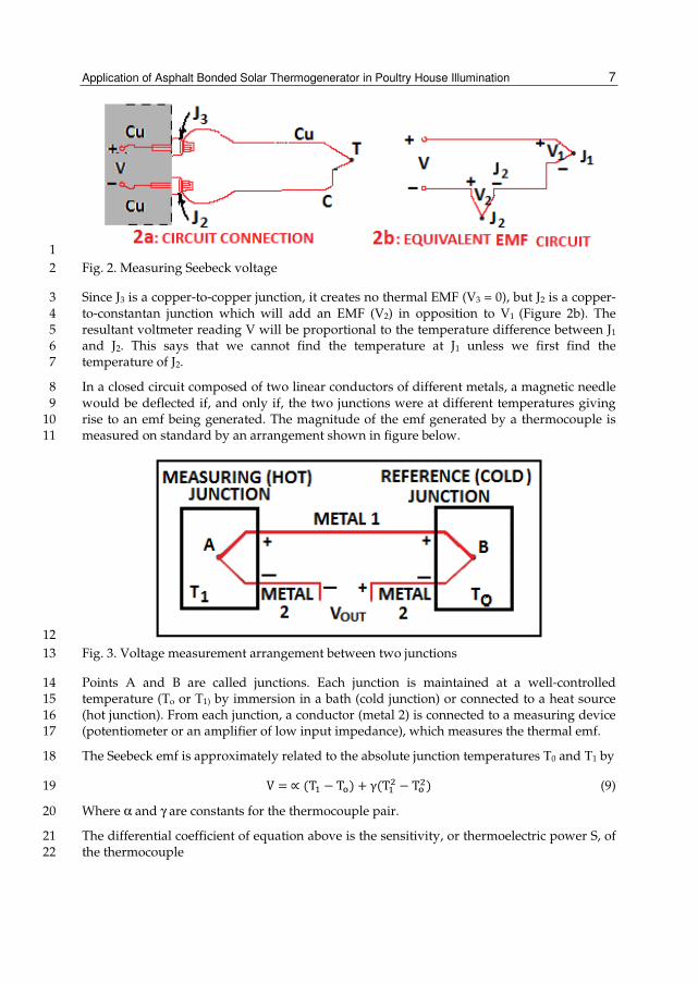
Fig. 2. Measuring Seebeck voltage 2
Since J3 is a copper-to-copper junction, it creates no thermal EMF (V3 = 0), but J2 is a copper-3 to-constantan junction which will add an EMF (V2) in opposition to V1 (Figure 2b). The 4 resultant voltmeter reading V will be proportional to the temperature difference between J1 5 and J2. This says that we cannot find the temperature at J1 unless we first find the 6 temperature of J2. 7
In a closed circuit composed of two linear conductors of different metals, a magnetic needle 8 would be deflected if, and only if, the two junctions were at different temperatures giving 9 rise to an emf being generated. The magnitude of the emf generated by a thermocouple is 10 measured on standard by an arrangement shown in figure below. 11
12
Fig. 3. Voltage measurement arrangement between two junctions 13
Points A and B are called junctions. Each junction is maintained at a well-controlled 14 temperature (To or T1) by immersion in a bath (cold junction) or connected to a heat source 15 (hot junction). From each junction, a conductor (metal 2) is connected to a measuring device 16 (potentiometer or an amplifier of low input impedance), which measures the thermal emf. 17
The Seebeck emf is approximately related to the absolute junction temperatures T0 and T1 by 18
V =∝ (T − T) + γ(T − T
) (9) 19
Where α and γ are constants for the thermocouple pair. 20
The differential coefficient of equation above is the sensitivity, or thermoelectric power S, of 21 the thermocouple 22

Solar Radiation 8
S =
=∝ +2γT (µV/ 0 c) (10) 1
2.3 Measuring thermoelectric power, S 2
According to the experimentally established law of Magnus, the thermoelectric emf for 3
homogenous conductors depends only on the temperatures of the junctions and not on the 4
shapes of the samples. This emf can thus be described by the symbol EAB (To, T1) and is 5
determined solely by conductor A and can be written as EA (To, T1). This emf is more 6
conveniently expressed in terms of a property, which depends upon only a single 7
temperature. Such property is the absolute thermoelectric power (thermo power Sa (T)) 8
defined as in equation (11). 9
E(T, T) = S
(T)dt (11) 10
If EA (T1, T+∆T) is known, for example, from measurements involving a super conductor, 11 then SA (T) can be determined from equation 12 12
ST = lim∆→ E(,∆)
∆ (12) 13
If equation 11 is for any homogenous conductor, then it ought to apply to both sides of the 14
thermocouple. Indeed, it has been verified experimentally that the emf EAB (To, T1) produced 15
by a thermocouple is just the difference between the emfs calculated using equation (17), 16
produced by its two arms as follows. 17
Employing the usual sign correction, to calculate EAB(To, T1), begin at the cooler bath, 18 integrate SA(T)dT along conductor (metal 2) at junction A up to the warmer bath and then 19 return to cooler bath along conductor (metal 1) through junction B by integrating SB(T)dT. 20
This circular loop produces EAB (To, T1) given by equation 13 and 14. 21
ET, T = S
Tdt+ S
Tdt (13) 22
ET, T = S
Tdt − S
Tdt (14) 23
Alternatively, combining the two integrals in equation 14 24
ET, T = ET,T − ET,T (15) 25
ET, T = [S
Tdt − ST]dt (16) 26
⇒ST = ST − S(T) (17) 27
Defining SAB according to equation 16 then yields equation 17 28
ET, T = S
TdT (18) 29
EAB(To,T1) can be calculated for a given thermocouple whenever the thermo powers SA(T) 30 and SB(T) are known for its two constituents over the temperature range To to T1. 31

Application of Asphalt Bonded Solar Thermogenerator in Poultry House Illumination 9
These equations lead directly to experimentally and theoretically verified results that in a 1 circuit kept at a uniform temperature (dt = 0) throughout, E= 0 even though the circuit may 2 consist of a number of different conductors (equation 18). If E did not equal 0, the circuit 3 could drive an electric motor and make it perform work. The only source of energy would 4 be heat from the surrounding. A circuit composed of single, homogenous conductor cannot 5 produce thermoelectric emf (equations 6) when SB (T) is equal to SA (T). Finally, equation 6 6 makes it clear that the source of the thermoelectric emf in a thermocouple lies in the bodies 7 of the two materials of which it is composed rather than the junctions. 8
The reference junction 9
One way to determine the temperature of reference junction J2 is to physically put the 10 junction into an ice bath, forcing its temperature to be 0oC. Since the voltmeter terminal 11 junctions are now copper-copper, they create no thermal emf and the reading V on the 12 voltmeter is proportional to the temperature difference between J1 and J2. 13
14
Fig. 4. External reference junction 15
Now the voltmeter reading is (see Figure 4): 16
V = V − V ≅∝ (t − t) (19) 17
If we specify TJ1 in degrees Celsius: 18
T°C + 273.15 = t (20) 19
Then V becomes: 20
V = V − V =∝ [(T + 273.15) − T + 273.15)] (21) 21
V =∝ (T − 0) =∝ T (22) 22
This derivation is used to emphasize that the ice bath junction output, V2, is not zero volts. It 23 is a function of absolute temperature. By adding the voltage of the ice point, reference 24 junction, we have now referenced the reading V to 0oC. This method is very accurate 25 because the ice point temperature can be precisely controlled. The ice point is used by the 26 National Bureau of Standards (NBS) as the fundamental reference point for their 27 thermocouple tables, so we can now look at the NBS tables and directly convert from 28 voltage V to Temperature TJ1. 29

Solar Radiation 10
Using an iron-constantan (Type J) thermocouple instead of the copper-constantan, the iron 1 wire (Figure 5) increases the number of dissimilar metal junctions in the circuit, as both 2 voltmeter terminals become Cu-Fe thermocouple junctions. 3
4
5
Fig. 5. An Iron- constantan couple 6
If both front panel terminals are not at the same temperature, there will be an error. For a 7 more precise measurement, the copper voltmeter leads should be extended so that the 8 copper-to- iron junctions (J3 and J4) are made on an isothermal (same temperature) block. 9
10
11
Fig. 6. Removing junctions from DVM terminals 12
The isothermal block is an electrical insulator but a good heat conductor, and it serves to 13 hold junctions J3 and J4 at the same temperature. The absolute block temperature is 14 unimportant because the two Cu-Fe junctions act in opposition. 15
Reference circuit 16
Replacing the ice bath with another isothermal block (Fig. 7) at JREF, the new block is at 17 reference temperature TREF, and because J3 and J4 are still at the same temperature, we can 18 again show that 19
V =∝ (T − T) (23) 20

Application of Asphalt Bonded Solar Thermogenerator in Poultry House Illumination 11
A thermistor, whose resistance RT is a function of temperature, provides us with a way to 1
measure the absolute temperature of the reference junction. Due to the design of the 2
isothermal block, junctions J3 and J4 and the thermistor are all assumed to be at the same 3
temperature. 4
5
6
Fig. 7. Eliminating the ice bath 7
However, the use of thermocouples other than thermistor is more preferable in that 8
thermocouple can be used over a range of temperatures, and optimized for various 9
atmospheres. Thermocouples are much more rugged than thermistors, as evidenced by 10
the fact that thermocouples are often welded to a metal part or clamped under a screw. 11
They can be manufactured on the spot, either by soldering or welding. In short, 12
thermocouples are the most versatile temperature transducers available and, since the 13
measurement system performs the entire task of reference compensation and software 14
voltage to-temperature conversion, using a thermocouple becomes as easy as connecting a 15
pair of wires. 16
2.4 Thermogenerator composite parameters 17
The effective composite materials for thermoelectric generator include heat source, the 18
thermocouple, the heat sink and the load. The composite parameters of the generator are the 19
total Seebeck coefficient of the junction S, the total internal resistance r, and the total thermal 20
conductivity k. The Seebeck coefficient can have either a positive or a negative sign. A 21
material that has a negative S is referred to as an n-type material while a material having 22
positive S is referred to as a p-type material. 23
Assuming that all the composite parameters are independent of temperature, and the 24
Seebeck coefficients of the legs of thermocouple are Sn and Sp, and the electrical resistivity of 25
each leg is ρn and ρp, and the thermal conductivities of each leg is kn and kp, then the 26
parameters are defined by the following equations. 27
S = S − S = S + |S| (24) 28
r =
+
(25) 29
k =
+
(26) 30

Solar Radiation 12
Where ln, An, and lp, Ap, refers to the length and area of the n-type and p-type materials 1
respectively, the heat source has a temperature Tn, and the heat sink has temperature Tc. 2
2.5 Thermogenerator efficiency 3
The efficiency η of generator is the power output I2R divided by the heat input Qin. 4
η = p Q ⁄ = R Q ⁄ (27) 5
R is the electrical load resistance. Heat input Qin consists of the Peltier heat STnI plus the 6 conduction heat K (Tn-Tc) less one-half of the Joule heat I2r librated in the thermocouple legs, 7 i.e. 8
Q = ST + kT − T! − "
(29) 9
Losses in maintaining the temperature Tn are not considered by this efficiency and thus it is 10 not a total efficiency including heat source losses. 11
The ratio of load resistance R to internal resistance r is defined as m = R/r 12
The open-circuit voltage, 13
V = S(T − T!) (30) 14
The current, 15
I =
" (31) 16
Using these quantities, and selecting m to give optimum loading, the optimized efficiency, 17 the efficiency expression becomes 18
η =#
$#
$
% (32) 19
Where 20
M = m| ⁄ = √ZT' − T) 2⁄ M = m| ⁄ = √Z(T' − T) 2⁄ ) (33) 21
Z is the figure of merit. 22
This efficiency for an optimum load consists of a Carnot efficiency ηc and device efficiency 23
ηd thus 24
η! =#
(34) 25
η =$#
$
% (35) 26
The device efficiency ηd will be a maximum for the largest value of M, for a fixed Tn and Tc; 27
this requires a maximum value of Z. For most good thermoelectrics, Z (Tn+Tc)/2 ≈1, so for 28
Tn/Tc ≈1, the efficiency is about 20% of the thermodynamic limit. 29

Application of Asphalt Bonded Solar Thermogenerator in Poultry House Illumination 13
2.6 Figure of merit 1
This is a measure of the ability of a given thermoelectric material in power generation, 2 heating or cooling at a given temperature T. ZT is given by the equation. 3
= / (36) 4
Where 5 S = the thermo power of the material 6
σ = The electrical conductivity 7 K = The thermal conductivity 8
The largest values of ZT are attained in semimetals and highly doped semiconductors, 9 which are the materials normally used in practical thermoelectric devices. Figure of merit 10 for single materials and thermocouples formed from two such materials varies hence one 11 thermocouple can be better than another at one temperature but less effective at a second 12 temperature. 13
Z depends upon the material parameters Sp, Kp, ρp Sn, Kn, ρn and the dimensions of the two 14 legs Ap, ℓn, ℓp ,An . Maximizing Z with respect to the area-to-length ratio of the legs gives 15
Z| ⁄ =((#()
[() ⁄ () ⁄ ] (37) 16
When equation 17
⁄
=
(38) 18
For the optimum area-to-length ratio Z depends only upon the specific properties of the 19 thermoelectric material. Generally, the parameters S, K, and ρ are not independent of 20 temperature, and in fact the temperature dependence of the n and p legs may differ 21 radically. The most widely used generator materials are lead telluride, which has a 22 maximum figure of merit of approximately 1.5x10⁻³ K-1. It can be doped to produce both p-23 type and n-type material and has a useful temperature range of about 300-700K (80-800oF). 24 In material development, existing thermoelectric p and n materials operates from 300 to 25 1300K (80 to 1900oF) and yield an overall theoretical thermal efficiency of 18%. 26
To maximize power output, it is necessary to produce the largest possible voltage, thus 27 Seebeck coefficient S should be made large, and hence proper selection of materials are 28 required. Materials should have low electrical resistance in the generator. The legs should 29 also have low thermal conductivities K since heat energy is carried away by thermal 30 conduction. Hence the requirements for materials to be used in thermoelectric power 31 generators are high S, low ρ and K and high figures of merit Z. Since the figures of merit Z 32 for single materials vary with temperature, so do the figures of merit for thermocouples 33 formed from two materials. 34
3. The thermocouple system 35
Thermocouples are differential temperature-measurement devices. They are constructed 36 with two wires of dissimilar metals. One wire is pre-designated as the positive side (Copper, 37

Solar Radiation 14
Iron, Chromel) and the other as the negative (Constantan, Alumel). Basic system suitable for 1 the application of thermoelectricity in power generation is that of several thermocouples 2 connected in series to form a thermopile (a device with increased output relative to a single 3 thermocouple). The junctions forming one end of the thermocouple are at the same low 4 temperature TL and the other junctions at the hot temperature TH. 5
The thermopile is connected to a device in which the temperature TL is fixed when 6
connected to a heat sink. The temperature TH is determined by the output of the heat source 7
and the thermal output of the thermopile. The load is run by the charges generated. With a 8
thermopile, the multiplication of thermocouple involves a corresponding increase of 9
resistance, hence it follows that one thermocouple can be better than another at one 10
temperature but less effective at a second temperature. In order to take maximum advantage 11
of the different materials, the thermocouples are cascaded, producing power in stages and 12
increase power output. 13
3.1 The choice of thermocouple 14
A primary consideration in choosing which thermocouple type to use in a given 15 circumstance is the range of temperatures over which the device is to be used. Some of the 16 other selection factors among others to be addressed include: 17
Suitability for conditions of use, expected service life and compactable installation 18 requirements 19
Adequate sensitivity S over a wide range of temperature, stability against physical and 20 chemical changes under various conditions of use and over extended periods of times, 21
Availability, moderate costs, abrasion and vibration resistance. 22
Thermocouples can either be sheathed or beaded with bare thermoelements (Figure 8). 23
24
25
Fig. 8. Thermocouple materials 26
Sheathed thermocouple probes are available with one of the three junction types: 27
Grounded Junction Type: This is recommended for gas and liquid temperatures and for 28 high-pressure applications. It has faster response than the ungrounded junction type. 29
Ungrounded Junction Type: This is recommended for measurements in corrosive 30 environments where it is desirable to have the thermocouple electronically isolated from 31 and shielded by the sheath. 32

Application of Asphalt Bonded Solar Thermogenerator in Poultry House Illumination 15
The Exposed Junction Type: This is recommended for the measurement of static or flowing 1 non-corrosive gas temperature where fast response time is required. 2
ANSI Polarity: In the thermocouple industry, standard practice is to colour the negative 3 lead red. The negative lead of a bare wire thermocouple is approximately 6mm (‘4’’) 4 shorter than the positive lead and the large pin on a thermocouple connector is always the 5 negative conductor (Omega Eng., 2001) Standard Diameters of thermocouple available 6 are: 0.25mm (0.010’’), 0.50mm (0.020’’), 0.75mm (0.032’’), 1.0mm (0.04’’), 1.5mm (1/16’’), 7 3mm (1/8’’), 4.5mm (3/16’’), 6 mm (1/4’’). With two wires 8mm and 9.5mm standard 8 Omega thermocouples have 12-inch (300mm) immersion lengths. Other lengths are 9 available. 10
3.2 Standard thermocouple types 11
ASTM and ANST standards explicitly stated that the letter designations identifying only the 12 reference tables might be applied to any thermocouple with a temperature-emf relationship 13 that complies with the table within the specified tolerances, regardless of the chemical 14 composition of the thermocouple (Quinn, 1983). Any randomly chosen pair of dissimilar 15 wires will produce some kind of thermal emf when subjected to a temperature difference 16 from end to end, however, the emf so produced may be unpredictable and of little use. 17 Hence certain thermoelement combinations have been commercially developed over the 18 years that have proved to be useful, reproducible, and readily available. 19
Eight of the most widely used of these combinations have been assigned letter-designations 20 for ease of reference, Base metal thermocouples types designated as E, J, K, and T. The rear 21 (Noble) metal thermocouple types are S, R, and B types. 22
3.3 Base metal types 23
Type E, Chromel (nickel-10% chromium) (+) vs. Constantan (nickel-45% copper (-)). Type E 24
is recommended for use to 900°C (1600°F) in oxidizing or inert atmospheres. Type E has 25
been recommended as the most suitable of all standardized types for general low-26
temperature use, about -230°C (-380°F), since it offers the best overall combination of 27
desirable properties i.e. high thermopower, low thermal conductivity, and reasonably good 28
thermoelectric homogeneity typical values for the thermopower of type E at 4, 20, and 50K 29
are 2.0, 8.5 and 18.7µVK-1 respectively (Spark et al., 1972). 30
Type J, Iron (+) vs. Constantan (nickel-45% copper (-)) is one of the most commonly used 31
thermocouples in industrial pyrometry due to its relatively high thermopower and low cost. 32
These thermocouples are suitable for use in vacuum, air, reducing, or oxidizing atmospheres 33
to 760°C (1400°F) in the heavier gage sizes. Rapid oxidation of the iron wire at temperatures 34
above 540°C (1000°F) limits the expected service life of the finer sized wires. 35
Types K (Chromel (nickel-10% chromium) (+) vs. Alumel (nickel-5% aluminum and silicon 36 (-)) and T (Copper (+) vs. Constantan (nickel-45% copper) (-) thermocouples are often used 37 below 0oC, but type J is not suitable for general low-temperature use because the positive 38 thermo element (noted as JP) is composed of iron and thus is subject to rusting and 39 embrittlement in moist atmospheres. Type K is more resistant to oxidation at elevated 40 temperatures than types E, J and T and consequently it finds wide application at 41

Solar Radiation 16
temperatures above 500oC. Type E has the highest thermopower above 0oC of any of the 1 standardized types. 2
Type N, Nicrosil (nickel-14% chromium, silicon) (+) vs. Nisil (nickel-4% silicon, magnesium) 3 (-). This type differs from type K by having silicon in both legs and containing magnesium 4 in the negative leg. It was developed to be more stable (exhibit less calibration drift) than 5 type K when used at temperatures above about 1000°C (1800°F). Both type N wires are 6 similar in color and both are non-magnetic, so identification is usually made by gently 7 heating the junction and observing the polarity of the resultant emf. 8
3.4 Noble metal types 9
Thermocouples employing platinum and platinum-rhodium alloys for their thermoelement 10 (Noble-metal thermocouple types B, R and S) have been used for many years and exhibit a 11 number of advantages over the base metal types. They are most resistant to oxidation, their 12 thermoelements have higher melting points, and they have generally been found to be more 13 reproducible at elevated temperatures in air. They are therefore used when higher accuracy 14 and longer life is sought, though more experience with lower thermopowers. 15
Of all the standardized thermocouples, Type S, Platinum-10% rhodium (+) vs. Platinum (-) 16 is the oldest and perhaps the most important. Type B, Platinum-30% rhodium (+) vs. 17 Platinum-6% rhodium (-), was adopted as a standard type in the US in the late 1960s 18 primarily to serve requirements in the 1200 to 1750oC range. At elevated temperatures, it 19 offers superior mechanical strength and improved stability over types R and S, and it 20 exhibits comparable thermopower. Its thermopower diminishes at lower temperatures and 21 is vary small in the room-temperature range. 22
Identification of noble metal thermocouple wires is made difficult by the fact that all 23 alloys are nearly identical in colour and all are non-magnetic. Sometimes it is possible to 24 distinguish the positive wire from the negative one for types R or S by observing the 25 ‘limpness’ of the wires. Pure platinum wires tend to be slightly more soft, or limp, while 26 the rhodium-alloyed conductors are a little stiffer, enough so to permit identification. The 27 differences, however, are subtle, and it is not possible to tell one rhodium alloy from 28 another by these means. Proper connections for these thermocouples can be reliably 29 determined by gently heating the junction and observing the resulting polarity on a 30 sensitive indicator. 31
4. Solar harvest circuit design 32
The core of the harvesting module (solar panel) is the harvesting circuit, which draws power 33
from the solar panels, manages energy storage, and routes power to the target system. The 34
most important consideration in the design of this circuit is to maximize efficiency and there 35
are several aspects to this. Solar panels have an optimal operating point that yields maximal 36
power output. The harvesting circuit should ensure operation at (or near) this maximal 37
power point, which is done by clamping the output terminals of the solar panel to a fixed 38
voltage. 39
A DC-DC converter is used to provide a constant supply voltage to the embedded system. 40 The choice of DC-DC converter depends on the operating voltage range of the particular 41

Application of Asphalt Bonded Solar Thermogenerator in Poultry House Illumination 17
battery used, as well as the supply voltage required by the target system. If the required 1 supply voltage falls within the voltage range of the battery, a boost-buck converter is 2 required, since the battery voltage will have to be increased or decreased depending on the 3 state of the battery. However, if the supply voltage falls outside the battery’s voltage range, 4 either a boost converter or a buck converter is sufficient, which significantly improves 5 power supply efficiency. 6
4.1 Material consideration for fabricating solar panel 7
4.1.1 Choice of composite material 8
A material for fabricating solar cells should be cheap to acquire and must be pure. Attempt 9
on polymer and composite material based cell is a good development. Composites in 10
general showed good physical properties and improved mechanical strength, 0-3 type super 11
conducting composites with epoxy and phenolic thermosetting plastics have advantages of 12
high toughness, superior abrasion, dimensional stability and heat, water and chemical 13
resistance. 14
The composition of naturally occurring or pyrolytically obtained composite material 15
(Bitumen), is complex but separation, by both physical and chemical methods, into different 16
chemical groups has been made (Oyekunle, 1985). The fractions so obtained consist of 17
asphaltic hydrocarbons (asphaltenes) viscous naphtheno-aromatic hydrocarbons (heavy 18
oils), heterocyclic and polar compounds (resins). Asphaltenes are hard, non plastic high, 19
molecular weight compounds ranging between 1200 and 200,000 and are thus responsible 20
for temperature susceptibility (Gun, 1973). 21
4.1.2 Asphalt composition 22
135cl by volume of emulsified (Cutback) asphalt (mixture of bitumen and mineral 23
aggregates of 0/5mm size) were sourced locally. The bitumen is heated in a container (hot-24
mix plant) and mixed thoroughly with aggregates to form asphalt concrete. The composition 25
is as shown in table 1. 26
27
Material Property
Mineral Aggregate Sieve Size No. 40
Mixture type A
Percentage Passing 0-8
Bituminous Material: MC Liquid asphalt, MC 250
Table 1. Asphalt Properties and Compositions 28
4.1.3 Asphalt preparation 29
The mineral aggregates and bituminous material is in proportions by weight. The aggregate 30
is ensured clean and surface dry before mixing. The mixing period is sufficient to produce a 31
uniform mixture in which all aggregate particles are thoroughly coated. Asphalt cement 32
content of mixes is an important physical characteristic and influences the performance life 33

Solar Radiation 18
of asphaltic concrete. Too much asphalt cement results in mixture stability problems, while 1
too little asphalt cement results in a mixture that is not durable, (Robert et al., 1996; Gordon 2
1997). 3
4.1.4 Thermocouple material 4
Thermocouple: Type E thermocouple has good stability, highest sensitivity among the 5 common metals and thus has high emf output. Based on ASTM set recommended upper 6 temperature limits for various wire sizes, selected diameter for the E type thermocouple is 7 AWG24, 0.51mm diameter. Upper temperature limits for E type is 427oC. Type E has the 8 highest thermopower of 6.317mV/oC in the temperature range (0 -100) oC among any of the 9 standardized types. The thermocouple properties are as shown in Table 2. 10
11 12
Property Nickel- Chromium
(Constantan) Copper – Nickel
(Chromel)
Composition 90% Ni, 10% Cr 60% Cu, 40% Ni
Thermal conductivity, k 22.7-w/m2 oC 17.1-w/m2 oC
Thermal diffusivity, α 61.2 x10⁴ m2/s 44.4x10⁴ m2/s
Density, ρ 8922 kg/ m2 8666kg/ m2
Electrical conductivity 58.14 x10⁶ m-1 Ω-1 -
Useful temperature range -200 to 980 -
Total thermal conductivity 5.4 x10⁻⁴ W/ m2 oC
Diameter 0.51mm ( 0.00051m)
Length 15mm (0.015m)
Figure of merit 1.0 x 10⁻⁶
Thermopower at (31-80)oC 3.116 mV/oC
Table 2. Thermocouple Material Properties 13
4.1.5 Extension wire 14
Thermocouple alloy wire is recommended to be used always to connect a thermocouple 15 sensor to the instrumentation to ensure accurate measurements. Due to the high cost of 16 thermocouple wire, a copper wire was used with assurance of no significant change in the 17 emf produced. 18
4.1.6 Heat source 19
The mixture is compressed into small pallets (0.5cm) with thermocouple junctions cascaded 20 and embedded into it. A glass screen is to be provided to prevent escape of long wave 21 radiation from the absorber surface. 22

Application of Asphalt Bonded Solar Thermogenerator in Poultry House Illumination 19
4.2 Modeling the generator 1
The following assumptions are used in determining the open circuit voltage: The heat 2
source is a flat plate collector, thus an assumption of maximum temperature of 80oC is 3
considered for the heat source, a black body absorber. An ambient temperature of 31oC was 4
considered for the isothermal block because ice baths are often inconvenient to maintain at 0 5 oC and not always practical. 6
4.2.1 Output voltage 7
To determine the output voltage X of the thermocouple at 31.0 oC and 80.0oC, the 8
thermoelectric emf at 31.0oC is interpolated (S31 = 1.867 mV/oC) and the difference used to 9
determine S = S80 - S31 = 3.116 mV/oC. The output (open-circuit) voltage, V of the 10
thermocouple junction is given by V = S (T80 –T31) = 152.68 mV 11
4.2.2 Thermocouple (heat sink) reference junction 12
With accurate thermocouple measurements required, it is common practice to reference 13
both legs to copper lead wire at the ice point so that copper leads may be connected to the 14
emf readout instrument. This procedure avoids the generation of thermal emfs at the 15
terminals of the readout instrument. The emf generated is dependent on a difference in 16
temperature, so in order to make a measurement the reference must be known. The 17
reference junction is placed in an ice water bath at a constant 0oC (32oF). Because ice baths 18
are often inconvenient to maintain and not always practical, several alternate methods are 19
often employed (Omega Engineering, 2001) 20
4.2.3 Solar cell configuration 21
Under bright sunlight, all silicon PV cells have an open circuit output of approximately 0.5V 22
irrespective of cell surface area. The voltage is a function of the cell’s physical composition, 23
while amperage is affected by area of cell and the amount and intensity of light falling upon 24
it. Increase in the voltage and amperage output of PV cells depends on the mode of 25
connection of the cells in a module. For higher voltage, the cells are linked in series (net 26
voltage is the sum of the individual voltages of the cells) (Figure 8a). The net current is 27
however the same as that of a single cell. To boost amperage, the cells must be connected in 28
parallel (Figure 8b) 29
30
31
Fig. 8. Solar cell connections 32

Solar Radiation 20
4.3 Construction of thermocouple circuit 1
The thermocouple wires (Type E) made of different metal alloys (Nickel-Chromium copper-2
constantan) is joined together by soldering. The number of thermocouples required to 3
generate an output voltage of 15V is required. Knowing the output voltage of one 4
thermocouple (type E) given as 153mv (0.153v), dividing 15 by 0.153 to give 98.04 = 98 5
junctions. There are six modules with 15 junctions each (Fig 9). These thermocouples were 6
joined together in series to form cascaded thermopile consisting of a number of 7
thermocouples. 8
9 10 11
12
13
Fig. 9. Thermocouple solar panel 14
The construction of the solar power module was simple and convenient employing modular 15
approach in which the entire system is divided into modules. The design is to generate high 16
voltage, thus the cells are connected in series in the module. The voltage is a function of the 17
cell’s physical composition, while the amperage is affected not only by the area of the cell, 18
but also by the amount and intensity of light falling upon it. 19

Application of Asphalt Bonded Solar Thermogenerator in Poultry House Illumination 21
1
2
Fig. 10. A section through the solar panel 3
For high amperage, the cells must be connected in parallel. The net voltage is the sum of the 4 individual voltages in the cell. Increase in the voltage and amperage output of the 5 thermocouple cells depends upon the mode of connection in the module. The efficiency and 6 power output requirement is determined by the power output of one thermocouple given 7 by the equations above, the number of thermocouples in series, and the surface area of the 8 solar cell were thus determined. 9
4.4 System fabrication 10
The entire system is divided into modules as shown in Figure 11. Vero board is used as the 11 circuit boards for the solar panel and the charge control system. 12
13
Fig. 11. Block diagram of the system 14
The charge control system uses the LED control charging system to charge a 12v lead Acid 15 battery. An electrical diode, D1 ensures unidirectional voltage flow when battery is under 16 charge (Fig 10). For simplicity of construction and convenience the modular approach of 17 constructing solar energy harvest modalities is used. Photovoltaic conversion provides the 18 highest power density, which makes it the modality of choice to power an embedded 19 system using reasonably small harvesting module. 20

Solar Radiation 22
1
Fig. 11. Circuit Diagram of the solar power supply 2
The components of the electrical circuit and ratings are as follows: 3
D1, D2 = Diode (MA2J728 or MA3x704), Q1, Q2 = FET transistor (IRFZ44), R1 = Resistor =220kΩ, 4
R2 = Resistor = 12kΩ, R3 = Resistor = 2.7kΩ, R4 = Resistor = 4.5kΩ, R5 = Variable Resistor = 1000kΩ, 5 LED (Green/Red), Battery = 12V Rechargeable Lead Acid. 6
Since the thermocouple array is expected to charge the battery on sunny days when output 7
exceeds the load, but on cloudy days or at night, the load is expected to exceed the array 8
output and drain the battery- Hence the array must be sized to ensure that the balance is 9
positive and the battery is recharged when discharged. The array delivered an average daily 10
output equal to the average daily system load (including all losses) plus approximately 10% 11
to ensure that the battery is recharged. 12
5. System test result 13
5.1 Collector surface temperature 14
The daily total solar energy Qt received per unit surface area of the absorber at the location 15
(Ishiagu, South East Nigeria) as evaluated by Bello and Odey (2009) is 747.67 W/m2. 16
The useful components of the global solar radiation at the location are: direct solar radiation 17
qD = 680.67 W/m2, diffuse solar radiation qd = 64.21 W/m2 and ground reflected radiation 18
qr = 2.34 W/m2. The collector heat transfer coefficient between the absorber and cover 19
expressed as the heat loss per unit area of the collector surface per temperature change 20
is 3.06 W/m2 oC. Total absorbed heat energy per unit surface area of absorber 21
qu = 592.43 W/m2 22

Application of Asphalt Bonded Solar Thermogenerator in Poultry House Illumination 23
Measurements were taken on a clear day without cloud cover and surface temperatures 1 were measured at five different spots every hour. According to measured temperature data, 2 the average daily surface temperature increases with increase in sunshine hour reaching its 3 peak between 1300hr and 1400hr (Fig 12) and then decline. On the average, 10hrs of 4 sunshine hours is available per day, but for useful solar harvest, 8hrs of sunshine may is 5 assumed because of difference in temperature between the collector surface and the 6 ambient. The full sun (peak sun) hour value monitored at the site during raining season and 7 dry season were found to be 4hrs and 5hrs respectively, agreeing with Onojo et al., (2004). 8
9
Fig. 12. Average daily temperature in collector 10
Three surface areas were used for the test as follows 0.6m2, 1.0m2 and 1.5m2. There appeared 11 to be no significant difference in spot temperatures in each of the surfaces per hour (Fig 12), 12 it can be concluded that the surface temperature is independent of surface area. There 13 appeared to be no significant difference in spot temperatures measured in each of the 14 collectors per hour (TAV1, TAV2, TAV3), hence, it can be concluded that the surface temperature 15 is independent of surface area. The average cell surface area used in computation is 1.03 m2 16 and the total surface area of the module is 6.2 m2. 17
Material density constitutes to heat retention within the system and hence increases in 18 surface temperature and higher potential difference. The collector compaction test shows 19 that a densely packed material retains more heat and hence increases surface temperature, 20 which obviously will produce higher potential difference. 21
5.1.1 Thermocouple sizing 22
The process of PV array sizing was utilized in determining the number of thermocouples to 23 give the desired amount of electrical power required. To achieve this, the amount of 24 electrical power required by the load and the amount of solar energy available at the site are 25 necessary. The amount of ampere load energy demand required for a fixed load such as 2 26 DC T8 2ft fluorescent tube is 5.14Ah. Therefore the total demand in ampere-hours is 5.14Ah. 27

Solar Radiation 24
5.1.2 Battery size requirement and efficiency 1
When sizing the battery bank, the ampere-hours efficiency (columbic efficiency) of new 2 battery is considered to be 100%. During the charge/discharge cycle of the battery, the 3 battery is charged by receiving an input voltage from the thermocouple system and the 4 same number of voltage is delivered at a lower output voltage. The battery efficiency 5 (battery’s voltaic efficiency) is expressed as the ratio of average voltage output to the 6 average input voltage. 7
The daily load requirements determine the necessary battery bank capacity while the system 8
voltage determines the battery bank voltage and the number of cells to be connected in 9
series. The product of Daily Load (DL) requirement and the number of no-sun days (N) 10
gives the total useable capacity (TUC) of the battery i.e. 11
Total Useable Capacity = DL X N (Ah) 12
The ampere-hours efficiency (columbic efficiency) of new battery is considered to be 100%. 13 The daily load requirement determines the necessary battery bank capacity. The total 14 useable capacity (TUC) of the battery is 22.84Ah 15
5.1.3 Daily load requirement 16
An assumption of a lighting programme in poultry house where power is needed for four 17
out of every seven days in a week was made, and the inverse relationship between voltage 18
and amperage was used to determine the average daily current requirement by multiplying 19
current by a factor of 4/7 to yield a net value in Ah, the average daily current required to 20
satisfy the load demand of 5.14Ah as calculated from given relations. An average of 4½ hrs 21
of full sunshine hours per day round the years is taken for a non-critical system. The 22
thermocouple array load capable of generating the required load demand is obtained by 23
dividing the average daily current requirement by 4.5. 24
Thermocouple load = average daily current requirement /4.5 (A). 25
When a peak sunshine hour of 4.5 hours/day is required, the thermocouple array designed 26
is capable of generating a measured 1.14A, capable of providing a glow continuously to 27
satisfy the load demand of 5.14Ah. At increased number of sunshine hours above 4 ½ hours, 28
more current generation is possible whereby the battery could be recharged. 29
5.1.4 The system conversion efficiency 30
The conversion efficiency is defined as the ratio of electrical power output and the heat flux 31 through the entire TEG surface. 32
= *
+= *
∆.., (39) 33
∆T corresponds to the temperature difference between the hot and the cold side of the TEG, 34
A is the TEG area and h is the overall heat transfer coefficient given by (the ratio of total 35
thermal conductivity (5.4 x 10 -4 W/m2/°C) of the materials of the thermoelectric generators 36
and the thickness (0.015m) of the TEG. The electrical power output (P=174.06 W h). The 37

Application of Asphalt Bonded Solar Thermogenerator in Poultry House Illumination 25
measured heat flux through the entire TEG surface is 10.94 W. The overall conversion 1
efficiency of the system calculated is 15.91%. The cost of system production is estimated at 2
average N20, 000.00 3
6. Summary 4
The conversion efficiency of the cell is 15%. This is comparable to other solar TEG system 5 efficiency. The research work indicates the possibility of the utilization of asphalt bonded 6 thermocouples to generate enough current for lighting programme in small scale 7 agricultural undertaking such as poultry house illumination. The output voltage across the 8 thermocouple generator can be increased to higher value enough to provide energy for 9 other low thermal processes. Asphalt heat absorber will be a promising solar harvest cell 10 when the surface is polished and made more sensitive to wider photon energy range (1.3-11 1.5eV) for increased efficiency. 12
From the economical point of view, there exists a huge discrepancy between the costs of 13 commercial thermoelectric generators compare with asphalts embedded TEG. The 14 commercial TEG is by a factor of 10 more expensive than the asphalt TEG. The properties of 15 asphalt TEGs are comparable with that of commercial TEG, even though the asphalt TEG 16 used in this study has a smaller area than most commercial TEGs, therefore more asphalt 17 TEGs per unit area can be mounted for increased overall performance at a cheaper price. 18 Further research on antireflection coatings and stacking of different cells with band gaps 19 covering the incident energy of the photons would be a good attempt at achieving higher 20 efficiency. 21
7. References 22
Afolabi M. O., Ajayi, R. I. and Siyanbola W. O., 2004. Photo-voltaic cells, efficiency and 23 optimization. Global J. pure & Applied Sc. Vol 10. No.3 P 435-439. 24
Akarakiri J. B. and Ilori M. O., 2003. Application of photovoltaic technology in developing 25 countries. Nig. Jour. of Industrial & Systems Studies (NJISS) vol.2 No.2 26
Angrist S. W., 1982. Direct Energy conversion. 4th Ed. 27 Bello S. R. and Odey S. O., 2009. Development of Hot Water Solar Oven for Low Temperature 28
Thermal Processes. Leonardo Electronic Journal of Practices and Technologies ISSN 29 1583-1078 Issue 14, January-June 2009 p. 73-84 30
Champier D., Bedecarrats J. P., Rivaletto M., Strub F., 2009. Thermoelectric power generation 31 from biomass cook stoves. Energy (2009) 1–8. doi:10.1016/ j.energy.2009.07.015 32 http//: www.elsevier.com/locate/energy 33
Coker J. O., 2004. Solar energy and its Applications in Nigeria. Short Communication, Global 34 Jour. pure & Applied Sc. Vol. 10 No 1 P 223-225. 35
Dennis A. and Kulsum A., 1996. The Case for Solar Energy Investments. World Bank 36 Technical Paper Number 279. Energy Series. 37
Duffie, J. A. and Beckman, W. A., 1976. Solar Energy Thermal Processes. John and Sons Pub 38 NY. 39
Encyclopedia Britannica Inc., 1987: Thermocouples. Vol. 11 pp 250-251, Vol. 15 pp 226-227, 40 Vol. 8 pp 193 William Benton publisher. 41
Gun R. B., 1973. Petroleum Bitumen (in Russian), khimiya, Moscow. 42

Solar Radiation 26
Goldsmid H. J., 1995. Conversion efficiency and figure-of-merit. In D. M. Rowe, editor, CRC 1 Handbook of Thermoelectrics, pages 19-25. CRC Press, 2
Lertsatitthanakorn C., 2007. Electrical performance analysis and economic evaluation of 3 combined biomass cook stove thermoelectric (BITE) generator. Bioresource 4 Technology 2007; 98:1670–4. 5
Madueme T. C., 2002. Independent power producers and the power sector in Nigeria. Nig.J. 6 Ind & Sys. Studies (NJISS) vol.1 no2. P.38-45. 7
Maycock D. Paul, Edward N., Stirewait, 1981. A guide to the Photovoltaic revolution. 8 Rodale Press, Emmans, Pa. 9
Nolas G. S., Sharp J., and Goldsmid H. J. 2001. Thermoelectrics: Basic Principles and New 10 Materials Development. Springer, Berlin, 11
Nuwayhid R. Y., Rowe D. M., Min G., 2003. Low cost stove-top thermoelectric generator for 12 regions with unreliable electricity supply. Renewable Energy 2003; 28:205–22. 13
Nuwayhid R. Y., Shihadeh A, Ghaddar N., 2005. Development and testing of a domestic 14 woodstove thermoelectric generator with natural convection cooling. Energy 15 Conversion and Management 2005; 46:1631–43. 16
Okelola, O. E., Bamgbade., B. J. Balogun, R. B., Bello S. R., (2011). Qualitative Analysis of 17 Rice Storage System in Yala Local Government Area of Cross River State. Proc. of 18 the 1st International Conference on Rice for food, Market and Development, held in Abuja 19 Nigeria. http://www.rice-africa.com/acceptedpapers/index.html#bv000030 20
Oladiran M. T., 1999. New and renewable Energy Education in Sub. Saharan Africa. Proc. of 21 renewable Energy Conf. Perth, Austria-energy 16. 22
Omega Eng., 2001. Introduction to thermocouples. 23 http://www.omega.com/techref/themointro.html /Omega Engineering. Date 24
modified 8/12/2009. 25 Onojo O. Chukwudebe G. A. and Nwodo T. C., 2004. Development of solar power supply 26
for domestic electricity. NJISS, Vol 3, No 2, 2004 pp 37-44 27 Oyekunle L. O., 1985. Effect of temperature on rheological properties of petroleum 28
Bitumens. Jour. Nig society chem. Engr. Vol 4 pp 124-129. 29 Quinn T. J., 1983. Temperature, Academic press. 30 Richner P., Pedro D. G., Luís C. G. and David A., 2011. Experimental Results Analysis of the 31
Energy Conversion Efficiency of Thermoelectric Generators. Electromechanical 32 Engineering Department – Engineering Faculty University of Beira Interior Edifício 33 1 das Engenharias, Calçada do Lameiro, 6201-001 Covilhã (Portugal). 34 http//www.312-richer.pdf . Date modified 8/12/2011. 35
Rowe D. M., 2009. Thermoelectric waste heat recovery as a renewable energy source. 36 International Journal of Innovations in Energy Systems and Power 2006; 1(1). 37
Solar Electric Light fund (SELF), 2002. Solar Electricity and Renewable Energy Technology. 38 Washington D.C, solar Electric light Fund. 39
Steven A. Moses, 2010. The Design and Construction of Two Experimental Setups to 40 Measure Thermoelectric Properties of Novel Materials. A thesis submitted in 41 partial fulfillment of the requirements for the degree of Bachelor of Science, Honors 42 (Physics) at the University of Michigan 43
Suharta, H, Senam P. D. Satighm A. M. and Komarudin D., 1999. The social Acceptability of 44 solar cooking in Indonesia. Renewable energy vol. 6 1151- 1154. 45
Zulovich J. M., 2005. Poultry Farm and Processing Plant Lighting. Published by University 46 of Missouri extension 47