INDOT CERTIFIED ASPHALT TECHNICIAN
492
INDOT CERTIFIED ASPHALT TECHNICIAN
-
Upload
khangminh22 -
Category
Documents
-
view
0 -
download
0
Transcript of INDOT CERTIFIED ASPHALT TECHNICIAN

INDOTCERTIFIEDASPHALTTECHNICIANPROGRAM 2021

TABLE OFCONTENTS

Table of Contents ICAT Logistics ICAT Agenda ICAT Instructors HMA Policies and Procedures Manual ICAT Class PowerPoint Presentations Chapter One: Introduction Safety 1-3 Terminology 1-6 Rounding 1-10 Mean 1-12 Standard Deviation 1-12 Volumetrics 1-14 Chapter Two: Aggregate Fundamentals, Sampling and Testing Aggregates 2-2 What is an Aggregate 2-2 Uses of Aggregates 2-2 Origins of Aggregates 2-3 Distribution of Aggregates 2-4 Aggregate Types 2-8 Classification of Aggregates 2-9 Physical Properties 2-9 Consensus Properties 2-12 HMA Surface Aggregates 2-14 Stockpiling 2-15 Sampling and Testing 2-16 Methods of Sampling 2-16 Size of Original Sample 2-19 Moisture Content 2-29
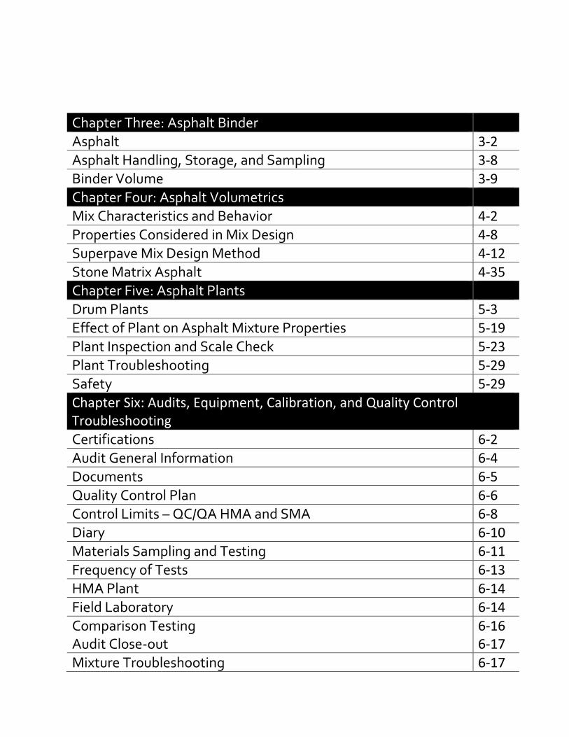
Chapter Three: Asphalt Binder Asphalt 3-2 Asphalt Handling, Storage, and Sampling 3-8 Binder Volume 3-9 Chapter Four: Asphalt Volumetrics Mix Characteristics and Behavior 4-2 Properties Considered in Mix Design 4-8 Superpave Mix Design Method 4-12 Stone Matrix Asphalt 4-35 Chapter Five: Asphalt Plants Drum Plants 5-3 Effect of Plant on Asphalt Mixture Properties 5-19 Plant Inspection and Scale Check 5-23 Plant Troubleshooting 5-29 Safety 5-29 Chapter Six: Audits, Equipment, Calibration, and Quality Control Troubleshooting Certifications 6-2 Audit General Information 6-4 Documents 6-5 Quality Control Plan 6-6 Control Limits – QC/QA HMA and SMA 6-8 Diary 6-10 Materials Sampling and Testing 6-11 Frequency of Tests 6-13 HMA Plant 6-14 Field Laboratory 6-14 Comparison Testing 6-16 Audit Close-out 6-17 Mixture Troubleshooting 6-17

Chapter Seven: Percent Within Limits and Field Testing Random Numbers 7-2 Design Mix Formula 7-4 Mixture Adjustment Factor 7-4 Lot/Sublot – QC/QA HMA 7-5 Acceptance Samples 7-5 Mixture Acceptance 7-12 Pay Factors – QC/QA HMS (Dense Graded Mixture ≥ 1 Lot) 7-12 Quality Assurance Adjustment – QC/QA HMA ≥ 1 Lot) 7-17 Pay Factors – QC/QA HMA (Dense Graded Mixture < 1 Lot and Open Graded Mixtures
7-20
Quality Assurance Adjustment – QC/QA HMA < 1 Lot and Open Graded Mixtures
7-25
Mix Appeal – QC/QA HMA 7-27 Smoothness 7-27 Chapter Eight: Appendix A Indiana Test Methods 8-1 Chapter Nine: Appendix B Audits 9-1 QCP 9-24 Chapter Ten: Appendix C Standard Specifications 10-1

INDOT Certified Asphalt Lab Technician Program Course Modules
Module #1 – 30 minutes Course Purpose and Overview (Chapter 1) Presenters: Kirsten Fowler, Matt Beeson
• Course overview • Module access and tracking • Manual layout • ITM 583 and certified/qualified program requirements • Rounding and calculator info
Module #2 – 1 hour Aggregate Fundamentals (Chapter 2) Presenter: Christa Phelps
• Highway construction materials • Properties & specifications
Module #3 – 1 hour, 30 minutes Aggregate Sampling and Testing (Chapter 2) Presenters: Kurt Sommer, Tom Partipilo, Jason Stroud
• Segregation • Sampling and splitting • Moisture and decant • Gradation • Fine & coarse aggregate specific gravity • Fine aggregate angularity • Flat & elongated particles • Percentage of fracture particles in coarse aggregate

Module #4 – 1 hour Aggregate Laboratory Demonstrations Presenters: TBD
• Sampling • Splitting • Moisture • Decant • Gradation • Fine & coarse aggregate specific gravity • Fine aggregate angularity • Flat & elongated particles • Percentage of fractured particles in coarse aggregate
Module #5 – 45 minutes Asphalt Binder (Chapter 3) Presenter: Jason Wielinski
• Manufacturing • Testing • Grading • Specifications
Module #6 – 1 hour, 30 minutes Asphalt Volumetrics (Chapter 4) Presenter: Gerry Huber (also e-mail to Nathan for calculation practice)
• Superpave • Specific gravity • Asphalt content, air voids, VMA & VFA • Mix design basics • SMA
Add calculation practice from Nathan Module #7 – 15 minutes Aggregate Blending (Chapter 4) Presenter: Kirsten Fowler
• Step-by-step asphalt blending example

Module #8 – 30 minutes Plants (Chapter 5) Presenter: Tim Sievers
• Plant types • Operations • Inspection and calibration • Safety
Module #9 – 1 hour Audits and Equipment Calibration (Chapter 6) Presenters: Elizabeth Pastuszka, Harley Phillips
• Example audit • Calibration verification
Module #10 – 30 minutes Quality Control Troubleshooting (Chapter 6) Presenter: Brad Cruea
• Relationships between volumetric properties Module #11 – 30 minutes Field Testing (Chapter 7) Presenter: Cody Fowler, Jason Galetka
• Truck sampling • Plate sampling • Coring • Smoothness (Cody is adding something)
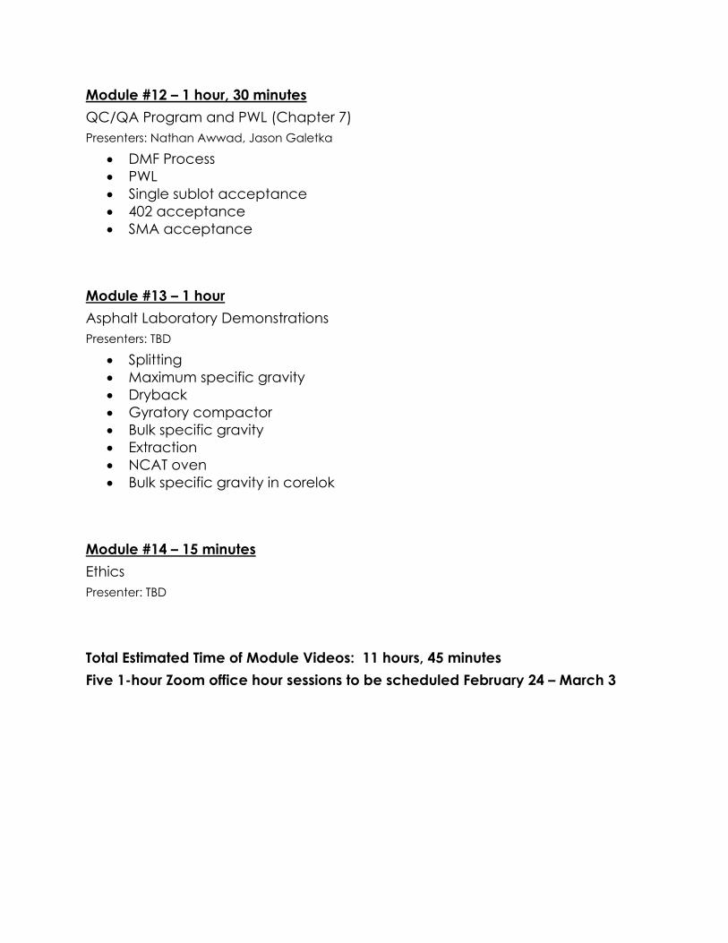
Module #12 – 1 hour, 30 minutes QC/QA Program and PWL (Chapter 7) Presenters: Nathan Awwad, Jason Galetka
• DMF Process • PWL • Single sublot acceptance • 402 acceptance • SMA acceptance
Module #13 – 1 hour Asphalt Laboratory Demonstrations Presenters: TBD
• Splitting • Maximum specific gravity • Dryback • Gyratory compactor • Bulk specific gravity • Extraction • NCAT oven • Bulk specific gravity in corelok
Module #14 – 15 minutes Ethics Presenter: TBD
Total Estimated Time of Module Videos: 11 hours, 45 minutes Five 1-hour Zoom office hour sessions to be scheduled February 24 – March 3

ICAT Instructors & Staff
Nathan Awwad, P.E. Asphalt Engineer Indiana Department of Transportation [email protected]
Chris Campbell Design Technician The Heritage Group [email protected]
Matt Beeson, P.E. Director, Office of Materials Management Indiana Department of Transportation [email protected]
Cody Fowler, P.E. Regional QC Manager Rieth-Riley Construction [email protected]
Brad Cruea Quality Control Manager – Indianapolis Milestone Contractors, L.P. [email protected]
Jason Howard Design Technician Heritage Group [email protected]
Jason Galetka Assistant Asphalt Engineer Indiana Department of Transportation [email protected]
Gerry Huber, P.E. Associate Director of Research The Heritage Group [email protected]

2
Kirsten Fowler, P.E. Executive Director Asphalt Pavement Association of Indiana (APAI) [email protected]
Elizabeth Pastuszka HMA Design & QC Coordinator – North E&B Paving, Inc. [email protected]
Jaymie Hunckler Member Services Manager Asphalt Pavement Association of Indiana (APAI) [email protected]
Christa Phelps State Geologist Indiana Department of Transportation [email protected]
Cartia Martin Asphalt Lab Supervisor Indiana Department of Transportation [email protected]
Harley Phillips HMA Technical Director Indiana Department of Transportation [email protected]
Tom Partipilo HMA Design & QC Coordinator – South E&B Paving, Inc. [email protected]
Kurt Sommer, P.E. District Testing Engineer Indiana Department of Transportation – Crawfordsville [email protected]

3
Tim Sievers Mix Cost Analyst Brooks Construction Company, Inc. [email protected]
Bart Williamson Aggregate Materials Technician Indiana Department of Transportation [email protected]
Jason Wielinski, P.E. Director of Construction Materials The Heritage Group [email protected]

1
1
WHY ARE WE HERE?Course Purpose & Overview
I N D O T C e r t i f i e d A s p h a l t Te c h n i c i a n P r o g r a m
C h a p t e r O n e – M o d u l e 1 B
2
Meet the Team
Director, Division of Materials and TestsIndiana Department of Transportation
M A T T B E E S O N , P . E .
3QC/QA HMA
Hot Mix Asphalt
• One of INDOT’s biggest expenses
• Vast majority of pavement in Indiana is HMA
• A way to validate the properties of the HMA metspecs was needed
4QC/QA HMA
Quality Control• Contractor testing
• Contractor performs testing to control mixture production
Quality Assurance• INDOT testing
• INDOT performs testing to assure the material meetsspecifications
Balances responsibility for quality between Contractor and INDOT
5ITM 583
Indiana Test Method 583Certified Hot Mix Asphalt Producer Program
• Documentation
• Laboratory and Equipment Calibration
• Materials Sampling and Testing
• Diary
• Quality Control Plan
6QC/QA HMA Technician School
Aggregates• Aggregates in Indiana• Aggregate Specifications
1 2
3 4
5 6
2
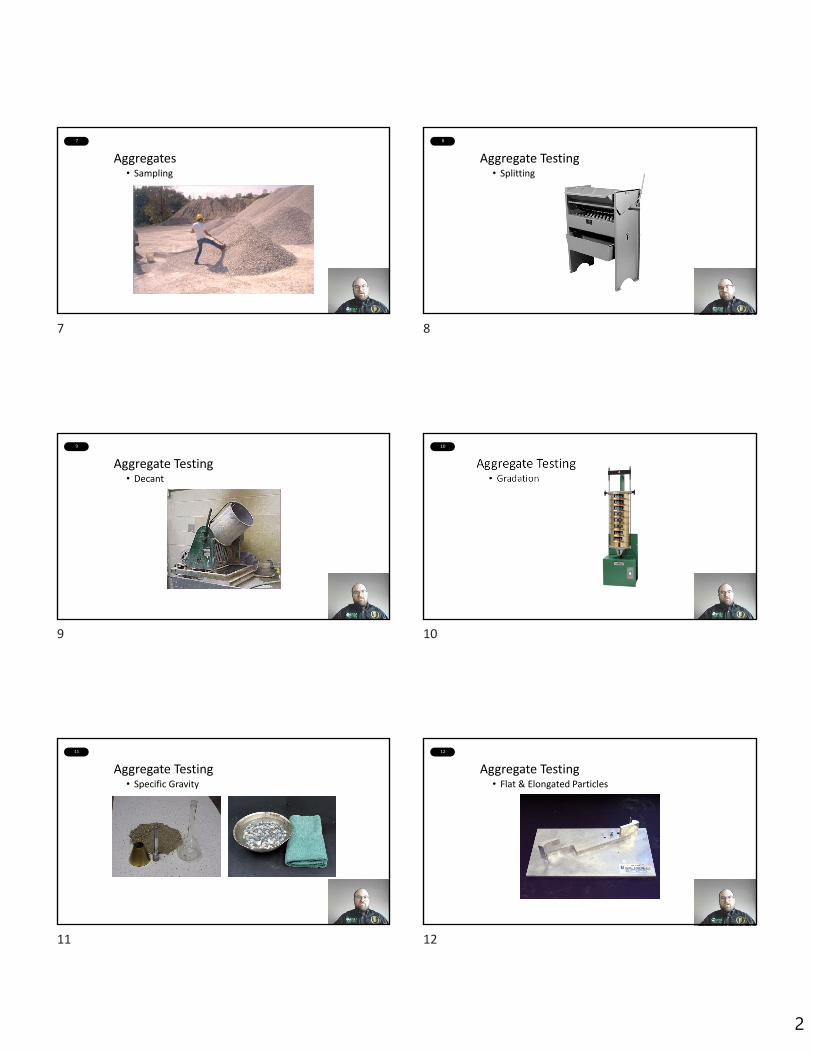
7QC/QA HMA Technician School
Aggregates• Sampling
8QC/QA HMA Technician School
Aggregate Testing• Splitting
9QC/QA HMA Technician School
Aggregate Testing• Decant
10QC/QA HMA Technician School
Aggregate Testing• Gradation
11QC/QA HMA Technician School
Aggregate Testing• Specific Gravity
12QC/QA HMA Technician School
Aggregate Testing• Flat & Elongated Particles
7 8
9 10
11 12

3
13QC/QA HMA Technician School
Aggregate Testing• Coarse Aggregate Angularity
14QC/QA HMA Technician School
Aggregate Testing• Fine Aggregate Angularity
15QC/QA HMA Technician School
QC/QA HMA Acceptance Specs• PWL (Percent Within Limits)
16QC/QA HMA Technician School
Asphalt Binder• Manufactured
17QC/QA HMA Technician School
Asphalt Binder• Testing
18QC/QA HMA Technician School
Asphalt Binder• Grading, PG Binder Specifications
13 14
15 16
17 18
4
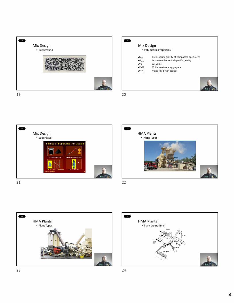
19QC/QA HMA Technician School
Mix Design• Background
20QC/QA HMA Technician School
Mix Design• Volumetric Properties
Gmb Bulk specific gravity of compacted specimensGmm Maximum theoretical specific gravityVa Air voidsVMA Voids in mineral aggregateVFA Voids filled with asphalt
21QC/QA HMA Technician School
Mix Design• Superpave
22QC/QA HMA Technician School
HMA Plants• Plant Types
23QC/QA HMA Technician School
HMA Plants• Plant Types
24QC/QA HMA Technician School
HMA Plants• Plant Operations
19 20
21 22
23 24
5
25QC/QA HMA Technician School
HMA Plants• Plant Inspection
26QC/QA HMA Technician School
HMA Plants• Warm Mix (Foaming)
27QC/QA HMA Technician School
HMA Plants• Plate Sampling
28QC/QA HMA Technician School
HMA Plants• Coring
29QC/QA HMA Technician School
HMA Laboratory Demo
30QC/QA HMA Technician School
Annual Plant Audits
25 26
27 28
29 30

6
31QC/QA HMA Technician School
Equipment Calibration/Verification
32QC/QA HMA Technician School
Quality Control Troubleshooting
33QC/QA HMA Technician School
Quality Control Troubleshooting
34QC/QA HMA Technician School
Quality Control Troubleshooting
35QC/QA HMA Certified Technician
All HMA produced for an INDOT Contract required to come from Certified Plant
Certified Plants are required to have a Certified Technician
That’s you!
36QC/QA HMA Certified Technician
Certified Technician• Complete this course and pass exam
• Can supervise but not perform tests
Qualified Technician• Have to be Qualified to actually run tests
• Can perform testing under supervision of a Certified Technician
Level 1 Technician• Both Qualified and Certified
QC/QA HMA Certified Technician
31 32
33 34
35 36
7
37QC/QA HMA Certified Technician
• Certification good for life• We may add Continuing Education in the future
• Level 1 Technician• Maintain Qualified Tech status
Steps to Remain Compliant38
Two main hazards in Asphalt Industry• Fire
• explosion hazards
• Health hazards • eye contact, skin contact (burns), inhalation of
fumes
Safety
39
Fire• Asphalt often heated to high temperatures
• Control possible ignition sources in vicinity of asphalt
Health Hazards• Eye Contact
• Safety glasses, goggles, face shield
• Fumes
• Improve ventilation, respirators
• Skin Contact
• Long sleeve shirts, long gloves, full high‐top safety boots, pants over top of boots
40QC/QA HMA Certified Technician
Skin Contact• What do you do if you get hot asphalt on your skin
• DON’T try to remove asphalt from skin
• Apply cold or lukewarm water to remove heat from asphalt as quickly as possible (major burns – lukewarm water)
• Do not bandage the burned area
• Go to the hospital/doctor immediately
41Questions?
37 38
39 40
41
1
1
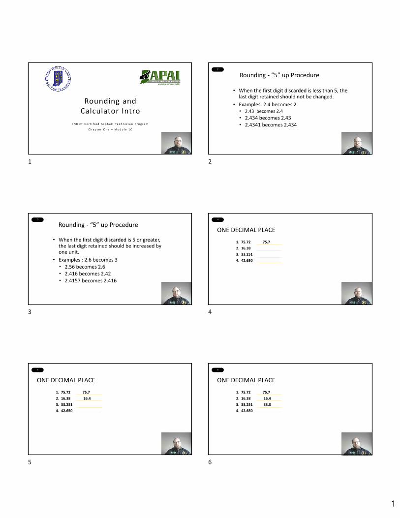
Rounding and Calculator Intro
I N D O T C e r t i f i e d A s p h a l t Te c h n i c i a n P r o g r a m
C h a p t e r O n e – M o d u l e 1 C
2
Rounding ‐ “5” up Procedure
• When the first digit discarded is less than 5, thelast digit retained should not be changed.
• Examples: 2.4 becomes 2• 2.43 becomes 2.4
• 2.434 becomes 2.43• 2.4341 becomes 2.434
3
Rounding ‐ “5” up Procedure
• When the first digit discarded is 5 or greater, the last digit retained should be increased by one unit.
• Examples : 2.6 becomes 3• 2.56 becomes 2.6• 2.416 becomes 2.42• 2.4157 becomes 2.416
4
ONE DECIMAL PLACE
1. 75.72 75.7
2. 16.38
3. 33.251
4. 42.650
5
ONE DECIMAL PLACE
1. 75.72 75.7
2. 16.38 16.4
3. 33.251
4. 42.650
6
ONE DECIMAL PLACE
1. 75.72 75.7
2. 16.38 16.4
3. 33.251 33.3
4. 42.650
1 2
3 4
5 6

2
7
ONE DECIMAL PLACE
1. 75.72 75.7
2. 16.38 16.4
3. 33.251 33.3
4. 42.650 42.7
8
TWO DECIMAL PLACES
1. 31.331 31.33
2. 16.917
3. 56.4251
4. 70.5150
9
1. 31.331 31.33
2. 16.917 16.92
3. 56.4251
4. 70.5150
TWO DECIMAL PLACES
10
TWO DECIMAL PLACES
1. 31.331 31.33
2. 16.917 16.92
3. 56.4251 56.43
4. 70.5150
11
TWO DECIMAL PLACES
1. 31.331 31.33
2. 16.917 16.92
3. 56.4251 56.43
4. 70.5150 70.52
12
MEAN (AVERAGE) ‐ TI – 30X
• Enter the first data point and press the Σ+ key. The display should read n = 1
7 8
9 10
11 12
3
13
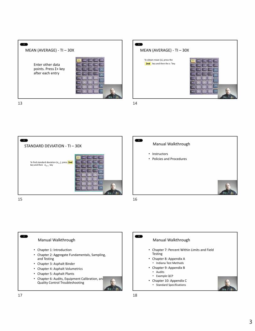
Enter other data points. Press Σ+ key after each entry
MEAN (AVERAGE) ‐ TI – 30X
14
To obtain mean (x), press the
key and then the x key 2nd
MEAN (AVERAGE) ‐ TI – 30X
2
15
STANDARD DEVIATION ‐ TI – 30X
To find standard deviation (σn‐1), press key and then σxn‐1 key
2nd
16
Manual Walkthrough
• Instructors
• Policies and Procedures
17
Manual Walkthrough
• Chapter 1: Introduction
• Chapter 2: Aggregate Fundamentals, Sampling, and Testing
• Chapter 3: Asphalt Binder
• Chapter 4: Asphalt Volumetrics
• Chapter 5: Asphalt Plants
• Chapter 6: Audits, Equipment Calibration, and Quality Control Troubleshooting
18
Manual Walkthrough
• Chapter 7: Percent Within Limits and Field Testing
• Chapter 8: Appendix A• Indiana Test Methods
• Chapter 9: Appendix B• Audits
• Example QCP
• Chapter 10: Appendix C• Standard Specifications
13 14
15 16
17 18

4
19
Thank you!
Good Luck!
19

1
AGGREGATE FUNDAMENTALS:Highway Construction Materials in
Indiana (M2A)I N D O T C e r t i f i e d A s p h a l t T e c h n i c i a n P r o g r a m
C h a p t e r T w o
2
• Asphalt mixture is binder and aggregateWe are going to start by talking about aggregates (Yay rocks!)
• Aggregate types and their origin and distribution inIndiana
• Materials found in Indiana aggregate which areconsidered non -durable (deleterious)
3
Aggregate Types
TThere are 4 types of aggregate.
• Sa n d• Gra ve l• Cru sh e d s t o n e• Sla g
Ea ch t yp e o f a g g re g a t e h a s it s o w n u n iq u e o rig in .
4
• Used in asphaltpavements
• Transported inIndiana byglaciers andstreams
• Abundant inthe state
Natural sand and gravel
5
Heavy sheets of ice carved out the northern Indiana landscape and transported and deposited sand and gravel.
6
• Over the past 2.6 million years,Indiana has experienced a seriesof glacial advances and retreats
• There are many glacial featuresin Indiana.

7• Streams carry sand and gravel.• Another word for stream related
activity is fluvial.• Large rivers carry more material -
Example: The Ohio, White, andWabash Rivers
8
•Three rock types: Igneous,sedimentary, metamorphic
•Type of road aggregate usedin US states is highlydependent on regionalgeology
• In Indiana, we havesedimentary bedrock,especially limestone
9
Ocean marine fossils are common in Indiana bedrock.
How is this possible?
10
Oldest exposed Indiana bedrock originated when the world map would have looked like this….
11 The continental plates merged to form the supercontinent Pangeaand then split apart again.
12
Eroded Appalachian Mountain and continental sediments collected in the Illinois Basin.

13
GGeologic Structures
• Illinois Basin
• Michigan Basin
• Kankakee/Cincinnati Arch
• Faults
14
Origin
PERMIAN **PENNSYLVANIANMISSISSIPPIAN
DEVONIANSILURIAN
ORDOVICIAN
CAMBRIAN *
PALEOZOIC
MESOZOIC
CENOZOIC
TRIASSIC **
JURASSIC **
CRETACEOUS **
TERTIARY ***
QUATERNARYEON ERA PERIOD
PHANEROZOIC
PROTEROZOIC
ARCHEAN
PRECAMBRIAN *
Millions ofYears Ago
540
500
435410355
295325
250
203
135
65
1.75
± 5
± 6± 8± 5
± 5± 3
± 3
± 5
± 0.5
± 0.05
* Not exposed at the surface *** Scattered deposits** Not present4,600
10 0 30 Miles
10 0 50 Km
Youngest
Oldest
15 16
Slag
• Blast Furnace slag - non -metallic material removed inmolten state of iron production
• Steel slag - material derivedfrom iron -to -steel refinement
• Slag is sometimes used in theproduction of asphalt
17
Differences in geology in Indiana = differences in aggregate physical properties = variations in product type
18
• Crushed stone ismined in quarries
• Bedrock is blastedand trucked to theprimary crusher
19
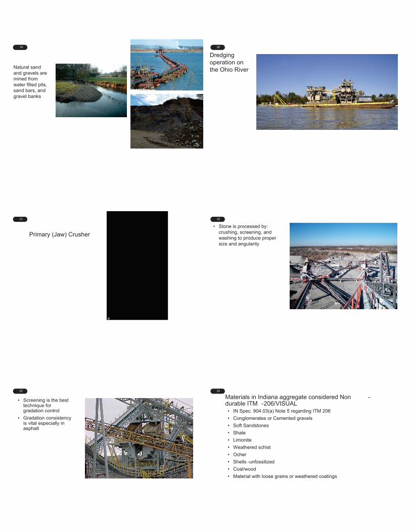
Natural sand and gravels are mined from water filled pits, sand bars, and gravel banks
20
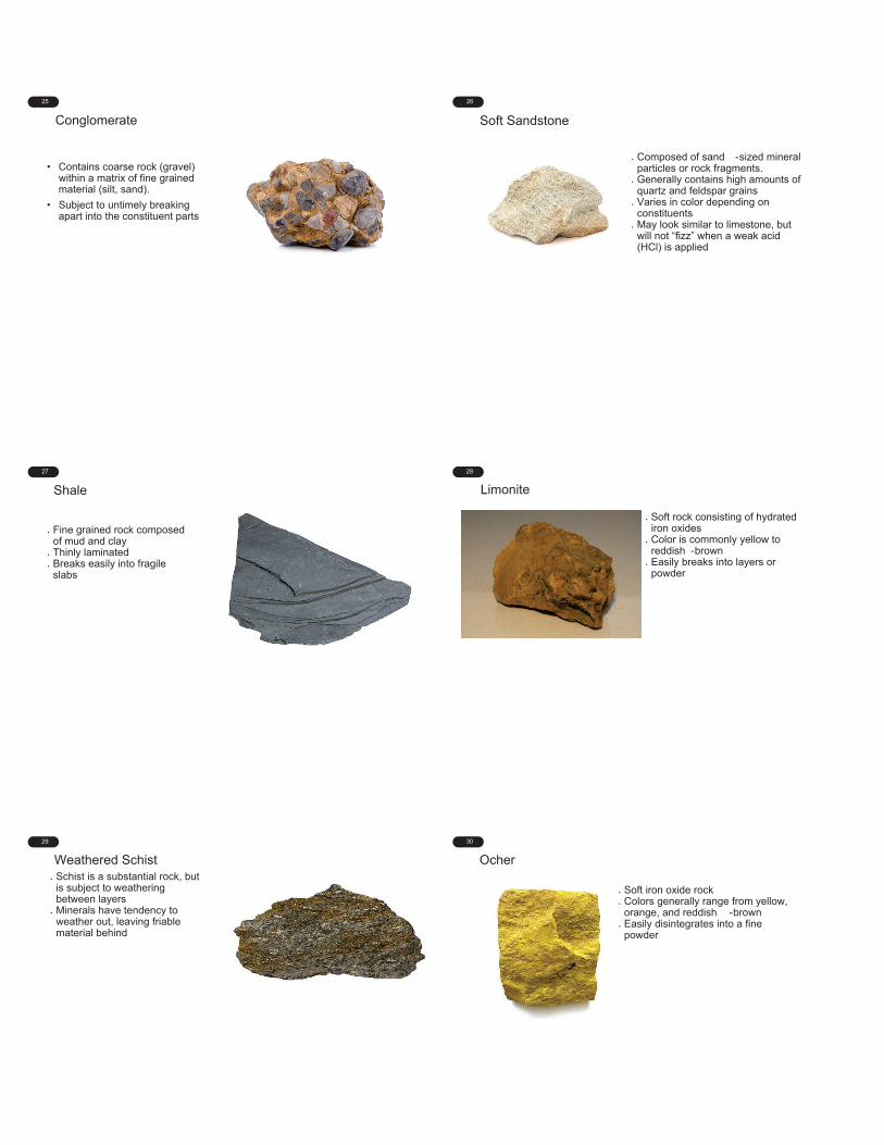
Dredge on the Ohio RiverDredging operation on the Ohio River
21
Primary (Jaw) Crusher
22
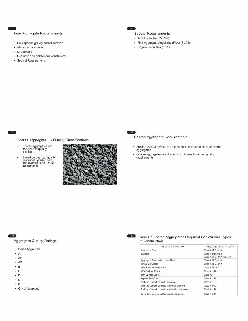
• Stone is processed by: crushing, screening, and washing to produce proper size and angularity
23
• Screening is the best technique for gradation control
• Gradation consistency is vital especially in asphalt
24
Materials in Indiana aggregate considered Non -durable ITM -206/VISUAL• IN Spec. 904.03(a) Note 5 regarding ITM 206
• Conglomerates or Cemented gravels
• Soft Sandstones
• Shale
• Limonite
• Weathered schist
• Ocher
• Shells -unfossilized
• Coal/wood
• Material with loose grains or weathered coatings
25
Conglomerate
• Contains coarse rock (gravel) within a matrix of fine grained material (silt, sand).
• Subject to untimely breaking apart into the constituent parts
26
Soft Sandstone
Composed of sand -sized mineral particles or rock fragments.Generally contains high amounts of quartz and feldspar grainsVaries in color depending on constituentsMay look similar to limestone, but will not “fizz” when a weak acid (HCl) is applied
27
Shale
Fine grained rock composed of mud and clayThinly laminatedBreaks easily into fragile slabs
28
Limonite
Soft rock consisting of hydrated iron oxidesColor is commonly yellow to reddish -brownEasily breaks into layers or powder
29
Weathered SchistSchist is a substantial rock, but is subject to weathering between layers Minerals have tendency to weather out, leaving friable material behind
30
Ocher
Soft iron oxide rock Colors generally range from yellow, orange, and reddish -brownEasily disintegrates into a fine powder

31
Shells
Unfossilized shellsMussel shells from rivers and lakes are common
Mussel shells in the Tippecanoe River, Indiana
1
AGGREGATE PROPERTIES(M2B)
I N D O T C e r t i f i e d A s p h a l t T e c h n i c i a n P r o g r a m
C h a p t e r T w o
2
• How aggregates are classified based on gradationand their inherent physical properties
• Special conditions to watch for• Segregation pitfalls
3
Aggregate Properties
Ag g re g a t e Qu a lit y Ra t in g s
P h ysica l Qu a lit y Te st s
Ge n e ra l Usa g e Re q u ire m e n t s
Gra d a t io n Re q u ire m e n t s
4
Fine and Coarse - Aggregate Definitions
FFine Aggregate sh a ll b e 10 0 % p a ssin g t h e 3/8 ” (9 .5m m ) s ie ve , a n d a m in im u m o f 8 0 % p a ssin g t h e # 4 (4 .75m m ) s ie ve .
Coarse Aggregate sh a ll h a ve a m in im u m o f 20 % re t a in e d o n t h e # 4 (4 .75m m ) s ie ve .
5
Fine Aggregate - Quality Classifications
• Fine aggregates are notdivided into quality classes asare coarse aggregate.
• Quality ratings on fineaggregate are no longerincluded in INDOT reports.
6 Requirements Of Fine Aggregates In Accordance With Standard Specifications Section 904.02
TYPE OF CONSTRUCTION ACCEPTABLE FINE AGGREGATEPortland cement concrete for pavement or bridge decks
Natural sand
Portland cement concrete for other construction
Natural sand or crushed limestone/dolomite, or air-cooled blast furnace slag
Hot Mix Asphalt (HMA) Natural sand or manufactured sand.
Steel furnace slag when used with steel furnace slag coarse aggregates.
Combination of natural and manufactured with some proportionate limitations.
Pneumatic placement Natural sand with suitable grading requirements.Mortar Natural sand with suitable grading requirements.Mineral filler Dust produced by crushing stone, portland cement, or
other inert mineral matter.
Snow and ice abrasives SF Slag, ABF Slag, GGBF Slag, NS, CS, Wet bottom boiler slag (cinders).
7
Fine Aggregate Requirements
• Bulk specific gravity and absorption
• Abrasion resistance
• Soundness
• Restriction on deleterious constituents
• Special Requirements
8
Special Requirements• Acid Insoluble (ITM 202)
• Fine Aggregate Angularity (FAA) (T 304)
• Organic impurities (T 21)
9
9
Coarse Aggregate - Quality Classifications
• Coarse aggregates areassigned to qualityclasses
• Based on physical qualityproperties, graded size,and eventual end use ofthe material.
10
Coarse Aggregate Requirements
• Section 904.03 defines the acceptable limits for all uses of coarseaggregates
• Coarse aggregates are divided into classes based on qualityrequirements
11
Aggregate Quality Ratings
Coarse Aggregate
• A
• AP
• AS
• B
• C
• D
• E
• F
• G-Not Approved
12 Class Of Coarse Aggregates Required For Various Types Of Construction
TYPE OF CONSTRUCTION REQUIRED QUALITY CLASSAggregate Base Class A, B, C, or DSubbase Class A or B (No. 8)
Class A, B, C, or D (No. 53)Aggregate Pavements or shoulders Class A, B, C, or DHMA Base Coarse Class A, B, C, or DHMA Intermediate Course Class A, B, or CHMA Surface Course Class A or BSMA Surface Course Class ASAsphalt Seal Coat Class A or BPortland Cement concrete pavement Class APPortland Cement concrete structural-exposed Class A or APPortland Cement concrete structural-non-exposed Class A or B
Cover (choke) aggregates coarse aggregate Class A or B

13
The minimum quality rating for a specified use of coarse aggregate is as follows:
No. 8 Exposed Concrete A
No. 11 Exposed Concrete A
No. 11 Non-exposed concrete B
HMA/CMA Surface B, B, or B
No. 8 Seal Coats B
No. 9 Seal Coats B
No. 11 Seal Coats B
No. 12 Seal Coats B
HMA/CMA Intermediate C, C, or C
HMA/CMA Base D
No. 43 Compacted Aggregate Base B
No. 53 Compacted Aggregate Base D
No. 73 Compacted Aggregate Base D
No. 8 Aggregate for Shoulder Drains E
No. 11 Aggregate for Shoulder Drains E
No.12 Aggregate for Shoulder Drains E
Rip Rap F
14
Aggregate for Hot Mix Asphalt
INDOT uses hot mix asphalt in a number of different ways. In all cases, the aggregates used should meet five requirements
1. Strong, tough and durable
2. The ability to be crushed into bulky particles, without many flakyparticles, slivers or pieces that are flat and elongated
3. Low porosity
4. Low permeability
5. Correct particle size and gradation for the type of pavement
15
Properties
• Absorption/specific gravity
• Resistance to abrasion
• Soundness
• Additional requirements
16
Quality Test1. Bulk Specific Gravity and Absorption
(AASHTO T 85)
2. LA Abrasion (Durability Strength)• (AASHTO T 96)
3. Soundness1. Sodium Sulfate (T 104)2. Brine (ITM 209)3. Water (T 103)
17
AbsorptionFine Aggregate AASHTO T -84/Coarse Aggregate AASHTO T-85
• Absorption (per AASHTO T -84/T -85) is defined as the increase inthe weight of aggregate because of water in the pores of thematerials, but not including water adhering to the outsidesurface of the particles.
18
ABSORPTION –AASHTO T-84/AASHTO T -85
• Aggregates with high absorption are not desirable in mostapplications.
• Highly absorptive material used in HMA applications will result inan increased asphalt binder demand.
• Some aggregates with elevated absorptions possess othercharacteristics such as skid resistance that are desirable despitehigher asphalt binder demand.

19
Internal Pore Properties
• Absorption – Particle’s ability to takein a liquid
• Porosity - Ratio of the volume ofpores to the total volume of theparticle
• Permeability – Particle’s ability toallow liquids to pass through
Size, number and continuity of the poresaffect other properties
20
Density and Specific Gravity• Density is the weight per unit of volume of a substance
• Specific gravity is the ratio of the density of the substance to thedensity of water
21
Specific gravityFine Aggregate AASHTO T -84/Coarse Aggregate AASHTO T-85
• Specific Gravity is the ratio of the weight of a substance(aggregate in this case) to the weight of an equal volume ofwater.
22
Specific Gravity of Common MaterialsSubstance Specific GravityW o o d (Oa k) 0 .7
W a t e r 1Co a l 1.6
Bla st Fu rn a ce Sla g 2.4Lim e st o n e 2.6
Qu a rt z 2.6Sh a le 2.6Gra ve l 2.7
Tra p Ro ck 2.9St e e l Sla g 3.5
Iro n 7.9Le a d 11.4Go ld 19.3
23
The Importance of Specific Gravity
• Specific gravity information is very important in the designasphalt mixtures
• Helps in determining the amount of cementing material needed
• Mixtures are designed using volumes and specific gravity allowsconversion between weight and volume
24
GSB List
24
I• INDOT tracks present and historical bulk specific gravity data• Quality samples are obtained from state approved sources on
an annual or biannual basis• The GSB list is updated to reflect the most current 5 year
average• The list is published on INDOT’S website around the end of
January each year• Contractors construct mix designs using bulk numbers
25
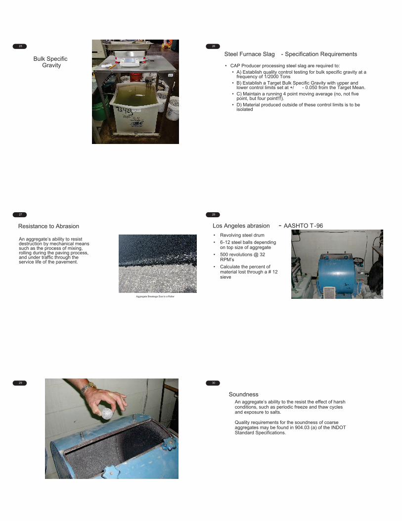
Bulk Specific Gravity
26
Steel Furnace Slag - Specification Requirements
• CAP Producer processing steel slag are required to:• A) Establish quality control testing for bulk specific gravity at a
frequency of 1/2000 Tons• B) Establish a Target Bulk Specific Gravity with upper and
lower control limits set at +/ - 0.050 from the Target Mean.• C) Maintain a running 4 point moving average (no, not five
point, but four point!!!).• D) Material produced outside of these control limits is to be
isolated
27
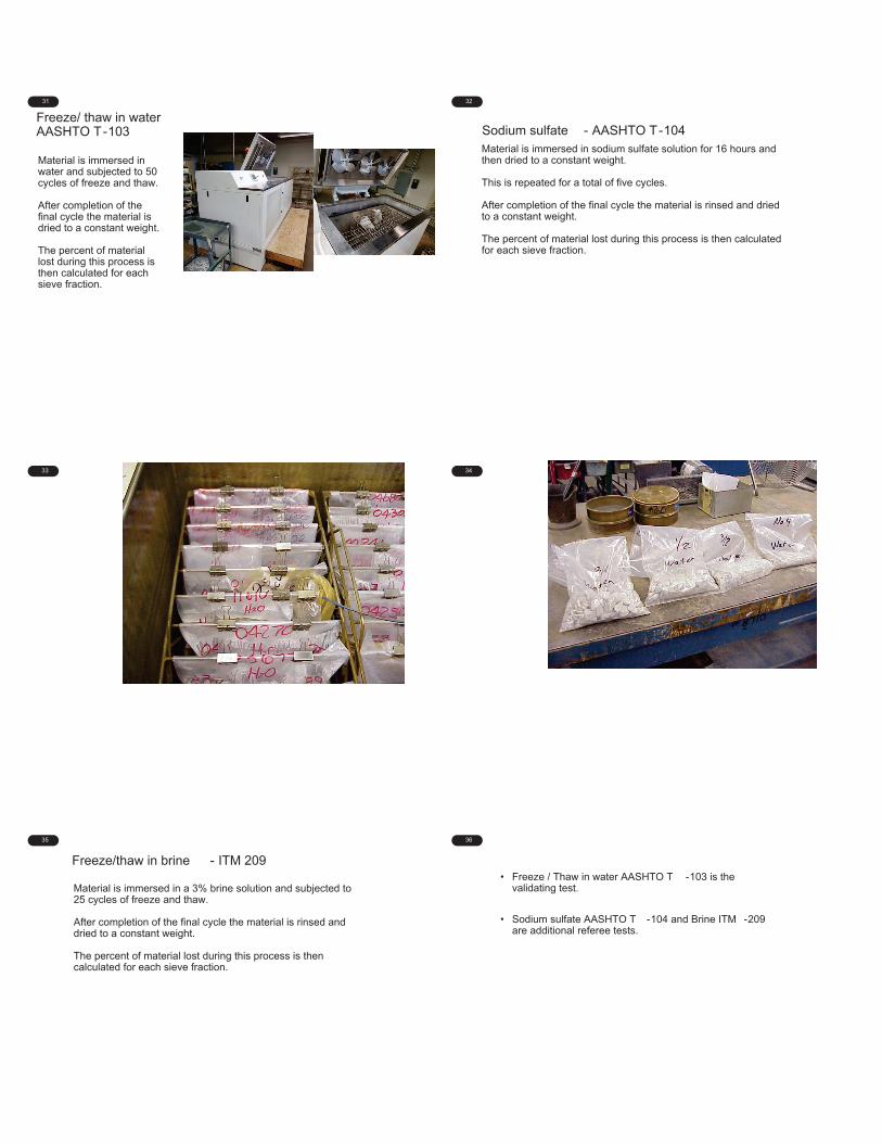
Resistance to Abrasion
An aggregate’s ability to resist destruction by mechanical means such as the process of mixing, rolling during the paving process, and under traffic through the service life of the pavement.
Aggregate Breakage Due to a Roller
28
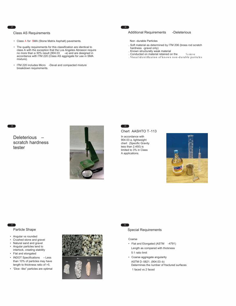
Los Angeles abrasion - AASHTO T-96
• Revolving steel drum
• 6-12 steel balls dependingon top size of aggregate
• 500 revolutions @ 32RPM’s
• Calculate the percent ofmaterial lost through a # 12sieve
29 30
Soundness• An aggregate’s ability to the resist the effect of harsh
conditions, such as periodic freeze and thaw cyclesand exposure to salts.
• Quality requirements for the soundness of coarseaggregates may be found in 904.03 (a) of the INDOTStandard Specifications.
31
Freeze/ thaw in waterAASHTO T-103
Material is immersed in water and subjected to 50 cycles of freeze and thaw.
After completion of the final cycle the material is dried to a constant weight.
The percent of material lost during this process is then calculated for each sieve fraction.
32
Sodium sulfate - AASHTO T-104• Material is immersed in sodium sulfate solution for 16 hours and
then dried to a constant weight. •• This is repeated for a total of five cycles.
• After completion of the final cycle the material is rinsed and dried to a constant weight.
• The percent of material lost during this process is then calculated for each sieve fraction.
33 34
35
Freeze/thaw in brine - ITM 209
Material is immersed in a 3% brine solution and subjected to 25 cycles of freeze and thaw.
After completion of the final cycle the material is rinsed and dried to a constant weight.
The percent of material lost during this process is then calculated for each sieve fraction.
36
• Freeze / Thaw in water AASHTO T -103 is the validating test.
• Sodium sulfate AASHTO T -104 and Brine ITM -209 are additional referee tests.
37
Class AS Requirements
• Class A for SMA (Stone Matrix Asphalt) pavements.
• The quality requirements for this classification are identical to class A with the exception that the Los Angeles Abrasion require no more than a 30% result (904.03 -a) and are designed in accordance with ITM 220 (Class AS aggregate for use in SMA mixture).
• ITM 220 includes Micro -Deval and compacted mixture breakdown requirements.
38
Additional Requirements -Deleterious
Non -durable Particles
Soft material as determined by ITM 206 (brass rod scratch hardness -gravel only)Known structurally weak materialConducted on material retained on the sie veVisu a l id e n t ifica t io n o f kn o w n n o n -d u ra b le p a rt ic le s
39
Deleterious –scratch hardness tester
40
Chert AASHTO T-113
In accordance with 904.03 a, lightweight chert (Specific Gravity less than 2.450) is limited to 3% in Class A applications.
41
Particle Shape
• Angular vs rounded• Crushed stone and gravel• Natural sand and gravel• Angular particles tend to
interlock, creating stability• Flat and elongated
• INDOT Specifications – Less than 10% of particles may have length to thickness ratio of >5.
• “Dice -like” particles are optimal
42
Special Requirements
Coarse
• Flat and Elongated (ASTM -4791)
Length as compared with thickness
5:1 ratio limit
• Coarse aggregate angularity
ASTM D -5821. (904.03 -b)Determines the number of fractured surfaces
1 faced vs 2 faced
43
Uncompacted Voids Fine Aggregate AASHTO T -304. IN Spec. 904.02(b)
• Measures the angularity of fine aggregate
44
Acid insoluble ITM-202
For fine aggregates the acid insoluble fraction will be no less than 40% (904.02)This Specification applies only to FA used in 4.75mm sand surface mixes
45
Surface Texture
• The pattern and the relative roughness or smoothness of the aggregate particle
• Impacts bond between aggregate and cementing material
• Gives cementing material something to grip
46
Surface Texture Polishing
• Aggregates that are exposed to traffic may polish over time
• This is why additional testing is required to verify that the aggregates are not susceptible to polishing
47
Approved Polish Resistant Aggregates (PRA)
47
• Source materials must undergo a series of several specific tests in order to obtain approval for use as a polish resistant aggregate
• ITM 214 describes the process, which includes an initial laboratory test under a polishing wheel, followed by the installation of a test strip
• Test strips are skid tested against a control, two times per year for at least two years
• Results will be analyzed by the The Division of Materials and Tests (M&T) for potential approval
• ITM 221 outlines the process for approval for use as a high friction aggregate
48
Special RequirementsHMA
• Dolomite (ITM 205)
• Sandstone
• Polish Resistance (ITM 214, 221)
• Slag
• Crushed (ASTM 5821)
49 Review• T-84/85 Specific Gravity/Absorption
• T-96 Los Angeles Abrasion
• T-104 Sodium Sulfate Soundness
• T-103 Freeze/Thaw Soundness
• ITM-209 Brine Freeze/Thaw Soundness
• T-112 Clay Lumps and Friable Particles
• ITM-206 Scratch Hardness
• T-113 Lightweight Particles ( Chert )
• ITM-202 Acid Insoluble content
• D-4791 Flat and Elongated Particles
• D-5821 Coarse Aggregate Angularity
• T-304 Fine Aggregate un -compacted Voids
• ITM-214 Acceptance procedure for polish resistant aggregates
50
General Usage and Gradation RequirementsFine Aggregate
• 904.02
Coarse Aggregate
• 904.03
51
Additional Gradation Requirements
B Borrow/Structure Backfill
• 211.02
RipRap
• 904.04
Aggregate Base
• 301.02
SubBase
• 302.02
Aggregate Pavement or Shoulder
• 303.02
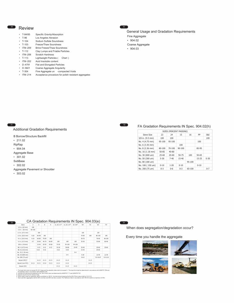
52FA Gradation Requirements IN Spec. 904.02(h)
SIZES (PERCENT PASSING)Sieve Size 23 24 15 16 PP S&I
3/8 in. (9.5 mm) 100 100 100No. 4 (4.75 mm) 95-100 95-100 100No. 6 (3.35 mm) 100No. 8 (2.36 mm) 80-100 70-100 90-100 85-95No. 16 (1.18 mm) 50-85 40-80No. 30 (600 um) 25-60 20-60 50-75 100 50-65No. 50 (300 um) 5-30 7-40 15-40 15-25 0-30No. 80 (180 um) 95-100No. 100 ( 150 um) 0-10 1-20 0-10 0-10No. 200 (75 um) 0-3 0-6 0-3 65-100 0-7
53 CA Gradation Requirements IN Spec. 904.03(e)Sieve 2 5 8 9 11, SC 11(5) 12, SC 12(5) SC 16(5) 431 91 531 731
2.5 in. (63 mm) 100
2.0 in. (50 mm) 80-100
1.5 in. (37.5 mm) 100 100 100
1.0 in. (25.0 mm) 0-25 85-98 100 70-90 100 80-100 100
¾ in. (19.0 mm) 0-10 60-85 75-95 100 50-70 70-90 90-100
½ in. (12.5 mm) 0-7 30-60 40-70 60-85 100 100 100 35-50 55-80 60-90
3/8 in. (9.5mm) 15-45 20-50 30-60 75-95 95-100 94-100
N0. 4 (4.75 mm) 0-15 0-15 0-15 10-30 50-80 15-45 20-40 35-60 35-60
N0. 8 (2.36 mm) 0-10 0-10 0-10 0-35 15-35 25-50
No. 16 (1.18 mm) 0-4
N0. 30 (600 mm) 0-4 5-20 12-30 12-30
No. 200 (75 um)2 0-6.0 5.0-10.04 5.0-12.0
Decant (PCC)3 0-1.5 0-1.5 0-1.5 0-1.5 0-1.5 0-1.5
Decant (non PCC) 0-2.5 0-2.5 0-3.0 0-2.5 0-2.5 0-2.5 0-2.5
Decant (SC) 0-1.5 0-1.5 0-1.5
1. The liquid limit shall not exceed 25 (35 if slag) and the plasticity index shall not exceed 5. The liquid limit shall be determined in accordance with AASHTO T89 and the plasticity index in accordance with AASHTO T90.
2. Includes the total amount passing the No. 200 (75um) sieve as determined by AASHTO T 11 and AASHTO T27.3. Decant may be 0-2.5 for stone or slag4. When slag is used for separation layers as defined on 302.01, the total amount passing the No.200 (75um) sieve shall be 10.0-12.0.5. Seal coat (SC) aggregates shall be 85% one face and 80% two face crushed. The Flakiness Index in accordance with ITM 224 shall be a maximum of 25%.
54
When does segregation/degradation occur?
Every time you handle the aggregate
55
Conveyor Belt Segregation
• Segregation begins on the belt where fines vibrate to the bottom and coarse remains on top
• At the end of the belt if left un -deflected the coarse particles are thrown out and away. Fine particles drop down or adhere to the belt. Higher speeds increase this affect.
56
High Conveyor Drop
• Segregation
• Degradation
• Loss of fines
57
Stockpile Segregation• Segregation is the separation of a well graded aggregate into
individual sizes due to gravity
• Segregation is probably the greatest nemesis of stockpiling and handling, but other situations such as degradation and contamination will affect quality as well
58
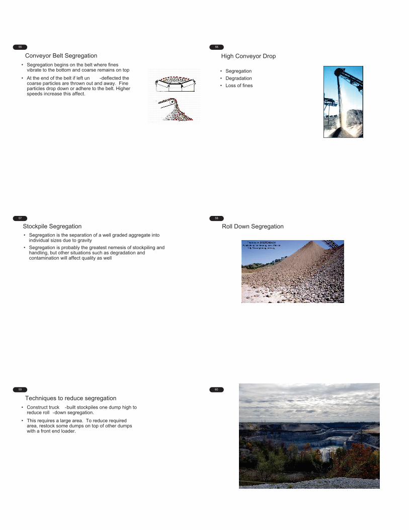
Roll Down Segregation
59
Techniques to reduce segregation
• Construct truck -built stockpiles one dump high to reduce roll -down segregation.
• This requires a large area. To reduce required area, restock some dumps on top of other dumps with a front end loader.
60

61
1
1
AGGREGATE SAMPLING AND TESTING
M3A Aggregate SamplingI N D O T C e r t i f i e d A s p h a l t L a b Te c h n i c i a n P r o g r a m
C h a p t e r Tw o
2
Module 3: Aggregate3A, 3B, 3C, 3D, 3E
Meet the Team
District Testing EngineerIndiana Department of
Transportation - Crawfordsville
K U R T S O M M E R , P . E .
HMA Design & QC Coordinator – South
E&B Paving, Inc.
T O M P A R T I P I L O
3
Module 3: Aggregate
• Introduction ‐ Aggregate Testing
• Sampling (Module 3A)
• Sample Reduction (Module 3B)
• Testing (Module 3C)• Moisture• Decant• Gradation• Practice Problems
4
Module 3: Aggregate (continued)
• Specific Gravity (Module 3D)
• Flat & Elongated (Module 3E)
• Coarse Aggregate Angularity (Module 3E)
• Fine Aggregate Angularity (Module 3E)
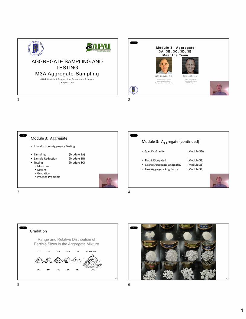
5
Gradation
Range and Relative Distribution of Particle Sizes in the Aggregate Mixture
6
6
1 2
3 4
5 6

2
7 Sieve Openings
• 1” nominal opening
• No. 4
• 4 openings per linear inch
• No. 200
• 200 openings per linear inch
8 Standard Specifications 904.03
9
Standard Specifications 904.0210
Aggregate Definitions
• Coarse Aggregate – Material that has a minimum of 20% retained on the No.4 sieve
• Fine Aggregate – Material that has 100% passing the 3/8 inch sieve and a minimum of 80% passing the No.4 sieve.
• Mineral Filler – Fraction of fine aggregate passing the No. 200 sieve
• Maximum Particle Size – The largest sieve size through which all material must pass
• Nominal Maximum Particle Size – The smallest sieve opening through which the entire amount of the aggregate is permitted to pass
13 Standard Specifications 904.03 14
Module 3: Aggregate
• Introduction ‐ Aggregate Testing
• Sampling (Module 3A)
• Sample Reduction (Module 3B)
• Testing (Module 3C)• Moisture• Decant• Gradation• Practice Problems
7 8
9 10
13 14
3
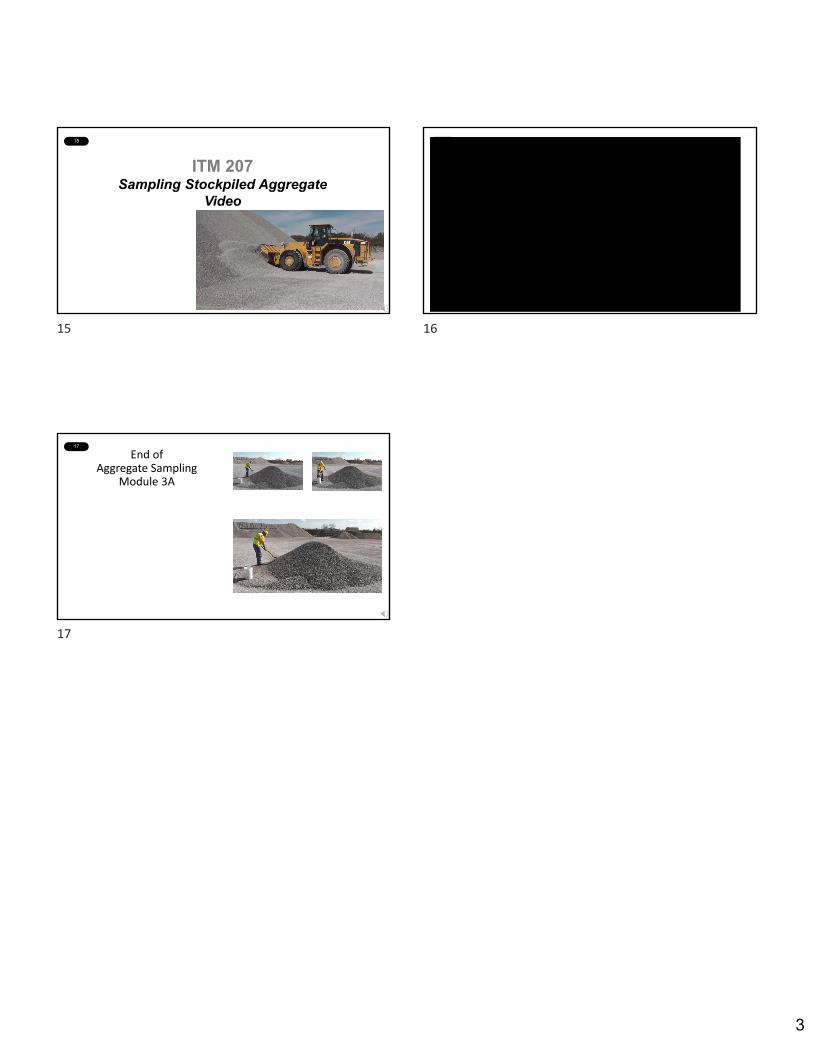
15
ITM 207Sampling Stockpiled Aggregate
Video
16
17
End of Aggregate Sampling
Module 3A
15 16
17
1
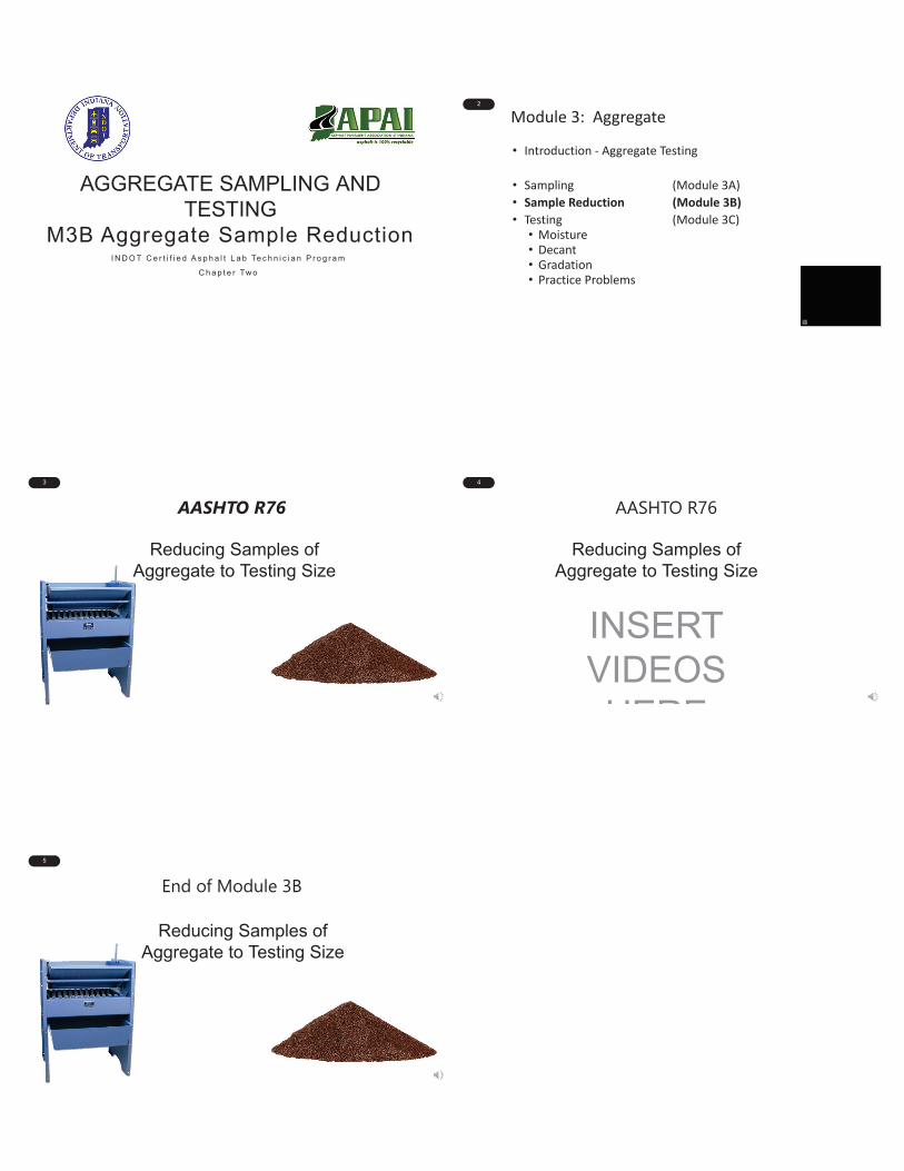
AGGREGATE SAMPLING AND TESTING
M3B Aggregate Sample ReductionI N D O T C e r t i f i e d A s p h a l t L a b Te c h n i c i a n P r o g r a m
C h a p t e r Tw o
2
Module 3: Aggregate
• Introduction - Aggregate Testing
• Sampling (Module 3A)
• Sample Reduction (Module 3B)
• Testing (Module 3C)• Moisture• Decant• Gradation• Practice Problems
3
Reducing Samples of Aggregate to Testing Size
AASHTO R76
AA
4
Reducing Samples of Aggregate to Testing Size
INSERT VIDEOS HERE
AASHTO R76
5
Reducing Samples of Aggregate to Testing Size
End of Module 3B
1
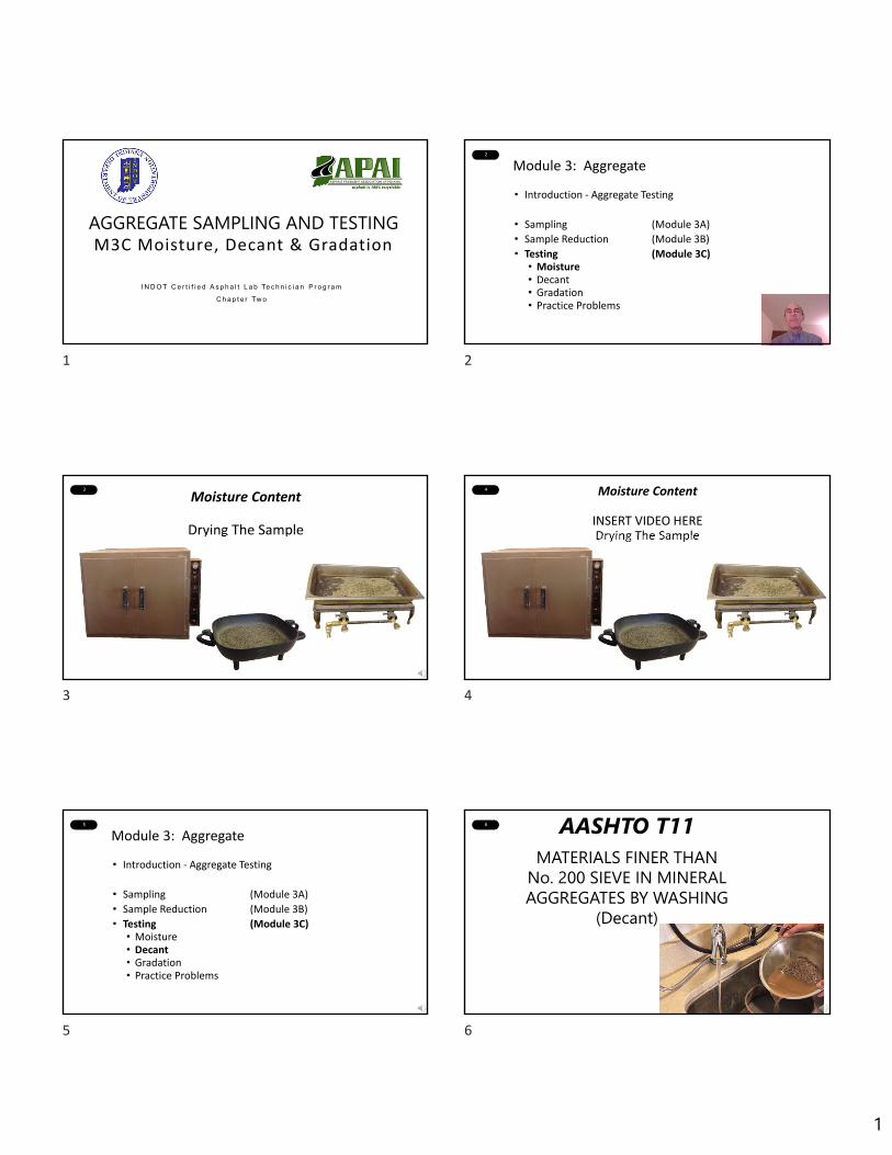
1
AGGREGATE SAMPLING AND TESTINGM3C Moisture, Decant & Gradation
I N D O T C e r t i f i e d A s p h a l t L a b Te c h n i c i a n P r o g r a m
C h a p t e r Tw o
2
Module 3: Aggregate
• Introduction ‐ Aggregate Testing
• Sampling (Module 3A)
• Sample Reduction (Module 3B)
• Testing (Module 3C)• Moisture• Decant• Gradation• Practice Problems
3
Moisture Content
Drying The Sample
4 Moisture Content
INSERT VIDEO HEREDrying The Sample
5
Module 3: Aggregate
• Introduction ‐ Aggregate Testing
• Sampling (Module 3A)
• Sample Reduction (Module 3B)
• Testing (Module 3C)• Moisture• Decant• Gradation• Practice Problems
6 AASHTO T11MATERIALS FINER THAN
No. 200 SIEVE IN MINERAL AGGREGATES BY WASHING
(Decant)
1 2
3 4
5 6
2
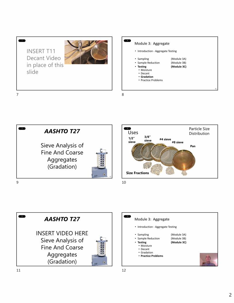
7
INSERT T11 Decant Video in place of this slide
8
Module 3: Aggregate
• Introduction ‐ Aggregate Testing
• Sampling (Module 3A)
• Sample Reduction (Module 3B)
• Testing (Module 3C)• Moisture• Decant• Gradation• Practice Problems
9
AASHTO T27
Sieve Analysis of Fine And Coarse
Aggregates(Gradation)
10
Uses1/2” sieve
3/8” sieve #4 sieve
#8 sievePan
Size Fractions
Particle Size Distribution
11
AASHTO T27
INSERT VIDEO HERESieve Analysis of Fine And Coarse
Aggregates(Gradation)
12
Module 3: Aggregate
• Introduction ‐ Aggregate Testing
• Sampling (Module 3A)
• Sample Reduction (Module 3B)
• Testing (Module 3C)• Moisture• Decant• Gradation• Practice Problems
7 8
9 10
11 12
3
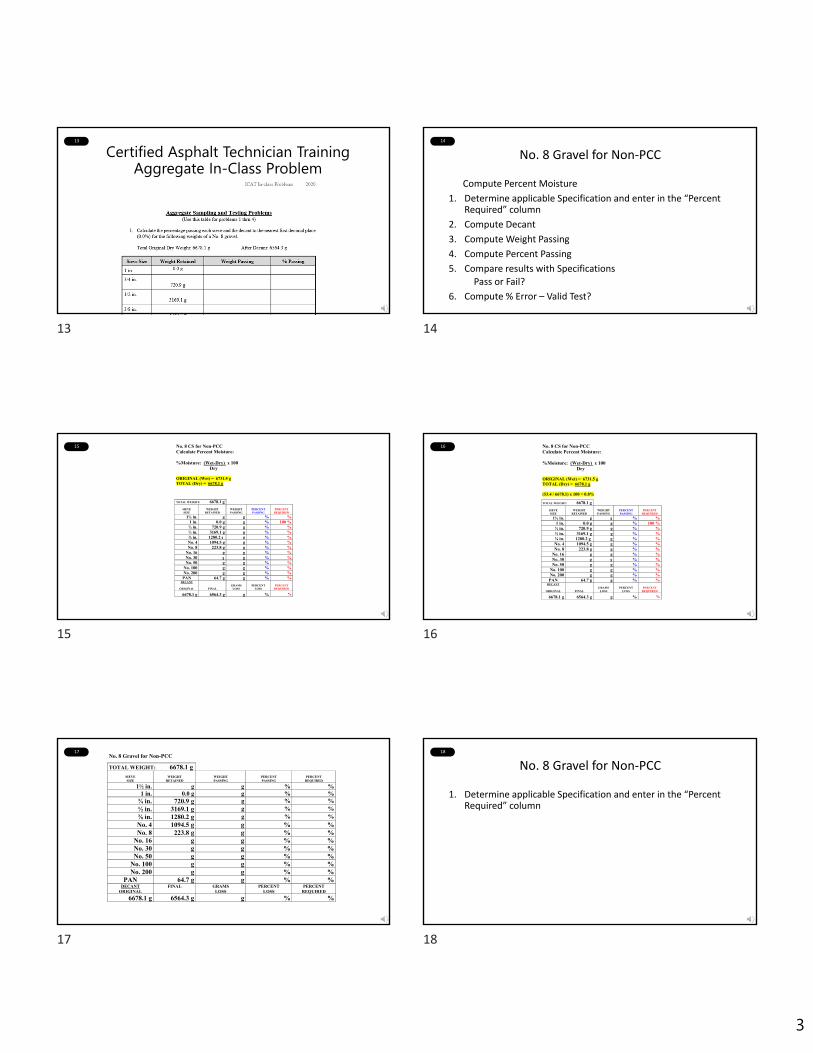
13
Certified Asphalt Technician TrainingAggregate In-Class Problem
14
No. 8 Gravel for Non‐PCC
Compute Percent Moisture
1. Determine applicable Specification and enter in the “Percent Required” column
2. Compute Decant
3. Compute Weight Passing
4. Compute Percent Passing
5. Compare results with Specifications
Pass or Fail?
6. Compute % Error – Valid Test?
15 No. 8 CS for Non-PCC Calculate Percent Moisture: %Moisture: (Wet-Dry) x 100 Dry ORIGINAL (Wet) = 6731.5 g TOTAL (Dry) = 6678.1 g
TOTAL WEIGHT: 6678.1 g
SIEVE SIZE
WEIGHT
RETAINED
WEIGHT PASSING
PERCENT PASSING
PERCENT
REQUIRED
1½ in. g g % % 1 in. 0.0 g g % 100 %
¾ in. 720.9 g g % % ½ in. 3169.1 g g % % ⅜ in. 1280.2 g g % % No. 4 1094.5 g g % % No. 8 223.8 g g % %
No. 16 g g % % No. 30 g g % % No. 50 g g % %
No. 100 g g % % No. 200 g g % %
PAN 64.7 g g % % DECANT
ORIGINAL
FINAL
GRAMS
LOSS
PERCENT
LOSS
PERCENT
REQUIRED
6678.1 g 6564.3 g g % %
16 No. 8 CS for Non-PCC Calculate Percent Moisture: %Moisture: (Wet-Dry) x 100 Dry ORIGINAL (Wet) = 6731.5 g TOTAL (Dry) = 6678.1 g (53.4 / 6678.1) x 100 = 0.8%
TOTAL WEIGHT: 6678.1 g
SIEVE SIZE
WEIGHT
RETAINED
WEIGHT PASSING
PERCENT PASSING
PERCENT
REQUIRED
1½ in. g g % % 1 in. 0.0 g g % 100 %
¾ in. 720.9 g g % % ½ in. 3169.1 g g % % ⅜ in. 1280.2 g g % % No. 4 1094.5 g g % % No. 8 223.8 g g % %
No. 16 g g % % No. 30 g g % % No. 50 g g % %
No. 100 g g % % No. 200 g g % %
PAN 64.7 g g % % DECANT
ORIGINAL
FINAL
GRAMS
LOSS
PERCENT
LOSS
PERCENT
REQUIRED
6678.1 g 6564.3 g g % %
17No. 8 Gravel for Non-PCC
TOTAL WEIGHT: 6678.1 g
SIEVE SIZE
WEIGHT
RETAINED
WEIGHT PASSING
PERCENT PASSING
PERCENT
REQUIRED
1½ in. g g % % 1 in. 0.0 g g % %
¾ in. 720.9 g g % % ½ in. 3169.1 g g % % ⅜ in. 1280.2 g g % % No. 4 1094.5 g g % % No. 8 223.8 g g % %
No. 16 g g % % No. 30 g g % % No. 50 g g % %
No. 100 g g % %
No. 200 g g % %
PAN 64.7 g g % %
DECANT ORIGINAL
FINAL GRAMS LOSS
PERCENT LOSS
PERCENT REQUIRED
6678.1 g 6564.3 g g % %
18
No. 8 Gravel for Non‐PCC
1. Determine applicable Specification and enter in the “Percent Required” column Spec Gradation Requirements found???
13 14
15 16
17 18

4
19 Standard Specifications 904.03 20
No. 8 Gravel for Non-PCC
TOTAL WEIGHT: 6678.1 g
SIEVE SIZE
WEIGHT
RETAINED
WEIGHT PASSING
PERCENT PASSING
PERCENT
REQUIRED
1½ in. g g % % 1 in. 0.0 g g % 100 %
¾ in. 720.9 g g % % ½ in. 3169.1 g g % % ⅜ in. 1280.2 g g % % No. 4 1094.5 g g % % No. 8 223.8 g g % %
No. 16 g g % % No. 30 g g % % No. 50 g g % %
No. 100 g g % % No. 200 g g % %
PAN 64.7 g g % % DECANT
ORIGINAL
FINAL
GRAMS
LOSS
PERCENT
LOSS
PERCENT
REQUIRED
6678.1 g 6564.3 g g % %
21
No. 8 Gravel for Non-PCC
TOTAL WEIGHT: 6678.1 g
SIEVE SIZE
WEIGHT
RETAINED
WEIGHT PASSING
PERCENT PASSING
PERCENT
REQUIRED
1½ in. g g % % 1 in. 0.0 g g % 100 %
¾ in. 720.9 g g % 75-95 % ½ in. 3169.1 g g % % ⅜ in. 1280.2 g g % % No. 4 1094.5 g g % % No. 8 223.8 g g % %
No. 16 g g % % No. 30 g g % % No. 50 g g % %
No. 100 g g % % No. 200 g g % %
PAN 64.7 g g % % DECANT
ORIGINAL
FINAL
GRAMS
LOSS
PERCENT
LOSS
PERCENT
REQUIRED
6678.1 g 6564.3 g g % %
22
No. 8 Gravel for Non-PCC
TOTAL WEIGHT: 6678.1 g
SIEVE SIZE
WEIGHT
RETAINED
WEIGHT PASSING
PERCENT PASSING
PERCENT
REQUIRED
1½ in. g g % % 1 in. 0.0 g g % 100 %
¾ in. 720.9 g g % 75-95 % ½ in. 3169.1 g g % 40-70 % ⅜ in. 1280.2 g g % 20-50 % No. 4 1094.5 g g % 0-15 % No. 8 223.8 g g % 0-10 %
No. 16 g g % % No. 30 g g % % No. 50 g g % %
No. 100 g g % % No. 200 g g % %
PAN 64.7 g g % % DECANT
ORIGINAL
FINAL
GRAMS
LOSS
PERCENT
LOSS
PERCENT
REQUIRED
6678.1 g 6564.3 g g % 0-3.0 %
23
No. 8 Gravel for Non‐PCC
1. Determine applicable Specification and enter in the Percent Required Column
2. Compute Decant
% Decant = Original Dry Wt. – Dry Wt. after Decant x 100
Original Dry Wt.
24
No. 8 Gravel for Non-PCC
TOTAL WEIGHT: 6678.1 g
SIEVE SIZE
WEIGHT
RETAINED
WEIGHT PASSING
PERCENT PASSING
PERCENT
REQUIRED
1½ in. g g % % 1 in. 0.0 g g % 100 %
¾ in. 720.9 g g % 75-95 % ½ in. 3169.1 g g % 40-70 % ⅜ in. 1280.2 g g % 20-50 % No. 4 1094.5 g g % 0-15 % No. 8 223.8 g g % 0-10 %
No. 16 g g % % No. 30 g g % % No. 50 g g % %
No. 100 g g % % No. 200 g g % %
PAN 64.7 g g % % DECANT
ORIGINAL
FINAL
GRAMS
LOSS
PERCENT
LOSS
PERCENT
REQUIRED
6678.1 g 6564.3 g 113.8 g % 0-3.0 %
19 20
21 22
23 24
5
25 No. 8 Gravel for Non-PCC
TOTAL WEIGHT: 6678.1 g
SIEVE SIZE
WEIGHT
RETAINED
WEIGHT PASSING
PERCENT PASSING
PERCENT
REQUIRED
1½ in. g g % % 1 in. 0.0 g g % 100 % ¾ in. 720.9 g g % 75-95 % ½ in. 3169.1 g g % 40-70 % ⅜ in. 1280.2 g g % 20-50 % No. 4 1094.5 g g % 0-15 % No. 8 223.8 g g % 0-10 %
No. 16 g g % % No. 30 g g % % No. 50 g g % %
No. 100 g g % % No. 200 g g % %
PAN 64.7 g g % % DECANT
ORIGINAL
FINAL
GRAMS
LOSS
PERCENT
LOSS
PERCENT
REQUIRED
6678.1 g 6564.3 g 113.8 g 1.7 % 0-3.0 %
26
No. 8 Gravel for Non‐PCC
1. Determine applicable Specification and enter in the Percent Required Column
2. Compute Decant
% Decant = Original Dry Wt. – Dry Wt. after Decant x 100
Original Dry Wt.
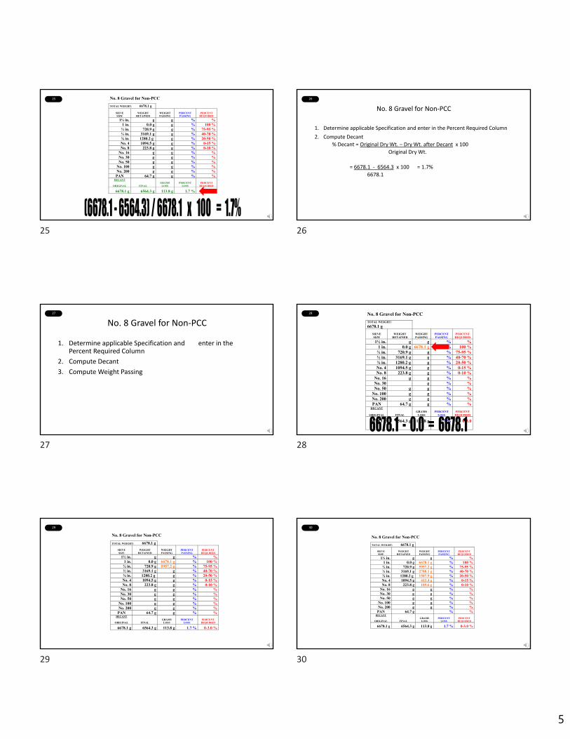
= 6678.1 ‐ 6564.3 x 100 = 1.7%
6678.1
27
No. 8 Gravel for Non‐PCC
1. Determine applicable Specification and enter in the Percent Required Column
2. Compute Decant
3. Compute Weight Passing
28 No. 8 Gravel for Non-PCC TOTAL WEIGHT: 6678.1 g
SIEVE SIZE
WEIGHT
RETAINED
WEIGHT PASSING
PERCENT PASSING
PERCENT
REQUIRED
1½ in. g g % % 1 in. 0.0 g 6678.1 g % 100 %
¾ in. 720.9 g g % 75-95 % ½ in. 3169.1 g g % 40-70 % ⅜ in. 1280.2 g g % 20-50 % No. 4 1094.5 g g % 0-15 % No. 8 223.8 g g % 0-10 %
No. 16 g g % % No. 30 g g % % No. 50 g g % %
No. 100 g g % % No. 200 g g % % PAN 64.7 g g % %
DECANT
ORIGINAL
FINAL
GRAMS
LOSS
PERCENT
LOSS
PERCENT
REQUIRED
6678.1 g 6564.3 g 113.8 g 1.7 % 0-3.0
29
No. 8 Gravel for Non-PCC
TOTAL WEIGHT: 6678.1 g
SIEVE SIZE
WEIGHT
RETAINED
WEIGHT PASSING
PERCENT PASSING
PERCENT
REQUIRED
1½ in. g g % % 1 in. 0.0 g 6678.1 g % 100 %
¾ in. 720.9 g 5957.2 g % 75-95 % ½ in. 3169.1 g g % 40-70 % ⅜ in. 1280.2 g g % 20-50 % No. 4 1094.5 g g % 0-15 % No. 8 223.8 g g % 0-10 %
No. 16 g g % % No. 30 g g % % No. 50 g g % %
No. 100 g g % % No. 200 g g % %
PAN 64.7 g g % % DECANT
ORIGINAL
FINAL
GRAMS
LOSS
PERCENT
LOSS
PERCENT
REQUIRED
6678.1 g 6564.3 g 113.8 g 1.7 % 0-3.0 %
30
No. 8 Gravel for Non-PCC
TOTAL WEIGHT: 6678.1 g
SIEVE SIZE
WEIGHT
RETAINED
WEIGHT PASSING
PERCENT PASSING
PERCENT
REQUIRED
1½ in. g g % % 1 in. 0.0 g 6678.1 g % 100 %
¾ in. 720.9 g 5957.2 g % 75-95 % ½ in. 3169.1 g 2788.1 g % 40-70 % ⅜ in. 1280.2 g 1507.9 g % 20-50 % No. 4 1094.5 g 413.4 g % 0-15 % No. 8 223.8 g 189.6 g % 0-10 %
No. 16 g g % % No. 30 g g % % No. 50 g g % %
No. 100 g g % % No. 200 g g % %
PAN 64.7 g % % DECANT
ORIGINAL
FINAL
GRAMS
LOSS
PERCENT
LOSS
PERCENT
REQUIRED
6678.1 g 6564.3 g 113.8 g 1.7 % 0-3.0 %
25 26
27 28
29 30

6
31
No. 8 Gravel for Non‐PCC
1. Determine applicable Specification and enter in the Percent Required Column
2. Compute Decant
3. Compute Weight Passing
4. Compute Percent Passing% Passing = Weight Passing Each Sieve x 100
Original Dry Sample Weight
32 No. 8 Gravel for Non-PCC
TOTAL WEIGHT: 6678.1 g
SIEVE SIZE
WEIGHT
RETAINED
WEIGHT PASSING
PERCENT PASSING
PERCENT
REQUIRED
1½ in. g g % % 1 in. 0.0 g 6678.1 g 100.0 % 100 %
¾ in. 720.9 g 5957.2 g % 75-95 % ½ in. 3169.1 g 2788.1 g % 40-70 % ⅜ in. 1280.2 g 1507.9 g % 20-50 % No. 4 1094.5 g 413.4 g % 0-15 % No. 8 223.8 g 189.6 g % 0-10 %
No. 16 g g % % No. 30 g g % % No. 50 g g % %
No. 100 g g % % No. 200 g g % %
PAN 64.7 g g % % DECANT
ORIGINAL
FINAL
GRAMS
LOSS
PERCENT
LOSS
PERCENT
REQUIRED
6678.1 g 6564.3 g 13.8 g 1.7 % 0-3.0 %
33
No. 8 Gravel for Non-PCC
TOTAL WEIGHT: 6678.1 g
SIEVE SIZE
WEIGHT
RETAINED
WEIGHT PASSING
PERCENT PASSING
PERCENT
REQUIRED
1½ in. g g % % 1 in. 0.0 g 6678.1 g 100.0 % 100 %
¾ in. 720.9 g 5957.2 g 89.2 % 75-95 % ½ in. 3169.1 g 2788.1 g % 40-70 % ⅜ in. 1280.2 g 1507.9 g % 20-50 % No. 4 1094.5 g 413.4 g % 0-15 % No. 8 223.8 g 189.6 g % 0-10 %
No. 16 g g % % No. 30 g g % % No. 50 g g % %
No. 100 g g % % No. 200 g g % %
PAN 64.7 g % % DECANT
ORIGINAL
FINAL
GRAMS
LOSS
PERCENT
LOSS
PERCENT
REQUIRED
6678.1 g 6564.3 g 113.8 g 1.7 % 0-3.0 %
34
No. 8 Gravel for Non-PCC
TOTAL WEIGHT: 6678.1 g
SIEVE SIZE
WEIGHT
RETAINED
WEIGHT PASSING
PERCENT PASSING
PERCENT
REQUIRED
1½ in. g g % % 1 in. 0.0 g 6678.1 g 100.0 % 100 %
¾ in. 720.9 g 5957.2 g 89.2 % 75-95 % ½ in. 3169.1 g 2788.1 g 41.7 % 40-70 % ⅜ in. 1280.2 g 1507.9 g 22.6 % 20-50 % No. 4 1094.5 g 413.4 g 6.2 % 0-15 % No. 8 223.8 g 189.6 g 2.8 % 0-10 %
No. 16 g g % % No. 30 g g % % No. 50 g g % %
No. 100 g g % % No. 200 g g % %
PAN 64.7 g % DECANT
ORIGINAL
FINAL
GRAMS
LOSS
PERCENT
LOSS
PERCENT
REQUIRED
6678.1 g 6564.3 g 113.8 g 1.7 % 0-3.0 %
35
No. 8 Gravel for Non‐PCC
1. Determine applicable Specification and enter in the Percent Required Column
2. Compute Decant
3. Compute Weight Passing
4. Compute Percent Passing
5. Compare results with SpecificationsPass or Fail?
36
No. 8 Gravel for Non-PCC
TOTAL WEIGHT: 6678.1 g
SIEVE SIZE
WEIGHT
RETAINED
WEIGHT PASSING
PERCENT PASSING
PERCENT
REQUIRED
1½ in. g g % % 1 in. 0.0 g 6678.1 g 100.0 % 100 % ¾ in. 720.9 g 5957.2 g 89.2 % 75-95 % ½ in. 3169.1 g 2788.1 g 41.7 % 40-70 % ⅜ in. 1280.2 g 1507.9 g 22.6 % 20-50 % No. 4 1094.5 g 413.4 g 6.2 % 0-15 % No. 8 223.8 g 189.6 g 2.8 % 0-10 %
No. 16 g g % % No. 30 g g % % No. 50 g g % %
No. 100 g g % % No. 200 g g % %
PAN 64.7 g % DECANT
ORIGINAL
FINAL
GRAMS
LOSS
PERCENT
LOSS
PERCENT
REQUIRED
6678.1 g 6564.3 g 113.8 g 1.7 % 0-3.0 %
31 32
33 34
35 36
7
37
No. 8 Gravel for Non-PCC
TOTAL WEIGHT: 6678.1 g
SIEVE SIZE
WEIGHT
RETAINED
WEIGHT PASSING
PERCENT PASSING
PERCENT
REQUIRED
1½ in. g g % % 1 in. 0.0 g 6678.1 g 10.00 % 100 % ¾ in. 720.9 g 5957.2 g 89.2 % 75-95 % ½ in. 3169.1 g 2788.1 g 41.7 % 40-70 % ⅜ in. 1280.2
g 1507.9 g 22.6 % 20-50 %
No. 4 1094.5 g 413.4 g 6.2 % 0-15 % No. 8 223.8 g 189.6 g 2.8 % 0-10 %
No. 16 g g % % No. 30 g g % % No. 50 g g % %
No. 100 g g % % No. 200 g g % % PAN 64.7 g %
DECANT
ORIGINAL
FINAL
GRAMS
LOSS
PERCENT
LOSS
PERCENT
REQUIRED
6678.1 g 6564.3 g 113.8 g 1.7 % 0-3.0 %
38
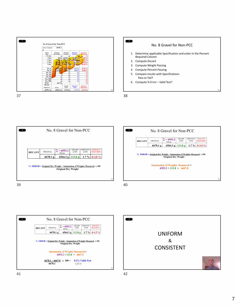
No. 8 Gravel for Non‐PCC
1. Determine applicable Specification and enter in the Percent Required Column
2. Compute Decant
3. Compute Weight Passing
4. Compute Percent Passing
5. Compare results with SpecificationsPass or Fail?
6. Compute % Error – Valid Test?
39 No. 8 Gravel for Non-PCC
DECANT
ORIGINAL = 6553.2 FINAL
GRAMS LOSS
PERCENT LOSS
PERCENT REQUIRED
6678.1 g 6564.3 g 113.8 g 1.7 % 0-3.0 % % ERROR = Original Dry Weight – Summation of Weights Measured x 100 Original Dry Weight
40 No. 8 Gravel for Non-PCC
DECANT
ORIGINAL = 6553.2
FINAL
GRAMS LOSS
PERCENT LOSS
PERCENT REQUIRED
6678.1 g 6564.3 g 113.8 g 1.7 % 0-3.0 % % ERROR = Original Dry Weight – Summation of Weights Measured x 100 Original Dry Weight
Summation of Weights Measured = 6553.2 + 113.8 = 6667.0
41
ORIGINAL = 6553.2
FINAL
GRAMS LOSS
PERCENT LOSS
PERCENT REQUIRED
DECANT
6678.1 g 6564.3 g 113.8 g 1.7 % 0-1.5 % % ERROR = Original Dry Weight – Summation of Weights Measured x 100 Original Dry Weight
Summation of Weights Measured = 6553.2 + 113.8 = 6667.0
6678.1 – 6667.0 x 100 = 0.2% Valid Test 6678.1 (<0.3)
No. 8 Gravel for Non-PCC 42
UNIFORM&
CONSISTENT
37 38
39 40
41 42
8
43
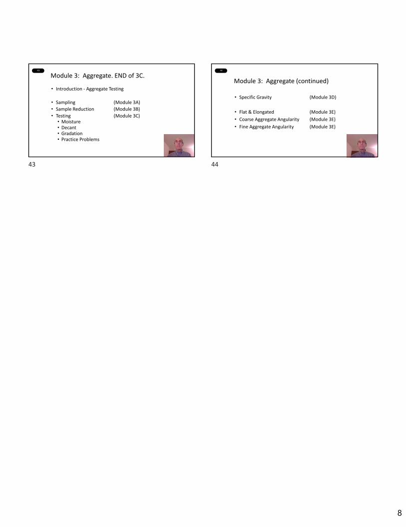
Module 3: Aggregate. END of 3C.
• Introduction ‐ Aggregate Testing
• Sampling (Module 3A)
• Sample Reduction (Module 3B)
• Testing (Module 3C)• Moisture• Decant• Gradation• Practice Problems
44
Module 3: Aggregate (continued)
• Specific Gravity (Module 3D)
• Flat & Elongated (Module 3E)
• Coarse Aggregate Angularity (Module 3E)
• Fine Aggregate Angularity (Module 3E)
43 44

2/8/2021
1
M3D Specific Gravity and Absorption of Aggregates
I N D O T C e r t i f i e d A s p h a l t L a b T e c h n i c i a n P r o g r a m
C h a p t e r T w o
Meet the Team
HMA Design & QC Coordinator – South
E&B Paving, Inc.
T O M P A R T I P I L O
3
Overview of Modules 3D and 3E
Aggregate Consensus Properties
4
Specific Gravity and Absorption of Fine
AggregatesAASHTO T84
5
(Insert Fine Agg Specific Gravity Video HERE)
6
Specific Gravity and Absorption of Coarse
AggregatesAASHTO T85
1 2
3 4
5 6
2/8/2021
2
7
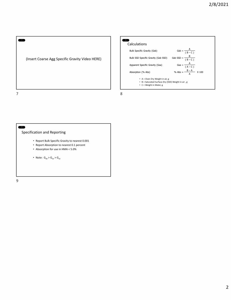
(Insert Coarse Agg Specific Gravity Video HERE)
8
Calculations
• A = Oven Dry Weight in air, g
• B = Saturated Surface‐Dry (SSD) Weight in air , g
• C = Weight in Water, g
Bulk Specific Gravity (Gsb) Gsb = A
( B – C )
Bulk SSD Specific Gravity (Gsb SSD) Gsb SSD =B
( B – C )
Apparent Specific Gravity (Gsa) Gsa =A
( A – C )
Absorption (% Abs) % Abs =B – A
X 100A
9
Specification and Reporting
• Report Bulk Specific Gravity to nearest 0.001
• Report Absorption to nearest 0.1 percent
• Absorption for use in HMA < 5.0%
• Note: Gsb > Gse > Gsa
7 8
9
2/8/2021
1
M3E Aggregate Shape Consensus Properties
I N D O T C e r t i f i e d A s p h a l t L a b T e c h n i c i a n P r o g r a m
C h a p t e r T w o
2
Uncompacted Void Content of Fine Aggregate
AASHTO T304
3
(Insert Fine FAA Video HERE)
4
• U = % Uncompacted Voids in the material
• V = Volume of cylindrical measure, mL
• F = net mass (g) of fine aggregate in measure (gross mass – mass of empty measure)
• G = bulk dry specific gravity of fine aggregate
Calculations
U = V – ( F/G) X 100V
5
Flat Particles, Elongated Particles in Coarse Aggregate
ASTM D ‐4791
6
(Insert Flat/Elongated Video HERE)
1 2
3 4
5 6
2/8/2021
2
7
Calculation
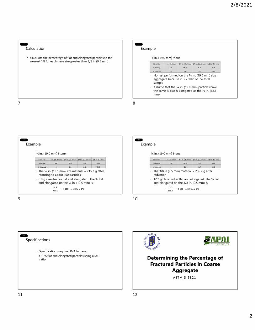
• Calculate the percentage of flat and elongated particles to the nearest 1% for each sieve size greater than 3/8 in (9.5 mm)
8
Example
¾ in. (19.0 mm) Stone
Sieve Size 1 in. (25.0 mm) 3/4 in. (19.0 mm) 1/2 in. (12.5 mm) 3/8 in. (9.5 mm)
% Passing 100 99.4 75.7 46.4
% Retained 0 0.6 23.7 29.3
• No test performed on the ¾ in. (19.0 mm) size aggregate because it is < 10% of the total sample
• Assume that the ¾ in. (19.0 mm) particles have the same % Flat & Elongated as the ½ in. (12.5 mm)
9
Example
¾ in. (19.0 mm) Stone
Sieve Size 1 in. (25.0 mm) 3/4 in. (19.0 mm) 1/2 in. (12.5 mm) 3/8 in. (9.5 mm)
% Passing 100 99.4 75.7 46.4
% Retained 0 0.6 23.7 29.3
• The ½ in. (12.5 mm) size material = 715.3 g after reducing to about 100 particles
• 6.9 g classified as flat and elongated. The % flat and elongated on the ½ in. (12.5 mm) is:
6.9X 100 = 1.0% ≈ 1%
715.3
10
Example
¾ in. (19.0 mm) Stone
Sieve Size 1 in. (25.0 mm) 3/4 in. (19.0 mm) 1/2 in. (12.5 mm) 3/8 in. (9.5 mm)
% Passing 100 99.4 75.7 46.4
% Retained 0 0.6 23.7 29.3
• The 3/8 in (9.5 mm) material = 239.7 g after reduction
• 12.2 g classified as flat and elongated. The % flat and elongated on the 3/8 in. (9.5 mm) is:
12.2X 100 = 5.1% ≈ 5%
239.7
11
Specifications
• Specifications require HMA to have
< 10% flat and elongated particles using a 5:1 ratio
12
Determining the Percentage of Fractured Particles in Coarse
AggregateASTM D ‐5821
7 8
9 10
11 12

2/8/2021
3
13
(Insert % Fractured Particles Video HERE)
14
Calculation
• Calculate the percentage of crushed particles with specified number of fractured faces as follows:
• P = percentage of particles with the specified number of faces
• F = mass of fractured particles with at least specified number of faces
• N = mass of non‐fractured particles
P = F X 100F + N
15
Specification Requirement
Coarse Aggregate Angularity
Traffic, ESALDepth from Surface
≤ 4 in. > 4 in.
< 3,000,000 75 50
3,000,000 to < 10,000,000 85/80* 60
≥ 10,000,000 95/90* 95/90*
* Denotes two faced crush requirements.
Section 904.03 (b)
13 14
15
1
1
Asphalt Binders forQuality Assurance Certified
Technician ProgramI N D O T C e r t i f i e d A s p h a l t L a b Te c h n i c i a n P r o g r a m
C h a p t e r T h r e e – M o d u l e 4
2
Meet the Team
Director of ResearchHeritage Research Group
T O N Y K R I E C H
Director of Construction MaterialsThe Heritage Group
J A S O N W I E L I N S K I , P . E .
3
Asphalt BindersOverview
• What are Asphalt Binders ?
• How are they Manufactured ?
• The Grading System
• How are they Tested and Certified ?
• Safety
• Storage Handling and Sampling
• Specific Gravity of Asphalt Binder
• Temperature Volume
4
Asphalt
• Asphalt is a black cementing material varying from solid to semi‐solid at room temperature. Virtually all asphalts used in roads are produced in petroleum refineries
5
Asphalt Binders
• Asphalt Binders used in paving asphalts are produced from the distillation of petroleum crude oil. Asphalt is the non‐distillable portion of the crude oil.
6
Asphalt Binders
1 2
3 4
5 6
2
7
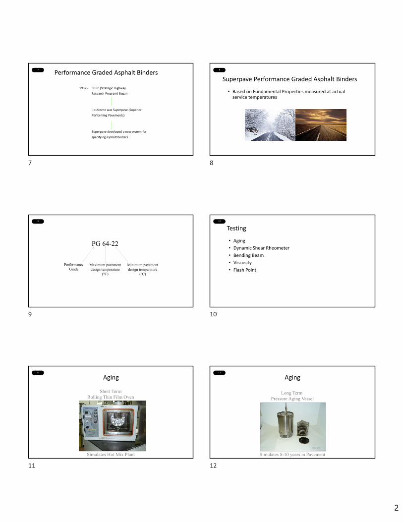
Performance Graded Asphalt Binders
1987 ‐ SHRP (Strategic Highway
Research Program) Began
‐ outcome was Superpave (Superior
Performing Pavements)
Superpave developed a new system for
specifying asphalt binders
8
Superpave Performance Graded Asphalt Binders
• Based on Fundamental Properties measured at actual service temperatures
9
PG 64-22
Minimum pavement design temperature
(°C)
PerformanceGrade
Maximum pavement design temperature
(°C)
10
Testing
• Aging
• Dynamic Shear Rheometer
• Bending Beam
• Viscosity
• Flash Point
11
Aging
Short Term Rolling Thin Film Oven
Simulates Hot Mix Plant
12
Aging
Long Term Pressure Aging Vessel
Simulates 8-10 years in Pavement
7 8
9 10
11 12

3
13
Dynamic Shear Rheometer
Evaluates High Temperature Stiffness
and Intermediate Stiffness
14
Bending Beam
Determines Stiffness and Ability of Asphalt to Relax at Low Temperature Pavement Condition
15
Rotational Viscosity
Test for High Temperature Storage and Handling
16
Flash Point
• Flash Point is a Safety Test
• Asphalt Binders should be stored below Flash Point temperature
17
Asphalt Safety Issues
• Storage & Handling Hazards• Burns• H2S• Fumes
• Traffic
18
Storage & Handling Solutions
• Be Aware of Burn Hazard Locations
• Use Designated Walk Areas
• Look Out for Construction Traffic
• Avoid Tank Vent Openings for H2S Build‐up
• Stay Upwind of Asphalt Fumes if possible
• When Sampling, wear long sleeve shirt & pants
• Follow Established Safety Procedures
13 14
15 16
17 18
4
19
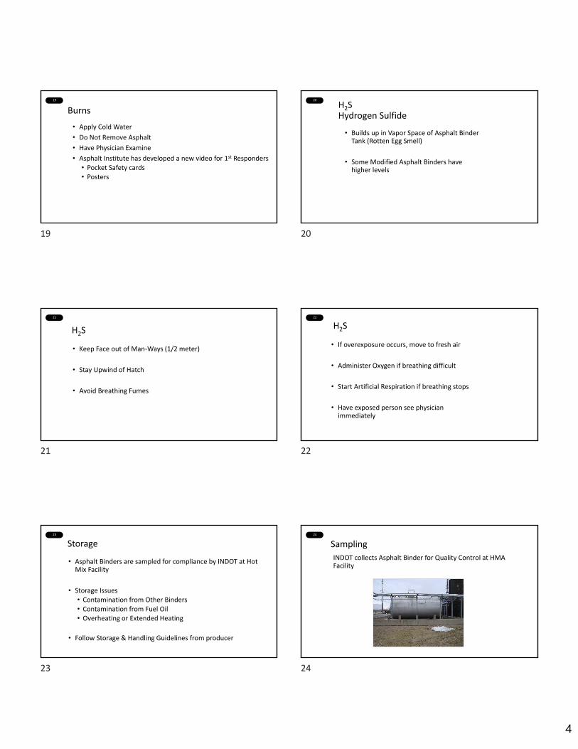
Burns
• Apply Cold Water
• Do Not Remove Asphalt
• Have Physician Examine
• Asphalt Institute has developed a new video for 1st Responders
• Pocket Safety cards• Posters
20
H2SHydrogen Sulfide
• Builds up in Vapor Space of Asphalt Binder Tank (Rotten Egg Smell)
• Some Modified Asphalt Binders have higher levels
21
H2S
• Keep Face out of Man‐Ways (1/2 meter)
• Stay Upwind of Hatch
• Avoid Breathing Fumes
22
H2S
• If overexposure occurs, move to fresh air
• Administer Oxygen if breathing difficult
• Start Artificial Respiration if breathing stops
• Have exposed person see physician immediately
23
Storage
• Asphalt Binders are sampled for compliance by INDOT at Hot Mix Facility
• Storage Issues• Contamination from Other Binders• Contamination from Fuel Oil• Overheating or Extended Heating
• Follow Storage & Handling Guidelines from producer
24
Sampling
INDOT collects Asphalt Binder for Quality Control at HMA Facility
19 20
21 22
23 24

5
25
Sampling
Proper Sampling
important for
representative sample
26
Sampling Issues
• Avoid sampling from top of tank if possible
• Use only clean containers
• Allow 1 Gallon of asphalt binder to drain before sampling
• Seal container immediately
27
Sampling Issues
• Clean container outside if spilled asphalt binder present
• Label all containers clearly
• Do not label lid
• Follow Safety Procedures
28
Specific Gravity of Asphalt BinderPycnometer Method
Performed by Material
Supplier
Usually listed at 60oF
29
Specific Gravity of Asphalt Binders
• Specific Gravity of Asphalt is the ratio of the weight of a volume of material to the weight of a equal volume of water, both at a specified temperature
• Asphalt Binders Expand & Contract with Temperature
• Specific Gravity at a specified temperature provides a Yardstick for Temperature Volume Calculation
30
Temperature – Volume Relationship
• Conversion between Mass and Volume is necessary
• Asphalt Binders typically sold by Mass, not Volume
• In HMA, Volume is more important for volumetrics of design
25 26
27 28
29 30
6
31
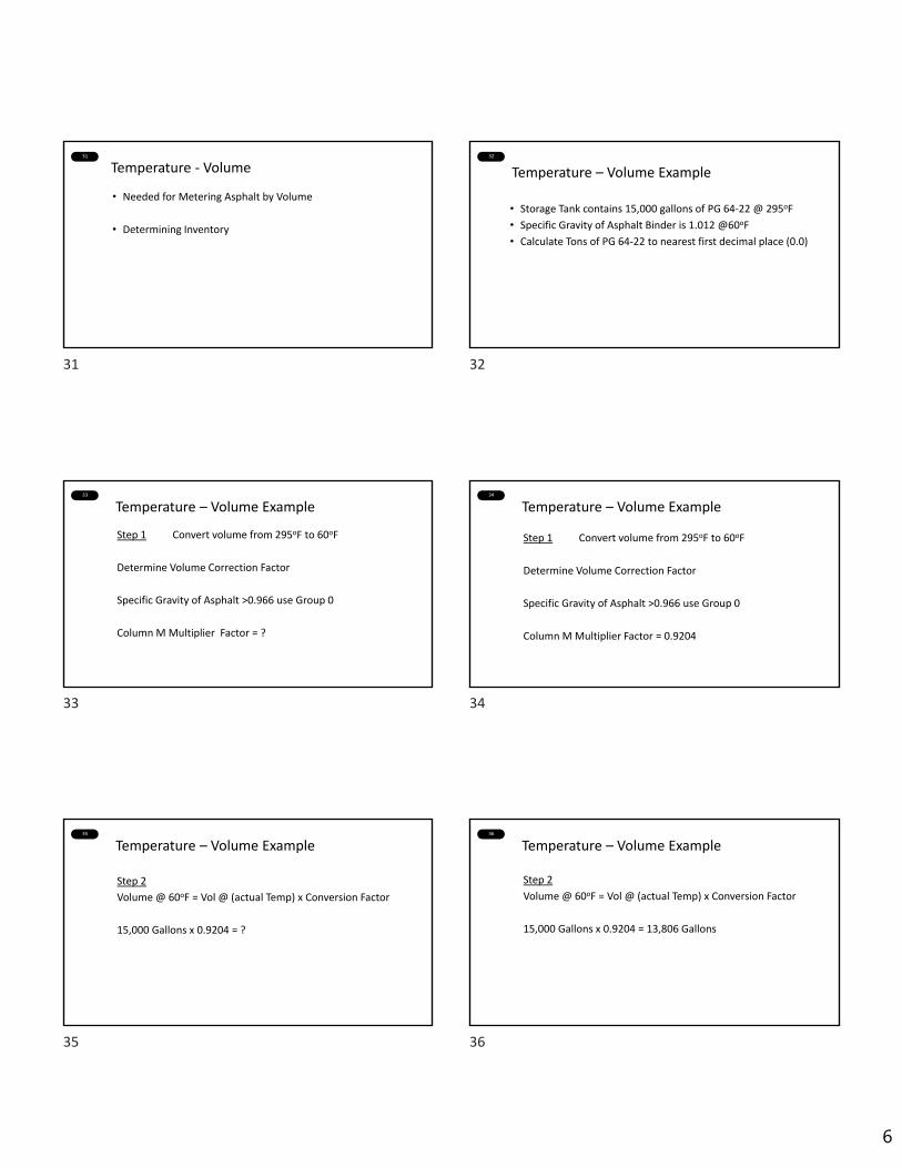
Temperature ‐ Volume
• Needed for Metering Asphalt by Volume
• Determining Inventory
32
Temperature – Volume Example
• Storage Tank contains 15,000 gallons of PG 64‐22 @ 295oF
• Specific Gravity of Asphalt Binder is 1.012 @60oF
• Calculate Tons of PG 64‐22 to nearest first decimal place (0.0)
33
Temperature – Volume Example
Step 1 Convert volume from 295oF to 60oF
Determine Volume Correction Factor
Specific Gravity of Asphalt >0.966 use Group 0
Column M Multiplier Factor = ?
34
Step 1 Convert volume from 295oF to 60oF
Determine Volume Correction Factor
Specific Gravity of Asphalt >0.966 use Group 0
Column M Multiplier Factor = 0.9204
Temperature – Volume Example
35
Step 2
Volume @ 60oF = Vol @ (actual Temp) x Conversion Factor
15,000 Gallons x 0.9204 = ?
Temperature – Volume Example36
Step 2
Volume @ 60oF = Vol @ (actual Temp) x Conversion Factor
15,000 Gallons x 0.9204 = 13,806 Gallons
Temperature – Volume Example
31 32
33 34
35 36
7
37
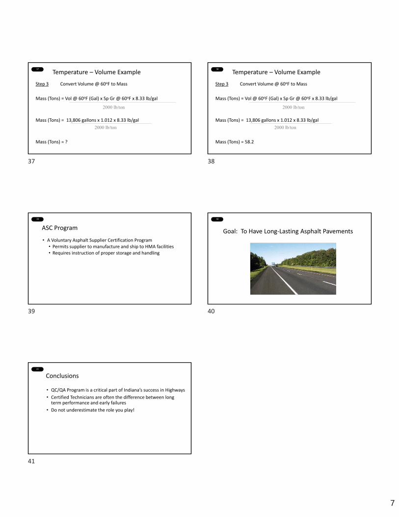
Step 3 Convert Volume @ 60oF to Mass
Mass (Tons) = Vol @ 60oF (Gal) x Sp Gr @ 60oF x 8.33 lb/gal
Mass (Tons) = 13,806 gallons x 1.012 x 8.33 lb/gal
Mass (Tons) = ?
2000 lb/ton
2000 lb/ton
Temperature – Volume Example38
Step 3 Convert Volume @ 60oF to Mass
Mass (Tons) = Vol @ 60oF (Gal) x Sp Gr @ 60oF x 8.33 lb/gal
Mass (Tons) = 13,806 gallons x 1.012 x 8.33 lb/gal
Mass (Tons) = 58.2
2000 lb/ton
2000 lb/ton
Temperature – Volume Example
39
ASC Program
• A Voluntary Asphalt Supplier Certification Program• Permits supplier to manufacture and ship to HMA facilities• Requires instruction of proper storage and handling
40
Goal: To Have Long‐Lasting Asphalt Pavements
41
Conclusions
• QC/QA Program is a critical part of Indiana’s success in Highways
• Certified Technicians are often the difference between long term performance and early failures
• Do not underestimate the role you play!
37 38
39 40
41
1
1
Asphalt Mixture Sample SplittingModule M5A
I N D O T C e r t i f i e d A s p h a l t L a b Te c h n i c i a n P r o g r a m
C h a p t e r F o u r
2
3
Video
1 2
3
1
1
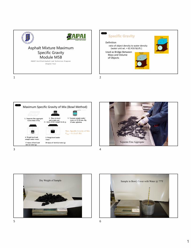
Asphalt Mixture Maximum Specific GravityModule M5B
I N D O T C e r t i f i e d A s p h a l t L a b Te c h n i c i a n P r o g r a m
C h a p t e r F o u r
2
Definitionratio of object density to water density
(water unit wt. = 62.416 lb/cft.)
Used as Bridge Between Mass and Volume of Objects
3
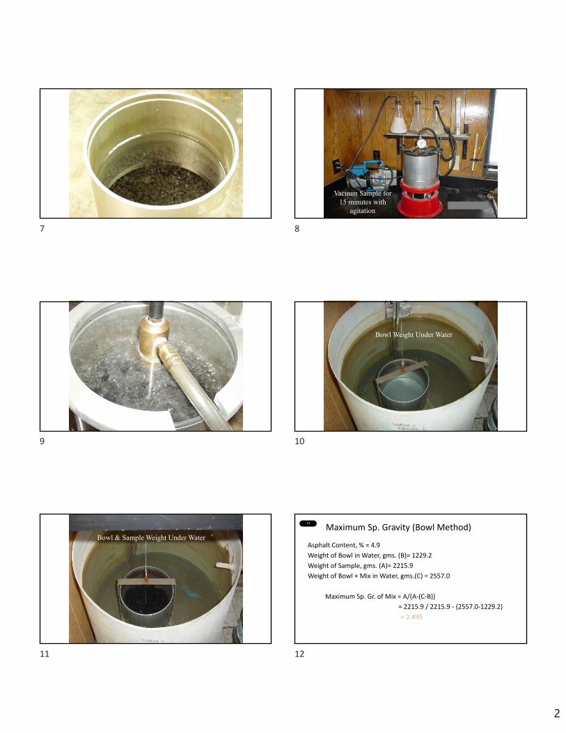
Maximum Specific Gravity of Mix (Bowl Method)
1. Separate fine aggregate to less than 1/4 in.
4. Weigh bowl and sample under water.
C=mass of bowl and mix in water (g)
5. Weigh bowl under water
B=mass of bowl in water (g)
Max. Specific Gravity of Mix Gmm = A/ (A-(C-B))
2. Place in bowl and weigh cool
A = mass of dry sample in air, g.
3. Vacuum sample under water @ 25-30 mm. Hg. 15 min. agitation
4
Separate Fine Aggregate
5
Dry Weight of Sample
6
Sample in Bowl, Cover with Water @ 77ºF
1 2
3 4
5 6
2
7 8
Vacuum Sample for 15 minutes with
agitation
9 10
Bowl Weight Under Water
11
Bowl & Sample Weight Under Water
12
Maximum Sp. Gravity (Bowl Method)
Asphalt Content, % = 4.9
Weight of Bowl in Water, gms. (B)= 1229.2
Weight of Sample, gms. (A)= 2215.9
Weight of Bowl + Mix in Water, gms.(C) = 2557.0
Maximum Sp. Gr. of Mix = A/(A‐(C‐B))
= 2215.9 / 2215.9 ‐ (2557.0‐1229.2)
= 2.495
7 8
9 10
11 12

3
13
Maximum Specific Gravity of Mix
Air Voids, % 4.2
Weight of Sample, gms. 2526.3
Weight of Bowl, gms. 2399.5
Weight of Bowl in Water, gms. 1228.2
Weight of Bowl+Mix in Water, gms. 2753.6
14
Maximum Specific Gravity of Mix
Air Voids, % 4.2
Weight of Sample, gms. 2526.3
Weight of Bowl, gms. 2399.5
Weight of Bowl in Water, gms. 1228.2
Weight of Bowl+Mix in Water, gms. 2753.6
Maximum Sp. Gr. of Mix = = 2526.3
2526.3 - (2753.6 - 1228.2)
15
Maximum Specific Gravity of Mix
Air Voids, % 4.2
Weight of Sample, gms. 2526.3
Weight of Bowl, gms. 2399.5
Weight of Bowl in Water, gms. 1228.2
Weight of Bowl+Mix in Water, gms. 2753.6
Maximum Sp. Gr. of Mix = = 2.5242526.3
2526.3 - (2753.6 - 1228.2)
16
Video
13 14
15 16

1
1
Asphalt Mixture Bulk Specific GravityModule M5C
I N D O T C e r t i f i e d A s p h a l t L a b Te c h n i c i a n P r o g r a m
C h a p t e r F o u r
2
Bulk Specific Gravity of Mixture
Weigh in air
Weigh in water
Weigh in air with surface water
3 4
Note that sample is on its sideso as not to trap air
5
Pat with a damp cloth to reach saturated surface dry condition.
6
1 2
3 4
5 6
2
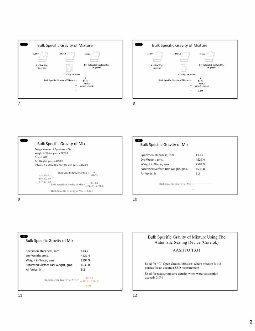
7 Bulk Specific Gravity of Mixture
4649.7 2624.1 4656.3
A = Dry Wgt. in grams
B = Saturated Surface Dryin grams
C = Wgt. in water
Bulk Specific Gravity of Mixture =
=
=
AB - C4649.7
4656.3 – 2624.1
8 Bulk Specific Gravity of Mixture
4649.7 2624.1 4656.3
A = Dry Wgt. in grams
B = Saturated Surface Dryin grams
C = Wgt. in water
Bulk Specific Gravity of Mixture =
=
= 2.288
AB - C4649.7
4656.3 – 2624.1
9
Bulk Specific Gravity of MixDesign Number of Gyrations = 50
Weight in Water, gms. = 2776.0
Gsb = 2.609
Dry Weight, gms. = 4718.2
Saturated Surface Dry (SSD)Weight, gms. = 4724.9
Bulk Specific Gravity of Mix = A(B-C)A = 4718.2
B = 4724.9C = 2776.0
Bulk Specific Gravity of Mix =
Bulk Specific Gravity of Mix = 2.421
4718.2(4724.9 – 2776.0)
10
Bulk Specific Gravity of Mix
Specimen Thickness, mm 413.7
Dry Weight, gms. 4527.4
Weight in Water, gms. 2594.9
Saturated Surface Dry Weight, gms. 4533.8
Air Voids, % 6.2
Bulk Specific Gravity of Mix =
=
11
Bulk Specific Gravity of Mix
Specimen Thickness, mm 413.7
Dry Weight, gms. 4527.4
Weight in Water, gms. 2594.9
Saturated Surface Dry Weight, gms. 4533.8
Air Voids, % 6.2
Bulk Specific Gravity of Mix =4527.4
(4533.8 – 2594.9)
= 2.335
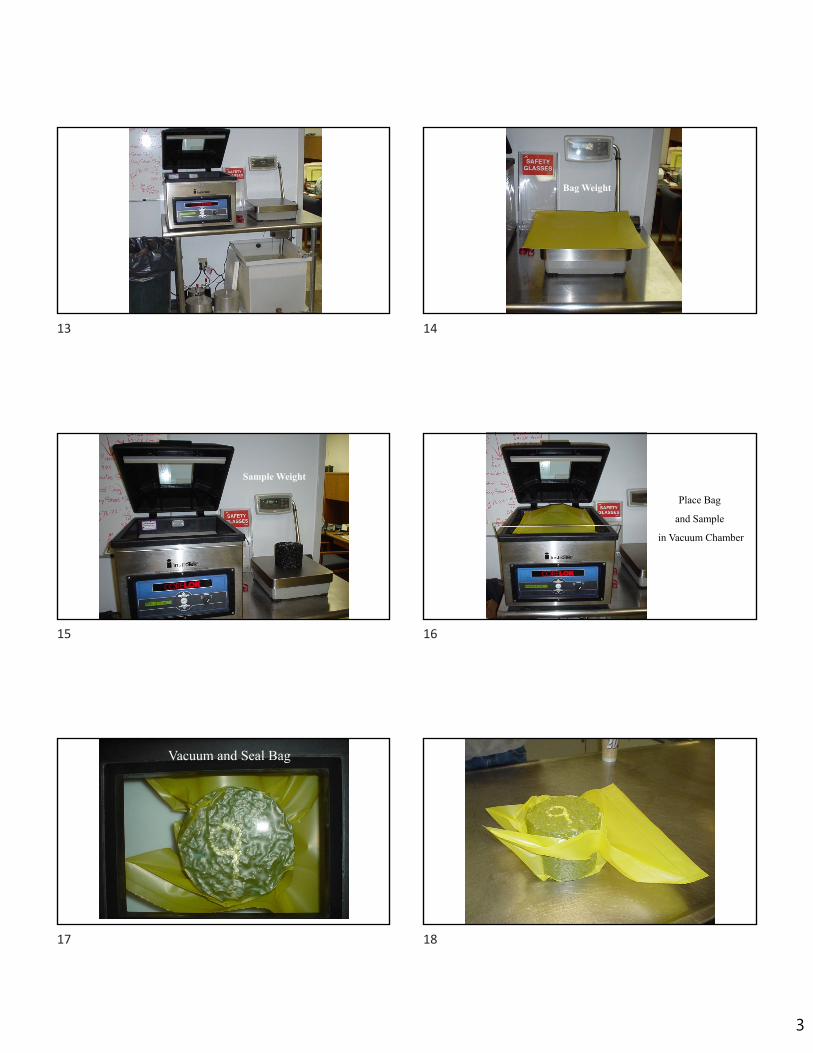
12 Bulk Specific Gravity of Mixture Using The Automatic Sealing Device (Corelok)
AASHTO T331
Used for “C” Open Graded Mixtures where mixture is too porous for an accurate SSD measurement
Used for measuring core density when water absorption exceeds 2.0%
7 8
9 10
11 12
3
13 14
Bag Weight
15
Sample Weight
16
Place Bag
and Sample
in Vacuum Chamber
17 Vacuum and Seal Bag 18
13 14
15 16
17 18
4
19
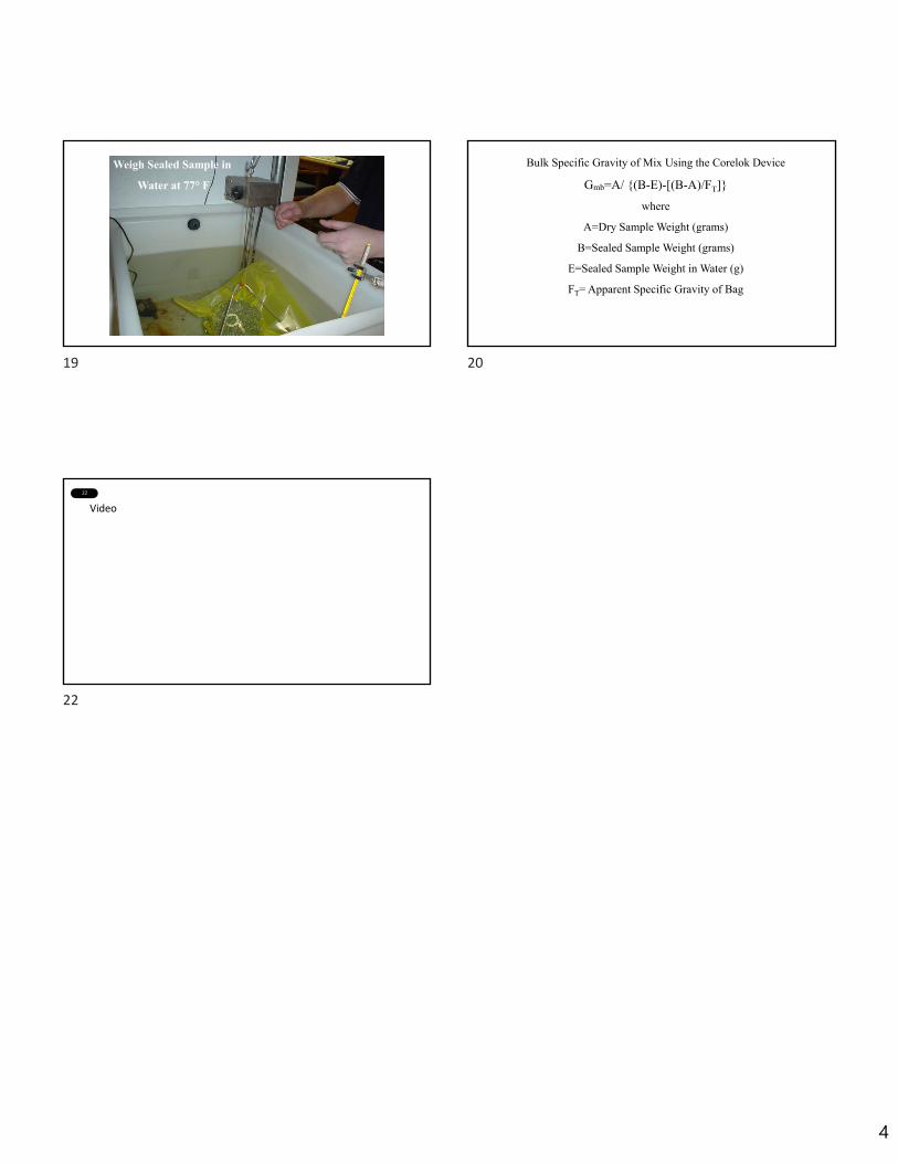
Weigh Sealed Sample in
Water at 77° F
20
Bulk Specific Gravity of Mix Using the Corelok Device
Gmb=A/ {(B-E)-[(B-A)/FT]}
where
A=Dry Sample Weight (grams)
B=Sealed Sample Weight (grams)
E=Sealed Sample Weight in Water (g)
FT= Apparent Specific Gravity of Bag
22
Video
19 20
22

1
1
Asphalt ContentModule M5D
I N D O T C e r t i f i e d A s p h a l t L a b Te c h n i c i a n P r o g r a m
C h a p t e r F o u r
2
3
Video
1 2
3

1
1
Asphalt Mixture Volumetric Property Calculations
Module M5EI N D O T C e r t i f i e d A s p h a l t L a b Te c h n i c i a n P r o g r a m
C h a p t e r F o u r
2 Air Void Calculation
Air Voids = 100 x Gmm ‐ Gmb
Gmm
Gmb = Bulk Specific Gravity of Mix
= 2.290
Gmm = Theoretical Max. Sp. Gr. of Mix
= 2.428
Air Voids = 100 x 2.428 ‐ 2.290
2.428
= 5.7%
3
Air VoidsUnit Weight = 144.5 lbs./cu. ft.
Bulk Sp. Gr. of Mix = 2.316
VMA = 14.3%
Aggregate, % = 94.3
Max. Sp. Gr. of Mix = 2.426
Air Voids = 100 x Gmm -Gmb
GmmGmb = 2.316Gmm = 2.426
Air Voids = 100 x
Air Voids = 4.5%
2.426 -2.3162.426
4
Air Voids
Max. Sp. Gr. of Mix 2.443
Asphalt Content, % 5.9
Bulk Sp. Gr. of Mix 2.284
Air Voids =
5
Air Voids
Max. Sp. Gr. of Mix 2.443
Asphalt Content, % 5.9
Bulk Sp. Gr. of Mix 2.284
Air Voids = 100 x
Air Voids = 6.5
2.443 -2.2842.443
6
VMA Calculation
VMA =
Gmb = Bulk Specific Gravity of Mix
Ps = Aggregate % of Total Mix
Gsb = Bulk Specific Gravity of Aggregate
(from Job Mix Formula)
Example:
Gmb = 2.290
Ps = 94.5%
Gsb = 2.514
Gmb x PsGsb( )
VMA = 100 - 2.290 x 94.52.514( )
= 13.9 %
100 -
1 2
3 4
5 6
2
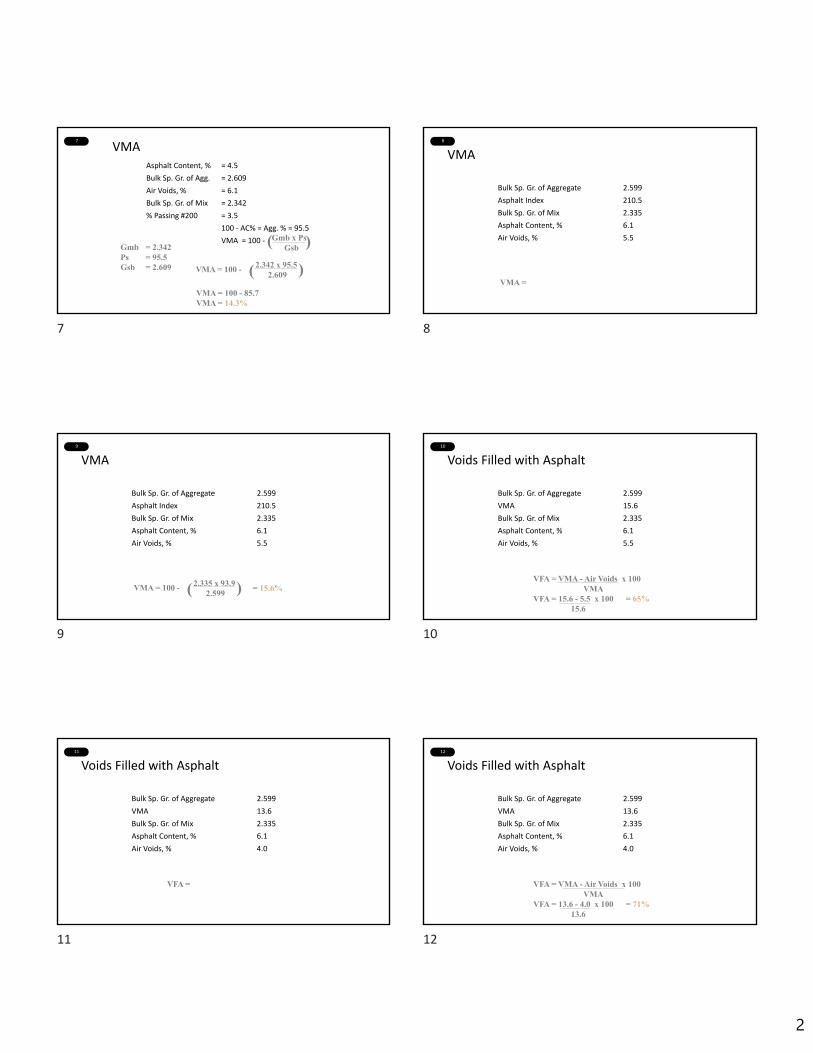
7
VMAAsphalt Content, % = 4.5
Bulk Sp. Gr. of Agg. = 2.609
Air Voids, % = 6.1
Bulk Sp. Gr. of Mix = 2.342
% Passing #200 = 3.5
100 ‐ AC% = Agg. % = 95.5
VMA = 100 ‐Gmb = 2.342Ps = 95.5Gsb = 2.609 VMA = 100 -
VMA = 100 - 85.7VMA = 14.3%
(Gmb x PsGsb )
2.342 x 95.52.609( )
8
VMA
Bulk Sp. Gr. of Aggregate 2.599
Asphalt Index 210.5
Bulk Sp. Gr. of Mix 2.335
Asphalt Content, % 6.1
Air Voids, % 5.5
VMA =
9
VMA
Bulk Sp. Gr. of Aggregate 2.599
Asphalt Index 210.5
Bulk Sp. Gr. of Mix 2.335
Asphalt Content, % 6.1
Air Voids, % 5.5
VMA = 100 - 2.335 x 93.92.599( ) = 15.6%
10
Voids Filled with Asphalt
Bulk Sp. Gr. of Aggregate 2.599
VMA 15.6
Bulk Sp. Gr. of Mix 2.335
Asphalt Content, % 6.1
Air Voids, % 5.5
VFA = VMA - Air Voids x 100VMA
VFA = 15.6 - 5.5 x 100 = 65%15.6
11
Voids Filled with Asphalt
Bulk Sp. Gr. of Aggregate 2.599
VMA 13.6
Bulk Sp. Gr. of Mix 2.335
Asphalt Content, % 6.1
Air Voids, % 4.0
VFA =
12
Voids Filled with Asphalt
Bulk Sp. Gr. of Aggregate 2.599
VMA 13.6
Bulk Sp. Gr. of Mix 2.335
Asphalt Content, % 6.1
Air Voids, % 4.0
VFA = VMA - Air Voids x 100VMA
VFA = 13.6 - 4.0 x 100 = 71%13.6
7 8
9 10
11 12
3
13
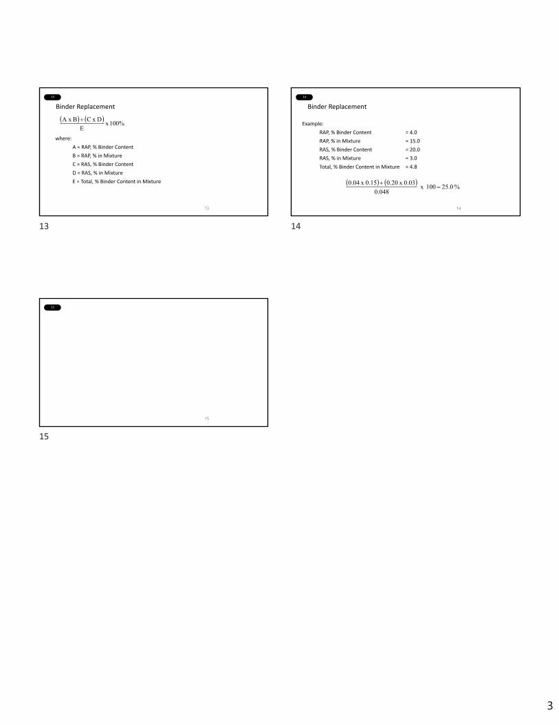
Binder Replacement
where:
A = RAP, % Binder Content
B = RAP, % in Mixture
C = RAS, % Binder Content
D = RAS, % in Mixture
E = Total, % Binder Content in Mixture
13
100% x
E
D x CBA x
14
Binder Replacement
Example:
RAP, % Binder Content = 4.0
RAP, % in Mixture = 15.0
RAS, % Binder Content = 20.0
RAS, % in Mixture = 3.0
Total, % Binder Content in Mixture = 4.8
14
% 25.0 100 x
0.048
0.03 x 0.20 0.15 x 0.04
15
15
13 14
15

2/8/2021
1
1
Calculation PracticeAsphalt Volumetrics
I N D O T C e r t i f i e d A s p h a l t L a b Te c h n i c i a n P r o g r a m
2
Meet the Team
Asphalt EngineerIndiana Department of Transportation
N A T H A N A W W A D , P E
3
• Please see pages 6 and 7 of your “Classroom Problems” packet.
• More information can be found in Chapter 4 of the ICAT Manual
4
Bulk Specific Gravity• BSG of compacted mixture using SSD
specimens
Bulk Sp. Gr (Gmb) 𝐴𝐵 𝐶
Where: A= weight of specimen in air, gB = weight of surface-dry specimen in air, gC = weight of specimen in water, g
5
Bulk Specific Gravity
A ________
B ________
C ________
Bulk Sp. Gr (Gmb) 𝐴𝐵 𝐶
Gmb = 2.353
4846.3g4850.2g2790.6g
Gmb 4846.34850.2 2790.6
6
Maximum Specific Gravity• MSG of compacted mixture using SSD
specimens
Max Sp. Gr (Gmm) 𝐴𝐴 𝐶 𝐵
Where: A= weight of specimen in air, gB = weight of container in water, gC = weight of container and sample in water, g
1 2
3 4
5 6
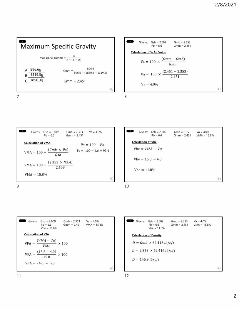
2/8/2021
2
7
Maximum Specific Gravity
A ________
B ________
C ________
Max Sp. Gr (Gmm) 𝐴𝐴 𝐶 𝐵
Gmm = 2.451
896.6g1319.5g1850.3g
Gmm 896.6896.6 1850.3 1319.5
8 Givens: Gsb = 2.609 Gmb = 2.353Pb = 6.6 Gmm = 2.451
Calculation of % Air Voids
Va 100 𝐺𝑚𝑚 𝐺𝑚𝑏
𝐺𝑚𝑚
Va 100 2.451 2.353
2.451
Va 4.0%
9 Givens: Gsb = 2.609 Gmb = 2.353 Va = 4.0%Pb = 6.6 Gmm = 2.451
Calculation of VMA
VMA 100 𝐺𝑚𝑏 𝑃𝑠
𝐺𝑠𝑏
𝑃𝑠 100 𝑃𝑏
Ps 100 6.6 93.4
VMA 100 2.353 93.4
2.609
VMA 15.8%
10
Calculation of Vbe
Vbe 𝑉𝑀𝐴 𝑉𝑎
Vbe 15.8 4.0
Vbe 11.8%
Givens: Gsb = 2.609 Gmb = 2.353 Va = 4.0%Pb = 6.6 Gmm = 2.451 VMA = 15.8%
11
Calculation of VFA
Givens: Gsb = 2.609 Gmb = 2.353 Va = 4.0%Pb = 6.6 Gmm = 2.451 VMA = 15.8%Vbe = 11.8%
VFA 𝑉𝑀𝐴 𝑉𝑎𝑉𝑀𝐴
100
VFA 15.8 4.0
15.8 100
VFA 74.6 75
12
Calculation of Density
Givens: Gsb = 2.609 Gmb = 2.353 Va = 4.0%Pb = 6.6 Gmm = 2.451 VMA = 15.8%Vbe = 11.8%
𝐷 𝐺𝑚𝑏 62.416 𝑙𝑏/𝑐𝑓𝑡
𝐷 2.353 62.416 𝑙𝑏/𝑐𝑓𝑡
𝐷 146.9 𝑙𝑏/𝑐𝑓𝑡
7 8
9 10
11 12
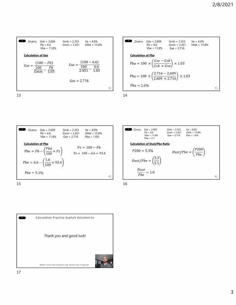
2/8/2021
3
13
Calculation of Gse
Givens: Gsb = 2.609 Gmb = 2.353 Va = 4.0%Pb = 6.6 Gmm = 2.451 VMA = 15.8%Vbe = 11.8%
Gse100 𝑃𝑏
100𝐺𝑚𝑚
𝑃𝑏1.03
Gse100 6.6
1002.451
6.61.03
Gse 2.716
14
Calculation of Pba
Givens: Gsb = 2.609 Gmb = 2.353 Va = 4.0%Pb = 6.6 Gmm = 2.451 VMA = 15.8%Vbe = 11.8% Gse = 2.716
Pba 100 𝐺𝑠𝑒 𝐺𝑠𝑏𝐺𝑠𝑏 𝐺𝑠𝑒
1.03
Pba 100 2.716 2.6092.609 2.716
1.03
Pba 1.6%
15
Calculation of Pbe
Givens: Gsb = 2.609 Gmb = 2.353 Va = 4.0%Pb = 6.6 Gmm = 2.451 VMA = 15.8%Vbe = 11.8% Gse = 2.716 Pba = 1.6%
Pbe 𝑃𝑏𝑃𝑏𝑎100
𝑃𝑠
Pbe 5.1%
Pbe 6.61.6100
93.4
𝑃𝑠 100 𝑃𝑏
Ps 100 6.6 93.4
16
Calculation of Dust/Pbe Ratio
Givens: Gsb = 2.609 Gmb = 2.353 Va = 4.0%Pb = 6.6 Gmm = 2.451 VMA = 15.8%Vbe = 11.8% Gse = 2.716 Pba = 1.6% Pbe = 5.1
𝑃200 5.3%
𝐷𝑢𝑠𝑡/𝑃𝑏𝑒5.35.1
𝐷𝑢𝑠𝑡/𝑃𝑏𝑒𝑃200𝑃𝑏𝑒
𝐷𝑢𝑠𝑡𝑃𝑏𝑒
1.0
17 Ca lcu lat ion Pract ice Asphal t Volumetr ics
I N D O T C e r t i f i e d A s p h a l t L a b Te c h n i c i a n P r o g r a m
Thank you and good luck!
13 14
15 16
17
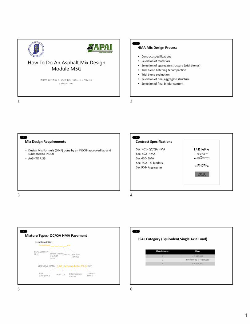
1
1
How To Do An Asphalt Mix DesignModule M5G
I N D O T C e r t i f i e d A s p h a l t L a b Te c h n i c i a n P r o g r a m
C h a p t e r F o u r
2
HMA Mix Design Process
• Contract specifications
• Selection of materials
• Selection of aggregate structure (trial blends)
• Trial blend batching & compaction
• Trial blend evaluation
• Selection of final aggregate structure
• Selection of final binder content
3
Mix Design Requirements
• Design Mix Formula (DMF) done by an INDOT‐approved lab and submitted to INDOT
• AASHTO R 35
4
Contract Specifications
Sec. 401‐ QC/QA HMA
Sec. 402‐ HMA
Sec.410‐ SMA
Sec. 902‐ PG binders
Sec.904‐ Aggregates
2020
5
Mixture Types‐ QC/QA HMA Pavement
Item DescriptionQC/QA HMA, ___, ___, ___, ___mm
ESAL Category (2-4) Binder Grade
(PG high temp.)
Course Mix Size (NMAS)
•QC/QA HMA, 2,64,intermediate,19.0 mm
ESAL Category 2 PG64-22 Intermediate
Course19.0 mm NMAS
6
ESAL Category (Equivalent Single Axle Load)
ESAL Category ESAL
2 < 3,000,0003 3,000,000 to < 10,000,0004 ≥10,000,000
1 2
3 4
5 6
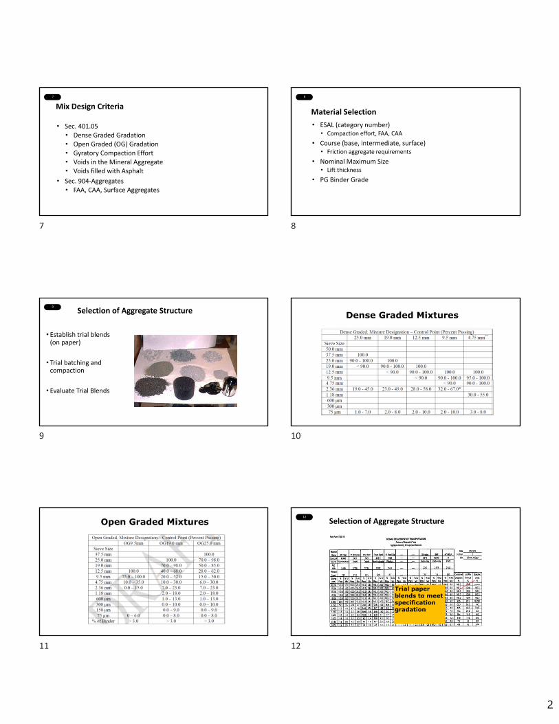
2
7
Mix Design Criteria
• Sec. 401.05• Dense Graded Gradation• Open Graded (OG) Gradation• Gyratory Compaction Effort• Voids in the Mineral Aggregate• Voids filled with Asphalt
• Sec. 904‐Aggregates• FAA, CAA, Surface Aggregates
8
Material Selection
• ESAL (category number)• Compaction effort, FAA, CAA
• Course (base, intermediate, surface)• Friction aggregate requirements
• Nominal Maximum Size • Lift thickness
• PG Binder Grade
9
Selection of Aggregate Structure
• Establish trial blends (on paper)
• Trial batching and compaction
• Evaluate Trial Blends
10
Dense Graded Mixtures
11
Open Graded Mixtures12
Selection of Aggregate Structure
Trial paper blends to meet specification gradation
7 8
9 10
11 12
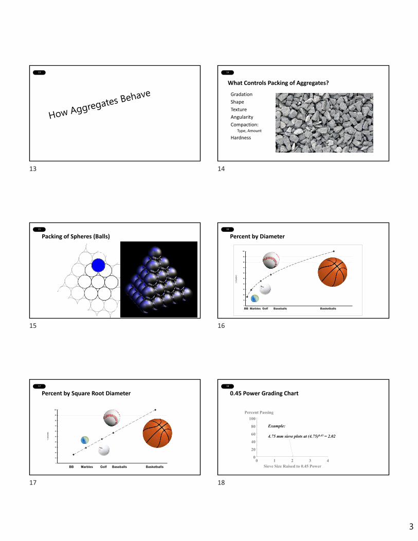
3
13 14
Gradation
Shape
Texture
Angularity
Compaction: Type, Amount
Hardness
What Controls Packing of Aggregates?
15
Packing of Spheres (Balls)
16
Percent by Diameter
0
10
20
30
40
50
60
70
80
90
100
% PASSING
BB Marbles Golf Baseballs Basketballs
17
Percent by Square Root Diameter
0
10
20
30
40
50
60
70
80
90
100
% PASSING
BB Marbles Golf Baseballs Basketballs
18
Example:
4.75 mm sieve plots at (4.75)0.45 = 2.02
Sieve Size Raised to 0.45 Power
0
20
40
60
80
100
0 1 2 3 4
Percent Passing
0.45 Power Grading Chart
13 14
15 16
17 18
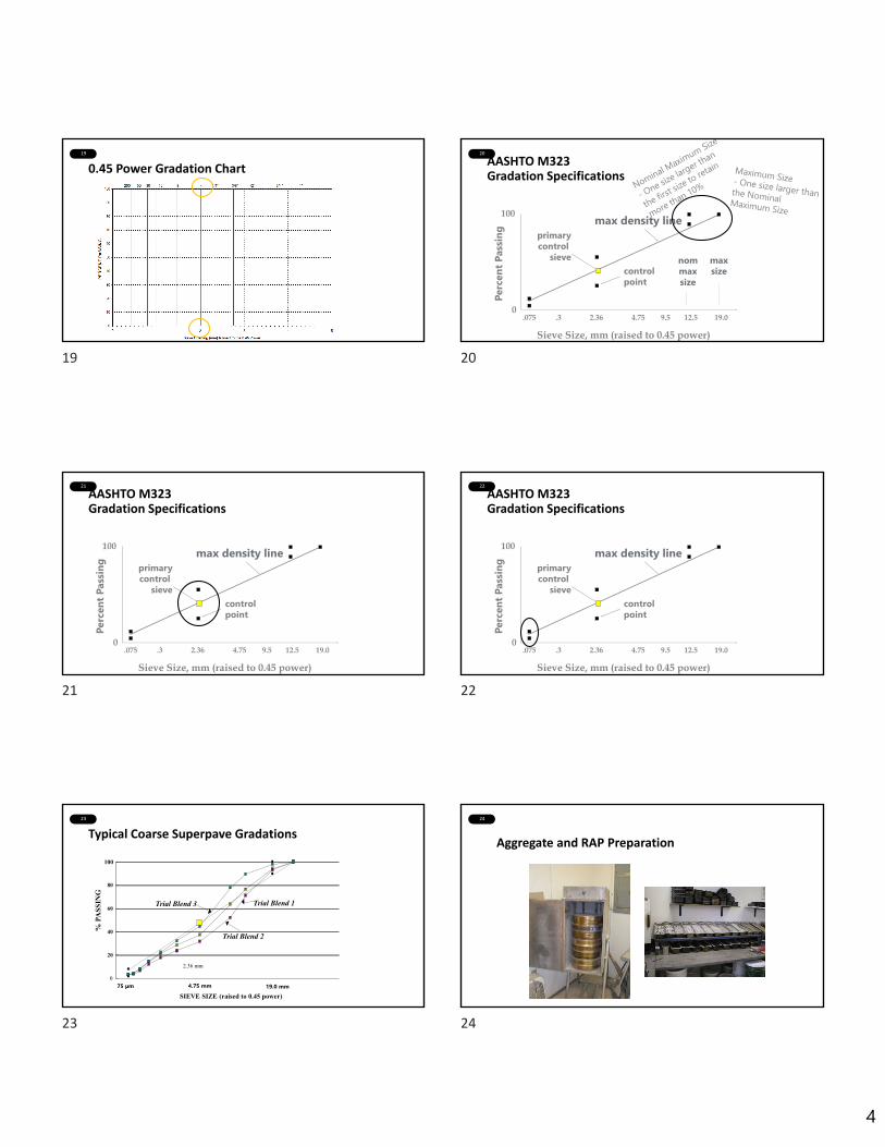
4
19
0.45 Power Gradation Chart
20
AASHTO M323 Gradation Specifications
100
0
Sieve Size, mm (raised to 0.45 power)
.075 .3 2.36 4.75 9.5 12.5 19.0
Perc
ent P
assin
g
controlpoint
primarycontrol
sieve
max density line
maxsize
nommaxsize
21
AASHTO M323 Gradation Specifications
100
0
Sieve Size, mm (raised to 0.45 power)
.075 .3 2.36 4.75 9.5 12.5 19.0
Perc
ent P
assin
g
controlpoint
primarycontrol
sieve
max density line
22
AASHTO M323 Gradation Specifications
100
0
Sieve Size, mm (raised to 0.45 power)
.075 .3 2.36 4.75 9.5 12.5 19.0
Perc
ent P
assin
g
controlpoint
primarycontrol
sieve
max density line
23
Typical Coarse Superpave Gradations
0
20
40
60
80
100
SIEVE SIZE (raised to 0.45 power)
% P
ASS
ING
19.0 mm
2.36 mm
Trial Blend 1
Trial Blend 2
Trial Blend 3
4.75 mm75 µm
24
Aggregate and RAP Preparation
19 20
21 22
23 24

5
25
Trial Blend Aggregate Batching Computations
Determination of batch weights
115.0 +/‐5.0 mm
26
Preparation for Mixing
Heat Aggregates, RAP and Asphalt Binder
Heat Mixing Container
27
Batching
28
Mixing and Preparation for 4‐hour Oven Aging
29
Specimen Oven Aging and Compaction Preparation
30
Compaction
ESAL Category Gyrations (Ndesign)
2 303 504 50
25 26
27 28
29 30

6
31
Ram Pressure0.6 MPa
Gyratory Mold Configuration and Compaction Parameters
1.16° Internal Angle
30 gyrations per minute
150 mm diameter mold
32
Height @ Ndesign (measured)
Height @ N (measured)
Gmb @ N design(measured)
Gmb @ N?
Bulk Specific Gravity of Gyratory Compacted Specimens
33
Densification Table‐Measure Gmm‐Measure Gmb
34
Evaluate Trial Blends
• Determine %Air Voids, %VMA
• Estimate asphalt binder content to achieve 5%Air Voids
• Estimate mixture properties at new asphalt binder content
• Estimate %Gmm @ Ninitial, Ndesign
• Estimate dust‐asphalt ratio
• Compare all estimates to mixture criteria
35 Evaluate Trial Blend(s) 36
Estimate Properties @ 5.0% Air Voids
31 32
33 34
35 36

7
37
Compare Trial Blends to Specification
Criteria Trial 1 Trial 2 Trial 3 Specs% Air Voids 6.4 4.9 4.9 5.0%VMA 17.3 15.4 16.4 16.0 min%VFA 63 68 70 60-70%Gmm @ Nini
87.4 91.5 max.
D/A Ratio 1.01 0.6-1.4Estim. VMA @ 5% AV
16.4
38
Determine Optimum Asphalt Binder Content
• Prepare specimens using the selected aggregate structure• 2 points above estimated optimum (+0.5 % & +1.0%)
• 1 point below estimated optimum
• (‐0.5%)
• Graph Mixture Properties verses Binder %
• Select Design Binder %
39
Air Voids versus Percent Binder
40
VMA versus Percent Binder
41
VFA versus Percent Binder
42
%Gmm @ Nini versus Percent Binder
37 38
39 40
41 42
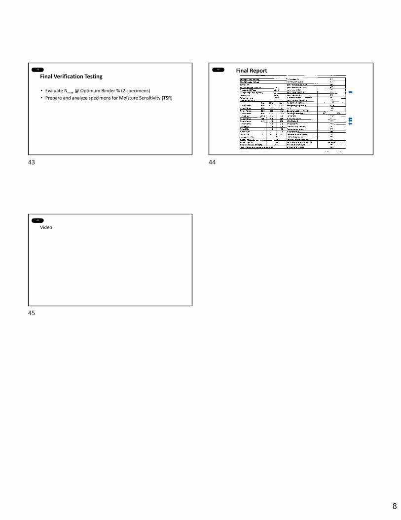
8
43
Final Verification Testing
• Evaluate Nmax @ Optimum Binder % (2 specimens)
• Prepare and analyze specimens for Moisture Sensitivity (TSR)
44 Final Report
6 50 75
70.016.5
5.9
45
Video
43 44
45
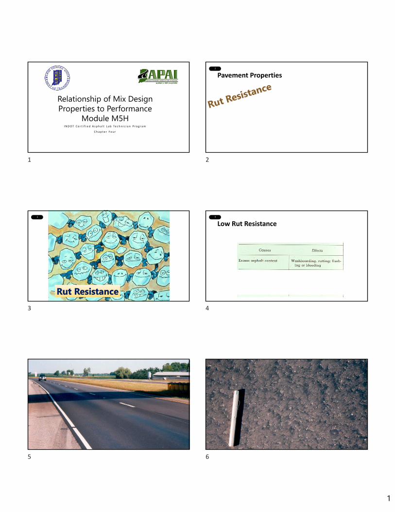
1
1
Relationship of Mix Design Properties to Performance
Module M5HI N D O T C e r t i f i e d A s p h a l t L a b Te c h n i c i a n P r o g r a m
C h a p t e r F o u r
2
Pavement Properties
3 4
Low Rut Resistance
5 6
1 2
3 4
5 6
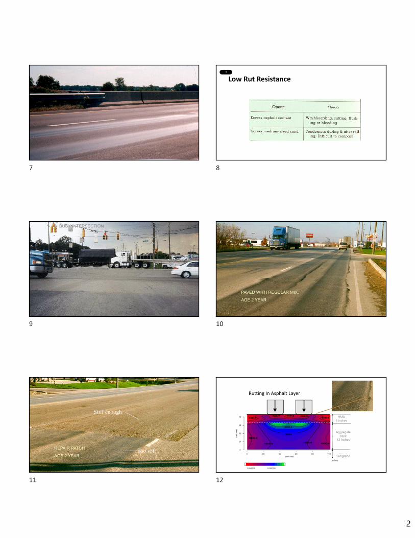
2
7 8
Low Rut Resistance
3-4
9 A BUSY INTERSECTION 10
PAVED WITH REGULAR MIX,
AGE 2 YEAR
11
REPAIR PATCH
AGE 2 YEARToo soft
Stiff enough
12
Rutting In Asphalt Layer
HMA6 inches
AggregateBase
12 inches
Subgrade
7 8
9 10
11 12
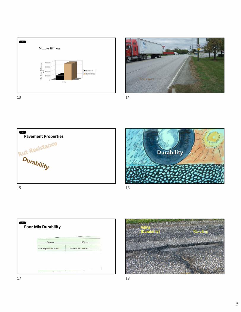
3
13
Mixture Stiffness
0
20,000
40,000
60,000
80,000
Mix
She
ar S
tiffn
ess,
ps
i
10 Hz
RuttedRepaired
14
After 9 years
15
Pavement Properties16
17
Poor Mix Durability18
Aging (Durability) Raveling
13 14
15 16
17 18

4
19
Poor Mix Durability20
21 22
23 24
19 20
21 22
23 24
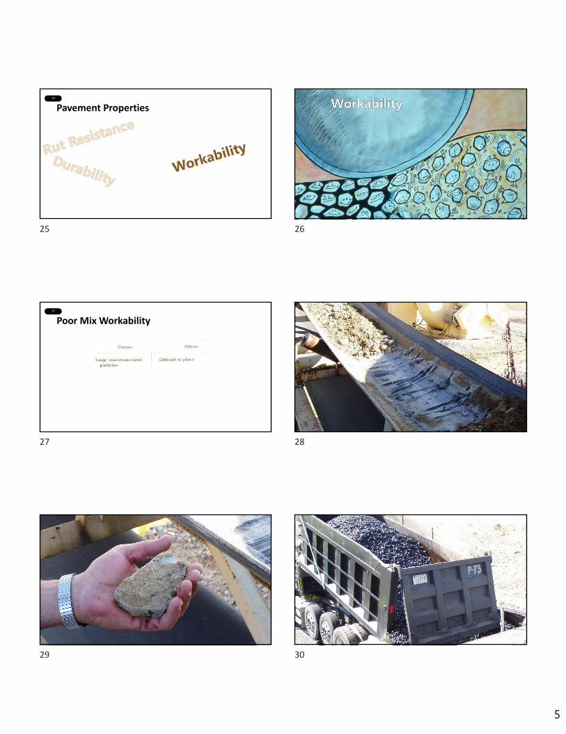
5
25
Pavement Properties26
27
Poor Mix Workability
3-6
28
29 30
25 26
27 28
29 30
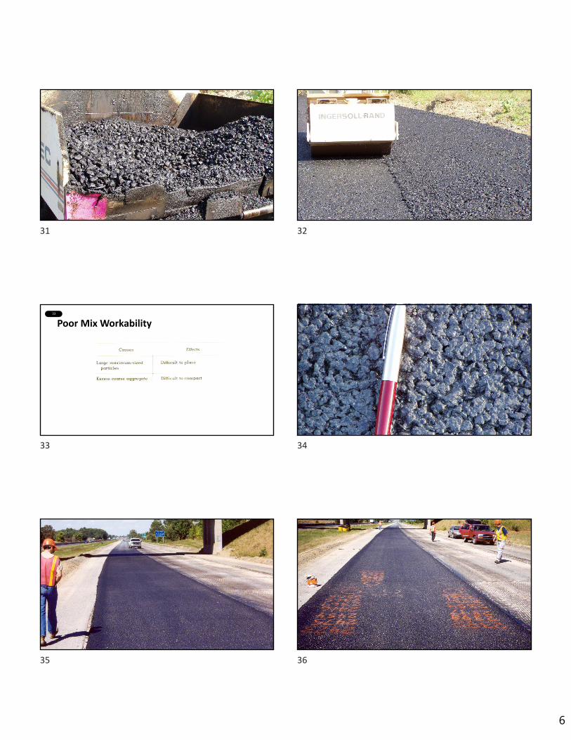
6
31 32
33
Poor Mix Workability
3-6
34
35 36
31 32
33 34
35 36

7
37
Poor Mix Workability
3-6
38
39 40
41 42
Poor Mix Workability
37 38
39 40
41 42

8
43
Pavement Properties44
45
Poor Fatigue Resistance46
Advanced Fatigue Cracking
47
Fatigue Cracking
48
Pavement Properties
43 44
45 46
47 48
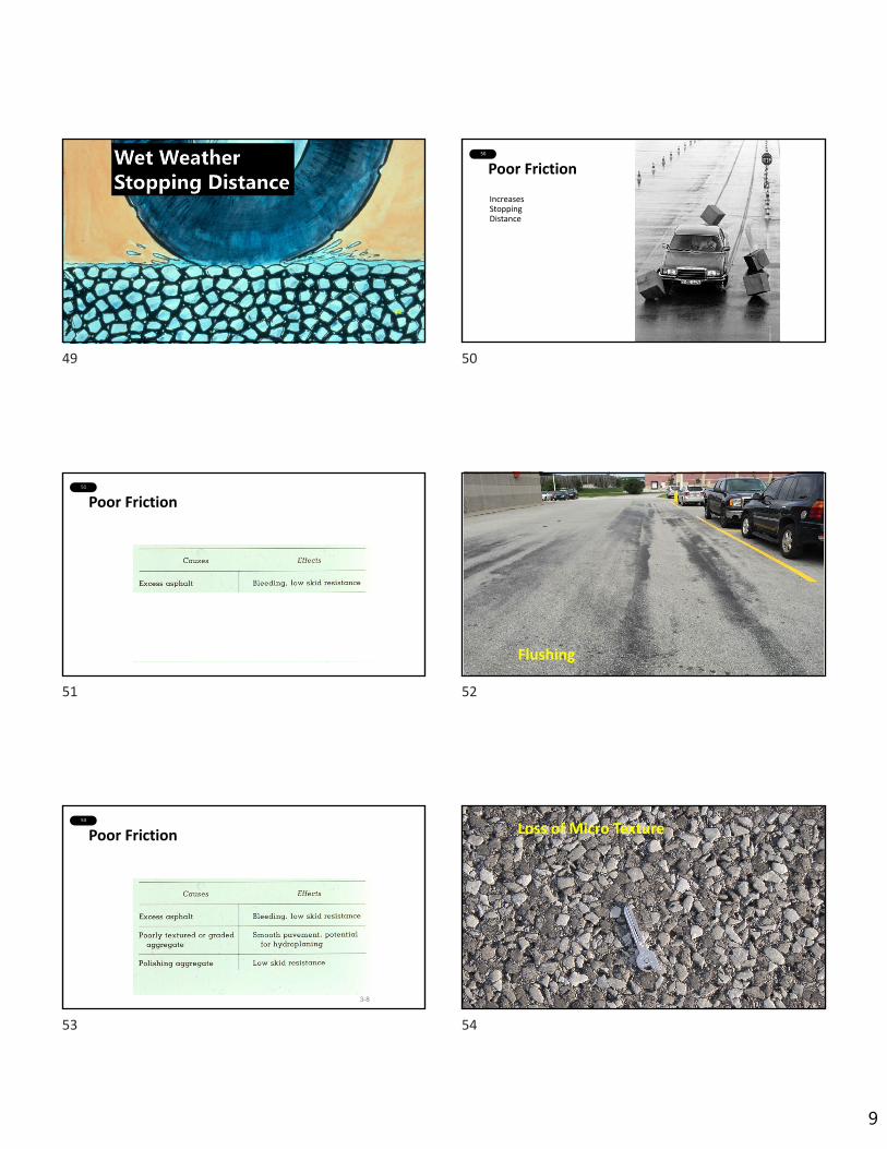
9
49
32
50
Poor Friction
IncreasesStoppingDistance
51
Poor Friction52
Flushing
53
Poor Friction
3-8
54
Loss of Micro Texture
49 50
51 52
53 54

10
55 56
Relationship of Mixture Properties to Performance
Rutting
Fatigue Cracking
Low Temperature Cracking
Aging
PG High Temperature
PG Low Temperature
Coarse Aggregate Angularity (CAA)
Fine Aggregate Angularity (FAA)
Gradation
Air Voids in‐place (Vaip)
Effective Asphalt Content (Vbe)
Voids in Mineral Aggregate in‐place (VMAip)
Voids Filled with Asphalt in‐place (VFAip)
57
Relationship of Mixture Properties to Performance
Rutting
Fatigue Cracking
Low Temperature Cracking
Aging
PG High Temperature
PG Low Temperature
Coarse Aggregate Angularity (CAA)
Fine Aggregate Angularity (FAA)
Gradation
Air Voids in‐place (Vaip)
Effective Asphalt Content (Vbe)
Voids in Mineral Aggregate in‐place (VMAip)
Voids Filled with Asphalt in‐place (VFAip)
58
Relationship of Mixture Properties to Performance
Rutting
Fatigue Cracking
Low Temperature Cracking
Aging
PG High Temperature
PG Low Temperature
Coarse Aggregate Angularity (CAA)
Fine Aggregate Angularity (FAA)
Gradation
Air Voids in‐place (Vaip)
Effective Asphalt Content (Vbe)
Voids in Mineral Aggregate in‐place (VMAip)
Voids Filled with Asphalt in‐place (VFAip)
59
Relationship of Mixture Properties to Performance
Rutting
Fatigue Cracking
Low Temperature Cracking
Aging
PG High Temperature
PG Low Temperature
Coarse Aggregate Angularity (CAA)
Fine Aggregate Angularity (FAA)
Gradation
Air Voids in‐place (Vaip)
Effective Asphalt Content (Vbe)
Voids in Mineral Aggregate in‐place (VMAip)
Voids Filled with Asphalt in‐place (VFAip)
60
Relationship of Mixture Properties to Performance
Rutting
Fatigue Cracking
Low Temperature Cracking
Aging
PG High Temperature
PG Low Temperature
Coarse Aggregate Angularity (CAA)
Fine Aggregate Angularity (FAA)
Gradation
Air Voids in‐place (Vaip)
Effective Asphalt Content (Vbe)
Voids in Mineral Aggregate in‐place (VMAip)
Voids Filled with Asphalt in‐place (VFAip)
55 56
57 58
59 60

11
61
Video
61
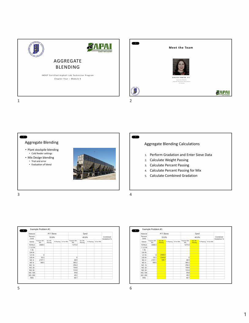
1
1
AGGREGATE BLENDING
I N D O T C e r t i f i e d A s p h a l t L a b Te c h n i c i a n P r o g r a m
C h a p t e r F o u r – M o d u l e 6
2
Meet the Team
Executive DirectorAsphalt Pavement Association
of Indiana
K I R S T E N F O W L E R , P . E .
3
Aggregate Blending
• Plant stockpile blending• Cold feeder settings
• Mix Design blending• Trial and error
• Evaluation of blend
4
Aggregate Blending Calculations
1. Perform Gradation and Enter Sieve Data
2. Calculate Weight Passing
3. Calculate Percent Passing
4. Calculate Percent Passing for Mix
5. Calculate Combined Gradation
5
Material #11 Stone SandCombined
Gradation %Percent Used 55.0% 45.0%
Sieves Fraction Wt. Ret.
Tot. Wt. Passing % Passing % For Mix Fraction Wt.
Ret.Tot. Wt. Passing % Passing % For Mix
TOTALS 2440.3 1275.41 1/2 IN
1 IN3/4 IN1/2 IN 03/8 IN 93.5 0NO. 4 2157.1 40.9NO. 8 189.5 385.2NO. 16 296.4NO. 30 194.8NO. 50 153.0NO. 100 94.8NO. 200 49.2
PAN 60.7
Example Problem #16
Material #11 Stone SandCombined
Gradation %Percent Used 55.0% 45.0%
Sieves Fraction Wt. Ret.
Tot. Wt. Passing % Passing % For Mix Fraction Wt.
Ret.Tot. Wt. Passing % Passing % For Mix
TOTALS 2440.3 1275.41 1/2 IN
1 IN3/4 IN1/2 IN 03/8 IN 93.5 0NO. 4 2157.1 40.9NO. 8 189.5 385.2NO. 16 296.4NO. 30 194.8NO. 50 153.0NO. 100 94.8NO. 200 49.2
PAN 60.7
Example Problem #1
2440.32346.8
189.7
1 2
3 4
5 6
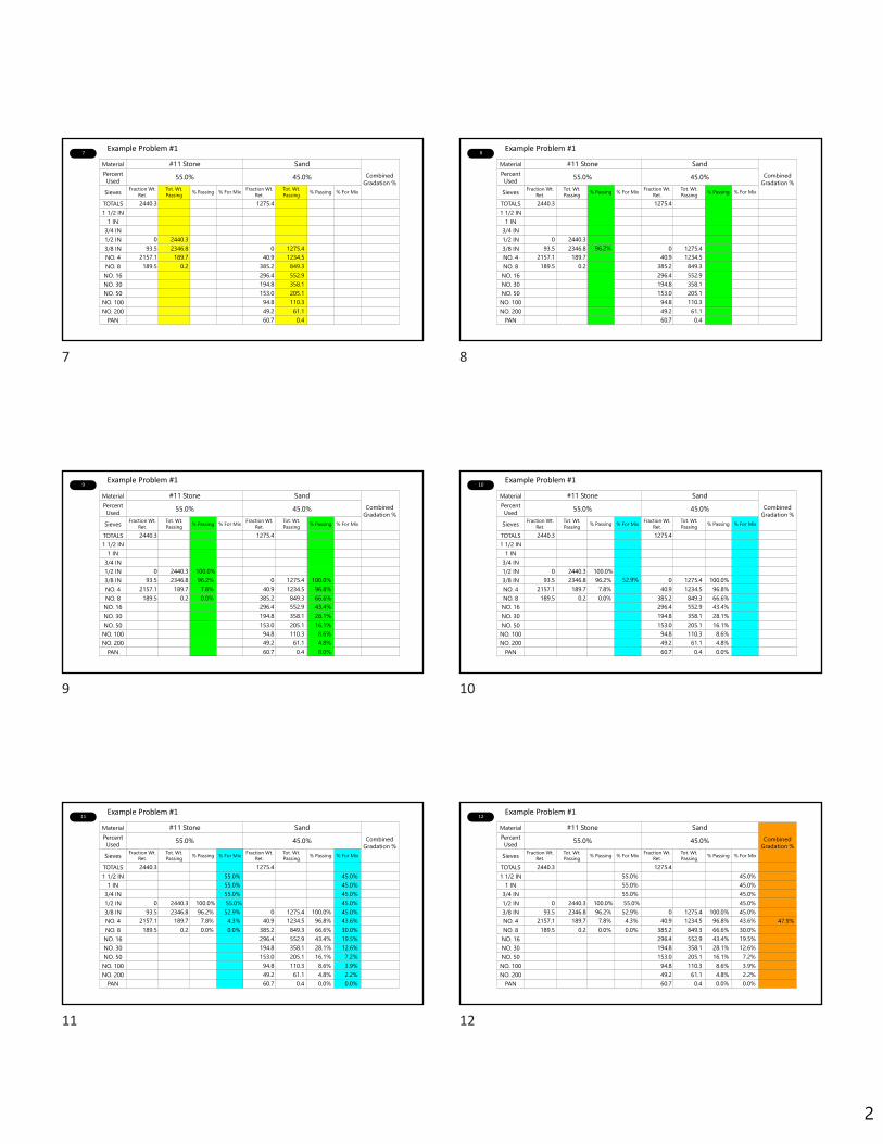
2
7
Material #11 Stone SandCombined
Gradation %Percent Used 55.0% 45.0%
Sieves Fraction Wt. Ret.
Tot. Wt. Passing % Passing % For Mix Fraction Wt.
Ret.Tot. Wt. Passing % Passing % For Mix
TOTALS 2440.3 1275.41 1/2 IN
1 IN3/4 IN1/2 IN 0 2440.33/8 IN 93.5 2346.8 0 1275.4NO. 4 2157.1 189.7 40.9 1234.5NO. 8 189.5 0.2 385.2 849.3NO. 16 296.4 552.9NO. 30 194.8 358.1NO. 50 153.0 205.1NO. 100 94.8 110.3NO. 200 49.2 61.1
PAN 60.7 0.4
Example Problem #18
Material #11 Stone SandCombined
Gradation %Percent Used 55.0% 45.0%
Sieves Fraction Wt. Ret.
Tot. Wt. Passing % Passing % For Mix Fraction Wt.
Ret.Tot. Wt. Passing % Passing % For Mix
TOTALS 2440.3 1275.41 1/2 IN
1 IN3/4 IN1/2 IN 0 2440.33/8 IN 93.5 2346.8 0 1275.4NO. 4 2157.1 189.7 40.9 1234.5NO. 8 189.5 0.2 385.2 849.3NO. 16 296.4 552.9NO. 30 194.8 358.1NO. 50 153.0 205.1NO. 100 94.8 110.3NO. 200 49.2 61.1
PAN 60.7 0.4
Example Problem #1
96.2%
9
Material #11 Stone SandCombined
Gradation %Percent Used 55.0% 45.0%
Sieves Fraction Wt. Ret.
Tot. Wt. Passing % Passing % For Mix Fraction Wt.
Ret.Tot. Wt. Passing % Passing % For Mix
TOTALS 2440.3 1275.41 1/2 IN
1 IN3/4 IN1/2 IN 0 2440.3 100.0%3/8 IN 93.5 2346.8 96.2% 0 1275.4 100.0%NO. 4 2157.1 189.7 7.8% 40.9 1234.5 96.8%NO. 8 189.5 0.2 0.0% 385.2 849.3 66.6%NO. 16 296.4 552.9 43.4%NO. 30 194.8 358.1 28.1%NO. 50 153.0 205.1 16.1%NO. 100 94.8 110.3 8.6%NO. 200 49.2 61.1 4.8%
PAN 60.7 0.4 0.0%
Example Problem #110
Material #11 Stone SandCombined
Gradation %Percent Used 55.0% 45.0%
Sieves Fraction Wt. Ret.
Tot. Wt. Passing % Passing % For Mix Fraction Wt.
Ret.Tot. Wt. Passing % Passing % For Mix
TOTALS 2440.3 1275.41 1/2 IN
1 IN3/4 IN1/2 IN 0 2440.3 100.0%3/8 IN 93.5 2346.8 96.2% 0 1275.4 100.0%NO. 4 2157.1 189.7 7.8% 40.9 1234.5 96.8%NO. 8 189.5 0.2 0.0% 385.2 849.3 66.6%NO. 16 296.4 552.9 43.4%NO. 30 194.8 358.1 28.1%NO. 50 153.0 205.1 16.1%NO. 100 94.8 110.3 8.6%NO. 200 49.2 61.1 4.8%
PAN 60.7 0.4 0.0%
Example Problem #1
52.9%
11
Material #11 Stone SandCombined
Gradation %Percent Used 55.0% 45.0%
Sieves Fraction Wt. Ret.
Tot. Wt. Passing % Passing % For Mix Fraction Wt.
Ret.Tot. Wt. Passing % Passing % For Mix
TOTALS 2440.3 1275.41 1/2 IN 55.0% 45.0%
1 IN 55.0% 45.0%3/4 IN 55.0% 45.0%1/2 IN 0 2440.3 100.0% 55.0% 45.0%3/8 IN 93.5 2346.8 96.2% 52.9% 0 1275.4 100.0% 45.0%NO. 4 2157.1 189.7 7.8% 4.3% 40.9 1234.5 96.8% 43.6%NO. 8 189.5 0.2 0.0% 0.0% 385.2 849.3 66.6% 30.0%NO. 16 296.4 552.9 43.4% 19.5%NO. 30 194.8 358.1 28.1% 12.6%NO. 50 153.0 205.1 16.1% 7.2%NO. 100 94.8 110.3 8.6% 3.9%NO. 200 49.2 61.1 4.8% 2.2%
PAN 60.7 0.4 0.0% 0.0%
Example Problem #112
Material #11 Stone SandCombined
Gradation %Percent Used 55.0% 45.0%
Sieves Fraction Wt. Ret.
Tot. Wt. Passing % Passing % For Mix Fraction Wt.
Ret.Tot. Wt. Passing % Passing % For Mix
TOTALS 2440.3 1275.41 1/2 IN 55.0% 45.0%
1 IN 55.0% 45.0%3/4 IN 55.0% 45.0%1/2 IN 0 2440.3 100.0% 55.0% 45.0%3/8 IN 93.5 2346.8 96.2% 52.9% 0 1275.4 100.0% 45.0%NO. 4 2157.1 189.7 7.8% 4.3% 40.9 1234.5 96.8% 43.6%NO. 8 189.5 0.2 0.0% 0.0% 385.2 849.3 66.6% 30.0%NO. 16 296.4 552.9 43.4% 19.5%NO. 30 194.8 358.1 28.1% 12.6%NO. 50 153.0 205.1 16.1% 7.2%NO. 100 94.8 110.3 8.6% 3.9%NO. 200 49.2 61.1 4.8% 2.2%
PAN 60.7 0.4 0.0% 0.0%
Example Problem #1
47.9%
7 8
9 10
11 12
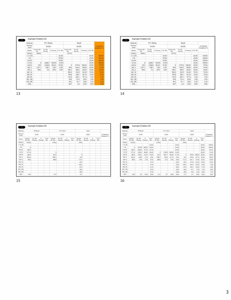
3
13
Material #11 Stone SandCombined
Gradation %Percent Used 55.0% 45.0%
Sieves Fraction Wt. Ret.
Tot. Wt. Passing % Passing % For Mix Fraction Wt.
Ret.Tot. Wt. Passing % Passing % For Mix
TOTALS 2440.3 1275.41 1/2 IN 55.0% 45.0% 100.0%
1 IN 55.0% 45.0% 100.0%3/4 IN 55.0% 45.0% 100.0%1/2 IN 0 2440.3 100.0% 55.0% 45.0% 100.0%3/8 IN 93.5 2346.8 96.2% 52.9% 0 1275.4 100.0% 45.0% 97.9%NO. 4 2157.1 189.7 7.8% 4.3% 40.9 1234.5 96.8% 43.6% 47.9%NO. 8 189.5 0.2 0.0% 0.0% 385.2 849.3 66.6% 30.0% 30.0%NO. 16 296.4 552.9 43.4% 19.5% 19.5%NO. 30 194.8 358.1 28.1% 12.6% 12.6%NO. 50 153.0 205.1 16.1% 7.2% 7.2%NO. 100 94.8 110.3 8.6% 3.9% 3.9%NO. 200 49.2 61.1 4.8% 2.2% 2.2%
PAN 60.7 0.4 0.0% 0.0% 0.0%
Example Problem #114
Material #11 Stone SandCombined
Gradation %Percent Used 55.0% 45.0%
Sieves Fraction Wt. Ret.
Tot. Wt. Passing % Passing % For Mix Fraction Wt.
Ret.Tot. Wt. Passing % Passing % For Mix
TOTALS 2440.3 1275.41 1/2 IN 55.0% 45.0% 100.0%
1 IN 55.0% 45.0% 100.0%3/4 IN 55.0% 45.0% 100.0%1/2 IN 0 2440.3 100.0% 55.0% 45.0% 100.0%3/8 IN 93.5 2346.8 96.2% 52.9% 0 1275.4 100.0% 45.0% 97.9%NO. 4 2157.1 189.7 7.8% 4.3% 40.9 1234.5 96.8% 43.6% 47.8%NO. 8 189.5 0.2 0.0% 0.0% 385.2 849.3 66.6% 30.0% 30.0%NO. 16 296.4 552.9 43.4% 19.5% 19.5%NO. 30 194.8 358.1 28.1% 12.6% 12.6%NO. 50 153.0 205.1 16.1% 7.2% 7.2%NO. 100 94.8 110.3 8.6% 3.9% 3.9%NO. 200 49.2 61.1 4.8% 2.2% 2.2%
PAN 60.7 0.4 0.0% 0.0% 0.0%
Example Problem #1
15
Material #8 Stone #11 Stone Sand
Combined Gradation %
Percent Used 55.0% 25.0% 20.0%
Sieves Fraction Wt. Ret.
Tot. Wt. Passing
% Passing
% For Mix
Fraction Wt. Ret.
Tot. Wt. Passing
% Passing
% For Mix
Fraction Wt. Ret.
Tot. Wt. Passing
% Passing
% For Mix
TOTALS 4720.0 2150.0 570.01 1/2 IN
1 IN 03/4 IN 883.41/2 IN 1571.6 03/8 IN 982.9 322.3 0NO. 4 1043.2 1288.1 16.4NO. 8 184.0 488.0 112.5NO. 16 69.3NO. 30 184.2NO. 50 81.9
NO. 100 64.0NO. 200 28.9
PAN 54.6 51.5 12.7
Example Problem #216
Material #8 Stone #11 Stone Sand
Combined Gradation %
Percent Used 55.0% 25.0% 20.0%
Sieves Fraction Wt. Ret.
Tot. Wt. Passing
% Passing
% For Mix
Fraction Wt. Ret.
Tot. Wt. Passing
% Passing
% For Mix
Fraction Wt. Ret.
Tot. Wt. Passing
% Passing
% For Mix
TOTALS 4720.0 2150.0 570.01 1/2 IN 55.0% 25.0% 20.0% 100.0%
1 IN 0 4720.0 100.0% 55.0% 25.0% 20.0% 100.0%3/4 IN 883.4 3836.6 81.3% 44.7% 25.0% 20.0% 89.7%1/2 IN 1571.6 2265.0 48.0% 26.4% 0 2150.0 100.0% 25.0% 20.0% 51.4%3/8 IN 982.9 1282.1 27.2% 15.0% 322.3 1827.7 85.0% 21.3% 0 570.0 100.0% 20.0% 56.3%NO. 4 1043.2 238.9 5.1% 2.8% 1288.1 539.6 25.1% 6.3% 16.4 553.6 97.1% 19.4% 28.5%NO. 8 184.0 54.9 1.2% 0.7% 488.0 51.6 2.4% 0.6% 112.5 441.1 77.4% 15.5% 16.8%NO. 16 0.7% 0.6% 69.3 371.8 65.2% 13.0% 14.3%NO. 30 0.7% 0.6% 184.2 187.6 32.9% 6.6% 7.9%NO. 50 0.7% 0.6% 81.9 105.7 18.5% 3.7% 5.0%
NO. 100 0.7% 0.6% 64.0 41.7 7.3% 1.5% 2.8%NO. 200 0.7% 0.6% 28.9 12.8 2.2% 0.4% 1.7%
PAN 54.6 0.3 0.0% 0.0% 51.5 0.1 0.0% 0.0% 12.7 0.1 0.0% 0.0% 0.0%
Example Problem #2
13 14
15 16

1
1
PLANTS: Annual Inspection And Calibration
I N D O T C e r t i f i e d A s p h a l t L a b Te c h n i c i a n P r o g r a m
C h a p t e r F i v e – M o d u l e 7
2
Meet the Team
Mix Cost AnalystBrooks Construction Company, Inc.
T I M S I E V E R S
3
Annual Inspection and CalibrationDrum Plant
• For a drum plant, HMA proportioning is accomplished by a moving weight system. The computer monitors must be checked for accuracy.
• The load cell on each aggregate belt must be checked by running material across the load cell into a tared truck. The computer inventory must match the actual weight by 0.5%, in three consecutive attempts. A truck load of material should be used each time.
4
Annual Inspection and CalibrationDrum Plant
• The binder check uses a tared distributor that must check against the pump reading on the flow meter and the computer monitor.
• These units must match the weight in the distributor by 0.5%, three consecutive times, within the working range of the plant.
• The fines return system must also be checked to 0.5% accuracy as is done with a batch plant.
5
Annual Inspection and Calibration
• Scales and meters shall be checked to the maximum capacity they will be used.
• The allowable difference between the scale reading and the actual weight applied shall be 0.5% or less.
• Meter variation shall also be 0.5% or less.
6
Annual Inspection and Calibration
Example 1
6
1 2
3 4
5 6
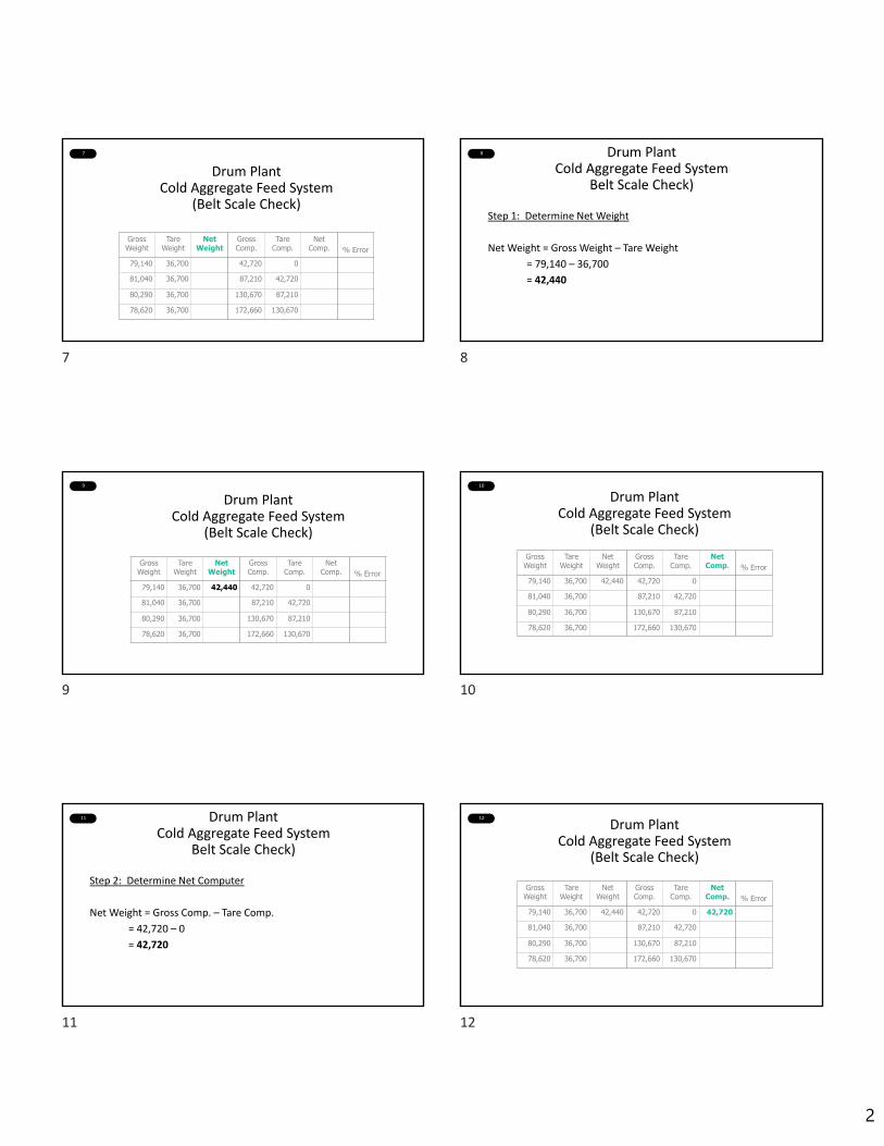
2
7
Drum PlantCold Aggregate Feed System
(Belt Scale Check)
Gross Weight
Tare Weight
Net Weight
Gross Comp.
Tare Comp.
Net Comp. % Error
79,140 36,700 42,720 0
81,040 36,700 87,210 42,720
80,290 36,700 130,670 87,210
78,620 36,700 172,660 130,670
8 Drum PlantCold Aggregate Feed System
Belt Scale Check)
Step 1: Determine Net Weight
Net Weight = Gross Weight – Tare Weight
= 79,140 – 36,700
= 42,440
9
Drum PlantCold Aggregate Feed System
(Belt Scale Check)
Gross Weight
Tare Weight
Net Weight
Gross Comp.
Tare Comp.
Net Comp. % Error
79,140 36,700 42,440 42,720 0
81,040 36,700 87,210 42,720
80,290 36,700 130,670 87,210
78,620 36,700 172,660 130,670
10
Drum PlantCold Aggregate Feed System
(Belt Scale Check)
Gross Weight
Tare Weight
Net Weight
Gross Comp.
Tare Comp.
Net Comp. % Error
79,140 36,700 42,440 42,720 0
81,040 36,700 87,210 42,720
80,290 36,700 130,670 87,210
78,620 36,700 172,660 130,670
11 Drum PlantCold Aggregate Feed System
Belt Scale Check)
Step 2: Determine Net Computer
Net Weight = Gross Comp. – Tare Comp.
= 42,720 – 0
= 42,720
12
Drum PlantCold Aggregate Feed System
(Belt Scale Check)
Gross Weight
Tare Weight
Net Weight
Gross Comp.
Tare Comp.
Net Comp. % Error
79,140 36,700 42,440 42,720 0 42,720
81,040 36,700 87,210 42,720
80,290 36,700 130,670 87,210
78,620 36,700 172,660 130,670
7 8
9 10
11 12

3
13
Drum PlantCold Aggregate Feed System
(Belt Scale Check)
Gross Weight
Tare Weight
Net Weight
Gross Comp.
Tare Comp.
Net Comp. % Error
79,140 36,700 42,440 42,720 0 42,720
81,040 36,700 87,210 42,720
80,290 36,700 130,670 87,210
78,620 36,700 172,660 130,670
14 Drum PlantCold Aggregate Feed System
(Belt Scale Check)
Step 3: Determine % Error
% Error = (Weightknown‐Weightvaries) x 100
Weightknown
= 42,440 – 42,720 x 100
42,440
= 280/42,440 x 100
= 0.0066 x 100
= 0.66
15
Drum PlantCold Aggregate Feed System
(Belt Scale Check)
Gross Weight
Tare Weight
Net Weight
Gross Comp.
Tare Comp.
Net Comp. % Error
79,140 36,700 42,440 42,720 0 42,720 0.66
81,040 36,700 87,210 42,720
80,290 36,700 130,670 87,210
78,620 36,700 172,660 130,670
16
Drum PlantCold Aggregate Feed System
(Belt Scale Check)
Gross Weight
Tare Weight
Net Weight
Gross Comp.
Tare Comp.
Net Comp. % Error
79,140 36,700 42,440 42,720 0 42,720 0.66
81,040 36,700 44,340 87,210 42,720 44,490 0.34
80,290 36,700 43,590 130,670 87,210 43,460 0.30
78,620 36,700 41,920 172,660 130,670 41,990 0.17
17
Drum PlantAsphalt Meter Check
Gross Weight Tare Weight
Net Weight
Computer Weight % Error
28,030 23,150 4,890
26,900 22,050 4,870
25,840 21,050 4,780
18
Step 1: Determine Net Weight
Net Weight = Gross Wt. – Tare Wt.
= 28,030 – 23,150
= 4,880
Drum PlantAsphalt Meter Check
13 14
15 16
17 18

4
19
Gross Weight Tare Weight Net
Weight
Computer Weight % Error
28,030 23,150 4,880 4,890
26,900 22,050 4,870
25,840 21,050 4,780
Drum PlantAsphalt Meter Check
20
Gross Weight Tare Weight Net Weight
Computer Weight % Error
28,030 23,150 4,880 4,890
26,900 22,050 4,870
25,840 21,050 4,780
Drum PlantAsphalt Meter Check
21
Step 2: Determine % Error
% Error = (Weightknown‐Weightvaries) x 100
Weightknown
= 4,880 – 4,890 x 1004,880
= 10/4,880 x 100= 0.0020 x 100= 0.20
Drum PlantAsphalt Meter Check
22
Gross Weight Tare Weight Net Weight
Computer Weight % Error
28,030 23,150 4,880 4,890 0.2026,900 22,050 4,870
25,840 21,050 4,780
Drum PlantAsphalt Meter Check
23
Gross Weight Tare Weight
Net Weight
Computer Weight % Error
28,030 23,150 4,880 4,890 0.20
26,900 22,050 4,850 4,870 0.4125,840 21,050 4,790 4,780 0.21
Drum PlantAsphalt Meter Check
24
DRUM PLANT
CALIBRATION
19 20
21 22
23 24
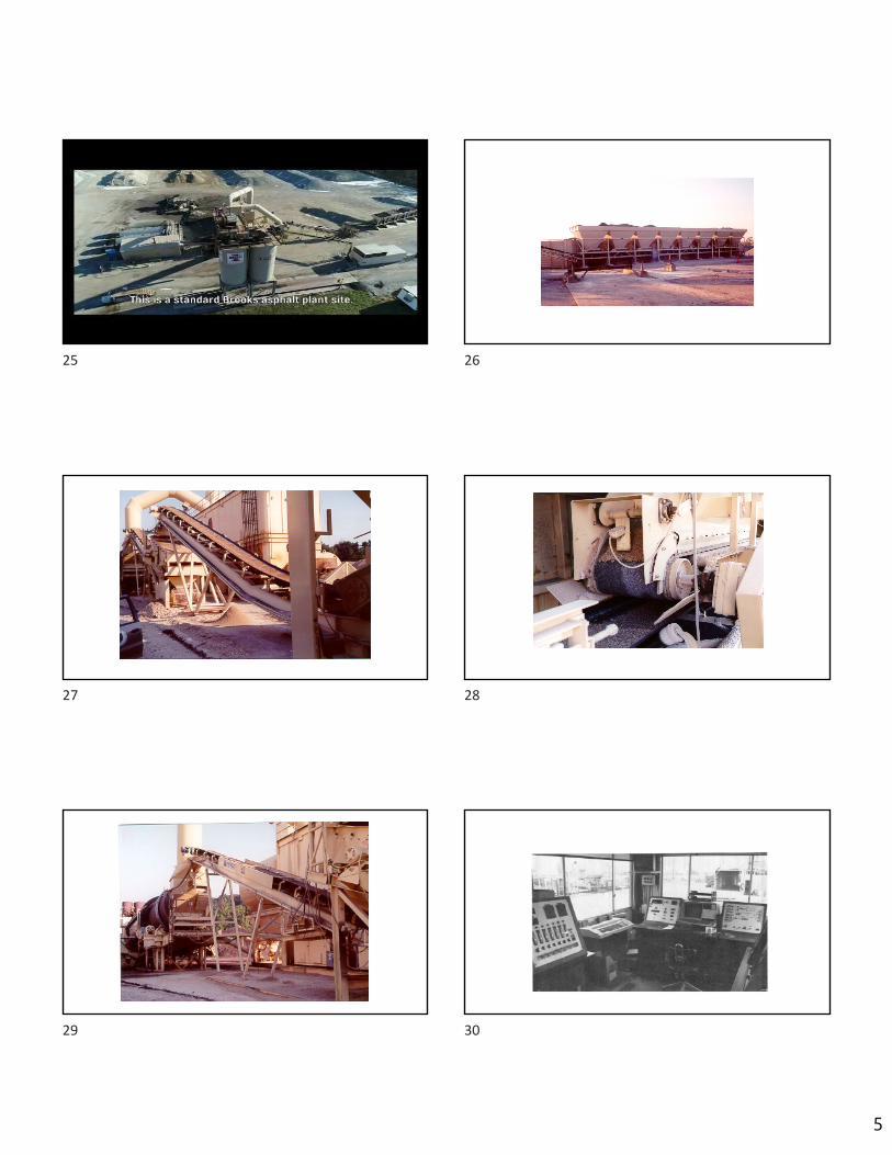
5
25
25
26
27 28
29 30
25 26
27 28
29 30
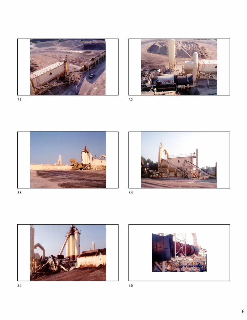
6
31 32
33 34
35 36
31 32
33 34
35 36

7
37 38
39 40
41 42
37 38
39 40
41 42

8
43
43
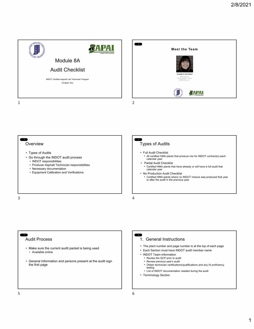
2/8/2021
1
1
Module 8A
Audit Checklist
INDOT Certified Asphalt Lab Technician Program
(Chapter Six)
2
HMA Design & QC Coordinator – North
E&B Paving, Inc.
ELIZABETH PASTUSZKA
3
Overview
• Types of Audits
• Go through the INDOT audit process• INDOT responsibilities• Producer Asphalt Technician responsibilities• Necessary documentation • Equipment Calibration and Verifications
4
Types of Audits
• Full Audit Checklist• All certified HMA plants that produce mix for INDOT contract(s) each
calendar year
• Partial Audit Checklist• Certified HMA plants that have already or will have a full audit that
calendar year
• No Production Audit Checklist• Certified HMA plants where no INDOT mixture was produced that year
or after the audit in the previous year
5
Audit Process
• Make sure the current audit packet is being used• Available online
• General Information and persons present at the audit sign the first page
6
1. General Instructions
• The plant number and page number is at the top of each page
• Each Section must have INDOT audit member name
• INDOT Team information• Review the QCP prior to audit• Review previous year’s audit• Obtain technician certifications/qualifications and any IA proficiency
testing • List of INDOT documentation needed during the audit
• Terminology Section
1 2
3 4
5 6

2/8/2021
2
7
1. General Instructions (cont’d)
How to fill out the audit packet
• ✔ Satisfactory Item• X Unsatisfactory Item• NA Not Applicable• * Only applicable in some cases
8
2. Producer General Information
• QCP general information is correct
• INDOT and Producer QCPs are up to date and the same
• Documentation for Level 1 Asphalt Technician, Certified Technician, or Qualified Technician
• Note if plant is equipped with a water injection foaming device or modified asphalt in-line blending capabilities
9
3. Documents
• Current INDOT Specification book
• ICAT Manual
• ITM, AASHTO, ASTM Test Methods referenced in the QCP are current and on file
• Number of assigned DMFs in ITAP
• Additional documents as needed• Fines correction• In-line blending information• Fibers information
10
4. Control Limits-QC/QA HMA and SMA
• Verify test results are within DMF targets or control limits identified by the Producer.
• Review all state properties for one QC/QA HMA (PWL if applicable) or SMA mixture from one current or recently completed contract.
• Select one PWL contract (if applicable) or one of the larger contracts available. Otherwise, select one SMA mixture from one current or recently completed contract.
11
4. Control Limits-QC/QA HMA and SMA
Review all test results and properties of that mixture• Air Voids• Binder Content• VMA
• Dust/Calculated Effective Binder Ratio• Volume of Effective Binder
• Aggregate Stockpiles• Gradation
• Blended Aggregate• Gradation
• Recycled Material Tests• Gradation, depending on size of recycled material• Binder Content
12
5. Diary• Review of one Production month within current calendar year or past
three calendar years.
• General requirements of ITM 583• On file for 3 years• Open book format• One or more pages for each day of production• Type of mixture produced and DMF number• Contract or Purchase Order number • Time sample was obtained and tests completed• Significant events or problems• Signature of Level 1, Certified Technician
or Management Representative
7 8
9 10
11 12
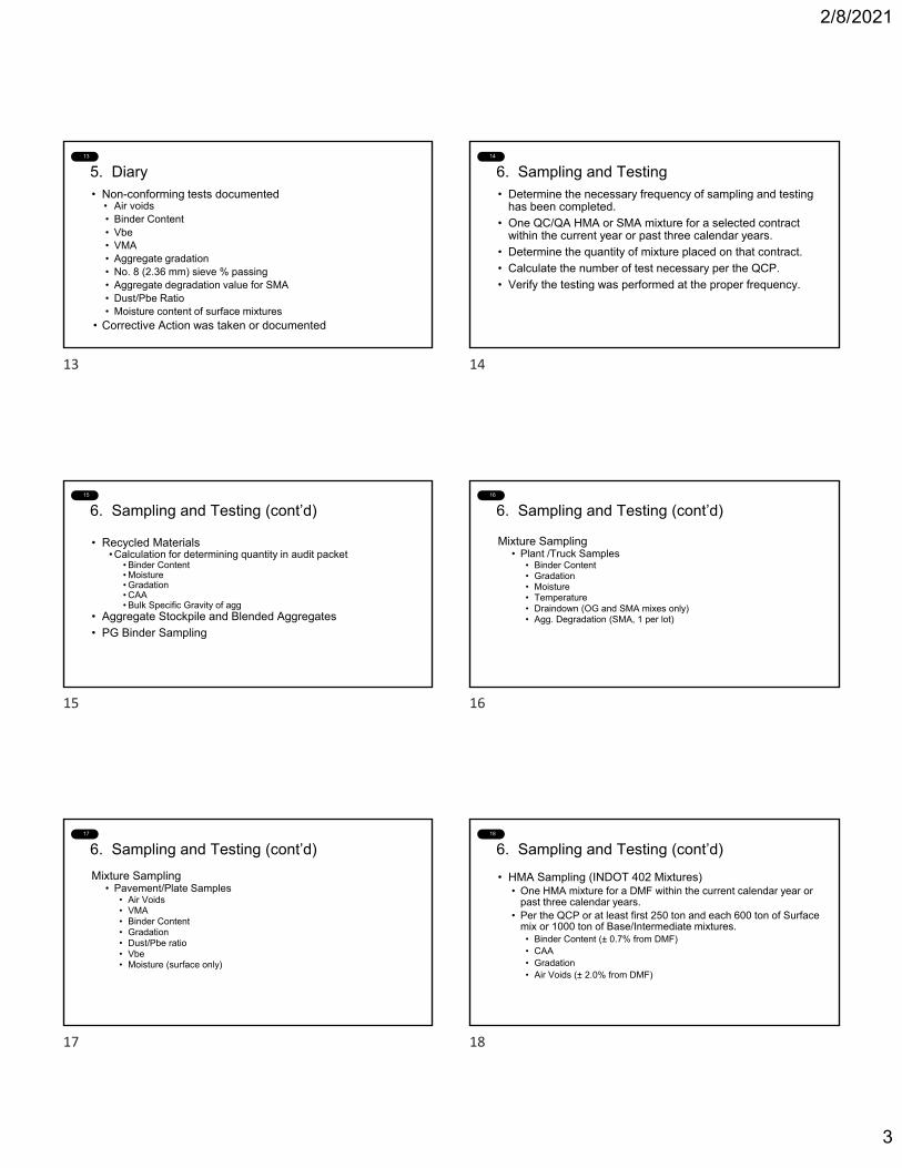
2/8/2021
3
13
5. Diary• Non-conforming tests documented
• Air voids• Binder Content• Vbe• VMA• Aggregate gradation• No. 8 (2.36 mm) sieve % passing• Aggregate degradation value for SMA• Dust/Pbe Ratio• Moisture content of surface mixtures
• Corrective Action was taken or documented
14
6. Sampling and Testing• Determine the necessary frequency of sampling and testing
has been completed.
• One QC/QA HMA or SMA mixture for a selected contract within the current year or past three calendar years.
• Determine the quantity of mixture placed on that contract.
• Calculate the number of test necessary per the QCP.
• Verify the testing was performed at the proper frequency.
15
6. Sampling and Testing (cont’d)
• Recycled Materials• Calculation for determining quantity in audit packet
• Binder Content• Moisture• Gradation• CAA• Bulk Specific Gravity of agg
• Aggregate Stockpile and Blended Aggregates
• PG Binder Sampling
16
6. Sampling and Testing (cont’d)
Mixture Sampling• Plant /Truck Samples
• Binder Content• Gradation• Moisture• Temperature• Draindown (OG and SMA mixes only)• Agg. Degradation (SMA, 1 per lot)
17
6. Sampling and Testing (cont’d)
Mixture Sampling• Pavement/Plate Samples
• Air Voids• VMA• Binder Content• Gradation• Dust/Pbe ratio• Vbe• Moisture (surface only)
18
6. Sampling and Testing (cont’d)
• HMA Sampling (INDOT 402 Mixtures)• One HMA mixture for a DMF within the current calendar year or
past three calendar years.• Per the QCP or at least first 250 ton and each 600 ton of Surface
mix or 1000 ton of Base/Intermediate mixtures.• Binder Content (± 0.7% from DMF)• CAA• Gradation• Air Voids (± 2.0% from DMF)
13 14
15 16
17 18
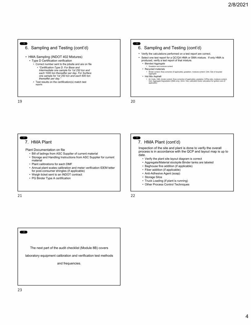
2/8/2021
4
19
6. Sampling and Testing (cont’d)
• HMA Sampling (INDOT 402 Mixtures)• Type D Certification verification
• Correct number sent to the jobsite and are on file• “Certification-Type D. For Base and
Intermediate one sample for 1st 250 ton and each 1000 ton thereafter per day. For Surface one sample for 1st 250 ton and each 600 ton thereafter per day.”
• Test results on the certification(s) match test reports
20
6. Sampling and Testing (cont’d)• Verify the calculations performed on a test report are correct.
• Select one test report for a QC/QA HMA or SMA mixture. If only HMA is produced, verify a test report of that mixture.• Blended Aggregate
• Gradation and moisture content
• Recycled materials• Binder content, fines correction (if applicable), gradation, moisture content, CAA, Gsb of recycled
aggregate
• Hot Mix Asphalt • Air Voids, VMA, binder content, fines correction (if applicable), gradation, D/Pbe ratio, moisture content,
Gsb, Aggregate Degradation (SMA only), Gmm, Vbe, calibration factor calculation for ignition oven (if applicable)
21
7. HMA Plant
Plant Documentation on file• Bill of ladings from ASC Supplier of current material• Storage and Handling Instructions from ASC Supplier for current
material• Plant calibrations for each DMF• Annual plant scales calibration and meter verification IDEM letter
for post-consumer shingles (if applicable)• Weigh ticket sent to an INDOT contract• PG Binder Type A certification
22
7. HMA Plant (cont’d)Inspection of the site and plant is done to verify the overall process is in accordance with the QCP and layout map is up to date.
• Verify the plant site layout diagram is correct• Aggregate/Material stockpile Binder tanks are labeled• Baghouse fine addition (if applicable)• Fiber addition (if applicable)• Anti-Adhesive Agent (soap) • Storage Silos• Truck Loading (if plant is running)• Other Process Control Techniques
23
The next part of the audit checklist (Module 8B) covers
laboratory equipment calibration and verification test methods
and frequencies.
19 20
21 22
23
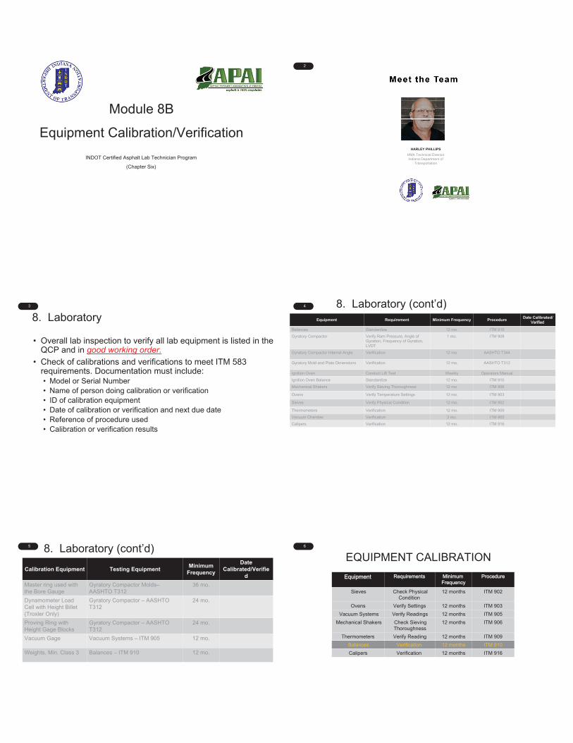
1
Module 8B
Equipment Calibration/Verification
INDOT Certified Asphalt Lab Technician Program
(Chapter Six)
2
HMA Technical DirectorIndiana Department of
Transportation
HARLEY PHILLIPS
3
8. Laboratory
• Overall lab inspection to verify all lab equipment is listed in the QCP and in good working order.
• Check of calibrations and verifications to meet ITM 583 requirements. Documentation must include:• Model or Serial Number• Name of person doing calibration or verification• ID of calibration equipment• Date of calibration or verification and next due date• Reference of procedure used• Calibration or verification results
4 8. Laboratory (cont’d)Equipment Requirement Minimum Frequency Procedure Date Calibrated/
Verified
Balances Standardize 12 mo. ITM 910
Gyratory Compactor Verify Ram Pressure, Angle of Gyration, Frequency of Gyration, LVDT
1 mo. ITM 908
Gyratory Compactor Internal Angle Verification 12 mo. AASHTO T344
Gyratory Mold and Plate Dimensions Verification 12 mo. AASHTO T312
Ignition Oven Conduct Lift Test Weekly Operators Manual
Ignition Oven Balance Standardize 12 mo. ITM 910
Mechanical Shakers Verify Sieving Thoroughness 12 mo. ITM 906
Ovens Verify Temperature Settings 12 mo. ITM 903
Sieves Verify Physical Condition 12 mo. ITM 902
Thermometers Verification 12 mo. ITM 909
Vacuum Chamber Verification 3 mo. ITM 905
Calipers Verification 12 mo. ITM 916
5 8. Laboratory (cont’d)
Calibration Equipment Testing Equipment Minimum Frequency
Date Calibrated/Verifie
dMaster ring used with the Bore Gauge
Gyratory Compactor Molds–AASHTO T312
36 mo.
Dynamometer Load Cell with Height Billet (Troxler Only)
Gyratory Compactor – AASHTO T312
24 mo.
Proving Ring with Height Gage Blocks
Gyratory Compactor – AASHTO T312
24 mo.
Vacuum Gage Vacuum Systems – ITM 905 12 mo.
Weights, Min. Class 3 Balances – ITM 910 12 mo.
6
EQUIPMENT CALIBRATION
Equipment Requirements MinimumFrequency
Procedure
Sieves Check Physical Condition
12 months ITM 902
Ovens Verify Settings 12 months ITM 903
Vacuum Systems Verify Readings 12 months ITM 905
Mechanical Shakers Check Sieving Thoroughness
12 months ITM 906
Thermometers Verify Reading 12 months ITM 909
Balances Verification 12 months ITM 910
Calipers Verification 12 months ITM 916
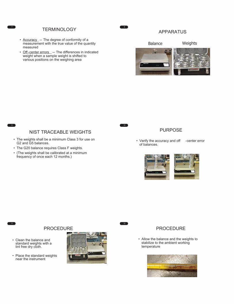
7
TERMINOLOGY
• Accuracy -- The degree of conformity of a measurement with the true value of the quantity measured
• Off -center errors -- The differences in indicated weight when a sample weight is shifted to various positions on the weighing area
8
APPARATUS
Balance Weights
9
NIST TRACEABLE WEIGHTS
• The weights shall be a minimum Class 3 for use on G2 and G5 balances.
• The G20 balance requires Class F weights.
• (The weights shall be calibrated at a minimum frequency of once each 12 months.)
10
PURPOSE
• Verify the accuracy and off -center error of balances.
11
PROCEDURE
• Clean the balance and standard weights with a lint free dry cloth.
• Place the standard weights near the instrument
12
• Allow the balance and the weights to stabilize to the ambient working temperature
PROCEDURE
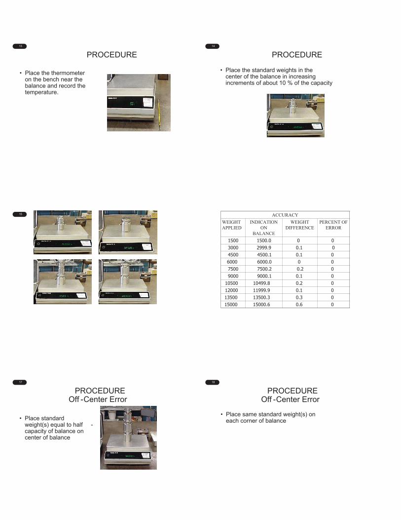
13
• Place the thermometer on the bench near the balance and record the temperature.
PROCEDURE14
• Place the standard weights in the center of the balance in increasing increments of about 10 % of the capacity
PROCEDURE
15 16 ACCURACYWEIGHTAPPLIED
INDICATION ON
BALANCE
WEIGHTDIFFERENCE
PERCENT OFERROR
1500 1500.0 0 03000 2999.9 0.1 04500 4500.1 0.1 06000 6000.0 0 07500 7500.2 0.2 09000 9000.1 0.1 0
10500 10499.8 0.2 012000 11999.9 0.1 013500 13500.3 0.3 015000 15000.6 0.6 0
17
PROCEDURE Off -Center Error
• Place standard weight(s) equal to half -capacity of balance on center of balance
18
• Place same standard weight(s) on each corner of balance
PROCEDURE Off -Center Error
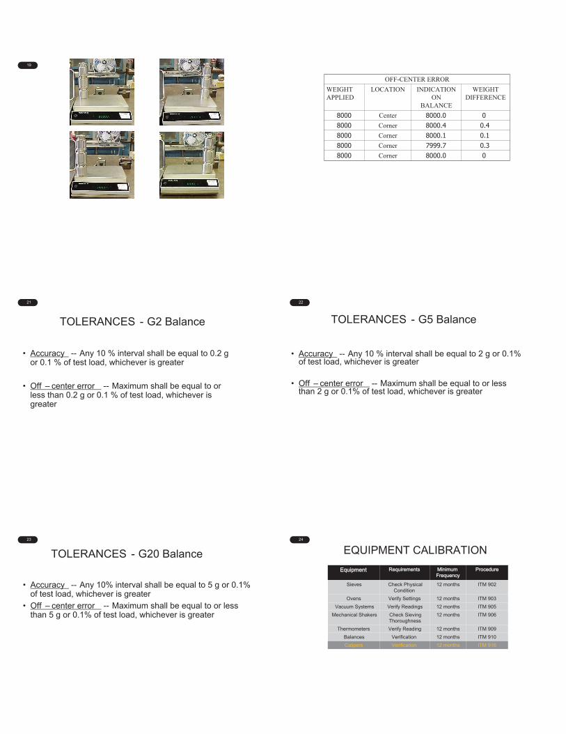
19 20
OFF-CENTER ERRORWEIGHTAPPLIED
LOCATION INDICATION ON
BALANCE
WEIGHTDIFFERENCE
8000 Center 8000.0 08000 Corner 8000.4 0.48000 Corner 8000.1 0.18000 Corner 7999.7 0.38000 Corner 8000.0 0
21
TOLERANCES - G2 Balance
• Accuracy -- Any 10 % interval shall be equal to 0.2 g or 0.1 % of test load, whichever is greater
• Off – center error -- Maximum shall be equal to or less than 0.2 g or 0.1 % of test load, whichever is greater
22
TOLERANCES - G5 Balance
• Accuracy -- Any 10 % interval shall be equal to 2 g or 0.1% of test load, whichever is greater
• Off – center error -- Maximum shall be equal to or less than 2 g or 0.1% of test load, whichever is greater
23
TOLERANCES - G20 Balance
• Accuracy -- Any 10% interval shall be equal to 5 g or 0.1% of test load, whichever is greater
• Off – center error -- Maximum shall be equal to or less than 5 g or 0.1% of test load, whichever is greater
24
EQUIPMENT CALIBRATION
Equipment Requirements MinimumFrequency
Procedure
Sieves Check Physical Condition
12 months ITM 902
Ovens Verify Settings 12 months ITM 903
Vacuum Systems Verify Readings 12 months ITM 905
Mechanical Shakers Check Sieving Thoroughness
12 months ITM 906
Thermometers Verify Reading 12 months ITM 909
Balances Verification 12 months ITM 910
Calipers Verification 12 months ITM 916
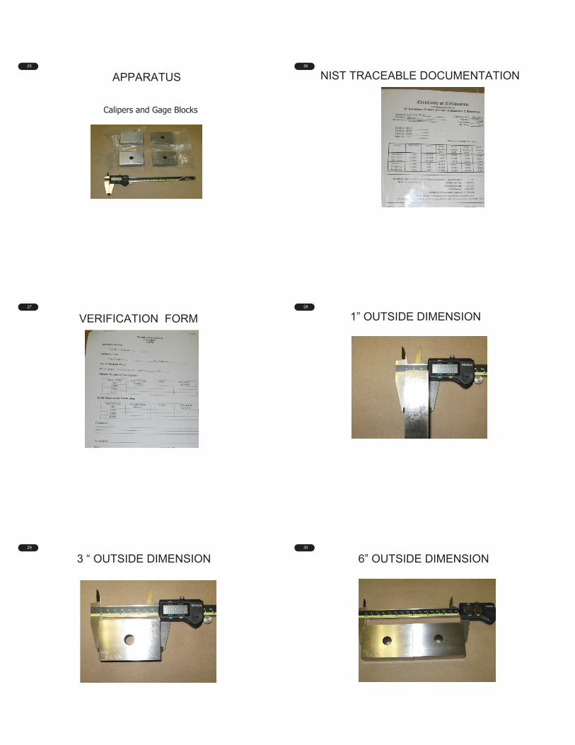
25
APPARATUS
Calipers and Gage Blocks
26
NIST TRACEABLE DOCUMENTATION
27
VERIFICATION FORM28
1” OUTSIDE DIMENSION
29
3 “ OUTSIDE DIMENSION30
6” OUTSIDE DIMENSION
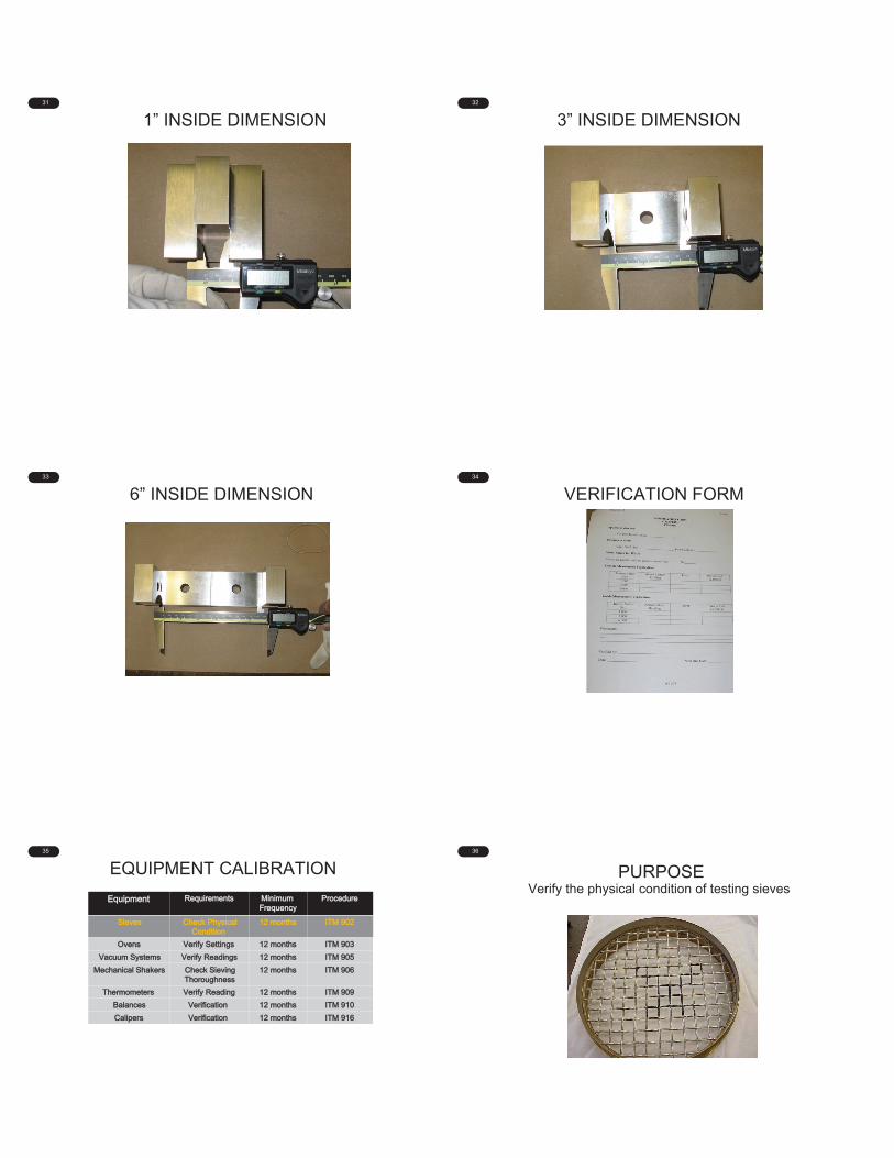
31
1” INSIDE DIMENSION32
3” INSIDE DIMENSION
33
6” INSIDE DIMENSION34
VERIFICATION FORM
35
EQUIPMENT CALIBRATION
Equipment Requirements MinimumFrequency
Procedure
Sieves Check Physical Condition
12 months ITM 902
Ovens Verify Settings 12 months ITM 903
Vacuum Systems Verify Readings 12 months ITM 905
Mechanical Shakers Check Sieving Thoroughness
12 months ITM 906
Thermometers Verify Reading 12 months ITM 909
Balances Verification 12 months ITM 910
Calipers Verification 12 months ITM 916
36
PURPOSEVerify the physical condition of testing sieves
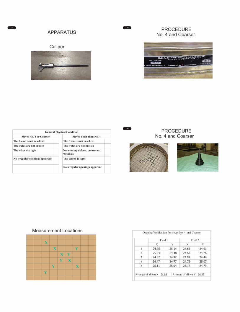
37
APPARATUS
Caliper
38
PROCEDURE No. 4 and Coarser
39
General Physical ConditionSieves No. 4 or Coarser Sieves Finer than No. 4
The frame is not cracked The frame is not crackedThe welds are not broken The welds are not brokenThe wires are tight No weaving defects, creases or
wrinkles
No irregular openings apparent The screen is tight
No irregular openings apparent
40
PROCEDURENo. 4 and Coarser
41
XX Y
X YY X
Y XY
Measurement Locations 42
Opening Verification for sieves No. 4 and Coarser
Field 1 Field 2X Y X Y
1 24.75 25.14 24.66 24.912 25.04 24.48 24.62 24.763 24.82 24.92 24.99 24.444 24.47 24.77 24.72 25.075 25.11 25.04 25.17 24.79
Average of all ten X 24.84 Average of all ten Y 24.83

43TOLERANCE – No. 4 and COARSER
SieveDesignation
PERMISSIBLEAVERAGE OPENING
MAXIMUM INDIVIDUAL
OPENING4 in. ±3.00 mm 104.8 mm
3 1/2 in. ±2.70 mm 94.4 mm
3 in. ±2.20 mm 78.7 mm
2 1/2 in. ±1.90 mm 66.2 mm
2 in. ±1.50 mm 52.6 mm
1 1/2 in. ±1.10 mm 39.5 mm
1 in. ±0.800 mm 26.4 mm
3/4 in. ±0.600 mm 20.1 mm
1/2 in. ±0.390 mm 13.31 mm
3/8 in. ±0.300 mm 10.16 mm
No. 4 ±0.150 mm 5.14 mm
44 PROCEDURE Sieves Finer Than No. 4
• Hold the sieve against a uniformly illuminated background
• Check general condition of sieve for:• cracks in frame• broken solder joints• weaving defects• creases• wrinkles• wire tightness• irregular openings
45
Solder Joint Crack in frame
46
47
EQUIPMENT CALIBRATIONEquipment Requirements Minimum
FrequencyProcedure
Sieves Check Physical Condition
12 months ITM 902
Ovens Verify Settings 12 months ITM 903
Vacuum Systems Verify Reading 12 months ITM 905
Mechanical Shakers Check Sieving Thoroughness
12 months ITM 906
Thermometers Verify Reading 12 months ITM 909
Balances Verification 12 months ITM 910
Calipers Verification 12 months ITM 916
48
PURPOSE: Verify sieving sufficiency and accuracy of timers.

49
APPARATUS50
APPARATUS
51
PROCEDURE
• Operate shaker
• Measure the time
52
PROCEDURE• Repeat with the timer set at 10 min and
15 min
53
TIMER VERIFICATION
Setting on Shaker Timer
Timing Device Reading
Corrective Adjustment Made
5 min 5 min - .78 sec ----10 min 10 min- .07 sec ----15 min 15 min- .13 sec ----
54
TOLERANCE
• Timer shall be within ± 5 sec at 5 min, ± 10 sec at 10 min, and ± 15 sec at 15 min of stopwatch reading
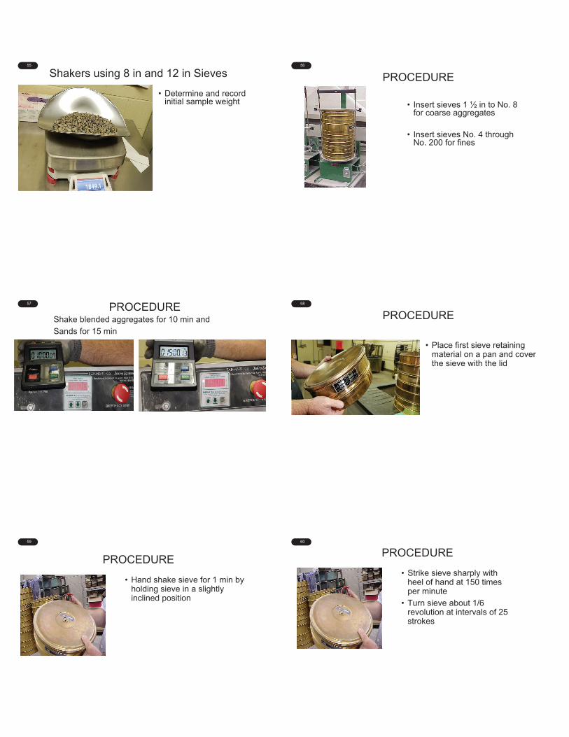
55
Shakers using 8 in and 12 in Sieves
• Determine and record initial sample weight
56
PROCEDURE
• Insert sieves 1 ½ in to No. 8 for coarse aggregates
• Insert sieves No. 4 through No. 200 for fines
57 PROCEDUREShake blended aggregates for 10 min and
Sands for 15 min
58
PROCEDURE
• Place first sieve retaining material on a pan and cover the sieve with the lid
59
PROCEDURE
• Hand shake sieve for 1 min by holding sieve in a slightly inclined position
60
PROCEDURE
• Strike sieve sharply with heel of hand at 150 times per minute
• Turn sieve about 1/6 revolution at intervals of 25 strokes

61
PROCEDURE
• Weigh material passing the sieve and retained in the pan
62
PROCEDURE
• Weigh the material retained on the sieve
63
PROCEDURE
• Add weight retained on sieve and weight passing the sieve to verify sieve was not overloaded
ScreenSize
12” Diameter
8” Diameter
3 in. 12.6 kg --------2 in. 8.4 kg 3.6 kg
1 ½ in. 6.3 kg 2.7 kg1 in. 4.2 kg 1.8 kg¾ in. 3.2 kg 1.4 kg½ in. 2.1 kg 890 g
3/8 in. 1.6 kg 670 gNo. 4 800 g 330 g
64
PROCEDURE
• If sieve was overloaded, verification is void and new sample shall be obtained
65 SIEVING SUFFICIENCY VERIFICATION
Sieve Size
Weight Retained by Mechanical
Sieving
Weight Passing
After Hand Sieving
% Passing After Hand Sieving
1 in. 0 0¾ in. 402.4 0½ in. 2618.7 21.6 0.33
3/8 in. 1270.6 10.4 0.16No. 4 2269.0 12.7 0.19No. 8 8.6 0
No. 16No. 30 No. 50No. 100No. 200
66
TOLERANCE
• No more than 0.5 percent by weight of the total sample shall pass any sieve after 1 min of hand sieving

67
PROCEDURE
• Repeat procedure for the remaining sieves.
• If a sieve does not meet the allowable tolerance , the shaking time shall be increased to determine an adequate time.
68
EQUIPMENT CALIBRATIONEquipment Requirements Minimum
FrequencyProcedure
Sieves Check Physical Condition
12 months ITM 902
Ovens Verify Settings 12 months ITM 903
Vacuum Systems Verify Reading 12 months ITM 905
Mechanical Shakers Check Sieving Thoroughness
12 months ITM 906
Thermometers Verify Reading 12 months ITM 909
Balances Verification 12 months ITM 910
Calipers Verification 12 months ITM 916
69
APPARATUS Certified Thermometer
Oil Bath
Water Bath
70
PURPOSE
• Verify the thermometer scale accuracy for:
• Liquid -in -glass total immersion
• Liquid -in -glass partial immersion
• Dial type
• Handheld digital
71
PROCEDURE
Record the manufacturer, serial number, type, model number, graduation, and date of calibration for the certified thermometer
72
PROCEDURE
• Liquid -In -Glass Total and Partial Immersion Thermometers

73
PROCEDURE
• Record the manufacturer, serial number, type, model number, and graduation of thermometer being verified.
74
PROCEDURE
• Visually inspect the shaft of the thermometer for:• Air bubbles• Separation of the liquid• Foreign matter• Glass faults• Other apparent defects
75
PROCEDURE
• Immerse the thermometer being verified into a water/oil bath• Partial immersion thermometers
• to immersion line • Total immersion thermometers
• to point being verified
76
PROCEDURE
• Use water bath for < 200 ºF
•
77
PROCEDURE
• Immerse the certified thermometer into water/oil bath
• Allow the readings on both thermometers to stabilize
• Record the temperature of each thermometer
78
TOLERANCE
• Within scale error max from Table 1 of ITM 909
• Thermometer may be used if difference is visibly noted and offset is applied during use
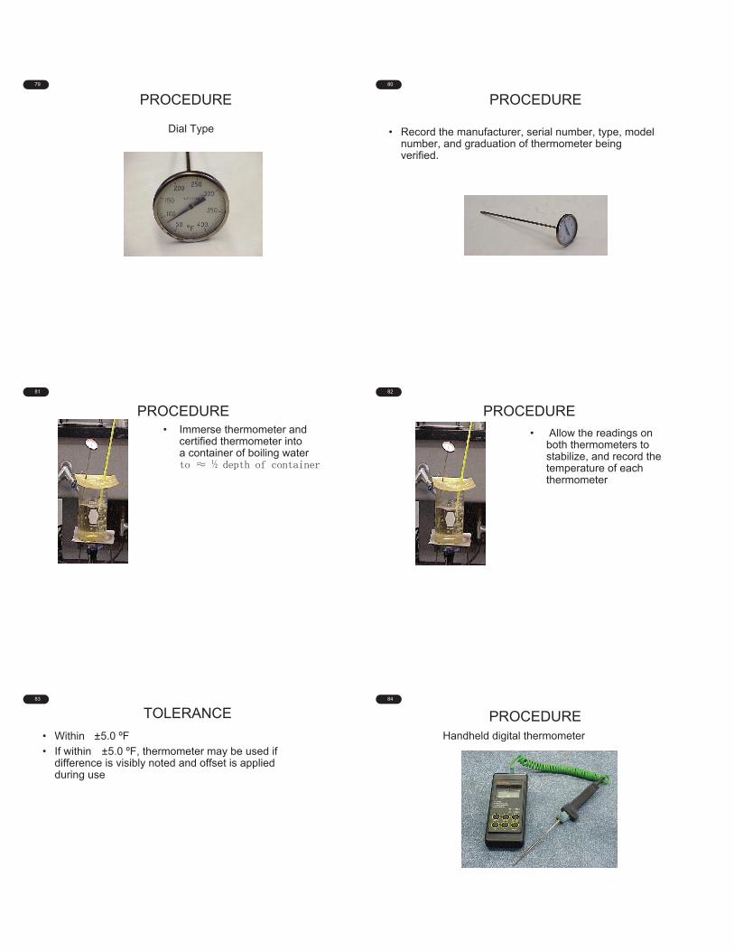
79
PROCEDURE
Dial Type
80
PROCEDURE
• Record the manufacturer, serial number, type, model number, and graduation of thermometer being verified.
81
PROCEDURE• Immerse thermometer and
certified thermometer into a container of boiling water
82
PROCEDURE
• Allow the readings on both thermometers to stabilize, and record the temperature of each thermometer
83
TOLERANCE
• Within ±5.0 ºF
• If within ±5.0 ºF, thermometer may be used if difference is visibly noted and offset is applied during use
84
PROCEDUREHandheld digital thermometer
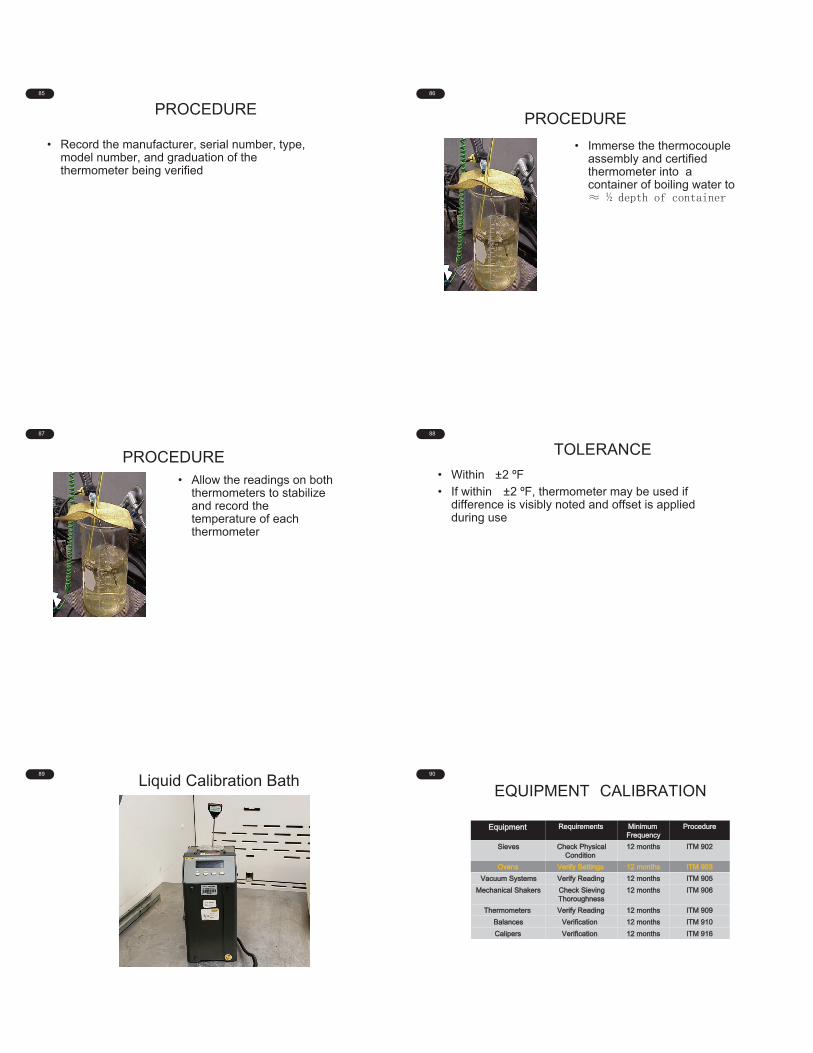
85
PROCEDURE
• Record the manufacturer, serial number, type, model number, and graduation of the thermometer being verified
86
PROCEDURE
• Immerse the thermocouple assembly and certified thermometer into a container of boiling water to
87
PROCEDURE• Allow the readings on both
thermometers to stabilize and record the temperature of each thermometer
88
TOLERANCE
• Within ±2 ºF
• If within ±2 ºF, thermometer may be used if difference is visibly noted and offset is applied during use
89
Liquid Calibration Bath90
EQUIPMENT CALIBRATION
Equipment Requirements Minimum Frequency
Procedure
Sieves Check Physical Condition
12 months ITM 902
Ovens Verify Settings 12 months ITM 903
Vacuum Systems Verify Reading 12 months ITM 905
Mechanical Shakers Check Sieving Thoroughness
12 months ITM 906
Thermometers Verify Reading 12 months ITM 909
Balances Verification 12 months ITM 910
Calipers Verification 12 months ITM 916
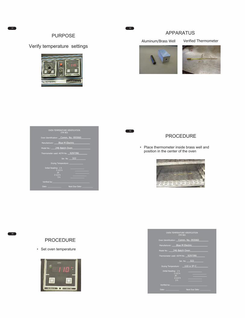
91
PURPOSE
Verify temperature settings
92
APPARATUS
Aluminum/Brass Well Verified Thermometer
93 OVEN TEMPERATURE VERIFICATIONITM 903
Oven Identification: __Comm. No. 093060_________
Manufacturer: ____Blue M Electric_______________
Model No.: ____246 Batch Oven_________________
Thermometer used: ASTM No. __9297J90________
Ser. No. ___322_________
Drying Temperature: _____________
Initial Reading: 1 h _____________1-1/2 h _____________2h _____________
2-1/2 h _____________3 h _____________
Verified by:___________________________________
Date: _____________ Next Due Date: __________
94
PROCEDURE
• Place thermometer inside brass well and position in the center of the oven
95
PROCEDURE
• Set oven temperature
96 OVEN TEMPERATURE VERIFICATIONITM 903
Oven Identification: __Comm. No. 093060_________
Manufacturer: ____Blue M Electric_______________
Model No.: ____246 Batch Oven_________________
Thermometer used: ASTM No. __9297J90________
Ser. No. ___322_________
Drying Temperature: __110 ± 5º C___________
Initial Reading: 1 h _____________1-1/2 h _____________2h _____________2-1/2 h _____________3 h _____________
Verified by:___________________________________
Date: _____________ Next Due Date: __________
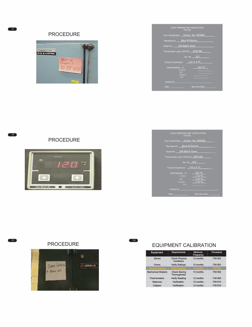
97
PROCEDURE98
OVEN TEMPERATURE VERIFICATIONITM 903
Oven Identification: __Comm. No. 093060_________
Manufacturer: ____Blue M Electric_______________
Model No.: ____246 Batch Oven_________________
Thermometer used: ASTM No. __9297J90________
Ser. No. ___322_________
Drying Temperature: __110 ± 5 ºC___________
Initial Reading: 1 h ____102 ºC___1-1/2 h _____________2h _____________2-1/2 h _____________3 h _____________
Verified by:___________________________________
Date: _____________ Next Due Date: __________
99
PROCEDURE100
OVEN TEMPERATURE VERIFICATIONITM 903
Oven Identification: __Comm. No. 093060_________
Manufacturer: ____Blue M Electric_______________
Model No.: ____246 Batch Oven_________________
Thermometer used: ASTM No. __9297J90________
Ser. No. ___322_________
Drying Temperature: __110 ± 5 ºC___________
Initial Reading: 1 h ____102 ºC___
1-1/2 h ____112 ºC___
2h ____110 ºC___
2-1/2 h ___ 110 ºC___ 3 h ____________
Verified by:___________________________________
Date: _____________ Next Due Date: __________
101
PROCEDURE102
EQUIPMENT CALIBRATIONEquipment Requirements Minimum
FrequencyProcedure
Sieves Check Physical Conditions
12 months ITM 902
Ovens Verify Settings 12 months ITM 903
Vacuum Systems Verify Reading 12 months ITM 905
Mechanical Shakers Check SievingThoroughness
12 months ITM 906
Thermometers Verify Reading 12 months ITM 909
Balances Verification 12 months ITM 910
Calipers Verification 12 months ITM 916
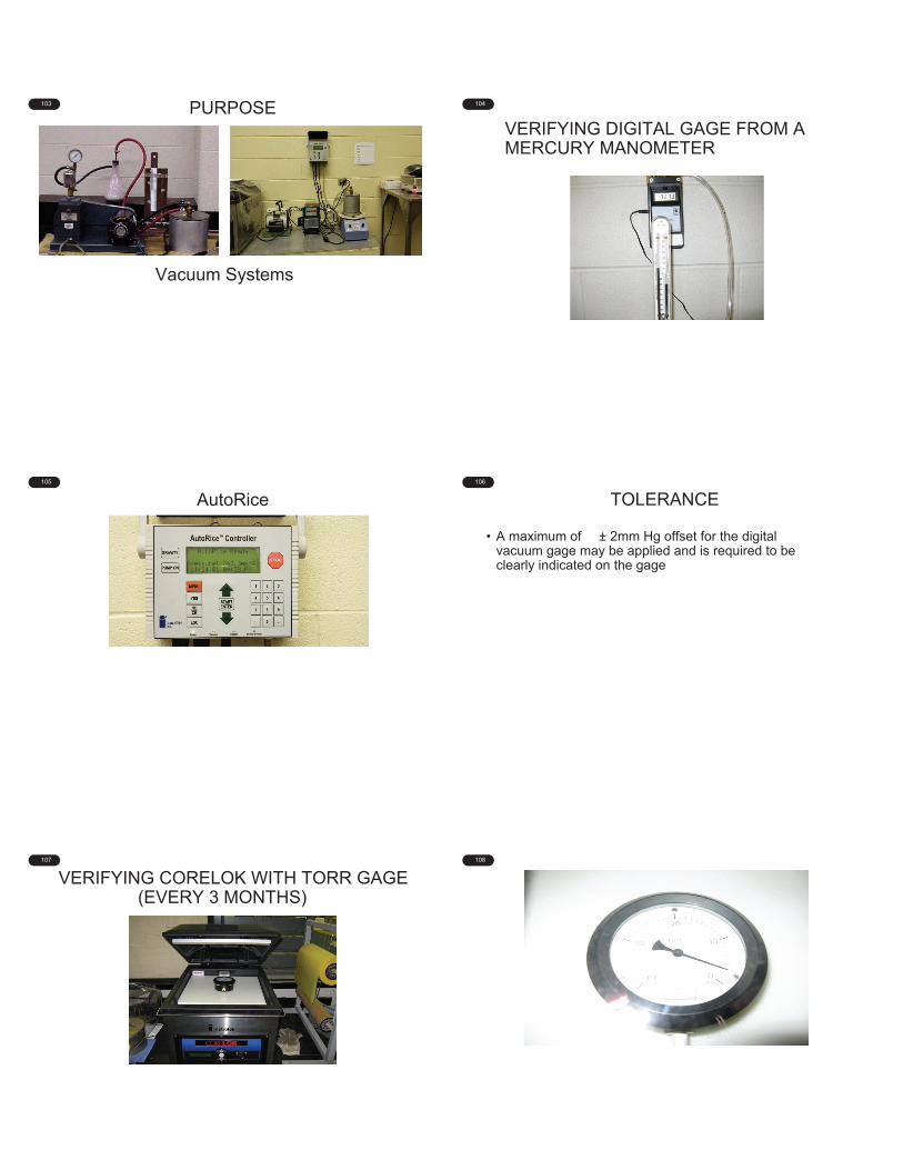
103 PURPOSE
Vacuum Systems
104
VERIFYING DIGITAL GAGE FROM A MERCURY MANOMETER
105
AutoRice106
TOLERANCE
• A maximum of ± 2mm Hg offset for the digital vacuum gage may be applied and is required to be clearly indicated on the gage
107
VERIFYING CORELOK WITH TORR GAGE(EVERY 3 MONTHS)
108

109
TOLERANCES
• The reading of the vacuum gage used for AASHTO T331 shall be 10 mm Hg (10 torr) or less
• The reading of the vacuum gage used for ITM 572 shall be 6 mm Hg (6 torr) or less
110
The remainder of the audit includes comparison
testing and the audit close-out meeting. This is
covered in Module 8C.

2/8/2021
1
1
Module 8C
Audit Close-Out
INDOT Certified Asphalt Lab Technician Program
(Chapter Six)
2
HMA Design & QC Coordinator – North
E&B Paving, Inc.
ELIZABETH PASTUSZKA
3
9. Comparison Testing• Verify the technician complies with sampling and testing
procedures.• IA comparison testing every 2 years is adequate
• Obtain sample of mixture, blended aggregate, and RAP• Sampling • Sample reduction• Gradation• Binder content of RAP• Binder content of mixture
4
Corrective Actions• Any item deemed as unsatisfactory or deficient requires a
Corrective Action Sheet with the problem and solution to resolve the corrective action stated.
• An item that occurred in the past and cannot be corrected is documented as an Observation
• An item that is has been corrected during the audit is documented as resolved
• An item that requires specific action from the Producer is documented and will need follow up from and INDOT audit team member
5
Corrective Actions
• Deadline date is two weeks maximum to resolve a Corrective Action from the date of the audit.
• Anything requiring longer than two weeks must be addressed by the DTE
6
Appendix: Testing Results Outside of Control Limits• Record the date and test value outside of the control limits
• Air Voids• Mixture Binder Content• VMA• Dust/Effective Binder Ratio• Vbe
1 2
3 4
5 6

2/8/2021
2
7
10. Audit Close-Out
• Meeting with the Producer and INDOT immediately after the audit is performed.
• The Producer shall submit any Addenda or Annex to the QCP.
• Make copies of each Corrective Action and Appendix sheet.
• Discuss any corrective actions or observations, resolutions, and deadlines.
8
10. Audit Close-Out (cont’d)
• INDOT is to follow up with the Producer on any outstanding Corrective Actions.
• INDOT reviews and addresses all Corrective Actions, comparison test results, QCP changes that were submitted during the audit, and verify that each page and item in the audit packet is complete.
9
10. Audit Close-Out (cont’d)
• The Audit Close-Out page is signed and dated by the INDOT DTE or Area Supervisor.
• All documentation from the audit should be sent to INDOT, OMM and the Producer.
10
Review
• INDOT Responsibilities prior to audit:• Familiarize yourself with the QCP • Obtain any documentation that may be helpful during the
audit• DMFs• approved lists• ITMs or other test methods, especially ITM 583 • IA Paperwork if applicable
11
Review (cont’d)
• Producer responsibilities prior to audit• Maintain Diary and daily test results• Obtain any QCP changes• Equipment Calibration/Verification• Have paperwork readily available for the audit
7 8
9 10
11
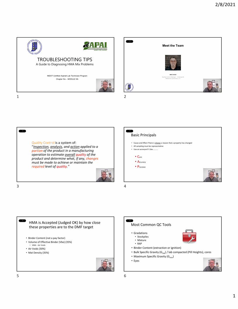
2/8/2021
1
1
TROUBLESHOOTING TIPSA Guide to Diagnosing HMA Mix Problems
INDOT Certified Asphalt Lab Technician Program
Chapter Six – MODULE 9A
2
Meet the Team
Quality Control Manager – IndianapolisMilestone Contractors, L.P.
BRAD CRUEA
3
Quality Control is a system of:“Inspection, analysis, and action applied to a portion of the product in a manufacturing operation to estimate overall quality of the product and determine what, if any, changesmust be made to achieve or maintain the required level of quality.”
4
Basic Principals
• Cause and Effect‐There is always a reason that a property has changed
• All sampling must be representative
• Use an acronym!!! Like………..
• Care
• Accuracy
• Precision
5
HMA is Accepted (Judged OK) by how close these properties are to the DMF target
• Binder Content (not a pay factor)
• Volume of Effective Binder (Vbe) (35%)• VMA – Air Voids
• Air Voids (30%)
• Mat Density (35%)
6
Most Common QC Tools
• Gradations • Stockpiles
• Mixture
• RAP
• Binder Content (extraction or ignition)
• Bulk Specific Gravity (Gmb) / lab compacted (Pill Heights), cores
• Maximum Specific Gravity (Gmm)
• Eyes
1 2
3 4
5 6

2/8/2021
2
7
General Relationships
Property Applicable Test(s)
Function of / Relative Impact
Air Voids=Gmm - Gmb / Gmm
Gmm
Binder Content /moderate
Absorption /high
Gradation / slight except when using different Aggregate w/ different Gsb
Aggr. Specific Gravity /high
Gmb Binder Content / slight
8
General Relationships
Property Applicable Test(s)
Function of / Relative Impact
VMA
Gmb
(Gsb)
Gradation / very high, especially %passing #200
Particle shape / high
Compactive effort /moderate
Aggregate strength / moderate
Binder Content / slight
9
General Relationships
Property Applicable Test(s)
Function of / Relative Impact
Vbe VMA - AV
Gradation
Binder Content
Absorption
Low Vbe – (VMA low, AV low)……
Gradation Change
High Vbe – (Vma high, AV low) or Low Vbe – (VMA low,
AV high).. Gradation and Binder Change
10
Aggregate
Binder
Air
By Volume By Mass (Unit weight)
Gsb
VMA
Gmb
5% Air
DMF
Gmm
Compacted Pills Loose Mix
By Mass (Unit weight)
11
Aggregate
% Binder ?
% Air ?
By Volume By Mass (Unit weight)
Gsb
VMA?
Gmb↑
Air?
What if, Gmb↑ & Gmm is ok ? VMA? AV? Binder?
Gmm
Compacted Pills Loose Mix
By Mass (Unit weight)
12
Aggregate
% Binder √
% Air ↓
By Volume By Mass (Unit weight)
Gsb
VMA↓
Gmb↑
Air↓
What if, Gmb↑ & Gmm is ok ? VMA? AV? Binder?
Gmm
Compacted Pills Loose Mix
By Mass (Unit weight)
7 8
9 10
11 12
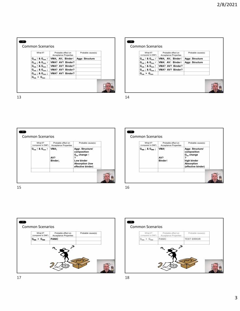
2/8/2021
3
13
Common Scenarios
What if? Probable effect on Acceptance Properties
Probable cause(s)
Gmb ↑ & Gmm √ VMA↓ AV↓ Binder√ Aggr. StructureGmb ↓ & Gmm √ VMA? AV? Binder?Gmb ↑ & Gmm ↑ VMA? AV? Binder?Gmb ↓ & Gmm ↓ VMA? AV? Binder?Gmb ↓ & Gmm ↓ VMA? AV? Binder?Gmb > Gmm
14
Common Scenarios
What if?(compared to DMF)
Probable effect on Acceptance Properties
Probable cause(s)
Gmb ↑ & Gmm √ VMA↓ AV↓ Binder√ Aggr. StructureGmb ↓ & Gmm √ VMA↑ AV↑ Binder√ Aggr. StructureGmb ↑ & Gmm ↑ VMA? AV? Binder?Gmb ↓ & Gmm ↓ VMA? AV? Binder?Gmb > Gmm
15
Common Scenarios
What if?(compared to DMF)
Probable effect on Acceptance Properties
Probable cause(s)
Gmb ↑ & Gmm ↑ VMA↓
AV? Binder↓
Aggr. Structure/ compositionGsb change ↑?Low binderAbsorption (low effective binder)
16
Common Scenarios
What if?(compared to DMF)
Probable effect on Acceptance Properties
Probable cause(s)
GMB ↓ & GMM ↓ VMA↑
AV? Binder↑
Aggr. Structure/ compositionGsb change?high binderAbsorption (effective binder)
17
Common Scenarios
What if?(compared to DMF)
Probable effect on Acceptance Properties
Probable cause(s)
GMB > GMM PANIC
18
Common Scenarios
What if?(compared to DMF)
Probable effect on Acceptance Properties
Probable cause(s)
GMB > GMM PANIC TEST ERROR
13 14
15 16
17 18
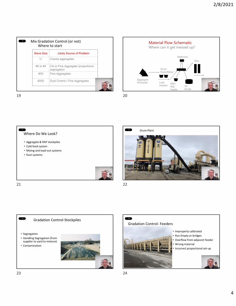
2/8/2021
4
19 Mix Gradation Control (or not)Where to start
Sieve Size Likely Source of Problem
½” Coarse aggregates
#8 or #4 CA or Fine Aggregate /proportions/ segregation
#30 Fine Aggregates
#200 Dust Control / Fine Aggregates
20
Cold Feeders
Aggregate Stockpiles RAP/
RAS Feeder
Baghouse
Drum Dryer/Mixer
Silos
Material Flow SchematicWhere can it get messed up?
PG Binder
21
Where Do We Look?
• Aggregate & RAP stockpiles
• Cold feed system
• Mixing and load‐out systems
• Dust systems
22 Drum Plant
22
23
Gradation Control‐Stockpiles
• Segregation
• Handling Segregation (from supplier to yard to mixture)
• Contamination
24
Gradation Control‐ Feeders
• Improperly calibrated
• Run Empty or bridges
• Overflow from adjacent feeder
• Wrong material
• Incorrect proportional set‐up
19 20
21 22
23 24
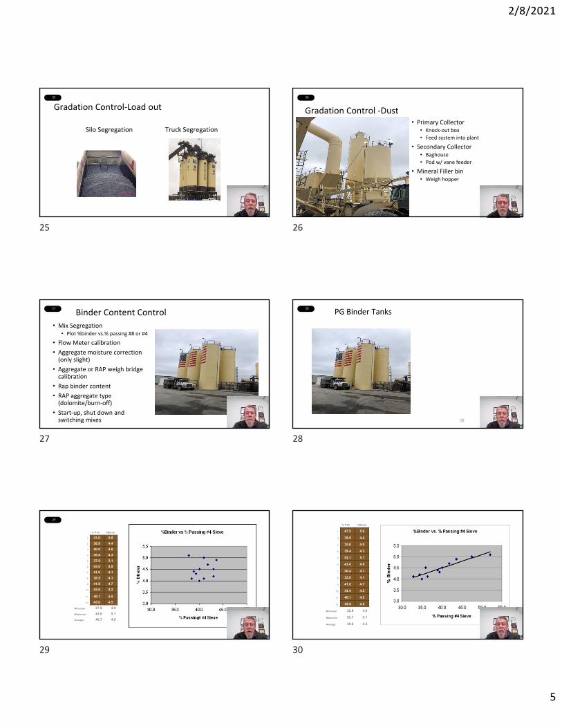
2/8/2021
5
25
Gradation Control‐Load out
Silo Segregation Truck Segregation
26
Gradation Control ‐Dust• Primary Collector
• Knock‐out box
• Feed system into plant
• Secondary Collector• Baghouse
• Pod w/ vane feeder
• Mineral Filler bin• Weigh hopper
27
Binder Content Control
• Mix Segregation• Plot %binder vs.% passing #8 or #4
• Flow Meter calibration
• Aggregate moisture correction (only slight)
• Aggregate or RAP weigh bridge calibration
• Rap binder content
• RAP aggregate type (dolomite/burn‐off)
• Start‐up, shut down and switching mixes
28
PG Binder Tanks
28
29
% P #4 %Binder
1 41.0 5.02 38.9 4.43 40.0 4.04 39.4 4.35 37.9 5.16 43.6 4.97 41.0 4.18 38.5 4.19 41.8 4.7
10 43.0 4.2
11 40.1 4.512 43.0 4.5
Minimum 37.9 4.0Maximum 43.6 5.1Average 40.7 4.5
30
% P #4 %Binder
1 47.5 5.0
2 38.9 4.4
3 35.0 4.0
4 39.4 4.3
5 52.1 5.1
6 43.6 4.9
7 36.4 4.1
8 32.8 4.1
9 41.8 4.7
10 34.4 4.2
11 40.1 4.5
12 35.9 4.5
Minimum 32.8 4.0
Maximum 52.1 5.1
Average 39.8 4.5
25 26
27 28
29 30

2/8/2021
6
31
Start out on the Right Foot
• Before you start production, check:• Stockpiles• Correct JMF input to plant• Plant calibrations (all meters and scales)• Test equipment calibration
• Communicate with your plant operator
32
Do a trial run on new JMF before starting major production
• 100± tons
• Don’t sample first or last load
• Possibly place on commercial project
• Cost of trial vs. cost of failure of removal
33
Tips
• Retest to verify results as needed
• Eliminate the obvious first (save time)
• Be careful not to overreact
• Keep track of all your changes so you can find patterns. Where you’ve been helps determine where to go.
• Gather as much data as you can before making decisions
34
THE BEGINNING ‐GOOD LUCK!
31 32
33 34

2/8/2021
1
ETHICS
Module 9B THE BACKBONE OF SUCCESSFUL COMPANIES
Meet the Team
Quality Control Manager – IndianapolisMilestone Contractors, L.P.
BRAD CRUEA
Merriam‐Webster’s Meaning
1. The discipline dealing with what is good and bad and with moral duty and obligation!
2. The principles of conduct governing an individual or a group!
ETHICS AND QUALITY CONTROL
•Why is it necessary for the QC department to be the leader on
Ethics at every company?
•LET’S TRY TO ANSWER THE WHY!
ETHICS
•Your Commitment…
Commitment• QUALITY should only be second to SAFETY
• QUALITY should be a vital part of your company’s culture:
• It reflects who you are and
• It reflects what you do.
1 2
3 4
5 6

2/8/2021
2
Commitment
• The QUALITY of your products should not be sacrificed to reach production goals
• Poor materials or construction will be evident, possibly leading to:• Removal and replacement of materials• Losing your customers
• Your company’s reputation is at stake!
Commitment
• Providing our customers with QUALITY products is a team effort:• Production, Quality Control and Construction
• EACH person on the team plays a role in QUALITY and shares in the responsibility of customer satisfaction
Commitment
• INTEGRITY begins with each team member
• Do the right thing all the time, not just when it’s convenient or when someone is watching
• When we collectively make and execute the right decisions, your company will be viewed as having a reputation of INTEGRITY
Commitment• As part of this course, let’s work together in keeping QUALITY and
INTEGRITY at a high level for your company
• Carry this mindset to your teammates…..support each other
• And hold each other accountable
Summary
1. Ensure mix sent to ANY job is in accordance with the customer’s specifications
2. Make ethics part of your company’s culture
3. Earn and build trust with you customers
4. Don’t sacrifice quality for quantity
5. Every team member is responsible for quality
6.Do the right thing….ALWAYSTHANK YOU and GOOD LUCK!
7 8
9 10
11 12
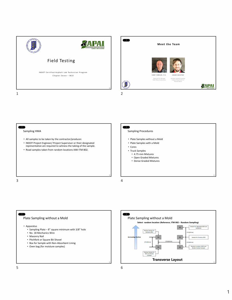
1
1
Field Testing
I N D O T C e r t i f i e d A s p h a l t L a b Te c h n i c i a n P r o g r a m
C h a p t e r S e v e n – M 1 0
2
Meet the Team
Regional QC ManagerRieth-Riley Construction
C O D Y F O W L E R , P . E .
Assistant Asphalt EngineerIndiana Department of
Transportation
J A S O N G A L E T K A
3
Sampling HMA
• All samples to be taken by the contractor/producer.
• INDOT Project Engineer/ Project Supervisor or their designated representative are required to witness the taking of the sample.
• Road samples taken from random locations IAW ITM 802.
4
Sampling Procedures
• Plate Samples without a Mold
• Plate Samples with a Mold
• Cores
• Truck Samples
• 4.75 mm Mixtures
• Open Graded Mixtures
• Dense Graded Mixtures
5
Plate Sampling without a Mold
• Apparatus
• Sampling Plate – 8” square minimum with 3/8” hole
• No. 18 Mechanics Wire
• Masonry Nail
• Pitchfork or Square Bit Shovel
• Box for Sample with Non‐Absorbent Lining
• Oven bag (for moisture samples)
6
Plate Sampling without a MoldSelect random location (Reference, ITM 802 – Random Sampling)
Transverse Layout
1 2
3 4
5 6
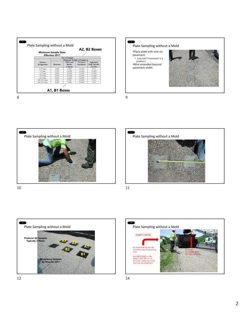
2
8
Plate Sampling without a MoldA2, B2 Boxes
A1, B1 Boxes
Minimum Sample SizesEffective 2017
9
Plate Sampling without a Mold
•Place plate with wire on pavement.
• (Use nail if movement is a problem.)
•Wire extended beyond pavement width.
10
Plate Sampling without a Mold
11
Plate Sampling without a Mold
12
Plate Sampling without a Mold
A1A3
B1B2
Acceptance SamplesA3 New for 2017
Producer QC SamplesTypically 2 Plates A2
14
Plate Sampling without a Mold
QC Technician (on far left) out of the way of the paving crew.
ALL EMPLOYEES on the project wear PPE (Hi-vis shirt/vest, safety-toe boots, hard hat, eye protection)
SAFETY NOTE!
No longer acceptable. Must also wear hard hat.
8 9
10 11
12 14

3
15
Plate Sampling without a Mold
Use wire to locate plate
16
Plate Sampling without a Mold
Use shovel to lift plate and sample
17
Plate Sampling without a Mold
Place entire sample in box.
HOT STUFF! = WEAR GLOVES!
18
Plate Sampling without a Mold
•Check sample weight or use tables in ITM-580 to estimate the weight.•Be sure sample is properly identified.
19
Plate Sampling without a Mold
Refill sample hole with HMA.
20
Sampling Procedures
• Plate Samples without a Mold
• Plate Samples with a Mold
• Cores
• Truck Samples
• 4.75 mm Mixtures
• Open Graded Mixtures
• Dense Graded Mixtures
15 16
17 18
19 20
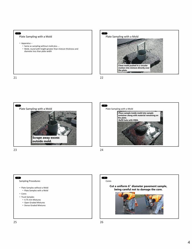
4
21
Plate Sampling with a Mold
• Apparatus ‐‐
• Same as sampling without mold plus ...
• Mold, round with height greater than mixture thickness and diameter less than plate width
22
Plate Sampling with a Mold
Clean mold pushed in a circular motion into mixture directly over the plate.
23
Plate Sampling with a Mold
Scrape away excess outside mold.
24
Plate Sampling with a Mold
•Place sample inside mold into sample container along with material remaining on the plate.•Refill hole with HMA.
25
Sampling Procedures
• Plate Samples without a Mold
• Plate Samples with a Mold
• Cores
• Truck Samples
• 4.75 mm Mixtures
• Open Graded Mixtures
• Dense Graded Mixtures
26
Cores
Cut a uniform 6” diameter pavement sample, being careful not to damage the core.
21 22
23 24
25 26
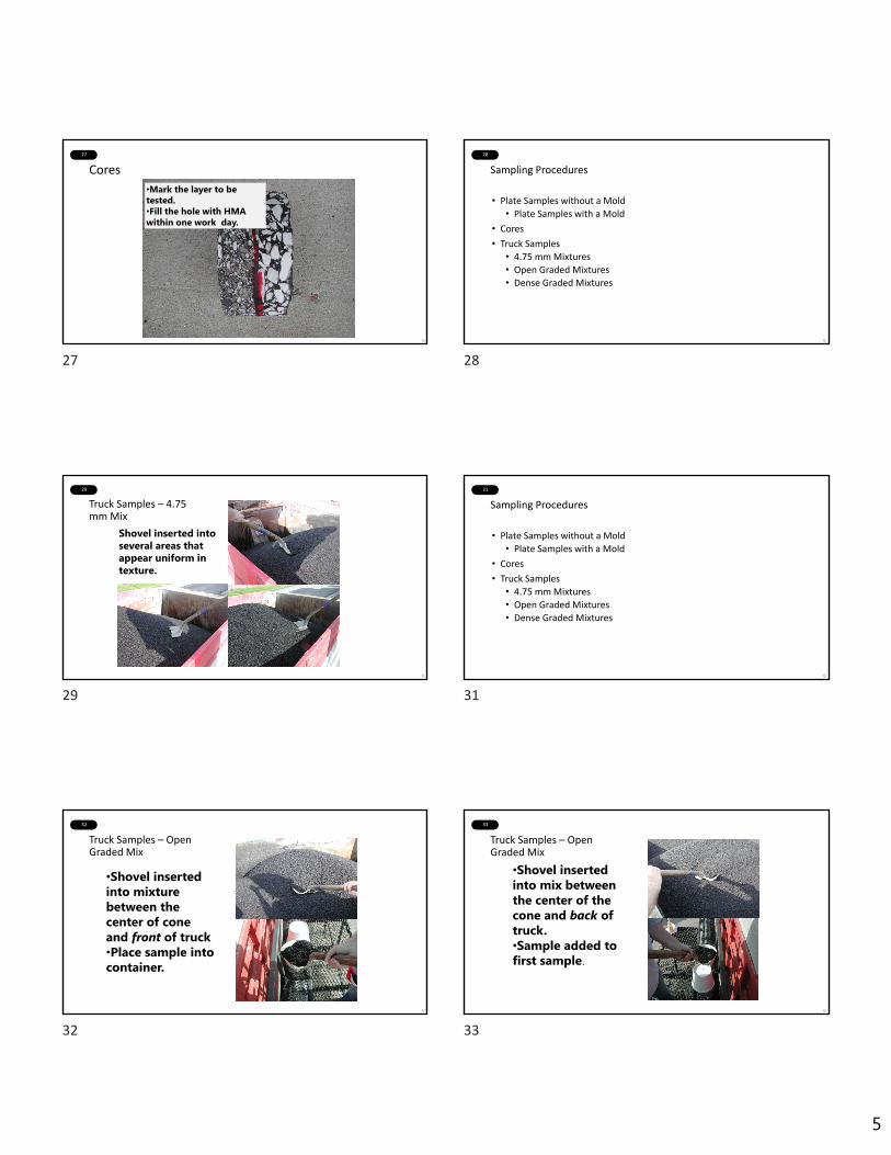
5
27
Cores
•Mark the layer to be tested.•Fill the hole with HMA within one work day.
28
Sampling Procedures
• Plate Samples without a Mold
• Plate Samples with a Mold
• Cores
• Truck Samples
• 4.75 mm Mixtures
• Open Graded Mixtures
• Dense Graded Mixtures
29
Truck Samples – 4.75 mm Mix
Shovel inserted into several areas that appear uniform in texture.
31
Sampling Procedures
• Plate Samples without a Mold
• Plate Samples with a Mold
• Cores
• Truck Samples
• 4.75 mm Mixtures
• Open Graded Mixtures
• Dense Graded Mixtures
32
Truck Samples – Open Graded Mix
•Shovel inserted into mixture between the center of cone and front of truck•Place sample into container.
33
Truck Samples – Open Graded Mix
•Shovel inserted into mix between the center of the cone and back of truck.•Sample added to first sample.
27 28
29 31
32 33
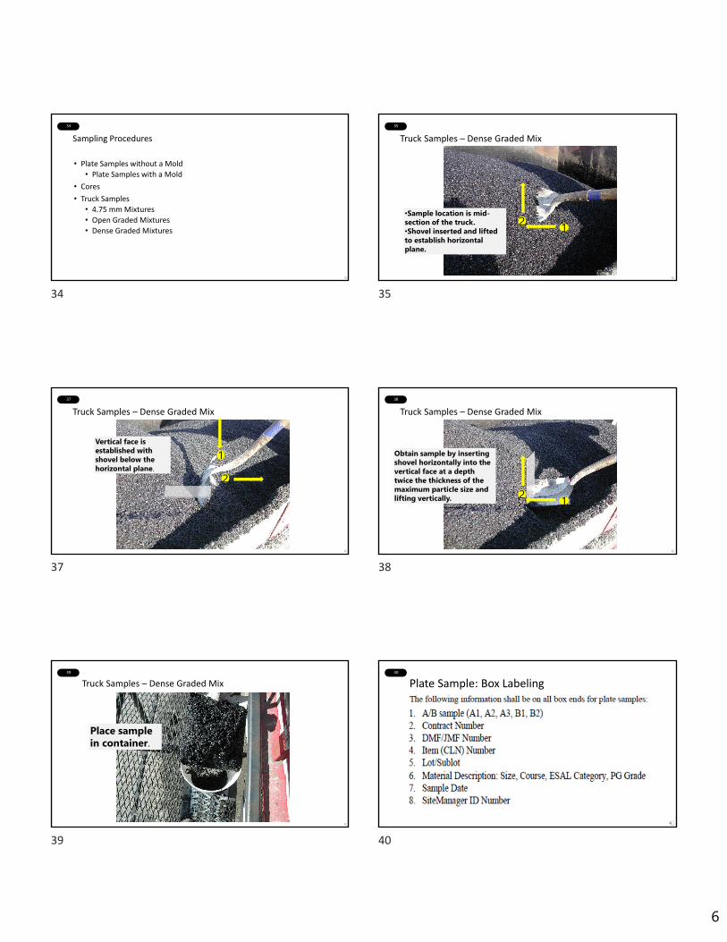
6
34
Sampling Procedures
• Plate Samples without a Mold
• Plate Samples with a Mold
• Cores
• Truck Samples
• 4.75 mm Mixtures
• Open Graded Mixtures
• Dense Graded Mixtures
35
Truck Samples – Dense Graded Mix
•Sample location is mid-section of the truck.•Shovel inserted and lifted to establish horizontal plane.
12
37
Truck Samples – Dense Graded Mix
Vertical face is established with shovel below the horizontal plane.
12
38
Truck Samples – Dense Graded Mix
Obtain sample by inserting shovel horizontally into the vertical face at a depth twice the thickness of the maximum particle size and lifting vertically. 12
39
Truck Samples – Dense Graded Mix
Place sample in container.
40
Plate Sample: Box Labeling
34 35
37 38
39 40

7
41
Plate Sample: Box Label Example
Box: ______ Sample ID:__________________________:Contract
Material (Size & Course): _________________________:CLN
(Item No.)Sample Wt: __________________Sample Date: ______
INDOT Signature: _________________________ :DMF
Lot/Sublot: ______ Contractor Signature: __________________
42
Pavement Smoothness (SS401.18)• Smoothness of pavement affects
• Public safety – vehicles are more controllable
• Ride quality
• Pavement longevity? Yes! A smooth road does not suffer point‐load impacts.
• How do we monitor smoothness?
• 16 foot or 10 foot straight edge
• Profilograph
• Inertial Profiler
43
Straight Edge44
Profilograph – ITM912
Video in next slide courtesy of AZ Dept. of Trans. https://youtu.be/wyGCpzhh6uA
45
Inertial Profiler – ITM 917
45
46
Sampling HMA
QUESTIONS ?
41 42
43 44
45 46

2/8/2021
1
1
M11 QC/QA Program and Asphalt Acceptance
I N D O T C e r t i f i e d A s p h a l t L a b Te c h n i c i a n P r o g r a m
C h a p t e r S e v e n
2
Meet the Team
Asphalt EngineerIndiana Department of Transportation
N A T H A N A W W A D , P E
3
Design Mix Formulas (DMFs)• Shall be in accordance with 401.05, 402.05 or
410.05
• DMFs must come from an INDOT Approved Mix Design Laboratory
• All mix must be produced at an INDOT Certified HMA Plant
• Online system “DMF ENTRY”
4
5 6
3 Main HMA Specifications401 ‐‐ QC/QA HMA
Dense GradedOpen Graded
402 – HMA
410 – QC/QA HMA , Stone Matrix Asphalt
1 2
3 4
5 6
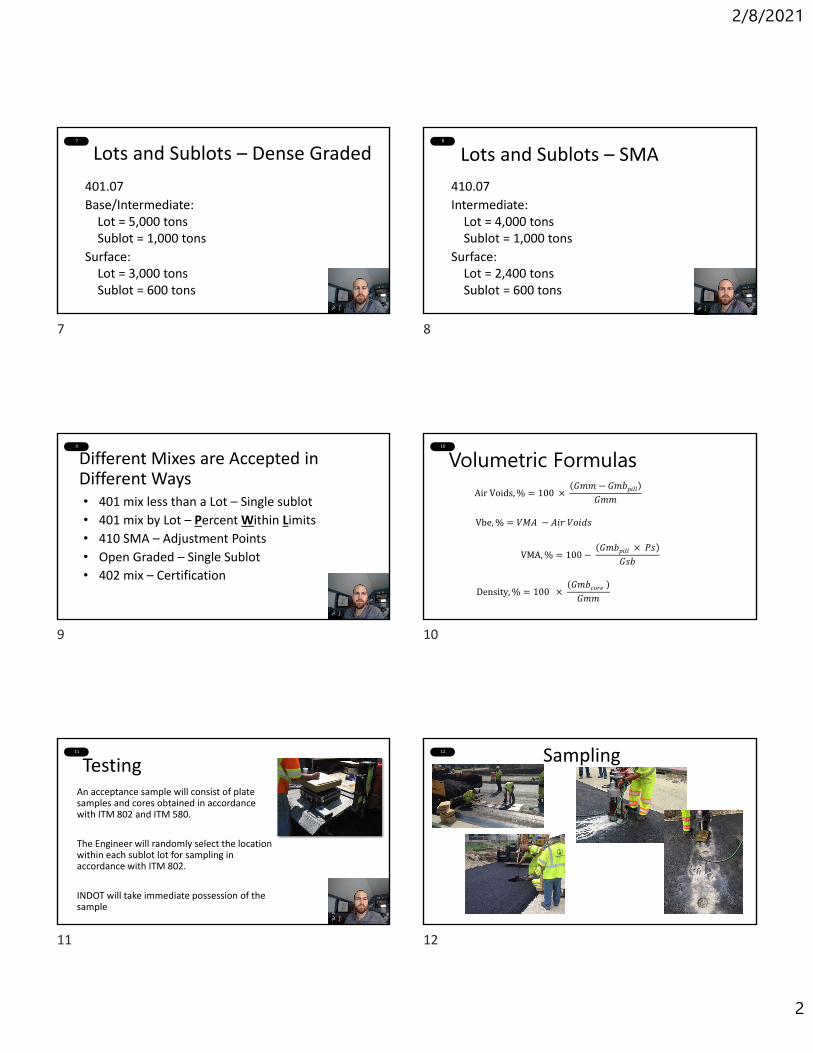
2/8/2021
2
7
Lots and Sublots – Dense Graded
401.07
Base/Intermediate:Lot = 5,000 tonsSublot = 1,000 tons
Surface:Lot = 3,000 tonsSublot = 600 tons
8
Lots and Sublots – SMA
410.07
Intermediate:Lot = 4,000 tonsSublot = 1,000 tons
Surface:Lot = 2,400 tonsSublot = 600 tons
9
Different Mixes are Accepted in Different Ways• 401 mix less than a Lot – Single sublot
• 401 mix by Lot – Percent Within Limits
• 410 SMA – Adjustment Points
• Open Graded – Single Sublot
• 402 mix – Certification
10
Volumetric FormulasAir Voids, % 100
𝐺𝑚𝑚 𝐺𝑚𝑏𝑝𝑖𝑙𝑙𝐺𝑚𝑚
VMA, % 100 𝐺𝑚𝑏𝑝𝑖𝑙𝑙 𝑃𝑠
𝐺𝑠𝑏
Density, % 100 𝐺𝑚𝑏𝑐𝑜𝑟𝑒 𝐺𝑚𝑚
Vbe, % 𝑉𝑀𝐴 𝐴𝑖𝑟 𝑉𝑜𝑖𝑑𝑠
11
TestingAn acceptance sample will consist of plate samples and cores obtained in accordance with ITM 802 and ITM 580.
The Engineer will randomly select the location within each sublot lot for sampling in accordance with ITM 802.
INDOT will take immediate possession of the sample
12 Sampling
7 8
9 10
11 12
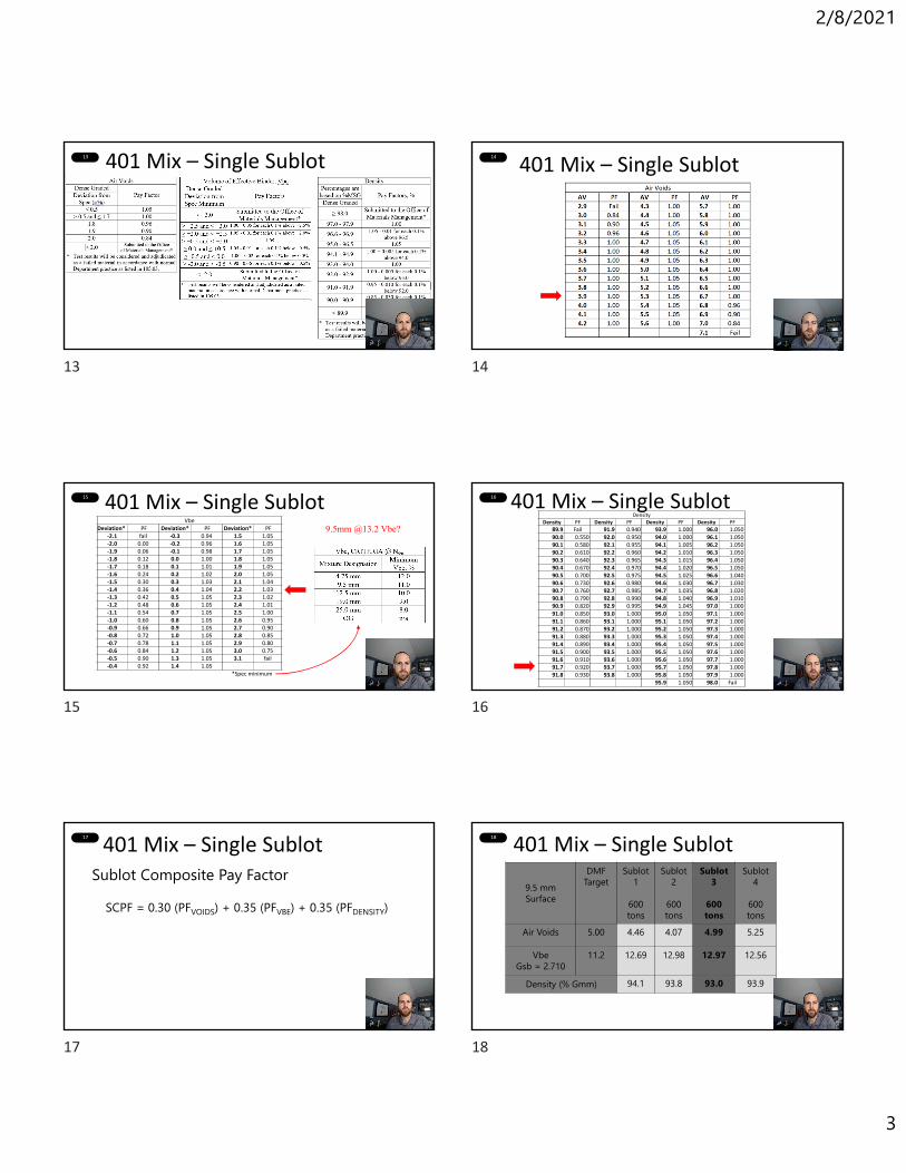
2/8/2021
3
13 401 Mix – Single Sublot 14
401 Mix – Single Sublot
15 401 Mix – Single SublotVbe
Deviation* PF Deviation* PF Deviation* PF ‐2.1 fail ‐0.3 0.94 1.5 1.05‐2.0 0.00 ‐0.2 0.96 1.6 1.05‐1.9 0.06 ‐0.1 0.98 1.7 1.05‐1.8 0.12 0.0 1.00 1.8 1.05‐1.7 0.18 0.1 1.01 1.9 1.05‐1.6 0.24 0.2 1.02 2.0 1.05‐1.5 0.30 0.3 1.03 2.1 1.04‐1.4 0.36 0.4 1.04 2.2 1.03‐1.3 0.42 0.5 1.05 2.3 1.02‐1.2 0.48 0.6 1.05 2.4 1.01‐1.1 0.54 0.7 1.05 2.5 1.00‐1.0 0.60 0.8 1.05 2.6 0.95‐0.9 0.66 0.9 1.05 2.7 0.90‐0.8 0.72 1.0 1.05 2.8 0.85‐0.7 0.78 1.1 1.05 2.9 0.80‐0.6 0.84 1.2 1.05 3.0 0.75‐0.5 0.90 1.3 1.05 3.1 fail‐0.4 0.92 1.4 1.05
*Spec minimum
9.5mm @13.2 Vbe?
16 401 Mix – Single SublotDensity
Density PF Density PF Density PF Density PF
89.9 Fail 91.9 0.940 93.9 1.000 96.0 1.050 90.0 0.550 92.0 0.950 94.0 1.000 96.1 1.050 90.1 0.580 92.1 0.955 94.1 1.005 96.2 1.050 90.2 0.610 92.2 0.960 94.2 1.010 96.3 1.050 90.3 0.640 92.3 0.965 94.3 1.015 96.4 1.050 90.4 0.670 92.4 0.970 94.4 1.020 96.5 1.050 90.5 0.700 92.5 0.975 94.5 1.025 96.6 1.040 90.6 0.730 92.6 0.980 94.6 1.030 96.7 1.030 90.7 0.760 92.7 0.985 94.7 1.035 96.8 1.020 90.8 0.790 92.8 0.990 94.8 1.040 96.9 1.010 90.9 0.820 92.9 0.995 94.9 1.045 97.0 1.000 91.0 0.850 93.0 1.000 95.0 1.050 97.1 1.000 91.1 0.860 93.1 1.000 95.1 1.050 97.2 1.000 91.2 0.870 93.2 1.000 95.2 1.050 97.3 1.000 91.3 0.880 93.3 1.000 95.3 1.050 97.4 1.000 91.4 0.890 93.4 1.000 95.4 1.050 97.5 1.000 91.5 0.900 93.5 1.000 95.5 1.050 97.6 1.000 91.6 0.910 93.6 1.000 95.6 1.050 97.7 1.000 91.7 0.920 93.7 1.000 95.7 1.050 97.8 1.000 91.8 0.930 93.8 1.000 95.8 1.050 97.9 1.000
95.9 1.050 98.0 Fail
17
401 Mix – Single Sublot
SCPF = 0.30 (PFVOIDS) + 0.35 (PFVBE) + 0.35 (PFDENSITY)
Sublot Composite Pay Factor
18
401 Mix – Single Sublot
9.5 mm Surface
DMF Target
Sublot 1
600 tons
Sublot 2
600 tons
Sublot 3
600 tons
Sublot4
600 tons
Air Voids 5.00 4.46 4.07 4.99 5.25
VbeGsb = 2.710
11.2 12.69 12.98 12.97 12.56
Density (% Gmm) 94.1 93.8 93.0 93.9
13 14
15 16
17 18

2/8/2021
4
19 401 Mix – Single Sublot
SCPF = 0.30 ( ) + 0.35 ( ) + 0.35 ( )
Sublot Composite Pay Factor
1.05 1.05 1.00
9.5 mm Surface
Sublot 3
600 tons
AV 4.99
Vbe 12.97
Density %
93.0
SCPF = 0.30 (PFVOIDS) + 0.35 (PFVBE) + 0.35 (PFDENSITY)
SCPF = 1.033 SCPF = 1.03
20 401 Mix – Single Sublot
QA Adjustment ($) = L x U x (SCPF – 1.00) / MAFL = Sublot QuantityU = Unit PriceSCPF = Sublot Composite Pay FactorMAF = Mixture Adjustment Factor ?
21 401 Mix – Single Sublot
MAFi = ( / ) =
MAFi > 1.020 MAF = MAFi – 0.0200.980 ≤ MAFi ≤ 1.020 MAF = 1.000
MAFi < 0.980 MAF = MAFi + 0.020
MAFi = DMF Gmm ÷2.465 for 9.5 mm2.500 for all else
DMF Gmm = 2.544
2.544 2.465 1.032
MAF = ( ) - 0.020 = 1.032 1.012
22 401 Mix – Single SublotQA Adjustment ($) = L x U x (SCPF – 1.00) / MAF
L = Sublot QuantityU = Unit PriceSCPF = Sublot Composite Pay FactorMAF = Mixture Adjustment Factor
QA ($) = 600.00ton x $74.00/ton x (1.03 – 1.00) / 1.012QA ($) = + $1,316.21
QA ($) = + $1,332.00(No MAF)
23
Benefits• A more discerning quality measure:• Captures the mean and standard deviation• Encourages Uniformity
401 Mix – Percent-Within-Limits (By Lots)
• Estimates the percentage of material within specification limits
• Assumes normal distribution
Quality Measure
24
Air Voids, % 100 𝐺𝑚𝑚 𝐺𝑚𝑏𝑝𝑖𝑙𝑙
𝐺𝑚𝑚
VMA, % 100 𝐺𝑚𝑏𝑝𝑖𝑙𝑙 𝑃𝑠
𝐺𝑠𝑏
Density, % 100 𝐺𝑚𝑏𝑐𝑜𝑟𝑒 𝐺𝑚𝑚
401 Mix – PWL (By Lots)
Average,
Standard Deviation,
n
xx
n
ii
1
11
2
n
xxs
n
ii
Vbe, % 𝑉𝑀𝐴 𝐴𝑖𝑟 𝑉𝑜𝑖𝑑𝑠
19 20
21 22
23 24

2/8/2021
5
25
Example Problem
9.5.5 mm Surface$74.00 / ton
3000 tons 5 - 600 ton sublots
MAF = 1.012
401 Mix – PWL (By Lots) 26
401 Mix – PWL (By Lots)
Lower Spec Limit LSL Upper Spec Limit USL
Air Voids @ Ndes, % 3.60 6.40
Vbe @ Ndes, %Spec Spec + 2.50
+ 2.50
Core Density, % Gmm
93.00 Not Applicable
11.00 11.0013.5
401.19 Specification Limits
27 401 Mix – PWL (By Lots)9.5 mm Surface
DMF Target
Sublot 1
600 tons
Sublot 2
600 tons
Sublot 3
600 tons
Sublot 4
600 tons
Sublot 5
600 tons
S
Air Voids 5.00 4.46 4.07 4.99 5.25 7.36 5.23 1.28
VbeGsb = 2.710
11.20 12.69 12.98 12.97 12.56 11.59 12.56 0.57
Density (% Gmm)92.48 93.02 92.66 93.36 89.32
93.38 1.8095.78 94.53 93.18 94.35 95.13
x
28
401 Mix – PWL (By Lots)
9.5 mm Surface s
QU QL TotalPWLUSL PWL
ULSL PWLL
Air Voidsn = 5
5.23 1.286.40 3.60
Vben = 5 12.56 0.57 13.5 11.0
Density(% Gmm)n = 10
93.38 1.80 93.0
xs
xUSLQU
s
LSLxQL
29
401 Mix – PWL (By Lots)
9.5 mm Surface s
QU QL TotalPWLUSL PWLU LSL PWLL
Air Voidsn = 5
5.23 1.286.40 0.91 81 3.60 1.27 91 72
Vben = 5 12.56 0.57 13.5 1.65 99 11.0 2.74 100 99
Density(% Gmm)n = 10
93.38 1.80 93.0 0.21 58 58
xs
xUSLQU
s
LSLxQL
30
401 Mix – PWL (By Lots)
Air Voids Vbe DensityLCPF QA
AdjustmentPWL = 97 PWL = 100 PWL = 100
PF 0.30 x PF PF 0.35 x PF PF 0.35 x PF
25 26
27 28
29 30
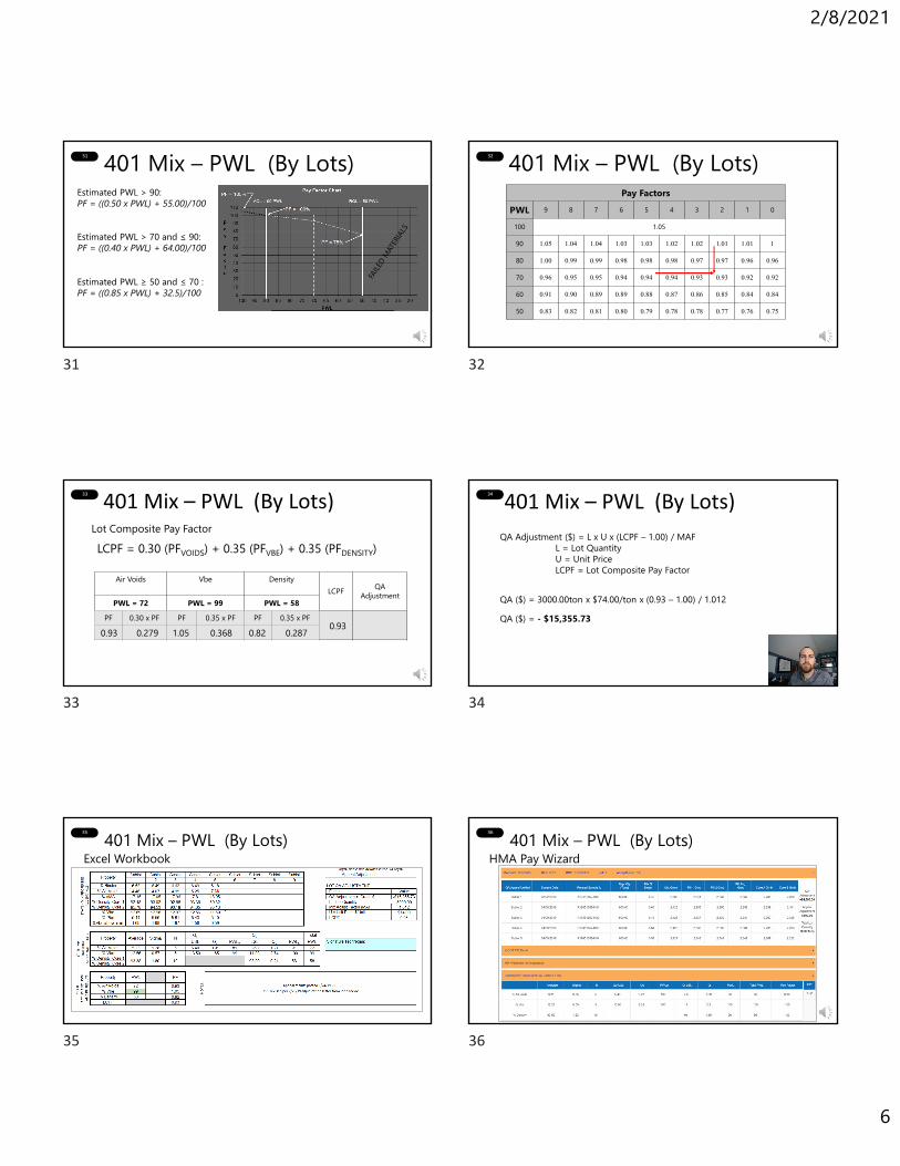
2/8/2021
6
31 401 Mix – PWL (By Lots)Estimated PWL > 90: PF = ((0.50 x PWL) + 55.00)/100
Estimated PWL ≥ 50 and ≤ 70 : PF = ((0.85 x PWL) + 32.5)/100
Estimated PWL > 70 and ≤ 90: PF = ((0.40 x PWL) + 64.00)/100
32
Pay FactorsPWL 9 8 7 6 5 4 3 2 1 0
100 1.05
90 1.05 1.04 1.04 1.03 1.03 1.02 1.02 1.01 1.01 1
80 1.00 0.99 0.99 0.98 0.98 0.98 0.97 0.97 0.96 0.96
70 0.96 0.95 0.95 0.94 0.94 0.94 0.93 0.93 0.92 0.92
60 0.91 0.90 0.89 0.89 0.88 0.87 0.86 0.85 0.84 0.84
50 0.83 0.82 0.81 0.80 0.79 0.78 0.78 0.77 0.76 0.75
401 Mix – PWL (By Lots)
33
401 Mix – PWL (By Lots)
LCPF = 0.30 (PFVOIDS) + 0.35 (PFVBE) + 0.35 (PFDENSITY)Lot Composite Pay Factor
Air Voids Vbe DensityLCPF QA
AdjustmentPWL = 72 PWL = 99 PWL = 58
PF 0.30 x PF PF 0.35 x PF PF 0.35 x PF0.93 1.05 0.820.279 0.368 0.287 0.93
34
401 Mix – PWL (By Lots)
QA Adjustment ($) = L x U x (LCPF – 1.00) / MAFL = Lot QuantityU = Unit PriceLCPF = Lot Composite Pay Factor
QA ($) = 3000.00ton x $74.00/ton x (0.93 – 1.00) / 1.012QA ($) = - $15,355.73
35
Excel Workbook401 Mix – PWL (By Lots) 36
HMA Pay Wizard401 Mix – PWL (By Lots)
31 32
33 34
35 36
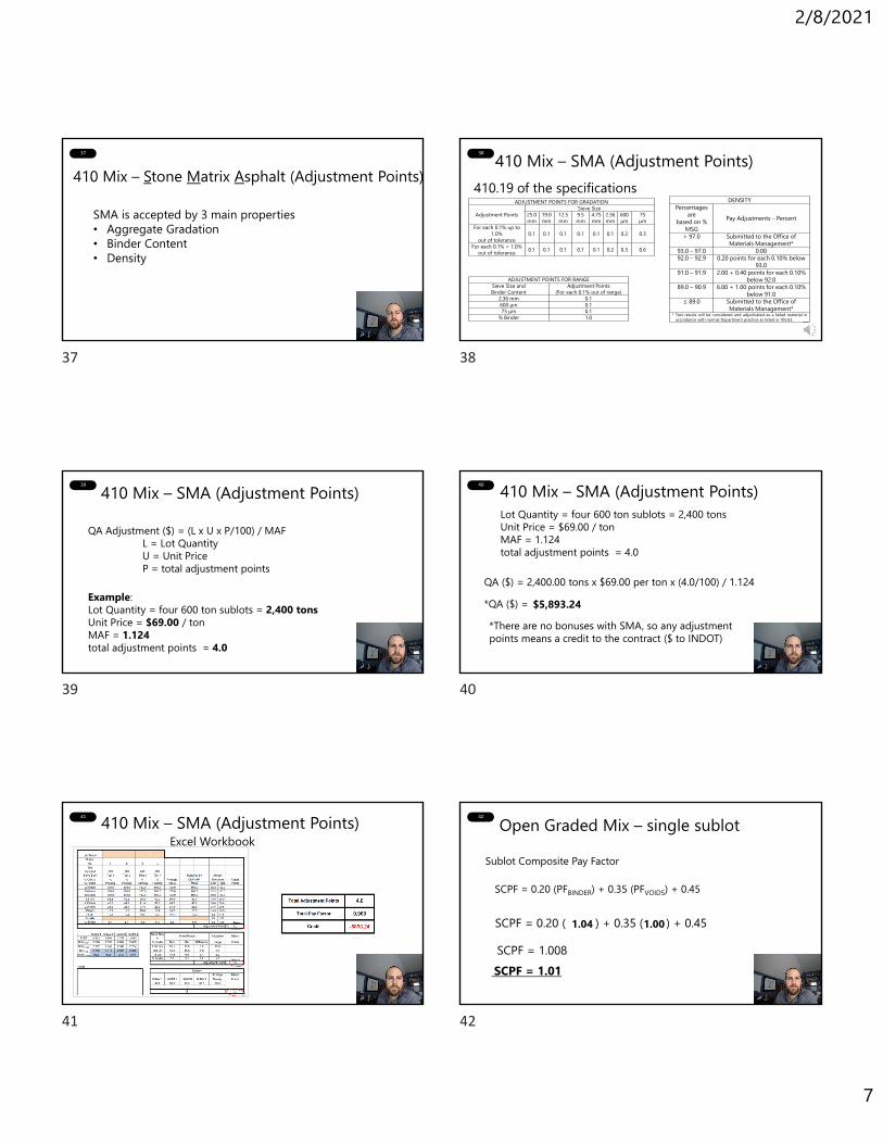
2/8/2021
7
37
410 Mix – Stone Matrix Asphalt (Adjustment Points)
SMA is accepted by 3 main properties• Aggregate Gradation• Binder Content• Density
38 410 Mix – SMA (Adjustment Points)
ADJUSTMENT POINTS FOR GRADATION
Adjustment PointsSieve Size
25.0mm
19.0mm
12.5mm
9.5mm
4.75mm
2.36mm
600µm
75µm
For each 0.1% up to 1.0%
out of tolerance0.1 0.1 0.1 0.1 0.1 0.1 0.2 0.3
For each 0.1% > 1.0%out of tolerance 0.1 0.1 0.1 0.1 0.1 0.2 0.3 0.6
ADJUSTMENT POINTS FOR RANGESieve Size andBinder Content
Adjustment Points(For each 0.1% out of range)
2.36 mm 0.1600 µm 0.175 µm 0.1
% Binder 1.0
DENSITYPercentages
are based on %
MSGPay Adjustments – Percent
> 97.0 Submitted to the Office of Materials Management*
93.0 – 97.0 0.0092.0 – 92.9 0.20 points for each 0.10% below
93.091.0 – 91.9 2.00 + 0.40 points for each 0.10%
below 92.089.0 – 90.9 6.00 + 1.00 points for each 0.10%
below 91.0≤ 89.0 Submitted to the Office of
Materials Management** Test results will be considered and adjudicated as a failed material in
accordance with normal Department practice as listed in 105.03.
410.19 of the specifications
39 410 Mix – SMA (Adjustment Points)
QA Adjustment ($) = (L x U x P/100) / MAFL = Lot QuantityU = Unit PriceP = total adjustment points
Example:Lot Quantity = four 600 ton sublots = 2,400 tonsUnit Price = $69.00 / tonMAF = 1.124total adjustment points = 4.0
40 410 Mix – SMA (Adjustment Points)
QA ($) = 2,400.00 tons x $69.00 per ton x (4.0/100) / 1.124*QA ($) = $5,893.24*There are no bonuses with SMA, so any adjustment points means a credit to the contract ($ to INDOT)
Lot Quantity = four 600 ton sublots = 2,400 tonsUnit Price = $69.00 / tonMAF = 1.124total adjustment points = 4.0
41 410 Mix – SMA (Adjustment Points)Excel Workbook
42 Open Graded Mix – single sublot
SCPF = 0.20 ( ) + 0.35 ( ) + 0.45
Sublot Composite Pay Factor
1.04 1.00
SCPF = 0.20 (PFBINDER) + 0.35 (PFVOIDS) + 0.45
SCPF = 1.008SCPF = 1.01
37 38
39 40
41 42
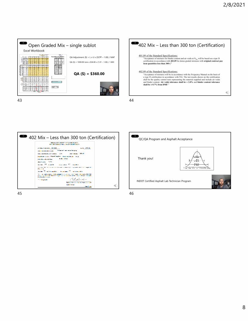
2/8/2021
8
43 Open Graded Mix – single sublotExcel Workbook
QA Adjustment ($) = L x U x (SCPF – 1.00) / MAF
QA ($) = 1000.00 tons x $36.00 x (1.01 – 1.00) / 1.000
QA ($) = $360.00
44 402 Mix – Less than 300 ton (Certification)
“Acceptance of mixtures for binder content and air voids at Ndes will be based on a type D certification in accordance with 402.09 for dense graded mixtures with original contract pay item quantities less than 300 t.”
401.09 of the Standard Specifications:
“Acceptance of mixtures will be in accordance with the Frequency Manual on the basis ofa type D certification in accordance with 916. The test results shown on the certificationshall be the quality control tests representing the material supplied and include air voidsand binder content. Air voids tolerance shall be ± 2.0% and binder content toleranceshall be ± 0.7% from DMF.”
402.09 of the Standard Specifications:
45 402 Mix – Less than 300 ton (Certification)
5.0 5.7
2.0
46
Thank you!
INDOT Certified Asphalt Lab Technician Program
QC/QA Program and Asphalt Acceptance
43 44
45 46

CHAPTER 1INTRODUCTION

1-1
CHAPTER 1 INTRODUCTION
SAFETY
FIRE HAZARDS
PERSONAL PROTECTIVE EQUIPMENT
FIRST AID
ASPHALT SAFETY REMINDERS
TERMINOLOGY ROUNDING MEAN STANDARD DEVIATION VOLUMETRICS
1-2
CHAPTER 1 INTRODUCTION
Welcome! If you are reading this, you are involved in the production, inspection, or testing of Hot Mix Asphalt in the State of Indiana. You may work for a Contractor, a Consultant, INDOT, or a local agency, but no matter who you work for, you are all integral to delivering quality Hot Mix Asphalt to the taxpayers and customers of Indiana.
The INDOT Certified Asphalt Lab Technician Program consists of a course and exam which will provide a basic background to the production of Hot Mix Asphalt and the materials that go into HMA, as well as the testing of HMA and INDOT specifications. The program is designed to target testing lab technicians in a Contractor Quality Control lab, but concepts learned will apply to all attendees.
This program began in 1986 as a way to train Contractor personnel who were required to begin testing their own materials. Up until that point, INDOT would design the mixtures, help set up the plant, test the mixtures, and then if test results were failing, would penalize the Contractor. To allocate the responsibility for Quality properly, INDOT went to a QC/QA model to test and accept Hot Mix Asphalt.
Quality Control/Quality Assurance (QC/QA) is often used synonymously with the term Quality Assurance (QA). AASHTO defines Quality Assurance as "All those planned and systematic actions necessary to provide confidence that a product will perform satisfactorily in service." This definition considers QA to be an all encompassing concept which includes quality control (QC), acceptance, and independent assurance (IA).
A better understanding of the QC/QA concept may be made if the characteristics of the specifications are considered. These include:
1. QC/QA recognizes the variation in materials and test methods. 2. QC/QA uses a statistical basis that is applied and modified with experience and sound
engineering judgement. 3. QC/QA places the primary responsibility on the Contractor for production control. 4. QC/QA makes a clear delineation between process control and acceptance testing.
The advantages of this type of specification include the proper allocation of responsibility for quality between the Contractor and INDOT, more complete records, and statistically based acceptance decisions. The Contractor has a greater choice of materials and may design the most economical mixtures to meet specifications. Finally, acceptance test results are provided upon completion of the tests during the contract so that the Contractor knows if the operations are producing a quality product.
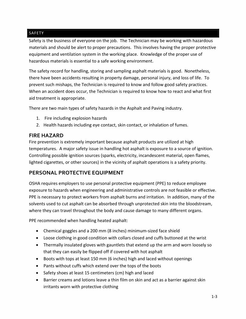
1-3
SAFETY
Safety is the business of everyone on the job. The Technician may be working with hazardous materials and should be alert to proper precautions. This involves having the proper protective equipment and ventilation system in the working place. Knowledge of the proper use of hazardous materials is essential to a safe working environment.
The safety record for handling, storing and sampling asphalt materials is good. Nonetheless, there have been accidents resulting in property damage, personal injury, and loss of life. To prevent such mishaps, the Technician is required to know and follow good safety practices. When an accident does occur, the Technician is required to know how to react and what first aid treatment is appropriate.
There are two main types of safety hazards in the Asphalt and Paving industry.
1. Fire including explosion hazards 2. Health hazards including eye contact, skin contact, or inhalation of fumes.
FIRE HAZARD Fire prevention is extremely important because asphalt products are utilized at high temperatures. A major safety issue in handling hot asphalt is exposure to a source of ignition. Controlling possible ignition sources (sparks, electricity, incandescent material, open flames, lighted cigarettes, or other sources) in the vicinity of asphalt operations is a safety priority.
PERSONAL PROTECTIVE EQUIPMENT
OSHA requires employers to use personal protective equipment (PPE) to reduce employee exposure to hazards when engineering and administrative controls are not feasible or effective. PPE is necessary to protect workers from asphalt burns and irritation. In addition, many of the solvents used to cut asphalt can be absorbed through unprotected skin into the bloodstream, where they can travel throughout the body and cause damage to many different organs.
PPE recommended when handling heated asphalt:
• Chemical goggles and a 200 mm (8 inches) minimum-sized face shield • Loose clothing in good condition with collars closed and cuffs buttoned at the wrist • Thermally insulated gloves with gauntlets that extend up the arm and worn loosely so
that they can easily be flipped off if covered with hot asphalt • Boots with tops at least 150 mm (6 inches) high and laced without openings • Pants without cuffs which extend over the tops of the boots • Safety shoes at least 15 centimeters (cm) high and laced • Barrier creams and lotions leave a thin film on skin and act as a barrier against skin
irritants worn with protective clothing

1-4
FIRST AID
Whenever a person is injured from exposure to asphalt fumes, cold asphalt, or hot asphalt, obtain first aid/medical attention immediately. To prevent the possibility of future medical complications, have the victim examined by a physician eve in the injury does not appear serious.
Asphalt Fumes
• Move victim to fresh air • Administer oxygen if breathing is difficult • Start artificial respiration if breathing stops • Have victim examined by a physician
Cold Asphalt
• Remove cold asphalt from skin with waterless hand cleaner • Wash skin thoroughly with soap and water • Removed contaminated clothing and shower victim at once • Flush out contaminants from eyes for at least 5 minutes with water, lifting upper and
lower eyelids occasionally • Have victim examined by a physician
Hot Asphalt (Burns)
• Apply cold water or ice pack to asphalt skin burns • If burns cover more than 10 percent of body (approximately the skin area of one arm or
half a leg), apply lukewarm water, or warmer if needed to alleviate pain, but heat in the asphalt must be reduced as rapidly as possible. Lukewarm water reduces the temperature of the asphalt material and skin without causing shock, which may be induced by applying cold water or ice to major burns.
• Do no remove asphalt from skin • Do not cover the burned area with a bandage • Have a physician examine the burn immediately
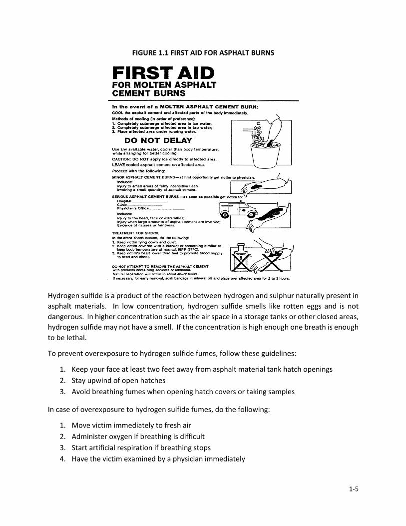
1-5
FIGURE 1.1 FIRST AID FOR ASPHALT BURNS
Hydrogen sulfide is a product of the reaction between hydrogen and sulphur naturally present in asphalt materials. In low concentration, hydrogen sulfide smells like rotten eggs and is not dangerous. In higher concentration such as the air space in a storage tanks or other closed areas, hydrogen sulfide may not have a smell. If the concentration is high enough one breath is enough to be lethal.
To prevent overexposure to hydrogen sulfide fumes, follow these guidelines:
1. Keep your face at least two feet away from asphalt material tank hatch openings 2. Stay upwind of open hatches 3. Avoid breathing fumes when opening hatch covers or taking samples
In case of overexposure to hydrogen sulfide fumes, do the following:
1. Move victim immediately to fresh air 2. Administer oxygen if breathing is difficult 3. Start artificial respiration if breathing stops 4. Have the victim examined by a physician immediately

1-6
ASPHALT SAFETY REMINDERS
• When working with any asphaltic materials, avoid prolonged contact of material with skin
• Excessive breathing of asphalt materials should be avoided • Wear PPE to protect against asphalt spatters • When chipping or chiseling old blacktop, wear eye protection. Also, don’t chisel with a
carpenter’s hammer because it isn’t designed for this type of job and may chip • Keep all asphalt materials away from high heat. Keep solvent-tinned materials away
from open flames • Close containers after each use • Always follow the manufacturer’s instructions for the product being used
TERMINOLOGY
Asphalt mixture has been called surprisingly by many different names. Hot Mix Asphalt (HMA), bituminous paving mix(ture), bituminous concrete, bituminous mix(ture), asphalt paving mix(ture), asphaltic concrete or plain "asphalt" are just a few of the synonyms used for this material. The term "asphalt mixture" is used to help standardize the wording and minimize confusion. When the Standard Specifications are referenced in the manual, QC/QA HMA will be used for mixtures in accordance with Section 401, HMA will be used for mixtures in accordance with Section 402, and SMA (Stone Matrix Asphalt) will be used for mixtures in accordance with Section 410.
Asphalt materials include Performance Graded (PG) Asphalt Binders, Asphalt Emulsions, Cutback Asphalt, Utility Asphalt, and Asphalt used for coating corrugated metal pipe. HMA used for Quality Assurance requires PG binders to be used for the asphalt material. The term "binder" is used when referring to this material.
Additional terms related to asphalt mixture include the following:
AASHTO - American Association of State Highway and Transportation Officials
Absorption - The increase in the mass of aggregate due to water in the pores of the material, but not including water adhering to the outside surface of the particles, expressed as a percentage of the dry mass
Actual Binder Content - The binder content determined in accordance with ITM 586 or the total of the binder content determined in accordance with ITM 571 and the binder absorption percent from the DMF
1-7
Aggregate Base - A layer of aggregate placed on a subgrade or subbase to support a surface course
Air-Cooled Blast Furnace Slag (ACBF) - Material resulting from solidification of molten blast-furnace slag under atmospheric conditions
Apparent Specific Gravity - The ratio of the weight in air of a unit volume of the impermeable portion of aggregate at a stated temperature to the weight in air of an equal volume of gas-free distilled water at a stated temperature
Air Voids - Internal spaces in a compacted mix surrounded by asphalt-coated particles, expressed as a percentage by volume of the total compacted mix
Artificial Aggregates - Aggregates that are manufactured or by-products of an industrial process. Blast furnace slag, steel slag and wet bottom boiler slag are examples of by-product artificial aggregates.
Asphalt Emulsion – An emulsion of asphalt and water that contains a small amount of an emulsifying agent. Emulsified asphalt droplets may be either anionic (negative charge), cationic (positive charge), or nonionic (neutral).
ASTM - American Society for Testing and Materials
Base Course – The layer in the pavement system immediately below the binder and surface courses. The base course consists of crushed aggregate or other stabilized material.
Binder – Asphalt that is classified according to the Standard specifications for Performance Graded Asphalt Binder, AASHTO Designation MP1. The binder may be either unmodified or modified asphalt.
Bulk Specific Gravity - The ratio of the weight in air of a unit volume of material (including the permeable and impermeable voids in the particles, but not including the voids between particles) at a stated temperature to the weight of an equal volume of gas-free distilled water at a stated temperature
Bulk Specific Gravity (SSD) - The ratio of the mass in air of a unit volume of material, including the mass of water within the voids filled to the extent achieved by submerging in water for a specified time (but not including the voids between particles) at a stated temperature to the weight in air of an equal volume of gas-free distilled water at a stated temperature
Certified Aggregate Producer - A Plant/Redistribution Terminal that meets the requirements of ITM 211 and is approved by the Department

1-8
Certified HMA Producer - An asphalt mixture plant that meets the requirements of ITM 583 and is approved by the Department
Coarse Aggregate - Aggregate that has a minimum of 20 percent retained on the No. 4 (4.75 mm) sieve
Decant - A test utilizing water to determine the amount of material that is passing the No. 200 sieve. The decantation test is conducted on both fine and coarse aggregate and is usually done in conjunction with the sieve analysis test.
Deleterious - Undesirable aggregate material
Density - The weight per unit volume of a substance
Dolomite - Carbonite rock containing at least 10.3% elemental magnesium when tested in accordance with ITM 205
Equivalent Single Axle Load (ESAL) – The effect on pavement performance of any combination of axle loads of varying magnitude equated to the number of 80-kN (18,000-lb.) single-axle loads that are required to produce an equivalent effect.
Fine Aggregate - Aggregate that is 100 percent passing the 3/8 in. (9.5 mm) sieve and a minimum of 80 percent passing the No. 4 (4.75 mm) sieve
Independent Assurance – Independent Assurance testing is conducted by INDOT personnel to verify the reliability of the results obtained in acceptance sampling and testing. Certified Asphalt Technicians are checked annually by Independent Assurance Technicians for the sampling and testing procedures that are conducted at the asphalt mixture plant.
Intermediate Course – The hot mix asphalt course immediately below the surface course, generally consisting of larger aggregates and less asphalt (by weight) than the surface course
Leveling Course – A course of hot mix asphalt of variable thickness used to eliminate irregularities in the contour of an existing surface prior to placing the subsequent course.
Maximum Particle Size - The sieve on which 100 percent of the material will pass
Mineral Filler - Dust produced by crushing stone, portland cement, or other inert mineral matter having similar characteristics. Mineral filler is required to be in accordance with the gradation requirements for size No.16.
National Institute of Standards and Technology (NIST) - A federal technology agency that develops and applies technology, measurements, and standards for testing equipment
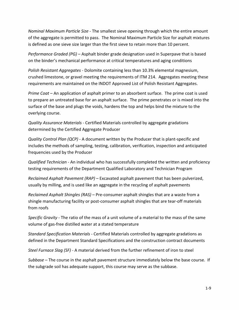
1-9
Nominal Maximum Particle Size - The smallest sieve opening through which the entire amount of the aggregate is permitted to pass. The Nominal Maximum Particle Size for asphalt mixtures is defined as one sieve size larger than the first sieve to retain more than 10 percent.
Performance Graded (PG) – Asphalt binder grade designation used in Superpave that is based on the binder’s mechanical performance at critical temperatures and aging conditions
Polish Resistant Aggregates - Dolomite containing less than 10.3% elemental magnesium, crushed limestone, or gravel meeting the requirements of ITM 214. Aggregates meeting these requirements are maintained on the INDOT Approved List of Polish Resistant Aggregates.
Prime Coat – An application of asphalt primer to an absorbent surface. The prime coat is used to prepare an untreated base for an asphalt surface. The prime penetrates or is mixed into the surface of the base and plugs the voids, hardens the top and helps bind the mixture to the overlying course.
Quality Assurance Materials - Certified Materials controlled by aggregate gradations determined by the Certified Aggregate Producer
Quality Control Plan (QCP) - A document written by the Producer that is plant-specific and includes the methods of sampling, testing, calibration, verification, inspection and anticipated frequencies used by the Producer
Qualified Technician - An individual who has successfully completed the written and proficiency testing requirements of the Department Qualified Laboratory and Technician Program
Reclaimed Asphalt Pavement (RAP) – Excavated asphalt pavement that has been pulverized, usually by milling, and is used like an aggregate in the recycling of asphalt pavements
Reclaimed Asphalt Shingles (RAS) – Pre-consumer asphalt shingles that are a waste from a shingle manufacturing facility or post-consumer asphalt shingles that are tear-off materials from roofs
Specific Gravity - The ratio of the mass of a unit volume of a material to the mass of the same volume of gas-free distilled water at a stated temperature
Standard Specification Materials - Certified Materials controlled by aggregate gradations as defined in the Department Standard Specifications and the construction contract documents
Steel Furnace Slag (SF) - A material derived from the further refinement of iron to steel
Subbase – The course in the asphalt pavement structure immediately below the base course. If the subgrade soil has adequate support, this course may serve as the subbase.

1-10
Subgrade – The soil prepared to support a pavement structure or a pavement system. The subgrade is the foundation of the pavement structure.
Superpave – Short for "Superior Performing Asphalt Pavement", a performance-based system for selecting and specifying asphalt binders and for designing asphalt mixtures
Tack Coat – A relatively thin application of asphalt applied to an existing asphalt or concrete pavement surface at a prescribed rate. Asphalt emulsion diluted with water is the preferred type. Tack coat is used to form a bond between an existing surface and the overlying course.
Water-Injection Foaming - Water-Injection Foaming is a process that allows a reduction in the temperature at which mixtures are produced and placed
Wet Bottom Boiler Slag - A material which is a by-product from coal combustion at electrical generating plant
ROUNDING
The Specifications designate specific quantities of material to be sampled, material test values, and test equipment calibration measurements. As such, a standard method for rounding values is essential. The method required is the "5 up" procedure. There are two rules for rounding numbers:
1. When the first digit discarded is less than 5, the last digit retained should not be changed.
Examples:
2.4 becomes 2 2.43 becomes 2.4 2.434 becomes 2.43 2.4341 becomes 2.434
2. When the first digit discarded is 5 or greater, the last digit retained should be increased by one unit.
Examples:
2.6 becomes 3 2.56 becomes 2.6 2.416 becomes 2.42 2.4157 becomes 2.416
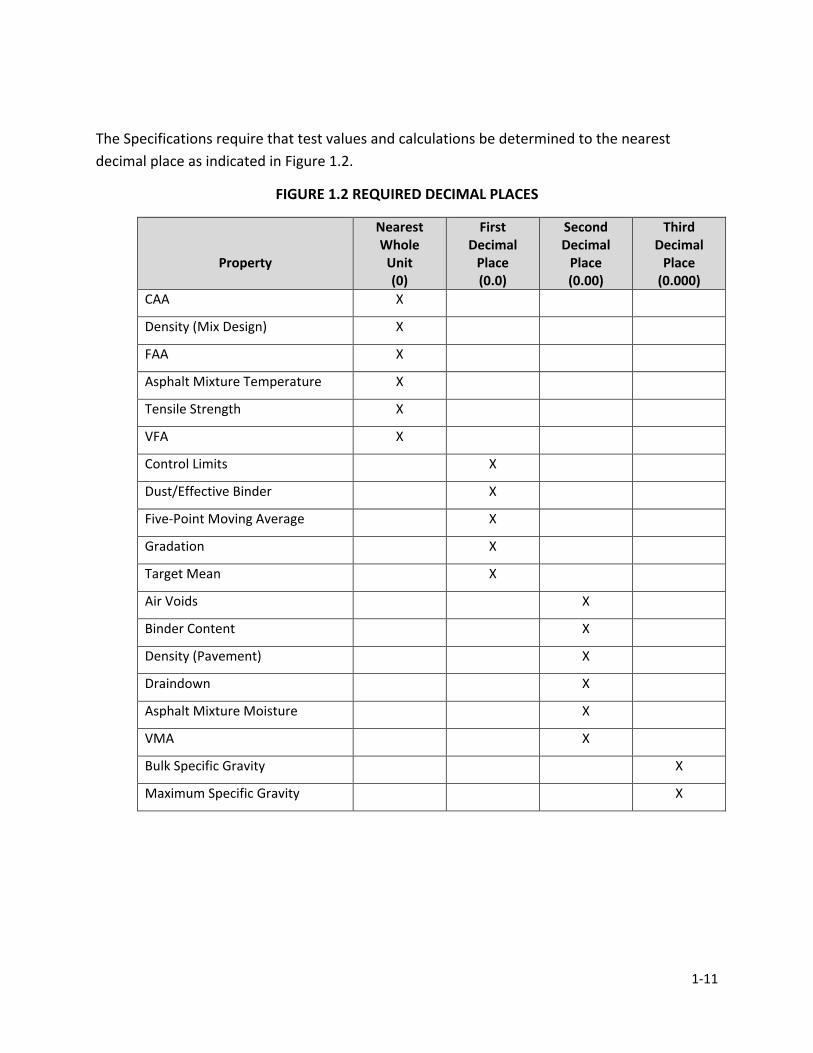
1-11
The Specifications require that test values and calculations be determined to the nearest decimal place as indicated in Figure 1.2.
FIGURE 1.2 REQUIRED DECIMAL PLACES
Property
Nearest Whole
Unit (0)
First Decimal
Place (0.0)
Second Decimal
Place (0.00)
Third Decimal
Place (0.000)
CAA X
Density (Mix Design) X
FAA X
Asphalt Mixture Temperature X
Tensile Strength X
VFA X
Control Limits X
Dust/Effective Binder X
Five-Point Moving Average X
Gradation X
Target Mean X
Air Voids X
Binder Content X
Density (Pavement) X
Draindown X
Asphalt Mixture Moisture X
VMA X
Bulk Specific Gravity X
Maximum Specific Gravity X
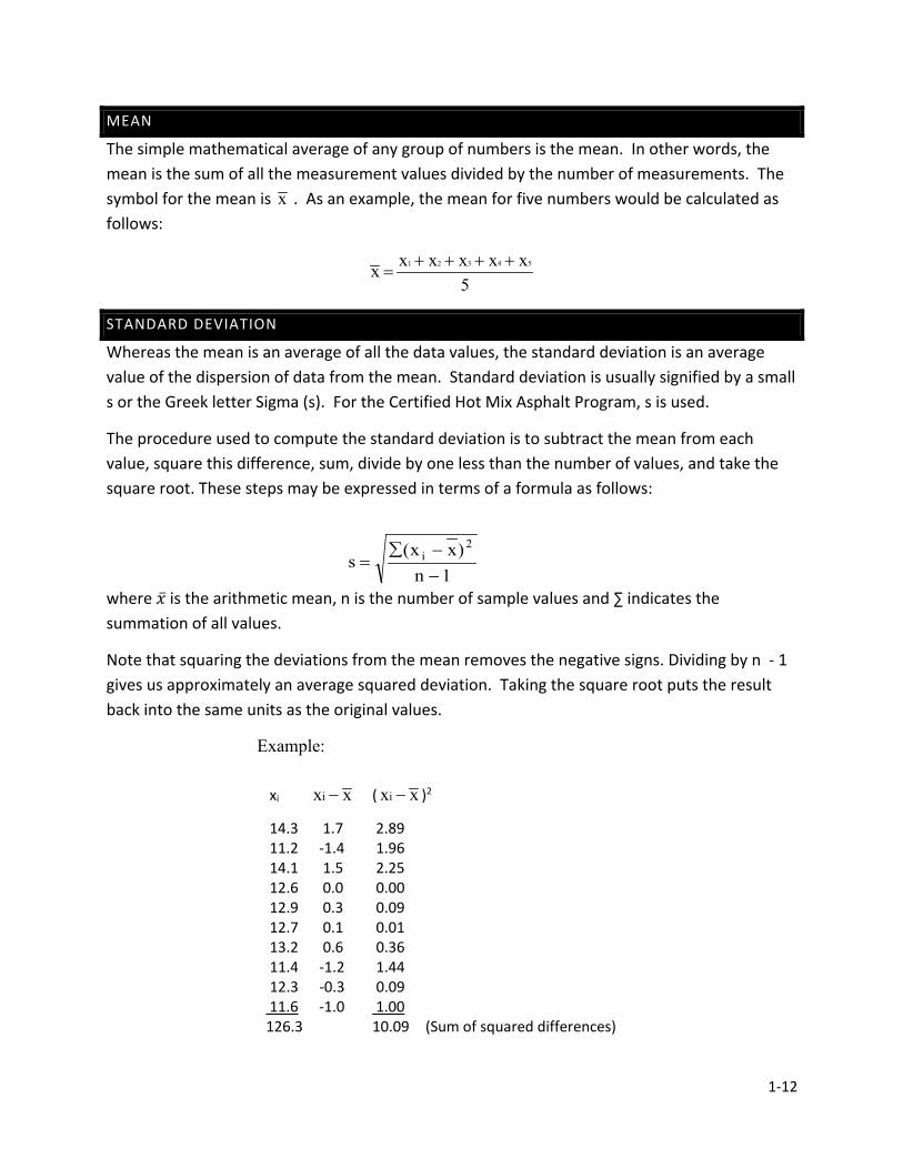
1-12
MEAN
The simple mathematical average of any group of numbers is the mean. In other words, the mean is the sum of all the measurement values divided by the number of measurements. The symbol for the mean is x . As an example, the mean for five numbers would be calculated as follows:
5 x x x x x x 54321 ++++
=
STANDARD DEVIATION
Whereas the mean is an average of all the data values, the standard deviation is an average value of the dispersion of data from the mean. Standard deviation is usually signified by a small s or the Greek letter Sigma (s). For the Certified Hot Mix Asphalt Program, s is used.
The procedure used to compute the standard deviation is to subtract the mean from each value, square this difference, sum, divide by one less than the number of values, and take the square root. These steps may be expressed in terms of a formula as follows:
where �̅�𝑥 is the arithmetic mean, n is the number of sample values and ∑ indicates the summation of all values.
Note that squaring the deviations from the mean removes the negative signs. Dividing by n - 1 gives us approximately an average squared deviation. Taking the square root puts the result back into the same units as the original values.
Example:
xi xxi − ( xxi − )2
14.3 1.7 2.89 11.2 -1.4 1.96 14.1 1.5 2.25 12.6 0.0 0.00 12.9 0.3 0.09 12.7 0.1 0.01 13.2 0.6 0.36 11.4 -1.2 1.44 12.3 -0.3 0.09 11.6 -1.0 1.00 126.3 10.09 (Sum of squared differences)
1n)xx(
s 2
i
−−∑
=
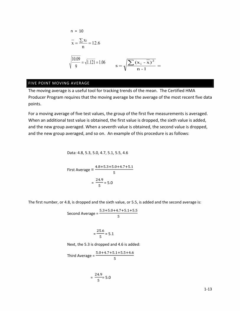
1-13
== ∑1-n
)x-(x s
2i
n = 10
6.12nxx i=∑=
FIVE POINT MOVING AVERAGE
The moving average is a useful tool for tracking trends of the mean. The Certified HMA Producer Program requires that the moving average be the average of the most recent five data points.
For a moving average of five test values, the group of the first five measurements is averaged. When an additional test value is obtained, the first value is dropped, the sixth value is added, and the new group averaged. When a seventh value is obtained, the second value is dropped, and the new group averaged, and so on. An example of this procedure is as follows:
Data: 4.8, 5.3, 5.0, 4.7, 5.1, 5.5, 4.6
First Average = 4.8+5.3+5.0+4.7+5.15
= 24.95
= 5.0
The first number, or 4.8, is dropped and the sixth value, or 5.5, is added and the second average is:
Second Average = 5.3+5.0+4.7+5.1+5.5
5
= 25.65
= 5.1
Next, the 5.3 is dropped and 4.6 is added:
Third Average = 5.0+4.7+5.1+5.5+4.6
5
= 24.95
= 5.0
06.1121.1909.10
==
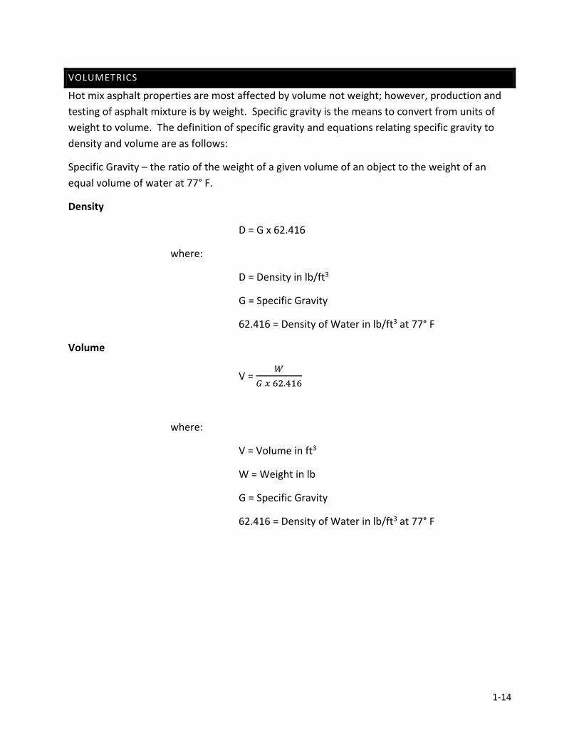
1-14
VOLUMETRICS
Hot mix asphalt properties are most affected by volume not weight; however, production and testing of asphalt mixture is by weight. Specific gravity is the means to convert from units of weight to volume. The definition of specific gravity and equations relating specific gravity to density and volume are as follows:
Specific Gravity – the ratio of the weight of a given volume of an object to the weight of an equal volume of water at 77° F.
Density
D = G x 62.416
where:
D = Density in lb/ft3
G = Specific Gravity
62.416 = Density of Water in lb/ft3 at 77° F
Volume
V = 𝑊𝑊
𝐺𝐺 𝑥𝑥 62.416
where:
V = Volume in ft3
W = Weight in lb
G = Specific Gravity
62.416 = Density of Water in lb/ft3 at 77° F

CHAPTER 2AGGREGATE
FUNDAMENTALS,SAMPLING AND TESTING
2-1
CHAPTER 2 AGGREGATE FUNDAMENTALS, SAMPLING, AND TESTING
AGGREGATES WHAT IS AN AGGREGATE
USES OF AGGREGATES ORIGINS OF AGGREGATES
NATURAL SAND AND GRAVEL, CRUSHED STONE, SLAG DISTRIBUTION OF AGGREGATES
GLACIAL DEPOSITS AND BEDROCK DEPOSITS AGGREGATE TYPES
NATURAL AGGREGATES AND ARTIFICIAL AGGREGATES CLASSIFICATIONS OF AGGREGATES
FINE AGGREGATES AND COARSE AGGREGATES PHYSICAL PROPERTIES
ABSORPTION AND SPECIFIC GRAVITY, SURFACE TEXTURE, ABRASION RESISTANCE, SOUNDNESS, PARTICLE SHAPE, DELETERIOUS MATERIALS
CONSENSUS PROPERTIES COARSE AGGREGATE ANGULARITY FLAT & ELONGATED PARTICLES FINE AGGREGATE ANGULARITY HMA SURFACE AGGREGATES
DOLOMITE AGGREGATES, POLISH RESISTANT AGGREGATES, SANDSTONE AGGREGATES, SLAG AGGREGATES
STOCKPILING SAMPLING AND TESTING
METHODS OF SAMPLING (BIN, BELT, STOCKPILE, TRUCK, CAR, BARGE) SIZE OF ORIGINAL SAMPLE
REDUCING A SAMPLE TO TEST SIZE SIZE OF TEST SAMPLE (AFTER SPLITTING) GRADATION
SIEVE ANALYSIS TEST MOISTURE CONTENT
2-2
CHAPTER 2 AGGREGATE FUNDAMENTALS, SAMPLING, AND TESTING
An asphalt mixture pavement is composed of binder and aggregate blended together. The individual material properties of each component may affect the overall performance of the pavement. If pavements are to perform long term and withstand specific traffic and loading, the materials making up the pavements are required to be of high quality.
This section covers in detail the sources of aggregates in Indiana, as well as material properties of aggregates that are necessary for high quality pavements. Many of the tests are not required to be conducted by the Technician; however, a thorough understanding of the materials and test procedures to determine quality is a necessary background for the Technician. Converting that understanding into a working knowledge assists the Technician in making accurate, reliable, day-to-day decisions.
AGGREGATES
WHAT IS AN AGGREGATE?
Aggregates are granular materials that have been mined for use as a building material in the construction industry. They include aggregates from natural and artificial origins, such as stone, sand and gravel, and slag.
USES OF AGGREGATES
Streets, bridges, roads and sidewalks are made of concrete or asphalt which is mostly made up of aggregates combined with a binder that acts like glue. Concrete is used in foundations and basements for houses. Other buildings sometimes use concrete throughout their structures.
But did you know that many items you use every day have aggregates in them? Your toothpaste has aggregates in it. Glass is made from sand, which is an aggregate. Minerals and aggregates are in plates, dishes, pots and pans, baby powder, household cleaners, makeup, medicines, paints, pencils, fertilizers, wallboard, and more including some of the foods you eat! How many times have you heard that your cereal, for instance, is fortified with vitamins and minerals?
Any object that hasn’t been grown had to be mined! Aggregates, minerals and metals all come from the ground. You can look at objects all around you and know which were grown and which were mined. If it is metal, it was mined. If it is wood, it was grown. If it is cotton or wool, it was grown. Paper comes from trees, which are grown. Pencils are grown and mined because wood is

2-3
grown and graphite is mined. The ink on this paper came from mining. But what about plastic? Is it grown or mined? Plastic comes from petroleum products, which are mined.
ORIGIN OF AGGREGATES
The four main types of mineral aggregates in Indiana, gravel and natural sand, crushed stone, and slag. They all have different origins.
NATURAL SAND AND GRAVEL
Natural Sand
A mineral particle or rock fragment that is larger than coarse silt but smaller than gravel. It is a widespread but highly variable resource in Indiana that was formed mostly by glacial actions of large ice sheets and then sorted by running water. Sand can be used as fill, or more often the coarser parts find use as components of concrete or asphalt pavement. Sand, a finer granular material, also is important in concrete and in making mortar and in snow and ice control. Very fine-grained sand finds use in foundries to make molds. It is also used in sandblasting, glass-making, or even as golf-course sand. The size of sand ranges from .0625mm (.002 in) to less than 2mm (.08 in).
Gravel
The term gravel applies to a range of particle sizes, rather than a specific rock or mineral type. Gravel is colored by the rock types present. It is a collection of rock particles that are at least .08 inches in diameter sizes but may also include boulders over 10 inches in diameter. Gravel is loose rock that is often rounded in shape from being worn by water at some point. Gravel can be used alone as fill, for gravel roads, or residential driveways. Gravel can also be used as a component of concrete or asphalt pavement. Gravel is greater than or equal to 2mm (.08 inch) in size. It can include larger rocks such as boulders (over 10 inches).
Most of the gravels and natural sands used today are a product of the Ice Ages. Indiana has experienced multiple glacial advances and retreats between 2.6 million years ago and as recent as 11,700 years ago. Geologists concur that glaciers may have been up to 1 mile thick. As the glaciers advanced southward, rock was scraped beneath them. When the glaciers melted, the flowing water carried the rock fragments and deposited them downstream. The scraping action of the ice and flowing waters gave the gravels and natural sands the rounded appearance.
In addition, gravel and sand are obtained from postglacial or modern stream deposits. Another word for stream processes is fluvial. Areas in Indiana where fluvial deposits are mined are largely
2-4
restricted to the river bars, bottom lands, and flood plains of the Ohio River and the lower reaches of the White and Wabash Rivers.
Gravel and sand are unconsolidated granular materials resulting from the natural disintegration of rocks. They disintegrate primarily from the abrading action of water or ice on rock material. In Indiana, deposits which are found beyond the physical limits of the glaciers, are likely to be found in greater abundance in stream bottoms and floodplains.
CRUSHED STONE
Crushed stone produced within Indiana originates from sedimentary bedrock deposits. There are three general classes of rocks: igneous, sedimentary, and metamorphic. Igneous rocks were formed from hot volcanic magma--molten mineral material. Sedimentary rocks were formed from the hardened deposits of the weathered remains of rocks, organic materials, and sediment. Metamorphic rocks were originally igneous or sedimentary rocks but were changed by pressure and/or heat. Across the United States, variations of the above noted rock types are utilized for crushed stone aggregate. Indiana bedrock is comprised of the sedimentary rock types, limestone and dolostone. Construction aggregates within Indiana primarily consist of these two sedimentary rock types. Sandstone from southern Illinois, a sedimentary rock type, is permitted for use in hot mix asphalt surface courses.
SLAG
There are different types of slag used as construction aggregate in the state of Indiana:
1. Blast Furnace Slag - a non-metallic material removed in the molten state of iron production. The further refinement of this blast furnace slag results in three aggregate variations: air cooled slag, expanded slag, and granulated slag.
2. Steel slag - a material derived from the further refinement of iron to steel.
DISTRIBUTION OF AGGREGATES
Aggregate types vary by geographic location throughout the State of Indiana. The composition of each type of aggregate also varies.
Glacial Deposits
Glaciers once blanketed five-sixths of Indiana. They carried sand and gravel deposit which are in great abundance in the northern part of the state, but also may be found along any river in Indiana. Figure 2.1 shows the southern boundaries of two of the major glacial advances which moved across the prehistoric Indiana landscape. The size of the gravel and the type of minerals

2-5
and rocks found in the deposits varies from place to place. Gravel becomes smaller as it travels downstream. Occurrence of gravel decreases from northeastern to southwestern Indiana.
FIGURE 2.1 MAJOR GLACIAL ADVANCES IN INDIANA
The composition of a deposit also varies from place to place. In some deposits, 10 to 20 different types of rocks may be found. Granite, gneiss, and schist (igneous and metamorphic rocks) or limestone, dolostone, chert, sandstone, siltstone, and shale (sedimentary rocks) are typically found. Porous chert, siltstone, sandstone, ocher, and shale are deleterious, meaning that the material does not perform well in certain applications in highway construction.
Bedrock Deposits
As shown in the bedrock map of Indiana (Figure 2.2), the bedrock belongs to five geologic periods which are listed from the oldest to youngest: Ordovician, Silurian, Devonian, Mississippian, and Pennsylvanian.
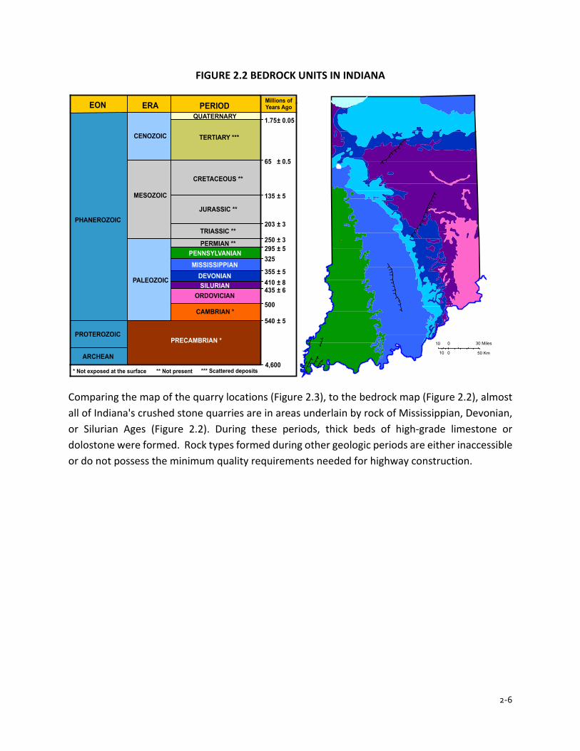
2-6
FIGURE 2.2 BEDROCK UNITS IN INDIANA
Comparing the map of the quarry locations (Figure 2.3), to the bedrock map (Figure 2.2), almost all of Indiana's crushed stone quarries are in areas underlain by rock of Mississippian, Devonian, or Silurian Ages (Figure 2.2). During these periods, thick beds of high-grade limestone or dolostone were formed. Rock types formed during other geologic periods are either inaccessible or do not possess the minimum quality requirements needed for highway construction.
PERMIAN **PENNSYLVANIANMISSISSIPPIAN
DEVONIANSILURIAN
ORDOVICIAN
CAMBRIAN *
PALEOZOIC
MESOZOIC
CENOZOIC
TRIASSIC **
JURASSIC **
CRETACEOUS **
TERTIARY ***
QUATERNARYEON ERA PERIOD
PHANEROZOIC
PROTEROZOIC
ARCHEAN
PRECAMBRIAN *
Millions ofYears Ago
540
500
435410355
295325
250
203
135
65
1.75
± 5
± 6± 8± 5
± 5± 3
± 3
± 5
± 0.5
± 0.05
* Not exposed at the surface *** Scattered deposits** Not present4,600
10 0 30 Miles
10 0 50 Km
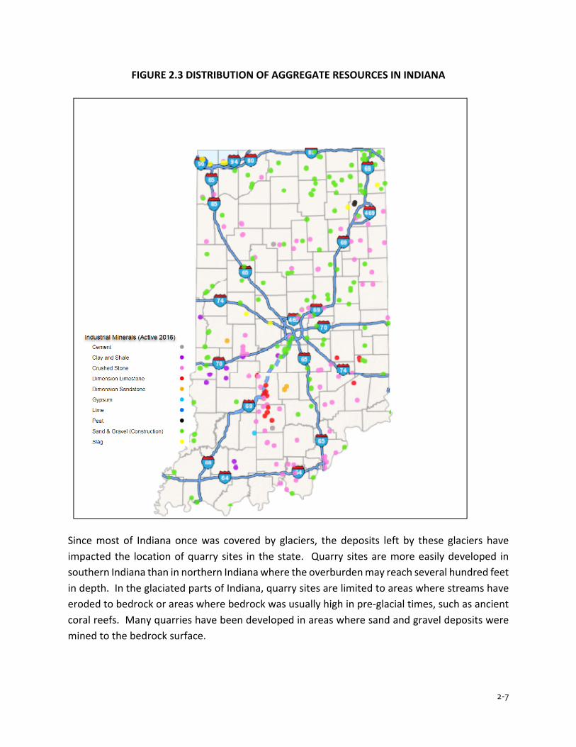
2-7
FIGURE 2.3 DISTRIBUTION OF AGGREGATE RESOURCES IN INDIANA
Since most of Indiana once was covered by glaciers, the deposits left by these glaciers have impacted the location of quarry sites in the state. Quarry sites are more easily developed in southern Indiana than in northern Indiana where the overburden may reach several hundred feet in depth. In the glaciated parts of Indiana, quarry sites are limited to areas where streams have eroded to bedrock or areas where bedrock was usually high in pre-glacial times, such as ancient coral reefs. Many quarries have been developed in areas where sand and gravel deposits were mined to the bedrock surface.

2-8
AGGREGATE TYPES
The aggregates used in highway construction are all mineral aggregates. Aggregates are composed of a naturally occurring solid chemical element or compound formed as a product of an inorganic process. There are two distinct types of aggregate: natural, and artificial.
Natural Aggregates
Rock or stone (either term may be used) fragments which are used in their natural state are considered natural aggregates. Crushed stone, sand, and gravel are natural aggregates.
Crushed Stone
Crushed stone is produced from quarries where the bedrock is blasted (shot) with explosives and further fragmented by mechanical crushing. All crushed stone fragments are angular in shape and all faces of the fragments are created by the crushing operation.
The most common sedimentary rock types found in Indiana are limestone, dolostone, sandstone, shale, and siltstone. Only limestone and dolostone are routinely used for highway construction, although some sandstone from southern Illinois is allowed for high friction HMA surface.
Sand and Gravel
Sand and gravel are generally found together. These aggregates may be mined from a water-filled pit (a deposit below the water table) or from a cut bank deposit (a deposit above the water table). If the aggregates come from a pit, the aggregate is referred to as "pit-run" material. A cut-bank deposit is termed "bank-run" material.
Sand from these deposits are referred to as natural sand, while sand made by crushing stone, pieces of gravel, or slag are commonly called manufactured sand.
The sand and gravel found in the deposits have a variety of assorted sizes. Further processing is required including screening, washing, and some crushing. The crushing is done to produce aggregates of the proper size and angularity.
Artificial Aggregates
These aggregates are processed either from blast furnace slag or steel slag.
2-9
CLASSIFICATIONS OF AGGREGATES
Aggregates are separated into two classifications: coarse aggregates, and fine aggregates. The No. 4 sieve generally determines the difference between coarse aggregate and fine aggregate for most highway construction work.
Fine Aggregates
Fine aggregate is defined as aggregate that is 100 percent passing the 3/8 in. sieve and a minimum of 80 percent passing the No. 4 sieve.
Coarse Aggregates
Coarse aggregate is defined as aggregate that has a minimum of 20 percent retained on the No. 4 sieve.
PHYSICAL PROPERTIES
The physical properties of aggregates are those that refer to the physical structure of the particles that make up the aggregate.
Absorption and Specific Gravity
The internal pore characteristics are very important properties of aggregates. The size, number, and the continuity of the pores through an aggregate particle may affect the strength of the aggregate, abrasion resistance, surface texture, specific gravity, bonding capabilities, and resistance to freezing and thawing action. Absorption is the particle's ability to take in a liquid. Porosity is a ratio of the volume of the pores to the total volume of the particle. Permeability refers to the particle's ability to allow liquids to pass through. If the rock pores are not connected, a rock may have high porosity and low permeability.
Density and Specific Gravity
Density is the weight per unit of volume of a substance. Specific gravity is the ratio of the density of the substance to the density of water.
The following chart illustrates these relationships for some common substances.

2-10
FIGURE 2.4 TYPICAL VALUES
Typical Specific Gravity Chart Substance Specific Gravity Wood (oak) 0.7 Water 1 Coal 1.6 Gypsum 2.3 Blast Furnace Slag 2.4 Limestone 2.6 Quartz 2.6 Shale 2.6 Gravel 2.7 Trap Rock 2.9 Steel Slag 3.5 Iron 7.9 Lead 11 Gold 19
The density and the specific gravity of an aggregate particle is dependent upon the density and specific gravity of the minerals making up the particle and upon the porosity of the particle. These may be defined as follows:
1. All of the pore space (bulk density or specific gravity) 2. Some of the pore space (effective density or specific gravity) 3. None of the pore space (apparent density or specific gravity)
As an example, specific gravity information about a particular aggregate helps to determine the amount of asphalt needed in hot mix asphalt. If an aggregate is highly absorptive, the aggregate continues to absorb asphalt, after initial mixing at the plant, until the mix cools down completely. This process leaves less asphalt for bonding purposes; therefore, a more porous aggregate requires more asphalt than a less porous aggregate. The porosity of the aggregate may be taken into consideration in determining the amount of asphalt required by applying the three types of specific gravity measurements.
Surface Texture
Surface texture is the pattern and the relative roughness or smoothness of the aggregate particle. Surface texture plays a big role in developing the bond between an aggregate particle and asphalt
2-11
cement. A rough surface texture gives the asphalt cement something to grip, producing a stronger bond. Surface texture also affects the workability of hot mix asphalt.
Some aggregates may initially have good surface texture but may polish smooth later under traffic. These aggregates are unacceptable for final wearing surfaces. Limestone usually falls into this category. Dolomite does not, in general, when the magnesium content exceeds the minimum required in the INDOT Standard Specifications.
Abrasion Resistance
For a coarse aggregate to be satisfactory for a pavement, the aggregate is required to be tough enough to withstand the action of rolling during construction and the action of traffic without breaking down under the loads. The test used for evaluating this property is the Los Angeles Abrasion test (AASHTO T 96). Briefly, this test requires the aggregate to be placed in a metal drum along with steel balls, and the drum rotated 500 times. Another test that is conducted to evaluate AS aggregates for use with SMA mixtures is the Micro-Deval Test (AASHTO T 327). The Micro-Deval Test is a measure of abrasion resistance and durability of mineral aggregates resulting from a combination of actions including abrasion and grinding with stainless steel balls in the presence of water.
Soundness
In asphalt pavements, particularly surface mixtures, aggregates are subjected to harsh conditions. Weather extremes create conditions conducive to aggregate breakdown. The soundness of an aggregate refers to the aggregate’s inherent ability to withstand these extremes. This aggregate quality is verified through tests involving exposure to chemicals, such as sodium sulfate, and by exposure to rapid freezing and thawing cycles.
Aggregates which disintegrate badly under the forces of weather are termed unsound. Shale is a typical unsound material because water enters into the aggregate and freezes, causing the aggregate to expand and disintegrate. Also, exposure to air (oxidation) causes shale to flake. Unsound aggregates are obviously unsatisfactory for use in asphalt mixtures, particularly for surface asphalt mixtures, which are more exposed to the weather. INDOT subjects aggregates to three different test methods to evaluate soundness:
1. The sodium sulfate test in AASHTO T 104 2. The brine freezing and thawing test in ITM 209 3. The freezing and thawing test in AASHTO T 103
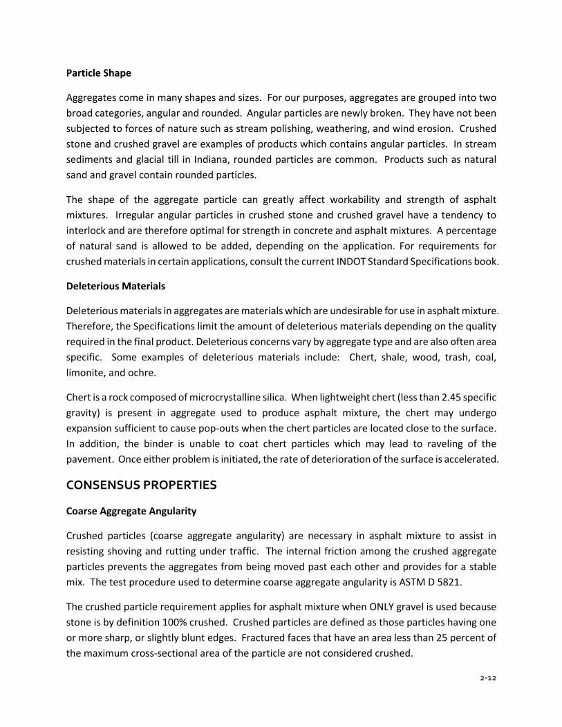
2-12
Particle Shape
Aggregates come in many shapes and sizes. For our purposes, aggregates are grouped into two broad categories, angular and rounded. Angular particles are newly broken. They have not been subjected to forces of nature such as stream polishing, weathering, and wind erosion. Crushed stone and crushed gravel are examples of products which contains angular particles. In stream sediments and glacial till in Indiana, rounded particles are common. Products such as natural sand and gravel contain rounded particles.
The shape of the aggregate particle can greatly affect workability and strength of asphalt mixtures. Irregular angular particles in crushed stone and crushed gravel have a tendency to interlock and are therefore optimal for strength in concrete and asphalt mixtures. A percentage of natural sand is allowed to be added, depending on the application. For requirements for crushed materials in certain applications, consult the current INDOT Standard Specifications book.
Deleterious Materials
Deleterious materials in aggregates are materials which are undesirable for use in asphalt mixture. Therefore, the Specifications limit the amount of deleterious materials depending on the quality required in the final product. Deleterious concerns vary by aggregate type and are also often area specific. Some examples of deleterious materials include: Chert, shale, wood, trash, coal, limonite, and ochre.
Chert is a rock composed of microcrystalline silica. When lightweight chert (less than 2.45 specific gravity) is present in aggregate used to produce asphalt mixture, the chert may undergo expansion sufficient to cause pop-outs when the chert particles are located close to the surface. In addition, the binder is unable to coat chert particles which may lead to raveling of the pavement. Once either problem is initiated, the rate of deterioration of the surface is accelerated.
CONSENSUS PROPERTIES
Coarse Aggregate Angularity
Crushed particles (coarse aggregate angularity) are necessary in asphalt mixture to assist in resisting shoving and rutting under traffic. The internal friction among the crushed aggregate particles prevents the aggregates from being moved past each other and provides for a stable mix. The test procedure used to determine coarse aggregate angularity is ASTM D 5821.
The crushed particle requirement applies for asphalt mixture when ONLY gravel is used because stone is by definition 100% crushed. Crushed particles are defined as those particles having one or more sharp, or slightly blunt edges. Fractured faces that have an area less than 25 percent of the maximum cross-sectional area of the particle are not considered crushed.
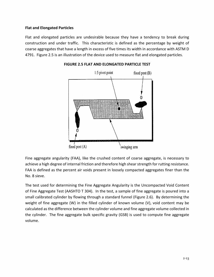
2-13
Flat and Elongated Particles
Flat and elongated particles are undesirable because they have a tendency to break during construction and under traffic. This characteristic is defined as the percentage by weight of coarse aggregates that have a length in excess of five times its width in accordance with ASTM D 4791. Figure 2.5 is an illustration of the device used to measure flat and elongated particles.
FIGURE 2.5 FLAT AND ELONGATED PARTICLE TEST
Fine aggregate angularity (FAA), like the crushed content of coarse aggregate, is necessary to achieve a high degree of internal friction and therefore high shear strength for rutting resistance. FAA is defined as the percent air voids present in loosely compacted aggregates finer than the No. 8 sieve.
The test used for determining the Fine Aggregate Angularity is the Uncompacted Void Content of Fine Aggregate Test (AASHTO T 304). In the test, a sample of fine aggregate is poured into a small calibrated cylinder by flowing through a standard funnel (Figure 2.6). By determining the weight of fine aggregate (W) in the filled cylinder of known volume (V), void content may be calculated as the difference between the cylinder volume and fine aggregate volume collected in the cylinder. The fine aggregate bulk specific gravity (GSB) is used to compute fine aggregate volume.

2-14
FIGURE 2.6 FINE AGGREGATE ANGULARITY
HMA SURFACE AGGREGATES
Dolomitic Aggregates
There is a special requirement to be met when dolomitic coarse aggregates are used in asphalt mixture. These aggregates are specified for high traffic applications to obtain high-friction, skid-resistant asphalt mixture surface courses. ITM 205 is used to ensure that the aggregate is a carbonate rock containing at least 10.3 percent elemental magnesium.
Polish Resistant Aggregates
Aggregates that meet the requirements of ITM 214 may be used in place of dolomitic aggregates in asphalt mixture surface mixtures. The procedure for approval requires initial lab testing, placement of a test section on an INDOT contract, and subsequent skid testing for two years.
Sandstone Aggregates
Coarse Sandstone is required to meet the Class B quality requirements and may only be used in asphalt mixture surface mixtures. The definition of sandstone is described in Section 904.01.
Slag Aggregates
Steel furnace slag for use in SMA is required to meet additional requirements for control of the specific gravity in accordance with Section 904.01.
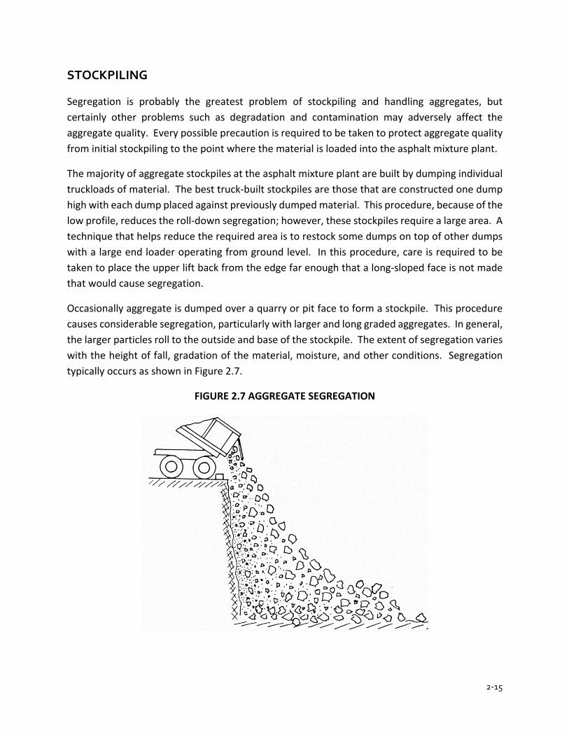
2-15
STOCKPILING
Segregation is probably the greatest problem of stockpiling and handling aggregates, but certainly other problems such as degradation and contamination may adversely affect the aggregate quality. Every possible precaution is required to be taken to protect aggregate quality from initial stockpiling to the point where the material is loaded into the asphalt mixture plant.
The majority of aggregate stockpiles at the asphalt mixture plant are built by dumping individual truckloads of material. The best truck-built stockpiles are those that are constructed one dump high with each dump placed against previously dumped material. This procedure, because of the low profile, reduces the roll-down segregation; however, these stockpiles require a large area. A technique that helps reduce the required area is to restock some dumps on top of other dumps with a large end loader operating from ground level. In this procedure, care is required to be taken to place the upper lift back from the edge far enough that a long-sloped face is not made that would cause segregation.
Occasionally aggregate is dumped over a quarry or pit face to form a stockpile. This procedure causes considerable segregation, particularly with larger and long graded aggregates. In general, the larger particles roll to the outside and base of the stockpile. The extent of segregation varies with the height of fall, gradation of the material, moisture, and other conditions. Segregation typically occurs as shown in Figure 2.7.
FIGURE 2.7 AGGREGATE SEGREGATION
2-16
SAMPLING AND TESTING
Because of the various sampling locations and the availability of equipment, there are several methods of taking aggregate samples. Uniformity of obtaining the sample cannot be emphasized enough. The uniformity eliminates one variable in the test results.
METHODS OF SAMPLING
Bin Sampling
Bin samples taken at asphalt mixture plants are required to be taken at the discharge chute of the bin. In this procedure, a number of small samples are taken at short intervals and combined to make the total sample. Each of these samples are required to include the entire cross section of the flow of material from the chute at the moment taken. If the rate of flow from the discharge chute cannot be controlled, obtaining a sample from the bin may be impractical or impossible. Therefore, a mechanical sampling device that supports the weight of sample or a diversion chute may be required.
Belt Sampling
Belt sampling material consists of taking samples of materials directly from conveyor belts. To ensure proper safety practices are followed, a belt sampling consists of:
1. Make sure that the belt is carrying a normal load of material which is not segregated 2. Have the plant operator stop the belt 3. Take a complete cross section of the material, being careful to include all the material on
the belt and only the material in the cross section. A template is recommended. Remove most of the sample with a scoop or shovel and the remainder with a brush
4. Take as many complete cross sections as necessary to obtain a sample that meets the minimum sample size
Stockpile Sampling
The primary control of aggregates at the asphalt mixture plant is done by sampling stockpiles of the finished materials. Therefore, a uniform and representative method of sampling (ITM 207) is required. Coarse aggregate samples are taken with a square bit shovel. The size of the shovel is required to be large enough so that the sample meets the minimum weight requirements of the test conducted on the sample. Fine aggregate samples are taken with a sampling tube or fire shovel.
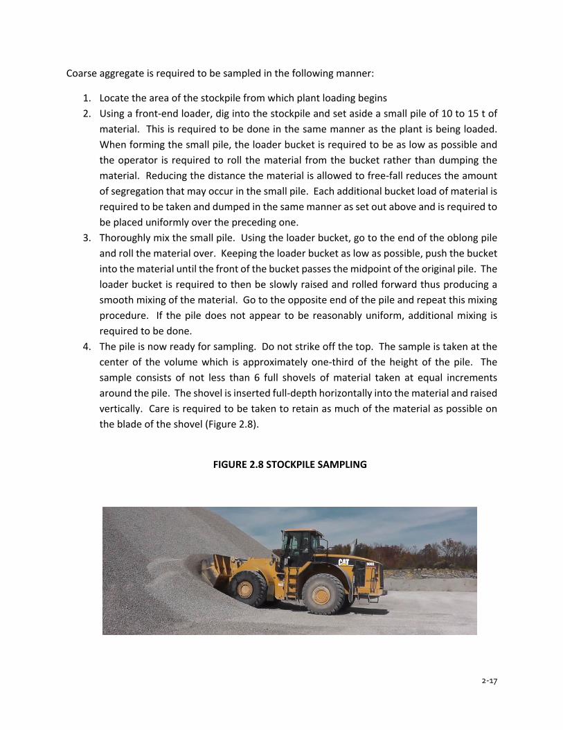
2-17
Coarse aggregate is required to be sampled in the following manner:
1. Locate the area of the stockpile from which plant loading begins 2. Using a front-end loader, dig into the stockpile and set aside a small pile of 10 to 15 t of
material. This is required to be done in the same manner as the plant is being loaded. When forming the small pile, the loader bucket is required to be as low as possible and the operator is required to roll the material from the bucket rather than dumping the material. Reducing the distance the material is allowed to free-fall reduces the amount of segregation that may occur in the small pile. Each additional bucket load of material is required to be taken and dumped in the same manner as set out above and is required to be placed uniformly over the preceding one.
3. Thoroughly mix the small pile. Using the loader bucket, go to the end of the oblong pile and roll the material over. Keeping the loader bucket as low as possible, push the bucket into the material until the front of the bucket passes the midpoint of the original pile. The loader bucket is required to then be slowly raised and rolled forward thus producing a smooth mixing of the material. Go to the opposite end of the pile and repeat this mixing procedure. If the pile does not appear to be reasonably uniform, additional mixing is required to be done.
4. The pile is now ready for sampling. Do not strike off the top. The sample is taken at the center of the volume which is approximately one-third of the height of the pile. The sample consists of not less than 6 full shovels of material taken at equal increments around the pile. The shovel is inserted full-depth horizontally into the material and raised vertically. Care is required to be taken to retain as much of the material as possible on the blade of the shovel (Figure 2.8).
FIGURE 2.8 STOCKPILE SAMPLING

2-18

2-19
Fine aggregates are sampled using the same technique used to sample coarse aggregates, except a sampling tube or fire shovel is used instead of the large shovel.
Truck, Car, or Barge Sampling
Direct sampling from trucks, railroads cars, or barges is not recommended. There are a number of factors which may influence the quality of the material before the aggregate is used. Therefore, material being shipped by trucks, railroad cars, or barges are required to be sampled at the point of delivery after the aggregate has been stockpiled.
SIZE OF ORIGINAL SAMPLE
The following is a list of recommended minimum sample sizes to be used as a guide when collecting materials.
MATERIAL SAMPLE SIZE
No. 2 coarse aggregate 220 lb
No. 5 coarse aggregate 110 lb
No. 8 coarse aggregate 55 lb
No. 9 coarse aggregate 35 lb
No. 11 & No. 12 coarse aggregate 25 lb
All sands 25 lb
The weight of the sample depends on the maximum particle size of the material being tested. As a rule, a larger top size material requires a larger sample. A 35 lb sample of No. 5 coarse aggregate would not be as representative of that material as a 35 lb sample of natural sand. The size of sample for materials that do not meet a specific INDOT size are required to be the same as the INDOT size the aggregate gradation is comparable to.
REDUCING A SAMPLE TO TEST SIZE
The total sample is required to be reduced to a sample size that may be continually tested. Time does not allow the Technician to test the total sample. The key to sample reduction is to ensure that the sample remains representative of the material in the stockpile. This practice is commonly referred to as splitting a sample. AASHTO R 76 details three different methods to reduce a sample to the proper test size.
1. Using a mechanical splitter is the most accepted method of reducing to test size all coarse aggregate material smaller than gradation size No. 2.
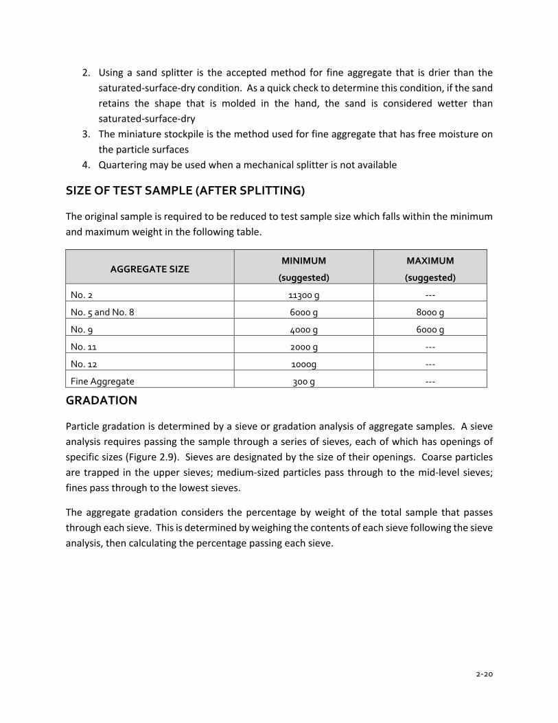
2-20
2. Using a sand splitter is the accepted method for fine aggregate that is drier than the saturated-surface-dry condition. As a quick check to determine this condition, if the sand retains the shape that is molded in the hand, the sand is considered wetter than saturated-surface-dry
3. The miniature stockpile is the method used for fine aggregate that has free moisture on the particle surfaces
4. Quartering may be used when a mechanical splitter is not available
SIZE OF TEST SAMPLE (AFTER SPLITTING)
The original sample is required to be reduced to test sample size which falls within the minimum and maximum weight in the following table.
AGGREGATE SIZE MINIMUM
(suggested)
MAXIMUM
(suggested)
No. 2 11300 g ---
No. 5 and No. 8 6000 g 8000 g
No. 9 4000 g 6000 g
No. 11 2000 g ---
No. 12 1000g ---
Fine Aggregate 300 g ---
GRADATION
Particle gradation is determined by a sieve or gradation analysis of aggregate samples. A sieve analysis requires passing the sample through a series of sieves, each of which has openings of specific sizes (Figure 2.9). Sieves are designated by the size of their openings. Coarse particles are trapped in the upper sieves; medium-sized particles pass through to the mid-level sieves; fines pass through to the lowest sieves.
The aggregate gradation considers the percentage by weight of the total sample that passes through each sieve. This is determined by weighing the contents of each sieve following the sieve analysis, then calculating the percentage passing each sieve.
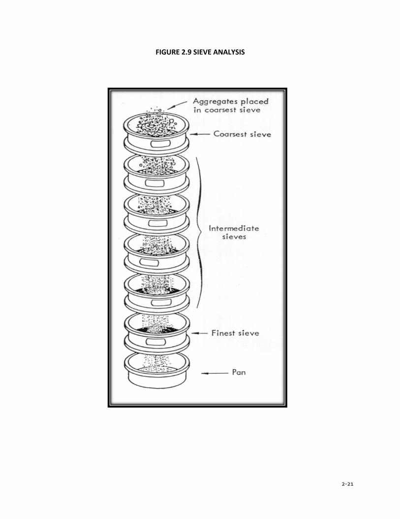
2-21
FIGURE 2.9 SIEVE ANALYSIS
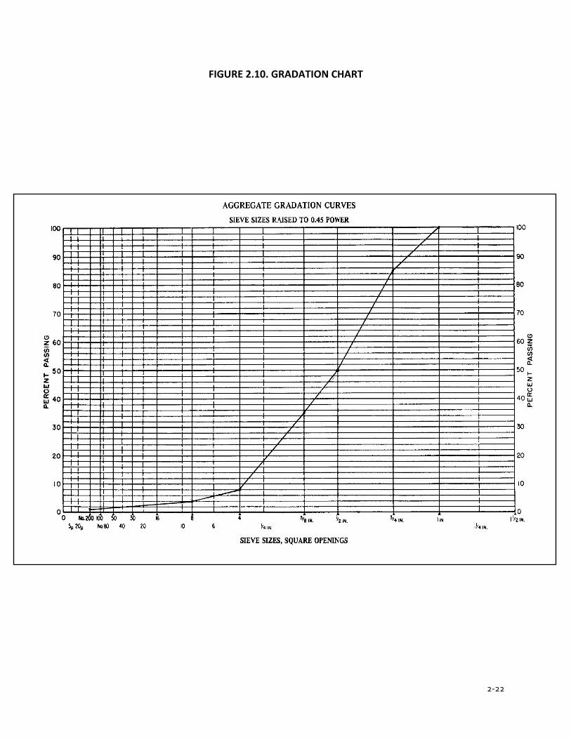
2-22
FIGURE 2.10. GRADATION CHART
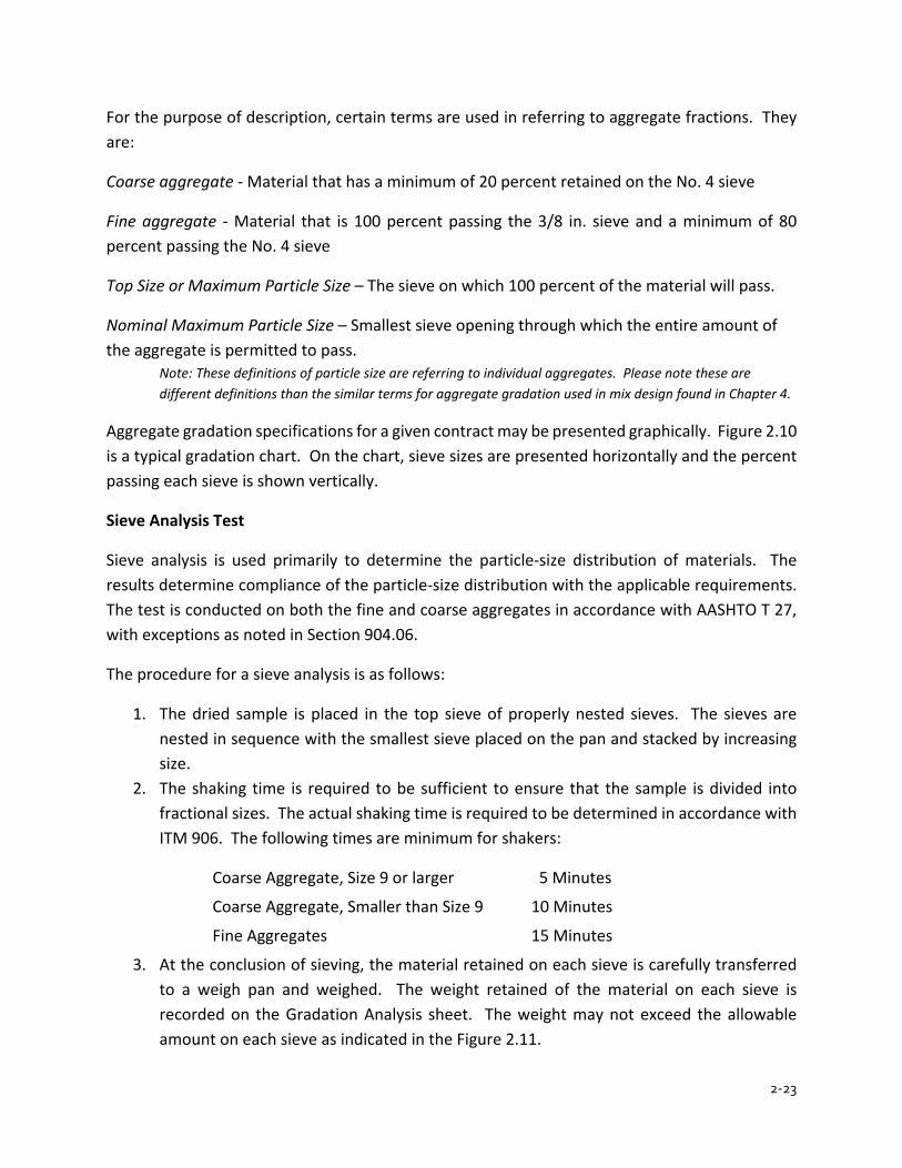
2-23
For the purpose of description, certain terms are used in referring to aggregate fractions. They are:
Coarse aggregate - Material that has a minimum of 20 percent retained on the No. 4 sieve
Fine aggregate - Material that is 100 percent passing the 3/8 in. sieve and a minimum of 80 percent passing the No. 4 sieve
Top Size or Maximum Particle Size – The sieve on which 100 percent of the material will pass.
Nominal Maximum Particle Size – Smallest sieve opening through which the entire amount of the aggregate is permitted to pass. Note: These definitions of particle size are referring to individual aggregates. Please note these are different definitions than the similar terms for aggregate gradation used in mix design found in Chapter 4.
Aggregate gradation specifications for a given contract may be presented graphically. Figure 2.10 is a typical gradation chart. On the chart, sieve sizes are presented horizontally and the percent passing each sieve is shown vertically.
Sieve Analysis Test
Sieve analysis is used primarily to determine the particle-size distribution of materials. The results determine compliance of the particle-size distribution with the applicable requirements. The test is conducted on both the fine and coarse aggregates in accordance with AASHTO T 27, with exceptions as noted in Section 904.06.
The procedure for a sieve analysis is as follows:
1. The dried sample is placed in the top sieve of properly nested sieves. The sieves are nested in sequence with the smallest sieve placed on the pan and stacked by increasing size.
2. The shaking time is required to be sufficient to ensure that the sample is divided into fractional sizes. The actual shaking time is required to be determined in accordance with ITM 906. The following times are minimum for shakers:
Coarse Aggregate, Size 9 or larger 5 Minutes
Coarse Aggregate, Smaller than Size 9 10 Minutes
Fine Aggregates 15 Minutes
3. At the conclusion of sieving, the material retained on each sieve is carefully transferred to a weigh pan and weighed. The weight retained of the material on each sieve is recorded on the Gradation Analysis sheet. The weight may not exceed the allowable amount on each sieve as indicated in the Figure 2.11.
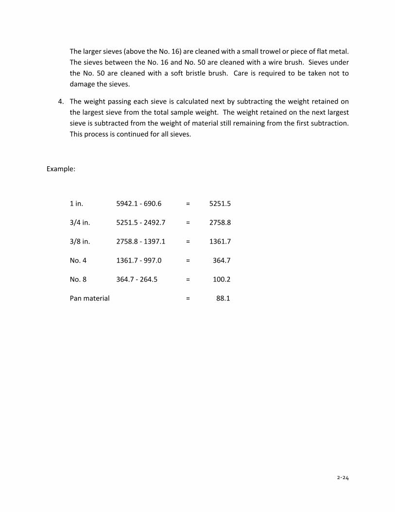
2-24
The larger sieves (above the No. 16) are cleaned with a small trowel or piece of flat metal. The sieves between the No. 16 and No. 50 are cleaned with a wire brush. Sieves under the No. 50 are cleaned with a soft bristle brush. Care is required to be taken not to damage the sieves.
4. The weight passing each sieve is calculated next by subtracting the weight retained on the largest sieve from the total sample weight. The weight retained on the next largest sieve is subtracted from the weight of material still remaining from the first subtraction. This process is continued for all sieves.
Example:
1 in. 5942.1 - 690.6 = 5251.5 3/4 in. 5251.5 - 2492.7 = 2758.8 3/8 in. 2758.8 - 1397.1 = 1361.7 No. 4 1361.7 - 997.0 = 364.7 No. 8 364.7 - 264.5 = 100.2 Pan material = 88.1
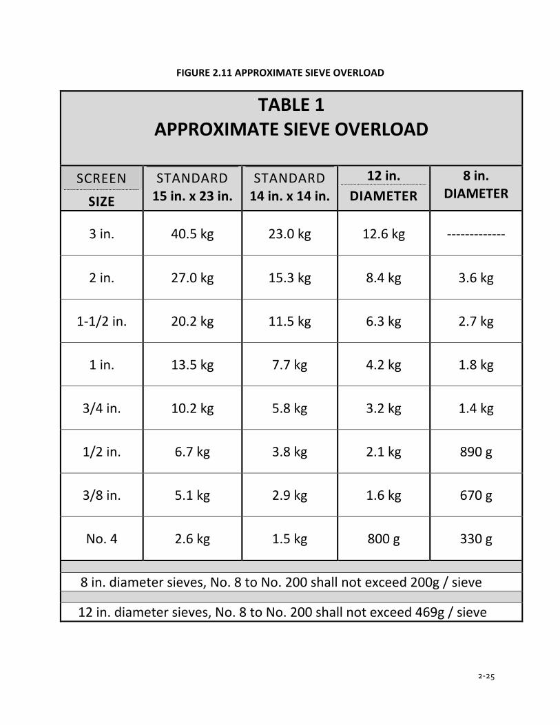
2-25
FIGURE 2.11 APPROXIMATE SIEVE OVERLOAD
TABLE 1 APPROXIMATE SIEVE OVERLOAD
SCREEN SIZE
STANDARD 15 in. x 23 in.
STANDARD 14 in. x 14 in.
12 in. DIAMETER
8 in. DIAMETER
3 in. 40.5 kg 23.0 kg 12.6 kg -------------
2 in. 27.0 kg 15.3 kg 8.4 kg 3.6 kg
1-1/2 in. 20.2 kg 11.5 kg 6.3 kg 2.7 kg
1 in. 13.5 kg 7.7 kg 4.2 kg 1.8 kg
3/4 in. 10.2 kg 5.8 kg 3.2 kg 1.4 kg
1/2 in. 6.7 kg 3.8 kg 2.1 kg 890 g
3/8 in. 5.1 kg 2.9 kg 1.6 kg 670 g
No. 4 2.6 kg 1.5 kg 800 g 330 g
8 in. diameter sieves, No. 8 to No. 200 shall not exceed 200g / sieve
12 in. diameter sieves, No. 8 to No. 200 shall not exceed 469g / sieve

2-26
FIGURE 2.12 GRADATION EXAMPLE
TOTAL WEIGHT: 5942.1g
SIEVE SIZE
WEIGHT
RETAINED
WEIGHT PASSING
PERCENT PASSING
PERCENT
REQUIRED
1½ in.
g
g
%
%
1 in.
0 g
5942.1 g
%
%
¾ in.
690.6 g
5251.5 g
%
%
½ in.
2492.7 g
2758.8 g
%
%
⅜ in.
1397.1 g
1361.7 g
%
%
No. 4
997.0 g
364.7 g
%
%
No. 8
264.5 g
100.2 g
%
%
No. 16
g
g
%
%
No. 30
g
g
%
%
No. 50
g
g
%
%
No. 100
g
g
%
%
No. 200
g
g
%
%
PAN
88.1 g
g
%
% DECANT
ORIGINAL
FINAL
GRAMS
LOSS
PERCENT
LOSS
PERCENT
REQUIRED
g
g
g
%
%
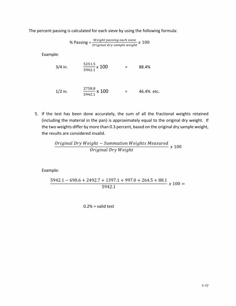
2-27
The percent passing is calculated for each sieve by using the following formula:
% Passing = 𝑊𝑊𝑊𝑊𝑊𝑊𝑊𝑊ℎ𝑡𝑡 𝑝𝑝𝑝𝑝𝑝𝑝𝑝𝑝𝑊𝑊𝑝𝑝𝑊𝑊 𝑊𝑊𝑝𝑝𝑒𝑒ℎ 𝑝𝑝𝑊𝑊𝑊𝑊𝑠𝑠𝑊𝑊𝑂𝑂𝑂𝑂𝑊𝑊𝑊𝑊𝑊𝑊𝑝𝑝𝑝𝑝𝑂𝑂 𝑑𝑑𝑂𝑂𝑑𝑑 𝑝𝑝𝑝𝑝𝑠𝑠𝑝𝑝𝑂𝑂𝑊𝑊 𝑤𝑤𝑊𝑊𝑊𝑊𝑊𝑊ℎ𝑡𝑡
𝑥𝑥 100
Example:
3/4 in. 5251.55942.1
x 100 = 88.4%
1/2 in. 2758.85942.1
x 100 = 46.4% etc.
5. If the test has been done accurately, the sum of all the fractional weights retained (including the material in the pan) is approximately equal to the original dry weight. If the two weights differ by more than 0.3 percent, based on the original dry sample weight, the results are considered invalid.
𝑂𝑂𝑂𝑂𝑂𝑂𝑂𝑂𝑂𝑂𝑂𝑂𝑂𝑂𝑂𝑂 𝐷𝐷𝑂𝑂𝐷𝐷 𝑊𝑊𝑊𝑊𝑂𝑂𝑂𝑂ℎ𝑡𝑡 − 𝑆𝑆𝑆𝑆𝑆𝑆𝑆𝑆𝑂𝑂𝑡𝑡𝑂𝑂𝑆𝑆𝑂𝑂 𝑊𝑊𝑊𝑊𝑂𝑂𝑂𝑂ℎ𝑡𝑡𝑡𝑡 𝑀𝑀𝑊𝑊𝑂𝑂𝑡𝑡𝑆𝑆𝑂𝑂𝑊𝑊𝑀𝑀𝑂𝑂𝑂𝑂𝑂𝑂𝑂𝑂𝑂𝑂𝑂𝑂𝑂𝑂𝑂𝑂 𝐷𝐷𝑂𝑂𝐷𝐷 𝑊𝑊𝑊𝑊𝑂𝑂𝑂𝑂ℎ𝑡𝑡
𝑥𝑥 100
Example:
5942.1 − 690.6 + 2492.7 + 1397.1 + 997.0 + 264.5 + 88.15942.1
𝑥𝑥 100 =
0.2% = valid test
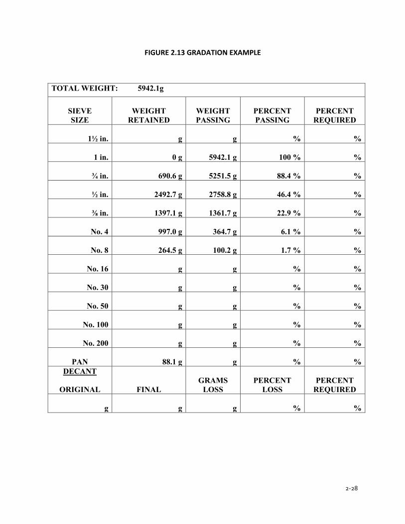
2-28
FIGURE 2.13 GRADATION EXAMPLE
TOTAL WEIGHT: 5942.1g
SIEVE SIZE
WEIGHT
RETAINED
WEIGHT PASSING
PERCENT PASSING
PERCENT
REQUIRED
1½ in.
g
g
%
%
1 in.
0 g
5942.1 g
100 %
%
¾ in.
690.6 g
5251.5 g
88.4 %
%
½ in.
2492.7 g
2758.8 g
46.4 %
%
⅜ in.
1397.1 g
1361.7 g
22.9 %
%
No. 4
997.0 g
364.7 g
6.1 %
%
No. 8
264.5 g
100.2 g
1.7 %
%
No. 16
g
g
%
%
No. 30
g
g
%
%
No. 50
g
g
%
%
No. 100
g
g
%
%
No. 200
g
g
%
%
PAN
88.1 g
g
%
% DECANT
ORIGINAL
FINAL
GRAMS
LOSS
PERCENT
LOSS
PERCENT
REQUIRED
g
g
g
%
%
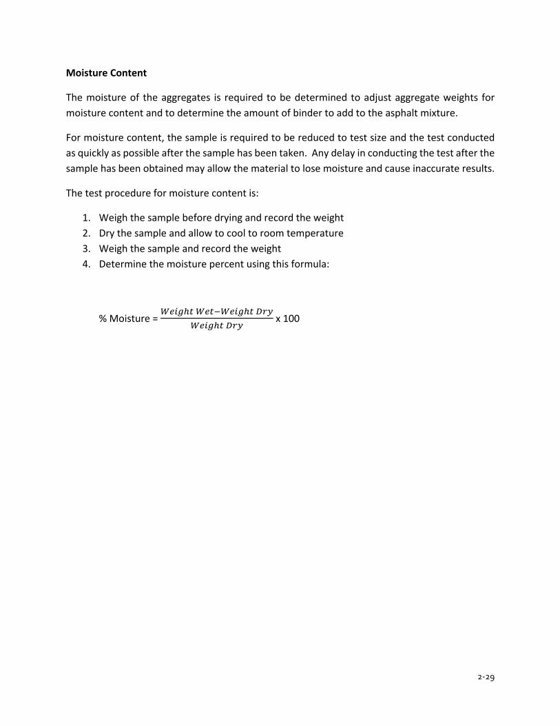
2-29
Moisture Content
The moisture of the aggregates is required to be determined to adjust aggregate weights for moisture content and to determine the amount of binder to add to the asphalt mixture.
For moisture content, the sample is required to be reduced to test size and the test conducted as quickly as possible after the sample has been taken. Any delay in conducting the test after the sample has been obtained may allow the material to lose moisture and cause inaccurate results.
The test procedure for moisture content is:
1. Weigh the sample before drying and record the weight 2. Dry the sample and allow to cool to room temperature 3. Weigh the sample and record the weight 4. Determine the moisture percent using this formula:
% Moisture = 𝑊𝑊𝑊𝑊𝑊𝑊𝑊𝑊ℎ𝑡𝑡 𝑊𝑊𝑊𝑊𝑡𝑡−𝑊𝑊𝑊𝑊𝑊𝑊𝑊𝑊ℎ𝑡𝑡 𝐷𝐷𝑂𝑂𝑑𝑑
𝑊𝑊𝑊𝑊𝑊𝑊𝑊𝑊ℎ𝑡𝑡 𝐷𝐷𝑂𝑂𝑑𝑑 x 100

CHAPTER 3ASPHALT BINDER
3-1
CHAPTER 3 ASPHALT BINDER
ASPHALT
SOURCE AND NATURE OF ASPHALT PERFORMANCE GRADED BINDER
ASPHALT HANDLING, STORAGE, AND SAMPLING HANDLING STORAGE SAMPLING
BINDER VOLUME SPECIFIC GRAVITY
TEMPERATURE VOLUME RELATIONSHIPS ASPHALT SUPPLIER CERTIFICATION PROGRAM

3-2
CHAPTER 3 ASPHALT BINDER
Asphalt mixture is composed of aggregates bound together with asphalt binder. Performance of the pavement is affected by properties of the aggregates, properties of the asphalt binder and proportions of each. The required properties as listed in the specifications are based on anticipated traffic and climate where the pavement is to be built.
This section discusses the properties of asphalt binders. Most asphalt binder tests are not done by contractor people; however, an understanding asphalt binder properties and test procedures is useful background for some day-to-day decisions.
ASHPALT
SOURCE AND NATURE OF ASPHALT
Asphalt is extracted from crude oil that is composed of hydrocarbon molecules, that is, molecules containing mostly of hydrogen and carbon. Crude oil is a mixture of different size molecules that have different boiling points. Figure 3.1 shows the boiling point ranges of different molecules in the crude oil. Oil refineries use distillation to “boil off” different size molecules as shown in Figure 3.1. For example, a molecule of diesel fuel boil between 575F and 700F. Crude oil is heated to 900F and since asphalt binder boils at a higher temperature, a residue is left.
Not all crude oil produces acceptable asphalt binder. Figure 3.1 shows different crude oils. Generally, crude oils with small amounts of asphalt binder in them, such as the Barrow Island crude (from Alaska) cannot be used to produce asphalt binder. Other crudes with a high percentage of asphalt binder, such as Boscan crude, produce good quality asphalt binders. In Indiana, most crude oil comes from Western Canada and produces good quality asphalt binders.
FIGURE 3.1 TYPICAL DISTILLATION TEMPERATURES AND PRODUCTS
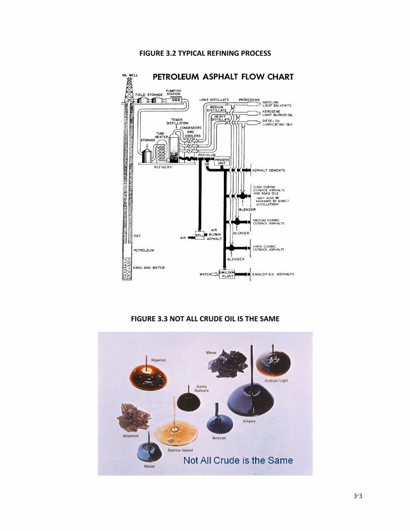
3-3
FIGURE 3.2 TYPICAL REFINING PROCESS
FIGURE 3.3 NOT ALL CRUDE OIL IS THE SAME
3-4
Many materials have a melting point, that is, a temperature at which it turns from solid to liquid. For example, water at 33℉ is a liquid. At 31℉ it is a solid, ice. At 32℉ water changes from liquid to solid. Asphalt binder does not have one temperature at which it changes from liquid to solid.
At very high temperatures, greater than 400℉, asphalt binder is a pure liquid. At very cold temperatures, about -50℉ or colder, it is a pure solid. At any temperature in between, it has both liquid and solid behavior at the same time. As temperature increases, the proportion of liquid behavior increases until it becomes a pure liquid. The opposite happens as temperature decreases.
Asphalt binder behavior depends on
• Temperature • Time of loading • Age
Temperature is the most commonly understood factor. Most people know that if asphalt is heated it becomes soft. And if it is heated enough, it will turn to liquid. Time of loading is less obvious. Asphalt binder will react with a different stiffness depending on how fast a load is placed.
So, for example, if you go to a swimming pool and someone asks, “How stiff is the water in the pool? How hard is it?” The response might be, “Huh. What are you talking about?” and you swish your hand in the water and say, “It’s not very hard at all. It’s water!”
And they say, “Why don’t you climb up that 30 foot high diving platform and dive off. Don’t worry that you don’t know how to dive. After all, the water is soft.”
When you hit the water at 50 mph, the water is not very soft. It’s pretty hard. It is the same water in the pool. In one case we put a load on slowly, by swishing our hand through the water. In the other case, we put it on quickly.
Asphalt binder works the same way. Cars and trucks moving at highway speed put a load on the pavement much faster than trucks coming to a stop at a red light.
Asphalt binder changes as it ages. Oxygen reacts with the asphalt molecules and the binder becomes harder and more brittle. The rate at which asphalt binder ages depends on the length of time it is exposed to high temperature, and access to oxygen during time in service. Low density on the road allows air to permeate into the pavement and accelerate aging.
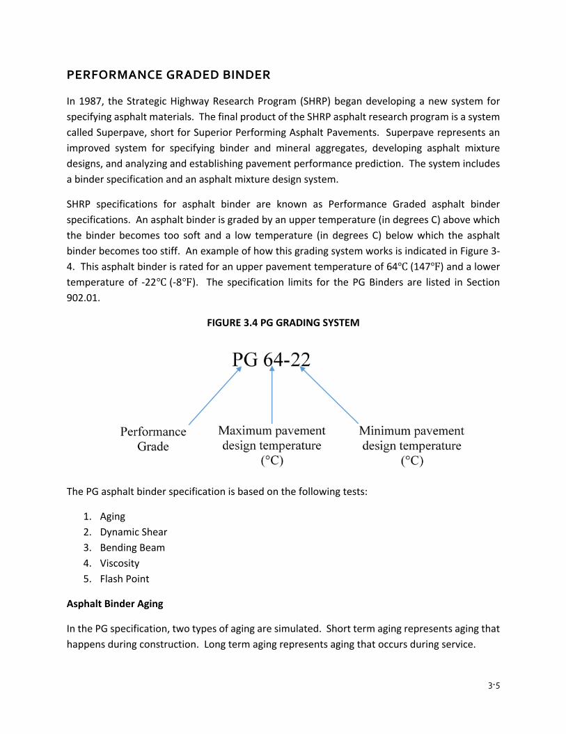
3-5
PERFORMANCE GRADED BINDER
In 1987, the Strategic Highway Research Program (SHRP) began developing a new system for specifying asphalt materials. The final product of the SHRP asphalt research program is a system called Superpave, short for Superior Performing Asphalt Pavements. Superpave represents an improved system for specifying binder and mineral aggregates, developing asphalt mixture designs, and analyzing and establishing pavement performance prediction. The system includes a binder specification and an asphalt mixture design system.
SHRP specifications for asphalt binder are known as Performance Graded asphalt binder specifications. An asphalt binder is graded by an upper temperature (in degrees C) above which the binder becomes too soft and a low temperature (in degrees C) below which the asphalt binder becomes too stiff. An example of how this grading system works is indicated in Figure 3-4. This asphalt binder is rated for an upper pavement temperature of 64℃ (147℉) and a lower temperature of -22℃ (-8℉). The specification limits for the PG Binders are listed in Section 902.01.
FIGURE 3.4 PG GRADING SYSTEM
The PG asphalt binder specification is based on the following tests:
1. Aging 2. Dynamic Shear 3. Bending Beam 4. Viscosity 5. Flash Point
Asphalt Binder Aging
In the PG specification, two types of aging are simulated. Short term aging represents aging that happens during construction. Long term aging represents aging that occurs during service.

3-6
Rolling Thin Film Oven, AASHTO T 240, (RTFO) (Figure 3.5) is used for short term aging. For long term aging the RTFO asphalt binder is conditioned with a Pressure Aging Vessel (PAV) (Figure 3.6).
FIGURE 3.5 ROLLING THIN FILM OVER (RTFO)
The PAV test (AASHTO R 28) uses a pressurized container into which pans containing RTFO residue binders are placed. Samples in the PAV are subjected to pressure for 20 hours.
FIGURE 3.6 PRESSURE AGING VESSEL

3-7
Dynamic Shear
Stiffness at high temperature is measured using dynamic shear (AASHTO T 315). A sample of asphalt about the size and thickness of a quarter is placed between two plates as shown in Figure 3.7.
FIGURE 3.7 DYNAMIC SHEAR RHEOMETER
Bending Beam
Low temperature stiffness of the binder is evaluated using the bending beam rheometer (AASHTO T 313). A beam of asphalt binder (about 6 inches long, ¾ inch wide and ¼ inch thick) is supported at each end and loaded in the middle. Deflection is measured for 5 minutes and a stiffness versus time curve is developed. Figure 3.8 provides a schematic view of the test apparatus.
FIGURE 3.8 BENDING BEAM

3-8
ASPHALT HANDLING, STORAGE, AND SAMPLING
HANDLING
The Technician is required to be aware of the potential sources of contamination that may exist where asphalt materials are stored or handled. Changes in volume that the asphalt material undergoes when heated or cooled are required to also be understood. This knowledge is especially important when comparing asphalt material quantities measured at different temperatures.
Please see Chapter 1 for more information about safety when handling asphalt materials.
STORAGE
The Technician is not required to test the binder or asphalt emulsion for Specification purposes. However, the Technician is required to be aware that these materials are tested for compliance based on samples from the asphalt mix plant, not the asphalt refinery. Therefore, the Technician is required to know what plant conditions could change the physical properties of these materials and possibly cause the materials to become out of Specification.
Three major problems may cause the asphalt binder to be outside of the Specifications. The first is contamination. If hot oil is used to heat the binder tank, then any leak in the system that allows hot oil to escape into the asphalt binder will cause the binder to become softer. Another source of contamination is fuel oil. If binder is contaminated with significant quantities of fuel oil because of flushing pumps and lines, then the binder stiffness drops.
A second and more prevalent problem is the effect that extended heating in storage tanks has on the binder. When binder is heated, the binder slowly increases in stiffness. The rate of change in viscosity is dependent on the size of tank, surface area, amount of circulation, temperature, etc. The problem of compliance with the Specifications generally is found after extended storage (e.g. long rainy periods). Material failure may be avoided by reducing heat and circulation during these periods. When the Technician has some doubts about the material, the binder is required to be tested to determine compliance. This greatly minimizes the number of problems and penalties associated with failures.
A third problem encountered with binder is improper storage. Modified binders include additives to improve (extend) the grade to encompass a wider temperature range for performance. Many of these modified binders are required to be stored under special conditions to maintain their properties. Material supplier recommendations for storage and handling are required to be followed.
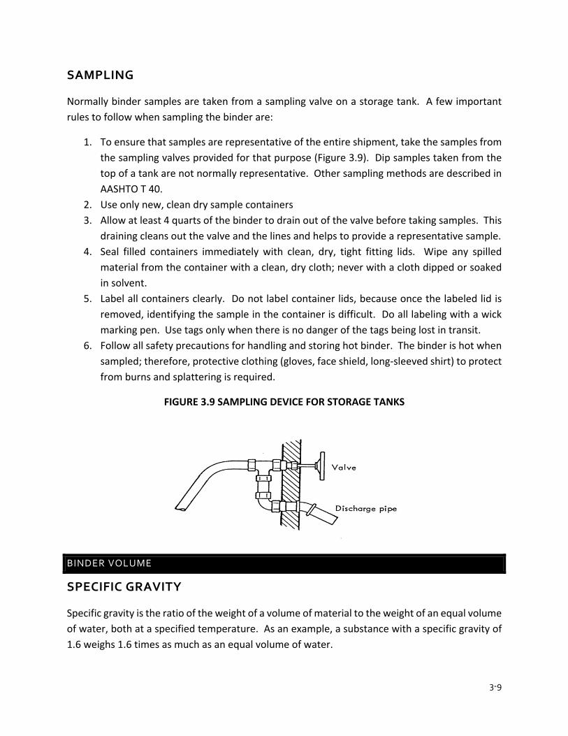
3-9
SAMPLING
Normally binder samples are taken from a sampling valve on a storage tank. A few important rules to follow when sampling the binder are:
1. To ensure that samples are representative of the entire shipment, take the samples from the sampling valves provided for that purpose (Figure 3.9). Dip samples taken from the top of a tank are not normally representative. Other sampling methods are described in AASHTO T 40.
2. Use only new, clean dry sample containers 3. Allow at least 4 quarts of the binder to drain out of the valve before taking samples. This
draining cleans out the valve and the lines and helps to provide a representative sample. 4. Seal filled containers immediately with clean, dry, tight fitting lids. Wipe any spilled
material from the container with a clean, dry cloth; never with a cloth dipped or soaked in solvent.
5. Label all containers clearly. Do not label container lids, because once the labeled lid is removed, identifying the sample in the container is difficult. Do all labeling with a wick marking pen. Use tags only when there is no danger of the tags being lost in transit.
6. Follow all safety precautions for handling and storing hot binder. The binder is hot when sampled; therefore, protective clothing (gloves, face shield, long-sleeved shirt) to protect from burns and splattering is required.
FIGURE 3.9 SAMPLING DEVICE FOR STORAGE TANKS
BINDER VOLUME
SPECIFIC GRAVITY
Specific gravity is the ratio of the weight of a volume of material to the weight of an equal volume of water, both at a specified temperature. As an example, a substance with a specific gravity of 1.6 weighs 1.6 times as much as an equal volume of water.
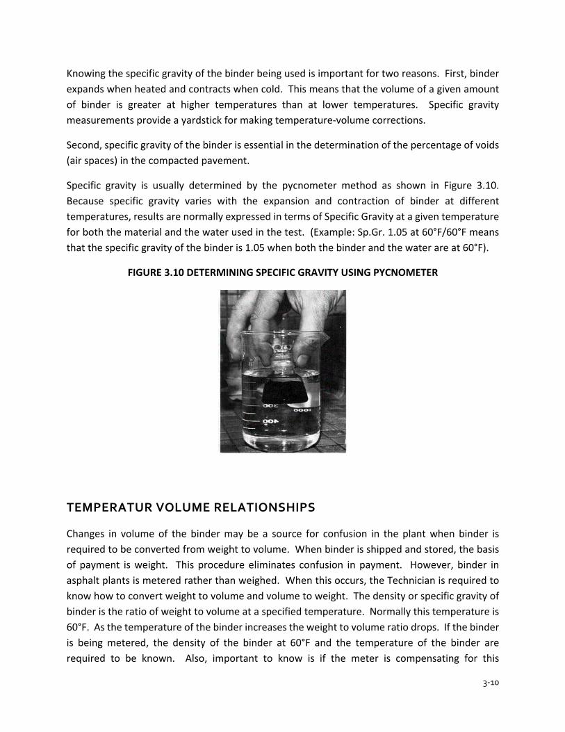
3-10
Knowing the specific gravity of the binder being used is important for two reasons. First, binder expands when heated and contracts when cold. This means that the volume of a given amount of binder is greater at higher temperatures than at lower temperatures. Specific gravity measurements provide a yardstick for making temperature-volume corrections.
Second, specific gravity of the binder is essential in the determination of the percentage of voids (air spaces) in the compacted pavement.
Specific gravity is usually determined by the pycnometer method as shown in Figure 3.10. Because specific gravity varies with the expansion and contraction of binder at different temperatures, results are normally expressed in terms of Specific Gravity at a given temperature for both the material and the water used in the test. (Example: Sp.Gr. 1.05 at 60°F/60°F means that the specific gravity of the binder is 1.05 when both the binder and the water are at 60°F).
FIGURE 3.10 DETERMINING SPECIFIC GRAVITY USING PYCNOMETER
TEMPERATUR VOLUME RELATIONSHIPS
Changes in volume of the binder may be a source for confusion in the plant when binder is required to be converted from weight to volume. When binder is shipped and stored, the basis of payment is weight. This procedure eliminates confusion in payment. However, binder in asphalt plants is metered rather than weighed. When this occurs, the Technician is required to know how to convert weight to volume and volume to weight. The density or specific gravity of binder is the ratio of weight to volume at a specified temperature. Normally this temperature is 60°F. As the temperature of the binder increases the weight to volume ratio drops. If the binder is being metered, the density of the binder at 60°F and the temperature of the binder are required to be known. Also, important to know is if the meter is compensating for this
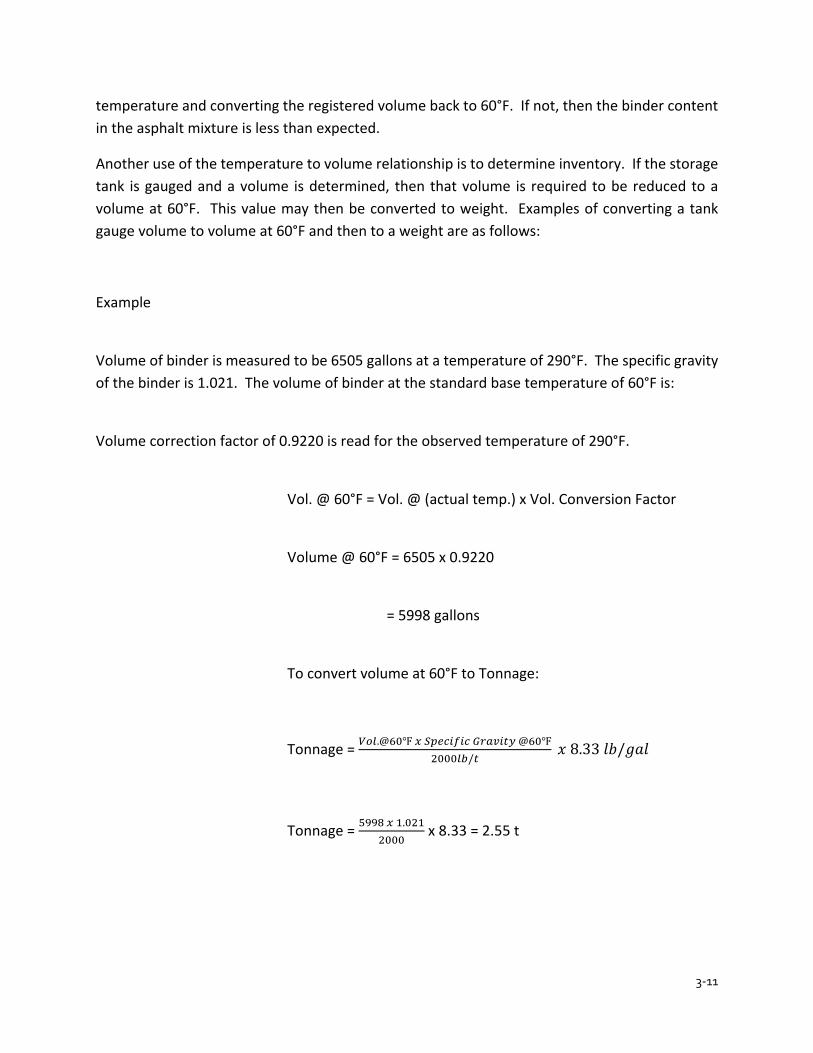
3-11
temperature and converting the registered volume back to 60°F. If not, then the binder content in the asphalt mixture is less than expected.
Another use of the temperature to volume relationship is to determine inventory. If the storage tank is gauged and a volume is determined, then that volume is required to be reduced to a volume at 60°F. This value may then be converted to weight. Examples of converting a tank gauge volume to volume at 60°F and then to a weight are as follows:
Example
Volume of binder is measured to be 6505 gallons at a temperature of 290°F. The specific gravity of the binder is 1.021. The volume of binder at the standard base temperature of 60°F is:
Volume correction factor of 0.9220 is read for the observed temperature of 290°F.
Vol. @ 60°F = Vol. @ (actual temp.) x Vol. Conversion Factor
Volume @ 60°F = 6505 x 0.9220
= 5998 gallons
To convert volume at 60°F to Tonnage:
Tonnage = 𝑉𝑉𝑉𝑉𝑉𝑉.@60℉ 𝑥𝑥 𝑆𝑆𝑆𝑆𝑆𝑆𝑆𝑆𝑆𝑆𝑆𝑆𝑆𝑆𝑆𝑆 𝐺𝐺𝐺𝐺𝐺𝐺𝐺𝐺𝑆𝑆𝐺𝐺𝐺𝐺 @60℉2000𝑉𝑉𝑙𝑙/𝐺𝐺
𝑥𝑥 8.33 𝑙𝑙𝑙𝑙/𝑔𝑔𝑔𝑔𝑙𝑙
Tonnage = 5998 𝑥𝑥 1.0212000
x 8.33 = 2.55 t

3-12
FIGURE 3.11 TEMPERATURE VOLUME CORRECTIONS FOR BINDER
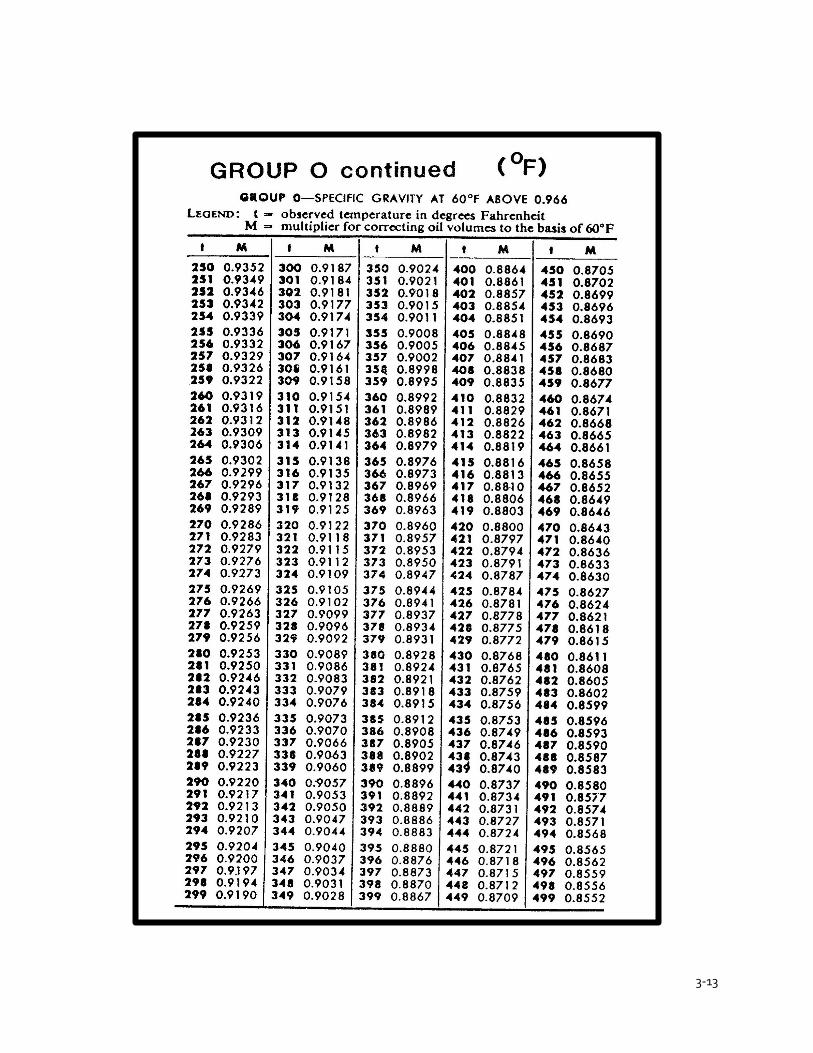
3-13

3-14
ASPHALT SUPPLIER CERTIFICATION PROGRAM
The Asphalt Supplier Certification Program (ASC) is a program in which a qualified asphalt supplier is allowed to manufacture and ship PG binders without complete pre-testing of the PG binder by INDOT or the supplier. PG binders are required to be supplied by an approved supplier in accordance with ITM 581.
PG binders that are shipped to asphalt mixture plants are required to have a shipping report indicating that the material was manufactured in accordance with the ASC program. Also, the supplier is required to furnish instructions with each PG binder concerning the proper storage and handling of the material.

CHAPTER 4ASPHALT VOLUMETRICS
4-1
CHAPTER 4 ASPHALT VOLUMETRICS
MIX CHARACTERISTICS AND BEHAVIOR BULK SPECIFIC GRAVITY OR DENSITY
VOIDS IN THE MINERAL AGGREGATES AIR VOIDS VOIDS FILLED WITH ASPHALT BINDER CONTENT PLANT PRODUCED ASPHALT MIXTURE
PROPERTIES CONSIDERED IN MIX DESIGN RUT RESISTANCE DURABILITY IMPERMEABILITY
WORKABILITY FATIGUE RESISTANCE
SUPERPAVE MIX DESIGN METHOD AGGREGATES
AGGREGATE BLENDING RECYCLED MATERIALS SUPERPAVE SPECIMENS MAXIMUM SPECIFIC GRAVITY BULK SPECIFIC GRAVITY – DENSE GRADED MIXTURES AND SMA BULK SPECFIC GRAVITY – RECYCLED MATERIALS DUST/CALCULATED EFFECTIVE BINDER RATIO AIR VOIDS VOIDS IN THE MINERAL AGGREGATE VOIDES FILLED WITH ASPHALT MOISTURE SUSCEPTIBILITY EXAMPLE CALCULATIONS
STONE MATRIX ASPHALT
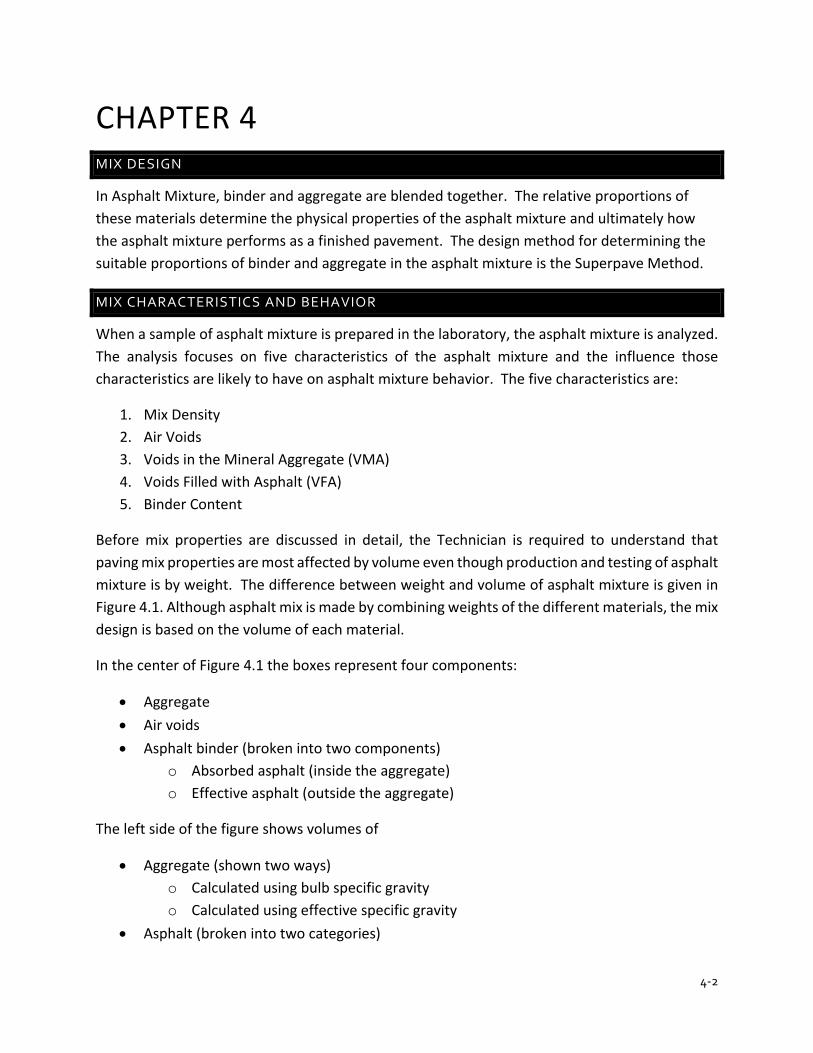
4-2
CHAPTER 4 MIX DESIGN
In Asphalt Mixture, binder and aggregate are blended together. The relative proportions of these materials determine the physical properties of the asphalt mixture and ultimately how the asphalt mixture performs as a finished pavement. The design method for determining the suitable proportions of binder and aggregate in the asphalt mixture is the Superpave Method.
MIX CHARACTERISTICS AND BEHAVIOR
When a sample of asphalt mixture is prepared in the laboratory, the asphalt mixture is analyzed. The analysis focuses on five characteristics of the asphalt mixture and the influence those characteristics are likely to have on asphalt mixture behavior. The five characteristics are:
1. Mix Density 2. Air Voids 3. Voids in the Mineral Aggregate (VMA) 4. Voids Filled with Asphalt (VFA) 5. Binder Content
Before mix properties are discussed in detail, the Technician is required to understand that paving mix properties are most affected by volume even though production and testing of asphalt mixture is by weight. The difference between weight and volume of asphalt mixture is given in Figure 4.1. Although asphalt mix is made by combining weights of the different materials, the mix design is based on the volume of each material.
In the center of Figure 4.1 the boxes represent four components:
• Aggregate • Air voids • Asphalt binder (broken into two components)
o Absorbed asphalt (inside the aggregate) o Effective asphalt (outside the aggregate)
The left side of the figure shows volumes of
• Aggregate (shown two ways) o Calculated using bulb specific gravity o Calculated using effective specific gravity
• Asphalt (broken into two categories)
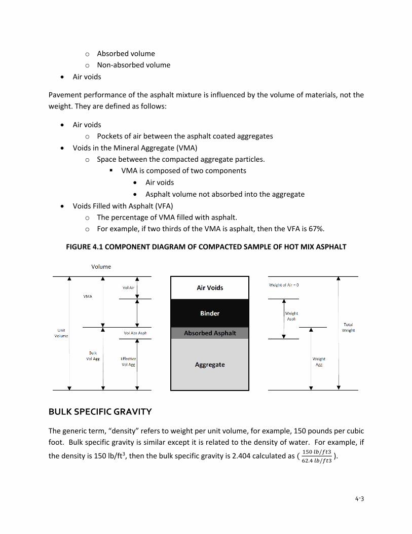
4-3
o Absorbed volume o Non-absorbed volume
• Air voids
Pavement performance of the asphalt mixture is influenced by the volume of materials, not the weight. They are defined as follows:
• Air voids o Pockets of air between the asphalt coated aggregates
• Voids in the Mineral Aggregate (VMA) o Space between the compacted aggregate particles.
VMA is composed of two components • Air voids • Asphalt volume not absorbed into the aggregate
• Voids Filled with Asphalt (VFA) o The percentage of VMA filled with asphalt. o For example, if two thirds of the VMA is asphalt, then the VFA is 67%.
FIGURE 4.1 COMPONENT DIAGRAM OF COMPACTED SAMPLE OF HOT MIX ASPHALT
BULK SPECIFIC GRAVITY
The generic term, “density” refers to weight per unit volume, for example, 150 pounds per cubic foot. Bulk specific gravity is similar except it is related to the density of water. For example, if
the density is 150 lb/ft3, then the bulk specific gravity is 2.404 calculated as ( 150 𝑙𝑙𝑙𝑙/𝑓𝑓𝑓𝑓362.4 𝑙𝑙𝑙𝑙/𝑓𝑓𝑓𝑓3
).

4-4
There are two common uses for the term “density”. Don’t be confused by them. Often people will talk about the density being achieved on a project, such as, “The average density is 93.2%”. This is really compaction.
In mix design, the term “density” refers to density of the gyratory compacted specimens. It is measured as bulk specific gravity.
VOIDS IN MINERAL AGGREGATES
Voids in the mineral aggregate (VMA) are the void spaces between the aggregate particles in the compacted paving asphalt mixture. See Figure 4.2. The space between the compacted aggregate particles (VMA) in the mix is calculated.
VMA is the space available for the volume of asphalt binder that is not absorbed, Vbe, and the volume of air voids necessary in the asphalt mixture. Minimum VMA and Vbe is specified in section 401.05 of INDOT specifications. For example, if the mixture being designed is a 9.5-mm mixture, the minimum VMA is 16.0%. Since design air voids are fixed at 5.0% the minimum volume of effective asphalt binder, Vbe, is 11.0%. Hence, Vbe is the main control of minimum asphalt content.
FIGURE 4.2 ILLUSTRATION OF VMA IN COMPACTED SPECIMEN
Factors that influence the packing of aggregate particles include:
Gradation
4-5
• This is the main tool used by mix designers to control VMA. Changing gradation, changes the amount of space between the aggregate (VMA).
Shape • Cubical particles will compact to a tighter configuration (have lower VMA) than the same
gradation of flat “potato-chip” shaped particles. Texture
• Particles with a rough, “sand-papery” texture will resist compaction, that is, they will have a higher VMA.
Angularity • Particles with sharp edges will resist compaction more than particles with rounded edges,
that is, they will have a higher VMA. Aggregate hardness
• Aggregates formed from softer rock, such as soft limestone, will compact more tightly because edges of the particles will break off.
Type and amount of compaction • For any set of aggregates (gradation, shape, texture, angularity and hardness) the more
compaction that is applied, the less space will remain between the aggregate particles.
Although the list of factors that impact compaction of aggregates is lengthy, many of the factors are outside the control of the mix designer. In the end, the main tool to control VMA is gradation. For a given mix design
• Compaction type (Superpave gyratory) and compaction amount (the number of design gyrations) is designated by the mix specification and cannot be changed by the designer.
• Hardness of the aggregate is usually not a choice of the designer. The availability of alternate sources of aggregate with different hardness are usually not choices given to the designer. They must attempt to design using the aggregates available.
• Shape, texture and angularity are available to the designer in that natural sand versus manufactured sand are choices the designer can make. At the same time, aggregate specifications in the mix design will limit the degree of freedom.
AIR VOIDS
Air voids are small pockets of air between the coated aggregate particles in the compacted asphalt mixture. A pavement needs a minimum percentage of air voids to prevent the pavement from flushing, shoving, and rutting. High air voids will lead to shortened pavement life from accelerated aging.

4-6
Air voids are important. Asphalt binder has both liquid behavior and solid behavior at the same time. At high temperature, 350 to 400℉ , asphalt binder is a liquid and can be poured. At low temperature, -40 to -50℉ , asphalt binder is a solid. Anywhere in between it has both liquid and solid behavior at the same time. And it is continually changing. At high temperature the stiffness of asphalt binder is lower and the percent of stiffness coming from the liquid behavior is greater than at low temperature.
To understand why HMA needs air voids, consider fresh concrete (with no air entrainment). The concrete mix is saturated (with water) since all space between the aggregate particles is filled. If the concrete won’t trowel nice and smooth, one way to make it more workable is to vibrate it by smacking it with the trowel. After a few hits (pumping up and down) with the trowel, it become soft and putty-like.
Consider what is happening in the concrete. When a trowel hits the fresh concrete a load pulse (pressure) goes down into the concrete. This pressure goes into the water (liquid phase) of the concrete. If there is only one pulse, the pressure will dissipate as it spreads down into the concrete and outwards. It is like dropping a pebble into a pond and watching the wave go outwards and disappear.
If another load pulse is applied before the pressure disappears then pressure will start to build up in the liquid. Once the pressure builds high enough, the rocks are pushed a part and the concrete become soft and putty-like.
Now, consider a spot on an asphalt pavement on a hot summer day. A truck approaches and the steering axle applies a load and takes it off. Very shortly after, the first drive axle applies a load, then the second drive axle. And just a short time later, the two trailer axles. And if there is a line of trucks then there are 10 or 15 or 20 or 25 loads applied to the pavement.
At summer temperatures the asphalt binder in the pavement is not liquid, but it has a higher percentage of liquid behavior than at cooler temperatures. If the asphalt pavement has zero percent air voids, that is, if it is saturated, then pressure from the repeated load pulses builds up and the pavement has a lower stiffness when the last axle of the last truck crosses the point. So, the pavement will rut.
So, what do air voids do? Air voids act like shock absorbers. Air is very compressible and instead of pressure building up in the asphalt binder, the air voids are slightly compressed. As a result, the pavement has the same stiffness when the last axle of the last truck is applied as when the first axle was applied. And the pavement does not rut.
Air void content is related to the durability, that is, a long life, of an asphalt mixture. If air voids are too low, it will lead to rutting and flushing. If too high the voids provide passageways into
4-7
the asphalt mixture for air and water to enter. This can lead to accelerated aging of the asphalt binder or stripping where water peels the asphalt binder off the rocks.
VOIDS FILLED WITH ASPHALT
Voids filled with asphalt (VFA) are the void spaces that exist between the aggregate particles in the compacted paving asphalt mixture that are filled with binder. VFA is expressed as a percentage of the VMA that contains binder.
VFA can be thought of as degree of saturation. If VFA is 100%, that is, air voids are zero, then there will be no “shock absorbers”. If the VFA is low, then there are too many air voids. Air and water will be able to enter the pavement.
BINDER CONTENT
The amount of asphalt binder in the mixture is critical. Low asphalt binder will lead to accelerated aging and cracking regardless of whether the air voids are correct or not. The mix design system is setup to ensure enough asphalt binder will be used. If there is too much asphalt binder, the mixture becomes softer and the pavement will rut, even if the correct amount of air voids is present.
The design asphalt binder content will depend on the amount of non-absorbed asphalt binder and the amount of absorbed asphalt binder. The amount of non-absorbed asphalt content is determined from VMA and air voids. For example, if the VMA requirement is a minimum of 14.0% (for a 19.0-mm mixture) and the design air voids are 5.0%, then the minimum asphalt volume is 9.0% (14.0 minus 5.0). This will be about 4.0% by weight.
The amount of absorbed asphalt binder will depend on the aggregate absorption. For a medium absorptive aggregate (1.5% water absorption) the amount of absorbed asphalt binder will be about 0.9%. The total asphalt content will be about 4.9%.
Effective binder content is calculated based on the aggregate bulk specific gravity (Gsb) and the aggregate effective specific gravity (Gse). The higher the aggregate absorption, the greater the difference between Gse and Gsb.
PLANT PRODUCED ASHPALT MIXTURE
Asphalt mixture characteristics are determined in a lab mix design to ensure that the combination of aggregates and binder meet Specification criteria and give long term performance; however, there may be subtle differences between the laboratory designed asphalt mixture and what is actually produced by the mixing plant. Plant type and environmental controls all have an effect on the asphalt mixture properties and may produce asphalt mixture with different characteristics
4-8
than those designed in the lab. For these reasons, specimens are prepared by the Technician from plant produced asphalt mixture to verify proper density, air voids and VMA from the original laboratory design.
PROPERTIES CONSIDERED IN MIX DESIGN
Good asphalt mixture pavements function well because they are designed, produced and placed in such a way as to give them certain desirable properties. There are several properties that contribute to the quality of asphalt mixture pavements. They include stability, durability, impermeability, workability, flexibility, and fatigue resistance.
Ensuring that asphalt mixture has each of these properties is a major goal of the mix design procedure. Therefore, the Technician is required to be aware what each of the properties measure, how the property is evaluated, and what the property means in terms of pavement performance.
RUT RESISTANCE
Rut resistance of an asphalt mixture pavement is the ability of the mixture to resist shoving and rutting under loads (traffic). It is mostly related to stiffness of the mixture. If the mixture is too soft, it will rut. If the stiffness is sufficiently high, the pavement will not rut.
Stiffness (rut resistance) of an asphalt mixture depends on aggregate properties and asphalt binder properties and amount. Internal friction among the aggregate particles (inter-particle friction) is related to aggregate characteristics such as shape and surface texture. Asphalt binder glues the rocks together and the stiffness of the mixture depends on having the correct grade (not too soft) and amount of asphalt binder. Low asphalt content or hard asphalt binders (for the temperature environment they need to endure) produces higher rut resistance but leaves the mixture susceptible to cracking.
In general, the more angular the shape of the aggregate particles and the rougher the surface texture, the higher the stiffness of the asphalt mixture. Mixture stiffness is influenced by asphalt binder stiffness. Stiffness increases as stiffness of the binder increases. For example, PG 76 asphalt binders are stiffer than PG 64 binders. Mixture stiffness will decrease if the asphalt binder content is too high.
Insufficient stability in a pavement has many causes and effects. Figure 4.3 lists some of them.
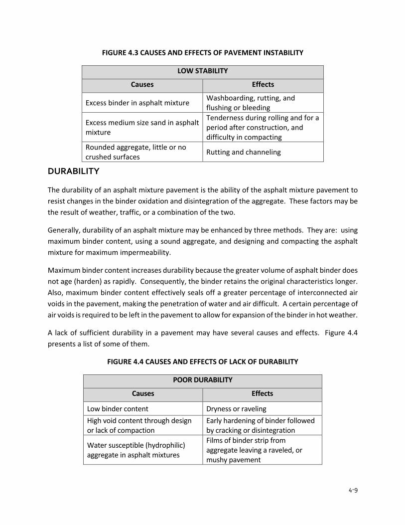
4-9
FIGURE 4.3 CAUSES AND EFFECTS OF PAVEMENT INSTABILITY
LOW STABILITY
Causes Effects
Excess binder in asphalt mixture Washboarding, rutting, and flushing or bleeding
Excess medium size sand in asphalt mixture
Tenderness during rolling and for a period after construction, and difficulty in compacting
Rounded aggregate, little or no crushed surfaces Rutting and channeling
DURABILITY
The durability of an asphalt mixture pavement is the ability of the asphalt mixture pavement to resist changes in the binder oxidation and disintegration of the aggregate. These factors may be the result of weather, traffic, or a combination of the two.
Generally, durability of an asphalt mixture may be enhanced by three methods. They are: using maximum binder content, using a sound aggregate, and designing and compacting the asphalt mixture for maximum impermeability.
Maximum binder content increases durability because the greater volume of asphalt binder does not age (harden) as rapidly. Consequently, the binder retains the original characteristics longer. Also, maximum binder content effectively seals off a greater percentage of interconnected air voids in the pavement, making the penetration of water and air difficult. A certain percentage of air voids is required to be left in the pavement to allow for expansion of the binder in hot weather.
A lack of sufficient durability in a pavement may have several causes and effects. Figure 4.4 presents a list of some of them.
FIGURE 4.4 CAUSES AND EFFECTS OF LACK OF DURABILITY
POOR DURABILITY
Causes Effects
Low binder content Dryness or raveling High void content through design or lack of compaction
Early hardening of binder followed by cracking or disintegration
Water susceptible (hydrophilic) aggregate in asphalt mixtures
Films of binder strip from aggregate leaving a raveled, or mushy pavement
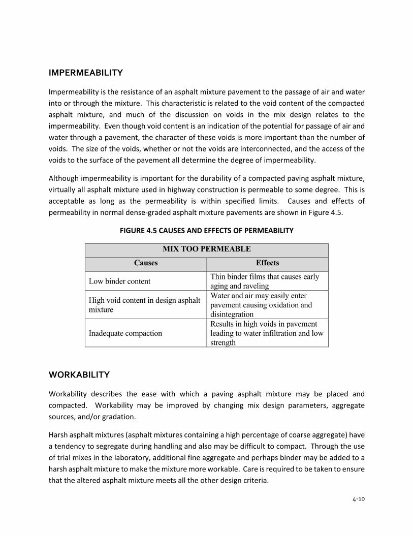
4-10
IMPERMEABILITY
Impermeability is the resistance of an asphalt mixture pavement to the passage of air and water into or through the mixture. This characteristic is related to the void content of the compacted asphalt mixture, and much of the discussion on voids in the mix design relates to the impermeability. Even though void content is an indication of the potential for passage of air and water through a pavement, the character of these voids is more important than the number of voids. The size of the voids, whether or not the voids are interconnected, and the access of the voids to the surface of the pavement all determine the degree of impermeability.
Although impermeability is important for the durability of a compacted paving asphalt mixture, virtually all asphalt mixture used in highway construction is permeable to some degree. This is acceptable as long as the permeability is within specified limits. Causes and effects of permeability in normal dense-graded asphalt mixture pavements are shown in Figure 4.5.
FIGURE 4.5 CAUSES AND EFFECTS OF PERMEABILITY
MIX TOO PERMEABLE
Causes Effects
Low binder content Thin binder films that causes early aging and raveling
High void content in design asphalt mixture
Water and air may easily enter pavement causing oxidation and disintegration
Inadequate compaction Results in high voids in pavement leading to water infiltration and low strength
WORKABILITY
Workability describes the ease with which a paving asphalt mixture may be placed and compacted. Workability may be improved by changing mix design parameters, aggregate sources, and/or gradation.
Harsh asphalt mixtures (asphalt mixtures containing a high percentage of coarse aggregate) have a tendency to segregate during handling and also may be difficult to compact. Through the use of trial mixes in the laboratory, additional fine aggregate and perhaps binder may be added to a harsh asphalt mixture to make the mixture more workable. Care is required to be taken to ensure that the altered asphalt mixture meets all the other design criteria.
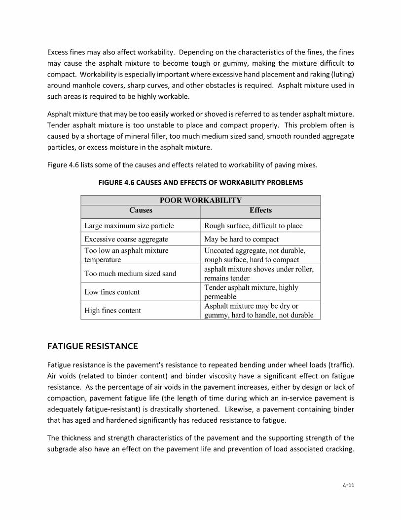
4-11
Excess fines may also affect workability. Depending on the characteristics of the fines, the fines may cause the asphalt mixture to become tough or gummy, making the mixture difficult to compact. Workability is especially important where excessive hand placement and raking (luting) around manhole covers, sharp curves, and other obstacles is required. Asphalt mixture used in such areas is required to be highly workable.
Asphalt mixture that may be too easily worked or shoved is referred to as tender asphalt mixture. Tender asphalt mixture is too unstable to place and compact properly. This problem often is caused by a shortage of mineral filler, too much medium sized sand, smooth rounded aggregate particles, or excess moisture in the asphalt mixture.
Figure 4.6 lists some of the causes and effects related to workability of paving mixes.
FIGURE 4.6 CAUSES AND EFFECTS OF WORKABILITY PROBLEMS
POOR WORKABILITY Causes Effects
Large maximum size particle Rough surface, difficult to place
Excessive coarse aggregate May be hard to compact Too low an asphalt mixture temperature
Uncoated aggregate, not durable, rough surface, hard to compact
Too much medium sized sand asphalt mixture shoves under roller, remains tender
Low fines content Tender asphalt mixture, highly permeable
High fines content Asphalt mixture may be dry or gummy, hard to handle, not durable
FATIGUE RESISTANCE
Fatigue resistance is the pavement's resistance to repeated bending under wheel loads (traffic). Air voids (related to binder content) and binder viscosity have a significant effect on fatigue resistance. As the percentage of air voids in the pavement increases, either by design or lack of compaction, pavement fatigue life (the length of time during which an in-service pavement is adequately fatigue-resistant) is drastically shortened. Likewise, a pavement containing binder that has aged and hardened significantly has reduced resistance to fatigue.
The thickness and strength characteristics of the pavement and the supporting strength of the subgrade also have an effect on the pavement life and prevention of load associated cracking.
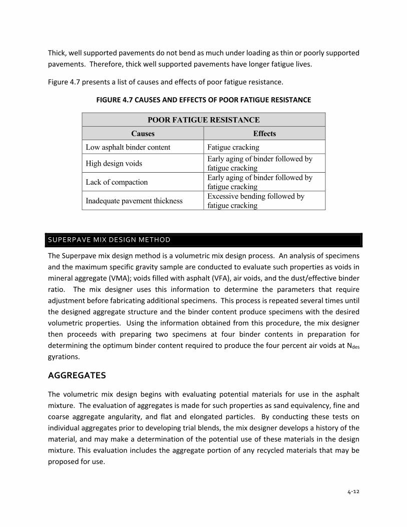
4-12
Thick, well supported pavements do not bend as much under loading as thin or poorly supported pavements. Therefore, thick well supported pavements have longer fatigue lives.
Figure 4.7 presents a list of causes and effects of poor fatigue resistance.
FIGURE 4.7 CAUSES AND EFFECTS OF POOR FATIGUE RESISTANCE
POOR FATIGUE RESISTANCE
Causes Effects
Low asphalt binder content Fatigue cracking
High design voids Early aging of binder followed by fatigue cracking
Lack of compaction Early aging of binder followed by fatigue cracking
Inadequate pavement thickness Excessive bending followed by fatigue cracking
SUPERPAVE MIX DESIGN METHOD
The Superpave mix design method is a volumetric mix design process. An analysis of specimens and the maximum specific gravity sample are conducted to evaluate such properties as voids in mineral aggregate (VMA); voids filled with asphalt (VFA), air voids, and the dust/effective binder ratio. The mix designer uses this information to determine the parameters that require adjustment before fabricating additional specimens. This process is repeated several times until the designed aggregate structure and the binder content produce specimens with the desired volumetric properties. Using the information obtained from this procedure, the mix designer then proceeds with preparing two specimens at four binder contents in preparation for determining the optimum binder content required to produce the four percent air voids at Ndes gyrations.
AGGREGATES
The volumetric mix design begins with evaluating potential materials for use in the asphalt mixture. The evaluation of aggregates is made for such properties as sand equivalency, fine and coarse aggregate angularity, and flat and elongated particles. By conducting these tests on individual aggregates prior to developing trial blends, the mix designer develops a history of the material, and may make a determination of the potential use of these materials in the design mixture. This evaluation includes the aggregate portion of any recycled materials that may be proposed for use.
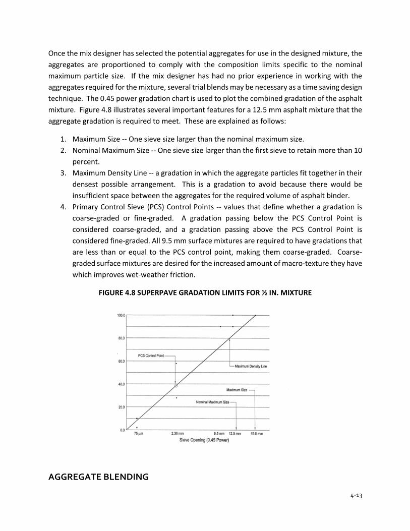
4-13
Once the mix designer has selected the potential aggregates for use in the designed mixture, the aggregates are proportioned to comply with the composition limits specific to the nominal maximum particle size. If the mix designer has had no prior experience in working with the aggregates required for the mixture, several trial blends may be necessary as a time saving design technique. The 0.45 power gradation chart is used to plot the combined gradation of the asphalt mixture. Figure 4.8 illustrates several important features for a 12.5 mm asphalt mixture that the aggregate gradation is required to meet. These are explained as follows:
1. Maximum Size -- One sieve size larger than the nominal maximum size. 2. Nominal Maximum Size -- One sieve size larger than the first sieve to retain more than 10
percent. 3. Maximum Density Line -- a gradation in which the aggregate particles fit together in their
densest possible arrangement. This is a gradation to avoid because there would be insufficient space between the aggregates for the required volume of asphalt binder.
4. Primary Control Sieve (PCS) Control Points -- values that define whether a gradation is coarse-graded or fine-graded. A gradation passing below the PCS Control Point is considered coarse-graded, and a gradation passing above the PCS Control Point is considered fine-graded. All 9.5 mm surface mixtures are required to have gradations that are less than or equal to the PCS control point, making them coarse-graded. Coarse-graded surface mixtures are desired for the increased amount of macro-texture they have which improves wet-weather friction.
FIGURE 4.8 SUPERPAVE GRADATION LIMITS FOR ½ IN. MIXTURE
AGGREGATE BLENDING
4-14
Building a pavement with an asphalt mixture requires more than binder, aggregate, and equipment. A good operation also requires knowledge, skill, and workmanship. Part of this knowledge and skill is the ability to blend aggregates to maintain the job mix formula.
A common problem in asphalt mixture construction is combining two or more aggregates with different gradations, to produce an aggregate blend that meets gradation specifications for a particular asphalt mixture. As previously stated, all particles required in the asphalt mixture are not usually found in one single stockpile. The asphalt mixture is made by blending different aggregate sizes together to meet the gradation requirements for the specified type of asphalt mixture.
Design Mix Formula
In the simplest form, a design mix formula consists of two parts:
1. The combined gradation of the aggregates to be used in the production of asphalt mixture 2. The binder content necessary to produce a satisfactory asphalt mixture meeting all the
specification requirements
Method for Combining Aggregates
Mathematical procedures have been developed to determine an optimum combination of aggregates and computer programs are available to facilitate this process. Although these procedures and programs are available, the Trial and Error Method, guided by a certain amount of reasoning, remains one of the easiest procedures to determine a satisfactory combination.
Trial and Error Method
The proportions of each of the aggregates to be used in an asphalt mixture are required to be determined to produce a combined gradation that meets the required Specifications. The "Trial and Error Method" is the method that is shown for combining the aggregates (Figures 4.9 and 4.10. First, each of the steps is discussed and then applied to an example problem.
Step 1 – OBTAIN THE REQUIRED DATA
1. The gradation of each material is required to be determined. 2. The design limits for the type of mix are required to be obtained (Section 400). Enter this
information on the worksheet. 3. Select a target value for the combined gradation. Normally, this value is the percentage
passing the No. 8 sieve. For example, the design limits for 25.0 mm Base mixture for the No. 8 sieve are 19.0-45.0. The combined gradation is required to be checked on this sieve first to verify that this value is within 19.0-45.0.
4-15
Step 2 – ESTIMATE THE PROPORTIONS
After the target value has been selected, the next step is to estimate the correct percentage of each aggregate needed to get a combined gradation near the target value.
Step 3 – CALCULATE THE INDIVIDUAL PROPORTIONS
This calculation determines the percentage of each aggregate for the asphalt mixture. On the form, the "% for Mix" is obtained by multiplying the "Percent Used" (as a decimal) by the "% Passing" value.
Step 4 – CALCULATE THE COMBINED GRADATION
This calculation indicates the results of the estimate from STEP 2. The method of calculating the combined gradation is shown in the example problem.
Step 5 – COMPARE THE RESULTS WITH THE TARGET VALUE
If the calculated gradation is close to the target value, the problem has been solved; if not, an adjustment in the proportions is required to be made and the calculation conducted again. The second trial should be closer due to the information obtained from the first trial. The trials are continued until proportions of each aggregate are found that come close to the target value. If the aggregates do not combine within the design range, then another material of a different gradation is required to be added to the blend.
Example (Combination of Two Aggregates)
An example problem using two aggregates is shown in Figures 4.9 and 4.10. The No. 5 stone is designated Aggregate 1 and the No. 24 sand is designated Aggregate 2. The target gradation is for a 25.0 mm base mixture.
Step 1 – Enter the known data:
1. Percent passing from the gradation of each aggregate component 2. Target specification for 1 in. base asphalt mixture
Step 2 – Estimate the proportions. How much of each of the two aggregates are needed to produce a combined gradation close to the target value. (trial blend #1).
The first estimate might be 50% of Aggregate 1 and 50% of Aggregate 2. The proportions of each aggregate used are required to total 100%. Enter these figures on the line marked "Percent Used".

4-16
Step 3 – Calculate the individual proportions on each sieve for each of the two aggregates and enter in the column "% for Mix". This is done by multiplying "% Passing" column by "Percent Used" (as a decimal). A sample calculation is shown at the bottom of Figure 4.9.
Step 4 – Calculate the combined gradation. Add the two "% of Mix" columns horizontally for each sieve and enter in the column "Combined Gradation %".
Step 5 – Compare this combined gradation with the Specification Limits %. Note that the combined gradation is not very close to the Specification Limits and is on the fine side. An adjustment is required to be made. For a trial blend #2, increase Aggregate 1 to 70% and lower Aggregate 2 to 30% as shown in Figure 4.10
Since this combined gradation is within the Specification Limits, the desired results have been obtained.
Example (Combination of More than Two Aggregates)
The same basic steps are followed when combining more than two aggregates (Figure 4.11).
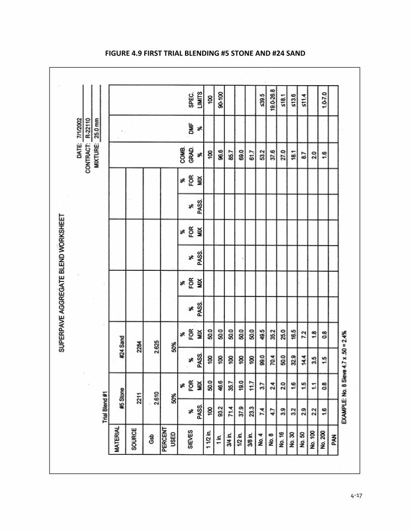
4-17
FIGURE 4.9 FIRST TRIAL BLENDING #5 STONE AND #24 SAND
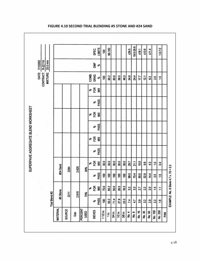
4-18
FIGURE 4.10 SECOND TRIAL BLENDING #5 STONE AND #24 SAND

4-19
FIGURE 4.11 THIRD BLENDING TRIAL TO INCLUDE #11 STONE
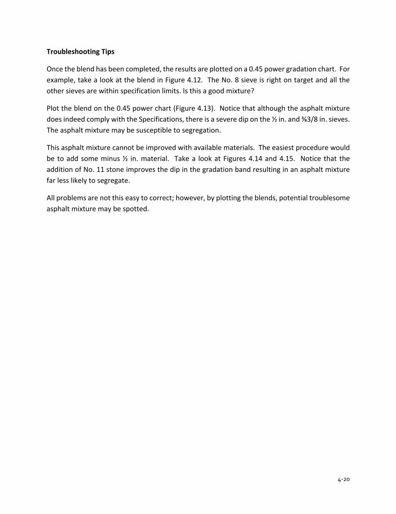
4-20
Troubleshooting Tips
Once the blend has been completed, the results are plotted on a 0.45 power gradation chart. For example, take a look at the blend in Figure 4.12. The No. 8 sieve is right on target and all the other sieves are within specification limits. Is this a good mixture?
Plot the blend on the 0.45 power chart (Figure 4.13). Notice that although the asphalt mixture does indeed comply with the Specifications, there is a severe dip on the ½ in. and ⅜3/8 in. sieves. The asphalt mixture may be susceptible to segregation.
This asphalt mixture cannot be improved with available materials. The easiest procedure would be to add some minus ½ in. material. Take a look at Figures 4.14 and 4.15. Notice that the addition of No. 11 stone improves the dip in the gradation band resulting in an asphalt mixture far less likely to segregate.
All problems are not this easy to correct; however, by plotting the blends, potential troublesome asphalt mixture may be spotted.
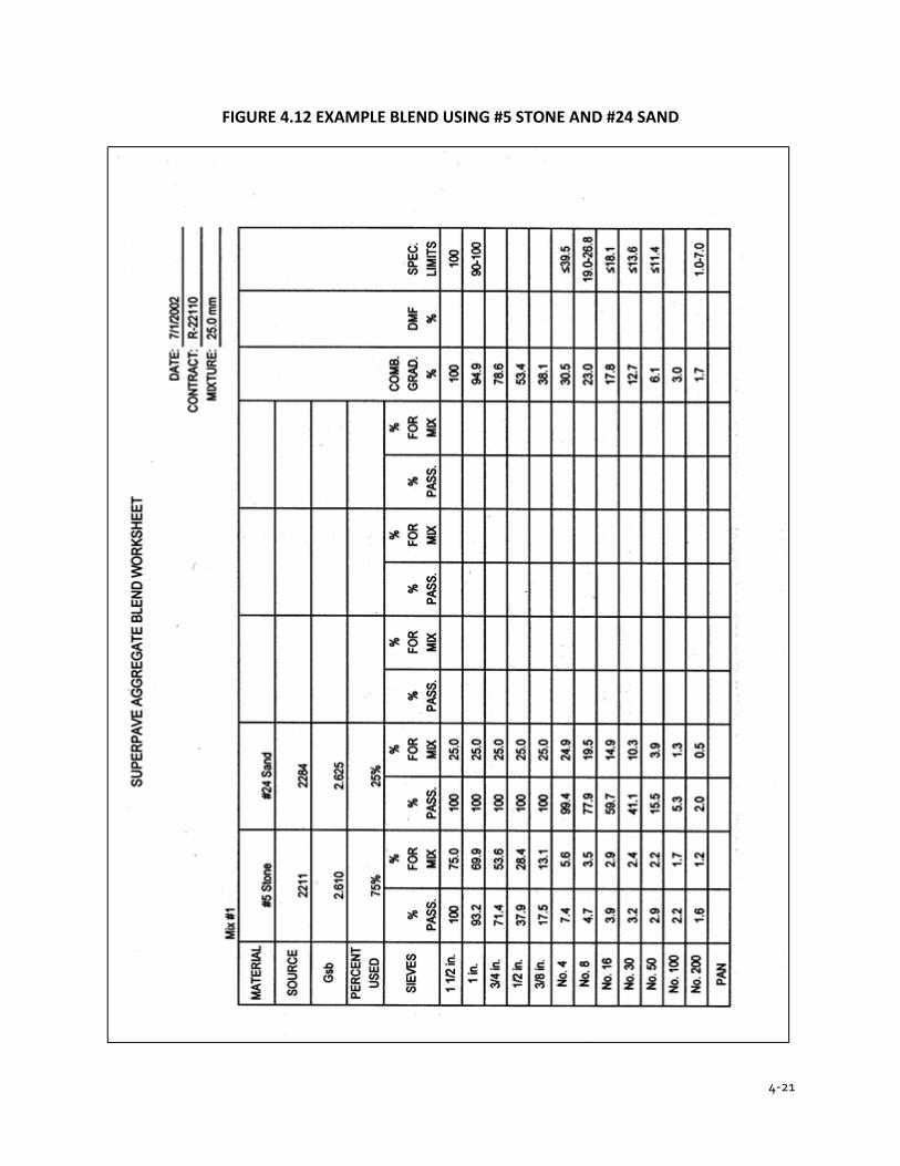
4-21
FIGURE 4.12 EXAMPLE BLEND USING #5 STONE AND #24 SAND
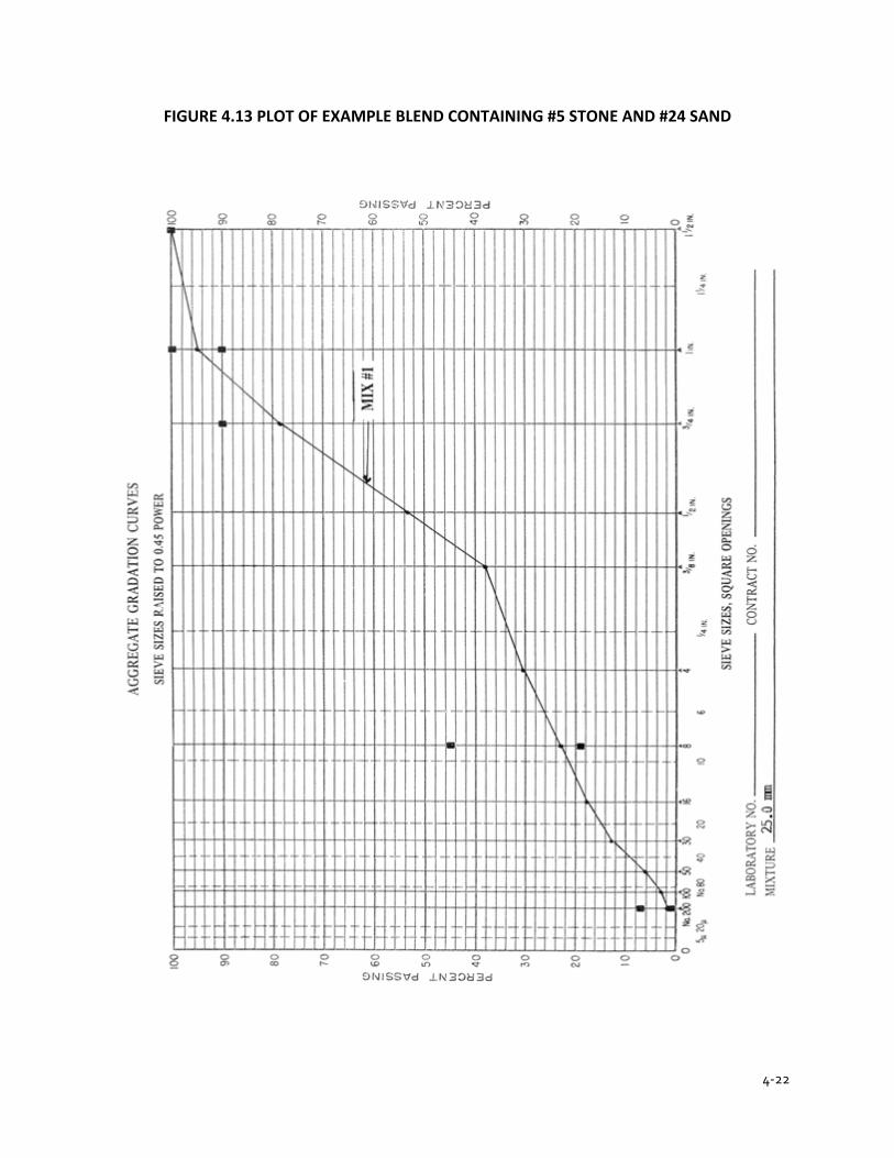
4-22
FIGURE 4.13 PLOT OF EXAMPLE BLEND CONTAINING #5 STONE AND #24 SAND

4-23
FIGURE 4.14 EXAMPLE BLEND WITH #11 STONE ADDED TO #5 STONE AND #24 SAND
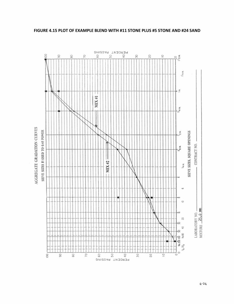
4-24
FIGURE 4.15 PLOT OF EXAMPLE BLEND WITH #11 STONE PLUS #5 STONE AND #24 SAND
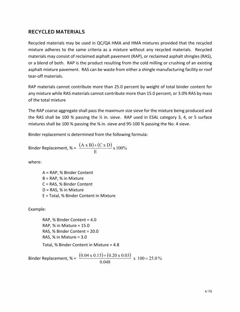
4-25
RECYCLED MATERIALS
Recycled materials may be used in QC/QA HMA and HMA mixtures provided that the recycled mixture adheres to the same criteria as a mixture without any recycled materials. Recycled materials may consist of reclaimed asphalt pavement (RAP), or reclaimed asphalt shingles (RAS), or a blend of both. RAP is the product resulting from the cold milling or crushing of an existing asphalt mixture pavement. RAS can be waste from either a shingle manufacturing facility or roof tear-off materials.
RAP materials cannot contribute more than 25.0 percent by weight of total binder content for any mixture while RAS materials cannot contribute more than 15.0 percent, or 3.0% RAS by mass of the total mixture
The RAP coarse aggregate shall pass the maximum size sieve for the mixture being produced and the RAS shall be 100 % passing the ½ in. sieve. RAP used in ESAL category 3, 4, or 5 surface mixtures shall be 100 % passing the ⅜ in. sieve and 95-100 % passing the No. 4 sieve.
Binder replacement is determined from the following formula:
Binder Replacement, % = ( ) ( ) 100% x E
D x CBA x +
where:
A = RAP, % Binder Content B = RAP, % in Mixture C = RAS, % Binder Content D = RAS, % in Mixture E = Total, % Binder Content in Mixture
Example:
RAP, % Binder Content = 4.0 RAP, % in Mixture = 15.0 RAS, % Binder Content = 20.0 RAS, % in Mixture = 3.0
Total, % Binder Content in Mixture = 4.8
Binder Replacement, % = ( ) ( ) % 25.0 100 x 0.048
0.03 x 0.20 0.15 x 0.04=
+
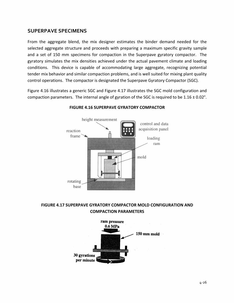
4-26
SUPERPAVE SPECIMENS
From the aggregate blend, the mix designer estimates the binder demand needed for the selected aggregate structure and proceeds with preparing a maximum specific gravity sample and a set of 150 mm specimens for compaction in the Superpave gyratory compactor. The gyratory simulates the mix densities achieved under the actual pavement climate and loading conditions. This device is capable of accommodating large aggregate, recognizing potential tender mix behavior and similar compaction problems, and is well suited for mixing plant quality control operations. The compactor is designated the Superpave Gyratory Compactor (SGC).
Figure 4.16 illustrates a generic SGC and Figure 4.17 illustrates the SGC mold configuration and compaction parameters. The internal angle of gyration of the SGC is required to be 1.16 ± 0.02°.
FIGURE 4.16 SUPERPAVE GYRATORY COMPACTOR
FIGURE 4.17 SUPERPAVE GYRATORY COMPACTOR MOLD CONFIGURATION AND COMPACTION PARAMETERS

4-27
Specimens compacted with the Superpave gyratory compactor in the mix design are analyzed at a different number of gyrations depending on the traffic for the contract and whether the mixture is a dense graded, open graded, or a SMA mixture. The procedure used for preparing Superpave specimens is AASHTO T 312. Three gyration levels are of interest:
Ndes = design number of gyrations Nini = initial number of gyrations Nmax = maximum number of gyrations
FIGURE 4.18 SUPERPAVE GYRATORY COMPACTIVE EFFORT
GYRATORY COMPACTION EFFORT
ESAL Nini Ndes Nmax Max. % Gmm@Nini
Max.% Gmm @Nmax
DENSE GRADED
<3,000,000 5 30 40 91.5 97.0
3,000,000 to < 10,000,000
6 50 75 91.5 97.0
> 10,000,000 6 50 75 91.5 97.0
OPEN GRADED
ALL ESAL NA 20 NA NA NA
SMA
ALL ESAL NA 75 NA NA
The compactive efforts Nini and Nmax are used to evaluate the compatibility of the asphalt mixture, while Ndes is used to select the binder content. A maximum percentage of the maximum theoretical density (Gmm) requirement at Nini insures an adequate aggregate structure in the asphalt mixture. A maximum percentage of the maximum theoretical density (Gmm) requirement at Nmax assures that the asphalt mixture does not compact excessively under the anticipated traffic, resulting in permanent deformation or rutting.
Specimens in the mix design are compacted to Ndes at each increment of binder content to evaluate the required air voids and VMA. After a mix design binder content has been estimated, two specimens are compacted to Ndes at each of the following four binder contents:
1. The estimated design binder content, Pb (design) 2. 0.5 percent below Pb (design) 3. 0.5 percent above Pb (design) 4. 1.0 percent above Pb (design)
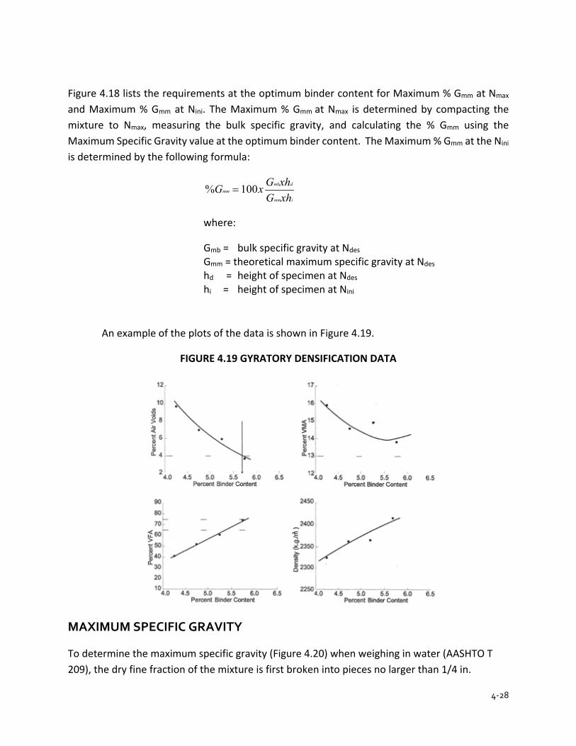
4-28
Figure 4.18 lists the requirements at the optimum binder content for Maximum % Gmm at Nmax and Maximum % Gmm at Nini. The Maximum % Gmm at Nmax is determined by compacting the mixture to Nmax, measuring the bulk specific gravity, and calculating the % Gmm using the Maximum Specific Gravity value at the optimum binder content. The Maximum % Gmm at the Nini is determined by the following formula:
imm
dmbmm
xhGxhGxG 100% =
where:
Gmb = bulk specific gravity at Ndes Gmm = theoretical maximum specific gravity at Ndes hd = height of specimen at Ndes hi = height of specimen at Nini
An example of the plots of the data is shown in Figure 4.19.
FIGURE 4.19 GYRATORY DENSIFICATION DATA
MAXIMUM SPECIFIC GRAVITY
To determine the maximum specific gravity (Figure 4.20) when weighing in water (AASHTO T 209), the dry fine fraction of the mixture is first broken into pieces no larger than 1/4 in.
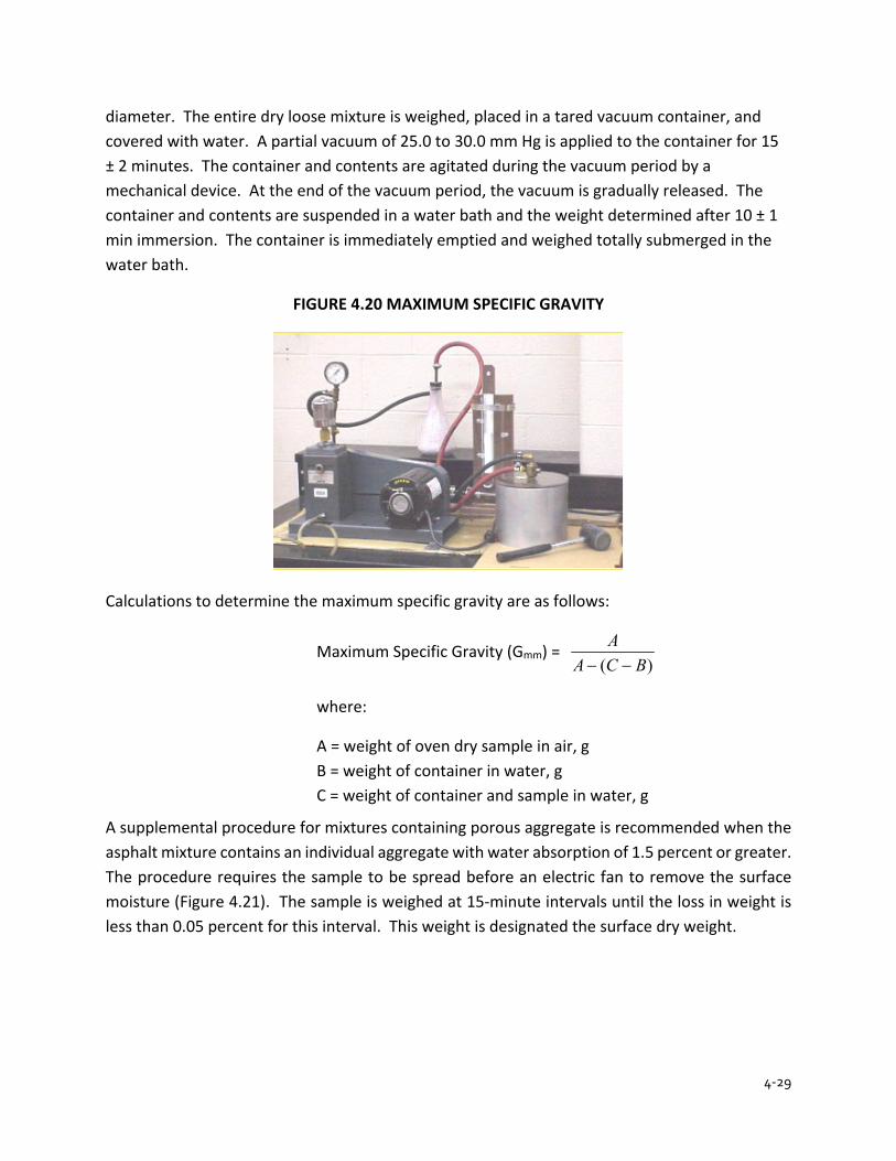
4-29
diameter. The entire dry loose mixture is weighed, placed in a tared vacuum container, and covered with water. A partial vacuum of 25.0 to 30.0 mm Hg is applied to the container for 15 ± 2 minutes. The container and contents are agitated during the vacuum period by a mechanical device. At the end of the vacuum period, the vacuum is gradually released. The container and contents are suspended in a water bath and the weight determined after 10 ± 1 min immersion. The container is immediately emptied and weighed totally submerged in the water bath.
FIGURE 4.20 MAXIMUM SPECIFIC GRAVITY
Calculations to determine the maximum specific gravity are as follows:
Maximum Specific Gravity (Gmm) = )( BCA
A−−
where:
A = weight of oven dry sample in air, g B = weight of container in water, g C = weight of container and sample in water, g
A supplemental procedure for mixtures containing porous aggregate is recommended when the asphalt mixture contains an individual aggregate with water absorption of 1.5 percent or greater. The procedure requires the sample to be spread before an electric fan to remove the surface moisture (Figure 4.21). The sample is weighed at 15-minute intervals until the loss in weight is less than 0.05 percent for this interval. This weight is designated the surface dry weight.
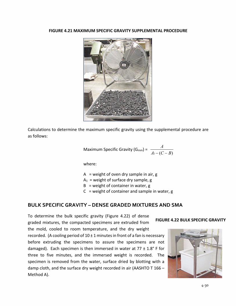
4-30
FIGURE 4.21 MAXIMUM SPECIFIC GRAVITY SUPPLEMENTAL PROCEDURE
Calculations to determine the maximum specific gravity using the supplemental procedure are as follows:
Maximum Specific Gravity (Gmm) = )(1 BCA
A−−
where:
A = weight of oven dry sample in air, g A1 = weight of surface dry sample, g B = weight of container in water, g C = weight of container and sample in water, g
BULK SPECIFIC GRAVITY – DENSE GRADED MIXTURES AND SMA
To determine the bulk specific gravity (Figure 4.22) of dense graded mixtures, the compacted specimens are extruded from the mold, cooled to room temperature, and the dry weight recorded. (A cooling period of 10 ± 1 minutes in front of a fan is necessary before extruding the specimens to assure the specimens are not damaged). Each specimen is then immersed in water at 77 ± 1.8° F for three to five minutes, and the immersed weight is recorded. The specimen is removed from the water, surface dried by blotting with a damp cloth, and the surface dry weight recorded in air (AASHTO T 166 – Method A).
FIGURE 4.22 BULK SPECIFIC GRAVITY
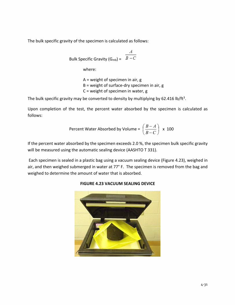
4-31
The bulk specific gravity of the specimen is calculated as follows:
Bulk Specific Gravity (Gmb) =
where:
A = weight of specimen in air, g B = weight of surface-dry specimen in air, g C = weight of specimen in water, g
The bulk specific gravity may be converted to density by multiplying by 62.416 lb/ft3.
Upon completion of the test, the percent water absorbed by the specimen is calculated as follows:
Percent Water Absorbed by Volume =
−−
CBAB x 100
If the percent water absorbed by the specimen exceeds 2.0 %, the specimen bulk specific gravity will be measured using the automatic sealing device (AASHTO T 331).
Each specimen is sealed in a plastic bag using a vacuum sealing device (Figure 4.23), weighed in air, and then weighed submerged in water at 77° F. The specimen is removed from the bag and weighed to determine the amount of water that is absorbed.
FIGURE 4.23 VACUUM SEALING DEVICE
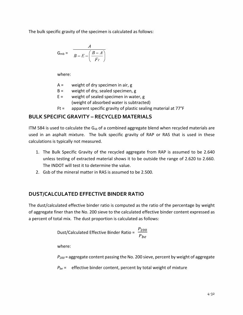
4-32
The bulk specific gravity of the specimen is calculated as follows:
Gmb =
where:
A = weight of dry specimen in air, g B = weight of dry, sealed specimen, g E = weight of sealed specimen in water, g (weight of absorbed water is subtracted) Ft = apparent specific gravity of plastic sealing material at 77°F
BULK SPECIFIC GRAVITY – RECYCLED MATERIALS
ITM 584 is used to calculate the Gsb of a combined aggregate blend when recycled materials are used in an asphalt mixture. The bulk specific gravity of RAP or RAS that is used in these calculations is typically not measured.
1. The Bulk Specific Gravity of the recycled aggregate from RAP is assumed to be 2.640 unless testing of extracted material shows it to be outside the range of 2.620 to 2.660. The INDOT will test it to determine the value.
2. Gsb of the mineral matter in RAS is assumed to be 2.500.
DUST/CALCULATED EFFECTIVE BINDER RATIO
The dust/calculated effective binder ratio is computed as the ratio of the percentage by weight of aggregate finer than the No. 200 sieve to the calculated effective binder content expressed as a percent of total mix. The dust proportion is calculated as follows:
Dust/Calculated Effective Binder Ratio = 𝑃𝑃200𝑃𝑃𝑏𝑏𝑏𝑏
where:
P200 = aggregate content passing the No. 200 sieve, percent by weight of aggregate
Pbe = effective binder content, percent by total weight of mixture
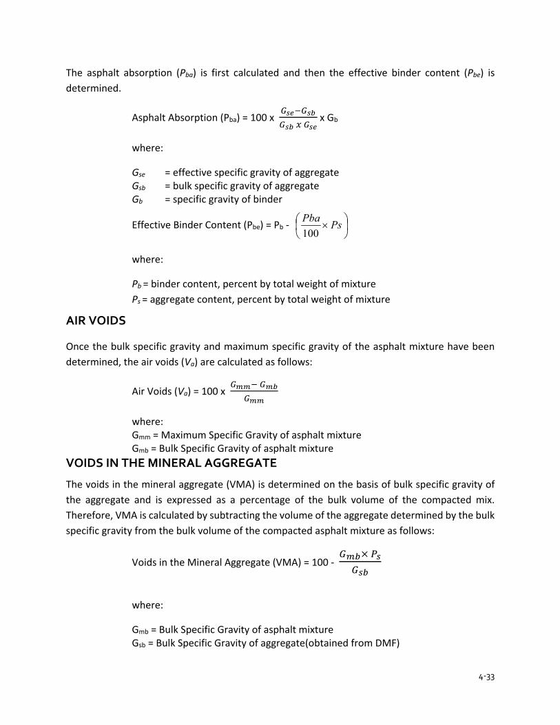
4-33
The asphalt absorption (Pba) is first calculated and then the effective binder content (Pbe) is determined.
Asphalt Absorption (Pba) = 100 x 𝐺𝐺𝑠𝑠𝑏𝑏−𝐺𝐺𝑠𝑠𝑏𝑏𝐺𝐺𝑠𝑠𝑏𝑏 𝑥𝑥 𝐺𝐺𝑠𝑠𝑏𝑏
x Gb
where:
Gse = effective specific gravity of aggregate Gsb = bulk specific gravity of aggregate Gb = specific gravity of binder
Effective Binder Content (Pbe) = Pb -
× PsPba
100
where:
Pb = binder content, percent by total weight of mixture Ps = aggregate content, percent by total weight of mixture
AIR VOIDS
Once the bulk specific gravity and maximum specific gravity of the asphalt mixture have been determined, the air voids (Va) are calculated as follows:
Air Voids (Va) = 100 x 𝐺𝐺𝑚𝑚𝑚𝑚− 𝐺𝐺𝑚𝑚𝑏𝑏
𝐺𝐺𝑚𝑚𝑚𝑚
where: Gmm = Maximum Specific Gravity of asphalt mixture Gmb = Bulk Specific Gravity of asphalt mixture VOIDS IN THE MINERAL AGGREGATE
The voids in the mineral aggregate (VMA) is determined on the basis of bulk specific gravity of the aggregate and is expressed as a percentage of the bulk volume of the compacted mix. Therefore, VMA is calculated by subtracting the volume of the aggregate determined by the bulk specific gravity from the bulk volume of the compacted asphalt mixture as follows:
Voids in the Mineral Aggregate (VMA) = 100 - 𝐺𝐺𝑚𝑚𝑏𝑏× 𝑃𝑃𝑠𝑠𝐺𝐺𝑠𝑠𝑏𝑏
where:
Gmb = Bulk Specific Gravity of asphalt mixture Gsb = Bulk Specific Gravity of aggregate(obtained from DMF)

4-34
Ps = Aggregate, percent by total weight of asphalt mixture
The percent of aggregate by total weight of asphalt mixture (Ps) is determined by subtracting the actual binder content by total weight of asphalt mixture (Pb) supplied on the design mix formula from 100.
Ps = 100 - Pb
MOISTURE SUSCEPTIBILITY
The final process required in the volumetric mix design is to check the moisture susceptibility of the asphalt mixture. The procedure used is AASHTO T 283, except that the loose mixture curing is replaced by mixture conditioning for 2 h in accordance with AASHTO R 30. Regardless of the mixture designation, all Superpave mixtures are required to meet a minimum tensile strength ratio (TSR) of 80 %.
EXAMPLE CALCULATIONS
A sample of the aggregate and compacted asphalt mixture is known to have the following properties. The density, air voids, VMA, VFA, and Dust/Calculated Effective Binder Ratio are determined as follows:
Effective Specific Gravity of Aggregate (Gse) = 2.726 Specific Gravity of Binder (Gb) = 1.030 Bulk Specific Gravity of Mix (Gmb) = 2.360 Bulk Specific Gravity of Aggregate (Gsb) = 2.715 Maximum Specific Gravity of Mix (Gmm) = 2.520 Binder Content (Pb) = 5.0 percent of weight of total mix Aggregate Passing No. 200 (P 200) = 5.3
Density D = Gmb x 62.416 lb/ft3
= 2.360 x 62.416 = 147.3 lb/ft3
Air Voids Va = 100 x 𝐺𝐺𝑚𝑚𝑚𝑚− 𝐺𝐺𝑚𝑚𝑏𝑏
𝐺𝐺𝑚𝑚𝑚𝑚
= 100 x
−
520.2360.2520.2
= 100 x .063 = 6.3 %
VMA Ps = 100 - Pb
= 100 - 5.0

4-35
= 95.0 %
VMA = 100 - 𝐺𝐺𝑚𝑚𝑏𝑏× 𝑃𝑃𝑠𝑠𝐺𝐺𝑠𝑠𝑏𝑏
= 100 -
×
715.20.95360.2
= 100 - 82.6 = 17.4 %
VFA VFA =
−
VMAVaVMA x 100
=
−
4.173.64.17 x 100 = 64 %
Dust/Calculated Effective Binder Ratio
Pba = 100 x 2.726−2.7152.715𝑥𝑥2.726
𝑥𝑥 1.030
= 100 x 0.117.401
x 1.030
= 0.15
Ps = 100 - 5.0 = 95.0
Pbe = 5.0 -
× 0.95
10015.0
= 5.0 - 0.1 = 4.9
P200/Pbe =beP
P200 =9.43.5 = 1.1
STONE MATRIX ASPHALT
Stone Matrix Asphalt (SMA) is a tough, stable, rut-resistant mixture that relies on coarse aggregate-to-coarse aggregate contact to provide strength and a rich mortar binder to provide durability. The coarse aggregate-to-coarse aggregate contact is obtained by designing with an aggregate skeleton that consists of a large percentage of very durable coarse aggregate. The mortar consists of asphalt binder, mineral filler (material passing the No. 200 sieve), and a stabilizing additive of either cellulose or mineral fibers.
The primary advantage of SMA is the expected extended life as compared to conventional dense-graded mixtures. This extended life is the result of better rut resistance and the potential to

4-36
reduce reflection cracks. Other potential advantages are the reduction in tire splash and spray, and traffic noise.
The mix design requirements of SMA that are different than dense-graded mixtures include the following:
1. A minimum VMA of 17.0 is required for 9.5 mm SMA mixtures, 16.0 for 12.5 mm SMA mixtures, and 15.0 for 19.0 mm SMA mixtures.
2. A draindown test (AASHTO T 305) to determine the amount of mortar that drains from the SMA at the plant-production temperature is conducted.

CHAPTER 5ASPHALT PLANTS
5-1
CHAPTER 5 ASPHALT PLANTS
DRUM PLANTS DRUM MIX PLANT COMPONENTS AGGREGATE STORAGE AND FEED
COLD AGGREGATE STORAGE AND FEEDING BINDER METERING AGGREGATE MOISTURE DETERMINATION DRUM MIX OPERATION SURGE BIN AND WIEGH SCALES
HOT MIX ASPHALT STORAGE SUMMARY OF DRUM MIXERS
EFFECT OF PLANT ON ASPHALT MIXTURE PROPERTIES
DUST CONTROL AND COLLECTION SYSTEMS DRUM/WET WASH DRUM/BAGHOUSE
PLANT INSPECTION AND SCALE CHECK DRUM PLANT
PLANT TROUBLESHOOTING
SAFETY
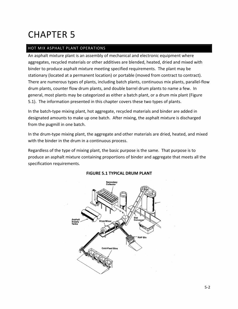
5-2
CHAPTER 5 HOT MIX ASPHALT PLANT OPERATIONS
An asphalt mixture plant is an assembly of mechanical and electronic equipment where aggregates, recycled materials or other additives are blended, heated, dried and mixed with binder to produce asphalt mixture meeting specified requirements. The plant may be stationary (located at a permanent location) or portable (moved from contract to contract). There are numerous types of plants, including batch plants, continuous mix plants, parallel-flow drum plants, counter flow drum plants, and double barrel drum plants to name a few. In general, most plants may be categorized as either a batch plant, or a drum mix plant (Figure 5.1). The information presented in this chapter covers these two types of plants.
In the batch-type mixing plant, hot aggregate, recycled materials and binder are added in designated amounts to make up one batch. After mixing, the asphalt mixture is discharged from the pugmill in one batch.
In the drum-type mixing plant, the aggregate and other materials are dried, heated, and mixed with the binder in the drum in a continuous process.
Regardless of the type of mixing plant, the basic purpose is the same. That purpose is to produce an asphalt mixture containing proportions of binder and aggregate that meets all the specification requirements.
FIGURE 5.1 TYPICAL DRUM PLANT
5-3
DRUM PLANTS
These operations include:
1. Cold aggregate storage and feeding 2. Dust control and collection 3. Mix storage 4. Recycled materials storage and feeding
Also common to all plants is the importance of uniformity and balance, both in materials used and in plant operations. Uniformity encompasses materials, material proportioning, and continuous operation of all plant components. Changes in material characteristics, proportions, and intermittent stops and starts in plant operations make producing an asphalt mixture meeting Specifications extremely difficult.
Balance requires careful coordination of all elements of production. Balancing material quantities to plant production, and balancing plant production and pavement placing operations guarantee a continuous, uniform production and placement effort.
Uniformity and balance are best ensured by careful preparation. Materials are required to be sampled and tested and plant components carefully inspected and calibrated before production begins.
Drum mixing is a relatively simple process of producing asphalt mixture. The mixing drum from which this type of plant obtains the drum mixing name is very similar in appearance to a batch plant dryer drum. The difference between drum mix plants (Figure 5.2) and batch plants is that in drum mix plants the aggregate is not only dried and heated within the drum, but also mixed with the binder. There are no gradation screens, hot bins, weigh hoppers, or pugmills in a drum mix plant. Aggregate gradation is controlled at the cold feed.
As the aggregates (correctly proportioned at the cold feed) are introduced into the drum mix plant for drying, the binder is also introduced into the drum. The rotation of the drum provides the mixing action that thoroughly blends the binder and the aggregates. As the asphalt mixture is discharged from the drum, the mixture is carried to a surge bin and subsequently loaded into trucks.
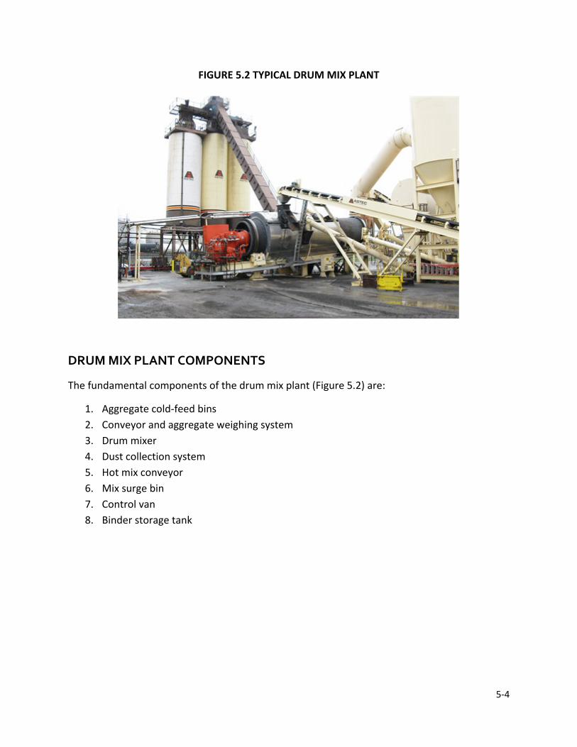
5-4
FIGURE 5.2 TYPICAL DRUM MIX PLANT
DRUM MIX PLANT COMPONENTS
The fundamental components of the drum mix plant (Figure 5.2) are:
1. Aggregate cold-feed bins 2. Conveyor and aggregate weighing system 3. Drum mixer 4. Dust collection system 5. Hot mix conveyor 6. Mix surge bin 7. Control van 8. Binder storage tank

5-5
FIGURE 5.3 BASIC DRUM MIX PLANT
5-6
Referring to (Figure 5.3), the following is a brief, general description of the sequence of processes involved in a typical drum mix plant operation: controlled gradations of aggregates are deposited in the cold feed bins (1) from which the aggregates are fed in exact proportions onto a cold-feed conveyor (2). An automatic aggregate weighing system (3) monitors the amount of aggregate flowing into the drum mixer (4). The weighing system is interlocked with the controls on the binder storage pump (5), which draws binder from a storage tank (6) and introduces binder into the drum where binder and aggregate are thoroughly blended by the rotating action of the drum. A dust collection system (7) captures excess dust escaping from the drum. From the drum, the asphalt mixture is transported by hot mix conveyor (8) to a surge bin (9) from which the mixture is loaded into trucks and hauled to the paving site. All plant operations are monitored and controlled from instruments in the control van (10).
The mixing process is essentially similar in all drum mixing plants; however, there are several plant designs available. These include the parallel-flow drum, as shown in (Figure 5-10), the counter-flow drum, which has the burner located near the outlet end of the drum, and the unitized counter-flow drum (Double Barrel), which has an outer mixing drum that surrounds the dryer drum.
The production of asphalt mixture meeting contract Specifications is most easily done when the various parts and functions of the plant are in balance; that is, when all parts are properly coordinated to work together as a smooth working unit. Also essential for consistent and high-quality asphalt mixture is uniform (uninterrupted) plant operation. Accurate proportioning of materials is entirely dependent on the uniform flow of those materials. Plant stops and starts adversely affect asphalt mixture quality.
To ensure balance and uniformity necessary to produce asphalt mixture to meet Specifications, the following control equipment is required:
1. Separate cold feed controls for each aggregate size 2. Interlocking controls of aggregate cold feed, binder delivery, and additive delivery to the
drum 3. Automatic burner controls 4. A dust collector constructed to waste or return the material uniformly as directed 5. Sensors to measure temperature of the asphalt mixture at drum discharge 6. Gate controls on surge hopper 7. Moisture compensator
Controls and monitoring devices are usually housed in the control van, where there is good visibility of the entire operation.
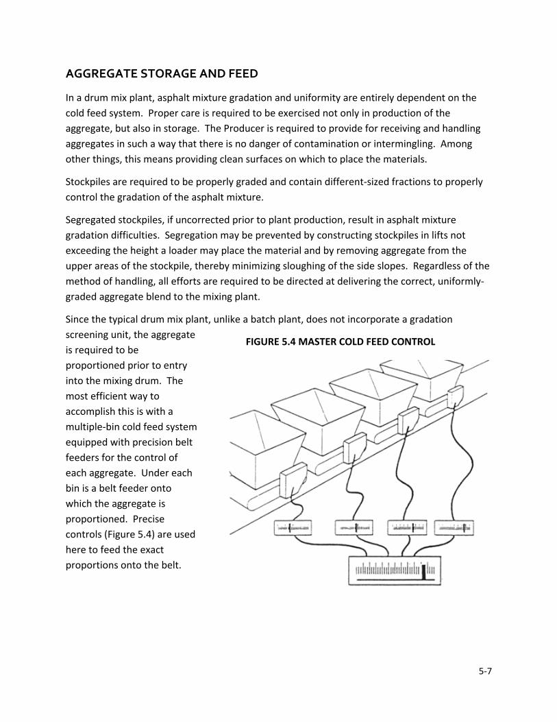
5-7
AGGREGATE STORAGE AND FEED
In a drum mix plant, asphalt mixture gradation and uniformity are entirely dependent on the cold feed system. Proper care is required to be exercised not only in production of the aggregate, but also in storage. The Producer is required to provide for receiving and handling aggregates in such a way that there is no danger of contamination or intermingling. Among other things, this means providing clean surfaces on which to place the materials.
Stockpiles are required to be properly graded and contain different-sized fractions to properly control the gradation of the asphalt mixture.
Segregated stockpiles, if uncorrected prior to plant production, result in asphalt mixture gradation difficulties. Segregation may be prevented by constructing stockpiles in lifts not exceeding the height a loader may place the material and by removing aggregate from the upper areas of the stockpile, thereby minimizing sloughing of the side slopes. Regardless of the method of handling, all efforts are required to be directed at delivering the correct, uniformly-graded aggregate blend to the mixing plant.
Since the typical drum mix plant, unlike a batch plant, does not incorporate a gradation screening unit, the aggregate is required to be proportioned prior to entry into the mixing drum. The most efficient way to accomplish this is with a multiple-bin cold feed system equipped with precision belt feeders for the control of each aggregate. Under each bin is a belt feeder onto which the aggregate is proportioned. Precise controls (Figure 5.4) are used here to feed the exact proportions onto the belt.
FIGURE 5.4 MASTER COLD FEED CONTROL
5-8
The plant is required to be equipped with provisions to obtain representative samples of the full flow of material on the cold feed belt. The Technician is required to conduct a sieve analysis of the dried aggregate from these samples.
Cold feed control consists of the following:
1. Conduct a sieve analysis of the aggregate in each bin 2. Calibrate feeders - both gates opening and belt speed 3. Establish bin proportions 4. Set gate openings and be drive speeds
Once calibrated, the gate openings are required to be checked frequently to ensure the proper settings. All settings are considered temporary because the cold aggregate used in the mix may vary in gradation and moisture content, which may require adjustment of the gates or belt speed to maintain a uniform flow. To calibrate the aggregate metering system and to plot a cold-feed control chart, a sampling device or method to obtain samples is necessary. The device is required to permit the flow of aggregate samples. Such devices are usually installed at the end of the conveyor belt just prior to entry into the drum mixer.
Drum mix plants require a continuous weighing system on the cold feed conveyor belts. In-line belt weighters, also called weigh bridges (Figure 5.5) are continuous belt-weighing devices used for this purpose. Combined aggregates passing over the conveyor belt are continuously weighed and a readout (in the control trailer) indicates the weight of the flow over the scale at any given instance. No material may be diverted from the conveyor belt after passing the belt weigher.
Figure 5.5 illustrates that one of the conveyor idlers (designated the weigh idler) of the belt weigher is mounted on a pivoted scale carriage. As the loaded belt passes over this idler, the weight is read in tons per hour and a reading is displayed at the control console in the control van or trailer. This reading is normally corrected to account for moisture in the aggregate (since dry-aggregate data is used to establish the required percentage of binder) and is a key reading in monitoring plant operations.

5-9
FIGURE 5.5 TYPICAL IN-LINE BELT WEIGHER
The in-line belt weigher is usually located midway between the head and tail pulley of the cold feed belt conveyor. This location tends to lessen variations in reading caused by impact loading, roll-back of aggregate, or changes in belt tension. Means may be provided for conveniently diverting aggregates into trucks, front-end loaders, or other containers for checking the accuracy of the belt weigher. The device is required to be within ± 0.5 percent when tested for accuracy.
In drum mix plants the aggregate is weighed before drying. Since the undried material may contain an appreciable amount of moisture that may influence the aggregate weight, an accurate measurement of aggregate moisture content is important. From the measurement, adjustments may be made to the automatic binder metering system to ensure that the amount of binder delivered to the drum is proportionate to the amount of aggregate minus the aggregate moisture content.
The Technician is required to monitor the moisture content of the cold feed aggregate before beginning each day of operation and again about the middle of the day and adjust the moisture control equipment accordingly. If the moisture content is believed to vary during the day, the aggregate is required to be checked more frequently. Provisions are required to be made for electronically correcting wet aggregate weight readings to dry aggregate weight readings.
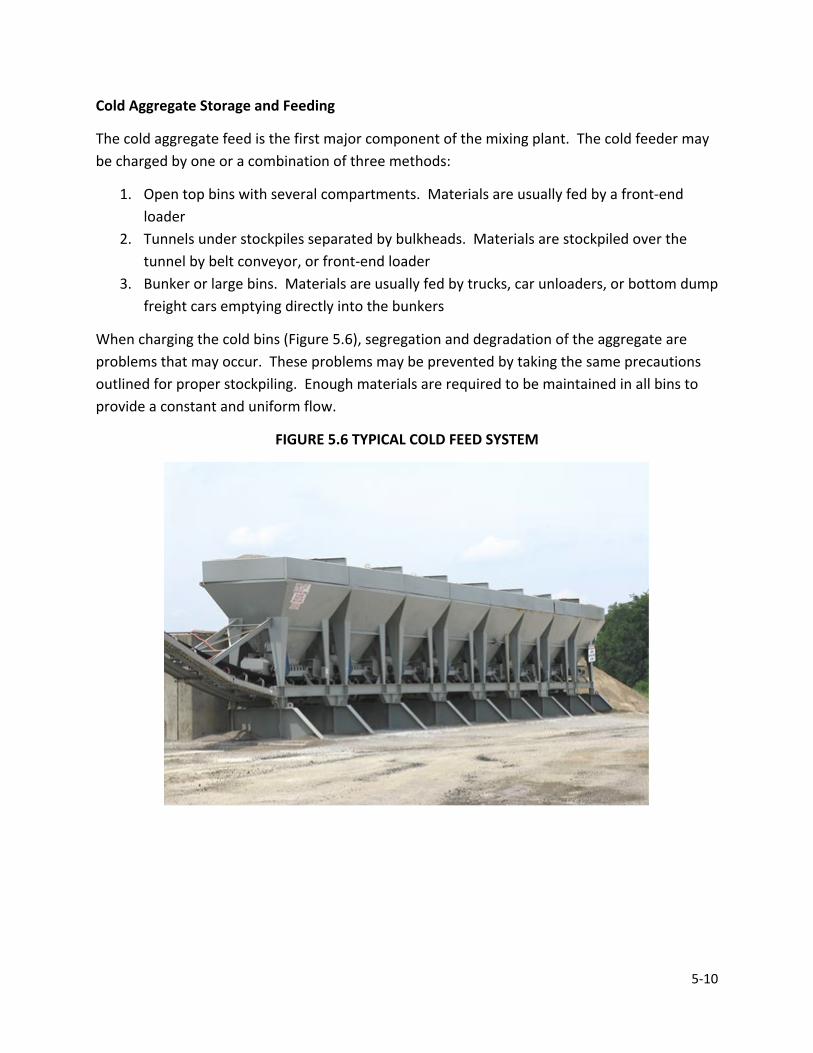
5-10
Cold Aggregate Storage and Feeding
The cold aggregate feed is the first major component of the mixing plant. The cold feeder may be charged by one or a combination of three methods:
1. Open top bins with several compartments. Materials are usually fed by a front-end loader
2. Tunnels under stockpiles separated by bulkheads. Materials are stockpiled over the tunnel by belt conveyor, or front-end loader
3. Bunker or large bins. Materials are usually fed by trucks, car unloaders, or bottom dump freight cars emptying directly into the bunkers
When charging the cold bins (Figure 5.6), segregation and degradation of the aggregate are problems that may occur. These problems may be prevented by taking the same precautions outlined for proper stockpiling. Enough materials are required to be maintained in all bins to provide a constant and uniform flow.
FIGURE 5.6 TYPICAL COLD FEED SYSTEM
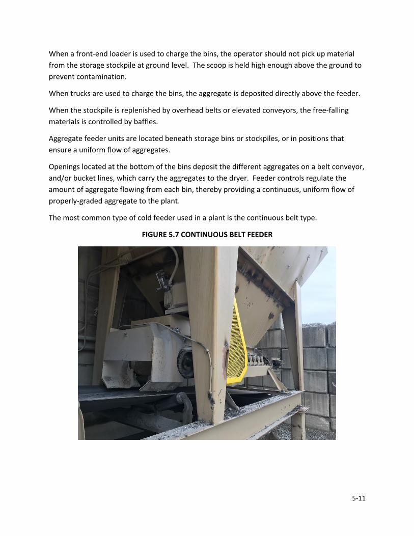
5-11
When a front-end loader is used to charge the bins, the operator should not pick up material from the storage stockpile at ground level. The scoop is held high enough above the ground to prevent contamination.
When trucks are used to charge the bins, the aggregate is deposited directly above the feeder.
When the stockpile is replenished by overhead belts or elevated conveyors, the free-falling materials is controlled by baffles.
Aggregate feeder units are located beneath storage bins or stockpiles, or in positions that ensure a uniform flow of aggregates.
Openings located at the bottom of the bins deposit the different aggregates on a belt conveyor, and/or bucket lines, which carry the aggregates to the dryer. Feeder controls regulate the amount of aggregate flowing from each bin, thereby providing a continuous, uniform flow of properly-graded aggregate to the plant.
The most common type of cold feeder used in a plant is the continuous belt type.
FIGURE 5.7 CONTINUOUS BELT FEEDER

5-12
The key element in the continuous belt feeder is how to control or regulate the flow of material from each bin. Every manufacturer has a different control method.
Typical control variations are:
1. Gate opening a. Fixed b. Adjustable
2. Belt a. One speed (on or off) b. Adjustable speed
The most common configuration is the adjustable gate with an adjustable belt speed.
Calibrating and Setting Feeders
The cold aggregate feeder is calibrated, set, and secured to ensure a uniform flow of aggregate. This calibration is the responsibility of the Producer.
The feeder is calibrated for each type and size of aggregate. Manufacturers often furnish approximate calibrations for their equipment, but the only accurate way to set a cold feed is to prepare a calibration chart for each of the aggregates to be used in the asphalt mixture. The Technician is required to examine the calibration charts of the cold feed systems to be aware of the production rate settings and how adjustments are made during production.
Calibration is simply determining the "Flow Rate" of a material graphed against the "Control" used by the particular system. Each material is calibrated for three to four control settings spanning the working production range anticipated for the material.
Control Setting
Each manufacturer has a method to control the flow of material from the cold feeds. The variable speed short belt feeder under each cold feed is the most common. The operator may adjust the RPM of the belt from the control room. Therefore, control is expressed as RPM or a percentage of the belt's total speed potential.
This same concept is used with vibrating units. The vibrator may be adjusted from the control room and expressed as a percent of maximum vibration potential.
Adjustable gates are employed on most cold feeds. The gate height is measured by the height of the opening. This gate height is required to not change when using the variable speed control.

5-13
There may be variations and modifications of these concepts. Each plant is unique; however, the plants are required to have some means to control the cold feeder. The system is required to be completely understood and controlled in a positive way to provide a uniform flow of material.
Flow Rate
Flow rate may be determined by a variety of methods that are basically pre-determined by the configuration of the plant. The most common and accurate method of determining flow rate is to physically weigh the material delivered at a specific control setting over a measured period of time. A divert chute on the intake of the dryer is the simplest, most accurate, and quickest method to do the calibration. Material may be weighed on a weigh bridge, if available, or completely processed through the plant and weighed on the plant scales. The flow rate is then converted to tons per hour. Moisture content is required to be considered in this procedure.
The degree of accuracy is only as good as the method used to determine the flow rate for each control setting. Therefore, the larger the sample measured, the more accurate the data received. Using an entire truck load of material provides dependable numbers.
Calibration Chart
After understanding the plant "Control" system and determining the best method to obtain a "Flow Rate", a calibration is required to be done. This process determines a flow rate at four different control settings for each cold feed. The process may be time-consuming, but the benefits are worth much more than the time spent. After multiple calculations have been done for each bin used during production, the calibration chart is prepared. On the chart, control settings are plotted on a horizontal scale, and the flow rate is plotted on the vertical scale.
For larger production plants, more than one bin is required to be calibrated for each material. This back-up cold feed calibration allows continuation of production if a cold feed bin fails mechanically.
Another common practice for large production rates is to use two cold feeders to supply the same size of material. This practice allows for slower machinery rates and tends to reduce segregation.

5-14
FIGURE 5.8 CALIBRATION CHART
Gross Weight
Tare Weight
Net Weight
Gross Comp.
Tare Comp.
Net Comp. % Error
79,140 36,700 42,720 0 81,040 36,700 87,210 42,720 80,290 36,700 130,670 87,210 78,620 36,700 172,660 130,670
BINDER METERING
The drum mixer is typically equipped with a device (Figure 5.9) to add binder to the aggregate inside the drum mixer. The binder metering and delivery system is a continuous mechanical proportioning system interlocked with the aggregate weight system to ensure an accurate binder content of the asphalt mixture. The weight of aggregate going into the mixer, as measured by the weigh belt, is the basis for determining the quantity of binder delivered into the drum.
FIGURE 5.9 BINDER INLET
The proportioning of binder is accomplished by establishing the necessary rate of binder delivery in gallons per minute to match the aggregate delivery in tons of dry aggregate per hour. The binder delivery rate is increased or decreased proportionately according to the corrected dry weight measurement of aggregate passing over the belt scale. The rate of binder delivery is indicated on a rate meter on the control panel.

5-15
The rates of delivery of aggregate and binder are sometimes recorded on continuously recording circular graphs located in the control van. The graphs provide both monitoring and a permanent record of the proportioning of binder and total aggregate.
AGGREGATE MOISTURE DETERMINATION
Since aggregate in a drum mix operation is weighed before drying, moisture content of the aggregate is required to be determined. The weighing of aggregate and the metering of binder are interlocked electronically in drum mix operations. To ensure proper metering of binder, adjustments for aggregate moisture are made. The moisture content of the aggregate is required to be properly determined prior to the start of mixing and subsequently thereafter as changes occur in the condition of the aggregate.
To determine the moisture content of aggregate, a representative sample is required. Generally, representative samples are easier to obtain from storage bins or stockpiles.
Regardless of the size of the aggregate, the procedure (AASHTO T 255) for making an aggregate moisture determination is basically the same. The steps for this procedure are outlined as follows.
1. Obtain a representative sample of the material for the production 2. Reduce the sample to a size that may be handled by the weighing device by either a
sample splitter or the quartering method 3. Weigh the aggregate sample and record the weight (Wet Weight) 4. Dry the aggregate sample thoroughly. The sample is dried to constant weight on a hot
plate or in an oven at a temperature of 230° F. 5. Accurately weigh the dried sample and record the weight (Dry Weight). In weighing and
handling the sample, extreme care is required to be taken to avoid any loss of the material, as this affects the accuracy of the results.
The percent moisture is determined by the following formula:
%𝑀𝑀𝑀𝑀𝑀𝑀𝑀𝑀𝑀𝑀𝑀𝑀𝑀𝑀𝑀𝑀 =𝑊𝑊𝑀𝑀𝑀𝑀 𝑊𝑊𝑀𝑀𝑀𝑀𝑊𝑊ℎ𝑀𝑀 − 𝐷𝐷𝑀𝑀𝐷𝐷 𝑊𝑊𝑀𝑀𝑀𝑀𝑊𝑊ℎ
𝐷𝐷𝑀𝑀𝐷𝐷 𝑊𝑊𝑀𝑀𝑀𝑀𝑊𝑊ℎ𝑀𝑀 𝑥𝑥 100
Example
Wet Weight = 1225 g
Dry Weight = 1175 g
%𝑀𝑀𝑀𝑀𝑀𝑀𝑀𝑀𝑀𝑀𝑀𝑀𝑀𝑀𝑀𝑀 =1225 − 1175
1175𝑥𝑥 100 = 4.3%

5-16
DRUM MIX OPERATION
The heart of the drum mix plant is the mixer. The mixer is similar in design and construction to a conventional batch plant rotary dryer, except that a drum mixer not only dries aggregate but also blends the aggregate and binder together into the asphalt mixture.
The drum mixer may be configured in two main variations: parallel-flow and counterflow. The benefits of counterflow over parallel-flow are the ability to use more RAP without higher emissions, and less damage to the virgin binder. The binder in counterflow drums are not exposed to the open flame and hot exhaust gas stream as much as in parallel-flow drums. Unitized counterflow drums and separate dryer and mixing drums separate the binder completely from the open flame and hot exhaust gases (Figure 5.10).
FIGURE 5.10 COUNTERFLOW DRUM MIXERS
COUNTERFLOW DRUM-MIXER FLOW
SEPARATE DRYER AND MIXER FLOW
DOUBLE-BARREL UNITIZED DRYER/MIXER FLOW
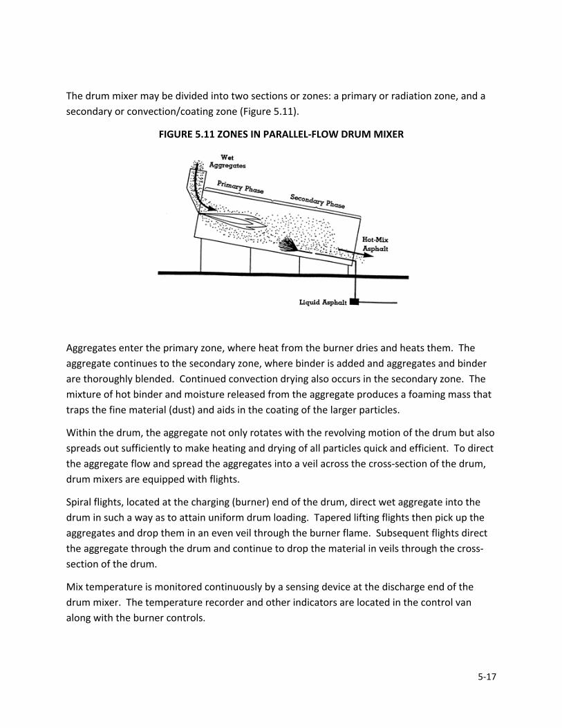
5-17
The drum mixer may be divided into two sections or zones: a primary or radiation zone, and a secondary or convection/coating zone (Figure 5.11).
FIGURE 5.11 ZONES IN PARALLEL-FLOW DRUM MIXER
Aggregates enter the primary zone, where heat from the burner dries and heats them. The aggregate continues to the secondary zone, where binder is added and aggregates and binder are thoroughly blended. Continued convection drying also occurs in the secondary zone. The mixture of hot binder and moisture released from the aggregate produces a foaming mass that traps the fine material (dust) and aids in the coating of the larger particles.
Within the drum, the aggregate not only rotates with the revolving motion of the drum but also spreads out sufficiently to make heating and drying of all particles quick and efficient. To direct the aggregate flow and spread the aggregates into a veil across the cross-section of the drum, drum mixers are equipped with flights.
Spiral flights, located at the charging (burner) end of the drum, direct wet aggregate into the drum in such a way as to attain uniform drum loading. Tapered lifting flights then pick up the aggregates and drop them in an even veil through the burner flame. Subsequent flights direct the aggregate through the drum and continue to drop the material in veils through the cross-section of the drum.
Mix temperature is monitored continuously by a sensing device at the discharge end of the drum mixer. The temperature recorder and other indicators are located in the control van along with the burner controls.
5-18
A suitable means is required to be provided for inspecting and sampling the mixture after the discharge from the drum.
Burner Operation and Control
The purpose of the burner inside the drum mixer is to provide the heat necessary to heat and dry the aggregates used in the final mix. The burners provide this heat by burning oil, gas, or both.
When oil is burned, low pressure air drafts are used to atomize the fuel oil for burning. Burners using natural gas and LPG may be low-pressure or high-pressure units. In all cases, the fuel feed and air blower are required to be balanced to ensure that the proper proportions of fuel and air are being introduced into the burner for efficient combustion. Lack of balance may lead to incomplete burning of the fuel, which, especially in the case of fuel oil or diesel fuel, may leave an oily coating on the aggregate particles. Such imbalances between fuel feed and air flow may be corrected by either decreasing the fuel feed rate or increasing the blower or draft air.
SURGE BIN AND WEIGH SCALES
In a drum mixer operation, which produces a continuous flow of asphalt mixture, the plant is required to have a surge bin for temporary storage of the material and for controlled loading of trucks. A weigh system may be connected to the holding bin of the surge bin to monitor the amount of material loaded into each truck. Weight measurements are normally recorded by the weigh system control panel, located in the control van or trailer.
Hot Mix Asphalt Storage
To prevent plant shutdowns due to temporary interruptions of paving operations or shortages of trucks to haul asphalt mixture from the plant to the paving site, most plants are equipped with surge bins (storage silos) for temporary storage of asphalt mixture. When a surge bin is used, the asphalt mixture is deposited by conveyor or hot elevator into the top of the bin (Figure 5.12) and is discharged into trucks from the bottom.
Surge bins work well if certain precautions are followed but may cause segregation of the asphalt mixture if not used properly. A good practice is to use a baffle plate or similar device at the discharge end of the conveyor used to load the bin. The baffle helps to prevent the segregation of the asphalt mixture as the mixture drops into the bins. A good recommendation is to keep the hopper at least one-third full to avoid segregation as the hopper empties and to help keep the mix hot.

5-19
FIGURE 5.12 TYPICAL STORAGE STRUCTURE CONFIGURATION
SUMMARY OF DRUM MIXES
Close control of aggregate gradation in the cold bins, and the control of aggregate and binder feeding into the drum mixer are essential in providing uniform asphalt mixture using a drum mix plant. Drum mix plant inspection procedures are required to be followed to ensure that materials are proportioned correctly and properly mixed at the desired temperature. These procedures include inspecting the proportioning equipment, sampling and testing the aggregate gradation, determining aggregate moisture content, and monitoring asphalt mixture temperature.
EFFECT OF PLANT ON ASPHALT MIXUTRE PROPERTIES
Asphalt mixture properties may vary depending on the type of plant and the environmental controls on the plant. The reason for these changes may be explained by how the plants function. Each plant/environmental control combination and the mix properties affected are discussed as follows.
DUST CONTROL AND COLLECTION SYSTEMS
Enforcement of air pollution regulations or codes is usually done by the local pollution agency. However, since the dust control system is integrated with plant operation, the Technician is required to at least be aware of the controls and equipment necessary to meet these
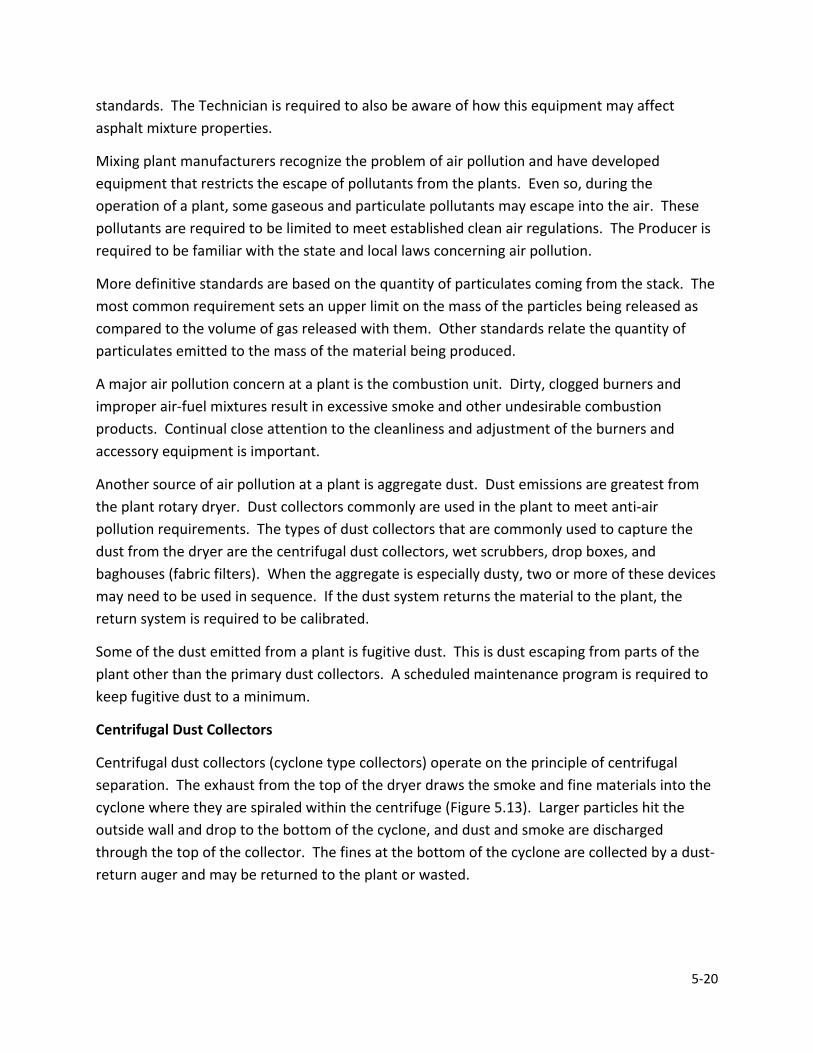
5-20
standards. The Technician is required to also be aware of how this equipment may affect asphalt mixture properties.
Mixing plant manufacturers recognize the problem of air pollution and have developed equipment that restricts the escape of pollutants from the plants. Even so, during the operation of a plant, some gaseous and particulate pollutants may escape into the air. These pollutants are required to be limited to meet established clean air regulations. The Producer is required to be familiar with the state and local laws concerning air pollution.
More definitive standards are based on the quantity of particulates coming from the stack. The most common requirement sets an upper limit on the mass of the particles being released as compared to the volume of gas released with them. Other standards relate the quantity of particulates emitted to the mass of the material being produced.
A major air pollution concern at a plant is the combustion unit. Dirty, clogged burners and improper air-fuel mixtures result in excessive smoke and other undesirable combustion products. Continual close attention to the cleanliness and adjustment of the burners and accessory equipment is important.
Another source of air pollution at a plant is aggregate dust. Dust emissions are greatest from the plant rotary dryer. Dust collectors commonly are used in the plant to meet anti-air pollution requirements. The types of dust collectors that are commonly used to capture the dust from the dryer are the centrifugal dust collectors, wet scrubbers, drop boxes, and baghouses (fabric filters). When the aggregate is especially dusty, two or more of these devices may need to be used in sequence. If the dust system returns the material to the plant, the return system is required to be calibrated.
Some of the dust emitted from a plant is fugitive dust. This is dust escaping from parts of the plant other than the primary dust collectors. A scheduled maintenance program is required to keep fugitive dust to a minimum.
Centrifugal Dust Collectors
Centrifugal dust collectors (cyclone type collectors) operate on the principle of centrifugal separation. The exhaust from the top of the dryer draws the smoke and fine materials into the cyclone where they are spiraled within the centrifuge (Figure 5.13). Larger particles hit the outside wall and drop to the bottom of the cyclone, and dust and smoke are discharged through the top of the collector. The fines at the bottom of the cyclone are collected by a dust-return auger and may be returned to the plant or wasted.
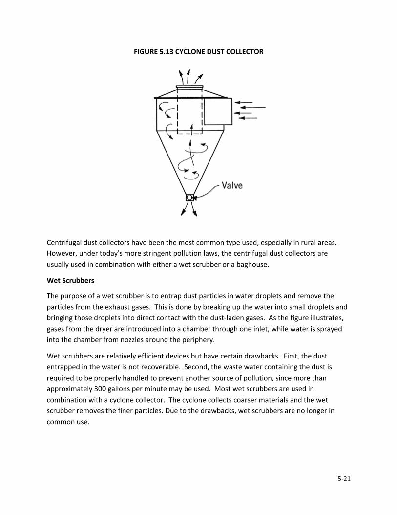
5-21
FIGURE 5.13 CYCLONE DUST COLLECTOR
Centrifugal dust collectors have been the most common type used, especially in rural areas. However, under today's more stringent pollution laws, the centrifugal dust collectors are usually used in combination with either a wet scrubber or a baghouse.
Wet Scrubbers
The purpose of a wet scrubber is to entrap dust particles in water droplets and remove the particles from the exhaust gases. This is done by breaking up the water into small droplets and bringing those droplets into direct contact with the dust-laden gases. As the figure illustrates, gases from the dryer are introduced into a chamber through one inlet, while water is sprayed into the chamber from nozzles around the periphery.
Wet scrubbers are relatively efficient devices but have certain drawbacks. First, the dust entrapped in the water is not recoverable. Second, the waste water containing the dust is required to be properly handled to prevent another source of pollution, since more than approximately 300 gallons per minute may be used. Most wet scrubbers are used in combination with a cyclone collector. The cyclone collects coarser materials and the wet scrubber removes the finer particles. Due to the drawbacks, wet scrubbers are no longer in common use.
5-22
Baghouses (Fabric Filters)
A baghouse (Figure 5.14) is a large metal housing containing hundreds of synthetic, heat-resistant fabric bags for collecting fines. The fabric bags are usually silicone-treated to increase their ability to collect very fine particles of dust. A baghouse functions much the same way as a vacuum cleaner. A large vacuum fan creates a suction within the housing, which draws in dirty air and filters the air though the fabric of the bags. To handle the huge volume of exhaust gases from the aggregate dryer, a very large number of bags (a typical unit may contain as many as 800) are required.
A baghouse is divided into a dirty gas chamber and a clean gas chamber. The filter bags are contained in the dirty gas chamber, into which the air from the dryer enters. The flow of air carrying the dust particles passes through the fabric of the filter bags, depositing the dust on the surface of the bag. The air then continues to the clean gas chamber. During the operation, the fabric filter traps large quantities of dust. Eventually, the dust accumulates into a "dust cake", that is required to be removed before the dust reduces or stops the flow of gas through the filter. There are many ways of cleaning the bags in a collector, but the most common methods are to flex the bags, back-flush the bags with clean air, or both flex and back-flush. Dust removed from the bags drops into an auger at the bottom of the baghouse and is transferred to a storage silo. The dust may then be returned to the plant or wasted.
FIGURE 5.14 TYPICAL BAGHOUSE
5-23
Drum/Wet Wash
In a drum plant, the aggregate drying and mixing chamber are located within the drum. Many of the fines being carried to the dust collection system are captured in the binder veil. This reduces the loading on the environmental equipment. If a wet wash system is used, then any fines that get past the binder veil are removed from the asphalt mixture. The amount of fines removed depends on several factors. The greatest factor is the total length of the drum and the length of the drum used for mixing. As both increase, less fines will enter into the environmental collection system.
The environmental controls in the drum/wet wash combination have less to do with the asphalt mixture properties. Asphalt mixtures produced from these plants are generally lower in Air Voids and VMA than Batch/Wet Wash combinations. The Certified Asphalt Technician may supervise all sampling and testing of materials, the maintenance of control charts, and the maintenance of the diary, however, the Certified Asphalt Technician shall not conduct sampling and testing.
Drum/Baghouses
If a baghouse is utilized in a drum plant, the fines that are returned to the drum are added near the binder inlet. This is done so that the fines are immediately wetted and captured in the asphalt mixture. Asphalt mixtures produced by Drum/Baghouse combinations tend to be lower in Air Voids and VMA than other plant combinations.
PLANT INSPECTION AND SCALE CHECK
All plants which produce asphalt mixture for INDOT are required to be inspected prior to becoming a Certified HMA Plant, annually thereafter, and when the plant is moved. This inspection verifies that all meters, scales, and other measuring devices are calibrated to accuracy within 0.5% throughout their range.
DRUM PLANT
The load cells and binder supply system are checked for accuracy on a drum plant. Since asphalt mixture proportioning for a drum plant is done by a moving weight system, the computer monitors are required to be checked for accuracy (Figure 5.15).
The load cell on each aggregate belt is required to be checked. This check is done by running material across the load cell into a tared truck. The computer inventory is required to match the actual weight by 0.5 percent. This check is required to meet accuracy requirements three consecutive times. A truck load of material is used for each check to obtain better accuracy.
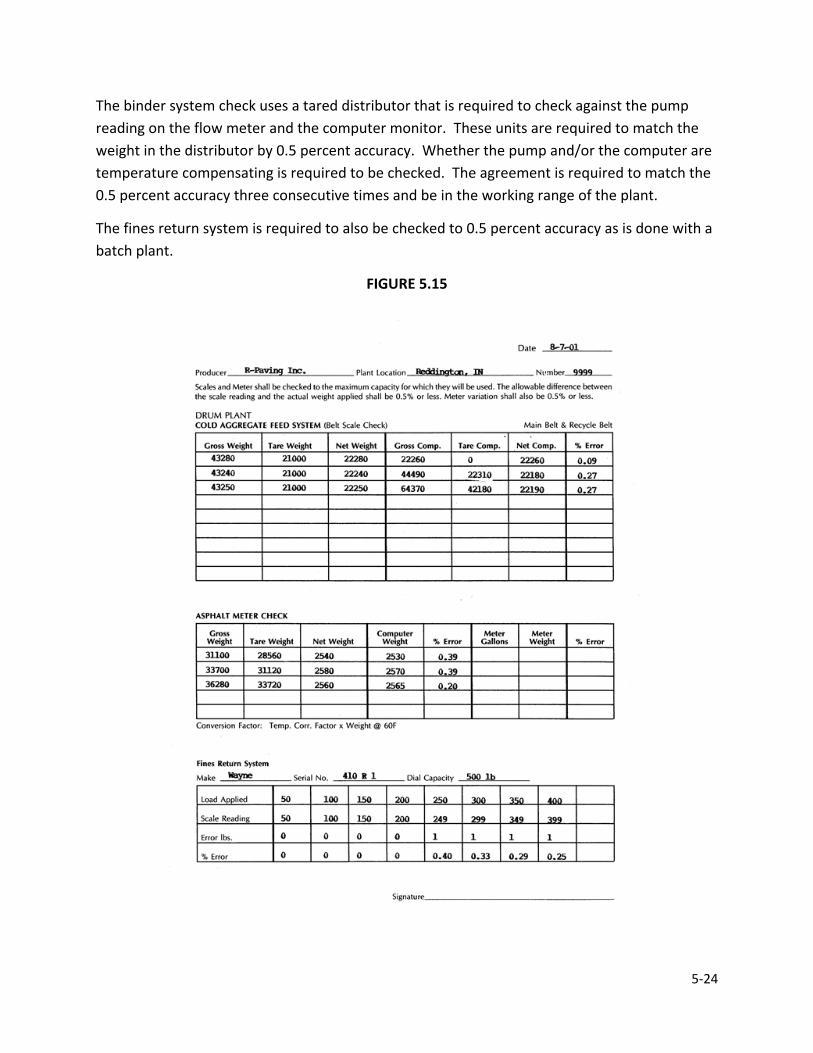
5-24
The binder system check uses a tared distributor that is required to check against the pump reading on the flow meter and the computer monitor. These units are required to match the weight in the distributor by 0.5 percent accuracy. Whether the pump and/or the computer are temperature compensating is required to be checked. The agreement is required to match the 0.5 percent accuracy three consecutive times and be in the working range of the plant.
The fines return system is required to also be checked to 0.5 percent accuracy as is done with a batch plant.
FIGURE 5.15

5-25
DRUM PLANT/COLD FEED
Each plant manufacturer has a somewhat different type of control panel for the cold aggregate feed system and binder metering system; however, all drum mixing plant aggregate and binder proportioning systems perform basically the same. Form IT 667 may be used to calibrate a drum plant. The entire calibration is required to be done at the same master control bin setting, which is recorded.
To calibrate a drum plant, each belt system with a load cell is checked: main collector belt, recycle belt, individual feeder belts, etc. To do a proper check, sufficient quantities of material to simulate normal production rates are passed over the load cell and into a tared truck. (Note: For a batch plant you only have the weight in the truck and there is no load cell). A beginning and ending computer inventory for the material is recorded and compared to the actual weight of the material in the truck. Three consecutive tests are required to be within 0.5 percent to ensure adequate accuracy (Figure 5.16).
Once the load cells have been checked, the calibration of each individual bin flow rates may be determined. At least three different flow rates for each bin spanning the normal production rate are determined. This may be done using the computer monitor readings at various control settings. The recommended method is to use a tared truck on a timed interval, as described next and on Form IT-667 (Figure 5.17).
Step 1 -- Determine Control Setting vs Flow Rate
Each bin contains material to be used and the gate height is measured and recorded. The timed method runs material across the load cells at three different dial control settings for each individual bin. The material is run into a tared truck and weighed at each control setting. Therefore, for each bin used, the dial (control) setting, time in minutes, and weight in tons are known. The ton per hour may be calculated for each setting (Figure 5.16)
Step 2 -- Plot Cold Feed Control Graph
From this data a Cold Feed Control Graph can be drawn for each bin which plots Flow Rate vs Control Setting (Figure 5.19). (This step is not needed for Batch Plant Cold Feed set up).
Step 3 -- Determine Plant Control Setting
The next step in the calibration is to use the Cold Feed Control Graph and the anticipated production rate at which the plant produces material to determine the Control Settings for each individual bin (Figure 5.20).

5-26
First determine Total Aggregate Flow Rate by multiplying the desired Production Rate times the % of Aggregate in the asphalt mixture. Next multiply that Total Aggregate Flow Rate times the % which each Individual Bin contributes to the asphalt mixture to obtain the Flow Rate desired from each bin (Note: This % per bin is obtained from the mix design or is obtained by trial and error using IT-651A). Using the Cold Feed Control Graph (1) locate the Flow Rate for that bin, (2) move to the Control Line for that bin, and (3) move to the resulting Control Setting. Follow the procedure for all bins. The control settings are supplied to the plant operator to produce the required mixture.
Step 4 -- Check for Accuracy of Calibration
To ensure the proper gradation has been determined, a composite aggregate sample is obtained. Set the established individual Bin Control Settings and start the aggregate flow into the drier. When a uniform material flow is on the main belt, stop the operation.
In a safe manner completely remove 2 to 5 ft of material from the belt. Split this sample to proper sample size. Conduct a gradation test and compare the data to the design mix formula. If agreement is not obtained, investigate to determine the discrepancy.

5-27
FIGURE 5.16

5-28
FIGURE 5.17
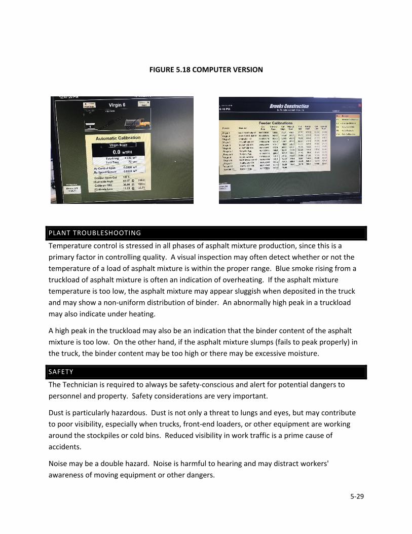
5-29
FIGURE 5.18 COMPUTER VERSION
PLANT TROUBLESHOOTING
Temperature control is stressed in all phases of asphalt mixture production, since this is a primary factor in controlling quality. A visual inspection may often detect whether or not the temperature of a load of asphalt mixture is within the proper range. Blue smoke rising from a truckload of asphalt mixture is often an indication of overheating. If the asphalt mixture temperature is too low, the asphalt mixture may appear sluggish when deposited in the truck and may show a non-uniform distribution of binder. An abnormally high peak in a truckload may also indicate under heating.
A high peak in the truckload may also be an indication that the binder content of the asphalt mixture is too low. On the other hand, if the asphalt mixture slumps (fails to peak properly) in the truck, the binder content may be too high or there may be excessive moisture.
SAFETY
The Technician is required to always be safety-conscious and alert for potential dangers to personnel and property. Safety considerations are very important.
Dust is particularly hazardous. Dust is not only a threat to lungs and eyes, but may contribute to poor visibility, especially when trucks, front-end loaders, or other equipment are working around the stockpiles or cold bins. Reduced visibility in work traffic is a prime cause of accidents.
Noise may be a double hazard. Noise is harmful to hearing and may distract workers' awareness of moving equipment or other dangers.
5-30
Moving belts transporting aggregates and belts to motors and sprocket and chain drives are also hazardous. All pulleys, belts and drive mechanisms are required to be covered or otherwise protected. Loose clothing that may get caught in machinery is never worn at a plant.
Good housekeeping is essential for plant safety. The plant and yard are required to be kept free of loose wires or lines, pipes, hoses, or other obstacles. High voltage lines, field connections, and wet ground surfaces are other hazards to the Technician. Any loose connections, frayed insulation or improperly grounded equipment are required to be reported immediately.
Plant workers are not allowed to work on cold bins while the plant is in operation. No one may walk or stand on the aggregates in the bins or on the bunkers over the feeder gate openings.
Burner flames and high temperatures around plant dryers are obvious hazards. Control valves that may be operated from a safe distance are required to be installed on all fuel lines. Flame safety devices also are required to be installed on all fuel lines. Smoking is not permitted near binder or fuel storage tanks. Leaks in oil heating lines and steam lines or jacketing on the binder distribution lines are dangerous. Safety valves are required to be installed in all steam lines and be in working order. Screens, barrier guards, and shields as protection from steam, hot binder, hot surfaces, and similar dangers are required to be used.
When handling heated binder, chemical goggles or a face-shield are required. All shirt collars are required to be worn closed and cuffs buttoned at the wrist. Gloves with gauntlets that extend up the arm are required to be worn loosely so the Technician may flip them off easily if covered with hot binder. Pants without cuffs are required to be extended over boot tops.
The Technician is required to exercise extreme care when climbing around the screen deck, inspecting the screens and hot bins, or collecting hot bin samples. Covered or protected ladders or stairways to provide safe access to all parts of the plant are required to be provided. All stairs and platforms are required to have secure handrails. All workers around the plant are required to always wear a hard hat when not under cover.
Truck traffic patterns are planned with both safety and convenience in mind. Trucks entering the plant to pick up a load of asphalt mixture do not cross the path of loaded trucks leaving the plant. Also, trucks should not have to back up.

CHAPTER 6AUDITS, EQUIPMENT,
CALIBRATION, ANDQUALITY CONTROLTROUBLESHOOTING

6-1
CHAPTER 6 AUDITS, EQUIPMENT, CALIBRATION, AND QUALITY CONTROL TROUBLESHOOTING
CERTIFICATIONS HMA PLANT PRODUCER PERSONNEL
AUDIT GENERAL INFORMATION
DOCUMENTS HMA LABORATORY HMA PLANT
QUALITY CONTROL PLAN
CONTROL LIMITS – QC/QA HMA AND SMA TARGET VALUES RESPONSE TO TEST RESULTS CONTROL CHARTS
DIARY
MATERIALS SAMPLING AND TESTING AGGREGATES PG BINDER MIXTURE PLANT AND PAVEMENT SAMPLING
FREQUENCY OF TESTS
HMA PLANT DOCUMENTATION MATERIAL STOCKPILES PROCESS CONTROL
FIELD LABORATORY TEST EQUIPMENT CALIBRATION
COMPARISON TESTING
AUDIT CLOSE-OUT
MIXTURE TROUBLESHOOTING VOLUMTERIC CONTROL
6-2
CHAPTER 6
QUALITY CONTROL PROCEDURES
The foundation for a successful Quality Assurance program is the quality control maintained by the Producer to assure that all materials submitted for acceptance conform to the contract requirements. To accomplish this, the Producer is required to have a functional plan to keep the process in control, quickly determine when the process goes out of control, and respond adequately to bring the process back into control.
Quality control is a system of:
“Inspection, analysis, and action applied to a portion of the product in a manufacturing operation to estimate overall quality of the product and determine what, if any, changes must be made to achieve or maintain the required level of quality.”
This section includes the minimum requirements of the Indiana Certified Hot Mix Asphalt Producer Program (Program) in accordance with ITM 583. The mixtures included in this Program include QC/QA HMA in accordance with Section 401, HMA in accordance with Section 402, and Stone Matrix Asphalt (SMA) in accordance with Section 410.
The most common Quality Control tools:
• Gradation o Stockpiles o Mixture o RAP
• Binder Content (extraction or ignition) • Bulk Specific Gravity (Gmb)/lab compacted (Pill Heights), cores • Maximum Specific Gravity (Gmm) • Eyes
CERTIFICATIONS
HMA PLANT CERTIFICATION
Each Producer requesting to establish a Certified Plant is required do so in writing to the Manager, Office of Materials Management. Upon receipt of the request for certification, the District is notified to inspect the plant and laboratory.
The plant inspection, including the correction of any deficiencies and calibration of all meters, scales and other measuring devices, is required to be completed prior to certification.

6-3
Each plant meeting the requirements of the Program is certified upon the approval of the QCP. Movement of the Certified Plant to a new location requires submittal of a QCP Annex, and verification of the calibration of all meters, scales, and other measuring devices.
The Producer, in accordance with ITM 581, shall submit a written request to the Asphalt Engineer, Office of Materials Management, to in-line blend SBR polymer latex at the HMA plant.
In the event of a change in ownership of the Certified HMA Plant, the certification shall expire on the date of such change. The new ownership may avoid expiration by submitting a statement to the Manager, Office of Materials Management indicating recognition of intent to operate in accordance with the requirements of both documents prior to providing mixture to the Program.
Producer Personnel Certification
The Producer personnel required to be identified include a Management Representative, Level 1 Asphalt Technician, and a Certified Asphalt Technician, and a Qualified Technician, if applicable.
Management Representative
The Management Representative shall be responsible for all aspects of mixture production and control at the HMA plant and on the pavement as required by the Program.
Level 1 Asphalt Technicians
The level 1 Asphalt Technician shall conduct or supervise all sampling and testing of materials, the maintenance of control charts, and the maintenance of the diary.
Certified Asphalt Technicians
The Certified Asphalt Technician may supervise all sampling and testing of materials, the maintenance of control charts, and the maintenance of the diary, however, the Certified Asphalt Technician shall not conduct sampling and testing used for acceptance.
Qualified Technicians
The Qualified Technician may conduct all sampling and testing used for acceptance of materials under the direct supervision of a Certified Asphalt Technical or Level 1 Asphalt Technician until the next opportunity to take the QC/QA HMA Certified Technician exam is available.
6-4
AUDIT GENERAL INFORMATION
Types of Audits
Each INDOT Certified Hot Mix Asphalt Producer is required to have an audit performed by INDOT personnel every calendar year. There are three types of audits. A Full Audit is performed on all Certified HMA plants that produced INDOT HMA mixtures. A No Production Audit is performed on all Certified HMA plants that do not produce INDOT HMA mixtures. A Partial Audit is performed on Certified HMA plants that have already or will have an audit performed within that same calendar year.
Audit General Instructions
INDOT Audit Team Members should review the current QCP, previous audits, and coordinate with the Independent Assurance (IA) Technician for a comparison testing schedule (if applicable) prior to performing the audit. A list of the following documents should be brought to the audit:
• All Approved DMF and Contract Record worksheets for the current calendar year. • Approved list of Level 1 Asphalt Technicians, Certified Technicians, and Qualified
Technicians • Approved list of PG Binder Suppliers • Approved list of Anti-Adhesive materials • IA comparison paperwork, if applicable • Current copy of ITM 583
Every item in the audit packet has a bracket that is to be filled in. A check mark is made if the item is found to be satisfactory. If the item is not applicable, “NA” is put in the bracket. If the item is not found to be unsatisfactory then an “X” is made. A Corrective Action sheet is to be prepared for every item with an “X”. Any unsatisfactory or deficient items that are resolved during the audit will be noted on the Corrective Action Sheet indicating the item has been corrected.

6-5
DOCUMENTS
HMA LABORATY
Each Certified HMA plant laboratory is required to have the following current documents on file:
1. Indiana Department of Transportation Standard Specifications (Includes applicable Special Provisions)
2. Indiana Certified Asphalt Technician (ICAT) Manual 3. All applicable Indiana, AASHTO, and ASTM Test Methods 4. Testing equipment calibrations or verifications 5. Mix design, DMF for each mixture 6. Fines correction data for the mixture and recycled materials for each DMF, if applicable 7. Type A certifications for PG binder materials 8. Type A certifications for the SBR polymer latex 9. PG 70-22 binder test reports from an AASHTO accredited laboratory whenever PG 64-22
are in-line blended with SBR polymer latex 10. Process control test results 11. Type D certifications issued to active Department contracts
HMA PLANT
Each Certified HMA Plant is required to have these current documents on file: 1. The Quality Control Plan (QCP) for the Certified Plant 2. Bill of ladings of the binder from each Supplier for a minimum period of three complete
calendar years 3. Weigh tickets from most current date of production of HMA and adhere to the
requirements of section 109.01(b) of INDOT Standard Specifications a. Net weight, ticket, serial number, date, contract number, source of material,
material designation (size or type), DMF number, truck designation, time weighed, gross weight/tar weight (if applicable)
4. Instructions from the Supplier concerning storage and handling of the binder 5. Flow meter calibration reports and flow computer printouts whenever in-line blending
with SBR polymer latex 6. IDEM Legitimate Use Approval letter from the post-consumer asphalt shingle processing
company, if applicable. 7. HMA plant calibrations for each DMF 8. Daily diary 9. Annual calibrations of the HMA plant scales and verification of meters 10. Fiber certification from the manufacturer 11. Instructions from the manufacturer concerning storage and handling of fibers

6-6
QUALITY CONTROL PLAN
Each Producer providing QC/QA HMA, HMA, or SMA under the Certified Hot Mix Asphalt Producer Program is required to have a written Quality Control Plan (QCP) that is plant specific and is the basis of control. The QCP contains, but is not limited to, the methods of sampling, testing, calibration, verification, inspection, and anticipated frequencies.
Production of mixture shall not begin before the QCP has been approved. The Producer is required to submit two copies of the QCP to the Department for review. One copy to the District Testing Engineer where the certified plant is located and one copy to the Office of Materials Management. Acceptance or rejection of the QCP will be made within 15 days of receipt of the QCP. One approved copy will be returned to the Producer.
The QCP includes the following information for each HMA Plant.
1. The location of the HMA Plant site, including the county and reference to the nearest identifiable points such as highway and towns.
2. The name, telephone number, fax number, email address, duties, and employer of the Management Representative, Level 1 Asphalt Technician(s), Certified Asphalt Technician(s), and Qualified Technician(s) if applicable. The duties of all other personnel responsible for implementation of the QCP are also included.
3. A list of test equipment that is calibrated or verified, the test methods and frequency of calibration or verification of the equipment, and a statement of accessibility of the laboratory to Department personnel. If the laboratory is not located at the HMA Plant, the location of the laboratory is required to be designated, and the procedure for transporting the mixture to the laboratory included.
4. A plant site layout diagram that includes the location of the stockpile area, binder tanks, fuel tank, fiber supply, anti-adhesive supply, field laboratory, visitor parking area and major components of the mixing plant.
5. A plan for controls of the aggregate and recycled material stockpiles. Controls for identification of stockpiles by signing or other acceptable methods, techniques for construction of proper stockpiles, and cold bin loading procedures to prevent overflow of material from one bin into another are required to be included.
6. A plan for the identification of the grade of binder in each storage tank and the use of more than one binder grade in a binder tank. The sampling location is required to be indicated.
7. A plan for in-line blending SBR polymer latex at the HMA plant to include a QCP in accordance with ITM 581 as an addendum to the plant QCP.
8. A plan for the production of HMA with a water-injection foaming device. The necessary plant modifications, plant production start-up process, planned mixture production temperature ranges, and moisture testing on mixtures sampled at the plant for each DMF shall be included.

6-7
9. The procedure for the consistent uniform addition of baghouse fines when returned into the HMA plant.
10. The procedure for the consistent uniform addition of fibers into the HMA plant. 11. The procedure for using an anti-adhesive agent for the truck bed, and a statement that
the agent is on the Department’s list of Approved Anti-Adhesive Materials. 12. The procedure for sealing the surge bin when used for extended storage of the mixture
up to one working day and the method to prevent the discharge when the mixture falls below the top of the cone. The written approval of the surge bin is required to be included.
13. The procedure for loading mixture into the trucks. 14. A sampling plan that includes locations, test methods, devices, techniques, frequencies,
and sample reduction procedures. 15. A testing plan that includes the types of tests and test methods. 16. A description of any other process control techniques that may be used beyond the
minimum required by INDOT. These controls may include, but are not limited to: a. Different types or greater frequencies of material testing b. Visual checks and monitoring of HMA plant production
17. A statement of the procedure for handling addenda to the QCP including a time schedule for submittal.
18. A documentation plan with details on control charting, test data, and the diary. Copies of the forms may be included.
The last page of the QCP is required to have two signatures. One signature shall be the Producer Management Representative, the date of submittal, and the corporate title of the Producer Management Representative. The other signature shall be for approval of the QCP by the Manager, Office of Materials Management.
A QCP checklist (Chapter 9) is provided to assure that all the applicable items required in ITM 583 are addressed in the QCP.
Addenda are defined as an addition or deletion to the QCP. Each page of the QCP that is revised is required to include the HMA plant number, date of revision, and means of identifying the revision. The addenda are required to be signed and dated by the Management Representative and subsequently signed and dated when approved by the District Testing Engineer.
Revisions for HMA plant major components, Level 1 Asphalt Technicians, Certified Asphalt Technicians, Qualified Asphalt Technicians, and movement of the HMA plant are submitted in the format of a QCP Annex per ITM 583 as they occur. Upon approval by the District Testing Engineer, the QCP Annex is placed in the Appendix of the QCP until such time that the revisions are incorporated as addenda into the QCP.

6-8
Revisions, other than items on the QCP Annex, are maintained on an Addenda Summary Sheet. The Addenda Summary Sheet is a page of the QCP Appendix that is used to record a brief description of the revision until such time that the revision is incorporated into the QCP.
Addenda may be submitted at the audit close-out meeting or anytime during the calendar year. The addenda are required to include items on the QCP Annex, items on the Addenda Summary Sheet, and any other necessary revisions at the time of submittal. Upon incorporation into the QCP as addenda, the QCP annex and items on the Addenda Summary Sheet are removed from the QCP Appendix.
CONTROL LIMITS – QC/QA HMA AND SMA
TARGET VALUES
The target values are identified on the DMF or identified by the Producer.
FIGURE 6.1 CONTROL LIMITS FROM THE TARGET VALUES
Parameter Maximum % Passing, Control Limits (±)
Aggregate Stockpiles Blended Aggregate Base and Intermediate Mixtures
Blended Aggregate Surface Mixtures
3/4 in. ± 10.0 ± 10.0 1/2 in. ± 10.0 ± 10.0 ± 10.0 No. 4 ± 10.0 ± 10.0 ± 10.0 No. 8 ± 10.0 ± 10.0 ± 8.0 No. 16 ± 8.0 ± 8.0 ± 8.0 No. 30 ± 6.0 ± 6.0 ± 4.0 No. 50 ± 6.0 ± 6.0 ± 4.0 No. 100 ± 6.0 ± 6.0 ± 3.0 No. 200 ± 2.0 ± 2.0 ± 2.0
Parameter Control Limits Binder Content of Mixture and RAP, % ± 0.7 Binder Content of RAS, % ± 3.0 Vbe, %, above design minimum (QC/QA HMA, SMA) +2.0 VMA @ Ndes, % (QC/QA HMA) ± 1.0 VMA @ N75, Min. % (9.5 mm SMA) 17.0 VMA @ N75, Min. % (12.5 mm SMA) 16.0 Target Air Voids, % (Dense Graded Mixtures and SMA) ± 1.0 Target Air Voids, % (Open Graded Mixtures) ± 3.0 2.36 mm (No. 8) sieve % passing (9.5 mm Surface Mixtures Only) + 4.0
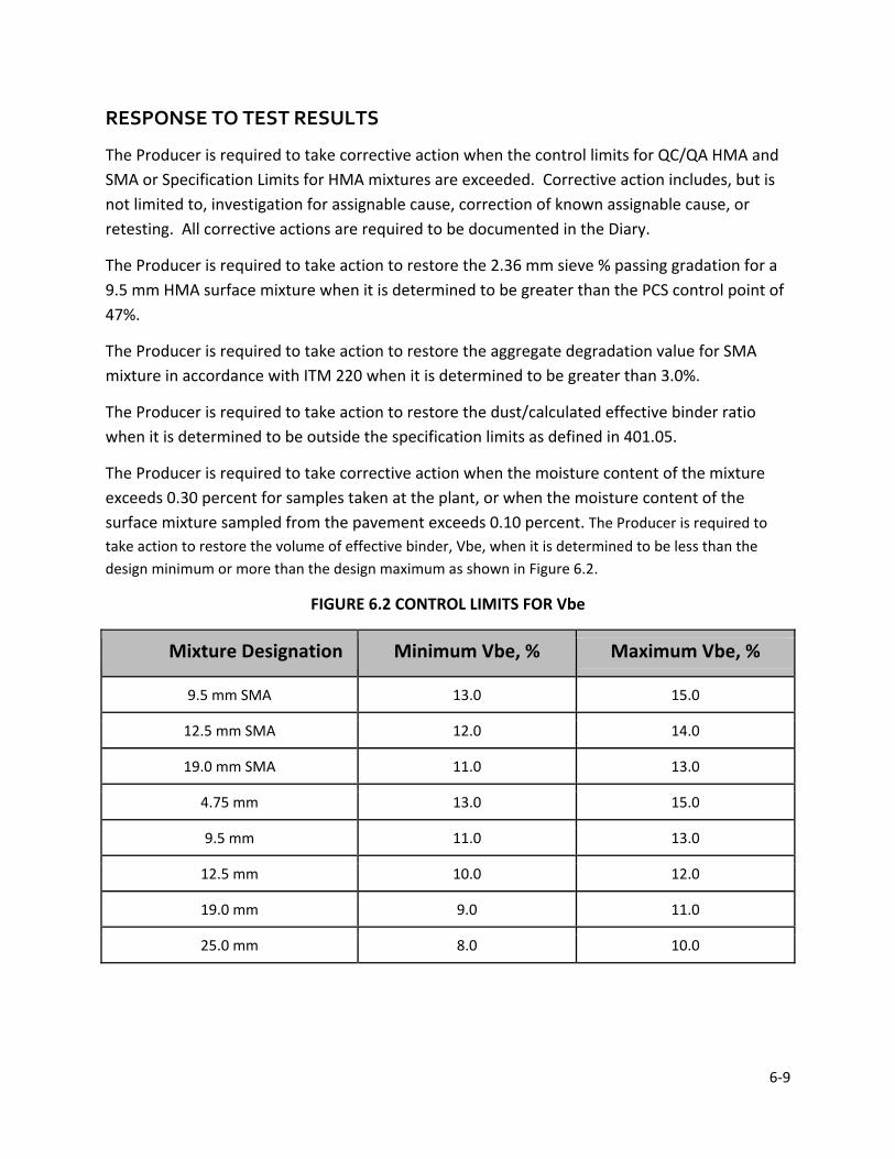
6-9
RESPONSE TO TEST RESULTS
The Producer is required to take corrective action when the control limits for QC/QA HMA and SMA or Specification Limits for HMA mixtures are exceeded. Corrective action includes, but is not limited to, investigation for assignable cause, correction of known assignable cause, or retesting. All corrective actions are required to be documented in the Diary.
The Producer is required to take action to restore the 2.36 mm sieve % passing gradation for a 9.5 mm HMA surface mixture when it is determined to be greater than the PCS control point of 47%.
The Producer is required to take action to restore the aggregate degradation value for SMA mixture in accordance with ITM 220 when it is determined to be greater than 3.0%.
The Producer is required to take action to restore the dust/calculated effective binder ratio when it is determined to be outside the specification limits as defined in 401.05.
The Producer is required to take corrective action when the moisture content of the mixture exceeds 0.30 percent for samples taken at the plant, or when the moisture content of the surface mixture sampled from the pavement exceeds 0.10 percent. The Producer is required to take action to restore the volume of effective binder, Vbe, when it is determined to be less than the design minimum or more than the design maximum as shown in Figure 6.2.
FIGURE 6.2 CONTROL LIMITS FOR Vbe
Mixture Designation Minimum Vbe, % Maximum Vbe, %
9.5 mm SMA 13.0 15.0
12.5 mm SMA 12.0 14.0
19.0 mm SMA 11.0 13.0
4.75 mm 13.0 15.0
9.5 mm 11.0 13.0
12.5 mm 10.0 12.0
19.0 mm 9.0 11.0
25.0 mm 8.0 10.0

6-10
The Producer in-line blending SBR latex at the HMA plant is required to take corrective action if the latex solids content is more than 0.2% below the lower target limit for more than 15 minutes of production.
CONTROL CHARTS
A control chart is a graphic representation of data shown with prescribed limits that indicate whether a process is in control. Although not required by the Certified HMA Producer Program, control charts may prevent the production of nonconforming material when used in a timely manner.
The control chart should have a means of designating the target mean, control limits, individual test results, and a moving average of the test results.
Control Chart Interpretation
The moving average is useful in determining the accuracy of the process. Averages tend to lessen the effect of erratic data points that may reflect errors not related to the actual material (sampling, testing, etc.). The presence of unusual patterns or trends may be evidence of non-conformance during the period of the pattern. Any of the following potential nonconforming conditions concerning the moving average may be reason for an investigation of the process.
1. Seven or more points in a row are above or below the target mean 2. Seven or more points in a row are consistently increasing or decreasing
DIARY
The Producer is required to maintain a diary at the HMA Plant. The diary is an open format book with at least one page devoted to each day mixture is produced. The diary is kept on file either by hard copy or electronically for a minimum period of three years.
Entries in the diary include at least the following:
1. The type of mixture and quantity produced, DMF number, and the contract number or purchase order for each mixture
2. The time that the samples were obtained and the time the test was completed 3. Nonconforming tests and the resulting corrective action taken 4. Any significant events or problems
The diary entry is to be signed by the Level 1 Asphalt Technician, Certified Asphalt Technician, or Management Representative. On occasion the diary may be signed by another person;
6-11
however, the diary is required to be counter-signed by the Level 1 Asphalt Technician, Certified Asphalt Technician, or Management Representative.
MATERIAL SAMPLING AND TESTING
The most important consideration in sampling is to be certain that the sample taken is representative of the material. The Producer is required to designate the sampling and sample reduction procedures, sampling location, devices, techniques, and size of samples necessary for testing. Sampling is conducted on uniform tonnage increments on a random basis.
Aggregate/Recycled Materials Sampling
Aggregate samples may be obtained from stockpiles, belts, or hot bins depending on the type of plant and control of aggregate gradation selected. The procedures for these methods of sampling are described in Chapter 2. If RAP and/or RAS is used in the mixture, the procedure for sampling this material is ITM 207.
Binder Sampling
Two one-quart samples are obtained from either the Certified Plant binder tank or injection line in accordance with AASHTO R 66. The procedure for sampling binder is described in Chapter 3.
Mixture Sampling
The sampling procedures for mixture at the plant or from the pavement are included in ITM 580. For truck sampling at the plant, a square bit shovel of the appropriate size for the required sample is used. For plate sampling from the pavement, a metal square plate with a minimum size of 8 in. is used. Procedures for sampling are discussed in Chapter 7.
MATERIALS TESTING
The Producer is required to designate the types of tests and test methods to be used for control of the aggregates, recycled material, and mixture. Mixture testing is required to be completed within two working days of the time the sample was taken. The Producer is required to keep the test results on file either by hard copy or electronically for a minimum period of three years.
Aggregate Testing
Gradation
Gradations done on blended aggregate or aggregate stockpile samples are conducted using AASHTO T 27. If RAP is used in the mixture, the test procedure for the gradation is AASHTO T 30.
6-12
Moisture Content
AASHTO T 255 is the test procedure used for determination of the total moisture content of the cold feed belt or belt discharge aggregate samples for a drum plant.
Mixture Testing
The analysis of the mixture to meet the requirements of the Program includes several tests. Detailed procedures of these tests include:
Mixture Calibration
A plant calibration is required to be made for each mixture to be produced in accordance with the following methods:
• Batch Plants -- the percentage of the total aggregate to be obtained from each hot bin and the RAP belt
• Drum Plants -- the percentage of the total aggregate to be obtained from each cold bin and the RAP bin
Moisture Content
ITM 572 outlines the procedure for determination of the moisture content. Of particular importance is that the sample be placed immediately into an oven bag when obtaining the sample so that an accurate moisture content may be obtained.
Binder Content
Several methods are allowed for determination of the binder content; however, the Ignition Method (ITM 586) and the Extraction Method (ITM 571) are the most common procedures.
Extracted Aggregate Gradation
After the binder content has been determined in accordance with ITM 571, the sieve analysis of the aggregate is made using AASHTO T 30, except the decantation through the No. 200 sieve is not required. If ITM 586 is used, the aggregate sample is first decanted and then the sample is sieved in accordance with AASHTO T 30.
Coarse Aggregate Angularity
If gravel is used in the mixture or the RAP contains gravel, the coarse aggregate angularity (crushed content) is determined after the sieve analysis. ASTM D 5821 is the procedure used for determination of both one and two faced crushed particles.
6-13
Mixture Specimen Preparation
Specimens to determine the air voids and VMA are compacted to Ndes in accordance with AASHTO T 312. The compaction temperature is 300 ± 9°F for dense graded mixtures and SMA, and 260 ± 9°F for open graded mixtures.
Bulk Specific Gravity
AASHTO T 166 is the procedure used for determination of the bulk specific gravity of the gyratory specimens for dense graded and SMA mixtures. The bulk specific gravity of the gyratory specimens for open graded mixtures, OG 19.0 mm and OG 25.0 mm, is determined in accordance with AASHTO T 331.
Maximum Specific Gravity
AASHTO T 209 is the procedure used for determination of the maximum specific gravity of the mixture. The supplemental procedure for mixtures containing porous aggregates may be required if the aggregate absorbs water during the test.
Draindown
AASHTO T 305 is the procedure used to determine the amount of binder that drains from the mixture during production. This is a requirement for open graded mixtures and SMA.
Temperature
The best procedure to determine the temperature of the mixture is with a dial and armored-stem thermometer. The stem is required to be inserted sufficiently deep (at least 6 in.) into the mixture, and the material is required to be in direct contact with the stem.
The gun-type infrared thermal meter, which measures reflective heat from the surface, may also be used. This device detects only surface heat and may not be accurate for material within the truck. To overcome this problem, the instrument may be directed at the stream of mixture at the discharge gate of the mixer or surge bin.
FREQUENCY OF TESTS
The frequency of tests is determined by the Producer and is required to be included in the QCP for the following items:
1. Aggregates a. Stockpiles b. Blended Aggregate
2. Binder 3. Recycled Materials

6-14
a. Actual Binder Content b. Gradation c. Moisture Content d. Coarse Aggregate Angularity e. Bulk Specific Gravity of Recycled Aggregate
4. Mixture Sampled at the HMA plant a. Actual Binder Content b. Gradation c. Aggregate degradation value (for SMA mixtures only) - once per lot d. Moisture Content e. Temperature f. Draindown (for open graded and SMA mixtures only)
5. Mixture Sampled from the Pavement a. Air Voids b. VMA c. Actual Binder Content d. Gradation e. Dust/calculated effective binder ratio f. Moisture Content (for surface mixtures only) g. Bulk Specific Gravity h. Maximum Specific Gravity i. Volume of Effective Binder, Vbe
HMA
HMA mixture produced concurrently with QC/QA HMA mixture is required to be sampled and tested in accordance with the requirements established for QC/QA HMA. All other HMA is required to be sampled at the HMA plant or the roadway and tested for binder content, coarse aggregate angularity for mixtures containing gravel, gradation, and air voids in accordance with the following minimum frequency:
1. The first 250 tons and each subsequent 1000 tons of each DMF in a construction season for base and intermediate mixtures
2. The first 250 tons and each subsequent 600 tons of each DMF in a construction season for surface mixtures
FIELD LABORATORY
A laboratory is required to be provided and maintained at the plant site with the necessary equipment and supplies for conducting quality control testing.

6-15
Performance of quality control tests at laboratory facilities other than the plant-site are allowed provided the laboratory facilities are owned by the Producer, transportation to an offsite laboratory is defined in the QCP, all test procedure criteria are satisfied, and the test results are furnished in writing to the plant-site laboratory within two working days. INDOT is allowed access to inspect any laboratory used for quality control testing and to witness quality control activities.
TEST EQUIPMENT CALIBRATION
The equipment furnished for testing is required to be properly calibrated and maintained within the calibration limits described in the applicable test method. A record of calibration results is maintained at the field laboratory for the equipment listed in the following table:
FIGURE 6.3 CALIBRATION AND VERIFICATION FREQUENCY FOR TESTING EQUIPMENT
Equipment Requirement Min
Freq Procedure
Balances Standardize 12 mo. ITM 910
Gyratory Compactor Verify Ram Pressure, Angle of Gyration, Frequency of Gyration, LVDT
1 mo. ITM 908
Gyratory Compactor Internal Angle
Verification 12 mo. AASHTO T 344
Gyratory Mold and Plate Dimensions
Verification 12 mo. AASHTO T 312
Ignition Oven Conduct Lift Test Weekly Operators Manual Ignition Oven Balance Standardize 12 mo. ITM 910 Mechanical Shakers Verify Sieving Thoroughness 12 mo. ITM 906 Ovens Verify Temperature Settings 12 mo. ITM 903 Sieves Verify Physical Condition 12 mo. ITM 902 Thermometers Verification 12 mo. ITM 909 Vacuum Chamber Verification 3 mo. ITM 905 Calipers Verification 12 mo. ITM 916
The equipment used to calibrate or verify the testing equipment is required to be NIST traceable and calibrated or verified in accordance with the following frequencies:

6-16
FIGURE 6.4 CALIBRATION AND VERIFICATION FREQUENCY FOR EQUIPMENT USED TO CALIBRATE OR VERIFY TESTING EQUIPMENT
Calibration Equipment Testing Equipment Minimum Frequency
Master Ring used with the Bore Gauge Gyratory Compactor Molds – AASHTO T 312 36 mo. Dynamometer or Load Cell & Proving Ring
Gyratory Compactor – AASHTO T 312 24 mo.
Height Gage Blocks Gyratory Compactor – AASHTO T 312 24 mo.
Height Billet Gyratory Compactor – AASHTO T 312 24 mo. Vacuum Gage Vacuum Systems – ITM 905 12 mo. Weights, Min. Class 3 Balances – ITM 910 12 mo.
COMPARISON TESTING
Testing procedures required by the QCP will be observed to verify that they comply with the Sampling, Sample Reduction, and Testing Procedures checklist. IA comparison testing that occurs every 2 years will be adequate.
If comparison testing is performed as part of the audit, the Producer’s Level 1 Asphalt Technician will obtain a sample of the mixture, blended aggregate, and recycled material (if applicable). A separate blended aggregate sample is only required if specified by the QCP. The samples obtained will be split by the Producer’s Certified Technician and the Department’s portion given to the INDOT audit team member. Samples are required to be tested by the Producer and INDOT.
Comparison tests required for an INDOT audit are the gradation, binder content of RAP, and binder content of the mixture are within the following limits:
FIGURE 6.5 COMPARISON TESTING ALLOWABLE DEVIATION
Sieves Deviation (± %)
Binder Content
Deviation (± %)
1 in. 5 RAP 0.5 ¾ in. 5 Mixture 0.5 ½ in. 5 No. 8 3 No. 30 3 No. 200 3
6-17
AUDIT CLOSE-OUT
A meeting with the Producer is to be conducted at the end of the audit. Any addenda on the Addenda Summary Sheet, QCP Annex, Corrective Action, and Appendix sheets will be submitted at this time. The results of the audit are discussed with the Producer and outstanding matters will be completely resolved or solutions with deadlines will be established. Corrective Action sheets requiring longer than two weeks must be addressed by the DTE. An Audit Close-Out meeting is to be held when all items indicated on Corrective Action Sheets have been addressed and all Comparison testing results (if applicable) have been reviewed.
The DTE will verify the audit package is prepared properly and completed. Upon completion of the Audit Close-Out meeting, all documents will be sent to the Asphalt Engineer, Office of Materials Management.
MIXTURE TROUBLESHOOTING
Mixture troubleshooting starts with knowing some common QC tools:
Gradation Binder Content Gmb of lab specimens and cores Gmm And your Eyes Using these common tools during production will help you find general relationships with properties and provide good troubleshooting skills.
During production there are other means available to make a quick determination of the properties of the mixture. For example, Air voids and VMA may be approximated by estimating the bulk specific gravity (Gmb) of the mixture. This estimation of Gmb is made from the height of the gyratory specimens when a constant sample mass is used.
Verification of a mix design prior to production is one of the best procedures to prevent potential problems. Using current gradations from your stockpiles should always be done when setting up a blend. Usually mix designs are not developed at the same time as a project, so consequently, modifications to the blend is necessary. And never forget that materials going through a drum will change in shape and gradation so keep this in mind when establishing blends in the field.
Figure 6.7 shows the relationships between certain volumetric properties of HMA. These properties are used in determining changes that may be made when troubleshooting HMA.
In troubleshooting, it is important to realize the possible issues that can occur. See Figure 6.6 to identify possible problem areas in the material flow schematic.
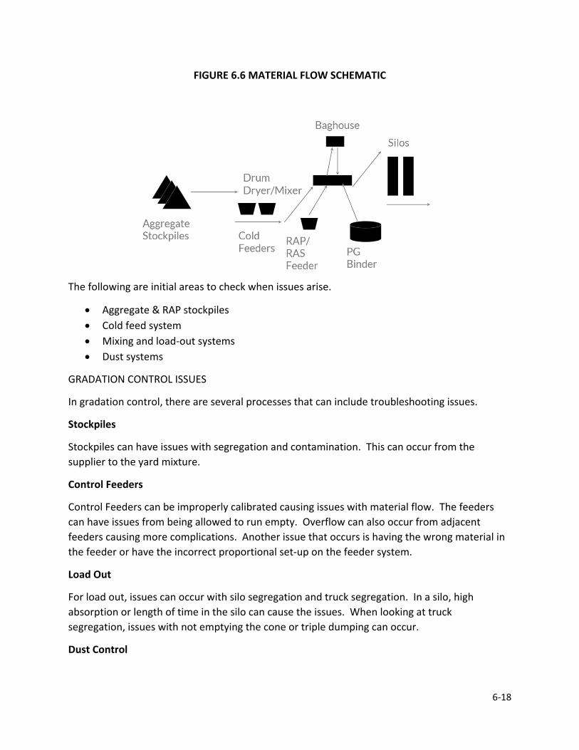
6-18
FIGURE 6.6 MATERIAL FLOW SCHEMATIC
The following are initial areas to check when issues arise.
• Aggregate & RAP stockpiles • Cold feed system • Mixing and load-out systems • Dust systems
GRADATION CONTROL ISSUES
In gradation control, there are several processes that can include troubleshooting issues.
Stockpiles
Stockpiles can have issues with segregation and contamination. This can occur from the supplier to the yard mixture.
Control Feeders
Control Feeders can be improperly calibrated causing issues with material flow. The feeders can have issues from being allowed to run empty. Overflow can also occur from adjacent feeders causing more complications. Another issue that occurs is having the wrong material in the feeder or have the incorrect proportional set-up on the feeder system.
Load Out
For load out, issues can occur with silo segregation and truck segregation. In a silo, high absorption or length of time in the silo can cause the issues. When looking at truck segregation, issues with not emptying the cone or triple dumping can occur.
Dust Control
6-19
Dust control is another issue that can cause problems with material flow. Make sure to always check the primary collector, secondary collector, and mineral filler bin
BINDER CONTROL
The following problems can occur with binder control:
• Mix Segregation
• Plot %binder vs.% passing #8 or #4
• Flow Meter calibration
• Aggregate moisture correction (only slight)
• Aggregate or RAP weigh bridge calibration
• Rap binder content
• RAP aggregate type (dolomite/burn-off)
• Start-up, shut down and switching mixes
• Refer to “Appendix C” in your QC Manual
VOLUMETRIC CONTROL
Verification of the volumetric mixture properties is one of the most important duties of the Technician. Changes in the material or control at the HMA plant may result in the air voids and VMA falling outside of the Specification limits. The general trend is that the design air voids and VMA will decrease during production at the plant. This section contains information concerning the steps that may be taken to correct a deficient volumetric property. In order to use these guidelines, the mixture composition is required to be reasonably close to the designed mixture.
VMA
Figure 6.8 is a flow chart for VMA adjustment for plant – produced mixture. The amount of material passing the No. 200 sieve and the relative proportions of coarse and fine aggregate may significantly affect the VMA. A loss of VMA is a common problem during production.
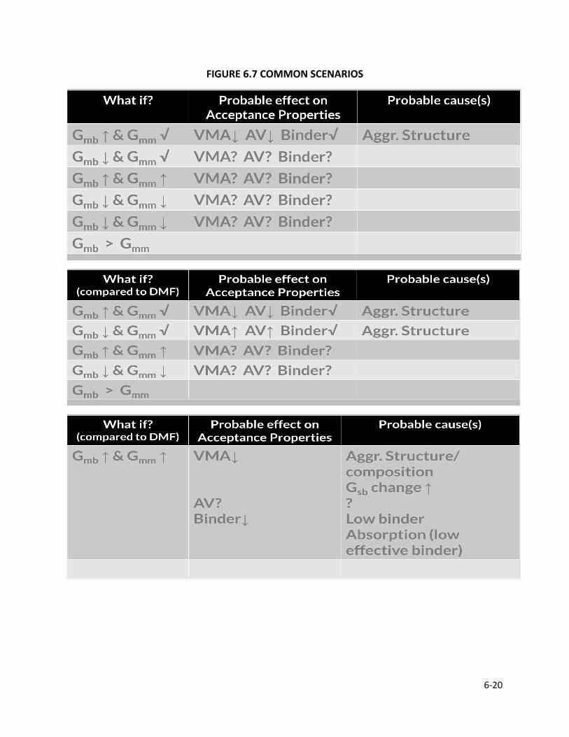
6-20
FIGURE 6.7 COMMON SCENARIOS

6-21
FIGURE 6.8 VMA ADJUSTMENT PROCESS
6-22
Gradation changes may be caused by a mechanical problem with the plant. A comparison of the blended aggregate and extracted aggregate gradations is a good technique to verify if this problem exists. Also, there is, in most cases, some "rounding" of the edges of the coarse aggregate particles as they pass through the drum. This rounding of the aggregate lowers the VMA.
Dust variation in the mixture may be caused by variations in the minus No. 200 sieve material of the aggregates; however, a change in the dust is more likely to be the result of the inconsistent return of fines from the plant baghouse. Specifications require that if dust is returned into the mixture, the system is required to return the material at a constant rate during production. A check on the fines return system is required to be made to verify this constant rate of return of fines.
Adjusting for low VMA is the more common problem a Technician needs to correct. Procedures for increasing the VMA include:
1. Reduce the amount of material passing the No. 200 sieve 2. Reduce the amount of natural sand in the mixture 3. Adjust the aggregate gradation away from the Maximum Density Line
Air Voids
Figure 6.9 is a flow chart for adjusting air voids for plant-produced mixture. Air voids are influenced by a combination of VMA, percent passing the No. 200 sieve, and the binder content. Adjustments of the air voids are dependent on the magnitude of the variance between the production and DMF values. If the difference is greater than 0.5 percent, consideration should be given to adjusting the binder content; if the difference is less than 0.5 percent, the percent passing the No. 200 sieve may be adjusted.
A comparison of the production bulk specific gravity (Gmb) and maximum specific gravity (Gmm) values to the DMF and previous production values should also be done. Different Gmb values may be caused by an aggregate gradation change (especially the P 200) or by a particle shape change from aggregate breakdown. Different Gmm values may be caused by a binder content, aggregate absorption, or aggregate specific gravity change.
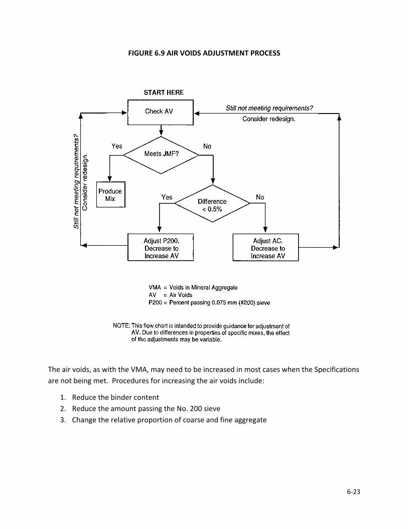
6-23
FIGURE 6.9 AIR VOIDS ADJUSTMENT PROCESS
The air voids, as with the VMA, may need to be increased in most cases when the Specifications are not being met. Procedures for increasing the air voids include:
1. Reduce the binder content 2. Reduce the amount passing the No. 200 sieve 3. Change the relative proportion of coarse and fine aggregate
6-24
TROUBLESHOOTING TIPS
To prevent issues, start off with the right steps and be diligent in your preparation. Before you start production, check stockpiles, correct JMF input to plant, plant calibrations (all meters and scales), test equipment calibration, and communicate with your plant operator.
Conduct a trial run on new JMF before starting major production. Use 100± tons. Don’t sample the first or last load. When doing this, think of the cost of trial vs. cost of failure of removal. Some additional tips for troubleshooting:
• Retest to verify results as needed • Eliminate the obvious first • Be careful not to overreact • Keep track of all your changes so you can find patterns • Gather as much data as you can before making decisions

CHAPTER 7PERCENT WITHIN LIMITS
AND FIELD TESTING

CHAPTER 7 PERCENT WITHIN LIMITS (PWL) AND FIELD TESTING
RANDOM NUMBERS
DESIGN MIX FORMULA
MIXTURE ADJUSTMENT FACTOR
LOT/SUBLOT – QC/QA HMA
ACCEPTANCE SAMPLES
MIXTURE ACCEPTANCE QC/QA HMA HMA
PAY FACTORS – QC/QA HMA (DENSE GRADED MIXTURE ≥ 1 LOT) PWL - MIXTURE PWL – DENSITY PAY FACTORS
QUALITY ASSURANCE ADJUSTMENT – QC/QA HMA ≥ 1 LOT
PAY FACTORS – QC/QA HMA (DENSE GRADED MIXTURE < 1 LOT AND OPEN GRADED MIXTURES) MIXTURE DENSITY
QUALITY ASSURANCE ADJUSTMENT – QC/QA HMA < 1 LOT AND OPEN
GRADED MIXTURES
MIX APPEAL – QC/QA HMA
SMOOTHNESS
7-2
CHAPTER 7 QUALITY ASSURANCE PROCEDURES
The acceptance criteria for QC/QA HMA set out in the Quality Assurance Specifications are based on air voids @ Ndes, Volume of Effective Binder, density and smoothness. The Specifications establish controls for temperature of the mixture, testing of aggregates for quality, and testing of binder. The acceptance criteria for HMA mixtures are based on binder content and air voids. The acceptance criteria for SMA mixtures are binder content and gradation.
This section includes the procedures for obtaining acceptance samples, minimum requirements for mixture properties in accordance with Sections 401 (QC/QA HMA), and 402 (HMA) and the procedures for determining pay factors.
RANDOM NUMBERS
The Producer personnel required include a Management Representative and a Certified Asphalt Technician Sampling for mixture tests is done on a random basis using ITM 802. A table of Random Numbers, as shown in Figure 7.1, can be used to determine the random quantity or random location. Random numbers generated by software may also be used. The numbers occur without aim or reason and are in no particular sequence. Therefore, samples obtained are truly random or chance and eliminate any bias in obtaining samples.
To use the random number table to determine the random ton to sample, select without looking one block in the table. After selecting the block, the top left number in the block is the first random number used. This number is the beginning number. Proceed down the column for additional numbers and proceed to the top of the next column on the right when the bottom of the column is reached. When the bottom of the last column on the right is reached, proceed to the top of the column at the left. If all numbers in the table are used, select a new starting number and proceed in the same manner.
To use this table to determine the location of the pavement sample, again select a block in the table and start with the top left number. This number is used to determine the test site station. The adjacent number within the block is used to determine the transverse distance to the random site. Proceed down by pairs until the bottom numbers are reached and proceed to the adjacent top block to the right, if available. When the bottom pair of numbers on the right are reached, proceed to the top block on the left in the table.
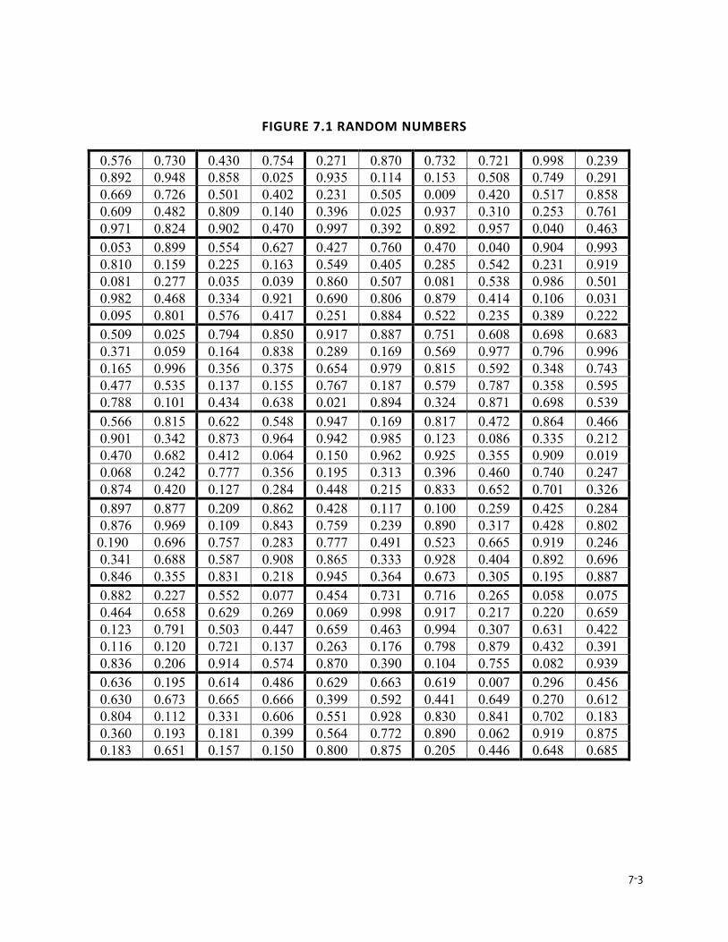
7-3
FIGURE 7.1 RANDOM NUMBERS
0.576 0.730 0.430 0.754 0.271 0.870 0.732 0.721 0.998 0.239 0.892 0.948 0.858 0.025 0.935 0.114 0.153 0.508 0.749 0.291 0.669 0.726 0.501 0.402 0.231 0.505 0.009 0.420 0.517 0.858 0.609 0.482 0.809 0.140 0.396 0.025 0.937 0.310 0.253 0.761 0.971 0.824 0.902 0.470 0.997 0.392 0.892 0.957 0.040 0.463 0.053 0.899 0.554 0.627 0.427 0.760 0.470 0.040 0.904 0.993 0.810 0.159 0.225 0.163 0.549 0.405 0.285 0.542 0.231 0.919 0.081 0.277 0.035 0.039 0.860 0.507 0.081 0.538 0.986 0.501 0.982 0.468 0.334 0.921 0.690 0.806 0.879 0.414 0.106 0.031 0.095 0.801 0.576 0.417 0.251 0.884 0.522 0.235 0.389 0.222 0.509 0.025 0.794 0.850 0.917 0.887 0.751 0.608 0.698 0.683 0.371 0.059 0.164 0.838 0.289 0.169 0.569 0.977 0.796 0.996 0.165 0.996 0.356 0.375 0.654 0.979 0.815 0.592 0.348 0.743 0.477 0.535 0.137 0.155 0.767 0.187 0.579 0.787 0.358 0.595 0.788 0.101 0.434 0.638 0.021 0.894 0.324 0.871 0.698 0.539 0.566 0.815 0.622 0.548 0.947 0.169 0.817 0.472 0.864 0.466 0.901 0.342 0.873 0.964 0.942 0.985 0.123 0.086 0.335 0.212 0.470 0.682 0.412 0.064 0.150 0.962 0.925 0.355 0.909 0.019 0.068 0.242 0.777 0.356 0.195 0.313 0.396 0.460 0.740 0.247 0.874 0.420 0.127 0.284 0.448 0.215 0.833 0.652 0.701 0.326 0.897 0.877 0.209 0.862 0.428 0.117 0.100 0.259 0.425 0.284 0.876 0.969 0.109 0.843 0.759 0.239 0.890 0.317 0.428 0.802 0.190 0.696 0.757 0.283 0.777 0.491 0.523 0.665 0.919 0.246 0.341 0.688 0.587 0.908 0.865 0.333 0.928 0.404 0.892 0.696 0.846 0.355 0.831 0.218 0.945 0.364 0.673 0.305 0.195 0.887 0.882 0.227 0.552 0.077 0.454 0.731 0.716 0.265 0.058 0.075 0.464 0.658 0.629 0.269 0.069 0.998 0.917 0.217 0.220 0.659 0.123 0.791 0.503 0.447 0.659 0.463 0.994 0.307 0.631 0.422 0.116 0.120 0.721 0.137 0.263 0.176 0.798 0.879 0.432 0.391 0.836 0.206 0.914 0.574 0.870 0.390 0.104 0.755 0.082 0.939 0.636 0.195 0.614 0.486 0.629 0.663 0.619 0.007 0.296 0.456 0.630 0.673 0.665 0.666 0.399 0.592 0.441 0.649 0.270 0.612 0.804 0.112 0.331 0.606 0.551 0.928 0.830 0.841 0.702 0.183 0.360 0.193 0.181 0.399 0.564 0.772 0.890 0.062 0.919 0.875 0.183 0.651 0.157 0.150 0.800 0.875 0.205 0.446 0.648 0.685
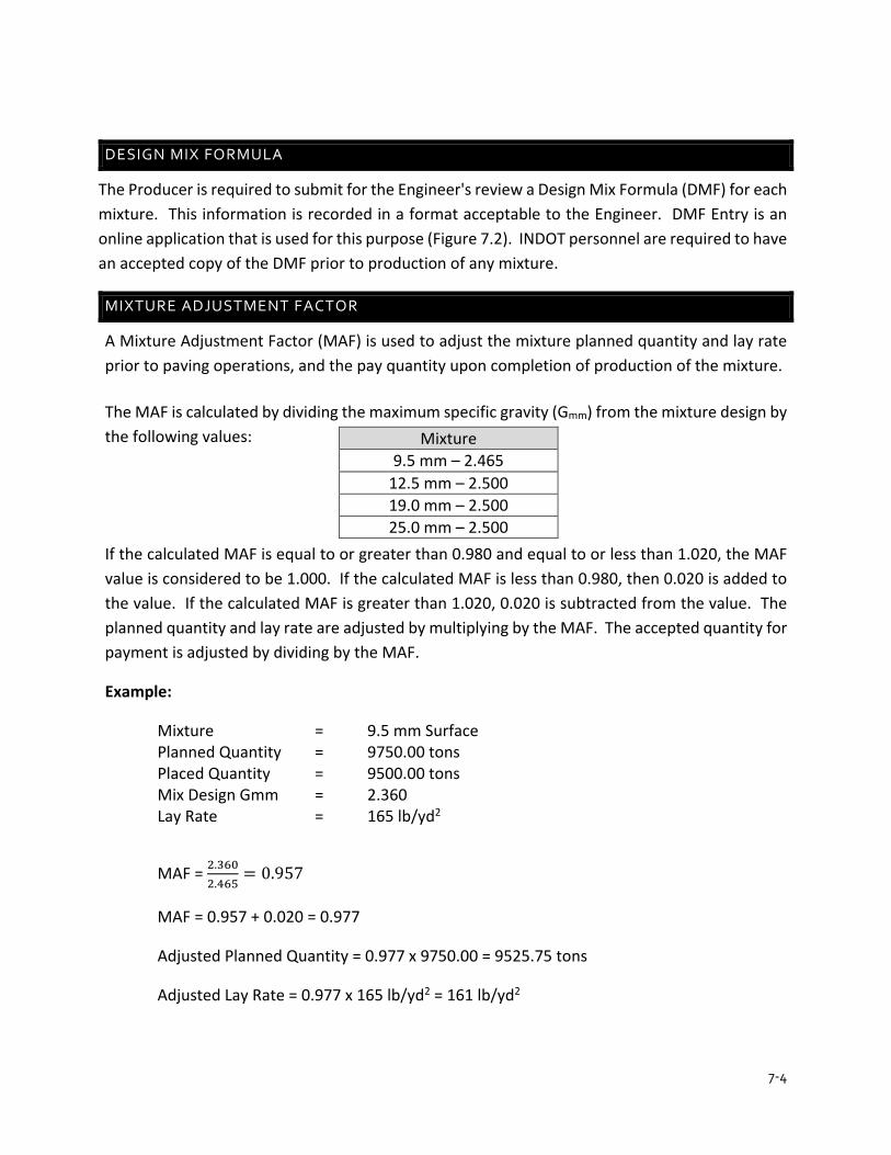
7-4
DESIGN MIX FORMULA
The Producer is required to submit for the Engineer's review a Design Mix Formula (DMF) for each mixture. This information is recorded in a format acceptable to the Engineer. DMF Entry is an online application that is used for this purpose (Figure 7.2). INDOT personnel are required to have an accepted copy of the DMF prior to production of any mixture.
MIXTURE ADJUSTMENT FACTOR
A Mixture Adjustment Factor (MAF) is used to adjust the mixture planned quantity and lay rate prior to paving operations, and the pay quantity upon completion of production of the mixture.
The MAF is calculated by dividing the maximum specific gravity (Gmm) from the mixture design by the following values:
If the calculated MAF is equal to or greater than 0.980 and equal to or less than 1.020, the MAF value is considered to be 1.000. If the calculated MAF is less than 0.980, then 0.020 is added to the value. If the calculated MAF is greater than 1.020, 0.020 is subtracted from the value. The planned quantity and lay rate are adjusted by multiplying by the MAF. The accepted quantity for payment is adjusted by dividing by the MAF.
Example:
Mixture = 9.5 mm Surface Planned Quantity = 9750.00 tons Placed Quantity = 9500.00 tons Mix Design Gmm = 2.360 Lay Rate = 165 lb/yd2
MAF = 2.3602.465
= 0.957
MAF = 0.957 + 0.020 = 0.977
Adjusted Planned Quantity = 0.977 x 9750.00 = 9525.75 tons
Adjusted Lay Rate = 0.977 x 165 lb/yd2 = 161 lb/yd2
Mixture 9.5 mm – 2.465
12.5 mm – 2.500 19.0 mm – 2.500 25.0 mm – 2.500

7-5
Adjusted Pay Quantity = 9500.000.977
= 9723.64 tons
The MAF does not apply to open graded mixtures.
LOT/SUBLOT – QC/QA HMA AND SMAlt Technicians
Quality Assurance Specifications consider a lot as 5000 t of Base or Intermediate QC/QA HMA, and 3000 t of Surface QC/QA HMA. The lots are divided into five sublots of equal tons. For Base and Intermediate QC/QA HMA therefore, a sublot is 1000 t, and for Surface QC/QA HMA, a sublot is 600 t. Partial sublots of 100 t or less are added to the previous sublot. Partial sublots greater than 100 t constitute a full sublot. Partial lots of four sublots or less are added to the previous lot, if applicable. QC/QA SMA specifications define a lot as 4000 t of Intermediate, and 2,400 t of Surface. The lots are divided into four sublots of equal tons. For Intermediate SMA, a sublot is 1000 t, and for Surface SMA, a sublot is 600 t.
ACCEPTANCE SAMPLE
Sampling of mixture for acceptance is made from the pavement in accordance with ITM 580. INDOT determines the random site and the Contractor obtains the samples under INDOT supervision. INDOT takes immediate possession of the samples.
A specific ton in each sublot is selected and the mixture from the truck containing that ton is sampled. This truck is determined by checking the weigh tickets. An example of how to determine what ton is to be sampled is indicated on form TD 452. These random tons are not shown to the Contractor so that there is no possible influence on the construction operations.
Once the truck that contains the random ton is identified, the approximate total length of mixture that the truck places is determined by knowing the weight of the truck, the paving width, and the quantity placed. When placing variable depth, such as a crown correction, the average depth is used. The following relationship is used to calculate this approximate length that a truck would place.
Length of Load = 𝐿𝐿𝐿𝐿𝐿𝐿𝐿𝐿 𝑊𝑊𝑊𝑊𝑊𝑊𝑊𝑊ℎ𝑡𝑡 (𝑡𝑡)
𝐴𝐴𝐴𝐴𝑊𝑊.𝑃𝑃𝑃𝑃𝐿𝐿𝑃𝑃𝑃𝑃𝑊𝑊𝐿𝐿 𝑄𝑄𝑄𝑄𝐿𝐿𝑡𝑡𝑊𝑊𝑡𝑡𝑡𝑡 � lbyd2� 𝑥𝑥 𝑊𝑊𝑊𝑊𝐿𝐿𝑡𝑡ℎ 𝐿𝐿𝑜𝑜 𝑃𝑃𝐿𝐿𝐴𝐴𝑊𝑊𝑃𝑃𝑊𝑊 (𝑜𝑜𝑡𝑡)
𝑥𝑥 18000
(Nearest Foot)
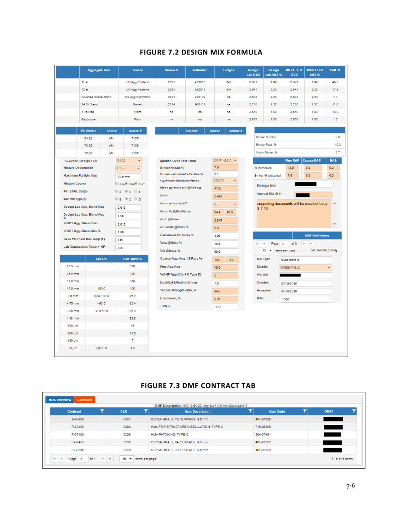
7-6
FIGURE 7.2 DESIGN MIX FORMULA
FIGURE 7.3 DMF CONTRACT TAB
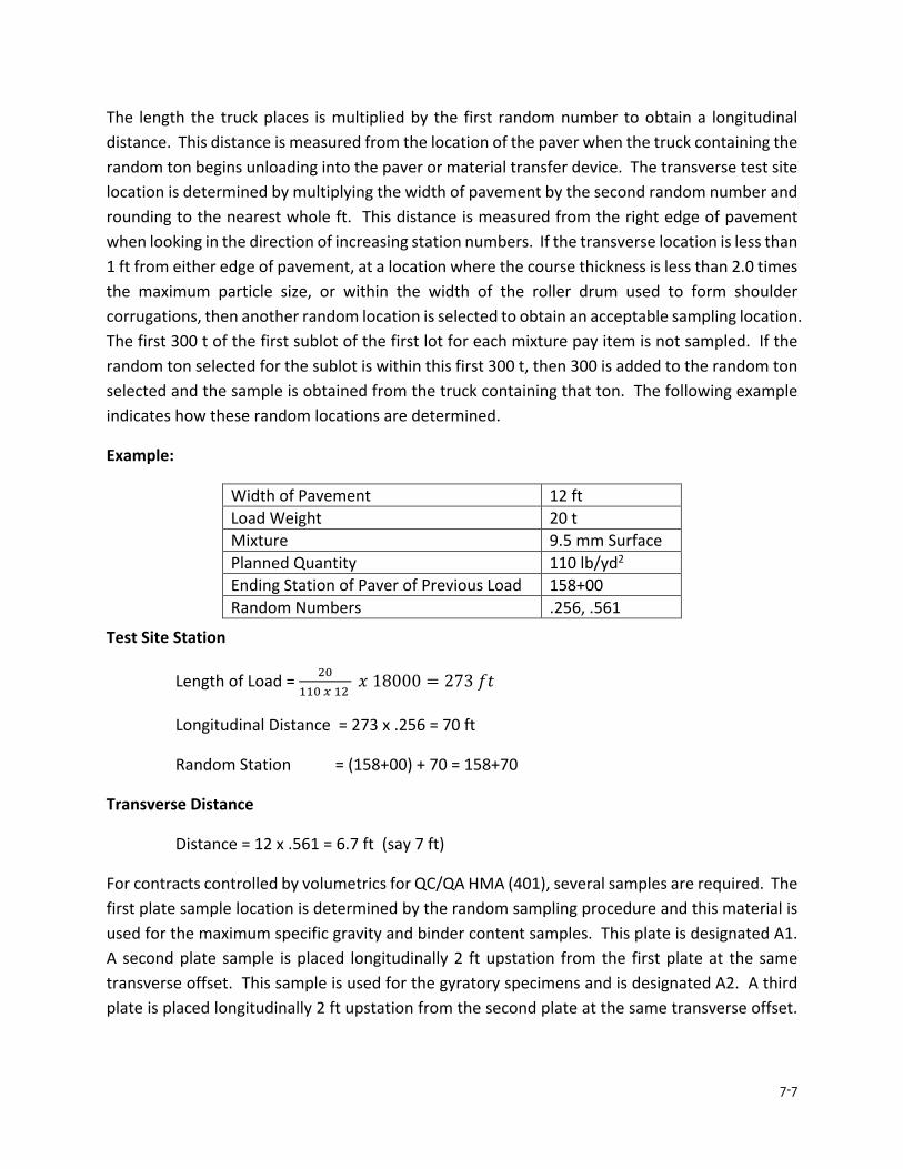
7-7
The length the truck places is multiplied by the first random number to obtain a longitudinal distance. This distance is measured from the location of the paver when the truck containing the random ton begins unloading into the paver or material transfer device. The transverse test site location is determined by multiplying the width of pavement by the second random number and rounding to the nearest whole ft. This distance is measured from the right edge of pavement when looking in the direction of increasing station numbers. If the transverse location is less than 1 ft from either edge of pavement, at a location where the course thickness is less than 2.0 times the maximum particle size, or within the width of the roller drum used to form shoulder corrugations, then another random location is selected to obtain an acceptable sampling location. The first 300 t of the first sublot of the first lot for each mixture pay item is not sampled. If the random ton selected for the sublot is within this first 300 t, then 300 is added to the random ton selected and the sample is obtained from the truck containing that ton. The following example indicates how these random locations are determined.
Example:
Width of Pavement 12 ft Load Weight 20 t Mixture 9.5 mm Surface Planned Quantity 110 lb/yd2 Ending Station of Paver of Previous Load 158+00 Random Numbers .256, .561
Test Site Station
Length of Load = 20110 𝑥𝑥 12
𝑥𝑥 18000 = 273 𝑓𝑓𝑓𝑓
Longitudinal Distance = 273 x .256 = 70 ft
Random Station = (158+00) + 70 = 158+70
Transverse Distance
Distance = 12 x .561 = 6.7 ft (say 7 ft)
For contracts controlled by volumetrics for QC/QA HMA (401), several samples are required. The first plate sample location is determined by the random sampling procedure and this material is used for the maximum specific gravity and binder content samples. This plate is designated A1. A second plate sample is placed longitudinally 2 ft upstation from the first plate at the same transverse offset. This sample is used for the gyratory specimens and is designated A2. A third plate is placed longitudinally 2 ft upstation from the second plate at the same transverse offset.
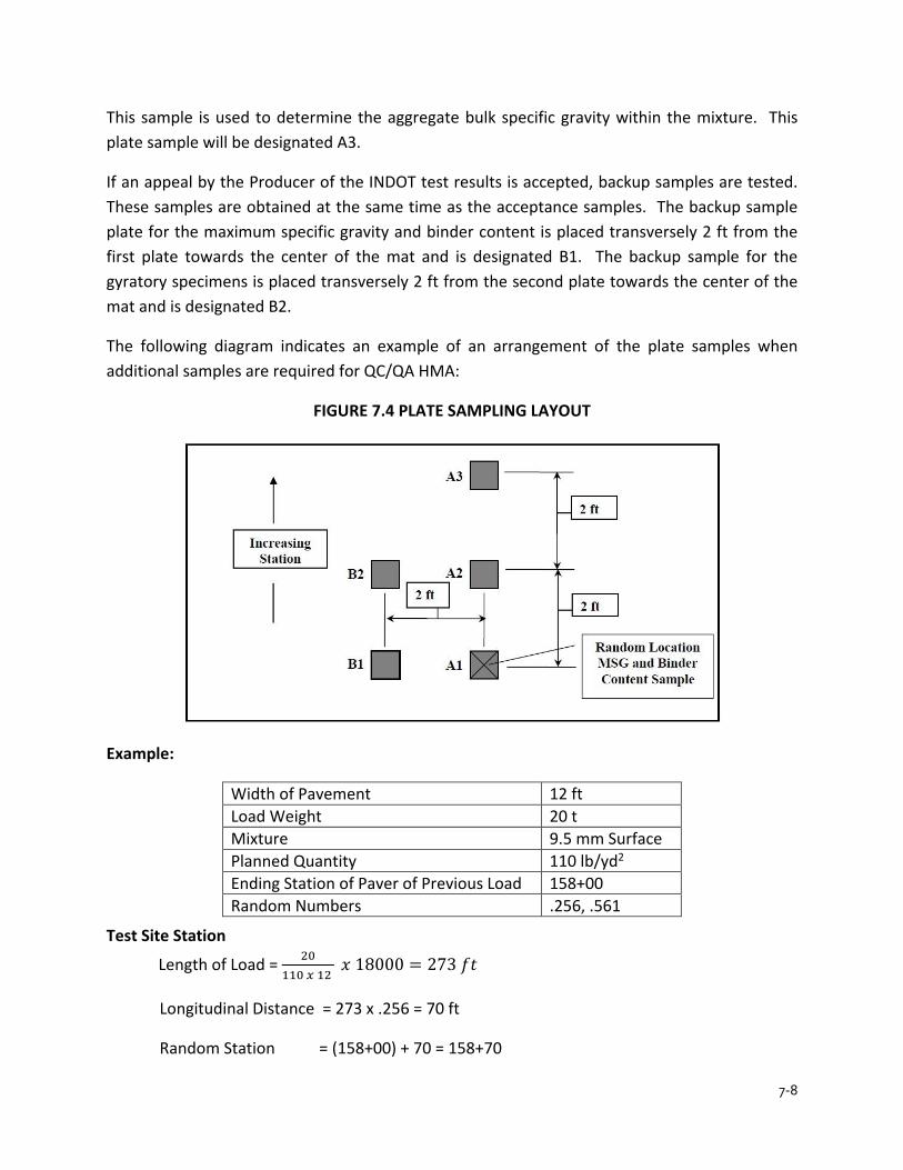
7-8
This sample is used to determine the aggregate bulk specific gravity within the mixture. This plate sample will be designated A3.
If an appeal by the Producer of the INDOT test results is accepted, backup samples are tested. These samples are obtained at the same time as the acceptance samples. The backup sample plate for the maximum specific gravity and binder content is placed transversely 2 ft from the first plate towards the center of the mat and is designated B1. The backup sample for the gyratory specimens is placed transversely 2 ft from the second plate towards the center of the mat and is designated B2.
The following diagram indicates an example of an arrangement of the plate samples when additional samples are required for QC/QA HMA:
FIGURE 7.4 PLATE SAMPLING LAYOUT
Example:
Width of Pavement 12 ft Load Weight 20 t Mixture 9.5 mm Surface Planned Quantity 110 lb/yd2 Ending Station of Paver of Previous Load 158+00 Random Numbers .256, .561
Test Site Station
Length of Load = 20110 𝑥𝑥 12
𝑥𝑥 18000 = 273 𝑓𝑓𝑓𝑓
Longitudinal Distance = 273 x .256 = 70 ft
Random Station = (158+00) + 70 = 158+70
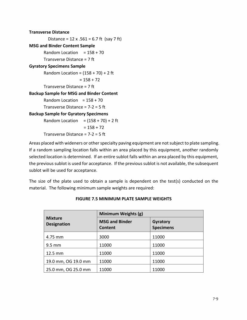
7-9
Transverse Distance Distance = 12 x .561 = 6.7 ft (say 7 ft) MSG and Binder Content Sample Random Location = 158 + 70 Transverse Distance = 7 ft Gyratory Specimens Sample Random Location = (158 + 70) + 2 ft = 158 + 72 Transverse Distance = 7 ft Backup Sample for MSG and Binder Content Random Location = 158 + 70 Transverse Distance = 7-2 = 5 ft Backup Sample for Gyratory Specimens Random Location = (158 + 70) + 2 ft = 158 + 72 Transverse Distance = 7-2 = 5 ft
Areas placed with wideners or other specialty paving equipment are not subject to plate sampling. If a random sampling location falls within an area placed by this equipment, another randomly selected location is determined. If an entire sublot falls within an area placed by this equipment, the previous sublot is used for acceptance. If the previous sublot is not available, the subsequent sublot will be used for acceptance.
The size of the plate used to obtain a sample is dependent on the test(s) conducted on the material. The following minimum sample weights are required:
FIGURE 7.5 MINIMUM PLATE SAMPLE WEIGHTS
Mixture Designation
Minimum Weights (g)
MSG and Binder Content
Gyratory Specimens
4.75 mm 3000 11000
9.5 mm 11000 11000
12.5 mm 11000 11000
19.0 mm, OG 19.0 mm 11000 11000
25.0 mm, OG 25.0 mm 11000 11000
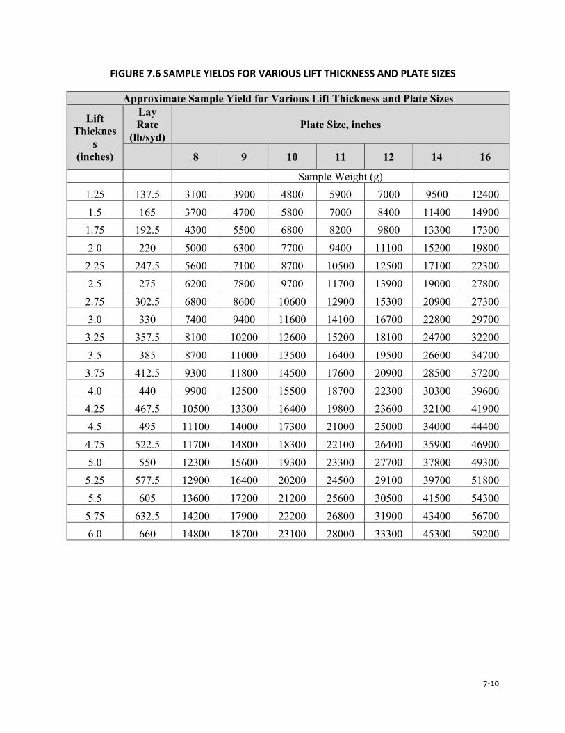
7-10
FIGURE 7.6 SAMPLE YIELDS FOR VARIOUS LIFT THICKNESS AND PLATE SIZES
Approximate Sample Yield for Various Lift Thickness and Plate Sizes
Lift Thicknes
s (inches)
Lay Rate
(lb/syd) Plate Size, inches
8 9 10 11 12 14 16
Sample Weight (g) 1.25 137.5 3100 3900 4800 5900 7000 9500 12400 1.5 165 3700 4700 5800 7000 8400 11400 14900 1.75 192.5 4300 5500 6800 8200 9800 13300 17300 2.0 220 5000 6300 7700 9400 11100 15200 19800 2.25 247.5 5600 7100 8700 10500 12500 17100 22300 2.5 275 6200 7800 9700 11700 13900 19000 27800 2.75 302.5 6800 8600 10600 12900 15300 20900 27300 3.0 330 7400 9400 11600 14100 16700 22800 29700 3.25 357.5 8100 10200 12600 15200 18100 24700 32200 3.5 385 8700 11000 13500 16400 19500 26600 34700 3.75 412.5 9300 11800 14500 17600 20900 28500 37200 4.0 440 9900 12500 15500 18700 22300 30300 39600 4.25 467.5 10500 13300 16400 19800 23600 32100 41900 4.5 495 11100 14000 17300 21000 25000 34000 44400 4.75 522.5 11700 14800 18300 22100 26400 35900 46900 5.0 550 12300 15600 19300 23300 27700 37800 49300 5.25 577.5 12900 16400 20200 24500 29100 39700 51800 5.5 605 13600 17200 21200 25600 30500 41500 54300 5.75 632.5 14200 17900 22200 26800 31900 43400 56700 6.0 660 14800 18700 23100 28000 33300 45300 59200
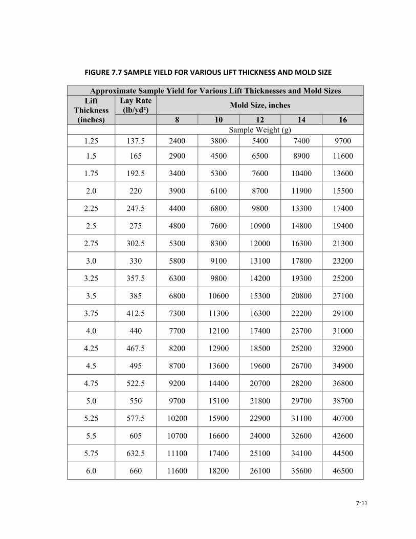
7-11
FIGURE 7.7 SAMPLE YIELD FOR VARIOUS LIFT THICKNESS AND MOLD SIZE
Approximate Sample Yield for Various Lift Thicknesses and Mold Sizes Lift
Thickness (inches)
Lay Rate (lb/yd²) Mold Size, inches
8 10 12 14 16 Sample Weight (g)
1.25 137.5 2400 3800 5400 7400 9700
1.5 165 2900 4500 6500 8900 11600
1.75 192.5 3400 5300 7600 10400 13600
2.0 220 3900 6100 8700 11900 15500
2.25 247.5 4400 6800 9800 13300 17400
2.5 275 4800 7600 10900 14800 19400
2.75 302.5 5300 8300 12000 16300 21300
3.0 330 5800 9100 13100 17800 23200
3.25 357.5 6300 9800 14200 19300 25200
3.5 385 6800 10600 15300 20800 27100
3.75 412.5 7300 11300 16300 22200 29100
4.0 440 7700 12100 17400 23700 31000
4.25 467.5 8200 12900 18500 25200 32900
4.5 495 8700 13600 19600 26700 34900
4.75 522.5 9200 14400 20700 28200 36800
5.0 550 9700 15100 21800 29700 38700
5.25 577.5 10200 15900 22900 31100 40700
5.5 605 10700 16600 24000 32600 42600
5.75 632.5 11100 17400 25100 34100 44500
6.0 660 11600 18200 26100 35600 46500
7-12
MIXTURE ACCEPTANCE
QC/QA HMA
Acceptance of QC/QA HMA mixtures for Vbe, and air voids at Ndes for each lot is based on tests conducted by INDOT. INDOT randomly selects the location(s) within each sublot for sampling in accordance with the ITM 802. Samples from the pavement are obtained from each sublot in accordance with ITM 580.
A binder draindown test in accordance with AASHTO T 305 for open graded mixtures is required once per lot and may not exceed 0.50 %.
The Engineer will make available the sublot acceptance test results after receiving the sublot quality control results from the Producer.
HMA
Acceptance of HMA mixtures is done on the basis of a Type D certification submitted by the Producer to the Project Engineer on a contract. The certification is required to be submitted with the first truck of each type of mixture each day. If no test results are available, the Producer indicates on the form that test results are required to be obtained within the first 250 tons and each subsequent 1000 tons for base and intermediate mixtures, and the first 250 tons and each subsequent 600 tons for surface mixtures.
PAY FACTORS – QC/QA HMA (DENSE GRADED ≥ 1 LOT)
Pay factors for dense graded QC/QA HMA mixtures with original pay item quantities greater than or equal to one lot are determined in accordance with the procedures for Percent Within Limits (PWL) designated in ITM 588. The PWL method uses the average and standard deviation of the lot tests to estimate the percentage of the lot that is within the specification limits. The procedure for determining the PWL of the lot is as follows:
PWL – MIXTURE
1. Determine the average of the lot mixture properties for air voids at Ndes and Vbe as follows:
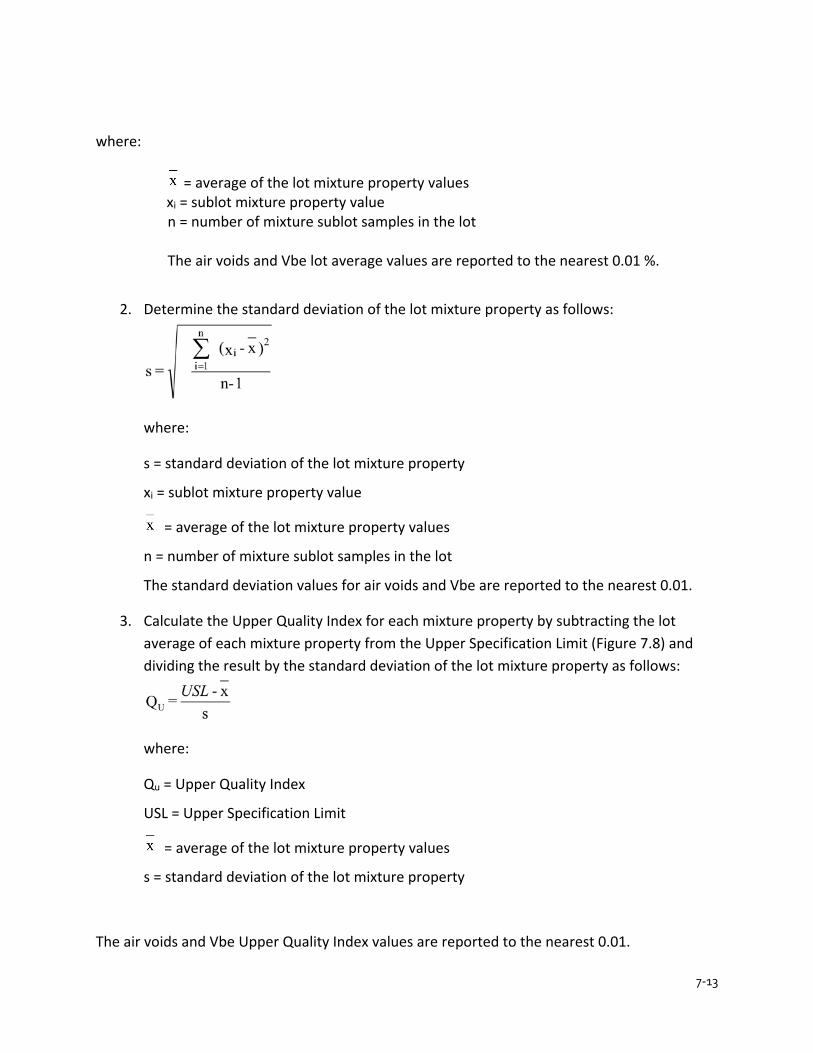
7-13
where:
= average of the lot mixture property values xi = sublot mixture property value n = number of mixture sublot samples in the lot
The air voids and Vbe lot average values are reported to the nearest 0.01 %.
2. Determine the standard deviation of the lot mixture property as follows:
where:
s = standard deviation of the lot mixture property
xi = sublot mixture property value
= average of the lot mixture property values
n = number of mixture sublot samples in the lot
The standard deviation values for air voids and Vbe are reported to the nearest 0.01.
3. Calculate the Upper Quality Index for each mixture property by subtracting the lot average of each mixture property from the Upper Specification Limit (Figure 7.8) and dividing the result by the standard deviation of the lot mixture property as follows:
where:
Qu = Upper Quality Index
USL = Upper Specification Limit
= average of the lot mixture property values
s = standard deviation of the lot mixture property
The air voids and Vbe Upper Quality Index values are reported to the nearest 0.01.

7-14
FIGURE 7.8 SPECIFICATION LIMITS
SPECIFICATION LIMITS Mixture
LSL* USL**
Air Voids(Va) at Ndes, % 3.60 6.40
Vbe at Ndes, % Spec
Spec + 2.50
Density LSL* USL**
Roadway Core Density
(%Gmm), % 93.00 Not Applicable
* LSL, Lower Specification Limit ** USL, Upper Specification Limit
4. Calculate the Lower Quality Index for each mixture property by subtracting the Lower Specification Limit (Figure 7.8) from the lot average of each mixture property and dividing the result by the standard deviation of the lot mixture property as follows:
where: QL = Lower Quality Index LSL = Lower Specification Limit
= average of the lot mixture property values
s = standard deviation of the lot mixture property The air voids and Vbe Lower Quality Index values are reported to the nearest 0.01
5. Determine the percentage of material that will fall within the Upper and Lower Specification Limits (Table of Quality Index Values found in ITM 588 in Chapter 8) with QU or QL using the column appropriate to the total number of measurements, n.
6. Determine the percent of material that will fall within the limits for each mixture property by adding the percent within the Upper Specification Limit (PWLU) to the percent within the Lower Specification Limit (PWLL), and subtracting 100 from the total as follows: Total PWL = (PWLU + PWLL) - 100

7-15
PWL – DENSITY
1. Determine the average of the lot density values as follows:
where:
= average of the lot density values xi = core density value
n = number of cores in the lot The density (% Gmm) lot average value is reported to the nearest 0.01 %.
2. Determine the standard deviation of the lot density as follows:
where: s = standard deviation of the density of the lot
= average of the lot density values xi = core density value n = number of cores in the lot The standard deviation value is reported to the nearest 0.01.
3. Calculate the Lower Quality Index for in-place density (% Gmm) by subtracting the Lower Specification Limit (Figure 7.7) from the average of the density of the lot and dividing the result by the standard deviation of the density of the lot as follows:
where: QL = Lower Quality Index LSL = Lower Specification Limit
= average of the lot density values s = standard deviation of the density of the lot The density Lower Quality Index value is reported to the nearest 0.01.
4. Determine the PWL for density by entering the table of Quality Index Values (Figure 7.8) using the column appropriate to the total number of measurements, n.
5. Determine the percent within the lower specification limit (PWLL) for density as follows: Total PWL = PWLL
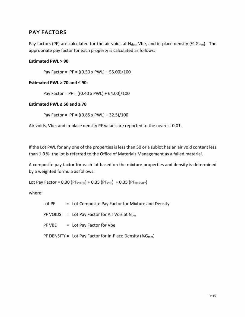
7-16
PAY FACTORS
Pay factors (PF) are calculated for the air voids at Ndes, Vbe, and in-place density (% Gmm). The appropriate pay factor for each property is calculated as follows:
Estimated PWL > 90
Pay Factor = PF = ((0.50 x PWL) + 55.00)/100
Estimated PWL > 70 and ≤ 90:
Pay Factor = PF = ((0.40 x PWL) + 64.00)/100
Estimated PWL ≥ 50 and ≤ 70
Pay Factor = PF = ((0.85 x PWL) + 32.5)/100
Air voids, Vbe, and in-place density PF values are reported to the nearest 0.01.
If the Lot PWL for any one of the properties is less than 50 or a sublot has an air void content less than 1.0 %, the lot is referred to the Office of Materials Management as a failed material.
A composite pay factor for each lot based on the mixture properties and density is determined by a weighted formula as follows:
Lot Pay Factor = 0.30 (PFVOIDS) + 0.35 (PFVBE) + 0.35 (PFDENSITY)
where:
Lot PF = Lot Composite Pay Factor for Mixture and Density
PF VOIDS = Lot Pay Factor for Air Vois at Ndes
PF VBE = Lot Pay Factor for Vbe
PF DENSITY = Lot Pay Factor for In-Place Density (%Gmm)
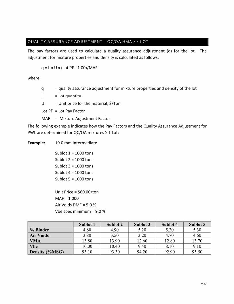
7-17
QUALITY ASSURANCE ADJUSTMENT – QC/QA HMA ≥ 1 LOT
The pay factors are used to calculate a quality assurance adjustment (q) for the lot. The adjustment for mixture properties and density is calculated as follows:
q = L x U x (Lot PF - 1.00)/MAF
where:
q = quality assurance adjustment for mixture properties and density of the lot
L = Lot quantity
U = Unit price for the material, $/Ton
Lot PF = Lot Pay Factor
MAF = Mixture Adjustment Factor
The following example indicates how the Pay Factors and the Quality Assurance Adjustment for PWL are determined for QC/QA mixtures ≥ 1 Lot:
Example: 19.0 mm Intermediate
Sublot 1 = 1000 tons Sublot 2 = 1000 tons Sublot 3 = 1000 tons Sublot 4 = 1000 tons Sublot 5 = 1000 tons Unit Price = $60.00/ton MAF = 1.000 Air Voids DMF = 5.0 % Vbe spec minimum = 9.0 % Sublot 1 Sublot 2 Sublot 3 Sublot 4 Sublot 5 % Binder 4.80 4.90 5.20 5.20 5.30 Air Voids 3.80 3.50 3.20 4.70 4.60 VMA 13.80 13.90 12.60 12.80 13.70 Vbe 10.00 10.40 9.40 8.10 9.10 Density (%MSG) 93.10 93.30 94.20 92.90 95.50

7-18
Air Voids
= 3.80 + 3.50 + 3.20 + 4.70 + 4.60 = 3.96 5 s = 0.67 USL = 6.40
6.40 – 3.96 / 0.67 = 3.64
From Figure 7.8 for n = 5 the PWLU is 100 LSL = 3.60
3.96 – 3.60 / 0.67 = 0.54
From Figure 7.8 for n = 5 the PWLL is 69
Total PWL = (PWLU + PWLL) – 100 = (100 + 69) – 100 = 69
Pay Factor (Estimated PWL > 70) = ((0.85 x PWL) + 32.5)/100
= ((0.85 x 69) + 32.5)/100
= 0.91
Pay Factors for the Vbe, and Density are indicated in Figures 7.11 thru 7.14 and are as follows:
Pay Factor (Vbe) = 0.89 Pay Factor (Density) = 0.95
Lot Pay Factor = + 0.30 (PFVOIDS) + 0.35 (PFVBE) + 0.35 (PFDENSITY)
= + 0.30 (0.91) + 0.35 (0.89) + 0.35 (0.95) = + 0.273 + 0.312 + 0.333 = 0.918 = 0.92
The Quality Assurance Adjustment for the Lot is calculated as follows:
Quality Assurance Adjustment ($) = L x U x (Lot PF – 1.00)/MAF
L = Lot quantity U = Unit Price for Material, $/Ton Lot PF = Lot Pay Factor MAF = Mixture Adjustment Factor
Quality Assurance Adjustment = 5000.00 tons x $60.00 x (0.92 – 1.00)/1.000
= - $24,000.00
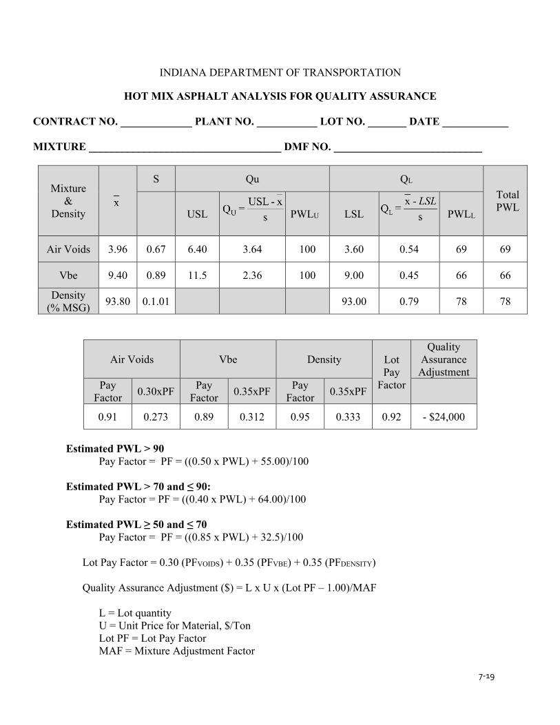
7-19
INDIANA DEPARTMENT OF TRANSPORTATION
HOT MIX ASPHALT ANALYSIS FOR QUALITY ASSURANCE
CONTRACT NO. _____________ PLANT NO. ___________ LOT NO. _______ DATE ____________
MIXTURE ___________________________________ DMF NO. ___________________________
Mixture &
Density
S Qu QL
Total PWL
USL
PWLU LSL
PWLL
Air Voids 3.96 0.67 6.40 3.64 100 3.60 0.54 69 69
Vbe 9.40 0.89 11.5 2.36 100 9.00 0.45 66 66
Density (% MSG) 93.80 0.1.01 93.00 0.79 78 78
Air Voids Vbe Density Lot Pay
Factor
Quality Assurance Adjustment
Pay Factor 0.30xPF Pay
Factor 0.35xPF Pay Factor 0.35xPF
0.91 0.273 0.89 0.312 0.95 0.333 0.92 - $24,000
Estimated PWL > 90 Pay Factor = PF = ((0.50 x PWL) + 55.00)/100 Estimated PWL > 70 and ≤ 90: Pay Factor = PF = ((0.40 x PWL) + 64.00)/100 Estimated PWL ≥ 50 and ≤ 70 Pay Factor = PF = ((0.85 x PWL) + 32.5)/100
Lot Pay Factor = 0.30 (PFVOIDS) + 0.35 (PFVBE) + 0.35 (PFDENSITY)
Quality Assurance Adjustment ($) = L x U x (Lot PF – 1.00)/MAF
L = Lot quantity U = Unit Price for Material, $/Ton Lot PF = Lot Pay Factor MAF = Mixture Adjustment Factor
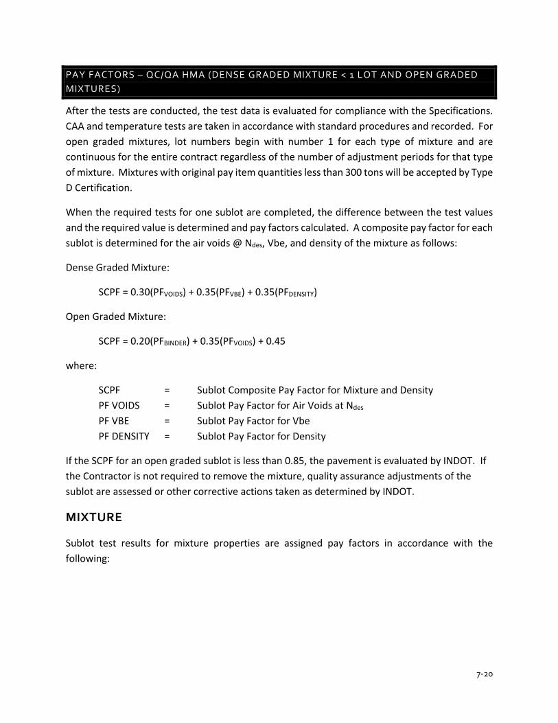
7-20
PAY FACTORS – QC/QA HMA (DENSE GRADED MIXTURE < 1 LOT AND OPEN GRADED MIXTURES)
After the tests are conducted, the test data is evaluated for compliance with the Specifications. CAA and temperature tests are taken in accordance with standard procedures and recorded. For open graded mixtures, lot numbers begin with number 1 for each type of mixture and are continuous for the entire contract regardless of the number of adjustment periods for that type of mixture. Mixtures with original pay item quantities less than 300 tons will be accepted by Type D Certification.
When the required tests for one sublot are completed, the difference between the test values and the required value is determined and pay factors calculated. A composite pay factor for each sublot is determined for the air voids @ Ndes, Vbe, and density of the mixture as follows:
Dense Graded Mixture:
SCPF = 0.30(PFVOIDS) + 0.35(PFVBE) + 0.35(PFDENSITY)
Open Graded Mixture:
SCPF = 0.20(PFBINDER) + 0.35(PFVOIDS) + 0.45
where:
SCPF = Sublot Composite Pay Factor for Mixture and Density PF VOIDS = Sublot Pay Factor for Air Voids at Ndes PF VBE = Sublot Pay Factor for Vbe PF DENSITY = Sublot Pay Factor for Density
If the SCPF for an open graded sublot is less than 0.85, the pavement is evaluated by INDOT. If the Contractor is not required to remove the mixture, quality assurance adjustments of the sublot are assessed or other corrective actions taken as determined by INDOT.
MIXTURE
Sublot test results for mixture properties are assigned pay factors in accordance with the following:
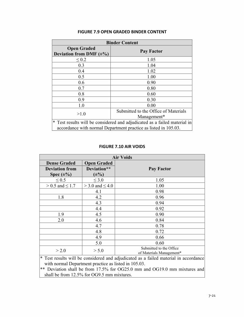
7-21
FIGURE 7.9 OPEN GRADED BINDER CONTENT
Binder Content Open Graded
Deviation from DMF (±%) Pay Factor
≤ 0.2 1.05 0.3 1.04 0.4 1.02 0.5 1.00 0.6 0.90 0.7 0.80 0.8 0.60 0.9 0.30 1.0 0.00
>1.0 Submitted to the Office of Materials Management*
* Test results will be considered and adjudicated as a failed material in accordance with normal Department practice as listed in 105.03.
FIGURE 7.10 AIR VOIDS
Air Voids Dense Graded Open Graded
Pay Factor Deviation from Spec (±%)
Deviation** (±%)
≤ 0.5 ≤ 3.0 1.05 > 0.5 and ≤ 1.7 > 3.0 and ≤ 4.0 1.00
4.1 0.98 1.8 4.2 0.96
4.3 0.94 4.4 0.92
1.9 4.5 0.90 2.0 4.6 0.84
4.7 0.78 4.8 0.72 4.9 0.66 5.0 0.60
> 2.0 > 5.0 Submitted to the Office of Materials Management*
* Test results will be considered and adjudicated as a failed material in accordance with normal Department practice as listed in 105.03.
** Deviation shall be from 17.5% for OG25.0 mm and OG19.0 mm mixtures and shall be from 12.5% for OG9.5 mm mixtures.
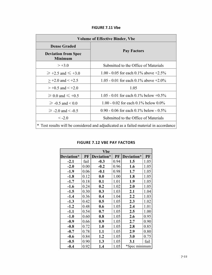
7-22
FIGURE 7.11 Vbe
Volume of Effective Binder, Vbe
Dense Graded Pay Factors
Deviation from Spec Minimum
> +3.0 Submitted to the Office of Materials
≥ +2.5 and ≤ +3.0 1.00 - 0.05 for each 0.1% above +2.5%
> +2.0 and < +2.5 1.05 - 0.01 for each 0.1% above +2.0%
> +0.5 and < +2.0 1.05
≥ 0.0 and ≤ +0.5 1.05 - 0.01 for each 0.1% below +0.5%
≥ -0.5 and < 0.0 1.00 - 0.02 for each 0.1% below 0.0%
≥ -2.0 and < -0.5 0.90 - 0.06 for each 0.1% below - 0.5%
< -2.0 Submitted to the Office of Materials * Test results will be considered and adjudicated as a failed material in accordance
FIGURE 7.12 VBE PAY FACTORS
Vbe Deviation* PF Deviation* PF Deviation* PF
-2.1 fail -0.3 0.94 1.5 1.05 -2.0 0.00 -0.2 0.96 1.6 1.05 -1.9 0.06 -0.1 0.98 1.7 1.05 -1.8 0.12 0.0 1.00 1.8 1.05 -1.7 0.18 0.1 1.01 1.9 1.05 -1.6 0.24 0.2 1.02 2.0 1.05 -1.5 0.30 0.3 1.03 2.1 1.04 -1.4 0.36 0.4 1.04 2.2 1.03 -1.3 0.42 0.5 1.05 2.3 1.02 -1.2 0.48 0.6 1.05 2.4 1.01 -1.1 0.54 0.7 1.05 2.5 1.00 -1.0 0.60 0.8 1.05 2.6 0.95 -0.9 0.66 0.9 1.05 2.7 0.90 -0.8 0.72 1.0 1.05 2.8 0.85 -0.7 0.78 1.1 1.05 2.9 0.80 -0.6 0.84 1.2 1.05 3.0 0.75 -0.5 0.90 1.3 1.05 3.1 fail -0.4 0.92 1.4 1.05 *Spec minimum
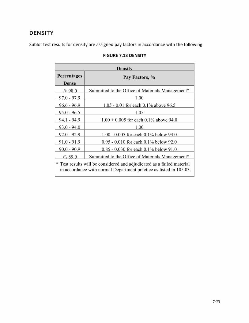
7-23
DENSITY
Sublot test results for density are assigned pay factors in accordance with the following:
FIGURE 7.13 DENSITY
Density Percentages
Pay Factors, % Dense
≥ 98.0 Submitted to the Office of Materials Management* 97.0 - 97.9 1.00 96.6 - 96.9 1.05 - 0.01 for each 0.1% above 96.5 95.0 - 96.5 1.05 94.1 - 94.9 1.00 + 0.005 for each 0.1% above 94.0 93.0 - 94.0 1.00 92.0 - 92.9 1.00 - 0.005 for each 0.1% below 93.0 91.0 - 91.9 0.95 - 0.010 for each 0.1% below 92.0 90.0 - 90.9 0.85 - 0.030 for each 0.1% below 91.0 ≤ 89.9 Submitted to the Office of Materials Management*
* Test results will be considered and adjudicated as a failed material in accordance with normal Department practice as listed in 105.03.

7-24
FIGURE 7.14 DENSITY PAY FACTORS
Density Density PF Density PF Density PF Density PF
≤ 89.9 Fail 91.9 0.940 93.9 1.000 96.0 1.050 90.0 0.550 92.0 0.950 94.0 1.000 96.1 1.050 90.1 0.580 92.1 0.955 94.1 1.005 96.2 1.050 90.2 0.610 92.2 0.960 94.2 1.010 96.3 1.050 90.3 0.640 92.3 0.965 94.3 1.015 96.4 1.050 90.4 0.670 92.4 0.970 94.4 1.020 96.5 1.050 90.5 0.700 92.5 0.975 94.5 1.025 96.6 1.040 90.6 0.730 92.6 0.980 94.6 1.030 96.7 1.030 90.7 0.760 92.7 0.985 94.7 1.035 96.8 1.020 90.8 0.790 92.8 0.990 94.8 1.040 96.9 1.010 90.9 0.820 92.9 0.995 94.9 1.045 97.0 1.000 91.0 0.850 93.0 1.000 95.0 1.050 97.1 1.000 91.1 0.860 93.1 1.000 95.1 1.050 97.2 1.000 91.2 0.870 93.2 1.000 95.2 1.050 97.3 1.000 91.3 0.880 93.3 1.000 95.3 1.050 97.4 1.000 91.4 0.890 93.4 1.000 95.4 1.050 97.5 1.000 91.5 0.900 93.5 1.000 95.5 1.050 97.6 1.000 91.6 0.910 93.6 1.000 95.6 1.050 97.7 1.000 91.7 0.920 93.7 1.000 95.7 1.050 97.8 1.000 91.8 0.930 93.8 1.000 95.8 1.050 97.9 1.000 95.9 1.050 ≥ 98.0 Fail
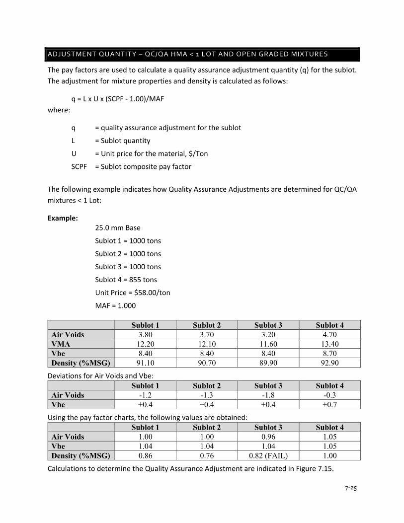
7-25
ADJUSTMENT QUANTITY – QC/QA HMA < 1 LOT AND OPEN GRADED MIXTURES
The pay factors are used to calculate a quality assurance adjustment quantity (q) for the sublot. The adjustment for mixture properties and density is calculated as follows:
q = L x U x (SCPF - 1.00)/MAF where:
q = quality assurance adjustment for the sublot
L = Sublot quantity
U = Unit price for the material, $/Ton
SCPF = Sublot composite pay factor
The following example indicates how Quality Assurance Adjustments are determined for QC/QA mixtures < 1 Lot:
Example: 25.0 mm Base
Sublot 1 = 1000 tons
Sublot 2 = 1000 tons
Sublot 3 = 1000 tons
Sublot 4 = 855 tons
Unit Price = $58.00/ton
MAF = 1.000 Sublot 1 Sublot 2 Sublot 3 Sublot 4 Air Voids 3.80 3.70 3.20 4.70 VMA 12.20 12.10 11.60 13.40 Vbe 8.40 8.40 8.40 8.70 Density (%MSG) 91.10 90.70 89.90 92.90
Deviations for Air Voids and Vbe: Sublot 1 Sublot 2 Sublot 3 Sublot 4 Air Voids -1.2 -1.3 -1.8 -0.3 Vbe +0.4 +0.4 +0.4 +0.7
Using the pay factor charts, the following values are obtained: Sublot 1 Sublot 2 Sublot 3 Sublot 4 Air Voids 1.00 1.00 0.96 1.05 Vbe 1.04 1.04 1.04 1.05 Density (%MSG) 0.86 0.76 0.82 (FAIL) 1.00
Calculations to determine the Quality Assurance Adjustment are indicated in Figure 7.15.

7-26
FIGURE 7.15 HMA ANALYSIS FOR QUALITY ASSURANCE
INDIANA DEPARTMENT OF TRANSPORTATION
HOT MIX ASPHALT ANALYSIS FOR QUALITY ASSURANCE CONTRACT NO. _______________ PLANT NO. _________ LOT NO. __________ DATE ____________ MIXTURE _____________________________________________ DMF NO. ____________________ Mixture
& Density
SUBLOT 1 SUBLOT 2 SUBLOT 3 SUBLOT 4
Pay Factor
Mult
Pay Factor
Mult
Pay Factor
Mult.
Pay Factor
Mult.
Air Voids
1.00
0.30
0.300 1.00
0.30 0.300 0.96
0.30 0.288 1.05
0.30 0.315
Vbe
1.04
0.35
0.364
1.04
0.35 0.364 1.04
0.35 0.364 1.05
0.35 0.368
Density
0.86
0.35
0.301 0.76
0.35 0.266 FAIL
0.35 FAIL 1.00
0.35 0.350
SCPF
0.97
0.93
FAIL
1.03
* Requires submittal to the Materials and Tests Division for Failed Material Investigation
QUALITY ASSURANCE ADJUSTMENTS Sublot 1 Quantity
L (tons)
Sublot 1 Adjustment
($)
Sublot 2 Quantity
L (tons)
Sublot 2 Adjustment
($)
Sublot 3 Quantity
L (tons)
Sublot 3 Adjustment
($)
Sublot 4 Quantity
L (tons)
Sublot 4 Adjustment
($)
1000.00
-1,740.00
1000.00
-4,060.00
1000.00
FAIL
855.00
+ 1,487.70
U = Unit Price for Material, $/Ton Quality Assurance Adjustment = L x U x (SCPF – 1.00) / MAF
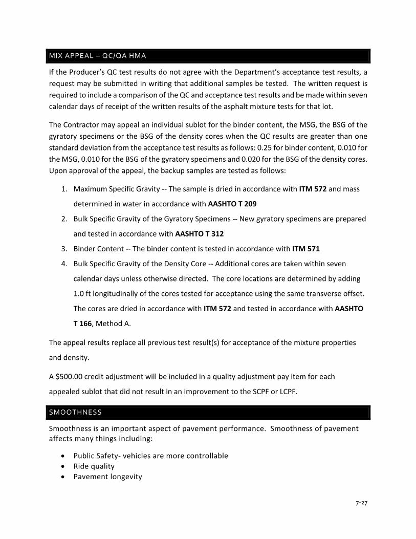
7-27
MIX APPEAL – QC/QA HMA
If the Producer’s QC test results do not agree with the Department’s acceptance test results, a request may be submitted in writing that additional samples be tested. The written request is required to include a comparison of the QC and acceptance test results and be made within seven calendar days of receipt of the written results of the asphalt mixture tests for that lot.
The Contractor may appeal an individual sublot for the binder content, the MSG, the BSG of the gyratory specimens or the BSG of the density cores when the QC results are greater than one standard deviation from the acceptance test results as follows: 0.25 for binder content, 0.010 for the MSG, 0.010 for the BSG of the gyratory specimens and 0.020 for the BSG of the density cores. Upon approval of the appeal, the backup samples are tested as follows:
1. Maximum Specific Gravity -- The sample is dried in accordance with ITM 572 and mass
determined in water in accordance with AASHTO T 209
2. Bulk Specific Gravity of the Gyratory Specimens -- New gyratory specimens are prepared
and tested in accordance with AASHTO T 312
3. Binder Content -- The binder content is tested in accordance with ITM 571
4. Bulk Specific Gravity of the Density Core -- Additional cores are taken within seven
calendar days unless otherwise directed. The core locations are determined by adding
1.0 ft longitudinally of the cores tested for acceptance using the same transverse offset.
The cores are dried in accordance with ITM 572 and tested in accordance with AASHTO
T 166, Method A.
The appeal results replace all previous test result(s) for acceptance of the mixture properties
and density.
A $500.00 credit adjustment will be included in a quality adjustment pay item for each
appealed sublot that did not result in an improvement to the SCPF or LCPF.
SMOOTHNESS
Smoothness is an important aspect of pavement performance. Smoothness of pavement affects many things including:
• Public Safety- vehicles are more controllable • Ride quality • Pavement longevity

7-28
It is important to measure smoothness at the time of pavement construction.
INDOT measures smoothness by the following methods:
• 16 Foot or 10 Foot Straight Edge • Profilograph • Inertial Profiler (IRI)
Specific details of smoothness acceptance can be found in section 401.18 of the Standard Specifications.

CHAPTER 8INDIANA TEST METHODS
APPENDIX A
Revised 2/26/2020
Page 1 of 12
INDIANA DEPARTMENT OF TRANSPORTATION OFFICE OF MATERIALS MANAGEMENT
QUANTITATIVE EXTRACTION OF ASPHALT AND GRADATION OF EXTRACTED AGGREGATE FROM HMA MIXTURES
ITM No. 571-20
1.0 SCOPE.
1.1 This method of test covers the procedure for the quantitative determination of the asphalt/binder content and gradation of the extracted aggregate of HMA mixtures.
1.2 The HMA mixture is extracted with a suitable solvent, depending on the type of extraction apparatus used. The asphalt content is calculated by determining the difference of the weight (mass) of the HMA mixture and the extracted aggregate, fibers if used, and the fines recovered from the extracted solvent and water rinse, if required. The gradation of the extracted aggregate is then determined.
1.3 This ITM may involve hazardous materials, operations, and equipment and may not address all of the safety problems associated with the use of the test method. The user of the ITM is responsible for establishing appropriate safety and health practices and determining the applicability of regulatory limitations prior to use.
2.0 REFERENCES.
2.1 AASHTO Standards.
M 231 Weighing Devices Used in the Testing of Materials T 30 Mechanical Analysis of Extracted Aggregate T 164 Quantitative Extraction of Asphalt Binder from Hot Mix Asphalt (HMA)
2.2 ITM Standards.
572 Dying HMA Mixtures 580 Sampling HMA 587 Reducing HMA Samples to Test Size
3.0 TERMINOLOGY. Definitions for terms and abbreviations shall be in accordance with the Department's Standard Specifications, Section 101.
4.0 SIGNIFICANCE AND USE. This ITM shall be used to determine the asphalt content and gradation of the extracted HMA mixture.
8-1
ITM 571-20 Revised 2/26/2020
Page 2 of 12
5.0 APPARATUS.
5.1 Balance, a Class G2, in accordance with AASHTO M 231
5.2 Electric skillet, with a thermostatic heat control capable of heating to 221°F
5.3 Oven, capable of maintaining the temperature at 221 ± 9°F
5.4 Pans and containers as needed
5.5 Sieves, in accordance with AASHTO T 30
5.6 Spatulas and trowels as needed
5.7 Stiff bristle brush, 1 in. in diameter
5.8 Thermometer, armored with a range of 100°F to 450°F, readable to 5°F
5.9 Wash bottle
6.0 REAGENTS.
6.1 Alternative Extraction Solvent.
6.2 Trichloroethylene
Note 1: INDOT labs will use trichloroethylene exclusively
7.0 SAFETY PRECAUTIONS.
7.1 Provide adequate ventilation and avoid inhalation of vapor. The ventilation fan shall be operating during the testing.
7.2 The exhaust from the vacuum pump shall be vented outside.
7.3 The extraction solvent shall be an approved solvent.
8.0 SAMPLING. Sampling shall conform to the requirements of ITM 580.
9.0 PREPARATION OF SAMPLE.
9.1 If the sample is not sufficiently soft to separate with a spatula or a trowel, place the sample in a large flat pan and heat to a maximum of 221 ± 9°F only until the
8-2
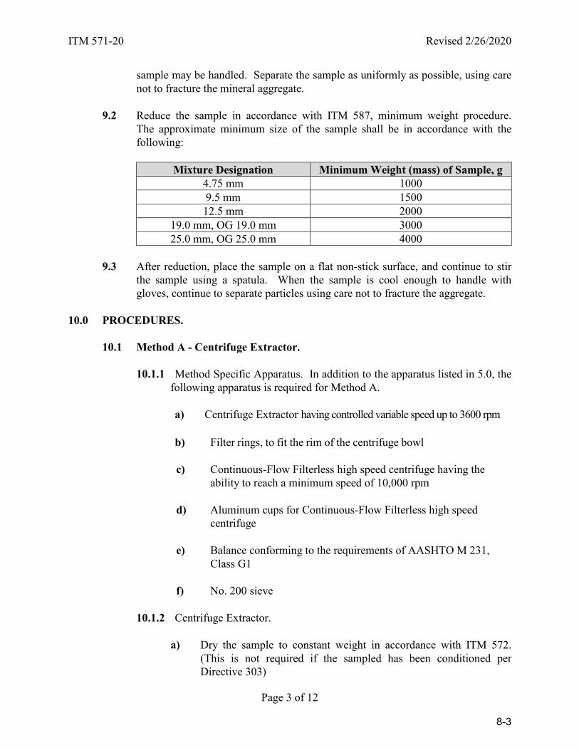
ITM 571-20 Revised 2/26/2020
Page 3 of 12
sample may be handled. Separate the sample as uniformly as possible, using care not to fracture the mineral aggregate.
9.2 Reduce the sample in accordance with ITM 587, minimum weight procedure. The approximate minimum size of the sample shall be in accordance with the following:
Mixture Designation Minimum Weight (mass) of Sample, g 4.75 mm 1000 9.5 mm 1500 12.5 mm 2000
19.0 mm, OG 19.0 mm 3000 25.0 mm, OG 25.0 mm 4000
9.3 After reduction, place the sample on a flat non-stick surface, and continue to stir the sample using a spatula. When the sample is cool enough to handle with gloves, continue to separate particles using care not to fracture the aggregate.
10.0 PROCEDURES.
10.1 Method A - Centrifuge Extractor.
10.1.1 Method Specific Apparatus. In addition to the apparatus listed in 5.0, the following apparatus is required for Method A.
a) Centrifuge Extractor having controlled variable speed up to 3600 rpm
b) Filter rings, to fit the rim of the centrifuge bowl
c) Continuous-Flow Filterless high speed centrifuge having theability to reach a minimum speed of 10,000 rpm
d) Aluminum cups for Continuous-Flow Filterless high speedcentrifuge
e) Balance conforming to the requirements of AASHTO M 231,Class G1
f) No. 200 sieve
10.1.2 Centrifuge Extractor.
a) Dry the sample to constant weight in accordance with ITM 572.(This is not required if the sampled has been conditioned perDirective 303)
8-3
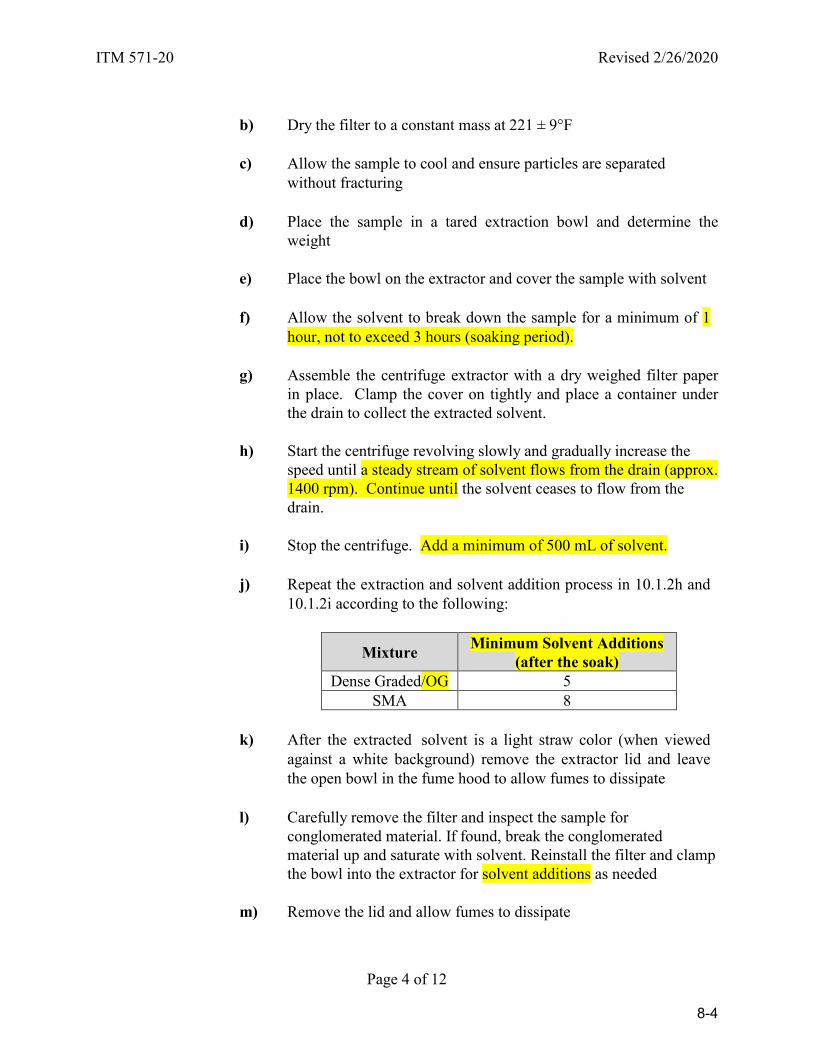
ITM 571-20 Revised 2/26/2020
Page 4 of 12
b) Dry the filter to a constant mass at 221 ± 9°F
c) Allow the sample to cool and ensure particles are separated
without fracturing
d) Place the sample in a tared extraction bowl and determine the weight
e) Place the bowl on the extractor and cover the sample with solvent
f) Allow the solvent to break down the sample for a minimum of 1
hour, not to exceed 3 hours (soaking period). g) Assemble the centrifuge extractor with a dry weighed filter paper
in place. Clamp the cover on tightly and place a container under the drain to collect the extracted solvent.
h) Start the centrifuge revolving slowly and gradually increase the
speed until a steady stream of solvent flows from the drain (approx. 1400 rpm). Continue until the solvent ceases to flow from the drain.
i) Stop the centrifuge. Add a minimum of 500 mL of solvent. j) Repeat the extraction and solvent addition process in 10.1.2h and
10.1.2i according to the following:
Mixture Minimum Solvent Additions (after the soak)
Dense Graded/OG 5 SMA 8
k) After the extracted solvent is a light straw color (when viewed
against a white background) remove the extractor lid and leave the open bowl in the fume hood to allow fumes to dissipate
l) Carefully remove the filter and inspect the sample for
conglomerated material. If found, break the conglomerated material up and saturate with solvent. Reinstall the filter and clamp the bowl into the extractor for solvent additions as needed
m) Remove the lid and allow fumes to dissipate
8-4
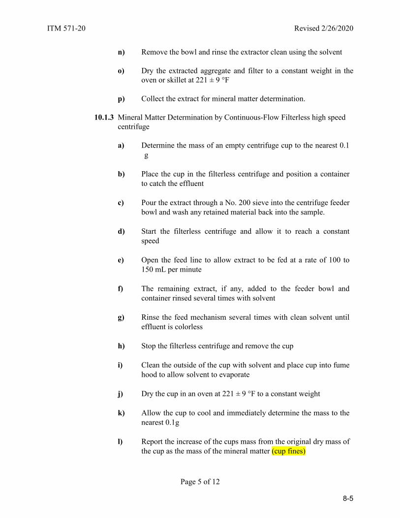
ITM 571-20 Revised 2/26/2020
Page 5 of 12
n) Remove the bowl and rinse the extractor clean using the solvent o) Dry the extracted aggregate and filter to a constant weight in the
oven or skillet at 221 ± 9 °F p) Collect the extract for mineral matter determination.
10.1.3 Mineral Matter Determination by Continuous-Flow Filterless high speed centrifuge
a) Determine the mass of an empty centrifuge cup to the nearest 0.1 g
b) Place the cup in the filterless centrifuge and position a container
to catch the effluent
c) Pour the extract through a No. 200 sieve into the centrifuge feeder bowl and wash any retained material back into the sample.
d) Start the filterless centrifuge and allow it to reach a constant
speed e) Open the feed line to allow extract to be fed at a rate of 100 to
150 mL per minute f) The remaining extract, if any, added to the feeder bowl and
container rinsed several times with solvent g) Rinse the feed mechanism several times with clean solvent until
effluent is colorless h) Stop the filterless centrifuge and remove the cup i) Clean the outside of the cup with solvent and place cup into fume
hood to allow solvent to evaporate j) Dry the cup in an oven at 221 ± 9 °F to a constant weight k) Allow the cup to cool and immediately determine the mass to the
nearest 0.1g l) Report the increase of the cups mass from the original dry mass of
the cup as the mass of the mineral matter (cup fines)
8-5

ITM 571-20 Revised 2/26/2020
Page 6 of 12
10.1.4 Calculation Using Centrifuge.
a) The asphalt content in percent is calculated by the following formula:
100 x W
) W (W - W % Content,Asphalt 1
321 +=
where: W1 = weight of sample, g W2 = weight of extracted aggregate, g W3 = weight of fines in extracted solvent (cup and filter fines), g
10.2 Method B - Vacuum Extractor. Note 2: It should not be assumed that results from Method B are equivalent to Method A or C.
10.2.1 Method Specific Apparatus. In addition to the apparatus listed in 5.0, the
following apparatus is required for Method B:
a) Vacuum extractor
b) Filter paper, medium grade, fast filtering of the diameter required to fit the extractor, (Eaton-Dikeman #633-70)
c) Vacuum pump
d) Pan, round, bowl type, stainless steel
e) No. 200 sieve
10.2.2 Vacuum Extractor for Mixture without Fibers.
a) Weigh approximately 50 g (record exact weight) of a filtering aid,
such as celite, into a 1000 mL flask, add 500 mL of extraction solvent, and swirl until the filtering aid is completely in suspension. 100 g of filtering aid may be used if the solvent does not readily pass through the filter. Immediately pour the solution onto the filter. Start the vacuum pump and let the pump run until the pad formed by the filtering aid is surface dry and begins to crack slightly. Collect the solvent which goes through the filter in a flask, and pour the solvent onto the filter.
8-6
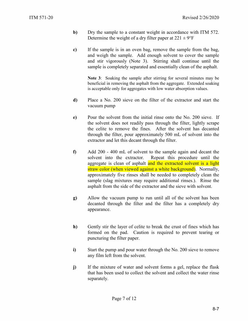
ITM 571-20 Revised 2/26/2020
Page 7 of 12
b) Dry the sample to a constant weight in accordance with ITM 572. Determine the weight of a dry filter paper at 221 ± 9°F
c) If the sample is in an oven bag, remove the sample from the bag,
and weigh the sample. Add enough solvent to cover the sample and stir vigorously (Note 3). Stirring shall continue until the sample is completely separated and essentially clean of the asphalt.
Note 3: Soaking the sample after stirring for several minutes may be beneficial in removing the asphalt from the aggregate. Extended soaking is acceptable only for aggregates with low water absorption values.
d) Place a No. 200 sieve on the filter of the extractor and start the
vacuum pump
e) Pour the solvent from the initial rinse onto the No. 200 sieve. If the solvent does not readily pass through the filter, lightly scrape the celite to remove the fines. After the solvent has decanted through the filter, pour approximately 500 mL of solvent into the extractor and let this decant through the filter.
f) Add 200 - 400 mL of solvent to the sample again and decant the
solvent into the extractor. Repeat this procedure until the aggregate is clean of asphalt and the extracted solvent is a light straw color (when viewed against a white background). Normally, approximately five rinses shall be needed to completely clean the sample (slag mixtures may require additional rinses.). Rinse the asphalt from the side of the extractor and the sieve with solvent.
g) Allow the vacuum pump to run until all of the solvent has been
decanted through the filter and the filter has a completely dry appearance.
h) Gently stir the layer of celite to break the crust of fines which has formed on the pad. Caution is required to prevent tearing or puncturing the filter paper.
i) Start the pump and pour water through the No. 200 sieve to remove
any film left from the solvent.
j) If the mixture of water and solvent forms a gel, replace the flask that has been used to collect the solvent and collect the water rinse separately.
8-7
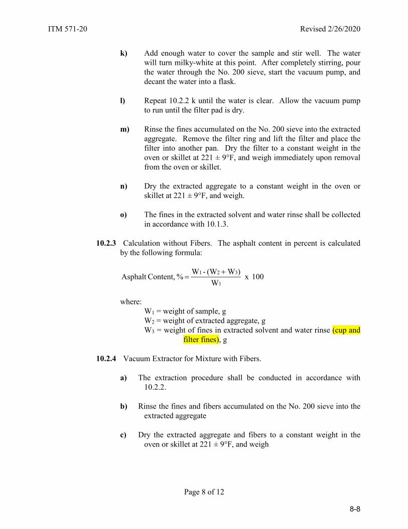
ITM 571-20 Revised 2/26/2020
Page 8 of 12
k) Add enough water to cover the sample and stir well. The water will turn milky-white at this point. After completely stirring, pour the water through the No. 200 sieve, start the vacuum pump, and decant the water into a flask.
l) Repeat 10.2.2 k until the water is clear. Allow the vacuum pump
to run until the filter pad is dry.
m) Rinse the fines accumulated on the No. 200 sieve into the extracted aggregate. Remove the filter ring and lift the filter and place the filter into another pan. Dry the filter to a constant weight in the oven or skillet at 221 ± 9°F, and weigh immediately upon removal from the oven or skillet.
n) Dry the extracted aggregate to a constant weight in the oven or
skillet at 221 ± 9°F, and weigh. o) The fines in the extracted solvent and water rinse shall be collected
in accordance with 10.1.3.
10.2.3 Calculation without Fibers. The asphalt content in percent is calculated by the following formula:
100 x W
)W (W - W % Content,Asphalt 1
321 +=
where: W1 = weight of sample, g W2 = weight of extracted aggregate, g W3 = weight of fines in extracted solvent and water rinse (cup and
filter fines), g
10.2.4 Vacuum Extractor for Mixture with Fibers.
a) The extraction procedure shall be conducted in accordance with 10.2.2.
b) Rinse the fines and fibers accumulated on the No. 200 sieve into the
extracted aggregate
c) Dry the extracted aggregate and fibers to a constant weight in the oven or skillet at 221 ± 9°F, and weigh
8-8
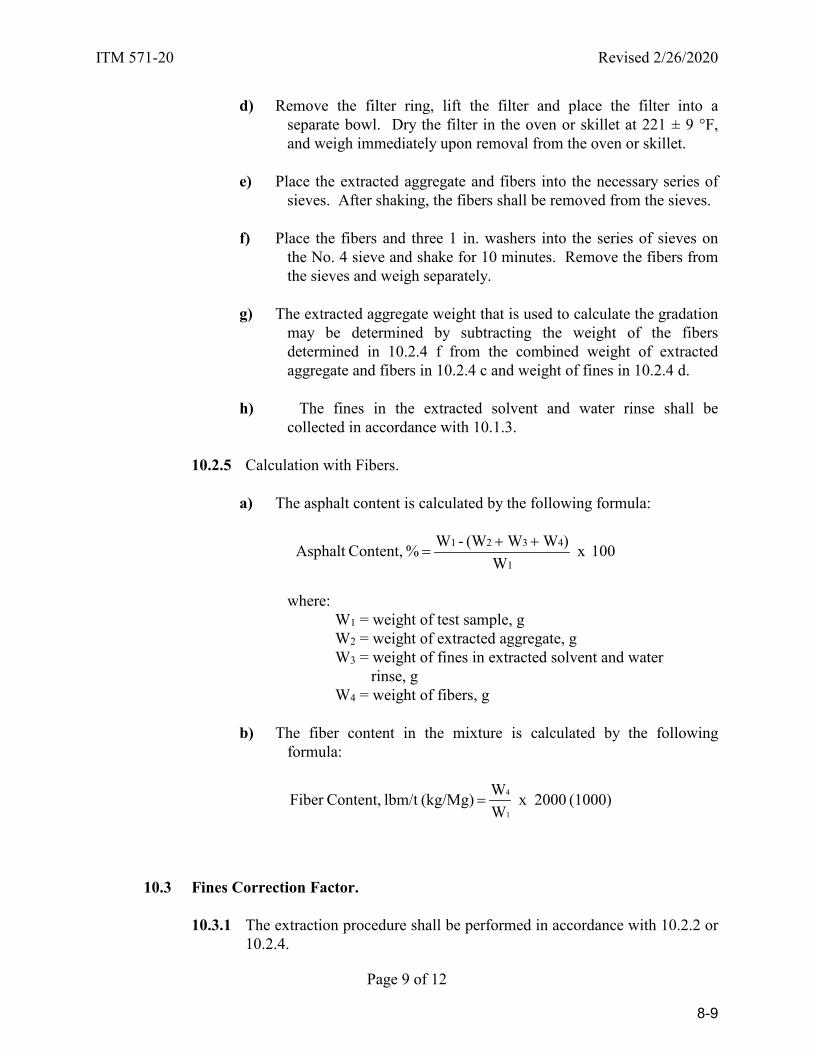
ITM 571-20 Revised 2/26/2020
Page 9 of 12
d) Remove the filter ring, lift the filter and place the filter into a separate bowl. Dry the filter in the oven or skillet at 221 ± 9 °F, and weigh immediately upon removal from the oven or skillet.
e) Place the extracted aggregate and fibers into the necessary series of
sieves. After shaking, the fibers shall be removed from the sieves.
f) Place the fibers and three 1 in. washers into the series of sieves on the No. 4 sieve and shake for 10 minutes. Remove the fibers from the sieves and weigh separately.
g) The extracted aggregate weight that is used to calculate the gradation
may be determined by subtracting the weight of the fibers determined in 10.2.4 f from the combined weight of extracted aggregate and fibers in 10.2.4 c and weight of fines in 10.2.4 d.
h) The fines in the extracted solvent and water rinse shall be
collected in accordance with 10.1.3.
10.2.5 Calculation with Fibers.
a) The asphalt content is calculated by the following formula:
100 x W
) W W (W - W % Content,Asphalt 1
4321 ++=
where:
W1 = weight of test sample, g W2 = weight of extracted aggregate, g W3 = weight of fines in extracted solvent and water rinse, g W4 = weight of fibers, g
b) The fiber content in the mixture is calculated by the following formula:
(1000) 2000 x WW (kg/Mg)lbm/t Content,Fiber
1
4=
10.3 Fines Correction Factor.
10.3.1 The extraction procedure shall be performed in accordance with 10.2.2 or
10.2.4.
8-9
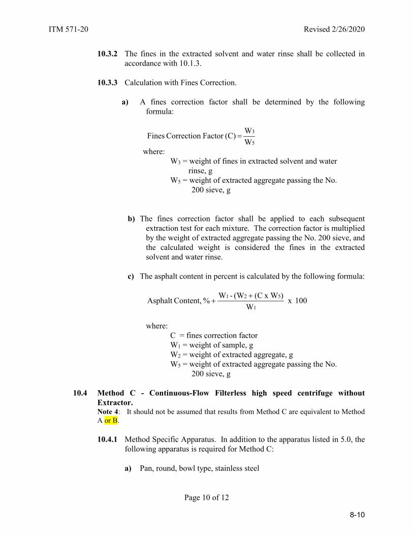
ITM 571-20 Revised 2/26/2020
Page 10 of 12
10.3.2 The fines in the extracted solvent and water rinse shall be collected in accordance with 10.1.3.
10.3.3 Calculation with Fines Correction.
a) A fines correction factor shall be determined by the following
formula:
5
3
WW (C)Factor Correction Fines =
where: W3 = weight of fines in extracted solvent and water rinse, g
W5 = weight of extracted aggregate passing the No. 200 sieve, g
b) The fines correction factor shall be applied to each subsequent extraction test for each mixture. The correction factor is multiplied by the weight of extracted aggregate passing the No. 200 sieve, and the calculated weight is considered the fines in the extracted solvent and water rinse.
c) The asphalt content in percent is calculated by the following formula:
100 x W
) x W(C (W - W % Content,Asphalt 1
521 ++
where:
C = fines correction factor W1 = weight of sample, g W2 = weight of extracted aggregate, g W5 = weight of extracted aggregate passing the No. 200 sieve, g
10.4 Method C - Continuous-Flow Filterless high speed centrifuge without Extractor. Note 4: It should not be assumed that results from Method C are equivalent to Method A or B.
10.4.1 Method Specific Apparatus. In addition to the apparatus listed in 5.0, the
following apparatus is required for Method C:
a) Pan, round, bowl type, stainless steel
8-10
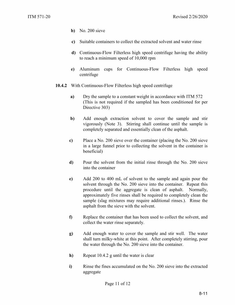
ITM 571-20 Revised 2/26/2020
Page 11 of 12
b) No. 200 sieve
c) Suitable containers to collect the extracted solvent and water rinse
d) Continuous-Flow Filterless high speed centrifuge having the ability to reach a minimum speed of 10,000 rpm
e) Aluminum cups for Continuous-Flow Filterless high speed
centrifuge
10.4.2 With Continuous-Flow Filterless high speed centrifuge
a) Dry the sample to a constant weight in accordance with ITM 572 (This is not required if the sampled has been conditioned for per Directive 303)
b) Add enough extraction solvent to cover the sample and stir
vigorously (Note 3). Stirring shall continue until the sample is completely separated and essentially clean of the asphalt.
c) Place a No. 200 sieve over the container (placing the No. 200 sieve in a large funnel prior to collecting the solvent in the container is beneficial)
d) Pour the solvent from the initial rinse through the No. 200 sieve
into the container e) Add 200 to 400 mL of solvent to the sample and again pour the
solvent through the No. 200 sieve into the container. Repeat this procedure until the aggregate is clean of asphalt. Normally, approximately five rinses shall be required to completely clean the sample (slag mixtures may require additional rinses.). Rinse the asphalt from the sieve with the solvent.
f) Replace the container that has been used to collect the solvent, and
collect the water rinse separately. g) Add enough water to cover the sample and stir well. The water
shall turn milky-white at this point. After completely stirring, pour the water through the No. 200 sieve into the container.
h) Repeat 10.4.2 g until the water is clear i) Rinse the fines accumulated on the No. 200 sieve into the extracted
aggregate
8-11

ITM 571-20 Revised 2/26/2020
Page 12 of 12
j) Dry the extracted aggregate to a constant weight in the oven or
skillet at 221 ± 9°F and weigh k) The fines in the extracted solvent and water rinse shall be collected
as in 10.1.3, except weighing may be performed to the nearest 0.1 g. The extracted solvent and water rinse shall be poured through the Continuous-Flow Filterless high speed centrifuge. The amount of material in the centrifuge cup(s) shall be verified to assure that the cup was not overloaded. If the cup was overloaded with fines, then an additional clean cup(s) shall be used, and the extracted solvent and water rinse shall be poured through the centrifuge again. This procedure is repeated until the cup is not overloaded.
10.4.3 Calculation with Continuous-Flow Filterless high speed centrifuge. The
asphalt content in percent is calculated by the following formula:
100 x W
) W (W - W % Content,Asphalt 1
321 +=
where:
W1 = weight of sample, g W2 = weight of extracted aggregate, g W3 = weight of fines in extracted solvent and water rinse, g
11.0 GRADATION. The gradation of the extracted aggregate shall be in accordance with AASHTO T 30 except that decantation through the No. 200 sieve is not required. The entire sample of extracted aggregate is tested for gradation.
12.0 REPORT. The asphalt content and gradation are reported to the nearest 0.01% and the
fiber content is reported to the nearest 0.1 lbm/t.
8-12

Revised 2/26/2020
Page 1 of 19
INDIANA DEPARTMENT OF TRANSPORTATION OFFICE OF MATERIALS MANAGEMENT
CERTIFIED HOT MIX ASPHALT PRODUCER PROGRAM
ITM 583-20
(Effective for Lettings on or after October 1, 2016)
1.0 SCOPE.
1.1 This procedure covers the requirements for a HMA plant to become a Certified Hot Mix Asphalt Producer. Mixtures produced shall be QC/QA HMA in accordance with 401, HMA in accordance with 402, and Stone Matrix Asphalt (SMA) in accordance with 410.
1.2 This procedure may involve hazardous materials, operations and equipment and
may not address all of the safety problems associated with the use of the test method. The user of this ITM is responsible for establishing the appropriate safety and health practices and determining the applicability of regulatory limitations prior to use.
2.0 REFERENCES. Documents required by the Program may be maintained electronically or by hard copy.
2.1 AASHTO Standards.
R 30 Mixture Conditioning of Hot Mix Asphalt R 35 Superpave Volumetric Design for Hot Mix Asphalt (HMA) R 46 Designing Stone Matrix Asphalt (SMA) R 66 Sampling Bituminous Materials R 76 Reducing Samples of Aggregate to Testing Size T 2 Sampling of Aggregates T 11 Materials Finer Than 75-µm (No. 200) Sieve in Mineral
Aggregates by Washing T 27 Sieve Analysis of Fine and Coarse Aggregates T 30 Mechanical Analysis of Extracted Aggregate T 166 Bulk Specific Gravity of Compacted Hot Mix Asphalt (HMA)
Using Saturated Surface-Dry Specimens. T 209 Theoretical Maximum Specific Gravity and Density of Hot Mix
Asphalt Paving Mixtures T 255 Total Evaporable Moisture Content of Aggregate by Drying T 269 Percent Air Voids in Compacted Dense and Open Asphalt Mixtures T 275 Bulk Specific Gravity of Compacted Hot Mix Asphalt (HMA) Using
Paraffin-Coated Specimens T 305 Determination of Draindown Characteristics in Uncompacted Asphalt
Mixtures
8-13
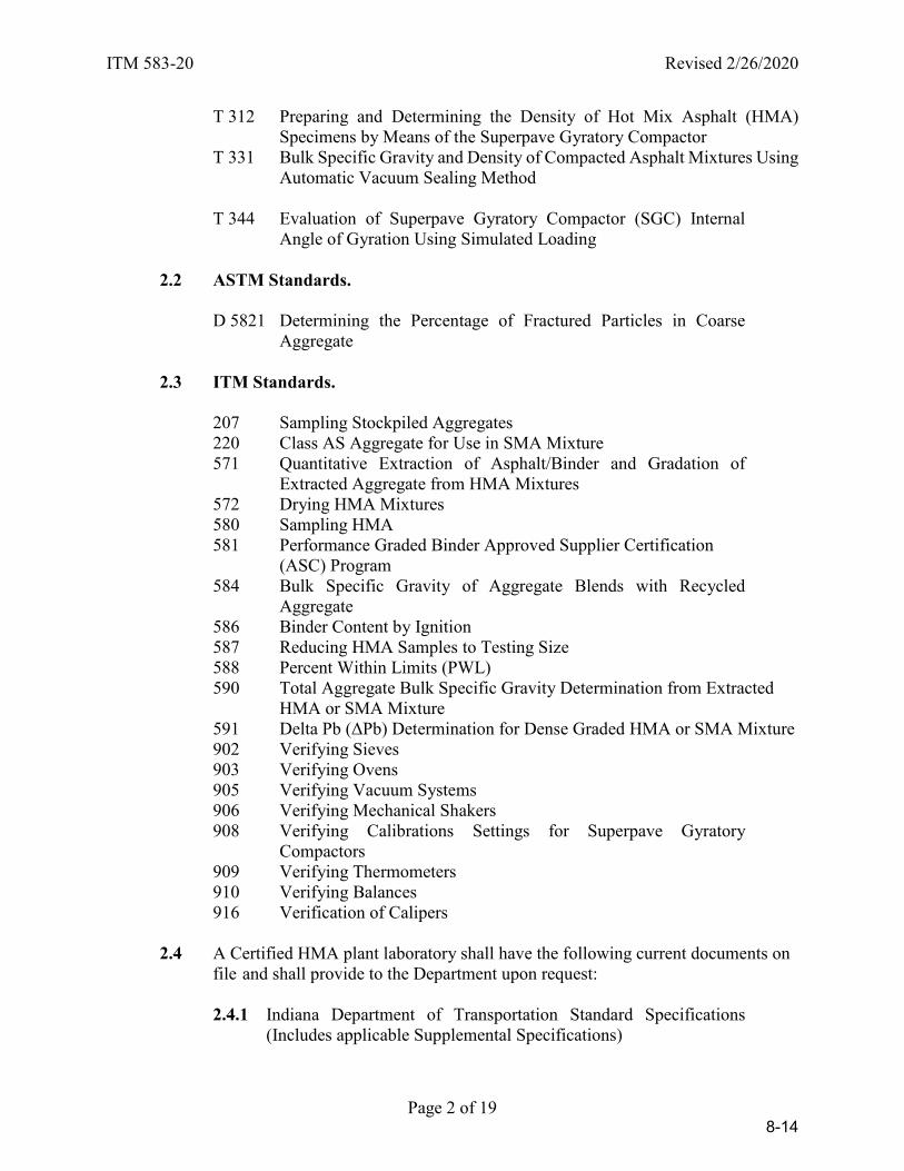
ITM 583-20 Revised 2/26/2020
Page 2 of 19
T 312 Preparing and Determining the Density of Hot Mix Asphalt (HMA) Specimens by Means of the Superpave Gyratory Compactor
T 331 Bulk Specific Gravity and Density of Compacted Asphalt Mixtures Using Automatic Vacuum Sealing Method
T 344 Evaluation of Superpave Gyratory Compactor (SGC) Internal
Angle of Gyration Using Simulated Loading
2.2 ASTM Standards. D 5821 Determining the Percentage of Fractured Particles in Coarse
Aggregate
2.3 ITM Standards. 207 Sampling Stockpiled Aggregates
220 Class AS Aggregate for Use in SMA Mixture 571 Quantitative Extraction of Asphalt/Binder and Gradation of
Extracted Aggregate from HMA Mixtures 572 Drying HMA Mixtures 580 Sampling HMA 581 Performance Graded Binder Approved Supplier Certification (ASC) Program 584 Bulk Specific Gravity of Aggregate Blends with Recycled
Aggregate 586 Binder Content by Ignition 587 Reducing HMA Samples to Testing Size 588 Percent Within Limits (PWL)
590 Total Aggregate Bulk Specific Gravity Determination from Extracted HMA or SMA Mixture
591 Delta Pb (ΔPb) Determination for Dense Graded HMA or SMA Mixture 902 Verifying Sieves 903 Verifying Ovens 905 Verifying Vacuum Systems 906 Verifying Mechanical Shakers
908 Verifying Calibrations Settings for Superpave Gyratory Compactors
909 Verifying Thermometers 910 Verifying Balances 916 Verification of Calipers
2.4 A Certified HMA plant laboratory shall have the following current documents on file and shall provide to the Department upon request:
2.4.1 Indiana Department of Transportation Standard Specifications
(Includes applicable Supplemental Specifications)
8-14

ITM 583-20 Revised 2/26/2020
Page 3 of 19
2.4.2 Pertinent contract Special Provisions
2.4.3 Indiana Certified Asphalt Technician Program Manual
2.4.4 All applicable ITM, AASHTO, and ASTM Test Methods
2.4.5 Testing equipment calibrations or verifications
2.4.6 Mix design, DMF, for each Mixture
2.4.7 Fines correction data for the mixture and recycled materials for each DMF
2.4.8 Type A certifications for all binder materials
2.4.9 Type A certifications for the SBR polymer latex
2.4.10 PG 64-28 and PG 70-22 binder test reports from an AASHTO accredited
laboratory whenever PG 58-28 and PG 64-22 are in-line blended with SBR polymer latex
2.4.11 Process control test results
2.4.12 Type D certifications issued to active Department contracts
2.5 A Certified HMA plant shall have the following current documents on file and
shall provide to the Department upon request:
2.5.1 The Quality Control Plan (QCP) for the HMA plant
2.5.2 Bill of ladings of the binder from each Supplier for a minimum period of three complete calendar years
2.5.3 Weigh tickets from most current date of production of HMA
2.5.4 Instructions from the Supplier concerning storage and handling of the
binder
2.5.5 Flow meter calibration reports and flow computer printouts whenever in-line blending with SBR polymer latex
2.5.6 The IDEM Legitimate Use Approval letter from the post-consumer asphalt
shingle processing company
2.5.7 HMA plant calibrations for each DMF
8-15
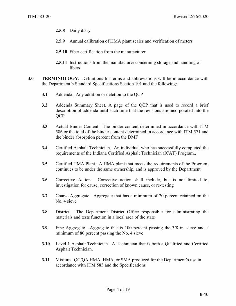
ITM 583-20 Revised 2/26/2020
Page 4 of 19
2.5.8 Daily diary
2.5.9 Annual calibration of HMA plant scales and verification of meters
2.5.10 Fiber certification from the manufacturer
2.5.11 Instructions from the manufacturer concerning storage and handling of fibers
3.0 TERMINOLOGY. Definitions for terms and abbreviations will be in accordance with
the Department’s Standard Specifications Section 101 and the following:
3.1 Addenda. Any addition or deletion to the QCP
3.2 Addenda Summary Sheet. A page of the QCP that is used to record a brief description of addenda until such time that the revisions are incorporated into the QCP
3.3 Actual Binder Content. The binder content determined in accordance with ITM
586 or the total of the binder content determined in accordance with ITM 571 and the binder absorption percent from the DMF
3.4 Certified Asphalt Technician. An individual who has successfully completed the
requirements of the Indiana Certified Asphalt Technician (ICAT) Program..
3.5 Certified HMA Plant. A HMA plant that meets the requirements of the Program, continues to be under the same ownership, and is approved by the Department
3.6 Corrective Action. Corrective action shall include, but is not limited to,
investigation for cause, correction of known cause, or re-testing
3.7 Coarse Aggregate. Aggregate that has a minimum of 20 percent retained on the No. 4 sieve
3.8 District. The Department District Office responsible for administrating the
materials and tests function in a local area of the state
3.9 Fine Aggregate. Aggregate that is 100 percent passing the 3/8 in. sieve and a minimum of 80 percent passing the No. 4 sieve
3.10 Level 1 Asphalt Technician. A Technician that is both a Qualified and Certified
Asphalt Technician.
3.11 Mixture. QC/QA HMA, HMA, or SMA produced for the Department’s use in accordance with ITM 583 and the Specifications
8-16

ITM 583-20 Revised 2/26/2020
Page 5 of 19
3.12 Moving Average. Average of the last four or five tests as stated in the QCP
3.13 National Institute of Standards and Technology (NIST). A federal technology agency that develops and applies technology, measurements, and standards
3.14 Office of Materials Management. An office of the Indiana Department of
Transportation, located at 120 S. Shortridge Rd. in Indianapolis, Indiana 46219-0389
3.15 Producer. A company or owner who shall assume responsibility for a Certified
HMA Plant. A Producer, in accordance with ITM 581, may modify a PG binder from a Supplier by in-line blending SBR polymer latex at the HMA plant for immediate use.
3.16 Program. ITM 583, Certified Hot Mix Asphalt Producer Program
3.17 QCP Annex. A page of the QCP, located in the Appendix, that is used to record
revisions for HMA Plant major components, Level 1 Asphalt Technicians, Certified Asphalt Technicians, and movement of the HMA Plant
3.18 Qualified Technician. An individual who has successfully completed the written
and proficiency testing requirements of the Department Independent Assurance and Qualified Acceptance Personnel Program
3.19 Supplier. A Supplier shall be a refinery or terminal that produces modified or
unmodified PG binders in accordance with ITM 581.
3.20 Water-Injection Foaming. Water-injection foaming is a technology that allows a reduction in the temperature at which mixtures are produced and placed.
4.0 SIGNIFICANCE AND USE. The Certified Hot Mix Asphalt Producer Program is a
program whereby the Producer takes responsibility for the production of quality mixture in accordance with contract requirements, and the Department monitors the Producers production, sampling, and testing procedures.
5.0 PRODUCER PERSONNEL. The Producer personnel shall include a Management
Representative, Level 1 Asphalt Technician, Certified Asphalt Technician, and a Qualified Technician, if applicable.
5.1 Management Representative. The Management Representative shall be
responsible for all aspects of mixture production and control at the HMA plant and on the pavement as required by the Program.
5.2 Level 1 Asphalt Technician. The Level 1 Asphalt Technician shall conduct or
supervise all sampling and testing of materials, the maintenance of control charts, and the maintenance of the diary.
8-17
ITM 583-20 Revised 2/26/2020
Page 6 of 19
5.3 Certified Asphalt Technician. The Certified Asphalt Technician may supervise
all sampling and testing of materials, the maintenance of control charts, and the maintenance of the diary, however, the Certified Asphalt Technician shall not conduct sampling and testing.
5.4 Qualified Technician. The Qualified Technician may conduct all sampling and
testing used for acceptance of materials under the direct supervision of a Certified Asphalt Technician or Level 1 Asphalt Technician until the next opportunity to take the QC/QA HMA Certified Technician exam is available.
6.0 LABORATORY.
6.1 Process control testing shall be performed at the HMA Plant or as permitted in 6. 3. The Producer shall provide and maintain a laboratory for process control testing. The laboratory shall have the necessary space, equipment, and supplies for the tests to be performed.
6.2 The laboratory testing equipment shall meet the requirements of the test methods
identified for the required sampling and testing, except that an electronic balance shall be provided. The electronic balance shall be readable to 0.1 g and accurate to 0.2 g or 0.1 percent of the test load, whichever is greater, at any point within the range of use. The gyratory compactor shall tilt the specimen mold at an average internal angle of 1.16 ± 0.02° as determined in accordance with AASHTO T 344. The gyratory compactor shall be on the Department’s List of Approved Superpave Gyratory Compactors.
6.3 Performance of process control tests at laboratory facilities other than at the HMA
Plant will be permitted provided the laboratory facilities are owned by the Producer, all test procedure criteria are satisfied in accordance with 6.2, and the test results are furnished in writing to the HMA Plant within two working days.
6.4 The Engineer shall be permitted access to inspect any laboratory used for process
control testing, and witness process control activities during production of mixtures.
7.0 TEST EQUIPMENT CALIBRATION.
7.1 The test equipment furnished by the Producer shall be properly calibrated or verified and maintained within the limits described in the applicable test method.
7.2 The Producer shall calibrate or verify equipment at the frequency indicated.
8-18
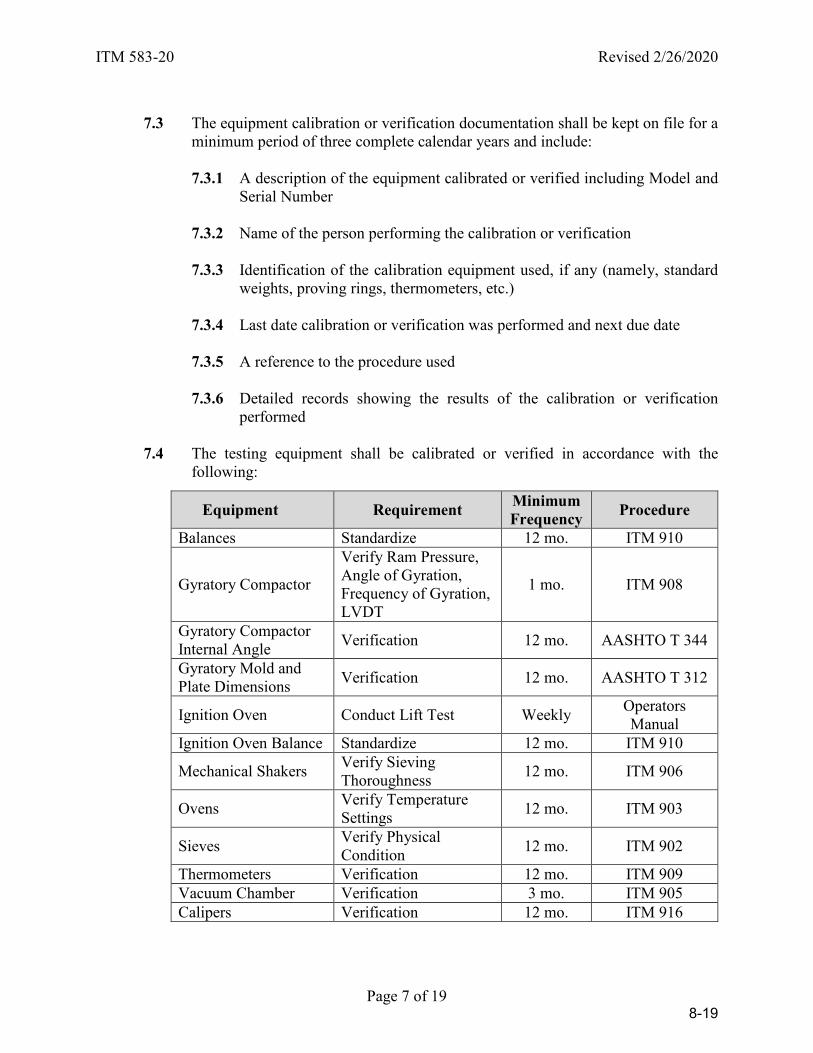
ITM 583-20 Revised 2/26/2020
Page 7 of 19
7.3 The equipment calibration or verification documentation shall be kept on file for a
minimum period of three complete calendar years and include:
7.3.1 A description of the equipment calibrated or verified including Model and Serial Number
7.3.2 Name of the person performing the calibration or verification
7.3.3 Identification of the calibration equipment used, if any (namely, standard weights, proving rings, thermometers, etc.)
7.3.4 Last date calibration or verification was performed and next due date
7.3.5 A reference to the procedure used
7.3.6 Detailed records showing the results of the calibration or verification
performed
7.4 The testing equipment shall be calibrated or verified in accordance with the following:
Equipment Requirement Minimum Frequency Procedure
Balances Standardize 12 mo. ITM 910
Gyratory Compactor
Verify Ram Pressure, Angle of Gyration, Frequency of Gyration, LVDT
1 mo. ITM 908
Gyratory Compactor Internal Angle Verification 12 mo. AASHTO T 344
Gyratory Mold and Plate Dimensions Verification 12 mo. AASHTO T 312
Ignition Oven Conduct Lift Test Weekly Operators Manual
Ignition Oven Balance Standardize 12 mo. ITM 910
Mechanical Shakers Verify Sieving Thoroughness 12 mo. ITM 906
Ovens Verify Temperature Settings 12 mo. ITM 903
Sieves Verify Physical Condition 12 mo. ITM 902
Thermometers Verification 12 mo. ITM 909 Vacuum Chamber Verification 3 mo. ITM 905 Calipers Verification 12 mo. ITM 916
8-19
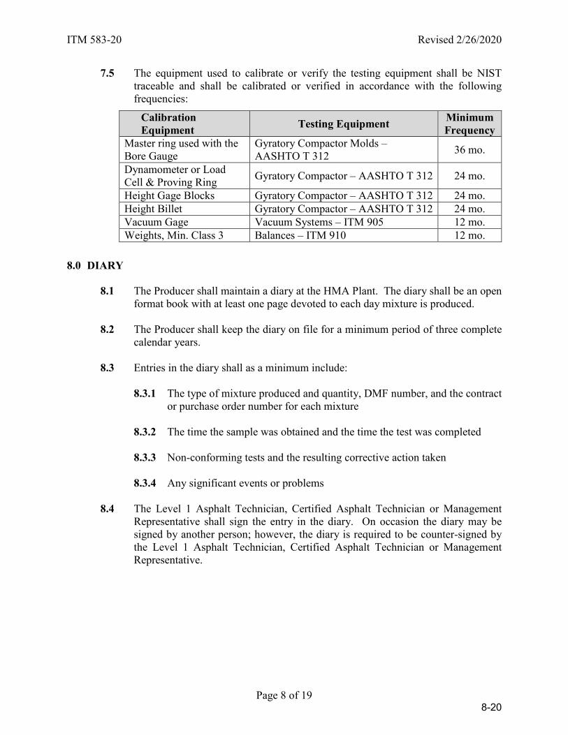
ITM 583-20 Revised 2/26/2020
Page 8 of 19
7.5 The equipment used to calibrate or verify the testing equipment shall be NIST traceable and shall be calibrated or verified in accordance with the following frequencies:
8.0 DIARY
8.1 The Producer shall maintain a diary at the HMA Plant. The diary shall be an open format book with at least one page devoted to each day mixture is produced.
8.2 The Producer shall keep the diary on file for a minimum period of three complete
calendar years.
8.3 Entries in the diary shall as a minimum include:
8.3.1 The type of mixture produced and quantity, DMF number, and the contract or purchase order number for each mixture
8.3.2 The time the sample was obtained and the time the test was completed
8.3.3 Non-conforming tests and the resulting corrective action taken
8.3.4 Any significant events or problems
8.4 The Level 1 Asphalt Technician, Certified Asphalt Technician or Management
Representative shall sign the entry in the diary. On occasion the diary may be signed by another person; however, the diary is required to be counter-signed by the Level 1 Asphalt Technician, Certified Asphalt Technician or Management Representative.
Calibration Equipment Testing Equipment Minimum
Frequency Master ring used with the Bore Gauge
Gyratory Compactor Molds – AASHTO T 312 36 mo.
Dynamometer or Load Cell & Proving Ring Gyratory Compactor – AASHTO T 312 24 mo.
Height Gage Blocks Gyratory Compactor – AASHTO T 312 24 mo. Height Billet Gyratory Compactor – AASHTO T 312 24 mo. Vacuum Gage Vacuum Systems – ITM 905 12 mo. Weights, Min. Class 3 Balances – ITM 910 12 mo.
8-20
ITM 583-20 Revised 2/26/2020
Page 9 of 19
9.0 MATERIALS SAMPLING AND TESTING. The Producer shall designate the sampling
and sample reduction procedures, test methods, sampling locations, and size of samples necessary for the quality control. Mixture shall be sampled in accordance with ITM 580. Testing of the samples shall be completed within two working days. Test values shall be reported to the nearest 0.1 percent, except as follows:
a) Coarse aggregate angularity shall be reported to the nearest 1 percent
b) Mixture temperature shall be reported to the nearest 1°F
c) Mixture moisture content and draindown shall be reported to the nearest
0.01 percent
Rounding shall be in accordance with 109.01(a). The Producer shall keep the test results on file for a minimum period of three complete calendar years.
The VMA shall be calculated in accordance with AASHTO R 35 using the actual binder content from the most recent binder content determination. The maximum specific gravity shall be mass determined in water in accordance with AASHTO T 209. Gyratory specimens shall be compacted at 300 ± 9°F for dense graded mixtures and SMA, and 260 ± 9°F for open graded mixtures. The volume of effective binder, Vbe, in the mixture shall be calculated as the mixture VMA minus the mixture Air Voids.
9.1 QC/QA HMA and SMA Mixtures. The following items shall be addressed in
the QCP as a minimum:
9.1.1 Aggregates
a) Stockpile
b) Blended
9.1.2 Binder
9.1.3 Recycled Materials
a) Actual Binder Content
b) Gradation
c) Moisture Content
d) Coarse Aggregate Angularity
e) Bulk Specific Gravity of Recycled Aggregate
8-21
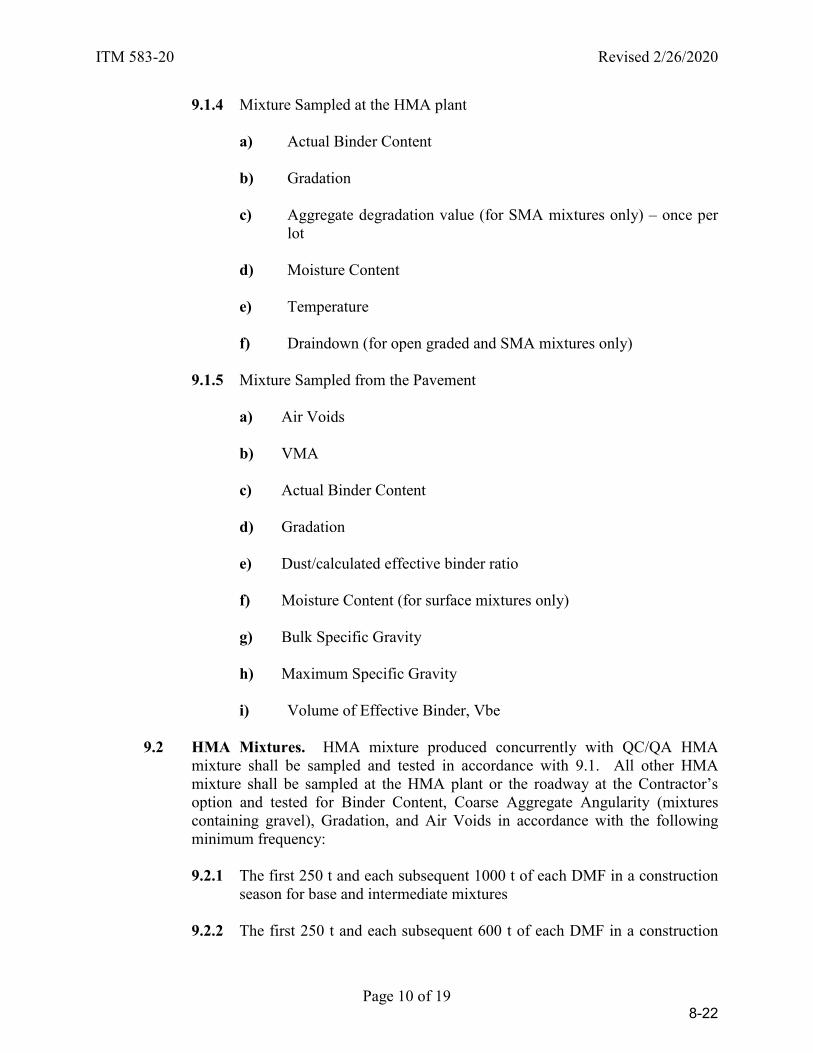
ITM 583-20 Revised 2/26/2020
Page 10 of 19
9.1.4 Mixture Sampled at the HMA plant
a) Actual Binder Content
b) Gradation
c) Aggregate degradation value (for SMA mixtures only) – once per lot
d) Moisture Content
e) Temperature
f) Draindown (for open graded and SMA mixtures only)
9.1.5 Mixture Sampled from the Pavement
a) Air Voids
b) VMA
c) Actual Binder Content
d) Gradation
e) Dust/calculated effective binder ratio
f) Moisture Content (for surface mixtures only) g) Bulk Specific Gravity
h) Maximum Specific Gravity
i) Volume of Effective Binder, Vbe
9.2 HMA Mixtures. HMA mixture produced concurrently with QC/QA HMA
mixture shall be sampled and tested in accordance with 9.1. All other HMA mixture shall be sampled at the HMA plant or the roadway at the Contractor’s option and tested for Binder Content, Coarse Aggregate Angularity (mixtures containing gravel), Gradation, and Air Voids in accordance with the following minimum frequency:
9.2.1 The first 250 t and each subsequent 1000 t of each DMF in a construction
season for base and intermediate mixtures
9.2.2 The first 250 t and each subsequent 600 t of each DMF in a construction
8-22
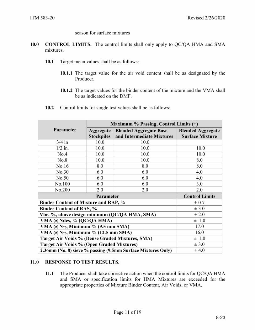
ITM 583-20 Revised 2/26/2020
Page 11 of 19
season for surface mixtures 10.0 CONTROL LIMITS. The control limits shall only apply to QC/QA HMA and SMA
mixtures.
10.1 Target mean values shall be as follows:
10.1.1 The target value for the air void content shall be as designated by the Producer.
10.1.2 The target values for the binder content of the mixture and the VMA shall
be as indicated on the DMF.
10.2 Control limits for single test values shall be as follows:
Parameter Maximum % Passing, Control Limits (±)
Aggregate Stockpiles
Blended Aggregate Base and Intermediate Mixtures
Blended Aggregate Surface Mixture
3/4 in 10.0 10.0 1/2 in. 10.0 10.0 10.0 No.4 10.0 10.0 10.0 No.8 10.0 10.0 8.0 No.16 8.0 8.0 8.0 No.30 6.0 6.0 4.0 No.50 6.0 6.0 4.0 No.100 6.0 6.0 3.0 No.200 2.0 2.0 2.0
Parameter Control Limits Binder Content of Mixture and RAP, % ± 0.7 Binder Content of RAS, % ± 3.0 Vbe, %, above design minimum (QC/QA HMA, SMA) + 2.0 VMA @ Ndes, % (QC/QA HMA) ± 1.0 VMA @ N75, Minimum % (9.5 mm SMA) 17.0 VMA @ N75, Minimum % (12.5 mm SMA) 16.0 Target Air Voids % (Dense Graded Mixtures, SMA) ± 1.0 Target Air Voids % (Open Graded Mixtures) ± 3.0 2.36mm (No. 8) sieve % passing (9.5mm Surface Mixtures Only) + 4.0
11.0 RESPONSE TO TEST RESULTS.
11.1 The Producer shall take corrective action when the control limits for QC/QA HMA and SMA or specification limits for HMA Mixtures are exceeded for the appropriate properties of Mixture Binder Content, Air Voids, or VMA.
8-23
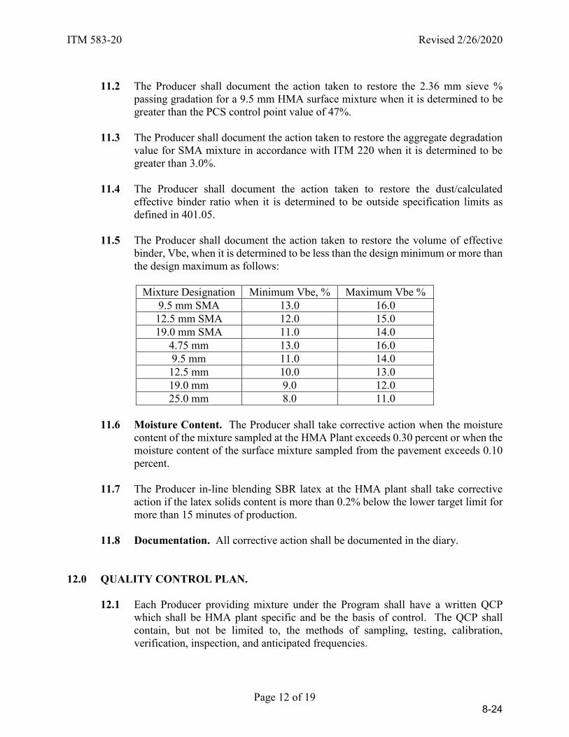
ITM 583-20 Revised 2/26/2020
Page 12 of 19
11.2 The Producer shall document the action taken to restore the 2.36 mm sieve %
passing gradation for a 9.5 mm HMA surface mixture when it is determined to be greater than the PCS control point value of 47%.
11.3 The Producer shall document the action taken to restore the aggregate degradation
value for SMA mixture in accordance with ITM 220 when it is determined to be greater than 3.0%.
11.4 The Producer shall document the action taken to restore the dust/calculated
effective binder ratio when it is determined to be outside specification limits as defined in 401.05.
11.5 The Producer shall document the action taken to restore the volume of effective
binder, Vbe, when it is determined to be less than the design minimum or more than the design maximum as follows:
Mixture Designation Minimum Vbe, % Maximum Vbe %
9.5 mm SMA 13.0 16.0 12.5 mm SMA 12.0 15.0 19.0 mm SMA 11.0 14.0
4.75 mm 13.0 16.0 9.5 mm 11.0 14.0 12.5 mm 10.0 13.0 19.0 mm 9.0 12.0 25.0 mm 8.0 11.0
11.6 Moisture Content. The Producer shall take corrective action when the moisture
content of the mixture sampled at the HMA Plant exceeds 0.30 percent or when the moisture content of the surface mixture sampled from the pavement exceeds 0.10 percent.
11.7 The Producer in-line blending SBR latex at the HMA plant shall take corrective
action if the latex solids content is more than 0.2% below the lower target limit for more than 15 minutes of production.
11.8 Documentation. All corrective action shall be documented in the diary.
12.0 QUALITY CONTROL PLAN.
12.1 Each Producer providing mixture under the Program shall have a written QCP which shall be HMA plant specific and be the basis of control. The QCP shall contain, but not be limited to, the methods of sampling, testing, calibration, verification, inspection, and anticipated frequencies.
8-24
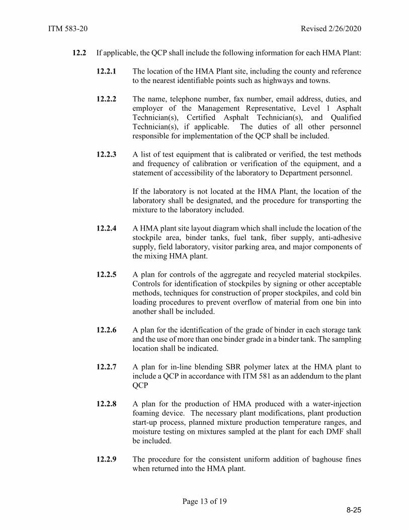
ITM 583-20 Revised 2/26/2020
Page 13 of 19
12.2 If applicable, the QCP shall include the following information for each HMA Plant:
12.2.1 The location of the HMA Plant site, including the county and reference to the nearest identifiable points such as highways and towns.
12.2.2 The name, telephone number, fax number, email address, duties, and
employer of the Management Representative, Level 1 Asphalt Technician(s), Certified Asphalt Technician(s), and Qualified Technician(s), if applicable. The duties of all other personnel responsible for implementation of the QCP shall be included.
12.2.3 A list of test equipment that is calibrated or verified, the test methods
and frequency of calibration or verification of the equipment, and a statement of accessibility of the laboratory to Department personnel.
If the laboratory is not located at the HMA Plant, the location of the laboratory shall be designated, and the procedure for transporting the mixture to the laboratory included.
12.2.4 A HMA plant site layout diagram which shall include the location of the
stockpile area, binder tanks, fuel tank, fiber supply, anti-adhesive supply, field laboratory, visitor parking area, and major components of the mixing HMA plant.
12.2.5 A plan for controls of the aggregate and recycled material stockpiles.
Controls for identification of stockpiles by signing or other acceptable methods, techniques for construction of proper stockpiles, and cold bin loading procedures to prevent overflow of material from one bin into another shall be included.
12.2.6 A plan for the identification of the grade of binder in each storage tank
and the use of more than one binder grade in a binder tank. The sampling location shall be indicated.
12.2.7 A plan for in-line blending SBR polymer latex at the HMA plant to
include a QCP in accordance with ITM 581 as an addendum to the plant QCP
12.2.8 A plan for the production of HMA produced with a water-injection
foaming device. The necessary plant modifications, plant production start-up process, planned mixture production temperature ranges, and moisture testing on mixtures sampled at the plant for each DMF shall be included.
12.2.9 The procedure for the consistent uniform addition of baghouse fines
when returned into the HMA plant.
8-25

ITM 583-20 Revised 2/26/2020
Page 14 of 19
12.2.10 The procedure for the consistent uniform addition of fibers into the
HMA plant.
12.2.11 The procedure for using an anti-adhesive agent for the truck bed, and a statement that the agent is on the Department’s List of Approved Anti-Adhesive Materials.
12.2.12 The procedure for sealing the surge bin when used for extended storage
of the mixture up to one working day, and the method to prevent the discharge when the mixture falls below the top of the cone.
12.2.13 The procedure for loading mixture into the trucks.
12.2.14 A sampling plan that includes locations, test methods, devices,
techniques, frequencies, and sample reduction procedures.
12.2.15 A testing plan that includes the types of tests, and test methods. 12.2.16 A description of any other process control techniques that may be used.
These controls may include, but are not limited to:
a) Different types of material testing
b) Visual checks, and monitoring of HMA plant production
12.2.17 A statement of the procedure for handling addenda to the QCP including a time schedule for submittal.
12.2.18 A documentation plan with details on control charting, test data, and the
diary. Copies of the forms may be included.
12.3 The last page of the QCP shall contain two signatures. One signature shall be the Producer Management Representative. The date of submittal and the corporate title of the Producer Management Representative making the signature shall be included. The other signature shall be for approval by the Manager, Office of Materials Management.
12.4 Production of mixture shall not begin before the QCP has been approved. The
Producer shall submit two copies of the QCP to the Department for review. One copy shall be submitted to the District Testing Engineer, and one copy to the Office of Materials Management. Acceptance or rejection of the QCP will be made within 15 days of receipt of the QCP. One approved copy will be returned to the Producer.
8-26

ITM 583-20 Revised 2/26/2020
Page 15 of 19
12.5 The Producer shall transmit all applicable process control changes to the District
Testing Engineer for approval. This shall be done in the format of addenda to the QCP. Each page of the QCP that is revised shall include the HMA plant number, date of revision, and means of identifying the revision. The addenda shall be signed and dated by the Management Representative and subsequently signed and dated when approved by the District Testing Engineer.
Revisions for HMA plant major components, Level 1 Asphalt Technicians, Certified Asphalt Technicians, and movement of the HMA plant shall be submitted in the format of a QCP Annex as they occur, and upon approval by the District Testing Engineer shall be included in the Appendix of the QCP. Revisions, other than items on the QCP Annex, shall be maintained on the Addenda Summary sheet in the QCP Appendix.
Addenda may be submitted at the audit close-out meeting or anytime during the calendar year. The addenda shall include items on the QCP Annex, items on the Addenda Summary Sheet, and any other necessary revisions at the time of submittal. Upon incorporation into the QCP as addenda, the QCP Annex and items on the Addenda Summary Sheet shall be removed from the QCP Appendix.
12.6 Movement of the HMA Plant to a new location will require an addendum to the
QCP. Verification of the calibration of all meters, scales and other measuring devices in accordance with 14.3 shall be completed.
13.0 CERTIFICATION.
13.1 Each Producer requesting to establish a Certified Plant shall do so in writing to the Manager, Office of Materials Management.
13.2 Upon receipt of the request for certification, the District Testing Engineer will be
notified to inspect the plant and laboratory.
13.3 A plant inspection, including the correction of any deficiencies and calibration of all meters, scales and other measuring devices to an accuracy within 0.5% throughout their range, shall be completed prior to certification.
13.4 Each HMA plant meeting the requirements of the Program will be certified upon
the approval of the QCP.
13.5 The Producer, in accordance with ITM 581, shall submit a written request to the Asphalt Engineer, Office of Materials Management, to in-line blend SBR polymer latex at the HMA plant.
8-27
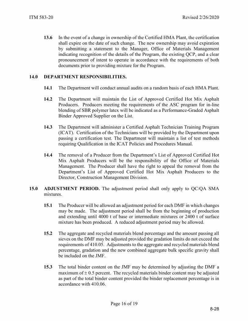
ITM 583-20 Revised 2/26/2020
Page 16 of 19
13.6 In the event of a change in ownership of the Certified HMA Plant, the certification
shall expire on the date of such change. The new ownership may avoid expiration by submitting a statement to the Manager, Office of Materials Management indicating recognition of the details of the Program, the existing QCP, and a clear pronouncement of intent to operate in accordance with the requirements of both documents prior to providing mixture for the Program.
14.0 DEPARTMENT RESPONSIBILITIES.
14.1 The Department will conduct annual audits on a random basis of each HMA Plant.
14.2 The Department will maintain the List of Approved Certified Hot Mix Asphalt Producers. Producers meeting the requirements of the ASC program for in-line blending of SBR polymer latex will be indicated as a Performance-Graded Asphalt Binder Approved Supplier on the List.
14.3 The Department will administer a Certified Asphalt Technician Training Program
(ICAT). Certification of the Technicians will be provided by the Department upon passing a certification test. The Department will maintain a list of test methods requiring Qualification in the ICAT Policies and Procedures Manual.
14.4 The removal of a Producer from the Department’s List of Approved Certified Hot
Mix Asphalt Producers will be the responsibility of the Office of Materials Management. The Producer shall have the right to appeal the removal from the Department’s List of Approved Certified Hot Mix Asphalt Producers to the Director, Construction Management Division.
15.0 ADJUSTMENT PERIOD. The adjustment period shall only apply to QC/QA SMA
mixtures.
15.1 The Producer will be allowed an adjustment period for each DMF in which changes may be made. The adjustment period shall be from the beginning of production and extending until 4000 t of base or intermediate mixtures or 2400 t of surface mixture has been produced. A reduced adjustment period may be allowed.
15.2 The aggregate and recycled materials blend percentage and the amount passing all
sieves on the DMF may be adjusted provided the gradation limits do not exceed the requirements of 410.05. Adjustments to the aggregate and recycled materials blend percentage, gradation and the new combined aggregate bulk specific gravity shall be included on the JMF.
15.3 The total binder content on the JMF may be determined by adjusting the DMF a
maximum of ± 0.5 percent. The recycled materials binder content may be adjusted as part of the total binder content provided the binder replacement percentage is in accordance with 410.06.
8-28

ITM 583-20 Revised 2/26/2020
Page 17 of 19
15.4 The JMF shall be submitted in writing for approval to the District Testing Engineer
one working day after the receipt of the original test results for the binder content and gradation of the adjustment period.
15.5 A DMF will be allowed one adjustment period in a construction season. A new
adjustment period will not be allowed for only a binder source change.
8-29
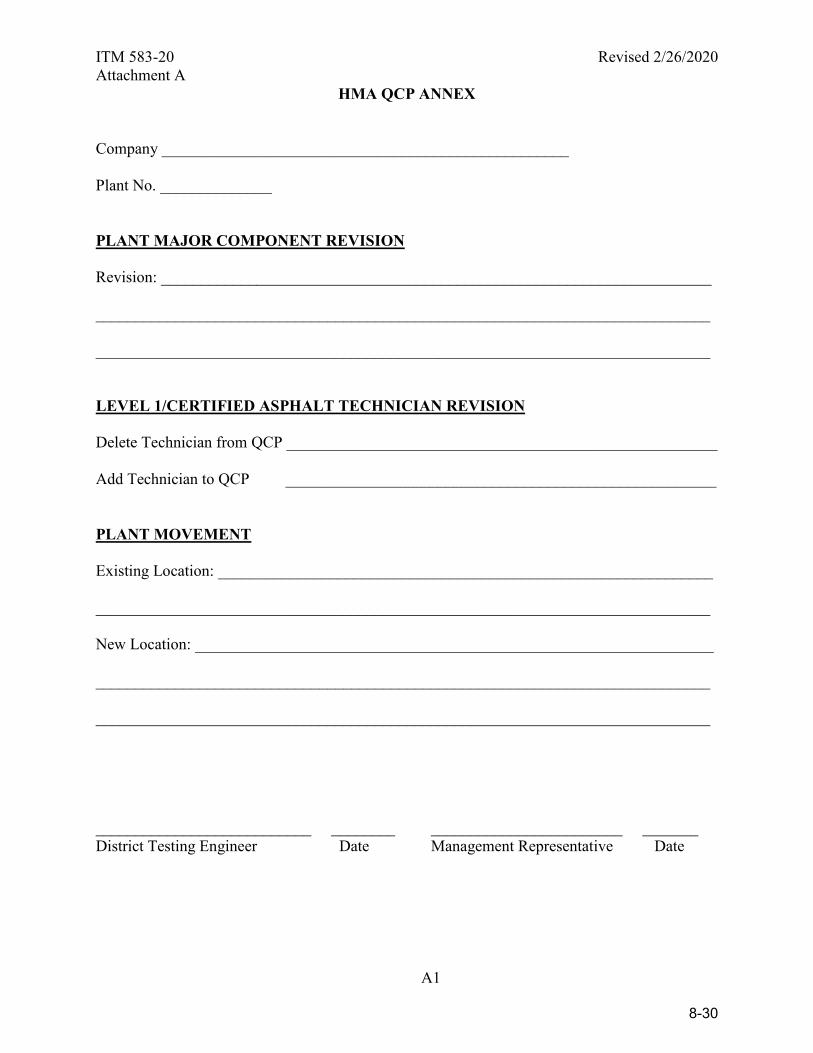
ITM 583-20 Revised 2/26/2020 Attachment A
A1
HMA QCP ANNEX Company ___________________________________________________ Plant No. ______________ PLANT MAJOR COMPONENT REVISION Revision: _____________________________________________________________________ _____________________________________________________________________________ _____________________________________________________________________________ LEVEL 1/CERTIFIED ASPHALT TECHNICIAN REVISION Delete Technician from QCP ______________________________________________________ Add Technician to QCP ______________________________________________________ PLANT MOVEMENT Existing Location: ______________________________________________________________ _____________________________________________________________________________ New Location: _________________________________________________________________ _____________________________________________________________________________ _____________________________________________________________________________ ___________________________ ________ ________________________ _______ District Testing Engineer Date Management Representative Date
8-30

ITM 583-20 Revised 2/26/2020 Attachment B
A2
INDIANA DEPARTMENT OF TRANSPORTATION
HOT MIX ASPHALT (HMA) TYPE D CERTIFICATION CONTRACT NUMBER _________________ DATE____________ CERTIFIED HMA PRODUCER ______________________________________________________________ CERTIFIED HMA PLANT NUMBER _________________ DMF NUMBER _________________ PG BINDER SOURCE _______________ PG BINDER GRADE________________ MIXTURE TYPE AND SIZE ________________________________________________________________ DESIGN ESAL __________________ Air Voids _________ (from DMF) Binder Content _________ (from DMF) This is to certify that the test results for Air Voids and Binder Content represent the HMA mixture supplied to this contract. Air Voids ______ (± 2.0 % from DMF) Binder Content _______ (± 0.7% from DMF) * [ ] Test results are not available for submittal. A production sample shall be taken within the first 250 t (250 Mg) and each subsequent 1000 t (1000 Mg) for base and intermediate mixtures and each subsequent 600 t (600 Mg) for surface mixtures. * If Applicable __________________________________________ Signature of Level 1 or Certified Asphalt Technician __________________________________________ Printed Name FOR PE/PS USE ONLY PAY ITEM(S) _____________________________________ ACCEPTANCE METHOD: SM9003 SPECIFICATION REFERENCE __ 304.04 - Patching __ 402.07(c) - Temporary HMA __ 610 - Approaches __ 304.05 - Widening __ 503.03(e) - Terminal Joints __ 610 - Crossovers __ 402.04 - HMA Pavements __ 507.05(b) - Partial Depth Patching __ 718.04 - Underdrains __ 402.07(a) - Rumble Strips __ 604.07(c) – Sidewalk __ 801.11- Temp. Crossovers __ 402.07(b) - Wedge & Leveling __ 605.07(c) – Curbing
8-31
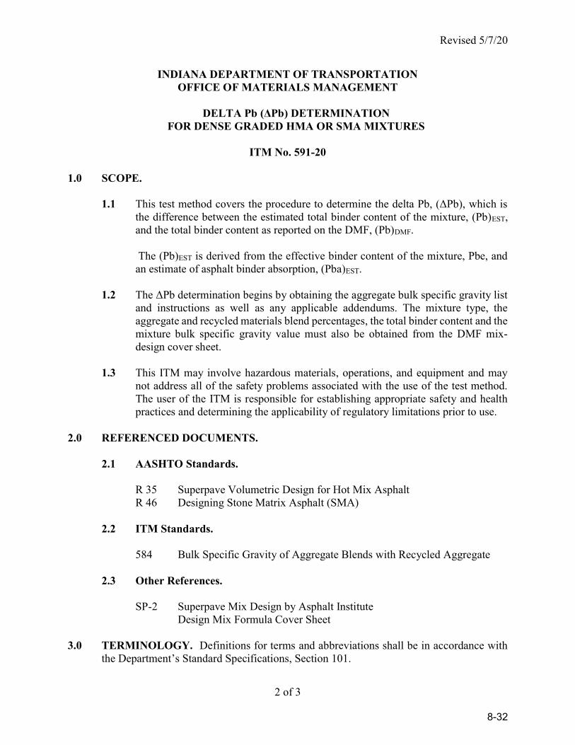
Revised 5/7/20
2 of 3
INDIANA DEPARTMENT OF TRANSPORTATION OFFICE OF MATERIALS MANAGEMENT
DELTA Pb (ΔPb) DETERMINATION
FOR DENSE GRADED HMA OR SMA MIXTURES
ITM No. 591-20 1.0 SCOPE.
1.1 This test method covers the procedure to determine the delta Pb, (ΔPb), which is the difference between the estimated total binder content of the mixture, (Pb)EST, and the total binder content as reported on the DMF, (Pb)DMF.
The (Pb)EST is derived from the effective binder content of the mixture, Pbe, and an estimate of asphalt binder absorption, (Pba)EST.
1.2 The ΔPb determination begins by obtaining the aggregate bulk specific gravity list
and instructions as well as any applicable addendums. The mixture type, the aggregate and recycled materials blend percentages, the total binder content and the mixture bulk specific gravity value must also be obtained from the DMF mix-design cover sheet.
1.3 This ITM may involve hazardous materials, operations, and equipment and may
not address all of the safety problems associated with the use of the test method. The user of the ITM is responsible for establishing appropriate safety and health practices and determining the applicability of regulatory limitations prior to use.
2.0 REFERENCED DOCUMENTS.
2.1 AASHTO Standards.
R 35 Superpave Volumetric Design for Hot Mix Asphalt R 46 Designing Stone Matrix Asphalt (SMA)
2.2 ITM Standards.
584 Bulk Specific Gravity of Aggregate Blends with Recycled Aggregate
2.3 Other References. SP-2 Superpave Mix Design by Asphalt Institute Design Mix Formula Cover Sheet 3.0 TERMINOLOGY. Definitions for terms and abbreviations shall be in accordance with
the Department’s Standard Specifications, Section 101.
8-32
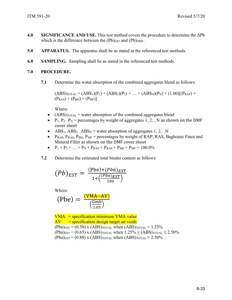
ITM 591-20 Revised 5/7/20
4.0 SIGNIFICANCE AND USE. This test method covers the procedure to determine the ΔPb
which is the difference between the (Pb)EST and (Pb)DMF. 5.0 APPARATUS. The apparatus shall be as stated in the referenced test methods. 6.0 SAMPLING. Sampling shall be as stated in the referenced test methods. 7.0 PROCEDURE.
7.1 Determine the water absorption of the combined aggregates blend as follows: (ABS)TOTAL = (ABS1)(P1) + (ABS2)(P2) + … + (ABSN)(PN) + (1.00)[(PRAP) +
(PRAS) + (PBH) + (PMF)] Where:
(ABS)TOTAL = water absorption of the combined aggregates blend P1, P2…PN = percentages by weight of aggregates 1, 2…N as shown on the DMF
cover sheet ABS1, ABS2…ABSN = water absorption of aggregates 1, 2…N PRAP, PRAS, PBH, PMF = percentages by weight of RAP, RAS, Baghouse Fines and
Mineral Filler as shown on the DMF cover sheet P1 + P2 + … + PN + PRAP + PRAS + PBH + PMF = 100.0%
7.2 Determine the estimated total binder content as follows:
( ) ( )
( )
Where:
( )
.
VMA = specification minimum VMA value AV = specification design target air voids
(Pba)EST = (0.50) x (ABS)TOTAL when (ABS)TOTAL < 1.25% (Pba)EST = (0.65) x (ABS)TOTAL when 1.25% ≤ (ABS)TOTAL ≤ 2.50% (Pba)EST = (0.80) x (ABS)TOTAL when (ABS)TOTAL > 2.50%
8-33

ITM 591-20 Revised 5/7/20
7.3 Determine the ΔPb as follows:
8.0 REPORT. The ΔPb value is reported to the nearest 0.01.
8-34
Revised 11/5/2020
1 of 19
INDIANA DEPARTMENT OF TRANSPORTATION OFFICE OF MATERIALS MANAGEMENT
RANDOM SAMPLING
ITM No. 802-20 1.0 SCOPE.
1.1 This procedure is used to determine the random unit, random quantity, or random location for sampling of construction materials. Use of this method is intended to minimize any bias on the part of the person taking the sample.
1.2 This ITM may involve hazardous materials, operations, and equipment and may
not address all of the safety problems associated with the use of the test method. The user of the ITM is responsible for establishing appropriate safety and health practices and to determining the applicability of regulatory limitations prior to use.
2.0 TERMINOLOGY. Definitions for terms and abbreviations shall be in accordance with
the Department’s Standard Specifications, Section 101 and ASTM D 16. 3.0 SIGNIFICANCE AND USE. This ITM is used to determine the unit, quantity, or
location of the material to be sampled for acceptance in accordance with the Standard Specifications.
4.0 RANDOM NUMBERS.
4.1 The Random Number Tables consist of a list of numbers in blocks which may be used in the random selection process. Random numbers generated by software may be used in place of the Random Number Tables.
4.2 To use a Random Number Table select one block in the table without looking.
4.3 After selecting the block, the top left number in the block is the first random
number used. If a pair of random numbers is needed, the adjacent number within the block is used.
4.4 Proceed down the vertical column for additional numbers and proceed to the top
of the adjacent column to the right, if available, when the bottom of the column is reached. When the bottom of the last column on the right is reached, proceed to the top of the column of the first column on the left in the table.
8-35
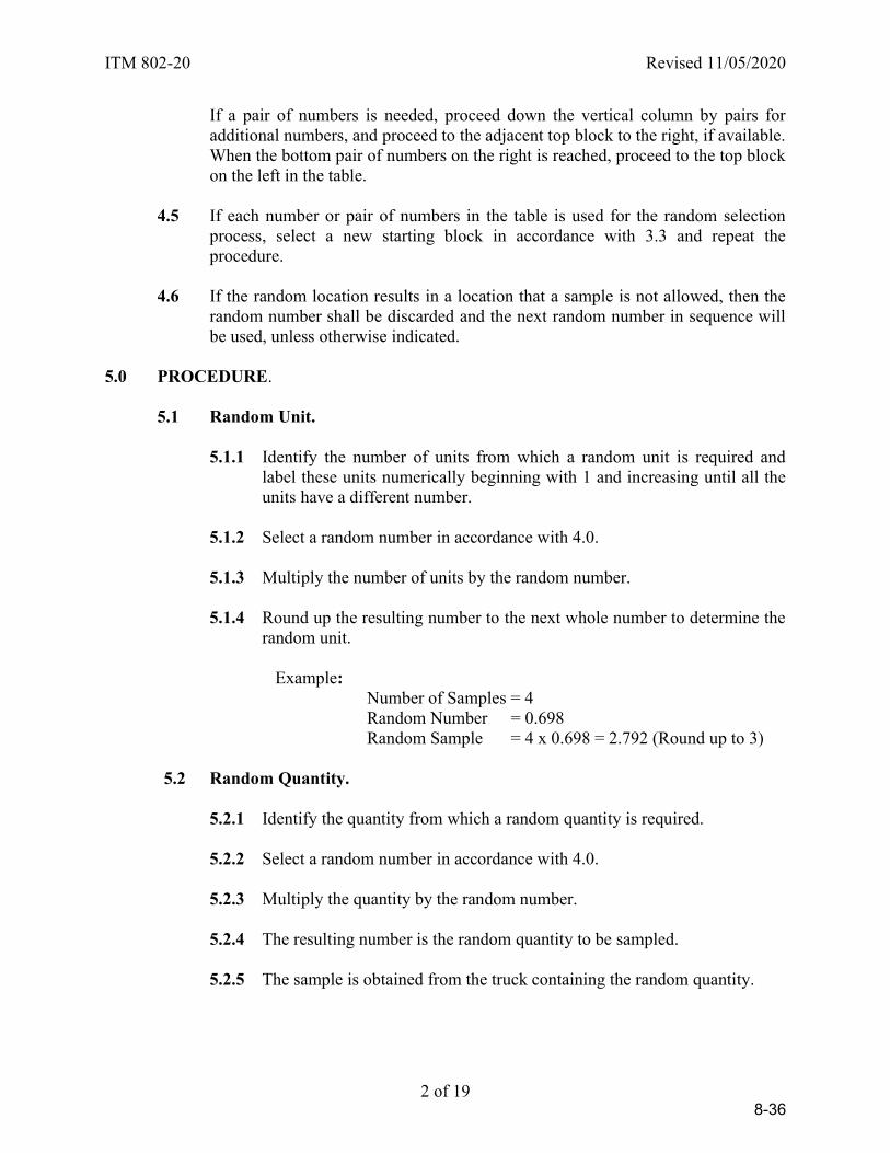
ITM 802-20 Revised 11/05/2020
2 of 19
If a pair of numbers is needed, proceed down the vertical column by pairs for additional numbers, and proceed to the adjacent top block to the right, if available. When the bottom pair of numbers on the right is reached, proceed to the top block on the left in the table.
4.5 If each number or pair of numbers in the table is used for the random selection
process, select a new starting block in accordance with 3.3 and repeat the procedure.
4.6 If the random location results in a location that a sample is not allowed, then the
random number shall be discarded and the next random number in sequence will be used, unless otherwise indicated.
5.0 PROCEDURE.
5.1 Random Unit.
5.1.1 Identify the number of units from which a random unit is required and label these units numerically beginning with 1 and increasing until all the units have a different number.
5.1.2 Select a random number in accordance with 4.0.
5.1.3 Multiply the number of units by the random number.
5.1.4 Round up the resulting number to the next whole number to determine the
random unit.
Example: Number of Samples = 4 Random Number = 0.698 Random Sample = 4 x 0.698 = 2.792 (Round up to 3)
5.2 Random Quantity.
5.2.1 Identify the quantity from which a random quantity is required.
5.2.2 Select a random number in accordance with 4.0.
5.2.3 Multiply the quantity by the random number.
5.2.4 The resulting number is the random quantity to be sampled.
5.2.5 The sample is obtained from the truck containing the random quantity.
8-36

ITM 802-20 Revised 11/05/2020
3 of 19
Example: Sublot Size = 380 t of HMA Random Number = 0.871 Random Quantity = 380 x 0.871 = 331 t
Sample HMA from the truck containing ton number 331
5.3 Random Location per Length.
5.3.1 Identify the length from which a random location is required.
5.3.2 Select a random number in accordance with 4.0
5.3.3 Multiply the length by the random number.
5.3.4 The resulting number is the random distance.
5.3.5 Add the random distance to the beginning of the length to determine the random location.
5.4 Random Location per Area.
5.4.1 Identify the area from which a random location is required.
5.4.2 Select a pair of random numbers in accordance with 4.0. Use the first
number for the longitudinal location and the second number for the transverse location.
5.4.3 Determine the longitudinal length in accordance with 4.3
5.4.4 Multiply the transverse width by the random number.
5.4.5 The resulting numbers represent the random location.
HMA -- Plate Samples.
The random location of a plate sample is determined from a random quantity, random longitudinal distance, and transverse distance as follows:
1. A random quantity is determined in accordance with 5.2.
2. The random longitudinal distance is determined from the length the
mixture is placed by the truck containing the random quantity. The starting station for the longitudinal distance is the location of the paver where the truck begins to unload the mixture into the paver or material transfer device. Computations are made to the nearest 1 ft.
8-37

ITM 802-20 Revised 11/05/2020
4 of 19
3. The random transverse distance is determined using the width of the course being placed. Computations are made to the nearest 1 ft. The distance is measured from the right edge of the course determined by looking in the direction of increasing station numbers. If the width of the course is 4 ft or less, the sample plate will be placed in the center of the course.
Plate samples will not be taken at the following locations and contract requirements:
1. Less than 1 ft from the edge of the course
2. A course thickness less than 2.0 times the maximum particle size except
4.75 mm mixtures shall be at least 1.5 times but not more than 3 times the maximum particle size
3. Original pay item quantities less than 300 t (Does not apply to SMA)
4. Areas specifically exempted per 401.09:
a. Mixture placed on an approach, taper, gore area, or crossover that is
not placed simultaneously with the mainline. b. Mixture placed on a shoulder less than 8 feet wide that is not placed
simultaneously with the mainline c. Within 25 feet of a transverse construction joint d. Areas placed with wideners, or specialty equipment approved by the
Engineer.
If the random location falls within these areas another randomly selected location is determined. If the entire sublot falls within these areas, the previous sublot is used for acceptance. If the previous sublot is not available, the subsequent sublot will be used for acceptance.
When additional plate samples are required for gyratory specimens and backup samples, the following procedure is used:
1. The first plate location is determined using the procedure for HMA plate samples. This sample is used for the MSG and binder content determination. This plate sample will be designated A1.
2. The second plate is placed longitudinally 2 ft ahead station from the first
plate at the same transverse offset. This sample is used for the gyratory specimens. This plate sample will be designated A2.
3. The third plate is placed longitudinally 2 ft ahead station from the second
plate at the same transverse offset. This sample is used to determine the aggregate bulk specific gravity within the mixture. This plate sample will be designated A3.
8-38
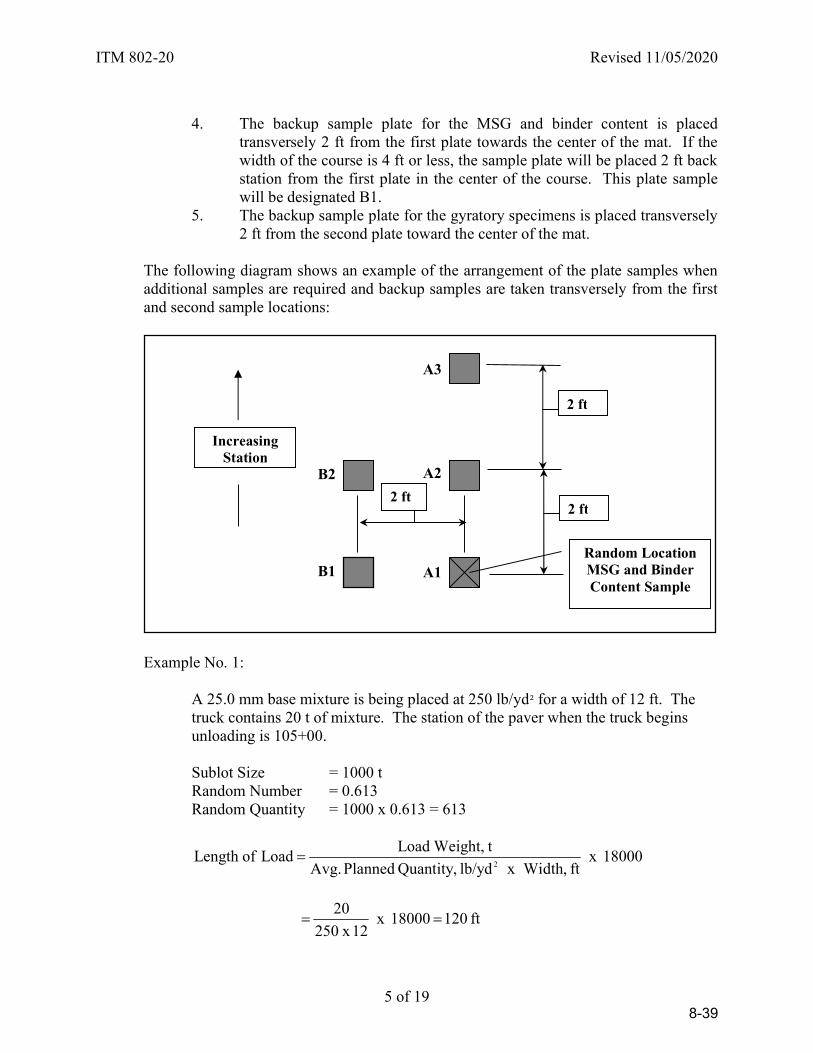
ITM 802-20 Revised 11/05/2020
5 of 19
4. The backup sample plate for the MSG and binder content is placed
transversely 2 ft from the first plate towards the center of the mat. If the width of the course is 4 ft or less, the sample plate will be placed 2 ft back station from the first plate in the center of the course. This plate sample will be designated B1.
5. The backup sample plate for the gyratory specimens is placed transversely 2 ft from the second plate toward the center of the mat.
The following diagram shows an example of the arrangement of the plate samples when additional samples are required and backup samples are taken transversely from the first and second sample locations:
Example No. 1:
A 25.0 mm base mixture is being placed at 250 lb/yd² for a width of 12 ft. The truck contains 20 t of mixture. The station of the paver when the truck begins unloading is 105+00.
Sublot Size = 1000 t Random Number = 0.613 Random Quantity = 1000 x 0.613 = 613
18000 x ft , x Widthlb/yd Quantity, Planned Avg.
t Weight,Load Load ofLength
2
ft 120 18000 x 12 x 250
20
Increasing Station
2 ft 2 ft
B2
B1 A1
A2
A3
2 ft
Random Location MSG and Binder Content Sample
8-39
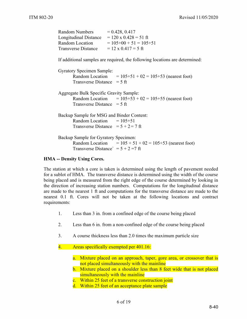
ITM 802-20 Revised 11/05/2020
6 of 19
Random Numbers = 0.428, 0.417 Longitudinal Distance = 120 x 0.428 = 51 ft Random Location = 105+00 + 51 = 105+51 Transverse Distance = 12 x 0.417 = 5 ft
If additional samples are required, the following locations are determined:
Gyratory Specimen Sample: Random Location = 105+51 + 02 = 105+53 (nearest foot) Transverse Distance = 5 ft Aggregate Bulk Specific Gravity Sample: Random Location = 105+53 + 02 = 105+55 (nearest foot) Transverse Distance = 5 ft Backup Sample for MSG and Binder Content: Random Location = 105+51 Transverse Distance = 5 + 2 = 7 ft Backup Sample for Gyratory Specimen: Random Location = 105 + 51 + 02 = 105+53 (nearest foot) Transverse Distance` = 5 + 2 =7 ft
HMA -- Density Using Cores.
The station at which a core is taken is determined using the length of pavement needed for a sublot of HMA. The transverse distance is determined using the width of the course being placed and is measured from the right edge of the course determined by looking in the direction of increasing station numbers. Computations for the longitudinal distance are made to the nearest 1 ft and computations for the transverse distance are made to the nearest 0.1 ft. Cores will not be taken at the following locations and contract requirements:
1. Less than 3 in. from a confined edge of the course being placed
2. Less than 6 in. from a non-confined edge of the course being placed
3. A course thickness less than 2.0 times the maximum particle size
4. Areas specifically exempted per 401.16:
a. Mixture placed on an approach, taper, gore area, or crossover that is
not placed simultaneously with the mainline b. Mixture placed on a shoulder less than 8 feet wide that is not placed
simultaneously with the mainline c. Within 25 feet of a transverse construction joint d. Within 25 feet of an acceptance plate sample
8-40

ITM 802-20 Revised 11/05/2020
7 of 19
e. Areas placed with wideners, or specialty equipment approved by the Engineer.
If the random location falls within these areas, another randomly selected location is determined. If the entire sublot falls within these areas, the previous sublot is used for acceptance. If the previous sublot is not available, the subsequent sublot will be used for acceptance.
5. Original pay item quantities less than 300 t Example:
A 19.0 mm intermediate mixture is being placed at 165 lb/yd² for a width of 12 ft. The starting station of the sublot is 158+00. The sublot size is 1000 t.
18000 x ft , x Widthlb/yd Quantity, Planned Avg.
tSize,Sublot Sublot ofLength
2
ft 9090 18000 x 12 x 165
1000
Random Numbers = 0.256, 0.561 Longitudinal Distance = 9090 x 0.256 = 2327 ft Random Station = (158+00) + (23+27) = 181+27 Transverse Distance = 12 x 0.561 = 6.7 ft (Say 7 ft)
PCCP -- Core Thickness.
The station at which a core is taken is determined using the length of pavement needed for the sublot of PCCP. The transverse distance is determined using the width of pavement being placed, and is measured from the right edge of the lane determined by looking in the direction of increasing station numbers. Computations for the longitudinal distance are made to the nearest 1 ft and computations for the transverse distance are made to the nearest 1 ft. Cores will not be taken at the following locations:
1. Less than 2 ft from a D-1 contraction joint;
2. Less than 3 in. from the longitudinal joint; or
3. Less than 5 ft from a transverse construction joint. 4. Less than 6 in. from edge of pavement
If a core location is less than 2 ft from a D-1 contraction joint, a new location will be determined by subtracting or adding 2 feet from the random station. If a core location is less than 3 in. from a longitudinal joint, a new location will be determined by subtracting or adding 3 inches from the random transverse distance. If a core location is less than 5 ft from a transverse construction joint, a new location will be determined by subtracting or adding 5 ft from the random station. If a core location is less than 6 in. from the edge of
8-41

ITM 802-20 Revised 11/05/2020
8 of 19
pavement, a new location will be determined by subtracting or adding 6 in. from the random transverse distance. If a core location is over a dowel bar, a new location will be determined by subtracting or adding 3 ft from the random station. Example:
A PCCP is being placed at a width of 12 ft and the starting station of the sublot is 75+00. The sublot size is 2400 yd2.
2
22
yd 1
ft 9 x
ftnearest Width,
yd Size,Sublot Sublot ofLength
ft 1800 9 x 12
2400
Random Numbers = 0.935, 0.114 Longitudinal Distance = 1800 x 0.935 = 1683 ft Random Station = (75+00) + (16+83) = 91+83 Transverse Distance = 12 x 0.114 = 1.4 ft (Say 1 ft)
(Too close to edge of pavement) = 1 + 2 = 3 ft Retroreflective Pavement Markings The random location to measure the retro-reflectivity of a pavement marking on a longitudinal line is determined by selecting a random sampling zone within the segment as follows:
Random Segment
1. The section is the number of miles to the nearest 0.1 mi of each color of pavement marking application completed in a single day.
2. Divide the section by three to determine the length of the segments to the nearest
0.1 mi.
Random Sampling Zone
1. Select three random numbers in accordance with 4.0.
2. For the first segment, multiply the first random number by the length of the segment and round to the nearest 0.1 mi. Add this length to the Reference Post (RP) at the beginning of the segment. This number is the beginning of the sampling zone. Repeat this procedure for the second and third segments using the second and third random numbers respectively.
3. The first measurement is taken at the beginning of the sampling zone and all
subsequent measurements are taken at approximately 15 ft intervals.
8-42
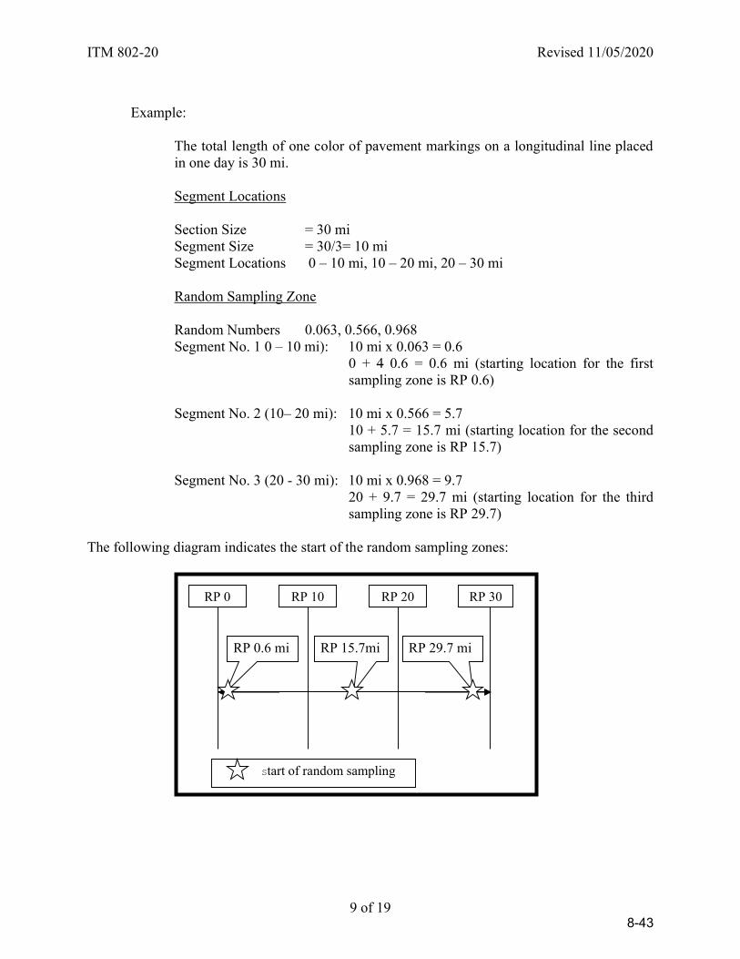
ITM 802-20 Revised 11/05/2020
9 of 19
Example:
The total length of one color of pavement markings on a longitudinal line placed in one day is 30 mi.
Segment Locations
Section Size = 30 mi Segment Size = 30/3= 10 mi Segment Locations 0 – 10 mi, 10 – 20 mi, 20 – 30 mi
Random Sampling Zone
Random Numbers 0.063, 0.566, 0.968 Segment No. 1 0 – 10 mi): 10 mi x 0.063 = 0.6
0 + 4 0.6 = 0.6 mi (starting location for the first sampling zone is RP 0.6)
Segment No. 2 (10– 20 mi): 10 mi x 0.566 = 5.7 10 + 5.7 = 15.7 mi (starting location for the second
sampling zone is RP 15.7)
Segment No. 3 (20 - 30 mi): 10 mi x 0.968 = 9.7 20 + 9.7 = 29.7 mi (starting location for the third
sampling zone is RP 29.7) The following diagram indicates the start of the random sampling zones:
RP 10 RP 20 RP 30
Start of random sampling
RP 29.7 mi RP 15.7mi RP 0.6 mi
RP 0
8-43
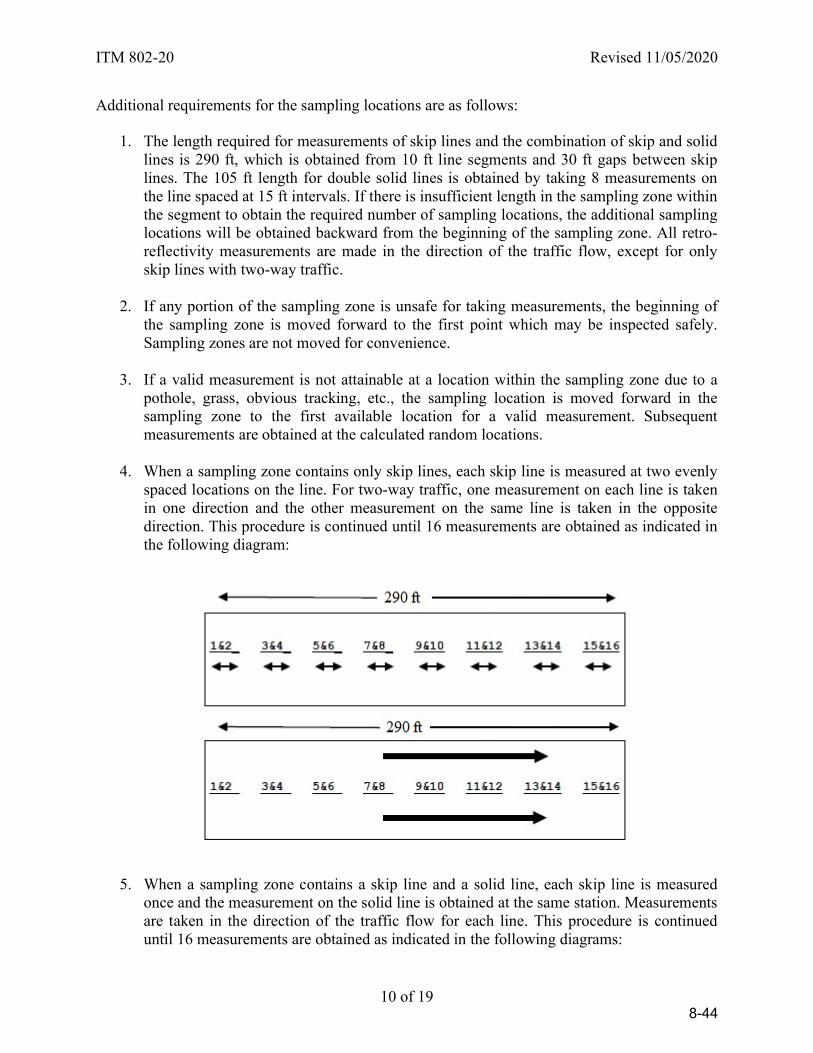
ITM 802-20 Revised 11/05/2020
10 of 19
Additional requirements for the sampling locations are as follows:
1. The length required for measurements of skip lines and the combination of skip and solid lines is 290 ft, which is obtained from 10 ft line segments and 30 ft gaps between skip lines. The 105 ft length for double solid lines is obtained by taking 8 measurements on the line spaced at 15 ft intervals. If there is insufficient length in the sampling zone within the segment to obtain the required number of sampling locations, the additional sampling locations will be obtained backward from the beginning of the sampling zone. All retro-reflectivity measurements are made in the direction of the traffic flow, except for only skip lines with two-way traffic.
2. If any portion of the sampling zone is unsafe for taking measurements, the beginning of
the sampling zone is moved forward to the first point which may be inspected safely. Sampling zones are not moved for convenience.
3. If a valid measurement is not attainable at a location within the sampling zone due to a
pothole, grass, obvious tracking, etc., the sampling location is moved forward in the sampling zone to the first available location for a valid measurement. Subsequent measurements are obtained at the calculated random locations.
4. When a sampling zone contains only skip lines, each skip line is measured at two evenly
spaced locations on the line. For two-way traffic, one measurement on each line is taken in one direction and the other measurement on the same line is taken in the opposite direction. This procedure is continued until 16 measurements are obtained as indicated in the following diagram:
5. When a sampling zone contains a skip line and a solid line, each skip line is measured once and the measurement on the solid line is obtained at the same station. Measurements are taken in the direction of the traffic flow for each line. This procedure is continued until 16 measurements are obtained as indicated in the following diagrams:
8-44
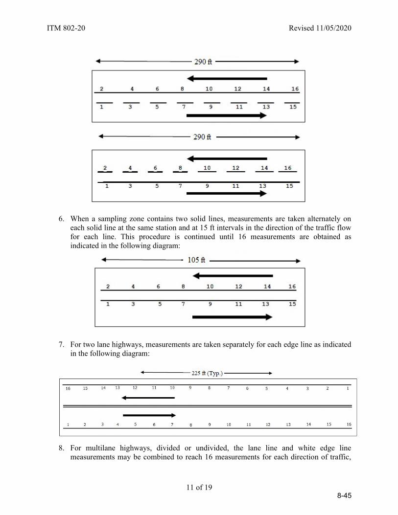
ITM 802-20 Revised 11/05/2020
11 of 19
6. When a sampling zone contains two solid lines, measurements are taken alternately on each solid line at the same station and at 15 ft intervals in the direction of the traffic flow for each line. This procedure is continued until 16 measurements are obtained as indicated in the following diagram:
7. For two lane highways, measurements are taken separately for each edge line as indicated in the following diagram:
8. For multilane highways, divided or undivided, the lane line and white edge line
measurements may be combined to reach 16 measurements for each direction of traffic,
8-45

ITM 802-20 Revised 11/05/2020
12 of 19
provided the markings were applied on the same day, as indicated in the following diagram:
Soil Embankment – DCP/LWD Measurements
The testing frequency for Light Weight Deflectometer (LWD) or Dynamic Cone Penetrometer (DCP) testing is based on the volume of material placed. The volume of material for a given lift thickness is converted to an area and the area is converted to a length and width based on the geometry of the lift to be tested. The station at which a LWD or DCP test is taken is determined using the length of embankment construction area. Three LWD tests will be taken at the random station at 2 ft from each edge of the construction area and at 1/2 of the width of the construction area. One DCP test will be obtained at the random station. The transverse distance for the DCP test is determined using the width of the embankment being placed and is measured from the right edge of the construction area determined by looking in the direction of increasing station numbers. Computations for the longitudinal distance and transverse distance are made to the nearest 1 ft.
DCP Example:
The construction area for a soil embankment 6 in. lift is determined to start at station 10+00 and the width of the construction area is 38 ft. The frequency of testing is one test for each 1400 yd3.
Convert 1400 yd3 to the length of embankment placed:
ft 1989 ft 1
in. 12 x
in. 6
1 x
ft 38
1 x
yd 1
ft 27 x yd 1400
3
33
Random Numbers = 0.420, 0.607 Longitudinal Distance = 1989 x 0.420 = 835 4 ft (Say 835 ft) Random Station = (10+00) + (8+35) = 18+35 Transverse Distance = 38 x 0.607 = 23.1 ft (Say 23 ft)
8-46
ITM 802-20 Revised 11/05/2020
13 of 19
5.5 Random Target Area.
5.5.1 Determine the area from which a random location is required to the nearest 1 yd2
5.5.2 Divide the area by 100 and round down to the nearest whole number. The
resulting number will be the number of segments within the area that are available for sampling.
5.5.3 Divide the area by the number of sample segments to determine the
sample segment size to the nearest 1 yd2
5.5.4 Select a random number in accordance with 4.0
5.5.5 Multiply the number of sample segments by the random number and round down to the nearest whole number. The resulting number represents the random target area. The sample will be taken from material placed within the random target area.
5.5.6 Divide the sample segment size by the width of the area and round to the
nearest 0.1 ft length. The resulting number is the length of the random target area.
5.5.7 Multiply the random target area by the length of the random target area
and round to the nearest whole foot. The resulting number will be the distance to the beginning of the random target area as measured from the start of the area to be sampled.
Portland Cement Concrete Pavement (PCCP) -- Plastic Concrete Samples.
The location of the random target area is determined for each sublot. The PCCP sample is taken from material placed within the random target area.
Example No. 1:
A PCCP is being placed at a width of 12 ft and the starting station of the sublot is 102+50. The sublot size is 2400 yd2.
24100
2400 Segments Sample ofNumber
2yd 10024
2400 SizeSegment Sample
Random Number = 0.830
8-47
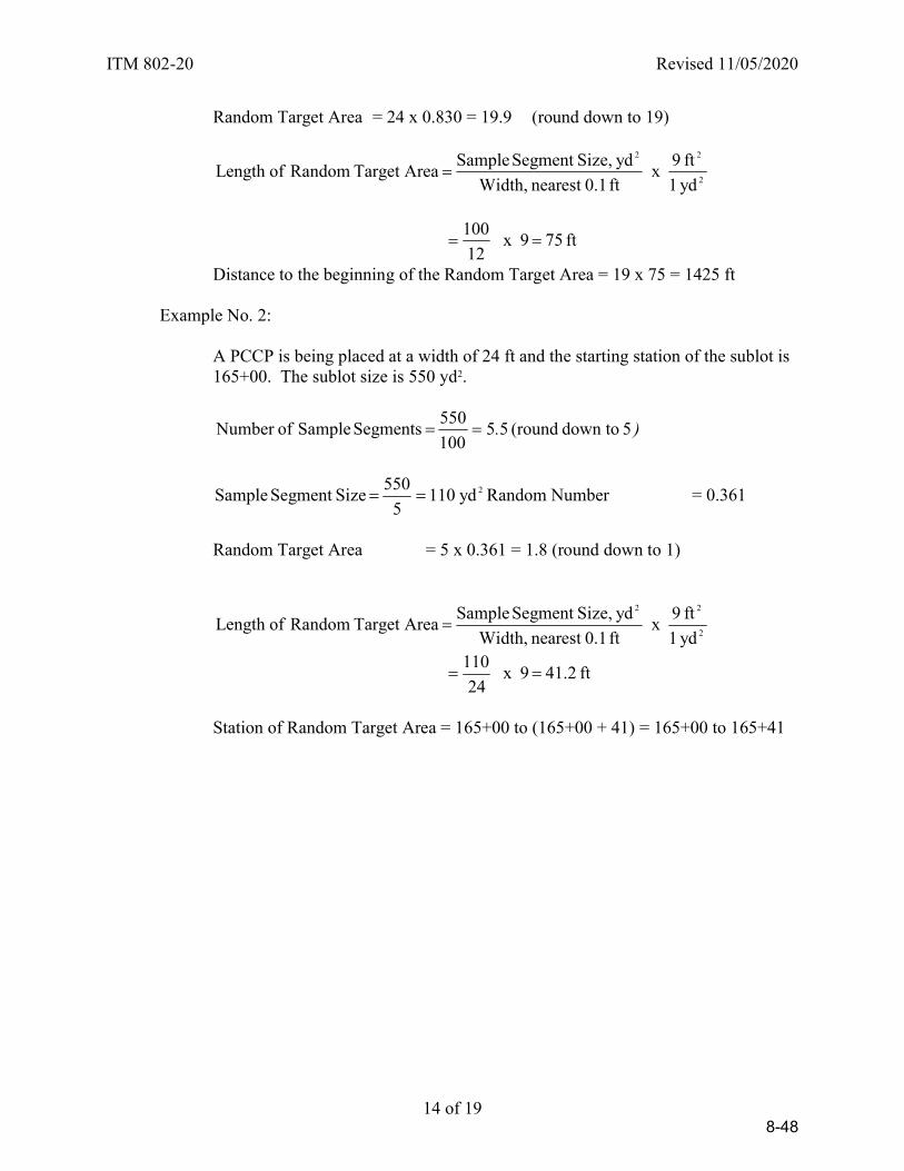
ITM 802-20 Revised 11/05/2020
14 of 19
Random Target Area = 24 x 0.830 = 19.9 (round down to 19)
2
22
yd 1
ft 9 x
ft 0.1nearest Width,
yd Size,Segment Sample AreaTarget Random ofLength
ft 75 9 x 12
100
Distance to the beginning of the Random Target Area = 19 x 75 = 1425 ft
Example No. 2:
A PCCP is being placed at a width of 24 ft and the starting station of the sublot is 165+00. The sublot size is 550 yd2.
). 5 down to (round 55100
550 Segments Sample ofNumber
2yd 110
5
550 SizeSegment Sample Random Number = 0.361
Random Target Area = 5 x 0.361 = 1.8 (round down to 1)
2
22
yd 1
ft 9 x
ft 0.1nearest Width,
yd Size,Segment Sample AreaTarget Random ofLength
ft 41.2 9 x 24
110
Station of Random Target Area = 165+00 to (165+00 + 41) = 165+00 to 165+41
8-48
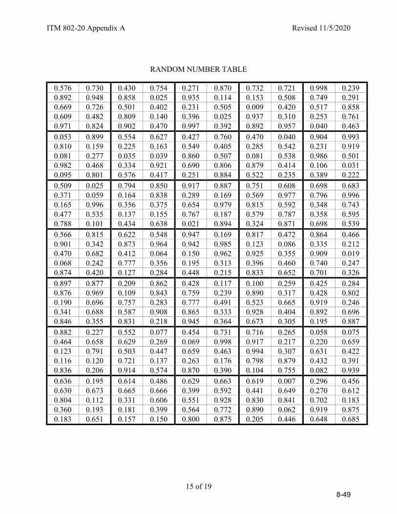
ITM 802-20 Appendix A Revised 11/5/2020
15 of 19
RANDOM NUMBER TABLE
0.576 0.730 0.430 0.754 0.271 0.870 0.732 0.721 0.998 0.239 0.892 0.948 0.858 0.025 0.935 0.114 0.153 0.508 0.749 0.291 0.669 0.726 0.501 0.402 0.231 0.505 0.009 0.420 0.517 0.858 0.609 0.482 0.809 0.140 0.396 0.025 0.937 0.310 0.253 0.761 0.971 0.824 0.902 0.470 0.997 0.392 0.892 0.957 0.040 0.463
0.053 0.899 0.554 0.627 0.427 0.760 0.470 0.040 0.904 0.993 0.810 0.159 0.225 0.163 0.549 0.405 0.285 0.542 0.231 0.919 0.081 0.277 0.035 0.039 0.860 0.507 0.081 0.538 0.986 0.501 0.982 0.468 0.334 0.921 0.690 0.806 0.879 0.414 0.106 0.031 0.095 0.801 0.576 0.417 0.251 0.884 0.522 0.235 0.389 0.222
0.509 0.025 0.794 0.850 0.917 0.887 0.751 0.608 0.698 0.683 0.371 0.059 0.164 0.838 0.289 0.169 0.569 0.977 0.796 0.996 0.165 0.996 0.356 0.375 0.654 0.979 0.815 0.592 0.348 0.743 0.477 0.535 0.137 0.155 0.767 0.187 0.579 0.787 0.358 0.595 0.788 0.101 0.434 0.638 0.021 0.894 0.324 0.871 0.698 0.539
0.566 0.815 0.622 0.548 0.947 0.169 0.817 0.472 0.864 0.466 0.901 0.342 0.873 0.964 0.942 0.985 0.123 0.086 0.335 0.212 0.470 0.682 0.412 0.064 0.150 0.962 0.925 0.355 0.909 0.019 0.068 0.242 0.777 0.356 0.195 0.313 0.396 0.460 0.740 0.247 0.874 0.420 0.127 0.284 0.448 0.215 0.833 0.652 0.701 0.326
0.897 0.877 0.209 0.862 0.428 0.117 0.100 0.259 0.425 0.284 0.876 0.969 0.109 0.843 0.759 0.239 0.890 0.317 0.428 0.802 0.190 0.696 0.757 0.283 0.777 0.491 0.523 0.665 0.919 0.246 0.341 0.688 0.587 0.908 0.865 0.333 0.928 0.404 0.892 0.696 0.846 0.355 0.831 0.218 0.945 0.364 0.673 0.305 0.195 0.887
0.882 0.227 0.552 0.077 0.454 0.731 0.716 0.265 0.058 0.075 0.464 0.658 0.629 0.269 0.069 0.998 0.917 0.217 0.220 0.659 0.123 0.791 0.503 0.447 0.659 0.463 0.994 0.307 0.631 0.422 0.116 0.120 0.721 0.137 0.263 0.176 0.798 0.879 0.432 0.391 0.836 0.206 0.914 0.574 0.870 0.390 0.104 0.755 0.082 0.939
0.636 0.195 0.614 0.486 0.629 0.663 0.619 0.007 0.296 0.456 0.630 0.673 0.665 0.666 0.399 0.592 0.441 0.649 0.270 0.612 0.804 0.112 0.331 0.606 0.551 0.928 0.830 0.841 0.702 0.183 0.360 0.193 0.181 0.399 0.564 0.772 0.890 0.062 0.919 0.875 0.183 0.651 0.157 0.150 0.800 0.875 0.205 0.446 0.648 0.685
8-49
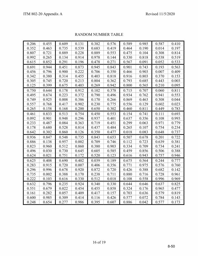
ITM 802-20 Appendix A Revised 11/5/2020
16 of 19
RANDOM NUMBER TABLE
0.206 0.455 0.609 0.131 0.382 0.576 0.589 0.985 0.587 0.410 0.352 0.463 0.735 0.539 0.683 0.419 0.464 0.190 0.014 0.197 0.807 0.721 0.889 0.228 0.889 0.553 0.475 0.104 0.308 0.814 0.992 0.265 0.134 0.914 0.978 0.144 0.330 0.818 0.538 0.519 0.615 0.852 0.291 0.196 0.478 0.271 0.567 0.091 0.052 0.533 0.691 0.944 0.451 0.873 0.945 0.843 0.901 0.743 0.193 0.563 0.456 0.796 0.900 0.222 0.706 0.350 0.466 0.903 0.007 0.409 0.342 0.380 0.314 0.455 0.403 0.818 0.916 0.803 0.370 0.153 0.305 0.745 0.720 0.213 0.804 0.362 0.793 0.685 0.443 0.003 0.125 0.399 0.675 0.403 0.269 0.942 0.800 0.565 0.210 0.095 0.750 0.644 0.178 0.912 0.102 0.378 0.715 0.707 0.060 0.811 0.495 0.674 0.223 0.372 0.790 0.496 0.934 0.762 0.941 0.553 0.749 0.925 0.008 0.386 0.170 0.266 0.869 0.463 0.308 0.044 0.557 0.768 0.417 0.902 0.230 0.775 0.556 0.129 0.602 0.023 0.265 0.158 0.168 0.200 0.650 0.302 0.460 0.811 0.449 0.783 0.461 0.833 0.513 0.754 0.450 0.553 0.154 0.741 0.111 0.693 0.092 0.901 0.948 0.296 0.937 0.401 0.637 0.356 0.108 0.993 0.233 0.487 0.084 0.363 0.719 0.451 0.299 0.063 0.971 0.779 0.178 0.680 0.528 0.814 0.437 0.484 0.265 0.107 0.754 0.234 0.642 0.302 0.860 0.126 0.350 0.477 0.018 0.083 0.648 0.737 0.936 0.847 0.548 0.735 0.843 0.653 0.507 0.678 0.201 0.722 0.886 0.138 0.957 0.002 0.709 0.746 0.112 0.723 0.639 0.381 0.823 0.960 0.512 0.860 0.380 0.903 0.334 0.709 0.734 0.241 0.496 0.030 0.730 0.645 0.605 0.585 0.459 0.856 0.506 0.388 0.624 0.021 0.751 0.172 0.520 0.123 0.616 0.943 0.757 0.946 0.625 0.408 0.690 0.402 0.039 0.189 0.675 0.564 0.244 0.777 0.283 0.915 0.720 0.007 0.406 0.356 0.771 0.975 0.576 0.760 0.296 0.996 0.678 0.920 0.872 0.720 0.426 0.388 0.682 0.142 0.735 0.002 0.388 0.170 0.238 0.711 0.880 0.716 0.728 0.961 0.222 0.103 0.616 0.330 0.512 0.018 0.108 0.558 0.996 0.969 0.632 0.796 0.235 0.924 0.340 0.330 0.644 0.646 0.637 0.825 0.551 0.679 0.022 0.454 0.455 0.858 0.324 0.176 0.965 0.477 0.161 0.282 0.057 0.409 0.417 0.157 0.703 0.636 0.579 0.819 0.600 0.985 0.309 0.414 0.116 0.426 0.577 0.072 0.784 0.143 0.248 0.654 0.277 0.986 0.395 0.607 0.886 0.042 0.577 0.173
8-50

ITM 802-20 Appendix A Revised 11/5/2020
17 of 19
RANDOM NUMBER TABLE
0.779 0.284 0.210 0.877 0.351 0.611 0.544 0.091 0.483 0.778 0.438 0.495 0.264 0.694 0.005 0.970 0.594 0.757 0.710 0.912 0.071 0.491 0.689 0.601 0.408 0.360 0.483 0.766 0.541 0.674 0.691 0.646 0.759 0.965 0.337 0.494 0.054 0.846 0.485 0.772 0.075 0.270 0.325 0.371 0.381 0.590 0.868 0.643 0.597 0.233 0.888 0.375 0.489 0.450 0.263 0.842 0.586 0.862 0.153 0.228 0.613 0.838 0.358 0.725 0.958 0.146 0.424 0.601 0.363 0.895 0.639 0.967 0.636 0.724 0.495 0.357 0.132 0.797 0.098 0.665 0.272 0.257 0.765 0.217 0.339 0.928 0.241 0.464 0.608 0.348 0.041 0.365 0.358 0.628 0.208 0.297 0.028 0.062 0.326 0.765 0.795 0.849 0.984 0.550 0.453 0.592 0.216 0.100 0.179 0.257 0.961 0.325 0.114 0.732 0.829 0.637 0.706 0.950 0.977 0.265 0.840 0.934 0.012 0.949 0.269 0.581 0.872 0.310 0.763 0.893 0.738 0.848 0.613 0.699 0.129 0.781 0.263 0.397 0.688 0.198 0.594 0.960 0.898 0.519 0.034 0.853 0.070 0.136 0.151 0.829 0.569 0.905 0.347 0.957 0.034 0.302 0.594 0.708 0.529 0.219 0.358 0.828 0.920 0.887 0.349 0.491 0.616 0.785 0.460 0.572 0.458 0.763 0.207 0.483 0.203 0.996 0.186 0.076 0.647 0.883 0.060 0.145 0.114 0.934 0.733 0.786 0.961 0.241 0.172 0.995 0.401 0.248 0.516 0.911 0.669 0.991 0.999 0.617 0.547 0.969 0.964 0.458 0.356 0.414 0.953 0.176 0.987 0.381 0.256 0.309 0.118 0.918 0.142 0.540 0.448 0.889 0.555 0.205 0.879 0.362 0.254 0.600 0.806 0.126 0.299 0.754 0.373 0.779 0.594 0.301 0.254 0.838 0.398 0.389 0.970 0.018 0.132 0.512 0.569 0.608 0.427 0.410 0.434 0.847 0.787 0.001 0.524 0.828 0.448 0.087 0.342 0.746 0.382 0.662 0.670 0.065 0.133 0.067 0.958 0.630 0.112 0.129 0.663 0.666 0.018 0.522 0.454 0.813 0.405 0.698 0.767 0.879 0.390 0.279 0.994 0.474 0.004 0.831 0.323 0.414 0.940 0.989 0.854 0.835 0.957 0.154 0.493 0.642 0.637 0.578 0.271 0.337 0.728 0.173 0.840 0.814 0.777 0.877 0.028 0.794 0.078 0.590 0.712 0.705 0.336 0.603 0.992 0.214 0.934 0.800 0.799 0.519 0.235 0.113 0.936 0.059 0.793 0.504 0.065 0.526 0.033 0.873 0.130 0.921 0.485 0.146 0.330 0.633 0.835 0.172 0.423 0.958 0.967 0.605 0.632 0.710 0.217 0.613 0.259 0.699 0.273 0.945 0.329 0.895 0.813 0.154 0.149 0.425 0.881 0.029
8-51

ITM 802-20 Appendix A Revised 11/5/2020
18 of 19
RANDOM NUMBER TABLE
0.731 0.731 0.423 0.958 0.950 0.212 0.700 0.267 0.448 0.975 0.799 0.629 0.160 0.292 0.932 0.083 0.068 0.763 0.794 0.785 0.061 0.225 0.782 0.150 0.006 0.645 0.422 0.666 0.818 0.182 0.272 0.685 0.643 0.687 0.945 0.205 0.461 0.399 0.588 0.677 0.941 0.170 0.982 0.792 0.435 0.142 0.244 0.140 0.395 0.295 0.428 0.330 0.534 0.376 0.903 0.036 0.165 0.725 0.200 0.736 0.618 0.542 0.219 0.787 0.114 0.594 0.833 0.070 0.114 0.450 0.080 0.806 0.777 0.185 0.473 0.341 0.810 0.462 0.811 0.736 0.190 0.444 0.671 0.642 0.726 0.451 0.955 0.952 0.859 0.929 0.343 0.766 0.809 0.365 0.646 0.768 0.717 0.848 0.053 0.545 0.281 0.633 0.189 0.261 0.950 0.549 0.906 0.164 0.921 .791 0.974 0.666 0.600 0.834 0.832 0.205 0.163 0.668 0.096 0.350 0.819 0.495 0.392 0.968 0.755 0.917 0.266 0.452 0.341 0.095 0.131 0.253 0.777 0.120 0.753 0.008 0.205 0.626 0.826 0.778 0.522 0.878 0.990 0.159 0.278 0.643 0.024 0.287 0.707 0.373 0.510 0.132 0.722 0.906 0.800 0.932 0.009 0.383 0.677 0.289 0.094 0.058 0.483 0.285 0.264 0.546 0.047 0.761 0.085 0.786 0.186 0.546 0.975 0.715 0.628 0.525 0.231 0.444 0.077 0.066 0.797 0.784 0.884 0.604 0.954 0.992 0.175 0.129 0.224 0.984 0.485 0.263 0.597 0.268 0.498 0.722 0.184 0.686 0.536 0.089 0.573 0.755 0.217 0.463 0.776 0.492 0.420 0.107 0.164 0.940 0.266 0.433 0.175 0.403 0.519 0.730 0.091 0.385 0.984 0.578 0.880 0.037 0.157 0.535 0.466 0.215 0.818 0.636 0.215 0.276 0.396 0.158 0.227 0.636 0.823 0.238 0.172 0.522 0.805 0.109 0.436 0.091 0.271 0.032 0.644 0.475 0.372 0.399 0.481 0.605 0.850 0.863 0.748 0.453 0.925 0.418 0.018 0.570 0.834 0.079 0.839 0.866 0.943 0.093 0.493 0.530 0.995 0.282 0.544 0.532 0.103 0.528 0.632 0.643 0.780 0.752 0.974 0.850 0.997 0.303 0.218 0.786 0.065 0.149 0.903 0.049 0.223 0.487 0.242 0.559 0.693 0.355 0.412 0.535 0.878 0.121 0.031 0.919 0.710 0.069 0.339 0.521 0.001 0.297 0.190 0.802 0.682 0.836 0.694 0.242 0.515 0.885 0.494 0.739 0.373 0.058 0.026 0.386 0.658 0.455 0.076 0.471 0.334 0.422 0.136 0.871 0.818 0.790 0.365 0.276 0.367 0.901 0.023 0.530 0.992 0.758 0.821 0.399 0.926 0.974 0.795 0.218 0.884 0.070 0.291 0.436 0.905 0.271 0.181 0.881
8-52

ITM 802-20 Appendix A Revised 11/5/2020
19 of 19
RANDOM NUMBER TABLE
0.344 0.569 0.290 0.243 0.451 0.836 0.596 0.159 0.878 0.107 0.409 0.991 0.666 0.609 0.026 0.620 0.772 0.318 0.987 0.197 0.375 0.596 0.892 0.472 0.916 0.252 0.988 0.470 0.980 0.566 0.547 0.253 0.020 0.474 0.462 0.096 0.515 0.729 0.251 0.676 0.350 0.802 0.627 0.825 0.866 0.765 0.999 0.268 0.058 0.968 0.885 0.786 0.077 0.805 0.089 0.953 0.055 0.825 0.436 0.330 0.389 0.889 0.169 0.491 0.804 0.132 0.862 0.703 0.558 0.808 0.839 0.142 0.211 0.099 0.662 0.627 0.919 0.012 0.104 0.378 0.100 0.781 0.332 0.776 0.546 0.370 0.524 0.470 0.919 0.796 0.510 0.331 0.467 0.221 0.364 0.434 0.386 0.642 0.077 0.456 0.481 0.599 0.085 0.647 0.500 0.120 0.592 0.103 0.702 0.999 0.213 0.195 0.999 0.470 0.268 0.215 0.220 0.043 0.360 0.024 0.431 0.730 0.905 0.420 0.210 0.805 0.723 0.137 0.156 0.031 0.029 0.832 0.713 0.435 0.520 0.503 0.452 0.981 0.633 0.118 0.240 0.329 0.015 0.550 0.088 0.086 0.325 0.397 0.061 0.806 0.906 0.743 0.882 0.924 0.310 0.456 0.396 0.784 0.686 0.184 0.559 0.408 0.245 0.212 0.802 0.017 0.841 0.598 0.142 0.228 0.161 0.678 0.660 0.388 0.964 0.169 0.184 0.237 0.222 0.328 0.068 0.035 0.547 0.227 0.818 0.008 0.467 0.353 0.615 0.264 0.459 0.348 0.664 0.718 0.920 0.382 0.824 0.039 0.462 0.235 0.541 0.776 0.752 0.366 0.016 0.827 0.608 0.923 0.601 0.087 0.517 0.859 0.217 0.074 0.766 0.689 0.650 0.404 0.729 0.980 0.669 0.598 0.372 0.594 0.043 0.378 0.416 0.857 0.039 0.905 0.274 0.385 0.352 0.367 0.149 0.327 0.160 0.283 0.840 0.708 0.235 0.165 0.658 0.567 0.982 0.094 0.690 0.319 0.605 0.706 0.881 0.556 0.066 0.062 0.614 0.018 0.030 0.035 0.728 0.859 0.326 0.663 0.566 0.470 0.421 0.477 0.066 0.018 0.825 0.434 0.683 0.304 0.968 0.239 0.663 0.236 0.277 0.317 0.214 0.478 0.618 0.944 0.985 0.105 0.540 0.183 0.748 0.009 0.353 0.963 0.925 0.226 0.388 0.513 0.526 0.718 0.539 0.924 0.442 0.197 0.685 0.943 0.431 0.317 0.476 0.228 0.414 0.064 0.955 0.340 0.658 0.412 0.512 0.885 0.685 0.636 0.851 0.584 0.048 0.951 0.869 0.495 0.608 0.567 0.035 0.493 0.500 0.229 0.826 0.337 0.125 0.157 0.056 0.436 0.657 0.602 0.823 0.453 0.823 0.099 0.569 0.998 0.733 0.097 0.268 0.640 0.272 0.718 0.153 0.644
8-53

Revised 2/26/2020
Page 1 of 4
INDIANA DEPARTMENT OF TRANSPORTATION OFFICE OF MATERIALS MANAGEMENT
VERIFYING SIEVES
ITM No. 902-20 1.0 SCOPE
1.1 This test method covers the procedure for verifying the physical condition of laboratory testing sieves ranging in size from 4 in. to No. 200.
1.2 Two procedures are included in this test method: verifying with calipers and
verifying with a go-no go gauge. The Department will use the verifying with calipers method. Industry may utilize the procedure with a go-no go gauge upon approval of the Department.
1.3 This ITM may involve hazardous materials, operations, and equipment and may
not address all of the safety problems associated with the use of the test method. The user of the ITM is responsible for establishing appropriate safety and health practices and to determining the applicability of regulatory limitations prior to use.
2.0 REFERENCES.
2.1 ASTM Standards. E11 - Woven Wire Test Sieve Cloth and Test Sieves
3.0 TERMINOLOGY. Definitions for terms and abbreviations shall be in accordance with
the Department's Standard Specifications, Section 101. 4.0 SIGNIFICANCE AND USE. This ITM is used by laboratory personnel to verify the
physical condition of testing sieves. 5.0 APPARATUS.
5.1 Calipers, readable to 0.01 mm and having a jaw depth allowing the blades to stay perpendicular to the screen throughout the measurements. 5.2 [Optional] Go-No Go Gauge, conforming to the tolerances shown in Table 1.
6.0 PROCEDURE.
6.1 Sieves #4 and Coarser With Calipers.
6.1.1 Record the sieve identification, manufacturer, opening size and diameter.
8-54
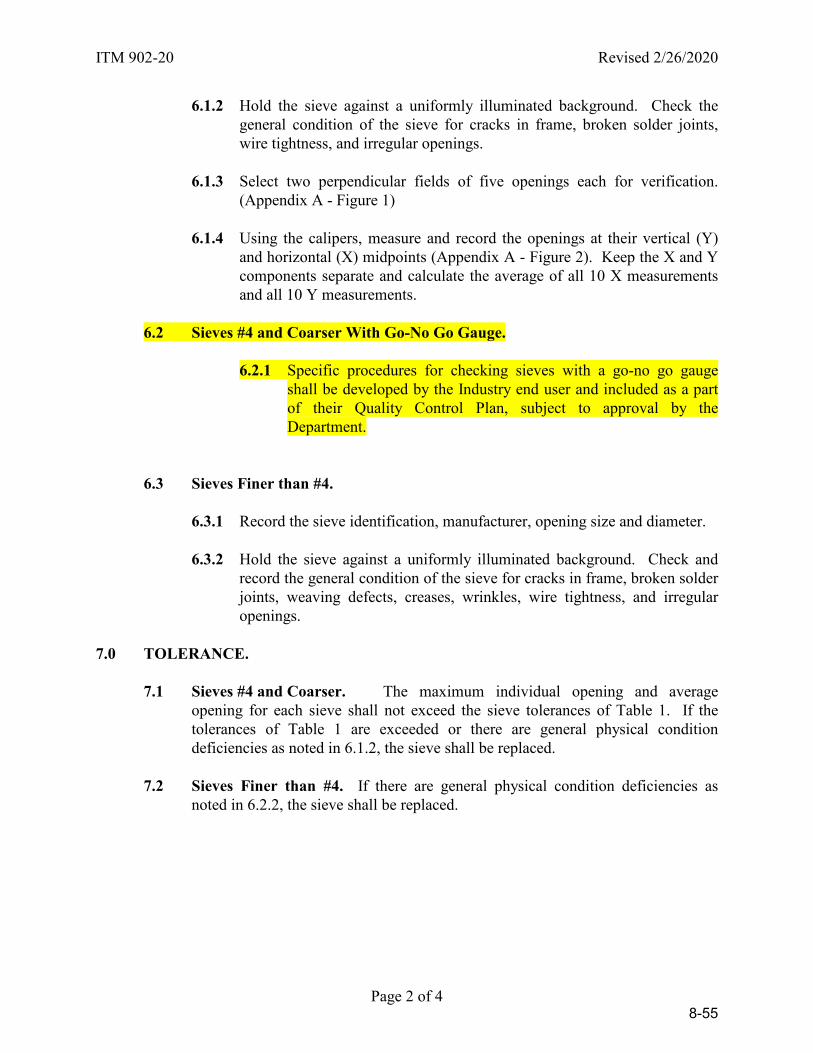
ITM 902-20 Revised 2/26/2020
Page 2 of 4
6.1.2 Hold the sieve against a uniformly illuminated background. Check the general condition of the sieve for cracks in frame, broken solder joints, wire tightness, and irregular openings.
6.1.3 Select two perpendicular fields of five openings each for verification.
(Appendix A - Figure 1)
6.1.4 Using the calipers, measure and record the openings at their vertical (Y) and horizontal (X) midpoints (Appendix A - Figure 2). Keep the X and Y components separate and calculate the average of all 10 X measurements and all 10 Y measurements.
6.2 Sieves #4 and Coarser With Go-No Go Gauge.
6.2.1 Specific procedures for checking sieves with a go-no go gauge shall be developed by the Industry end user and included as a part of their Quality Control Plan, subject to approval by the Department.
6.3 Sieves Finer than #4.
6.3.1 Record the sieve identification, manufacturer, opening size and diameter.
6.3.2 Hold the sieve against a uniformly illuminated background. Check and record the general condition of the sieve for cracks in frame, broken solder joints, weaving defects, creases, wrinkles, wire tightness, and irregular openings.
7.0 TOLERANCE.
7.1 Sieves #4 and Coarser. The maximum individual opening and average opening for each sieve shall not exceed the sieve tolerances of Table 1. If the tolerances of Table 1 are exceeded or there are general physical condition deficiencies as noted in 6.1.2, the sieve shall be replaced.
7.2 Sieves Finer than #4. If there are general physical condition deficiencies as
noted in 6.2.2, the sieve shall be replaced.
8-55

ITM 902-20 Revised 2/26/2020
Page 3 of 4
SIEVE TOLERANCES
TABLE 1
Sieve Designation Permissible Average Opening
Maximum Individual Opening
100 mm (4 in.) (97.35 - 102.65) mm 103.44 mm
90 mm (3 ½ in.) (87.61 - 92.39) mm 93.18 mm
75 mm (3 in.) (73.00 - 77.00) mm 77.78 mm
63 mm (2 ½ in.) (61.31 - 64.69) mm 65.44 mm
50 mm (2 in.) (48.66 - 51.34) mm 52.06 mm
37.5 mm (1 ½ in.) (36.49 - 38.51) mm 39.17 mm
25 mm (1 in.) (24.32 - 25.68) mm 26.24 mm
19 mm (3/4 in.) (18.48-19.52) mm 20.01 mm
12.5 mm (1/2 in.) (12.15 - 12.85) mm 13.25 mm
9.5 mm (3/8 in.) (9.24 - 9.76) mm 10.11 mm
4.75 mm (No. 4) (4.62 - 4.88) mm 5.12 mm
Tolerances for sieves not in Table 1 may be found in ASTM E11
8-56
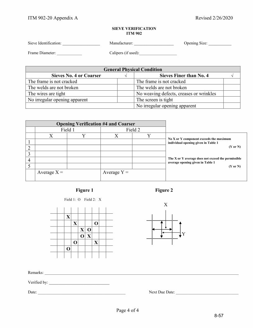
ITM 902-20 Appendix A Revised 2/26/2020
Page 4 of 4
SIEVE VERIFICATION ITM 902
Sieve Identification: __________________ Manufacturer: ___________________ Opening Size: ___________ Frame Diameter: ____________ Calipers (if used):__________________
General Physical Condition Sieves No. 4 or Coarser √ Sieves Finer than No. 4 √
The frame is not cracked The frame is not cracked The welds are not broken The welds are not broken The wires are tight No weaving defects, creases or wrinkles No irregular opening apparent The screen is tight No irregular opening apparent
Opening Verification #4 and Coarser
Field 1 Field 2 X Y X Y
No X or Y component exceeds the maximum individual opening given in Table 1 (Y or N) The X or Y average does not exceed the permissible average opening given in Table 1 (Y or N)
1 2 3 4 5 Average X = Average Y =
Figure 1 Figure 2 Field 1: O Field 2: X X
Y
Remarks: _____________________________________________________________________________________________ Verified by: _____________________________ Date: __________________________________________ Next Due Date: ______________________________
X X O X O O X O X O
8-57
Revised 2/26/2020
Page 1 of 6
INDIANA DEPARTMENT OF TRANSPORTATION OFFICE OF MATERIALS MANAGEMENT
VERIFICATION OF CALIPERS
ITM No. 916-20 1.0 SCOPE.
1.1 This test method covers the procedures for verifying the accuracy of calipers used for measuring the critical dimension of various testing equipment.
1.2 This ITM may involve hazardous materials, operations, and equipment and may
not address all of the safety problems associated with the use of the test method. The user of the ITM is responsible for establishing appropriate safety and health practices and determining the applicability of regulatory limitations prior to use.
2.0 TERMINOLOGY.
2.1 Accuracy. The degree of conformity of a measurement with the true value of the quantity measured.
2.2 National Institute of Standards and Technology (NIST). A federal technology
agency that develops and applies technology, measurements, and standards. 3.0 APPARATUS.
3.1 Set of gauge blocks including the 1.000”, 3.000”, 6.000” and 12.000” (if applicable) having NIST traceability documentation which includes parallelism verification and certified within the last 24 months.
3.2 Calipers readable to the nearest 0.001 in.
3.3 Rubber band 3.4 Thermometer having a range of at least 68°F-77°F. 3.5 Record all measurements on Appendix A
4.0 SIGNIFICANCE AND USE. This ITM is used by laboratory personnel to determine
the accuracy of calipers. Verification should be performed in an environment that the ambient temperature will be between 68°F-77°F.
8-58
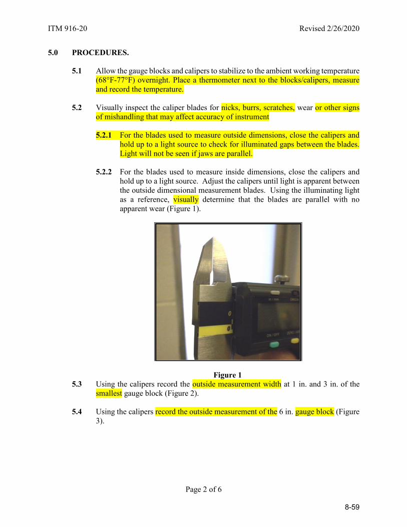
ITM 916-20 Revised 2/26/2020
Page 2 of 6
5.0 PROCEDURES.
5.1 Allow the gauge blocks and calipers to stabilize to the ambient working temperature (68°F-77°F) overnight. Place a thermometer next to the blocks/calipers, measure and record the temperature.
5.2 Visually inspect the caliper blades for nicks, burrs, scratches, wear or other signs
of mishandling that may affect accuracy of instrument
5.2.1 For the blades used to measure outside dimensions, close the calipers and hold up to a light source to check for illuminated gaps between the blades. Light will not be seen if jaws are parallel.
5.2.2 For the blades used to measure inside dimensions, close the calipers and
hold up to a light source. Adjust the calipers until light is apparent between the outside dimensional measurement blades. Using the illuminating light as a reference, visually determine that the blades are parallel with no apparent wear (Figure 1).
Figure 1 5.3 Using the calipers record the outside measurement width at 1 in. and 3 in. of the
smallest gauge block (Figure 2).
5.4 Using the calipers record the outside measurement of the 6 in. gauge block (Figure 3).
8-59
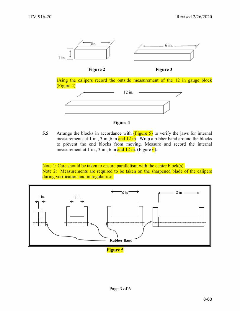
ITM 916-20 Revised 2/26/2020
Page 3 of 6
Figure 2 Figure 3
Using the calipers record the outside measurement of the 12 in gauge block (Figure 4)
Figure 4
5.5 Arrange the blocks in accordance with (Figure 5) to verify the jaws for internal measurements at 1 in., 3 in.,6 in and 12 in. Wrap a rubber band around the blocks to prevent the end blocks from moving. Measure and record the internal measurement at 1 in., 3 in., 6 in and 12 in. (Figure 6).
Note 1: Care should be taken to ensure parallelism with the center block(s). Note 2: Measurements are required to be taken on the sharpened blade of the calipers during verification and in regular use.
Figure 5
8-60
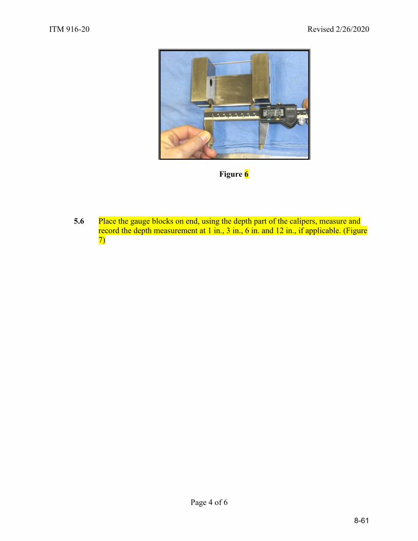
ITM 916-20 Revised 2/26/2020
Page 4 of 6
Figure 6
5.6 Place the gauge blocks on end, using the depth part of the calipers, measure and
record the depth measurement at 1 in., 3 in., 6 in. and 12 in., if applicable. (Figure 7)
8-61
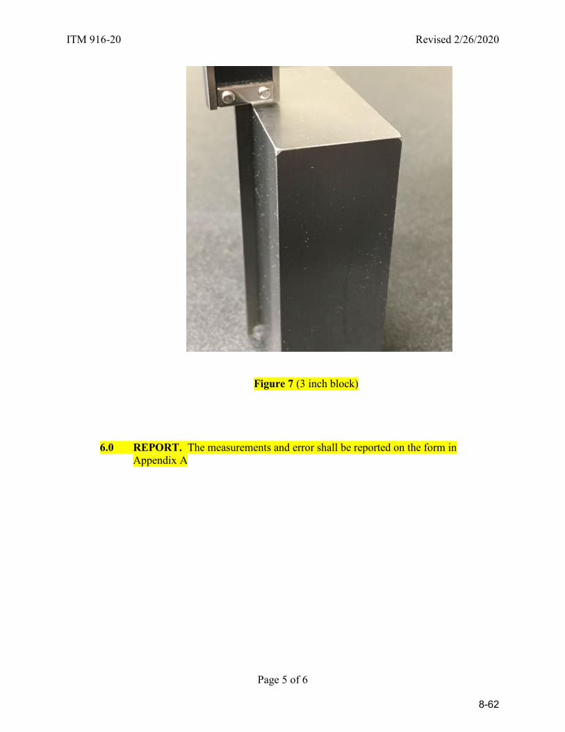
ITM 916-20 Revised 2/26/2020
Page 5 of 6
Figure 7 (3 inch block)
6.0 REPORT. The measurements and error shall be reported on the form in Appendix A
8-62
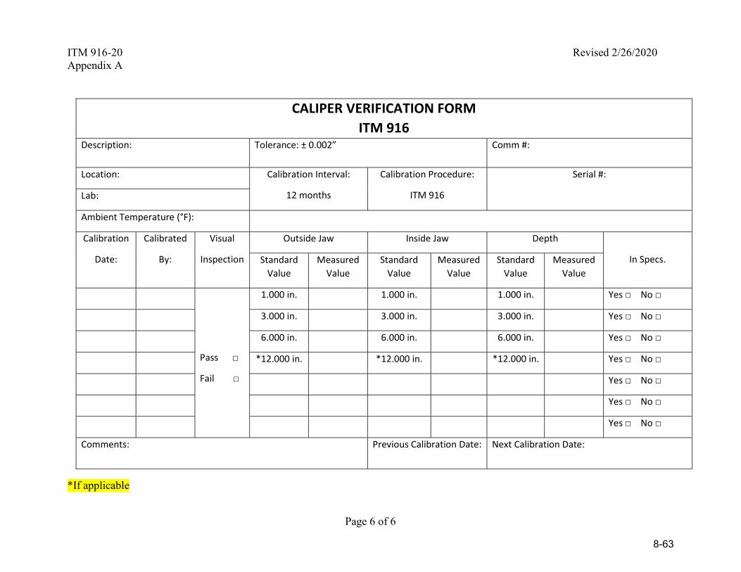
ITM 916-20 Revised 2/26/2020 Appendix A
Page 6 of 6
CALIPER VERIFICATION FORM ITM 916
Description: Tolerance: ± 0.002” Comm #:
Location: Calibration Interval:
12 months
Calibration Procedure:
ITM 916
Serial #:
Lab:
Ambient Temperature (°F):
Calibration
Date:
Calibrated
By:
Visual
Inspection
Outside Jaw Inside Jaw Depth
In Specs. Standard Value
Measured Value
Standard Value
Measured Value
Standard Value
Measured Value
Pass □
Fail □
1.000 in. 1.000 in. 1.000 in. Yes □ No □
3.000 in. 3.000 in. 3.000 in. Yes □ No □
6.000 in. 6.000 in. 6.000 in. Yes □ No □
*12.000 in. *12.000 in. *12.000 in. Yes □ No □
Yes □ No □
Yes □ No □
Yes □ No □
Comments: Previous Calibration Date: Next Calibration Date:
*If applicable
8-63
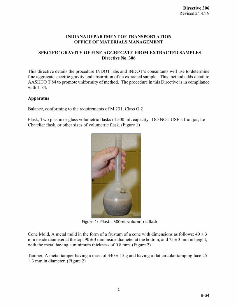
Directive 306
Revised 2/14/19
1
INDIANA DEPARTMENT OF TRANSPORTATION
OFFICE OF MATERIALS MANAGEMENT
SPECIFIC GRAVITY OF FINE AGGREGATE FROM EXTRACTED SAMPLES Directive No. 306
This directive details the procedure INDOT labs and INDOT’s consultants will use to determine fine aggregate specific gravity and absorption of an extracted sample. This method adds detail to AASHTO T 84 to promote uniformity of method. The procedure in this Directive is in compliance with T 84. Apparatus Balance, conforming to the requirements of M 231, Class G 2 Flask, Two plastic or glass volumetric flasks of 500 mL capacity. DO NOT USE a fruit jar, Le Chatelier flask, or other sizes of volumetric flask. (Figure 1)
Figure 1: Plastic 500mL volumetric flask
Cone Mold, A metal mold in the form of a frustum of a cone with dimensions as follows: 40 ± 3 mm inside diameter at the top, 90 ± 3 mm inside diameter at the bottom, and 75 ± 3 mm in height, with the metal having a minimum thickness of 0.8 mm. (Figure 2) Tamper, A metal tamper having a mass of 340 ± 15 g and having a flat circular tamping face 25 ± 3 mm in diameter. (Figure 2)
8-64

Directive 306
Revised 2/14/19
2
Figure 2: Cone Mold and Tamper
Fine aggregate splitter, in accordance with AASHTO R 76. (Figure 3)
Figure 3: Fine Aggregate Splitter
Flat, non-absorbent pan, and two smaller pans. (Figures 4 and 5)
8-65

Directive 306
Revised 2/14/19
3
Figure 4: Flat, non-absorbent pan
Figure 5: Two smaller pans
Small space heater, similar to type shown in Figure 6.
8-66
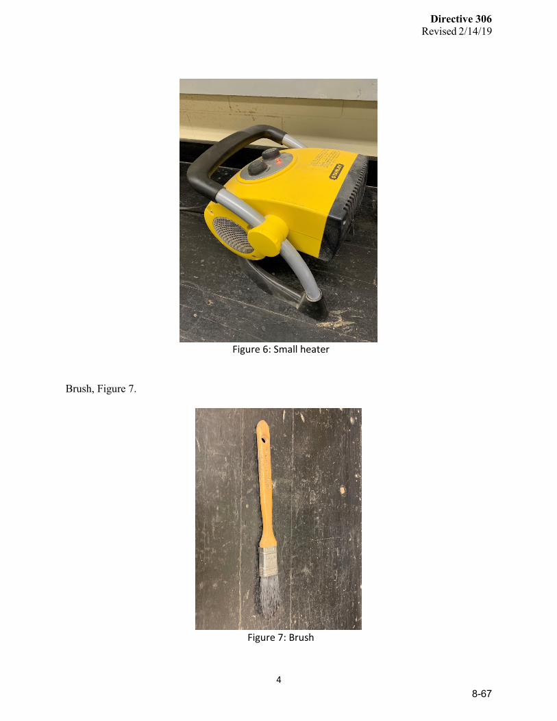
Directive 306
Revised 2/14/19
4
Figure 6: Small heater
Brush, Figure 7.
Figure 7: Brush
8-67
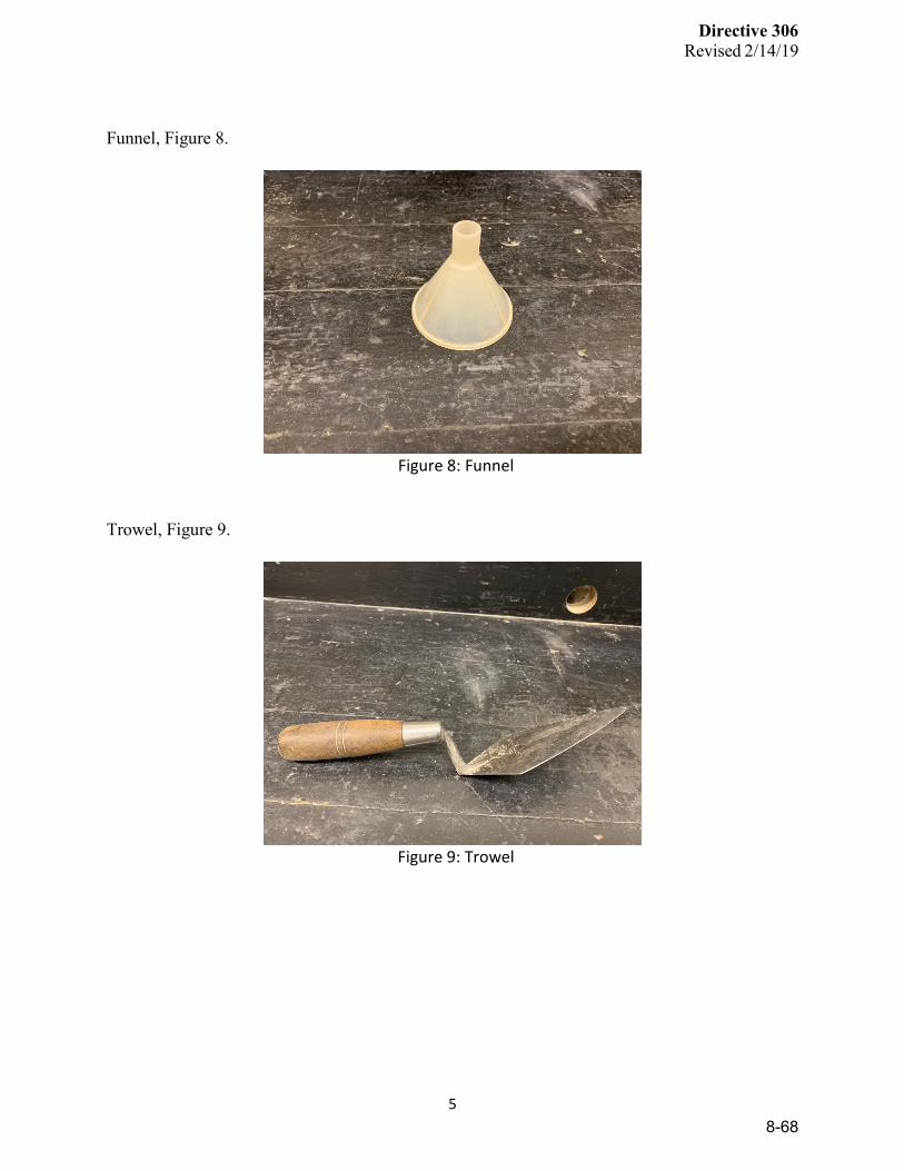
Directive 306
Revised 2/14/19
5
Funnel, Figure 8.
Figure 8: Funnel
Trowel, Figure 9.
Figure 9: Trowel
8-68

Directive 306
Revised 2/14/19
6
Squeeze bottle, Figure 10.
Figure 10: Squeeze Bottle
#200 sieve, Figure 11.
Figure 11: #200 Sieve
8-69
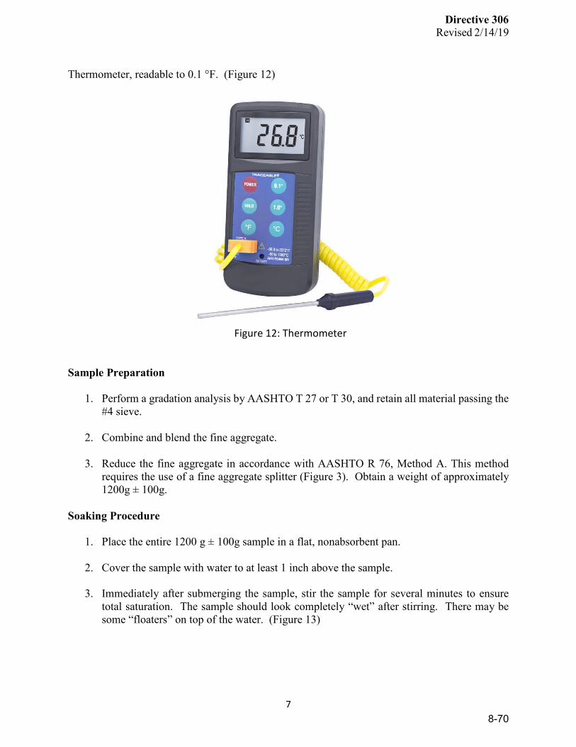
Directive 306
Revised 2/14/19
7
Thermometer, readable to 0.1 °F. (Figure 12)
Figure 12: Thermometer
Sample Preparation
1. Perform a gradation analysis by AASHTO T 27 or T 30, and retain all material passing the #4 sieve.
2. Combine and blend the fine aggregate.
3. Reduce the fine aggregate in accordance with AASHTO R 76, Method A. This method requires the use of a fine aggregate splitter (Figure 3). Obtain a weight of approximately 1200g ± 100g.
Soaking Procedure
1. Place the entire 1200 g ± 100g sample in a flat, nonabsorbent pan.
2. Cover the sample with water to at least 1 inch above the sample.
3. Immediately after submerging the sample, stir the sample for several minutes to ensure total saturation. The sample should look completely “wet” after stirring. There may be some “floaters” on top of the water. (Figure 13)
8-70
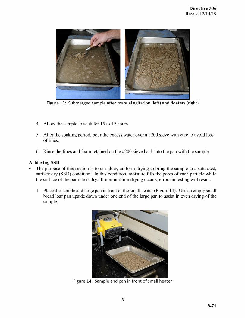
Directive 306
Revised 2/14/19
8
Figure 13: Submerged sample after manual agitation (left) and floaters (right)
4. Allow the sample to soak for 15 to 19 hours.
5. After the soaking period, pour the excess water over a #200 sieve with care to avoid loss of fines.
6. Rinse the fines and foam retained on the #200 sieve back into the pan with the sample.
Achieving SSD • The purpose of this section is to use slow, uniform drying to bring the sample to a saturated,
surface dry (SSD) condition. In this condition, moisture fills the pores of each particle while the surface of the particle is dry. If non-uniform drying occurs, errors in testing will result.
1. Place the sample and large pan in front of the small heater (Figure 14). Use an empty small
bread loaf pan upside down under one end of the large pan to assist in even drying of the sample.
Figure 14: Sample and pan in front of small heater
8-71
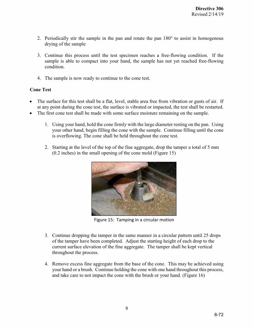
Directive 306
Revised 2/14/19
9
2. Periodically stir the sample in the pan and rotate the pan 180° to assist in homogenous
drying of the sample
3. Continue this process until the test specimen reaches a free-flowing condition. If the sample is able to compact into your hand, the sample has not yet reached free-flowing condition.
4. The sample is now ready to continue to the cone test.
Cone Test • The surface for this test shall be a flat, level, stable area free from vibration or gusts of air. If
at any point during the cone test, the surface is vibrated or impacted, the test shall be restarted. • The first cone test shall be made with some surface moisture remaining on the sample.
1. Using your hand, hold the cone firmly with the large diameter resting on the pan. Using
your other hand, begin filling the cone with the sample. Continue filling until the cone is overflowing. The cone shall be held throughout the cone test.
2. Starting at the level of the top of the fine aggregate, drop the tamper a total of 5 mm (0.2 inches) in the small opening of the cone mold (Figure 15)
Figure 15: Tamping in a circular motion
3. Continue dropping the tamper in the same manner in a circular pattern until 25 drops
of the tamper have been completed. Adjust the starting height of each drop to the current surface elevation of the fine aggregate. The tamper shall be kept vertical throughout the process.
4. Remove excess fine aggregate from the base of the cone. This may be achieved using your hand or a brush. Continue holding the cone with one hand throughout this process, and take care to not impact the cone with the brush or your hand. (Figure 16)
8-72
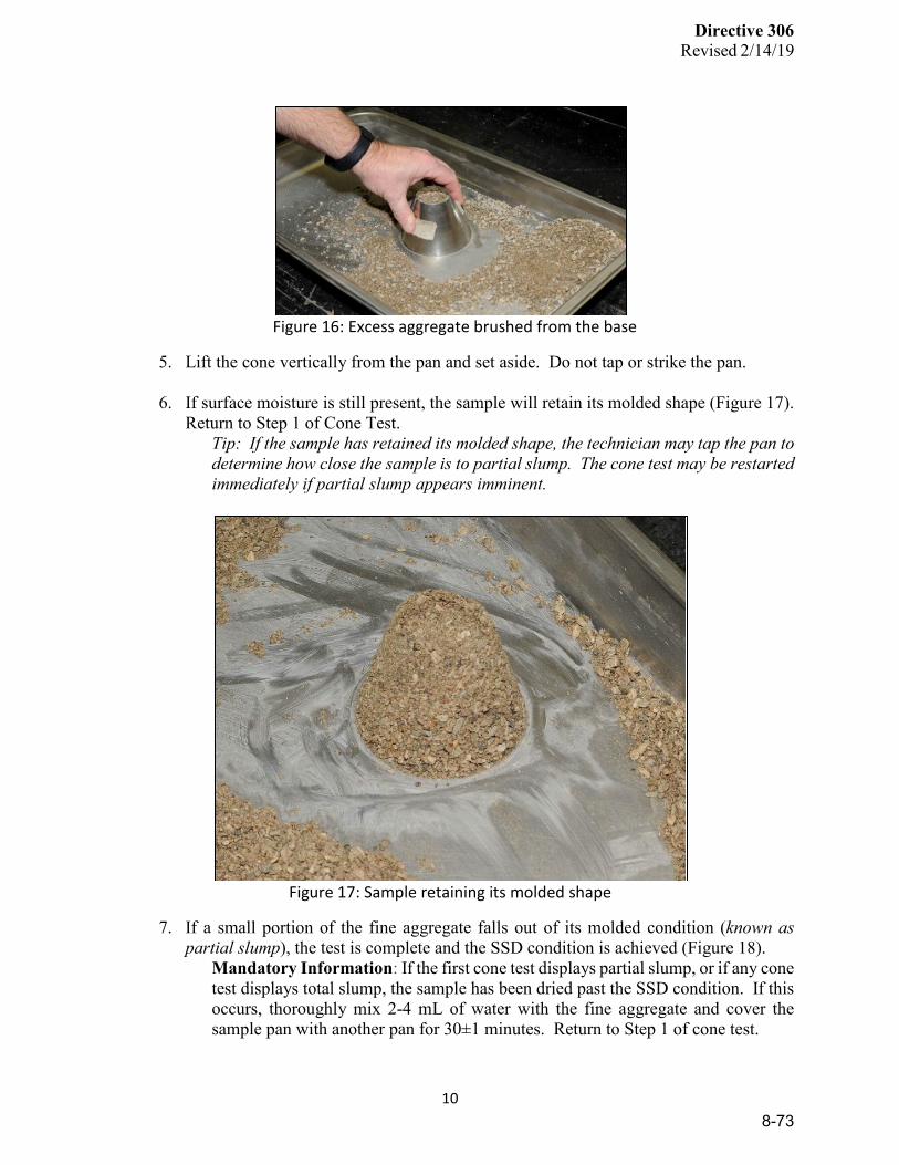
Directive 306
Revised 2/14/19
10
Figure 16: Excess aggregate brushed from the base
5. Lift the cone vertically from the pan and set aside. Do not tap or strike the pan. 6. If surface moisture is still present, the sample will retain its molded shape (Figure 17).
Return to Step 1 of Cone Test. Tip: If the sample has retained its molded shape, the technician may tap the pan to determine how close the sample is to partial slump. The cone test may be restarted immediately if partial slump appears imminent.
Figure 17: Sample retaining its molded shape
7. If a small portion of the fine aggregate falls out of its molded condition (known as partial slump), the test is complete and the SSD condition is achieved (Figure 18).
Mandatory Information: If the first cone test displays partial slump, or if any cone test displays total slump, the sample has been dried past the SSD condition. If this occurs, thoroughly mix 2-4 mL of water with the fine aggregate and cover the sample pan with another pan for 30±1 minutes. Return to Step 1 of cone test.
8-73

Directive 306
Revised 2/14/19
11
Figure 18: Sample displaying partial slump
Tip: Partial slump occurs when 25% - 75% of the top diameter of the cone “falls”, moves, or is otherwise disturbed after lifting the cone. Any less than that is not considered partial slump, and any more than that is considered total slump.
Tip: Partial slump is not typically an “apple core” or “dime size” area remaining in the center. This is typically considered total slump. However, these can be considered partial slump if they occur immediately (within a minute or two) after a test where the sample retained its molded shape. All fine aggregate samples are different and slumps can be different from sample to sample. A complete “pancake” of the sample is always considered total slump.
8-74

Directive 306
Revised 2/14/19
12
Determining Bulk Specific Gravity
Once partial slump has been achieved in the previous section, immediately prepare two fine aggregate samples for testing as follows:
1. Using a trowel, measure 500.0 ± 1.0 g of the sample into a small bread pan. Ensure a homogenous blend of the sample is represented in the 500g of material. Repeat for a second pan. Record as S Tip: The use of your fingers for “pinches” of material is acceptable to reach the prescribed weight.
2. Partially fill each flask with approximately an inch of water.
3. Place one flask in a large pan and add the first 500.0 g sample (“Sample 1”) using a funnel. Repeat for second sample (“Sample 2”).
4. Inspect the pan and funnel for any material that did not go into the flask. Ensure that any material that did not make it into the flask is added. Tap the funnel or the pan, or use a small brush to add any remaining material to the flask.
5. Add additional water to approximately halfway between the calibration line and the bottom
of the neck of the flask.
6. Shake, twist, or otherwise agitate the flask by hand until all air bubbles are released. Do not invert the flask. This may reintroduce air bubbles in to the sample. Tip: This may take longer than 15-20 minutes.
7. If at any point the water level goes below the base of the neck of the flask during agitation, this may reintroduce air bubbles into the sample. Refill the flask to halfway between the calibration line and the bottom of the neck of the flask and continue agitation.
8. Once air bubbles are no longer visible, add more water to push any foam to the top of the flask.
9. Using a folded paper towel, remove the foam and any contaminants.
10. Using a squeeze bottle, fill the flask with additional water up to the calibrated line of 500
mL on the flask. Tip: If there is a meniscus, read the bottom of the meniscus.
11. Verify the temperature of the water is 73.4 ± 3 °F, and adjust the temperature of the water if necessary.
Tip: Partially immersing in a water bath at approximately 73°F is one way achieve this temperature.
12. With the cap off, record the mass of the flask and its contents for Sample 1. Record as C.
8-75

Directive 306
Revised 2/14/19
13
Repeat for Sample 2. 13. Empty the contents of the flask into a small bread pan.
Tip: This is best achieved by holding the flask at a downward angle, using a fast, continuous, shaking method to minimize material left in the flask.
14. Using the squeeze bottle, rinse out the flask, ensuring all material has been emptied into
the pan. 15. Dry the sample to constant mass at a temperature of 230 ± 9°F.
16. Cool the sample to room temperature for 1.0 ± 0.5 hour and record the mass. Record as
A. Repeat for Sample 2.
17. Determine the mass of each flask filled to 500 mL with water at 73.4 ± 3 °F. Record as B. Tip: This step can be done once per year for each individual flask. The yearly calibrated mass is then used as mass B.
Calculations
Bulk Specific Gravity (Gsb)
𝐺𝐺𝐺𝐺𝐺𝐺 = 𝐴𝐴
(𝐵𝐵 + 𝑆𝑆 − 𝐶𝐶)
A = mass of oven-dry specimen in air B = mass of pycnometer filled with water to calibration mark S = mass of SSD specimen C = mass of pycnometer with specimen and water to calibration mark
Absorption
𝐴𝐴𝐺𝐺𝐺𝐺 = (𝑆𝑆 − 𝐴𝐴)
𝐴𝐴𝑥𝑥100
A = mass of oven-dry specimen in air S = mass of SSD specimen
Report Report specific gravity values to the nearest 0.001 and absorption to the nearest 0.1 percent
8-76

CHAPTER 9AUDITS AND QCP CHECKLIST
APPENDIX B

CHAPTER 10STANDARD
SPECIFICATIONS
APPENDIX C
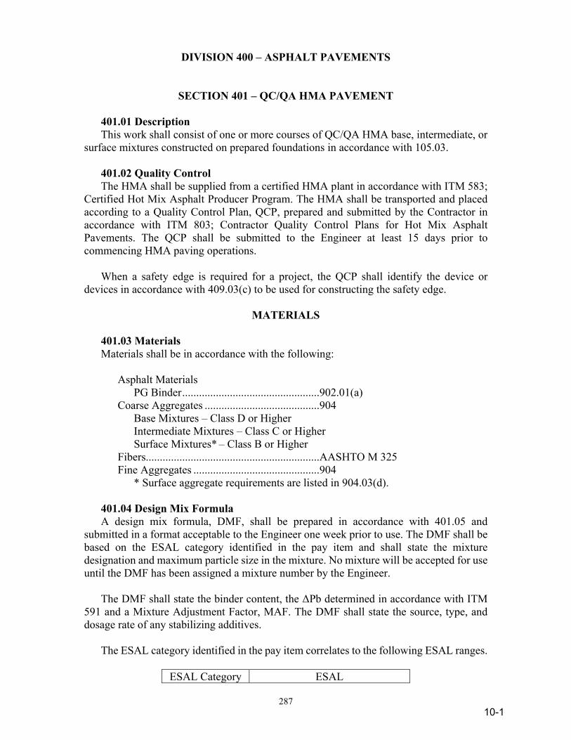
287
DIVISION 400 – ASPHALT PAVEMENTS
SECTION 401 – QC/QA HMA PAVEMENT 401.01 Description This work shall consist of one or more courses of QC/QA HMA base, intermediate, or surface mixtures constructed on prepared foundations in accordance with 105.03. 401.02 Quality Control The HMA shall be supplied from a certified HMA plant in accordance with ITM 583; Certified Hot Mix Asphalt Producer Program. The HMA shall be transported and placed according to a Quality Control Plan, QCP, prepared and submitted by the Contractor in accordance with ITM 803; Contractor Quality Control Plans for Hot Mix Asphalt Pavements. The QCP shall be submitted to the Engineer at least 15 days prior to commencing HMA paving operations. When a safety edge is required for a project, the QCP shall identify the device or devices in accordance with 409.03(c) to be used for constructing the safety edge.
MATERIALS 401.03 Materials Materials shall be in accordance with the following: Asphalt Materials PG Binder .................................................902.01(a) Coarse Aggregates .........................................904 Base Mixtures – Class D or Higher Intermediate Mixtures – Class C or Higher Surface Mixtures* – Class B or Higher Fibers..............................................................AASHTO M 325 Fine Aggregates .............................................904 * Surface aggregate requirements are listed in 904.03(d). 401.04 Design Mix Formula A design mix formula, DMF, shall be prepared in accordance with 401.05 and submitted in a format acceptable to the Engineer one week prior to use. The DMF shall be based on the ESAL category identified in the pay item and shall state the mixture designation and maximum particle size in the mixture. No mixture will be accepted for use until the DMF has been assigned a mixture number by the Engineer. The DMF shall state the binder content, the ΔPb determined in accordance with ITM 591 and a Mixture Adjustment Factor, MAF. The DMF shall state the source, type, and dosage rate of any stabilizing additives. The ESAL category identified in the pay item correlates to the following ESAL ranges.
ESAL Category ESAL
10-1
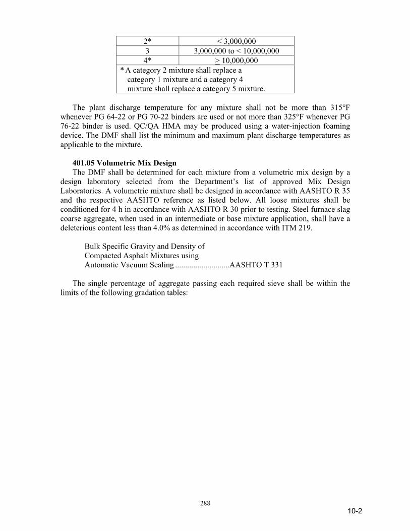
288
2* < 3,000,000 3 3,000,000 to < 10,000,000 4* > 10,000,000
* A category 2 mixture shall replace a category 1 mixture and a category 4 mixture shall replace a category 5 mixture.
The plant discharge temperature for any mixture shall not be more than 315°F whenever PG 64-22 or PG 70-22 binders are used or not more than 325°F whenever PG 76-22 binder is used. QC/QA HMA may be produced using a water-injection foaming device. The DMF shall list the minimum and maximum plant discharge temperatures as applicable to the mixture. 401.05 Volumetric Mix Design The DMF shall be determined for each mixture from a volumetric mix design by a design laboratory selected from the Department’s list of approved Mix Design Laboratories. A volumetric mixture shall be designed in accordance with AASHTO R 35 and the respective AASHTO reference as listed below. All loose mixtures shall be conditioned for 4 h in accordance with AASHTO R 30 prior to testing. Steel furnace slag coarse aggregate, when used in an intermediate or base mixture application, shall have a deleterious content less than 4.0% as determined in accordance with ITM 219. Bulk Specific Gravity and Density of Compacted Asphalt Mixtures using Automatic Vacuum Sealing ...........................AASHTO T 331 The single percentage of aggregate passing each required sieve shall be within the limits of the following gradation tables:
10-2
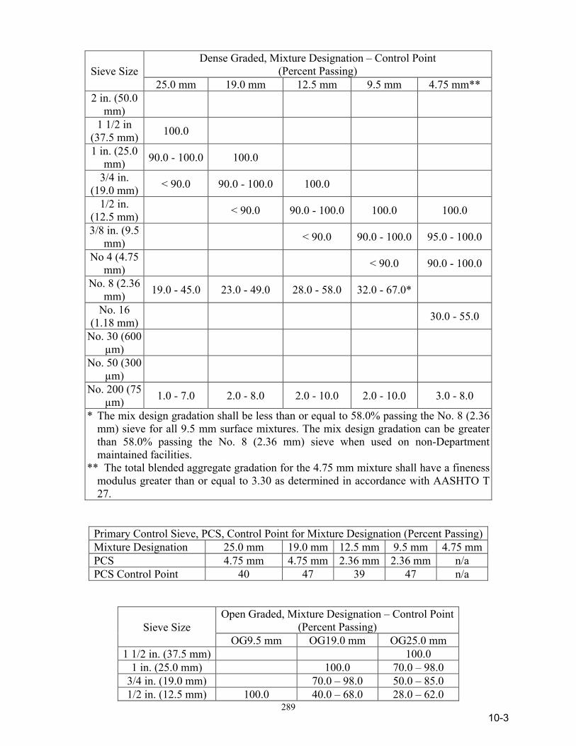
289
Sieve Size Dense Graded, Mixture Designation – Control Point
(Percent Passing) 25.0 mm 19.0 mm 12.5 mm 9.5 mm 4.75 mm**
2 in. (50.0 mm)
1 1/2 in (37.5 mm) 100.0
1 in. (25.0 mm) 90.0 - 100.0 100.0
3/4 in. (19.0 mm) < 90.0 90.0 - 100.0 100.0
1/2 in. (12.5 mm) < 90.0 90.0 - 100.0 100.0 100.0
3/8 in. (9.5 mm) < 90.0 90.0 - 100.0 95.0 - 100.0
No 4 (4.75 mm) < 90.0 90.0 - 100.0
No. 8 (2.36 mm) 19.0 - 45.0 23.0 - 49.0 28.0 - 58.0 32.0 - 67.0*
No. 16 (1.18 mm) 30.0 - 55.0
No. 30 (600 µm)
No. 50 (300 µm)
No. 200 (75 µm) 1.0 - 7.0 2.0 - 8.0 2.0 - 10.0 2.0 - 10.0 3.0 - 8.0
* The mix design gradation shall be less than or equal to 58.0% passing the No. 8 (2.36 mm) sieve for all 9.5 mm surface mixtures. The mix design gradation can be greater than 58.0% passing the No. 8 (2.36 mm) sieve when used on non-Department maintained facilities.
** The total blended aggregate gradation for the 4.75 mm mixture shall have a fineness modulus greater than or equal to 3.30 as determined in accordance with AASHTO T 27.
Primary Control Sieve, PCS, Control Point for Mixture Designation (Percent Passing) Mixture Designation 25.0 mm 19.0 mm 12.5 mm 9.5 mm 4.75 mm PCS 4.75 mm 4.75 mm 2.36 mm 2.36 mm n/a PCS Control Point 40 47 39 47 n/a
Sieve Size Open Graded, Mixture Designation – Control Point
(Percent Passing) OG9.5 mm OG19.0 mm OG25.0 mm
1 1/2 in. (37.5 mm) 100.0 1 in. (25.0 mm) 100.0 70.0 – 98.0
3/4 in. (19.0 mm) 70.0 – 98.0 50.0 – 85.0 1/2 in. (12.5 mm) 100.0 40.0 – 68.0 28.0 – 62.0
10-3

290
3/8 in. (9.5 mm) 75.0 – 100.0 20.0 – 52.0 15.0 – 50.0 No. 4 (4.75 mm) 10.0 – 35.0 10.0 – 30.0 6.0 – 30.0 No. 8 (2.36 mm) 0.0 – 20.0 7.0 – 23.0 7.0 – 23.0 No. 16 (1.18 mm) 2.0 – 18.0 2.0 – 18.0 No. 30 (600 µm) 1.0 – 13.0 1.0 – 13.0 No. 50 (300 µm) 0.0 – 10.0 0.0 – 10.0 No. 100 (150 µm) 0.0 – 9.0 0.0 – 9.0 No. 200 (75 µm) 0 – 6.0 0.0 – 8.0 0.0 – 8.0
% Binder > 3.0 > 3.0 > 3.0 Dust/Calculated Effective Binder Ratio shall be 0.6 to 1.4. The Dust/Calculated Effective Binder Ratio for 4.75 mm mixtures shall be 1.0 to 2.0. The optimum binder content shall produce a ΔPb ≤ 0.20 as determined in accordance with ITM 591 and the following air voids at Ndes:
Air Voids at Optimum Binder Content Dense Graded Open Graded Mixture Designation
25.0 mm
19.0 mm
12.5 mm
9.5 mm
4.75 mm
25.0 mm
19.0 mm
9.5 mm
Air Voids 5.0% 5.0% 5.0% 5.0% 5.0% 15.0% - 20.0% 12.0% - 17.0% The design for dense graded mixtures shall have at least four points, including a minimum of two points above and one point below the optimum. A one point design may be used for open graded mixtures. The maximum specific gravity shall be mass determined in water in accordance with AASHTO T 209. The bulk specific gravity of the gyratory specimens shall be determined in accordance with AASHTO T 166, Method A or AASHTO T 331, if required, for dense graded and open graded mixtures. The percent draindown of open graded mixtures shall not exceed 0.30% in accordance with AASHTO T 305. Open graded mixtures may incorporate recycled materials and fibers. The recycled materials shall be in accordance with 401.06, and the fiber type and minimum dosage rate shall be in accordance with AASHTO M 325. The binder for open graded mixtures may have the upper temperature classification reduced by 6°C from the specified binder grade if fibers are incorporated into the mixture or if 3.0% reclaimed asphalt shingles by weight of the total mixture is used. The percent draindown of dense graded mixtures shall not exceed 0.30% in accordance with AASHTO T 305. Dense graded mixture shall be tested for moisture susceptibility in accordance with AASHTO T 283 except that the loose mixture curing shall be replaced by mixture conditioning for 4 h in accordance with AASHTO R 30. The minimum tensile strength ratio, TSR, shall be 80%. The 6 in. mixture specimens shall be compacted in accordance with AASHTO T 312. If anti-stripping additives are added to the mixture to be in accordance with the minimum TSR requirements, the dosage rate shall be submitted with the DMF. A PG binder grade or source change will not require a new mix design. If the upper temperature classification of the PG binder is lower than the original PG grade, a new TSR value is required.
10-4
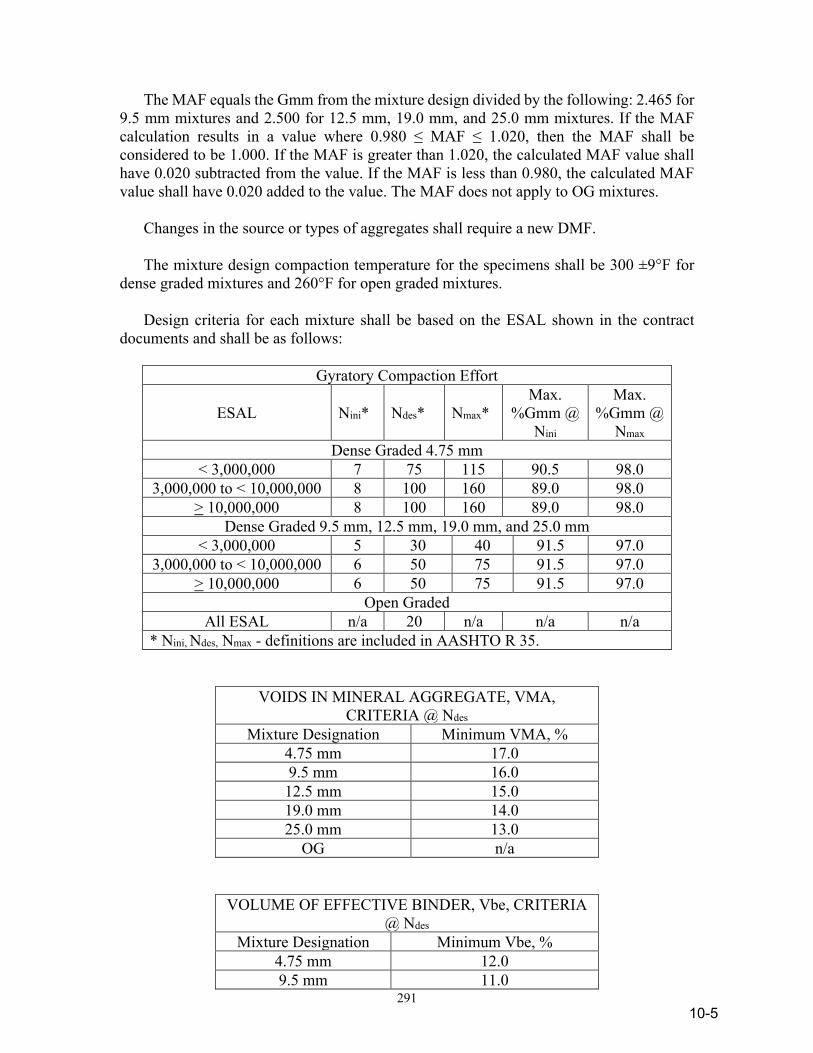
291
The MAF equals the Gmm from the mixture design divided by the following: 2.465 for 9.5 mm mixtures and 2.500 for 12.5 mm, 19.0 mm, and 25.0 mm mixtures. If the MAF calculation results in a value where 0.980 ≤ MAF ≤ 1.020, then the MAF shall be considered to be 1.000. If the MAF is greater than 1.020, the calculated MAF value shall have 0.020 subtracted from the value. If the MAF is less than 0.980, the calculated MAF value shall have 0.020 added to the value. The MAF does not apply to OG mixtures. Changes in the source or types of aggregates shall require a new DMF. The mixture design compaction temperature for the specimens shall be 300 ±9°F for dense graded mixtures and 260°F for open graded mixtures. Design criteria for each mixture shall be based on the ESAL shown in the contract documents and shall be as follows:
Gyratory Compaction Effort
ESAL Nini* Ndes* Nmax* Max.
%Gmm @ Nini
Max. %Gmm @
Nmax Dense Graded 4.75 mm
< 3,000,000 7 75 115 90.5 98.0 3,000,000 to < 10,000,000 8 100 160 89.0 98.0
> 10,000,000 8 100 160 89.0 98.0 Dense Graded 9.5 mm, 12.5 mm, 19.0 mm, and 25.0 mm
< 3,000,000 5 30 40 91.5 97.0 3,000,000 to < 10,000,000 6 50 75 91.5 97.0
> 10,000,000 6 50 75 91.5 97.0 Open Graded
All ESAL n/a 20 n/a n/a n/a * Nini, Ndes, Nmax - definitions are included in AASHTO R 35.
VOIDS IN MINERAL AGGREGATE, VMA, CRITERIA @ Ndes
Mixture Designation Minimum VMA, % 4.75 mm 17.0 9.5 mm 16.0 12.5 mm 15.0 19.0 mm 14.0 25.0 mm 13.0
OG n/a
VOLUME OF EFFECTIVE BINDER, Vbe, CRITERIA @ Ndes
Mixture Designation Minimum Vbe, % 4.75 mm 12.0 9.5 mm 11.0
10-5
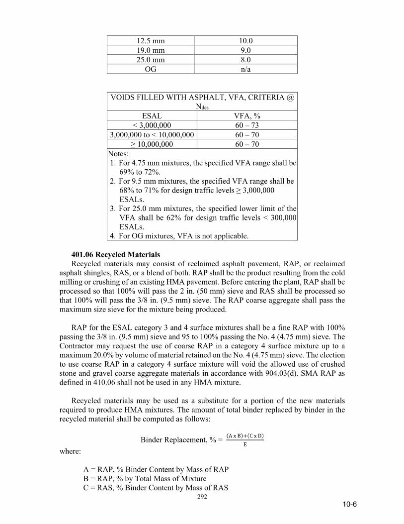
292
12.5 mm 10.0 19.0 mm 9.0 25.0 mm 8.0
OG n/a
VOIDS FILLED WITH ASPHALT, VFA, CRITERIA @ Ndes
ESAL VFA, % < 3,000,000 60 – 73
3,000,000 to < 10,000,000 60 – 70 ≥ 10,000,000 60 – 70
Notes: 1. For 4.75 mm mixtures, the specified VFA range shall be
69% to 72%. 2. For 9.5 mm mixtures, the specified VFA range shall be
68% to 71% for design traffic levels ≥ 3,000,000 ESALs.
3. For 25.0 mm mixtures, the specified lower limit of the VFA shall be 62% for design traffic levels < 300,000 ESALs.
4. For OG mixtures, VFA is not applicable. 401.06 Recycled Materials Recycled materials may consist of reclaimed asphalt pavement, RAP, or reclaimed asphalt shingles, RAS, or a blend of both. RAP shall be the product resulting from the cold milling or crushing of an existing HMA pavement. Before entering the plant, RAP shall be processed so that 100% will pass the 2 in. (50 mm) sieve and RAS shall be processed so that 100% will pass the 3/8 in. (9.5 mm) sieve. The RAP coarse aggregate shall pass the maximum size sieve for the mixture being produced. RAP for the ESAL category 3 and 4 surface mixtures shall be a fine RAP with 100% passing the 3/8 in. (9.5 mm) sieve and 95 to 100% passing the No. 4 (4.75 mm) sieve. The Contractor may request the use of coarse RAP in a category 4 surface mixture up to a maximum 20.0% by volume of material retained on the No. 4 (4.75 mm) sieve. The election to use coarse RAP in a category 4 surface mixture will void the allowed use of crushed stone and gravel coarse aggregate materials in accordance with 904.03(d). SMA RAP as defined in 410.06 shall not be used in any HMA mixture. Recycled materials may be used as a substitute for a portion of the new materials required to produce HMA mixtures. The amount of total binder replaced by binder in the recycled material shall be computed as follows:
Binder Replacement, % = (A x B)+(C x D)E
where: A = RAP, % Binder Content by Mass of RAP B = RAP, % by Total Mass of Mixture C = RAS, % Binder Content by Mass of RAS
10-6
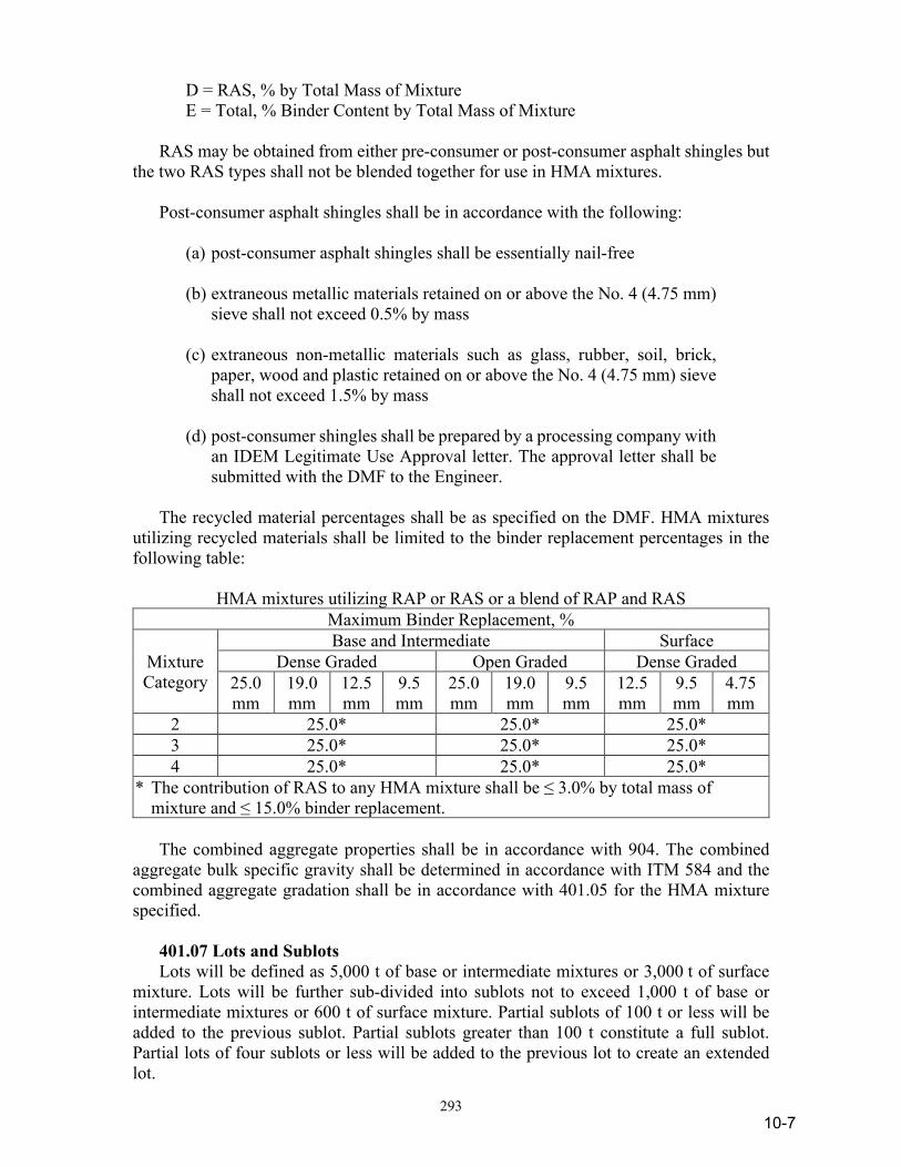
293
D = RAS, % by Total Mass of Mixture E = Total, % Binder Content by Total Mass of Mixture RAS may be obtained from either pre-consumer or post-consumer asphalt shingles but the two RAS types shall not be blended together for use in HMA mixtures. Post-consumer asphalt shingles shall be in accordance with the following: (a) post-consumer asphalt shingles shall be essentially nail-free (b) extraneous metallic materials retained on or above the No. 4 (4.75 mm)
sieve shall not exceed 0.5% by mass (c) extraneous non-metallic materials such as glass, rubber, soil, brick,
paper, wood and plastic retained on or above the No. 4 (4.75 mm) sieve shall not exceed 1.5% by mass
(d) post-consumer shingles shall be prepared by a processing company with
an IDEM Legitimate Use Approval letter. The approval letter shall be submitted with the DMF to the Engineer.
The recycled material percentages shall be as specified on the DMF. HMA mixtures utilizing recycled materials shall be limited to the binder replacement percentages in the following table:
HMA mixtures utilizing RAP or RAS or a blend of RAP and RAS Maximum Binder Replacement, %
Mixture Category
Base and Intermediate Surface Dense Graded Open Graded Dense Graded
25.0 mm
19.0 mm
12.5 mm
9.5 mm
25.0 mm
19.0 mm
9.5 mm
12.5 mm
9.5 mm
4.75 mm
2 25.0* 25.0* 25.0* 3 25.0* 25.0* 25.0* 4 25.0* 25.0* 25.0*
* The contribution of RAS to any HMA mixture shall be ≤ 3.0% by total mass of mixture and ≤ 15.0% binder replacement.
The combined aggregate properties shall be in accordance with 904. The combined aggregate bulk specific gravity shall be determined in accordance with ITM 584 and the combined aggregate gradation shall be in accordance with 401.05 for the HMA mixture specified. 401.07 Lots and Sublots Lots will be defined as 5,000 t of base or intermediate mixtures or 3,000 t of surface mixture. Lots will be further sub-divided into sublots not to exceed 1,000 t of base or intermediate mixtures or 600 t of surface mixture. Partial sublots of 100 t or less will be added to the previous sublot. Partial sublots greater than 100 t constitute a full sublot. Partial lots of four sublots or less will be added to the previous lot to create an extended lot.
10-7
294
401.08 Blank 401.09 Acceptance of Mixtures Acceptance of mixtures for Vbe at Ndes, and air voids at Ndes for each lot will be based on tests performed by the Engineer for dense graded 9.5 mm, 12.5 mm, 19.0 mm and 25.0 mm mixtures with original contract pay item quantities greater than or equal to 300 t. Acceptance of mixtures for binder content and air voids at Ndes will be based on a type D certification in accordance with 402.09 for dense graded mixtures with original contract pay item quantities less than 300 t. Acceptance of mixtures for binder content and air voids at Ndes for each lot will be based on a type D certification in accordance with 402.09 for dense graded 4.75 mm mixtures. Acceptance of mixtures for binder content and air voids at Ndes for each lot will be based on tests performed by the Engineer for open graded mixtures with original contract pay item quantities greater than or equal to 300 t. Acceptance of mixtures for binder content and air voids at Ndes will be based on a type D certification in accordance with 402.09 for open graded mixtures with original pay item quantities less than 300 t, except the air voids tolerance shall be ±3.5% from the DMF. The Engineer will randomly select the location within each sublot for sampling in accordance with ITM 802. The first 300 t of the first sublot of the first lot for each mixture pay item will not be sampled. An acceptance sample will consist of plate samples obtained in accordance with ITM 802 and ITM 580. The Engineer will take immediate possession of the samples. Acceptance samples will be reduced to the appropriate size for testing in accordance with ITM 587. The binder content and gradation will be determined in accordance with ITM 571. The maximum specific gravity will be mass determined in water in accordance with AASHTO T 209. The effective specific gravity, Gse, of the mixture will be determined in each sublot and reported from the acceptance sample testing. The total aggregate bulk specific gravity, Gsb, value will be determined in accordance with ITM 597. The air voids will be determined in accordance with AASHTO R 35 based on the average bulk specific gravity from two gyratory specimens and the MSG for the sublot. The VMA will be determined in accordance with AASHTO R 35 based on the average bulk specific gravity from two gyratory specimens, the percent aggregate in the mixture from the sublot and the BSG of the aggregate blend from the DMF as applicable. The gyratory pills will be prepared in accordance with AASHTO T 312. The dust/calculated effective binder ratio and the volume of effective binder in the mixture will be determined and reported from the acceptance sample testing conducted in each sublot. The volume of effective binder will be the difference between VMA and air voids. The Contractor shall take action in accordance with ITM 583 to address a dust/calculated effective binder ratio not in accordance with 401.05, a volume of effective
10-8

295
binder in the mixture below design minimums, or a volume of effective binder in the mixture greater than 2.0% above design minimums. The bulk specific gravity of gyratory specimens for dense graded mixtures will be determined in accordance with AASHTO T 166, Method A or AASHTO T 331, if required, except samples are not required to be dried overnight. The bulk specific gravity of gyratory specimens for open graded mixtures will be determined in accordance with AASHTO T 331. A binder draindown test in accordance with AASHTO T 305 for open graded mixtures shall be completed once per lot in accordance with 401.07 and shall not exceed 0.50%. The Contractor shall make available the sublot quality control results within seven calendar days from the date the acceptance sample was taken. The Engineer will make available the sublot acceptance test results after receiving the sublot quality control results from the Contractor. Air voids, binder content and Vbe values will be reported to the nearest 0.01%. Draindown test results will be rounded to the nearest 0.01%. Rounding will be in accordance with 109.01(a). Pay factors for dense graded mixtures with original contract pay item quantities greater than or equal to one lot will be determined in accordance with 401.19(a). Partial lots of four sublots or less will have pay factors determined in accordance with 401.19(b) if the previous lot is not available. Pay factors for dense graded mixtures with original contract pay item quantities greater than or equal to 300 t and less than one lot and open graded mixtures will be determined in accordance with 401.19(b). The Contractor may request an appeal of the Engineer’s test results in accordance with 401.20. Fibers incorporated into the mixture will be accepted on the basis of a type A certification for the specified material properties for each shipment of fibers. Fibers from different manufacturers and different types of fibers shall not be intermixed. In the event that an acceptance sample is not available to represent a sublot, all test results of the previous sublot will be used for acceptance. If the previous sublot is not available, the subsequent sublot will be used for acceptance. Samples shall not be obtained from the following areas: (a) Mixture placed on an approach, taper, gore area, crossover that is
not placed simultaneously with the mainline. (b) Mixture placed on a shoulder less than 8 ft in width that is not placed
simultaneously with the mainline.
10-9
296
(c) Within 25 ft of a transverse construction joint. (d) Areas placed with paving equipment in accordance with 409.03(c)2
or 409.03(c)3. If a random location falls within this area, the Engineer will randomly select another location within the sublot for sampling. If an entire sublot falls within this area, test results from the previous sublot will be used for acceptance. If the previous sublot is not available, the subsequent sublot will be used for acceptance. If previous or subsequent sublot results for a mixture accepted by 401.19(a) will be replicated for an entire lot, each sublot in that lot will be accepted by 401.19(b).
CONSTRUCTION REQUIREMENTS 401.10 General Equipment for HMA operations shall be in accordance with 409. The Contractor shall submit to the Engineer written documentation that includes the manufacturer’s make, model, serial number, manufactured year, and the manufacturer’s literature with pictures. The documentation shall be submitted prior to use and shall certify that the paving equipment proposed for the project is new and includes the modifications or has been modified in accordance with the following. The paver shall be equipped with means of preventing the segregation of the coarse aggregate particles when moving the mixture from the paver hopper to the paver augers. The means and methods used shall be in accordance with the paver manufacturer’s instructions and may consist of chain curtains, deflector plates, or other such devices, or any combination of these. The following specific requirements shall also apply to identified HMA pavers: 1. Blaw-Knox HMA pavers shall be equipped with the Blaw-Knox
Materials Management Kit, MMK. 2. Cedarapids HMA pavers shall be those that were manufactured
in 1989 or later. 3. Barber-Green/Caterpillar HMA pavers shall be equipped with
deflector plates as identified in the December, 2000 Service Magazine entitled “New Asphalt Deflector Kit {6630-DFL, 6631-DFL, or 6640-DFL}”.
The Contractor is also required to demonstrate to the Engineer prior to use, that the modifications to the paving equipment have been implemented on all pavers to be used on the project. Fuel oil, kerosene, or solvents shall not be transported in open containers on equipment. Cleaning of equipment and small tools shall not be performed on the pavement or shoulder areas.
10-10
297
HMA mixtures shall not exhibit segregation, flushing, or bleeding. Corrective action shall immediately be taken to prevent continuation of these conditions. Segregated, flushed, or bleeding HMA mixtures will be referred to the Department’s Division of Materials and Tests for adjudication as a failed material in accordance with 105.03. All mixtures that become loose and broken, mixed with dirt, or are in any way defective shall be removed and replaced in accordance with 105.03. 401.11 Preparation of Surfaces to be Overlaid The subgrade shall be shaped to the required grade and sections, free from all ruts, corrugations, or other irregularities, and uniformly compacted and approved in accordance with 207. Milling of an existing pavement surface shall be in accordance with 306. Surfaces on which a mixture is placed shall be free from objectionable or foreign materials at the time of placement. Prior to placing an open graded mixture, the underlying HMA course shall have a full width base seal applied in accordance with 415. The base seal materials shall be applied within three calendar days after all density cores in accordance with 401.16 have been obtained. Rubblized concrete pavements shall be primed in accordance with 405. PCCP, milled asphalt surfaces, and new and existing asphalt surfaces shall be tacked in accordance with 406. Contact surfaces of curbing, gutters, manholes, and other structures shall be tacked in accordance with 406. All partially completed sections of roadway that are 8 in. or less in thickness shall be proofrolled prior to the placement of additional materials unless otherwise directed by the Engineer. Proofrolling shall be accomplished in accordance with 203.26. The contact pressure shall be 70 to 80 psi. Soft yielding areas shall be removed and replaced. 401.12 Process Control The Engineer and Contractor will jointly review the operations to ensure compliance with the QCP. Continuous violations of compliance with the QCP will result in suspension of paving operations. 401.13 Weather Limitations HMA courses of less than 138 lb/sq yd shall be placed when the ambient temperature and the temperature of the surface on which it is to be placed is 45°F or above. No mixture shall be placed on a frozen subgrade. 401.14 Spreading and Finishing The mixture shall be placed upon an approved surface by means of laydown equipment in accordance with 409.03(c). Prior to paving, both the planned quantity and lay rate shall be adjusted by multiplying by the MAF. When mixture is produced from more than one DMF for a given pay item, the MAF will be applied to the applicable portion of the mixture for each. The temperature of each mixture at the time of spreading shall be less than 315°F whenever PG 64-22 or PG 70-22 binders are used or not more than 325°F whenever PG 76-22 binder is used. No mixture shall be placed on a previously paved course that has not cooled to below 175°F. For mixtures compacted in accordance with 402.15, the temperature of each mixture at the time of spreading shall not be less than
10-11
298
245°F. Planned HMA courses greater than 220 lb/sq yd placed under traffic, shall be brought up even with each adjacent lane at the end of each work day. Planned HMA courses less than or equal to 220 lb/sq yd shall be brought forward concurrently, within practical limits, limiting the work in one lane to not more than one work day of production before moving back to bring forward the adjacent lane. Traffic shall not be allowed on open graded mixtures. Hydraulic extensions on the paver will not be allowed for continuous paving operations. Fixed extensions or extendable screeds shall be used on courses greater than the nominal width of the paver except in areas where the paving width varies. Hydraulic extensions may be used in tapers and added lanes less than 250 ft in length. Automatic slope and grade controls shall be used as outlined in the QCP. HMA mainline and HMA shoulders which are 8 ft or more in width shall be placed with paving equipment in accordance with 409.03(c)1. When laying mixtures with density not controlled by cores, the speed of the paver shall not exceed 50 ft per minute. Rollers shall be operated to avoid shoving of the HMA and at speeds not to exceed 3 mph. However, vibratory rollers will be limited to 2.5 mph. The finished thickness of any course shall be at least two times but not more than five times the maximum particle size as shown on the DMF, except 4.75 mm mixtures shall be at least 1.5 times but not more than 3 times the maximum particle size shown on the DMF. A safety edge shall be constructed at locations where a dense graded intermediate mixture or a surface mixture is constructed adjacent to an aggregate or earth shoulder. Vibratory rollers in accordance with 409.03(d)4 shall not be operated in the vibratory mode at locations indicated on the plans. Oscillatory rollers in accordance with 409.03(d)5 will be allowed for use but the vertical impact force capability shall not be used. Density acceptance shall be in accordance with 401.16. 401.15 Joints Longitudinal joints in the surface shall be at the lane lines of the pavement. Longitudinal joints below the surface shall be offset from previously constructed joints by approximately 6 in., and be located within 12 in. of the lane line. Hot poured joint adhesive in accordance with 906 shall be applied to longitudinal joints constructed between two adjacent HMA courses in the top course of dense graded intermediate mixtures and all 4.75 mm, 9.5 mm and 12.5 mm surface mixture courses. This includes joints within the traveled way as well as between any of the following: traveled way and an auxiliary lane; traveled way and a paved shoulder; and auxiliary lane and a paved shoulder. The material shall be heated in a jacketed, double boiler melting kettle. The kettle shall have an attached pressure feed wand system with applicator shoe.
10-12

299
The joint adhesive shall be applied to the face of the previously constructed edge at the joint using a wand applicator. Prior to application of the joint adhesive, the joint face shall be dry and free of loose material and foreign objects. The adhesive shall be applied on the joint face 1/8 in. thick at the temperature recommended by the manufacturer. Excess joint adhesive shall not be allowed to pool on the top of the previously constructed pavement course or the pavement to be overlaid. The application of the adhesive shall be made within the same day, but at least 30 minutes prior to construction of the longitudinal joint. All 9.5 mm and 12.5 mm surface mixture longitudinal joints that have the joint adhesive applied shall be sealed using SS-1h or AE-NT asphalt emulsion in accordance with 902.01(b). The sealing operation shall not begin until all density cores in accordance with 401.16 and 401.20 have been obtained and the installation of pavement corrugations, when specified in accordance with 606, has been completed. The liquid asphalt sealant shall be a minimum width of 24 in., centered on the joint line, and shall be extended, when necessary, to provide coverage beyond the edge of the pavement corrugation. The sealant shall be applied at an application rate of 0.03 ±0.01 gal./sq yd onto a dry surface, free of any foreign or loose material, using a distributor in accordance with 409.03(a). Areas receiving greater than 0.04 gal./sq yd shall be lightly broomed to reduce the effects of excess sealant on the pavement surface. The sealant temperature at the time of application shall be at least 135°F and shall not exceed 180°F. The ambient air and pavement temperatures at the time of application shall be greater than 32°F. Temporary pavement markings in accordance with 801.12 shall be offset a sufficient distance from the longitudinal joint so as not to obstruct the installation of the pavement corrugations or the application of the liquid asphalt sealant. The sealant shall be cured a minimum of five days prior to applying the permanent pavement traffic markings in accordance with 808. Where pavement markings are to be grooved in accordance with 808.07(b)1, the minimum cure of five days for the sealant shall not apply. Transverse joints shall be constructed by exposing a near vertical full depth face of the previous course. For areas inaccessible to rollers, other mechanical devices shall be used to achieve the required density. If constructed under traffic, temporary transverse joints shall be feathered to provide a smooth transition to the driving surface. 401.16 Density Acceptance will be based on lots and sublots in accordance with 401.07. Density of the compacted dense graded mixture will be determined from cores except where: (a) the total planned lay rate to be placed over a shoulder existing prior to
the contract award is less than 385 lb/sq yd; or (b) the first lift of material placed at less than 385 lb/sq yd over a shoulder
existing prior to the contract award.
10-13

300
Density of any random core location in these areas will be assigned a value of 94.0% MSG and compaction shall be in accordance with 402.15. Open graded mixtures shall be compacted with six passes of a static tandem roller and will be assigned a value of 84.0% MSG. Vibratory rollers shall not be used on open graded mixtures. Compaction of 4.75 mm mixtures shall be in accordance with 402.15, except vibratory rollers shall be operated in static mode and the vertical impact force capability of oscillatory rollers shall not be used. Compaction of mixtures with original contract pay item quantities less than 300 t shall be in accordance with 402.15. Density acceptance by cores will be based on samples obtained from two random locations selected by the Engineer within each sublot in accordance with ITM 802. One core shall be cut at each random location in accordance with ITM 580. The transverse core location will be located so that the edge of the core will be no closer than 3 in. from a confined edge or 6 in. from a non-confined edge of the course being placed. The maximum specific gravity will be determined from the samples obtained in 401.09. The Contractor shall obtain cores in the presence of the Engineer with a device that shall produce a uniform 6.00 ±0.25 in. diameter pavement sample. Coring shall be completed prior to the random location being covered by the next course. All core locations will be marked and shall be cored within two work days of placement. A damaged core shall be discarded and replaced with a core from a location selected by adding 1 ft to the longitudinal location of the damaged core using the same transverse offset. The Contractor and the Engineer shall mark the core to define the course to be tested. If the core indicates a course thickness of less than two times the maximum particle size, the core will be discarded and a core from a new random location will be selected for testing. Cores shall not be obtained from the following areas: (a) Mixture placed on an approach, taper, gore area, crossover that is not
placed simultaneously with the mainline. (b) Mixture placed on a shoulder less than 8 ft in width that is not placed
simultaneously with the mainline. (c) Within 25 ft of a transverse construction joint. (d) Within 25 ft of an acceptance sample taken in accordance with 401.09. (e) Areas placed with paving equipment in accordance with 409.03(c)2 or
409.03(c)3.
10-14
301
If a random location falls within this area, the Engineer will randomly select another location within the sublot for coring. If an entire sublot falls within this area, test results from the previous sublot will be used for acceptance. If the previous sublot is not available, the subsequent sublot will be used for acceptance. The Engineer will take immediate possession of the cores. If the Engineer’s cores are subsequently damaged, additional coring will be the responsibility of the Department. Subsequent core locations will be determined by subtracting 1 ft from the random location using the same transverse offset. The density for the mixture will be expressed as the percentage of maximum specific gravity, %MSG, obtained by dividing the average bulk specific gravity by the maximum specific gravity for the sublot, times 100. Samples for the bulk specific gravity and maximum specific gravity will be dried in accordance with ITM 572. The Engineer will determine the bulk specific gravity of the cores in accordance with AASHTO T 166, Method A or AASHTO T 331, if required. The maximum specific gravity will be mass determined in water in accordance with AASHTO T 209. Within one work day of coring operations the Contractor shall clean, dry, and refill the core holes with HMA of similar or smaller size particles. The Engineer’s acceptance test results for each sublot will be available when the sublot testing is complete. Acceptance of the pavement for density, %MSG, will be reported to the nearest 0.01%. Rounding will be in accordance with 109.01(a). 401.17 Pavement Corrugations Pavement corrugations shall be in accordance with 606. 401.18 Pavement Smoothness Pavement smoothness will be accepted by means of a profilograph, a 16 ft long straightedge, or a 10 ft long straightedge as described below. (a) Profilograph When a pay item for Profilograph, HMA is included in the contract, the Contractor shall furnish, calibrate, and operate an approved profilograph in accordance with ITM 912 on the mainline traveled way and ramps, including adjacent acceleration or deceleration lane, where all of the following conditions are met: 1. The design speed is greater than 45 mph. 2. The traveled way or ramp lane width is constant and is 0.1 mi in
length or longer. 3. The HMA is placed on a milled surface or the total combined
planned lay rate of surface, intermediate, and base courses is 385 lb/sq yd or greater.
The profilogram produced shall become the property of the Department. The profilograph shall remain the property of the Contractor.
10-15
302
The project area, less paving exceptions and areas exempt from profilograph operation in accordance with ITM 912, will be divided into individual smoothness sections measuring 0.1 mi in length for each lane. Partial length smoothness sections adjacent to project limits, paving exceptions, or areas exempt from profilograph operation will be considered in accordance with ITM 912. If the original contract pay item quantity for a surface mixture is less than or equal to one sublot, the item will be exempt from profilograph operation and the smoothness will be accepted in accordance with 401.18(b). If the posted speed limit for an entire smoothness section is less than or equal to 45 mph, the section will be exempt from profilograph operation and the smoothness within the section will be accepted in accordance with 401.18(b). If the posted speed limit is greater than 45 mph for a portion of a smoothness section and is less than or equal to 45 mph for the remainder, the section smoothness acceptance will be as follows: 1. By profilograph for the portion of the section with a posted
speed limit greater than 45 mph. 2. In accordance with 401.18(b) for the portion of the section with
a posted speed limit less than or equal to 45 mph. At locations where the profilograph is required, it shall be used on the surface course and on any dense graded intermediate course immediately below the surface course. (b) 16 ft Straightedge and 10 ft Straightedge The Department will furnish and operate 16 ft and 10 ft straightedges as described below. The 16 ft straightedge is used to accept smoothness along the direction of mainline traffic and the 10 ft straightedge is used to accept smoothness transverse to the direction of mainline traffic. This includes longitudinal smoothness on public road approaches and median crossovers. For contracts which include the Profilograph, HMA pay item, the 16 ft long straightedge will be used to accept longitudinal smoothness on surface courses at the following locations: 1. All mainline traveled way lanes shorter than 0.1 mi. 2. All mainline traveled way lanes within smoothness sections with
posted speed limits less than or equal to 45 mph throughout the entire section length.
3. All mainline traveled way lanes at locations exempted from
profilograph operation in accordance with ITM 912. 4. All tapers. 5. All turn lanes, including bi-directional left turn lanes.
10-16
303
6. All ramps with design speeds of 45 mph or less. 7. All acceleration and deceleration lanes associated with ramps
with design speeds of 45 mph or less. 8. All shoulders. For contracts where the profilograph is not used for smoothness acceptance, the 16 ft straightedge will be used to accept longitudinal smoothness on all dense graded courses at the above locations as well as all mainline travel way lanes and ramps with design speeds of greater than 45 mph. Smoothness acceptance on ramp acceleration or deceleration lanes will also be based on operation of the 16 ft straightedge. The 10 ft long straightedge shall be used to check transverse slopes, across travel lanes and shoulders, approaches, and crossovers. (c) Smoothness Correction At locations where the profilograph is being used on an intermediate course, all areas having a high or low point deviation in excess of 0.30 in. shall be corrected. After corrective action is taken on an intermediate course, a 16 ft straightedge may be used to verify the adequacy of the corrective action. At locations where the profilograph is being used on a surface course, all areas having a high or low point deviation in excess of 0.30 in. shall be corrected. All smoothness sections with a deficient profile index in accordance with 401.19(c) shall be corrected. Underlying courses that are exposed by corrective action shall be milled to a depth of 1 1/2 in. and replaced with surface course. After the corrective action is taken on a surface course, the profilograph shall be operated throughout the entire affected smoothness section to verify the adequacy of the corrective action. At locations where the 16 ft straightedge is used, the pavement variations shall be corrected to 1/4 in. or less. When the 10 ft straightedge is used, the pavement variations shall be corrected to 1/8 in. or less. If grinding of an intermediate course is used for pavement smoothness corrections, the grinding shall not precede the surface placement by more than 30 calendar days if open to traffic. 401.19 Pay Factors (a) Dense Graded Mixture ≥ One Lot Pay factors, PF, are calculated for the air voids at Ndes, Vbe at Ndes and in-place density, %Gmm. The Percent Within Limits, PWL, for each lot will be determined in accordance with ITM 588. The appropriate pay factor for each property is calculated as follows: Estimated PWL greater than 90:
PF = ((0.50 x PWL) + 55.00)/100
10-17
304
Estimated PWL greater than 70 and equal to or less than 90:
PF = ((0.40 x PWL) + 64.00)/100 Estimated PWL greater than or equal to 50 and equal to or less than 70:
PF = ((0.85 x PWL) + 32.5)/100 If the Lot PWL for any one of the properties is less than 50, a sublot has an air void content less than 1.0% or greater than 8.0%, or a sublot has a volume of effective binder greater than 3.0% above design minimums, the lot will be referred to the Department’s Division of Materials and Tests for adjudication as a failed material in accordance with normal Department practice as listed in 105.03. Air voids, Vbe, and in-place density, %Gmm, PF values will be reported to the nearest 0.01. Rounding will be in accordance with 109.01(a). A composite pay factor for each lot based on test results for mixture properties and density is determined by a weighted formula as follows:
Lot PF = 0.30(PFVOIDS) + 0.35(PFVbe) + 0.35(PFDENSITY) where:
Lot PF = Lot Composite Pay Factor for Mixture and Density
PFVOIDS = Lot Pay Factor for Air Voids at Ndes PFVbe = Lot Pay Factor for Vbe at Ndes
PFDENSITY =
Lot Pay Factor for In-Place Density, % Gmm
The lot quality assurance adjustment for mixture properties and density is calculated as follows:
q = L x U x (Lot PF – 1.00)/MAF where:
q = quality assurance adjustment for mixture properties and density of the lot
L = Lot quantity U = Unit price for the material, $/ton
Lot PF = Lot Pay Factor Lot test results for the air voids at Ndes, Vbe at Ndes, and density will be used to determine the Lot Pay Factors. The specification limits for the air voids at Ndes, Vbe at Ndes, and density will be as follows:
10-18
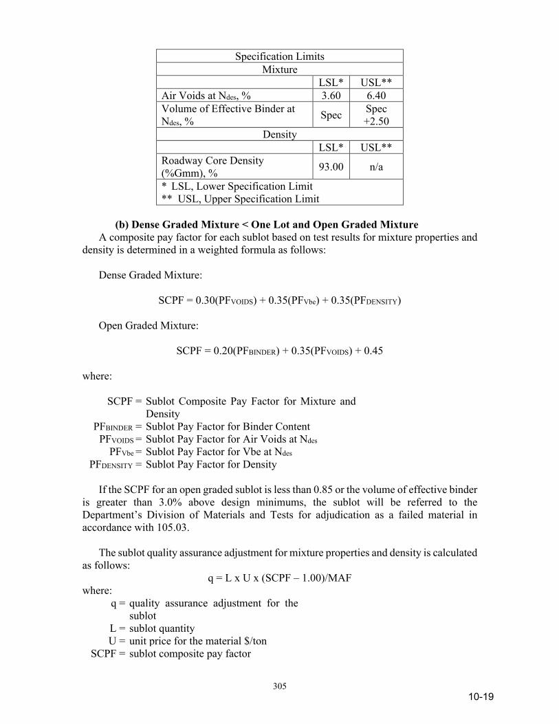
305
Specification Limits Mixture
LSL* USL** Air Voids at Ndes, % 3.60 6.40 Volume of Effective Binder at Ndes, % Spec Spec
+2.50 Density
LSL* USL** Roadway Core Density (%Gmm), % 93.00 n/a
* LSL, Lower Specification Limit ** USL, Upper Specification Limit
(b) Dense Graded Mixture < One Lot and Open Graded Mixture A composite pay factor for each sublot based on test results for mixture properties and density is determined in a weighted formula as follows: Dense Graded Mixture:
SCPF = 0.30(PFVOIDS) + 0.35(PFVbe) + 0.35(PFDENSITY) Open Graded Mixture:
SCPF = 0.20(PFBINDER) + 0.35(PFVOIDS) + 0.45 where:
SCPF = Sublot Composite Pay Factor for Mixture and Density
PFBINDER = Sublot Pay Factor for Binder Content PFVOIDS = Sublot Pay Factor for Air Voids at Ndes
PFVbe = Sublot Pay Factor for Vbe at Ndes PFDENSITY = Sublot Pay Factor for Density
If the SCPF for an open graded sublot is less than 0.85 or the volume of effective binder is greater than 3.0% above design minimums, the sublot will be referred to the Department’s Division of Materials and Tests for adjudication as a failed material in accordance with 105.03. The sublot quality assurance adjustment for mixture properties and density is calculated as follows:
q = L x U x (SCPF – 1.00)/MAF where:
q = quality assurance adjustment for the sublot
L = sublot quantity U = unit price for the material $/ton
SCPF = sublot composite pay factor
10-19

306
Sublot test results for mixture properties will be assigned pay factors in accordance with the following:
Binder Content Open Graded
Deviation from DMF (±%) Pay Factor
≤ 0.2 1.05 0.3 1.04 0.4 1.02 0.5 1.00 0.6 0.90 0.7 0.80 0.8 0.60 0.9 0.30 1.0 0.00
>1.0 Submitted to the
Department’s Division of Materials and Tests*
* Test results will be considered and adjudicated as a failed material in accordance with normal Department practice as listed in 105.03.
Volume of Effective Binder, Vbe
Dense Graded Pay Factors Deviation from
Spec Minimum
> +3.0 Submitted to the Department’s Division of Materials and Tests*
≥ +2.5 and ≤ +3.0 1.00 - 0.05 for each 0.1% above +2.5%
> +2.0 and < +2.5 1.05 - 0.01 for each 0.1% above +2.0%
> +0.5 and < +2.0 1.05 ≥ 0.0 and ≤ +0.5 1.05 - 0.01 for each 0.1% below
+0.5% ≥ -0.5 and < 0.0 1.00 - 0.02 for each 0.1% below
0.0%
≥ -2.0 and < -0.5 0.90 - 0.06 for each 0.1% below -0.5%
< -2.0 Submitted to the Department’s Division of Materials and Tests*
* Test results will be considered and adjudicated as a failed material in accordance with normal Department practice as listed in 105.03.
Air Voids
Dense Graded Open Graded Pay Factor
10-20
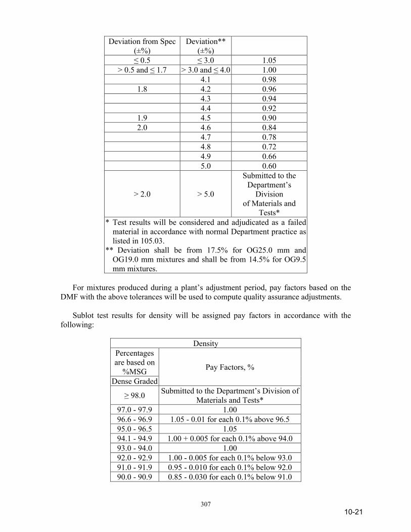
307
Deviation from Spec (±%)
Deviation** (±%)
≤ 0.5 ≤ 3.0 1.05 > 0.5 and ≤ 1.7 > 3.0 and ≤ 4.0 1.00
4.1 0.98 1.8 4.2 0.96
4.3 0.94 4.4 0.92
1.9 4.5 0.90 2.0 4.6 0.84
4.7 0.78 4.8 0.72 4.9 0.66 5.0 0.60
> 2.0 > 5.0
Submitted to the Department’s
Division of Materials and
Tests* * Test results will be considered and adjudicated as a failed
material in accordance with normal Department practice as listed in 105.03.
** Deviation shall be from 17.5% for OG25.0 mm and OG19.0 mm mixtures and shall be from 14.5% for OG9.5 mm mixtures.
For mixtures produced during a plant’s adjustment period, pay factors based on the DMF with the above tolerances will be used to compute quality assurance adjustments. Sublot test results for density will be assigned pay factors in accordance with the following:
Density Percentages are based on
%MSG Pay Factors, %
Dense Graded
≥ 98.0 Submitted to the Department’s Division of Materials and Tests*
97.0 - 97.9 1.00 96.6 - 96.9 1.05 - 0.01 for each 0.1% above 96.5 95.0 - 96.5 1.05 94.1 - 94.9 1.00 + 0.005 for each 0.1% above 94.0 93.0 - 94.0 1.00 92.0 - 92.9 1.00 - 0.005 for each 0.1% below 93.0 91.0 - 91.9 0.95 - 0.010 for each 0.1% below 92.0 90.0 - 90.9 0.85 - 0.030 for each 0.1% below 91.0
10-21

308
≤ 89.9 Submitted to the Department’s Division of Materials and Tests*
* Test results will be considered and adjudicated as a failed material in accordance with normal Department practice as listed in 105.03.
The pay factors will be rounded to the nearest 0.01. (c) Smoothness Smoothness pay adjustments will only be applied when the smoothness is measured by a profilograph. The pay adjustment will be based on the profile index generated on the surface course only. At locations where a profilograph is used to accept smoothness, a quality assurance adjustment will be determined for each 0.1 mile section of each lane. This adjustment will be applied to all QC/QA HMA pay items within the pavement section. The adjustment for each section will be calculated using the following formula:
∑=
=
n
1i
ss x UTSA x 1.00) - (PF q
where:
qs = quality assurance adjustment for smoothness for one section
PFs = pay factor for smoothness n = number of layers A = area of the section, sq yd S = planned spread rate for material, lb/sq yd T = conversion factor: 2,000 lb/ton U = unit price for the material, $/ton.
For smoothness sections that are less than 0.1 mile in length or require profilograph operation along both lane edges, the profile index used to obtain the smoothness pay factor used in the above formula will be determined in accordance with ITM 912. The quality assurance adjustment for smoothness, Qs, for the contract will be the total of the quality assurance adjustments for smoothness, qs, on each section by the following formula:
Qs = ∑qs
When smoothness is measured by a profilograph, payment adjustments will be made based on a zero blanking band on the final profile index in accordance with the following table. Regardless of the tabulated value, the maximum pay factor for a smoothness section where corrective action has been performed will be 1.00.
10-22
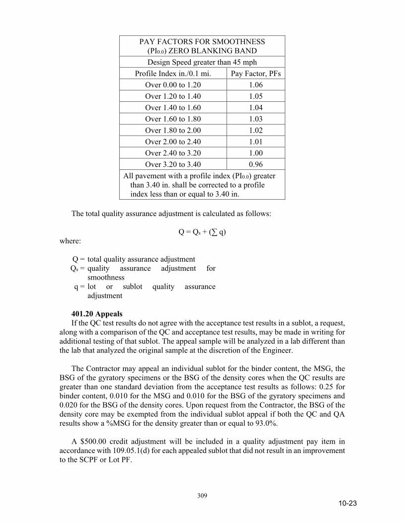
309
PAY FACTORS FOR SMOOTHNESS (PI0.0) ZERO BLANKING BAND Design Speed greater than 45 mph
Profile Index in./0.1 mi. Pay Factor, PFs Over 0.00 to 1.20 1.06 Over 1.20 to 1.40 1.05 Over 1.40 to 1.60 1.04 Over 1.60 to 1.80 1.03 Over 1.80 to 2.00 1.02 Over 2.00 to 2.40 1.01 Over 2.40 to 3.20 1.00 Over 3.20 to 3.40 0.96
All pavement with a profile index (PI0.0) greater than 3.40 in. shall be corrected to a profile index less than or equal to 3.40 in.
The total quality assurance adjustment is calculated as follows:
Q = Qs + (∑ q) where:
Q = total quality assurance adjustment Qs = quality assurance adjustment for
smoothness q = lot or sublot quality assurance
adjustment 401.20 Appeals If the QC test results do not agree with the acceptance test results in a sublot, a request, along with a comparison of the QC and acceptance test results, may be made in writing for additional testing of that sublot. The appeal sample will be analyzed in a lab different than the lab that analyzed the original sample at the discretion of the Engineer. The Contractor may appeal an individual sublot for the binder content, the MSG, the BSG of the gyratory specimens or the BSG of the density cores when the QC results are greater than one standard deviation from the acceptance test results as follows: 0.25 for binder content, 0.010 for the MSG and 0.010 for the BSG of the gyratory specimens and 0.020 for the BSG of the density cores. Upon request from the Contractor, the BSG of the density core may be exempted from the individual sublot appeal if both the QC and QA results show a %MSG for the density greater than or equal to 93.0%. A $500.00 credit adjustment will be included in a quality adjustment pay item in accordance with 109.05.1(d) for each appealed sublot that did not result in an improvement to the SCPF or Lot PF.
10-23

310
A written request for an appeal shall be submitted within seven calendar days of receipt of the Department’s written results for the lot accepted under 401.19(a) or the sublot accepted under 401.19(b). The conditions for an extended lot appeal are as follows: 1. One appeal will be allowed for the entire extended lot if the
Contractor informs the Department of the anticipated extended lot condition within seven calendar days of receipt of the lot results, or;
2. One appeal will be allowed only for the extended sublots if the
Contractor did not inform the Department of the anticipated extended lot condition within seven calendar days of receipt of the lot results.
The backup sample will be tested in accordance with the applicable test method for the sublot requested for all tests exceeding the sublot standard deviation criteria. (a) MSG The backup MSG will be dried in accordance with ITM 572 and mass determined in water in accordance with AASHTO T 209. (b) BSG of the Gyratory Specimen New gyratory specimens will be prepared and tested in accordance with AASHTO T 312 from the backup sample. (c) Binder Content The backup binder content sample will be prepared and tested in accordance with ITM 571. (d) BSG of the Density Core Additional cores shall be taken within seven calendar days unless otherwise directed. Additional core locations will be determined by adding 1 ft longitudinally of the cores tested using the same transverse offset. The appeal density cores will be dried in accordance with ITM 572 and tested in accordance with AASHTO T 166, Method A or AASHTO T 331, if required. The appeal results will replace all previous test result for acceptance of mixture in accordance with 401.09 and density in accordance with 401.16. The results will be furnished to the Contractor. 401.21 Method of Measurement HMA mixtures will be measured by the ton of the type specified, in accordance with 109.01(b). The measured quantity will be divided by the MAF to determine the pay quantity. Milled shoulder corrugations will be measured in accordance with 606.02. Joint adhesive will be measured by the linear foot in accordance with 109.01(a). Liquid asphalt sealant will be measured by the linear foot.
10-24

311
401.22 Basis of Payment The accepted quantities for this work will be paid for at the contract unit price per ton for QC/QA-HMA, of the type specified, complete in place. Payment for furnishing, calibrating, and operating the profilograph, and furnishing profile information will be made at the contract lump sum price for profilograph, HMA. Adjustments to the contract payment with respect to mixture, density, and smoothness for mixture produced will be included in a quality adjustment pay item in accordance with 109.05.1. Milled shoulder corrugations will be paid for in accordance with 606.03. Joint adhesive will be paid for at the contract unit price per linear foot, complete in place. Liquid asphalt sealant will be paid for at the contract unit price per linear foot. Payment will be made under: Pay Item Pay Unit Symbol Joint Adhesive, __________ ......................................LFT course type Liquid Asphalt Sealant ...............................................LFT Profilograph, HMA ....................................................LS QC/QA-HMA, ______, ______, ______, ______mm TON (ESAL(1)) (PG(2)) (Course(3)) (Mix(4)) (1) ESAL Category as defined in 401.04 (2) Number represents the high temperature binder grade. Low
temperature grades are - 22 (3) Surface, Intermediate, or Base (4) Mixture Designation Preparation of surfaces to be overlaid shall be included in the cost of other pay items. Coring and refilling of the core holes shall be included in the cost of other pay items within this section. No payment will be made for additional anti-stripping additives, appeal coring or traffic control expenditures related to coring operations. The cost of removing and replacing soft and yielding areas shall be included in the cost of other pay items in this section. Corrections for pavement smoothness shall be included in the cost of other pay items within this section. The price for Profilograph, HMA will be full compensation regardless of how often the profilograph is used or how many profilograms are produced.
10-25
312
If QC/QA-HMA 19.0 mm over QC/QA-HMA 25.0 mm mixtures are specified, QC/QA-HMA 19.0 mm mixture may be considered as a substitute for the QC/QA-HMA 19.0 mm and QC/QA-HMA 25.0 mm mixtures upon a written request by the Contractor. The request for the substitution shall be prepared in advance of the work. A computation will be made in order to obtain a unit price for the QC/QA-HMA 19.0 mm mixture. The quantity and amount for QC/QA-HMA 19.0 mm mixture shall equal the sum of the contract quantities and amounts shown for QC/QA-HMA 19.0 mm and QC/QA-HMA 25.0 mm mixtures. The unit price for QC/QA-HMA 19.0 mm mixture shall be equal to the sum of contract amounts divided by the sum of contract quantities. Payment for the QC/QA-HMA 19.0 mm mixture will be made at the unit price per ton for QC/QA-HMA 19.0 mm mixture. No payment will be made for additional work or costs which may result due to this change.
SECTION 402 – HMA PAVEMENT 402.01 Description This work shall consist of one or more courses of miscellaneous mixtures constructed in accordance with 105.03. 402.02 Quality Control The HMA shall be supplied from a certified HMA plant in accordance with ITM 583; Certified Hot Mix Asphalt Producer Program. The HMA shall be transported and placed according to a Quality Control Plan, QCP, prepared and submitted by the Contractor in accordance with ITM 803; Contractor Quality Control Plans for Hot Mix Asphalt Pavements. The QCP shall be submitted to the Engineer at least 15 days prior to commencing HMA paving operations. When a safety edge is required for a project, the QCP shall identify the device or devices in accordance with 409.03(c) to be used for constructing the safety edge.
MATERIALS 402.03 Materials Materials shall be in accordance with the following: Asphalt Materials PG Binder .................................................902.01(a) Coarse Aggregates .........................................904 Base Mixtures – Class D or Higher Intermediate Mixtures – Class C or Higher Surface Mixtures* – Class B or Higher Fine Aggregates .............................................904 * Surface aggregate requirements are listed in 904.03(d). 402.04 Design Mix Formula A DMF shall be prepared in accordance with 401.04 and submitted in a format acceptable to the Engineer one week prior to use. The DMF will be based on the ESAL and mixture designation as follows:
10-26
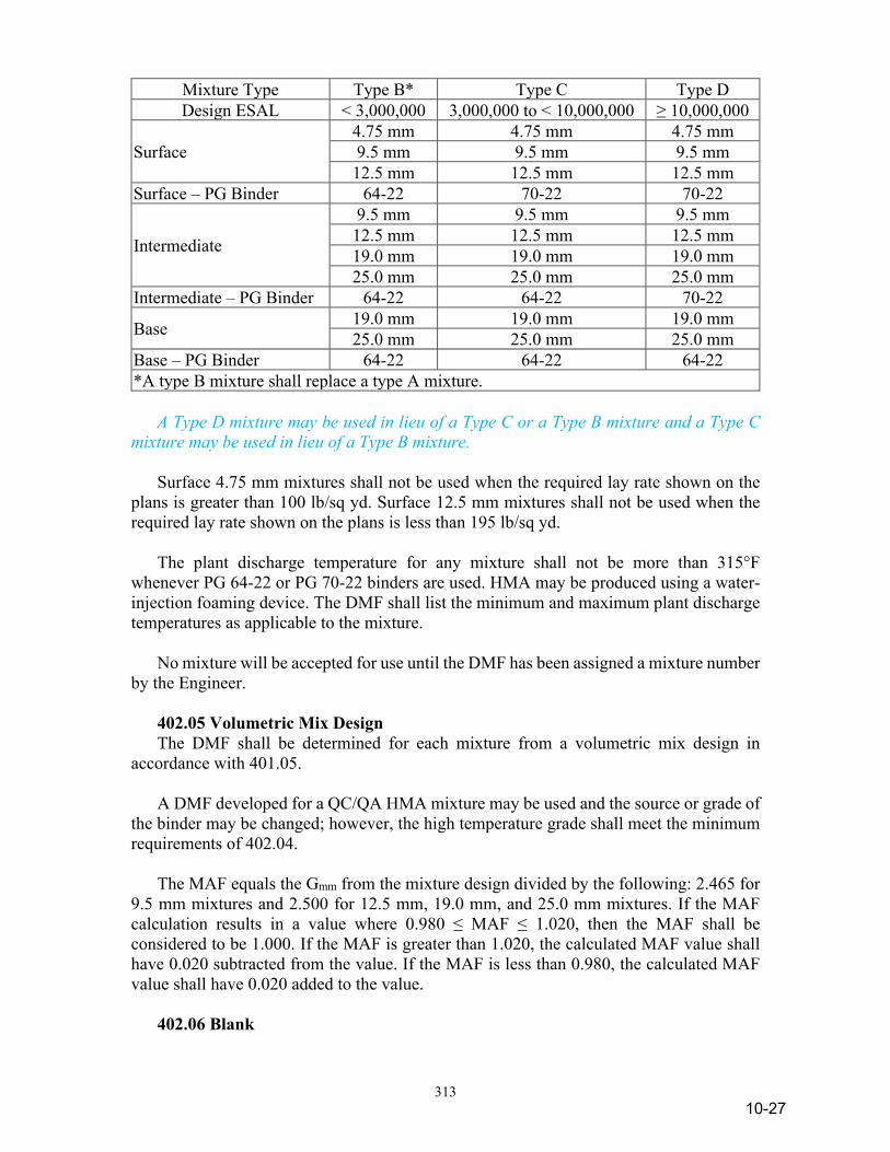
313
Mixture Type Type B* Type C Type D Design ESAL < 3,000,000 3,000,000 to < 10,000,000 ≥ 10,000,000
Surface 4.75 mm 4.75 mm 4.75 mm 9.5 mm 9.5 mm 9.5 mm 12.5 mm 12.5 mm 12.5 mm
Surface – PG Binder 64-22 70-22 70-22
Intermediate
9.5 mm 9.5 mm 9.5 mm 12.5 mm 12.5 mm 12.5 mm 19.0 mm 19.0 mm 19.0 mm 25.0 mm 25.0 mm 25.0 mm
Intermediate – PG Binder 64-22 64-22 70-22
Base 19.0 mm 19.0 mm 19.0 mm 25.0 mm 25.0 mm 25.0 mm
Base – PG Binder 64-22 64-22 64-22 *A type B mixture shall replace a type A mixture. A Type D mixture may be used in lieu of a Type C or a Type B mixture and a Type C mixture may be used in lieu of a Type B mixture. Surface 4.75 mm mixtures shall not be used when the required lay rate shown on the plans is greater than 100 lb/sq yd. Surface 12.5 mm mixtures shall not be used when the required lay rate shown on the plans is less than 195 lb/sq yd. The plant discharge temperature for any mixture shall not be more than 315°F whenever PG 64-22 or PG 70-22 binders are used. HMA may be produced using a water-injection foaming device. The DMF shall list the minimum and maximum plant discharge temperatures as applicable to the mixture. No mixture will be accepted for use until the DMF has been assigned a mixture number by the Engineer. 402.05 Volumetric Mix Design The DMF shall be determined for each mixture from a volumetric mix design in accordance with 401.05. A DMF developed for a QC/QA HMA mixture may be used and the source or grade of the binder may be changed; however, the high temperature grade shall meet the minimum requirements of 402.04. The MAF equals the Gmm from the mixture design divided by the following: 2.465 for 9.5 mm mixtures and 2.500 for 12.5 mm, 19.0 mm, and 25.0 mm mixtures. If the MAF calculation results in a value where 0.980 ≤ MAF ≤ 1.020, then the MAF shall be considered to be 1.000. If the MAF is greater than 1.020, the calculated MAF value shall have 0.020 subtracted from the value. If the MAF is less than 0.980, the calculated MAF value shall have 0.020 added to the value. 402.06 Blank
10-27
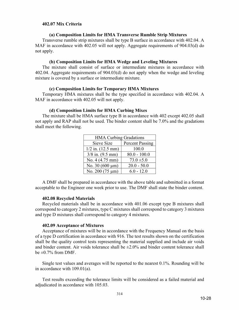
314
402.07 Mix Criteria (a) Composition Limits for HMA Transverse Rumble Strip Mixtures Transverse rumble strip mixtures shall be type B surface in accordance with 402.04. A MAF in accordance with 402.05 will not apply. Aggregate requirements of 904.03(d) do not apply. (b) Composition Limits for HMA Wedge and Leveling Mixtures The mixture shall consist of surface or intermediate mixtures in accordance with 402.04. Aggregate requirements of 904.03(d) do not apply when the wedge and leveling mixture is covered by a surface or intermediate mixture. (c) Composition Limits for Temporary HMA Mixtures Temporary HMA mixtures shall be the type specified in accordance with 402.04. A MAF in accordance with 402.05 will not apply. (d) Composition Limits for HMA Curbing Mixes The mixture shall be HMA surface type B in accordance with 402 except 402.05 shall not apply and RAP shall not be used. The binder content shall be 7.0% and the gradations shall meet the following.
HMA Curbing Gradations Sieve Size Percent Passing
1/2 in. (12.5 mm) 100.0 3/8 in. (9.5 mm) 80.0 - 100.0 No. 4 (4.75 mm) 73.0 ±5.0 No. 30 (600 µm) 20.0 - 50.0 No. 200 (75 µm) 6.0 - 12.0
A DMF shall be prepared in accordance with the above table and submitted in a format acceptable to the Engineer one week prior to use. The DMF shall state the binder content. 402.08 Recycled Materials Recycled materials shall be in accordance with 401.06 except type B mixtures shall correspond to category 2 mixtures, type C mixtures shall correspond to category 3 mixtures and type D mixtures shall correspond to category 4 mixtures. 402.09 Acceptance of Mixtures Acceptance of mixtures will be in accordance with the Frequency Manual on the basis of a type D certification in accordance with 916. The test results shown on the certification shall be the quality control tests representing the material supplied and include air voids and binder content. Air voids tolerance shall be ±2.0% and binder content tolerance shall be ±0.7% from DMF. Single test values and averages will be reported to the nearest 0.1%. Rounding will be in accordance with 109.01(a). Test results exceeding the tolerance limits will be considered as a failed material and adjudicated in accordance with 105.03.
10-28
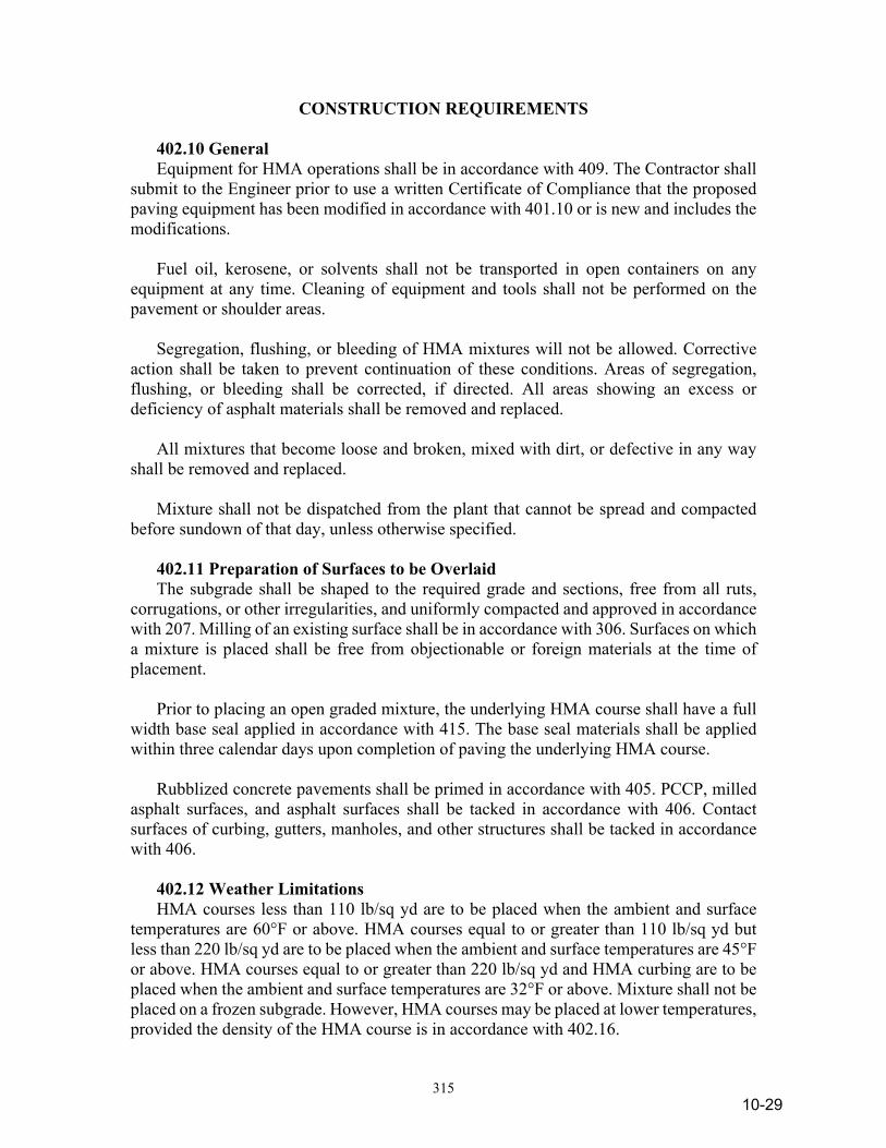
315
CONSTRUCTION REQUIREMENTS
402.10 General Equipment for HMA operations shall be in accordance with 409. The Contractor shall submit to the Engineer prior to use a written Certificate of Compliance that the proposed paving equipment has been modified in accordance with 401.10 or is new and includes the modifications. Fuel oil, kerosene, or solvents shall not be transported in open containers on any equipment at any time. Cleaning of equipment and tools shall not be performed on the pavement or shoulder areas. Segregation, flushing, or bleeding of HMA mixtures will not be allowed. Corrective action shall be taken to prevent continuation of these conditions. Areas of segregation, flushing, or bleeding shall be corrected, if directed. All areas showing an excess or deficiency of asphalt materials shall be removed and replaced. All mixtures that become loose and broken, mixed with dirt, or defective in any way shall be removed and replaced. Mixture shall not be dispatched from the plant that cannot be spread and compacted before sundown of that day, unless otherwise specified. 402.11 Preparation of Surfaces to be Overlaid The subgrade shall be shaped to the required grade and sections, free from all ruts, corrugations, or other irregularities, and uniformly compacted and approved in accordance with 207. Milling of an existing surface shall be in accordance with 306. Surfaces on which a mixture is placed shall be free from objectionable or foreign materials at the time of placement. Prior to placing an open graded mixture, the underlying HMA course shall have a full width base seal applied in accordance with 415. The base seal materials shall be applied within three calendar days upon completion of paving the underlying HMA course. Rubblized concrete pavements shall be primed in accordance with 405. PCCP, milled asphalt surfaces, and asphalt surfaces shall be tacked in accordance with 406. Contact surfaces of curbing, gutters, manholes, and other structures shall be tacked in accordance with 406. 402.12 Weather Limitations HMA courses less than 110 lb/sq yd are to be placed when the ambient and surface temperatures are 60°F or above. HMA courses equal to or greater than 110 lb/sq yd but less than 220 lb/sq yd are to be placed when the ambient and surface temperatures are 45°F or above. HMA courses equal to or greater than 220 lb/sq yd and HMA curbing are to be placed when the ambient and surface temperatures are 32°F or above. Mixture shall not be placed on a frozen subgrade. However, HMA courses may be placed at lower temperatures, provided the density of the HMA course is in accordance with 402.16.
10-29
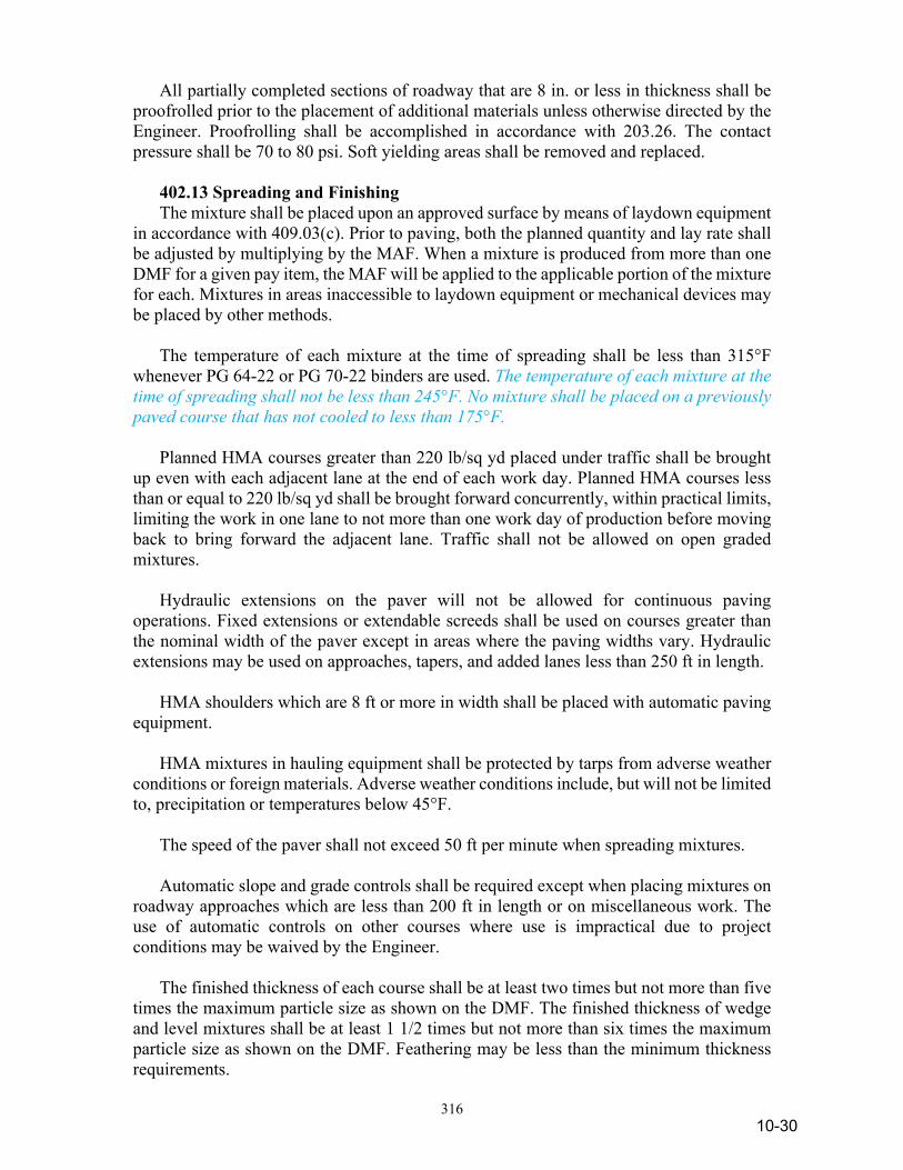
316
All partially completed sections of roadway that are 8 in. or less in thickness shall be proofrolled prior to the placement of additional materials unless otherwise directed by the Engineer. Proofrolling shall be accomplished in accordance with 203.26. The contact pressure shall be 70 to 80 psi. Soft yielding areas shall be removed and replaced. 402.13 Spreading and Finishing The mixture shall be placed upon an approved surface by means of laydown equipment in accordance with 409.03(c). Prior to paving, both the planned quantity and lay rate shall be adjusted by multiplying by the MAF. When a mixture is produced from more than one DMF for a given pay item, the MAF will be applied to the applicable portion of the mixture for each. Mixtures in areas inaccessible to laydown equipment or mechanical devices may be placed by other methods. The temperature of each mixture at the time of spreading shall be less than 315°F whenever PG 64-22 or PG 70-22 binders are used. The temperature of each mixture at the time of spreading shall not be less than 245°F. No mixture shall be placed on a previously paved course that has not cooled to less than 175°F. Planned HMA courses greater than 220 lb/sq yd placed under traffic shall be brought up even with each adjacent lane at the end of each work day. Planned HMA courses less than or equal to 220 lb/sq yd shall be brought forward concurrently, within practical limits, limiting the work in one lane to not more than one work day of production before moving back to bring forward the adjacent lane. Traffic shall not be allowed on open graded mixtures. Hydraulic extensions on the paver will not be allowed for continuous paving operations. Fixed extensions or extendable screeds shall be used on courses greater than the nominal width of the paver except in areas where the paving widths vary. Hydraulic extensions may be used on approaches, tapers, and added lanes less than 250 ft in length. HMA shoulders which are 8 ft or more in width shall be placed with automatic paving equipment. HMA mixtures in hauling equipment shall be protected by tarps from adverse weather conditions or foreign materials. Adverse weather conditions include, but will not be limited to, precipitation or temperatures below 45°F. The speed of the paver shall not exceed 50 ft per minute when spreading mixtures. Automatic slope and grade controls shall be required except when placing mixtures on roadway approaches which are less than 200 ft in length or on miscellaneous work. The use of automatic controls on other courses where use is impractical due to project conditions may be waived by the Engineer. The finished thickness of each course shall be at least two times but not more than five times the maximum particle size as shown on the DMF. The finished thickness of wedge and level mixtures shall be at least 1 1/2 times but not more than six times the maximum particle size as shown on the DMF. Feathering may be less than the minimum thickness requirements.
10-30
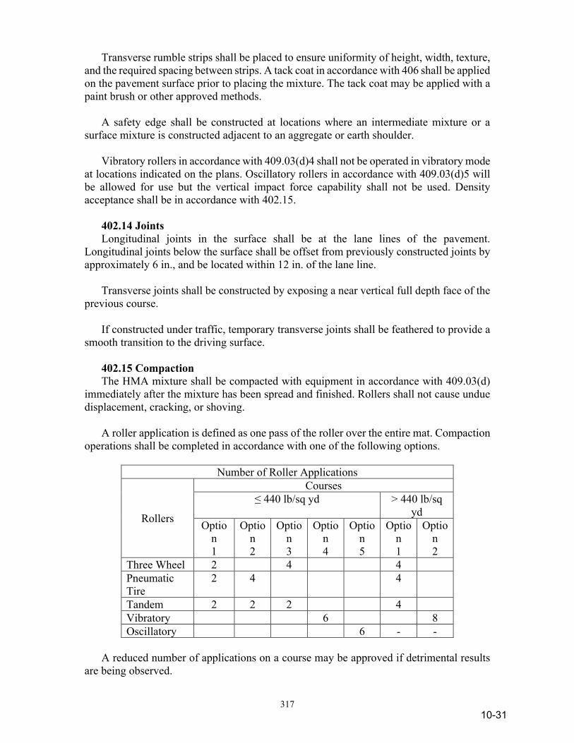
317
Transverse rumble strips shall be placed to ensure uniformity of height, width, texture, and the required spacing between strips. A tack coat in accordance with 406 shall be applied on the pavement surface prior to placing the mixture. The tack coat may be applied with a paint brush or other approved methods. A safety edge shall be constructed at locations where an intermediate mixture or a surface mixture is constructed adjacent to an aggregate or earth shoulder. Vibratory rollers in accordance with 409.03(d)4 shall not be operated in vibratory mode at locations indicated on the plans. Oscillatory rollers in accordance with 409.03(d)5 will be allowed for use but the vertical impact force capability shall not be used. Density acceptance shall be in accordance with 402.15. 402.14 Joints Longitudinal joints in the surface shall be at the lane lines of the pavement. Longitudinal joints below the surface shall be offset from previously constructed joints by approximately 6 in., and be located within 12 in. of the lane line. Transverse joints shall be constructed by exposing a near vertical full depth face of the previous course. If constructed under traffic, temporary transverse joints shall be feathered to provide a smooth transition to the driving surface. 402.15 Compaction The HMA mixture shall be compacted with equipment in accordance with 409.03(d) immediately after the mixture has been spread and finished. Rollers shall not cause undue displacement, cracking, or shoving. A roller application is defined as one pass of the roller over the entire mat. Compaction operations shall be completed in accordance with one of the following options.
Number of Roller Applications
Rollers
Courses ≤ 440 lb/sq yd > 440 lb/sq
yd Optio
n 1
Option 2
Option 3
Option 4
Option 5
Option 1
Option 2
Three Wheel 2 4 4 Pneumatic Tire
2 4 4
Tandem 2 2 2 4 Vibratory 6 8 Oscillatory 6 - -
A reduced number of applications on a course may be approved if detrimental results are being observed.
10-31
318
Compaction equipment shall be operated with the drive roll or wheels nearest the paver and at speeds not to exceed 3 mph. However, vibratory rollers will be limited to 2.5 mph. Rolling shall be continued until applications are completed and all roller marks are eliminated. Compaction operations shall begin at the low side and proceed to the high side of the mat. The heaviest roller wheel shall overlap its previous pass by a minimum of 6 in. Longitudinal joints shall be compacted in accordance with the following: (a) For confined edges, the first pass adjacent to the confined edge, the
compaction equipment shall be entirely on the hot mat 6 in. from the confined edge.
(b) For unconfined edges, the compaction equipment shall extend 6 in.
beyond the edge of the hot mat. All displacement of the HMA mixture shall be corrected at once by the use of lutes or the addition of fresh mixture as required. The line and grade of the edges of the HMA mixture shall not be displaced during rolling. The wheels shall be kept properly moistened with water or water with detergent to prevent adhesion of the materials to the wheels. Areas inaccessible to rollers shall be compacted thoroughly with hand tampers or other mechanical devices in accordance with 409.03(d)7 to achieve the required compaction. A trench roller, in accordance with 409.03(d)6, may be used to obtain compaction in depressed areas. The final two roller applications shall be completed at the highest temperature where the mixture does not exhibit any tenderness. Vehicular traffic will not be allowed on a course until the mixture has cooled sufficiently to prevent distortions. Transverse rumble strips shall be compacted with vibratory compacting equipment in accordance with 409.03(d)7 unless otherwise stated. 402.16 Low Temperature Compaction Requirements Compaction for mixtures placed below the temperatures listed in 402.12 shall be controlled by density determined from MSG of the plate samples and cores cut from the compacted pavement placed during a low temperature period. Samples shall be obtained in accordance with ITM 580. Acceptance will be based on a plate sample and two cores. The Engineer will randomly select the locations in accordance with ITM 802. The transverse core location will be located so that the edge of the core will be no closer than 3 in. from a confined edge or 6 in. from a non-confined edge of the course being placed. For compaction of HMA during low temperature periods with quantities less than 100 t per day, acceptance may be visual.
10-32
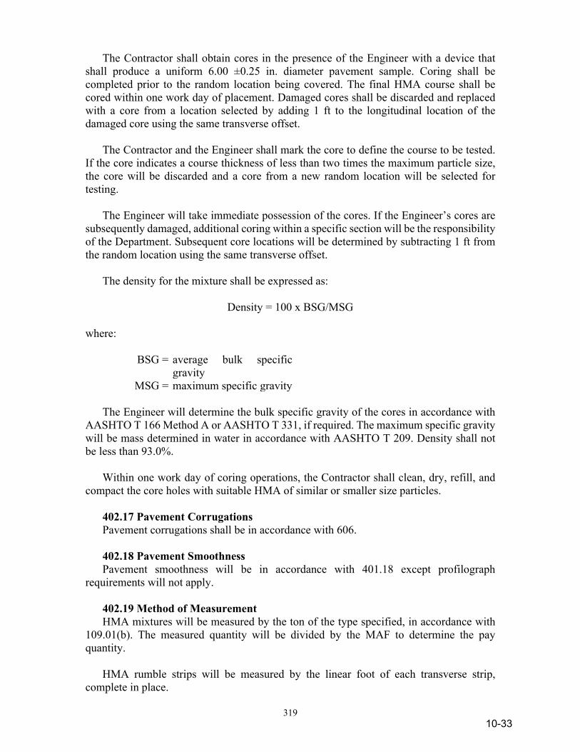
319
The Contractor shall obtain cores in the presence of the Engineer with a device that shall produce a uniform 6.00 ±0.25 in. diameter pavement sample. Coring shall be completed prior to the random location being covered. The final HMA course shall be cored within one work day of placement. Damaged cores shall be discarded and replaced with a core from a location selected by adding 1 ft to the longitudinal location of the damaged core using the same transverse offset. The Contractor and the Engineer shall mark the core to define the course to be tested. If the core indicates a course thickness of less than two times the maximum particle size, the core will be discarded and a core from a new random location will be selected for testing. The Engineer will take immediate possession of the cores. If the Engineer’s cores are subsequently damaged, additional coring within a specific section will be the responsibility of the Department. Subsequent core locations will be determined by subtracting 1 ft from the random location using the same transverse offset. The density for the mixture shall be expressed as:
Density = 100 x BSG/MSG where:
BSG = average bulk specific gravity
MSG = maximum specific gravity The Engineer will determine the bulk specific gravity of the cores in accordance with AASHTO T 166 Method A or AASHTO T 331, if required. The maximum specific gravity will be mass determined in water in accordance with AASHTO T 209. Density shall not be less than 93.0%. Within one work day of coring operations, the Contractor shall clean, dry, refill, and compact the core holes with suitable HMA of similar or smaller size particles. 402.17 Pavement Corrugations Pavement corrugations shall be in accordance with 606. 402.18 Pavement Smoothness Pavement smoothness will be in accordance with 401.18 except profilograph requirements will not apply. 402.19 Method of Measurement HMA mixtures will be measured by the ton of the type specified, in accordance with 109.01(b). The measured quantity will be divided by the MAF to determine the pay quantity. HMA rumble strips will be measured by the linear foot of each transverse strip, complete in place.
10-33

320
Milled pavement corrugations will be measured in accordance with 606.02. 402.20 Basis of Payment The accepted quantities for this work will be paid for at the contract unit price per ton for HMA, of the type specified complete in place. HMA transverse rumble strips will be paid for at the contract unit price per linear foot, complete in place. Milled pavement corrugations will be paid for in accordance with 606.03. Payment will be made under: Pay Item Pay Unit Symbol HMA Transverse Rumble Strips ................................LFT HMA for Temporary Pavement, Type * ............TON HMA Wedge and Level, Type * ........................TON * Mixture type Preparation of surfaces to be overlaid shall be included in the cost of other pay items in this section. No payment will be made for additional anti-stripping additives. The cost of removing and replacing soft yielding areas shall be included in the cost of other pay items in this section. No payment will be made for coring operations and related traffic control expenditures required in 402.16. Corrections for pavement smoothness including removal and replacement of pavement, shall be included in the cost of other pay items in this section. The cost of removal of HMA for temporary pavement including the subgrade and subbase materials shall be included in the cost of HMA for temporary pavement.
SECTION 403 – CMA PAVEMENT 403.01 Description This work shall consist of the construction of one or more courses of CMA base, intermediate, or surface for immediate use or stockpiled in accordance with 105.03.
MATERIALS 403.02 Materials Materials shall be in accordance with the following: Asphalt Materials
10-34
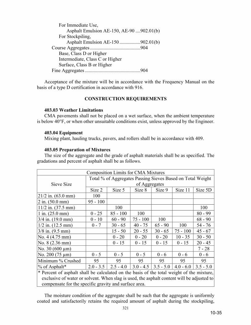
321
For Immediate Use, Asphalt Emulsion AE-150, AE-90 ....902.01(b) For Stockpiling, Asphalt Emulsion AE-150 .................902.01(b) Course Aggregates .........................................904 Base, Class D or Higher Intermediate, Class C or Higher Surface, Class B or Higher Fine Aggregates .............................................904 Acceptance of the mixture will be in accordance with the Frequency Manual on the basis of a type D certification in accordance with 916.
CONSTRUCTION REQUIREMENTS 403.03 Weather Limitations CMA pavements shall not be placed on a wet surface, when the ambient temperature is below 40°F, or when other unsuitable conditions exist, unless approved by the Engineer. 403.04 Equipment Mixing plant, hauling trucks, pavers, and rollers shall be in accordance with 409. 403.05 Preparation of Mixtures The size of the aggregate and the grade of asphalt materials shall be as specified. The gradations and percent of asphalt shall be as follows.
Composition Limits for CMA Mixtures
Sieve Size Total % of Aggregates Passing Sieves Based on Total Weight
of Aggregates Size 2 Size 5 Size 8 Size 9 Size 11 Size 5D
21/2 in. (63.0 mm) 100 2 in. (50.0 mm) 95 - 100 11/2 in. (37.5 mm) 100 100 1 in. (25.0 mm) 0 - 25 85 - 100 100 80 - 99 3/4 in. (19.0 mm) 0 - 10 60 - 90 75 - 100 100 68 - 90 1/2 in. (12.5 mm) 0 - 7 30 - 65 40 - 75 65 - 90 100 54 - 76 3/8 in. (9.5 mm) 15 - 50 20 - 55 30 - 65 75 - 100 45 - 67 No. 4 (4.75 mm) 0 - 20 0 - 20 0 - 20 10 - 35 30 - 50 No. 8 (2.36 mm) 0 - 15 0 - 15 0 - 15 0 - 15 20 - 45 No. 30 (600 µm) 7 - 28 No. 200 (75 µm) 0 - 5 0 - 5 0 - 5 0 - 6 0 - 6 0 - 6 Minimum % Crushed 95 95 95 95 95 95 % of Asphalt* 2.0 - 3.5 2.5 - 4.0 3.0 - 4.5 3.5 - 5.0 4.0 - 6.0 3.5 - 5.0 * Percent of asphalt shall be calculated on the basis of the total weight of the mixture,
exclusive of water or solvent. When slag is used, the asphalt content will be adjusted to compensate for the specific gravity and surface area.
The moisture condition of the aggregate shall be such that the aggregate is uniformly coated and satisfactorily retains the required amount of asphalt during the stockpiling,
10-35

322
hauling, and spreading operations. Mixtures shall not be produced at temperatures exceeding 180°F. 403.06 Preparation of Subgrade or Base Mixtures for CMA base may be placed on an earth subgrade, on an existing pavement surface to be used as a base, or on a previously prepared base or subbase as specified. If such material is to be laid on a newly prepared subgrade, then all applicable requirements of 207 shall apply. 403.07 Spreading Mixture The CMA mixture shall be spread in accordance with 402.13. A safety edge shall be constructed at locations where an intermediate mixture or a surface mixture is constructed adjacent to an aggregate or earth shoulder. 403.08 Curing All CMA mixtures shall be allowed to cure sufficiently to prevent undue distortions under the roller wheels. When a CMA mixture is allowed to cure under traffic, the surface shall be maintained and all damaged areas shall be satisfactorily repaired. 403.09 Compaction Compaction shall be in accordance with 402.15. Satisfactory means to confine the mixture within the required limits shall be in place during the compaction operation. 403.10 Surface Tolerances The smoothness requirements for CMA pavements shall be in accordance with 402.18. 403.11 Method of Measurement CMA pavement will be measured by the ton, of the type and size specified, in accordance with 109.01(b). 403.12 Basis of Payment The accepted quantities of CMA pavement will be paid for at the contract unit price per ton, of the type and size specified, for the mixture. Payment will be made under: Pay Item Pay Unit Symbol CMA Base ______ .....................................................TON size CMA Intermediate ______ ........................................TON size CMA Surface ______ ................................................TON size The cost of repairing damaged areas of mixture allowed to cure under traffic shall be included in the cost of the pay items in this section.
10-36
323
SECTION 404 – SEAL COAT 404.01 Description This work shall consist of one or more applications of asphalt material, each followed by an application of cover aggregate in accordance with 105.03. 404.02 Quality Control Seal coat shall be constructed according to a quality control plan, QCP, prepared and submitted by the Contractor in accordance with ITM 803; Contractor Quality Control Plan for Seal Coat. The QCP shall be submitted to the Engineer at least 15 days prior to commencing seal coat operations.
MATERIALS 404.03 Asphalt Material The type and grade of asphalt material shall be in accordance with the following: Asphalt Emulsion, RS-2, AE-90, AE-90S, or HFRS-2 ......................................902.01(b) 404.04 Cover Aggregate Aggregate shall be in accordance with the following requirements. When slag is used as an alternate to natural aggregate, adjustments will be made in accordance with 904.01, to compensate for differences in specific gravity. Coarse Aggregates*, Class B or Higher Size No. 8, 9, 11, 12, SC 11, SC 12, or SC 16 904 Fine Aggregate, Size No. 23 or 24 .................904 * Coarse aggregate type required shall be in accordance with
904.03(d)1 for ESAL categories 2 or 3. The types of seal coats shall be as follows:
10-37
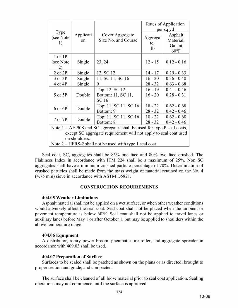
324
Type (see Note
1)
Application
Cover Aggregate Size No. and Course
Rates of Application per sq yd
Aggregate, lb
Asphalt Material, Gal. at 60°F
1 or 1P (see Note
2) Single 23, 24 12 - 15 0.12 - 0.16
2 or 2P Single 12, SC 12 14 - 17 0.29 - 0.33 3 or 3P Single 11, SC 11, SC 16 16 - 20 0.36 - 0.40 4 or 4P Single 9 28 - 32 0.63 - 0.68
5 or 5P Double Top: 12, SC 12 Bottom: 11, SC 11, SC 16
16 - 19 16 - 20
0.41 - 0.46 0.28 - 0.31
6 or 6P Double Top: 11, SC 11, SC 16 Bottom: 9
18 - 22 28 - 32
0.62 - 0.68 0.42 - 0.46
7 or 7P Double Top: 11, SC 11, SC 16 Bottom: 8
18 - 22 28 - 32
0.62 - 0.68 0.42 - 0.46
Note 1 – AE-90S and SC aggregates shall be used for type P seal coats, except SC aggregate requirement will not apply to seal coat used on shoulders.
Note 2 – HFRS-2 shall not be used with type 1 seal coat. Seal coat, SC, aggregates shall be 85% one face and 80% two face crushed. The Flakiness Index in accordance with ITM 224 shall be a maximum of 25%. Non SC aggregates shall have a minimum crushed particle percentage of 70%. Determination of crushed particles shall be made from the mass weight of material retained on the No. 4 (4.75 mm) sieve in accordance with ASTM D5821.
CONSTRUCTION REQUIREMENTS 404.05 Weather Limitations Asphalt material shall not be applied on a wet surface, or when other weather conditions would adversely affect the seal coat. Seal coat shall not be placed when the ambient or pavement temperature is below 60°F. Seal coat shall not be applied to travel lanes or auxiliary lanes before May 1 or after October 1, but may be applied to shoulders within the above temperature range. 404.06 Equipment A distributor, rotary power broom, pneumatic tire roller, and aggregate spreader in accordance with 409.03 shall be used. 404.07 Preparation of Surface Surfaces to be sealed shall be patched as shown on the plans or as directed, brought to proper section and grade, and compacted. The surface shall be cleaned of all loose material prior to seal coat application. Sealing operations may not commence until the surface is approved.
10-38

325
All castings, detector housings, and snowplowable raised pavement markers shall be covered prior to applying the asphalt material to prevent coating with seal coat. These coverings shall be removed prior to opening to unrestricted traffic. 404.08 Applying Asphalt Material Asphalt material shall be applied in a uniform continuous spread over the section to be treated. The quantity of asphalt material to be applied per square yard shall be in accordance with the QCP. During application, minor adjustments to the application rate shall be made in accordance with the QCP. The asphalt material shall not be spread over a greater area than that which can be covered with the cover aggregate that is in trucks at the site. The spread of the asphalt material shall be no wider than the width covered by the cover aggregate from the spreading device. Operations shall not proceed such that asphalt material is allowed to chill, set up, dry, or otherwise impair retention of the cover coat. 404.09 Application of Cover Aggregate Within 1 minute of the application of the asphalt material, cover aggregate shall be spread in quantities as required. Spreading shall be accomplished such that the tires of the trucks or aggregate spreader do not contact the uncovered and newly applied asphalt material. 404.10 Rolling Operation The aggregate shall be seated with at least three roller applications. A roller application is defined as one pass of the roller over the width sealed. The first roller application shall be completed within 2 minutes of aggregate application, with the final application completed within 30 minutes after the cover aggregate is applied. The rollers shall not be operated at speeds that will displace the cover aggregate from the asphalt material. 404.11 Sweeping Operation Excess cover aggregate shall be removed from the pavement surface by brooming no later than the morning after placement of the seal coat. The brooming shall not displace the imbedded aggregate. A second brooming operation shall be performed prior to opening to unrestricted traffic in accordance with 101.33. 404.12 Protection of Surface Traffic shall not be allowed on the freshly sealed surfaces until final rolling application is complete. The seal coat shall be protected by keeping traffic off of the freshly sealed surface or by controlling traffic speed in accordance with the QCP. Traffic shall not displace the imbedded aggregate. Any areas with minor bleeding will be covered with fine aggregate or other approved blotting material. 404.13 Method of Measurement Seal coat will be measured by the square yard of the seal coated surface. Patching will be measured in accordance with 304.06.
10-39
326
404.14 Basis of Payment Seal coat will be paid for at the contract unit price per square yard complete in place. Patching will be paid for in accordance with 304.07. Payment will be made under: Pay Item Pay Unit Symbol Seal Coat, ______ ......................................................SYS type Seal Coat, ______ P ...................................................SYS type The cost of determination of asphalt material and cover aggregate application rates, sweeping and rolling operations, blotting material, and other incidentals shall be included in the cost of the pay items. The Contractor shall adjust application rates as required by the Engineer within the limits set out herein. No additional payment will be made for additional materials necessary to meet the required application rates within the specified limits.
SECTION 405 – PRIME COAT 405.01 Description This work shall consist of preparing and treating a rubblized PCCP with asphalt material in accordance with 105.03.
MATERIALS 405.02 Asphalt Materials The type and grade of asphalt material shall be in accordance with the following: Asphalt Emulsion, AE-PL .............................902.01(b) 405.03 Cover Aggregate Aggregate shall be in accordance with the following: Coarse Aggregate, Class B or Higher, Size No. 12 904 Fine Aggregate, Size No. 23 or 24 .................904
CONSTRUCTION REQUIREMENTS 405.04 Weather Limitations Asphalt material shall not be applied on a wet surface, when the ambient temperature is below 50°F, or when other unsuitable conditions exist, unless approved by the Engineer. 405.05 Equipment A distributor and aggregate spreader in accordance with 409.03 shall be used.
10-40
327
405.06 Preparation of Surface The existing surface to be treated shall be shaped to the required grade and section, free from all ruts, corrugations, or other irregularities; uniformly compacted; and approved. 405.07 Application of Asphalt Material AE-PL shall be uniformly applied at the rate of 0.50 to 0.75 gal./sq yd placed in a single application. When placing material on a rubblized base, a carpet drag shall be utilized behind the distributor. When traffic is to be maintained within the limits of the section, approximately one half of the width of the section shall be treated in one application. Complete coverage of the section shall be ensured. Treated areas shall not be opened to traffic until the asphalt material has been absorbed. 405.08 Cover Aggregate If the asphalt material fails to penetrate and the primed surface must be used by traffic, cover aggregate shall be spread to provide a dry surface. 405.09 Method of Measurement Asphalt for prime coat will be measured by the ton, or by the square yard. Cover aggregate will be measured by the ton. 405.10 Basis of Payment The accepted quantities of prime coat will be paid for at the contract unit price per ton, or per square yard for asphalt for prime coat. The accepted quantities of cover aggregate will be paid for at the contract unit price per ton, complete in place. Payment will be made under: Pay Item Pay Unit Symbol Asphalt for Prime Coat ..............................................TON SYS Cover Aggregate, Prime Coat ....................................TON
SECTION 406 – TACK COAT 406.01 Description This work shall consist of preparing and treating an existing pavement or concrete surface with asphalt material in accordance with 105.03.
MATERIALS 406.02 Materials The type and grade of asphalt material shall be in accordance with the following: Asphalt Emulsion, SS-1h, AE-NT .................902.01(b) PG Asphalt Binder, PG 64-22 ........................902.01(a)
10-41
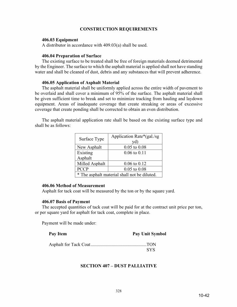
328
CONSTRUCTION REQUIREMENTS
406.03 Equipment A distributor in accordance with 409.03(a) shall be used. 406.04 Preparation of Surface The existing surface to be treated shall be free of foreign materials deemed detrimental by the Engineer. The surface to which the asphalt material is applied shall not have standing water and shall be cleaned of dust, debris and any substances that will prevent adherence. 406.05 Application of Asphalt Material The asphalt material shall be uniformly applied across the entire width of pavement to be overlaid and shall cover a minimum of 95% of the surface. The asphalt material shall be given sufficient time to break and set to minimize tracking from hauling and laydown equipment. Areas of inadequate coverage that create streaking or areas of excessive coverage that create ponding shall be corrected to obtain an even distribution. The asphalt material application rate shall be based on the existing surface type and shall be as follows:
Surface Type Application Rate*(gal./sg yd)
New Asphalt 0.05 to 0.08 Existing Asphalt
0.06 to 0.11
Milled Asphalt 0.06 to 0.12 PCCP 0.05 to 0.08 * The asphalt material shall not be diluted.
406.06 Method of Measurement Asphalt for tack coat will be measured by the ton or by the square yard. 406.07 Basis of Payment The accepted quantities of tack coat will be paid for at the contract unit price per ton, or per square yard for asphalt for tack coat, complete in place. Payment will be made under: Pay Item Pay Unit Symbol Asphalt for Tack Coat ................................................TON SYS
SECTION 407 – DUST PALLIATIVE
10-42
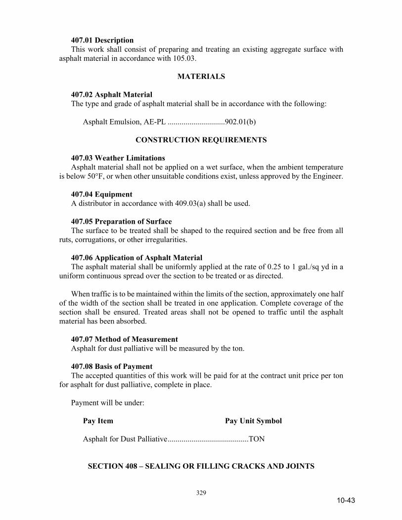
329
407.01 Description This work shall consist of preparing and treating an existing aggregate surface with asphalt material in accordance with 105.03.
MATERIALS 407.02 Asphalt Material The type and grade of asphalt material shall be in accordance with the following: Asphalt Emulsion, AE-PL .............................902.01(b)
CONSTRUCTION REQUIREMENTS 407.03 Weather Limitations Asphalt material shall not be applied on a wet surface, when the ambient temperature is below 50°F, or when other unsuitable conditions exist, unless approved by the Engineer. 407.04 Equipment A distributor in accordance with 409.03(a) shall be used. 407.05 Preparation of Surface The surface to be treated shall be shaped to the required section and be free from all ruts, corrugations, or other irregularities. 407.06 Application of Asphalt Material The asphalt material shall be uniformly applied at the rate of 0.25 to 1 gal./sq yd in a uniform continuous spread over the section to be treated or as directed. When traffic is to be maintained within the limits of the section, approximately one half of the width of the section shall be treated in one application. Complete coverage of the section shall be ensured. Treated areas shall not be opened to traffic until the asphalt material has been absorbed. 407.07 Method of Measurement Asphalt for dust palliative will be measured by the ton. 407.08 Basis of Payment The accepted quantities of this work will be paid for at the contract unit price per ton for asphalt for dust palliative, complete in place. Payment will be under: Pay Item Pay Unit Symbol Asphalt for Dust Palliative .........................................TON
SECTION 408 – SEALING OR FILLING CRACKS AND JOINTS
10-43
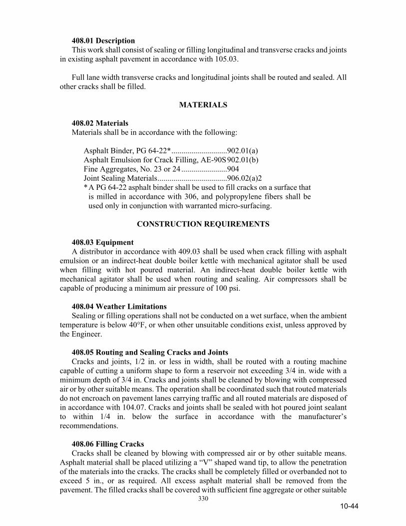
330
408.01 Description This work shall consist of sealing or filling longitudinal and transverse cracks and joints in existing asphalt pavement in accordance with 105.03. Full lane width transverse cracks and longitudinal joints shall be routed and sealed. All other cracks shall be filled.
MATERIALS 408.02 Materials Materials shall be in accordance with the following: Asphalt Binder, PG 64-22* ............................902.01(a) Asphalt Emulsion for Crack Filling, AE-90S 902.01(b) Fine Aggregates, No. 23 or 24 .......................904 Joint Sealing Materials ...................................906.02(a)2 * A PG 64-22 asphalt binder shall be used to fill cracks on a surface that
is milled in accordance with 306, and polypropylene fibers shall be used only in conjunction with warranted micro-surfacing.
CONSTRUCTION REQUIREMENTS
408.03 Equipment A distributor in accordance with 409.03 shall be used when crack filling with asphalt emulsion or an indirect-heat double boiler kettle with mechanical agitator shall be used when filling with hot poured material. An indirect-heat double boiler kettle with mechanical agitator shall be used when routing and sealing. Air compressors shall be capable of producing a minimum air pressure of 100 psi. 408.04 Weather Limitations Sealing or filling operations shall not be conducted on a wet surface, when the ambient temperature is below 40°F, or when other unsuitable conditions exist, unless approved by the Engineer. 408.05 Routing and Sealing Cracks and Joints Cracks and joints, 1/2 in. or less in width, shall be routed with a routing machine capable of cutting a uniform shape to form a reservoir not exceeding 3/4 in. wide with a minimum depth of 3/4 in. Cracks and joints shall be cleaned by blowing with compressed air or by other suitable means. The operation shall be coordinated such that routed materials do not encroach on pavement lanes carrying traffic and all routed materials are disposed of in accordance with 104.07. Cracks and joints shall be sealed with hot poured joint sealant to within 1/4 in. below the surface in accordance with the manufacturer’s recommendations. 408.06 Filling Cracks Cracks shall be cleaned by blowing with compressed air or by other suitable means. Asphalt material shall be placed utilizing a “V” shaped wand tip, to allow the penetration of the materials into the cracks. The cracks shall be completely filled or overbanded not to exceed 5 in., or as required. All excess asphalt material shall be removed from the pavement. The filled cracks shall be covered with sufficient fine aggregate or other suitable
10-44
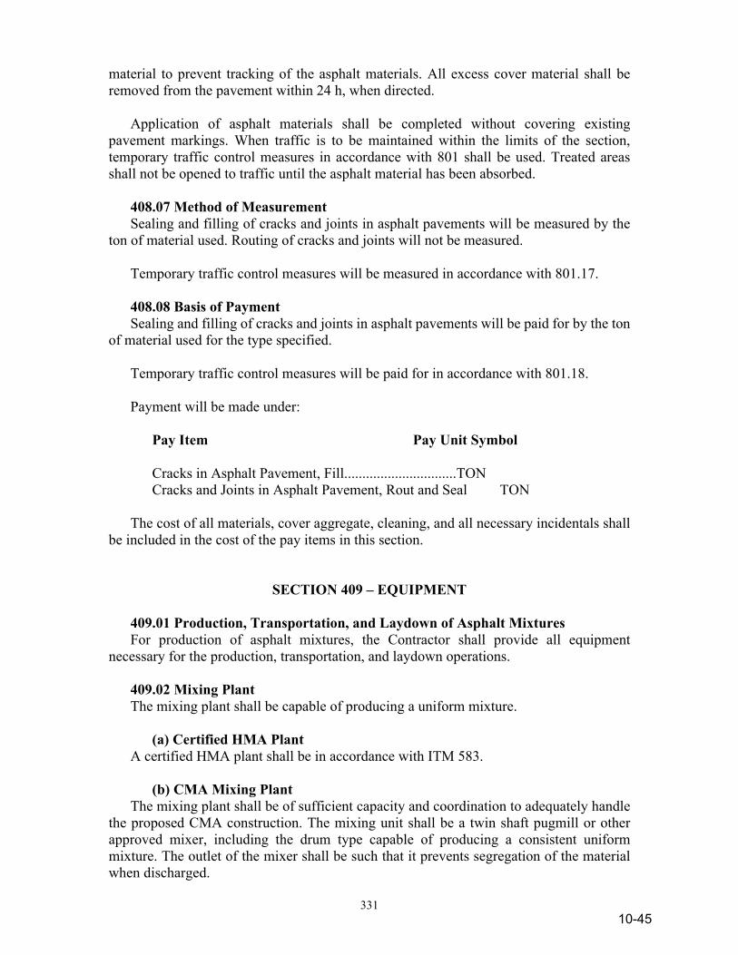
331
material to prevent tracking of the asphalt materials. All excess cover material shall be removed from the pavement within 24 h, when directed. Application of asphalt materials shall be completed without covering existing pavement markings. When traffic is to be maintained within the limits of the section, temporary traffic control measures in accordance with 801 shall be used. Treated areas shall not be opened to traffic until the asphalt material has been absorbed. 408.07 Method of Measurement Sealing and filling of cracks and joints in asphalt pavements will be measured by the ton of material used. Routing of cracks and joints will not be measured. Temporary traffic control measures will be measured in accordance with 801.17. 408.08 Basis of Payment Sealing and filling of cracks and joints in asphalt pavements will be paid for by the ton of material used for the type specified. Temporary traffic control measures will be paid for in accordance with 801.18. Payment will be made under: Pay Item Pay Unit Symbol Cracks in Asphalt Pavement, Fill ...............................TON Cracks and Joints in Asphalt Pavement, Rout and Seal TON The cost of all materials, cover aggregate, cleaning, and all necessary incidentals shall be included in the cost of the pay items in this section.
SECTION 409 – EQUIPMENT 409.01 Production, Transportation, and Laydown of Asphalt Mixtures For production of asphalt mixtures, the Contractor shall provide all equipment necessary for the production, transportation, and laydown operations. 409.02 Mixing Plant The mixing plant shall be capable of producing a uniform mixture. (a) Certified HMA Plant A certified HMA plant shall be in accordance with ITM 583. (b) CMA Mixing Plant The mixing plant shall be of sufficient capacity and coordination to adequately handle the proposed CMA construction. The mixing unit shall be a twin shaft pugmill or other approved mixer, including the drum type capable of producing a consistent uniform mixture. The outlet of the mixer shall be such that it prevents segregation of the material when discharged.
10-45
332
A certified HMA plant in accordance with 409.02(a) may be utilized as a CMA mixing plant. 409.03 HMA Laydown Operations (a) Distributor The distributor shall be equipped, maintained, and operated to provide uniform heating and application rates as specified. The distributor shall have a volume measuring device and a thermometer to monitor the asphalt material. Distributors shall also be equipped with a power unit for the pump and with a full circulation spray bar with vertical controls. (b) Hauling Equipment The mixtures shall be transported to the laydown operation in trucks that have tight, clean, and smooth beds. Truck beds may be treated with approved anti-adhesive agents. The truck beds shall be raised after application of non-foaming anti-adhesive agents to drain liquids from the bed prior to HMA being loaded into the truck. The Department will maintain a list of approved Anti-Adhesive Materials. Hauling equipment shall be equipped with a watertight cover to protect the mixture. (c) Laydown Equipment 1. Paver The paver shall be self-propelled, and equipped with a material receiving system, and equipped with heated and vibrating screeds. The paver may also include automatic slope and grade controls, extendable screeds and extendable augers. Automatic control devices shall be separated from the paver screeds, paver tracks or wheels and be capable of adjusting both sides of the screeds automatically to maintain a constant angle of attack in relation to the grade leveler device or grade line. A grade leveling system may be used to activate the control devices on each HMA course, including matching lays. The leveling system shall be attached to the paver and operated parallel to the paver’s line of travel. Extendable screeds shall be rigid, heated, and vibrating, and be capable of maintaining the cross slope, and line and grade of the pavement, to produce uniform placement of the materials. Auger extensions shall be used when required to distribute the HMA uniformly in front of the screed. When a dense graded intermediate or a surface mixture is placed adjacent to an aggregate or earth shoulder, the side of the paver adjacent to the aggregate or earth shoulder shall be equipped with a device capable of constructing a safety edge. The following devices are approved for this application:
10-46
333
(a) Advant-Edge™, Advant-Edge Paving Equipment LLC (b) Safety Edge End Gate, Carlson Paving Products, Inc. (c) TransTech Shoulder Wedge Maker™, TransTech Systems, Inc. (d) SafeTSlope Edge Smoother™, Troxler Electronic Laboratories, Inc. 2. Widener A device capable of receiving, transferring, spreading, and striking off materials to the proper grade and slope. 3. Other Mechanical Devices Inaccessible or short sections of HMA may be placed with specialty equipment approved by the Engineer. (d) Compaction Equipment Compaction equipment shall be self-propelled, steel wheel or pneumatic tire types, in good condition, and capable of reversing direction without backlashing. All roller wheels shall be equipped with scrapers to keep the wheels clean, have water spraying devices on the wheels, and steering devices capable of accurately guiding the roller. 1. Tandem Roller A roller having two axles and a minimum weight of 10 t. 2. Three Wheel Roller A roller having three wheels with a minimum bearing of 300 lb/in. on the rear wheels. The crown of the wheels shall not exceed 2.5 in. in 18 ft. A tandem roller which has a drive wheel bearing of no less than 300 lb/in. may be used in lieu of the three wheel roller. 3. Pneumatic Tire Roller A pneumatic tire roller shall have a minimum rolling width of 5.5 ft. The roller shall be equipped with compaction tires, minimum size 7:50 by 15, exerting a uniform, average contact pressure from 50 to 90 psi uniformly over the pavement by adjusting ballast and tire inflation pressures. The wheels on at least one axle shall be fully oscillating vertically, and mounted as to prevent scuffing of the pavements during rolling or turning operations. Charts or tabulations showing the contact areas and pressures for the full range of tire inflation pressures and for the full range of tire loadings for each compactor shall be furnished to the Engineer. 4. Vibratory Roller A vibratory roller shall have both drums equipped for vertical impact forces, a variable amplitude system, a speed control device, and have a minimum vibration frequency of 2,000 vibrations per minute. A reed tachometer shall be provided for verifying the frequency of vibrations. 5. Oscillatory Roller An oscillatory roller shall have both drums equipped for horizontal and vertical shear forces or one drum equipped for horizontal and vertical shear force and the other drum equipped for a vertical impact force.
10-47
334
6. Trench Roller A trench roller shall have a compaction wheel bearing of no less than 300 lb/in. 7. Specialty Roller/Compactor Inaccessible or short sections of HMA may be compacted with specialty equipment approved by the Engineer. (e) Miscellaneous Equipment 1. Aggregate Spreader A spreader shall be a self-propelled, pneumatic tired, motorized unit with a front loading hopper and a transportation system for distributing the aggregates uniformly across the pavement. 2. Rotary Power Broom A motorized, pneumatic tired unit with rotary bristle broom head. (f) Smoothness Equipment 1. Profilograph The profilograph shall be in accordance with ITM 912. 2. Straightedge – 16 ft A 16 ft straightedge shall be a rigid beam mounted on two solid wheels on axles 16 ft apart. The straightedge has a mounted push bar to facilitate propelling the device along or across the pavement. Tolerance points are located at the 1/4, 1/2, and 3/4 points and may be composed of threaded bolts capable of being adjusted to the tolerance required. 3. Straightedge – 10 ft A 10 ft straightedge is the same as a 16 ft straightedge except that the wheels are mounted 10 ft apart. A handheld rigid beam may be substituted.
SECTION 410 – QC/QA HMA – SMA PAVEMENT 410.01 Description This work shall consist of one course of QC/QA HMA – SMA mixture constructed on prepared foundations in accordance with 105.03. 410.02 Quality Control The SMA mixture shall be supplied from a certified HMA plant in accordance with ITM 583; Certified Hot Mix Asphalt Producer Program. The QCP shall be modified to include the requirements for the SMA mixtures. The SMA shall be transported and placed according to the QCP prepared and submitted by the Contractor in accordance with ITM 803; Contractor Quality Control Plans for Hot Mix Asphalt Pavements. The QCP shall be submitted to the Engineer at least 15 days prior to commencing SMA paving operations. When a safety edge is required for a project, the QCP shall identify the device or devices in accordance with 409.03(c) to be used for constructing the safety edge.
10-48

335
MATERIAL
410.03 Materials Materials shall be in accordance with the following: Asphalt Materials PG Binder, PG 76-22, PG 70-22 ..............902.01(a) Coarse Aggregates, Class AS ........................904 Fibers..............................................................AASHTO M 325 Fine Aggregates (sand, mineral filler) ...........904 410.04 Design Mix Formula A design mix formula, DMF, shall be prepared in accordance with 410.05 and submitted in a format acceptable to the Engineer one week prior to use. The DMF shall state the maximum particle size in the mixture. The DMF shall state the calibration factor, test temperature and absorption factors to be used for the determination of binder content using the ignition oven in accordance with ITM 586, the binder content by extraction in accordance with ITM 571, ΔPb, determined in accordance with ITM 591, the aggregate degradation loss value in accordance with ITM 220 and a Mixture Adjustment Factor, MAF. The DMF shall state the source, type dosage rate of any stabilizing additives. The DMF will be based on the ESAL and mixture designation. No mixture will be accepted for use until the DMF has been assigned a mixture number by the Engineer. The ESAL category identified in the pay item correlates to the following ESAL ranges:
ESAL Category ESAL 2* < 3,000,000
3 3,000,000 to < 10,000,000
4* > 10,000,000 * A category 2 mixture shall replace a category
1 mixture and a category 4 mixture shall replace a category 5 mixture.
The plant discharge temperature for any mixture shall not be more than 315°F whenever PG 70-22 binder is used or not more than 325°F whenever PG 76-22 binder is used. SMA may be produced using a water-injection foaming device. The DMF shall list the minimum and maximum plant discharge temperatures as applicable to the mixture. 410.05 SMA Mix Design The DMF shall be determined for each mixture from a SMA mix design by a design laboratory selected from the Department’s list of approved Mix Design Laboratories. A SMA mixture shall be designed in accordance with ITM 220, AASHTO M 325 and R 46 except the design gyrations shall be 75 for all ESAL categories. All loose mixture shall be conditioned for 4 h in accordance with AASHTO R 30 prior to testing. Steel furnace slag coarse aggregate, when used in an intermediate mixture application, shall have a deleterious content less than 4.0% as determined in accordance with ITM 219.
10-49

336
The single percentage of aggregate passing each required sieve shall be within the limits of the following gradation table.
SMA Gradation Control Limits
Mixture Designation 9.5 mm 12.5 mm 19.0 mm
Sieve Size Lower Upper Lower Upper Lower Upper 1 1/2 in. (37.5 mm) 100.0 100.0 1 in. (25.0 mm) 100.0 100.0 99.0* 100.0 3/4 in. (19.0 mm) 100.0 100.0 99.0* 100.0 90.0 99.0 1/2 in. (12.5 mm) 99.0* 100.0 90.0 99.0 50.0 88.0 3/8 in. (9.5 mm) 70.0 95.0 50.0 80.0 25.0 60.0 No. 4 (4.75 mm) 30.0 50.0 20.0 35.0 20.0 28.0 No. 8 (2.36 mm) 20.0 30.0 16.0 24.0 16.0 24.0 No. 16 (1.18 mm) --- 21.0 --- --- --- --- No. 30 (600 µm) --- 18.0 --- --- --- --- No. 50 (300 µm) --- 15.0 --- --- --- --- No. 200 (75 µm) 8.0 12.0 8.0 11.0 8.0 11.0 * The lower % passing gradation may be 98.0% when SMA RAP material in
accordance with 410.06 is used in the SMA mixture. The optimum binder and aggregate gradation content shall produce a ΔPb ≤ 0.20 as determined in accordance with ITM 591 and 4.0% air voids. The maximum specific gravity shall be mass determined in water in accordance with AASHTO T 209. The percent draindown for SMA mixture shall not exceed 0.30% in accordance with AASHTO T 305. The MAF equals the Gmm from the mixture design divided by the following: 2.465 for 9.5 mm mixtures and 2.500 for 12.5 mm mixtures. If the MAF calculation results in a value where 0.980 ≤ MAF ≤ 1.020, then the MAF shall be considered to be 1.000. If the MAF is greater than 1.020, the calculated MAF value shall have 0.020 subtracted from the value. If the MAF is less than 0.980, the calculated MAF value shall have 0.020 added to the value. The MAF does not apply to OG mixtures. The mixture shall be tested for moisture susceptibility in accordance with AASHTO T 283 except that the loose mixture curing shall be replaced by mixture conditioning for 4 h in accordance with AASHTO R 30. The minimum tensile strength ratio, TSR, shall be 70%. The 6 in. mixture specimens shall be compacted to 6.0 ±1.0% air voids in accordance with AASHTO T 312. Specimens shall be prepared using freeze-thaw preconditioning. If anti-stripping additives are added to the mixture to be in accordance with the minimum TSR requirements, the dosage rate shall be submitted with the DMF. The fine aggregate portion of the aggregate blend shall be non-plastic as determined in accordance with AASHTO T 90. A change in the source or types of aggregates, a change in source or type of stabilizing additives, or a change in the source of the specified binder shall require a new DMF.
10-50
337
The specific gravity of SF and the Gsb of the aggregate blend containing SF may be adjusted once per contract upon notification by the SF source and approval by the District Testing Engineer. A new DMF is not required for this adjustment. The mixture design compaction temperature for the specimens shall be 300 ±9°F.
Voids in Mineral Aggregate, VMA, Criteria
Mixture Designation Minimum VMA, %
19.0 mm 15.0 12.5 mm 16.0 9.5 mm 17.0
410.06 Recycled Materials Recycled materials shall be in accordance with 401.06 for dense graded mixtures except non-SMA RAP material for use in the SMA mixture shall be 100% passing the 3/8 in. (9.5 mm) sieve and 95 to 100% passing the No. 4 (4.75 mm) sieve. SMA RAP material shall be the product derived by exclusively milling an existing SMA mixture. The SMA RAP material shall pass the maximum size sieve for the mixture being produced as follows:
SMA RAP Gradation, %
Sieve Size Mixture Designation
9.5 mm 12.5 mm 19.0 mm Lower Upper Lower Upper Lower Upper
1 1/2 in. (37.5 mm) 100.0 100.0 1 in. (25.0 mm) 100.0 100.0 95.0 100.0 3/4 in. (19.0 mm) 100.0 100.0 95.0 100.0 --- --- 1/2 in. (12.5 mm) 95.0 100.0 --- --- --- ---
The Contractor may request the use of SMA RAP material in the SMA mixture provided the material is stockpiled separately at the plant and the material properties were determined in accordance with ITM 584 during stockpile construction. The request shall include all QC test results describing the stockpile composition. The Engineer will obtain a representative sample of the SMA RAP material in accordance with ITM 207 for testing in accordance with ITM 590 to verify the proposed design value. 410.07 Lots and Sublots Lots will be defined as 4,000 t of SMA intermediate mixture or 2,400 t of SMA surface mixture. Lots will be further sub-divided into sublots not to exceed 1,000 t of SMA intermediate mixture or 600 t of SMA surface mixture. Partial sublots of 100 t or less will be added to the previous sublot. Partial sublots greater than 100 t constitute a full sublot. 410.08 Job Mix Formula A job mix formula, JMF, shall be developed by a certified HMA producer in accordance with ITM 583. A JMF used for SMA mixture in the current calendar year will be allowed.
10-51
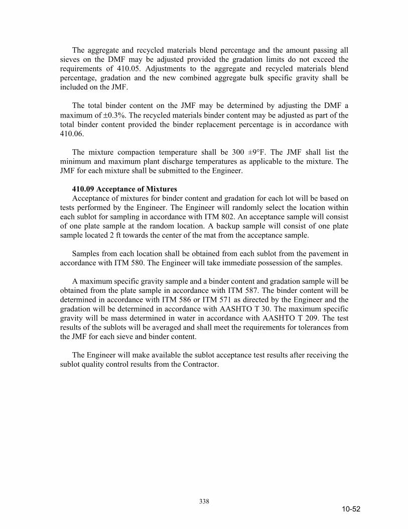
338
The aggregate and recycled materials blend percentage and the amount passing all sieves on the DMF may be adjusted provided the gradation limits do not exceed the requirements of 410.05. Adjustments to the aggregate and recycled materials blend percentage, gradation and the new combined aggregate bulk specific gravity shall be included on the JMF. The total binder content on the JMF may be determined by adjusting the DMF a maximum of ±0.3%. The recycled materials binder content may be adjusted as part of the total binder content provided the binder replacement percentage is in accordance with 410.06. The mixture compaction temperature shall be 300 ±9°F. The JMF shall list the minimum and maximum plant discharge temperatures as applicable to the mixture. The JMF for each mixture shall be submitted to the Engineer. 410.09 Acceptance of Mixtures Acceptance of mixtures for binder content and gradation for each lot will be based on tests performed by the Engineer. The Engineer will randomly select the location within each sublot for sampling in accordance with ITM 802. An acceptance sample will consist of one plate sample at the random location. A backup sample will consist of one plate sample located 2 ft towards the center of the mat from the acceptance sample. Samples from each location shall be obtained from each sublot from the pavement in accordance with ITM 580. The Engineer will take immediate possession of the samples. A maximum specific gravity sample and a binder content and gradation sample will be obtained from the plate sample in accordance with ITM 587. The binder content will be determined in accordance with ITM 586 or ITM 571 as directed by the Engineer and the gradation will be determined in accordance with AASHTO T 30. The maximum specific gravity will be mass determined in water in accordance with AASHTO T 209. The test results of the sublots will be averaged and shall meet the requirements for tolerances from the JMF for each sieve and binder content. The Engineer will make available the sublot acceptance test results after receiving the sublot quality control results from the Contractor.
10-52

339
Acceptance Tolerance for Mixtures (Percent Mass) Mixture
Number of Tests
Sieve Size
Surface
*1 in. (25.0 mm)
*3/4 in. (19.0 mm)
*1/2 in. (12.5 mm)
*3/8 in. (9.5 mm)
*No. 4 (4.75 mm)
No. 8 (2.36 mm)
No. 30 (600 µm)
No. 200 (75 µm)
1 --- --- --- --- --- 8.0 4.0 2.5 2 --- --- --- --- --- 5.7 2.8 2.1 3 --- --- --- --- --- 4.6 2.3 1.8 4 --- --- --- --- --- 4.0 2.0 1.5
Intermediate
1 --- --- --- --- --- 10.0 6.0 2.0 2 --- --- --- --- --- 7.0 4.2 1.4 3 --- --- --- --- --- 5.8 3.5 1.2 4 --- --- --- --- --- 5.0 3.0 1.0
* The acceptance tolerance for this sieve shall be the applicable composition limits specified in 410.05.
Acceptance Tolerance for Binder
Binder Content Number of Tests 1 2 3 4
%Binder 0.7 0.5 0.4 0.3 Acceptance of mixtures for range will be determined using the results of sublot tests performed by the Engineer from each lot. If the range is not in accordance with the requirements, adjustment points will be assessed in accordance with 410.19(a).
Acceptance Tolerance for Range (±Percent Mass) Sieve Size and Binder Content
Percentage Points Surface Intermediate
No. 8 (2.36 mm) 12.0 15.0 No. 30 (600 µm) 6.0 9.0 No. 200 (75 µm) 2.0 3.0
%Binder 1.0 1.0 Acceptance tolerances for binder content and gradation will be as set out above for the number of tests performed. The acceptance tolerance for range will be as set out above for lots of more than one sublot. The range of binder shall be the difference between the highest sublot binder content and the lowest sublot binder content in one lot. The range of gradation shall be the difference between the highest sublot percent passing and the lowest sublot percent passing each required sieve in one lot. Single test values and averages will be reported to the nearest 0.1%. Rounding will be in accordance with 109.01(a). Lot adjustment points will be assessed in accordance with 410.19(a) when the average or range for binder content or gradation are not met. The Contractor may request an appeal of the Engineer’s test results in accordance with 410.20.
10-53
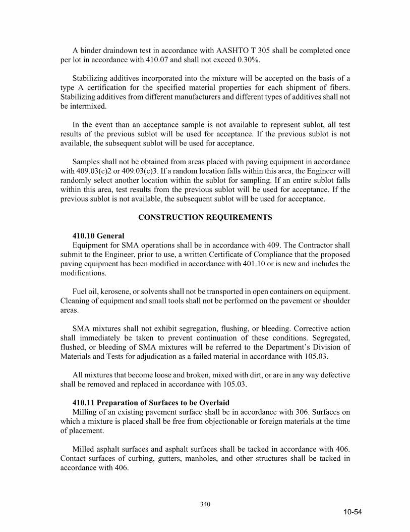
340
A binder draindown test in accordance with AASHTO T 305 shall be completed once per lot in accordance with 410.07 and shall not exceed 0.30%. Stabilizing additives incorporated into the mixture will be accepted on the basis of a type A certification for the specified material properties for each shipment of fibers. Stabilizing additives from different manufacturers and different types of additives shall not be intermixed. In the event than an acceptance sample is not available to represent sublot, all test results of the previous sublot will be used for acceptance. If the previous sublot is not available, the subsequent sublot will be used for acceptance. Samples shall not be obtained from areas placed with paving equipment in accordance with 409.03(c)2 or 409.03(c)3. If a random location falls within this area, the Engineer will randomly select another location within the sublot for sampling. If an entire sublot falls within this area, test results from the previous sublot will be used for acceptance. If the previous sublot is not available, the subsequent sublot will be used for acceptance.
CONSTRUCTION REQUIREMENTS 410.10 General Equipment for SMA operations shall be in accordance with 409. The Contractor shall submit to the Engineer, prior to use, a written Certificate of Compliance that the proposed paving equipment has been modified in accordance with 401.10 or is new and includes the modifications. Fuel oil, kerosene, or solvents shall not be transported in open containers on equipment. Cleaning of equipment and small tools shall not be performed on the pavement or shoulder areas. SMA mixtures shall not exhibit segregation, flushing, or bleeding. Corrective action shall immediately be taken to prevent continuation of these conditions. Segregated, flushed, or bleeding of SMA mixtures will be referred to the Department’s Division of Materials and Tests for adjudication as a failed material in accordance with 105.03. All mixtures that become loose and broken, mixed with dirt, or are in any way defective shall be removed and replaced in accordance with 105.03. 410.11 Preparation of Surfaces to be Overlaid Milling of an existing pavement surface shall be in accordance with 306. Surfaces on which a mixture is placed shall be free from objectionable or foreign materials at the time of placement. Milled asphalt surfaces and asphalt surfaces shall be tacked in accordance with 406. Contact surfaces of curbing, gutters, manholes, and other structures shall be tacked in accordance with 406.
10-54
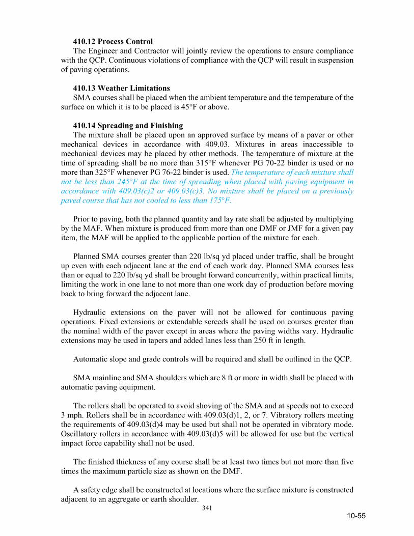
341
410.12 Process Control The Engineer and Contractor will jointly review the operations to ensure compliance with the QCP. Continuous violations of compliance with the QCP will result in suspension of paving operations. 410.13 Weather Limitations SMA courses shall be placed when the ambient temperature and the temperature of the surface on which it is to be placed is 45°F or above. 410.14 Spreading and Finishing The mixture shall be placed upon an approved surface by means of a paver or other mechanical devices in accordance with 409.03. Mixtures in areas inaccessible to mechanical devices may be placed by other methods. The temperature of mixture at the time of spreading shall be no more than 315°F whenever PG 70-22 binder is used or no more than 325°F whenever PG 76-22 binder is used. The temperature of each mixture shall not be less than 245°F at the time of spreading when placed with paving equipment in accordance with 409.03(c)2 or 409.03(c)3. No mixture shall be placed on a previously paved course that has not cooled to less than 175°F. Prior to paving, both the planned quantity and lay rate shall be adjusted by multiplying by the MAF. When mixture is produced from more than one DMF or JMF for a given pay item, the MAF will be applied to the applicable portion of the mixture for each. Planned SMA courses greater than 220 lb/sq yd placed under traffic, shall be brought up even with each adjacent lane at the end of each work day. Planned SMA courses less than or equal to 220 lb/sq yd shall be brought forward concurrently, within practical limits, limiting the work in one lane to not more than one work day of production before moving back to bring forward the adjacent lane. Hydraulic extensions on the paver will not be allowed for continuous paving operations. Fixed extensions or extendable screeds shall be used on courses greater than the nominal width of the paver except in areas where the paving widths vary. Hydraulic extensions may be used in tapers and added lanes less than 250 ft in length. Automatic slope and grade controls will be required and shall be outlined in the QCP. SMA mainline and SMA shoulders which are 8 ft or more in width shall be placed with automatic paving equipment. The rollers shall be operated to avoid shoving of the SMA and at speeds not to exceed 3 mph. Rollers shall be in accordance with 409.03(d)1, 2, or 7. Vibratory rollers meeting the requirements of 409.03(d)4 may be used but shall not be operated in vibratory mode. Oscillatory rollers in accordance with 409.03(d)5 will be allowed for use but the vertical impact force capability shall not be used. The finished thickness of any course shall be at least two times but not more than five times the maximum particle size as shown on the DMF. A safety edge shall be constructed at locations where the surface mixture is constructed adjacent to an aggregate or earth shoulder.
10-55

342
410.15 Joints Longitudinal joints in the surface shall be at the lane lines of the pavement. Hot poured joint adhesive in accordance with 906 shall be applied to longitudinal joints constructed between two adjacent HMA courses in the top course of dense graded intermediate mixtures and all 9.5 mm and 12.5 mm SMA mixture courses. This includes joints within the traveled way as well as between any of the following: traveled way and an auxiliary lane; traveled way and a paved shoulder; and auxiliary lane and a paved shoulder. The material shall be heated in a jacketed, double boiler melting kettle. The kettle shall have an attached pressure feed wand system with applicator shoe. The joint adhesive shall be applied to the face of the previously constructed edge at the joint using a wand applicator. Prior to application of the joint adhesive, the joint face shall be dry and free of loose material and foreign objects. The adhesive shall be applied on the joint face 1/8 in. thick at the temperature recommended by the manufacturer. Excess joint adhesive shall not be allowed to pool on the top of the previously constructed pavement course or the pavement to be overlaid. The application of the adhesive shall be made within the same day, but at least 30 minutes prior to construction of the longitudinal joint. Transverse joints shall be constructed by exposing a near vertical full depth face of the previous course. For areas inaccessible to rollers, other mechanical devices shall be used to achieve the required density. If constructed under traffic, temporary transverse joints shall be feathered to provide a smooth transition to the driving surface. 410.16 Density Acceptance will be based on lots and sublots in accordance with 410.07. The Engineer’s acceptance test results for each sublot will be available after the sublot and testing are complete. Sublot and lot density values will be reported to the nearest 0.1%. Rounding will be in accordance with 109.01(a). Density acceptance for all SMA mixtures shall be based on cores cut from the compacted pavement and analysis of pavement samples obtained in accordance with ITM 580. Acceptance will be based on lots and sublots in accordance with 410.07. The Engineer will randomly select two locations in accordance with ITM 802, within each sublot for coring. The transverse core location will be located so that the edge of the core will be no closer than 3 in. from a confined edge or 6 in. from a non-confined edge of the course being placed. The maximum specific gravity will be determined from the sample obtained in 410.09. The Contractor shall obtain cores in the presence of the Engineer with a device that shall produce a uniform 6.00 ±0.25 in. diameter pavement sample. Surface courses shall be cored within one work day of placement. Damaged core shall be discarded and replaced
10-56

343
with a core from a location selected by adding 1 ft to the longitudinal location of the damaged core using the same transverse offset. The Contractor and the Engineer shall mark the core to define the course to be tested. If the core indicates a course thickness of less than two times the maximum particle size, the core will be discarded and a core from a new random location will be selected for testing. Cores shall not be obtained from areas placed with paving equipment in accordance with 409.03(c)2 or 409.03(c)3. If a random location falls within this area, the Engineer will randomly select another location within the sublot for coring. If an entire sublot falls within this area, test results from the previous sublot will be used for acceptance. If the previous sublot is not available, the subsequent sublot will be used for acceptance. The Engineer will take immediate possession of the cores. If the Engineer’s cores are subsequently damaged, additional coring within a specific sublot or sublots will be the responsibility of the Department. Subsequent core locations will be determined by subtracting 1 ft from the random location using the same transverse offset. The density of the mixture will be expressed as the percentage of maximum specific gravity, % MSG, obtained by dividing the average bulk specific gravity by the maximum specific gravity for the sublot, times 100. Samples for the bulk specific gravity and maximum specific gravity will be dried in accordance with ITM 572. The Engineer will determine the bulk specific gravity of the cores in accordance with AASHTO T 166, Method A or AASHTO T 331, if required. The maximum specific gravity will be mass determined in water in accordance with AASHTO T 209. The target value for density of SMA mixtures of each sublot shall be 93.0%. The densities of the sublots will be averaged to determine the density of the lot. Within one work day of coring operations the Contractor shall clean, dry, and refill the core holes with SMA of similar or smaller size particles or other approved materials. The Contractor’s plan for refilling core holes shall be outlined in the QCP. 410.17 Pavement Corrugations Pavement corrugations shall be in accordance with 606. 410.18 Pavement Smoothness The pavement smoothness will be evaluated and determined in accordance with 401.18. 410.19 Adjusted Points When test results for mixture properties or density exceed the allowable tolerances, adjustment points will be assessed. The adjustment points will be used to calculate a quality assurance adjustment quantity, q, for the lot. Quality assurance adjustment points for smoothness will be in accordance with 401.19(c). The adjustment for mixture properties and density are calculated as follows:
q = 1.00 x (L x U x P/100)/MAF
10-57

344
where:
q = quality assurance adjustment quantity
L = lot quantity U = unit price for the material, $/ton P = total adjustment points
The total quality assurance adjustments is to be calculated as follows:
Q = Qs + ∑ (qm + qd) where:
Q = total quality assurance adjustment quantity
Qs = quality assurance adjustment for smoothness as calculated in 401.19(c)
qm = lot adjustments for mixtures qd = lot adjustments for density
If the total adjustment points for a lot are greater than 15, the pavement will be evaluated by the Department’s Division of Materials and Tests. If the Contractor is not required to remove the mixture, quality assurance adjustments of the lot will be assessed or other corrective actions as determined by the Department’s Division of Materials and Tests. (a) Mixture When test results for the mixture furnished exceeded the allowable tolerances, adjustment points will be assessed as follows:
Adjustment Points for Gradation
Adjustment Points
Sieve Size 1 in. (25.0 mm)
3/4 in. (19.0 mm)
1/2 in. (12.5 mm)
3/8 in. (9.5 mm)
No. 4 (4.75 mm)
No. 8 (2.36 mm)
No. 30
(600 µm)
No. 200 (75 µm)
For each 0.1% up to 1.0%
out of tolerance 0.1 0.1 0.1 0.1 0.1 0.1 0.2 0.3
For each 0.1% above 1.0% out of tolerance
0.1 0.1 0.1 0.1 0.1 0.2 0.3 0.6
Gradation adjustment points for the lot shall be the sum of points calculated for up to 1% out of tolerance and the points calculated for greater than 1% out of tolerance in accordance with 410.09. Binder content adjustment points for the lot shall be two points for each 0.1% above the tolerance or four points for each 0.1% below the tolerance in accordance with 410.09.
10-58
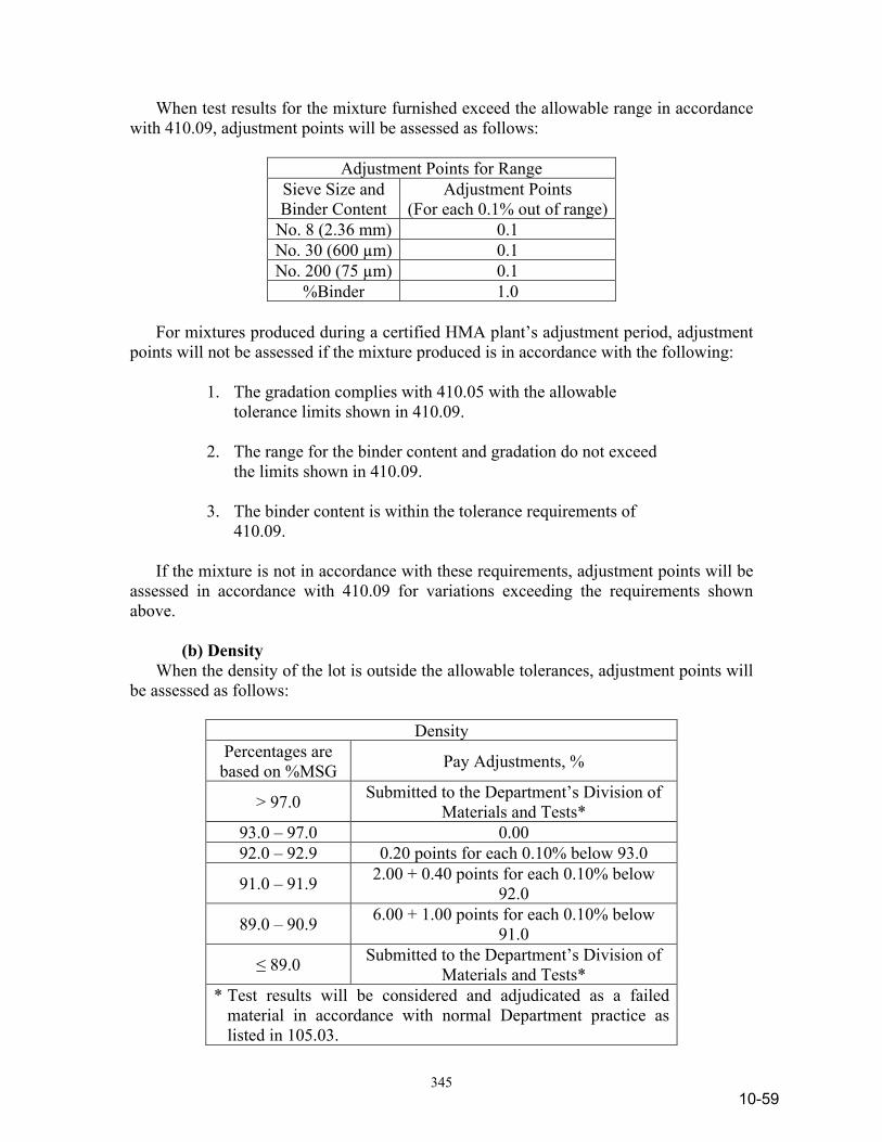
345
When test results for the mixture furnished exceed the allowable range in accordance with 410.09, adjustment points will be assessed as follows:
Adjustment Points for Range Sieve Size and Binder Content
Adjustment Points (For each 0.1% out of range)
No. 8 (2.36 mm) 0.1 No. 30 (600 µm) 0.1 No. 200 (75 µm) 0.1
%Binder 1.0 For mixtures produced during a certified HMA plant’s adjustment period, adjustment points will not be assessed if the mixture produced is in accordance with the following: 1. The gradation complies with 410.05 with the allowable
tolerance limits shown in 410.09.
2. The range for the binder content and gradation do not exceed the limits shown in 410.09.
3. The binder content is within the tolerance requirements of
410.09.
If the mixture is not in accordance with these requirements, adjustment points will be assessed in accordance with 410.09 for variations exceeding the requirements shown above. (b) Density When the density of the lot is outside the allowable tolerances, adjustment points will be assessed as follows:
Density Percentages are
based on %MSG Pay Adjustments, %
> 97.0 Submitted to the Department’s Division of Materials and Tests*
93.0 – 97.0 0.00 92.0 – 92.9 0.20 points for each 0.10% below 93.0
91.0 – 91.9 2.00 + 0.40 points for each 0.10% below 92.0
89.0 – 90.9 6.00 + 1.00 points for each 0.10% below 91.0
≤ 89.0 Submitted to the Department’s Division of Materials and Tests*
* Test results will be considered and adjudicated as a failed material in accordance with normal Department practice as listed in 105.03.
10-59
346
410.20 Appeals If the QC test results do not agree with the acceptance test results, a request, along with the QC test results, may be made in writing for additional testing. Additional testing may be requested for one or more of the following tests: binder content, gradation, or MSG of the mixture samples and bulk specific gravity of the density cores. The appeal request shall be submitted within seven calendar days of receipt of the Department’s written results for that sublot. The request for the appeal for MSG, BSG of the density cores or binder content and gradation shall be submitted within seven calendar days of receipt of the Department’s written results for that sublot. The sublot and specific tests shall be specified at the time of the appeal request. Only one appeal request per sublot is allowed. Upon approval of the appeal, the Engineer will perform additional testing. The appeal results will replace all previous test results for acceptance of mixture in accordance with 410.09 and density in accordance with 410.16. The results will be furnished to the Contractor. The backup mixture samples or density cores will be tested in accordance with the following: (a) MSG The backup MSG will be dried in accordance with ITM 572 and mass determined in water in accordance with AASHTO T 209. (b) Binder Content and Gradation The backup binder content and gradation sample will be prepared and tested in accordance with the test methods that were used for acceptance. (c) BSG of the Density Core Cores shall be taken within seven calendar days unless otherwise directed. Additional core locations will be determined by adding 1 ft longitudinally of the cores tested using the same transverse offset. The cores will be dried in accordance with ITM 572 and tested in accordance with AASHTO T 166, Method A or AASHTO T 331, if required. The Contractor shall clean, dry, and refill the core holes with SMA or HMA surface materials within one work day of the coring operations. 410.21 Method of Measurement SMA mixtures will be measured by the ton of the type specified, in accordance with 109.01(b). The measured quantity will be divided by the MAF to determine the pay quantity. Joint adhesive will be measured by the linear foot in accordance with 109.01(a). 410.22 Basis of Payment The accepted quantities for this work will be paid for at the contract unit price per ton for QC/QA-HMA, of the type specified, – SMA, complete in place. Payment for furnishing, calibrating, and operating the profilograph, and furnishing profile information will be made in accordance with 401.22. Joint adhesive will be paid for by the linear foot, complete in place.
10-60
347
Adjustments to the contract payment with respect to mixture, density, and smoothness for mixture produced will be included in a quality assurance adjustment pay item. The unit price for this pay item will be $1.00 and the quantity will be in units of dollars. The quantity is the total calculated in accordance with 410.19. A change order developed in accordance with 109.05 will be prepared to reflect contract adjustments. Payment will be made under: Pay Item Pay Unit Symbol Joint Adhesive, ____________ ..................................LFT course type QC/QA-HMA, _____, _____, _____, ______ mm, - SMA TON (ESAL(1))(PG(2))(Course(3))(Mix(4)) Quality Assurance Adjustment ..................................DOL (1) ESAL Category as defined in 410.04 (2) Number represents the high temperature binder grade. Low
temperature grades are - 22 (3) Surface or Intermediate (4) Mixture Designation Preparation of surfaces to be overlaid shall be included in the cost of other pay items within this section. Coring and refilling of the pavement holes shall be included in the cost of other pay items within this section. No payment will be made for additional anti-stripping additives, appeal coring or related traffic control expenditures for coring operations. Corrections for pavement smoothness shall be included in the cost of other pay items within this section. The price for profilograph, HMA will be full compensation regardless of how often the profilograph is used or how many profilograms are produced.
10-61
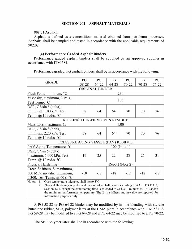
1
SECTION 902 – ASPHALT MATERIALS 902.01 Asphalt Asphalt is defined as a cementitious material obtained from petroleum processes. Asphalts shall be sampled and tested in accordance with the applicable requirements of 902.02. (a) Performance Graded Asphalt Binders Performance graded asphalt binders shall be supplied by an approved supplier in accordance with ITM 581. Performance graded, PG asphalt binders shall be in accordance with the following:
GRADE PG 58-28
PG 64-22
PG 64-28
PG 70-22
PG 70-28
PG 76-22
ORIGINAL BINDER Flash Point, minimum, °C 230 Viscosity, maximum, 3 Pa·s, Test Temp, °C 135
DSR, G*/sin δ (delta), minimum, 1.00 kPa, Test Temp. @ 10 rad/s, °C
58 64 64 70 70 76
ROLLING THIN-FILM OVEN RESIDUE Mass Loss, maximum, % 1.00 DSR, G*/sin δ (delta), minimum, 2.20 kPa, Test Temp. @ 10 rad/s, °C
58 64 64 70 70 76
PRESSURE AGING VESSEL (PAV) RESIDUE PAV Aging Temperature, °C 100 (Note 1) DSR, G*sin δ (delta), maximum, 5,000 kPa, Test Temp. @ 10 rad/s, °C
19 25 22 28 25 31
Physical Hardening Report (Note 2) Creep Stiffness, S, maximum, 300 MPa, m-value, minimum, 0.300, Test Temp. @ 60 s, °C
-18 -12 -18 -12 -18 -12
Notes: 1. Oven temperature tolerance shall be ±0.5°C. 2. Physical Hardening is performed on a set of asphalt beams according to AASHTO T 313,
Section 12.1, except the conditioning time is extended to 24 h ±10 minutes at 10°C above the minimum performance temperature. The 24 h stiffness and m-value are reported for information purposes only.
A PG 58-28 or PG 64-22 binder may be modified by in-line blending with styrene butadiene rubber, SBR, polymer latex at the HMA plant in accordance with ITM 581. A PG 58-28 may be modified to a PG 64-28 and a PG 64-22 may be modified to a PG 70-22. The SBR polymer latex shall be in accordance with the following:
10-62
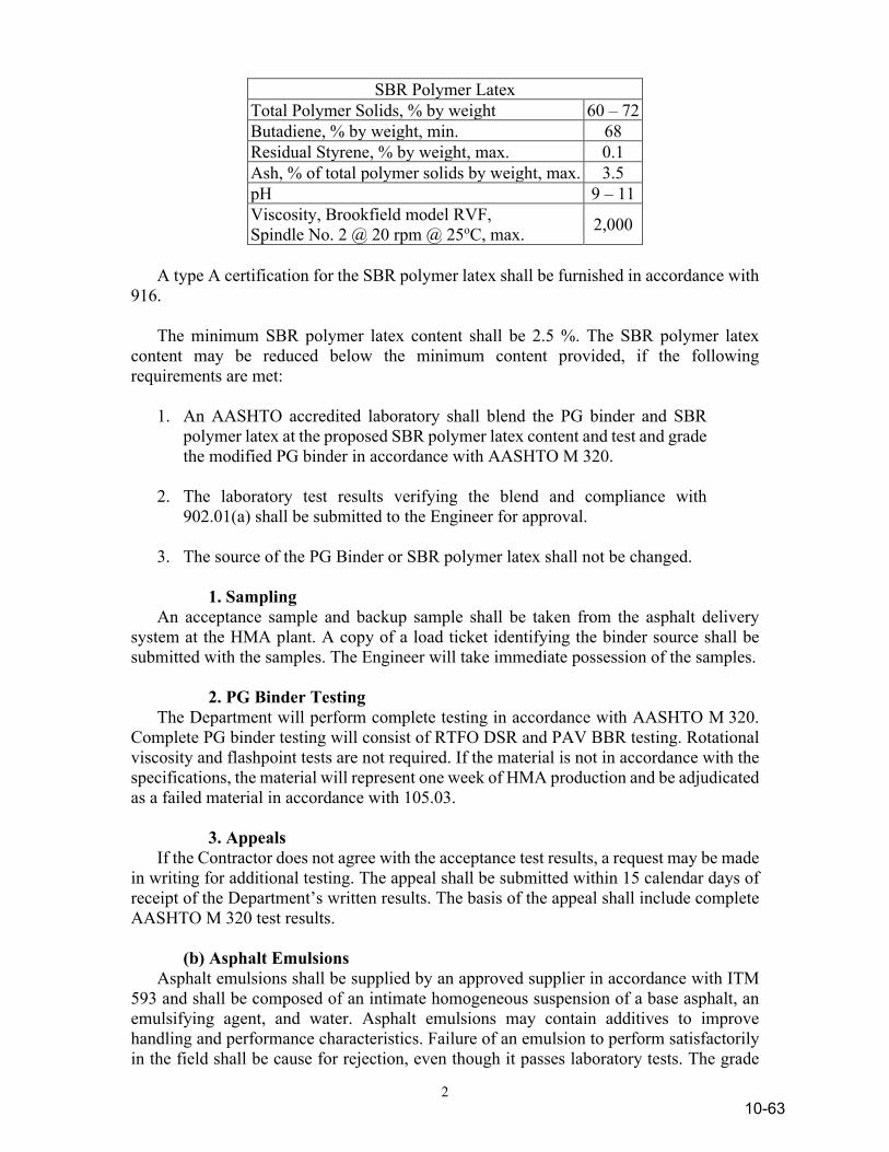
2
SBR Polymer Latex Total Polymer Solids, % by weight 60 – 72 Butadiene, % by weight, min. 68 Residual Styrene, % by weight, max. 0.1 Ash, % of total polymer solids by weight, max. 3.5 pH 9 – 11 Viscosity, Brookfield model RVF, Spindle No. 2 @ 20 rpm @ 25oC, max. 2,000
A type A certification for the SBR polymer latex shall be furnished in accordance with 916. The minimum SBR polymer latex content shall be 2.5 %. The SBR polymer latex content may be reduced below the minimum content provided, if the following requirements are met: 1. An AASHTO accredited laboratory shall blend the PG binder and SBR
polymer latex at the proposed SBR polymer latex content and test and grade the modified PG binder in accordance with AASHTO M 320.
2. The laboratory test results verifying the blend and compliance with
902.01(a) shall be submitted to the Engineer for approval. 3. The source of the PG Binder or SBR polymer latex shall not be changed. 1. Sampling An acceptance sample and backup sample shall be taken from the asphalt delivery system at the HMA plant. A copy of a load ticket identifying the binder source shall be submitted with the samples. The Engineer will take immediate possession of the samples. 2. PG Binder Testing The Department will perform complete testing in accordance with AASHTO M 320. Complete PG binder testing will consist of RTFO DSR and PAV BBR testing. Rotational viscosity and flashpoint tests are not required. If the material is not in accordance with the specifications, the material will represent one week of HMA production and be adjudicated as a failed material in accordance with 105.03. 3. Appeals If the Contractor does not agree with the acceptance test results, a request may be made in writing for additional testing. The appeal shall be submitted within 15 calendar days of receipt of the Department’s written results. The basis of the appeal shall include complete AASHTO M 320 test results. (b) Asphalt Emulsions Asphalt emulsions shall be supplied by an approved supplier in accordance with ITM 593 and shall be composed of an intimate homogeneous suspension of a base asphalt, an emulsifying agent, and water. Asphalt emulsions may contain additives to improve handling and performance characteristics. Failure of an emulsion to perform satisfactorily in the field shall be cause for rejection, even though it passes laboratory tests. The grade
10-63
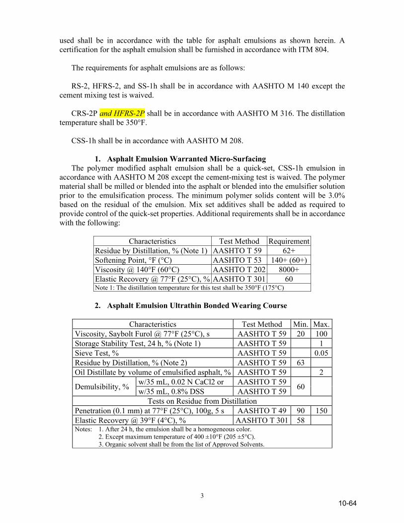
3
used shall be in accordance with the table for asphalt emulsions as shown herein. A certification for the asphalt emulsion shall be furnished in accordance with ITM 804. The requirements for asphalt emulsions are as follows: RS-2, HFRS-2, and SS-1h shall be in accordance with AASHTO M 140 except the cement mixing test is waived. CRS-2P and HFRS-2P shall be in accordance with AASHTO M 316. The distillation temperature shall be 350°F. CSS-1h shall be in accordance with AASHTO M 208. 1. Asphalt Emulsion Warranted Micro-Surfacing The polymer modified asphalt emulsion shall be a quick-set, CSS-1h emulsion in accordance with AASHTO M 208 except the cement-mixing test is waived. The polymer material shall be milled or blended into the asphalt or blended into the emulsifier solution prior to the emulsification process. The minimum polymer solids content will be 3.0% based on the residual of the emulsion. Mix set additives shall be added as required to provide control of the quick-set properties. Additional requirements shall be in accordance with the following:
Characteristics Test Method Requirement Residue by Distillation, % (Note 1) AASHTO T 59 62+ Softening Point, °F (°C) AASHTO T 53 140+ (60+) Viscosity @ 140°F (60°C) AASHTO T 202 8000+ Elastic Recovery @ 77°F (25°C), % AASHTO T 301 60 Note 1: The distillation temperature for this test shall be 350°F (175°C)
2. Asphalt Emulsion Ultrathin Bonded Wearing Course
Characteristics Test Method Min. Max. Viscosity, Saybolt Furol @ 77°F (25°C), s AASHTO T 59 20 100 Storage Stability Test, 24 h, % (Note 1) AASHTO T 59 1 Sieve Test, % AASHTO T 59 0.05 Residue by Distillation, % (Note 2) AASHTO T 59 63 Oil Distillate by volume of emulsified asphalt, % AASHTO T 59 2
Demulsibility, % w/35 mL, 0.02 N CaCl2 or AASHTO T 59 60 w/35 mL, 0.8% DSS AASHTO T 59 Tests on Residue from Distillation
Penetration (0.1 mm) at 77°F (25°C), 100g, 5 s AASHTO T 49 90 150 Elastic Recovery @ 39°F (4°C), % AASHTO T 301 58 Notes: 1. After 24 h, the emulsion shall be a homogeneous color. 2. Except maximum temperature of 400 ±10°F (205 ±5°C). 3. Organic solvent shall be from the list of Approved Solvents.
10-64

4
3. Asphalt Emulsion Recycling
Characteristics (Note 1) Test Method Min. Max. Viscosity, Saybolt Furol, @ 77 °F (25°C), SFS
AASHTO T 59 20 100
Sieve Test, No. 20, retained on sieve, % AASHTO T 59 0.10
Storage Stability Test, 24 hr, % AASHTO T 59 1
Residue by Distillation, % (Note 2) AASHTO T 59 64
Oil Distillate by volume of emulsified asphalt, %
AASHTO T 59 1
Penetration, 77°F (25°C), 100 g, 5 s, dmm AASHTO T 49
50 200
Notes: 1. The asphalt emulsion shall be selected for the project by the asphalt emulsion supplier based on the Contractor’s mixture design. The penetration of the supplied asphalt emulsion shall be within ±25 dmm of the penetration of the design asphalt emulsion. The asphalt emulsion shall be received on the job site at a temperature no greater than 120ºF (50°C).
2. Modified AASHTO T 59 – distillation temperature of 350 ±9°F (175 ±5°C) with a 20 minute hold.
10-65
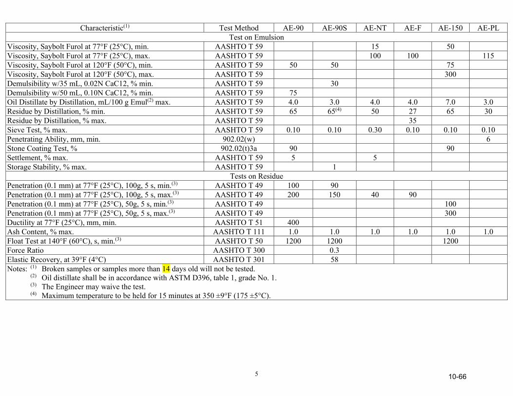
5
Characteristic(1) Test Method AE-90 AE-90S AE-NT AE-F AE-150 AE-PL Test on Emulsion
Viscosity, Saybolt Furol at 77°F (25°C), min. AASHTO T 59 15 50 Viscosity, Saybolt Furol at 77°F (25°C), max. AASHTO T 59 100 100 115 Viscosity, Saybolt Furol at 120°F (50°C), min. AASHTO T 59 50 50 75 Viscosity, Saybolt Furol at 120°F (50°C), max. AASHTO T 59 300 Demulsibility w/35 mL, 0.02N CaC12, % min. AASHTO T 59 30 Demulsibility w/50 mL, 0.10N CaC12, % min. AASHTO T 59 75 Oil Distillate by Distillation, mL/100 g Emul(2) max. AASHTO T 59 4.0 3.0 4.0 4.0 7.0 3.0 Residue by Distillation, % min. AASHTO T 59 65 65(4) 50 27 65 30 Residue by Distillation, % max. AASHTO T 59 35 Sieve Test, % max. AASHTO T 59 0.10 0.10 0.30 0.10 0.10 0.10 Penetrating Ability, mm, min. 902.02(w) 6 Stone Coating Test, % 902.02(t)3a 90 90 Settlement, % max. AASHTO T 59 5 5 Storage Stability, % max. AASHTO T 59 1
Tests on Residue Penetration (0.1 mm) at 77°F (25°C), 100g, 5 s, min.(3) AASHTO T 49 100 90 Penetration (0.1 mm) at 77°F (25°C), 100g, 5 s, max.(3) AASHTO T 49 200 150 40 90 Penetration (0.1 mm) at 77°F (25°C), 50g, 5 s, min.(3) AASHTO T 49 100 Penetration (0.1 mm) at 77°F (25°C), 50g, 5 s, max.(3) AASHTO T 49 300 Ductility at 77°F (25°C), mm, min. AASHTO T 51 400 Ash Content, % max. AASHTO T 111 1.0 1.0 1.0 1.0 1.0 1.0 Float Test at 140°F (60°C), s, min.(3) AASHTO T 50 1200 1200 1200 Force Ratio AASHTO T 300 0.3 Elastic Recovery, at 39°F (4°C) AASHTO T 301 58 Notes: (1) Broken samples or samples more than 14 days old will not be tested. (2) Oil distillate shall be in accordance with ASTM D396, table 1, grade No. 1. (3) The Engineer may waive the test. (4) Maximum temperature to be held for 15 minutes at 350 ±9°F (175 ±5°C).
10-66

6
(c) Cutback Asphalts Cutback asphalts shall be composed of an intimate homogeneous mixture of an asphalt base and a suitable distillate designed for medium, or slow curing. Cutback asphalts may also contain an additive as an aid in uniformly coating wet, damp, or dry aggregates used in patching mixtures or HMA pavements. These asphalts shall not contain more than 0.3% water as determined by ASTM D95, shall not separate when allowed to stand, and shall not foam when heated to permissible temperatures. When an additive is used, it shall be incorporated homogeneously in the asphalt at the point of manufacture. The temperature of the cutback asphalt shall not be higher than shown for that grade in 902.03. A type A certification for the cutback asphalt shall be furnished in accordance with 916. 1. Medium Curing Asphalts With and Without Additives Medium curing asphalts with and without additives shall be in accordance with the following:
Characteristics Grades
MC-70 MCA-70
MC-250 MCA-250
MC-800 MCA-800
MC-3000 MCA-3000
Flash Point (Open Tag.), °C(4) 38+ 66+ 66+ 66+ Kinematic Viscosity at 60°C (cSt)(2) 70 - 140 250 - 500 800 - 1600 3000 - 6000 Saybolt-Furol Viscosity at 50°C (s) Saybolt-Furol Viscosity at 60°C (s) Saybolt-Furol Viscosity at 83°C (s)
60 - 120 125 - 250
100 - 200
300 - 600 Distillation(1)
Distillate (% of total distillate to 360°C MC-70 @ 225°C): to 225°C to 260°C to 316°C
Residue from distillation to 360°C (volume % by difference)
0 - 20 20 - 60 65 - 90
55+
0 - 10 15 - 55 60 - 87
67+
35+ 45 - 80
75+
15+ 15 - 75
80+
Tests on Residue from Distillation(1) Penetration, 25°C, 100 g, 5 s, - (0.1 mm) (without additive) (with additive) Ductility, 25°C (10 mm)(3) Solubility in organic solvents, %
120 - 250 120 - 300
100+ 99.5+
120 - 250 120 - 300
100+ 99.5+
120 - 250 120 - 300
100+ 99.5+
120 - 250 120 - 300
100+ 99.5+
(1) Test may be waived when approved. (2) Viscosity may be determined by either the Saybolt-Furol or Kinematic test. In case of dispute, the Kinematic
viscosity test shall prevail. (3) If the ductility at 25°C is less than 100, the material will be acceptable if its ductility at 16°C is 100+. (4) Flash point by Cleveland Open Cup may be used for products having a flash point greater than 80°C.
10-67
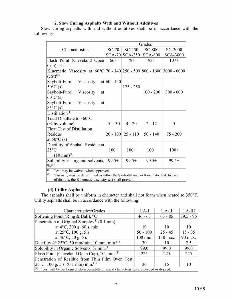
7
2. Slow Curing Asphalts With and Without Additives Slow curing asphalts with and without additives shall be in accordance with the following:
Characteristics Grades
SC-70 SCA-70
SC-250 SCA-250
SC-800 SCA-800
SC-3000 SCA-3000
Flash Point (Cleveland Open Cup), °C
66+ 79+ 93+ 107+
Kinematic Viscosity at 60°C (cSt)(2)
70 - 140 250 - 500 800 - 1600 3000 - 6000
Saybolt-Furol Viscosity at 50°C (s) Saybolt-Furol Viscosity at 60°C (s) Saybolt-Furol Viscosity at 83°C (s)
60 - 120 125 - 250
100 - 200
300 - 600
Distillation(1) Total Distillate to 360°C
(% by volume) Float Test of Distillation
Residue at 50°C (s)
10 - 30
20 - 100
4 - 20
25 - 110
2 - 12
50 - 140
5
75 - 200
Ductility of Asphalt Residue at 25°C (10 mm)(1)
100+
100+
100+
100+
Solubility in organic solvents, %(1)
99.5+ 99.5+ 99.5+ 99.5+
(1) Test may be waived when approved. (2) Viscosity may be determined by either the Saybolt-Furol or Kinematic test. In case
of dispute, the Kinematic viscosity test shall prevail. (d) Utility Asphalt The asphalts shall be uniform in character and shall not foam when heated to 350°F. Utility asphalts shall be in accordance with the following:
Characteristics/Grades UA-I UA-II UA-III Softening Point (Ring & Ball), °C 46 - 63 63 - 85 79.5 - 96 Penetration of Original Samples(1) (0.1 mm) at 4°C, 200 g, 60 s, min. at 25°C, 100 g, 5 s at 46°C, 50 g, 5 s
10
50 - 100 100 min.
10
25 - 45 130 max.
10
15 - 35 90 max.
Ductility @ 25°C, 50 mm/min, 10 mm, min.(1) 30 10 2.5 Solubility in Organic Solvents, % min.(1) 99.0 99.0 99.0 Flash Point (Cleveland Open Cup), °C, min.(1) 225 225 225 Penetration of Residue from Thin Film Oven Test, 25°C, 100 g, 5 s, (0.1 mm) min.(1)
30
15
10
(1) Test will be performed when complete physical characteristics are needed or desired.
10-68
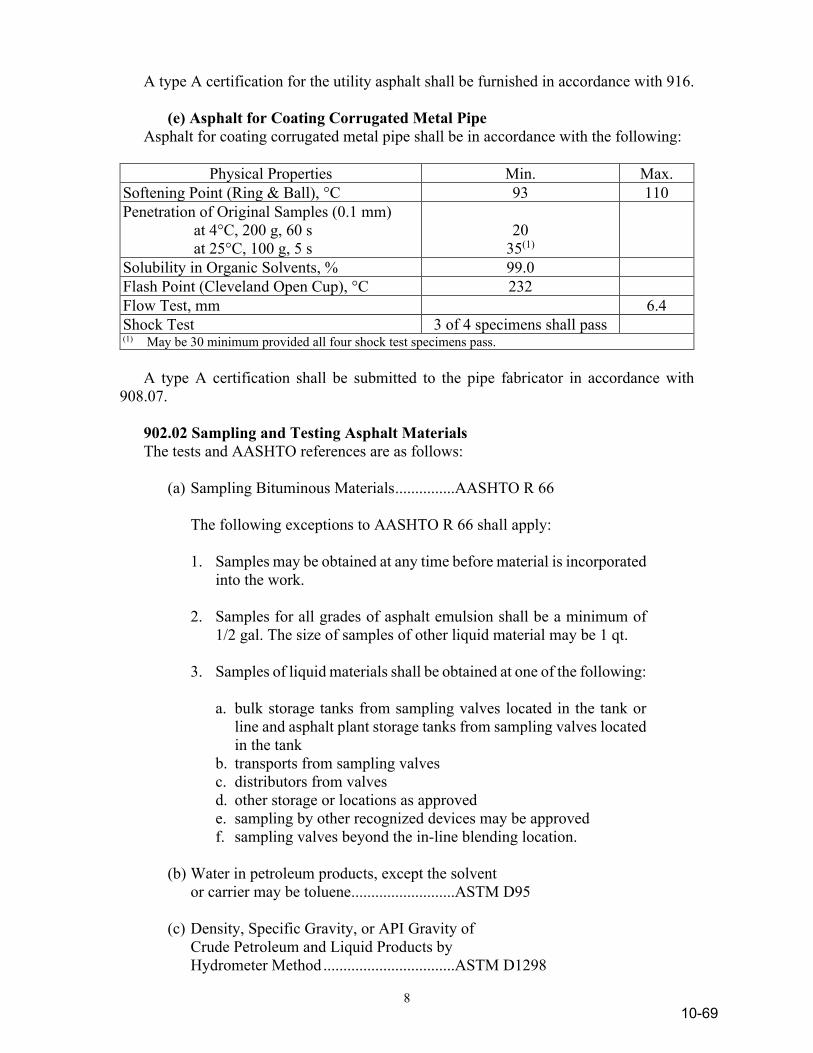
8
A type A certification for the utility asphalt shall be furnished in accordance with 916. (e) Asphalt for Coating Corrugated Metal Pipe Asphalt for coating corrugated metal pipe shall be in accordance with the following:
Physical Properties Min. Max. Softening Point (Ring & Ball), °C 93 110 Penetration of Original Samples (0.1 mm) at 4°C, 200 g, 60 s at 25°C, 100 g, 5 s
20
35(1)
Solubility in Organic Solvents, % 99.0 Flash Point (Cleveland Open Cup), °C 232 Flow Test, mm 6.4 Shock Test 3 of 4 specimens shall pass (1) May be 30 minimum provided all four shock test specimens pass. A type A certification shall be submitted to the pipe fabricator in accordance with 908.07. 902.02 Sampling and Testing Asphalt Materials The tests and AASHTO references are as follows: (a) Sampling Bituminous Materials ...............AASHTO R 66 The following exceptions to AASHTO R 66 shall apply: 1. Samples may be obtained at any time before material is incorporated
into the work. 2. Samples for all grades of asphalt emulsion shall be a minimum of
1/2 gal. The size of samples of other liquid material may be 1 qt. 3. Samples of liquid materials shall be obtained at one of the following: a. bulk storage tanks from sampling valves located in the tank or
line and asphalt plant storage tanks from sampling valves located in the tank
b. transports from sampling valves c. distributors from valves d. other storage or locations as approved e. sampling by other recognized devices may be approved f. sampling valves beyond the in-line blending location. (b) Water in petroleum products, except the solvent or carrier may be toluene ..........................ASTM D95 (c) Density, Specific Gravity, or API Gravity of Crude Petroleum and Liquid Products by Hydrometer Method .................................ASTM D1298
10-69
9
(d) Specific Gravity of Semi-Solid Bituminous Materials ...................................................AASHTO T 228 (e) Specific Gravity of Solid Pitch and Asphalt ASTM D71 (f) Flash and Fire Points (Open Cup) 1. When the flash point is higher than 175°F, “Flash and Fire Points by Cleveland Open Cup” ........................AASHTO T 48 2. When the flash point is 175°F, or lower, “Flash Point with Tagliabue Open Cup” .........................................AASHTO T 79 (g) Softening Point of Bituminous Materials, Ring and Ball ............................................AASHTO T 53 (h) Penetration of Bituminous Materials .......AASHTO T 49 (i) Loss of Heating ........................................ASTM D6 (j) Solubility in Organic Solvents, except the solvent may be 1,1,1,-Trichloroethane .....AASHTO T 44 (k) Inorganic Matter or Ash ...........................AASHTO T 59 (l) Saybolt-Furol Viscosity ...........................AASHTO T 72 (m) Ductility of Binder Material, except that the conditioning period of
the specimens may be shortened, and that only one normal test will be required. Shortened conditioning period: The specimen shall be allowed to cool in air for at least 30 minutes. It shall then be trimmed and placed in the water bath for a period of 60 to 90 minutes before testing. In case of failure or dispute, three normal tests will be required and specimens shall be conditioned as in AASHTO T 51.
(n) Distillation of Cutback Asphaltic Products, except the length of condenser tube may be 400 mm ±24 mm ......................................AASHTO T 78 (o) Float Test for Bituminous Materials ........AASHTO T 50 (p) Kinematic Viscosity of Asphalts ..............AASHTO T 201 (q) Absolute Viscosity of Asphalts ................AASHTO T 202 (r) Effect of Heat and Air on Asphalt Materials,
10-70
10
Thin-Film Oven Test ................................AASHTO T 179 (s) Effect of Heat and Air on a Moving Film of Asphalt, Rolling Thin Film Oven Test .....AASHTO T 240 (t) Testing Asphalt Emulsions ......................AASHTO T 59 The following exceptions to T 59 shall apply: 1. For the Residue by Distillation test, the specified aluminum alloy
still shall be the referee still. 2. When tests on the residue are not required, the % of residue for
emulsion grades RS-2 and AE-90 only, may be determined by the Residue by Evaporation test of AASHTO T 59. The % of residue shall be determined by the Residue of Distillation test in all cases of failure or dispute.
3. The stone coating test shall be performed as follows on a mixture of
465 ±1 g of reference stone and 35.0 ±0.1 g of asphalt emulsion: a. For AE-90 the mixture of stone and asphalt shall be mixed
vigorously for 5 minutes. At the end of the mixing period, the mix shall be rinsed by running sufficient tap water at the side of the container to completely immerse the mix. The tap water shall then be poured off and the rinsing step repeated as necessary until the rinse water pours off essentially clear. The stone shall remain a minimum of 90% coated.
b. For AE-150 the mixture of stone and asphalt shall be mixed
vigorously for 5 minutes and then allowed to stand for 3 h. At the end of this time, the mixture shall again be mixed vigorously for 5 minutes. At the end of the mixing period, the mix shall be rinsed by running sufficient tap water at the side of the container to completely immerse the mix. The tap water shall then be poured off and the rinsing step repeated as necessary until the rinse water pours off essentially clear. The stone shall remain a minimum of 90% coated.
4. For the Demulsibility test, normally only one test will be required.
In case of failure or dispute, the specified procedure in AASHTO T 59 will be followed.
5. For oil portion from Residue by Distillation, report the number of
milliliters of oil per 100 g of emulsion. (u) For coating test for cutback asphalts with additive, 20 g of 20 to 30 mesh
Ottawa sand shall be placed in a clean 2 oz (60 mL) wide-mouthed jar and covered with 25 g of distilled water at room temperature. One gram of the liquid asphalt to be tested shall be placed gently upon the surface
10-71
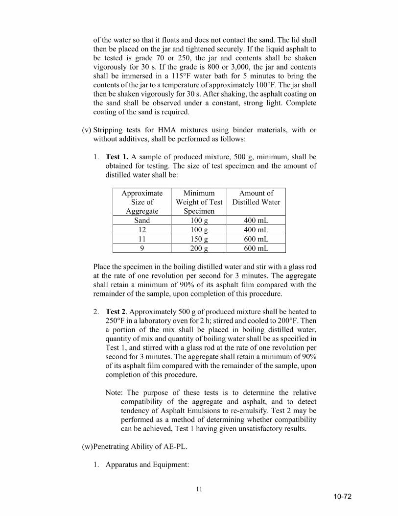
11
of the water so that it floats and does not contact the sand. The lid shall then be placed on the jar and tightened securely. If the liquid asphalt to be tested is grade 70 or 250, the jar and contents shall be shaken vigorously for 30 s. If the grade is 800 or 3,000, the jar and contents shall be immersed in a 115°F water bath for 5 minutes to bring the contents of the jar to a temperature of approximately 100°F. The jar shall then be shaken vigorously for 30 s. After shaking, the asphalt coating on the sand shall be observed under a constant, strong light. Complete coating of the sand is required.
(v) Stripping tests for HMA mixtures using binder materials, with or
without additives, shall be performed as follows: 1. Test 1. A sample of produced mixture, 500 g, minimum, shall be
obtained for testing. The size of test specimen and the amount of distilled water shall be:
Approximate
Size of Aggregate
Minimum Weight of Test
Specimen
Amount of Distilled Water
Sand 100 g 400 mL 12 100 g 400 mL 11 150 g 600 mL 9 200 g 600 mL
Place the specimen in the boiling distilled water and stir with a glass rod
at the rate of one revolution per second for 3 minutes. The aggregate shall retain a minimum of 90% of its asphalt film compared with the remainder of the sample, upon completion of this procedure.
2. Test 2. Approximately 500 g of produced mixture shall be heated to
250°F in a laboratory oven for 2 h; stirred and cooled to 200°F. Then a portion of the mix shall be placed in boiling distilled water, quantity of mix and quantity of boiling water shall be as specified in Test 1, and stirred with a glass rod at the rate of one revolution per second for 3 minutes. The aggregate shall retain a minimum of 90% of its asphalt film compared with the remainder of the sample, upon completion of this procedure.
Note: The purpose of these tests is to determine the relative
compatibility of the aggregate and asphalt, and to detect tendency of Asphalt Emulsions to re-emulsify. Test 2 may be performed as a method of determining whether compatibility can be achieved, Test 1 having given unsatisfactory results.
(w) Penetrating Ability of AE-PL. 1. Apparatus and Equipment:
10-72
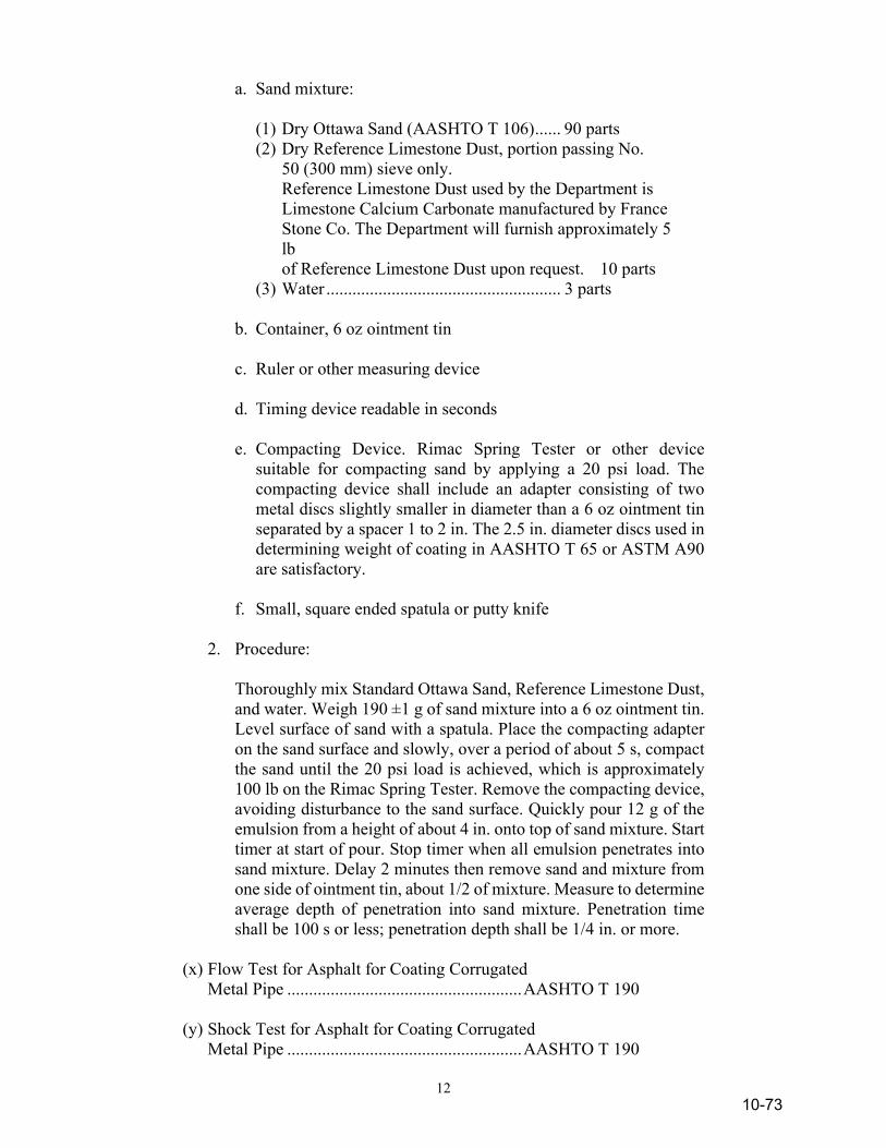
12
a. Sand mixture: (1) Dry Ottawa Sand (AASHTO T 106) ...... 90 parts (2) Dry Reference Limestone Dust, portion passing No.
50 (300 mm) sieve only. Reference Limestone Dust used by the Department is
Limestone Calcium Carbonate manufactured by France Stone Co. The Department will furnish approximately 5 lb of Reference Limestone Dust upon request. 10 parts
(3) Water ...................................................... 3 parts b. Container, 6 oz ointment tin c. Ruler or other measuring device d. Timing device readable in seconds e. Compacting Device. Rimac Spring Tester or other device
suitable for compacting sand by applying a 20 psi load. The compacting device shall include an adapter consisting of two metal discs slightly smaller in diameter than a 6 oz ointment tin separated by a spacer 1 to 2 in. The 2.5 in. diameter discs used in determining weight of coating in AASHTO T 65 or ASTM A90 are satisfactory.
f. Small, square ended spatula or putty knife 2. Procedure: Thoroughly mix Standard Ottawa Sand, Reference Limestone Dust,
and water. Weigh 190 ±1 g of sand mixture into a 6 oz ointment tin. Level surface of sand with a spatula. Place the compacting adapter on the sand surface and slowly, over a period of about 5 s, compact the sand until the 20 psi load is achieved, which is approximately 100 lb on the Rimac Spring Tester. Remove the compacting device, avoiding disturbance to the sand surface. Quickly pour 12 g of the emulsion from a height of about 4 in. onto top of sand mixture. Start timer at start of pour. Stop timer when all emulsion penetrates into sand mixture. Delay 2 minutes then remove sand and mixture from one side of ointment tin, about 1/2 of mixture. Measure to determine average depth of penetration into sand mixture. Penetration time shall be 100 s or less; penetration depth shall be 1/4 in. or more.
(x) Flow Test for Asphalt for Coating Corrugated Metal Pipe ...................................................... AASHTO T 190 (y) Shock Test for Asphalt for Coating Corrugated Metal Pipe ...................................................... AASHTO T 190
10-73

13
(z) Viscosity Determinations of Unfilled Asphalts Using the Brookfield Thermosel Apparatus .. AASHTO T 316 (aa) Determining the Rheological Properties of Asphalt Binder Using a Dynamic Shear Rheometer ... AASHTO T 315 (bb) Accelerated Aging of Asphalt Binder Using a Pressurized Aging Vessel ............................... AASHTO R 28 (cc) Determining the Flexural Creep Stiffness of Asphalt Binder Using the Bending Beam Rheometer ...................................................... AASHTO T 313 902.03 Application Temperatures Binder materials for the several applications indicated in the specifications shall be applied at temperatures not to exceed those shown in the following:
Type and Grade of Material Maximum Application
Temperature, °F Spray Mix
MC-70, MCA-70 ................................................ MC-250, MCA-250 ............................................ MC-800, MCA-800 ............................................ MC-3000, MCA-3000 ........................................ SC-70, SCA-70 ................................................... SC-250, SCA-250 ............................................... SC-800-3000, SCA-800-3000 ............................ All Emulsions ..................................................... All Penetration and Viscosity, Utility and Pipe Coating PG Binders .........................................................
150 225 250 275 200 225 250 160 350
(Note 1)
200 225 250
225 250 180 325
(Note 1) Note 1: In accordance with manufacturer’s recommendations.
10-74